amendment-i - delhi transco limited
TRANSCRIPT
Page 1 of 90
Amendment-I
Clarifications to the queries from the bidders on Tender No. T14P070076 (for Design, supply, erection, testing & commissioning of 220/66/33 KV
GIS substation at R.K.Puram) discussed during Pre – Bid Conference held on 06.02.2015 and representations received thereafter Sr. No.
Category Clause Description Queries DLT Clarifications
1. Qualification Requirement
Section II, ITB, Annexure-A Clause No. 1.1 (d) page 22 of 33
A joint venture firm consisting of two or more partners each of whom shall be: i. Either the Manufacturers of GIS meeting the technical experience as mentioned in clause no. 1.1.1 below or/and ii. Erectors having technical experience as mentioned in clause no. 1.1.2 below. Each of the Partners of the Joint Venture must meet the minimum qualifying requirements given under clause 1.1.1and/ or 1.1.2. However, all the partners of Joint Venture shall meet collectively, the requirements of Clauses 1.1.1 and 1.1.2 below. The Techno-commercial and legal arrangement between the Joint Venture partners shall be in line with the clause 1.1.3 below. All the documents/evidences as required should be submitted along with the Part-I, Techno-Commercial bid.
1. As per Section-III, CC Interpretation clause no. 3.9 Joint Venture or Consortium is acceptable. 2. This will help us to bring more competition which will beneficial to the DTL. Proposed change by Bidder A joint venture/Consortium firm consisting of two or more partners each of whom shall be: i. Either the Manufacturers of GIS meeting the technical experience as mentioned in clause no. 1.1.1 below or/and ii. Erectors having technical experience as mentioned in clause no. 1.1.2 below. All the Partners of the Joint Venture/Consortium shall meet collectively, the requirements of clause 1.1.1 and 1.1.2 below. The Techno-commercial and legal arrangement between the Joint Venture partners shall be in line with the clause 1.1.3 below. All the documents/evidences as required should be submitted along with the Part-I, Techno-Commercial bid.
Refer modified QR in Annexure-I. The term J.V. & consortium shall be construed without any difference in the formation of the contract and terms & conditions applicable to J.V. shall be applicable to the consortium in the same manner and meaning. The award of contract shall be issued to the successful bidder in the name of J.V. or consortium only and not in the individual name of the companies.
Page 2 of 90
Section II, ITB, Annexure-A Clause No. 1.1.3 (i) page 23 of 33
Each of the Partners of the Joint Venture must meet the minimum qualifying requirements given under clause 1.1.1and/ or 1.1.2. However, all the partners of Joint Venture shall meet collectively, the requirements of Clauses 1.1.1 and 1.1.2 above.
All the Partners of the Joint Venture/Consortium shall meet collectively, the requirements of clause 1.1.1 and 1.1.2 below.
2. Commercial Section III, CC, interpretation Clause No. 3.9 page 4 of 48
Joint Venture or Consortium If the Contractor is a joint venture or consortium of two or more firms, all such firms shall be jointly and severally bound to the employer for the fulfilment of the provisions of the Contract and shall designate one of such firms to act as a leader with authority to bind the joint venture or consortium. The composition or the constitution of the joint venture or consortium shall not be altered without the prior consent of the Employer
As per this clause, we understood that Joint Venture or Consortium is acceptable and quoting tender in consortium with our partner. .
As per Sr. No. 1 above.
3. Commercial Section II, ITB, A. Introduction Clause No. 12.3 page 9 of 33
Any bid not accompanied by an acceptable bid security shall be rejected by the Employer as being non-responsive. The bid security of a joint venture must be in the name of all the partners in the joint venture submitting the bid.
As per section III CC, interpretation, clause No. 3.9 we are submitting bid as per consortium. We presume that below clauses are not applicable for consortium. a) Section II, ITB, A. Introduction Clause No. 12.3 page 9 of 33 b) Section II, ITB, A. Introduction Clause No. 12.7 page 10 of 33 c) Section III, CC, 13 Securities Clause No. 13.3.4 page 10 of 48 d) Section II, ITB, A. Introduction
As per Sr. No. 1 above.
Section II, ITB, A. Introduction Clause No. 12.7 page 10 of 33
In case the Bid is submitted by a Joint Venture, the Bid Security shall be in the name of the Joint Venture covering
Page 3 of 90
all partners of the Joint Venture and not in the name of the Lead Partner or any partner(s) of the Joint Venture alone.
Clause No. 32.1 page 10 of 33 we will submit bid security, PBG, ABG on the name of lead partner only. Kindly confirm. Section III, CC, 13
Securities Clause No. 13.3.4 page 10 of 48
In case of award of the contract to a Joint Venture, the performance security and the Bank Guarantee for advance payment shall be submitted in the name of the Joint Venture and not in the name of the Lead Partner or any Partner(s) of the Joint Venture alone.
Section II, ITB, A. Introduction Clause No. 32.1 page 10 of 33
Within twenty-eight (28) days after receipt of the notification of award, the successful Bidder shall furnish the performance security 10% (Ten percent) of the contract price in the form provided in the section "Sample Forms and Procedures" of the bidding documents or in another form acceptable to the Employer. The performance security of a joint venture shall be in the name of joint venture.
In case of award of the contract to a Joint Venture, the performance security and the Bank Guarantee for advance payment shall be submitted in the name of the Joint Venture and not in the name of the Lead Partner or any Partner(s) of the Joint Venture alone.
4. Payment terms Section IV, F & P Supply portion Supply portion As per NIT.
Page 4 of 90
1. Terms of payment Clause no. 1.1 supply portion page 16 of 65
10% interest bearing advance against ABG 30% progressive against dispatch document. 25% against receipt and physical verification. 20% against successful erection. 15% against Operation acceptance.
10% interest free advance against ABG 10% against engineering/drawing approval. 30% progressive against dispatch document. 30% against receipt and physical verification. 10% against successful erection. 10% against Operation acceptance.
Section IV, F & P 1. Terms of payment Clause no. 1.5 installation (including civil work) Portion page 16 of 65
Installation (including civil work) Portion 10% interest bearing advance against ABG 50% progressive against installation. 15% against successful Testing & Commissioning. 15% against Operation acceptance.
Installation (including civil work) Portion 10% interest free advance against ABG 70% progressive against installation. 10% against successful Testing progressively. 10% against Operation acceptance. It will help us to maintain cash flow and completion of work within time.
As per NIT.
5. Technical Layout Layout is not readable. Please provide readable.
The drawing showing the land for establishment of 220/66&33kV R. K. Puram substation of DTL is enclosed as Annexure-II which is 80m x 60m. However the detailed layout will be finalized during detailed Engineering.
6. Technical Tree cutting & Land levelling
We understood that tree cutting and land levelling shall be done by DTL and levelled with clear titled land is handover to contractor.
As per clause 1.7.7 (Section:- Civil) Fairly levelled land shall be handed over to the Contractor by the owner. Finished ground level shall be the finished formation level furnished by the owner.
7. Technical Section 1, Project E) Eight transmission line feeder Page 2 of 21
As per Section project, page no. 2 of 21 E) Feeder bay GIS Cable termination enclosure suitable for connecting single phase 1200/1000 sq. Mm
Understood that, Supply Cable termination is in our scope who will do the termination of 220 kV cable? Since 220kV cable is not in our scope.
The supply of Cable termination for Transmission line feeder bay will not be in the scope of the bidder except 6 no. of single phase 220kV cable end termination kit for two no.
Page 5 of 90
XLPE cable. As per BOM of Supply and installation service gas insulated terminal connection for connecting XLPE cable with cable termination enclosure and accessories with GIS
Please provide the specification for 220 kV Cable termination.
220kV transmissions lines feeder circuit bay module complete suitable for 1000 sq.mm XLPE cable alongwith cable supporting structure. The bidder is required to submit their bid in the revised price schedule attached as Annexure-VI. However, GIS Cable termination enclosure suitable for connecting single phase 1200/1000 sq. mm XLPE cable is in the scope of the bidder.
8. Technical Section 1, Project E) Eight transmission line feeder Page 2 of 21
As per Section project, page no. 2 of 21 E) Feeder bay GIS Cable termination enclosure suitable for connecting single phase 1200/1000 sq. Mm XLPE cable. As per clause No. 3.7 specific exclusion “Transmission lines insulator for the line termination and tension camp for earth wire termination”
From clause we understand that, for 220 kV feeder bay is to be connected through 220 kV, 1Phx1200 sq.mm cable. We consider that there is no ‘Line Termination’ for the same. Please confirm if so, please give the details.
Refer S. No 7 above.
9. Technical Section 1, Project Page 2 of 21
Four transformers feeder circuit breaker bay modules with one spare bay
As per this point the there shall be spare bay, however, same is not reflected in BOM. Therefore we consider that, the provision shall be there, and spare bay not to be provided.
There shall be four transformer feeder circuit breaker bay modules (two numbers for 100MVA 220/33/11KV power transformer bay and two numbers for 160MVA 220/66/11KV power transformer bay). However, there shall be space provision for 2 no. 220kV GIS future bays in the GIS building.
10. Technical BOM and Specification PLCC is not in scope. Please confirm. As per Clause 1.6 (Section:-Substation Automation), the Contractor will make arrangement for supplying terminal equipment
Page 6 of 90
required for communication & for converting optic fibre signals into PLCC in case of requirement. This is the general specification of DTL for substation automation.
11. Price Schedule Supply and erection price schedule
For 220 KV, 66KV and 33KV GIS, gas insulated terminal connection for connecting XLPE cable (XLPE cable/SF6) with cable termination are inclusive in GIS cost.
We request you to provide separate line item for cable termination. As the supplier for both GIS and cable termination are different. Also the taxes for both GIS and cable termination are different so to avoid tax implication to bidder.
The item ‘Termination Kit’ is already mentioned in Sr. No. F(7) & F(8) of price schedule 1, 2, 3 and 4 with power cable for connecting transformers. However, 6 no. of single phase 220kV cable end termination kit for two no. 220kV transmissions lines feeder circuit bay module complete suitable for 1000 sq.mm XLPE cable alongwith cable supporting structure shall also be in the scope of work of bidder. The bidder is required to submit their bid in the revised price schedule attached as Annexure-VI.
12. Technical Specification clause no. 3.5, Page 19 of 29
Type of cooling and rating a) ONAN 60% b)ONAF 80% c) OFAF 100%
As per clause the Transformer rating shall be 98/128/160MVA. Please confirm.
As per NIT.
13. Technical Specification for 100 MVA Transformer clause no. 1.15.4 bushing. Page 8 of 39
As per scope of work in IFB, point no. (xiv) and as per BOM point no. B. 1 “SF6/Oil interface to connect to 220/66kV, 160MVA and 220/33kV 100 MVA transformers” Bushings for 220 KV and 66 KV side shall be oil filled condense type and shall preferably be of the draw lead type to facilitate removal.
From these clauses it is not clear that, what type of connection between 220 kV GIS and 100MVA Transformer. Please specify the type of connection between 220kV GIS and 100MVA Power Transformer
The type of connection between 220KV GIS and 220/66kV, 160MVA & 220/33kV 100 MVA transformers shall be as per BOM point no. B. 1.
14. Technical Specification for 160 MVA Transformer clause no. 3
As per scope of work in IFB, point no. (xiv) and as per
From these clauses it is not clear that, what type of connection between 220
The type of connection between 220KV GIS and 220/66kV,
Page 7 of 90
bushing. Page 30 of 39 BOM point no. B. 1 “SF6/Oil interface to connect to 220/66kV, 160MVA and 220/33kV 100 MVA transformers” 245 KV condenser Bushings complete with terminal connector suitable for twin ACSR BERSIMIS conductor. Creepage distance as per IS/2090 and IEC-71suitable for heavily polluted atmosphere.
kV GIS and 100MVA Transformer. Please specify the type of connection between 220kV GIS and 160MVA Power Transformer
160MVA & 220/33kV 100 MVA transformers shall be as per BOM point no. B. 1.
15. Commercial Section II (ITB) Clause No, 10.4 (e)
As per clause, Training Charges shall be furnished separately in Schedule 6a for the training to be imparted abroad and in Schedule 6b for the training to be imparted in India. However, in price schedule 6a & 6b-“not applicable” is mentioned.
Please clarify. As per clause 12.1, Section-Project, Contractor shall organize and conduct complete & thorough Training programme (to be conducted in English language) providing necessary training material at no extra cost to the employer. However, the travelling and living expenses of owner’s engineers, if any, shall be borne by the owner. The training shall be carried out at site for 120 mandays to cover testing, operation & maintenance aspects so as to ensure the complete adequacy of the programme. Thus, the training charges shall be provided at no extra cost to the employer. As such, price schedule 6a & 6b are not applicable.
16. Commercial Price schedule and CC clause 14.5
In respect of direct transaction between the Employer and the Contractor, the EXW price is inclusive of all cost as well as duties and tax (viz., custom
We are bidding as consortium and one of our consortium partners is manufacturer in abroad then equipments supplied by our consortium partner will be treated as
The Direct transaction in NIT refers to the transactions of purchase/sale between DTL (Employer) & the contractor (Successful bidder). The said transactions thus shall be
Page 8 of 90
duties & levies, duties, sales tax/VAT etc.) paid or payable on components, raw materials and any other items used /incorporated or to be incorporated in the Plants & Equipments and other final goods to be supplied by the contractor under the proposed contract.
“Direct Transaction”? Kindly confirm.
evidenced/substantiated through the invoices/bills and other documents of the title of the goods. The source of procurement of the raw material/sub-supplies/assemblies by the successful bidder is matter internal to the contractor (Successful bidder). Therefore, DTL will be paying the taxes only against the Direct transactions evidenced by the invoices issued in the name of DTL as provided under NIT.
17. Commercial Section III, CC, clause no. 14.5 Page no. 11 of 48
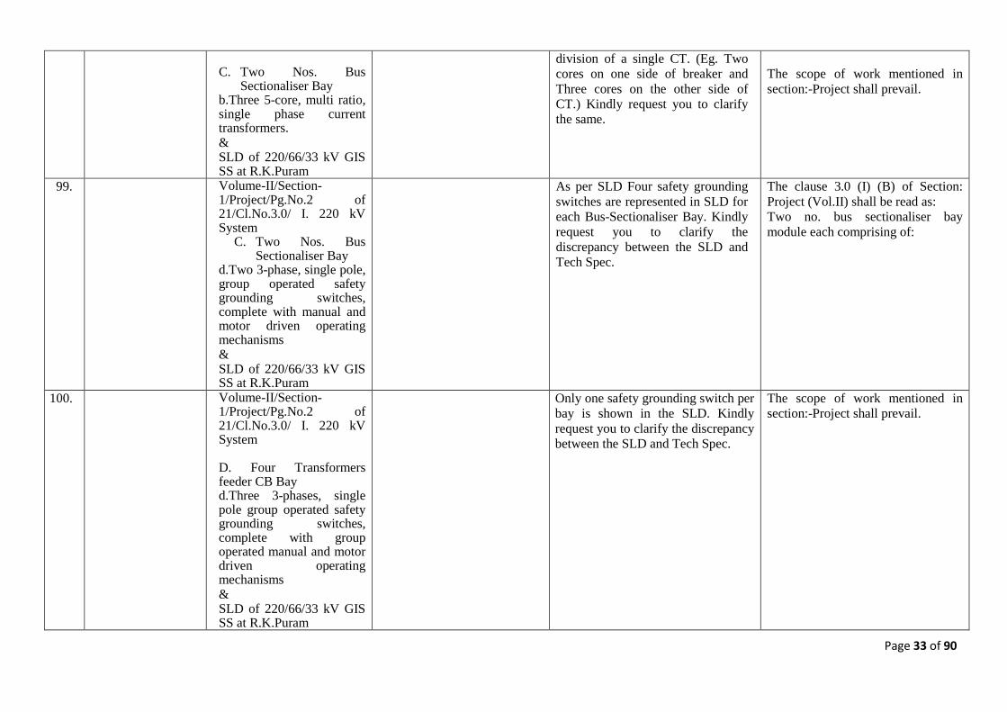
In respect of direct transaction between the Employer and the Contractor, the EXW price is inclusive of all cost as well as duties and tax (viz., custom duties & levies, duties, sales tax/VAT etc.) paid or payable on components, raw materials and any other items used /incorporated or to be incorporated in the Plants & Equipments and other final goods to be supplied by the contractor under the proposed contract.
The clause mentioned is for India or abroad? Since the word ‘Ex-works’ indicates its for India, however, the work ‘Custom Duty’ in the same line indicates its for abroad.
It is applicable to any supplies whether from India or from abroad. The custom duty payable by contractor on the raw material shall be inclusive.
18. Commercial Section III, CC, clause no. 14.5 Page no. 11 of 48 and Section III, CC, clause no. 14..6 Page no. 11 of 48
In respect of direct transaction between the Employer and the Contractor, the EXW price is inclusive of all cost as well as duties and tax (viz., custom duties & levies, duties, sales tax/VAT etc.) paid or payable on components, raw materials and any other items used /incorporated or to be incorporated in the Plants &
There is discrepancy in these clauses. As per clause no.. 14.5 & 14.6 Ex-works needs to be inclusive of all taxes, whereas as per clause 10.4 taxes shall not be included. Please clarify whether the sale tax, vat and local tax and other levies to be considered in Ex-works for direct transaction. Please clarify the rate of taxes i.e.
The following line in Clause 10.4 (b) is deleted to avoid confusion “Sales Tax, VAT, local Tax and other levies in respect of direct transaction between the Employer and the Contractor and octroi/entry tax as applicable for destination site/ state on all items of supply including bought-out finished items, which shall be dispatched directly from the sub-vender’s works to the
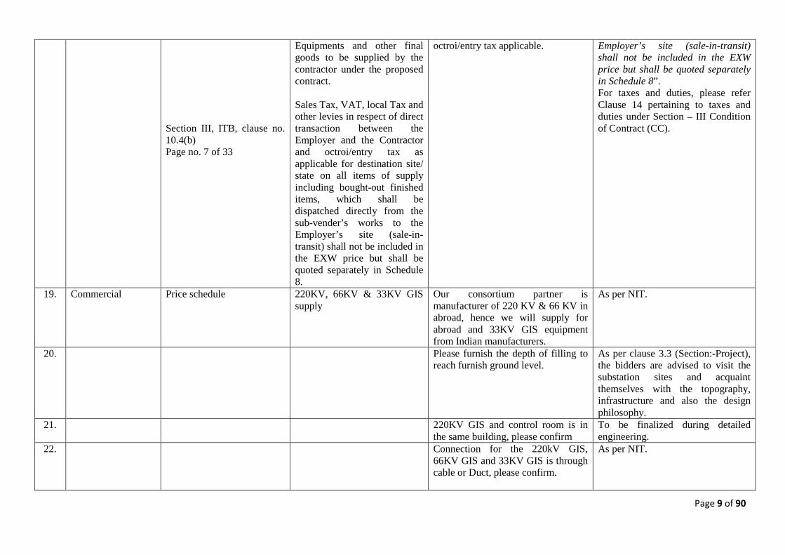
Page 9 of 90
Section III, ITB, clause no. 10.4(b) Page no. 7 of 33
Equipments and other final goods to be supplied by the contractor under the proposed contract. Sales Tax, VAT, local Tax and other levies in respect of direct transaction between the Employer and the Contractor and octroi/entry tax as applicable for destination site/ state on all items of supply including bought-out finished items, which shall be dispatched directly from the sub-vender’s works to the Employer’s site (sale-in-transit) shall not be included in the EXW price but shall be quoted separately in Schedule 8.
octroi/entry tax applicable. Employer’s site (sale-in-transit) shall not be included in the EXW price but shall be quoted separately in Schedule 8”. For taxes and duties, please refer Clause 14 pertaining to taxes and duties under Section – III Condition of Contract (CC).
19. Commercial Price schedule 220KV, 66KV & 33KV GIS supply
Our consortium partner is manufacturer of 220 KV & 66 KV in abroad, hence we will supply for abroad and 33KV GIS equipment from Indian manufacturers.
As per NIT.
20. Please furnish the depth of filling to reach furnish ground level.
As per clause 3.3 (Section:-Project), the bidders are advised to visit the substation sites and acquaint themselves with the topography, infrastructure and also the design philosophy.
21. 220KV GIS and control room is in the same building, please confirm
To be finalized during detailed engineering.
22. Connection for the 220kV GIS, 66KV GIS and 33KV GIS is through cable or Duct, please confirm.
As per NIT.
Page 10 of 90
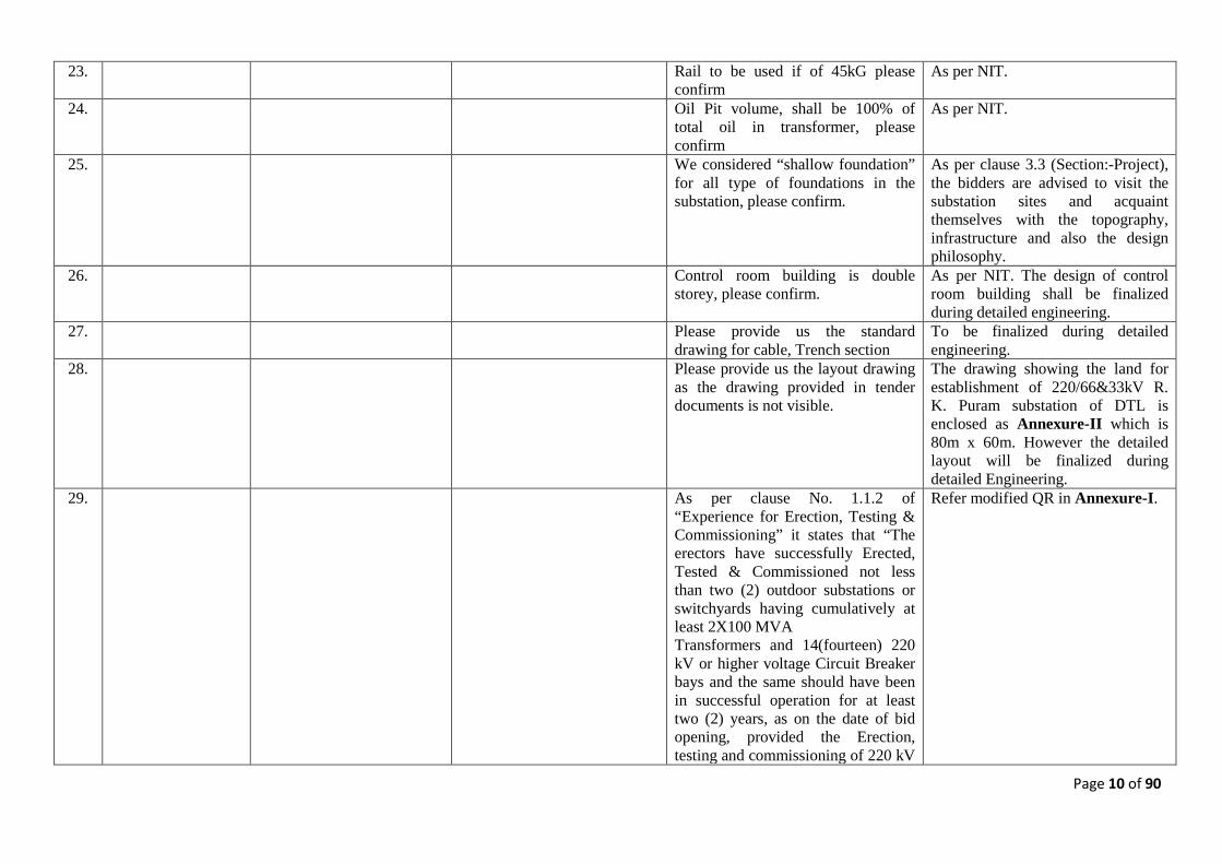
23. Rail to be used if of 45kG please confirm
As per NIT.
24. Oil Pit volume, shall be 100% of total oil in transformer, please confirm
As per NIT.
25. We considered “shallow foundation” for all type of foundations in the substation, please confirm.
As per clause 3.3 (Section:-Project), the bidders are advised to visit the substation sites and acquaint themselves with the topography, infrastructure and also the design philosophy.
26. Control room building is double storey, please confirm.
As per NIT. The design of control room building shall be finalized during detailed engineering.
27. Please provide us the standard drawing for cable, Trench section
To be finalized during detailed engineering.
28. Please provide us the layout drawing as the drawing provided in tender documents is not visible.
The drawing showing the land for establishment of 220/66&33kV R. K. Puram substation of DTL is enclosed as Annexure-II which is 80m x 60m. However the detailed layout will be finalized during detailed Engineering.
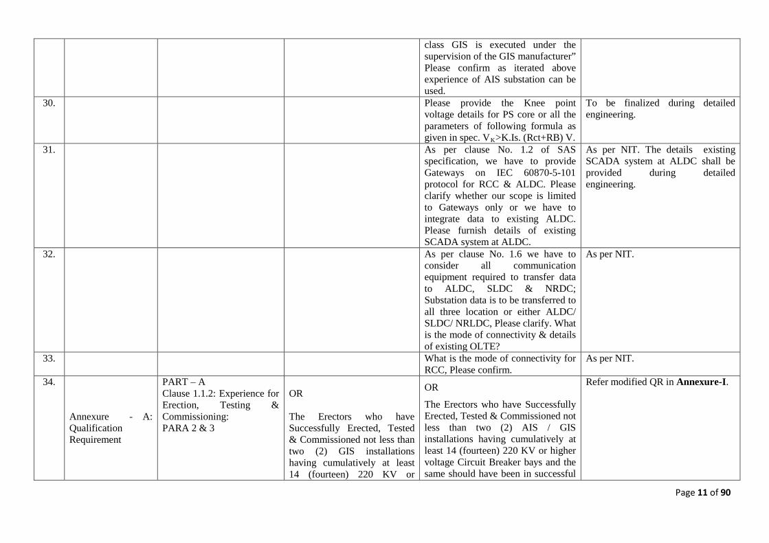
29. As per clause No. 1.1.2 of “Experience for Erection, Testing & Commissioning” it states that “The erectors have successfully Erected, Tested & Commissioned not less than two (2) outdoor substations or switchyards having cumulatively at least 2X100 MVA Transformers and 14(fourteen) 220 kV or higher voltage Circuit Breaker bays and the same should have been in successful operation for at least two (2) years, as on the date of bid opening, provided the Erection, testing and commissioning of 220 kV
Refer modified QR in Annexure-I.
Page 11 of 90
class GIS is executed under the supervision of the GIS manufacturer” Please confirm as iterated above experience of AIS substation can be used.
30. Please provide the Knee point voltage details for PS core or all the parameters of following formula as given in spec. VK
To be finalized during detailed engineering.
>K.Is. (Rct+RB) V. 31. As per clause No. 1.2 of SAS
specification, we have to provide Gateways on IEC 60870-5-101 protocol for RCC & ALDC. Please clarify whether our scope is limited to Gateways only or we have to integrate data to existing ALDC. Please furnish details of existing SCADA system at ALDC.
As per NIT. The details existing SCADA system at ALDC shall be provided during detailed engineering.
32. As per clause No. 1.6 we have to consider all communication equipment required to transfer data to ALDC, SLDC & NRDC; Substation data is to be transferred to all three location or either ALDC/ SLDC/ NRLDC, Please clarify. What is the mode of connectivity & details of existing OLTE?
As per NIT.
33. What is the mode of connectivity for RCC, Please confirm.
As per NIT.
34.
Annexure - A: Qualification Requirement
PART – A Clause 1.1.2: Experience for Erection, Testing & Commissioning: PARA 2 & 3
OR The Erectors who have Successfully Erected, Tested & Commissioned not less than two (2) GIS installations having cumulatively at least 14 (fourteen) 220 KV or
OR
The Erectors who have Successfully Erected, Tested & Commissioned not less than two (2) AIS / GIS installations having cumulatively at least 14 (fourteen) 220 KV or higher voltage Circuit Breaker bays and the same should have been in successful
Refer modified QR in Annexure-I.
Page 12 of 90
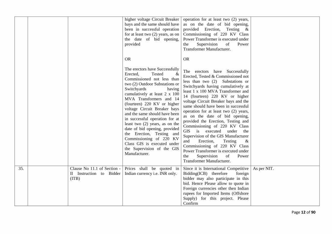
higher voltage Circuit Breaker bays and the same should have been in successful operation for at least two (2) years, as on the date of bid opening, provided OR The erectors have Successfully Erected, Tested & Commissioned not less than two (2) Outdoor Substations or Switchyards having cumulatively at least 2 x 100 MVA Transformers and 14 (fourteen) 220 KV or higher voltage Circuit Breaker bays and the same should have been in successful operation for at least two (2) years, as on the date of bid opening, provided the Erection, Testing and Commissioning of 220 KV Class GIS is executed under the Supervision of the GIS Manufacturer.
operation for at least two (2) years, as on the date of bid opening, provided Erection, Testing & Commissioning of 220 KV Class Power Transformer is executed under the Supervision of Power Transformer Manufacturer. OR
The erectors have Successfully Erected, Tested & Commissioned not less than two (2) Substations or Switchyards having cumulatively at least 1 x 100 MVA Transformer and 14 (fourteen) 220 KV or higher voltage Circuit Breaker bays and the same should have been in successful operation for at least two (2) years, as on the date of bid opening, provided the Erection, Testing and Commissioning of 220 KV Class GIS is executed under the Supervision of the GIS Manufacturer and Erection, Testing & Commissioning of 220 KV Class Power Transformer is executed under the Supervision of Power Transformer Manufacturer.
35. Clause No 11.1 of Section - II Instruction to Bidder (ITB)
Prices shall be quoted in Indian currency i.e. INR only.
Since it is International Competitive Bidding(ICB) therefore foreign bidder may also participate in this bid. Hence Please allow to quote in Foreign currencies other then Indian rupees for Imported Items (Offshore Supply) for this project. Please Confirm
As per NIT.
Page 13 of 90
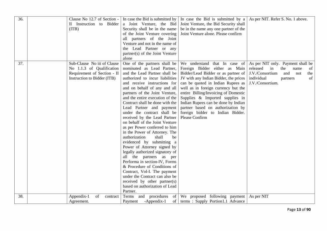
36. Clause No 12.7 of Section - II Instruction to Bidder (ITB)
In case the Bid is submitted by a Joint Venture, the Bid Security shall be in the name of the Joint Venture covering all partners of the Joint Venture and not in the name of the Lead Partner or any partner(s) of the Joint Venture alone
In case the Bid is submitted by a Joint Venture, the Bid Security shall be in the name any one partner of the Joint Venture alone. Please confirm
As per NIT. Refer S. No. 1 above.
37. Sub-Clause No iii of Clause No 1.1.3 of Qualification Requirement of Section - II Instruction to Bidder (ITB)
One of the partners shall be nominated as Lead Partner, and the Lead Partner shall be authorized to incur liabilities and receive instructions for and on behalf of any and all partners of the Joint Venture, and the entire execution of the Contract shall be done with the Lead Partner and payment under the contract shall be received by the Lead Partner on behalf of the Joint Venture as per Power conferred to him in the Power of Attorney. The authorization shall be evidenced by submitting a Power of Attorney signed by legally authorized signatory of all the partners as per Performa in section-IV, Forms & Procedure of Conditions of Contract, Vol-I. The payment under the Contract can also be received by other partner(s) based on authorization of Lead Partner.
We understand that In case of Foreign Bidder either as Main Bidder/Lead Bidder or as partner of JV with any Indian Bidder, the prices can be quoted in Indian Rupees as well as in foreign currency but the entire Billing/Invoicing of Domestic Supplies & Imported supplies in Indian Rupees can be done by Indian partner based on authorization by foreign bidder to Indian Bidder. Please Confirm
As per NIT only. Payment shall be released in the name of J.V./Consortium and not the individual partners of J.V./Consortium.
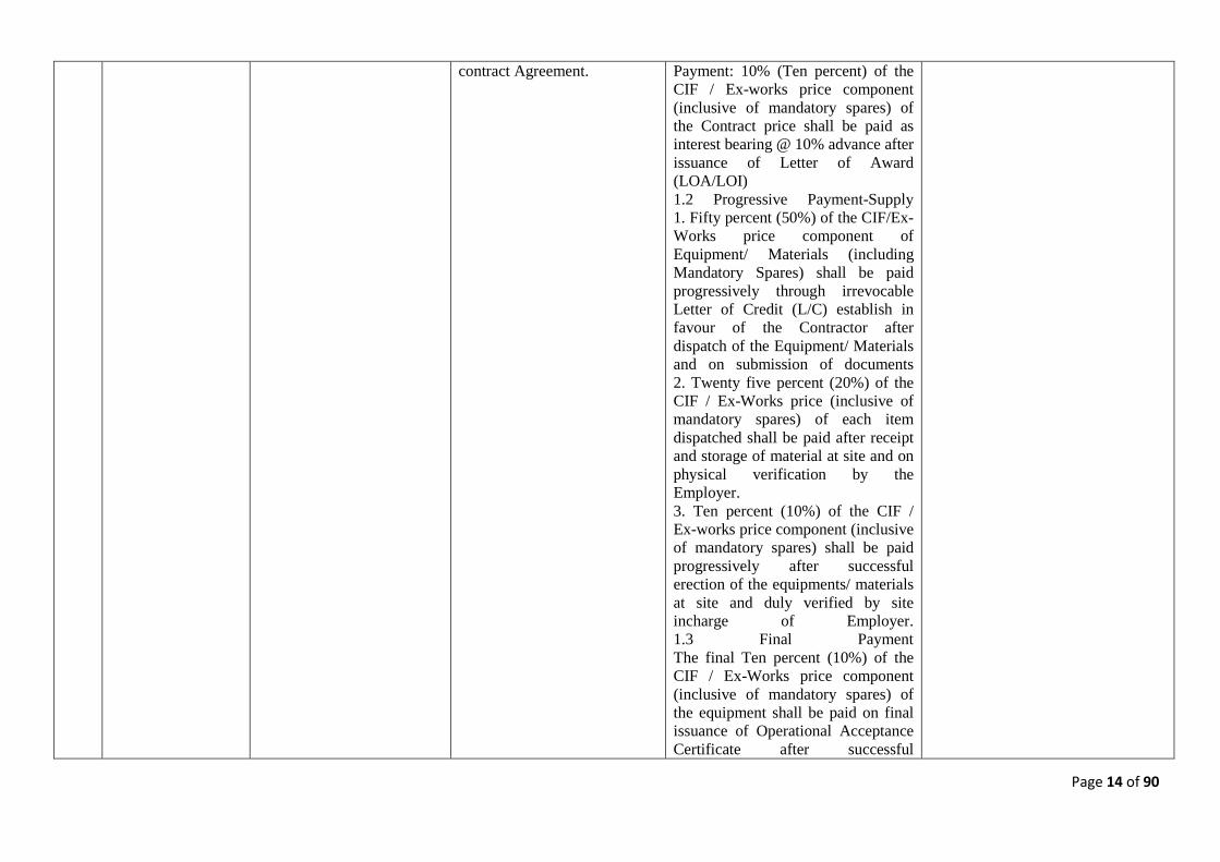
38. Appendix-1 of contract Agreement.
Terms and procedures of Payment -Appendix-1 of
We proposed following payment terms : Supply Portion1.1 Advance
As per NIT
Page 14 of 90
contract Agreement. Payment: 10% (Ten percent) of the CIF / Ex-works price component (inclusive of mandatory spares) of the Contract price shall be paid as interest bearing @ 10% advance after issuance of Letter of Award (LOA/LOI) 1.2 Progressive Payment-Supply 1. Fifty percent (50%) of the CIF/Ex-Works price component of Equipment/ Materials (including Mandatory Spares) shall be paid progressively through irrevocable Letter of Credit (L/C) establish in favour of the Contractor after dispatch of the Equipment/ Materials and on submission of documents 2. Twenty five percent (20%) of the CIF / Ex-Works price (inclusive of mandatory spares) of each item dispatched shall be paid after receipt and storage of material at site and on physical verification by the Employer. 3. Ten percent (10%) of the CIF / Ex-works price component (inclusive of mandatory spares) shall be paid progressively after successful erection of the equipments/ materials at site and duly verified by site incharge of Employer. 1.3 Final Payment The final Ten percent (10%) of the CIF / Ex-Works price component (inclusive of mandatory spares) of the equipment shall be paid on final issuance of Operational Acceptance Certificate after successful
Page 15 of 90
completion of erection, testing and commissioning, proof of submission of the required no. of reproducible, O&M manuals, approved drawings, data sheets, test reports, pamphlets and manual of spares, maintenance & testing equipment etc. (Note: In case the project will be not Commissioned within Six month after successful completion of erection & testing due to non completion of other associate project i.e Feeder line projects or any other projects then this projects is consider to be handed over and Last 10% final payment shall be released)
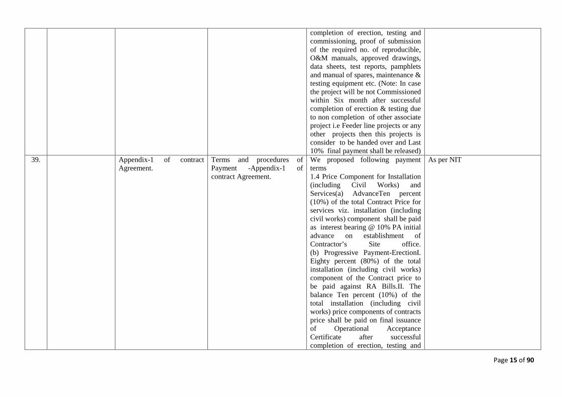
39. Appendix-1 of contract Agreement.
Terms and procedures of Payment -Appendix-1 of contract Agreement.
We proposed following payment terms 1.4 Price Component for Installation (including Civil Works) and Services(a) AdvanceTen percent (10%) of the total Contract Price for services viz. installation (including civil works) component shall be paid as interest bearing @ 10% PA initial advance on establishment of Contractor’s Site office. (b) Progressive Payment-ErectionI. Eighty percent (80%) of the total installation (including civil works) component of the Contract price to be paid against RA Bills.II. The balance Ten percent (10%) of the total installation (including civil works) price components of contracts price shall be paid on final issuance of Operational Acceptance Certificate after successful completion of erection, testing and
As per NIT
Page 16 of 90
commissioning, proof of submission of the required no. of reproducible, O&M manuals, approved drawings, data sheets, test reports, pamphlets and manual of spares, maintenance & testing equipment etc. (Note: In case the project will be not Commissioned within Six month after successful completion of erection & testing due to non completion of other associate project i.e Feeder line projects or any other projects then this projects is consider to be handed over and Last 10% final payment shall be released)
40. General Supply of 33KV GIS The Bidders meeting the qualification Criteria of GIS manufacturing for 220KV GIS may supply the 33KV GIS from any other make who comply the tender specification and are approved by DTL during execution stage. Please confirm
As per NIT.
41.
Schedule No.2 ,SL B. 245 GIS Equipment
As per BOQ SL no.2 of 245kV GIS equipment. Feeder bay for 220kV, 66kV, 33 kV should be suitable for cable.
Please confirm if these cable & cable jointing Kits for feeder bays will be supplied by other agency and will not be in our scope.
For feeder bays, Cable and Cable termination will not be in the scope of the bidders except, 6 no. of single phase 220kV cable end termination kit for two no. 220kV transmissions lines feeder circuit bay module complete suitable for 1000 sq.mm XLPE cable alongwith cable supporting structure which shall also be in the scope of work of bidder. The bidder is required to submit their bid in the revised price schedule attached as Annexure-VI. GIS Cable termination enclosure is
Page 17 of 90
in the scope of the bidder. Further, bidder shall also provide the provision of 66kV GIS cable termination enclosure for double run cable in 2 no. 66kV line feeder bay module (i.e. provision of terminating 6 nos. of 1Cx 800 sq.mm. cable (2 runs per phase) in each feeder bay).
42. Schedule No.2 ,SL B. 245 GIS Equipment
As per BOQ SL no.1 of 245kV GIS equipment. Transformer bay for 220kV should be connected through bus duct.
We propose to use 220kV cable instead of bus duct- Please confirm
As per NIT.
43. Technical Specification for Substation Automation System
As mentioned in TS of Substation Automation System in Section: 14, 1.6 The bidder will quote equipment for the SCADA and Auxiliary power supply and associated fibre optic communication system for transfer of SCADA data of the station to ALDC, SLDC and NRLDC.
Please confirm that Fibre optic communication system is in scope of bidder. If yes, then please provide the detailed technical specification of the same. Also do we need to consider it only at R.K. Puram end or at other locations as well. Please clarify. Please let us have the remote location to which communication system is to be connected. Fote terminal requirement not indicate in BOQ.
As per scope in NIT. FOTE terminals are required at both locations. The cost shall be inclusive in the line item ‘Automation and SCADA’ in the price schedule.
44. Technical Specification In given BOQ 66kV cable is required for interconnection of Transformer GIS bay & Transformer.
Please provide Technical Specification of 33kV/66kV Cable terminations.
As per NIT and relevant IEC.
45. Technical Specification TS for CCTV is not given in the document.
Please provide CCTV Technical Specification
Technical specification of visual monitoring system is enclosed as Annexure-III.
46. Section Project:- Annexure II
Tentative Layout Plan of 220/66/33kV GIS Sub-station (Land Area and Location) is not visualize well
Please provide clear Layout Plan of 220/66/33kV GIS Sub-station.
The drawing showing the land for establishment of 220/66&33kV R. K. Puram substation of DTL is enclosed as Annexure-II which is
Page 18 of 90
80m x 60m. However the detailed layout will be finalized during detailed Engineering.
47. General Please confirm whether order for supply and service part issued separately.
As per NIT.
48. TS for LT Switchgear 11/0.415 KV, 400KVA, 2 Nos Station Transformer are indicated in BOQ. We presume Ist 400KVA Station Transformer in for Connecting tertiary Winding. The Second 400KVA is for receiving alternative Sources. Please confirm
As per NIT. (Refer Section:-Project)
49. General Payment terms Since it is International Competitive Bidding (ICB) therefore, foreign bidder may also participate in this bid. Hence Please confirm mechanism of payment for Imported Items in currencies other then Indian rupees for this project
As per NIT. Refer clause 12.3 (Section:-CC), all payments shall be made in Indian currency i.e. INR only.
50. Defect Liability, Clause No. 27.2 Section-III Condition of Contract (CC), Page 28 of 48
The Defect Liability Period shall be five years from the date of Operational Acceptance of the facilities (or any part thereof).
We request to amend the Defect Liability Period as 12 months from the Operational Acceptance of Substation and 18 months from the last supplied equipments whichever is earlier, which is being accepted by other State/Central utilities.
As per NIT.
51. Section –II Instruction to Bidder (ITB), 1.13 Techno-commercial and Legal Arrangement of Joint Venture. Page 23 of 33
Payment under the contract shall be received by the lead partner on behalf of the Joint Venture as per Power conferred to him in the Power of Attorney. The authorization shall be evidenced by submitting a power of Attorney signed by legally authorized signatory of all the partners as per Performa in
Payment under the contract shall be received by any partner on behalf of the Joint Venture as per Power conferred to him in the Power of Attorney. The authorization shall be evidenced by submitting a power of attorney signed by legally authorized signatory of all the partners as per performa in Section-IV. Forms & Procedure of conditions of Contract. Vol-1
As per NIT only. Payment shall be released in the name of J.V./Consortium.
Page 19 of 90
section-iv. Forms & Procedure of Conditions of Contract. Vol-I
52. General Taxes & Duties Clause 14.10, section-GCC For the purpose of the Contract, it is agreed that the Contract Price specified in Article-2 (Contract Price and Terms of Payment) of the Contract Agreement is based on the taxes inclusive of duties, levies and charges prevailing at the date seven (07) days prior to the last date of bid submission If any rates of Tax are increased or decreased or , a new Tax is introduced, or/an existing Tax is abolished in the course of the performance of the Contract, which was or will be assessed on the Contractor in connection with performance of the Contract, an equitable adjustment of the Contract price shall be made to take into account any such change by addition to the Contract price or deduction therefrom, as the case may be (changes in law & regulations) hereof. However, these adjustments would be restricted to direct transactions between the owner and the Contractor for which the taxes and duties are reimbursable by
As you may be aware GST may be introduced in near future. Statutory variation may happen in forth coming budget. We would request any variation & imposition of new Taxes & Duties for Direct & Bought out items should be reimburse by DTL at actual basis. Kindly confirm.
As per NIT only. Please refer Clause 14 pertaining to taxes and duties under Section – III Condition of Contract (CC).
Page 20 of 90
the Employer as per the Contract. These adjustments shall not be applicable on procurement of raw materials, intermediary components etc by the Contractor and also not applicable on the bought out items dispatched directly from sub-vendor’s works to site.
53. Section III/ Conditions of Contract /14.6 and 14.9, Page Number 14 of 48
As we understand, DTL will issue FÓRM C for the concessional CST for the Direct & Bought out items Kindly confirm.
Yes, However, other formalities/ compliances in respect of in-transit sale as per the applicable provisions of Sales Tax Law shall be fulfilled by the successful contractor.
54. TERMS AND PROCEDURES OF PAYMENT, APPENDIX 1, Procedure (F&P), Page 15 of 65
Supply Portion 1.2 Advance Payment 10% (Ten percent) of the CIF/Ex-works price component (inclusive of mandatory spares) of the Contract price shall be paid as internet bearing advance after signing the Contract Agreement and on submission of documents. \ 1.3 progressive payment 1.3.1 Thirty percent (30%) of the CIF/Ex-Works price component of Equipment/Materials (including Mandatory Spares) shall be paid progressively through irrevocable letter of Credit (L/C) establish in favour of the Contractor after dispatch of the Equipment/Materials and on submission of documents.
We would request to amend the Terms of Payment as below: Supply Portion 1.2.1 Advance Payment 10% (Ten percent) of the CIF / Ex-Works price component (inclusive of mandatory spares) of the Contract price shall be paid as interest free advance after signing the Contract Agreement and on submission of documents. 1.2.2 Further advance of 10% ( ten percent) of the CIF (Indian Port of Entry)/Ex-works price component (inclusive of Mandatory spares) of the contract price shall be paid within 30 days against approval of SLD/Layout drawings. GTPs of main equipments, quality plan and sub vendor list. 1.3 Progressive Payment 1.3.1 Fifty percent (50%) of the CIF/Ex-works price component of Equipment/Materials (including
As per NIT.
Page 21 of 90
Further, Twenty five percent (25%) of the CIF/Ex-works price (inclusive of mandatory spares) of each item shipped shall be paid after receipt and storage of material at site and on physical verification by the Employer. Further twenty percent (20%) of the CIF/ Ex-works price component (inclusive of mandatory spares) shall be paid progressively after successful erection of the equipments/ materials at site and duly verified by site Incharge of Employer. 1.4 Final payment. The fifteen percent (15%) of the CIF / Ex-Works price component (inclusive of mandatory spares) of the equipment shall be paid on final issuance of operational Acceptance Certificate after successful completion of erection, testing and commisssiong, proof of submission of the required no. of reproducible.
Mandatory Spares) shall be paid progressively through irrevocable Letter of Credit (L/C) establish in favour of the Contractor after dispatch of the Equipment/Materials and on submission of documents. Further, Ten percent (10%) of the CIF / Ex-Works price (inclusive of mandatory spares) of each item shipped shall be paid after receipt and storage of material at site and on physical verification by the Employer. Further, Ten percent (10%) of the CIF /Ex-works price component (inclusive of mandatory spares) shall be paid progressively after successful erection of the equipments/materials at site and duly verified by site Incharge of Employer. 1.4 Final Payment, The final ten percent (10%) of the CIF / Ex-Works price component (inclusive of mandatory spares) of the equipment shall be paid on final issuance of Operational Acceptance Certificate after successful completion of erection, testing and commissioning, proof of submission of the required no. of reproducible. For Erection & Civil: 1. 10% of contract value as advance 2. 80% after running bill on pro-rata basis 3. 10% after satisfactory commissioning, however if any delay which is not attributable to us. M/s
Page 22 of 90
DTL will release the Payment after 60 Days from commissioning.
55. BID SECURITY FORM, Section-IV-Forms and Procedure (F & P), Page 3 of 66
In case the bid is submitted by a Joint Venture, the bid security shall be in the name of the joint Venture and not in the name of the Lead Partner or any other Partner(s) of the Joint Venture.
Since, JV will be project specific for the purpose of execution of the specific contract, bank will not be in a position to provide the EMD in the name of JV partner. We request you to please accept the EMD from any of the JV partner.
As per NIT. Refer S. No. 1 above.
56. QUALIFYING REQUIREMENT-Annexure-A, Clause No. 1.1.1, Section-11, Instruction to Bidders, Page 23 of 33
Have designed, manufacture, type tested and supplied 220KV or higher voltage class Power Transformers which must be in satisfactory operation for last 2 (two) years, as on the date of bid opening or supply the said power transformer from such manufactures who have designed, manufactured, type tested, and supplied 220 KV or higher voltage class Power Transformers which must be in satisfactory operation for last 2 (two) years, as on the date of bid opening.
Apart from the same, Transformers supply from the Bidders subsidiary company who have recently established manufacturing facilities in India shall also be acceptable provided they should also have designed, manufactured, type tested and supplied 220 KV or higher voltage class Power Transformers/Reactors with 02 years satisfactory performance Criteria being met by their Principal/Bidder.
Refer modified QR in Annexure-I.
57. Section II (ITB) Annexure-A Part-A Qualifying Requirement Clause 1.1.2
1.1 (e) Indian manufacturers who have Technical Collaboration with a foreign firm(collaborator) or the GIS manufacturers who have established production line in India for these equipment(s) based on technological support of their parent company/ principal provided
In case of Bidders who meet the Requirements under Clause 1.1 e) on the basis of their Parent Company / Principal, then: We understand that - Erection, Testing & Commissioning, the most important Erection activity of the Project (being the GIS Equipment) are to be carried out only under the GIS Manufacturer’s Supervision and the
Refer modified QR in Annexure-I.
Page 23 of 90
the said Collaborator or the said Parent company/Principal meet the experience as mentioned in clause no. 1.1.1 below and erection, testing and commissioning of GIS is carried out by either such manufacturer himself meeting criteria in clause 1.1.2 or through an erector meeting criteria at clause 1.1.2. The Techno-commercial and legal arrangement between them shall be as per clause 1.1.4 below. All the documents/evidences as required in this regard should be submitted along with the Part-I, Techno-Commercial bid. 1.1.4(5) Such Indian GIS manufacturer should be duly authorized by the Collaborator/Parent Company/ Principals to supply and / or install the GIS in the owner’s country.
complete Testing & Commissioning by the GIS Manufacturer. Erection of other Equipment is carried out by Erection Contractor who has sufficient experience for such installations, and subject to Owner (DTL) Approvals during the Contract Execution Stage. - As per clause 1.1.4 item 5) – GIS manufacturer is to be authorized by its principal for the Erection, Testing & Commissioning. - Bidder (Indian Manufacturer who meet the Requirements under Clause 1.1 e) on the basis of their Parent Company / Principal) is fully responsible as an GIS Equipment Manufacturer to carry out the Supervision of installation GIS Equipment, Testing & Commissioning of GIS Equipment. - Bidder (Indian Manufacture who meet the Requirements under Clause 1.1 e) is awarded, carries the overall responsibility for the Contract with respect to Owner (DTL) In view of the above, we understand that “Experience for Erection, Testing & Commissioning under 1.1.2 can also be of the Parent Company / Principal / Collaborator. Please kindly confirm.
58. Section II (ITB) Annexure-A-Part A: Qualification Requirement Clause 1.1.4 Clause 1.1.2 – Item 6 & item 8
1.1.4 (6) A confirmation letter from the Collaborator/Parent Company/ Principals along with the bid stating that Collaborator/Parent Company/
In case of Indian Manufacturers who have a valid and ongoing Technology Transfer Agreement with their Principals (same Parent Company / Principal / Collaborator whose credentials are used by the
Refer modified QR in Annexure-I.
Page 24 of 90
Principals shall furnish an additional performance guarantee for an amount of 10% of the cost of such GIS to guarantee their obligations toward the owner as referred hereinbefore or elsewhere in the NIT conditions. This performance guarantee shall be in addition to the Contract Performance Guarantee to be submitted by the bidder. Notwithstanding the aforesaid confirmation the bidder shall be responsible as a condition of contract for the performance guarantee of their Collaborator or as the case may be of their parent company/Principal. 1.1.4 (8) The above Contract Performance Guarantee from the Collaborator/Parent Company/Principals shall be submitted in favour of owner as provided in Form 6A.
Indian GIS Manufacturer for qualification under clause 1.1. e), we understand the following: a) Joint undertaking by the Collaborator along with the Bidder / Manufacturer (Form 18) is not applicable. Instead, a Letter of Authorization from Bidder’s (Indian GIS Manufacturer) Principals for the Supply, Installation and Testing & Commissioning of the GIS Equipment is to be submitted with the Bid. b) Performance Bank Guarantee from the Principal / Collaborator (Form 6A) is not required in case of an ongoing and Valid Technical Collaboration Agreement between the Bidders (Manufacturers) and their Parent Company/ Principal / Collaborator, whose credentials are used by the Indian GIS Manufacturer for qualification under clause 1.1. e). Please kindly confirm.
59. Qualifying Requirements Annexure-A, Item 1.1 Eligible Bidders
We understand that the GIS Manufacturer, whose GIS equipments are being offered in the bid, shall have servicing facility in India with sufficient trained personnel and necessary testing equipment for providing prompt after-sale service for GIS equipments being offered. Kindly confirm.
May kindly refer cl. 1.1.5 (4) of qualifying requirement regarding after sales support facility in India.
60. Section 3.0/Clause2.0/Intent As per Intent of Specification, the The 220kV system is double bus bar
Page 25 of 90
of Specification/ page 1 of 21
220kV system is double bus bar arrangement with 2 No 160MVA and 2Nos 100MVA Transformers whereas in scope of Works it is mentioned that the 220kV system is double bus bar arrangement with 4 No 100MVA Transformers. Please confirm/clarify
arrangement with 2 No 160MVA and 2Nos 100MVA Transformers.
61. Section 3.0/Scope of Work/220kv System/ I.B/ page 2 of 21
We understand that each bus coupler bay comprising of
1. 1No 2500A 3-ph SF6 CB 2. 3Nos single phase 5C CT 3. 2No 3-phase 1pole group
operated isolator Switch complete with manual & motor driven operating mechanism.
4. 2No 3-ph 1 pole group operated safety grounding switches complete with manual & motor driven operating system.
Kindly confirm/clarify.
There shall be two number bus coupler bay module, each comprising of items detailed in 3.0 (I) (B).
62. Section 3.0Scope of Work I.C .220kv System page 2 of 21
We understand that each Bus Sectionlizer Bay comprises of
1. 1No 2500A 3-ph SF6 CB 2. 6Nos 5 Core Multi ratio 1-ph
CT. 3. 2Nos 3-ph group operated
Isolator Switches complete with manual & motor driven operating mechanism
4. 2 Nos 3-ph 1pole group operated safety grounding switches complete with manual and motor driven operating mechanism Kindly confirm / clarify
There shall be two number bus Sectionalizer bay module, each comprising of items detailed in 3.0 (I) (C).
Page 26 of 90
63. Section 3.0/Scope of Work/220kv System page 2 of 21
In scope of work it was mentioned with group operated safety grounding switch but the same not shown in SLD. Kindly Clarify/Confirm
The scope of work mentioned in section:-Project shall prevail.
64. Section 3.0/Scope of Work We understand that 220kV, 66kV, 33kV Surge Arrestors for Transformers and Feeder Bays would be located inside the GIS Hall. Kindly Clarify/Confirm
Shall be finalized during detailed engineering.
65. Section 3.0 Scope of Work/ I. E /220kv System/page 3 of 21
In SLD on Feeder Circuit side CVT is shown but in Scope of Work it was mentioned 3 core PT. Kindly Clarify / Confirm.
The scope of work mentioned in section:-Project shall prevail.
66. Section 3.0/ Scope of Work We understand that we have to consider each 220kV Busbar 3Nos 1-ph CVT, each 66kV Bus bar 3Nos 1-ph PT and on each 33kV Bus bar 3Nos 1ph PT are considered. Kindly confirm/clarify.
As per NIT (Section: Project).
67. Section 3.0/ Scope of Work Discrepancy between Scope of work and SLD in symbol and wording of CVT and PT. Please kindly clarify.
The scope of work mentioned in section:-Project shall prevail.
68. Section 6.2/Basic Reference Drawings
As per the clause the detailed scheme for Auxiliary Transformer is not shown in SLD. Kindly clarify
The scope of work mentioned in section:-Project shall prevail.
69. Section-4/ Special Equipment/ Clause7.1/ page 5 of 8
We understand that DTL 6000LPH capacity high vacuum type transformer Mineral Oil filtration plants for 220/33kV Rajghat Power House is in DTL Scope
As per NIT. The bidder shall quote the rates inclusive of transformer Mineral oil Filtration plant. Kindly read 220/33kV Rajghat Power House as 220/66/33kV R.K.Puram GIS s/stn, wherever appears in the NIT.
70. Section-IV/Price Schedule item no:7
Item corresponding to Power cable with termination kit/ Bus Duct for 220kv, 66kv and 33kV on feeder side is not mentioned in Schedule of Prices. Kindly Clarify
As per NIT.
Page 27 of 90
71. Section 2.0/Intent of Specification /Page 1 of 21
We understand that the for connecting 220kV GIS Bus Duct with Primary of Transformer, the Bus Duct from GIS would be directly connected to Bushing of Transformer without using any cable/conductor. Kindly Clarify
The inter-connection of 220kV GIS with Primary of Power Transformers shall be through GIS bus duct as detailed in Section:-Project.
72. Section-1 Project /Clause 2.1 /Intent of Specification
Kindly Provide the clear Layout indicating with existing arrangements and Rooms for Estimation Quantity of lot items. Kindly confirm/clarify
The drawing showing the land for establishment of 220/66&33kV R. K. Puram substation of DTL is enclosed which is 80m x 60m. However the detailed layout will be finalized during detailed Engineering.
73. Section VA/1.18.1,VB 1.18.2 and Section12 Clause 6
As per the section-VA 1.18.1 & VB 1.18.2 Neutral Earthing arrangement for transformer to be connected to Employer’s Grounding Earth mat whereas as per section 12 clause 6 Earthing, Main Earth Conductor is in contractor scope. Section VA and section VB are contradicting with Section 12. Kindly clarify/ confirm.
Since this is turnkey project, the Grounding Earth mat and earthing shall be in the scope of the bidder. (refer clause 3.0(XV) of Section:-Project).
74. Section 14 Substation Automation System Clause 3.3.2
We understand the Fiber optic cables shall be supplied by Employer for Communication between SAS and Remote Control Centre Communication Interface. Kindly Confirm & Clarify.
As per NIT.
75. Section 15 : 10. TRANSMISSION LINE PROTECTION/10.1
We understand that as incomer is through cable, Distance protection shall be used as Main-I & current diff. Protection shall be used as main-II. We also understood that fiber optic cable & interfacing units required for
As per NIT. Kindly refer updated technical specifications of Relay and Protection Panel in Annexure-V.
Page 28 of 90
protection data transfer (for both line differential & distance protection of all 220kV , 66kV & 33kV feeders) between substations under present scope to remote end relays & vice versa shall be in employer’s scope. Please clarify/Confirm.
76. Section VA /100MVA Transformer/Pg.no:6of29/Cl.no:1.18/ Neutral Earthing Arrangment.
Please provide complete Scope and details of employer providing Ground mat.
Since this is turnkey project, the Grounding Earth mat and earthing shall be in the scope of the bidder. (refer clause 3.0(XV) of Section:-Project).
77. Section VA /100MVA Transformer
Details of Employer’s Control Room such as location, type of Panels to be housed inside the Room. Kindly clarify
This is general specification of 100MVA Power Transformer. The scope of work shall be as per Section:-Project. The design of substation and control room shall be finalized during detailed engineering.
78. Section VA /100MVA Transformer/Pg.no:3 of 29/1.7.9
Please provide details of employer providing panels and existing location of panel
This is general specification of 100MVA Power Transformer. The scope of work shall be as per Section:-Project. The design of substation and control room shall be finalized during detailed engineering.
79. Section VB/160MVA Transformer/clause 1.18/pg.no Neutral Earthing Arrangment.
Please provide complete Scope and details of employer providing Ground mat.
The scope of work shall be as per Section:-Project. The design of ground mat shall be in the scope of work of the bidder. Kindly refer updated technical specifications of 160MVA Transformer in Annexure-IV.
80. Section VB/160MVA Transformer
Details of Employer’s Control Room such as location, type of Panels to be housed inside the Room. Kindly clarify
The scope of work shall be as per Section:-Project. The design of substation and control room shall be finalized during detailed engineering.
Page 29 of 90
Kindly refer updated technical specifications of 160MVA Transformer in Annexure-IV.
81. Section VB /160MVA Transformer/Pg.no:4 of 39/1.7.9
Please provide details of employer providing panels and existing location of panel
The scope of work shall be as per Section:-Project. The design of substation and control room shall be finalized during detailed engineering. Kindly refer updated technical specifications of 160MVA Transformer in Annexure-IV.
82. Section VA/100MVA Transformer /clause 1.19.20/Pg.no 8of29
We Consider RTCC Panels for 100MVA & 160MVA Power Transformers placed inside the Employer’s Control Room is not in Contractor Scope.
This is general specification of 100MVA Power Transformer. The scope of work shall be as per Section:-Project. RTCC Panels for 100MVA & 160MVA Power Transformers placed inside the Control Room shall be in the Scope of bidder.
83. Section-I project/ clause XVII/Pg.no 6 of 21
We understand that only provisions for CCTV at 220kv, 66kv & 33kv GIS Halls and Main Gate are in contractor scope and supply, Installation of CCTV is in Employers Scope. Kindly Clarify/ confirm
Since this is turnkey project, installation of CCTV shall be in the scope of bidder.
84. Section-I project/ Clause 3.2 Civil Works /Pg.no: 7 of 21.
Request please provide all civil drawings as mentioned in Civil scope of Works
Drawing shall be finalized during detailed engineering.
85. Section-9 Lighting System/Clause no:1.6/Pg.no:2of12
We understand that the Scope of Contractor for Lighting is limited to following Areas
1. GIS cum Control Room Building
2. Switchyard outside GIS cum Control Room Building.
3. DG Set 4. Land Scape Lighting around
The complete lighting and illumination of the substation shall be in the scope of work of bidder (refer clause 3.0(XVI), section-Project). Drawing shall be finalized during detailed engineering.
Page 30 of 90
GIS cum Control Room Building
5. Roads in substation Kindly Confirm/clarify
Request you to kindly Provide drawing for above mentioned areas
86. Section-9/ Lighting System/Cl.no:1.2.2/Pg.no:1of12
We understand that scope of AC Emergency lighting is limited to CR Building, DG Set Buildings & Switchyard. Kindly Confirm/Clarify
As per NIT.
87. Section-9/ Lighting System/Cl.no:1.2.3/pg.no:1of12
We understand that scope of DC Emergency Lighting is limited to Stair Case, Corridors, Electrical Rooms, Battery Charger Room, LT Switchgear Room in Control Room Building & DG set Building. Kindly Confirm/ Clarify
As per NIT.
88. Section-9/ Lighting System/Cl.no:1.2.4/ Portable Fixtures /Pg.no:Pg.no:1of12
We understand that Scope of Portable Fixtures is limited to 3Nos in Control Room and 1No DG set Building. Kindly Confirm/Clarify.
As per NIT.
89. Section-1 Project/Scope of work/Cl.no:3.00/Pg.no:1 of 21 and Single Line Diagram
We understand from Scope of Work and SLD there are no AIS related Equipment on 220kv, 66kV and 33kV. Kindly confirm/clarify.
As per NIT.
90. Section 1 /Project/Cl.no3.7/Specific Exclusions and Section 13/Civil Works/ clause 13.4.d Design Criteria page 17 of 34
We understand that, as 220KV incomers, 66kV & 33kV Outgoings are through cables, OHTL is not applicable in this case. Hence we are not considering any material related to OHTL termination. Please Clarify/Confirm.
As per NIT.
91. Section 2 / GIS / Cl no.23 /Pg No 30 of 34
1. We understand that 220kV incoming cables shall directly terminate at SF6/cable termination
The 220kV/66KV/33kV feeder cables shall directly terminate at SF6/cable termination interface in
Page 31 of 90
interface in GIS Bay module in GIS hall. 2. We understand that 66kV & 33kV outgoing cable shall originate directly from SF6/cable termination in GIS bay Module in GIS Hall. 3. Laying & termination of 220kV incoming Cables, 66kV & 33kV outgoing cables at SF6/cable termination shall be in client/others scope. Kindly clarify/ confirm.
GIS Bay module in GIS hall. Also refer S. No. 41 above.
92. General Kindly confirm if the Bus Duct Termination of future Bays for 220kV,66kV & 33kV is to suit XLPE Cable
As per NIT.
93. General Kindly provide the details of existing facilities, arrangements, buildings
As per clause 3.3 (Section:-Project), the bidders are advised to visit the substation sites and acquaint themselves with the topography, infrastructure and also the design philosophy.
94. Volume-II/Section-1/Project/ Pg.8 of 21/Cl.No.4.2 However for Design purpose, ambient temperature shall be considered as 50 degree centigrade. & Volume-II/Section-2/GIS/Pg.No.14 of 34/Cl.No. 10.7.3 e) Rated continuous current (A) at an ambient temperature of 40 degree centigrade
Kindly request you to clarify the actual Design Temperature.
As per NIT.
95. Volume-II/Section-3/GTR/ We understand that the clauses are These are general technical
Page 32 of 90
Pg.No.20 of 39/Cl.No.24.0 24.0 Technical Requirements of Equipments 24.1(b) Circuit Breakers 24.2 Isolators 24.3 Instrument Transformers 24.4 Surge Arresters
related to AIS Sub-Station and not related to GIS SS, as these items are a part of GIS equipment for which technical requirement as already specified at Annexure-A/ Qualifying Requirement/ page no. 22 of 33 Kindly Clarify/Confirm
requirements of equipments. The order of precedent is defined in section Project.
96. Volume-II/Section-1/Project/Pg.No.2 of 21/Cl.No.3.0/ I. 220 kV System
Sectionalized Double Bus bar arrangement b.Three inductive or capacitive type voltage transformers, complete with isolator switchand safety grounding switches. & SLD of 220/66/33 kV GIS SS at R.K.Puram
As per SLD Only two VT's with DS/ES are shown for each bus-bar. Kindly request you to clarify the discrepancy between the SLD and Tech Spec. Further understand that Capacitive Voltage Transformers (CVT's) are not used in GIS but only Inductive type are used. Please Clarify.
The scope of work mentioned in section:-Project shall prevail.
97. Volume-II/Section-1/Project/Pg.No.2 of 21/Cl.No.3.0/ I. 220 kV System B. Two Nos. Bus Coupler
Bay d. Two 3-phase, single pole, group operated safety grounding switches, complete with manual and motor driven operating mechanisms. & SLD of 220/66/33 kV GIS SS at R.K.Puram
As per SLD No safety grounding switch is shown in the Bus Coupler Section of the 220 kV SLD
Kindly request you to clarify the discrepency between the SLD and Tech Spec.
The clause 3.0 (I) (B) of Section: Project (Vol.II) shall be read as: Two no. bus coupler bay module each comprising of:
98. Volume-II/Section-1/Project/Pg.No.2 of 21/Cl.No.3.0/ I. 220 kV System
As per SLD Two CT's on either side of CB are represented in the SLD. We Understand that these are no two different CT's but are core
The clause 3.0 (I) (B) of Section: Project (Vol.II) shall be read as: Two no. bus sectionaliser bay module each comprising of:
Page 33 of 90
C. Two Nos. Bus
Sectionaliser Bay b.Three 5-core, multi ratio, single phase current transformers. & SLD of 220/66/33 kV GIS SS at R.K.Puram
division of a single CT. (Eg. Two cores on one side of breaker and Three cores on the other side of CT.) Kindly request you to clarify the same.
The scope of work mentioned in section:-Project shall prevail.
99. Volume-II/Section-1/Project/Pg.No.2 of 21/Cl.No.3.0/ I. 220 kV System
C. Two Nos. Bus Sectionaliser Bay
d.Two 3-phase, single pole, group operated safety grounding switches, complete with manual and motor driven operating mechanisms & SLD of 220/66/33 kV GIS SS at R.K.Puram
As per SLD Four safety grounding switches are represented in SLD for each Bus-Sectionaliser Bay. Kindly request you to clarify the discrepancy between the SLD and Tech Spec.
The clause 3.0 (I) (B) of Section: Project (Vol.II) shall be read as: Two no. bus sectionaliser bay module each comprising of:
100. Volume-II/Section-1/Project/Pg.No.2 of 21/Cl.No.3.0/ I. 220 kV System D. Four Transformers feeder CB Bay d.Three 3-phases, single pole group operated safety grounding switches, complete with group operated manual and motor driven operating mechanisms & SLD of 220/66/33 kV GIS SS at R.K.Puram
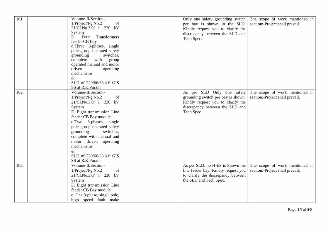
Only one safety grounding switch per bay is shown in the SLD. Kindly request you to clarify the discrepancy between the SLD and Tech Spec.
The scope of work mentioned in section:-Project shall prevail.
Page 34 of 90
101. Volume-II/Section-1/Project/Pg.No.2 of 21/Cl.No.3.0/ I. 220 kV System D. Four Transformers feeder CB Bay d.Three 3-phases, single pole group operated safety grounding switches, complete with group operated manual and motor driven operating mechanisms & SLD of 220/66/33 kV GIS SS at R.K.Puram
Only one safety grounding switch per bay is shown in the SLD. Kindly request you to clarify the discrepancy between the SLD and Tech Spec.
The scope of work mentioned in section:-Project shall prevail.
102. Volume-II/Section-1/Project/Pg.No.2 of 21/Cl.No.3.0/ I. 220 kV System E. Eight transmission Line feeder CB Bay module d.Two 3-phases, single pole group operated safety grounding switches, complete with manual and motor driven operating mechanisms. & SLD of 220/66/33 kV GIS SS at R.K.Puram
As per SLD Only one safety grounding switch per bay is shown. Kindly request you to clarify the discrepancy between the SLD and Tech Spec.
The scope of work mentioned in section:-Project shall prevail.
103. Volume-II/Section-1/Project/Pg.No.2 of 21/Cl.No.3.0/ I. 220 kV System E. Eight transmission Line feeder CB Bay module e. One 3-phase, single pole, high speed fault make
As per SLD, no H-ES is Shown the line feeder bay. Kindly request you to clarify the discrepancy between the SLD and Tech Spec.
The scope of work mentioned in section:-Project shall prevail.
Page 35 of 90
grounding switch, complete with group operated manual and motor driven operating mechanisms. & SLD of 220/66/33 kV GIS SS at R.K.Puram
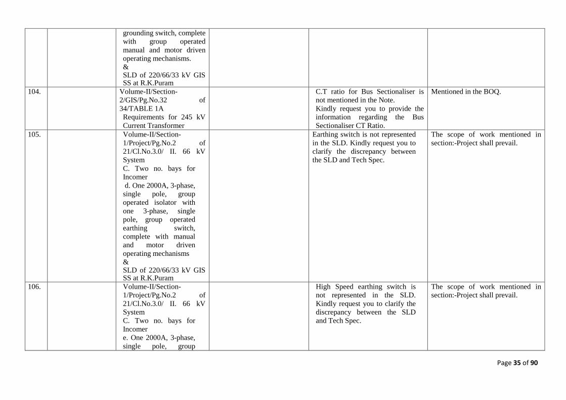
104. Volume-II/Section-2/GIS/Pg.No.32 of 34/TABLE 1A Requirements for 245 kV Current Transformer
C.T ratio for Bus Sectionaliser is not mentioned in the Note. Kindly request you to provide the information regarding the Bus Sectionaliser CT Ratio.
Mentioned in the BOQ.
105. Volume-II/Section-1/Project/Pg.No.2 of 21/Cl.No.3.0/ II. 66 kV System C. Two no. bays for Incomer d. One 2000A, 3-phase, single pole, group operated isolator with one 3-phase, single pole, group operated earthing switch, complete with manual and motor driven operating mechanisms & SLD of 220/66/33 kV GIS SS at R.K.Puram
Earthing switch is not represented in the SLD. Kindly request you to clarify the discrepancy between the SLD and Tech Spec.
The scope of work mentioned in section:-Project shall prevail.
106. Volume-II/Section-1/Project/Pg.No.2 of 21/Cl.No.3.0/ II. 66 kV System C. Two no. bays for Incomer e. One 2000A, 3-phase, single pole, group
High Speed earthing switch is not represented in the SLD. Kindly request you to clarify the discrepancy between the SLD and Tech Spec.
The scope of work mentioned in section:-Project shall prevail.
Page 36 of 90
operated isolator with one normal and one high speed fault make 3-phase, single pole, group operated earthing switch, complete with manual and motor driven operating mechanisms. & SLD of 220/66/33 kV GIS SS at R.K.Puram
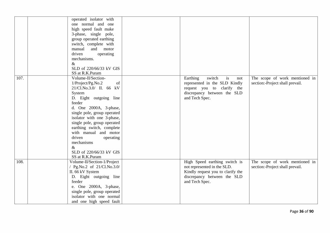
107. Volume-II/Section-1/Project/Pg.No.2 of 21/Cl.No.3.0/ II. 66 kV System D. Eight outgoing line feeder d. One 2000A, 3-phase, single pole, group operated isolator with one 3-phase, single pole, group operated earthing switch, complete with manual and motor driven operating mechanisms & SLD of 220/66/33 kV GIS SS at R.K.Puram
Earthing switch is not represented in the SLD Kindly request you to clarify the discrepancy between the SLD and Tech Spec.
The scope of work mentioned in section:-Project shall prevail.
108. Volume-II/Section-1/Project / Pg.No.2 of 21/Cl.No.3.0/ II. 66 kV System D. Eight outgoing line feeder e. One 2000A, 3-phase, single pole, group operated isolator with one normal and one high speed fault
High Speed earthing switch is not represented in the SLD. Kindly request you to clarify the discrepancy between the SLD and Tech Spec.
The scope of work mentioned in section:-Project shall prevail.
Page 37 of 90
make 3-phase, single pole, group operated earthing switch, complete with manual and motor driven operating mechanisms.
109. Qualification Requirement, PART- A, Eligible Bidders:
Clause no 1.1 ( c) Erectors who have the experience as per the criteria/conditions mentioned in 1.1.2 below and supply GIS from such manufacturer(s) who fulfils the criteria mentioned at 1.1.1 below. The bid shall include consent letter (as per format Annexure-D2) from the proposed GIS manufacturer stating that the manufacturer shall furnish an additional performance guarantee for an amount of 10% of the cost of such GIS. This performance guarantee shall be in addition to the Contract Performance Guarantee to be submitted by the bidder.
Being a Govt organisation, the selection of GIS manufacturer shall be done by open tendering process after award of contract. However, we assure that GIS shall be meeting the Qualifying Criteria as per Annexure A, Clause No 1.1.1.We propose that you allow us to submit multiple Manufacturer Authorization from GIS manufacturers meeting Clause 1.1.1 during bidding stage. Also, DTL is requested to clarify whether a party which provides consent letter to another, shall be able to participate on its own or not.
Refer modified QR in Annexure-I.
110. Experience for GIS Manufacturer(s):
Clause no 1.1.1 ( c) Have designed, manufactured, type tested and supplied 220 kV or higher voltage class Power Transformers which must be in satisfactory operation for last 2 (two) years, as on the date of bid opening or supply the said power transformer from such manufacturers who have designed, manufactured, type tested, and supplied 220 kV or higher voltage class Power
We understand that POWER Transformer is to be supplied by the main bidder (manufacturer OR Erector), and not necessarily by the GIS manufacturer. However, the said clause is to the contrary. Kindly clarify.
Refer modified QR in Annexure-I.
Page 38 of 90
Transformers which must be in satisfactory operation for last 2 (two) years, as on the date of bid opening.
111. TERMS AND PROCEDURES OF PAYMENT
Appendix 1, Terms of Payment Supply DTL to consider our proposed terms of Payment for Supplies- FOR Site Basis: - 10% of contract price as interest-free mobilization advance against equivalent value of BG. - 60% of contract price against despatch documents - 20% along with 100% Taxes, F&I charges on receipt of goods at site on pro rata basis upon verification by Purchaser - Balance 10% on issuance of TOC or deemed TOC against issue BG of equivalent value to be kept valid up to warranty period.
As per NIT.
112. TERMS AND PROCEDURES OF PAYMENT
Appendix 1, Terms of Payment ETC and Civil Works
DTL to consider our proposed terms of Payment for ETC and Civil Works :-10% of contract price as interest-free mobilization advance against equivalent value of BG.- 80% of the Civil Works price along with 100% taxes on pro-rata basis based on the progress made and as per the agreed billing breakup.- Balance 10% on issuance of TOC or deemed TOC against issue BG of equivalent value to be kept valid up to warranty period.
As per NIT.
113. Technical Specification Volume-II Section - 3
9.0 ,9.3 TYPE TEST REQUIREMENTS
We are not considering type testing of GIS/any switchyard equipment/items. We shall submit only valid type test reports. Please confirm.
As per NIT.
Page 39 of 90
114. Section - 1 3.0 (I) The 245kV SF6 ... 16 bays- 4 nos. 100MVA transformer bays
Please confirm that 2 nos. 220/33kV,100MVA & 2 Nos. 220/66kV 160MVA ICT only are to be provided in subject tender.
2 nos. 220/33/11kV,100MVA & 2 Nos. 220/66/11kV 160MVA Power Transformer are in the scope of work.
115. Section - 1 Single Line Diagram Please provide the following in Single Line Diagram for subject tender:- 1. Please mark Future bays required in 220,66,33kV GIS in SLD. 2. Please indicate feeder current ratings for 220,66,33kV GIS in SLD. 3. Please indicate fault current ratings for 220,66,33kV GIS in SLD. 4.Please mark all earth switches required for 220,66,33kV GIS in SLD.
The scope of work mentioned in section:-Project shall prevail.
116. Section - 1 3.0 (I) There shall be provision for 2 no. future bays in the GIS building.
Please confirm that only space provision is required to be provided for future bays in GIS halls for 220,66,33kV GIS and that future bays shall be provided un-equipped.
As per clause 3.0 ‘scope of work’ there shall be space provision for future bays in GIS hall.
117. Section - 1 3.0 (I) (A) b. Three inductive or capacitive type voltage transformers, ….grounding switches.
Please indicate the following bus CVT in Single Line Diagram for subject tender in 200kV Double bus bar arrangement: - "Three inductive or capacitive type voltage transformers, complete with isolator switch and safety grounding switches."
The scope of work mentioned in section:-Project shall prevail.
118. Section - 1 3.0 (I) (E) f,j GIS Cable termination ….1200/1000 sq. mm XLPE cable.
Please confirm that only GIS Cable termination enclosure suitable for connecting single phase 1200/1000 sq. mm XLPE cable is to be provided in outgoing line feeder circuits as per item (j). Hence item (f), ie, Three, single phase SF6/XLPE cable terminations is not required/relevant. Please confirm.
Refer Sr. No. 41 above.
Page 40 of 90
119. Section - 1 3.0 (I) (A) 3-phase/three 1-phase (isolated) units
Please confirm whether single phase segregated or three phase encapsulated busbar is to be provided in 220kV/66kV GIS.
As per NIT
120. Section - 1 3.0 (XIX) Bidder shall arrange suitable provision for testing of 220kV, 66kV & 33kV cables after …. testing purpose.
Please confirm that any Supply/ETC/Testing of 220kV EHV cable is not in bidder's scope, either for outgoing 220kV GIS line feeders or for inter-connection between 220kV GIS & 220/66kV ICT or 220/33kV ICT.
As per NIT
121. Section - 1 3.0 (I) (E) ,k GIS duct with gas monitoring devices, barriers, pressure switches, etc. as required.
Please confirm whether Gas insulated bus-duct or 220kV EHV cable is to be provided for inter-connection between 220kV GIS & 220/66kV ICT / 220kV GIS & 220/33kV ICT.
The inter-connection of 220kV GIS with Primary of Power Transformers shall be through GIS bus duct as detailed in Section:-Project.
122. Section - 1 4.3 Soil Data Please provide preliminary soil investigation report for subject project.
As per NIT.
123. Section - 1 12.1 Training of Owner’s Personnel Please provide areas/topics in which training is to be provided along with number of days of training required for each subject.
As per NIT.
124. Section - 1 12.2 TYPE TEST REQUIREMENTS
We are not considering type testing of GIS/any switchyard equipment/items. We shall submit only valid type test reports .Please confirm.
As per NIT.
125. Section - 1 Annexure-IV The GIS Building…. luminaries having 250 watt metal halide fixtures …. areas.
Please confirm whether HPSV fixtures can be provided instead of metal halide fixtures in GIS Building.
As per NIT.
126. Section - 1 Annexure- VI A Cl. 1.01.3
66kV XLPE Cable i) Please provide size (sq mm) of 66kV XLPE Cable to be considered. ii) Please confirm that Lead sheath is not to be provided for 66/33 kV cable.
(i). As per NIT. (ii) The Lead sheath is not allowed.
Page 41 of 90
127. Section - 1 Annexure- VI A Cl. 3.0
Cable Laying and Termination i) Please provide cable trench drawing/cable routing drawing for 66/33kV Cables. ii) Please confirm whether 66/33kV XLPE Cables are to be laid on cable trays/angles/directly buried in soil.
Shall be finalized during detailed engineering.
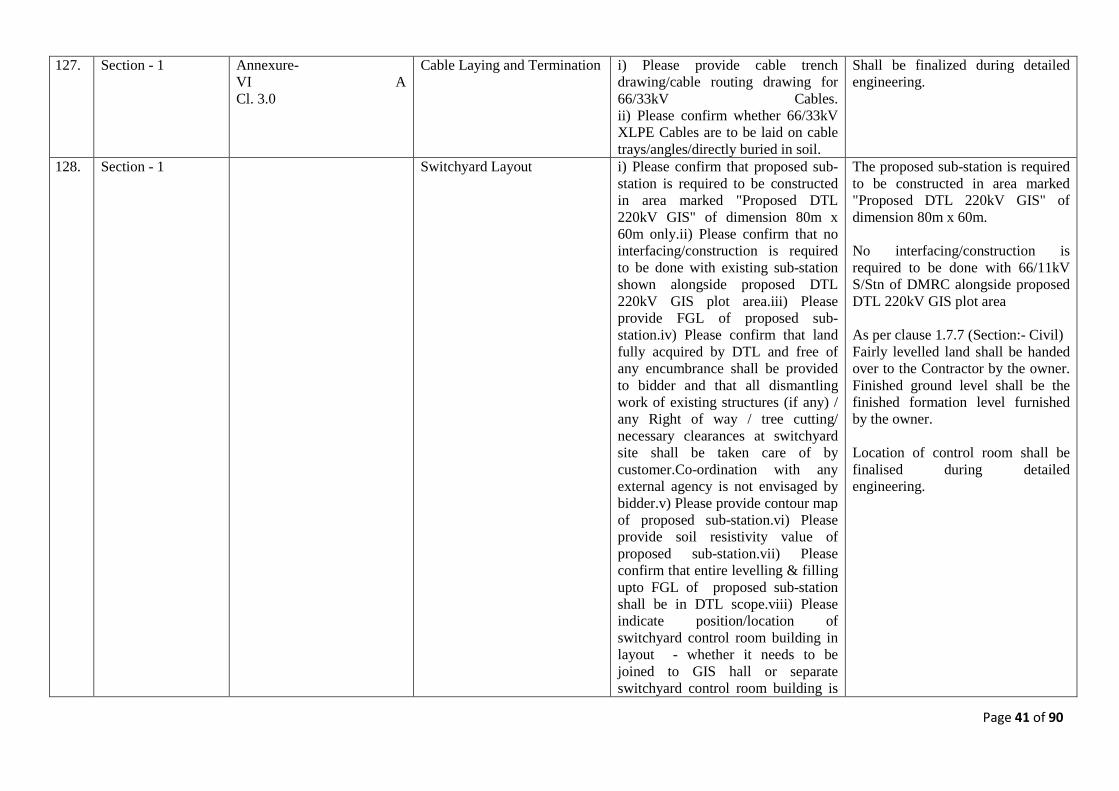
128. Section - 1 Switchyard Layout i) Please confirm that proposed sub-station is required to be constructed in area marked "Proposed DTL 220kV GIS" of dimension 80m x 60m only.ii) Please confirm that no interfacing/construction is required to be done with existing sub-station shown alongside proposed DTL 220kV GIS plot area.iii) Please provide FGL of proposed sub-station.iv) Please confirm that land fully acquired by DTL and free of any encumbrance shall be provided to bidder and that all dismantling work of existing structures (if any) / any Right of way / tree cutting/ necessary clearances at switchyard site shall be taken care of by customer.Co-ordination with any external agency is not envisaged by bidder.v) Please provide contour map of proposed sub-station.vi) Please provide soil resistivity value of proposed sub-station.vii) Please confirm that entire levelling & filling upto FGL of proposed sub-station shall be in DTL scope.viii) Please indicate position/location of switchyard control room building in layout - whether it needs to be joined to GIS hall or separate switchyard control room building is
The proposed sub-station is required to be constructed in area marked "Proposed DTL 220kV GIS" of dimension 80m x 60m. No interfacing/construction is required to be done with 66/11kV S/Stn of DMRC alongside proposed DTL 220kV GIS plot area As per clause 1.7.7 (Section:- Civil) Fairly levelled land shall be handed over to the Contractor by the owner. Finished ground level shall be the finished formation level furnished by the owner. Location of control room shall be finalised during detailed engineering.
Page 42 of 90
required. 129. Section - 2 1.00 It should be designed for
indoor/outdoor (as specified) application…
Please confirm that 220,66 & 33kV GIS shall be designed for indoor application only.
As per NIT.
130. Section - 2 4.3 The switchgear….. have complete phase isolation.
Please confirm whether single phase segregated or three phase encapsulated busbar is to be provided in 220kV/66kV GIS.
As per NIT.
131. Section - 2 9 The GIS supplier shall define clearly what constitutes the main grounding bus of the GIS.
Please confirm if copper earthing needs to be provided for GIS or MS rod can be used for earthmat of GIS.
As per NIT. However, design of earth mat is in the scope of bidder.
132. Section - 2 17 a 220kV & 66kVGIS BUILDING
i) Please provide dimension of 220kv & 66kV & 33kV GIS buildings for subject project. ii) Please confirm whether 220kV & 66kV GIS buildings shall be separate.(enjoined buildings)
Building dimensions & locations shall be finalized at the time of detailed engineering.
133. Section - 2 24 Electric Overhead Crane Please provide capacity/ tonnage of Electric Overhead Crane to be provided for 220, 66 & 33kV GIS buildings.
As per NIT.
134. Section - 2 15.0 Incomer and Outgoing Connections
i) Please provide size of XLPE Cable to be considered for incoming feeders. ii) Please provide size of SF6-XLPE Cable termination to be considered for outgoing line feeders.
Refer Sr. No. 41 above.
135. Section - 2 23.0 SF6 GIS to XLPE Cable Termination
Please confirm that only 33kV GIS-XLPE cable termination arrangement only needs to be provided by bidder for 33kV GIS outgoing feeders. Please note that any supply/ETC/laying/trench material of 33kV cables & 33kV Cable terminations are not in bidder scope for 33kV GIS outgoing feeders.
As per NIT.
136. Section - 3 24.1~24.4 TECHNICAL Please confirm whether technical These are general technical
Page 43 of 90
REQUIREMENT OF EQUIPMENTS
requirement of equipments (Circuit Breakers, Isolators, Instrument transformers, Surge Arresters) specified in subject clause pertain to AIS or GIS equipment.
requirements of equipments. The order of precedent is defined in section Project.
137. Section - 4 5.0 Circuit Breaker Operation Analyser
Please confirm whether Circuit Breaker Operation Analyser specified in subject clause pertains to AIS or GIS Circuit Breaker.
Circuit Breaker Operation Analyser specified is for subject tender which is GIS.
138. Section - 4 7.1 Delhi Transco …. for its transformers for 220/33kV Rajghat Power House.
i) Subject clause mentions 220/33kV Rajghat Power House. Please confirm that 220/33kV Rajghat Power House is not related to scope of subject tender. ii) Please confirm whether transformer Mineral oil Filtration plant is required for R K Puram GIS Sub-station.
As per NIT. The bidder shall quote the rates inclusive of transformer Mineral oil Filtration plant. Kindly read 220/33kV Rajghat Power House as 220/66/33kV R.K.Puram GIS s/stn, wherever appears in the NIT.
139. Section - 7 1.25.2 Standard scheme... in Standard SLD of A/C & DC system enclosed bid documents.
Please provide Standard SLD of A/C & DC system mentioned in subject clause.
Shall be finalized during detailed engineering.
140. Section - 8 1.3 Battery Charger Please confirm whether Battery Charger required for subject tender is float cum boost type charger.
As per NIT.
141. Section - 13 15.2 (A) Area Requirement- Control Room Building
Please provide size of sub-station Control room building of switchyard alongwith individual room dimensions.
As per NIT. However, the design of the building shall be finalised during detailed engineering.
142. Section - 13 13.0 Structure We are considering lattice type structure for all outdoor yard equipment. Please confirm.
Shall be finalized during detailed engineering.
143. Section - 8 1.3 Battery charger Please confirm minimum Amp rating of 220V & 48V Switchyard battery charger.
Design is in the scope of the bidder.
144. Section - 1 3.0 Communication Equipment Please confirm that any PLCC/OPGW equipment or CVT/Wave Trap/48V DC System for both local & remote ends is not required to be provided for subject
As per NIT. (Section: substation automation)
Page 44 of 90
tender. 145. Volume-II,
Technical Specifications,
Section- 1,
Page 2 of 21 Clause. No 3.0 I) - 220kV System C) SLD - 220-66-33 kV GIS at RK Puram
As per the referred clause, the requirement of CT is mentioned as "Three 5-core, multi ratio, single phase current transformers" whereas SLD shows 2 nos of CTs on either side of Circuit breaker in each bay of bus sectionalizer. We understand that 1 number 5 core CT has been distributed on both sides of CB. Kindly confirm our understanding
The scope of work mentioned in section:-Project shall prevail.
146. Volume-II, Technical Specifications, Section- 1,
Page 2 of 21 Clause. No 3.0 I) - 220kV System E) g) SLD - 220-66-33 kV GIS at RK Puram
As per the referred clause, the requirement of CVT is mentioned as "3-core, single phase voltage transformers/PT whereas in SLD shows CVT connected to each outgoing feeders. We would like to inform that GIS type CVT is not available and hence the same shall be considered as PT only. Kindly confirm your acceptance
The scope of work mentioned in section:-Project shall prevail.
147. Volume-II, Technical Specifications, Section- 1,
Page 2 of 21 Clause. No 3.0 I) - 220kV System D) SLD - 220-66-33 kV GIS at RK Puram
As per the referred clause, it is mentioned as four transformers feeder circuit breaker bay modules with one spare bay. We understand that, only space for spare bay has to be provided as the spare bay is not shown in SLD. Kindly confirm
As per NIT. Refer Section:-Project.
148. Volume-II, Technical Specifications, Section- 1,
Page 3 of 21 Clause. No 3.0 II) - 66kV System A) & B)
As per referred clause for 66 kV GIS system Busbar is rated for 3000A where as the circuit breaker of Bus coupler is rated for 2500A only. Kindly confirm the requirement
As per NIT.
149. Volume-II, Technical Specifications,
Project, Page 4 of 21 Clause. No 3.0 III) - & SLD - 220-66-33 kV GIS at
As per the referred clause "33kV GIS shall have sectionalised double bus bar arrangement",
At 33kV level there will be no bus section.
Page 45 of 90
Section- 1, RK Puram We understand that the same is a typographical error since there is no "Bus sectionalized" for 33kV GIS as per specification & SLD. Please confirm our understanding
150. Volume-II, Technical Specifications, Section- 1,
Project, Page 4 of 21 Clause. No II.(D).i
As per the referred clause it is mentioned as "GIS cable termination enclosure suitable for connecting 3 cables of 1C x 1000 sq.mm. XLPE". In this regard we understand that cable termination enclosure shall be suitable for 1 cable of 1C x 1000 sq.mm. per phase and in total 3 cables for feeder are to be considered. Kindly confirm our understanding
The 66kV outgoing line feeder circuit breaker bay module shall have GIS cable termination enclosure suitable for connecting 3 cables of 1C x 1000 sq.mm. XLPE. (1C x 1000 sq.mm. per phase) However, bidder shall also provide the provision of 66kV GIS cable termination enclosure for double run cable in 2 no. 66kV line feeder bay module (i.e. provision of terminating 6 nos. of 1Cx 800 sq.mm. cable (2 runs per phase) in each feeder bay).
151. Volume-II, Technical Specifications, Section- 1,
Project, Page 6 of 21 Clause. No XX & BPS I.F.5.a)
As per the referred clause, "Purchasers site office & stores are in the scope of tender". Please confirm the requirement of Illumination system for the above under present scope of bidder. If required, kindly include the same in price schedule & amend suitably
Complete illumination system is in the scope of bidder.
152. Volume-II, Technical Specifications, Section- 1,
Project, Page 5 of 21 Clause. No 3.0 III) - 33kV System C) c), d) SLD - 220-66-33 kV GIS at RK Puram
As per the referred clause, for 33 kV GIS there are two isolators in each incomer bay whereas SLD shows 3 isolators in each bay. Please confirm the requirement
The scope of work mentioned in section:-Project shall prevail.
153. Volume-II, Technical Specifications, Section- 1,
Scope of outgoing line feeders
Please specify the scope demarcation for outgoing line feeders of 220 kV, 66 kV, 33 kV since the same is not clear from the specifications.
Refer Sr. No. 41 above.
154. Volume-II, Technical
Project, Page 18 of 21 ANNEXURE-VIA Clause.
As per the referred clause, for 66 kV cable it is mentioned that "the cable
Relevant latest IEC shall prevail.
Page 46 of 90
Specifications, Section- 1,
No 2.02) should have been type tested for all type tests as per IEC 62067/IS: 7098 (Part- 3) – 1993 including its amendments for XLPE insulated HT cable". We wish to highlight that the above referred IEC 62067 standard is not applicable for 66 kV system and the applicable standard shall be IEC 60840. Kindly confirm.
155. Volume-II, Technical Specifications, Section- 1,
Annexure VIA and Annexure VIB, Page 20 of 21 & 21 of 21
As per the referred clause, 66 kV & 33kV XLPE cable shall be laid in buried cable trench. We understood that Buried trench shall have only back filled earth without any RCC & steel structures. Kindly confirm.
Shall be finalized during detailed engineering.
156. Volume-II, Technical Specifications, Section- 13,
Page 1 of 34, - Clause. No 1.1.4.(7),
As per the referred cl. It is mentioned as "Cable trenches for 220KV, 66kV & 33KV outgoing feeders from GIS building up to the boundary wall of the substation, as per approved drawing shall be in the scope of the Bidder". In this regard we presume that the required cable trench shall be buried type (i.e. directly laid in ground with earth back filling without any RCC & steel structures). Kindly confirm.
Shall be finalized during detailed engineering.
157. Volume-II, Technical Specifications, Section- 13,
Page 1 of 34, - Clause. No 1.1.4.(7),
Further to the above clarification, please furnish 220kV, 66kV & 33kV outgoing cable details (size, runs) for estimating buried cable trench width.
Shall be finalized during detailed engineering.
158. Volume-II, Technical Specifications, Section- 1,
Page 1 of 21, - Clause. No 2.1,
As per the referred cl. it is mentioned as "11kV Cable (from Metering Cubicle onward) and room for Discom (if required) shall be in the scope of Bidder". We presume that the 11kV cable which is inside the
Shall be finalized during detailed engineering.
Page 47 of 90
substation shall only be in the bidder scope. And also the cable shall be laid as directly buried in ground.
159. Volume-II, Technical Specifications, Section- 1,
Annexure VIB, Page 21 of 21
As per the referred clause, the following parameters specified for sizing of 33 kV Cables a) Max. conductor temp 900
It is agreeable.
C & Ambient temp 50 deg C b) Soil temperature of 35 deg C. Kindly confirm that the above parameters shall also be applicable for sizing of 66 kV cable.
160. Volume-II, Technical Specifications, Section- 1,
Soil thermal resistivity for 66kV & 33kV cable sizing
Further to the above clarification, the maximum current capacity of 66 kV & 33 kV cable shall be guaranteed at 1.2 Mtr depth of laying from ground level & 120 degree C/watt/cm soil thermal resistivity. Kindly confirm your acceptance
As per site conditions during detailed engineering.
161. Volume-II, Technical Specifications, Section- 1,
Annexure VIB, Page 21 of 21
We request to include IEC 60840 standard to refer the Type testing report requirement of 33 kV XLPE cables.
Type testing shall be as per relevant latest IEC.
162. Volume-II, Technical Specifications, Section-2,
Page 9 of 34, Clause 10), Circuit Breakers Page 1 of 26, 33kV SF6 Gas Insulated Metal Enclosed Switchgear, Clause 10) Circuit Breakers
We presume that Control switching device for 245 kV Circuit Breaker is not required. Kindly confirm
As per NIT.
163. Volume-II, Technical Specifications, Section-2,
Page 19 of 34 and page 20 of 34, Clause 12 & 13, Safety ground switches and High Make proof Grounding Switches
Please provide the electrical endurance class for Safety ground switches and High Make proof Grounding Switches.
Endurance class shall be M2 & E2.
164. Volume-II, Technical Specifications, Section-2,
Page 25 of 34, Surge Arrestors
Please provide the minimum energy discharge capability of 245kV, 72.5kV and 36 kV Surge Arrestors
As per NIT.
Page 48 of 90
165. Volume-II, Technical Specifications, Section-2,
cl.no. 23, Page 30 of 34- 220kV & 66kV GIS Cl.no. 23, page 24 of 26- 33kV GIS
From the referred clause, we understand that only cable sealing enclosure at 220 kV, 66 kV & 33 kV GIS incomer/outgoing feeder end shall be considered as per IEC 62271-209. However 220kV, 66kV & 33kV Incoming/ outgoing cables & cable terminations (except cables & its accessories between GIS & Transformers) shall not be in bidder scope. Kindly confirm.
Refer S. No. 41 above.
166. Volume-II, Technical Specifications, Section-2,
Cl.no. 25, page 24 of 26- 33kV GIS
The requirement of EOT crane for 33kV GIS shall further increase height of 33 kV GIS hall which is not desirable. Further, due to panel mounted type of 33 kV GIS, separate EOT crane is not required for 33 kV GIS. Hence we request you to delete the requirement of separate EOT crane for 33kV GIS.
As per NIT.
167. Volume-II, Technical Specifications, Section-2,
Page 1 of 26, 33kV SF6 Gas Insulated Metal Enclosed Switchgear, Clause 10) Circuit Breakers
We understand that 33kV Circuit Breaker shall have 2 trip coils. Please confirm
33 kV Circuit Breaker shall have 1 trip coil.
168. Volume-II, Technical Specifications, Section- 1,
Standard AC & DC SLD Please provide standard AC & DC single line diagram for estimation of auxiliary power supply feeders.
As per NIT. Further, it shall be finalized during detailed engineering.
169. Volume-II, Technical Specifications, Section- 1,
approach road details Please furnish the distance of approach road between switchyard and existing main road for estimation of lighting requirements.
The approach road between switchyard and existing main road to be shared with DMRC and will be approx. 40 mtr.
170. Volume-II, Technical Specifications, Section- 1,
Page 1 of 21, - Clause. No 1.0
Please mention the requirement of LT AC/DC feeders for future bays.
It shall be finalized during detailed engineering.
171. Volume-II, Switchyard erection, cable Please note that indoor cable It shall be finalized during detailed
Page 49 of 90
Technical Specifications, Section- 12,
laying trenches shall have cables laid on cable trays whereas outdoor cable trenches shall have cables laid on angles for LT power & control cables. Kindly confirm.
engineering.
172. Volume-II, Technical Specifications, Section- 12,
Switchyard erection, cl.no. 6.4, Details of Earthing system
As per the referred clause, "Rod earth electrode as 40mm dia Galvanised steel & Pipe earth electrode as 40mm Mild steel", We understand that the above is a typographical error and shall be read "Rod earth electrode as 40mm dia MILD steel & Pipe earth electrode as 40mm Galvanised steel". Kindly confirm.
It shall be finalized during detailed engineering.
173. Volume-II, Technical Specifications, Section- 1,
SLD - 220-66-33 kV GIS at RK Puram GA drawing
Please provide AutoCAD/ High resolution GA drawing and Single Line Diagram since details from the provided GA drawing/ SLD are not clear
SLD/GA drawings shall be finalised during detailed Engineering.
174. Volume-II, Technical Specifications, Section- 1,
Communication accessories We understand that, requirement of FO cables / FODB if any shall be considered only within the substation boundary. Kindly confirm our understanding
As per NIT.
175. Volume-II, Technical Specifications, Section- 9,
Street lighting system We understand that, Street lighting shall be done with Lighting cum Lightning mast (High mast lighting) only. No separate street lighting poles are required. Kindly confirm.
As per NIT.
176. Volume-II, Technical Specifications, Section- 3,
Cl.no. 4.7.1.4.ii)- 33kV power frequency withstand voltage
We shall consider 33 kV system power frequency withstand voltage as 70 kV as per IEC 62271-1 (High voltage Switchgear and Control gear - Common Specification), Table-1a, Instead of 80 kV which is mentioned in section -GTR. Kindly confirm.
33kV system power frequency withstand voltage is 70 kV
177. Volume-II, Cl.no. XVII, page 6 / 21 We understood that CCTV cameras As per scope of work.
Page 50 of 90
Technical Specifications, Section- 1,
shall only be provided for entrance of GIS halls & main gate only. Kindly confirm. Also request to furnish specification for CCTV system.
The technical specification of visual monitoring system is enclosed as Annexure-III
178.
Volume-II, Technical Specifications, Section- 14,
Substation automation system, cl.no. 1.8, page 3/30
As per the referred clause, requirement of communication system (Fibre optical system) is mentioned. However, specifications for the same is not available along with the bidding documents. Request you to furnish technical specification for FOTE system & also kindly confirm the requirement of FOTE systems at local & remote end, furnishing the details of remote end locations. Further we request you to include the FOTE system in BPS separately
Technical specifications of FOTE shall be finalized during detailed engineering. However, FOTE system at both locations shall be inclusive in the item no. E 4 “Automation and SCADA” in Price schedule.
179.
Volume-II, Technical Specifications, Section- 14,
Substation automation system, cl.no. 1.8, page 3/30
As per the referred clause, it is mentioned to consider CT cables of size 8C x 4 sq.mm. We understand that, the same is typographical error and shall be read of 10C x 2.5 sq.mm. as per the standard practice. Kindly confirm your acceptance
As per NIT
180.
Volume-II, Technical Specifications, Section- 13,
Civil works, cl.no. 13.4.h.a) As per the referred clause, 35 Mtr height High Mast are to be provided for Lighting cum Lightning protection of switchyard & Mounting of Lighting fixtures shall be decided during detail engineering based on lighting requirement. We propose to provide, High mast with integral motor technology which shall bring down the Light fixture for ease of maintenance & hence separate platform of 25 Mtr
It shall be finalized during detailed engineering.
Page 51 of 90
height for accessing the light fixtures is not required. Kindly confirm your acceptance
181.
Volume-III, BPS
Sl.no. F.5.b) - Illumination system & F.9.b) - Lightning system
As per the bid Price Schedule, item number F.5.b) refers to "Switchyard/ Street Lighting (High Mast Lighting System)" where as item number F.9.b) refers to "Lightning Mast/ GS Shield Wire". From the above we understand that item n. F.5.b) can be referred to "Light fixtures" & item no. F.9.b) can be referred to "Lighting cum Lightning mast/ High mast" for the purpose of Lightning protection. Please confirm our understanding
It shall be finalized during detailed engineering.
182.
Volume-III, BPS
Sl.no. F.6.b)- power cables Please include 4C x 2.5 sq.mm. Cu & 2C x 2.5 sq.mm Cu cables also in power cables in BPS separately, as these cables are required for connecting GIS individual equipment operating mechanism circuits & heater circuits.
As per NIT.
183.
Volume-III, BPS
11kV cable between As per the section- 16, cl.no. 2.1 it is mentioned to consider 11 kV cable for connecting 400 kV Transformer & SEB supply point (within the substation). However the same is not available in BPS. Kindly include the same as separate line item.
Already included in F.13 (a) of Price schedule.
184.
Volume- II, Technical specification
SLD & GA drawing As per the Tender General arrangement drawing 2 nos of Future transformers are shown, but the same is not shown in the SLD. Please clarify the requirement of space for future transformer.
No future transformer is covered in the scope of work.
185. Volume- II, Technical
General arrangement drawing
As per the Tender General arrangement drawing plot area is
The proposed sub-station is required to be constructed in area marked
Page 52 of 90
specification shown as 100 mtrs x 80 mtrs where as switchyard is limited to 40 mtrs x 80 mtrs. Please confirm whether the balance area can be used for accommodating switchyard as the space of 40 mtrs x 80 mtrs is not sufficient to accommodate GIS buildings (3 nos), control building, Transformers & 220 kV/ 66kV/ 33kV Incoming/ outgoing cable corridor.
"Proposed DTL 220kV GIS" of dimension 80m x 60m. The space of 40 mtrs x 80 mtrs is for 66/11kV sub-station of DMRC.
186. Volume- II, Technical specification, section-1
cl.no. 3.2. l, page 7 / 21 Gravelling shall be done in switchyard equipment area only. Please confirm.
As per NIT.
187. Volume- II, Technical specification, section-1
cl.no. 3.2. q, page 7 / 21 Please furnish the details & purpose of Pump house building since only portable fire extinguishers are envisaged under the scope of subject package
As per NIT.
188. Volume- II, Technical specification, section-7
cl.no. 1.25.4 to 1.25.15 page 14 to 17
As per the referred clause different type of LT feeder modules are defined (Type AE, M1,E, G-1, G-2, H&H, S, X DG-1, H1, EL). Please confirm the application of above feeder modules.
As per NIT
189. Volume- II, Technical specification, section-8
Battery Design factors (ageing factor, design margin, temp. correction factors) for sizing of VRLA battery shall be considered as per relevant IEC standard. Please confirm.
As per NIT
190. Volume- II, Technical specification, section-8
Battery charger Design factors for Battery charger rating (float , Boost) shall be considered as per Battery/ Charger manufacturers recommendations. Kindly confirm.
As per NIT
191. Volume- II, Technical
LT transformer- cl.no. 7.2 & 7.3- Type tests
As per the referred clause it is mentioned to carry our all the type
Bidder to quote the price inclusive of Type test charges on LT
Page 53 of 90
specification, section-10
tests including additional tests on one transformer of each rating. However there is no item in BPS schedule - 5 (a) / 5 (b) for type test charges for LT Transformers. In this regard, please confirm the requirement of type testing on LT Transformer and accordingly include the same as separate line item in BPS schedule - 5.
transformer.
192.
Volume- II, Technical specification, section-13
cl.no. 1.1.9.c), page 2/34 As per the referred clause, tentative dimensions of building is given as "220kV GIS cum control building - 60 m x 15 m, 66kV GIS hall 20m x 10 m & 33kV GIS hall - 20m x 10m". We presume that the above building dimensions are including Local control room and also the dimensions can be optimised based on the offered GIS with all the required clearances. Please confirm.
As per NIT. The dimensions are tentative. It shall be finalized during detailed engineering.
193. Volume- II, Technical specification, section-13
cl.no. 15.2.a), page 22/34 As per the referred clause it is mentioned as "GIS room - GF (found floor)". We understood that the above GIS room refers to 220kV (or) 66kV GIS hall. Please confirm.
As per NIT. However, the design of the building shall be finalized during detailed engineering.
194.
Volume- II, Technical specification, section-16
cl.no. 1.1.4, page no 1/12 As per the referred clause it is mentioned as "Main switch board to oil filtration unit - 1-3.5C x 300 sq.mm.". We understood that the above cable is not applicable for present scope of tender as there is no oil filtration units for the present scope of work. Kindly confirm
As per NIT. The bidder shall quote the rates inclusive of transformer Mineral oil Filtration plant.
195. Volume- II, Technical specification, section-16
cl.no. 1.1.4, page no 1/12 As per the referred clause it is mentioned as "AC distribution board to Bay MB- 1-3.5C x 35 sq.mm.". We understood that the above cable
Shall be finalized during detailed engineering.
Page 54 of 90
is not applicable for present scope of tender as there is no Bay MBs for GIS substation. Please confirm.
196. Volume-II, Substation Automation System, Section- 14
Page 1 of 30, Clause. No 1.2 & 1.6
As per referred clause. we understand that SAS shall be communicating with RCC/ALDC on IEC 60870 protocol. Kindly clarify the number of ports required for 101 & 104.
As per NIT. however the number of ports shall be finalized during detailed engineering.
197. Volume-II, Substation Automation System, Section- 14
Page 3 of 30, Clause. No 1.8 We understand that 61850 protocol does not require RTU Panel. Kindly clarify the requirement of RTU Panel under the subject package.
As per NIT. It shall be finalized during detailed engineering.
198. Volume-II, Substation Automation System, Section- 14
Page 3 of 30, Clause. No 1.8 Kindly clarify the requirement of SIC Panel in SAS. Also provide the specification for SIC Panel.
As per NIT It shall be finalized during detailed engineering.
199.
Volume-II, Control & Relay Panels, Section- 15 & Substation Automation System, Section- 14
Page 6 of 19, Clause. No 10.7 & Page 7 of 30, Clause. No 3.1.2.1
As per referred clause we presume that for 33kV Line protection, Numerical Main Distance Protection and Back up Directional over current and Earth fault Protection shall be provided. We understand that for 33kV back up directional o/c & e/f protection & BCU shall be provided together in a single relay as BCPU (Bay control & protection unit). Kindly confirm.
As per NIT. However, the backup relay shall be provided separately.
200.
Bid Price Schedule
Page 4 of 15, Clause No. I.E.3
As per referred clause, separate protection panels for 33 kV shall be supplied. We propose to provide protection as integral of 33 kV switchgear panel i.e. in LV compartment of 33 kV switchgear. Kindly confirm your acceptance.
As per NIT
201. Volume-II, Control & Relay Panels,
Page 6 of 19, Clause. No 10.7
As per referred clause we presume that for 66 kV Line protection,
As per NIT. Kindly refer updated technical specifications of Relay and

Page 55 of 90
Section- 15 Numerical Main Distance Protection and Back up Directional over current and Earth fault Protection shall be provided. Kindly confirm.
Protection panel in Annexure-V.
202.
Volume-II, Control & Relay Panels, Section- 15
Page 6 of 19, Clause. No 10.7
As per referred clause we presume that for 220kV Line protection, Numerical Main-I Distance Protection and Main-II Current Differential Protection shall be provided. Kindly confirm.
As per NIT. Kindly refer updated technical specifications of Relay and Protection panel in Annexure-V.
203.
Volume-II, Control & Relay Panels, Section- 15
Page 6 of 19, Clause. No 10.7
As per referred clause, for 220kV Line, in case of Main-II Current Differential protection, kindly confirm whether the supply of remote end current differential relay is in the present scope of bid or not
For current differential protection, the current differential relay at both end should match with each other.
204.
Volume-II, Control & Relay Panels, Section- 15
Page 6 of 19, Clause. No 10.7
As per referred clause, for 220kV Line, in case of Main-II Current Differential protection kindly confirm if the communication is direct Relay to Relay communication through FO cable or through FOTE equipment.
As per NIT. It shall be finalized during detailed engineering.
205. Volume-II, Control & Relay Panels, Section- 15
Page 10 of 19, Clause. No 17
We presume that Centralised Bus Bar Protection is also acceptable. Kindly confirm.
As per NIT. Kindly refer updated technical specifications of Relay and Protection panel in Annexure-V.
206. Volume-II, Control & Relay Panels, Section- 15
Page 10 of 19, Clause. No 17
In case of Centralised Bus Bar protection, Kindly confirm that Local Breaker Backup Protection as inbuilt feature of Bus Bar Protection Relay is acceptable
As per NIT. Kindly refer updated technical specifications of Relay and Protection panel in Annexure-V.
207. Volume-II, Control & Relay Panels, Section- 15
Page 10 of 19, Clause. No 17
We presume that Bus Bar Protection is not envisaged for 33 kV & 66 kV System. Kindly confirm.
Bus bar protection is not required for 33 & 66 kV.
Civil & Structural 208. General Kindly furnish the depth of filling
envisaged at the present location, to As per clause 3.3 (Section:-Project), the bidders are advised to visit the
Page 56 of 90
estimate the quantities of foundation. Kindly provide us the following details Also, kindly furnish the contours of existing ground and the FGL envisaged.
substation sites and acquaint themselves with the topography, infrastructure and also the design philosophy.
209.
GA Drawing
As the layout attached with the tender specifications is not clear, we request you to furnish a legible copy. Also kindly indicate the location of 220/66 kV 160 MVA transformer and 220/33 kV 100 MVA transformer on the same.
To be finalised during detailed engineering.
210.
Tender Drawing
Kindly confirm that rail-cum-roads needs to be provided as per the tender layout attached with tender documents
As per NIT, refer Section: Civil Works.
211.
Sec. Project Bid Price schedules
Pg. 6 - Cl. VIII Section F - Item 4 (a)
As per referred clause, and in line with referred items of BPS, we understand that water based firefighting is not envisaged in present scope of works and hence Firefighting pump house and reservoir is not required. Please confirm.
As per NIT.
212.
Sec. Project Pg. 7 - Cl. 3.2
From the referred clause & bid price schedule, we understand that substation levelling is not in the scope of the current bid. Kindly confirm.
As per NIT.
213.
Sec. Project Pg. 7 - Cl. 3.2 (b)
As per the referred clause, we understand that the employer's site office and store has to be constructed by successful bidder. Kindly indicate the size of the store and porta cabin office that needs to be provided.
Shall be finalised during detailed engineering.
214. Sec. Project Pg. 11 - Cl. 12.6 As the interconnection between 66kV and 33kV GIS and
Shall be finalised during detailed engineering.
Page 57 of 90
transformers is by means of XLPE cables, kindly clarify whether suitable cable trenches allowing for the specified bending radius of cables can be provided or whether separate cable cellar or pull pit is required to be provided
215.
Sec. Civil Works Pg. 2 - Cl. 1.1.9
From the referred clause, we understand that a common building of approx. size 60m x 15m is envisaged. Since the 220kV, 66kV, 33kV GISs will generate high forces. Hence it is advisable to house the same on ground floor & we propose to house all other equipment rooms listed on Pg. 21 - Cl. 15.2 on subsequent storeys of the combined GIS-cum-Control building. Please confirm your acceptance
Shall be finalised during detailed engineering.
216.
Sec. Civil Works Pg. 12, Cl. 10.0
We understand that pipe trenches conforming to the loading conditions mentioned in the referred clause can be provided in locations where the outdoor cable route crosses the roads or drains. Please confirm.
As per NIT.
217.
Sec. Civil Works Pg. 14 - Cl. 11.2 (c )
We propose to use reinforcement conforming to Grade Fe-500/TMT of IS 1786 instead of Grade Fe415. Kindly confirm your acceptance
Shall be finalised during detailed engineering.
218.
Sec. Civil Works Pg. 26 - Cl. 15.2.8
Kindly confirm that hermetically sealed doors and windows are to be provided in rooms as indicated in referred clause. Also kindly confirm that the same need not be provided for GIS halls.
As per NIT.
219. Sec. Civil works Pg. 17 - Cl. 13.4 (h)(a)
We propose to provide 35m high Tubular mast for Lighting-cum-lightning protection. Kindly confirm
As per NIT.
Page 58 of 90
your acceptance 220.
Sec. Civil Works Pg. 11 - Cl. 8.2
As per the referred clause, 5 HP pump has to be provided and housed in a Pump house. Kindly indicate the size of the Pump House. Also, kindly clarify whether a common pump house can be provided for all transformers or separate pump house has to be provided for each transformer.
As per NIT.
221.
Bid Price schedules Section F - Item 11
In the referred item of BPS, the steel structures are said to be payable on Tonnage and it is mentioned that the bidder has to estimate his quantities and fill accordingly. Kindly confirm whether any variation in quantities quoted here shall be payable as per actual tonnage based on the quoted unit rates. Further, in order to bring all bidders at par, we request you to indicate a quantity to be considered by all the bidders.
As per NIT.
222.
Sec. Civil Works & Tender drawings
Pg. 2 - Cl. 1.1.9
As per the referred clause, it is understood that the control and other equipment rooms, 220kV GIS, 66kV GIS, and 33kV GIS have to be housed inside a common building with suitable partitions. However, in the referred drawing, a separate building is shown housing the panels. Kindly clarify the utility to be housed in this building
Shall be finalised during detailed engineering.
MECHANICAL SYSTEM (Fire Protection System & AC/ Ventilation System 223. Fire Protection
system Bid price schedule Schedule 4
Sl.No. F - LT Switchgear & other items, 4(a)
As per price schedule only portable fire extinguishers has been mentioned (Under the items for Fire Protection for GIS halls, control
As per NIT.
Page 59 of 90
(Installation Charges)
room building). Hence we understand that, Fire hydrant system along with pumps, Pump House, Fire detection & alarm systems are not required to be provided under the present scope of works. Kindly confirm.
224. Volume-II, Section 14 : Substation Automation System, P. No 15 of 30
Clause no 4.3
Kindly confirm the requirement of standby units in Air conditioning system.
As per NIT.
225.
Volume-II, Section 14 : Substation Automation System, P. No 15 of 30
Clause no 4.3
Kindly confirm whether the hot & cool mode is required in split AC or not. If the same is required, please note that such split AC system will not come under star rating. Kindly confirm the requirement
As per NIT.
226. Volume-I, Annexure-V, Ventilation System For GIS Hall
Page 17 of 31 in Section Project. Clause 1 & 2
Specification calls for efficiency of pre filter of 95 % down to 10 micron. However, the available efficiency of pre filter is 90% down to 10 micron in the present market Grade (EU-4). Kindly confirm the acceptance
As per NIT.
COMMERCIAL 227.
Vol-I, Section-III, Conditions of Contract
Clause number 14, Taxes & Duties
In case of introduction of new taxes/ duties like GST, the same shall be paid extra at actual for all items including bought out finished goods which will directly be dispatched from our sub-vendors work, please confirm.
As per NIT only. Please refer Clause 14 pertaining to taxes and duties under Section – III Condition of Contract (CC).
228. Vol-I, Section-III, Conditions of Contract
Clause number 14, Taxes & Duties
We understand that 1% BOCW cess shall be applicable only the Civil & Installation works. Please confirm.
Yes
229. Section-IV - Forms Appendix-2: Price As per referred clause, Price As per NIT
Page 60 of 90
& Procedures Adjustment Variation for only Power Transformers is mentioned. We request you to confirm applicability of Price Adjustment (Either up or down) for Power cables & Control cables, LT Transformers, Steel Structures. Price variation for the items will avoid extra loading by bidders while making costing and in turn it will reduce the overall project cost. Kindly confirm your acceptance
230.
Section Project Pg. 7 - Cl. 3.2
From the referred clause & bid price schedule, we understand that substation levelling is not in the scope of the current bid. In this regard, kindly confirm that levelled, hassle-free/ incumbent free land shall be handed over to the successful bidder.
As per clause 3.3 (Section:-Project), the bidders are advised to visit the substation sites and acquaint themselves with the topography, infrastructure and also the design philosophy.
231.
General
With reference to the referred clause, we request you to provide the DTL Approved Vendor/ Subcontractors list for the subject package
The list of vendors who have earlier supplied various materials in DTL would be uploaded as Annexure-VII for reference to the bidder.
232.
Qualification Requirement
Clause 1.1.2 Experience for Erection Testing & Commissioning of Qualification Requirement Annexure-A
Manufacturer(s) of 220 kV or higher class GIS who have successfully erected, tested and commissioned not less than two (2) GIS installations having cumulatively at least 14(fourteen) 220 kV or higher voltage Circuit Breaker bays and the same should have been in successful operation
We understand, for Qualification purpose both GIS manufacturer with installation, testing and commissioning capability and an EPC contractor with GIS installation, testing and commissioning capability or with AIS installation, testing and commissioning capability are put on the same platform which is not justified. We would like to clarify that any make of GIS supplied to any utility is installed, tested and
Refer modified QR in Annexure-I.
Page 61 of 90
for at least two(2) years, as on the date of bid opening, OR The Erectors who have successfully erected, tested and commissioned not less than two (2) GIS installations having cumulatively at least 14(fourteen) 220 kV or higher voltage Circuit Breaker bays and the same should have been in successful operation for at least two(2) years, as on the date of bid opening, provided OR The erectors have successfully Erected, Tested & Commissioned not less than two (2) Outdoor Substations or Switchyards having cumulatively at least 2X100 MVA Transformers and 14(fourteen) 220 kV or higher voltage Circuit Breaker bays and the same should have been in successful operation for at least two (2) years, as on the date of bid opening, provided the Erection, testing and commissioning of 220 kV class GIS is executed under the supervision of the GIS manufacturer.
commissioned under the strict supervision of its designated team and then only it stands for manufacturer’s guarantee/warrantee. The function of EPC contractor in this case is just to provide man & material support to GIS installation team and in no case EPC contractor can be hold accountable for any improper installation of GIS. In Hyosung opinion, GIS is the most critical equipment of any GIS substation project as such DTL must have a direct hold on GIS supplier/ manufacturer through a Contract & Performance Security. In Tender conditions, we don’t find any reference which can hold a GIS manufacturer/ supplier accountable to DTL if the GIS equipment has been supplied through an EPC contractor. In event of any malfunctioning of GIS DTL may have to approach the GIS supplier/ manufacturer through EPC contractor only and it depend what the response will be. Additionally, even the experience of a GIS erector cannot be equated with AIS erector experience as the requirements of the system are not the same. DTL is requested to review its Bidder’s Qualification Requirements in view of above submission.
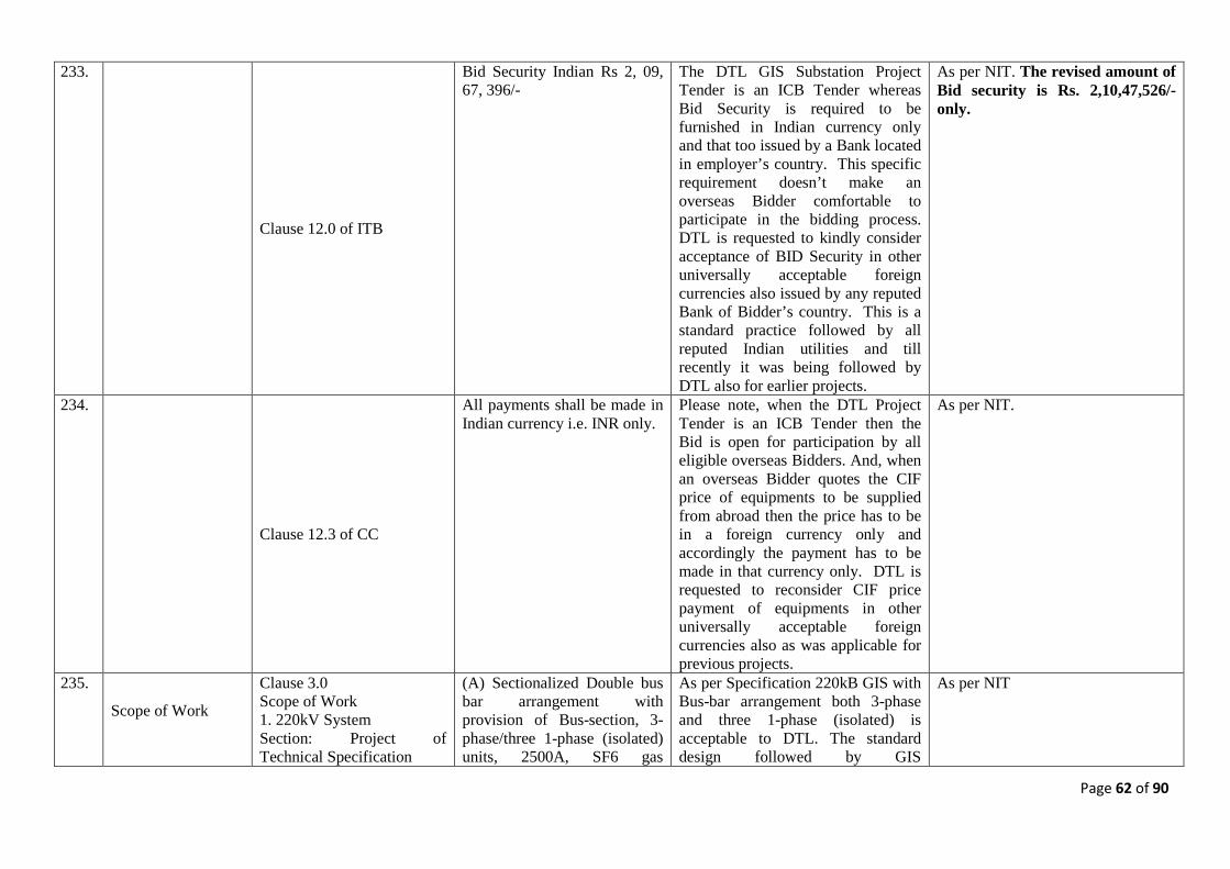
Page 62 of 90
233.
Clause 12.0 of ITB
Bid Security Indian Rs 2, 09, 67, 396/-
The DTL GIS Substation Project Tender is an ICB Tender whereas Bid Security is required to be furnished in Indian currency only and that too issued by a Bank located in employer’s country. This specific requirement doesn’t make an overseas Bidder comfortable to participate in the bidding process. DTL is requested to kindly consider acceptance of BID Security in other universally acceptable foreign currencies also issued by any reputed Bank of Bidder’s country. This is a standard practice followed by all reputed Indian utilities and till recently it was being followed by DTL also for earlier projects.
As per NIT. The revised amount of Bid security is Rs. 2,10,47,526/- only.
234.
Clause 12.3 of CC
All payments shall be made in Indian currency i.e. INR only.
Please note, when the DTL Project Tender is an ICB Tender then the Bid is open for participation by all eligible overseas Bidders. And, when an overseas Bidder quotes the CIF price of equipments to be supplied from abroad then the price has to be in a foreign currency only and accordingly the payment has to be made in that currency only. DTL is requested to reconsider CIF price payment of equipments in other universally acceptable foreign currencies also as was applicable for previous projects.
As per NIT.
235.
Scope of Work
Clause 3.0 Scope of Work 1. 220kV System Section: Project of Technical Specification
(A) Sectionalized Double bus bar arrangement with provision of Bus-section, 3-phase/three 1-phase (isolated) units, 2500A, SF6 gas
As per Specification 220kB GIS with Bus-bar arrangement both 3-phase and three 1-phase (isolated) is acceptable to DTL. The standard design followed by GIS
As per NIT
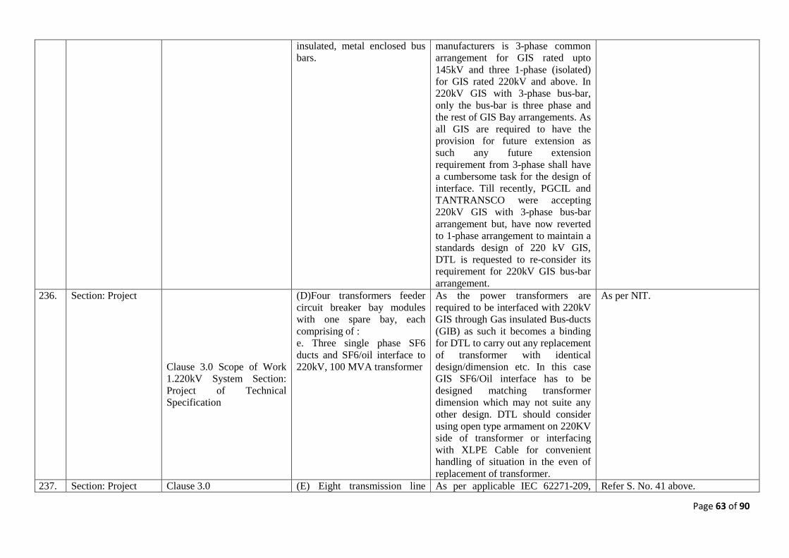
Page 63 of 90
insulated, metal enclosed bus bars.
manufacturers is 3-phase common arrangement for GIS rated upto 145kV and three 1-phase (isolated) for GIS rated 220kV and above. In 220kV GIS with 3-phase bus-bar, only the bus-bar is three phase and the rest of GIS Bay arrangements. As all GIS are required to have the provision for future extension as such any future extension requirement from 3-phase shall have a cumbersome task for the design of interface. Till recently, PGCIL and TANTRANSCO were accepting 220kV GIS with 3-phase bus-bar arrangement but, have now reverted to 1-phase arrangement to maintain a standards design of 220 kV GIS, DTL is requested to re-consider its requirement for 220kV GIS bus-bar arrangement.
236. Section: Project
Clause 3.0 Scope of Work 1.220kV System Section: Project of Technical Specification
(D)Four transformers feeder circuit breaker bay modules with one spare bay, each comprising of : e. Three single phase SF6 ducts and SF6/oil interface to 220kV, 100 MVA transformer
As the power transformers are required to be interfaced with 220kV GIS through Gas insulated Bus-ducts (GIB) as such it becomes a binding for DTL to carry out any replacement of transformer with identical design/dimension etc. In this case GIS SF6/Oil interface has to be designed matching transformer dimension which may not suite any other design. DTL should consider using open type armament on 220KV side of transformer or interfacing with XLPE Cable for convenient handling of situation in the even of replacement of transformer.
As per NIT.
237. Section: Project Clause 3.0 (E) Eight transmission line As per applicable IEC 62271-209, Refer S. No. 41 above.
Page 64 of 90
Scope of Work/ 1. 220kV System Section: Project of Technical Specification
feeder circuit breaker bay modules, each comprising of : f. Three, single phase SF6/XLPE cable terminations.
the supply of SF6/XLPE GIS Cable Termination is in the scope of Cable System supply as such it should not be part of GIS bay configuration. DTL requested to amend the specification accordingly.
238. Section: Project Clause 3.0 Scope of Work/ 1. 220kV System Section: Project of Technical Specification
(E) Eight transmission line feeder circuit breaker bay modules, each comprising of : g. Three, 3-core, single phase voltage transformers/PTs.
DTL is requested to also consider requirement of isolator for isolating PTs when required.
As per NIT.
239. Section: Project
Clause 3.0 Scope of Work II. 66kV System Section: Project of Technical Specification
(A) Double bus bar arrangement (3000A), Three -phase or single phase encapsulated SF6
The Standard design followed by GIS manufacturers is 3-phase common arrangement for complete GIS rated upto 145kV. DTL requested to review its 66kV GIS requirement and amend the specification accordingly.
As per NIT.
240. Section: Project
Clause 3.0 Scope of Work III. .33kV System Section: Project of Technical Specification
SLD of 220/66/33kV GIS Substation
33kVGIS Bay configuration indicates requirement of Line isolator. As far as we know, no 33kV GIS is available globally with line isolator as such DTL to review its requirement amend the specification accordingly.
The scope of work mentioned in section:-Project shall prevail.
241.
Clause 2.0 Section: GIS Technical Specification
IEC 60859 Cable connections for gas-insulated switchgear
IEC 60859 has been superseded by IEC 62271-209 with some dimensional changes. DTL is requested the update the specification accordingly.
As per latest IEC.
242.
Qualifying Requirement
1.1 Eligible Bidders : (d) A joint venture firm consisting of two or more partners each of whom shall be: i. Either the Manufacturers of GIS meeting the technical
1.1 Eligible Bidders : (d) A joint Venture firm consisting of two or more partners
each of whom shall be:-
Refer modified QR in Annexure-I. Refer S. No. 1 above.
i. Either the manufacturers of GIS meeting the technical experience as mentioned in clause no. 1.1.1 below.
Page 65 of 90
experience as mentioned in clause no. 1.1.1 below. OR/AND ii. Erectors having technical experience as mentioned in clause no. 1.1.2 below. Each of the partners of the Joint Venture must meet the minimum qualifying requirements given under clause no. 1.1.1 and/or 1.1.2 However, all the partners of Joint Venture shall meet collectively, the requirements of clauses no. 1.1.1 and 1.1.2 below. The Techno-commercial and Joint Venture partners shall be in line with the clause no. 1.1.3 below. All the documents/evidence as required should be submitted alongwith the Part-I, Techno-commercial bid.
AND/OR ii. Erectors having technical experience as mentioned in clause no. 1.1.2 below. Each of the partners of the Joint Venture must meet the minimum qualifying requirements given under clause no. 1.1.1 and/or 1.1.2 However,
all the partners of Joint Venture shall meet collectively, the requirements of clauses no. 1.1.1 and 1.1.2 below. The Techno-commercial and Joint Venture partners shall be in line with the clause no. 1.1.3 below. All the documents/evidences as required should be submitted alongwith the Part-I, Techno-commercial bid.
Since the JV partners are jointly and severally liable, this does not impact DTL’s interests in any way, while allowing more competition.
Commercial 243. Conditions of the
Contract
Conditions of the Contract, Section III, Clause 10.2 Employer's Obligations
The Employer shall be responsible for acquiring and providing legal and physical possession of the Site and access thereto, and for providing possession of and access to all other areas reasonably required for the proper execution of the Contract, including all requisite rights of way,........... The Employer shall give full possession of and accord all rights of access thereto on
The Contractor requests that in the case the Employer is unable to fulfill their obligations in the contract as mentioned in clause 10 of conditions of contract, then the additional cost reasonably incurred by the Contractor in consequence thereof shall be added to the Contract Price.
As per NIT.
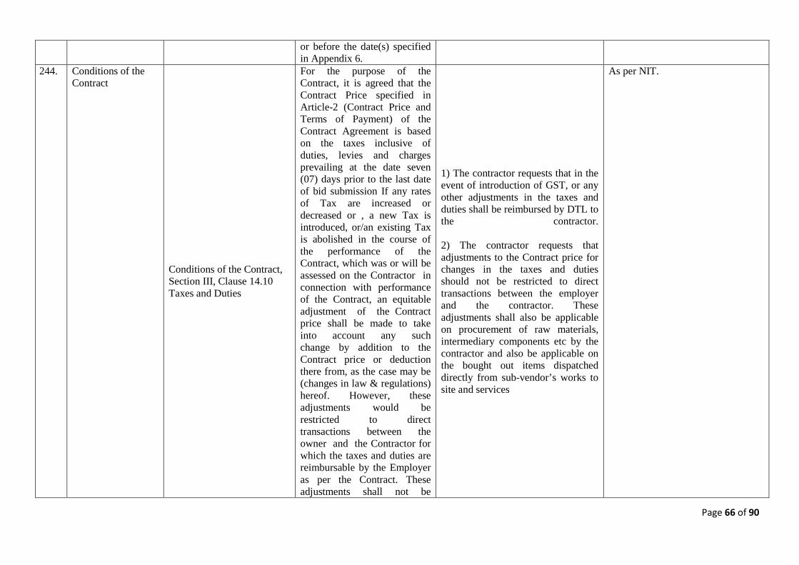
Page 66 of 90
or before the date(s) specified in Appendix 6.
244. Conditions of the Contract
Conditions of the Contract, Section III, Clause 14.10 Taxes and Duties
For the purpose of the Contract, it is agreed that the Contract Price specified in Article-2 (Contract Price and Terms of Payment) of the Contract Agreement is based on the taxes inclusive of duties, levies and charges prevailing at the date seven (07) days prior to the last date of bid submission If any rates of Tax are increased or decreased or , a new Tax is introduced, or/an existing Tax is abolished in the course of the performance of the Contract, which was or will be assessed on the Contractor in connection with performance of the Contract, an equitable adjustment of the Contract price shall be made to take into account any such change by addition to the Contract price or deduction there from, as the case may be (changes in law & regulations) hereof. However, these adjustments would be restricted to direct transactions between the owner and the Contractor for which the taxes and duties are reimbursable by the Employer as per the Contract. These adjustments shall not be
1) The contractor requests that in the event of introduction of GST, or any other adjustments in the taxes and duties shall be reimbursed by DTL to the contractor. 2) The contractor requests that adjustments to the Contract price for changes in the taxes and duties should not be restricted to direct transactions between the employer and the contractor. These adjustments shall also be applicable on procurement of raw materials, intermediary components etc by the contractor and also be applicable on the bought out items dispatched directly from sub-vendor’s works to site and services
As per NIT.
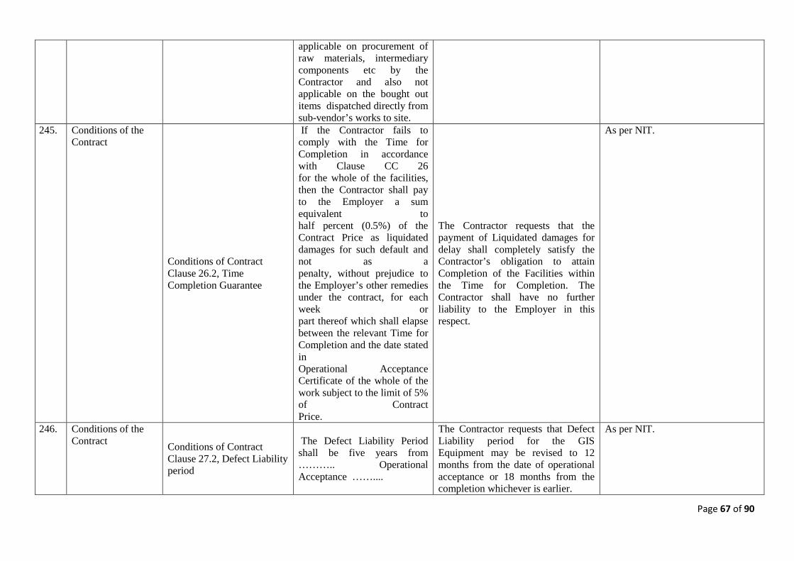
Page 67 of 90
applicable on procurement of raw materials, intermediary components etc by the Contractor and also not applicable on the bought out items dispatched directly from sub-vendor’s works to site.
245. Conditions of the Contract
Conditions of Contract Clause 26.2, Time Completion Guarantee
If the Contractor fails to comply with the Time for Completion in accordance with Clause CC 26 for the whole of the facilities, then the Contractor shall pay to the Employer a sum equivalent to half percent (0.5%) of the Contract Price as liquidated damages for such default and not as a penalty, without prejudice to the Employer’s other remedies under the contract, for each week or part thereof which shall elapse between the relevant Time for Completion and the date stated in Operational Acceptance Certificate of the whole of the work subject to the limit of 5% of Contract Price.
The Contractor requests that the payment of Liquidated damages for delay shall completely satisfy the Contractor’s obligation to attain Completion of the Facilities within the Time for Completion. The Contractor shall have no further liability to the Employer in this respect.
As per NIT.
246. Conditions of the Contract Conditions of Contract
Clause 27.2, Defect Liability period
The Defect Liability Period shall be five years from ……….. Operational Acceptance ……....
The Contractor requests that Defect Liability period for the GIS Equipment may be revised to 12 months from the date of operational acceptance or 18 months from the completion whichever is earlier.
As per NIT.
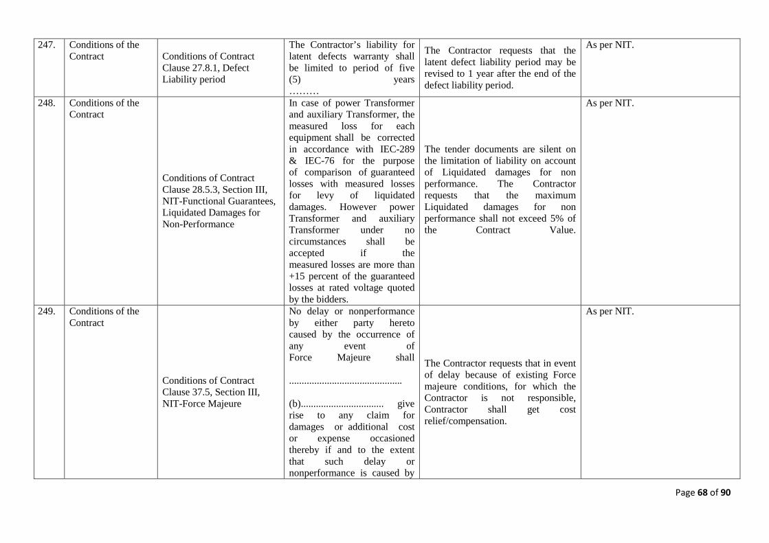
Page 68 of 90
247. Conditions of the Contract Conditions of Contract
Clause 27.8.1, Defect Liability period
The Contractor’s liability for latent defects warranty shall be limited to period of five (5) years ………
The Contractor requests that the latent defect liability period may be revised to 1 year after the end of the defect liability period.
As per NIT.
248. Conditions of the Contract
Conditions of Contract Clause 28.5.3, Section III, NIT-Functional Guarantees, Liquidated Damages for Non-Performance
In case of power Transformer and auxiliary Transformer, the measured loss for each equipment shall be corrected in accordance with IEC-289 & IEC-76 for the purpose of comparison of guaranteed losses with measured losses for levy of liquidated damages. However power Transformer and auxiliary Transformer under no circumstances shall be accepted if the measured losses are more than +15 percent of the guaranteed losses at rated voltage quoted by the bidders.
The tender documents are silent on the limitation of liability on account of Liquidated damages for non performance. The Contractor requests that the maximum Liquidated damages for non performance shall not exceed 5% of the Contract Value.
As per NIT.
249. Conditions of the Contract
Conditions of Contract Clause 37.5, Section III, NIT-Force Majeure
No delay or nonperformance by either party hereto caused by the occurrence of any event of Force Majeure shall ............................................. (b)................................. give rise to any claim for damages or additional cost or expense occasioned thereby if and to the extent that such delay or nonperformance is caused by
The Contractor requests that in event of delay because of existing Force majeure conditions, for which the Contractor is not responsible, Contractor shall get cost relief/compensation.
As per NIT.
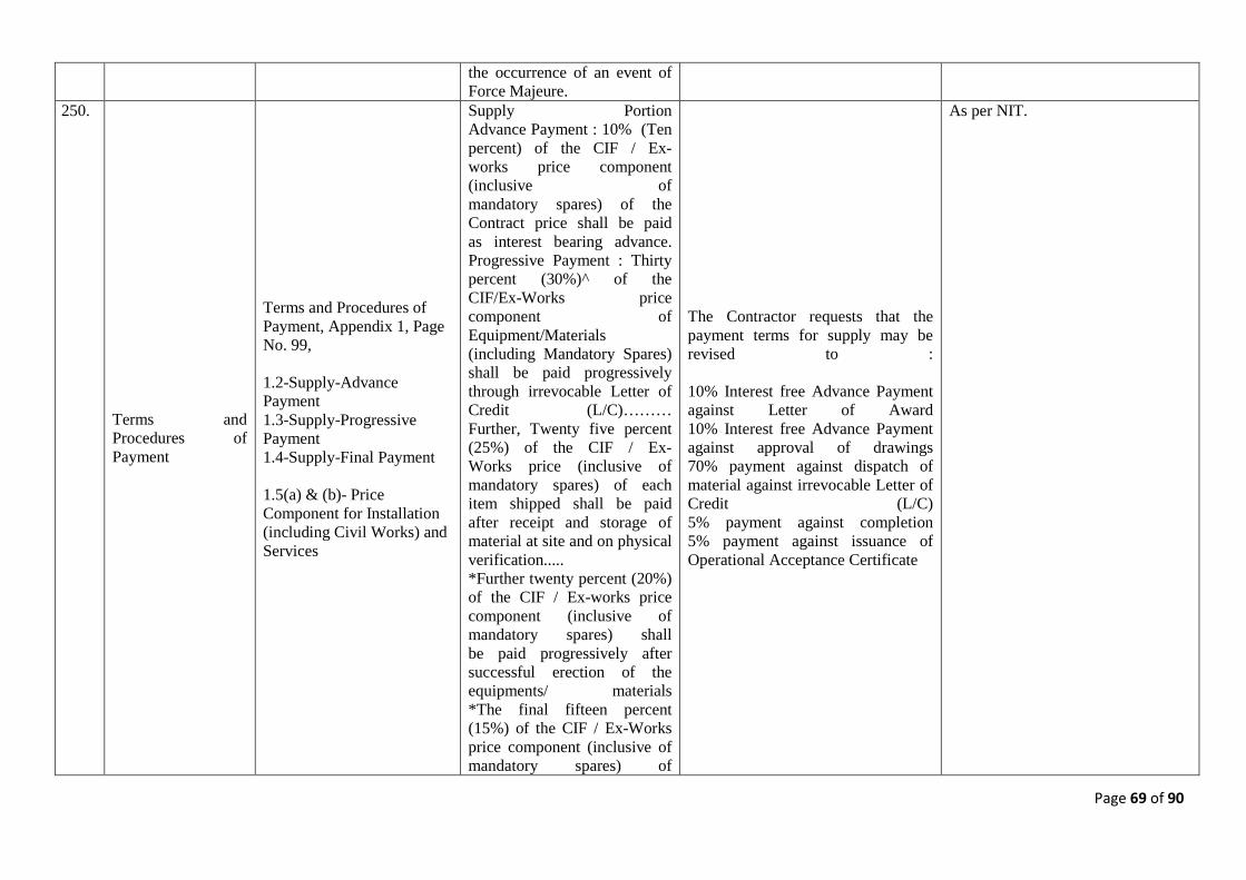
Page 69 of 90
the occurrence of an event of Force Majeure.
250.
Terms and Procedures of Payment
Terms and Procedures of Payment, Appendix 1, Page No. 99, 1.2-Supply-Advance Payment 1.3-Supply-Progressive Payment 1.4-Supply-Final Payment 1.5(a) & (b)- Price Component for Installation (including Civil Works) and Services
Supply Portion Advance Payment : 10% (Ten percent) of the CIF / Ex-works price component (inclusive of mandatory spares) of the Contract price shall be paid as interest bearing advance. Progressive Payment : Thirty percent (30%)^ of the CIF/Ex-Works price component of Equipment/Materials (including Mandatory Spares) shall be paid progressively through irrevocable Letter of Credit (L/C)……… Further, Twenty five percent (25%) of the CIF / Ex-Works price (inclusive of mandatory spares) of each item shipped shall be paid after receipt and storage of material at site and on physical verification..... *Further twenty percent (20%) of the CIF / Ex-works price component (inclusive of mandatory spares) shall be paid progressively after successful erection of the equipments/ materials *The final fifteen percent (15%) of the CIF / Ex-Works price component (inclusive of mandatory spares) of
The Contractor requests that the payment terms for supply may be revised to : 10% Interest free Advance Payment against Letter of Award 10% Interest free Advance Payment against approval of drawings 70% payment against dispatch of material against irrevocable Letter of Credit (L/C) 5% payment against completion 5% payment against issuance of Operational Acceptance Certificate
As per NIT.
Page 70 of 90
the equipment shall be paid on final issuance of Operational Acceptance Certificate after successful completion of erection, testing and commissioning.......
251.
Time Schedule Time Schedule, Appendix 4, page 108
The project completion schedule is ……………………………………..12 months
Since, scope of work includes soil investigation, supply of Transformers including ETC & Civil works etc. , it is very difficult to execute the work within 12 months stipulated time, in vire of this , please amend the clause that the completion period for the project may be revised to 18 months.
As per NIT.
Technical 252.
Qualification Requirement
Section - II Instruction to Bidder Qualification Requirement Clause 1.1.1 a.
Have experience in manufacturing & supplying of 220kV or higher voltage class GIS for at least five years as on the date of bid opening
Have experience in manufacturing & supplying of 220kV or higher voltage class GIS for at least four years as on the date of bid opening
Refer modified QR in Annexure-I.
253.
Qualification Requirement
Section - II Instruction to Bidder Qualification Requirement Clause 1.1.1 b.
Have designed, manufactured, supplied, erected, tested as per IEC or equivalent standard and commissioned not less than two (2) GIS installations having cumulatively at least 14(fourteen) 220 kV or higher voltage Circuit Breaker bays of 40kA or higher short circuit level, and the same should have been in successful operation for last two(2) years as on the date of bid opening
Have designed, manufactured, supplied, erected, tested as per IEC or equivalent standard and commissioned not less than two (2) GIS installations having cumulatively at least 12(twelve) 220 kV or higher voltage Circuit Breaker bays of 40kA or higher short circuit level, and the same should have been in successful operation for last two(2) years as on the date of bid opening
Refer modified QR in Annexure-I.
254. Qualification Requirement
Section - II Instruction to Bidder Qualification
Manufacturer(s) of 220 kV or higher class GIS who
Manufacturer(s) of 220 kV or higher class GIS who have
Refer modified QR in Annexure-I.
Page 71 of 90
Requirement Clause 1.1.2
have successfully erected, tested and commissioned not less than two (2) GIS installations having cumulatively at least 14(fourteen) 220 kV or higher voltage Circuit Breaker bays and the same should have been in successful operation for at least two(2) years, as on the date of bid opening
successfully erected, tested and commissioned not less than two (2) GIS installations having cumulatively at least 12(twelve) 220 kV or higher voltage Circuit Breaker bays and the same should have been in successful operation for at least two(2) years, as on the date of bid opening
255.
Section 2 : GIS Specification Page 2 of 34 Clause 2
IEC 60044-1 Current transformers IEC 60044-2 Voltage transformers
Revised reference standard for Instrument Transformers IEC 61869-2 Current transformers IEC 61869-3 Voltage transformers Please accept.
As per relevant latest IEC.
256.
GIS Specification
Section 2 : GIS Specification Page 5 of 34 Clause 4.29
The Bidder shall furnish the following information regarding the loosely distributed metallic particles within the GIS encapsulation. a) Calculations of critical field strength for specific particles of defined mass & geometry b) The methodology and all the equipment for electrical partial discharge (PD) detection and/or acoustic detection methods, including that mentioned in the specification else- where.
Intellectual property of Manufacturer & no such information shall be reviewed.
As per NIT.
257. GIS Specification Section 2 : GIS Specification
GENERAL CHARACTERISTICS
We hereby clarify that, the 220kVGIS switchgear is designed for
As per NIT.
Page 72 of 90
Page 1 of 34 Clause 1.0
The SF6 gas insulated metal enclosed switchgear shall be totally safe against inadvertent touch of any of it's live constituent parts. It should be designed for indoor/outdoor (as specified) application with meteorological conditions at site as per Section Project.
indoor application and the busducts are designed for outdoor application.
258. GIS Specification Section 2 : GIS Specification Page 3 of 34 Clause 4.3
General Design & safety requirement The switchgear, which shall be of modular design, shall have complete phase isolation.
The proposed 220kV GIS is single phase design except from bus bar and 66kV GIS will be three phase encapsulated.
As per NIT.
259. GIS Specification
Section 2 : GIS Specification Page 5 of 34 Clause 4.17
Local Control & Substation Automation System:- Separate control cubicle including gas monitoring kiosk shall be provided for each bay which shall be installed near the switchgear for local control & monitoring of respective switchgear bay.
220kV and 66kV GIS Design shall be with integrated type Local Control cubicle
As per NIT.
260. GIS Specification Section 2 : GIS Specification Page 6 of 34 Clause 4.31
The ladders and walkways shall be provided wherever necessary for access to the equipment.
We have envisaged provision of Ladders for access to operating mechanisms and therefore we have not allowed for walkways in the layout of GIS
As per NIT.
261. GIS Specification
Section 2 : GIS Specification Page 6 of 34 Clause 4.32
The possibility of using heaters without thermostats in order to achieve the higher reliability may be examined by the bidder and accordingly included in the offer but it
No such study is considered in our scope.
As per NIT.
Page 73 of 90
shall be ensured by the bidder that the temperature rise of different enclosures where heating is provided should be within safe limits as per relevant standards.
262. GIS Specification
Section 2 : GIS Specification Page 8 of 34 Clause 9
Grounding The GIS supplier must supply the entire material for grounding bus of GIS viz conductor, clamps, joints, operating and safety platforms etc. The GIS supplier is also required to supply all the earthling conductors and associated hardware material for the following: 1. Connecting all GIS equipment, bus ducts, enclosures, control cabinets, supporting structure etc. to the ground bus of GIS. 2. Grounding of transformer, CVT, SA and other outdoor switchyard equipments/structures etc.
Not in the scope of GIS manufacturer
As per NIT. Since it is a Turnkey Project, the complete grounding shall be in the scope of the Bidder.
263. GIS Specification Section 2 : GIS Specification Page 10 of 34 Clause 10.2
Interrupting the steady and transient magnetizing current corresponding to 220/33/11kV and
Interrupting the steady and transient magnetizing current as stipulated in IEC.
As per NIT and relevant latest IEC.
264. GIS Specification Section 2 : GIS Specification Page 21 of 34 Clause D d)
The rated extended primary current shall be 150% at highest ratio and 200% at ratios other than highest ratios.
Considering the design space restrictions for CT cores & as a standard, 120% extended primary current on all ratio shall be considered.
As per NIT.
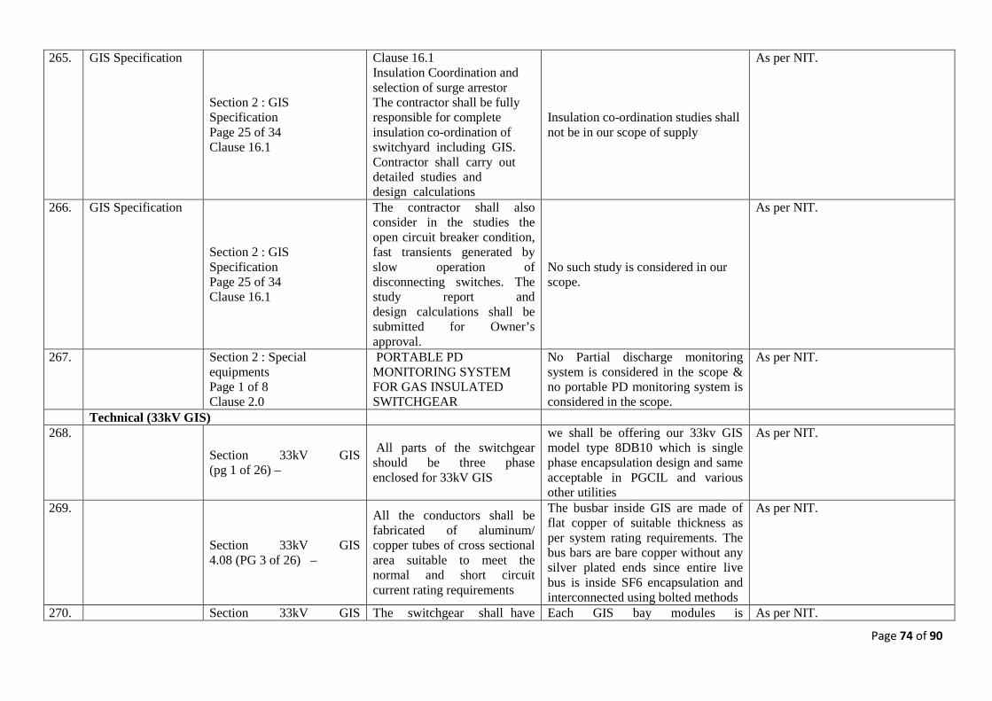
Page 74 of 90
265. GIS Specification
Section 2 : GIS Specification Page 25 of 34 Clause 16.1
Clause 16.1 Insulation Coordination and selection of surge arrestor The contractor shall be fully responsible for complete insulation co-ordination of switchyard including GIS. Contractor shall carry out detailed studies and design calculations
Insulation co-ordination studies shall not be in our scope of supply
As per NIT.
266. GIS Specification
Section 2 : GIS Specification Page 25 of 34 Clause 16.1
The contractor shall also consider in the studies the open circuit breaker condition, fast transients generated by slow operation of disconnecting switches. The study report and design calculations shall be submitted for Owner’s approval.
No such study is considered in our scope.
As per NIT.
267.
Section 2 : Special equipments Page 1 of 8 Clause 2.0
PORTABLE PD MONITORING SYSTEM FOR GAS INSULATED SWITCHGEAR
No Partial discharge monitoring system is considered in the scope & no portable PD monitoring system is considered in the scope.
As per NIT.
Technical (33kV GIS) 268.
Section 33kV GIS (pg 1 of 26) –
All parts of the switchgear should be three phase enclosed for 33kV GIS
we shall be offering our 33kv GIS model type 8DB10 which is single phase encapsulation design and same acceptable in PGCIL and various other utilities
As per NIT.
269.
Section 33kV GIS 4.08 (PG 3 of 26) –
All the conductors shall be fabricated of aluminum/ copper tubes of cross sectional area suitable to meet the normal and short circuit current rating requirements
The busbar inside GIS are made of flat copper of suitable thickness as per system rating requirements. The bus bars are bare copper without any silver plated ends since entire live bus is inside SF6 encapsulation and interconnected using bolted methods
As per NIT.
270. Section 33kV GIS The switchgear shall have Each GIS bay modules is As per NIT.
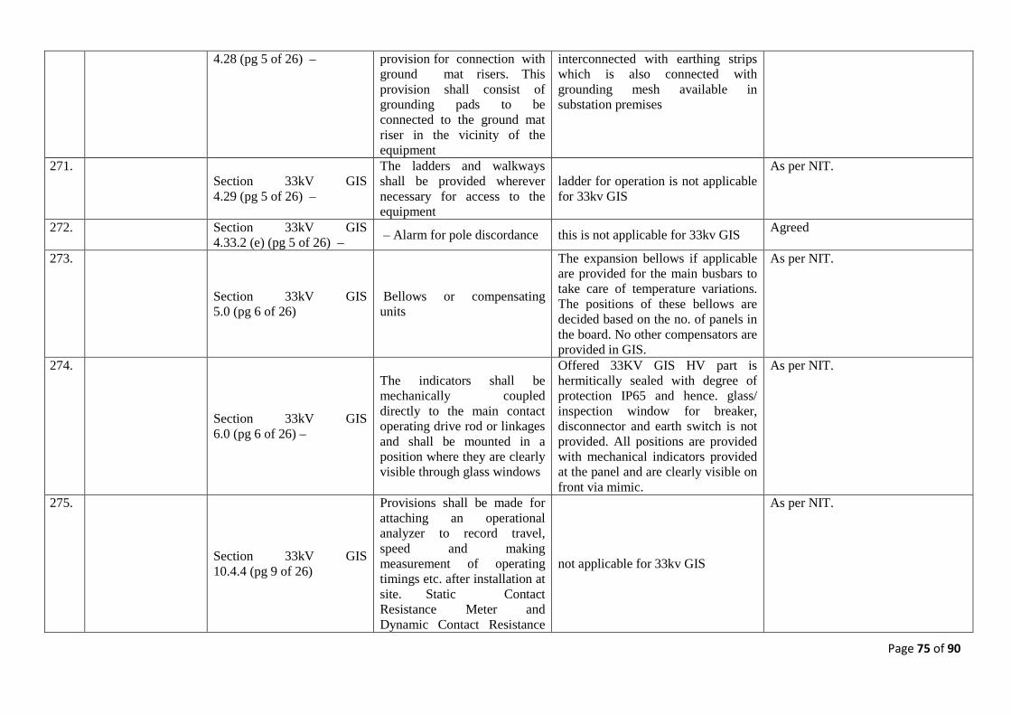
Page 75 of 90
4.28 (pg 5 of 26) – provision for connection with ground mat risers. This provision shall consist of grounding pads to be connected to the ground mat riser in the vicinity of the equipment
interconnected with earthing strips which is also connected with grounding mesh available in substation premises
271.
Section 33kV GIS 4.29 (pg 5 of 26) –
The ladders and walkways shall be provided wherever necessary for access to the equipment
ladder for operation is not applicable for 33kv GIS
As per NIT.
272. Section 33kV GIS 4.33.2 (e) (pg 5 of 26) – – Alarm for pole discordance this is not applicable for 33kv GIS Agreed
273.
Section 33kV GIS 5.0 (pg 6 of 26)
Bellows or compensating units
The expansion bellows if applicable are provided for the main busbars to take care of temperature variations. The positions of these bellows are decided based on the no. of panels in the board. No other compensators are provided in GIS.
As per NIT.
274.
Section 33kV GIS 6.0 (pg 6 of 26) –
The indicators shall be mechanically coupled directly to the main contact operating drive rod or linkages and shall be mounted in a position where they are clearly visible through glass windows
Offered 33KV GIS HV part is hermitically sealed with degree of protection IP65 and hence. glass/ inspection window for breaker, disconnector and earth switch is not provided. All positions are provided with mechanical indicators provided at the panel and are clearly visible on front via mimic.
As per NIT.
275.
Section 33kV GIS 10.4.4 (pg 9 of 26)
Provisions shall be made for attaching an operational analyzer to record travel, speed and making measurement of operating timings etc. after installation at site. Static Contact Resistance Meter and Dynamic Contact Resistance
not applicable for 33kv GIS
As per NIT.
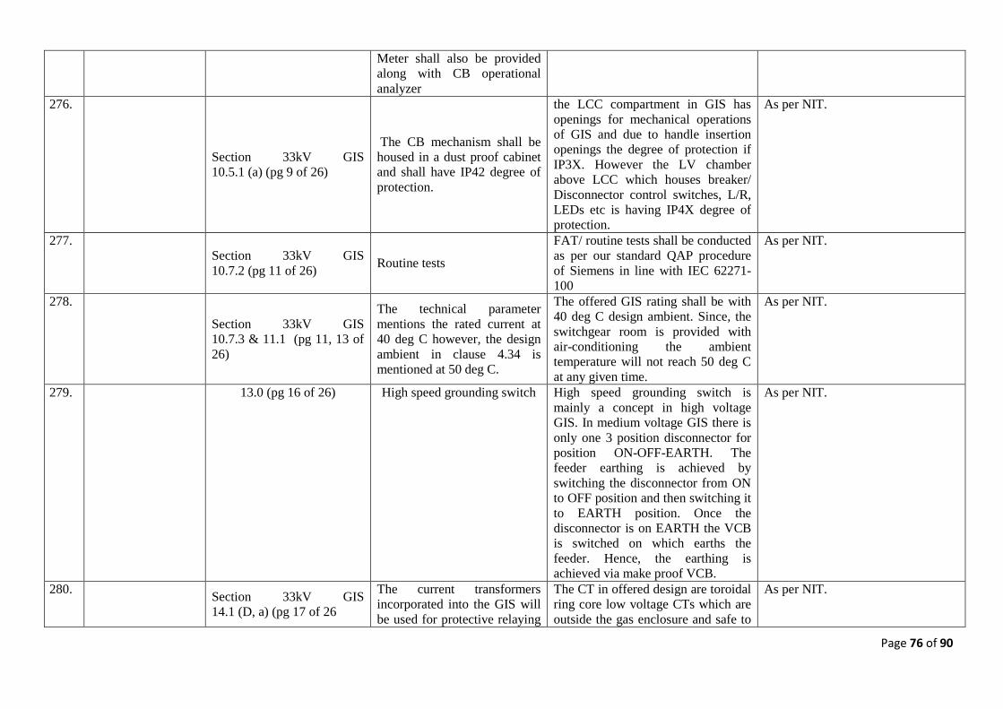
Page 76 of 90
Meter shall also be provided along with CB operational analyzer
276.
Section 33kV GIS 10.5.1 (a) (pg 9 of 26)
The CB mechanism shall be housed in a dust proof cabinet and shall have IP42 degree of protection.
the LCC compartment in GIS has openings for mechanical operations of GIS and due to handle insertion openings the degree of protection if IP3X. However the LV chamber above LCC which houses breaker/ Disconnector control switches, L/R, LEDs etc is having IP4X degree of protection.
As per NIT.
277.
Section 33kV GIS 10.7.2 (pg 11 of 26) Routine tests
FAT/ routine tests shall be conducted as per our standard QAP procedure of Siemens in line with IEC 62271-100
As per NIT.
278.
Section 33kV GIS 10.7.3 & 11.1 (pg 11, 13 of 26)
The technical parameter mentions the rated current at 40 deg C however, the design ambient in clause 4.34 is mentioned at 50 deg C.
The offered GIS rating shall be with 40 deg C design ambient. Since, the switchgear room is provided with air-conditioning the ambient temperature will not reach 50 deg C at any given time.
As per NIT.
279.
13.0 (pg 16 of 26) High speed grounding switch High speed grounding switch is mainly a concept in high voltage GIS. In medium voltage GIS there is only one 3 position disconnector for position ON-OFF-EARTH. The feeder earthing is achieved by switching the disconnector from ON to OFF position and then switching it to EARTH position. Once the disconnector is on EARTH the VCB is switched on which earths the feeder. Hence, the earthing is achieved via make proof VCB.
As per NIT.
280. Section 33kV GIS
14.1 (D, a) (pg 17 of 26
The current transformers incorporated into the GIS will be used for protective relaying
The CT in offered design are toroidal ring core low voltage CTs which are outside the gas enclosure and safe to
As per NIT.
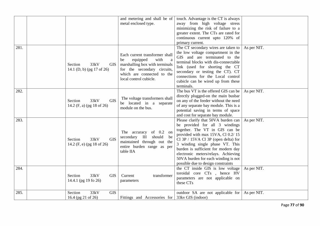
Page 77 of 90
and metering and shall be of metal enclosed type.
touch. Advantage is the CT is always away from high voltage stress minimizing the risk of failure to a greater extent. The CTs are rated for continuous current upto 120% of primary current.
281.
Section 33kV GIS 14.1 (D, b) (pg 17 of 26)
Each current transformer shall be equipped with a marshalling box with terminals for the secondary circuits, which are connected to the local control cubicle.
The CT secondary wires are taken to the low voltage compartment in the GIS and are terminated to the terminal blocks with dis-connectable link (used for shorting the CT secondary or testing the CT). CT connections for the Local control cubicle can be wired up from these terminals.
As per NIT.
282.
Section 33kV GIS 14.2 (F, a) (pg 18 of 26)
The voltage transformers shall be located in a separate module on the bus.
The bus VT is the offered GIS can be directly plugged-on the main busbar on any of the feeder without the need of any separate bay module. This is a potential saving in terms of space and cost for separate bay module.
As per NIT.
283.
Section 33kV GIS 14.2 (F, e) (pg 18 of 26)
The accuracy of 0.2 on secondary III should be maintained through out the entire burden range as per table IIA
Please clarify that 50VA burden can be provided for all 3 windings together. The VT in GIS can be provided with max 15VA, Cl 0.2/ 15 Cl 3P / 15VA Cl 3P (open delta) for 3 winding single phase VT. This burden is sufficient for modern day electronic meters/relays. Achieving 50VA burden for each winding is not possible due to design constraints
As per NIT.
284.
Section 33kV GIS 14.4.1 (pg 19 fo 26)
Current transformer parameters
the CT inside GIS is low voltage toroidal core CTs , hence HV parameters are not applicable on these CTs
As per NIT.
285. Section 33kV GIS 16.4 (pg 21 of 26)
Fittings and Accessories for
outdoor SA are not applicable for 33kv GIS (indoor)
As per NIT.
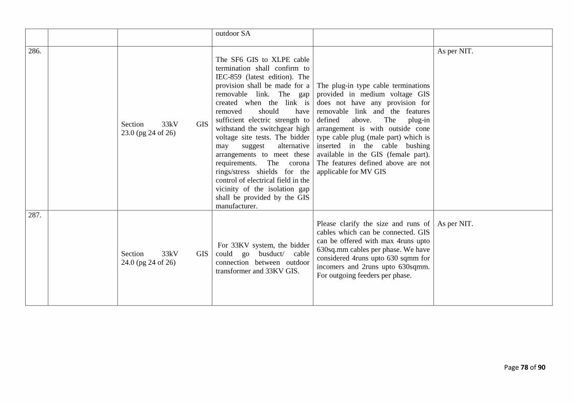
Page 78 of 90
outdoor SA
286.
Section 33kV GIS 23.0 (pg 24 of 26)
The SF6 GIS to XLPE cable termination shall confirm to IEC-859 (latest edition). The provision shall be made for a removable link. The gap created when the link is removed should have sufficient electric strength to withstand the switchgear high voltage site tests. The bidder may suggest alternative arrangements to meet these requirements. The corona rings/stress shields for the control of electrical field in the vicinity of the isolation gap shall be provided by the GIS manufacturer.
The plug-in type cable terminations provided in medium voltage GIS does not have any provision for removable link and the features defined above. The plug-in arrangement is with outside cone type cable plug (male part) which is inserted in the cable bushing available in the GIS (female part). The features defined above are not applicable for MV GIS
As per NIT.
287.
Section 33kV GIS 24.0 (pg 24 of 26)
For 33KV system, the bidder could go busduct/ cable connection between outdoor transformer and 33KV GIS.
Please clarify the size and runs of cables which can be connected. GIS can be offered with max 4runs upto 630sq.mm cables per phase. We have considered 4runs upto 630 sqmm for incomers and 2runs upto 630sqmm. For outgoing feeders per phase.
As per NIT.
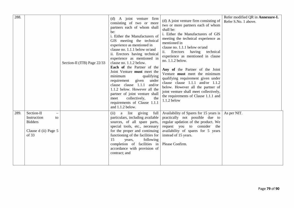
Page 79 of 90
288.
Section-II (ITB) Page 22/33
(d) A joint venture firm consisting of two or more partners each of whom shall be: i. Either the Manufacturers of GIS meeting the technical experience as mentioned in clause no. 1.1.1 below or/and ii. Erectors having technical experience as mentioned in clause no. 1.1.2 below. Each of the Partner of the Joint Venture must meet the minimum qualifying requirement given under clause clause 1.1.1 and/or 1.1.2 below. However all the partner of joint venture shall meet collectively, the requirements of Clause 1.1.1 and 1.1.2 below.
(d) A joint venture firm consisting of two or more partners each of whom shall be: i. Either the Manufacturers of GIS meeting the technical experience as mentioned in clause no. 1.1.1 below or/and ii. Erectors having technical experience as mentioned in clause no. 1.1.2 below. Any of the Partner of the Joint Venture must meet the minimum qualifying requirement given under clause clause 1.1.1 and/or 1.1.2 below. However all the partner of joint venture shall meet collectively, the requirements of Clause 1.1.1 and 1.1.2 below
Refer modified QR in Annexure-I. Refer S.No. 1 above.
289. Section-II – Instruction to Bidders Clause d (ii) Page 5 of 33
(ii) a list giving full particulars, including available sources, of all spare parts, special tools, etc., necessary for the proper and continuing functioning of the facilities for 15 years, following completion of facilities in accordance with provision of contract; and
Availability of Spares for 15 years is practically not possible due to regular updation of the product. We request you to consider the availability of spares for 5 years instead of 15 years. Please Confirm.
As per NIT.
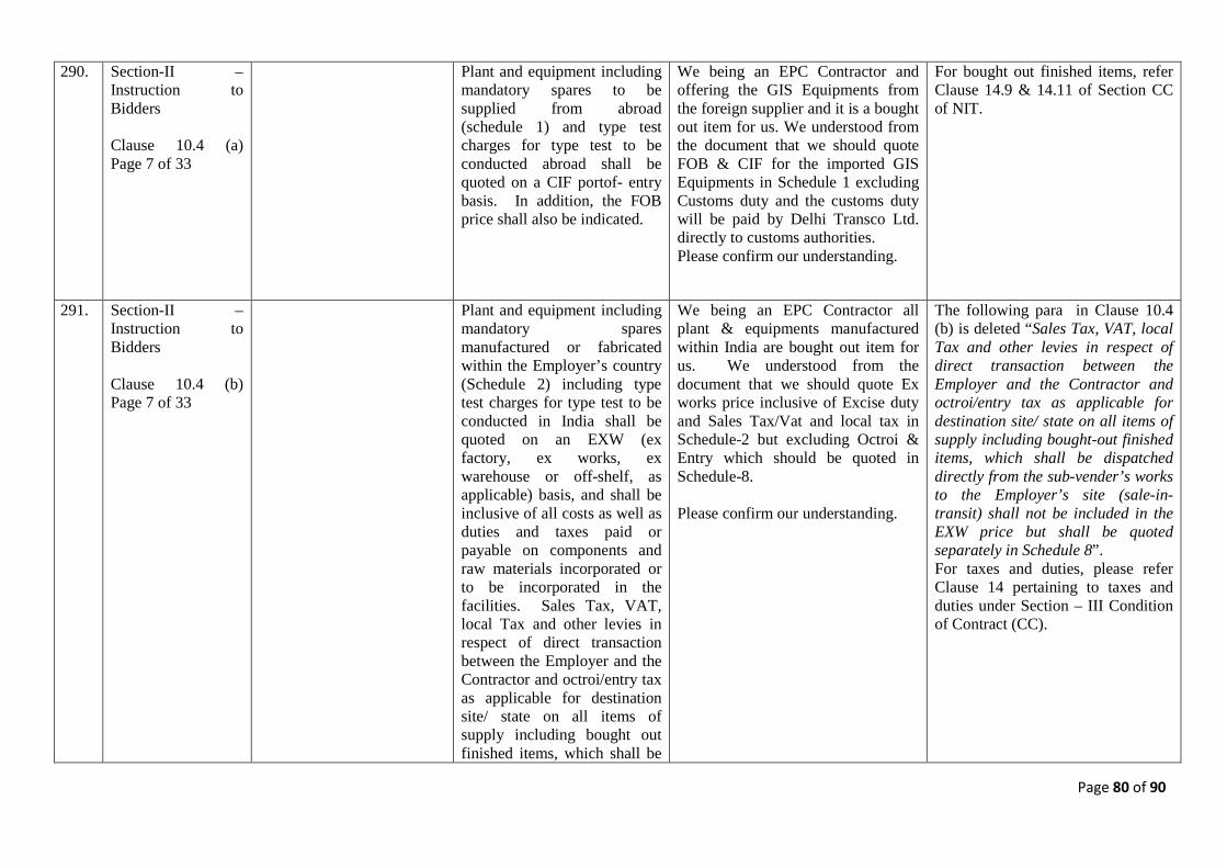
Page 80 of 90
290. Section-II – Instruction to Bidders Clause 10.4 (a) Page 7 of 33
Plant and equipment including mandatory spares to be supplied from abroad (schedule 1) and type test charges for type test to be conducted abroad shall be quoted on a CIF portof- entry basis. In addition, the FOB price shall also be indicated.
We being an EPC Contractor and offering the GIS Equipments from the foreign supplier and it is a bought out item for us. We understood from the document that we should quote FOB & CIF for the imported GIS Equipments in Schedule 1 excluding Customs duty and the customs duty will be paid by Delhi Transco Ltd. directly to customs authorities. Please confirm our understanding.
For bought out finished items, refer Clause 14.9 & 14.11 of Section CC of NIT.
291. Section-II – Instruction to Bidders Clause 10.4 (b) Page 7 of 33
Plant and equipment including mandatory spares manufactured or fabricated within the Employer’s country (Schedule 2) including type test charges for type test to be conducted in India shall be quoted on an EXW (ex factory, ex works, ex warehouse or off-shelf, as applicable) basis, and shall be inclusive of all costs as well as duties and taxes paid or payable on components and raw materials incorporated or to be incorporated in the facilities. Sales Tax, VAT, local Tax and other levies in respect of direct transaction between the Employer and the Contractor and octroi/entry tax as applicable for destination site/ state on all items of supply including bought out finished items, which shall be
We being an EPC Contractor all plant & equipments manufactured within India are bought out item for us. We understood from the document that we should quote Ex works price inclusive of Excise duty and Sales Tax/Vat and local tax in Schedule-2 but excluding Octroi & Entry which should be quoted in Schedule-8. Please confirm our understanding.
The following para in Clause 10.4 (b) is deleted “Sales Tax, VAT, local Tax and other levies in respect of direct transaction between the Employer and the Contractor and octroi/entry tax as applicable for destination site/ state on all items of supply including bought-out finished items, which shall be dispatched directly from the sub-vender’s works to the Employer’s site (sale-in-transit) shall not be included in the EXW price but shall be quoted separately in Schedule 8”. For taxes and duties, please refer Clause 14 pertaining to taxes and duties under Section – III Condition of Contract (CC).
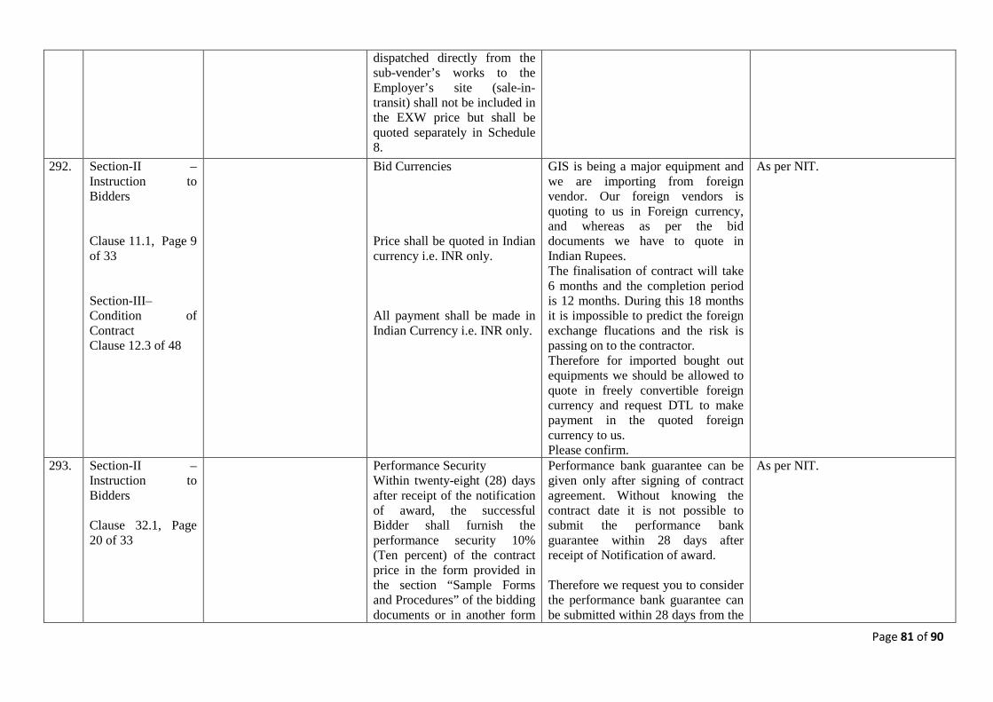
Page 81 of 90
dispatched directly from the sub-vender’s works to the Employer’s site (sale-in-transit) shall not be included in the EXW price but shall be quoted separately in Schedule 8.
292. Section-II – Instruction to Bidders Clause 11.1, Page 9 of 33 Section-III– Condition of Contract Clause 12.3 of 48
Bid Currencies Price shall be quoted in Indian currency i.e. INR only. All payment shall be made in Indian Currency i.e. INR only.
GIS is being a major equipment and we are importing from foreign vendor. Our foreign vendors is quoting to us in Foreign currency, and whereas as per the bid documents we have to quote in Indian Rupees. The finalisation of contract will take 6 months and the completion period is 12 months. During this 18 months it is impossible to predict the foreign exchange flucations and the risk is passing on to the contractor. Therefore for imported bought out equipments we should be allowed to quote in freely convertible foreign currency and request DTL to make payment in the quoted foreign currency to us. Please confirm.
As per NIT.
293. Section-II – Instruction to Bidders Clause 32.1, Page 20 of 33
Performance Security Within twenty-eight (28) days after receipt of the notification of award, the successful Bidder shall furnish the performance security 10% (Ten percent) of the contract price in the form provided in the section “Sample Forms and Procedures” of the bidding documents or in another form
Performance bank guarantee can be given only after signing of contract agreement. Without knowing the contract date it is not possible to submit the performance bank guarantee within 28 days after receipt of Notification of award. Therefore we request you to consider the performance bank guarantee can be submitted within 28 days from the
As per NIT.
Page 82 of 90
acceptable to the Employer. The performance security of a joint venture shall be in the name of joint venture.
date of Contract agreement instead of 28 days after receipt of notification of award. Please Confirm.
294. Section-II – Instruction to Bidders Clause 28.4 (i) & (ii), Page 19 of 33
(i) First Contract: For Ex-Works supply and CIF supply, if any, of all equipments and materials including mandatory spares indentifying separately the CIF and EXW components of the supply. (ii) Second Contract: For providing all services i.e. inland transportation for delivery at Site, unloading storage, handling at Site, installation, Testing and Commissioning including performance testing in respect of all the equipments supplied under the “First Contract” and any other services specified in the Contract Documents. Both contracts will contain a cross fall breach clause specifying that breach of one will constitute breach of the other.
This provision will make the contractor liable towards WCT which indirectly increases the project cost. Therefore, we request you to clarify the cross fall breach clause so that the WCT can be eliminated for Supply Contract.
WCT will be recovered at source as per the settled legal position only. Thus, in the contract of supply of materials only, DTL will not deduct WCT even though there is a cross fall breach clause between two contracts.
295. Section-II – Instruction to Bidders Clause 1.1.1, Page 23 of 33
GIS Manufacturer(s) as referred in clause no.1.1 above should:
Experience for GIS Manufacturers (s)
a. Have experience in
As per the Qualification requirements the GIS manufacturer should also be a manufacturer of Power Transformers. There are few vendors in the world manufacturers both GIS Equipments and Power
Refer modified QR in Annexure-I.
Page 83 of 90
manufacturing and supplying of 220 kV or higher voltage class GIS for at least last five years as on the date of bid opening and b. Have designed, manufactured, supplied, erected, tested as per IEC or equivalent standard and commissioned not less than two (2) GIS installations having cumulatively at least 14(fourteen) 220 kV or higher voltage Circuit Breaker bays of 40KA or higher short circuit level, and the same should have been in successful operation for last two(2) years as on the date of bid opening, and c. Have designed, manufactured, type tested and supplied 220 kV or higher voltage class Power Transformers which must be in satisfactory operation for last 2(two) years, as on the date of bid opening or supply the said power transformer from such manufactures who have designed, manufactured, type tested, and supplied 220 kV or higher voltage class Power Transformers which must be in satisfactory operation for last 2(two) years, as on the sate of bid opening.
Transformer. Therefore it is very difficult to meet the specified criteria and the competition is limited to very few bidders. We are proposing the GIS Equipment from Foreign vendor who is a pioneer in manufacture of GIS Equipments alone and will be sourcing the Power Transformer from another Indian Manufacturer. We request you to consider the above proposal and modify the qualification requirements so that more bidders can participate in this tender and DTL get an better price advantage in view of relaxation of this qualification requirement.
Page 84 of 90
296. Section-II – Instruction to Bidders – Annexure A Qualification Requirements Clause 1.1 (c) Page 23 of 33
Eligible Bidders: (c) Erectors who have the experience as per the criteria/ conditions mentioned in 1.1.2 below and supply GIS from such manufacturer(s) who fulfils the criteria mentioned at 1.1.1 below. The bid shall include consent letter (as per format Annexure-D2) from the proposed GIS manufacturer stating that the manufacture shall furnish an additional performance guarantee for an amount of 10% of the cost of such GIS. This performance guarantee shall be in addition to the Contract Performance Guarantee to be submitted by the bidder.
We being an EPC Contractor bidding for this project based on the consent letter provided by GIS Equipment manufacturers. As per the tender conditions, GIS manufacturer is supposed to furnish additional performance bank guarantee for an amount of 10% of the cost of GIS equipments Supplied by them. Our proposed GIS Equipment manufacturer is not having any direct contractual relation with DTL. Hence our GIS equipment manufacturer objects submission of 10% additional performance bank guarantee to DTL. However Our Proposed GIS Equipment manufacturer will submit additional 10% performance guarantee for the cost of GIS to us whereas we will submit 10% additional performance bank guarantee for 10% of the cost of GIS to DTL from our banker. We request to consider the above proposal and confirm.
Refer modified QR in Annexure-I.
297. Section-III – Conditions of Contract Clause 7.3, Page 7 of 48
The contractor shall ensure the availability of spare parts for the supplied items for a minimum period of fifteen (15) years from operational acceptance by the Employer
Availability of Spares for 15 years is practically not possible due to regular updation of the product. We request you to consider the availability of spares for 5 years instead of 15 years. Please Confirm.
As per NIT.
298. Section-III – Conditions of Contract
Whenever the Contractor is ready to carry out any such test and/or inspection, the Contractor shall give a
This Project is having tight Completion period i.e. 12 Months only. With this tight completion schedule
As per NIT.
Page 85 of 90
Clause 23.3, Page 24 of 48
reasonable advance notice of such test and/or inspection and of the place and time thereof to the Project Manager. The Contractor shall obtain from any relevant third party or manufacturer any necessary permission or consent to enable the Employer and the Project Manager (or their designated representatives) to attend the test and/or inspection. For notification of testing, four weeks shall be deemed as reasonable advance notice.
it is not possible to keep 4 week time for advance intimation of inspection schedule. Considering the tight project completion schedule we request you to consider 15 days advance notification for inspection schedule instead of 4 weeks. Please confirm.
299. Section-III – Conditions of Contract Clause 25.2.2, Page 27 of 48
The Guarantee Test of the Facilities shall be successfully completed within twenty-six weeks from the date of Completion.
This is contradictory to the completion of 12 months. Please clarify.
Refer cl.1.1 section: CC, the time for completion is linked with the operation acceptance by the Employer upon successful completion of the work.
300. Section-III – Conditions of Contract Clause 27.8, Page 30 of 48
Upon correction of the defects in the Facilities or any part thereof by repair/replacement, such repair/replacement shall have the Defect Liability Period extended by a period of Sixty (60) months from the time such replacement/repair of the facilities or any part thereof.”
We can provide 5 Years Warranty from the date of completion of facilities. During this 5 years if any defects occurred we will replace the same at free of cost. But it is not possible to provide additional warranty for 5 years from the date of any defects occurred. Please confirm.
As per NIT.
301. Section-III – Conditions of Contract Clause 34.1 (f),
Employers Liability In accordance with the statutory requirements applicable in any country
This insurance facility is not available in India. Please clarify and modify accordingly.
The insurance clause at 34.1 relates to the all risks during the construction of facility, third party liability during the construction and in-transit risk. Since all these
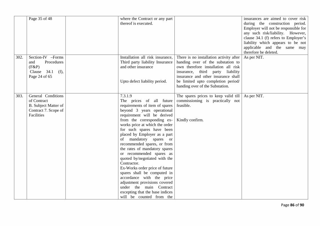
Page 86 of 90
Page 35 of 48 where the Contract or any part thereof is executed.
insurances are aimed to cover risk during the construction period. Employer will not be responsible for any such risk/liability. However, clause 34.1 (f) refers to Employer’s liability which appears to be not applicable and the same may therefore be deleted.
302. Section-IV –Forms and Procedures (F&P) Clause 34.1 (f), Page 24 of 65
Installation all risk insurance, Third party liability Insurance and other insurance Upto defect liability period.
There is no installation activity after handing over of the substation to own therefore installation all risk insurance, third party liability insurance and other insurance shall be limited upto completion period/ handing over of the Substation.
As per NIT.
303. General Conditions of Contract B. Subject Matter of Contract 7. Scope of Facilities
7.3.1.9 The prices of all future requirements of item of spares beyond 3 years operational requirement will be derived from the corresponding ex-works price at which the order for such spares have been placed by Employer as a part of mandatory spares or recommended spares, or from the rates of mandatory spares or recommended spares as quoted by/negotiated with the Contractor. Ex-Works order price of future spares shall be computed in accordance with the price adjustment provisions covered under the main Contract excepting that the base indices will be counted from the
The spares prices to keep valid till commissioning is practically not feasible. Kindly confirm.
As per NIT.
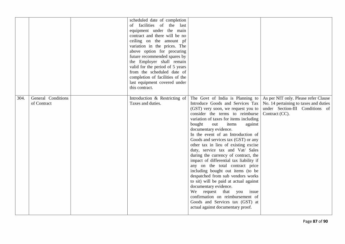
Page 87 of 90
scheduled date of completion of facilities of the last equipment under the main contract and there will be no ceiling on the amount pf variation in the prices. The above option for procuring future recommended spares by the Employer shall remain valid for the period of 5 years from the scheduled date of completion of facilities of the last equipment covered under this contract.
304. General Conditions of Contract
Introduction & Restricting of Taxes and duties.
The Govt of India is Planning to Introduce Goods and Services Tax (GST) very soon, we request you to consider the terms to reimburse variation of taxes for items including bought out items against documentary evidence. In the event of an Introduction of Goods and services tax (GST) or any other tax in lieu of existing excise duty, service tax and Vat/ Sales during the currency of contract, the impact of differential tax liability if any on the total contract price including bought out items (to be despatched from sub vendors works to sit) will be paid at actual against documentary evidence. We request that you issue confirmation on reimbursement of Goods and Services tax (GST) at actual against documentary proof.
As per NIT only. Please refer Clause No. 14 pertaining to taxes and duties under Section-III Conditions of Contract (CC).
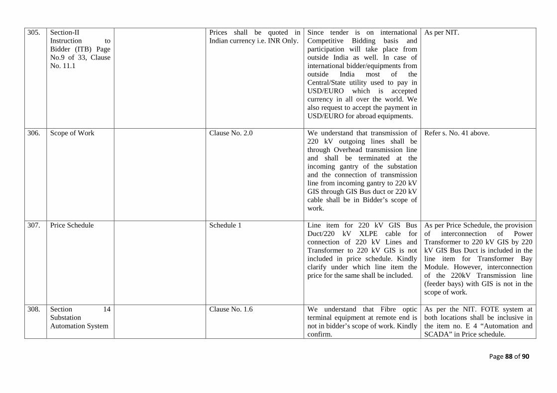
Page 88 of 90
305. Section-II Instruction to Bidder (ITB) Page No.9 of 33, Clause No. 11.1
Prices shall be quoted in Indian currency i.e. INR Only.
Since tender is on international Competitive Bidding basis and participation will take place from outside India as well. In case of international bidder/equipments from outside India most of the Central/State utility used to pay in USD/EURO which is accepted currency in all over the world. We also request to accept the payment in USD/EURO for abroad equipments.
As per NIT.
306. Scope of Work Clause No. 2.0 We understand that transmission of 220 kV outgoing lines shall be through Overhead transmission line and shall be terminated at the incoming gantry of the substation and the connection of transmission line from incoming gantry to 220 kV GIS through GIS Bus duct or 220 kV cable shall be in Bidder’s scope of work.
Refer s. No. 41 above.
307. Price Schedule Schedule 1 Line item for 220 kV GIS Bus Duct/220 kV XLPE cable for connection of 220 kV Lines and Transformer to 220 kV GIS is not included in price schedule. Kindly clarify under which line item the price for the same shall be included.
As per Price Schedule, the provision of interconnection of Power Transformer to 220 kV GIS by 220 kV GIS Bus Duct is included in the line item for Transformer Bay Module. However, interconnection of the 220kV Transmission line (feeder bays) with GIS is not in the scope of work.
308. Section 14 Substation Automation System
Clause No. 1.6 We understand that Fibre optic terminal equipment at remote end is not in bidder’s scope of work. Kindly confirm.
As per the NIT. FOTE system at both locations shall be inclusive in the item no. E 4 “Automation and SCADA” in Price schedule.
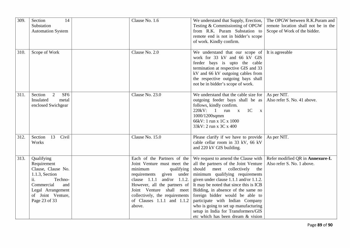
Page 89 of 90
309. Section 14 Substation Automation System
Clause No. 1.6 We understand that Supply, Erection, Testing & Commissioning of OPGW from R.K. Puram Substation to remote end is not in bidder’s scope of work. Kindly confirm.
The OPGW between R.K.Puram and remote location shall not be in the Scope of Work of the bidder.
310. Scope of Work Clause No. 2.0 We understand that our scope of work for 33 kV and 66 kV GIS feeder bays is upto the cable termination at respective GIS and 33 kV and 66 kV outgoing cables from the respective outgoing bays shall not be in bidder’s scope of work.
It is agreeable
311. Section 2 SF6 Insulated metal enclosed Swichgear
Clause No. 23.0 We understand that the cable size for outgoing feeder bays shall be as follows, kindly confirm. 220kV: 1 run x 1C x 1000/1200sqmm 66kV: 1 run x 1C x 1000 33kV: 2 run x 3C x 400
As per NIT. Also refer S. No. 41 above.
312. Section 13 Civil Works
Clause No. 15.0 Please clarify if we have to provide cable cellar room in 33 kV, 66 kV and 220 kV GIS building.
As per NIT.
313. Qualifying Requirement Clause, Clause No. 1.1.3, Section ii. Techno-Commercial and Legal Arrangement of Joint Venture, Page 23 of 33
Each of the Partners of the Joint Venture must meet the minimum qualifying requirements given under clause 1.1.1 and/or 1.1.2. However, all the partners of Joint Venture shall meet collectively, the requirements of Clauses 1.1.1 and 1.1.2 above.
We request to amend the Clause with all the partners of the Joint Venture should meet collectively the minimum qualifying requirements given under clause 1.1.1 and/or 1.1.2. It may be noted that since this is ICB Bidding, in absence of the same no foreign bidder would be able to participate with Indian Company who is going to set up manufacturing setup in India for Transformers/GIS etc which has been dream & vision
Refer modified QR in Annexure-I. Also refer S. No. 1 above.
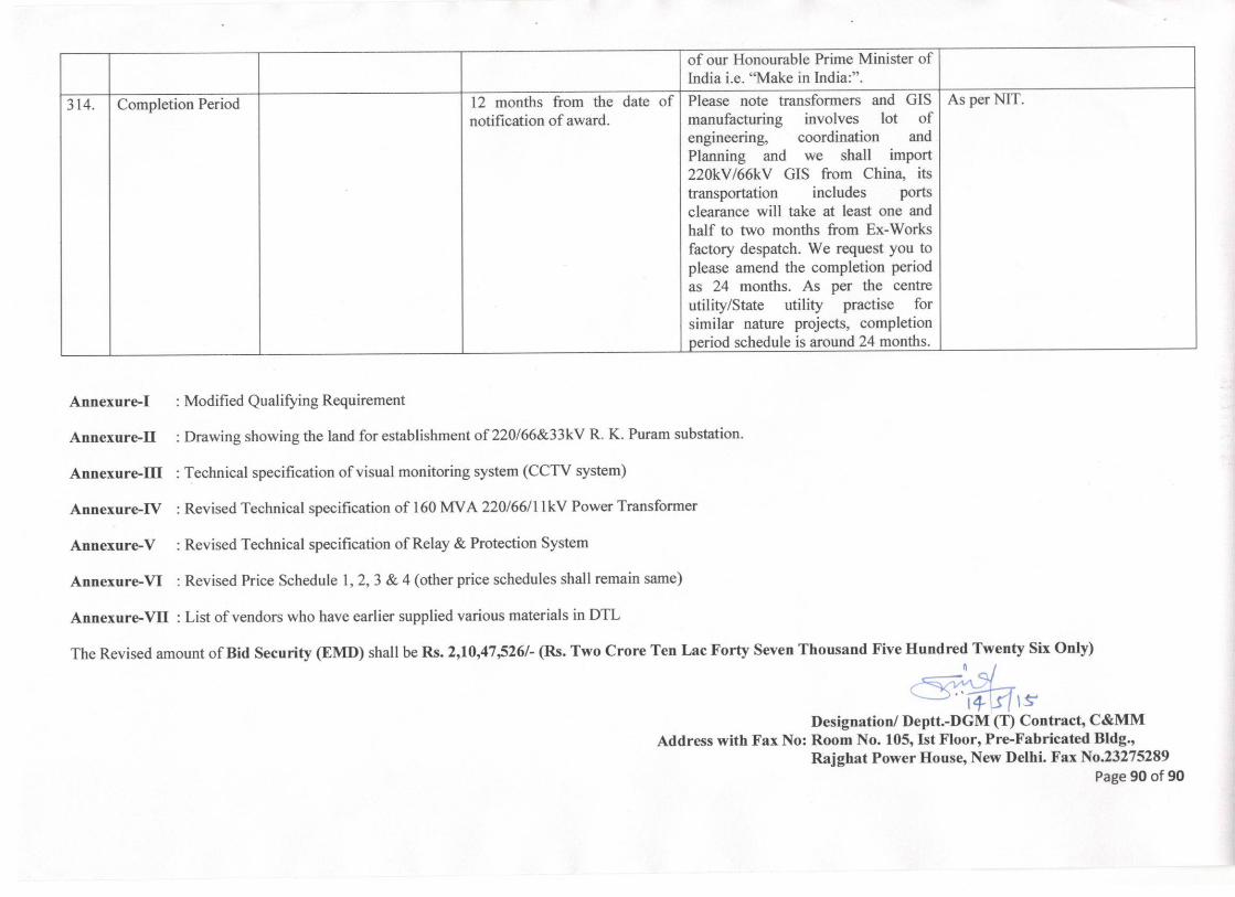
Page 1 of 8
Annexure-I
Qualifying Requirements of Bidders
Qualification of bidder will be based on meeting the minimum pass/fail criteria specified in Part-A below, regarding the Bidder's technical experience and financial position as demonstrated by the Bidder's responses in the corresponding Bid Schedules. The bidder shall also be required to furnish the information specified in Part-B in their Bid. Technical experience and financial resources of any proposed subcontractor(s) (except as specified in Part-A below) shall not be taken into account in determining the Bidder's compliance with the qualifying criteria. The bid can be submitted by an individual firm or a Joint Venture/consortium of two or more firms or by a firm having foreign collaboration. The Employer may assess the capacity and capability of the bidder, to successfully execute the scope of work covered under the package within stipulated completion period. This assessment may inter-alia include (i) document verification; (ii) bidders work/manufacturing facilities visit; (iii) manufacturing capacity, details of works executed , works in hand, anticipated in future & the balance capacity available for present scope of works; (iv) details of plant and machinery, manufacturing and testing facilities, manpower and financial resources; (v) details of quality systems in place; (vi) past experience and performance; (vii) customer feedback; (viii) banker’s feedback etc.
PART- A
1.1 Eligible Bidders:
(a) Manufacturers of GIS who have the experience of manufacture, supply, erection, testing and commissioning of the GIS as per the criteria/conditions mentioned for Manufacturing and Erection in clause no. 1.1.1 & 1.1.2 respectively below.
OR (b) Manufacturers of GIS who have the experience of manufacture and supply
mentioned in clause no. 1.1.1 below and the Erection, Testing & Commissioning of GIS is carried out through an erector as a sub-contractor, who has the experience as per the criteria/conditions mentioned in 1.1.2 below. The bid shall include consent letter (as per format Annexure-D1) from the proposed Erector.
OR (c) Erectors who have the experience as per the criteria/conditions mentioned in
1.1.2 below and supply GIS from such manufacturer(s) who fulfils the criteria mentioned at 1.1.1 below. The bid shall include consent letter (as per format Annexure-D2) from the proposed GIS manufacturer. The bidder shall furnish an additional performance guarantee for an amount of 10% of the cost of such GIS. This performance guarantee shall be in addition to the Contract Performance Guarantee to be submitted by the bidder.
OR
Page 2 of 8
(d) A joint venture/consortium firm consisting of two or more partners each of whom shall be:
i. Either the Manufacturers of GIS meeting the technical experience as mentioned in clause no. 1.1.1 below or/and
ii. Erectors having technical experience as mentioned in clause no. 1.1.2 below.
Each of the Partners of the Joint Venture/consortium must meet the minimum qualifying requirements given under clause 1.1.1and/ or 1.1.2. However, all the partners of Joint Venture/consortium shall meet collectively, the requirements of Clauses 1.1.1 and 1.1.2 below. The Techno-commercial and legal arrangement between the Joint Venture/consortium partners shall be in line with the clause 1.1.3 below. All the documents/evidences as required should be submitted along with the Part-I, Techno-Commercial bid.
OR (e) Indian manufacturers who have Technical Collaboration with a foreign
firm(collaborator) or the GIS manufacturers who have established production line in India for these equipment(s) based on technological support of their parent company/ principal provided the said Collaborator or the said Parent company/Principal meet the experience as mentioned in clause no. 1.1.1 below and erection, testing and commissioning of GIS is carried out by either such manufacturer himself meeting criteria in clause 1.1.2 or through an erector meeting criteria at clause 1.1.2. The Techno-commercial and legal arrangement between them shall be as per clause 1.1.4 below. All the documents/evidences as required in this regard should be submitted along with the Part-I, Techno-Commercial bid.
1.1.1
Experience for GIS Manufacturer(s):
GIS Manufacturer(s) as referred in clause no1.1 above should:
a. Have experience in manufacturing and supplying of 220 kV or higher voltage class GIS for at least last five years as on the date of bid opening and
b. Have designed, manufactured, supplied, erected, tested as per IEC or equivalent standard and commissioned not less than two (2) GIS installations having cumulatively at least 14(fourteen) 220kV or higher voltage Circuit Breaker bays of 40kA or higher short circuit level, and the same should have been in successful operation for last two(2) years as on the date of bid opening, and
c. Have designed, manufactured, type tested and supplied 220 kV or higher voltage
class Power Transformers which must be in satisfactory operation for last 2 (two) years, as on the date of bid opening or supply the said power transformer from such manufacturers who have designed, manufactured, type tested, and
Page 3 of 8
supplied 220 kV or higher voltage class Power Transformers which must be in satisfactory operation for last 2 (two) years, as on the date of bid opening.
1.1.2
Experience for Erection, Testing & Commissioning:
The Erectors for Erection, Testing & Commissioning of GIS should be: Manufacturer(s) of 220 kV or higher class GIS who have successfully erected, tested and commissioned not less than two (2) GIS installations having cumulatively at least 14(fourteen) 220kV or higher voltage Circuit Breaker bays and the same should have been in successful operation for at least two(2) years, as on the date of bid opening,
OR The Erectors who have successfully erected, tested and commissioned not less than two (2) GIS installations having cumulatively at least 14(fourteen) 220kV or higher voltage Circuit Breaker bays and the same should have been in successful operation for at least two(2) years, as on the date of bid opening,
OR The erectors have successfully Supply, Erected, Tested & Commissioned not less than two (2) Outdoor Substations or Switchyards having cumulatively at least 2X100 MVA Transformers and 14(fourteen) 220kV or higher voltage Circuit Breaker bays and the same should have been in successful operation for at least two (2) years, as on the date of bid opening, provided the erection, testing and commissioning of 220 kV GIS is executed under the supervision of the GIS manufacturer.
1.1.3 Techno- Commercial and Legal Arrangement of Joint Venture/consortium:
In case of Joint Venture/consortium, the following conditions shall also apply: i. The bid, and in case of successful bid, the specified Form of Agreement shall be
signed so as to be legally binding on all partners (Form enclosed). ii. Each of the Partners of the Joint Venture/consortium must meet the minimum
qualifying requirements given under clause 1.1.1and/ or 1.1.2. However, all the partners of Joint Venture/consortium shall meet collectively, the requirements of Clauses 1.1.1 and 1.1.2 above.
iii. One of the partners shall be nominated as Lead Partner, and the Lead Partner shall be authorized to incur liabilities and receive instructions for and on behalf of any and all partners of the Joint Venture/consortium, and the entire execution of the Contract shall be done with the Lead Partner and payment under the contract shall be received by the Lead Partner on behalf of the Joint Venture/consortium as per Power conferred to him in the Power of Attorney. The authorization shall be evidenced by submitting a Power of Attorney signed by legally authorized signatory of all the partners as per bidding documents. The payment under the Contract can also be received by other partner(s) based on authorization of Lead Partner.

Page 4 of 8
iv. All the partners of the joint venture/consortium shall be liable jointly and severally for the execution of the Contract in accordance with the Contract terms, and a statement of this effect shall be included in the authorization mentioned under (iii) above as well as in the Bid Form and in the Contract Form (in case of a successful bid);
v. Agreement entered into by the Joint Venture/consortium partners shall be submitted with the bid.
1.1.4 Techno-Commercial and Legal Arrangement for Indian Manufacturer with
Foreign firm for Foreign Collaboration and for Foreign Firm establishing plant in India with their Parent Company:
1. The Foreign Collaborators and the foreign manufacturers who have established
production line in India for GIS, as referred in para 1.1 (e ) above should have requisite experience as provided in clause 1.1.1 and 1.1.2 for complete design, manufacture, erection, testing & commissioning of 220kV or above voltage class GIS. Indian GIS manufacturers referred in para 1.1(e) above shall enter into Technical Collaboration agreement with the aforesaid foreign firm for complete design, manufacture, engineering and testing of 220kV and above voltage class GIS.
2. Such Indian GIS manufactures shall have to submit the Type Test Reports for GIS identically manufactured by the Collaborator/Parent Company/Principals for 220kV class or above GIS and furnish certificate to this effect from the Collaborator/Parent Company/Principals that since manufacturing procedure is same, the tests are applicable to product manufactured in India under phased manufacturing programme. Also the material for GIS should be similarly certified by the Collaborator.
3. The Indian GIS manufacturer shall furnish a legally enforceable undertaking (jointly with Parent Company/Principals or Collaborator) to guarantee quality, timely supply, performance and warranty obligations and be responsible under the contract in accordance with the requirement of the contract.
4. The Collaborator/Parent Company/Principal should undertake backup support
for 5 years for successful operation of the offered GIS. 5. Such Indian GIS manufacturer should be duly authorized by the
Collaborator/Parent Company/Principals to supply and / or install the GIS in the owner’s country.
6. A confirmation letter from the Collaborator/Parent Company/Principals along
with the bid stating that Collaborator/Parent Company/Principals shall furnish an additional performance guarantee for an amount of 10% of the cost of such GIS to guarantee their obligations toward the owner as referred hereinbefore or
Page 5 of 8
elsewhere in the NIT conditions. This performance guarantee shall be in addition to the Contract Performance Guarantee to be submitted by the bidder. Notwithstanding the aforesaid confirmation the bidder shall be responsible as a condition of contract for the performance guarantee of their Collaborator or as the case may be of their parent company/Principal.
7. All the above documents shall be submitted by the bidder along with the bid. 8. The above Contract Performance Guarantee from the Collaborator/Parent
Company/Principals shall be submitted in favour of owner as provided in the bidding documents.
1.1.5 General Requirements
1. The bidder shall furnish documentary evidence in support of the qualifying requirement stipulated as above along with the bid.
2. All the Bidders shall submit the proof of work executed by them along with the Performance Certificates in support of their qualification.
3. The bidder shall have a project manager with 15 years experience in executing such
contract of comparable nature including not less than five years as manager.
4. The bidder should have adequate after sales support facility or shall establish the same in India for GIS so as to attend warrantee provisions under this contract.
5. For the purpose of qualifying requirement, one no. of circuit breaker bay shall be
considered as a bay, used for controlling a line or a transformer or a bus coupler and comprising of at least one circuit breaker, two disconnectors and three nos. of single phase CTs/ Bushing CTs.
6. A Bidder shall submit only one bid in the same tendering process, either individually as bidder or as a partner of a Joint Venture. A bidder who submits or participates in more than one bid will cause all of the proposals in which the bidder has participated to be disqualified. No bidder can be a sub-contractor while submitting a bid individually or as a partner of a Joint Venture in the same bidding process.
1.2 Financial Position: 1.2.1 Individual Firms:
For the purpose of this particular bid, bidders shall meet the following minimum criteria:
a) Minimum Average Annual Turnover (MAAT) of the bidder for the best three
years out of last five financial years as annualised should be:
Page 6 of 8
MAAT = (1.5 x Estimated Cost) / completion period in years
b) Bidder shall have Liquid Assets (LA) and/or evidence of access to or availability of credit facilities of not less than:
LA = (3 x estimated cost) /completion period in months
In case bidder is a holding company, MAAT & LA referred to in clause 1.2.1 (a) & (b) above shall be, that of holding company only (i.e. excluding its subsidiary / group companies). In case bidder is a subsidiary of a holding company, MAAT & LA referred to in clause 1.2.1 (a) & (b) above shall be that of subsidiary company only (i.e. excluding its holding company).
Note: In case completion period is less than one (1) year, the denominator to calculate MAAT and LA shall be considered as one (1) and twelve (12) respectively.
1.2.2 Joint Venture/consortium Firms:
The figures for each of the partners of the joint venture/consortium shall be added together to determine the bidder’s compliance with the minimum qualifying criteria set out in Clause 1.2.1 (a) & (b) above. However, in order for a joint venture to qualify, partners of the joint venture/consortium must meet the following minimum criteria:
The lead partner shall meet, not less than 40% of the minimum criteria given at Para 1.2.1 (a) & (b) above.
Each of the other partner(s) shall meet not less than 25% of the criteria given at 1.2.1 (a) & (b) above.
1.2.3 Indian Manufacturers with Foreign Collaboration:
The Indian manufacturer should meet the minimum financial qualifying criterion as mentioned in Clause 1.2.1 above.
PART-B 1.1
Financial & Capacity Requirements
1.1.1 Bidder shall be financially sound.
i. Bidder shall submit a certificate from their Banker(s) as per format indicating various fund based/non fund based limits sanctioned to the bidder and the extent of utilization as on date. Such certificate should have been issued not earlier than three months prior to the date of bid opening.
Page 7 of 8
ii. Bidder shall submit a monthly cash flow projection for execution of the contract having regard to implementation schedule. Bidder should indicate how funding gap in each month is proposed to be met.
iii. Bidder shall submit the complete Annual reports together with Audited statement of accounts of the company for last five years.
1.1.2 The Bidder shall submit the audited balance sheet and income statement of its own
(separate) for the last 5 years (five years) and must demonstrate the soundness of their financial position showing long term profitability. Wherever necessary the Employer may make enquiries with the Bidder's bankers.
1.1.3 In the event the Bidder (being a company registered/ incorporated outside India or otherwise) is not able to furnish the above information of its own (separate), being a subsidiary company and the accounts are being consolidated with their Group/ Holding/ Parent company, the Bidder should submit the balance sheet, income statement, other information as required, of its own (separate), (not of its Group/ Holding/ Parent company) duly certified by:
i. Their statutory Auditor; or
ii. A Certified Public Accountant; or iii. Their Company Secretary certifying that it is based on audited accounts, as the
case may be.
Similarly, if the Bidder happens to be a Group / Holding / Parent company, the Bidder should submit the above information of its own (separate), exclusive of its Subsidiaries, duly certified by:
i. Their statutory Auditor; or
ii. A certified Public Accountant; or iii. Their Company Secretary certifying that it is based on audited accounts, as the
case may be. 1.2 GIS Manufacturer shall have adequate GIS sub-station Design infrastructure and
capacity & procedures including quality control. Erector shall have adequate erection facilities and capacity & procedures including quality control.
2.0 To be qualified for award, bidders shall provide evidence satisfactory to the Employer
of their capability and adequacy of resources to carry out the Contract effectively. Bids shall include the following information:
a. Copies of original documents defining the constitution or legal status, place of
Registration and principal place of business; written power of attorney of the Signatory of the bid to commit the bidder;

Page 8 of 8
b. The qualification and experience of key personnel, proposed for carrying out the work;
c. Proposal for subcontracting elements of the supply of materials amounting to
more than 10% of the Bid Price for each element;
d. Litigation History: Information regarding any current litigation in which the bidder is involved, the parties concerned and disputed amount;
3.0 Bids submitted by a joint venture/consortium of firms as partners shall comply with
following requirements.
a. The bid shall include all the information listed in sub clause 2.0 (a) to (d) of PART - B above for each joint venture/consortium partner
b. The bid, and in case of successful bid, the Form of Agreement shall be signed,
so as to be legally binding on all partners; 4.0 No margin of preference will be granted to plant & equipment manufactured in
employers country. 5.0 Public Sector Companies Majority publicly owned enterprises domiciled in India may be eligible to qualify if, in addition to meeting all the above requirements, they also;
a. are commercially oriented legal entities, distinct from the Employer, and are not a government department;
b. are financially autonomous, as demonstrated by requirements in their constitutions to provide separate audited accounts, and return on capital, powers to raise loans and obtain revenues, through the sale of goods or services; and
c. are managerially autonomous. Notwithstanding anything stated above the Employer reserves the right to assess the bidder's capability and capacity to perform the contract, should the circumstances warrant such assessment in the over all interest of the Employer
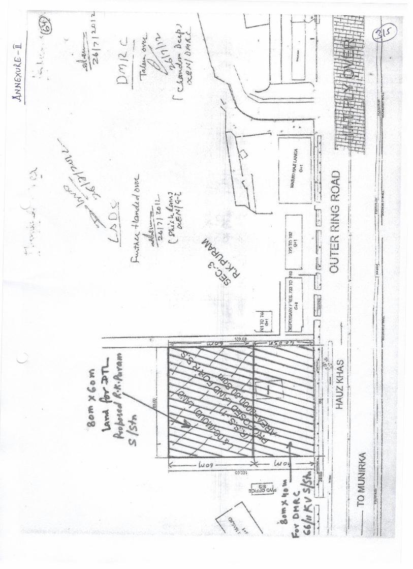
Technical Specifications of Visual Monitoring System Page 1 of 8
Annexure-III
Visual monitoring system for Remote monitoring of unmanned new S/stn equipment
Visual monitoring system (VMS) for effective watch and ward of sub -station premises covering the areas of entire switchyard, Control Room cum Administrative building, Fire lighting pump house, stores and main gate, shall be provided. The contractor shall design, supply, erect, test and commission the complete system including cameras, Network video recorder system, mounting arrangement for cameras, cables, LAN Switches, UPS and any other items accessories required to complete the system. To provide all the necessary licenses to run the system successfully shall be in the scope of contractor.
System with Color IP cameras for VMS surveillance would be located at various locations including indoor areas and outdoors switchyard and as per the direction of Engineer-In-charge. The VMS data partly / completely shall be recorded (minimum for 15 days) and stored on network video recorder.
The number of cameras and their locations shall be decided in such a way that any location covered in the area can be scanned. The cameras shall be located in such a way to monitor at least: The operation of each and every isolator pole of the complete yard (including future scope).
1. All the Transformer and Reactors (including future scope). 2. All the Entrance doors of Control Room Building and Fire-fighting Pump House and
Switchyard Panel Room. 3. All the gates of switchyard. 4. Main entrance Gate. 5. All other Major Equipments (such as CB, CT, CVT, LA etc. for present and future)
The cameras can be mounted on structures, buildings or any other suitable mounting arrangement to be provided by the contractor.
1.1 Technical requirements of major equipment of Visual Monitoring System.
1.1.1 The Video Monitoring system shall be an integrated system with IP network centric functional and management architecture aimed at providing high-speed manual / automatic operation for best performance.
1.1.2 The system should facilitate viewing of live and recorded images and controlling of all cameras by the authorized users.
1.1.3 The system shall use video signals from various types of indoor/outdoor Charge Couple Device (CCD) color cameras installed at different locations, process them for viewing on workstations/monitors in the control Room and simultaneously record all the cameras after compression H 264 / MPEG 4 or better standard. Mouse/joystick-keyboard controllers shall be used for Pan, Tilt, Zoom, and other functions of desired cameras.
1.1.4 The system shall provide sufficient storage of all the cameras recordings for a period of 15 days or more @ 25 FPS (Frame Per Second), at 4 CIF (Common Intermediate Format) or better quality using necessary compression techniques for all cameras. It
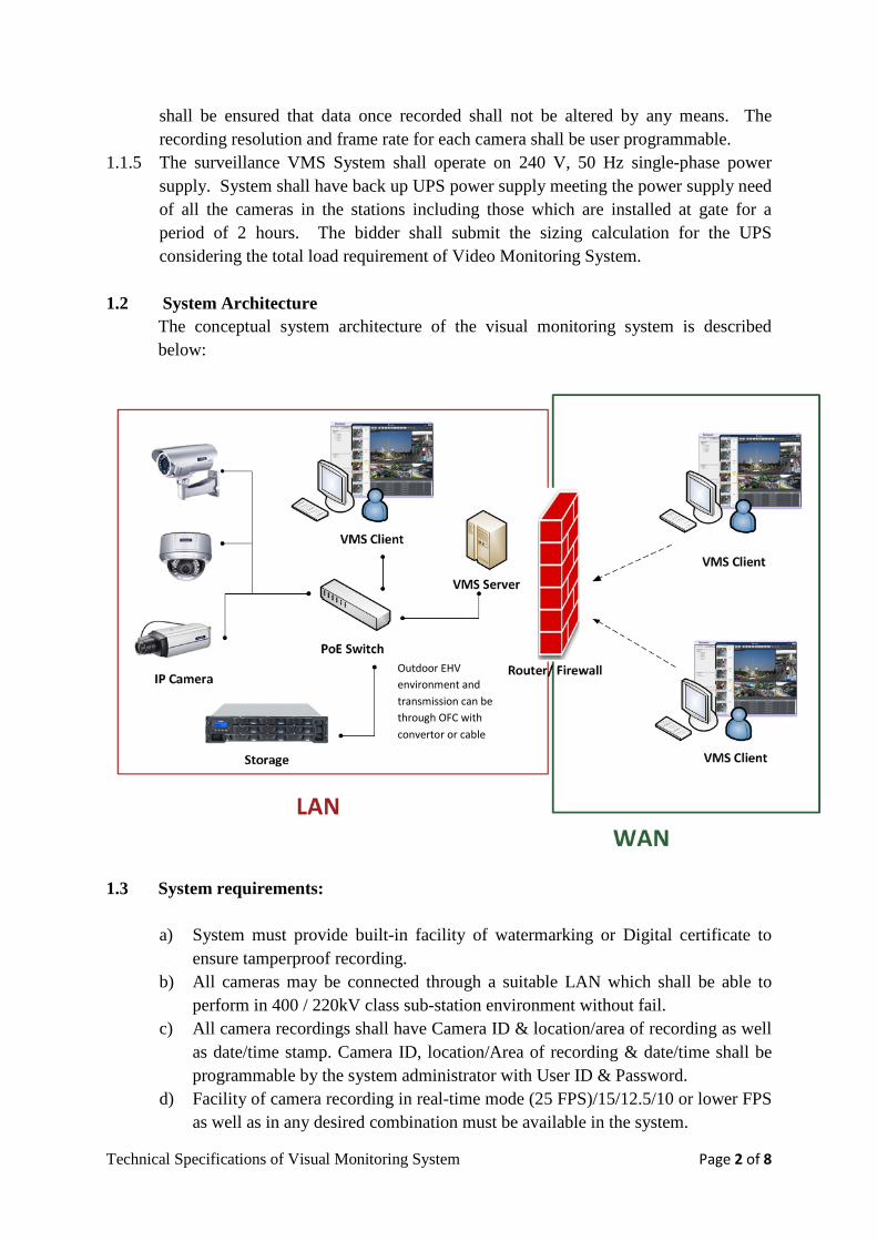
Technical Specifications of Visual Monitoring System Page 2 of 8
shall be ensured that data once recorded shall not be altered by any means. The recording resolution and frame rate for each camera shall be user programmable.
1.1.5 The surveillance VMS System shall operate on 240 V, 50 Hz single-phase power supply. System shall have back up UPS power supply meeting the power supply need of all the cameras in the stations including those which are installed at gate for a period of 2 hours. The bidder shall submit the sizing calculation for the UPS considering the total load requirement of Video Monitoring System.
1.2 System Architecture The conceptual system architecture of the visual monitoring system is described below:
1.3 System requirements:
a) System must provide built-in facility of watermarking or Digital certificate to
ensure tamperproof recording. b) All cameras may be connected through a suitable LAN which shall be able to
perform in 400 / 220kV class sub-station environment without fail. c) All camera recordings shall have Camera ID & location/area of recording as well
as date/time stamp. Camera ID, location/Area of recording & date/time shall be programmable by the system administrator with User ID & Password.
d) Facility of camera recording in real-time mode (25 FPS)/15/12.5/10 or lower FPS as well as in any desired combination must be available in the system.
Outdoor EHV environment and transmission can be through OFC with convertor or cable
Technical Specifications of Visual Monitoring System Page 3 of 8
e) Facility of Camera recording in HD (1280X720p), D1, 4CIF, CIF, VGA, as well as in any combination i.e. any camera can be recorded in any quality.
f) System to have facility of 100% additional camera installation beyond the original planned capacity.
g) In order to optimize the memory, while recording, video shall be compressed using H 264 / MPEG-4 or better standard and streamed over the IP network.
h) System shall be triplex i.e. it should provide facility of Viewing, Recording & Replay simultaneously.
i) The offered system shall have facility to export the desired portion of clipping (from a specific date/time to another specific date/time) on CD or DVD. Viewing of this recording shall be possible on standard PC using standard software like windows media player etc.
j) System shall have provision of WAN connectivity for remote monitoring. The client can log into WAN and then monitor the live video / recorded video of the substation.
k) The contractor shall provide the Software Development Kit (SDK) and Application Program Interface (API) for all the system software’s including NVR / Cameras installed under the CCTV system. The Software Development Kit (SDK) / Application programming interface (API) for the NVR and the cameras shall be supplied including for the future integration of the following functions with visual monitoring system (i) Camera- Network device discovery, live video streaming, video capture
configuration, video compression configuration, event and metadata configuration, storage recording.
(ii) NVR- Network device discovery, video capture configuration, video compression configuration, video recording control, video recording search, video replay control.
l) The equipment should generally conform to Electro magnetic compatibility requirements for outdoor equipment in EHV switchyards. The major EC required for Cameras and other equipment shall be as under:
Technical Specification for Visual Monitoring System
1. Electrical Fast Transient (Level 4) - As per IEC 61000-4-4 2. Damped Oscillatory ( 1 MHZ and 100 KHZ) (Level
3) - As per IEC 61000-4-12
3. AC Voltage Dips & Interruption/Variation (Level 4) - As per IEC 61000-4-12 4. Electrostatic Discharge (Level4) - As per IEC 61000-4-2 5. Power Frequency Magnetic Field (Level 4) - As per IEC 61000-4-8 6. Ripple on DC Power Supply (Level 4) - As per IEC 61000-4-17
Type test reports to establish compliance with the above requirement shall be submitted during detailed engineering.
Technical Specifications of Visual Monitoring System Page 4 of 8
1.3.1 Video Surveillance Application Software
a) Digital video surveillance software control software should be capable to display and manage the entire surveillance system. It should be capable of supporting variety of devices such as cameras, video encoder, servers, NAS boxes/Raid back up device etc.
b) The software should have inbuilt facility to store configuration of encoders and cameras.
c) The software should support flexible 1/2/4/8/16/32 window split screen display mode and scroll mode on the PC monitor.
d) The software should be able to control all cameras i.e. PTZ control, Iris control, auto / manual focus, and color balance of camera, selection of presets, video tour selection etc.
e) The software should have user access authority configurable on per device or per device group basis. The system shall provide user activity log with user ID, time stamp, action performed etc.
f) The users should be on a hierarchical basis as assigned by the administrator. The higher priority person can take control of cameras, which are already being controlled by a lower priority user.
g) It should have recording modes, viz. continuous, manual, or programmed modes on date, time and camera-wise. All modes should be disables or enabled using scheduled configuration. It should also be possible to search and replay the recorded images on date, time and camera-wise. It should provide onscreen controls for remote operation of PTZ cameras. It should have a facility for scheduled recording. Different recordings speeds (Fps) and resolution for each recording mode for each camera should be possible.
h) The software for clients should also be working on a browser based system to remote users. This will allow any authorized user to display the video of any desired camera on the monitor with full PTZ and associated controls.
i) Retrieval: The VMS application should allow retrieval of data instantaneously or any date/time interval chosen through search functionality of the application software. In case data is older than 15 days and available, then the retrieval should be possible. The system should also allow for backup of specified data on any drive like DVD’s or any other device in a format which can be replayed through standard PC based software. Log of any such activity should be maintained by the system.
j) VMS shall provide the full functionality reporting tool which can provide reports for user login/logoff, camera accessibility report, server health check reports etc.
1.3.2 Network video recorder
The Network recorder shall include at least Server (min 3.0 Ghz, 4GB RAM, 3000GB HDD (min)), RAID 5 with suitable configuration along with colored TFT 22” High resolution monitor and internal DVD writer. Windows XP/7 Prof. or VMS compatible operating system latest version with hardware like graphic cards, licensed anti virus etc.
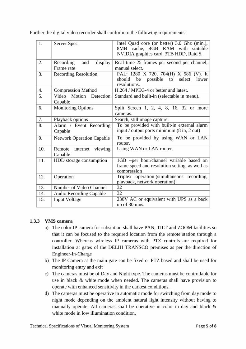
Technical Specifications of Visual Monitoring System Page 5 of 8
Further the digital video recorder shall conform to the following requirements:
1. Server Spec Intel Quad core (or better) 3.0 Ghz (min.), 8MB cache, 4GB RAM with suitable NVIDIA graphics card, 3TB HDD, Raid 5.
2. Recording and display Frame rate
Real time 25 frames per second per channel, manual select.
3. Recording Resolution PAL: 1280 X 720, 704(H) X 586 (V). It should be possible to select lower resolutions.
4. Compression Method H.264 / MPEG-4 or better and latest. 5. Video Motion Detection
Capable Standard and built-in (selectable in menu).
6. Monitoring Options Split Screen 1, 2, 4, 8, 16, 32 or more cameras.
7. Playback options Search, still image capture. 8. Alarm / Event Recording
Capable To be provided with built-in external alarm input / output ports minimum (8 in, 2 out)
9. Network Operation Capable To be provided by using WAN or LAN router.
10. Remote internet viewing Capable
Using WAN or LAN router.
11. HDD storage consumption
1GB ~per hour/channel variable based on frame speed and resolution setting, as well as compression
12. Operation Triplex operation (simultaneous recording, playback, network operation)
13. Number of Video Channel 32 14. Audio Recording Capable 32 15. Input Voltage 230V AC or equivalent with UPS as a back
up of 30mins.
1.3.3 VMS camera a) The color IP camera for substation shall have PAN, TILT and ZOOM facilities so
that it can be focused to the required location from the remote station through a controller. Whereas wireless IP cameras with PTZ controls are required for installation at gates of the DELHI TRANSCO premises as per the direction of Engineer-In-Charge
b) The IP Camera at the main gate can be fixed or PTZ based and shall be used for monitoring entry and exit
c) The cameras must be of Day and Night type. The cameras must be controllable for use in black & white mode when needed. The cameras shall have provision to operate with enhanced sensitivity in the darkest conditions.
d) The cameras must be operative in automatic mode for switching from day mode to night mode depending on the ambient natural light intensity without having to manually operate. All cameras shall be operative in color in day and black & white mode in low illumination condition.
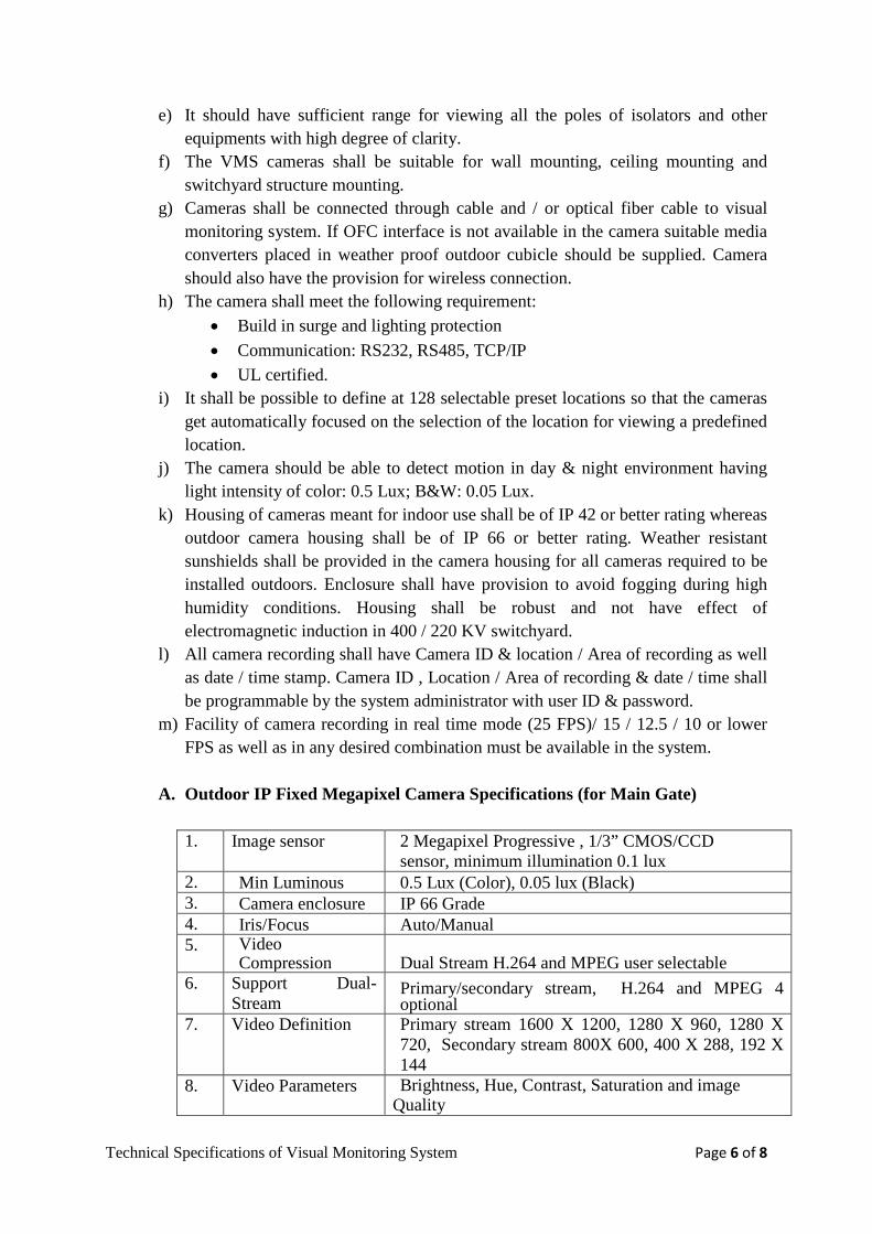
Technical Specifications of Visual Monitoring System Page 6 of 8
e) It should have sufficient range for viewing all the poles of isolators and other equipments with high degree of clarity.
f) The VMS cameras shall be suitable for wall mounting, ceiling mounting and switchyard structure mounting.
g) Cameras shall be connected through cable and / or optical fiber cable to visual monitoring system. If OFC interface is not available in the camera suitable media converters placed in weather proof outdoor cubicle should be supplied. Camera should also have the provision for wireless connection.
h) The camera shall meet the following requirement: • Build in surge and lighting protection • Communication: RS232, RS485, TCP/IP • UL certified.
i) It shall be possible to define at 128 selectable preset locations so that the cameras get automatically focused on the selection of the location for viewing a predefined location.
j) The camera should be able to detect motion in day & night environment having light intensity of color: 0.5 Lux; B&W: 0.05 Lux.
k) Housing of cameras meant for indoor use shall be of IP 42 or better rating whereas outdoor camera housing shall be of IP 66 or better rating. Weather resistant sunshields shall be provided in the camera housing for all cameras required to be installed outdoors. Enclosure shall have provision to avoid fogging during high humidity conditions. Housing shall be robust and not have effect of electromagnetic induction in 400 / 220 KV switchyard.
l) All camera recording shall have Camera ID & location / Area of recording as well as date / time stamp. Camera ID , Location / Area of recording & date / time shall be programmable by the system administrator with user ID & password.
m) Facility of camera recording in real time mode (25 FPS)/ 15 / 12.5 / 10 or lower FPS as well as in any desired combination must be available in the system.
A. Outdoor IP Fixed Megapixel Camera Specifications (for Main Gate) 1. Image sensor 2 Megapixel Progressive , 1/3” CMOS/CCD
sensor, minimum illumination 0.1 lux 2. Min Luminous 0.5 Lux (Color), 0.05 lux (Black) 3. Camera enclosure IP 66 Grade 4. Iris/Focus Auto/Manual 5. Video
Compression Dual Stream H.264 and MPEG user selectable 6. Support Dual-
Stream Primary/secondary stream, H.264 and MPEG 4 optional
7. Video Definition Primary stream 1600 X 1200, 1280 X 960, 1280 X 720, Secondary stream 800X 600, 400 X 288, 192 X 144
8. Video Parameters Brightness, Hue, Contrast, Saturation and image Quality
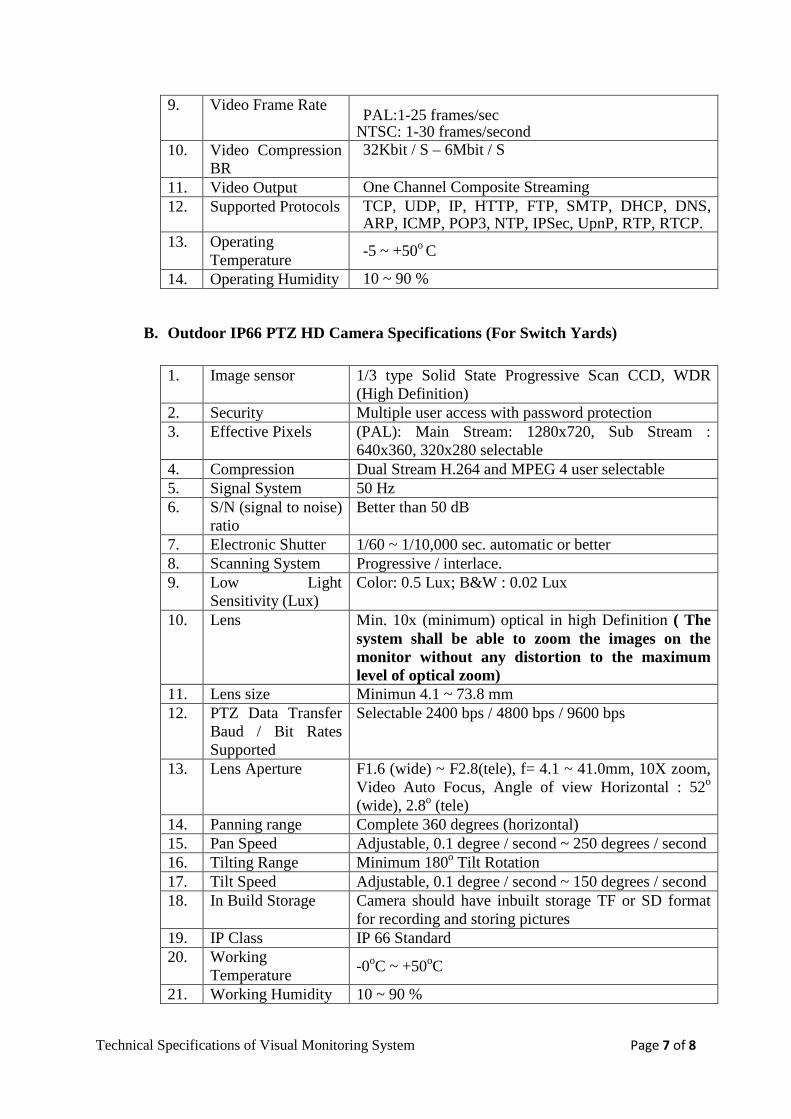
Technical Specifications of Visual Monitoring System Page 7 of 8
9. Video Frame Rate PAL:1-25 frames/sec
NTSC: 1-30 frames/second 10. Video Compression
BR 32Kbit / S – 6Mbit / S
11. Video Output One Channel Composite Streaming 12. Supported Protocols TCP, UDP, IP, HTTP, FTP, SMTP, DHCP, DNS,
ARP, ICMP, POP3, NTP, IPSec, UpnP, RTP, RTCP. 13. Operating
Temperature -5 ~ +50o C
14. Operating Humidity 10 ~ 90 %
B. Outdoor IP66 PTZ HD Camera Specifications (For Switch Yards) 1. Image sensor 1/3 type Solid State Progressive Scan CCD, WDR
(High Definition) 2. Security Multiple user access with password protection 3. Effective Pixels (PAL): Main Stream: 1280x720, Sub Stream :
640x360, 320x280 selectable 4. Compression Dual Stream H.264 and MPEG 4 user selectable 5. Signal System 50 Hz 6. S/N (signal to noise)
ratio Better than 50 dB
7. Electronic Shutter 1/60 ~ 1/10,000 sec. automatic or better 8. Scanning System Progressive / interlace. 9. Low Light
Sensitivity (Lux) Color: 0.5 Lux; B&W : 0.02 Lux
10. Lens Min. 10x (minimum) optical in high Definition ( The system shall be able to zoom the images on the monitor without any distortion to the maximum level of optical zoom)
11. Lens size Minimun 4.1 ~ 73.8 mm 12. PTZ Data Transfer
Baud / Bit Rates Supported
Selectable 2400 bps / 4800 bps / 9600 bps
13. Lens Aperture F1.6 (wide) ~ F2.8(tele), f= 4.1 ~ 41.0mm, 10X zoom, Video Auto Focus, Angle of view Horizontal : 52o (wide), 2.8o (tele)
14. Panning range Complete 360 degrees (horizontal) 15. Pan Speed Adjustable, 0.1 degree / second ~ 250 degrees / second 16. Tilting Range Minimum 180o Tilt Rotation 17. Tilt Speed Adjustable, 0.1 degree / second ~ 150 degrees / second 18. In Build Storage Camera should have inbuilt storage TF or SD format
for recording and storing pictures 19. IP Class IP 66 Standard 20. Working
Temperature -0oC ~ +50oC
21. Working Humidity 10 ~ 90 %
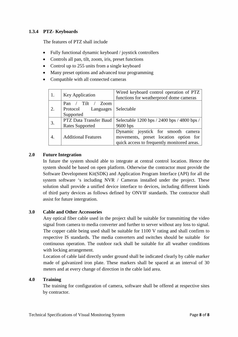
Technical Specifications of Visual Monitoring System Page 8 of 8
1.3.4 PTZ- Keyboards
The features of PTZ shall include
• Fully functional dynamic keyboard / joystick controllers • Controls all pan, tilt, zoom, iris, preset functions • Control up to 255 units from a single keyboard • Many preset options and advanced tour programming • Compatible with all connected cameras
1. Key Application Wired keyboard control operation of PTZ functions for weatherproof dome cameras
2. Pan / Tilt / Zoom Protocol Languages Supported
Selectable
3. PTZ Data Transfer Baud Rates Supported
Selectable 1200 bps / 2400 bps / 4800 bps / 9600 bps
4. Additional Features Dynamic joystick for smooth camera movements, preset location option for quick access to frequently monitored areas.
2.0 Future Integration
In future the system should able to integrate at central control location. Hence the system should be based on open platform. Otherwise the contractor must provide the Software Development Kit(SDK) and Application Program Interface (API) for all the system software ‘s including NVR / Cameras installed under the project. These solution shall provide a unified device interface to devices, including different kinds of third party devices as follows defined by ONVIF standards. The contractor shall assist for future intergration.
3.0 Cable and Other Accessories Any optical fiber cable used in the project shall be suitable for transmitting the video signal from camera to media converter and further to server without any loss to signal. The copper cable being used shall be suitable for 1100 V rating and shall confirm to respective IS standards. The media converters and switches should be suitable for continuous operation. The outdoor rack shall be suitable for all weather conditions with locking arrangement. Location of cable laid directly under ground shall be indicated clearly by cable marker made of galvanized iron plate. These markers shall be spaced at an interval of 30 meters and at every change of direction in the cable laid area.
4.0 Training The training for configuration of camera, software shall be offered at respective sites by contractor.
______________________________________________________________________________ 160MVA Power Transformer Page 1 of 26
Annexure IV
POWER TRANSFORMER
160 MVA POWER TRANSFORMER & NEUTRAL CURRENT TRANSFORMER
SECTION – I CONSTRUCTIONAL DETAILS & DETAILED DESCRIPTION 1.1 CONSTRUCTION DETAILS
The features and construction details of each power transformer shall be in accordance with the requirements stated herein under.
1.2 TANK CONSTRUCTION 1.2.1 Tank shall be of welded construction and fabricated from tested quality, low carbon steel
of adequate thickness. 1.2.2 All seams and joints not required to be opened at site shall be factory welded and
wherever possible they shall be double welded. 1.2.3 Each tank shall be provided with lifting lugs suitable for lifting the transformer complete
with oil. A minimum of four jacking Pads in accessible position are to be provided to enable the transformer complete with oil, to be raised or lowered using hydraulic or mechanical screw jacks.
1.2.4 Tank stiffeners shall be provided for general rigidity and these shall be so designed as to prevent any retention of water.
1.2.5 The tank shall be designed to withstand. i) Mechanical shocks during transportation ii) Vacuum of 760mm of Hg. iii) Continuous internal pressure over normal hydrostatic pressure of oil as well as the
pressure developed due to abnormal condition which may arise during service. iv) Earthquake forces as per Seismic zone v) Short Circuit forces
1.2.6 The base of each tank shall be so designed that it shall be possible to move the complete transformer unit by skidding in any direction without injury when using plates or rails.
1.2.7 The transformer tank and its accessories shall be so designed as to avoid collection of gas/air.
1.2.8 Bolted inspection opening shall be provided on the sides of the tank near the bottom to observe the position of the core.
1.2.9 Inspection opening shall be provided on the tank to facilitate inspection of Core, assembly fittings and fixtures etc.
1.2.10 Adequate space shall be provided at the bottom of the tank for collection of sediments. 1.2.11 Transformer shall have the provision for installation of the Fire Prevention and
Extinguishing System offered by the tenderer. 1.3 TANK COVER: 1.3.1 The tank cover shall be sloped to prevent retention of rain water and shall not distort when
lifted. Suitable lifting arrangement shall be provided. 1.3.2 At least two adequately sized bolted inspection openings one at each end of the tank shall
be provided for easy access to bushings and earth connections. The inspection covers shall not weigh more than 25 kg. and shall be provided with suitable lifting arrangements.
1.3.3 The tank covers shall be fitted with pockets at the position of maximum oil temperature at C.M.R. for bulbs of oil and winding temperature indicators. It shall be possible to remove these bulbs without lowering the oil in the tank.
1.3.4 The thermometer pocket shall be fitted with a captive screwed top to prevent the ingress of water.
1.3.5 Bushings, turrets cover of inspection openings, thermometer pockets etc. shall be designed to prevent ingress of water into or leakage of oil from the tank.
1.3.6 All bolted connections shall be fitted with weather proof, hot oil resistant gasket in between for complete oil tightness. If gasket is compressible, metallic stops shall be provided to prevent over compression.
1.3.7 Neoprene gaskets shall be used.
______________________________________________________________________________ 160MVA Power Transformer Page 2 of 26
1.4 AXLES AND WHEELS 1.4.1 The transformers shall be provided with flanged, bi-directional wheels and axles. These
shall be so designed that under both the directions of movement they shall not deflect as to interfere with the movement of the transformer. Wheels shall be provided with suitable bearings which shall be rust corrosion resistant. Fittings/nipples for lubrication shall also be provided or the bearing shall be of permanently lubricated type.
1.4.2 All wheels should be detachable and shall be made of cast iron or steel as required. 1.4.3 Suitable locking arrangement shall be provided for the wheels to prevent accidental
movement of transformer. 1.4.4 The wheels are required to swivel and they shall be arranged so that they can be turned
through an angle of 900
1.4.5 The wheel centre in both directions shall be1676 mm to facilitate placement of transformer on rails spaced 1676 mm centre to centre.
C when the tank is jacked up clear off the rails. Means shall be provided for locking the swivel movements in positions parallel to or at right angels to the longitudinal axis of the tank.
1.5 CONSERVATOR TANK 1.5.1 The conservator tank shall have adequate capacity between highest and lowest visible
levels to meet the requirement of expansion of the total cold oil volume, in the transformer and cooling equipment from minimum ambient temperature to 900
1.5.2 Conservator shall be provided with sump and drain valve so that it can be completely drained by means of the drain valve, when mounted in service position.
C.
1.5.3 The conservator shall be bolted into position so that it can be removed for cleaning purposes.
1.5.4 The conservator shall be fitted with magnetic oil level gauge with low level electrically insulated alarm contacts.
1.5.5 Conservator shall be provided in such a position as not to obstruct the electrical connections to the transformers.
1.6 PRESSURE RELIEF DEVICE: 1.6.1 The pressure relief valve provided shall be of sufficient size for rapid release of any
pressure that may be generated within the tank and which may result in damage to the equipment. The device shall operate at a static pressure of less than the hydraulic test pressure of transformer tank. The device shall have two micro switches having contacts which shall close for actuating trip circuits in the event of operation of the pressure relief device. The pressure relief device shall be spring loaded type with detachable type diaphragm. Means shall be provided to prevent the ingress of rain water. Terminal box of PRD should confirm to degree of protection as per IP-55 of IS
1.7 GAS AND OIL ACTUATED RELAYS 1.7.1 The transformer shall be fitted with gas and oil actuated relay as per specification
hereunder. 1.7.2 Each gas and oil actuated relay shall be provided with a test cock to take a flexible pipe
connection for checking the operation of the relay. 1.7.3 A double float type Buchholz relay shall be provided between the main conservator and
tank. All gas evolved in the transformer shall collect in this relay. A copper tube shall be connected from the gas collector to a valve located about 1200mm. above ground level, to facilitate sampling, with the transformer in service. The device shall be provide with two electrically independent ungrounded contacts, one for alarm on gas accumulation and the other for tripping on sudden rise of pressure.
1.7.4 A machined surface shall be provided on the top of each relay to facilitate the setting of the relays and to check the mounting angle in the pipe and the cross level of the relay.
1.7.5 The design of the relay mounting arrangements, the associated pipe work and the cooling plant shall be such that mal-operation of the relays shall not take place under normal service condition.
1.7.6 The pipe work shall be so arranged that all gas arising from the transformer shall pass into the gas and oil-actuated relay. The oil circuit through the relay shall not form a delivery path in parallel with any circulating oil pipe, nor shall it be tied or connected through the pressure relief vent. Sharp bends in the pipe work shall be avoided.
______________________________________________________________________________ 160MVA Power Transformer Page 3 of 26
1.7.7 A sudden pressure relay shall be fitted on main tank to detect a sharp rise in internal pressure. An electrically insulated trip contact shall be provided in sudden pressure relay.
1.7.8 A surge relay shall also be provided between OLTC and conservator tank to detect a sharp rise in internal pressure. An electrically insulated trip contact shall be provided in the surge relay.
1.7.9 Provision shall be made for parallel wiring of all the alarm & trip events for separate annunciation on Employer panel.
1.8 CORE 1.8.1 The core shall be constructed from high grade non-ageing, cold rolled grain oriented
silicon steel laminations. Provision of core belts shall be preferred in place of core bolts to avoid hot spots. The manufacturer who has in house cutting facility for core laminations shall be preferred.
1.8.2 The design of the magnetic circuit shall be such as to avoid static discharges, developments of short circuit paths within itself or to the earthed clamping structure and production of flux component at right angles to the plane of laminations which may cause local heating.
1.8.3 The insulation structure for core to core bolts and core to clamp plates shall be able to withstand a voltage of 2 KV rms for 1 minute.
1.8.4 Core and windings shall be capable of withstanding shocks during transport, installation, service and adequate provision shall be made to prevent movement of core and winding relative to tank during these conditions including short circuit condition.
1.8.5 All steel sections used for supporting the core shall be thoroughly sand blasted, after cutting, drilling and welding.
1.8.6 With bell type tank construction suitable projecting guides shall be provided on core assembly to facilitate removal from the tank.
1.8.7 Every care shall be exercised in the selection, treatment and handling of core steel to ensure that as far as practicable, the laminations are flat and finally assembled core is free from distortion.
1.8.8 Oil ducts shall be provided wherever necessary to ensure adequate cooling. The winding structure and major insulation shall not obstruct the free flow of oil through such ducts.
1.8.9 Adequate lifting lugs shall be provided to enable the core and windings to be lifted. 1.8.10 The supporting frame work of the cores shall be so designed as to avoid the presence of
pockets which would prevent complete emptying of the tank through the drain valve. 1.8.11 The air core reactance of HV winding of transformer shall not be less than 20%. 1.9 EARTHING TERMINALS Two earthing pads suitable for connecting mild steel flat shall be provided at positions
close to each of the two bottom corners of the tank. These grounding terminals should be suitable for bolted connections. The earthing terminals shall be capable of carrying for 4 seconds the full load voltage, short circuit current of the transformer.
1.10 WINDINGS 1.10.1 The tenderer shall ensure that windings are made in dust proof, conditioned atmosphere.
The tenderer shall furnish the facilities available at his works alongwith the Bid. 1.10.2 The conductors shall be of electrolytic copper. Current density in all the windings should
not be more than 2.5 Amps/mm2
1.10.3 The insulation of transformer windings and connections shall be free from insulating compounds which are liable to soften, ooze out, shrink or collapse and be non-catalytic and chemically inert in transformer oil during service.
.
1.10.4 Coil assembly and insulating spacers shall be so arranged as to ensure free circulation of oil and to reduce hot spot of the winding.
1.10.5 220 KV and 66 KV star connected winding shall have graded insulation as defined in IEC-60076/IS-2026. The tertiary delta connected winding wherever applicable shall be insulated for the voltage specified in clause 3.7 of section-3. In the event the tenderer recommends to adopt higher insulation level of the tertiary, the offer should give complete detailed justification and calculations related thereto. Protection scheme shall be so designed that tertiary can be loaded for auxiliary supply in future
1.10.6 The windings shall be designed to withstand impulse and power frequency test voltages as specified in IEC-60076/IS-2026 and clause 3.7 of Section-3 of the specification.
______________________________________________________________________________ 160MVA Power Transformer Page 4 of 26
1.10.7 The windings shall be designed to reduce to a minimum the out of balance forces in the transformer at all voltage ratios.
1.10.8 The stacks of windings shall receive adequate shrinkage treatment before final assembly. Adjustable devices shall be provided for taking up possible shrinkages of coils in service
1.10.9 No strip conductor shall have a width on edge exceeding six times its thickness. 1.10.10 The conductors shall be transposed at sufficient intervals in order to minimize eddy
currents and equalize the distribution of currents and temperatures along the windings. 1.10.11 Core and winding shall be capable of withstanding the shock during transport, installation
and service. Adequate provision shall be made to prevent movement of core and winding relative to tank during these conditions.
1.10.12 Coil clamping rings, if provided, shall be of steel or of suitable insulating material. Axial laminated material other than bakelised paper shall not be used.
1.10.13 All threaded connections shall be provided with locking facilities. All leads from the winding to terminal board & bushings shall be rigidly supported to prevent injury from vibration. Guide tubes shall be used where practicable.
1.11 TEMPERATURE INDICATING DEVICES 1.11.1 Oil Temperature Indicator (OTI): The transformer shall be provided with a 150mm dial type thermometer for top oil temp,
indication. The thermometer shall have adjustable, electrically independent ungrounded alarm and trip contacts, maximum reading pointer and resetting device. The thermometer shall be mounted on body of the transformer at a height of 1200 mm above rail top level.
1.11.2 Winding Temperature Indicator (WTI ) In the case of two winding transformers, winding temperature indicator shall be provided
on LV side only and in case of three winding transformers winding temperature indicators shall be provided separately on all the three windings. It shall comprise the following: i) Temperature Sensing element ii) Thermal Image coil iii) Current Transformer iv) 150mm dial type temperature indicating instrument mounted on the transformer
with maximum reading pointer and two adjustable electrically independent ungrounded contacts, one for high winding temperature alarm and one trip besides those required for control of cooling equipment.
v) Calibration device. Zero adjustment. vi) Automatic ambient temp compensation.
In addition to the above, the following remote indication equipment shall be provided for each of the winding:
a) Single transmitter (for recording windings) temp. b) Remote winding temp. indicator shall be mounted on OLTC panel.
1.11.3 The tripping contacts of winding temperature indicators shall be adjustable to close between 600C and 1200C and alarm contacts to close between 500C and 1000C and both shall re-open when the temperature has fallen by about 100
1.11.4 The contacts used to control the cooling plant motors on the above devices shall be adjustable to close between 50
C.
0C and 1000C and to re-open when the temperature has fallen by 200
1.11.5 All contacts shall be adjustable on a scale and shall be accessible on removal of the cover.
C.
1.11.6 The temperature indicators shall be so designed that it shall be possible to check the operation of the contacts and associated equipment.
1.11.7 Connections shall be brought from the temperature indicators to terminals placed inside the marshalling box.
1.11.8 Cooler failure and oil flow alarm indication shall also be provided at local and remote end. 1.12 ANTI-EARTHQUAKE CLAMPING DEVICE
To prevent transformer movement during earthquake a clamping device should be provided for fixing the transformer to the foundation. The tenderer shall supply necessary bots for embedding in the concreting.
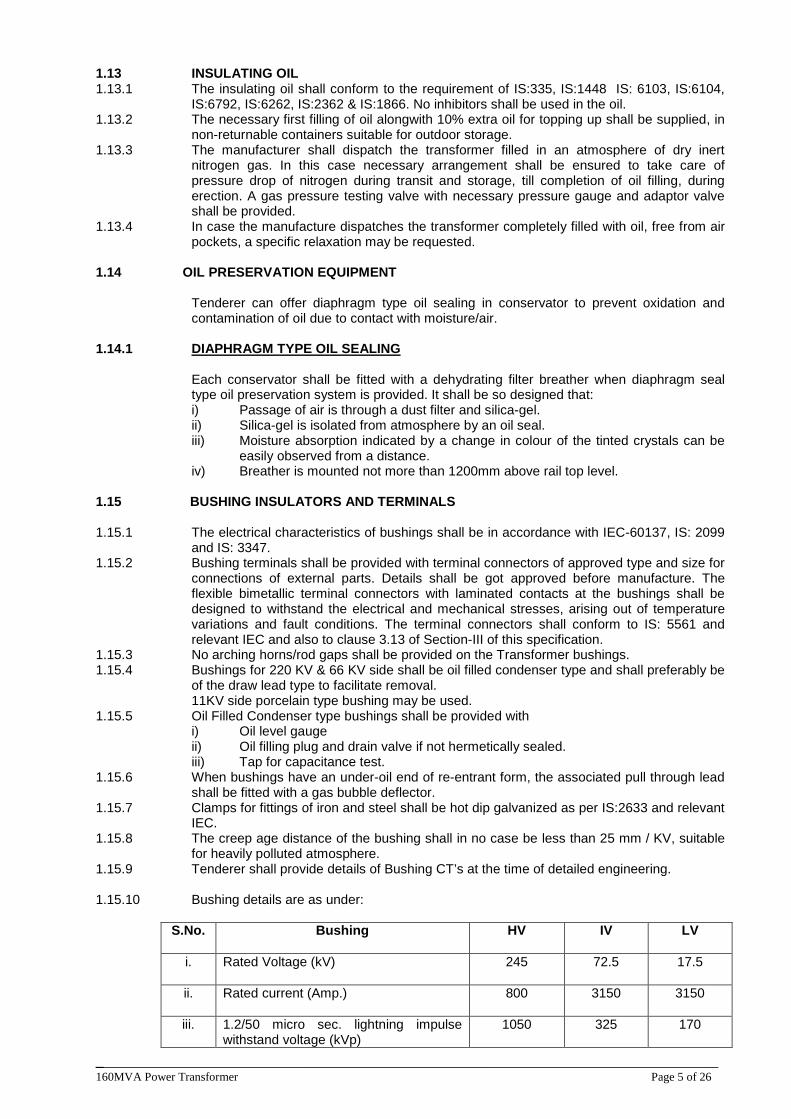
______________________________________________________________________________ 160MVA Power Transformer Page 5 of 26
1.13 INSULATING OIL 1.13.1 The insulating oil shall conform to the requirement of IS:335, IS:1448 IS: 6103, IS:6104,
IS:6792, IS:6262, IS:2362 & IS:1866. No inhibitors shall be used in the oil. 1.13.2 The necessary first filling of oil alongwith 10% extra oil for topping up shall be supplied, in
non-returnable containers suitable for outdoor storage. 1.13.3 The manufacturer shall dispatch the transformer filled in an atmosphere of dry inert
nitrogen gas. In this case necessary arrangement shall be ensured to take care of pressure drop of nitrogen during transit and storage, till completion of oil filling, during erection. A gas pressure testing valve with necessary pressure gauge and adaptor valve shall be provided.
1.13.4 In case the manufacture dispatches the transformer completely filled with oil, free from air pockets, a specific relaxation may be requested.
1.14 OIL PRESERVATION EQUIPMENT
Tenderer can offer diaphragm type oil sealing in conservator to prevent oxidation and contamination of oil due to contact with moisture/air.
1.14.1 DIAPHRAGM TYPE OIL SEALING
Each conservator shall be fitted with a dehydrating filter breather when diaphragm seal type oil preservation system is provided. It shall be so designed that: i) Passage of air is through a dust filter and silica-gel. ii) Silica-gel is isolated from atmosphere by an oil seal. iii) Moisture absorption indicated by a change in colour of the tinted crystals can be
easily observed from a distance. iv) Breather is mounted not more than 1200mm above rail top level.
1.15 BUSHING INSULATORS AND TERMINALS 1.15.1 The electrical characteristics of bushings shall be in accordance with IEC-60137, IS: 2099
and IS: 3347. 1.15.2 Bushing terminals shall be provided with terminal connectors of approved type and size for
connections of external parts. Details shall be got approved before manufacture. The flexible bimetallic terminal connectors with laminated contacts at the bushings shall be designed to withstand the electrical and mechanical stresses, arising out of temperature variations and fault conditions. The terminal connectors shall conform to IS: 5561 and relevant IEC and also to clause 3.13 of Section-III of this specification.
1.15.3 No arching horns/rod gaps shall be provided on the Transformer bushings. 1.15.4 Bushings for 220 KV & 66 KV side shall be oil filled condenser type and shall preferably be
of the draw lead type to facilitate removal. 11KV side porcelain type bushing may be used.
1.15.5 Oil Filled Condenser type bushings shall be provided with i) Oil level gauge ii) Oil filling plug and drain valve if not hermetically sealed. iii) Tap for capacitance test.
1.15.6 When bushings have an under-oil end of re-entrant form, the associated pull through lead shall be fitted with a gas bubble deflector.
1.15.7 Clamps for fittings of iron and steel shall be hot dip galvanized as per IS:2633 and relevant IEC.
1.15.8 The creep age distance of the bushing shall in no case be less than 25 mm / KV, suitable for heavily polluted atmosphere.
1.15.9 Tenderer shall provide details of Bushing CT’s at the time of detailed engineering. 1.15.10 Bushing details are as under:
S.No. Bushing
HV IV LV
i. Rated Voltage (kV)
245 72.5 17.5
ii. Rated current (Amp.)
800 3150 3150
iii. 1.2/50 micro sec. lightning impulse withstand voltage (kVp)
1050 325 170
______________________________________________________________________________ 160MVA Power Transformer Page 6 of 26
iv. 250/2500 micro sec. Switching impulse withstand voltage (kVp.)
-- -- --
v. One minute power frequency withstand voltage kV (rms.)
460 140 70
vi. Minimum creepage distances
25mm/KV 25mm/KV 25mm/KV
1.16 PROTECTIVE DEVICES
The protective relaying of the power transformer shall be as under:- a) Pressure relief valve for the main tank. b) Buchholz Protection for main tank. c) Sudden pressure relay for the main tank. d) Surge relay for OLTC tank conservator. e) Thermal Protection (Oil and windings with high temp.). f) Tap changer out of step trip.
1.17 TERMINAL MARKING
The terminal marking and their physical position shall be in accordance with IEC-60076/IS: 2026.
1.18 NEUTRAL EARTHING ARRANGEMENT 1.18.1 The neutral terminal of transformer shall be connected to Neutral Current Transformer
through brass/tinned copper bar and then brought to the ground level by a G.S. Flat, supported from the tank by using porcelain insulators. The end of the G.S. Flat shall be brought to the bottom of the tank, at a convenient point, for making bolted connection to two (2) 75x12 mm galvanized steel flats connected to Employer’s grounding mat.
1.19 ON-LOAD TAP-CHANGING MECHANISM (O.L.T.C.) 1.19.1 Each transformer shall be provided with an on-load tap changing mechanism. This shall
be designed suitable for remote control operation from switch boards in the control room in addition to being capable of local manual as well as local electrical operation.
1.19.2 It shall not be possible to use the electric drive when manual gear is in use and it shall be possible to use only one electrical control at a time. Operation of the local or remote control switches shall cause one tap movement only until the control switch is returned to the off position for the next operation.
1.19.3 The local electrical control switches shall be mounted in the out door cubicle. 1.19.4 The equipment shall be so arranged as to ensure that when a tap change operation has
been commenced it shall be completed independently of the operation of the control relays and switches. If a failure of the auxiliary supply during a tap change or any other contingency result in that movement not being completed, adequate means shall be provided to safeguard the transformer and its auxiliary equipment from damage. Supervisory indication shall be provided to indicate “The change incomplete” foul.
1.19.5 Limit switches may be connected in the control circuit of the operation motor provided that a mechanical de-clutching mechanism is incorporated. Otherwise it shall be directly connected to the operating motor circuit and mechanical stop provided.
1.19.6 Thermal devices or other means shall be provided to protect the motor and control circuits. All relays switches, fuses etc. shall be mounted in the marshalling box and shall be clearly marked to indicate their purpose.
1.19.7 The control circuit shall operate at 110 V single phase to be supplied from a transformer having a ratio of 230/55-0-55 V with the centre point earthed through a removable link mounted in the marshalling box.
1.19.8 The whole of the apparatus shall be of robust design and capable of giving satisfactory service without undue maintenance under the conditions to be met in service, including frequent operation.
1.19.9 A five-digit counter shall be fitted to the tap changing mechanism to indicate the number of operations completed by the equipment.
1.19.10 A permanently legible lubrication chart shall be fitted within the driving mechanism chamber.
1.19.11 The ON-LOAD Tap Changer shall include the following :-
______________________________________________________________________________ 160MVA Power Transformer Page 7 of 26
a) An oil immersed tap selector and arcing switch or arc-suppressing tap selector, provided with resistor for reduction of make and break arcing voltage, overload and short circuits.
b) Motor driven mechanism. c) Control and Protection devices. d) Local and remote tap-changer position indicator. e) Manual operating device.
1.19.12 The on-load tap changer shall be designed so that the contacts shall not interrupt arc within the main tank of the transformer. The tap selector and arcing switch or arc suppressing tap selector switch shall be located in one oil filled compartment. The compartment shall be provided with a means of releasing the gas produced by the arcing. It shall be designed so as to prevent the oil in the tap selector compartment from mixing with the oil in the transformer tank.
1.19.13 The oil in those compartments of the main tap-changing apparatus which do not contain contacts used for making or breaking current shall be maintained under conservator head by means of an adequate diameter pipe corresponding dia of OLTC oil surge relays connection from the highest point of the chamber connection corresponding to the dia. of OLTC oil surge relay from the highest point of the chamber to the conservator. This connection shall be controlled by a suitable valve and shall be arranged so that any gas leaving the chamber will pass into the gas and oil actuated relay.
1.19.14 The tap changer shall be capable of permitting parallel operation with other transformers for which necessary wiring and accessories, if any, shall be provided.
1.19.15 The centre of manual operating device shall be located at a height of 1000 mm from rail top so that it can be operated by a person standing at the ground level. The arrangement shall be strong and robust in construction. The transformer shall give full load output on all tap positions.
1.19.16 The control scheme for the tap changer shall be provided for independent control of the tap changers when the transformers are in independent service. In addition, provision shall be made to enable parallel operation control also at time so that the tap changer will be operated simultaneously when one unit is in parallel with another will not become out of step and this will eliminate circulating current. Additional features like Master / Follower and visual indication during the operation of motor shall also be incorporated.
1.19.17 Necessary interlock, blocking independent control when the units are in parallel, shall be provided.
1.19.18 Under abnormal conditions such as may occur if the contactor controlling one tap changer sticks, the arrangement must be such as to switch off supply to the motor so that an out of step condition is limited to one tap difference between the units. Details of out of step protection provided for the taps should be furnished in the bid.
1.19.19 The contactor and associated gear for the tap change driving motors shall be housed in a local kiosk mounted adjacent to the transformer. The motors shall be suitable for operation on 230 V single phase or 3-phase 440 V, 50 cycle external power supply. The kiosk having space heater, shall be dust and vermin proof and suitable protected against corrosion or deterioration due to condensation, fungi etc.
1.19.20 The supplier shall furnish, in addition to the above equipment, one indoor cubicle (RTCC panel) for installation in the Employer’s control room which shall contain : a) Indication of the transformer ratio in use on each transformer and the number
designating the tap in use by means of digital type indicators. b) Raise and lower push Button switch and AVR Relay. c) Independent/Master/Follower selector switch. d) Remote tap position indicator with indicating lamp. e) Repeater dial of winding temperature indicator for remote indication with a device
for indicating hottest spot winding temperature in addition to a pointer to register the highest temperature reached.
f) An indication lamp showing tap change in progress. g) Necessary audible and visual alarms. h) Pressure relief device operation alarm. i) Out of step relay with two spare contacts (2 NC and 2 NO). j) The remote indoor cubicle in addition to the above indications shall also have the
following trip and non-trip alarm windows facias with 5 spare windows suitable for 220V DC supply. i) Oil Temperature alarm ii) Winding Temperature alarm iii) Winding temperature trip
______________________________________________________________________________ 160MVA Power Transformer Page 8 of 26
iv) Buchholz alarm v) Buchholz trip vi) Sudden Pressure trip (Main tank) vii) Surge Relay trip (OLTC Gear) viii) Tap changer out of step alarm ix) Low oil level alarm x) Cooling fans working indication xi) Oil pumps on and off indication xii) Failure of group of fans alarm xiii) Failure of group of oil pumps alarm xiv) Failure of supply xv) Oil flow alarm Each relay for tripping function shall have two normally open and two normally closed contacts for connection.
1.19.21 The OLTC shall be provided on the conservator side of the Power Transformer and not in front of H.V. Bushings.
1.19.22 OLTC shall be suitable for bi-directional power flow. 1.20 COOLING EQUIPMENT 1.20.1 Cooling fans for each radiator bank shall be housed in fan box to prevent ingress of rain
water. Each fan shall be suitably protected by galvanized wire mesh guard. It shall be possible to remove the cooling fan with motors without disturbing and dismantling the cooler structural frame work.
1.20.2 Where OFAF cooling is applicable, two numbers of centrifugal oil pumps shall be used. Measures shall be taken to prevent mal-operation of Buchholz relay or sudden pressure relay when all oil pumps are simultaneously put into service. The pumps shall be so designed that on failure of power supply to the pump motor, the pump impeller will not limit the natural circulation of oil.
1.20.3 Cooling fans and oil pump motors shall be of squirrel cage, totally enclosed whether proof type suitable for operation on 400 volts, three phase, 50 Hz power supply. All motors having ball and roller bearings and grease lubricators shall be fitted with hexagonal nipples conforming to relevant Indian Standard.
1.20.4 An oil flow indicator with alarm contacts shall be provided for the confirmation of the oil pump operating in a normal state. An indication shall be provided on the control panel to indicate that the pump is running.
1.20.5 The coolers and theirs accessories shall be hot dip galvanized or corrosive resistant painted.
1.20.6 The supporting arrangement for the cooler units or for radiator banks shall be in such a manner that the stresses if developed, shall not be transferred to the flanges of the butterfly valves.
1.20.7 The shut off valves shall be provided on the tank at each point of connection of cooler units radiators to the transformer tank. Removable blanking plates shall be provided to permit blanking off the oil connection to cooler radiators.
1.20.8 All valves shall be of gun metal or cast steel or may have cast iron bodies with gun metal fittings. They shall be of full way type with internal screw and shall be opened by turning counter clock-wise when facing the hand wheel.
1.20.9 Means shall be provided for pad locking of valves in the open and closed position. 1.20.10 Every valve shall be provided with indicator to show clearly the position of the valve
whether open or closed. 1.20.11 All valves shall be provided with flanges having machined faces. 1.20.12 The drilling of valve flanges shall comply with the requirements of IS:3639. 1.21 CONTROL OF COOLER OPERATION 1.21.1 Each motor or group of motors shall be provided with an electrically operated contactor
and with control gear of suitable design both for starting and stopping the motor manually and also automatically from the contacts on the winding temperature indicating device as specified. Additional terminal for remote manual electrical control of motors shall be provided. Overload and single phasing protection shall be provided. HRC fuses shall be provided for short circuit protection. This equipment shall be accommodated in the marshalling box. The power supply shall be adequately and properly fused.
1.21.2 Where small motors are connected in groups, the group protection shall be arranged so that it operates satisfactorily in the event of a fault occurring on a single motor.
______________________________________________________________________________ 160MVA Power Transformer Page 9 of 26
1.21.3 Where fans and oil pumps are provided, the connection shall be arranged as to allow the motors or groups of motors to be started up and shutdown either collectively or individually.
1.21.4 All motor contactors and their associated apparatus shall be capable of holding in and operating satisfactorily and without over heating for a period of ten minutes if the supply voltage falls for that period, to 75% of normal value and at normal frequency. The motor contactors and associated apparatus shall be capable of normal operation with a supply voltage of 85 % of the normal value and at normal frequency.
1.21.5 All contacts and other parts which may require renewal, adjustment or inspection shall be readily accessible.
1.21.6 The control arrangements are to be so designed as to prevent the simultaneous starting of motors of total rating of more than 20 HP where such an eventually may arise, two step operation shall be preferred.
1.21.7 Alarm indication for failure of group of fans and oil pump shall be provided. 1.21.8 Alarm indication shall be provided to indicate failure of power supply. 1.21.9 Provision in the cooler control circuit may be made such that tripping of transformer
breaker on Differential or Sudden Pressure should lead to supply disconnection to motor of the cooler pump.
1.22 MARSHALLING BOX 1.22.1 A sheet steel, vermin, dust proof, galvanized, well ventilated and weather-proof
marshalling box of a suitable construction shall be provided for the transformer ancillary apparatus. The box shall have domed or sloping roofs and the interior and exterior painting shall be in accordance with clause-1.25. Sheet thickness of the box shall not be less than 3.15mm and it shall be provided with lockable doors.
1.22.2 The marshalling box shall accommodate the following : a) Control and protection equipment for the local electrical control of tap changer. b) Control and protection equipment for the cooling plant. c) Terminal blocks and gland plates with electroplated brass glands for incoming and
outgoing cables. 1.22.3 All the above equipments except(c) shall be mounted on panels and back of panel wiring
shall be used for interconnection. 1.22.4 The temp. indicators shall be so mounted on the body of the transformer at a height of
1200 mm above rail top level. 1.22.5 Terminal block shall be adequate and suitable to adopt at least 4mm sq. control wires and
loop connections. One piece moulded from non inflammable plastic material only with insulation barriers, stud type terminals, washers, nuts, lock nuts and identification strips. Separate studs shall be provided for incoming and outgoing wires. Making on the terminal strip shall correspond to the wire numbers on the wiring diagram. Wire termination shall be made with solderless crimping type tinned cooper, lugs which firmly grip the conductor and insulation. Insulated sleeves shall be provided at all the wire terminations. Engraved core identification ferrules marked to correspond with panel wiring diagram shall be fitted at both ends of each wire. Supplier shall indicate the no. and size of control cables terminating at the marshalling box.
1.22.6 To prevent internal condensation an approved type of metal clad space heater shall be provided, controlled by a suitable switch. Cubicle lighting with door switch and ventilation louvers shall be provided. HRC cartridge fuse protection shall be provided for space heater and light. Supply shall be 230 V single phase 50 Hz AC.
1.22.7 All incoming cables shall enter the cubical from the bottom and the gland plate shall be not less than 450mm from the base of box. The gland plate and associated compartment shall be sealed in suitable manner to prevent the ingress of moisture from the cable trench. The marshalling box front and back shall be flushed with the ground level.
1.22.8 Drilled gland plate with proper blanking plates shall be provided for accommodating glands for incoming and outgoing cables. Sizes and number of glands to be provided shall correspond to the no. the control cables. Also the gland shall be suitable for earthing of armour.
______________________________________________________________________________ 160MVA Power Transformer Page 10 of 26
1.23 CONTROL CONNECTIONS AND INSTRUMENT WIRING TERMINAL BOARD AND FUSES :
1.23.1 All wiring connections, boards, fuses and links shall be suitable for tropical atmosphere.
Any wiring liable to be in contact with oil shall have oil resisting insulation and the bared ends of standard wire shall be sweated together to prevent creepage of oil along the wire.
1.23.2 There shall be no possibility of oil entering connection boxes used for cables or wiring. 1.23.3 Panel connections shall be neatly and squarely fixed to the panel. All instruments and
panels wiring shall be run in PVC cleats of the limited compression or in ‘C’ type channels. All wiring to a panel shall be taken from suitable terminal boards.
1.23.4 Where conduits are used, the runs shall be laid with suitable falls, and the lowest parts of the run shall be external to the boxes. All conduit runs shall be adequately drained and ventilated. Conduits shall not be run at or below ground level.
1.23.5 Danger plates wherever necessary shall be provided. 1.23.6 All box wiring shall be in accordance with the relevant IS. All wiring shall be of high grade
PVC or polythene insulated stranded copper of 1100V grade and size not less than 2.5 sq.mm. The cables shall be suitable for tropical climate and shall be vermin and fire proof.
1.23.7 All wires shall be suitably terminated with ferruled numbers in accordance with the schematic and wiring diagram for ease of identification and tracing of faults.
1.23.8 All those paints of interconnection between the wiring carried out on control equipments, where a change of number cannot be avoided double ferrules shall be provided on each wire. The change of numbering shall be shown on the appropriate diagram of the equipment.
1.23.9 The same ferrule number shall not be used on wires in different circuits on the same panel.
1.23.10 Ferrules shall be of insulated material and shall be provided with glossy finish to prevent the adhesion of dirt. They shall be clearly and durably marked in black and shall not be affected by damp or oil.
1.23.11 Stranded wires shall be terminated with tinned Ross Countncy terminals, claw washers or crimped tubular lugs. Separate washers shall be used for each wire. The size of the washers shall be suitable to the size of the wire terminated. Wiring shall in general be accommodated on the sides of the box and the wires for each circuit shall be separately grouped and name plates fixed for each type of circuits.
1.23.12 Wires shall not be jointed or tied between terminal points. 1.23.13 Wherever practicable, all circuits in which the voltage exceeds 125 volts, shall be kept
physically separated from the remaining wiring. The function of each circuit shall be marked on the associated terminal boards.
1.23.14 Where apparatus is mounted on panels all metal cases shall be separately earthed by means of copper wire or strip having a cross-section of not less than 2 sq.mm where strip is used, the joints shall be suitably ferruled and crimped.
1.23.15 All wiring diagram for control and relay panel shall preferably be drawn as viewed from the back and shall show the terminal boards arranged as in service. All diagrams shall show which view is employed.
1.23.16 Multicore cable tails shall be so bound that each wire may be traced without difficulty to its location.
1.23.17 The screens or screen pairs of multi-core cables shall be earthed at one end of the cable only. The position of earthing connections shall be shown clearly on the diagrams.
1.23.18 All terminal boards shall be mounted obliquely towards the rear door to give easy access to terminators and to enable ferrules numbers to be read without difficulty.
1.23.19 Terminal boards rows should be spaced not less than 100mm apart to permit convenient access to wires and terminations.
1.23.20 Terminal boards shall be so placed with respect to the cable gland (at a min. distance of 200 mm) as to permit satisfactory arrangement of multicore cable tails.
1.23.21 Terminal boards shall have pairs of terminals for incoming and outgoing wires. Insulating barriers shall be provided between adjacent connections. The height of the barriers and the spacing between terminals shall be such as to give adequate protection while allowing easy access to terminals. The terminals shall be adequately protected with insulating dust-proof covers.
1.23.22 No live metal shall be exposed at the back of the terminal boards. 1.23.23 All fuses shall be of the cartridge type. 1.23.24 Fuses and links shall be labeled.
______________________________________________________________________________ 160MVA Power Transformer Page 11 of 26
1.24 CLEANING AND PAINTING 1.24.1 Before painting or filling with oil or compound all un-galvanised parts shall be completely
cleaned and freed from rust, scale and grease by pickling, degreasing process and all external surface cavities on castings shall be filled by metal deposition.
1.24.2 The interior of all transformer tanks and other oil filled chambers and internal structural steel works shall be cleaned of all scale and rust by shot blasting or other approved method. These surfaces shall be spray painted with hot oil resisting varnish or paint. Unexposed welds need not be painted.
1.24.3 Except for nuts, bolts and washers, which may have to be removed for maintenance purposes, all external surfaces shall receive a minimum of three coats of spray paint.
1.24.4 The primary coat shall be applied immediately after cleaning. The second coat shall be of an oil and weather resisting nature and preferably of a shade or colour easily distinguishable from the primary and final coats and shall be applied after the primary coat has been touched up where necessary. The final coat shall be of a glossy oil and whether resisting non-fading paint of shade No. 631 of IS:5. Primer paint shall be ready make zinc chrome as per IS:104 ; intermediate and final coats of paint shall be as per IS:2932.
1.24.5 Nuts, bolts and washers which may have to be removed for maintenance purposes shall receive a minimum of one coat of paint after erection.
1.24.6 All interior surfaces of mechanism chambers and kiosks except those which have receive anticorrosion – treatment shall receive three coats of paint applied to the thoroughly cleaned metal surface. The final coat shall be of an approved light coloured anti-condensation mixture.
1.24.7 Any damage to paint work incurred during transport and erection shall be made good by the supplier by thoroughly cleaning the damaged portion and applying the full number of coats of paint that had been applied before the damage was caused.
1.24.8 One coat of additional paint shall be given at site to the purchase. Supplier will also supply the requisite quantity of paint.
1.24.9 Cubical and marshalling kiosk sheets shall be phosphated before application of enamel paint.
1.25 BOLTS AND NUTS 1.25.1 Steel bolts and nuts exposed to atmosphere shall have suitable finishers like cadmium
plated or zinc plated for diameters above 6mm. 1.25.2 All nuts/bolts and pins shall be locked in position with the exception of those external to
the transformer. 1.25.3 On outdoor equipments all bolts, nuts and washers in contact with non-ferrous parts,
which a carry curt shall be phosphor-bronze, where transfer of current is through the bolts. 1.25.4 If bolts and nuts are placed so that they are inaccessible by means of ordinary spanners,
suitable special spanners shall be provided by the supplier. 1.26 PACKING
The packing shall be in accordance with the tenderer’s standard practice but he shall give full particulars of packing for the approval of the Employer. All parts shall be adequately marked to facilitate field erection. Boxes and crates shall be marked with the contract number and shall have a packing list enclosed showing the parts contained therein.
1.27 LABELLING
The transformer shall be labeled with the name of the substation where proposed to be installed. The label plate shall be fixed adjoining the name and plate and shall be of similar design so as to match with the name plate. The transformer should only be dispatched with the name plate and the labeling plate indicating the name of the sub station thereon.
1.28 TRANSPORTATION 1.28.1 Transportation of power transformer shall be done on Hydraulic trailer.
It is mandatory condition which the supplier is bound to follow.
______________________________________________________________________________ 160MVA Power Transformer Page 12 of 26
SECTION – II: INSPECTION AND TESTING 2.0 INSPECTION AND TESTING
The Contractor shall carry out a comprehensive inspection and testing programme during manufacture of the equipment. An indication of inspection envisaged by the Employer is given under Clause 2.1. This is however not intended to form a comprehensive programme as it is Contractor’s responsibility to draw up and carry out such a programme in the form of detailed quality plan duly approved by Employer for necessary implementation.
2.1 Inspection 2.1.1 Tank and Conservator 2.1.1.1 Certification of chemical analysis and material tests of plates. 2.1.1.2 Check for fitness. 2.1.1.3 Electrical interconnection of top and bottom by braided tinned copper flexible. 2.1.1.4 Welder’s qualification and weld procedure. 2.1.1.5 Testing of electrodes for quality of base materials and coatings. 2.1.1.6 Inspection of major weld preparation. 2.1.1.7 Crack detection of major strength weld seams by dye penetration test. 2.1.1.8 Measurement of film thickness of :
i). Oil insoluble varnish. ii). Zinc chromate paint. iii). Finished coat.
2.1.1.9 Check correct dimensions between wheels; demonstrate turning of wheels through 90º C and further dimensional check.
2.1.1.10 Check for physical properties of materials for lifting lugs, jacking pads, etc. All load bearing welds including lifting lug welds shall be subjected to Non Destructive Testing (NDT).
2.1.1.11 Leakage test of the conservator. 2.1.1.12 Certification of all test results.
2.1.2 Core 2.1.2.1 Sample testing of core materials for checking specific loss, bend properties, magnetization
characteristics and thickness. 2.1.2.2 Check on the quality of varnish if used on the stampings: i). Measurement of thickness and hardness of varnish on stampings. ii). Solvent resistance test to check that varnish does not react in hot oil. iii). Check over all quality of varnish by sampling to ensure uniform shining colour, no bare
spots, no over burnt varnish layer and no bubbles on varnished surface. 2.1.2.3 Check on the amount of burrs. 2.1.2.4 Bow check on stampings. 2.1.2.5 Check for the overlapping of stampings. Corners of the sheet are to be part. 2.1.2.6 Visual and dimensional check during assembly stage. 2.1.2.7 Check for interlaminated insulation between core sectors before and after pressing. 2.1.2.8 Check on completed core for measurement of iron loss and check for any hot spot by exciting
the core so as to induce the designed value of flux density in the core. 2.1.2.9 Visual and dimensional checks for straightness and roundness of core, thickness of limbs. 2.1.2.10 High voltage test (2kV for one minute) between core and clamps.. 2.1.2.11 Certification of all test results.
2.1.3 Insulation Material 2.1.3.1 Sample check for physical properties of materials. 2.1.3.2 Check for dielectric strength. 2.1.3.3 Visual and dimensional checks. 2.1.3.4 Check for the reaction of hot oil on insulating materials. 2.1.3.5 Dimension stability test at high temperature for insulating material. 2.1.3.6 Tracking resistance test on insulating material 2.1.3.7 Certification of all test results.
2.1.4 Winding 2.1.4.1 Sample check on winding conductor for mechanical properties and electrical conductivity. 2.1.4.2 Visual and dimensional checks on conductor for scratches, dent marks etc. 2.1.4.3 Sample check on insulating paper for pH value, bursting strength and electric strength. 2.1.4.4 Check for the reaction of hot oil on insulating paper. 2.1.4.5 Check for the bonding of the insulating paper with conductor.
______________________________________________________________________________ 160MVA Power Transformer Page 13 of 26
2.1.4.6 Check and ensure that physical condition of all materials taken for windings is satisfactory and free of dust.
2.1.4.7 Check for absence of short circuit between parallel strands. 2.1.4.8 Check for brazed joints wherever applicable. 2.1.4.9 Measurement of voltage ratio to be carried out when core/ yoke is completely restacked and all
connections are ready. 2.1.4.10 Conductor enamel test for checking of cracks, leakage and pin holes. 2.1.4.11 Conductor flexibility test. 2.1.4.12 Heat shrink test for enameled wire. 2.1.4.13 Certification of all test results.
2.1.5 Checks Before Drying Process 2.1.5.1 Check condition of insulation on the conductor and between the windings. 2.1.5.2 Check insulation distance between high voltage connections, cables and earth and other live
parts. 2.1.5.3 Check insulating distances between low voltage connections and earth and other parts. 2.1.5.4 Insulation of core shall be tested at 2 kV/ minute between core to bolts and core to clamp plates. 2.1.5.5 Check for proper cleanliness and absence of dust etc. 2.1.5.6 Certification of all test results.
2.1.6 Checks During Drying Process 2.1.6.1 Measurement and recording of temperature, vacuum and drying time during vacuum treatment. 2.1.6.2 Check for completeness of drying by periodic monitoring of IR and Tan delta. 2.1.6.3 Certification of all test results.
2.1.7 Assembled Transformer 2.1.7.1 Check completed transformer against approved outline drawings, provision for all fittings, finish
level etc. 2.1.7.2 Test to check effective shielding of the tank. 2.1.7.3 Jacking test with oil on all the assembled transformers. 2.1.7.4 Dye penetration test shall be carried out after the jacking test.
2.1.8 Bought Out Items 2.1.8.1 The makes of all major bought out items shall be subject to Employer’s approval. 2.1.8.2 The Contractor shall also prepare a comprehensive inspection and testing programme for all
bought out/ sub-contracted items and shall submit the same to the Employer for approval. Such programme shall include the following components: a) Buchholz Relay. b) Pressure Relief Valve. c) Axles and wheels. d) Winding temperature indicators for local and remote mounting. e) Oil temperature indicators. f) Bushings. g) Bushing current transformers. h) Cooler control cabinet. i) Cooling equipment. j) Oil pumps. k) Fans/ Air Blowers l) Tap change gear. m) Terminal connectors. n) Transformer Oil The above list is not exhaustive and the Contractor shall also include other bought out items in his programme .
2.2 Factory Tests. 2.2.1 Routine Tests 2.2.1.1 All standard routine tests in accordance with IS: 2026 with dielectric tests corresponding to
Method 2 shall be carried out on each transformer. Operation and dielectric testing of OLTC shall also be carried out as per IS: 2026.
2.2.1.2 The Routine test should be done in the following sequence of testing:- 1. Transformer turn ratio test. 2. Magnetising current with single phase A.C. supply 3. Magnetising balance at 230 V A.C. supply. 4. Short circuit test at 400V, 3 phase A.C. supply
______________________________________________________________________________ 160MVA Power Transformer Page 14 of 26
5. D.C. resistance Test. 6. I.R. Value in Mega Ohm by Meggar.
2.2.1.3 Following additional routine tests shall also be carried out on each transformer: 1. Magnetic Circuit Test After assembly each core shall be tested for 1 minute at 2000 Volts between core and core belts. 2. Oil leakage test on transformer tank as per Clause 2.2.6.1 below. 3. Magnetic balance test 4. Measurement of no-load current with 415V, 50Hz ac supply on IV side. 5. Frequency response analysis (FRA). 6. High voltage withstand test shall be performed on auxiliary equipment and wiring after complete
assembly.
2.2.2 Type Tests 2.2.2(a) Following type test shall be conducted on one Transformer of each rating: 2.2.2.1 Tank vacuum Test as per Cl. No. 2.2.6.2(i) below. 2.2.2.2 Tank pressure Test as per Cl. No. 2.2.6.2 (ii) below. 2.2.2.3 Lightning Impulse withstand test in all phases as per IS: 2026. 2.2.2(b) In addition to above, the following tests shall be perform on each transformer. 2.2.2.1 Temp. Rise Test as per IS: 2026 (Part-II).
Gas chromatographic analysis on oil shall also be conducted before and after this test and the values shall be recorded in the test report. This sampling shall be in accordance with IEC 567. For the evaluation of the gas analysis in temperature rise test the procedure shall be as per IS:9434 (based on IEC:567) and results will be interpreted as per IS:10593 (based on IEC-599). The temperature rise test shall be conducted at a tap for the worst combination of loading on the three windings of the transformer. The Contractor before carrying out such test shall submit detailed calculation showing alternatives possible, on various taps and for the three types of ratings of the transformer and shall recommend the combination that results in highest temperature rise for the test. The Thermo Vision Scanning and Images shall be taken during Heat Run Test.
2.2.2.2 Measurement of capacitance and Tan Delta of Bushing and Winding. The value of Tan Delta should not exceed 0.5%.
2.2.3 Additional type tests Following additional type tests other than type and routine tests shall also be carried out on one unit of each type:
2.2.3.1 Measurement of zero Seq. reactance (As per IS:2026). 2.2.3.2 Measurement of acoustic noise level. 2.2.3.3 Measurement of power taken by fans and oil pumps. 2.2.3.4 Measurement of harmonic level in no load current. 2.2.3.5 Measurement of transferred surge on LV (tertiary) winding due to HV lightning impulse and IV
lightning impulse.
2.2.4 Routine tests on bushings The following tests shall be conducted on bushings
2.2.4.1 Test for leakage on internal fillings. 2.2.4.2 Measurement of creepage distance, dielectric dissipation factor and capacitance. 2.2.4.3 Dry power frequency test on terminal and tapping. 2.2.4.4 Partial discharge test followed by dielectric dissipation factor and capacitance measurement. 2.2.5 Type Tests on fittings:
All the following fittings shall conform to type tests and the type test reports shall be furnished by the contractor along with the drawings of equipment/ fittings. The list of fittings and the type test requirement is:
1. Bushing (Type Test as per IS:2099/ IEC:137) 2. Buchholz relay (Type Test as per IS:3637 and IP-55 Test on terminal box) 3. OLTC (Temperature Rise of contact, Short circuit current test, Mechanical test and
Dielectric Test as per IEC:214 and IP-55 test on driving mechanism box) 4. Cooler control Cabinet (IP-55 test) 5. Pressure Relief device Test
The pressure Relief Device of each size shall be subjected to increase in oil pressure. It shall operate before reaching the test pressure specified in transformer tank pressure test at Cl. No.2.2.6.2 (ii) below. The operating pressure
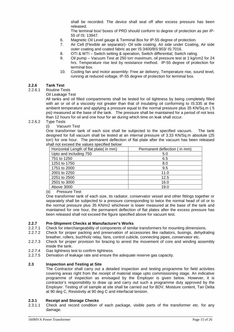
______________________________________________________________________________ 160MVA Power Transformer Page 15 of 26
shall be recorded. The device shall seal off after excess pressure has been released. The terminal box/ boxes of PRD should conform to degree of protection as per IP-55 of IS: 13947.
6. Magnetic Oil Level gauge & Terminal Box for IP-55 degree of protection. 7. Air Cell (Flexible air separator)- Oil side coating, Air side under Coating, Air side
outer coating and coated fabric as per IS:3400/BS:903/ IS:7016. 8. OTI & WTI – Switch setting & operation, Switch differential, Switch rating. 9. Oil pump – Vacuum Test at 250 torr maximum, oil pressure test at 1 kg/cm2 for 24
hrs. Temperature rise test by resistance method. IP-55 degree of protection for terminal box.
10. Cooling fan and motor assembly- Free air delivery, Temperature rise, sound level, running at reduced voltage, IP-55 degree of protection for terminal box.
2.2.6 Tank Test 2.2.6.1 Routine Tests
Oil Leakage Test All tanks and oil filled compartments shall be tested for oil tightness by being completely filled with air or oil of a viscosity not greater than that of insulating oil conforming to IS:335 at the ambient temperature and applying a pressure equal to the normal pressure plus 35 KN/Sq.m ( 5 psi) measured at the base of the tank. The pressure shall be maintained for a period of not less than 12 hours for oil and one hour for air during which time on leak shall occur.
2.2.6.2 Type Tests (i) Vacuum Test One transformer tank of each size shall be subjected to the specified vacuum. The tank designed for full vacuum shall be tested at an internal pressure of 3.33 KN/Sq.m absolute (25 torr) for one hour. The permanent deflection of flat plate after the vacuum has been released shall not exceed the values specified below:
Horizontal Length of flat plate( in mm) Permanent deflection ( in mm) Upto and including 750 5.0 751 to 1250 6.5 1251 to 1750 8.0 1751 to 2000 9.5 2001 to 2250 11.0 2251 to 2500 12.5 2501 to 3000 16.0 Above 3000 19.0
(ii) Pressure Test One transformer tank of each size, its radiator, conservator vessel and other fittings together or separately shall be subjected to a pressure corresponding to twice the normal head of oil or to the normal pressure plus 35 KN/m2 whichever is lower measured at the base of the tank and maintained for one hour, the permanent deflection of flat plates after the excess pressure has been released shall not exceed the figure specified above for vacuum test.
2.2.7 Pre-Shipment Checks at Manufacturer’s Works 2.2.7.1 Check for interchangeability of components of similar transformers for mounting dimensions. 2.2.7.2 Check for proper packing and preservation of accessories like radiators, busings, dehydrating
breather, rollers, buchholz relay, fans, control cubicle, connecting pipes, conservator etc. 2.2.7.3 Check for proper provision for bracing to arrest the movement of core and winding assembly
inside the tank. 2.2.7.4 Gas tightness test to confirm tightness. 2.2.7.5 Derivation of leakage rate and ensure the adequate reserve gas capacity.
2.3 Inspection and Testing at Site
The Contractor shall carry out a detailed inspection and testing programme for field activities covering areas right from the receipt of material stage upto commissioning stage. An indicative programme of inspection as envisaged by the Employer is given below. However, it is contractor’s responsibility to draw up and carry out such a programme duly approved by the Employer. Testing of oil sample at site shall be carried out for BDV, Moisture content, Tan Delta at 90 deg C, Resistivity at 90 deg C and interfacial tension.
2.3.1 Receipt and Storage Checks 2.3.1.1 Check and record condition of each package, visible parts of the transformer etc. for any
damage.
______________________________________________________________________________ 160MVA Power Transformer Page 16 of 26
2.3.1.2 Check and record the gas pressure in the transformer tank as well as in the gas cylinder. 2.3.1.3 Visual check for wedging of core and coils before filling up with oil and also check conditions of
core and winding in general. 2.3.1.4 Check and record reading of impact recorder at receipt and verify the allowable limits as per
manufacturer’s recommendations. 2.3.2 Installation Checks 2.3.2.1 Inspection and performance testing of accessories like tap changers, cooling fans, oil pumps etc. 2.3.2.2 (i) Check the direction of rotation of fans and pumps. (ii) Check the bearing lubrication. 2.3.2.3 Check whole assembly for tightness, general appearance etc. 2.3.2.4 Oil leakage test 2.3.2.5 Test on Oil Sample. 2.3.2.6 Capacitance and tan delta measurement of bushing before fixing/ connecting to the winding,
contractor shall furnish these values for site reference. 2.3.2.7 Leakage test on bushing before erection. 2.3.2.8 Measure and record the dew point of nitrogen in the main tank before assembly.
2.3.3 Commissioning Checks 2.3.3.1 Check the colour of silica gel in silica gel breather. 2.3.3.2 Check the oil level in the breather housing, conservator tanks, cooling system, condenser
bushing etc. 2.3.3.3 Check the bushing for conformity of connection to the lines etc. 2.3.3.4 Check for correct operation of all protection devices and alarms:
(i) Buchholz relay. (ii) Excessive winding temperature. (iii) Excessive oil temperature. (iv) Low oil flow. (v) Low oil level indication. (vi) Fan and pump failure protection.
2.3.3.5 Check for the adequate protection on the electric circuit supplying the accessories. 2.3.3.6 Check resistance of all windings on all steps of the tap changer. Insulation resistance
measurement for the following: (i) Control Wiring (ii) Cooling system motor and control (iii) Main windings (iv) Tap changer motor and control.
2.3.3.7 Check for cleanliness of the transformer and the surroundings. 2.3.3.8 Continuously observe the transformer operation at no load for 24 hours. 2.3.3.9 Gradually put the transformer on load, check and measure increase in temperature in relation to
the load and check the operation with respect to temperature rise and noise level etc. 2.3.3.10 Phase out and vector group test. 2.3.3.11 Ratio test on all taps. 2.3.3.12 Magnetizing current test. 2.3.3.13 Capacitance and Tan delta measurement of winding and busing after assembly of transformer. It
will provide a base data which would act as guideline for maintenance staff for subsequent condition monitoring of the transformer.
2.3.3.14 DGA of oil just before commissioning and after 24 hours energisation at site. 2.3.3.15 Frequency response analysis (FRA). 2.3.3.16 Contractor shall prepare a comprehensive commissioning report including all commissioning test
results and forward to Employer for future record.
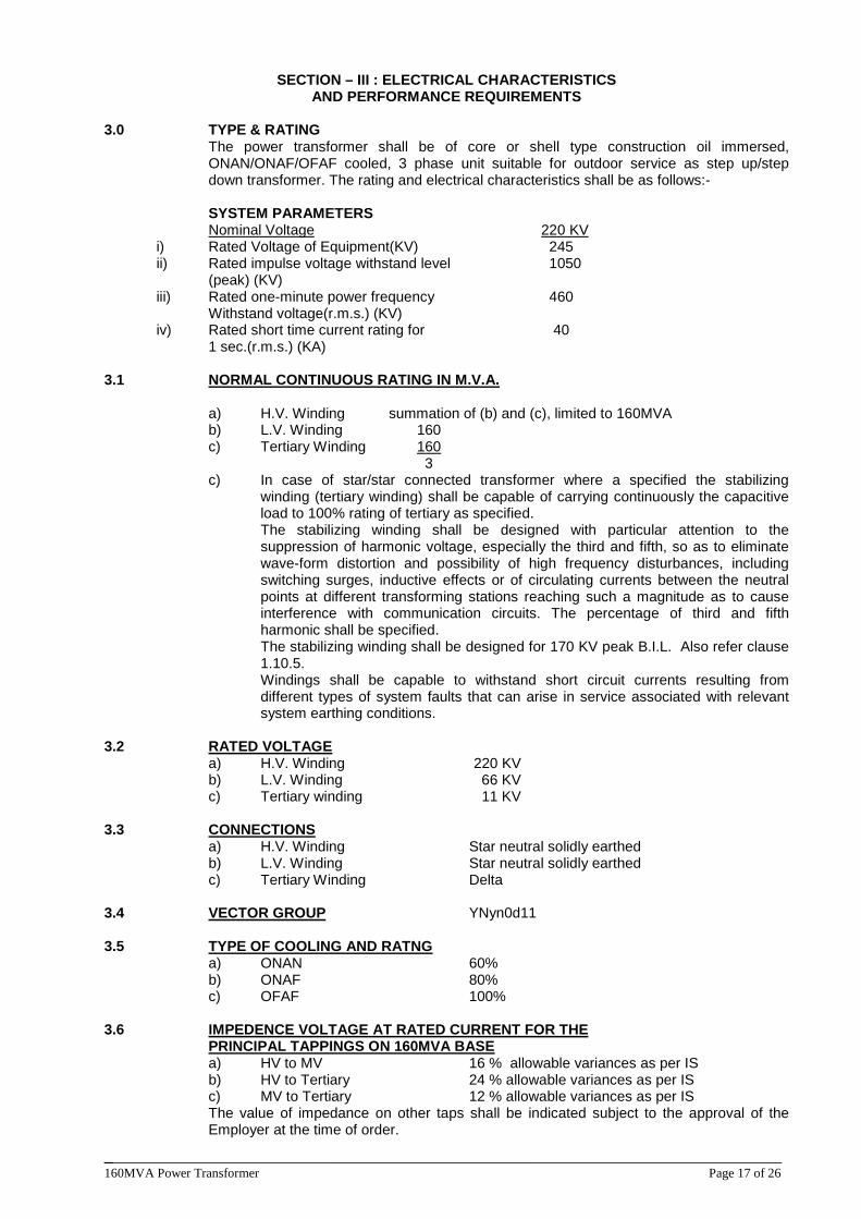
______________________________________________________________________________ 160MVA Power Transformer Page 17 of 26
SECTION – III : ELECTRICAL CHARACTERISTICS AND PERFORMANCE REQUIREMENTS
3.0 TYPE & RATING
The power transformer shall be of core or shell type construction oil immersed, ONAN/ONAF/OFAF cooled, 3 phase unit suitable for outdoor service as step up/step down transformer. The rating and electrical characteristics shall be as follows:-
SYSTEM PARAMETERS Nominal Voltage 220 KV
i) Rated Voltage of Equipment(KV) 245
ii) Rated impulse voltage withstand level 1050 (peak) (KV)
iii) Rated one-minute power frequency 460 Withstand voltage(r.m.s.) (KV)
iv) Rated short time current rating for 40 1 sec.(r.m.s.) (KA) 3.1
NORMAL CONTINUOUS RATING IN M.V.A.
a) H.V. Winding summation of (b) and (c), limited to 160MVA b) L.V. Winding 160 c) Tertiary Winding 3
160
c) In case of star/star connected transformer where a specified the stabilizing winding (tertiary winding) shall be capable of carrying continuously the capacitive load to 100% rating of tertiary as specified. The stabilizing winding shall be designed with particular attention to the suppression of harmonic voltage, especially the third and fifth, so as to eliminate wave-form distortion and possibility of high frequency disturbances, including switching surges, inductive effects or of circulating currents between the neutral points at different transforming stations reaching such a magnitude as to cause interference with communication circuits. The percentage of third and fifth harmonic shall be specified. The stabilizing winding shall be designed for 170 KV peak B.I.L. Also refer clause 1.10.5. Windings shall be capable to withstand short circuit currents resulting from different types of system faults that can arise in service associated with relevant system earthing conditions.
3.2 a) H.V. Winding 220 KV
RATED VOLTAGE
b) L.V. Winding 66 KV c) Tertiary winding 11 KV 3.3
a) H.V. Winding Star neutral solidly earthed CONNECTIONS
b) L.V. Winding Star neutral solidly earthed c) Tertiary Winding Delta
3.4 VECTOR GROUP
YNyn0d11
3.5 a) ONAN 60% TYPE OF COOLING AND RATNG
b) ONAF 80% c) OFAF 100%
3.6 IMPEDENCE VOLTAGE AT RATED CURRENT FOR THE
a) HV to MV 16 % allowable variances as per IS PRINCIPAL TAPPINGS ON 160MVA BASE
b) HV to Tertiary 24 % allowable variances as per IS c) MV to Tertiary 12 % allowable variances as per IS The value of impedance on other taps shall be indicated subject to the approval of the Employer at the time of order.
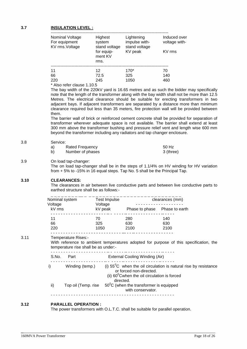
______________________________________________________________________________ 160MVA Power Transformer Page 18 of 26
3.7
------------------------------------------------------------------------------------- INSULATION LEVEL :
Nominal Voltage Highest Lightening Induced over For equipment system impulse with- voltage with- KV rms. Voltage stand voltage stand voltage for equip- KV peak KV rms ment KV rms. ------------------------------------------------------------------------------------- 11 12 170* 70 66 72.5 325 140 220 245 1050 460 * Also refer clause 1.10.5 The bay width of the 220kV yard is 16.65 metres and as such the bidder may specifically note that the length of the transformer along with the bay width shall not be more than 12.5 Metres. The electrical clearance should be suitable for erecting transformers in two adjacent bays. If adjacent transformers are separated by a distance more than minimum clearance required but less than 35 meters, fire protection wall will be provided between them. The barrier wall of brick or reinforced cement concrete shall be provided for separation of transformer wherever adequate space is not available. The barrier shall extend at least 300 mm above the transformer bushing and pressure relief vent and length wise 600 mm beyond the transformer including any radiators and tap changer enclosure.
3.8 Service: a) Rated Frequency 50 Hz b) Number of phases 3 (three) 3.9 On load tap-changer:
The on load tap-changer shall be in the steps of 1.1/4% on HV winding for HV variation from + 5% to -15% in 16 equal steps. Tap No. 5 shall be the Principal Tap.
3.10 CLEARANCES:
The clearances in air between live conductive parts and between live conductive parts to earthed structure shall be as follows:-
_ _ _ _ _ _ _ _ __ _ _ _ _ _ _ _ _ _ _ _ _ _ _ _ _ _ _ _ _ _ _ _ _ _ _ _ _ Nominal system Test Impulse clearances (mm) Voltage Voltage - - - - - - - - - - - - - - - - - - - kV rms kV peak Phase to phase Phase to earth - - - - - - - - - - - - - - - - - - - - - - -- - - - - - -- - - - - - - - - - - - - - -- - - - - 11 70 280 140 66 325 630 630 220 1050 2100 2100 - - - - - - - - - - - - - - - - - - - - - - - - - - - - --- - - -- - - - - - - - - - - - - - - - 3.11 Temperature Rises:-
With reference to ambient temperatures adopted for purpose of this specification, the temperature rise shall be as under:-
- - - - - - - - - - - - - - - - - - - - - - -- - - - - - -- - - - - - - - - - - - - - -- - - - - S.No. Part External Cooling Winding (Air) - - - - - - - - - - - - - - - - - - - - - -- - - - - - -- - - - - - - - - - - - - - -- - - - - - i) Winding (temp.) (i) 550
(ii) 60
C when the oil circulation is natural rise by resistance or forced non-directed.
0
directed. Cwhen the oil circulation is forced
ii) Top oil (Temp. rise 500
- - - - - - - - - - - - - - - - - - - - - - - - - - - - - - - - - - - - - - - - - - - - - - - - -
C (when the transformer is equipped with conservator.
3.12 PARALLEL OPERATION :
The power transformers with O.L.T.C. shall be suitable for parallel operation.
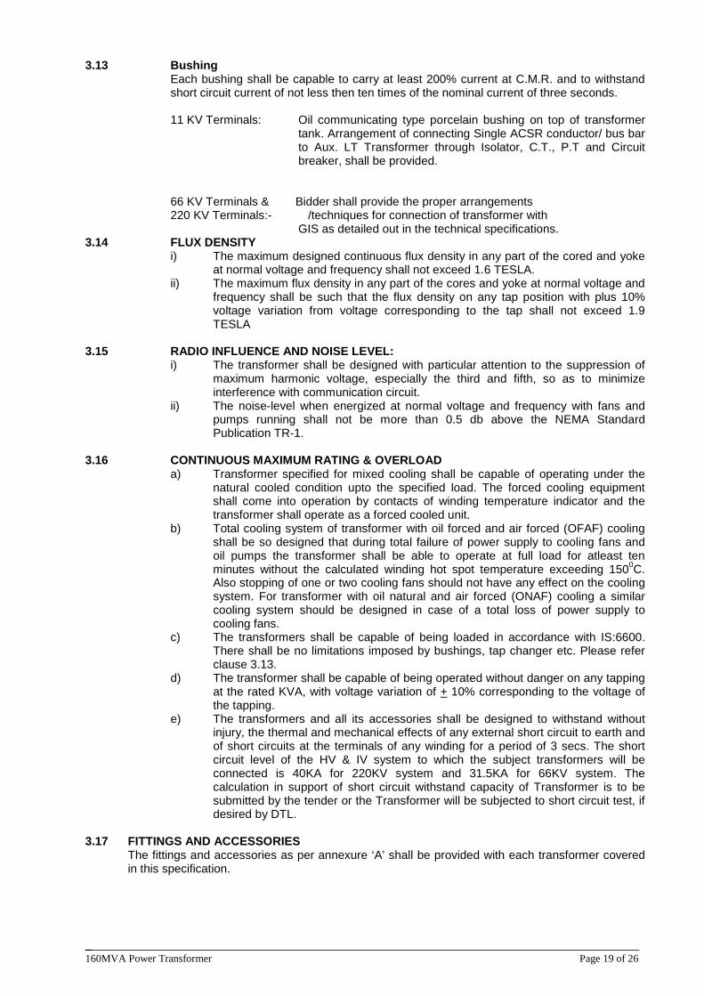
______________________________________________________________________________ 160MVA Power Transformer Page 19 of 26
3.13 Bushing Each bushing shall be capable to carry at least 200% current at C.M.R. and to withstand short circuit current of not less then ten times of the nominal current of three seconds.
11 KV Terminals: Oil communicating type porcelain bushing on top of transformer
tank. Arrangement of connecting Single ACSR conductor/ bus bar to Aux. LT Transformer through Isolator, C.T., P.T and Circuit breaker, shall be provided.
66 KV Terminals & Bidder shall provide the proper arrangements 220 KV Terminals:- /techniques for connection of transformer with GIS as detailed out in the technical specifications.
3.14 FLUX DENSITY i) The maximum designed continuous flux density in any part of the cored and yoke
at normal voltage and frequency shall not exceed 1.6 TESLA. ii) The maximum flux density in any part of the cores and yoke at normal voltage and
frequency shall be such that the flux density on any tap position with plus 10% voltage variation from voltage corresponding to the tap shall not exceed 1.9 TESLA
3.15 RADIO INFLUENCE AND NOISE LEVEL: i) The transformer shall be designed with particular attention to the suppression of
maximum harmonic voltage, especially the third and fifth, so as to minimize interference with communication circuit.
ii) The noise-level when energized at normal voltage and frequency with fans and pumps running shall not be more than 0.5 db above the NEMA Standard Publication TR-1.
3.16 CONTINUOUS MAXIMUM RATING & OVERLOAD a) Transformer specified for mixed cooling shall be capable of operating under the
natural cooled condition upto the specified load. The forced cooling equipment shall come into operation by contacts of winding temperature indicator and the transformer shall operate as a forced cooled unit.
b) Total cooling system of transformer with oil forced and air forced (OFAF) cooling shall be so designed that during total failure of power supply to cooling fans and oil pumps the transformer shall be able to operate at full load for atleast ten minutes without the calculated winding hot spot temperature exceeding 1500
c) The transformers shall be capable of being loaded in accordance with IS:6600. There shall be no limitations imposed by bushings, tap changer etc. Please refer clause 3.13.
C. Also stopping of one or two cooling fans should not have any effect on the cooling system. For transformer with oil natural and air forced (ONAF) cooling a similar cooling system should be designed in case of a total loss of power supply to cooling fans.
d) The transformer shall be capable of being operated without danger on any tapping at the rated KVA, with voltage variation of + 10% corresponding to the voltage of the tapping.
e) The transformers and all its accessories shall be designed to withstand without injury, the thermal and mechanical effects of any external short circuit to earth and of short circuits at the terminals of any winding for a period of 3 secs. The short circuit level of the HV & IV system to which the subject transformers will be connected is 40KA for 220KV system and 31.5KA for 66KV system. The calculation in support of short circuit withstand capacity of Transformer is to be submitted by the tender or the Transformer will be subjected to short circuit test, if desired by DTL.
3.17 FITTINGS AND ACCESSORIES
The fittings and accessories as per annexure ‘A’ shall be provided with each transformer covered in this specification.
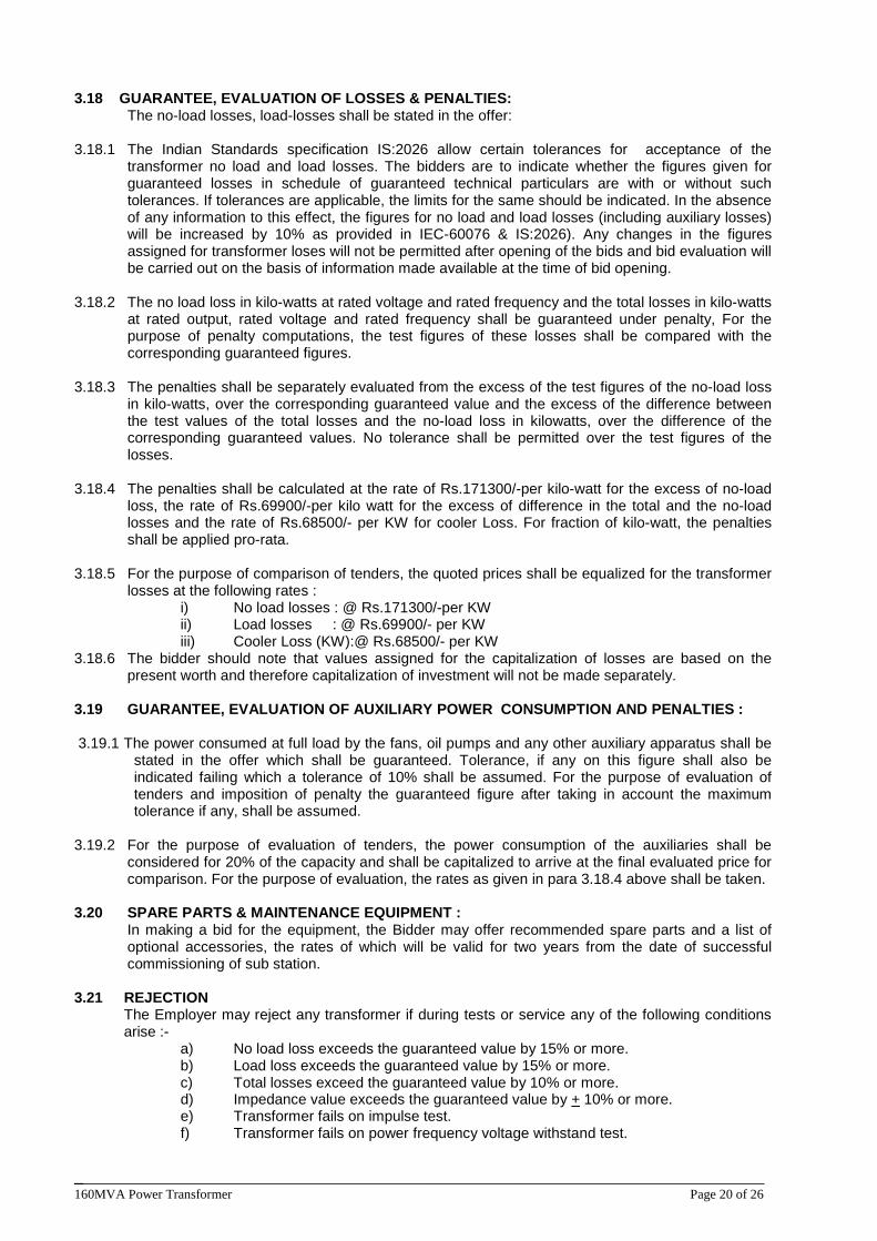
______________________________________________________________________________ 160MVA Power Transformer Page 20 of 26
3.18 GUARANTEE, EVALUATION OF LOSSES & PENALTIES: The no-load losses, load-losses shall be stated in the offer: 3.18.1 The Indian Standards specification IS:2026 allow certain tolerances for acceptance of the
transformer no load and load losses. The bidders are to indicate whether the figures given for guaranteed losses in schedule of guaranteed technical particulars are with or without such tolerances. If tolerances are applicable, the limits for the same should be indicated. In the absence of any information to this effect, the figures for no load and load losses (including auxiliary losses) will be increased by 10% as provided in IEC-60076 & IS:2026). Any changes in the figures assigned for transformer loses will not be permitted after opening of the bids and bid evaluation will be carried out on the basis of information made available at the time of bid opening.
3.18.2 The no load loss in kilo-watts at rated voltage and rated frequency and the total losses in kilo-watts at rated output, rated voltage and rated frequency shall be guaranteed under penalty, For the purpose of penalty computations, the test figures of these losses shall be compared with the corresponding guaranteed figures.
3.18.3 The penalties shall be separately evaluated from the excess of the test figures of the no-load loss
in kilo-watts, over the corresponding guaranteed value and the excess of the difference between the test values of the total losses and the no-load loss in kilowatts, over the difference of the corresponding guaranteed values. No tolerance shall be permitted over the test figures of the losses.
3.18.4 The penalties shall be calculated at the rate of Rs.171300/-per kilo-watt for the excess of no-load
loss, the rate of Rs.69900/-per kilo watt for the excess of difference in the total and the no-load losses and the rate of Rs.68500/- per KW for cooler Loss. For fraction of kilo-watt, the penalties shall be applied pro-rata.
3.18.5 For the purpose of comparison of tenders, the quoted prices shall be equalized for the transformer
losses at the following rates : i) No load losses : @ Rs.171300/-per KW ii) Load losses : @ Rs.69900/- per KW iii) Cooler Loss (KW):@ Rs.68500/- per KW
3.18.6 The bidder should note that values assigned for the capitalization of losses are based on the present worth and therefore capitalization of investment will not be made separately.
3.19 GUARANTEE, EVALUATION OF AUXILIARY POWER CONSUMPTION AND PENALTIES :
3.19.1 The power consumed at full load by the fans, oil pumps and any other auxiliary apparatus shall be
stated in the offer which shall be guaranteed. Tolerance, if any on this figure shall also be indicated failing which a tolerance of 10% shall be assumed. For the purpose of evaluation of tenders and imposition of penalty the guaranteed figure after taking in account the maximum tolerance if any, shall be assumed.
3.19.2 For the purpose of evaluation of tenders, the power consumption of the auxiliaries shall be
considered for 20% of the capacity and shall be capitalized to arrive at the final evaluated price for comparison. For the purpose of evaluation, the rates as given in para 3.18.4 above shall be taken.
3.20 SPARE PARTS & MAINTENANCE EQUIPMENT : In making a bid for the equipment, the Bidder may offer recommended spare parts and a list of
optional accessories, the rates of which will be valid for two years from the date of successful commissioning of sub station.
3.21 REJECTION
The Employer may reject any transformer if during tests or service any of the following conditions arise :-
a) No load loss exceeds the guaranteed value by 15% or more. b) Load loss exceeds the guaranteed value by 15% or more. c) Total losses exceed the guaranteed value by 10% or more. d) Impedance value exceeds the guaranteed value by + 10% or more. e) Transformer fails on impulse test. f) Transformer fails on power frequency voltage withstand test.
______________________________________________________________________________ 160MVA Power Transformer Page 21 of 26
g) Transformer is proved to have been manufactured not in accordance with the specification.
3.22 STANDARD
The transformer shall generally conform to the I.E.C./ I.S. specification and CBIP recommendations except for certain technical variations as per specification.
3.23 Transformer shall be provided with gas collecting device.
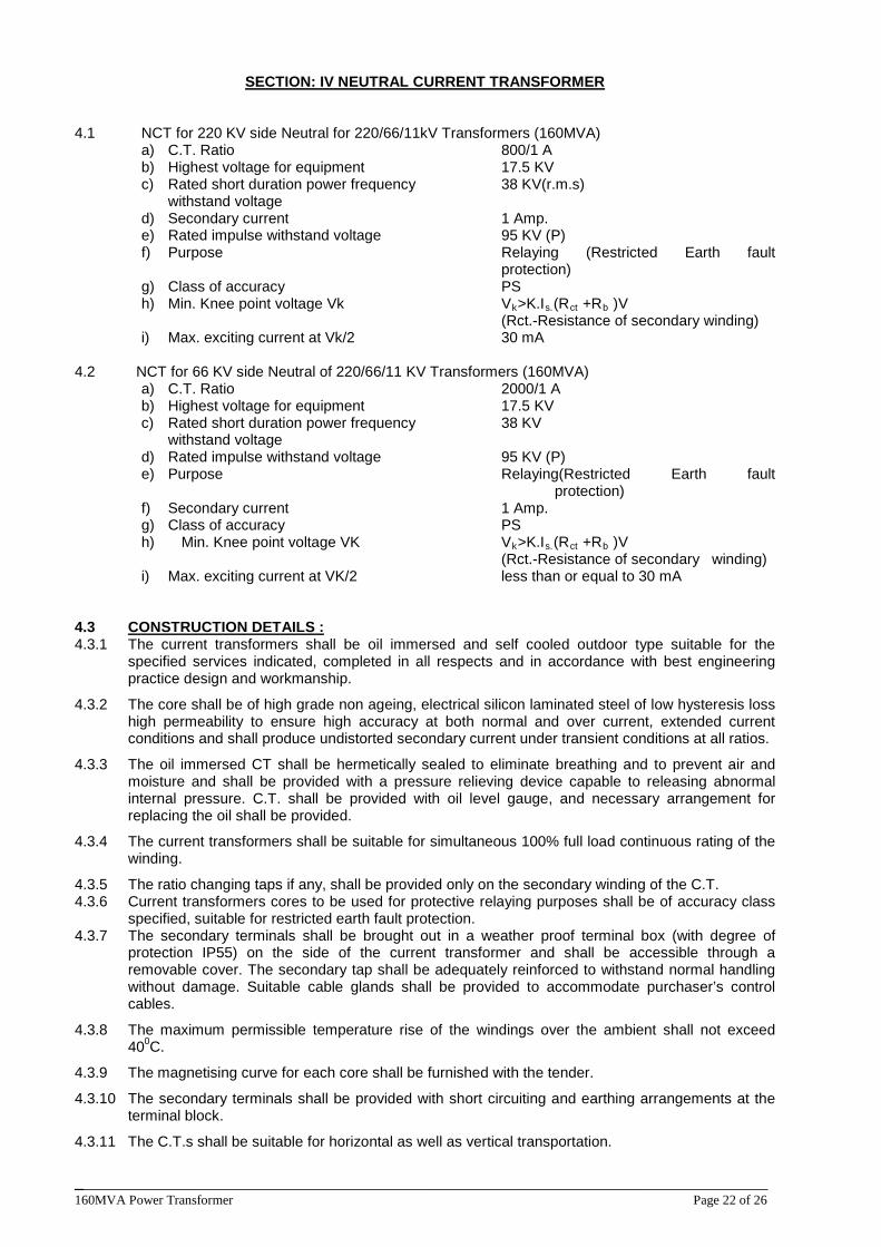
______________________________________________________________________________ 160MVA Power Transformer Page 22 of 26
SECTION: IV NEUTRAL CURRENT TRANSFORMER
4.1 NCT for 220 KV side Neutral for 220/66/11kV Transformers (160MVA) a) C.T. Ratio 800/1 A b) Highest voltage for equipment 17.5 KV c) Rated short duration power frequency 38 KV(r.m.s) withstand voltage d) Secondary current 1 Amp. e) Rated impulse withstand voltage 95 KV (P) f) Purpose Relaying (Restricted Earth fault
protection) g) Class of accuracy PS h) Min. Knee point voltage Vk Vk>K.Is.(Rct +Rb
(Rct.-Resistance of secondary winding) )V
i) Max. exciting current at Vk/2 30 mA 4.2 NCT for 66 KV side Neutral of 220/66/11 KV Transformers (160MVA) a) C.T. Ratio 2000/1 A b) Highest voltage for equipment 17.5 KV c) Rated short duration power frequency 38 KV withstand voltage d) Rated impulse withstand voltage 95 KV (P) e) Purpose Relaying(Restricted Earth fault
protection) f) Secondary current 1 Amp. g) Class of accuracy PS
h) Min. Knee point voltage VK Vk>K.Is.(Rct +Rb (Rct.-Resistance of secondary winding)
)V
i) Max. exciting current at VK/2 less than or equal to 30 mA
4.3 4.3.1 The current transformers shall be oil immersed and self cooled outdoor type suitable for the
specified services indicated, completed in all respects and in accordance with best engineering practice design and workmanship.
CONSTRUCTION DETAILS :
4.3.2 The core shall be of high grade non ageing, electrical silicon laminated steel of low hysteresis loss high permeability to ensure high accuracy at both normal and over current, extended current conditions and shall produce undistorted secondary current under transient conditions at all ratios.
4.3.3 The oil immersed CT shall be hermetically sealed to eliminate breathing and to prevent air and moisture and shall be provided with a pressure relieving device capable to releasing abnormal internal pressure. C.T. shall be provided with oil level gauge, and necessary arrangement for replacing the oil shall be provided.
4.3.4 The current transformers shall be suitable for simultaneous 100% full load continuous rating of the winding.
4.3.5 The ratio changing taps if any, shall be provided only on the secondary winding of the C.T. 4.3.6 Current transformers cores to be used for protective relaying purposes shall be of accuracy class
specified, suitable for restricted earth fault protection. 4.3.7 The secondary terminals shall be brought out in a weather proof terminal box (with degree of
protection IP55) on the side of the current transformer and shall be accessible through a removable cover. The secondary tap shall be adequately reinforced to withstand normal handling without damage. Suitable cable glands shall be provided to accommodate purchaser’s control cables.
4.3.8 The maximum permissible temperature rise of the windings over the ambient shall not exceed 400
4.3.9 The magnetising curve for each core shall be furnished with the tender.
C.
4.3.10 The secondary terminals shall be provided with short circuiting and earthing arrangements at the terminal block.
4.3.11 The C.T.s shall be suitable for horizontal as well as vertical transportation.
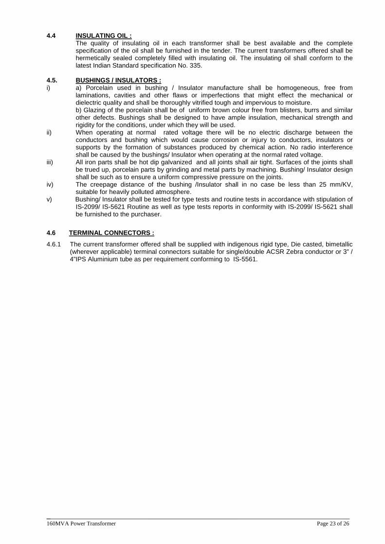
______________________________________________________________________________ 160MVA Power Transformer Page 23 of 26
4.4 The quality of insulating oil in each transformer shall be best available and the complete
specification of the oil shall be furnished in the tender. The current transformers offered shall be hermetically sealed completely filled with insulating oil. The insulating oil shall conform to the latest Indian Standard specification No. 335.
INSULATING OIL :
4.5. i) a) Porcelain used in bushing / Insulator manufacture shall be homogeneous, free from
laminations, cavities and other flaws or imperfections that might effect the mechanical or dielectric quality and shall be thoroughly vitrified tough and impervious to moisture.
BUSHINGS / INSULATORS :
b) Glazing of the porcelain shall be of uniform brown colour free from blisters, burrs and similar other defects. Bushings shall be designed to have ample insulation, mechanical strength and rigidity for the conditions, under which they will be used.
ii) When operating at normal rated voltage there will be no electric discharge between the conductors and bushing which would cause corrosion or injury to conductors, insulators or supports by the formation of substances produced by chemical action. No radio interference shall be caused by the bushings/ Insulator when operating at the normal rated voltage.
iii) All iron parts shall be hot dip galvanized and all joints shall air tight. Surfaces of the joints shall be trued up, porcelain parts by grinding and metal parts by machining. Bushing/ Insulator design shall be such as to ensure a uniform compressive pressure on the joints.
iv) The creepage distance of the bushing /Insulator shall in no case be less than 25 mm/KV, suitable for heavily polluted atmosphere.
v) Bushing/ Insulator shall be tested for type tests and routine tests in accordance with stipulation of IS-2099/ IS-5621 Routine as well as type tests reports in conformity with IS-2099/ IS-5621 shall be furnished to the purchaser.
4.6
4.6.1 The current transformer offered shall be supplied with indigenous rigid type, Die casted, bimetallic (wherever applicable) terminal connectors suitable for single/double ACSR Zebra conductor or 3” / 4”IPS Aluminium tube as per requirement conforming to IS-5561.
TERMINAL CONNECTORS :
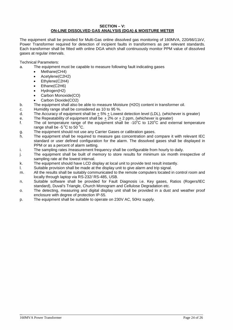
______________________________________________________________________________ 160MVA Power Transformer Page 24 of 26
SECTION – V:
ON-LINE DISSOLVED GAS ANALYSIS (DGA) & MOISTURE METER
The equipment shall be provided for Multi-Gas online dissolved gas monitoring of 160MVA, 220/66/11kV, Power Transformer required for detection of incipient faults in transformers as per relevant standards. Each transformer shall be fitted with online DGA which shall continuously monitor PPM value of dissolved gases at regular intervals. Technical Parameters: a. The equipment must be capable to measure following fault indicating gases
• Methane(CH4) • Acetylene(C2H2) • Ethylene(C2H4) • Ethane(C2H6) • Hydrogen(H2) • Carbon Monoxide(CO) • Carbon Dioxide(CO2)
b. The equipment shall also be able to measure Moisture (H2O) content in transformer oil. c. Humidity range shall be considered as 10 to 95 %. d. The Accuracy of equipment shall be + 5% + Lowest detection level (LDL), (whichever is greater) e. The Repeatability of equipment shall be + 2% or + 2 ppm, (whichever is greater) f. The oil temperature range of the equipment shall be -10oC to 120oC and external temperature
range shall be -5 oC to 50 og. The equipment should not use any Carrier Gases or calibration gases.
C.
h. The equipment shall be required to measure gas concentration and compare it with relevant IEC standard or user defined configuration for the alarm. The dissolved gases shall be displayed in PPM or as a percent of alarm setting.
i. The sampling rates /measurement frequency shall be configurable from hourly to daily. j. The equipment shall be built of memory to store results for minimum six month irrespective of
sampling rate at the lowest interval. k. The equipment should have LCD display at local unit to provide test result instantly. l. Suitable provision shall be made at the display unit to give alarm and trip signal. m. All the results shall be suitably communicated to the remote computers located in control room and
locally through laptop via RS-232/ RS-485, USB. n. Suitable software shall be provided for Fault Diagnosis i.e. Key gases, Ratios (Rogers/IEC
standard), Duval’s Triangle, Church Monogram and Cellulose Degradation etc. o. The detecting, measuring and digital display unit shall be provided in a dust and weather proof
enclosure with degree of protection IP-55. p. The equipment shall be suitable to operate on 230V AC, 50Hz supply.
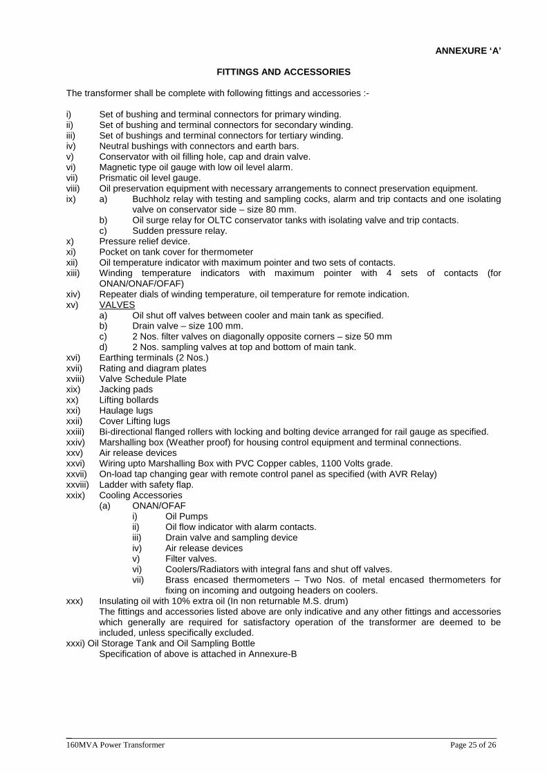
______________________________________________________________________________ 160MVA Power Transformer Page 25 of 26
ANNEXURE ‘A’
FITTINGS AND ACCESSORIES
The transformer shall be complete with following fittings and accessories :- i) Set of bushing and terminal connectors for primary winding. ii) Set of bushing and terminal connectors for secondary winding. iii) Set of bushings and terminal connectors for tertiary winding. iv) Neutral bushings with connectors and earth bars. v) Conservator with oil filling hole, cap and drain valve. vi) Magnetic type oil gauge with low oil level alarm. vii) Prismatic oil level gauge. viii) Oil preservation equipment with necessary arrangements to connect preservation equipment. ix) a) Buchholz relay with testing and sampling cocks, alarm and trip contacts and one isolating
valve on conservator side – size 80 mm. b) Oil surge relay for OLTC conservator tanks with isolating valve and trip contacts.
c) Sudden pressure relay. x) Pressure relief device. xi) Pocket on tank cover for thermometer xii) Oil temperature indicator with maximum pointer and two sets of contacts. xiii) Winding temperature indicators with maximum pointer with 4 sets of contacts (for
ONAN/ONAF/OFAF) xiv) Repeater dials of winding temperature, oil temperature for remote indication. xv) a) Oil shut off valves between cooler and main tank as specified.
VALVES
b) Drain valve – size 100 mm. c) 2 Nos. filter valves on diagonally opposite corners – size 50 mm d) 2 Nos. sampling valves at top and bottom of main tank. xvi) Earthing terminals (2 Nos.) xvii) Rating and diagram plates xviii) Valve Schedule Plate xix) Jacking pads xx) Lifting bollards xxi) Haulage lugs xxii) Cover Lifting lugs xxiii) Bi-directional flanged rollers with locking and bolting device arranged for rail gauge as specified. xxiv) Marshalling box (Weather proof) for housing control equipment and terminal connections. xxv) Air release devices xxvi) Wiring upto Marshalling Box with PVC Copper cables, 1100 Volts grade. xxvii) On-load tap changing gear with remote control panel as specified (with AVR Relay) xxviii) Ladder with safety flap. xxix) Cooling Accessories (a) ONAN/OFAF i) Oil Pumps ii) Oil flow indicator with alarm contacts. iii) Drain valve and sampling device iv) Air release devices
v) Filter valves. vi) Coolers/Radiators with integral fans and shut off valves. vii) Brass encased thermometers – Two Nos. of metal encased thermometers for
fixing on incoming and outgoing headers on coolers. xxx) Insulating oil with 10% extra oil (In non returnable M.S. drum)
The fittings and accessories listed above are only indicative and any other fittings and accessories which generally are required for satisfactory operation of the transformer are deemed to be included, unless specifically excluded.
xxxi) Oil Storage Tank and Oil Sampling Bottle Specification of above is attached in Annexure-B
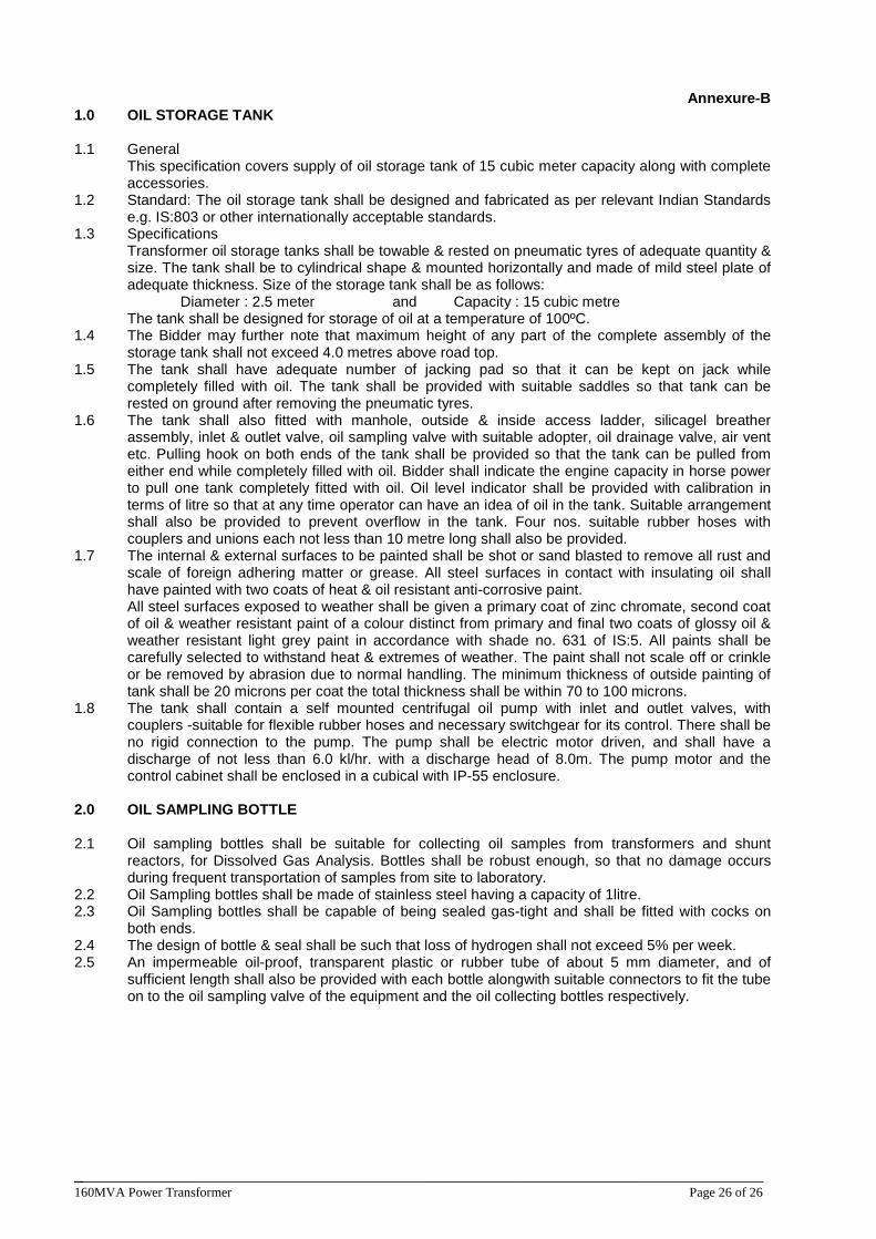
______________________________________________________________________________ 160MVA Power Transformer Page 26 of 26
Annexure-B
1.0 OIL STORAGE TANK 1.1 General
This specification covers supply of oil storage tank of 15 cubic meter capacity along with complete accessories.
1.2 Standard: The oil storage tank shall be designed and fabricated as per relevant Indian Standards e.g. IS:803 or other internationally acceptable standards.
1.3 Specifications Transformer oil storage tanks shall be towable & rested on pneumatic tyres of adequate quantity & size. The tank shall be to cylindrical shape & mounted horizontally and made of mild steel plate of adequate thickness. Size of the storage tank shall be as follows:
Diameter : 2.5 meter and Capacity : 15 cubic metre The tank shall be designed for storage of oil at a temperature of 100ºC.
1.4 The Bidder may further note that maximum height of any part of the complete assembly of the storage tank shall not exceed 4.0 metres above road top.
1.5 The tank shall have adequate number of jacking pad so that it can be kept on jack while completely filled with oil. The tank shall be provided with suitable saddles so that tank can be rested on ground after removing the pneumatic tyres.
1.6 The tank shall also fitted with manhole, outside & inside access ladder, silicagel breather assembly, inlet & outlet valve, oil sampling valve with suitable adopter, oil drainage valve, air vent etc. Pulling hook on both ends of the tank shall be provided so that the tank can be pulled from either end while completely filled with oil. Bidder shall indicate the engine capacity in horse power to pull one tank completely fitted with oil. Oil level indicator shall be provided with calibration in terms of litre so that at any time operator can have an idea of oil in the tank. Suitable arrangement shall also be provided to prevent overflow in the tank. Four nos. suitable rubber hoses with couplers and unions each not less than 10 metre long shall also be provided.
1.7 The internal & external surfaces to be painted shall be shot or sand blasted to remove all rust and scale of foreign adhering matter or grease. All steel surfaces in contact with insulating oil shall have painted with two coats of heat & oil resistant anti-corrosive paint. All steel surfaces exposed to weather shall be given a primary coat of zinc chromate, second coat of oil & weather resistant paint of a colour distinct from primary and final two coats of glossy oil & weather resistant light grey paint in accordance with shade no. 631 of IS:5. All paints shall be carefully selected to withstand heat & extremes of weather. The paint shall not scale off or crinkle or be removed by abrasion due to normal handling. The minimum thickness of outside painting of tank shall be 20 microns per coat the total thickness shall be within 70 to 100 microns.
1.8 The tank shall contain a self mounted centrifugal oil pump with inlet and outlet valves, with couplers -suitable for flexible rubber hoses and necessary switchgear for its control. There shall be no rigid connection to the pump. The pump shall be electric motor driven, and shall have a discharge of not less than 6.0 kl/hr. with a discharge head of 8.0m. The pump motor and the control cabinet shall be enclosed in a cubical with IP-55 enclosure.
2.0 OIL SAMPLING BOTTLE 2.1 Oil sampling bottles shall be suitable for collecting oil samples from transformers and shunt
reactors, for Dissolved Gas Analysis. Bottles shall be robust enough, so that no damage occurs during frequent transportation of samples from site to laboratory.
2.2 Oil Sampling bottles shall be made of stainless steel having a capacity of 1litre. 2.3 Oil Sampling bottles shall be capable of being sealed gas-tight and shall be fitted with cocks on
both ends. 2.4 The design of bottle & seal shall be such that loss of hydrogen shall not exceed 5% per week. 2.5 An impermeable oil-proof, transparent plastic or rubber tube of about 5 mm diameter, and of
sufficient length shall also be provided with each bottle alongwith suitable connectors to fit the tube on to the oil sampling valve of the equipment and the oil collecting bottles respectively.
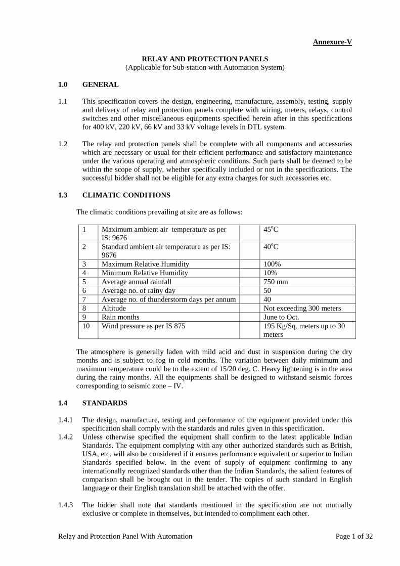
Relay and Protection Panel With Automation Page 1 of 32
Annexure-V
RELAY AND PROTECTION PANELS (Applicable for Sub-station with Automation System)
1.0 GENERAL
1.1 This specification covers the design, engineering, manufacture, assembly, testing, supply
and delivery of relay and protection panels complete with wiring, meters, relays, control switches and other miscellaneous equipments specified herein after in this specifications for 400 kV, 220 kV, 66 kV and 33 kV voltage levels in DTL system.
1.2 The relay and protection panels shall be complete with all components and accessories which are necessary or usual for their efficient performance and satisfactory maintenance under the various operating and atmospheric conditions. Such parts shall be deemed to be within the scope of supply, whether specifically included or not in the specifications. The successful bidder shall not be eligible for any extra charges for such accessories etc.
1.3 CLIMATIC CONDITIONS
The climatic conditions prevailing at site are as follows:
1 Maximum ambient air temperature as per IS: 9676
45oC
2 Standard ambient air temperature as per IS: 9676
40oC
3 Maximum Relative Humidity 100% 4 Minimum Relative Humidity 10% 5 Average annual rainfall 750 mm 6 Average no. of rainy day 50 7 Average no. of thunderstorm days per annum 40 8 Altitude Not exceeding 300 meters 9 Rain months June to Oct. 10 Wind pressure as per IS 875 195 Kg/Sq. meters up to 30
meters
The atmosphere is generally laden with mild acid and dust in suspension during the dry months and is subject to fog in cold months. The variation between daily minimum and maximum temperature could be to the extent of 15/20 deg. C. Heavy lightening is in the area during the rainy months. All the equipments shall be designed to withstand seismic forces corresponding to seismic zone – IV.
1.4 STANDARDS 1.4.1 The design, manufacture, testing and performance of the equipment provided under this
specification shall comply with the standards and rules given in this specification. 1.4.2 Unless otherwise specified the equipment shall confirm to the latest applicable Indian
Standards. The equipment complying with any other authorized standards such as British, USA, etc. will also be considered if it ensures performance equivalent or superior to Indian Standards specified below. In the event of supply of equipment confirming to any internationally recognized standards other than the Indian Standards, the salient features of comparison shall be brought out in the tender. The copies of such standard in English language or their English translation shall be attached with the offer.
1.4.3 The bidder shall note that standards mentioned in the specification are not mutually exclusive or complete in themselves, but intended to compliment each other.
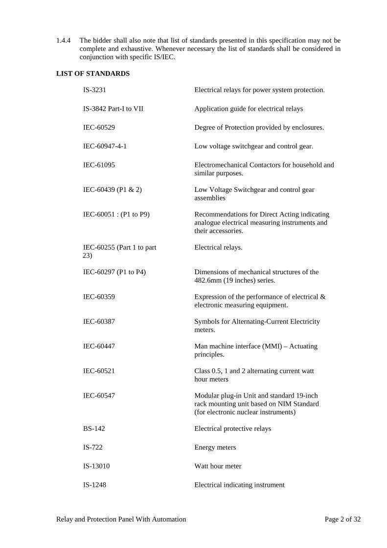
Relay and Protection Panel With Automation Page 2 of 32
1.4.4 The bidder shall also note that list of standards presented in this specification may not be complete and exhaustive. Whenever necessary the list of standards shall be considered in conjunction with specific IS/IEC.
LIST OF STANDARDS
IS-3231 Electrical relays for power system protection.
IS-3842 Part-I to VII Application guide for electrical relays
IEC-60529
Degree of Protection provided by enclosures.
IEC-60947-4-1
Low voltage switchgear and control gear.
IEC-61095
Electromechanical Contactors for household and similar purposes.
IEC-60439 (P1 & 2)
Low Voltage Switchgear and control gear assemblies
IEC-60051 : (P1 to P9)
Recommendations for Direct Acting indicating analogue electrical measuring instruments and their accessories.
IEC-60255 (Part 1 to part 23)
Electrical relays.
IEC-60297 (P1 to P4)
Dimensions of mechanical structures of the 482.6mm (19 inches) series.
IEC-60359
Expression of the performance of electrical & electronic measuring equipment.
IEC-60387
Symbols for Alternating-Current Electricity meters.
IEC-60447
Man machine interface (MMI) – Actuating principles.
IEC-60521
Class 0.5, 1 and 2 alternating current watt hour meters
IEC-60547
Modular plug-in Unit and standard 19-inch rack mounting unit based on NIM Standard (for electronic nuclear instruments)
BS-142 Electrical protective relays
IS-722 Energy meters
IS-13010 Watt hour meter
IS-1248 Electrical indicating instrument
Relay and Protection Panel With Automation Page 3 of 32
IS-6875 Control switches
IEC-337 and 3371 Control switches LV switching device for control and auxiliary circuits
IS-2605 Auxiliary current transformers
IS-3165 Auxiliary potential transformers
IS-1554 part-I PVC insulated cables up to & including 1100V.
IS-2208 HRC cartridge fuses links up to 650V.
IS-8828 MCB’s
IS-2516 Circuit breaker
2. CONSTRUCTIONAL FEATURES
2.1 Simplex panel shall consist of a vertical front panel with equipment mounted thereon and having wiring access from front for control & relay panels. In case of panel having width more than 800mm, double leaf-doors shall be provided. Doors shall have handles with either built-in locking facility or will be provided with pad-lock.
2.2 Relay panels shall be of simplex type design as indicated. It is the responsibility of the Contractor to ensure that the equipment specified and such unspecified complementary equipment required for completeness of the protective/control schemes is properly accommodated in the panels without congestion and if necessary, provide panels with larger dimensions. No price increase at a later date on this account shall be allowed. However, the width of panels that are being offered to be placed in control rooms, should be in conformity with the space availability in the control room.
2.3 Panels shall be completely metal enclosed and shall be dust, moisture and vermin proof. The enclosure shall provide a degree of protection not less than IP-42.
2.4 Panels shall be free standing, floor mounting type and shall comprise structural frames completely enclosed with specially selected smooth finished, cold rolled sheet steel of thickness not less than 3 mm for weight bearing members of the panels such as base frame, front sheet and door frames, and 2.0 mm for sides, door, top and bottom portions. There shall be sufficient reinforcement to provide level transportation and installation.
2.5 All doors, removable covers and panels shall be gasketed all around with synthetic rubber gaskets Neoprene/EPDM generally conforming with provision of IS 11149. However, XLPE gaskets can also be used for fixing protective glass doors. Ventilating louvers, if provided shall have screens and filters. The screens shall be made of either brass or GI wire mesh.
2.6 Design, materials selection and workmanship shall be such as to result in neat appearance, inside and outside with no welds, rivets or bolt head apparent from outside, with all exterior surfaces tune and smooth.
2.7 Panels shall have base frame with smooth bearing surface, which shall be fixed on the embedded foundation channels/insert plates. Anti vibration strips made of shock absorbing materials which shall be supplied by the contractor, shall be placed
Relay and Protection Panel With Automation Page 4 of 32
between panel & base frame.
2.8 Cable entries to the panel shall be from the bottom. The bottom plate of the panels shall be fitted with removable gland plates of adequate size for fixing the cable gland. Necessary number of cable glands made of brass (electroplated) of size to suit purchaser's external cables to the panels shall be supplied. Cable glands shall be screw type and made of brass and shall be suitable for PVC armoured cable. Cable gland plate fitted on the bottom of the panel shall be connected to earthing of the panel/station through a flexible braided copper conductor rigidly.
2.9 Relay panels of modern modular construction would also be acceptable.
2.10 Synchronising sockets shall be provided on panel wherever applicable. 3.0 MOUNTING 3.1 All equipment on and in panels shall be mounted and completely wired to the
terminal blocks ready for external connections. The equipment on front of panel shall be mounted flush. No equipment shall be mounted on the doors.
3.2 Equipment shall be mounted such that removal and replacement can be accomplished individually without interruption of service to adjacent devices and are readily accessible without use of special tools. Terminal marking on the equipment shall be clearly visible.
3.3 The Contractor shall carry out cut out, mounting and wiring of the free issue items supplied by others which are to be mounted in his panel in accordance with the corresponding equipment manufacturer's drawings. Cut outs if any, provided for future mounting of equipment shall be properly blanked off with blanking plate.
3.4 The centre lines of switches, push buttons and indicating lamps shall be not less than750mm from the bottom of the panel. The centre lines of relays, meters and recorders shall be not less than 450mm from the bottom of the panel.
3.5 The centre lines of switches, push buttons and indicating lamps shall be matched to give a neat and uniform appearance. Like wise the top lines of all meters, relays and recorders etc. shall be matched.
3.6 No equipment shall be mounted on the doors.
3.7 All equipment connections and cabling shall be designed and arranged to minimize the risk of fire and damage which may be caused by fire.
3.8 Provision shall be made in the panel for earthing the panels and mountings.
4.0 PANEL INTERNAL WIRING 4.1 Panels shall be supplied complete with interconnecting wiring provided between all
electrical devices mounted and wired in the panels and between the devices and terminal blocks for the devices to be connected to equipment outside the panels. When panels are arranged to be located adjacent to each other all inter panel wiring and connections between the panels shall be furnished and the wiring shall be carried out internally.
4.2 All wiring shall be carried out with 1100V grade, single core, stranded copper conductor wires with PVC insulation and shall be FRLS type. The minimum size of the multi-stranded copper conductor used for internal wiring shall be as follows:
Relay and Protection Panel With Automation Page 5 of 32
• All circuits except current transformer circuits and voltage transformer circuits – one 1.5mm sq. per lead.
• All current transformer circuits one 2.5 sq.mm lead. • Voltage transformer circuit (for energy meters): Two 2.5 mm sq. per
lead.
4.3 All internal wiring shall be securely supported, neatly arranged, readily accessible and connected to equipment terminals and terminal blocks. Wiring gutters & troughs shall be used for this purpose where necessary, while terminating wiring at equipment/terminal blocks the wiring shall be securely bunched so that the position of each individual connection wire does not get disturbed when disconnected from equipment terminals.
4.4 Auxiliary bus wiring for AC and DC supplies, voltage transformer circuits, annunciation circuits and other common services shall be provided near the top of the panels running throughout the entire length of the panels.
4.5 Wire termination shall be made with solder less crimping type and tinned copper lugs, which firmly grip the conductor. Insulated sleeves shall be provided at all the wire terminations. Engraved core identification plastic ferrules marked to correspond with panel wiring diagram shall be fitted at both ends of each wire. Ferrules shall fit tightly on the wire and shall not fall off when the wire is disconnected from terminal blocks. All wires directly connected to trip circuit breaker or device shall be distinguished by the addition of red coloured unlettered ferrule.
4.6 Longitudinal troughs extending throughout the full length of the panel shall be preferred for inter panel wiring. Inter-connections to adjacent panel shall be brought out to a separate set of terminal blocks located near the slots of holes meant for taking the inter-connecting wires.
4.7 Contractor shall be solely responsible for the completeness and correctness of the internal wiring and for the proper functioning of the connected equipments.
4.8 The control scheme shall incorporate necessary isolating device for easy testing and isolation of faults in the control and signaling circuits.
4.9 The colour coding for wiring inside the panel shall be as follows:
a) Earth: Green b) Neutral: Black c) Phases: Red, Yellow, Blue
5.0 TERMINAL BLOCKS 5.1 All internal wiring to be connected to external equipment shall terminate on terminal
blocks. Terminal blocks shall be 1100 V grade and have 10 Amps. Continuous rating, moulded piece, complete with insulated barriers, stud type terminals, washers, nuts and lock nuts. Markings on the terminal blocks shall correspond to wire number and terminal numbers on the wiring diagrams. All terminal blocks shall have shrouding with transparent unbreakable material.
5.2 Disconnecting type terminal blocks for current transformer and voltage transformer secondary leads shall be provided. Also current transformer secondary leads shall be provided with short circuiting and earthling facilities.
5.3 Terminal blocks shall be fully enclosed with easily removable covers and made of moulded non-inflammable plastic material. The terminal block shall have marking strips and all terminals shall be clearly marked with identification number or letters to facilitate
Relay and Protection Panel With Automation Page 6 of 32
connection to the external wiring.
5.4 At least 20% spare terminals shall be provided on each panel and these spare terminals shall be uniformly distributed on all terminal blocks.
5.5 Unless otherwise specified, terminal blocks shall be suitable for connecting the following conductors of external cable on each side.
• All CT & PT circuits: minimum of two of 2.5mm Sq. copper. • All other circuits: minimum of one of 2.5mm Sq. Copper.
5.6 There shall be a minimum clearance of 250mm between the first row of terminal blocks
and the associated cable gland plate or panel side wall. Also the clearance between two rows of terminal blocks edges shall be minimum of 150mm.
5.7 Arrangement of the terminal block assemblies and the wiring channel within the enclosure shall be such that a row of terminal blocks is run in parallel and close proximity along each side of the wiring-duct to provide for convenient attachment of internal panel wiring. The side of the terminal block opposite the wiring duct shall be reserved for the Owner's external cable connections. All adjacent terminal blocks shall also share this field wiring corridor. All wiring shall be provided with adequate support inside the panels to hold them firmly and to enable free and flexible termination without causing strain on terminals.
5.8 The number and sizes of the Owner's multi core incoming external cables will be furnished to the Contractor after placement of the order. All necessary cable terminating accessories such as gland plates, supporting clamps & brackets, wiring troughs and gutters etc. (except glands & lugs) for external cables shall be included the scope of supply.
6.0 PAINTING
6.1 All sheet steel work shall be phosphated in accordance with the IS: 6005 "Code of practice
for phosphating iron and steel".
6.2 Oil, grease, dirt and swarf shall be thoroughly removed by emulsion cleaning. 6.3 Rust and scale shall be removed by pickling with dilute acid followed by washing
with running water rinsing with a slightly alkaline hot water and drying. 6.4 After phosphating, thorough rinsing shall be carried out with clean water followed by final
rinsing with dilute dichromate solution and oven drying. 6.5 The phosphate coating shall be sealed with application of two coats of ready mixed, stoved
type zinc chromate primer. The first coat may be "flash dried" while the second coat shall be stoved.
6.6 After application of the primer, two coats of finishing synthetic enamel paint shall
be applied, each coat followed by stoving. The second finishing coat shall be applied after inspection of first coat of painting. The exterior colour of paint shall be of a slightly different shade to enable inspection of the painting.
6.7 A small quantity of finished paint shall be supplied for minor touching up required at site after installation of the panels.
6.8 The finished painted surface of panels shall present aesthetically pleasing appearance free from dents and even surface.
Relay and Protection Panel With Automation Page 7 of 32
6.9 In case the bidder proposes to follow any other established painting procedure like electrostatic painting , the procedure shall be submitted for DTL’s review and approval.
7.0 NAME PLATES AND MARKINGS 7.1 All equipment mounted on front and rear side as well as equipment mounted
inside the panels shall be provided with individual name plates with equipment designation engraved. Also on the top of each panel on front as well as rear side, large and bold nameplates shall be provided for circuit/feeder designation.
7.2 All front mounted equipment shall also be provided at the rear with individual name plates engraved with tag numbers corresponding to the one shown in the panel internal wiring to facilitate easy tracing of the wiring.
7.3 All relays and other devices shall be clearly marked with manufacturer's name,
manufacturer's type, serial number and electrical rating data. 7.4 Name Plates shall be made of non-rusting metal or 3 ply lamicoid. Name plates shall have
white engraving letters on black or dark blue background. The labels designation and the size of the lettering the labels shall be subject to approval of the purchaser.
7.5 Each switch shall bear clear inscription identifying its function e.g. 'BREAKER' '52A',
"SYNCHRONISING" etc. Similar inscription shall also be provided on each device whose function is not other-wise identified. If any switch device does not bear this inscription separate name plate giving its function shall be provided for it. Switch shall also have clear inscription for each position indication e.g. "Trip- Neutral-Close", "ON-OFF", "R-Y-B-OFF" etc.
7.6 All the panels shall be provided with name plate mounted inside the panel bearing LOA
No & Date, Name of the Substation & feeder and reference drawing number. 8.0 MISCELLANEOUS ACCESSORIES 8.1 Plug Point: 240V, Single phase 50Hz, AC socket with switch suitable to accept 5 Amps
and 15 Amps pin round standard Indian plug, shall be provided in the interior of each cubicle with ON-OFF switch.
8.2 Interior Lighting: Each panel shall be provided with a fluorescent lighting fixture rated for 240 Volts, single phase, 50 Hz supply for the interior illumination of the panel controlled by the respective panel door switch.
8.3 Switches and Fuses: Each panel shall be provided with necessary arrangements
for receiving, distributing and isolating of DC and AC supplies for various control, signaling, lighting and space heater circuits. The incoming and sub-circuits shall be separately provided with miniature circuit breakers (MCB). Selection of the main and sub-circuit MCB rating shall be such as to ensure selective clearance of sub-circuit faults. MCBs shall confirm to IS: 13947. Each MCB shall be provided with one potential free contact and the same shall be wired for annunciation purpose. MCBs shall have imprints of the 'rating' and 'voltage'.
8.4 Space Heater: Each panel shall be provided with a space heater rated for 240V, single
phase, 50 Hz AC supply for the internal heating of the panel to prevent condensation of moisture. The fittings shall be complete with switch unit.
8.5 ENERGY METERS: - ABT meters (Microprocessor-based 3 Phase, 4 wire bi directional TriVector meter) of 0.2 accuracy class with open communication protocol (DLMS) of reputed make shall be supplied for each line protection panel and transformer
Relay and Protection Panel With Automation Page 8 of 32
panel for metering purpose. They shall be type tested as per IS / IEC. Details of the same shall be submitted to the Employer.
9.0 EARTHING 9.1 All panels shall be equipped with an earth bus securely fixed. Location of earth bus shall
ensure no radiation interference for earth systems under various switching conditions of isolators and breakers. The material and the sizes of the bus bar shall be at least 25 X 6 sq. mm perforated copper with threaded holes at a gap of 50mm with a provision of bolts and nuts for connection with cable armours and mounted equipment etc for effective earthing. When several panels are mounted adjoining each other, the earth bus shall be made continuous and necessary connectors and clamps for this purpose shall be included in the scope of supply of Contractor. Provision shall be made for extending the earth bus bars to future adjoining panels on either side.
9.2 Provision shall be made on each bus bar of the end panels for connecting Substation earthing grid. Necessary terminal clamps and connectors for this purpose shall be included in the scope of supply of Contractor.
9.3 All metallic cases of relays, instruments and other panel mounted equipment
including gland plate, shall be connected to the earth bus by copper wires of size not less than 2.5 sq. mm. The colour code of earthing wires shall be green. Earthing wire shall be connected on terminals with suitable clamp connectors and soldering shall not be permitted.
9.4 Looping of earth connections which would result in loss of earth connection to
other devices when the loop is broken, shall not be permitted. Earthing may be done in such a manner that no circulating current shall flow in the panel.
9.5 VT and CT secondary neutral or common lead shall be earthed at one place only at the
terminal blocks where they enter the panel. Such earthing shall be made through links so that earthing may be removed from one group without disturbing continuity of earthing system for other groups.
9.6 An electrostatic discharge point shall be provided in each panel connected to earth bus via
1 Mega Ohm resistor.
10.0 RELAYS 10.1 All relays shall conform to the requirements of IS:3231/IEC-60255/IEC 61000 or
other applicable standards. Relays shall be suitable for flush or semi-flush mounting on the front with connections from the rear.
10.2 All main protective relays shall be of numerical type and communication protocol shall be as per IEC 61850. Further, the test levels of EMI as indicated in IEC 61850 shall be applicable to these. All the relays shall be directly connected to the inter bay bus using fiber optic cables and shall support peer to peer communication. The relay shall generate GOOSE message as per IEC 61850 standards for interlocking and shall also ensure interoperability with 3rd Party relays. Each relay shall also generate an ICD file in XML format for engineering / integration to a vendor independent SCADA System. The relays should have a port for local communication for relay settings, modifications etc.
10.3 All the relays should have time synchronization facility and shall be connected with existing time synchronizing equipment available with DTL, with the available signals like PPS, PPM, IRIG-B, potential free contact etc.
10.4 All protective relays shall be in draw out or plug-in type/modular cases with proper testing
Relay and Protection Panel With Automation Page 9 of 32
facilities. Necessary test plugs/test handles shall be supplied loose and shall be included in contractor's scope of supply.
10.5 All AC operated relays shall be suitable for operation at 50 Hz. AC Voltage operated
relays shall be suitable for 110 Volts VT secondary and current operated relays for 1 amp CT secondary. All DC operated relays and timers shall be designed for the DC voltage specified, and shall operate satisfactorily between 80% and 110% of rated voltage. Voltage operated relays shall have adequate thermal capacity for continuous operation.
10.6 The protective relays shall be suitable for efficient and reliable operation of the protection
scheme described in the specification. Necessary auxiliary relays and timers required for interlocking schemes for multiplying of contacts suiting contact duties of protective relays and monitoring of control supplies and circuits, lockout relay monitoring circuits etc. also required for the complete protection schemes described in the specification shall be provided. All protective relays shall be provided with at least two pairs of potential free isolated output contacts. Auxiliary relays and timers shall have pairs of contacts as required to complete the scheme; contacts shall be silver faced with spring action. Relay case shall have adequate number of terminals for making potential free external connections to the relay coils and contacts, including spare contacts. Relay case size shall be chosen so as not to introduce any limitation on the use of available contacts of the relay.
10.7 All protective relays, auxiliary relays and timers except the lock out relays, master relay
and interlocking relays specified shall be provided with self-reset type contacts. All protective relays and timers shall be provided with externally hand reset positive action operation indicators with inscription. All protective relays which do not have built-in hand-reset operation indicators shall have additional auxiliary relays with operating indicators (Flag relays) for this purpose. Similarly, separate operating indicator (auxiliary relays) shall also be provided in the trip circuits of protections located outside the board such as Buchholz relays, oil and winding temperature protection, sudden pressure devices, fire protection etc.
10.8 Timers shall be electronic/digital or software base timer. Time delay in terms of
milliseconds obtained by the external capacitor resistor combination is not preferred and shall be avoided .
10.9 No control relay which shall trip the power circuit breaker when the relay is de-energised
shall be employed in the circuits. 10.10 Provision shall be made for easy isolation of trip circuits of each relay for the purpose of
testing and maintenance. 10.11 Auxiliary seal-in-units provided on the protective relays shall preferably be of shunt
reinforcement type. If series relays are used the following shall be strictly ensured
(a) The operating time of the series seal-in-unit shall be sufficiently shorter than that of the trip coil or trip relay in series with which it operates to ensure definite operation of the flag indicator of the relay.
(b) Seal-in-unit shall obtain adequate current for operation when one or more relays
operate simultaneously. (c) Impedance of the seal-in-unit shall be small enough to permit satisfactory operation
of the trip coil on trip relays when the D.C. Supply Voltage is minimum. (d) Trip-circuit seal-in is required for all trip outputs, irrespective of the magnitude of
Relay and Protection Panel With Automation Page 10 of 32
the interrupted current. The trip-circuit seal-in logic shall not only seal-in the trip output(s),but also the relevant initiation signals to other scheme functions, (e.g. initiate signals to the circuit-breaker failure function, reclosing function etc.), and the alarm output signals.
(e) Two methods of seal-in are required, one based on the measurement of AC
current, catering for those circumstances for which the interrupted current is above a set threshold, and one based on a fixed time duration, catering for those circumstances for which the interrupted current is small (below the set threshold).
(f) For the current seal-in method, the seal-in shall be maintained until the
circuit-breaker opens, at which time the seal-in shall reset and the seal-in method shall not now revert to the fixed time duration method. For this seal-in method, the seal-in shall be maintained for the set time duration. For the line protection schemes, this time duration shall be independently settable for single- and three-pole tripping.
(g) Seal-in by way of current or by way of the fixed duration timer shall occur
irrespective of whether the trip command originates from within the main protection device itself (from any of the internal protection functions), or from an external device with its trip output routed through the main protection device for tripping. Trip-circuit seal-in shall not take place under sub-harmonic conditions (e.g. reactor ring down).
10.12 All protective relays and alarm relays shall be provided with one extra isolated
pair of contacts wired to terminals exclusively for future use.
10.13 Any alternative/additional protections or relays considered necessary for providing complete effective and reliable protection shall also be offered separately. The acceptance of this alternative/ additional equipment shall lie with the DTL.
10.14 The bidder shall include in his bid a list of installations where the relays quoted have been
in satisfactory operation. 10.15 All devices required for correct operation of each relay shall be provided. The supplier
shall ensure that all terminals and the contacts of the relays are readily brought out for connections as required in the final approval scheme. The type of the relay case size offered shall not create any restriction on the availability of contact terminals for wiring connections.
10.16 All relays and their drawings shall have phase indications as R-Red, Y-Yellow, B-blue. 10.17 For numerical relays, the scope shall include the following:
a) Necessary software and hardware to up/down load the data to/from the relay from/to the personal computer installed in the substation. However, the supply of PC is not covered under this clause. The copy of software (2 Nos.) is to be supplied to protection department & substation under execution.
b) The relay shall have suitable communication facility for future connectivity to SCADA.
The relay shall be capable of supporting IEC 870-5-103 and IEC 61850 protocol. c) Manuals for all relays (both Soft & Hard copy) and Computer manuals are to be supplied
at every sub-station and 4 copies in Protection department and one copy each in Planning department and C&MM department. 2 nos. copies of complete system files after testing & commissioning is to be supplied to protection department & substation under execution.
Relay and Protection Panel With Automation Page 11 of 32
11.0 TRANSMISSION LINE PROTECTION 11.1 The line protection relays are required to protect the line and clear the faults on line within
shortest possible time with reliability, selectivity and full sensitivity to all type of faults on lines. The general concept is to have two fast operating distance protection scheme preferably with two different make for 400 kV system. In case of 220 kV system one fast operating distance & one fast operating current differential protection scheme be adopted. The Main-I and Main-II will generally be operated from signal from different cores of line VT. In case line VT is out due to any reason manual selection for Bus VT will be made. The Main-I and Main-II protections having equal performance requirement specially in respect of time as called for Main-I and Main-II for 400 & 220KV transmission lines. In case of 220KV O/H lines and XLPE cables Distance protection will be used as Main-I whereas the current differential protection will be used as Main-II protection. For 220 kV XLPE cable auto reclosing feature is not required whereas for 220 kV O/H lines auto reclosing feature is required. The general concept is to have Main (distance protection) and back up protection for 66 kV & 33 kV line feeders.
11.2 The Transmission system for which the line protection equipment are required is shown in
the reference drawing/document(s). The length of lines and the line parameters (Electrical Constants) shall be provided during detailed engineering.
11.3 The maximum fault current could be as high as 40 kA for 400 kV and 220 kV system and
31.5 KV for 66 KV and 33 kV, but the minimum fault current could be as low as 20% of rated current of CT secondary. The starting & measuring relays characteristics should be satisfactory under these extremely varying conditions.
11.4 The protective relays shall be suitable for use with capacitor voltage transformers having
non-electronic damping and transient response as per IEC. 11.5 Disturbance Recorder, Distance to fault Locator and Over voltage relay (stage -1)
functions if offered as an integral part of line protection relay, shall be acceptable provided these meet the technical requirements as specified in the respective clauses.
11.6 Auto reclose relay function if offered as an integral part of line distance protection relay,
shall be acceptable provided the auto reclose relay feature meets the technical requirements as specified in the respective clause.
11.7 The following protections shall be provided for each of the Transmission lines:
For 400 KV Main-I: Numerical distance protection scheme (with back up IDMT earth fault
protection) Main-II: Numerical distance protection scheme (with back up IDMT earth fault
protection) of a different make from that of Main-I For 220KV Main-I: Numerical distance protection scheme (with back up IDMT earth
fault protection) Main-II: Line current differential protection scheme
For 66KV & 33 KV Main: Numerical distance protection scheme Back up: Directional over current and Earth fault Protection
11.8 The detailed description of the above line protections is given here under:
11.8.1 Numerical Distance Protection scheme: (a) Shall be numerical type and shall have continuous self monitoring and diagnostic
feature.
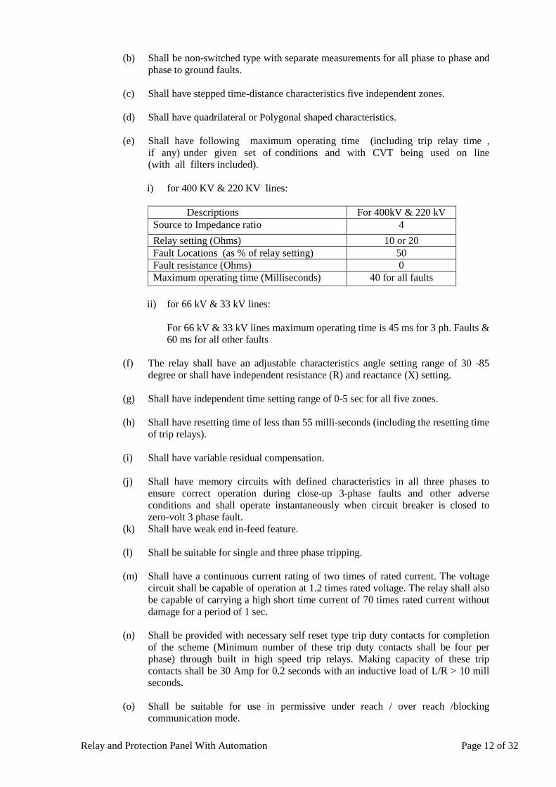
Relay and Protection Panel With Automation Page 12 of 32
(b) Shall be non-switched type with separate measurements for all phase to phase and phase to ground faults.
(c) Shall have stepped time-distance characteristics five independent zones.
(d) Shall have quadrilateral or Polygonal shaped characteristics.
(e) Shall have following maximum operating time (including trip relay time ,
if any) under given set of conditions and with CVT being used on line (with all filters included).
i) for 400 KV & 220 KV lines:
Descriptions For 400kV & 220 kV
Source to Impedance ratio 4 Relay setting (Ohms) 10 or 20 Fault Locations (as % of relay setting) 50 Fault resistance (Ohms) 0 Maximum operating time (Milliseconds) 40 for all faults
ii) for 66 kV & 33 kV lines:
For 66 kV & 33 kV lines maximum operating time is 45 ms for 3 ph. Faults & 60 ms for all other faults
(f) The relay shall have an adjustable characteristics angle setting range of 30 -85
degree or shall have independent resistance (R) and reactance (X) setting.
(g) Shall have independent time setting range of 0-5 sec for all five zones.
(h) Shall have resetting time of less than 55 milli-seconds (including the resetting time of trip relays).
(i) Shall have variable residual compensation.
(j) Shall have memory circuits with defined characteristics in all three phases to
ensure correct operation during close-up 3-phase faults and other adverse conditions and shall operate instantaneously when circuit breaker is closed to zero-volt 3 phase fault.
(k) Shall have weak end in-feed feature.
(l) Shall be suitable for single and three phase tripping.
(m) Shall have a continuous current rating of two times of rated current. The voltage circuit shall be capable of operation at 1.2 times rated voltage. The relay shall also be capable of carrying a high short time current of 70 times rated current without damage for a period of 1 sec.
(n) Shall be provided with necessary self reset type trip duty contacts for completion
of the scheme (Minimum number of these trip duty contacts shall be four per phase) through built in high speed trip relays. Making capacity of these trip contacts shall be 30 Amp for 0.2 seconds with an inductive load of L/R > 10 mill seconds.
(o) Shall be suitable for use in permissive under reach / over reach /blocking
communication mode.
Relay and Protection Panel With Automation Page 13 of 32
(p) Shall have suitable number of potential free contacts for Inter Tripping, Auto
reclosing, CB failure, Event Logger, Disturbance recorder & Data acquisition system.
(q) Include power swing blocking protection which shall
• Have suitable setting range to encircle the distance protection described above.
• Block tripping during power swing conditions. • Release blocking in the event of actual fault
(r) Include fuse failure protection which shall
• Monitor all the three fuses of V.T. and associated cable against open circuit.
• Inhibit trip circuits on operation and initiate annunciation. • Have an operating time less than 7 milliseconds • Remain inoperative for system earth faults
(s) Include a directional back up Inverse Definite Minimum Time (IDMT ) earth fault
relay with normal inverse characteristics as per IEC 60255-3 as a built in feature
(t) Must have a current reversal guard feature. Must also have module for Tx and Rx for interconnection with other end relay through fibre optic cable. Relay must be able to send and receive three independent codes.
(u) Must have SOTF (Switch on to Fault) feature
11.8.2 Numerical Line Current Differential Scheme:
(a) Shall be phase segregated current line differential protection scheme. (b) For overhead lines and cables for short length for primary ckt. (c) Shall have high sensitivity for differential current below the minimum line loading
of 20%. (d) Suitable for single and three phase tripping. (e) Shall be suitable for different CT ratio of the CTs provided at the terminals of the
line. (f) Shall be non-operative for transient cable/line charging current without affecting
the sensitivity of the relay. (g) Shall have high stability for high through fault currents. (h) Shall have measurement of delay time to remote line terminals for dynamic
compensation of delay in differential measurement. (i) Shall have CT Secondary current supervision. (j) Shall have Continuous self monitoring and diagnostic feature. (k) Potential free binary contacts shall be wired as per requirement for Inter Tripping,
Auto reclosing, direct trip, CB failure, Disturbance recorder & Data acquisition system (These contacts are included in the total no of contacts).
(l) Shall have facility for selecting synchronizing or dead line charging features.
Relay and Protection Panel With Automation Page 14 of 32
(m) Shall be based on IEC 61850 and should be communicable through direct fiber
optic as well as through multiplexers. (n) Shall be suitable for Direct inter tripping. (o) Measurement:
The relay shall have the following measurements: Local and remote phase current Local neutral current Phase bias and differential currents. Sequence currents. Thermal state.
The relay shall provide protection signaling supervision indicating the following parameters:
Channel propagation delay. Channel status. Number of valid and error messages.
(p) In Case of communication failure, relay shall work as Numerical Distance
Protection scheme with all features mentioned in Distance relay specifications.
11.8.3 Numerical Back-up directional Over Current and Earth fault protection scheme with high set feature (a) Shall have three over current and one earth fault element(s) which shall be either
independent or composite unit(s). (b) The scheme shall include necessary VT fuse failure relays for alarm purposes
(c) Over current relay shall
• Have directional IDMT characteristic with a definite minimum time of 3.0
seconds at 10 times setting and have a variable setting range of 50-200% of rated current.
• have low transient, over reach high set instantaneous unit of continuously variable setting range 100-2000 % of rated current.
• Have a characteristic angle of 30/45 degree . • Include self / electrical reset flag indicators or LEDs.
(d) Earth fault relay shall
• Have directional IDMT characteristic with a definite minimum time of 3.0
seconds at 10 times setting and have a variable setting range of 20-80% of rated current
• Have low transient, over reach high set instantaneous unit of continuously variable setting range 10-1000 % of rated current.
• Have a characteristic angle of 45/60 degree lag. • Include self/ electrical reset flag indicators or LEDs. • Have internal feature in the relay for open delta voltage to the relay.
11.8.4 All trip relays used in transmission line protection scheme shall be of self/electrical
reset type depending on application requirement.
Relay and Protection Panel With Automation Page 15 of 32
12.0 Circuit Breaker Protection This shall include following function: 12.1 AUTO RECLOSING RELAY shall be separate from Main-I and Main-II protection.
However, auto reclose as inbuilt function of bay controller unit (BCU) provided for substation automation is acceptable. The auto reclose shall
(a) Have single phase or/and three phase reclosing facilities.
(b) Have a continuously variable single phase dead time range of 0.1-2 seconds.
(c) Have a continuously variable three phase dead time range of 0.1-2 seconds. (d) Have a continuously variable reclaim time range of 5-25 seconds.
(e) Have facilities for selecting check synchronizing or dead line charging features. It
shall be possible at any time to change the required feature by reconnection of links.
(f) Have priority circuit to closing of both circuit breakers in case one and half/double
breaker arrangements for 400 kV to allow sequential closing of breakers
(g) Include check synchronizing relay which shall
• Have a time setting continuously variable between 0.5-5 seconds with a facility of additional 10 seconds.
• Have a response time within 200 milli seconds with the timer disconnected.
• Have a phase angle setting not exceeding 35 degree
• Have a voltage difference setting not exceeding 10%
(h) Include dead line charging relay which shall
• Have two sets of relays and each set shall be able to monitor the three phase voltage where one set shall be connected to the line CVTs with a fixed setting of 20% of rated voltage and the other set shall be connected to the bus CVTs with a fixed setting of 80% of rated voltage.
• Incorporate necessary auxiliary relays and timers to give comprehensive scheme.
12.2 LOCAL BREAKER BACK-UP PROTECTION SCHEME shall
(a) Be triple pole type
(b) Have an operating time of less than 15 milli seconds
(c) Have a resetting time of less than 15 milli seconds
(d) Have three over current elements
(e) be arranged to get individual initiation from the corresponding phase of main protections of line for each over current element. However, common three phase initiation is acceptable for other protections and transformer /reactor equipment protections.
Relay and Protection Panel With Automation Page 16 of 32
(f) Have a setting range of 20-80% of rated current
(g) have a continuous thermal withstand two times rated current irrespective of
the setting
(h) Have a timer with continuously adjustable setting range of 0.1-1 seconds.
(i) Have necessary auxiliary relays to make a comprehensive scheme.
(j) Be suitable for 220 V DC supply. 12.3 TRIP CIRCUIT SUPERVISION RELAY
(a) The relay shall be capable of monitoring the healthiness of each 'phase' trip-coil and associated circuit of circuit breaker during 'ON' and 'OFF' conditions.
(b) The relay shall have adequate contacts for providing connection to alarm and event logger.
(c) The relay shall have time delay on drop-off of not less than 200 milli seconds and
be provided with operation indications for each phase. 13.0 LINE OVER VOLTAGE PROTECTION RELAY shall
(a) monitor all three phases
(b) have two independent stages and stage- 1 & II relay are acceptable as built in with line distance relays Main I & II respectively .
(c) have an adjustable setting range of 100-170% of rated voltage with an adjustable time delay range of 1 to 60 seconds for the first stage.
(d) Have an adjustable setting range of 100-170% of rated voltage with a time delay of
100-200 milliseconds for the second stage.
(e) be tuned to power frequency
(f) Provided with separate operation indicators (flag target) for each stage relays.
(g) Have a drop-off to pick-up ratio greater than 95%.
(h) provide separate output contacts for each 'Phase' and stage for breaker trip relays, event logger and other scheme requirements.
14.0 TRANSFORMER PROTECTION
14.1 Transformer differential protection scheme shall
(a) Be triple pole type, with faulty phase identification/ indication
(b) have an operating time not greater than 30 milli seconds at 5 times the rated current .
(c) Have three instantaneous high set over-current units.
(d) Have an adjustable bias setting range of 20-50%
Relay and Protection Panel With Automation Page 17 of 32
(e) Be suitable for rated current of 1 Amp.
(f) have second harmonic or other inrush proof features and also should be stable under normal over fluxing conditions. Magnetising inrush proof feature shall not be achieved through any intentional time delay e.g. use of timers to block relay operation or using disc operated relays
(g) Have an operating current setting of 15% or less
(h) include necessary separate interposing current transformers for angle and
ratio correction or have internal feature in the relay to take care of the angle & ratio correction
(i) shall be numerical type and shall have continuous self monitoring and diagnostic
feature.
(j) have a disturbance recording feature to record graphic form of instantaneous values of current in all three windings in nine analogue channels in case of 400kv class and above transformers and 6 analogue channels for lower voltage transformers , during faults and disturbances for the pre fault and post fault period. The disturbance recorder shall have the facility to record the following external digital channel signals apart from the digital signals pertaining to differential relay.
i. REF protection operated
ii. HV breaker status iii. LV breaker status iv. Buchholz /OLTC Buchholz alarm / trip v. WTI/OTI/PRD alarm/trip of transformer
Necessary hardware and software for down loading the data captured by disturbance recorder to the personal computer or work station available in the substation shall be included in the scope.
14.2 Over fluxing protection Relays shall
(a) Operate on the principle of Voltage to frequency ratio and shall be phase to phase connected
(b) Have inverse time characteristics, matching with transformer over fluxing withstand capability curve.
(c) Provide an independent 'alarm' with the time delay continuously adjustable
between 0.1 to 6.0 seconds at values of 'v/f' between 100% to 130% of rated values.
(d) Tripping time shall be governed by 'v/f' Vs. time characteristics of the relay
(e) have a set of characteristics for Various time multiplier settings. The maximum
operating time of the relay shall not exceed 3 seconds and 1.5 seconds at ‘v/f values of 1.4 and 1.5 times, the rated values, respectively.
(f) Have an accuracy of operating time, better than ±10%.
(g) Have a resetting ratio of 95 % or better.
(h) Be acceptable as a built in feature of numerical transformer differential relay
Relay and Protection Panel With Automation Page 18 of 32
14.3 Numerical Restricted Earth Fault Protection shall (a) Be single pole type
(b) Be of current/voltage operated high impedance type
(c) Have a current setting range of 10-40% of 1 Amp./ have a suitable
voltage setting range.
(d) Be tuned to the system frequency
(e) have suitable non-linear resistor to limit the peak voltage to 1000 Volts. 14.4 Numerical Back-up Over Current and Earth fault protection scheme with high set
feature
(e) Shall have three over current and one earth fault element(s) which shall be either independent or composite unit(s).
(f) The scheme shall include necessary VT fuse failure relays for alarm purposes (g) Over current relay shall
• have directional IDMT characteristic with a definite minimum time of 3.0
seconds at 10 times setting and have a variable setting range of 50-200% of rated current
• have low transient, over reach high set instantaneous unit of continuously variable setting range 500-2000 % of rated current
• have a characteristic angle of 30/45 degree lead • include self/ electrical reset flag indicators or LEDs.
(h) Earth fault relay shall
• have directional IDMT characteristic with a definite minimum time of 3.0
seconds at 10 times setting and have a variable setting range of 20-80% of rated current
• have low transient, over reach high set instantaneous unit of continuously variable setting range 200-800 % of rated current
• have a characteristic angle of 45/60 degree lag • include self/ electrical reset flag indicators or LEDs • include necessary separate interposing voltage transformers or have internal
feature in the relay for open delta voltage to the relay. 14.5 Transformer Overload Protection Relay shall
(a) be of single pole type
(b) be of definite time over-current type
(c) have one set of over-current relay element, with continuously adjustable setting range of 50%-200% of rated current
(d) Have one adjustable time delay relay for alarm having setting range of 1 to 10.0
seconds, continuously.
(e) Have a drop-off/pick-up ratio greater than 95%.
(f) be acceptable as built in feature of numerical transformer differential relay
Relay and Protection Panel With Automation Page 19 of 32
15.0 TRIPPING RELAY
High Speed Tripping Relay shall (a) Be instantaneous (operating time not to exceed 10 milliseconds).
(b) Reset within 20 milliseconds
(c) Be D.C. operated
(d) have adequate contacts to meet the requirement of scheme, other functions
like auto-reclose relay, LBB relay as well as cater to associated equipment like event logger, Disturbance recorder, fault Locator, etc.
(e) Be provided with operation indicators for each element/coil.
16.0 FLAG RELAYS
These shall have (a) self/ electrical reset flag indication
(b) have minimum 4NO and 1 NC or combination as required for each relay.
17.0 DC SUPPLY SUPERIVISION RELAY
(a) The relay shall be capable of monitoring the failure of D.C. supply to which, it is connected.
(b) It shall have adequate potential free contacts to meet the scheme requirement.
(c) The relay shall have a 'time delay on drop-off' of not less than 100 milliseconds and be provided with operation indicator/flag.
18.0 BUS BAR PROTECTION (For New & Replacement of Whole Scheme) 18.1 Redundant (1+1) numerical Bus Bar protection scheme for each bus system (Bus1
+Bus2) for 400kV shall be provided. The scheme shall be engineered so as to ensure that operation of any one out of two schemes connected to main faulty bus shall result in tripping of the same.
18.2 Single bus bar protection scheme shall be provided for each bus for 220KV voltage level. 18.3 Each Bus Bar protection scheme shall
(a) Have maximum operating time up to trip impulse to trip relay for all types of faults of 25 milliseconds at 5 times setting value.
(b) Operate selectively for each bus bar
(c) Give hundred percent securities up to 40 KA fault level for 400KV and 220KV
(d) Incorporate continuous supervision for CT secondary against any possible open circuit and if it occurs, shall render the relevant zone of protection inoperative and initiate an alarm
(e) Not give false operation during normal load flow in bus bars.
Relay and Protection Panel With Automation Page 20 of 32
(f) Incorporate clear zone indication.
(g) Be of phase segregated and triple pole type
(h) Provide independent zones of protection (including transfer bus if any). If the bus
section is provided then each side of bus section shall have separate set of bus bar protection schemes.
(i) include individual high speed electrically reset tripping relays for each feeder.
(j) Be transient free in operation
(k) include continuous D.C. supplies supervision.
(l) not cause tripping for the differential current below the load current of
heaviest loaded feeder. Bidder shall submit application check for the same.
(m) Shall include necessary C.T. Switching relays wherever C.T. switching is involved and have 'CT' selection incomplete alarm
(n) Include protection 'IN/OUT' switch for each zone.
(o) shall include trip relays, CT switching relays(if applicable) , auxiliary CTs (if
applicable) as well as additional power supply modules, input modules etc. as may required to provide a Bus-bar protection scheme for the complete bus arrangement i.e. for all the bay or breakers under this specification as well as for the future bays as per the Single line diagram for new substations. However for extension of bus bar protection scheme (if specified) in existing substations, scope shall be limited to the bay or breakers covered under this specification. Suitable panels to mount these are also included in the scope of the work.
(p) Shall have disturbance recorder.
18.4 Built-in Local Breaker Backup protection feature as a part of bus bar protection scheme
shall also be acceptable.
18.5 At existing substations, Bus-bar protection scheme with independent zones for each bus will be available. All necessary co-ordination for 'AC' and 'DC' interconnections between existing schemes (Panels) and the bays proposed under the scope of this contract shall be fully covered by the bidder. Any auxiliary relay, trip relay, flag relay and multi tap auxiliary CTs (in case of biased differential protection) required to facilitate the operation of the bays covered under this contract shall be fully covered in the scope of the bidder.
(a) The test terminal blocks (TTB) to be provided shall be fully enclosed with
removable covers and made of moulded, non-inflammable plastic material with boxes and barriers moulded integrally. All terminals shall be clearly marked with identification numbers or letters to facilitate connection to external wiring. Terminal block shall have shorting, disconnecting and testing facilities for CT circuits.
19.0 DISTURBANCE RECORDER 19.1 Disturbance recorder shall be microprocessor based and shall be used to record the
graphic form of instantaneous values of voltage and current in all three phases, open delta voltage & neutral current, open or closed position of relay contacts and breakers during the system disturbances and built in feature of line distance/ line current differential/ transformer current differential / Bus bar protection relay is
Relay and Protection Panel With Automation Page 21 of 32
acceptable provided the requirements of following clauses are met.
19.2 The disturbance recorder shall consist of individual acquisition units, one for each feeder and an Evaluation unit which is common for the entire Substation. Whenever, more than one acquisition units are connected to an Evaluation unit, necessary hardware and software shall also be supplied for on line transfer of data from all acquisition units to Evaluation unit. If there are any constraints for one Evaluation unit to accept the data from number of acquisition units under the present scope, adequate number of Evaluation units shall be supplied. In case of extension of existing substation(s), one set of Evaluation unit shall be supplied for each substation where ever disturbance recorders are specified.
19.3 Disturbance recorder shall have 8 analog and 16 digital channels for each feeder. 19.4 Acquisition units shall acquire the fault data for the pre fault and post fault period
and transfer them to Evaluation unit automatically to store in the hard disk. The acquisition units shall be located in the protection panels of the respective feeders.
19.5 The acquisition unit shall be suitable for inputs from current transformers with 1A rated
secondary and capacitive voltage transformers with 63.5V (phase to neutral voltage) rated secondary. Any device required for processing of input signals in order to make the signals compatible to the Disturbance recorder equipment shall form an integral part of it. However, such processing of input signals shall in no way distort its waveform.
19.6 The equipment shall be carefully screened, shielded, earthed and protected as may be
required for its safe functioning. Also, the disturbance recorder shall have stable software, reliable hardware, simplicity of maintenance and immunity from the effects of the hostile environment of EHV switchyard which are prone to various interference signals typically from large switching transients.
19.7 The Evaluation unit shall consist of a desktop personal computer (including TFT colour
monitor, mouse and keyboard) and printer. The desktop PC shall be of latest configuration.
19.8 Necessary software for transferring the data automatically from local evaluation unit to a
remote station and receiving the same at the remote station through owner’s PLCC/VSAT/LEASED LINE shall be provided.
19.9 Evaluation software shall be provided for the analysis and evaluation of the
recorded data made available in the PC under DOS/WINDOWS environment. The Software features shall include repositioning of analog and digital signals, selection and amplification of time and amplitude scales of each analog and digital channel, calculation of MAX/MIN frequency, phase difference values, recording of MAX/MIN values etc. of analog channel, group of signal to be drawn on the same axis etc, listing and numbering of all analog and digital channels and current, voltage, frequency and phase difference values at the time of fault/tripping. Also, the software should be capable of carrying out Fourier /Harmonic analysis of the current and voltage wave forms. The disturbance records shall also be available in COMTRADE format ( IEEE standard- Common Format for Transient data Exchange for Power System )
19.10 The Evaluation unit shall be connected to the printer to obtain the graphic form of
disturbances whenever desired by the operator. 19.11 Disturbance recorder acquisition units shall be suitable to operate from 220V DC as
available at sub-station. Evaluation unit along with the printer shall normally be connected to 240V, single phase AC supply. In case of failure of AC supply, Evaluation unit and printer shall be switched automatically to the station DC through Inverter of
Relay and Protection Panel With Automation Page 22 of 32
adequate capacity which shall form a part of Fault recorder system. 19.12 The acquisition unit shall have the following features
(a) Facility shall exist to alarm operator in case of any internal faults in the acquisition units such as power supply fail, processor / memory fail etc and same shall be wired to annunciation system.
(b) The frequency response shall be 5 Hz on lower side and 250 Hz or better on upper side.
(c) Scan rate shall be 1000 Hz/channel or better.
(d) Pre-fault time shall not be less than 100 milliseconds and the post fault time shall
not be less than 2 seconds (adjustable). If another system disturbance occurs during one post-fault run time, the recorder shall also be able to record the same. However, the total memory of acquisition unit shall not be less than 5.0 seconds.
(e) The open delta voltage and neutral current shall be derived either through software
or externally by providing necessary auxiliary transformers.
(f) The acquisition unit shall be typically used to record the following digital channels:
1. Main CB R phase open 2. Main CB Y phase open 3. Main CB B phase open 4. Main-1 carrier received 5. Main-1 protection operated 6. Main Auto reclosed operated 7. Over Voltage -Stage-1 /2 operated 8. Stub/ UF protection operated 9. Direct Trip received 10. Main-2 carrier received 11. Main- 2/ Back Up protection operated 12. Bus bar protection operated 13. LBB operated of main circuit breaker
(g) In case the disturbance recorder is in-built part of line distance/ line current differential/ transformer current differential / Bus bar protection, above digital channels may be interfaced either externally or internally.
(h) Any digital signal can be programmed to act as trigger for the acquisition unit. Analog channels should have programmable threshold levels for triggers and selection for over or under levels should be possible.
19.13 The printer shall be compatible with the desktop PC and shall use Plain paper. The print
out shall contain the Feeder identity, Date and time (in hour, minute and second up to 100th of a second), identity of trigger source and Graphic form of analogue and digital signals of all the channels. Two packets of paper (500 sheets in each packet) suitable for printer shall be supplied.
19.14 Each Disturbance recorder shall have its own time generator and the clock of the time generator shall be such that the drift is limited to ±0.5 seconds/day, if allowed to run without synchronization. Further, Disturbance recorder shall have facility to synchronies its time generator from Time Synchronisation Equipment having output generator from Time Synchronization Equipment/ GPS having output of following types.
• Voltage signal : (0-5V continuously settable, with 50m Sec. minimum pulse duration
Relay and Protection Panel With Automation Page 23 of 32
• Potential free contact (Minimum pulse duration of 50 m Sec.). • IRIG-B • RS232C • RJ-45/Ethernet
20.0 DISTANCE TO FAULT LOCATOR
(a) Be electronic or microprocessor based type.
(b) Be 'On-line' type
(c) Be suitable for breaker operating time of 2 cycles
(d) Have built-in display unit
(e) The display shall be directly in percent of line length or kilometers without requiring any further calculations
(f) have an accuracy of 3% or better for the typical conditions defined for
operating timings measurement of distance relays.
(g) The above accuracy should not be impaired under the following conditions:
• presence of remote end infeed • predominant D.C. component in fault current • high fault arc resistance • severe CVT transients
(h) Shall have mutual zero sequence compensation unit if fault locator is to be used on
double circuit transmission line.
(i) built in feature of line distance relay is acceptable provided the requirements of above clauses are met.
21.0 TIME SYNCHRONISATION EQUPMENT (if applicable) 21.1 The Time synchronisation equipment shall receive the coordinated Universal
Time (UTC) transmitted through Geo Positioning Satellite System (GPS) and synchronise equipments to the Indian Standard Time in a substation.
21.2 Time synchronisation equipment shall include antenna, all special cables and processing equipment etc.
21.3 It shall be compatible for synchronisation of Event Loggers, Disturbance recorders and
SCADA at a substation through individual port or through Ethernet realised through optic fibre bus.
21.4 Equipment shall operate up to the ambient temperature of 50 degree centigrade and
100% humidity. 21.5 The synchronisation equipment shall have 2 micro second accuracy. Equipment shall
give real time corresponding to IST (taking into consideration all factors like voltage, & temperature variations, propagation & processing delays etc).
21.6 Equipment shall meet the requirement of IEC 60255 for storage & operation. 21.7 The system shall be able to track the satellites to ensure no interruption of
Relay and Protection Panel With Automation Page 24 of 32
synchronisation signal. 21.8 The output signal from each port shall be programmable at site for either one hour, half
hour, minute or second pulse, as per requirement. 21.9 The equipment offered shall have six (6) output ports. Various combinations of output
ports shall be selected by the customer, during detailed engineering, from the following:
• Voltage signal : Normally 0-5V with 50 milliseconds minimum pulse duration. In case any other voltage signal required, it shall be decided during detailed engineering.
• Potential free contact (Minimum pulse duration of 50 milli Seconds.) • IRIG-B • RS232C
21.10 The equipment shall have a periodic time correction facility of one second periodicity.
21.11 Time synchronization equipment shall be suitable to operate from 220V DC as available at Substation.
21.12 Equipment shall have real time digital display in hour, minute, second (24 hour mode) &
have a separate time display unit to be mounted on the top of control panels having display size of approx. 100 mm height.
22.0 RELAY TEST KIT (If specified in BOQ)
One automatic relay test kit suitable for both steady state and dynamic testing of all types of relay (voltage, current, frequency, distance and differential) electromechanical/static/numerical/along with inbuilt HMI/ separate laptop all accessories, test leads, carrying case etc. shall be supplied by bidder. The make of the test set shall be approved by DTL before placement of order. It should be suitable for testing of relay supplied.
23.0 TYPE TESTS 23.1 All equipment and components shall be subjected to routine tests and type tests according
to relevant standards and such other tests as may be required to ensure that all equipment and component are satisfactory and in accordance with the specification. Any modification required in the testing procedure shall be made as directed by the purchaser at no additional cost to the purchaser. No equipment shall be dispatched from the manufacture works before the relevant tests reports have been approved by the purchaser.
23.2 The reports for following type tests shall be submitted by the bidder for the Protective relays, Fault locator, Disturbance recorder and Event Logger.
(a) Insulation tests as per IEC 60255-5
(b) High frequency disturbance test as per IEC 60255-4 (Appendix -E) Class III (not
applicable for electromechanical relays)
(c) Fast transient test as per IEC 1000-4, Level III (not applicable for electromechanical relays)
(d) Relay characteristics, performance and accuracy test as per IEC 60255
• Steady state Characteristics and operating time • Dynamic Characteristics and operating time for distance protection relays
and current differential protection relays
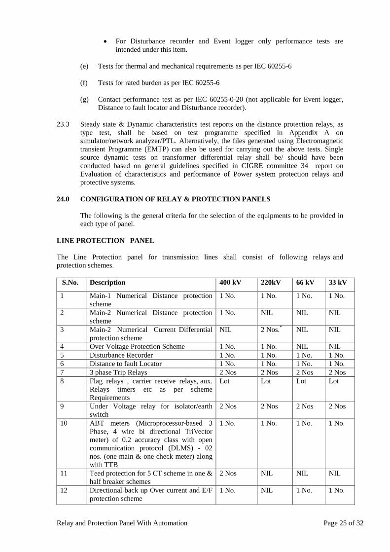
Relay and Protection Panel With Automation Page 25 of 32
• For Disturbance recorder and Event logger only performance tests are intended under this item.
(e) Tests for thermal and mechanical requirements as per IEC 60255-6
(f) Tests for rated burden as per IEC 60255-6
(g) Contact performance test as per IEC 60255-0-20 (not applicable for Event logger,
Distance to fault locator and Disturbance recorder). 23.3 Steady state & Dynamic characteristics test reports on the distance protection relays, as
type test, shall be based on test programme specified in Appendix A on simulator/network analyzer/PTL. Alternatively, the files generated using Electromagnetic transient Programme (EMTP) can also be used for carrying out the above tests. Single source dynamic tests on transformer differential relay shall be/ should have been conducted based on general guidelines specified in CIGRE committee 34 report on Evaluation of characteristics and performance of Power system protection relays and protective systems.
24.0 CONFIGURATION OF RELAY & PROTECTION PANELS
The following is the general criteria for the selection of the equipments to be provided in each type of panel.
LINE PROTECTION PANEL The Line Protection panel for transmission lines shall consist of following relays and protection schemes. S.No. Description 400 kV 220kV 66 kV 33 kV
1 Main-1 Numerical Distance protection scheme
1 No.
1 No.
1 No. 1 No.
2 Main-2 Numerical Distance protection scheme
1 No.
NIL
NIL
NIL
3 Main-2 Numerical Current Differential protection scheme
NIL 2 Nos. NIL * NIL
4 Over Voltage Protection Scheme 1 No. 1 No. NIL NIL 5 Disturbance Recorder 1 No. 1 No. 1 No. 1 No. 6 Distance to fault Locator 1 No. 1 No. 1 No. 1 No. 7 3 phase Trip Relays 2 Nos 2 Nos 2 Nos 2 Nos 8 Flag relays , carrier receive relays, aux.
Relays timers etc as per scheme Requirements
Lot
Lot
Lot
Lot
9 Under Voltage relay for isolator/earth switch
2 Nos 2 Nos 2 Nos 2 Nos
10 ABT meters (Microprocessor-based 3 Phase, 4 wire bi directional TriVector meter) of 0.2 accuracy class with open communication protocol (DLMS) - 02 nos. (one main & one check meter) along with TTB
1 No. 1 No.
1 No.
1 No.
11 Teed protection for 5 CT scheme in one & half breaker schemes
2 Nos NIL NIL NIL
12 Directional back up Over current and E/F protection scheme
1 No. NIL
1 No.
1 No.
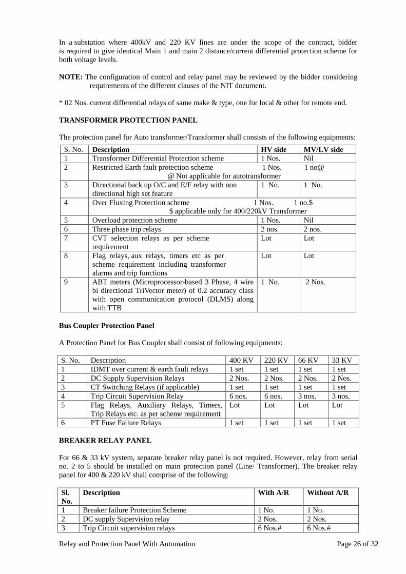
Relay and Protection Panel With Automation Page 26 of 32
In a substation where 400kV and 220 KV lines are under the scope of the contract, bidder is required to give identical Main 1 and main 2 distance/current differential protection scheme for both voltage levels. NOTE: The configuration of control and relay panel may be reviewed by the bidder considering
requirements of the different clauses of the NIT document. * 02 Nos. current differential relays of same make & type, one for local & other for remote end. TRANSFORMER PROTECTION PANEL The protection panel for Auto transformer/Transformer shall consists of the following equipments:
Bus Coupler Protection Panel A Protection Panel for Bus Coupler shall consist of following equipments: S. No. Description 400 KV 220 KV 66 KV 33 KV 1 IDMT over current & earth fault relays 1 set 1 set 1 set 1 set 2 DC Supply Supervision Relays 2 Nos. 2 Nos. 2 Nos. 2 Nos. 3 CT Switching Relays (if applicable) 1 set 1 set 1 set 1 set 4 Trip Circuit Supervision Relay 6 nos. 6 nos. 3 nos. 3 nos. 5 Flag Relays, Auxiliary Relays, Timers,
Trip Relays etc. as per scheme requirement Lot Lot Lot Lot
6 PT Fuse Failure Relays 1 set 1 set 1 set 1 set BREAKER RELAY PANEL For 66 & 33 kV system, separate breaker relay panel is not required. However, relay from serial no. 2 to 5 should be installed on main protection panel (Line/ Transformer). The breaker relay panel for 400 & 220 kV shall comprise of the following: Sl. No.
Description
With A/R Without A/R
1 Breaker failure Protection Scheme 1 No. 1 No. 2 DC supply Supervision relay 2 Nos. 2 Nos. 3 Trip Circuit supervision relays 6 Nos.# 6 Nos.#
S. No. Description HV side MV/LV side 1 Transformer Differential Protection scheme 1 Nos. Nil 2 Restricted Earth fault protection scheme 1 Nos. 1 no@
@ Not applicable for autotransformer 3 Directional back up O/C and E/F relay with non
directional high set feature 1 No.
1 No.
4 Over Fluxing Protection scheme 1 Nos. 1 no.$ $ applicable only for 400/220kV Transformer
5 Overload protection scheme 1 Nos. Nil 6 Three phase trip relays 2 nos. 2 nos. 7 CVT selection relays as per scheme
requirement Lot Lot
8 Flag relays, aux relays, timers etc as per scheme requirement including transformer alarms and trip functions
Lot Lot
9 ABT meters (Microprocessor-based 3 Phase, 4 wire bi directional TriVector meter) of 0.2 accuracy class with open communication protocol (DLMS) along with TTB
1 No.
2 Nos.
Relay and Protection Panel With Automation Page 27 of 32
4 Auto reclose scheme with check synchronizing and dead line charging relay
1 Nos.
NIL
5 Flag relays, aux relays, timers, trip relays as per scheme requirements.
Lot
Lot
# Trip supervision relays shall be 2 numbers for each 66 KV & 33 KV Circuit Breaker 25.0 ERECTION AND MAINTENANCE TOOL EQUIPMENTS
All special testing equipment/ tools required for the installation and maintenance of the apparatus, instruments devices shall be furnished in relevant schedule.
26.0 TROPICALISATION
Control room will be normally air-cooled/air- conditioned. All equipments shall however be suitable for installation in a tropical monsoon area having hot, humid climate and dry and dusty seasons with ambient conditions specified in the specification. All control wiring, equipment and accessories shall be protected against fungus growth, condensation, vermin and other harmful effects due to tropical environment.
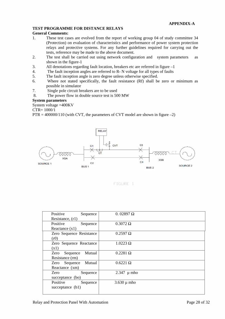
Relay and Protection Panel With Automation Page 28 of 32
APPENDIX-A TEST PROGRAMME FOR DISTANCE RELAYS General Comments: 1. These test cases are evolved from the report of working group 04 of study committee 34
(Protection) on evaluation of characteristics and performance of power system protection relays and protective systems. For any further guidelines required for carrying out the tests, reference may be made to the above document.
2. The test shall be carried out using network configuration and system parameters as shown in the figure-1
3. All denotations regarding fault location, breakers etc are referred in figure –1 4. The fault inception angles are referred to R- N voltage for all types of faults 5. The fault inception angle is zero degree unless otherwise specified. 6. Where not stated specifically, the fault resistance (Rf) shall be zero or minimum as
possible in simulator 7. Single pole circuit breakers are to be used 8. The power flow in double source test is 500 MW System parameters System voltage =400KV CTR= 1000/1 PTR = 400000/110 (with CVT, the parameters of CVT model are shown in figure –2)
Positive Sequence Resistance, (r1)
0. 02897 Ω
Positive Sequence Reactance (x1)
0.3072 Ω
Zero Sequence Resistance (r0)
0.2597 Ω
Zero Sequence Reactance (x1)
1.0223 Ω
Zero Sequence Mutual Resistance (rm)
0.2281 Ω
Zero Sequence Mutual Reactance (xm)
0.6221 Ω
Zero Sequence succeptance (bo)
2.347 µ mho
Positive Sequence succeptance (b1)
3.630 µ mho
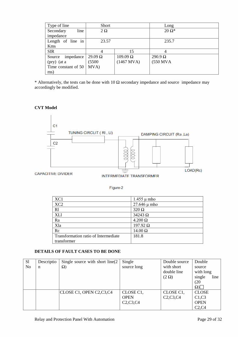
Relay and Protection Panel With Automation Page 29 of 32
* Alternatively, the tests can be done with 10 Ω secondary impedance and source impedance may accordingly be modified. CVT Model
XC1 1.455 μ mho XC2 27.646 μ mho Rl 320 Ω XLl 34243 Ω Ra 4.200 Ω Xla 197.92 Ω Rc 14.00 Ω Transformation ratio of Intermediate transformer
181.8
DETAILS OF FAULT CASES TO BE DONE
Sl No
Description
Single source with short line(2 Ω)
Single source long
Double source with short double line (2 Ω)
Double source with long single line (20 Ω)
CLOSE C1, OPEN C2,C3,C4 CLOSE C1, OPEN C2,C3,C4
CLOSE C1, C2,C3,C4
CLOSE C1,C3 OPEN C2,C4
Type of line Short Long Secondary line impedance
2 Ω 20 Ω*
Length of line in Kms
23.57
235.7
SIR 4 15 4 Source impedance (pry) (at a Time constant of 50 ms)
29.09 Ω (5500 MVA)
109.09 Ω (1467 MVA)
290.9 Ω (550 MVA
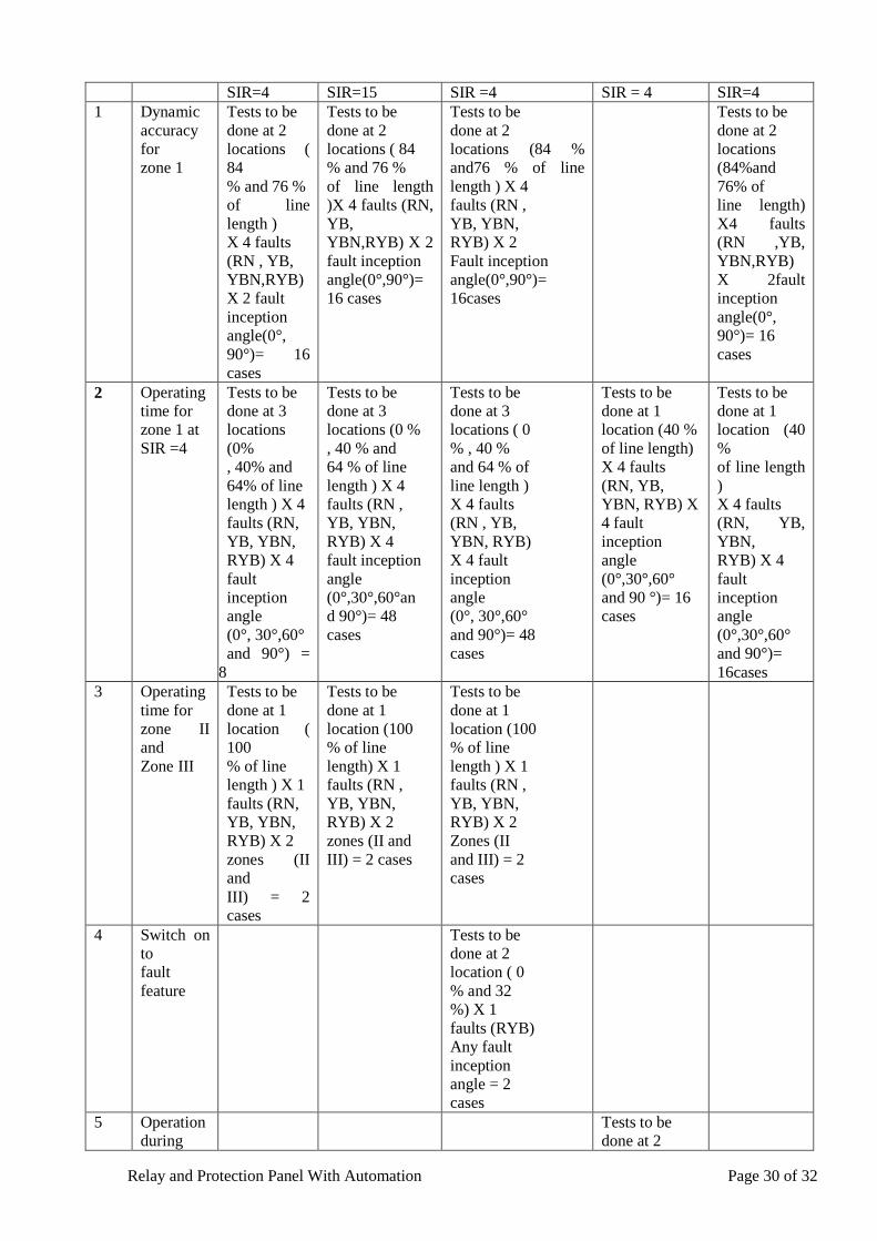
Relay and Protection Panel With Automation Page 30 of 32
SIR=4 SIR=15 SIR =4 SIR = 4 SIR=4 1 Dynamic
accuracy for zone 1
Tests to be done at 2 locations ( 84 % and 76 % of line length ) X 4 faults (RN , YB, YBN,RYB) X 2 fault inception angle(0°, 90°)= 16 cases
Tests to be done at 2 locations ( 84 % and 76 % of line length )X 4 faults (RN, YB, YBN,RYB) X 2 fault inception angle(0°,90°)= 16 cases
Tests to be done at 2 locations (84 % and76 % of line length ) X 4 faults (RN , YB, YBN, RYB) X 2 Fault inception angle(0°,90°)= 16cases
Tests to be done at 2 locations (84%and 76% of line length) X4 faults (RN ,YB, YBN,RYB) X 2fault inception angle(0°, 90°)= 16 cases
2 Operating time for zone 1 at SIR =4
Tests to be done at 3 locations (0% , 40% and 64% of line length ) X 4 faults (RN, YB, YBN, RYB) X 4 fault inception angle (0°, 30°,60° and 90°) =
8
Tests to be done at 3 locations (0 % , 40 % and 64 % of line length ) X 4 faults (RN , YB, YBN, RYB) X 4 fault inception angle (0°,30°,60°an d 90°)= 48 cases
Tests to be done at 3 locations ( 0 % , 40 % and 64 % of line length ) X 4 faults (RN , YB, YBN, RYB) X 4 fault inception angle (0°, 30°,60° and 90°)= 48 cases
Tests to be done at 1 location (40 % of line length) X 4 faults (RN, YB, YBN, RYB) X 4 fault inception angle (0°,30°,60° and 90 °)= 16 cases
Tests to be done at 1 location (40 % of line length ) X 4 faults (RN, YB, YBN, RYB) X 4 fault inception angle (0°,30°,60° and 90°)= 16cases
3 Operating time for zone II and Zone III
Tests to be done at 1 location ( 100 % of line length ) X 1 faults (RN, YB, YBN, RYB) X 2 zones (II and III) = 2 cases
Tests to be done at 1 location (100 % of line length) X 1 faults (RN , YB, YBN, RYB) X 2 zones (II and III) = 2 cases
Tests to be done at 1 location (100 % of line length ) X 1 faults (RN , YB, YBN, RYB) X 2 Zones (II and III) = 2 cases
4 Switch on to fault feature
Tests to be done at 2 location ( 0 % and 32 %) X 1 faults (RYB) Any fault inception angle = 2 cases
5 Operation during
Tests to be done at 2
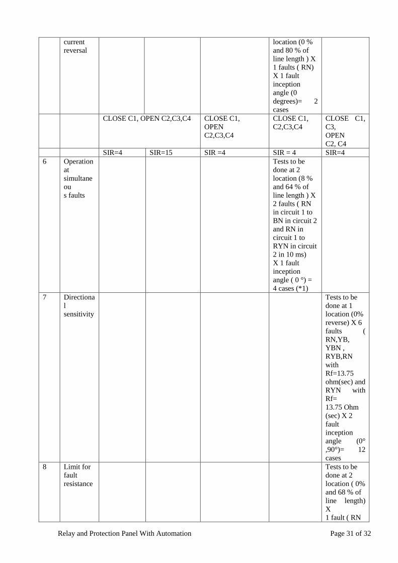
Relay and Protection Panel With Automation Page 31 of 32
current reversal
location (0 % and 80 % of line length ) X 1 faults ( RN) X 1 fault inception angle (0 degrees)= 2 cases
CLOSE C1, OPEN C2,C3,C4 CLOSE C1, OPEN C2,C3,C4
CLOSE C1, C2,C3,C4
CLOSE C1, C3, OPEN C2, C4
SIR=4 SIR=15 SIR =4 SIR = 4 SIR=4 6 Operation
at simultaneou s faults
Tests to be done at 2 location (8 % and 64 % of line length ) X 2 faults ( RN in circuit 1 to BN in circuit 2 and RN in circuit 1 to RYN in circuit 2 in 10 ms) X 1 fault inception angle ( 0 °) = 4 cases (*1)
7 Directional sensitivity
Tests to be done at 1 location (0% reverse) X 6 faults ( RN,YB, YBN , RYB,RN with Rf=13.75 ohm(sec) and RYN with Rf= 13.75 Ohm (sec) X 2 fault inception angle (0° ,90°)= 12 cases
8 Limit for fault resistance
Tests to be done at 2 location ( 0% and 68 % of line length) X 1 fault ( RN
Relay and Protection Panel With Automation Page 32 of 32
with Rf=13.75 ohm(sec) X 2 fault inception angle (0°,90°)= 4 cases
9 Operation at evolving faults
Tests to be done at 2 location (32 % and 0% of line length) X 2 faults (RN to RYN) x in 2 timings (10 ms and 30 ms) X 2 load direction (from A to B and from B to A) =16 cases
10 Fault locator function , in case the same is offered as built in feature
Measure fault location for all cases under 1 and 2
Measure fault location for all cases under 1 and 2
Measure fault location for all cases under 1 and 2
Measure fault location for all cases under 2 and 6
Measure fault location for all cases under 2, 7 and 9
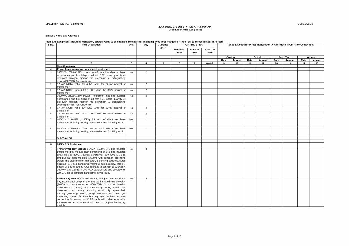
Page 1 of 15
SPECIFICATION NO. T14P070076 SCHEDULE-1
Bidder's Name and Address :
Plant and Equipment (including Mandatory Spares Parts) to be supplied from abroad, including Type Test charges for Type Test to be conducted in Abroad.
Unit FOB Price
Unit CIF Price
Total CIF Price
Rate Amount Rate Amount Rate Amount Rate amount1 2 3 4 5 6 7 8=4x7 9 10 11 12 13 14 15 16I. Main Equipment.A Power Transformer and associated equipment1 100MVA, 220/33/11kV power transformer including bushing,
accessories and first filling of oil with 10% spare quantity oilalongwith nitrogen injection fire prevention & extinguishingsystem (NIFPES) for transformer.
No. 2
2 17.5kV NCTof ratio 800-400/1 Amp for 220kV neutral oftransformer
No. 2
3 17.5kV NCTof ratio 2000-1000/1 Amp for 33kV neutral oftransformer
No. 2
4 160MVA, 220/66/11kV Power Transformer including bushing,accessories and first filling of oil with 10% spare quantity oilalongwith nitrogen injection fire prevention & extinguishingsystem (NIFPES) for transformer.
No. 2
5 17.5kV NCTof ratio 800-400/1 Amp for 220kV neutral oftransformer
No. 2
6 17.5kV NCTof ratio 2000-1000/1 Amp for 66kV neutral oftransformer
No. 2
7 400KVA, 11/0.433kV, 170kVp BIL at 11kV side,three phasetransformer including bushing, accessories and first filling of oil.
No. 1
8 400KVA, 11/0.433kV, 75kVp BIL at 11kV side, three phasetransformer including bushing, accessories and first filling of oil.
No. 1
Sub-Total (A)
B 245kV GIS Equipment
1 Transformer Bay Module : 245kV, 1600A, SF6 gas insulatedtransformer bay module each comprising of SF6 gas insulatedcircuit breaker (1600A), current transformer (800-400/1-1-1-1-1),two bus-bar disconnectors (1600A) with common groundingswitch, line disconnector with safety grounding switches, surgearrestors, SF6 gas monitoring system for complete bay, Three 1-phase SF6 ducts and SF6/Oil interface to connect to 220/66kV,160MVA and 220/33kV 100 MVA transformers and accessorieswith GIS etc. to complete transformer bay module.
Set 4
2 Feeder Bay Module : 245kV, 1600A, SF6 gas insulated feederbay module each comprising of SF6 gas insulated circuit breaker (1600A), current transformer (800-400/1-1-1-1-1), two bus-bardisconnectors (1600A) with common grounding switch, linedisconnector with safety grounding switch, high speed faultmaking grounding switch, surge arrestors, PT, SF6 gasmonitoring system for complete bay, gas insulated terminalconnection for connecting XLPE cable with cable terminationenclosure and accessories with GIS etc. to complete feeder baymodule.
Set 8
Custom Octroi Entry Tax Others
220/66/33kV GIS SUBSTATION AT R.K.PURAM(Schedule of rates and prices)
Currency (INR)
CIF PRICE (INR) Taxes & Duties for Direct Transaction (Not included in CIF Price Component) S.No. Item Description Unit Qty
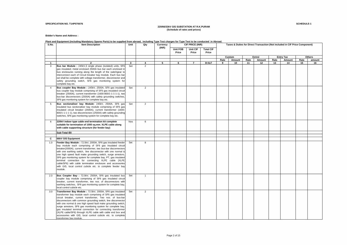
Page 2 of 15
SPECIFICATION NO. T14P070076 SCHEDULE-1
Bidder's Name and Address :
Plant and Equipment (including Mandatory Spares Parts) to be supplied from abroad, including Type Test charges for Type Test to be conducted in Abroad.
Unit FOB Price
Unit CIF Price
Total CIF Price
Rate Amount Rate Amount Rate Amount Rate amount1 2 3 4 5 6 7 8=4x7 9 10 11 12 13 14 15 16
Custom Octroi Entry Tax Others
220/66/33kV GIS SUBSTATION AT R.K.PURAM(Schedule of rates and prices)
Currency (INR)
CIF PRICE (INR) Taxes & Duties for Direct Transaction (Not included in CIF Price Component) S.No. Item Description Unit Qty
3 Bus bar Module : 245kV,3 single phase (isolated) units, SF6gas insulated, metal enclosed 2500A bus bar each enclosed inbus enclosures running along the length of the switchgear tointerconnect each of Circuit breaker bay module. Each bus barset shall be complete with voltage transformer, disconnector andsafety grounding switch, SF6 gas monitoring system forcomplete bay etc.
Set 2
4 Bus coupler Bay Module : 245kV, 2500A, SF6 gas insulatedbus coupler bay module comprising of SF6 gas insulated circuitbreaker (2500A), current transformer (1600-800/1-1-1-1-1), twobus-bar disconnectors (2500A) with safety grounding switches,SF6 gas monitoring system for complete bay etc.
Set 2
5 Bus sectionaliser bay Module: 245kV, 2500A, SF6 gasinsulated bus sectionaliser bay module comprising of SF6 gasinsulated circuit breaker (2500A), current transformer (1600-800/1-1-1-1-1), two disconnectors (2500A) with safety groundingswitches, SF6 gas monitoring system for complete bay etc.
Set 2
6 220kV indoor type cable end termination kit complete suitable for termination of 1000 sq.mm. XLPE cable along with cable supporting structure (for feeder bay)
Nos 6
Sub-Total (B)
C 66kV GIS Equipment1.0 Feeder Bay Module : 72.5kV, 2000A, SF6 gas insulated feeder
bay module each comprising of SF6 gas insulated circuitbreaker(2000A), current transformer, two bus-bar disconnectorswith one earthing switch, line disconnector with one normal &one high speed fault make grounding switch, surge arrestors,SF6 gas monitoring system for complete bay, PT, gas insulatedterminal connection for connecting XLPE cable (XLPEcable/SF6) with cable termination enclosure and accessorieswith GIS, local control cubicle etc. to complete feeder baymodule.
Set 8
2.0 Bus Coupler Bay : 72.5kV, 2500A, SF6 gas insulated buscoupler bay module comprising of SF6 gas insulated circuitbreaker, current transformer, two nos. of disconnectors withearthing switches, SF6 gas monitoring system for complete bay,local control cubicle etc.
Set 1
3.0 Transformer Bay Module : 72.5kV, 2000A, SF6 gas insulatedtransformer bay module each comprising of SF6 gas insulatedcircuit breaker, current transformer, Two nos. of bus-bardisconnectors with common grounding switch, line disconnectorwith one normal & one high speed fault make grounding switch,surge arrestors, SF6 gas monitoring system for complete bay,gas insulated terminal connection for connecting transformer(XLPE cable/SF6) through XLPE cable with cable end box andaccessories with GIS, local control cubicle etc. to completetransformer bay module.
Set 2
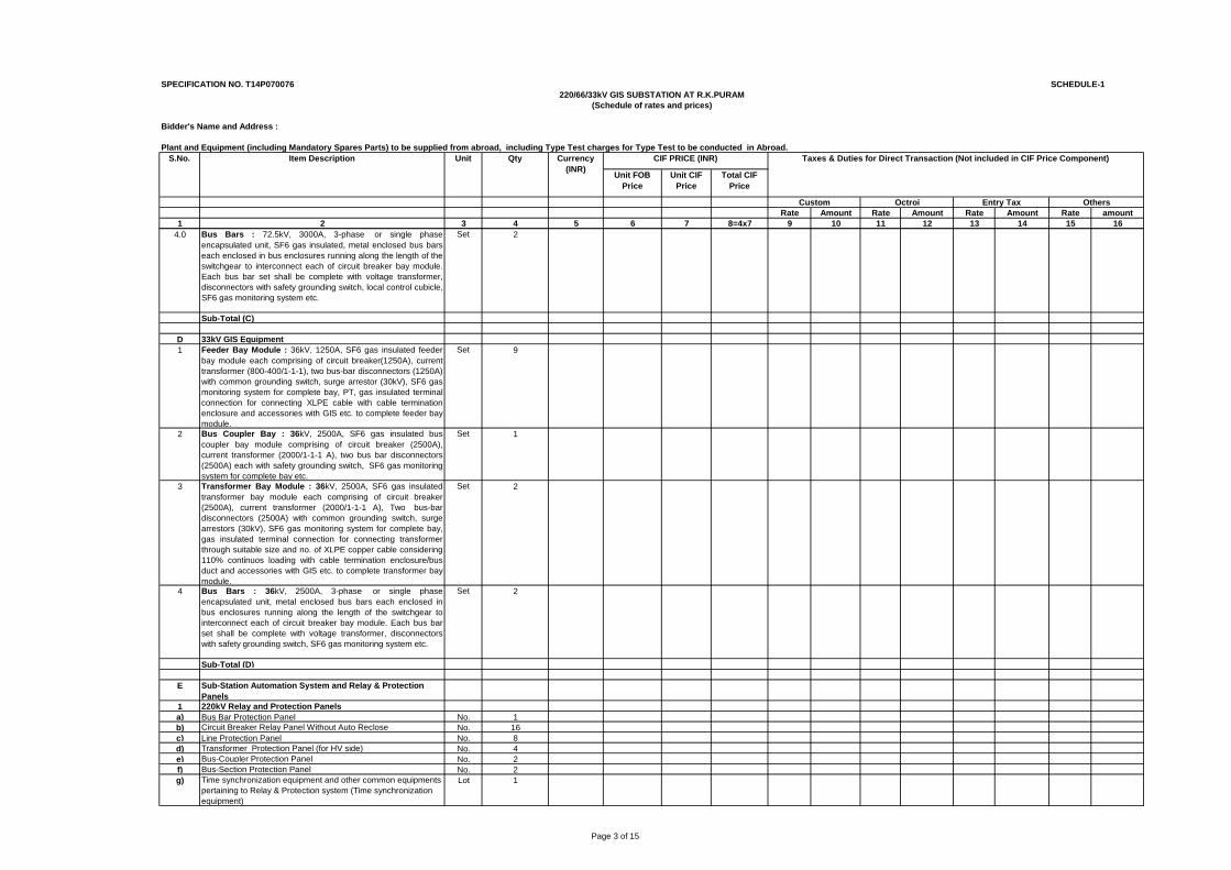
Page 3 of 15
SPECIFICATION NO. T14P070076 SCHEDULE-1
Bidder's Name and Address :
Plant and Equipment (including Mandatory Spares Parts) to be supplied from abroad, including Type Test charges for Type Test to be conducted in Abroad.
Unit FOB Price
Unit CIF Price
Total CIF Price
Rate Amount Rate Amount Rate Amount Rate amount1 2 3 4 5 6 7 8=4x7 9 10 11 12 13 14 15 16
Custom Octroi Entry Tax Others
220/66/33kV GIS SUBSTATION AT R.K.PURAM(Schedule of rates and prices)
Currency (INR)
CIF PRICE (INR) Taxes & Duties for Direct Transaction (Not included in CIF Price Component) S.No. Item Description Unit Qty
4.0 Bus Bars : 72.5kV, 3000A, 3-phase or single phaseencapsulated unit, SF6 gas insulated, metal enclosed bus barseach enclosed in bus enclosures running along the length of theswitchgear to interconnect each of circuit breaker bay module.Each bus bar set shall be complete with voltage transformer,disconnectors with safety grounding switch, local control cubicle,SF6 gas monitoring system etc.
Set 2
Sub-Total (C)
D 33kV GIS Equipment1 Feeder Bay Module : 36kV, 1250A, SF6 gas insulated feeder
bay module each comprising of circuit breaker(1250A), currenttransformer (800-400/1-1-1), two bus-bar disconnectors (1250A)with common grounding switch, surge arrestor (30kV), SF6 gasmonitoring system for complete bay, PT, gas insulated terminalconnection for connecting XLPE cable with cable terminationenclosure and accessories with GIS etc. to complete feeder baymodule.
Set 9
2 Bus Coupler Bay : 36kV, 2500A, SF6 gas insulated buscoupler bay module comprising of circuit breaker (2500A),current transformer (2000/1-1-1 A), two bus bar disconnectors(2500A) each with safety grounding switch, SF6 gas monitoringsystem for complete bay etc.
Set 1
3 Transformer Bay Module : 36kV, 2500A, SF6 gas insulatedtransformer bay module each comprising of circuit breaker(2500A), current transformer (2000/1-1-1 A), Two bus-bardisconnectors (2500A) with common grounding switch, surgearrestors (30kV), SF6 gas monitoring system for complete bay,gas insulated terminal connection for connecting transformerthrough suitable size and no. of XLPE copper cable considering110% continuos loading with cable termination enclosure/busduct and accessories with GIS etc. to complete transformer baymodule.
Set 2
4 Bus Bars : 36kV, 2500A, 3-phase or single phaseencapsulated unit, metal enclosed bus bars each enclosed inbus enclosures running along the length of the switchgear tointerconnect each of circuit breaker bay module. Each bus barset shall be complete with voltage transformer, disconnectorswith safety grounding switch, SF6 gas monitoring system etc.
Set 2
Sub-Total (D)
E Sub-Station Automation System and Relay & Protection Panels
1 220kV Relay and Protection Panelsa) Bus Bar Protection Panel No. 1b) Circuit Breaker Relay Panel Without Auto Reclose No. 16c) Line Protection Panel No. 8d) Transformer Protection Panel (for HV side) No. 4e) Bus-Coupler Protection Panel No. 2f) Bus-Section Protection Panel No. 2g) Time synchronization equipment and other common equipments
pertaining to Relay & Protection system (Time synchronization equipment)
Lot 1
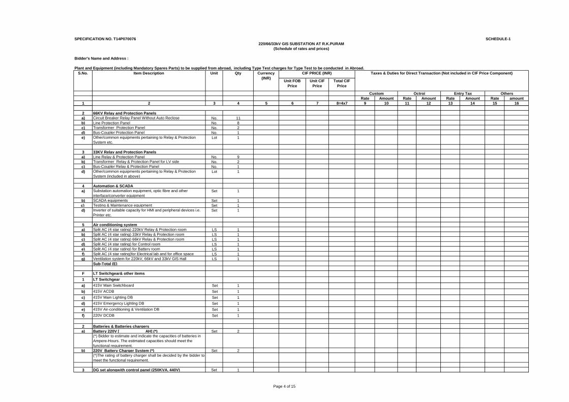
Page 4 of 15
SPECIFICATION NO. T14P070076 SCHEDULE-1
Bidder's Name and Address :
Plant and Equipment (including Mandatory Spares Parts) to be supplied from abroad, including Type Test charges for Type Test to be conducted in Abroad.
Unit FOB Price
Unit CIF Price
Total CIF Price
Rate Amount Rate Amount Rate Amount Rate amount1 2 3 4 5 6 7 8=4x7 9 10 11 12 13 14 15 16
Custom Octroi Entry Tax Others
220/66/33kV GIS SUBSTATION AT R.K.PURAM(Schedule of rates and prices)
Currency (INR)
CIF PRICE (INR) Taxes & Duties for Direct Transaction (Not included in CIF Price Component) S.No. Item Description Unit Qty
2 66KV Relay and Protection Panelsa) Circuit Breaker Relay Panel Without Auto Reclose No. 11b) Line Protection Panel No. 8c) Transformer Protection Panel No. 2d) Bus-Coupler Protection Panel No. 1e) Other/common equipments pertaining to Relay & Protection
System etc.Lot 1
3 33KV Relay and Protection Panelsa) Line Relay & Protection Panel No. 9b) Transformer Relay & Protection Panel for LV side No. 2c) Bus-Coupler Relay & Protection Panel No. 1d) Other/common equipments pertaining to Relay & Protection
System (included in above)Lot 1
4 Automation & SCADAa) Substation automation equipment, optic fibre and other
interface/converter equipmentSet 1
b) SCADA equipments Set 1c) Testing & Maintenance equipment Set 1d) Inverter of suitable capacity for HMI and peripheral devices i.e.
Printer etc.Set 1
5 Air conditioning systema) Split AC (4 star rating) 220kV Relay & Protection room LS 1b) Split AC (4 star rating) 33kV Relay & Protection room LS 1c) Split AC (4 star rating) 66kV Relay & Protection room LS 1d) Split AC (4 star rating) for Control room LS 1e) Split AC (4 star rating) for Battery room LS 1f) Split AC (4 star rating)for Electrical lab and for office space LS 1g) Ventilation system for 220kV, 66kV and 33kV GIS Hall LS 1
Sub-Total (E)
F LT Switchgear& other items1 LT Switchgeara) 415V Main Switchboard Set 1b) 415V ACDB Set 1c) 415V Main Lighting DB Set 1d) 415V Emergency Lighting DB Set 1e) 415V Air-conditioning & Ventilation DB Set 1f) 220V DCDB Set 1
2 Batteries & Batteries chargersa) Battery 220V [____________AH] (*) Set 2
(*) Bidder to estimate and indicate the capacities of batteries in Ampere-Hours. The estimated capacities should meet the functional requirement.
b) 220V Battery Charger System (*) Set 2(*)The rating of battery charger shall be decided by the bidder tomeet the functional requirement.
3 DG set alongwith control panel (250KVA, 440V) Set 1
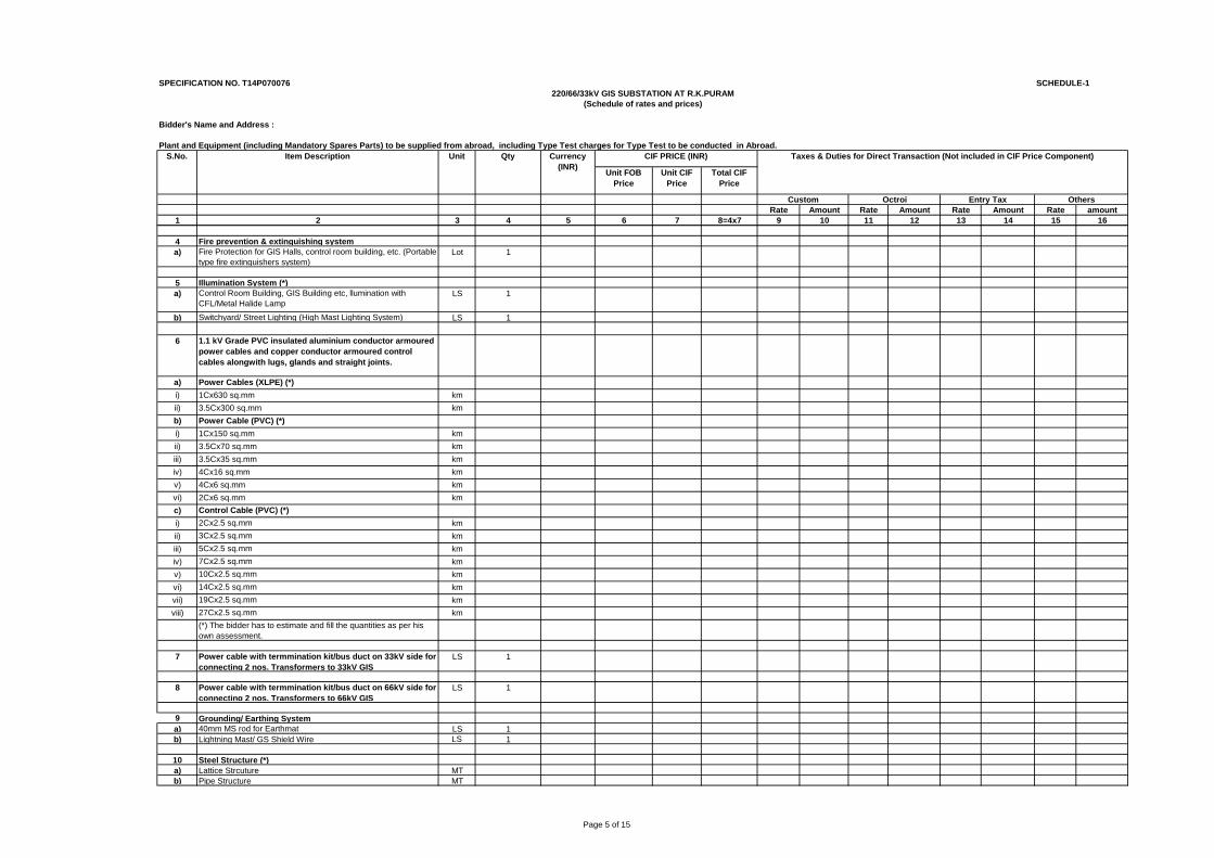
Page 5 of 15
SPECIFICATION NO. T14P070076 SCHEDULE-1
Bidder's Name and Address :
Plant and Equipment (including Mandatory Spares Parts) to be supplied from abroad, including Type Test charges for Type Test to be conducted in Abroad.
Unit FOB Price
Unit CIF Price
Total CIF Price
Rate Amount Rate Amount Rate Amount Rate amount1 2 3 4 5 6 7 8=4x7 9 10 11 12 13 14 15 16
Custom Octroi Entry Tax Others
220/66/33kV GIS SUBSTATION AT R.K.PURAM(Schedule of rates and prices)
Currency (INR)
CIF PRICE (INR) Taxes & Duties for Direct Transaction (Not included in CIF Price Component) S.No. Item Description Unit Qty
4 Fire prevention & extinguishing system a) Fire Protection for GIS Halls, control room building, etc. (Portable
type fire extinguishers system)Lot 1
5 Illumination System (*)a) Control Room Building, GIS Building etc, llumination with
CFL/Metal Halide LampLS 1
b) Switchyard/ Street Lighting (High Mast Lighting System) LS 1
6 1.1 kV Grade PVC insulated aluminium conductor armoured power cables and copper conductor armoured control cables alongwith lugs, glands and straight joints.
a) Power Cables (XLPE) (*)i) 1Cx630 sq.mm kmii) 3.5Cx300 sq.mm kmb) Power Cable (PVC) (*)i) 1Cx150 sq.mm kmii) 3.5Cx70 sq.mm kmiii) 3.5Cx35 sq.mm kmiv) 4Cx16 sq.mm kmv) 4Cx6 sq.mm kmvi) 2Cx6 sq.mm kmc) Control Cable (PVC) (*)i) 2Cx2.5 sq.mm kmii) 3Cx2.5 sq.mm kmiii) 5Cx2.5 sq.mm kmiv) 7Cx2.5 sq.mm kmv) 10Cx2.5 sq.mm kmvi) 14Cx2.5 sq.mm kmvii) 19Cx2.5 sq.mm kmviii) 27Cx2.5 sq.mm km
(*) The bidder has to estimate and fill the quantities as per his own assessment.
7 Power cable with termmination kit/bus duct on 33kV side for connecting 2 nos. Transformers to 33kV GIS
LS 1
8 Power cable with termmination kit/bus duct on 66kV side for connecting 2 nos. Transformers to 66kV GIS
LS 1
9 Grounding/ Earthing Systema) 40mm MS rod for Earthmat LS 1b) Lightning Mast/ GS Shield Wire LS 1
10 Steel Structure (*) a) Lattice Strcuture MTb) Pipe Structure MT
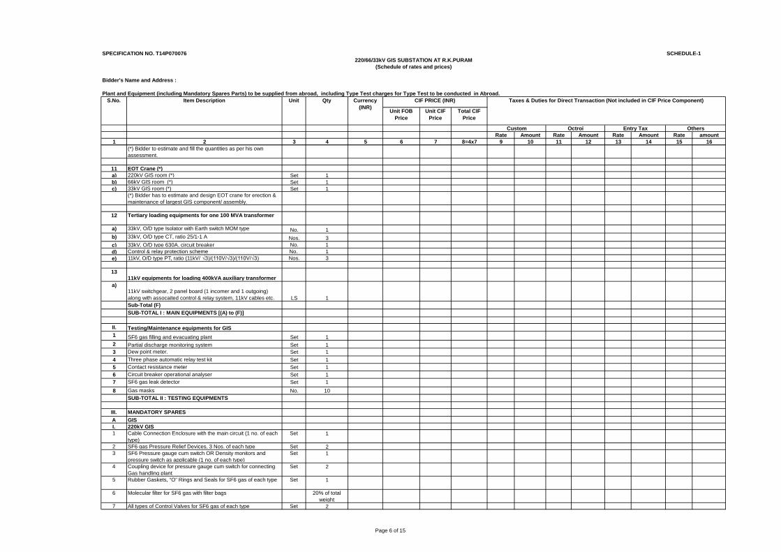
Page 6 of 15
SPECIFICATION NO. T14P070076 SCHEDULE-1
Bidder's Name and Address :
Plant and Equipment (including Mandatory Spares Parts) to be supplied from abroad, including Type Test charges for Type Test to be conducted in Abroad.
Unit FOB Price
Unit CIF Price
Total CIF Price
Rate Amount Rate Amount Rate Amount Rate amount1 2 3 4 5 6 7 8=4x7 9 10 11 12 13 14 15 16
Custom Octroi Entry Tax Others
220/66/33kV GIS SUBSTATION AT R.K.PURAM(Schedule of rates and prices)
Currency (INR)
CIF PRICE (INR) Taxes & Duties for Direct Transaction (Not included in CIF Price Component) S.No. Item Description Unit Qty
(*) Bidder to estimate and fill the quantities as per his own assessment.
11 EOT Crane (*) a) 220kV GIS room (*) Set 1b) 66kV GIS room (*) Set 1c) 33kV GIS room (*) Set 1
(*) Bidder has to estimate and design EOT crane for erection & maintenance of largest GIS component/ assembly.
12 Tertiary loading equipments for one 100 MVA transformer
a) 33kV, O/D type Isolator with Earth switch MOM type No. 1b) 33kV, O/D type CT, ratio 25/1-1 A Nos. 3c) 33kV, O/D type 630A, circuit breaker No. 1d) Control & relay protection scheme No. 1e) 11kV, O/D type PT, ratio (11kV/ √3)/(110V/√3)/(110V/√3) Nos. 3
1311kV equipments for loading 400kVA auxiliary transformer
a)11kV switchgear, 2 panel board (1 incomer and 1 outgoing) along with assocaited control & relay system, 11kV cables etc. LS 1Sub-Total (F)SUB-TOTAL I : MAIN EQUIPMENTS [(A) to (F)]
II. Testing/Maintenance equipments for GIS1 SF6 gas filling and evacuating plant Set 12 Partial discharge monitoring system Set 13 Dew point meter. Set 14 Three phase automatic relay test kit Set 15 Contact resistance meter Set 16 Circuit breaker operational analyser Set 17 SF6 gas leak detector Set 18 Gas masks No. 10
SUB-TOTAL II : TESTING EQUIPMENTS
III. MANDATORY SPARES A GISI. 220kV GIS1 Cable Connection Enclosure with the main circuit (1 no. of each
type)Set 1
2 SF6 gas Pressure Relief Devices, 3 Nos. of each type Set 23 SF6 Pressure gauge cum switch OR Density monitors and
pressure switch as applicable (1 no. of each type)Set 1
4 Coupling device for pressure gauge cum switch for connecting Gas handling plant
Set 2
5 Rubber Gaskets, “O” Rings and Seals for SF6 gas of each type Set 1
6 Molecular filter for SF6 gas with filter bags 20% of total weight
7 All types of Control Valves for SF6 gas of each type Set 2
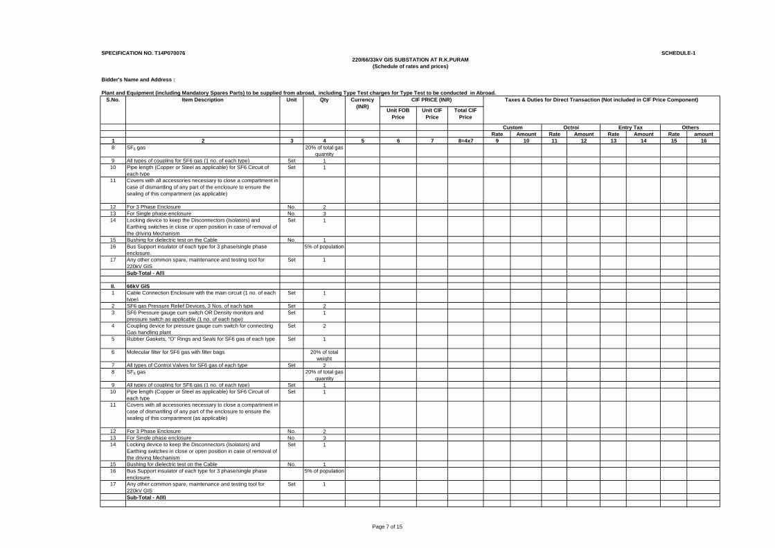
Page 7 of 15
SPECIFICATION NO. T14P070076 SCHEDULE-1
Bidder's Name and Address :
Plant and Equipment (including Mandatory Spares Parts) to be supplied from abroad, including Type Test charges for Type Test to be conducted in Abroad.
Unit FOB Price
Unit CIF Price
Total CIF Price
Rate Amount Rate Amount Rate Amount Rate amount1 2 3 4 5 6 7 8=4x7 9 10 11 12 13 14 15 16
Custom Octroi Entry Tax Others
220/66/33kV GIS SUBSTATION AT R.K.PURAM(Schedule of rates and prices)
Currency (INR)
CIF PRICE (INR) Taxes & Duties for Direct Transaction (Not included in CIF Price Component) S.No. Item Description Unit Qty
8 SF6 gas 20% of total gas quantity
9 All types of coupling for SF6 gas (1 no. of each type) Set 110 Pipe length (Copper or Steel as applicable) for SF6 Circuit of
each typeSet 1
11 Covers with all accessories necessary to close a compartment in case of dismantling of any part of the enclosure to ensure the sealing of this compartment (as applicable)
12 For 3 Phase Enclosure No. 213 For Single phase enclosure No. 314 Locking device to keep the Disconnectors (Isolators) and
Earthing switches in close or open position in case of removal of the driving Mechanism
Set 1
15 Bushing for dielectric test on the Cable No. 116 Bus Support insulator of each type for 3 phase/single phase
enclosure.5% of population
17 Any other common spare, maintenance and testing tool for 220kV GIS
Set 1
Sub-Total - A(I)
II. 66kV GIS1 Cable Connection Enclosure with the main circuit (1 no. of each
type)Set 1
2 SF6 gas Pressure Relief Devices, 3 Nos. of each type Set 23 SF6 Pressure gauge cum switch OR Density monitors and
pressure switch as applicable (1 no. of each type)Set 1
4 Coupling device for pressure gauge cum switch for connecting Gas handling plant
Set 2
5 Rubber Gaskets, “O” Rings and Seals for SF6 gas of each type Set 1
6 Molecular filter for SF6 gas with filter bags 20% of total weight
7 All types of Control Valves for SF6 gas of each type Set 28 SF6 gas 20% of total gas
quantity9 All types of coupling for SF6 gas (1 no. of each type) Set 1
10 Pipe length (Copper or Steel as applicable) for SF6 Circuit of each type
Set 1
11 Covers with all accessories necessary to close a compartment in case of dismantling of any part of the enclosure to ensure the sealing of this compartment (as applicable)
12 For 3 Phase Enclosure No. 213 For Single phase enclosure No. 314 Locking device to keep the Disconnectors (Isolators) and
Earthing switches in close or open position in case of removal of the driving Mechanism
Set 1
15 Bushing for dielectric test on the Cable No. 116 Bus Support insulator of each type for 3 phase/single phase
enclosure.5% of population
17 Any other common spare, maintenance and testing tool for 220kV GIS
Set 1
Sub-Total - A(II)
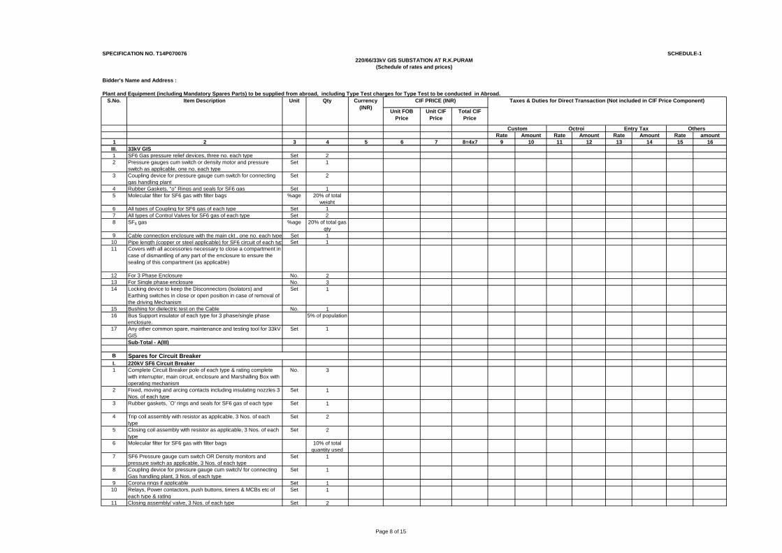
Page 8 of 15
SPECIFICATION NO. T14P070076 SCHEDULE-1
Bidder's Name and Address :
Plant and Equipment (including Mandatory Spares Parts) to be supplied from abroad, including Type Test charges for Type Test to be conducted in Abroad.
Unit FOB Price
Unit CIF Price
Total CIF Price
Rate Amount Rate Amount Rate Amount Rate amount1 2 3 4 5 6 7 8=4x7 9 10 11 12 13 14 15 16
Custom Octroi Entry Tax Others
220/66/33kV GIS SUBSTATION AT R.K.PURAM(Schedule of rates and prices)
Currency (INR)
CIF PRICE (INR) Taxes & Duties for Direct Transaction (Not included in CIF Price Component) S.No. Item Description Unit Qty
III. 33kV GIS1 SF6 Gas pressure relief devices, three no. each type Set 22 Pressure gauges cum switch or density motor and pressure
switch as applicable, one no. each typeSet 1
3 Coupling device for pressure gauge cum switch for connecting gas handling plant
Set 2
4 Rubber Gaskets, “o” Rings and seals for SF6 gas Set 15 Molecular filter for SF6 gas with filter bags %age 20% of total
weight6 All types of Coupling for SF6 gas of each type Set 17 All types of Control Valves for SF6 gas of each type Set 28 SF6 gas %age 20% of total gas
qty9 Cable connection enclosure with the main ckt , one no. each type Set 1
10 Pipe length (copper or steel applicable) for SF6 circuit of each typ Set 111 Covers with all accessories necessary to close a compartment in
case of dismantling of any part of the enclosure to ensure the sealing of this compartment (as applicable)
12 For 3 Phase Enclosure No. 213 For Single phase enclosure No. 314 Locking device to keep the Disconnectors (Isolators) and
Earthing switches in close or open position in case of removal of the driving Mechanism
Set 1
15 Bushing for dielectric test on the Cable No. 116 Bus Support insulator of each type for 3 phase/single phase
enclosure.5% of population
17 Any other common spare, maintenance and testing tool for 33kV GIS
Set 1
Sub-Total - A(III)
BI. 220kV SF6 Circuit Breaker1 Complete Circuit Breaker pole of each type & rating complete
with interrupter, main circuit, enclosure and Marshalling Box with operating mechanism
No. 3
2 Fixed, moving and arcing contacts including insulating nozzles 3 Nos. of each type
Set 1
3 Rubber gaskets, `O' rings and seals for SF6 gas of each type Set 1
4 Trip coil assembly with resistor as applicable, 3 Nos. of each type
Set 2
5 Closing coil assembly with resistor as applicable, 3 Nos. of each type
Set 2
6 Molecular filter for SF6 gas with filter bags 10% of total quantity used
7 SF6 Pressure gauge cum switch OR Density monitors and pressure switch as applicable, 3 Nos. of each type
Set 1
8 Coupling device for pressure gauge cum switch/ for connecting Gas handling plant, 3 Nos. of each type
Set 1
9 Corona rings if applicable Set 110 Relays, Power contactors, push buttons, timers & MCBs etc of
each type & ratingSet 1
11 Closing assembly/ valve, 3 Nos. of each type Set 2
Spares for Circuit Breaker
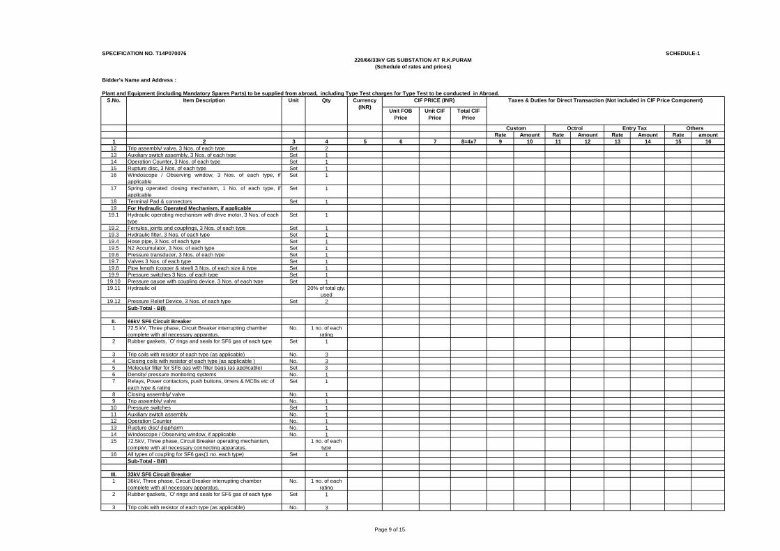
Page 9 of 15
SPECIFICATION NO. T14P070076 SCHEDULE-1
Bidder's Name and Address :
Plant and Equipment (including Mandatory Spares Parts) to be supplied from abroad, including Type Test charges for Type Test to be conducted in Abroad.
Unit FOB Price
Unit CIF Price
Total CIF Price
Rate Amount Rate Amount Rate Amount Rate amount1 2 3 4 5 6 7 8=4x7 9 10 11 12 13 14 15 16
Custom Octroi Entry Tax Others
220/66/33kV GIS SUBSTATION AT R.K.PURAM(Schedule of rates and prices)
Currency (INR)
CIF PRICE (INR) Taxes & Duties for Direct Transaction (Not included in CIF Price Component) S.No. Item Description Unit Qty
12 Trip assembly/ valve, 3 Nos. of each type Set 213 Auxiliary switch assembly, 3 Nos. of each type Set 114 Operation Counter, 3 Nos. of each type Set 115 Rupture disc, 3 Nos. of each type Set 116 Windoscope / Observing window, 3 Nos. of each type, if
applicableSet 1
17 Spring operated closing mechanism, 1 No. of each type, ifapplicable
Set 1
18 Terminal Pad & connectors Set 119 For Hydraulic Operated Mechanism, if applicable
19.1 Hydraulic operating mechanism with drive motor, 3 Nos. of each type
Set 1
19.2 Ferrules, joints and couplings, 3 Nos. of each type Set 119.3 Hydraulic filter, 3 Nos. of each type Set 119.4 Hose pipe, 3 Nos. of each type Set 119.5 N2 Accumulator, 3 Nos. of each type Set 119.6 Pressure transducer, 3 Nos. of each type Set 119.7 Valves 3 Nos. of each type Set 119.8 Pipe length (copper & steel) 3 Nos. of each size & type Set 119.9 Pressure switches 3 Nos. of each type Set 119.10 Pressure gauge with coupling device, 3 Nos. of each type Set 119.11 Hydraulic oil 20% of total qty.
used19.12 Pressure Relief Device, 3 Nos. of each type Set 2
Sub-Total - B(I)
II. 66kV SF6 Circuit Breaker1 72.5 kV, Three phase, Circuit Breaker interrupting chamber
complete with all necessary apparatus.No. 1 no. of each
rating2 Rubber gaskets, `O' rings and seals for SF6 gas of each type Set 1
3 Trip coils with resistor of each type (as applicable) No. 34 Closing coils with resistor of each type (as applicable ) No. 35 Molecular filter for SF6 gas with filter bags (as applicable) Set 36 Density/ pressure monitoring systems No. 17 Relays, Power contactors, push buttons, timers & MCBs etc of
each type & ratingSet 1
8 Closing assembly/ valve No. 19 Trip assembly/ valve No. 1
10 Pressure switches Set 111 Auxiliary switch assembly No. 112 Operation Counter No. 113 Rupture disc/ diapharm No. 114 Windoscope / Observing window, if applicable No. 115 72.5kV, Three phase, Circuit Breaker operating mechanism,
complete with all necessary connecting apparatus.1 no. of each
type16 All types of coupling for SF6 gas(1 no. each type) Set 1
Sub-Total - B(II)
III. 33kV SF6 Circuit Breaker1 36kV, Three phase, Circuit Breaker interrupting chamber
complete with all necessary apparatus.No. 1 no. of each
rating2 Rubber gaskets, `O' rings and seals for SF6 gas of each type Set 1
3 Trip coils with resistor of each type (as applicable) No. 3
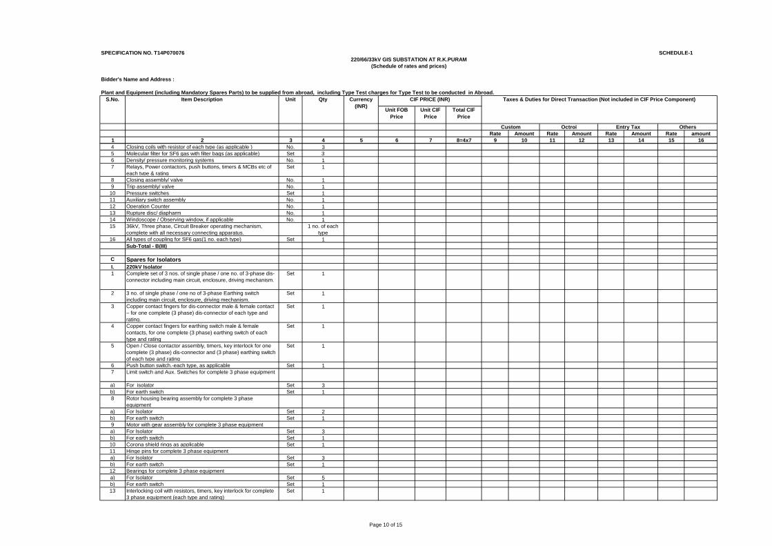
Page 10 of 15
SPECIFICATION NO. T14P070076 SCHEDULE-1
Bidder's Name and Address :
Plant and Equipment (including Mandatory Spares Parts) to be supplied from abroad, including Type Test charges for Type Test to be conducted in Abroad.
Unit FOB Price
Unit CIF Price
Total CIF Price
Rate Amount Rate Amount Rate Amount Rate amount1 2 3 4 5 6 7 8=4x7 9 10 11 12 13 14 15 16
Custom Octroi Entry Tax Others
220/66/33kV GIS SUBSTATION AT R.K.PURAM(Schedule of rates and prices)
Currency (INR)
CIF PRICE (INR) Taxes & Duties for Direct Transaction (Not included in CIF Price Component) S.No. Item Description Unit Qty
4 Closing coils with resistor of each type (as applicable ) No. 35 Molecular filter for SF6 gas with filter bags (as applicable) Set 36 Density/ pressure monitoring systems No. 17 Relays, Power contactors, push buttons, timers & MCBs etc of
each type & ratingSet 1
8 Closing assembly/ valve No. 19 Trip assembly/ valve No. 1
10 Pressure switches Set 111 Auxiliary switch assembly No. 112 Operation Counter No. 113 Rupture disc/ diapharm No. 114 Windoscope / Observing window, if applicable No. 115 36kV, Three phase, Circuit Breaker operating mechanism,
complete with all necessary connecting apparatus.1 no. of each
type16 All types of coupling for SF6 gas(1 no. each type) Set 1
Sub-Total - B(III)
C Spares for IsolatorsI. 220kV Isolator 1 Complete set of 3 nos. of single phase / one no. of 3-phase dis-
connector including main circuit, enclosure, driving mechanism.Set 1
2 3 no. of single phase / one no of 3-phase Earthing switch including main circuit, enclosure, driving mechanism.
Set 1
3 Copper contact fingers for dis-connector male & female contact – for one complete (3 phase) dis-connector of each type and rating.
Set 1
4 Copper contact fingers for earthing switch male & female contacts, for one complete (3 phase) earthing switch of each type and rating
Set 1
5 Open / Close contactor assembly, timers, key interlock for one complete (3 phase) dis-connector and (3 phase) earthing switch of each type and rating
Set 1
6 Push button switch.-each type, as applicable Set 17 Limit switch and Aux. Switches for complete 3 phase equipment
a) For isolator Set 3b) For earth switch Set 18 Rotor housing bearing assembly for complete 3 phase
equipmenta) For Isolator Set 2b) For earth switch Set 19 Motor with gear assembly for complete 3 phase equipmenta) For Isolator Set 3b) For earth switch Set 110 Corona shield rings as applicable Set 111 Hinge pins for complete 3 phase equipmenta) For Isolator Set 3b) For earth switch Set 112 Bearings for complete 3 phase equipment a) For Isolator Set 5b) For earth switch Set 113 Interlocking coil with resistors, timers, key interlock for complete
3 phase equipment (each type and rating)Set 1
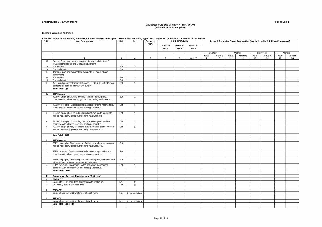
Page 11 of 15
SPECIFICATION NO. T14P070076 SCHEDULE-1
Bidder's Name and Address :
Plant and Equipment (including Mandatory Spares Parts) to be supplied from abroad, including Type Test charges for Type Test to be conducted in Abroad.
Unit FOB Price
Unit CIF Price
Total CIF Price
Rate Amount Rate Amount Rate Amount Rate amount1 2 3 4 5 6 7 8=4x7 9 10 11 12 13 14 15 16
Custom Octroi Entry Tax Others
220/66/33kV GIS SUBSTATION AT R.K.PURAM(Schedule of rates and prices)
Currency (INR)
CIF PRICE (INR) Taxes & Duties for Direct Transaction (Not included in CIF Price Component) S.No. Item Description Unit Qty
14 Relays, Power contactors, resistors, fuses, push buttons & MCBs (complete for one 3 phase equipment)
a) For Isolator Set 3b) For earth switch Set 115 Terminal pad and connectors (complete for one 3 phase
equipment)a) For Isolator Set 2b) For earth switch Set 116 Aux. switch assembly (complete) with 10 NO & 10 NC OR more
contacts for both isolator & earth switchSet 1
Sub-Total - C(I)
II. 66kV Isolator1 72.5kV, single ph., Disconnecting Switch internal parts,
complete with all necessary gaskets, mounting hardware, etc.Set 1
2 72.5kV, three ph., Disconnecting Switch operating mechanism, complete with all necessary connecting apparatus.
Set 1
3 72.5kV, single ph., Grounding Switch internal parts, complete with all necessary gaskets, mounting hardware etc
Set 1
4 72.5kV, three ph., Grounding Switch operating mechanism, complete with all necessary connecting apparatus.
Set 1
5 72.5kV, single phase, grounding switch, Internal parts complete with all necessary gaskets mounting hardware etc.
Set 1
Sub-Total - C(II)
III. 33kV Isolator1 36kV, single ph., Disconnecting Switch internal parts, complete
with all necessary gaskets, mounting hardware, etc.Set 1
2 36kV, three ph., Disconnecting Switch operating mechanism, complete with all necessary connecting apparatus.
Set 1
3 36kV, single ph., Grounding Switch internal parts, complete with all necessary gaskets, mounting hardware etc
Set 1
4 36kV, three ph., Grounding Switch operating mechanism, complete with all necessary connecting apparatus.
Set 1
Sub-Total - C(III)
D Spares for Current Transformer (GIS type)I. 220kV CT1 Complete CT of each type and rating with enclosure. No. 22 Secondary bushing of each type Set 2
II. 66kV CT1 single phase current transformer of each rating No. three each type
III. 33kV CT1 single phase current transformer of each rating No. three each type
Sub-Total - D(I+II+III)
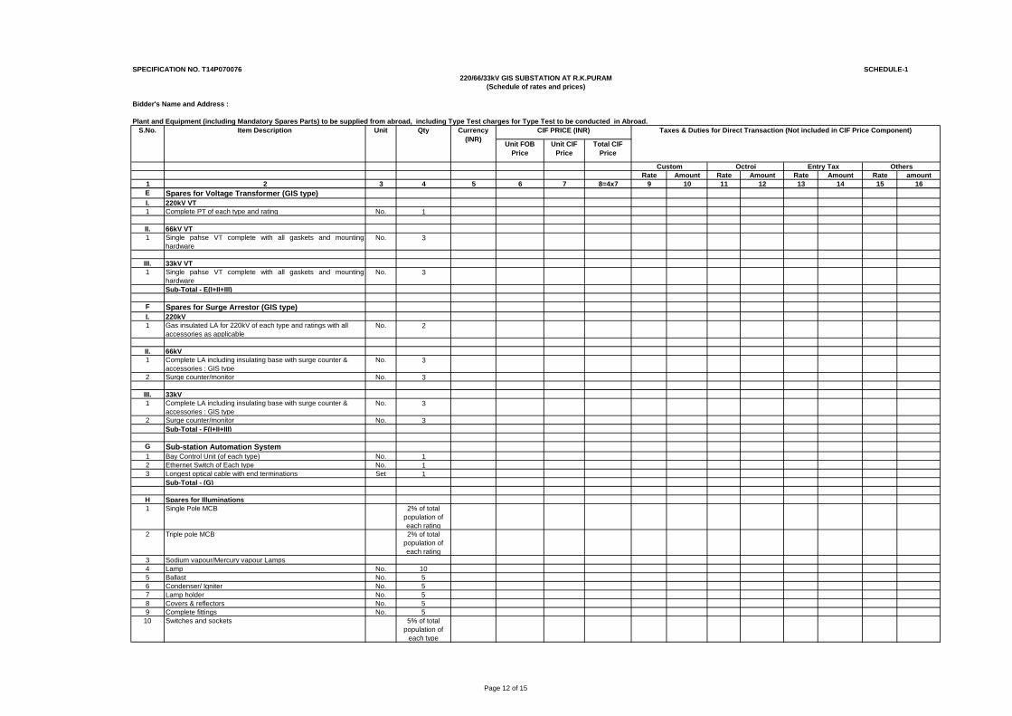
Page 12 of 15
SPECIFICATION NO. T14P070076 SCHEDULE-1
Bidder's Name and Address :
Plant and Equipment (including Mandatory Spares Parts) to be supplied from abroad, including Type Test charges for Type Test to be conducted in Abroad.
Unit FOB Price
Unit CIF Price
Total CIF Price
Rate Amount Rate Amount Rate Amount Rate amount1 2 3 4 5 6 7 8=4x7 9 10 11 12 13 14 15 16
Custom Octroi Entry Tax Others
220/66/33kV GIS SUBSTATION AT R.K.PURAM(Schedule of rates and prices)
Currency (INR)
CIF PRICE (INR) Taxes & Duties for Direct Transaction (Not included in CIF Price Component) S.No. Item Description Unit Qty
E Spares for Voltage Transformer (GIS type)I. 220kV VT1 Complete PT of each type and rating No. 1
II. 66kV VT1 Single pahse VT complete with all gaskets and mounting
hardware No. 3
III. 33kV VT1 Single pahse VT complete with all gaskets and mounting
hardware No. 3
Sub-Total - E(I+II+III)
F Spares for Surge Arrestor (GIS type)I. 220kV1 Gas insulated LA for 220kV of each type and ratings with all
accessories as applicableNo. 2
II. 66kV1 Complete LA including insulating base with surge counter &
accessories : GIS typeNo. 3
2 Surge counter/monitor No. 3
III. 33kV 1 Complete LA including insulating base with surge counter &
accessories : GIS typeNo. 3
2 Surge counter/monitor No. 3Sub-Total - F(I+II+III)
G Sub-station Automation System1 Bay Control Unit (of each type) No. 12 Ethernet Switch of Each type No. 13 Longest optical cable with end terminations Set 1
Sub-Total - (G)
H Spares for Illuminations1 Single Pole MCB 2% of total
population of each rating
2 Triple pole MCB 2% of total population of each rating
3 Sodium vapour/Mercury vapour Lamps4 Lamp No. 105 Ballast No. 56 Condenser/ Igniter No. 57 Lamp holder No. 58 Covers & reflectors No. 59 Complete fittings No. 5
10 Switches and sockets 5% of total population of
each type
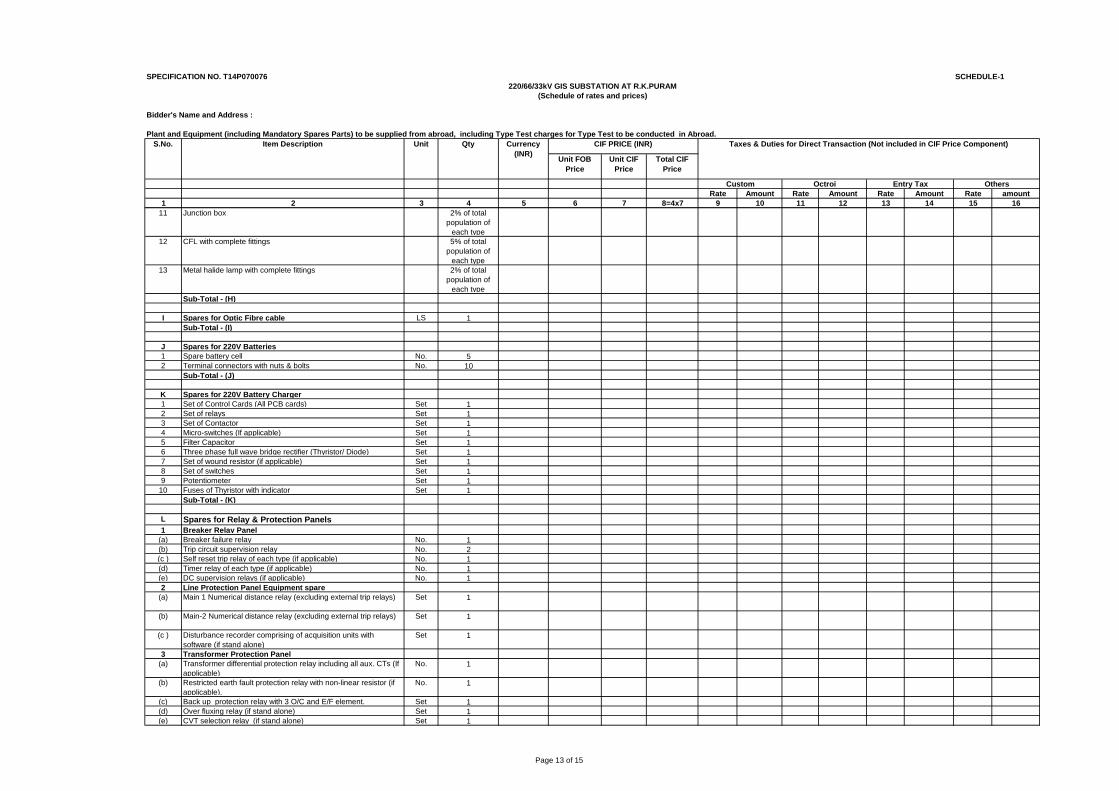
Page 13 of 15
SPECIFICATION NO. T14P070076 SCHEDULE-1
Bidder's Name and Address :
Plant and Equipment (including Mandatory Spares Parts) to be supplied from abroad, including Type Test charges for Type Test to be conducted in Abroad.
Unit FOB Price
Unit CIF Price
Total CIF Price
Rate Amount Rate Amount Rate Amount Rate amount1 2 3 4 5 6 7 8=4x7 9 10 11 12 13 14 15 16
Custom Octroi Entry Tax Others
220/66/33kV GIS SUBSTATION AT R.K.PURAM(Schedule of rates and prices)
Currency (INR)
CIF PRICE (INR) Taxes & Duties for Direct Transaction (Not included in CIF Price Component) S.No. Item Description Unit Qty
11 Junction box 2% of total population of
each type12 CFL with complete fittings 5% of total
population of each type
13 Metal halide lamp with complete fittings 2% of total population of
each typeSub-Total - (H)
I Spares for Optic Fibre cable LS 1Sub-Total - (I)
J Spares for 220V Batteries1 Spare battery cell No. 52 Terminal connectors with nuts & bolts No. 10
Sub-Total - (J)
K Spares for 220V Battery Charger1 Set of Control Cards (All PCB cards) Set 12 Set of relays Set 13 Set of Contactor Set 14 Micro-switches (If applicable) Set 15 Filter Capacitor Set 16 Three phase full wave bridge rectifier (Thyristor/ Diode) Set 17 Set of wound resistor (if applicable) Set 18 Set of switches Set 19 Potentiometer Set 1
10 Fuses of Thyristor with indicator Set 1Sub-Total - (K)
L Spares for Relay & Protection Panels1 Breaker Relay Panel
(a) Breaker failure relay No. 1(b) Trip circuit supervision relay No. 2(c ) Self reset trip relay of each type (if applicable) No. 1(d) Timer relay of each type (if applicable) No. 1(e) DC supervision relays (if applicable) No. 12 Line Protection Panel Equipment spare
(a) Main 1 Numerical distance relay (excluding external trip relays) Set 1
(b) Main-2 Numerical distance relay (excluding external trip relays) Set 1
(c ) Disturbance recorder comprising of acquisition units with software (if stand alone)
Set 1
3 Transformer Protection Panel(a) Transformer differential protection relay including all aux. CTs (If
applicable)No. 1
(b) Restricted earth fault protection relay with non-linear resistor (if applicable).
No. 1
(c) Back up protection relay with 3 O/C and E/F element. Set 1(d) Over fluxing relay (if stand alone) Set 1(e) CVT selection relay (if stand alone) Set 1
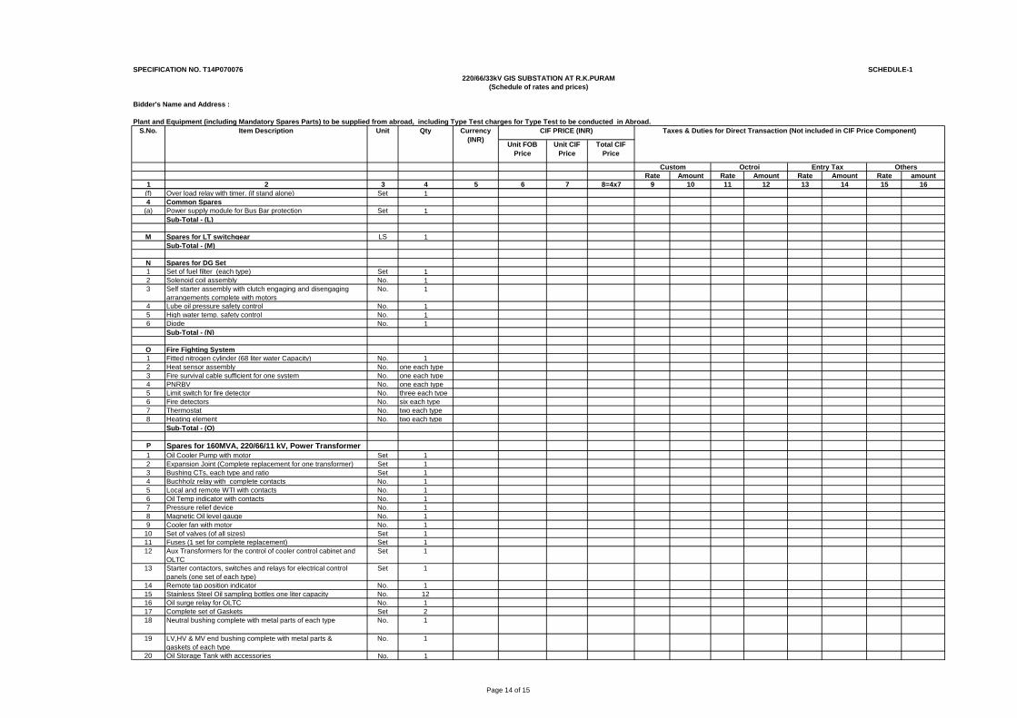
Page 14 of 15
SPECIFICATION NO. T14P070076 SCHEDULE-1
Bidder's Name and Address :
Plant and Equipment (including Mandatory Spares Parts) to be supplied from abroad, including Type Test charges for Type Test to be conducted in Abroad.
Unit FOB Price
Unit CIF Price
Total CIF Price
Rate Amount Rate Amount Rate Amount Rate amount1 2 3 4 5 6 7 8=4x7 9 10 11 12 13 14 15 16
Custom Octroi Entry Tax Others
220/66/33kV GIS SUBSTATION AT R.K.PURAM(Schedule of rates and prices)
Currency (INR)
CIF PRICE (INR) Taxes & Duties for Direct Transaction (Not included in CIF Price Component) S.No. Item Description Unit Qty
(f) Over load relay with timer. (if stand alone) Set 14 Common Spares
(a) Power supply module for Bus Bar protection Set 1Sub-Total - (L)
M Spares for LT switchgear LS 1Sub-Total - (M)
N Spares for DG Set1 Set of fuel filter (each type) Set 12 Solenoid coil assembly No. 13 Self starter assembly with clutch engaging and disengaging
arrangements complete with motorsNo. 1
4 Lube oil pressure safety control No. 15 High water temp. safety control No. 16 Diode No. 1
Sub-Total - (N)
O Fire Fighting System1 Fitted nitrogen cylinder (68 liter water Capacity) No. 12 Heat sensor assembly No. one each type3 Fire survival cable sufficient for one system No. one each type4 PNRBV No. one each type5 Limit switch for fire detector No. three each type6 Fire detectors No. six each type7 Thermostat No. two each type8 Heating element No. two each type
Sub-Total - (O)
P Spares for 160MVA, 220/66/11 kV, Power Transformer1 Oil Cooler Pump with motor Set 12 Expansion Joint (Complete replacement for one transformer) Set 13 Bushing CTs, each type and ratio Set 14 Buchholz relay with complete contacts No. 15 Local and remote WTI with contacts No. 16 Oil Temp indicator with contacts No. 17 Pressure relief device No. 18 Magnetic Oil level gauge No. 19 Cooler fan with motor No. 1
10 Set of valves (of all sizes) Set 111 Fuses (1 set for complete replacement) Set 112 Aux Transformers for the control of cooler control cabinet and
OLTC Set 1
13 Starter contactors, switches and relays for electrical control panels (one set of each type)
Set 1
14 Remote tap position indicator No. 115 Stainless Steel Oil sampling bottles one liter capacity No. 1216 Oil surge relay for OLTC No. 117 Complete set of Gaskets Set 218 Neutral bushing complete with metal parts of each type No. 1
19 LV,HV & MV end bushing complete with metal parts &gaskets of each type
No. 1
20 Oil Storage Tank with accessories No. 1
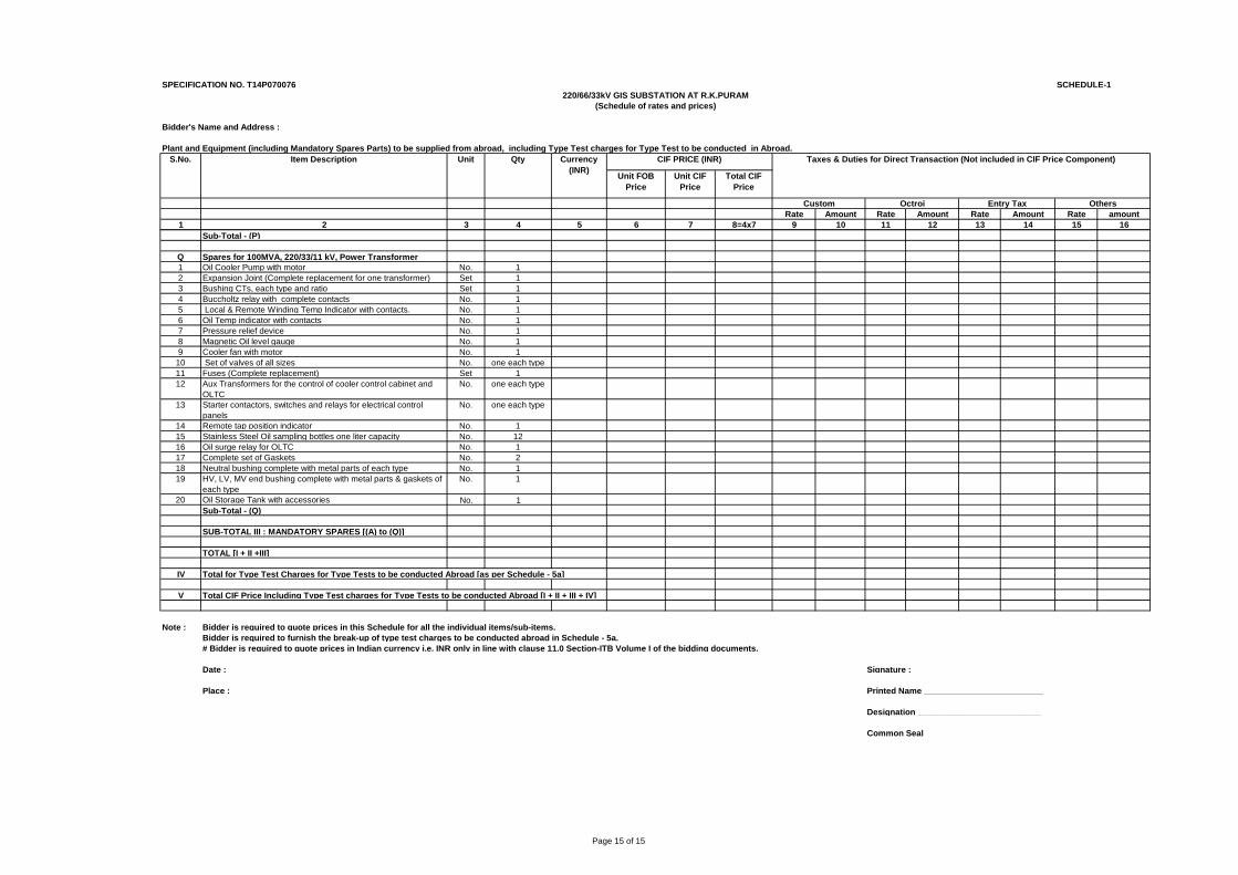
Page 15 of 15
SPECIFICATION NO. T14P070076 SCHEDULE-1
Bidder's Name and Address :
Plant and Equipment (including Mandatory Spares Parts) to be supplied from abroad, including Type Test charges for Type Test to be conducted in Abroad.
Unit FOB Price
Unit CIF Price
Total CIF Price
Rate Amount Rate Amount Rate Amount Rate amount1 2 3 4 5 6 7 8=4x7 9 10 11 12 13 14 15 16
Custom Octroi Entry Tax Others
220/66/33kV GIS SUBSTATION AT R.K.PURAM(Schedule of rates and prices)
Currency (INR)
CIF PRICE (INR) Taxes & Duties for Direct Transaction (Not included in CIF Price Component) S.No. Item Description Unit Qty
Sub-Total - (P)
Q Spares for 100MVA, 220/33/11 kV, Power Transformer1 Oil Cooler Pump with motor No. 12 Expansion Joint (Complete replacement for one transformer) Set 13 Bushing CTs, each type and ratio Set 14 Buccholtz relay with complete contacts No. 15 Local & Remote Winding Temp Indicator with contacts. No. 16 Oil Temp indicator with contacts No. 17 Pressure relief device No. 18 Magnetic Oil level gauge No. 19 Cooler fan with motor No. 1
10 Set of valves of all sizes No. one each type11 Fuses (Complete replacement) Set 112 Aux Transformers for the control of cooler control cabinet and
OLTC No. one each type
13 Starter contactors, switches and relays for electrical control panels
No. one each type
14 Remote tap position indicator No. 115 Stainless Steel Oil sampling bottles one liter capacity No. 1216 Oil surge relay for OLTC No. 117 Complete set of Gaskets No. 218 Neutral bushing complete with metal parts of each type No. 119 HV, LV, MV end bushing complete with metal parts & gaskets of
each typeNo. 1
20 Oil Storage Tank with accessories No. 1Sub-Total - (Q)
SUB-TOTAL III : MANDATORY SPARES [(A) to (Q)]
TOTAL [I + II +III]
IV Total for Type Test Charges for Type Tests to be conducted Abroad [as per Schedule - 5a]
V Total CIF Price Including Type Test charges for Type Tests to be conducted Abroad [I + II + III + IV]
Note : Bidder is required to quote prices in this Schedule for all the individual items/sub-items. Bidder is required to furnish the break-up of type test charges to be conducted abroad in Schedule - 5a.# Bidder is required to quote prices in Indian currency i.e. INR only in line with clause 11.0 Section-ITB Volume I of the bidding documents.
Date : Signature : ___________________________
Place : Printed Name _________________________
Designation __________________________
Common Seal ________________________
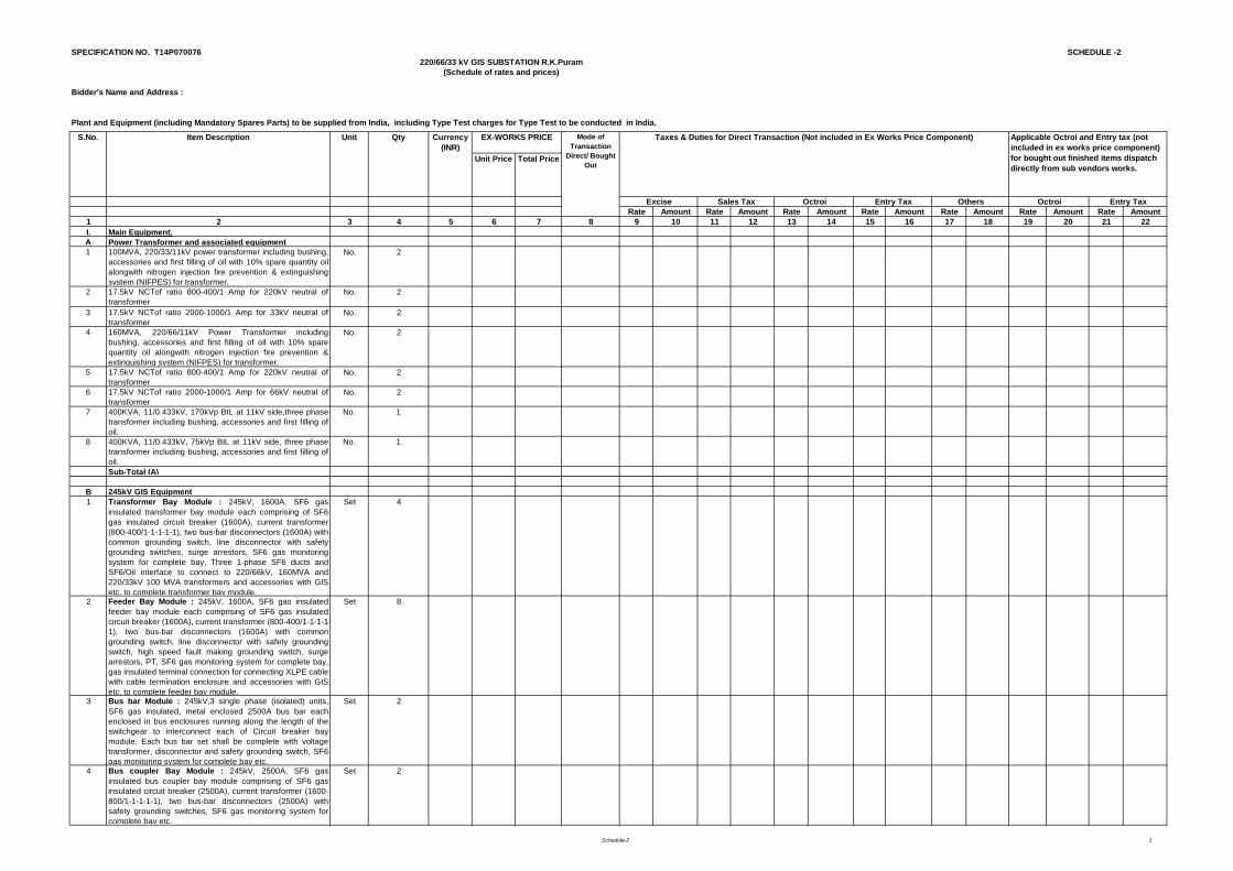
Schedule-2 1
SPECIFICATION NO. T14P070076 SCHEDULE -2
Bidder's Name and Address :
Unit Price Total Price
Rate Amount Rate Amount Rate Amount Rate Amount Rate Amount Rate Amount Rate Amount1 2 3 4 5 6 7 8 9 10 11 12 13 14 15 16 17 18 19 20 21 22I. Main Equipment.A Power Transformer and associated equipment1 100MVA, 220/33/11kV power transformer including bushing,
accessories and first filling of oil with 10% spare quantity oilalongwith nitrogen injection fire prevention & extinguishingsystem (NIFPES) for transformer.
No. 2
2 17.5kV NCTof ratio 800-400/1 Amp for 220kV neutral oftransformer
No. 2
3 17.5kV NCTof ratio 2000-1000/1 Amp for 33kV neutral oftransformer
No. 2
4 160MVA, 220/66/11kV Power Transformer includingbushing, accessories and first filling of oil with 10% sparequantity oil alongwith nitrogen injection fire prevention &extinguishing system (NIFPES) for transformer.
No. 2
5 17.5kV NCTof ratio 800-400/1 Amp for 220kV neutral oftransformer
No. 2
6 17.5kV NCTof ratio 2000-1000/1 Amp for 66kV neutral oftransformer
No. 2
7 400KVA, 11/0.433kV, 170kVp BIL at 11kV side,three phasetransformer including bushing, accessories and first filling ofoil.
No. 1
8 400KVA, 11/0.433kV, 75kVp BIL at 11kV side, three phasetransformer including bushing, accessories and first filling ofoil.
No. 1
Sub-Total (A)
B 245kV GIS Equipment1 Transformer Bay Module : 245kV, 1600A, SF6 gas
insulated transformer bay module each comprising of SF6gas insulated circuit breaker (1600A), current transformer(800-400/1-1-1-1-1), two bus-bar disconnectors (1600A) withcommon grounding switch, line disconnector with safetygrounding switches, surge arrestors, SF6 gas monitoringsystem for complete bay, Three 1-phase SF6 ducts andSF6/Oil interface to connect to 220/66kV, 160MVA and220/33kV 100 MVA transformers and accessories with GISetc. to complete transformer bay module.
Set 4
2 Feeder Bay Module : 245kV, 1600A, SF6 gas insulatedfeeder bay module each comprising of SF6 gas insulatedcircuit breaker (1600A), current transformer (800-400/1-1-1-1-1), two bus-bar disconnectors (1600A) with commongrounding switch, line disconnector with safety groundingswitch, high speed fault making grounding switch, surgearrestors, PT, SF6 gas monitoring system for complete bay,gas insulated terminal connection for connecting XLPE cablewith cable termination enclosure and accessories with GISetc. to complete feeder bay module.
Set 8
3 Bus bar Module : 245kV,3 single phase (isolated) units,SF6 gas insulated, metal enclosed 2500A bus bar eachenclosed in bus enclosures running along the length of theswitchgear to interconnect each of Circuit breaker baymodule. Each bus bar set shall be complete with voltagetransformer, disconnector and safety grounding switch, SF6gas monitoring system for complete bay etc.
Set 2
4 Bus coupler Bay Module : 245kV, 2500A, SF6 gasinsulated bus coupler bay module comprising of SF6 gasinsulated circuit breaker (2500A), current transformer (1600-800/1-1-1-1-1), two bus-bar disconnectors (2500A) withsafety grounding switches, SF6 gas monitoring system forcomplete bay etc.
Set 2
Entry Tax
220/66/33 kV GIS SUBSTATION R.K.Puram(Schedule of rates and prices)
Plant and Equipment (including Mandatory Spares Parts) to be supplied from India, including Type Test charges for Type Test to be conducted in India.
S.No. Item Description Applicable Octroi and Entry tax (not included in ex works price component) for bought out finished items dispatch directly from sub vendors works.
Octroi
Unit Qty Currency (INR)
Taxes & Duties for Direct Transaction (Not included in Ex Works Price Component) Mode of Transaction
Direct/ Bought Out
EX-WORKS PRICE
Excise Sales Tax Octroi OthersEntry Tax
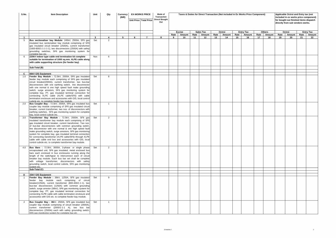
Schedule-2 2
Unit Price Total Price
Rate Amount Rate Amount Rate Amount Rate Amount Rate Amount Rate Amount Rate Amount1 2 3 4 5 6 7 8 9 10 11 12 13 14 15 16 17 18 19 20 21 22
Entry Tax
S.No. Item Description Applicable Octroi and Entry tax (not included in ex works price component) for bought out finished items dispatch directly from sub vendors works.
Octroi
Unit Qty Currency (INR)
Taxes & Duties for Direct Transaction (Not included in Ex Works Price Component) Mode of Transaction
Direct/ Bought Out
EX-WORKS PRICE
Excise Sales Tax Octroi OthersEntry Tax
5 Bus sectionaliser bay Module: 245kV, 2500A, SF6 gasinsulated bus sectionaliser bay module comprising of SF6gas insulated circuit breaker (2500A), current transformer(1600-800/1-1-1-1-1), two disconnectors (2500A) with safetygrounding switches, SF6 gas monitoring system forcomplete bay etc.
Set 2
6 220kV indoor type cable end termination kit complete suitable for termination of 1000 sq.mm. XLPE cable along with cable supporting structure (for feeder bay)
Nos 6
Sub-Total (B)
C 66kV GIS Equipment1.0 Feeder Bay Module : 72.5kV, 2000A, SF6 gas insulated
feeder bay module each comprising of SF6 gas insulatedcircuit breaker(2000A), current transformer, two bus-bardisconnectors with one earthing switch, line disconnectorwith one normal & one high speed fault make groundingswitch, surge arrestors, SF6 gas monitoring system forcomplete bay, PT, gas insulated terminal connection forconnecting XLPE cable (XLPE cable/SF6) with cabletermination enclosure and accessories with GIS, local controlcubicle etc. to complete feeder bay module.
Set 8
2.0 Bus Coupler Bay : 72.5kV, 2500A, SF6 gas insulated buscoupler bay module comprising of SF6 gas insulated circuitbreaker, current transformer, two nos. of disconnectors withearthing switches, SF6 gas monitoring system for completebay, local control cubicle etc.
Set 1
3.0 Transformer Bay Module : 72.5kV, 2000A, SF6 gasinsulated transformer bay module each comprising of SF6gas insulated circuit breaker, current transformer, Two nos.of bus-bar disconnectors with common grounding switch,line disconnector with one normal & one high speed faultmake grounding switch, surge arrestors, SF6 gas monitoringsystem for complete bay, gas insulated terminal connectionfor connecting transformer (XLPE cable/SF6) through XLPEcable with cable end box and accessories with GIS, localcontrol cubicle etc. to complete transformer bay module.
Set 2
4.0 Bus Bars : 72.5kV, 3000A, 3-phase or single phaseencapsulated unit, SF6 gas insulated, metal enclosed busbars each enclosed in bus enclosures running along thelength of the switchgear to interconnect each of circuitbreaker bay module. Each bus bar set shall be completewith voltage transformer, disconnectors with safetygrounding switch, local control cubicle, SF6 gas monitoringsystem etc.
Set 2
Sub-Total (C)
D 33kV GIS Equipment1 Feeder Bay Module : 36kV, 1250A, SF6 gas insulated
feeder bay module each comprising of circuitbreaker(1250A), current transformer (800-400/1-1-1), twobus-bar disconnectors (1250A) with common groundingswitch, surge arrestor (30kV), SF6 gas monitoring system forcomplete bay, PT, gas insulated terminal connection forconnecting XLPE cable with cable termination enclosure andaccessories with GIS etc. to complete feeder bay module.
Set 9
2 Bus Coupler Bay : 36kV, 2500A, SF6 gas insulated buscoupler bay module comprising of circuit breaker (2500A),current transformer (2000/1-1-1 A), two bus bardisconnectors (2500A) each with safety grounding switch,SF6 gas monitoring system for complete bay etc.
Set 1
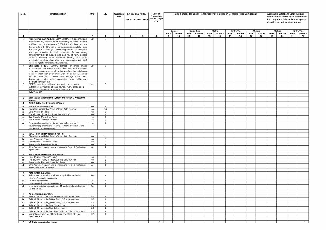
Schedule-2 3
Unit Price Total Price
Rate Amount Rate Amount Rate Amount Rate Amount Rate Amount Rate Amount Rate Amount1 2 3 4 5 6 7 8 9 10 11 12 13 14 15 16 17 18 19 20 21 22
Entry Tax
S.No. Item Description Applicable Octroi and Entry tax (not included in ex works price component) for bought out finished items dispatch directly from sub vendors works.
Octroi
Unit Qty Currency (INR)
Taxes & Duties for Direct Transaction (Not included in Ex Works Price Component) Mode of Transaction
Direct/ Bought Out
EX-WORKS PRICE
Excise Sales Tax Octroi OthersEntry Tax
3 Transformer Bay Module : 36kV, 2500A, SF6 gas insulatedtransformer bay module each comprising of circuit breaker(2500A), current transformer (2000/1-1-1 A), Two bus-bardisconnectors (2500A) with common grounding switch, surge arrestors (30kV), SF6 gas monitoring system for completebay, gas insulated terminal connection for connectingtransformer through suitable size and no. of XLPE coppercable considering 110% continuos loading with cabletermination enclosure/bus duct and accessories with GISetc. to complete transformer bay module.
Set 2
4 Bus Bars : 36kV, 2500A, 3-phase or single phaseencapsulated unit, metal enclosed bus bars each enclosedin bus enclosures running along the length of the switchgearto interconnect each of circuit breaker bay module. Each busbar set shall be complete with voltage transformer,disconnectors with safety grounding switch, SF6 gasmonitoring system etc.
Set 2
6 220kV indoor type cable end termination kit complete suitable for termination of 1000 sq.mm. XLPE cable along with cable supporting structure (for feeder bay)
Nos 6
Sub-Total (D)
E Sub-Station Automation System and Relay & Protection Panels
1 220kV Relay and Protection Panelsa) Bus Bar Protection Panel No. 1b) Circuit Breaker Relay Panel Without Auto Reclose No. 16c) Line Protection Panel No. 8d) Transformer Protection Panel (for HV side) No. 4e) Bus-Coupler Protection Panel No. 2f) Bus-Section Protection Panel No. 2
g) Time synchronization equipment and other common equipments pertaining to Relay & Protection system (Time synchronization equipment)
Lot 1
2 66KV Relay and Protection Panelsa) Circuit Breaker Relay Panel Without Auto Reclose No. 11b) Line Protection Panel No. 8c) Transformer Protection Panel No. 2d) Bus-Coupler Protection Panel No. 1e) Other/common equipments pertaining to Relay & Protection
System etc.Lot 1
3 33KV Relay and Protection Panelsa) Line Relay & Protection Panel No. 9b) Transformer Relay & Protection Panel for LV side No. 2c) Bus-Coupler Relay & Protection Panel No. 1d) Other/common equipments pertaining to Relay & Protection
System (included in above)Lot 1
4 Automation & SCADAa) Substation automation equipment, optic fibre and other
interface/converter equipmentSet 1
b) SCADA equipments Set 1c) Testing & Maintenance equipment Set 1d) Inverter of suitable capacity for HMI and peripheral devices
i.e. Printer etc.Set 1
5 Air conditioning systema) Split AC (4 star rating) 220kV Relay & Protection room LS 1b) Split AC (4 star rating) 33kV Relay & Protection room LS 1c) Split AC (4 star rating) 66kV Relay & Protection room LS 1d) Split AC (4 star rating) for Control room LS 1e) Split AC (4 star rating) for Battery room LS 1f) Split AC (4 star rating)for Electrical lab and for office space LS 1g) Ventilation system for 220kV, 66kV and 33kV GIS Hall LS 1
Sub-Total (E)
F LT Switchgear& other items
Schedule-2 4
Unit Price Total Price
Rate Amount Rate Amount Rate Amount Rate Amount Rate Amount Rate Amount Rate Amount1 2 3 4 5 6 7 8 9 10 11 12 13 14 15 16 17 18 19 20 21 22
Entry Tax
S.No. Item Description Applicable Octroi and Entry tax (not included in ex works price component) for bought out finished items dispatch directly from sub vendors works.
Octroi
Unit Qty Currency (INR)
Taxes & Duties for Direct Transaction (Not included in Ex Works Price Component) Mode of Transaction
Direct/ Bought Out
EX-WORKS PRICE
Excise Sales Tax Octroi OthersEntry Tax
1 LT Switchgeara) 415V Main Switchboard Set 1b) 415V ACDB Set 1c) 415V Main Lighting DB Set 1d) 415V Emergency Lighting DB Set 1e) 415V Air-conditioning & Ventilation DB Set 1f) 220V DCDB Set 1
2 Batteries & Batteries chargersa) Battery 220V [ AH] (*) Set 2
(*) Bidder to estimate and indicate the capacities of batteries in Ampere-Hours. The estimated capacities should meet the functional requirement.
b) 220V Battery Charger System (*) Set 2(*)The rating of battery charger shall be decided by thebidder to meet the functional requirement.
3 DG set alongwith control panel (250KVA, 440V) Set 1
4 Fire prevention & extinguishing system a) Fire Protection for GIS Halls, control room building, etc.
(Portable type fire extinguishers system)Lot 1
5 Illumination System (*)a) Control Room Building, GIS Building etc, llumination with
CFL/Metal Halide LampLS 1
b) Switchyard/ Street Lighting (High Mast Lighting System) LS 1
6 1.1 kV Grade PVC insulated aluminium conductor armoured power cables and copper conductor armoured control cables alongwith lugs, glands and straight joints.
a) Power Cables (XLPE) (*)i) 1Cx630 sq.mm kmii) 3.5Cx300 sq.mm kmb) Power Cable (PVC) (*)i) 1Cx150 sq.mm kmii) 3.5Cx70 sq.mm kmiii) 3.5Cx35 sq.mm kmiv) 4Cx16 sq.mm kmv) 4Cx6 sq.mm kmvi) 2Cx6 sq.mm kmc) Control Cable (PVC) (*)i) 2Cx2.5 sq.mm kmii) 3Cx2.5 sq.mm kmiii) 5Cx2.5 sq.mm kmiv) 7Cx2.5 sq.mm kmv) 10Cx2.5 sq.mm kmvi) 14Cx2.5 sq.mm kmvii) 19Cx2.5 sq.mm kmviii) 27Cx2.5 sq.mm km
(*) The bidder has to estimate and fill the quantities as per his own assessment.
7 Power cable with termmination kit/bus duct on 33kV side for connecting 2 nos. Transformers to 33kV GIS
LS 1
8 Power cable with termmination kit/bus duct on 66kV side for connecting 2 nos. Transformers to 66kV GIS
LS 1
9 Grounding/ Earthing Systema) 40mm MS rod for Earthmat LS 1b) Lightning Mast/ GS Shield Wire LS 1
10 Steel Structure (*) a) Lattice Strcuture MTb) Pipe Structure MT
(*) Bidder to estimate and fill the quantities as per his own assessment.
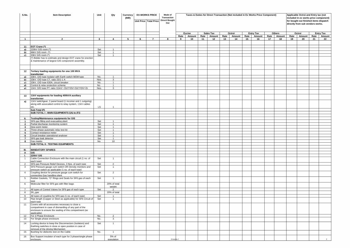
Schedule-2 5
Unit Price Total Price
Rate Amount Rate Amount Rate Amount Rate Amount Rate Amount Rate Amount Rate Amount1 2 3 4 5 6 7 8 9 10 11 12 13 14 15 16 17 18 19 20 21 22
Entry Tax
S.No. Item Description Applicable Octroi and Entry tax (not included in ex works price component) for bought out finished items dispatch directly from sub vendors works.
Octroi
Unit Qty Currency (INR)
Taxes & Duties for Direct Transaction (Not included in Ex Works Price Component) Mode of Transaction
Direct/ Bought Out
EX-WORKS PRICE
Excise Sales Tax Octroi OthersEntry Tax
11 EOT Crane (*) a) 220kV GIS room (*) Set 1b) 66kV GIS room (*) Set 1c) 33kV GIS room (*) Set 1
(*) Bidder has to estimate and design EOT crane for erection & maintenance of largest GIS component/ assembly.
12 Tertiary loading equipments for one 100 MVA transformer
a) 33kV, O/D type Isolator with Earth switch MOM type No. 1b) 33kV, O/D type CT, ratio 25/1-1 A Nos. 3c) 33kV, O/D type 630A, circuit breaker No. 1d) Control & relay protection scheme No. 1e) 11kV, O/D type PT, ratio (11kV/ √3)/(110V/√3)/(110V/√3) Nos. 3
13 11kV equipments for loading 400kVA auxiliary transformer
a) 11kV switchgear, 2 panel board (1 incomer and 1 outgoing) along with assocaited control & relay system, 11kV cables etc. LS 1Sub-Total (F)SUB-TOTAL I : MAIN EQUIPMENTS [(A) to (F)]
II. Testing/Maintenance equipments for GIS1 SF6 gas filling and evacuating plant Set 12 Partial discharge monitoring system Set 13 Dew point meter. Set 14 Three phase automatic relay test kit Set 15 Contact resistance meter Set 16 Circuit breaker operational analyser Set 17 SF6 gas leak detector Set 18 Gas masks No. 10
SUB-TOTAL II : TESTING EQUIPMENTS
III. MANDATORY SPARES A GISI. 220kV GIS1 Cable Connection Enclosure with the main circuit (1 no. of
each type)Set 1
2 SF6 gas Pressure Relief Devices, 3 Nos. of each type Set 23 SF6 Pressure gauge cum switch OR Density monitors and
pressure switch as applicable (1 no. of each type)Set 1
4 Coupling device for pressure gauge cum switch for connecting Gas handling plant
Set 2
5 Rubber Gaskets, “O” Rings and Seals for SF6 gas of each type
Set 1
6 Molecular filter for SF6 gas with filter bags 20% of total weight
7 All types of Control Valves for SF6 gas of each type Set 28 SF6 gas 20% of total
9 All types of coupling for SF6 gas (1 no. of each type) Set 110 Pipe length (Copper or Steel as applicable) for SF6 Circuit of
each typeSet 1
11 Covers with all accessories necessary to close a compartment in case of dismantling of any part of the enclosure to ensure the sealing of this compartment (as applicable)
12 For 3 Phase Enclosure No. 213 For Single phase enclosure No. 3
14 Locking device to keep the Disconnectors (Isolators) and Earthing switches in close or open position in case of removal of the driving Mechanism
Set 1
15 Bushing for dielectric test on the Cable No. 1
16 Bus Support insulator of each type for 3 phase/single phase enclosure.
5% of population
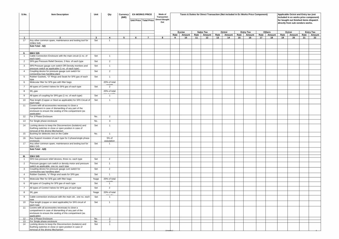
Schedule-2 6
Unit Price Total Price
Rate Amount Rate Amount Rate Amount Rate Amount Rate Amount Rate Amount Rate Amount1 2 3 4 5 6 7 8 9 10 11 12 13 14 15 16 17 18 19 20 21 22
Entry Tax
S.No. Item Description Applicable Octroi and Entry tax (not included in ex works price component) for bought out finished items dispatch directly from sub vendors works.
Octroi
Unit Qty Currency (INR)
Taxes & Duties for Direct Transaction (Not included in Ex Works Price Component) Mode of Transaction
Direct/ Bought Out
EX-WORKS PRICE
Excise Sales Tax Octroi OthersEntry Tax
17 Any other common spare, maintenance and testing tool for 220kV GIS
Set 1
Sub-Total - A(I)
II. 66kV GIS1 Cable Connection Enclosure with the main circuit (1 no. of
each type)Set 1
2 SF6 gas Pressure Relief Devices, 3 Nos. of each type Set 2
3 SF6 Pressure gauge cum switch OR Density monitors and pressure switch as applicable (1 no. of each type)
Set 1
4 Coupling device for pressure gauge cum switch for connecting Gas handling plant
Set 2
5 Rubber Gaskets, “O” Rings and Seals for SF6 gas of each type
Set 1
6 Molecular filter for SF6 gas with filter bags 20% of total weight
7 All types of Control Valves for SF6 gas of each type Set 2
8 SF6 gas 20% of total gas quantity
9 All types of coupling for SF6 gas (1 no. of each type) Set 1
10 Pipe length (Copper or Steel as applicable) for SF6 Circuit of each type
Set 1
11 Covers with all accessories necessary to close a compartment in case of dismantling of any part of the enclosure to ensure the sealing of this compartment (as applicable)
12 For 3 Phase Enclosure No. 2
13 For Single phase enclosure No. 3
14 Locking device to keep the Disconnectors (Isolators) and Earthing switches in close or open position in case of removal of the driving Mechanism
Set 1
15 Bushing for dielectric test on the Cable No. 1
16 Bus Support insulator of each type for 3 phase/single phase enclosure.
5% of population
17 Any other common spare, maintenance and testing tool for 66kV GIS
Set 1
Sub-Total - A(II)
III. 33kV GIS1 SF6 Gas pressure relief devices, three no. each type Set 2
2 Pressure gauges cum switch or density motor and pressure switch as applicable, one no. each type
Set 1
3 Coupling device for pressure gauge cum switch for connecting gas handling plant
Set 2
4 Rubber Gaskets, “o” Rings and seals for SF6 gas Set 1
5 Molecular filter for SF6 gas with filter bags %age 20% of total weight
6 All types of Coupling for SF6 gas of each type Set 1
7 All types of Control Valves for SF6 gas of each type Set 2
8 SF6 gas %age 20% of total gas qty
9 Cable connection enclosure with the main ckt , one no. each type
Set 1
10 Pipe length (copper or steel applicable) for SF6 circuit of each type
Set 1
11 Covers with all accessories necessary to close a compartment in case of dismantling of any part of the enclosure to ensure the sealing of this compartment (as applicable)
12 For 3 Phase Enclosure No. 213 For Single phase enclosure No. 314 Locking device to keep the Disconnectors (Isolators) and
Earthing switches in close or open position in case of removal of the driving Mechanism
Set 1
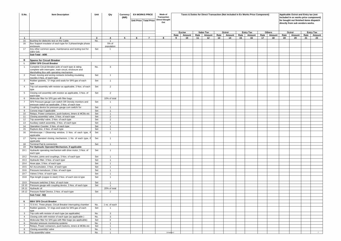
Schedule-2 7
Unit Price Total Price
Rate Amount Rate Amount Rate Amount Rate Amount Rate Amount Rate Amount Rate Amount1 2 3 4 5 6 7 8 9 10 11 12 13 14 15 16 17 18 19 20 21 22
Entry Tax
S.No. Item Description Applicable Octroi and Entry tax (not included in ex works price component) for bought out finished items dispatch directly from sub vendors works.
Octroi
Unit Qty Currency (INR)
Taxes & Duties for Direct Transaction (Not included in Ex Works Price Component) Mode of Transaction
Direct/ Bought Out
EX-WORKS PRICE
Excise Sales Tax Octroi OthersEntry Tax
15 Bushing for dielectric test on the Cable No. 116 Bus Support insulator of each type for 3 phase/single phase
enclosure.5% of
population17 Any other common spare, maintenance and testing tool for
33kV GISSet 1
Sub-Total - A(III)
BI. 220kV SF6 Circuit Breaker1 Complete Circuit Breaker pole of each type & rating
complete with interrupter, main circuit, enclosure and Marshalling Box with operating mechanism
No. 3
2 Fixed, moving and arcing contacts including insulating nozzles 3 Nos. of each type
Set 1
3 Rubber gaskets, `O' rings and seals for SF6 gas of each type
Set 1
4 Trip coil assembly with resistor as applicable, 3 Nos. of each type
Set 2
5 Closing coil assembly with resistor as applicable, 3 Nos. of each type
Set 2
6 Molecular filter for SF6 gas with filter bags 10% of total 7 SF6 Pressure gauge cum switch OR Density monitors and
pressure switch as applicable, 3 Nos. of each typeSet 1
8 Coupling device for pressure gauge cum switch/ for
Set 19 Corona rings if applicable Set 1
10 Relays, Power contactors, push buttons, timers & MCBs etc
Set 111 Closing assembly/ valve, 3 Nos. of each type Set 212 Trip assembly/ valve, 3 Nos. of each type Set 213 Auxiliary switch assembly, 3 Nos. of each type Set 114 Operation Counter, 3 Nos. of each type Set 115 Rupture disc, 3 Nos. of each type Set 116 Windoscope / Observing window, 3 Nos. of each type, if
applicableSet 1
17 Spring operated closing mechanism, 1 No. of each type, ifapplicable
Set 1
18 Terminal Pad & connectors Set 119 For Hydraulic Operated Mechanism, if applicable
19.1 Hydraulic operating mechanism with drive motor, 3 Nos. of each type
Set 1
19.2 Ferrules, joints and couplings, 3 Nos. of each type Set 119.3 Hydraulic filter, 3 Nos. of each type Set 119.4 Hose pipe, 3 Nos. of each type Set 119.5 N2 Accumulator, 3 Nos. of each type Set 119.6 Pressure transducer, 3 Nos. of each type Set 119.7 Valves 3 Nos. of each type Set 119.8 Pipe length (copper & steel) 3 Nos. of each size & type Set 1
19.9 Pressure switches 3 Nos. of each type Set 119.10 Pressure gauge with coupling device, 3 Nos. of each type Set 119.11 Hydraulic oil 20% of total
19.12 Pressure Relief Device, 3 Nos. of each type Set 2Sub-Total - B(I)
II. 66kV SF6 Circuit Breaker1 72.5 kV, Three phase, Circuit Breaker interrupting chamber
No. 1 no. of each
2 Rubber gaskets, `O' rings and seals for SF6 gas of each type
Set 1
3 Trip coils with resistor of each type (as applicable) No. 34 Closing coils with resistor of each type (as applicable ) No. 35 Molecular filter for SF6 gas with filter bags (as applicable) Set 36 Density/ pressure monitoring systems No. 17 Relays, Power contactors, push buttons, timers & MCBs etc
Set 1
8 Closing assembly/ valve No. 19 Trip assembly/ valve No. 1
Spares for Circuit Breaker
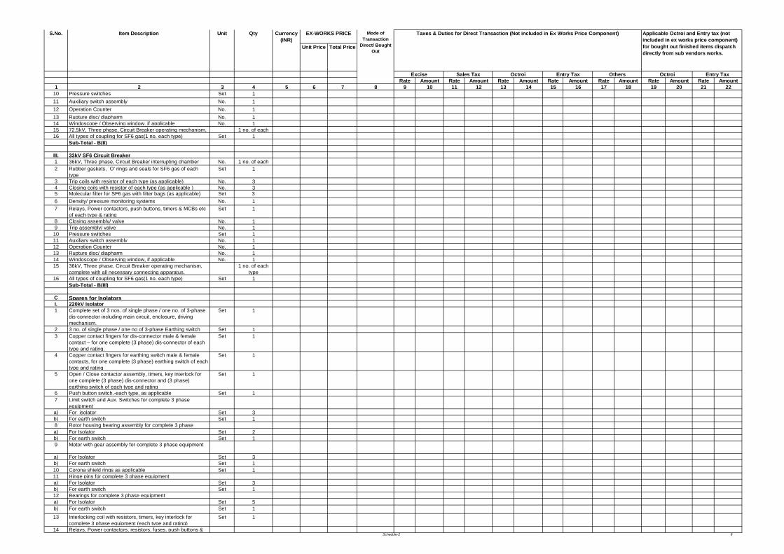
Schedule-2 8
Unit Price Total Price
Rate Amount Rate Amount Rate Amount Rate Amount Rate Amount Rate Amount Rate Amount1 2 3 4 5 6 7 8 9 10 11 12 13 14 15 16 17 18 19 20 21 22
Entry Tax
S.No. Item Description Applicable Octroi and Entry tax (not included in ex works price component) for bought out finished items dispatch directly from sub vendors works.
Octroi
Unit Qty Currency (INR)
Taxes & Duties for Direct Transaction (Not included in Ex Works Price Component) Mode of Transaction
Direct/ Bought Out
EX-WORKS PRICE
Excise Sales Tax Octroi OthersEntry Tax
10 Pressure switches Set 111 Auxiliary switch assembly No. 112 Operation Counter No. 113 Rupture disc/ diapharm No. 114 Windoscope / Observing window, if applicable No. 115 72.5kV, Three phase, Circuit Breaker operating mechanism, 1 no. of each 16 All types of coupling for SF6 gas(1 no. each type) Set 1
Sub-Total - B(II)
III. 33kV SF6 Circuit Breaker1 36kV, Three phase, Circuit Breaker interrupting chamber
No. 1 no. of each
2 Rubber gaskets, `O' rings and seals for SF6 gas of each type
Set 1
3 Trip coils with resistor of each type (as applicable) No. 34 Closing coils with resistor of each type (as applicable ) No. 35 Molecular filter for SF6 gas with filter bags (as applicable) Set 36 Density/ pressure monitoring systems No. 17 Relays, Power contactors, push buttons, timers & MCBs etc
of each type & ratingSet 1
8 Closing assembly/ valve No. 19 Trip assembly/ valve No. 1
10 Pressure switches Set 111 Auxiliary switch assembly No. 112 Operation Counter No. 113 Rupture disc/ diapharm No. 114 Windoscope / Observing window, if applicable No. 115 36kV, Three phase, Circuit Breaker operating mechanism,
complete with all necessary connecting apparatus.1 no. of each
type16 All types of coupling for SF6 gas(1 no. each type) Set 1
Sub-Total - B(III)
C Spares for IsolatorsI. 220kV Isolator 1 Complete set of 3 nos. of single phase / one no. of 3-phase
dis-connector including main circuit, enclosure, driving mechanism.
Set 1
2 3 no. of single phase / one no of 3-phase Earthing switch
Set 13 Copper contact fingers for dis-connector male & female
contact – for one complete (3 phase) dis-connector of each type and rating.
Set 1
4 Copper contact fingers for earthing switch male & female contacts, for one complete (3 phase) earthing switch of each type and rating
Set 1
5 Open / Close contactor assembly, timers, key interlock for one complete (3 phase) dis-connector and (3 phase) earthing switch of each type and rating
Set 1
6 Push button switch.-each type, as applicable Set 17 Limit switch and Aux. Switches for complete 3 phase
equipment a) For isolator Set 3b) For earth switch Set 18 Rotor housing bearing assembly for complete 3 phase a) For Isolator Set 2b) For earth switch Set 19 Motor with gear assembly for complete 3 phase equipment
a) For Isolator Set 3b) For earth switch Set 110 Corona shield rings as applicable Set 111 Hinge pins for complete 3 phase equipmenta) For Isolator Set 3b) For earth switch Set 112 Bearings for complete 3 phase equipment a) For Isolator Set 5b) For earth switch Set 113 Interlocking coil with resistors, timers, key interlock for
complete 3 phase equipment (each type and rating)Set 1
14 Relays, Power contactors, resistors, fuses, push buttons &
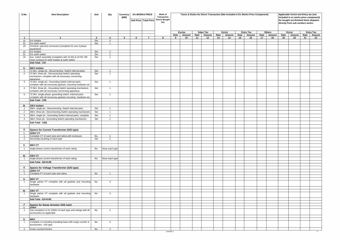
Schedule-2 9
Unit Price Total Price
Rate Amount Rate Amount Rate Amount Rate Amount Rate Amount Rate Amount Rate Amount1 2 3 4 5 6 7 8 9 10 11 12 13 14 15 16 17 18 19 20 21 22
Entry Tax
S.No. Item Description Applicable Octroi and Entry tax (not included in ex works price component) for bought out finished items dispatch directly from sub vendors works.
Octroi
Unit Qty Currency (INR)
Taxes & Duties for Direct Transaction (Not included in Ex Works Price Component) Mode of Transaction
Direct/ Bought Out
EX-WORKS PRICE
Excise Sales Tax Octroi OthersEntry Tax
a) For Isolator Set 3b) For earth switch Set 115 Terminal pad and connectors (complete for one 3 phase
equipment)a) For Isolator Set 2b) For earth switch Set 116 Aux. switch assembly (complete) with 10 NO & 10 NC OR
more contacts for both isolator & earth switchSet 1
Sub-Total - C(I)
II. 66kV Isolator1 72.5kV, single ph., Disconnecting Switch internal parts, Set 12 72.5kV, three ph., Disconnecting Switch operating
mechanism, complete with all necessary connecting apparatus.
Set 1
3 72.5kV, single ph., Grounding Switch internal parts, complete with all necessary gaskets, mounting hardware etc
Set 1
4 72.5kV, three ph., Grounding Switch operating mechanism, complete with all necessary connecting apparatus.
Set 1
5 72.5kV, single phase, grounding switch, Internal parts complete with all necessary gaskets mounting hardware etc.
Set 1
Sub-Total - C(II)
III. 33kV Isolator1 36kV, single ph., Disconnecting Switch internal parts,
Set 1
2 36kV, three ph., Disconnecting Switch operating mechanism,
Set 13 36kV, single ph., Grounding Switch internal parts, complete
Set 1
4 36kV, three ph., Grounding Switch operating mechanism,
Set 1Sub-Total - C(III)
D Spares for Current Transformer (GIS type)I. 220kV CT1 Complete CT of each type and rating with enclosure. No. 22 Secondary bushing of each type Set 2
II. 66kV CT1 single phase current transformer of each rating No. three each type
III. 33kV CT1 single phase current transformer of each rating No. three each type
Sub-Total - D(I+II+III)
E Spares for Voltage Transformer (GIS type)I. 220kV VT1 Complete PT of each type and rating No. 1
II. 66kV VT1 Single pahse VT complete with all gaskets and mounting
hardware No. 3
III. 33kV VT1 Single pahse VT complete with all gaskets and mounting
hardware No. 3
Sub-Total - E(I+II+III)
F Spares for Surge Arrestor (GIS type)I. 220kV1 Gas insulated LA for 220kV of each type and ratings with all
accessories as applicableNo. 2
II. 66kV1 Complete LA including insulating base with surge counter &
accessories : GIS typeNo. 3
2 Surge counter/monitor No. 3
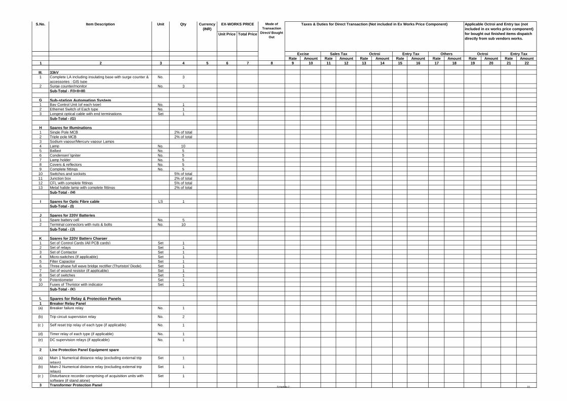
Schedule-2 10
Unit Price Total Price
Rate Amount Rate Amount Rate Amount Rate Amount Rate Amount Rate Amount Rate Amount1 2 3 4 5 6 7 8 9 10 11 12 13 14 15 16 17 18 19 20 21 22
Entry Tax
S.No. Item Description Applicable Octroi and Entry tax (not included in ex works price component) for bought out finished items dispatch directly from sub vendors works.
Octroi
Unit Qty Currency (INR)
Taxes & Duties for Direct Transaction (Not included in Ex Works Price Component) Mode of Transaction
Direct/ Bought Out
EX-WORKS PRICE
Excise Sales Tax Octroi OthersEntry Tax
III. 33kV 1 Complete LA including insulating base with surge counter &
accessories : GIS typeNo. 3
2 Surge counter/monitor No. 3Sub-Total - F(I+II+III)
G Sub-station Automation System1 Bay Control Unit (of each type) No. 12 Ethernet Switch of Each type No. 13 Longest optical cable with end terminations Set 1
Sub-Total - (G)
H Spares for Illuminations1 Single Pole MCB 2% of total 2 Triple pole MCB 2% of total 3 Sodium vapour/Mercury vapour Lamps4 Lamp No. 105 Ballast No. 56 Condenser/ Igniter No. 57 Lamp holder No. 58 Covers & reflectors No. 59 Complete fittings No. 5
10 Switches and sockets 5% of total 11 Junction box 2% of total 12 CFL with complete fittings 5% of total 13 Metal halide lamp with complete fittings 2% of total
Sub-Total - (H)
I Spares for Optic Fibre cable LS 1Sub-Total - (I)
J Spares for 220V Batteries1 Spare battery cell No. 52 Terminal connectors with nuts & bolts No. 10
Sub-Total - (J)
K Spares for 220V Battery Charger1 Set of Control Cards (All PCB cards) Set 12 Set of relays Set 13 Set of Contactor Set 14 Micro-switches (If applicable) Set 15 Filter Capacitor Set 16 Three phase full wave bridge rectifier (Thyristor/ Diode) Set 17 Set of wound resistor (if applicable) Set 18 Set of switches Set 19 Potentiometer Set 1
10 Fuses of Thyristor with indicator Set 1Sub-Total - (K)
L Spares for Relay & Protection Panels1 Breaker Relay Panel
(a) Breaker failure relay No. 1
(b) Trip circuit supervision relay No. 2
(c ) Self reset trip relay of each type (if applicable) No. 1
(d) Timer relay of each type (if applicable) No. 1(e) DC supervision relays (if applicable) No. 1
2 Line Protection Panel Equipment spare
(a) Main 1 Numerical distance relay (excluding external trip relays)
Set 1
(b) Main-2 Numerical distance relay (excluding external trip relays)
Set 1
(c ) Disturbance recorder comprising of acquisition units with software (if stand alone)
Set 1
3 Transformer Protection Panel
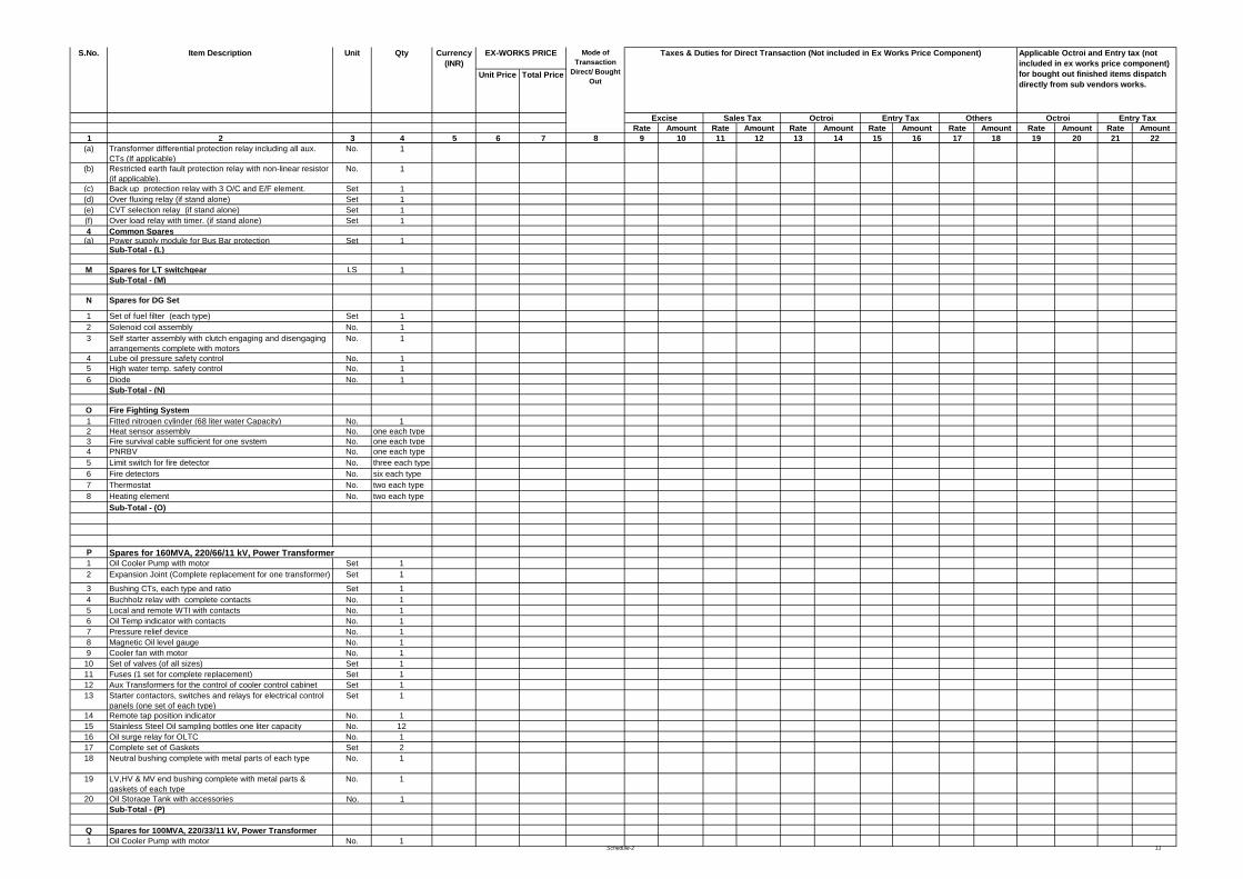
Schedule-2 11
Unit Price Total Price
Rate Amount Rate Amount Rate Amount Rate Amount Rate Amount Rate Amount Rate Amount1 2 3 4 5 6 7 8 9 10 11 12 13 14 15 16 17 18 19 20 21 22
Entry Tax
S.No. Item Description Applicable Octroi and Entry tax (not included in ex works price component) for bought out finished items dispatch directly from sub vendors works.
Octroi
Unit Qty Currency (INR)
Taxes & Duties for Direct Transaction (Not included in Ex Works Price Component) Mode of Transaction
Direct/ Bought Out
EX-WORKS PRICE
Excise Sales Tax Octroi OthersEntry Tax
(a) Transformer differential protection relay including all aux. CTs (If applicable)
No. 1
(b) Restricted earth fault protection relay with non-linear resistor (if applicable).
No. 1
(c) Back up protection relay with 3 O/C and E/F element. Set 1(d) Over fluxing relay (if stand alone) Set 1(e) CVT selection relay (if stand alone) Set 1(f) Over load relay with timer. (if stand alone) Set 14 Common Spares
(a) Power supply module for Bus Bar protection Set 1Sub-Total - (L)
M Spares for LT switchgear LS 1Sub-Total - (M)
N Spares for DG Set
1 Set of fuel filter (each type) Set 12 Solenoid coil assembly No. 13 Self starter assembly with clutch engaging and disengaging
arrangements complete with motorsNo. 1
4 Lube oil pressure safety control No. 15 High water temp. safety control No. 16 Diode No. 1
Sub-Total - (N)
O Fire Fighting System1 Fitted nitrogen cylinder (68 liter water Capacity) No. 12 Heat sensor assembly No. one each type3 Fire survival cable sufficient for one system No. one each type4 PNRBV No. one each type5 Limit switch for fire detector No. three each type6 Fire detectors No. six each type7 Thermostat No. two each type8 Heating element No. two each type
Sub-Total - (O)
P Spares for 160MVA, 220/66/11 kV, Power Transformer1 Oil Cooler Pump with motor Set 12 Expansion Joint (Complete replacement for one transformer) Set 1
3 Bushing CTs, each type and ratio Set 14 Buchholz relay with complete contacts No. 15 Local and remote WTI with contacts No. 16 Oil Temp indicator with contacts No. 17 Pressure relief device No. 18 Magnetic Oil level gauge No. 19 Cooler fan with motor No. 1
10 Set of valves (of all sizes) Set 111 Fuses (1 set for complete replacement) Set 112 Aux Transformers for the control of cooler control cabinet
Set 1
13 Starter contactors, switches and relays for electrical control panels (one set of each type)
Set 1
14 Remote tap position indicator No. 115 Stainless Steel Oil sampling bottles one liter capacity No. 1216 Oil surge relay for OLTC No. 117 Complete set of Gaskets Set 218 Neutral bushing complete with metal parts of each type No. 1
19 LV,HV & MV end bushing complete with metal parts &gaskets of each type
No. 1
20 Oil Storage Tank with accessories No. 1Sub-Total - (P)
Q Spares for 100MVA, 220/33/11 kV, Power Transformer1 Oil Cooler Pump with motor No. 1
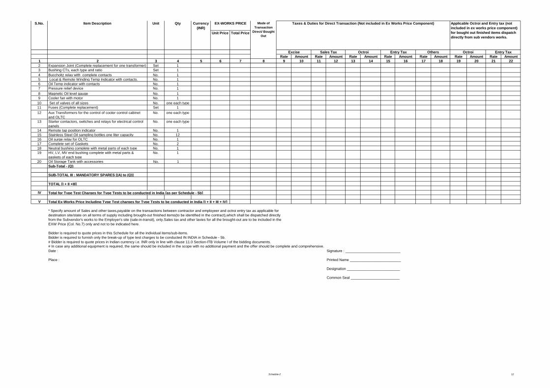
Schedule-2 12
Unit Price Total Price
Rate Amount Rate Amount Rate Amount Rate Amount Rate Amount Rate Amount Rate Amount1 2 3 4 5 6 7 8 9 10 11 12 13 14 15 16 17 18 19 20 21 22
Entry Tax
S.No. Item Description Applicable Octroi and Entry tax (not included in ex works price component) for bought out finished items dispatch directly from sub vendors works.
Octroi
Unit Qty Currency (INR)
Taxes & Duties for Direct Transaction (Not included in Ex Works Price Component) Mode of Transaction
Direct/ Bought Out
EX-WORKS PRICE
Excise Sales Tax Octroi OthersEntry Tax
2 Expansion Joint (Complete replacement for one transformer) Set 13 Bushing CTs, each type and ratio Set 14 Buccholtz relay with complete contacts No. 15 Local & Remote Winding Temp Indicator with contacts. No. 16 Oil Temp indicator with contacts No. 17 Pressure relief device No. 18 Magnetic Oil level gauge No. 19 Cooler fan with motor No. 1
10 Set of valves of all sizes No. one each type11 Fuses (Complete replacement) Set 112 Aux Transformers for the control of cooler control cabinet
and OLTC No. one each type
13 Starter contactors, switches and relays for electrical control panels
No. one each type
14 Remote tap position indicator No. 115 Stainless Steel Oil sampling bottles one liter capacity No. 1216 Oil surge relay for OLTC No. 117 Complete set of Gaskets No. 218 Neutral bushing complete with metal parts of each type No. 119 HV, LV, MV end bushing complete with metal parts &
gaskets of each typeNo. 1
20 Oil Storage Tank with accessories No. 1Sub-Total - (Q)
SUB-TOTAL III : MANDATORY SPARES [(A) to (Q)]
TOTAL [I + II +III]
IV Total for Type Test Charges for Type Tests to be conducted in India [as per Schedule - 5b]
V Total Ex-Works Price Including Type Test charges for Type Tests to be conducted in India [I + II + III + IV]
* Specify amount of Sales and other taxes,payable on the transactions between contractor and employeer and octroi entry tax as applicable fordestination site/state on all terms of supply including brought-out finished items(to be identified in the contract),which shall be dispatched directlyfrom the Subvendor's works to the Employer's site (sale-in-transit), only.Sales tax and other lavies for all the brought-out are to be included in theEXW Price (Col. No.7) only and not to be indicated here.
Bidder is required to quote prices in this Schedule for all the individual items/sub-items.Bidder is required to furnish only the break-up of type test charges to be conducted IN INDIA in Schedule - 5b.# Bidder is required to quote prices in Indian currency i.e. INR only in line with clause 11.0 Section-ITB Volume I of the bidding documents.# In case any additional equipment is required, the same should be included in the scope with no additional payment and the offer should be complete and comprehensive.Date : Signature : ___________________________
Place : Printed Name _________________________
Designation __________________________
Common Seal ________________________
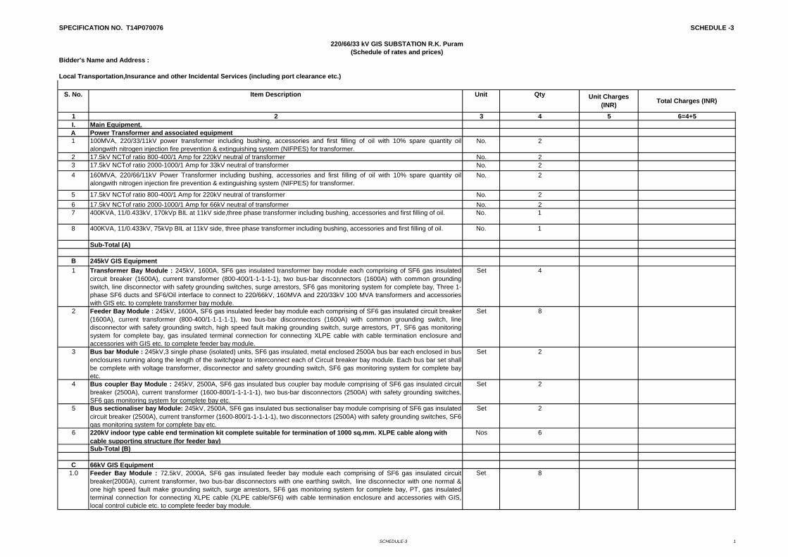
SCHEDULE-3 1
SPECIFICATION NO. T14P070076 SCHEDULE -3
Bidder's Name and Address :
Local Transportation,Insurance and other Incidental Services (including port clearance etc.)
1 2 3 4 5 6=4+5I. Main Equipment.A Power Transformer and associated equipment1 100MVA, 220/33/11kV power transformer including bushing, accessories and first filling of oil with 10% spare quantity oil
alongwith nitrogen injection fire prevention & extinguishing system (NIFPES) for transformer.No. 2
2 17.5kV NCTof ratio 800-400/1 Amp for 220kV neutral of transformer No. 23 17.5kV NCTof ratio 2000-1000/1 Amp for 33kV neutral of transformer No. 24 160MVA, 220/66/11kV Power Transformer including bushing, accessories and first filling of oil with 10% spare quantity oil
alongwith nitrogen injection fire prevention & extinguishing system (NIFPES) for transformer.No. 2
5 17.5kV NCTof ratio 800-400/1 Amp for 220kV neutral of transformer No. 26 17.5kV NCTof ratio 2000-1000/1 Amp for 66kV neutral of transformer No. 27 400KVA, 11/0.433kV, 170kVp BIL at 11kV side,three phase transformer including bushing, accessories and first filling of oil. No. 1
8 400KVA, 11/0.433kV, 75kVp BIL at 11kV side, three phase transformer including bushing, accessories and first filling of oil. No. 1
Sub-Total (A)
B 245kV GIS Equipment1 Transformer Bay Module : 245kV, 1600A, SF6 gas insulated transformer bay module each comprising of SF6 gas insulated
circuit breaker (1600A), current transformer (800-400/1-1-1-1-1), two bus-bar disconnectors (1600A) with common groundingswitch, line disconnector with safety grounding switches, surge arrestors, SF6 gas monitoring system for complete bay, Three 1-phase SF6 ducts and SF6/Oil interface to connect to 220/66kV, 160MVA and 220/33kV 100 MVA transformers and accessorieswith GIS etc. to complete transformer bay module.
Set 4
2 Feeder Bay Module : 245kV, 1600A, SF6 gas insulated feeder bay module each comprising of SF6 gas insulated circuit breaker(1600A), current transformer (800-400/1-1-1-1-1), two bus-bar disconnectors (1600A) with common grounding switch, linedisconnector with safety grounding switch, high speed fault making grounding switch, surge arrestors, PT, SF6 gas monitoringsystem for complete bay, gas insulated terminal connection for connecting XLPE cable with cable termination enclosure andaccessories with GIS etc. to complete feeder bay module.
Set 8
3 Bus bar Module : 245kV,3 single phase (isolated) units, SF6 gas insulated, metal enclosed 2500A bus bar each enclosed in busenclosures running along the length of the switchgear to interconnect each of Circuit breaker bay module. Each bus bar set shallbe complete with voltage transformer, disconnector and safety grounding switch, SF6 gas monitoring system for complete bayetc.
Set 2
4 Bus coupler Bay Module : 245kV, 2500A, SF6 gas insulated bus coupler bay module comprising of SF6 gas insulated circuitbreaker (2500A), current transformer (1600-800/1-1-1-1-1), two bus-bar disconnectors (2500A) with safety grounding switches,SF6 gas monitoring system for complete bay etc.
Set 2
5 Bus sectionaliser bay Module: 245kV, 2500A, SF6 gas insulated bus sectionaliser bay module comprising of SF6 gas insulatedcircuit breaker (2500A), current transformer (1600-800/1-1-1-1-1), two disconnectors (2500A) with safety grounding switches, SF6gas monitoring system for complete bay etc.
Set 2
6 220kV indoor type cable end termination kit complete suitable for termination of 1000 sq.mm. XLPE cable along with cable supporting structure (for feeder bay)
Nos 6
Sub-Total (B)
C 66kV GIS Equipment1.0 Feeder Bay Module : 72.5kV, 2000A, SF6 gas insulated feeder bay module each comprising of SF6 gas insulated circuit
breaker(2000A), current transformer, two bus-bar disconnectors with one earthing switch, line disconnector with one normal &one high speed fault make grounding switch, surge arrestors, SF6 gas monitoring system for complete bay, PT, gas insulatedterminal connection for connecting XLPE cable (XLPE cable/SF6) with cable termination enclosure and accessories with GIS,local control cubicle etc. to complete feeder bay module.
Set 8
220/66/33 kV GIS SUBSTATION R.K. Puram(Schedule of rates and prices)
S. No. Item Description Unit Qty Unit Charges (INR) Total Charges (INR)
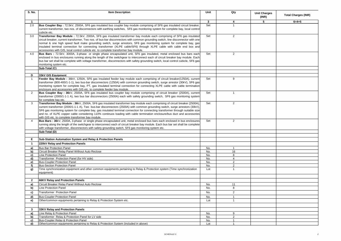
SCHEDULE-3 2
1 2 3 4 5 6=4+5
S. No. Item Description Unit Qty Unit Charges (INR) Total Charges (INR)
2.0 Bus Coupler Bay : 72.5kV, 2500A, SF6 gas insulated bus coupler bay module comprising of SF6 gas insulated circuit breaker,current transformer, two nos. of disconnectors with earthing switches, SF6 gas monitoring system for complete bay, local controlcubicle etc.
Set 1
3.0 Transformer Bay Module : 72.5kV, 2000A, SF6 gas insulated transformer bay module each comprising of SF6 gas insulatedcircuit breaker, current transformer, Two nos. of bus-bar disconnectors with common grounding switch, line disconnector with onenormal & one high speed fault make grounding switch, surge arrestors, SF6 gas monitoring system for complete bay, gasinsulated terminal connection for connecting transformer (XLPE cable/SF6) through XLPE cable with cable end box andaccessories with GIS, local control cubicle etc. to complete transformer bay module.
Set 2
4.0 Bus Bars : 72.5kV, 3000A, 3-phase or single phase encapsulated unit, SF6 gas insulated, metal enclosed bus bars eachenclosed in bus enclosures running along the length of the switchgear to interconnect each of circuit breaker bay module. Eachbus bar set shall be complete with voltage transformer, disconnectors with safety grounding switch, local control cubicle, SF6 gasmonitoring system etc.
Set 2
Sub-Total (C)
D 33kV GIS Equipment1 Feeder Bay Module : 36kV, 1250A, SF6 gas insulated feeder bay module each comprising of circuit breaker(1250A), current
transformer (800-400/1-1-1), two bus-bar disconnectors (1250A) with common grounding switch, surge arrestor (30kV), SF6 gasmonitoring system for complete bay, PT, gas insulated terminal connection for connecting XLPE cable with cable terminationenclosure and accessories with GIS etc. to complete feeder bay module.
Set 9
2 Bus Coupler Bay : 36kV, 2500A, SF6 gas insulated bus coupler bay module comprising of circuit breaker (2500A), currenttransformer (2000/1-1-1 A), two bus bar disconnectors (2500A) each with safety grounding switch, SF6 gas monitoring systemfor complete bay etc.
Set 1
3 Transformer Bay Module : 36kV, 2500A, SF6 gas insulated transformer bay module each comprising of circuit breaker (2500A),current transformer (2000/1-1-1 A), Two bus-bar disconnectors (2500A) with common grounding switch, surge arrestors (30kV),SF6 gas monitoring system for complete bay, gas insulated terminal connection for connecting transformer through suitable sizeand no. of XLPE copper cable considering 110% continuos loading with cable termination enclosure/bus duct and accessorieswith GIS etc. to complete transformer bay module.
Set 2
4 Bus Bars : 36kV, 2500A, 3-phase or single phase encapsulated unit, metal enclosed bus bars each enclosed in bus enclosuresrunning along the length of the switchgear to interconnect each of circuit breaker bay module. Each bus bar set shall be completewith voltage transformer, disconnectors with safety grounding switch, SF6 gas monitoring system etc.
Set 2
Sub-Total (D)
E Sub-Station Automation System and Relay & Protection Panels1 220kV Relay and Protection Panelsa) Bus Bar Protection Panel No. 1b) Circuit Breaker Relay Panel Without Auto Reclose No. 16c) Line Protection Panel No. 8d) Transformer Protection Panel (for HV side) No. 4e) Bus-Coupler Protection Panel No. 2f) Bus-Section Protection Panel No. 2g) Time synchronization equipment and other common equipments pertaining to Relay & Protection system (Time synchronization
equipment) Lot 1
2 66KV Relay and Protection Panelsa) Circuit Breaker Relay Panel Without Auto Reclose No. 11b) Line Protection Panel No. 8c) Transformer Protection Panel No. 2d) Bus-Coupler Protection Panel No. 1e) Other/common equipments pertaining to Relay & Protection System etc. Lot 1
3 33KV Relay and Protection Panelsa) Line Relay & Protection Panel No. 9b) Transformer Relay & Protection Panel for LV side No. 2c) Bus-Coupler Relay & Protection Panel No. 1d) Other/common equipments pertaining to Relay & Protection System (included in above) Lot 1
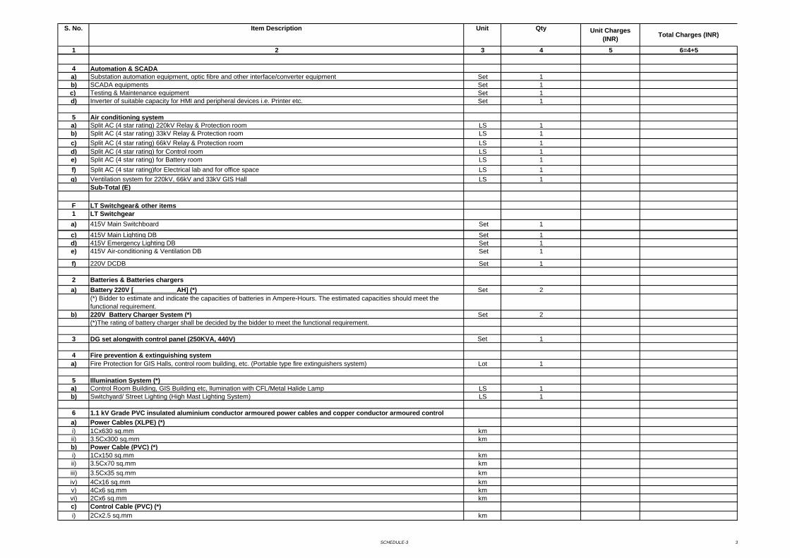
SCHEDULE-3 3
1 2 3 4 5 6=4+5
S. No. Item Description Unit Qty Unit Charges (INR) Total Charges (INR)
4 Automation & SCADAa) Substation automation equipment, optic fibre and other interface/converter equipment Set 1b) SCADA equipments Set 1c) Testing & Maintenance equipment Set 1d) Inverter of suitable capacity for HMI and peripheral devices i.e. Printer etc. Set 1
5 Air conditioning systema) Split AC (4 star rating) 220kV Relay & Protection room LS 1b) Split AC (4 star rating) 33kV Relay & Protection room LS 1c) Split AC (4 star rating) 66kV Relay & Protection room LS 1d) Split AC (4 star rating) for Control room LS 1e) Split AC (4 star rating) for Battery room LS 1f) Split AC (4 star rating)for Electrical lab and for office space LS 1g) Ventilation system for 220kV, 66kV and 33kV GIS Hall LS 1
Sub-Total (E)
F LT Switchgear& other items1 LT Switchgeara) 415V Main Switchboard Set 1
c) 415V Main Lighting DB Set 1d) 415V Emergency Lighting DB Set 1e) 415V Air-conditioning & Ventilation DB Set 1
f) 220V DCDB Set 1
2 Batteries & Batteries chargersa) Battery 220V [____________AH] (*) Set 2
(*) Bidder to estimate and indicate the capacities of batteries in Ampere-Hours. The estimated capacities should meet the functional requirement.
b) 220V Battery Charger System (*) Set 2(*)The rating of battery charger shall be decided by the bidder to meet the functional requirement.
3 DG set alongwith control panel (250KVA, 440V) Set 1
4 Fire prevention & extinguishing system a) Fire Protection for GIS Halls, control room building, etc. (Portable type fire extinguishers system) Lot 1
5 Illumination System (*)a) Control Room Building, GIS Building etc, llumination with CFL/Metal Halide Lamp LS 1b) Switchyard/ Street Lighting (High Mast Lighting System) LS 1
6 1.1 kV Grade PVC insulated aluminium conductor armoured power cables and copper conductor armoured control a) Power Cables (XLPE) (*)
i) 1Cx630 sq.mm kmii) 3.5Cx300 sq.mm kmb) Power Cable (PVC) (*)i) 1Cx150 sq.mm kmii) 3.5Cx70 sq.mm kmiii) 3.5Cx35 sq.mm kmiv) 4Cx16 sq.mm kmv) 4Cx6 sq.mm kmvi) 2Cx6 sq.mm kmc) Control Cable (PVC) (*)i) 2Cx2.5 sq.mm km
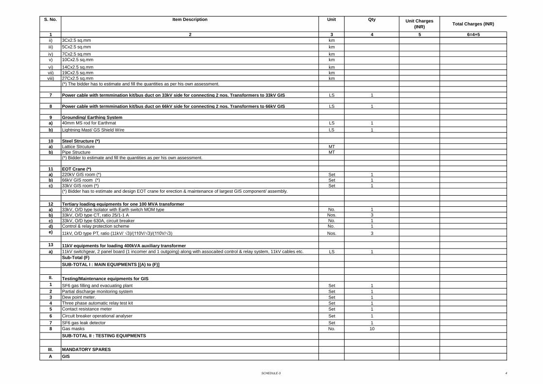
SCHEDULE-3 4
1 2 3 4 5 6=4+5
S. No. Item Description Unit Qty Unit Charges (INR) Total Charges (INR)
ii) 3Cx2.5 sq.mm kmiii) 5Cx2.5 sq.mm kmiv) 7Cx2.5 sq.mm kmv) 10Cx2.5 sq.mm km
vi) 14Cx2.5 sq.mm kmvii) 19Cx2.5 sq.mm kmviii) 27Cx2.5 sq.mm km
(*) The bidder has to estimate and fill the quantities as per his own assessment.
7 Power cable with termmination kit/bus duct on 33kV side for connecting 2 nos. Transformers to 33kV GIS LS 1
8 Power cable with termmination kit/bus duct on 66kV side for connecting 2 nos. Transformers to 66kV GIS LS 1
9 Grounding/ Earthing Systema) 40mm MS rod for Earthmat LS 1b) Lightning Mast/ GS Shield Wire LS 1
10 Steel Structure (*) a) Lattice Strcuture MTb) Pipe Structure MT
(*) Bidder to estimate and fill the quantities as per his own assessment.
11 EOT Crane (*) a) 220kV GIS room (*) Set 1b) 66kV GIS room (*) Set 1c) 33kV GIS room (*) Set 1
(*) Bidder has to estimate and design EOT crane for erection & maintenance of largest GIS component/ assembly.
12 Tertiary loading equipments for one 100 MVA transformera) 33kV, O/D type Isolator with Earth switch MOM type No. 1b) 33kV, O/D type CT, ratio 25/1-1 A Nos. 3c) 33kV, O/D type 630A, circuit breaker No. 1d) Control & relay protection scheme No. 1e) 11kV, O/D type PT, ratio (11kV/ √3)/(110V/√3)/(110V/√3) Nos. 3
13 11kV equipments for loading 400kVA auxiliary transformera) 11kV switchgear, 2 panel board (1 incomer and 1 outgoing) along with assocaited control & relay system, 11kV cables etc. LS 1
Sub-Total (F)SUB-TOTAL I : MAIN EQUIPMENTS [(A) to (F)]
II. Testing/Maintenance equipments for GIS1 SF6 gas filling and evacuating plant Set 12 Partial discharge monitoring system Set 13 Dew point meter. Set 14 Three phase automatic relay test kit Set 15 Contact resistance meter Set 16 Circuit breaker operational analyser Set 17 SF6 gas leak detector Set 18 Gas masks No. 10
SUB-TOTAL II : TESTING EQUIPMENTS
III. MANDATORY SPARES A GIS
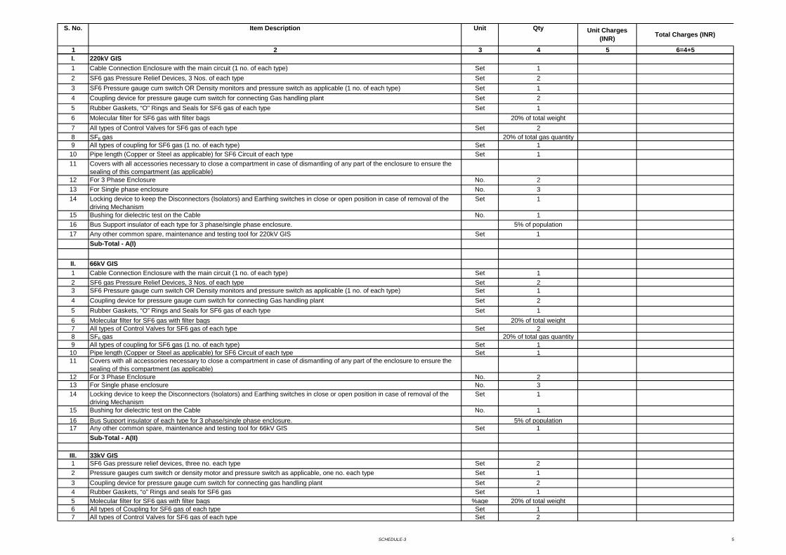
SCHEDULE-3 5
1 2 3 4 5 6=4+5
S. No. Item Description Unit Qty Unit Charges (INR) Total Charges (INR)
I. 220kV GIS1 Cable Connection Enclosure with the main circuit (1 no. of each type) Set 12 SF6 gas Pressure Relief Devices, 3 Nos. of each type Set 23 SF6 Pressure gauge cum switch OR Density monitors and pressure switch as applicable (1 no. of each type) Set 14 Coupling device for pressure gauge cum switch for connecting Gas handling plant Set 25 Rubber Gaskets, “O” Rings and Seals for SF6 gas of each type Set 16 Molecular filter for SF6 gas with filter bags 20% of total weight7 All types of Control Valves for SF6 gas of each type Set 28 SF6 gas 20% of total gas quantity9 All types of coupling for SF6 gas (1 no. of each type) Set 110 Pipe length (Copper or Steel as applicable) for SF6 Circuit of each type Set 111 Covers with all accessories necessary to close a compartment in case of dismantling of any part of the enclosure to ensure the
sealing of this compartment (as applicable)12 For 3 Phase Enclosure No. 213 For Single phase enclosure No. 314 Locking device to keep the Disconnectors (Isolators) and Earthing switches in close or open position in case of removal of the
driving MechanismSet 1
15 Bushing for dielectric test on the Cable No. 116 Bus Support insulator of each type for 3 phase/single phase enclosure. 5% of population17 Any other common spare, maintenance and testing tool for 220kV GIS Set 1
Sub-Total - A(I)
II. 66kV GIS1 Cable Connection Enclosure with the main circuit (1 no. of each type) Set 12 SF6 gas Pressure Relief Devices, 3 Nos. of each type Set 23 SF6 Pressure gauge cum switch OR Density monitors and pressure switch as applicable (1 no. of each type) Set 14 Coupling device for pressure gauge cum switch for connecting Gas handling plant Set 25 Rubber Gaskets, “O” Rings and Seals for SF6 gas of each type Set 16 Molecular filter for SF6 gas with filter bags 20% of total weight7 All types of Control Valves for SF6 gas of each type Set 28 SF6 gas 20% of total gas quantity9 All types of coupling for SF6 gas (1 no. of each type) Set 110 Pipe length (Copper or Steel as applicable) for SF6 Circuit of each type Set 111 Covers with all accessories necessary to close a compartment in case of dismantling of any part of the enclosure to ensure the
sealing of this compartment (as applicable)12 For 3 Phase Enclosure No. 213 For Single phase enclosure No. 314 Locking device to keep the Disconnectors (Isolators) and Earthing switches in close or open position in case of removal of the
driving MechanismSet 1
15 Bushing for dielectric test on the Cable No. 116 Bus Support insulator of each type for 3 phase/single phase enclosure. 5% of population17 Any other common spare, maintenance and testing tool for 66kV GIS Set 1
Sub-Total - A(II)
III. 33kV GIS1 SF6 Gas pressure relief devices, three no. each type Set 22 Pressure gauges cum switch or density motor and pressure switch as applicable, one no. each type Set 13 Coupling device for pressure gauge cum switch for connecting gas handling plant Set 24 Rubber Gaskets, “o” Rings and seals for SF6 gas Set 15 Molecular filter for SF6 gas with filter bags %age 20% of total weight6 All types of Coupling for SF6 gas of each type Set 17 All types of Control Valves for SF6 gas of each type Set 2
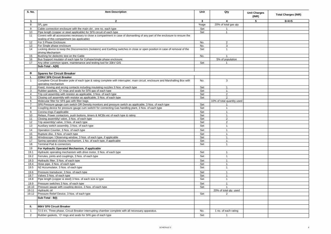
SCHEDULE-3 6
1 2 3 4 5 6=4+5
S. No. Item Description Unit Qty Unit Charges (INR) Total Charges (INR)
8 SF6 gas %age 20% of total gas qty9 Cable connection enclosure with the main ckt , one no. each type Set 110 Pipe length (copper or steel applicable) for SF6 circuit of each type Set 111 Covers with all accessories necessary to close a compartment in case of dismantling of any part of the enclosure to ensure the
sealing of this compartment (as applicable)12 For 3 Phase Enclosure No. 213 For Single phase enclosure No. 314 Locking device to keep the Disconnectors (Isolators) and Earthing switches in close or open position in case of removal of the
driving MechanismSet 1
15 Bushing for dielectric test on the Cable No. 116 Bus Support insulator of each type for 3 phase/single phase enclosure. 5% of population17 Any other common spare, maintenance and testing tool for 33kV GIS Set 1
Sub-Total - A(III)
BI. 220kV SF6 Circuit Breaker1 Complete Circuit Breaker pole of each type & rating complete with interrupter, main circuit, enclosure and Marshalling Box with
operating mechanismNo. 3
2 Fixed, moving and arcing contacts including insulating nozzles 3 Nos. of each type Set 13 Rubber gaskets, `O' rings and seals for SF6 gas of each type Set 14 Trip coil assembly with resistor as applicable, 3 Nos. of each type Set 25 Closing coil assembly with resistor as applicable, 3 Nos. of each type Set 26 Molecular filter for SF6 gas with filter bags 10% of total quantity used7 SF6 Pressure gauge cum switch OR Density monitors and pressure switch as applicable, 3 Nos. of each type Set 18 Coupling device for pressure gauge cum switch/ for connecting Gas handling plant, 3 Nos. of each type Set 19 Corona rings if applicable Set 110 Relays, Power contactors, push buttons, timers & MCBs etc of each type & rating Set 111 Closing assembly/ valve, 3 Nos. of each type Set 212 Trip assembly/ valve, 3 Nos. of each type Set 213 Auxiliary switch assembly, 3 Nos. of each type Set 114 Operation Counter, 3 Nos. of each type Set 115 Rupture disc, 3 Nos. of each type Set 116 Windoscope / Observing window, 3 Nos. of each type, if applicable Set 117 Spring operated closing mechanism, 1 No. of each type, if applicable Set 118 Terminal Pad & connectors Set 119 For Hydraulic Operated Mechanism, if applicable
19.1 Hydraulic operating mechanism with drive motor, 3 Nos. of each type Set 119.2 Ferrules, joints and couplings, 3 Nos. of each type Set 119.3 Hydraulic filter, 3 Nos. of each type Set 119.4 Hose pipe, 3 Nos. of each type Set 119.5 N2 Accumulator, 3 Nos. of each type Set 1
19.6 Pressure transducer, 3 Nos. of each type Set 119.7 Valves 3 Nos. of each type Set 119.8 Pipe length (copper & steel) 3 Nos. of each size & type Set 119.9 Pressure switches 3 Nos. of each type Set 119.10 Pressure gauge with coupling device, 3 Nos. of each type Set 119.11 Hydraulic oil 20% of total qty. used19.12 Pressure Relief Device, 3 Nos. of each type Set 2
Sub-Total - B(I)
II. 66kV SF6 Circuit Breaker1 72.5 kV, Three phase, Circuit Breaker interrupting chamber complete with all necessary apparatus. No. 1 no. of each rating2 Rubber gaskets, `O' rings and seals for SF6 gas of each type Set 1
Spares for Circuit Breaker
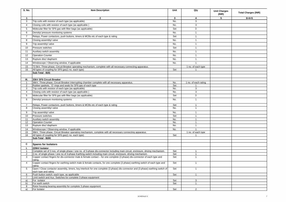
SCHEDULE-3 7
1 2 3 4 5 6=4+5
S. No. Item Description Unit Qty Unit Charges (INR) Total Charges (INR)
3 Trip coils with resistor of each type (as applicable) No. 34 Closing coils with resistor of each type (as applicable ) No. 35 Molecular filter for SF6 gas with filter bags (as applicable) Set 36 Density/ pressure monitoring systems No. 17 Relays, Power contactors, push buttons, timers & MCBs etc of each type & rating Set 18 Closing assembly/ valve No. 19 Trip assembly/ valve No. 110 Pressure switches Set 111 Auxiliary switch assembly No. 112 Operation Counter No. 113 Rupture disc/ diapharm No. 114 Windoscope / Observing window, if applicable No. 115 72.5kV, Three phase, Circuit Breaker operating mechanism, complete with all necessary connecting apparatus. 1 no. of each type16 All types of coupling for SF6 gas(1 no. each type) Set 1
Sub-Total - B(II)
III. 33kV SF6 Circuit Breaker1 36kV, Three phase, Circuit Breaker interrupting chamber complete with all necessary apparatus. No. 1 no. of each rating2 Rubber gaskets, `O' rings and seals for SF6 gas of each type Set 13 Trip coils with resistor of each type (as applicable) No. 34 Closing coils with resistor of each type (as applicable ) No. 35 Molecular filter for SF6 gas with filter bags (as applicable) Set 3
6 Density/ pressure monitoring systems No. 1
7 Relays, Power contactors, push buttons, timers & MCBs etc of each type & rating Set 18 Closing assembly/ valve No. 1
9 Trip assembly/ valve No. 110 Pressure switches Set 111 Auxiliary switch assembly No. 112 Operation Counter No. 113 Rupture disc/ diapharm No. 114 Windoscope / Observing window, if applicable No. 115 36kV, Three phase, Circuit Breaker operating mechanism, complete with all necessary connecting apparatus. 1 no. of each type16 All types of coupling for SF6 gas(1 no. each type) Set 1
Sub-Total - B(III)
C Spares for IsolatorsI. 220kV Isolator 1 Complete set of 3 nos. of single phase / one no. of 3-phase dis-connector including main circuit, enclosure, driving mechanism. Set 12 3 no. of single phase / one no of 3-phase Earthing switch including main circuit, enclosure, driving mechanism. Set 13 Copper contact fingers for dis-connector male & female contact – for one complete (3 phase) dis-connector of each type and
rating.Set 1
4 Copper contact fingers for earthing switch male & female contacts, for one complete (3 phase) earthing switch of each type and rating
Set 1
5 Open / Close contactor assembly, timers, key interlock for one complete (3 phase) dis-connector and (3 phase) earthing switch of each type and rating
Set 1
6 Push button switch.-each type, as applicable Set 17 Limit switch and Aux. Switches for complete 3 phase equipment a) For isolator Set 3b) For earth switch Set 18 Rotor housing bearing assembly for complete 3 phase equipmenta) For Isolator Set 2
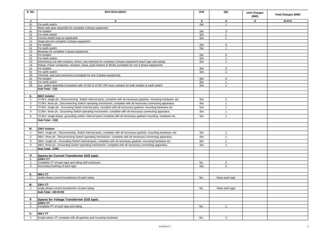
SCHEDULE-3 8
1 2 3 4 5 6=4+5
S. No. Item Description Unit Qty Unit Charges (INR) Total Charges (INR)
b) For earth switch Set 19 Motor with gear assembly for complete 3 phase equipmenta) For Isolator Set 3b) For earth switch Set 110 Corona shield rings as applicable Set 111 Hinge pins for complete 3 phase equipmenta) For Isolator Set 3b) For earth switch Set 112 Bearings for complete 3 phase equipment a) For Isolator Set 5b) For earth switch Set 113 Interlocking coil with resistors, timers, key interlock for complete 3 phase equipment (each type and rating) Set 114 Relays, Power contactors, resistors, fuses, push buttons & MCBs (complete for one 3 phase equipment)a) For Isolator Set 3b) For earth switch Set 115 Terminal pad and connectors (complete for one 3 phase equipment)a) For Isolator Set 2b) For earth switch Set 116 Aux. switch assembly (complete) with 10 NO & 10 NC OR more contacts for both isolator & earth switch Set 1
Sub-Total - C(I)
II. 66kV Isolator1 72.5kV, single ph., Disconnecting Switch internal parts, complete with all necessary gaskets, mounting hardware, etc. Set 12 72.5kV, three ph., Disconnecting Switch operating mechanism, complete with all necessary connecting apparatus. Set 13 72.5kV, single ph., Grounding Switch internal parts, complete with all necessary gaskets, mounting hardware etc Set 14 72.5kV, three ph., Grounding Switch operating mechanism, complete with all necessary connecting apparatus. Set 15 72.5kV, single phase, grounding switch, Internal parts complete with all necessary gaskets mounting hardware etc. Set 1
Sub-Total - C(II)
III. 33kV Isolator1 36kV, single ph., Disconnecting Switch internal parts, complete with all necessary gaskets, mounting hardware, etc. Set 12 36kV, three ph., Disconnecting Switch operating mechanism, complete with all necessary connecting apparatus. Set 13 36kV, single ph., Grounding Switch internal parts, complete with all necessary gaskets, mounting hardware etc Set 14 36kV, three ph., Grounding Switch operating mechanism, complete with all necessary connecting apparatus. Set 1
Sub-Total - C(III)
D Spares for Current Transformer (GIS type)I. 220kV CT1 Complete CT of each type and rating with enclosure. No. 22 Secondary bushing of each type Set 2
II. 66kV CT1 single phase current transformer of each rating No. three each type
III. 33kV CT1 single phase current transformer of each rating No. three each type
Sub-Total - D(I+II+III)
E Spares for Voltage Transformer (GIS type)I. 220kV VT1 Complete PT of each type and rating No. 1
II. 66kV VT1 Single pahse VT complete with all gaskets and mounting hardware No. 3
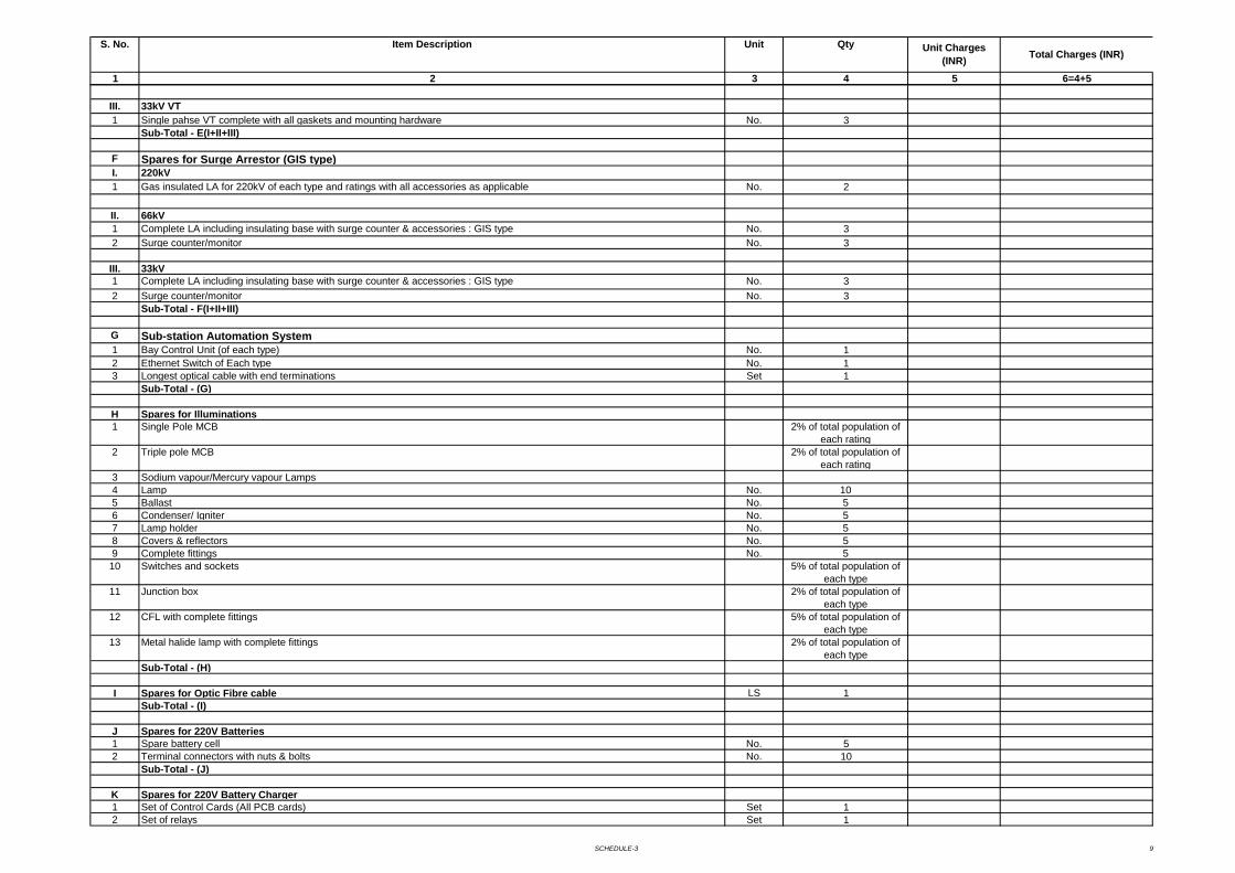
SCHEDULE-3 9
1 2 3 4 5 6=4+5
S. No. Item Description Unit Qty Unit Charges (INR) Total Charges (INR)
III. 33kV VT1 Single pahse VT complete with all gaskets and mounting hardware No. 3
Sub-Total - E(I+II+III)
F Spares for Surge Arrestor (GIS type)I. 220kV1 Gas insulated LA for 220kV of each type and ratings with all accessories as applicable No. 2
II. 66kV1 Complete LA including insulating base with surge counter & accessories : GIS type No. 32 Surge counter/monitor No. 3
III. 33kV 1 Complete LA including insulating base with surge counter & accessories : GIS type No. 32 Surge counter/monitor No. 3
Sub-Total - F(I+II+III)
G Sub-station Automation System1 Bay Control Unit (of each type) No. 12 Ethernet Switch of Each type No. 13 Longest optical cable with end terminations Set 1
Sub-Total - (G)
H Spares for Illuminations1 Single Pole MCB 2% of total population of
each rating2 Triple pole MCB 2% of total population of
each rating3 Sodium vapour/Mercury vapour Lamps4 Lamp No. 105 Ballast No. 56 Condenser/ Igniter No. 57 Lamp holder No. 58 Covers & reflectors No. 59 Complete fittings No. 510 Switches and sockets 5% of total population of
each type11 Junction box 2% of total population of
each type12 CFL with complete fittings 5% of total population of
each type13 Metal halide lamp with complete fittings 2% of total population of
each typeSub-Total - (H)
I Spares for Optic Fibre cable LS 1Sub-Total - (I)
J Spares for 220V Batteries1 Spare battery cell No. 52 Terminal connectors with nuts & bolts No. 10
Sub-Total - (J)
K Spares for 220V Battery Charger1 Set of Control Cards (All PCB cards) Set 12 Set of relays Set 1
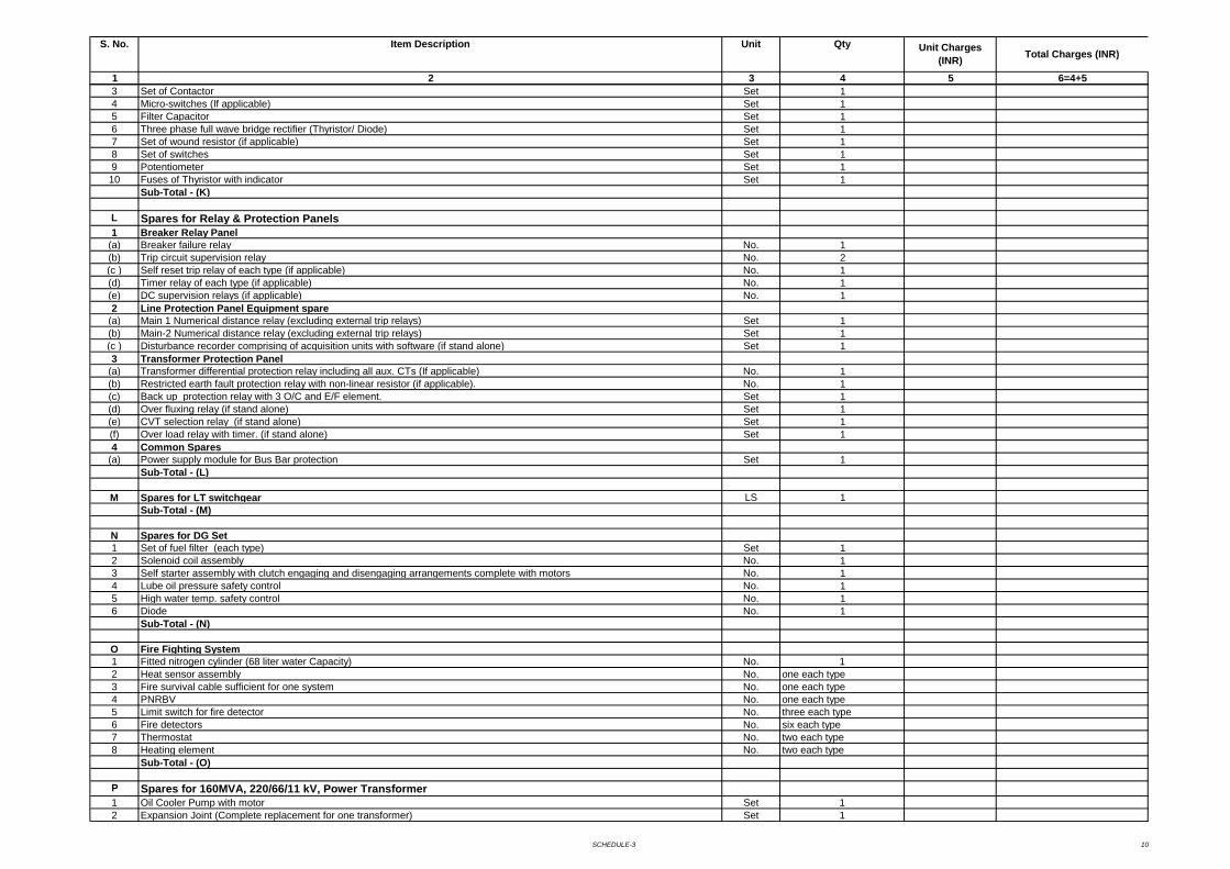
SCHEDULE-3 10
1 2 3 4 5 6=4+5
S. No. Item Description Unit Qty Unit Charges (INR) Total Charges (INR)
3 Set of Contactor Set 14 Micro-switches (If applicable) Set 15 Filter Capacitor Set 16 Three phase full wave bridge rectifier (Thyristor/ Diode) Set 17 Set of wound resistor (if applicable) Set 18 Set of switches Set 19 Potentiometer Set 110 Fuses of Thyristor with indicator Set 1
Sub-Total - (K)
L Spares for Relay & Protection Panels1 Breaker Relay Panel
(a) Breaker failure relay No. 1(b) Trip circuit supervision relay No. 2(c ) Self reset trip relay of each type (if applicable) No. 1(d) Timer relay of each type (if applicable) No. 1(e) DC supervision relays (if applicable) No. 12 Line Protection Panel Equipment spare
(a) Main 1 Numerical distance relay (excluding external trip relays) Set 1(b) Main-2 Numerical distance relay (excluding external trip relays) Set 1(c ) Disturbance recorder comprising of acquisition units with software (if stand alone) Set 13 Transformer Protection Panel
(a) Transformer differential protection relay including all aux. CTs (If applicable) No. 1(b) Restricted earth fault protection relay with non-linear resistor (if applicable). No. 1(c) Back up protection relay with 3 O/C and E/F element. Set 1(d) Over fluxing relay (if stand alone) Set 1(e) CVT selection relay (if stand alone) Set 1(f) Over load relay with timer. (if stand alone) Set 14 Common Spares
(a) Power supply module for Bus Bar protection Set 1Sub-Total - (L)
M Spares for LT switchgear LS 1Sub-Total - (M)
N Spares for DG Set1 Set of fuel filter (each type) Set 12 Solenoid coil assembly No. 13 Self starter assembly with clutch engaging and disengaging arrangements complete with motors No. 14 Lube oil pressure safety control No. 15 High water temp. safety control No. 16 Diode No. 1
Sub-Total - (N)
O Fire Fighting System1 Fitted nitrogen cylinder (68 liter water Capacity) No. 12 Heat sensor assembly No. one each type3 Fire survival cable sufficient for one system No. one each type4 PNRBV No. one each type5 Limit switch for fire detector No. three each type6 Fire detectors No. six each type7 Thermostat No. two each type8 Heating element No. two each type
Sub-Total - (O)
P Spares for 160MVA, 220/66/11 kV, Power Transformer1 Oil Cooler Pump with motor Set 12 Expansion Joint (Complete replacement for one transformer) Set 1
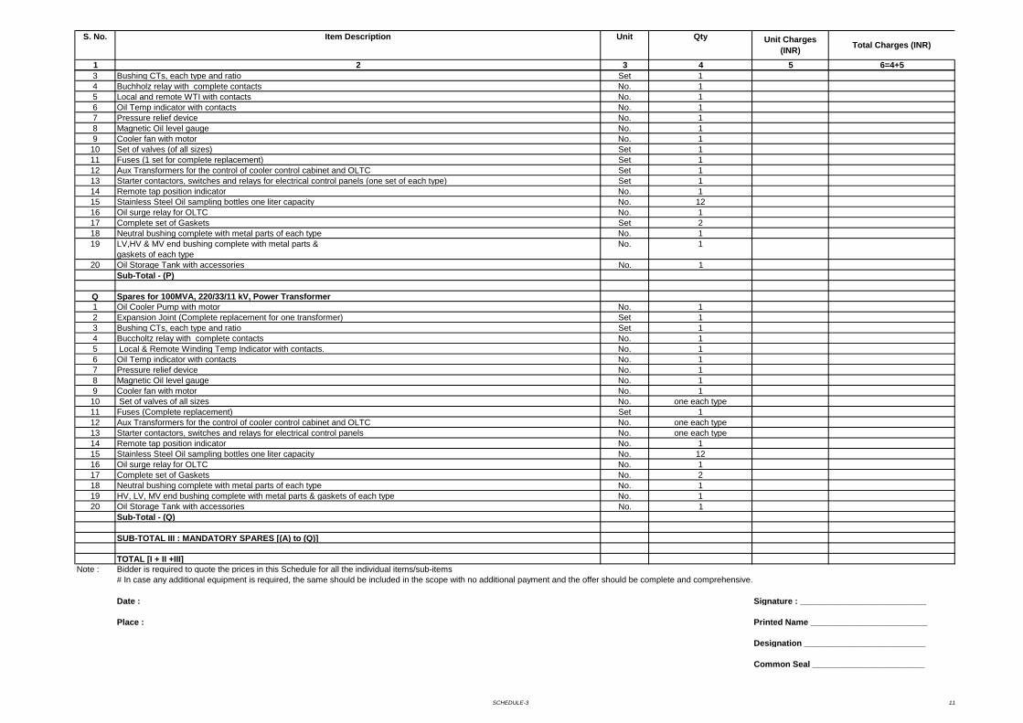
SCHEDULE-3 11
1 2 3 4 5 6=4+5
S. No. Item Description Unit Qty Unit Charges (INR) Total Charges (INR)
3 Bushing CTs, each type and ratio Set 14 Buchholz relay with complete contacts No. 15 Local and remote WTI with contacts No. 16 Oil Temp indicator with contacts No. 17 Pressure relief device No. 18 Magnetic Oil level gauge No. 19 Cooler fan with motor No. 110 Set of valves (of all sizes) Set 111 Fuses (1 set for complete replacement) Set 112 Aux Transformers for the control of cooler control cabinet and OLTC Set 113 Starter contactors, switches and relays for electrical control panels (one set of each type) Set 114 Remote tap position indicator No. 115 Stainless Steel Oil sampling bottles one liter capacity No. 1216 Oil surge relay for OLTC No. 117 Complete set of Gaskets Set 218 Neutral bushing complete with metal parts of each type No. 119 LV,HV & MV end bushing complete with metal parts &
gaskets of each typeNo. 1
20 Oil Storage Tank with accessories No. 1Sub-Total - (P)
Q Spares for 100MVA, 220/33/11 kV, Power Transformer1 Oil Cooler Pump with motor No. 12 Expansion Joint (Complete replacement for one transformer) Set 13 Bushing CTs, each type and ratio Set 14 Buccholtz relay with complete contacts No. 15 Local & Remote Winding Temp Indicator with contacts. No. 16 Oil Temp indicator with contacts No. 17 Pressure relief device No. 18 Magnetic Oil level gauge No. 19 Cooler fan with motor No. 110 Set of valves of all sizes No. one each type11 Fuses (Complete replacement) Set 112 Aux Transformers for the control of cooler control cabinet and OLTC No. one each type13 Starter contactors, switches and relays for electrical control panels No. one each type14 Remote tap position indicator No. 115 Stainless Steel Oil sampling bottles one liter capacity No. 1216 Oil surge relay for OLTC No. 117 Complete set of Gaskets No. 218 Neutral bushing complete with metal parts of each type No. 119 HV, LV, MV end bushing complete with metal parts & gaskets of each type No. 120 Oil Storage Tank with accessories No. 1
Sub-Total - (Q)
SUB-TOTAL III : MANDATORY SPARES [(A) to (Q)]
TOTAL [I + II +III]Note : Bidder is required to quote the prices in this Schedule for all the individual items/sub-items
# In case any additional equipment is required, the same should be included in the scope with no additional payment and the offer should be complete and comprehensive.
Date : Signature : ___________________________
Place : Printed Name _________________________
Designation __________________________
Common Seal ________________________
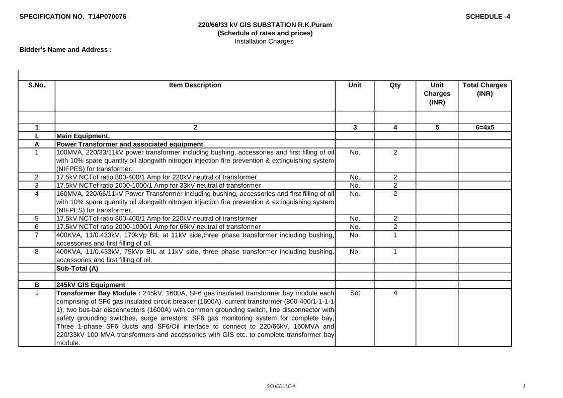
SCHEDULE-4 1
SPECIFICATION NO. T14P070076 SCHEDULE -4
Bidder's Name and Address :
1 2 3 4 5 6=4x5I. Main Equipment.A Power Transformer and associated equipment1 100MVA, 220/33/11kV power transformer including bushing, accessories and first filling of oil
with 10% spare quantity oil alongwith nitrogen injection fire prevention & extinguishing system(NIFPES) for transformer.
No. 2
2 17.5kV NCTof ratio 800-400/1 Amp for 220kV neutral of transformer No. 23 17.5kV NCTof ratio 2000-1000/1 Amp for 33kV neutral of transformer No. 24 160MVA, 220/66/11kV Power Transformer including bushing, accessories and first filling of oil
with 10% spare quantity oil alongwith nitrogen injection fire prevention & extinguishing system(NIFPES) for transformer.
No. 2
5 17.5kV NCTof ratio 800-400/1 Amp for 220kV neutral of transformer No. 26 17.5kV NCTof ratio 2000-1000/1 Amp for 66kV neutral of transformer No. 27 400KVA, 11/0.433kV, 170kVp BIL at 11kV side,three phase transformer including bushing,
accessories and first filling of oil.No. 1
8 400KVA, 11/0.433kV, 75kVp BIL at 11kV side, three phase transformer including bushing,accessories and first filling of oil.
No. 1
Sub-Total (A)
B 245kV GIS Equipment1 Transformer Bay Module : 245kV, 1600A, SF6 gas insulated transformer bay module each
comprising of SF6 gas insulated circuit breaker (1600A), current transformer (800-400/1-1-1-1-1), two bus-bar disconnectors (1600A) with common grounding switch, line disconnector withsafety grounding switches, surge arrestors, SF6 gas monitoring system for complete bay,Three 1-phase SF6 ducts and SF6/Oil interface to connect to 220/66kV, 160MVA and220/33kV 100 MVA transformers and accessories with GIS etc. to complete transformer baymodule.
Set 4
Unit
Installation Charges
Qty
220/66/33 kV GIS SUBSTATION R.K.Puram(Schedule of rates and prices)
S.No. Item Description Unit Charges
(INR)
Total Charges (INR)
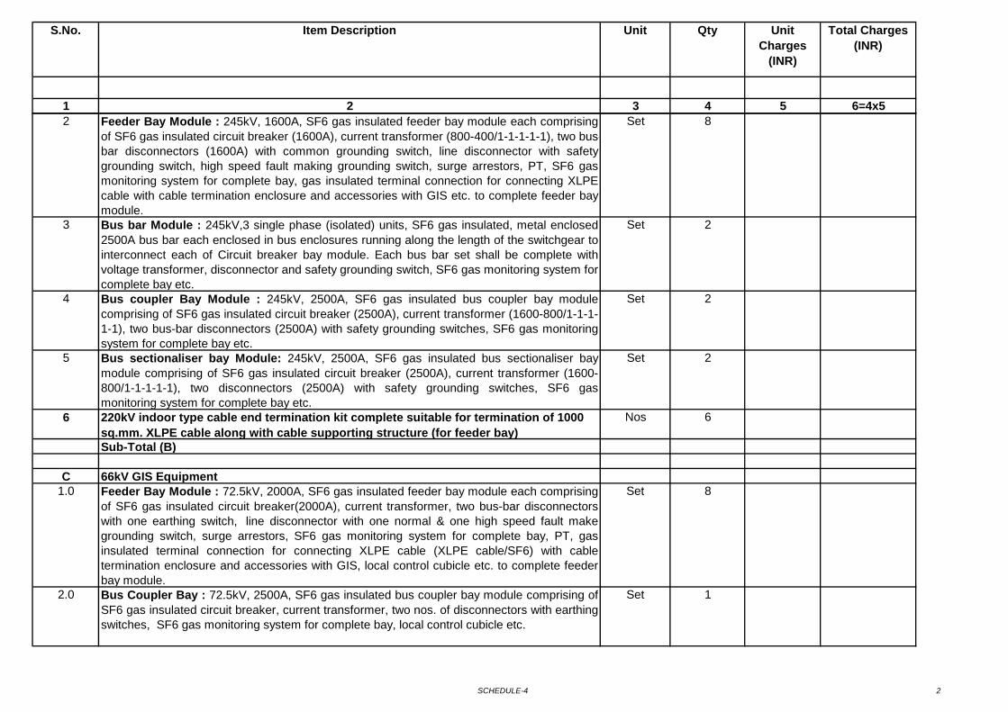
SCHEDULE-4 2
1 2 3 4 5 6=4x5
Unit QtyS.No. Item Description Unit Charges
(INR)
Total Charges (INR)
2 Feeder Bay Module : 245kV, 1600A, SF6 gas insulated feeder bay module each comprisingof SF6 gas insulated circuit breaker (1600A), current transformer (800-400/1-1-1-1-1), two bus-bar disconnectors (1600A) with common grounding switch, line disconnector with safetygrounding switch, high speed fault making grounding switch, surge arrestors, PT, SF6 gasmonitoring system for complete bay, gas insulated terminal connection for connecting XLPEcable with cable termination enclosure and accessories with GIS etc. to complete feeder baymodule.
Set 8
3 Bus bar Module : 245kV,3 single phase (isolated) units, SF6 gas insulated, metal enclosed2500A bus bar each enclosed in bus enclosures running along the length of the switchgear tointerconnect each of Circuit breaker bay module. Each bus bar set shall be complete withvoltage transformer, disconnector and safety grounding switch, SF6 gas monitoring system forcomplete bay etc.
Set 2
4 Bus coupler Bay Module : 245kV, 2500A, SF6 gas insulated bus coupler bay modulecomprising of SF6 gas insulated circuit breaker (2500A), current transformer (1600-800/1-1-1-1-1), two bus-bar disconnectors (2500A) with safety grounding switches, SF6 gas monitoringsystem for complete bay etc.
Set 2
5 Bus sectionaliser bay Module: 245kV, 2500A, SF6 gas insulated bus sectionaliser baymodule comprising of SF6 gas insulated circuit breaker (2500A), current transformer (1600-800/1-1-1-1-1), two disconnectors (2500A) with safety grounding switches, SF6 gasmonitoring system for complete bay etc.
Set 2
6 220kV indoor type cable end termination kit complete suitable for termination of 1000 sq.mm. XLPE cable along with cable supporting structure (for feeder bay)
Nos 6
Sub-Total (B)
C 66kV GIS Equipment1.0 Feeder Bay Module : 72.5kV, 2000A, SF6 gas insulated feeder bay module each comprising
of SF6 gas insulated circuit breaker(2000A), current transformer, two bus-bar disconnectorswith one earthing switch, line disconnector with one normal & one high speed fault makegrounding switch, surge arrestors, SF6 gas monitoring system for complete bay, PT, gasinsulated terminal connection for connecting XLPE cable (XLPE cable/SF6) with cabletermination enclosure and accessories with GIS, local control cubicle etc. to complete feederbay module.
Set 8
2.0 Bus Coupler Bay : 72.5kV, 2500A, SF6 gas insulated bus coupler bay module comprising ofSF6 gas insulated circuit breaker, current transformer, two nos. of disconnectors with earthingswitches, SF6 gas monitoring system for complete bay, local control cubicle etc.
Set 1
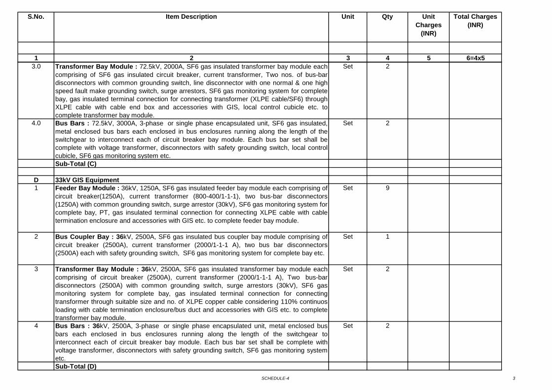
SCHEDULE-4 3
1 2 3 4 5 6=4x5
Unit QtyS.No. Item Description Unit Charges
(INR)
Total Charges (INR)
3.0 Transformer Bay Module : 72.5kV, 2000A, SF6 gas insulated transformer bay module eachcomprising of SF6 gas insulated circuit breaker, current transformer, Two nos. of bus-bardisconnectors with common grounding switch, line disconnector with one normal & one highspeed fault make grounding switch, surge arrestors, SF6 gas monitoring system for completebay, gas insulated terminal connection for connecting transformer (XLPE cable/SF6) throughXLPE cable with cable end box and accessories with GIS, local control cubicle etc. tocomplete transformer bay module.
Set 2
4.0 Bus Bars : 72.5kV, 3000A, 3-phase or single phase encapsulated unit, SF6 gas insulated,metal enclosed bus bars each enclosed in bus enclosures running along the length of theswitchgear to interconnect each of circuit breaker bay module. Each bus bar set shall becomplete with voltage transformer, disconnectors with safety grounding switch, local controlcubicle, SF6 gas monitoring system etc.
Set 2
Sub-Total (C)
D 33kV GIS Equipment1 Feeder Bay Module : 36kV, 1250A, SF6 gas insulated feeder bay module each comprising of
circuit breaker(1250A), current transformer (800-400/1-1-1), two bus-bar disconnectors(1250A) with common grounding switch, surge arrestor (30kV), SF6 gas monitoring system for complete bay, PT, gas insulated terminal connection for connecting XLPE cable with cabletermination enclosure and accessories with GIS etc. to complete feeder bay module.
Set 9
2 Bus Coupler Bay : 36kV, 2500A, SF6 gas insulated bus coupler bay module comprising ofcircuit breaker (2500A), current transformer (2000/1-1-1 A), two bus bar disconnectors(2500A) each with safety grounding switch, SF6 gas monitoring system for complete bay etc.
Set 1
3 Transformer Bay Module : 36kV, 2500A, SF6 gas insulated transformer bay module eachcomprising of circuit breaker (2500A), current transformer (2000/1-1-1 A), Two bus-bardisconnectors (2500A) with common grounding switch, surge arrestors (30kV), SF6 gasmonitoring system for complete bay, gas insulated terminal connection for connectingtransformer through suitable size and no. of XLPE copper cable considering 110% continuosloading with cable termination enclosure/bus duct and accessories with GIS etc. to completetransformer bay module.
Set 2
4 Bus Bars : 36kV, 2500A, 3-phase or single phase encapsulated unit, metal enclosed busbars each enclosed in bus enclosures running along the length of the switchgear tointerconnect each of circuit breaker bay module. Each bus bar set shall be complete withvoltage transformer, disconnectors with safety grounding switch, SF6 gas monitoring systemetc.
Set 2
Sub-Total (D)
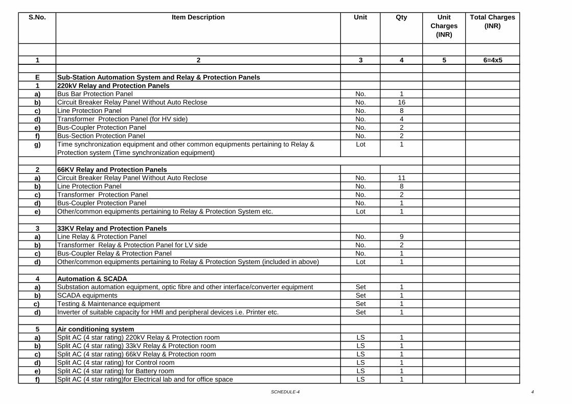
SCHEDULE-4 4
1 2 3 4 5 6=4x5
Unit QtyS.No. Item Description Unit Charges
(INR)
Total Charges (INR)
E Sub-Station Automation System and Relay & Protection Panels1 220kV Relay and Protection Panelsa) Bus Bar Protection Panel No. 1b) Circuit Breaker Relay Panel Without Auto Reclose No. 16c) Line Protection Panel No. 8d) Transformer Protection Panel (for HV side) No. 4e) Bus-Coupler Protection Panel No. 2f) Bus-Section Protection Panel No. 2g) Time synchronization equipment and other common equipments pertaining to Relay &
Protection system (Time synchronization equipment) Lot 1
2 66KV Relay and Protection Panelsa) Circuit Breaker Relay Panel Without Auto Reclose No. 11b) Line Protection Panel No. 8c) Transformer Protection Panel No. 2d) Bus-Coupler Protection Panel No. 1e) Other/common equipments pertaining to Relay & Protection System etc. Lot 1
3 33KV Relay and Protection Panelsa) Line Relay & Protection Panel No. 9b) Transformer Relay & Protection Panel for LV side No. 2c) Bus-Coupler Relay & Protection Panel No. 1d) Other/common equipments pertaining to Relay & Protection System (included in above) Lot 1
4 Automation & SCADAa) Substation automation equipment, optic fibre and other interface/converter equipment Set 1b) SCADA equipments Set 1c) Testing & Maintenance equipment Set 1d) Inverter of suitable capacity for HMI and peripheral devices i.e. Printer etc. Set 1
5 Air conditioning systema) Split AC (4 star rating) 220kV Relay & Protection room LS 1b) Split AC (4 star rating) 33kV Relay & Protection room LS 1c) Split AC (4 star rating) 66kV Relay & Protection room LS 1d) Split AC (4 star rating) for Control room LS 1e) Split AC (4 star rating) for Battery room LS 1f) Split AC (4 star rating)for Electrical lab and for office space LS 1
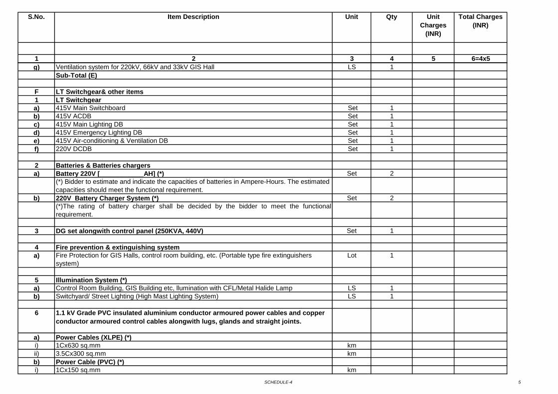
SCHEDULE-4 5
1 2 3 4 5 6=4x5
Unit QtyS.No. Item Description Unit Charges
(INR)
Total Charges (INR)
g) Ventilation system for 220kV, 66kV and 33kV GIS Hall LS 1Sub-Total (E)
F LT Switchgear& other items1 LT Switchgeara) 415V Main Switchboard Set 1b) 415V ACDB Set 1c) 415V Main Lighting DB Set 1d) 415V Emergency Lighting DB Set 1e) 415V Air-conditioning & Ventilation DB Set 1f) 220V DCDB Set 1
2 Batteries & Batteries chargersa) Battery 220V [____________AH] (*) Set 2
(*) Bidder to estimate and indicate the capacities of batteries in Ampere-Hours. The estimated capacities should meet the functional requirement.
b) 220V Battery Charger System (*) Set 2(*)The rating of battery charger shall be decided by the bidder to meet the functionalrequirement.
3 DG set alongwith control panel (250KVA, 440V) Set 1
4 Fire prevention & extinguishing system a) Fire Protection for GIS Halls, control room building, etc. (Portable type fire extinguishers
system)Lot 1
5 Illumination System (*)a) Control Room Building, GIS Building etc, llumination with CFL/Metal Halide Lamp LS 1b) Switchyard/ Street Lighting (High Mast Lighting System) LS 1
6 1.1 kV Grade PVC insulated aluminium conductor armoured power cables and copper conductor armoured control cables alongwith lugs, glands and straight joints.
a) Power Cables (XLPE) (*)i) 1Cx630 sq.mm kmii) 3.5Cx300 sq.mm kmb) Power Cable (PVC) (*)i) 1Cx150 sq.mm km

SCHEDULE-4 6
1 2 3 4 5 6=4x5
Unit QtyS.No. Item Description Unit Charges
(INR)
Total Charges (INR)
ii) 3.5Cx70 sq.mm kmiii) 3.5Cx35 sq.mm kmiv) 4Cx16 sq.mm kmv) 4Cx6 sq.mm kmvi) 2Cx6 sq.mm kmc) Control Cable (PVC) (*)i) 2Cx2.5 sq.mm kmii) 3Cx2.5 sq.mm kmiii) 5Cx2.5 sq.mm kmiv) 7Cx2.5 sq.mm kmv) 10Cx2.5 sq.mm kmvi) 14Cx2.5 sq.mm kmvii) 19Cx2.5 sq.mm kmviii) 27Cx2.5 sq.mm km
(*) The bidder has to estimate and fill the quantities as per his own assessment.
7 Power cable with termmination kit/bus duct on 33kV side for connecting 2 nos. Transformers to 33kV GIS
LS 1
8 Power cable with termmination kit/bus duct on 66kV side for connecting 2 nos. Transformers to 66kV GIS
LS 1
9 Grounding/ Earthing Systema) 40mm MS rod for Earthmat LS 1b) Lightning Mast/ GS Shield Wire LS 1
10 Steel Structure (*) a) Lattice Strcuture MTb) Pipe Structure MT
(*) Bidder to estimate and fill the quantities as per his own assessment.
11 EOT Crane (*) a) 220kV GIS room (*) Set 1b) 66kV GIS room (*) Set 1c) 33kV GIS room (*) Set 1
(*) Bidder has to estimate and design EOT crane for erection & maintenance of largest GIS component/ assembly.
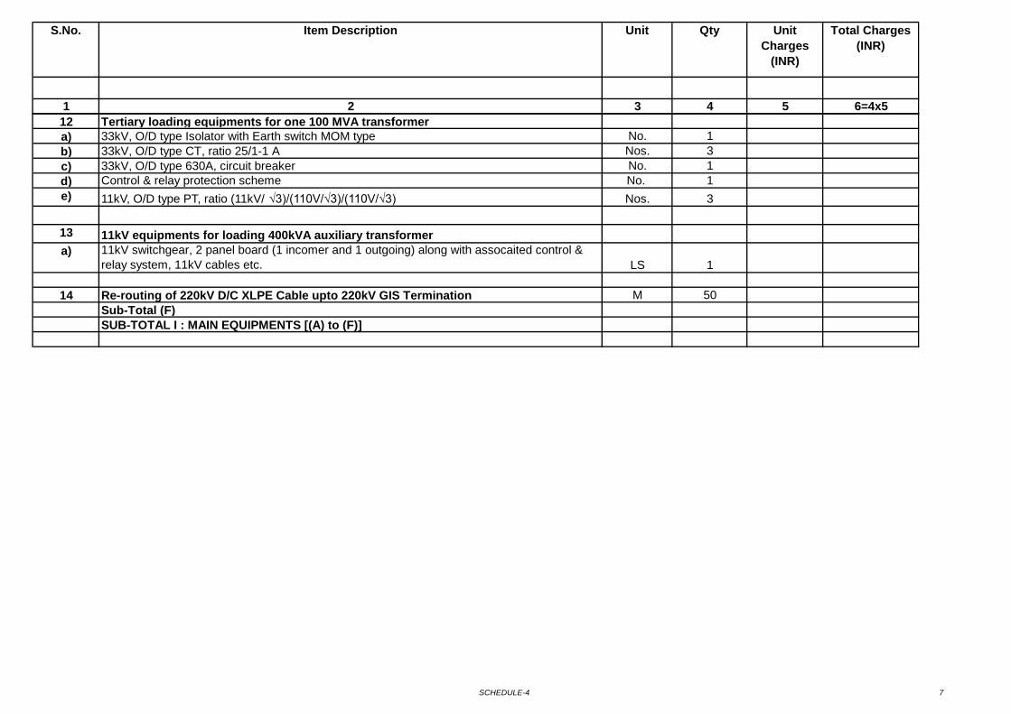
SCHEDULE-4 7
1 2 3 4 5 6=4x5
Unit QtyS.No. Item Description Unit Charges
(INR)
Total Charges (INR)
12 Tertiary loading equipments for one 100 MVA transformera) 33kV, O/D type Isolator with Earth switch MOM type No. 1b) 33kV, O/D type CT, ratio 25/1-1 A Nos. 3c) 33kV, O/D type 630A, circuit breaker No. 1d) Control & relay protection scheme No. 1e) 11kV, O/D type PT, ratio (11kV/ √3)/(110V/√3)/(110V/√3) Nos. 3
13 11kV equipments for loading 400kVA auxiliary transformera) 11kV switchgear, 2 panel board (1 incomer and 1 outgoing) along with assocaited control &
relay system, 11kV cables etc. LS 1
14 Re-routing of 220kV D/C XLPE Cable upto 220kV GIS Termination M 50Sub-Total (F)SUB-TOTAL I : MAIN EQUIPMENTS [(A) to (F)]
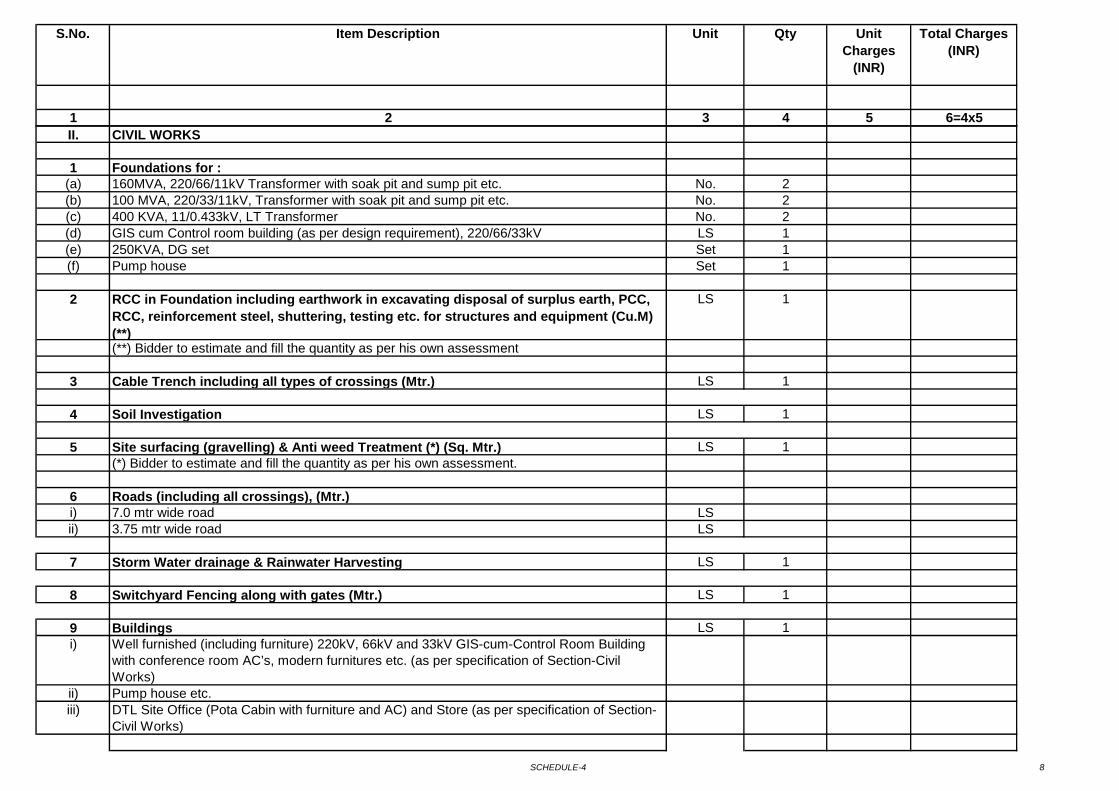
SCHEDULE-4 8
1 2 3 4 5 6=4x5
Unit QtyS.No. Item Description Unit Charges
(INR)
Total Charges (INR)
II. CIVIL WORKS
1 Foundations for :(a) 160MVA, 220/66/11kV Transformer with soak pit and sump pit etc. No. 2(b) 100 MVA, 220/33/11kV, Transformer with soak pit and sump pit etc. No. 2(c) 400 KVA, 11/0.433kV, LT Transformer No. 2(d) GIS cum Control room building (as per design requirement), 220/66/33kV LS 1(e) 250KVA, DG set Set 1(f) Pump house Set 1
2 RCC in Foundation including earthwork in excavating disposal of surplus earth, PCC, RCC, reinforcement steel, shuttering, testing etc. for structures and equipment (Cu.M) (**)
LS 1
(**) Bidder to estimate and fill the quantity as per his own assessment
3 Cable Trench including all types of crossings (Mtr.) LS 1
4 Soil Investigation LS 1
5 Site surfacing (gravelling) & Anti weed Treatment (*) (Sq. Mtr.) LS 1(*) Bidder to estimate and fill the quantity as per his own assessment.
6 Roads (including all crossings), (Mtr.)i) 7.0 mtr wide road LSii) 3.75 mtr wide road LS
7 Storm Water drainage & Rainwater Harvesting LS 1
8 Switchyard Fencing along with gates (Mtr.) LS 1
9 Buildings LS 1i) Well furnished (including furniture) 220kV, 66kV and 33kV GIS-cum-Control Room Building
with conference room AC’s, modern furnitures etc. (as per specification of Section-Civil Works)
ii) Pump house etc.iii) DTL Site Office (Pota Cabin with furniture and AC) and Store (as per specification of Section-
Civil Works)
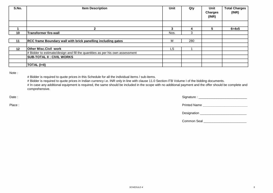
SCHEDULE-4 9
1 2 3 4 5 6=4x5
Unit QtyS.No. Item Description Unit Charges
(INR)
Total Charges (INR)
10 Transformer fire-wall Nos. 3
11 RCC frame Boundary wall with brick panelling including gates M 280
12 Other Misc.Civil work LS 1# Bidder to estimate/design and fill the quantities as per his own assessmentSUB-TOTAL II : CIVIL WORKS
TOTAL (I+II)
Note :# Bidder is required to quote prices in this Schedule for all the individual items / sub-items.# Bidder is required to quote prices in Indian currency i.e. INR only in line with clause 11.0 Section-ITB Volume I of the bidding documents.
Date : Signature : ___________________________
Place : Printed Name _________________________
Designation __________________________
Common Seal ________________________
# In case any additional equipment is required, the same should be included in the scope with no additional payment and the offer should be complete and comprehensive.
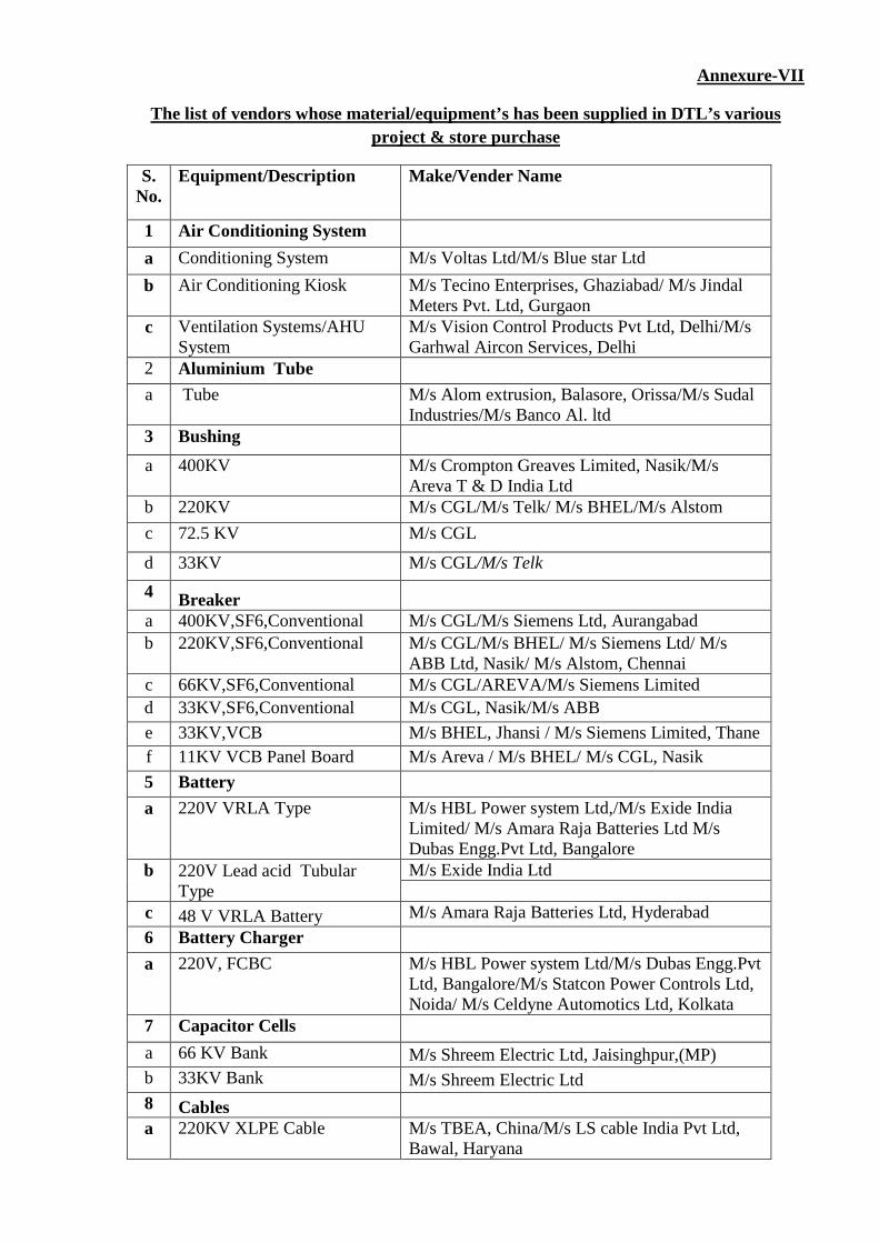
Annexure-VII
S. No.
The list of vendors whose material/equipment’s has been supplied in DTL’s various project & store purchase
Equipment/Description Make/Vender Name
1 Air Conditioning System a Conditioning System M/s Voltas Ltd/M/s Blue star Ltd b Air Conditioning Kiosk M/s Tecino Enterprises, Ghaziabad/ M/s Jindal
Meters Pvt. Ltd, Gurgaon c Ventilation Systems/AHU
System M/s Vision Control Products Pvt Ltd, Delhi/M/s Garhwal Aircon Services, Delhi
2 Aluminium Tube a Tube M/s Alom extrusion, Balasore, Orissa/M/s Sudal
Industries/M/s Banco Al. ltd 3 Bushing a 400KV M/s Crompton Greaves Limited, Nasik/M/s
Areva T & D India Ltd b 220KV M/s CGL/M/s Telk/ M/s BHEL/M/s Alstom c 72.5 KV M/s CGL
d 33KV M/s CGL/M/s Telk 4 Breaker a 400KV,SF6,Conventional M/s CGL/M/s Siemens Ltd, Aurangabad b 220KV,SF6,Conventional M/s CGL/M/s BHEL/ M/s Siemens Ltd/ M/s
ABB Ltd, Nasik/ M/s Alstom, Chennai c 66KV,SF6,Conventional M/s CGL/AREVA/M/s Siemens Limited d 33KV,SF6,Conventional M/s CGL, Nasik/M/s ABB e 33KV,VCB M/s BHEL, Jhansi / M/s Siemens Limited, Thane f 11KV VCB Panel Board M/s Areva / M/s BHEL/ M/s CGL, Nasik 5 Battery a 220V VRLA Type M/s HBL Power system Ltd,/M/s Exide India
Limited/ M/s Amara Raja Batteries Ltd M/s Dubas Engg.Pvt Ltd, Bangalore
b 220V Lead acid Tubular Type
M/s Exide India Ltd
c 48 V VRLA Battery M/s Amara Raja Batteries Ltd, Hyderabad 6 Battery Charger a 220V, FCBC M/s HBL Power system Ltd/M/s Dubas Engg.Pvt
Ltd, Bangalore/M/s Statcon Power Controls Ltd, Noida/ M/s Celdyne Automotics Ltd, Kolkata
7 Capacitor Cells a 66 KV Bank M/s Shreem Electric Ltd, Jaisinghpur,(MP) b 33KV Bank M/s Shreem Electric Ltd 8 Cables a 220KV XLPE Cable M/s TBEA, China/M/s LS cable India Pvt Ltd,
Bawal, Haryana
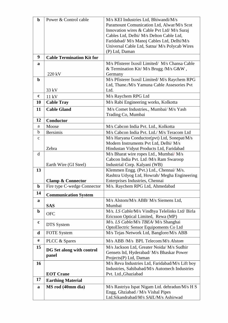
b Power & Control cable M/s KEI Industries Ltd, Bhiwandi/M/s Paramount Comunication Ltd, Alwar/M/s Scot Innovation wires & Cable Pvt Ltd/ M/s Suraj Cables Ltd, Delhi/ M/s Delton Cable Ltd, Faridabad/ M/s Manoj Cables Ltd, Delhi/M/s Universal Cable Ltd, Satna/ M/s Polycab Wires (P) Ltd, Daman
9 Cable Termination Kit for a
220 kV
M/s Pfisterer Ixosil Limited/ M/s Chansa Cable & Termination Kit/ M/s Brugg /M/s G&W , Germany
b
33 kV
M/s Pfisterer Ixosil Limited/ M/s Raychem RPG Ltd, Thane./M/s Yamuna Cable Assesories Pvt Ltd.
c 11 kV M/s Raychem RPG Ltd 10 Cable Tray M/s Rabi Engineering works, Kolkotta 11 Cable Gland M/s Comet Industries., Mumbai/ M/s Yash
Trading Co, Mumbai 12 Conductor a Moose M/s Cabcon India Pvt. Ltd., Kolkotta b Bersimis M/s Cabcon India Pvt. Ltd./ M/s Teracom Ltd c
Zebra
M/s Haryana Conductor(pvt) Ltd, Sonepat/M/s Modern Instruments Pvt Ltd, Delhi/ M/s Hindustan Vidyut Products Ltd, Faridabad
d
Earth Wire (GI Steel)
M/s Bharat wire ropes Ltd., Mumbai/ M/s Cabcon India Pvt. Ltd /M/s Ram Swaroop Industrial Corp. Kalyani (WB)
13
Clamp & Connector
Klemmen Engg. (Pvt.) Ltd., Chennai/ M/s. Rashtra Udyog Ltd, Howrah/ Megha Engineering Enterprises Industries, Chennai
b Fire type C-wedge Connector M/s. Raychem RPG Ltd, Ahmedabad 14 Communication System a
SAS M/s Alstom/M/s ABB/ M/s Siemens Ltd, Mumbai
b OFC M/s. LS Cable/M/s Vindhya Telelinks Ltd/ Birla Ericsson Optical Limited, Rewa (MP)
c DTS System M/s. LS Cable/M/s TBEA/ M/s Shanghai OptoElectric Sensor Equipoments Co Ltd
d FOTE System M/s Tejas Network Ltd, Banglore/M/s ABB e PLCC & Spares M/s ABB /M/s BPL Telecom/M/s Alstom
15 DG Set along with control panel
M/s Jackson Ltd, Greater Noida/ M/s Sudhir Gensets ltd, Hyderabad/ M/s Bhaskar Power Projects(P) Ltd, Daman
16
EOT Crane
M/s Reva Industries Ltd, Faridabad/M/s Lift boy Industries, Sahibabad/M/s Automech Industries Pvt. Ltd.,Ghaziabad
17 Earthing Material a MS rod (40mm dia) M/s Rastriya Ispat Nigam Ltd. dehradun/M/s H S
Engg, Ghziabad / M/s Vishal Pipes Ltd.Sikandrabad/M/s SAIL/M/s Ashirwad
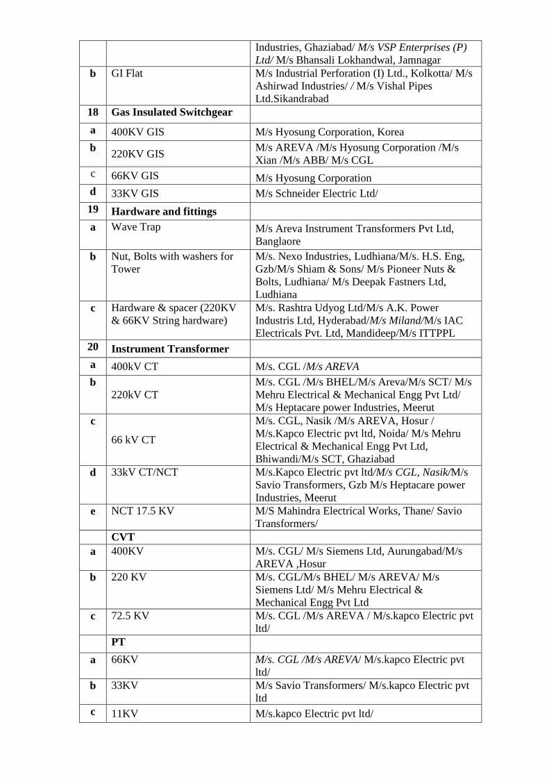
Industries, Ghaziabad/ M/s VSP Enterprises (P) Ltd/ M/s Bhansali Lokhandwal, Jamnagar
b GI Flat M/s Industrial Perforation (I) Ltd., Kolkotta/ M/s Ashirwad Industries/ / M/s Vishal Pipes Ltd.Sikandrabad
18 Gas Insulated Switchgear a 400KV GIS M/s Hyosung Corporation, Korea b 220KV GIS M/s AREVA /M/s Hyosung Corporation /M/s
Xian /M/s ABB/ M/s CGL c 66KV GIS M/s Hyosung Corporation d 33KV GIS M/s Schneider Electric Ltd/ 19 Hardware and fittings a Wave Trap M/s Areva Instrument Transformers Pvt Ltd,
Banglaore b Nut, Bolts with washers for
Tower M/s. Nexo Industries, Ludhiana/M/s. H.S. Eng, Gzb/M/s Shiam & Sons/ M/s Pioneer Nuts & Bolts, Ludhiana/ M/s Deepak Fastners Ltd, Ludhiana
c Hardware & spacer (220KV & 66KV String hardware)
M/s. Rashtra Udyog Ltd/M/s A.K. Power Industris Ltd, Hyderabad/M/s Miland/M/s IAC Electricals Pvt. Ltd, Mandideep/M/s ITTPPL
20 Instrument Transformer a 400kV CT M/s. CGL /M/s AREVA b
220kV CT M/s. CGL /M/s BHEL/M/s Areva/M/s SCT/ M/s Mehru Electrical & Mechanical Engg Pvt Ltd/ M/s Heptacare power Industries, Meerut
c
66 kV CT
M/s. CGL, Nasik /M/s AREVA, Hosur / M/s.Kapco Electric pvt ltd, Noida/ M/s Mehru Electrical & Mechanical Engg Pvt Ltd, Bhiwandi/M/s SCT, Ghaziabad
d 33kV CT/NCT M/s.Kapco Electric pvt ltd/M/s CGL, Nasik/M/s Savio Transformers, Gzb M/s Heptacare power Industries, Meerut
e NCT 17.5 KV M/S Mahindra Electrical Works, Thane/ Savio Transformers/
CVT a 400KV M/s. CGL/ M/s Siemens Ltd, Aurungabad/M/s
AREVA ,Hosur b 220 KV M/s. CGL/M/s BHEL/ M/s AREVA/ M/s
Siemens Ltd/ M/s Mehru Electrical & Mechanical Engg Pvt Ltd
c 72.5 KV M/s. CGL /M/s AREVA / M/s.kapco Electric pvt ltd/
PT a 66KV M/s. CGL /M/s AREVA/ M/s.kapco Electric pvt
ltd/ b 33KV M/s Savio Transformers/ M/s.kapco Electric pvt
ltd c 11KV M/s.kapco Electric pvt ltd/
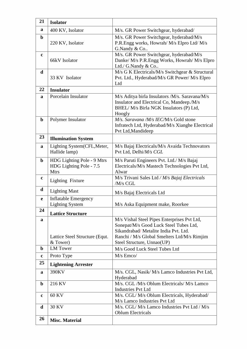
21 Isolator a 400 KV, Isolator M/s. GR Power Switchgear, hyderabad/ b
220 KV, Isolator M/s. GR Power Switchgear, hyderabad/M/s P.R.Engg works, Howrah/ M/s Elpro Ltd/ M/s G.Nandy & Co..
c 66kV Isolator
M/s. GR Power Switchgear, hyderabad/M/s Danke/ M/s P.R.Engg Works, Howrah/ M/s Elpro Ltd./ G.Nandy & Co..
d 33 KV Isolator
M/s G K Electricals/M/s Switchgear & Structural Pvt. Ltd., Hyderabad/M/s GR Power/ M/s Elpro Ltd
22 Insulator a Porcelain Insulator M/s Aditya birla Insulators /M/s. Saravana/M/s
Insulator and Electrical Co, Mandeep./M/s BHEL/ M/s Birla NGK Insulators (P) Ltd, Hoogly
b Polymer Insulator M/s. Saravana /M/s IEC/M/s Gold stone Infratech Ltd, Hyderabad/M/s Xianghe Electrical Pvt Ltd,Mandideep
23 Illumination System a Lighting System(CFL,Meter,
Hallide lamp) M/s Bajaj Electricals/M/s Avaida Technovators Pvt Ltd, Delhi/M/s CGL
b HDG Lighting Pole - 9 Mtrs HDG Lighting Pole - 7.5 Mtrs
M/s Paruti Engineers Pvt. Ltd./ M/s Bajaj Electricals/M/s Mastech Technologies Pvt Ltd, Alwar
c Lighting Fixture M/s Trivani Sales Ltd / M/s Bajaj Electricals /M/s CGL
d Lighting Mast M/s Bajaj Electricals Ltd e Inflatable Emergency
Lighting System M/s Aska Equipment make, Roorkee 24 Lattice Structure a
Lattice Steel Structure (Equt. & Tower)
M/s Vishal Steel Pipes Enterprises Pvt Ltd, Sonepat/M/s Good Luck Steel Tubes Ltd, Sikandrabad/ Metalite India Pvt. Ltd. Ranchi / M/s Global Smelters Ltd/M/s Rimjim Steel Structure, Unnao(UP)
b LM Tower M/s Good Luck Steel Tubes Ltd c Proto Type M/s Emco/
25 Lightening Arrester a 390KV M/s. CGL, Nasik/ M/s Lamco Industries Pvt Ltd,
Hyderabad b 216 KV M/s. CGL /M/s Oblum Electricals/ M/s Lamco
Industries Pvt Ltd c 60 KV M/s. CGL/ M/s Oblum Electricals, Hyderabad/
M/s Lamco Industries Pvt Ltd d 30 KV M/s. CGL/ M/s Lamco Industries Pvt Ltd / M/s
Oblum Electricals 26 Misc. Material
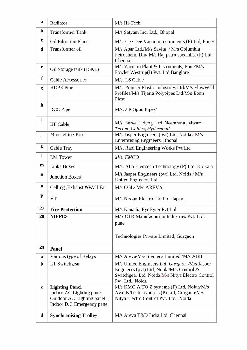
a Radiator M/s Hi-Tech b Transformer Tank M/s Satyam Ind. Ltd., Bhopal c Oil Filtration Plant M/s. Cee Dee Vacuum instruments (P) Ltd, Pune/ d Transformer oil M/s Apar Ltd./M/s Savita / M/s Columbia
Petrochem, Diu/ M/s Raj petro specialist (P) Ltd, Chennai
e Oil Storage tank (15KL) M/s Vacuum Plant & Instruments, Pune/M/s Fowler Westrup(I) Pvt. Ltd,Banglore
f Cable Accessories M/s. LS Cable g HDPE Pipe M/s. Pioneer Plastic Industries Ltd/M/s FlowWell
Profiles/M/s Tijaria Polypipes Ltd/M/s Eonn Plast
h RCC Pipe M/s. J K Spun Pipes/
i HF Cable M/s. Servel Udyog Ltd ,Neemrana , alwar/
Techno Cables, Hyderabad. j Marshelling Box M/s Jasper Engineers (pvt) Ltd, Noida / M/s
Enterprising Engineers, Bhopal k Cable Tray M/s. Rabi Engineering Works Pvt Ltd l LM Tower M/s. EMCO
m Links Boxes M/s. Alfa Elemtech Technology (P) Ltd, Kolkata n Junction Boxes M/s Jasper Engineers (pvt) Ltd, Noida / M/s
Unilec Engineers Ltd o Celling ,Exhaust &Wall Fan M/s CGL/ M/s AREVA p
VT M/s Nissan Electric Co Ltd, Japan
27 Fire Protection M/s Kanadia Fyr Fyter Pvt Ltd. 28 NIFPES M/S CTR Manufacturing Industries Pvt. Ltd,
pune Technologies Private Limited, Gurgaon
29 Panel a Various type of Relays M/s Areva/M/s Siemens Limited /M/s ABB b LT Switchgear M/s Unilec Engineers Ltd, Gurgaon /M/s Jasper
Engineers (pvt) Ltd, Noida/M/s Control & Switchgear Ltd, Noida/M/s Nitya Electro Control Pvt. Ltd., Noida
c Lighting Panel Indoor AC Lighting panel Outdoor AC Lighting panel Indoor D.C Emergency panel
M/s KMG A TO Z systems (P) Ltd, Noida/M/s Avaids Technovations (P) Ltd, Gurgaon/M/s Nitya Electro Control Pvt. Ltd., Noida
d Synchronising Trolley M/s Areva T&D India Ltd, Chennai
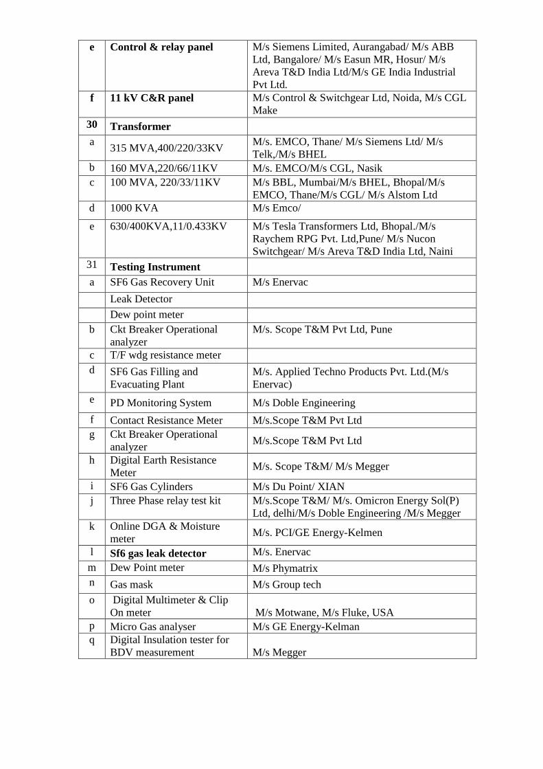
e Control & relay panel M/s Siemens Limited, Aurangabad/ M/s ABB Ltd, Bangalore/ M/s Easun MR, Hosur/ M/s Areva T&D India Ltd/M/s GE India Industrial Pvt Ltd.
f 11 kV C&R panel M/s Control & Switchgear Ltd, Noida, M/s CGL Make
30 Transformer a 315 MVA,400/220/33KV M/s. EMCO, Thane/ M/s Siemens Ltd/ M/s
Telk,/M/s BHEL b 160 MVA,220/66/11KV M/s. EMCO/M/s CGL, Nasik c 100 MVA, 220/33/11KV M/s BBL, Mumbai/M/s BHEL, Bhopal/M/s
EMCO, Thane/M/s CGL/ M/s Alstom Ltd d 1000 KVA M/s Emco/
e 630/400KVA,11/0.433KV M/s Tesla Transformers Ltd, Bhopal./M/s Raychem RPG Pvt. Ltd,Pune/ M/s Nucon Switchgear/ M/s Areva T&D India Ltd, Naini
31 Testing Instrument a SF6 Gas Recovery Unit M/s Enervac Leak Detector Dew point meter b Ckt Breaker Operational
analyzer M/s. Scope T&M Pvt Ltd, Pune
c T/F wdg resistance meter d SF6 Gas Filling and
Evacuating Plant M/s. Applied Techno Products Pvt. Ltd.(M/s Enervac)
e PD Monitoring System M/s Doble Engineering f Contact Resistance Meter M/s.Scope T&M Pvt Ltd g Ckt Breaker Operational
analyzer M/s.Scope T&M Pvt Ltd
h Digital Earth Resistance Meter M/s. Scope T&M/ M/s Megger
i SF6 Gas Cylinders M/s Du Point/ XIAN j Three Phase relay test kit M/s.Scope T&M/ M/s. Omicron Energy Sol(P)
Ltd, delhi/M/s Doble Engineering /M/s Megger k Online DGA & Moisture
meter M/s. PCI/GE Energy-Kelmen
l Sf6 gas leak detector M/s. Enervac m Dew Point meter M/s Phymatrix n Gas mask M/s Group tech o Digital Multimeter & Clip
On meter M/s Motwane, M/s Fluke, USA p Micro Gas analyser M/s GE Energy-Kelman q Digital Insulation tester for
BDV measurement M/s Megger