alternating current characterization of nano-pt(ii) octaethylporphyrin (ptoep) thin film as a new...
TRANSCRIPT

This content has been downloaded from IOPscience. Please scroll down to see the full text.
Download details:
IP Address: 129.93.16.3
This content was downloaded on 07/06/2016 at 12:42
Please note that terms and conditions apply.
Alternating current characterization of nano-Pt(II) octaethylporphyrin (PtOEP) thin film as a
new organic semiconductor
View the table of contents for this issue, or go to the journal homepage for more
2016 Chinese Phys. B 25 067201
(http://iopscience.iop.org/1674-1056/25/6/067201)
Home Search Collections Journals About Contact us My IOPscience

Chin. Phys. B Vol. 25, No. 6 (2016) 067201
Alternating current characterization of nano-Pt(II)octaethylporphyrin (PtOEP) thin film as a new
organic semiconductorM Dongol1, M M El-Nahass2, A El-Denglawey1,3,†, A A Abuelwafa1,4, and T Soga4
1Nano and Thin Film Laboratory, Physics Department, Faculty of Science, South Valley University, Qena 83523, Egypt2Physics Department, Faculty of Education, Ain Shams University, Roxy, Cairo 11757, Egypt
3Physics Department, Faculty of Applied Medical Science, Taif University, Turabah 21995, Kingdom of Saudi Arabia4Department of Frontier Materials, Nagoya Institute of Technology, Gokiso-cho, Showa-ku, Nagoya 466-8555, Japan
(Received 31 October 2015; revised manuscript received 24 January 2016; published online 25 April 2016)
Alternating current (AC) conductivity and dielectric properties of thermally evaporated Au/PtOEP/Au thin films areinvestigated each as a function of temperature (303 K–473 K) and frequency (50 Hz–5 MHz). The frequency dependenceof AC conductivity follows the Jonscher universal dynamic law. The AC-activation energies are determined at differentfrequencies. It is found that the correlated barrier hopping (CBH) model is the dominant conduction mechanism. Thevariation of the frequency exponent s with temperature is analyzed in terms of the CBH model. Coulombic barrier heightWm, hopping distance Rω , and the density of localized states N(EF) are valued at different frequencies. Dielectric constantε1(ω,T ) and dielectric loss ε2(ω,T ) are discussed in terms of the dielectric polarization process. The dielectric modulusshows the non-Debye relaxation in the material. The extracted relaxation time by using the imaginary part of modulus (M′′)is found to follow the Arrhenius law.
Keywords: PtOEP thin films, AC conductivity, dielectric constants, organic semiconductors, solar cell, nanomaterials
PACS: 72.15.v, 72.20.–i, 73.63.b, 73.50.h DOI: 10.1088/1674-1056/25/6/067201
1. IntroductionOrganic semiconductors are comprised of organic mate-
rials such as organic oligomers, polymers and small organicmolecules, which are formed by a π-conjugated system.[1]
They are easily processed due to their flexibility, light weight,and low sublimation point. Band theory is used to describethe electronic transitions of organic and inorganic semicon-ductors. More detailed descriptions of the highest occupiedmolecular orbital (HOMO π−orbitals) and the lowest unoccu-pied molecular orbital (LUMO; π*-orbitals) and their relationswith the valence and conduction band of inorganic semicon-ductors are available everywhere.[1–6]
Porphyrin has a wide range of variable properties becauseof its stability, free base and its two active positions, meso andbeta. The free base of porphyrin can be combined with metalssuch as Mg, Fe, Zn, Ni, Co, Cu, Zn, and Pt to form metallo-porphyrin.[2,7,8] Of course, metallo-porphyrin has differentproperties. Metalloporphyrin is considered to be a promis-ing organic material, and it has many applications such as gassensors, solar cell and photo voltaic systems, data storage me-dia, optoelectronic devices and biological applications.[9–12]
Owing to the limitations and hazards of the available organic
materials and because of the dramatic increase of the indus-trial sectors of nanomaterials and nanotechnology, new or-ganic materials with high quality and new properties, new re-searches are needed to solve these problems. Platinum oc-taethylporphyrin metalloporphysin or (PtOEP) is one of thenewest promissing organic materials in the mentioned fields.So it is important to understand the nature of the conductionmechanism[13–15] to obtain the information about the interiorof PtOEP in the region of relatively low conductivity and dis-tinguish between localized and free band conduction.[16] Fur-thermore, dielectric relaxation studies are also important forunderstanding the nature and the origin of dielectric losses,which in turn may be useful for determining the structures anddefects in solids.[17]
Various models have been proposed to explain theAC conductivity.[13–17] Many studies of porphyrin deriva-tives: H2TPP,[18] FeTPPCl,[19] CoMTPP,[20] and CuTPP[21]
NiTPP[7,8,22] were performed. Platinum octaethylporphyrin(PtOEP) nanostructure and optical properties were studiedthrough our earlier work.[23,24] According to the available lit-erature, AC conduction mechanism and dielectric properties ofthermally evaporated PtOEP thin film have not been reported
†Corresponding author. E-mail: [email protected]© 2016 Chinese Physical Society and IOP Publishing Ltd http://iopscience.iop.org/cpb http://cpb.iphy.ac.cn
067201-1

Chin. Phys. B Vol. 25, No. 6 (2016) 067201
yet. The present work focuses on the effects of temperature(303 K–473 K) and applied frequencies (50 Hz–5 MHz) onthe electrical conductivity of PtOEP film respectively. More-over, dielectric constants and complex dielectric modulus ofPtOEP thin film are also studied.
2. Experimental details2.1. Preparation of samples
Pt(II)octaethylporphyrin (PtOEP) powder provided byAldrich was used to prepare 220-nm thick PtOEP films byusing an Edwards E306A coating unit. Film thickness anddeposition rate were controlled by using a quartz crystal thick-ness monitor (Edwards, FTM5) and confirmed by Tolansky’sinterferometric technique.[25] The schematic diagram of themolecular structure of PtOEP is shown in Fig. 1.
CH2CH
3CH
2CH
3
CH2CH
3
CH2CH
3
CH2CH
3CH
2CH
3
CH3CH
2
CH3CH
2
N
N N
N
Pt
Fig. 1. The molecular structure of PtOEP.
top Au electrode
bottom Au electrode
Pt OEP thin film
glass substrate
Fig. 2. (color online) The structure diagram of Au/PtOEP /Au.
The Au/PtOEP/Au sandwich structure was used to in-vestigate the alternating current (AC) electrical properties asindicated in Fig. 2. The layer thickness values of the men-tioned design were 100, 220, and 100 nm, respectively. ThePtOEP deposition process was performed at a deposition rate0.3 nms−1 and vacuum of 10−6 Torr (1 Torr = 1.33322×10² Pa), and a deposition rate of 0.5 nms−1 for the gold elec-trode. The lower and upper gold electrodes were deposited
through masks, they were circular in shape each with an ef-fective area of 0.20 cm2. The two-point probe technique wasused to measure AC conductivity. All measurements of PtOEPthin films were performed in air and dark conditions, sepa-rately. A NiCreNiAl thermocouple with an accuracy of ±1 Kwas used to measure the sample temperature. AC electricalmeasurements were performed by using a programmable au-tomatic LCR Bridge (model Hioki 3532-50 Hitester).
2.2. AC electrical measurements
Total electrical conductivity σ(ω), dielectric constant ε1,and dielectric loss ε2 of PtOEP film were calculated respec-tively according to[14,26]
σac(ω) = σ(ω)−σdc, (1)
where σdc is the dc conductivity, which is independent of fre-quency. Its value can be obtained by extrapolating the exper-imental data of σ(ω) at low frequency down to zero value,and σac is the frequency-dependent conductivity. σ(ω) can becalculated from
σ(ω) =d
ZA, (2)
where d is the film thickness, A is the cross-sectional area, andZ is the impedance
ε1 =Cdε0A
, (3)
where ε0 is the permittivity of free space.
ε2 = ε1 tanδ , (4)
where tanδ (δ = 90−φ) is the dissipation factor.The frequency-dependent AC electrical conductivity, σac
can be expressed by the following equation[27,28]
σac(ω) = Aωs, (5)
where ω is the angular frequency, A and s are the frequencyand exponent factor both of which are temperature-dependentparameters. The frequency exponent s is obtained by leastsquares straight-line fit of the experimental data and is plottedas a function of temperature. There are many theoretical mod-els proposed to explain the conduction mechanism of σac withs(T ) behavior, i.e., the quantum-mechanical tunneling (QMT)model, small polaron tunneling (SPT) model, large polarontunneling (LPT) model, atomic hopping (AH) model, and cor-related barrier hopping (CBH) model.[27,29] The CBH modelis a dominant conduction mechanism in our obtained data.
The value of s is in a range from 0.7 to 1.0 at room tem-perature, and decreases with increasing temperature accordingto CBH.
In the CBH model,[27–30] the conduction mechanism oc-curs via a bipolaron hopping process. It was concluded that
067201-2

Chin. Phys. B Vol. 25, No. 6 (2016) 067201
two electrons simultaneously hop over the potential barrier,this hopping occurs between two charged defect states (D+
and D) and Coulombic interaction controls the correlation be-tween the barrier height and the intersite separation. At hightemperatures, thermal excitations of D+ and D− states and sin-gle polaron hopping produce D states.
The exponent s was found to obey the followingequation[29]
s = 1− 6kBT[WM + kBT ln(ωτ0)]
, (6)
where WM is the maximum barrier height for hopping at in-finite separation also, which is called the binding energy ofthe carrier in its localized sites,[27,29] kB is the Boltzmann con-stant, and τ is a characteristic relaxation time which is on theorder of an atom vibration period τ = 10−12 s. The value ofWM can be calculated according to[29]
s = 1− 6kBTWM
. (7)
The value of s is in a range from 0.7 to 1.0 at room temper-ature, and decreases with increasing temperature according toCBH.
The hopping distance Rω , the lower bound (cutoff) Rmin,and the Coulombic barrier height Wm are calculated respec-tively from the following eauations[27,29,31–34]
Rω =e2
πεε0 [WM− kBT ln(1/ωτ0)], (8)
where e is the electronic charge and ε is the dielectric constantof material
Rmin =e2
πεε0WM, (9)
Wm =WM−e2
πεε0Rω
. (10)
According to the Austin–Mott formula based on the CBHmodel, σac(ω) can be explained in terms of hopping of elec-trons between pairs of localized states at Fermi level. Theσac(ω) is related to the density of localized states N(EF) atFermi level, which is given by the following equation[35]
σac(ω) =π
3e2kBT α
−5 [N(EF)]2
ω
[ln(
νph
ω
)]4, (11)
where α is the exponential decay parameter of the localizedstate wave function and νph is the frequency of the phonons.The dependence of σac(T ) on temperature was found to obeythe well-known relation[13]
σac(T ) = σ0 exp[−∆Eac
kBT
], (12)
where σ0 is the pre-exponential constant, and ∆Eac is the ac-activation energy.
Electrical transport process parameters can be analyzedby complex electric modulus formalism. This presents an al-ternative approach based on polarization analysis. Complexelectric modulus plots give more importance to elements withthe smallest capacitance occurring in the dielectric system.The real and imaginary parts of the electric moduli M′ andM′′ can be calculated from ε1 and ε2 as follows:[36–38]
M∗ =1ε∗
= M′+ iM”, (13)
M′ =ε1
ε21 + ε2
2, (14)
M” =ε2
ε21 + ε2
2. (15)
The temperature dependence of the characteristic relaxationtime can be calculated from the Arrhenius relation[14,39]
ωmax = ω0 exp[−∆Eω
kBT
], (16)
where ω0 is the pre-exponent factor, and ∆Eω is the activationenergy for dielectric relaxation, which is about 0.21 eV.
3. Results and discussion3.1. AC conductivity3.1.1. Frequency-dependent conductivity
The curves of frequency dependent AC electrical conduc-tivity, σac, at different temperatures are shown in Fig. 3.
ln ω
T/K303313323363393
418433453473
-20
-18
-16
-14
-12
-10
-8
lnσac/W-1⋅cm
-1
Fig. 3. (color online) The frequency dependence of σac for PtOEPfilm as afunction of temperatures.
The calculated value of s of PtOEP thin film decreaseswith the increase of temperature, and ranges from 0.86 to 0.97and relates to the CBH model.[27–30]
By plotting (1− s) versus T as shown in Fig. 4 and us-ing its slope, the binding energy WM is found to be 0.977 eV.The value of WM is equal to the band gap Eg for the material
067201-3
Chin. Phys. B Vol. 25, No. 6 (2016) 067201
of conduction by bipolaron hopping. For the case of single-polaron transport, the value of WM in the CBH mechanismis equal to one quarter of Eg.[40–43] In our case, the value ofWM is approximately a quarter of fundamental energy gap ofPtOEP thin film[24] indicating that the single polaron hoppingis a dominating mechanism.
T/K
0.86
0.88
0.90
0.98
0.92
0.94
0.96
s
.
.
.
.
.
.
.
↩s
Fig. 4. The temperature dependence of s and 1− s for PtOEP film.
The values of Rω , lower bound (cutoff) Rmin, and theCoulombic barrier height Wm are given in Table 1 at variousfrequencies. By assuming νph = 1012 Hz and α−1 = 10 A, thevalues of N(EF) are calculated at different frequencies (at tem-perature T = 303 K) and the results are listed in the followingTable 1.
Table 1. AC conductivity parameters of PtOEP films at various frequen-cies (T = 303 K).
f /kHz Rw/A Rmin/A Wm/eV N(EF)/1022 eV · cm−3
10 3.07 1.60 4.21 1.282
1000 2.43 1.601 3.01 1.526
2000 2.39 1.602 2.82 1.645
5000 2.33 1.603 2.59 2.235
It can be observed that the values of N(EF) increase withthe increase of frequency and σac(ω). The increasing of theapplied frequency of the electric field supports the electronichops between localized states,[20,21,34] thus leading to the in-crease of the density of localized states N(EF) at Fermi level.In this case charges can hop easily at the nearest neighbor sites,so that Rω and Wm decrease as frequency increases[38] (see Ta-ble 1).
3.1.2. Temperature-dependent conductivity
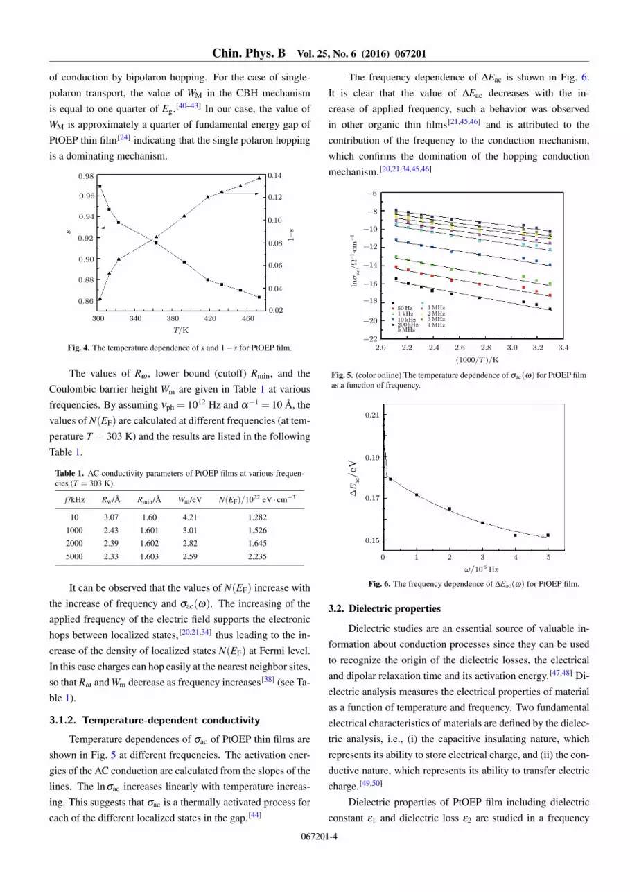
Temperature dependences of σac of PtOEP thin films areshown in Fig. 5 at different frequencies. The activation ener-gies of the AC conduction are calculated from the slopes of thelines. The lnσac increases linearly with temperature increas-ing. This suggests that σac is a thermally activated process foreach of the different localized states in the gap.[44]
The frequency dependence of ∆Eac is shown in Fig. 6.It is clear that the value of ∆Eac decreases with the in-crease of applied frequency, such a behavior was observedin other organic thin films[21,45,46] and is attributed to thecontribution of the frequency to the conduction mechanism,which confirms the domination of the hopping conductionmechanism.[20,21,34,45,46]
. . . . . . . .
↼/T ↽/K
50 Hz1 kHz10 kHz200kHz5MHz
1MHz2MHz3MHz4MHz
-22
-20
-18
-16
-14
-12
-10
-8
-6
lnσac/W-1⋅cm-1
Fig. 5. (color online) The temperature dependence of σac(ω) for PtOEP filmas a function of frequency.
0 1 2 3 4 5
ω/106 Hz
0.15
0.17
0.19
0.21
DEac/eV
Fig. 6. The frequency dependence of ∆Eac(ω) for PtOEP film.
3.2. Dielectric properties
Dielectric studies are an essential source of valuable in-formation about conduction processes since they can be usedto recognize the origin of the dielectric losses, the electricaland dipolar relaxation time and its activation energy.[47,48] Di-electric analysis measures the electrical properties of materialas a function of temperature and frequency. Two fundamentalelectrical characteristics of materials are defined by the dielec-tric analysis, i.e., (i) the capacitive insulating nature, whichrepresents its ability to store electrical charge, and (ii) the con-ductive nature, which represents its ability to transfer electriccharge.[49,50]
Dielectric properties of PtOEP film including dielectricconstant ε1 and dielectric loss ε2 are studied in a frequency
067201-4

Chin. Phys. B Vol. 25, No. 6 (2016) 067201
range of 50 Hz–5 MHz and temperature range of 303 K–473 K. ε1 is related to the capacitive nature of the materialand is a measure of the reversible energy stored in the materialby polarization, while ε2 is a measure of the energy requiredfor molecular motion.[51,52]
4 6 8 10 12 14 16
ln ω
8
12
16
20
24
28
32
36
ε 1(ω)
T/K
303313323363393
418433453473
(a)
4 6 8 10 12 14 16
ln ω
0
20
40
60
80
ε 2(ω)
T/K
303313323363393
418433453473
Fig. 7. (color online) The frequency dependence of ε1 for PtOEP film as afunction of temperatures.
The frequency dependences of ε1 and ε2 at different tem-peratures are illustrated in Figs. 7(a) and 7(b), respectively.Both ε1 and ε2 decrease with the increase of frequency. Thiscan be explained by means of dielectric polarization.[53–59]
The ε1 and ε2 decreasing with the increasing of frequency canbe explained as follows: at low frequencies the contributionof multi-components of polarizability, deformational polariza-tion (electronic and ionic), and relaxation polarization (orien-tational and interfacial) occur and this contribution leads toincreases of ε1 and ε2 at low frequencies. Also, the dipolesalign themselves along the field direction and fully contributeto the total polarization.
As the frequency increases, dipoles no longer rotate suf-ficiently rapidly. So, their oscillations begin to lag behind thefield. As the frequency further increases, the dipole will beunable to follow the field and the orientation stops, so the con-tribution of the polarization becomes less. Therefore ε1 andε2 decrease at a higher frequency approaching constant valuesdue to the interfacial polarization.[58]
The temperature dependences of both ε1 and ε2 at differ-ent frequencies of PtOEP films are shown in Figs. 8(a) and
8(b). Both ε1 and ε2 increase as the temperature increasesover the applied frequencies, which can be attributed to thefact that dipoles in polar materials cannot orient themselvesat low temperatures while at high temperatures, the orienta-tion polarization increases causing the dielectric constant toincrease.[20,21,34,45,46]
. . . . . . . .
. . . . . . . .
↼/T↽/K
↼/T↽/K
10
35
30
25
20
15
50 Hz1 kHz10 kHz200 kHz5MHz
1MHz2MHz3MHz4MHz
(b)
ε2
ε1
10
15
20
25
30
35
(a)
50 Hz1 kHz10 kHz200 kHz5MHz
1MHz2MHz3MHz4MHz
Fig. 8. (color online) The frequency dependence of ε2 for PtOEP film as afunction of temperatures.
3.3. Complex dielectric modulus
The variations of M′ with frequency at different tempera-tures are shown in Fig. 9.
4 6 8 10 12 14 16
lnω
0
0.04
0.08
0.12
0.16
Mϕ
T/K
303
313
323
363
393
418
433
453
473
Fig. 9. (color online) The frequency dependence of M′ for PtOEP film as afunction of temperature.
At the low frequency region, M′ values tend to zero,which confirms the negligible or absent electrode polarization
067201-5

Chin. Phys. B Vol. 25, No. 6 (2016) 067201
phenomenon.[38,60,61] A continuous increase of the M′ dis-persion with increasing frequency shows a tendency to con-stant values at high frequencies for all the temperatures. Thisbehavior may be due to the short-range mobility of chargecarriers.[60] M′′ represents the energy loss under an electricfield.[61]
lnω
.
.
.
.
.
Mε
T/K
303
313
323
363
393
418
433
453
473
Fig. 10. (color online) The frequency dependence of M′′ for PtOEP film asa function of temperature.
Figure 10 shows the plots of M′′ values versus thelogrithm of frequency (ln(ω)) at different temperatures. Thevariation of M′′ with frequency shows that the relaxation peaksare moving towards higher frequencies by increasing temper-ature. This behavior indicates that the dielectric relaxationis thermally activated in which the hopping process of thecharge carrier dominates intrinsically.[38,60–63] The asymmet-ric broadening of the M′′ peak shows the spread of relax-ation with time constant so, relaxation of our sample followsthe non-Debye type.[63] The frequency region below the peakmaximum is an indication of the transition from long-range toshort-range mobility with the increase of frequency.[14,63]
The most suitable way to measure relaxation time is tochoose the inverse of frequency of the maximum position(τm = ω−1
m ) as shown in Fig. 11.
. . . . . . . .
↼/T ↽/K
11
12
13
14
15
lnωmax
Fig. 11. The variation of lnωmax versus 1000/T for PtOEP film.
4. ConclusionsAC conductivities and dielectric properties of nano-
structured PtOEP films are studied in a temperature range of303 K–473 K and frequency range from 50 Hz to 5 MHz. Theobtained results of AC conductivity are reasonably explainedin terms of the correlated barrier hopping (CBH) model. Di-electric constant ε1 and dielectric loss ε2 are found to decreasewith frequency increasing and increase with temperature in-creasing in the investigated range. The real part of the mod-ulus M′ in the low frequency region tends to zero; this ap-proves the elimination of the electrode effect in the material.The imaginary part of dielectric modulus, M′′ peak shifts to-ward the higher frequency region with increasing temperature,specifying that the presence of dielectric relaxation is due tothe thermal activiation. The dielectric relaxation time obtainedfrom M′′ shows an Arrhenius behavior with ∆Eω = 0.21 eV.
References[1] Trogler W C and Choy H C 2013 Organic Solar Cells Materials and
Device Physics p. 250[2] Dongol M, El-Denglawey A, Elhady A F and Abuelwafa A A 2015
Appl. Phys. A 118 345[3] Schon J H, Kloc C and Batlogg B 2001 Phys. Rev. Lett. 86 3843[4] Perepichka D F, BryceM R, Batsanov A S, McInnes E J L, Zhao J P
and Farley R D 2002 Chem. Eur. J. 8 4656[5] Brutting W 2005 Physics of Organic Semiconductors (WILEY-VCH:
Verlag GmbH & Co. KGaA)[6] Toal S J and Trogler W C 2006 J. Mater. Chem. 16 2871[7] Dongol M, El-Nahass M M, El-Denglawey A, Elhady A F and Abuel-
wafa A A 2012 Curr. Appl. Phys. 12 1178[8] Dongol M, El-Denglawey A, Elhady A F and Abuelwafa A A 2012
Curr. Appl. Phys. 12 1334[9] Li X, Zhang C, Wu Y, Zhang H, Wang W, Yuan L, Yang H, Liu Z and
Chen H 2015 Int. J. Mol. Sci. 16 27707[10] Lee C, Hwang I, Byeon C C, Kim B H and Greenham N C 2010 Adv.
Funct. Mater. 20 2945[11] Tsuboi T, Wasai Y and Gabain N 2006 Thin Solid Films 496 674[12] Xiong K, Hou L, Wang P, Xia Y, Chen D and Xiao B 2014 J. Lumin.
151 193[13] Eldenglawey A 2013 Structural, optical and electrical properties of
As-Se-Tl films: Physical properties of As-Se-Tl films (LAP LAMBERTAcademic Publishing) p. 85
[14] Darwish A A A, El-Nahass M M and Bekheet A E 2014 J. AlloysCompd. 586 142
[15] Mohamed R I 2000 J. Phys. Chem. Solids 61 1357[16] El-Nahass M M, Atta A A, Kamel M A and Huthaily S Y 2013 Vacuum
91 14[17] Elliott S R 1979 Phil. Mag. B 40 507[18] Zeyada H M, El-Nahass M M and Makhlouf M M 2011 Curr. Appl.
Phys. 11 1326[19] El-Nahass M M, Metwally H S, El-Sayed H E A and Hassanien A M
2012 Mater. Chem. Phys. 133 649[20] El-Nahass M M, Farag A A M, Abu-Samaha F S H and Elesh E 2014
Vacuum 99 153[21] El-Nahass M M, Atta A A, El-Zaidia E F M, Farag A A M and Ammar
A H 2014 Mater. Chem. Phys. 143 490[22] Nawar A M, Abd El-Khalek H M and El-Nahass M M 2015 Org. Opto-
Elect. 1 25[23] Abuelwafaa A A, El-Denglawey A, Dongol M, El-Nahass M M and
Soga T 2016 J. Alloys Compd. 655 415[24] Abuelwafaa A A, El-Denglawey A, Dongol M, El-Nahass M M and
Soga T 2015 Opt. Mater. 49 271[25] Tolansky T 1948 Multiple-Beam Interferometry of Surface and Films
(London: Oxford University Press) p. 125[26] Jonscher A K 1977 Nature 267 673
067201-6

Chin. Phys. B Vol. 25, No. 6 (2016) 067201
[27] Elliott S R 1987 Adv. Phys. 36 135[28] Long A R 1982 Adv. Phys. 31 553[29] Elliott S R 1977 Philos. Mag. B 36 1291[30] Elliott S R 1978 Philos. Mag. B 37 135[31] Shimakawa K and Kondo A 1983 Phys. Rev. B 72 1136[32] Pike G E 1972 Phys. Rev. B 6 1572[33] Atyia H E 2014 Acta Phys. Pol. A 125 98[34] Kahouli A, Sylvestre A, Jomni F, Yangui B and Legrand J 2012 J. Phys.
Chem. A 116 1051[35] Austin I G and Mott N F 1969 Adv. Phys. 18 41[36] Macedo P B, Moynihan C T and Laberge N L 1973 Phys. Chem.
Glasses 14 122[37] Macedo P B, Moynihan C T and Bose R 1972 Phys. Chem. Glasses 13
171[38] Wonga Y J, Hassan J and Hashim M 2013 J. Alloys Compd. 571 138[39] El-Nahass M M and Ali H A M 2012 Solid State Commun. 152 1084[40] Dakhel A A 2006 Thin Solid Films 496 353[41] Chen R H, Chang R Y and Shern S C 2002 J. Phys. Chem. Solids 63
2069[42] Chen R H, Shern S C and Fukami T 2002 J. Phys. Chem. Solids 63 203[43] Farag A A M, Mansour A M, Ammar A H, Abdel Rafea M and Farid
A M 2012 J. Alloys Compd. 513 404[44] Yakuphanoglu F, Aydogdu Y, Schatzschneider U and Rentschler E
2003 Solid State Commun. 128 63[45] El-Menyawy E M, Zeyada H M and El-Nahass M M 2010 Solid State
Sci. 12 2182[46] El-Nahass M M, Kamal H, Elshorbagy M H and Abdel-Hady K 2013
Org. Electron. 14 2847
[47] Ayouchi R, Leien D, Martin F, Gabas M, Dalchiele E and Barrodo J R2003 Thin Solid Films 68 426
[48] Rhouma F H I, Dhahri A, Dhahri J and Valente M A 2012 Appl. Phys.A 108 593
[49] Hegab N A and El-Mallah H M 2009 Acta Phys. Pol. A 116 1048[50] Atyia H E Hegab N A, Affi M A and Ismail M A 2013 J. Alloys Compd.
574 345[51] Atyia H E 2014 J. Nonlinear Cryst. Solids 391 83[52] Atyia H E, Farid A M and Hegab N A 2008 Physica B 403 3980[53] Yahia I S, Hegab N A, Shakra A M and AL-Ribaty A M 2012 Physica
B 407 2476[54] Stevels J M 1975 Handbuch der Physik. In: Flugge (Berlin: Springer)
p. 108[55] El-Nahass M M, Ali H A M, Saadeldin M and Zaghllol M 2012 Phys-
ica B 407 4453[56] Smyth P 1965 Dielectric Behavior and Structure (New York: McGraw-
Hill)[57] Barsoum M 1997 Fundamental of Ceramics (London: McGraw Hill)
p. 215[58] Tareev B 1975 Physics of Dielectric Materials (Moscow: Mir Publish-
ers) p. 187[59] Sharma A and Mehtaa N 2012 Eur. Phys. J. Appl. Phys. 59 10101[60] Tabib A, Sdiri N, Elhouichet H and Fe’rid M 2015 J. Alloys Compd.
622 138[61] Dult M, Kundu R S, Hooda J, Murugavel S, Punia R and Kishore N
2015 J. Non-Cryst. Solids 423–424 1[62] Atif M and Nadeem M 2015 J. Alloys Compd. 623 447[63] El-Menyawy E M, Zedan I T, Mansour A M and Nawar H H 2014 J.
Alloys Compd. 611 50
067201-7