alpha mercedes e63 cls carbon turbo intake system
TRANSCRIPT

Mercedes E63/CLS AMG Carbon
Turbo Intake System Instructions
The goal of Alpha Performance is to provide the highest quality, best
performing products available. By utilizing research and development, and
rigorous testing programs Alpha Performance will never compromise the
quality or performance of our products. In addition, Alpha Performance will
only provide the finest customer service offering only parts and advice that
are in the best interests of the customer. Alpha Performance was built on a
foundation of integrity. This is who we are; this is what you can count on.
A vehicle modified by the use of performance parts may not meet the legal
requirements for use on public roads. Federal and state laws prohibit the
removal, modification, or rendering inoperative of any part or element of
design affecting emissions or safety on motor vehicles used for transporting
persons or property on public streets or highways. Use or installation of
performance parts may adversely affect the drivability and reliability of your
vehicle, and may also affect or eliminate your insurance coverage, factory
warranty, and/or new OEM part warranty. Performance parts are sold as-is
without any warranty of any type. There is no warranty stated or implied due
to the stresses placed on your vehicle by performance parts and our inability
to monitor their use, tuning, or modification.
These instructions are provided as a guide only as there are many variables
that cannot be accounted for concerning your particular vehicle, including but
not limited to model year differences, model differences, the presence of non-
OEM parts, and modifications that may already be or were previously
installed. A basic knowledge of automotive parts and systems is helpful but a
better understanding of the parts and systems on your particular vehicle may
be required.
If you have any questions or issues at any time during the installation of your
Alpha Performance product(s) please call us for technical assistance. The
Alpha Performance tech line can be reached during business hours at 847-
709-0530 for Alpha Performance products only.
Carbon Turbo Induction Kit Installation
1) The installation process will vary between model year and specific model. In
these instructions, we will be showing a vehicle that would require the most
amount of disassembly that would be required to install the Carbon Turbo
Induction Kit.
2) In order to install the carbon inlet tubes, the radiator will have to be moved
forward. To do this, you will have to remove the front bumper and some
supporting components depending on the model and year.
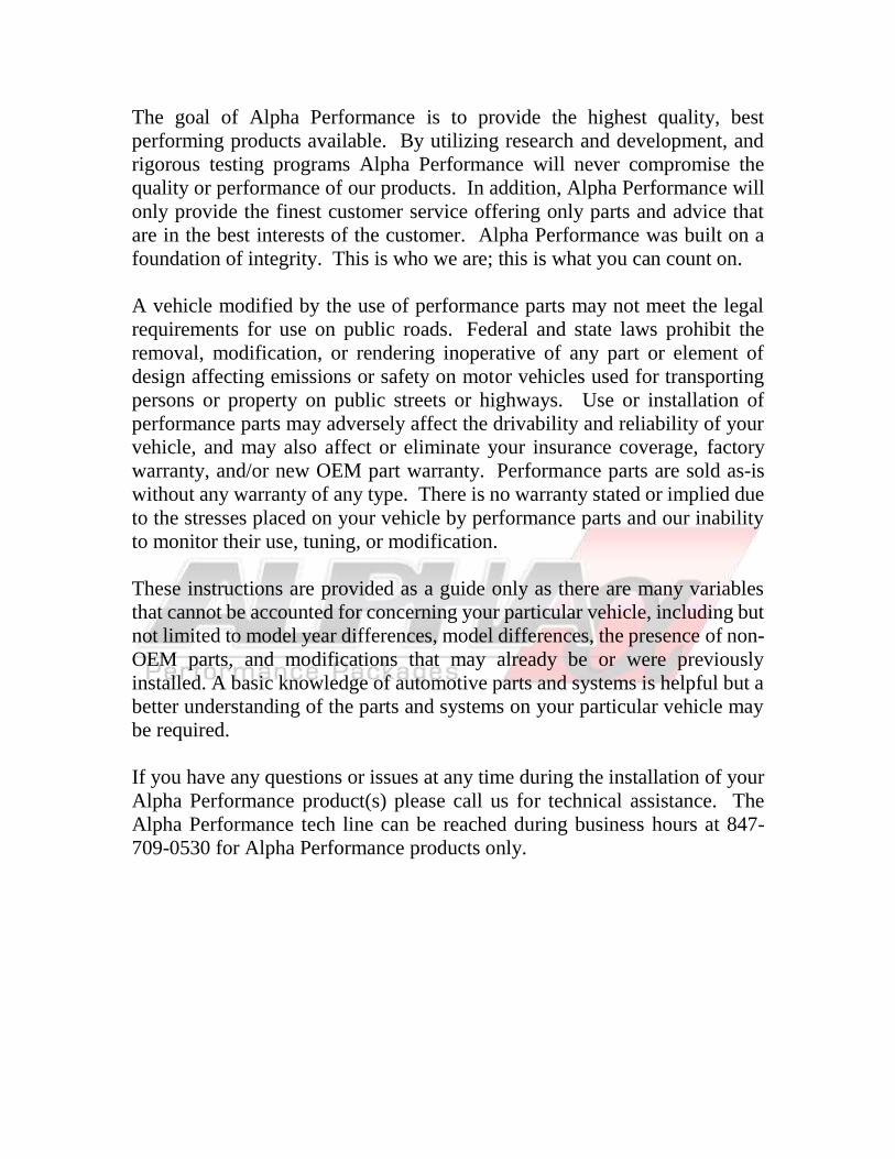
3) Start by disconnecting both batteries. The main battery will be in the engine bay
and the secondary battery will be located in the trunk. CAUTION, this step is
important because SRS impact sensors will be disconnected during the install
process!
4) Raise the vehicle and remove these items,
a. Front wheels
b. Center and front under trays
c. Both front wheel well liners
d. Front bumper
3 3
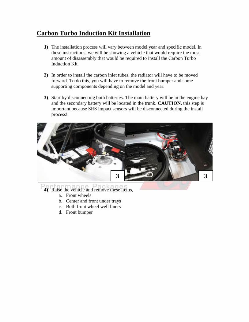
5) You will need to lift and move the radiator front clip forward to install the Carbon
Turbo Inlet Tubes. To do this, you will need to remove the upper core support
plate. On most of these models, the headlights and mounts will have to be
removed due to over lapping parts. Start by removing these parts in this order.
a. Air box inlet ducts
b. Upper plastic core support trim panel
c. Both headlights
d. Front bumper and headlight adjustment bracket
e. Upper radiator core support plate
f. Distronix bracket
4
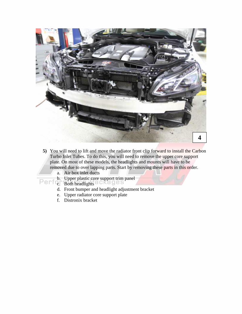
6) Next remove the front crash bar. Take caution when disconnecting both impact
sensors behind the crash bar.
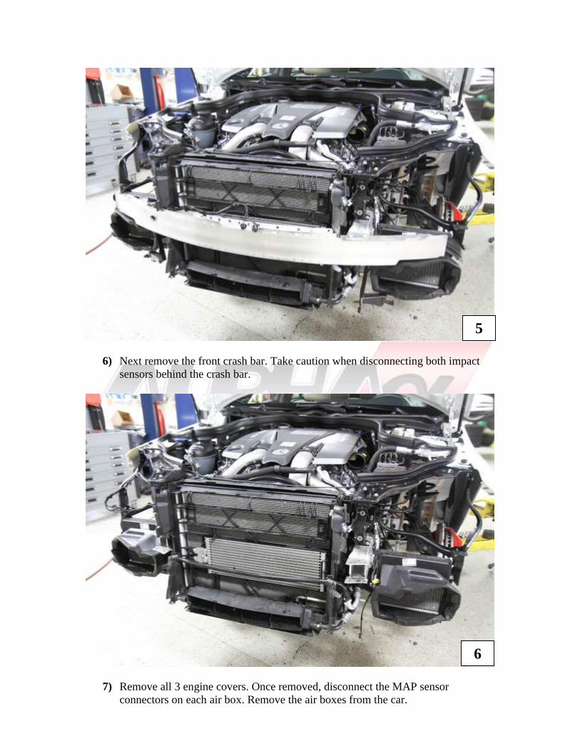
7) Remove all 3 engine covers. Once removed, disconnect the MAP sensor
connectors on each air box. Remove the air boxes from the car.
5
6
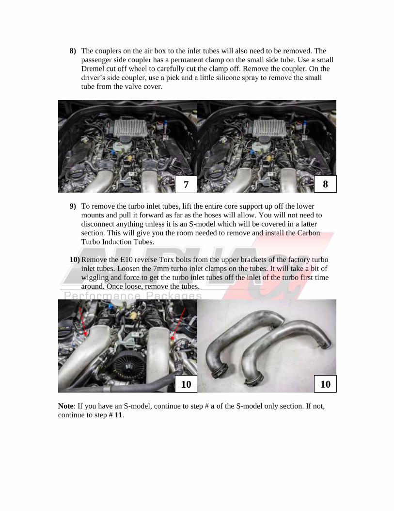
8) The couplers on the air box to the inlet tubes will also need to be removed. The
passenger side coupler has a permanent clamp on the small side tube. Use a small
Dremel cut off wheel to carefully cut the clamp off. Remove the coupler. On the
driver’s side coupler, use a pick and a little silicone spray to remove the small
tube from the valve cover.
9) To remove the turbo inlet tubes, lift the entire core support up off the lower
mounts and pull it forward as far as the hoses will allow. You will not need to
disconnect anything unless it is an S-model which will be covered in a latter
section. This will give you the room needed to remove and install the Carbon
Turbo Induction Tubes.
10) Remove the E10 reverse Torx bolts from the upper brackets of the factory turbo
inlet tubes. Loosen the 7mm turbo inlet clamps on the tubes. It will take a bit of
wiggling and force to get the turbo inlet tubes off the inlet of the turbo first time
around. Once loose, remove the tubes.
Note: If you have an S-model, continue to step # a of the S-model only section. If not,
continue to step # 11.
7 8
10 10
E63 / CLS S-model Only
a) At this time, on S-models only, there is an Intercooler water pipe that need to be
removed. The hard pipe interferes with the passenger side Carbon Turbo Inlet
Tube. A hose to reroute this pipe has been included for S-models only.
Note: If you have our Turbo Cooler Kit with Fender Reservoir or are installing it, you
can bypass this section since this pipe has already been removed and rerouted.
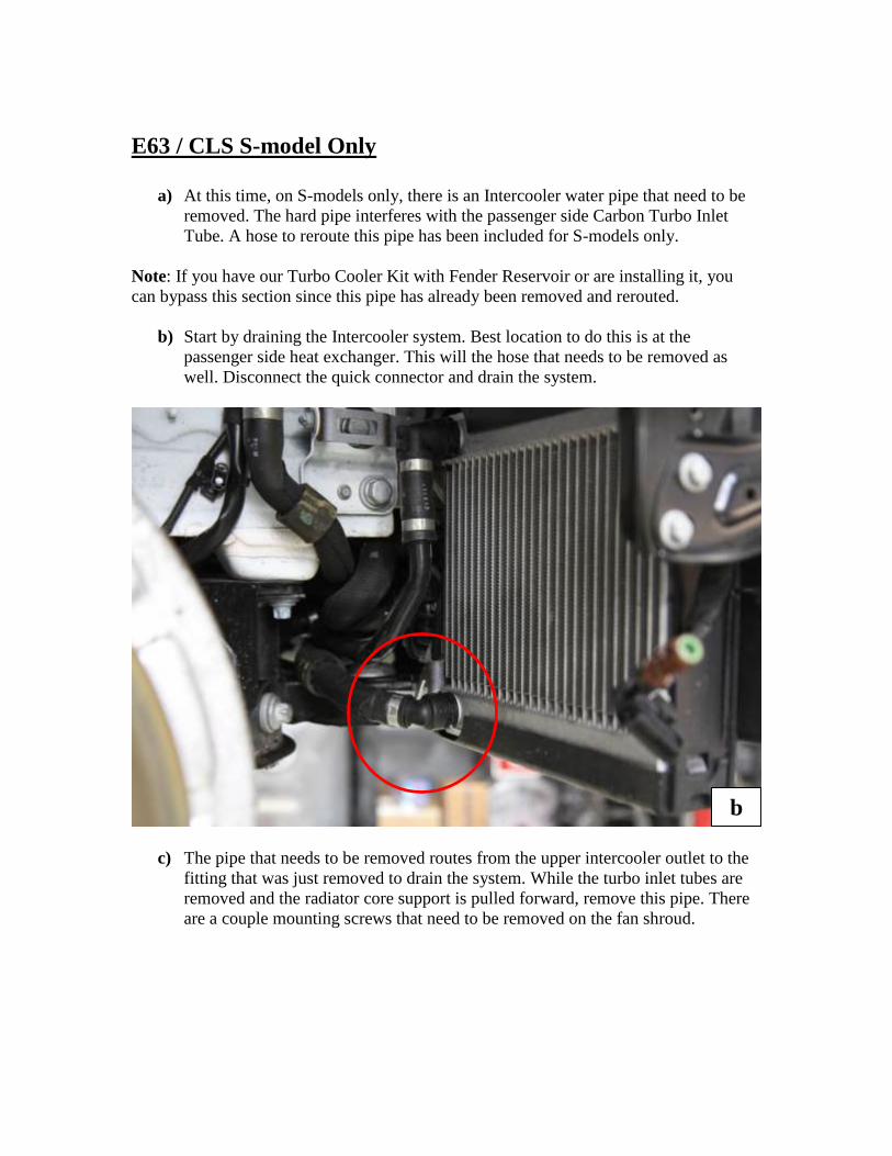
b) Start by draining the Intercooler system. Best location to do this is at the
passenger side heat exchanger. This will the hose that needs to be removed as
well. Disconnect the quick connector and drain the system.
c) The pipe that needs to be removed routes from the upper intercooler outlet to the
fitting that was just removed to drain the system. While the turbo inlet tubes are
removed and the radiator core support is pulled forward, remove this pipe. There
are a couple mounting screws that need to be removed on the fan shroud.
b
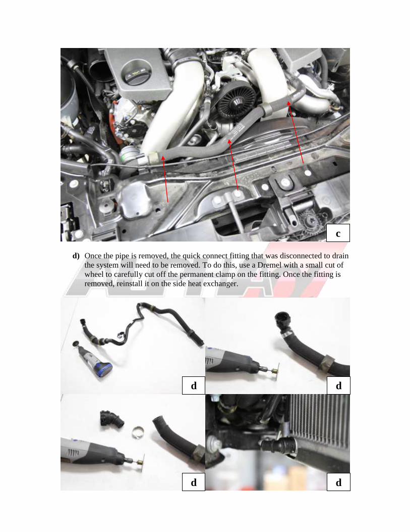
d) Once the pipe is removed, the quick connect fitting that was disconnected to drain
the system will need to be removed. To do this, use a Dremel with a small cut of
wheel to carefully cut off the permanent clamp on the fitting. Once the fitting is
removed, reinstall it on the side heat exchanger.
c
d d
d d
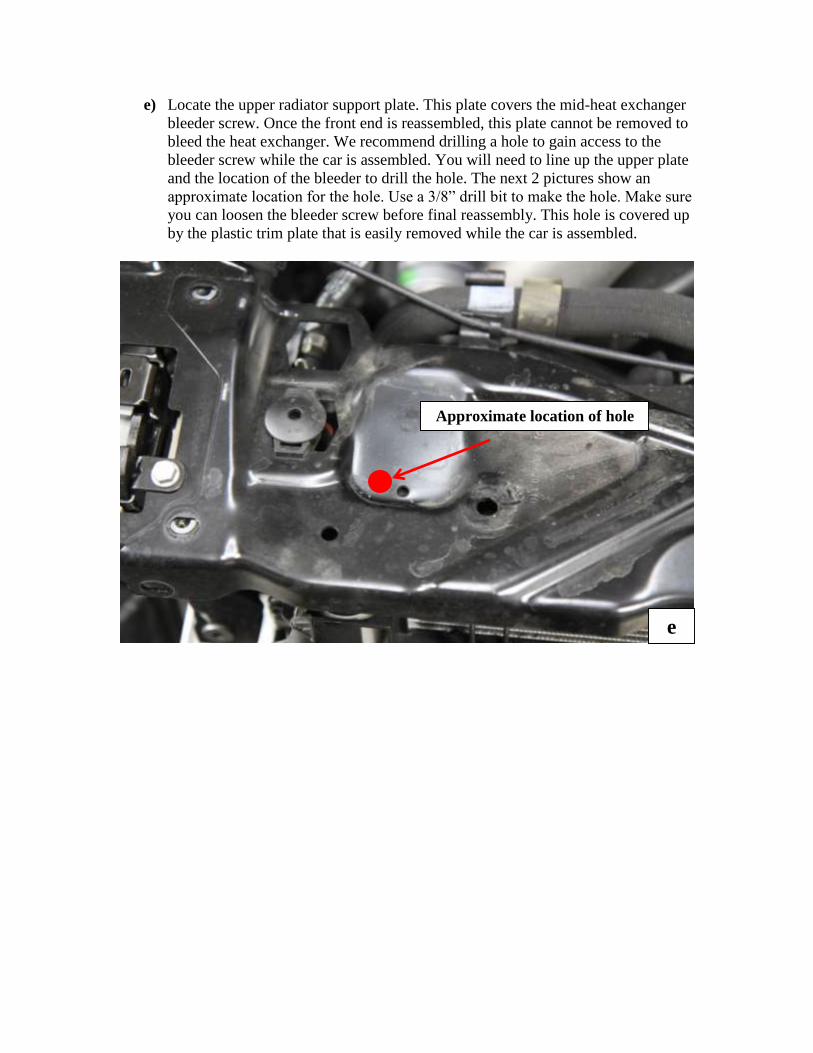
e) Locate the upper radiator support plate. This plate covers the mid-heat exchanger
bleeder screw. Once the front end is reassembled, this plate cannot be removed to
bleed the heat exchanger. We recommend drilling a hole to gain access to the
bleeder screw while the car is assembled. You will need to line up the upper plate
and the location of the bleeder to drill the hole. The next 2 pictures show an
approximate location for the hole. Use a 3/8” drill bit to make the hole. Make sure
you can loosen the bleeder screw before final reassembly. This hole is covered up
by the plastic trim plate that is easily removed while the car is assembled.
Approximate location of hole
e
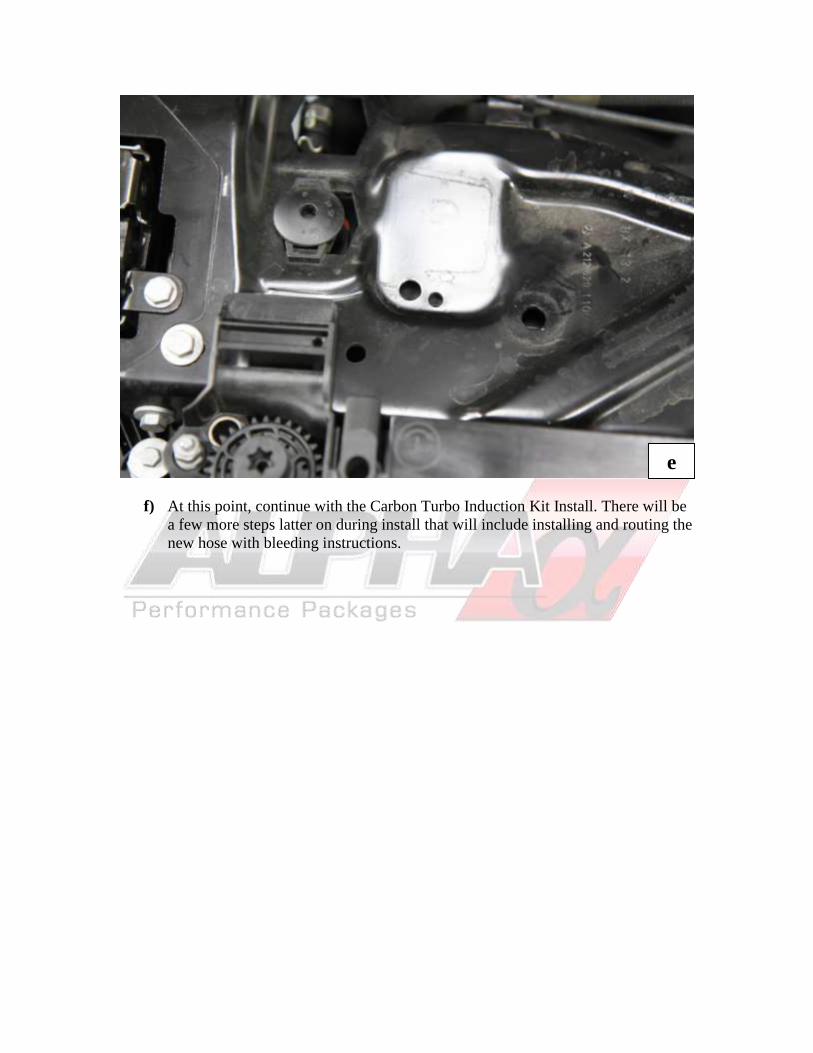
f) At this point, continue with the Carbon Turbo Induction Kit Install. There will be
a few more steps latter on during install that will include installing and routing the
new hose with bleeding instructions.
e
Carbon Turbo Induction Kit Installation (Continued)
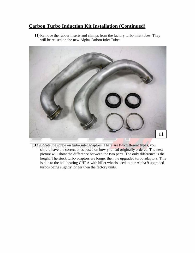
11) Remove the rubber inserts and clamps from the factory turbo inlet tubes. They
will be reused on the new Alpha Carbon Inlet Tubes.
12) Locate the screw on turbo inlet adaptors. There are two different types, you
should have the correct ones based on how you had originally ordered. The next
picture will show the difference between the two parts. The only difference is the
height. The stock turbo adaptors are longer then the upgraded turbo adaptors. This
is due to the ball bearing CHRA with billet wheels used in our Alpha 9 upgraded
turbos being slightly longer then the factory units.
11
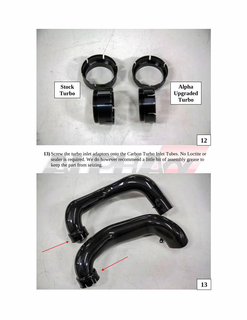
13) Screw the turbo inlet adaptors onto the Carbon Turbo Inlet Tubes. No Loctite or
sealer is required. We do however recommend a little bit of assembly grease to
keep the part from seizing.
12
13
Stock
Turbo
Alpha
Upgraded
Turbo
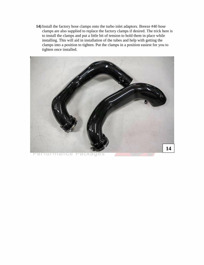
14) Install the factory hose clamps onto the turbo inlet adaptors. Breeze #40 hose
clamps are also supplied to replace the factory clamps if desired. The trick here is
to install the clamps and put a little bit of tension to hold them in place while
installing. This will aid in installation of the tubes and help with getting the
clamps into a position to tighten. Put the clamps in a position easiest for you to
tighten once installed.
14
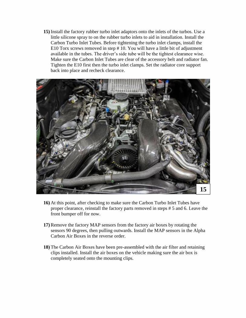
15) Install the factory rubber turbo inlet adaptors onto the inlets of the turbos. Use a
little silicone spray to on the rubber turbo inlets to aid in installation. Install the
Carbon Turbo Inlet Tubes. Before tightening the turbo inlet clamps, install the
E10 Torx screws removed in step # 10. You will have a little bit of adjustment
available in the tubes. The driver’s side tube will be the tightest clearance wise.
Make sure the Carbon Inlet Tubes are clear of the accessory belt and radiator fan.
Tighten the E10 first then the turbo inlet clamps. Set the radiator core support
back into place and recheck clearance.
16) At this point, after checking to make sure the Carbon Turbo Inlet Tubes have
proper clearance, reinstall the factory parts removed in steps # 5 and 6. Leave the
front bumper off for now.
17) Remove the factory MAP sensors from the factory air boxes by rotating the
sensors 90 degrees, then pulling outwards. Install the MAP sensors in the Alpha
Carbon Air Boxes in the reverse order.
18) The Carbon Air Boxes have been pre-assembled with the air filter and retaining
clips installed. Install the air boxes on the vehicle making sure the air box is
completely seated onto the mounting clips.
15
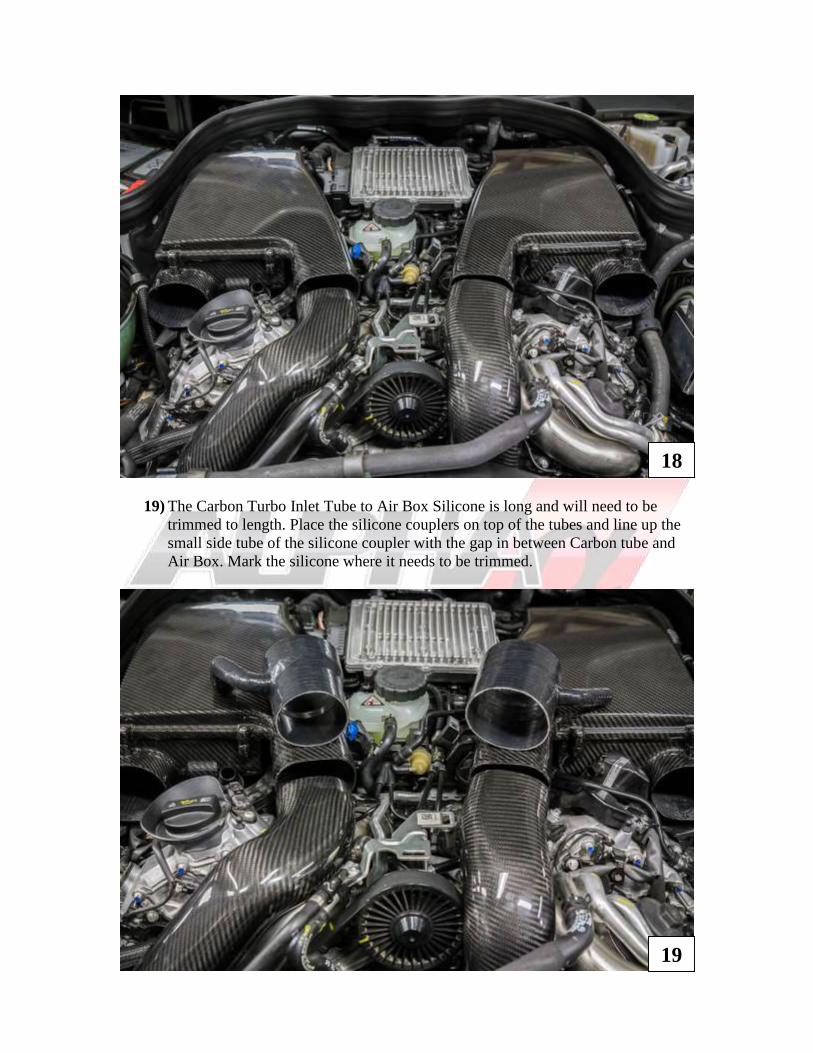
19) The Carbon Turbo Inlet Tube to Air Box Silicone is long and will need to be
trimmed to length. Place the silicone couplers on top of the tubes and line up the
small side tube of the silicone coupler with the gap in between Carbon tube and
Air Box. Mark the silicone where it needs to be trimmed.
18
19
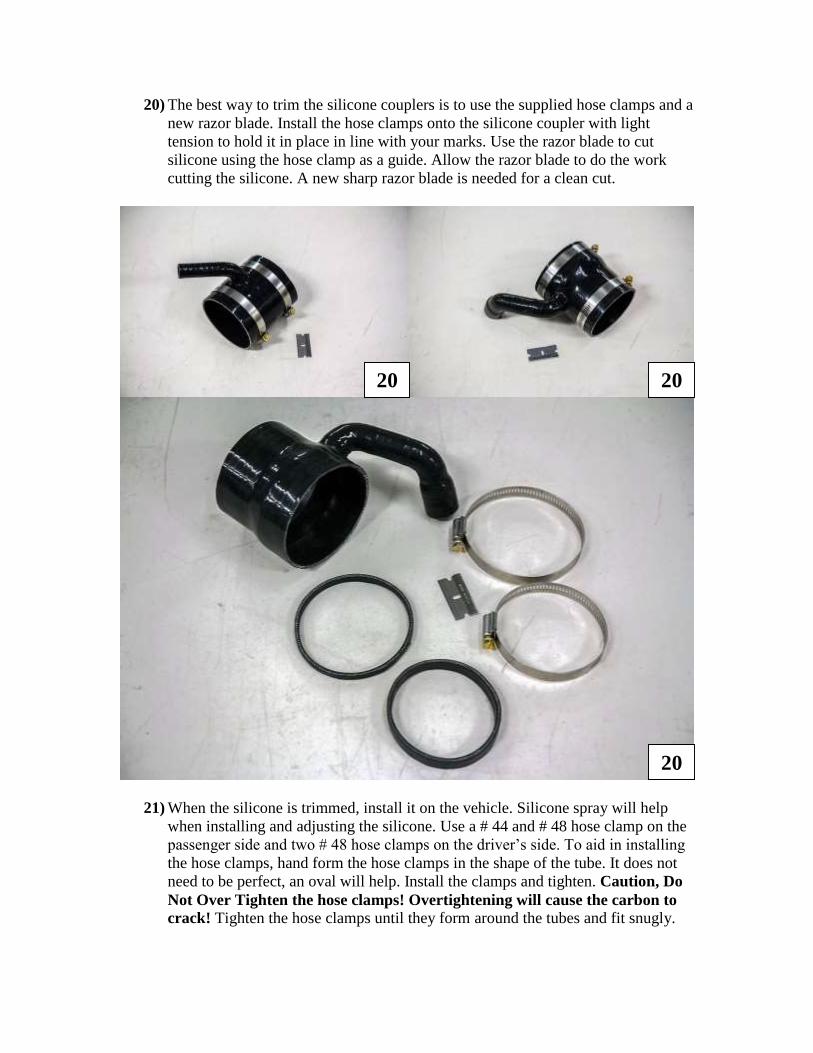
20) The best way to trim the silicone couplers is to use the supplied hose clamps and a
new razor blade. Install the hose clamps onto the silicone coupler with light
tension to hold it in place in line with your marks. Use the razor blade to cut
silicone using the hose clamp as a guide. Allow the razor blade to do the work
cutting the silicone. A new sharp razor blade is needed for a clean cut.
21) When the silicone is trimmed, install it on the vehicle. Silicone spray will help
when installing and adjusting the silicone. Use a # 44 and # 48 hose clamp on the
passenger side and two # 48 hose clamps on the driver’s side. To aid in installing
the hose clamps, hand form the hose clamps in the shape of the tube. It does not
need to be perfect, an oval will help. Install the clamps and tighten. Caution, Do
Not Over Tighten the hose clamps! Overtightening will cause the carbon to
crack! Tighten the hose clamps until they form around the tubes and fit snugly.
20 20
20
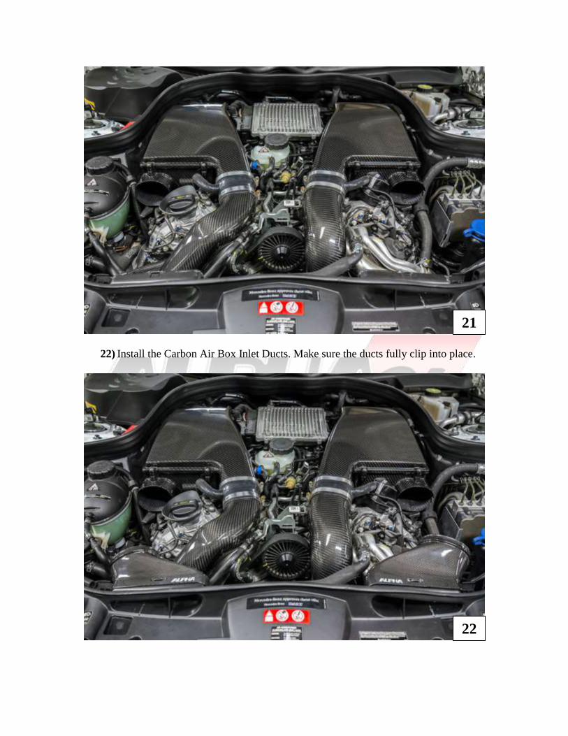
22) Install the Carbon Air Box Inlet Ducts. Make sure the ducts fully clip into place.
21
22
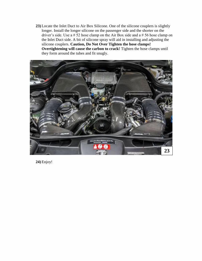
23) Locate the Inlet Duct to Air Box Silicone. One of the silicone couplers is slightly
longer. Install the longer silicone on the passenger side and the shorter on the
driver’s side. Use a # 52 hose clamp on the Air Box side and a # 56 hose clamp on
the Inlet Duct side. A bit of silicone spray will aid in installing and adjusting the
silicone couplers. Caution, Do Not Over Tighten the hose clamps!
Overtightening will cause the carbon to crack! Tighten the hose clamps until
they form around the tubes and fit snugly.
24) Enjoy!
23
E63 / CLS S-model Only (Continued)
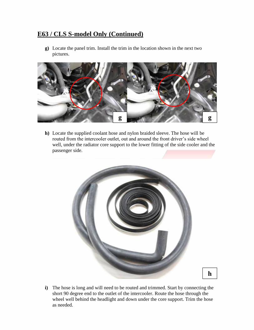
g) Locate the panel trim. Install the trim in the location shown in the next two
pictures.
h) Locate the supplied coolant hose and nylon braided sleeve. The hose will be
routed from the intercooler outlet, out and around the front driver’s side wheel
well, under the radiator core support to the lower fitting of the side cooler and the
passenger side.
i) The hose is long and will need to be routed and trimmed. Start by connecting the
short 90 degree end to the outlet of the intercooler. Route the hose through the
wheel well behind the headlight and down under the core support. Trim the hose
as needed.
g g
h
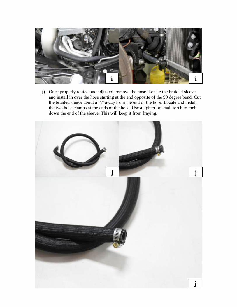
j) Once properly routed and adjusted, remove the hose. Locate the braided sleeve
and install in over the hose starting at the end opposite of the 90 degree bend. Cut
the braided sleeve about a ½” away from the end of the hose. Locate and install
the two hose clamps at the ends of the hose. Use a lighter or small torch to melt
down the end of the sleeve. This will keep it from fraying.
i i
j j
j
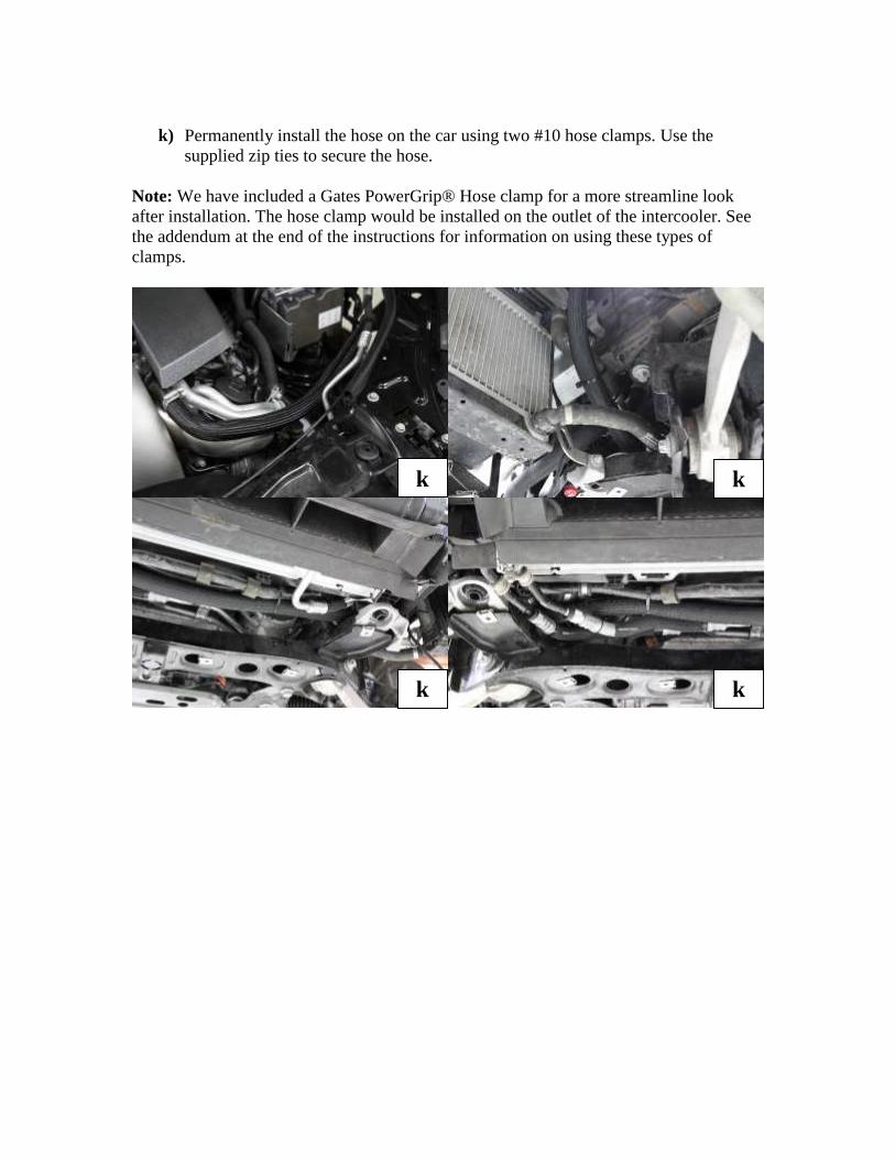
k) Permanently install the hose on the car using two #10 hose clamps. Use the
supplied zip ties to secure the hose.
Note: We have included a Gates PowerGrip® Hose clamp for a more streamline look
after installation. The hose clamp would be installed on the outlet of the intercooler. See
the addendum at the end of the instructions for information on using these types of
clamps.
k k
k k
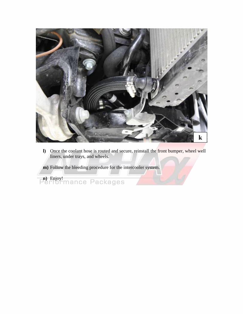
l) Once the coolant hose is routed and secure, reinstall the front bumper, wheel well
liners, under trays, and wheels.
m) Follow the bleeding procedure for the intercooler system.
n) Enjoy!
k
Alpha Carbon Engine Cover
Note: If the factory cover will be utilized, trimming and adjustment of the cover will be
necessary.
1) If the Alpha Carbon Engine Cover was purchased as an option, locate it now.
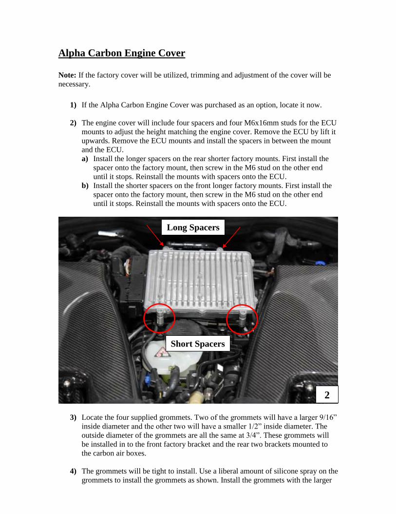
2) The engine cover will include four spacers and four M6x16mm studs for the ECU
mounts to adjust the height matching the engine cover. Remove the ECU by lift it
upwards. Remove the ECU mounts and install the spacers in between the mount
and the ECU.
a) Install the longer spacers on the rear shorter factory mounts. First install the
spacer onto the factory mount, then screw in the M6 stud on the other end
until it stops. Reinstall the mounts with spacers onto the ECU.
b) Install the shorter spacers on the front longer factory mounts. First install the
spacer onto the factory mount, then screw in the M6 stud on the other end
until it stops. Reinstall the mounts with spacers onto the ECU.
3) Locate the four supplied grommets. Two of the grommets will have a larger 9/16”
inside diameter and the other two will have a smaller 1/2” inside diameter. The
outside diameter of the grommets are all the same at 3/4”. These grommets will
be installed in to the front factory bracket and the rear two brackets mounted to
the carbon air boxes.
4) The grommets will be tight to install. Use a liberal amount of silicone spray on the
grommets to install the grommets as shown. Install the grommets with the larger
2
Short Spacers
Long Spacers
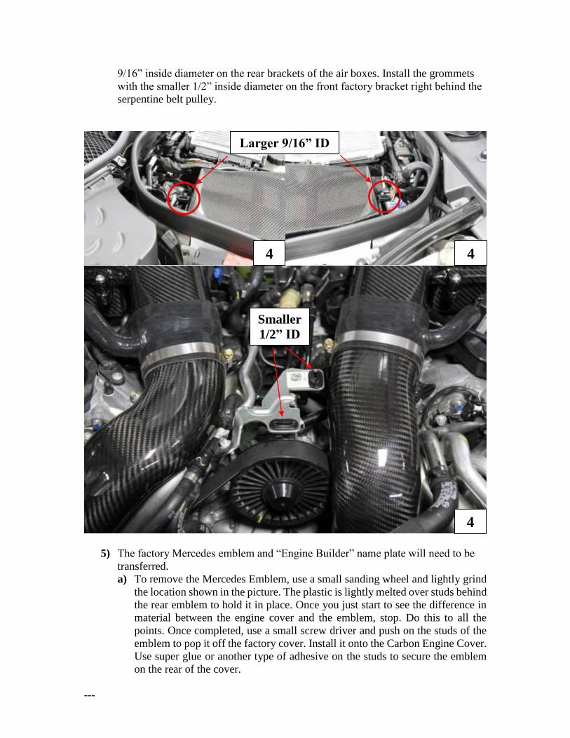
9/16” inside diameter on the rear brackets of the air boxes. Install the grommets
with the smaller 1/2” inside diameter on the front factory bracket right behind the
serpentine belt pulley.
5) The factory Mercedes emblem and “Engine Builder” name plate will need to be
transferred.
a) To remove the Mercedes Emblem, use a small sanding wheel and lightly grind
the location shown in the picture. The plastic is lightly melted over studs behind
the rear emblem to hold it in place. Once you just start to see the difference in
material between the engine cover and the emblem, stop. Do this to all the
points. Once completed, use a small screw driver and push on the studs of the
emblem to pop it off the factory cover. Install it onto the Carbon Engine Cover.
Use super glue or another type of adhesive on the studs to secure the emblem
on the rear of the cover.
---
Smaller
1/2” ID
Larger 9/16” ID
4 4
4
b) To remove the engine builder name plate, use a heat gun and heat up the back
side of the factory engine cover while gently prying on the name plate with a
plastic trim tool. The factory double sided tape will eventually release slowly
when heated. Once removed, clean the rea of the name plate. Install it using the
supplied double sided tape.
---
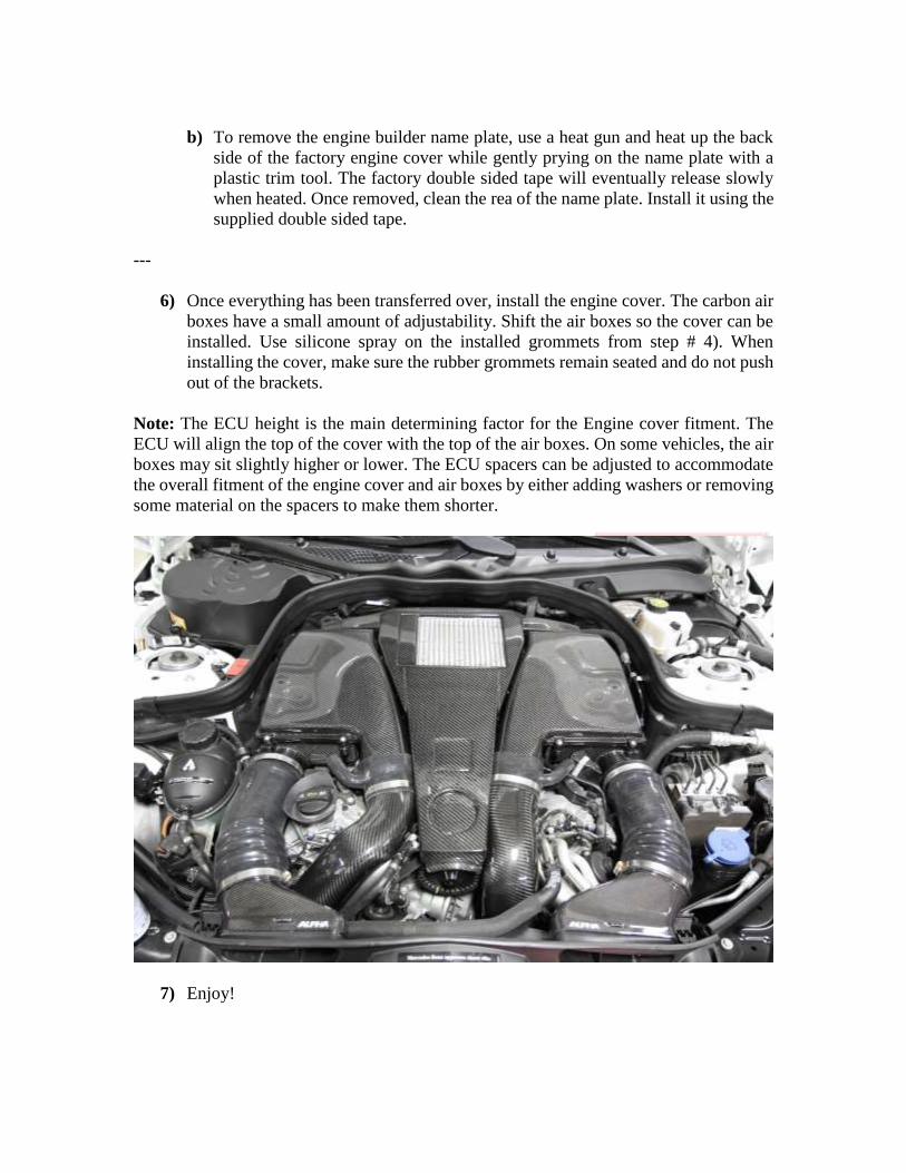
6) Once everything has been transferred over, install the engine cover. The carbon air
boxes have a small amount of adjustability. Shift the air boxes so the cover can be
installed. Use silicone spray on the installed grommets from step # 4). When
installing the cover, make sure the rubber grommets remain seated and do not push
out of the brackets.
Note: The ECU height is the main determining factor for the Engine cover fitment. The
ECU will align the top of the cover with the top of the air boxes. On some vehicles, the air
boxes may sit slightly higher or lower. The ECU spacers can be adjusted to accommodate
the overall fitment of the engine cover and air boxes by either adding washers or removing
some material on the spacers to make them shorter.
7) Enjoy!
Intercooler System Bleeding with Air Lift
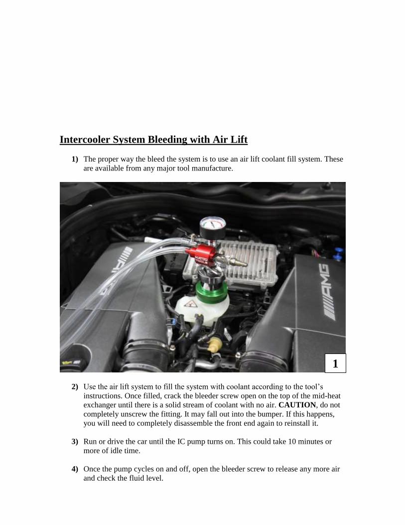
1) The proper way the bleed the system is to use an air lift coolant fill system. These
are available from any major tool manufacture.
2) Use the air lift system to fill the system with coolant according to the tool’s
instructions. Once filled, crack the bleeder screw open on the top of the mid-heat
exchanger until there is a solid stream of coolant with no air. CAUTION, do not
completely unscrew the fitting. It may fall out into the bumper. If this happens,
you will need to completely disassemble the front end again to reinstall it.
3) Run or drive the car until the IC pump turns on. This could take 10 minutes or
more of idle time.
4) Once the pump cycles on and off, open the bleeder screw to release any more air
and check the fluid level.
1
5) If when the IC pump turns off and the reservoir pushes a bunch off coolant out,
this means there is still a large amount of air in the system that needs to be bled.
6) You may have to repeat this process multiple times along with test drives.
Continue until the coolant level is stable with the pump on or off.
7) Enjoy!
Intercooler System Bleeding with Standard Filling
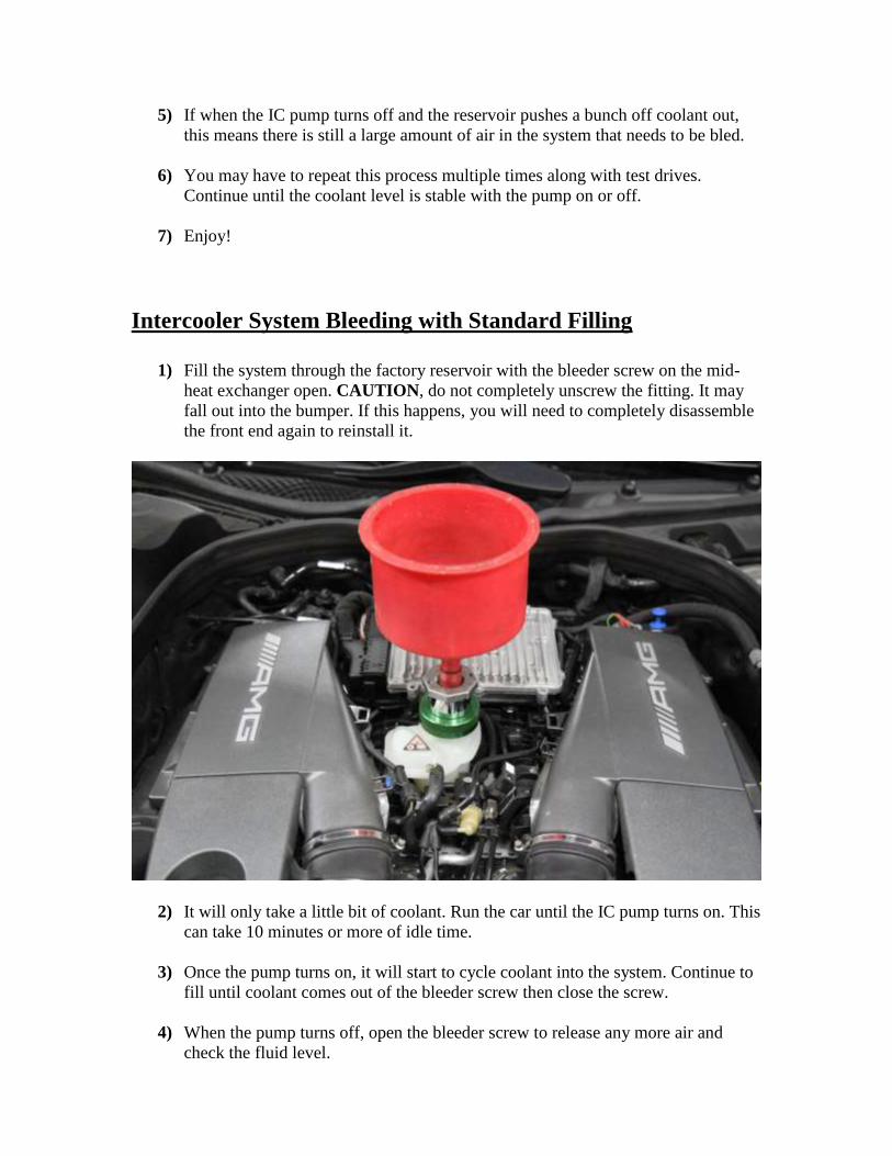
1) Fill the system through the factory reservoir with the bleeder screw on the mid-
heat exchanger open. CAUTION, do not completely unscrew the fitting. It may
fall out into the bumper. If this happens, you will need to completely disassemble
the front end again to reinstall it.
2) It will only take a little bit of coolant. Run the car until the IC pump turns on. This
can take 10 minutes or more of idle time.
3) Once the pump turns on, it will start to cycle coolant into the system. Continue to
fill until coolant comes out of the bleeder screw then close the screw.
4) When the pump turns off, open the bleeder screw to release any more air and
check the fluid level.
5) If when the IC pump turns off and the reservoir pushes a bunch off coolant out,
this means there is still a large amount of air in the system that needs to be bled.
6) You may have to repeat this process multiple times along with test drives.
Continue until the coolant level is stable with the pump on or off.
7) Enjoy!
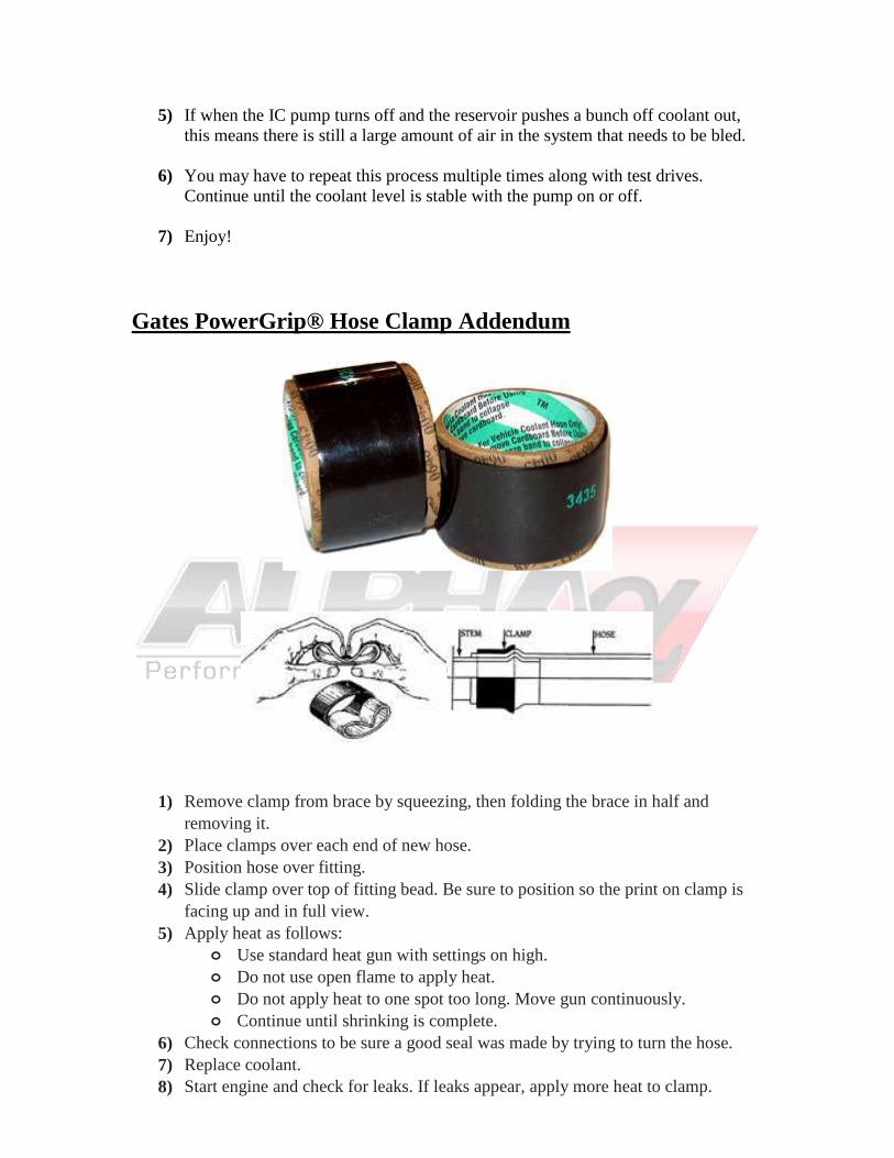
Gates PowerGrip® Hose Clamp Addendum
1) Remove clamp from brace by squeezing, then folding the brace in half and
removing it.
2) Place clamps over each end of new hose.
3) Position hose over fitting.
4) Slide clamp over top of fitting bead. Be sure to position so the print on clamp is
facing up and in full view.
5) Apply heat as follows:
o Use standard heat gun with settings on high.
o Do not use open flame to apply heat.
o Do not apply heat to one spot too long. Move gun continuously.
o Continue until shrinking is complete.
6) Check connections to be sure a good seal was made by trying to turn the hose.
7) Replace coolant.
8) Start engine and check for leaks. If leaks appear, apply more heat to clamp.

If the clamp ever needs to be removed, it will have to be cut off and replaced. Make sure
you have another clamp ready for reinstallation or another standard clamp.
Enjoy!