airworthiness directive schedule amendment nr 22-06 - caa
TRANSCRIPT
CIVIL AVIATION AUTHORITY OF NEW ZEALAND
AIRWORTHINESS DIRECTIVES
Amendment Nr 22-06
Effective date 30 June 2022
These Airworthiness Directives are issued pursuant to sections 72I(3A) and (3B) of the Civil Aviation Act 1990 and according to the procedures in Civil Aviation Rule Part 39. Holders of New Zealand certificates of registration for aircraft are required to comply with Civil Aviation Rule 39.53.
List of New or Revised Airworthiness Directives Amendment Nr 22-06
1
Airworthiness Directive Schedule
List of New or Revised ADs Amendment Nr 22-06 30 June 2022
AD Schedule AD Number AD Title Eff Date
Airbus Helicopters AS350 Series
EASA AD 2022-0051 (Correction) Rear Structure Junction Frame Reinforcement Angles - Inspection
30-Jun-22
Airbus Helicopters AS355 Series
EASA AD 2022-0051 (Correction) Rear Structure Junction Frame Reinforcement Angles - Inspection
30-Jun-22
Airbus Helicopters Deutschland MBB-BK117 Series
EASA AD 2022-0097 Instrument Flight Rule Screens - Removal 8-Jun-22
Airbus Helicopters EC135 Series
EASA AD 2022-0097 Instrument Flight Rule Screens - Removal 8-Jun-22
Aircraft Seats and Harnesses
UK CAA AD G-2022-0011
Pilot and Co-pilot Seats – Inspection 30-Jun-22
Bell 206 Series TC AD CF-2022-33 Tail Rotor Drive Shafts with Bonded Adapters – Inspection
30-Jun-22
Bell 212 Series FAA AD 2022-11-19 Engine Oil Check Valve - Inspection 6-Jul-22 Bell 412 Series FAA AD 2022-11-19 Engine Oil Check Valve - Inspection 6-Jul-22 Honeywell LTS101 and T53 Series
FAA AD 2002-03-01 Cancelled – FAA AD 2022-10-02 refers 30-Jun-22
Honeywell LTS101 and T53 Series
FAA AD 2022-10-02 Tachometer Drive Spur Gear – Inspection 30-Jun-22
Pilatus PC-12 Series EASA AD 2021-0214 Cancelled – EASA AD 2022-0103 refers 30-Jun-22 Pilatus PC-12 Series EASA AD 2022-0103 Airworthiness Limitations - Amendment 30-Jun-22 Pratt & Whitney JT15D Series
CF-2022-27 Compressor Impeller – Inspection 30-Jun-22
Robinson R22 Series FAA AD 2022-12-08 Engine Governor and RPM Sensor - Inspection
29-Jun-22
Robinson R44 Series FAA AD 2022-12-08 Engine Governor and RPM Sensor - Inspection
29-Jun-22
List of New or Revised Airworthiness Directives Amendment Nr 22-06
2
State of Design Airworthiness Directives Hyperlinks to all the various National Airworthiness Authorities (NAA) and State of Design home pages are available on the CAA website at https://www.aviation.govt.nz/aircraft/airworthiness/airworthiness-directives/links-to-state-of-design-airworthiness-directives/ These hyperlinks will take you to a particular State of Design AD home page. There you can search for the aircraft type, or the specific AD you are looking for. The hyperlinks in the AD Schedules will only take you to the State of Design AD home page. We do not provide links to individual ADs, because these change too often to keep current. If you are having difficulty obtaining a particular AD, send a request to the CAA at [email protected]
Notes on New/Revised Airworthiness Directives Airbus Helicopters (AH) AS350 and AS355 Series EASA AD 2022-0051 (correction) Rear Structure Junction Frame - Inspection This AD is re-issued to correct typos in the referenced AD numbers in the Reason section of the AD.
Airbus Helicopters Deutschland MBB-BK117 and EC135 Series EASA AD 2022-0097 Intrument Flight Rule Screens - Removal EASA AD 2022-0097 with effective date 8 June 2022 is applicable to EC135 P1, EC135 P2, EC135 P2+, EC135 P3, EC135 T1, EC135 T2, EC135 T2+, EC135 T3, EC635 P2+, EC635 P3, EC635 T1, EC635 T2+ and EC635 T3 helicopters, all variants, all S/N, and MBB-BK117 C-2, MBB-BK117 D-2, MBB-BK117 D-3 and MBB-BK117 D-3m helicopters, all variants, all S/N.
Affected parts:
For EC135 and EC635 helicopters: Instrument Flight Rules (IFR)-screen lower with P/N L251M4854101, IFR-screen upper with P/N L251M4855101, and IFR-screen pilot door with P/N L251M4856101; For MBB-BK117 C-2 helicopters: IFR-screen below assembly with P/N B349M7006101, IFR-screen above assembly with P/N B349M7003101, and IFR-screen door assembly with P/N B349M7007101; and For MBB-BK117 D-2, D-3 and D-3m helicopters: IFR-screen below assembly with P/N B349M7006101, IFR-screen above assembly with P/N B349M7003101 and P/N D251M7001101, and IFR-screen door assembly with P/N B349M7007101.
It has been determined that affected parts may have been installed on certain helicopters in accordance with Airbus Helicopters (AH) maintenance instructions and used for IFR training.
This could result in reduced situational awareness of the pilot, possibly resulting in a mid-air collision. To address this potential unsafe condition, AH has issued an ASB, providing instructions to remove the IFR-screens. This AD requires removal of the affected parts and prohibits (re)installation of affected parts.
AH also issued Safety Information Notice (SIN) 3807-S-25 providing information applicable to other helicopter types and models for which no maintenance instructions for IFR-screen installation have been issued.
Bell 212 and 412 Series FAA AD 2022-11-19 Engine Oil Check Valve – Inspection FAA AD 2022-11-19 with effective date 6 July 2022 is applicable to certain Bell Textron Inc. Model 212, 412, 412CF, and 412EP helicopters.
This AD is prompted by a report of finding a cracked engine oil check valve and requires inspecting certain engine oil and fuel check valves, and depending on the results, repetitively inspecting, and removing the check valve from service.
The AD also prohibits installing affected engine oil and fuel check valves on any helicopter. Please refer to the FAA AD for further information.
List of New or Revised Airworthiness Directives Amendment Nr 22-06
3
Honeywell LTS101 and T53 Series FAA AD 2022-10-02 Tachometer Drive Gear Spur – Inspection FAA AD 2002-03-01 applied to Honeywell (formerly AlliedSignal, Inc. and Textron Lycoming) T5311A, T5311B, T5313B, T5317A, T5317B, and former military T53-L-11, T53-L-11A, T53-L-11B, T53-L-11C, T53-L-11D, T53-L-11A S/SA, T53-L-13B, T53-L-13B S/SA, T53-L-13B S/SB, and T53-L-703 model turboshaft engines. The AD was prompted by reports indicating that Honeywell T5317A-1 and T5317BCV model turboshaft engines are subject to the same unsafe condition identified in AD 2002-03-01, tachometer drive spur gear failures due to vibration loads.
These model turboshaft engines were not included in the applicability of AD 2002-03-01. The FAA and Honeywell determined that the Honeywell T5317A-1 engine model was inadvertently left out of the applicability of AD 2002-03-01 and the Honeywell T5317BCV engine model was introduced into production after the publication of AD 2002-03-01.
The AD continues to require initial and repetitive special vibration tests of the engine and, depending on the results, replacement of either the reduction gearbox assembly or the engine. The AD expands the applicability to include Honeywell T5317A-1 and T5317BCV model turboshaft engines.
Pilatus PC-12 Series EASA AD 2022-0103 Airworthiness Limitations – Amendment EASA AD 2022-0103 supersedes AD 2021-0214 which required the actions described in Pilatus PC-12 AMM Chapter 04-00-00, Document Number 02049 Issue 01 Revision 41, Document Number 02300 Issue 01 Revision 25, and Document Number 02436 Issue 01 Revision 03.
Since that AD was issued, Pilatus published the applicable ALS, as defined in this AD, which contains new and/or more restrictive tasks and limitations, as specified in the Component Limitations section, to introduce new repetitive inspections of the horizontal stabilizer internal structure.
For the reason described above, this AD retains the requirements of superseded EASA AD 2021-0214 and requires accomplishment of the actions specified in the applicable ALS.
Robinson R22 and R44 Series FAA AD 2022-12-08 Engine Governor and RPM Sensor - Inspection FAA AD 2022-12-08 with effective date 29 June 2022 is applicable to:
1. Robinson R22 BETA helicopters, S/N 4825 through to 4857 inclusive, 4860, and 4861.
2. Robinson R44 helicopters, S/N 2625 through to 2669 inclusive, 30061, 30071 through to 30080 inclusive, 30083, and 30084. Note: Helicopters with an R44 Cadet designation are R44 helicopters.
3. Robinson R44 II helicopters, S/N 14364, 14412 through to 14512 inclusive, 14514 through to 14517 inclusive, 14519 through to 14521 inclusive, and 14525.
FAA AD 2022-12-08 is prompted by reports received by the FAA of intermittent or abnormal operation of the governor.
In normal conditions, a properly functioning governor maintains engine speed within acceptable limits.
Intermittent or abnormal operation of the governor may result in engine overspeed, or under speed conditions during flight.
If the engine governor malfunctions, the pilot may assume manual throttle control by firmly gripping the throttle and overriding the governor's friction clutch, or by switching the governor off.
In the event of low rotor RPM, an alarm sounds.
This condition, if not addressed, could result in reduced control of the helicopter and a subsequent emergency landing, or loss of control of the helicopter.
The FAA AD can be obtained from the FAA website at: http://rgl.faa.gov/Regulatory_and_Guidance_Library/rgAD.nsf/MainFrame?OpenFrameSet
CIVIL AVIATION AUTHORITY OF NEW ZEALAND
A/L 22-06 AIRWORTHINESS DIRECTIVE SCHEDULE REVISION STATUS 30 June 2022
Page 1
Schedule Date AD Schedule Cover Page 30 JUN 22 AD Schedule Revision Status 30 JUN 22 List of New or Revised ADs 30 JUN 22 Aeroplanes Aeroplanes General - Large (Greater than 5700kg MCTOW)
23 DEC 21
Aeroplanes General - Small (Up to 5700kg MCTOW)
23 DEC 21
Aero Commander 100 Series 24 JUN 21 Aerostar 600 and 601 Series 25 FEB 21 Air Tractor AT-402, AT-502 & AT-504 Series 29 APR 21 Air Tractor AT-602 29 APR 21 Airtourer Series (NZ Aerospace) 26 OCT 00 Alpha Aviation HR200 & R2000 Series 27 AUG 15 American Champion 7 and 8 Series 26 JUL 18 Auster & Beagle Series 26 JUL 12 Aviat A-1 Series (Husky) 27 AUG 20 BAC-167 Strikemaster 30 OCT 14 Beagle Aircraft B.121 Series 2 30 JUN 11 Beechcraft 17 Series 31 AUG 00 Beechcraft 18 Series 31 AUG 00 Beechcraft 23 & 24 Series 31 AUG 00 Beechcraft 33, 35 & 36 Series 19 DEC 19 Beechcraft 60 Series 22 FEB 01 Beechcraft 76 Series 29 APR 21 Beechcraft 77 Series 28 AUG 08 Beechcraft 90 Series 27 MAY 10 Beechcraft 58 & 95 Series 29 AUG 13 Beechcraft 99 Series 27 JUL 06 Beechcraft 200 Series 24 FEB 11 Beechcraft 300LW 24 FEB 22 Boeing-Stearman E75 & A75N1 28 AUG 08 Bolkow BO 208 C Junior 14 MAY 93 Bolkow BO 209 Monsun 28 AUG 08 British Aerospace Dove (DH 104) 19 FEB 93 British Aerospace Heron (DH 114) 19 FEB 93 Britten-Norman Islander BN-2A & BN-2B 26 JUL 18 Britten-Norman BN-2A Mk III 22 OCT 15 Cessna 120 Series 28 APR 22 Cessna 150/152 Series 29 SEP 11 Cessna 170 Series 30 JUN 11 Cessna 172 Series (includes R172) 29 OCT 20 Cessna 175 Series 28 JUL 16 Cessna 177 Series 29 SEP 16 Cessna 180 Series 26 NOV 20 Cessna 182 Series 26 NOV 20 Cessna 185 Series 26 NOV 20 Cessna 188 Series 27 AUG 20 Cessna 195 Series 28 NOV 13 Cessna 206 Series 29 OCT 20 Cessna 207 Series 29 OCT 20 Cessna 208 Series 25 MAR 21 Cessna 210 & 205 Series 29 OCT 20 Cessna 303 Series 30 JUN 11 Cessna 337 Series 27 JUL 17 Cessna 310 & 320 Series 29 SEP 16 Cessna 402 Series 31 MAY 18 Cessna 404 Series 29 NOV 07 Cessna 414 Series 24 FEB 00 Cessna 421 Series 31 MAY 18 Cessna 425 Series 27 APR 06 Cessna 441 Series 27 MAR 14 Cessna 500 Series 27 MAY 10 Cessna 501 Series 24 SEP 15 Cessna 510 Series 26 APR 18 Cessna 525 Series 24 APR 08 Cessna 560 Series 27 MAY 10 Cirrus SR20 and SR22 Aircraft 28 JAN 10 De Havilland DH60 Series (Moth) 26 APR 18 De Havilland DH80 Series (Puss Moth) 26 MAR 09 De Havilland DH82 Series (Tiger Moth) 26 APR 18 De Havilland DH83 Series (Fox Moth) 26 APR 18
De Havilland DH89 Series (Dragon Rapide / Dominie)
28 OCT10
De Havilland DH94 Series (Moth Minor) 31 AUG 17 De Havilland DHC-1 Series (Chipmunk) 22 FEB 18 De Havilland DHC-2 Series (Beaver) 1 OCT 20 De Havilland DHC-3 Series (Otter) 25 JUN 20 Diamond DA20 Series 28 FEB 08 Diamond DA40 Series 29 JUL 21 Diamond DA42 Series 26 NOV 20 Douglas DC3C-S1C3G 18 APR 19 Dornier Do 228 Series 27 SEP 07 Eagle X-TS & 150 Series 30 AUG 07 Embraer EMB-500 26 NOV 20 Embraer EMB-820 Series 25 FEB 21 Erco 415-D Series (Ercoupe) 31 JAN 13 Extra EA 300 Series 1 OCT 20 Fairchild SA227 25 JUNE 09 G-164 Ag-Cat Series 29 JUL 21 Gippsland GA200 Fatman 27 SEP 12 Gippsland GA8 Airvan 25 OCT 18 Grumman American AA-1 & AA-5 Series 29 JUL 21 Grumman G-44 Series 25 NOV 94 Gulfstream Aerospace G-IV Series 27 SEP 07 Gulfstream Aerospace GA-7 28 FEB 19 Harvard 2, 2A and 3 Series 26 SEP 13 Helio H-250 (Courier) 27 OCT 16 Jabiru Aeroplane Series 27 MAY 21 Lake LA-4, LA-4-200 & Model 250 28 SEP 17 Maule Series 30 JAN 14 Mitsubishi MU-2B-26A/ -60 Series 28 JAN 21 Mitsubishi MU-2B-30 Series 25 JUN 20 Mooney M20 Series 28 AUG 14 Moravan Zlin Z-50 28 JUL 05 Moravan Zlin Z-137T 28 JUL 05 Nanchang CJ-6 Series 23 FEB 17 North American P-51 Series 30 MAY 13 Nomad N22 and N24 Series 21 APR 11 Pacific Aerospace CT/4 Series 29 APR 21 Pacific Aerospace FBA-2C Series 29 NOV 18 Pacific Aerospace Fletcher FU24 Series 28 JUL 16 Pacific Aerospace Cresco 08-600 30 APR 20 Pacific Aerospace 750XL 29 AUG 19 Percival Proctor Mk1 26 JUL 07 Percival Proctor Mk5 24 FEB 00 Pilatus PC-6 Series 29 APR 21 Pilatus PC-12 Series 30 JUN 22 Piper J3 Series 28 MAY 15 Piper PA-14 Series 26 JUL 18 Piper PA-18 Series 25 JAN 18 Piper PA-20 Series 28 MAY 15 Piper PA-22 Series 25 MAY 17 Piper PA-23 Series 27 JAN 22 Piper PA-24 Series 28 JUN 18 Piper PA-25 Series 25 FEB 16 Piper PA-28 Series 28 JAN 21 Piper PA-30 Series 28 JUN 18 Piper PA-31 Series 29 JUL 21 Piper PA-32 Series 28 JAN 21 Piper PA-34 Series 28 APR 22 Piper PA-38 Series 27 OCT 11 Piper PA-39 Series 17 DEC 15 Piper PA-42 Series 27 OCT 11 Piper PA-44 Series 28 JAN 16 Piper PA-46 Series 29 APR 21 Pitts S-1 & S-2 Series 26 SEP 19 PZL-M18 Dromander Series 25 SEP 03 PZL-104 Wilga 35 and 80 27 JUN 13 Reims F406 Series 31 JAN 19 Robin DR400 Series 31 MAR 22 Robin R1180 Series 22 FEB 18 Robin R3000 Series 27 NOV 14 Rockwell Commander 112 & 114 Series 24 JUN 21 Slingsby T67 Series 24 NOV 16 Socata/Rallye Series 22 OCT 15 Socata TB9, TB10 and TB20 Series 21 NOV 19 Sud Aviation Gardan Horizon GY 80 18 DEC 08
CIVIL AVIATION AUTHORITY OF NEW ZEALAND A/L 22-06 AIRWORTHINESS DIRECTIVE SCHEDULE REVISION STATUS 30 June 2022
Page 2
Supermarine Spitfire 26 AUG 20 Taylorcraft BC12-D 26 AUG 20 Tecnam Aircraft 26 AUG 20 Thrush S2R Series 26 OCT 17 Transavia PL12 Series 23 DEC 94 Twin Commander 500/600 Series 30 MAY 13 Univair Stinson 108 Series 22 FEB 18 Vulcanair P68B, P68C and P68C-TC 23 DEC 21 Yakovlev/Aerostar Series 27 OCT 16 Yeoman YA-1 Series 25 OCT 12
Amateur Built Amateur Built Aircraft 24 FEB 22
Ex-military & Vintage Factory Built Aircraft, not type certified
Ex-military and Vintage Factory Built Aircraft 28 MAY 20
Microlight
Microlight 24 FEB 22
Helicopters Helicopter - General 23 DEC 21 Agusta Bell AB212 26 MAY 22 Airbus Helicopters SA 315 & SA 316 27 OCT 11 Airbus Helicopters AS 350 30 JUN 22 Airbus Helicopters AS 355 30 JUN 22 Airbus Helicopters EC 120 31 MAR 22 Airbus Helicopters EC 130 26 MAY 22 Airbus Helicopters EC 155 and SA 365 31 MAR 22 Airbus Helicopters Deutschland BO 105 24 JUN 21 Airbus Helicopters Deutschland EC 135 30 JUN 22 Airbus Helicopters Deutschland MBB-BK 117 30 JUN 22 Bell/Kawasaki-Bell 47 Series 25 JUN 09 Bell 205 Series 28 APR 22 Bell 206 Series and Agusta Bell AB206 Series 30 JUN 22 Bell 212 Series 30 JUN 22 Bell 214 Series 26 JUN 14 Bell 222 Series 24 JUN 21 Bell 407 Series 28 OCT 21 Bell 412 Series 30 JUN 22 Bell 427 Series 28 JUN 18 Bell 429 Series 24 FEB 22 Bell 505 Series 23 DEC 21 Bell OH-58 Series 27 NOV 14 Bell UH-1, TH-1 and HH-1 Series 31 MAR 22 Boeing Vertol 107-II 31 AUG 06 Brantly Aircraft B-2 Series 23 DEC 21 Enstrom F-28, 280 & 480 Series 27 SEP 18 Fairchild FH-1100 Series 30 NOV 06 Guimbal Cabri G2 29 JUL 21 Hiller UH-12C & UH-12E Series 22 OCT 15 Kaman K-1200 Kmax 24 FEB 11 Kawasaki BK117 Series 24 FEB 22 Leonardo A109 Series 31 MAR 22 Leonardo A119 & AW119 Series 31 MAR 22 Leonardo AW169 25 NOV 21 MD 369, Kawasaki/Hughes 369 & 500N 23 DEC 21 MD 600N 23 DEC 21 MD 900N 22 OCT 15 Robinson R22 Series 30 JUN 22 Robinson R44 Series 30 JUN 22 Robinson R66 Series 25 MAR 21 Sikorsky/Schweizer (Hughes) 269 Series 22 MAR 18 Sikorsky Aircraft S-55 Series 25 AUG 05 Sikorsky Aircraft S-76 Series 24 JUN 21
Gliders Gliders General 25 NOV 21 DG-100 /-200 /-300 /-400 /-500 /-800 /-808 & /-1000 Series
26 SEP 19
DG-Flugzeugbau LS1, LS3, LS4, LS6 & LS8 Series
26 JUL 18
Diamond/Hoffmann H36 Dimona 30 JUN 11 Eiravion OY Pik 20 Series 11 JUN 93 Elliots Eon 463 Series 29 AUG 97 Glasflugel and HPH Glasflugel 28 OCT 21
Grob 25 JUN 20 KR-03A Puchatek 26 July 18 Lange E1 Antares 28 AUG 14 LET Blanik L-13 Series 31 AUG 17 M&D Gliders JS-MD Series 25 NOV 21 MBB Phoebus Series 11 JUN 93 PW-5 Smyk 26 JUL 18 PW-6U 26 JUL 18 Schempp-Hirth Series 26 MAY 22 Schleicher Series 28 OCT 21 Schneider ES52/II Kookaburra 29 OCT 09 Slingsby Series 22 FEB 18 Sportine Aviacija LAK-17 series 25 JUL 19 Start & Flug 28 AUG 98 Stemme S10 Series 23 DEC 21 SZD Series (Allstar PZL) 31 JAN 19 Technoflug Series 26 APR 02 Vliegtuigbouw NV Sagitta 11 JUN 93
Balloons Balloons 26 MAY 22 Ultramagic Balloons 25 FEB 16
Engines Austro E4 Series 23 DEC 21 Engines General – Reciprocating Engines 28 JUN 18 Blackburn Cirrus 27 JUN 02 Continental 6-285-C Series 28 MAY 20 Continental A-50, A-65, C-75 & C-85 Series 28 MAY 20 Continental C-90 & O-200 Series & RR C-90 Series
28 MAY 20
Continental 240 Series & RR O-240-A Series 28 MAY 20 Continental 300 Series 24 FEB 22 Continental 360 Series 24 FEB 22 Continental 470 Series 24 FEB 22 Continental 520 Series 24 FEB 22 Continental 550 Series 24 FEB 22 Continental TAE 125-01 & TAE 125-02 Series (previously Technify Motors & Thielert Aircraft Engines)
28 JAN 21
De Havilland Gipsy 28 AUG 08 Franklin 30 OCT 03 GE Aviation Czech M601 Series (previously Walter Engines)
31 MAR 22
General Electric T-58 Series 25 MAR 04 Honeywell Int. LTS101 & T53 Series 30 JUN 22 Honeywell International T5508D 26 JUL 12 Honeywell International TFE731 Series 30 APR 09 Honeywell International TPE331 Series 29 NOV 18 Jabiru 2200 & 3300 27 SEP 12 Kinner R-55 (R-540-1) 29 NOV 07 Limbach Engines 29 JUL 10 Lycoming Engines - FAA TC E-223 31 AUG 17 Lycoming Engines - FAA TC E-229 28 FEB 19 Lycoming Engines - FAA TC 1E12 28 FEB 19 Lycoming Engines - FAA TC E-274 28 FEB 19 Lycoming Engines - FAA TC 1E13 28 FEB 19 Lycoming Engines - FAA TC E-279 28 FEB 19 Lycoming Engines - FAA TC 1E10 17 DEC 20 Lycoming Engines - FAA TC E-286 17 DEC 20 Lycoming Engines - FAA TC 1E1 28 FEB 19 Lycoming Engines - FAA TC E26EA 28 FEB 19 Lycoming Engines - FAA TC E16EA 28 FEB 19 Lycoming Engines - FAA TC E-275 28 FEB 19 Lycoming Engines - FAA TC 1E4 28 FEB 19 Lycoming Engines - FAA TC 1E7 28 FEB 19 Lycoming Engines - FAA TC E14EA 28 FEB 19 Lycoming Engines - FAA TC E-295 28 FEB 19 Lycoming Engines - FAA TC E-304 28 FEB 19 Lycoming Engines - FAA TC 1E15 28 FEB 19 Lycoming Engines - FAA TC 108 27 AUG 15 Lycoming Engines - FAA TC E00004NY 28 FEB 19 Lycoming Engines - FAA TC E00006NY 28 FEB 19 Mikron III Series 28 JAN 16 Pratt & Whitney Piston Series 2 JUL 99 Pratt & Whitney JT8D Series 27 OCT 95 Pratt & Whitney JT15D Series 30 JUN 22
CIVIL AVIATION AUTHORITY OF NEW ZEALAND
A/L 22-06 AIRWORTHINESS DIRECTIVE SCHEDULE REVISION STATUS 30 June 2022
Page 3
Pratt & Whitney PT6 Series 29 OCT 20 Pratt & Whitney PW200 Series 30 AUG 12 Pratt & Whitney PW615 Series 25 FEB 10 Pratt & Whitney PW617F Series 26 NOV 20 Rolls-Royce 250 Series 26 MAY 22 Rolls-Royce Avon Series 28 JUN 18 Rolls-Royce Deutschland Tay 25 MAR 04 Rolls-Royce Merlin & Packard Merlin 28 MAY 20 Rolls-Royce Viper MK522 31 AUG 17 Rolls-Royce Viper MK535 30 OCT 14 Rotax Engines 24 OCT 19 Safran Helicopter Engines – Arriel 1 Series 30 JUL 20 Safran Helicopter Engines – Arriel 2 Series 26 MAY 22 Safran Helicopter Engines – Arrius 1A Series 27 JAN 22 Safran Helicopter Engines – Arrius 2 Series 23 DEC 21 Safran Helicopter Engines – Arrius 2F Series 26 APR 18 Safran Helicopter Engines – Artouste III 27 OCT 16 Solo 2350 Series 26 MAY 22 Solo 2625 Series 26 MAR 20 Superior Air Parts Engines 17 DEC 20 Technify Motors (previously Thielert) 25 JAN 18 Vedeneyev M-14, Ivchenko AI-14 & Housai HS-6 Series
18 APR 19
Williams International Turbofan Series 30 OCT 03
Propellers & Prop Governors Propellers General AD Supplements (NZCAR III A6-3)
JUL 54
(NZCAR III A6-4) JUL 54 Dowty Rotol Series 29 AUG 13 DUC Hélices H-FLR2 (FLAIR-2) Series 28 JUN 18 Fairey-Reed Series AD Supplements (NZCAR III A6-2)
AUG 64
Hamilton Standard Series 29 SEP 16 Hartzell Series 27 MAY 21 Hoffman Series 28 APR 22 McCauley Series 1 OCT 20 MT Propeller Series 28 AUG 14 Ontic Propeller Governors 29 JUL 10 PZL – Warszawa Series 25 SEP 03 Sensenich Series 26 JUL 07 Tarver F200 26 NOV 09 Woodward Propeller Governors 26 MAY 11
Components & Equipment Aircraft Seats & Harnesses 30 JUN 22 Avionics (previously Radio Communication & Navigation Equipment)
24 FEB 22
Brakes and Wheels 28 FEB 02 Carburettors & Injection Systems 30 JUL 20 Electrical Equipment – Reciprocating Engines 28 JUN 18 Electrical Equipment – Aircraft General 29 SEP 16 Emergency Equipment 28 APR 22 Fuel System Equipment 20 JAN 95 Instruments and Automatic Pilots 24 FEB 22 Role Equipment - Aeroplanes 24 SEP 15 Role Equipment - Helicopters 26 MAY 22
Issued 30 June 2022 Page 1 of 57 CAA of NZ
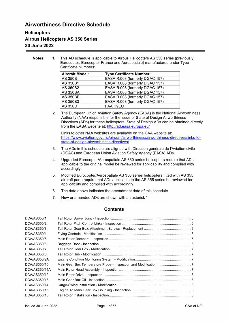
Airworthiness Directive Schedule Helicopters Airbus Helicopters AS 350 Series 30 June 2022
Notes: 1. This AD schedule is applicable to Airbus Helicopters AS 350 series (previously Eurocopter, Eurocopter France and Aerospatiale) manufactured under Type Certificate Numbers:
Aircraft Model: Type Certificate Number: AS 350B EASA R.008 (formerly DGAC 157) AS 350B1 EASA R.008 (formerly DGAC 157) AS 350B2 EASA R.008 (formerly DGAC 157) AS 350BA EASA R.008 (formerly DGAC 157) AS 350BB EASA R.008 (formerly DGAC 157) AS 350B3 EASA R.008 (formerly DGAC 157) AS 350D FAA H9EU
2. The European Union Aviation Safety Agency (EASA) is the National Airworthiness Authority (NAA) responsible for the issue of State of Design Airworthiness Directives (ADs) for these helicopters. State of Design ADs can be obtained directly from the EASA website at: http://ad.easa.europa.eu/
Links to other NAA websites are available on the CAA website at: https://www.aviation.govt.nz/aircraft/airworthiness/airworthiness-directives/links-to-state-of-design-airworthiness-directives/
3. The ADs in this schedule are aligned with Direction générale de l'Aviation civile (DGAC) and European Union Aviation Safety Agency (EASA) ADs.
4. Upgraded Eurocopter/Aerospatiale AS 350 series helicopters require that ADs applicable to the original model be reviewed for applicability and complied with accordingly.
5. Modified Eurocopter/Aerospatiale AS 350 series helicopters fitted with AS 355 aircraft parts require that ADs applicable to the AS 355 series be reviewed for applicability and complied with accordingly.
6. The date above indicates the amendment date of this schedule.
7. New or amended ADs are shown with an asterisk *
Contents
DCA/AS350/1 Tail Rotor Swivel Joint - Inspection ................................................................................... 6 DCA/AS350/2 Tail Rotor Pitch Control Links - Inspection ........................................................................ 6 DCA/AS350/3 Tail Rotor Gear Box, Attachment Screws - Replacement ................................................. 6 DCA/AS350/4 Flying Controls - Modification ............................................................................................ 6 DCA/AS350/5 Main Rotor Dampers - Inspection...................................................................................... 6 DCA/AS350/6 Baggage Door - Inspection ............................................................................................... 6 DCA/AS350/7 Tail Rotor Gear Box - Modification .................................................................................... 7 DCA/AS350/8 Tail Rotor Hub - Modification ............................................................................................. 7 DCA/AS350/9A Engine Condition Monitoring System - Modification .......................................................... 7 DCA/AS350/10 Main Gear Box Temperature Probe - Inspection and Modification .................................... 7 DCA/AS350/11A Main Rotor Head Assembly - Inspection ........................................................................... 7 DCA/AS350/12 Main Rotor Drive - Inspection ............................................................................................ 8 DCA/AS350/13 Main Gear Box Oil - Inspection ......................................................................................... 8 DCA/AS350/14 Cargo-Swing Installation - Modification ............................................................................. 8 DCA/AS350/15 Engine To Main Gear Box Coupling - Inspection .............................................................. 8 DCA/AS350/16 Tail Rotor Installation - Inspection ..................................................................................... 8
Issued 30 June 2022 Page 2 of 57 CAA of NZ
DCA/AS350/17A Tail Rotor Blade Assembly - Retirement ........................................................................... 8 DCA/AS350/18B Fin Installation - Inspection and Modification .................................................................... 9 DCA/AS350/19C Cancelled – DCA/AS350/31A refers ................................................................................. 9 DCA/AS350/20 Tail Rotor Blades - Inspection ........................................................................................... 9 DCA/AS350/21C Cancelled – DCA/AS350/50 now refers ............................................................................ 9 DCA/AS350/22A Main Gear Box, Bevel Ring Gear Assembly - Inspection .................................................. 9 DCA/AS350/23F Tail Rotor Blades – Inspection and Rework .................................................................... 10 DCA/AS350/24 Main Gear Box Oil Filter - Inspection .............................................................................. 10 DCA/AS350/25B Main Rotor Shaft - Inspection .......................................................................................... 10 DCA/AS350/26 Emergency Flotation System - Modification .................................................................... 10 DCA/AS350/27 Fuel Filter Drain - Modification ........................................................................................ 11 DCA/AS350/28 Oil and Fuel Filters - Inspection ...................................................................................... 11 DCA/AS350/29 Raised Skid Landing Gear - Modification ........................................................................ 11 DCA/AS350/30 Main Rotor Head - Life Limitation and Inspection ........................................................... 11 DCA/AS350/31A Fuel Filter - Inspection and Modification .......................................................................... 12 DCA/AS350/32 Fuel Filter - Inspection ..................................................................................................... 12 DCA/AS350/33E Main Rotor Head, Main Gear Box and Landing Gear – Inspection ................................. 12 DCA/AS350/34 Sliding Doors - Modification ............................................................................................ 13 DCA/AS350/35 Main and Tail Rotor Servo Controls - Inspection ............................................................. 13 DCA/AS350/36B Main Rotor, Rotating Swash Plate - Inspection ............................................................... 13 DCA/AS350/37 Cancelled - CAR 91.603(b) refers ................................................................................... 13 DCA/AS350/38 Tail Rotor Pitch Control Lever Expansion Pin - Inspection .............................................. 13 DCA/AS350/39 Emergency Location Transmitter (ELT) Antenna - Modification ...................................... 14 DCA/AS350/40 Hydraulic Reservoir - Modification................................................................................... 14 DCA/AS350/41A Pitch Change Lever Bushes - Inspection ........................................................................ 14 DCA/AS350/42 Engine Fire Detection System - Modification .................................................................. 14 DCA/AS350/43 Main Rotor Mast Assembly - Inspection .......................................................................... 14 DCA/AS350/44A Sliding Windows - Inspection and Modification ............................................................... 15 DCA/AS350/45 MGB Oil Pressure Switch - Removal .............................................................................. 15 DCA/AS350/46 Cyclic Pitch Change Control Rod - Inspection ................................................................ 15 DCA/AS350/47 Main Rotor Shaft Oil Jet - Inspection............................................................................... 15 DCA/AS350/48 MGB Suspension Bi-directional Cross Beam - Inspection .............................................. 16 DCA/AS350/49 Tail Boom Attachment Screws - Replacement ................................................................ 16 DCA/AS350/50 Cancelled – EASA AD 2015-0195 refers ........................................................................ 17 DCA/AS350/51 Single Pole Circuit Breakers – Inspection and Removal ................................................. 17 DCA/AS350/52B Tail Rotor Hub Pitch Change Plate Bearings - Inspection ............................................... 17 DCA/AS350/53 NR Indicator Lighting - Modification ................................................................................ 18 DCA/AS350/54A Tail Rotor Pitch Change Rotating Plates – Inspection and Modification.......................... 18 DCA/AS350/55 Engine Oil Tank Breather Pipe - Fireproofing ................................................................. 19 DCA/AS350/56 Ferry Fuel Tanks - Electrical Bonding ............................................................................. 19 DCA/AS350/57B Tail Rotor Drive Shaft Forward Fairing - Inspection ........................................................ 19 DCA/AS350/58 Tail Rotor Hub Pitch Change Plate Bearings - Replacement .......................................... 21 DCA/AS350/59 Cancelled – DCA/AS350/108 refers ................................................................................ 21 DCA/AS350/60 Engine Indication System – Resistor Installation ............................................................ 21 DCA/AS350/61A Cancelled – DGAC AD 2001-557-086R3 refers .............................................................. 21 DCA/AS350/62 Cancelled – DCA/AS350/74 refers .................................................................................. 21 DCA/AS350/63B Tail Servo Control Eye End Fitting – Inspection and Rework .......................................... 22 DCA/AS350/64 Engine Control Switch – Inspection................................................................................. 22 DCA/AS350/65 Hydraulic Cut-Off Control - Modification .......................................................................... 22 DCA/AS350/66 Cancelled - DCA/AS350/94 refers................................................................................... 23 DCA/AS350/67 HSI - Inspection .............................................................................................................. 23 DCA/AS350/68 Hawker Pacific TRW-SAMM Main Servocontrols - Replacement ................................... 23 DCA/AS350/69 Eurocopter Canada Collective Lock - Replacement ........................................................ 23 DCA/AS350/70 Cancelled – EASA AD 2019-0228 refers ........................................................................ 23
Issued 30 June 2022 Page 3 of 57 CAA of NZ
DCA/AS350/71 Cyclic Friction Cup - Inspection ....................................................................................... 24 DCA/AS350/72 Dynamic Components – Life Correction .......................................................................... 24 DCA/AS350/73A Battery Lug - Inspection .................................................................................................. 24 DCA/AS350/74 TRW-SAMM Servo Controls - Replacement ................................................................... 25 DCA/AS350/75A Flight Control Stops – Inspection and Modification ......................................................... 26 DCA/AS350/76 Collective Lever Lock – Inspection .................................................................................. 26 DCA/AS350/77 Fuel Bleed Lever - Modification ....................................................................................... 26 DCA/AS350/78 Rear Fuselage - Inspection ............................................................................................. 26 DCA/AS350/79 Tail Rotor Control Cable - Replacement ......................................................................... 27 DCA/AS350/80A Cancelled – DCA/AS350/112 refers ................................................................................ 27 DCA/AS350/81 Hydraulic System Cut-off- Modification ........................................................................... 27 DCA/AS350/82 Cancelled - DCA/AS350/98 refers................................................................................... 27 DCA/AS350/83 Tail Rotor Blade Trailing Edge Tab – Inspection and Modification .................................. 28 DCA/AS350/84B Cancelled - DCA/AS350/99 refers................................................................................... 28 DCA/AS350/85 Cancelled – DCA/AS350/86 refers .................................................................................. 28 DCA/AS350/86 Cancelled - DCA/AS350/97 refers................................................................................... 28 DCA/AS350/87 Breeze Eastern 450-lb Electric Hoist - Inspection ........................................................... 28 DCA/AS350/88 Cancelled – DCA/AS350/91 refers .................................................................................. 29 DCA/AS350/89 Main Servo Controls – Inspection and Replacement ...................................................... 29 DCA/AS350/90 Cancelled – DCA/AS350/109 refers ................................................................................ 30 DCA/AS350/91 Cancelled – DCA/AS350/109 refers ................................................................................ 30 DCA/AS350/92 Cancelled – DCA/AS350/126 refers ................................................................................ 30 DCA/AS350/93 Twist Grip Solenoid – Inspection, Operation and Replacement ...................................... 30 DCA/AS350/94 Cancelled – DCA/AS350/103 refers ................................................................................ 30 DCA/AS350/95 Cancelled - DCA/EMY/27 refers ..................................................................................... 30 DCA/AS350/96A Tail Rotor Servo Control – Inspection and Rework ......................................................... 31 DCA/AS350/97B Cancelled – DCA/AS350/106 refers ................................................................................ 31 DCA/AS350/98 Sliding Door Rollers and Rails – Inspection and Modification ......................................... 31 DCA/AS350/99 RH Cabin Vibration Damper and Blade Assy – Inspection and Modification ................... 32 DCA/AS350/100 Starter Generator – Load Limitation ................................................................................ 32 DCA/AS350/101 Yaw Control Load Compensator Lever – Inspection ....................................................... 33 DCA/AS350/102 Main & Tail Rotor Servo Controls – Inspection and Rework ........................................... 33 DCA/AS350/103C Tail Rotor Blade Skin – Inspection and Repair ................................................................ 34 DCA/AS350/104 Cabin Floor Cross Member – Inspection and Rework ..................................................... 34 DCA/AS350/105 Main & Tail Rotor Servo Controls – Inspection and Replacement .................................. 35 DCA/AS350/106 Sliding Door Rear Fitting and Support Shaft – Inspection and Replacement .................. 36 DCA/AS350/107 Collective Lever Recess - Modification ........................................................................... 36 DCA/AS350/108 Rear Bench Seat Cushions – Removal or Modification................................................... 37 DCA/AS350/109 Cancelled – DCA/AS350/114 refers ................................................................................ 37 DCA/AS350/110 Aerazur Emergency Flotation Gear - Inspection and Replacement ............................... 37 DCA/AS350/111A Cancelled – DCA/AS350/115 refers ................................................................................ 38 DCA/AS350/112 Emergency Flotation Gear – Inspection, Placard and Replacement ............................... 38 DCA/AS350/113 Cancelled – DCA/AS350/116 refers ................................................................................ 39 DCA/AS350/114 Fin Attach Fittings – Inspection, Modification & Replacement ......................................... 39 DCA/AS350/115B Collective Lever Lock – Inspection and Rework .............................................................. 40 DCA/AS350/116 Starter Generator Damping Assembly – Adjustment and Marking .................................. 41 DCA/AS350/117 Cancelled – EASA AD 2013-0061 refers ........................................................................ 41 DCA/AS350/118 Cancelled – EASA AD 2010-0006 refers ........................................................................ 41 DCA/AS350/119 Cancelled – DCA/AS350/120 refers ................................................................................ 42 DCA/AS350/120 Tail Gearbox Control Lever – Inspection, Rework and Replacement .............................. 42 DCA/AS350/121 Hydraulic Servo Hoses – Inspection and Rework ........................................................... 43 DCA/AS350/122 EASA AD 2011-0072 Cancelled by EASA on 4 March 2022 .......................................... 43 DCA/AS350/123 Tail Gearbox Casing Assembly – Inspection and Replacement ...................................... 43 DCA/AS350/124 Cancelled – EASA AD 2011-0164R1 refers .................................................................... 44
Issued 30 June 2022 Page 4 of 57 CAA of NZ
DCA/AS350/125 Cancelled – EASA AD 2013-0281 refers ........................................................................ 44 DCA/AS350/126 Cancelled – EASA AD 2012-0252 refers ........................................................................ 44 DCA/AS350/127 Fire Detection System – Modification .............................................................................. 44 The State of Design ADs listed below are available directly from the National Airworthiness Authority (NAA) websites. Links to NAA websites are available on the CAA website at https://www.aviation.govt.nz/aircraft/airworthiness/airworthiness-directives/links-to-state-of-design-airworthiness-directives/ If additional NZ ADs need to be issued when an unsafe condition is found to exist in an aircraft or aeronautical product in NZ, they will be added to the list below. .............................................. 45 2012-0205 Sliding Door Lower Ball-joint – Modification .................................................................... 45 2012-0207-E Cancelled – EASA AD 2012-0217-E refers ..................................................................... 45 2012-0217-E Cancelled – EASA AD 2013-0029 refers ........................................................................ 45 2012-0252 Cancelled – EASA AD 2017-0035 refers ........................................................................ 45 2012-0257-E Tail Rotor Laminated Half-bearings – Inspection and Replacement ............................... 45 2013-0029 Tail Rotor Laminated Half Bearings – Inspection ............................................................ 45 2013-0044-E Cancelled – EASA AD 2013-0284-E refers ..................................................................... 45 2013-0061 Cancelled – EASA AD 2013-0191-E refers ..................................................................... 46 2013-0088 Cancelled – EASA AD 2015-0132 refers ........................................................................ 46 2013-0095-E Main/Tail Rotor Servo-Control Bearings – Inspection and Replacement ........................ 46 2013-0133-CN Cancelled – Purpose fulfilled ........................................................................................... 46 2013-0191-E Cancelled – EASA AD 2017-0052 refers ........................................................................ 46 2010-0006 Cancelled by EASA on 3 September 2021 ..................................................................... 46 2013-0281R1 Position Strobe Light – Inspection ................................................................................... 46 2013-0284R1 Cancelled – EASA AD 2014-0233 refers ........................................................................ 46 2013-0287 Cancelled – EASA AD 2021-0195 Refers ....................................................................... 46 2014-0076R3 Cancelled – EASA AD 2022-0051 refers ........................................................................ 46 2014-0132R1 Rotating Star Swashplate – Inspection ........................................................................... 47 2014-0233 Hydraulic Pump Bearing - Inspection .............................................................................. 47 Transport Canada AD CF-2015-10 STC SR00825NY-D - Hydraulic Test Switch Replacement ....................... 47 2015-0094 Cancelled by EASA on 3 September 2021 ..................................................................... 47 DGAC AD 1991-165-058R1 Electric Hoist Bonding – Inspection .................................................................. 47 2015-0132 Cancelled – EASA AD 2021-0194 Refers ....................................................................... 47 2015-0178 Normal Procedures – AFM Amendment ......................................................................... 47 2015-0195 Tail Rotor Drive Shaft Bearings – Inspection .................................................................. 47 DCA/AS350/128C Forward Two-place Seat - Operating Limitations .......................................................... 48 2016-0020 Main Gearbox Casings – Inspection ............................................................................... 49 2016-0021 Main Gearbox Bottom Casing – Inspection ..................................................................... 50 2016-0220 Dual Hydraulic System – Inspection................................................................................ 50 2016-0260 Main Rotor NR Indicator – Inspection ............................................................................. 50 2017-0020R1 Tail Rotor Pitch Rod – Inspection .................................................................................... 50 2011-0164R3 Tail Rotor Control Stop Screws – Inspection ................................................................... 50 2017-0032 Cancelled by EASA on 11 August 2021 .......................................................................... 51 2017-0035 Twist Grip Assembly – Inspection ................................................................................... 51 2017-0052 Cancelled – EASA AD 2017-0059 refers ........................................................................ 51 2017-0059 Switches 53Ka, 53Kb and 65K – Inspection ................................................................... 51 2017-0089R1 Main Rotor Mast Upper Bearing - Inspection ................................................................ 51 2017-0109 (Correction) Starter Generator and Brushes - Inspection ............................................................ 51 2017-0114 Cancelled - EASA AD 2020-0186 refers ....................................................................... 51 2017-0143 Direct Current (Optional) Second Battery – Replacement ............................................... 51 Transport Canada AD CF-2017-37 Restriction of Directional Control Pedal Movement................................ 51 DCA/AS350/129A Cargo Swing Modification OAL114 – Inspection ........................................................... 52 2018-0152 Main Gearbox Bracket Bolts - Inspection ...................................................................... 52 2018-0206 Mast Upper Bearing Sealant Bead/Inner Race Retaining Rings - Inspection ................ 52 FAA AD 2018-18-12 Cancelled – FAA AD 2019-16-16 refers .......................................................................... 52 FAA AD 2018-25-17 Air Comm Corp Air Conditioning System – Inspection .................................................... 52 2018-0287 Cancelled – EASA AD 2019-0060 refers ........................................................................ 52
Issued 30 June 2022 Page 5 of 57 CAA of NZ
DCA/AS350/130 HETS STC 11/21E/34 – Removal from Service ............................................................ 53 Transport Canada CF-2019-01 Helicopter External Transport System (HETS) STC SH98-35 ..................... 53 2019-0060 Tail Rotor Gearbox Actuating Rod – Inspection .............................................................. 53 DGAC AD 2001-557-086R3 Starflex Star – Inspection ................................................................................. 53 2019-0184 Main Rotor Servo Actuators – Inspection ........................................................................ 54 FAA AD 2019-16-16 Inlet Barrier Filter – Inspection ........................................................................................ 54 2019-0225-E MGB Drive Shaft / Engine Coupling – Inspection ............................................................ 54 2019-0228 Electric Hoist Installation – Inspection ............................................................................. 54 2019-0280 Spherical Bearing – Inspection ....................................................................................... 54 FAA AD 2020-02-23 Emergency Float System STC SR00470LA – Inspection ............................................... 54 DCA/AS350/131 Dual Front Seat Modification MB 25.20.05 - Inspection ................................................ 54 2020-0064 Emergency Flotation System – Inspection ...................................................................... 55 2020-0175 Cancelled by EASA on 13 September 2021 ................................................................... 55 2020-0186 Cancelled – EASA AD 2021-0099 refers ........................................................................ 55 2020-0217-E Cancelled – EASA AD 2021-0023 refers ........................................................................ 55 2020-0224R1 Tail Rotor Blades – Inspection ........................................................................................ 55 2021-0023 Cyclic Stick Grip UP / Down Hoist Control Switch – Modification .................................... 55 2021-0048 Main Rotor Pitch Rod Upper Links – Inspection .............................................................. 56 2021-0099 Vertical Fin – Inspection .................................................................................................. 56 2021-0123-E Tail Rotor Load Compensator – Inspection ..................................................................... 56 2021-0168 Indicating / Recording Systems Control Unit – Inspection ............................................... 56 2021-0194R1 Airworthiness Limitations ................................................................................................ 56 2021-0195 Engine Digital ECU Emergency Procedure – AFM Amendment ..................................... 56 2021-0282 Tail Rotor Head Pitch Change Unit Bearing Spacer - Inspection .................................... 57 * 2022-0051 (Correction) Rear Structure Junction Frame Reinforcement Angles - Inspection .......... 57 2022-0077-E Flight Control Flexball Cables - Replacement ............................................................... 57
Airbus Helicopters AS 350 Series
Issued 30 June 2022 Page 6 of 57 CAA of NZ
DCA/AS350/1 Tail Rotor Swivel Joint - Inspection Applicability: All Model AS350 not incorporating mods. AMS 350A.07.6513 and AMS
350A.07.8515.
Requirement: Inspect per Aerospatiale SB 05.01. (DGAC AD 1978-193-001 refers)
Compliance: At intervals not exceeding 50 hours TIS.
Effective Date: 17 August 1979
DCA/AS350/2 Tail Rotor Pitch Control Links - Inspection Applicability: All Model AS350 not incorporating mods. AMS 350A.07.6510 or AMS 350A.07.6512
and AMS 350A.07.5524.
Requirement: Inspect per Aerospatiale SB 05.02 paras 1C.1(A) and 1C.1(B). (DGAC AD 1978-193-001 refers)
Compliance: Para 1C.1(A) - Prior to every flight. Para 1C.1(B) - At intervals not exceeding 10 hours TIS.
Effective Date: 17 August 1979
DCA/AS350/3 Tail Rotor Gear Box, Attachment Screws - Replacement Applicability: All Model AS350 not incorporating mod. AMS 350A.07.8517.
Requirement: Embody replacement screws per Aerospatiale SB 65.07. (DGAC AD F-1979-012-004 refers)
Compliance: Within the next 50 hours TIS
Effective Date: 17 August 1979
DCA/AS350/4 Flying Controls - Modification Applicability: All Model AS350 not incorporating mod. AMS 350A.07.0452.
Requirement: Embody control rod P/N 704A.34.113 per Aerospatiale SB 67.01. (DGAC AD 1979-013-005 refers)
Compliance: Within next 100 hours TIS unless already accomplished.
Effective Date: 17 August 1979
DCA/AS350/5 Main Rotor Dampers - Inspection Applicability: All Model AS350 not incorporating mod. AMS 350.07.6063.
Requirement: Inspect per Aerospatiale SB 05.03. (DGAC AD 1979-104-006 refers)
Compliance: At intervals not exceeding 25 hours TIS.
Effective Date: 17 August 1979
DCA/AS350/6 Baggage Door - Inspection Applicability: All Model AS350.
Requirement: Inspect L.H. baggage door for correct latching per Aerospatiale SB 52.04.
Deficient installations shall be corrected before further flight. (DGAC AD 1979-133-007 refers)
Compliance: By 8 August 1979
Effective Date: 31 July 1979
Airbus Helicopters AS 350 Series
Issued 30 June 2022 Page 7 of 57 CAA of NZ
DCA/AS350/7 Tail Rotor Gear Box - Modification Applicability: All Model AS350 not incorporating mod. AMS 07.8519.
Requirement: Modify per Aerospatiale SB 65.08.
(DGAC AD 1979-174-009 refers)
Compliance: By 31 October 1979
Effective Date: 28 September 1979
DCA/AS350/8 Tail Rotor Hub - Modification Applicability: All Model AS350
Requirement: Modify per Aerospatiale SB 65.13.
(DGAC AD 1979-217-011 refers)
Compliance: By 31 January 1980
Effective Date: 21 December 1979
DCA/AS350/9A Engine Condition Monitoring System - Modification Applicability: All Model AS350B not incorporating mods. AMS 07.0615 and 07.0804.
Requirement: Embody modifications AMS 07.0615 and 07.0804 per Aerospatiale SB 77.02 issue 2.
(DGAC AD 1980-165-014 refers)
Compliance: Mod. 07.0615 - By 31 March 1980
Mod. 07.0804 - By 31 March 1981
Effective Date: DCA/AS350/9 - 22 February 1980 DCA/AS350/9A - 21 November 1981
DCA/AS350/10 Main Gear Box Temperature Probe - Inspection and Modification Applicability: All Model AS350 not incorporating mod. AMS 350A.07.0733.
Requirement: Inspect and modify per Aerospatiale SB 65.18. Probe installations found defective shall be modified before further flight.
(DGAC AD F-1980-104-013 refers)
Compliance: Inspection - Prior to next flight unless already accomplished.
Modification - not later that next 300 hour inspection.
Effective Date: 6 June 1980
DCA/AS350/11A Main Rotor Head Assembly - Inspection Applicability: All Model AS350
Requirement: Check starflex attachment bolt torque, inspect and/or renew bolts as necessary, per Aerospatiale SB 05.04 Rev.1.
(DGAC AD 1980-184-015R1 refers).
Compliance: At 600 hours TTIS and thereafter at intervals not exceeding 400 hours TIS.
Aircraft with 590 hours or more TIS shall be initially inspected within next 10 hours TIS unless already accomplished
Effective Date: DCA/AS350/11 - 21 November 1980 DCA/AS350/11A - 18 March 1988
Airbus Helicopters AS 350 Series
Issued 30 June 2022 Page 8 of 57 CAA of NZ
DCA/AS350/12 Main Rotor Drive - Inspection Applicability: All Model AS350 with bevel gear module P/N 350A32.0300.00, .01 or .02. Requirement: Inspect per Aerospatiale telex service bulletin 05.05. Modules with indications of
excessive wear must be removed from service before further flight. Compliance: At 600 hours TTIS and thereafter at intervals not exceeding 150 hours TIS. Modules
with 580 hours or more TIS, shall be initially inspected within next 20 hours TIS unless already accomplished.
Effective Date: 9 January 1981. DCA/AS350/13 Main Gear Box Oil - Inspection
Applicability: All Model AS350 with spiro conical modules not incorporating mods. 07.7027 or 07.7042.
Requirement: Accomplish spectrometric oil analysis per Aerospatiale telex SB 05.06. Modules with indication of excessive wear must be removed from service before further flight. (DGAC AD F-1981-094-018 refers)
Compliance: At 300 hours TTIS and thereafter at intervals not exceeding 300 hours TIS. Effective Date: 3 April 1981
DCA/AS350/14 Cargo-Swing Installation - Modification Applicability: All Model AS350 with cargo-swing installation. Requirement: Modify per Aerospatiale SB 25.19.
(DGAC AD 1981-067-016 refers). Compliance: Prior to next use of cargo-swing installation. Effective Date: 12 June 1981.
DCA/AS350/15 Engine To Main Gear Box Coupling - Inspection Applicability: All Model AS350. Requirement: Inspect attachment bolts per Aerospatiale SB 01.06 and renew as necessary before
further flight. (DGAC AD 1981-084-017 refers)
Compliance: At next 300 hour inspection. Effective Date: 12 June 1981.
DCA/AS350/16 Tail Rotor Installation - Inspection Applicability: All Model AS350 Requirement: Accomplish dye penetrant and visual inspections per Aerospatiale telex SB 01.07A. Compliance: Dye penetrant inspection - within next 10 hours TIS.
Visual inspection - following last flight on each day aircraft is operated. Effective Date: 13 June 1981
DCA/AS350/17A Tail Rotor Blade Assembly - Retirement Applicability: All Model AS350 Requirement: Retire tail rotor pitch change horn assemblies P/N 350A12.1368.01 and
350A12.1368.02 from service. (DGAC AD 1981-184-020 refers)
Compliance: P/N 350A12.1368.01 - at 450 hours TTIS. P/N 350A12.1368.02 - at 1250 hours TTIS.
Effective Date: DCA/AS350/17 - 6 July 1981 DCA/AS350/17A - 11 December 1981
Airbus Helicopters AS 350 Series
Issued 30 June 2022 Page 9 of 57 CAA of NZ
DCA/AS350/18B Fin Installation - Inspection and Modification Applicability: All Model AS350 not incorporating mod. 07.1047.
Requirement: 1. Inspect per Aerospatiale telex SB 05.07 and SB 05.09.
2. Modify per Aerospatiale SB 55.02 Rev.1.
(DGAC AD F-1982-098-026 refers)
Compliance: 1. Inspections - At intervals not exceeding 10 hours TIS until modified per Aerospatiale SB's 55.02 Rev.1 and 55.03 respectively.
2. Modification - within next 100 hours TIS.
Effective Date: DCA/AS350/18A - 12 February 1982 DCA/AS350/18B - 27 August 1982
DCA/AS350/19C Cancelled – DCA/AS350/31A refers Effective Date: 30 August 2007
DCA/AS350/20 Tail Rotor Blades - Inspection Applicability: All Model AS350 with tail rotor blades, P/N 350.12.0020 all dash numbers,
350.12.0030.00 all dash numbers and 350A.08.1011.00.
Requirement: Inspect tail rotor blades for bonding separation of leading edge stainless steel protection strips per Aerospatiale work card AS350.65.20.601.
(DGAC AD 1982-024-024 refers).
Compliance: 1. Blades with 100 hours or less TTIS or since overhaul - at intervals not exceeding 10 hours TIS until accumulation of 100 hours TIS and thereafter per Aerospatiale M.S.R. AS350 CH5.24 P.2 latest issue.
2. Blades which have exceeded 100 hours TTIS or since overhaul - within next 10 hours TIS, and thereafter per Aerospatiale M.S.R. AS350 CH5.24 P.2 latest issue.
Effective Date: 30 April 1982
DCA/AS350/21C Cancelled – DCA/AS350/50 now refers Effective Date: 28 August 1998
DCA/AS350/22A Main Gear Box, Bevel Ring Gear Assembly - Inspection Applicability: All Model AS350 with bevel reduction gear assemblies P/N 350A32.0300.00.01 and
.02 not incorporating mods. AMS 07.7082, AMS 07.7083 or AMS 07.7098.
Requirement: Visually inspect per Aerospatiale SB 05.10 para 1C(1) and check screw torques per para 1C(2).
Correct defective screw installations before further flight.
(DGAC AD 1985-068-038 refers).
Compliance: Visual inspection - at intervals not exceeding 50 hours TIS until screw torque check accomplished and thereafter at intervals not exceeding 300 hours TIS.
Torque check - Within next 300 hours TIS unless already accomplished.
Effective Date: DCA/AS350/22 - 11 February 1983 DCA/AS350/22A - 2 August 1985
Airbus Helicopters AS 350 Series
Issued 30 June 2022 Page 10 of 57 CAA of NZ
DCA/AS350/23F Tail Rotor Blades – Inspection and Rework Applicability: All AS350 series aircraft fitted with tail rotor blade assembly P/N 350A08.1011,
350A12.0020, 350A12.0030, 355A12.0031 and 355A12.0040 (all dash numbers).
Note: The compliance time for requirement 2 extended to 600 hours TIS with no change to the AD requirement.
Requirement: To prevent tail rotor blade failure due to possible cracks in the blade root which can result in severe unbalance and loss of aircraft control, accomplish the following:
1. Check tail rotor blades per the instructions in paragraph 1(C)1 of Eurocopter AS350 SB 05.11 revision 5 or later approved revisions. If any abnormal noises are detected, inspect and accomplish the instructions in paragraph 1(C)(2) in AS350 SB 05.11 before further flight.
2. Visually inspect per the instructions in paragraph 1C(2) of SB 05.11. Renew defective parts before further flight. (DGAC AD 1984-064-037R3 refers)
Compliance: 1. Noise check: At intervals not to exceed 30 hours TIS.
2. Inspection: At intervals not to exceed 600 hours TIS and every time the laminate half-bearings are replaced, and if balance difficulties are experienced, and or after an incident which may have adversely affected the tail rotor.
Effective Date: DCA/AS350/23D - 7 October 1988 DCA/AS350/23E - 16 January 1998 DCA/AS350/23F - 30 September 2010
DCA/AS350/24 Main Gear Box Oil Filter - Inspection Applicability: All model AS350 fitted with 'TEDECO' magnetic plug P/N B4439 per mod
350A.07.0720 (AS 350 SB 65-20).
Requirement: Inspect oil filter per Aerospatiale SB 05.12. (DGAC AD 82-175-29 refers).
Compliance: At intervals not exceeding 100 hours TIS.
Effective Date: 11 February 1983.
DCA/AS350/25B Main Rotor Shaft - Inspection Applicability: All Model AS350 with rotor shaft P/N 350A37.1076.00 to .06.
Requirement: Inspect per Aerospatiale SB 05.13 Rev.2. Renew defective part before further flight. (DGAC AD 1983-173-036 refers)
Compliance: 1. At 300 hours TTIS or within next 50 hours TIS, whichever is the later and thereafter at intervals not exceeding 300 hours TIS.
2. Before further flight following severe rotor tracking abnormalities.
Effective Date: DCA/AS350/25A - 2 March 1984 DCA/AS350/25B - 2 May 1986
DCA/AS350/26 Emergency Flotation System - Modification Applicability: All Model AS350B, C and D-1 with air cruiser flotation system installed per STC
SH4032SW or SH2825SW.
Requirement: Modify floation system per FAA AD 83-11-01 R1. (FAA AD 83-11-01R1 refers)
Compliance: Prior to next overwater flight, unless already accomplished.
Effective Date: 1 March 1985
Airbus Helicopters AS 350 Series
Issued 30 June 2022 Page 11 of 57 CAA of NZ
DCA/AS350/27 Fuel Filter Drain - Modification Applicability: Model AS350B and AS350D S/Ns 1 through 1808, 1813 through 1826 except 1818
and 1822
Requirement: Modify fuel filter drain in accordance with SB 28.06.
(DGAC 1985-066-039 refers)
Compliance: Before 1 September 1985
Effective Date: 2 August 1985.
DCA/AS350/28 Oil and Fuel Filters - Inspection Applicability: All Model AS350
Requirement: 1. Inspect main gear box filter and fuel filter cartridges for correct installation per Aerospatiale Telex SB No. 01.14 including amendment 01.14A.
2. When installing replacement `LEBOZEC' and `GAUTHIER' filters ensure that:
Fuel filter P/N 432 B12.30 filter cartridge is marked `FUEL'
Oil filter P/N 434 B12.11 filter cartridge is marked `OIL'.
(DGAC AD 1985-135-042 refers)
Compliance: 1. Inspection - Within next 5 hours TIS unless already accomplished
2. Filter check - Prior to installation
Effective Date: 28 February 1986
DCA/AS350/29 Raised Skid Landing Gear - Modification Applicability: All Model AS350 with raised skid landing gear and flotation gear installation not
incorporating mod. AMS 350A.07.1755
Requirement: To prevent possible interference between landing gear steps and flotation bags when inflated, remove steps per Aerospatiale Telex SB 32.06A
(DGAC AD 1986-030-043 refers)
Compliance: By 31 May 1986, or prior to flotation gear installation.
Effective Date: 2 May 1986
DCA/AS350/30 Main Rotor Head - Life Limitation and Inspection Applicability: All Model AS350B and AS350D with roving sleeve upper and lower beams P/N
350A31.1830.00 and .01; 350A31.1831.00, .04, .05, .06 and .07
Requirement: 1. Remove affected beams from service per Aerospatiale telex SB 01.16 para BB at 4000 hours TTIS. Beams with 3900 hours or more TIS must be removed within next 100 hours TIS.
2. In the event of sudden or repeated occurrence or severe rotor tracking problems inspect per telex SB 01.16 para CC before further flight. If sleeve bush separation found remove beam from service before further flight.
(DGAC AD 1986-057-044 refers)
Effective Date: 1 August 1986
Airbus Helicopters AS 350 Series
Issued 30 June 2022 Page 12 of 57 CAA of NZ
DCA/AS350/31A Fuel Filter - Inspection and Modification Applicability: All Model AS350B and AS350D without modification 07.1671 embodied.
Note: This AD is no longer applicable once modification 07.1671 is embodied and supersedes DCA/AS350/19C.
Requirement: To prevent leaks at the fuel system filter and drain valve, accomplish the following:
1. Pull the drain valve to ensure it is correctly seated. Switch the fuel pump on and confirm that the drain valve does not leak. If any leak is detected repair as required, before further flight.
2. Embody modification 07.1671 per the instructions in Aerospatiale SB 28.07. (DGAC ADs 1986-077-046(B)R2 and 1986-070-045(B) refers)
Compliance: 1. Check the drain valve whenever the filter drain is operated until requirement 2 of this AD is accomplished. 2. By 30 November 2007, unless aready accomplished.
Effective Date: DCA/AS250/31 - 1 August 1986 DCA/AS350/31A - 30 August 2007
DCA/AS350/32 Fuel Filter - Inspection Applicability: All Model AS350 with LEBOZEC and GAUTHIER fuel filter P/N 432B12.3, .3C or P/N
350A52-1070.00 (post mod. 07.1671)
Requirement: To prevent leaks at fuel system filter, check that filter bowl is correctly tightened per instruction given on M.E.T. work card 28.00.00.302 page 3 rev.5A dated 86.21 and subsequent revisions. (DGAC AD 1986-097-047 and Aerospatiale telex SB 28.08 refer)
Compliance: Within 50 hours TIS and thereafter whenever filter bowl is disturbed for any other reason.
Effective Date: 1 August 1986
DCA/AS350/33E Main Rotor Head, Main Gear Box and Landing Gear – Inspection Applicability: All model AS350 B, B1, C, D and D1 aircraft.
Note: The compliance time for requirement 1 extended to 600 hours TIS with no change to the AD requirement. Aerospatiale SB 01.17A can be obtained from the Eurocopter T.I.P.I. web site under AS 350 ASB 01.00.17
Requirement: To prevent failure of main rotor (M/R) star arms and main gear box (MGB) suspension bars, accomplish the following:
1. Inspect the M/R head components, the MGB suspension bars (struts) and landing gear per paragraph CC3, subparagraph CCA, CCB and CCC in Aerospatiale SB 01.17A or later approved revisions. Rework or renew defective parts before further flight. 2. Inspect the M/R head components and MGB suspension bars per paragraph CC3 subparagraphs CCA and CCB in SB 01.17A. Rework or renew defective parts before further flight. (BV AD 1986-125-48R1 refers)
Compliance: 1. At intervals not to exceed 600 hours TIS. Prior to further flight following a hard landing which causes abnormal self sustained dynamic vibrations (ground resonance type). 2. Prior to further flight following a hard landing or exposure to high winds without the M/R blades secured.
Effective Date: DCA/AS350/33C - 16 January 1998 DCA/AS350/33D - 25 September 1998 DCA/AS350/33E - 30 September 2010
Airbus Helicopters AS 350 Series
Issued 30 June 2022 Page 13 of 57 CAA of NZ
DCA/AS350/34 Sliding Doors - Modification Applicability: All Model AS350 with LH and/or RH sliding doors.
Requirement: To preclude the possibility of door loss in flight, modify per Aerospatiale SB 52.18. (DGAC AD 1987-088-049 refers)
Compliance: By 31 May 1988
Effective Date: 18 March 1988
DCA/AS350/35 Main and Tail Rotor Servo Controls - Inspection Applicability: All Model AS350 with Dunlop main and tail rotor servo controls P/N AC64182,
AC67030, AC67244, AC66442, AC67034, AC67246, AC66436, AC67032.
Requirement: To preclude possible failure of servo control assembly bolts, inspect per Aerospatiale SB 01.21 and renew bolts as prescribed. (DGAC AD 1988-184-052 refers)
Compliance: Within next 50 hours TIS or by 31 May 1989 whichever is the sooner.
Effective Date: 10 March 1989
DCA/AS350/36B Main Rotor, Rotating Swash Plate - Inspection Applicability: All Model AS350B, B1, B2 and D with swash plates fitted with bearings P/Ns VH
36132 (704A33.651.051), Y 51BB 10843 SIM 73 (704A33.651.080), INA 36132 A (704A33.651.126).
Requirement: To prevent seizing of the swash plate bearing, inspect and lubricate per Aerospatiale SB 62.12R2. Renew defective parts before further flight. (DGAC AD 1989-155-054R4 refers)
Compliance: 1. Within next 10 hours TIS (T.I.S.), unless already accomplished, and thereafter relubricate per SB 62.12R2 para 1.C-i at intervals not exceeding 100 hours T.I.S.
2. Check per SB 62.12R2 para 1.C-g following last flight on each day aircraft is operated.
Effective Date: DCA/AS350/36A - 2 March 1990 DCA/AS350/36B - 29 November 1991
DCA/AS350/37 Cancelled - CAR 91.603(b) refers Effective Date: 27 August 2009
DCA/AS350/38 Tail Rotor Pitch Control Lever Expansion Pin - Inspection Applicability: All Model AS350B, B1, B2 and D.
Requirement: To prevent failure of the tail rotor pitch control lever hinge yoke lugs due to incorrect assembly, accomplish the following:-
1. Inspect the pitch control rod support yoke for cracks per para B of Aerospatiale Telex SB NR 01-33. If a crack is found replace the TGB per the SB before further flight.
2. Inspect for correct installation of the expansion pin per para C of Aerospatiale Telex SB NR 01-33. Rectify if necessary as prescribed by the SB, before further flight. (DGAC AD 1991-137-059 refers)
Compliance: 1. Within next 10 hours TIS (TIS) and thereafter at intervals not to exceed 10 hours TIS until part 2 is accomplished.
2. Within next 50 hours TIS.
Effective Date: 4 July 1991
Airbus Helicopters AS 350 Series
Issued 30 June 2022 Page 14 of 57 CAA of NZ
DCA/AS350/39 Emergency Location Transmitter (ELT) Antenna - Modification Applicability: Model AS350 Series fitted with the JOLLIET ELT system
Requirement: To prevent loss of the ELT antenna in flight, modify per Eurocopter AS 350 SB 25.45. (DGAC AD 1992-144-061 refers)
Compliance: Within next 400 hours TIS or by 1 April 1993 whichever is the sooner.
Effective Date: 30 October 1992
DCA/AS350/40 Hydraulic Reservoir - Modification Applicability: All Model AS350B, BA, B1, B2 and D fitted with hydraulic reservoir P/N 350A75-1030-
00.
Requirement: To decontaminate the hydraulic system and prevent water entering the hydraulic reservoir, modify and flush the system per paragraph 2B1 or 2B2 of Eurocopter SB 01.36. (DGAC AD 1992-145-062 refers)
Compliance: For aircraft operating in temperatures of -10° C or less, within next 100 hours TIS or 3 months whichever is the sooner. For all other aircraft, within next 400 hours TIS.
Effective Date: 30 October 1992
DCA/AS350/41A Pitch Change Lever Bushes - Inspection Applicability: All Model AS350B, BA, D, B1, B2 and L1 with pitch change lever P/N 350A
31.1877.02 not marked with an "X" and have a S/N less than 100,000.
Requirement: To prevent failure of the pitch change rod/lever coupling bolt and loss of pitch control, inspect per Eurocopter SB 62.21 R1. Renew defective parts per SB 62.21 R1. (DGAC AD 1992-179-064R1 refers)
Compliance: Within next 50 hours TIS.
Effective Date: DCA/AS350/41 - 27 November 1992 DCA/AS350/41A - 11 June 1993
DCA/AS350/42 Engine Fire Detection System - Modification Applicability: Model AS350B1 and B2
Requirement: To ensure correct operation of the engine bay fire detection system, modify per Eurocopter SB 26-01. (DGAC AD 1992-159-063R2 refers)
Compliance: By 31 May 1993
Effective Date: 19 March 1993
DCA/AS350/43 Main Rotor Mast Assembly - Inspection Applicability: Model AS350B, BA, B1, B2 and D fitted with main rotor mast assembly P/N
350A37.0004.02, 350A37.0004.03, 355A37.0005.01.
Requirement: As a result of an accident overseas involving an AS350B2, inspect per Eurocopter Telex Service 01-41, paragraphs DD (A) or (B) as appropriate and EE. (DGAC AD 1993-030-065 refers)
Compliance: 1. Whenever abnormal noises appear (metal rubbing) in flight or when the rotor is turning on the ground. Flights must be terminated as soon as practicable.
2. Within the next 5 hours TIS, for any main rotor mast shaft on which maintenance requiring the removal of the mast epicyclic reduction gear assembly has been performed during the last 100 hours TIS, unless the maintenance was performed by Eurocopter Marignane.
Effective Date: 27 March 1993
Airbus Helicopters AS 350 Series
Issued 30 June 2022 Page 15 of 57 CAA of NZ
DCA/AS350/44A Sliding Windows - Inspection and Modification Applicability: All Model AS350B, BA, B1, B2, D and L1 fitted with sliding window panes P/N:
704A41-512-003, -004, -005, -006, -010, -011, -025 and 355A25-2030-00.
Requirement: To prevent window separation in flight accomplish the following:-
1. Inspect per Eurocopter SB 05.25 R1. If cracks are found, or if a piece of the slide is unstuck and/or has been lost, replace the window per paragraph 1C3 of SB 05.25 R1 before further flight.
2. Modify (Repair) per paragraph 1C2 of SB 05.25 R1.
(DGAC AD 1993-090-067R1 refers)
Compliance: 1. Inspect within next 50 hours TIS and thereafter at intervals not to exceed 25 hours TIS, until modification per paragraph 1C2 of SB 05.25 R1. After modification, inspect at intervals not to exceed 100 hours TIS.
2. Modify within next 100 hours TIS.
Effective Date: DCA/AS350/44 - 3 September 1993 DCA/AS350/44A - 18 March 1994
DCA/AS350/45 MGB Oil Pressure Switch - Removal Applicability: Model AS350B, BA, B1, B2, D and L1, fitted with MGB oil pressure switch P/N
704A37.721.082 (S 1130.021.082).
Requirement: Replace MGB oil pressure switch P/N 704A37.721.082 (S 1130.021.082) per Eurocopter Telex Service 01.43.
(DGAC AD 1994-087-068 refers)
Compliance: By 1 August 1994
Effective Date: 8 July 1994
DCA/AS350/46 Cyclic Pitch Change Control Rod - Inspection Applicability Model AS 350B, BA, B1, B2 and D, fitted with cyclic pitch change control rod P/N
704A34-113-279. This airworthiness directive does not apply to aircraft fitted with an autopilot.
Requirement: To ensure that cyclic pitch change control rods have been correctly safetied, inspect per Eurocopter SB 01-42. Replace any rods found not safetied per SB 01-42 before further flight.
(DGAC AD 1994-180-069 refers)
Compliance: Within next 100 hours TIS.
Effective Date: 23 December 1994
DCA/AS350/47 Main Rotor Shaft Oil Jet - Inspection Applicability Model AS350B, BA, B1, B2, D and L1, fitted with a “TIMKEN” main rotor shaft P/N
350A37-0003 (all dash numbers), that has logged less than 100 operating hours since new or overhaul.
Requirement: To ensure correct lubrication of the shaft bearing, accomplish the inspection per Eurocopter France AS 350 Telex Service No 01-44. Replace any assembly that does not comply with Telex Service No 01-44, before further flight.
(DGAC AD 1994-279-070R1 refers)
Compliance: Before further flight.
Effective Date: 9 March 1995
Airbus Helicopters AS 350 Series
Issued 30 June 2022 Page 16 of 57 CAA of NZ
DCA/AS350/48 MGB Suspension Bi-directional Cross Beam - Inspection Applicability: Model AS 350B, BA, B1, B2 and D fitted with a MGB suspension bi-directional cross
beam P/N 350A38.1018 - (all dash numbers), installed on the complete cross beam assemblies P/N 350A38.0210 - (all dash numbers), not modified per MOD. 072720.
Requirement: To prevent failure of the suspension cross beam, accomplish the following:-
1. Cross beams that have logged at least 2000 hours TIS or 10,000 cycles:
1.1 Within next 30 hours TIS and thereafter at intervals not to exceed 30 hours TIS or 150 cycles, whichever is the sooner, visually inspect the cross beam for cracks, per paragraph 2B(1) of Eurocopter France SB 05.00.28 and rectify defects if necessary as detailed.
1.2 Each time the cross beam or the MGB is removed, irrespective of whether the removal was scheduled or not, comply with paragraph 2B(2) of SB 05.00.28.
2. For cross beams that have logged more than 5000 hours TIS and which have not been checked during or since the last major inspection per paragraph 2B(2) of SB 05.00.28 accomplish the following:
2.1 Within next 30 hours TIS and thereafter at intervals not to exceed 30 hours TIS or 150 cycles, whichever is the sooner, visually inspect both the upper faces of the cross beam for cracks, per paragraph 2B(1) of SB 05.00.28 and rectify any defects found as detailed.
2.2 Within 550 hours TIS or 2750 cycles whichever is the later, comply with paragraph 2B(2) of SB 05.00.28.
Note: If there is no record of the number of the flying hours logged or of the number of cycles completed: If the component has been installed on the aircraft since new, refer to the number of the flying hours and cycles logged by the airframe. If the component has not been installed on the aircraft since new, comply with the instructions given in paragraph 2.1.
3. Before installing a cross beam as a replacement part that has already been installed on an aircraft, comply with the instructions given in paragraph 2B(2) of SB 05.00.28. (DGAC AD 1996-156-071R1 refers)
Compliance: Compliance is required at the times specified within the requirement of this airworthiness directive.
Effective Date: 29 August 1997
DCA/AS350/49 Tail Boom Attachment Screws - Replacement Applicability: Model AS 350B, BA, BB, B1, B2 and D fitted with tail boom attachment screws P/N
22201BC060008L (N5103337287). This AD does not apply to new or overhauled aircraft delivered after 15 May 1997 or to aircraft on which no tail boom attachment screws have been replaced since 1 July 1994.
Requirement: To prevent failure of the tail boom attachment screws, accomplish the following:-
Check the marking on the heads of the 23 attachment screws which are located above the cargo compartment floor. Remove and scrap all screws which are marked with the letter “M” on their head above the designation “BC” per paragraph 2.B.1 of Eurocopter Alert Service Bulletin No. 01.00.46. Any affected screws held as spares must be scrapped per paragraph 2.B.2 of Eurocopter Alert Service Bulletin 01.00.46. (DGAC AD 1997-147-072R1 refers)
Compliance: Within next 100 hours TIS or by 29 September 1997, whichever is the sooner.
Effective Date: 29 August 1997
Airbus Helicopters AS 350 Series
Issued 30 June 2022 Page 17 of 57 CAA of NZ
DCA/AS350/50 Cancelled – EASA AD 2015-0195 refers Effective Date: 7 October 2015
DCA/AS350/51 Single Pole Circuit Breakers – Inspection and Removal Applicability: AS 350 helicopters, versions: B, BA, BB, B1, B2, B3 and D equipped with single-pole
CROUZET circuit breakers, P/Ns:
-5 amperes : 84 4000 032 Emergency flotation gear optional installation
-10 amperes : 84 4000 034 -1 ampere : 84 4000 028 Other optional installations -3 amperes : 84 4000 031 -7.5 amperes : 84 4000 033 -15 amperes : 84 4000 035 -20 amperes : 84 4000 036
(a) Delivered new between April 24, 1995, and August 31, 1996.
(b) Delivered new before April 24, 1995 or after August 31, 1996 if:
- Circuit breakers have been replaced on an optional equipment (emergency flotation gear or another optional equipment) since April 24, 1995.
- An optional equipment (emergency flotation gear or another optional installation) was installed on the aircraft between April 24, 1995 and August 31, 1996.
Requirement: To ensure that there is no loss of electrical continuity, accomplish the following:-
1. Inspect the circuit breakers and replace if necessary per Eurocopter SB 01.00.47.
2. Remove from service all circuit breakers listed in the applicability section of this AD.
(DGAC AD 1998-511-074 refers)
Compliance: 1. Inspect within next 200 hours TIS or by 12 June 1999, whichever is the sooner. For those circuit breakers held as spares, inspect before installation.
2. Replace by 1 January 2000.
Effective Date: 12 March 1999
DCA/AS350/52B Tail Rotor Hub Pitch Change Plate Bearings - Inspection Applicability: AS 350 helicopters, versions: B, BA, BB, B1, B2, B3 and D fitted with tail rotor hub
pitch change plate, P/Ns 350A33-2004-00, -01, -02, -03, -05 or 350A33-2009-00, -01 that do not incorporate MOD 076551 (new generation bearing P/N 6010F234M16 (704A33.651.190) introduced by AS 350 SB 65.00.38 R1)
Requirement: To prevent seizure of the tail rotor hub pitch change plate bearings and loss of control of the helicopter, accomplish the following:-
1. Check the rotation torque of the bearing per paragraph 2.B 1) of Eurocopter AS350 ASB 05.00.29.
2. Inspect for axial play, friction point and brinelling per paragraph 2.B 2) of Eurocopter AS350 ASB 05.00.29.
3. Check any pitch change plate assemblies held as spares per paragraph 2.B 1) b) and 2.B 2) of Eurocopter AS350 ASB 05.00.29.
If the measured rotational load is greater than 300 grams, remove the pitch change plate assembly from the aircraft or do not install if the assembly as held as a spare.
If the measured rotational load is less than 300 grams, and if the axial play is greater than or equal to 0.4mm and/or friction points or brinelling are detected:
Check the condition of the parts (excluding the pitch change plate bearing) and replace them per paragraph 2.B 3) b) of Eurocopter AS350 ASB 05.00.29.
Airbus Helicopters AS 350 Series
Issued 30 June 2022 Page 18 of 57 CAA of NZ
Replace the pitch change plate bearing with a bearing in airworthy condition. (DGAC AD 1999-085-076R3 refers)
Compliance: 1. Unless already accomplished, within the next 10 hours TIS or 14 days, whichever is the sooner. 2. Within next 10 hours TIS and thereafter at intervals not to exceed 50 hours TIS or 6 months whichever is the sooner. 3. Before installing a pitch change plate assembly or a tail rotor gear box assembly held as spare.
Effective Date: DCA/AS350/52A - 10 June 1999 DCA/AS350/52B - 17 December 1999
DCA/AS350/53 NR Indicator Lighting - Modification Applicability: AS 350B3 that do not incorporate MOD 072810 or any other approved modification
enabling full NR indicator lighting in normal and emergency mode.
Requirement: To ensure lighting of the NR indicator by the emergency lighting power supply, modify per Eurocopter AS 350 SB 33.00.17. (DGAC AD 1999-512-077 refers)
Compliance: By 24 May 2000
Effective Date: 24 February 2000
DCA/AS350/54A Tail Rotor Pitch Change Rotating Plates – Inspection and Modification Applicability: AS 350 aircraft, versions B, BA, BB, B1, B2, B3, and D fitted with tail rotor pitch
change rotating plates all P/Ns, which have not had MOD 07 6554 embodied.
Requirement: To prevent rotation of the bearing spacers and the inner bearing race of the tail rotor pitch change plate, which may cause excessive wear and cut the rotating plate and result in loss of pitch control of the tail rotor, accomplish the following:
1. Mark the position of the spacer and the tail rotor pitch change rotating plate, per paragraph 2.B.1. of Eurocopter AS 350 ASB 05.00.33 R1 or later revision.
2. Inspect the paint index marks on the tail rotor pitch change rotating plate and on the spacer for alignment, per paragraph 2.B.2. of ASB 05.00.33. If the paint index marks are not aligned, accomplish paragraph 2.B.4. per ASB 05.00.33 within the next 25 hours TIS.
3. Embody MOD 07 6554 per paragraph 2.B.3. of ASB 05.00.33. (DGAC F-2000-222-079R1 refers)
Note 1: This AD does not apply to aircraft fitted with pitch change plate assembly P/N 350A33-2030-00 (MOD 076550).
Note 2: Before installing any pitch change plate assembly or a tail gear box assembly held as spares, accomplish paragraph 2.B.3. per AS 350 ASB 05.00.33 (embodiment of MOD 07 6554).
Note 3: The inspection detailed in requirement 2 may be accomplished by the pilot in accordance with CAR Part 43, Appendix A. The pilot must be trained and authorised (Part 43, Subpart B refers) and certification must be provided (Part 43, Subpart C refers).
Compliance: 1. Within next 10 hours TIS, unless previously accomplished. 2. After the last flight of the day. 3. Within 400 hours TIS after 15 June 2000.
Effective Date: DCA/AS350/54 - 15 June 2000 DCA/AS350/54A - 28 July 2005
Airbus Helicopters AS 350 Series
Issued 30 June 2022 Page 19 of 57 CAA of NZ
DCA/AS350/55 Engine Oil Tank Breather Pipe - Fireproofing Applicability: AS 350 helicopters, versions: B, B1, B2, BA, BB and D which have not had MOD 07
2793 embodied.
Requirement: Fireproof the engine oil tank breather pipe, by fitting a heat-resistant silicone sheath per paragraph 2 of Eurocopter AS 350 SB 79.00.11 Rev 1.
(DGAC AD 2000-268-078 refers)
Compliance: By 31 December 2000
Effective Date: 27 July 2000
DCA/AS350/56 Ferry Fuel Tanks - Electrical Bonding Applicability: AS 350 B, BA, B1, B2, B3, BB and D helicopters equipped with metal ferry fuel tanks,
P/N 330A 871310 .00, .01, .02, .03 and .04.
Requirement: To prevent the generation an electrostatic spark between the re-fueling nozzle and the ferry fuel tank caused by the absence of this electrical bonding and possible explosion of the fuel tank, accomplish the electrical bonding per Eurocopter Service Telex AS 350 No. 28.00.14, paragraph C.C.
(DGAC AD 2000-302 refers)
Compliance: For ferry fuel tanks which are already installed on a helicopter, before the next re-fueling. For ferry fuel tanks which are not installed on a helicopter, before installation.
Effective Date: 27 July 2000
DCA/AS350/57B Tail Rotor Drive Shaft Forward Fairing - Inspection Applicability: AS 350B3 helicopters equipped with forward fairing P/N 350A.23.0032.09 pre Mod
073097.
AS 350B3 helicopters equipped with forward fairing P/N 350A23.1075.00 post Mod 073097.
Requirement: To prevent separation of the tail rotor drive shaft forward fairing heat shield and possible loss of control of the helicopter, accomplish the following:-
1. P/N 350A23.0032.09 without the repair 350-53-42-00 or pre mod 073097 1.1 Before the first flight and at each check after the last flight of the day (ALF
check):
a) Visually check the fairing in the 6 areas of attachment to the heat shield per Eurocopter AS 350 ASB 05.00.35.
b) In case of detection of a crack or in case of doubt about the presence of crack, apply the instructions of paragraphs 1.2 a) and 1.2 b) below.
1.2 Within 50 hours TIS and thereafter at intervals not exceeding 50 hours TIS:
a) After removal of the fairing, visually check the internal face of the fairing in the 9 areas of attachment to the heat shield per paragraph 2.B.1 of the ASB.
b) In case of detection of a crack and before the next flight, discard the fairing or repair it, if the repair criteria in paragraph 2.B.1 of the ASB are not exceeded, per repair sheet 350 53 42 00 (crack stop and 3 stiffeners setting).
2. P/N 350A23.0032.09 with repair 350-53-42-00 2.1 At each check after the last flight of the day (ALF check):
a) Visually check the fairing in the 6 areas of attachment to the heat shield per paragraph 2.B.2 of Eurocopter AS350 ASB 05.00.35.
b) In case of propagation of an existing crack out of the crack stop or in case of a new crack or in case of doubt, before the next flight and after removal the
Airbus Helicopters AS 350 Series
Issued 30 June 2022 Page 20 of 57 CAA of NZ
fairing, visually check the stiffeners and the external face of the fairing under the heat protection per paragraph 2.B.1 of the Telex Service.
c) In case of presence of a crack in one or more stiffeners or in case of propagation of an existing crack out of the crack stop or in case of detection of a new crack on the fairing, discard the fairing.
2.2 Every 100 hours TIS and after removal of the fairing:
a) Visually check the stiffeners and the external face of the fairing under the heat protection per paragraph 2.B.1 of the ASB.
b) In case of presence of a crack in one or more stiffeners or in case of propagation of an existing crack out of the crack stop or in case of detection of a new crack on the fairing discard the fairing.
3. Fairing P/N 350A23.1075.00 with the Modification 073097 3.1 At each check after the last flight of the day (ALF check):
a) Visually check the fairing in the 6 areas of attachment to the heat shield per paragraph 2.B.2 of Eurocopter AS350 ASB 05.00.35.
b) In case of doubt of existing cracks, before the next flight and after removal the fairing, visually check the stiffeners and the external face of the fairing under the heat protection per paragraph 2.B.1 of the ASB.
c) In case of presence of a crack, discard the fairing.
3.2 Every 100 hours TIS and after removal of the fairing:
a) Visually check the stiffeners and the external face of the fairing under the heat protection per paragraph 2.B.1 of the ASB.
b) In case of presence of a crack, discard the fairing.
4. Replacement Fairing P/N 350A23.0032.09 4.1 Embody Mod 073097 before installing a tail rotor drive shaft forward fairing
P/N 350A23.0032.09.
(DGAC AD 2000-340-080R2 refers).
Compliance: Compliance is required at the times specified within the requirement of this airworthiness directive.
Note: The daily inspections may be accomplished by the pilot in accordance with CAR Part 43, Appendix A. The pilot must be trained and authorised (Part 43, Subpart B refers) and certification must be provided (Part 43, Subpart C refers).
Effective Date: DCA/AS350/57A - 26 October 2000 DCA/AS350/57B - 28 February 2002
Airbus Helicopters AS 350 Series
Issued 30 June 2022 Page 21 of 57 CAA of NZ
DCA/AS350/58 Tail Rotor Hub Pitch Change Plate Bearings - Replacement Applicability: AS 350, versions B, BA, BB, B1, B2, B3 and D fitted with tail rotor pitch change plate
SNR bearing, P/N 6010F234M16 (704A33-651-190).
Requirement: To prevent failure of the tail rotor hub pitch-change bearings and subsequent loss of control of the helicopter, replace tail rotor pitch change plate bearings, P/N 6010F234M16 (704A33-651-190) at the compliance times specified below. (DGAC AD 2001-074-081 refers)
Compliance: (a) AS 350 B3 version: For bearings with less than 270 hours TTIS, replace no later than 300 hours TTIS. For bearings with between 270 and 600 hours TTIS, replace within the next 30 hours
TIS. For bearings with between 600 and 900 hours TTIS, replace within the next 20 hours
TIS. For bearings with 900 hours or higher TTIS, replace within the next 10 hours TIS. Thereafter, bearing life is not to exceed 300 hours TTIS. (b) AS 350 B, BA, BB, B1, B2 and D versions: For bearings with less than 1150 hours TTIS, replace no later than 1200 TTIS. For bearings with between 1150 and 1550 hours TTIS, replace within the next 50
hours TIS. For bearings with 1550 hours or higher TTIS, replace within the next 10 hours TIS. Thereafter, bearing life is not to exceed 1200 hours TTIS. (c) Transfer of bearings between AS 350 versions: If bearings are to be transferred from one AS 350 version to another, apply the
transfer rules per Master Servicing Manual, Chapter 05.99, Page P8. Effective Date: 15 March 2001
DCA/AS350/59 Cancelled – DCA/AS350/108 refers Effective Date: 27 March 2008
DCA/AS350/60 Engine Indication System – Resistor Installation Applicability: AS 350B3 helicopters delivered new before 1 May 1999 or containing ASU No 2
circuit boards, P/N SE 03022 (704A47720110), that were manufactured before 1 May 1999.
Requirement: To ensure the correct functioning of the BATT.TEMP, ENGINE CHIP and the rotor rpm signal output to the VEMD, accomplish the following:-
Determine if the resistor R8 is installed on the ASU No 2 circuit board, per paragraph 2.B of Eurocopter SB 77.00.07. If the resistor is not fitted, replace the circuit board with a serviceable item. (DGAC 2001-319-083 refers)
Compliance: Within 50 hours TIS
Inspect all uninstalled boards prior to installation
Effective Date: 30 August 2001
DCA/AS350/61A Cancelled – DGAC AD 2001-557-086R3 refers Effective Date: 27 June 2019
DCA/AS350/62 Cancelled – DCA/AS350/74 refers Effective Date: 30 October 2003
Airbus Helicopters AS 350 Series
Issued 30 June 2022 Page 22 of 57 CAA of NZ
DCA/AS350/63B Tail Servo Control Eye End Fitting – Inspection and Rework Applicability: Model AS350 B, BA, B1, B2, B3, BB and D aircraft fitted with all types and all P/N tail
servo controls except those aircraft embodied with modification 073139 or those aircraft embodied with Eurocopter AS350 SB No. 67.00.22.
Note: DCA/AS350/63B revised to clarify the AD requirement when no play is detected and the lockwasher is found correctly installed in the tail servo control coupling with no change to the AD requirement. The repetitive inspection interval revised to 500 hours TIS. A repetitive inspection per DCA/AS350/63B may be deferred for a period of not more than 10% of the AD inspection interval to allow the inspection to be carried out during other scheduled maintenance (CAA Rule Part 39.55 refers).
Requirement: To prevent the progressive reduction of the servo yaw control range which could cause loss of servo control power assistance, inspect the eye end fitting to servo control coupling locking, per the instructions in paragraph 2.A. of Eurocopter AS350 Alert Service Bulletin (ASB) No. 05.00.37 revision 1 or later approved revisions.
If no play is found and the lockwasher is correctly installed, then the aircraft may be returned to service. If any play is detected and/or the lockwasher is not correctly installed, accomplish the corrective actions per paragraph 2.B. of ASB No. 05.00.37 before further flight. (DGAC AD F-2001-580-085R2 refers)
Compliance: At 500 hours TTIS or within the next 50 hours TIS whichever occurs later, unless previously accomplished within the last 500 hours TIS, and thereafter at intervals not to exceed 500 hours TIS.
Effective Date: DCA/AS350/63A - 28 June 2007 DCA/AS350/63B - 30 August 2012
DCA/AS350/64 Engine Control Switch – Inspection Applicability: AS 350 B3 delivered before 15 October 2001 and equipped with engine control
switching unit P/N 200192.
Requirement: To prevent ingress of water, which may freeze, and jam the engine control switching unit preventing manual engine governing, inspect the unit for water-tightness per Eurocopter AS 350 ASB 76.00.16. If water is discovered comply with paragraphs 2.B.2a and S.B.3 of the ASB. If no water is discovered apply sealing procedure as described in paragraph 2.B.3 of the ASB. (DGAC 2001-548-084 refers)
Compliance: Within next 100 hours TIS or before next flight into freezing conditions whichever occurs first.
Effective Date: 20 December 2001
DCA/AS350/65 Hydraulic Cut-Off Control - Modification Applicability: Model AS 350B helicopters with S/N less than 1525.
Requirement: To prevent accidental or uncommanded cut-off of the hydraulic system, modify the electrical connection to hydraulic cut-off push button on the pilot’s collective lever, per Aerospatiale SB 29.01. This SB is not included in the current publication list, but is available from Eurocopter International Pacific, NZ Ltd.
Note: If the hydraulic cut-off push button switch shows any signs of wear, it is recommended that the switch be renewed while accomplishing this modification.
Compliance: By 31 August 2002
Effective Date: 28 February 2002
Airbus Helicopters AS 350 Series
Issued 30 June 2022 Page 23 of 57 CAA of NZ
DCA/AS350/66 Cancelled - DCA/AS350/94 refers Effective Date: 16 August 2006
DCA/AS350/67 HSI - Inspection Applicability: AS 350 B, BA, B1, B2, B3, BB and D equipped with HSI KI 525A.
Requirement: To prevent navigation errors due to incorrect installations of the HSI KI 525A P/N 066-3046-07, accomplish the following:
Check the part number of HSI KI 525A installed on aircraft. If the P/N is 066-3046-07, comply with the instructions given in Eurocopter AS 350 Alert Telex No. 34.00.13.
(DGAC AD 2002-281-091 refers)
Compliance: Within 100 hours TIS or by 28 July 2002, whichever occurs first.
Effective Date: 27 June 2002
DCA/AS350/68 Hawker Pacific TRW-SAMM Main Servocontrols - Replacement Applicability: AS 350 B3 helicopters equipped with TRW-SAMM main servo controls P/N SC 8042
or SC 8043 which underwent their last complete overhaul or repair at Hawker Pacific Aerospace, USA, before 1 March 2002.
Requirement: To prevent incorrect tightening torque on the end-fitting that attaches the servo control cylinder to the upper ball end-fitting from causing separation of the upper end-fitting and loss of the control of the helicopter, remove the subject servo controls and return them to Hawker Pacific Aerospace for a check of the thread condition and application of the tightening torque per Eurocopter AS 350 Alert Telex No. 67.00.23.
(DGAC AD 2002-314-069 refers)
Compliance:
Effective Date: 27 June 2002
DCA/AS350/69 Eurocopter Canada Collective Lock - Replacement Applicability: Model AS350BA and B2 helicopters, modified with a Eurocopter Canada Limited
(ECL) Left-Side Pilot Configuration kit in accordance with Canadian STC SH96-32 or United States STC SR00429 NY.
Requirement: To prevent inadvertent engagement of the collective control locking device, and subsequent loss of control of the helicopter, accomplish the following: Replace the collective control locking device with a redesigned locking device in accordance with ECL AS350 BA, B2 Service Bulletin No. ECL-99-67-002, Revision 2.
(FAA AD 2002-04-07 refers)
Compliance: Within 50 hours TIS or by 31 July 2002, whichever occurs first.
Effective Date: 27 June 2002
DCA/AS350/70 Cancelled – EASA AD 2019-0228 refers Effective Date: 26 September 2019
Servo control TTIS (hours) Replace before (whichever occurs first)
less than 1000 next 550 hours TIS or by 27 June 2003 1000 - 1300 1,550 hours TTIS or by 28 March 2003 1300 or more: next 250 hours TIS or by 28 Dec 2002
Airbus Helicopters AS 350 Series
Issued 30 June 2022 Page 24 of 57 CAA of NZ
DCA/AS350/71 Cyclic Friction Cup - Inspection Applicability: AS 350 helicopter versions B, BA, B1, B2, B3, BB and D, modified per MOD 070682
(AS 350 SB No. 67.09), and before embodiment of MOD 073179.
Requirement: To eliminate the risk of binding in the cyclic stick "nose-up" control stop position configuration, due to the lower friction cup causing interference with the trimming edge of the friction bowl, measure the cyclic stick bowl-lower friction cup overlap in compliance with the instructions described in EUROCOPTER AS 350 Alert Telex (AT) No. 67.00.24 R1. If the overlapping is not correct, within the next 2 months, replace the cup in compliance with the instructions described in paragraph 2.B.2 of the referenced AT.
(DGAC AD 2003-002 refers)
Compliance: By 28 February 2003, and thereafter each readjustment of the cyclic stick longitudinal nose-up control stop.
Effective Date: 30 January 2003
DCA/AS350/72 Dynamic Components – Life Correction Applicability: AS 350 B, BA, BB, B1, B2, B3 and D, equipped with dynamic components following
overhaul (RG) or repair (RE) at the EUROCOPTER helicopter maintenance and overhaul facility (D.E.R.H.), listed in Tables 1 and 2 (as applicable) of paragraph 3 "APPENDIX" of the Alert Telex referenced below.
Requirement: To prevent life limited dynamic components from exceeding their life limits due to a miscalculation of their operating hours at the time of repair or overhaul at the Eurocopter overhaul and maintenance center (D.E.R.H) listed in Alert Telex 62.00.25, accomplish the following:
1. With reference to the equipment log cards (FME) determine whether any of the helicopter’s dynamic components embody parts affected by this directive, IAW the instructions of paragraph 2.B.1 of the Alert Telex. If a check reveals that no components are affected, no further action is required.
2. If affected parts are fitted, correct the operating hours IAW the instructions of Paragraph 2.B.2 of the Alert Telex. If after correction, the operating hours of a part exceed its life limit, remove the part from service. Comply with paragraph 2.B.2 of the Alert Telex before installing dynamic components or parts held as spares that have undergone repair or overhaul.
(DGAC AD 2002-452R1 refers)
Compliance: 1. Within 10 Hours TIS
2. Within 50 Hours TIS
Effective Date: 29 May 2003
DCA/AS350/73A Battery Lug - Inspection Applicability: AS 350 B, BA, BB, B1, B2, B3 and D, pre MOD 073226
Requirement: To prevent a short circuit which may cause a complete loss of electrical power, inspect the battery lug in accordance with Eurocopter AS 350 ASB 24.00.10.
(DGAC AD 2003-260R1refers)
Compliance: Within 50 hours or by 31 August 2003 whichever occurs first.
Effective Date: 31 July 2003
Airbus Helicopters AS 350 Series
Issued 30 June 2022 Page 25 of 57 CAA of NZ
DCA/AS350/74 TRW-SAMM Servo Controls - Replacement
Applicability: AS350 B, BA, B1, B2, B3 BB and D equipped with the following main and tail TRW SAMM servo controls:
A. P/N S/N
SC5083: 1500 through 1515. SC5084 722 through 726.
B. P/N S/N
SC5081-1: 78, 89, 227, 240, 315, 362, 427, 451, 452, 492, 497, 498, 506, 512, 532, 550, 556, 561.
SC5082-1: 045, 180, 194, 197, 254, 264.
SC5083: 01, 03, 05, 082, 17, 21, 40, 43M, 65M, 77, 87, 103M, 106M, 107, 109, 128, 129, 138, 139, 144, 148, 152 206, 207, 218, 221, 226, 235, 239, 240, 241, 243, 254, 256, 269, 286, 287, 290, 291, 302, 312, 321, 325, 327 330, 331, 334, 338, 339, 347M, 356M, 365, 371, 372 378M, 380M, 389, 412M, 418, 423, 428, 439, 484M, 503, 505, 525, 526, 528, 529, 573M, 587, 594M, 598, 612, 622, 1150 to 1155, 1157, 1159 to 1169, 1180 to
1199, 1207, 1208, 1210 to 1259, 1269, 1291 to 1499.
SC5084: 013, 025, 31, 75, 087, 87, 101M, 102, 105, 108, 136, 160, 162, 165M, 203, 205, 205M, 209, 220, 225, 232M,
239M, 267M, 271, 288M, 292, 300, 320, 364M, 458, 612, 627, 630, 632 to 634, 636 to 652, 654, 656 to 660, 682 to 721, 727 to 731, 733 to 756.
SC5071-1: 343, 389.
SC5072: 003, 35, 108, 197, 216M, 253M, 339M, 347M, 432M, 700 to 724, 726 to 744, 763 to 768, 783 to 789, 820 to
883. Note: Servo controls with part numbers with suffix "V" have been checked or repaired by
TRW SAMM. These servocontrols are exempt from the actions of this AD.
(DGAC AD F-2003-099 refers)
Requirement: Due to a quality control problem, the above servo controls may be non-airworthy and must be removed from service. Inspect to determine S/N of servo controls, and replace any affected servo controls with serviceable units. (DGAC AD 2003-099 and Eurocopter AS350 ASB 01.00.52 refer)
Compliance: Servo controls with S/N in list A, before further flight. Servo controls in list B, within 550 hours TIS or by 30 October 2005 whichever occurs first.
Effective Date: 30 October 2003
Airbus Helicopters AS 350 Series
Issued 30 June 2022 Page 26 of 57 CAA of NZ
DCA/AS350/75A Flight Control Stops – Inspection and Modification Applicability: Model AS 350 B, BA, BB, B1, B2, B3 and D aircraft which are not fitted with MOD
073206 or MOD 073102.
Requirement: To prevent loosening of the flight control stops which may restrict the travel of the flight controls, accomplish the following:
1. Check the flight control stop positions and adjust if necessary, per paragraph 2.B.1 of Eurocopter AS 350 ASB 67.00.25 revision 1 or later.
2. Double lock the flight control stop adjusting screws as per paragraph 2.B.2 of ASB 67.00.25.
(DGAC AD F-2003-322R1 refers)
Compliance: 1. Within 100 hours TIS.
2. Within 500 hours TIS.
Effective Date: DCA/AS350/75 - 30 October 2003 DCA/AS350/75A - 28 July 2005
DCA/AS350/76 Collective Lever Lock – Inspection Applicability: AS 350 B, BA, BB, B1, B2, B3 and D fitted with the pilot collective lever locking
system: Locks PN 350A77.1309.xx and 350A27.3155.20.
Requirement: To prevent uncommanded collective control inputs, check for wear on the collective lever lock by measuring the dimension "C" on the collective lever per paragraph 2.B.2 of Eurocopter AS 350 ASB 67.00.27. Any defects found must be rectified before further flight.
(DGAC AD 2003-406 refers)
Compliance: Within the next 50 hours TIS.
Effective Date: 27 November 2003
DCA/AS350/77 Fuel Bleed Lever - Modification Applicability: AS 350 B, BA, BB, B1, B2, B3 and D, pre-MOD 073239.
Requirement: To prevent the possible loss of the fuel bleed lever in flight, which may result in damage to the tail rotor, remove and modify the fuel bleed lever per Eurocopter AS 350 ASB No. 28.00.16.
(DGAC AD F-2004-033 refers)
Compliance: Within next 100 hours TIS.
Effective Date: 25 March 2004
DCA/AS350/78 Rear Fuselage - Inspection Applicability: AS 350 B, BA, BB, B1, B2, B3 and D pre-MOD 073215, or not equipped with the four
reinforcement angles, P/Ns 350A08.2493.20 / .21 / .22 / .23, following repair per MRM Work Card 53.10.22.772.
Requirement: To prevent loss of the helicopter due to cracking of the tail boom junction frame accomplish either part 1 or part 2 as applicable: 1. For aircraft not equipped with two reinforcement angles on the RH side of the rear frame per the repair defined on MRM Work Card 53.10.22.772:
a. Comply with paragraph 2.B.1.A of Eurocopter AS 350 ASB No. 05.00.43. b. inspect the RH side of the rear frame per the instructions described in paragraph 2.B.1.B of the referenced ASB.
Airbus Helicopters AS 350 Series
Issued 30 June 2022 Page 27 of 57 CAA of NZ
c. If there is a crack in the rear frame, of length less than or equal to 30 mm, comply with the instructions in paragraph 2.B.1.B of the referenced ASB, at intervals not exceeding 110 hours TIS. d. If there is a crack in the rear frame, more than 30 mm long, carry out the repair per MRM Work Card 53.10.22.772, no later than within 110 hours TIS, if all the cracks are less than or equal to 50 mm, or before further flight, if one or more crack is greater than 50 mm long.
2. For aircraft equipped with two reinforcement angles on the RH side of the rear frame per the repair defined on MRM Work Card 53.10.22.772:
Comply with paragraph 2.B.2 of the referenced ASB. If there is a crack in the reinforcement angles, replace the frame per the instructions described in paragraph 2.B.2 of the referenced ASB before further flight.
(DGAC AD F-2004-035 refers)
Compliance: Before accumulating 2700 hours TIS or within 100 hours TIS whichever is the later and thereafter at intervals not to exceed 550 hours TIS.
Effective Date: 25 March 2004
DCA/AS350/79 Tail Rotor Control Cable - Replacement Applicability: AS 350 B, BA, BB, B1, B2, B3 and D fitted with tail rotor control cable P/N 704A34-
130-058 or P/N 704A34-130-068.
Requirement: To prevent binding or seizing of the tail rotor control cable and subsequent loss of control of the helicopter, replace cables P/N 704A34-130-058 and P/N 704A34-130-068 per Eurocopter SB 67-00-26.
(DGAC AD F-2005-042 refers)
Compliance: Before further flight following any report by the pilot of tail rotor control binding or by 22 October 2004, whichever is the sooner.
Effective Date: 22 April 2004
DCA/AS350/80A Cancelled – DCA/AS350/112 refers Effective Date: 12 December 2008
DCA/AS350/81 Hydraulic System Cut-off- Modification Applicability: AS 350 B, B1, B2, B3, BA, BB and D, pre Mod 073263
Requirement: To prevent a possible load imbalance in the flight controls due to residual fluid trapped after shutting off the hydraulic assistance, modify the electrical system in accordance with Eurocopter AS350 ASB 29.00.07.
(DGAC AD F-2004-089 refers)
Compliance: Before 31 December 2004
Effective Date: 30 September 2004
DCA/AS350/82 Cancelled - DCA/AS350/98 refers Effective Date: 28 September 2006
Airbus Helicopters AS 350 Series
Issued 30 June 2022 Page 28 of 57 CAA of NZ
DCA/AS350/83 Tail Rotor Blade Trailing Edge Tab – Inspection and Modification Applicability: All model AS350 B, BA, BB, B1, B2, B3 and D aircraft, fitted with tail rotor blades with
P/Ns as listed in the following table and which have not been repaired per Repair Sheet No 238 or Work Card 64.10.00.872.
Part Numbers: Serial Numbers:
355A 12.0040 all dash numbers 8400 through 9224
355A 12.0050.04 8400 through 9224
Requirement: To prevent the failure of tail rotor blade trailing edge tab due to debonding and subsequent increase in the vibration level of the aircraft, accomplish the following:
1. Install additional rivets on the trailing edge tab of blades as per instruction 2.B. in Eurocopter AS350 ASB 64.00.05.
2. Before installing spare tail rotor blades confirm that additional rivets have been installed on the trailing edge tab of blades as per instruction 2.B. in Eurocopter AS350 ASB 64.00.05. (DGAC AD F-2004-178 refers)
Compliance: 1. Within 100 TIS or by 28 July 2005, whichever is the sooner. 2. Prior to installation for any affected tail rotor blades.
Effective Date: 28 April 2005
DCA/AS350/84B Cancelled - DCA/AS350/99 refers Effective Date: 28 September 2006
DCA/AS350/85 Cancelled – DCA/AS350/86 refers Effective Date: 29 September 2005
DCA/AS350/86 Cancelled - DCA/AS350/97 refers Effective Date: 28 September 2006
DCA/AS350/87 Breeze Eastern 450-lb Electric Hoist - Inspection Applicability: Model AS 350 B3 aircraft, fitted with a Breeze Eastern 450 lb. Electric Hoist P/N BL
29700-23.
Requirement: To prevent cable damage caused by malfunction of the up end-of-travel stop mechanism, accomplish the following:
1. Inspect the spring compression of the damper assembly and perform a dimensional check of the damper assembly buffer, per paragraphs 2.B.1.a and 2.B.1.b of Eurocopter AS 350 Alert Service Bulletin AS355 No. 25.00.73.
2. Perform a dimensional check of the damper assembly buffer, per paragraph 2.B.1.b of ASB 25.00.73.
3. Check the hook in the up position, per paragraph 2.B.2 of ASB 25.00.73. (DGAC AD F-2002-027-088R1 refers)
Compliance: 1. Before the next hoisting mission and on each installation of a hoist in the helicopter.
2. Every 50 hoisting cycles or 3 months, whichever occurs first.
3. Every day that the hoist is to be used.
Effective Date: 1 December 2005
Airbus Helicopters AS 350 Series
Issued 30 June 2022 Page 29 of 57 CAA of NZ
DCA/AS350/88 Cancelled – DCA/AS350/91 refers Effective Date: 1 June 2006
DCA/AS350/89 Main Servo Controls – Inspection and Replacement Applicability: Model AS 350 B, AS 350 BA, AS 350 BB, AS 350 B1, AS 350 B2, AS 350 B3 and AS
350 D aircraft, fitted with main servo-controls, all P/Ns not modified per MOD 073343, and
On which the tightening torque of the nut that secures the upper ball-end has been increased following the embodiment of MOD 073191, or
Compliance with MET Work Card 67.30.00.402 since MET Revision 04-06.
Requirement: To detect cracks in the tapered housing of a main servo-control, which in time could lead to the loss of the attachment of the servo-control to the non-rotating swashplate, and subsequent loss of aircraft control, accomplish the following:
1. Inspect the tapered housings of the main servo-controls for cracks, per the instructions specified in paragraph 2.B.2. of Eurocopter AS 350 Alert Service Bulletin (ASB), No. 05.00.51.
If no cracks are found, comply once with the tightening torque instructions per paragraph 2.B.3. of ASB No. 05.00.51, before further flight. No further action is required.
2. If a crack is found, accomplish the following:
a) If the crack is vertical along the servo-control axis and is less than 20 mm long comply once with the tightening torque instructions per paragraph 2.B.3. of ASB No. 05.00.51 and identify the end of the crack using an indelible ink marker, before further flight.
Inspect for crack growth per the instructions in paragraph 2.B.4. of the ASB No. 05.00.51.
b) If the crack is vertical along the servo-control axis and is 20mm or longer, or the crack has grown by more than 5mm, or there is an oblique or a horizontal crack, or there are several cracks, replace the servo-control per the instructions in paragraph 2.A. of ASB No. 05.00.51, before further flight.
(EASA AD 2006-0055-E refers)
Note 1: Before installing a main servo-control held as spares, comply with the instructions per paragraph 2.B.2.b. of ASB No. 05.00.51. If no cracks are evident, comply once with the instructions per paragraph 2.B.3. of ASB No. 05.00.51. If a crack is evident, return the servo-control to Eurocopter for repair.
Note 2: The replacement of cracked servo-controls per the instructions in paragraph 2.A. of ASB No. 05.00.51, is a terminating action to the requirements of this AD.
Compliance: 1. Within the next 10 hours TIS, or by 16 March 2006, whichever is the sooner.
2.a) At every ALF-check inspect for crack growth, without exceeding 10 hours TIS between two inspections, and replace cracked servo-controls within 150 hours TIS or by 6 June 2006 or if crack growth exceeds 5mm, whichever occurs first. (ALF-Check: Check after last flight of the day.)
2.b) Before further flight.
Effective Date: 7 March 2006
Airbus Helicopters AS 350 Series
Issued 30 June 2022 Page 30 of 57 CAA of NZ
DCA/AS350/90 Cancelled – DCA/AS350/109 refers Effective Date: 28 August 2008
DCA/AS350/91 Cancelled – DCA/AS350/109 refers Effective Date: 28 August 2008
DCA/AS350/92 Cancelled – DCA/AS350/126 refers Effective Date: 26 January 2012
DCA/AS350/93 Twist Grip Solenoid – Inspection, Operation and Replacement Applicability: All AS 350 B3 aircraft with twist grips MOD 073084 embodied and solenoid MOD
073222 not embodied.
Note: This AD is not applicable to aircraft fitted with the Arriel 2B1 engines and with modification 073261 embodied.
Requirement: To prevent twist grip seizure and loss of the emergency governing function due to prolonged use of the emergency governing function, causing overheating of the solenoid and seizure of the twist grip locking pin, accomplish the following:
1. Inspect the solenoid, per the instructions in paragraph 2.B.1 of Eurocopter AS 350 Alert Service Bulletin (ASB) No. 05.00.44.
2. Operate the aircraft per paragraph 2.B.3 of ASB No. 05.00.44 when carrying out governor failure training or in the event of actual governor failure.
Operate the aircraft when maintenance operations are performed that require the "AUTO/MAN" governing mode selector to be held in the "MAN" position, per paragraph 2.B.2 of ASB No. 05.00.44.
If the operating time of the solenoid has exceeded 15 consecutive minutes, or if a waiting time of at least 15 minutes between two operations was not observed (even if the solenoid has operated only for a few minutes), or if the emergency governing function has been subjected to prolonged use due to an actual governor failure, the solenoid shall be replaced, per the instructions in paragraph 2.B.3 of ASB No. 05.00.44, before the next flight.
(EASA AD 2006-0183-E refers)
Compliance: 1. Before the first flight of the day, until embodiment of Mod 07322 is accomplished.
2. With effect from 11 July 2006, until embodiment of Mod 07322 is accomplished.
Effective Date: 11 July 2006
DCA/AS350/94 Cancelled – DCA/AS350/103 refers Effective Date: 18 May 2007
DCA/AS350/95 Cancelled - DCA/EMY/27 refers Effective Date: 30 November 2006
Airbus Helicopters AS 350 Series
Issued 30 June 2022 Page 31 of 57 CAA of NZ
DCA/AS350/96A Tail Rotor Servo Control – Inspection and Rework Applicability: Model AS 350 B3 aircraft fitted with a Goodrich tail servo-control P/Ns SC5071-XX or
SC5072 except: Tail rotor servo-controls P/N SC5072, S/N 1372 onward, or Tail rotor servo-controls overhauled or repaired per Goodrich Service Bulletin No. SC507X-67-39-01-3, or Tail rotor servo-controls that have never been removed since aircraft manufacture.
Requirement: To prevent restricted travel of the tail rotor control pedals, which could lead to side slip of the helicopter in an autorotation flight at VNE, accomplish the following: 1. Intentional auto-rotation is prohibited until the tail rotor servo-control system has been inspected per requirement 2.
Note: Requirement 1 may be accomplished by inserting a copy of this AD in the AFM. 2. For helicopters not fitted with an Automatic Flight Control System accomplish the instructions in paragraph 2.B.2.a. of AS 350 ASB No. 67.00.30. For helicopters fitted with an Automatic Flight Control System accomplish the instructions in paragraph 2.B.2.b. of AS 350 ASB No. 67.00.30. If the travel of the tail rotor servo-control is not within limits per paragraph 2.B.6. of AS 350 ASB No. 67.00.30, replace the tail rotor servo-control per the instructions in paragraph 2.B.3 and 2.B.2 of AS 350 ASB No. 67.00.30. 3. Before replacing tail rotor servo-controls, comply with the instructions specified in paragraph 2.B.6. of AS 350 ASB No. 67.00.30. (EASA AD 2006-0247 refers)
Compliance: 1. From the effective date of this AD. 2. Within 50 hours TIS, unless already accomplished. 3. At every replacement of the tail rotor servo-control.
Effective Date: DCA/AS350/96 - 18 September 2006 DCA/AS350/96A - 28 September 2006
DCA/AS350/97B Cancelled – DCA/AS350/106 refers Effective Date: 27 September 2007
DCA/AS350/98 Sliding Door Rollers and Rails – Inspection and Modification Applicability: Model AS 350 B, BA, BB, B1, B2, B3 and D aircraft fitted with sliding doors not
modified per MOD 073287 and/or MOD 073290. Requirement: To prevent loss of the sliding door in flight, due to the possibility of sliding door rollers
and rail wear, inspect the diameter of the roller and the dimensions of the front end opening of the middle rail, per the instructions in paragraph 2.B.1 of Eurocopter AS 350 Alert Service Bulletin (ASB) No. 05.00.41, revision 2. According to the criteria defined in paragraph 2.B.1 of AS 350 ASB No. 05.00.41 accomplish the following actions per paragraph 2.B.2 of AS 350 ASB No. 05.00.41: - If C1 > 5 mm and C2 > 1.5 mm: Door opening in flight is permitted.
- If C1 < 5 mm and/or C2 < 1.5 mm: Door opening in flight is prohibited. If C1 < 5 mm and/or C2 < 1.5 mm, then fix a ‘Door Opening in Flight is Prohibited’ placard on the instrument panel of the aircraft.
Note 1: Before installing sliding doors held as spares, accomplish the requirements of this AD.
Note 2: Embodiment of MOD 073287 and/or MOD 073290, per Eurocopter AS 350 Service Bulletin No. 52.00.29 is a terminating action to the requirements of this AD. (EASA AD 2006-0249 refers)
Compliance: Before further flight, unless already accomplished, and thereafter at intervals not to exceed 100 hours TIS.
Effective Date: 28 September 2006
Airbus Helicopters AS 350 Series
Issued 30 June 2022 Page 32 of 57 CAA of NZ
DCA/AS350/99 RH Cabin Vibration Damper and Blade Assy – Inspection and Modification Applicability: All model AS 350 B, BA, BB, B1, B2, B3 and D aircraft fitted with an automatic flight
control system and a right hand cabin vibration damper blade (all P/Ns) with MOD 073325 not embodied.
Requirement: To prevent the failure of the blade of the cabin vibration damper assembly, which could lead to the failed part interfering with the trim actuator rod, resulting in the jamming of the flight controls accomplish the following:
1. Inspect the visible areas of the cabin vibration damper assembly blade for cracks, per paragraph 2.B.1. of Eurocopter AS 350 Alert Service Bulletin No. 05.00.48.
Replace cracked blades per paragraph 2.B.1. of AS 350 ASB No. 05.00.48, before further flight.
2. Modify the ccabin vibration damper and blade assembly by fitting a containment casing assembly, per the instructions in paragraph 2. of AS 350 ASB No. 53.00.34.
Note 1: After blade replacement, continue inspecting the blades for cracks, per requirement 1 at every daily post flight inspection, until accomplishment of requirement 2.
Note 2: Sign log book for compliance with requirement 1 at time of raising the aircraft technical log.
Note 3: Accomplishment of requirement 2 (MOD 073325) is a terminating action to the requirements of this AD.
Note 4: This AD is applicable to AS 350 aircraft fitted with an automatic flight control system modified per MODs 072262, 071543 and OP1055. (EASA AD 2006-0273 refers)
Compliance: 1. At every daily post flight inspection. 2. By 30 June 2007.
Effective Date: 28 September 2006
DCA/AS350/100 Starter Generator – Load Limitation Applicability: Model AS 350 B3 aircraft fitted with APC 200 A starter generators P/N 200SGL130Q
and not embodied with MOD 073345, and
All model AS 350 aircraft fitted with APC 200 A starter generators P/N 200SGL130Q.
Note: All model AS 350 aircraft are included in the applicability because APC 200 A starter generators P/N 200SGL130Q may have been fitted to these aircraft under a New Zealand modification approval.
Requirement: To prevent excessive power consumption of the starter generator reducing the engine surge margin which could result in engine failure, the current draw for APC 200 A starter generators is limited to 180 Amp.
Install a label indicating this load limitation on the instrument panel below the VEMD, per the instructions in paragraph 2.B. of Eurocopter AS 350 Alert Service Bulletin No. 01.00.57.
(EASA AD 2006-0337 refers)
Compliance: Within the next 100 hours TIS or by 30 November 2007, whichever occurs sooner.
Effective Date: 30 November 2006
Airbus Helicopters AS 350 Series
Issued 30 June 2022 Page 33 of 57 CAA of NZ
DCA/AS350/101 Yaw Control Load Compensator Lever – Inspection Applicability: All model AS 350 B1 and AS 350 B2 aircraft.
Requirement: To prevent restricted travel of the yaw control due to the possibility of the incorrect part being fitted to the aircraft, which could lead to loss of aircraft control, inspect the aircraft log book to determine whether the yaw control load compensator lever has been replaced.
a) If the load compensator lever has never been replaced, or if the load compensator lever was replaced with P/N 355A27-0072-00, no further action is required.
b) If the P/N is 355A27-0082-00, contact the manufacturer for further instruction.
c) If it cannot be determined whether the load compensator lever has been replaced, or if the load compensator lever P/N cannot be determined, inspect the aircraft to determine the P/N of load compensator lever, within the next 10 hours TIS, per the instructions in paragraph 2.B. of Eurocopter AS 350 Alert Service Bulletin (ASB) No. 67.00.39.
(EASA AD 2006-0363-E refers)
Note: Yaw control load compensator levers P/N 355A27-0082-00 may not be fitted to AS 350 B1 or AS 350 B2 aircraft.
Compliance: Before further flight.
Effective Date: 7 December 2006
DCA/AS350/102 Main & Tail Rotor Servo Controls – Inspection and Rework Applicability: Model AS 350 aircraft, all S/N
Fitted with Goodrich main or tail rotor servo-controls with the following P/N and S/N with no letter “R” marked in the inspection box of the servo-control identification plate:
P/N SC8042, S/N 1590, 1591, 1592, 1593, 1616 or 1618.
P/N SC8043, S/N 865, 866, 867 or 881.
Requirement: To prevent the incorrect installation of the servo-control cap from not mechanically limiting the rotation of the distributor, which could result in loss of aircraft rotor control, accomplish the following:
1. Inspect the aircraft and/or the aircraft log books to verify the P/N and S/N of the main rotor and tail rotor servo-controls in accordance with the instructions in paragraph 1.A of Eurocopter AS 350 Alert Service Bulletin (ASB) No. 67.00.40.
2. Replace all affected servo-controls per the instructions in paragraph 2.B. of AS 350 ASB No. 67.00.40.
Note: Affected servo-controls may not be fitted to any aircraft unless they have been returned to conformity per the instructions in paragraph 2.B. of AS 350 ASB No. 67.00.40.
(EASA AD 2007-0099 refers)
Compliance: 1. By 31 July 2007.
2. At the next removal of the servo-controls or by 31 May 2009, whichever is the later.
Effective Date: 31 May 2007
Airbus Helicopters AS 350 Series
Issued 30 June 2022 Page 34 of 57 CAA of NZ
DCA/AS350/103C Tail Rotor Blade Skin – Inspection and Repair Applicability: Model AS 350 B, BA, BB, B1, B2, B3 and D aircraft, all S/N fitted with tail rotor blades
P/N:
- 355A12-0031-01/ -02/ -03/ -04/ -05/ -06/ -07/ -08/ -09/ -11/ -12/ -13/ -14, and - 355A12-0040-00/ -01/ -02/ -03/ -04/ -05/ -07/ -08, and - 355A12-0050-04.
Note 1: This AD supersedes DCA/AS350/103B with no change to the requirement. This AD revised to introduce EASA AD 2009-0039 as reference.
Requirement: To prevent tail rotor blade skin separation causing significant imbalance and possibly resulting in loss of aircraft control, accomplish the following:
1. Visually inspect the blade face in zone A, per the instructions specified in paragraph 2.B.1. of Eurocopter AS 350 Alert Service Bulletin (ASB) No. 05.00.40, revision 3 or later approved revisions.
If the tail rotor blade skin is cracked in zone A, comply with the instructions specified in paragraph 2.B.2. of AS 350 ASB No. 05.00.40, before further flight.
Note 2: The visual inspection may be accomplished by the pilot in accordance with CAR Part 43, Appendix A. The pilot must be trained and authorised (Part 43, Subpart B refers) and certification must be provided (Part 43, Subpart C refers).
Note 3: Sign log book for requirement 1 compliance at time of raising tech log.
2. For tail rotor blades P/N 355A12-0050-00/-01/-02/-03/-04/-05 with S/N listed per paragraph 2.B.2.a. of AS 350 ASB No. 05.00.40, embody Repair Sheet (FR) CN 376 or (FR) CN 453.
For tail rotor blades with S/N below 8419, with annotation “repaired as per Work Card 64.10.00.872” or “repaired as per Work Card 64.10.20.712” recorded on the log card, embody Repair Sheet (FR) CN 376 or (FR) CN 453.
3. Affected tail rotor blades shall not be fitted to any aircraft unless the instructions in paragraph AS 350 ASB No. 05.00.40 is accomplished.
Note 4: Accomplishing (FR) CN 376 on affected tail rotor blades per AS 350 ASB No. 05.00.40 revision 2 is acceptable to comply with requirements 2 and 3 of this AD.
(EASA AD 2009-0039 refers)
Compliance: 1. After the last flight of the day without exceeding 10 flight hours between each check.
2. By 5 April 2009, unless previously accomplished.
3. From 5 March 2009.
Effective Date: DCA/AS350/103A - 25 September 2008 DCA/AS350/103B - 29 January 2009 DCA/AS350/103C - 5 March 2009
DCA/AS350/104 Cabin Floor Cross Member – Inspection and Rework Applicability: Model AS350 B, BA, BB, B1, B2, B3 and D aircraft, all S/N delivered before 1 January
2007 and fitted with a collective-to-yaw control coupling with or without an Automatic Flight Control System.
Requirement: To prevent a cracked cabin floor cross member at X2325 possibly resulting in reduced ability to control aircraft yaw, accomplish the following:
1. Inspect the aircraft and establish whether the cross-member at station X 2165 and the doublers at stations X 2325 and Y 269 are installed per Eurocopter AS 350 Alert Service Bulletin (ASB) No. 53.00.37.
If a cross-member and doublers are installed, no further action is required.
Airbus Helicopters AS 350 Series
Issued 30 June 2022 Page 35 of 57 CAA of NZ
If a cross-member and/or doublers are not installed, inspect for cracks per AS 350 ASB No. 53.00.37.
If no cracks are found inspect the tail rotor control rigging per AS 350 ASB No. 53.00.37, before further flight. Tail rotor control rigging only required to be accomplished at the initial visual inspection.
If any cracks are found accomplish a manufacturer approved repair scheme, before further flight.
2. Install a cross-member at station X 2165 and doublers at stations X 2325 and Y 269, in accordance with the instructions in AS 350 ASB No. 53.00.37.
(EASA AD 2007-0139-E refers)
Compliance: 1. Within the next 10 hours TIS or by 18 June 2007, whichever occurs sooner, and thereafter at intervals not to exceed 50 hours TIS until accomplishment of requirement 2.
2. By 18 May 2008.
Effective Date: 18 May 2007
DCA/AS350/105 Main & Tail Rotor Servo Controls – Inspection and Replacement Applicability: Model AS 350 B, BA, BB, B1, B2, B3 and D aircraft, all S/N,
Fitted with Goodrich main rotor servo-controls with the following P/N and S/N with no letter “C” marked in the inspection box of the servo-control identification plate:
P/N SC5083, S/N 270M, 272M, 409M, 423M, 452M or 1573, P/N SC5083-1, S/N 2902 through to 2921, P/N SC5084, S/N 30, 84, 104, 186, 438, 575 or 695, P/N SC5084-1, S/N 1462 through to 1481, or
Fitted with Goodrich tail rotor servo-controls with the following P/N and S/N with no letter “C” marked in the inspection box of the servo-control identification plate:
P/N SC5072, S/N 222M, 306M or 309.
Requirement: To prevent the distributor slide valve jamming on its sleeve due to the possibility of excessive play in the servo control input lever bearing which could result in reduced rotor control, accomplish the following:
1. Inspect the aircraft and/or the aircraft log books to verify the P/N and S/N of the main rotor and tail rotor servo-controls in accordance with the instructions in paragraph 1.E.2. of Eurocopter AS 350 Alert Service Bulletin (ASB) No. 01.00.58 revision 1. If an affected servo-control is fitted to the aircraft, accomplish a flight control system check per section 4 of the AFM to establish that no “hard points” exist in the flight controls.
If any “hard point” is detected in the flight controls, replace the defective servo-control(s) per the instructions in paragraph 2.B. of AS 350 ASB No. 01.00.58, before further flight.
2. Replace all affected servo-controls per the instructions in paragraph 2.B. of AS 350 ASB No. 01.00.58. (EASA AD 2007-0141-E refers)
Note: Affected servo-controls may not be fitted to any aircraft unless they have been returned to conformity per the instructions in paragraph 2. of AS350 ASB No. 01.00.58.
Compliance: 1. Before further flight, and if an affected part is fitted to the aircraft inspect thereafter at every pre-flight inspection, until accomplishment of requirement 2.
2. Within the next 50 hours TIS or by 24 September 2007, whichever occurs sooner.
Effective Date: 24 May 2007
Airbus Helicopters AS 350 Series
Issued 30 June 2022 Page 36 of 57 CAA of NZ
DCA/AS350/106 Sliding Door Rear Fitting and Support Shaft – Inspection and Replacement Applicability: Models AS 350 B, AS 350 BA, AS 350 BB, AS 350 B1, AS 350 B2, AS 350 B3 and
AS 350 D, all S/N fitted with sliding door(s) without MOD 073298 and/or MOD 073308 embodied.
Note: This AD supersedes DCA/AS350/97B with the inclusion of requirement 3 and 4.
Requirement: To detect cracks in the rear roller support shaft and the rear fitting of the sliding door, accomplish the following:
1. Inspect the sliding door support shaft and rear fitting, per paragraph 2.B in Eurocopter AS 350 Alert Service Bulletin (ASB) No. 05.00.47.
If cracked, replace per paragraph 2.B in AS 350 ASB No. 05.00.30, before further flight.
2. Modify sliding doors, per paragraph 2.B in AS 350 ASB No. 52.00.30. 3. Before installing sliding doors listed in paragraph 1.A.2 of ASB No. 52.00.30 revision 1 embody MOD 073298 and/or MOD 073308 per the instructions in AS 350 ASB No. 52.00.30.
4. Rail roller pins P/N 350A25-1275-20 and cast roller support fittings P/N 350A25-1270-20 and P/N 350A25-1270-22 shall not be fitted to any aircraft.
(EASA AD 2007-0236 refers) Compliance: 1. At 100 hours TTIS or within 20 hours TIS whichever is the later, unless already
accomplished and thereafter at intervals not to exceed 100 hours TIS.
2. By 31 December 2007.
3. & 4. From 27 September 2007.
Effective Date: 27 September 2007
DCA/AS350/107 Collective Lever Recess - Modification Applicability: Model AS 350 B, AS 350 B1 and AS 350 D aircraft not embodied with MOD 071995.
Requirement: To prevent foreign material possibly restricting the collective pitch control travel which could result in loss of aircraft control, accomplish the following:
1. Modify the collective lever per the instructions in paragraph 2.B. of Eurocopter Alert Service Bulletin (ASB) No. 67.00.16 revision 2.
2. Covers P/N 350A27-1385-20 shall not be fitted to any aircraft.
(EASA AD 2007-0289 refers)
Compliance: 1. Within the next 550 hours TIS or by 29 November 2008 whichever occurs sooner.
2. From 29 November 2007.
Effective Date: 29 November 2007
Airbus Helicopters AS 350 Series
Issued 30 June 2022 Page 37 of 57 CAA of NZ
DCA/AS350/108 Rear Bench Seat Cushions – Removal or Modification Applicability: Model AS 350 B, BA, BB, B1, B2, B3 and D models fitted with a rear bench seat not
embodied with modification 073166 per Eurocopter AS 350 Service Bulletin No. 25.00.70.
Note 1: This AD supersedes DCA/AS350/59 and includes modification 073166 (per AS 350 SB No.25.00.70) as a terminating action to the requirements of this AD.
Requirement: To prevent in-flight loss of rear bench seat cushions and possible impact with the main or tail rotor and subsequent loss of aircraft, revise the Limitations Section of the Aircraft Flight Manual (AFM) to include the following:
“Before any flight with the door(s) removed or the sliding door(s) open, remove the cushions from the rear bench seat, unless the seat is to be occupied.”
Note 2: This requirement may be accomplished by inserting a copy of this AD in the AFM or by incorporating a manufacturer’s flight manual revision that contains the wording per this AD. Operators must ensure that pilots are aware of this flight manual revision.
Note 3: The embodiment of modification 073166 per AS 350 SB No.25.00.70 is a terminating action to the requirements of this AD. (EASA AD 2008-0044 refers)
Compliance: By 27 April 2008.
Effective Date: 27 March 2008
DCA/AS350/109 Cancelled – DCA/AS350/114 refers Effective Date: 23 February 2009
DCA/AS350/110 Aerazur Emergency Flotation Gear - Inspection and Replacement Applicability: Model AS350 BA aircraft, all S/N fitted with emergency flotation gear including LH
container assembly P/N 158170 or 158210-1 and RH container assembly P/N 158171 or 158215-1 for which a non-recurring service life extension has not been granted by Aerazur.
Requirement: To prevent an emergency flotation gear container from remaining in service beyond the safe operating service life limit, accomplish the following:
1. Replace container assemblies per Eurocopter ASB No. 25.01.02 revision 0 dated 24 September 2008 or later approved revisions.
2. A container assembly manufactured 10 years or more ago shall not be fitted to any aircraft unless the emergency flotation gear is returned to the equipment manufacturer for examination and the issue of a non-recurring service life extension.
3. A container assembly shall not be fitted to any aircraft or remain in service if the non-recurring service life extension granted by the equipment manufacturer has expired.
Note: A non-recurring service life extension can be obtained from Aerazur by returning the emergency flotation gear to them for inspection.
(EASA AD 2008-0189 refers)
Compliance: 1. For container assemblies that were manufactured 12 or more years ago:
By 30 November 2008, and
For container assemblies that were manufactured between 10 and 12 years:
By 30 December 2008 or 145 months (12 years and 1 month) since the container date of manufacture, whichever occurs sooner, and
For container assemblies that were manufactured between 9 and 10 years:
By 122 months (10 years and 2 months) since the container date of manufacture, and
Airbus Helicopters AS 350 Series
Issued 30 June 2022 Page 38 of 57 CAA of NZ
For container assemblies that were manufactured less than 9 years ago:
By 120 months (10 years) since the equipment date of manufacture, and
Thereafter at intervals not to exceed 10 years.
2. From 30 October 2008
3. From 30 October 2008
Effective Date: 30 October 2008
DCA/AS350/111A Cancelled – DCA/AS350/115 refers Effective Date: 26 February 2009
DCA/AS350/112 Emergency Flotation Gear – Inspection, Placard and Replacement Applicability: Model AS350 B, AS350 BA and AS350 D aircraft, all S/N fitted with emergency flotation
gear.
Note: This AD supersedes DCA/AS350/80A and introduces a conformity inspection of the fixed and removable parts of the emergency flotation gear.
Requirement: To prevent insufficient weight carrying capability of the emergency flotation gear which could result in aircraft instability or aircraft loss in the event of a ditching, accomplish the following:
1. Inspect the emergency flotation gear for conformity per paragraph 2.B.1. in Eurocopter ASB No. 01.00.59 revision 0 dated 20 November 2008 of later approved revisions.
For aircraft fitted with flotation gear limited to 1900 kg and the fixed and removable parts of the emergency flotation gear are found compliant, the maximum permissable aircraft weight for flights over water is limited to 1900 kg. Install the applicable placard on the instrument panel indicating the maximum permissible aircraft weight for flights over water, per paragraph 2.B.2. of ASB No. 01.00.59.
For AS350 B and AS350 D aircraft fitted with flotation gear limited to 1950 kg and the fixed and removable parts of the emergency flotation gear are found compliant, the maximum permissible aircraft weight for flights over water is the maximum permissible weight of the aircraft. (Refer to the AFM to determine the maximum permissible weight of the aircraft).
For AS350 BA aircraft fitted with flotation gear limited to 1950 kg and the fixed and removable parts of the emergency flotation gear are found compliant, the maximum permissible aircraft weight for flights over water is limited to 1950 kg. Install the applicable placard on the instrument panel indicating the maximum permissible aircraft weight for flights over water, per paragraph 2.B.2. of ASB No. 01.00.59.
For aircraft fitted with flotation gear limited to 2600 kg and the fixed and removable parts of the emergency flotation gear are found compliant, the maximum permissible aircraft weight for flights over water is the maximum permissible weight of the aircraft. (Refer to the AFM to determine the maximum permissible weight of the aircraft).
If the fixed and removable parts of the emergency flotation gear are found non-compliant and if any of the gear parts are limited to 1900 kg, the maximum aircraft weight for flights over water is limited to 1900 kg. Install the applicable placard on the instrument panel indicating the maximum permissible aircraft weight for flights over water, per paragraph 2.B.2. of ASB No. 01.00.59.
For AS350 BA aircraft if the fixed and removable parts of the emergency flotation gear are found non-compliant and neither of the parts are limited to 1900 kg, the maximum aircraft weight for flights over water is limited to 1950 kg. Install the applicable placard on the instrument panel indicating the maximum permissible aircraft weight for flights over water, per paragraph 2.B.2. of ASB No. 01.00.59.
2. For aircraft fitted with non-compliant emergency flotation gear, return the gear to an acceptable configuration by either replacing the non compliant removable part with
Airbus Helicopters AS 350 Series
Issued 30 June 2022 Page 39 of 57 CAA of NZ
another part which conforms with the fixed part, or by replace the non-compliant fixed part with another part which conforms with the removable part per ASB No. 01.00.59.
3. Emergency flotation gear shall not be fitted to any aircraft unless the configuration conforms to the requirements in paragraph 2.B.1. of ASB No. 01.00.59. (EASA AD 2008-0214-E refers)
Compliance: 1. Within the next 15 hours TIS. 2. By 12 December 2009. 3. From 12 December 2008.
Effective Date: 12 December 2008
DCA/AS350/113 Cancelled – DCA/AS350/116 refers Effective Date: 4 March 2009
DCA/AS350/114 Fin Attach Fittings – Inspection, Modification & Replacement Applicability: Model AS 350 B, AS 350 B1, AS 350 B2, AS 350 B3, AS 350 BA, AS 350 BB and AS
350 D helicopters, all S/N fitted with the following upper and lower fins without modification 073330 embodied:
Upper fin assembly P/N: 350A14-0020-00XX, 350A14-0020-01XX, 350A14-0020-02XX, 350A14-0020-03XX, 350A14-0020-08XX, 350A14-0020-09XX, 350A14-0020-10XX, 350A14-0020-17XX, 350A14-0020-18XX, 350A14-0020-19XX and 350A64-1144-00XX, and
Lower fin assembly P/N: 350A14-0021-00XX, 350A14-0021-01XX, 350A14-0021-02XX, 350A14-0021-03XX and 350A14-0021-04XX.
Note 1: This AD retains the requirements of superseded DCA/AS350/109, introduces additional affected fin assemblies in the applicability, and reintroduces the omitted initial requirement and repetitive inspections previously required by DCA/AS350/90.
Requirement: To prevent failure of the upper and lower fin attachment fittings due to fatigue, which could result in loss of the vertical fin, accomplish the following:
1. For AS 350 B, B1, B2, BA, BB and D helicopters:
Remove the fins and embody modification 073330 per Eurocopter AS 350 Alert Service Bulletin No. 55.00.16 Revision 1 dated 05 January 2009 or later approved revisions.
2. For AS 350 B3 helicopters without upper fin MOD 073148 embodied and without MOD 073288 embodied:
Replace the upper and lower fin attachment screws and embody modification 073288 per paragraph per paragraph 2.B.1 and 2.B.2 of Eurocopter AS 350 Alert Service Bulletin No. 55.00.13 revision 2 dated 28 February or later approved revisions.
3. For AS 350 B3 helicopters without upper fin MOD 073148 embodied and with MOD 073288 embodied:
Check the tightening torque of the upper fin attachment screws and check the upper fin reinforcement splice for cracks and loosened rivets per paragraph 2.B.3 of AS 350 ASB 55.00.13.
If cracks or loose rivets in the reinforcement splice are found, or if the tightening torque of one or both of the attachment screws is less than 80% of the minimum torque value, accomplish the corrective actions per paragraph 2.B.3.a.1, 2.B.3.a.2. or 2.B.3.a.3. as applicable, of AS 350 ASB 55.00.13 before further flight.
4. For all AS 350 B3 helicopters:
Remove the upper and lower fins and embody modification 073330 per AS 350 ASB No. 55.00.16.
5. An affected upper or lower fin shall not be fitted to any aircraft unless embodied with modification MOD 073330 per AS 350 ASB No. 55.00.16.
Airbus Helicopters AS 350 Series
Issued 30 June 2022 Page 40 of 57 CAA of NZ
Note 2: Accomplishment of requirement 4 of this AD is a terminating action for the repetitive inspections of requirement 3.
Note 3: With the embodiment of modification 073330 the lower and upper fittings bolts P/N 22126BV060032L and washers P/N 23112AG060LE are replaced with special bolts P/N 350A23-4016-20 and special washers P/N 350A23- 4017-22.
(EASA AD 2009-0030 refers)
Compliance: 1. By 15 April 2009.
2. Within the next 15 hours TIS unless already accomplished.
3. For aircraft with more than 100 hours TIS since the last inspection:
Within the next 15 hours TIS and thereafter at intervals not to exceed 100 hours TIS.
For aircraft with less than 100 hours TIS since the last inspection:
Within 100 hours TIS since the last inspection and thereafter at intervals not to exceed 100 hours TIS.
4. By 15 April 2009 unless previously accomplished.
5. From 23 February 2009.
Effective Date: 23 February 2009
DCA/AS350/115B Collective Lever Lock – Inspection and Rework Applicability: Model AS350 B, AS350 BA, AS350 BB, AS350 B1, AS350 B2, AS350 B3 and AS350
D aircraft embodied with modification 073237 per Eurocopter SB No. 67.00.37 revision 0 or revision 1.
Model AS350 B, AS350 BA, AS350 BB, AS350 B1, AS350 B2, AS350 B3 and AS350 D aircraft not embodied with modification 073175.
Model AS350 B, AS350 BA, AS350 BB, AS350 B1, AS350 B2, AS350 B3 and AS350 D aircraft on which the locking studs, or the collective pitch levers, or the locking strips have been reworked or modified in service.
Model AS350 B, AS350 BA, AS350 BB, AS350 B1, AS350 B2, AS350 B3 and AS350 D aircraft, S/N 3972, 3973, 3982, 3987, 4003, 4023, 4046, 4050, 4086, 4120, 4122, 4132, 4143, 4152, 4172, 4194, 4259, 4314, 4324, 4378, 4392, 4447, 4452, 4477, 4489, 4490, 4501, 4523, 4546, 4560, 4589, 4594, 4599, 4632, 4659, 4666 and 4671.
Note 1: Review the aircraft records/logbooks to determine the helicopter/collective lever configuration and AD applicability.
Note 2: This AD revised to clarify the compliance. There is no change to the AD requirement.
Requirement: To prevent inadvertent engagement of the collective control locking device which could result in loss of aircraft control, accomplish the following:
1. For aircraft embodied with modification 073237:
Measure the clearance between the end of the locking stud and the locking strip in accordance with paragraph 2.B.2.a. of Eurocopter ASB No. 05.00.58 revision 0 dated 1 December 2008, or later approved revisions.
If the clearance is equal to or more than 3 mm return the aircraft to service.
If the clearance is less than 3 mm on aircraft not embodied with modification 073175, accomplish the instructions of paragraph 2.B.2.b. of ASB No. 05.00.58 before further flight.
If the clearance is less than 3 mm on aircraft embodied with modification 073175, accomplish the instructions of paragraph 2.B.2.c. of ASB No. 05.00.58 before further flight.
Airbus Helicopters AS 350 Series
Issued 30 June 2022 Page 41 of 57 CAA of NZ
2. For aircraft not embodied with modification 073237:
Measure the clearance between the end of the locking stud and the locking strip in accordance with paragraph 2.B.3.a. of ASB No. 05.00.58.
If the clearance is equal to or more than 3 mm return the aircraft to service.
If the clearance is less than 3 mm on aircraft not embodied with modification 073175, accomplish the instructions of paragraph 2.B.3.b. of ASB No. 05.00.58.
If the clearance is less than 3 mm on aircraft embodied with modification 073175, accomplish a manufacturer approved repair before further flight.
(EASA AD 2009-0019 refers)
Note 3: If required one ferry flight is permitted with no passengers on board to reposition the aircraft to a base where the requirements of this AD can be accomplished.
Compliance: 1. Initial compliance: After the last flight of the day.
Repetitive compliance: At intervals not to exceed 600 hours TIS or 24 months whichever occurs sooner, and every time the collective pitch lever, the locking stud or the locking strip is replaced, and every time the locking strip setting is readjusted.
2. Initial compliance: After the last flight of the day.
Repetitive compliance: At intervals not to exceed 600 hours TIS or 24 months whichever occurs sooner, and every time the collective pitch lever, the locking stud or the locking strip is replaced, and every time the locking strip setting is readjusted.
Effective Date: DCA/AS350/115 - 26 February 2009 DCA/AS350/115A - 17 December 2009 DCA/AS350/115B - 8 December 2011
DCA/AS350/116 Starter Generator Damping Assembly – Adjustment and Marking Applicability: Model AS 350 B, BA, BB, B1, B2 and B3 aircraft, all S/N fitted with an Arriel engine
and an Aircraft Parts Corporation (APC) starter generator P/N 150SG122Q or P/N 200SGL130Q without a “004” mark on the data plate.
Note: This AD supersedes DCA/AS350/113 and introduces a new adjustment procedure to improve the performance of the APC starter generator damping assembly.
Requirement: To prevent failure of the 41 tooth pinion in the engine accessory gear box due to an inoperative starter generator torque damping system which could result in loss of engine power, accomplish the following:
1. Adjust and mark the APC starter generator per the instructions in paragraph 2.B.2 of Eurocopter AS350 ASB No. 80.00.07 revision 1 dated 06 February 2009 or later approved revisions.
2. An affected starter generator shall not be fitted to any aircraft unless it has been adjusted and marked per AS350 ASB No. 80.00.07.
(EASA AD 2009-0027 refers)
Compliance: 1. Within the next 100 hours or by 4 June 2009, whichever occurs sooner.
2. From 4 March 2009.
Effective Date: 4 March 2009
DCA/AS350/117 Cancelled – EASA AD 2013-0061 refers Effective Date: 25 March 2013
DCA/AS350/118 Cancelled – EASA AD 2010-0006 refers Effective Date: 31 October 2013
Airbus Helicopters AS 350 Series
Issued 30 June 2022 Page 42 of 57 CAA of NZ
DCA/AS350/119 Cancelled – DCA/AS350/120 refers Effective Date: 9 March 2011
DCA/AS350/120 Tail Gearbox Control Lever – Inspection, Rework and Replacement Applicability: Model AS 350 B, BA, BB, B1, B2 and D aircraft, all S/N fitted with tail gearbox control
levers P/N 350A33-1058-00, 350A33-1058-01, 350A33-1058-02 or 350A33-1058-03 except reinforced control levers P/N 350A33-1524-00 or 350A33-1526-00.
Note 1: This AD retains the requirements in superseded DCA/AS350/119 and introduces a new inspection per Eurocopter ASB 05.00.62 revision 2 dated 28 February 2011. Requirement 3 in this AD introduces an inspection for the opposite rib in affected control levers including those control levers marked with an “X”.
Requirement: To prevent failure of the tail gearbox control lever due to possible induced cracks caused by surface anomalies which could result in reduced aircraft control, accomplish the following:
1. Visual Inspection:
Visually inspect affected control levers per the instructions in paragraph 2.B.1.a of Eurocopter AS350 ASB No. 05.00.62 revision 1, dated 23 April 2010 or later EASA approved revisions.
If any cracks are found contact the manufacturer and replace the affected control lever per the instructions in paragraph 2.B.1.b 2) of Eurocopter AS350 ASB 05.00.62 revision 2, dated 1 March 2011 or later EASA approved revisions.
If no cracks are found accomplish requirement 2 of this AD.
2. No cracks found:
Rework affected control levers per the instructions in paragraph 2.B.3 of AS350 ASB 05.00.62, or replace with a reworked lever (marked with an “X”), or replace with a reinforced control lever P/N 350A33-1524-00 or 350A33-1526-00.
3. New Inspection Requirement:
Visually inspect affected control levers per the instructions in paragraph 2.B.4 of Eurocopter AS350 ASB 05.00.62 revision 2, dated 1 March 2011 or later EASA approved revisions.
If any cracks are found contact the manufacturer and replace the affected control lever per the instructions in paragraph 2.B.1.b 2) of Eurocopter AS350 ASB 05.00.62 revision 2, dated 1 March 2011 or later EASA approved revisions.
4. Rework Requirement:
A tail gearbox control lever with P/N 350A33-1058-00, 350A33-1058-01, 350A33-1058-02 or 350A33-1058-03 shall not be fitted to any aircraft unless it has been reworked (marked with an “X”) per the instructions in of paragraph 2.B.3 of Eurocopter AS350 ASB No. 05.00.62.
Note 2: The repetitive inspections per requirement 1 of this AD may be accomplished by adding the inspection requirements to the tech log. The visual inspection may be performed and certified under the provision in Part 43 Appendix A.1 (7) by the holder of a current pilot licence, if that person is rated on the aircraft, appropriately trained and authorised (Part 43, Subpart B refers), and the maintenance is recorded and certified as required by Part 43.
Note 3: The installation of a reworked lever (marked with an ‘X’) is a terminating action to the repetitive inspections mandated by requirement 1 of this AD.
Note 4: The installation of a reinforced control lever P/N 350A33-1524-00 or 50A33-1526-00 is a terminating action to the repetitive inspections mandated by requirements 1 and 3 of this AD. (Corrected EASA AD 2011-0038-E refers)
Airbus Helicopters AS 350 Series
Issued 30 June 2022 Page 43 of 57 CAA of NZ
Compliance: 1. Within the next 10 hours TIS or after the last flight of the day whichever occurs sooner after 30 April 2010 (the effective date of DCA/AS350/119), and thereafter at intervals not to exceed 10 hours TIS or after the last flight of the day, whichever occurs sooner. 2. Within the next 660 hours TIS or 14 months whichever occurs sooner after 30 April 2010 (the effective date of DCA/AS350/119). 3. Before 660 hours TSN or overhaul, or within the next 55 hours TIS for affected TGB control levers with 605 or more hours TSN or overhaul, and thereafter at intervals not to exceed 600 hours TIS. 4. From 30 April 2010 (the effective date of DCA/AS350/119).
Effective Date: 9 March 2011 DCA/AS350/121 Hydraulic Servo Hoses – Inspection and Rework
Applicability: Model AS 350 B, BA, BB, D, B1, B2 and B3 helicopters, all S/N fitted with a single hydraulic power system and forward (pitch) servo-control hydraulic hoses P/N 704A34-412-033 (or MP/N 675-102-05-01) and P/N 704A34-412-035 (or MP/N 675-102-06-01).
Requirement: To prevent an inflight main gearbox compartment fire due to possible hydraulic fluid leaks from the forward hydraulic servo control hoses which could result in loss of main rotor and aircraft control, accomplish the following: 1. Install protection sleeves P/N 706A34-402-225 and P/N 706A34-402-224 on hydraulic hoses P/N 704A34-412-033 and P/N 704A34-412-035 as applicble, per the instructions in paragraph 2.B.2 of Alert Service Bulletin (ASB) No. 29.00.13 revision 0, dated 26 July 2010 or later EASA approved revisions. 2. Hydraulic hoses P/N 704A34-412-033 and P/N 704A34-412-035 may not be fitted to any helicopter without protection sleeves P/N 706A34-402-225 and P/N 706A34-402-224 as applicable, per the instructions in paragraph 2.B.2 of ASB No. 29.00.13.
Note: Modification 074238 has been introduced on new helicopters at production. This modification satisfies requirement 1 of this AD. (EASA AD 2011-0033 refers)
Compliance: 1. By 30 April 2011. 2. From 31 March 2011.
Effective Date: 31 March 2011
DCA/AS350/122 EASA AD 2011-0072 Cancelled by EASA on 4 March 2022 Effective Date: 4 March 2022
DCA/AS350/123 Tail Gearbox Casing Assembly – Inspection and Replacement Applicability: Model AS 350 B, BA, BB, B1, B2, B3 and D helicopters, all S/N fitted with TGB casing
assembly P/N 350A33-1090-02, S/N MA47577, MA47585, MA47587, MA47588, MA47589, MA47590, MA47591, MA47592, MA47593, MA47597, MA47598, MA47599, MA47600, MA47602, MA47604, MA47606, MA47610, MA47613, MA47615, MA47617, MA47619, MA47620, MA47621, MA47622, MA47623, MA47624, MA47626, MA47628 or MA47631.
Requirement: To prevent loss of tail rotor pitch control due to possible cracks in the TGB control lever attachment yoke which could result in loss of aircraft control, accomplish the following:
1. Review the aircraft records or inspect the aircraft and determine the S/N of the TGB casing assembly P/N 350A33-1090-02. If an affected TGB casing assembly is found fitted, inspect the attachment yoke of the control lever on the TGB casing assembly for cracks per the instructions in paragraph 3 of Eurocopter AS350 ASB 65.00.46 revision 0, dated 18 May 2011 or later approved revisions.
If a crack is found in the control lever yoke on the TGB casing assembly, replace the TGB with a serviceable part per the instructions in AS350 ASB 65.00.46.
Airbus Helicopters AS 350 Series
Issued 30 June 2022 Page 44 of 57 CAA of NZ
2. An affected TGB casing shall not be fitted to any aircraft unless the pitch control lever attachment yokes on the TGB casing assembly have been inspected and found serviceable per the requirements of this AD.
(EASA AD 2011-0104 refers)
Compliance: 1. TGB casings with less than 550 hours TSN:
By 30 August 2012 or 660 hours TSN on the TGB casing, whichever occurs sooner.
TGB casings with more than 550 hours TSN:
Within the next 100 hours TIS or by 30 July 2012, whichever occurs sooner.
2. From 30 June 2011.
Effective Date: 30 June 2011
DCA/AS350/124 Cancelled – EASA AD 2011-0164R1 refers Effective Date: 28 February 2017
DCA/AS350/125 Cancelled – EASA AD 2013-0281 refers Effective Date: 11 December 2013
DCA/AS350/126 Cancelled – EASA AD 2012-0252 refers Effective Date: 12 December 2012
DCA/AS350/127 Fire Detection System – Modification Applicability: Model AS 350 B2 helicopters, all S/N fitted with a Turbomeca Arriel 1D1 engine and
embodied with Eurocopter modification 073273, excluding helicopters embodied with modification 074346.
Requirement: To prevent failure of the engine fire detection system which could result in an undetected engine fire and loss of the aircraft, accomplish the following:
Modify the fire detection system by installing resistor modules 39W and 38W per the instructions in paragraph 3 of Eurocopter AS350 Emergency ASB 26.00.02 dated 23 February 2012 or later approved revisions. (EASA AD 2012-0033R1 refers)
Compliance: Within the next 40 hours TIS or by 14 May 2012 whichever occurs sooner, unless previously accomplished.
Effective Date: 1 March 2012
Airbus Helicopters AS 350 Series
Issued 30 June 2022 Page 45 of 57 CAA of NZ
The State of Design ADs listed below are available directly from the National Airworthiness Authority (NAA) websites. Links to NAA websites are available on the CAA website at https://www.aviation.govt.nz/aircraft/airworthiness/airworthiness-directives/links-to-state-of-design-airworthiness-directives/ If additional NZ ADs need to be issued when an unsafe condition is found to exist in an aircraft or aeronautical product in NZ, they will be added to the list below.
2012-0205 Sliding Door Lower Ball-joint – Modification Applicability: AS 350 B, AS 350 BA, AS 350 BB, AS 350 B1, AS 350 B2, AS 350 B3 and AS 350 D
helicopters, all serial numbers (s/n), and AS 355 E, AS 355 F, AS 355 F1, AS 355 F2, AS 355 N and AS 355 NP helicopters, all S/N, if fitted with sliding doors, except those that embody modification AL. 4262.
Effective Date: 15 October 2012
2012-0207-E Cancelled – EASA AD 2012-0217-E refers Effective Date: 19 October 2012
2012-0217-E Cancelled – EASA AD 2013-0029 refers Effective Date: 1 March 2013
2012-0252 Cancelled – EASA AD 2017-0035 refers Effective Date: 6 March 2017
2012-0257-E Tail Rotor Laminated Half-bearings – Inspection and Replacement Applicability: AS 350 B, AS 350 BA, AS 350 BB, AS 350 B1, AS 350 B2 and AS 350 D helicopters,
all serial numbers (s/n).
AS 350 B3 helicopters, all s/n, except helicopters that embody modification (MOD) 075601.
AS 355 E, AS 355 F, AS 355 F1, AS 355 F2, AS 355 N and AS 355 NP helicopters, all s/n.
Note 1: MOD 075601 is an integral part of a specific AS 350 B3 model configuration, commercially identified as “AS350B3e” and is not fitted on AS 350 B3 model helicopters of other configurations.
Note 2: The visual inspection per the requirements in paragraph (1) of EASA AD 2012-0257-E may be accomplished by adding the inspection requirement to the tech log. The visual inspection may be performed and certified under the provision in Part 43 Appendix A.1 (7) by the holder of a current pilot license, if that person is rated on the aircraft, appropriately trained and authorized, and the training/authorization is appropriately documented (Part 43, Subpart B refers), and the maintenance is recorded and certified as required by Part 43.
Effective Date: 7 December 2012 2013-0029 Tail Rotor Laminated Half Bearings – Inspection
Applicability: AS 350 B3 helicopters, all serial numbers, if modified in production by incorporating Eurocopter modification (MOD) 07 5601, except those helicopters that have been modified by incorporating Eurocopter MOD 07 5606 in production.
Note: MOD 07 5601 is an integral part of a specific AS 350 B3 model configuration, commercially identified as “AS350B3e” and is not fitted on AS 350 B3 model helicopters of other configurations
Effective Date: 1 March 2013
2013-0044-E Cancelled – EASA AD 2013-0284-E refers Effective Date: 4 December 2013
Airbus Helicopters AS 350 Series
Issued 30 June 2022 Page 46 of 57 CAA of NZ
2013-0061 Cancelled – EASA AD 2013-0191-E refers Effective Date: 23 August 2013
2013-0088 Cancelled – EASA AD 2015-0132 refers Effective Date: 22 July 2015
2013-0095-E Main/Tail Rotor Servo-Control Bearings – Inspection and Replacement Applicability: AS 350 B, AS 350 BA, AS 350 BB, AS 350 B1, AS 350 B2, AS 350 B3 and AS 350 D,
AS 355 E, AS 355 F, AS 355 F1, AS 355 F2, AS 355 N, AS 355 NP helicopters, all serial numbers, equipped with single hydraulic main and tail servo-controls manufactured by “SAMM”, “TRW”, “GOODRICH”, or “UTAS”
Effective Date: 18 April 2013
2013-0133-CN Cancelled – Purpose fulfilled Effective Date: 16 February 2016
2013-0191-E Cancelled – EASA AD 2017-0052 refers Effective Date: 7 April 2017
2010-0006 Cancelled by EASA on 3 September 2021 Effective Date: 3 September 2021
2013-0281R1 Position Strobe Light – Inspection Applicability: AS 350 B, AS 350 BA, AS 350 BB, AS 350 B1, AS 350 B2, AS 350 B3 and AS 350 D
helicopters, all serial numbers (s/n), and AS 355 E, AS 355 F, AS 355 F1, AS 355 F2, AS 355 N and AS 355 NP helicopters, all s/n, if modified in production with (optional) modification OP0811 and equipped with a Grimes-Honeywell power supply unit, Part Number (P/N) 60-1431-3, in the baggage compartment as part of that optional modification, except helicopters that have embodied at least one of the modifications as listed in Appendix1 of this AD.
Effective Date: 2013-0281 - 11 December 2013 2013-0281R1 - 13 February 2015
2013-0284R1 Cancelled – EASA AD 2014-0233 refers Effective Date: 31 October 2014
2013-0287 Cancelled – EASA AD 2021-0195 Refers Effective Date: 3 September 2021
2014-0076R3 Cancelled – EASA AD 2022-0051 refers Effective Date: 5 April 2022
Airbus Helicopters AS 350 Series
Issued 30 June 2022 Page 47 of 57 CAA of NZ
2014-0132R1 Rotating Star Swashplate – Inspection
Applicability: AS 350 B, BA, BB, B1, B2, B3 and D helicopters, and AS 355 E, F, F1, F2, N and NP helicopters, and EC130 B4 and T2 helicopters, all serial numbers, if equipped with a swashplate assembly comprising a rotating star with Part Number (P/N) 350A371003-04, P/N 350A371003-05, P/N 350A371003-06, P/N 350A371003-07, or P/N 350A371003-08.
Effective Date: 2014-0132 - 9 June 2014 2014-0132R1 - 9 June 2014
2014-0233 Hydraulic Pump Bearing - Inspection Applicability: AS 350 B, AS 350 BA, AS 350 BB, AS 350 B1, AS 350 B2, AS 350 B3 and AS 350 D
helicopters, all serial numbers, Fitted with single hydraulic system (PRE MOD OP3346 or OP3082) and incorporating Airbus Helicopters, modification 079566 (hydraulic pump drive assembly part number (P/N) 350A35-0132-00 equipped with bearing P/N 704A33651243), or Modified in service by Airbus Helicopter Alert Service Bulletin (ASB) No. 05.00.72 Rev.04 when the pump drive assembly is equipped with bearing P/N 704A33651243, Except helicopters which embody modification 079568 (hydraulic pump drive assembly P/N 350A35-0132-01 fitted with bearing P/N 704A33651269).
Effective Date: 31 October 2014 Transport Canada AD CF-2015-10 STC SR00825NY-D - Hydraulic Test Switch Replacement
Applicability: Airbus Helicopters (formerly Eurocopter) AS 350 Series Helicopters equipped with Console Upgrade Kits VIA-350-24-001 or -002 in accordance with Supplemental Type Certificate (STC) SR00825NY-D.
Effective Date: 20 May 2015
2015-0094 Cancelled by EASA on 3 September 2021 Effective Date: 3 September 2021
DGAC AD 1991-165-058R1 Electric Hoist Bonding – Inspection Applicability: AS 350 series helicopters specified in DGAC AD 1991-165-058R1 fitted with hoists
P/N 76370.010, 76370.011 and 76370.030.
Effective Date: 18 June 2015
2015-0132 Cancelled – EASA AD 2021-0194 Refers Effective Date: 3 September 2021
2015-0178 Normal Procedures – AFM Amendment Applicability: AS 350 B3 helicopters, all serial numbers, if fitted with a dual hydraulic system,
production modification (mod) OP 3082, or mod OP 3346. Effective Date: 31 August 2015
2015-0195 Tail Rotor Drive Shaft Bearings – Inspection Applicability: AS 350 B, BA, BB, B1, B2, B3 and D helicopters, and AS 355 E, F, F1, F2, N and NP
helicopters, all serial numbers, if equipped with tail rotor (TR) drive shaft bearings as indicated in Table 1 of this AD.
Effective Date: 7 October 2015
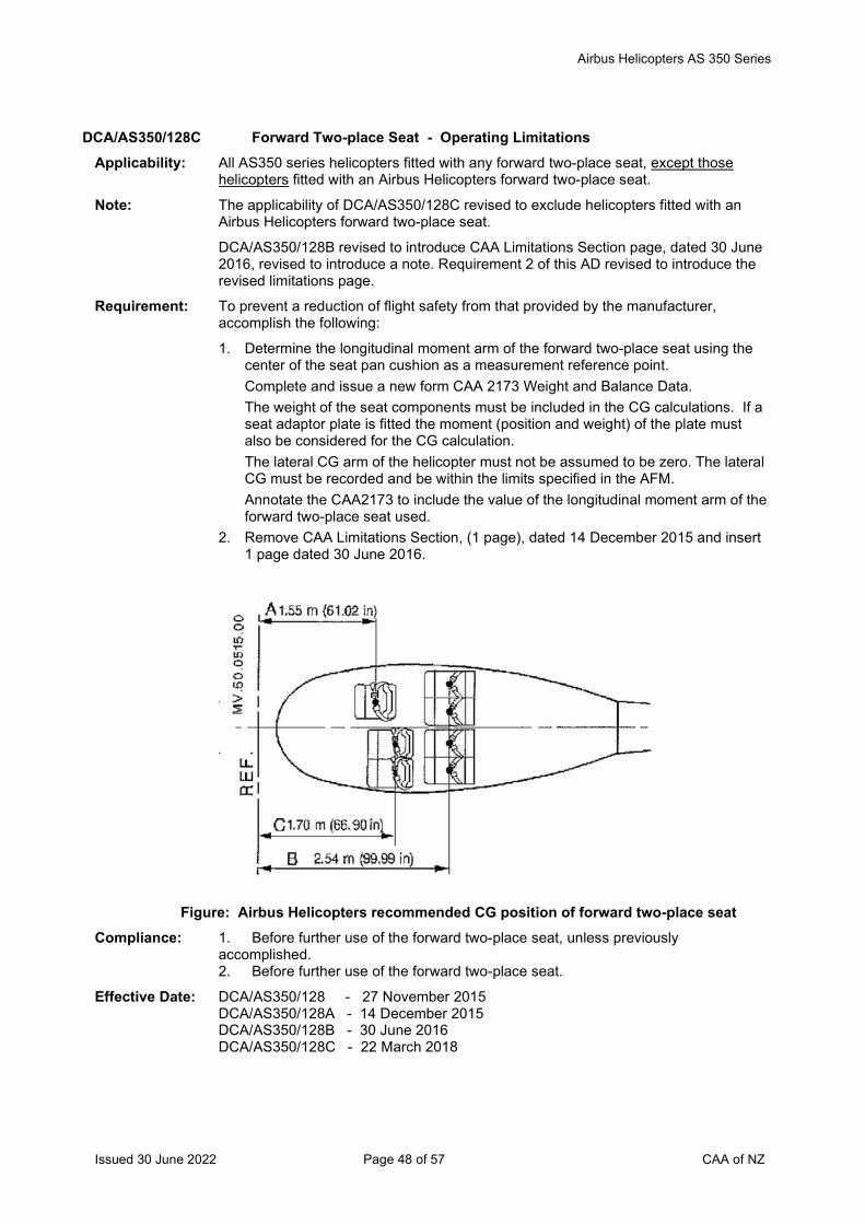
Airbus Helicopters AS 350 Series
Issued 30 June 2022 Page 48 of 57 CAA of NZ
DCA/AS350/128C Forward Two-place Seat - Operating Limitations Applicability: All AS350 series helicopters fitted with any forward two-place seat, except those
helicopters fitted with an Airbus Helicopters forward two-place seat.
Note: The applicability of DCA/AS350/128C revised to exclude helicopters fitted with an Airbus Helicopters forward two-place seat.
DCA/AS350/128B revised to introduce CAA Limitations Section page, dated 30 June 2016, revised to introduce a note. Requirement 2 of this AD revised to introduce the revised limitations page.
Requirement: To prevent a reduction of flight safety from that provided by the manufacturer, accomplish the following:
1. Determine the longitudinal moment arm of the forward two-place seat using the center of the seat pan cushion as a measurement reference point. Complete and issue a new form CAA 2173 Weight and Balance Data. The weight of the seat components must be included in the CG calculations. If a seat adaptor plate is fitted the moment (position and weight) of the plate must also be considered for the CG calculation. The lateral CG arm of the helicopter must not be assumed to be zero. The lateral CG must be recorded and be within the limits specified in the AFM. Annotate the CAA2173 to include the value of the longitudinal moment arm of the forward two-place seat used.
2. Remove CAA Limitations Section, (1 page), dated 14 December 2015 and insert 1 page dated 30 June 2016.
Figure: Airbus Helicopters recommended CG position of forward two-place seat
Compliance: 1. Before further use of the forward two-place seat, unless previously accomplished. 2. Before further use of the forward two-place seat.
Effective Date: DCA/AS350/128 - 27 November 2015 DCA/AS350/128A - 14 December 2015 DCA/AS350/128B - 30 June 2016 DCA/AS350/128C - 22 March 2018
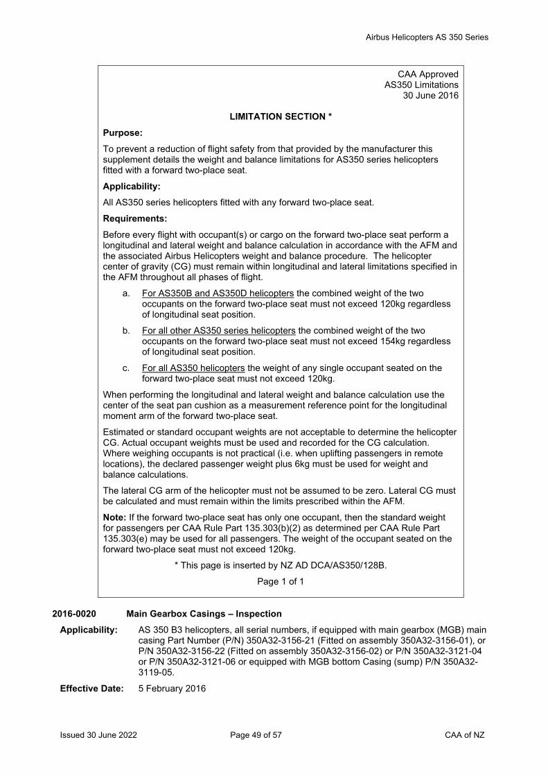
Airbus Helicopters AS 350 Series
Issued 30 June 2022 Page 49 of 57 CAA of NZ
CAA Approved AS350 Limitations
30 June 2016
LIMITATION SECTION * Purpose: To prevent a reduction of flight safety from that provided by the manufacturer this supplement details the weight and balance limitations for AS350 series helicopters fitted with a forward two-place seat.
Applicability: All AS350 series helicopters fitted with any forward two-place seat.
Requirements: Before every flight with occupant(s) or cargo on the forward two-place seat perform a longitudinal and lateral weight and balance calculation in accordance with the AFM and the associated Airbus Helicopters weight and balance procedure. The helicopter center of gravity (CG) must remain within longitudinal and lateral limitations specified in the AFM throughout all phases of flight.
a. For AS350B and AS350D helicopters the combined weight of the two occupants on the forward two-place seat must not exceed 120kg regardless of longitudinal seat position.
b. For all other AS350 series helicopters the combined weight of the two occupants on the forward two-place seat must not exceed 154kg regardless of longitudinal seat position.
c. For all AS350 helicopters the weight of any single occupant seated on the forward two-place seat must not exceed 120kg.
When performing the longitudinal and lateral weight and balance calculation use the center of the seat pan cushion as a measurement reference point for the longitudinal moment arm of the forward two-place seat.
Estimated or standard occupant weights are not acceptable to determine the helicopter CG. Actual occupant weights must be used and recorded for the CG calculation. Where weighing occupants is not practical (i.e. when uplifting passengers in remote locations), the declared passenger weight plus 6kg must be used for weight and balance calculations.
The lateral CG arm of the helicopter must not be assumed to be zero. Lateral CG must be calculated and must remain within the limits prescribed within the AFM.
Note: If the forward two-place seat has only one occupant, then the standard weight for passengers per CAA Rule Part 135.303(b)(2) as determined per CAA Rule Part 135.303(e) may be used for all passengers. The weight of the occupant seated on the forward two-place seat must not exceed 120kg.
* This page is inserted by NZ AD DCA/AS350/128B.
Page 1 of 1
2016-0020 Main Gearbox Casings – Inspection
Applicability: AS 350 B3 helicopters, all serial numbers, if equipped with main gearbox (MGB) main casing Part Number (P/N) 350A32-3156-21 (Fitted on assembly 350A32-3156-01), or P/N 350A32-3156-22 (Fitted on assembly 350A32-3156-02) or P/N 350A32-3121-04 or P/N 350A32-3121-06 or equipped with MGB bottom Casing (sump) P/N 350A32-3119-05.
Effective Date: 5 February 2016
Airbus Helicopters AS 350 Series
Issued 30 June 2022 Page 50 of 57 CAA of NZ
2016-0021 Main Gearbox Bottom Casing – Inspection Applicability: AS 350 B1, B2 and AS 355 E, F, F1, F2, N helicopters, all serial numbers, if equipped
with main gearbox (MGB) bottom Casing (sump) P/N 350A32-3119-03 or P/N 350A32-3119-05.
Effective Date: 5 February 2016
2016-0220 Dual Hydraulic System – Inspection Applicability: AS 350 B3 helicopters, all serial numbers, if equipped with a dual hydraulic system,
except those that embody Airbus Helicopters modification (mod) 074719 and mod 074622.
Effective Date: 18 November 2016
2016-0260 Main Rotor NR Indicator – Inspection Applicability: AS 350 B2 helicopters, all serial numbers, if equipped with NR sensor Part Number
704A37614007, except helicopters modified in accordance with AH modification 350A084886.00.
Effective Date: 3 January 2017
2017-0020R1 Tail Rotor Pitch Rod – Inspection Applicability: AS 350 B, AS 350 BA, AS 350 BB, AS 350 B1, AS 350 B2 and AS 350 B3
helicopters, all S/N embodied with modification (mod) 075601 or mod 076602.
Note 1: EASA AD 2017-0020R1 is revised to include requirements for reverting to the original ALS interval for affected pitch rods. Some editorial changes have also been made which does not affect the technical content of the AD.
Note 2: The repetitive inspection requirement per paragraph (1) of EASA AD 2017-0020R1 may be accomplished by adding the inspection to the tech log. The inspection may be performed and certified under the provision in Part 43 Appendix A.1 (7) by the holder of a current pilot license, if that person is rated on the aircraft, appropriately trained and authorized, and the training/authorization is appropriately documented (Part 43, Subpart B refers), and the maintenance is recorded and certified as required by Part 43.
If any damage is found in one or more layers of the elastomer with a circumference of more than 90 degrees as detailed in the instructions of the applicable ASB, then an engineer must replace the affected tail rotor pitch change rod with a serviceable part, before further flight.
Effective Date: EASA AD 2017-0020-E - 9 February 2017 EASA AD 2017-0020R1 - 30 May 2019
2011-0164R3 Tail Rotor Control Stop Screws – Inspection Applicability: AS 350 B, AS 350 BA, AS 350 BB, AS 350 B1, AS 350 B2, AS 350 B3 and AS 350 D
helicopters, all S/N fitted with an Autopilot (AP), and AS350 B3 helicopters, all S/N, without an AP installed, but embodied with modification (mod) 073252; except helicopters that have mod 074819 embodied.
Effective Date: EASA AD 2011-0164R1 - 28 February 2017 EASA AD 2011-0164R2 - 28 September 2017 EASA AD 2011-0164R3 - 30 April 2020
Airbus Helicopters AS 350 Series
Issued 30 June 2022 Page 51 of 57 CAA of NZ
2017-0032 Cancelled by EASA on 11 August 2021 Effective Date: 11 August 2021
2017-0035 Twist Grip Assembly – Inspection Applicability: AS 350 B3 helicopters, all serial numbers, if equipped with ARRIEL 2B engines.
Effective Date: 6 March 2017
2017-0052 Cancelled – EASA AD 2017-0059 refers Effective Date: 13 April 2017
2017-0059 Switches 53Ka, 53Kb and 65K – Inspection Applicability: AS 350 B3 helicopters, all serial numbers, if equipped with a Turbomeca ARRIEL 2B1
engine incorporating the two-channel FADEC (modification (MOD) 073254) and embodying MOD 073261 (new twist grip), or if equipped with a Turbomeca ARRIEL 2D engine (MOD 074302).
Effective Date: 13 April 2017
2017-0089R1 Main Rotor Mast Upper Bearing - Inspection Applicability: AS 350 B, AS 350 BA, AS 350 BB, AS 350 B1, AS 350 B2, AS 350 B3 and AS 350 D
helicopters, all S/N.
Note: This AD revised to introduce an amended OEM ASB to clarify affected parts identification.
Effective Date: EASA AD 2017-0089 - 31 May 2017 EASA AD 2017-0089R1 - 30 June 2020
2017-0109 (Correction) Starter Generator and Brushes - Inspection Applicability: AS 350 B, AS 350 B1, AS 350 BA and AS 350 BB helicopters, all S/N except those
helicopters fitted with a Vehicle and Engine Management Display (VEMD) System.
AS 350 B2 helicopters, all S/N
AS 350 B3 helicopters, all S/N, fitted with an ARRIEL 2B engine.
Effective Date: 7 July 2017
2017-0114 Cancelled - EASA AD 2020-0186 refers Effective Date: 3 September 2020
2017-0143 Direct Current (Optional) Second Battery – Replacement Applicability: AS 350 B, AS 350 B1, AS 350 B2, AS 350 B3, AS 350 BA, AS 350 BB and AS 350 D
helicopters fitted with a Very Cold Weather Starting Installation (a second battery), except those helicopters embodied with modification 074838 at manufacture.
Effective Date: 31 August 2017
Transport Canada AD CF-2017-37 Restriction of Directional Control Pedal Movement Applicability: Litter kits P/N 350-200034 or P/N 350-200194 (LH litter kits), or P/N 350-200144 (RH
litter kit).
These kits could be found installed on Airbus Helicopter models AS 350 B, AS 350 BA, AS 350 B1, AS 350 B2, AS 350 B3, AS 350 D, AS 355 E, AS 355 F, AS 355 F1, AS 355 F2, AS 355 N and AS 355 NP as listed in Tables 1 and 2 of TC AD CF-2017-37.
Effective Date: 19 January 2018
Airbus Helicopters AS 350 Series
Issued 30 June 2022 Page 52 of 57 CAA of NZ
DCA/AS350/129A Cargo Swing Modification OAL114 – Inspection Applicability: All AS350 series helicopters embodied with Oceania Aviation Limited (OAL) cargo
swing modification OAL114. Note: DCA/AS350/129A introduces a revised AFM Supplement and a revised ICA for cargo
swing modification OAL114. Requirement: To prevent failure of the cargo swing due to possible fatigue cracks in the gimbal /
universal joint assembly, which could result in loss of the load, accomplish the following: 1. Revise the AFM and insert OAL AFM Supplement MB 25.00.149, revision 2,
dated 30 July 2018, or later approved revision, into the helicopter AFM. Introduce OAL ICA MB 25.00.149 revision 3, dated 19 October 2018, or later approved revision, into the helicopter maintenance programme. Determine that a placard is fitted on the cargo swing frame, per OAL AFM Supplement MB 25.00.149 revision 1, or later approved revision, unless previously accomplished.
2. Dye penetrant inspect the Gimbal / Universal Joint Assembly P/N OAL114-10500 and P/N OAL114-10504, per the instructions in OAL ICA MB 25.00.149 revision 1, 2 or 3, or later approved revision. Replace defective parts before next hook operation.
Compliance: 1. By 25 November 2018. 2. For bucket operations:
Before the next hook operation (i.e. both agricultural and firefighting operations), unless previously accomplished.
For non-bucket operations: By 25 November 2018, unless previously accomplished.
Effective Date: DCA/AS350/129 - 28 June 2018 DCA/AS350/129A - 25 October 2018
2018-0152 Main Gearbox Bracket Bolts - Inspection Applicability: AS 350 B, AS 350 D, AS 350 B1, AS 350 B2, AS 350 BA, AS 350 BB and AS 350 B3
helicopters, all S/N. Effective Date: 1 August 2018
2018-0206 Mast Upper Bearing Sealant Bead/Inner Race Retaining Rings - Inspection Applicability: AS 350 B, AS 350 BA, AS 350 BB, AS 350 B1, AS 350 B2, AS 350 B3 and AS 350 D
helicopters, all S/N. Effective Date: 4 October 2018
FAA AD 2018-18-12 Cancelled – FAA AD 2019-16-16 refers Effective Date: 26 September 2019
FAA AD 2018-25-17 Air Comm Corp Air Conditioning System – Inspection Applicability: AS350B, AS350B1, AS350B2, AS350B3, AS350BA, AS350C, AS350D and AS350D1
helicopters fitted with an Air Comm air conditioning system P/N AS350-202-1, AS350-202-2, AS350-202-3, AS350-202-4, AS350-202-5, AS350-204-1, AS350-204- 2, AS350-204-3, AS350-204-4, AS350-204-5, AS350-204-6, AS350-204-7, AS350-204-8, AS350- 204-9, AS350-204-10, AS350-204-11 or AS350-204-12.
Effective Date: 22 January 2019 2018-0287 Cancelled – EASA AD 2019-0060 refers
Effective Date: 3 April 2019
Airbus Helicopters AS 350 Series
Issued 30 June 2022 Page 53 of 57 CAA of NZ
DCA/AS350/130 HETS STC 11/21E/34 – Removal from Service Applicability: All AS350 series helicopters embodied with Aero Design Limited Human External
Transport System (HETS) STC 11/21E/34. Requirement: To prevent a reduction of the level of occupant safety from that provided by Transport
Canada STC SH98-35, due to mismatched instructions for continuing airworthiness, accomplish the following: 1. Remove Aero Design Limited HETS STC 11/21E/34 from service. 2. Remove the Flight Manual Supplement (FMS) associated with HETS STC
11/21E/34 from the helicopter AFM. 3. Remove the Instructions for Continued Airworthiness (ICA) associated with HETS
STC 11/21E/34 from the helicopter maintenance programme. Note 1: The equipment approved under revoked HETS STC 11/21E/34 is the same as
Transport Canada STC SH98-35. Under the provisions of CAR 21.503(a) the Director has accepted Transport Canada STC SH98-35. Refer to the List of Technical Data accepted by the Director under the provisions of CAR 21.503(a) available on the CAA website.
Note 2: In accordance with Rule 21, Appendix D(b)(3) the installer of a foreign STC requires the written permission of the STC holder to install their STC and use the FMS/ICA associated with the STC.
Compliance: By 31 March 2019 Effective Date: 31 January 2019
Transport Canada CF-2019-01 Helicopter External Transport System (HETS) STC SH98-35 Applicability: HETS™ certified under Transport Canada Supplemental Type Certificate (STC)
SH98-35, Issue 1 and Issue 2 installed on the following helicopter models: Airbus Helicopters (formerly Eurocopter France) model AS 350 B, AS 350 B1, AS 350 B2, AS 350 B3, AS 350 BA and AS 350 D. Airbus Helicopters (formerly Eurocopter France) model AS 355 E, AS 355 F, AS 355 F1 and AS 355 F2. MD Helicopter Inc. model 369, 369A, 369H, 369HM, 369HS, 369HE, 369D, 369E, 369F, 369FF and 500N. Bell Helicopter Textron Canada Ltd. model 206B, 206L, 206L-1, 206L-3, 206L-4 and 407.
Note: HETS™ approved under SH98-35 are only eligible for installation on helicopter models listed above and they are not eligible for any other models not specifically listed above (Example: not eligible for installation on AS 355 N or AS 355 NP).
Effective Date: 22 January 2019 2019-0060 Tail Rotor Gearbox Actuating Rod – Inspection
Applicability: AS 350 B, AS 350 BA, AS 350 BB, AS 350 B1, AS 350 B2, AS 350 B3 and AS 350 D helicopters, all S/N.
Effective Date: 3 April 2019 DGAC AD 2001-557-086R3 Starflex Star – Inspection
Applicability: AS 350 B, AS 350 BA, AS 350 BB, AS 350 B1, AS 350 B2, AS 350 B3 and AS 350 D helicopters, all S/N fitted with a Starflex star P/N 350A31.1916.00 mounted on a main rotor hub not embodied with Mod 076221.
Note 1: DGAC AD 2001-557-086R3 supersedes DCA/AS350/61A, which mandated DGAC AD 2001-557-086R2.
Note 2: The inspection per mandatory action 3.1 in DGAC AD 2001-557-086R3, which is required after every flight when the rotors are stopped, may be accomplished by adding the inspection requirement to the tech log. The visual inspection may be performed and certified under the provision in Part 43 Appendix A.1 (7) by the holder of a current pilot licence, if that person is rated on the aircraft, appropriately trained and authorised (Part 43, Subpart B refers), and the maintenance is recorded and certified as required by Part 43.
Effective Date: 27 June 2019
Airbus Helicopters AS 350 Series
Issued 30 June 2022 Page 54 of 57 CAA of NZ
2019-0184 Main Rotor Servo Actuators – Inspection
Applicability: AS 350 B3 helicopters, all S/N fitted with a dual hydraulic system OP 3346 or OP 3082.
Effective Date: 29 August 2019
FAA AD 2019-16-16 Inlet Barrier Filter – Inspection Applicability: AS350B, AS350B1, AS350B2, AS350B3, and AS350BA helicopters fitted with a Pall
Aerospace Inlet Barrier Filter (IBF) element P/N CE01301F2, CE01301F2B, CE01303F2, or CE01303F2B.
Effective Date: 26 September 2019
2019-0225-E MGB Drive Shaft / Engine Coupling – Inspection Applicability: AS 350 B3 helicopters, all S/N fitted with a SAFRAN Helicopter Engines (SAFRAN)
ARRIEL 2D engine, having accumulated (on the effective date of this AD) less than 300 hours TIS since first flight.
Effective Date: 13 September 2019
2019-0228 Electric Hoist Installation – Inspection Applicability: AS 350 B, AS 350 BA, AS 350 BB, AS 350 B1, AS 350 B2, AS 350 B3 and AS 350 D
helicopters, all S/N. Effective Date: 26 September 2019
2019-0280 Spherical Bearing – Inspection Applicability: AS 350 BB helicopters, all S/N. Note: The initial inspection of the spherical bearing elastomer per the AD requirements
must be accomplished by an aircraft maintenance engineer. The repetitive inspection per mandatory action (1) in EASA AD 2019-0280, may be accomplished by adding the inspection requirement to the helicopter tech log. The visual inspection may be performed and certified under the provision in Part 43 Appendix A.1 (7) by the holder of a current pilot licence, if that person is rated on the aircraft, appropriately trained and authorised (Part 43, Subpart B refers), and the maintenance is recorded and certified as required by Part 43. If any defects are found, then an aircraft maintenance engineer must inspect the spherical bearing elastomer and accomplish the corrective actions per EASA AD 2019-0280, before further flight.
Effective Date: 3 December 2019 FAA AD 2020-02-23 Emergency Float System STC SR00470LA – Inspection
Applicability: AS350B, AS350BA, AS350B1, AS350B2, AS350B3, AS350C, AS350D, and AS350D1 helicopters embodied with STC SR00470LA.
Effective Date: 28 February 2020 DCA/AS350/131 Dual Front Seat Modification MB 25.20.05 - Inspection
Applicability: AS350 series helicopters embodied with Ntech Dual Front Seat Modification MB 25.20.05 revisions 0, 1, 2 or 3 before 27 February 2020.
Requirements: To ensure that the helicopter weight and balance limitations are not exceeded throughout the flight and to ensure the airworthiness of the dual front seat installation, accomplish the following: Amend the aircraft flight manual (AFM) and introduce Ntech Dual Front Seat Flight Manual Supplement FMS 25.20.05 revision 4, dated 14 February 2020, or later approved revision, into the AFM. Amend the aircraft maintenance programme and introduce Ntech Dual Front Seat Instructions for Continued Airworthiness ICA MB 25.20.05 revision 1, dated 14 February 2020, or later approved revision, into the aircraft maintenance programme.
Accomplish an inspection of the dual front seat installation per the instructions in ICA MB 25.20.05, unless previously accomplished within the last 1200 hours TIS, or 1200 cycles, or 48 months, whichever is the sooner since installation of modification MB 25.20.05 on the aircraft. Install a placard per FMS 25.20.05 on the left side of the
Airbus Helicopters AS 350 Series
Issued 30 June 2022 Page 55 of 57 CAA of NZ
dual front seat installation in clear view of boarding passengers and flight crew, unless previously accomplished.
Note: FMS 25.20.05 revision 4, dated 14 February 2020, or later CAA approved revision and ICA MB 25.20.05 revision 1, dated 14 February 2020, or later approved revision can be obtained from: NTech Limited Ardmore Airport
PDC 14, Papakura, Auckland 2244 Tel: +64 9 296 1950 Fax: +64 9 296 1952 Email: [email protected] Compliance: At the next maintenance inspection, or the next review of airworthiness, or the next
annual inspection, whichever occurs first. Effective Date: 27 February 2020
2020-0064 Emergency Flotation System – Inspection Applicability: AS 350 B, AS 350 B1, AS 350 B2, AS 350 BA, AS 350 BB, AS 350 B3, AS 350 D
helicopters, all S/N.
Effective Date: 2 April 2020
2020-0175 Cancelled by EASA on 13 September 2021 Effective Date: 30 September 2021
2020-0186 Cancelled – EASA AD 2021-0099 refers Effective Date: 29 April 2021
2020-0217-E Cancelled – EASA AD 2021-0023 refers Effective Date: 2 February 2021
2020-0224R1 Tail Rotor Blades – Inspection Applicability: AS 350 B, AS 350 BA, AS 350 BB, AS 350 B1, AS350 B2 and AS 350 D helicopters,
all S/N.
Note 1: Initial tail rotor blade leading edge protection shield inspection: An initial inspection per requirements (1) and (2) of EASA AD 2020-0224 original issue, or revision 1, must be accomplished by an aircraft maintenance engineer.
Note 2: The visual inspection before every flight per requirement (1) of EASA AD 2020-0224R1, may be accomplished by adding the inspection requirement to the helicopter tech log. The visual inspection may be performed and certified under the provision in Part 43 Appendix A.1 (7) by the holder of a current pilot licence, if that person is rated on the aircraft, appropriately trained and authorised (Part 43, Subpart B refers), and the maintenance is recorded and certified as required by Part 43.
If any defects are found in the tail rotor blades during the repetitive visual inspections, then an aircraft maintenance engineer must inspect the tail rotor hub body and accomplish the corrective actions per EASA AD 2020-0224R1, before further flight.
Effective Date: EASA AD 2020-0224-E - 20 October 2020 EASA AD 2020-0224R1 - 26 November 2020
2021-0023 Cyclic Stick Grip UP / Down Hoist Control Switch – Modification Applicability: AS 350 B, AS 350 BA, AS 350 B1, AS 350 B2 and AS 350 D helicopters, all S/N,
except those helicopters embodied with Airbus Helicopters modification MC20096.
Effective Date: 2 February 2021
Airbus Helicopters AS 350 Series
Issued 30 June 2022 Page 56 of 57 CAA of NZ
2021-0048 Main Rotor Pitch Rod Upper Links – Inspection Applicability: AS 350 B, AS 350 BA, AS 350 BB, AS 350 B1, AS 350 B2, AS 350 B3 and AS 350 D
helicopters, all S/N.
Note: The repetitive visual inspections required at intervals not to exceed 10 hours TIS per requirement (2) of EASA AD 2021-0048 may be accomplished by adding the inspection requirement to the helicopter tech log. The visual inspection may be performed and certified under the provision in Part 43 Appendix A.1 (7) by the holder of a current pilot licence, if that person is rated on the aircraft, appropriately trained and authorised (Part 43, Subpart B refers), and the maintenance is recorded and certified as required by Part 43.
If the markings on one, or both sides of a main rotor pitch rod upper link are found misaligned during the repetitive visual inspections, then an aircraft maintenance engineer must accomplish the corrective actions per requirement (3) of EASA AD 2021-0048 before further flight.
Effective Date: 2 March 2021
2021-0099 Vertical Fin – Inspection Applicability: AS 350 B3 helicopters, all S/N, except those helicopters embodied with modification
(MOD) 073148 at manufacture.
Effective Date: 29 April 2021
2021-0123-E Tail Rotor Load Compensator – Inspection Applicability: AS 350 B, AS 350 B2, AS 350 B3 and AS 350 BA helicopters, S/N 1241, 1525, 1601,
1708, 1825, 1910, 1973, 2056, 2072, 2361, 2394, 3170, 3223, 3479, 3789, 9005, 9010 and 9035.
Effective Date: 11 May 2021
2021-0168 Indicating / Recording Systems Control Unit – Inspection Applicability: AS 350 B2 and AS 350 B3 helicopters, all S/N embodied with MOD 073273 at
production, except those helicopters that also have MOD 074280 embodied in production.
Effective Date: 30 July 2021
2021-0194R1 Airworthiness Limitations Applicability: AS 350 B, AS 350 BA, AS 350 BB, AS 350 B1, AS 350 B2, AS 350 B3 and AS 350 D
helicopters, all S/N.
Effective Date: EASA AD 2021-0194 - 3 September 2021 EASA AD 2021-0194R1 – 28 October 2021
2021-0195 Engine Digital ECU Emergency Procedure – AFM Amendment Applicability: AS 350 B3 helicopters, all S/N fitted with an ARRIEL 2D engine.
Effective Date: 3 September 2021
Airbus Helicopters AS 350 Series
Issued 30 June 2022 Page 57 of 57 CAA of NZ
2021-0282 Tail Rotor Head Pitch Change Unit Bearing Spacer - Inspection Applicability: AS 350 B, AS 350 BA, AS 350 BB, AS 350 B1, AS 350 B2, AS 350 B3 and AS 350 D
helicopters, all S/N.
Note: The initial inspection and the black paint index marking per requirement (1) of EASA AD 2021-0282 must be accomplished by an aircraft maintenance engineer.
The 10 hour repetitive inspections per requirement (4) of EASA AD 2021-0282 may be accomplished by adding the inspection requirement to the helicopter tech log. The visual inspection may be performed and certified under the provision in Part 43 Appendix A.1 (7) by the holder of a current pilot licence, if that person is rated on the aircraft, appropriately trained and authorised (Part 43, Subpart B refers), and the maintenance is recorded and certified as required by Part 43.
If during the repetitive inspections the black paint index marking is found misaligned, then an aircraft maintenance engineer must inspect the aircraft and accomplish the corrective actions per EASA AD 2021-0282 before further flight.
Effective Date: 31 December 2021
* 2022-0051 (Correction) Rear Structure Junction Frame Reinforcement Angles - Inspection Applicability: AS 350 B, BA, BB, B1, B2, B3 and D helicopters, all S/N fitted with an affected part as
defined in EASA AD 2022-0051, except helicopters embodied with Airbus Helicopters (AH) modification (MOD) 073232 in production, or helicopters embodied with AH AS350 Service Bulletin (SB) No. 53.00.58 in service.
Note: EASA AD 2022-0051 retains the requirements in superseded EASA AD 2014-0076R3, and requires repetitive inspections for additional helicopters. EASA AD 2022-0051 (Correction) is re-issued to correct typos in the referenced AD numbers in the Reason section of the AD.
Effective Date: EASA AD 2022-0051 - 5 April 2022 EASA AD 2022-0051 (Correction) - 30 June 2022
2022-0077-E Flight Control Flexball Cables - Replacement Applicability: AS 350 B, AS 350 B1, AS 350 B2, AS 350 B3, AS 350 BA, AS 350 BB and AS 350 D
helicopters, all S/N.
Effective Date: 2 May 2022
Issued 30 June 2022 Page 1 of 46 CAA of NZ
Airworthiness Directive Schedule Helicopters Airbus Helicopters AS 355 Series 30 June 2022
Notes: 1. This AD schedule is applicable to Airbus Helicopters AS 355 series (previously Eurocopter, Eurocopter France and Aerospatiale) manufactured under Type Certificate Numbers:
Aircraft Model: Type Certificate Number: AS 355 F1 EASA R.146 (formerly DGAC 168) AS 355 F2 EASA R.146 (formerly DGAC 168) AS 355 N EASA R.146 (formerly DGAC 168) AS 355 NP EASA R.146 (formerly DGAC 168)
2. The European Union Aviation Safety Agency (EASA) is the National Airworthiness Authority (NAA) responsible for the issue of State of Design Airworthiness Directives (ADs) for these helicopters. State of Design ADs can be obtained directly from the EASA website at http://ad.easa.europa.eu/
Links to other NAA websites are available on the CAA website at https://www.aviation.govt.nz/aircraft/airworthiness/airworthiness-directives/links-to-state-of-design-airworthiness-directives/
3. The date above indicates the amendment date of this schedule.
4. New or amended ADs are shown with an asterisk *
Contents
DCA/AS355/1 Fatigue Critical Components - Retirement ........................................................................ 5 DCA/AS355/2 Tail Rotor Blades - Inspection ........................................................................................... 5 DCA/AS355/3C Cancelled – EASA AD 2015-0195 refers .......................................................................... 5 DCA/AS355/4 Upper Fin Attachment - Inspection .................................................................................... 5 DCA/AS355/5 Main Gear Box Filter - Inspection ...................................................................................... 5 DCA/AS355/6 Horizontal Stabilizer - Inspection ....................................................................................... 5 DCA/AS355/7 Main Gear Box, Epicyclic Gear Cages - Retirement ......................................................... 6 DCA/AS355/8D Tail Rotor Blades – Inspection .......................................................................................... 6 DCA/AS355/9 Main Gear Box, Bevel Ring Gear Assembly - Inspection .................................................. 6 DCA/AS355/10 Main Rotor Mast - Inspection ............................................................................................ 7 DCA/AS355/11 Raised Skid Landing Gear - Modification .......................................................................... 7 DCA/AS355/12C Main Rotor Head, Main Gear Box and Landing Gear – Inspection ................................... 7 DCA/AS355/13 Hydraulic System - Modification ........................................................................................ 8 DCA/AS355/14 MGB Suspension Bars - Inspection .................................................................................. 8 DCA/AS355/15 Main Rotor Sleeve Beams - Inspection ............................................................................. 8 DCA/AS355/16 Sliding Doors - Modification .............................................................................................. 8 DCA/AS355/17B Main Rotor, Rotating Swash Plate - Inspection ................................................................. 9 DCA/AS355/18 MGB Oil Cooler Fan Assembly - Inspection ...................................................................... 9 DCA/AS355/19 Tail Rotor Pitch Control Lever Expansion Pin - Inspection ................................................ 9 DCA/AS355/20 Emergency Location Transmitter (ELT) Antenna - Modification ........................................ 9 DCA/AS355/21A Pitch Change Lever Bushes - Inspection ........................................................................ 10 DCA/AS355/22 Main Rotor Mast Assembly - Inspection .......................................................................... 10 DCA/AS355/23A Sliding Windows - Inspection .......................................................................................... 10 DCA/AS355/24 Main and Tail Rotor Servo Controls - Inspection ............................................................. 10 DCA/AS355/25 MGB Oil Pressure Switch - Removal .............................................................................. 11 DCA/AS355/26 Cyclic Pitch Change Control Rod - Inspection ................................................................ 11 DCA/AS355/27A Main Rotor Shaft Oil Jet – Inspection .............................................................................. 11
Issued 30 June 2022 Page 2 of 46 CAA of NZ
DCA/AS355/28 MGB Suspension Bi-directional Cross Beam - Inspection .............................................. 12 DCA/AS355/29 Tail Boom Attachment Screws - Replacement ................................................................ 12 DCA/AS355/30B Tail Rotor Hub Pitch Change Plate Bearings - Inspection ............................................... 13 DCA/AS355/31 Flight Manual - Revision .................................................................................................. 13 DCA/AS355/32 Single Pole Circuit Breakers – Inspection ....................................................................... 14 DCA/AS355/33 Cancelled – EASA AD F-2000-223-059R1 refers ........................................................... 14 DCA/AS355/34 Ferry Fuel Tanks - Electrical Bonding ............................................................................. 14 DCA/AS355/35B Use of the Landing Light – AFM Revision ....................................................................... 15 DCA/AS355/36 Tail Rotor Hub Pitch Change Plate Bearings - Replacement .......................................... 15 DCA/AS355/37 Cancelled – DCA/AS355/83 refers .................................................................................. 16 DCA/AS355/38A Starflex Bush – Inspection .............................................................................................. 16 DCA/AS355/39 Cancelled - DCA/AS355/48 refers................................................................................... 16 DCA/AS355/40 Cancelled - DCA/AS355/67 refers................................................................................... 16 DCA/AS355/41 HSI - Inspection .............................................................................................................. 16 DCA/AS355/42 Hawker Pacific TRW-SAMM Main Servocontrols - Replacement ................................... 17 DCA/AS355/43 Tail Servocontrol – Locking of Eye End Fitting ................................................................ 17 DCA/AS355/44A Cancelled – DCA/AS355/60 refers .................................................................................. 17 DCA/AS355/45 Cancelled – EASA AD 2019-0228 refers ........................................................................ 17 DCA/AS355/46 Cyclic Friction Cup - Inspection ....................................................................................... 18 DCA/AS355/47 Dynamic Components – Life Correction .......................................................................... 18 DCA/AS355/48 TRW-SAMM Servo Controls - Replacement ................................................................... 19 DCA/AS355/49A Flight Control Stops – Inspection .................................................................................... 20 DCA/AS355/50B Newly Overhauled or Repaired Main Gearboxes - Removal from Service ...................... 20 DCA/AS355/51 Rear Fuselage - Inspection ............................................................................................. 20 DCA/AS355/52A Cancelled – DCA/AS355/65 refers .................................................................................. 21 DCA/AS355/53 Hydraulic System Cut-off - Modification ........................................................................ 21 DCA/AS355/54 Cancelled - DCA/AS355/70 refers................................................................................... 21 DCA/AS355/55 Tail Rotor Blade Trailing Edge Tab – Inspection ............................................................. 21 DCA/AS355/56B Cancelled - DCA/AS355/71 refers................................................................................... 22 DCA/AS355/57 Cancelled – DCA/AS355/66 refers .................................................................................. 22 DCA/AS355/58 Cancelled - DCA/AS355/68 refers................................................................................... 22 DCA/AS355/59 Breeze Eastern 450-lb Electric Hoist - Inspection ........................................................... 22 DCA/AS355/60 Cancelled – DCA/AS355/73 refers .................................................................................. 22 DCA/AS355/61 Main Servo Controls – Inspection ................................................................................... 22 DCA/AS355/62 Cancelled – DCA/AS355/63 refers .................................................................................. 23 DCA/AS355/63 Cancelled – DCA/AS355/84 refers .................................................................................. 23 DCA/AS355/64A Cancelled – DCA/AS355/84 refers .................................................................................. 23 DCA/AS355/65 Tail Rotor Control Cable - Replacement ......................................................................... 23 DCA/AS355/66 Tail Rotor Drive Shaft – Inspection.................................................................................. 24 DCA/AS355/67 Cancelled - DCA/AS355/77 refers................................................................................... 24 DCA/AS355/68B Cancelled – DCA/AS355/81 refers .................................................................................. 24 DCA/AS355/69 Cancelled – DCA/AS355/96 refers .................................................................................. 24 DCA/AS355/70 Sliding Door Rollers and Rails – Inspection .................................................................... 24 DCA/AS355/71 RH Cabin Vibration Damper and Blade Assy – Inspection .............................................. 25 DCA/AS355/72 Starter Generator – Load Limitation ................................................................................ 25 DCA/AS355/73 Cancelled – DCA/AS355/80 refers .................................................................................. 25 DCA/AS355/74 Main & Tail Rotor Servo Controls – Inspection ............................................................... 26 DCA/AS355/75 Engine Automatic Relighting System – Installation ......................................................... 26 DCA/AS355/76 Load Compensator Lever – Inspection ........................................................................... 27 DCA/AS355/77A Cancelled – DCA/AS355/86 refers .................................................................................. 27 DCA/AS355/78 Cabin Floor Cross Member – Inspection ......................................................................... 27 DCA/AS355/79 Main & Tail Rotor Servo Controls – Inspection ............................................................... 28 DCA/AS355/80 Cancelled – EASA AD 2007-0209R1 refers .................................................................... 29 DCA/AS355/81 Sliding Door Rear Fitting and Support Shaft – Inspection ............................................... 29
Issued 30 June 2022 Page 3 of 46 CAA of NZ
DCA/AS355/82 Collective Lever Recess - Modification ........................................................................... 29 DCA/AS355/83 Rear Bench Seat Cushions – Removal ........................................................................... 30 DCA/AS355/84 Cancelled – DCA/AS355/85 refers .................................................................................. 30 DCA/AS355/85 Fin Attach Fittings – Inspection ....................................................................................... 30 DCA/AS355/86 Tail Rotor Blade Skin – Inspection .................................................................................. 31 DCA/AS355/87 Cancelled – EASA AD 2010-0006 refers ........................................................................ 32 DCA/AS355/88A Engine and MGB Cowling Locking – Modification ........................................................... 32 DCA/AS355/89 Cancelled – DCA/AS355/90 refers .................................................................................. 33 DCA/AS355/90 Tail Gearbox Control Lever – Inspection ......................................................................... 33 DCA/AS355/91 EASA AD 2011-0072 Cancelled by EASA on 4 March 2022 .......................................... 34 DCA/AS355/92 Tail Gearbox Casing Assembly – Inspection ................................................................... 34 DCA/AS355/93 Cancelled – EASA AD 2011-0164R1 .............................................................................. 34 DCA/AS355/94 Cancelled – EASA AD 2015-0181 refers ........................................................................ 35 DCA/AS355/95 Cancelled – EASA AD 2013-0281 refers ........................................................................ 35 DCA/AS355/96 Starter Generator – Inspection ........................................................................................ 35 The State of Design ADs listed below are available directly from the National Airworthiness Authority (NAA) websites. Links to NAA websites are available on the CAA website at https://www.aviation.govt.nz/aircraft/airworthiness/airworthiness-directives/links-to-state-of-design-airworthiness-directives/ If additional NZ ADs need to be issued when an unsafe condition is found to exist in an aircraft or aeronautical product in NZ, they will be added to the list below. .............................................. 36 2012-0205 Sliding Door Lower Ball-joint – Modification .................................................................... 36 2012-0257-E Tail Rotor Laminated Half-bearings – Inspection ............................................................ 36 2013-0095-E Main/Tail Rotor Servo-Control Bearings – Inspection ..................................................... 36 2013-0130 Cancelled – EASA AD 2021-0193 Refers ....................................................................... 36 2013-0133-CN Cancelled – Purpose fulfilled ........................................................................................... 36 2013-0205 Cancelled – EASA AD 2015-0202 refers ........................................................................ 36 DGAC AD F-2000-223-059R1 Tail Rotor Pitch Change Rotating Plates – Inspection ..................................... 36 2010-0006 Cancelled by EASA on 3 September 2021 ..................................................................... 36 2013-0281R1 Position Strobe Light – Inspection ................................................................................... 37 2014-0076R3 Cancelled – EASA AD 2022-0051 refers ........................................................................ 37 2014-0132R1 Rotating Star Swashplate – Inspection ........................................................................... 37 2014-0135-E Cabin Ventilation Air Scoop - Inspection ......................................................................... 37 2015-0094 Cancelled by EASA on 3 September 2021 ..................................................................... 37 DGAC AD 1991-164-042 Electric Hoist Bonding – Inspection ....................................................................... 37 2015-0122-E Engine “Chip” Warning Emergency Procedure – AFM Amendment................................ 37 2015-0143-E Tail Rotor Blades – Inspection ........................................................................................ 37 2007-0209R1 Main Gearbox Lubrication Pump – Inspection ................................................................ 38 2015-0181 Engine Fire Extinguisher System – Modification ............................................................. 38 2015-0195 Tail Rotor Drive Shaft Bearings – Inspection .................................................................. 38 2015-0202 Cancelled – EASA AD 2016-0109 refers ........................................................................ 38 DCA/AS355/97C Forward Two-place Seat – Operating Limitations ........................................................... 38 2016-0021 Main Gearbox Bottom Casing – Inspection ..................................................................... 41 2016-0022 Main Gearbox Casings – Inspection ............................................................................... 41 2016-0109R1 Fueltron Flowmeter – Inspection ..................................................................................... 41 2017-0020R1 Tail Rotor Pitch Rod – Inspection .................................................................................... 41 2011-0164R3 Tail Rotor Control Stop Screws – Inspection ................................................................... 41 2017-0032 Cancelled by EASA on 11 August 2021 .......................................................................... 41 2017-0089R1 Main Rotor Mast Upper Bearing - Inspection ................................................................ 42 2017-0114 Cancelled - EASA AD 2020-0186 refers ....................................................................... 42 2017-0159 Fan Assembly - Inspection .............................................................................................. 42 Transport Canada AD CF-2017-37 Restriction of Directional Control Pedal Movement................................ 42 DCA/AS355/98A Cargo Swing Modification OAL114.355 – Inspection .................................................... 42 2018-0152 Main Gearbox Bracket Bolts - Inspection ...................................................................... 43 2018-0206 Mast Upper Bearing Sealant Bead/Inner Race Retaining Rings - Inspection ................ 43 2018-0287 Cancelled – EASA AD 2019-0060 refers ........................................................................ 43
Issued 30 June 2022 Page 4 of 46 CAA of NZ
DCA/AS355/99 HETS STC 11/21E/34 – Removal from Service ........................................................... 43 Transport Canada CF-2019-01 HETS STC SH98-35 .................................................................................... 43 2019-0060 Tail Rotor Gearbox Actuating Rod – Inspection .............................................................. 43 2019-0184 Main Rotor Servo Actuators – Inspection ........................................................................ 44 2019-0228 Electric Hoist Installation – Inspection ............................................................................. 44 FAA AD 2020-02-23 Emergency Float System STC SR00645LA – Inspection ............................................... 44 2020-0064 Emergency Flotation System – Inspection ...................................................................... 44 2020-0175 Cancelled by EASA on 13 September 2021 ................................................................... 44 2020-0186 Cancelled – EASA AD 2021-0099 refers ........................................................................ 44 2020-0217-E Cancelled – EASA AD 2021-0023 refers ........................................................................ 44 2020-0224R1 Tail Rotor Blades – Inspection ........................................................................................ 44 2020-0266 N2 Speed Avoidance Limitation – Placard and AFM Amendment .................................. 44 2021-0023 Cyclic Stick Grip UP / Down Hoist Control Switch – Modification .................................... 45 2021-0027R1 Collective Controls – Modification ................................................................................... 45 2021-0048 Main Rotor Pitch Rod Upper Links – Inspection .............................................................. 45 2021-0099 Vertical Fin – Inspection .................................................................................................. 45 2021-0193 Airworthiness Limitations ................................................................................................ 45 2021-0265 Cowlings - Inspection ...................................................................................................... 45 2021-0282 Tail Rotor Head Pitch Change Unit Bearing Spacer - Inspection .................................... 46 * 2022-0051 (Correction) Rear Structure Junction Frame Reinforcement Angles - Inspection .......... 46 2022-0069 Tail Rotor Assembly - Inspection................................................................................... 46 2022-0077-E Flight Control Flexball Cables - Replacement ............................................................... 46
Helicopters Airbus Helicopters AS 355 Series
Issued 30 June 2022 Page 5 of 46 CAA of NZ
DCA/AS355/1 Fatigue Critical Components - Retirement Applicability: All model AS355 E, F, F1 and F2.
Requirement: All service life limited components must be retired from service not later than the times shown in the AS355E, F, F1 and F2 Master Servicing Recommendations, Section 5.99 (Issue 1, Rev.14) for AS355E, (Issue 1, Rev.15) for AS355F, and (Issue 1, Rev.5) for AS355 F2.
Effective Date: 18 March 1988
DCA/AS355/2 Tail Rotor Blades - Inspection Applicability: All models AS355, with tail rotor blades P/N 350A.12.0030.00 to .05
Requirement: Inspect blade stainless steel leading edge protection for bond separation per Aerospatiale Workcard AS355 No.64.10.00.601.
(BV AD F-1982-025-004 refers).
Compliance: Prior to blade installation and thereafter at intervals not exceeding 10 hours TIS until accumulation of 100 hours TTIS.
Effective Date: 18 March 1988
DCA/AS355/3C Cancelled – EASA AD 2015-0195 refers Effective Date: 7 October 2015.
DCA/AS355/4 Upper Fin Attachment - Inspection Applicability: All models AS355, not incorporating mod. 350A07.1047 (SB 55.02).
Requirement: Inspect per Aerospatiale SB 05.03. Renew cracked fittings before further flight.
(BV AD F-1982-099-006 refers).
Compliance: At intervals not exceeding 10 hours TIS until modified per SB 55.02.
Effective Date: 18 March 1988
DCA/AS355/5 Main Gear Box Filter - Inspection Applicability: All models AS355, with main gear box fitted with a TEDECO magnetic plug P/N
B4439 and electrical indication (SB 63.02) not incorporating mod. 350A.07.1211 (SB 63.02 Rev.1).
Requirement: Inspect per Aerospatiale SB 05.07.
(BV AD F-1982-180-009 refers).
Compliance: At intervals not exceeding 100 hours TIS until modified per SB 63.02 Rev.1.
Effective Date: 18 March 1988.
DCA/AS355/6 Horizontal Stabilizer - Inspection Applicability: All models AS355, with horizontal stabilizer P/N 355A.13.0520.01.01.
Requirement: A. Inspect per Aerospatiale SB 05.10A paras 1 and 2.
B. Retire horizontal stabilizer from service per Aerospatiale SB 01.10.
(BV AD F-1983-115-015 and F-1984-17-21 refers).
Compliance: A. Inspections - At intervals not exceeding 10 hours and 300 hours TIS respectively.
B. Retirement - At 700 hours TTIS.
Effective Date: 18 March 1988
Airbus Helicopters AS 355 Series
Issued 30 June 2022 Page 6 of 46 CAA of NZ
DCA/AS355/7 Main Gear Box, Epicyclic Gear Cages - Retirement
Applicability: All models AS355, with planet pinion cages P/N's 350A.32.3147.20 and 350A.32.1081.20 or .21.
Requirement: Retire affected pinion cages from service per Aerospatiale SB 01.07 Rev.2.
(DGAC AD F-1983-166-018 refers)
Compliance: P/N 350A.32.3147.20 - At 160 hours TTIS. P/N 350A.32.1081.20 and .21 - At 300 hours TTIS.
Effective Date: 18 March 1988
DCA/AS355/8D Tail Rotor Blades – Inspection Applicability: All AS355 series aircraft fitted with tail rotor blade assembly P/N 350A12.0030,
355A12.0031, 355A12.0040 and 355A12.0050 (all dash numbers).
Note: The compliance time for requirement 2 extended to 600 hours TIS with no change to the AD requirement.
Requirement: To prevent tail rotor blade failure due to possible cracks in the blade root which can result in severe unbalance and loss of aircraft control, accomplish the following:
1. Check tail rotor blades per the instructions in paragraph 1(C)1 of Eurocopter AS355 SB 05.06 revision 6 or later approved revisions. If any abnormal noises are detected, inspect and accomplish the instructions in paragraph 1(C)(2) in AS355 SB 05.06 before further flight.
2. Visually inspect per the instructions in paragraph 1C(2) of SB 05.06. Renew defective parts before further flight.
(DGAC AD 1984-045-022R4 refers)
Compliance: 1. Noise check - At intervals not to exceed 30 hours TIS.
2. Inspection - At intervals not to exceed 600 hours TIS and every time the laminate half-bearings are replaced, and if balance difficulties are experienced, and or after an incident which may have adversely affected the tail rotor.
Effective Date: DCA/AS355/8B - 16 April 1993 DCA/AS355/8C - 2 July 1999 DCA/AS355/8D - 30 September 2010
DCA/AS355/9 Main Gear Box, Bevel Ring Gear Assembly - Inspection Applicability: All models AS355, with gear assemblies P/N 355A.32.0600.00 and 01 not
incorporating mods. AMS07.7082, AMS07.7083 or AMS07.7098.
Requirement: Visually inspect per Aerospatiale SB 05.05 Rev.1 para 1C(1) and check screw torque per para 1C(2). Correct defective screw installations before further flight.
(BV AD F-1985-069-024 refers).
Compliance: Visual inspection - At intervals not exceeding 50 hours TIS until torque check accomplished and thereafter at intervals not exceeding 300 hours TIS.
Torque check - Within next 300 hours TIS, unless already accomplished.
Effective Date: 18 March 1988
Airbus Helicopters AS 355 Series
Issued 30 June 2022 Page 7 of 46 CAA of NZ
DCA/AS355/10 Main Rotor Mast - Inspection
Applicability: All models AS355, with main rotor masts P/N 350A37.1076.04, .05 or .06.
Requirement: Inspect per Aerospatiale SB 05.08 Rev.2. Renew defective parts before further flight. (BV AD 83-31-11(B) refers).
Compliance: 1. At 300 hours TTIS, or within next 50 hours TIS whichever is the later and thereafter at intervals not exceeding 300 hours TIS.
2. Before further flight following severe rotor tracking anomalies.
Effective Date: 18 March 1988
DCA/AS355/11 Raised Skid Landing Gear - Modification Applicability: All models AS355, with raised skid landing gear and flotation gear installation not
incorporating mod. AMS 350A.07.1755.
Requirement: To prevent possible interference between landing gear steps and flotation bags when inflated, remove steps per Aerospatiale Telex SB 32.04A.
(BV AD F-1986-032-027 refers).
Compliance: Within next 10 hours TIS, unless already accomplished, or prior to flotation gear installation.
Effective Date: 18 March 1988
DCA/AS355/12C Main Rotor Head, Main Gear Box and Landing Gear – Inspection Applicability: All model AS355E, AS355F, AS355F1 and AS355F2 helicopters.
Note: The compliance time for requirement 1 extended to 600 hours TIS with no change to the AD requirement. Aerospatiale SB 01.14A can be obtained from the Eurocopter T.I.P.I. web site under AS 355 ASB 01.00.14
Requirement: To prevent failure of main rotor (M/R) star arms and main gear box (MGB) suspension bars, accomplish the following:
1. Inspect the M/R head components, the MGB suspension bars (struts) and landing gear per paragraph CC3, subparagraph CCA, CCB and CCC in Aerospatiale SB 01.14A or later approved revisions. Rework or renew defective parts before further flight.
2. Inspect the M/R head components and MGB suspension bars per paragraph CC3 subparagraphs CCA and CCB in SB 01.14A. Rework or renew defective parts before further flight.
(BV AD 1986-126-029 refers)
Compliance: 1. At intervals not to exceed 600 hours TIS. Prior to further flight following a hard landing which causes abnormal self sustained dynamic vibrations (ground resonance type).
2. Prior to further flight following a hard landing or exposure to high winds without the M/R blades secured.
Effective Date: DCA/AS355/12A - 25 May 1990 DCA/AS355/12B - 2 July 1999 DCA/AS355/12C - 30 September 2010
Airbus Helicopters AS 355 Series
Issued 30 June 2022 Page 8 of 46 CAA of NZ
DCA/AS355/13 Hydraulic System - Modification
Applicability: All models AS355, not incorporating mod. AMS 350A07-1765.
Requirement: To prevent possible over pressure of hydraulic system, modify per Aerospatiale SB 29.01 Rev.1
(BV AD F-1986-150-030 refers).
Compliance: Within next 300 hours TIS or three months, whichever is the sooner, unless already accomplished.
Effective Date: 18 March 1988
DCA/AS355/14 MGB Suspension Bars - Inspection Applicability: All model AS355E, F, F1 and F2.
Requirement: 1. Inspect suspension bars per Aerospatiale S.B. 05.16 para 1C(1) and identify bar ends found free from defects per para 1C(2)(A).
2. Inspect per para 1C(2)(B).
Bars with longitudinal displacement of spherical bearings, or sealing compound discrepancies must be removed from service before further flight.
(BV AD F-1987-038-032 refers)
Compliance: Within next 10 hours TIS, unless already accomplished, thereafter re inspect at intervals not exceeding 10 hours TIS.
Effective Date: 18 March 1988
DCA/AS355/15 Main Rotor Sleeve Beams - Inspection Applicability: All models AS355, with sleeve beams P/N 350A31.1831.04, .05, .06 and .07.
Requirement: Retire affected sleeve beams from service and inspect per Aerospatiale SB 01.13.
(BV AD F-1986-035-028 R1 refers)
Compliance: Retirement - At 1500 hours TTIS, or as otherwise prescribed in SB 01.13.
Inspection - Prior to further flight following any severe tracking defect.
Effective Date: 18 March 1988
DCA/AS355/16 Sliding Doors - Modification Applicability: All models AS355, with LH and/or RH sliding doors.
Requirement: To preclude possibility of door loss in flight, modify per Aerospatiale SB 52.10.
(BV AD F-1987-089-033 refers).
Compliance: By 31 May 1988
Effective Date: 18 March 1988
Airbus Helicopters AS 355 Series
Issued 30 June 2022 Page 9 of 46 CAA of NZ
DCA/AS355/17B Main Rotor, Rotating Swash Plate - Inspection
Applicability: All model AS355E, F, F1, F2 and N with swash plates fitted with bearings P/Ns VH36132 (704A33.651.051), Y 51 BB 10843 SI M 73 (704A33.651.080), INA 36132A (704A33.651.126).
Requirement: To prevent seizing of the swash plate bearing, inspect and lubricate per Aerospatiale SB 62.16R2. Renew defective parts before further flight. (BV AD F-1989-156-039 R3 refers).
Compliance: 1. Within next 10 hours TIS (T.I.S), unless already accomplished, and thereafter relubricate per SB 62.16R2 para 1.C-i at intervals not exceeding 100 hours T.I.S.
2. Check per SB 62.16R2 para 1.C-g following last flight on each day the aircraft is operated.
Effective Date: DCA/AS355/17A - 2 March 1990 DCA/AS355/17B - 29 November 1991
DCA/AS355/18 MGB Oil Cooler Fan Assembly - Inspection Applicability: All model AS355 Series with tail rotor drive shaft forward element P/N 355A34-1037-
00.
Requirement: To prevent excessive fan assembly vibration, modify and inspect assembly per Aerospatiale SB 05.20 issue 2. (BV AD 1988-057-036 R2 refers).
Compliance: Within next 50 hours TIS unless already accomplished and thereafter re-inspect as prescribed in SB 05.20 issue 2.
Effective Date: 2 March 1990
DCA/AS355/19 Tail Rotor Pitch Control Lever Expansion Pin - Inspection Applicability: All model AS355E, F, F1, F2 and N.
Requirement: To prevent failure of the tail rotor pitch control lever hinge yoke lugs due to incorrect assembly, accomplish the following:-
1. Inspect the pitch control rod support yoke for cracks per para B of Aerospatiale Telex SB NR 01-34. If a crack is found replace the TGB per the SB before further flight.
2. Inspect for correct installation of the expansion pin per para C of Aerospatiale Telex SB NR 01-34. Rectify if necessary as prescribed by the SB, before further flight. (BV AD F-1991-138-043 refers)
Compliance: 1. Within next 10 hours TIS (TIS) and thereafter at intervals not to exceed 10 hours TIS until part 2 is accomplished.
2. Within next 50 hours TIS.
Effective Date: 4 July 1991
DCA/AS355/20 Emergency Location Transmitter (ELT) Antenna - Modification Applicability: All model AS355E, F, F1, and F2 fitted with the JOLLIET ELT system.
Requirement: To prevent loss of the ELT antenna in flight, modify per Eurocopter AS 355 SB 25.33. (BV AD F-1992-142-045 refers)
Compliance: Within next 400 hours TIS or by 1 April 1993 whichever is the sooner.
Effective Date: 30 October 1992.
Airbus Helicopters AS 355 Series
Issued 30 June 2022 Page 10 of 46 CAA of NZ
DCA/AS355/21A Pitch Change Lever Bushes - Inspection
Applicability: All model AS355E, F, F1, F2 and N with pitch change lever P/N 350A 31.1877.02 not marked with an "X" and have a S/N less than 100,000.
Requirement: To prevent failure of the pitch change rod/lever coupling bolt and loss of pitch control, inspect per Eurocopter SB 62.24 R1. Renew defective parts per SB 62.24 R1. (BV AD F-1992-183-046 R1 refers)
Compliance: Within next 50 hours TIS.
Effective Date: DCA/AS355/21 - 27 November 1992 DCA/AS355/21A - 11 June 1993
DCA/AS355/22 Main Rotor Mast Assembly - Inspection Applicability: Model AS355E, F, F1, F2 and N fitted with main rotor mast assembly P/N
350A37.0004.02, 350A37.0004.03, 355A37.0005.01.
Requirement: As a result of an accident overseas involving an AS350B2, inspect per Eurocopter Telex Service 01-37, paragraphs DD (A) or (B) as appropriate and EE. (BV AD F-1993-031-047 refers)
Compliance: 1. Whenever abnormal noises appear (metal rubbing) in flight or when the rotor is turning on the ground. Flights must be terminated as soon as practicable. 2. Within the next 5 hours TIS, for any main rotor mast shaft on which maintenance requiring the removal of the mast epicyclic reduction gear assembly has been performed during the last 100 hours TIS, unless the maintenance was performed by Eurocopter Marignane.
Effective Date: 27 March 1993
DCA/AS355/23A Sliding Windows - Inspection Applicability: All Model AS355E, F, F1, F2, and N fitted with sliding window panes P/N: 704A41-
512-003, -004, -005, -006, -010, -011, -025 and 355A25-2030-00.
Requirement: To prevent window separation in flight accomplish the following:
1. Inspect per Eurocopter SB 05.26 R1. If cracks are found, or if a piece of the slide is unstuck and/or has been lost, replace the window per paragraph 1C3 of SB 05.26 R1 before further flight. 2. Modify (Repair) per paragraph 1C2 of SB 05.26 R1. (BV AD F-1993-089-048 R1 refers)
Compliance: 1. Inspect within next 50 hours TIS and thereafter at intervals not to exceed 25 hours TIS, until modification per paragraph 1C2 of SB 05.26 R1. After modification, inspect at intervals not to exceed 100 hours TIS.
2. Modify within next 100 hours TIS.
Effective Date: DCA/AS355/23 - 3 September 1993 DCA/AS355/23A - 18 March 1994
DCA/AS355/24 Main and Tail Rotor Servo Controls - Inspection Applicability: All model AS355E, F, F1 and F2 with Dunlop main and tail rotor servo controls P/N
AC64182, AC67030, AC67244, AC66442, AC67034, AC67246, AC66436, AC67032.
Requirement: To preclude possible failure of servo control assembly bolts, inspect per Eurocopter SB 01.21 R1 and renew bolts as prescribed. (BV AD F-1988-183-037 R1 refers)
Compliance: Within next 50 hours TIS or by 30 November 1993 whichever is the sooner, unless already accomplished.
Effective Date: 29 October 1993
Airbus Helicopters AS 355 Series
Issued 30 June 2022 Page 11 of 46 CAA of NZ
DCA/AS355/25 MGB Oil Pressure Switch - Removal Applicability: Model AS355E, F, F1, F2 and N fitted with MGB oil pressure switch P/N
704A37.721.082 (S 1130.021.082).
Requirement: Replace MGB oil pressure switch P/N 704A37.721.082 (S 1130.021.082) per Eurocopter Telex Service 01.39.
(BV AD F-1994-088-050 refers)
Compliance: By 1 August 1994
Effective Date: 8 July 1994
DCA/AS355/26 Cyclic Pitch Change Control Rod - Inspection Applicability Model AS 355E, F, F1, F2 and N, fitted with cyclic pitch change control rod P/N
704A34-113-279. This airworthiness directive does not apply to aircraft fitted with an autopilot.
Requirement: To ensure that cyclic pitch change control rods have been correctly safetied, inspect per Eurocopter SB 01-38. Replace any rods found not safetied per SB 01-38 before further flight.
(BV AD F-1994-179-051 refers)
Compliance: Within next 100 hours TIS.
Effective Date: 23 December 1994
DCA/AS355/27A Main Rotor Shaft Oil Jet – Inspection Applicability: Model AS355E, F and F1 aircraft fitted with a “TIMKEN” main rotor shaft P/N 355A37-
0000 (all dash numbers) that have logged less than 100 operating hours since new or overhaul.
Note: This AD revised to correct the P/N of the affected main rotor shaft.
Requirement: To ensure correct lubrication of the shaft bearing, accomplish the following:
1. Inspect the main rotor shaft per the instructions in paragraph CC and DD of Eurocopter France AS 355 Telex Service No 01-41. Replace any assembly that does not comply with the requirements in Telex Service No 01-41 before further flight.
2. An affected main rotor shaft with less than 100 operating hours since new or overhaul may not be fitted to any aircraft unless the actions in this AD have been accomplished.
(BV AD 94-280-052(B)R1 refers)
Compliance: 1. Before further flight unless previously accomplished.
2. From 9 March 1995 (effective date of DCA/AS355/27).
Effective Date: DCA/AS355/27 - 9 March 1995 DCA/AS355/27A - 21 April 2011
Airbus Helicopters AS 355 Series
Issued 30 June 2022 Page 12 of 46 CAA of NZ
DCA/AS355/28 MGB Suspension Bi-directional Cross Beam - Inspection Applicability: Model AS 355E, F, F1, F2 and N fitted with a MGB suspension bi-directional cross
beam P/N 350A38.1018 - (all dash numbers), installed on the complete cross beam assemblies P/N 350A38.0210 - (all dash numbers), not modified per MOD. 072720.
Requirement: To prevent failure of the suspension cross beam, accomplish the following:-
1. Cross beams that have logged at least 2000 hours TIS or 10,000 cycles:
1.1 Within next 30 hours TIS and thereafter at intervals not to exceed 30 hours TIS or 150 cycles, whichever is the sooner, visually inspect the cross beam for cracks, per paragraph 2B(1) of Eurocopter France SB 05.00.29 and rectify defects if necessary as detailed. 1.2 Each time the cross beam or the MGB is removed, irrespective of whether the removal was scheduled or not, comply with paragraph 2B(2) of SB 05.00.29.
2. For cross beams that have logged more than 5000 hours TIS and which have not been checked during or since the last major inspection per paragraph 2B(2) of SB 05.00.29 accomplish the following:
2.1 Within next 30 hours TIS and thereafter at intervals not to exceed 30 hours TIS or 150 cycles, whichever is the sooner, visually inspect both the upper faces of the cross beam for cracks, per paragraph 2B(1) of SB 05.00.29 and rectify any defects found as detailed. 2.2 Within 550 hours TIS or 2750 cycles whichever is the later, comply with paragraph 2B(2) of SB 05.00.29.
Note: If there is no record of the number of the flying hours logged or of the number of cycles completed: If the component has been installed on the aircraft since new, refer to the number of the flying hours and cycles logged by the airframe. If the component has not been installed on the aircraft since new, comply with the instructions given in paragraph 2.1.
3. Before installing a cross beam as a replacement part that has already been installed on an aircraft, comply with the instructions given in paragraph 2B(2) of SB 05.00.29. (DGAC AD F-1996-155-053 R1 refers)
Compliance: Compliance is required at the times specified within the requirement of this airworthiness directive.
Effective Date: 29 August 1997
DCA/AS355/29 Tail Boom Attachment Screws - Replacement Applicability: Model AS 355E, F, F1, F2 and N fitted with tail boom attachment screws P/N
22201BC060008L (N5103337287). This AD does not apply to new or overhauled aircraft delivered after 15 May 1997 or to aircraft on which no tail boom attachment screws have been replaced since 1 July 1994.
Requirement: To prevent failure of the tail boom attachment screws, accomplish the following:-
Check the marking on the heads of the 23 attachment screws which are located above the cargo compartment floor. Remove and scrap all screws which are marked with the letter “M” on their head above the designation “BC” per paragraph 2.B.1 of Eurocopter Alert Service Bulletin 01.00.43. Any affected screws held as spares must be scrapped per paragraph 2.B.2 of Eurocopter Alert Service Bulletin 01.00.43. (DGAC AD F-1997-146-054 R1 refers)
Compliance: Within next 100 hours TIS or by 29 September 1997, whichever is the sooner.
Effective Date: 29 August 1997
Airbus Helicopters AS 355 Series
Issued 30 June 2022 Page 13 of 46 CAA of NZ
DCA/AS355/30B Tail Rotor Hub Pitch Change Plate Bearings - Inspection Applicability: AS 355 helicopters, versions: E, F, F1, F2 and N fitted with tail rotor hub pitch change
plate, P/Ns 350A33-2004-00, -01, -02, -03, -05 that do not incorporate MOD 076551 (new generation bearing P/N 6010F234M16 (704A33.651.190) introduced by AS 355 SB 65.00.15R1).
Requirement: To prevent seizure of the tail rotor hub pitch change plate bearings and loss of control of the helicopter, accomplish the following:-
1. Check the rotation torque of the bearing per paragraph 2B(1) of Eurocopter AS355 ASB 05.00.30.
2. Inspect for axial play, friction point and brinelling per paragraph 2.B.2 of Eurocopter AS355 ASB 05.00.30.
3. Check any pitch change plate assemblies held as spares per paragraph 2.B 1)b) and 2.B 2) of Eurocopter AS355 ASB 05.00.30.
If the measured rotational load is greater than 300 grams, remove the pitch change plate assembly from the aircraft or do not install if the assembly as held as a spare.
If the measured rotational load is less than 300 grams, and if the axial play is greater than or equal to 0.4mm and/or friction points or brinelling are detected;
• Check the condition of the parts (excluding the pitch change plate bearing) and replace them per paragraph 2.B 3)b) of Eurocopter AS355 SB 05.00.30 R2.
• Replace the pitch change plate bearing with a bearing in airworthy condition. (DGAC AD 1999-084-057(A) R3 refers)
Compliance: 1. Unless already accomplished, within the next 10 hours TIS or 14 days, whichever is the sooner.
2. Within next 10 hours TIS and thereafter at intervals not to exceed 50 hours TIS or 6 months whichever is the sooner.
3. Before installing a pitch change plate assembly or a tail rotor gear box assembly held as spare.
Effective Date: DCA/AS355/30A - 10 June 1999 DCA/AS355/30B - 17 December 1999
DCA/AS355/31 Flight Manual - Revision Applicability: AS 355 helicopters, versions: E, F, F1, F2 and N.
Requirement: To alert the pilot to a possible reduction in available engine power as a result of P2 system 3-way coupling valve failure, accomplish the following:-
1. Insert the rush revision (date code 99-03) into the applicable flight manual.
2. Insert the normal revision (date code 99-03) into the applicable flight manual.
(DGAC AD F-1999-084-057 refers)
Compliance: 1. By 7 June 1999, unless already accomplished.
2. Within one month of receipt of the normal revision.
Effective Date: 7 May 1999
Airbus Helicopters AS 355 Series
Issued 30 June 2022 Page 14 of 46 CAA of NZ
DCA/AS355/32 Single Pole Circuit Breakers – Inspection Applicability: AS 355 helicopters, versions: E, F, F1, F2 and N.equipped with single-pole
CROUZET circuit breakers, P/Ns:
- 5 amperes : 84 4000 032 Emergency flotation gear optional installation
- 10 amperes : 84 4000 034
-1 ampere : 84 4000 028 Other optional installations
- 3 amperes : 84 4000 031
- 7.5 amperes : 84 4000 033
- 15 amperes : 84 4000 035
- 20 amperes : 84 4000 036
(a) Delivered new between April 24, 1995, and August 31, 1996.
(b) Delivered new before April 24, 1995 or after August 31, 1996 if:
- Circuit breakers have been replaced on an optional equipment (emergency flotation gear or another optional equipment) since April 24, 1995.
- An optional equipment (emergency flotation gear or another optional installation) was installed on the aircraft between April 24, 1995 and August 31, 1996.
Requirement: To ensure that there is no loss of electrical continuity, accomplish the following:-
1. Inspect the circuit breakers and replace if necessary per Eurocopter AS 355 SB 01.00.44.
2. Remove from service all circuit breakers listed in the applicability section of this AD.
(DGAC AD F-1998-510-055 refers)
Compliance: 1. Inspect within next 200 hours TIS or by 7 August 1999, whichever is the sooner. For those circuit breakers held as spares, inspect before installation.
2. Replace by 1 January 2000.
Effective Date: 7 May 1999
DCA/AS355/33 Cancelled – EASA AD F-2000-223-059R1 refers Effective Date: 31 October 2013
DCA/AS355/34 Ferry Fuel Tanks - Electrical Bonding Applicability: AS 355 E, F, F1, F2 and N helicopters equipped with metal ferry fuel tanks, P/N 330A
871310 .00, .01, .02, .03 and .04.
Requirement: To prevent the generation an electrostatic spark between the re-fueling nozzle and the ferry fuel tank caused by the absence of this electrical bonding and possible explosion of the fuel tank, accomplish the electrical bonding per Eurocopter Service Telex AS 355 No. 28.00.10, paragraph C.C.
(DGAC AD F-2000-302 refers)
Compliance: For ferry fuel tanks which are already installed on a helicopter, before the next re-fueling. For ferry fuel tanks which are not installed on a helicopter before installation.
Effective Date: 27 July 2000
Airbus Helicopters AS 355 Series
Issued 30 June 2022 Page 15 of 46 CAA of NZ
DCA/AS355/35B Use of the Landing Light – AFM Revision
Applicability: AS 355 E, F, F1, F2 and N helicopters that are equipped for IFR flights but without MOD 073019 incorporated or prior to compliance with EUROCOPTER AS 355 SB No. 24.00.14, and equipped with the following electrical master boxes:
48xGC01Yxxx up to S/N 1352 and 49xGC01Yxxx up to S/N 1143. Requirement: To prevent electrical power failure, except direct battery, during flights with high OAT
and prolonged use of the landing light, do not use the landing light except during takeoff and landing. The electrical power failure is due to the disengagement of 40A contactors in the electrical power systems below their nominal threshold.
Do not use the landing light except during takeoff and landing. In case of electrical power failure (except direct battery) in flight, apply the procedure described in paragraph C.C.2 of EUROCOPTER AS 355 ASB 25.00.63.
1. A copy of this AD and ASB 25.00.63 must be inserted into the applicable flight manual. Alternatively, a manufacturer’s flight manual revision with the same wording is acceptable.
2. Replace the non temperature-compensated contactors with temperature-compensated circuit breakers, in accordance with the instructions described in Eurocopter AS 355 ASB No. 24.00.14 (MOD 073019). Incorporation of this modification Is a terminating action for this AD.
(DGAC AD F-2000-339-060 R2 refers) Compliance: 1. By 27 March 2003, if not already accomplished.
2. Modify by 1 August 2003. Effective Date: DCA/AS350/35A - 26 October 2000
DCA/AS350/35B - 27 February 2003 DCA/AS355/36 Tail Rotor Hub Pitch Change Plate Bearings - Replacement
Applicability: AS 355, versions E, F, F1, F2 and N fitted with tail rotor pitch change plate SNR bearing, P/N 6010F234M16 (704A33-651-190).
Requirement: To prevent failure of the tail rotor hub pitch-change bearings and subsequent loss of control of the helicopter, replace tail rotor pitch change plate bearings, P/N 6010F234M16 (704A33-651-190) at the compliance times specified below. (DGAC AD F-2001-073-061 refers)
Compliance: (a) AS 355 N version: For bearings with less than 270 hours TTIS, replace no later than 300 hours TTIS.
For bearings with between 270 and 600 hours TTIS, replace within the next 30 hours TIS. For bearings with between 600 and 900 hours TTIS, replace within the next 20 hours TIS. For bearings with 900 hours or higher TTIS, replace within the next 10 hours TIS.
Thereafter, bearing life is not to exceed 300 hours TTIS. (b) AS 355 E, F, F1 and F2 versions: For bearings with less than 1150 hours TTIS, replace no later than 1200 TTIS.
For bearings with between 1150 and 1550 hours TTIS, replace within the next 50 hours TIS. For bearings with 1550 hours or higher TTIS, replace within the next 10 hours TIS.
Thereafter, bearing life is not to exceed 1200 hours TTIS. (c) Transfer of bearings between AS 355 versions: If bearings are to be transferred from one AS 355 version to another, apply the
transfer rules per Master Servicing Manual, Chapter 05.99, Page P8. Effective Date: 15 March 2001
Airbus Helicopters AS 355 Series
Issued 30 June 2022 Page 16 of 46 CAA of NZ
DCA/AS355/37 Cancelled – DCA/AS355/83 refers
Effective Date: 27 March 2008
DCA/AS355/38A Starflex Bush – Inspection Applicability: AS 355 E, F, F1, F2, and N model helicopters equipped with “Starflex’ star P/N
350A31.1916.00.
Requirement: To detect bonding failure of the metal bush installed in each ‘Starflex’ arm end, accomplish the following:-
1. Inspect adhesive bead of the metal bush bonded onto each starflex star arm end. Ensure there is no gap between the adhesive bead and the bush as per work card 62.20.00.601 para 7. If a gap is found, replace starflex before further flight.
2. Install stop stud at the bottom of each frequency adapter (MOD 076221) in accordance with paragraph 2 of AS 355 ASB No. 62.00.26.
(DGAC AD F-2001-558-064 R2 refers)
Compliance: 1. Before further flight and thereafter during each pre-flight inspection.
2. By 31 May 2002.
Note 1: This inspection may be accomplished by the pilot in accordance with CAR Part 43, Appendix A. The pilot must be trained and authorised (Part 43, Subpart B refers) and certification must be provided (Part 43, Subpart C refers).
Note 2: Failure of the bush may occur suddenly and is characterised by strong 1 per revolution main rotor vibrations as the bush is centrifuged outwards. If these symptoms are detected the pilot should immediately select the minimum power recovery speed (approx 60 knots) and land as soon as possible with minimum load factors.
Effective Date: DCA/AS355/38 - 22 November 2001 DCA/AS350/38A - 28 February 2002
DCA/AS355/39 Cancelled - DCA/AS355/48 refers Effective Date: 30 October 2003
DCA/AS355/40 Cancelled - DCA/AS355/67 refers Effective Date: 16 August 2006
DCA/AS355/41 HSI - Inspection Applicability: AS 355 E, F, F1, F2 and N fitted with HSI KI 525A.
Requirement: To prevent navigation errors due to the incorrect installation of the HSI KI 525A P/N 066-3046-07, accomplish the following:
Check the P/N of HSI KI 525A installed on the aircraft. If the P/N is 066-3046-07, comply with the instructions given Eurocopter AS 355 ASB 34.00.09 or later approved revisions.
(DGAC AD F-2002-280-068R1 refers)
Compliance: Within 100 hours TIS or by 28 July 2002, whichever occurs first
Effective Date: 27 June 2002
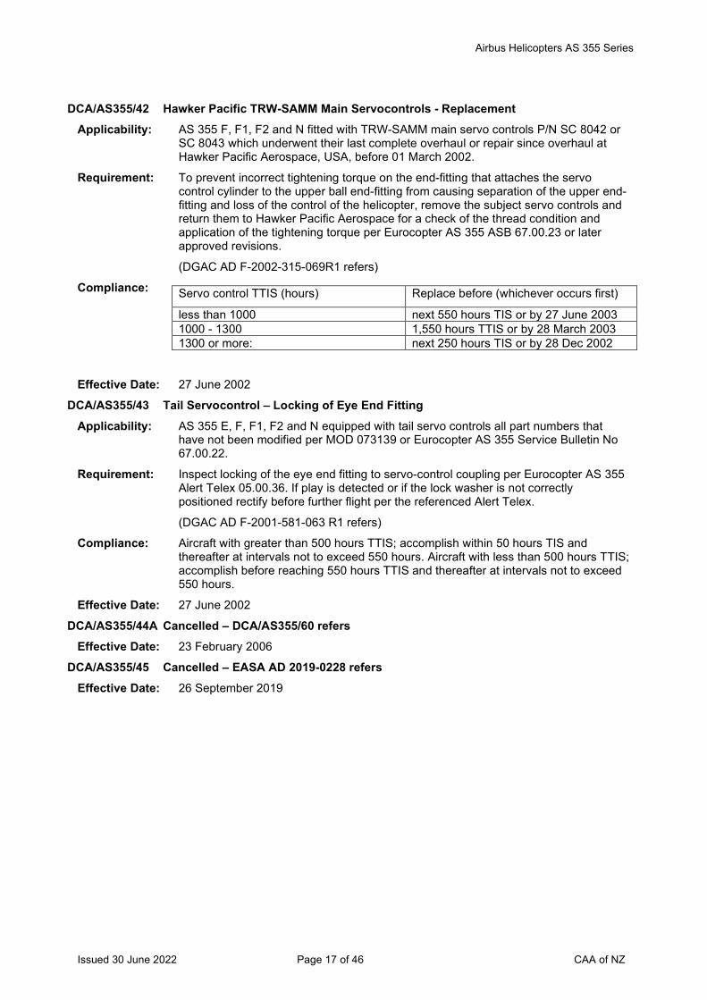
Airbus Helicopters AS 355 Series
Issued 30 June 2022 Page 17 of 46 CAA of NZ
DCA/AS355/42 Hawker Pacific TRW-SAMM Main Servocontrols - Replacement
Applicability: AS 355 F, F1, F2 and N fitted with TRW-SAMM main servo controls P/N SC 8042 or SC 8043 which underwent their last complete overhaul or repair since overhaul at Hawker Pacific Aerospace, USA, before 01 March 2002.
Requirement: To prevent incorrect tightening torque on the end-fitting that attaches the servo control cylinder to the upper ball end-fitting from causing separation of the upper end-fitting and loss of the control of the helicopter, remove the subject servo controls and return them to Hawker Pacific Aerospace for a check of the thread condition and application of the tightening torque per Eurocopter AS 355 ASB 67.00.23 or later approved revisions.
(DGAC AD F-2002-315-069R1 refers)
Compliance:
Effective Date: 27 June 2002
DCA/AS355/43 Tail Servocontrol – Locking of Eye End Fitting Applicability: AS 355 E, F, F1, F2 and N equipped with tail servo controls all part numbers that
have not been modified per MOD 073139 or Eurocopter AS 355 Service Bulletin No 67.00.22.
Requirement: Inspect locking of the eye end fitting to servo-control coupling per Eurocopter AS 355 Alert Telex 05.00.36. If play is detected or if the lock washer is not correctly positioned rectify before further flight per the referenced Alert Telex.
(DGAC AD F-2001-581-063 R1 refers)
Compliance: Aircraft with greater than 500 hours TTIS; accomplish within 50 hours TIS and thereafter at intervals not to exceed 550 hours. Aircraft with less than 500 hours TTIS; accomplish before reaching 550 hours TTIS and thereafter at intervals not to exceed 550 hours.
Effective Date: 27 June 2002
DCA/AS355/44A Cancelled – DCA/AS355/60 refers Effective Date: 23 February 2006
DCA/AS355/45 Cancelled – EASA AD 2019-0228 refers Effective Date: 26 September 2019
Servo control TTIS (hours) Replace before (whichever occurs first)
less than 1000 next 550 hours TIS or by 27 June 2003 1000 - 1300 1,550 hours TTIS or by 28 March 2003 1300 or more: next 250 hours TIS or by 28 Dec 2002
Airbus Helicopters AS 355 Series
Issued 30 June 2022 Page 18 of 46 CAA of NZ
DCA/AS355/46 Cyclic Friction Cup - Inspection
Applicability: AS 355 E, F, F1, F2 and N, modified per MOD 070682 (AS 355 SB No. 67.08), and before embodiment of MOD 073179.
Requirement: To eliminate the risk of binding in the cyclic stick "nose-up" control stop position configuration, due to the lower friction cup causing interference with the trimming edge of the friction bowl, measure the cyclic stick bowl-lower friction cup overlap in compliance with the instructions in Eurocopter AS 355 ASB 67.00.24 or later approved revisions. If the overlapping is not correct, within the next 2 months, replace the cup in compliance with the instructions described in paragraph 2.B.2 of the referenced AT. (DGAC AD F-2003-003R1 refers)
Compliance: By 28 February 2003, and thereafter each readjustment of the cyclic stick longitudinal nose-up control stop.
Effective Date: 30 January 2003
DCA/AS355/47 Dynamic Components – Life Correction Applicability: AS 355 E, F, F1, F2 and N, equipped with dynamic components following overhaul
(RG) or repair (RE) at the EUROCOPTER helicopter maintenance and overhaul facility (D.E.R.H.), listed in Tables 1 and 2 (as applicable) of paragraph 3 "APPENDIX" of the Alert Telex referenced below.
Requirement: To prevent life limited dynamic components from exceeding their life limits due to a miscalculation of their operating hours at the time of repair or overhaul at the Eurocopter overhaul and maintenance centres (D.E.R.H) listed in Alert Telex 62.00.27, accomplish the following:
1. With reference to the equipment log cards (FME) determine whether any of the helicopter’s dynamic components embody parts affected by this directive, IAW the instructions of paragraph 2.B.1 of the Alert Telex. If a check reveals that no components are affected, no further action is required.
2. If affected parts are fitted, correct the operating hours IAW the instructions of Paragraph 2.B.2 of the Alert Telex. If after correction, the operating hours of a part exceed its life limit, remove the part from service. Comply with paragraph 2.B.2 of the Alert Telex before installing dynamic components or parts held as spares that have undergone repair or overhaul.
(DGAC AD F-2002-452 R1 refers)
Compliance: 1. Within 10 hours TIS 2. Within 50 hours TIS
Effective Date: 29 May 2003
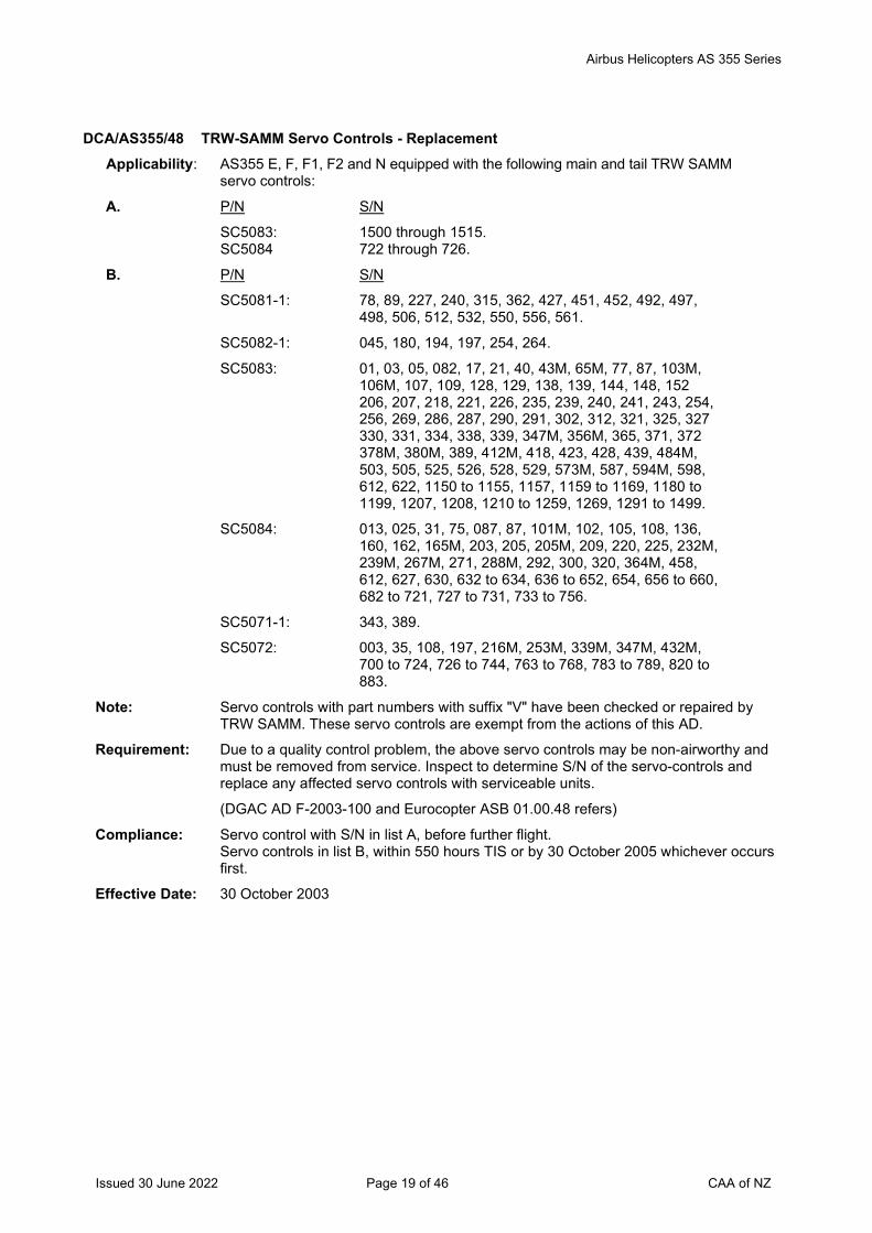
Airbus Helicopters AS 355 Series
Issued 30 June 2022 Page 19 of 46 CAA of NZ
DCA/AS355/48 TRW-SAMM Servo Controls - Replacement Applicability: AS355 E, F, F1, F2 and N equipped with the following main and tail TRW SAMM
servo controls:
A. P/N S/N
SC5083: 1500 through 1515. SC5084 722 through 726.
B. P/N S/N
SC5081-1: 78, 89, 227, 240, 315, 362, 427, 451, 452, 492, 497, 498, 506, 512, 532, 550, 556, 561.
SC5082-1: 045, 180, 194, 197, 254, 264.
SC5083: 01, 03, 05, 082, 17, 21, 40, 43M, 65M, 77, 87, 103M, 106M, 107, 109, 128, 129, 138, 139, 144, 148, 152 206, 207, 218, 221, 226, 235, 239, 240, 241, 243, 254, 256, 269, 286, 287, 290, 291, 302, 312, 321, 325, 327 330, 331, 334, 338, 339, 347M, 356M, 365, 371, 372 378M, 380M, 389, 412M, 418, 423, 428, 439, 484M, 503, 505, 525, 526, 528, 529, 573M, 587, 594M, 598, 612, 622, 1150 to 1155, 1157, 1159 to 1169, 1180 to
1199, 1207, 1208, 1210 to 1259, 1269, 1291 to 1499.
SC5084: 013, 025, 31, 75, 087, 87, 101M, 102, 105, 108, 136, 160, 162, 165M, 203, 205, 205M, 209, 220, 225, 232M,
239M, 267M, 271, 288M, 292, 300, 320, 364M, 458, 612, 627, 630, 632 to 634, 636 to 652, 654, 656 to 660, 682 to 721, 727 to 731, 733 to 756.
SC5071-1: 343, 389.
SC5072: 003, 35, 108, 197, 216M, 253M, 339M, 347M, 432M, 700 to 724, 726 to 744, 763 to 768, 783 to 789, 820 to
883.
Note: Servo controls with part numbers with suffix "V" have been checked or repaired by TRW SAMM. These servo controls are exempt from the actions of this AD.
Requirement: Due to a quality control problem, the above servo controls may be non-airworthy and must be removed from service. Inspect to determine S/N of the servo-controls and replace any affected servo controls with serviceable units.
(DGAC AD F-2003-100 and Eurocopter ASB 01.00.48 refers)
Compliance: Servo control with S/N in list A, before further flight. Servo controls in list B, within 550 hours TIS or by 30 October 2005 whichever occurs first.
Effective Date: 30 October 2003
Airbus Helicopters AS 355 Series
Issued 30 June 2022 Page 20 of 46 CAA of NZ
DCA/AS355/49A Flight Control Stops – Inspection Applicability: Model AS 355 E, F, F1, F2 and N aircraft which are not fitted with MOD 073206 or
MOD 073102.
Requirement: To prevent loosening of the flight control stops which may restrict the travel of the flight controls, accomplish the following:
1. Check the flight control stop positions and adjust if necessary, per paragraph 2.B.1 of Eurocopter AS 350 ASB 67.00.25 revision 1 or later.
2. Double lock the flight control stop adjusting screws as per paragraph 2.B.2 of ASB 67.00.25.
(DGAC AD F-2003-322 R1 refers)
Compliance: 1. Within 100 hours TIS.
2. Within 500 hours TIS.
Effective Date: DCA/AS355/49 - 30 October 2003 DCA/AS355/49A - 28 July 2005
DCA/AS355/50B Newly Overhauled or Repaired Main Gearboxes - Removal from Service Applicability: AS 355 E, F, F1, F2 and N fitted with a new MGB bevel reduction gear or a MGB
bevel reduction gear, that does not have MOD 077212 incoprorated and has logged fewer than 10 hours TIS since new, overhaul or repair.
Requirement: To prevent MGB free-wheel slippage and engine shut-down due to overspeed, accomplish the following:
For aircraft equipped with at least one of the dynamic components listed in the applicability, having logged less than 10 hours TIS since new, overhaul or repair, further flights are prohibited until MOD 0077212 is incorporated.
For aircraft equipped with the dynamic components listed in the applicability, having logged 10 flying hours or more since new or overhaul or repair, flights can be continued.
(EASA AD 2006-0250 refers)
Note: Eurocopter AS 355 Alert Service Bulleting No. 63.00.21 also refers.
Compliance: Before further flight, unless already accomplished.
Effective Date: DCA/AS355/50 - 15 December 2003 DCA/AS355/50A - 25 March 2004 DCA/AS355/50B - 28 September 2006
DCA/AS355/51 Rear Fuselage - Inspection Applicability: AS 355 helicopter versions E, F, F1, F2 and N pre-MOD 073215, or not equipped
with the four reinforcement angles, P/Ns 350A08.2493.20 / .21 / .22 / .23, following repair per MRM Work Card 53.10.22.772.
Requirement: To prevent loss of the helicopter due to cracking of the tail boom junction frame accomplish either part 1 or part 2 as applicable: 1. For aircraft not equipped with two reinforcement angles on the RH side of the rear frame per the repair defined on MRM Work Card 53.10.22.772:
a. Comply with paragraph 2.B.1.A of Eurocopter AS 350 ASB No. 05.00.42
b. inspect the RH side of the rear frame per the instructions described in paragraph 2.B.1.B of the referenced ASB.
c. If there is a crack in the rear frame, of length less than or equal to 30 mm, comply with the instructions in paragraph 2.B.1.B of the referenced ASB, at intervals not exceeding 110 hours TIS.
Airbus Helicopters AS 355 Series
Issued 30 June 2022 Page 21 of 46 CAA of NZ
d. If there is a crack in the rear frame, more than 30 mm long, carry out the repair as per MRM Work Card 53.10.22.772, no later than within 110 hours TIS, if all the cracks are less than or equal to 50 mm, or before further flight, if one or more crack is more than 50 mm long.
2. For aircraft equipped with two reinforcement angles on the RH side of the rear frame per the repair defined on MRM Work Card 53.10.22.772:
a. comply with paragraph 2.B.2 of the referenced ASB. If there is a crack in the reinforcement angles, replace the frame per the instructions described in paragraph 2.B.2 of the referenced ASB before further flight.
(DGAC AD F-2004-036 refers)
Compliance: Before accumulating 2700 hours TIS or within 100 hours TIS whichever is the later and thereafter at intervals not to exceed 550 hours TIS.
Effective Date: 25 March 2004
DCA/AS355/52A Cancelled – DCA/AS355/65 refers Effective Date: 1 June 2006
DCA/AS355/53 Hydraulic System Cut-off - Modification Applicability: AS 355 E, pre-Mod 073263
Requirement: To prevent a possible load imbalance in the flight controls due to residual fluid trapped after shutting off the hydraulic assistance, modify the electrical system in accordance with Eurocopter AS355 ASB 29.00.04.
(DGAC AD F-2004-090 refers)
Compliance: Before 31 December 2004
Effective Date: 30 September 2004
DCA/AS355/54 Cancelled - DCA/AS355/70 refers Effective Date: 28 September 2006
DCA/AS355/55 Tail Rotor Blade Trailing Edge Tab – Inspection Applicability: All model AS355 E, F, F1, F2, and N aircraft, fitted with tail rotor blades P/N 355A
12.0040 and P/N 355A 12.0050 all dash numbers inclusive, with S/Ns 8400 through 9224 which have not been repaired per Repair Sheet No 238 or Work Card 64.10.00.872.
Requirement: To prevent the failure of tail rotor blade trailing edge tab due to debonding and subsequent increase in the vibration level of the aircraft, accomplish the following:
1. Install additional rivets on the trailing edge tab of blades as per instruction 2.B. in Eurocopter AS350 ASB 64.00.04.
2. Before installing spare tail rotor blades confirm that additional rivets have been installed on the trailing edge tab of blades as per instruction 2.B. in Eurocopter AS350 ASB 64.00.04.
(DGAC AD F-2004-176 refers)
Compliance: 1. Within 100 TIS or by 28 July 2005, whichever is the sooner.
2. Prior to installation for any affected tail rotor blades.
Effective Date: 28 April 2005
Airbus Helicopters AS 355 Series
Issued 30 June 2022 Page 22 of 46 CAA of NZ
DCA/AS355/56B Cancelled - DCA/AS355/71 refers
Effective Date: 28 September 2006
DCA/AS355/57 Cancelled – DCA/AS355/66 refers Effective Date: 1 June 2006
DCA/AS355/58 Cancelled - DCA/AS355/68 refers Effective Date: 28 September 2006
DCA/AS355/59 Breeze Eastern 450-lb Electric Hoist - Inspection Applicability: Model AS 355 F, F1, F2 and N aircraft, fitted with a Breeze Eastern 450 lb. Electric
Hoist P/N BL 29700-23.
Requirement: To prevent cable damage caused by malfunction of the up end-of-travel stop mechanism, accomplish the following:
1. Inspect the spring compression of the damper assembly and perform a dimensional check of the damper assembly buffer, per paragraphs 2.B.1.a and 2.B.1.b of Eurocopter AS 355 Alert Service Bulletin AS355 No. 25.00.68.
2. Perform a dimensional check of the damper assembly buffer, per paragraph 2.B.1.b of ASB 25.00.68.
3. Check the hook in the up position, per paragraph 2.B.2 of ASB 25.00.68.
(DGAC AD F-2002-028-066 R1 refers)
Compliance: 1. Before the next hoisting mission and on each installation of a hoist in the helicopter.
2. Every 50 hoisting cycles or 3 months, whichever occurs first.
3. Each day that the hoist is to be used.
Effective Date: 1 December 2005
DCA/AS355/60 Cancelled – DCA/AS355/73 refers Effective Date: 25 January 2007
DCA/AS355/61 Main Servo Controls – Inspection Applicability: Model AS 355 E aircraft, fitted with main servo-controls, all P/Ns not modified per
MOD 073343, and
On which the tightening torque of the nut that secures the upper ball-end has been increased following the embodiment of MOD 073191, or
Compliance with MET Work Card 67.30.00.402 since MET Revision 04-06.
Requirement: To detect cracks in the tapered housing of a main servo-control, which in time could lead to the loss of the attachment of the servo-control to the non-rotating swashplate, and subsequent loss of aircraft control, accomplish the following:
1. Inspect the tapered housings of the main servo-controls for cracks, per the instructions specified in paragraph 2.B.2. of Eurocopter AS 350 Alert Service Bulletin (ASB), No. 05.00.48.
If no cracks are found, comply once with the tightening torque instructions per paragraph 2.B.3. of ASB No. 05.00.48, before further flight. No further action is required.
2. If a crack is found, accomplish the following:
a) If the crack is vertical along the servo-control axis and is less than 20 mm long comply once with the tightening torque instructions per paragraph 2.B.3. of ASB No. 05.00.48 and identify the end of the crack using an indelible ink marker, before further flight.
Airbus Helicopters AS 355 Series
Issued 30 June 2022 Page 23 of 46 CAA of NZ
Inspect for crack growth per the instructions in paragraph 2.B.4. of the ASB No. 05.00.48.
b) If the crack is vertical along the servo-control axis and is 20mm or longer, or the crack has grown by more than 5mm, or there is an oblique or a horizontal crack, or there are several cracks, replace the servo-control per the instructions in paragraph 2.A. of ASB No. 05.00.48, before further flight.
(EASA AD 2006-0055-E refers)
Note 1: Before installing a main servo-control held as spares, comply with the instructions per paragraph 2.B.2.b. of ASB No. 05.00.48. If no cracks are evident, comply once with the instructions per paragraph 2.B.3. of ASB No. 05.00.48. If a crack is evident, return the servo-control to Eurocopter for repair.
Note 2: The replacement of cracked servo-controls per the instructions in paragraph 2.A. of ASB No. 05.00.48, is a terminating action to the requirements of this AD.
Compliance: 1. Within the next 10 hours TIS, or by 16 March 2006, whichever is the sooner.
2.a) At every ALF-check inspect for crack growth, without exceeding 10 hours TIS between two inspections, and replace cracked servo-controls within 150 hours TIS or by 6 June 2006 or if crack growth exceeds 5mm, whichever occurs first. (ALF-Check: Check after last flight of the day.)
2.b) Before further flight.
Effective Date: 7 March 2006
DCA/AS355/62 Cancelled – DCA/AS355/63 refers Effective Date: 1 June 2006
DCA/AS355/63 Cancelled – DCA/AS355/84 refers Effective Date: 28 August 2008
DCA/AS355/64A Cancelled – DCA/AS355/84 refers Effective Date: 28 August 2008
DCA/AS355/65 Tail Rotor Control Cable - Replacement Applicability: Model AS 355 E, AS 355 F, AS 355 F1, AS 355 F2 and AS 355 N aircraft, fitted with
stainless steel-caged ball-type controls pre-MOD 072771, P/Ns:
- 704A 34-130-068 with Automatic Flight Control System (AFCS) or without AFCS, but with collective-to-yaw control coupling,
- 704A 34-130-086 without AFCS and without collective-to-yaw control coupling.
Requirement: To prevent binding in stainless steel-caged ball-type yaw controls, which may generate increased control loads or a feeling of pedal seizure, replace with new Teflon-caged ball-type controls, per the instructions in paragraph 2. of Eurocopter AS 355 Alert Service Bulletin (ASB) No. 67.00.26 revision 2.
(EASA AD 2006-0081 refers)
Note: Stainless steel-caged ball-type controls P/Ns 704A34-130-068 and 704A34-130-086 held as spares, are to be returned to Eurocopter.
Compliance: Before further flight following any report by the pilot of tail rotor control binding, or by 23 August 2006, whichever is the sooner, unless already accomplished.
Effective Date: 1 June 2006
Airbus Helicopters AS 355 Series
Issued 30 June 2022 Page 24 of 46 CAA of NZ
DCA/AS355/66 Tail Rotor Drive Shaft – Inspection Applicability: Model AS 355 E, AS 355 F, AS 355 F1, AS 355 F2 and AS 355 N aircraft fitted with a
tail rotor drive shaft forward shaft section P/N 355A 34-1090-00 with S/Ns M 858 through M 873.
Requirement: A metallurgical non-conformity was discovered on a flange of the tail rotor drive shaft forward shaft section of an Ecureuil helicopter. A stress analysis has shown that this non-conformity may significantly reduce the strength of the forward shaft section. With the service life of the forward shaft section possibly being significantly reduced, remove the tail rotor drive shaft forward shaft section and install a new part, per the instructions specified in paragraph 2.B of Eurocopter AS 355 ASB 01.00.51. (EASA AD 2006-0100 refers)
Note 1: This AD does not apply to aircraft delivered after 1 January, 2005. Note 2: Tail rotor drive shaft forward shaft sections specified in the applicability section of this
AD are to be returned to the manufacturer at the latest by 31 December 2005. Compliance: At 2500 hours TTIS or by 31 December 2006, whichever is the sooner, for aircraft
with up to 2400 hours TTIS, unless already accomplished. Within the next 100 hours TIS or by 31 December 2006, whichever is the sooner, for aircraft with more than 2400 hours TTIS, unless already accomplished.
Effective Date: 1 June 2006 DCA/AS355/67 Cancelled - DCA/AS355/77 refers
Effective Date: 18 May 2007 DCA/AS355/68B Cancelled – DCA/AS355/81 refers
Effective Date: 27 September 2007 DCA/AS355/69 Cancelled – DCA/AS355/96 refers
Effective Date: 29 March 2012 DCA/AS355/70 Sliding Door Rollers and Rails – Inspection
Applicability: Model AS 355 E, F, F1, F2 and N aircraft fitted with sliding doors not modified per MOD 073287 and/or MOD 073290.
Requirement: To prevent loss of the sliding door in flight, due to the possibility of sliding door rollers and rail wear, inspect the diameter of the roller and the dimensions of the front end opening of the middle rail, per the instructions in paragraph 2.B.1 of Eurocopter AS 355 Alert Service Bulletin (ASB) No. 05.00.39, revision 2. According to the criteria defined in paragraph 2.B.1 of AS 355 ASB No. 05.00.39 accomplish the following actions per paragraph 2.B.2 of AS 355 ASB No. 05.00.39: - If C1 > 5 mm and C2 > 1.5 mm: Door opening in flight is permitted.
- If C1 < 5 mm and/or C2 < 1.5 mm: Door opening in flight is prohibited. If C1 < 5 mm and/or C2 < 1.5 mm, then fix a ‘Door Opening in Flight is Prohibited’ placard on the instrument panel of the aircraft.
Note 1: Before installing sliding doors held as spares, accomplish the requirements of this AD.
Note 2: Embodiment of MOD 073287 and/or MOD 073290, per Eurocopter AS 355 Service Bulletin No. 52.00.22 is a terminating action to the requirements of this AD. (EASA AD 2006-0249 refers)
Compliance: Before further flight, unless already accomplished, and thereafter at intervals not to exceed 100 hours TIS.
Effective Date: 28 September 2006
Airbus Helicopters AS 355 Series
Issued 30 June 2022 Page 25 of 46 CAA of NZ
DCA/AS355/71 RH Cabin Vibration Damper and Blade Assy – Inspection Applicability: All model AS 355 E, F, F1, F2 and N aircraft fitted with an automatic flight control
system and a right hand cabin vibration damper blade (all P/Ns) with MOD 073325 not embodied.
Requirement: To prevent the failure of the blade of the cabin vibration damper assembly, which could lead to the failed part interfering with the trim actuator rod, resulting in the jamming of the flight controls accomplish the following:
1. Inspect the visible areas of the cabin vibration damper assembly blade for cracks, per paragraph 2.B.1. of Eurocopter AS 355 Alert Service Bulletin (ASB) No. 05.00.46.
Replace cracked blades per paragraph 2.B.1. of AS 355 ASB No. 05.00.46, before further flight.
2. Modify the cabin vibration damper and blade assembly by fitting a containment casing assembly, per the instructions in paragraph 2. of AS 355 ASB No. 53.00.22.
Note 1: After blade replacement, continue inspecting the blades for cracks per requirement 1, at every daily post flight inspection, until accomplishment of requirement 2.
Note 2: Sign logbook for compliance with requirement 1 at time of raising the aircraft technical log.
Note 3: Accomplishment of requirement 2 (MOD 073325) is a terminating action to the requirements of this AD.
Note 4: This AD is applicable to AS 355 aircraft fitted with an automatic flight control system modified per MODs 072262, 071543 and OP1055.
(EASA AD 2006-0273 refers)
Compliance: 1. At every daily post flight inspection.
2. By 30 June 2007.
Effective Date: 28 September 2006
DCA/AS355/72 Starter Generator – Load Limitation Applicability: Model AS 355 N aircraft fitted with all P/N starter generators, and not embodied with
MOD 073344.
Requirement: To prevent excessive power consumption of the starter generator reducing the engine surge margin which could result in engine failure, the starter generator current draw is limited to 100 Amps at altitudes above 3000 meters (10000 feet).
Install a label indicating this load limitation on the instrument panel below the ammeter, per the instructions in paragraph 2.B. of Eurocopter AS 355 Alert Service Bulletin No. 01.00.52.
(EASA AD 2006-0338 refers)
Compliance: Within the next 100 hours TIS or by 30 November 2007, whichever occurs sooner.
Effective Date: 30 November 2006
DCA/AS355/73 Cancelled – DCA/AS355/80 refers
Airbus Helicopters AS 355 Series
Issued 30 June 2022 Page 26 of 46 CAA of NZ
DCA/AS355/74 Main & Tail Rotor Servo Controls – Inspection
Applicability: Model AS 355 F, F1, F2 and N aircraft, all S/N
Fitted with Goodrich main or tail rotor servo-controls with the following P/N and S/N with no letter “R” marked in the inspection box of the servo-control identification plate:
P/N SC8042, S/N 1590, 1591, 1592, 1593, 1616 or 1618.
P/N SC8043, S/N 865, 866, 867 or 881.
Requirement: To prevent the incorrect installation of the servo-control cap from not mechanically limiting the rotation of the distributor, which could result in loss of aircraft rotor control, accomplish the following:
1. Inspect the aircraft and/or the aircraft log books to verify the P/N and S/N of the main rotor and tail rotor servo-controls in accordance with the instructions in paragraph 1.A of Eurocopter AS 355 Alert Service Bulletin (ASB) No. 67.00.28.
2. Replace all affected servo-controls per the instructions in paragraph 2.B. of AS 355 ASB No. 67.00.28.
Note: Affected servo-controls may not be fitted to any aircraft unless they have been returned to conformity per the instructions in paragraph 2.B. of AS 355 ASB No. 67.00.28.
(EASA AD 2007-0099 refers)
Compliance: 1. By 31 July 2007.
2. At the next removal of the servo-controls or by 31 May 2009, whichever is the later.
Effective Date: 31 May 2007
DCA/AS355/75 Engine Automatic Relighting System – Installation Applicability: Model AS 355E, AS 355F, AS 355F1 and AS 355F2 aircraft fitted with Allison 250-
C20F engines with air intake debris guards.
Requirement: To prevent engine flame out in heavy precipitation at low ambient temperatures, install a manufacturer approved automatic engine relighting system or a continuous ignition system.
Note 1: The installation of an automatic engine relighting system per the instructions in Eurocopter AS350 Service Bulletin No. 80.02 revision 2, or later approved revisions, is an acceptable means of compliance to the requirements of this AD.
Note 2: Aircraft are prohibited from being operated in heavy precipitation at ambient temperatures below + 5 degrees celsius per the operating limitations in section 2.1 of the AFM, unless fitted with an automatic engine relighting system or a continuous ignition system per the requirements of this AD.
Note 3: For aircraft already modified per AMS 350A 07-1823 and AMS 350A 07-1905, embody modifications AMS 350A 07-1910 and AMS 350A 07-1920 in order to prevent inadvertant operation of the automatic engine relighting system.
Note 4: Installation of the Aerospatiale relighting kit requires exclusive utilisation of Champion or Auburn Igniters P/N 68 77518, or Champion Igniters P/N 23006266 with service life limits of 1200 hours for each approved igniter.
(DGAC AD 1986-153-031 R4 refers)
Compliance: By 30 November 2007, unless already accomplished.
Effective Date: 31 May 2007
Airbus Helicopters AS 355 Series
Issued 30 June 2022 Page 27 of 46 CAA of NZ
DCA/AS355/76 Load Compensator Lever – Inspection Applicability: Model AS 355 N and AS 355 F2 aircraft, all S/N
Requirement: To prevent restricted yaw control travel due to the possibility of the incorrect load compensator lever being fitted to the aircraft which could result in loss of control of the aircraft, accomplish the following:
1. Inspect the aircraft and/or the aircraft log books to verify the P/Ns of both the load compensator lever and the hydraulic actuator assembly fitted to the aircraft, per the instructions in Eurocopter AS 355 Alert Service Bulletin (ASB) No. 67.00.29, revision 1. If the P/Ns cannot be identified, accomplish the instructions in paragraph 2.B.2.of ASB No. 67.00.29 to determine the relevant P/Ns.
2. For aircraft not embodied with MOD 072065:
If compensator lever P/N 355A27-0082-00 is fitted to the aircraft and provided the aircraft has not been operated in this configuration, replace the lever with P/N 355A27- 0072-00, per the instructions in paragraph 2.B.3.a.of ASB No. 67.00.29. If the aircraft has been operated with lever P/N 355A27-0082-00, accomplish all the actions in 2.B.3.b.of ASB No. 67.00.29, before further flight.
Note 1: Aircraft not embodied with mod 072065 are fitted with hydraulic actuator assembly P/N 355A75-1370-01 or 355A75-1370-03.
3. For aircraft embodied with MOD 072065:
If compensator lever P/N 355A27-0072-00 is fitted to the aircraft and provided the aircraft has not been operated in this configuration, replace the lever with P/N 355A27- 0082-00, per the instructions in 2.B.3.a.of ASB No. 67.00.29. If the aircraft has been operated with lever P/N 355A27-0072- 00, accomplish all the actions in 2.B.3.b. of ASB No. 67.00.29, before further flight.
Note 2: Aircraft embodied with mod 072065 are fitted with hydraulic actuator assembly 355A75-1370-02 or 355A75-1370-04. (EASA AD 2007-0131-E refers)
Note 3: From the effective date of this AD, load compensator lever P/N 355A27-0082-00 shall not be fitted on any AS 355 N or AS 355 F2 aircraft not embodied with MOD 072065, and load compensator lever P/N 355A27-0072-00 shall not be fitted to any AS 355 N and AS 355 F2 aircraft embodied with MOD 072065.
Compliance: 1. Before further flight. 2. & 3. Within the next 10 hours TIS.
Effective Date: 18 May 2007
DCA/AS355/77A Cancelled – DCA/AS355/86 refers Effective Date: 5 March 2009
DCA/AS355/78 Cabin Floor Cross Member – Inspection Applicability: Model AS355 E, F, F1, F2 and N aircraft, all S/N delivered before 1 January 2007 and
fitted with a collective-to-yaw control coupling with or without an Automatic Flight Control System.
Requirement: To prevent a cracked cabin floor cross member at X2325 possibly resulting in reduced ability to control aircraft yaw, accomplish the following:
1. Inspect the aircraft and establish whether the cross-member at station X 2165 and the doublers at stations X 2325 and Y 269 are installed per Eurocopter AS 355 Alert Service Bulletin (ASB) No. 53.00.23.
If a cross-member and doublers are installed, no further action is required.
If a cross-member and/or doublers are not installed, inspect for cracks per AS 355 ASB No. 53.00.23.
Airbus Helicopters AS 355 Series
Issued 30 June 2022 Page 28 of 46 CAA of NZ
If no cracks are found inspect the tail rotor control rigging per AS 355 ASB No. 53.00.23, before further flight. Tail rotor control rigging only required to be accomplished at the initial visual inspection.
If any cracks are found accomplish a manufacturer approved repair scheme, before further flight.
2. Install a cross-member at station X 2165 and doublers at stations X 2325 and Y 269, in accordance with the instructions in AS 355 ASB No. 53.00.23. (EASA AD 2007-0139-E refers)
Compliance: 1. Within the next 10 hours TIS or by 18 June 2007, whichever occurs sooner, and thereafter at intervals not to exceed 50 hours TIS until accomplishment of requirement 2.
2. By 18 May 2008.
Effective Date: 18 May 2007
DCA/AS355/79 Main & Tail Rotor Servo Controls – Inspection Applicability: Model AS 355 E, F, F1, F2 and N aircraft, all S/N,
Fitted with Goodrich main rotor servo-controls with the following P/N and S/N with no letter “C” marked in the inspection box of the servo-control identification plate:
P/N SC5083, S/N 270M, 272M, 409M, 423M, 452M or 1573,
P/N SC5083-1, S/N 2902 through to 2921,
P/N SC5084, S/N 30, 84, 104, 186, 438, 575 or 695,
P/N SC5084-1, S/N 1462 through to 1481, or
Fitted with Goodrich tail rotor servo-controls with the following P/N and S/N with no letter “C” marked in the inspection box of the servo-control identification plate:
P/N SC5072, S/N 222M, 306M or 309.
Requirement: To prevent the distributor slide valve jamming on its sleeve due to the possibility of excessive play in the servo control input lever bearing which could result in reduced rotor control, accomplish the following:
1. Inspect the aircraft and/or the aircraft log books to verify the P/N and S/N of the main rotor and tail rotor servo-controls in accordance with the instructions in paragraph 1.E.2. of Eurocopter AS 355 Alert Service Bulletin (ASB) No. 01.00.53 revision 1.
If an affected servo-control is fitted to the aircraft, accomplish a flight control system check per section 4 of the AFM to establish that no “hard points” exist in the flight controls.
If any “hard point” is detected in the flight controls, replace the defective servo-control(s) per the instructions in paragraph 2.B. of AS 355 ASB No. 01.00.53, before further flight.
2. Replace all affected servo-controls per the instructions in paragraph 2.B. of AS 355 ASB No. 01.00.53. (EASA AD 2007-0141-E refers)
Note: Affected servo-controls may not be fitted to any aircraft unless they have been returned to conformity per the instructions in paragraph 2. of AS355 ASB No. 01.00.53.
Compliance: 1. Before further flight, and if an affected part is fitted to the aircraft inspect thereafter at every pre-flight inspection, until accomplishment of requirement 2.
2. Within the next 50 hours TIS or by 24 September 2007, whichever occurs sooner.
Effective Date: 24 May 2007
Airbus Helicopters AS 355 Series
Issued 30 June 2022 Page 29 of 46 CAA of NZ
DCA/AS355/80 Cancelled – EASA AD 2007-0209R1 refers
Effective Date: 25 September 2015
DCA/AS355/81 Sliding Door Rear Fitting and Support Shaft – Inspection Applicability: All model AS 355 E, F, F1, F2 and N aircraft fitted with sliding doors without MOD
073298 and/or MOD 073308 embodied.
Note: This AD supersedes DCA/AS355/68B with the inclusion of requirement 3 and 4.
Requirement: To detect cracks in the rear roller support shaft and the rear fitting of the sliding door, accomplish the following:
1. Inspect the sliding door support shaft and rear fitting, per paragraph 2.B in Eurocopter AS 355 Alert Service Bulletin (ASB) No. 05.00.45.
If cracked, replace per paragraph 2.B in AS 355 ASB No. 05.00.23, before further flight.
2. Modify sliding doors, per paragraph 2.B in AS 355 ASB No. 52.00.23. 3. Before installing sliding doors listed in paragraph 1.A.2 of ASB No. 52.00.23 revision 1 embody MOD 073298 and/or MOD 073308 per the instructions in AS 355 ASB No. 52.00.23.
4. Rail roller pins P/N 350A25-1275-20 and cast roller support fittings P/N 350A25-1270-20 and P/N 350A25-1270-22 shall not be fitted to any aircraft.
(EASA AD 2007-0236 refers) Compliance: 1. At 100 hours TTIS or within 20 hours TIS whichever is the later, unless already
accomplished and thereafter at intervals not to exceed 100 hours TIS.
2. By 31 December 2007.
3. & 4. From 27 September 2007.
Effective Date: 27 September 2007
DCA/AS355/82 Collective Lever Recess - Modification Applicability: Model AS 355 E, AS 355 F, AS 355 F1 and AS 355 F2 aircraft not embodied with
MOD 071995.
Requirement: To prevent foreign material possibly restricting the collective pitch control travel which could result in loss of aircraft control, accomplish the following:
1. Modify the collective lever per the instructions in paragraph 2.B. of Eurocopter Alert Service Bulletin (ASB) No. 67.00.12 revision 2.
2. Covers P/N 355A27-2373-20 shall not be fitted to any aircraft.
(EASA AD 2007-0289 refers)
Compliance: 1. Within the next 550 hours TIS or by 29 November 2008 whichever occurs sooner.
2. From 29 November 2007.
Effective Date: 29 November 2007
Airbus Helicopters AS 355 Series
Issued 30 June 2022 Page 30 of 46 CAA of NZ
DCA/AS355/83 Rear Bench Seat Cushions – Removal Applicability: Model AS 355 E, F, F1, F2 and N models fitted with a rear bench seat not embodied
with modification 073166 per Eurocopter AS 355 Service Bulletin No. 25.00.66. Note 1: This AD supersedes DCA/AS355/37 and includes modification 073166 (per AS 355
SB No.25.00.66) as a terminating action to the requirements of this AD. Requirement: To prevent in-flight loss of rear bench seat cushions and possible impact with the
main or tail rotor and subsequent loss of aircraft, revise the Limitations Section of the Aircraft Flight Manual (AFM) to include the following text: “Before any flight with the door(s) removed or the sliding door(s) open, remove the cushions from the rear bench seat, unless the seat is to be occupied.”
Note 2: This requirement may be accomplished by inserting a copy of this AD in the AFM or by incorporating a manufacturer’s flight manual revision that contains the wording per this AD. Operators must ensure that pilots are aware of this flight manual revision.
Note 3: The embodiment of modification 073166 per AS 355 SB No.25.00.66 is a terminating action to the requirements of this AD. (EASA AD 2008-0044 refers)
Compliance: By 27 April 2008 Effective Date: 27 March 2008
DCA/AS355/84 Cancelled – DCA/AS355/85 refers Effective Date: 23 February 2009
DCA/AS355/85 Fin Attach Fittings – Inspection Applicability: Model AS 355 E, AS 355 F, AS 355 F1, AS 355 F2 and AS 355 N helicopters, all S/N
fitted with the following upper and lower fins without modification 073330 embodied: Upper fin assembly P/N: 355A14-0522-00XX, 355A14-0522-01XX, 355A14-0522-02XX, 355A14-0522-03XX, 355A14-0522-13XX, 355A14-0522-14XX and 355A14-0522-15XX, and Lower fin assembly P/N 355A14-0521-00XX, 355A14-0521-01XX, 355A14-0521-02XX and 355A14-0521-03XX.
Note 1: This AD supersedes DCA/AS355/84 which superseded DCA/AS355/64A. This AD retains the requirements of DCA/AS355/84, introduces additional affected fin assemblies in the applicability, and reintroduces the omitted initial requirement and repetitive inspections previously required by DCA/AS355/64A.
Requirement: To prevent failure of the upper and lower fin attachment fittings due to fatigue, which could result in loss of the vertical fin, accomplish the following: 1. For helicopters fitted with upper and lower fins without MOD 073288 embodied: Replace the upper and lower fin attachment screws and embody modification 073288 per paragraph 2.B.2. in Eurocopter AS 355 ASB No. 55.00.11 revision 2 or later approved revisions. 2. For helicopters fitted with upper and lower fins with MOD 073288 embodied: Check the tightening torque of the upper fin attachment screws and check the upper fin reinforcement splice for cracks and loosened rivets per paragraph 2.B.3 in AS 355 ASB 55.00.11. If cracks or loose rivets in the reinforcement splice are found, or if the tightening torque of one or both of the attachment screws is less than 80% of the minimum torque value, accomplish the corrective actions per paragraph 2.B.3.a.1, 2.B.3.a.2. or 2.B.3.a.3. as applicable in AS 355 ASB 55.00.11. 3. For helicopters fitted with upper and lower fins without MOD 073330 embodied: Remove the upper and lower fins and embody modification 073330 per AS 355 ASB No. 55.00.12. revision 1 or later approved revisions.
Airbus Helicopters AS 355 Series
Issued 30 June 2022 Page 31 of 46 CAA of NZ
4. An affected upper or lower fin shall not be fitted to any aircraft unless embodied with modification MOD 073330 per AS 355 ASB No. 55.00.12. (EASA AD 2009-0029 refers)
Note 2: Accomplishment of requirement 3 of this AD is a terminating action for the repetitive inspections of requirement 2.
Note 3: With the embodiment of modification 073330 per requirement 3 of this AD the lower and upper fittings bolts P/N 22126BV060032L and washers P/N 23112AG060LE are replaced with special bolts P/N 350A23-4016-20 and special washers P/N 350A23- 4017-22.
Compliance: 1. Within the next 15 hours TIS unless already accomplished. 2. For aircraft with more than 100 hours TIS since the last inspection: Within the next 15 hours TIS and thereafter at intervals not to exceed 100 hours TIS. For aircraft with less than 100 hours TIS since the last inspection: Within 100 hours TIS since the last inspection and thereafter at intervals not to exceed 100 hours TIS. 3. By 15 April 2009 unless previously accomplished. 4. From 23 February 2009.
Effective Date: 23 February 2009 DCA/AS355/86 Tail Rotor Blade Skin – Inspection
Applicability: Model AS 355 E, F, F1, F2, N and NP aircraft, all S/N fitted with tail rotor blades P/N: - 355A12-0031-01/ -02/ -03/ -04/ -05/ -06/ -07/ -08/ -09/ -11/ -12/ -13/ -14, and - 355A12-0040-00/ -01/ -02/ -03/ -04/ -05/ -07/ -08, and - 355A12-0050-00/ -01/ -02/ -03/ -04/ -05.
Note 1: This AD supersedes DCA/AS355/77A with no change to the requirement. This AD introduces model AS 355 NP aircraft in the applicability.
Requirement: To prevent tail rotor blade skin separation causing significant imbalance and possibly resulting in loss of aircraft control, accomplish the following: 1. Vvisually inspect the blade face in zone A, per the instructions specified in paragraph 2.B.1. of Eurocopter AS 355 Alert Service Bulletin (ASB) No. 05.00.38, revision 3 or later approved revisions. If the tail rotor blade skin is cracked in zone A, comply with the instructions specified in paragraph 2.B.2. of AS 355 ASB No. 05.00.38, before further flight.
Note 2: The visual inspection may be accomplished by the pilot in accordance with CAR Part 43, Appendix A. The pilot must be trained and authorised (Part 43, Subpart B refers) and certification must be provided (Part 43, Subpart C refers).
Note 3: Sign log book for requirement 1 compliance at time of raising tech log. 2. For tail rotor blades P/N 355A12-0050-00/-01/-02/-03/-04/-05 with S/N listed per paragraph 2.B.2.a. of AS 355 ASB No. 05.00.38, embody Repair Sheet (FR) CN 376 or (FR) CN 453. For tail rotor blades with S/N below 8419, with annotation “repaired as per Work Card 64.10.00.872” or “repaired as per Work Card 64.10.20.712” recorded on the log card, embody Repair Sheet (FR) CN 376 or (FR) CN 453. 3. Affected tail rotor blades shall not be fitted to any aircraft unless the instructions in paragraph 2.B.1 of AS 355 ASB No. 05.00.38 is accomplished.
Note 4: Accomplishing (FR) CN 376 on affected tail rotor blades per AS 355 ASB No. 05.00.38 revision 2 is acceptable to comply with requirements 2 and 3 of this AD. (EASA AD 2009-0039 refers)
Compliance: 1. After the last flight of the day without exceeding 10 flight hours between each check. 2. By 5 April 2009, unless previously accomplished. 3. From 5 March 2009.
Effective Date: 5 March 2009
Airbus Helicopters AS 355 Series
Issued 30 June 2022 Page 32 of 46 CAA of NZ
DCA/AS355/87 Cancelled – EASA AD 2010-0006 refers
Effective Date: 31 October 2013
DCA/AS355/88A Engine and MGB Cowling Locking – Modification Applicability: Model AS355E, AS355F, AS355F1 and AS355F2 helicopters, all S/N.
Note 1: No action required for those aircraft already in compliance with DCA/AS355/88. This AD revised to introduce Kent Helicopters Ltd. modification KHL/MOD/355/001 per requirement vi). This modification was previously approved by the UK CAA. Aircraft already embodied with this modification are compliant with the requirements of this AD.
Requirement: To prevent the loss of unsecured engine cowls or MGB cowls in flight due to possible incorrect locking of the cowls which could affect flight safety and safety of persons on the ground, accomplish one of the following five options:
i) Eurocopter Modification No. 073313 per the instructions in Eurocopter SB No. 53.00.24 – Improvement to engine and MGB cowling locking, or
ii) Eurocopter UK (McAlpine Helicopters) modification MCH/A/355/597 – Installation of cockpit warning, or
iii) Aerospace Design Facilities modification ADF 2007-021 (EASA STC 10028585) – Installation of cowling secondary safety latch, or
iv) Aerospace Design Facilities modification ADF 350/5-101 – Installation of cowling secondary safety latch, or
v) Aero Engineering Design Ltd modification 31-10-013 – Installation of cockpit warning.
vi) Kent Helicopters Ltd. modification KHL/MOD/355/001 – Freefall of cowling and secure latching.
Note 2: For requirement i) of this AD the painting of the flags must be in a conspicuous and in a contrasting colour to the colour scheme of the helicopter.
Note 3: Eurocopter SB No. 53.00.24 revision 0 or later EASA approved revisions are acceptable for compliance with requirements of this AD.
Note 4: For any questions concerning the technical content of the requirements in the referenced Aero Engineering Design Ltd. Modification 31-10-013 contact AeroEngineering Design Ltd., 9 Argosy Rd. Derby, Derbyshire, D74 2NG, UK.
Note 5: For any questions concerning the technical content of the requirements in the referenced Eurocopter UK modification MCH/A/355/597 contact Eurocopter UK Limited, Oxford Airport, Kidlington, Oxford, OX5 1QZ, UK. (EASA AD 2010-0023R2 correction refers)
Compliance: By 25 March 2012 (the compliance date for DCA/AS355/88).
Effective Date: DCA/AS355/88 - 25 March 2010 DCA/AS355/88A - 29 March 2012
Effective Date: 25 March 2010
Airbus Helicopters AS 355 Series
Issued 30 June 2022 Page 33 of 46 CAA of NZ
DCA/AS355/89 Cancelled – DCA/AS355/90 refers
Effective Date: 9 March 2011
DCA/AS355/90 Tail Gearbox Control Lever – Inspection Applicability: Model AS 355 E, F, F1, F2 and N aircraft, all S/N fitted with tail gearbox control levers
P/N 350A33-1058-00, 350A33-1058-01, 350A33-1058-02 or 350A33-1058-03 except reinforced control levers P/N 350A33-1524-00 or 350A33-1526-00.
Note 1: This AD retains the requirements in superseded DCA/AS355/89 and introduces a new inspection per Eurocopter ASB 05.00.57 revision 2 dated 28 February 2011. Requirement 3 in this AD introduces an inspection for the opposite rib in affected control levers including those control levers marked with an “X”.
Requirement: To prevent failure of the tail gearbox control lever due to possible induced cracks caused by surface anomalies which could result in reduced aircraft control, accomplish the following:
1. Visual Inspection:
Visually inspect affected control levers per the instructions in paragraph 2.B.1.a of Eurocopter AS355 ASB 05.00.57 revision 1, dated 23 April 2010 or later EASA approved revisions. If any cracks are found contact the manufacturer and replace the affected control levers per the instructions in paragraph 2.B.1.b 2) of Eurocopter AS355 ASB 05.00.57 revision 2, dated 1 March 2011 or later EASA approved revisions.
If no cracks are found accomplish requirement 2 of this AD.
2. No cracks found:
Rework affected control levers per the instructions in paragraph 2.B.3 of AS355 ASB 05.00.57, or replace with a reworked lever (marked with an “X”), or replace with a reinforced control lever P/N 350A33-1524-00 or 350A33-1526-00.
3. New Inspection Requirement:
Visually inspect affected control levers per the instructions in paragraph 2.B.4 of Eurocopter AS355 ASB 05.00.57 revision 2, dated 1 March 2011 or later EASA approved revisions.
If any cracks are found contact the manufacturer and replace the affected control lever per the instructions in paragraph 2.B.1.b 2) of Eurocopter AS355 ASB 05.00.57 revision 2, dated 1 March 2011 or later EASA approved revisions.
4. Rework Requirement:
A tail gearbox control lever with P/N 350A33-1058-00, 350A33-1058-01, 350A33-1058-02 or 350A33-1058-03 shall not be fitted to any aircraft unless it has been reworked (marked with an “X”) per the instructions in of paragraph 2.B.3 of Eurocopter AS355 ASB No. 05.00.57.
Note 2: The repetitive inspections per requirement 1 of this AD may be accomplished by adding the inspection requirements to the tech log. The visual inspection may be performed and certified under the provision in Part 43 Appendix A.1 (7) by the holder of a current pilot licence, if that person is rated on the aircraft, appropriately trained and authorised (Part 43, Subpart B refers), and the maintenance is recorded and certified as required by Part 43.
Note 3: The installation of a reworked lever (marked with an ‘X’) is a terminating action to the repetitive inspections mandated by requirement 1 of this AD.
Note 4: The installation of a reinforced control lever P/N 350A33-1524-00 or 50A33-1526-00 is a terminating action to the repetitive inspections mandated by requirements 1 and 3 of this AD.
(Corrected EASA AD 2011-0038-E refers)
Airbus Helicopters AS 355 Series
Issued 30 June 2022 Page 34 of 46 CAA of NZ
Compliance: 1. Within the next 10 hours TIS or after the last flight of the day whichever occurs sooner after 30 April 2010 (the effective date of DCA/AS355/89), and thereafter at intervals not to exceed 10 hours TIS or after the last flight of the day, whichever occurs sooner.
2. Within the next 660 hours TIS or 14 months whichever occurs sooner after 30 April 2010 (the effective date of DCA/AS355/89).
3. All AS355 series aircraft except AS355N:
Before 660 hours TSN or overhaul, or within the next 55 hours TIS for affected TGB control levers with 605 or more hours TSN or overhaul, and thereafter at intervals not to exceed 600 hours TIS.
AS355N aircraft:
Before 110 hours TSN or overhaul, or within the next 10 hours TIS for affected TGB control levers with 100 or more hours TSN or overhaul, and thereafter at intervals not to exceed 100 hours TIS.
4. From 30 April 2010 (the effective date of DCA/AS355/89).
Effective Date: 9 March 2011
DCA/AS355/91 EASA AD 2011-0072 Cancelled by EASA on 4 March 2022 Effective Date: 4 March 2022
DCA/AS355/92 Tail Gearbox Casing Assembly – Inspection Applicability: Model AS 355 E, F, F1, F2, N and NP helicopters, all S/N fitted with TGB casing
assembly P/N 350A33-1090-02, S/N MA47577, MA47585, MA47587, MA47588, MA47589, MA47590, MA47591, MA47592, MA47593, MA47597, MA47598, MA47599, MA47600, MA47602, MA47604, MA47606, MA47610, MA47613, MA47615, MA47617, MA47619, MA47620, MA47621, MA47622, MA47623, MA47624, MA47626, MA47628 and MA47631.
Requirement: To prevent loss of tail rotor pitch control due to possible cracks in the TGB control lever attachment yoke which could result in loss of aircraft control, accomplish the following: 1. Review the aircraft records or inspect the aircraft and determine the S/N of the TGB casing assembly P/N 350A33-1090-02. If an affected TGB casing assembly is found fitted, inspect the attachment yoke of the control lever on the TGB casing assembly for cracks per the instructions in paragraph 3 of Eurocopter AS355 ASB 65.00.22 revision 0, dated 18 May 2011 or later approved revisions. If a crack is found in the control lever yoke on the TGB casing assembly, replace the TGB with a serviceable part per the instructions in AS355 ASB 65.00.22. 2. An affected TGB casing shall not be fitted to any aircraft unless the pitch control lever attachment yokes on the TGB casing assembly have been inspected and found serviceable per the requirements of this AD. (EASA AD 2011-0104 refers)
Compliance: 1. TGB casings with less than 550 hours TSN: By 30 August 2012 or 660 hours TSN on the TGB casing, whichever occurs sooner. TGB casings with more than 550 hours TSN: Within the next 100 hours TIS or by 30 July 2012, whichever occurs sooner.
2. From 30 June 2011. Effective Date: 30 June 2011
DCA/AS355/93 Cancelled – EASA AD 2011-0164R1 Effective Date: 28 February 2017
Airbus Helicopters AS 355 Series
Issued 30 June 2022 Page 35 of 46 CAA of NZ
DCA/AS355/94 Cancelled – EASA AD 2015-0181 refers
Effective Date: 14 September 2015 DCA/AS355/95 Cancelled – EASA AD 2013-0281 refers
Effective Date: 11 December 2013 DCA/AS355/96 Starter Generator – Inspection
Applicability: Model AS355 N aircraft, all S/N. Note: This AD retains the requirements in superseded DCA/AS355/69. The AD applicability
expanded to include all S/N aircraft, and the inspection intervals and maintenance actions in this AD revised taking the embodiment of Turboméca Modification TU107 (including mod TU106 and the installation of reinforced attachment tabs) into account.
Requirement: To prevent loss of the exhaust pipe ejector in flight due to possibile excess starter generator vibration ehich could result in the failure of the exhaust attachment lugs, accomplish the inspections and corrective actions specified in EASA AD 2012-0022. (EASA AD 2012-0022 refers)
Compliance: At the compliance times specified in EASA AD 2012-0022. Effective Date: 29 March 2012
Airbus Helicopters AS 355 Series
Issued 30 June 2022 Page 36 of 46 CAA of NZ
The State of Design ADs listed below are available directly from the National Airworthiness Authority (NAA) websites. Links to NAA websites are available on the CAA website at https://www.aviation.govt.nz/aircraft/airworthiness/airworthiness-directives/links-to-state-of-design-airworthiness-directives/ If additional NZ ADs need to be issued when an unsafe condition is found to exist in an aircraft or aeronautical product in NZ, they will be added to the list below. 2012-0205 Sliding Door Lower Ball-joint – Modification
Applicability: AS 355 E, AS 355 F, AS 355 F1, AS 355 F2, AS 355 N and AS 355 NP helicopters, all S/N, if fitted with sliding doors, except aircraft embodied with modification AL 4262.
Effective Date: 15 October 2012
2012-0257-E Tail Rotor Laminated Half-bearings – Inspection
Applicability: AS 355 E, AS 355 F, AS 355 F1, AS 355 F2, AS 355 N and AS 355 NP helicopters, all S/N.
Note: The visual inspection per the requirements in paragraph (1) of EASA AD 2012-0257-E may be accomplished by adding the inspection requirement to the tech log. The visual inspection may be performed and certified under the provision in Part 43 Appendix A.1 (7) by the holder of a current pilot license, if that person is rated on the aircraft, appropriately trained and authorized, and the training/authorization is appropriately documented (Part 43, Subpart B refers), and the maintenance is recorded and certified as required by Part 43.
Effective Date: 7 December 2012 2013-0095-E Main/Tail Rotor Servo-Control Bearings – Inspection
Applicability: AS 355 E, AS 355 F, AS 355 F1, AS 355 F2, AS 355 N, AS 355 NP helicopters, all serial numbers, fitted with a single hydraulic main and tail servo-controls manufactured by “SAMM”, “TRW”, “GOODRICH”, or “UTAS”.
Effective Date: 18 April 2013
2013-0130 Cancelled – EASA AD 2021-0193 Refers Effective Date: 3 September 2021
2013-0133-CN Cancelled – Purpose fulfilled Effective Date: 16 February 2016
2013-0205 Cancelled – EASA AD 2015-0202 refers Effective Date: 21 October 2015
DGAC AD F-2000-223-059R1 Tail Rotor Pitch Change Rotating Plates – Inspection
Applicability: AS 355 helicopters, versions E, F, F1, F2 and N, fitted with tail rotor pitch change rotating plates all part numbers, on which EUROCOPTER modification (MOD) 07 6554 has not been embodied.
Note 1: This Airworthiness Directive (AD) does not apply to pitch change plate assembly part number 350A33-2030-00 (MOD 076550).
Note 2: EASA AD F-2000-223-059R1 supersedes DCA/AS355/33 to introduce Eurocopter AS 355 ASB 05.00.33R1 dated 11 March 2004 and change the AD applicability / effectivity to exclude those aircraft fitted with pitch change plate assembly P/N 350A33-2030-00 (Mod 076550).
Effective Date: 25 September 2004 (the effective date of DGAC AD F-2000-223-059R1)
2010-0006 Cancelled by EASA on 3 September 2021 Effective Date: 3 September 2021
Airbus Helicopters AS 355 Series
Issued 30 June 2022 Page 37 of 46 CAA of NZ
2013-0281R1 Position Strobe Light – Inspection
Applicability: AS 355 E, AS 355 F, AS 355 F1, AS 355 F2, AS 355 N and AS 355 NP helicopters, all S/N, if modified in production with (optional) modification OP0811 and fitted with a Grimes-Honeywell power supply unit, P/N 60-1431-3, in the baggage compartment as part of that optional modification, except helicopters that have embodied at least one of the modifications as listed in Appendix1 of this AD.
Effective Date: 2013-0281 - 11 December 2013 2013-0281R1 - 13 February 2015
2014-0076R3 Cancelled – EASA AD 2022-0051 refers
Effective Date: 5 April 2022 2014-0132R1 Rotating Star Swashplate – Inspection
Applicability: AS 355 E, F, F1, F2, N and NP helicopters, all serial numbers, if fitted with a swashplate assembly comprising a rotating star with Part Number (P/N) 350A371003-04, P/N 350A371003-05, P/N 350A371003-06, P/N 350A371003-07, or P/N 350A371003-08.
Effective Date: 2014-0132 - 9 June 2014 2014-0132R1 - 9 June 2014
2014-0135-E Cabin Ventilation Air Scoop - Inspection Applicability: AS 355 E, F, F1, F2, N and NP helicopters, all serial numbers. Effective Date: 29 May 2014
2015-0094 Cancelled by EASA on 3 September 2021 Effective Date: 3 September 2021
DGAC AD 1991-164-042 Electric Hoist Bonding – Inspection Applicability: AS 355 series helicopters specified in DGAC AD 1991-164-042 fitted with hoists P/N
76370.010, 76370.011 and 76370.030. Effective Date: 18 June 2015
2015-0122-E Engine “Chip” Warning Emergency Procedure – AFM Amendment Applicability: AS355 N and AS355 NP helicopters, all serial numbers, if fitted with Turboméca
ARRIUS 1A, 1A1, or 1M engines. Effective Date: 26 June 2015
2015-0143-E Tail Rotor Blades – Inspection Applicability: AS355 NP helicopters, all serial numbers, when equipped with a blade having P/N
355A12-0050-10, P/N 355A12-0050-12, P/N 355A12-0051-10, or P/N 355A12-0051-12.
Effective Date: 17 July 2015
Airbus Helicopters AS 355 Series
Issued 30 June 2022 Page 38 of 46 CAA of NZ
2007-0209R1 Main Gearbox Lubrication Pump – Inspection
Applicability: AS 355 E, AS 355 F, AS 355 F1, AS 355 F2 and AS 355 N helicopters, all serial numbers, equipped with lubrication pumps Part Number (P/N) 355A32-0700-01, P/N 355A32-0700-02 or P/N 355A32-0701-00, installed on the main gearbox (MGB), except those modified in accordance with Airbus Helicopters modification (mod) 077222.
Effective Date: 25 September 2015 2015-0181 Engine Fire Extinguisher System – Modification
Applicability: AS 355 NP helicopters, all serial numbers, if equipped with the ARRIUS 1A1 engine fire extinguishing system through production modification (mod) OP-3931, except those incorporating Airbus Helicopters (AH) mod 07-3990.
Effective Date: 14 September 2015 2015-0195 Tail Rotor Drive Shaft Bearings – Inspection
Applicability: AS 350 B, BA, BB, B1, B2, B3 and D helicopters, and AS 355 E, F, F1, F2, N and NP helicopters, all serial numbers, if equipped with tail rotor (TR) drive shaft bearings as indicated in Table 1 of this AD.
Effective Date: 7 October 2015 2015-0202 Cancelled – EASA AD 2016-0109 refers
Effective Date: 28 June 2016 DCA/AS355/97C Forward Two-place Seat – Operating Limitations
Applicability: All AS355 series helicopters fitted with any forward two-place seat, except those helicopters fitted with an Airbus Helicopters forward two-place seat.
Note: The applicability of DCA/AS355/97C revised to exclude helicopters fitted with an Airbus Helicopters forward two-place seat.
DCA/AS355/97B revised to introduce CAA Limitations Section page, dated 30 June 2016, revised to introduce a note. Requirement 2 of this AD revised to introduce the revised limitations page.
Requirement: To prevent a reduction of flight safety from that provided by the manufacturer, accomplish the following:
1. Determine the longitudinal moment arm of the forward two-place seat using the center of the seat pan cushion as a measurement reference point. Complete and issue a new form CAA 2173 Weight and Balance Data. The weight of the seat components must be included in the CG calculations. If a seat adaptor plate is fitted the moment (position and weight) of the plate must also be considered for the CG calculation. The lateral CG arm of the helicopter must not be assumed to be zero. The lateral CG must be recorded and be within the limits specified in the AFM. Annotate the CAA2173 to include the value of the longitudinal moment arm of the forward two-place seat used.
2. Remove CAA Limitations Section, (1 page), dated 14 December 2015 and insert 1 page dated 30 June 2016.
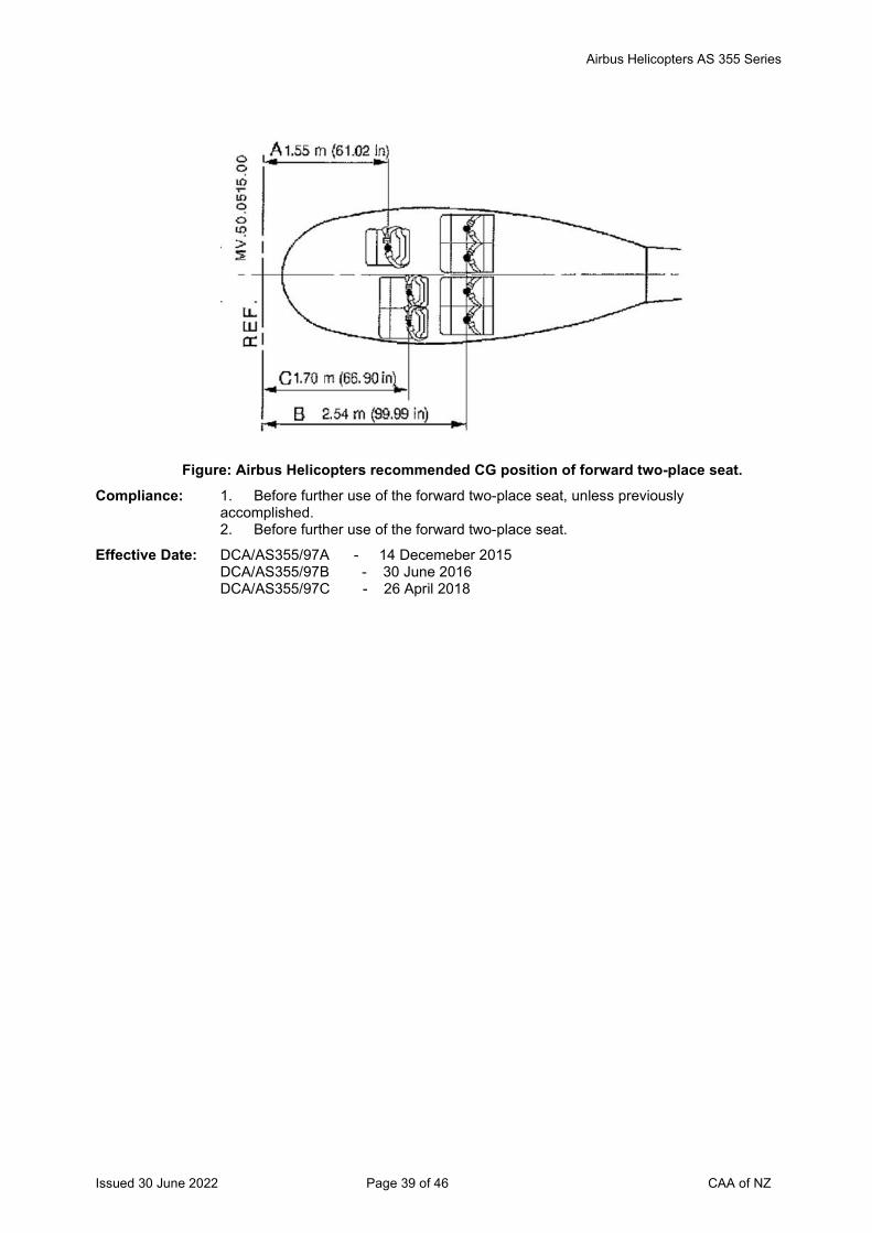
Airbus Helicopters AS 355 Series
Issued 30 June 2022 Page 39 of 46 CAA of NZ
Figure: Airbus Helicopters recommended CG position of forward two-place seat.
Compliance: 1. Before further use of the forward two-place seat, unless previously accomplished. 2. Before further use of the forward two-place seat.
Effective Date: DCA/AS355/97A - 14 Decemeber 2015 DCA/AS355/97B - 30 June 2016 DCA/AS355/97C - 26 April 2018
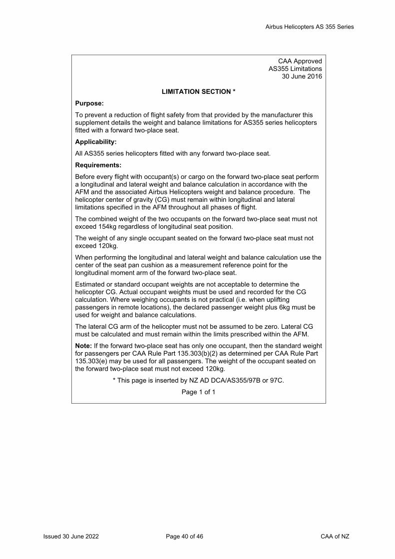
Airbus Helicopters AS 355 Series
Issued 30 June 2022 Page 40 of 46 CAA of NZ
CAA Approved
AS355 Limitations 30 June 2016
LIMITATION SECTION *
Purpose: To prevent a reduction of flight safety from that provided by the manufacturer this supplement details the weight and balance limitations for AS355 series helicopters fitted with a forward two-place seat.
Applicability: All AS355 series helicopters fitted with any forward two-place seat.
Requirements: Before every flight with occupant(s) or cargo on the forward two-place seat perform a longitudinal and lateral weight and balance calculation in accordance with the AFM and the associated Airbus Helicopters weight and balance procedure. The helicopter center of gravity (CG) must remain within longitudinal and lateral limitations specified in the AFM throughout all phases of flight.
The combined weight of the two occupants on the forward two-place seat must not exceed 154kg regardless of longitudinal seat position.
The weight of any single occupant seated on the forward two-place seat must not exceed 120kg.
When performing the longitudinal and lateral weight and balance calculation use the center of the seat pan cushion as a measurement reference point for the longitudinal moment arm of the forward two-place seat.
Estimated or standard occupant weights are not acceptable to determine the helicopter CG. Actual occupant weights must be used and recorded for the CG calculation. Where weighing occupants is not practical (i.e. when uplifting passengers in remote locations), the declared passenger weight plus 6kg must be used for weight and balance calculations.
The lateral CG arm of the helicopter must not be assumed to be zero. Lateral CG must be calculated and must remain within the limits prescribed within the AFM.
Note: If the forward two-place seat has only one occupant, then the standard weight for passengers per CAA Rule Part 135.303(b)(2) as determined per CAA Rule Part 135.303(e) may be used for all passengers. The weight of the occupant seated on the forward two-place seat must not exceed 120kg.
* This page is inserted by NZ AD DCA/AS355/97B or 97C.
Page 1 of 1
Airbus Helicopters AS 355 Series
Issued 30 June 2022 Page 41 of 46 CAA of NZ
2016-0021 Main Gearbox Bottom Casing – Inspection Applicability: AS 355 E, F, F1, F2, N helicopters, all serial numbers, if equipped with main gearbox
(MGB) bottom Casing (sump) P/N 350A32-3119-03 or P/N 350A32-3119-05.
Effective Date: 5 February 2016
2016-0022 Main Gearbox Casings – Inspection Applicability: AS 355 NP helicopters, all serial numbers, if equipped with main gearbox (MGB) main
casing Part Number (P/N) 350A32-3121-07, or equipped with MGB bottom casing (sump) P/N 350A32-3119-03 or P/N 350A32-3119-05.
Effective Date: 5 February 2016
2016-0109R1 Fueltron Flowmeter – Inspection Applicability: AS 355 E, AS 355 F, AS 355 F1 and AS 355 F2 helicopters, all serial numbers.
Effective Date: EASA AD 2016-0109 - 28 June 2016 EASA AD 2016-0109R1 - 10 November 2016
2017-0020R1 Tail Rotor Pitch Rod – Inspection Applicability: AS 355 E, AS 355 F, AS 355 F1, AS 355 F2, AS 355 N and AS 355 NP helicopters,
all S/N embodied with modification (mod) 075601 or mod 076602.
Note 1: EASA AD 2017-0020R1 is revised to include requirements for reverting to the original ALS interval for affected pitch rods. Some editorial changes have also been made which does not affect the technical content of the AD.
Note 2: The repetitive inspection requirement per paragraph (1) of EASA AD 2017-0020R1 may be accomplished by adding the inspection to the tech log. The inspection may be performed and certified under the provision in Part 43 Appendix A.1 (7) by the holder of a current pilot license, if that person is rated on the aircraft, appropriately trained and authorized, and the training/authorization is appropriately documented (Part 43, Subpart B refers), and the maintenance is recorded and certified as required by Part 43.
If any damage is found in one or more layers of the elastomer with a circumference of more than 90 degrees as detailed in the instructions of the applicable ASB, then an engineer must replace the affected tail rotor pitch change rod with a serviceable part, before further flight.
Effective Date: EASA AD 2017-0020-E - 9 February 2017 EASA AD 2017-0020R1 - 30 May 2019
2011-0164R3 Tail Rotor Control Stop Screws – Inspection Applicability: AS 355 E, AS 355 F, AS 355 F1, AS 355 F2, AS 355 N and AS 355 NP helicopters,
all S/N fitted with an AP, and AS 355 N and AS 355 NP helicopters, all S/N without an AP installed, but embodied with mod 071908; except helicopters that have mod 074819 embodied.
Effective Date: EASA AD 2011-0164R1 - 28 February 2017 EASA AD 2011-0164R2 - 28 September 2017 EASA AD 2011-0164R3 - 30 April 2020
2017-0032 Cancelled by EASA on 11 August 2021 Effective Date: 11 August 2021
Airbus Helicopters AS 355 Series
Issued 30 June 2022 Page 42 of 46 CAA of NZ
2017-0089R1 Main Rotor Mast Upper Bearing - Inspection
Applicability: AS 355 E, AS 355 F, AS 355 F1, AS 355 F2, AS 355 N and AS 355 NP helicopters, all S/N.
Note: This AD revised to introduce an amended OEM ASB to clarify affected parts identification.
Effective Date: EASA AD 2017-0089 - 31 May 2017 EASA AD 2017-0089R1 - 30 June 2020
2017-0114 Cancelled - EASA AD 2020-0186 refers Effective Date: 3 September 2020
2017-0159 Fan Assembly - Inspection Applicability: AS 355 E, AS 355 F, AS 355 F1, AS 355 F2 and AS 355 N helicopters, all serial
numbers.
Effective Date: 8 September 2017
Transport Canada AD CF-2017-37 Restriction of Directional Control Pedal Movement Applicability: Litter kits P/N 350-200034 or P/N 350-200194 (LH litter kits), or P/N 350-200144 (RH
litter kit). These kits could be found installed on Airbus Helicopter models AS 350 B, AS 350 BA, AS 350 B1, AS 350 B2, AS 350 B3, AS 350 D, AS 355 E, AS 355 F, AS 355 F1, AS 355 F2, AS 355 N and AS 355 NP as listed in Tables 1 and 2 of TC AD CF-2017-37.
Effective Date: 19 January 2018
DCA/AS355/98A Cargo Swing Modification OAL114.355 – Inspection Applicability: All AS355 series helicopters embodied with Oceania Aviation Limited (OAL) cargo
swing modification OAL114.355.
Note: DCA/AS355/98A introduces a revised AFM Supplement and a revised ICA for cargo swing modification OAL114.355.
Requirement: To prevent failure of the cargo swing due to possible fatigue cracks in the gimbal / universal joint assembly, which could result in loss of the load, accomplish the following:
1. Revise the AFM and insert OAL AFM Supplement MB 25.00.150, revision 2, dated 30 July 2018, or later approved revision, into the helicopter AFM.
Introduce OAL ICA MB 25.00.150 revision 3, dated 19 October 2018, or later approved revision, into the helicopter maintenance programme. Determine that a placard is fitted on the cargo swing frame, per OAL AFM Supplement MB 25.00.150 revision 1, or later approved revision, unless previously accomplished.
2. Dye penetrant inspect the Gimbal / Universal Joint Assembly P/N OAL114-10500 and P/N OAL114-10504, per the instructions in OAL ICA MB 25.00.150 revision 1, 2 or 3, or later approved revision. Replace defective parts before next hook operation.
Compliance: 1. By 25 November 2018.
2. For bucket operations: Before the next hook operation (i.e. both agricultural and firefighting operations), unless previously accomplished.
For non-bucket operations: By 25 November 2018, unless previously accomplished.
Effective Date: DCA/AS355/98 - 28 June 2018 DCA/AS355/98A - 25 October 2018
Airbus Helicopters AS 355 Series
Issued 30 June 2022 Page 43 of 46 CAA of NZ
2018-0152 Main Gearbox Bracket Bolts - Inspection
Applicability: AS 355 E, AS355 F, AS355 F1, AS355 F2, AS355 N and AS355 NP helicopters, all S/N.
Effective Date: 1 August 2018 2018-0206 Mast Upper Bearing Sealant Bead/Inner Race Retaining Rings - Inspection
Applicability: AS 355 E, AS 355 F, AS 355 F1, AS 355 F2, AS 355 N and AS 355 NP helicopters, all S/N.
Effective Date: 4 October 2018 2018-0287 Cancelled – EASA AD 2019-0060 refers
Effective Date: 3 April 2019 DCA/AS355/99 HETS STC 11/21E/34 – Removal from Service
Applicability: All AS355 series helicopters embodied with Aero Design Limited Human External Transport System (HETS) STC 11/21E/34.
Requirement: To prevent a reduction of the level of occupant safety from that provided by Transport Canada STC SH98-35, due to mismatched instructions for continuing airworthiness, accomplish the following: 1. Remove Aero Design Limited HETS STC 11/21E/34 from service. 2. Remove the Flight Manual Supplement (FMS) associated with HETS STC
11/21E/34 from the helicopter AFM. 3. Remove the Instructions for Continued Airworthiness (ICA) associated with HETS
STC 11/21E/34 from the helicopter maintenance programme. Note 1: The equipment approved under revoked HETS STC 11/21E/34 is the same as
Transport Canada STC SH98-35. Under the provisions of CAR 21.503(a) the Director has accepted Transport Canada STC SH98-35. Refer to the list of technical data accepted by the Director on the CAA website.
Note 2: In accordance with Rule 21, Appendix D(b)(3) the installer of a foreign STC requires the written permission of the STC holder to install their STC and use the FMS/ICA associated with the STC.
Compliance: By 31 March 2019 Effective Date: 31 January 2019
Transport Canada CF-2019-01 HETS STC SH98-35 Applicability: Helicopter External Transport System (HETS™) certified under Transport Canada
STC SH98-35, Issue 1 and Issue 2 installed on the following helicopter models: Airbus Helicopters (formerly Eurocopter France) model AS 355 E, AS 355 F, AS 355 F1 and AS 355 F2.
Note: HETS™ approved under SH98-35 are only eligible for installation on helicopter models listed above and they are not eligible for any other models not specifically listed above (Example: not eligible for installation on AS 355 N or AS 355 NP).
Effective Date: 22 January 2019 2019-0060 Tail Rotor Gearbox Actuating Rod – Inspection
Applicability: AS 355 E, AS 355 F, AS 355 F1, AS 355 F2, AS 355 N and AS 355 NP series helicopters, all S/N.
Effective Date: 3 April 2019
Airbus Helicopters AS 355 Series
Issued 30 June 2022 Page 44 of 46 CAA of NZ
2019-0184 Main Rotor Servo Actuators – Inspection
Applicability: AS355 F, AS355 F1, AS355 F2, AS355 N and AS355 NP series helicopters, all S/N.
Effective Date: 29 August 2019
2019-0228 Electric Hoist Installation – Inspection Applicability: AS 355 E, AS 355 F, AS 355 F1, AS 355 F2 and AS 355 N series helicopters, all S/N.
Effective Date: 26 September 2019
FAA AD 2020-02-23 Emergency Float System STC SR00645LA – Inspection Applicability: AS355E, AS355F, AS355F1, AS355F2, AS355N and AS355NP series helicopters
embodied with STC SR00645LA.
Effective Date: 28 February 2020 2020-0064 Emergency Flotation System – Inspection
Applicability: AS 355 E, AS 355 F, AS 355 F1, AS 355 F2, AS 355 N and AS 355 NP series helicopters, all S/N.
Effective Date: 2 April 2020
2020-0175 Cancelled by EASA on 13 September 2021 Effective Date: 30 September 2021
2020-0186 Cancelled – EASA AD 2021-0099 refers Effective Date: 29 April 2021
2020-0217-E Cancelled – EASA AD 2021-0023 refers Effective Date: 2 February 2021
2020-0224R1 Tail Rotor Blades – Inspection Applicability: AS 355 E, AS 355 F, AS 355 F1, AS 355 F2 and AS 355 N series helicopters, all S/N.
Note 1: Initial tail rotor blade leading edge protection shield inspection: An initial inspection per requirements (1) and (2) of EASA AD 2020-0224 original issue, or revision 1 must be accomplished by an aircraft maintenance engineer.
Note 2: The visual inspection before every flight, per requirement (1) of EASA AD 2020-0224R1, may be accomplished by adding the inspection requirement to the helicopter tech log. The visual inspection may be performed and certified under the provision in Part 43 Appendix A.1 (7) by the holder of a current pilot licence, if that person is rated on the aircraft, appropriately trained and authorised (Part 43, Subpart B refers), and the maintenance is recorded and certified as required by Part 43.
If any defects are found in the tail rotor blades during the repetitive visual inspections, then an aircraft maintenance engineer must inspect the tail rotor blades and accomplish the corrective actions per EASA AD 2020-0224R1, before further flight.
Effective Date: EASA AD 2020-0224-E - 20 October 2020 EASA AD 2020-0224R1 - 26 November 2020
2020-0266 N2 Speed Avoidance Limitation – Placard and AFM Amendment Applicability: AS 355 E, AS 355 F, AS 355 F1 and AS 355 F2 series helicopters, all S/N fitted with
a Rolls-Royce Corporation (formerly Allison) engine model 250-C20F.
Effective Date: 22 December 2020
Airbus Helicopters AS 355 Series
Issued 30 June 2022 Page 45 of 46 CAA of NZ
2021-0023 Cyclic Stick Grip UP / Down Hoist Control Switch – Modification
Applicability: AS 355 E, AS 355 F, AS 355 F1 and AS 355 F2 helicopters, all S/N, except those helicopters embodied with MOD MC20096.
Effective Date: 2 February 2021
2021-0027R1 Collective Controls – Modification Applicability: AS 355 NP helicopters, all S/N.
Effective Date: EASA AD 2021-0027 - 3 February 2021 EASA AD 2021-0027R1 – 3 February 2021
2021-0048 Main Rotor Pitch Rod Upper Links – Inspection Applicability: AS 355 E, AS 355 F, AS 355 F1, AS 355 F2, AS 355 N and AS 355 NP helicopters,
all S/N.
Note: The repetitive visual inspections required at intervals not to exceed 10 hours TIS per requirement (2) of EASA AD 2021-0048 may be accomplished by adding the inspection requirement to the helicopter tech log. The visual inspection may be performed and certified under the provision in Part 43 Appendix A.1 (7) by the holder of a current pilot licence, if that person is rated on the aircraft, appropriately trained and authorised (Part 43, Subpart B refers), and the maintenance is recorded and certified as required by Part 43.
If the markings on one, or both sides of a main rotor pitch rod upper link are found misaligned during the repetitive visual inspections, then an aircraft maintenance engineer must accomplish the corrective actions per requirement (3) of EASA AD 2021-0048 before further flight.
Effective Date: 2 March 2021
2021-0099 Vertical Fin – Inspection Applicability: AS 355 E, AS 355 F, AS 355 F1, AS 355 F2, AS 355 N and AS 355 NP helicopters,
all S/N.
Effective Date: 29 April 2021
2021-0193 Airworthiness Limitations Applicability: AS 355 E, AS 355 F, AS 355 F1, AS 355 F2, AS 355 N and AS 355 NP helicopters,
all S/N.
Effective Date: 3 September 2021
2021-0265 Cowlings - Inspection Applicability: AS 355 E, AS 355 F, AS 355 F1 and AS 355 F2 helicopters, all S/N.
Effective Date: 7 December 2021
Airbus Helicopters AS 355 Series
Issued 30 June 2022 Page 46 of 46 CAA of NZ
2021-0282 Tail Rotor Head Pitch Change Unit Bearing Spacer - Inspection
Applicability: AS 355 E, AS 355 F, AS 355 F1, AS 355 F2, AS 355 N and AS 355 NP helicopters, all S/N.
Note: The initial inspection and the black paint index marking per requirement (1) of EASA AD 2021-0282 must be accomplished by an aircraft maintenance engineer.
The 10 hour repetitive inspections per requirement (4) of EASA AD 2021-0282 may be accomplished by adding the inspection requirement to the helicopter tech log. The visual inspection may be performed and certified under the provision in Part 43 Appendix A.1 (7) by the holder of a current pilot licence, if that person is rated on the aircraft, appropriately trained and authorised (Part 43, Subpart B refers), and the maintenance is recorded and certified as required by Part 43.
If during the repetitive inspections the black paint index marking is found misaligned, then an aircraft maintenance engineer must inspect the aircraft and accomplish the corrective actions per EASA AD 2021-0282 before further flight.
Effective Date: 31 December 2021
* 2022-0051 (Correction) Rear Structure Junction Frame Reinforcement Angles - Inspection Applicability: AS 355 E, F, F1, F2 and N helicopters, all S/N fitted with an affected part as defined
in EASA AD 2022-0051, except helicopters embodied with Airbus Helicopters (AH) modification (MOD) 073232 in production, or helicopters embodied with AH AS355 Service Bulletin (SB) No. AS355 SB No. 53.00.34 as in service.
AS 355 NP helicopters, S/N 5747, and 5749 through to 5766 inclusive, except helicopters embodied with AH AS355 SB No. 53.00.34 in service.
Note: EASA AD 2022-0051 retains the requirements in superseded EASA AD 2014-0076R3, and requires repetitive inspections for additional helicopters. EASA AD 2022-0051 (Correction) is re-issued to correct typos in the referenced AD numbers in the Reason section of the AD.
Effective Date: EASA AD 2022-0051 - 5 April 2022 EASA AD 2022-0051 (Correction) - 30 June 2022
2022-0069 Tail Rotor Assembly - Inspection Applicability: AS 355 E, AS 355 F, AS 355 F1, AS 355 F2 and AS 355 N helicopters, all S/N.
Effective Date: 3 May 2022
2022-0077-E Flight Control Flexball Cables - Replacement Applicability: AS 355 E, AS 355 F, AS 355 F1, AS 355 F2, AS 355 N and AS 355 NP helicopters,
all S/N.
Effective Date: 2 May 2022
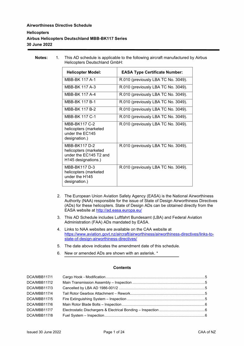
Issued 30 June 2022 Page 1 of 24 CAA of NZ
Airworthiness Directive Schedule Helicopters Airbus Helicopters Deutschland MBB-BK117 Series 30 June 2022
Notes: 1. This AD schedule is applicable to the following aircraft manufactured by Airbus Helicopters Deutschland GmbH:
Helicopter Model:
EASA Type Certificate Number:
MBB-BK 117 A-1 R.010 (previously LBA TC No. 3049).
MBB-BK 117 A-3 R.010 (previously LBA TC No. 3049).
MBB-BK 117 A-4 R.010 (previously LBA TC No. 3049).
MBB-BK 117 B-1 R.010 (previously LBA TC No. 3049).
MBB-BK 117 B-2 R.010 (previously LBA TC No. 3049).
MBB-BK 117 C-1 R.010 (previously LBA TC No. 3049).
MBB-BK117 C-2 helicopters (marketed under the EC145 designation.)
R.010 (previously LBA TC No. 3049).
MBB-BK117 D-2 helicopters (marketed under the EC145 T2 and H145 designations.)
R.010 (previously LBA TC No. 3049).
MBB-BK117 D-3 helicopters (marketed under the H145 designation.)
R.010 (previously LBA TC No. 3049).
2. The European Union Aviation Safety Agency (EASA) is the National Airworthiness Authority (NAA) responsible for the issue of State of Design Airworthiness Directives (ADs) for these helicopters. State of Design ADs can be obtained directly from the EASA website at http://ad.easa.europa.eu/
3. This AD Schedule includes Luftfahrt Bundesamt (LBA) and Federal Aviation Administration (FAA) ADs mandated by EASA.
4. Links to NAA websites are available on the CAA website at https://www.aviation.govt.nz/aircraft/airworthiness/airworthiness-directives/links-to-state-of-design-airworthiness-directives/
5. The date above indicates the amendment date of this schedule.
6. New or amended ADs are shown with an asterisk. *
Contents
DCA/MBB117/1 Cargo Hook - Modification ................................................................................................ 5 DCA/MBB117/2 Main Transmission Assembly – Inspection ...................................................................... 5 DCA/MBB117/3 Cancelled by LBA AD 1986-001/2 ................................................................................... 5 DCA/MBB117/4 Tail Rotor Gearbox Attachment – Rework ........................................................................ 5 DCA/MBB117/5 Fire Extinguishing System – Inspection ........................................................................... 5 DCA/MBB117/6 Main Rotor Blade Bolts – Inspection ................................................................................ 6 DCA/MBB117/7 Electrostatic Dischargers & Electrical Bonding – Inspection ............................................ 6 DCA/MBB117/8 Fuel System – Inspection ................................................................................................. 6
Issued 30 June 2022 Page 2 of 24 CAA of NZ
DCA/MBB117/9 Cancelled – EASA AD 2017-0193 refers .......................................................................... 6 DCA/MBB117/10 Main Transmission – Life Limitation .................................................................................. 7 DCA/MBB117/11 Cancelled – EASA AD 2012-0196 refers .......................................................................... 7 DCA/MBB117/12 Transmission & Engine Cowling Doors – Modification ...................................................... 7 DCA/MBB117/13 Cancelled – DCA/MBB117/17 refers ................................................................................. 7 DCA/MBB117/14 Cancelled – DCA/MBB117/16 refers ................................................................................. 7 DCA/MBB117/15 Fire Protection System – Rework ...................................................................................... 7 DCA/MBB117/16 Tail Rotor Control Lever Weights – Inspection ................................................................ 8 DCA/MBB117/17A Engine MAX N1 Power – Inspection & AFM/Placard Amendment ................................... 8 DCA/MBB117/18 Cancelled – DCA/MBB117/24 refers ................................................................................. 9 DCA/MBB117/19 Cyclic Stick Locking Device – Modification and AFM Amendment .................................... 9 DCA/MBB117/20 Cancelled – DCA/MBB117/21 refers ................................................................................. 9 DCA/MBB117/21 Cancelled – DCA/MBB117/25 refers ................................................................................. 9 DCA/MBB117/22 Tail Rotor Drive Shaft – Inspection.................................................................................... 9 DCA/MBB117/23 Upper Control Bellcrank Assembly – Inspection ............................................................. 10 DCA/MBB117/24 Cancelled – EASA AD 2010-0058R1 refers .................................................................... 10 DCA/MBB117/25A Intermediate Gearbox Bevel Gear – Inspection .............................................................. 10 DCA/MBB117/26A Instrument Control Panel – Flight Limitation, Placard and Modification .......................... 11 DCA/MBB117/27 Cancelled – DCA/MBB117/34 refers ............................................................................... 12 DCA/MBB117/28 Main Rotor Controls – Inspection .................................................................................... 12 DCA/MBB117/29 Cancelled – DCA/MBB117/33 refers ............................................................................... 12 DCA/MBB117/30 Autopilot Automatic Level-off Function – AFM Amendment ............................................ 13 DCA/MBB117/31 Sliding Door Emergency Jettison System – Inspection ................................................... 13 DCA/MBB117/32A Generator Control Unit – Inspection ................................................................................ 13 DCA/MBB117/33 Starter/Generator Relays – AFM Amendment and Modification ..................................... 14 DCA/MBB117/34 Cancelled – EASA AD 2011-0168R1 refers .................................................................... 14 DCA/MBB117/35 Generator Control Unit – Inspection ................................................................................ 15 DCA/MBB117/36 Tail Rotor Pitch Links – Inspection .................................................................................. 15 DCA/MBB117/37 Airworthiness Directive Compliance at Initial Airworthiness Certificate Issue ................. 16 DCA/MBB117/38 Vertical Fin – Inspection .................................................................................................. 16 DCA/MBB117/39 Main Rotor System – Inspection ..................................................................................... 16 DCA/MBB117/40 Tail Rotor – Inspection .................................................................................................... 17 DCA/MBB117/41 Main Rotor Blades – Inspection ...................................................................................... 17 DCA/MBB117/42 External Rescue Hoist – Deactivation and Modification .................................................. 17 DCA/MBB117/43 Cancelled – EASA AD 2013-0159 refers ........................................................................ 17 The State of Design ADs listed below are available directly from the National Airworthiness Authority (NAA) websites. Links to NAA websites are available on the CAA website at https://www.aviation.govt.nz/aircraft/airworthiness/airworthiness-directives/links-to-state-of-design-airworthiness-directives/ If additional NZ ADs need to be issued when an unsafe condition is found to exist in an aircraft or aeronautical product in NZ, they will be added to the list below. .............................................. 18 2012-0196 Cancelled – EASA AD 2013-0135 refers ........................................................................ 18 2012-0216 Autopilot – Dispatch Restriction ...................................................................................... 18 2012-0263 Cancelled – EASA AD 2013-0189 refers ........................................................................ 18 2013-0135 Time Limits and Maintenance Checks – Airworthiness Limitations Amendment ............. 18 2013-0154 N2 Control Arm – Inspection and Modification ................................................................ 18 2013-0159 Cancelled – EASA AD 2017-0174 refers ........................................................................ 18 2013-0176 Flight System Actuators – Inspection .............................................................................. 18 2013-0182 Lateral and Longitudinal Trim Actuator – Inspection ....................................................... 18 2013-0189 Flight Control Display System Wire Harness - Modification ............................................ 18 2014-0046-E Cancelled – EASA AD 2014-0057 refers ........................................................................ 18 2014-0057 Cancelled – EASA AD 2015-0019R1 refers .................................................................... 19 2014-0126 Automatic Flight Control System Wiring – Modification and AFM Amendment ............... 19 2014-0180R1 Cancelled – EASA AD 2015-0166 refers ........................................................................ 19 2014-0188R4 Emergency Flotation System – AFM Supplement ........................................................... 19 2014-0211 Hoist Control Pendant Wiring Harness – Inspection ....................................................... 19
Issued 30 June 2022 Page 3 of 24 CAA of NZ
2015-0019R1 External Rescue Hoist System – Inspection ................................................................... 19 2015-0044 Electrical Terminals – Inspection..................................................................................... 19 2015-0045 Cancelled – EASA AD 2016-0002 refers ........................................................................ 19 2015-0098 Starter-generator/Voltage Regulator Grounding – Inspection ......................................... 19 2015-0144 Collective Lever Wiring Harness – Inspection ................................................................. 19 2015-0163R1 Doors Jettison System - Removal ................................................................................... 20 2015-0166 Cancelled – EASA AD 2016-0060 refers ........................................................................ 20 2015-0198 Cancelled – EASA AD 2019-030 refers .......................................................................... 20 2015-0210R2 Cancelled – EASA AD 2017-0047 refers ........................................................................ 20 2016-0001 Air Conditioning Air Inlet Cover Ring – Inspection .......................................................... 20 2016-0002 Main Rotor Blade Vibration Absorber – Inspection ......................................................... 20 2016-0060 Cancelled – EASA AD 2016-0142 refers ........................................................................ 20 2016-0134 Tail Rotor Gearbox Housing - Inspection ........................................................................ 20 2016-0142R1 Swashplate Assembly - Inspection.................................................................................. 20 2017-0026 Overhead Panel Shock Mounts - Inspection ................................................................... 20 2017-0037 Rotor Mast Nut and Helical Gear Support - Inspection ................................................... 21 2017-0038 Cable Cut Flip Guard - Inspection ................................................................................... 21 2017-0047 Module Plate Assembly - Inspection ............................................................................... 21 2010-0058R1 Tail Rotor, Cyclic and Collective Control Levers – Inspection ....................................... 21 2017-0094 Trim Actuators – Inspection .......................................................................................... 21 2017-0146 Cancelled – EASA AD 2018-0230 refers ...................................................................... 21 2017-0174 Time Limits and Maintenance Checks – Airworthiness Limitations Amendment ............. 21 2017-0177 Outboard Load System – Inspection ............................................................................... 21 2017-0193 Main Rotor Mast – Inspection ......................................................................................... 21 2017-0238 Cancelled – EASA AD 2019-0208 refers ........................................................................ 21 2018-0046 Tail Gearbox – Inspection ............................................................................................. 21 2018-0061 Blade Thimbles - Inspection .......................................................................................... 22 2011-0168R1 Instrument Lighting Display Brightness - Inspection....................................................... 22 2018-0163 Cancelled – EASA AD 2021-0116 refers ........................................................................ 22 2018-0225-E Hook Mount Assembly - Inspection ................................................................................. 22 2018-0230 Cancelled – EASA AD 2019-0208 refers ........................................................................ 22 2018-0283 Cancelled – EASA AD 2020-0257 refers ........................................................................ 22 2019-0030 Cancelled – EASA AD 2019-0275 refers ........................................................................ 22 2019-0198 Flight Controls Wiring Harness - Modification ................................................................. 22 2019-0208 Aircraft Management Computer – Software Modification ................................................ 22 FAA AD 2019-10-51 FAA STC SR00592DE – Inspection ................................................................................ 22 2019-0258 Tail Rotor Drive Titanium Bolts – Inspection ................................................................... 22 2019-0275 Engine Mount Bushings – Inspection .............................................................................. 23 2019-0305R1 Cabin Wiring Harness – Inspection ................................................................................. 23 2019-0313 Cancelled – EASA AD 2022-0086 refers ........................................................................ 23 2020-0013 Hand Held Fire Extinguishers – Inspection ..................................................................... 23 2020-0064 Emergency Flotation System – Inspection ...................................................................... 23 2020-0084 Collective Lever Switch Unit – Inspection ....................................................................... 23 2020-0246 Lateral Control Rod Wiring – Inspection .......................................................................... 23 2020-0257 Main Rotor Actuator – Inspection .................................................................................... 23 2021-0074 Collective Bellcrank – Inspection..................................................................................... 23 2021-0116 Co-pilot Collective Lever Wire Harness - Inspection ....................................................... 23 2021-0122 Time Limits and Maintenance Checks – Airworthiness Limitations Amendment ............. 23 2021-0160 Main Rotor Flex Control Unit Bearing Pin – Inspection ................................................... 24 2021-0231 Emergency Flashlight – Replacement............................................................................. 24 2021-0287 (Correction) Seat Belt Restraint System – Inspection ..................................................... 24 2021-0289-E Aircraft Flight Manual - Amendment ................................................................................ 24 2021-0290 (Correction) Airworthiness Limitations - Amendment ...................................................... 24 2022-0077-E Flight Control Flexball Cables - Replacement ............................................................... 24
Issued 30 June 2022 Page 4 of 24 CAA of NZ
2022-0086 Tail Rotor Actuator - Inspection ....................................................................................... 24 * 2022-0097 Instrument Flight Rule Screens - Removal .................................................................... 24
Helicopters Airbus Helicopters Deutschland MBB-BK117 Series
Issued 30 June 2022 Page 5 of 24 CAA of NZ
DCA/MBB117/1 Cargo Hook - Modification Applicability: All model MBB-BK117 aircraft fitted with a cargo hook release mechanism P/N
S1609-1-117A.
Requirement: To prevent inadvertent release of the cargo hook load under certain flight conditions accomplish the instructions in MBB Helicopters Service Bulletin No. SB-MBB-BK117-80-4, revision 1, dated 27 November 1984. (LBA AD 1984-177/2 refers)
Compliance: Before further use of the cargo hook, or by 26 July 2007 whichever is the later, unless already accomplished.
Effective Date: 31 May 2007
DCA/MBB117/2 Main Transmission Assembly – Inspection Applicability: All model MBB-BK117 aircraft fitted with main transmission assembly P/N 117-12005-
01.
Requirement: To prevent the free wheel unit from being damaged due to the possibility of locating pin P/N 117-12037-01 being incorrectly installed, accomplish the instructions in paragraph 2 of MBB Helicopters Alert Bulletin No. AB-MBB-BK117-2, dated 15 July 1985. (LBA AD 1985-208 refers)
Compliance: Within the next 50 hours TIS, unless already accomplished.
Effective Date: 31 May 2007
DCA/MBB117/3 Cancelled by LBA AD 1986-001/2 Effective Date: 30 August 2012
DCA/MBB117/4 Tail Rotor Gearbox Attachment – Rework Applicability: All model MBB-BK117 aircraft, S/N all through 7121.
Requirement: To prevent failure of the tail rotor gearbox attachment screws due to the possibility of suspect screws being fitted, replace the two screws with bolts per the instructions in paragraph 2 of MBB Helicopters Alert Bulletin No. AB-MBB-BK117-4, dated 27 March 1986. (LBA AD 1986-149 refers)
Compliance: By 31 May 2007, unless already accomplished.
Effective Date: 31 May 2007
DCA/MBB117/5 Fire Extinguishing System – Inspection Applicability: All model MBB-BK117 aircraft fitted with a fire extinguishing system P/N 117-75201-
01.
Requirement: To prevent failure of the fire extinguishing system due to the possibility of the ball rod retainer fitted to the check tee valve P/N 35200100 not being correctly installed, accomplish the instructions in paragraph 2 of MBB Helicopters Alert Service Bulletin No. ASB-MBB-BK117-70-100, dated 11 August 1986. (LBA AD 1986-190 refers)
Compliance: Within the next 50 hours TIS, unless already accomplished.
Effective Date: 31 May 2007
Airbus Helicopters Deutschland MBB-BK117 Series
Issued 30 June 2022 Page 6 of 24 CAA of NZ
DCA/MBB117/6 Main Rotor Blade Bolts – Inspection Applicability: All model MBB-BK117 aircraft.
Requirement: To prevent failure of the main rotor blade secondary attachment bolts due to the possibility of cracks at the junction of the bolt head and the shank, accomplish the instructions in paragraph 2 of MBB Helicopters Alert Service Bulletin No. ASB-MBB-BK117-10-101, revision 1, dated 26 May 1987, or later approved revisions. (LBA AD 1987-106/2 refers)
Compliance: Within the next 50 hours TIS, unless already accomplished.
Effective Date: 31 May 2007
DCA/MBB117/7 Electrostatic Dischargers & Electrical Bonding – Inspection Applicability: All model MBB-BK117 aircraft, S/N 7001 onward.
Requirement: To improve the discharge of electrostatic energy between numerous aircraft components and to also ensure that the aircraft landing gear is correctly bonded, accomplish the following:
1. Install and/or rework electrostatic dischargers and electrical bonding per the instructions in paragraph 2 of MBB Helicopters Alert Service Bulletin No. ASB-MBB-BK117-90-105, dated 23 May 1990, or later approved revisions.
2. Replace or rework bonding jumpers per the instructions in paragraph 2 of MBB Helicopters Alert Service Bulletin No. ASB-MBB-BK117-90-104, dated 11 August 1989, or later approved revisions. (LBA AD 1990-212/2 refers)
Compliance: 1. & 2. Within the next 50 hours TIS, unless already accomplished.
Effective Date: 31 May 2007
DCA/MBB117/8 Fuel System – Inspection Applicability: All model MBB-BK117 aircraft, S/N 7001 onward.
Requirement: To prevent loss of fuel supply to the aircraft engine due to the possibility of the fuel vents being completely or partially blocked which may result in engine failure, and also to prevent the risk of flammable fuel/air mixture developing in the fuel vent system due to warm fuel flowing through the fuel return line into the fuel vent system, accomplish the following:
1. Inspect and clear the fuel vent holes per the instructions in paragraph 2 of MBB Helicopters Service Bulletin No. SB-MBB-BK117-60-108, dated 22 December 1989.
2. Remove the fuel return lines per the instructions in paragraph 2 of MBB Helicopters Alert Service Bulletin No. ASB-MBB-BK117-60-107, dated 12 December 1989. (LBA AD 1990-212/2 refers)
Compliance: 1. & 2. Within the next 50 hours TIS, unless already accomplished.
Effective Date: 31 May 2007
DCA/MBB117/9 Cancelled – EASA AD 2017-0193 refers Effective Date: 26 October 2017
Airbus Helicopters Deutschland MBB-BK117 Series
Issued 30 June 2022 Page 7 of 24 CAA of NZ
DCA/MBB117/10 Main Transmission – Life Limitation Applicability: All model MBB-BK117 aircraft, S/N 7001 through to 7250 and 7500 through to 7509.
Requirement: To prevent failure of the bevel gear P/N 117-12215-01 the life limit has been changed to 18500 hours TIS.
Accomplish the instructions in paragraph 2 of MBB Helicopters Alert Service Bulletin No. ASB-MBB-BK117-10-113, revision 1, dated 17 December 1997. (LBA AD 1997-350 refers)
Compliance: By 31 May 2007, unless already accomplished.
Effective Date: 31 May 2007
DCA/MBB117/11 Cancelled – EASA AD 2012-0196 refers Effective Date: 9 October 2012
DCA/MBB117/12 Transmission & Engine Cowling Doors – Modification Applicability: All model MBB-BK117 aircraft, S/N 7001 through to 7253 and 7500 through to 7523.
Note: For aircraft S/N 7001 through to 7201 the accomplishment of ASB-MBB-BK 117-20-104 is required prior to the accomplishment of this AD.
Requirement: To prevent the transmission and engine cowlings doors opening during flight, accomplish the instructions in paragraph 2 of Eurocopter Service Bulletin No. SB-MBB-BK117-20-109, revision 2, dated 30 April 1999. (LBA AD 1999-302 refers)
Compliance: By 31 January 2008, unless already accomplished.
Effective Date: 31 May 2007
DCA/MBB117/13 Cancelled – DCA/MBB117/17 refers Effective Date: 24 April 2008
DCA/MBB117/14 Cancelled – DCA/MBB117/16 refers Effective Date: 14 September 2007
DCA/MBB117/15 Fire Protection System – Rework Applicability: Model MBB-BK 117C-2 aircraft, S/N 9004 through to 9104, 9106, 9107 and 9111,
fitted with fire extinguishing system B262K1002-801, B262K1003-801 or B262K1004-801.
Requirement: To prevent inadvertant operation of the fire protection system due to the possibility of injection tubes becoming disconnected, replace the affected clamps in accordance with the instructions in Eurocopter Deutschland Alert Service Bulletin No. MBB BK117 C-2-26A-001 dated 22 January 2007. (EASA AD 2007-0121 refers)
Compliance: Within the next 100 hours TIS or 31 December 2007, whichever is the sooner.
Effective Date: 31 May 2007
Airbus Helicopters Deutschland MBB-BK117 Series
Issued 30 June 2022 Page 8 of 24 CAA of NZ
DCA/MBB117/16 Tail Rotor Control Lever Weights – Inspection Applicability: Model MBB-BK 117C-2 aircraft, all S/N fitted with Tail Rotor Control Lever P/N
B642M1009103.
Note 1: This AD supersedes DCA/MBB117/14 and introduces a terminating action to the repetitive inspection requirements.
Requirement: To prevent separation of the dynamic weights on the tail rotor, which could result in severe vibration and affect aircraft control, accomplish the following:
1. Visually inspect the control lever per the instructions in section 3.A of Eurocopter Deutschland Alert Service Bulletin (ASB) MBB BK117 C-2-64A-002 revision 01 or revision 02.
If score marks, notching, scratching, cracks or similar damage is detected, replace the affected control lever, before further flight.
2. Replace all tail rotor control levers P/N B642M1009103 and weights P/N B642M1011202 per the instructions in section 3.B of ASB MBB BK117 C-2-64A-002 revision 02.
Note 2: Accomplishment of requirement 2 is a terminating action to the repetitive inspection requirements of this AD.
3. Tail Rotor Control Levers P/N B642M1009103 held as spares shall not be fitted to any aircraft. (EASA AD 2007-0237 refers)
Compliance: 1. For helicopters that have not been previously inspected per DCA/MBB117/14:
Before further flight and thereafter at intervals not to exceed 8 hours TIS.
For helicopters that have been previously inspected per DCA/MBB117/14:
Within the next 8 hours TIS or within 25 hours TIS since the last inspection as required by DCA/MBB117/14, whichever occurs sooner, and thereafter at intervals not to exceed 8 hours TIS.
2. By 31 October 2007.
3. From 31 October 2007.
Effective Date: 14 September 2007
DCA/MBB117/17A Engine MAX N1 Power – Inspection & AFM/Placard Amendment Applicability: All MBB-BK 117 C-1 and MBB-BK 117 C-2 helicopters, all S/N except those
helicopters embodied with Turboméca Modification TU358 on both engines.
Note 1: This AD revised to expand the AD applicability to include MBB-BK 117 C-1 aircraft with no change to the AD requirement.
Requirement: To prevent a loss of engine power at high altitude, accomplish the requirements in EASA AD 2008-0061.
Note 2: Eurocopter Deutschland ASB No. ASB-MBB-BK117-60-121 revision 4 or ASB No. MBB BK117 C-2-71A-003 revision 3, as applicable, both dated 11 December 2007 or later EASA approved revisions pertains to the subject of this AD. (EASA AD 2008-0061 refers)
Compliance: At the compliance times specified in of EASA AD 2008-0061.
Effective Date: DCA/MBB117/17 - 24 April 2008 DCA/MBB117/17A - 27 September 2012
Airbus Helicopters Deutschland MBB-BK117 Series
Issued 30 June 2022 Page 9 of 24 CAA of NZ
DCA/MBB117/18 Cancelled – DCA/MBB117/24 refers Effective Date: 29 April 2010
DCA/MBB117/19 Cyclic Stick Locking Device – Modification and AFM Amendment Applicability: Model MBB-BK 117 C-2 aircraft, S/N 9004 through to 9230
Requirement: To prevent take-off with a locked cyclic stick which could result in loss of aircraft control accomplish the following:
1. Modify the cyclic stick locking/centering device by removing the slide and spring from the cyclic stick cantilever per the instructions in ECD Alert Service Bulletin (ASB) No. MBB BK 117C-2-67A-008, dated 14 April 2008 or later approved revisions.
2. Amend the AFM by inserting the following note into the AFM:
NOTE: Before starting the engines, the cyclic stick must be moved to its neutral position. By folding the cantilever towards the pin, it is possible to move the cyclic stick into its neutral position and to center it. Locking the cyclic stick is no longer possible.
Note: Requirement 2 may be accomplished by inserting a copy of this AD into the AFM, or by inserting the ECD supplied AFM page(s) into the AFM. (EASA AD 2008-0113 refers)
Compliance: 1. & 2. By 15 September 2008.
Effective Date: 31 July 2008
DCA/MBB117/20 Cancelled – DCA/MBB117/21 refers Effective Date: 22 July 2009
DCA/MBB117/21 Cancelled – DCA/MBB117/25 refers Effective Date: 24 June 2010
DCA/MBB117/22 Tail Rotor Drive Shaft – Inspection Applicability: Model MBB-BK 117 C-2 aircraft, all S/N.
Requirement: To prevent failure of the long tail rotor drive shaft due to the possible erroneous installation of blind rivets instead of solid rivets which can result in loss of tail rotor drive, accomplish the following:
1. Inspect the aircraft log books or the long tail rotor drive shaft and determine if any blind rivets are fitted to the tail rotor drive shaft per the instructions in Eurocopter Deutschland ASB MBB BK117 C-2-65A-003 dated 04 May 2009. If any blind rivets are found fitted to the long tail rotor drive shaft, accomplish requirement 2 of this AD. If no blind rivets are fitted to the long tail rotor drive shaft then no further AD action is required.
2. Replace the affected tail rotor drive shaft with a serviceable part per the instructions in ASB MBB BK 117 C-2-65A-003.
3. Do not repair any long tail rotor drive shafts per the instructions in Eurocopter Deutschland ECD MBB-BK 117 C-2 Aircraft Maintenance Manual chapter 65-11-00, 8-3, and do not install any long tail rotor drive shafts that have been repaired per the instructions in the MBB-BK 117 C-2 AMM Chapter 65-11-00, 8-3. (EASA AD 2009-0119 refers)
Compliance: 1. Within the next 100 hours TIS. 2. Within the next 100 hours TIS after accomplishment of requirement 1 of this AD. 3. From 30 July 2009.
Effective Date: 30 July 2009
Airbus Helicopters Deutschland MBB-BK117 Series
Issued 30 June 2022 Page 10 of 24 CAA of NZ
DCA/MBB117/23 Upper Control Bellcrank Assembly – Inspection Applicability: Model MBB-BK 117 C-2 aircraft, all S/N
Requirement: To prevent the bellcrank bearing movement due to possible incorrect staking which could cause interference between the bolts connecting the control rods to Bellcrank-Q and Bellcrank-K, and result in reduced helicopter control, accomplish the following:
1. Inspect affected bearings for correct attachment and modify affected bellcrank assemblies per the instructions in Eurocopter Deutschland GmbH ASB MBB BK117 C-2-67A-011 revision 1, dated 23 February 2010 or later EASA approved revisions. If any damaged or corroded parts are found replace affected parts per ASB MBB BK117 C-2-67A-011 before further flight.
2. Inspect the bellcrank levers per the instructions in ASB MBB BK117 C-2-67A-011. If any damaged or corroded parts are found replace affected parts per ASB MBB BK117 C-2-67A-011 before further flight.
3. Bellcranks or bellcrank assemblies held as spares delivered before 17 February 2010 shall not be fitted to any aircraft unless the inspection per the instructions in ASB MBB BK117 C-2-67A-011 has been accomplished. If any damaged or corroded parts are found replace affected parts per ASB MBB BK117 C-2-67A-011 before installation on an aircraft.
Note: The installation of replacement parts per the requirements of this AD and ASB MBB BK117 C-2-67A-011 is not a terminating action to the repetitive inspections specified in requirement 2 of this AD. (EASA AD 2010-0045 2nd Correction refers)
Compliance: 1. Within the next 100 hours TIS or 29 May 2010 whichever occurs sooner. 2. Within the next 100 hours TIS or 29 May 2010 whichever occurs sooner and thereafter at intervals not to exceed 300 hours TIS. 3. Within 100 hours TIS but not before accumulating 50 hours TIS after installation.
Effective Date: 29 April 2010
DCA/MBB117/24 Cancelled – EASA AD 2010-0058R1 refers Effective Date: 7 April 2017
DCA/MBB117/25A Intermediate Gearbox Bevel Gear – Inspection Applicability: Model MBB-BK117 C-2 aircraft, all S/N fitted with an Intermediate Gearbox (IGB)
bevel gear P/N 4639 310 065.
Note: This AD revised editorially to clarify the applicability with no change to the AD requirement.
Requirement: To prevent failure of the Intermediate Gearbox (IGB) bevel gear which can result in loss of aircraft control, accomplish the following:
1. Determine the S/N of the bevel gear P/N 4639 310 065 fitted in the aircraft IGB per Eurocopter Deutschland ASB MBB BK117 C-2-04A-005 revision 02, dated 28 April 2010 or later EASA approved revisions.
If the IGB is not fitted with a bevel gear with a S/N listed in table 1 of ASB MBB BK117 C-2-04A-005 no further action is required.
If the IGB is fitted with a bevel gear with a S/N listed in table 1 of ASB MBB BK117 C-2-04A-005, amend the aircraft maintenance programme with the reduced life limit per ASB MBB BK117 C-2-04A-005, and replace the affected bevel gear with a serviceable part before reaching the reduced life limit per the instructions in ECD ASB MBB BK117 C-2-04A-005.
Airbus Helicopters Deutschland MBB-BK117 Series
Issued 30 June 2022 Page 11 of 24 CAA of NZ
If the IGB is fitted with an affected bevel gear which has already exceeded the reduced life limit, replace the affected bevel gear with a serviceable part per ASB MBB BK117 C-2-04A-005 before further flight.
2. A bevel gear P/N 4639 310 065 with an affected S/N listed in table 1 of ECD ASB MBB BK117 C-2-04A-005 shall not be fitted to any aircraft unless the requirements of this AD have been accomplished. (EASA AD 2010-0096 refers)
Compliance: 1. By 26 September 2010. 2. From 26 August 2010.
Effective Date: DCA/MBB117/25 - 24 June 2010 DCA/MBB117/25A - 26 August 2010
DCA/MBB117/26A Instrument Control Panel – Flight Limitation, Placard and Modification Applicability: Model MBB-BK117 C-2 aircraft, all S/N fitted with Instrument Control Panel (ICP) P/N
C19269AA, S/N E0034, E0055, E0066, E0081, E0097, E0252, E0456, E0467, E1029, E1117, E1179, E1271, E1391, E1434, E1462, E1486, E1490, E1529, E1582, E1730, E1849, E1874, E1891, E1972, E2041, E2117 and E2156 through to E2400.
Note 1: No action required if the aircraft is already in compliance with DCA/MBB117/26. This AD revised to introduce the option to replace affected ICP with an ICP embodied with modification standard ‘Amdt. C’ as an acceptable method of compliance with the modification requirements of this AD.
Requirement: To prevent unintentional turning of BARO rotary knobs on certain Instrument Control Panels (ICP) due to insufficient turn resistance which can result in erroneous altitude information and increase the risk of flight into terrain during IFR operation, accomplish the following:
1. Review the aircraft records or inspect the aircraft and determine the S/N of the ICP P/N C19269AA installed on the aircraft.
If an affected ICP is found installed on the aircraft, install a placard with text “Single Pilot IFR Operation Prohibited“ on the instrument panel in full view of the pilots before further flight per the instructions in ECD ASB MBB BK117 C-2-31A-041 revision 2, dated 23 May 2011 or later approved revisions and inform the flight crew.
2. Modify the ICP per the instructions in ASB MBB BK117 C-2-31A-041, or replace the ICP with a unit embodied with modification standard ‘Amdt. C’ or higher, and remove the placard introduced by requirement 1 of this AD.
3. An affected ICP shall not be fitted to any aircraft unless the ICP has been modified per the instructions in ASB MBB BK117 C-2-31A-041 or unless the ICP is embodied with modification standard ‘Amdt. C’ or higher.
Note 2: ICP P/N C19269AA with S/N E2401 through to E2999 have been modified by ECD per the requirements of this AD prior to installation on an aircraft, or prior to despatch as a replacement unit. The ICP manufacturer (Thale) has informed ECD that ICP units from S/N E3000 onwards have been embodied with modification standard ‘Amdt. C’ at production. Existing units can be returned to Thales for modification to this standard.
Note 3: Eurocopter Deutschland GmbH (ECD) ASB MBB BK117 C-2-31A-041 revision 2, dated 23 May 2011 or later approved revisions is acceptable to comply with the requirements of this AD. (EASA AD 2010-0207R1 refers)
Compliance: 1. By 23 October 2010 (ten days after the effective date of DCA/MBB117/26). 2. By 13 December 2010 (two months after the effective date of DCA/MBB117/26). 3. From 13 October 2010 (the effective date of DCA/MBB117/26).
Effective Date: DCA/MBB117/26 - 13 October 2010 DCA/MBB117/26A - 30 June 2011
Airbus Helicopters Deutschland MBB-BK117 Series
Issued 30 June 2022 Page 12 of 24 CAA of NZ
DCA/MBB117/27 Cancelled – DCA/MBB117/34 refers Effective Date: 29 September 2011
DCA/MBB117/28 Main Rotor Controls – Inspection Applicability: Model MBB-BK 117 C-2 helicopters, all S/N.
Requirement: To prevent incorrect rigging resulting in impaired freedom of movement of the upper main rotor controls with reduced helicopter control, accomplish the following:
1. Revise the AFM and introduce the following text into section 5.1.9 Performance of the AFM.
”For hover out of ground effect in density altitudes up to 7000 ft, controllability has been demonstrated for winds up to 30 kts, except for winds from the rightrear side, where 20 kts has been demonstrated, and except for winds from the left-rear side, where 12 kts has been demonstrated. For hover out of ground effect in density altitudes above 7000ft, controllability has also been demonstrated for winds up to 30 kts, except for winds from the right to the right-rear side, where 17 kts has been demonstrated, and except for winds from the left-rear side, where 12 kts has been demonstrated.”
Revise the AFM and introduce the the information in appendix 2 of EASA AD 2010-0248 into the AFM supplement 9.2-11 “External Hoist System”, as applicable.
Note 1: Requirement 1 of this AD may be accomplished by inserting a copy of appendices 1 and 2 of EASA AD 2010-0248 into the AFM.
2. Inspect the rigging of the power boosted section of the main rotor controls per the instructions in ECD ASB MBB BK117 C-2-67A-012 dated 16 September 2010 or later EASA approved revisions.
If improper rigging is found, correct the rigging per the instructions in TR 12b dated 16 September 2010 of the MBB-BK117 C-2 AMM.
When the inspection and corrective actions per requirement 2 have been accomplished, remove the AFM changes introduced by requirement 1 of this AD.
3. Any scheduled or unscheduled rigging of the power boosted section of the main rotor controls must be accomplished per the instructions in TR 12b of the MBB-BK117 C-2 AMM.
Note 2: Compliance with requirements 3 of this AD can be accomplished by revising the Aircraft Maintenance Programme by incorporating the rigging instructions contained in ECD TR 12b of MBB BK117 C-2 AMM.
Note 3: ECD ASB MBB BK117 C-2-67A-012 dated 16 September 2010 and ECD MBB-BK117 C-2 AMM, TR 12b (pages attached to ECD ASB MBB BK117 C-2-67A-012) dated 16 September 2010 and later EASA approved revisions of these documents is acceptable for compliance with the requirements of this AD. (EASA AD 2010-0248 refers)
Compliance: 1. By 23 January 2011. 2. Within the next 300 hours TIS or by 23 December 2011, whichever occurs sooner. 3. From 23 December 2010.
Effective Date: 23 December 2010
DCA/MBB117/29 Cancelled – DCA/MBB117/33 refers Effective Date: 6 September 2011
Airbus Helicopters Deutschland MBB-BK117 Series
Issued 30 June 2022 Page 13 of 24 CAA of NZ
DCA/MBB117/30 Autopilot Automatic Level-off Function – AFM Amendment Applicability: MBB-BK117 C-2 helicopters, all S/N fitted with a Three-Axis Autopilot System.
Requirement: To prevent a condition which could result in the autopilot conducting a descent and level off below the minimum safety altitude, amend supplement 9.2-1 for the Automatic Flight Control System in the AFM with the flight manual pages in ECD Alert Service Bulletin (ASB) MBB BK117 C-2-22A-012 dated 20 December 2010 or later EASA approved revisions and inform the flight crew. (EASA AD 2010-0270-E refers)
Compliance: Before the next IFR flight.
Effective Date: 27 January 2011
DCA/MBB117/31 Sliding Door Emergency Jettison System – Inspection Applicability: Model MBB-BK117 C-2 helicopters, all S/N fitted with jettisonable sliding doors.
Requirement: To prevent unintended jettison of a sliding door during normal opening due to possible incorrect installation of the door guides and release cables which could result in loss of the door in flight, damage to the aircraft and/or loss of aircraft control, accomplish the following:
Inspect the sliding door installation, the door guides and the release mechanism per the instructions in ECD ASB MBB-BK117 C-2-52A-015.
If any defects are found as described in ECD ASB MBB-BK117 C-2-52A-015 accomplish the applicable corrective actions per the instructions in ECD ASB MBB-BK117 C-2-52A-015.
Note: ECD ASB MBB BK117 C-2-52A-015 dated 26 April 2011 or later approved revisions is acceptable to comply with the requirements of this AD. (EASA AD 2011-0107 refers)
Compliance: Within the next 50 hours TIS or by 30 August 2011 whichever occurs sooner, and thereafter every time the door guides of jettisonable sliding doors are installed.
Effective Date: 30 June 2011
DCA/MBB117/32A Generator Control Unit – Inspection Applicability: Model MBB-BK117 C-2 aircraft, all S/N.
Note: This AD revised to extend the AD compliance time for those aircraft embodied with the modification per ECD ASB MBB BK117 C-2-24A-008 revision 1, dated 29 August 2011.
Requirement: To prevent loss of generator electrical power due to a possible electrical short circuit in the Generator Control Unit (GCU), accomplish the following:
1. For helicopters not embodied with the modification per ECD ASB MBB BK117 C-2-24A-008 revision 1, dated 29 August 2011:
Review the aircraft records or inspect the aircraft and determine the P/N and modification status of every GCU installed on the aircraft per the instructions in ECD Alert Service Bulletin (ASB) MBB-BK117 C-2-24A-010 revision 1, dated 01 July 2011 or later approved revisions.
If a GCU P/N 51530-021EI “no MOD”, or P/N 51530-021EI “MOD A”, or P/N 51530-021EI “MOD B” is found installed on the aircraft, replace affected GCU with a serviceable part.
Airbus Helicopters Deutschland MBB-BK117 Series
Issued 30 June 2022 Page 14 of 24 CAA of NZ
2. For helicopters embodied with the modification per ECD ASB MBB BK117 C-2-24A-008 revision 1, dated 29 August 2011:
Review the aircraft records or inspect the aircraft and determine the P/N and modification status of every GCU installed on the aircraft per the instructions in ECD Alert Service Bulletin (ASB) MBB-BK117 C-2-24A-010 revision 1, dated 01 July 2011 or later approved revisions.
If a GCU P/N 51530-021EI “no MOD”, or P/N 51530-021EI “MOD A”, or P/N 51530-021EI “MOD B” is found installed on the aircraft, replace affected GCU with a serviceable part.
3. Affected GCU P/N 51530-021EI “no MOD”, or P/N 51530-021EI “MOD A”, or P/N 51530-021EI “MOD B” shall not be installed on any aircraft. (EASA AD 2011-0149R1 refers)
Compliance: 1. Within the next 300 hours TIS after 25 August 2011 (the effective date of DCA/MBB117/32), or by 25 February 2012 whichever occurs sooner, unless previously accomplished.
2. Within the next 500 hours TIS after 25 August 2011 (the effective date of DCA/MBB117/32), or by 25 December 2012 whichever occurs sooner, unless previously accomplished.
3. From 25 August 2011 (the effective date of DCA/MBB117/32).
Effective Date: DCA/MBB117/32 - 25 August 2011 DCA/MBB117/32A - 27 October 2011
DCA/MBB117/33 Starter/Generator Relays – AFM Amendment and Modification Applicability: Model MBB-BK117 C-2 aircraft, S/N 9004 through to 9500.
Note: This AD supersedes DCA/MBB117/29 to introduce another AFM amendment and a terminating modification.
Requirement: To prevent generator failure which could result in loss of electrical power and electrical systems required for safe flight, accomplish the following:
1. Amend the AFM by inserting the applicable pages in ECD Alert Service Bulletin (ASB) MBB BK117 C-2-24A-008 dated 20 December 2010 or later EASA approved revisions into the AFM and inform the flight crew.
2. Amend the AFM by removing the pages introduced by requirement 1 of this AD, and insert the pages provided in ECD MBB BK117 C-2 RFM TR 11 dated 09 August 2011 or later EASA approved revisions into the AFM and inform the flight crew.
3. Modify the aircraft per the instructions in ECD ASB MBB BK117 C-2-24A-008 revision 1, dated 29 August 2011 or later EASA approved revisions.
4. An after junction box shall not be fitted to any aircraft, unless the after junction box has been modified per the requirements in this AD. (EASA AD 2011-0162 refers)
Compliance: 1. Before further flight unless previously accomplished.
2. Within the next 25 hours TIS or by 6 October 2011 whichever occurs sooner.
3. By 6 January 2012.
4. From 6 September 2011.
Effective Date: 6 September 2011
DCA/MBB117/34 Cancelled – EASA AD 2011-0168R1 refers Effective Date: 26 April 2018
Airbus Helicopters Deutschland MBB-BK117 Series
Issued 30 June 2022 Page 15 of 24 CAA of NZ
DCA/MBB117/35 Generator Control Unit – Inspection Applicability: Model MBB-BK117 C-2 aircraft, all S/N.
Requirement: To prevent loss of electrical generating power due to possible overvoltage in the electrical power system which can result in damage to electronic equipment required for the continuation of safe flight, accomplish the following:
1. Review the aircraft records or inspect the aircraft and determine if a P/N 51530-001EI GCU is installed on the helicopter.
If a P/N 51530-001EI GCU is found fitted, amend the AFM and introduce MBB BK117 C-2 AFM revision 15 or higher and accomplish a visual inspection of the grounding connection on the starter/generator and measure the resistance between the starter/generator and the voltage regulator per the instructions in section 3.E of ECD ASB MBB-BK117 C-2-24A-006.
If damage is found or suspected to be present, replace the wire terminal per the instructions in section 3.F of ASB C-2-24A-006 before further flight.
2. Replace affected GCU P/N 51530-001EI with a GCU with P/N 51530-021EI “MOD C” or higher.
3. An affected GCU P/N 51530-001EI shall not be fitted to any aircraft.
Note 1: The replacement of the wire terminal is not a terminating action for the repetitive inspections mandated by requirement 1 of this AD. The installation of a GCU P/N 51530-021EI “MOD C” or higher is a terminating action to the repetitive inspections mandated by this AD.
Note 2: ECD ASB MBB-BK117 C-2-24A-006 revision 3, dated 6 July 2011 and later approved revisions is acceptable to comply with the requirements of this AD. (EASA AD 2011-0208 refers)
Compliance: 1. Within the next 50 hours TIS and thereafter inspect the grounding connection on the starter/generator and measure the resistance between the starter/generator and the voltage regulator per the instructions in section 3.E of ECD ASB MBB-BK117 C-2-24A-006 every time the starter/generator is removed and/or the wiring is disconnected from the starter/generator. 2. By 8 March 2012. 3. From 8 December 2011.
Effective Date: 8 December 2011
DCA/MBB117/36 Tail Rotor Pitch Links – Inspection Applicability: Model MBB-BK 117 A-1, MBB-BK117 A-3, MBB-BK 117 A-4, MBB-BK 117 B-1, MBB-
BK 117 B-2, MBB-BK 117 C-1 and MBB-BK117 C-2 helicopters fitted with tail rotor pitch links P/N 117-31821, 117-31822 or B642M1018101 with a S/N listed in appendix 1 of Able Engineering & Component Services (Able) ASB No. 2012-001 revision IR, dated 7 March 2012.
Requirement: To prevent failure of the tail rotor pitch link due to possible spherical bearing migration out of the bearing bore which could result in loss of aircraft control, accomplish the requirements in FAA AD 2012-13-11. (FAA AD 2012-13-11 refers)
Compliance: Before further flight for pitch links installed within the last 10 hours TIS. Within the next 10 hours TIS for all other affected pitch links.
Effective Date: 7 August 2012
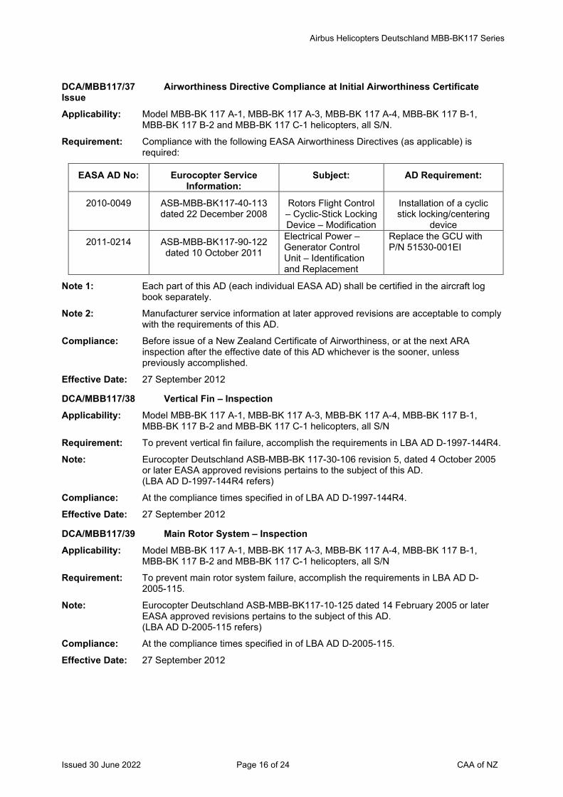
Airbus Helicopters Deutschland MBB-BK117 Series
Issued 30 June 2022 Page 16 of 24 CAA of NZ
DCA/MBB117/37 Airworthiness Directive Compliance at Initial Airworthiness Certificate Issue Applicability: Model MBB-BK 117 A-1, MBB-BK 117 A-3, MBB-BK 117 A-4, MBB-BK 117 B-1,
MBB-BK 117 B-2 and MBB-BK 117 C-1 helicopters, all S/N.
Requirement: Compliance with the following EASA Airworthiness Directives (as applicable) is required:
EASA AD No: Eurocopter Service Information:
Subject: AD Requirement:
2010-0049 ASB-MBB-BK117-40-113 dated 22 December 2008
Rotors Flight Control – Cyclic-Stick Locking Device – Modification
Installation of a cyclic stick locking/centering
device
2011-0214 ASB-MBB-BK117-90-122 dated 10 October 2011
Electrical Power –Generator Control Unit – Identification and Replacement
Replace the GCU with P/N 51530-001EI
Note 1: Each part of this AD (each individual EASA AD) shall be certified in the aircraft log book separately.
Note 2: Manufacturer service information at later approved revisions are acceptable to comply with the requirements of this AD.
Compliance: Before issue of a New Zealand Certificate of Airworthiness, or at the next ARA inspection after the effective date of this AD whichever is the sooner, unless previously accomplished.
Effective Date: 27 September 2012
DCA/MBB117/38 Vertical Fin – Inspection Applicability: Model MBB-BK 117 A-1, MBB-BK 117 A-3, MBB-BK 117 A-4, MBB-BK 117 B-1,
MBB-BK 117 B-2 and MBB-BK 117 C-1 helicopters, all S/N
Requirement: To prevent vertical fin failure, accomplish the requirements in LBA AD D-1997-144R4.
Note: Eurocopter Deutschland ASB-MBB-BK 117-30-106 revision 5, dated 4 October 2005 or later EASA approved revisions pertains to the subject of this AD. (LBA AD D-1997-144R4 refers)
Compliance: At the compliance times specified in of LBA AD D-1997-144R4.
Effective Date: 27 September 2012
DCA/MBB117/39 Main Rotor System – Inspection Applicability: Model MBB-BK 117 A-1, MBB-BK 117 A-3, MBB-BK 117 A-4, MBB-BK 117 B-1,
MBB-BK 117 B-2 and MBB-BK 117 C-1 helicopters, all S/N
Requirement: To prevent main rotor system failure, accomplish the requirements in LBA AD D-2005-115.
Note: Eurocopter Deutschland ASB-MBB-BK117-10-125 dated 14 February 2005 or later EASA approved revisions pertains to the subject of this AD. (LBA AD D-2005-115 refers)
Compliance: At the compliance times specified in of LBA AD D-2005-115.
Effective Date: 27 September 2012
Airbus Helicopters Deutschland MBB-BK117 Series
Issued 30 June 2022 Page 17 of 24 CAA of NZ
DCA/MBB117/40 Tail Rotor – Inspection Applicability: Model MBB-BK 117 A-1, MBB-BK 117 A-3, MBB-BK 117 A-4, MBB-BK 117 B-1,
MBB-BK 117 B-2 and MBB-BK 117 C-1 helicopters, all S/N
Requirement: To prevent tail rotor failure, accomplish the requirements in EASA AD 2008-0206.
Note: Eurocopter Deutschland GmbH BK117 ASB No. ASB-MBB-BK117-30-113 dated 23 September 2008 or later EASA approved revisions pertains to the subject of this AD. (EASA AD 2008-0206 refers)
Compliance: At the compliance times specified in of EASA AD 2008-0206.
Effective Date: 27 September 2012
DCA/MBB117/41 Main Rotor Blades – Inspection Applicability: Model MBB-BK 117 A-1, MBB-BK 117 A-3, MBB-BK 117 A-4, MBB-BK 117 B-1,
MBB-BK 117 B-2 and MBB-BK 117 C-1 helicopters, all S/N fitted with main rotor blades listed in Eurocopter Deutschland GmbH (ECD) ASB-MBB-BK117-10-108 revision 4.
Requirement: To prevent tail rotor failure, accomplish the requirements in EASA AD 2009-0199.
Note: Eurocopter Deutschland GmbH ASB-MBB-BK117-10-108 revision 4 dated 17 August 2009 or later EASA approved revisions pertains to the subject of this AD. (EASA AD 2009-0199 refers)
Compliance: At the compliance times specified in of EASA AD 2009-0199.
Effective Date: 27 September 2012
DCA/MBB117/42 External Rescue Hoist – Deactivation and Modification Applicability: Model MBB-BK 117 A-3, MBB-BK 117 A-4, MBB-BK 117 B-1, MBB-BK 117 B-2 and
MBB-BK 117 C-1 helicopters, all S/N.
Requirement: To prevent failure of the external rescue hoist, accomplish the requirements in EASA AD 2011-0148R1.
Note: ECD ASB MBB-BK117-80-166 revision 1, dated 04 August 2011 or later EASA approved revisions pertains to the subject of this AD. (EASA AD 2011-0148R1 refers)
Compliance: At the compliance times specified in of EASA AD 2011-0148R1.
Effective Date: 27 September 2012
DCA/MBB117/43 Cancelled – EASA AD 2013-0159 refers Effective Date: 5 August 2013
Airbus Helicopters Deutschland MBB-BK117 Series
Issued 30 June 2022 Page 18 of 24 CAA of NZ
The State of Design ADs listed below are available directly from the National Airworthiness Authority (NAA) websites. Links to NAA websites are available on the CAA website at https://www.aviation.govt.nz/aircraft/airworthiness/airworthiness-directives/links-to-state-of-design-airworthiness-directives/ If additional NZ ADs need to be issued when an unsafe condition is found to exist in an aircraft or aeronautical product in NZ, they will be added to the list below.
2012-0196 Cancelled – EASA AD 2013-0135 refers Effective Date: 16 July 2013
2012-0216 Autopilot – Dispatch Restriction Applicability: MBB-BK 117 C-2 helicopters, all serial numbers.
Effective Date: 22 October 2012
2012-0263 Cancelled – EASA AD 2013-0189 refers Effective Date: 2 September 2013
2013-0135 Time Limits and Maintenance Checks – Airworthiness Limitations Amendment Applicability: MBB-BK 117 A-1, MBB-BK 117 A-3, MBB-BK 117 A-4, MBB-BK 117 B-1, MBB-BK
117 B-2 and MBB-BK 117 C-1 helicopters, all serial numbers.
Effective Date: 16 July 2013
2013-0154 N2 Control Arm – Inspection and Modification Applicability: MBB-BK117 A-1, A-3, A-4, B-1, B-2, C-1 and C-2 helicopters, all serial numbers.
Effective Date: 5 August 2013
2013-0159 Cancelled – EASA AD 2017-0174 refers Effective Date: 28 September 2017
2013-0176 Flight System Actuators – Inspection Applicability: MBB-BK 117 C-2 helicopters, all S/N.
Effective Date: 21 August 2013
2013-0182 Lateral and Longitudinal Trim Actuator – Inspection Applicability: MBB-BK117 C-2, helicopters, all serial numbers, with at least one of the following
Duplex Trim Actuator Part Numbers (P/N) installed:
Duplex Trim Actuator lateral P/N 418-00878-050 or P/N 418-00878-051, and/or Duplex Trim Actuator longitudinal P/N 418-00878-000 or P/N 418-00878-001.
Effective Date: 26 August 2013
2013-0189 Flight Control Display System Wire Harness - Modification Applicability: MBB-BK117 C-2 helicopters equipped with dual pilot instruments, and equipped with
optional equipment ”Night Vision Imaging System (NVIS)/Night Vision Goggles (NVG)”, or with ”Special Cockpit Lighting” (NVG friendly), S/N 9004 to 9500 inclusive, except S/N 9418, 9432, 9435, 9445, 9448, 9454, 9460, 9465 and 9476.
Effective Date: 2 September 2013
2014-0046-E Cancelled – EASA AD 2014-0057 refers Effective Date: 7 March 2014
Airbus Helicopters Deutschland MBB-BK117 Series
Issued 30 June 2022 Page 19 of 24 CAA of NZ
2014-0057 Cancelled – EASA AD 2015-0019R1 refers Effective Date: 13 February 2015
2014-0126 Automatic Flight Control System Wiring – Modification and AFM Amendment Applicability: MBB-BK117 C-2 helicopters, all S/N up to 9675 inclusive, if equipped with optional
Automatic Flight Control System (AFCS).
Effective Date: 29 May 2014
2014-0180R1 Cancelled – EASA AD 2015-0166 refers Effective Date: 25 August 2015
2014-0188R4 Emergency Flotation System – AFM Supplement Applicability: MBB-BK 117 A-1, MBB-BK 117 A-3, MBB-BK 117 A-4, MBB-BK 117 B-1, MBB-BK
117 B-2 and MBB-BK 117 C-1 helicopters, all S/N, fitted with Emergency Flotation System (EFS), all part numbers, as approved optional kit for ditching provision from the helicopter Manufacturer or by a Supplemental Type Certificate (STC).
Effective Date: EASA AD 2014-0188R1 – 7 November 2014 EASA AD 2014-0188R2 – 25 March 2015 EASA AD 2014-0188R3 – 22 July 2015 EASA AD 2014-0188R4 – 22 July 2015
2014-0211 Hoist Control Pendant Wiring Harness – Inspection Applicability: MBB-BK117 C-2 helicopters, all serial numbers, when equipped with optional
equipment external mounted hoist system.
Effective Date: 22 September 2014
2015-0019R1 External Rescue Hoist System – Inspection Applicability: MBB-BK117 C-2 and MBB-BK117 D-2 helicopters, all serial numbers, if equipped
with a Goodrich external mounted hoist. Effective Date: 2015-0019-E - 7 February 2015
2015-0019R1 - 13 February 2015
2015-0044 Electrical Terminals – Inspection Applicability: MBB-BK117 C-2 helicopters, serial numbers as listed in Appendix 1 of this AD.
Effective Date: 27 March 2015
2015-0045 Cancelled – EASA AD 2016-0002 refers Effective Date: 18 January 2016
2015-0098 Starter-generator/Voltage Regulator Grounding – Inspection Applicability: MBB-BK117 A-1, MBB-BK117 A-3, MBB-BK117 A-4, MBB-BK117 B-1, MBB-BK117
B-2 and MBB-BK117 C-1 helicopters, all serial numbers.
Effective Date: 16 June 2015
2015-0144 Collective Lever Wiring Harness – Inspection Applicability: MBB-BK117 C-2 helicopters, all serial numbers up to 9708 inclusive.
Effective Date: 4 August 2015
Airbus Helicopters Deutschland MBB-BK117 Series
Issued 30 June 2022 Page 20 of 24 CAA of NZ
2015-0163R1 Doors Jettison System - Removal Applicability: MBB-BK 117 A-3, MBB-BK 117 A-4, MBB-BK 117 B-1, MBB-BK 117 B-2 and MBB-
BK 117 C-1 helicopters, all serial numbers.
Effective Date: EASA AD 2015-0163 - 20 August 2015 EASA AD 2015-0163R1 - 27 April 2016
2015-0166 Cancelled – EASA AD 2016-0060 refers Effective Date: 6 April 2016
2015-0198 Cancelled – EASA AD 2019-030 refers Effective Date: 28 February 2019
2015-0210R2 Cancelled – EASA AD 2017-0047 refers Effective Date: 27 March 2017
2016-0001 Air Conditioning Air Inlet Cover Ring – Inspection Applicability: MBB-BK117 C-2, MBB-BK117 C-2e, MBB-BK117 D-2 and MBB-BK117 D-2m
helicopters, all serial numbers.
Effective Date: 18 January 2016
2016-0002 Main Rotor Blade Vibration Absorber – Inspection Applicability: MBB-BK117 C-2, MBB-BK117 C-2e, MBB-BK117 D-2 and MBB-BK117 D-2m
helicopters, all serial numbers.
Effective Date: 18 January 2016
2016-0060 Cancelled – EASA AD 2016-0142 refers Effective Date: 2 August 2016
2016-0134 Tail Rotor Gearbox Housing - Inspection Applicability: MBB-BK 117 A-1, MBB-BK 117 A-3, MBB-BK 117 A-4, MBB-BK 117 B-1, MBB-BK
117 B-2 and MBB-BK 117 C-1, MBB-BK117 C-2 and MBB-BK117 C-2e helicopters, all serial numbers.
Effective Date: 22 July 2016
2016-0142R1 Swashplate Assembly - Inspection Applicability: MBB-BK117 A-1, MBB-BK117 A-3, MBB-BK117 A-4, MBB-BK117 B-1, MBB-BK117
B-2, MBB-BK117 C-1, MBB-BK117 C-2 and MBB-BK117 C-2e helicopters, all serial numbers.
Effective Date: EASA AD 2016-0142 - 2 August 2016 EASA AD 2016-0142R1 - 26 April 2018
2017-0026 Overhead Panel Shock Mounts - Inspection Applicability: MBB-BK 117 C-2, MBB-BK117 C-2e, MBB-BK 117 D-2 and MBB-BK117 D-2m
helicopters, all serial numbers.
Effective Date: 28 February 2017
Airbus Helicopters Deutschland MBB-BK117 Series
Issued 30 June 2022 Page 21 of 24 CAA of NZ
2017-0037 Rotor Mast Nut and Helical Gear Support - Inspection Applicability: MBB-BK 117 D-2 and MBB-BK117 D-2m helicopters, all serial numbers.
Effective Date: 8 March 2017
2017-0038 Cable Cut Flip Guard - Inspection Applicability: MBB-BK 117 D-2 and MBB-BK117 D-2m helicopters, all serial numbers.
Effective Date: 8 March 2017
2017-0047 Module Plate Assembly - Inspection Applicability: MBB-BK117 C-2, MBB-BK117 C-2e, MBB-BK117 D-2 and MBB-BK117 D-2m
helicopters, all serial numbers.
Effective Date: 27 March 2017
2010-0058R1 Tail Rotor, Cyclic and Collective Control Levers – Inspection Applicability: MBB-BK117 C-2 helicopters, all S/N.
Effective Date: 7 April 2017
2017-0094 Trim Actuators – Inspection Applicability: MBB-BK 117 D-2 helicopters, all S/N up to 20126 inclusive, excluding S/N 20109,
20119 and 20124.
Effective Date: 29 June 2017
2017-0146 Cancelled – EASA AD 2018-0230 refers Effective Date: 6 November 2018
2017-0174 Time Limits and Maintenance Checks – Airworthiness Limitations Amendment Applicability: MBB-BK 117 C-2 helicopters, all S/N.
Effective Date: 28 September 2017
2017-0177 Outboard Load System – Inspection Applicability: MBB-BK 117 C-2 helicopters, all S/N except C-2e variant, and
MBB-BK 117 D-2 helicopters, all S/N.
Effective Date: 28 September 2017
2017-0193 Main Rotor Mast – Inspection Applicability: MBB-BK117 A-1, MBB-BK117 A-3, MBB-BK117 A-4, MBB-BK117 B-1, MBB-BK117
B-2 and MBB-BK117 C-1 helicopters, all S/N.
Effective Date: 26 October 2017
2017-0238 Cancelled – EASA AD 2019-0208 refers Effective Date: 29 August 2019
2018-0046 Tail Gearbox – Inspection Applicability: MBB-BK117 A-1, MBB-BK117 A-3, MBB-BK117 A-4, MBB-BK117 B-1, MBB-BK117
B-2, MBB-BK117 C-1 and MBB-BK117 C-2 helicopters, all S/N.
Effective Date: 5 March 2018
Airbus Helicopters Deutschland MBB-BK117 Series
Issued 30 June 2022 Page 22 of 24 CAA of NZ
2018-0061 Blade Thimbles - Inspection Applicability: MBB-BK117 A-1, MBB-BK117 A-3, MBB-BK117 A-4, MBB-BK117 B-1, MBB-BK117
B-2 and MBB-BK117 C-1 helicopters, all S/N.
Effective Date: 27 March 2018
2011-0168R1 Instrument Lighting Display Brightness - Inspection Applicability: MBB-BK117 C-2 helicopters, S/N 9004 through to 9450 inclusive, if fitted with an
optional NVG system with a secured toggle switch P/N 845UN01F4AD0A (and associated wiring changes), either installed during production, or in-service in accordance with ECD Service Bulletin (SB) MBB-BK117 C-2-33-006 original issue or revision 1.
Effective Date: 26 April 2018
2018-0163 Cancelled – EASA AD 2021-0116 refers Effective Date: 10 May 2021
2018-0225-E Hook Mount Assembly - Inspection Applicability: MBB-BK 117 C-2 and MBB-BK 117 D-2 helicopters, all S/N.
Effective Date: 22 October 2018
2018-0230 Cancelled – EASA AD 2019-0208 refers Effective Date: 29 August 2019
2018-0283 Cancelled – EASA AD 2020-0257 refers Effective Date: 1 December 2020
2019-0030 Cancelled – EASA AD 2019-0275 refers Effective Date: 21 November 2019
2019-0198 Flight Controls Wiring Harness - Modification Applicability: MBB-BK 117 D-2 helicopters, all S/N.
Effective Date: 31 August 2019
2019-0208 Aircraft Management Computer – Software Modification Applicability: MBB-BK 117 D-2 helicopters, all S/N.
Effective Date: 29 August 2019
FAA AD 2019-10-51 FAA STC SR00592DE – Inspection Applicability: MBB-BK 117 C-2 helicopters, all S/N.
Effective Date: 19 September 2019
2019-0258 Tail Rotor Drive Titanium Bolts – Inspection Applicability: MBB-BK 117 D-2 helicopters, all S/N.
Effective Date: 1 November 2019
Airbus Helicopters Deutschland MBB-BK117 Series
Issued 30 June 2022 Page 23 of 24 CAA of NZ
2019-0275 Engine Mount Bushings – Inspection Applicability: MBB-BK 117 D-2 helicopters, all S/N.
Effective Date: 21 November 2019
2019-0305R1 Cabin Wiring Harness – Inspection Applicability: MBB-BK 117 D-2 helicopters, all S/N, except those helicopters embodied with Airbus
Helicopters SB MBB-BK117 D-2-25-022, original issue dated 30 June 2021, or later EASA approved revision.
Effective Date: 29 July 2021
2019-0313 Cancelled – EASA AD 2022-0086 refers Effective Date: 27 May 2022
2020-0013 Hand Held Fire Extinguishers – Inspection Applicability: MBB-BK117 A-1, A-3, A-4, B-1, B-2, C-1, C-2 and D-2 helicopters, all S/N.
Effective Date: 27 February 2020
2020-0064 Emergency Flotation System – Inspection Applicability: MBB-BK117 C-2 and D-2 helicopters, all variants, all S/N.
Effective Date: 2 April 2020
2020-0084 Collective Lever Switch Unit – Inspection Applicability: MBB-BK117 D-2 helicopters, all S/N.
Effective Date: 17 April 2020
2020-0246 Lateral Control Rod Wiring – Inspection Applicability: MBB-BK117 D-2 helicopters, all S/N up to 20334 inclusive, except S/N 20274, 20281,
20284, 20286, 20320, 20322, 20327, 20328, 20331 and 20332.
Effective Date: 26 November 2020
2020-0257 Main Rotor Actuator – Inspection Applicability: MBB-BK117 C-2 and MBB-BK D-2 helicopters, all S/N.
Effective Date: 1 December 2020
2021-0074 Collective Bellcrank – Inspection Applicability: MBB-BK117 C-2 and MBB-BK D-2 helicopters, all S/N.
Effective Date: 29 March 2021
2021-0116 Co-pilot Collective Lever Wire Harness - Inspection Applicability: MBB-BK117 D-2 helicopters, all S/N up to 20340.
Effective Date: 10 May 2021
2021-0122 Time Limits and Maintenance Checks – Airworthiness Limitations Amendment Applicability: MBB-BK117 A-1, MBB-BK117 A-3, MBB-BK117 A-4, MBB-BK117 B-1, MBB-BK117
B-2, MBB-BK117 C-1, MBB-BK117 C-2 and MBB-BK117 D-2 helicopters, all S/N.
Effective Date: 27 May 2021
Airbus Helicopters Deutschland MBB-BK117 Series
Issued 30 June 2022 Page 24 of 24 CAA of NZ
2021-0160 Main Rotor Flex Control Unit Bearing Pin – Inspection Applicability: MBB-BK117 D-3 helicopters, all S/N, including MBB-BK117 D-2 helicopters that have
been converted into MBB-BK117 D-3 with the embodiment of Airbus Helicopters SB MBB-BK117 D-2-00-003.
Effective Date: 29 July 2021
2021-0231 Emergency Flashlight – Replacement Applicability: MBB-BK117 C-2 helicopters, all S/N.
Effective Date: 29 October 2021
2021-0287 (Correction) Seat Belt Restraint System – Inspection Applicability: MBB-BK117 C-2, D-2 and D-3 helicopters, all S/N embodied with EASA STC
10038915 or STC 10055175.
Note: This AD re-issued to correct a STC number. Refer EASA STC 10038915 in the applicability.
Effective Date: EASA AD 2021-0287 - 27 January 2022 EASA AD 2021-0287 (Correction) - 24 February 2022
2021-0289-E Aircraft Flight Manual - Amendment Applicability: MBB-BK117 C-2, D-2, D3 and D-3m helicopters, all S/N.
Effective Date: 27 December 2021
2021-0290 (Correction) Airworthiness Limitations - Amendment Applicability: MBB-BK117 D3 and D-3m helicopters, all S/N.
Effective Date: EASA AD 2021-0290 (Correction) - 27 January 2022
2022-0077-E Flight Control Flexball Cables - Replacement Applicability: MBB-BK 117 D-2, MBB-BK 117 D-3, MBB-BK 117 D-3m and MBB-BK 117 C-2
helicopters, all S/N.
Effective Date: 2 May 2022
2022-0086 Tail Rotor Actuator - Inspection Applicability: MBB-BK117 C-2 helicopters, all S/N.
Effective Date: 27 May 2022
* 2022-0097 Instrument Flight Rule Screens - Removal Applicability: MBB-BK117 C-2, MBB-BK117 D-2, MBB-BK117 D-3 and MBB-BK117 D-3m
helicopters, all variants, all S/N.
Effective Date: 8 June 2022
Issued 30 June 2022 Page 1 of 19 CAA of NZ
Airworthiness Directive Schedule Helicopters Airbus Helicopters Deutschland EC 135 Series 30 June 2022
Notes: 1. This AD schedule is applicable to Airbus Helicopters Deutschland EC 135 P1, EC 135 P2, EC 135 P2+, EC 135 T1, EC 135 T2 and EC 135 T2+ helicopters manufactured under EASA Type Certificate (TC) No. R.009 (previously LBA TC No. 3061).
2. The European Union Aviation Safety Agency (EASA) is the National Airworthiness Authority (NAA) responsible for the issue of State of Design Airworthiness Directives (ADs) for these helicopters. State of Design ADs can be obtained directly from the EASA website at http://ad.easa.europa.eu/
3. The date above indicates the amendment date of this schedule.
4. New or amended ADs are shown with an asterisk *
Contents
DCA/EC135/1A Airworthiness Directive Compliance at Initial Airworthiness Certificate Issue ................... 3 DCA/EC135/2A Main Rotor Hub Shaft - Inspection .................................................................................... 3 DCA/EC135/3A Tail Rotor Drive Shaft Bearing Attachment Flange - Inspection ........................................ 4 DCA/EC135/4 Main Rotor Blade Lead-Lag Damper Attachment – Inspection ........................................ 4 DCA/EC135/5 Air Conditioning System - Modification .............................................................................. 4 DCA/EC135/6A Main Rotor Drive Torque Struts - Inspection ..................................................................... 5 DCA/EC135/7 Primary Flight and Navigation Displays - Replacement .................................................... 5 DCA/EC135/8 Automatic Engine Control – Software Improvement.......................................................... 5 DCA/EC135/9 Cancelled – Purpose Fulfilled ........................................................................................... 5 DCA/EC135/10 FADEC Fail – AFM Revision ............................................................................................. 6 DCA/EC135/11 Cancelled – DCA/EC135/27 refers.................................................................................... 6 DCA/EC135/12 Emergency Flotation System - Modification ...................................................................... 6 DCA/EC135/13A Cancelled – EASA AD 2006-0318R2 refers ...................................................................... 6 DCA/EC135/14 LH and RH Cable Channel Wire Harnesses – Inspection ................................................. 6 DCA/EC135/15 Direct Current Power Distribution – Modification ............................................................... 7 DCA/EC135/16 Cancelled – DCA/EC135/17 refers.................................................................................... 7 DCA/EC135/17 Cancelled – DCA/EC135/18 refers.................................................................................... 7 DCA/EC135/18A Cancelled – DCA/EC135/31 refers.................................................................................... 7 DCA/EC135/19 Cancelled – DCA/EC135/20 refers.................................................................................... 7 DCA/EC135/20 Cancelled – DCA/EC135/26 refers.................................................................................... 7 DCA/EC135/21 Cancelled – DCA/EC135/28 refers.................................................................................... 7 DCA/EC135/22 Cyclic Stick Locking Device – Modification and AFM Amendment .................................... 7 DCA/EC135/23 Main Rotor Lower Mast Bearing – Inspection ................................................................... 8 DCA/EC135/24 Cancelled – DCA/EC135/25 refers.................................................................................... 8 DCA/EC135/25A Cancelled – DCA/EC135/33 refers.................................................................................... 8 DCA/EC135/26A Main Gearbox – Inspection ............................................................................................... 8 DCA/EC135/27 Main Rotor Sliding Sleeve – Inspection and AFM Amendment ....................................... 10 DCA/EC135/28 Cancelled – EASA AD 2010-0058R1 refers .................................................................... 11 DCA/EC135/29A Instrument Control Panel – Flight Limitation, Placard and Modification .......................... 11 DCA/EC135/30A Cancelled – EASA AD 2017-0002 refers ........................................................................ 11 DCA/EC135/31 Cancelled – EASA AD 2010-0227R1 ............................................................................ 12 DCA/EC135/32 Cancelled – DCA/EC135/35 refers.................................................................................. 12 DCA/EC135/33 Tailboom Fenestron Ring Frame – Inspection and AFM Amendment............................. 12 DCA/EC135/34A Mechanical Air Conditioning System – Inspection .......................................................... 13
Issued 30 June 2022 Page 2 of 19 CAA of NZ
DCA/EC135/35 Cancelled – EASA AD 2011-0168R1 refers .................................................................... 13 DCA/EC135/36 Fire Extinguishing System Injection Tubes – Replacement ............................................ 14 DCA/EC135/37 Emergency Float Kit – Inspection.................................................................................... 14 DCA/EC135/38 Cancelled – DCA/EC135/39 refers.................................................................................. 14 DCA/EC135/39B Cancelled – EASA AD 2012-0085R4 refers .................................................................... 14 The State of Design ADs listed below are available directly from the National Airworthiness Authority (NAA) websites. Links to NAA websites are available on the CAA website at https://www.aviation.govt.nz/aircraft/airworthiness/airworthiness-directives/links-to-state-of-design-airworthiness-directives/ If additional NZ ADs need to be issued when an unsafe condition is found to exist in an aircraft or aeronautical product in NZ, they will be added to the list below. .............................................. 15 2012-0085R6 Main Rotor Hub – Inspection ........................................................................................... 15 2013-0176 Flight System Actuators – Inspection .............................................................................. 15 2013-0178 Cancelled - EASA AD 2017-0243 refers ....................................................................... 15 2013-0228-E Main Rotor Actuator – Replacement ............................................................................... 15 2013-0289-E Rear Structure / Ring Frame – Inspection ....................................................................... 15 2013-0306-CN AD Cancelled by EASA – Purpose fulfilled ..................................................................... 15 2013-0307-E Fuel Quantity Indication – AFM Amendment ................................................................... 15 2014-0226 Main Gearbox and Tail Gearbox Oil – Inspection ........................................................... 15 2017-0002 Main Transmission Housing – Modification ..................................................................... 16 2010-0058R1 Tail Rotor, Cyclic and Collective Control Levers – Inspection ....................................... 16 2010-0227R1 Tail Rotor Rod and Ball Pivot – Inspection .................................................................... 16 2006-0318R2 Tail Rotor Linear Control Transducer Bearing and Rod – Inspection .............................. 16 2017-0147 Tail Rotor Controls – Modification ................................................................................... 16 2017-0199 Cancelled – EASA AD 2021-0011 refers ........................................................................ 16 2017-0243 Cancelled – EASA AD 2022-0067 refers ...................................................................... 16 2011-0168R1 Instrument Lighting Display Brightness – Inspection ..................................................... 16 2018-0063 Cyclic Stick – Modification ............................................................................................. 17 2018-0168R1 Cancelled – EASA AD 2022-0067 refers ...................................................................... 17 2018-0210-E Hoist Carrier Assembly – Inspection ............................................................................. 17 2018-0284 Cancelled – EASA AD 2022-0067 refers ...................................................................... 17 2019-0087-E Cancelled – EASA AD 2020-0105 refers ........................................................................ 17 2019-0199 Tail Rotor Drive Ti-Bolts – Inspection ............................................................................. 17 2020-0013 Hand Held Fire Extinguishers – Inspection ..................................................................... 17 2020-0064 Emergency Flotation System – Inspection ...................................................................... 17 2020-0099 Titanium Bolts – Inspection ............................................................................................. 17 2020-0102 Tail Rotor Control System – Inspection ........................................................................... 17 2020-0105 Main Rotor Actuator Single-Axis Actuators – Inspection ................................................. 18 2020-0282 Tail Rotor Blades – Inspection ........................................................................................ 18 2021-0011 Outboard Load System – Inspection ............................................................................... 18 2021-0050 Tail Rotor Blades – Replacement.................................................................................... 18 2021-0066 Outboard Load System Fittings – Inspection .................................................................. 18 2021-0149 Emergency Flashlight – Inspection ................................................................................. 18 2022-0023 Air Conditioning System – Inspection.............................................................................. 18 2022-0067 Airworthiness Limitations – Amendment ......................................................................... 18 2022-0077-E Flight Control Flexball Cables - Replacement ............................................................... 19 * 2022-0097 Instrument Flight Rule Screens - Removal .................................................................... 19
Helicopters Airbus Helicopters Deutschland EC 135 Series
Issued 30 June 2022 Page 3 of 19 CAA of NZ
DCA/EC135/1A Airworthiness Directive Compliance at Initial Airworthiness Certificate Issue Applicability Model EC 135 aircraft.
Requirement: Compliance with the following LBA Airworthiness Directives (as applicable) is required:
LBA AD Nr: AD Subject:
1998-033/7 Bearing supports of the tail rotor drive shaft. Inspection of the bolt connections for loose bolts and damage
1998-109 Oil cooling system - Fan - Replacement of Shaft with Spline
1998-389 Fuselage - Tail Boom - Replacement of Bearing Support
1999-102/2 Fuselage - Tail Boom - Bearing-Location No. 1 of the Tail Rotor Shaft
Note: Each part of this AD (each individual LBA AD) shall be certified in the aircraft log book separately.
Compliance: Before issue of New Zealand Airworthiness Certificate. Repetitive inspections to be accomplished at intervals not to exceed the times specified in the LBA Airworthiness Directives.
Effective Date: DCA/EC135/1 - 30 July 1999 DCA/EC135/1A - 30 March 2006
DCA/EC135/2A Main Rotor Hub Shaft - Inspection Applicability: Model EC 135 series
Requirement: To prevent fracture of the main rotor hub-shaft, which could result in loss of control of the helicopter, accomplish the following per Eurocopter Deutschland Alert SB EC 135-62A-004 Revision 2:
1. Visual inspection of the main rotor hub-shaft.
2. Dye Penetrant Inspection of the main rotor hub-shaft.
Replace main rotor hub-shaft before further flight if any cracks are found.
(LBA AD 1999-185/3 refers)
Compliance: Initial Inspection:
1. Visual inspection before further flight. 2. Dye penetrant inspection within 10 hours TIS.
Following the initial inspections, accomplish either:-
1. Visual inspections at intervals not to exceed 15 hours TIS, or 2. Dye penetrant inspections at intervals not to exceed 100 hours TIS.
Effective Date: DCA/EC135/2 - 30 July 1999 DCA/EC135/2A - 17 December 1999
Helicopters Airbus Helicopters Deutschland EC 135 Series
Issued 30 June 2022 Page 4 of 19 CAA of NZ
DCA/EC135/3A Tail Rotor Drive Shaft Bearing Attachment Flange - Inspection Applicability: Model EC 135 series S/N 0005 through S/N 0120.
Requirement: To prevent a fracture of the bearing attachment flange of the tail rotor drive shaft, accomplish the following per Eurocopter Deutschland Alert SB EC 135-53A-010 Revision 2:
1. Inspect the bearing attachment flange for cracks. Replace the bearing attachment flange before further flight, if any cracks are found.
2. Install additional bearing support bracket.
(LBA AD 1999-199/3 refers)
Compliance: 1. Before further flight and thereafter at intervals not to exceed 15 hours TIS until modified, and then inspect (visual inspection only) at intervals not to exceed 50 hours TIS.
2. By 14 October 1999.
Effective Date: DCA/EC135/3 - 30 July 1999 DCA/EC135/3A - 7 October 1999
DCA/EC135/4 Main Rotor Blade Lead-Lag Damper Attachment – Inspection Applicability: Model EC 135 series
Requirement: To ensure proper screw connection of the nut of the expansion bolt which serves as bearing support attachment for the main rotor blade lead-lag damper, accomplish the following:-
Inspect the lockwire and of the head of the expansion bolt per Eurocopter Deutschland Alert SB EC 135-62A-005.
(LBA AD 1999-264 refers)
Compliance: The inspection must be accomplished after the last flight of the day and must be repeated every 15 flight hours until the replacement of nuts and bearing pins by modified nuts and bearing pins has been accomplished.
Effective Date: 30 July 1999
DCA/EC135/5 Air Conditioning System - Modification Applicability: Model EC 135 series S/N 0005 through 0169 equipped with air conditioning system,
except; S/N 0030, 0076, 0093, 0098, 0102, 0104, 0106, 0108, 0110, 0111, 0113, 0114, 0116, 0117, 0119, 0121, 0145, 0146, 0148, 0150, 0152, 0155.
Requirement: To prevent a short circuit following a failure of the spring resistor located in the compressor/condenser unit of the air conditioning system, and possible smoke and fire in the helicopter, accomplish the following:-
Install an insulating mat in the area of the spring resistor per Eurocopter SB EC135-21A-002 Revision 1.
Alternatively, the air conditioning system may be deactivated and placarded per Eurocopter SB EC135-21A-002 Revision 1.
(LBA AD 2000-270 refers)
Compliance: Within next 25 hours TIS.
Effective Date: 10 August 2000
Helicopters Airbus Helicopters Deutschland EC 135 Series
Issued 30 June 2022 Page 5 of 19 CAA of NZ
DCA/EC135/6A Main Rotor Drive Torque Struts - Inspection Applicability: Model EC 135 series
Requirement: To prevent failure of the torque struts, accomplish the following:-
1. Inspect, mark, exchange and observe life limitation limits of the LH and RH torque struts per ASB ECD 135-63A-002 Revision 4.
2. Brief all pilots:-
During flight if a thump-like sound occurs followed by an unusual vibration (similar to faulty Aris); – continue flight with reduced power
– land at the nearest suitable airfield.
(LBA AD 2001-107/3 refers)
Compliance: 1. At the times specified in ASB ECD 135-63A-002 Revision 4.
2. Before the next flight.
Effective Date: DCA/EC135/6 - 22 March 2001 DCA/EC135/6A - 28 August 2003
DCA/EC135/7 Primary Flight and Navigation Displays - Replacement Applicability: Model EC 135 Series S/N 0005 through 0216 equipped with SMD45H Smart
Multifunction Display.
Requirement: To prevent loss of primary flight display information check that the S/N of the SMD45H unit is not one of the faulty units listed in Eurocopter ASB EC135-31A-002 Revision 1. If the S/N is one of the listed units, operation of the helicopter is restricted to VFR conditions until the SMD45H is replaced with a serviceable unit. Placard instrument panel accordingly.
(LBA AD 2001-306 refers)
Compliance: Within next 50 hours TIS.
Effective Date: 29 November 2001
DCA/EC135/8 Automatic Engine Control – Software Improvement Applicability: Model EC 135T1 S/N 0005 through 0187 with Turbomeca Arrius 2B1 engines
Requirement: To prevent loss of automatic engine control, accomplish Eurocopter ASB EC135-71A-016 in combination with Turbomeca SB 319 73 2019.
(LBA AD 2001-304 refers)
Compliance: By 28 February 2002
Effective Date: 29 November 2001
DCA/EC135/9 Cancelled – Purpose Fulfilled Effective Date: 28 August 2003
Airbus Helicopters Deutschland EC 135 Series
Issued 30 June 2022 Page 6 of 19 CAA of NZ
DCA/EC135/10 FADEC Fail – AFM Revision Applicability: Model EC135 T1
Requirement: To maintain automatic engine control in the event of possibly spurious FADEC FAIL caution indications, comply with Eurocopter Deutschland ASB No. EC135-71A-024. This ASB requires the insertion of pages into the AFM.
(LBA AD 2002-333 refers)
Compliance: Within 50 hours TIS.
Effective Date: 28 August 2003
DCA/EC135/11 Cancelled – DCA/EC135/27 refers Effective Date: 22 January 2010
DCA/EC135/12 Emergency Flotation System - Modification Applicability: All model EC 135 aircraft fitted with removable and/or fixed parts of ECD Emergency
Flotation System Version 1.
Requirement: Due to the increased admissible maximum take-off weight of EC135 aircraft, the ECD Emergency Flotation System Version I no longer meets requirements, and the removable parts of the emergency flotation system version I must be replaced.
Remove the removable parts of ECD Emergency Flotation System Version I. Install all removable parts and components of ECD Emergency Flotation System Version II.
These actions must be accomplished per the instructions in Eurocopter Deutschland EC135 Alert Service Bulletin No. EC135-32A-010 dated 13 September 2004.
(LBA AD D-2005-414 refers)
Compliance: By 23 March 2006.
Effective Date: 23 February 2006
DCA/EC135/13A Cancelled – EASA AD 2006-0318R2 refers Effective Date: 25 April 2017
DCA/EC135/14 LH and RH Cable Channel Wire Harnesses – Inspection Applicability: All model EC135 aircraft, S/Ns 0005 through 0654.
Requirement: To prevent short circuits in the wiring harnesses due to the possibility of damage/chafing caused by the side channel cover attachment hardware, accomplish the following:
Inspect the wire harnesses in both the LH and RH cable channels, per the instructions in Eurocopter Deutschland EC135 ASB No. EC135-53A-017. If the wire harnesses are damaged, accomplish a manufacturer approved repair scheme, before further flight.
Modify the LH and RH side channel cover attachments and attach chafing protection to the wire harnesses, per the instructions in EC135 ASB No. EC135-53A-017.
For aircraft fitted with a co-pilot collective lever, modify the cover attachments per the instructions in EC135 ASB No. EC135-53A-017.
(EASA AD 2007-0021-E refers)
Compliance: Within the next 25 hours TIS or by 21 March 2007, whichever is the sooner.
Effective Date: 9 February 2007
Airbus Helicopters Deutschland EC 135 Series
Issued 30 June 2022 Page 7 of 19 CAA of NZ
DCA/EC135/15 Direct Current Power Distribution – Modification Applicability: Model EC135 aircraft, S/N 0005 all through 0497, excluding 0028, 0473, 0484, 0492
and 0496.
Requirement: To prevent energy sources interfering with each other due to the possibility of power lines being routed too close to each other and too close to signal lines, modify and separate the direct-current (DC) power supply lines per the instructions in Eurocopter Deutschland EC135 Alert Service Bulletin (ASB) No. EC135-24A-013.
(EASA AD 2007-0165 refers)
Compliance: Within the next 100 hours TIS, or at the next annual inspection, or by 31 December 2007, whichever is the sooner.
Effective Date: 28 June 2007
DCA/EC135/16 Cancelled – DCA/EC135/17 refers Effective Date: 31 January 2008
DCA/EC135/17 Cancelled – DCA/EC135/18 refers Effective Date: 24 April 2008
DCA/EC135/18A Cancelled – DCA/EC135/31 refers Effective Date: 25 November 2010
DCA/EC135/19 Cancelled – DCA/EC135/20 refers Effective Date: 26 June 2008
DCA/EC135/20 Cancelled – DCA/EC135/26 refers Effective Date: 28 May 2009
DCA/EC135/21 Cancelled – DCA/EC135/28 refers Effective Date: 29 April 2010
DCA/EC135/22 Cyclic Stick Locking Device – Modification and AFM Amendment Applicability: Model EC135 aircraft, S/N 0005 through to 0699, except S/N 0028, 0076, 0093, 0098,
0099, 0102, 0104, 0106, 0108, 0110, 0111, 0113, 0114, 0116, 0117 and 0119.
Requirement: To prevent take-off with a locked cyclic stick which could result in loss of aircraft control accomplish the following:
1. Modify the cyclic stick locking/centering device by removing the slide and spring from the cyclic stick cantilever per the instructions in ECD Alert Service Bulletin (ASB) No. ASB EC135-67A-015, dated 14 April 2008 or later approved revisions.
2. Amend the AFM by inserting the following note into the AFM:
NOTE: Before starting the engines, the cyclic stick must be moved to its neutral position. By folding the cantilever towards the pin, it is possible to move the cyclic stick into its neutral position and to center it. Locking the cyclic stick is no longer possible.
Note: Requirement 2 may be accomplished by inserting a copy of this AD into the AFM, or by inserting the ECD supplied AFM page(s) into the AFM. (EASA AD 2008-0113 refers)
Compliance: 1. & 2. By 15 September 2008.
Effective Date: 31 July 2008
Airbus Helicopters Deutschland EC 135 Series
Issued 30 June 2022 Page 8 of 19 CAA of NZ
DCA/EC135/23 Main Rotor Lower Mast Bearing – Inspection Applicability: Model EC135 P1, EC135 P2, EC135 P2+, EC135 T1, EC135 T2 and EC135 T2+
aircraft, all S/N.
Requirement: To prevent the outer race of the lower hub shaft bearing dislocating due to the retaining bolts becoming loose, accomplish the following:
1. Inspect the lower mast bearing attachment hardware and install lock washers per section 3.B of Eurocopter ASB No. EC135-63A-013 revision 02 or later approved revisions.
2. For aircraft which have previously been modified per Eurocopter ASB No. EC135-63A-013 original issue or revision 01, inspect the lower mast bearing attachment hardware and install lock washers per section 3.B of ASB No. EC135-63A-013 revision 02.
3. A main rotor gearbox shall not be fitted to any aircraft unless the instructions in section 3.B of ASB No. EC135-63A-013 revision 02 has been accomplished.
(EASA AD 2008-0175-E refers)
Compliance: 1. Within 3 flight cycles after detecting any unusual vibration during main rotor startup, or within 3 flight cycles after detecting any unusual vibration at the end of the main rotor rundown, or within the next 50 hours TIS, or by 31 March 2009, whichever occurs sooner.
2. Within the next 400 hours TIS.
3. From 20 September 2008.
Effective Date: 20 September 2008
DCA/EC135/24 Cancelled – DCA/EC135/25 refers Effective Date: 27 March 2009
DCA/EC135/25A Cancelled – DCA/EC135/33 refers Effective Date: 23 December 2010
DCA/EC135/26A Main Gearbox – Inspection Applicability: Model EC135 P1(CDS), EC135 P1(CPDS), EC135 P2(CPDS), EC135 P2+, EC135
T1(CDS), EC135 T1(CPDS), EC135 T2(CPDS) and EC135 T2+, all S/N fitted with a MGB P/N 4649 010 003, 4649 010 005, 4649 010 006, 4649 010 006X, 4649 010 008, 4649 010 008X, 4649 001 007, 4649 010 010 or 4649 010 013.
Note 1: This AD retains the requirements in superseded DCA/EC135/26. The AD applicability revised to exclude those aircraft fitted with a modified MGB. Aircraft fitted with a MGB P/N not listed in the applicability of this AD is not affected by this AD.
Requirement: To prevent tooth failure of the MGB drive pinion due to wear, accomplish the following:
1. For aircraft S/N all through to 504 which have not been modified (to use a more efficient lubricating oil) per Eurocopter Deutschland (ECD) SB EC135-63-011, take an oil sample per the instructions in ASB EC135-63A-012 revision 4, dated 27 April 2009 or later EASA approved revisions. After taking the oil sample and before the aircraft accumulates 25 hours TIS, accomplish the analysis per the instructions in ASB EC135-63A-012 and depending on the results accomplish the instructions at the time(s) specified in ASB EC135-63A-012 revision 04, dated 27 April 2009 or later approved revisions.
Airbus Helicopters Deutschland EC 135 Series
Issued 30 June 2022 Page 9 of 19 CAA of NZ
2. For aircraft S/N all through to 504 which have been modified per SB EC135-63-011 take an oil sample per the instructions in ASB EC135-63A-012. After taking the oil sample and before the aircraft accumulates 25 hours TIS, accomplish the analysis per the instructions in ASB EC135-63A-012 and depending on the results accomplish the instructions at the time(s) specified in ASB EC135-63A-012 revision 04, dated 27 April 2009 or later approved revisions.
3. For aircraft S/N 505 onwards, take an oil sample per the instructions in ASB EC135-63A-012. After taking the oil sample and before the aircraft accumulates 25 hours TIS, accomplish the analysis per the instructions in ASB EC135-63A-012 and depending on the results accomplish the instructions at the time(s) specified in ASB EC135-63A-012 revision 04, dated 27 April 2009 or later approved revisions.
Note 2: The first oil change must be accomplished at 50 hours TSN.
4. If the chip warning indicator illuminates, accomplish the instructions and the corrective action at the time(s) specified in ASB EC135-63A-012 revision 04, dated 27 April 2009 or later approved revisions.
5. For a MGB that has accumulated 300 hours or more TTIS, TSN, TSO or TSR (Time Since Repair): Inspect the MGB log card and/or the aircraft log book and determine if any chip indication log entries are recorded. Depending on the findings accomplish the instructions and corrective actions at the time(s) specified in ASB EC135-63A-012 revision 04, dated 27 April 2009 or later approved revisions.
Note 3: Oil sampling, analysis and corrective actions accomplished prior to the effective date of this AD per the instructions in ECD ASB EC135-63A-012 original issue or revision 01, revision 02 or revision 03 is acceptable to comply with the initial requirements of this AD. After 28 May 2009 (the effective date of DCA/EC135/26) oil sampling, analysis and corrective actions must be accomplished per the instructions in ECD ASB EC135-63A-012 revision 04 or later approved revisions.
Note 4: The installation of a MGB with a P/N not listed in the applicability section of this AD is a terminating action to the requirements of this AD. (EASA AD 2009-0106R1-E refers)
Compliance: 1. Within the next 100 hours TIS, unless previously accomplished and thereafter at intervals not to exceed 100 hours TIS or 12 months, whichever occurs sooner. 2. Not before 100 hours TIS after the aircraft has been modified per ECD SB EC135-63-011, or within the next 100 hours TIS for aircraft that have already been modified per ECD SB EC135-63-011 unless previously accomplished and thereafter at intervals not to exceed 100 hours TIS or 12 months, whichever occurs sooner.
3. Not before 90 hours TIS after the first oil change, or within the next 100 hours TIS, whichever occurs later unless previously accomplished and thereafter at intervals not to exceed 100 hours TIS or 12 months, whichever occurs sooner.
4. From 28 May 2009 (the effective date of DCA/EC135/26).
5. Before further flight unless previously accomplished.
Effective Date: DCA/EC135/26 - 28 May 2009 DCA/EC135/26A - 8 December 2011
Airbus Helicopters Deutschland EC 135 Series
Issued 30 June 2022 Page 10 of 19 CAA of NZ
DCA/EC135/27 Main Rotor Sliding Sleeve – Inspection and AFM Amendment Applicability: Model EC 135 P1(CDS), EC 135 P1(CPDS), EC 135 P2(CPDS), EC 135 T1(CDS),
EC 135 T1(CPDS), EC 135 T2(CPDS) and EC 635 T1(CPDS) helicopters, all S/N.
Note 1: This AD retains the requirements of superseded DCA/EC135/11 and introduces an AFM amendment which contains the requirements of that AD.
Note 2: This AD is not applicable to EC 135 P2+, EC 135 T2+, EC 635 P2+ and EC 635 T2+ helicopters as these aircraft have been certificated and delivered with the appropriate AFM preflight check instructions.
Requirement: To prevent dislocation of the plain journal bearing towards the inside or outside of the main rotor sliding sleeve resulting in limited movement of the collective controls and reduced helicopter control, accomplish the following:
1. Amend the AFM by inserting a copy of the applicable AFM page which is attached to Eurocopter ASB EC135-62A-021 initial issue dated 23 June 2005 or later EASA approved revisions into the AFM.
2. Visually inspect the position of the upper and lower plain journal bearings in the sliding sleeve for dislocated plain journal bearings per the instructions in the applicable AFM page which is attached to Eurocopter ASB EC135-62A-021. If the plain journal bearings have moved and found in the incorrect position contact the aircraft manufacturer for corrective action instructions which must be accomplished before further flight.
Note 3: The visual inspection requirements of this AD may be accomplished by adding the inspection requirement to the tech log. The visual inspection may be performed and certified under the provision in Part 43 Appendix A.1 (7) by the holder of a current pilot licence, if that person is rated on the aircraft, appropriately trained and authorised (Part 43, Subpart B refers), and the maintenance is recorded and certified as required by Part 43.
3. Amend the AFM with the applicable revision level indicated in the following table or later approved revision which contains the requirements of this AD. Remove the copy of the AFM page which was introduced by requirement 1 of this AD.
Model AFM revision or later approved revisions
EC135 P1(CDS) 15 EC135 P1(CPDS) 15 EC135 P2(CPDS) 13 EC135 T1(CDS) 18 EC135 T1(CPDS) 19 EC135 T2(CPDS) 9 EC635 T1(CPDS) 19
Note 4: The accomplishment of corrective actions is not a terminating action for the preflight inspections of the main rotor sliding sleeve.
(EASA AD 2009-0272 refers)
Compliance: 1. Before further flight unless previously accomplished and until requirement 3 of this AD is accomplished.
2. Before further flight and thereafter at every preflight inspection until requirement 3 of this AD is accomplished.
3. By 22 February 2010.
Effective Date: 22 January 2010
Airbus Helicopters Deutschland EC 135 Series
Issued 30 June 2022 Page 11 of 19 CAA of NZ
DCA/EC135/28 Cancelled – EASA AD 2010-0058R1 refers Effective Date: 7 April 2017
DCA/EC135/29A Instrument Control Panel – Flight Limitation, Placard and Modification Applicability: Model EC 135 P1(CDS), EC 135 P1(CPDS), EC 135 P2(CPDS), EC 135 P2+, EC
135 T1(CDS), EC 135 T1(CPDS), EC 135 T2(CPDS) and EC 135 T2+ aircraft, all S/N fitted with Instrument Control Panel (ICP) P/N C19269AA, S/N E0034, E0055, E0066, E0081, E0097, E0252, E0456, E0467, E1029, E1117, E1179, E1271, E1391, E1434, E1462, E1486, E1490, E1529, E1582, E1730, E1849, E1874, E1891, E1972, E2041, E2117 and E2156 through to E2400.
Note 1: No action required if the aircraft is already in compliance with DCA/EC135/29. This AD revised to introduce the option to replace affected ICP with an ICP embodied with modification standard ‘Amdt. C’ as an acceptable method of compliance with the modification requirements of this AD.
Requirement: To prevent unintentional turning of BARO rotary knobs on certain Instrument Control Panels (ICP) due to insufficient turn resistance which can result in erroneous altitude information and increase the risk of flight into terrain during IFR operation, accomplish the following:
1. Review the aircraft records or inspect the aircraft and determine the S/N of the ICP P/N C19269AA installed on the aircraft.
If an affected ICP is found installed on the aircraft, install a placard with text “Single Pilot IFR Operation Prohibited“ on the instrument panel in full view of the pilots before further flight per the instructions in ECD ASB EC135-31A-053 revision 2, dated 23 May 2011 or later approved revisions and inform the flight crew.
2. Modify the ICP per the instructions in ASB EC135-31A-053 or replace the ICP with a unit embodied with modification standard ‘Amdt. C’ or higher, and remove the placard introduced by requirement 1 of this AD
3. An affected ICP shall not be fitted to any aircraft unless the ICP has been modified per the instructions in ASB EC135-31A-053 or unless the ICP is embodied with modification standard ‘Amdt. C’ or higher.
Note 2: ICP P/N C19269AA with S/N E2401 through to E2999 have been modified by ECD per the requirements of this AD prior to installation on an aircraft, or prior to despatch as a replacement unit. The ICP manufacturer (Thale) has informed ECD that ICP units from S/N E3000 onwards have been embodied with modification standard ‘Amdt. C’ at production. Existing units can be returned to Thales for modification to this standard.
Note 3: Eurocopter Deutschland GmbH (ECD) ASB EC135-31A-053 revision 2, dated 23 May 2011 or later approved revisions is acceptable to comply with the requirements of this AD.
(EASA AD 2010-0207R1 refers)
Compliance: 1. By 23 October 2010 (ten days after the effective date of DCA/EC135/29).
2. By 13 December 2010 (two months after the effective date of DCA/EC135/29).
3. From 13 October 2010 (the effective date of DCA/EC135/29).
Effective Date: DCA/EC135/29 - 13 October 2010 DCA/EC135/29A - 30 June 2011
DCA/EC135/30A Cancelled – EASA AD 2017-0002 refers Effective Date: 23 January 2017
Airbus Helicopters Deutschland EC 135 Series
Issued 30 June 2022 Page 12 of 19 CAA of NZ
DCA/EC135/31 Cancelled – EASA AD 2010-0227R1 Effective Date: 7 April 2017
DCA/EC135/32 Cancelled – DCA/EC135/35 refers Effective Date: 29 September 2011
DCA/EC135/33 Tailboom Fenestron Ring Frame – Inspection and AFM Amendment Applicability: Model EC 135 P1(CDS), EC 135 P1(CPDS), EC 135 P2(CPDS), EC 135 P2+, EC
135 T1(CDS), EC 135 T1(CPDS), EC 135 T2(CPDS) and EC 135 T2+ helicopters, all S/N fitted with ring frame P/N L535A3501230.
Note 1: This AD retains the requirements of superseded DCA/EC135/25A, reduces the repetitive inspection intervals and requires the modification of the aft ring frame as a terminating action to the repetitive inspection requirements of this AD.
Requirement: To prevent structural failure of the tailboom to fenestron ring frame attachment which could result in loss of aircraft control, accomplish the following: 1. Revise the preflight check in section 4 of the AFM by inserting a copy of pages 6 or 7 (as applicable to the aircraft model) of Eurocopter Deutschland ASB EC135-53A-022 revision 2 dated 30 November 2010, or later approved revisions into the AFM, and advise the flight crew of this amendment. Accomplish a visual inspection of the rear structure tube per the instructions in ECD ASB EC135-53A-022. If any cracks are detected in the ring frame, replace with a serviceable part before further flight.
Note 2: The AFM amendment and the preflight inspection of the ring frame for cracks per requirement 1 of this AD may be performed and certified under the provision in Part 43 Appendix A.1 (7) by the holder of a current pilot licence, if that person is rated on the aircraft, appropriately trained and authorised (Part 43, Subpart B refers), and the maintenance is recorded and certified as required by Part 43.
Note 3: The amendment of the AFM to a revision level as indicated in appendix 1 of EASA AD 2010-0254 (as applicable to helicopter model) is acceptable to comply with the AFM amendment per requirement 1 of this AD. 2. Accomplish a visual inspection per the instructions in ECD ASB EC135-53A-022. revision 2, or later approved revisions. If any cracks are detected in the ring frame, replace with a serviceable part before further flight. 3. Modify the aft ring frame and change the ring frame P/N to L535H2120302 per the instructions in Eurocopter Deutschland SB EC135-53-023 original issue, dated 19 August 2009 or later EASA approved revisions. 4. An aft ring frame with P/N L535A3501230 shall not be fitted to any helicopter which already has ring frame P/N to L535H2120302 fitted or is in compliance with requirement 3 of this AD.
Note 4: The installation of a P/N L535A3501230 ring frame as replacement part is not a terminating action for the repetitive inspection requirements of this AD.
Note 5: The modification of a helicopter per requirement 3 of this AD is a terminating action for the repetitive inspection requirements of this AD. (EASA AD 2010-0254 refers)
Compliance: 1. Before further flight after 24 September 2009 (the effective date of DCA/EC135/25A) unless previously accomplished, and thereafter before the first flight of every day accomplish a visual inspection of the rear structure per requirement 1. 2. Within the next 25 hours TIS, or within 100 hours TIS since the last inspection per DCA/EC135/25A whichever occurs sooner, and thereafter at intervals not to exceed 25 hours TIS. 3. By 23 December 2011. 4. From 23 December 2010.
Effective Date: 23 December 2010
Airbus Helicopters Deutschland EC 135 Series
Issued 30 June 2022 Page 13 of 19 CAA of NZ
DCA/EC135/34A Mechanical Air Conditioning System – Inspection Applicability: Model EC 135 P2+ and EC 135 T2+ aircraft, S/N 870, 872, 873, 879, 883, 884, 888,
893, 900, 905, 911, 914, 916, 917, 923 and 926 fitted with a mechanical air condition system with compressor bearing block P/N L210M1872105.
Note 1: This AD revised to introduce an optional terminating action to the repetitive inspections per note 2 of this AD.
Requirement: To prevent bearing cage debris entering the engine inlet due to possible failure of a bearing in the air conditioning compressor bearing block which could result in engine compressor damage and loss of engine power, accomplish the following:
Inspect the upper bearing in the bearing block of the mechanical air conditioning system compressor, per the instructions in Eurocopter Deutschland (ECD) ASB EC135-21A-013 original issue, dated 06 June 2011 or later approved revisions.
If water, corrosion or grease leaks are found deactivate the air conditioning system per the instructions in ECD ASB EC135-21A-013 before further flight.
Note 2: The repetitive inspections mandated by this AD may be terminated when the mechanical air conditioning system compressor bearing block P/N L210M1872105 is replaced with an improved block P/N L210M1872107 or P/N L210M1872886 per the instructions in of ECD SB EC135-21-015 original issue, dated 12 July 2011 or later approved revisions.
(EASA AD 2011-0111R1 refers)
Compliance: Within 25 hours TIS or 14 days after 30 June 2011 (the effective date of DCA/EC135/34), whichever occurs sooner, and
If condensation is found accomplish the AD requirements thereafter at intervals not to exceed 25 hours TIS or 28 days whichever occurs sooner, and
If no water, corrosion or grease leaks are found, accomplish the AD requirements thereafter at intervals not to exceed 100 hours TIS or 3 months whichever occurs sooner.
Effective Date: DCA/EC135/34 - 30 June 2011 DCA/EC135/34A - 27 October 2011
DCA/EC135/35 Cancelled – EASA AD 2011-0168R1 refers Effective Date: 26 April 2018
Airbus Helicopters Deutschland EC 135 Series
Issued 30 June 2022 Page 14 of 19 CAA of NZ
DCA/EC135/36 Fire Extinguishing System Injection Tubes – Replacement Applicability: Model EC 135 P1(CDS), EC 135 P1(CPDS), EC 135 P2(CPDS), EC 135 P2+, EC
135 T1(CDS), EC 135 T1(CPDS), EC 135 T2(CPDS) and EC 135 T2+ helicopters, all S/N fitted with a single engine fire extinguishing system P/N L262M1808101, L262M1812101 or P/N L262M1812102, or fitted with a dual engine fire extinguishing system P/N L262M1813102.
Requirement: To prevent failure of the fire extinguishing system due to non-compliant injection tubes accomplish the following:
1. Modify or replace RH and LH injection tubes and elbow (if installed) listed in table 1 of this AD per the instructions in Eurocopter Deutschland GmbH (ECD) ASB EC135-26A-003 revision 01 dated 16 May 2011 or later approved revisions.
Table 1 – Parts to be modified or replaced:
For single engine fire extinguishing systems:
RH tube P/N L262M1810101; LH tube P/N L262M1811801 and/or P/N L262M1809101.
For dual engine fire extinguishing systems:
RH tube P/N L262M1814101; RH tube P/N L262M1808212; LH tube elbow P/N L262M1815101 and LH tube P/N L262M1808211.
2. An injection tube or elbow listed in table 1 of this AD shall not be installed on any helicopter unless the part has been modified per the instructions in ECD ASB EC135-26A-003. (EASA AD 2011-0172 refers)
Compliance: 1. For single engine fire extinguishing systems P/N L262M1808101, P/N L262M1812101 and P/N L262M1812102:
By 29 June 2012.
For dual engine fire extinguishing system P/N L262M1813102:
By 29 March 2012.
2. From 29 September 2011.
Effective Date: 29 September 2011
DCA/EC135/37 Emergency Float Kit – Inspection Applicability: Model EC-135 aircraft fitted with Apical emergency float kit P/N 644.1801, S/N all
through to 031 (embodied under FAA STC SR01855LA).
Requirement: To prevent an unsafe condition accomplish the inspections and corrective actions specified in FAA AD 2011-25-01.
(FAA AD 2011-25-01 refers)
Compliance: By 26 July 2012
Effective Date: 26 January 2012
DCA/EC135/38 Cancelled – DCA/EC135/39 refers Effective Date: 19 May 2012
DCA/EC135/39B Cancelled – EASA AD 2012-0085R4 refers Effective Date: 4 October 2012
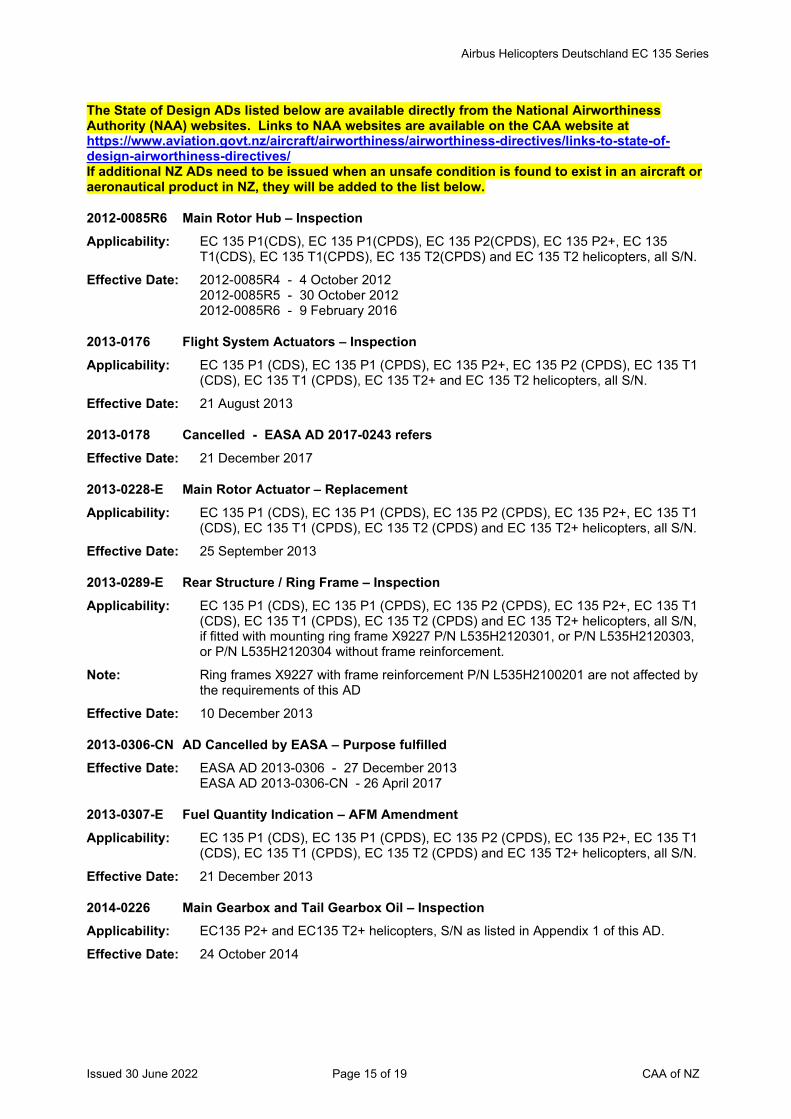
Airbus Helicopters Deutschland EC 135 Series
Issued 30 June 2022 Page 15 of 19 CAA of NZ
The State of Design ADs listed below are available directly from the National Airworthiness Authority (NAA) websites. Links to NAA websites are available on the CAA website at https://www.aviation.govt.nz/aircraft/airworthiness/airworthiness-directives/links-to-state-of-design-airworthiness-directives/ If additional NZ ADs need to be issued when an unsafe condition is found to exist in an aircraft or aeronautical product in NZ, they will be added to the list below.
2012-0085R6 Main Rotor Hub – Inspection Applicability: EC 135 P1(CDS), EC 135 P1(CPDS), EC 135 P2(CPDS), EC 135 P2+, EC 135
T1(CDS), EC 135 T1(CPDS), EC 135 T2(CPDS) and EC 135 T2 helicopters, all S/N.
Effective Date: 2012-0085R4 - 4 October 2012 2012-0085R5 - 30 October 2012 2012-0085R6 - 9 February 2016
2013-0176 Flight System Actuators – Inspection Applicability: EC 135 P1 (CDS), EC 135 P1 (CPDS), EC 135 P2+, EC 135 P2 (CPDS), EC 135 T1
(CDS), EC 135 T1 (CPDS), EC 135 T2+ and EC 135 T2 helicopters, all S/N.
Effective Date: 21 August 2013
2013-0178 Cancelled - EASA AD 2017-0243 refers Effective Date: 21 December 2017
2013-0228-E Main Rotor Actuator – Replacement Applicability: EC 135 P1 (CDS), EC 135 P1 (CPDS), EC 135 P2 (CPDS), EC 135 P2+, EC 135 T1
(CDS), EC 135 T1 (CPDS), EC 135 T2 (CPDS) and EC 135 T2+ helicopters, all S/N.
Effective Date: 25 September 2013
2013-0289-E Rear Structure / Ring Frame – Inspection Applicability: EC 135 P1 (CDS), EC 135 P1 (CPDS), EC 135 P2 (CPDS), EC 135 P2+, EC 135 T1
(CDS), EC 135 T1 (CPDS), EC 135 T2 (CPDS) and EC 135 T2+ helicopters, all S/N, if fitted with mounting ring frame X9227 P/N L535H2120301, or P/N L535H2120303, or P/N L535H2120304 without frame reinforcement.
Note: Ring frames X9227 with frame reinforcement P/N L535H2100201 are not affected by the requirements of this AD
Effective Date: 10 December 2013
2013-0306-CN AD Cancelled by EASA – Purpose fulfilled Effective Date: EASA AD 2013-0306 - 27 December 2013
EASA AD 2013-0306-CN - 26 April 2017
2013-0307-E Fuel Quantity Indication – AFM Amendment Applicability: EC 135 P1 (CDS), EC 135 P1 (CPDS), EC 135 P2 (CPDS), EC 135 P2+, EC 135 T1
(CDS), EC 135 T1 (CPDS), EC 135 T2 (CPDS) and EC 135 T2+ helicopters, all S/N.
Effective Date: 21 December 2013
2014-0226 Main Gearbox and Tail Gearbox Oil – Inspection Applicability: EC135 P2+ and EC135 T2+ helicopters, S/N as listed in Appendix 1 of this AD. Effective Date: 24 October 2014
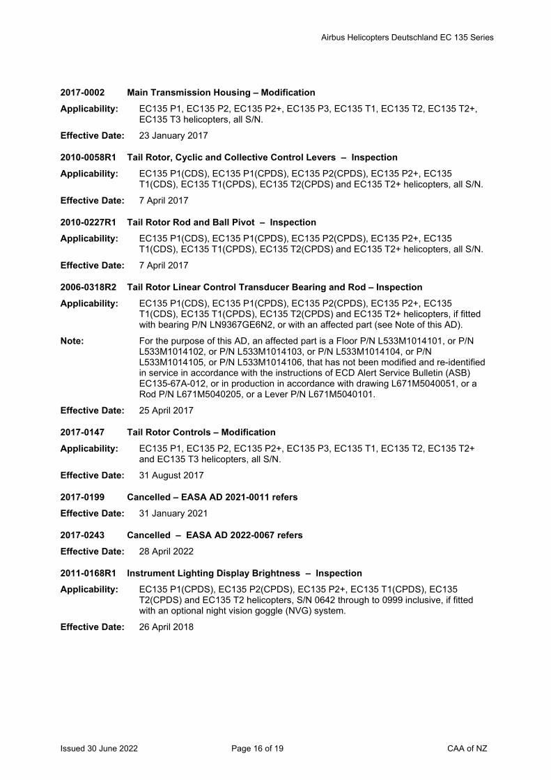
Airbus Helicopters Deutschland EC 135 Series
Issued 30 June 2022 Page 16 of 19 CAA of NZ
2017-0002 Main Transmission Housing – Modification Applicability: EC135 P1, EC135 P2, EC135 P2+, EC135 P3, EC135 T1, EC135 T2, EC135 T2+,
EC135 T3 helicopters, all S/N.
Effective Date: 23 January 2017
2010-0058R1 Tail Rotor, Cyclic and Collective Control Levers – Inspection Applicability: EC135 P1(CDS), EC135 P1(CPDS), EC135 P2(CPDS), EC135 P2+, EC135
T1(CDS), EC135 T1(CPDS), EC135 T2(CPDS) and EC135 T2+ helicopters, all S/N.
Effective Date: 7 April 2017
2010-0227R1 Tail Rotor Rod and Ball Pivot – Inspection Applicability: EC135 P1(CDS), EC135 P1(CPDS), EC135 P2(CPDS), EC135 P2+, EC135
T1(CDS), EC135 T1(CPDS), EC135 T2(CPDS) and EC135 T2+ helicopters, all S/N.
Effective Date: 7 April 2017
2006-0318R2 Tail Rotor Linear Control Transducer Bearing and Rod – Inspection Applicability: EC135 P1(CDS), EC135 P1(CPDS), EC135 P2(CPDS), EC135 P2+, EC135
T1(CDS), EC135 T1(CPDS), EC135 T2(CPDS) and EC135 T2+ helicopters, if fitted with bearing P/N LN9367GE6N2, or with an affected part (see Note of this AD).
Note: For the purpose of this AD, an affected part is a Floor P/N L533M1014101, or P/N L533M1014102, or P/N L533M1014103, or P/N L533M1014104, or P/N L533M1014105, or P/N L533M1014106, that has not been modified and re-identified in service in accordance with the instructions of ECD Alert Service Bulletin (ASB) EC135-67A-012, or in production in accordance with drawing L671M5040051, or a Rod P/N L671M5040205, or a Lever P/N L671M5040101.
Effective Date: 25 April 2017
2017-0147 Tail Rotor Controls – Modification Applicability: EC135 P1, EC135 P2, EC135 P2+, EC135 P3, EC135 T1, EC135 T2, EC135 T2+
and EC135 T3 helicopters, all S/N.
Effective Date: 31 August 2017
2017-0199 Cancelled – EASA AD 2021-0011 refers Effective Date: 31 January 2021
2017-0243 Cancelled – EASA AD 2022-0067 refers Effective Date: 28 April 2022
2011-0168R1 Instrument Lighting Display Brightness – Inspection Applicability: EC135 P1(CPDS), EC135 P2(CPDS), EC135 P2+, EC135 T1(CPDS), EC135
T2(CPDS) and EC135 T2 helicopters, S/N 0642 through to 0999 inclusive, if fitted with an optional night vision goggle (NVG) system.
Effective Date: 26 April 2018
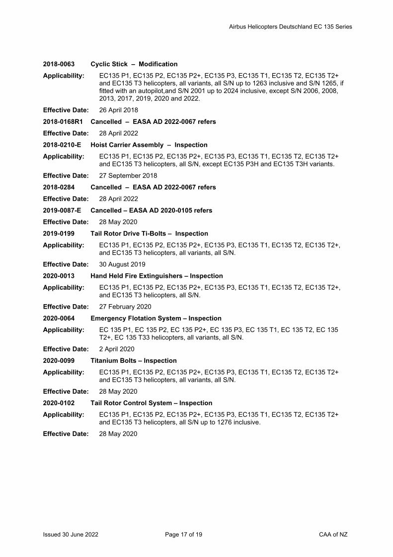
Airbus Helicopters Deutschland EC 135 Series
Issued 30 June 2022 Page 17 of 19 CAA of NZ
2018-0063 Cyclic Stick – Modification Applicability: EC135 P1, EC135 P2, EC135 P2+, EC135 P3, EC135 T1, EC135 T2, EC135 T2+
and EC135 T3 helicopters, all variants, all S/N up to 1263 inclusive and S/N 1265, if fitted with an autopilot,and S/N 2001 up to 2024 inclusive, except S/N 2006, 2008, 2013, 2017, 2019, 2020 and 2022.
Effective Date: 26 April 2018
2018-0168R1 Cancelled – EASA AD 2022-0067 refers Effective Date: 28 April 2022
2018-0210-E Hoist Carrier Assembly – Inspection Applicability: EC135 P1, EC135 P2, EC135 P2+, EC135 P3, EC135 T1, EC135 T2, EC135 T2+
and EC135 T3 helicopters, all S/N, except EC135 P3H and EC135 T3H variants.
Effective Date: 27 September 2018
2018-0284 Cancelled – EASA AD 2022-0067 refers Effective Date: 28 April 2022
2019-0087-E Cancelled – EASA AD 2020-0105 refers Effective Date: 28 May 2020
2019-0199 Tail Rotor Drive Ti-Bolts – Inspection Applicability: EC135 P1, EC135 P2, EC135 P2+, EC135 P3, EC135 T1, EC135 T2, EC135 T2+,
and EC135 T3 helicopters, all variants, all S/N.
Effective Date: 30 August 2019
2020-0013 Hand Held Fire Extinguishers – Inspection Applicability: EC135 P1, EC135 P2, EC135 P2+, EC135 P3, EC135 T1, EC135 T2, EC135 T2+,
and EC135 T3 helicopters, all S/N.
Effective Date: 27 February 2020
2020-0064 Emergency Flotation System – Inspection Applicability: EC 135 P1, EC 135 P2, EC 135 P2+, EC 135 P3, EC 135 T1, EC 135 T2, EC 135
T2+, EC 135 T33 helicopters, all variants, all S/N.
Effective Date: 2 April 2020
2020-0099 Titanium Bolts – Inspection Applicability: EC135 P1, EC135 P2, EC135 P2+, EC135 P3, EC135 T1, EC135 T2, EC135 T2+
and EC135 T3 helicopters, all variants, all S/N.
Effective Date: 28 May 2020
2020-0102 Tail Rotor Control System – Inspection Applicability: EC135 P1, EC135 P2, EC135 P2+, EC135 P3, EC135 T1, EC135 T2, EC135 T2+
and EC135 T3 helicopters, all S/N up to 1276 inclusive.
Effective Date: 28 May 2020
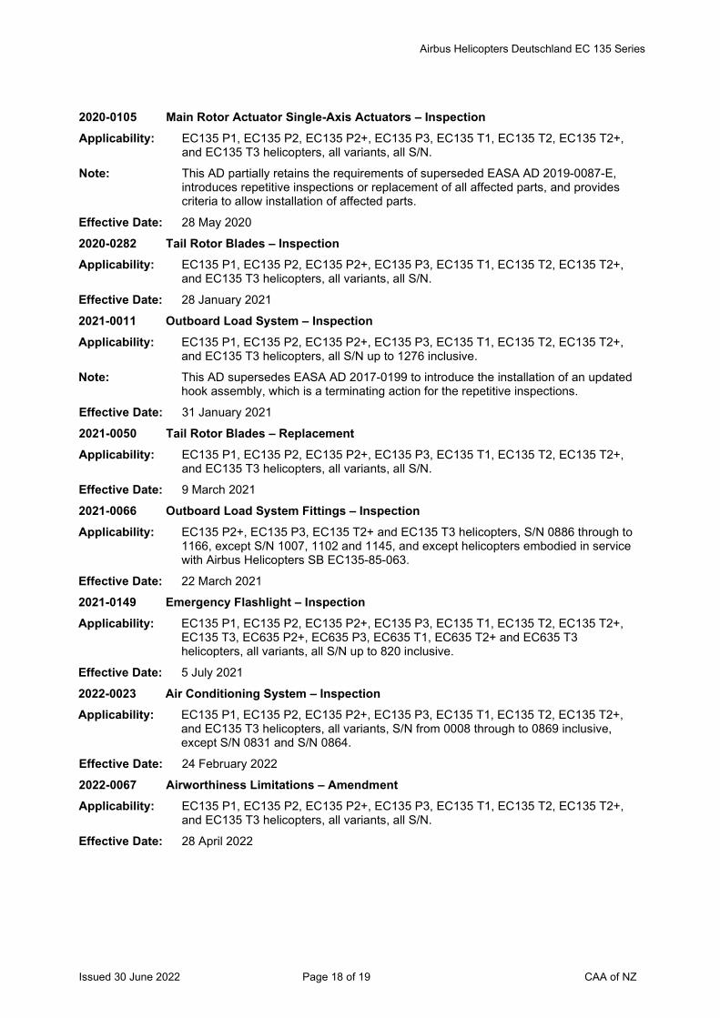
Airbus Helicopters Deutschland EC 135 Series
Issued 30 June 2022 Page 18 of 19 CAA of NZ
2020-0105 Main Rotor Actuator Single-Axis Actuators – Inspection Applicability: EC135 P1, EC135 P2, EC135 P2+, EC135 P3, EC135 T1, EC135 T2, EC135 T2+,
and EC135 T3 helicopters, all variants, all S/N.
Note: This AD partially retains the requirements of superseded EASA AD 2019-0087-E, introduces repetitive inspections or replacement of all affected parts, and provides criteria to allow installation of affected parts.
Effective Date: 28 May 2020
2020-0282 Tail Rotor Blades – Inspection Applicability: EC135 P1, EC135 P2, EC135 P2+, EC135 P3, EC135 T1, EC135 T2, EC135 T2+,
and EC135 T3 helicopters, all variants, all S/N.
Effective Date: 28 January 2021
2021-0011 Outboard Load System – Inspection Applicability: EC135 P1, EC135 P2, EC135 P2+, EC135 P3, EC135 T1, EC135 T2, EC135 T2+,
and EC135 T3 helicopters, all S/N up to 1276 inclusive.
Note: This AD supersedes EASA AD 2017-0199 to introduce the installation of an updated hook assembly, which is a terminating action for the repetitive inspections.
Effective Date: 31 January 2021
2021-0050 Tail Rotor Blades – Replacement Applicability: EC135 P1, EC135 P2, EC135 P2+, EC135 P3, EC135 T1, EC135 T2, EC135 T2+,
and EC135 T3 helicopters, all variants, all S/N.
Effective Date: 9 March 2021
2021-0066 Outboard Load System Fittings – Inspection Applicability: EC135 P2+, EC135 P3, EC135 T2+ and EC135 T3 helicopters, S/N 0886 through to
1166, except S/N 1007, 1102 and 1145, and except helicopters embodied in service with Airbus Helicopters SB EC135-85-063.
Effective Date: 22 March 2021
2021-0149 Emergency Flashlight – Inspection Applicability: EC135 P1, EC135 P2, EC135 P2+, EC135 P3, EC135 T1, EC135 T2, EC135 T2+,
EC135 T3, EC635 P2+, EC635 P3, EC635 T1, EC635 T2+ and EC635 T3 helicopters, all variants, all S/N up to 820 inclusive.
Effective Date: 5 July 2021
2022-0023 Air Conditioning System – Inspection Applicability: EC135 P1, EC135 P2, EC135 P2+, EC135 P3, EC135 T1, EC135 T2, EC135 T2+,
and EC135 T3 helicopters, all variants, S/N from 0008 through to 0869 inclusive, except S/N 0831 and S/N 0864.
Effective Date: 24 February 2022
2022-0067 Airworthiness Limitations – Amendment Applicability: EC135 P1, EC135 P2, EC135 P2+, EC135 P3, EC135 T1, EC135 T2, EC135 T2+,
and EC135 T3 helicopters, all variants, all S/N.
Effective Date: 28 April 2022
Airbus Helicopters Deutschland EC 135 Series
Issued 30 June 2022 Page 19 of 19 CAA of NZ
2022-0077-E Flight Control Flexball Cables - Replacement Applicability: EC 135 T1, EC 135 T2, EC 135 T2+, EC 135 T3, EC 135 P1, EC 135 P2, EC 135
P2+, EC 135 P3, EC 635 T1, EC 635 T2+, EC 635 T3, EC 635 P2+ and EC 635 P3 helicopters, all S/N.
Effective Date: 2 May 2022
* 2022-0097 Instrument Flight Rule Screens - Removal Applicability: EC135 P1, EC135 P2, EC135 P2+, EC135 P3, EC135 T1, EC135 T2, EC135 T2+,
EC135 T3, EC635 P2+, EC635 P3, EC635 T1, EC635 T2+ and EC635 T3 helicopters, all variants, all S/N.
Effective Date: 8 June 2022

Issued 30 June 2022 Page 1 of 10 CAA of NZ
Airworthiness Directive Schedule Components & Equipment Aircraft Seats and Harnesses 30 June 2022
Notes: 1. This AD schedule is applicable to aircraft seats and harnesses installed on aircraft.
2. This AD schedule includes those foreign National Airworthiness Authority (NAA) ADs applicable to seats and harnesses installed on aircraft. NAA ADs can be obtained directly from the applicable NAA website. Links to NAA websites are available on the CAA website at https://www.aviation.govt.nz/aircraft/airworthiness/airworthiness-directives/links-to-state-of-design-airworthiness-directives/
3. The date above indicates the amendment date of this schedule.
4. New or amended ADs are shown with an asterisk *
Contents
DCA/SEAT/1 Aircraft Seats - Removal ................................................................................................... 2 DCA/SEAT/2 Eon Safety Belt - Modification ........................................................................................... 2 DCA/SEAT/3 Safety Belt Assembly - Removal ....................................................................................... 2 DCA/SEAT/4 Safety Belt - Modification .................................................................................................. 2 DCA/SEAT/5 Safety Belt - Modification .................................................................................................. 3 DCA/SEAT/6 Safety Belt Assemblies - Removal .................................................................................... 3 DCA/SEAT/7 Safety Belt Assemblies - Inspection .................................................................................. 4 DCA/SEAT/8 Safety Belt Assemblies - Inspection .................................................................................. 4 DCA/SEAT/9 Safety Belt Assemblies - Replacement ............................................................................. 4 DCA/SEAT/10 Aircraft Belts Inc – Inspection and Replacement ............................................................... 5 DCA/SEAT/11B Type 343 Safety Belts – Inspection ................................................................................... 6 DCA/SEAT/12A Cancelled – FAA AD 2021-07-13 refers ............................................................................ 6 The State of Design ADs listed below are available directly from the National Airworthiness Authority (NAA) websites. Links to NAA websites are available on the CAA website at https://www.aviation.govt.nz/aircraft/airworthiness/airworthiness-directives/links-to-state-of-design-airworthiness-directives/ If additional NZ ADs need to be issued when an unsafe condition is found to exist in an aircraft or aeronautical product in NZ, they will be added to the list below. ................................................ 7 EASA AD 2013-0020R4 (Correction) Safety Belts and Torso Restraint Systems – Inspection ....................... 7 UK MPD 2013-005-E Cancelled – Refer Ex-military AD Schedule ..................................................................... 7 EASA AD 2014-0279 Restraint System Rotary Buckle Sub-assembly – Inspection ........................................... 8 DCA/SEAT/13 Cancelled – DCA/HELI/5 Refers ....................................................................................... 8 EASA AD 2016-0210 Seat Energy Absorber Assembly – Inspection ................................................................. 8 UK CAA AD 002-12-2001R2 Sutton Safety Harnesses – Inspection and Life Limitation................................ 8 EASA AD 2017-0225 Seat Restraint Systems – Inspection ............................................................................... 9 EASA AD 2018-0195 Restraint System Rotary Buckle – Removal from Service ............................................... 9 EASA AD 2018-0223 Seat Energy Absorber Assembly – Modification .............................................................. 9 FAA AD 2021-07-13 Pacific Scientific Company Rotary Buckle Assemblies – Inspection ................................. 9 EASA AD 2021-0137 Pilot and Co-pilot Seats – Inspection .............................................................................. 10 * UK CAA AD G-2022-0011 Pilot and Co-pilot Seats – Inspection ................................................................ 10

Components & Equipment Aircraft Seats and Harnesses
Issued 30 June 2022 Page 2 of 10 CAA of NZ
DCA/SEAT/1 Aircraft Seats - Removal Applicability: TECO Model 603 seats.
Requirement: Remove from service all TECO Model 603 seats.
Compliance: By 31 March 1969
Effective Date: 31 March 1968
DCA/SEAT/2 Eon Safety Belt - Modification Applicability: Safety Belts model E2900 manufactured by Eon Corp., Los Angeles, California, USA
and used on but not limited to Schweizer (Hughes) 269 series helicopters.
Requirement: To safeguard against inadvertent release, Eon Corp. safety belts model E2900 with series E8000 buckle shall, unless withdrawn from service and replaced with approved alternative safety belts, be modified in accordance with Dalhoff and King modification RAL 480 or approved equivalent.
Compliance: Not later than next 50 hours TIS or by 30 November 1977, whichever occurs first.
Effective Date: 11 October 1977
DCA/SEAT/3 Safety Belt Assembly - Removal Applicability: 1. Indiana Mills and Manufacturing Inc. model IMM 111040-1, -2, -3, -4 and -8 safety
belt assemblies, installed in but not limited to, Gulfstream American Corp. (formerly Grumman American Aviation Corp.) model AA-1B, AA-1C, AA-5, AA-5A and AA-5B.
2. Hamill Manufacturing Co. model GA-4 and GA-5 safety belt assemblies.
Requirement: The safety belts concerned are to be removed from service being no longer considered to meet the standards prescribed by FAA TSO-C22F and the approved special criteria for push-button release mechanisms, which requires push-button release force to be between 2.5 and 8 pounds, when using loading conditions specified in FAA TSO.
(FAA AD 79-16-02 and 80-05-02 refer)
Compliance: 30 August 1980
Effective Date: 18 April 1980
DCA/SEAT/4 Safety Belt - Modification Applicability: Eon model E2900 and E8000 seat belts and harnesses.
Requirement: To prevent inadvertent opening and/or false latching, remove from service assemblies with bullet shaped latch or open-ended buckle cover as shown in Eon Corporation SB 1 and replace with components of improved design.
(FAA AD 80-05-04 refers)
Compliance: By 30 July 1980
Effective Date: 20 June 1980
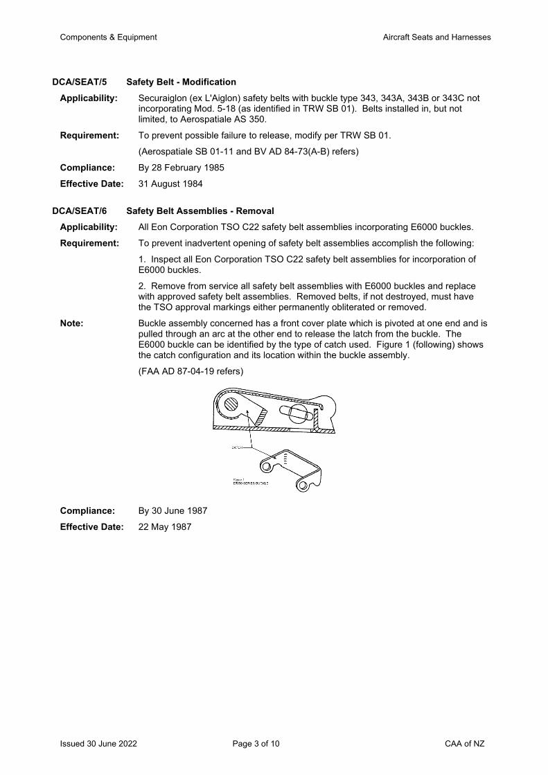
Components & Equipment Aircraft Seats and Harnesses
Issued 30 June 2022 Page 3 of 10 CAA of NZ
DCA/SEAT/5 Safety Belt - Modification Applicability: Securaiglon (ex L'Aiglon) safety belts with buckle type 343, 343A, 343B or 343C not
incorporating Mod. 5-18 (as identified in TRW SB 01). Belts installed in, but not limited, to Aerospatiale AS 350.
Requirement: To prevent possible failure to release, modify per TRW SB 01.
(Aerospatiale SB 01-11 and BV AD 84-73(A-B) refers)
Compliance: By 28 February 1985
Effective Date: 31 August 1984
DCA/SEAT/6 Safety Belt Assemblies - Removal Applicability: All Eon Corporation TSO C22 safety belt assemblies incorporating E6000 buckles.
Requirement: To prevent inadvertent opening of safety belt assemblies accomplish the following:
1. Inspect all Eon Corporation TSO C22 safety belt assemblies for incorporation of E6000 buckles.
2. Remove from service all safety belt assemblies with E6000 buckles and replace with approved safety belt assemblies. Removed belts, if not destroyed, must have the TSO approval markings either permanently obliterated or removed.
Note: Buckle assembly concerned has a front cover plate which is pivoted at one end and is pulled through an arc at the other end to release the latch from the buckle. The E6000 buckle can be identified by the type of catch used. Figure 1 (following) shows the catch configuration and its location within the buckle assembly.
(FAA AD 87-04-19 refers)
Compliance: By 30 June 1987
Effective Date: 22 May 1987
Components & Equipment Aircraft Seats and Harnesses
Issued 30 June 2022 Page 4 of 10 CAA of NZ
DCA/SEAT/7 Safety Belt Assemblies - Inspection Applicability: All Pacific Scientific TSO C22F lap belt assemblies P/N 1107177 (all dash numbers)
manufactured between 1 September 1984 and 1 January 1986.
Requirement: To eliminate belt assemblies with belt retractor shafts which do not provide adequate strength, accomplish the following:
Inspect affected assemblies to determine if they have P/N 1106294-01 retractor shafts made from the correct material. This is achieved by visually inspecting the end of the shaft. If the colour is gold anodise, the shaft is acceptable. If the colour is dull battleship grey anodise, the shaft must be replaced with a part of the correct colour before further flight.
(FAA AD 87-20-05 refers)
Compliance: By 30 June 1988
Effective Date: 18 March 1988
DCA/SEAT/8 Safety Belt Assemblies - Inspection Applicability: All Davis Aircraft Products Co. Inc. safety belts which incorporate black "Ultem"
plastic latch-cover with 90° type pull-release mechanism and have P/N's detailed in Davis Aircraft Products SB No. 1.
Requirement: To prevent difficulty in releasing latch,or possibility of becoming completely jammed when actuated through 90°, inspect per Davis Aircraft Products SB No. 1.
Remove all with affected P/N's and replace with an approved safety belt assembly before further flight.
(FAA AD 89-09-02 refers)
Compliance: Within next 100 flights.
Effective Date: 11 August 1989
DCA/SEAT/9 Safety Belt Assemblies - Replacement Applicability Pacific Scientific lap belt assemblies and restraint systems, as listed in Pacific
Scientific SB 1108435-25-01 and 1108460-25-01.
Requirement: To prevent the inability of passengers and crew to egress from their seats during an emergency accomplish the following:
Remove the lap belt assemblies and restraint systems and replace them with new design assemblies per Pacific Scientific SB 1108435-25-01 or SB 1108460-25-01 as applicable.
(FAA AD 94-21-06 refers)
Compliance: By 20 April 1995
Effective Date: 20 January 1995
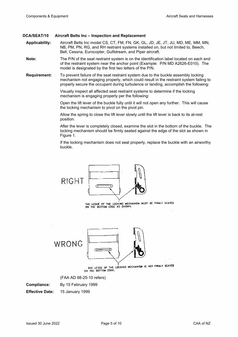
Components & Equipment Aircraft Seats and Harnesses
Issued 30 June 2022 Page 5 of 10 CAA of NZ
DCA/SEAT/10 Aircraft Belts Inc – Inspection and Replacement Applicability: Aircraft Belts Inc model CS, CT, FM, FN, GK, GL, JD, JE, JT, JU, MD, ME, MM, MN,
NB, PM, PN, RG, and RH restraint systems installed on, but not limited to, Beech, Bell, Cessna, Eurocopter, Gulfstream, and Piper aircraft.
Note: The P/N of the seat restraint system is on the identification label located on each end of the restraint system near the anchor point (Example: P/N MD A2626-E010). The model is designated by the first two letters of the P/N.
Requirement: To prevent failure of the seat restraint system due to the buckle assembly locking mechanism not engaging properly, which could result in the restraint system failing to properly secure the occupant during turbulence or landing, accomplish the following:
Visually inspect all affected seat restraint systems to determine if the locking mechanism is engaging properly per the following:
Open the lift lever of the buckle fully until it will not open any further. This will cause the locking mechanism to pivot on the pivot pin.
Allow the spring to close the lift lever slowly until the lift lever is back to its at-rest position.
After the lever is completely closed, examine the slot in the bottom of the buckle. The locking mechanism should be firmly seated against the edge of the slot as shown in Figure 1.
If the locking mechanism does not seat properly, replace the buckle with an airworthy buckle.
(FAA AD 98-25-10 refers)
Compliance: By 15 February 1999
Effective Date: 15 January 1999
Components & Equipment Aircraft Seats and Harnesses
Issued 30 June 2022 Page 6 of 10 CAA of NZ
DCA/SEAT/11B Type 343 Safety Belts – Inspection Applicability: All Type 343 safety belts, Type 343 safety belt extensions and all torso restraint
systems that incorporate a Type 343 buckle, manufactured by Anjou Aeronautique, Formerly TRW Repa SA, formerly L’Aiglon.
Note 1: Manufacturer may not have identified equipment with S/Ns. P/N is stamped on buckle and could be any one of the following:
ANJOU AERONAUTIQUE, or TRW Repa S.A, or, L’AIGLON, TYPE 343; 343M, 343AM, 343B, 343BM, 343C, 343CM, or 343D.
Requirement: To ensure security of buckle, inspect buckle spring per paragraph B of SB ANJOU AERONAUTIQUE 343-25-02.
Note 2: French airworthiness directive DGAC 2002-105 (AB) limits the life to 5 calendar years. While this is not a requirement per this AD, frequent inspections of the buckle spring are recommended.
Compliance: Inspect within six months and thereafter at intervals not to exceed 12 months.
Effective Date: DCA/SEAT/11A - 30 May 2002 DCA/SEAT/11B - 29 August 2002
DCA/SEAT/12A Cancelled – FAA AD 2021-07-13 refers Note: DCA/SEAT/12A (EASA AD 2007-0256 refers) is cancelled by EASA AD Cancellation
Notice 2007-0256-CN issued 11 May 2021. Since EASA issued AD 2007-0256, the FAA issued AD 2021-07-13. The FAA AD was prompted by EASA AD 2007-0256, which was not a ‘State of Design’ AD for US designed and manufactured parts. EASA has now adopted FAA AD 2021-07-13, being the ‘State of Design’ AD for the affected parts, and cancelled EASA AD 2007-0256. The FAA AD applies to the same Pacific Scientific Company P/N (all dash numbers) rotary buckle assemblies, irrespective of manufacturing date, or P/N restraint system, or the aircraft type they are installed on.
Effective Date: 11 May 2021
Components & Equipment Aircraft Seats and Harnesses
Issued 30 June 2022 Page 7 of 10 CAA of NZ
The State of Design ADs listed below are available directly from the National Airworthiness Authority (NAA) websites. Links to NAA websites are available on the CAA website at https://www.aviation.govt.nz/aircraft/airworthiness/airworthiness-directives/links-to-state-of-design-airworthiness-directives/ If additional NZ ADs need to be issued when an unsafe condition is found to exist in an aircraft or aeronautical product in NZ, they will be added to the list below.
EASA AD 2013-0020R4 (Correction) Safety Belts and Torso Restraint Systems – Inspection Note 1: EASA AD 2013-0020R4 revised to clarify EPA markings in the applicability section of
the AD, introduce Pacific Scientific SIL 25-0303D dated 10 September 2013, and correct Appendix 1. No action required for those aircraft already in compliance with EASA AD 2013-0020 or previous revisions.
Note 2: For aircraft with a MCTOW in excess of 5700 kg the CAA revised CAR Part 39.51(a)(2) on 1 March 2007 to require compliance with every applicable AD issued by the State of Design of the aircraft, and every applicable AD issued by the State of Design of an aeronautical product that is used on the aircraft. CAR Part 39.51(a)(1) also requires compliance with every applicable airworthiness directive issued by the Director in accordance with section 72I(3A) of the Act.
Affected safety belts and torso restraint systems are found on certain aircraft type required to be fitted with dynamically tested seats in accordance with the aircraft type certification basis. Affected safety belts and torso restaint systems are certified to CS/JAR/FAR 23.562, 25.562, 27.562 or 29.562, or have been certificated under TSO C127a. These seats and seat belts can only be repaired in accordance with instructions for continuing airworthiness issued by the aircraft manufacturer or the seat TSO holder.
This AD is only applicable to aircraft fitted with dynamically tested seats required in accordance with the aircraft type certification basis, or aircraft fitted with dynamically tested seats as a production upgrade or a retrofit, and if the safety belts have been repaired or maintained since 28 September 2003 by an overseas maintenance organisation or repair station.
This AD requires a review of the aircraft records, and/or an inspection of the markings on the safety belt labels to determine if they have been repaired or maintained since 28 September 2003 by an overseas maintenance organisation or repair station.
If the safety belt has not been repaired since 28 September 2003, then no further action is required.
If the safety belt has been repaired since 28 September 2003 under a New Zealand STC approval, then no further action is required.
If the safety belt has been repaired or maintained since 28 September 2003 by an overseas maintenance organisation, then determine whether the maintenance organisation is authorised by the design approval holder. The AD provides information on how to determine this.
If the safety belt has been maintained or repaired by an overseas maintenance organisation or repair station not authorised by the design approval holder, then replace the safety belts in accordance with the instructions in the AD.
Effective Date: EASA AD 2013-0020R3 - 28 March 2014 EASA AD 2013-0020R4 - 11 July 2014 EASA AD 2013-0020R4 - 11 July 2014 (Correction: 5 September 2014)
UK MPD 2013-005-E Cancelled – Refer Ex-military AD Schedule Effective Date: 2 October 2014
Components & Equipment Aircraft Seats and Harnesses
Issued 30 June 2022 Page 8 of 10 CAA of NZ
EASA AD 2014-0279 Restraint System Rotary Buckle Sub-assembly – Inspection Applicability: Romtex Anjou Aeronautique model 358 torso restraint systems.
These restraint systems are known to be installed on, but not limited to, Airbus Helicopters EC130 T2, AS 350 B2 and B3 helicopters.
Effective Date: 2 January 2015
DCA/SEAT/13 Cancelled – DCA/HELI/5 Refers Effective Date: 29 July 2016
EASA AD 2016-0210 Seat Energy Absorber Assembly – Inspection Applicability: Attendant Seats NG and Pilot Seats 120/335, all P/N and S/N listed in Appendix I of
EASA AD 2016-0210.
These seats are known to be installed on, but not limited to, Leonardo (formerly Finmeccanica, AgustaWestland, Agusta) A109, AW109SP and AW169 helicopters.
Effective Date: 7 November 2016
UK CAA AD 002-12-2001R2 Sutton Safety Harnesses – Inspection and Life Limitation Applicability: Aircraft fitted with Sutton harnesses.
Note 1: This AD is applicable to aircraft types fitted with Sutton harnesses not covered by UK CAA AD No. 007–03–99 and British Aerospace Technical News Sheet (TNS) No. 33.
Requirement: To prevent safety harness failure, inspect Sutton harnesses for evidence of broken stitches, cuts and tears, chafing, signs of contamination due to acid, oil, grease or water, and deterioration due to sunlight.
If any signs of degradation are found the harness is to be replaced before further flight.
An installed life of 9 years from the initial date of fitment is introduced for Sutton harnesses. If it is not possible to determine from the aircraft technical records the date of initial fitment of the Sutton harnesses, they are to be replaced at the next Review of Airworthiness (RA).
(UK CAA AD 007-03-99 and UK CAA MPD 2001-012R2 also refer)
Note 2: For De Havilland DH60, DH60G, DH60M, DH60X, DH82, DH82A, Queen Bee, DH83 and DH94 aircraft fitted with Sutton safety harness installations, refer to UK CAA AD No. 007–03–99, which mandates British Aerospace Mandatory Technical News Sheet (TNS) No. 33 issue 2, dated 21 March 2002, or later revision.
Compliance: Initial compliance required before the issue of a New Zealand Certificate of Airworthiness, or at the next Review of Airworthiness (RA), whichever is the sooner, unless previously accomplished, and thereafter at every annual inspection.
Effective Date: 31 August 2017
Aircraft Seats and Harnesses
Issued 30 June 2022 Page 9 of 10 CAA of NZ
EASA AD 2017-0225 Seat Restraint Systems – Inspection Applicability: Schroth Safety Products seat restraint systems P/N 4-01-( ), P/N 4-02-( ), P/N 4-03-(
), P/N 4-04-( ), P/N 1-09-043201BCR, P/N 1-09-483D01 and P/N 510100-01 REVA, all dash numbers, all S/N fitted with a buckle type listed in Appendix 1 of EASA AD 2017-0225.
These seat restraint systems are known to be installed on, but not limited to, GROB Aircraft AG G 115 and G 120 series aeroplanes; GROB Aircraft AG G 109B, DG-Flugzeugbau DG-300, DG-500 and DG-1000 series, Schleicher ASK21, Zakłady Lotnicze Marganski MDM-1 Fox and Swift S-1, Pilatus Aircraft Ltd. B4-PC11 and E.I.S. AIRCRAFT GmbH (formerly Fournier) RF-5 gliders and powered gliders.
Effective Date: 1 December 2017
EASA AD 2018-0195 Restraint System Rotary Buckle – Removal from Service Applicability: Anjou Aeronautique (formerly Romtex Anjou Aeronautique, Securaiglon) Torso
Restraint System model 358 with P/N 358XX XXX-XX-XXX (where XX XXX-XX-XXX can be any combination of numbers and/or letters), S/N 738 through to 1619 inclusive.
These torso restraint systems are known to be installed on, but not limited to, Airbus Helicopters AS 350 B2, AS 350 B3 and EC130 T2 helicopters.
Effective Date: 27 September 2018
EASA AD 2018-0223 Seat Energy Absorber Assembly – Modification Applicability: Common Seats 170/260 H160 with a P/N and S/N as identified in Annex A of B/E
Aerospace Fischer Service Bulletin SB0718-004 Ausgabe (Issue) A, dated 26 June 2018, or later approved revision.
These seats are known to be installed on, but not limited to, Airbus Helicopters (formerly Airbus Helicopters Deutschland GmbH, Eurocopter Deutschland GmbH, Eurocopter España S.A.) EC135 and EC635 helicopters; Airbus Helicopters (formerly Eurocopter, Eurocopter France, Aerospatiale) AS 332 L1 and EC 225 LP.
Effective Date: 31 October 2018
FAA AD 2021-07-13 Pacific Scientific Company Rotary Buckle Assemblies – Inspection Applicability: Pacific Scientific Company rotary buckle assembly P/N 1111430 and 1111475, all
dash numbers.
These buckles may be installed on but not limited to Bombardier Inc., Learjet Inc., Mitsubishi Heavy Industries, Ltd., Textron Aviation, Inc. (Type Certificate (TC) previously held by Cessna Aircraft Company), and Viking Air Limited (TC previously held by de Havilland, Inc.) model aircraft and Airbus Helicopters (TC previously held by Eurocopter France) model helicopters.
Note: Note 1 to paragraph (a) in FAA AD 2021-07-13: The rotary buckle may be included as a component of a different P/N restraint system assembly. Pacific Scientific Service Bulletin SB 25-1111432, dated 22 May 2007 (SB 25-1111432), Appendix 1, or later approve revision includes a list of these restraint system P/Ns.
Effective Date: 11 May 2021
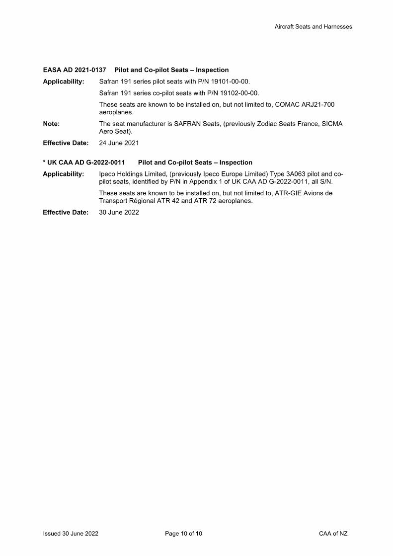
Aircraft Seats and Harnesses
Issued 30 June 2022 Page 10 of 10 CAA of NZ
EASA AD 2021-0137 Pilot and Co-pilot Seats – Inspection Applicability: Safran 191 series pilot seats with P/N 19101-00-00.
Safran 191 series co-pilot seats with P/N 19102-00-00.
These seats are known to be installed on, but not limited to, COMAC ARJ21-700 aeroplanes.
Note: The seat manufacturer is SAFRAN Seats, (previously Zodiac Seats France, SICMA Aero Seat).
Effective Date: 24 June 2021
* UK CAA AD G-2022-0011 Pilot and Co-pilot Seats – Inspection Applicability: Ipeco Holdings Limited, (previously Ipeco Europe Limited) Type 3A063 pilot and co-
pilot seats, identified by P/N in Appendix 1 of UK CAA AD G-2022-0011, all S/N.
These seats are known to be installed on, but not limited to, ATR-GIE Avions de Transport Régional ATR 42 and ATR 72 aeroplanes.
Effective Date: 30 June 2022
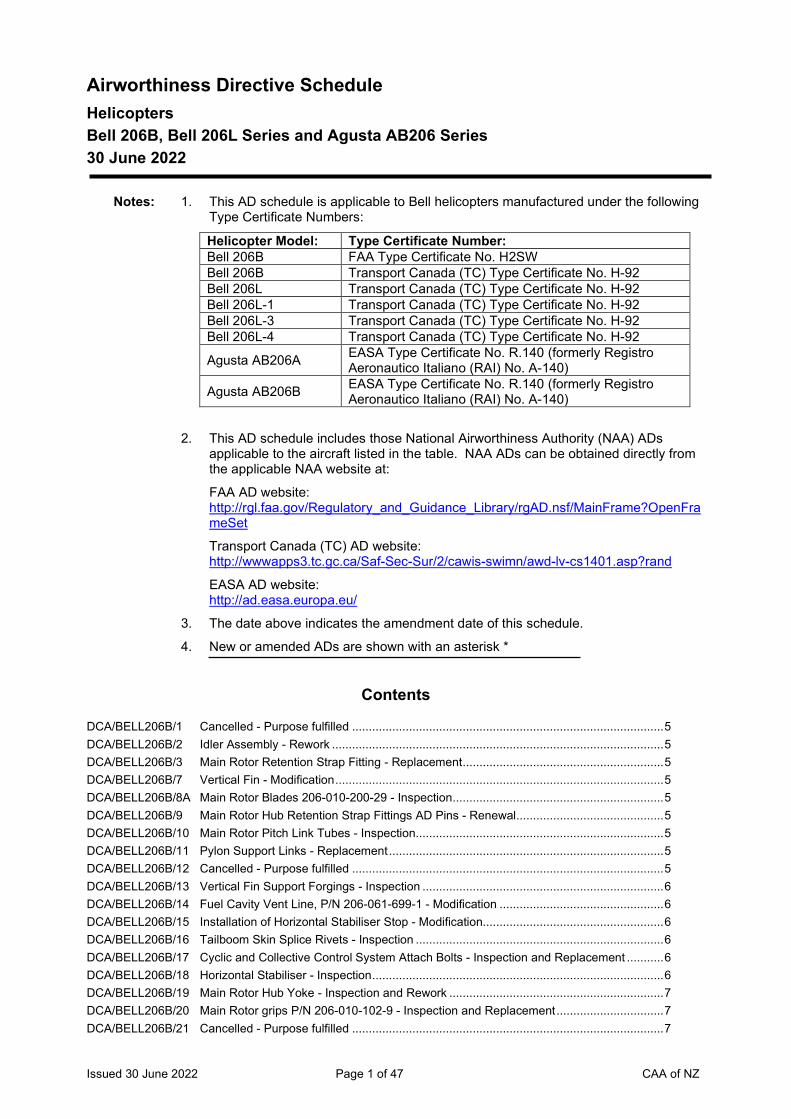
Issued 30 June 2022 Page 1 of 47 CAA of NZ
Airworthiness Directive Schedule Helicopters Bell 206B, Bell 206L Series and Agusta AB206 Series 30 June 2022
Notes: 1. This AD schedule is applicable to Bell helicopters manufactured under the following Type Certificate Numbers:
Helicopter Model: Type Certificate Number: Bell 206B FAA Type Certificate No. H2SW Bell 206B Transport Canada (TC) Type Certificate No. H-92 Bell 206L Transport Canada (TC) Type Certificate No. H-92 Bell 206L-1 Transport Canada (TC) Type Certificate No. H-92 Bell 206L-3 Transport Canada (TC) Type Certificate No. H-92 Bell 206L-4 Transport Canada (TC) Type Certificate No. H-92
Agusta AB206A EASA Type Certificate No. R.140 (formerly Registro Aeronautico Italiano (RAI) No. A-140)
Agusta AB206B EASA Type Certificate No. R.140 (formerly Registro Aeronautico Italiano (RAI) No. A-140)
2. This AD schedule includes those National Airworthiness Authority (NAA) ADs applicable to the aircraft listed in the table. NAA ADs can be obtained directly from the applicable NAA website at:
FAA AD website: http://rgl.faa.gov/Regulatory_and_Guidance_Library/rgAD.nsf/MainFrame?OpenFrameSet
Transport Canada (TC) AD website: http://wwwapps3.tc.gc.ca/Saf-Sec-Sur/2/cawis-swimn/awd-lv-cs1401.asp?rand
EASA AD website: http://ad.easa.europa.eu/
3. The date above indicates the amendment date of this schedule.
4. New or amended ADs are shown with an asterisk *
Contents
DCA/BELL206B/1 Cancelled - Purpose fulfilled ............................................................................................. 5 DCA/BELL206B/2 Idler Assembly - Rework ................................................................................................... 5 DCA/BELL206B/3 Main Rotor Retention Strap Fitting - Replacement ............................................................ 5 DCA/BELL206B/7 Vertical Fin - Modification .................................................................................................. 5 DCA/BELL206B/8A Main Rotor Blades 206-010-200-29 - Inspection ............................................................... 5 DCA/BELL206B/9 Main Rotor Hub Retention Strap Fittings AD Pins - Renewal ............................................ 5 DCA/BELL206B/10 Main Rotor Pitch Link Tubes - Inspection .......................................................................... 5 DCA/BELL206B/11 Pylon Support Links - Replacement .................................................................................. 5 DCA/BELL206B/12 Cancelled - Purpose fulfilled ............................................................................................. 5 DCA/BELL206B/13 Vertical Fin Support Forgings - Inspection ........................................................................ 6 DCA/BELL206B/14 Fuel Cavity Vent Line, P/N 206-061-699-1 - Modification ................................................. 6 DCA/BELL206B/15 Installation of Horizontal Stabiliser Stop - Modification...................................................... 6 DCA/BELL206B/16 Tailboom Skin Splice Rivets - Inspection .......................................................................... 6 DCA/BELL206B/17 Cyclic and Collective Control System Attach Bolts - Inspection and Replacement ........... 6 DCA/BELL206B/18 Horizontal Stabiliser - Inspection ....................................................................................... 6 DCA/BELL206B/19 Main Rotor Hub Yoke - Inspection and Rework ................................................................ 7 DCA/BELL206B/20 Main Rotor grips P/N 206-010-102-9 - Inspection and Replacement ................................ 7 DCA/BELL206B/21 Cancelled - Purpose fulfilled ............................................................................................. 7
Issued 30 June 2022 Page 2 of 47 CAA of NZ
DCA/BELL206B/22 Pitch Link Assemblies - Inspection .................................................................................... 7 DCA/BELL206B/23 Cabin Roof Straps - Replacement..................................................................................... 7 DCA/BELL206B/24 Tail Rotor Yokes - Service Life Limitation ......................................................................... 7 DCA/BELL206B/25 Main Rotor Hub Pillow Blocks - Inspection ........................................................................ 8 DCA/BELL206B/26 Hydraulic Servo Actuator Assembly P/N 206-001-520-5 - Inspection ............................... 8 DCA/BELL206B/27 Main Rotor Hub Tension/Torsion Strap Assy – Replacement and Inspection ................... 8 DCA/BELL206B/28A Main Rotor Hub Tension/Torsion Strap - Life Limitation .................................................... 8 DCA/BELL206B/29 Operating Restriction - Placard ......................................................................................... 8 DCA/BELL206B/30 Tail Rotor Drive - Modification ........................................................................................... 9 DCA/BELL206B/31A MRB Tension Torsion Straps - Replacement .................................................................... 9 DCA/BELL206B/32 Tail Rotor Drive - Modification ........................................................................................... 9 DCA/BELL206B/33 VOR Antenna - Modification ............................................................................................ 10 DCA/BELL206B/34 Freewheel Assembly - Inspection ................................................................................... 10 DCA/BELL206B/35A Cancelled - Purpose Fulfilled .......................................................................................... 10 DCA/BELL206B/36B Tail Rotor Blades - Inspection and Retirement ................................................................ 10 DCA/BELL206B/37A Main Input Drive Shaft Assembly - Inspection and Modification ...................................... 11 DCA/BELL206B/38 Horizontal Stabiliser Assembly - Modification or Retirement ........................................... 11 DCA/BELL206B/39D Tail Rotor Blades - Inspection and Modification .............................................................. 12 DCA/BELL206B/40 Main Rotor Mast Assembly - Inspection and Protection .................................................. 12 DCA/BELL206B/41A Cyclic Control Stick – Inspection and Replacement ........................................................ 12 DCA/BELL206B/42 Tail Rotor Yoke and Pitch Links - Inspection and Removal ............................................. 13 DCA/BELL206B/43A Main Rotor Mast – Replacement ..................................................................................... 13 DCA/BELL206B/44 Fatigue Critical Components - Retirement ...................................................................... 13 DCA/BELL206B/45A Tail Rotor Yoke – Inspection and Replacement .............................................................. 14 DCA/BELL206B/46 Cancelled – Transport Canada AD CF-2015-14 refers ................................................... 14 DCA/BELL206B/47A Unapproved Parts - Removal .......................................................................................... 14 DCA/BELL206B/48A Horizontal Stabiliser – Inspection and Replacement ....................................................... 14 DCA/BELL206B/49B Main Rotor Blades – Inspection and Replacement ......................................................... 15 DCA/BELL206B/50 Air Induction System - Modification ................................................................................. 15 DCA/BELL206B/51A Tail Rotor Blade Assemblies – Replacement .................................................................. 16 DCA/BELL206B/52 Tail Rotor Blade Assemblies - Removal .......................................................................... 16 DCA/BELL206B/53 Emergency Float Bag Valve Restrictors - Installation ..................................................... 16 DCA/BELL206B/54 Vertical Fin Support Inspection and Modification ............................................................ 17 DCA/BELL206B/55 Sungear - Replacement .................................................................................................. 17 DCA/BELL206B/56 Main Rotor Pillow Block Bolts - Replacement ................................................................. 17 DCA/BELL206B/57A Trunnion Master Spline - Inspection................................................................................ 17 DCA/BELL206B/58 Main Rotor Trunnions - Replacement ............................................................................. 18 DCA/BELL206B/59 Main Rotor Blade - Inspection and Rework ..................................................................... 18 DCA/BELL206B/60A Swashplate Support Assembly - Inspection .................................................................... 18 DCA/BELL206B/61 Bearing Support Bracket - Inspection.............................................................................. 19 DCA/BELL206B/62 Cancelled – FAA AD 95-09-06 refers .............................................................................. 19 DCA/BELL206B/63 Crosstube Assemblies - Removal ................................................................................... 19 DCA/BELL206B/64 Fuel Drain Tubes - Modification ...................................................................................... 20 DCA/BELL206B/65 Cancelled – Transport Canada AD CF-2013-28 refers ................................................... 20 DCA/BELL206B/66B Unapproved Components - Removal .............................................................................. 20 DCA/BELL206B/67 Kratos Turbine Outlet Temperature Indicators - Removal ............................................... 20 DCA/BELL206B/68 Main Rotor Mast and Trunnion - Retirement Index Number ............................................ 21 DCA/BELL206B/69 Main Rotor Pitch Link Data Plate - Inspection ................................................................. 21 DCA/BELL206B/70 Tailboom Assembly – Inspection and Modification.......................................................... 22 DCA/BELL206B/71C Cancelled – TC AD CF-1998-42R4 refers ....................................................................... 23 DCA/BELL206B/72B Cross Tube Assemblies – Inspection and Removal ........................................................ 23 DCA/BELL206B/73 Collective Lever Assembly - Inspection ........................................................................... 24 DCA/BELL206B/74 Soloy Engine RPM Sensor - Flight Manual Revision ...................................................... 24 DCA/BELL206B/75A Tedeco Chip Detector – Continuity Test and Replacement ............................................ 25
Issued 30 June 2022 Page 3 of 47 CAA of NZ
DCA/BELL206B/76 Memcor Truohm Magnetic Brake - Inspection and Repair .............................................. 25 DCA/BELL206/77 Main Rotor Transmission Drag Pin Attachment Studs – Inspection ................................ 25 DCA/BELL206/78C Tail Rotor Blade Trailing Edge Cracks – Inspection ........................................................ 26 DCA/BELL206/79A Freewheel Assembly - Inspection ................................................................................... 27 DCA/BELL206/80 Low Fuel Sender - Replacement ..................................................................................... 27 DCA/BELL206/81A Tail Rotor Blade Doubler – Inspection and Replacement................................................ 28 DCA/BELL206/82 Door Handle – Inspection and Rework. ........................................................................... 28 DCA/BELL206/83C Fuel Distribution System – Inspection and Modification .................................................. 29 DCA/BELL206/84 Forward and Aft Cross Tubes – Inspection and Replacement ........................................ 29 DCA/BELL206/85A Turbine Steady RPM Operation Avoidance – AFM Amendment and Decal .................... 30 DCA/BELL206/86 Cancelled – DCA/BELL206/87 refers .............................................................................. 30 DCA/BELL206/87 Main Rotor Blade Grip Plate Tang – Inspection and Rework .......................................... 30 DCA/BELL206/88A Forged Vertical Stabilizer Supports – Inspection and Torque Check .............................. 30 DCA/BELL206/89 Cancelled - DCA/BELL206/93 refers............................................................................... 31 DCA/BELL206/90B Transmission Pylon Support Spindle – Replacement ..................................................... 31 DCA/BELL206/91 Exhaust Duct Clamps – Inspection and Replacement .................................................... 32 DCA/BELL206/92 Upper LH Tailboom Attachment – Inspection and Bolt Replacement ............................. 32 DCA/BELL206/93 Main Rotor Latch Bolts - Replacement ............................................................................ 32 DCA/BELL206/94 Horizontal Stabiliser – Inspection and Replacement ....................................................... 33 DCA/BELL206/95C Tail Rotor Blades – Inspection and Replacement ........................................................... 33 DCA/BELL206/96 Tail Rotor Driveshaft Disc Assembly – Inspection and Replacement .............................. 34 DCA/BELL206/97B Cancelled – Transport Canada AD CF-2018-23 refers ................................................... 34 DCA/BELL206/98 Main Rotor Blades – Inspection and Replacement ......................................................... 34 DCA/BELL206/99 Stabilizer Assembly – Inspection and Replacement........................................................ 35 DCA/BELL206/100 Cancelled – FAA AD 96-18-05R1 refers ......................................................................... 35 DCA/BELL206/101 Mast and Trunion – Life Limitation .................................................................................. 35 DCA/BELL206/102 Cancelled – EASA AD 2018-0175-E refers ..................................................................... 36 DCA/BELL206/103C Cyclic Control Lever Installation – Inspection and Rework .............................................. 36 DCA/BELL206/104 Pitch Horn Trunnion Bearings – Inspection and Replacement ........................................ 37 DCA/BELL206/105 Staked Bearings – Inspection and Replacement ............................................................ 37 DCA/BELL206/106 Main Rotor Pitch Horn Bearing – Inspection and Replacement ...................................... 38 DCA/BELL206/107 Cancelled – Transport Canada AD CF-2009-41R1 refers............................................... 38 DCA/BELL206/108 Tail Rotor Disc Assembly – Inspection and Replacement ............................................... 38 DCA/BELL206/109A Hydraulic Servo Actuators – Inspection and Rework ...................................................... 39 DCA/BELL206/110A Main Rotor Blades – Inspection and Life Limit ................................................................ 40 DCA/BELL206/111 Emergency Float Kit – Inspection and Modification......................................................... 40 DCA/BELL206/112 Main Rotor Blades – Inspection and Life Limitation ........................................................ 41 DCA/BELL206/113 Control Box Assembly – Replacement ............................................................................ 41 DCA/BELL206/114 Cross Tube Assemblies – Inspection and Replacement ................................................. 42 The State of Design ADs listed below are available directly from the National Airworthiness Authority (NAA) websites. Links to NAA websites are available on the CAA website at https://www.aviation.govt.nz/aircraft/airworthiness/airworthiness-directives/links-to-state-of-design-airworthiness-directives/ If additional NZ ADs need to be issued when an unsafe condition is found to exist in an aircraft or aeronautical product in NZ, they will be added to the list below. .............................................. 43 EASA AD 2013-0040-E Battery Overheat Sensor – Inspection and Replacement ........................................ 43 FAA AD 82-16-12 Aircraft with STC SH139WE - Chadwick C-22 Aux Fuel System (AFS) .......................... 43 FAA AD 95-09-06 Fuel Valve Switch Guard – Installation............................................................................ 43 CF-95-11R2 Flight Control Servo Actuators – Unapproved Bolts ........................................................ 43 CF-98-11 High Altitude Tail Rotor Kit .............................................................................................. 43 CF-98-15 External Rescue Systems ............................................................................................... 43 CF-98-20 Collective Idler Link and Lever – Life Limitations ............................................................ 43 CF-98-34 Hydraulic Relief Valve ..................................................................................................... 43 CF-1998-42R4 Tail Boom Skin ................................................................................................................ 44 CF-2002-03R3 KAflex Shaft – Replacement ........................................................................................... 44 CF-2005-22 Torque Indicator – Replacement ..................................................................................... 44
Issued 30 June 2022 Page 4 of 47 CAA of NZ
FAA AD 2012-12-11 Night Vision Goggles – Glare and Reflections ................................................................ 44 CF-2013-28 Fuel Cell Vent Decal – Installation .................................................................................. 44 FAA AD 2013-22-21 Emergency Floatation Gear - Inspection ......................................................................... 44 FAA AD 96-18-05R1 Tailboom – Inspection and Replacement ........................................................................ 44 EASA AD 2014-0102-E Tail Rotor Drive Shaft Line Nuts – Inspection and Replacement ............................. 45 CF-2015-14 Fuel System Flow Switch – Inspection ............................................................................ 45 CF-2016-09 Tension Torsion Straps – Inspection ............................................................................... 45 CF-2016-13R1 Freewheel Lubrication System – Inspection .................................................................... 45 EASA AD 2016-0117 Cancelled – EASA AD 2018-0028 .................................................................................. 45 CF-2009-41R1 Tailboom Attachment Fitting – Inspection ....................................................................... 45 EASA AD 2018-0028 Freewheel Lubrication System – Inspection .................................................................... 45 CF-2018-16 Seat Belt Comfort Clips – Inspection............................................................................... 45 EASA AD 2018-0175-E Power Turbine Limitations – Operational Limitation ................................................ 45 CF-2018-23 Turbine Steady RPM Operation – AFM Amendment and Placard .................................. 46 FAA AD 2018-25-17 Air Comm Corp Air Conditioning System – Inspection .................................................... 46 CF-2019-01 Helicopter External Transport System (HETS) STC SH98-35 ........................................ 46 EASA AD 2019-0178-E Main Rotor Blades – Inspection............................................................................... 46 CF-2019-34 Cancelled – CF-2020-15 refers ....................................................................................... 46 CF-2020-15 Tail Rotor Drive Shaft Coupling Bolted Connections – Inspection .................................. 46 FAA AD 2021-24-15 Oil Cooler Blower – Inspection ........................................................................................ 47 * CF-2022-33 Tail Rotor Drive Shafts with Bonded Adapters – Inspection ............................................ 47
Helicopters Bell 206B, Bell 206L Series and Agusta AB206 Series
Issued 30 June 2022 Page 5 of 47 CAA of NZ
DCA/BELL206B/1 Cancelled - Purpose fulfilled
DCA/BELL206B/2 Idler Assembly - Rework Applicability: Model 206A and 206B S/N 498 through to 873, 875, 878, 879 and 880.
Requirement: Bell SB 206-22.
Compliance: Within the next 100 hours TIS.
DCA/BELL206B/3 Main Rotor Retention Strap Fitting - Replacement Applicability: All model 206A, 206B, 206A-1 and 206B-1.
Requirement: FAA AD 72-19-01.
Compliance: As detailed.
DCA/BELL206B/7 Vertical Fin - Modification Applicability: Model 206A, 206B S/N's 4 through 865 and 867 through 873.
Requirement: Bell SL No. 206-203.
Compliance: Within the next 25 hours TIS.
DCA/BELL206B/8A Main Rotor Blades 206-010-200-29 - Inspection Applicability: Model 206A, 206B and 206-B1
Requirement: Bell SB 206A-19 Rev. C
Compliance: As detailed.
DCA/BELL206B/9 Main Rotor Hub Retention Strap Fittings AD Pins - Renewal Applicability: All model 206.
Requirement: Bell TB 206 (04-01) -73-1.
(FAA AD 73-19-08 refers)
Compliance: As detailed.
DCA/BELL206B/10 Main Rotor Pitch Link Tubes - Inspection Applicability: All model 206 with Pitchlink Tubes P/N 206-010-330.
Requirement: Bell SB 206-04-2-73-1.
(FAA AD 73-19-09 refers)
Compliance: As detailed.
DCA/BELL206B/11 Pylon Support Links - Replacement Applicability: All model 206 with Pylon Support Links P/N 206-031-508-5 and 7.
Requirement: Bell SB 206-01-73-6.
Compliance: Within the next 5 hours TIS.
DCA/BELL206B/12 Cancelled - Purpose fulfilled
Helicopters Bell 206B, Bell 206L Series and Agusta AB206 Series
Issued 30 June 2022 Page 6 of 47 CAA of NZ
DCA/BELL206B/13 Vertical Fin Support Forgings - Inspection Applicability: All model 206 S/N 4 through 1097.
Requirement: Bell SB 206-01-73-5.
(FAA AD 73-21-03 refers)
Compliance: Within the next 50 hours TIS.
DCA/BELL206B/14 Fuel Cavity Vent Line, P/N 206-061-699-1 - Modification Applicability: Model 206B, S/N 914 through to 1125, 1127 through to 1131, 1133 through to 1370.
Requirement: Bell SB 206-10-74-1 and 206-10-74-2.
Compliance: Within the next 100 hours TIS.
Effective Date: 15 May 1974.
DCA/BELL206B/15 Installation of Horizontal Stabiliser Stop - Modification Applicability: Model 206A, 206B S/N 1 through to 1251.
Requirement: Bell SB 206-01-74-1 Rev. A
Compliance: Within the next 100 hours TIS.
Effective Date: 15 June 1974.
DCA/BELL206B/16 Tailboom Skin Splice Rivets - Inspection Applicability: Model 206A, 206B, S/N 1 through to 944.
Requirement: Bell SB 206-01-73-4 Rev B.
(FAA AD 74-08-12 refers)
Compliance: Within the next 5 hours TIS and thereafter at intervals not exceeding 100 hours TIS.
Effective Date: 15 June 1974
DCA/BELL206B/17 Cyclic and Collective Control System Attach Bolts - Inspection and Replacement Applicability: All 206 series.
Requirement: Replace attachment bolts P/N NAS 1305-18, NAS 1305-18D and NAS 1305-19D with special NAS 1305-18D bolts per Bell SB 206-04-2-74-1.
Compliance: As detailed.
Effective Date: 19 June 1974
DCA/BELL206B/18 Horizontal Stabiliser - Inspection Applicability: All model 206 with horizontal stabilisers P/N 206-020-119 (all dash numbers) also -
123-3 and -4.
Requirement: Bell SB 206-01-73-7.
Compliance: As detailed.
Effective Date: 16 July 1974
Helicopters Bell 206B, Bell 206L Series and Agusta AB206 Series
Issued 30 June 2022 Page 7 of 47 CAA of NZ
DCA/BELL206B/19 Main Rotor Hub Yoke - Inspection and Rework Applicability: All model 206 with main rotor hub yoke P/N 206-010-101-1, -5, -9 and -13
Requirement: Bell SB 206-04-1-74-1.
Compliance: 1. Part 1. Daily inspection, prior to first flight each day.
2. Part 2. At the next 1200 hour inspection or when the main rotor hub is removed for any reason, but not later than 31 December 1974.
Effective Date: 28 August 1974
DCA/BELL206B/20 Main Rotor grips P/N 206-010-102-9 - Inspection and Replacement Applicability: All model 206 with main rotor grips S/N as listed in Bell Flight safety messages of
10.9.74 and 10.10.74
Requirement: Bell Flight Safety messages of 10 September 1974, and 10 October 1974.
Compliance: Within the next 5 hours TIS as applicable.
Effective Date: 10 September 1974
DCA/BELL206B/21 Cancelled - Purpose fulfilled Effective Date: 10 October 1974
DCA/BELL206B/22 Pitch Link Assemblies - Inspection Applicability: All model 206A, 206B, 206A-1 and 206B-1 fitted with pitch link assemblies, P/N 206-
010-330 or 206-010-342.
Requirement: FAA AD 75-06-03
Compliance: Within the next 10 hours TIS unless already accomplished.
(FAA AD 75-06-03 refers)
Effective Date: 12 March 1975
DCA/BELL206B/23 Cabin Roof Straps - Replacement Applicability: Model 206A and 206B S/N 1 through to 1163.
Requirement: Bell SB 206-01-74-2.
(FAA AD 75-06-10 refers)
Compliance: Within the next 1200 hours TIS.
Effective Date: 17 April 1975
DCA/BELL206B/24 Tail Rotor Yokes - Service Life Limitation Applicability: All model 206 series fitted with tail rotor yokes P/N 206-010-788-1 or 206-011-802-1.
Requirement: Bell SB 206-75-4.
Compliance: All yokes with 1000 hours or more TIS, within the next 200 hours TIS.
Effective Date: 1 August 1975
Helicopters Bell 206B, Bell 206L Series and Agusta AB206 Series
Issued 30 June 2022 Page 8 of 47 CAA of NZ
DCA/BELL206B/25 Main Rotor Hub Pillow Blocks - Inspection Applicability: Bell 206 series, S/N 1 through to 1657.
Requirement: Bell SB 206-75-3.
(FAA AD 75-18-07 refers)
Compliance: Within the next 600 hours TIS.
Effective Date: 31 October 1975
DCA/BELL206B/26 Hydraulic Servo Actuator Assembly P/N 206-001-520-5 - Inspection Applicability: All 206 series.
Requirement: Bell SB 206-76-1.
Compliance: Within next 10 hours TIS and thereafter at intervals not exceeding 100 hours TIS.
Effective Date: 4 February 1976
DCA/BELL206B/27 Main Rotor Hub Tension/Torsion Strap Assy – Replacement and Inspection Applicability: All model 206 fitted with straps P/N 206-010-105-3.
Requirement: Bell SB 206-76-4 Rev. B
(FAA AD 76-15-03 refers)
Compliance: Unless already accomplished, within next 25 hours TIS.
Effective Date: 18 August 1976
DCA/BELL206B/28A Main Rotor Hub Tension/Torsion Strap - Life Limitation Applicability: All model 206 fitted with straps P/N 206-010-105-3 and -5.
Requirement: Bell SB 206-76-7.
Compliance: Replace all straps with 1200 hours or more TIS, within next 150 hours TIS or 60 days, whichever is the sooner.
Effective Date: 18 February 1977
DCA/BELL206B/29 Operating Restriction - Placard Applicability: All model 206B having Allison 250-C20 series Engines fitted with third stage turbine
wheel P/N 6887113 or 6888633.
Requirement: Bell SB 206B-77-6.
(FAA AD 77-10-13 refers)
Compliance: By 30 June 1977.
Effective Date: 24 June 1977
Helicopters Bell 206B, Bell 206L Series and Agusta AB206 Series
Issued 30 June 2022 Page 9 of 47 CAA of NZ
DCA/BELL206B/30 Tail Rotor Drive - Modification Applicability: All model 206A and 206B.
Requirement: Bell SB 206-76-12.
(FAA AD 77-10-06 refers)
Compliance: Within next 100 hours TIS, unless already accomplished.
Effective Date: 20 July 1977
DCA/BELL206B/31A MRB Tension Torsion Straps - Replacement Applicability: All model 206A, 206A-1, 206B, 206B-1, 206L, 206L-1, and 206L-3 aircraft fitted with
tension torsion straps P/N 206-010-105-3, 206-010-105-5 or 206-011-127-1.
Note 1: AD applicability revised to include model 206L-3 aircraft. Aircraft in compliance with DCA/BELL206B/31 are not affected by this AD.
Requirement: To prevent failure of the tension torsion straps which could result in separation of a MRB resulting in loss of aircraft control, accomplish the following:
For model 206A, 206B, 206A-1 and 206B-1 aircraft replace affected straps with P/N 206-011-147-1 or -5 and inboard strap fittings with P/N 206-011-140-1.
On 206L series aircraft replace affected straps with P/N 206-011-147-3 or -7.
If inboard strap fittings P/N 206-010-155-11 and -15 are installed, replace with straps P/N 206-011-140-1.
Note 2: The retirement life of tension-torsion straps P/N 206-010-105-3, 206-010-105-5, and 206-011-127-1 are reduced from 1200 to 600 hours TIS.
Note 3: Replacement tension-torsion straps, P/N 206-011-147-001, -003, -005, -007 and 206-011-154-101 and -103, have a life limit of 1200 hour TIS or 2 years, whichever occurs sooner.
(FAA AD 78-11-02R1 refers)
Compliance: Strap assemblies with 550 hours or more TTIS - within next 50 hours TIS, or by 29 January 2008, whichever occurs sooner.
Strap assemblies with less than 550 hours TTIS - prior to attaining 600 hours TTIS or by 29 January 2008, whichever occurs sooner.
Effective Date: DCA/BELL206B/31 - 23 June 1978 DCA/BELL206B/31A - 29 November 2007
DCA/BELL206B/32 Tail Rotor Drive - Modification Applicability: Model 206A and 206B S/N 148 and 414 through to 913.
Requirement: Embody tail rotor drive shaft bearing installation modifications detailed in Bell SB 206-77-9.
(FAA AD 78-16-01 refers)
Compliance: Within next 500 hours TIS, unless already accomplished.
Effective Date: 1 September 1978
Helicopters Bell 206B, Bell 206L Series and Agusta AB206 Series
Issued 30 June 2022 Page 10 of 47 CAA of NZ
DCA/BELL206B/33 VOR Antenna - Modification Applicability: All model 206 series with a VOR Antenna P/N CI-159 and CI-159A.
Requirement: 1. Remove VOR Antenna per Part I of Bell SB 206-79-3.
2. Fit replacement Antenna P/N CI-259 per Part II of Bell SB 206-79-3.
Compliance: Part I - within next 5 hours TIS. Part II - by 31 August 1979.
Effective Date: 6 June 1979
DCA/BELL206B/34 Freewheel Assembly - Inspection Applicability: Model 206 series S/N 2385 through to 2419, 2421 through to 2499, 2501 through to
2507, 2509 through to 2512, 2514 through to 2525, 2527 through to 2531, 2533 through to 2536, 2539 through to 2541 and 2543 through to 2557. Also, all freewheel assemblies P/N 206-040-270-3 and outer race shafts P/N 206-040-221-3 delivered by Bell Helicopters Textron as spares between 25 January 1978 and 12 December 1978.
Requirement: Inspect outer race shaft P/N 206-040-221-3 per Bell SB 206-78-2 and renew any cracked part before further flight.
Compliance: Within next 100 hours TIS unless already accomplished and thereafter at each freewheel assembly overhaul.
Effective Date: 29 June 1979
DCA/BELL206B/35A Cancelled - Purpose Fulfilled
DCA/BELL206B/36B Tail Rotor Blades - Inspection and Retirement Applicability: All model 206A, 206B, 206A-1, 206B-1 and 206L with aluminium tail rotor blades P/N
206-010-75-005 and -007.
Requirement: 1. Visually inspect blades per Bell Alert SB 206-80-6 or 206L-80-8 Rev. A (as applicable) using at least 3 x magnification. Renew blades found cracked before further flight.
2. Retire blades from service per formula stated in Bell Alert SB 206-80-12.
(FAA AD 80-17-05 refers)
Compliance: 1. Inspection - before first flight on each day.
2. Retirement - at 500 hours calculated TIS.
Effective Date: DCA/BELL206/36A - 19 December 1980 DCA/BELL206/36B - 9 September 1988
Helicopters Bell 206B, Bell 206L Series and Agusta AB206 Series
Issued 30 June 2022 Page 11 of 47 CAA of NZ
DCA/BELL206B/37A Main Input Drive Shaft Assembly - Inspection and Modification Applicability All model 206A and 206B. Requirement: To prevent failure of the main transmission input driveshaft assembly due to coupling
wear or overheating, accomplish the following:- 1. Visually check the driveshaft P/N 206-040-100-13 for; grease leakage from the
driveshaft couplings P/N 206-040-108-005 and damage and security of the clamps and bolts used to attach the driveshaft to the transmission and engine couplings. Also check the self-adhesive over-temperature indicators (once fitted) for overheating, deterioration, debonding or discoloration.
If any discrepancies are found, before further flight rectify as follows; (a) If there is any grease leakage or any indications of overheating, disassemble and
inspect the driveshaft per the applicable maintenance manual and replace the over-temperature indicators per Bell Alert SB 206-93-76, revision B.
(b) If any “dot” on an over-temperature indicator has changed colour to black, accomplish the corrective action per Table I and the accompanying Notes in Alert SB 206-93-76, revision B.
(c) If there are any deteriorated, debonded, or discoloured over-temperature indicators that would prevent interpretation of the indicating “dots”, replace those over-temperature indicators per Part III of Alert SB 206-93-76, revision B. If only one over-temperature indicator is missing, and no “dot” on any other over-temperature indicator on the same coupling is discoloured or shows mechanical damage or degradation of the epoxy overcoating, the helicopter may be returned to service.
(d) If there are any loose or damaged clamps or bolts, secure the loose clamps or bolts and replace the damaged clamps or bolts per the applicable maintenance manual.
2. Inspect and lubricate the driveshaft assembly P/N 206-040-100-13 and driveshaft couplings P/N 206-040-108-005 per the maintenance manual.
3. Install the self-adhesive over-temperature indicators per Part I of Alert SB 206-93-76, revision B.
(FAA AD 96-06-04 refers)
Compliance: 1. Before first flight of each day. 2. At intervals not exceeding 300 hours TIS. 3. Within next 300 hours TIS.
Note: The daily check may be accomplished by the pilot subject to, adequate instruction by LAME responsible for the aircraft, and a Certificate of Release to Service endorsed to refer to inspection requirement.
Effective Date: DCA/BELL206B/37 3 April 1981 DCA/BELL206B/37A 10 May 1996
DCA/BELL206B/38 Horizontal Stabiliser Assembly - Modification or Retirement Applicability: All model 206L and 206L-1 with S/N and Horizontal stabiliser P/N detailed in Bell ASB
206L-81-23.
Requirement: Modify, or retire and replace horizontal stabiliser assemblies as specified per Bell ASB 206L-81-23.
Compliance: By 30 April 1982.
Effective Date: 12 March 1982
Helicopters Bell 206B, Bell 206L Series and Agusta AB206 Series
Issued 30 June 2022 Page 12 of 47 CAA of NZ
DCA/BELL206B/39D Tail Rotor Blades - Inspection and Modification Applicability: All model 206A, 206B, 206B-1, 206L, 206L-1 and 206L-3 with Tail rotor Blades P/N
206-016-201-001; 206-016-201-103 or 206-016-201-107.
Requirement: 1. Inspect tail rotor blades per Part I of Bell ASB 206-95-28 or 206L-85-34 (as applicable).
2. Modify per Part II of Bell ASB 206-85-28 or 206L-85-34 (as applicable) .
(FAA AD 85-26-06 refers)
Compliance: 1. Pilot inspection per Note (4) - at intervals not exceeding 7 days until modified.
2. Modification - by 30 April 1986.
3. Maintenance inspection - at intervals not exceeding 100 hours TIS.
Effective Date: DCA/BELL206/39C - 28 February 1986 DCA/BELL206/39D - 9 September 1988
DCA/BELL206B/40 Main Rotor Mast Assembly - Inspection and Protection Applicability: All model 206A, 206B, 206B-1, 206B-III, 206L, 206L-1 and 206L-3.
Requirement: Inspect and apply protective coating per Parts A and B of Bell ASBs 206-83-21/206L-83-30 Rev. A as applicable.
Compliance: Part A - Within next 300 hours TIS.
Part B 0 At intervals not exceeding 12 months following compliance with Part A.
Effective Date: 6 April 1984
DCA/BELL206B/41A Cyclic Control Stick – Inspection and Replacement Applicability: Model 206A and 206B aircraft, S/N 4 through to 3818, 3821 through to 3848 and
3851 through to 3856.
Model 206A aircraft fitted with dual controls kits, P/N 206-706-006-3, -5 or -7.
Model 206B-1 aircraft.
Model 206L and 206L-1 aircraft.
Model 206L-3 aircraft, S/N 51001 through to 51128, 51130 through to 51138, and 51140 through to 51142.
Note: AD applicability revised to include model 206L-3 aircraft. Aircraft in compliance with DCA/BELL206B/41 are not affected by this AD.
Requirement: To prevent failure of the cyclic control stick accomplish the following:
For 206 series aircraft inspect the cyclic control stick per the instructions in Bell Helicopter Textron Alert Service Bulletin (ASB) No. 206-85-29.
For 206L series aircraft inspect the cyclic control stick per the instructions in ASB No. 206L-85-36.
Replace any cracked parts before further flight.
(FAA AD 85-25-01 refers)
Compliance: Within the next 25 hours TIS or by 29 December 2007 whichever occurs the sooner, unless previously accomplished.
Effective Date: DCA/BELL206B/41 - 12 July 1985 DCA/BELL206B/41A - 29 November 2007
Bell 206B, Bell 206L Series and Agusta AB206 Series
Issued 30 June 2022 Page 13 of 47 CAA of NZ
DCA/BELL206B/42 Tail Rotor Yoke and Pitch Links - Inspection and Removal Applicability: All model 206A, 206B and 206L with T/R yoke P/N 206-011-819-101 in combination
with T/R crosshead P/N 206-010-741-001 or -003.
Requirement: To prevent failure of the T/R pitch links, accomplish the following:
1. Within next 25 hours TIS, inspect T/R assembly and determine if T/R yoke P/N 206-011-819-101 is installed in combination with T/R crosshead P/N 206-010-741-001 or -003. If this T/R yoke and crosshead combination is installed, either:
(a) Remove T/R yoke P/N 206-011-819-010 and replace it with T/R yoke P/N 206-011-811-009; or
(b) Remove T/R crosshead P/N 206-010-741-001 or -003 and replace it with T/R crosshead P/N 206-011-855-001 or 206-011-857-001. (FAA AD 86-24-01 and Bell ASB 206-36-31 refers)
Effective Date: 15 December 1986
DCA/BELL206B/43A Main Rotor Mast – Replacement Applicability: Model 206A and 206B aircraft fitted with mast assemblies P/N 206-010-332-121, S/N
FAJF-58340 through 58353, 58395 through to 58398, 58400, 58402 through 58408, 58421 and 58423 through 58434.
Model 206L, 206L-1, and 206L-3 aircraft fitted with mast assemblies P/N 206-040-535-105, S/N NJF-935 through to 973, 1000, 1003, 1004, 1006 through to 1012, 1014 through to 1019, 1022 through to 1024, 1026, 1040 through to 1042, 1046, 1050 through to 1057, 1059, 1066, 1068, 1073, 1079, 1086, 1087, 1089 through to 1097, 1099, 1101, 1102, 1123, 1124, 1129, 1135, 1141, 1143, 1145, 1146, 1149, 1151, 1153, 1156, 1157, 1161, 1162, 1165, 1167 and 1169 through to 1172.
Note: AD applicability revised to include model 206L-3 aircraft. Aircraft in compliance with DCA/BELL206B/43 are not affected by this AD.
Requirement: To prevent failure of the main rotor mast, remove affected masts and replace with an airworthy part per Bell Helicopter Alert Service Bulletin (ASB) No. 206-87-37 or 206-87-44, as applicable. (FAA AD 87-10-11 refers)
Compliance: Within the next 25 hours TIS or by 29 December 2007, whichever occurs sooner, unless previously accomplished.
Effective Date: DCA/BELL206B/43 - 25 May 1987 DCA/BELL206B/43A - 29 November 2007
DCA/BELL206B/44 Fatigue Critical Components - Retirement Applicability: All model 206, 206A, 206B, 206L and 206L-1 aircraft.
Requirement: All components listed in the Airworthiness Limitations Schedule contained in the following references must be retired from service not later than the times specified:
1. For 206A/206B Jet Ranger II Series, Bell 206A/206B Jet Ranger II Series Maintenance and Overhaul Instructions, Section 1-44A Rev. 38 dated 31 August 1987.
2. For 206B Jet Ranger III Series, Bell 206B Jet Ranger III Series Maintenance Manual, Section 4 Rev. 28 dated 2 December 1987.
3. For 206L Long Ranger Series, Bell 206L Long Ranger Series Maintenance Manual, Section 4 Rev. 20 dated 1 June 1987.
4. For 206L-1 Long Ranger II Series, Bell 206L-1 Long Ranger II Series Maintenance Manual, Section 4 Rev. 15 dated 1 June 1987.
Effective Date: 9 September 1988
Bell 206B, Bell 206L Series and Agusta AB206 Series
Issued 30 June 2022 Page 14 of 47 CAA of NZ
DCA/BELL206B/45A Tail Rotor Yoke – Inspection and Replacement Applicability: Model 206A, 206B, 206B-1, 206L, 206L-1 and 206L-3 aircraft fitted with tail rotor yoke
assembly P/N 206-011-819-101, S/N A-1807 through to A-2364 as detailed in ASB No. 206-88-41 and ASB No. 206L-88-51.
Note: AD applicability revised to include model 206L-3 aircraft. Aircraft in compliance with DCA/BELL206B/45 are not affected by this AD.
Requirement: To prevent failure of the tail rotor yoke assembly possibly resulting in the loss of a tail rotor blade and causing loss of aircraft control, inspect the tail rotor yoke assembly fitted to the aircraft and establish the P/N and S/N per Bell Helicopter Alert Service Bulletin (ASB) No. 206-88-41 or ASB No. 206L-88-51, as applicable. If an affected tail rotor yoke assembly is fitted, replace the assembly before further flight. (FAA AD 88-23-03 refers)
Compliance: By 29 December 2007 unless previously accomplished.
Effective Date: DCA/BELL206B/45 - 10 March 1989 DCA/BELL206B/45A - 29 November 2007
DCA/BELL206B/46 Cancelled – Transport Canada AD CF-2015-14 refers Effective Date: 25 June 2015
DCA/BELL206B/47A Unapproved Parts - Removal Applicability: All model 206A, 206B, 206B-1, 206BJRII, 206BJRIII, 206L, 206L-1 and 206L-3.
Requirement: To ensure that unapproved parts are identified and removed from service, inspect:
1. Main Rotor Tension - Torsion Strap Assemblies P/N 206-011-147-7 and 106-011-154-101, and remove from service any part with S/N detailed in Bell ASB 206-89-46 Rev. A or 206L-89-60 as applicable. 2. Tail Rotor Hub Assembly P/N 206-011-810-015 and Tail Rotor Yoke P/N 206-011-811-009, and remove from service any part with S/N detailed in Bell ASB 206-89-47 Rev. A or 206L-89-59 as applicable. 3. Spare parts must also be inspected as detailed above.
Compliance: By 15 January 1980
Effective Date: DCA/BELL206/47 - 25 September 1989 DCA/BELL206/47A - 15 December 1989
DCA/BELL206B/48A Horizontal Stabiliser – Inspection and Replacement Applicability: All model 206L, 206L-1 and 206L-3 aircraft.
Note: The AD applicability revised to include model 206L-3 aircraft. Aircraft in compliance with DCA/BELL206B/48 are not affected by this AD.
Requirement: To prevent failure and separation of the horizontal stabiliser, accomplish the following:
1. Visually inspect horizontal stabiliser and confirm installation of a required raised external doubler. The doubler is visible on the stabiliser top surface and extends approx. 4 inches outward from either side of the tailboom and covers the upper surface from within half inch of the forward leading edge to the trailing edge.
2. Stabilisers not incorporating the external doubler must be removed from service and replaced with an airworthy part before further flight. (FAA AD 89-20-13 refers)
Compliance: 1. and 2. Within the next 5 hours TIS, unless previously accomplished.
Effective Date: DCA/BELL206B/48 - 1 November 1989 DCA/BELL206B/48A - 29 November 2007
Bell 206B, Bell 206L Series and Agusta AB206 Series
Issued 30 June 2022 Page 15 of 47 CAA of NZ
DCA/BELL206B/49B Main Rotor Blades – Inspection and Replacement Applicability: Model 206A, 206B, 206L, 206L-1 and 206L-3 aircraft fitted with main rotor blades P/N
206-015-001-001, 206-015-001-103, 206-015-001-105 or 206-010-200-033.
Note 1: AD applicability revised to include model 206L-3 aircraft. Aircraft in compliance with DCA/BELL206B/49A are not affected by this AD.
Requirement: To prevent failure and separation of the main rotor blades possibly resulting in loss of aircraft control, accomplish the following:
For model 206A and 206B aircraft determine if any of the following S/N blades are fitted to the aircraft: TAC-0089, TAC-0542, TAC-0607, TAC-0614, TAC-0624, TAC-1643, TAC-1749, TAC-1776, TAC-1831, TAC-1911, TAC-1922, TAC-2399, TAC-2768, TAC-5742, TKK-9794, TKK-9883 or TKK-9933.
If any of these S/N main rotor blades are fitted, replace before further flight.
For model 206L, 206L-1 and 206L-3 aircraft determine if any of the following S/N blades are fitted to the aircraft: T-92, T-245, T-417, TLY-0075, TLY-0095, TLY-0764, TLY-0770, TLY-0973, TLY-1438, TLY-1619, TLY-1653, TLY-1697, TLY-1766, TLY-1801, TLY-1858, TLY-1953, TLY-1984, TLY-2031, TLY-2039, TLY-2064, TLY-2081, TLY-2148, TLY-2335, TLY-2337, TLY-2549, TLY-2603, TLY-2604, TLY-2625, TLY-2633, TLY-2648, TLY-2745, TLY-2786, TLY-2951 or TLY-2954.
If any of these S/N main rotor blades are fitted, replace before further flight.
Note 2: The S/N may be found on the Bell Helicopter data plate located on top of the blade at the root end and is also marked on the root end of the lower grip plate in the l.5 inch radius.
(FAA AD 92-01-05 and FAA AD 89-22-01R1 refers)
Compliance: Before further flight, unless previously accomplished.
Effective Date: DCA/BELL206B/49 - 15 December 1989 DCA/BELL206B/49A - 30 March 1990 DCA/BELL206B/49B - 29 November 2007
DCA/BELL206B/50 Air Induction System - Modification Applicability: All model 206A and 206B.
Requirement: To prevent possible in-flight engine flameout when operating in falling and/or blowing snow, the following shall be installed:
Particle Separator Engine Air Induction System Kit and Deflector Kit, or Snow Winterization Air Induction System. (See BHT-206A-FMS-18, -24, -11)
(FAA AD 89-10-11R1 refers)
Compliance: Before operating in areas of falling and/or blowing snow
Effective Date: 4 May 1990
Bell 206B, Bell 206L Series and Agusta AB206 Series
Issued 30 June 2022 Page 16 of 47 CAA of NZ
DCA/BELL206B/51A Tail Rotor Blade Assemblies – Replacement Applicability: Model 206B, 206L, 206L-1 and 206L-3 aircraft fitted with tail rotor blade assembly
P/N 206-016-201-113 or P/N 206-016-201-127.
Note: AD applicability revised to include model 206L-3 aircraft. Aircraft in compliance with DCA/BELL206B/51 are not affected by this AD.
Requirement: To prevent failure of tail rotor blade assembly determine the S/N of the tail rotor blade assembly fitted to the aircraft.
Replace assemblies with the following S/Ns, before further flight:
T-41361 T-41627 T-41725 T-41737 T-42088 T-42127 T-42157 T-42307 T-42311 T-42316 T-42494 T-42496 T-42497 T-42502 T-42523 T-42534 T-43276 T-44089 T-44120 T-44157 T-44174 T-44222 T-44300 T-44638
(FAA AD 90-13-01R1 refers)
Compliance: Within the next 5 hours TIS, unless previously accomplished.
Effective Date: DCA/BELL206B/51 - 29 June 1990 DCA/BELL206B/51A - 29 November 2007
DCA/BELL206B/52 Tail Rotor Blade Assemblies - Removal Applicability: Models 206A, 206A-1, 206B, 206B-1, 206L, 206L-1 and 206L-3 with tail rotor blade
assembly P/N 206-016-201-125 or P/N 206-016-201-127.
Requirement: To prevent possible loss of the tail rotor blade tip weight, failure of the tail rotor blade, loss of the tail rotor hub assembly and subsequent loss of the helicopter, accomplish the following:
Determine the serial number of the tail rotor assembly installed on the helicopter and remove from service before further flight any assemblies with the serial numbers detailed in Bell ASB 206-90-58 or 206L-90-71 as applicable.
Spare parts must also be inspected and any assemblies with serial numbers detailed in the ASBs removed from stock.
(FAA AD 90-21-03 refers)
Compliance: Prior to next flight
Effective Date: 18 October 1990
DCA/BELL206B/53 Emergency Float Bag Valve Restrictors - Installation Applicability: All model 206A, 206B, 206L, 206L-1, and 206L-3 helicopters fitted with emergency
float bags, P/N 206-050-248-107, -109 and -111 manufactured prior to September 1, 1989. These float bags are used in BHTI emergency float kits 206-706-210 and 206-706-211.
Requirement: To prevent unequal float inflation which could result in aircraft roll-over and impede emergency egress after an emergency water landing, accomplish the following:
Inspect float bags per Bell ASB 206-89-49 or 206L-89-63 as applicable and modify if necessary prior to further flight.
(FAA AD 91-03-12 refers)
Compliance: Within next 100 hours TIS or before installation of float bags not installed on an aircraft unless already accomplished
Effective Date: 22 March 1991
Bell 206B, Bell 206L Series and Agusta AB206 Series
Issued 30 June 2022 Page 17 of 47 CAA of NZ
DCA/BELL206B/54 Vertical Fin Support Inspection and Modification Applicability: Model 206A and 206B S/N 4 through 1163 fitted with a vertical fin assembly that has
an external doubler installed on LH side adjacent to the support forgings.
Requirement: To prevent fatigue failure of vertical fin supports, inspect for cracks and modify per Bell ASB 206-91-60. Support forgings found cracked must be renewed before further flight.
Compliance: By 30 November 1991
Effective Date: 30 August 1991
DCA/BELL206B/55 Sungear - Replacement Applicability: Models 206A, 206B, 206L, 206L-1 and 206L-3 with sungear P/N 206-040-662-101
installed and S/Ns detailed in Bell ASB 206-90-56 or 206L-90-69 as applicable.
Requirement: To prevent premature wear of the sungear and mating spur gears which could result in transmission failure, accomplish the following:
At next sungear inspection, replace sungears which have the S/Ns list in Bell ASB 206-90-56 or 206L-90-69 as applicable.
If the listed S/Ns are found in service, inspect per Part 2 of the ASB. If wear or damage exceeds the specified limits, remove and replace the affected spur gears with serviceable parts before further flight.
(FAA AD 92-06-12 refers)
Compliance: At next routine inspection of the main transmission sungear, or within the next 1500 hours TIS, whichever is the sooner.
Effective Date: 30 April 1992
DCA/BELL206B/56 Main Rotor Pillow Block Bolts - Replacement Applicability: All model 206A, 206B, 206L, 206L-1, and 206L-3 series.
Requirement: To prevent failure, replace main rotor pillow block bolts per Bell ASB 206-92-66 or 206L-92-79 as applicable.
Compliance: By 31 July 1992
Effective Date: 26 June 1992
DCA/BELL206B/57A Trunnion Master Spline - Inspection Applicability Model 206A, 206B, 206B-1, 206L, 206L-1, 206L-3 and 206L-4 fitted with trunnion P/N
206-011-113-103 or 206-011-120-103.
Requirement: To prevent pitch link misalignment, accomplish the following:-
Inspect the trunnion master spline for proper positioning per Parts I and II of Bell ASB 206-93-75 or 206L-93-90, Revision A as applicable. If the master spline is not in the proper position, replace the trunnion per the applicable maintenance manual before further flight. (FAA AD 94-20-03 refers)
Compliance: Within next 50 hours TIS or 90 days, whichever is the sooner.
Effective Date: DCA/BELL206B/57 24 December 1993 DCA/BELL206/57A 20 January 1995
Bell 206B, Bell 206L Series and Agusta AB206 Series
Issued 30 June 2022 Page 18 of 47 CAA of NZ
DCA/BELL206B/58 Main Rotor Trunnions - Replacement Applicability: All Model 206 series fitted with trunnion P/N 206-011-113-103.
Requirement: To prevent main rotor trunnion failure, remove from service trunnions having the following serial numbers A1-00823 through A1-00861, except A1-00825 and A1-00842.
(Bell ASB 206-94-80 refers)
Compliance: Before further flight.
Effective Date: 5 August 1994
DCA/BELL206B/59 Main Rotor Blade - Inspection and Rework Applicability: Model 206A and 206B fitted with main rotor blade P/N 206-010-200-133, having a
S/N with prefix "A", except for those blades with S/Ns listed as exempt in Bell ASB 206-93-77.
Model 206L, 206L-1, 206L-3 and 206L-4 fitted with main rotor blade P/N 206-015-001-107, having a S/N with prefix "A", except for those blades with S/Ns listed as exempt in Bell ASB 206L-93-92.
Requirement: To prevent failure of the main rotor blade and subsequent loss of the helicopter, accomplish the following:
Inspect and rework per Part I of Bell ASB 206-93-77 or 206L-93-92 as applicable. If cracks are found rectify or replace per ASB 206-93-77 or 206L-93-92 as applicable before further flight.
(FAA AD 94-15-07 refers)
Compliance: Within next 50 hours TIS.
Effective Date: 30 September 1994
DCA/BELL206B/60A Swashplate Support Assembly - Inspection Applicability: Model 206A, 206A-1, 206B, 206B-1, 206L, 206L-1 and 206L-3 series fitted with
swashplate support assembly, P/N 206-010-452-001, -005, or -109.
Requirement: To prevent failure of the swashplate support assembly and subsequent loss of control of the helicopter, accomplish the following:-
Inspect the swashplate support assembly in the fillet radius area for cracks per Bell ASB 206-93-74 Rev B or 206L-93-89 Rev B, as applicable. Replace any cracked swashplate support assembly with an airworthy assembly before further flight.
(FAA AD 94-19-02 refers)
Note 1: Installation of a swashplate support assembly, P/N 206-010-452-113, constitutes a terminating action for the requirements of this airworthiness directive. The swashplate support assembly, P/N 206-010-452-113, has a life limit of 4,800 hours TIS.
Compliance: At 1500 hours TTIS or within next 25 hours TIS, whichever is the later, and thereafter at intervals not to exceed 50 hours TIS.
Note 2: The 50 hour inspection between the scheduled inspections may be accomplished by the pilot subject to: (a) Adequate instruction by LAME responsible for the aircraft. (b) Certificate of Release to Service endorsed to refer to inspection requirement. (c) Copy of Bell ASB 206-93-74 Rev B or 206L-93-89 Rev B, as applicable to be attached to the Certificate of Release to Service.
Effective Date: DCA/BELL206B/60 - 28 October 1994 DCA/BELL206B/60A - 10 April 1998
Bell 206B, Bell 206L Series and Agusta AB206 Series
Issued 30 June 2022 Page 19 of 47 CAA of NZ
DCA/BELL206B/61 Bearing Support Bracket - Inspection Applicability: Model 206A and 206B fitted with tail rotor drive shaft hangar bearing support
brackets. P/N 206-030-407 or -433.
Models 206L, 206L-1 and 206L-3 fitted with brackets, P/N 206-033-412.
Requirement: To prevent failure of the tail rotor drive shaft system, accomplish the following:- Inspect and rework brackets, P/N 206-030-407 or -433 per Bell Alert SB 206-92-69. Inspect and rework brackets, P/N 206-033-412 per Bell Alert SB 206L-92-84. If multiple cracks are found, or if a crack is found that equals or exceeds 0.10 inches in length, replace the bracket before further flight.
(FAA AD 94-24-11 refers)
Compliance: Within next 100 hours TIS, and prior to installing any affected brackets on a helicopter.
Effective Date: 14 April 1995
DCA/BELL206B/62 Cancelled – FAA AD 95-09-06 refers Effective Date: 31 October 2013
DCA/BELL206B/63 Crosstube Assemblies - Removal Applicability Model 206A, 206B, 206L, 206L-1, 206L-3 and 206L-4 with cross tube assemblies
BHTI P/N 206-050-107, 206-050-119, 206-050-134, 206-050-157, 206-050-169, 206-053-109, 206-053-119 and 206-053-129 (all dash numbers), or Airbourne Supply Inc P/N AB206-050-107, AB206-050-119, or AB206-053-109 (all dash numbers).
Requirement: To prevent failure of the crosstubes accomplish the following:-
Remove any affected crosstube and replace it with an airworthy crosstube per the appropriate maintenance manual or service instructions. Any crosstubes removed as a result of this airworthiness directive shall be permanently marked as unairworthy.
If the crosstubes’ P/N cannot be determined by reference to the crosstubes, if possible determine the P/N by reference to the maintenance records or other aircraft records. If the crosstubes’ P/N cannot be determined, replace the crosstubes with airworthy crosstubes per the appropriate maintenance manual or service instructions.
(FAA AD 95-11-14 refers)
Note: For BHTI P/N 206-053-109 and 206-053-119, the P/N is vibro-etched on the upper cuff of the crosstube on the aft side on both forward and aft crosstubes; for BHTI P/N 206-053-129, the P/N is vibro-etched on the bottom of the cuff on both forward and aft crosstubes; for BHTI P/N 206-050-107, 206-050-119, 206-050-134, 206-050-157 and 206-050-169, the P/N is stamped in ink on the crosstube, which is shipped without paint (once the helicopter is painted, the P/N is covered); and for Airbourne Supply Inc, P/N AB206-050-107, AB206-050-119, and AB206-053-109 the P/N is rubber stamped at the bottom end of the crosstube.
Compliance: By 31 December 1995
Effective Date: 29 September 1995
Bell 206B, Bell 206L Series and Agusta AB206 Series
Issued 30 June 2022 Page 20 of 47 CAA of NZ
DCA/BELL206B/64 Fuel Drain Tubes - Modification Applicability Model 206L-1 S/N 45154 through to 45790. Model 206L-3 S/N 51001 through to 51612. Model 206L-4 S/N 52001 through to 52158.
Requirement: To prevent possible fire hazard caused by fuel reaching the fuel pump and starter-generator during airframe fuel filter drainage, accomplish the following:-
Ensure a positive drain of fuel by reworking fuel drain tubes P/N 206-064-228-001 and 206-064-229-001 per BHTC ASB 206L-96-103, Revision A.
(Transport Canada AD CF-96-10 refers)
Compliance: Within next 25 hours TIS.
Effective Date: 18 May 1996
DCA/BELL206B/65 Cancelled – Transport Canada AD CF-2013-28 refers Effective Date: 18 October 2013
DCA/BELL206B/66B Unapproved Components - Removal Applicability: Model 206 series fitted with any of the following components.
Main Rotor Grips P/N 206 010 102 13
Serial Numbers: JI1-9559 JI1-9750
Float Bottles P/N 26AF1022-01
Serial Number: 943799 943826
Requirement: To prevent possible in-service failure of unapproved components, remove the components listed from service.
Any of the components listed held as spares must not be fitted to any helicopter.
Compliance: Before further flight.
Effective Date: DCA/BELL206B/66A - 27 November 1996 DCA/BELL206B/66B - 14 February 1997
DCA/BELL206B/67 Kratos Turbine Outlet Temperature Indicators - Removal Applicability: Model 206L-1 fitted with Kratos turbine outlet temperature (TOT) indicators P/N
124.444-6 or 124.444-20.
Requirement: To prevent false temperature indications, which could result in an over-temperature condition of the engine turbine and subsequent thermal damage to engine components, accomplish the following:-
Remove Kratos indicator P/N 124.444-6 or 124.444-20 and replace it with any other TOT indicator approved for use on the Bell 206L-1. Bell ASB 206L-94-94 also refers.
(Transport Canada AD CF-96-13 refers)
Compliance: Within next 100 hours TIS.
Effective Date: 25 October 1996
Bell 206B, Bell 206L Series and Agusta AB206 Series
Issued 30 June 2022 Page 21 of 47 CAA of NZ
DCA/BELL206B/68 Main Rotor Mast and Trunnion - Retirement Index Number Applicability: Model 206L, 206L-1, 206L-3, and 206L-4 helicopters, fitted with main rotor mast, P/N
206-040-535-001, -005, -101, or -105, or fitted with a main rotor trunnion, P/N 206-011-120-103.
Requirement: To prevent fatigue failure of the mast or trunnion, which could result in loss of the main rotor system and subsequent loss of the helicopter, accomplish the following:-
1. Create a component history card or an equivalent record for the affected mast and trunnion.
2. Determine the accumulated Retirement Index Number (RIN) to date based on the number of takeoffs and external load lifts (torque events) for parts in service per paragraphs 1 and 2 of the Accomplishment Instructions of Bell Helicopter Textron, ASB 206L-94-99, Revision A. Record this accumulated RIN on the component history card.
3. After complying with paragraphs 1 and 2 of this AD, during each operation thereafter, maintain a count of the number of external load lifts and the number of takeoffs performed and at the end of each days operations, increase the accumulated RIN on the component history cards as follows:-
(a) For the trunnion, Increase the RIN for the Model 206L, 206L-1, and 206L-3 helicopters by 1 for each torque event. Increase the RIN for the Model 206L-4 helicopters by 2 for each torque event.
(b) For the mast, increase the RIN for the Model 206L, 206L-1, 206L-3, and 206L-4 helicopters by 1 for each torque event.
4. Remove the trunnion from service on or before attaining the maximum accumulated RIN (24,000) per Table 1 of the Accomplishment Instructions of ASB 206L-94-99, Revision B.
5. Remove the mast from service on or before attaining the maximum accumulated RIN (44,000) or the flight hour service life limit, whichever occurs first, per Table 2 of the Accomplishment Instructions of ASB 206L-94-99, Revision B.
(Transport Canada AD CF-97-03 and FAA AD 97-07-07 refer)
Compliance: Within next 100 hours TIS unless already accomplished.
Effective Date: 4 July 1997
DCA/BELL206B/69 Main Rotor Pitch Link Data Plate - Inspection Applicability: All model 206 series.
Requirement: To detect and correct corrosion of main rotor pitch links under their data plates, accomplish the following:-
Inspect all main rotor pitch link data plates for signs of de-bonding. If there are any signs of de-bonding, before further flight, remove the data plate and rectify as follows:
1. Remove any traces of corrosion from the pitch links, per limits specified in the applicable Bell CRandO manual.
2. Chemically treat area with alodine.
3. Apply primer and topcoat.
4. Re-install data plate using PR 1422 B.
5. Report any defects found to the CAA.
Compliance: Within next 100 hours TIS.
Effective Date: 8 May 1998
Bell 206B, Bell 206L Series and Agusta AB206 Series
Issued 30 June 2022 Page 22 of 47 CAA of NZ
DCA/BELL206B/70 Tailboom Assembly – Inspection and Modification Applicability: Model 206L series. Tailboom assemblies modified per Bell TB 206L-96-191, or BHT-
206-SRM-1, section 63-4, with upper tailboom skin P/N 206-033-004-155 installed, are not affected by this airworthiness directive.
Requirement: To ensure the structural integrity of all affected tailbooms, accomplish the following as applicable:-
Part 1. Applies to Model 206L series, S/N 45001 through 51283, having unmodified tailboom assemblies P/N 206-033-004-003, -011, -045 and -103.
Modify the tailboom between boom station BS 151.15 and 159.35 by installing doubler P/N 206-704-167-111 with clip P/N 206-033-407-119, and re-identify the tailboom by adding the suffix "FM" to the original P/N as outlined in Part I of Bell ASB 206L-87-47 Revision C.
Part 2. Applies to the following Model 206L series: Model 206L S/N 45003 through 45153, and 46601 through 46617 Model 206L-1 S/N 45154 through 45790 Model 206L-3 S/N 51001 through 51283 having tailboom assemblies of the following P/Ns: 206-033-004-003FM, -003FM1 206-033-004-011FM, -011FM1, -011FM2, -011FM3 206-033-004-103FM, -103FM1 206-033-004-045FM
(a) For tailbooms with a sheet metal tail rotor gearbox support, perform an Eddy Current inspection as outlined in Part I of ASB 206L-97-107 Revision A.
(b) For tailbooms with a cast tail rotor gearbox support P/N 206-033-426-001 and that do not have upper skin P/N 206-033-004-155 installed, install nutplate assemblies as per Part II of ASB 206L97107 Revision A.
Note: For all Model 206L helicopters affected by Parts 1 and 2 above, replacement of the tailboom with any tailboom listed below constitutes terminating action for the requirements of this airworthiness directive:
206-033-004-003FM2 206-033-004-011FM4 206-033-004-103FM2 206-033-004-045FM1, -045FM2 206-033-004-143, -143FM1 206-033-004-175, -175FM1 206-033-004-177
(Transport Canada AD CF-98-27 refers)
Compliance: Part 1 - Within the next 200 hours TIS or by 31 May 1999, whichever is the sooner.
Part 2 (a) - Within next 100 hours TIS and thereafter at intervals not to exceed 1000 hours TIS.
Part 2 (b) - Within the next 200 hours TIS or by 31 May 1999, whichever is the sooner.
Effective Date: 20 November 1998
Bell 206B, Bell 206L Series and Agusta AB206 Series
Issued 30 June 2022 Page 23 of 47 CAA of NZ
DCA/BELL206B/71C Cancelled – TC AD CF-1998-42R4 refers Effective Date: 31 October 2013
DCA/BELL206B/72B Cross Tube Assemblies – Inspection and Removal Applicability: Model 206 series helicopters fitted with cross tube assemblies (cross tubes) of older
design having rivet holes in the support area for rivet-on supports with the following P/N, but not limited to P/N:
(iv) Other manufacturers, as approved by the FAA under Parts Manufacturer Approval
(PMA).
Note 1: Riveted cross tubes P/N 206-050-2xx-xxx and 206-053-2xx-xxx with newer configurations which have rivet holes only on the sides of the cross tube are not affected by this AD.
Note 2: DCA/BELL206B/72B revised to align the applicability with Transport Canada AD CF-98-43 and remove the reference to Transport Canada AD CF-95-17. The requirements in AD CF-95-17R2 is mandated by DCA/BELL206/114.
Requirement: To prevent possible failure of cross tube assemblies, accomplish the requirements in Transport Canada AD CF-98-43.
(Transport Canada AD CF-98-43 refers)
Compliance: At the next maintenance inspection, or the next 50 hours TIS, or by 26 August 2012 whichever occurs sooner, unless previously accomplished.
Effective Date: DCA/BELL206B/72 - 12 Februray 1999 DCA/BELL206B/72A - 4 June 1999 DCA/BELL206B/72B - 26 July 2012
Bell 206B, Bell 206L Series and Agusta AB206 Series
Issued 30 June 2022 Page 24 of 47 CAA of NZ
DCA/BELL206B/73 Collective Lever Assembly - Inspection Applicability: Model 206A aircraft, S/N 004 through to 660 and 672 through to 715.
Model 206B aircraft, S/N 661 through to 671, 716 through to 4529, and 5101 through to 5267.
Model 206L aircraft, S/N 45004 through to 45153 and 46601 through to 46617.
Model 206L-1 aircraft, S/N 45154 through to 45790.
Model 206L-3 aircraft, S/N 51001 through to 51612.
Requirement: To ensure adequate clearance between the collective lever and the swashplate outer ring, accomplish the following:-
1. Inspect the clearance between the collective lever assembly and the swashplate outer ring per BHTC ASB 206-00-93 Revision A, or 206L-00-116 as applicable. If the clearance is 0.060 inch (1.52 mm) or less, remove the raised forging boss before further flight per the applicable ASB.
2. Regardless of the clearance measured per the inspection above, remove the raised forging boss per the applicable ASB.
(Transport Canada AD CF-2000-13 and FAA AD 2001-02-03 refers)
Compliance: 1. By 31 July 2000.
2. At the next removal of the collective lever assembly but no later than 31 January 2001.
Effective Date: 29 June 2000
DCA/BELL206B/74 Soloy Engine RPM Sensor - Flight Manual Revision Applicability: Model 206B and 206L series, fitted with Allison 250-C20R engine and Soloy engine
power-out warning sensors, P/N 206-075-545-001, per STC SH 95-46 (FAA STC SH4179NM) or SH 95-45 (FAA STC SH4169NM).
Requirement: To alert pilots of a potential false engine-out warning from the Soloy sensor when practicing autorotations, revise the Limitations section of the applicable approved STC Rotorcraft Flight Manual Supplement by adding the following Warning statement and Note.
WARNING: For aircraft with an engine-out sensor other than P/N 680-2551-1 only. To prevent false engine-out signals, the following procedure must be followed during practice auto-rotations. When entering a practice auto-rotation, avoid a pausing or creeping movement of any throttle decrease or increase between full open and idle. If movement is not made at a firm and continuous rate, N1 RPM undershoot and/or oscillation may occur causing a momentary false engine-out warning light and audio indication. NOTE: Ensure N1 RPM idle speed is set at 62-64%.
(Transport Canada AD CF-2001-13 refers)
Compliance: 28 July 2001
Effective Date: 28 June 2001
Bell 206B, Bell 206L Series and Agusta AB206 Series
Issued 30 June 2022 Page 25 of 47 CAA of NZ
DCA/BELL206B/75A Tedeco Chip Detector – Continuity Test and Replacement Applicability: Model 206A, 206A-1, 206B, 206B-1, 206L, 206L-1, 206L-3 and 206L-4 aircraft fitted
with Tedeco B3188B and B4093 chip detector assemblies.
Note: AD applicability revised to include model 206L-3 and 206L-4 aircraft. Aircraft in compliance with DCA/BELL206B/75 are not affected by this AD.
Requirement: To ensure the chip detector provides intended warning function, accomplish the following:
1. Perform a continuity test of the chip detector assemblies and repair if necessary, per the test procedure and repair instructions in Bell Helicopter Textron Canada ASB No. 206-01-96 revision A or ASB 206L-01-119 revision A, as applicable.
2. Replace any assemblies repaired per requirement 1 of this AD. (FAA AD 2003-13-14 and Transport Canada AD CF-2001-33 refers)
Compliance: 1. Within the next 75 hours TIS, unless already accomplished.
2. Within the next 300 hours TIS or by 29 November 2008, whichever occurs sooner.
Effective Date: DCA/BELL206B/75 - 25 October 2001 DCA/BELL206B/75A - 29 November 2007
DCA/BELL206B/76 Memcor Truohm Magnetic Brake - Inspection and Repair Applicability: Model 206L-1 and 206L-3 fitted with IFR kit 206-705-001, -101, or -103 and all spare
magnetic brakes P/N 204-001-376-003 manufactured by Memcor Truohm as P/N MP 498-3. Magnetic brakes P/N 204-001-376-003 made by other manufacturers are not affected.
Requirement: The stop screws (Memcor P/N MS51959-3) may have been installed without the proper adhesive. This may allow the screws to loosen and limit the travel of the brake arm assembly, which could limit the movement of the flight controls. To prevent this, inspect each magnetic brake P/N 204-001-376-003 per Bell ASB 206L-01-122, and repair, as necessary. (Transport Canada AD CF-2002-16 and FAA AD 2004-22-13 refers)
Compliance: Within next 100 hours TIS unless already accomplished.
Effective Date: 30 May 2002
DCA/BELL206/77 Main Rotor Transmission Drag Pin Attachment Studs – Inspection Applicability: All model 206B series.
Requirement: To prevent loss of main rotor transmission oil caused by loose drag pin attachment studs, accomplish the following:-
Inspect the studs that attach the main rotor transmission drag pin to the base of the transmission to ensure that the studs are not loose. Signs of an oil leak at the base of the transmission may be evidence that one or more studs are loose. If any of the studs are found to be loose, rectify before further flight.
Remove the split pins from the studs and lock wire the studs together in pairs using 0.040” lock wire.
Note: An occurrence has been reported where one stud complete with nut and split pin had unscrewed completely causing a substantial oil loss. (NZ occurrence refers)
Compliance: Within next 100 hours TIS.
Effective Date: 30 October 2003
Bell 206B, Bell 206L Series and Agusta AB206 Series
Issued 30 June 2022 Page 26 of 47 CAA of NZ
DCA/BELL206/78C Tail Rotor Blade Trailing Edge Cracks – Inspection Applicability: Model 206A, 206B fitted with tail rotor blade P/N 206–016–201–131 and P/N 206–
016–201–133 with S/N listed in Bell Helicopter Textron Alert Service Bulletin No. 206- 04-100 revision C.
Model 206L, 206L-1, 206L-3 and 206L-4 aircraft fitted with tail rotor blade P/N 206–016–201–131 with S/N listed in Bell Helicopter Textron Alert Service Bulletin No. 206L-04-127 revision C.
Note 1: AD applicability revised to include model 206L-3 aircraft. Aircraft in compliance with DCA/BELL206/78B are not affected by this AD.
Requirement: To detect cracking of the tail rotor blade, accomplish the following:
1. Determine if the tail rotor blades are in the range of affected S/Ns. If so inspect per part 1 of the applicable ASB. If a crack is found replace blade before further flight.
Note 2: The 3 hour TIS may be accomplished by adding the inspection requirement to the tech log. The visual inspection may be performed and certified under the provision in Part 43 Appendix A.1 (7) by the holder of a current pilot licence, if that person is rated on the aircraft, appropriately trained and authorised (Part 43, Subpart B refers), and the maintenance is recorded and certified as required by Part 43.
2. Perform detailed visual inspection of the tail rotor blade with appropriate lighting and magnification, per part 2 of the applicable ASB. If a crack is found replace blade before further flight.
3. Remove affected tail rotor blades and return to the repair facility indentified in part 3 of the applicable ASB for skin thickness check. Tail rotor blades with unacceptable blade skin thickness are to be removed from service.
4. Inspect the maintenance records of the affected blades to determine if the blades had been previously repaired following the inspection called by the previous revisions of this AD. If it has been repaired, contact the blade repair shop to determine if the weight of the trailing edge root weight package had changed. If the weight package was increased, the tail rotor blade is to be sent for rebalancing, per part 3 of the applicable ASB.
5. Inspect rotor blades for skin damage, per part 4 of the applicable ASB.
(FAA AD 2007-01-06 and Transport Canada AD CF-2004-05R2 refers)
Compliance: 1. Before further flight and thereafter at the intervals prescribed in the applicable ASB.
2. Within next 100 hours TIS and thereafter at intervals not to exceed 100 hours TIS.
3. and 4. By 29 May 2008.
5. Within the next 100 hours TIS and thereafter at intervals not to exceed 100 hours TIS or if skin damage is identified.
Effective Date: DCA/BELL206/78B - 30 June 2005 DCA/BELL206/78C - 29 November 2007
Bell 206B, Bell 206L Series and Agusta AB206 Series
Issued 30 June 2022 Page 27 of 47 CAA of NZ
DCA/BELL206/79A Freewheel Assembly - Inspection Applicability: Model 206L-4 fitted with freewheel aft bearing cap, P/N 406-040-509-101, S/N A-
1833 through to A-1912.
Requirement: Transport Canada has been advised that a manufacturing oversight has occurred where a lubrication channel to allow oil flow has not been machined into the aft bearing cap of some freewheel units. As a lack of lubrication may adversely affect the durability and potentially the function of the freewheel unit, it is necessary to accomplish the following:
1. Identification of Affected Aft Bearing Caps
Determine the aft bearing cap serial number to identify if this directive is applicable as per Part I of ASB 206L-04-129 revision A, or later revisions approved by Transport Canada.
2. Rework of Affected Freewheel Assemblies
Rework the affected freewheel assemblies as per Part II or III of ASB 206L-04-129 revision A, as stipulated by the calculated average engine start cycle count identified in the ASB, or later revisions approved by Transport Canada.
3. Terminating Action
Rework the affected freewheel assemblies as per Part IV of ASB 206L-04-129 revision A, or later revisions approved by Transport Canada.
(Transport Canada AD CF-2004-17R1 refers)
Compliance: 1. Upon receipt of this directive.
2. Within the next 50 hours TIS.
3. Within the next 300 hours TIS, but no later than 30 June 2005.
Effective Date: DCA/BELL206/79 - 27 January 2005 DCA/BELL206/79A - 31 March 2005
DCA/BELL206/80 Low Fuel Sender - Replacement Applicability: Model 206L series helicopters fitted with Low Fuel Level Level Detector Unit P/N 206-
063-613-003, serial numbers: 1413, 1414, 1415, 1424, 1428, 1430, 1432 and 1433.
Requirement: It was determined that eight discrepant Low Fuel Level Detectors may have been installed on Model 206L helicopters. These detectors can fail to indicate the low fuel condition. Accordingly to prevent an erroneous fuel reading being presented to the pilot, that could lead to unexpected fuel exhaustion, remove from service Low Fuel Level Detector unit P/N 206-063-613-003, serial numbers: 1413, 1414, 1415, 1424, 1428, 1430, 1432 and 1433 as per BHTC ASB 206L-04-132, Revision A, dated 4 October 2004, or later revisions approved by Transport Canada.
(Transport Canada AD CF-2004-24 refers)
Compliance: By 28 February 2005
Effective Date: 27 January 2005
Bell 206B, Bell 206L Series and Agusta AB206 Series
Issued 30 June 2022 Page 28 of 47 CAA of NZ
DCA/BELL206/81A Tail Rotor Blade Doubler – Inspection and Replacement Applicability: Model 206A, 206A-1, 206B, 206B-1, 206L, 206L-1, 206L-3 and 206L-4 aircraft, fitted
with tail rotor blade P/N 206- 016-201-131, S/N CS4820 through to CS4845.
Note: AD applicability revised to include model 206L-3 aircraft. Aircraft in compliance with DCA/BELL206/81 are not affected by this AD.
Requirement: An inadequate surface preparation on a limited number of blades resulted in two instances of blade root doubler de-bonding. To ensure blade integrity, all suspected blades are to be checked daily until removed from service. Spares inventory should be checked to ensure affected blades are identified and marked as not airworthy. 1. Identification of Affected Tail Rotor Blades
Verify if the aircraft is fitted with rotor blades identified in the “Blades Affected” section of the applicable Alert Service Bulletin as listed below. If the aircraft is fitted with an affected blade, enter the P/N and S/N number into the aircraft logbook. If not fitted, indicate in the logbook that the aircraft is not fitted with blades affected by this AD.
2. Check for Tail Rotor Doubler De-bonding
Check the affected blades in accordance with part 1 of the applicable ASB listed below or later revisions approved by Transport Canada.
3. Replacement of the Blades
Replace all affected blades in accordance with part 2 of the applicable Alert Service Bulletin listed below or later revisions approved by Transport Canada.
Helicopter Model: Alert Service Bulletin:
206A/B series 206-04-101 206L series 206L-04-131
(FAA AD 2005-21-03 and Transport Canada AD CF-2004-25 refers)
Compliance: 1. Before further flight, unless already accomplished.
2. Daily, until blade replacement.
3. Within the next 100 hours TIS or 29 January 2008, whichever occurs sooner.
Effective Date: DCA/BELL206/81 - 27 January 2005 DCA/BELL206/81A - 29 November 2007
DCA/BELL206/82 Door Handle – Inspection and Rework. Applicability: Model 206B S/N 3567 through to 4577 and 5101 through to 5284.
Requirement: To detect and correct possible “D” handle disconnection from the latching mechanism, resulting in the handle turning freely and not opening the door, inspect the inside door handle assembly in accordance with ASB 206-04-102. If the inspection indicates the need for rework of the handle, perform this task in accordance with ASB 206-04-102.
(Transport Canada AD CF-2004-27 refers)
Compliance: Within next 100 hours TIS.
Effective Date: 31 March 2005
Bell 206B, Bell 206L Series and Agusta AB206 Series
Issued 30 June 2022 Page 29 of 47 CAA of NZ
DCA/BELL206/83C Fuel Distribution System – Inspection and Modification Applicability: Model 206A and 206B aircraft, S/N all through to 5305.
Note 1: The applicability of this AD expanded to include aircraft model 206A which have been converted to a model 206B.
Requirement: To prevent the possibility of arcing in the main fuel cell due to inadequate electrical grounding of the fuel boost pump and the fuel drain solenoid valve, combined with fuel hoses contact, accomplish the following:
1. Electrical Grounds: Inspect and modify the electrical grounds of the fuel pumps and solenoid valve, per the instructions in part I of Bell Helicopter Textron Canada (BHTC) Alert Service Bulletin ASB 206-05-103 dated 11 February 2005 or later approved revisions.
2. Clamping of the Purge Hose and Boost Pump positioning: Accomplish the instructions in part II of ASB 206-05-103 revision A or later approved revisions.
3. Fuel Purge Restrictor: Inspect the fuel restrictor installation per the instructions in part III of ASB 206-05-103 revision A or later approved revisions. Install a restrictor if required, per the instructions in part III of ASB 206-05-103 revision A or later approved revisions.
4. Fuel Filter: Inspect and modify the fuel filter installation per the instructions in part IV of ASB 206-05-103 revision A or later approved revisions.
(Transport Canada AD CF-2005-10R3 refers)
Compliance: 1. Within the next 100 hours TIS or by 15 January 2008 whichever occurs sooner, unless already accomplished.
2. By 15 January 2008, unless already accomplished.
3. Within the next 100 hours TIS or by 15 January 2008 whichever occurs sooner, unless already accomplished.
4. Within the next 100 hours TIS or by 15 January 2008 whichever occurs sooner, unless already accomplished, and thereafter at intervals not to exceed 24 months inspect and clean the fuel filter per paragraph 2 of part IV in ASB 206-05-103 revision A or later approved revisions.
Note 2: The maintenance program is to be amended to require a recurring 24 month inspection and cleaning of the fuel filter per paragraph 2 of part IV in ASB 206-05-103.
Effective Date: DCA/BELL206/83B - 30 November 2006 DCA/BELL206/83C - 25 October 2007
DCA/BELL206/84 Forward and Aft Cross Tubes – Inspection and Replacement Applicability: Model 206A and 206B aircraft fitted with high forward crosstube P/N 206-321-001
with S/Ns 1001 through to 1152, and high aft crosstube P/N 206-321-002 with S/N 2001 through to 2152 fitted in accordance with Aeronautical Accessories, Inc. Supplemental Type Certificate SH1392SO.
Requirement: To detect cracks in the crosstube, which could lead to crosstube failure, collapsing of the landing gear and subsequent loss of control of the aircraft, remove each crosstube and inspect for cracks per Aeronautical Accessories, Inc. Alert Service Bulletin AA-03121. Replace cracked crosstubes prior to further flight. (FAA AD 2005-16-04 refers)
Compliance: Within the next 300 hours TIS or by 29 November 2005, whichever occurs first.
Effective Date: 29 September 2005
Bell 206B, Bell 206L Series and Agusta AB206 Series
Issued 30 June 2022 Page 30 of 47 CAA of NZ
DCA/BELL206/85A Turbine Steady RPM Operation Avoidance – AFM Amendment and Decal Applicability: Model 206L-3 aircraft, S/Ns 51001 through to 51612 and
Model 206L-4 aircraft, S/Ns 52001 through 52313, excluding aircraft fitted with 250-C20R engines per STC SR00036SE (twin engine conversion).
Note: AD applicability revised to exclude aircraft embodied with STC SR00036SE.
Requirement: To prevent the failure of the third stage turbine wheel used in both the Rolls-Royce 250-C30S and 250-C47B engines, due to detrimental vibrations which can occur within a particular range of turbine speed, accomplish the following:
1. Insert the appropriate revision 6 amendment, dated 26 April 2005 (or later Transport Canada approved revision) in flight manual BHT-206L3-FM-1 and/or flight manual BHT-206L4-FM-1. Notify the pilot of this change. 2. Install a decal, as per Bell Helicopter Textron Canada (BHTC) Alert Service Bulletin 206L-05-134, dated 8 June 2005, or later Transport Canada approved revision. (Transport Canada AD CF-2005-28R1 refers)
Compliance: 1. and 2. By 26 August 2007, unless already accomplished.
Effective Date: DCA/BELL206/85 - 22 December 2005 DCA/BELL206/85A - 26 July 2007
DCA/BELL206/86 Cancelled – DCA/BELL206/87 refers Effective Date: 1 June 2006
DCA/BELL206/87 Main Rotor Blade Grip Plate Tang – Inspection and Rework Applicability: Bell 206A and 206B aircraft and Agusta Bell Model 206A and 206B aircraft,
Fitted with main rotor blades P/N 206-010-200-(all dash numbers) having a S/N with the prefix A-xxxx, except S/Ns A-3586, A-3915, A-4044, A-4087, A-4095, A-4130, A-4132, A-4133, A-4134, A-4135, A-4137, A-4143, A-4145, A-4146, A-4147, A-4150, A-4154, A-4155, A-4157, A-4163, A-4167, A-4174, A-4175, A-4179, A-4202, A-4206, A-4217, A-4221, A-4224, A-4277, A-4302, A-4363, A-4366, A-4375, A-4398, A-4400, A-4403, A-4411, A-4414, A-4423, A-4446, A-4497, A-4503, A-5714, and subsequent S/Ns.
Requirement: To detect tool mark damage on the edges of the grip plate tangs, which if left undetected could lead to cracking, inspect and rework the grip plate tangs, per Textron Bell 206-02-99 or Agusta Technical Bulletin No. 206-239, as applicable. (ENAC AD 2005-406 refers - Agusta Bell aircraft)
Compliance: Within the next 100 hours TIS, or by 1 June 2007, whichever occurs sooner.
Effective Date: 1 June 2006
DCA/BELL206/88A Forged Vertical Stabilizer Supports – Inspection and Torque Check Applicability: Model 206 A and 206 B aircraft, S/Ns 004 through to 3906 fitted with two-piece fin
supports P/Ns 206-031-417-003/-007 and 206-031-418-001/-005.
All model AB 206A and AB 206B aircraft fitted with vertical fin supports P/Ns 206-031-417-3/-7 and 206-031-418-1/-7.
Requirement: To prevent failure of the forged vertical stabilizer supports due to the possibility of the tail boom vertical fin supports and the adjoining mating surface of the vertical fin inserts being painted which is not appropriate since the paint coating may affect the security of the installation and may also affect the inspectability of the joints, accomplish the following:
1. Inspect and repair the vertical stabilizer and its supports per Bell Helicopter Textron (BHT) Alert Service Bulletin (ASB) No. 206-06-107 or Agusta Bolletino
Bell 206B, Bell 206L Series and Agusta AB206 Series
Issued 30 June 2022 Page 31 of 47 CAA of NZ
Tecnico (BT) No. 206-240 or later approved revisions, as applicable to helicopter type. 2. Torque check the vertical stabilizer attaching hardware per ASB No. 206-06-107 or BT No. 206-240 or later approved revisions and per the aircraft maintenance program BHT-206A/B-Series-MM, revision 4. (Transport Canada AD CF-2006-12 refers and EASA AD 2006-0275 refers)
Compliance: 1. Within the next 100 hours TIS, but no later than 29 December 2006, unless already accomplished. 2. At intervals not to exceed 100 hours TIS.
Effective Date: DCA/BELL206/88 - 27 July 2006 DCA/BELL206/88A - 28 September 2006
DCA/BELL206/89 Cancelled - DCA/BELL206/93 refers Effective Date: 26 April 2007
DCA/BELL206/90B Transmission Pylon Support Spindle – Replacement Applicability: Model 206A and 206B series aircraft, and model AB206A and AB206B aircraft,
Fitted with Transmission Pylon Support Spindle P/N 206-031-554 repaired by Cadorath Aerospace Inc. with S/N B12-11568, B12-12244, B12-12260, B12-12647, B12-12676, B12-12847, B12-13292, B12-14395, B12-15750, B12-17149, B12-17266, B12-1828, B12-18649, B12-19330, B12-19381, B12-20668, B12-2224, B12-2286, B12-3595, B12-3774, B12-3808, B12-5171, B12-757, B12-8053, B12-8605, B12-932, B-21223, B-21297, B22005, B22515, B-22558, CAI3852, CAI3853, EA287, EA318, EA322, EA393, EA751,EA-761, MW546, RE1044, RE113 and RE743, or
Fitted with Transmission Pylon Support Spindle P/N 206-031-554 repaired by H-S Tools and Parts Inc. with S/N B12-11127, B12-12883, B12-13158, B12-13535, B12-13545, B12-13593, B12-13657, B12-13716, B12-14061, B12-14078, B12-15131, B12-15908, B12-16078, B12-16267, B12-16825, B12-16867, B12-17149, B12-17266, B12-18157, B12-18163, B12-18456,B12-19450, B12-21573, B12-3106, B12-605, B12-7627, B-22385, EA-391, MW445,MW506, MW546, RE278, RE329 and RE852.
Note: This AD revised to include spindles repaired by H-S Tools and Parts Inc.
Requirement: To prevent failure of the transmission pylon support spindles which could result in loss of aircraft control, inspect the aircraft log books and determine if an affected transmission pylon support spindle is fitted to the aircraft. If an affected spindle is fitted to the aircraft, replace before further flight. (TC AD CF-2007-02R1, EASA AD 2007-0089 and EASA AD 2007-0257 refer)
Compliance: Within the next 16 hours TIS, or by 24 October 2007 whichever occurs sooner, unless already accomplished.
Effective Date: DCA/BELL206/90A - 31 May 2007 DCA/BELL206/90B - 24 September 2007
Bell 206B, Bell 206L Series and Agusta AB206 Series
Issued 30 June 2022 Page 32 of 47 CAA of NZ
DCA/BELL206/91 Exhaust Duct Clamps – Inspection and Replacement Applicability: All model AB206A and AB206B aircraft.
Requirement: To prevent failure of the exhaust duct clamps which could result in loss of the duct and possibly cause further damage to the aircraft, inspect the exhaust duct grooved clamps P/N 4656AA and P/N 4606AC, per Agusta Bollettino Tecnico 206-242, dated 18 December 2006 or later approved revisions. If the clamps are cracked or corroded, replace per ABT 206-242, before further flight. (EASA AD 2007-0043 refers)
Compliance: Within the next 50 hours TIS or 31 May 2007, whichever is the sooner, and thereafter at intervals not to exceed 100 hours TIS or 12 months, whichever is the sooner.
Effective Date: 29 March 2007
DCA/BELL206/92 Upper LH Tailboom Attachment – Inspection and Bolt Replacement Applicability: Model 206A, 206B, 206L, 206L-1, 206L-3 and 206L-4 aircraft.
Requirement: To prevent failure of the upper LH tailboom attachment, accomplish the following:
1. Determine if the upper left-hand attachment fitted to the aircraft is a CRES steel fitting, P/N 407-030-750-103. If a CRES fitting is fitted, inspect the bolt assembly and if required, correct the washer installation per the instructions in Part I of Alert Service Bulletin (ASB) 206-06-110 or ASB 206L-06-140, as applicable.
2. Replace the upper LH tailboom attachment bolt per the instructions in Part II of Alert Service Bulletin (ASB) 206-06-110 or ASB 206L-06-140, as applicable.
3. Check the torque of the upper LH tailboom attachment per the instructions in the applicable Alert Service Bulletin (ASB) 206-06-110 or ASB 206L-06-140 and the applicable aircraft maintenance manual. (Transport Canada AD CF-2007-01 refers)
Compliance: 1. Within the next 50 hours TIS. 2. Within the next 100 hours TIS or annual inspection, whichever occurs sooner. 3. Within the next 100 hour TIS after bolt replacement per Requirement 2.
Effective Date: 29 March 2007
DCA/BELL206/93 Main Rotor Latch Bolts - Replacement Applicability: Model 206A and 206B aircraft, all S/N through to 3216, and
Model AB206A and AB206B aircraft, all S/N, and
Fitted with main rotor latch bolts P/Ns 206-010-169-001, 206-010-169-003 and 206-011-122-003.
Requirement: Re-evaluation of the structural analysis of the main rotor latch bolts has established the need for these bolts to be replaced.
To prevent failure of the main rotor latch bolts replace affected bolts, per Bell Textron Alert Service Bulletin (ASB) 206-06-109. (Transport Canada AD CF-2006-23R1 and EASA AD 2006-0371-E refers)
Note 1: Accomplishment of DCA/BELL206/89 satisfies the requirements of this AD. This AD clarifies the applicability for those model 206B aircraft that have S/Ns within the range of the model 206A aircraft.
Note 2: Affected main rotor latch bolts listed in ASB 206-06-109 and held as spares, are not to be fitted to an aircraft.
Compliance: At the next scheduled main rotor hub disassembly, or by 28 May 2007, unless already accomplished, whichever is the sooner.
Effective Date: 26 April 2007
Bell 206B, Bell 206L Series and Agusta AB206 Series
Issued 30 June 2022 Page 33 of 47 CAA of NZ
DCA/BELL206/94 Horizontal Stabiliser – Inspection and Replacement Applicability: Model 206L series aircraft, all S/N.
Requirement: To prevent failure of the horizontal stabiliser due to the possibility of manufacturing defects causing cracks to develop in the skin which may result in loss of aircraft control, accomplish the following:
1. Inspect the aircraft and aircraft log books and determine the S/N of the horizontal stabiliser per the instructions in Part I of Alert Service Bulletin (ASB) No. 206L-06-141.
If an affected S/N horizontal stabiliser is not fitted to the aircraft, no further action is required.
If an affected S/N horizontal stabiliser is fitted to the aircraft, inspect the horizontal stabiliser per the instructions in Part II of ASB No. 206L-06-141. If any defects are found replace the horizontal stabiliser per the instructions in Part III of ASB No. 206L-06-141, before further flight.
2. Replace affected horizontal stabilisers per the instructions in Part III of ASB No. 206L-06-141.
(Transport Canada AD CF-2007-03 refers)
Compliance: 1. Within the next 100 hours TIS or by 30 June 2007, whichever is the sooner, and thereafter inspect affected parts at intervals not to exceed 600 hours TIS or annual inspection, whichever is the sooner, until requirement 2 of this AD is accomplished.
2. By 30 November 2008.
Effective Date: 31 May 2007
DCA/BELL206/95C Tail Rotor Blades – Inspection and Replacement Applicability: Model 206A, 206B, 206L, 206L-1, 206L-3 and 206L-4 aircraft, all S/N.
Model AB206A and AB206B, all S/N.
Note: This AD supersedes DCA/BELL206/95B with the applicability revised to include Agusta AB206A and AB206B series aircraft and the applicable SB. DCA/BELL206/95B was a revised 4 December 2010 to include Bell Helicopter Textron Canada (BHTC) ASBs which list additional affected tail rotor blades.
Requirement: To prevent balance weights departing from the tail rotor blades during flight, inspect the aircraft log books and determine if any affected tail rotor blades are fitted to the aircraft per Bell Helicopter Textron Canada (BHTC) ASB No. 206-07-116 or BHTC ASB No. 206L-07-148 as applicable, both at revision B, dated 29 November 2010 or later Transport Canada approved revisions, or Agusta Bollettino Tecnico BT 206-248 dated 20 December 2010 as applicable, or later EASA approved revisions.
If an affected tail rotor blade is found fitted, replace with an airworthy part before further flight.
(Transport Canada AD CF-2007-21R1 and EASA AD 2010-0272-E refer)
Compliance: Before further flight unless already in compliance with DCA/BELL206/95B.
Effective Date: DCA/BELL206/95A - 5 November 2007 DCA/BELL206/95B - 4 December 2010 DCA/BELL206/95C - 27 January 2011
Bell 206B, Bell 206L Series and Agusta AB206 Series
Issued 30 June 2022 Page 34 of 47 CAA of NZ
DCA/BELL206/96 Tail Rotor Driveshaft Disc Assembly – Inspection and Replacement Applicability: Model 206 series aircraft, S/N all through to 4618.
Model 206L series aircraft, S/N all through to 52340.
Model AB206A and AB206B aircraft, all S/N.
Requirement: To prevent failure of the disc assemblies fitted to the tail rotor driveshaft, accomplish the following:
1. Inspect the aircraft log book and disc assemblies P/N 32721-1 fitted to the aircraft, and establish the manufacturing date, the thickness and indexing, per the instructions in part 2 of Bell Helicopter Textron Alert Service Bulletin (ASB) No. 206-07-114 for 206 series aircraft, ASB No. 206L-07-145 for 206L series aircraft and Agusta Bollettino Tecnico (BT) No. 206-243 for AB206A and AB206B aircraft.
Note 1: If the manufacturing date is not between 1 November 2005 and 30 November 2006, no further action is required.
2. Replace any disc assembly that is not within the required thickness 0.115 - 0.127 inch (2.921 - 3.225 mm) per ASB No. 206-07-114, or ASB No. 206L-07-145, or BT No. 206-243 as applicable.
3. Replace any disc assembly that is not correctly indexed per ASB No. 206-07-114, or ASB No. 206L-07-145, or BT No. 206-243 as applicable.
4. For disc assemblies held as spares confirm the manufacture date. If the manufactured date is between 1 November 2005 and 30 November 2006 establish the thickness and indexing per the instructions in part 1 of the applicable service bulletin. If required adjust the thickness of the disc assembly by removing or adding new discs, and re-index if necessary, per the applicable Maintenance Manual. Attach a serviceable tag stating compliance with the requirements of this AD.
Note 2: If the manufacturing date is not between 1 November 2005 and 30 November 2006, no further action is required. (Transport Canada AD CF-2007-16 and ENAC AD 2007-324 refers)
Compliance: 1. Within the next 25 hours TIS, or by 21 October 2007 whichever is the sooner. 2. Within the next 10 hours TIS. 3. Within the next 300 hours TIS, or next scheduled inspection, whichever comes sooner. 4. From 21 September 2007.
Effective Date: 21 September 2007
DCA/BELL206/97B Cancelled – Transport Canada AD CF-2018-23 refers Effective Date: 5 September 2018
DCA/BELL206/98 Main Rotor Blades – Inspection and Replacement Applicability: Model 206L, 206L-1 and 206L-3 aircraft fitted with main rotor blades P/N 206-015-
001-001 or 206-015-001-103 and inboard trim tabs P/N 206-015-516-101.
Requirement: To prevent MRB failure accomplish the following:
Remove all main rotor inboard trim tabs P/N 206-015-516-101 per part II, paragraph A of Bell Helicopter Textron Inc. Alert Service Bulletin (ASB) No. 206L-85-35.
Accomplish the inspection and repair procedures as required, per part II, paragraphs B and C of ASB No. 206L-85-35. (FAA AD 85-09-04 refers)
Compliance: Within the next 50 hours TIS, unless already accomplished.
Effective Date: 29 November 2007
Bell 206B, Bell 206L Series and Agusta AB206 Series
Issued 30 June 2022 Page 35 of 47 CAA of NZ
DCA/BELL206/99 Stabilizer Assembly – Inspection and Replacement Applicability: Model 206L-1 and 206L-3 aircraft fitted with stabilizer assembly P/N 206-023-119-
151, S/N A0-02065, A0-02069, A0-02075, A0-02080, A0-02084, A0-02095, A0-02097, A0-02126, A0-02132, A0-02136, A0-02144, A0-02149, A0-02150, A0-02166 and A0-10644.
Requirement: To prevent possible failure of the stabilizer assembly, inspect the stabilizer assembly P/N 206-023-119-151 and establish if an affected S/N is fitted to the aircraft.
If an affected stabilizer is installed, replace before further flight.
Note: The P/N and S/N are located in the concave portion of the trailing edge of the stabilizer assembly (fixed portion) forward of the elevator assembly (movable portion). (FAA AD 87-15-01 refers)
Compliance: Within the next 25 hours TIS, unless already accomplished.
Effective Date: 29 November 2007
DCA/BELL206/100 Cancelled – FAA AD 96-18-05R1 refers Effective Date: 21 December 2010
DCA/BELL206/101 Mast and Trunion – Life Limitation Applicability: Model 206L, 206L-1, 206L-3 and 206L-4 aircraft, fitted with main rotor mast P/N 206-
040-535-001, -005, -101 or -105, or main rotor trunnion P/N 206-011-120-103.
Requirement: To prevent fatigue failure of the mast or trunnion, which could result in loss of the main rotor system and loss of aircraft control, accomplish the following: 1. Determine the accumulated Retirement Index Number (RIN) to date based on the number of takeoffs and external load lifts (torque events) for parts in service in accordance with the instructions in paragraphs 1 and 2 of Bell Helicopter Textron Alert Service Bulletin (ASB) No. 206L-94-99 revision A. Create a component history card for the affected mast and trunnion and record this accumulated RIN on the component history card.
2. Maintain a count of the number of external load lifts and the number of takeoffs performed and at the end of each day's operations, increase the accumulated RIN on the component history card as follows:
For masts and trunnions fitted model 206L, 206L-1, and 206L-3 aircraft increase the RIN by 1 for each torque event. For masts and trunnions fitted to model 206L-4 aircraft increase the RIN by 2 for each torque event. Determination of the RIN count on the trunnion and mast shall be made per the instructions in ASB No. 206L-94-99. (FAA AD 99-17-19 refers)
Note 1: Previous Model 206L-4 mast RIN calculations may have increased the RIN by only 1 for each torque event. This AD increases the Model 206L-4 mast RIN by 2 for each torque event.
Compliance: 1. Within the next 100 hours TIS, unless previously accomplished. 2. Replace the trunnion at or before accumulating 24000 RIN per table 1 of ASB No. 206L-94-99. Replace the mast at or before accumulating 44000 RIN or the TTIS life limit, whichever occurs sooner, per table 2 of ASB No. 206L-94-99.
Note 2: This AD revises the limitations section of the maintenance manual by establishing a retirement life of 44000 RIN for the mast and a retirement life of 24000 RIN for the trunnion.
Effective Date: 29 November 2007
Bell 206B, Bell 206L Series and Agusta AB206 Series
Issued 30 June 2022 Page 36 of 47 CAA of NZ
DCA/BELL206/102 Cancelled – EASA AD 2018-0175-E refers Effective Date: 20 August 2018
DCA/BELL206/103C Cyclic Control Lever Installation – Inspection and Rework Applicability: Model 206A aircraft, all S/N, and
Model 206B aircraft, all S/N, including aircraft converted from model 206A aircraft, and
Model 206L series aircraft, all S/N, and
Model AB206A and AB206B aircraft, all S/N.
With less than 50 hours TSN and aircraft fitted with a cyclic lever assembly within the last 50 hours TIS.
Note: Revision C of this AD revised to include model AB206A and AB206B aircraft in the applicability and introduce Agusta Bollettino Tecnico 206-247. No action required for Bell 206A, 206B and 206L series aircraft if already in compliance with DCA/BELL206/103B.
Requirement: To prevent failure of the cyclic control lever assembly which could result in loss of aircraft control, accomplish the following:
For 206A and 206B aircraft inspect the cyclic lever assembly installation Bell Helicopter Textron Canada (BHTC) ASB 206-09-121 revision C dated 7 July 2009 or later Transport Canada approved revisions.
For 206L series aircraft inspect the cyclic lever assembly installation per ASB 206L-09-155 dated 10 March 2009 or later Transport Canada approved revisions.
For AB206 series aircraft inspect the cyclic lever assembly installation per Agusta Bollettino Tecnico 206-247 Rev A dated 22 October 2009 or later EASA approved revisions.
Correct any defects found per ASB 206-09-121 or ASB 206L-09-155 or BT 206-247, as applicable, before further flight.
(Transport Canada AD CF-2009-10R1 and EASA AD 2009-0226 refer)
Compliance: For Bell 206A, 206B and 206L series aircraft:
Before further flight, unless previously accomplished.
For model AB206A and AB206B aircraft:
Within the next 25 hours TIS or by 31 January 2010 whichever occurs sooner.
Effective Date: DCA/BELL206/103A - 25 September 2009 DCA/BELL206/103B - 30 September 2009 DCA/BELL206/103C - 5 November 2009
Bell 206B, Bell 206L Series and Agusta AB206 Series
Issued 30 June 2022 Page 37 of 47 CAA of NZ
DCA/BELL206/104 Pitch Horn Trunnion Bearings – Inspection and Replacement Applicability: Model AB206A and AB206B aircraft, all S/N fitted with trunnion bearings P/N 206-
011-105-1.
Requirement: To prevent failure of the trunnion bearings on the main rotor pitch horns, accomplish the following:
1. Inspect the trunnion bearings P/N 206-011-105-1 fitted to the main rotor pitch horns and determine whether the trunnion bearings have a lubrication hole per Agusta Alert BT 206-245 dated 20 March 2009 or later approved revisions.
If the lubrication hole is not found replace the trunnion bearing before further flight.
2. Trunnion bearings P/N 206-011-105-1 shall not be fitted to any aircraft unless inspected per Agusta Alert BT 206-245.
(EASA AD 2009-0067-E refers)
Compliance: 1. Within the next 5 hours TIS or by 31 March 2009 whichever occurs sooner.
2. From 25 March 2009
Effective Date: 25 March 2009
DCA/BELL206/105 Staked Bearings – Inspection and Replacement Applicability: Model 206A aircraft, S/N 004 through to 660 and 672 through to 715.
Model 206B aircraft, converted from model 206A aircraft, all S/N.
Model 206B aircraft, S/N 661 through to 671 and 716 through to 4661, 4663 through to 4665, 4667 and 4670.
Model 206L aircraft, S/N 45004 through to 45153 and 46601 through to 46617.
Model 206L-1 aircraft, S/N 45154 through to 45790.
Model 206L-3 aircraft, S/N 51001 through to 51612.
Model 206L-4 aircraft, S/N 52001 through to 52389, 52391 and 52393.
Requirement: To prevent failure of flight control bellcranks, levers and supports of the flight control system due to possible bearing migration which could result in loss of aircraft control, accomplish the following:
For model 206A and 206B series aircraft inspect flight control bearings per the instructions in Bell Helicopter ASB No. 206-09-122 dated 7 April 2009 or later Transport Canada approved revisions.
For model 206L series aircraft inspect flight control bearings per the instructions in ASB No. 206L-09-156 dated 7 April 2009 or later Transport Canada approved revisions.
If any defects are found replace affected parts before further flight.
Note: Bell Helicopter Operations Safety Notice (OSN) GEN-09-38 dated 7 April 2009 provides further information on the subject of this AD.
(Transport Canada AD CF-2009-32 refers)
Compliance: Within the next 10 hours TIS or by 13 September 2009 whichever is the sooner, unless previously accomplished.
Effective Date: 13 August 2009
Bell 206B, Bell 206L Series and Agusta AB206 Series
Issued 30 June 2022 Page 38 of 47 CAA of NZ
DCA/BELL206/106 Main Rotor Pitch Horn Bearing – Inspection and Replacement Applicability: Model 206A aircraft, all S/N.
Model 206B aircraft, S/N all through to 4660, including those converted from Model 206A aircraft.
Model 206L aircraft, S/N 45004 through to 45153 and 46601 through to 46617.
Model 206L-1 aircraft, S/N 45154 through to 45790.
Model 206L-3 aircraft, S/N 51001 through to 51612.
Model 206L-4 aircraft, S/N 52001 through to 52388.
Requirement: To prevent main rotor pitch horn bearing failure which could result in loss of aircraft control inspect the bearing P/N 206-011-105-001 per the instructions in ASB 206-09-120 dated 25 February 2009 or later Transport Canada approved revisions for Bell 206A and 206B aircraft, or per the instructions in ASB 206L-09-154 dated 25 February 2009 or later Transport Canada approved revisions for Bell 206L, 206L-1, 206L-3 and 206L-4 aircraft.
If any defects are found replace the bearing before further flight.
Note: This AD is prompted after it was determined that some bearings P/N 206-011-105-001 were manufactured without the required lubrication passage.
(Transport Canada AD CF-2009-34 refers)
Compliance: By 29 November 2009
Effective Date: 29 October 2009
DCA/BELL206/107 Cancelled – Transport Canada AD CF-2009-41R1 refers Effective Date: 7 November 2016
DCA/BELL206/108 Tail Rotor Disc Assembly – Inspection and Replacement Applicability: Model 206A aircraft, S/N 004 through to 660 and 672 through to 715.
Model 206B, all S/N including those aircraft converted from model 206A aircraft. Model 206L, S/N 45004 through to 45153 and 46601 through to 46617. Model 206L-1, S/N 45154 through to 45790. Model 206L-3, S/N 51001 through to 51612. Model 206L-4, all S/N.
Requirement: To prevent failure of the tail rotor disc assembly due to non-conformance to the approved configuration, which could result on loss of aircraft control, accomplish the following:
1. Review the aircraft records or inspect the tail rotor disc assembly fitted to the aircraft and determine if a disc assembly P/N 101584-1 or -2 is fitted to the helicopter. If an affected disc assembly is not found fitted to the aircraft, no further action is required.
2. If a disc assembly P/N 101584-1 or -2 is found fitted to the aircraft, replace with an airworthy disc assembly P/N 32721-1 per the instructions in the applicable BHTC ASB before further flight.
3. An affected disc assembly P/N 101584-1 or -2 shall not be fitted to any aircraft.
Bell 206B, Bell 206L Series and Agusta AB206 Series
Issued 30 June 2022 Page 39 of 47 CAA of NZ
Note: For Bell 206 series helicopters accomplish the requirements of this AD per the
instructions in Bell Helicopter Textron Canada (BHTC) Alert Service Bulletin (ASB) No. 206-09-123 revision A, dated 10 June 2009, or later Transport Cananda approved revisions, and for Bell 206L series helicopters accomplish the requirements of this AD per the instructions in ASB No. 206L-09-157 revision A, dated 10 June 2009, or later Transport Cananda approved revisions. (Transport Canada AD CF-2010-07 refers)
Compliance: 1. Within the next 100 hours TIS or by 25 April 2010 whichever is the sooner, unless previously accomplished.
2. Within the next 100 hours TIS or by 25 April 2010 whichever is the sooner, unless previously accomplished.
3. From 25 March 2010.
Effective Date: 25 March 2010
DCA/BELL206/109A Hydraulic Servo Actuators – Inspection and Rework Applicability: Model 206L, 206L-1 and 206L-3 aircraft, all S/N, and
Model 206L4 aircraft, S/N 52001 through to 52430,
Fitted with servo actuators P/N 206-076-062-103.
Note: This AD revised to introduce requirement 2 and expand the affected S/N range for model 206L4 aircraft.
Requirement: To prevent failure of a hydraulic servo actuator due to possible incorrect installation of the clevis assembly lock washer which could result in loss of aircraft control, accomplish the following:
1. Inspect the hydraulic servo actuators and accomplish the applicable corrective actions per the instructions in ASB 206L-11-169, revision B, dated 22 August 2011 or later Transport Canada approved revisions.
2. For actuators already in compliance with DCA/BELL206/109 and actuators in compliance with requirement 1 of this AD, re-identify the actuator data plate and add the letter “V” at the end of the P/N per the instructions in ASB 206L-11-169.
3. A hydraulic actuator with P/N 206-076-062-103 affected by this AD shall not be fitted to any model 206L, 206L-1, 206L-3 or 206L-4 aircraft, unless the actuator complies with the requirements of this AD and the actuator is identified with the letter “V” after the P/N.
(Transport Canada AD CF-2011-19R1 refers)
Compliance: 1. Before further flight unless previously accomplished per DCA/BELL206/109. 2. Within the next 100 hours TIS. 3. From 19 January 2012.
Effective Date: 19 January 2012
Bell 206B, Bell 206L Series and Agusta AB206 Series
Issued 30 June 2022 Page 40 of 47 CAA of NZ
DCA/BELL206/110A Main Rotor Blades – Inspection and Life Limit Applicability: Model 206L, 206L-1, 206L-3 and 206L-4 aircraft fitted with main rotor blade P/N 206-
015-001-107, 206-015-001-109, 206-015-001-111, 206-015-001-115, 206-015-001-117, 206-015-001-119 or 206-015-001-121.
Note: This AD revised to introduce a main rotor blade life limit of 1400 hours TIS on all affected blades regardless of previous inspections accomplished.
Requirement: To prevent main rotor blade failure, accomplish the following:
1. Review the aircraft records or inspect the aircraft and determine the P/N and S/N of the main rotor blades. Affected main rotor blades can be identified per the instructions in part I of Bell ASB 206L-09-159 revision A, dated 13 November 2009 or later revisions approved by Transport Canada.
If affected blades are found fitted to the aircraft accomplish requirement 2 of this AD.
2. Replace affected main rotor blades per the aircraft manufacturer instructions.
(Transport Canada AD CF-2011-44R1 refers)
Compliance: 1. Before further flight.
2. For affected main rotor blades with 1400 or more hours TIS:
Before further flight.
For affected main rotor blades with less than 1400 hours TIS:
Before accumulating 1400 hours TIS.
Effective Date: DCA/BELL206/110 - 2 December 2011 DCA/BELL206/110A - 4 February 2012
DCA/BELL206/111 Emergency Float Kit – Inspection and Modification Applicability: Model 206A and 206B aircraft fitted with Apical emergency float kit P/N 614.3007,
S/N all through to 014 (embodied under FAA STC SR01535LA).
Model 206L, L-1, L-3 and L-4 aircraft fitted with Apical emergency float kit P/N 614.3003, S/N all through to 133 (embodied under FAA STC SR01535LA).
Requirement: To prevent an unsafe condition accomplish the inspections and corrective actions specified in FAA AD 2011-25-01.
(FAA AD 2011-25-01 refers)
Compliance: By 26 July 2012.
Effective Date: 26 January 2012.
Bell 206B, Bell 206L Series and Agusta AB206 Series
Issued 30 June 2022 Page 41 of 47 CAA of NZ
DCA/BELL206/112 Main Rotor Blades – Inspection and Life Limitation Applicability: Model 206L, 206L-1, 206L-3 and 206L-4 aircraft, all S/N.
Requirement: To prevent main rotor blade failure, accomplish the following:
1. Review the aircraft records or inspect the aircraft and determine the S/N of the main rotor blades per the instructions in part I of Bell Helicopter ASB 206L-09-163 dated 13 November 2009, or later revisions approved by Transport Canada.
If the main rotor blade S/N is not listed in table 1 or 2 of ASB 206L-09-163 then no further AD action is required. If the main rotor blade S/N is listed in table 1 or 2 of ASB 206L-09-163, measure the spar spacer per the instructions in part II A. or II B. of ASB 206L-09-163, as applicable.
• If the blades are fitted with a spacer of the correct size (no more than 25.86 mm or 1.018 inches), theb no further AD action is required.
• If the blades are fitted with an oversized spacer (more than 25.86 mm or 1.018 inches), accomplish requirement 2 of this AD.
2. For the main rotor blades are fitted with a spar spacer larger than the required width (more than 25.86 mm or 1.018 inches):
Re-identify the main rotor blade data plate per the instructions in part II A. or part II B. of ASB 206L-09-163, as applicable, and Record the reduced life limit of 2300 hours TIS for the affected main rotor blade/s in the aircraft logbook, and Replace affected main rotor blades which have exceeded the new life limit of 2300 hours TIS before further flight.
3. Main rotor blades affected by this AD may not be installed on any aircraft unless the main rotor blade life limit has been determined and entered in the aircraft logbook.
Note: The life limit of main rotor blades affected by this AD have been reduced from 3600 to 2300 hours TIS. (Transport Canada AD CF-2011-43 refers)
Compliance: 1. Within the next 100 hours TIS or by 26 February 2012 whichever occurs sooner. 2. Within the next 100 hours TIS or by 26 February 2012 whichever occurs sooner. 3. From 26 January 2012.
Effective Date: 26 January 2012
DCA/BELL206/113 Control Box Assembly – Replacement Applicability: Models 206A and 206B aircraft, S/N 4 onwards, and
Model 206L, S/N 45004 through to 45153 and 46601 through to 46617, and
Fitted with control box assembly P/N 206-375-017-101 or 206-375-017-103 which is part of the engine auto-relight system.
Requirement: To prevent possible failure of the auto-relight system, accomplish the corrective actions specified in Transport Canada AD CF-2012-19.
Note: Bell Helicopter Textron Canada ASB No 206-11-127 and ASB No 206L-11-167 both dated 2 May 2011 or later Transport Canada approved revisions pertain to the subject of this AD. (Transport Canada AD CF-2012-19 refers)
Compliance: By 28 October 2012 unless previously accomplished.
Effective Date: 28 June 2012
Bell 206B, Bell 206L Series and Agusta AB206 Series
Issued 30 June 2022 Page 42 of 47 CAA of NZ
DCA/BELL206/114 Cross Tube Assemblies – Inspection and Replacement Applicability: All model 206 helicopters fitted with the following cross tube assemblies:
Aeronautical Accessories Inc. P/N 206-320-101 and -102 P/N 206-321-001 and -002 P/N 206-323-* P/N 206-325-* P/N 206-328-* P/N 206-329-001 and -002
Airborne Supply Inc. P/N AB206-050-107-* and -119-* P/N AB206-053-109-*
Bell Helicopter Textron P/N 206-050-107-*, -119-*, -134-*, -157-* and -169-* 206-053-109-*, -119-* and -129-*
* All dash numbers
Note 1: This AD supersedes DCA/BELL206B/72A to correct errors in the AD applicability per the requirements in Transport Canada AD CF-1995-17R2.
Requirement: To prevent possible failure of the cross tube assemblies, accomplish the requirements in Transport Canada AD CF-1995-17R2.
Note 2: Aeronautical Accessories Inc. ASB No.94045 revision B dated 17 April 1995 and Aeronautical Accessories Inc. ASB No. 94046 revision B dated 17 April 1995 or later Transport Canada approved revisions pertain to the subject of this AD. FAA Approved Instructions for Continued Airworthiness for cross tubes report number AA-01147 revision E, dated 5 October 2005, and FAA Approved Instructions for Continued Airworthiness for cross tubes report number AA-01149 revision A, dated 12 May 2004 or later FAA approved revisions pertain to the subject of this AD.
Note 3: The replacement of affected cross tubes with later P/N cross tubes is a terminating action for the inspection requirements of this AD. (Transport Canada AD CF-1995-17R2 refers)
Compliance: At the compliance times specified in Transport Canada AD CF-1995-17R2.
Effective Date: 26 July 2012
Bell 206B, Bell 206L Series and Agusta AB206 Series
Issued 30 June 2022 Page 43 of 47 CAA of NZ
The State of Design ADs listed below are available directly from the National Airworthiness Authority (NAA) websites. Links to NAA websites are available on the CAA website at https://www.aviation.govt.nz/aircraft/airworthiness/airworthiness-directives/links-to-state-of-design-airworthiness-directives/ If additional NZ ADs need to be issued when an unsafe condition is found to exist in an aircraft or aeronautical product in NZ, they will be added to the list below.
EASA AD 2013-0040-E Battery Overheat Sensor – Inspection and Replacement Applicability: AB206A and AB206B helicopters, all S/N. Effective Date: 28 February 2013
FAA AD 82-16-12 Aircraft with STC SH139WE - Chadwick C-22 Aux Fuel System (AFS) Applicability: Bell 206 series helicopters fitted with Chadwick C-22 Auxiliary Fuel System embodied
per Supplemental Type Certificate SH139WE. Effective Date: 1 September 1982
FAA AD 95-09-06 Fuel Valve Switch Guard – Installation Note: FAA AD 95-09-06 supersedes DCA/BELL206B/62 to include Bell 206L-4 aircraft in
the AD applicability with no change to the AD requirement.
Applicability: All Bell 206A, 206B, 206L, 206L-1, and 206L-3 helicopters Effective Date: 8 June 1995 (the effective date of FAA AD 95-09-06)
CF-95-11R2 Flight Control Servo Actuators – Unapproved Bolts Applicability: All Bell 206 series helicopters.
Effective Date: 29 February 1996
CF-98-11 High Altitude Tail Rotor Kit Applicability: Bell 206L-4 helicopters fitted with a High Altitude Tail Rotor Kit P/N 206704722101
(BHT206SI2054), and
All spare yoke assemblies P/N 406012-102107 with previous time in service. Effective Date: 17 July 1998
CF-98-15 External Rescue Systems Applicability: All helicopter External Rescue Systems (ERS) including, but not limited to,
emergency mountain rescue systems embodied per Supplemental Type Approval SH82-3, issues 1, 2, 3, 4 and 5.
Effective Date: 14 August 1998
CF-98-20 Collective Idler Link and Lever – Life Limitations Applicability: All Bell 206L-4 helicopters. Effective Date: 11 September 1998
CF-98-34 Hydraulic Relief Valve Applicability: Bell 206L-4 helicopters, S/N 52001 through to 52208. Effective Date: 23 October 1998
Bell 206B, Bell 206L Series and Agusta AB206 Series
Issued 30 June 2022 Page 44 of 47 CAA of NZ
CF-1998-42R4 Tail Boom Skin Note: Transport Canada AD CF-1998-42R4 supersedes DCA/BELL206B/71C to include
Bell 206L-4 aircraft in the AD applicability. AD CF-1998-42R4 extends the compliance time for the requirements in paragraph 6.
Applicability: Bell 206L helicopters, S/N 45004 through to 45049, 45051 through to 45153, and 46601 through to 46617.
Bell 206L-1 helicopters, S/N 45154 through to 45790.
Bell 206L-3 helicopters, S/N 51001 through to 51612.
Bell 206L-4 helicopters, S/N 52001 through to 52163, 52165 through to 52212, and 52214 through to 52216.
Effective Date: 31 March 1999
CF-2002-03R3 KAflex Shaft – Replacement Applicability: All Bell 206L-4 helicopters.
Effective Date: 10 October 2013
CF-2005-22 Torque Indicator – Replacement Applicability: Bell 206B helicopters, S/N 254 through to 4585, and 5101 through to 5305 fitted with
a torque indicator P/N 206-075-739-125; and
Bell 206L4 helicopters, S/N 52001 through to 52301 and 52303 fitted with a torque indicator P/N 206-075-739-123.
Note: Affected torque indicators were installed at delivery or fitted as replacement units in service.
Effective Date: 25 July 2005
FAA AD 2012-12-11 Night Vision Goggles – Glare and Reflections Applicability: Bell 206, 206A, 206A-1, 206B, 206B-1, 206L, 206L-1, 206L-3, and 206L-4
helicopters, fitted with Aviation Specialties Unlimited, Inc. (ASU), Night Vision Imaging System (NVIS) lighting embodied per Supplemental Type Certificate (STC) SR01383SE.
Effective Date: 24 July 2012
CF-2013-28 Fuel Cell Vent Decal – Installation Applicability: Bell 206A, 206B, 206L, 206L-1, 206L-3 and 206L-4 helicopters, all S/N.
Effective Date: 18 October 2013
FAA AD 2013-22-21 Emergency Floatation Gear - Inspection Applicability: Bell 206A, 206B, 206L, 206L-1, 206L-3 and 206L helicopters fitted with an Apical
Industries, Inc. (Apical), emergency float kit embodied per Supplemental Type Certificate (STC) Number SR01535LA.
Effective Date: 13 December 2013
FAA AD 96-18-05R1 Tailboom – Inspection and Replacement Applicability: Bell 206L, 206L-1, and 206L-3 helicopters fitted with tailboom P/N 206-033-004-003, -
011, -45, -045, or -103.
Effective Date: 21 December 2010
Bell 206B, Bell 206L Series and Agusta AB206 Series
Issued 30 June 2022 Page 45 of 47 CAA of NZ
EASA AD 2014-0102-E Tail Rotor Drive Shaft Line Nuts – Inspection and Replacement Applicability: AB206A and AB206B helicopters, all S/N. Effective Date: 6 May 2014
CF-2015-14 Fuel System Flow Switch – Inspection Applicability: Bell 206L helicopters, S/N 45001 through to 45153 and 46601 through to 46617.
Bell 206L-1 helicopters, S/N 45154 through to 45790. Effective Date: 25 June 2015
CF-2016-09 Tension Torsion Straps – Inspection Applicability: Bell 206A, 206B, 206L, 206L-1, 206L-3 and 206L-4 helicopters, all S/N fitted with
Tension Torsion Straps P/N 206-011-147-005, S/N BTFS-23868 through to BTFS-24277, and P/N 206-011-147-007, S/N BT-22719 through to BT-23437.
Effective Date: 4 April 2016
CF-2016-13R1 Freewheel Lubrication System – Inspection Applicability: Bell 206A and 206B helicopters, all S/N.
Bell 206L, 206L-1, 206L-3 and 206L-4 helicopters, all S/N. Effective Date: TC AD CF-2016-13 - 16 May 2016
TC AD CF-2016-13R1 - 26 September 2019
EASA AD 2016-0117 Cancelled – EASA AD 2018-0028 Effective Date: 22 February 2018
CF-2009-41R1 Tailboom Attachment Fitting – Inspection Applicability: Bell 206L helicopters, S/N 45004 through to 45153 and 46601 through to 46617.
Bell 206L-1 helicopters, S/N 45154 through to 45790.
Bell 206L-3 helicopters, S/N 51001 through to 51612.
Bell 206L-4 helicopters, all S/N.
Effective Date: 7 November 2016
EASA AD 2018-0028 Freewheel Lubrication System – Inspection Applicability: AB206A and AB206B helicopters, all S/N.
Effective Date: 22 February 2018
CF-2018-16 Seat Belt Comfort Clips – Inspection Applicability: Bell 206, 206A, 206A-1, 206B, 206B-1, 206L, 206L-1, 206L-3 and 206L-4 helicopters,
all S/N.
Effective Date: 28 June 2018
EASA AD 2018-0175-E Power Turbine Limitations – Operational Limitation Applicability: AB206B helicopters fitted with a Rolls-Royce Corporation (formerly Allison) 250-C20
series engine, or a 250-C20R engine, all S/N.
This AD is also applicable to AB206B helicopters which were formerly AB206A helicopters, embodied in service with Bollettino Tecnico (BT) 206-52.
Effective Date: 20 August 2018
Bell 206B, Bell 206L Series and Agusta AB206 Series
Issued 30 June 2022 Page 46 of 47 CAA of NZ
CF-2018-23 Turbine Steady RPM Operation – AFM Amendment and Placard Applicability: Bell 206B series helicopters including those converted from model 206A, S/N up to
4690, and
Bell 206L series helicopters, S/N 45001 through to 45153 and 46601 through to 46617.
Note: This AD does not address Bell 206A, 206B, 206L and 206L-4 modified by TCCA Supplemental Type Certificates (STCs) SH95-45, SH95-46, SH01-30 and FAA STCs SH4169NM, SH4179NM and SR00036SE. A separate AD may be issued in the future.
Effective Date: 5 September 2018
FAA AD 2018-25-17 Air Comm Corp Air Conditioning System – Inspection Applicability: Bell 206A, 206B, 206L, 206L-1, 206L-3, and 206L-4 helicopters fitted with an Air
Comm air conditioning system P/N 206EC-200, 206EC-201, 206EC-202, 206EC-203, 206EC-204, 206EC-205, 206EC-206, 206EC-207, 206EC-208, 206EC-209, 206EC-210, 206EC-211 or 206EC-212.
Effective Date: 22 January 2019
CF-2019-01 Helicopter External Transport System (HETS) STC SH98-35 Applicability: HETS™ certified under Transport Canada Supplemental Type Certificate (STC)
SH98-35, Issue 1 and Issue 2 installed on the following helicopter models:
Bell Helicopter Textron Canada Ltd. model 206B, 206L, 206L-1, 206L-3, 206L-4 and 407.
Airbus Helicopters (formerly Eurocopter France) model AS 350 B, AS 350 B1, AS 350 B2, AS 350 B3, AS 350 BA and AS 350 D.
Airbus Helicopters (formerly Eurocopter France) model AS 355 E, AS 355 F, AS 355 F1 and AS 355 F2.
MD Helicopter Inc. model 369, 369A, 369H, 369HM, 369HS, 369HE, 369D, 369E, 369F, 369FF and 500N.
Note: HETS™ approved under SH98-35 are only eligible for installation on helicopter models listed above and they are not eligible for any other models not specifically listed above (Example: not eligible for installation on AS 355 N or AS 355 NP).
Effective Date: 22 January 2019
EASA AD 2019-0178-E Main Rotor Blades – Inspection Applicability: AB206A and AB206B helicopters, all S/N.
Effective Date: 23 July 2019
CF-2019-34 Cancelled – CF-2020-15 refers Effective Date: 28 May 2020
CF-2020-15 Tail Rotor Drive Shaft Coupling Bolted Connections – Inspection Applicability: Bell 206, 206A, 206A-1, 206B, 206B-1, 206L, 206L-1, 206L-3 and 206L-4 helicopters,
all S/N.
Effective Date: 28 May 2020
Bell 206B, Bell 206L Series and Agusta AB206 Series
Issued 30 June 2022 Page 47 of 47 CAA of NZ
FAA AD 2021-24-15 Oil Cooler Blower – Inspection Applicability: Bell 206L-1 and 206L-3 helicopters embodied with Bell 206L-1/L-3 Service Instruction
for Increased Gross Weight Upgrade Kit BHT-206-SI-2052, Revision 1, dated 14 October 2010, and fitted with one of the following Air Comm Corporation Supplemental Type Certificate (STC) SH2750NM air conditioning systems:
P/Ns 206EC-204-1, 206EC-204-2, 206EC-208-1, 206EC-208-2, 206EC-210-1, 206EC-210-2, 206EC-210-3, 206EC-212-3, or 206EC-212-4, and
Bell 206 L-4 helicopters embodied with one of the following Air Comm Corporation STC SH2750NM air conditioning systems:
P/N 206EC-204-1, 206EC-204-2, 206EC-208-1, 206EC-208-2, 206EC-210-1, 206EC-210-2, 206EC-210-3, 206EC-212-3, or 206EC-212-4.
Note: Helicopters with a 206L-1+ designation are 206L-1 helicopters and helicopters with a 206L-3+ designation are 206L-3 helicopters.
Effective Date: 18 January 2022
* CF-2022-33 Tail Rotor Drive Shafts with Bonded Adapters – Inspection Applicability: Bell 206A, 206A-1, 206B, 206B-1, 206L, 206L-1, 206L-3 and 206L-4 helicopters, all
S/N. Effective Date: 30 June 2022
Issued 30 June 2022 Page 1 of 25 CAA of NZ
Airworthiness Directive Schedule Helicopters Bell 212 Series 30 June 2022
Notes: 1. This AD schedule is applicable to Bell 212 helicopters manufactured under Federal Aviation Administration (FAA) Type Certificate No. H4SW.
2. The FAA is the National Airworthiness Authority (NAA) responsible for the issue of State of Design Airworthiness Directives (ADs) for these helicopters. State of Design ADs are available on the FAA website at http://rgl.faa.gov/Regulatory_and_Guidance_Library/rgAD.nsf/MainFrame?OpenFrameSet
EASA ADs can be obtained directly from the EASA website at http://ad.easa.europa.eu/
3. The date above indicates the amendment date of this schedule.
4. New or amended ADs are shown with an asterisk *
Contents DCA/BELL212/1 Emergency Exit and Main Door Markings - Inspection...................................................... 4 DCA/BELL212/3A Main Rotor Blades - Replacement .................................................................................... 4 DCA/BELL212/4 Main Rotor Blades - Inspection ......................................................................................... 4 DCA/BELL212/5 Main Rotor Blades - Replacement .................................................................................... 4 DCA/BELL212/6A Main Rotor Blades - Inspection ......................................................................................... 4 DCA/BELL212/7 Passenger Door Emergency Escape Panels - Inspection ................................................. 5 DCA/BELL212/8 Passenger Door Assembly - Modification ......................................................................... 5 DCA/BELL212/9 Emergency Exit Release Handle Covers - Modification .................................................... 5 DCA/BELL212/10 Tail Rotor Control Horn - Inspection .................................................................................. 5 DCA/BELL212/11 External Cargo Suspension Kit - Modification ................................................................... 5 DCA/BELL212/12 Passenger Doors - Modification ........................................................................................ 5 DCA/BELL212/13A Main Rotor Hub Strap Assemblies - Retirement ............................................................... 6 DCA/BELL212/14 Skid Landing Gear Cross Tubes - Inspection .................................................................... 6 DCA/BELL212/15B Rotor Brake/Bevel Gear Installation - Inspection .............................................................. 6 DCA/BELL212/16 Emergency Flotation Bags - Modification .......................................................................... 7 DCA/BELL212/17A Main Rotor Yoke - Inspection ............................................................................................ 7 DCA/BELL212/18 Swashplate Support - Inspection....................................................................................... 7 DCA/BELL212/19A Cancelled - DCA/BELL212/24 now refers ......................................................................... 7 DCA/BELL212/20A Cancelled - DCA/BELL212/24 now refers ......................................................................... 7 DCA/BELL212/21B Fatigue Critical Components - Retirement ........................................................................ 7 DCA/BELL212/22 Main Transmission Bevel Gear - Inspection ...................................................................... 8 DCA/BELL212/23 Tailboom Upper Longeron Splice - Inspection .................................................................. 8 DCA/BELL212/24D Main Rotor Yoke, Trunnion and Mast - Retirement ........................................................... 8 DCA/BELL212/25 Drag Brace Assembly - Inspection .................................................................................... 9 DCA/BELL212/26A Tail Rotor Drive Shaft Hanger Bearing - Inspection .......................................................... 9 DCA/BELL212/27 Swashplate Support - Inspection....................................................................................... 9 DCA/BELL212/28 Transmission Planetary Spider Gear - Inspection ........................................................... 10 DCA/BELL212/29 Main Rotor Pillow Block Bolts - Renewal ........................................................................ 10 DCA/BELL212/30 Main Rotor Yoke - Inspection .......................................................................................... 11 DCA/BELL212/31 Main Transmission Lower Spider - Retirement ............................................................... 11 DCA/BELL212/32 Improved Fuel Lines - Installation ................................................................................... 11 DCA/BELL212/33 Tail Rotor Yoke - Inspection ............................................................................................ 11 DCA/BELL212/34 Main Rotor Actuator Locking Washer – Inspection ......................................................... 12
Issued 30 June 2022 Page 2 of 25 CAA of NZ
DCA/BELL212/35 Tail Rotor Bellcrank Retention Nuts - Replacement ........................................................ 13 DCA/BELL212/36 Cancelled – DCA/BELL212/42 refers .............................................................................. 13 DCA/BELL212/37 Vertical Fin Spar - Modification ....................................................................................... 13 DCA/BELL212/38 Tension-Torsion Strap - Retirement ................................................................................ 14 DCA/BELL212/39 Main Rotor Grip – Inspection .......................................................................................... 14 DCA/BELL212/40 Flotation System Nitrogen Bottles – Inspection ............................................................... 17 DCA/BELL212/41 Tail Rotor Blades – Inspection ........................................................................................ 17 DCA/BELL212/42 Tail Rotor Blades – Inspection ........................................................................................ 18 DCA/BELL212/43 Tail Rotor Blades – Inspection ........................................................................................ 18 DCA/BELL212/44 Main Rotor Blades – Inspection ...................................................................................... 20 The State of Design ADs listed below are available directly from the National Airworthiness Authority (NAA) websites. Links to NAA websites are available on the CAA website at https://www.aviation.govt.nz/aircraft/airworthiness/airworthiness-directives/links-to-state-of-design-airworthiness-directives/ If additional NZ ADs need to be issued when an unsafe condition is found to exist in an aircraft or aeronautical product in NZ, they will be added to the list below. .............................................. 21 74-02-01 Tail Rotor Trunion Bearings – Inspection ........................................................................ 21 74-20-05 Elevator – Modification .................................................................................................... 21 75-07-01 High Frequency Vibration – Inspection ........................................................................... 21 76-14-03 Cross Tube Assemblies – Inspection .............................................................................. 21 78-17-03 Spiral Bevel Gear – Inspection ........................................................................................ 21 78-20-07 Shoulder Radius Fitting – Inspection............................................................................... 21 78-21-02 External Load Link Assembly – Inspection ...................................................................... 21 80-21-05 Landing Gear Cross Tubes – Inspection ......................................................................... 21 81-10-07 Swashplate Support – Inspection .................................................................................... 21 86-17-09 Tail Rotor Hub Assembly – Inspection ............................................................................ 21 90-03-09 Tail Rotor Hub Assembly – Inspection ............................................................................ 21 92-09-05 Torque Adaptor – Inspection ........................................................................................... 21 92-13-10 Tail Rotor Driveshaft Hanger Bearing – Inspection ......................................................... 22 2000-15-52 Main Rotor Mast – Inspection ......................................................................................... 22 2001-08-04 Main Rotor Actuator – Inspection .................................................................................... 22 2010-10-16 Crosstube – Inspection ................................................................................................... 22 2010-26-52 Tail Rotor Blades – Inspection ........................................................................................ 22 2011-12-08 Cancelled – FAA AD 2020-12-10 refers .......................................................................... 22 2011-23-02 Main Rotor Blades – Inspection ...................................................................................... 22 2011-25-01 Liferafts – Inspection ....................................................................................................... 22 2012-17-08 Main Rotor Head – Inspection ......................................................................................... 22 2012-22-06 High Landing Gear Forward Crosstube Assembly – Inspection ...................................... 22 2013-03-16 Main Rotor Head – Inspection ......................................................................................... 22 2013-06-51 Equipment/Furnishings – Inspection ............................................................................... 22 2013-15-02 Tail Rotor Blades – Inspection ........................................................................................ 22 2014-12-04 Main Rotor Head – Inspection ......................................................................................... 22 2015-15-04 Main Rotor Blade Grip – Inspection ................................................................................ 23 2017-15-02 Cancelled – Refer FAA AD 2018-17-01 .......................................................................... 23 EASA AD 2014-0244 Cancelled – EASA AD 2021-0148 refers ........................................................................ 23 2018-17-01 Cancelled – FAA AD 2019-09-02 refers .......................................................................... 23 2018-16-14 Emergency Flotation System – Inspection ...................................................................... 23 EASA AD 2014-0118R1 Engine to Transmission Driveshaft Line Nuts – Inspection .................................... 23 2019-09-02 Oil and Fuel Check Valves – Inspection .......................................................................... 23 2020-12-10 Tail Rotor Blades – Inspection ........................................................................................ 23 2020-16-10 Shoulder Harness Seat Belt – Inspection ........................................................................ 24 2020-19-08 Main Rotor Hub Tension-Torsion Straps – Inspection................................................... 24 EASA AD 2021-0148 Emergency Flotation System (EFS) – AFM Supplement ................................................ 24 2021-15-51 Cancelled - FAA AD 2022-02-02 refers ......................................................................... 24 2022-02-02 Cancelled - FAA AD 2022-06-03 refers ......................................................................... 24 EASA AD 2022-0047 Tail Boom Attachment – Inspection................................................................................. 24
Issued 30 June 2022 Page 3 of 25 CAA of NZ
2022-06-03 Main Rotor Hub Strap Pins - Inspection ........................................................................ 24 2022-07-02 Tail Boom Fin Spar Cap - Inspection ............................................................................ 24 * 2022-11-19 Engine Oil Check Valve - Inspection ............................................................................. 25
Helicopters Bell 212 Series
Issued 30 June 2022 Page 4 of 25 CAA of NZ
DCA/BELL212/1 Emergency Exit and Main Door Markings - Inspection Applicability: All model 212
Requirement: Inspect main passenger doors and the four emergency exit handles both inside and outside helicopter for proper and legible placards and handle covers as prescribed in Bell SB 212-7507. (FAA AD 75-26-03 refers).
Compliance: Unless already accomplished, within 100 hours TIS and thereafter at intervals not exceeding 300 hours TIS.
Effective Date: 16 February 1976
DCA/BELL212/3A Main Rotor Blades - Replacement Applicability: All model 212
Requirement: Remove from service main rotor blades having the following serial numbers:
A2-28221, A2-29920, A2-29325, A2-28198, A2-27872, A2-28195, A2-29315, A2-29919, A2-29334, A2-29915, A2-28016, A2-27961, A2-27982, A2-27963, AS028023, A2-28015, A2-28019, A2-27968, A2-27967, A2-28020, A2-03642, A2-03646, A2-03643. (FAA AD 76-02-06 refers)
Compliance: Before further flight.
Effective Date: 27 February 1976.
DCA/BELL212/4 Main Rotor Blades - Inspection Applicability: All model 212.
Requirement: Inspect per Bell SB 212-75-6 Rev.A. (FAA AD 75-26-05 refers)
Compliance: 1. Blades with 12 months or more TIS by 16 May 1976.
2. Blades with less than 12 months TIS, prior to attaining 15 months in service.
3. All blades at 12 month intervals thereafter.
Effective Date: 16 February 1976
DCA/BELL212/5 Main Rotor Blades - Replacement Applicability: All model 212 with main rotor blades P/N 204-012-001-23 or P/N 204-012-001-29.
Requirement: To prevent possible failure remove affected blades from service. (FAA AD 77-05-02 refers).
Compliance: Prior to blades attaining 1500 hours TTIS.
Effective Date: 31 March 1977
DCA/BELL212/6A Main Rotor Blades - Inspection Applicability: All model 212 not equipped with Main Rotor Blades P/N 212-015-501.
Requirement: Inspect and modify per FAA AD 77-10-05 amendment 39-2988.
Compliance: As detailed.
Effective Date: DCA/BELL212/6 - 20 July 1977 DCA/BELL212/6A - 31 August 1977
Bell 212 Series
Issued 30 June 2022 Page 5 of 25 CAA of NZ
DCA/BELL212/7 Passenger Door Emergency Escape Panels - Inspection Applicability: All model 212.
Requirement: Inspect per Bell SB 212-76-9. (FAA AD 77-17-05 refers)
Compliance: Within next 100 hours TIS unless already accomplished and thereafter at intervals not exceeding 300 hours TIS.
Effective Date: 30 November 1977
DCA/BELL212/8 Passenger Door Assembly - Modification Applicability: All model 212.
Requirement: Modify per Bell SB 212-77-9. (FAA AD 77-17-05 refers).
Compliance: Within next 100 hours TIS unless already accomplished.
Effective Date: 30 November 1977
DCA/BELL212/9 Emergency Exit Release Handle Covers - Modification Applicability: All model 212
Requirement: Modify per Bell SB 212-77-11. (FAA AD 77-17-05 refers)
Compliance: Within next 100 hours TIS unless already accomplished.
Effective Date: 30 November 1977
DCA/BELL212/10 Tail Rotor Control Horn - Inspection Applicability: All model 212 with control horn P/N 212-010-716-5 or P/N 212-010-716-9.
Requirement: Inspect per Bell SB 212-77-7. (FAA AD 77-17-03 refers)
Compliance: Within next 25 hours TIS unless already accomplished and thereafter at intervals not exceeding 100 hours TIS.
Effective Date: 30 November 1977
DCA/BELL212/11 External Cargo Suspension Kit - Modification Applicability: All model 212 with external cargo suspension kit P/N 204-706-103-1.
Requirement: Modify per Bell SB 212-78-2.
Compliance: Part I - Prior to next use of suspension kit.
Part II - Prior to resumption of 5000 lb load utilisation.
Effective Date: 31 March 1978
DCA/BELL212/12 Passenger Doors - Modification Applicability: All model 212 with emergency flotation equipment.
Requirement: Modify per Bell SB 212-78-5. (FAA AD 78-09-02 refers)
Compliance: By 31 July 1978
Effective Date: 23 June 1978
Bell 212 Series
Issued 30 June 2022 Page 6 of 25 CAA of NZ
DCA/BELL212/13A Main Rotor Hub Strap Assemblies - Retirement Applicability: All model 212 with strap assembly P/N 204-012-122-001 or 204-012-122-005.
Requirement: Retire straps from service per Bell SB 212-80-17.
Compliance: At 1200 hours TIS or 24 months calendar time whichever is the sooner. Straps which have exceeded 1200 hours or 24 calendar months TIS shall be retired within next 100 hours TIS of by 30 June 1980 whichever is the sooner.
Effective Date: DCA/BELL212/13 - 23 June 1978 DCA/BELL212/13A - 23 May 1980
DCA/BELL212/14 Skid Landing Gear Cross Tubes - Inspection Applicability: All model 212 with forward tube assemblies P/N 205-050-400-5, -13, -37, -39, -701
and -703, or aft tube assemblies P/N 205-050-400-7, -29, -35 and -705.
Requirement: 1. Replace aft tube assemblies per Bell SB 212-77-17.
2. Inspect forward and aft tube assemblies per Bell TB 212-7708.
(FAA AD 78-14-07 refers)
Compliance: 1. Aft tube replacement - at intervals not exceeding 1000 hours TIS.
2. Forward and aft tube inspection - prior to attaining 1000 hours TIS. Tubes with 900 hours or more TIS within next 100 hours TIS, unless already accomplished.
Effective Date: 1 September 1978.
DCA/BELL212/15B Rotor Brake/Bevel Gear Installation - Inspection Applicability: All model 212
Requirement: 1. When Bevel gear P/N 204-040-701-3 fitted:
(a) Remove rotor brake quill P/N 205-040-300-1 and inspect spiral gear per Bell SB 212-78-8 Part I.
(b) On rotor brake handle adjacent to limitation placard affix placard which reads:-
ROTOR BRAKE INOPERATIVE"
(c) Inspect Bevel gear per Bell S.B. 212-78-8 Part II.
2. When Bevel gear P/N 204-040-701-101 fitted:
Inspect per Bell S.B. 212-78-12. (Rotor brake may be refitted per Bell S.I. 212-6 when gear P/N 204-040-701-101 fitted).
Compliance: 1. (a) and (b) - Within next 25 hours TIS.
(c) - At intervals not exceeding 25 hours in service.
2. At intervals not exceeding 600 hours TIS.
Effective Date: DCA/BELL212/15A - 28 August 1979 DCA/BELL212/15B - 28 September 1979
Bell 212 Series
Issued 30 June 2022 Page 7 of 25 CAA of NZ
DCA/BELL212/16 Emergency Flotation Bags - Modification Applicability: All model 212 S/N 30501 through 30888 with emergency flotation (ditching)
equipment.
Requirement: To preclude possible tearing, puncturing, and deflation of a float bag after ditching:
1. Remove the four emergency float bags and install the following modified or new float bags:
Air Cruisers P/N D24650-105, -106, -107, and -108 (Bell P/N 212-050-207-5, -6, -7 and -8 respectively) or B.F. Goodrich P/N 7MA1002-5, -6, -7 and -8 (Bell P/N 212-050-207-9, -10, -11 and -12 respectively).
2. Air Cruisers or B.F. Goodrich float bags may be modified and reidentified as prescribed by Air Cruisers Co. SB 120-78-1 dated 18 May 1978 or later FAA approved revision or B.F. Goodrich Engineered Systems Division, SB 01 dated 8 May 1978, or later FAA approved revision respectively. (FAA AD 79-05-08 refers)
Compliance: Within next 600 hours TIS or 6 months, whichever is the sooner.
Effective Date: 1 June 1979
DCA/BELL212/17A Main Rotor Yoke - Inspection Applicability: All model 212 with main rotor hub assembly P/N 204-012-101 and yoke assembly
P/N 204-011-102.
Requirement: Inspect per FAA AD 79-20-05 amendment 39-3662 and renew any yoke found defective before further flight.
Compliance: Prior to 1000 hours TIS and thereafter at intervals not exceeding 2400 hours TIS.
Effective Date: DCA/BELL212/17 - 9 November 1979 DCA/BELL212/17A - 23 May 1980
DCA/BELL212/18 Swashplate Support - Inspection Applicability: All model 212 with Swashplate support P/N 204-011-404-017.
Requirement: 1. Inspect and retire swashplate support assemblies per Bell SB 212-81-22. 2. Replace assemblies P/N 204-011-404-017 with P/N 204-011-404-121.
Compliance: 1. Inspection - At intervals not exceeding 10 hours TIS. Retirement - At 40 hours total time in serivce.
2. Replacement - By 30 April 1982.
Effective Date: 21 May 1981
DCA/BELL212/19A Cancelled - DCA/BELL212/24 now refers
DCA/BELL212/20A Cancelled - DCA/BELL212/24 now refers
DCA/BELL212/21B Fatigue Critical Components - Retirement Applicability: All model 212.
Requirement: All components listed in Airworthiness Limitations Schedule contained in Chapter 4 of Bell 212 Maintenance Manual, incorporating revision dated 25 September 1997, must be retired from service not later than the times specified.
Effective Date: DCA/BELL212/21A - 6 August 1993 DCA/BELL212/21B - 5 June 1998
Bell 212 Series
Issued 30 June 2022 Page 8 of 25 CAA of NZ
DCA/BELL212/22 Main Transmission Bevel Gear - Inspection Applicability: All model 212 with spiral bevel gear P/N 204-040-701-103 having S/N detailed in Bell
ASB 212-89-54.
Requirement: To prevent possible failure of affected spiral bevel gears inspect per Bell ASB 212-89-54 Parts I and II. Also per Part III for spare (uninstalled) gears.
Renew defective parts before further flight. (FAA AD 89-08-05 refers)
Compliance: Part I - Prior to the first flight of each day until 250 hours TTIS. Part II - At intervals not exceeding 50 hours TIS, until 250 hours TTIS. Part III - Prior to installation.
Effective Date: 16 June 1989
DCA/BELL212/23 Tailboom Upper Longeron Splice - Inspection Applicability: Model 212 S/N 30501 through 30999, 31101 through 31311, 32101 through 32142
and 35001 through 35022.
Requirement: 1. To provide increased structural integrity and inspection provisions, modify tailboom per Part I of Bell ASB 212-90-63 Rev.A. 2. Inspect per Part II of the ASB.
Compliance: 1. By 14 March 1991. 2. Before first flight after the modification per Part I, and thereafter at intervals not to exceed 300 hours TIS.
Effective Date: 21 September 1990
DCA/BELL212/24D Main Rotor Yoke, Trunnion and Mast - Retirement Applicability: Model 212 helicopters, with main rotor mast P/N 204-011-450-001, -007, -105, -113,
or -119, or main rotor trunnion, P/N 204-011-105-001 or -103, installed.
Requirement: To prevent failure of a main rotor mast or main rotor trunnion, separation of main rotor system, and subsequent loss of the helicopter, accomplish the following per FAA AD 2000-15-52:-
- Reduce the allowable RIN life limit; - Apply a standard RIN factor for all external load lift events, regardless of altitude change; and - Accomplish a one-time special inspection of certain S/N masts for burrs and inadequate radii in the snap ring groove areas. - Requires the immediate removal from service of any mast that has been previously installed with a hub spring.
Note: This AD has new requirements which must be complied with even if FAA ADs 98-24-15 and 2000-08-52 have already been accomplished. This AD requires the recalculation of accumulated mast and trunnion RIN and increases the RIN factors for masts and trunnions installed on certain helicopter models. This AD also expands the S/N applicability for the one-time special inspection of the mast.
Compliance: Compliance is required at the times specified in FAA AD 2000-15-52.
Effective Date: DCA/BELL212/24C – 4 May 2000 DCA/BELL212/24D – 31 August 2000
Bell 212 Series
Issued 30 June 2022 Page 9 of 25 CAA of NZ
DCA/BELL212/25 Drag Brace Assembly - Inspection Applicability: All model 212
Requirement: To prevent failure of the main rotor drag brace assembly inspect and assemble with corrosion preventive compound per Bell ASB 212-90-59. If cracks are found, or if corrosion or mechanical damage is present which cannot be removed within the rework limits of BHTI Component Repair and Overhaul Manual, BHT-212-CR&O-1, replace with serviceable parts.
(FAA AD 90-26-11 refers)
Compliance: At next main rotor hub retention strap change and thereafter at intervals not to exceed 1200 hours TIS or 24 months, whichever is the sooner.
Effective Date: 22 February 1991
DCA/BELL212/26A Tail Rotor Drive Shaft Hanger Bearing - Inspection Applicability: All model 212 with tail rotor drive shaft hanger bearings P/N 204-040-623-003, S/N
T1744 and up, S/N N0001 through N3999, or P/N 204-040-623-005 with a S/N prefix of T or N.
Requirement: 1. To prevent possible failure of the tail rotor drive shaft bearing, visually inspect the tail rotor drive shaft hanger bearing per Bell ASB 212-91-69 Rev A. Replace any bearing, before further flight, that exhibits signs of overheating, roughness or grease leakage other than normal leakage as detailed in the ASB.
(FAA AD 93-13-10 refers)
2. Remove from service and destroy the applicable serial numbered bearings per Bell ASB 212-91-71.
Compliance: 1. Prior to the first flight of each day the helicopter is to be operated.
2. By 30 June 1992.
Effective Date: DCA/BELL212/26 20 December 1991 DCA/BELL212/26A 28 February 1992
DCA/BELL212/27 Swashplate Support - Inspection Applicability: All model 212
Requirement: To prevent possible failure of the swashplate support assembly that could result in the loss of the helicopter, inspect per Bell ASB 212-91-72. Any support, with a bushing flange outsize diameter in excess of 0.64 inches, must be replaced before further flight.
(FAA AD 92-07-08 refers)
Compliance: Within next 25 hours TIS.
Effective Date: 29 May 1992
Bell 212 Series
Issued 30 June 2022 Page 10 of 25 CAA of NZ
DCA/BELL212/28 Transmission Planetary Spider Gear - Inspection Applicability: All model 212 with main transmission lower planetary spider gear, P/N 204-040-785-
003.
Requirement: To prevent possible fatigue failure of the main transmission lower planetary spider gear, P/N 204-040-785-003, accomplish the following:-
Perform a magnetic particle inspection of the main transmission lower planetary spider gear in accordance with the applicable BHTI maintenance, repair and overhaul manuals. Bell ASB 212-91-66 Revision A, also refers. Replace unairworthy parts before further flight.
(FAA AD 93-17-12 refers)
Compliance: Within next 600 hours TIS or prior to the accumulation of 3,100 hours TIS from the last magnetic particle inspection, whichever occurs first, and thereafter at intervals not to exceed 3,100 hours TIS.
Effective Date: 28 August 1992
DCA/BELL212/29 Main Rotor Pillow Block Bolts - Renewal Applicability: All model 212.
Requirement: To prevent separation of the main rotor pillow blocks from the hub assembly as a result of bolt cracking, remove the four bolts, P/N 204-011-171-003, joining the two pillow blocks to the main rotor yoke assembly. Replace with new (zero time) pillow block bolts P/N 204-011-171-003, nuts P/N EB080 or 42FLW-820 and washers P/N 140-007-33S28-3 as follows:-
Coat the shank of the bolts with corrosion prevention compound, such as MIL-C-16173 Grade 1, and dry torque the bolts and nuts 65 to 79 foot-pounds. Retorque nuts within 15 to 30 hours TIS after initial installation. If the torque has reduced below the minimum value of 65 foot-pounds, repeat the torque check at intervals of 15 to 30 hours TIS until the torque remains at or above 65 foot-pounds or until the torque check has been accomplished four times. If during the fourth check the torque has reduced below 65 foot-pounds, remove and replace the bolts, washers, and nuts and repeat the torque check procedure above.
After initial installation or retorque, apply sealant, such as BHTI P/N 299-947-107 TYIII CL7, to the four bolt heads, washers, nuts and yoke mating surfaces to prevent moisture from entering the pillow block retention area. Bell ASB 212-90-62 also refers.
Rework or repair of the bolts P/N 204-011-171-003, nuts P/N EB080 or 42FLW-820 and washers P/N 140-007-33S28-3, is not permitted.
(FAA AD 92-23-01 refers)
Compliance: Within next 300 hours TIS, or at the next main rotor hub retention strap change, or at the next hub assembly overhaul, whichever occurs first. Thereafter at each hub assembly overhaul, at each change of the main rotor hub retention strap, or whenever the bolts are removed for any reason.
Effective Date: 14 May 1993
Bell 212 Series
Issued 30 June 2022 Page 11 of 25 CAA of NZ
DCA/BELL212/30 Main Rotor Yoke - Inspection Applicability: All model 212
Requirement: To prevent possible fatigue failure of the main rotor yoke assembly, inspect per Bell ASB 212-90-60, Part III. If cracks are found, or if corrosion or mechanical damage is present that cannot be removed within the rework limits of the BHTI component repair and overhaul manual, replace the main rotor yoke with an airworthy part.
(FAA AD 93-05-01 refers)
Compliance: At 1200 hours TIS since new or since the last overhaul, or within next 100 hours TIS, whichever is the later. Thereafter at intervals not to exceed 1200 hours TIS.
Effective Date: 14 May 1993
DCA/BELL212/31 Main Transmission Lower Spider - Retirement Applicability Model 212 with main transmission planetary spider P/N 412-040-785-101.
Requirement: To prevent fatigue failure of the spider, that could result in failure of the main transmission, remove and replace the spider P/N 412-040-785-101 with an airworthy spider per Bell ASB 212-93-83.
(FAA AD 94-18-09 refers)
Compliance: At 2500 hours TTIS or within next 100 hours TIS, whichever is the later.
Effective Date: 28 October 1994
DCA/BELL212/32 Improved Fuel Lines - Installation Applicability: Model 212 S/N 30501 through 30999, 31101 through 31311, 32101 through 32142
and 35001 through 35080.
Requirement: To improve the crashworthiness of the helicopter, install improved fuel lines per Bell Technical Bulletin 212-96-157.
(Canadian AD CF-97-04 refers)
Compliance: By 1 March 1998
Effective Date: 1 August 1997
DCA/BELL212/33 Tail Rotor Yoke - Inspection Applicability: Model 212 helicopters, with tail rotor yoke assembly, P/N 212-010-704-all dash
numbers, P/N 212-010-744-all dash numbers, or P/N 212-011-702-all dash numbers.
Requirement: To prevent failure of the tail rotor yoke (yoke), loss of the tail rotor, and subsequent loss of control of the helicopter, accomplish the following:-
(a) Before further flight, review all historical records of the helicopter and the tail rotor yoke assembly (yoke assembly) for any static or dynamic incident history that could have imposed an excessive bending load on the yoke. If such a history exists, comply with paragraph (b) of this AD before further flight.
Note 1: Examples of excessive bending loads include exposure to high wind gusts (such as those from rotor wash or prop blast), improper ground handling (in which the tail rotor blade has been used as a hand hold), improper feathering bearing removal (in which the yoke is not properly supported when pressing out bearings), a static ground strike of some type (such as being struck by a vehicle), or an incident in which a damaged tail rotor blade was replaced due to a blade strike. An overload may also occur dynamically during a power-on or power-off sudden stoppage incident or hard landing.
Bell 212 Series
Issued 30 June 2022 Page 12 of 25 CAA of NZ
(b) Within the next 180 calendar days, remove the yoke assembly and replace it with an airworthy yoke assembly having zero hours TIS, or with an airworthy yoke assembly (regardless of TIS) that has passed an x-ray diffraction inspection per Bell ASB 212-96-100, Revision A, or ASB 212-96-101, whichever is applicable. When the yoke assembly is replaced, for helicopters with a yoke assembly, P/N 212-011-702-all dash numbers, install an airworthy tail rotor flapping stop, P/N 212-011-713-103 and for helicopters with yoke assemblies, P/N 212-010-704-all dash numbers or P/N 212-010-744-all dash numbers, install an airworthy trunnion assembly, P/N 212-010-738-001. If any incident as described in paragraph (a) of this AD occurs after the effective date of this AD and prior to compliance with this paragraph, then compliance with this paragraph is required before further flight.
Note 2: Yoke assemblies that have passed an x-ray diffraction inspection at BHTI will have the letters “FM” vibro-etched on them following the S/N.
(c) After accomplishing the requirements of paragraph (b) of this AD, thereafter, at intervals not to exceed 25 hours TIS, or before further flight after any incident as described in paragraph (a) of this AD, inspect the trunnion assembly and replace the yoke assembly and trunnion assembly, if required, per Part III, Paragraph 1, of ASB 212-96-100, Revision A; or inspect the tail rotor flapping stop and replace the yoke assembly and flapping stop, if required, per Part III, Paragraphs 1, 2, and 3, of ASB 212-96-101, whichever is applicable.
(FAA AD 98-11-15 refers)
Compliance: Compliance is required at the times specified within the requirement of this airworthiness directive.
Effective Date: 28 May 1998
DCA/BELL212/34 Main Rotor Actuator Locking Washer – Inspection Applicability: Model 212 helicopters fitted with a main rotor actuator, P/N 41000470, S/N with an
"HR" prefix up to and including 10010.
Note: P/N 41000470 is the P/N assigned by HR Textron; BHTI has assigned P/N 212-076-005 to this part when fitted with a support mount.
Requirement: To prevent an actuator piston from unthreading from its rod end, loss of control of the main rotor, and subsequent loss of control of the helicopter, accomplish the following:-
1. Inspect the tab on the NAS513-6 locking washer on each actuator for any twisting or damage per HR Textron ASB 41105950-67A-01. Replace any twisted or damaged locking washer with an airworthy NAS1193K6C locking device before further flight.
2. Replace the NAS513-6 locking washer on each actuator with an airworthy NAS1193K6C locking device. Installation of an airworthy NAS1193K6C locking device on each of the three actuators constitutes terminating action for the requirements of this AD.
(FAA AD 2000-25-03 refers)
Compliance: 1. Within next 25 hours TIS.
2. Within next 100 hours TIS or at the next actuator overhaul, whichever occurs first.
Effective Date: 25 January 2001
Bell 212 Series
Issued 30 June 2022 Page 13 of 25 CAA of NZ
DCA/BELL212/35 Tail Rotor Bellcrank Retention Nuts - Replacement Applicability: All model 212
Requirement: To prevent failure of the tail rotor counterweight bellcrank retention nut and loss of control of the helicopter, replace the two existing retention nuts P/N 212-010-709-001 or 212-011-705-001 with nuts P/N MS14145L6 or MS17826-6 per Bell ASB 212-00-107 Revision A.
(FAA AD 2001-13-01 refers)
Compliance: Within 100 hours TIS or by 25 Oct 2001 whichever is the sooner.
Effective Date: 26 July 2001
DCA/BELL212/36 Cancelled – DCA/BELL212/42 refers Effective Date: 29 November 2007
DCA/BELL212/37 Vertical Fin Spar - Modification Applicability: Model 212 helicopters, with vertical fin spar cap, P/N 212-030-125-001, with retrofit kit
P/N 212- 704-087 installed; vertical fin left-hand spar cap P/N 212-030-125-001, without the retrofit kit installed; or spar cap P/ N 212-030-447-001 or P/N 212-030-447-101 installed.
Requirement: To prevent failure of a vertical fin spar and subsequent loss of control of the helicopter, accomplish the following:
1. Spar Cap P/N 212-030-125-001, (unmodified) or P/N 212-030-447-001 Within 25 hours TIS, modify and visually inspect each spar cap, P/N 212-030- 125-001, not modified by retrofit kit P/N 212-704-087 or, spar cap P/N 212-030-447-001, for a crack, loose fasteners, or corrosion per Part I (A1), paragraphs 1, 2, 3, 4, 6, and 7, of Bell ASB 212-00-110, Rev A. Repair any loose fastener or corrosion before further flight. Replace any cracked or disbonded spar cap with an airworthy spar cap before further flight.
Thereafter at intervals not to exceed 8 hours TIS, visually inspect each affected spar cap per Part I (A2), paragraphs 1, 2, 3, 5, and 6, of the ASB.
2. Spar Cap P/N 212-030-125-001 (with retrofit kit) or P/N 212-030-447-101 Within 25 hours TIS, for each spar cap, P/N 212-030-125-001 modified by retrofit kit, P/N 212-704-087, or spar cap P/N 212-030-447-101, modify and inspect each spar cap for a crack, loose fastener, corrosion, or disbonding per Part II (A1), paragraphs 1, 2, 3, 4, 5, 7, 8, 9, and 10., of the ASB. Thereafter, at intervals not to exceed 8 hours TIS, visually inspect each affected spar cap per Part II (A2), paragraphs 1, 2, 3, 5, and 6, of the ASB.
Within 50 hours TIS, unless accomplished previously, and thereafter at intervals not to exceed 300 hours TIS, inspect each spar cap for disbonding using a hammer per Part II (B), paragraphs 1 through 13, of the ASB.
Within 50 hours TIS, unless accomplished previously, modify the vertical fin, and dye-penetrant inspect each spar cap per Part II (C1), paragraphs 1. through 8. and 10. through 12., of the ASB. Thereafter, at intervals not to exceed 300 hours TIS, dye-penetrant inspect each spar cap per Part II (C2), paragraphs 1 through 9 and 11 through 14, of the ASB.
Note 1: The dye-penetrant inspection is addressed in paragraph 6-2 of the Standard Practices Manual, BHT-ALL-SPM, dated October 11, 1996.
Repair any loose fasteners or corrosion and replace any cracked or disbonded spar cap with an airworthy spar cap before further flight.
Bell 212 Series
Issued 30 June 2022 Page 14 of 25 CAA of NZ
3. Spar Cap P/N 212-030-125-001, 212-030-447-001, or 212-030-447-101 Within 24 months, replace each affected spar cap with a cold expansion spar cap, P/N 212-030-447-117S, per the Accomplishment Instructions, paragraphs 1. through 35. and 37., and Attachments A, B, and C of Bell Technical Bulletin No. 212-00-184, Revision A. Replacing each spar cap per the requirements of this AD is terminating action for this AD.
Note 2: This AD does not apply to tail booms with spar cap, P/N 212-030-447-117 or "117S, already installed, that used the cold- expanded fastener installation process. (FAA AD 2002-19-05 refers)
Compliance: Compliance is required at the times specified within the requirement of this airworthiness directive.
Effective Date: 31 October 2002
DCA/BELL212/38 Tension-Torsion Strap - Retirement Applicability: Model 212 with main rotor tension-torsion (TT) strap P/N 204-012-122-1, -5, installed.
Requirement: To prevent failure of a TT strap, loss of a main rotor blade, and subsequent loss of the helicopter, accomplish the following:
Remove and replace any TT strap with 1,200 hours TIS or 24 months since the initial installation, whichever occurs first. (FAA AD 2002-22-14 refers)
Compliance: From 19 December 2002
Effective Date: 19 December 2002
DCA/BELL212/39 Main Rotor Grip – Inspection Applicability: Model 212 fitted with main rotor grip (Grip) P/N 204-011-121-009 or 204-011-121-
121.
Requirement: To prevent failure of the main rotor grip, separation of the main rotor blade and subsequent loss of control of the helicopter, accomplish the following:
1. Create a component history card or equivalent record and determine and record the hours TTIS for each grip. If the hours TTIS cannot be determined from the helicopter records, assume and record 900 hours TIS for each year the grip has been installed on any helicopter. Continue to count and record the hours TIS and begin to count and record the engine start/stop cycles.
2. Without removing the main rotor blades, clean the exposed surfaces of the upper and lower tangs of each grip with denatured alcohol. Wipe dry. Using a 10-power or higher magnifying glass, visually inspect the exposed surfaces of the upper and lower tangs of each grip for cracks. Pay particular attention to the lower surface of each lower grip tang from the main rotor blade bolt-bushing flange to the leading and trailing edge of each grip tang. See Figure 1 as follows:
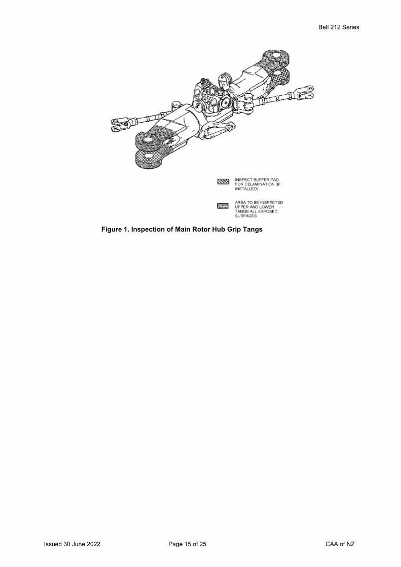
Bell 212 Series
Issued 30 June 2022 Page 15 of 25 CAA of NZ
Figure 1. Inspection of Main Rotor Hub Grip Tangs
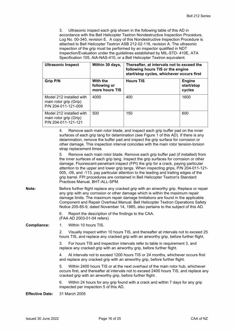
Bell 212 Series
Issued 30 June 2022 Page 16 of 25 CAA of NZ
3. Ultrasonic inspect each grip shown in the following table of this AD in accordance with the Bell Helicopter Textron Nondestructive Inspection Procedure, Log No. 00-340, revision E. A copy of this Nondestructive Inspection Procedure is attached to Bell Helicopter Textron ASB 212-02-116, revision A. The ultrasonic inspection of the grip must be performed by an inspector qualified in NDT Inspection/Evaluation under the guidelines established by MIL-STD- 410E, ATA Specification 105, AIA-NAS-410, or a Bell Helicopter Textron equivalent.
Ultrasonic Inspect Within 30 days, Thereafter, at intervals not to exceed the following hours TIS or the engine start/stop cycles, whichever occurs first
Grip P/N With the following or more hours TIS
Hours TIS Engine start/stop cycles
Model 212 installed with main rotor grip (Grip) P/N 204-011-121-009
4000 400 1600
Model 212 installed with main rotor grip (Grip) P/N 204-011-121-121
500 150 600
4. Remove each main rotor blade, and inspect each grip buffer pad on the inner surfaces of each grip tang for delamination (see Figure 1 of this AD). If there is any delamination, remove the buffer pad and inspect the grip surface for corrosion or other damage. This inspection interval coincides with the main rotor tension-torsion strap replacement times.
5. Remove each main rotor blade. Remove each grip buffer pad (if installed) from the inner surfaces of each grip tang. Inspect the grip surfaces for corrosion or other damage. Fluorescent-penetrant inspect (FPI) the grip for a crack, paying particular attention to the upper and lower grip tangs. When inspecting grips, P/N 204-011-121-005, -09, and -113, pay particular attention to the leading and trailing edges of the grip barrel. FPI procedures are contained in Bell Helicopter Textron's Standard Practices Manual, BHT-ALL-SPM.
Note: Before further flight replace any cracked grip with an airworthy grip. Replace or repair any grip with any corrosion or other damage which is within the maximum repair damage limits. The maximum repair damage limitations are found in the applicable Component and Repair Overhaul Manual. Bell Helicopter Textron Operations Safety Notice 205-85-9, dated November 14, 1985, also pertains to the subject of this AD.
6. Report the description of the findings to the CAA. (FAA AD 2003-01-04 refers)
Compliance: 1. Within 10 hours TIS.
2. Visually inspect within 10 hours TIS, and thereafter at intervals not to exceed 25 hours TIS, and replace any cracked grip with an airworthy grip, before further flight.
3. For hours TIS and inspection intervals refer to table in requirement 3, and replace any cracked grip with an airworthy grip, before further flight.
4. At intervals not to exceed 1200 hours TIS or 24 months, whichever occurs first and replace any cracked grip with an airworthy grip, before further flight.
5. Within 2400 hours TIS or at the next overhaul of the main rotor hub, whichever occurs first, and thereafter at intervals not to exceed 2400 hours TIS, and replace any cracked grip with an airworthy grip, before further flight .
6. Within 24 hours for any grip found with a crack and within 7 days for any grip inspected per inspection 5 of this AD.
Effective Date: 31 March 2005
Bell 212 Series
Issued 30 June 2022 Page 17 of 25 CAA of NZ
DCA/BELL212/40 Flotation System Nitrogen Bottles – Inspection Applicability: Model 212 helicopters embodied with Aeronautical Accessories, Inc. (AAI),
Supplemental Type Certificate (STC) SH2820SO, or fitted with AAI Parts Manufacturer Approval (PMA) reservoir assembly P/N 212-372-050, or fitted with adapter P/N 212-371-002.
Requirement: To prevent rupture of an adapter and uncontrolled jetting of pressurized gas from the nitrogen bottle and possible injury to occupants, vent the nitrogen from the reservoir assembly, per the Accomplishment Instructions, Part II - Floatation System Discharging in AAI Alert Service Bulletin ASB No. AA-05005, revision A or later FAA approved revision.
Remove the valve assembly and air line from the adapter and inspect the counter bore depth (dimension D) as shown in Figure 1 of ASB AA-05005. If dimension D does not exceed 0.860 inches, recharge the floatation system by following the Accomplishment Instructions, Part III - Floatation System Charging referring to Figures 2 and 3 of ASB AA-05005.
If dimension D exceeds 0.860 inches, per Figure 1 of ASB AA-05005, replace the reservoir assembly and the adapter, prior to further flight. (FAA AD 2005-20-38 refers)
Compliance: Within the next 24 hours TIS, or before the next emergency floatation supply bottle nitrogen charging, whichever occurs first, unless already accomplished.
Effective Date: 22 December 2005
DCA/BELL212/41 Tail Rotor Blades – Inspection Applicability: Model 212 aircraft fitted with tail rotor blades with a P/N and S/N listed in the following
table:
Part Number Serial Number 204-011-702-015 AFS-12703, AFS-12893, AFS-23525 and AFS-23573 204-011-702-121 A-22020 212-010-750-105FM A-10090, A-10836, A-11207 and A-11332 212-010-750-113 A-14953, A15090 and CS-12702 212-010-750-113FM A-12240, A-12296, A-12640, A-12670, A-12789, A-
13033, A-13096, A-13134, A-13199, A-13264 and A-13366
212-010-750-133 A15602
Requirement: To prevent the loss of tail rotor blade balance weights during flight, accomplish the following:
1. Inspect the aircraft log books and establish whether affected tail rotor blades are fitted to the aircraft.
2. Replace affected tail rotor blades per Bell Helicopter Textron Alert Service Bulletin (ASB) No. 212-07-125. (FAA AD 2007-19-53 refers)
Compliance: 1. & 2. Before further flight.
Effective Date: 20 September 2007
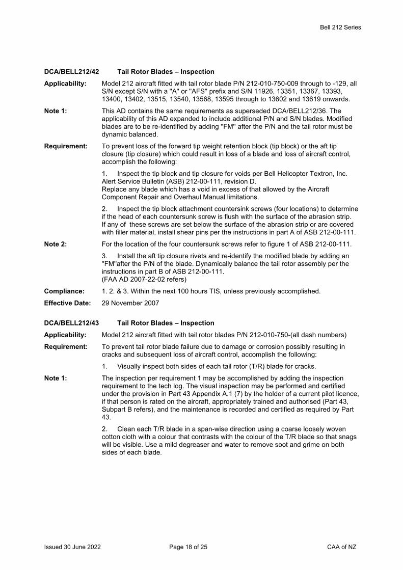
Bell 212 Series
Issued 30 June 2022 Page 18 of 25 CAA of NZ
DCA/BELL212/42 Tail Rotor Blades – Inspection Applicability: Model 212 aircraft fitted with tail rotor blade P/N 212-010-750-009 through to -129, all
S/N except S/N with a ''A'' or ''AFS'' prefix and S/N 11926, 13351, 13367, 13393, 13400, 13402, 13515, 13540, 13568, 13595 through to 13602 and 13619 onwards.
Note 1: This AD contains the same requirements as superseded DCA/BELL212/36. The applicability of this AD expanded to include additional P/N and S/N blades. Modified blades are to be re-identified by adding ''FM'' after the P/N and the tail rotor must be dynamic balanced.
Requirement: To prevent loss of the forward tip weight retention block (tip block) or the aft tip closure (tip closure) which could result in loss of a blade and loss of aircraft control, accomplish the following:
1. Inspect the tip block and tip closure for voids per Bell Helicopter Textron, Inc. Alert Service Bulletin (ASB) 212-00-111, revision D. Replace any blade which has a void in excess of that allowed by the Aircraft Component Repair and Overhaul Manual limitations.
2. Inspect the tip block attachment countersink screws (four locations) to determine if the head of each countersunk screw is flush with the surface of the abrasion strip. If any of these screws are set below the surface of the abrasion strip or are covered with filler material, install shear pins per the instructions in part A of ASB 212-00-111.
Note 2: For the location of the four countersunk screws refer to figure 1 of ASB 212-00-111.
3. Install the aft tip closure rivets and re-identify the modified blade by adding an ''FM''after the P/N of the blade. Dynamically balance the tail rotor assembly per the instructions in part B of ASB 212-00-111. (FAA AD 2007-22-02 refers)
Compliance: 1. 2. & 3. Within the next 100 hours TIS, unless previously accomplished.
Effective Date: 29 November 2007
DCA/BELL212/43 Tail Rotor Blades – Inspection Applicability: Model 212 aircraft fitted with tail rotor blades P/N 212-010-750-(all dash numbers)
Requirement: To prevent tail rotor blade failure due to damage or corrosion possibly resulting in cracks and subsequent loss of aircraft control, accomplish the following:
1. Visually inspect both sides of each tail rotor (T/R) blade for cracks.
Note 1: The inspection per requirement 1 may be accomplished by adding the inspection requirement to the tech log. The visual inspection may be performed and certified under the provision in Part 43 Appendix A.1 (7) by the holder of a current pilot licence, if that person is rated on the aircraft, appropriately trained and authorised (Part 43, Subpart B refers), and the maintenance is recorded and certified as required by Part 43.
2. Clean each T/R blade in a span-wise direction using a coarse loosely woven cotton cloth with a colour that contrasts with the colour of the T/R blade so that snags will be visible. Use a mild degreaser and water to remove soot and grime on both sides of each blade.
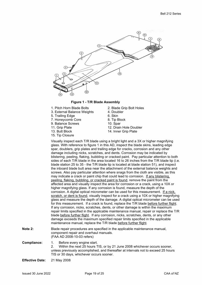
Bell 212 Series
Issued 30 June 2022 Page 19 of 25 CAA of NZ
Figure 1 - T/R Blade Assembly
1. Pitch Horn Blade Bolts 2. Blade Grip Bolt Holes 3. External Balance Weights 4. Doubler 5. Trailing Edge 6. Skin 7. Honeycomb Core 8. Tip Block 9. Balance Screws 10. Spar 11. Grip Plate 12. Drain Hole Doubler 13. Butt Block 14. Inner Grip Plate 15. Tip Closure
Visually inspect each T/R blade using a bright light and a 3X or higher magnifying glass. With reference to figure 1 in this AD, inspect the blade skins, leading edge spar, doublers, grip plates and trailing edge for cracks, corrosion and any other damage including nicks, scratches, and dents. Corrosion may be indicated by blistering, peeling, flaking, bubbling or cracked paint. Pay particular attention to both sides of each T/R blade in the area located 16 to 26 inches from the T/R blade tip (i.e. blade station 25 to 35 - the T/R blade tip is located at blade station 51), and inspect the inboard blade butt area near the attachment of the external balance weights and screws. Also pay particular attention where snags from the cloth are visible, as this may indicate a crack or paint chip that could lead to corrosion. If any blistering, peeling, flaking, bubbling, or cracked paint is found, remove the paint from the affected area and visually inspect the area for corrosion or a crack, using a 10X or higher magnifying glass. If any corrosion is found, measure the depth of the corrosion. A digital optical micrometer can be used for this measurement. If a nick, scratch, or dent is found, visually inspect for a crack using a 10X or higher magnifying glass and measure the depth of the damage. A digital optical micrometer can be used for this measurement. If a crack is found, replace the T/R blade before further flight. If any corrosion, nicks, scratches, dents, or other damage is within the maximum repair limits specified in the applicable maintenance manual, repair or replace the T/R blade before further flight. If any corrosion, nicks, scratches, dents, or any other damage exceeds the maximum specified repair limits specified in the applicable maintenance manual, replace the T/R blade before further flight.
Note 2: Blade repair procedures are specified in the applicable maintenance manual, component repair and overhaul manuals. (FAA AD 2008-10-03 refers)
Compliance: 1. Before every engine start. 2. Within the next 25 hours TIS, or by 21 June 2008 whichever occurs sooner, unless previously accomplished, and thereafter at intervals not to exceed 25 hours TIS or 30 days, whichever occurs sooner.
Effective Date: 21 May 2008
Bell 212 Series
Issued 30 June 2022 Page 20 of 25 CAA of NZ
DCA/BELL212/44 Main Rotor Blades – Inspection Applicability: Model 212 helicopters, S/N 30502 through to 30603, 30611 through to 30999, 31101
through to 31311, 32101 through to 32262 and 35001 through to 35103 fitted with main rotor blades P/N 212-015-501-005, -111, -113, -115, -117, -119 or -121.
Requirement: To prevent main rotor blade failure due to an edge void, corrosion or cracks which could result in blade loss and loss of aircraft control, accomplish the following:
Wash the upper and lower blade surfaces with a solution of cleaning compound (C-318) and water. Rinse the blades thoroughly and wipe dry.
Inspect the upper and lower grip plates and the blade doublers in the area from stations 24.5 through to 40 and inspect the entire width of the blade chord per figure 1 in Bell Helicopter ASB No. 212-08-130 revision A, dated 13 January 2009. Inspect the affected area for an edge void, corrosion and cracks. Also inspect the remaining upper and lower blade surfaces for corrosion and cracks. Accomplish the inspections with the aid of a magnifying glass (3x magnification or higher).
Note 1: These inspections can be accomplished with the main rotor blades installed on the helicopter. Examples of typical blade cracks are shown in figure 2 of ASB No. 212-08-130.
If no defects are found apply a light coat of preservative oil (C-125) to all surfaces of the blades in the specified area.
If any corrosion or an edge void is found, replace the blade with an airworthy blade before further flight, or repair the blade if the damage is within the maximum repair damage limits before further flight.
If a crack is found in the M/R blade paint finish, remove the paint in the affected area by lightly sanding with 180-220 grit paper in a span wise direction to determine if the grip plate, doubler or the skin is cracked. Do not remove any parent material of the blade during the sanding operation. If no cracks are found refinish the sanded area.
If any parent material is removed during the sanding operation, replace the blade with an airworthy blade before further flight, or repair the blade if the amount of parent material removed is within the maximum repair damage limits before further flight.
If a crack is found in any part of the blade other than the paint finish, replace the blade with an airworthy blade, before further flight.
Note 2: The maximum repair damage limits are specified in the applicable Component and Repair Overhaul Manual.
Note 3: Accomplish the requirements of this AD per Bell Helicopter ASB No. 212-08-130.
(FAA AD 2010-03-03 refers)
Compliance: Within the next 25 hours TIS unless previously accomplished and thereafter at intervals not to exceed 100 hours TIS.
Effective Date: 25 February 2010
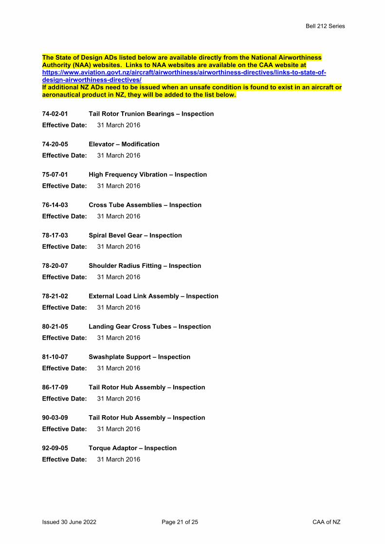
Bell 212 Series
Issued 30 June 2022 Page 21 of 25 CAA of NZ
The State of Design ADs listed below are available directly from the National Airworthiness Authority (NAA) websites. Links to NAA websites are available on the CAA website at https://www.aviation.govt.nz/aircraft/airworthiness/airworthiness-directives/links-to-state-of-design-airworthiness-directives/ If additional NZ ADs need to be issued when an unsafe condition is found to exist in an aircraft or aeronautical product in NZ, they will be added to the list below.
74-02-01 Tail Rotor Trunion Bearings – Inspection Effective Date: 31 March 2016
74-20-05 Elevator – Modification Effective Date: 31 March 2016
75-07-01 High Frequency Vibration – Inspection Effective Date: 31 March 2016
76-14-03 Cross Tube Assemblies – Inspection Effective Date: 31 March 2016
78-17-03 Spiral Bevel Gear – Inspection Effective Date: 31 March 2016
78-20-07 Shoulder Radius Fitting – Inspection Effective Date: 31 March 2016
78-21-02 External Load Link Assembly – Inspection Effective Date: 31 March 2016
80-21-05 Landing Gear Cross Tubes – Inspection Effective Date: 31 March 2016
81-10-07 Swashplate Support – Inspection Effective Date: 31 March 2016
86-17-09 Tail Rotor Hub Assembly – Inspection Effective Date: 31 March 2016
90-03-09 Tail Rotor Hub Assembly – Inspection Effective Date: 31 March 2016
92-09-05 Torque Adaptor – Inspection Effective Date: 31 March 2016
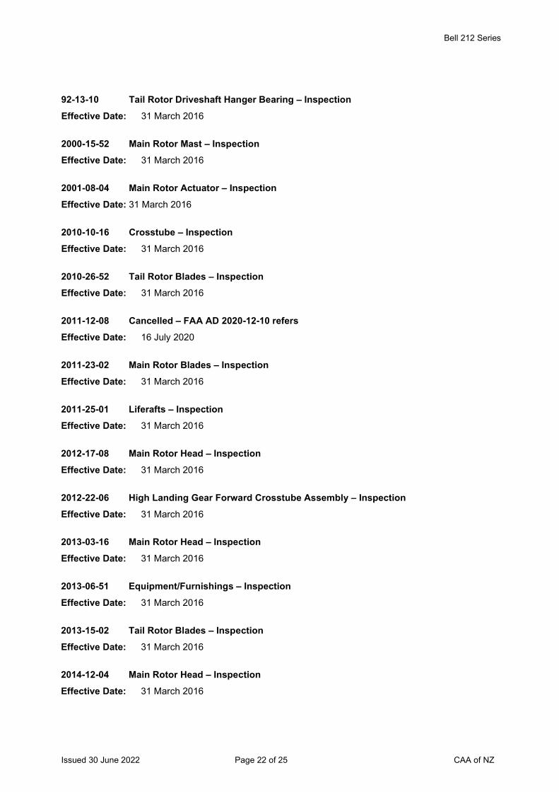
Bell 212 Series
Issued 30 June 2022 Page 22 of 25 CAA of NZ
92-13-10 Tail Rotor Driveshaft Hanger Bearing – Inspection Effective Date: 31 March 2016
2000-15-52 Main Rotor Mast – Inspection Effective Date: 31 March 2016
2001-08-04 Main Rotor Actuator – Inspection Effective Date: 31 March 2016
2010-10-16 Crosstube – Inspection Effective Date: 31 March 2016
2010-26-52 Tail Rotor Blades – Inspection Effective Date: 31 March 2016
2011-12-08 Cancelled – FAA AD 2020-12-10 refers Effective Date: 16 July 2020
2011-23-02 Main Rotor Blades – Inspection Effective Date: 31 March 2016
2011-25-01 Liferafts – Inspection Effective Date: 31 March 2016
2012-17-08 Main Rotor Head – Inspection Effective Date: 31 March 2016
2012-22-06 High Landing Gear Forward Crosstube Assembly – Inspection Effective Date: 31 March 2016
2013-03-16 Main Rotor Head – Inspection Effective Date: 31 March 2016
2013-06-51 Equipment/Furnishings – Inspection Effective Date: 31 March 2016
2013-15-02 Tail Rotor Blades – Inspection Effective Date: 31 March 2016
2014-12-04 Main Rotor Head – Inspection Effective Date: 31 March 2016
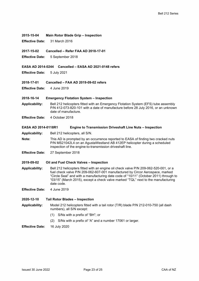
Bell 212 Series
Issued 30 June 2022 Page 23 of 25 CAA of NZ
2015-15-04 Main Rotor Blade Grip – Inspection Effective Date: 31 March 2016
2017-15-02 Cancelled – Refer FAA AD 2018-17-01 Effective Date: 5 September 2018
EASA AD 2014-0244 Cancelled – EASA AD 2021-0148 refers Effective Date: 5 July 2021
2018-17-01 Cancelled – FAA AD 2019-09-02 refers Effective Date: 4 June 2019
2018-16-14 Emergency Flotation System – Inspection Applicability: Bell 212 helicopters fitted with an Emergency Flotation System (EFS) tube assembly
P/N 412-073-820-101 with a date of manufacture before 28 July 2016, or an unknown date of manufacture.
Effective Date: 4 October 2018
EASA AD 2014-0118R1 Engine to Transmission Driveshaft Line Nuts – Inspection Applicability: Bell 212 helicopters, all S/N.
Note: This AD is prompted by an occurrence reported to EASA of finding two cracked nuts P/N MS21042L4 on an AgustaWestland AB 412EP helicopter during a scheduled inspection of the engine-to-transmission driveshaft line.
Effective Date: 27 September 2018
2019-09-02 Oil and Fuel Check Valves – Inspection Applicability: Bell 212 helicopters fitted with an engine oil check valve P/N 209-062-520-001, or a
fuel check valve P/N 209-062-607-001 manufactured by Circor Aerospace, marked “Circle Seal” and with a manufacturing date code of “10/11” (October 2011) through to “03/15” (March 2015), except a check valve marked “TQL” next to the manufacturing date code.
Effective Date: 4 June 2019
2020-12-10 Tail Rotor Blades – Inspection Applicability: Model 212 helicopters fitted with a tail rotor (T/R) blade P/N 212-010-750 (all dash
numbers), all S/N except:
(1) S/Ns with a prefix of “BH”; or
(2) S/Ns with a prefix of “A” and a number 17061 or larger.
Effective Date: 16 July 2020

Bell 212 Series
Issued 30 June 2022 Page 24 of 25 CAA of NZ
2020-16-10 Shoulder Harness Seat Belt – Inspection Applicability: Bell 212 helicopters fitted with a shoulder harness seat belt comfort clip (comfort clip)
P/N D7LZ-6560286-A, P/N D7LZ-6560286-B, or P/N 504636-401.
Effective Date: 3 September 2020
2020-19-08 Main Rotor Hub Tension-Torsion Straps – Inspection Applicability: Bell 212 helicopters fitted with a main rotor hub tension-torsion strap (TT strap)
assembly P/N 204-012-112-005.
Effective Date: 21 October 2020
EASA AD 2021-0148 Emergency Flotation System (EFS) – AFM Supplement Applicability: Bell 212 helicopters, all S/N fitted with an Emergency Flotation System (EFS), all part
numbers, as approved optional kit for ditching from the helicopter design approval holder, or by installation through a Supplemental Type Certificate (STC).
Note: EASA AD 2021-0148 retains the requirements in superseded EASA AD 2014-0244 and introduces a revised Appendix 2-B in the AD.
Effective Date: 5 July 2021
2021-15-51 Cancelled - FAA AD 2022-02-02 refers Effective Date: 16 February 2022
2022-02-02 Cancelled - FAA AD 2022-06-03 refers Effective Date: 31 March 2022
EASA AD 2022-0047 Tail Boom Attachment – Inspection Applicability: Bell 212 helicopters, S/N 30501 through to 30999 inclusive, 31101 through to 31311
inclusive, 32101 through to 32142 inclusive and 35001 through to 35103 inclusive.
Effective Date: 24 March 2022
2022-06-03 Main Rotor Hub Strap Pins - Inspection Applicability: Model 212 helicopters, fitted with a main rotor hub strap pin P/N 204-012-104-005
with a S/N prefix “FNFS”. Effective Date: 31 March 2022
2022-07-02 Tail Boom Fin Spar Cap - Inspection Applicability: This AD applies to the following Bell helicopters fitted with a tail boom left hand fin
spar cap (spar cap) P/N 212-030-447-117:
Model 212 helicopters, S/N 30502 through to 30603 inclusive, 30611 through to 30999 inclusive, 31101 through to 31311 inclusive, 32101 through to 32142 inclusive, and 35001 through to 35103 inclusive.
Effective Date: 9 May 2022
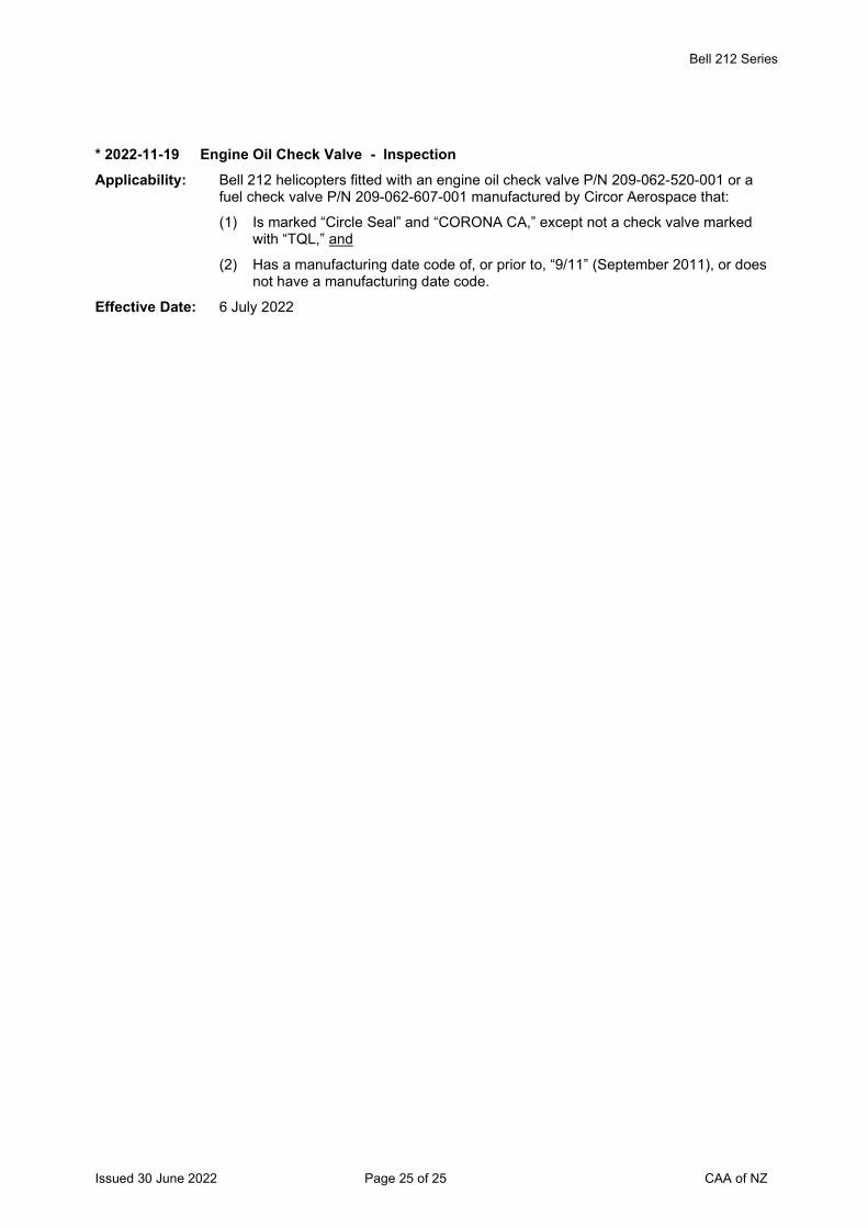
Bell 212 Series
Issued 30 June 2022 Page 25 of 25 CAA of NZ
* 2022-11-19 Engine Oil Check Valve - Inspection Applicability: Bell 212 helicopters fitted with an engine oil check valve P/N 209-062-520-001 or a
fuel check valve P/N 209-062-607-001 manufactured by Circor Aerospace that:
(1) Is marked “Circle Seal” and “CORONA CA,” except not a check valve marked with “TQL,” and
(2) Has a manufacturing date code of, or prior to, “9/11” (September 2011), or does not have a manufacturing date code.
Effective Date: 6 July 2022
Issued 30 June 2022 Page 1 of 12 CAA of NZ
Airworthiness Directive Schedule Helicopters Bell 412 Series 30 June 2022
Notes: 1. This AD schedule is applicable to Bell 412 and 412EP helicopters manufactured under FAA Type Certificate No. H4SW.
2. The Federal Aviation Administration (FAA) is the National Airworthiness Authority (NAA) responsible for the issue of State of Design Airworthiness Directives (ADs) for these helicopters. State of Design ADs can be obtained directly from the FAA website at http://rgl.faa.gov/Regulatory_and_Guidance_Library/rgAD.nsf/MainFrame?OpenFrameSet
EASA ADs can be obtained directly from the EASA website at http://ad.easa.europa.eu/
3. The date above indicates the amendment date of this schedule.
4. New or amended ADs are shown with an asterisk *
Contents
DCA/BELL412/1 Airworthiness Directive Compliance at Initial Airworthiness Certificate Issue ................... 3 DCA/BELL412/2 Main Rotor Yoke - Inspection ............................................................................................ 3 DCA/BELL412/3 Tail Boom Attachment Cap Angle - Inspection .................................................................. 4 DCA/BELL412/4 Main Rotor Actuator Locking Washer – Inspection ........................................................... 4 DCA/BELL412/5 Tail Rotor Yoke – Inspection ............................................................................................. 5 DCA/BELL412/6 Tail Rotor Bellcrank Retention Nuts - Replacement .......................................................... 6 DCA/BELL412/7 Cancelled – DCA/BELL412/10 refers ................................................................................ 6 DCA/BELL412/8 Floatation System Nitrogen Bottles – Inspection ............................................................... 6 DCA/BELL412/9 Cancelled – DCA/BELL412/14 refers ................................................................................ 6 DCA/BELL412/10 Tail Rotor Blades – Inspection .......................................................................................... 7 DCA/BELL412/11 Cancelled – FAA AD 2013-15-02 refers ............................................................................ 7 DCA/BELL412/12 Cancelled – FAA AD 2013-20-18 refers ............................................................................ 7 DCA/BELL412/13 Landing Gear Forward Cross Tubes – Inspection ............................................................. 8 DCA/BELL412/14A Tail Rotor Blades – Inspection .......................................................................................... 8 DCA/BELL412/15 Cancelled – FAA AD 2020-12-10 refers ............................................................................ 9 DCA/BELL412/16 Emergency Float Kit – Inspection...................................................................................... 9 DCA/BELL412/17A Cross Tubes – Life Limitation ............................................................................................ 9 DCA/BELL412/18 Aft Cross Tube Assembly – Life Limitation ........................................................................ 9 The State of Design ADs listed below are available directly from the National Airworthiness Authority (NAA) websites. Links to NAA websites are available on the CAA website at https://www.aviation.govt.nz/aircraft/airworthiness/airworthiness-directives/links-to-state-of-design-airworthiness-directives/ If additional NZ ADs need to be issued when an unsafe condition is found to exist in an aircraft or aeronautical product in NZ, they will be added to the list below. .............................................. 10 2012-22-06 Landing Gear Forward Crosstubes – Inspection ............................................................. 10 2012-22-11 Collective Lever – Inspection .......................................................................................... 10 2013-01-04 Crosstubes – Inspection .................................................................................................. 10 2013-05-14 Swashplate Outer Ring Assembly – Life Limitation ......................................................... 10 2013-15-02 Tail Rotor Blade Assembly – Inspection .......................................................................... 10 2013-16-16 Dart Aerospace Ltd. Crosstubes – Life Limitation ........................................................... 10 2013-20-18 Main Rotor Yoke - Inspection .......................................................................................... 10 2014-0189 Cancelled – EASA AD 2014-0244 refers ........................................................................ 10 EASA AD 2014-0244 Cancelled – EASA AD 2021-0148 refers ........................................................................ 10 2015-04-04 Cancelled – FAA AD 2020-02-11 refers .......................................................................... 10
Issued 30 June 2022 Page 2 of 12 CAA of NZ
2017-15-02 Cancelled – FAA AD 2018-17-01 refers .......................................................................... 10 2018-17-01 Cancelled – FAA AD 2019-09-02 refers .......................................................................... 10 2018-16-14 Emergency Flotation System – Inspection ...................................................................... 10 EASA AD 2014-0118R1 Engine to Transmission Driveshaft Line Nuts – Inspection .................................... 11 2019-09-02 Oil and Fuel Check Valves – Inspection .......................................................................... 11 2020-02-11 Static Inverter – Inspection .............................................................................................. 11 2020-12-10 Tail Rotor Blades – Inspection ........................................................................................ 11 2020-16-10 Shoulder Harness Seat Belt – Inspection ........................................................................ 11 2020-22-07 MGB Support Case – AFM Amendment ......................................................................... 11 EASA AD 2021-0148 Emergency Flotation System (EFS) – AFM Supplement ................................................ 12 EASA AD 2022-0047 Tail Boom Attachment – Inspection................................................................................. 12 2022-07-03 Collective Levers – Inspection ........................................................................................ 12 2022-07-02 Tail Boom Fin Spar Cap - Inspection ............................................................................ 12 * 2022-11-19 Engine Oil Check Valve - Inspection ............................................................................. 12
Helicopters Bell 412 Series
Issued 30 June 2022 Page 3 of 12 CAA of NZ
DCA/BELL412/1 Airworthiness Directive Compliance at Initial Airworthiness Certificate Issue Applicability: Model 412 series.
Requirement: Compliance with the following Airworthiness Directives (as applicable) is required.
FAA Airworthiness Directives: 82-26-51 R1 - Main rotor yoke 85-07-01 - Main rotor pitch horn 86-16-11 - Tail rotor hub 89-08-05 - Trans internal sump oil filter 90-03-09 - T/R trunnion bearing housing 92-09-05 - Combining gearbox 92-13-10 - Tail rotor bearing 93-02-07 - Vertical fin spar cap 93-17-12 - Spider fatigue 94-18-09 - Lower planetary spider 97-07-06 - Swashplate support assembly 97-11-04 - RIN component history card
Note: Each part of this AD (each individual FAA AD) shall be certified in the aircraft log book separately.
Compliance: Before issue of New Zealand Certificate of Airworthiness. Repetitive inspections to be accomplished at intervals not exceeding the times specified in the FAA Airworthiness Directives.
Effective Date: 26 October 2000
DCA/BELL412/2 Main Rotor Yoke - Inspection Applicability: Model 412 or 412EP S/N 33001 through 33213, 34001 through 34036, and 36001
through 36204, and model 412CF S/N 46400 through 46499, with main rotor yoke assembly P/N 412-010-101-123 or –127 installed.
Requirement: To prevent a fatigue failure of a yoke, loss of a main rotor blade, and subsequent loss of control of the helicopter, accomplish the following:-
Inspect and measure each yoke per paragraphs 1 through 6, of BHTI ASB 412-98-93, or BHTI ASB 412CF-98-5 as applicable. If any measurement for a yoke is less than 0.478-inch thickness, add 500 hours to the TIS indicated on the component history card or equivalent record.
(FAA AD 99-23-23 refers)
Compliance: Required within 10 hours TIS for a yoke with 4,500 or more hours TIS or required within 90 days for a yoke with less than 4,500 hours TIS but prior to the accumulation of 4,500 hours TIS, unless accomplished previously.
Effective Date: 26 October 2000
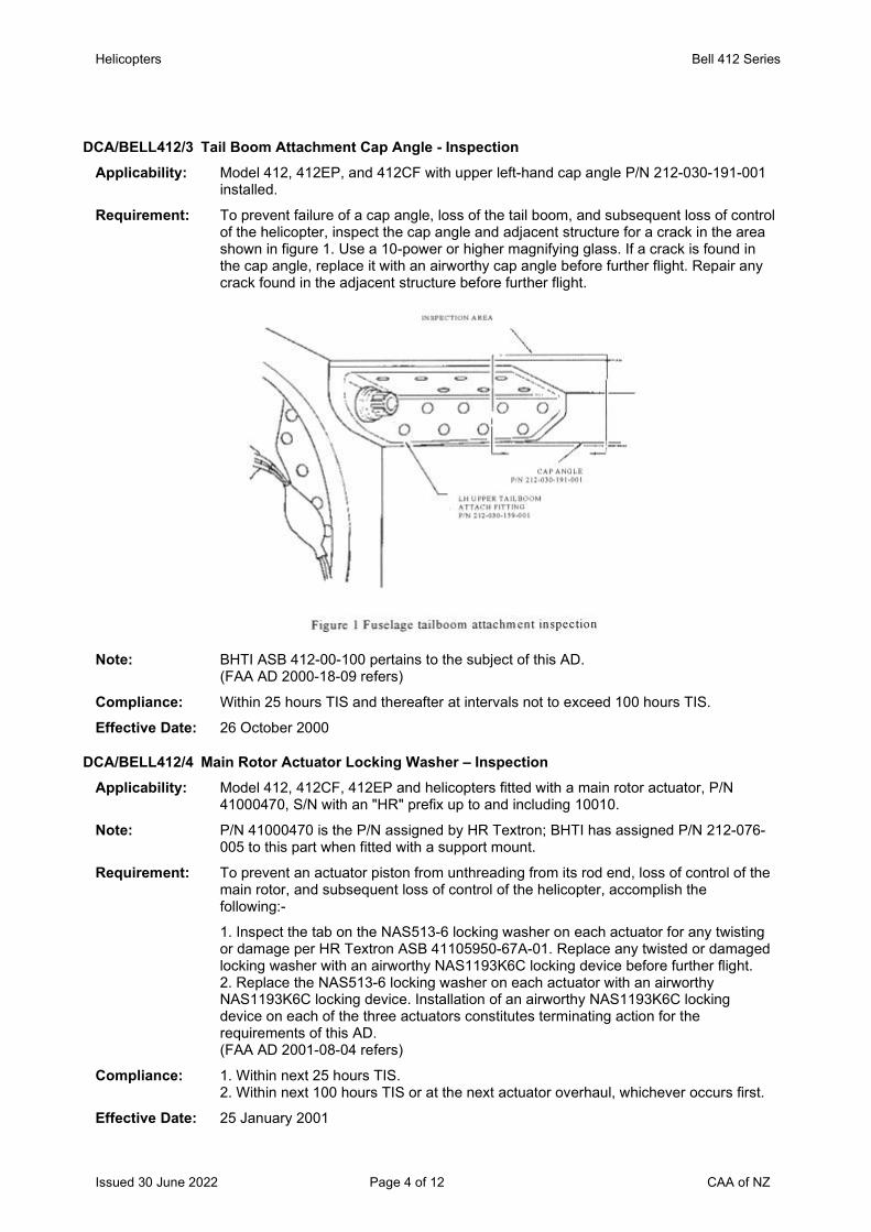
Helicopters Bell 412 Series
Issued 30 June 2022 Page 4 of 12 CAA of NZ
DCA/BELL412/3 Tail Boom Attachment Cap Angle - Inspection Applicability: Model 412, 412EP, and 412CF with upper left-hand cap angle P/N 212-030-191-001
installed.
Requirement: To prevent failure of a cap angle, loss of the tail boom, and subsequent loss of control of the helicopter, inspect the cap angle and adjacent structure for a crack in the area shown in figure 1. Use a 10-power or higher magnifying glass. If a crack is found in the cap angle, replace it with an airworthy cap angle before further flight. Repair any crack found in the adjacent structure before further flight.
Note: BHTI ASB 412-00-100 pertains to the subject of this AD.
(FAA AD 2000-18-09 refers)
Compliance: Within 25 hours TIS and thereafter at intervals not to exceed 100 hours TIS.
Effective Date: 26 October 2000
DCA/BELL412/4 Main Rotor Actuator Locking Washer – Inspection Applicability: Model 412, 412CF, 412EP and helicopters fitted with a main rotor actuator, P/N
41000470, S/N with an "HR" prefix up to and including 10010.
Note: P/N 41000470 is the P/N assigned by HR Textron; BHTI has assigned P/N 212-076-005 to this part when fitted with a support mount.
Requirement: To prevent an actuator piston from unthreading from its rod end, loss of control of the main rotor, and subsequent loss of control of the helicopter, accomplish the following:-
1. Inspect the tab on the NAS513-6 locking washer on each actuator for any twisting or damage per HR Textron ASB 41105950-67A-01. Replace any twisted or damaged locking washer with an airworthy NAS1193K6C locking device before further flight. 2. Replace the NAS513-6 locking washer on each actuator with an airworthy NAS1193K6C locking device. Installation of an airworthy NAS1193K6C locking device on each of the three actuators constitutes terminating action for the requirements of this AD. (FAA AD 2001-08-04 refers)
Compliance: 1. Within next 25 hours TIS. 2. Within next 100 hours TIS or at the next actuator overhaul, whichever occurs first.
Effective Date: 25 January 2001
Bell 412 Series
Issued 30 June 2022 Page 5 of 12 CAA of NZ
DCA/BELL412/5 Tail Rotor Yoke – Inspection
Applicability: Model 412, 412CF, and 412EP helicopters fitted with tail rotor yoke assembly, P/N 212-011-702-all dash numbers.
Requirement: To prevent static and dynamic overload damage to the tail rotor yoke that could result in loss of the tail rotor and subsequent loss of control of the helicopter, accomplish the following:-
1. Before further flight, review the historical records of the yoke assembly for any static or dynamic overload damage that could have imposed a bending load on the yoke. The damage may not have required replacing the yoke assembly; for example, an incident in which a damaged tail rotor blade was replaced due to a blade strike. If the records indicate that overload damage may have occurred, replace the yoke with an airworthy yoke.
2. Before further flight unless the requirements of paragraph 3. of this AD have been accomplished previously:
a) Install a Never Exceed Velocity (Vne) red line at 120 KIAS on the pilot and copilot airspeed indicators using red tape or paint and a slippage indicator on the instrument case and glass.
b) Install a placard made of material that is not easily erased, disfigured, or obscured on the instrument panel in clear view of the pilot and copilot:
"Observe temporary Maximum Never Exceed (Vne) airspeed red line (marked at 120 knots indicated airspeed (KIAS)). Vne is 20 KIAS less than the value presented on the airspeed limitation placard for each ambient condition."
c) Insert the applicable BHT 412 Temporary Revision, dated August 16, 1996, into the Model 412 Rotorcraft Flight Manual (RFM) or the applicable section of Agusta AB412 Temporary Revision No. 2, dated April 17, 1997, into the Model AB412 RFM.
3. Within 180 calendar days:
a) Remove yoke assembly, P/N 212-011-702-all dash numbers, and replace it with an airworthy yoke assembly, P/N 212-011-702-all dash numbers, with zero hours TIS, or an airworthy yoke (regardless of TIS) that has passed a one-time x-ray diffraction inspection per BHT ASB 412-96-89, Revision A; BHT ASB 412CF-96-01; or Agusta Technical Bulletin 412-65, whichever is applicable.
b) Install an airworthy tail rotor flapping stop, P/N 212-011-713-103.
c) After the requirements of paragraphs 3. a) and 3. b) of this AD are accomplished, remove the 120 KIAS redline from the pilot and copilot airspeed indicators; remove the Vne airspeed restriction placard; and remove the BHT 412 Temporary Revision, dated August 16, 1996; BHT ASB 412CF-96-01, dated September 3, 1996; or Agusta AB412 Temporary Revision No. 2, as applicable, from the RFM.
4. After accomplishing the requirements of paragraph 3. of this AD, at intervals not to exceed 25 hours TIS, inspect the yoke assembly and tail rotor flapping stop (stop) per Part III, Recurring 25-Hour Special Inspection and Conditional Inspection Requirement, of BHT ASB 412-96-89, Revision A; BHT ASB 412CF-96-01; or Agusta Technical Bulletin 412-65, as applicable. Replace any unairworthy yoke assembly or stop with an airworthy yoke assembly or stop before further flight. (FAA AD 2001-09-11 refers)
Compliance: Compliance is required at the times specified within the requirement of this airworthiness directive.
Effective Date: 31 May 2001
Bell 412 Series
Issued 30 June 2022 Page 6 of 12 CAA of NZ
DCA/BELL412/6 Tail Rotor Bellcrank Retention Nuts - Replacement
Applicability: Model 412 series
Requirement: To prevent failure of the tail rotor counterweight bellcrank retention nut and loss of control of the helicopter, replace the two existing retention nuts P/N 212-010-709-001 or 212-011-705-001 with nuts P/N MS14145L6 or MS17826-6 per Bell ASB 412-00-102 Revision A.
(FAA AD 2001-13-01 refers)
Compliance: Within 100 hours TIS or by 25 Oct 2001 whichever is the sooner.
Effective Date: 26 July 2001
DCA/BELL412/7 Cancelled – DCA/BELL412/10 refers Effective Date: 29 November 2007
DCA/BELL412/8 Floatation System Nitrogen Bottles – Inspection Applicability: Model 412 and 412EP helicopters embodied with Aeronautical Accessories, Inc.
(AAI), Supplemental Type Certificate (STC) SH2820SO, or fitted with AAI Parts Manufacturer Approval (PMA) reservoir assembly P/N 212-372-050, or fitted with adapter P/N 212-371-002.
Requirement: To prevent rupture of an adapter and uncontrolled jetting of pressurized gas from the nitrogen bottle, and possible injury to occupants, vent the nitrogen from the reservoir assembly, per the Accomplishment Instructions, Part II - Floatation System Discharging in AAI Alert Service Bulletin ASB No. AA-05005, revision A or later FAA approved revision.
Remove the valve assembly and air line from the adapter and inspect the counter bore depth (dimension D) as shown in Figure 1 of ASB AA-05005. If dimension D does not exceed 0.860 inches, recharge the floatation system by following the Accomplishment Instructions, Part III - Floatation System Charging referring to Figures 2 and 3 of ASB AA-05005.
If dimension D exceeds 0.860 inches, per Figure 1 of ASB AA-05005, replace the reservoir assembly and the adapter, prior to further flight.
(FAA AD 2005-20-38 refers)
Compliance: Within the next 24 hours TIS, or before the next emergency floatation supply bottle nitrogen charging, whichever occurs first, unless already accomplished.
Effective Date: 22 December 2005
DCA/BELL412/9 Cancelled – DCA/BELL412/14 refers Effective Date: 15 December 2010
Bell 412 Series
Issued 30 June 2022 Page 7 of 12 CAA of NZ
DCA/BELL412/10 Tail Rotor Blades – Inspection
Applicability: Model 412, 412CF and 412EP aircraft fitted with tail rotor blade P/N 212-010-750-009 through to -129, all S/N except S/N with a ''A'' or ''AFS'' prefix and S/N 11926, 13351, 13367, 13393, 13400, 13402, 13515, 13540, 13568, 13595 through to 13602 and 13619 onwards.
Note 1: This AD contains the same requirements as superseded DCA/BELL412/7. The applicability of this AD expanded to include additional P/N and S/N blades. Modified blades are to be re-identified by adding ''FM'' after the P/N and the tail rotor must be dynamic balanced.
Requirement: To prevent loss of the forward tip weight retention block (tip block) or the aft tip closure (tip closure) which could result in loss of a blade and loss of aircraft control, accomplish the following:
1. Inspect the tip block and tip closure for voids per Bell Helicopter Textron, Inc. Alert Service Bulletins (ASB) 412-00-106, revision D.
Replace any blade which has a void in excess of that allowed by the Aircraft Component Repair and Overhaul Manual limitations.
2. Inspect the tip block attachment countersink screws (four locations) to determine if the head of each countersunk screw is flush with the surface of the abrasion strip.
If any of these screws are set below the surface of the abrasion strip or are covered with filler material, install shear pins per the instructions in part A of ASB 412-00-106.
Note 2: For the location of the four countersunk screws refer to figure 1 in ASB 412-00-106.
3. Install the aft tip closure rivets and re-identify the modified blade by adding an ''FM''after the P/N of the blade. Dynamically balance the tail rotor assembly per the instructions in part B of ASB 412-00-106. (FAA AD 2007-22-02 refers)
Compliance: 1. 2. & 3. Within the next 100 hours TIS, unless previously accomplished.
Effective Date: 29 November 2007
DCA/BELL412/11 Cancelled – FAA AD 2013-15-02 refers Effective Date: 14 August 2013
DCA/BELL412/12 Cancelled – FAA AD 2013-20-18 refers Effective Date: 29 November 2013
Bell 412 Series
Issued 30 June 2022 Page 8 of 12 CAA of NZ
DCA/BELL412/13 Landing Gear Forward Cross Tubes – Inspection
Applicability: Model 412, 412EP and 412CF aircraft, and Agusta S.p.A. model AB412 and AB412EP aircraft, and
Fitted with Aeronautical Accessories, Inc. (AAI) Low Skid Landing Gear Forward Cross Tube P/N 212-320-103 with a S/N prefix of ‘‘AA'' and a S/N 574 through to 628.
Note 1: Cross tube P/N 212-320-103 is also part of AAI Low Skid Gear Assembly Kits P/N 412-320-500 and 412-320-502.
Requirement: To prevent failure of a cross tube and subsequent collapse of the landing gear, replace affected cross tubes with an airworthy part per AAI Alert SB No. AA-10012 dated 5 March 2010.
Note 2: AAI Alert SB No. AA-10012 references the AAI Instructions for Continued Airworthiness AA-01136 which contains instructions to replace the cross tubes. A copy of ASB No. AA-10012 dated 5 March 2010 can be obtained from [email protected] (FAA AD 2010-10-16 refers)
Compliance: Within the next 25 hours TIS.
Effective Date: 18 June 2010
DCA/BELL412/14A Tail Rotor Blades – Inspection Applicability: Model 412, 412CF and 412EP aircraft fitted with tail rotor blades with a P/N and S/N
listed in the following table:
Part Number Serial Number 204-011-702-015 AFS-12703, AFS-12893, AFS-23525 and AFS-23573 204-011-702-121 A-22020 212-010-750-105 A-11923 212-010-750-105FM A-10090, A-10836, A-11207, A-11332, A-10857, A-11617, A-
11828, A-12043 and A-12091 212-010-750-113 A-14953, A15090 and CS-12702 212-010-750-113FM A-12240, A-12296, A-12640, A-12670, A-12789, A-13033, A-
13096, A-13134, A-13199, A-13264, A-13366, A-12286, A-12398, A-13088, A-13106 and A-13539
212-010-750-133 A15602
Note 1: There is no change to the requirements of this AD. Aircraft already in compliance with DCA/BELL412/14 are not affected by this AD. This AD revised to correct the ASB document number applicable to model 412CF aircraft.
Requirement: To prevent the loss of tail rotor blade balance weights during flight which can result in loss of aircraft control, review the aircraft records or inspect the aircraft and determine if an affected tail rotor blade is fitted to the aircraft. If an affected blade is found fitted, replace the blade with a P/N and S/N tail rotor blade which is not affected by this AD.
Note 2: Bell Helicopter Textron ASB No. 412CF-07-30 for model 412CF helicopters and ASB No. 412-07-123 for model 412 and 412EP helicopters, both at revision B and dated 22 November 2010 pertains to the subject of this AD. (FAA AD 2010-26-52 refers)
Compliance: Before further flight unless previously accomplished.
Effective Date: DCA/BELL412/14 - 15 December 2010 DCA/BELL412/14A - 8 December 2011
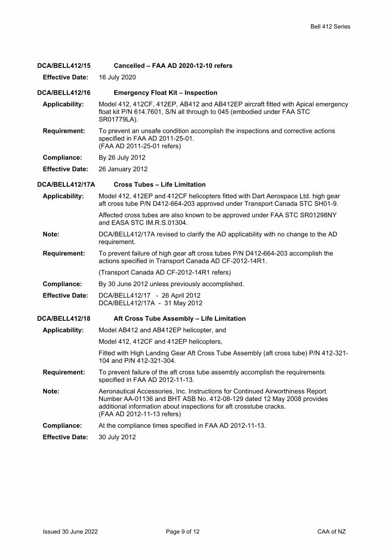
Bell 412 Series
Issued 30 June 2022 Page 9 of 12 CAA of NZ
DCA/BELL412/15 Cancelled – FAA AD 2020-12-10 refers
Effective Date: 16 July 2020
DCA/BELL412/16 Emergency Float Kit – Inspection Applicability: Model 412, 412CF, 412EP, AB412 and AB412EP aircraft fitted with Apical emergency
float kit P/N 614.7601, S/N all through to 045 (embodied under FAA STC SR01779LA).
Requirement: To prevent an unsafe condition accomplish the inspections and corrective actions specified in FAA AD 2011-25-01. (FAA AD 2011-25-01 refers)
Compliance: By 26 July 2012
Effective Date: 26 January 2012
DCA/BELL412/17A Cross Tubes – Life Limitation Applicability: Model 412, 412EP and 412CF helicopters fitted with Dart Aerospace Ltd. high gear
aft cross tube P/N D412-664-203 approved under Transport Canada STC SH01-9.
Affected cross tubes are also known to be approved under FAA STC SR01298NY and EASA STC IM.R.S.01304.
Note: DCA/BELL412/17A revised to clarify the AD applicability with no change to the AD requirement.
Requirement: To prevent failure of high gear aft cross tubes P/N D412-664-203 accomplish the actions specified in Transport Canada AD CF-2012-14R1.
(Transport Canada AD CF-2012-14R1 refers)
Compliance: By 30 June 2012 unless previously accomplished.
Effective Date: DCA/BELL412/17 - 26 April 2012 DCA/BELL412/17A - 31 May 2012
DCA/BELL412/18 Aft Cross Tube Assembly – Life Limitation Applicability: Model AB412 and AB412EP helicopter, and
Model 412, 412CF and 412EP helicopters,
Fitted with High Landing Gear Aft Cross Tube Assembly (aft cross tube) P/N 412-321-104 and P/N 412-321-304.
Requirement: To prevent failure of the aft cross tube assembly accomplish the requirements specified in FAA AD 2012-11-13.
Note: Aeronautical Accessories, Inc. Instructions for Continued Airworthiness Report Number AA-01136 and BHT ASB No. 412-08-129 dated 12 May 2008 provides additional information about inspections for aft crosstube cracks. (FAA AD 2012-11-13 refers)
Compliance: At the compliance times specified in FAA AD 2012-11-13.
Effective Date: 30 July 2012
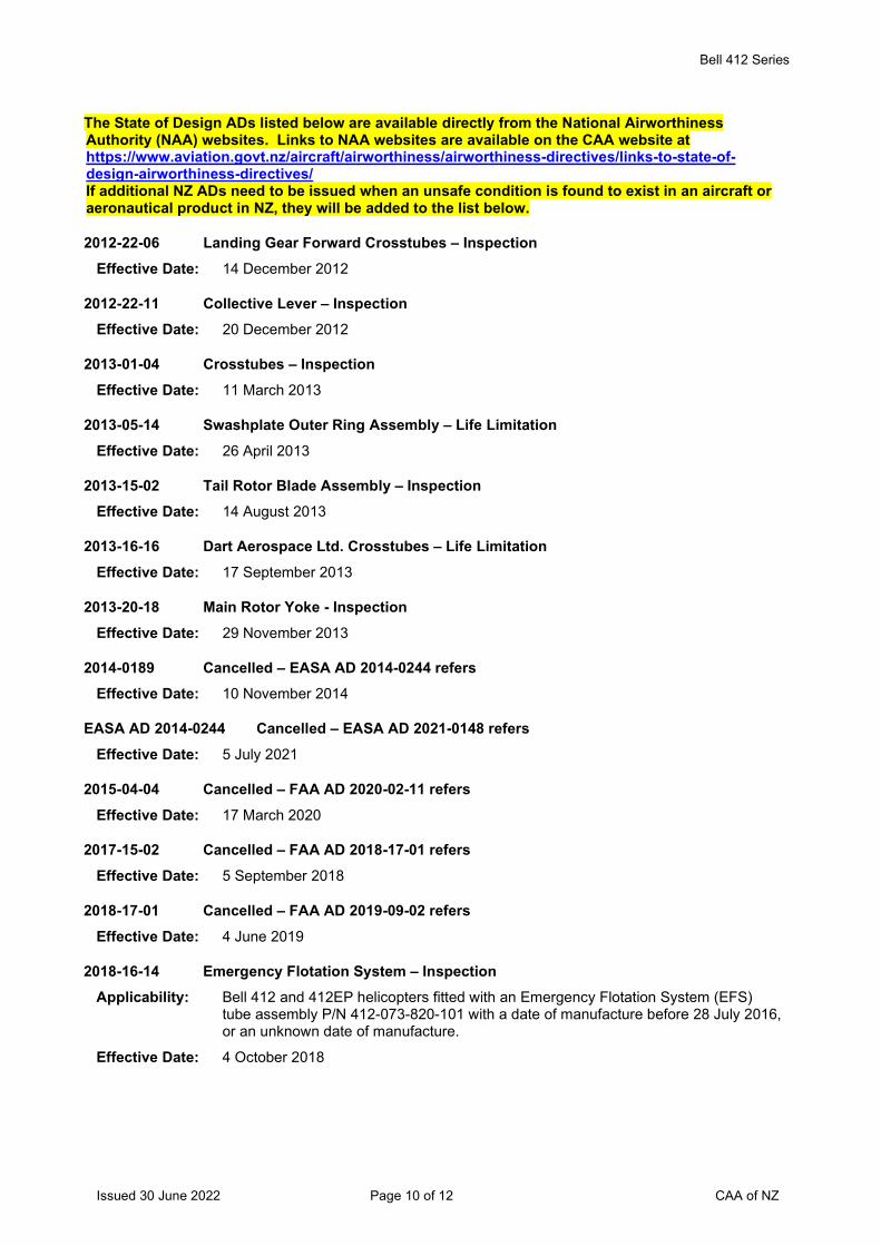
Bell 412 Series
Issued 30 June 2022 Page 10 of 12 CAA of NZ
The State of Design ADs listed below are available directly from the National Airworthiness Authority (NAA) websites. Links to NAA websites are available on the CAA website at https://www.aviation.govt.nz/aircraft/airworthiness/airworthiness-directives/links-to-state-of-design-airworthiness-directives/ If additional NZ ADs need to be issued when an unsafe condition is found to exist in an aircraft or aeronautical product in NZ, they will be added to the list below.
2012-22-06 Landing Gear Forward Crosstubes – Inspection Effective Date: 14 December 2012
2012-22-11 Collective Lever – Inspection Effective Date: 20 December 2012
2013-01-04 Crosstubes – Inspection Effective Date: 11 March 2013
2013-05-14 Swashplate Outer Ring Assembly – Life Limitation Effective Date: 26 April 2013
2013-15-02 Tail Rotor Blade Assembly – Inspection Effective Date: 14 August 2013
2013-16-16 Dart Aerospace Ltd. Crosstubes – Life Limitation Effective Date: 17 September 2013
2013-20-18 Main Rotor Yoke - Inspection Effective Date: 29 November 2013
2014-0189 Cancelled – EASA AD 2014-0244 refers Effective Date: 10 November 2014
EASA AD 2014-0244 Cancelled – EASA AD 2021-0148 refers Effective Date: 5 July 2021
2015-04-04 Cancelled – FAA AD 2020-02-11 refers Effective Date: 17 March 2020
2017-15-02 Cancelled – FAA AD 2018-17-01 refers Effective Date: 5 September 2018
2018-17-01 Cancelled – FAA AD 2019-09-02 refers Effective Date: 4 June 2019
2018-16-14 Emergency Flotation System – Inspection Applicability: Bell 412 and 412EP helicopters fitted with an Emergency Flotation System (EFS)
tube assembly P/N 412-073-820-101 with a date of manufacture before 28 July 2016, or an unknown date of manufacture.
Effective Date: 4 October 2018
Bell 412 Series
Issued 30 June 2022 Page 11 of 12 CAA of NZ
EASA AD 2014-0118R1 Engine to Transmission Driveshaft Line Nuts – Inspection
Applicability: Bell 412 and 412EP helicopters, all S/N.
Note: This AD is prompted by an occurrence reported to EASA of finding two cracked nuts P/N MS21042L4 on an AgustaWestland AB 412EP helicopter during a scheduled inspection of the engine-to-transmission driveshaft line.
Effective Date: 27 September 2018
2019-09-02 Oil and Fuel Check Valves – Inspection Applicability: Bell 412, 412CF and 412EP helicopters fitted with an engine oil check valve P/N 209-
062-520-001, or a fuel check valve P/N 209-062-607-001 manufactured by Circor Aerospace, marked “Circle Seal” and with a manufacturing date code of “10/11” (October 2011) through to “03/15” (March 2015), except a check valve marked “TQL” next to the manufacturing date code.
Effective Date: 4 June 2019
2020-02-11 Static Inverter – Inspection Applicability: Bell 412 and 412EP helicopters, S/N 33001 through to 33213, 34001 through to
34036, 36001 through to 36648, 36650 through to 36657, 36660 through to 36672, 36674 through to 36680, 36685, 36687, 36689, 36691, 36693, 36695, and 37002 through to 37012 fitted with a static inverter (inverter) P/N 412-375-079-101 or 412-375-079-103 with S/N 29145 or higher.
Effective Date: 17 March 2020
2020-12-10 Tail Rotor Blades – Inspection Applicability: Bell 412, 412CF and 412EP helicopters fitted with a tail rotor (T/R) blade P/N 212-
010-750 (all dash numbers), all S/N except:
(1) S/Ns with a prefix of “BH”; or
(2) S/Ns with a prefix of “A” and a number 17061 or larger.
Effective Date: 16 July 2020
2020-16-10 Shoulder Harness Seat Belt – Inspection Applicability: Bell 412, 412CF and 412EP helicopters fitted with a shoulder harness seat belt
comfort clip (comfort clip) P/N D7LZ-6560286-A, P/N D7LZ-6560286-B, or P/N 504636-401.
Effective Date: 3 September 2020
2020-22-07 MGB Support Case – AFM Amendment Applicability: Bell 412, 412CF and 412EP helicopters, all S/N.
Effective Date: 18 November 2020
Bell 412 Series
Issued 30 June 2022 Page 12 of 12 CAA of NZ
EASA AD 2021-0148 Emergency Flotation System (EFS) – AFM Supplement
Applicability: Bell 412 and 412EP helicopters, all S/N, fitted with an Emergency Flotation System (EFS), all part numbers, as approved optional kit for ditching from the helicopter design approval holder, or by installation through a Supplemental Type Certificate (STC).
Note: EASA AD 2021-0148 retains the requirements in superseded EASA AD 2014-0244 and introduces a revised Appendix 2-B in the AD.
Effective Date: 5 July 2021
EASA AD 2022-0047 Tail Boom Attachment – Inspection Applicability: Bell 412 and 412EP helicopters, S/N 33001 through to 33213 inclusive, 34001
through to 34036 inclusive, 36001 through to 36687 inclusive, 36689 through to 36999 inclusive, 37002 through to 37018 inclusive, 37021 through to 37051 inclusive, 38001 and 39101 through to 39103 inclusive.
Effective Date: 24 March 2022
2022-07-03 Collective Levers – Inspection Applicability: Bell 412, 412CF and 412EP helicopters, all S/N.
Effective Date: 27 April 2022
2022-07-02 Tail Boom Fin Spar Cap - Inspection Applicability: This AD applies to the following Bell helicopters fitted with a tail boom left hand fin
spar cap (spar cap) P/N 212-030-447-117:
Bell 412 and 412EP helicopters, S/N 33001 through to 33213 inclusive, 34001 through to 34036 inclusive, 36001 through to 36999 inclusive, 37002 through to 37999 inclusive, 38001 through to 38999 inclusive, and 39101 through to 39999 inclusive; and
Model 412CF helicopters, S/N 46400 through to 46499 inclusive.
Effective Date: 9 May 2022
* 2022-11-19 Engine Oil Check Valve - Inspection Applicability: Bell 412, 412CF and 412EP helicopters fitted with an engine oil check valve P/N 209-
062-520-001 or a fuel check valve P/N 209-062-607-001 manufactured by Circor Aerospace that:
(1) Is marked “Circle Seal” and “CORONA CA,” except not a check valve marked with “TQL,” and
(2) Has a manufacturing date code of, or prior to, “9/11” (September 2011), or does not have a manufacturing date code.
Effective Date: 6 July 2022
Issued 30 June 2022 Page 1 of 21 CAA of NZ
Airworthiness Directive Schedule Engines Honeywell International LTS101 and T53 Series 30 June 2022
Notes: 1. This AD schedule is applicable to Honeywell International LTS101-600, LTS101-650, LTS101-700, LTS101-750 and LTS101-850B-2 series engines (formally Allied Signal and Textron Lycoming), manufactured under Federal Aviation Administration (FAA) Type Certificate No. E5NE and Honeywell International T53-L-13 and T5317A-1 series engines.
2. The Federal Aviation Administration (FAA) is the National Airworthiness Authority (NAA) responsible for the issue of State of Design Airworthiness Directives (ADs) for these engines. State of Design ADs can be obtained directly from the FAA website at http://rgl.faa.gov/Regulatory_and_Guidance_Library/rgAD.nsf/MainFrame?OpenFrameSet
3. The date above indicates the amendment date of this schedule.
4. New or amended ADs are shown with an asterisk *
Contents
DCA/AL-T/1 Cancelled - Purpose fulfilled ............................................................................................. 3 DCA/AL-T/2 Accessory Drive Gears - Modification ............................................................................... 3 DCA/AL-T/3A N2 Accessory Gear Installation - Modification ................................................................... 3 DCA/AL-T/4E Rotating Components - Life Limitations ............................................................................ 3 DCA/AL-T/5 Gas Producer Blades - Modification .................................................................................. 3 DCA/AL-T/6 Cancelled – DCA/AL-T/32 refers ....................................................................................... 4 DCA/AL-T/7 Gear Assemblies - Replacement ...................................................................................... 4 DCA/AL-T/8 Gas Producer Assembly - Inspections .............................................................................. 4 DCA/AL-T/9B Power Turbine Rotor - Inspection...................................................................................... 4 DCA/AL-T/10 Cancelled - DCA/AL-T/12 refers ....................................................................................... 4 DCA/AL-T/11 Cancelled - DCA/AL-T/12 refers ....................................................................................... 4 DCA/AL-T/12B Lubrication System – Inspection ....................................................................................... 4 DCA/AL-T/13B Main Fuel Pump – Inspection ............................................................................................ 5 DCA/AL-T/14 Number Two Bearings - Removal ..................................................................................... 5 DCA/AL-T/15 Engine Overspeed Protection System - Inspection ........................................................... 6 DCA/AL-T/16 Axial Compressor Rotors - Removal ................................................................................. 6 DCA/AL-T/17A Improved PT Rotor and PT Rotor Overspeed Controller - Installation .............................. 6 DCA/AL-T/18 Power Turbine Rotor Retention System - Modifications .................................................... 7 DCA/AL-T/19 Cancelled – DCA/AL-T/24A refers .................................................................................... 7 DCA/AL-T/20 Power Turbine Rotors - Removal ...................................................................................... 7 DCA/AL-T/21 Gas Producer Rotor Discs - One Time Inspection ............................................................ 8 DCA/AL-T/22 N2 Spur Gear Retainer - Replacement ............................................................................. 8 DCA/AL-T/23 Accessory Drive Carrier Assembly - Removal from Service ............................................. 8 DCA/AL-T/24A Fuel Control Bellows - Replacement ................................................................................. 9 DCA/AL-T/25A Centrifugal Compressor Impeller - Inspection ................................................................... 9 * 2002-03-01 Cancelled – FAA AD 2022-10-02 refers .......................................................................... 10 DCA/AL-T/27 Centrifugal Compressor - Revised Cycle Limit and Inspection ....................................... 10 DCA/AL-T/28 Cancelled – DCA/AL-T/33 refers ..................................................................................... 10 DCA/AL-T/29 Engine Fuel Control Regulator – Inspection and Replacement ....................................... 11 DCA/AL-T/30 Boost Pump Drive Shaft – Replacement ......................................................................... 12 DCA/AL-T/31 Fuel Regulator Lever – Rework ...................................................................................... 12
Issued 30 June 2022 Page 2 of 21 CAA of NZ
DCA/AL-T/32 Compressor Drive Assembly – Inspection & Life Limitation ............................................ 12 DCA/AL-T/33 Turbine Rotating Components – Life Limitation .............................................................. 13 DCA/AL-T/34 Combustion Chamber Housings – Inspection and Replacement .................................... 15 DCA/AL-T/35 Gas Generator Turbine Discs – Life Limitation and Replacement .................................. 16 DCA/AL-T/36 Rigid Tube Fuel Manifolds – Inspection and Replacement ............................................. 17 DCA/AL-T/37 Power Turbine Rotor – Life Limitation ............................................................................. 19 DCA/AL-T/38 Power Turbine Governor (PTG) – Inspection and Replacement ..................................... 20 The State of Design ADs listed below are available directly from the National Airworthiness Authority (NAA) websites. Links to NAA websites are available on the CAA website at https://www.aviation.govt.nz/aircraft/airworthiness/airworthiness-directives/links-to-state-of-design-airworthiness-directives/ If additional NZ ADs need to be issued when an unsafe condition is found to exist in an aircraft or aeronautical product in NZ, they will be added to the list below. .............................................. 21 * 2022-10-02 Tachometer Drive Spur Gear – Inspection ...................................................................... 21
Engines Honeywell International LTS101 and T53 Series
Issued 30 June 2022 Page 3 of 21 CAA of NZ
DCA/AL-T/1 Cancelled - Purpose fulfilled
DCA/AL-T/2 Accessory Drive Gears - Modification Applicability: All LTP 101-600, -600A and -600 A1A turboprop and LTS101-600A-2 turboshaft
engines
Requirement: To prevent failure:
1. Remove fuel control and fuel pump accessory drive gear P/N 4 083 020 01 from service and replace with gear P/N 4 083 020 02.
2. Remove oil pump accessory drive gear P/N 4 081 080 02 from service and replace with gear P/N 4 081 080 06. (FAA AD 79-20-03 refers)
Compliance: Before further flight
Effective Date: 10 August 1979
DCA/AL-T/3A N2 Accessory Gear Installation - Modification Applicability: Model LTP101-600A-1A prior to S/N 50095 and -700A-1A prior to S/N 51009
Requirement: Embody Avco Lycoming kit P/N TLW 18823 per Avco Lycoming SB's LTP 101A-72-0021 Rev.1 and LTP 101-72-0025 Rev.1. (FAA AD T82-20-51 refers)
Compliance: Within next 25 hours TIS
Effective Date: DCA/AL-T/3 - 24 September 1982 DCA/AL-T/3A - 1 August 1986
DCA/AL-T/4E Rotating Components - Life Limitations Applicability: All Model LTS 101-600A-2, -600A-3, -650B-1, -650B-1A, -650C-2, -650C-3, -650C-
3A, -750A-1, -750A-3, -750B-1, -750B-2, and -750C-1 turboshaft engines and LTP 101-600A-1A and -700A-1A turboprop engines.
Requirement: Retire rotating components from service per Textron Lycoming SB LT 101-71-00-0002, Revision 13. (FAA AD 93-13-11 refers)
Effective Date: DCA/AL-T/4D 30 October 1992 DCA/AL-T/4E 18 March 1994
DCA/AL-T/5 Gas Producer Blades - Modification Applicability: All model LTP101-600A-1A and -700A-1A turboprop and LTS101-600A-2 turboshaft
engines
Requirement: To prevent blade failure due to fatigue cracking from excessive virbatory stresses, modify per Avco Lycoming SB LT101-72-50-0079 Rev.1. (FAA AD 86-10-04 refers)
Compliance: By 30 September 1986
Effective Date: 1 August 1986
Engines Honeywell International LTS101 and T53 Series
Issued 30 June 2022 Page 4 of 21 CAA of NZ
DCA/AL-T/6 Cancelled – DCA/AL-T/32 refers Effective Date: 18 April 2019
DCA/AL-T/7 Gear Assemblies - Replacement Applicability: All model LTS101-600A-2 turboshaft engines
Requirement: Replace output gear assemblies per FAA AD 84-02-07
Compliance: As prescribed in FAA AD 84-02-07 unless already accomplished
Effective Date: 12 June 1987
DCA/AL-T/8 Gas Producer Assembly - Inspections Applicability: All model LTS101-600A-2 turboshaft engines
Requirement: To prevent in-flight power loss due to failure of gas producer turbine blades, accomplish inspections detailed in FAA AD 84-14-01
Compliance: As prescribed in FAA AD 84-14-01
Effective Date: 12 June 1987
DCA/AL-T/9B Power Turbine Rotor - Inspection Applicability: All LTP101 turboprop and LTS101 turboshaft engines
Requirement: To prevent fracture of the integrally cast power turbine (PT) rotor blade which can result in engine power loss and uncontained engine failure, accomplish inspections detailed in FAA AD 92-15-07. PT rotors found cracked must be removed before further flight
Compliance: 1. Within 50 hours TIS or 300 PT cycles in service (CIS), whichever occurs first, since last inspection per DCA/AL-T/9A. Thereafter at intervals not to exceed 50 hours TIS or 300 PT CIS, whichever occurs first.
2. Prior to installation into a PT module or prior to returning to service.
Note: For information on PT rotor cycle counting methodology consult the latest revision of Textron Lycoming SB LT 101-71-00-0002.
Effective Date: DCA/AL-T/9A - 12 June 1987 DCA/AL-T/9B - 30 October 1992
DCA/AL-T/10 Cancelled - DCA/AL-T/12 refers
DCA/AL-T/11 Cancelled - DCA/AL-T/12 refers
DCA/AL-T/12B Lubrication System – Inspection Applicability: Model LTS101-600A-2, LTS101-600A-3 & LTS101-600A-3A series turboshaft
engines.
Note 1: This AD introduces note 2. Since the release of this AD the manufacturer has issued Honeywell SB No. LT 101-72-50-0227. Accomplishment of this SB meets the requirements of this AD.
Requirement: To prevent uncontained failure of the power turbine disc which could result from failure of the number 3 or 4 bearings, accomplish the inspections detailed in FAA AD 88-14-01. (FAA AD 88-14-01 refers)
Engines Honeywell International LTS101 and T53 Series
Issued 30 June 2022 Page 5 of 21 CAA of NZ
Note 2: Accomplishment of the instructions in paragraph 3 of Honeywell SB No. LT 101-72-50-0227 including the daily inspection requirements in the engine maintenance manual, is approved as an alternate means of compliance to the requirements of this AD. AD should be anotated as ‘Embodied’ in AD section of log book.
Compliance: As prescribed in FAA AD 88-14-01.
Effective Date: DCA/AL-T/12 - 5 July 1988 DCA/AL-T/12A - 7 October 1988 DCA/AL-T/12B - 25 September 2008
DCA/AL-T/13B Main Fuel Pump – Inspection Applicability: All LTS101-600A-2, -600A-3, -600A-3A, -600A-1A and -700A-1A series incorporating
Chandler Evans Company (CECO) engine fuel pumps, P/N 4-301-128-01, -02, -03, -04, -05, -06, -07, -08, -09, and -10 and -11. These engines are installed on but not limited to the Aerospatiale AS350D and the PAC 08-600. This AD is not applicable to engines installed on twin-engine aircraft.
Requirement: To prevent engine fuel pump failure, which can result in total engine power loss, accomplish the following:-
Remove pump from service and return to CECO for inspection per AlliedSignal SB LT 101-73-20-0203, or Honeywell SB LT 101-73-20-0203, Revision 1.
Engine fuel pumps that exhibit wear beyond the limits specified in the SBs, may not be returned to service. (FAA AD 2001-17-15 refers)
Compliance: At 600 hours TIS (since new, overhaul, or time since last inspection), or within the next 100 hours TIS, whichever is the later. Thereafter at intervals not to exceed 600 hours TIS since the last inspection.
Effective Date: DCA/AL-T/13A – 28 October 1994 DCA/AL-T/13B – 25 October 2001
DCA/AL-T/14 Number Two Bearings - Removal Applicability LTS101 and LTP101 series engines incorporating number 2 bearings P/N 4-301-262-
01 that have S/N 3-740 through 3-839, 3-1288 through 3-1361, and 4-534 through 4-680. These engines are installed on but not limited to Eurocopter (Aerospatiale AS350D, Bell 222 series, BMM BK117 series and the PAC 08-600.
Note: Affected bearings, or kits P/N T05K21714, incorporating those bearings, would have been shipped from Textron Lycoming or an approved Service Facility after 20 September 1993.
Requirement: To prevent engine failure due to number 2 bearing failure, remove the number 2 bearing per Textron Lycoming ASB A-LT101-72-50-0163, Rev 1, and replace with serviceable parts. (FAA AD 94-18-06 refers)
Compliance: For engines installed on single-engine aircraft and twin-engine aircraft with both engines having affected bearings, prior to further flight.
For engines installed on all other aircraft, within next 25 hours TIS.
Effective Date: 1 October 1994
Honeywell International LTS101 and T53 Series
Issued 30 June 2022 Page 6 of 21 CAA of NZ
DCA/AL-T/15 Engine Overspeed Protection System - Inspection Applicability Models LTS101-650B1, -750B1, -650C3/3A, and -750C1 turboshaft engines
incorporating electronic overspeed protection system. These engines are installed on but not limited to BK117 series and Bell 222 series helicopters.
Requirement: To prevent the engine electronic overspeed protection system from failing to function, accomplish the following:
1(a) Replace magnetic speed pickups, P/N 4-301-356-01 with a serviceable part per AlliedSignal SB LTS101-73-10-0169, or
1(b) Inspect magnetic speed pickups, P/N 4-301-356-01 for polarity per SB LTS101-73-10-0169. Remove magnetic speed pickups with incorrect polarity and replace with a serviceable part per AlliedSignal SB LTS101-73-10-0169 before further flight.
2. Inspect all uninstalled magnetic speed pickups, P/N 4-301-356-01 for polarity per SB LTS101-73-10-0169. Replace pickups with incorrect polarity per AlliedSignal SB LTS101-73-10-0169. (FAA AD 95-08-14 refers)
Compliance: 1. Within next 150 hours TIS.
2. Prior to installation.
Effective Date: 7 July 1995
DCA/AL-T/16 Axial Compressor Rotors - Removal Applicability LTS101 and LTP101 engines, installed on but not limited to Aerospatiale AS350, Bell
222, BMM BK117 and the PAC 08-600.
Requirement: To prevent engine power loss and in-flight engine shutdown, accomplish the following:
Remove from service P/N 4-101-006-20, -21, -24, -26, -35, -36 and -40 cast material axial compressor rotors per Textron Lycoming SB LT 101-72-30-0088, Revision 5.
Replace with a serviceable wrought material axial compressor rotor P/N 4-101-006-28, -32, -39 or -41 as applicable per SB LT 101-72-30-0088, Revision 5. (FAA AD 95-16-04 refers)
Compliance: As detailed in SB LT 101-72-30-0088, Revision 5.
Effective Date: 29 September 1995
DCA/AL-T/17A Improved PT Rotor and PT Rotor Overspeed Controller - Installation Applicability Models LTS101-650B1, -750B1, -650C and -750C engines installed on Bell 222
series, Messerschmitt-Bolkow-Blohm BK117 and Kawasaki Heavy Industry BK117 series helicopters
Requirement: To prevent power turbine (PT) overspeed and uncontained engine failure, accomplish the following:-
1. Install the improved PT rotor with retention capability per Textron Lycoming SB LTS101B-72-50-0122 Rev 4, LTS101B-72-50-0116 Rev 6 or LTS101C-72-50-0119 Rev 2 as applicable.
2. Install the improved PT rotor overspeed controller per Textron Lycoming SB LTS101B-73-10-0127 Rev 2 or LTS101C-73-10-0129 Rev 3 as applicable. (FAA AD 95-26-01 and JCAB TCD-4385-1-97 refer)
Note: Compliance with this requirement constitutes terminating action to the inspection requirements of DCA/AL-T/12A (FAA AD 88-14-01 refers).
Honeywell International LTS101 and T53 Series
Issued 30 June 2022 Page 7 of 21 CAA of NZ
Compliance: 1. For the Bell 222 and MBB BK117, at the next shop visit when the PT rotor is removed, but prior to 31 December 1997. For the Kawasaki BK117 at the next shop visit when the PT rotor is removed, but prior to 16 April 1998.
2. At the same time as compliance with part 1, or at the next airframe 600 hour inspection, whichever occurs later.
Effective Date: DCA/AL-T/17 - 12 April 1996 DCA/AL-T/17A - 16 January 1998
DCA/AL-T/18 Power Turbine Rotor Retention System - Modifications Applicability Models LTS101-600A-2 and -600A-3 engines installed on Eurocopter France AS-
350D helicopters.
Requirement: To prevent an uncontained engine failure due to power turbine disk failure, accomplish the following:-
Incorporate improved power turbine rotor retention system modifications per AlliedSignal SB LTS101A-72-50-0134 revision 2 paras A through AT. Also replace elbow fitting in fuel control governor orifice cover Py port with tee-fitting assembly, P/N 2543854 per SB LTS101A-73-20-166 revision 2, Section II paras C (5) through C (7). (FAA AD 96-06-10 refers)
Compliance: By 1 July 1996
Effective Date: 10 May 1996
DCA/AL-T/19 Cancelled – DCA/AL-T/24A refers Effective Date: 25 September 2008
DCA/AL-T/20 Power Turbine Rotors - Removal Applicability Model LTS101 series and LTP101 series
Requirement: To prevent power turbine rotor failure accomplish the following:-
1. For all LTS101 series except LTS101-750B2 model, and for all LTP101 series, replace power turbine rotors identified in Table 1 of Textron Lycoming SB LT101-72-50-0144 per the accomplishment procedures in SB LT101-72-50-0144.
2. For all model LTS101-750B2 replace power turbine rotors per SB LT101-72-50-0145. (FAA AD 96-12-05 refers)
Compliance: 1. For power turbine rotors with more than 1000 hours time since new (TSN), replace within the next 50 hours TIS or not to exceed 1,800 cycles since new (CSN), whichever occurs first.
For power turbine rotors with 1000 hours TSN or less, but more than 800 hours TSN, replace within the next 100 hours TIS or not to exceed 1,800 CSN, whichever occurs first.
For power turbine rotors with 800 hours TSN or less, but more than 400 hours TSN, replace within the next 150 hours TIS or not to exceed 1,800 CSN, whichever occurs first.
For power turbine rotors with 400 hours TSN or less, replace by 600 hours TSN or not to exceed 1,800 CSN, whichever occurs first.
2. Replace within the next 100 hours TIS or 800 hours TSN, whichever occurs first.
Effective Date: 2 August 1996
Honeywell International LTS101 and T53 Series
Issued 30 June 2022 Page 8 of 21 CAA of NZ
DCA/AL-T/21 Gas Producer Rotor Discs - One Time Inspection Applicability Models LTS 101 series and LTP 101 series.
Requirement: To prevent loss of engine power and possible damage to the aircraft, accomplish the following:-
Remove from service suspect gas generator disks and perform a one-time inspection of the disk tenon area of the disk per Textron Lycoming SB LT 101-72-50-0150. Replace if necessary with a serviceable part per SB LT 101-72-50-0150. (FAA AD 96-12-27 refers)
Compliance: Comply before the accumulation of the additional cycles as detailed in SB LT 101-72-50-0150.
Effective Date: 2 August 1996
DCA/AL-T/22 N2 Spur Gear Retainer - Replacement Applicability: Model T5311, T5313, T5317, and T53 (military) series turboshaft engines, installed
on but not limited to Bell Helicopter Textron 209, 205, 204, AH-1 and UH-1 series.
Requirement: To prevent N2 accessory drive assembly disengagement due to N2 spur gear nut retainer separation, accomplish the following:-
Remove from service N2 spur gear nut retainers, P/N 1-070-066-01, and replace with N2 spur gear nut retainers P/Ns 1-070-066-02 or 1-070-066-03, per the following applicable AlliedSignal Aerospace SBs:
(1) For retainers installed on T5311 and T53-L-11 (military) series engines, per SB T5311/T53-L-11-0080, dated May 28, 1996.
(2) For retainers installed on T5313B and T5317 series engines, per SB T5313B/T5317-0081, Revision 1, dated May 28, 1996.
(3) For retainers installed on T53-L-13B/SSA/SSB (military) series engines, per SB T53-L-13B-0082, Revision 1, dated October 25, 1996.
(4) For retainers installed on T53-L-13B/SSD (military) series engines, per SB T53-L-13B/D-0083, dated May 28, 1996.
(5) For retainers installed on T53-L-703 (military) series engines, per SB T53-L-703-0084, Revision 1, dated October 25, 1996. (FAA AD 97-07-05 refers)
Compliance: Within 300 hours time in service, or by 6 June 1999, whichever occurs first.
Effective Date: 6 June 1997
DCA/AL-T/23 Accessory Drive Carrier Assembly - Removal from Service Applicability: Model T5313B, T5317A, and T53 series military turboshaft engines, with accessory
drive carrier assemblies, P/N 1-070-220-03, 1-070-220-12, and 1-070-220-13, that were installed after November 1, 1985, and have S/Ns listed in AlliedSignal Inc. ASB T5313B/17A-A0092, Revision 1; T53-L-13B-A0092; or T53-L-703-A0092. These engines may be installed on but not limited to Bell 205A-1 and 205B series helicopters as well as the following ex-military helicopters: UH-1A through E; UH-1G, H, L, M; AH-1F, Q, G, S; HH-1H, K; TH-1L; OV-1C, D; and HH-43.
Requirement: To prevent accessory drive carrier assembly failure, which could result in an N2 overspeed and an uncontained engine failure, accomplish the following per AlliedSignal Inc. ASB T5313B/17A-A0092, Revision 1; or T53-L-13B-A0092; or T53-L-703-A0092, as applicable.
Visually inspect to determine if the accessory drive carrier assembly is marked with an affected S/N listed in the applicable ASBs.
Honeywell International LTS101 and T53 Series
Issued 30 June 2022 Page 9 of 21 CAA of NZ
If the accessory drive carrier assembly is not marked with an affected S/N listed in the applicable ASB, no further action is required.
If the accessory drive carrier assembly is marked with an affected S/N listed in the applicable ASB, or the serial number cannot be positively determined, remove the accessory drive carrier assembly from service and replace with a serviceable assembly. (FAA AD 97-21-07R1 refers)
Compliance: Within next 100 hours TIS or by 21 May 1998, whichever is the sooner.
Effective Date: 21 November 1997
DCA/AL-T/24A Fuel Control Bellows - Replacement Applicability: Model LTS101-600A-2 engines fitted with fuel control P/N 4-301-098-01, 4-301-098-
04, 4-301-098-10 & 4-301-098-15
Model LTS101-600A-3 engines fitted with fuel control P/N 4-301-288-01, 4-301-288-02 & 4-301-288-04
Model LTP101-600A-1A engines fitted with fuel control P/N 4-303-023-01, 4-303-023-02, 4-303-023-03 & 4-303-023-04
Model LTP101-700A-1A engines fitted with fuel control P/N 4-303-033-01, 4-303-033-02 & 4-303-033-04.
Note 1: The applicability of this AD revised to include the replacement of fuel control P/N 4-301-288-02. Compliance with this AD supersedes the requirements of AD DCA/AL-T/19 (FAA AD 1996-10-04 refers).
Requirement: To prevent failure of fuel control bellows due to possible corrosion damage which could result in uncommanded loss of engine power, remove affected fuel controls and replace with a fuel control P/N that is not listed in the applicability of this AD.
Note 2: Honeywell SB LT101-73-20-0202 dated 1 February 1999 pertains to the subject of this AD. Compliance with this AD ensures that fuel controls fitted with Beryllium - Copper Bellows are withdrawn from service and replaced with a part with an improved Inconel 718 stainless steel bellows. (FAA AD 2001-25-04 refers)
Compliance: At the next replacement of the FCU or by 25 March 2009 whichever occurs first, unless previously accomplished.
Effective Date: DCA/AL-T/24 - 31 January 2002 DCA/AL-T/24A - 25 September 2008
DCA/AL-T/25A Centrifugal Compressor Impeller - Inspection Applicability: Model LTS101 series turboshaft and LTP101 series turboprop engines with the
following centrifugal compressor impeller P/Ns installed:
4-101-052-57 and 4-101-052-62,
Except those with a P/N or S/N listed in paragraphs 1.A.(1) through 1.A.(3) of AlliedSignal Service Bulletin (SB) LT 101-72-30-0186, dated October 1, 1999, or Honeywell International Inc. SB LT 101-72-30-0186, Revision 1, dated April 25, 2000.
These engines are installed on, but not limited to Aerospatiale AS350, Eurocopter MBB-BK117 and HH-65A, Bell 222, Page Thrush, Air Tractor AT-302, Piaggio P.166-DL3, Riley International R421, and Pacific Aerospace 08-600 aircraft.
Requirement: To prevent impeller failure from cracks in the impeller back face area, which could result in an uncontained engine failure, accomplish the following:
1. Conduct a one-time visual inspection for surface finish and fluorescent penetrant inspection of impellers P/N 4-101-052-57 and 4-101-052-62 for cracks in accordance with paragraphs 3.A through 3.F of the Accomplishment Instructions of Allied Signal
Honeywell International LTS101 and T53 Series
Issued 30 June 2022 Page 10 of 21 CAA of NZ
SB LT 101-72-30-0186, or Honeywell International Inc. SB LT 101-72-30-0186, Revision 1. Replace all impellers that exceed the acceptable limits of SB LT 101-72-30-0186 or SB LT 101-72-30-0186 (as applicable), with a serviceable impeller.
2. Do not install impeller P/Ns 4-101-052-57 or 4-101-052-62, except those with an impeller P/N or S/N listed in paragraphs 1.A.(1) through 1.A.(3) of SB LT 101-72-30-0186, or SB LT 101-72-30-0186, Revision 1, unless it has passed the inspection requirements of paragraph 1 of this AD. (FAA AD 2002-03-09R1 refers)
Compliance: 1. Within 900 gas generator (Ng) cycles, unless already accomplished. 2. After effective date.
Effective Date: DCA/AL-T/25 - 28 March 2002 DCA/AL-T/25A - 26 April 2002
* 2002-03-01 Cancelled – FAA AD 2022-10-02 refers Effective Date: 30 June 2022
DCA/AL-T/27 Centrifugal Compressor - Revised Cycle Limit and Inspection Applicability: T53 series turboshaft engines with centrifugal compressor impellers P/N 1-100-078-
07 or 1-100-078-08 installed. These engines are installed on, but not limited to, Bell AH-1, UH-1, and SW-204/205 (UH-1) helicopters.
Requirement: To prevent centrifugal compressor impeller failure, which can result in an uncontained engine failure, accomplish the following:-
1. Cycle Calculation
Do a revised centrifugal compressor impeller operating cycle count (prorate) per Honeywell International, Inc. SB T53-L-13B-0020, Revision 3, SB T53-L-13B/D-0020 Revision 1, or SB T53-L-703-0020 Revision 1, as applicable to engine type.
2. Removal from Service
Following the revised operating cycle count required by part 1 of this AD, remove from service installed centrifugal compressor impellers that exceed their life limit or whose life cannot be determined, and replace with a serviceable part that does not exceed the life limit, which is revised per part 1 of this AD.
3. Inspection
Inspect centrifugal compressor impellers, P/N 1-100-078-07 and 1-100-078-08, per the accomplishment instructions of AlliedSignal SB No. T53-L-13B-0108, Revision 1, SB No. T53-L-13B/D-0108, Revision 1, or SB No. T53-L-703-0108, Revision 1, as applicable to engine model. Impellers found cracked must be removed from service prior to further flight and replaced with a serviceable part.
4. Repetitive Inspections
If no cracks are found, perform repetitive inspections of the centrifugal compressor impellers per the applicable SB. (FAA AD 2002-09-09 refers)
Compliance: 1. Within 25 CIS or 7 calendar days, whichever occurs first. 2. Within a further 50 hours TIS, or 25 CIS, whichever occurs first. 3. Prior to reaching 4800 CSN or within 200 CIS whichever occurs later. 4. At intervals not to exceed 500 CIS since last inspection.
Effective Date: 30 May 2002
DCA/AL-T/28 Cancelled – DCA/AL-T/33 refers Effective Date: 18 April 2019
Honeywell International LTS101 and T53 Series
Issued 30 June 2022 Page 11 of 21 CAA of NZ
DCA/AL-T/29 Engine Fuel Control Regulator – Inspection and Replacement Applicability: Model T5311A, T5311B, T5313B, T5317A, T5317A-1 and T5317B series turboshaft
engines, and
Model T53-L-11B, T53-L-11D, T53-L-13B, T53-L-13B/D and T53-L-703 series turboshaft engines,
Fitted with Goodrich Pump & Engine Control Systems, Inc. (formerly Chandler Evans Control Systems) engine fuel control regulator assembly models TA-2S, TA-2G, TA-2F, TA-7 or TA-10.
These engines are installed on, but not limited to, Bell 204, Bell 205, Kaman K-1200, Bell AH-1 and Bell UH-1 helicopters.
Requirement: To prevent in-flight engine failure due to the possibility of loss of fuel flow from the engine fuel control regulator assembly because of the failure of both main and secondary drive shaft and pump gear splines, perform a visual and dimensional inspection of the fuel control regulator assembly main and secondary drive shaft and pump gear splines for wear, per Goodrich Pump & Engine Control Systems, Inc. (TA series) Service Bulletin No. 73-42, revision 1.
Remove the fuel control regulator assembly from the engine and accomplish a visual and dimensional inspection of the fuel control regulator assembly main and secondary drive shaft and pump gear splines, per paragraphs 2.A. through to 2.D.(7) and paragraphs 2.E. through to 2.F.(2) in the accomplishment instructions of SB No. 73-42.
Engine fuel control regulators which fail the inspection are to be replaced per SB No. 73-42, before further flight. (FAA AD 2006-11-16 refers)
Compliance: Within the next 150 hours TIS and thereafter at intervals not to exceed 1250 hours TIS.
Effective Date: 29 June 2006
Honeywell International LTS101 and T53 Series
Issued 30 June 2022 Page 12 of 21 CAA of NZ
DCA/AL-T/30 Boost Pump Drive Shaft – Replacement Applicability: Model T53 series turbine engines.
Requirement: To prevent secondary failure of the N2 secondary drive shaft as a result of possible binding of the torque meter boost pump drive shaft, replace the torque meter boost pump P/N 1-300-221-02 and P/N 1-300-221-02 with P/N 1-300-221-03 or P/N 1-300-221-04.
Note: Avco Lycoming SB No. 0031 pertains to the subject of this AD. (FAA AD 1975-22-02 refers)
Compliance: Within the next 200 hours TIS unless previously accomplished.
Effective Date: 26 February 2009
DCA/AL-T/31 Fuel Regulator Lever – Rework Applicability: Model T53 series turbine engines.
Requirement: To prevent failure of the fuel regulator P1 multiplier lever which could result in loss of engine power, accomplish the following instructions in accordance with Avco Lycoming SB No. 0048, revision 1, dated 15 March 1978 or later approved revisions: Fill the fuel regulator P1 multiplier cavity with silicone oil, General Electric P/N SF96-100 or an equivalent and re-identify the fuel regulator with a new P/N per the instructions in SB No. 0048.
Note: Avco Lycoming SB No. 0048 revision 1 dated 15 March 1878 pertains to the subject of this AD. (FAA AD 1977-17-08 refers)
Compliance: By 26 April 2009.
Effective Date: 26 February 2009
DCA/AL-T/32 Compressor Drive Assembly – Inspection & Life Limitation Applicability: Model T5313B and T5317 series turboshaft engines.
Requirement: To prevent centrifugal compressor impeller failure which could result in an uncontained engine failure, possible damage to the aircraft and loss of engine power, accomplish the following:
1. Inspect the aircraft engine logbooks and determine the centrifugal compressor impeller operating cycle count per the revised operating cycle count in paragraph 2.E. of Textron Lycoming SB No. T5313B/17-0020 revision 4 dated 5 July 1994.
2. Replace centrifugal compressor impellers that have exceeded their life limit.
3. Centrifugal compressor impellers that have exceeded their life limit shall not be fitted to any engine.
4. For centrifugal compressor impellers fitted to model T5313B engines:
Inspect centrifugal compressor impellers P/N 1-100-078-07 and 1-100- 078-08 for cracks per Textron Lycoming SB No. T5313B/17-0052 revision 2 dated 16 December 1993. Replace cracked centrifugal compressor impellers with a serviceable part.
Honeywell International LTS101 and T53 Series
Issued 30 June 2022 Page 13 of 21 CAA of NZ
5. For centrifugal compressor impellers fitted to model T5317 series engines:
Inspect centrifugal compressor impellers P/N 1-100-078-07 and 1-100- 078-08 for cracks, per SB No. T5313B/17-0052. Replace cracked centrifugal compressor impellers with a serviceable part. (FAA AD 1995-10-04 refers)
Compliance: 1. By 16 March 2009 unless previously accomplished.
2. Within the next 50 hours TIS or 25 cycles whichever occurs first, unless previously accomplished.
3. From 26 February 2009.
4. Within 200 cycles for centrifugal compressor impellers with 4600 or more cycles and by 4800 cycles for centrifugal compressor impellers with less than 4600 cycles, and thereafter at intervals not to exceed 500 cycles.
5. Within 200 cycles for centrifugal compressor impellers with 3500 or more cycles and by 3700 cycles for centrifugal compressor impellers with less than 3500 cycles and thereafter at intervals not to exceed 500 cycles.
Effective Date: 26 February 2009
DCA/AL-T/33 Turbine Rotating Components – Life Limitation Applicability: Model T5309, T5311, T5313B, T5317A, T5317A-1 and T5317B series turboshaft
engines which ae fitted to Bell 204, Bell 205 and Kaman K- 1200 series helicopters.
Model T53-L-9, T53-L-11, T53-L-13B, T53-L-13BA, T53-L-13B S/SA, T53-L-13B S/SB, T53-L-13B/D and T53-L-703 series turboshaft engines fitted to Bell AH-1 and UH-1 helicopters.
Requirement: To prevent failure of certain compressor, gas producer and power turbine rotating components which could result in an uncontained engine failure, possible damage to the aircraft and loss of engine power, accomplish the following:
1. For T5309, T5311, T53-L-9, and T53-L-11 series turboshaft engines:
Inspect the aircraft engine logbooks and determine the total operating hours and cycles of the rotating components and replace as required before exceeding the new service life limits per paragraph 2.a. through to 2.f. and the Component Service Life Limits Table 1 in Lycoming SB No. 0002 revision 2 dated 6 March 1989.
2. For T5313B, T5317A, T5317A-1, and T5317B turboshaft engines:
Inspect the aircraft engine logbooks and determine the total operating hours and cycles of the rotating components and replace as required before the new service life limits per 2.A. through to 2.K. and the Component Service Life Limits Table 1 in Honeywell International Inc. SB No. T5313B/17-0020 revision 7 dated 21 November 2002.
For affected engines that have one or more rotating components that exceed the limits specified in the Component Service Life Limits Table 1 of SB No. T5313B/17-0020, replace the components using the applicable draw-down schedule in Table 1 of Honeywell International Inc. SB No. T5313B-0125 dated 15 March 2001 or Honeywell International Inc. SB No. T5317-0125 dated 15 March 2001.
3. For T53-L-13B, T53-L-13BA, T53-L-13B S/SA, and T53-L-13B S/ SB turboshaft engines:
Inspect the aircraft engine logbooks and determine the total operating hours and cycles of the rotating components and replace as required before the new service life limits per 2.A. through to 2.J. and Component Service Life Limits Table 1 in Honeywell International Inc. SB No. T53-L-13B-0020 revision 3 dated 25 October 2001.
Honeywell International LTS101 and T53 Series
Issued 30 June 2022 Page 14 of 21 CAA of NZ
For affected engines that have one or more rotating components that exceed the limits specified in the Component Service Life Limits Table 1 of Honeywell SB No. T53-L-13B-0020 replace the components using the applicable draw-down schedule in Table 1 of Honeywell International Inc. SB No. T53-L-13B-0125 dated 5 April 2001.
4. For T53-L-13B/D turboshaft engines:
Inspect the aircraft engine logbooks and determine the total operating hours and cycles of the rotating components and replace as required before the new service life limits per 2.A. through to 2.J. and the Component Service Life Limits Table 1 in Honeywell International Inc. SB No. T53-L-13B/D-0020 revision 2, dated 25 November 2002.
For affected engines that have one or more rotating components that exceed the limits specified in the Component Service Life Limits Table 1 in Honeywell International Inc. SB No. T53-L-13B/D-0020, replace the components using the applicable draw-down schedule in Table 1 in SB No. T53-L-13B/D-0125 date 5 April 2001.
5. For T53-L-703 turboshaft engines:
Inspect the aircraft engine logbooks and determine the total operating hours and cycles of the rotating components and replace as required before the new service life limits per 2.A. through to 2.K. and Component Service Life Limits Table 1 in SB No. T53-L-703-0020 revision 2 dated 25 November 2002.
For affected engines that have one or more rotating components that exceed the limits specified in the Component Service Life Limits Table 1 in SB No. T53-L-703-0020, replace the components using the applicable draw-down schedule in Table 1 in SB No. T53-L-703-0125 dated 5 April 2001.
6. For any engines fitted with affected parts with unknown hour TIS or cycles:
Replace the affected parts. Computing Compliance Intervals.
7. Do not fit any rotating component to any engine which has been removed from service per the requirements of this AD.
Note: For the purpose of this AD, use the effective date of this AD for determining compliance intervals whenever the SBs refer to the release date of the SB. (FAA AD 2006-01-05 refers)
Compliance: 1. Within the next 100 hours TIS or by 26 May 2009 whichever occurs first, unless previously accomplished.
2. Within the next 100 hours TIS or by 26 May 2009 whichever occurs first, unless previously accomplished.
3. Within the next 100 hours TIS or by 26 May 2009 whichever occurs first, unless previously accomplished.
4. Within the next 100 hours TIS or by 26 May 2009 whichever occurs first, unless previously accomplished.
5. Within the next 100 hours TIS or by 26 May 2009 whichever occurs first, unless previously accomplished.
6. Within the next 250 cycles.
7. From 26 February 2009.
Effective Date: 26 February 2009
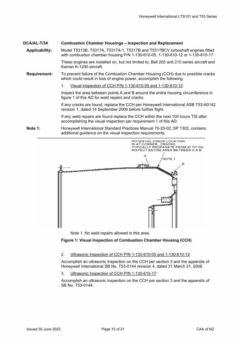
Honeywell International LTS101 and T53 Series
Issued 30 June 2022 Page 15 of 21 CAA of NZ
DCA/AL-T/34 Combustion Chamber Housings – Inspection and Replacement Applicability: Model T5313B, T5317A, T5317A-1, T5317B and T5317BCV turboshaft engines fitted
with combustion chamber housing P/N 1-130-610-05, 1-130-610-12 or 1-130-610-17.
These engines are installed on, but not limited to, Bell 205 and 210 series aircraft and Kaman K-1200 aircraft.
Requirement: To prevent failure of the Combustion Chamber Housing (CCH) due to possible cracks which could result in loss of engine power, accomplish the following:
1. Visual Inspection of CCH P/N 1-130-610-05 and 1-130-610-12:
Inspect the area between points A and B around the entire housing circumference in figure 1 of this AD for weld repairs and cracks.
If any cracks are found, replace the CCH per Honeywell International ASB T53-A0142 revision 1, dated 14 September 2006 before further flight.
If any weld repairs are found replace the CCH within the next 100 hours TIS after accomplishing the visual inspection per requirement 1 of this AD.
Note 1: Honeywell International Standard Practices Manual 70-20-02, SP 1302, contains additional guidance on the visual inspection requirements.
Note 1: No weld repairs allowed in this area.
Figure 1: Visual Inspection of Combustion Chamber Housing (CCH)
2. Ultrasonic Inspection of CCH P/N 1-130-610-05 and 1-130-610-12:
Accomplish an ultrasonic inspection on the CCH per section 3 and the appendix of Honeywell International SB No. T53-0144 revision 4, dated 31 March 31, 2008.
3. Ultrasonic Inspection of CCH P/N 1-130-610-17:
Accomplish an ultrasonic inspection on the CCH per section 3 and the appendix of SB No. T53-0144.
Honeywell International LTS101 and T53 Series
Issued 30 June 2022 Page 16 of 21 CAA of NZ
Note 2: The installation of a CCH P/N 1-130-610-19 or 1-130-610R16 or a manufacturer
approved equivalent part is a terminating action to the inspection requirements of this AD.
Note 3: Honeywell International ASB T53-A0142 revision 1, dated 14 September 2006 and the Standard Practices Manual 70-20-02, SP 1302 pertains to the subject of this AD. (FAA AD 2009-15-13 refers)
Compliance: 1. Within the next 50 hours TIS and thereafter at intervals not to exceed 50 hour TIS.
2. Within the next 500 hours TIS, or the next hot section inspection, or by 27 February 2010 whichever occurs sooner, and
Thereafter at intervals not to exceed 1200 cycles (defined as the cumulative number of landings), or at intervals not to exceed 200 cycles if there were ultrasonic findings at the last inspection as defined in paragraph 3.A.(2) or paragraph 3.A.(3) of SB No. T53-0144.
3. At the first engine overhaul, or before 5000 hours TTIS on the engine, or 11000 total cycles on the engine, whichever occurs sooner, and
Thereafter at intervals not to exceed 1200 cycles (defined as the cumulative number of landings), or at intervals not to exceed 200 cycles if there were ultrasonic findings at the last inspection as defined in paragraph 3.A.(2) or paragraph 3.A.(3) of SB No. T53-0144.
Effective Date: 27 August 2009
DCA/AL-T/35 Gas Generator Turbine Discs – Life Limitation and Replacement Applicability: Model LTS101-600A-2, -600A-3, -600A-3A, -650B-1, -650B-1A, -650C-2, -650C-3, -
650C-3A, -750A-1, -750A-3, -750B-1, -750B-2, and -750C-1 turboshaft engines and LTP101-600A-1A and -700A-1A turboprop engines fitted with a gas generator turbine disc P/N 4-111-015-14 and S/N listed in appendix 1 of Honeywell International Inc. SB LT 101-71-00-0002.
These engines are known to be installed on, but not limited to, Eurocopter France AS350, Eurocopter Deutchland GMBH BK117, Bell Helicopter Textron 222 helicopters, Page Thrush, Air Tractor AT-302, Industrie Aeronautiche e Meccaniche (formerly Piaggio & Co.) P166-DL3, Pacific Aerospace 08-600 and Riley International R421 aircraft.
Requirement: To prevent failure of the gas generator turbine disc due to an error in a change to the engineering drawing which could result in an uncontained engine rupture, loss of engine power and damage to the aircraft, accomplish the following:
1. Replace affected engines or replace affected gas generator turbine discs per the instructions in Honeywell International Inc. SB LT 101-71-00-0002, revision 26, dated 2 April 2008.
2. An affected gas generator turbine disc P/N 4-111-015-14 with a S/N listed in appendix 1 of SB LT 101-71-00-0002 with 5040 or more CSN shall not be fitted to any model LTS101-600, -650 or -750 series turboshaft engine.
3. An affected gas generator turbine disc P/N 4-111-015-14 with a S/N listed in appendix 1 of SB LT 101-71-00-0002 with 2770 or more CSN shall not be fitted to any model LTP101-600A-1A or -700A-1A turboprop engine.
Note: The S/N of affected gas generator turbine discs are listed in appendix 1 of Honeywell International Inc. SB LT 101-71-00-0002 revision 26 dated 2 April 2008. (FAA AD 2009-24-12 refers)
Honeywell International LTS101 and T53 Series
Issued 30 June 2022 Page 17 of 21 CAA of NZ
Compliance: 1. For model LTS101–600, –650, and –750 series turboshaft engines:
Within the next 100 cycles for engines with 4940 or more CSN, and at 5040 CSN for engines with less than 4940 CSN.
For LTP101–600A–1A and –700A–1A turboprop engines:
Within the next 50 cycles for engines with 2720 or more CSN, and at 2770 CSN for engines with less than 2720 CSN.
2. From 4 January 2010.
3. From 4 January 2010.
Effective Date: 4 January 2010
DCA/AL-T/36 Rigid Tube Fuel Manifolds – Inspection and Replacement Applicability: Model LTS101 series turboshaft engines fitted with rigid tube fuel manifolds P/N 4-
301-042-02, 4-301-042-04, 4-301-042-05, 4-301-042-06, 4-301-236-01, 4-301-236-02, 4-301-236-03, 4-301-236-04, 4-301-286-01, 4-301-286-02 and 4-301-376-01.
These engines are installed on, but not limited to Aerospatiale AS350, Eurocopter MBB-BK117 and HH-65A, Bell 222, Page Thrush, Air Tractor AT-302, Piaggio P.166-DL3, Riley International R421, and Pacific Aerospace 08-600 aircraft.
Requirement: To prevent engine fuel leaks due to possible low cycle fatigue cracks in the rigid tube fuel manifold, which could result in an inflight fire, accomplish the following:
1. Replace affected fuel manifolds per the compliance of this AD.
2. New Life Limitation:
Affected fuel manifolds listed in the applicability of this AD may not be fitted to any engine if they meet any of the following conditions:
• The manifold has accumulated 3000 or more total Ng cycles, or
• The manifold has had partial tube replacements, or
• The manifold has an unknown number of Ng cycles.
(FAA AD 2001-22-07 refers)
Compliance: 1. Fuel Tube Replacement Schedule:
Replace affected fuel manifolds that have accumulated the following gas generator rotor (Ng) cycles since new (CSN) on the effective date of this AD, or Ng cycles in service (CIS) on the effective date of this AD since all tubes were replaced, unless previously accomplished:
Gas Generator (Ng) CSN, or Ng CIS since total tube
replacement:
Replacement schedule:
With 2750 or less Before accumulating 3000 total Ng cycles.
With more than 2750 Within 250 CIS after the effective date of this AD.
Unknown Within 2000 CIS after the effective date of this AD, or At the next engine removal, or At the removal of the fuel manifold for cause, whichever occurs sooner.
2. From 31 March 2011.
Honeywell International LTS101 and T53 Series
Issued 30 June 2022 Page 18 of 21 CAA of NZ
Effective Date: 31 March 2011
Honeywell International LTS101 and T53 Series
Issued 30 June 2022 Page 19 of 21 CAA of NZ
DCA/AL-T/37 Power Turbine Rotor – Life Limitation Applicability: Model LTS101-600A-2, -3, -3A, LTS101-700D-2, LTS101-650B-1, LTS101-650C-3,
LTS101-650C-3A, LTS101-750B-1, LTS101-750B-2, LTS101-750C-1 and LTS101-850B-2 turboshaft engines, and
Model LTP101-600A-1A and LTP101-700A-1A turboprop engines,
Fitted with power turbine rotor P/N 4-141-290-01, -02, -03, -05, -06, -11, -12, -13, -14 or -16.
These engines are installed on, but not limited to Eurocopter AS350 and BK117 series helicopters and Bell 222 series helicopters, and Page Thrush, Air Tractor AT-302, Pacific Aero 08-600, Piaggio P166 DL3 and Riley International R421 aeroplanes.
Note: This AD is not applicable to engines fitted with power turbine rotors P/N 4-141-290-11, -12, -13 and -14 marked with ''ORI T41881'' on the aft hub in the vicinity of the P/N.
Requirement: To prevent failure of power turbine blades which could result in sudden loss of engine power and safe continued flight, accomplish the following:
1. For LTS101-600A-2, -3, -3A and LTS101-700D-2 turboshaft engines and LTP101-600A-1A and LTP101-700A-1A turboprop engines:
Replace power turbine rotors P/N 4-141-290-01, -02, -03, -05, -06, -11, -12, -13, -14, or -16 per the instructions in Honeywell International Inc. SB LT 101-71-00-0252 and/or LTS101-71-00-0253 as applicable.
2. For LTS101-650B-1, -650C-3,–650C-3A, -750B-1, -2, -750C-1 and -850B-2 turboshaft engines:
Replace power turbine rotors P/N 4-141-290-01, -02, -03, -05, -06, -11, -12, -13, -14, or -16 per the instructions in Honeywell International Inc. SB LT 101-71-00-0252 and/or LTS101-71-00-0253 as applicable. (FAA AD 2011-08-06 refers)
Compliance: 1. For LTS101-600A-2, -3, -3A and LTS101-700D-2 turboshaft engines and LTP101-600A-1A and LTP101-700A-1A turboprop engines:
Power Turbine Rotor CSN: Replace Power Turbine Rotor:
Less than 5000 CSN Between 5000 and 5500 CSN
5000 to 7899 CSN Within the next 500 cycles or before exceeding 8000 CSN whichever occurs sooner.
7900 to 9999 CSN Within the next 100 cycles or before exceeding 10050 CSN whichever occurs sooner.
10000 or more CSN Within the next 50 cycles.
Honeywell International LTS101 and T53 Series
Issued 30 June 2022 Page 20 of 21 CAA of NZ
2. For LTS101-650B-1, -650C-3,–650C-3A, -750B-1, -2, -750C-1 and -850B-2
turboshaft engines:
Power Turbine Rotor CSN: Replace Power Turbine Rotor:
Less than 5500 CSN Between 5000 and 7200 CSN.
5500 to 7999 CSN Within the next 1700 cycles or before exceeding 8950 CSN whichever occurs sooner.
8000 to 9999 CSN Within the next 950 cycles or before exceeding 10400 CSN whichever occurs sooner.
10000 or more CSN Within the next 400 cycles.
Effective Date: 17 May 2011
DCA/AL-T/38 Power Turbine Governor (PTG) – Inspection and Replacement Applicability: Model LTS101-600A-2, LTS101-600A-3, LTS101-600A-3A and LTS101-700D-2
turboshaft engines with a Power Turbine Governor (PTG) model AL-AB1 P/N 4-301-289-03, 4-301-289-05, 4-301-289-09, 4-301-101-16 or 4-301-101-18 that has no compliance symbol, or is marked with a compliance symbol N or P on the PTG identification plate.
Requirement: To prevent loss of engine power which could result in an emergency autorotation landing and damage to the aircraft, accomplish the following:
1. For a PTG marked with a compliance symbol N, or with no compliance symbol on the PTG identification plate, replace the PTG with a part eligible for installation.
2. For a PTG marked with compliance symbol P on the PTG identification plate, replace the PTG with a part eligible for installation.
Note: Honeywell International Inc. SB No. LTS101-73-20-A0268, dated 23 August 2011 pertains to the subject of this AD. (FAA AD 2011-23-13 refers)
Compliance: 1. Within the next 50 hours TIS for PTG with more than 150 hours TIS, TSN or TSO, and Before accumulating 200 hours TTIS for PTG with 150 hours or less TIS, TSN or TSO, and Thereafter at intervals not to exceed 200 hours TIS, TSN or TSO. 2. Before accumulating 900 hours TTIS, and thereafter at intervals not to exceed 900 hours TIS, TSN or TSO.
Effective Date: 8 December 2011
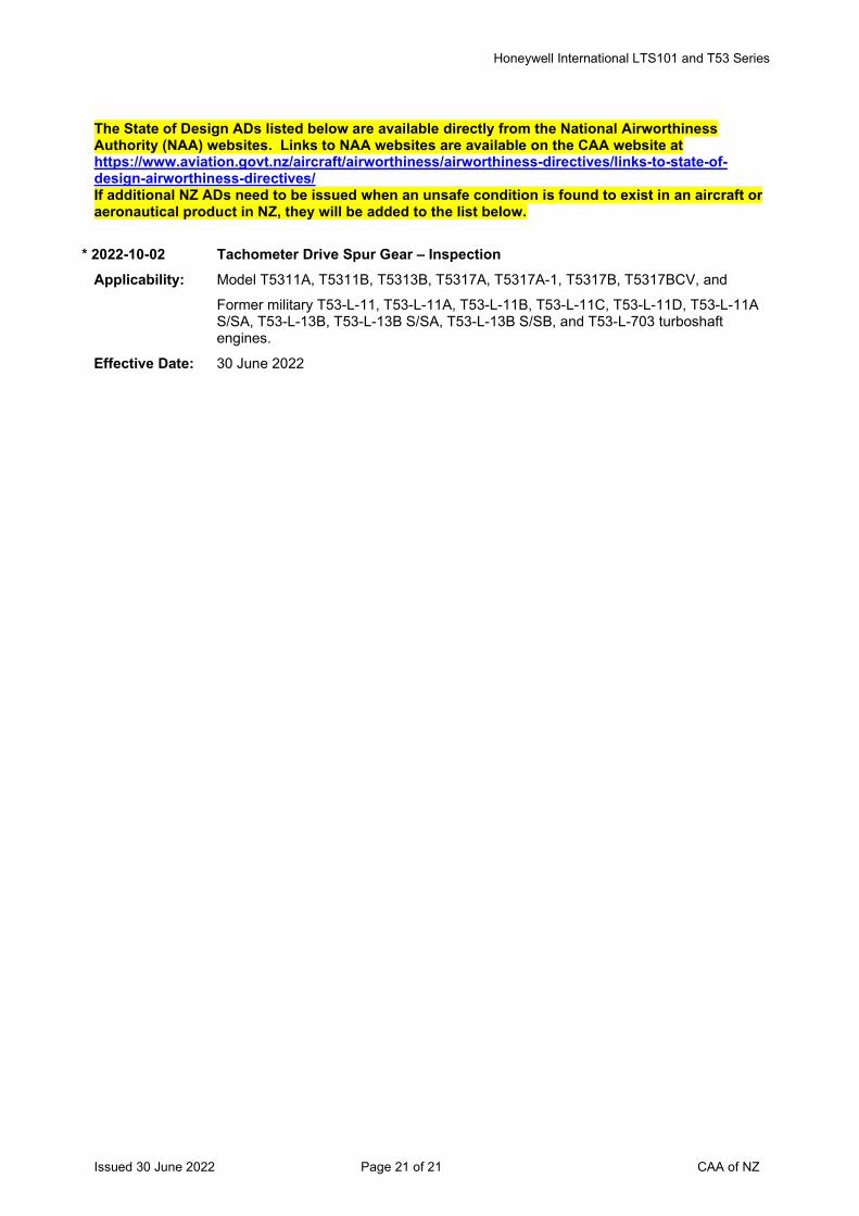
Honeywell International LTS101 and T53 Series
Issued 30 June 2022 Page 21 of 21 CAA of NZ
The State of Design ADs listed below are available directly from the National Airworthiness Authority (NAA) websites. Links to NAA websites are available on the CAA website at https://www.aviation.govt.nz/aircraft/airworthiness/airworthiness-directives/links-to-state-of-design-airworthiness-directives/ If additional NZ ADs need to be issued when an unsafe condition is found to exist in an aircraft or aeronautical product in NZ, they will be added to the list below.
* 2022-10-02 Tachometer Drive Spur Gear – Inspection Applicability: Model T5311A, T5311B, T5313B, T5317A, T5317A-1, T5317B, T5317BCV, and
Former military T53-L-11, T53-L-11A, T53-L-11B, T53-L-11C, T53-L-11D, T53-L-11A S/SA, T53-L-13B, T53-L-13B S/SA, T53-L-13B S/SB, and T53-L-703 turboshaft engines.
Effective Date: 30 June 2022
Issued 30 June 2022 Page 1 of 8 CAA of NZ
Airworthiness Directive Schedule Aeroplanes Pilatus PC-12 Series 30 June 2022
Notes: 1. This AD schedule is applicable to Pilatus PC-12 series aircraft manufactured under EASA Type Certificate No. A.089.
2. The European Union Aviation Safety Agency (EASA) (previously the Swiss Federal Office of Civil Aviation (FOCA)) is the National Airworthiness Authority (NAA) responsible for the issue of State of Design Airworthiness Directives (ADs) for these aircraft.
State of Design ADs can be obtained directly from the EASA website at http://ad.easa.europa.eu/
3. The date above indicates the amendment date of this schedule.
4. New or amended ADs are shown with an asterisk *
Contents
HB 1996-139 Hydraulic Handpump Installation .............................................................................................. 3 HB 1996-416 Propeller De-Icing Controller .................................................................................................... 3 HB 1996-535A Elevator .................................................................................................................................... 3 HB 1997-001 Magnetic Compass Deviation ................................................................................................... 3 HB 1997-002 Automatic Disconnect Circuit for the Non-Ess. Bus/Nav Converter (KN 40) ............................. 3 HB 1997-174 Aileron Tie-Rod Assembly ........................................................................................................ 3 HB 1997-249A Executive Cabin Layout ............................................................................................................ 3 HB 1998-126 Fuel Storage – Vent Valve System ........................................................................................... 3 HB 1998-179 Corporate Commuter Cabin Layout .......................................................................................... 3 HB 1998-352 Alternate Flap System .............................................................................................................. 3 HB 1998-426 Magnetic Compass Swing ........................................................................................................ 3 HB 1998-460 Flap Actuator ............................................................................................................................ 3 HB 1998-537 Electrical Power Cut-Out Relay ................................................................................................ 3 HB 1999-142 Limited Service-Life Flap Screw Actuators ............................................................................... 4 HB 1999-143 Electrical Power – Generator 2 Excitation ................................................................................ 4 HB 1999-241 Flap Drive Shafts ...................................................................................................................... 4 HB 1999-348 Windshield Heat Wiring ............................................................................................................ 4 HB 1999-353 Flap Inboard Attachment Fittings .............................................................................................. 4 HB 1999-406 Stick Pusher Servo and Capstan .............................................................................................. 4 HB 1999-542 Electrical Power-Suppression Filter .......................................................................................... 4 HB 2000-007 Powerplant – Chafing of Pipe Assemblies ................................................................................ 4 HB 2000-393 Windshield De-ice System – Wires and Circuit Breakers ......................................................... 4 HB 2000-443 Flap System – Modification ....................................................................................................... 4 HB 2000-444 Flap Control and Warning Unit (FCWU) ................................................................................... 4 HB 2001-001 Passenger Oxygen System – Rear Bench Seat ....................................................................... 4 HB 2001-070 Flap Control Wiring – Modification ............................................................................................ 4 HB 2001-389R1 Cargo Door End Frame – Lightening Holes .............................................................................. 5 HB 2001-603 Main Landing Gear – Special Bolts .......................................................................................... 5 HB 2001-636 Firewall Insulation – Application of Adhesive Tape ................................................................... 5 HB 2002-608 Rear Pressure Bulkhead ........................................................................................................... 5 HB 2002-609 Operation Limitation Placard .................................................................................................... 5 HB 2002-658 Passenger Seats – Part Number and Pedestal Leg Assembly ................................................. 5 HB 2002-659 Overhead Panel – Switch Caps Replacement .......................................................................... 5
Issued 30 June 2022 Page 2 of 8 CAA of NZ
HB 2003-251 Engine Driven Fuel Pump – Inspection / Replacement ............................................................ 5 HB 2003-301 Fuel Booster Pump Wiring – Inspection / Modification.............................................................. 5 HB 2003-522 Main Landing Gear – Shock-Absorber Attachment Bolts.......................................................... 5 HB 2004-068 Inboard and Outboard Flap Flexible Shafts .............................................................................. 5 HB 2004-101 Generator Control Unit – Replacement..................................................................................... 5 HB 2004-182 Passenger Oxygen System – Oxygen Pipes ............................................................................ 5 HB 2004-330 Main Landing Gear Actuator – Replacement ............................................................................ 6 HB 2005-079 Windshield Deice System Wiring – Inspection .......................................................................... 6 HB 2005-128 Pitch Actuator – Replacement .................................................................................................. 6 HB 2005-168 Landing Gear Components – Inspection .................................................................................. 6 HB 2005-288 Main Landing Gear Special Bolt Assembly – Inspection........................................................... 6 HB 2005-470 Crew Seats – Backrest Tubes – Life Limitations ...................................................................... 6 HB-2006-223 Fuselage – Centre Fuselage Frame 21 – Inspection ................................................................ 6 HB-2006-444 Executive Passenger Seats Legs – Identification / Replacement ............................................. 6 HB 2007-382 Main Landing Gear Special Bolts – Identification ..................................................................... 6 2007-0235 Torque Oil Pressure Pipe & Hose Assemblies – Inspection / Replacement ............................. 6 2008-0047 Elevator Control Stick-Pusher Servo-Cable Tension & Cable Clamp Bolts .............................. 6 2008-0163 Time Limits / Maintenance Checks – Airworthiness Limitations – Amendment ........................ 6 2009-0007 Overboard Vent for the Airfoil Deice System Pressure Regulator ............................................ 6 2009-0040 Elevator and Tab – Stick-Pusher Servo-Cables – Inspection ................................................... 7 2009-0060 Nose Gear – Torque Tube of the Nose Wheel Steering – Replacement / Limitations .............. 7 2009-0086 Nose Landing Gear – Right Hand Upper Drag Link – Inspection / Life Limitation .................... 7 2009-0249 Air Data, Attitude and Heading Reference System (ADAHRS) – Modification .......................... 7 2010-0093 Engine Controls – Power Control Lever Reverse Thrust Latch – Inspection / Modification ...... 7 2013-0031 Cancelled – EASA AD 2014-0170 refers .................................................................................. 7 2013-0114 Navigation – Electronic Standby Instrument System / Power Return Wires – Modification ...... 7 2014-0170 Cancelled – EASA AD 2016-0083 refers .................................................................................. 7 2015-0060 Aileron Tab Counter Balance Weight - Replacement ............................................................... 7 2015-0111 Aileron Control System – Inspection ......................................................................................... 7 2016-0037 Wing-To-Fuselage Attachment Torlon Plates – Inspection ....................................................... 7 2016-0081 Engine Mount Frame Swage Tube Ends – Inspection .............................................................. 7 2016-0083 Cancelled – EASA AD 2021-0005 (Correction) refers .............................................................. 7 2017-0024 Primus APEX Build 10 or 10.9 – Amendment ........................................................................... 8 2019-0032 MLG Spring Pack Assemblies – Inspection .............................................................................. 8 2019-0129 Horizontal Stabiliser Rear Attachment Bolts – Inspection ......................................................... 8 2019-0231 Flap Drive System – Inspection ................................................................................................ 8 2020-0229 Fuel Transfer Injector – Inspection ........................................................................................... 8 2021-0005 Cancelled - EASA AD 2021-0214 refers ................................................................................. 8 2021-0010 Inward Vent Valve – Inspection ................................................................................................ 8 2021-0110 Cancelled by EASA on 3 November 2021 ................................................................................ 8 * 2021-0214 Cancelled – EASA AD 2022-0103 refers .................................................................................. 8 FAA AD 2021-24-01 Aerodynamic Fairing - Inspection ................................................................................... 8 * 2022-0103 Airworthiness Limitations - Amendment.................................................................................... 8
Aeroplanes Pilatus PC-12 Series
Issued 30 June 2022 Page 3 of 8 CAA of NZ
HB 1996-139 Hydraulic Handpump Installation Effective Date: 18 March 1996
HB 1996-416 Propeller De-Icing Controller Effective Date: 30 September 1996
HB 1996-535A Elevator Effective Date: 30 November 1996
HB 1997-001 Magnetic Compass Deviation Effective Date: 01 January 1997
HB 1997-002 Automatic Disconnect Circuit for the Non-Ess. Bus/Nav Converter (KN 40) Effective Date: 01 January 1997
HB 1997-174 Aileron Tie-Rod Assembly Effective Date: 30 April 1997
HB 1997-249A Executive Cabin Layout Effective Date: 31 May 1997
HB 1998-126 Fuel Storage – Vent Valve System Effective Date: 15 May 1998
HB 1998-179 Corporate Commuter Cabin Layout Effective Date: 15 June 1998
HB 1998-352 Alternate Flap System Effective Date: 28 September 1998
HB 1998-426 Magnetic Compass Swing Effective Date: 06 November 1998
HB 1998-460 Flap Actuator Effective Date: 23 November 1998
HB 1998-537 Electrical Power Cut-Out Relay Effective Date: 29 December 1998
Aeroplanes Pilatus PC-12 Series
Issued 30 June 2022 Page 4 of 8 CAA of NZ
HB 1999-142 Limited Service-Life Flap Screw Actuators Effective Date: 17 February 1999
HB 1999-143 Electrical Power – Generator 2 Excitation Effective Date: 19 February 1999
HB 1999-241 Flap Drive Shafts Effective Date: 08 May 1999
HB 1999-348 Windshield Heat Wiring Effective Date: 28 June 1999
HB 1999-353 Flap Inboard Attachment Fittings Effective Date: 12 July 1999
HB 1999-406 Stick Pusher Servo and Capstan Effective Date: 16 August 1999
HB 1999-542 Electrical Power-Suppression Filter Effective Date: 29 October 1999
HB 2000-007 Powerplant – Chafing of Pipe Assemblies Effective Date: 17 January 2000
HB 2000-393 Windshield De-ice System – Wires and Circuit Breakers Effective Date: 06 September 2000
HB 2000-443 Flap System – Modification Effective Date: 09 November 2000
HB 2000-444 Flap Control and Warning Unit (FCWU) Effective Date: 09 November 2000
HB 2001-001 Passenger Oxygen System – Rear Bench Seat Effective Date: 28 December 2000
HB 2001-070 Flap Control Wiring – Modification Effective Date: 12 February 2001
Aeroplanes Pilatus PC-12 Series
Issued 30 June 2022 Page 5 of 8 CAA of NZ
HB 2001-389R1 Cargo Door End Frame – Lightening Holes Effective Date: 25 June 2001
HB 2001-603 Main Landing Gear – Special Bolts Effective Date: 05 November 2001
HB 2001-636 Firewall Insulation – Application of Adhesive Tape Effective Date: 26 November 2001
HB 2002-608 Rear Pressure Bulkhead Effective Date: 01 November 2002
HB 2002-609 Operation Limitation Placard Effective Date: 01 November 2002
HB 2002-658 Passenger Seats – Part Number and Pedestal Leg Assembly Effective Date: 30 November 2002
HB 2002-659 Overhead Panel – Switch Caps Replacement Effective Date: 30 November 2002
HB 2003-251 Engine Driven Fuel Pump – Inspection / Replacement Effective Date: 16 June 2003
HB 2003-301 Fuel Booster Pump Wiring – Inspection / Modification Effective Date: 17 July 2003
HB 2003-522 Main Landing Gear – Shock-Absorber Attachment Bolts Effective Date: 14 November 2003
HB 2004-068 Inboard and Outboard Flap Flexible Shafts Effective Date: 15 March 2004
HB 2004-101 Generator Control Unit – Replacement Effective Date: 06 April 2004
HB 2004-182 Passenger Oxygen System – Oxygen Pipes Effective Date: 21 May 2004
Aeroplanes Pilatus PC-12 Series
Issued 30 June 2022 Page 6 of 8 CAA of NZ
HB 2004-330 Main Landing Gear Actuator – Replacement Effective Date: 23 August 2004
HB 2005-079 Windshield Deice System Wiring – Inspection Effective Date: 18 February 2005
HB 2005-128 Pitch Actuator – Replacement Effective Date: 29 March 2005
HB 2005-168 Landing Gear Components – Inspection Effective Date: 10 May 2005
HB 2005-288 Main Landing Gear Special Bolt Assembly – Inspection Effective Date: 06 July 2005
HB 2005-470 Crew Seats – Backrest Tubes – Life Limitations Effective Date: 30 December 2005
HB-2006-223 Fuselage – Centre Fuselage Frame 21 – Inspection Effective Date: 20 April 2006
HB-2006-444 Executive Passenger Seats Legs – Identification / Replacement Effective Date: 14 November 2006
HB 2007-382 Main Landing Gear Special Bolts – Identification Effective Date: 03 September 2007
2007-0235 Torque Oil Pressure Pipe & Hose Assemblies – Inspection / Replacement Effective Date: 14 September 2007
2008-0047 Elevator Control Stick-Pusher Servo-Cable Tension & Cable Clamp Bolts Effective Date: 13 March 2008
2008-0163 Time Limits / Maintenance Checks – Airworthiness Limitations – Amendment Effective Date: 10 September 2008
2009-0007 Overboard Vent for the Airfoil Deice System Pressure Regulator Effective Date: 27 January 2009
Aeroplanes Pilatus PC-12 Series
Issued 30 June 2022 Page 7 of 8 CAA of NZ
2009-0040 Elevator and Tab – Stick-Pusher Servo-Cables – Inspection Effective Date: 01 March 2009
2009-0060 Nose Gear – Torque Tube of the Nose Wheel Steering – Replacement / Limitations Effective Date: 25 March 2009
2009-0086 Nose Landing Gear – Right Hand Upper Drag Link – Inspection / Life Limitation Effective Date: 28 April 2009
2009-0249 Air Data, Attitude and Heading Reference System (ADAHRS) – Modification Effective Date: 04 December 2009
2010-0093 Engine Controls – Power Control Lever Reverse Thrust Latch – Inspection / Modification
Effective Date: 03 June 2010
2013-0031 Cancelled – EASA AD 2014-0170 refers Effective Date: 31 July 2014
2013-0114 Navigation – Electronic Standby Instrument System / Power Return Wires – Modification
Effective Date: 11 June 2013
2014-0170 Cancelled – EASA AD 2016-0083 refers Effective Date: 12 May 2016
2015-0060 Aileron Tab Counter Balance Weight - Replacement Effective Date: 24 April 2015
2015-0111 Aileron Control System – Inspection Effective Date: 30 June 2015
2016-0037 Wing-To-Fuselage Attachment Torlon Plates – Inspection Effective Date: 11 March 2016
2016-0081 Engine Mount Frame Swage Tube Ends – Inspection Effective Date: 2 May 2016
2016-0083 Cancelled – EASA AD 2021-0005 (Correction) refers Effective Date: 28 January 2021
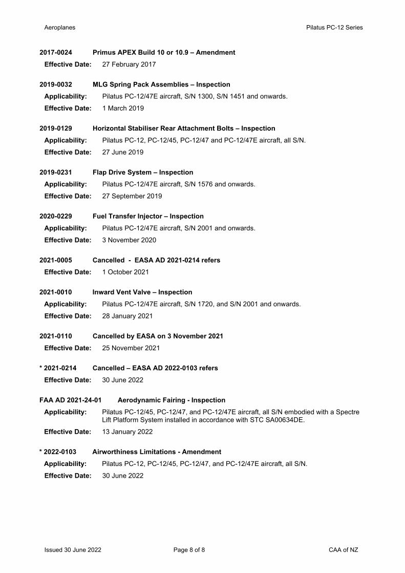
Aeroplanes Pilatus PC-12 Series
Issued 30 June 2022 Page 8 of 8 CAA of NZ
2017-0024 Primus APEX Build 10 or 10.9 – Amendment Effective Date: 27 February 2017
2019-0032 MLG Spring Pack Assemblies – Inspection Applicability: Pilatus PC-12/47E aircraft, S/N 1300, S/N 1451 and onwards. Effective Date: 1 March 2019
2019-0129 Horizontal Stabiliser Rear Attachment Bolts – Inspection Applicability: Pilatus PC-12, PC-12/45, PC-12/47 and PC-12/47E aircraft, all S/N. Effective Date: 27 June 2019
2019-0231 Flap Drive System – Inspection Applicability: Pilatus PC-12/47E aircraft, S/N 1576 and onwards.
Effective Date: 27 September 2019
2020-0229 Fuel Transfer Injector – Inspection Applicability: Pilatus PC-12/47E aircraft, S/N 2001 and onwards.
Effective Date: 3 November 2020
2021-0005 Cancelled - EASA AD 2021-0214 refers Effective Date: 1 October 2021
2021-0010 Inward Vent Valve – Inspection Applicability: Pilatus PC-12/47E aircraft, S/N 1720, and S/N 2001 and onwards. Effective Date: 28 January 2021
2021-0110 Cancelled by EASA on 3 November 2021 Effective Date: 25 November 2021
* 2021-0214 Cancelled – EASA AD 2022-0103 refers Effective Date: 30 June 2022
FAA AD 2021-24-01 Aerodynamic Fairing - Inspection Applicability: Pilatus PC-12/45, PC-12/47, and PC-12/47E aircraft, all S/N embodied with a Spectre
Lift Platform System installed in accordance with STC SA00634DE.
Effective Date: 13 January 2022
* 2022-0103 Airworthiness Limitations - Amendment Applicability: Pilatus PC-12, PC-12/45, PC-12/47, and PC-12/47E aircraft, all S/N.
Effective Date: 30 June 2022
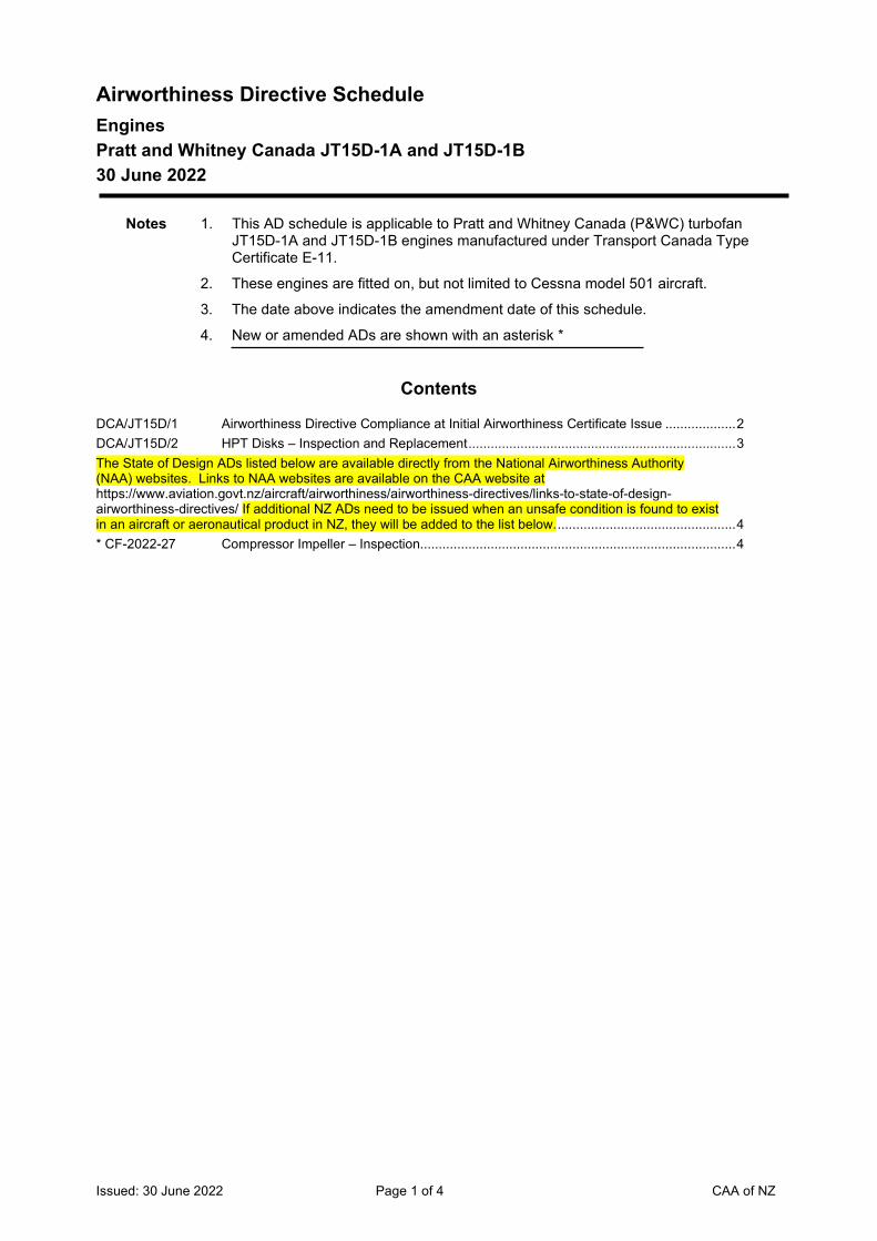
Issued: 30 June 2022 Page 1 of 4 CAA of NZ
Airworthiness Directive Schedule Engines Pratt and Whitney Canada JT15D-1A and JT15D-1B 30 June 2022
Notes 1. This AD schedule is applicable to Pratt and Whitney Canada (P&WC) turbofan JT15D-1A and JT15D-1B engines manufactured under Transport Canada Type Certificate E-11.
2. These engines are fitted on, but not limited to Cessna model 501 aircraft.
3. The date above indicates the amendment date of this schedule.
4. New or amended ADs are shown with an asterisk *
Contents
DCA/JT15D/1 Airworthiness Directive Compliance at Initial Airworthiness Certificate Issue ................... 2 DCA/JT15D/2 HPT Disks – Inspection and Replacement ........................................................................ 3 The State of Design ADs listed below are available directly from the National Airworthiness Authority (NAA) websites. Links to NAA websites are available on the CAA website at https://www.aviation.govt.nz/aircraft/airworthiness/airworthiness-directives/links-to-state-of-design-airworthiness-directives/ If additional NZ ADs need to be issued when an unsafe condition is found to exist in an aircraft or aeronautical product in NZ, they will be added to the list below. ................................................ 4 * CF-2022-27 Compressor Impeller – Inspection..................................................................................... 4
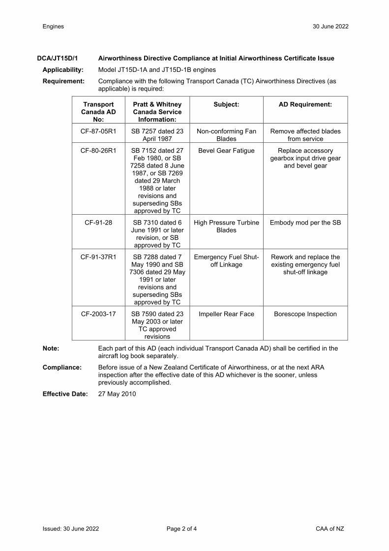
Engines 30 June 2022
Issued: 30 June 2022 Page 2 of 4 CAA of NZ
DCA/JT15D/1 Airworthiness Directive Compliance at Initial Airworthiness Certificate Issue Applicability: Model JT15D-1A and JT15D-1B engines
Requirement: Compliance with the following Transport Canada (TC) Airworthiness Directives (as applicable) is required:
Transport Canada AD
No:
Pratt & Whitney Canada Service
Information:
Subject: AD Requirement:
CF-87-05R1 SB 7257 dated 23 April 1987
Non-conforming Fan Blades
Remove affected blades from service
CF-80-26R1 SB 7152 dated 27 Feb 1980, or SB
7258 dated 8 June 1987, or SB 7269 dated 29 March
1988 or later revisions and
superseding SBs approved by TC
Bevel Gear Fatigue Replace accessory gearbox input drive gear
and bevel gear
CF-91-28 SB 7310 dated 6 June 1991 or later
revision, or SB approved by TC
High Pressure Turbine Blades
Embody mod per the SB
CF-91-37R1 SB 7288 dated 7 May 1990 and SB
7306 dated 29 May 1991 or later revisions and
superseding SBs approved by TC
Emergency Fuel Shut-off Linkage
Rework and replace the existing emergency fuel
shut-off linkage
CF-2003-17 SB 7590 dated 23 May 2003 or later
TC approved revisions
Impeller Rear Face Borescope Inspection
Note: Each part of this AD (each individual Transport Canada AD) shall be certified in the aircraft log book separately.
Compliance: Before issue of a New Zealand Certificate of Airworthiness, or at the next ARA inspection after the effective date of this AD whichever is the sooner, unless previously accomplished.
Effective Date: 27 May 2010
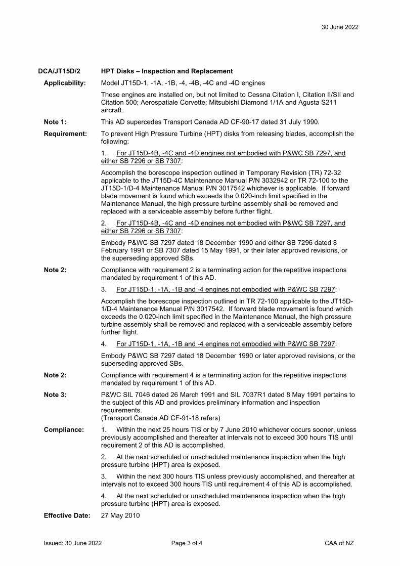
30 June 2022
Issued: 30 June 2022 Page 3 of 4 CAA of NZ
DCA/JT15D/2 HPT Disks – Inspection and Replacement Applicability: Model JT15D-1, -1A, -1B, -4, -4B, -4C and -4D engines
These engines are installed on, but not limited to Cessna Citation I, Citation II/SII and Citation 500; Aerospatiale Corvette; Mitsubishi Diamond 1/1A and Agusta S211 aircraft.
Note 1: This AD supercedes Transport Canada AD CF-90-17 dated 31 July 1990.
Requirement: To prevent High Pressure Turbine (HPT) disks from releasing blades, accomplish the following:
1. For JT15D-4B, -4C and -4D engines not embodied with P&WC SB 7297, and either SB 7296 or SB 7307:
Accomplish the borescope inspection outlined in Temporary Revision (TR) 72-32 applicable to the JT15D-4C Maintenance Manual P/N 3032942 or TR 72-100 to the JT15D-1/D-4 Maintenance Manual P/N 3017542 whichever is applicable. If forward blade movement is found which exceeds the 0.020-inch limit specified in the Maintenance Manual, the high pressure turbine assembly shall be removed and replaced with a serviceable assembly before further flight.
2. For JT15D-4B, -4C and -4D engines not embodied with P&WC SB 7297, and either SB 7296 or SB 7307:
Embody P&WC SB 7297 dated 18 December 1990 and either SB 7296 dated 8 February 1991 or SB 7307 dated 15 May 1991, or their later approved revisions, or the superseding approved SBs.
Note 2: Compliance with requirement 2 is a terminating action for the repetitive inspections mandated by requirement 1 of this AD.
3. For JT15D-1, -1A, -1B and -4 engines not embodied with P&WC SB 7297:
Accomplish the borescope inspection outlined in TR 72-100 applicable to the JT15D-1/D-4 Maintenance Manual P/N 3017542. If forward blade movement is found which exceeds the 0.020-inch limit specified in the Maintenance Manual, the high pressure turbine assembly shall be removed and replaced with a serviceable assembly before further flight.
4. For JT15D-1, -1A, -1B and -4 engines not embodied with P&WC SB 7297:
Embody P&WC SB 7297 dated 18 December 1990 or later approved revisions, or the superseding approved SBs.
Note 2: Compliance with requirement 4 is a terminating action for the repetitive inspections mandated by requirement 1 of this AD.
Note 3: P&WC SIL 7046 dated 26 March 1991 and SIL 7037R1 dated 8 May 1991 pertains to the subject of this AD and provides preliminary information and inspection requirements. (Transport Canada AD CF-91-18 refers)
Compliance: 1. Within the next 25 hours TIS or by 7 June 2010 whichever occurs sooner, unless previously accomplished and thereafter at intervals not to exceed 300 hours TIS until requirement 2 of this AD is accomplished.
2. At the next scheduled or unscheduled maintenance inspection when the high pressure turbine (HPT) area is exposed.
3. Within the next 300 hours TIS unless previously accomplished, and thereafter at intervals not to exceed 300 hours TIS until requirement 4 of this AD is accomplished.
4. At the next scheduled or unscheduled maintenance inspection when the high pressure turbine (HPT) area is exposed.
Effective Date: 27 May 2010
30 June 2022
Issued: 30 June 2022 Page 4 of 4 CAA of NZ
The State of Design ADs listed below are available directly from the National Airworthiness Authority (NAA) websites. Links to NAA websites are available on the CAA website at https://www.aviation.govt.nz/aircraft/airworthiness/airworthiness-directives/links-to-state-of-design-airworthiness-directives/ If additional NZ ADs need to be issued when an unsafe condition is found to exist in an aircraft or aeronautical product in NZ, they will be added to the list below.
* CF-2022-27 Compressor Impeller – Inspection Applicability: Model JT15D-1 with build specification (BS) 407 and BS 540 which are pre-Service
Bulletin (SB) 7151 fitted with impeller P/N 3020365,
Model JT15D-1A with BS503 which are pre-SB 7151 fitted with impeller P/N 3020365, and
Model JT15D-1B with BS623 which are pre-SB 7151 fitted with impeller P/N 3020365.
Effective date: 30 June 2022
Helicopters Robinson R22 Series
Issued 30 June 2022 Page 1 of 24 CAA of NZ
Airworthiness Directive Schedule Helicopters Robinson R22 Series 30 June 2022
Notes: 1. This AD schedule is applicable to Robinson R22, R22 Alpha, R22 Beta and R22 Mariner helicopters manufactured under FAA Type Certificate No. H10WE.
2. The Federal Aviation Administration (FAA) is the National Airworthiness Authority (NAA) responsible for the issue of State of Design Airworthiness Directives (ADs) for these helicopters. State of Design ADs can be obtained directly from the FAA website at http://rgl.faa.gov/Regulatory_and_Guidance_Library/rgAD.nsf/MainFrame?OpenFrameSet
3. The date above indicates the amendment date of this schedule.
4. New or amended ADs are shown with an asterisk *
Contents
DCA/R22/1 Main Rotor Blades - Inspection ......................................................................................... 3 DCA/R22/2 Airframe Structure - Inspection ......................................................................................... 3 DCA/R22/3B Main Gear Box Coupling - Inspection................................................................................ 3 DCA/R22/4 Safety Harness Latch - Rework ........................................................................................ 3 DCA/R22/5B Main Rotor Blades - Retirement ........................................................................................ 4 DCA/R22/6 Control rod Ends - Modification ......................................................................................... 4 DCA/R22/7 Clutch Shaft Plug Installation - Inspection ......................................................................... 4 DCA/R22/8A Upper Frame Structure - Inspection .................................................................................. 4 DCA/R22/9 Tail Rotor Drive Shaft - Replacement ................................................................................ 5 DCA/R22/10 Superseded by DCA/R22/32 ............................................................................................. 5 DCA/R22/11 Main Rotor Blade - Inspection/Retirement ........................................................................ 5 DCA/R22/12 Actuator Drive Screw - Replacement ................................................................................ 5 DCA/R22/13 Control Tubes - Inspection ................................................................................................ 5 DCA/R22/14 Main rotor Gear Box - Inspection and Modification ........................................................... 6 DCA/R22/15 Lower Vertical Fin - Inspection .......................................................................................... 6 DCA/R22/16 Main Rotor Pitch Link - Inspection and Removal .............................................................. 6 DCA/R22/17A Cancelled – FAA AD 88-26-01R2 refers ........................................................................... 6 DCA/R22/18 Cancelled – FAA AD 88-26-01R2 refers ........................................................................... 6 DCA/R22/19 Cancelled – Purpose Fulfilled ........................................................................................... 6 DCA/R22/20 Carburettor Air Box - Modification ..................................................................................... 6 DCA/R22/21 NAS1304-16 AF Bolts - Replacement ............................................................................... 7 DCA/R22/22 Tailcone Skin Doubler - Installation ................................................................................... 7 DCA/R22/23D Main Rotor Blades - Inspection ......................................................................................... 7 DCA/R22/24B Forward Flexplate - Replacement ..................................................................................... 8 DCA/R22/25B Tail Rotor Gearbox Input and Output Shaft Key - Inspection ............................................ 8 DCA/R22/26A Main Rotor Shaft Retaining Nuts - Inspection ................................................................... 9 DCA/R22/27C Cancelled – DCA/R22/48 refers ........................................................................................ 9 DCA/R22/28 Cancelled – Purpose Fulfilled ........................................................................................... 9 DCA/R22/29 Tail Rotor Blades - Inspection for Unapproved Parts ........................................................ 9 DCA/R22/30 Main Rotor Blades - Inspection for Unairworthy Parts..................................................... 10 DCA/R22/31 Upper V-Belt Sheaves - Replacement ............................................................................ 10 DCA/R22/32A Main Rotor RPM Governor - Installation ......................................................................... 11
Helicopters Robinson R22 Series
Issued 30 June 2022 Page 2 of 24 CAA of NZ
DCA/R22/33 Main Rotor Blades - Removal ......................................................................................... 11 DCA/R22/34 Carburettor - Replacement .............................................................................................. 11 DCA/R22/35 Fuel Tank Vent - Modifications ........................................................................................ 12 DCA/R22/36 Special Pilot Caution – Flight Manual Revision ............................................................... 13 DCA/R22/37 Sprag Clutch - Replacement ........................................................................................... 13 DCA/R22/38 Yoke – Inspection and Replacement............................................................................... 14 DCA/R22/39 Tail Rotor Pitch Control – Inspection and Replacement .................................................. 15 DCA/R22/40A Main Rotor Blades – Placard and Inspections ................................................................ 15 DCA/ R22/41 Main Rotor Blades – Reduced Retirement Life ............................................................... 16 DCA/R22/42A Main Rotor Blades P/N A016-1 and A016-2 – Reduced Retirement Lives ...................... 16 DCA/R22/43 LH and RH Door Assemblies – Inspection and Replacement ......................................... 17 DCA/R22/44B Cancelled – DCA/R22/47 refers ...................................................................................... 19 DCA/R22/45C Door Hinge Security – Inspection and Installation ........................................................... 19 DCA/R22/46 Tail Rotor Control Pedals – Inspection and Rework ........................................................ 20 DCA/R22/47B Cancelled - FAA AD 2014-23-16 refers ......................................................................... 21 The State of Design ADs listed below are available directly from the National Airworthiness Authority (NAA) websites. Links to NAA websites are available on the CAA website at https://www.aviation.govt.nz/aircraft/airworthiness/airworthiness-directives/links-to-state-of-design-airworthiness-directives/ If additional NZ ADs need to be issued when an unsafe condition is found to exist in an aircraft or aeronautical product in NZ, they will be added to the list below. .............................................. 22 2013-19-06 Fuel Shut-off Valve - Replacement ................................................................................. 22 2014-23-16 Main Rotor Blade Skin - Inspection ............................................................................... 22 DCA/R22/48 Cancelled - CAA Notice NTC 61.365 refers .................................................................. 22 DCA/R22/49 Bladder Fuel Tanks – Retrofit ......................................................................................... 22 DCA/R22/50 Helipod III Spray System STC 7/21E/9 – Removal from Service .................................. 22 DCA/R22/51 Helipod NZ Limited STCs – Report of Installation ........................................................... 23 88-26-01R2 Main Rotor Spindle and Journals - Inspection ................................................................. 23 * 2022-12-08 Engine Governor and RPM Sensor - Inspection ............................................................. 24
Helicopters Robinson R22 Series
Issued 22 March 2018 Page 3 of 24 CAA of NZ
DCA/R22/1 Main Rotor Blades - Inspection Applicability: All model R22 series
Requirement: Visually inspect rotor blades per Robinson SB's B-1 and B-2. If any delamination is detected, blades must be replaced with like serviceable parts before further flight
(FAA AD 80-08-08 refers)
Compliance: Daily
Effective Date: 5 December 1980
Note: May be accomplished by pilot subject to: (a) Adequate instruction by LAME responsible for aircraft (b) Maintenance Release endorsed to refer to inspection requirement (c) Copy of requirement document(s) attached to Maintenance Release
DCA/R22/2 Airframe Structure - Inspection Applicability: Model R22 S/N 0002 through 0082
Requirement: Inspect tubular structure per Robinson SB B-4. Before further flight rectify any defects found and renew all attachment nuts, bolts and PAL nuts
(FAA AD 80-24-01 refers)
Compliance: Within the next 100 hours TIS and thereafter at intervals not exceeding 100 hours TIS
DCA/R22/3B Main Gear Box Coupling - Inspection Applicability: Model R22 S/N 0002 through 0107
Requirement: Inspect flex coupling yokes P/N A192 and A194 per Robinson SB 11 and remove from service any found cracked
Compliance: At intervals not exceeding 10 hours TIS until replaced with yokes P/N A907 and A908
Effective Date: DCA/R22/3A - 20 March 1981 DCA/R22/3B - 21 August 1981
DCA/R22/4 Safety Harness Latch - Rework Applicability: All model R22 S/N 0002 through 0153
Requirement: Rework harness latch per Robinson SB 12
Compliance: Within the next 10 hours TIS
Effective Date: 17 June 1981
Note: Requirement notified to registered owner(s) on effective date
Helicopters Robinson R22 Series
Issued 22 March 2018 Page 4 of 24 CAA of NZ
DCA/R22/5B Main Rotor Blades - Retirement Applicability: All model R22 with main rotor blades P/N A016-1 Rev A through Rev W S/N 0100
through 0810
Requirement: 1. Before further flight retire from service all main rotor blades P/N A016-1 Rev A through Rev V S/N 0100 through 0593 and using letters at least ½ inch high, mark as "UNAIRWORTHY". Also mark data plate "UNAIRWORTHY" using metal stamp.
2. Retire from service main rotor blades P/N A016-1 Rev W S/N 0600 through 0810 at 1000 hours TTIS
(FAA AD 82-03-07 refers)
Effective Date: DCA/R22/5A - 26 November 1981 DCA/R22/5B - 26 February 1982
DCA/R22/6 Control rod Ends - Modification Applicability: Model R22 S/N 0002 through 0180
Requirement: Install safety washers per Robinson SL 9
Compliance: Within the next 100 hours TIS
Effective Date: 2 October 1981
DCA/R22/7 Clutch Shaft Plug Installation - Inspection Applicability: Model R22 S/N 002 through 0226
Requirement: Inspect shaft plug per Robinson SB 16 and rectify installation as necessary before further flight
Compliance: Within the next 25 hours TIS
Effective Date: 11 December 1981
Note: Requirement notified to registered owner(s) on effective date
DCA/R22/8A Upper Frame Structure - Inspection Applicability: Model R22 S/N 0002 through 0311 with P/N A020-2 frames S/N 0002 through 0361
Requirement: Inspect frames S/N 0002 through 0287 per Robinson SB 18 and frames S/N 0002 through 0361 per Robinson SB 23. Remove cracked frames from service before further flight
Compliance: At intervals not exceeding 50 hours TIS
Effective Date: DCA/R22/8 - 16 April 1982 DCA/R22/8A - 21 October 1983
Helicopters Robinson R22 Series
Issued 22 March 2018 Page 5 of 24 CAA of NZ
DCA/R22/9 Tail Rotor Drive Shaft - Replacement Applicability: Model R22 S/N 0002 through 0282
Requirement: Remove from service tail rotor drive shaft assemblies P/N A197 through Rev P and install P/N A197 Rev Q and subsequent per Robinson SB 21
Ensure that dash number of replacement A197 shaft is the same as that of the shaft removed
(FAA AD 82-15-07 refers)
Compliance: Within the next 100 hours TIS
Effective Date: 27 August 1982
DCA/R22/10 Superseded by DCA/R22/32 DCA/R22/11 Main Rotor Blade - Inspection/Retirement Applicability: All model R22 with blade P/N A016-1 Rev W S/N 0600 through 0810
Requirement: 1. Inspect main rotor blades for part and serial numbers
2. Retire from service all main rotor blades P/N A016-1 Rev W S/N 0600 through 0810 and using letters at least 2 inches high mark `UNAIRWORTHY'
(FAA AD 83-15-07 R1 refers)
Compliance: Before further flight
Effective Date: 12 August 1983
Note: Requirement notified to registered owner(s) on effective date
DCA/R22/12 Actuator Drive Screw - Replacement Applicability: All model R22 with P/N A051 actuator S/N 152 through 346
Requirement: Remove incorrectly heat treated drive screws from service per Robinson SB 32
Compliance: Within the next 25 hours TIS or by 30 November whichever is the sooner
Effective Date: 21 October 1983
DCA/R22/13 Control Tubes - Inspection Applicability: Model R22 S/N 0002 through 0369
Requirement: Inspect push-pull tubes P/N A121-7 and guide bushes per Robinson SB 36. Rectify or renew worn parts as prescribed before further flight
Compliance: Within the next 50 hours TIS or by 29 February 1984 whichever is the sooner
Effective Date: 16 December 1983
Helicopters Robinson R22 Series
Issued 22 March 2018 Page 6 of 24 CAA of NZ
DCA/R22/14 Main rotor Gear Box - Inspection and Modification Applicability: All model R22 series with main rotor gear box P/N A006-1 Rev A through V
Requirement: To prevent hazards resulting from ring gear bolt failure, inspection and modification per FAA AD 84-18-04 is required.
Compliance: 1. Inspection per AD 84-18-04 para (a) - within next 15 hours TIS and thereafter at intervals not exceeding 50 hours TIS until modified per para (c). 2. Inspection also required before further flight if gear box oil chip detector light illuminates during ground or flight operations. 3. Modification per para (c) - within next 200 hours TIS.
Effective Date: 22 September 1984
Note: Requirement notified to registered owner(s) on effective date
DCA/R22/15 Lower Vertical Fin - Inspection Applicability: Model R22 series S/N 0002 through 0598.
Requirement: To preclude possibility of in-flight failure inspect, rectify as necessary and re-install vertical fins per Robinson SB 53.
Compliance: Within the next 25 hours TIS or by 30 November 1986, whichever is the sooner.
Effective Date: 30 October 1986
Note: Requirement notified to registered owner(s) on effective date.
DCA/R22/16 Main Rotor Pitch Link - Inspection and Removal Applicability: Model R22 series S/N 0580 through 0644 and all pitch link spare parts P/N A258-1, -2
or -4 received from RHC between 15 August 1986 and 7 May 1987.
Requirement: Inspect pitch link assemblies and remove from service per Robinson SB 57, Parts A and B respectively. (FAA AD 87-18-03 refers)
Compliance: Part A - Prior to each flight until Part B accomplished. Part B - Within the next 10 hours TIS or by 31 October 1987 whichever is the sooner.
Effective Date: 21 September 1987
Note: Requirement notified to registered owner(s) on effective date
DCA/R22/17A Cancelled – FAA AD 88-26-01R2 refers Effective Date: 30 April 2020
DCA/R22/18 Cancelled – FAA AD 88-26-01R2 refers Effective Date: 30 April 2020
DCA/R22/19 Cancelled – Purpose Fulfilled DCA/R22/20 Carburettor Air Box - Modification Applicability: All model R22 with carburetor air box latches
Requirement: To prevent carburettor air box latches coming loose in flight, which could result in engine power loss, replace the latches with bolts per Robinson SB 61
(FAA AD 90-17-01 refers)
Compliance: By 31 October 1990
Effective Date: 21 September 1990
Robinson R22 Series
Issued 22 March 2018 Page 7 of 24 CAA of NZ
DCA/R22/21 NAS1304-16 AF Bolts - Replacement Applicability: Model R22 series S/N 1880 through 2060 and 2073. Also, any R22 which have been
overhauled or repaired by RHC between 9 July 1991 and 1 March 1992, and all NAS1304-16 AF bolts shipped from RHC as spares after 9 July 1991.
Requirement: Visually inspect per Robinson SB 69, the heads of all NAS1304-16 bolts for the raised identifying markings "AF". Remove from service before further flight any bolts with the above markings which have been installed by or obtained from the RHC factory after 9 July 1991.
Replace with NAS1304-16 bolts with head markings other than "AF", or replace with NAS6604-16 bolts. Suspect NAS1304-16 AF bolts not returned to RHC, must be destroyed. (FAA AD 92-06-17 refers)
Compliance: Within the next 10 hours TIS or by 30 March 1992, whichever is the sooner. Effective Date: 13 March 1992 Note: Requirement notified to registered owner(s) on effective date.
DCA/R22/22 Tailcone Skin Doubler - Installation Applicability: Model R22 series S/N 0002 through S/N 2060 and 2073 equipped with Tail Rotor
Visual Warning Guards (with either two or three red stripes) Requirement: 1. Remove tail rotor visual warning guard per Robinson SB 68.
2. Install KI-73 doubler kit and guard per kit instructions. Compliance: 1. Within the next 50 hours TIS, or within the next 20 hours TIS if the aircraft has
been in service over 400 hours since guard installation. 2. Within 14 days of receipt of kit, or by 30 September 1992 whichever is the sooner
Effective Date: 13 March 1992 Note: Requirement notified to registered owner(s) on effective date DCA/R22/23D Main Rotor Blades - Inspection Applicability Model R22 equipped with main rotor blades, P/N A016-2, with S/N up to and including
7569 (including any suffixes). Requirement: To prevent abnormal in-flight vibrations, failure of a main rotor blade (blade), and
subsequent loss of the helicopter, accomplish the following:- 1. Visually inspect the blades' top and bottom skins for corrosion or cracks using a 5-
power or higher magnifying glass per the applicable maintenance manual. 2. Visually check the blades' top and bottom skins for corrosion or cracks per Robinson SB 72.
If a suspected crack is found in a blade during any of the inspections or checks required by this AD, perform a dye penetrant inspection for crack verification. If any crack is found in the blade skins, replace the blade with an airworthy blade before further flight. If any corrosion is found in the blade skins, repair or replace the blade with an airworthy blade per the maintenance manual. (FAA AD 94-15-08 refers)
Compliance: 1. Visual inspections at intervals not to exceed 100 hours TIS or 12 months, whichever is the sooner. Also, before further flight after the onset of abnormal vibrations of the main rotor system.
2. Visual checks at intervals not to exceed 25 hours TIS. Note: This check may be accomplished by the pilot between scheduled inspections, in accordance with CAR Part 43, Appendix A. The pilot must be trained and authorised (Part 43, Subpart B refers) and certification must be provided (Part 43, Subpart C refers).
Effective Date: DCA/R22/23C - 27 January 2000 DCA/R22/23D - 28 February 2002
Robinson R22 Series
Issued 22 March 2018 Page 8 of 24 CAA of NZ
DCA/R22/24B Forward Flexplate - Replacement Applicability All model R22 not fitted with forward flexplate P/N A947-1E or subsequent FAA
approved revisions to P/N A947-1.
Requirement: To prevent failure of the forward flexplate, failure of the main rotor drive and subsequent loss of control of the helicopter, replace the flexplate with a flexplate P/N A947-1E or a subsequent FAA-approved revision to P/N A947-1.
(FAA AD 95-06-07 refers)
Compliance: By 11 June 1998
Effective Date: DCA/R22/24 - 15 April 1994 DCA/R22/24A - 12 May 1995 DCA/R22/24B - 4 June 1998
DCA/R22/25B Tail Rotor Gearbox Input and Output Shaft Key - Inspection Applicability: Model R22 series with tail rotor (T/R) gearboxes which were overhauled or
manufactured by RHC prior to 8 June 1992. This airworthiness directive is not applicable to helicopters where the installation of the T/R input and output key has been confirmed by inspection. FAA AD 95-23-05 (see note 2) lists tail rotor gearbox S/Ns that have already been determined to have the T/R input and output shaft keys installed.
Requirement: To prevent slippage of the tail rotor drive and loss of directional control, accomplish the following:-
A. Install the alignment dots and inspect per Part A of Robinson SB #74. If slippage is detected, replace the tail rotor gearbox before further flight.
B. Check alignment dots per Part B of SB #74. If misalignment is detected, repeat inspection per Part A before further flight.
C. Verify installation of both the input and output shaft keys per FAA AD 95-23-05.
(FAA AD 95-23-05 refers)
Compliance: A. Within next 5 hours TIS.
B. Prior to the first flight of each day the helicopter is to be operated, until Part C is accomplished.
C. Within next 100 hours TIS.
Note 1: The daily inspection may be accomplished by pilot subject to: (a) Adequate instruction by LAME responsible for the aircraft. (b) Aircraft Technical Log to be endorsed to refer to inspection requirement. (c) Copy of Robinson SB #74 to be attached to the Aircraft Technical Log. (d) Pilot to certify inspection compliance, date and licence number on the copy of SB
#74. Note 2: A copy of FAA AD 95-23-05 has been provided to Robinson Service Centres.
Effective Date: DCA/R22/25A - 12 May 1995 DCA/R22/25B - 16 February 1996
Robinson R22 Series
Issued 22 March 2018 Page 9 of 24 CAA of NZ
DCA/R22/26A Main Rotor Shaft Retaining Nuts - Inspection Applicability All Model R22 series with main rotor gearboxes manufactured or overhauled by the
Robinson Helicopter Company prior to 16 June 1992.
Gearboxes fitted to new helicopters S/N 2178 and on, were manufactured after 15 June 1992.
Requirement: To prevent failure of the mast support structure due to the rotor shaft nuts becoming loose and allowing the rotor shaft to pull through the retention bearing in the gearbox, accomplish the following:
Inspect main rotor shaft retaining nuts per Robinson SB 76. Remove, renew lockwashers and reinstall per SB 76.
Compliance: Within next 100 hours TIS or by 31 March 1995, whichever is the sooner.
Notes: 1. This airworthiness directive must be accomplished by a Robinson Service Centre. 2. Report any defects or looseness of the shaft nuts to the CAA immediately.
Effective Date DCA/R22/26 - 20 January 1995 DCA/R22/26A - 23 January 1995
DCA/R22/27C Cancelled – DCA/R22/48 refers Effective Date: 26 May 2016
DCA/R22/28 Cancelled – Purpose Fulfilled DCA/R22/29 Tail Rotor Blades - Inspection for Unapproved Parts Applicability All Model R22 series
Requirement: To detect bogus tail rotor blades and remove them from service, accomplish one of the following documentation checks:-
1. Compare your tail rotor (TR) blade S/Ns with the S/Ns listed in your aircraft log book or records to insure that the blades on your helicopter are either:- (a) The blades installed when the helicopter was manufactured or overhauled by the Robinson Helicopter Company (RHC) factory, or (b) Replacement blades that were purchased either directly from RHC, or from RHC via a New Zealand Robinson Service Centre.
If records show that the TR blades were installed on the helicopter by RHC, or the blades were purchased from RHC either directly or via a NZ Robinson Service Centre, no further action is required.
2. If the blades were replaced after the helicopter left RHC, determine the identity of the organisation and the name and license number of the maintenance person who installed the replacement blades. If available, obtain a copy of the FAA 8130-3 Airworthiness Tag, RHC yellow Maintenance Release Tag, and the invoice showing the purchase of the blades from RHC and fax this information to RHC Customer Service (Fax No. 001 310 539 5198) for verification.
If RHC verify the TR blades as approved parts no further action is required. If the history of any blade cannot be determined or RHC cannot verify the blades as approved parts, replace the blades before further flight. The finding of any bogus parts must be reported to the Civil Aviation Authority.
Compliance: Before further flight Effective Date: 17 November 1995
Robinson R22 Series
Issued 22 March 2018 Page 10 of 24 CAA of NZ
DCA/R22/30 Main Rotor Blades - Inspection for Unairworthy Parts Applicability All Model R22 series
Requirement: To detect unairworthy main rotor blades and remove them from service, accomplish one of the following documentation checks:-
1. Compare your main rotor (MR) blade S/Ns with the S/Ns listed in your aircraft log book or records to insure that the blades on your helicopter are either:- a) The blades installed when the helicopter was manufactured or overhauled by the Robinson Helicopter Company (RHC) factory, or b) Replacement blades that were purchased either directly from RHC, or from RHC via a New Zealand Robinson Service Centre.
If records show that the MR blades were installed on the helicopter by RHC, or the blades were purchased from RHC either directly or via a NZ Robinson Service Centre, no further action is required.
2. If the blades have been replaced since the helicopter left RHC, verify that the manufacturer’s blade life limitations have not been exceeded by checking; the FAA 8130-3 Airworthiness Tag information, and all subsequent blade times in service as recorded in the helicopter log books. If this process cannot be followed completely and the actual blade time in service not positively established, the blades must be removed from service before further flight.
3. If MR blade S/Ns 2657 or 2653 are found fitted, they must be removed from service before further flight. The CAA has determined that these blades have been imported with zero time in service remaining.
Details of any unairworthy blades found must be reported to:
CIA Civil Aviation Authority P O Box 31-441 LOWER HUTT
Compliance: Before further flight.
Effective Date: 29 April 1996
DCA/R22/31 Upper V-Belt Sheaves - Replacement Applicability R22 series with upper V-belt sheave P/N A170-1I, A170-1J, or A170-2J installed.
Requirement: To prevent failure of the sheave, which could result in damage to other drive system components, accomplish the following:-
Replace the sheave P/N A170-1I, A170-1J, or A170-2J with an airworthy sheave, P/N A170-1 or P/N A170-2 per Robinson R22 SB-77.
(FAA AD 96-09-29 refers)
Compliance: Within next 100 hours TIS or by 7 August 1996, whichever is the sooner.
Effective Date: 7 June 1996
Robinson R22 Series
Issued 22 March 2018 Page 11 of 24 CAA of NZ
DCA/R22/32A Main Rotor RPM Governor - Installation Applicability All model R22 series
Requirement: To minimise the possibility of pilot mismanagement of the main rotor RPM, which could result in unrecoverable main rotor blade stall and subsequent loss of control of the helicopter, accomplish the following:-
Adjust the A569-1 or -5 low-RPM warning unit so that the warning horn and caution light activate when the main rotor RPM is between 96% and 97% rotor RPM per the procedures contained in the R22 maintenance manual.
For helicopters that do not have a governor currently installed, install a Robinson Helicopter Company KI-67-2 Governor Field Installation Kit per the kit instructions.
For helicopters that have a throttle/collective governor currently installed, upgrade the governor with a Robinson Helicopter Company KI-67-3 Governor Upgrade Kit per the kit instructions.
Upon installation of the governor, revise the R22 Flight Manual (AIR2140) to include the FAA-approved Flight Manual revision dated July 23, 1996.
(FAA AD 97-02-14 refers)
Compliance: Within next 60 days unless already accomplished.
Effective Date: DCA/R22/32 - 5 July 1996 DCA/R22/32A - 14 March 1997
DCA/R22/33 Main Rotor Blades - Removal Applicability: All model R22 series
Requirement: The CAA has determined that main rotor blades S/N 1838 and 1840 were removed from service time expired, but may have been refitted to a New Zealand registered R22. To prevent failure of these main rotor blades accomplish the following:-
Determine S/Ns of main rotor blades fitted. If main rotor blade S/N 1838 or 1840 is found fitted, remove from service and notify the CAA.
Compliance: Before further flight
Effective Date: 7 November 1996
DCA/R22/34 Carburettor - Replacement Applicability: Model R22 series, S/N 2571 through 2664.
Requirement: To prevent inadvertent placement of the mixture control to the idle cut-off position during in-flight leaning of the engine, which could result in engine stoppage, accomplish the following:
Remove the MA-4-5 carburettor and carburettor air temperature (CAT) gauge, P/N C604-6, and replace them with an airworthy MA-4SPA carburettor and remarked CAT gauge, P/N A604-2, per Robinson R22 SB-82, and Robinson KI-114 O-360 Engine Carburettor Change Kit instructions, Revision A, dated March 6, 1997.
Upon completion of this, insert the FAA-approved R22 Pilot’s Operating Handbook Section 9, Supplements 7 (R22 Beta II) and 8 (R22 Mariner II), revised February 6, 1997, into the R22 Rotorcraft Flight Manual.
(FAA AD 97-25-05 refers)
Compliance: Within next 50 hours TIS.
Effective Date: 13 February 1998
Robinson R22 Series
Issued 22 March 2018 Page 12 of 24 CAA of NZ
DCA/R22/35 Fuel Tank Vent - Modifications Applicability: Part 1 - Model R22 manufactured prior to 1991 with fuel tank vent tube(s) in the mast
fairing attached to both the mast tube and to the rain scupper on the fuel tank cowling. RHC R22 SB-83 refers.
Part 2 - Model R22 S/N 0002 through 1451, unless factory overhauled January 1991 or later. RHC R22 SB-84 refers.
Requirement: To prevent fuel starvation, loss of engine power, and subsequent forced landing, accomplish the following:-
Part 1.- Visually inspect the fuel tank vent tube(s) in the mast fairing. If each fuel tank vent tube is attached only to the mast tube at two locations, the helicopter complies with the requirements of Part 1 of this AD.
If each fuel tank vent tube is attached to the mast tube at one location, and to the rain scupper (channel), P/N A032-16, on the fuel tank cowling at another location accomplish the following per Robinson R22 SB-83:-
a) For helicopters without an auxiliary fuel tank, install RHC upgrade kit KI-118-1.
b) For helicopters with an auxiliary fuel tank, install RHC upgrade kit KI-118-2.
Part 2. - Visually inspect the fuel tank vents. If the helicopter is equipped with a main fuel tank (only) with dual vent tubes, or, if the helicopter is equipped with an auxiliary fuel tank and has a crossover vent tube between the tanks, no further action is required per Part 2 of this AD, otherwise springs must be installed as follows. (RHC R22 SB-84 refers)
Install springs into the flexible vent tubes leading to the main fuel tank; and the auxiliary fuel tank (if an auxiliary fuel tank is installed), per RHC kit instructions KI-140 R22 Fuel Tank Vent Upgrade For Fuel Tanks With Single Vent.
(FAA AD 98-21-09 refers)
Compliance: Within the next 50 hours TIS or by 20 November 1998, whichever is the sooner.
Effective Date: 15 October 1998
Robinson R22 Series
Issued 22 March 2018 Page 13 of 24 CAA of NZ
DCA/R22/36 Special Pilot Caution – Flight Manual Revision Applicability: Model R22 helicopters, S/N 0002 through 2862, with sprag clutch, P/N A188-2, S/N
3708 through 3757, 3808 through 3893, and 3908 through 4207, installed.
Requirement: To alert pilots of the potential for the sprag clutch failing to overrun during autorotation due to failure of the sprags within the sprag clutch assembly, and loss of main rotor rpm, accomplish the following:
Insert either the Special Pilot Caution, which is contained in Robinson Helicopter Company R22 SB-85, dated March 22, 1999, or the following Special Pilot Caution paragraphs, into the Normal Procedures section of the Rotorcraft Flight Manual, between pages P.4-8 and P.4-9. Aircraft owners must ensure that all pilots are aware of this flight manual revision.
SPECIAL PILOT CAUTION Some sprags in overrunning clutches have been found cracked in service. A broken
sprag could conceivably prevent the clutch from overrunning when entering autorotation. Until the clutch in this aircraft has been replaced, do not enter practice autorotations by rapidly closing or "chopping" the throttle. "Chopping" the throttle could result in a sudden loss of rotor RPM if the clutch failed to disengage.
Enter autorotation by first lowering collective and then rolling off just enough throttle to produce a small visible split between the rotor and engine tachometer needles. If the clutch fails to disengage, immediately complete a power recovery. Perform hovering autos only after checking the function of the overrunning sprag clutch prior to lift-off, then smoothly rolling off the throttle from a low hover with the skids no more than two feet above the ground.
Be sure to perform the sprag clutch check (split tach needles) before every flight, not just the first flight of the day.
(FAA AD 99-07-17 refers)
Compliance: Before further flight.
Effective Date: 8 April 1999
DCA/R22/37 Sprag Clutch - Replacement Applicability: Model R22, S/N 0002 through 2862, inclusive, fitted with sprag clutch, P/N A188-2,
S/N 3708 through 3757, 3808 through 3893, and 3908 through 4207.
Requirement: To prevent sprag clutch failure, loss of main rotor RPM during autorotation, and subsequent loss of control of the helicopter, accomplish the following:-
Replace sprag clutch, P/N A188-2, S/N 3708 through 3757, 3808 through 3893, and 3908 through 4207, with sprag clutch, P/N A188-2, S/N 4208 or higher.
Remove from the Rotorcraft Flight Manual the Special Pilot Caution contained in Robinson Helicopter Company R22 SB-85, dated March 22, 1999, or the Special Pilot Caution insert in the Normal Procedures Section of the Rotorcraft Flight Manual between pages P.4-8 and P.4-9 required by airorthiness directive DCA/R22/36, as applicable.
(FAA AD 2000-08-09 refers)
Compliance: Within next 50 hours TIS or by 24 June 2000, whichever is the sooner.
Effective Date: 25 May 2000
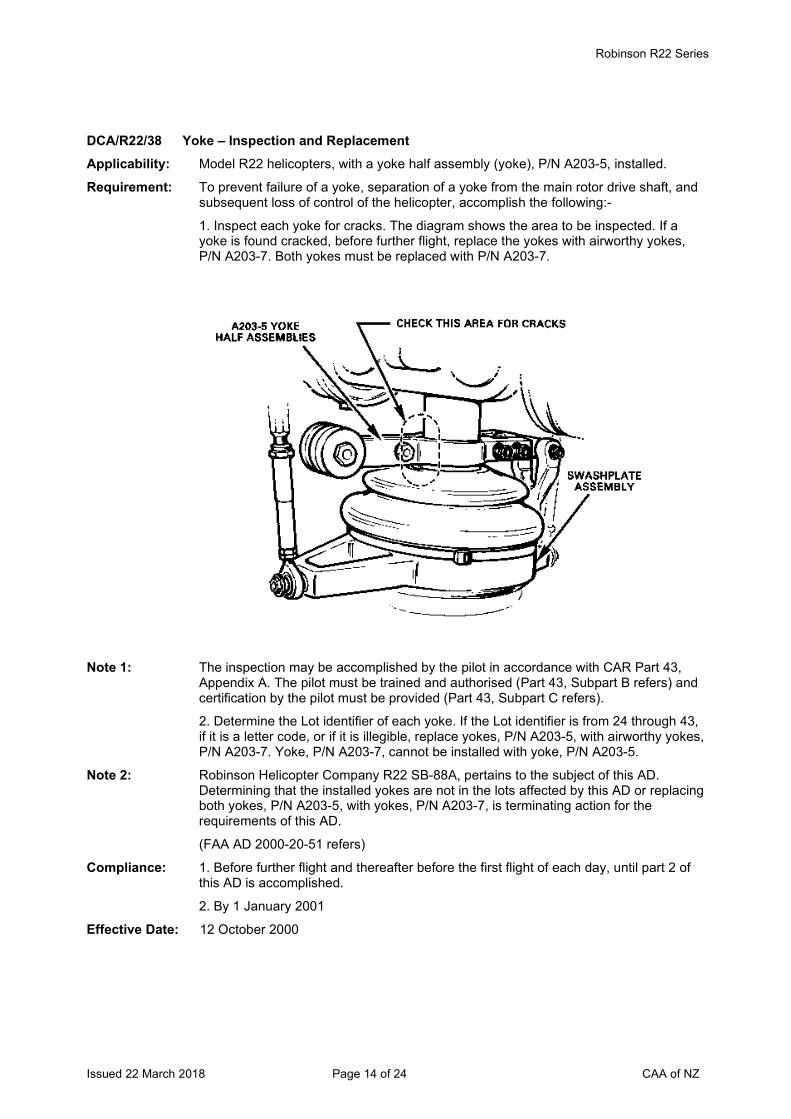
Robinson R22 Series
Issued 22 March 2018 Page 14 of 24 CAA of NZ
DCA/R22/38 Yoke – Inspection and Replacement Applicability: Model R22 helicopters, with a yoke half assembly (yoke), P/N A203-5, installed.
Requirement: To prevent failure of a yoke, separation of a yoke from the main rotor drive shaft, and subsequent loss of control of the helicopter, accomplish the following:-
1. Inspect each yoke for cracks. The diagram shows the area to be inspected. If a yoke is found cracked, before further flight, replace the yokes with airworthy yokes, P/N A203-7. Both yokes must be replaced with P/N A203-7.
Note 1: The inspection may be accomplished by the pilot in accordance with CAR Part 43,
Appendix A. The pilot must be trained and authorised (Part 43, Subpart B refers) and certification by the pilot must be provided (Part 43, Subpart C refers).
2. Determine the Lot identifier of each yoke. If the Lot identifier is from 24 through 43, if it is a letter code, or if it is illegible, replace yokes, P/N A203-5, with airworthy yokes, P/N A203-7. Yoke, P/N A203-7, cannot be installed with yoke, P/N A203-5.
Note 2: Robinson Helicopter Company R22 SB-88A, pertains to the subject of this AD. Determining that the installed yokes are not in the lots affected by this AD or replacing both yokes, P/N A203-5, with yokes, P/N A203-7, is terminating action for the requirements of this AD.
(FAA AD 2000-20-51 refers)
Compliance: 1. Before further flight and thereafter before the first flight of each day, until part 2 of this AD is accomplished.
2. By 1 January 2001
Effective Date: 12 October 2000
Robinson R22 Series
Issued 22 March 2018 Page 15 of 24 CAA of NZ
DCA/R22/39 Tail Rotor Pitch Control – Inspection and Replacement Applicability: Model R22 helicopters, up to and including S/N 3328, except 3167, 3326, and 3327,
with pitch control assembly, P/N A031-1, Revision J or prior.
Requirement: To detect corrosion of a tail rotor pitch control bearing and to prevent bearing failure and loss of directional control of the helicopter, inspect the pitch control assembly for roughness or binding of the pitch control bearings by hand-rotating the pitch control bearing housing in accordance with Robinson Helicopter Company SB-90A, Revision A. If the housing does not rotate freely, replace the unairworthy pitch control assembly with an airworthy unit before further flight. (FAA AD 2003-04-04 refers)
Compliance: Within 50 hours TIS or by 31 March 2003 whichever occurs first. Thereafter inspect at intervals not to exceed 300 hours TIS or 12 months, whichever occurs first.
Effective Date: 27 February 2003
DCA/R22/40A Main Rotor Blades – Placard and Inspections Applicability: All R22 series with main rotor blades P/N A016-1 or A016-2 installed.
Requirement: To prevent in-flight failure of a main rotor blade caused by fatigue cracking in the inboard end of the main rotor blades and subsequent loss of the helicopter, accomplish the following:-
Install in the helicopter a placard that is easily visible to the pilot and which says:
IF MAIN ROTOR VIBRATION INCREASES RAPIDLY OR BECOMES SEVERE DURING FLIGHT, LAND IMMEDIATELY.
Note 1: Operators must ensure that all pilots are aware of the requirements of this AD. In particular, main rotor vibration that increases rapidly or becomes severe during a flight could be warning signs of imminent blade failure and the helicopter must be landed immediately. Following any landing because of main rotor vibration, the helicopter requires mandatory inspections before any further flight.
If the pilot has landed the helicopter because main rotor vibration increased rapidly or became severe during a flight; or there is an unexplained main rotor unbalance, especially if the unbalance developed in only a few flights, accomplish the following two inspections:-
1. Using a 10x magnifying glass, visually inspect the inboard end of each main rotor blade per Robinson R22 SL- 53. In addition to the location of the crack shown in the SL, look for cracks in:
The leading edge in the same area; and the filler at the edge of the skin (as arrowed in the SL).
Robinson R22 SL-21A contains guidance on how to determine whether cracks in the filler are superficial or serious.
2. Perform an eddy current inspection of the most inboard bolt hole attaching the leading edge D-spar to the blade root fitting. This eddy current inspection must be performed in accordance with procedures approved by the CAA.
Note 2: If either main rotor unbalance or any inspection finding remains unexplained after doing all the inspections in this AD, contact the helicopter manufacturer for advice, before further flight. (Australian AD/R22/31 Amdt 4 also refers)
Compliance: Install placard by 11 July 2003.
Effective Date: DCA/R22/40 - 7 July 2003 DCA/R22/40A - 29 July 2004
Robinson R22 Series
Issued 22 March 2018 Page 16 of 24 CAA of NZ
DCA/ R22/41 Main Rotor Blades – Reduced Retirement Life Applicability: All R22 series helicopters.
Requirement: To prevent in-flight failure of a main rotor blade caused by fatigue cracking in the inboard end of the main rotor blades and subsequent loss of the helicopter, accomplish the following:
1. For main rotor blades which have been fitted to helicopters performing aerial mustering operations in Australia for more than 50 hours TIS, the blade retirement life is reduced to 1500 hours TTIS. Where used blades have been imported from Australia and it can not be determined whether or not the blades have been fitted to helicopters performing aerial mustering operations, the blade retirement life is reduced to 1500 hours TTIS.
2. Main rotor blades retired from service per Australian AD/R22/31 Amdt 7 are not to be fitted to any helicopter.
Note: MRBs that are removed at less than the time specified in the Airworthiness Limitations Section of the R22 Maintenance Manual should be retained as future developments may enable them to be placed back into service.
Compliance: 1. Retire blades at 1500 hours TTIS or within the next 25 hours TIS, whichever is the later.
2. From 13 August 2003.
Effective Date: 13 August 2003
DCA/R22/42A Main Rotor Blades P/N A016-1 and A016-2 – Reduced Retirement Lives Applicability: All R22 series with a main rotor blade P/N A016-1 or A016-2 installed.
Requirement: To prevent a fatigue crack, blade failure, and subsequent loss of control of the helicopter, accomplish the following:
1. Within 10 hours TIS or 30 days, whichever occurs first, for helicopters with blades that have exceeded 5 years or 1,000 hours TIS, track-and-balance the blades. If an abnormal increase in vibration occurs within 5 hours TIS after the last track-and-balance, replace the blades before further flight with airworthy blades other than blades, P/N A016-1.
2. Within 10 hours TIS or 30 days, whichever occurs first, for helicopters with blades, P/N A016-1, replace the blades with airworthy blades other than blades, P/N A016-1. Compliance with the current life limit of 2,000 hours TIS for blade, P/N A016-1 is required.
3. For helicopters with blades, P/N A016-2, replace the blades with airworthy blades other than blades, P/N A016-1, on or before reaching 2,200 hours TTIS or 10 years, whichever occurs first. For those blades that have already exceeded 10 years, compliance is required within 10 hours TIS or 30 days, whichever occurs first.
4. Within 10 hours TIS or 30 days, whichever occurs first, unless accomplished previously, revise the component history card or equivalent maintenance record for blades, P/N A016-2, by adding a10-year retirement life to the current 2,200 hours TTIS retirement life.
Note: The manufacturer has clarified from when the 10 year retirement life begins. For new MR blade(s) fitted to a new helicopter, the 10 year retirement life commences from the date stated on the initial Airworthiness Certificate. For blades shipped as spares, use the date on the original RHC-issued Airworthiness Approval tag. If this tag is not available, use the blade's date of manufacture. The manufacturer can provide blade manufacture date when the blade S/N is provided.
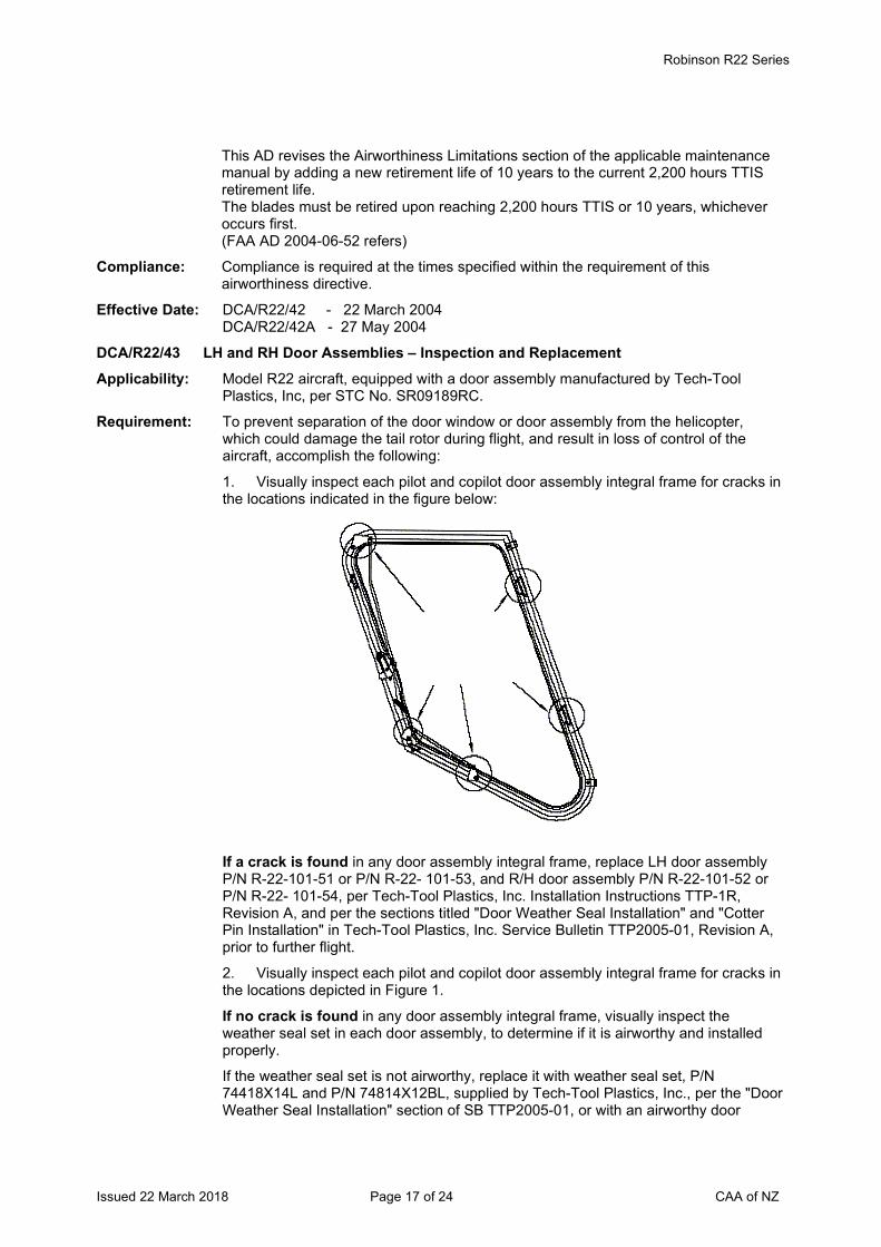
Robinson R22 Series
Issued 22 March 2018 Page 17 of 24 CAA of NZ
This AD revises the Airworthiness Limitations section of the applicable maintenance manual by adding a new retirement life of 10 years to the current 2,200 hours TTIS retirement life. The blades must be retired upon reaching 2,200 hours TTIS or 10 years, whichever occurs first. (FAA AD 2004-06-52 refers)
Compliance: Compliance is required at the times specified within the requirement of this airworthiness directive.
Effective Date: DCA/R22/42 - 22 March 2004 DCA/R22/42A - 27 May 2004
DCA/R22/43 LH and RH Door Assemblies – Inspection and Replacement Applicability: Model R22 aircraft, equipped with a door assembly manufactured by Tech-Tool
Plastics, Inc, per STC No. SR09189RC.
Requirement: To prevent separation of the door window or door assembly from the helicopter, which could damage the tail rotor during flight, and result in loss of control of the aircraft, accomplish the following:
1. Visually inspect each pilot and copilot door assembly integral frame for cracks in the locations indicated in the figure below:
If a crack is found in any door assembly integral frame, replace LH door assembly P/N R-22-101-51 or P/N R-22- 101-53, and R/H door assembly P/N R-22-101-52 or P/N R-22- 101-54, per Tech-Tool Plastics, Inc. Installation Instructions TTP-1R, Revision A, and per the sections titled "Door Weather Seal Installation" and "Cotter Pin Installation" in Tech-Tool Plastics, Inc. Service Bulletin TTP2005-01, Revision A, prior to further flight.
2. Visually inspect each pilot and copilot door assembly integral frame for cracks in the locations depicted in Figure 1.
If no crack is found in any door assembly integral frame, visually inspect the weather seal set in each door assembly, to determine if it is airworthy and installed properly.
If the weather seal set is not airworthy, replace it with weather seal set, P/N 74418X14L and P/N 74814X12BL, supplied by Tech-Tool Plastics, Inc., per the "Door Weather Seal Installation" section of SB TTP2005-01, or with an airworthy door
Robinson R22 Series
Issued 22 March 2018 Page 18 of 24 CAA of NZ
weather seal set, per the applicable manufacturer approved installation instructions, prior to further flight.
Robinson R22 Series
Issued 22 March 2018 Page 19 of 24 CAA of NZ
If the weather seal set is not installed properly, reinstall per the "Door Weather Seal Installation" section of the SB TTP2005-01, prior to further flight. If the improperly installed weather seal set is not the weather seal set supplied by Tech-Tool Plastics, Inc., reinstall per the applicable manufacturer approved installation instructions, prior to further flight.
Visually inspect each door hinge on each door assembly to determine if the cotter pins, P/N MS24665-136 are installed per the "Cotter Pin Installation" section of SB TTP2005-01. If the cotter pins are not installed correctly, install the cotter pins per the "Cotter Pin Installation" section of the SB TTP2005-01, prior to further flight.
Note 1: The installation of nylon adjustment screws and the trimming of door assembly edges are important maintenance actions that may reduce the strength of a door assembly if not done properly.
Note 2: If any of the inspections required by this AD reveal a crack in any door assembly frame, report findings (i.e. the description of the crack and the helicopter model) to the CAA within 30 days after discovering the crack.
(FAA AD 2005-16-05 refers)
Compliance: 1. By 31 October 2005 and thereafter at intervals not to exceed 100 hours TIS.
2. By 31 October 2005.
Effective Date: 29 September 2005
DCA/R22/44B Cancelled – DCA/R22/47 refers Effective Date: 7 July 2011
DCA/R22/45C Door Hinge Security – Inspection and Installation Applicability: All model R22, R22 Alpha, R22 Beta, R22 Mariner aircraft.
Note 1: No action required if already in compliance with DCA/R22/45B. This AD revised to introduce Robinson SB-101 dated 30 April 2010 which provides instructions for the installation of lower hinge assemblies with a longer pin P/N A227-3 and -4 at revision N. These assemblies have drilled hinge pins with sufficient length to install a cotter pin.
Requirement: To prevent a cabin door separating from the aircraft, accomplish the following:
1. Inspect the upper and lower hinge assemblies P/N A227-1, A227-2, A227-3 and A227-4 on both the cabin doors for the installation of cotter pins.
If cotter pins are not fitted to all the door hinges assemblies, fit cotter pins P/N MS24665-151 (or an equivalent approved part), before further flight.
Older doors may only have provision for an upper cotter pin. The lower hinge pin may be too short for a cotter to be fitted. On these doors replace the lower hinge with a hinge which has a longer pin and provision for a cotter. Lower hinge assemblies with a longer pin are P/N A227-3 and -4 revision N or newer. These hinge assemblies have drilled hinge pins with sufficient length to install a cotter pin. Robinson SB-101 refers.
On some aircraft the hinges may be misaligned due to doors exchanged between aircraft. Doors are hand fitted and the hinges may be spaced differently between aircraft. Rework hinges to correct alignment and permit the installation of cotters in the upper and lower cabin door hinges.
Robinson R22 Series
Issued 22 March 2018 Page 20 of 24 CAA of NZ
Note 2: Ring cotters P/N B427-1 which are used on R44 helicopters are not approved for use
on R22 helicopters. On R22 helicopters these ring cotters are damaged with the opening and closing of the doors as the door hinges are smaller than those fitted to the R44 helicopter.
2. Install cotter pins on the upper and lower hinge assemblies on both the cabin doors.
Note 3: Requirement 2 of this AD may be accomplished by adding the requirement to the tech log. Requirement 2 may be performed and certified under the provision in Part 43 Appendix A.1 (7) by the holder of a current pilot licence, if that person is rated on the aircraft, appropriately trained and authorised (Part 43, Subpart B refers), and the maintenance is recorded and certified as required by Part 43.
Note 4: With reference to the system description in section 7, page 7-1 of the AFM, both cabin doors may be removed by the pilot or maintenance personnel and cotters must be fitted to both the upper and lower hinges with the re-installation of a door. The Robinson R22 Illustrated Parts Catalogue shows the installation of two cotter pins P/N MS24665-151 per door assembly. One cotter is fitted on the upper door hinge and the second on the lower door hinge.
Note 5: Doors are known to pop open in flight due to turbulence. If the aircraft is descending, an open door could be forced upward by the airflow. If the lower hinge is a poor fit and the door is only secured by one pin (on the upper hinge), the door could depart the aircraft in flight. If a cabin door strikes the main or tail rotor, the resultant damage to a blade could cause severe out of balance vibration and a catastrophic accident. (NZ Occurrence 06/633 refers)
Compliance: 1. By 27 June 2010 unless previously accomplished, and thereafter at every annual inspection.
2. Every time the cabin doors are refitted to the aircraft.
Effective Date: DCA/R22/45A - 28 January 2010 DCA/R22/45B - 25 March 2010 DCA/R22/45C - 27 May 2010
DCA/R22/46 Tail Rotor Control Pedals – Inspection and Rework Applicability: Model R22, R22 Alpha, R22 Beta and R22 Mariner helicopters, S/N 0002 through to
3325 with more than 2200 hours TTIS.
Requirement: To prevent failure of the tail rotor (T/R) control pedal bearing block support which can bind the T/R control pedals and result in a reduction of yaw control and loss of aircraft control, accomplish the following:
1. Accomplish a visual inspection of the pedal support A359-1 (left) and A359-2 (right) for cracks per the figure in Robinson Helicopter Company (Robinson) SB No. SB-97, dated 22 February 2008.
If any cracks are found in a support, replace the cracked support with an airworthy support that is at least 0.050-inch thick, before further flight.
For every uncracked support, measure the thickness of the support. If the support is less than 0.050-inch thick, install a safety tab on the support per the compliance procedures section, steps 4 and 5 in SB-97, before further flight.
2. Replace all supports that are less than 0.050-inch thick with an airworthy support that is at least 0.050-inch thick per the instructions in SB No. SB-97. (FAA AD 2010-24-03 refers)
Compliance: 1. Within the next 100 hours TIS. 2. At the next 2200 hours TIS overhaul.
Effective Date: 23 December 2010
Robinson R22 Series
Issued 22 March 2018 Page 21 of 24 CAA of NZ
DCA/R22/47B Cancelled - FAA AD 2014-23-16 refers Effective Date: 9 January 2015
Robinson R22 Series
Issued 22 March 2018 Page 22 of 24 CAA of NZ
The State of Design ADs listed below are available directly from the National Airworthiness Authority (NAA) websites. Links to NAA websites are available on the CAA website at https://www.aviation.govt.nz/aircraft/airworthiness/airworthiness-directives/links-to-state-of-design-airworthiness-directives/ If additional NZ ADs need to be issued when an unsafe condition is found to exist in an aircraft or aeronautical product in NZ, they will be added to the list below. 2013-19-06 Fuel Shut-off Valve - Replacement Effective Date: 5 November 2013
2014-23-16 Main Rotor Blade Skin - Inspection Note: The visual inspection required before the first flight of every day per requirement (f)(1)
of FAA AD 2014-23-16 may be accomplished by adding the inspection requirement to the tech log. The visual inspection may be performed and certified under the provision in Part 43 Appendix A.1 (7) by the holder of a current pilot licence, if that person is rated on the aircraft, appropriately trained and authorised (Part 43, Subpart B refers), and the maintenance is recorded and certified as required by Part 43. If any bare metal in the skin-to-spar bond line area is found, an engineer shall accomplish the corrective actions per the AD before further flight.
Effective Date: 9 January 2015
DCA/R22/48 Cancelled - CAA Notice NTC 61.365 refers Effective Date: 27 September 2018
DCA/R22/49 Bladder Fuel Tanks – Retrofit Applicability: Robinson R22 helicopters, S/N 0002 through to 4620.
Requirement: To improve the fuel tanks resistance to post-accident rupture and fuel leaks which could result in a non survivable fire, accomplish the following:
Install bladder-type tanks per the instructions in Robinson Helicopter Company (RHC) R22 SB-109A dated 15 January 2018, or later approved revision.
Note: RHC R22 SB-109A introduces bladder tank retrofit kit KI-217-1 for R22 series aircraft not already fitted with bladder tanks. This kit is now included in the 2200 hour overhaul kits ordered from RHC, unless previously installed.
Compliance: At the next 2200 hour helicopter overhaul, the 12 year inspection, or by 15 January 2020 whichever occurs first, unless previously accomplished.
Effective Date: 22 March 2018
DCA/R22/50 Helipod III Spray System STC 7/21E/9 – Removal from Service Applicability: All Robinson R22 helicopters fitted with a R22 Helipod III Spray System embodied per
STC 7/21E/9.
Note 1: This AD is prompted by a review of the Helipod III Spray System STC 7/21E/9 designed and manufactured by Helipod NZ Limited. The CAA has determined that there are safety concerns with the STC weight and balance considerations. In addition Helipod NZ Limited no longer provides continued airworthiness support for STC 7/21E/9.
Requirement: To prevent a reduction of the level of operational safety from that provided by the helicopter manufacturer, accomplish the following:
Remove the Helipod III Spray System STC 7/21E/9 and return the helicopter to an approved configuration. Remove the Flight Manual Supplement applicable to STC 7/21E/9 from the AFM.
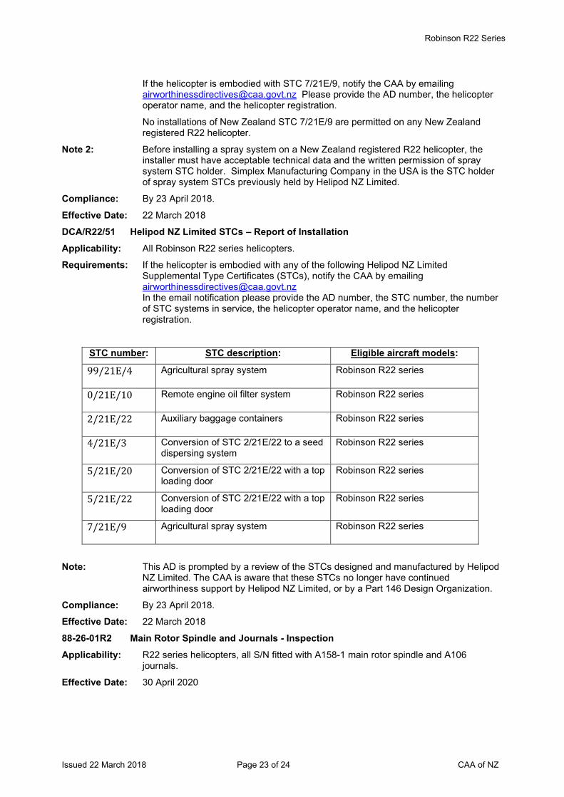
Robinson R22 Series
Issued 22 March 2018 Page 23 of 24 CAA of NZ
If the helicopter is embodied with STC 7/21E/9, notify the CAA by emailing [email protected] Please provide the AD number, the helicopter operator name, and the helicopter registration.
No installations of New Zealand STC 7/21E/9 are permitted on any New Zealand registered R22 helicopter.
Note 2: Before installing a spray system on a New Zealand registered R22 helicopter, the installer must have acceptable technical data and the written permission of spray system STC holder. Simplex Manufacturing Company in the USA is the STC holder of spray system STCs previously held by Helipod NZ Limited.
Compliance: By 23 April 2018.
Effective Date: 22 March 2018
DCA/R22/51 Helipod NZ Limited STCs – Report of Installation Applicability: All Robinson R22 series helicopters.
Requirements: If the helicopter is embodied with any of the following Helipod NZ Limited Supplemental Type Certificates (STCs), notify the CAA by emailing [email protected] In the email notification please provide the AD number, the STC number, the number of STC systems in service, the helicopter operator name, and the helicopter registration.
STC number: STC description: Eligible aircraft models:
99/21E/4 Agricultural spray system Robinson R22 series
0/21E/10 Remote engine oil filter system Robinson R22 series
2/21E/22 Auxiliary baggage containers Robinson R22 series
4/21E/3 Conversion of STC 2/21E/22 to a seed dispersing system
Robinson R22 series
5/21E/20 Conversion of STC 2/21E/22 with a top loading door
Robinson R22 series
5/21E/22 Conversion of STC 2/21E/22 with a top loading door
Robinson R22 series
7/21E/9 Agricultural spray system Robinson R22 series
Note: This AD is prompted by a review of the STCs designed and manufactured by Helipod NZ Limited. The CAA is aware that these STCs no longer have continued airworthiness support by Helipod NZ Limited, or by a Part 146 Design Organization.
Compliance: By 23 April 2018.
Effective Date: 22 March 2018
88-26-01R2 Main Rotor Spindle and Journals - Inspection Applicability: R22 series helicopters, all S/N fitted with A158-1 main rotor spindle and A106
journals.
Effective Date: 30 April 2020
Robinson R22 Series
Issued 22 March 2018 Page 24 of 24 CAA of NZ
* 2022-12-08 Engine Governor and RPM Sensor - Inspection Applicability: R22 Beta helicopters, S/N 4825 through to 4857 inclusive, 4860 and 4861.
Effective Date: 29 June 2022
Issued 30 June 2022 Page 1 of 22 CAA of NZ
Airworthiness Directive Schedule Helicopters Robinson R44 Series 30 June 2022
Notes: 1. This AD schedule is applicable to Robinson R44 Raven and R44 Raven II helicopters manufactured under FAA Type Certificate No. H11NM.
2. The Federal Aviation Administration (FAA) is the National Airworthiness Authority (NAA) responsible for the issue of State of Design Airworthiness Directives (ADs) for these helicopters. State of Design ADs can be obtained directly from the FAA website at http://rgl.faa.gov/Regulatory_and_Guidance_Library/rgAD.nsf/MainFrame?OpenFrameSet
3. The date above indicates the amendment date of this schedule.
4. New or amended ADs are shown with an asterisk *
Contents
DCA/R44/1 Cyclic Stick Assembly - Removal of Parts ......................................................................... 3 DCA/R44/2B Fanwheel and Shaft - Replacement .................................................................................. 3 DCA/R44/3C Cancelled .......................................................................................................................... 3 DCA/R44/4 Cancelled - Purpose Fulfilled ............................................................................................ 3 DCA/R44/5 Cyclic Control System - Replacement and Inspection....................................................... 4 DCA/R44/6A Main Rotor RPM Warning Unit - Adjustment ..................................................................... 4 DCA/R44/7 Main Rotor Gearbox Ring Gear Bolts - Inspection ............................................................ 4 DCA/R44/8 Main Rotor Clutch - Inspection and Replacement ............................................................. 5 DCA/R44/9 Cyclic Control System - Inspection.................................................................................... 5 DCA/R44/10 Oil Line Elbows - Replacement ......................................................................................... 5 DCA/R44/11A Main Rotor Blades – Inspection and Replacement ........................................................... 6 DCA/R44/12A FAA AD 98-21-36 Cancelled – FAA AD 99-23-01 now refers .......................................... 7 DCA/R44/13 Cancelled – DCA/R44/17 refers. ....................................................................................... 7 DCA/R44/14 Auxiliary Fuel Tank Sump Drain - Modification ................................................................. 8 DCA/R44/15 Yoke Assembly P/N C908-1 – Replacement ..................................................................... 9 DCA/R44/16 Fuel Line Assembly – Inspection and Modification............................................................ 9 DCA/R44/17 Sprag Clutch - Replacement ............................................................................................. 9 DCA/R44/18 Horizontal Stabilizer Assembly – Life Limit ..................................................................... 10 DCA/R44/19 V-Belt Restraint Panel Assembly - Replacement ............................................................ 10 DCA/R44/20 Tail Rotor Pitch Control - Inspection................................................................................ 10 DCA/R44/21 Main Rotor Swashplate and Tail Rotor Blade Attachment Bolts - Replacement ............. 11 DCA/R44/22A Fuel Control Unit – Modification ...................................................................................... 12 DCA/R44/23B Sprag Clutch Assembly – Inspection.............................................................................. 12 DCA/R44/24 Seat Belt Buckle Assembly – Replacement .................................................................... 13 DCA/R44/25 Helipod R44 5 Place Kit – Removal from Service .......................................................... 14 DCA/R44/26B Cancelled – DCA/R44/29 refers ...................................................................................... 14 DCA/R44/27A Door Hinge Security – Inspection and Installation ........................................................... 14 DCA/R44/28 Tail Rotor Control Pedals – Inspection and Rework ........................................................ 15 DCA/R44/29B Cancelled - FAA AD 2014-23-16 refers ......................................................................... 15 The State of Design ADs listed below are available directly from the National Airworthiness Authority (NAA) websites. Links to NAA websites are available on the CAA website at https://www.aviation.govt.nz/aircraft/airworthiness/airworthiness-directives/links-to-state-of-design-airworthiness-directives/ If additional NZ ADs need to be issued when an unsafe condition is found to exist in an aircraft or aeronautical product in NZ, they will be added to the list below. .............................................. 16 2013-05-15 Emergency Floats – Inspection ....................................................................................... 16
Issued 30 June 2022 Page 2 of 22 CAA of NZ
DCA/R44/30 Bladder Fuel Tanks – Retrofit ......................................................................................... 16 2014-23-16 Main Rotor Blade Skin - Inspection ............................................................................... 16 DCA/R44/31 Cancelled – Purpose Fulfilled ......................................................................................... 16 DCA/R44/32C Main Rotor Blades P/N C016-7 ....................................................................................... 17 DCA/R44/33 Clutch Shaft and Yoke Installation - Inspection ............................................................. 18 DCA/R44/34 Cancelled - CAA Notice NTC 61.365 refers .................................................................... 19 DCA/R44/35 Revised Instrument Marking ........................................................................................... 19 2016-26-04 Main Rotor Blades – Inspection ...................................................................................... 19 DCA/R44/36 Helipod NZ Limited STCs – Report of Installation ........................................................... 20 2019-12-18 Cancelled – FAA AD 2020-18-08 refers .......................................................................... 20 2020-05-11 Agricultural Spray System STCs – Inspection ................................................................. 21 2020-08-10 Tail Rotor Blades – Inspection ........................................................................................ 21 2020-18-08 Engine Air Induction Hoses – Inspection ......................................................................... 21 2021-19-08 Tail Rotor Blades – Inspection ........................................................................................ 22 99-23-01 Cyclic Control Grip Assembly - Inspection ...................................................................... 22 * 2022-12-08 Engine Governor and RPM Sensor - Inspection ............................................................. 22
Helicopters Robinson R44 Series
Issued 30 June 2022 Page 3 of 22 CAA of NZ
DCA/R44/1 Cyclic Stick Assembly - Removal of Parts Applicability R44 series helicopters, S/N less than but not including 0017.
Requirement: To prevent failure of the cyclic stick assembly and loss of control of the helicopter accomplish the following:
Remove the following cyclic control system parts and replace with the corresponding replacement parts per the applicable maintenance manual:
Remove P/Ns: Replace with P/Ns: A205-3 A205-5 Revision J or higher C175-1 C175-2 Revision H or higher C176-1 C176-2 Revision B or higher C177-1 C177-2 Revision F or higher C319-1 C319-3 Revision I or higher C320-1 C320-1 Revision L or higher C958-4 C958-5 Revision E or higher A101-4 D173-1 Revision A or higher C338-1 C338-4 Revision C or higher A211-2 A211-3 Revision I or higher A137-1 A137-2 Revision C or higher
(FAA AD 94-26-10 refers)
Compliance: Before further flight
Effective Date: 16 September 1994
DCA/R44/2B Fanwheel and Shaft - Replacement Applicability R44 series helicopters, S/Ns 0006 through to 0246, except S/N 0014, 0069, 0090,
0182, 0186, 0215, 0228, 0237 and 0239.
Requirement: To prevent loss of engine cooling, replace the fanwheel and shaft assembly, per Robinson R44 SB -14.
Note: With the replacement of the fanwheel and shaft assembly, Textron Lycoming recommends the installation of P/N 14W22647 counterweight rollers, per Textron Lycoming Service Instruction No. 1500. If this has not been accomplished, comply with DCA/LYC/211.
Compliance: Within the next 100 hours TIS, unless already accomplished.
Effective Date: DCA/R44/2A - 7 June 1996 DCA/R44/2B - 31 August 2006
DCA/R44/3C Cancelled Effective Date: 25 November 2004
DCA/R44/4 Cancelled - Purpose Fulfilled
Helicopters Robinson R44 Series
Issued 30 June 2022 Page 4 of 22 CAA of NZ
DCA/R44/5 Cyclic Control System - Replacement and Inspection Applicability R44 series helicopters, S/N 0001 through to 0150.
Requirement: To prevent binding in the cyclic control system and subsequent loss of control of the helicopter, accomplish the following:
1. Replace, the existing push-pull tube sleeve guide assembly with a C439-7 assembly (included in the KI-88 push-pull tube guide kit) per Robinson SB-4. Inspect the C121-7 push-pull tube sleeve for signs of wear per SB-4. Replace if necessary using the sleeves and adhesive in the KI-88 kit before further flight.
2. Inspect the C121-7 push-pull tube sleeve for signs of wear per the applicable maintenance manual. Replace if necessary using the sleeves and adhesive in the KI-88 kit before further flight.
(FAA AD 95-09-07 refers)
Compliance: 1. Within next 25 hours TIS.
2. At intervals not to exceed 100 hours TIS.
Effective Date: 7 July 1995
DCA/R44/6A Main Rotor RPM Warning Unit - Adjustment Applicability All R44 series helicopters.
Requirement: To minimise the possibility of pilot mismanagement of the main rotor RPM, which could result in unrecoverable main rotor blade stall and subsequent loss of control of the helicopter, accomplish the following:-
Adjust the A569-6 low-RPM warning unit so that the warning horn and caution light activate when the main rotor RPM is between 96% and 97% rotor RPM per the procedures contained in the R44 maintenance manual.
Revise the R44 Flight Manual (AIR2479) to include the FAA-approved Flight Manual revision dated July 25, 1996.
(FAA AD 97-02-15 refers)
Compliance: Within next 30 days unless already accomplished.
Effective Date: DCA/R44/6 - 5 July 1996 DCA/R44/6A - 14 March 1997
DCA/R44/7 Main Rotor Gearbox Ring Gear Bolts - Inspection Applicability All R44 series helicopters fitted with main rotor gearbox P/N C006-1, revisions A
through to P.
Requirement: To prevent loosening of the bolts securing the gear to the gear carrier which could lead to fatigue failure of the gear carrier, accomplish Robinson SB-15.
(FAA Priority Letter AD 96-18-22 refers)
Compliance: Within next 5 hours TIS.
Effective Date: 4 September 1996
Helicopters Robinson R44 Series
Issued 30 June 2022 Page 5 of 22 CAA of NZ
DCA/R44/8 Main Rotor Clutch - Inspection and Replacement Applicability: R44 series helicopters, S/N 0001 through to 0332.
Requirement: To prevent failure of the sprag clutch to lock or unlock, accomplish the following:
1. Inspect both up-limit switches, P/N V3-1001, for proper operation per Robinson R44 SB-21. If the motor runs when the springs are depressed on one side, the switch on the OPPOSITE side is not functioning properly. If either up-limit switch does not function properly, before further flight replace the up-limit switch with an airworthy up-limit switch per SB-21.
2. Replace the clutch assembly, P/N C018-1, with a clutch assembly, P/N C018-2 or P/N C018-2A, per Robinson R44 SB-23.
(FAA AD 97-16-02 refers)
Compliance: 1. Inspect within next 25 hours TIS and thereafter at intervals not to exceed 100 hours TIS.
2. Replace within next 50 hours TIS.
Effective Date: 14 August 1997
DCA/R44/9 Cyclic Control System - Inspection Applicability: R44 series helicopters, S/N 0002 through to 0420, 0425, 0426, and 0427 fitted with a
C056-1 Rev A through to G spring assembly.
Requirement: To detect excessive wear on the lateral cyclic trim spring shaft, which could allow the shaft to move from its lower mount and interfere with lateral cyclic control resulting in loss of control of the helicopter, accomplish the following:-
Measure the diameter of the shaft per the Compliance Procedure contained in Robinson R44 SB-26.
If the shaft diameter varies more than 0.004 inch in any 0.50 inch of length, in the measurement area shown in Figure 1 of SB-26, replace the C056-1 Rev. A through G spring assembly with a C056-1 Rev. H spring assembly before further flight.
Replacing the C056-1 Rev. A through G spring assembly with a C056-1 Rev. H spring assembly per SB-26 is considered terminating action for the requirements of this AD.
(FAA Priority Letter AD 98-04-12 refers)
Compliance: Within next 10 hours TIS, and thereafter at intervals not to exceed 20 hours TIS.
Effective Date: 13 February 1998
DCA/R44/10 Oil Line Elbows - Replacement Applicability: R44 series helicopter, S/N 0001 through to 0330.
Requirement: To prevent failure of either the 45 degree or 90 degree aluminium elbows that connect the oil lines from the oil cooler to the engine accessory case, which would cause loss of engine oil, resulting in an engine failure, accomplish the following:-
Remove any aluminium (blue-coloured) AN823-8D (45 degree) or MS20822-8D (90 degree) elbows that connect the A723 oil cooler lines to the engine accessory case and replace them with airworthy MS20823-8 (45 degree) steel elbows or MS20822-8 (90 degree) steel elbows per Robinson R44 SB-25.
(FAA AD 98-05-10 refers)
Compliance: Within next 50 hours TIS.
Effective Date: 10 April 1998
Helicopters Robinson R44 Series
Issued 30 June 2022 Page 6 of 22 CAA of NZ
DCA/R44/11A Main Rotor Blades – Inspection and Replacement Applicability: R44 series helicopters, S/N 0002 through to 0486 fitted with main rotor blades P/N
C016-1.
Requirement: To prevent failure of a main rotor blade and subsequent loss of the helicopter, accomplish the following:-
1. Perform a dye-penetrant inspection of the main rotor blade skin around both inboard trim tab alignment rivets as follows, referring to Figure 1.
a) Remove all paint around both rivets, exposing an area of approximately 3/4" in diameter, at the inboard trim tab on the top and bottom of each main rotor blade (4 places per main rotor blade). Use 180 grit or finer abrasive paper, followed by 600 grit or finer paper to eliminate course sanding marks. Sand only in a spanwise direction. Do not use chemical paint strippers.
b) Inspect the main rotor blade skin around the rivets on the upper and lower surfaces (4 locations) using a dye-penetrant inspection method.
Note 1: Chord-wise cracks in the paint up to 2 inches long which are located along either inboard or outboard edge of the trim tab are acceptable.
c) Clean the sanded areas prepared in accordance with paragraph a) of this AD with 111-Trichloroethane or methyl ethyl ketone (MEK) and then apply clear lacquer to seal the unpainted areas.
Note 2: Do not bend the inboard main rotor blade tabs from their present position or utilise them for any subsequent main rotor blade tracking adjustment.
2. Using a 5-power or higher magnifying glass, visually inspect both upper and lower main rotor blade skin surfaces around the inboard trim tab rivets (4 locations) for cracks. If a crack is found, replace the main rotor blade with an airworthy main rotor blade before further flight.
Note 3: The daily inspection may be accomplished by pilot subject to: Adequate instruction by LAME responsible for the aircraft. Aircraft Technical Log to be endorsed to refer to inspection requirement.
3. Install a set of main rotor blades, P/N C016-2. This constitutes terminating action for the inspections required by this AD.
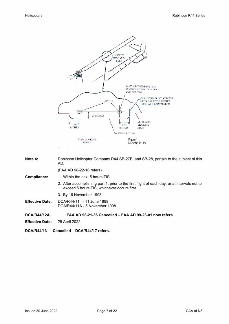
Helicopters Robinson R44 Series
Issued 30 June 2022 Page 7 of 22 CAA of NZ
Note 4: Robinson Helicopter Company R44 SB-27B, and SB-28, pertain to the subject of this
AD.
(FAA AD 98-22-16 refers)
Compliance: 1. Within the next 5 hours TIS
2. After accomplishing part 1, prior to the first flight of each day, or at intervals not to exceed 5 hours TIS, whichever occurs first.
3. By 16 November 1998
Effective Date: DCA/R44/11 - 11 June 1998 DCA/R44/11A - 5 November 1998
DCA/R44/12A FAA AD 98-21-36 Cancelled – FAA AD 99-23-01 now refers Effective Date: 28 April 2022
DCA/R44/13 Cancelled – DCA/R44/17 refers.

Robinson R44 Series
Issued 30 June 2022 Page 8 of 22 CAA of NZ
DCA/R44/14 Auxiliary Fuel Tank Sump Drain - Modification Applicability: R44 series helicopters, S/N 0002 through to 0529, except S/N 0440, 0485, 0512,
0515, 0519, 0526, 0527 and 0528.
Requirement: To prevent fuel leaks from the auxiliary fuel tank sump drain, which could cause a fire and subsequent loss of the helicopter, accomplish the following:-
Install a shutoff clamp, P/N D663-1, by sliding it onto the auxiliary fuel tank sump drain tube, P/N A729-7, as shown.
Install placard decal, P/N A654-93, as shown.
(FAA AD 99-13-11 refers)
Compliance: Within 100 hours TIS or 3 months, whichever occurs first.
Effective Date: 30 July 1999
Robinson R44 Series
Issued 30 June 2022 Page 9 of 22 CAA of NZ
DCA/R44/15 Yoke Assembly P/N C908-1 – Replacement Applicability: R44 series helicopters, S/N 0219 and 0535 through to 0608 (except S/N 0565, 0582,
and 0592).
Requirement: To prevent failure of the yoke assembly, which could result in loss of main and tail rotor drive and subsequent loss of control of the helicopter, determine, if the yoke assembly, P/N C908-1C, from Lot No 36B, 37, or 38 is installed. Yoke assemblies, P/N C908-1C, from Lot Nos 36B, 37, and 38 were installed as original equipment in R44 helicopters, S/N 0219 and 0535 through 0608 (except S/N’s 0565, 0582, and 0592). Replace any yoke assembly, P/N C908-1C, from Lot No 36B, 37, or 38, with an airworthy yoke assembly from a lot other than 36B, 37, or 38 perRobinson Helicopter Company R44 SB-35. (FAA AD 99-17-17 refers)
Compliance: Before further flight
Effective Date: 24 September 1999
DCA/R44/16 Fuel Line Assembly – Inspection and Modification Applicability: R44 series helicopters, S/N 0002 through to 0462.
Requirement: To prevent contact between the wire harness and the fuel line assembly, which could result in chafing of the wire harness and a potential fire hazard, remove the cover, P/N C474-1, from between the rear seatbacks.
Inspect the wire harness, P/N C059, and the fuel line assembly, P/N C726-2, above the fuel shutoff valve for contact. If the wire harness contacts the fuel line assembly, inspect for chafing. If chafing has occurred between the wire harness and the fuel line assembly, replace the fuel line with an airworthy fuel line assembly. Torque the fuel line nuts to 110-130 in-lbs. Verify that clearance exists between the fuel line assembly and the wire harness. Install a 3-inch section of spiral wrap tubing, P/N B161-8, on the fuel line assembly as shown in Robinson SB-31. Push the spiral wrap tubing down until it is against the fuel line fitting.
Note: FAA AC 43.13-1B, Chapter 11, describes procedures acceptable for replacing the wire harness if required. (FAA AD 2000-07-03 refers)
Compliance: Within next 100 hours TIS or by 31 July 2000, whichever is the sooner.
Effective Date: 27 April 2000
DCA/R44/17 Sprag Clutch - Replacement Applicability: R44 series helicopters, S/N 0001 through to 0541, 0543, 0550, 0556 and 0565 fitted
with sprag clutch P/N C188-3, S/N 0003 through to 0505.
Requirement: To prevent sprag clutch failure, loss of main rotor RPM during autorotation, and subsequent loss of control of the helicopter, replace sprag clutch, P/N C188-3, S/N 0003 through 0505, with sprag clutch P/N C188-3, S/N 0506 or higher.
Remove from the Rotorcraft Flight Manual the Special Pilot Caution contained in Robinson Helicopter Company R44 SB-32 dated March 22, 1999, or the Special Pilot Caution insert in the Normal Procedures Section of the Rotorcraft Flight Manual between pages P.4-8 and P.4-9 required by airworthiness directive DCA/R44/13, as applicable. (FAA AD 2000-08-04 refers)
Compliance: Within next 50 hours TIS or by 24 June 2000, whichever is the sooner.
Effective Date: 25 May 2000
Robinson R44 Series
Issued 30 June 2022 Page 10 of 22 CAA of NZ
DCA/R44/18 Horizontal Stabilizer Assembly – Life Limit Applicability: All R44 series helicopters fitted with horizontal stabilizer assembly, P/N C044-1; and
S/N 0009 through 0224, except S/N 0018, 0090, 0094, 0111, 0129, 0144, 0161, 0178, 0201, and 0223.
Requirement: To prevent a crack through a vertical-to-horizontal stabilizer attach channel (channel), which can cause separation of the stabilizers and subsequent loss of control of the helicopter, accomplish the following:-
Remove the vertical stabilizer and inspect the nutplate on channels, P/N D283-1 and -2. If the nutplates are P/N MS21086L4, no further action is required by this AD. If the nutplates are P/N NAS697A4, replace the channels with airworthy channels, P/N D296-1, or D296-2 before further flight.
Robinson SB-39 also refers to the subject of this AD.
This AD revises the Limitations section of the maintenance manual by establishing a retirement life of 2200 hours TIS for assembly, P/N CO44-1, with channels, P/N D283-1 or -2, with nutplates, P/N NAS697A4, installed.
(FAA AD 2001-20-18 refers)
Compliance: Before accumulating 2200 hours TIS on the assembly.
Effective Date: 29 November 2001
DCA/R44/19 V-Belt Restraint Panel Assembly - Replacement Applicability: R44 series helicopters, S/N 0002 through to 0240.
Requirement: To prevent failure of the support structure for the right-hand V-belt restraint, replace the C309-1 panel assembly per Robinson Helicopter Company SB-16.
Compliance: By 31 August 2002
Effective Date: 30 May 2002
DCA/R44/20 Tail Rotor Pitch Control - Inspection Applicability: R44 series helicopters, all S/N up to and including S/N 1208, except S/N 1143, 1165,
1183, 1189, 1192, 1196, 1197, 1198, 1200, 1203 and 1204 fitted with a pitch control assembly, P/N C031-1, revision G or prior.
Requirement: To detect corrosion of a tail rotor pitch control bearing and to prevent bearing failure and loss of directional control of the helicopter, accomplish the following:
Inspect the pitch control assembly for roughness or binding of the pitch control bearings by hand-rotating the pitch control bearing housing in accordance with Robinson Helicopter Company SB-43A, Revision A. If the housing does not rotate freely, replace the unairworthy pitch control assembly with an airworthy unit before further flight.
(FAA AD 2003-04-05 refers)
Compliance: Within 50 hours TIS or by 31 March 2003 whichever occurs first. Thereafter inspect at intervals not to exceed 300 hours TIS or 12 months, whichever occurs first.
Effective Date: 27 February 2003
Robinson R44 Series
Issued 30 June 2022 Page 11 of 22 CAA of NZ
DCA/R44/21 Main Rotor Swashplate and Tail Rotor Blade Attachment Bolts - Replacement Applicability: All R44 and R44II helicopters.
Requirement: To prevent failure of the main rotor swashplate and tail rotor blade attachment bolts, and subsequent loss of control of the helicopter, accomplish the following:
1. For model R44 S/N 0210, 0565, 0641, 0987, and 1312 through 1349, except 1345 and 1346; and R44II helicopters, S/N 10010, 10062, and 10083 through 10212, except 10092, 10173, 10204, 10207, 10210, and 10211, accomplish the following:-
Visually inspect each bolt for fretting residue under the bolt head as indications of a loose or cracked bolt. Apply 10-15 ft-lb (13-20 Nm) torque to each bolt head and verify no rotation. See Figure 1 of Robinson SB-51. If residue or rotation of the bolt is found, before further flight, replace each unairworthy bolt with an airworthy bolt that does not have a vendor identification marking of 01DO.
Within 10 hours TIS or by 31 December 2003, whichever occurs first, replace each bolt, P/N NAS6605-31, which has vendor identification marking 01DO on the bolt head, with an airworthy bolt, P/N NAS6605-31, that has an alternate vendor identification marking.
2. For all other R44 and R44II helicopters accomplish the following:-
Determine if maintenance has been performed after 7 February 2003 on the areas specified in Figure 1 of Robinson SB-51, and determine if any bolt, P/N NAS6605-31, shown in Figure 1 has been replaced for any reason. If any bolt has been replaced, or if it is uncertain whether any bolt has been replaced after 7 February 2003, remove the paint from the bolt head to reveal the vendor identification marking. Determine if the bolt vendor identification is 01DO.
If the bolt vendor identification is 01DO before further flight accomplish the following:
Visually inspect each bolt for fretting residue under the bolt head as indications of a loose or cracked bolt. Apply 10-15 ft-lb (13-20 Nm) torque to each bolt head and verify no rotation. See Figure 1 of Robinson SB-51. If residue or rotation of the bolt is found, then before further flight, replace each unairworthy bolt with an airworthy bolt that does not have a vendor identification marking of 01DO.
Within 10 hours TIS or by 31 December 2003, whichever occurs first, replace each bolt, P/N NAS6605-31, which has vendor identification marking 01DO on the bolt head, with an airworthy bolt, P/N NAS6605-31, that has an alternate vendor identification marking.
3. Bolt, P/N NAS6605-31, with vendor identification marking 01DO on the bolt head, is NOT ELIGIBLE for installation on any helicopter.
(FAA 2003-24-51 AD refers)
Compliance: Before further flight.
Effective Date: 4 December 2003
Robinson R44 Series
Issued 30 June 2022 Page 12 of 22 CAA of NZ
DCA/R44/22A Fuel Control Unit – Modification Applicability: All R44 II series helicopters fitted with Lycoming engine model IO-540-AE1A5 not
embodied with Robinson SB No. 55.
Note 1: This AD revised to mandate the fuel control unit modification per Robinson SB No. 55.
Requirement: To prevent corrosion inside the fuel control unit, which may lead to loss of engine power and in-flight engine failure, accomplish the following:
Modify the fuel control unit per Robinson SB No. 55 dated 20 July 2005.
Note 2: This modification rotates the fuel control through 90 degrees to reduce the possibility of water entering the fuel control unit intake. (NZ occurrences refer)
Compliance: Within the next 100 hours TIS or annual inspection whichever is the sooner, unless previously accomplished.
Effective Date: 30 July 2009
DCA/R44/23B Sprag Clutch Assembly – Inspection Applicability: All R44 series helicopters fitted with a sprag clutch assembly P/N C188-3 revisions D,
E, F, G or H.
Note 1: DCA/R44/23B revised to clarify the applicability and the requirements. The AD mandates lubricant inspections for sprag clutch assemblies P/N C188-3 revisions D, E, F, G and H.
Requirement: To prevent failure of the clutch assembly due to worn or broken parts which could either result in loss of the main rotor drive, or result in the clutch assembly failing to disengage during autorotation, accomplish the following:
1. Review the aircraft records, or inspect the sprag clutch assembly fitted to the aircraft and determined if both the forward and aft retainers P/N C168-X fitted to the sprag clutch have a screw P/N B289-3.
If both the forward and aft retainers P/N C168-X are found fitted with screws P/N B289-3, then accomplish requirement 2 of this AD.
If early revision retainers P/N C168-X are found fitted, which do not have screws P/N B289-3, then accomplish requirement 3 of this AD.
Note 2: Sprag clutches with retainers P/N C168-5 are fitted with a screw P/N B289-3. Older clutch assemblies may not have retainers fitted with screws P/N B289-3. To determine the dash number of the forward and aft retainers fitted to the sprag clutch refer to the RHC R44 IPC.
2. For a sprag clutch with retainers fitted with screws P/N B289-3:
Accomplish steps 4 through to 7 in Robinson R44 SB-79, dated 20 December 2010 or later approved revision.
If any evidence of metal contamination is found, remove the clutch assembly P/N C018-X from the aircraft, and replace with a new or overhauled clutch assembly per the instructions in the Robinson R44 MM.
If no metal contamination is found, service the sprag clutch assembly with lubricant per the instructions in steps 8 through to 11 in Robinson R44 SB-79.
3. For a sprag clutch with retainers not fitted with screws P/N B289-3:
Remove the clutch assembly P/N C018-X from the aircraft per the instructions in section 7.210 of Robinson R44 Maintenance Manual (MM), and remove the aft and forward seal retainers per the instructions in section 7.213 of the R44 MM to expose the bearing cavity, and inspect for metal particle contamination.
Robinson R44 Series
Issued 30 June 2022 Page 13 of 22 CAA of NZ
If any evidence of metal contamination is found or if any defective parts are found, replace with a new or overhauled clutch assembly per the instructions in the Robinson R44 MM
If there is no evidence of metal contamination, rotate the sheave drive shaft in the free wheel direction and feel for momentary drag. As the rotation is continued in the free wheel direction inspect for a notchy feel, listen for unusual noises and roughness from the sprag clutch area. If any of these symptoms are detected, or if any defective parts are found, replace with a new or overhauled clutch assembly per the instructions in the Robinson R44 MM.
Remove any light surface corrosion at the shaft-to-seal junctures and apply a suitable corrosion inhibitor, and replace all clutch assembly seals, o-rings and lubricant per the clutch assembly seal replacement instructions in section 7.213 of the Robinson R44 MM, before further flight.
Restore the actuator drive belt tension per the instructions in section 7.500 of the Robinson R44 MM. Adjust the actuator, as required, per the instructions in section 7.540 of the Robinson R44 MM. (NZ occurrences refers)
Note 3: Older clutch assemblies fitted with early revision retainers can be retrofitted with retainers P/N C168-5 with the embodiment of RHC Kit KI-202.
Note 4: Symptoms of a worn clutch assembly or cracked sprag ends may include leaking clutch assembly oil seals, unusual noise from the upper sheave or unusual aircraft vibration on engine shutdown, or momentary drag with clutch overrun during autorotation.
Note 5: If metal contamination is found, submit a defect report form CA005D to the Civil Aviation Authority per Rule Part 12.57 and provide the clutch assembly hours TIS and the nature of the defects found.
Compliance: 1. 2. & 3. At 500 hours TTIS, or within the next 50 hours TIS, whichever is the later, unless previously accomplished, and thereafter at intervals not to exceed 500 hours TIS.
Effective Date: DCA/R44/23 - 31 May 2007 DCA/R44/23A - 21 April 2011 DCA/R44/23B - 30 August 2018
DCA/R44/24 Seat Belt Buckle Assembly – Replacement Applicability: R44 helicopters, all S/N through to 1576.
R44 II helicopters, all S/N through to 11107.
Fitted with a seat belt buckle assembly P/N C628-4 revision M or earlier.
Requirement: To prevent cracks developing in the stainless support strap of the seat belt buckle assembly which could result in failure of a seat belt, remove the buckle assembly and the spacer, and replace with a buckle assembly P/N C628-4, revision N and a new buckle assembly spacer P/N A130-52, per the procedure in paragraph 3 of Robinson Helicopter Company Service Bulletin SB-56. (FAA AD 2007-11-01 refers)
Note 1: The new buckle assembly spacers have been redesigned to be slightly longer than the previous spacers to reduce friction in the joint.
Note 2: Inspecting the buckle assembly for cracks is not a requirement of this AD.
Compliance: Within the next 100 hours TIS unless already accomplished.
Effective Date: 28 June 2007
Robinson R44 Series
Issued 30 June 2022 Page 14 of 22 CAA of NZ
DCA/R44/25 Helipod R44 5 Place Kit – Removal from Service Applicability: All R44 and R44 II helicopters fitted with Helipod R44 5 place kit P/N
MHPR44BS25200.
Requirement: To prevent a reduction of the level of occupant safety, from that provided by the manufacturer, accomplish the following:
1. The carriage of a passenger in the centre rear seat position is prohibited. Insert a copy of this AD into the AFM, opposite the supplement for the Helipod 5 Place Kit.
2. Remove the rear seat P/N MHPR44BS25200 and return the aircraft to an approved configuration. Remove the Flight Manual Supplement and AD from the AFM.
Note: It has not been demonstrated that this modification kit maintains the existing level of occupant safety for the centre seat passenger in an emergency landing. The modification may also reduce the existing occupant safety features of the two other rear seats.
Compliance: 1. From 20 September 2007
2. By 20 October 2007
Effective Date: 20 September 2007
DCA/R44/26B Cancelled – DCA/R44/29 refers Effective Date: 7 July 2011
DCA/R44/27A Door Hinge Security – Inspection and Installation Applicability: All R44 and R44 II helicopters.
Note 1: This AD revised to introduce requirement 2 which requires the installation of cotter pins or ring-cotters on the upper and lower hinge assemblies every time any of the doors are refitted to the aircraft.
Requirement: To prevent a cabin door separating from the aircraft, accomplish the following:
1. Inspect the upper and lower hinge assemblies P/N C227-1, C227-2 C227-3, C227-4 on both the forward cabin doors for the installation of cotter pins or ring-cotters.
Also inspect the upper and lower hinge assemblies P/N C389-3, C389-4, C389-9 and C389-10 on both the aft cabin doors for the installation of cotter pins or ring-cotters.
If cotter pins or ring-cotters are not fitted to all door hinges assemblies, fit cotter pins P/N MS24665-151 or ring-cotters P/N B427-1 (or an approved equivalent part).
On doors where the lower hinge pin may be too short for a cotter to be fitted, replace the lower hinge with a hinge which has a longer pin and provision for a cotter.
On doors where the hinges may be misaligned, rework the hinges to correct alignment and permit the installation of cotters in the upper and lower cabin door hinges.
2. Install cotter pins or ring-cotters on the upper and lower hinge assemblies on both the aft and forward cabin doors.
Note 2: Requirement 2 of this AD may be accomplished by adding the requirement to the tech log. Requirement 2 may be performed and certified under the provision in Part 43 Appendix A.1 (7) by the holder of a current pilot licence, if that person is rated on the aircraft, appropriately trained and authorised (Part 43, Subpart B refers), and the maintenance is recorded and certified as required by Part 43.
Note 3: The Robinson R44 IPC specifies the installation of cotter pins P/N B427-1 on all the upper and lower door hinge assemblies.
Robinson R44 Series
Issued 30 June 2022 Page 15 of 22 CAA of NZ
Note 4: Doors are known to pop open in flight due to turbulence. If the aircraft is descending, an open door could be forced upward by the airflow. If the lower hinge is a poor fit and the door is only secured by one pin (on the upper hinge), the door could depart the aircraft in flight. If a cabin door strikes the main or tail rotor, the resultant damage to a blade could cause severe out of balance vibration and a catastrophic accident.
(NZ Occurrence 06/633 refers)
Compliance: 1. By 29 November 2009 and thereafter at every annual inspection.
2. Every time the aft or forward cabin doors are refitted to the aircraft.
Effective Date: DCA/R44/27 - 24 April 2008 DCA/R44/27A - 29 October 2009
DCA/R44/28 Tail Rotor Control Pedals – Inspection and Rework Applicability: R44 and R44 II helicopters, S/N 0001 through to 1200 with more than 2200 hours
TTIS.
Requirement: To prevent failure of the tail rotor (T/R) control pedal bearing block support which can bind the T/R control pedals and result in a reduction of yaw control and loss of aircraft control, accomplish the following:
1. Accomplish a visual inspection of the pedal support A359-1 (left) and A359-2 (right) for cracks per the figure in Robinson Helicopter Company (Robinson) SB No. SB-63, dated 22 February 2008.
If any cracks are found in a support, replace the cracked support with an airworthy support that is at least 0.050-inch thick, before further flight.
For every uncracked support, measure the thickness of the support. If the support is less than 0.050-inch thick, install a safety tab on the support per the compliance procedures section, steps 4 and 5 in SB-63, before further flight.
2. Replace all supports that are less than 0.050-inch thick with an airworthy support that is at least 0.050-inch thick per the instructions in SB No. SB-63.
(FAA AD 2010-24-03 refers)
Compliance: 1. Within the next 100 hours TIS.
2. At the next 2200 hours TIS overhaul.
Effective Date: 23 December 2010
DCA/R44/29B Cancelled - FAA AD 2014-23-16 refers Effective Date: 9 January 2015
Robinson R44 Series
Issued 30 June 2022 Page 16 of 22 CAA of NZ
The State of Design ADs listed below are available directly from the National Airworthiness Authority (NAA) websites. Links to NAA websites are available on the CAA website at https://www.aviation.govt.nz/aircraft/airworthiness/airworthiness-directives/links-to-state-of-design-airworthiness-directives/ If additional NZ ADs need to be issued when an unsafe condition is found to exist in an aircraft or aeronautical product in NZ, they will be added to the list below.
2013-05-15 Emergency Floats – Inspection Effective Date: 30 April 2013
DCA/R44/30 Bladder Fuel Tanks – Retrofit Applicability: All R44 and R44 II helicopters not fitted with bladder fuel tanks.
Note 1: This AD mandates the installation of bladder fuel tanks to improve the fuel system’s resistance to post accident fuel leaks, reduce the risk of post crash fires and increase the survivability in such an event. Overseas experience has revealed that post crash fires are the primary cause of fatalties and injuries in survivable helicopter accidents. The CAA considers that this airworthiness directive should be accomplished at the earliest opportunity but has allowed a 6 month compliance time to provide for maintenance planning.
Requirement: To improve the fuel tanks resistance to post-accident rupture and fuel leaks which could result in a non survivable fire, accomplish the following:
Replace the aluminium fuel tanks with bladder-type tanks, per the instructions in Robinson Helicopter Company R44 SB-78B dated 28 September 2012.
Note 2: Robinson Helicopter Company R44 SB-78B introduces bladder tank retrofit kits KI-196-1 and KI-196-2 for R44 series aircraft not already fitted with bladder tanks.
Compliance: At the next helicopter overhaul, or by 27 December 2013 whichever occurs first.
Effective Date: 27 June 2013
2014-23-16 Main Rotor Blade Skin - Inspection Note: The visual inspection required before the first flight of every day per requirement (f)(1)
of FAA AD 2014-23-16 may be accomplished by adding the inspection requirement to the tech log. The visual inspection may be performed and certified under the provision in Part 43 Appendix A.1 (7) by the holder of a current pilot licence, if that person is rated on the aircraft, appropriately trained and authorised (Part 43, Subpart B refers), and the maintenance is recorded and certified as required by Part 43. If any bare metal in the skin-to-spar bond line area is found, an engineer shall accomplish the corrective actions per the AD before further flight.
Effective Date: 9 January 2015
DCA/R44/31 Cancelled – Purpose Fulfilled Effective Date: 24 February 2015

Robinson R44 Series
Issued 30 June 2022 Page 17 of 22 CAA of NZ
DCA/R44/32C Main Rotor Blades P/N C016-7 Applicability: All Robinson R44 series helicopters fitted with main rotor blades P/N C016-7.
Note 1: DCA/R44/32C revised to clarify the visual inspection requirements and mandate the main rotor blade modification per the instructions in Robinson Helicopter Company R44 Service Bulletin SB-89 dated 30 March 2015.
Requirement: To prevent possible main rotor blade separation and loss of the helicopter, accomplish the following:
1. Inspect the upper and lower surfaces of each main rotor blade in the area shown in Figure 1. Inspect for any damage which may initiate a fatigue crack. A stepladder may be required to inspect the blades. If the inspection reveals any damage or unusual marks, then the blades must be inspected by a maintenance engineer before further flight. If any unusual rotor system vibration is detected in flight, land immediately and inspect the main rotor blades in the area shown in Figure 1. If the inspection reveals any damage or unusual marks, then the blades must be inspected by a maintenance engineer before further flight.
Figure 1 – Section of MRB P/N C016-7 (View of blade lower surface)
2. Modify the main rotor blades per the instructions in Robinson Helicopter Company R44 Service Bulletin SB-89 dated 30 March 2015.
Note 2: Requirement 1 of this AD may be accomplished by adding the inspection requirement to the tech log. The visual inspection may be performed and certified under the provision in Part 43 Appendix A.1 (7) by the holder of a current pilot licence, if that person is rated on the aircraft, appropriately trained and authorised (Part 43, Subpart B refers), and the maintenance is recorded and certified as required by Part 43.
Note 3: Report any defects to the CAA by completing a CA005 Defect Report form and provide as much detail as possible. The form can be obtained from http://www.caa.govt.nz/Forms/CA005D_Form.pdf The completed form can be emailed to the CAA at [email protected]
(Occurrence #15/390 refers)
Robinson R44 Series
Issued 30 June 2022 Page 18 of 22 CAA of NZ
Compliance: 1. At every daily preflight inspection and before every engine start if the aircraft is
to be flown until requirement 2 is accomplished.
2. By 30 March 2016. Effective Date: DCA/R44/32A - 27 February 2015
DCA/R44/32B - 02 April 2015 DCA/R44/32C - 24 September 2015
DCA/R44/33 Clutch Shaft and Yoke Installation - Inspection Applicability: All Robinson R44 series helicopters.
Note 1: This AD is prompted by a recent crack found in a clutch shaft on a R44 reported to the CAA. The investigation revealed that at the last assembly of the clutch shaft P/N C166 and the yoke P/N C907 a non-approved jointing compound (Mastinox) was used, and the aft attach bolt of the installation was found under torqued. The torque of the bolt probably reduced due to breakdown of the Mastinox which resulted in fretting corrosion and initiation of a fatigue crack.
Requirement: To prevent possible failure of clutch shaft P/N C166-4 which could result in loss of engine power to the main rotor gearbox, inspect the clutch shaft P/N C166-4 and the yoke P/N C907 installation for the following:
1. Review the aircraft records and inspect the clutch shaft/yoke installation and determine that a Robinson Helicopter Company (RHC) approved primer has been used for the assembly of the mating portion of the clutch shaft with the yoke.
If the type of primer at last assembly of the parts cannot be determined, or if a non-approved joining compound has been used at last assembly of the parts, then remove/dis-assemble and inspect the parts for corrosion and cracks.
Accomplish corrective actions, as required, per the instructions in the RHC R44 Maintenance Manual (MM) before further flight.
If a RHC approved primer has been used for the assembly of the mating portion of the clutch shaft at the last assembly, or if the installation is factory original, then accomplish requirements 2 and 3 of the AD.
2. Inspect the clutch shaft and yoke installation for corrosion and cracks.
If any corrosion or cracks are found, accomplish corrective actions, as required, per the instructions in the R44 MM before further flight.
3. Check the torque of the attachment bolts P/N NAS6606-31 of the clutch shaft and yoke installation per the instructions in the R44 MM.
Note 2: RHC specify that the mating portion of the clutch shaft must be coated with zinc-chromate or epoxy primer, and the parts must be assembled while the primer is still wet. The RHC approved primers are listed in section 1.450 of the RHC R44 MM. The bolt torque is specified in section 1.320 of the RHC R44 MM.
Note 3: Report any defects found to the CAA by completing a CA005D defect report form and submit to the CAA at [email protected] Defect report form CA005D can be obtained from http://www.caa.govt.nz/Forms/CA005D_Form.pdf
(Occurrence #15/5520 refers)
Compliance: 1. 2. & 3. At the next maintenance inspection, or within the next 50 hours TIS, whichever occurs sooner.
Effective Date: 14 December 2015
Robinson R44 Series
Issued 30 June 2022 Page 19 of 22 CAA of NZ
DCA/R44/34 Cancelled - CAA Notice NTC 61.365 refers Effective Date: 27 September 2018
DCA/R44/35 Revised Instrument Marking Applicability: R44 helicopters S/N 0004 through to S/N 2449, and
R44 II helicopters S/N 10001 through to S/N 14026.
Requirement: To introduce a yellow arc above 110 knots to the Airspeed Indicator (ASI), accomplish the following:
1. For aircraft fitted with an analogue Airspeed Indicator (ASI):
By 31 December 2016 accomplish the requirements in paragraph 1. of Robinson Helicopter Company (RHC) R44 SB-90 dated 14 November 2016, or later approved revision.
2. For aircraft fitted with an Electronic Flight Display (EFD):
By 31 December 2016 accomplish the requirements in paragraph 2. of RHC R44 SB-90.
Note: R44 helicopters are capable of high cruise speeds especially when lightly loaded. A yellow precautionary operating range has been added to the R44 ASI as a reminder to slow down for safety. The yellow arc indicates the maximum recommended cruise speed is 110 knots. Speeds above 110 knots are not recommended except in smooth air with the pilot’s attention fully focused on flying.
(RHC SB-90 dated 14 November 2016 refers)
Compliance: Refer requirements section of the AD.
Effective Date: 24 November 2016
2016-26-04 Main Rotor Blades – Inspection Effective Date: 8 February 2017
Robinson R44 Series
Issued 30 June 2022 Page 20 of 22 CAA of NZ
DCA/R44/36 Helipod NZ Limited STCs – Report of Installation Applicability: All R44 series helicopters.
Requirements: If the helicopter is embodied with any of the following Helipod NZ Limited Supplemental Type Certificates (STCs), notify the CAA by emailing [email protected] In the email notification please provide the AD number, the STC number, the number of STC systems in service, the helicopter operator name, and the helicopter registration.
STC number: STC description: Eligible aircraft models:
1/21E/18 Auxiliary baggage containers Robinson R44 series
1/21E/19 Agricultural spray system Robinson R44 series
4/21E/4 Agricultural spray system Robinson R44 series
4/21E/7 Auxiliary baggage containers Robinson R44 series
5/21E/11 Auxiliary baggage containers Robinson R44 series
5/21E/21 Conversion of STC 5/21E/11 with a low profile door
Robinson R44 series
5/21E/23 Clipper pod installation Robinson R44 series
6/21E/4 Ski pod installation Robinson R44 series
6/21E/7 Auxiliary baggage containers Robinson R44 series
6/21E/10 Conversion of STC 4/21E/7 with a top loading door
Robinson R44 series
6/21E/11 Conversion of STC 6/21E/7 with a top loading door
Robinson R44 series
8/21E/6 Conversion of STC 6/21E/10 and 6/21E/11 to a seed dispersing system
Robinson R44 series
Note: This AD is prompted by a review of the STCs designed and manufactured by Helipod NZ Limited. The CAA is aware that these STCs no longer have continued airworthiness support by Helipod NZ Limited, or a Part 146 Design Organization.
Compliance: By 23 April 2018.
Effective Date: 22 March 2018
2019-12-18 Cancelled – FAA AD 2020-18-08 refers Effective Date: 29 August 2020
Robinson R44 Series
Issued 30 June 2022 Page 21 of 22 CAA of NZ
2020-05-11 Agricultural Spray System STCs – Inspection Applicability: R44 and R44 II helicopters fitted with an agricultural spray system embodied by NZ
STC 4/21E/4. R44 and R44 II helicopters fitted with an agricultural spray system embodied by FAA STC SR00286BO with spray systems S/N 0045 through to 0178 inclusive.
Note 1: The requirements in FAA AD 2020-05-11 are also applicable to R44 and R44 II helicopters fitted with an agricultural spray system embodied by STC 4/21E/4.
Note 2: The repetitive inspection (i.e. before every flight) required by paragraph (g)(1) of FAA AD 2020-05-11, may be accomplished by adding the inspection requirement to the tech log. The visual inspection may be performed and certified under the provision in Part 43 Appendix A.1 (7) by the holder of a current pilot licence, if that person is rated on the aircraft, appropriately trained and authorised (Part 43, Subpart B refers), and the maintenance is recorded and certified as required by Part 43. If there are any signs of stress, cracking, fatigue, or evidence of leaking at the spray system pump fitting, then a maintenance engineer must accomplish paragraph (g)(2) of FAA AD 2020-05-11 before further flight.
Effective Date: 16 April 2020
2020-08-10 Tail Rotor Blades – Inspection Applicability: R44 and R44 II helicopters fitted with a tail rotor blade P/N C029-1 or C029-2.
Note: The initial inspection per paragraph (e)(1) of FAA AD 2020-08-10 must be accomplished by an engineer.
The repetitive inspection (i.e. before every flight) required by paragraph (e)(1) of FAA AD 2020-08-10, may be accomplished by adding the inspection requirement to the tech log. The visual inspection may be performed and certified under the provision in Part 43 Appendix A.1 (7) by the holder of a current pilot licence, if that person is rated on the aircraft, appropriately trained and authorised (Part 43, Subpart B refers), and the maintenance is recorded and certified as required by Part 43. If there are any signs of cracks in the tail rotor blade, then a maintenance engineer must replace the tail rotor blade per paragraph (e)(2) of FAA AD 2020-08-10 before further flight.
Effective Date: 22 May 2020
2020-18-08 Engine Air Induction Hoses – Inspection Applicability: R44 II helicopters, all S/N fitted with an orange silicone engine air induction hose P/N
A785-31.
Note: This AD does not apply to helicopters fitted with a black neoprene hose P/N A785-31.
Effective Date: 29 August 2020
Robinson R44 Series
Issued 30 June 2022 Page 22 of 22 CAA of NZ
2021-19-08 Tail Rotor Blades – Inspection Applicability: R44 and R44 II helicopters, all S/N fitted with a tail rotor blade P/N C029-3 with S/N
9410 through to 9909.
Note: The initial inspection per requirement (g)(1) of this AD must be accomplished by an aircraft maintenance engineer. The inspection per requirement (g)(1) of this AD may be accomplished by adding the inspection requirement to the tech log. The visual inspection may be performed and certified under the provision in Part 43 Appendix A.1 (7) by the holder of a current pilot licence, if that person is rated on the aircraft, appropriately trained and authorised (Part 43, Subpart B refers), and the maintenance is recorded and certified as required by Part 43. If any defects or cracks are found during the repetitive visual inspections, then an aircraft maintenance engineer must inspect the tail rotor blades and accomplish the corrective actions per requirement (g)(2) of FAA AD 2021-19-08, before further flight.
Effective Date: 22 September 2021
99-23-01 Cyclic Control Grip Assembly - Inspection Applicability: R44 helicopters, S/N 0001 through to 0159, (except S/N 0143, 0150, and 0156) fitted
with a pilot cyclic control grip assembly (grip assembly) P/N A756-6, Revision N or prior revision.
Note: FAA AD 99-23-01 introduces a revised AD applicability. This is because the FAA discovered an error in the grip assembly P/N listed in the applicability of superseded FAA AD 98-21-36. FAA AD 99-23-01 requires the same actions as superseded AD 98-21-36 and introduces a corrected applicability.
Compliance: Within the next 50 hours TIS, or by 31 May 2022, whichever is first, unless previously accomplished.
Effective Date: 28 April 2022
* 2022-12-08 Engine Governor and RPM Sensor - Inspection Applicability: R44 helicopters, S/N 2625 through to 2669 inclusive, 30061, 30071 through to 30080
inclusive, 30083 and 30084.
R44 II helicopters, S/N 14364, 14412 through to 14512 inclusive, 14514 through to 14517 inclusive, 14519 through to 14521 inclusive and 14525.
Note: Helicopters with a R44 Cadet designation are R44 helicopters.
Effective Date: 29 June 2022