airfield lighting manual - safeccr idm 8003 sco • series
TRANSCRIPT
Airfield Lighting Manual SafeCCR IDM 8003 SCO
• Series Cut Out for Constant Current Regulators

Note: This page is blank for convenient double-sided printing.
Airfield Lighting Safegate Group Manual Date: October 2011 Document: SG_AFL_Manual_IDM8003_CCR_SCO Version: 1.1
Page 1 of 12
IDM8003 SCO
MANUAL
CONTENTS
Section Description Page No.
1. INTRODUCTION ........................................................................................................... 3 1.1 SERIES CUT OUT (SCO) SWITCH ................................................................. 3 1.2 SAFETY INSTRUCTIONS ................................................................................ 3 1.2.1 General safety ............................................................................................ 3 1.2.2 Product safety ............................................................................................ 3 1.2.3 Electrical maintenance .............................................................................. 4 1.3 TECHNICAL SPECIFICATIONS ....................................................................... 5 2. INSTALLATION ............................................................................................................. 6 2.1 CCR (WITH SCO) COMMISSIONING AND CALIBRATION ............................ 7 3. OPERATION ................................................................................................................ 10 4. MAINTENANCE .......................................................................................................... 11 4.1 PREVENTATIVE MAINTENANCE ................................................................. 11 4.2 MAINTENANCE MODE .................................................................................. 11
Airfield Lighting Safegate Group Manual Date: October 2011 Document: SG_AFL_Manual_IDM8003_CCR_SCO Version: 1.1
Page 2 of 12
Documentation This document includes information with a focus on safety, installation and maintenance procedures. For more information, see www.safegate.com. Note: It is very important to read this document before any work is started.
Copyright © Copyright 2011 by Safegate Group. All rights reserved. This item and the information contained herein are the property of Safegate Group. No part of this document may be reproduced, transmitted, transcribed, stored in a retrieval system, or translated into any language or computer language in any form or by any means otherwise, without the expressed written permission of Safegate Group, Djurhagegatan 19, SE-213 76 Malmö, Sweden. History Version Date Description 1.0 July 2010 First Release (Safegate Group) 1.1 October 2011 Second Release minor update Note: This page is to be updated with every authorised change to the document.
Abbreviations and Terms This document may include abbreviations and terms.
Abbreviation Term CAA Civil Aviation Authority CCR Constant Current Regulator CU Concentrator Unit FAA Federal Aviation Administration ICAO International Civil Aviation Organization IEC International Electrotechnical Committee LED Light Emitting Diode LMS Light Monitor and Switch unit NATO North Atlantic Treaty Organization SCO Series Cut Out STAC Service Technique de l'Aviation Civile (France) STANAG Standardization Agreement (NATO)
Airfield Lighting Safegate Group Manual Date: October 2011 Document: SG_AFL_Manual_IDM8003_CCR_SCO Version: 1.1
Page 3 of 12
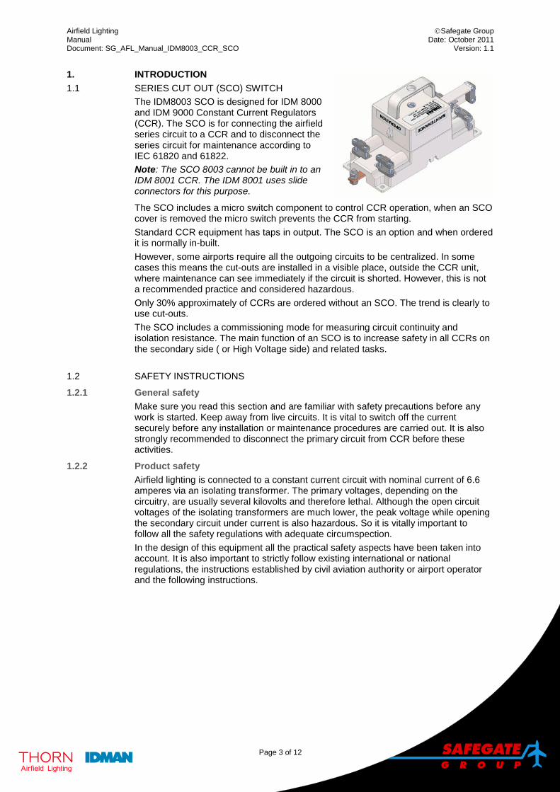
1. INTRODUCTION 1.1 SERIES CUT OUT (SCO) SWITCH
The IDM8003 SCO is designed for IDM 8000 and IDM 9000 Constant Current Regulators (CCR). The SCO is for connecting the airfield series circuit to a CCR and to disconnect the series circuit for maintenance according to IEC 61820 and 61822. Note: The SCO 8003 cannot be built in to an IDM 8001 CCR. The IDM 8001 uses slide connectors for this purpose.
The SCO includes a micro switch component to control CCR operation, when an SCO cover is removed the micro switch prevents the CCR from starting. Standard CCR equipment has taps in output. The SCO is an option and when ordered it is normally in-built. However, some airports require all the outgoing circuits to be centralized. In some cases this means the cut-outs are installed in a visible place, outside the CCR unit, where maintenance can see immediately if the circuit is shorted. However, this is not a recommended practice and considered hazardous. Only 30% approximately of CCRs are ordered without an SCO. The trend is clearly to use cut-outs. The SCO includes a commissioning mode for measuring circuit continuity and isolation resistance. The main function of an SCO is to increase safety in all CCRs on the secondary side ( or High Voltage side) and related tasks.
1.2 SAFETY INSTRUCTIONS
1.2.1 General safety Make sure you read this section and are familiar with safety precautions before any work is started. Keep away from live circuits. It is vital to switch off the current securely before any installation or maintenance procedures are carried out. It is also strongly recommended to disconnect the primary circuit from CCR before these activities.
1.2.2 Product safety Airfield lighting is connected to a constant current circuit with nominal current of 6.6 amperes via an isolating transformer. The primary voltages, depending on the circuitry, are usually several kilovolts and therefore lethal. Although the open circuit voltages of the isolating transformers are much lower, the peak voltage while opening the secondary circuit under current is also hazardous. So it is vitally important to follow all the safety regulations with adequate circumspection. In the design of this equipment all the practical safety aspects have been taken into account. It is also important to strictly follow existing international or national regulations, the instructions established by civil aviation authority or airport operator and the following instructions.
Airfield Lighting Safegate Group Manual Date: October 2011 Document: SG_AFL_Manual_IDM8003_CCR_SCO Version: 1.1
Page 4 of 12
1.2.3 Electrical maintenance Valid safety regulations must always be followed. Never carry out any maintenance or maintenance measures before the current is confirmed as safely disconnected. Use extreme caution when disconnecting or connecting high voltage primary connectors.
WARNING! PRIOR TO THE COMMENCEMENT OF WORK ALL ELECTRICAL SERVICES MUST BE ISOLATED FROM THE SUPPLY AND CONNECTED TO EARTH. FULL DETAILS OF THE WORK INVOLVED MUST BE GIVEN TO THE AUTHORISED PERSON RESPONSIBLE FOR THE ELECTRICAL ENGINEERING SERVICES AT THE AIRPORT WITH REGARD TO THE DURATION OF THE WORK AND SO ON. IT IS RECOMMENDED THAT PRIOR TO STARTING ANY CUTTING WORK THE NATURE AND LOCATION OF SERVICES SUCH AS CABLE DUCTS AND SO ON SHOULD BE IDENTIFIED. ANY INSTALLATION OR MAINTENANCE WORK SHOULD ONLY BE CARRIED OUT BY TRAINED AND EXPERIENCED PERSONNEL.
For more information, see www.safegate.com.
Airfield Lighting Safegate Group Manual Date: October 2011 Document: SG_AFL_Manual_IDM8003_CCR_SCO Version: 1.1
Page 5 of 12
1.3 TECHNICAL SPECIFICATIONS
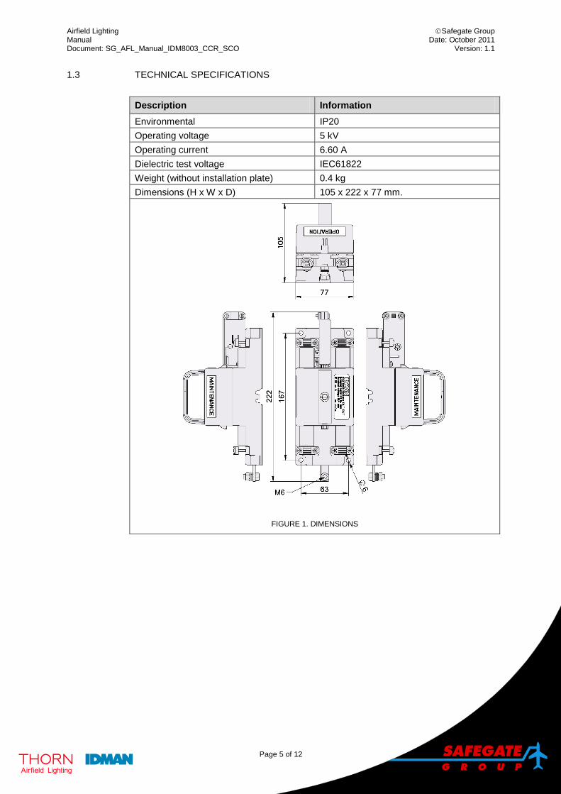
Description Information Environmental IP20 Operating voltage 5 kV Operating current 6.60 A Dielectric test voltage IEC61822 Weight (without installation plate) 0.4 kg Dimensions (H x W x D) 105 x 222 x 77 mm.
FIGURE 1. DIMENSIONS
Airfield Lighting Safegate Group Manual Date: October 2011 Document: SG_AFL_Manual_IDM8003_CCR_SCO Version: 1.1
Page 6 of 12
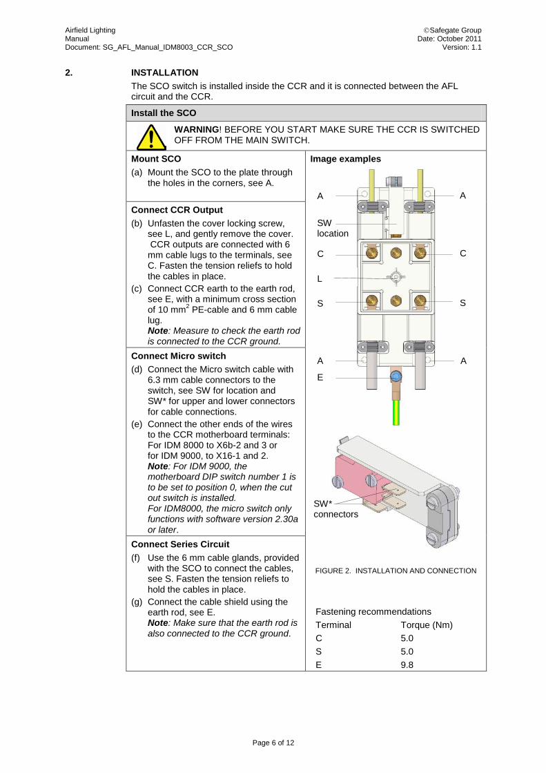
2. INSTALLATION The SCO switch is installed inside the CCR and it is connected between the AFL circuit and the CCR.
Install the SCO
WARNING! BEFORE YOU START MAKE SURE THE CCR IS SWITCHED OFF FROM THE MAIN SWITCH.
Mount SCO (a) Mount the SCO to the plate through
the holes in the corners, see A.
Image examples
FIGURE 2. INSTALLATION AND CONNECTION
Fastening recommendations Terminal Torque (Nm) C 5.0 S 5.0 E 9.8
Connect CCR Output (b) Unfasten the cover locking screw,
see L, and gently remove the cover. CCR outputs are connected with 6 mm cable lugs to the terminals, see C. Fasten the tension reliefs to hold the cables in place.
(c) Connect CCR earth to the earth rod, see E, with a minimum cross section of 10 mm2 PE-cable and 6 mm cable lug. Note: Measure to check the earth rod is connected to the CCR ground.
Connect Micro switch (d) Connect the Micro switch cable with
6.3 mm cable connectors to the switch, see SW for location and SW* for upper and lower connectors for cable connections.
(e) Connect the other ends of the wires to the CCR motherboard terminals: For IDM 8000 to X6b-2 and 3 or for IDM 9000, to X16-1 and 2. Note: For IDM 9000, the motherboard DIP switch number 1 is to be set to position 0, when the cut out switch is installed. For IDM8000, the micro switch only functions with software version 2.30a or later.
Connect Series Circuit (f) Use the 6 mm cable glands, provided
with the SCO to connect the cables, see S. Fasten the tension reliefs to hold the cables in place.
(g) Connect the cable shield using the earth rod, see E. Note: Make sure that the earth rod is also connected to the CCR ground.
A A
A A
E
L
C C
S S
SW location
SW* connectors
Airfield Lighting Safegate Group Manual Date: October 2011 Document: SG_AFL_Manual_IDM8003_CCR_SCO Version: 1.1
Page 7 of 12
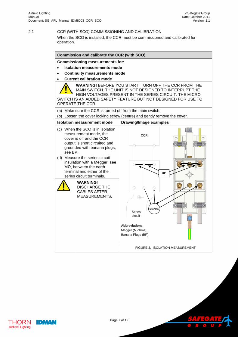
2.1 CCR (WITH SCO) COMMISSIONING AND CALIBRATION When the SCO is installed, the CCR must be commissioned and calibrated for operation.
Commission and calibrate the CCR (with SCO) Commissioning measurements for: • Isolation measurements mode • Continuity measurements mode • Current calibration mode
WARNING! BEFORE YOU START, TURN OFF THE CCR FROM THE MAIN SWITCH. THE UNIT IS NOT DESIGNED TO INTERRUPT THE HIGH VOLTAGES PRESENT IN THE SERIES CIRCUIT. THE MICRO
SWITCH IS AN ADDED SAFETY FEATURE BUT NOT DESIGNED FOR USE TO OPERATE THE CCR. (a) Make sure the CCR is turned off from the main switch. (b) Loosen the cover locking screw (centre) and gently remove the cover. Isolation measurement mode Drawing/Image examples (c) When the SCO is in isolation
measurement mode, the cover is off and the CCR output is short circuited and grounded with banana plugs, see BP.
(d) Measure the series circuit insulation with a Megger, see MΩ, between the earth terminal and either of the series circuit terminals.
CCR
Seriescircuit
M
Abbreviations: Megger (M ohms) Banana Plugs (BP)
WARNING! DISCHARGE THE CABLES AFTER MEASUREMENTS.
FIGURE 3. ISOLATION MEASUREMENT
BP
M ohms
Airfield Lighting Safegate Group Manual Date: October 2011 Document: SG_AFL_Manual_IDM8003_CCR_SCO Version: 1.1
Page 8 of 12
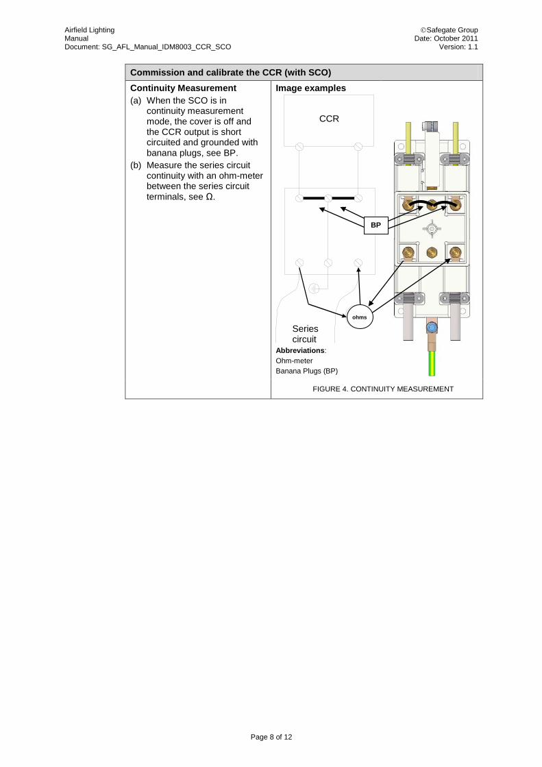
Commission and calibrate the CCR (with SCO) Continuity Measurement (a) When the SCO is in
continuity measurement mode, the cover is off and the CCR output is short circuited and grounded with banana plugs, see BP.
(b) Measure the series circuit continuity with an ohm-meter between the series circuit terminals, see Ω.
Image examples
CCR
Seriescircuit
Abbreviations: Ohm-meter Banana Plugs (BP)
FIGURE 4. CONTINUITY MEASUREMENT
BP
ohms
Airfield Lighting Safegate Group Manual Date: October 2011 Document: SG_AFL_Manual_IDM8003_CCR_SCO Version: 1.1
Page 9 of 12
Commission and calibrate the CCR (with SCO)
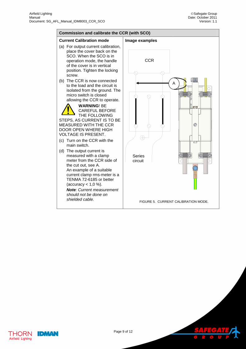
Current Calibration mode (a) For output current calibration,
place the cover back on the SCO. When the SCO is in operation mode, the handle of the cover is in vertical position. Tighten the locking screw.
(b) The CCR is now connected to the load and the circuit is isolated from the ground. The micro switch is closed allowing the CCR to operate.
WARNING! BE CAREFUL BEFORE THE FOLLOWING
STEPS, AS CURRENT IS TO BE MEASURED WITH THE CCR DOOR OPEN WHERE HIGH VOLTAGE IS PRESENT. (c) Turn on the CCR with the
main switch. (d) The output current is
measured with a clamp meter from the CCR side of the cut out, see A. An example of a suitable current clamp rms-meter is a TENMA 72-6185 or better (accuracy < 1,0 %). Note: Current measurement should not be done on shielded cable.
Image examples
CCR
Seriescircuit
FIGURE 5. CURRENT CALIBRATION MODE.
A
Airfield Lighting Safegate Group Manual Date: October 2011 Document: SG_AFL_Manual_IDM8003_CCR_SCO Version: 1.1
Page 10 of 12
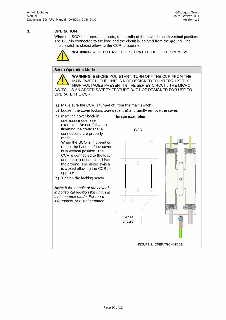
3. OPERATION When the SCO is in operation mode, the handle of the cover is set in vertical position. The CCR is connected to the load and the circuit is isolated from the ground. The micro switch is closed allowing the CCR to operate.
WARNING! NEVER LEAVE THE SCO WITH THE COVER REMOVED.
Set to Operation Mode
WARNING! BEFORE YOU START, TURN OFF THE CCR FROM THE MAIN SWITCH. THE UNIT IS NOT DESIGNED TO INTERRUPT THE HIGH VOLTAGES PRESENT IN THE SERIES CIRCUIT. THE MICRO
SWITCH IS AN ADDED SAFETY FEATURE BUT NOT DESIGNED FOR USE TO OPERATE THE CCR. (a) Make sure the CCR is turned off from the main switch. (b) Loosen the cover locking screw (centre) and gently remove the cover. (c) Inset the cover back in
operation mode, see examples. Be careful when inserting the cover that all connections are properly made. When the SCO is in operation mode, the handle of the cover is in vertical position. The CCR is connected to the load and the circuit is isolated from the ground. The micro switch is closed allowing the CCR to operate.
(d) Tighten the locking screw.
Note: If the handle of the cover is in horizontal position the unit is in maintenance mode. For more information, see Maintenance.
Image examples
CCR
Seriescircuit
FIGURE 6. OPERATION MODE
Airfield Lighting Safegate Group Manual Date: October 2011 Document: SG_AFL_Manual_IDM8003_CCR_SCO Version: 1.1
Page 11 of 12
4. MAINTENANCE 4.1 PREVENTATIVE MAINTENANCE
It is recommended to periodically check the SCO, minimum once a year: • Visually check the unit for external and internal damage. • Clean the surfaces of the unit. • Check the tightening of the cable connections and also the micro switch cabling. • Check the function of the micro switch by:
• Setting the device to maintenance mode. Note: Turning the CCR locally to step 1, from the rotary switch, should not start it.
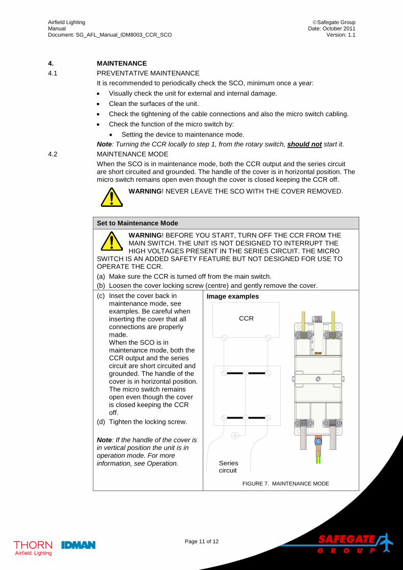
4.2 MAINTENANCE MODE When the SCO is in maintenance mode, both the CCR output and the series circuit are short circuited and grounded. The handle of the cover is in horizontal position. The micro switch remains open even though the cover is closed keeping the CCR off.
WARNING! NEVER LEAVE THE SCO WITH THE COVER REMOVED.
Set to Maintenance Mode
WARNING! BEFORE YOU START, TURN OFF THE CCR FROM THE MAIN SWITCH. THE UNIT IS NOT DESIGNED TO INTERRUPT THE HIGH VOLTAGES PRESENT IN THE SERIES CIRCUIT. THE MICRO
SWITCH IS AN ADDED SAFETY FEATURE BUT NOT DESIGNED FOR USE TO OPERATE THE CCR. (a) Make sure the CCR is turned off from the main switch. (b) Loosen the cover locking screw (centre) and gently remove the cover. (c) Inset the cover back in
maintenance mode, see examples. Be careful when inserting the cover that all connections are properly made. When the SCO is in maintenance mode, both the CCR output and the series circuit are short circuited and grounded. The handle of the cover is in horizontal position. The micro switch remains open even though the cover is closed keeping the CCR off.
(d) Tighten the locking screw.
Note: If the handle of the cover is in vertical position the unit is in operation mode. For more information, see Operation.
Image examples
CCR
Seriescircuit
FIGURE 7. MAINTENANCE MODE
Airfield Lighting Safegate Group Manual Date: October 2011 Document: SG_AFL_Manual_IDM8003_CCR_SCO Version: 1.1
Page 12 of 12
Safegate Group offers solutions for increased safety, efficiency and environmental benefits to airports around the world. The company was founded in 1973 and has its headquarters in Malmö, Sweden. Safegate Group has over 70 partners around the globe in order to be close to its customers. The latest members of Safegate Group, Thorn AFL and Idman, have both over 40 years of experience in airfield lighting solutions for airports and heliports worldwide. Safegate Group´s complete range of products and services, a “one-stop shop”, provides solutions to customers and airborne travellers around the globe.
For more contact information and details: www.safegate.com
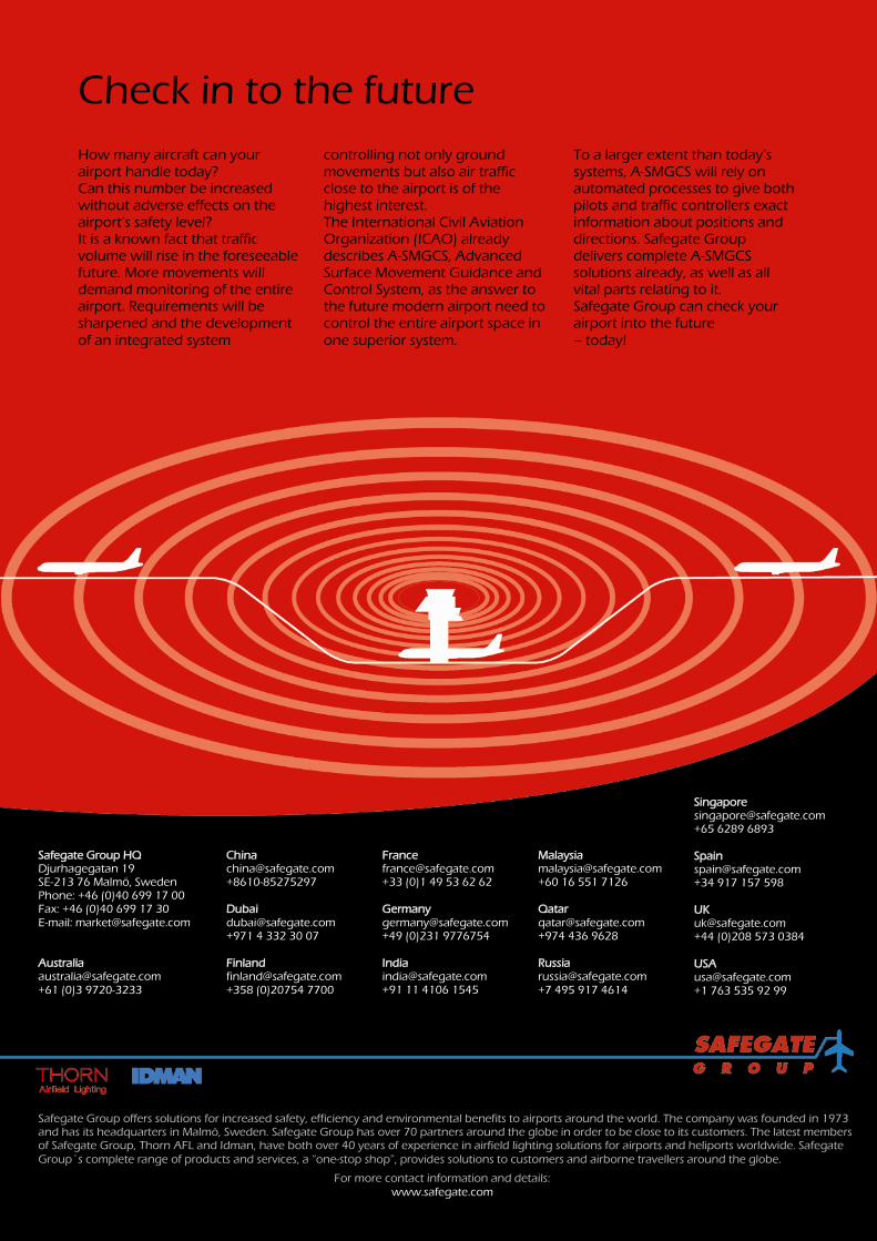
Check in to the future How many aircraft can your airport handle today? Can this number be increased without adverse effects on the airport’s safety level? It is a known fact that traffic volume will rise in the foreseeable future. More movements will demand monitoring of the entire airport. Requirements will be sharpened and the development of an integrated system
controlling not only ground movements but also air traffic close to the airport is of the highest interest. The International Civil Aviation Organization (ICAO) already describes A-SMGCS, Advanced Surface Movement Guidance and Control System, as the answer to the future modern airport need to control the entire airport space in one superior system.
To a larger extent than today’s systems, A-SMGCS will rely on automated processes to give both pilots and traffic controllers exact information about positions and directions. Safegate Group delivers complete A-SMGCS solutions already, as well as all vital parts relating to it. Safegate Group can check your airport into the future – today!
Safegate Group HQ Djurhagegatan 19 SE-213 76 Malmö, Sweden Phone: +46 (0)40 699 17 00 Fax: +46 (0)40 699 17 30 E-mail: [email protected] Australia [email protected] +61 (0)3 9720-3233
China [email protected] +8610-85275297 Dubai [email protected] +971 4 332 30 07 Finland [email protected] +358 (0)20754 7700
France [email protected] +33 (0)1 49 53 62 62 Germany [email protected] +49 (0)231 9776754 India [email protected] +91 11 4106 1545
Malaysia [email protected] +60 16 551 7126 Qatar [email protected] +974 436 9628 Russia [email protected] +7 495 917 4614
Singapore [email protected] +65 6289 6893 Spain [email protected] +34 917 157 598 UK [email protected] +44 (0)208 573 0384 USA [email protected] +1 763 535 92 99