advanced svc models for newton-raphson load flow and newton optimal power flow studies
TRANSCRIPT
IEEE TRANSACTIONS ON POWER SYSTEMS. VOL. 15. NO. 1, FEBRUARY 2000 129
Advanced SVC Models for Newton-Raphson Load Flow and Newton Optimal Power Flow Studies
H. Amhriz-PBrez, E. Acha, and C. R. Fuerte-Esquivel
Abstract-Advanced load flow models for the static VAR cum- pensator (SVC) are presented in this paper. The models are incor- porated into existing load flow (LF) and optimal power flow (OPF) Newton algorithms. Unlike SVC models available in open litera- ture, the new models depart from the generator representation of the SVC and are based instead on the variable shunt susceptance concept. In particular, a SVC model which uses the firing angle as the state variable provides key information for cases when the load flow solution is used to initialize other power system applied- tions, e.g., harmonic analysis. The SVC state variables are com- bined with the nodal voltage magnitudes and angles of the net- work in a single frame-of-reference fur U unified, iterative solution through Newton methods. Both algorithms, the LF and the OPF exhibit very strong convergence characteristics, regardless of net- work size and the number of controllable devices. Results are pre- sented which demonstrate the prowess of the new SVC models.
Index Terms-FACTS, Newton method, OPF, SVC, voltage con- trol.
I. INTRODUCTION
N ELECTRIC power systems, nodal voltages are signifi- I cantly affected by load variations and by network topology changes. Voltages can drop considerably and even collapse when the network is operating under heavy loading. This may trigger the operation of under-voltage relays and other voltage sensitive controls, leading to extensive disconnection of loads and thus adversely affecting consumers and company revenue. On the other hand, when the load level in the system is low, over-voltages can arise due to Ferranti effect. Capac- itive over-compcnsation and over-excitation of synchronous machines can also occur [I]. Over-voltages cause equipment failures due to insulation breakdown and produce magnetic saturation in transformers, rcsulting in harmonic generation. Hence, voltage magnitudc throughout the network cannot deviate significantly from its nominal value if an efficient and reliable operation of the power system is to bc achieved.
Voltage regulation is achieved by controlling the production, absorption and flow of reactive power throughout the network. Reactive power flows are minimized so as to reduce system losses. Sources and sinks of reactive power, such as shunt ca- pacitors, shunt reactors, rotating synchronous condensers and SVC’s are used for this purpose. Shunt capacitors and shunt
Manuscript received December 8, 1997; revised September 30,1998. H. Am- briz-P6rez and C. R. Fuerte-Esqoivel were financially supported hy the Consejo Nacional de Ciencia y Tecnologiil, MCxica.
H. Ambriz-PCrw and E. Acha are with the Department of Electronics and Electrical Engineering, University of Glasgow, Scotland, UK.
C. R. Fuerte-Esquivel is with the Departamentu de Ingenieria EICctrica y Electrhica, Institute Tccnol6gico de March , Mexico.
Publishcr Item Identifier S 0885-8950(110)01862-9.
reactors are either permanently connected to the network, or switched on and off according to operative conditions. They only provide passive compensation since their productionlab- sorption of reactive power depends on their ratings and local bus voltage level. Conversely, the reactive power suppliedabsorbed by rotating synchronous condensers and SVC’s is automatically adjusted, attempting to maintain fixed voltage magnitude at the connection points.
This paper focuses on the development of new SVC models and their implementation in Newton-Raphson load flow and op- timal power flow algorithms. The SVC is taken to be a con- tinuous, variable-shunt susceptance, which is adjusted in order to achieve a specified voltage magnitude while satisfying con- straint conditions.
Two models are presented in this paper: I ) SVC total susceptance model. A changing susceptance
R,,, represents the fundamental frequency equivalent susceptance of all shunt modules making up the SVC. This model is an improved version of SVC models currently available in open literature.
2) SVC firing angle model. The equivalent susceptance Be, which is function of a changing firing angle (Y, is made up of the parallel combination of a thyristor controlled re- actor (TCR) equivalent admittance and a fixcd capacitive susceptance. This is a new and more advanced SVC rep- resentation than those that are currently available in open literature. This model provides information on the SVC firing angle required to achieve a given level of compen- sation.
The SVC models have been tested in a wide range of power networks of varying sizes. Io this paper, an actual power network consisting of 26 generators, 166 buses, 108 transmission lines and 128 transformers is used as the test network.
11. STATIC VAR COMPENSATOR‘S EQUIVALENT SUSCEPTANCB
Advances in power electronics technology together with so- phisticated control methods made possible the development of fast SVC‘s in the early 1970’s. The SVC consists of a group of shunt-connected capacitors and reactors banks with fast control action by means of thyristor switching. From the operational point of view, the SVC can be secn as a variable shunt reac- tance that adjusts automatically in response to changing system operative conditions. Depending on the nature of the equivalent SVC’s reactance, i.e., capacitive or inductive, the SVC draws either capacitive or inductive current from the network. Snit- able control of this equivalent reactance allows voltage magni- tude regulation at the SVC point of connection. SVC’s achieve
0885-8950/00$10.00 0 2000 IEEE
IBSS 1IlANSACTIONS ON POWER SYSWMS, VOL. I S , NO. I , FEBRUARY 20110
: 0.0 0 \ -
XC fi' - - -
' A . , 90 100 110 120 1 140 150 160 170 180
Firing angle (degrees)
Fig. I . SVC stmctiirc.
60
40 - E 6 - 20
4 o - r + -20
.f -40
U " c
n
0 c3 -
LT w
-
-
-
- -
-
Reactive region J -60 1 , , , , , , , ,
90 100 110 120 130
Capacitive region
40 150 160 170 180 Firing angle (degrees)
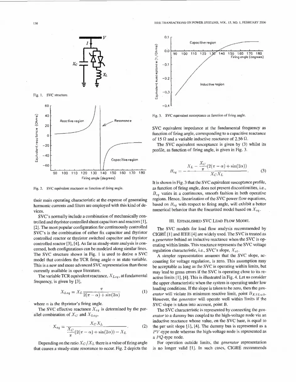
Fig. 2.
their main operating Characteristic at the expense of generating harmonic currents and filters are employed with this kind of de- vices.
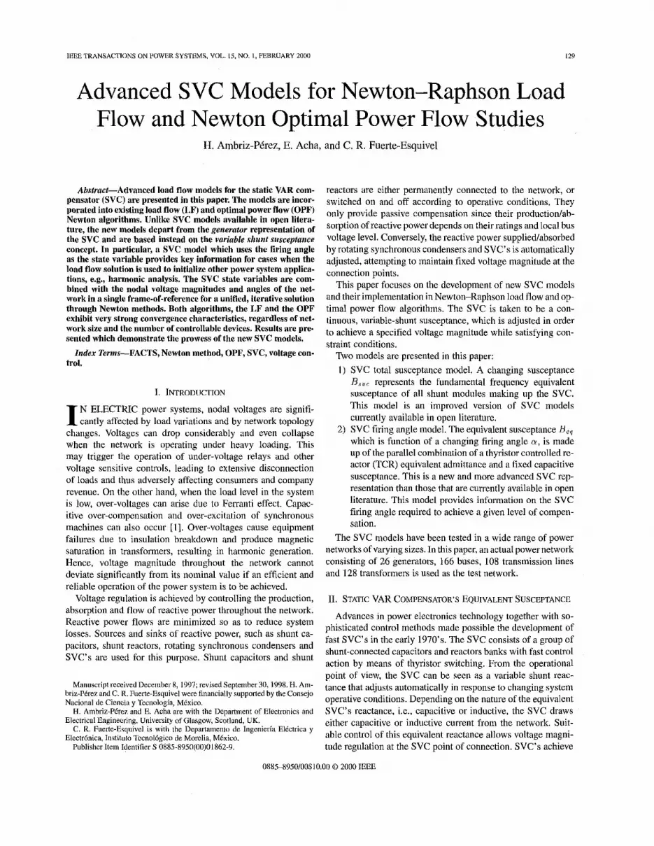
SVC's normally include a combination of mechanically con- trolled and thyristor controlled shunt capacitors andreactors [U, [Z]. The most popular configuration for continuously controlled SVC's is the combination of either fix capacitor and thyristor controlled reactor or thyristor switched capacitor and thyristor controlled reactor [3], [41. As far as steady-stale analysis is con- cerned, both configurations can be modeled along similar lines. The SVC structure shown in Fig. I is used to derive a SVC model that considers the TCR firing angle (Y as state variablc. This is a new and more advanced SVC representation than those currently available in open literature.
The variable TCR equivalent reactance, X.ce,, at fundamental frequency, is given by [31,
SVC equivalent reactancc as function of firing angle.
wherc IY is the thyristor's firing angle.
allel combination of X<; and XL,,. The SVC effective reactance X,, is determined by the par-
Depending on the ratio Sc / X J ~ there is a value of firing angle that causes a steady-state resonance to occur. Fig. 2 depicts the
0.1 r
r - Capacitive region I
-0.4 1
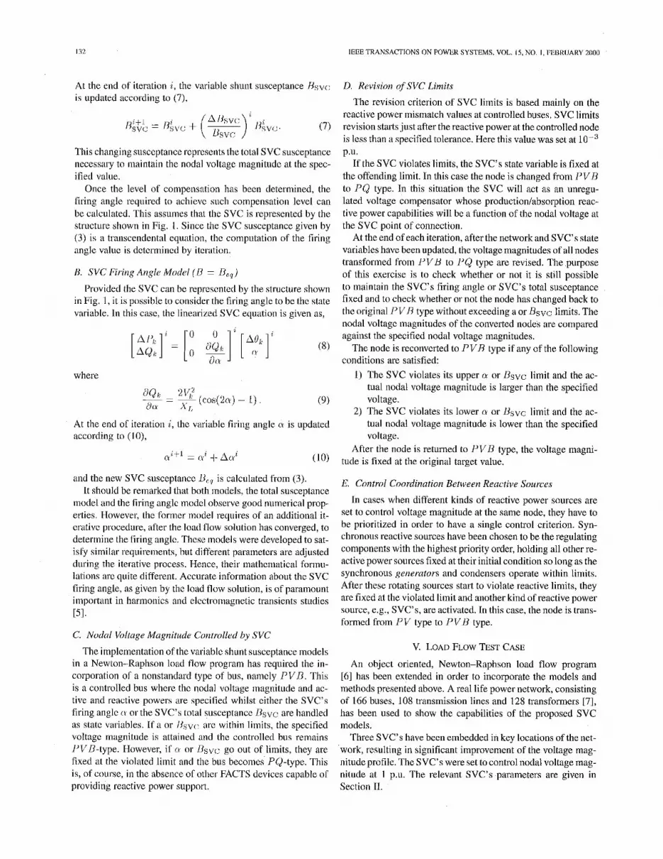
Fig. 3. SVC equivalent susceptance as functiao offiring angle,
SVC equivalent impedance at the fundamental frequency as function of firing angle, corresponding to a capacitive reilctance of 15 62 and a variable inductive reactance of 2.56 R.
The SVC equivalent susceptance is given by (3) whilst its profile, as function of firing angle, is given in Fig. 3.
It is shown in Fig. 3 that the SVC equivalent susceptance profile, as function of firing angle, does not present discontinuities, i.e., O,, varies in a continuous, smooth fashion in both operative regions. Hence, linearization of the SVC power flow equations, based on U,, with respect to firing angle, will exhibit a better numerical behavior than the linearized model based on X,, .
111. ESTABLI~HKI SVC LEAD FLOW MODEL
The SVC models for load flow analysis recommended by C E R E 111 and IEEE [4] are widely used. The SVC is treated as iigenerator behind an inductive reactance when the SVC is op- erating within limits. This reactance represents the SVC voltage rcgulation characteristic, i.e., SVC's slope, X a t .
A simpler representation assumes that the SVC slope, ac- counting for voltage regulation, is zero. This assumption may be acceptable as long as the SVC is operating within limits, but may lead to gross errors if the SVC is operating close to its re- active limits [ 11, 141. This is illustrated in Fig. 4. Let us consider the upper characteristic when the system is operating under low loading conditions. If the slope is taken to be zero, then the gen. erator will violate its minimum reactive limit, point H x . s ~ = o . However, the generator will operate well within limits if the SVC slope is taken into account, point B.
The SVC characteristic is represented by connecting the gen- erator to a dummy bus coupled to the high-voltage node via an inductive reactance whose value, on the SVC base, is equal to the per unit slope [ I ] , [4]. The dummy bus is represented as a PV-type node whereas the high-voltage node is represenlcd as a PQ-type node.
For operalion outside limits, the generutur represeutation is no longer valid [I] . In such caws, C E R E recommends

AMBRIZPkREZ ctnl.: ADVANCE0 SVC MOUE1.S FOR NEWTON-RAPHSON LOAD FLOW AND NEWTON OPTIMAL POWER FLOW STUDIES 131
v 4 1 1 2 r
1 1 0 -
1 0 8 -
&? 106- ' 104
- I e g 100
1 0 2 -
System reactive
characteristics I
- Generator model /' --- Susceptonce model //
/' , , -
-
Capacitive I ratine Ir -
Inductive rating
b Is IMlN 0 IM4X
Fig. 4. characteristic.
Comparison between actual a n d idcalized SVC voltage c~irrcnt
changing the SVC representation to a fixed reactive suscep- tance. This combined model yields accurate results. However, both representations require a different number of nodes. The generator uses two or three nodes [4] whereas the fixed susceptance uses only one node [ I ] . In Newton-Raphson load flow implementations this may require Jacobian reordering and redimensioning during the iterative solution. Also, extensive checking becomes necessary in order to verify whether or not the SVC can return to operation inside limits.
It must be remarked that for operation outside limits, it is im- portant to model the SVC as a susceptance and not as a gener- ator set at its violated limit, QvioliLtcc~. Ignoring this point will lead to inaccurate results. The reason is that the amount of reac- tive power drawn by the SVC is given by the product of the fixed susceptance, nfiXed, and the nodal voltage magnitude, V, , Since V, is a function of network operating conditions, the amount of reactive power drawn by the fixed susceptance model may differ from the reactive power drawn by the generator model, i.e.
Qviolalcd f - Rfixcd vb2. (4)
This point is exemplified in Fig. 5 where the reactive power output of the generator was set at 100 MVAR. This value is con- stant as it is voltage independent. The result given by the con- stant susceptance model varies with nodal voltage magnitude. A voltage range of 0.95-1 .OS was considered. A susceptance value of 1 p a . on a 100 MVA base was used.
The SVC model presented above, based on the generator and fixed susceptance representations, is better handled as a suscep- tance model only. It takes the form of a variable susceptance when the SVC is operating within reactive limits and it takes the form of a fixed susceptance otherwise.
Moreover, a new and more advanced SVC representation then becomes possible, wherc the thyristor firing angle mechanism is represented explicitly as a function of network operating condi- tions. In contrast to all SVC models proposed heretofore, this model assesses ranges of firing angle operation leading to in- trinsic, internal SVC resonances. Both representations, the total susceptance and the firing angle models, are presented below.
- Fig. 5.1. Variable shunt susceptance.
IV. NEW SVC LOAD FLOW MODELS
In practice the SVC can be seen as an adjustable reactance with either firing angle limits or reactance limits. The circuit shown in Fig. 5.1 is used to derive the SVC's nonlinear power equations and the linearized equations required by Newton's method.
In general, the transfer admittance equation for the variable- shunt compensator is,
/ = jov, (4)
and the reactive power equation is,
Q , = -v;u. (3
Linearized, positive sequence SVC models for Newton-Raphson load flows are presentcd in this section whereas SVC models optimal power flows are presented in Scction V.
A. SVC Total Suscnptance Model ( H = BSVC;)
total susceptance BSVC is taken to be the state variable, The linearized equation ofthe SVCis given by (6), wherc the
I12 IEEE TRANSACTIONS ON POWhK SYSTEMS, VOL IS. NO I , rEBRUARY 2000
At the end of iteration i, the variable shunt susceptance Hsvt: i q updated according to (7),
This changing susceptance represents the tolal SVC susceptance necessary to iiiaintsin the nodal voltage magnitude at the spec- ified value.
Once the level of compensation has been determined, the firing angle requircd to achievc such compensation level can be calculated. This assumes that the SVC is represented by the slriicture shown in Fig. 1. Since the SVC susceptance given hy (3) is a transcendental equation, tlie coinpulation of the tiring angle valirc is dctcrmincd by iteration.
R. SVC Firing Angle Model ( U = De,) Provided the SVC can be represented by the structure shown
in Fig. 1, it is possihle to consider the firing angle to be the state variable. In this casc, the lincarized SVC equation is given as,
where
At the end oC iteration i , lhc variahle firing angle 0 is updated according to ( I 0),
(10) nitl ~
~ i t i 4- ACV‘
and the new SVC susceptancc 1Lq is calculated from (3). It should be remarked that both models, the total susceptance
model and the tiring anglc tnodcl obscrve good numerical prop- erties. However, the Cortncr model requires of an additional it- crativc procedure, after the load flow solution has converged, to determine the tiring angle. These models were developed to sat- isly similar requirements, hut different parametcrs are adjusted during the iterative process. Hence, heir inathcniatical formu- lalions arc quite different. Accurate information about the SVC tiring angle, as given by the load tlow solution, is of paramount important in harmonics and clcctromagnetic transients studies ~51.
C. Nodal Voltage Magnitude Controlled by SVC The implemeiitation of the variahlc shunt susceptance models
in a Newlon-Raphson load flow program has required the in- corporation of a nonstandard type of bus, namcly P V B . This is a controlled bus where the nodal voltage inagnitiide and ac- tive and rcactive powers are specified whilst either the SVC’s firing anglc (I or the SVC’s total susceptance Usvc are handled as state variables. If a or l l s ~ ~ ~ ~ arc within limits, the specified voltagc magnitude is atlained and the coiitrolled bus remains I’VD-type. However, i i CY or Dsv,: go out of limits, they are fixed at the violatcd limit and tlie bus becomes’ PCJ-type. This is, of course, i n the absence of other FACTS devices capable o l providing reactive power support.
D. Revision @SVC Limits The revision criterion of SVC limits is based mainly on the
rcactive power mismatch values at controlled buses. SVC limits revision startsjust after the reactive power at the controlled node is lcss than a specified tolerance. Hcrc this value was set at p.u.
If the SVC violates limits, the SVC’s state variable is fixed at the offending limit. In this case the node is changed from PVB to PQ type. In this situation the SVC will act as an unregu- lated voltage compensator whose productionhibsorption reac- tive power capabilities will be a function of the nodal voltage at the SVC point of connection.
At the end of each iteration, after the network and SVC’s state variables have been updated, the voltage magnitudes of all nodes transformed from I’VU to I’& type are revised. The purpose of this exercise is to check whether or not it is still possible to maintain the SVC’s firing angle or SVC’s total susceptance fixed and to check whether 01’not the node has changed back to thc original P V R type without exceeding a or Bsvc: limits. The nodal voltagc magnitudes of the converted nodes are compared against the specified nodal voltage magnitudes.
The node is recoiivcrted to P V R type if any of the following conditions are satisfied:
I ) The SVC violates its upper n or Dsvc limit and the ac- tual nodal voltage magnitude is larger than the specified voltage.
2) The SVC violates its lower (Y or Usvc limit and the ac- tual nodal voltage magnitude is lower than ‘the specified voltage.
After the node is returned to P V B type, the voltage magni- tude is fixed at the original target value.
E. Control Coordination Between Reactive Sources
In cases when different kinds of reactive power sources are set to control voltage magnitude at the same node, they have to be prioritized in order to have a single control criterion. Syn- chronous reactive sources have been chosen to be the regulating components with the highest priority order, holding all other re- active power sources fixed at their initial condition so long as the synchronous Renerators and condensers operate within limits. After these rotating sources start to violate reactive limits, they arc fixed at the violated limit and auother kind of reactive power source, e.g., SVC’s, are activated. In this case, the node is trans- formed from PV type to PVH type.
v. LOAD FLOW TEST CASE
An ohject oriented, Newton-Raphson load flow program [61 has been extended in order to incorporate the models and methods presented above. A real life power network, consisting of 166 buses, 108 transmission lines and 128 transformers [7], has been used to show the capab es of the proposcd SVC models.
Three SVC’s have been embedded in key locations ofthe net- ‘work, resulting in significant improvement of the voltage mag- nitude profile. The SVC’s were set to control nodal voltage mag- nitude at I p.u. The relevant SVC’s parameters are given in Section 11.
133 AMRKIZPEREZ eta!.: ADVANCE0 SVC MODELS FOR NF.WTON~RAP1iSON LOAD Fl.OW AND NEWTON OPTIMAL POWER PLOW STUDIFS
static VAR susceptance Compensator Model
Firing angle model
SVCl s v c 2 s v c 3
L- 1 2 3 4
lteroiions
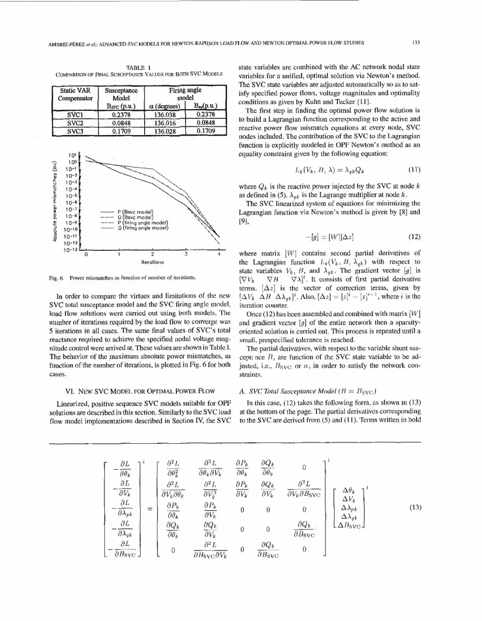
Fig. 6. Power mismatches as function of number of iterationb.
In order to compare the virtues and limitations of the new SVC total susceptance model and the SVC firing anglc model load flow solutions were carried out using both models. The number of iterations required by the load flow to converge war 5 iterations in all cases. The same final values of SVC's total reactance required to achieve the specified nodal voltage mag nitude control were arrived at. These values are shown in Tablc I
Bsvc @.U,) a (degrees) Bdp.u.) 0.2378 136.038 0.2378 0.0848 136.016 0.0848 0.1709 136.028 0.1709
state variables are combined with the AC nctwork nodal state. variables for a unified, optimal solution via Newton's method. The SVC state variables are adjusted antoinatically so as to sat- isfy specified power flows, voltage magnitudes and optimality conditions as given by Kuhn and Tuckcr [ I l l .
The first stcp in finding thc optimal power flow solution is to build a Lagrangian function corresponding to the active and reactive power flow mismatch equations at every nodc, SVC nodes included. The contribution of the SVC to the Lagrangian function is cxplicitly modeled in OPF Newton's method as an equality constraint given by the following equation:
h(h, A) = XqrBr (1 1)
where &e is the reactive power injected by the SVC at nodc le as defined in ( 5 ) . X q e is the Ltigrange multiplier at node le.
The SVC linearized systcm of equations for minimizing the Lagrangian function via Newton's method is given by [SI and PI,
[1/1 2 [WI[Azl (12)
where matrix [ W ] contains second partial derivatives of the Lagrangian function / , h ( V h , 13, Xqk) with respect to statc variables V,, H , and X q r . The gradicnt vector [g] is [VVk VH VAJt. It consists of first partial derivative tcrms. [Az] is the vector of corrcction terms, given by [Allh AR Also, [Az] = [%Ii - [z]"', where i is the itcration counter.
Once (12) has been assembled and combined with matrix [W] and gradient vector [g] of the entirc network then a sparsity- oriented soltition i s carried out. This process is repeated until a small, prespecified tolerance is reached.
The Dartial derivativcs, with resoect to the variable shunt sus- The behavior of the lnaximum absolute power mismatches, as function of the number of iterations, is plotted in Fig. 6 for both cases. straints.
q t : rice /?, are function of the svc State variable to be ad- justed, i.c., Ilsvc: or o, in order to satisfy the network con-
VI. NEW SVC MODEL FOR OPTIMAL POWER FLOW A. SVC ?btu1 Susceptance Model ( H = I&; J In this casc, (12) takes the following form, as shown in (13)
at the bottom of the page. The partial derivativcs corresponding to the SVC are derivcd from ( 5 ) and ( I I). Terms written in bold
Linearized, positive sequence SVC models suitable for OPF solutions are described in this section, Similarly to the SVC load flow model implcmentations described in Section IV, the SVC
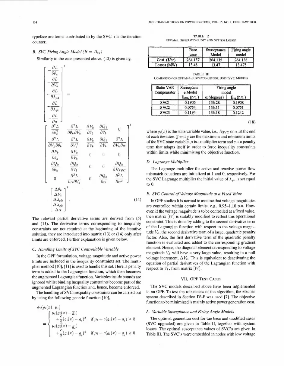
134
Base C a S e
Losses (MW) 13.48 cost (Sh) 264.137
IEEE TRANSACTIONS ON POWBK SYSTEMS, VOL. 15, NO. I . PCDRUARY znnn
Susceptance Firing angle Model model
264.135 264.136 13.47 13.475 - aL - I
a I, a C% BL ilX,i
d L
-~ asi,
--
- -- -
-- a& aL -_
- act -
(14)
Compensator
svc 1 s v c 2 svc3
The relevant partial derivative terms are derived from ( 5 ) and ( I I). The derivative terms corrcsponding to ineqtiality constraints are not required at the beginning of the iterative solution, they are introduced into matrix (I 3) or (14) only after limits arc enforced. Further explanation is given below.
C. Handling Limits of SVC Controllable Variable In the OPF forinnlation, voltage magnitude and active power
limits are included in the inequality constraints set. The inulti- plier method 1101, [ I I] is used to handle this set. Here, a penalty term is added to the Lagrangian function, which then becomes the augmented Lagrangian function. Variables inside bounds are ignored whilst binding ineqtiality constraints become part of the augmented Lagrangian function and, hence, hecome enforced.
The handling of SVC inequality constraints can be carried out by using the following generic function 1101,
di(Si(Xj, lJi j
3;)' i f p i + c ( g i ( z ) - B ~ ) >_ o
+,(Si(xj - G ) ~ i fp i + c(s;(z) - -% 9 . ) 2 U c
e Model model Bsvc (P.U.) a (degrees) Blb (P.U.)
0.1905 136.28 0.1908 0.0754 136.11 0.0751 0.1194 136.18 0.1242
TAULE If OWIMAI. GENERATION COST AND SYSrF.M LOSSES
TABLE Ill COMPARSION OF OPTIMAI. SUSCEPTANCBS FOR BOT?[ SVC MOIX1.S
I Staticvm I ~usceptanc I Firing angle I
( 1 8)
wheregi(x) isthestatevariablevalue, i.e., Hsvc orru,attheend of each iteration. 4 and g are the maximum and minimum limits of the SVC state variable. p is a multiplier term and c is a pcnalty term that adapts itself in order to force inequality constraints within limits while minimising the objective function.
D. Lugrange Multiplier
The Lagrange multiplier for active and reactive powcr flow mismatch equations are initialized at 1 and 0, respectively. For the SVC Lagrangc multiplier the initial valiic of A,,, is set equal to 0.
E. SVC Control of Voltage Magnitude ut a Fixed Value In OPF studies i t is normal to asstime that voltage magnitudes
arc controlled within certain limits, e.g., 0.95-1.10 p.u. How- ever, if the voltage magnitude is to he controlled at a Fixed value, then matrix [W] is suitably modified to reflect this opcrational constraint. This is done by adding to the second derivative term of the Lagrangian function with respect to the voltage inagni- tude Vi, the second derivative term of a large, quadratic penalty factor. Also, the first derivative term of the quadratic pcnally function is evaluated and added to the corresponding gradient element. Hence, the diagonal element corresponding to voltage magnitude Vi, will have a very large value, resulting i n a null voltage increment, A l/k. This is equivalent to deactivating the equation of partial derivatives of the Lagrangian function with respect to K:, from matrix [I&'].
VI1. OPF TRST CASES
The SVC models described above have been implemented in an OPE To test the robustness of the algorithm, the electric system described in Section IV-F was used [7]. The objective function to be minimized is mainly active power generation cost.
A. Variable Susceptance and Firing Angle Models The optimal generation cost for the base and modified cases
(SVC upgraded) are given in Table 11, together with system losses. The optimal susceptance values of SVC's are given in Table 111. The SVC's were embedded in nodes with low voltage

AMBRIZ-PBRBZ ADVANCED svc MODEIS FOR NEWTON-RAPHSON MAD FLOW AND NEWTON OPTIMAL POWER FLOW STUDIES 135
32 3 0 -
YI 28-
3 2 4 -
a 2 0 . %!
26-
g 22-
z 1 8 - ' 1 6 - 14
1 300 - 2 .- g 290 -
.. s 280 -
!? 2
" + D t 270 -
260 -
SVC toto1 susceptanre model a $ 2 5 0 . SVCfiring ongle model ?.
-
-
1 2 3 4 5 6 4' 2 4 C L ' ' ' ' '
0 lterotions
Fig. 7 . Active power generiltion cos1 p r ~ f i l ~ s
34 1 Base case N C total susceptonce model
- . SVC iiring ongle model \ ---
3 4 5 6 Iterations
1 2 5 r - 7 ' 1 " " " '
Fig. X.
magnitudes and, as expected, the voltage profiles improved in such nodes (not shown). SVC voltage magnitudes were sub- jected to inequality constraints within 0.95-1.10 p a .
In all cases, solutions were achieved in 6 iterations. Fig. 7 shows active power generation cost as a function of the iter- ation number whilst Fig. 8 shows the active power losses as a function of the iteration number. Oscillations can be observed in the cost and losses profiles in the early iterations. This is due to large variations in both the active set constraint and the penalty weighting factors during the early iterations.
The SVC control specifications used above werc modified in order to assess the SVC inodcl capability to control voltage magnitude at fixed values. In this case the SVC's were set to control voltage magnitudes at I p.u.
The optimal SVC state variable values for both models, i.c. susceptance and firing angle models, are shown in Table IV. As expected, these values difler from those given in Table 111.
It is interesting to note that both SVC operating control modes, i.e. fixed and free, produce similar active power gener- ation cost and active power losses.
B. Transmission Lusses Minimization The algorithm is now applied to investigate the problem of
transmission loss tniniinimtion. The active power cost opti- mization and the transmission losses minimization procedures
Active puwer lasses profiles.
TABLE 1V COMPARISON OmlMAL SUSCEPPANCE FOR BOTH SVC MODELS
Firing angle
0.2150 136.32 0.2151 0.0741 136.10 0.0741 0.1376 136.20 0.1377
TABLE V OI'TIMAL GENERATION COST ANU SYSTEM LOSSES
Base Susceptance Firingangle case Model model
cost (Sib) 264.136 264.134 264.134 I 7 475 1 1 A K l
1.018L-12.23 1.021L-12.23 I I
&40'00 6 1 4 1 . 7 3 6
+ Fig. 9. the case when u p p ~ limits have bcen reached.
Comparison between the g e w m o v and susceptiince SVC ,nod& for
are carried out sequentially. Transmission loss minimization is amenable to a redistribution of the reactive power throughout the network, which in turn induces changes in the active power generated by the slack generator. This may then result in an additional reduction of the active power generation cost. Table V presents results obtained with the combined optimization algorithm for the case when the SVC's are not set to main- tain nodal voltage magnitude at a specified value. It can be observed that the second optimization exercise, i.e., network loss minimization, has only a minor effect on the active power generation cost. The network losses were reduced in only 0.15%, but a more uniform voltage profile was observed in all nodes (not shown). The reason for such a small variation in the network losses is due to the fact that the first optimization exercise, active power cost optimization, indirectly reduces the transmission network losses, i.e., large network losses means more active generation. The network loss minimization cases converged in 2 iterations
C. Limitations of the Generator Model In order to show the limitations of the generator representa-
tion of an SVC, compared to the two SVC models introduced in this paper, a case is presented below where the SVC hits its upper reactive limit. SVC 1 was assumed to have a 40 MVAR upperlimit. Fig. 9 shows thereactive powers contributed by both models, where the network losses objective function was mini- mized. It can be observed that the reactive powers drawn by bath SVC models differ. The reason is that the reactive power is not really constant, as taken to be by the generator representation, but afunction of nodal voltage magnitude, as correctly indicated
116 IEEE TRANSACTIONS ON POWER SYSTEMS, VOL 15. NO. I . PEBRUARY 2000
by the variable susceptance representation. As expected, both representations have a minimum impact on network losses, but
REFERHNCES 111 CIGRB. workine ~ r o u o 38-01, Task F~~~~ N ~ . 2 un SVC. -stittic VAR
at the point of SVC connection differences can be observed in the voltage profile and in the reactive power contributed by both models.
As discussed in Section 111, the compound generator-con- stunt susceptance representation provides an accurate load flow represetitation of SVC's for the complete range of operation. However, inefficiencies may be observed owing to the need to reorder and to redimension the linearized systems of equations. In the OPF formulation, further complications may arise with this compound representation. The multiplier method, which has shown to be very effective in enforcing variables outside limits, may have difficulties in checking whether or not a SVC is operating within limits when represented as a constant sus- ceptancc.
VIII. CONCLUSIONS
Comprehensive SVC models suitable for conventional and optimal power flow analysis have been presented in this paper, namely SVC total suscepiance model and SVC firing angle model. In contrast to SVC models reported in the open literature, the proposed models do not make use of the generafor concept normally employed for the SVC representation. Instead, they use the variable shunt susceptance concept. Arguably, this has the advantage of representing actual SVC operation more realistically. Moreover, since SVC shunt susceptance models only make use of one node to represent SVC's operating inside and outside ranges then Newton based power flow solutions become more efficient, compared to cases when generafor based models of SVC's are used in Newton algorithms. An SVC model which uses the thyristor firing angle as the state variable has shown to provide fuller information that existing SVC models. The firing angle required to achieve a specified level of compensation becomes readily available from the power flow solution, as well as the fundamental frequency, internal SVC resonant points. A Newton-Raphson load flow and a Newton's OPF algorithms have been upgraded to incorporate the new SVC models. A real-life, bulk transmis- sion system has been used as the test case. Conventional and optimal solutions were obtained in less than 6 iterations.
ACKNOWLEDGMENT
H. Ambriz-PBrez would like to thank Comisi6n Federal de Electricidad, MBxico for granting him study leave to carry out Ph.D. studies at the University of Glasgow, Scotland, UK.
- . comnensutors.". I. A. Enrimez. EL. 1986.
sciencc, 1982. 141 IEEE Special Stability Controls Working Glaup, Working Group 38-01,
Task Force No. 2 an SVC, "Static VAR compensator models for power flow and dynamic performance simulation," IEEE T,una. on Po'owrr Syr- tems, vol. 9, no. I , pp. 229-240, Feb. 1995.
151 J . 1. Rico, E. Acha, and 1: J . H. Miller, 'Harmunic dainain modelling of three phme thyristor-cuntmlled ceilctors by means of switching vectors and tllscmte COrIVOIUtionS," /BEE Pwl.;. on Power. Delivery, vol. I I, no. 3, pp. 1678-1684, July 1996.
I61 C. R. Fuerte-Esquivel, E. Acha, S. G. Tang, and J. I. Rico, "Ellicient oh- jcct orienled power systems saftwarc for the antilysis of lsrge~scalc net- works containing FACTS-controlled branches," I B m 7mns. on Power Sy .~ lons , vol. 13, no. 2, pp. 464472, May 1998.
171 E Aboytes and G. Arroyo, "Sccurity assessment i n the operation of 1011- gitudinal power systems,"lEEE Trans. on PwrrSys tcms, vol. PWRS- I, no. 2, pp. 225-232, May 1986.
181 D. I . Sun, B. Ashley. B. Rrcewer, A. Hughes, and W. E Tinney, "Optimal power flow by Newton approach," IEEE Tmns. on I'owerAppapnmtusnnd Sysrems, vol. PAS-103, no. IO, pp. 286G2880, Oct. 19x4.
I91 D. 1. Sun, T. I. Hu, G. S. Lin, C. 1. Lin, and C. H. Chen, "Expericnces wilh implementing optimal power flow for ceactive scheduling i n the Taiwan power system," I Trrms. on Power S),,rremu, vol. 3, no. 3, pp, 1193-1200, Aug. 1988.
I101 D. P. Bettsekas, "Multiplier methods: A wrvcy," in Auroniurlco: Perg- amonPress, 1976, vol. 12, pp. 133-145.
[I 11 D. G. Luenberger, Intmducfirm to Linear and Nonlineur Pmgramming, 2nd e& Addisun-Wesley Publishing Ca., 1984.
It. Aeha was horn in Mexico. He graduated from University of Michoilcdn in 1979 and rcceiverl the Ph.D. degrcc from the University of Canterbury, Christchurch, New Zealand, in 1988, He was a postdoctoral Fellow at the University of Toronto, Cantidti and the Univcrsity of Durham, England. He is currently n Senior Lecturer ut the University 01 Glasgow, Scotland, wherc hc lectures and conducts mseilrcli on power systems analysis i~nd power electronics applications. His research interests arc in the aceus of FACTS, custom power, and real-time modeling and iinalysis.
C. R. Focrte-Esqaivel was barii in Mexico in 1964. He received the B.Eng. de- gree (Hans) from Institute Tecnol6gicn de March , Mexico i n 1990, the MSc. degree 1wm lnstiluto Politecnico Naciunal, Mexico i n 1993, and thc Ph.D de- gree from the University dGlasgaw, Scotland, UK, in lY97. He is currently :NI Assistant Professor at thc Institute TecnolOgico de M a r c h His main research interests lie oil the dynamic and steady-state analysis of FACTS, custom power, and real-time modeling and analysis.