advanced naval tactical command and control
TRANSCRIPT
FINAL REPORT OF THE FIRST PHASE
ADVANCED NAVAL TACTICAL COMMAND AND CONTROL STUDY
Prepared for The Advanced Warfare Systems Division Naval Analysis Group OFFICE OF NAVAL RESEARCH
Prepared by
informatics inc.
VOLUME-V TECHNOLOGY
PART TWO
Final Report of the First Phase of the
ADVANCED NAVAL TACTICAL COMMAND AND CONTROL STUDY (U)
VOLUME V - TECHNOLOGY
{Part Two}
15 January 1965
Prepared for Advanced Warfare Systems Division
Naval Analysis Group Office of Naval Research
under Contract Nonr-4388(OO)
by
Informatics Inc.
U. S. military agencies may obtain copies of this report directly from DDC. Other qualified DDC users shall request through the Advanced Warfare Systems Division of the Office of Naval Research.
Informatics Report TR-65-58-2
Reproduction in whole or in part is permitted for any purpose of the United States Govermnent.

GENERAL PREFACE TO ALL VOLUMES OF THE FINAL REPORT OF THE FIRST PHASE OF ANTACCS
The first phase of the Advanced Naval Tactical Command and Control Study
(ANTACCS) is complete. A final report of the first year's work is presented in
five volumes of which this is Volume V. This Volume is presented in two parts.
Part One consists of Sections 1 through 6. Part Two contains Sections 7 through
10 and Appendices A, Band C. The five volumes are:
Volume 1
Volume II
Volume III
Volume IV
Volume V
Summary Report; a revi ew of the total study to date I
summarizing study findings and giving principal con
clusions and recommendations. Provides an introduction
to all other vol umes.
General System Requirements; develops for system
pi anners, deta i I s of command and control needed to
meet the anticipated threat with the anticipated
Naval force posture of the 1970-1980 period 0
Integration; uses system concepts developed in Volume /I
to give a planning example by analyzing command and
control needs of a Task Force Commander, showing how
technology (Volume V) and methodology (Volume IV)
can be appl ied to meet his needs.
Methodology; analyzes planning tools for system design
and evaluation and interprets their use in planning
tactical command and control systems.
Technology; collects for system planners basic information
on current and projected electronic data processing and
display technology of importance to the improvement of
tactical command and control 0
V-iv
ANTACCS is a continuing study to assist planners of the Navy·s tactical command
and control system of 1970-1980. It is sponsored and directed by the Office of
Naval Research and is supported by the Bureau of Ships and the U. S. Marine Corps.
The overall program is directed by Mr. Ralph G. Tuttle, the ONR Scientific Officer.
The program benefitted from the assistance of a Study Monitor Panel consisting of
representatives from:
Bu reau of Sh i ps
Bureau of Weapons
Naval Command System Support Activity
Office of the Ch ief of Naval Operations
Office of Naval Research, and
United States Marine Corps
The first phase of the study was carried out by Booz Allen Applied Research, Inc.
and Informatics Inc. from January 1964 through January 1965. Booz Allen Applied
Research Inc. prepared Volume II and supplied parts of Volume 10 Informatics Inco
prepared Volumes III, IV, and V, and the rest of Volume 10
V-v
TABLE OF CONTENTS
Page
ABSTRACT V-iii
GENERAL PREFACE V-iv
Section 1 . INTRODUCTION V-l-l
1 . 1 Summary V-l-l
1 .2 The Planner and Technology V-1-2
1 .3 Technology Overview V-1-5
1 .4 Comments and Conclusions V-1-8
Section 2. INPUT/OUTPUT V-2-1
2. 1 Introduction V-2-1
2.2 Machine Inputs V-2-2
2.3 Machine Outputs V-2-11
2.4 Data Storage and Transfer V-2-38
2.5 Cone lusions V-2-68
Section 3. DISPLA Y SYSTEMS V-3-1
3. 1 On- Line System Env ironment V-3-1
3.2 Hardware Characteristics V-3-9
3.3 Display Software V-3- 20
3.4 ACDS Appl ications V-3-48
3.5 Cost Considerations V-3-82
3.6 Conclusions and Recommendations V-3-88
Section 4. DISPLAY TECHNOLOGY V-4-1
4.1 I ntroduct ion V-4-1
4.2 Classification and Functional Uses of V-4-3 Display Technology
4.3 Requirements for Display Technology in a V-4-5 1970 Naval Tactical System
4.4 Comparison of Display Technology V-4-11
4.5 Anticipated Capabilities vs Navy Requirements V-4-19
4.6 Technical Discussion of Display Techniques V-4-23
4.7 Cone lusions and Recommendations for Display V-4-78 Technology
V-vi

TABLE OF CONTENTS (Cont. )
Page
Section 5 COMPONENTS AND PACKAGING V-5-1
50 1 Introduct i on V-5-1
5.2 Classification and Functional Uses of Components V-5-4
5.3 Requ i rements for Component and Packag i ng V-5-8 Technology in a 1970 ACDS
504 Comparison of Component Technologies V-5-10
5.5 Anticipated Capabil ities vs Requirements V-5-20
5.6 Packaging V-5-22
5.7 Factors Affecting Cost and Yield V-5-34
5.8 Redundancy Techniques V-5-41
5.9 Reliability V-5-45
5. 10 Maintainabil ity V-5-53
5. 11 Conclusions and Recommendations V-5-55
Section 6. MEMORY TECHNOLOGY V-6-1
6. 1 Introduction V-6-1
6.2 Classification and Functional Uses of Memory V-6-2 Devices
6 03 Memory Technology in a 1970 Advanced V-6-6 Command Data System
6.4 Comparison of Memory Technologies V-6-7
6.5 Anticipated Capabil ities vs Navy Requirements V-6-21
6.6 Conclusions and Recommendations V-6-25
Section 7. MACHINE SYSTEMS ORGANIZATION V-7-1
70 1 Introduction V-7-1
7.2 Mu I t i-Computers V-7-6
703 Associative Memories V-7-65
704 Stored Logic and Microprogrammed Computers V-7-99
7.5 Memory Hierarchies V-7-122
706 Highly Parallel Computers V-7-135
7.7 Computer System Organization V-7 -147
V-vii

TA BLE OF CONTENTS (Cont.)
Page
Section 8. PROGRAMMING V-8-1
8. 1 Introduction V-8-1
8.2 Computer Programs and Computer Programmers V-8-1
8.3 Programming Tools V-8-2
8.4 Computer Program Production V-8-21
8.5 Special Topics V-8-34
8.6 Conclusions and Recommendations V-8-38
Section 9. ADVANCE USAGE TECHNIQUES V-9-1
9. 1 Definition of Artificial Intel I igence V-9-1
9.2 System Self -Diagnosis V-9-17
Section 10. SOURCE MATER IALS AND REFERE NCES V -10-1
10. 1 Introduction V -10-1
10.2 Source Material V -10-1
1003 References V -10-1
10.4 Section 2 Input Output Source Material and V -10-2 References
10.5 Section 3 Display Systems References V-10-5
10.6 Section 4 Display Technology Source Material V -10-6 and References
10.7 Section 5 Component and Packaging Technology V -10-11 Source Material and References
1008 Section 6 Memory Technology Source Material V -10--20
1009 Section 7 Machine Systems Organization V-10-22 References
10. 10 Section 9 Advanced Usage Techniques References V -10-27
Appendices
A STORAGE ELEMENTS V-A-1
B COMPONENTS AND PACKAGING V-B-1
C DISPLAY CONSOLE SPECIFICATIONS V-C-1
V-viii
LIST OF ILLUSTRATIONS
Figure Page
2-1 Typical Display Overlay V-2-6
2-2 Typical Series of Operator Steps in Using Function Keys V-2-7
2-3 Rotating Drum Printer V-2-16
2-4 Impact Wheel Printer V-2-17
2-5 Matrix Printer V-2-18
2-6 Styl us Pri nter V-2-19
2-7 Chain Printer V-2-20
2-8 St ick - Type Pr inter Bars V-2-22
2-9 Electro-Optical Printer V-2-24
2-10 E I ectrograph i c Pri nter V-2-27
2-11 Magnetic Printer V-2-29
2-12 Drum Pri nter V-2-31
2-13 Typical Card Punch V-2-43
2-14 Card Punch Read Stati ons Before and After Punch Stati ons V-2-47
2-15 Typical Card Reader V-2-49
2-16 Index Positions and Tolerances of Different Feeds V-2-51
2-17 Typical Pinch Roller Drive V-2-59
2-18 Pressure Capstan Drive V-2-59
2-19 Typical CI utched Capstan Drive V-2-60
2-20 Typical Vacuum Column Tape Buffer Using Photo V-2-63 Electric Position Sensing
2-21 Typical Tension Arm or Mechanical Tape Buffering Station V-2-64
2-22 Typical Tape Bin, Tape Buffering System V-2-65
2-23 Recording Techniques V-2-66
3-1 Man-Machi ne Concept V-3-2
3-2 Mi litary Command-Data Processing System Relationship V-3-3
3-3 Conventi anal Procedure in Fulfi Ilment of Informati on V-3-5 Requests
V- ix
LIST OF ILLUSTRATIONS (Cont.)
Fi gure Page
3-4 Typical On-Line Display Console Operator Procedure V-3-14
3-5 Computer /On-Li ne Devi ce Confi gurati ons V-3-19
3-6 Multiple Console with Shared Components V-3-21
3-7 Example of List Display V-3-24
3-8 Multiple Selecti on of List Displays V-3-25
3-9 Example of Format Display V-3-27
3-10 Console Processor System Operati on V-3-30
3-11 Basic Executive Control Loop V-3-37
3-12 Computer Steps in Conjunction with On-Line V-3-38 Communi cati on
3-13 NTDS Display Console V-3-49
3-14 Bunker-Ramo 85 Control Display Console V-3-52
3-15 Raytheon Digital Information Display System 500 V-3-53
3-16 Data Display Inc's dd 10 Data Entry and Retrieval "Device V-3-54
3-17 Command Node Confi gurati on V-3-58
3-18 List Display of Operati ons V-3-61
3-19 Li st Disp lay of Stri ke Parameters V-3-61
3-20 List Display for Air OB V-3-62
3-21 List Display for Ready Air Units V-3-62
3-22 List Display I Task Force Units V-3-64
3-23 Format Display I Alert Time V-3-64
3-24 Sample Query Output V-3-65
3-25 Display Request Flow V-3-67
3-26 Ammunition on Hand Display V-3-69
3-27 Ammunition on Hand Query Retrieval Parameters V-3-71 and Bar Chart Specifiers
3-28 Ammunition on Hand Display (Bar Chart) V-3-72
3-29 Selective Ammunition on Hand Disptay V-3-72
3-30 Automated I nput Message Process i ng V-3-74
3-31 Display for "COpy n RECORDS" V-3-80
V-x
LIST OF ILLUSTRATIONS (Cont.)
Fisure Page
3-32 Display for IIREAD RECORD II V-3-81
3-33 Display for "DISPLAY PROGRAM RECORD IJ V-3-81
4-1 Character Generation Techniques V-4-28
4-2 Typical CHARACTRON Shaped Beam Tube V-4-40
4-3 Mechanical Inscribing System V-4-44
4-4 Multicolor Fi 1m Projecti on Display System V-4-48
4-5 Photochromic/CRT Large Screen Display V-4-57
4-6 A ThPical Light Valve Projection System and V-4-61 (rig t) The Principle of Thermoplastic Recording
4-7 Solid State Light Valve V-4-64
4-8 E lec trol um i nescent Element V-4-65
5-1 Discrete Devices Being Placed into Position on a Substrate V-5-24 by Conventional and Flip-Chip Methods
5-2 Flip-Chip Technique V-5-24
5-3 Reliability Improvement in Transistors for the Past V-5-49 Ten Years
6-1 Storage Capacit) and Cycle Time of Memories V-6-20 (After Rajchman
7-1 Assignment of Functions V-7-10
7-2 Topology of Communication V-7-12
7-3 Processor and Memory Organizations V-7-14
7-4 Ramo-Wooldridge RW-400 V-7-16
7-5 System Organization, Burroughs 0825 Modular Data V-7-19 Processi ng System
7-6 Organi zat i on of the B5000 System V-7-22
7-7 Maximum 3600 Simple System V-7-24
7-8(A) Two 3600 Systems Sharing Common Storage V-7-25
7-8(B) Two Computer Systems with Private and Common Storage V-7-26
V-xi
LIST OF I LLU STRATI ONS (Cont. )
Figure Page
7-9 IBM 704x/709x Direct Coupled System V-7-29
7-10 IBM System/360 Communication Methods V-7-30
7-11 Shared 2361 Core Storage V-7-32
7-12 Navy OPCON Center Configurati on V-7-34
7-13 Sate II i te T es t Center STC V-7-38
7-14 Hierarchy of Control for Multiprogramming System V-7-47
7-15 III us trat i on of Data Cyel e Control Transfers V-7-56
7-16 Associative Memory Organization V-7-76
7-17 Comparison of Track Correlation Speed with and without V-7-88 Associative Memory
7-18 Block Diagram of the ATLAS Computer V-7-131
7-19 Block Diagram of the Variable Structure Computer System V-7-133
9-1 Percepti on-Type Learni ng Network V-9-5
V-xii

LIST OF TABLES
Table Page
2-i Input Technology - Mon-to-Mochine V-2-3
2-:-2 E lectromechani ca I Character Pri nters V-2-13
2-3 Characteristi cs of Pri nters - 1970 V-2-14
2-4 Characteristi cs of E lectromechani co I Li ne Pri nters V-2-15
2-5 Comparison of Digital X - Y Plotting Techniques V-2-36
2-6 Digital Stored Machine to Machine Communication V-2-40 (Off Li ne Data Storage)
2-7 Magnetic Tape Transport Characteristics V-2-62
3-1 Response Times V-3-8
3-2 On-Line CRT Display Console Characteristics V-3-12
3-3 Group Display Characteristics V-3-17
3-4 Relationship of Console Features to Generic Man/Mach i ne Operati ons
V-3-28
3-5 Programming Requirements for Typical Display Subsystem V-3-84
3-6 Processor Servi ci ng Requi red in Support of Console V-3-85 Message Entry
3-7 Probability of n Consoles of Ten Requiring Service V-3-87 at the Same Ti me
4-1 Large Screen Display Characteristics V-4-7
4-2 Summary of Characteristics of Display Technologies V-4-14
4-3 Status and Features of Group Display Systems V-4-18 and Techniques
4-4 Display Technologies for 1970 Ear Naval Tactical System V-4-21
4-5 Comparison of Character-Generator T echni ques V-4-29
4-6 Typical Values of Brightness and Contrast V-4-33
4-7 State-of-the-Art of Cathode Ray Tubes V-4-37
4-8 Typical Options Available with Cathode-Roy-Tubes (1968-1970)
V-4-43
4-9 Methods of Recording CRT Displays for Projection V-4-47
4-10 Classification of Existing Photo and Repro Processes V-4-52
4-11 Classification of New Photographic Systems V-4-53
V-.xiii
LI ST OF TABLES (Cont. )
Table Page
5-1 Components and Packaging Technology V-5-13
5-2 Comparison of Component Technologies for 1970 V-5-16
5-3 Summary Circuit Packages V-5-30
5-4 Summary Subsystem Packages V-5-31
5-5 Hypothetical Cost Comparison for Transistors and V\-5-38 Integrated Circuits of Comparable Specifications (Presented by R. N. Noyce)
5-6 Failure Rates of Typical Circuits V-5-51
6-1 Characteristics Avai lable in 1965 for Storage Devices V-6-11 Typical of Major Categories
6-2 Estimate of Characteristics of Registers and High-Speed V-6-12 Contro~ Memories in 1970
6-3 Estimate of Characteristics of Main High-Speed Internal V-6-13 Memories in 1970
6-4 Estimate of Characteristics of On-Line Auxiliary Storage V-6-14 Devi ces in 1970
6-5 Summary of Characteristics of Electromechanical Mass V-6-15 Memories Avai lable in 1964
6-6 Memory Systems V-6-23
7-1 Associative Descriptors V-7-74
7-2 Summary of Program Memory Requirements for the ACDS V-7-150 Attack Carrier Task Force Command Post
7-3 CP-642A/USQ-20 (V) V-7-153
7-4 CP-642B/USQ-20 (V) V-7-154
7-5 CP-667 V-7-155
7-6 AN/UYK-1 V-7-156
7-7 Speed/Cost Comparison V-7-158
V-xiv
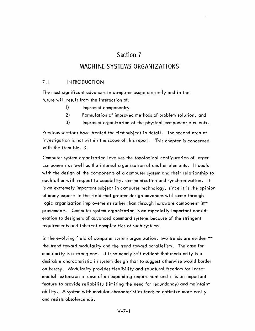
Section 7
MACHINE SYSTEMS ORGANIZATIONS
7.1 INTRODUCTION
The most signifi cant advances in computer usage currentl y and in the
future will resu I t from the i nterac ti on of:
I) Improved componentry
2) Formulation of improved methods of problem solution, and
3) Improved organization of the physical component elements.
Previous sections have treated the first subject in detail. The second area of
investigation is not within the scope of this report. fhis chapter is concerned
with the item· No.3.
Computer system organization involves the topological configuration of larger
components as well as the internal organization of smaller elements. It deals
with the design of the components of a computer system and their relationship to
each other with respect to capability, communication and synchronization. It
is an extremely important subject in computer technology, since it is the opinion
of many experts in the field that greater design advances wi II come through
logic organization improvements rather than through hardware component im
provements. Computer system organization is an especia Ily important consid
eration to designers of advanced command systems because of the stringent
requirements and inherent complexities of such systems.
In the evolving field of computer system organization, two trends are evident-
the trend toward modularity and the trend toward parallelism. The case for
modularity is a strong one. It is so nearly self evident that modularity is a
desirable characteristic in system design that to suggest otherwise would border
on heresy. Modularity provides flexibility and structural freedom for incre
mental extension in case of an expanding requirement and it is an important
feature to provide reliability (limiting the need for redundancy) and maintain
ability. A system with modular characteristics tends to optimize more easily
and resists obsolescence.
V-7-1

The advantages of using parallelism in a system are less clear. There are attendant
difficulties relating to increased complexity and coordination, and precedence
problems which are sometimes imposed as a result of parallel processing. However,
it appears that research effort is sh ifting from emphasis on monol ith ic concepts.
There are inherent I imitations of flexibil ity, rei iabil ity and capabil ity in th is
approach. A degree of physical decentral ization and functional disbursement
is increasingly evident in system design.
It is assumed that the trends toward modularity and parallel processing are well
established and valid, but not fully developed. The resultant advantage of
modularity and parallelism may be summarized as those of flexibility and adapt
ability. Changing tactical situations for ACDS will call for increased speed of
response and ab i I ity to reconfigure fl ex ibl y.
The first subject to be discussed is that of multi-computer systems. The advantages
of multi-computers are seen in the areas of reliabil ity, cost, maintenance, and
parallel processing capability. Definitions are presented and existing hardware
configurations are described. These definitions are sometimes arbitrary but are in
I ine with current usage. It is noted that the discussion of highly parallel computers
to be considered in a later section is an extension of the multi-computer system topic.
Future plans for the acquisition of computer systems by the Navy for ACDS
should be heavily influenced by multicomputing considerations. The use of multi
computers represents one of the most promising approaches to achieving more
processing capacity by introducing parallelism.
Command and control systems are especially amenable to the application of
multi-computers. The changing patterns of the data processing load related to
the threat or the military situation is especially suitable for multi-computer
a?proaches. An important advantage of multi-computers is the reliability which
can be achieved through the module redundancy rather than total system redun
dancy. Improved performance is also obtained by the automatic scheduling and
sharing of peripheral equipment among the processing units.
V-7-2
An important aspect of the multi-computers is the design of executive control
programs. Executive systems for achievi ng program control shou Id be given
priority consideration in the design of multi-computer systems.
The next subsection discusses the development of associative memories. Con
siderable emphasis is placed on this topic since it seems likely that this
development wi II prove very useful in the time period of interest. The use of
associative memories as the main memory element in a large system is a doubt-
ful prospect r but for use as a peripherat component, associative memories appear to be
promising. Here again the interrelationship between subtopics is noted. The
inherent parallelism provided by the parallel search characteristics of associa-
tive memories may, by logical extension of their capabilities, relate to the study
of highly parallel canputers. Further, it is seen that the capability for parallel
processing may be obtained by application of microprogramming techniques
simi lar to those used with stored logic machines.
The associative memory may find a place of special usefulness in the future ACDS
environment o In general, the associative memory is useful when fast or immediate
access to data is needed for which comparison criteria are available. The
technique of retrieving data associatively r based on one or more search
criteria, is intended to replace the costly functi on of table search.
The system planner should be alert to the unique logical capabi lity afforded by
associative memory techniques. Associative memories have potential applica
tion for several areas of particular interest for future tactical systems. Among
these are: data correlation, sorting, data retrieval and systems programming.
Although the associative memory is not without drawbacks, (primarily of cost),
the possibilities for limited use in conjunction with other memory elements is
worthy of considerati on.
Stored logic computers and microprogramming techniques are discussed next. The
stored logic design has fallen from favor in recent years due to a number of
disadvantages which became apparent in the course of events. However, there
appear to be a number of valuable design concepts which were associated with
V-7-3
early designs and which are currently being exploited in the design of new computers.
Stored logic may be viewed from the standpoint of the programmer and from the
standpoint of the logic designer. It is the latter viewpoint which is receiving
continuing emphasis and attention.
Stored logic should not be the foremost criterion in the selection of a machine
for future Navy use. Further requests for quotation on future computers should
neither demand it nor exclude it. Rather, they should encourage flexibility
and adaptability from the logic and programming points of view and let the
des igne r-manufactu re r deve lop an approach best su ited.
There is an increasing use of memory hierarchies in computers and computer
system design. The usual method of memory classification is according to access
speed and storage capacity. The ideal hierarchy is usually described as one
with a fine gradation of speed and capacity characteristics from small amounts
of ver,' high speed storage (register, scratchpad storage) through high speed
memory main storage, through successively larger amounts of lower speed
storage, and finally, to large amounts of bulk storage such as that provided
b y dis c s 0 r d ru m s •
The trend toward use of mu Itiple memories of various speeds and capabi I ities
may be expected to continue u One cou Id antic ipate a system design encompas
sing a wide variety of such memory types each employed according to the
spec ia I capac it ies affo rded •
The system planner must not only be aware of the various kinds of memory at
his disposal, but must be alert to the special capabilities afforded by the com
binative properties of hierarchies of memories. Also included are the topics
of read-only memories and the fixed plus variable computer organizational
concept.
The next subsection deals with novel computer organizations which are usually
described as highly parallel computerso The highly parallel computer organization
represents an almost complete departure from conventional computer design. In
these computers, the arithmetic and control logic is decentralized to the extent
V-7-4

that it ex i sts at nodes of a network. All of the ari thmeti c and control uni ts at
the nodes may operate in parallel to provide, in theory, a high speed operation.
There is some question whether the significant capabi lities of this organization
can be effectively used for command systems in 'the future.' The
description of these novel organizations is limited in scope according to eval
uations of potential applicability to advanced command systems.
The final subsection outlines important computer design parameters for ACDS
app Ii cati ons, indicates present trends and spec ifi es areas for further study. A
consideration of ACDS general computer requirements is followed by a review of
present NTDS compatible computers.
One of the central obiectives of computer system organization is to arrive at a
series of recommendations on the characteristics of a possible future NTDS
family of computers. The basic computer is considered, as a member of a
family of computers, in a time sharing environment, and in a multi-computer
configu ration.
Note that in choosing systems for description in this section the choice has been
made on the basis of reflecting different forms of multi-processing or multi
computer organi zati on rather than to present the latest i nformati on on new
systems. For example, it is not possible to include the very latest information
on deve loping systBms such as the IBM System/360.
V-7-5
7.2 MULTI-COMPUTERS
7.2.1 I ntroduc ti on
One of the major areas of interest in system organization is the subject of multi
computers. The use of mu I ti-computers represents one of the most prom i si ng ap
proaches to achieving more processing capacity by using parallelism in system design.
Recent years have seen a significant trend from the concept of a single large central
computer as the main system element toward a decentralization of computer elements.
This trend is consistent with the increasing emphasis on modularity and parallelism
noted ear I i er .
Among applications for which the use of multi-computers have been found particularly
advantageous are those with these characteristics:
I) Those systems in which the I/O demands of the system measured
as a percentage of overa II system capacity are unusually high.
2) Those in which there is a geographic separation of locations at
which information is to be fed to or received from the system.
3) Those in which the system must respond to varying traffic rates
of input and output messages.
4) Those in which the system must continue to accomplish high
priority tasks even though it is not completely functional.
5) Those in which a number of diverse problems or tasks must be
hand led simu Itaneously.
6) Those in which real time response capability is an important
requirement.
7) On line systems.
Multi-computers represent an increasing segment of total installed hardware. This
is particularly the case in command and control systems, both tactical and strategic.
V-7-6
Designing multi-computer systems is not an exact science. The possible interrelation
ships of elements are highly complex. Such efforts call for the traditional disciplines
of digital logic design, communications, switching theory, programming, and related
sk iI/ s.
7.2.1.1 Defi ni ti ons
A multi-computer system is one which is composed of a number of computing elements
including two or more separate processors capable of operating programs simul-
taneously. The term multi-processing is used to describe appl ication of a number of
computers all executing different jobs, or parts of a single job, under control of a
single executive program. It is noted that these definitions suggest more
than simply duplexing for reliability (as in SAGE). Also, computers operating
independently on separate tasks (even though coiocated) do not qualify under the
definition.
tv\u I ti-programmi n9 is the process of usi ng one computer for different processi ng
tasks on a time shared basis. Time sharing is a special case of multi-programming
wherein the several jobs being run concurrently are originated by different users.
It is getting a great deal of attention, especially among scientific users who wish
to have many problem solvers using the machine simultaneously. Applications in
command and control could involve many analysts using the machine simultaneously.
To some extent, multi-programming supplies a motivation for multi-computing.
There are advantages associated with the use of each, a;-~d there are reinforcing
advantages to the use of a comb ination of both concepts.
7.2.1.2 Characteristics of Command and Control System
The trend toward multi-computer systems is particular!y evident in mi litary systems.
In command and control systems~ the concept is so well established
that it is not a question of whether multi-computers are used but rather the extent
to which they are used.
There are a number of characteristics and requirements of command and control
systems which motivate toward the selection of a multi-computer design. Some
of these are:
V-7-7
7.2.1.3
I) Reliabi lity - Duplication of equipment is a characteristic of
command and control systems. However, the use of multi
computers permits reliability to be achieved through module
redundancy rather than total system redundancy. Fai lure of
a component must result in a reduced capabi lity rather than
a catastrophic failure of the entire system. The characteristic
of continued operation despite component fai lure is sometimes
referred to as gracefu I degradati on.
2) Expansibility - It is frequently found necessary to increase the
scope of system tasks or to expand the capacity of the system
as a whole. The multi-computer approach provides for in
crementally modular expansibi lity.
3) Need for Parallel Processing - It is often a system requirement
that multiple programs be runsimultaneouslywithout interference.
The use of mu I ti-computers provi des the abi Ii ty of processi ng
multiple tasks simultaneously.
4) Flexibility and Adaptability - Flexibility and adaptability can
be achieved on a millisecond basis by realigning tasks for the
avai lable equipment, or can be achieved on a month or year
basis by adding components to the system.
5) Operational Compatability - The use of multi-computers is
compatible with tactical deployment concepts/and provides the
degree of functional or physical decentralization desired.
Shipboard Use of Multi-Computers
The use of multi-computers aboard ship presents special problems of communi
cation, physical placement, reliability and backup, processing load distribution,
and task assignment. The computers selected may be general purpose or highly
specialized, similar or identical to each other, or disparate in size or capacity,
(e.g., large primary computers used in conjunction with satellite or peripheral
computers). The system design may call for the computer to be assigned individual
ly to accommodate separate subsystems or for shared task assignments and dynamic
V-7-8
reassi gnment of avai labl e processi ng capaci ty as a function of current task priori ti es.
The computers may be required to be highly interrelated, sharing common inputs,
and servicing the same display devices and peripheral equipment. The number of
computers and the optimum size to provide the proper degree of granularity for
rei i abi I i ty and backup, is, of course, of primary importance. These co;-)si derations,
and many others, must be examined in detail in the context of system requirements
with cognizance of the most advanced multi-computer usages.
7.2.2 Classifications of Multi-computers
Multi-computers can be classified according to a number of criteria. Categoriza- *
tion by assignment of function and topology of communication is described by Bauer. I
Other classifications could be made on the basis of machine capabilities or by the
number of processors in the system. Comfort2 selects a classification of multi
processors by order. From 2 to 9 processors consti tutes a mu I ti-processor of Order 1;
from 10-99 processors, Order 2; 100-999 processors, Order 3, etc. A mu I ti-processor
of Order 3 or more he classifies a "highly parallel machine. II
Another classification is according to whether the processors are all idenHcal
(e.g., D-825) or incorporate a gradation of capability (e.g., IBM 7090/1401,
CDC 1604/160A Systems). Yet other c!j sti neti OilS involve executive concepts,
principles of load sharing, and scheduling control. Multi-processors may be dis
cussed according to how they interrelate with peripheral equipment and memory
units.
Typically, multi-computer system organization involves:
(I) Interaction of processors with each other
(2) Interaction of processors with peripheral or satellite equipment
(3) Interaction of processors with memory units
*References are collected in Section 10.9
V-7-9

7.2.2.1 Interaction between Processors
Two basi c approaches to the organization of mu I ti computers based on assignment
of functions are described in the Bauer paper (See Figure 7-1). The hierarchy
arrangement is that in which one or more central processors carry out the main
processing load, and a number of special processors carry out subordinate tasks.
A distributed arrangement has two or more processors of approximately equal
power and responsibility in the system.
Hierarchy Concept
Oillribvted Concept
Fi gure 7-1. Assi gnment of Functi ons
V-7-10
7.2.2.2 Interaction of Processors with Peripheral Equipment
A categorization according to topology of communication is discussed and i 1-
lustrated in the Bauer paper. The primary types of communication are the
substation approach and the centralized communication approach.
Substation communication uses a level of principal processing and a level of
switching and communication. All communication with peripheral units is
handled through communication with the substation. No highly-specialized
or unusual devices are required for switching. Usually switching can be done
by small satellite computers. But if the switching requirements become high,
these satellite computers become expensive and awkward to handle.
The centralized communication approach routes all communication through
one central switching unit (See Figure 7-2). It results in a flexible system
and provides high total reliability, since only the switching unit is critical
to system operati on.
Switching can be by information bus or by central switch. In the information
bus method, communication must rely on specifying, coding/and addressing, or
on dedicated time slot techniques. All techniques are conventional and re
latively inexpensive for a small number of modules.
The central switch is a crossbar type similar to those used in telephone central.
For many modules the cost is low, and high communication rates through the
switch are possible since communication paths are independent. However,
few electromechanical switches of this type have actually been made for
computer use. The original crossbar switches developed for telephone purposes
were electromechanical. Those used in computers have employed transfluxor
magnetic cores or diodes and gates.
The information bus can be further classified as a multiple bus or a time shared
bus. Separate buses connect the processor to one or more memories in the
multiple bus system. This is a fairly inflexible system. In the time-shared
bus system, each module time shares a bus. This is the lowest-cost system but
it suffers from control complexity problems.
V-7-11

Substation Communication
Centralized Communicatian
Figure 7-2. Topology of Communication
V-7-12

7.2.2.3 Interaction of Processors with Memory Units
The tendency to separate the primary computer components into distinct
functional categories provides numerous combinative possibilities for system
manipulation. In particular, the relation of computer memories to associated
processors is varied. The question of shared vs. private storage, the types of
memory divisibi lity, and memory protection features, are all important con
siderations.
The shared memory concept is illustrated in Figure 7-3(A). One of the early
memory sharing systems is the GAMMA 60 system. It consists of arithmetic
processors., I/O units, logical processors/and a common memory.
The configurations shown in Figure 7-3 (8 and C) are logically simi lar but
suggest slightly different implementations. When a complex switching network
is employed, it is necessary to have a control unit (perhaps a small computer)
control the switching functions. It is sometimes suggested that the capability
to switch memory units from one processor to another amounts to an extremely
high rate of data transfer. This capability also has reliability significance
since it is possible to switch an entire memory from a failing processor to an
operational one. Figure 7-3 represents schematically the concept. of
shared and private memory contai ned in the same system. It shou Id be noted
that the question of single vs. multiple memories is to some extent arbitrary
since a single large memory may be regarded as being composed of separate
logical memories. The basic functional distinction of private vs. shared
memory involves the ability or inability for a given processor to address a
particular segment or unit of memory in the system.
V-7-13
I P
I
I P
I
r--
P
'--
r---
P
'"-
r---
P
'--
Shared Memory
I J
P I I
I J
P I J
C
P = Processor Un i t M = Memory Un it
M
A
Switching I I k nter oc
_I-_ .....
M M
- I-.- ,...--
B M
"--
Pt------t
P
S W I T C H
1------1 M
1------1 M
P I-------I"--_.....J
B
r--
p
L..--
r--
p S W
L..-- I T C
roo-- H p
-
-p
I-.- D
Fi gure 7-3. Processor and Memory Organ i zati ons
V-7-14
....--
M
"--
....--
M
"--
r--
M
'"-
r---
M
I-.-
r---
M
"--

7.2.3 Multi-Computer Systems
7.2.3.1 RW-400 System
The RW-400 multi-computer system is built around an expandable central
exchange to which a number of primary modules are attached. The central
exchange is a switching center. Computing and buffering modules provide
control for the system. These consist of computer modules and self-instructed
buffer modules. They are self-controlled, and allow completely independent
processi ng of two or more probl ems.
The system operational concept is that, although each of the computer modules
is identical, one is designated the controlling module. In this designated
module the master control program resides. The master control program initiates
all operations on the basis of priority. It gives jobs to computer modules and
assigns certain slave modules in groups to the computer modules. An alert
interrupt network allows coordinated system action. This makes it possible
for the system to change on a microsecond basis to provide a programmable
self-organizing aspect to the system. The intention is that the most efficient
and economical complement of equipment should be applied to the problem at
all times.
The RW-400 computer is centered around a high speed cross bar type switch.
The Y axis of the switch represents "spigots" onto which controlling modules
are tied. The X axis represents spigots onto which slave units are tied. The
kinds of slave units tied to this system are printers, reagers, plotters, tapes,
input buffers and output buffers.
Another configuration of the RW-400 uses a CDC 1604. This system is shown
schematically in Figure 7-4. A master control program written for the 1604
controls the system.
Perhaps the most interesting part of the system is the switch. The switch is
16 x 64 (controlling axis and slave axis respectively). Connections can be
made by anyone of the controlling modules to anyone of the slave modules
in approximately 70 microseconds.
V-7-15
11604~
I CM ~
I eM :
I CM :
: BM }
: BM :
CM - COMPUTER MODULE
BM - BUFFER MODULE P - PERIPHERAL'MODULE
(PRINTERS, READERS, TAPES, . ETC.)
I
~- _I- 1"""'" ,..-
P P P P
--- - ~ ......
Figure 7-4. Ramo-Woo ldridge RW-400
V-7-16
--P
.--
Two switches were made for this system, one uses transfluxors and the other
diodes. The switch has some interesting and advanced features. The switch itself
has a core memory of some 2,000 words. The core memory stores data on the
connections which are made or could be made. The programmer can disallow
certa in sw itch points under program control, thus fac iI itat i ng the master control of
the system. Another feature is the "symbolic address file" which allows symbolic
addresses to be ass igned rather arb itrar i I y to the var ious hardware sp igots. A
comprehensive set of alerts and interrupt lines is also possible through the switch.
An important aspect of this system is that each module is self-contained. That
is, each module has its own power supply and may be tied to the switch with
little difficulty. This has the advantage of expansibility but the disadvantage
of the high cost of each of the modules. Although not part of the first RW system,
a group of peripheral equipment can be attached to one spigot.
Connected to the switching center are magnetic tape modules, magnetic drum
modules, peripheral buffer modules, and console communication and display
buffer modules. There are also modules for punched cards, punched tape, high
speed printing, and control consoles to handle the input/output requirements of
the nominal system. Additional man/machine communication devices for inter
rogation, display, and control operations can be added as required o
The functioning of an RW-400 multi-computer system depends on the number and
type of the modules, and the number of modules in a given system is governed by
the system application. Initially it may consist of the minimum number and
types of modules,to do a small problem solution. In this configuration it would
work very much like a conventional computer. Later this system could be ex
panded by the addition of modules as needed. Modules may be assigned to work
together on a problem in proportion to its needs. As soon as a module's function
has been completed, it may be released for assignment to another task. The
system is thus self-controlled, matching processing capacity to each problem
for the time necessary to do the job. Full system capabi Ii ty can be brought to
bear upon very large problems when the need arises.
V-7-17
The RW- 400 data system a II ows the expansion of the system from a modest i ni ti a I
installation into a powerful and comprehensive information processing center.
System obsolescence is reduced by the expandabi I ity in both the number and types
of processing modules. The ultra-high systems reliability is a feature of the sys
tem because of the multiplicity of common elements. Parallel pro::essing and
parallel information handling modules increase the system's speed and adaptability
when handling complex computing workloads.
The system was designed for a specialized military application and IS now in
operation at the Rome Air Development Center Experimental Computer Complex.
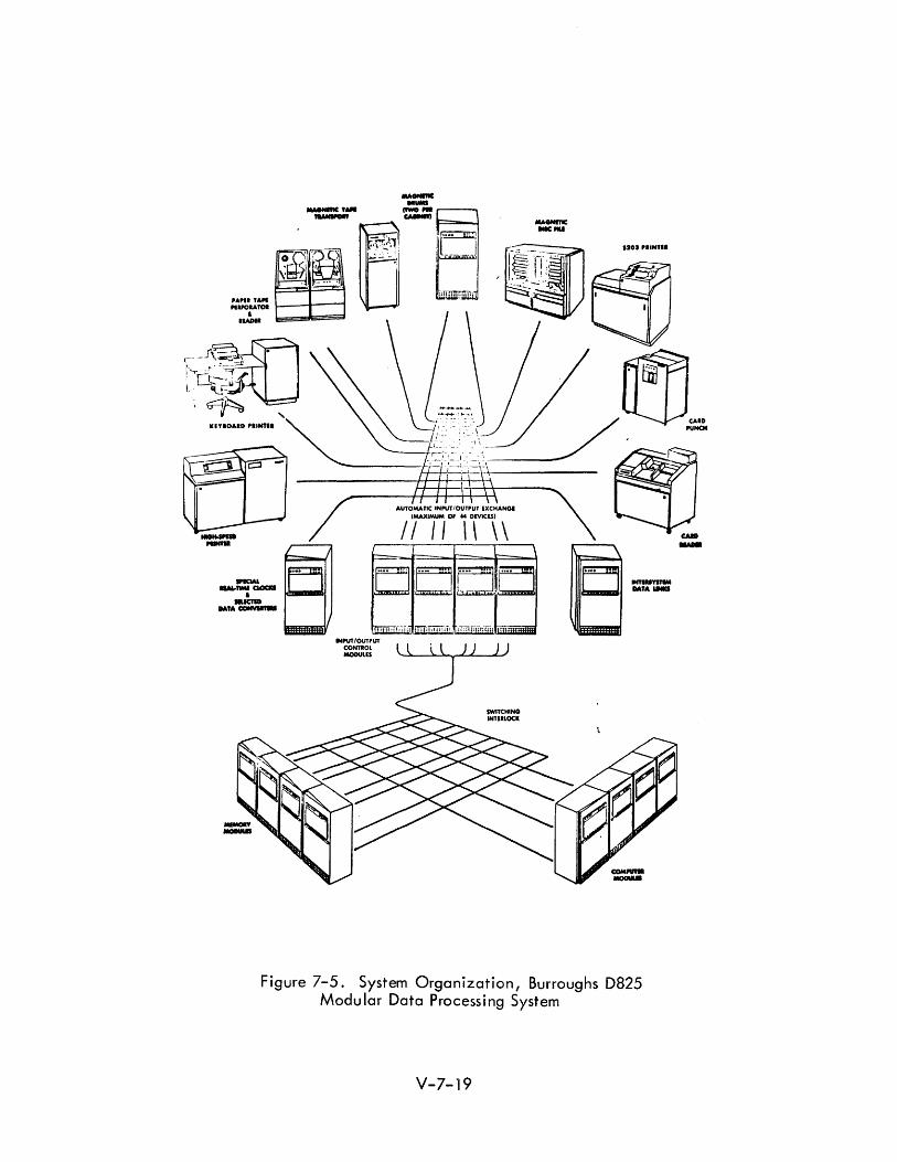
7.2.3.2 Burroughs D825
The D 825 is a military system oriented toward the command/control problem ~ (See Figure 7-5). Its modular design allows a building block approach to ap
plications design. The simplest configuration is a single computer module, one
memory module, one input/output control module, and peripheral devices. A
fully expanded system would consist of four computer modules, 16 memory modules,
ten input/output control modules, and 64 peripheral devices. The processor or
computer modu les share access to the executive program, to each other, and to
a II memory and input outputs.
The interconnection switching is termed a switching interlock by Burroughs.
This switching function is distributed among the various modules which are then
interconnected by cabling. Accordingly, a failure in the switch hardware can
be handled in the same way as a failure in a module.
The executive routine used with this multi-computing system was developed to
provide an automatic control framework for efficiently and effectively running
multipath, parallel, real-time programs. The executive program maintains a
job file for all programs currently in the system. One element on the file is
an "image" of the job, which is transferred to the thin-film registers of a
processor when assignment of that job to that processor is made by the executive
routine. This image is either the initial data needed by the processor to begin
the job or it is data retrieved from the thin-film registers of an interrupted
processor, giving the status of the job at that instant.
\1-7-18
, ~.-' e:D120a'.~~TI. -- ..... _- -.
0-. I
I
::::::~, ~ .... ll-tt. t, . - . PUNCH
l! - , . 1_ _ __
__ --'-,_ - I ....
,---<_J_ -'r ,... •
---------------M~+_~~
- \
Figure 7-5. System Organization, Burroughs D825 Modular Data Processing System
V-7-19
. CAID .u.
When a processor seeks a new assignment because it has completed a program
or has been interrupted, it runs the executive routine. If it is assigned to thnt
program it transfers the image of the program from the ma in memory to its own
thin film registers. If this program is again interrupted the processor transfers
the program, revised to the new status, back to the executive routine to be
drawn out again as another processor becomes available. Thus, programs or
program segments are shifted about from processor to processor to permit direct
response to the various interrupts in the system. Programs are never associated
directly with any individual processor. Moreover, processors need not even be
aware that they are picking up a partially completed job.
The executive routine may also be used by the programmer to divide a program
among severa I processors for simu Itaneous para lie I solut ion of the separate
elements.
The D825 system has a comprehensive interrupt system with eight internal
processor generated interrupts and four external interrupts. The automati c
interrupt capability is fairly extensive and includes protection features such
as reflecting (by interrupt) when an attempt is made to write out of bounds, and
a real-time clock overflow. The control structure permits immediate and auto
matic entry of a priority program without damage to interrupt programs. It
also permits rapid, simple addition to or substitution of hardware or executive
routines within the system structure.
The D825 is the expanded and mil itarized forerunner of the Burroughs B 5000
Computer, and is to be used as the real time computer for the Back-Up
Interceptor Control (BU IC) System of SAGE.
V-7-20
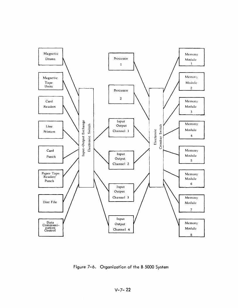
702.3.3 Burroughs B-5000
The B-5000 (See Figure 7-6) achieves physical and operational modularity
through the use of electronic switches which function logically like telephone
crossbar switches.5
The Burroughs B-5000, in a duol configuration, is a standard
B-5000 computer complex to which is added a second processor, usua II y desig
nated Processor B. Both processors are connected directly into the memory
exchange and hence have equal access to memory modules or to I/O channels.
Since the B-5000 uses independent memory modules, both processors may work
continuously provided they are working from different modules.
Processor A (and either physical processor may be logically so designated) is
the only one that may work in control state. This is a state determined by
hardware in which Processor A executes the master control program functions.
In this machine the master control program is kept permanentl y stored on drum,
and is called into core at the initiation of processing.
Processor B may not work in control state, but may halt and interrupt Proces
sor A at completion of any operation, need for I/O, etc. Hence, Processor A
schedules and controls Processor B, endeavoring to keep it and itself busy.
Desi gn cri teria of the B-5000 ca \I for separateness of i nput/ output operati ons
from processing operations and generalized handling of indexing and subrou
tines. Multi-programming and parallel processing by the multiple processors
are both featured. The design is said to have been conceived from a joint
hardware/software standpoint and assumes that the user wi II use higher level
(compi ler) language to the virtua I exclusion of machi ne language programming.
7.2.3.4 CDC-3600
The Control Data 3600 system incorporates a modular approach which pro
vides many possibilities for multicomputer usages. 6 The design maintains
V-7- 21
Magnetic Memory
Drums Processor Module 1
Magnetic Memory
Tape Module Units
2 Processor
2 Card Memory
Readers Module
3
Q) Input bll Memory Line
s:: ...c Output CII u ..c: .....
Printers u 'i Channel 1 Module >< ~ Vl
..... 4 ;:::l
8-;:::l 0
I
Card .....
Memory ;:::l 0..
Punch ..: Input Module Output
5 Channel 2
Paper Tape Memory Reader/
Module Punch
6 Input
Output
Channel 3 Memory
Disc File Module
7
Input Data Output Memory
CommWli-cation Channel 4 Module
Control
8
Figure 7-6. Organization of the B 5000 System
V-7- 22
compatibility with the CDC-1604 (programs written for the 1604 may be
executed on the 3600 system) and inter-computer communication may be
achi eved between these two computers.
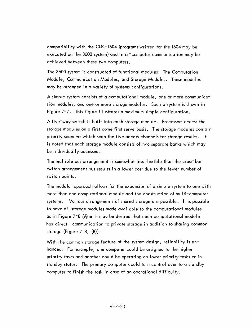
The 3600 system is constructed of functional modules: The Computation
Module, Communication Modules, and Storage Modules. These modules
may be arranged ina vari ety of systems confi gurati ons.
A simple system consists of a computational module, one or more communica
tion modules, and one or more storage modules. Such a system is shown in
Figure 7-7. This figure illustrates a maximum simple configuration.
A five-way switch is bui It into each storage module. Processors access the
storage modules on a first come first serve basis. The storage modules contain
priority scanners which scan the five access channels for storage results. It
is noted that each storage module consists of two separate banks which may
be individually accessed.
The multiple bus arrangement is somewhat less flexible than the cross-bar
switch arrangement but results in a lower cost due to the fewer number of
sw i tc h poi n ts .
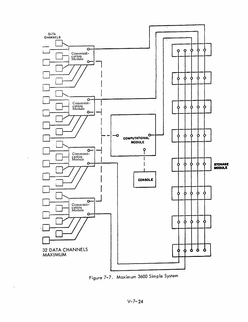
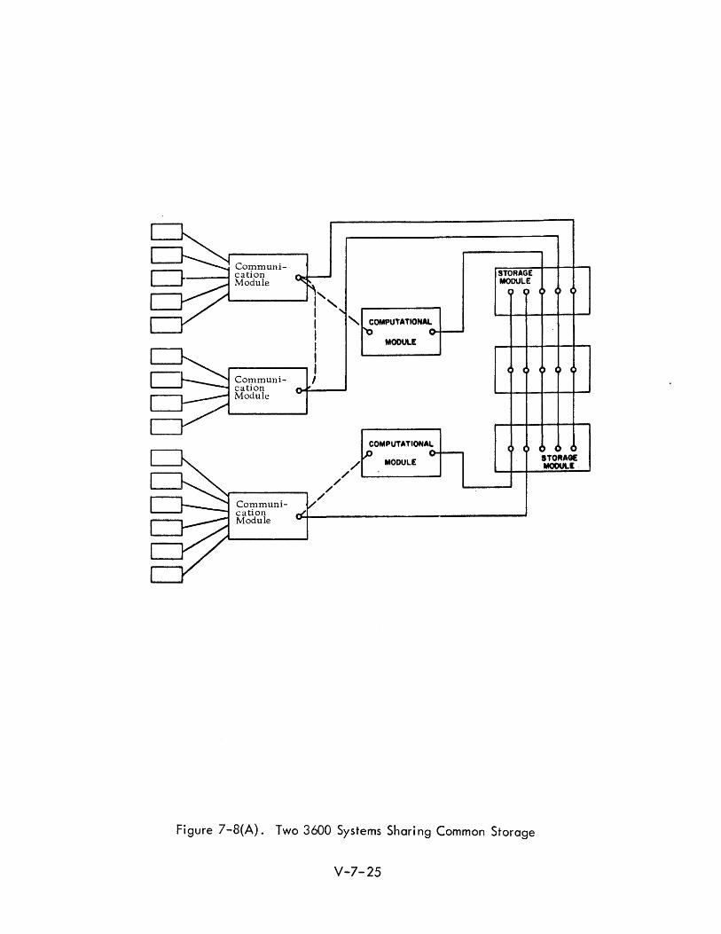
The modular approach allows for the expansion of a simple system to one with
more than one computational module and the construction of multi-computer
systems. Various arrangements of shared storage are possible. It is possible
to have all storage modules made available to the computational modules
as in Figure 7-8 ,(~ or it may be desired that each computational module
has direct communication to private storage in addition to sharing common
storage (Figure 7-8, (B)).
With the common storage feature of the system design, reliability is en
hanced. For example, one computer could be assigned to the higher
priority tasks and another could be operating on lower priority tasks or in
standby status. The primary computer cou Id turn control over to a standby
computer to finish the task in case of an operational difficulty.
V-7-23
():..TA CHANNELS
-r-l-; Communi-LJI I" cation Module t----~l 0-1
..---/ II : ~ I
u' ,-------, Oo-~~------------------~
0-, Communi- I
cation r:,...; _---I Module 0- ~
IIj ~ ___ .J
0-
0-Communication Module
-.
I I .-- -0
I -i
I
~ I o-.J
0-Cotpmuni-
I cation Module --j ----
~/ 32 DATA CHANNELS MAXIMUM
COM PUTATIO NALMODULE
I I
[ CO~SOLE I
C) C) C> () ()
CJ 0 C) 4) >
() . 4) C) ) )
C) I) 4) 4) C
) C) 4) C C)
Figure 7-7. Maximum 3600 Simple System
V-7- 24
Communi----I cation
Module
-----'" I', 1 I " COMPUTATIONAL
I I I r-----..., I
Communication Module
Communication Module
I
/' /'
/ /'
/'
MODULE
COMPUTATIONAL
MOOULE
STORAGE MODULE
Figure 7-8(A). Two 3600 Systems Sharing Common Storage
V-7-25
eTORAG! MODUlE,
Communi~-----t cation
Module \ '--___ ---' 1.,
: ' I I , I I
,..-------, I Communication Module
r---__ I Communication Module
Data Channe Is
I
/
/ I
I
COMPUTATIONAL '0
MODULE
COMPUTAYIONAL
P i\Q)ULE
,,'--------
torage Module I 000 0
o 0 0 0 0
o
o
Fi gure 7-8(8). Two Computer System wi th Pri vate and Common Storage
V-7-26
STORAGE MODULE
STORAGE MODULE
7.2.3.5 CDC-1604/160A
A configuration of Control Data Corporation computers on a smaller scale is
the 1604/160A system.
Other configurations include the 160A as a satellite to any 3000 Series com
puter. Also the 3200 computer may be used as a sate II ite to another 3200 or
to a 3400 or a 3600. Or a 3400 may be used as a satellite to another 3400 or
to a 3600.
The 1604/160A configuration uses a magnetic tape system to link the 160A to
the 1604. Ei ther computer has independent and simu I taneous access to the
tape system. In the various modes of operati on, the computers may be used
independently or together in a single system.
The 1607 magnetic tape system consists of four digital tape handlers and a
synchronizer control unit. The synchronizer control unit makes use of indepen
dent read and write channels. Any tape handler may be operated through the
synchronizer read channel, while any other tape handler is being operated
through the synchronizer write channel. Synchronizer read and write channels
may be assigned to either computer. A direct line from the synchronizer read
channel to the synchronizer write channel permits direct transmission of in
formati on between the two computers.
The 160A uses a single 12-bit channel for both read and write. The 1604 uses
separate 48-bit channels and is capable of reading and writing simultaneously.
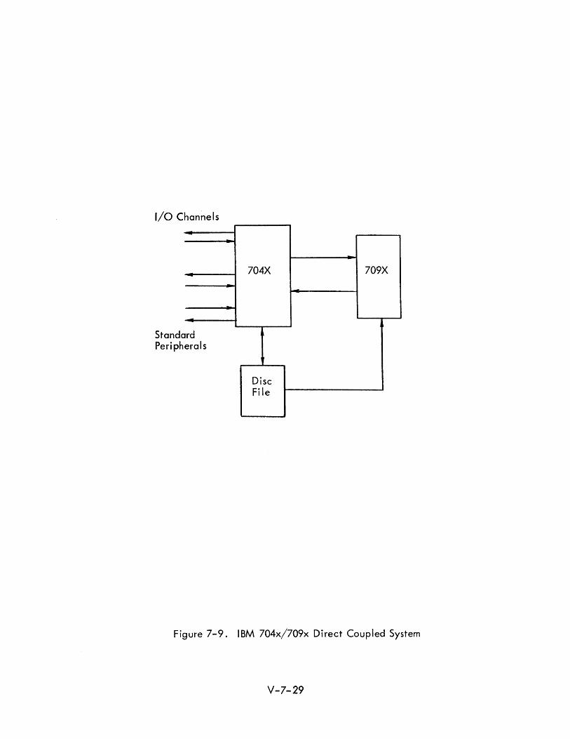
7.2.3.6 704X/709X Di rec t Coup I ed System
The IBM 704X/709X Direct Coupled System presents an approach to multi
processing aimed at achieving faster throughput and reduced turn-around time.
Division of function between the computer is segregated by relegating one
computer to the role of input/output handling thus relieving the other computer
from input/output delays. The Direct Coupled System combines the IBM 7090/
7094 (704X) and the IBM 7090/7094/709411 (709X) systems.
V-7- 27
Direct coupling allows the 709X to be operated with no data channels or peri
phera� equipment. Each computer is modified slightly to provide the direct
coupling capability. However, when not operating as a direct coupled system,
both computers may be operated as stand-alone independent systems. The
system is intended to operate in conjunction with a mass storage device such
as a disc file or a core file. A simplified system configuration is illustrated
in Figure 7-9. Each computer has the capabi I ity to interrupt the other.
The 704X is provided direct access to the 709X memory and may specify
block core-to-core transfers between the 704X and the 709X. It may also
request direct transfers from the disc fi Ie to the 709X memory (or to the 704X).
In addition to performing buffering and input/output functions, the 704X is
usually called on to handle all utility functions, sequencing of jobs, system
program loading and other administrative tasks.
Executive functions are performed in the 704X and the executive routine for
the system resides entirely in the 704X. This program uses 16K words of
storage and is contained also on the disc. The remaining 16K are allotted
for I/O buffer purposes.
The Direct Coupled System may be regarded as achieving its purpose in in
creasing machine utilization and reducing turn-around time. As a multi
computer system, it is not a modular design,and incremental system ex
pansion is possible only on the grossest level. Another difficulty is sometimes
encountered in trying to equalize the load between the two computers.
7.2.3.7 I sM/Sys tem 360
The design of the ISM/System 360 family of computers permits a wide variety of
multi-computer systems. A rather even gradation of computer capabil ity is avail
able with increases of performance of approximately 2.5 to 3 from one model to
the next. The largest computer is approximately fifty times as powerful as the
smallest one. Even finer gradations are avai lable through combining models in
vari ous configurati ons.
Communication between central processing units in a multi-computer system may be
accomplished in a number of ways and at several different transmission rates. There
are basically four methods of communication: I) via shared control units, 2) through
a list channel connector I 3) by a direct control feature, and 4) through shared stor
age. These methods are illustrated schematically in Figure 7-10.
V-7-28
I/O Channels
rd Standa Periph erals
704X 709X
Disc File
Figure 7-9. IBM 704x/709x Direct Coupled System
V-7-29

() :r
() :r o
System/360 5 t---------I Storage Control Unit
t----------t§ System/360 :J (1) (1)
Shared Control Unit
() () :r :r
System/360 0 0
System/360 :J :J :J :J (1) (1) - -
Channel-to-Channe I Connecti on
System/360 Direct Control System/360 Connection
Channel Channel
Direct Control Interconnection
Figure 7-10. IBM System/360 Communication Methods
V-7-30
Of the various levels of communication, the largest in capacity, (but only moder
ately fast in response), is by means of shared I/O device, for example, a disc file.
Faster transmission is obtained by direct connection befween the channels of fwo
individual systems.
The channel-to-channel adapter allows any channel on any model of System/360
to appear as an I/O device to any other channel of any model of System/360. These
channels can be on the same machine or on different machines.
The direct control features eight input and eight output lines which may be used in
a mc.nner ana logous to the sense Ii nes of the direct data feature of the 7090 0 Thi s
feature a Iso has external interrupt capabi I i ties and may be used to transfer control
signals in a multi-system complex.
Finally, it is possible for storage to be shared befween processing units, making
information exchang~ possible at storage speeds.
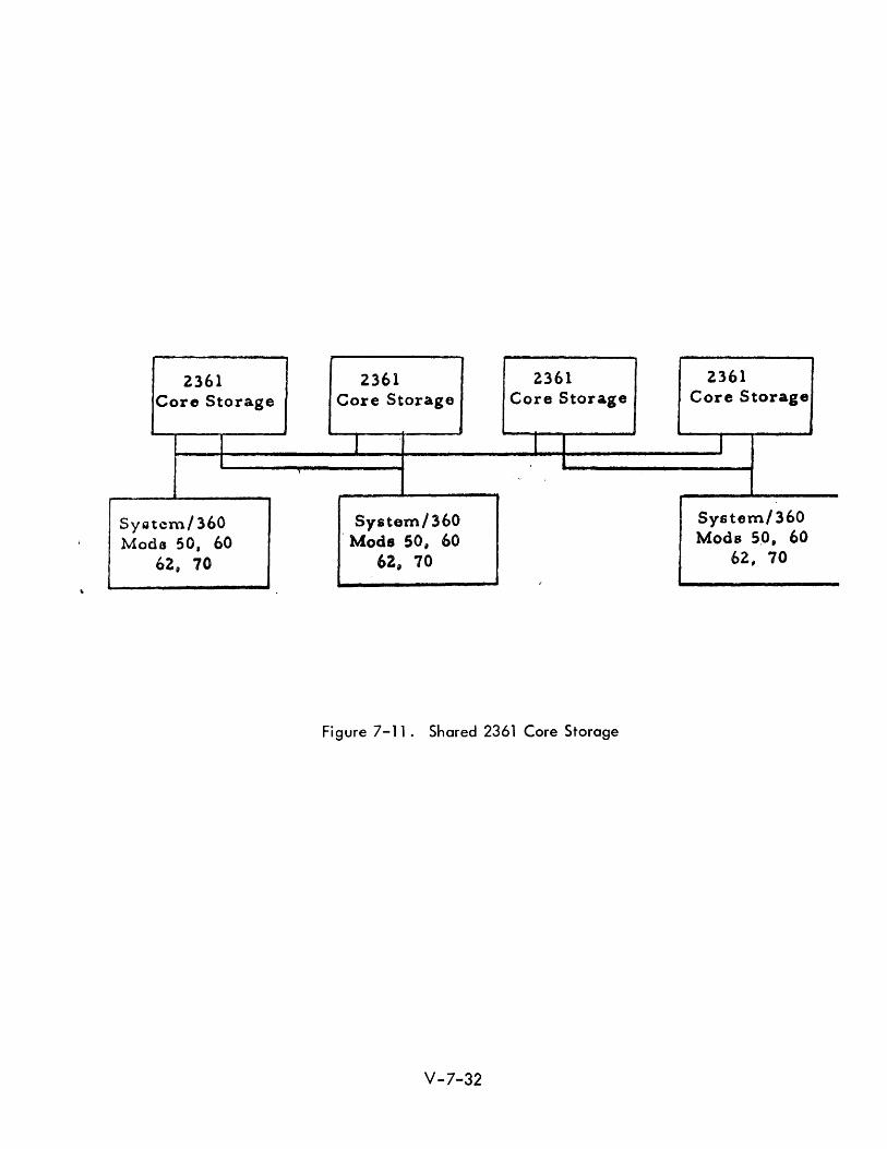
The IBM 2361 Core Storage (See Figure 7-11) provides from I to 8 million characters
of core storage in addition to the regular core storage on the Models 50,60,62
and 70. It may be shared befween any two of these models of System/360. It is
a Iso possible for mu Itip Ie 2361 boxes to be avoi lable to one processor whi Ie some
of the boxes are available to a second processor and the remainder to a third
processor.
A design feature of the System/360 Model 50 allows two Model 50 processors to
be connected so that the full complement of addressable core storage of each
processor is available to either, both for processing or input/output.
The various modes of communication are supplemented by an interrupt feature
which permits one processing unit to be interrupted by another, and makes avai 1-
able status information from one processor to another. To facilitate control of
multi-system configurations, the operator control panel of each processor may be
remoted to a common master consol e •
IBM has selected no single multi-computer configuration for special attention. The
flexibility possible allows each user to tailor the equipment to his specific needs.
V-7-31
2361 2361 2361 2361 Core Storage Core Storage Core Storage Core Storage
I I I I 1 1 I
Syotcm/360 System/360 System/360
Mada 50, 60 Mods 50, 60 Mods 5,0, 60
62" 70 62, 70 62, 70 ,
Figure 7-11. Shared 2361 Core Storage
V-7-32
7.2.4
7.2.4.1
Existing System Usage of Multi-computers
Navy Tactical Data System (NTDS)
The Navy Tactical Data System is a multi-computer combat direction system operating
aboard ships, in real-time. It is used to process, correlate,and evaluate tactical
data. Inputs to the system come from sensors and from other systems. Outputs are
provided to other systems both i nterna Ily on the ships and externa I to them.
The NTDS system uses a standard computer, the AN/USQ-20 (UNIVAC), and
achieves needed capacity by the use of multiple units of this standard item. At
least two unit computers are used in each installation to satisfy requirements for
high reliability and twenty-four hours' operation. Changes in the system to satisfy
additional or modified requirements are met by changing the programming and by
the addition of more unit computers.
A set of operating modes was designed to provide ability to handle the most im
portant functions in all but the most extreme conditions of damage or equipment
malfunction.
A typical configuration for the NTDS system would consist of three unit computers,
three data links (high-speed, teletype, and surface-to-air), a video processor for
radar data, three display units, a keyset general, a magnetic tape unit, a symbol
generating unit for the displays, and a system monitoring console.
All tasks for the system are classified into three categories: service, tracking/and
user. Service tasks are those common to more than one function, and service
tasks associated with inputs are usually the highest priority tasks. Tracking tasks
have next highest priority. Service tasks associated with outputs and user tasks
are lowest priority. An exception is that subprograms connected with inter
computer data transfer, which is classified as a service task, are actually
contained in each computer.
In the NTDS, techniques have been developed which allow computer changeover
to take place without serious interruption to system operations. Unless no system
recovery is involved, computer changeover can be accomplished in a period of a
few seconds to several minutes. When computer changeover is required for system
V-7-33
recovery the problem becomes involved, especially with regard to preserving data
when a computer has malfunctioned. However, critical information can sti II be
obtained from magnetic tape,and other data must be reacquired by starting the
computing processes again or by getting the data from other ships.
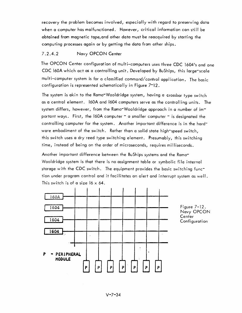
7.2.4.2 Navy OPCON Center
The OPCON Center configuration of multi-computers uses three CDC 1604 1s and one
CDC 160A which act as a controlling unit. Developed by BuShips, this large-scale
multi-computer system is for a classified command/control application. The basic
configuration is represented schematically in Figure 7-12.
The system is akin to the Ramo-Wooldridge system, having a crossbar type switch
as a central element. 160A and 1604 computers serve as the controlling units. The
system differs, however, from the Ramo-Wooldridge approach in a number of im
portant ways. First, the 160A computer - a smaller computer - is designated the
control I i ng computer for the system. Another important di fference is in the hard
ware embodiment of the switch. Rather than a solid state high-speed switch,
this switch uses a dry reed type switching element. Presumably, this switching
time, instead of being on the order of microseconds, requires milliseconds.
Another important difference between the BuShips systems and the Ramo
Wooldridge system is that there is no assignment table or symbolic file internal
storage with the CDC switch. The equipment provides the basic switching func
tion under program control and it facilitates an alert and interrupt system as well.
This switch is of a size 16 x 64.
I J60A :
r 1604!
I 1604 !
r 1604 : ..
p - PERIPHERAL MODULE ,.. ... ,.. ....
p p ...... --
,..- ,.. ... ,.. ... p p p
...... ...... --V-7-34
-
... ~ p .....
... ~ p --
Figure 7-12. Navy OPCON Center Confi gurati on
7.2.4.3 Burroughs 0 825 Applications
This system is now being applied to a number of command and control problems.
These include air defense and communications processing. The prototype system
has been in use at the U.S. Naval Research laboratory for two years. Two other
systems are also being used by the Government. Burroughs is under contract to
develop an Automatic Message Processing System for the Signal Corps which is
of the store-and-forward type o It will use the 0 825 including data demand and
data buffer modules and a data demand exchange. Thirty-four systems are in
stalled or in production for the SAGE back-up intercepter control network (BUrC).
7.2.4.4 Real Time Data Handling System - Pacific Missile Range
The real time data handling system of the Pacific Missile Range, RTDHS, provides
data handling support in four areas:7
I) Ballistic impact prediction for range safety.
2) Flight testing involving air breathing, air-to-air and ground-to-air missi les.
3) Ballistic or perturbed (controlled) impact predictions to aid recovery.
4) Orbital vehicle control to alter free body path as for injection into orbit, rendezvous of orbiting vehicles, and control of re-entry.
The system is heavily communication oriented. The computers communicate with
each other and with range instrumentation. Computers used are the CP642B/USQ-20
computers. These computers are p laced at vari ous i nstrumentati on si tes and at
centra I operati ons areas.
The basic concept of the RTOHS includes two types of sites; primary and peripheral.
Peripheral sites use the RTOH-PC computer. Primary sites have the Q-20B com
puter. Peripheral sites receive local radar and human control inputs, and
provide local radar control, data recording, and data monitoring facilities.
Tracking data is sent from the peripheral sites to the primary sites. In addition
to the inputs and outputs to the peripheral sites, the primary sites handle range
safety and automatic aircraft vectoring operations. Control data and acquisition
data are sent from primary sites to peripheral sites.
V-7-35
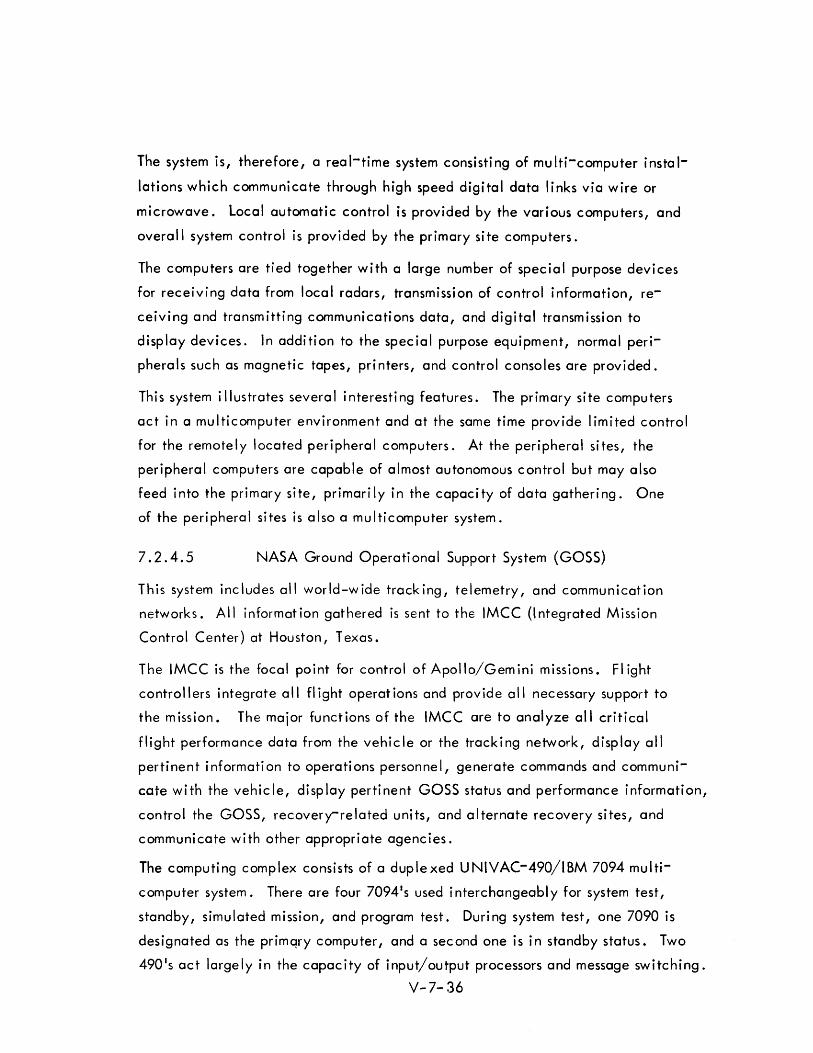
The system is, therefore, a real-time system consisting of multi-computer instal
lations which communicate through high speed digital data links via wire or
microwave. local automatic control is provided by the various computers, and
overall system control is provided by the primary site computers.
The computers are tied together with a large number of special purpose devices
for receiving data from local radars, transmission of control information, re
ceiving and transmitting communications data, and digital transmission to
display devices. In addition to the special purpose equipment, normal peri
pherals such as magnetic tapes, printers, and control consoles are provided.
This system illustrates several interesting features. The primary site computers
act in a multicomputer environment and at the same time provide limited control
for the remotely located peripheral computers. At the peripheral sites, the
peripheral computers are capable of almost autonomous control but may also
feed into the primary site, primarily in the capacity of data gathering. One
of the peripheral sites is also a multicomputer system.
7.2.4.5 NASA Ground Operational Support System (GOSS)
This system includes all world-wide tracking, telemetry, and communication
networks. All informat ion gathered is sent to the IMCC (I ntegrated Mission
Control Center) at Houston, Texas.
The IMCC is the focal point for control of Apollo/Gem ini missions. FI ight
controllers integrate all fl ight operations and provide all necessary support to
the mission. The major functions of the IMCC are to analyze all critical
flight performance data from the vehicle or the tracking network, display all
pertinent i nformati on to operati ons personne I, generate commands and communi
cate with the vehicle, display pertinent GOSS status and performance information,
control the GOSS, recovery-related units, and alternate recovery sites, and
communicate with other appropriate agencies.
The computing complex consists of a duplexed UNIVAC-490/IBM 7094 multi
computer system. There are four 7094 1s used i nterchangeabl y for system test,
standby, simulated mission, and program test. During system test, one 7090 is
designated as the primqry computer, and a second one is in standby status. Two
490 l s act largely in the capacity of input/output processors and message switching.
V-7- 36
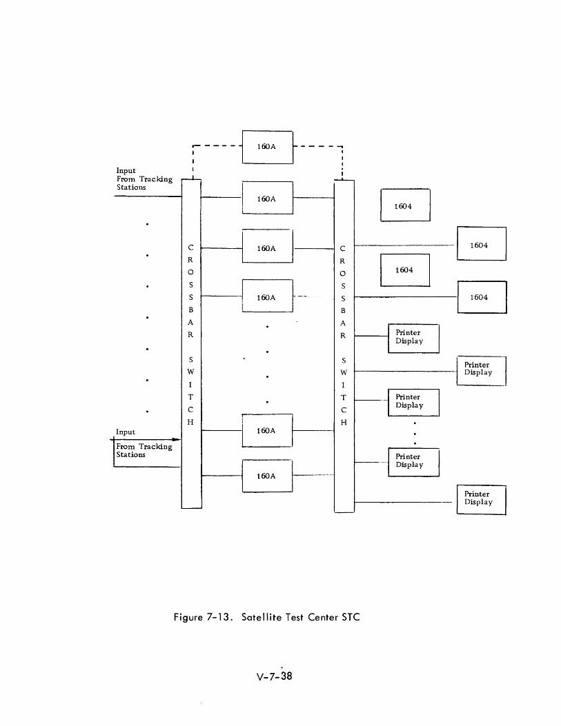
7.2.4.6 Sate II ite Test Center
The Satellite Test Center (STC) presents an interesting example of several multi
computer usages. 8 The function of this system is to provide control of satellite
vehicles with multiple satellites in orbit at the same time.
Each tracking station has at least two, and, typically, four CDC 160-A computers.
A division of the computing task between two 160-A's is according to function.
One 160-A receives, and formats input data, the other handles communications
data, antenna pointing data, command data, etc. With four computers, two
vehicles may be supported.
The Satell ite Test Center receives data from the tracking station by telephone
lines which lead to a crossbar switch. This switch allows the input data to go
to anyone of sixteen -160-A computers. These computers act primarily in the
capacity of buffers (and are in fact, called Bird Buffers).
Another crossbar switch is used for connections to sixteen printer displays and
four CDC-1604's. Both crossbar switches are operated under control of a
schedul ing computer (160-A).
The arrangement of computers (See Figure 7-13) is flexible for communication
and segregates computer tasks according to function. The primary problem of
control in this system is one of schedul ing. It was found that the control I ing
160-A was only marginally adequate for this task.
V-7-37
.- - - - - Er60A - - - - ~ I I
I : Input I
From Tracking --L-...
Stations I B 160A
·
B C 160A C · R B R
0 0
· S EJ-- S
c:J S S
B B · A · A R R Printer
Display
· · S S Printer
W W Display · · I I
T T Printer · Display · C C ,
I H I H · Input
I 160A · -
From Tracking · Stations Printer
Display
160A t-------
Printer Display
L--
'-
Figure 7-13. Satellite Test Center STC
V-7-38
7.2.5 Hardware Reguirements
Certain hardware requirements are essential to achieving desirable system characteristics
in a multi-computer complex. Several of these are I isted and described briefly to
follow:
I) Priority Interrupt Logic - It must be possible for processors to
i nterrup~ each other and to be interrupted by other system
devices. The logic design may call for a wired-in priority
scheme; it may be entirely a function of software logic;
or it may be a combi nati on of the two.
2) Expansibility - The ability to add modules, either in real or
extended time, permits the system to access or release
equipment (or to grow with requirements which may change
with time). This capabi lity exercised in systems real-time
per~its functioning as a single large system or a number
of smaller ones.
3) Switching and Communication - There must be a switching
scheme, controllable from the master processors to perm it
reconfiguration of the system from the hardware and inter
connecti on standpoi nt. More than one processor shou Id be
able to control, access, and execute the master control
program. Extensive ability for data communication must
be built into the system with provision for alternate paths.
4) Memory Protection - Provision must be made to prevent memory
addressing errors. This is particularly the case when more than
one processor is accessi ng the same memory bank. Several
methods of memory protection are described by Critchlow.
These include the use of limit registers, mask registers, the
hardware lockout feature, use of a check routi ne and use of
fixed (read-only memories). The latter two methods are
usefu I on I y for spec i a I cases.
V-7- 39
7.2.6 Programm i ng Consi derati ons
7.2.6.1 Cyclic Operation
In real-time operations, there are periodic functions to be performed. Unfor
tunately, the periodicity of these functions are likely to vary and sometimes
the frequency of operations are unpredictable. This may present severe schedul
ing and load balancing problems in a multi-computer system. One approach to
this problem is to select a computation cycle which approximates the frequency
of the most significant periodic occurrences. This cycle may be initiated by a
computer clock signal or by some regular event such as a regularly expected
input request interrupt. The cyc Ie is of parti cu lar importance to the execu-
tive control program which may use the cycle interval as a framework for
scheduling required processing. Typically, certain functions must operate
every cycle, some operations occur at multiples of the cycle interval and
others operate asynchronously in respect to the cycle.
7.2.6.2 Interrupt Processi ng
An important trend in real-t i me systems is th e use of interrupt meth ods for data input.
A characteristic of such systems is the requirement that input/output demands be
serviced rapidly. In particular, a sensitive and timely response to command/control
information input by human or electronic intervention is needed. In some cases, the
computers must respond to reconfiguration commands and alter the priority of opera
t ions in real-time.
The i mpo,rtance of servi c i ng external devi ces before possi bl e loss of data suggests
that interrupt control assumes a prominent position in processing priority. Viewed in
th is way, the aggregate of interrupt processors constitutes a high (perhaps preeminent)
level of executive control. By means of the interrupt technique, events external to
the computer are registered in the computer program,and the computer is able to
respond to new situations in a predetermined and appropriate manner.
V-7-40
The interrupt feature consists of the ability to impose a hardware signal into the
computing sequence in order to initiate a required action. The interrupt signal will
ordinarily cause a branching of control to an interrupt routine. After the interrupt
routine is completed, control is usually reverted to the sequence which was suspended.
Typically, the interrupt signals that data is ready for input into computer memory.
It may also, however, simply signal an external event. Another use of the interrupt
is to signal the end of a previously initiated data transfer. In some cases, this
notifi cation of a compl eted transfer triggers a new transfer. The interrupt is al so
used to indicate malfunctions (e.g., power failure, parity error, etc.) Interrupt
signals should be identifiable, both as to the interrupt source (which device), and
as to the reason for the interrupt.
In a multi-computer system, the ability for one processor to interrupt other
processors is a desi rabl e, if not neces3ary, characteristi c. One of the most signifi
cant tasks involves the updating of common data bases to maintain currency. An
important consideration in this connection is the extent to which data input is to be
dupl icated.
Interrupts will ordinarily cause interrupted routines (that is, the routine that was
operating is interrupted). This may result in a re-entrant condition. If the routine
is re-entered prior to completion, previously computed interim results (usually in
temporary storage) may be destroyed. This is a problem that has been solved in a
number of ways, usually by the individual user programmer. However, standard
re-entrant procedures should be adopted, and an easily specified method provided,
as a function of system support.
When various equipment is competing for attention, problems of priority result.
These priorities relate not only to I/O requirements but to the computations underway.
In some systems, interrupt signals may be selectively enabled or inhibited under
program control. This feature provides flexibility in providing for an operational
sequence based on a priority logic which may be preset or dynamically alterable.
V-7-41
7.2.6.3 Multi -Level Control
The priorities of varying processing and interrupt requirements will ordinarily result
in a multi-level hierarchy of control. In a fixed inflexible program sequence, tasks
may be arranged in a preset order. This characteristic is not typical of a real time
cycl ic command system in wh ich the operation sequence is I ikely to vary from cycle
to cycle. To facilitate this type of operation, various levels of executive control
may be recognized.
In the Real Time Data Handl ing System (RTDHS) an executive concept is employed
which recognizes a division of executive control function into several levels: the
executive, the cycl e supervisor, and the interrupt processors.
"Multi-Ievel Programming for a Real-Time System" is described in a paper by Shafritz
et ai, which makes similar distinctions between executive levels. 10 These levels
are called the base control level; which controls operations which must be done each
cycle; the iterative control level, which controls non-cycle bound tasks of lower
priority; and the peripheral device control level.
The implications of multi-level programming on multi-computer systems is of particular
significance in systems which share the executive function between processors. In
such systems, comm unication between processors is required when tasks are under
taken and when tasks are completed in order that the overall systems priorities of
operations be maintained. For processors employing shared memories the need for
such communication is eliminated.
Priority Considerations
The dynamic entrance of priority tasks into a system may require that other tasks
must be deferred or suspended. A great deal of complex analysis may be required
to determine which tasks should be deferred or suspended in order to cause the
minimum disruption of establ ished scheduleso Saturation of the computing system
with job requests also creates a requirement for analysis and judgment in scheduling.
V-7-42
For example, a decision is required as to whether all tasks should be a little bit
late or one task should be very late in order that the other tasks can be on timeo
However, relativeJy simple rul es can be invoked wh ich state how the executive
programs should handle the scheduling and equipment allocation tasks, allowing
for empirical optimization by the programmer through his priority and task definition,
and at the same time provide for future improvements to be made wh ich refl ect more
mathematical or soph isticated treatments.
There are a number of criteria for determining priority. Input requests assume a high
priority because of possible loss of datao High priority is also accorded failure or
malfunction condition signalso One priority criterion suggested by Bauer in 1958 is
important to note. 11 He stated that on the basis of the user'- ~esires, a priority
should be assigned to a problem and a rough estimate made of the time required to
perform the computation in the problem multiplexed environment. As the time grew
nearer for the completion of the problem solution, the computer would upgrade the
priority if it appeared unl ikely that the schedule could be met on the existing opera
tion. Thus the computer through its supervisory control would automatically monitor
the status of current tasks and would dynamically change the priorities as necessary.
Thus priority may be alterable as a function of elapsed time. An example of this need
is seen in several cases. For instance, it is possible that a low priority task could be
delayed for minutes (indefinitely) because of its low priority status, when to service
the task would require only a matter of microseconds.
Ordering the priority of system tasks is normally the function of the executive program.
A convenient method used in several systems (NTDS, RTDHS), and implied in others is
to consider all programs to be ordered by priority and referenced in a single task list.
It is then possible that each computer will contain an executive program which would
scan the list sequentially and select the highest task then pending.
V-7-43
The requisites for a workable multi -computer task assignment concept based on a
common task I ist are:
1) Each computer must contain or have access to all programs
referenced in this common task list and all required data.
2) The list must be contained in each computer and continuously
updated to insure currency.
3) Timely communication to the other computers must follow.
when each task is selected in order to avoid dupl icate
assignment.
The use of this concept in priority control achieves a high degree of flexibility but has
certain disadvantages. The dupl icated storage of programs and data may be somewhat
wasteful; this may be avoided, however, in systems with memory-sharing processors.
Several probl ems must be solved usi ng th is method (e.g. , precedence and reentrant
standard izati on probl ems), but these are not necessari I y un ique to th i s concept of
priority determination. It is noted that back up and reliability are served by this
design since, in case of computer or other failure, highest priority tasks are auto
matically assumed by the remaining processors.
Another method of task assignment according to priority is to segregate tasks among
processors in order of priority; i. e. , the highest priority tasks to one computer, and
lower priority tasks to the other :::omputers. In case of failure, a switchover may be
required to assure that highest priority tasks are accomplished.
7.2.6.5 Precedence Consi derat ions
The scheduling problem resolves to the requirement to operate a given set of programs
with available processors in such a way as to optimize one or more operational
functions, e.g., to minimize execution time or program steps.
A thorough treatment of sequencing and schedul ing from the standpoint of precedence
I . h· . . b S 12 A . . d· d re atlons IpS IS given y wartz. n automatic sequencing proce ure IS propose.
A precedence diagram is first prepared from which is derived a precedence matrix. An
assignment matrix is then developed which designates the unit in which each task is to
be performed. Six generalized rules are derived which obviate the need for testing
all permutations.
V-7-44
Sequencing procedures in a multi-computer system are highly dependent upon prece
dence relationships. The primary precedence relationship derives from the dependence
on the completion of one task for the successful operation of another.
A primary advantage of multi-computers is that greater computing capacity can be
brought to bear on high priority tasks and response time is thus shortened. However,
the problem must be formulated in such a way as to be solvable by parallel computa
tion. The use of precedence diagrams is very helpful in determining the degree of
potential parallel ism for a given problem.
"In a multi-computer system, precedence relationships must be preserved. These
relationships are not changed materially by reason of being operated in a multi
processing system rather than by a single computer. However, the method of assign
ment of tasks will vary according to the executive concept. One method of assign
ment involves a fixed ordering of the tasks under control of a master executive program.
If the duration of each task is known in advance, this method results in an efficient
computer use. However, if the duration of the tasks may not be accurately anticipated,
idle time may result. An alternate method consistent with the use of a common task
list as discussed in the previous section allows each processor to select the highest
priority task then pending.
7.2.6.6 Mul ti -Programmi ng
Multi-programming is defined as the time sharing of a processor or of several processors
to operate concurrently on several independent program tasks. Multi-processing refers
to the appl ication of more than one processor to the solution of one or more program
tasks. The two terms are qu ite d isti nct and can even be thought of as two extremes.
The two concepts are often considered together, 9 and are appl ied in the same systems
to good effect. They are by no means incompatible, and to some extent, multi
programming suppl ies a motivation for multi-computing. There are advantages associated
with the use of each, and there are reinforcing advantages to the use of a combination
of both concepts.
The purpose of multi-programming is to minimize delays caused by processors having
to wait for I/O service. In addition to input/output/processing load smoothing,
V-7-45
multi-programming may be s:aid to exhibit advantages of greater throughput, reduction
of turn around time, improved machine utilization, and less set-up time (as amortized
over the greater number of users served).
Several of the purported advantages are somewhat doubtful and in practice, the added
complex ities may, to a large extent, negate the advantages. There are schedu ling,
space allocation, and I/O conflict problems to be resolved. Accounting for machine
time used poses another difficult problem.
There are a number of features, both programm i ng and hardware, to be considered in
connection with multi-programming. Amdahl lists five requirements which must be
prov ided for in hardware and/or in the programm i ng system:
1) Memory protecti on,
2) Program and data rei ocatabi I ity ,
3) Supervisory program for I/O control and interrupt processing,
4) Interrupt System,
5) Symbol ic addressing of I/O. 13
To these could be added a real-time clock interrupt to provide a basis for distribution
of computer time among time sharing programs (hardware), and a clean subroutine
linkage method for standard use (programm i ng).
A goal of multi -programming systems is to allow each user to consider that h is program
is operating continuously; and to relieve him of consideration of I/O details. There
fore, contact with I/O is handled by the supervisor program,and user references should
be symbol i c (as noted above).
Schedul ing remains the princ ipal problem for multi -computer systems. One method,
used by the Honeywell 800/1800 system is to treat scheduling as a separate pre
process. This simplifies the operations required of the monitor-executive (control
program) at execute time.
A division of scheduling and allocation control functions is suggested by Critchlow. 9
He outl ines the functions of three programs: the Peripheral Control Program, the
Scheduler, and the Memory Allocator. The hierarchy of control for this scheme is
shown in Figure 7 - 14.
V-7-46
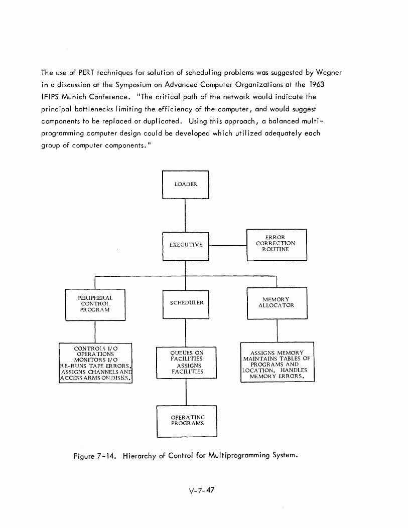
The use of PERT techniques for solution of scheduling problems was suggested by Wegner
in a discussion at the Symposium on Advanced Computer Organizations at the 1963
IFIPS Munich Conference. liThe critical path of the network would indicate the
principal bottlenecks I imiting the efficiency of the computer, and would suggest
components to be replaced or duplicated. Using this approach, a balanced multi
programming computer design could be developed which utilized adequately each
group of computer components. II
PERIPHERAL CONTROL PROGRAM
CONTROLS I/O OPERATIONS
MONITORS I/O RE-RUNS TAPE ERRORS. ASSIGNS CHANNELS ANI: ACCESS ARMS ON DISKS.
LOADER
EXECUTIVE
SCHEDULER
QUEUES ON FACILITIES
ASSIGNS FACILITIES
OPERATING PROGRAMS
ERROR CORRECTION
ROUTINE
MEMORY ALLOCATOR
ASSIGNS MEMORY MAINTAINS TABLES OF
PROGRAMS AND LOCA TION. HANDLES
MEMOR Y ERRORS.
Figure 7-14. Hierarchy of Control for Multiprogramming System.
V-7-47
7.2.6.7 load Shari ng
If the length of computer tasks may be clearly anticipated, the problem of optimum
allocation of tasks to processors, and optimum sequencing of tasks within individual
processors is greatly simplified. Unfortunately, this is usually not the case. It is not
always possible to divide the tasks between processors in such a way as to equal ize
the load.
Even in cases in which tasks are of fixed and predictable duration, the occurrence of
external events, (e. g., input request interrupts, receipt of command information,
etc.) may cause computing load imbalance, and possibly enforced idle time. This
problem may become particularly serious if the output of one processor is required by
another processor for performance of a subsequent task.
In systems for which the processors interrelate to a high degree in the performance of
common tasks, intermediate results are often passed between the processors. Frequently,
one machine must be idle while waiting for needed data.
One approach to this problem involves periodic monitoring of the program progress in
each processor. For th is sch eme, processors signal each other, reporti ng status informa
tion, and make periodic decisions whether to cause a shift of functions from one
computer to another. It is quickly seen that the logic for such decisions is not
necessarily trivial and that such a monitoring scheme, if made too complex, becomes
so cumbersome as to negate the advantages of load redi stri buti on. I n general, the
pre-empting of one processor from continuation of its assigned tasks to accommodate
higher priority tasks should be minimized.
A preferable treatment of load sharing may be obtained with the use of common
function lists as described in a foregoing subsection. With this approach, the
processors are able to schedule themselves by selecting tasks on an availability basis.
Th is scheme introduces a self -organizing characteristic to the system, but is subject to
precedence limitations as was noted.
V-7- 48
"An Analysis of Computing-Load Assignment in a Multi-Processor ComputerU is the
title to a paper by Aoki, Estrin, and Mandell wh ich presents one of the few analytical
treatments of this subject. 14 The problem was analyzed with the use of three 2-com
puter models. One interesting conclusion derived is that, uassuming two processors
with uniformly distributed computation times, it was shown that the ratio of computing
time in a one-processor system is a function of the ratio of the standard deviation of
the computing time distribution to the expected computing time for the single computer. It
7.2.6.8 Programmi ng
The basic limitation in computer technology is sometimes seen as the difficulty in
describing problems in an operational language that is both unambiguous and precise.
However, multi-computer systems are probably not significantly more difficult to
program than other systems. The primary complexities imposed by reason of the multi
computing aspects of the system are those of scheduling and load sharing as discussed
in the previous section. To a large extent, executive control for any system deals
mainly with considerations which are independent of whether the system is a multi
computer system or not. Executive control in a multi -computer system involves
different kinds of complexities (not necessarily more) than for a single unit processing
system.
Design of control programs for multi-computers is a pre-eminent consideration,
nonetheless, and much attention should be devoted to this problem. The preparation
of the executive programs is a one time expense which pays dividends in the system
support afforded. The control programs provide the framework with in wh ich the
operati ons programs are executed. If properl y designed, the system user programmer
may be rei ieved of much of the concern about the details of the system operation.
In general, the user programmer should not have to be unduly aware of the multi
computer aspect of the system.
The programmer should be provided with the necessary tools to specify parallelism
without the necessity of being concerned with assignment of individual processors to
the tasks. This subject is explored in a paper by Conway. He suggests the use of the
terms "FORK" and "JOIN" as instructions for specifying parallelism. These are
particularly useful commands, since, from a programming standpoint, all parallelism
is the result of forks in flowchart paths. Similarly, parallel paths may be rejoined
by a JOI N command. V-7-49
The incorporation of special language features and the addition of new compiler
language statements for multi-computer usages will be an important consideration
in developing programming facility. The language design should be flexible and
should incorporate software modularity; and should be as nearly parametric to the
anticipated applications as is possible.
In this connection, the development of a special command/control language is
recommended. This language should include special multi-computer macros to treat
precedence, scheduling, and task allocation problems. In addition, it should be
sufficiently generalized to be to some extent translatable through switch action and
should also have display feedback characteristics.
7.2.7 Executive Control
Executive control philosophy has been described in a paper by Pickering et al as
"0 recognition of the system1s t~sks in order of system priority; distributing them
among the system's computers; and then control I ing them in the individual computers
of the system by an executive routine within each computer. II 15
There are several kinds of executive control, and within each executive program is
usually a hierarchy of control to provide supervisory, schedul ing, monitoring, and
peripheral control. In addition, as was pointed out earl ier, the aggregate of external
interrupt signals together with the awaiting interrupt routine logic constitutes another
form of executive control which is able to superimpose environmental conditions and
occurrences into the system operati on.
Several basic concepts of executive control are characteri stic in current mu It i-computer
systems. Some of these are:
1) Master-Slave Control - Th is is typical in systems with central ized
control. Th is has the advantage of flexibil ity in the assignment
to the various subprocessors.
2) Reciprocal Control - This type of control prevails in systems
wherein both (or several) computers all have equal control
capabil ity, but at anyone time only one processor is in charge.
V-7-50
3) Autonomous Control - Th is type of control may be appropriate
for systems which divide tasks largely by function (e.g. , one
for I/O and one for processing). The executive programs may
be relatively independent and interrelate only occasionally.
4) Shared Control - The shared task concept was discussed in
previous sections. Here, as in the reciprocal control concept,
the processors have equal executive control capabi I itYi but no
one computer is in absolute control, and the executive concept
is one of self-servicing in respect to task selection.
There has been relativel y I ittle done in terms of formal or rigorous investigation of
program control of multi-computer systems. This subject is a challenging one,
deserving much design consideration; preferably early in the development of the
total system design.
The determination of executive philosophy is usually derived after other system
elements are determined and is, therefore, largely a pragmatic consideration, an
after-the-fact recognition of the system structure.
The full and complete optimization of all units of a multi-computer system is a multi
queue and schedul ing problem of great proportions. However, much can be imple
mented by the executive control program to improve the overall efficiency of the
system. AI though the executive control program cannot yet be expected to optimize
the system according to a complex mathematical formula, it can nevertheless
accomplish considerable system optimization. It can also provide the very first and
important step in the research and development process which must take place to allow
full use of multi -computer systems.
7.2.7.1 Burroughs D 825
Since all memory is totally shared between all processors in this system, programs or
program segments may be sh if ted about from processor to processor. AI so, since
programs need not be associated with any particular processor, it is possible to regard
programs as controll ing processors instead of processors executing programs. The
result of this concept is an executive routine that is executed by each processor when
its services are needed for obtaining a new job. This program is called Automatic
Operating and Schedul ing Program (AOSP).
V-7-51
The AOSP maintains a job file for all programs currently in the system. When a
processor seeks a new assignment, it runs the AOSp, and if it is assigned to the program
it transfers the program from the ma in memory to its own memory. If the program is
interrupted for any reason, the proces:;or transfers it back to the main memory suitably
revised to take account of the work done to that time by the processor. Subsequently,
the program is again taken up by another processor or the same processor depending on
the priorities and the loadings.
The AOSP may also divide a single program between several processors since program
branches may be specified by programmers. In this way, simultaneous parallel solution
of the separate segments can be ach i eved.
The AOSP resides in the main memory of the D 825. The actual memory space
required varies considerably with the application because,for any given application,
the AOSP is a selection of routines drawn from many options.
The AOSP initiates all programs thai" are part of the system application. It allocates
space for these programs in the system l s memory. The AOSP schedul es all i obs and
determines the equipment configurations to be used. Additionally, it coordinates all
input/output operations and obtains buffer storage, updates lists of availability of
input/output peripherals, and sequences multiple requests for the same data.
7.2.7.2 UNIVAC NTDS System
The un it computer of the Naval T acti cal Data System is the UN IVAC AN/USQ-20
A typical multi -computer installation may use three of these basic units. The executive
control ph i I osophy for the NTDS was based on the requ irement that in a real-time
system the delay in responding to an input is negligible in the time reference of the
user equipment or operator. Hence, schedul ing of the functions to be performed by
the system must ensure that peak loads are smoothed out and all tasks must be per
formed within their real-time requirements.
V-7-52

The executive control philosophy recognizes systems tasks in order of system priority,
distributes these tasks among the computers, and controls the tasks in the individual
computers through an executive routine within each computer.
The executive routine consists of an eight instruction main control loop, some interrupt
processing, and "flag" setting routines, together with three tables per computer.
An operational program is organized into component subprograms of which there might
be ten to twenty-five typi call y. These subprograms in each computer vary in compl ex
ity up to six subroutine levels.
The executive routine calls on one of the subprograms based on the need for execution.
When the subprogram has been executed control is returned to the executive.
One of the many interrupts may be activated at any time. Each interrupt triggers a
subroutine in the executive thus setting a 11flag" to cause a later entry to that sub
program.
The executive control philosophy is complemented through a method of table control.
There are three tables,which contain entries for each assigned subprogram,
ordered by system priority. The executive flag table contains the time at which the
subprogram is to be executed. The executive time table contains the automatic delay
before the subprogram can be repeated, and the executive jump table contains the
address of the subprogram. In operation, the executive routine sequentially compares
the real-time clock of the computer with the entries in the executive flag table. It
starts with the task of highest priority. When the clock is greater than or equal to
the executive flag table, the corresponding time table entry is added to the current
time, the sum is stored in the executive flag table,and control is transferred to the
subprogram as specified in the executive jump table. When control is returned to the
executive routine, or if no correspondence occurs, the search of the executive flag
table is repeated starting again with the task of highest priority.
V-7-53
7.2.7.3 Real Time Data Handl ing System Primary Site Executive Concept
The RTDHS Primary Site is a two-computer sytem which illustrates the shared executive
concept of control. The RTDHS Primary Site executive programs provide the framework
within which the operations programs are executed. In general, the control functions
divide conveniently between those functions required for system operation and support,
and those wh ich control and sequence the operations programs. Imposed upon the
operation defined by these two systems of control is a third set of controls, exerted
external to the computer by the many interrupt control I ines of the system.
Accordingly, the master control design of the primary site computer program incorpor
ates interrelating control programs which are divided functionally into three categories:
the executive, the cyc I e supervi sor ,and the interrupt processors. TheE;xecutive
program (EXEC) controls the system operation, sequences and schedules system functions,
responds to new input, by setting communication items and control information, and
controls porgram output. These operations may be performed synchronously in respect
to the data cycle. The functions of EXEC are classified into two categories:
1) Class 1 - The higher priority executive functions which must
operate every data cycle.
2) Class 2 - Those functions of lower priority wh ich are performed
on a time available basis.
The cycle supervisor program (CYSUP) controls the sequence of the operations programs.
It accomplishes this by interrogating a common task list, called the common function
table, selecting the highest priority task and branching control to the operations program
requ ired to perform the task. If the system is operat ing in a two computer mode, the
second computer is notified when the task is undertaken and the program results are
transm itted to the other computer when the task is completed. It is noted that the
cycle supervisor program is completely dependent upon the common function table;
that is, it makes no independent decisions regarding the operations programs sequence
other than those explicitly derived from the logic associated with the common function
table. Imposed on the system control program (EXEC) and the operations control
program or cycle supervisor (CYSUP) are the interrupt processors. By this means,
events external to the computer are registered in the computer program in a timely way,
and the computer is able to respond to new situations in a predetermined manner.
V-7-54
In addition to the external interrupts wh ich are expected regularly as a function of
time, there are many other external interrupt sources from wh ich events external to
the computer may be registered in the computer program almost instantaneously. Thus,
a sensitive and timely response to command/control information input by human or
electronic intervention is possible. The computer can also respond quickly to
reconfiguration commands and is able to alter quickly the priority of operations
when necessary.
All real-time operations in the system are carried out within the framework of the
cycle concept. The cycle is initiated regularly by the input of data (Input Data
Request Interrupt). The transfer of control between the several levels of control
programs and the operations and utilities programs for three data cycles is illustrated
in Figure 7-15. This illustration is for one computer only. The control transfers forthe
other computer would be similar but they vary in detail except in respect to the common
input data request interrupt wh ich initiates the cycles.
V-7- 55
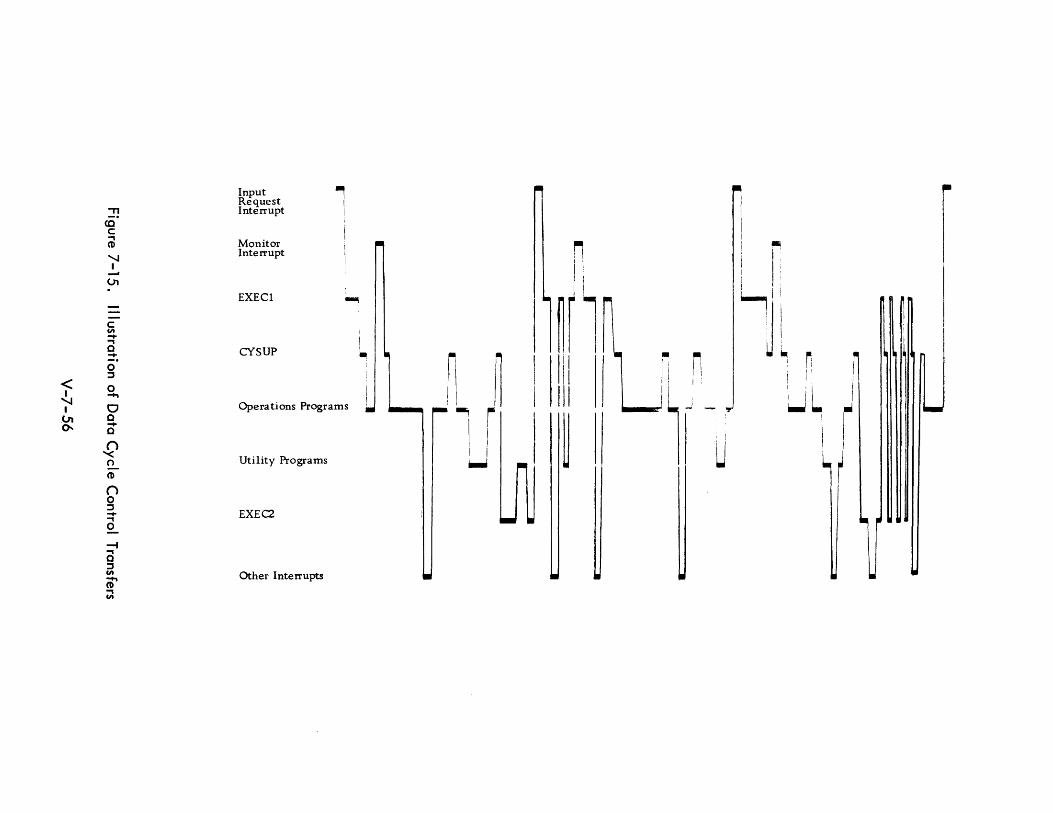
< I
'.J I 01 ~
" co c .., CD
'.J I
01
c CIt -.., o -o ::l
o ~
o o -o ()
"'< o CD
() o ::l -.., o ---4 .., o ::l CIt
CD' .., CIt
Input , Request I Interrupt I
Monitor Interrupt
EXEC1
CYSUP
~
I
i i I
I.
U
: . I
OperatIons Programs I
Utility Programs
EXEC2
Other Interrupts
iI , I
!
~ 11 '-, r I I ~
I ~r l I II
~
· r: '. I I! I
II I I I " I I I
i
1J u
.. I
Ii I'
I I : i
~J .. lil
~ Ii . I ~ I I
I iL ~ , I
\ I
r
I
7.2.8 Advantages of Multi -processing
The advantages of multi-processing are noted in foregoing sections. A brief summary
of these advantages follow. Several potential disadvantages are also listed. In
general, they are the contra of the characteristics cited as advantages, i. e. , the
items enumerated to foil ow are not all necessari I y unmixed bl essings.
7.2.8.1 Flexibil ity
Multi-computer systems are expansible and flexible. Additional modules can be
added easily to modular multi-computer systems. Flexibility is gained by using the
various larger elements in different ways at different times. Even in a multi
computer system that is not modular, system capabil ity can be expanded by replacing
one of the computers with a more capable computer. For th is purpose, it is important
to provide interfaces among the computers that do not I ead to undu Iy compl icated
programming for the replacement.
7.2.8.2 Rei iabil ity
Multi -computer systems give increased rei iabil ity over a system wh ich rei ies on a
single central computer. In the multi -computer system one computer can perform
high priority tasks while the other is down for preventive maintenance. Moreover I
in a highly decentralized, modular system, a few extra modules are sufficient to give
the system the same rei iabil ity as that achieved by duplexing a large computer and
at a mere fract i on of the cost.
7.2.8.3 Equipment Cost
Multi -computer systems can be less expensive than central computer systems. However,
the small er computer usually has a lower capabi I ity/ cost ratio than the larger. If the
cost of equipment were the only consideration the multi -computer system would not
show to advantage. But the economics of a system are often improved by a decentral
ized computer system. The question of equipment cost is a complex one. It requires
careful analysis on a case-by-case basis, with due regard to the somewhat intangible
cost items, such as tactical compatibil ity and obsolescence factors. As mentioned
earl ier, the rei iabil ity of the multi -computer complex can be increased at less cost
than the dupl ication of computers in the central computer system.
V-7- 57
7.2.8.4 Programming
Programming considerations were discussed in an earlier section. Added complexity
required for multi-processor control may be partially offset by several possible
advantages.
From a programming point of view, the use of multi -computers allows a more natural
division of the problem into levels of control. Interfaces in programming can be
developed among the various large programming components, such as: input, output,
analysis, information retrieval,and so on. This is of great advantage in large pro
gramming jobs, especially where pieces of the programming might be subcontracted.
If there is independent programming in independent computers with a simple communi
cation interface among them, programming of the computers can be relatively
independent. With executive programs, for example, the separation from the executive
control program of the input/output control program greatly simplifies synchronization
and memory allocation problems.
7.2.8.5 Summary of Advantages
In summary, a I ist of possible advantages of the multi -computer system design foil ows:
1) The equipment complement can be tailored to a specific task by
selecting the most useful set of modules for that task.
2) The system can be expanded incrementally as the task changes
in nature and in size, thereby keeping an efficient system-to
task match.
3) Parallel processing is achieved, i.e., a number of tasks can be
processed at the same time without having to time share equipment.
4) Automati.cscheduling and sharing of peripheral units is facilitated.
5) System rei iabil ity is increased by module redundancy instead of
system redundancy.
6) Module rei iabil ity is increased because large capacities are
achieved by multiple modules.
V-7- 58
7) Maintenance is made simpler since some modules may be used to
detect and locate equipment malfunction in the other modules.
8) Continuous real-time system operation is practical since individual
modules can be removed for preventive or emergency maintenance
without making the overall system inoperative.
9) Tasks that involve widely varying equipment configurations can be
handled with high efficiency.
10) A large number of simultaneous requests by men and machines can
be rapidly processed by a modular multi-computer system.
11) Improved utilization of equipment may be achieved.
12) Reduction of program checkout time and production run turn
around time is facilitated.
13) Multi-processing and multi-programming facilitate on-line
debugging, man-mach ine interaction, and remote operations
and communication.
14) It may be argued that minimization of overall system cost is
achieved in terms of cost performance economics.
15) Compatibil ity with tactical deployment procedures is enhanced.
16) A modular multi-computer system should obsolesce at a slower
rate than a single computer system.
V-7- 59
7.2.8.6 Disadvantages
Some of the advantages cited above are advanced tentativel y since several of these
points are open to question and may even belong on the other side of the ledger
(e.g., 9), 12), 14)). Others are highly dependent on the successful solution of
substantial problems of schedul ing and communication (1), 4), 11), 12)).
A few disadvantages are I isted below. In general, they are those of program and
system complexity, potential confl icts of hardware usage, and coordination overhead.
1) The aggregate of coordination overhead functions may constitute
an appreciable proportion of the required computers' activities.
Included in such overhead functions are information exchange
requirements, extend executive overhead, load balancing, and
task monitoring.
2) Confl icts of priority and equipment usage are possible. For
example the same device may be needed by more than one
processor, requiring that one wait. Memory accessing of the
same memory by more than one processor may reqlJi re queu ing
procedures.
3) Although improved hardware util ization was cited as an advantage,
it should be noted that two computers are usually less than twice
as powerful as one. Hardware utilization efficiency results only
if, by schedul ing, a higher util ization of all system equipment
may be maintained.
4) The programming of multi-computers is considerably more complex
unl ess methods can be developed to make the several processors
appear to the programmer as one. To obtain th is capabi I ity may
itself be a complex undertaking.
V-7-60

7.2.9 Conclusions
Any future plans for the acquisition of computer systems by the Navy for ACDS should
be heavily influenced by multi-computing considerations. The most important aspect
of multi-computers is the reliability which can be achieved through module
redundancy rather than total system redundancy. Improved performance is obtained I
by the automatic schedul ing and sharing of peripheral equipment among the processing
units.
Command and control systems are especially amenable to approaches by multi-computer
systems. These real-time systems are large scale, involving many different types of
tasks proceeding simultaneously (communications handl ing, display data handl ing,
internal processi ng, information retrieval, etc.). The various tasks can be compart
mental ized and th is compartmental ization can be related to the system components.
Also, the changing patterns of the data processing load related to the threat or the
military situation is especially suitable for multi-computer approaches.
Computer systems for ACDS should employ multi-computing and multi-programming.
In some cases it will make sense to have the computing elements time shared by many
processing functions. In other words, if multi-programming and multi-computing are
considered as two extremes, future systems should not look like either extreme since
there are advantages of both, and there are reinforcing advantages to a combination
of both. It can be argued that multi-programming supplies a motivation for multi-computing.
In general, because switching and control techniques are involved with multi-computer
systems, the equipment cost is probably somewhat higher. However, these equipment
costs are offset by savings in allowing incremental additions of equipment and by the
increased service, responsiveness, and rei iabi I ity of the total system.
Since the switching problems involved with the multi-computer systems for tactical
command and control might be quite different than those necessary in commercial
applications, studies of the switching problem should be undertaken. These studies
should cover the requirements as well as the various possibil ities for hardware implemen
tation. For example, simulation studies could be undertaken to better understand the
type and frequency of switching within a system since these answers will greatly affect
V-7-61
equipment development and equipment manufacturing costs. A specific important
question, for example, is whether solid state switching techniques are necessary or
whether electromechanical devices such as dry reed switching devices can be employed.
Studies should also be undertaken on the various topological approaches to multi
computer systems such as the number and type of modules required. Similarty, studies
should continue with the various approaches to executive control and programming;
various executive control programs should be developed and tried.
Multi -computer systems are probably not significantly more difficult to program than
other systems. There is, however, a need for highly developed system support in the
form of carefully designed executive programs. In general, the user programmer should
not have to be unduly aware of the multi -computer aspect of the system and should be
able to approach the system as if he were programming a single computer.
Executive systems for achieving program control should be given much consideration
in the design and early application of the multi-computer system. The program control
system requires as much design consideration as the hardware itself. It is noted that
preparation of the executive programs, however, is a one-time expense and pays
dividends in the operati ons programs support afforded.
Programming costs for multi-computer systems are not significantly higher than
for single computer system. Executive control for any system deals mai nly wi th
items which are independent of whether it is a one-computer system or a distri
buted multi-computer system. Executive control in the multi-computer system
involved different kinds of complexities (not necessari Iy more) than that control
with a single processing unit system. There are many phi losophies of executive
control through programming. For example, there is the hierarchy approach which
was considered in the RW-400 work, as compared with the distributed or shared
control in the D-825. In the hierarchy approach to executive control, the control
can be vested in one processing unit or can be decentralized to many.
V-7- 62
Several general design criteria are advanced for the development of multi-computer
systems for ACDS:
1) They should be composed of modular elements capable of
communicating freely. The restriction that the processing
units, I/O control, and memory units should be housed in
the same package should be removed.
2) A major portion of the high-speed memory should be shared by
or accessible to the processing elements. The use of common
storage eliminates the necessity of large amounts of inter
processor communication.
3) All peripheral equipment and auxil iary memory should be
switchable to anyone of the main frames or processing units
which could conceivably be used to support it or transmit data
to it. All displays should be accessible to all computing
equipment of data files which could conceivably supply infor
mation to them.
4) Arithmetic/control units should be small enough so that two to
four units can be used to supply the needed processing. The
degree of granularity allows the redundancy necessary for
rei iabil ity and provides growth in small enough increments to
allow cost savings.
5) Different types of main processing units (central processor,
communications handling, display data handling, etc.) are
acceptable. However, the employment of modules should be
consistent with the principle espoused in 4) above.
6) The system should have a limited self-organizing capability such
that it can schedule tasks, allocate modules, and reconfigure the
system accordi ng to simpl e procedural directions (both programmed
and operator control I ed).
V-7-63
7) The system should be self-sufficient requiring little operator
intervention in the usual situation, yet be instantly responsive to
developing situations.
8) The equipment itself must be capable of accepting information
from many sources asynchronously and without data loss. This
impl ies an extensive interrupt capabil ity and the establ ishment
of fine gradations of priority.
V-7-64

7.3 ASSOCIATIVE MEMORIES
7.3. 1 Introduction
To keep pace with computer problems of ever increasing complexity, the usual sol uti on
has been to demand greater speeds of computing components. Further speed advantages
may be expected with the application of micro-miniaturization techniques. Devices
currently under development have switching speeds measured in fractions of nano
seconds. However, theoretic bounds of maximum speed appear to be impl icit in
certain physical parameters which at this time seem to be immutable. It also is evident
that a number of important problems are still not computable at current or anticipated
speeds by conventionally organized computers.
As it becomes more difficult if not impossible to achieve order of magnitude speed
advantages, increasing attention is given to the possibilities of utilizing parallel
processing techniques to achieve additional computing power. The development of
associative memories constitues one approach in this direction.
The use of associative memories in future command systems appears promising. Several
areas for which associative memories are candidate are:
Radar data - track data correlation.
Scan-to-scan radar data correlation.
Track data retrieval.
Weapons assignment.
Threat evaluation.
Sorting.
File search for communication and display.
Message format conversi on.
ECCM.
Decoy discrimination.
V-7-65

The development of associative memories is very broad and it is difficult and perhaps
inaccurate to generalize on all such implementation with a single evaluation.
Currently, there is a wide assortment of designs in various stages of development
using many different hardware approaches. Therefore, we indicate the kinds of
capabilities that are provided in current designs, discuss programming implications
and the kinds of applications for which associative memories seem best fitted,and
consider potential extensions of the capabilities in the direction of parallel processing.
We then place associative memories in the context of concomitant developments,
both competing and reinforcing, and finally, discuss their pertinence to the development
of future tactical command and control systems.
7.3.2 Implications to Advanced Tactical Data Systems
The programmer tends to regard the advent of associative memories as a blessing since
it provides him a new capability. However, since the development has not won
widespread acceptance,and saleable commercial versions appear to be some way off,
it must be examined closely from the standpoint of capability per unit cost. In
particular, the following questions must be considered:
1) Do associative memories provide a capabil ity for a number of
appl ications of interest to future tactical command and control
systems?
2) Are other developments (e.g., hardware advances and new
software techniques) likely to achieve the same capabilities at
less cost? Will applications be found which justify development
to the point that commercial versions will be in production and
readily available by 1970?
3) Do associative memories appear to be more useful or less useful
for tactical command and control probl ems than for general
computing problems as a whole?
4) Do associative memories provide computing power at times of
system stress? (i. e. , at times when normal system excess capacity
is unavailable)?
5) Are there uses to which associative memories may be put which will
achieve results unobtainable by other means?
V-7- 66
The first questions are typical of any decision involving differential costs. The last
question, however, alludes to one of the distinguishing characteristics of military
appl ications and to command and control problems in particular.
These characteristics are those of urgency and immediacy. Military applications
sometimes demand capabilities which can be supplied only by utilizing devices on the
frontier of technological development. Where matters of national interest and perhaps
survival are at stake, absolute performance is someth imes demanded by means wh ich
would not seem justified according to usual cost/performance formulae.
In summary, the inclusion of associative memories in a future tactical system must be
justified either on the basis of intrinsic economic advantage (more capacity per unit
cost) or on the basis of unique performance capabilities in critical situations.
7.3.3 Defi n iti ons
The term assoc i at ive memory (AM) as used in th is report encompasses a number of
current and postulated developments, several of which are perhaps more descriptively
called by other names. Some of these designations are:
1 ) Content addressable memories.
2) Search memories.
3) Parallel search memories.
4) Recogn iti on memori es.
5) Data addressed memories.
6) Tag memories.
7) Catalog memories.
V-7- 67
The term content-addressable-memory (CAM) is perhaps the most descriptive term
since the capabil ity to address by contents is the basic characteristic common to most
proposed designs. The term search memory is indicative of the type of application
anticipated and, in conjunction with the word parallel, suggests the basic advantage
over conventional computer organization, i.e., parallel logical operation. The
associative aspect of these memories derives from the ability to ~btain quickly
associated information by specifying a set of key information referred to as
associative descriptors.
Prol iferation of terms is due not only to the usual chronic difficulty of achieving
standard terminology, but also to the fact that researchers are anticipating usages
from differing viewpoints. Therefore, emphasis is placed on different aspects of the
same basic design depending on the applications envisioned.
7.3.3.1 Content Addressabl e Characteri st i cs
The addressing technique employed for conventional memories requires that the location
of the information to be retrieved be known. This is sometimes referred to as coordinate
addressing or addressing by location. An alternative addressing technique is the
retrieval of stored information on the basis of content. Word cells are accessed by
the characteristics of the stored data rather than by the physical location of the cell.
The physical location is immaterial in this case. Memories with this capability are
said to be content-addressable. The term content-addressable-memory is somewhat
broader than the associative memory designation since several other computer memory
organizations not generally recognized as associative memories depend on the content
add ress i ng capab iii ty .
The development of new addressing techniques is not without precedent. It is some
times suggested that th e deve I opment of content addressi ng is analogous to that of
indirect or other recognized addressing techniques (e.g., relative, indexed, implicit,
immediate, truncated, etc.) To a similar (or greater) extent, content addressing
provides generality to the common task of II operand fetching. II
V-7- 68
The problems of addressing are taken for granted to such an ex tent by the programmer
that he is perhaps not aware of the somewhat superficial relationsh ip of an address with
a quantity of information. Unfortunately, the programmer, particularly, the machine
language programmer, must often deal largely with addresses rather than information
Th is preoccupation with location imposes a large housekeeping and data organization
requ i rement wh i ch is expensive in terms of mach i ne execution time, and storage and
programming effort. Although it is not unreasonable to expect the programmer to keep
track of and in some cases plan where information is to be kept, it is interesting to
conjecture concerning the advantages to be obtained by a programming technique
substantially free from the addressing requirement. This is feasible with several
designs of content addressable memories. Information is simply stored in the first
available cell and may be retrieved later in one cycle (or two) without knowledge of
the physical whereabouts of the information.
7.3.3.2 Parallel Search Characteristics
Some writers prefer the designation" Parall el Search Memory" (PSM) wh ich conveys
what is felt to be the basic advantage of the design, i.e., the capability for simul
taneous search of multiple registers for stored data identified by its characteristics
rather than by its location. This term is descriptive of the type of application for
which associative memories seem best fitted, e.g., those tasks for which a conventional
computer would perform a sequential search through data cells. The speed advantage
derived from parallel logical operation could amount to an order of magnitude perfor
mance improvement. The parallel processing aspect of associative memories is the
most exciting characteristic. Extensions of this capability include the concept of
simultaneous computation in a distributed logic machine.
7.3.3.3 Associative Characteristics
The associative memory designation derives from the facility to obtain quickly
associative information. Th is may be accompl ished in several ways. For some designs
the physical address is obtained when a successful search is terminated. This address,
which is usually a function of the address of the desired information, may then be
used to retrieve the associative data. In other designs, only a part of the contents of
each cell is used for the purpose of the search, and the remainder of the cell {which
V-7- 69
mayor may not have content-addressable properties) consists of associative informa
tion. Alternately, the associative information may be obtained by means of an address
contained in the accessed word which, in turn, is used to access (conventionally or
not) another area of memory. Thus, it is possible that a word may be compared with
several thousand quantities in one access time; when a match with a selected subset
occurs, the associative data may, in turn, be used to call other subsets in an
associative chain.
Some writers reserve the term associative memory for those designs wh ich are used in
conjunction with a conventional memory, assuming that the associative information
is stored there, and that the key (or index) to it is obtai ned by associative memory
i nterrogati ons.
7.3.3.4 Other Termi nol ogy
Other designations which refer to the same basic capabilities are found in the litera
ture on the subject. Examples of these are the recognition memory and the data
addressed memory (DAM). The term tag memory is sometimes used to describe a
memory which limits the search capability to certain bits (called the tag field) of the
cells to be searched. The catalog memory is used in the same connection to refer to
a memory in which the tag field encompasses the entire memory cell.
Finally, it should be noted that the term associative memory has only recently come
to refer to a particular hardware design. Formerly, the term was used to refer to the
use of conventional memory for purposes of associative logical processes. This usage
of the term persists and is of continuing validity.
V-7-70
Associative Memory Capabilities
Associative memories currently under consideration present a broad spectrum of
capabil ity -- from the simplest search based on the criterion of equality, to searches
using selected bit patterns (masks) and based on any of a dozen search criteria, and
extending to proposals which include computation on matched items. The feature, in
common with most designs, is the capacity to interrogate simultaneously a region
of the associative memory based on comparison with an external keyo The charac
teristic property is economical search speed. ]n the more advanced designs, in
dividual memory cells are capable of elementary logical decisions in relating the
stored data to the search criteria. By a modest extensi on of the log ical capabi I ity ,
parallel operation of simple conventional commands is obtained.
7.3.4. 1 Kinds of Capabi I ities
Associative memory functions can be classified as: (l). search functions, {2} read
function, and (3) write functions. The range of each type is quite broado Ac
cordingly, the combinative possibil ities for the design of an associative memory
are extremely varied. Thus, many tradeoffs exist which may be manipulated for
optimization. An important outgrowth of this fact will be the eventual abil ity
to specify a capabil ity which is very closely oriented to specific appl ication needs.
Search functions vary according to the types and combinations of search criteria and
the various ways of specifying the search field to be interrogated. A typical search
function will involve the specification of a number of search descriptors {e.g.,
search mode indicators, search criteria, masks, comparands, etc.}.
The reading functions relate to the type of reaction desired as a result of the search.
For example, data contained in the addressed cell (as in conventional location
addressing) and/or the physical location could be desired as an output to the search.
Multiple match resolution may be a readout feature. Other read function by-products
may include a tally of the number of matches or simply an indication of whether one
match or no match was found.
V-7- 71
Write functions may include conventional coordinate addressing, but may also allow
other write modes. One method of writing would load the first empty (zero) location
with the word to be entered. Th is feature has a data packing effect and tends to
preserve contiguous blocks in the associative memory. The ability to write selective
bits (or fields) in a particular word is usually provided. This is achieved by forming
the logical product of the operand and a mask register. A parallel write operation is
provided in some designs. This allows the entire memory, or a selected subset of
memory, to be changed in parallel.
7.3.4.2 Search Criteria
Search criteria are presented simultaneously to all ot to selected subsets of the associative
memory. Criteria other than identity with the externally presented key are possible.
For example, the associative memory may be designed to search on the basis of:
greater than, less than, between limits, minimum, maximum, next higher, next
lower, etc. Mixed modes may also be specified involving combinations of indepen-
dent searches performed in sequence. Th is is also referred to as a successive search
criterion. In addition, a simultaneous search criterion may be provided which
accomplishes a search on multiple criteria in one search cycle. Composite searches
in which different search criteria are used for each of several fields in the search
word are also proposed in some designs. The 11m of nil logical relationship is also
possible; thus, a successful search is defined as one which satisfies m out of n criteria
(e.g., any three out of four specified characteristics).
The satisfaction of the specified search criterion is said to result in a IImatch. 1I A
search may result in a match, no match, or in some cases multiple matches. Some
designs include the option of specifying that the search be terminated after the first
match or after n matches occur, where n is a preset threshold parameter. A more
usual method is to provide a multi-response resolver which provides unique to non
unique processing to allow a serial treatment of matched items. Typically, the
matched cells are identified, i.e., tagged or marked, in order that the contents may
subsequently be retrieved. Typically, one or more tag bits are provided with each
cell for th is purpose.
V-7-72
A select pattern or mask is sometimes used in conjunction with the match word to
specify that only certain bits of each cell be examined. This permits the use of a
completely variable field structure to fit any format requirement and allows any or
all bits to participate in the search. Memory partitioning may also be provided.
This refers to the ability to search on segments of memory selectively. This capability
is especially powerful if the capability to reconfigure search memory segmentation
is also provided.
7.3.4.3 Associative Descriptors
As indicated in the foregoing discussion, input parameters to the search process are
made up of several el ements. The input arguments, when considered separatel y from
the data, are sometimes called the associative descriptors. A list of these parameters
in the approximate order of logical complexity is given in Table 7-1.
As parallel operations become more intricate, the required (distributed) logic is
extended. The additional capabilities are, in some cases, prohibitively expensive.
Th is factor motivates simpl icity of design and, where possible, the use of programming
to extend the logical properties of the hardware. For example, it may be found more
economical to provide the sequential retrieval of multiple matches rather than the
more complex capability to distinguish a unique match from a non-unique match and
an automatic tally of the number of matches.
In this connection, a renewal of motivation for the use of micro-programming may be
justified. Many of the more complex logic (i.e., instructions) may be derived by
programming. In general, the parallel execution of commands of modest complexity
will depend on the effective combination of logical subcommands of an even lower
order.
V-7-73
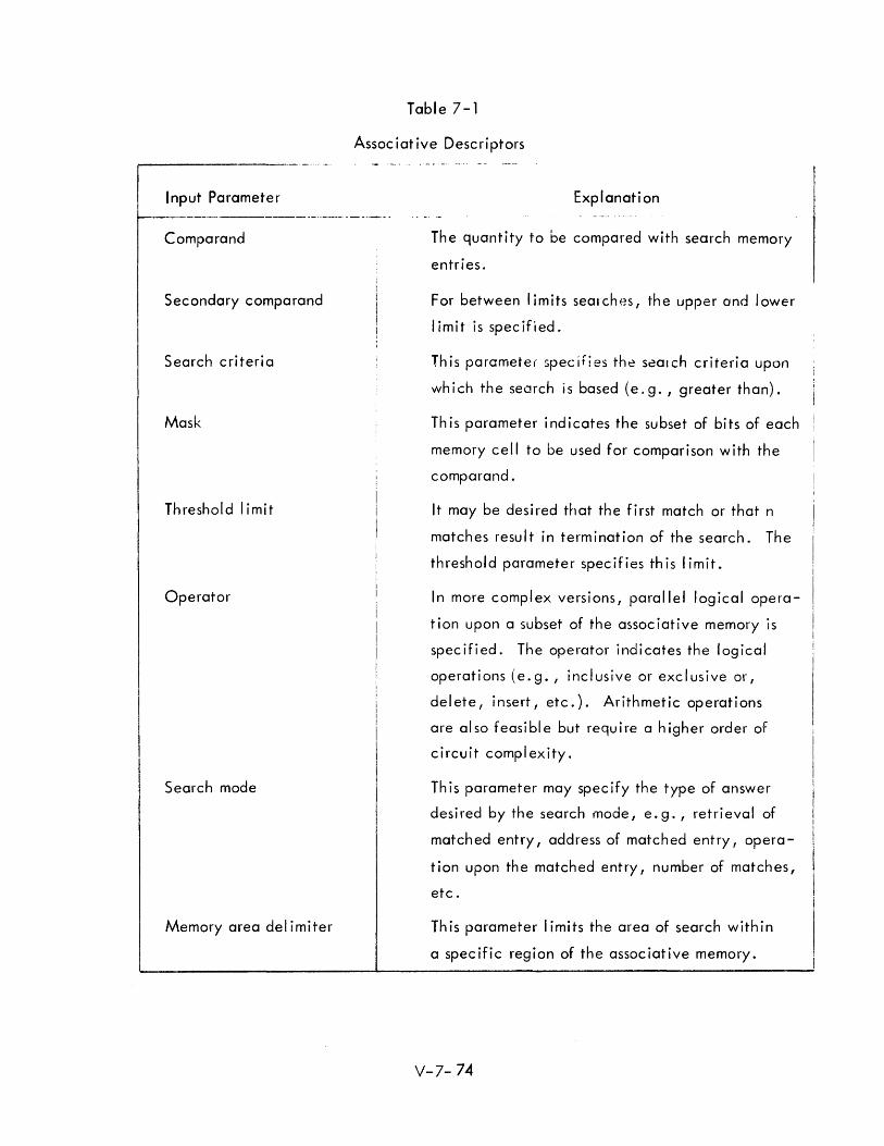
Input Parameter
Comparand
Secondary comparand
Search criteria
Mask
Threshold limit
Operator
Search mode
Memory area del imiter
Table 7-1
Assoc iat ive Descri ptors
Explanation
The quantity to be compared with search memory
entries.
For between limits searches, t-he upper and lower
I imit is specified.
This parameter specifies the s~OIch criteria upon
which the search is based (e.g., greater than).
This parameter indicates the subset of bits of each
memory cell to be used for comparison with the
comparand.
It may be desired that the first match or that n
matches result in termination of the search. The
threshold parameter specifies this limit.
In more complex versions, parallel logical opera
tion upon a subset of the associative memory is
specified. The operator indicates the logical
operations (e.g., inclusive or exclusive or,
delete, insert, etc.). Arithmetic operations
are al so feasi bl e but requ i re a higher order of
circuit complexity.
This parameter may specify the type of answer
desired by the search mode, e.g. I retrieval of
matched entry, address of matched entry, opera
tion upon the matched entry I number of matches,
etc.
This parameter I imits the area of search within
a specific region of the associative memory.
V-7- 74
7.3.4.4 Organization of Associative Memories
Several methods may be used to obtain the associative information after a search
interrogation. In some designs, only part of the cell is used for the search (is content
addressable) and the remainder of the cell constitutes the associative information. This
arrangement is shown in Figure 7 - 16 (A). Another method of deriving the associative
memory is by using the physical address of the matched cell to indicate the location of
the associative information in conventional memory (Figure 7-16 (B). These two
arrangement are logically identical if the somewhat arbitrary division of boundaries
of word length are ignored and it is assumed that both sets of associative data reside
in conventional memory. A third possibility is that the address of ~he associative
information is contained in the accessed word (Figure 7-16 (C).
Although an ordering of addresses is implied in the diagrams, any number of methods
may be used to transform the locations in Figure 7-16 (B). Similarly, A, B, C, and
D as shown in Figure 7-16 are simply address tags indicating locations in conventional
memory and need not appear in any particular order.
7.3.5 Programming Considerations
New developments in computer hardware invariably suggest changes in programming
techniques and software methods. For associative memory programming, the conven
tional instruction repertoire must be modified and extended in order to provide those
functions required to manipulate the associative memory search descriptors.
7.3.5.1 Associative Memory Instructions 16,17,18,19,20
A number of command sets have been postulated - some of them highly structured.
Some designs assume that the associative memory is used in conjunction with a conven
tional memory which contains the instruction strings (programs). Others assume that
the associative memory contains the instructions. In this case there are programming
considerations regarding differentiating instructions from data. Contents addressing
may be used for this purpose and for controll ing the program sequence (i. e. , the next
instruction to be operated is determined by a search of indicator bits.) Instruction
decoding done within the associative structure often uses a stored logic design.
V-7-75
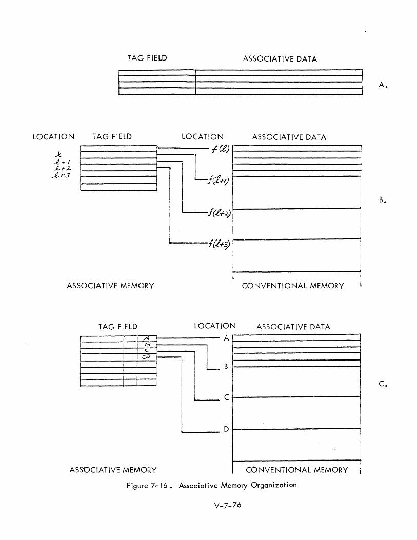
TAG FIELD ASSOCIATIVE DATA
A ..
LOCATION TAG FIELD LOCATION ASSOCIATIVE DATA
fet) 1------------1 i'--" L
I
ASSOCIATIVE MEMORY CONVENTIONAL MEMORY
TAG FIELD LOCATION ASSOCIATIVE DATA
A B c
:::;::J
- B
C.
C
D
ASSOCIATIVE MEMORY CONVENTIONAL MEMORY i
Figure 7.,..16. Associative Memory Organization
V-7-76

· . ,t;v§ memories will tend t L The basic commands used for programmang assocl(.. . ooe
elemento'l for some time to minimize the considerab. '. cost in providing distributed
logic capabil ities. It is important to consider the dift:erential cost of hardware vs.
software implementation (io e., cost vs. processing time] .for each new feature which
is contemplated as a potentially useful addit:on to associative .7'emory instruction
repertoires.
Instructions used for associative memories can be classified according to Vv'hether they
call for the performance of central logical operation (as with a conventiona I command)
or for the exercise of the logical circuitry; associated with each cell executed over
either the entire contents or a selected subset of the associative memory. These
categories might be termed central logic and distributed logic, re5pe~tivelyo Th~
latter term is more widely appl ied to computer organizations. Examples of the first
type are: the loading of central control registers (e.go, data register, mask register,
comparand register, etco) preparatory to operation upon previously retrieved values.
The latter type are search commands which are selectively operated as specified by
the setting of search designators. These include the ability to store data in cells
by parallel write (store) commands. It is also possible to mechanize one or more
simple operators at each cell, providing a parallel computation capabilityo
A paper by Estrin and Fuller describes algorithms for arithemetic and logical
commands which are executable in parallel for all words in memory or for some input lQ
set determined by a previous search 0" The commands are classified as basic memory
commands, basic logical commands and compound commands. An important feature
of this instruction set is a replacement addressing mode which allows writing into
many word cells simultaneously.
Several methods of writing into an associative memory are possibleo If the intention
of the write operation is to store a quantity in the first available cell, the write
command is preceeded by a search for a zero word. Alternately, a conventional
(location addressing) mode may be used if the location is known, as may be the case
when one value is to be replaced with another. Another technique for storage of
data involves the setting of location tag variables in a field of the associative
memory. In effect, this method provides the individual cells with names; unique
names, if des ired.
V-7-77
7.3.5.2 Programming Ease
It is of particular concern for implementation of military applications that programming
methods be tractable in terms of reasonable programmer effort. It is likely that
devices requiring complex and intricate programming methods will be adjudged as
unattractive sel ect ions for advanced tactical data systems unl ess adequate interpret ive
or compiler tools are available to make the programming task manageable.
At this time, the implications of associative memories on this question are not very
clear. Obvious usages to obtain efficient retrieval do not appear difficult to apply.
The programming for a search process is simply to specify the various search descrip
tors and retrieve the matched items. However, if the more complex parallel com
puting capabilities are assumed, questions of usage arise for which answers are not
obvious. A question such as "How do we utilize the capability to do 1000 multiply
operations at the same time?" resolves into t~e more general question of how
problems may be formulated to be solved in parallel. In short, the abil ity to program
parallel processing routines will prove to be much more difficult than that of pro
gramming a search. For the most part, these instructions will consist of loading the
search memory control registers, specifying the search mode, executing the search
command, and retrieving the matching quantities. For example, the instruction
sequence might be:
1) Load Test Word (Comparand)
2} Load Mask Word
3} Specify Search Mode
4} Execute Search (tag matched cells)
5} Retrieve tagged quantity(s}
V-7-78
On a higher level of code, a macro-calling-sequence might specify all the foregoing
functions. For example,
LOAD A, M
could be used to retrieve the (first) cell which contains A in the field(s) specified
by the Mask M. Similarly,
STO X
could call for the storage of X in the first available cell and could represent the
follow i ng const ituent commands:
Load Search Word (with zeros)
Execute Search (Tag fi rst zero cell found)
Retri eve address of Tagged Cell
Write X into Tagged Cell
Macros of the simple sort indicated above would help simplify the programming task
and would not pose an unusual task to existing assembly and compiler programs.
7.3.5.3 System Uses
The natures of the order codes differ widely, largely as a function of the varying design
approaches to associative memories. The basic differences stem from whether the
associative memory is visualized as a peripheral element for use with a conventional
computer, as special circuitry in a system organization composed of several (possibly
diverse) memory components, or as the central memory element in what might be
called an associative computer.
V-7-79
7.3.5.4 Assoc i at ive Computer
The use of an associative memory as the main memory in a computerwas anticipated by . 16 21 22
several writers. " Davies describes a design in which an extension of the
principles inherent in the associative memory point to the possibility of complex
simultaneous computations. 16 He provides a command list composed of logically
simple subcommands and demonstrates the feasibility of using microprogramming
techniques to extend the repertoire. This is illustrated by a multiply routine code
built from the simpler commands in the command list. By extension, general compu
tation can be performed simultaneously throughout the memory upon selected data
(i. e. , on data satisfying selected search criteria which are then tagged and thereby
made candidate for further computation). Davies concludes that the organization of
such a computer is particularly suited to the type of computation in which the same
program must be performed on a large number of data sets. This is characteristic of
many data processing problems and of a number of scientific calculations as well.
In fact, it raises the question of how often problems originally formulated in some
other way can be recast into this form.
The last comment is pertinent not only to this particular design but to the subject of
associative memories in general and to other novel developments in the direction of
paralleled processing designs.
Rosin has described the II Organization of an Associative Cryogenic Computer ll wherein
instructions must be in sequence but not necessarily contiguous and thus data words
b · . d 22 H '1' I b' f . I t 'd t'f . may e Intermlxe . e uti Izes contro Its or Interrupt contro 0 I en I y in-
structions, specify the addressing mode,and for sequencing control.
The instruction word format consists of twenty-five control bits, a 48-bit tag field
and a 64-bit data field. An interesting feature of the design is that the contents
addressing feature provides the instruction sequencing function. This is accomplished
by a masked search (based on a comparison with two control bits) for the next
i nstructi on to be operated.
V-7-80
7.3.5.5 Associative Memory Used as a Subsystem
The associative memory is more often suggested as a device to be used in conjunction
with a conventional computer organization. As such I it consitutes a special purpose
element in a system providing an augmentation of computing power in those areas in
which associative memories show promise.
Such subsystems have been proposed by several writers and impl ied by others. The
associative memory is also suggested as an appropriate component in the "variable
structure" of the fixed -pi us-vari abl e computer proposed by Estri n. 23
Another novel usage is the Associative Logic Parallel System (ALPS) described in a
paper by Seeber and Lindquist. 24 This system features parallel associative memory
modules used in conjunction with a set of computer modules. It uses the associative
memory to store instructions as well as data. The program structure is in the form of
a binary tree. Associative logic is used to control the parallel computers.
A II Search Memory Subsystem for a General Purpose Computer" is described by Kapla~.5 The unit operates similarly to a conventional arithmetic unit I receiving data directly
from main memory and placing the results of the search in an accumulator. This
design contai ns a search memory of 4096 36-bit words and 4096 48-bit words of
data memory. A number of working registers are provided: a search register contain
ing the comparand I a mask register I a mode of search register I and a parameter
register. The parameter register provides for variable length field designation. The
first bit of each field is indicated by setting a II 111 in the first bit of the field of the
parameter register. All other bits are set to 110. II
V-7-81
7.3.6 Appl ications
The applicability of associative memories to future tactical data systems depends
largely on whether significant portions of the processing problems are of a type for
wh ich the content-addressing capabi I ity is demonstrated to possess dec ided advantages
over conventional (location) addressing. It is, therefore, important to determine those
problem characteristics which tend to guarantee that problem solution time will be
decreased (or effective work increased) with the use of this capability; and to define
classes of data processing operations which make effective use of the inherent
parallel ism afforded by associative memories.
Content-addressing is efficient relative to location addressing for those applications
in which:
1) Files of data are manipulated and the search for individual items
in the data store is a significant part of the data processing task.
2) Fast or immediate access to data is needed in order to avoid
table search functions.
3) Data is retrieved on the basis of a multiplicity of reference
properties and cross referencing between files is a frequent
program activity.
4) Li st organ i zed data storage is requ ired.
5) Sorting is performed.
6) Encyclopedic data is stored from which retrieval of individual
items is called for.
7) Cataloging and cross indexing is required.
8) Comparisons with data arguments are needed quickly and test
answers concerning item characteristics required.
9) It is necessary to order data quickly for output or in the case
where data tends to become disordered dynamically during pro
cessing, or must be reordered according to varying criteria.
10) Problem solution is obtained by solving large sparce matrices.
V-7-82
These characteristics are to a large extent concentrated on data-oriented problems.
In particular, data with the following attributes:
I) Data with multiple arguments.
2) Data for which unpredictable growth of tables , arrays, or other
structures appears likely.
3) Data with a large proportion of void or zero elements.
Retrieval execution time is largely independent of table length. The advantage of
an associative memory is, therefore, more pronounced as file size increases.
Several applications which are anticipated for future tactical data systems are of the
type indicated in the foregoing list of characteristics. These are discussed briefly in
subsections to follow. Beyond the special applications for which advantages are
easi I y seen I ie new usages derived from new software techniques. These further
advantages will accrue from the reformulation of problems from the standpoint of
expl icitly exploiting inherent parallel ism, and from the unknown but predictable
advances to be derived from experimentation in these techniques when associative
memori es are a pract i cal hardware real ity.
7.3.6.1 Appl ication Studies
Relatively little has been done in the area of detailed associative memory application
studies. Instead, the emphasis of effort has been on the engineering aspects of the
development. The current chall enge appears to be to develop a workabl eversion
with sufficiently strong logical properties at a cost which is likely to result in
(commercial) acceptance of the design. Thus, significant work on the appl ications
of associative memories is much harder to find in the literature than descriptions of
the development of (yet another) "economical associative cell ," "logical design for
associative memoryll or II organization of an associative computer. II Another factor,
however, is that many striking advantages appear even from a superficial investigation,
so that further motivation is not needed to spur designers to continued efforts. The
utility is recognized; an economic mechanization is the next step.
V-7-83
There are several reports, however, of substantial scope which give quantitative
evaluations of associative memory performance contrasted with standard computing
methods.
A paper by Gall contrasts the performance of a sample tracking problem using the
USQ-20 Computer with the performance of a search memory used in two alternate
configurations of the USQ-20 on the same problem. 26 This application shows the
advantages of an associative memory to an impressive degree. The results of this
study are discussed briefly under breakdown 7.3.6.3 of this section.
A compreh ens i ve study of content -addressabl e memory systems is canto i ned ina
report prepared by R. H. Fuller at the University of California under the sponsorship
of the Office of Naval Research. 20 The problem areas investigated are function
optimization, visual pattern recognition, solution of elliptic difference equations,
real-time vehicle surveillance and determination of a critical path through a graph.
Performance figures are obtained for content-addressable memories of several types.
Characteristics based on current implementation design efforts were assumed. The
implementation media considered were: ferrite core, cryogenic tunnel diode, and
permalloy film. Solution times are compared with performance using the IBM 7090,
which is held to be representative of current large-scale,genera~purpose computers.
The 7090 is used to compare test probl ems for wh ich software techn iques are high I y
developed and associative memories are also considered candidate. A 7090-CAM
configuration was also studied.
Of particular interest are yet other solution time comparisons with highly-parallel
computer organizations: the Spatial Computer (SPAC), the Solomon Computer
developed at Westinghouse,and a computer specially designed for list processing,
specifically, a 7090 modification.
For these comparisons a CAM Model is developed and a highly structured instruction
repertoire defined. A relatively small set of operations is proposed from which
algorithms for the more complex commands are derived. The properties of the
content addressable memory are extended somewhat to include certain properties
V-7-84
usually associated with highly parallel machines (e.g., the capability to communi
cate with neighboring word cells). The CAM is assumed to be a subsystem used in
conjunction with a conventional computer. A simulation package was developed
which derived execution times for the various alternatives investigated. Various
conclusions were formed, several of which follow:
1) The CAM configuration outperformed the conventional computer
with speed advantages largely dependent on the application
considered. The reported gains range from two (function
optimization) to several thousand (solution of partial differential
equations, air traffic control and visual pattern recognition).
2) The extensions proposed for implementation of arithmetic and
logical commands similar to those proposed for distributed logic
(highly parallel, cellular) computers provides a comparable
capabil ity with a markedly less complex (and thus cheaper) design.
3) The CAM is suggested as an appropriate element in the variable
part of the fixed-plus-variable computing structure.
4) The proposed organization provides dynamic storage features
and capabilities for list searches that are more efficient than
the I ist organization methods used in conventional
(I ocat i on add ressed) mach i nes.
Another report prepared for the Advanced Planning Division of the Naval Analysis
Group of ONR investigates the use of associative memories for two applications:
"A Pattern Recognition Process for Bubble Chamber Pictures," and "An Automated
Sea Surveillance System. II Both these appl ications require extensive searching of
computer memory during solution. Comparison solution times are given for two
organizations: a Hardware Associative Memory (HAM) and a Programmed (software)
Associative Memory (PAM). A software simulation of associative memory properties
was developed for the PAM configuration which utilized an IBM 7094; the HAM
design was patterned on the IIFixed Plus Variable Computer" design of G. Estrin. 19
V-7- 85
The evaluation of these designs was based on assumptions of feasibility as reported by
current researchers. The reported results are somewhat more real istic than other studies
since they include the time required for the processing of an entire problem, rather
than only those portions which favor associative memories. The study concluded that:
1) "A 256 to 512 word associative memory may speed up the Data
Association Process, which is part of the Pattern Recognition of
Bubble Chamber Pictures, and the Merging of Records of Uniden
tified Ships, which is part of the Automated Sea Surveillance
program, by approximatel y 30% .
These two processes potenti a Ily represent a I arge part of the
workload in the respective systems. The cost of up to a 512 word
associative memory is well justified by a 30% increase in speed
on a computer of the size of the IBM 7094.
2) An associative memory of 4096 word capacity will speed up the
Sailing Plan Generation and Modification Process in the Automated
Sea Survei Ilance System by 50%. However, these processes
represent only a small fraction of the total workload of the system. II
These conclusions indicate the nature of the types of differential cost decisions which
the system planner must make regarding appropriate usage and optimum size of
associative memories.
7.3.6.2 Data Correlation
A general classification of computer problem is data correlation. An example of this
type of problem is the requirement in many high-track capacity surveillance radar
systems to correlate radar (sonar) data with establ ished tracks. It is customary in
such systems to keep account of the currently known trackable entities in the computer
store. These entities, once recognized, become known as "tracks". The information of
interest concerning each track is usually kept as a body of information (as a block of
track data) and dynamically updated by current inputs. Examples of track character
istics are track position, track velocity, track identification, threat priority,
pred i cted posit ion, etc.
V-7-B6
The association of a set of incoming radar returns with existing tracks is called radar
correlation. This function is performed by determining, according to tracking
correlation logic, if a given return lies within a volume of space which is centered
about a predicted track position. If it does, it is said to correlate.
With a conventional computer the correlation process is quite time consuming since
each return must be compared with all track positions. Therefore, the processing
time increases approximately as the square of the number of current tracks. However,
with a parallel search memory the position of each return can be compared
with all track positions in one search time. The track correlation problem solution
time thus increases only linearly with the number of tracks. The process is particularly
efficient in an associative memory possessing between-limits search capabilities.
This application is one for which a dramatic time advantage can be demonstrated.
The processing time ratio is illustrated in Figure 7-17. In the conventional computer,
a searched for val ue can be found, on the average, by a search of n /2 items, where
n is the number of tracks. Total searches for correlation would then be approximately
~ where k is the number of returns processed. This compares with k searches needed
by the associative memory.
Another aspect of radar correlation is scan-to~can correlation, i. e. , the correlation
of radar returns received on successive scans. Ambiguous and spurious returns are
el iminated as a result of this process. Another associated function is the recognition
of new tracks and track initiation.
Although no single measure of effective improvement 1,'.11' be claimed for associative
memories in this application, such measures can usu::.~:;y be computed as a function of
the number of tracks in the system and the relative magnitude of this application to
that of the system computing tasks as a whole. It should be noted that the computing
power of the usage tends to be appl ied at times of system stress, i. e. , during high
traffi c si tuati ons.
V-7-&7
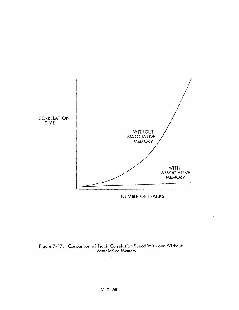
CORRELATION TIME
WITHOUT ASSOCIATIVE
MEMORY
WITH ASSOC IA T IVE
MEMORY
NUMBER OF TRACKS
Figure 7-170 Comparison of Track Correlation Speed With and Without Associative Memory
V-7-89
7.3.6.3 Track Data Updating and Retrieval
In the general application areas of surveillance and tracking, other associative
memory usages are apparent. In such appl ications, it is often required that track
data be updated frequently from data received externally; it is frequently found
necessary to retrieve track information by specifying one or more of the track charac
teristics. In a conventional memory, the ordering of track data is according to one
or more of these characteristics (e.g., track number, t~ack channel number). Some
times data concerning the same track is kept in different physical locations and
ordered differently as may be required. This will ordinarily necessitate that special
cross referencing items be maintained. If the ordering criterion is not known (as in
the radar data correlation problem), a search is required entailing observation of
each item. With the use of an associative memory, track data could be retrieved by
specifying any of its known attributes.
A sample tracking problem of this type was used to evaluate the performance of three
al ternate systems in the report prepared by Gall. 26 The systems eval uated were:
1} Only the USQ-20,
2} USQ-20 with peripheral search memory and
3} USG'-20 with integrated search memory.
The problem was a four-dimensional search for a IItrack" which satisfied between-
I imits search criteria for X and Y coordinates, greater than or equal to the Z
coordinate and classified by a status item as hostile. Execution time analysis resulted
in curves for the sample problem solution as a function of the number of items searched
and the frequency of search memory updati ng. The advantages for the assoc iative
memory were substantial although somewhat difficult to quantitatively assess because
of other problem assumption details; and because the purpose of the report was to
evaluate alternate associative memory systems rather than demonstrate associative
memory effectiveness. The derived advantages were also largely sensitive to the
number of tracks to be processed and ranged up to 100 to 1 for high -track loads.
V-7-89
7.3.6.4 Sort i ng
Sorting involves the sequencing or resequencing of data such that the newly formed
sequence satisfies some specified ordering relation. Sorting has become a major
computer application and one which is quite (computer) time consuming. The
i mportCll1c ~ of the probl em is evi dent from the emphasi s pi aced on research into
efficiEnt ~(i,ting methods. Sort programs of considerable length and complexity are
wr itten, ol1d improvement of method is cont i nuousl y sought.
Several aspects of the sorting problem are related to the development of associative
memories. The most obvious advantage for such a usage is that in many cases the
need for sorting is eliminated. Since the data may be addressed by its known
characteristics, the need for ordering it is often obviated.
However, the need for sorting would still be required for certain tasks. For example,
when sorted data must be transmitted to some other memory device, for preparation of
sorted output lists, etc. I f sort i ng is necessary, the assoc i at i ve memory may
efficiently be put to the task.
To effect a sort, if the maximum (minimum) search criterion is available, a search is
made for the maximum (minimum) value and it is retrieved. This data entry is then
effectively removed from successive searches and the process repeated.
A paper by Seeber and Lindquist proposes an "Associative Memory with Ordered
Retrieval" and presents a simple left to right binary search algorithm similar to the
method used by the human brain to approach the problem.27
This memory uses a
parallel-by-bit and parallel-by-word approach. In an earlier paper by Seeber, a
self sorting memory is described. 28 Incoming words are entered in random order and
are placed in memory in proper relationship with other quantities. As each word is
entered, it is compared with all words al ready entered. However, th is organ ization
requires the use of a dummy register between each associative memory cell to
facilitate the insertion process.
V-7-90
7.3.6.5 Information Retrieval
Information retrieval is characterized as a request/response process. The requirement
of this type of problem is to obtain information in a timely fashion based on a partial
description of the desired data. Another characteristic frequently associated with
this problem is the dynamic nature of the data. Data ordering, file updating or
sort i ng may be requ ired frequent I y. A requ i rement for command and control system
information retrieval is that the response patterns may change dynamically in order
that the most relevant information be the most readily accessible. For some systems,
the response is required almost immediately in real time. There is some doubt that the
typical computer organization and instruction repertoire is well designed for this type
of problem.
There are several approaches to the problem. One approach involves the arrangement
of data into a stratified structure wh ich facil itates retrieval. In particular, list
structures have been found effective. Further benefits can be derived by the develop
ment of special instruction sets to provide the manipulative functions needed.
Another approach is to develop special hardware to provide additional capability.
Since a characteristic of associative memories is the capability to bypass scanning
and sorting in many instances, it is often considered for this application.
However, another characteristic of the information retrieval problem is the generally
voluminous size of the data files. Since the development of extremely large associative
memories in the future appears remote for economic reasons, the use of associative
memories to contain only a select amount of key data is indicated for indexing
into lower {or higher} levels of the file structure.
For future tactical data systems, commodious storage capacity will be needed and
retrieval of selected data will be required on a real time basis. The advantage of
the associative memory for th is appl ication would be two-fold: speed of retrieval
and a lessening of the requirement for frequent reordering of the data files. The
latter consideration is particularly important for problems where there does not appear
to be anyone best ordering scheme.
V-7-91
However, it must be acknowl edged that the approaches to information retrieval by
programming methods is highly developed. It is in this area that sophisticated pro
gramming tools are said to offer an economical alternative to hardware associative
memori es. I n part i cu I ar, th e use of list st ructu re storage and list process i ng methods
have proved extremely useful. Historically, the same motivations which have given
impetus to assoc i at i ve memory deve I opment have resu I ted in the development and
refi n i ng of list processing tech n i ques.
7.3.6.6 List Processing
The idea of an associative memory was borne of a need to provide lists of information
as described in some experiments on heuristic programming by Newell, Shaw, and
Simon. In this application it was impossible to predict the ultimate lengths of the
various I ists so a technique was invented to make the location of the various items
independent of any physical location or specific address. The address of the next item
on a I ist was simply stored with each I ist item, so that sequential I ist items were
scattered randomly in the memory. Unused cells -- ones which were available for
assignment -- were "chained" in this manner also. There is no doubt that motivation
for the development of contents addressable and associative memories was provided by
this application.
As a result of these efforts, special list processing languages have been developed.
These languages (e. g., I P L -V) are used to sol ve many probl ems in the areas of i nfor
mation processing and artificial intelligence. The primary difference between list
processing and conventional programs lies in the different data structures used. In
conventional programs, data is ordinarily stored accc. :ing to some preset ordering
scheme. In list processing programs, the data is list oriented such that each data item
contains not only the list entry information, but the location of the succeeding (and
somet imes, preced ing) entry. Another characteri sti cis that the list structure may
evolve during processing; the lists may be dynamically changed in size, structure,
or content. The list structures may be highly complex since data may be filed
according to different ordering requirements. Although I ist processing techniques are
highly developed, retrieval is time consuming and somewhat inefficient as compared
to the direct retrieval obtained by associative memory usage.
V-7-92
A promising approach to list processing problems would be the use of an associative
memory as an adjunct to the various I ist processing techniques. Several advantages
can be gained by retaining a list structure in an associative memory environment.
The associate memory could increase the capabil ity of present techniques by directly
retrieving I ist elements.
Another possibility is to design a machine especially for list processing. Such a
h · ... d ·b d b W· . 30 Th h· tit d . mac Ine organization IS escn e y Igmgton. e mac me pos u a e Incorpor-
ates a search memory to be used as an automatic symbol tabl e. The organ izati on al so
includes a high-speed scratch pad. memory used in conjunction with special working
registers and a main memory of 32000 60-bit words.
7.3.6.7 System Programming
The production of system support programs such as assemblers, compilers, translators,
etc. is an appropriate appl ication area for associative memories. In such programs,
the functions of scanning, table building, table lookup and table search are very
common and, in fact, constitute a large part of the computer activity. In a machine
featuring an associative memory, these functions are greatly facilitated. Tables used
during the assembly process could be stored in the associative memory to improve
search speeds.
Another aspect of assembly and compiler programs is relocation of programs and data
and the assignment of absolute locations. Contents addressing eliminates the need for
some of th is activity since data can be entered without undue concern about storage
allocation. For example, it is not necessary to determine in advance if contiguous
areas of core storage of the appropriate size are available nor even keep track of data
locations if retrieval keys are stored with the data. The need for translation from
symbol i c to absol ute storage I ocat i on may be to some extent eli m i nated . I n a se nse ,
the cells could contain their own names (simply another attribute -- an array of bits
wh ich could be used as a basis for search).
V-7-93
The associative memory would enhance the efficiency of current assembly and
compiler programs. However, the design of new systems programs oriented specifically
around the associative memory could result not only in increased processing speed, but
the addition of new capabilities. The development of powerful information retrieval
languages is a particular possibility. Addition could be made to the language to
incorporate search features. These would be in the form of additional statements and
extensions of present ones.
An important trend in computer usage is the development of computer programs to
translate present written programs from the machine language of one computer to
another. The conservation of programming inventories is exceedingly vital and such
programs allow widespread use of common software libraries. The ass:Jciative memory
would find a natural application in the writing of such translator programs.
Interpretive programming ,would be given new life by associative memory usage.
Multi-programming and time sharing techniques would also be enhanced. Another
usage may be anticipated in multi-computer systems with the associative memory
util ized as a shared memory element by several processors.
Other programs which could make important use of an associative memory are loaders,
monitors, debugging programs, overlay processors, and multi-program monitors.
V-7- 94

7.3.6.8 Other Appl ications
The associative memory would be useful for file searching of data for display, communi
cation and data updating. Other appl icable areas of interest are ECCM, decoy
discrimination, threat evaluation message decoding and general areas such as:
Air traffic control.
Automated intell igence.
Automatic abstracting.
Matrix arithmetic.
Document retrieval.
Language transl at i on.
Compiler writing.
Data retrieval (Medical, Legal).
Payroll.
Problem solving.
Perpetual inventory.
Linear programming.
Automated teach i ng.
Communications switching.
Airl ine reservation.
Process control.
Vehicle registration
Mathematical appl ications.
Many of these have no forseeable usage in connection with tactical systems. However,
the fact that there is such a wide potential usage does relate to the question of whether
such devices will be available in economically commercial versions. If the range of
appl icabil ity is broad enough, the motivation for commercial development will be '
provided so that successful implementation will not depend entirely on subsidized
development. V-7-95
7.3.7 Concl usi ons
Mechanization studies to date have not justified large scale implementation efforts
nor resulted in decisive acceptance of the idea of associative memories. However,
many designs have been considered and logical organizations described. Associative
memories with contents-addressable, parallel-search capacities unquestionably
provide a potential capability for a number of applications of interest to future
tactical system planners. The absol ute advantages in terms of differential cost are
less clear.
Since these constitute a sizable part of the operating system, it may be concluded
that associative memories are more useful for these appl ications than for general
computing problems as a whole. The number of appl ications in other areas is
sufficient to suggest that motivation exists for continued interest, development,
and implementation of associative memories largely independent of military or
governmental subsidization.
The advantages of associative memory usages are those of speed and flexibility.
Since it is possible to retrieve desired information at a rate which is independent
of the amount of memory searched, assoc iative memories may save substantial time
in some applications and provide a good tradeoff of storage saving in others. The
associative memory is especially attractive from the logician's point of view. A
case can also be made for increased ease of programming since the requirement for
certain housekeeping functions concerned with problems of addressing are simpl ified.
However, this is offset by the necessity for using techniques which are currently
unfamiliar to the programming community. Thus, if it can be anticipated that a new
type of programming problem will be created calling for a new class of computer
instructions, the resulting programming efforts will also yield benefits in yet
unforeseen efficiencies.
Frequent updating of data bases constitute a large part of the processing task
required of command system computers. This task would be facilitated by an
associative memory since search may· be made on the basis of varying search
characteristics or upon status change indicators. The associative memory would
also prove efficient for retrieving data for the output of summary and detail
i nf ormat ion.
V-7- 96
The drawbacks are largely those related to implementation difficulties which are cur
rently evident and the attendant costs associated with development and production.
It is obvious that the initial cost for workable associative memories will be much
higher than for conventional memories of equivalent size. Even after successful
installation of production models in working systems, this ratio may not be expected
to change appreciably. However, the important cost consideration is that of total
system cost vs. overall system capability. It is in this context that the utility and
economy of associative memories will ultimately be weighed.
The question resolves to one of avai labi lity at reasonable cost and of appropriate
usage. The associative memory should be employed in areas of application for which
its properties exhibit unusual capability. Its use must be justified in the command/
control environment ei ther by usual cost/capability ratio criteria or by providing a
unique computing capability at critical times. In this connection, it is important
to note that the power of the associative memory is brought to bear in high traffic
situations and situations of system stress, rather than simply providing a largely
unneeded addition to excess margin capacity. Associative memories possess certain
properties that make them more powerful in several applications. Should they prove
as useful as expected, they will significantly influence system design.
For a number of applications for which associative memories are considered, software
techniques have been devised to a high degree of sophistication to provide a
similar capability and in some cases, to simulate the operation of an associative
memory. However, either speed or storage must be sacrificed to obtain equivalent
capability. In most cases the software implementation depends on a careful ordering
of data to facilitate retrieval involving periodic reordering and file updating. The
possibi lity of combining these highly developed software techniques with a hardware
associative memory is a further possibility not to be overlooked.
From a system standpoint associative memories may provide a unique capabi lity in
special situations for which physical or environmental constraints determine unusual
processor requirements. They may be used peripheral to the main computer or inte
grated into a special computer organization including a hierarchy of memory elements.
In time, the associative memory may be provided as an optiona I component by computer
manufacturers.
V-7- 97
Several design characteristics appear to be advantageous for associative memory
application. The tendency toward long word length was noted. It is also desirable
to build associative memories in uniform logical modules in order to reduce fabrication
costs and to facilitate maintenance. Extensions of the properties of associative mem
ories provide additional capabilities other than searching only (e.g., self sorting,
parallel arithmetic, etc.). The economic advisabi lity of these extensions is not
clear at present.
The approach taken to discover desired characteristics should include the development
of measures of relevance for individual applications. Simulation and analysis tech
niques should be used to investigate various logical organizations and to consider the
effects of these variations on the individual application.
literature is currently divided among the topics of associative memory mechanization,
design of associative memory cell circuitry and associative processor organization.
Relatively little is available in the form of application studies. Such studies could
be undertaken profitably to develop tests of merit for various designs and to compare
associative memory performance with conventional memories in various areas of
interest.
We cannot anticipate clearly which designs will prove most economically feasible
in the next decade but would suspect that the simpler ones will become available
first. The cost of design is determined largely by the complexity of the logic as.
sociated with each memory cell rather than the total number of elements involved.
This argues for elemental type logic augmented by micro-programmed combinations.
Cost considerations may dictate the use of relatively slow elements. It is quite
possible that a very fast (and efficient) system operation could result from the use of
moderately fast elements at a reasonable cost. It seems unl ikely that very large
associative memories can be used to economical advantage as primary memory elements
in the time period 1970 to 1980. However, an associative memory of modest size
would provide excellent complementary characteristics for use in a system composed
of other memory and computing elements. It is suggested that such a memory be
regarded as a likely candidate for inclusion in future tactical data system designs.
V-7-98
7.4 STORED LOGIC AND MICROPROGRAMMED COMPUTERS
7 .4. 1 Introduction
For a number of years the term stored logic has been equated through usage with micro
programming. Although the literal definitions of these terms, if they could be agreed
upon, might indicate that a distinction should be made between them, it would be a
minor one; perhaps, simply, a matter of the point of view.
Historically, the term microprogramming is attributed to Wilkes. The greatest area
of agreement concerning the definition among writers on the subject is that it is
difficult. 31,32,33 For the most part, the question is side stepped and earlier defini-
tions are cited.
The difficulty is that the concept was initially seen as a radical departure from con
ventional design, was implemented somewhat incomplete Iy (in terms of the original
concept) and has since come to be thought of in terms of these implementations. It,
therefore, takes on varying meanings and associations in different applications of the
design c
The term microprogramming has become ambiguous primarily because the techniques
are commonly thought of from two different viewpoints--the engineers' and the pro
grammers'. The engineering viewpoint considers microprogramming as a technique
for specifyinS computer processes in terms of aggregate subprocesses. The program
mer defines microprogramming as the capability to control directly lower level logi
cal operation.
An ambitious definition is given by Glantz: 34
"Microprogram (noun)--a program of analytic instructions which the programmer in
tends to construct from the basic subcommands of a digital computer; a sequence of
pseudo-commands which will be translated by hardware into machine sub-commands;
a means of Suilding various analytic instructions as needed from the subcommand
structure of a computer; a plan for obtaining maximum use of the abilities of a digital
computer by efficient use of the subcommands of the machine. II
"Microprogram (verb)--to plan an analytical process in a pseudo-code which is to be
reduced to the subcommands of a digital computer; to plan an analytical operation in
terms of the subcommand structure of a digital computer; to plan an analysis which will
use the subcommands of a compute r in an optimum fashion."
V-7- 99
A conclusion to be derived by the various definitions is the relative nature of the
term. If "command" is read for "sub-command II and IIcode II for IIpseudo-code, II
the definitions given by Glantz could easily apply to· the word program. The
difference turns out to be one of degree.
The defini ti on hi nges on the words IIsubcommand II and IIsubcommand structure II
by which is meant simply the manipulation of smaller elements of logic than IS
usual. The term pseudo-command, although a hackneyed term, may mean
almost anything, and is used here to indicate that the code is different or at
least unconventional.
Initially, Wilkes envisioned a design somewhat more specific. He conceived
the possibility of dynamically alterable instruction sets incorporating the use of
two control matrices, a IIconnec ti on II matrix and a IIsequenc i ng II matrix.
One matrix wou Id determ i ne a number of control states and the other wou Id
select the specific micro-operations for a particular state. The micro-operations
performed would vary, depending on which set of control logic was in effect.
From this idea of variable logical machines which depend on the state of a
control matrix, grew the notion that the programmer could determine a unique
order code by combining basic building blocks of logic (variously called,
micro-operations, micro-commands or sub-commands).
The concept is derived from the fact that the typical machine instruction
consists of a sequence of basic elementary operations which are, however,
fixed (or wired in), i. e. implemented by hardware. These sequences are
often complicated and intricate. It was felt that a basic defect of the
conventi ona I mach i ne was the probabi Ii ty of the superfl uous performance of
certain of these subcommands serving no useful purpose in the computation
involved.
It was, therefore proposed that the basic machine operations be made avai lable
to the programmer. It was recognized that the selection of these basic elements
would be of paramount importance in order that the combinative properties of
those chosen wou Id allow the programmer to develop a powerful logical machine.
In effect, the logical design of the instruction set would be done by the programmer.
V-7-100
Mercer defines microprogramming as lithe technique of designing the control
circuits of an electronic digital computer formally to interpret and to execute a
given set of machine operations, as an equivalent set of sequences of micro
operati onSi elementary operati ons that can be executed in one pu Ise time. ,,35
This would tend to place the responsibility in the hands of the logic designer
and there is, perhaps, a continuing validity in this viewpoint. However, the
original fascination of the concept lay in the possibility that the order code
could ultimately be chosen at will by the programmer.
The "one-pulse" criterion, however, is considerably diluted in later develop
ments, although, one of the characteristics of stored logic is the relatively
small number of clock pulses per computer instruction. Furthermore, the concept
of programming using individual microcommands is not strictly realized (in the
sense of a one-for-one sequencial specification by the programmer). Rather,
the programmer ordinarily specifies that a particular set of microcommands occur
(perhaps a dozen or so). He may specify explicitly that a particular one will
operate, but usually in combination with others. He may modify in a sensitive
manner his choice of microcommands, and may combine them in many ways.
In this respect, however, the stored logic computer may not be so different
from the conventional computer which also may have a sensitive control of
operation (with various modifiers in its instruction word). Indeed, an occasion
al debunker1s pastime is the "explaining away" of the difference attributed to
stored logic computers in conventional terms.
Nevertheless, we shall attempt to characterize the development by describing
the successful commercial adaptations of the principle and to indicate certain
directions that the development of this concept may take. For although there
does not appear to be precise agreement as to what constitutes microprogram
ming or stored logic, and further, whether intrinsically it is a good design,
the effects of the development to date are undeniable and the future implications
are far-reaching.
It will be seen that certain of the early motivations for this type of design are
no longer so compelling due to other developments (mostly hardware), and that
certai n other trends have perhaps rei nforced the reason for its continued use.
V-7-101

7.4.2 Descriptions of Current Stored Logic CO'11puters
Rather than attempt a rigorous or composite definition of stored logic, it is
perhaps more instructive to consider the common characteri stics of the' vari ous
stored logic implementations, and to indicate those attributes that, it is
generally agreed, characterize its development. Parenthetically, it might
be noted that the earlier thinking in some respects is the more sophisticated
and is perhaps deserving of attention as a sub-topic in the somewhat neglected
field of basic computer organization.
The subject of stored logic was presented in a series of articles in the February,
1964 issue of Datamation, and the material contained there was drawn on in . th· 36,37,38,39,40 Th h k . h . I prepart ng I s report. e approac ta en In t ese artl c es was
that of describing the commercial machines which were currently marketed as
stored logic machines; and the concept is described in terms of these machines.
These computers are the TRW-130/133/530 computers, the PB-440 and the C-8401.
However, these computers in some respects are as different from each other as
they are from the conventional computer (with which stored logic computers are
invariably contrasted). And, perhaps, even more, they depart from the ori
ginal concepts of stored logic and micro-programming as described by Wi Ikes.
We will, however, examine the characteristics of these machines briefly,
noting the common attributes and the distinctive features of each.
I) TRW-130 (AN/UYK-l)' TRW-530, TRW-133
The TRW-130 is the forerunner of this family of computers.
It was initially designed under a Navy contract to serve as
a militarized multi-general purpose computer to be used
primari Iy for shipboard use. The considerable success of
this computer was probably due more to other design
characteristics (small size, militarized construction,
ruggedness, ability to operate with high reliability
under adverse environmental conditions), --than to its
stored logic design. It is claimed, however, that the
stored logic method permitted a simplicity of hardware
V-7- 102
which would have been impossible to implement economically
if a more standard design had been adopted.
The TRW-130 contai ns 8192 words of 15 bi t storage wi th a six
microsecond read-write cycle. The TRW-530 is very similarly
organized but has an 18 bit word and certain additional logical
options due to the longer instruction word. The TRW-133 in
corporates the same design as the TRW-130 but is three times
as fast, with a two microsecond cycle.
Operati on may be thought of as occurri ng on three leve Is in
the TRW machines; the microcommand level, the machine
instruction level and the interpretive level. Microcommands
are not accessible individually to the programmer although
he specifies them in combinations (explicitly and implicitly)
at the machine code level. The machine code command is
given the name Logand (~cal Command) and occupies one
word of computer memory. A string of logands may be com
bined to form a routine called a Logram (Logical Program).
These routi nes whi ch are wri tten ina closed subrouti ne form
operate in a sequential fashion and are called into operation
by the programmer specifying a list of routines to be operated
(a Logram Calling Sequence). When the computer is used in
this manner it is said to be operating in the interpretive mode.
The logical organization features accessible working registers
which are available to the programmer for the various machine
functions to be performed, sometimes interchangeably. It is
the individual transfers between these registers which are
recognized as the microcommands which are defined for this
machine. These registers are used for arithmetic, memory
addressing, logical, and control transfer purposes, and for
i nput/ output and temporary storage. For examp Ie, the
V-7-103
P regi ster is used as an addressi ng reg i ster, as an ex tensi on
of the arithmetic register, as a shifting register, contains
the quotient in division, the least significant part of the
product in multiplication, and also acts as an instruction
counter for the interpretive level of programming. In
crementing logic is available and, therefore, indexing and
program counter sequencing may be assumed by these working
registers.
The programmer of the lower (mach i ne code) leve I of codi ng
is given the name logrammer, presumably because he is com
posing lograms. He programs (or lograms) using logands.
The term logander, however, is not val id. The coder who
uses logram calling sequences is called a programmer.
The instruction word format (Iogand format) features an
address opti on field that prov ides unusua I addressi ng
flexibility. The address for the current operand is ordinarily
found in one of four of the working registers mentioned
earlier and is specified by the address option field.
Indirect addressing is also available and the combina-
tion properties of this addressing scheme are designed
to mi nimize addressing overhead.
The i nstructi on word has vari ous formats and may contai n
two functional commands (operations codes) per word. These
will explicitly call for the execution of particular micro
commands. It also contains a control field which has to do
with memory accessing (allowing or inhibiting) and address
i ncrementation.
It is sometimes maintained that the combinative properties of
this word allows a vast number of unique instructions variously
estimated at ,8 to 12 thousand. Only a relatively small fraction
V-7-104
of these are meani ngfu I, however, and fewer yet are usefu I .
Such sales arguments miss the point since the real strength
of the machine involves the way combinations of logands
(the more common ones, usua Ily) may be put together, rather
than the ability to calion an unusual or esoteric instruction
from the large number avai lable.
The hi gher order interpretive language consi sts of a stri ng of
logram calling sequences. The symbolic names of the lograms
are arbi trary in the sense that the programmer can name and
design his own. The assembly program will assign the starting
addresses for the corresponding logand strings.
The logram calling sequence is specified to the computer by
placing in sequencial cells the starting addresses of the cor
responding machine code subroutines. Interspersed among
these addresses are the addresses of any operands needed.
Thus, the interpretive mode code (the logram call i ng sequence)
consists simply of a string of addresses of subroutines and oper
ands. It is said that these lograms correspond to the wired-in
instructions of other computers, but a closer look would sug
gest they correspond more closely simply to closed subroutines,
which, in fact, is what they are. However, a unique method
of subroutine linkage is used which obviates the necessity for
an interpretive routi ne to sequence the routi nes. Each sub
routine provides its own linkage to the succeeding routine
by accessing the address supplied in the calling sequence and
placing it in the machine program counter. To facilitate
this method, the canputer {program} maintains essentially
two separate program counter registers which indicate the
current posi ti on in the ca II i ng sequence and the program
counter location within the current subroutine.
V-7-105

The interpretive level instruction repertoire is called the
Basi c Logram Package. The instructions defi ned by thi s set
resemble those of a one address computer, including single
and double precision commands. In addition, special logram
packages are available, e.g. floating-point package, matrix
arithmetic, etc. These routines require memory space and,
in general, only those routines needed in the application
should be loaded. Although, initially, wide varieties of
instruction repertoires were anticipated, including those
which could simulore those of other machinE:s 1 in practice
the Basic Logram Set is most commonly used. In some ways,
the interpretive level is the Inure cumbersome. The most
attractive alternative to those familiar enough with the
machi ne operati on is to descend to the machi ne code
level using the more efficient methods available there.
The interpretive mode overhead tends to be constant ( ap
proximate Iy two logands per logram) which constitutes a rather
high cost for the simpler lograms. For example, the logram
add command costs 18 microseconds (on the TRW-133), the
logand add, only 4 microseconds. Therefore, a combination
of the two codes is sometimes preferred, using logands for
the simpler functions (add, shift and those commands that
can utilize the efficient memory addressing available on
level, i.e. load, store, and indexing) and using lograms
for the more complex such as sine, cosine, BCD to binary
conversion, etc. The computer, when programmed in
this way, approaches very closely the typical usage one
would expect on our conventional computer using machine
code and closed subroutines.
V-7-106
2) PB-440
The motivation for the development of the PB~440 was simi lar
to that held by the AN/UYK-l designers - the desire to develop
the capability to tailor-make instruction sets specially
suited to the application. An important feature was added
and the claim was made that the first dual memory stored
logic computer had been developed. A honogenous memory
design, it was felt, would just barely hold its own compared
with conventional designs (presumably because of the inter
pretive mode overhead) and therefore, it would be advantageous
to place the strings of microsteps in a special module of fast
memory.
The PB-440, then, has two c lasses of memory; a mai n memory,
which operates at a five microsecond cycle time, and logic
memory {or "control" memory} which is a non-destructive biax
memory with a one microsecond read time. The minimum con
figuration of the computer has 4096 and 256 24-bit words of
these types of memory, respec ti ve I y .
The relatively small amount of fast memory was sufficient
to define certain basic instruction sets which could be
modified or replaced by reading in new ones, and it was
expandable in 256 word modu les, if desired.
The format of the PB-440 allows two micro-orders, sometimes
called micro-steps, per instruction word. Any of 64 separate
micro-order codes may be specified. In addition, the format
contains two modifier fields per micro-order which will
ordinarily indicate one of seven working registers as operand
source and/or destination. Here, as in the TRW machines, the
working registers are available to program manipulation (i .e.
accessible to the programmer) to an unusually large degree.
V-7-107
The routines stored in fast memory are called microutines.
They are called into play by the "control sequence" which
uses special instructions designed for the purpose. It was
noted that the higher language leve I operati on code for
t he TRW machines was, in fact, simply an address; the
address in core memory of the start of the logram. In the
PB-440 the operation code will ordinarily refer to a mic
routine by number (i .e. I of 64), and utilize a jump table
to facilitate rapid micro-instruction interpretation.
From a hardware standpoint, two-level programming is a
fiction, since the computer will always remain on one level
(i .e. the lower). The interpretive level (which is sometimes
referred to as pseudo-code) consists of a macro-instruction
control sequence which simply specifies which subroutines
are to operate. This is true of all the computers discussed
in this section.
Special instruction sets include a systems-oriented command
list, a scientific/engineering problem-oriented command list,
and a FORTRAN set. These are interchangeable by computer
memory loading. The instruction sets are normally stored in
fast memory but are a Iso executable from mai n memory. The
micro orders are tai lored to recognize various data formats
such as floating point, or sign-magnitude numbers, and
alphanumeric characters.
Program optimization involves the use of the time between
main memory accesses, referred to as "shadow time, II during
which useful computing may be accomplished (as long as it
does not involve further main memory access).
V-7-10B
3) C-8401
The dual memory concept is also implemented in the Collins
Computer, the C-8401 Data Processor. The microprograms are
stored in the fast memory, called the instruction memory.
This memory is composed of 1024 36-bit words with a read time
of one microsecond. The formats of the instruction word
allows either two or three transfers to occur. The transfers
re late to the exchange of information between exchange
registers, certain of which are associated with logical or
arithmetic functions. Each of the basic operations is as
sociated with a particular register. A large number of
working registers are thus made available to the programmer.
The main memory is composed of 4096 {expandable in 4K modules}
16 bit words with a five micr,osecond cycle. Thus, up to 15
micro-instructions can be performed during each main memory
cycle time. Notice that this assumes a micro-instruction to
be a part {or field} of a computer instruction word.
Macro-instructions are stored in main memory and constitute
a higher level problem-oriented language. The interpretive
mode linkage is effected by an interpretive routine called
RNI (Read Next Instruction). This routine maintains an
address counter which is stored in one of the exchange
registers. It also provides branching in the instruction
memory to the subsequent micro-!'Jrogramming to be performed.
The C-8401 was designed primari Iy as a communication network
processor. One of the distinctive features of the machine is
the abi I i ty to control I/O operati ons from many sources at the
same time. AI though this is not unique in modern computers,
it is facilitated to an unusual degree by the computer design
V-7- 109
7.4.3
which incorporates the external exchange registers for this purpose.
Input and output is specified by separate microprograms selected by the
RNI microprogram in the same manner that other microprograms are acti
vated. The machine was designed with a single application in mind but
is suitable for other applications by software modification. This conforms
to the basic rationale of the stored logic principle.
Characteristics of Stored Logic
To the general observation that programming may be undertaken on a lower level of
abstraction on stored logic computers, using generally smaller logical elements, we
shall add certain other characteristics of the stored logic implementations to date.
1) Multi-level programming - interpretive operation is featured on each of
the computers discussed. Although complete programs may be prepared
on the machine code level, the machines are specifically designed to
facilitate subroutinization.
2) Multiple Instruction Counters - In accordance with 1), above.
3) Relatively few clock pulses per computer instruction.
4) Accessible Working Registers - The internal registers of the machine are
available for minute manipulation involving transfers, temporary storage,
addressing, as well as arithmetic computation and control.
5) Adaptive instruction sets - All claim the feasibi I ity of custom made in
struction sets to suit individual applications.
It is noted that there tends to be fewer clock pulses per machine instruction.
Usually, however, the clock pulse contains several micro-operations and the com
pounding of useful functions is considered a design advantage. This doubling up of
logical operations is seen in the fact that all three computers allow at least two
command functions per computer word.
V-7-110
The PB-440 and the C-8401 have in common the use of fast CD ntrol memory
modules for the storage of the stored logic routines. It should be noted that
the development of fast (control) memory modules for special purposes is not
a unique stored logic feature. It is a common characteristic in recent entries
in the computer field.
And, finally, these machines have the common characteristic of admitting to
being stored logic computers. The implementation of micro-programming
techniques is more widespread than the number of machines which admit to
being stored logic would indicate. Stored logic is now claimed only by
those manufacturers who are committed to it. No longer can much benefit be
derived from claiming it as an innovation. If the term stored logic does not
survive, it will probably be because of semantic difficulties and the current
uncertainty among ccrnputer manufacturers as to whether the designation has
positive or negative sales value. The term microprogramming is somewhat more
acceptable currently and probably more descriptive.
Micro-programming is a prominent design feature of the IBM System/360. The
emphasi sis not on custom made i nstruc ti on sets but rather on i nstructi on reper
toire compatibility and standardization. Several other manufacturers have in
dicated willingness to conform to this new instruction repertoire and, in at
least one case, the translation will be achieved with micro-programming
techniques.
7.4.4 Other Current Usages
Although the number of computers which may be described as stored logic machines
is small, the number of computers which use micro-programming in some sense is
considerable. The use of micro-programming is particularly evident in connection
with the development of read-only fixed stores. Discussion of read-only memories
is found in other sections (7.5.2). Motivations are also seen for the use of micro
programming in connection with multi-programming and with the development of
associative memories. It could also be descriptively applied to certain program
ming aspects of highly parallel computers.
V-7-111
7.4.4.1 Mi cro-programm i ng and Associative Memori es
Micro-programming may receive renewed interest in conjunction with other
developments. For example, with the impending advent of practical models of
associative memories, interest in micro-programming may be renewed. Micro
programming and associative memories may turn out to complement and reinforce
each other for the following reasons:
A basic rationale for the advantages of the stored logic design assumes that the
hardware commands are to be kept simple to decrease cost, and that the software
development, i.e. combinations of microcommands, makes up the difference in
capability. However, with the associative memory design calling for the com
puter I :>gic to be to some extent distributed, we are confronted again with sub
commands of an extremely elemental order. The hardware/software cost ratio
is altered by the fact that the logic is distributed (i.e. repeated) throughout
memory. Further, if attempts are made to increase the distributed logic com
plexity, the resulting cost is multiplicative as a function of the size of the
memory. This suggests that the logic remain simple and that where possible
commands of greater logical power should be derived by combing the smaller
subcommands (micro-programming). Examples of this type of basic command
combinations are developed by Davies 16 and Full~r and Estrin.19
7.4.42 Multi-programming with Micro-program Control
The system design of CIRRUS, a mu Iti-program computer with micro-program
control is described by Allen and others. 41 This organization uses a prewired
read-only memory to contain the micro-programs, a main memory, a set of
genera I-purpose work i ng registers and ami cro-program uni t. These elements may
be connected in various ways providing unusual flexibility. The fixed store
contains 4096 words of 36 bits with a read time of 0.3 #Jsec. (Thi"s is consider
ably more extensive than the fast memories of other dual memory designs.) A
main memory of 8192 wor&; is also provided.
V-7- 112
The distinctive feature of the CIRRUS organization is that it is designed for ef
ficient concurrent execution of several programs. It operates on a priority basis
with each program having the ability to preempt programs of lower priority. The
time-sharing decisions are determined by the central processor, and switching is
achieved by microcoded interprogram routines. Allowance is made for the
operati ons of up to seven programs.
Development of this design was sponsored by the University of Adelaide, South
Australia.
7 .4.4.3 Micro-proqrammin,g and list Processing
The organization of a computer especially for list processing applications is
suggested by Wigington, 30, and by Muth and Skidmore. 42
The first paper proposes the use of a conventi ona I random access memory and a
set of special registers. The constituent microsteps for several macro-instructions
(I NSERT, DELETE, SEARCH and EXECUTE) are given. In the second paper, a
more complex organization is proposed including a search memory, a fast
scratchpad, and a large conventional memory. Here again, microcommand
sequences for basic list processing command functions are described. Specifi
cation of basic processes for mainpulating list structures by combining elemental
commands is a characteristic of the current list processing languages IPLV,
LISP, COMIT.
7.4.4.4 Micro-programmed Control for Computing Systems
This topic is the title of a paper prepared by Gerace reporting on the design of
the CEP computer bui I t at Pi sa, I ta I y ~3 Thi s represents one of the few efforts
to design a large-scale micro-programmed system. It is described as an extension
of Wilkes design. The cycle time varies according to the micro-operation to be
executed. The variable cycle timing system permits a speed advantage of this
synchronized computer very nearly as great as that of an asynchronous one.
This computer organization is also considered efficient for multiprograr.lming
operation.
V-7- 113
The control of computers by micrv~programming methods is of evident interest
elsewhere in Europe. At a Symposium on Advanced Computer Organization held
during the IFIPS CO'11puter Conference held in Munich in 1962, the use of micro
program control of computers was advanced by Wheeler (UKf.4
Wheeler sug
gests the use of read-only stores to control register transfers and sequencing
functions. It is judged that error detection is facilitated in this approach to
control. At the same symposium, Yaroslavsky and Timofeev (USSR) proposed
the use of a similar fixed memory for storing micro-programs as a control signal
source for the operating circuits. An interesting extension is the use of two or
more of these computers operating in tandem with micro information exchange
between them. This provides speed advantages and contributes to reliability
by facilitating search for failing elements.
7.4.4.5 The SD-2Co'1lputer
Thi s computer was designed to fu Ifi II a parti cu lar environment, space and
b· I· . . h h· f' 45 Th capa I Ity requirement wit emp aSls on ease 0 maintenance. e computer
consists of a 4096 word memory and a diode storage micro-program unit. The
word length is 19 bits with a five bit operation code field. The emphasis of
this machine organization is on simplicity of design in order that the computer
be readily understood (to be easily maintained). This computer is intended for
use as an or}-I i ne controller.
7.4.4.6 The KT Pilot Computer
An experimental computer was developed jointly by Kyoto University and Tokyo
Shibaura Electric Co., Ltd., w,ich is patterned after the Librascope SD-2 Com
puter~6 A unique feature of this computer is the mechanization of the fixed
memory. This memory consists of 256 x 80 phototransistors packed into a small
rectangle used in conjunction with a punched card. By replacing the punched
card with one of a different pattern the computer operator can effectively change
the micro-order repertoire. Other types of fixed memory are also contemplated
to provide both fixed micro-programs and alterable (micro-programmable) logic.
V-7- 114
7.4.4.7 I BM/360 System
One of the most extensive current uses of the micro-programming technique is seen
in the design of the IBM/360 system.
Read-Only Storage, (ROS), is used for all models up to but not including the
Model 70. These devices contain micro-programmed routines which provide the
advantages of instruction compatibility throughout the product line,and flexibility
in terms of compatibility with other IBM systems.
This usage of micro-programming qualifies as a stored 109;- machine from the en
gineers (or logic designers) standpoint but probably not from the standpoint of the
programmer, si nee the stored routi nes are not program a I terable.
This usage is described in greater detai I in connection -M th read-only memories
(Section 7.5.2.3).
7.4.5 Evaluation
The advantages and disadvantages of stored logic as a design principle are difficult
to weigh. It could be argued that the stored logic design has not been the most
compelling reason for success or failure of those computers which have used it;
nor even the most important feature. In any case, commercial success is not a
valid indicator of design excellence since the two seem to correlate only casually.
The advantages are perhaps most often summed up in the word "flexibi lity";
flexibi Ii ty in the sense that vari eti es of i nstructi ons may be produced; that there
is a selection of programming methods; that the instruction repertoire may be
changed by reading in a new set of microsteps. Whole "logical" computers may
be designed to suit particular problem requirements; other computer repertoires
may be simulated to retain software investments; and special instructions can be
designed as needed and added to the growi ng I ibrary of routi nes. The user has
the freedom to select an instruction set best suited to his application.
Stored logic appears to offer certain cost savings to the manufacturer. The less
complicated control logic, the lower number and types of components, (common
V-7-115
control c ircu its replace ind iv idual c ircu it elements}, together with the opportun it ies
for standardization of component modules make it intrinsically an attractive design.
Another advantage which was cited by early writers is that the order code may be
changed late in the development of a new machine. And, of course, the inter
pretive language can be modified even after it is built. This reflects the early
concern regarding rapidly changing instruction repertoires. Thus, stored logic was
seen as a way of delaying obsolescence. Currently, however, there is a tendency
to perpetuate code structures, at least among families of computers, in order to
maintain compatibi lity.
Most applications of the stored logic design have been closely associated with
interpretive operation; and so the interpretive penalty is often cited as a primary
drawback to the method. It is claimed, however, that the stored logic design is
specifically aimed at reducing this overhead and it is probably true that interpretive
operation is facilitated by this design.
Although the interpretive operation is considered the primary programming method,
the lower level machine code is sometimes preferred. This is occasionally necessary
to extract max imum effic iency for crit ica I computation.
The i nterpreti ve overhead cost must a I so be we i ghed in terms of storage as we 1\ as
execution time. For, in the case of stored logic computers, the (interpretive)
instruction repertoire must be stored. In the case of the dual memory machines
this storage is quite expensive. This argument may be turned around, however.
The i nstructi on repertoire saves storage in the sense that subrouti nes save storage.
And the dual memory machines assuredly have a compelling reason for storing the
instruction set in fast memory.
The primary objection to stored logic computers is that it is difficult to program
them. It is felt that the logical complications that must be dealt with are enormous;
that the programmer shou Id not on Iy have a thorough understanding of the subcom
mands, but should have a knowledge of the internal logic of the computer and
even the circuitry involved. It is said that micro-programming is not intended
for the casua I user.
V-7-116

It is likely that the actual difficulty of programming stored logic computers is exag
gerated. Although it takes a little longer to develop facility at the lower language
level, programmers experienced in micro-programming are usually enthusiastic.
They consider it challenging; and sometimes it takes on the characteristic of an
intellectual recreation. However, what is often overlooked among those who
{modestly} insist its a "snap," is that, while it may not seem more difficult to them,
it will very likely take considerably longer to write a string of code by micro
programming than it would with conventional code. The apparently greater lati
tude to compose elegant code even when machine efficiency results, can sometimes
turn out to be a false economy in terms of work accomplished per unit cost.
However, it is argued that once the software is developed to provide the desired
interpretive instruction repertoire, programming is as easy as for any other computer.
The theory is that a small team of micro-programmers (perhaps one) may serve to
prepare all special instructions that may be required, and will generate new re
pertoires as the need is seen. This is a perfectly valid point of view, and the
capability to tailor-make an instruction set is certainly one of the most powerful
arguments for micro-programming. Unfortunately, however, this kind of software
has turned out to be extremely expensive. This is due not only to the cost of the
programming effort but also to the concomitant costs of library maintenance, docu
mentation, and attendant activities assoc iated wi th users I groups and software
development generally.
It is usually found more expedient to use combinations of instructions already
available than to develop new ones that are more efficient. Private instructions
make the rounds unofficially {usually to avoid the bother of getting them accepted
as a part of the library}, and standard usages become difficult to maintain. The
concept of private order codes for vari able machi nes does present some procedural
problems. Too much flexibility may be a disadvantage.
The consensus among those who are familiar with the cost trade-offs involved
tends to suggest {reluctantly} that stored logic as practiced by the programmer is
not paying its way. A partial solution is to not allow the applications programmer
V-7-117
the discretion of instruction repertoire alteration. He is presented with a "Iogical"
machine that is unalterable. This unfortunately tends to negate the basic advantage
of micro-programming, i.e., flexibility. Another approach is to fix the stored
logic (a contradiction in terms?) in the machine. At least one manufacturer is
using this approach, and has, in effect, a plugboard type of stored logic
modu lari ty .
The stored logic design should be evaluated in the context of various other develop
ments affecting its utility. One important consideration has been the changing size
both logical and physical, of hardware components. Initially stored logic received
considerable impetus from the fact that hardware replacment of large component
modules was expensive and sometimes difficult. Use of smaller logical elements
was found to be more economical. Lower component count, standardization of
pluggable replacements, and savings in control logic; these factors were all felt
to be especially compatible with the stored logic design.
A counter trend seems now in effect whi ch suggests that larger and more comp lex
logical components may be produced now at a fraction of earlier costs. This,
together with the tendency towards miniaturization, may limit the degree of
divisibility that is economical. As the cost of hardware components decreases,
the motivation for small micro-logics may be expected to diminish. In this
connection, it is noted that the ratio between hardware and software costs is
changing. There is little evidence that the latter may be reduced in the same
dramatic fashion as the former.
With the increasing cost of software, use of existing software inventories becomes
very important. One approach to this problem is the development of tr:lnslators
to allow programs written in the language of one computer to be executable on
another. Stored logic machines are very amenable to this type of implementa
tion and, as the "host ll computer, wi \I not pay so severe an execution time
penalty ordinarily as would one with a conventional design.
V-7-11B
Perhaps in the farger view, it is not too significant if the stored logic concept is
maintained as an entity (although the term micro-programming is almost certain
to continue to be applied to whatever seems convenient and appropriate).
The advances associated with this development; language flexibility by sensitive
manipulation of small logical elements, standardization of hardware components,
dual or multiple memories (hierarchies) to suit varying computational demands,
and translations of language repertoires to use software inventories, are likely
to be of an enduring nature in computer technology.
The concept has diverged in development and has been diluted in implementation.
It has turned out to be a variation rather than a radical departure from conven
tional design. Investigation in this direction is incomplete, however, and the
techniques involved are certainly worthy of continuing study in consideration
of the larger topic of computer organization. Perhaps the development wi II go
full circle with a new look at Wilkes' control matrices.
7.4.6 Conc I us ions
The terms stored logic and micro-programmi ng have become somewhat ambiguous.
This primarily is due to the fact that they are commonly thought of from two dif
ferent points of view; the engineers' and the programmers'. The engineering
viewpoint considers micro-programming as a technique for specifying computer
processes in terms of aggregate subprocesses. The programmer defi nes mi cro
programming as the capability to directly control lower level logical operation.
Stored logic has been a considerable influence on the design of computers and
will continue to influence computer design. Flexibility is the principal claim
oi stored logic proponents. They claim that the computer can be tai lored to the
problem. By tailoring an instruction repertoire to fit an application, execution
speed and programming efficiency may be increased. The price, however, is
paid in terms of increased software systems cost and the costs which are incurred
due to the lack of a "standard machine. II Applications programming costs may
be lower because of "tailored machine"; however, the software investment is
higher. The programmer has a greater flexibility with micro-programmed com
puters si nce he can increase the speed/cost rati 0 by an expendi ture of program
ming time. V-7-119
The theoretical advantage of providing several alternate machine order codes is
seldom exploited. Tailor-made instruction sets are usually not forthcoming from
the manufacturers, and the user cannot usual I y afford this type of effort. For
most applications, optimizing the instruction set from problem to problem
is difficult to justify. The advantage is seen only when frequency of use war
rants these techniques and when the changing of repertoires is reasonably
convenient (e.g., pluggable instruction repertoires).
Micro-programming currently is more often used for purposes of standardization
of repertoires rather than for diversification of repertoires. This is seen in the
use of micro-programmed routines for simulation of one computer by another,
and, as in the case of the IBM/360 system, to provide product line instruction
compatibi Ii ty .
Stored logic has not gained public computer acceptance. Almost universally
and uniformly, sales successes have been due to factors other than the stored
logic idea itself. For instance, in the case of the AN/UYK-I a more important
sales fact has been that the computer is Mil Spec, NTDS compatible, and of-
ficially Navy-designated. TRW, Packard-Bell, and Collins, with modest
computer images and modest public relations, have not been able to convince
the technical community. This fact clouds the issues and presents many
psychological blocks to stored logic acceptance. Currently, the degree to
which the technique has been developed is very low. If one of the larger
companies were to actively pursue the technique, the complexion of the tech
nology would change considerably and so would its public acceptance.
Stored logic should not be the foremost criterion in the selection of a machine
for future Navy use. Further requests for quotation on future computers should
neither demand it nor exclude it. Rather, they should encourage flexibility
and adaptability from the logic and programming points of view and let the
designer-manufacturer develop an approach best suited.
V-7-120
It should be noted that there is renewed and continuing interest in micro-programming
techniques due to the advent of techniques in the use of associative memories, dis
tributed computers, and read-only and fast-read memory devices. The door for stored
logic and micro-programming should certainly be left open for ACDS applications.
Studies which would develop the best approaches and more quantitatively study pros
and cons should be sponsored by the Navy.
V-7 -121
7.5 MEMORY HIERARCHIES
7.5.1 GenE!ral
There is an increasing use of memory hierarchies in computers and computer system
design. This is evident not only in the proliferation of the numbers of memory units
but also in the varying capabilities and capacities of the individual units. The usual
method of categorization is according to speed, but memories may also be classified
according to size (capacity), and capability (e.g., random access, read-only,
content addressable, etc.). The ideal hierarchy is usually described as one with a
fine gradation of speed and capacity characteristics, from small amounts of very
high speed storage (registers, scratchpad storage), through high speed memory main
storage, through successively larger amounts of lower speed storage and finally,
large amounts of bu Ik storage such as that provided by discs or drums. The steps
from one type of storage to the next should be somewhat equal in magnitudeo
Although it is sometimes suggested that there are gaps in this continuum, memory
devices to suit the speed/size/cost requirements of the user are fairly complete.
Although memory hierarchies are characterized mostly by speed and size, other
aspects are also noteworthy. Specialization of memory functions, topological
relationship of memories with processors, and control hierarchy are also important
considerations.
There is a trend in computer design to divide the traditional elements of input,
storage, ari thmeti c (computi ng), control, and output into separate modul ar un its.
This provides possibilities for the manipulation of these units in the system design
which provides flexibility and enhanced performance capability, (usually in
terms of parallel processing). Another trend is the functional exchange of some
of these elements. Thus, it is seen that memory cells are sometimes endowed
with logical capability (associative memories, distributed logic machines) and
processors are extended to include associated memory elements (shift registers,
scratchpads, etc.).
V-7-122
Automatic data transfers among the elements of a memory hierarchy is an
interesting possibi lity. Ideally, the current operands of interest should reside in
the fastest, most accessibl e, memory el ements. Transfers between main memory and
small high speed storage (scratchpad) units are accomplished which provide faster
access to the working registers. On a slower time scale, transfers from main
storage to buffer storage or to bu Ik memory are effec ted as the mai n memory
becomes saturated. Conversely, there is the possibility of automatically re
furbishing high speed storage from bulk storage. A notable example of this
is the one-level store concept used in the design of the Atlas computer which
allows the user to take advantage of the main core, drums, · .. md an extensive in
ventory of memory types, as though they were all immediate access.
Transfers may, of course, be accomplished as a function of the computer program
but this is not without expense in terms of programmer effort and computer time.
If such transfers could be accomplished automatically on the basis of pre-selected
criteria (e.g., frequency of use, recency of use, preset index of importance, etc.)
the effective computer speed would be increased. Several algorithms are possible
to evaluate the chosen criteria; however, only the most simple methods would be
amenable to hardware mechanization at a cost commensurate with the resulting
time saving.
One of the most interesting challenges involves methods for the automatic utilization
of hierarchies of memories so that the programmer need not know the whereabouts of
the data to be accessed. The possible freeing of the programmer from the addres
sing requirement was suggested in connection with associative memories.
V-7- 123
7.5.2 Read Only Memories
An important type of memory which is finding increasing application in computer
systems organization is the read-only memory (ROM). The cost of read-only memory
is considerably less than for read-write memory of equivalent speed. This type of
memory is referred to as permanent since the machine using it is ordinari Iy not
capable of changing its contents. The designation semi-permanent is also used
to refer to memories which are physically removable, (e.g., card-changing
memories) but not electrically alterable. As with associative memories, the basic
characteristic is the non-destructive read-out (NORO) capability. It is possible
to combine these capabilities to produce a read-only associative memory.
There is a tendency to equate the terms, read-only memory and NDRO memory.
This is not quite accurate since read/write memories may also be NORO (as is
the case with some contenraddressable memories). The term read-only is not
entirely precise, in any case, since the memory must be written into initially.
The term is often used to refer to fast read, slow write memories. One criteria
for classification of read-only memories is whether the contents are fixed in
construction or are capable of being written into electrically (i .e., mechanically
or electrically alterable).
A number of important usages are envisioned for read-only memories, among these
are:
1) Storage of micro-programs (stored logic).
2) Storage of arithmetic tables.
3) Multiprogram control.
4) Function generators.
5) Storage of executive control programs.
6) Code conversion (e.g., radix conversion).
7) Storage of tables of branches.
8) Interrupt processing routine storage.
9) Storage of test routines.
V-7- 124
Read-'Only memories have not achieved extensive application because the areas
of economic use are somewhat limited. The basic advantage is greater access
speed at lower cost. The relative savings obtained from eliminating the ad
ditional circuitry to obtain full read/write capability is not considerable enough
in the general case to warrant the special system design to use the advantage.
In several cases, however, read-only memories have been effectively used, and
the design is postulated in a number of proposed systems designs.
7.5.2.1 Kinds of Read-Only Memories
Read-only capability may be implemented by a number of different methods (See
Section 6 ). Basic methods for detecting the stored information are capacitance
coupling, eddy currents, electromagnetic coupling (mutual inductance), fiber
and twistor sensing. There are vari ous mechanization techniques for these memories,
the most common is the card-changeable memory, but other types such as solenoid
arrays, thin film, and rope memories are also receiving attention. It is also possible
to use conventional storage devices (such as drum storage) with the write circuitry
locked out to achieve read-only characteristics.
7.5.2.2 Uses of the Read-Only Memory
One of the important motivations for development of read-only memories is for
storage of microprogram routi nes (stored logic). The development of dual memory
stored logic machines is noted in Section 7.4.2. The use of fast storage for opera
tion of pseudo-instructions (macros) constitutes a distinct enhancement of the stored
logic design. For several of the dual or multi-memory computer organizations,
the fast memory has non-destructive read-out capability and fast read, slow write
characteristics. Use of read-only memories for micro-program storage is seen in
the IBM-360, Ferranti Atlas and CIRRUS system designs. The read-mostly memory,
where the read time is considerably shorter than the write time, is used as the high
speed memory element of the PB-440.
Another use of read-only memory is for storage of control programs (e.g., execu
tive or moni tor programs) and for i nput/ output processors and interrupt processor
V-7-125
routines. They may be used to substitute for a part of main memory or for faster access
for large capacity storage at low cost. The primary characteristic of programs which
can effectively exploit the read-only memory speed, are those which are relatively
immune to change and whose frequency of usage is sufficient to result in significant
time saving. Several computers use a form of read-only memory as a control memory,
for special input/output parameters to indicate buffer storage regions or for interrupt
processor starti ng locati ons. It is a Iso an appropriate usage for interpretive program
ming for storage of tables of branch locations to enable quick switching from routine
to routine.
The read-only memory is also considered for storage of arithmetic or function tables.
Used in this fashion, the device takes on the appearance of a function generator
where the input is one input variable (presented in the form of an address) and the
output is a particular function of the input variable. If the read-only memory is
also content-addressable, the input variable may also be stored.
Examples of functions which could be stored are sine, cosine, square root, arc
tangent, etc. Another possibility is the use of the device for purposes of data
linearization in converting engineering units. Effectively, the read-only storage
can substitute for computation and allows manipulation of the time/storage trade
off equation. This is particularly evident if the table look-up method is combined
with interpolation.
Other applications include code conversion, radix conversion, and multiprogram
control. Read-only memories have also been suggested for storage of the dictionary
in automatic language translation and for the storage of the program for an electronic
telephone switching system. They can be used to effect information retrieval by
providing the cross-referencing associations needed. In addition, large read-only
memories could be used to contain encyclopedic data which is not subject to change.
In some spaceborne systems, a large read-only memory is used for storing the program
in conjunction with a small read/write scratchpad memory. This insures that the
program wi II not be destroyed by malfunctions in other parts of the system and it
reduces the weight and power consumption required for the total memory capacity.
V-7-126
In some ground-based computers, a smaller read-only memory has been used in con
junction with a large read/write main internal memoryo In this latter application,
the read-only memory is used only to store constants, subroutines, or micro
instructions that are changed relatively infrequentlyo This permits faster access to
this information than to information stored in the main memory.
Current Read-Only Usages
An example of the use of a read-only memory for several purposes is seen in the
fixed store of the Ferranti Atlas.47
Th is memory consists of a woven screen wire mesh
into which ferrite plugs are inserted which determine the numerical values (i.eo, bit
pattern) of the storeo This store is 8192 words in length and is not electrically alter
ableo The Atlas fixed store is used for peripheral equipment control and for con
taining subroutines to perform several of the more complicated macro functions, thus
extending the hardware order code. These routines, called extracodes, appear to
the programmer the same as basic instructions. Control commands for storage all oca
tion, monitoring, and interrupt processing are also contained in this store. The
organization of the Atlas computer is described in Section 7.5040
Read-only storage (ROS), as implemented in the IBM/360 system, provides consider
able flexibil ity and code compatibil ity over the entire range of the System/360 as
reported in a paper on the IBM System/360 Engineering. "There were two major
reasons for the general adoption of read-only storages in System/360o 48
1) Assist downward compatibil ity due to the cost advantageso Readonly storage (ROS) showed an advantage in cost over the circuitry which it replaced. ROS is used primarily in the control section of the system and its advantages becomes more pronounced when more functions are to be performedo Therefore, ROS units showed a method of maintaining full compatibility by allowing complex function even in the smallest systems.
2) Flexibil ity, such as the implementation of compatibil ity features with other IBM systems. A unique fl exibi I ity is ach ieved by being able to add to the control section of the computer, when implemented by a ROS, without significantly affecting the remainder of the system o One result is to allow certain System/360 models to operate as another computer, such as the 1401, by adding to but without redesigning the system. This ROS concept can be combined with software to offer almost any performance from pure simulation (no ROS) to maximum performance (no software). II
V-7-127
This use of read-only storage to contain micro-programs is reminiscent of stored
logic computers but probably qualifies as a stored logic from the logic
designers I poi nt of vi ew rather than the programmers I si nce the stored routi nes
are not program alterable. Several types of read-only memory are used, and
determination of the particular method is not deemed critical in the system design.
ROS is implemented for all models up to but not including the Model 70.
Read only memories are seen as memory elements in a number of other computer
organizations for containing micro-programmed routines. Several of these are
described in Section 7.5.4 including the CIRRUS organization, the SD-2 Computer,
and the KT Pi lot Computer.
7.5.2.4 Evaluation
The advantages of read-only memory rest in the prospects for development of:
1) Very fast memories of modest size for special ized uses.
2) Very large memories for large quantities of data which require
updating infrequently.
From a commercial standpoint, manufacturers have often found it advisable to offer
a conventional capability which is attractive to a larger number of potential buyers,
rather than a specialized device for which development amortization is spread over
a narrower base. This suggests that in some instances, memories with full read/write
capability may be available as cheaply as their read-only counterparts. Thus,
potential cost reduction must be weighed against the mass production economic
factor. This type of engineering economics also applies to associative memories
and, in general, to the question of special purpose vs. general purpose costs
trade-off. Except for certain instances where memory protection might be
desirable, there is little intrinsic value in the "no-writeJt capability.
The uti lity of read-only memories, therefore, resolves largely to questions of ap
plication fit and costs savings. If such cost savings can be demonstrated, the range
of usefulness for read-only memories is sufficiently broad to suggest favorable con
sideration as components in the memory hierarchy.
V-7-128
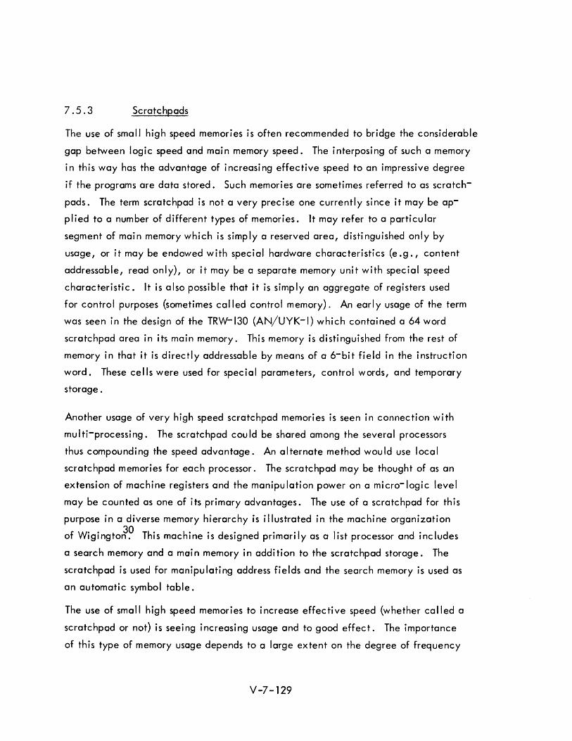
7.5.3 Scratchpads
The use of small high speed memories is often recommended to bridge the considerable
gap between logic speed and main memory speed. The interposing of such a memory
in this way has the advantage of increasing effective speed to an impressive degree
if the programs are data stored. Such memories are sometimes referred to as scratch
pads. The term scratchpad is not a very precise one currently since it may be ap
plied to a number of different types of memories. It may refer to a particular
segment of main memory which is simply a reserved area, distinguished only by
usage, or it may be endowed with special hardware characteristics (e.g., content
addressable, read only), or it may be a separate memory unit with special speed
characteristic. It is also possible that it is simply an aggregate of registers used
for control purposes (sometimes called control memory). An early usage of the term
was seen in the design of the TRW-130 (AN/UYK-I) which contained a 64 word
scratchpad area in its main memory. This memory is distinguished from the rest of
memory in that it is directly addressable by means of a 6-bit field in the instruction
word. These cells were used for special parameters, control words, and temporary
storage.
Another usage of very high speed scratchpad memori es is seen in connection wi th
mu I ti-processi ng . The scratchpad cou Id be shared among the severa I processors
thus compounding the speed advantage. An alternate method would use local
scratchpad memories for each processor. The scratchpad may be thought of as an
extension of machine registers and the manipulation power on a micro-logic level
may be counted as one of its primary advantages. The use of a scratchpad for this
purpose in a diverse memory hierarchy is illustrated in the machine organization
f W" 30 Th' h" d' d "1 I' d' I d o Iglngton. IS mac Inels eSlgne prlmarl yasa 1St processor an Incu es
a search memory and a main memory in addition to the scratchpad storage. The
scratchpad is used for manipulating address fields and the search memory is used as
an automatic symbol table.
The use of small high speed memories to increase effective speed (whether called a
scratchpad or not) is seei ng i ncreasi ng usage and to good effec t . The importance
of this type of memory usage depends to a large extent on the degree of frequency
V-7-129

of use of the high priority data or instructions contained. This usage is particularly
powerful if method5 for periodically refurbishing the high speed memory with the
most critical data are providedo This possibility of automatically mechanized trans
fers of this sort was suggested in a previous sectiono
7.5.4 The Ferranti Atlas Computer
The use of a hierarchy of memories {stores} in a single computer organization is
illustrated in the design of the Ferranti Atlas Computer. 47 The basic motivation of
this design is to allow operation of several programs simultaneously and at the same
time allow each user to write his program as if he were the only user of the machine.
The machine is said to utilize "one store" concept from the user's standpoint, while
from a hardware standpoint a great variety of storage levels exist.
The main storage consists of a large drumo Blocks of 512 words each, sometimes
referred to as "pages,1I are brought into core memory when needed o These transfers
are made simultaneously with computing functionso
The core store features four separate access systemso The core is divided into stacks
which are interleaved in pairs to allow overlapping of commands. Instructions are
brought from memory in pairs, and accesses to the various elements of the arithmetic
unit, as well as the memory stacks, are accomplished simultaneously. The paral
lelism of this operation results in an effective reduction of the nominal cycle rate,
which is 2 microsecondso
The fastest store is a fixed {read-only} store with an access time of 0.3 microseconds.
An executive routine resides in this store which oversees drum, and other I/O trans
fers, and performs a highly sophisticated scheduling operation intended to optimize
util ization of the overall systemo
The fixed store also contains subroutines, called extracode routines" These are used
to provide the more compl icated functi ons of the instruction repertoireo Th is fixed
store uses a part of the core store as a private working space for the fixed store
routines.
V-7-130
In addition to the memories listed above, there is what is called the V-store which
is composed of a set of address registers for control of system transfers. The V -store
is also used only by the fixed store routines.
A diagram of the Atlas memory elements is shown in Figure 7-18.
In summary, it is seen that the power of the Atlas derives primarily from a highly
developed organ izati on of its memory el ements. The system features both multi
programming and microprogramming concepts. Although the system makes use of
many different types of memory, the user may regard these elements substantially
as a single level, very large store 0 49
c;,~..,.;{.u ... COMPJ·E.Q
.(0...0
:!l·!lioq~
Figure 7-18. Block Diagram of the ATLAS Computer

The Fixed Plus Variable Computer Organization
An experimental computer organization which incorporates the strong features of
both general purpose and special purpose computing components is being developed
at UCLAo This computer organization called the Fixed Plus Variable Computer
organization, first formulated in 1959, is being developed under the sponsorship of
the Office of Naval Research and the Atomic Energy Commission.
The Fixed Plus Variable Structure consists of a conventional general purpose computer
(fixed components), and a number of special purpose modules (variable components)
which may be reconfigured according to the requirements of the particular computing
problemo The stated goal of the Fixed Plus Variable Structure Computer is:
liTo permit computations which are beyond the capabilities of present
systems by providing an inventory of high speed substructures and rules
for interconnecting them such that the entire system may be temporarily 50 distorted into a problem oriented special purpose computero II
The variable part of the organization is expected to change from problem to problem
and from day to day 0 However, the same basic hardware substructures may be used
in a variety of special purpose structureso This organization is seen as an evolving
machine which may be reconfigured both electronically and mechanically. The
basic advantage is the efficiency that may be achieved by reconnecting the com
ponents either physically or by program into an organization pecul iarly effective for
the problem at hando The flexibility of the special purpose devices raises the
question of whether the structure is meaningful without the fixed component 0 The
rationale for using a commercial general purpose computer with in the structure is to
take advantage of the developmental investment available in such computers as
measured in terms of libraries of subroutines, procedures for communication with the
computer via standardized peripheral equipment, and avai labil ity of higher order
languageso The IBM 7090 was selected as the initial IIfixed ll part of the system.
A supervisory control unit coordinates the activities of the various processors and
controls data transferso A conceptual diagram of the fixed-plus variable structure
computer system is shown in Figure 7 -19.
V-7-132
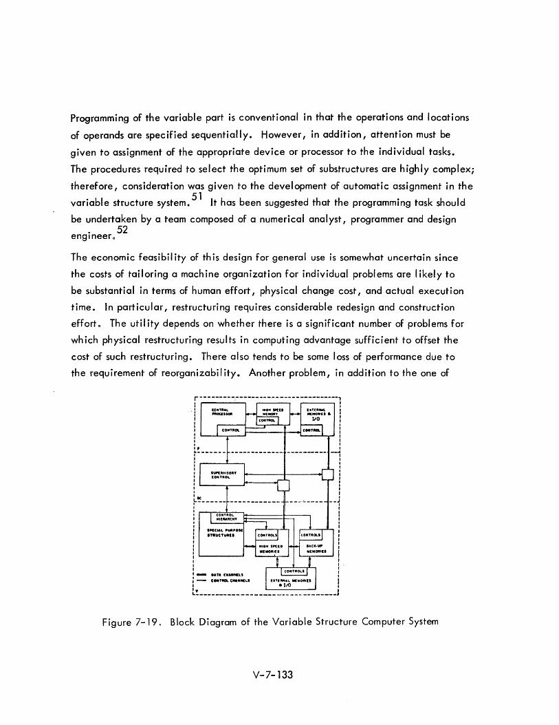
Programming of the variable part is conventional in that the operations and locations
of operands are specified sequentially. However, in addition, attention must be
given to assignment of the appropriate device or processor to the individual tasks.
The procedures required to select the optimum set of substructures are highly complex;
therefore, consideration was given to the development of automatic assignment in the
variable structure system. 51 It has been suggested that the programming task should
be undertaken by a team composed of a numerical analyst, programmer and design . 52
englneero
The economic feasibil ity of th is design for general use is somewhat uncertain since
the costs of tailoring a machine organization for individual problems are likely to
be substantial in terms of human effort, physical change cost, and actual execution
time. In particular, restructuring requires considerable redesign and construction
efforto The util ity depends on whether there is a significant number of problems for
which physical restructuring results in computing advantage sufficient to offset the
cost of such restructuring. There also tends to be some loss of performance due to
the requirement of reorganizability. Another problem, in addition to the one of
r---------~-------------------------, , I , , . : Cl"TIIAL I I PIIOCII_ :
I : I I I I
: I I, I ~ _______ _____________ --________ --4
I I I I , , I : : I : I , I
: Ie l L_______ ____________ __J
CONUOL "'[MIIC"'
"'IC'A" 'UII' ... ITIIUCTUIIII
- .A'" C"A""'"
M[MOIIIU
I I
I I ,
,.--J'----,---": I I I I
,,'"011''' I I I, I I ,
- C .. , ... '''''''''LI • ItO I L!. ________________________________ J
Figure 7-19. Block Diagram of the Variable Structure Computer System
V-7-133
assigning, sequencing, and allocation of tasks, is the question of when to reconfigure.
The ultimate programmability of such an evolving organization depends on the defin
ition of procedures which will resolve these questions in a reasonably satisfactory
fash ion 0
Speed advantages of from 205 to 1000 have been reported, depending on the problem
characteristics, as compared with general purpose computer solutions. Although these
speed advantages are substantial, they must be weighed against the costs indicated
in the foregoing discussion.
The organization of tactical computer systems in the 1970 period will probably include
a wide array of diverse elements in some respects similar to the fixed plus variable
organizationo However, it is doubtful that the same degree of structural fluidity will
pertain. It is inadvisable to reconfigure hardware elements, and, in effect, redesign
the system arrangement from problem to problem, except as this can be managed by
normal switching and modularization techniques" The dynamics of the type of system
change needed for tactical systems is on a much slower time scale than that anticipated
by the fixed plus variable proponents.
The fixed plus variable structure is particularly useful as a research tool for experi
ments in computer organization and for evaluation of new circuits and devices~ The
same basic inventory of elements can be arranged to constitute a variety of special
purpose systems, and as weaknesses of the system become apparent, indicated im
provements are incorporatedo It could also be used for study relative to establ ish ing
better design criteria for building future general purpose computerso
It is axiomatic that usage influences {or should influence} design; but it is also noted
that design sometimes influences usage o The latter is the more distorting effect. If
design is kept in a fluid state, conceivably, this distortion could be removed"
V-7-134
7.6 HIGHLY PARALLEL COMPUTERS
7.6.1 Introduction
It has been concluded in earlier sections that an important segment of the current
efforts toward improved computer organization is in the direction of providing paral- ,
leI processing capability_ The subject to be considered now may be thought of as an
extension of multi-computer systems. It is suggested by Comfort that the term, highly
parallel machine, is a subclass of the term, multiprocessor, and that a highly parallel
machine may be classified as one having more than an arbitrary number of subprocessors,
which he selects to be IOOO~
By this definition, there are a number of computer organizations which are currently
under investigation. To a large extent, they share the same basic potential advan
tages and the same basic defects. Their utility depends largely on the degree of in
herent parallelism in the problems for which they are proposed; and to the extent that
the problems can be redefined to exploit this parallelism, the design may be deemed
efficient.
7.6.2 Types of Highly Parallel Computers
As was the case with associative memories, highly parallel machine organizations
have come to be described according to various designations, each more or less
descriptive of the individual development under consideration. Some of these are:
1) Distributed logic computer
2) Cellu lar computer
3) Iterative circuit computer
4) Pattern recognition computer
5) Spacial computer
6) Orthogonal computer
7) Multi-layer computer
These terms are not synonymous, however. They have distinct, although overlapping
meanings.
V-7- 135
The distributed logic designation is somewhat the more encompassing and, in fact,
transcends the subject of highly parallel computers. The feasibility of a high degree
of parallelism is obtained by dispersing the central control logic to the individual
memory cells and thus the logic is said to be distributed. The degree of control logic
retained centrally is a criterion for classification for the highly parallel designs cur
rently under investigation. If the logic is entirely distributed, it is said to be locally
controlled. If primary control resides in a central control unit, the computer is
sometimes referred to as a global computer since central control is retained and is
broadcast throughout memory.
Associative memories with parallel search capabilities are distributive logic machines
since they contain a multiplicity of independent registers each capable of independent
logical decision.
The term cellular computer is sometimes applied to refer to the distribution of com
puting power over a large network of (usually) identical modules (cells). The interest
in identical simple units is heightened by the prospects of the development of econo
mical batch processing techniques.
The Iterative Circuit Computer (ICC) was proposed by Hollan~,54 His multi-layer
design is more generally referred to as a Holland machine, currently. The principal
characteristic is the large number of homogeneous modules capable of containing
many independent programs which may all be operated simultaneously. Other itera
tive circuit computers have also been proposed which are for the most part modifica
tions of the Holland machin;~' 56 However, these have somewhat more central
control than is true of the origi nal Holland computer.
Several pattern recognition computers have been proposed which incorporate a
cellular distributed logic organizatfln,.58 An early one was described by Unger
and is referred to as a spatial computer (SPACr? The orthogonal computer is
another specific design proposed by Shooman. 59 I
V-7-136
7.6.3 The SOLOMON Computer
The SOLOMON computer was designed at Westinghouse to solve problems which in
volve a large number of data sets for which the same program is applicabr~! 61,62
The designation ~imultaneous Qperation ,binked 9rdinal MOdular .tietwork, was ap
plied subsequent to the selection of SOLOMON as the name for this design. It is
composed of a large number of identical processing elements (PEls) each of which
contains the 64-word storage banks and a serial address. The original design calls
for 1024 processing elements arranged in a 32 x 32 rectangular array. Each PE is
able to communicate with each of four neighboring PEls. The entire organization
is under control of a central processor. At any point in time the same instruction
may be exerted on as many as 1024 different data items stored in corresponding
registers of the respective storage areas. The modules which respond to any particu
lar command are determined by the state of a mode address field. Thus, the program
is executed with varying numbers of PEls participating. Transfer from one program to
another is affected by changing the mode registers. The mode registers may also be
altered locally, i.e., by intra-module action.
The instruction repertoire includes addition, subtraction, multiplication and division
commands. Commands are executed serially in each PE. Communication between
neighboring PEls is effected via "edge ll registers. Operands may also be broadcast
from the central processor to any or all PEfs. In this way, storage may be saved in
the PE storage banks since quantities common to all PEls can be stored in the central
memory.
Potential uses for the SOLOMON computer are reported in a paper by Ball, et al.
Satellite surveillance is suggested as an appropriate application area. Speed ad
vantages in the range of from 60 to 200 over current large scale computers are ad
vantageous in numerical weather forecasting, air traffic control, nuclear reactor
calculations, photo-reconnaissance, and communication and transportation problems.
Itls use has also been suggested for problems involving solution of partial differential
equations and matrix problems and for function optimization.
V-7-137
In summary, it is seen that the SO LOMON computer is appropriate for problems with
the property of having parallel data sets which can be manipulated by the same pro
gram. The primary disadvantage is the extremely large number of components required
for a workable version. The expense would be a formidable objection und machine
utilization is relatively low. The design is supported by significant application studies,
however, for several important problems.
An extension of the SOLOMON organization would involve a planar configuration
allowing intercommunication between any processing unit and its six nearest neigh
bors in a three-dimensional organization. This configuration would facilitate the
path-bui Idi ng process.
7.6.4 Holland Machine
A highly speculative design for a computer capable of simultaneous operation of an
arbitrari Iy large number of programs has been suggested by Holland. He termed his
computer design on iterative circuit computer, but such designs have since been
termed Holland machines. The development was motivated to provide a vehicle
suitable for establ ishing a theory of adaptive systems. Thi s work was conducted at
the University of Michigan.
The Hollamd machine differs from other highly parallel organizations significantly
in the area of control. The schemes presented in the foregoing sections retain the
principle of central control. The Holland machine assumes an entirely local
control. Another unique feature is a relative addressing technique which involves
obtaining the operand by construction of paths to the desired locations. This is
descri bed by some as addressi ng by poi nti ng .
7.6.4.1 Organization and Operation
The Holland machine is a iterative homogeneous structure composed of a set of
interconnected modules arranged in a rectangular array. Each module consists of
a multipurpose storage register which may contain an instruction or piece of data;
and may be called upon to act as a storage element, an accumulator, or to serve
a communication function with its neighbors.
V-7-138
The operation is synchronously controlled and all instructions which are defined as
currently active within the independent subprograms are executed simultaneously in
a three-phase sequence. The first phase allows for modification of the storage
register and for changes instate of the control registers. During the second phase,
the operands are obtai ned. These are linked to the active modules by a sequence
of gates. Essentially, a path is opened which is terminated at the module contain
ing the operand. (Other programs can use the same operand modules.) The operands
are routed along the opened paths to arithmetic modules, where the operations are
to be performed.
During the third phase, the instructions contained in active modules are executed.
The operation may involve both the operand derived in Phase 2 and quantities to
be found in the associated arithmetic units (A-modules).
The programs can be written so that under local control they can connect with other
program segments. They can also be controlled directly from the input source 0
Advantages and Di sadvantages
The Holland machine is regarded as potentially powerful for most of the applications
for which parallel processors are considered. It is a good research vehicle because
the parallelism of other designs are also achievable in the Holland machine. As
with parallel processors of other types, a speed advantage may be derived for select
problems which can be formulated for parallel operation. It has the advantage of
operating parallel program sequences which are not necessarily identical, rather
than operating the same program on parallel data sets as with the SOLOMON
computer.
However, the list of disadvantages at this point in time appear formidable. The
foremost difficulty is that the machine as initially postulated may be practically
unprogrammable. Unfortunately, the programming art as currently developed finds
little applicability for a geometrical organization wherein programs are spatially
organized. Problems of unpredictable interaction of the subprograms, path inter
ference and possible i nadvertant IIdead ends II appear to be unavoidable. The
question of programmabi lity depends largely on whether a compi ler can be
imp I emented . V-7-139
Another apparent disadvantage is the large amount of hardware implied in the machine
design. An inefficient utilization of the hardware is also evident since at anyone
time only a fraction of the componentry is used. The generality obtained by allowing
all modules to have identical and multiple capabilities (e.g., to act as storage
arithmetic and shifting registers, for instruction interpretation, etc.) is inordinately
expensive.
7.6.4.2 Modified Holland Machines
Although the Holland machine was designed primarily as a theoretical tool for the
study of adaptive systems, it is considered by several as a prototype for a practical
computer. Severa I efforts are underway to improve the practi cabi Ii ty of the concept
by selected modifications of the design. Comfort lists the characteristics of the
Holland machine which I imit its effectiveness and proposes that the following modifi
cations be considered~
I) Extended operation codes
2) Different types of modu les
3) Generalized path-building
4) Compiler (development)
By segregating the arithmetic modules and limiting the decoding and arithmetic
capabilities of the other modules, he claims that machine size may be reduced by
a factor of five and that hardware utilization is improved by a factor of threeo
Garner and Squire consider the extension of the 2-dimensional iterative circuit
computer to an N-cube arrangement for which each modu Ie has N neighbors. 63
Two problems are evaluated--a matrix inversion problem and a path-building problem.
The performance of the N-cube ICC is contrasted with the 2-dimensional ICC and
with a conventional computer. The N-cube ICC is shown to be markedly superior
primarily because it exhibits fewer path interference difficulties.
V-7-140
Pattern Recogni ti on Computers
The highly parallel computer organization finds an important application in those
problems for which spatial relationships must be represented. Conversely, this type
of problem is one for which conventional computer organizations seem relatively
inept. The early motivations for highly parallel machines stem from this realization
and the desire to design a computer whose organization is better suited to this type
problem.
The Spatial Computer
An early pattern recognition computer is described by Unger?? This computer is
called the Spatial ~omputer (SPAC) and represents one of the earliest cellular designs.
The organization consists of a rectangular array of modules called principal registers
(PR 's),and a master control unit which broadcasts the commands to the modu les 0
Each module consists of a small amount of memory and a one-bit accumulator. There
is also provision for a limited storage in memory elements located between neighbor
cells (including diagonally located neighbors). The modules have the ability to
communicate to nearest neighbors (to left, right, above and below) by means of
shift instructions. Other instructions provided are add, multiply, invert, andtransfer
and invert. Also included is a link command which records in the memory element
between (PR 's) whether or not ones are located in both accumu lators.
Illinois Pattern Recognition Computer - IlLiAC III
This computer was specifically designed for the processing of visual information. 58
The computer organization consists of a Pattern Articulation Unit (PAU), a Taxi
crinic Unit (TU), and an Arithmetic Unit (AU). The PAU consists of a 32 x 32 array
of identical processing modules called stalactites. It also contains a core memory
called a transfer memory. This memory is capable of operating as an associative
memory. Inter-communication between neighboring cells is similar to the SPAC
computer except that the PR's may communi cate wi th eight nearest neighbors.
This design was developed for the particular application of bubble-chamber data
proc ess i ng •
V-?-141

7.6.4.4 Multilayer Iterative Circuit Computer
A multi layer arrangement is described by Gonzalez. 55 The organization consists of
three layers each composed of an iterative rectangular network of modules. The functions
of each plane are distinct and are associated with a three-phase cycle. The first plane
which contains the program to be operated is called the program plane. The middle
layer is called the control plane; it interprets the instructions to be operated in the thirJ
plane, called the computing plane. The corresponding modules of the three planes are
connected by a communication line. Each module contains an accumulator, a register, a
decoder and severa I switchi ng matrixes.
A three phase operat ion sim u Itaneous lyon a \I leve Is prov ides a staggered or cascad i ng
effect. This provides a look ahead feature which compensates for the delay introduced
by the three-phase cycle. In this organization is seen specialization of functions ac
cording to layer. Geometrical operations are provided in addition to arithmetic and
logical ones. Path building is established by row and column communication lines,
wh i ch determ i ne current operator and operand locations.
This computer differs from the Holland ICC by having a centr~1 control unit and
functionally specialized modules. The organization is proposed for use in
problems involving spatial relationships.
7.6.4.5 Orthogona I Computer
An orthogonal computer has been described by Shooman .59 The technique used is
called vertical data processing (VDP). Processing is parallel by word and serial by bit.
The memory is visualized as composed of columns which may be separately addressed.
Multiple data are processed simultaneously over the entire memory on those words for
which mask bits are appropriately set. The mask bits also provide the decision functions
likened to branching in a conventional computer.
This computer also provides for horizontal (conventional) memory access.
This organization was analyzed for three applications:
1) An FICA payroll computation
2) Number ordering
3) Mnemonic code translation as required in assembly programs.
The speed advantage reported ranged from 32 to 660 as compared with a conventional
computer.
V-7-142
7.6.4.6 Distributed Logic Computers
A content addressable distributed logic computer organization designed for manipulating
lists is described by Lee.64 A process of retrieval by cell association is proposed.
The design is simi lar to other contents-addressable designs with the added feature of
inter-communicating cells. Data is retrieved by sequential interrogations of the memory
cells. The first interrogation locates the first element of the string. The cell contain
ing this element wi II alert a neighboring cell making it elibible for the next search.
The process is continued unti I the entire string is retrieved. It is noted that the
contents of the initial cells may be used as tags or names to identify the
information to follow. This constitutes a slightly different form of addressing; names
of data are stored a long with the data itse If. Data may be referred to by name with-
out knowledge of its whereabouts. However, this method does require contiguous
storage of list items. This implies problems of utilization of spare storage between lists,
and the necessity of periodic restructuring if the list elements must be added or deleted
frequently. This addressing method is implicit in other associative memory designs as
well.
Lee, in his concluding remarks, presents the rationale that a distributed logic organi
zation may provide a framework for more powerfu I programm ing methods and can u Iti
mately ease (rather than complicate) the programmer's task.
liThe most obvious asset of such an organization is the tremendous speed it offers for
retrieval. Suitable programs can also be developed to make the organization extremely
flexible. In addition, we believe what is called the macroscopic concept of logical
design, away from addressing, from scanning, from searching, and from counting, is
equally important. We must, at all cost, free ourselves from the burdens of detailed
local problems which only befit a machine low on the evolutionary scale of machines.
Furthermore, because the cells are all identical, mass production techniques should
be developed in which a whole block of circuitry can be formed at once. II
All the highly parallel organizations described in this section qualify as distribute
logic machines,as do the more complex associative memory designs. However, other
descri ptive designations have been preferred for the other designs.
V-7-143
7.6.4.7 Summary and Conclusions
The general class of parallelism involved in the designs discussed in the foregoing
subsections is fascinating to contemplate. These organizations stimulate the imagination
with their strangeness and give promise (however veiled) of self adaptive programming,
self organizing systems and, therefore, learning (possibly intelligent) machines. For
our purpose, however, the justification for consideration must evolve from a determina
tion that a highly parallel computer can be developed to a point of utility to make it
an economical system component or that it can execute needed tasks beyond the power
of other organizations. More parti cu larly, the potentia I usefu Iness depends on whether
the defects apparent in current designs can be overcome.
These problems appear to be extremely formidable; particularly if considered in the
context of future tactica I system usage. These disadvantages were discussed in con
nection with the individual designs. The difficulties inherent to this type of organi
zation may be summarized as those of cost and programmabi lity. The cost factor is
somewhat augmented by the reluctance on the part of the designers to limit either the
capability of the modules, or the number of the modules. To maintain generality,
designers are reluctant to limit the theoretical capabilities and thus curtail their study
efforts; nor does design of a machine with fewer modules result in an effective com
promise, it is felt. The hardware utilization, therefore, to date is extremely low. An
attendant difficulty associated with the tendency to insist on a large number of
modules, is that the resultant machine is potentially massive and perhaps difficult to
incorporate into the system.
The programm ing problem is perhaps even more severe. The experience bui It up over
the years with seria I mach i nes is on Iy partia lIy app Ii cable. The problems of spatial
constraints, the importance of relative positioning of data and programs creates formi
dable problems of allocation. Path interference and restricted intercommunication
must also be coped with along with the necessity for careful scheduling and solution of
precedence problems. A large measure of success wi II depend on whether compi lers
can be written to make communication with this organization tractable in terms of
workable programs obtained from reqsonable human effort. There is reason for cer
tain optimism in this area since dramatic changes in the language required for com
munication with machines give promise for greater leverage in the use of programming
effort.
The element of time maya Iso be considered a drawback. A Ithough investigators are
uniform Iy enthusiasti c, the concensus suggests that practical implementation is some
way off. Emphasis has not been on development of a practi ca I version, but on the
development of theories of organization.
A number of steps must precede a practical implementation. Analytic and simulation
studies of considerable scope must be undertaken to point to possible organizational
improvements. This should be coupled with extensive investigation concerning the
characteristics of problems whose solutions justify the considerable expense involved.
Many limited versions may then be built for experiment and demonstration. Finally,
large prototypes will be built, probably costing several millions of dollars each.
The designers and bui Iders of such mach i nes are understandably re luctant to take th i s
last step until the underlying theories are highly developed. There is little question
about the need for parallelism but great uncertainty about the most efficient means of
implementation.
The potential importance of these developments should not be minimized since
impressive speed advantages have a Iready been demonstrated. The organization is a Iso
particularly efficient for many of the applications of interest to tactical system planners.
I n genera I, they may be characterized as the same type of usage for whi ch associative
memories were found efficient. In addition, highly parallel organizations are consi
dered promising for problems for which problem solution is an evolving process,and for
which program modification is undertaken as a gradual and self-adaptive procedure.
The hopes for development of adaptive self programming and self organizing systems
are valid but likely to prove elusive.
The question is not whether the high Iy para lie I organization is effi cient for the problems
of interest, but rather, whether it is as efficient as other alternative means which wi II
be available. In particular, the associative memory with certain extensions may be
regarded as providing a large degree of parallelism at considerably less expense. The
continuum of capabi Iity may be described with the simplest search memories at one end
and the Holland machine at the other. Starting with the basic parallel search capa-
bi lity, the abi lity to change memory cells simultaneously is added (with a parallel
write operation); it is then possible to combine elemental logic by microprogramming to
provide parallel computation; the next capability is the capacity for the memory cells
V-7- 145
to communicate or affect each other. {This is roughly at the arbitrary boundary point we
have chosen for highly parallel machines}. At this point we have the capability for par
allel operation by a program upon many data sets (SOLOMON, SPAC). Finally, the
operation of independent autonomous programs operati ng in para lie I is proposed.
{Ho Iland machi ne}. It seems I ike Iy that the practi ca I uti I ization of para lie I processi ng
for advanced tactical systems of 1970 will stop short of the highly parallel machines.
V-7- 146
7.7 COMPUTER SYSTEM ORGANIZATION
7.7.1 Introduction
This section identifies important computer design parameters for Advanced Command Data
Systems applications, attempts to place bounds on these parameters by extrapolating
present trends, and indicates areas where further study is required to permit design de
cisions. The analyses of Advanced Command Data Systems requirements and the studies
of technological trends presented in earlier sections provide a basis for many of the con
clusions reached in this section. A consideration of Advanced Command Data Systems
general computer requirements is followed by a review of present NTDS compatible
com puters. I n subsequent sections an exam i nation of trends in computer technology
leads to an investigation of the many factors to be considered in u detai led design of
a basic computer. The basic computer is then considered, as a member of a family of
computers, in a time sharing environment, and in a multi-computer configuration.
7.7.2 Computer Considerations for ACDS
General requirements for ACDS computers may be derived from an analysis of data
processing functions necessary to support a representative command post, a study of
appropriate computer implementations, and a consideration of the hardware constraints
imposed by the ACDS environment. The following observations are based on a previous
analysis of the command posts for an Attack Carrier Strike Force with particular em
phasis on the CTF function.
7.7.2.1 ACDS Data Processing Requirements
The Attack Carrier Strike Force command posts requiring data processing and
computationa I support are:
1) Commander Task Force/Officer in Tactical Command
a) Anti-Aircraft Warfare Commander
b) Air Operations Coordinator
c) Fleet Electroni c Warfare Commander
d) Screen Coordinator.
V-7- 147
2) Screen Commander
3) Contact Area Commander
4) Air Operations
5) Task Element
The CTF JOTC command post and its four components are expected to be located on an
attack carrier. In addition, each attack carrier wi II contain an Air Operations Com
mand post. Screen Commanders wi II most probably be located on a lead destroyer
(DlG) whi Ie Contact Area Commanders wi II typi co Ily operate from DD's. Task Element
command posts apply to all NTDS equipped ships and aircraft.
7.7.2.2 Computer Implementation of ACDS Functions
Data processing tasks common to the ACDS command functions are:
1) Console and group display handling
2) Communications hand ling
3) Data base updati ng
4) Data ~etrieval and formatting for output
5) Computations
6) Executi ve contro I functions
Typical computational tasks accomplish tracking, CAP vectoring, mission success
modeling, grid lock calculations and threat evaluation and weapons assignment model
solutions. The computer implications of these tasks vary from one command post to
another. A detai led ana lysis of the CTF function I however, has provided information
perti nent to the implementation of that processi ng task and from whi ch conc lusions may
be drawn about the equi pment requi red for other command posts.
Three important computer system design parameters are:
1) Typical data rates
2) T ota I data base size
3) Program memory requirements
V-7- 148
A n ana lysis of message traffi c at the command post input interface has i ndi cated that
the computer assigned this task must process 600-700 characters/second. Similar esti
mates of the size of data fi les comprising the data base indicate that approximately
one mi Ilion 30 bit words of bulk memory wi II be required for th is purpose. A summary
of program storage requirements, presented in Table 7-2, indicates that approximately
120,000 words of random access memory will be required for all CTF programs.
The ana lyses of section four suggest that the data processi ng. work loads for the command
posts under consideration are in the following approximate ratios (normalized for the
CAC post):
1 ) CTF 5
2) Screen Commander 2
3) CAC
4) Air Operations 2
5) Task Element 3
It has also been estimated that the CAC requirement can be met with a computational
capabi lity rough Iy equiva lent to the AN/USQ-20A computer.
7.7.2.3 Hardware Constrai nts
The operati ng environment for Navy tacti ca I data systems varies from sh i pboroe NTDS
use, airborne Airborne Tactical Data System use, to land Marine Tactical Data System
use. M TDS has a further requi rement to be he Ii copter transportable. I n a II three of
these environments, the space occupied by computing equipment is an important con
sideration. For MTDS and ATDS weight is also of importance. Since equipment
designed for ai rborne use wou Id meet the requirements for land and sea use, it might
be concluded that any computing equipment should be designed for all three. However,
airborne equipment has tended to be more expensive than ruggedized surface equipment
and might thus negate the advantage of standardization. A Iso the form of airborne
equipment is sometimes specialized to the location in which it will be used, parti
cularly peripheral equipment such as display consoles. For these reasons, it seems
likely that future tactical data systems will be based on two series of modular equip
ment -- airborne and surface equipment.
V-7-149
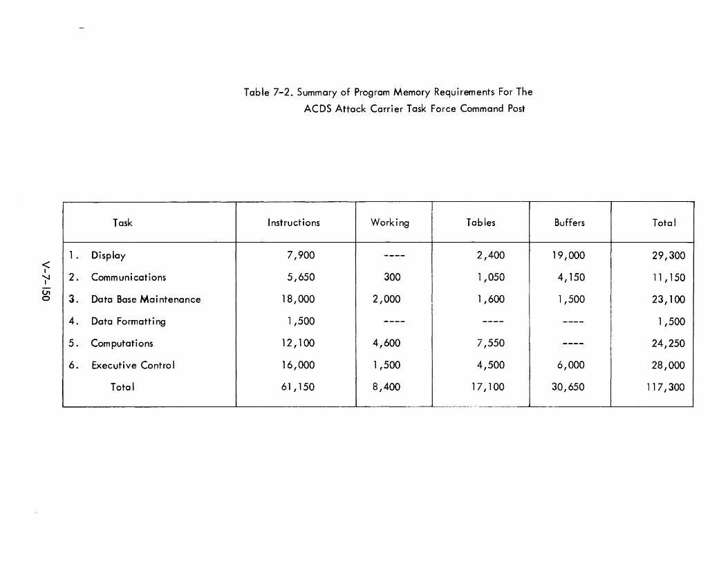
< I
""'-..I I
01 o
1 .
2.
3.
4.
5.
6.
Task
Display
Comm uni cations
Data Base Mai ntenance
Data Formatt i ng
Computations
Executive Control
Total
---- -----
Table 7-2. Summary of Program Memory Requirements For The
ACDS Attack Carrier Task Force Command Post
Instructions Working Tables
7,900 ---- 2,400
5,650 300 1,050
18,000 2,000 1,600
1,500 ---- ----
12,100 4,600 7,550
16,000 1,500 4,500
61 , 150 8,400 17,100
Buffers Total
19,000 29,300
4,150 11 , 150
1,500 23,100
---- 1,500 ,
24,250 I ---- I
6,000 28,000 I
30,650 117,300
-
It is desirable that each of these have standard system interfaces and, where possible,
have identical performance characteristics. This is of particular importance for the
processor, memory, and standard I/O modu les, where certain programm ing aids are of
use in both series of equipment.
Reliability of individual modules must increase as systems become more complex.
MTBFs of 1000 hours and more for present Navy computers should be improved in next
generation equi pment.
V-7- lSI
7.7.3 Present Computers
The role of Naval forces in meeting the challenges of modern warfare has led to the
deve lopment of computers especia Ily designed for military envi ronments. These com
puters function as the central processing elements in systems designed to provide rapid
response to both defense and attack situations. They must be capable of operation in
severe physical environments, demonstrate high reliability and have relatively low
rna i ntenance requi rements.
A number of successfu I Navy computers have been designed and produced by UNIVAC.
The Nava I computers USQ-17, CP-642A/USQ-20, CP-642B/USQ-20, and the CP-667
are direct descendents of the earlier UNIVAC 11 03A and 1105. In addition, two
sma lIer computers have been bui It with NDTS interfaces: the TRW AN/UYK-1 and
UNIVAC's Model 1218. Among these, only the CP-642A/USQ-20 has been officially
designated a NTDS computer. It is in current and widespread use by the Navy as the
unit computer of NTDS.
The UNIVAC designation for the Q-20A is Model 1206. It is identical to the earlier
Q-17 but uses an improved form of logic circuits. The Q-20B (UNIVAC Model 1212)
is a later version of the Q-20A with a compatible instruction set and improved execu
tion times. The CP-667 is a newer (1964) computer equivalent to the Q-20B in one
mode. It has a longer word length and more powerful instructions in another mode.
Also, UNIVAC's Model 1830 computer, to be deliverable in 1965, will be a micro
miniaturized version of the Q-206 using integrated circuit components.
The hardware and programm ing characteristi cs of the Q-20A, Q-20B, CP-667 and
A.N/UYK-1 are summarized in Tables 7-3 through 7-6. This information provides a
basis for comparing basic computer capabilities and for observing evolutionary trends.
The A N/UYK-1 wi II not be compared with the other computers because of its shorter
word length and fundamentally different logical structure.
V-7-152
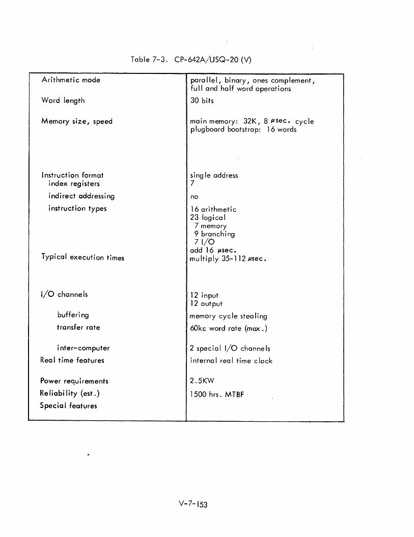
Arithmetic mode
Word length
Memory size, speed
I nstruction format index registers
indirect addressing
instruction types
Typical execution times
I/O channe Is
bufferi ng
transfer rate
inter-computer
Rea I time features
Power requ i rem ents
Re liabi I ity (est.)
Specia I features
Table 7-3. CP-642A/USQ-20 (V)
para Ilel, binary, ones complement, full and half word operations
30 bits
main memory: 32K, 8 psec. cycle plugboard bootstrap: 16 words
single address 7
no
16 ari thmeti c 23 logical
7 memory 9 branching 71/0
add 16 ~sec. m u It i ply 35- 1 12 pse c •
12 input 12 output
memory cyc Ie stea ling
60kc word rate (max.)
2 spec i a I I/O channe Is
i nterna I rea I time clock
2.5KW
1500 hrs. MTBF
V-7- 153
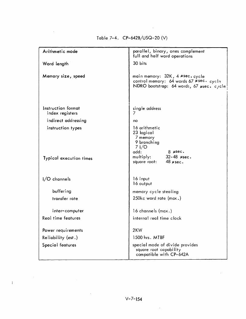
Arithmetic mode
Word length
Memory size, _ speed
I nstruction format index registers
indirect addressing
instruction types
Typical execution times
I/O channe Is
bufferi ng
transfer rate
inter-computer
Rea I time features
Power requirements
Reliability (est.)
Specia I features
Table 7-4. CP-642B/USQ-20 (V)
parallel, binary, ones complement fu II and ha If word operations
30 bits
main memory: 32K,4 Ilsec.cycle contro I memory: 64 words 67 It sec. cye Ie NDRO bootstrap: 64 word:;, 67 ~sec. cJcle I
j
sing Ie address 7
no
16 arithmetic 23 logical
7 memory 9 branching 71/0
add: multiply: square root:
16 input 16 output
8 Ilsec. 32-48 Itsec. 48 J,lsec.
memory cycle stealing
250kc word rate (max.)
16 channe Is (max.)
internal real time clock
2KW
1500 hrs. MTBF
specia I mode of divide provides square root capabi lity compatible with CP-642A
V-7-154
I I
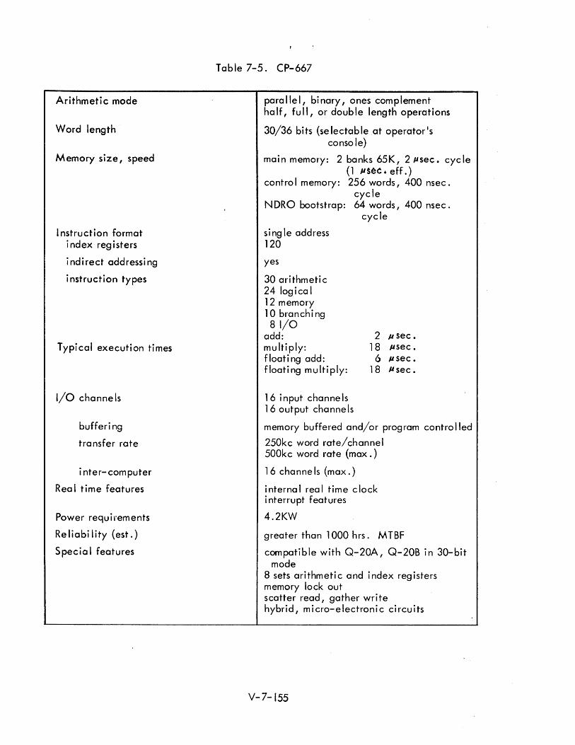
Arithmetic mode
Word length
Memory size, speed
I nstruction format index registers
indirect addressing
instruction types
Typical execution times
I/O channe Is
bufferi ng
transfer rate
inter-computer
Rea I time features
Power requirements
Reliability (est.)
Specia I features
Table 7-5. CP-667
parallel, binary, ones complement ha If, fu II, or doub Ie length operations
30/36 bits (selectable at operator's console)
mai n memory: 2 banks 65K, 2 Jlsec. eye Ie (1 JlS~C. eff.)
contro I memory: 256 words, 400 nsec. cycle
N DRO bootstrap: 64 words, 400 nsec. cycle
si ng Ie address 120
yes
30 arithmetic 24 logica I 12 memory 10 branch i ng 81/0
add: multiply: floating add: floating multiply:
16 input channe Is 16 output channels
2 p sec. 18 J.lsec.
6 J.I sec. 18 J.t sec.
memory buffered and/or program controlled
250kc word rate/channel 500kc word rate (max.)
16 channe Is (max.)
internal real time clock interrupt features
4.2KW
greater than 1000 hrs. MTBF
compatible with Q-20A, Q-20B in 30-bit mode
8 sets ari thmeti c and index reg i sters memory lock out scatter read, gather wri te hybrid, micro-electronic circuits
V-7-155
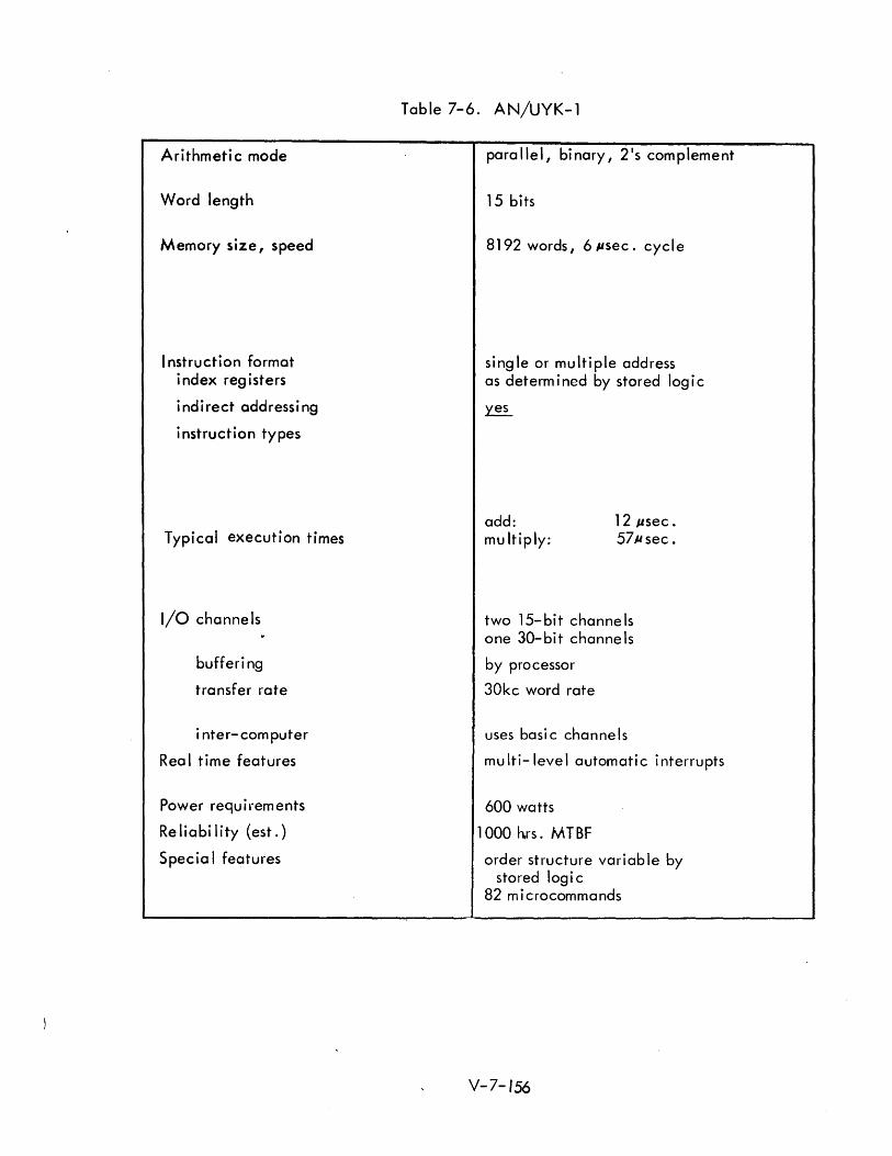
Arithmeti c mode
Word length
Memory size, speed
I nstruction format index reg isters
indirect addressing
instruction types
Typical execution times
I/O channe Is
bufferi ng
transfer rate
inter-computer
Rea I time features
Power requ i rem ents
Re I i a b iii ty (es t . )
Specia I features
Table 7-6. AN/UYK-1
parallel, binary, 2's complement
15 bits
8192 words, 6llsec. cycle
single or multiple address as determ i ned by stored log i c
~
add: multiply:
12 Ilsec . 57J.lsec.
two 15-bit channels one 30-bit channe Is
by processor
30kc word rate
uses basi c channe Is
multi-level automatic interrupts
600 watts
1000 h.rs. MTBF
order structure variable by stored log i c
82 m i crocommands
V-7-156
The 1830 computer was identified earlier as an integrated circuit version of the Q-20B
and wi II exh i bi t essentially the same performance characteristi cs. It wi" occupy less
than five cubic feet and will weigh approximately 50 pounds or about 1/15 the volume
and weight of the equivalent Q-20B. MTBF for the 1830 is estimated at 8,000 to
15,000 hours, or approximately 10 times the reliability experienced on the Q-20A.
Table 7-7 presents a speed/cost comparison for the three computers under discussion.
The adjusted cost for the CP-667 has been obtained by estimating the differential cost
of its larger memory due both to greater word capacity and its longer word. No actual
memory cost data are avai lable; it is assumed that a computer of th is word length with
a 32K memory would have approximately equal cost in memory and non-memory portions
as is true for many commercial computers. The normalized speed/cost figures correspond
to a speed/cost improvement of about 15% per year. The CP-667 performance figures
do not reflect its greater capabi lities in the 36-bit mode.
V-7-157
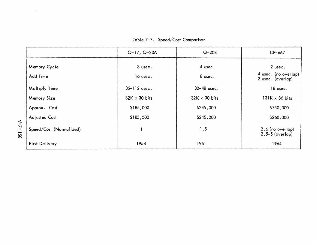
< I 'I
I
01 co
Memory Cyele
Add Time
Multiply Time
Memory Size
Approx. Cost
Ad i usted Cost
Speed/Cost (Norma I ized)
First Delivery
Table 7-7. Speed/Cost Comparison
Q-17, Q-20A Q-20B
8 usee. 4 usee.
16 usee. 8 usee.
35- 112 usee. 32-48 usee.
32K x 30 bits 32K x 30 bits
$185,000 $245,000
$185,000 $245,000
1 1 .5
1958 1961
CP-667
2 usee.
4 usee. (no over lap) 2 usee. (over lap;
18 usee.
131K x 36 bits
$750,000
$260,000
2.6 (no overlap) 2.5-5 (overlap)
1964 ---
7.7.3 Trends in Computer Systems
Computer system organization is in a state of flux. Factors are at work which will
have great impact on the computers of the 1970-80 era. These factors are many, in
cluding new applications, higher levels of system complexity, extended supporting
software, advanced peri phera I equi pment, new concepts in computer organization, and
revolutionary changes in electronic components.
7.7.3.1 Component Technology
E lectroni c components wi II undoubted Iy be the most signi fi cant si ng Ie factor i nfluenci ng
computer systems in this era. Changes in computer organization, software developments
and system complexity will in many ways merely reflect the "era of microelectronics ll•
The reader is reminded of these implications of the use of microelectronics in computer
systems as compared to discrete components:
1) Cost for equivalent circuit capability will be sharply reduced in
most cases.
2) Functional circuits (counters, shift registers, etc.) will be stressed
rather than basi c ci rcuits (i ndividua I fl i p-flops and standard log i c)
3) Design tradeoffs wi II be much different, favoring symmetry and
reduced term i na I count.
4) Reliability will be greatly improved (although the spares problem
wi II be aggravated).
5) Weight and volume requirements for electronics wi II be greatly
reduced (reduced wire length wi II perm it greater circuit speed).
Other components wi II be improved during this era. For example, the present trend
of more and faster memory per dollar will continue, further aided by microelectronics.
It is also likely that memories with new characteristics such as content addressing may
find system use in the 1970s. In the area of peripheral equipment, improvements which
make peripheral devices more usable to the Navy can be expected, such as a larger
selection of rugged equipment and improvements in user characteristics. One emphasis
partly due to microelectronics, will be to do more of the peripheral function elec-
tronically, and less of it mechanically. In addition to physical improvements, a com
parable virtual improvement in peripheral equipment can be expected from better design
in com puter programs.
V-7-159
7.7.3.2 Computer Organization
The principal features of todey's general purpose computers are remarkably similar to
the Von Neumann computer of the early 1950s. The change from vacuum tube to tran
sistor techno logy in retrospect has had a re lative Iy modest effect on com puter organi
zation. Integrated circuits, however, are much more likely to affect basic computer
structure.
For computers requiring only modest performance, the benefits of microelectronics
might principally be applied in the form of reduced cost, size, and weight, rather
than a more complex organization. For computer systems whi ch are performance
limited, the trend will be to a greater parallelism of structure. One trend which has
a Iready become apparent is the use of a much larger array of registers in the computer,
both in the processor and in I/O channe Is. However, it is too early to predi ct the
direction whi ch the industry wi II take in more genera I forms of para lie I structure, or
indeed, if it will take only one direction. Three possible directions parallel com
puter organization might take are suggested be low:
1) Multiple special purpose processors which together constitute a
genera I purpose processor.
2) Multiple identical processors which share certain facilities such
as memory eccess interrupt structure, etc.
3) Arrays of identical processors which communicate principally with
their neighbors and with their local memory.
Parallel organization (1) is found in existing and planned computers which are very
large, and which derive their computing speed from overlapped processing. Examples
of special purpose processors are add/subtract units, multiply units, divide units,
and variable length computation units. This type of organization is usually accom-
panied by substantia I memory look-ahead features.
Organization (2) is a variation from conventional multiple computer configurations
in that several processors reside in one unit and share certain faci lities. This type of
structure is now found in I/O I with n:'ultiple autonomous channel control units
sharing memory and supervisory control.
V-7-160
Organization (3) is typical of computers such as the Holland and SOLOMON machines
described earlier. The applicability of this type of computing array to problems which
are spatially structured has been demonstrated. However I applicabi lity to generalized
command and control is questionable at this time.
7.7.3.3 Communications and Displays
Communication and display subsystems have increasing importance in future Navy
command and control systems. I n communications, higher transm ission rates and more
communication sources wi II combine to produce a much greater information bandwidth.
Certain ACDS functions, such as rapid transferral of a command post from one ship to
another, require careful examination of communication capacity. In such a massive
transfer there must be a much greater emphasis on absolute fidelity of transferred
information.
I n another area, increased requi rements for store-and-forward message communication
can a Iso be expected. With greater dependence of non- Navy forces on computer
based communications systems, a potential situation for interchange is developing.
Complete automaticity of this function, including substantial amounts of memory, is
desirable. The handling of Fieldata and ASCII codes will be greatly increased in this
environment. For the 1970's, there may be renewed emphasis on the adoption of a
si ng Ie code for data interchange.
In displays, CRT consoles supporting the individual user seem desirable. This type of
display which connects to the computer system in an all-digital manner has been used
for a number of years, and it can now be considered a mature peripheral device. Re
freshi ng the information displayed on CRT conso les shou Id be automati c -- computer
handling should be confined to changing the data being displayed. This implies dis
play buffering either at each console, or dedicated memory for supporting a number
of displays.
The ACDS tactical environment makes certain background information desirable. The
detail in such background cannot be properly handled by generation of symbols and
line segments, requiring other methods of presenting background information such as
projection or video mixing.
Group displays which are capable of rapid updating have not achieved a level of
performance which is satisfactory. Whi Ie extensive use of this type of display could
not now be recommended, further developments of basic group display techniques
shou Id be encouraged and monitored.
V-7- 161
7.7.3.4 Software
Trends in software development of particular significance to ACDS have two principal
directions. First, a trend is taking place towards greater simplicity and effectiveness
in use of systems. One form this takes is that of languages. Since command and con
trol involves such diverse activities as air operations, threat evaluation, communications
handling, and information retrieval, its language requirements are truly complex. One
example of a language area which needs development is that related to display of re
trieved information. Present display methods employ display generators which are
quite inflexible, in turn requiring that the system depend on highly formatted displays
and display change data. Display flexibi lity would simplify and extend the use of
displays, and might also make displays more effective in an overload environment.
The second trend in software deve lopment is to produce greater computer system effi
ciency and dependability. This involves concepts of time sharing, multiprocessing
and degraded operation which are contained principally in the executive control pro
gram. Successful preparation of an executive program requires combined knowledge
of the system functions, the system hardware, and the working programs.
7.7.4 Basi c Computer Organization
The internal organization or logical structure of a computer is properly based upon:
1) a consideration of the uses wh i ch are anti ci pated for the com puter ,
2) the characteristi cs and capabi lities of existing equipment, and
3) the current states of the art and discerni ble trends in system
organization and component technology.
An understanding and appreciation of the problem is obviously important. A
know ledge of existi ng equi pment is a Iso essentia I, pcrticu larly if compctibi liti es are
to be achieved. Finally, it is necessary to establish cost/value trade-offs in the light
of technological advances and changes in user emphasis based on experience.
The subsequent sections, 7.7.5, 7.7.6 and 7.7.7 I consider the topi cs of fam i I ies of
computers, time sharing, and multiple computer systems in greater detai I.
V-7- 162
7.7.4.1 Control Phi losophy
Control philosophy is here defined to include both a basic design approach and the
essential features of a particular plan. Several basic approaches have already been
identified. Previous discussions of multi-computers dealt with unique configurations
of "conventional" stored program computers and did not imply an otherwise unique
form of contro I at the basi c computer leve I. The high Iy para lie I computers were found
to be of qLGstionable value in the Navy tactical environment and were observed to have
inherent disadvantages of relatively high cost and difficulty of programming.
It may be concluded that the conventional Von Neumann computer, in which a stored
program of instruction is retrieved from memory and sequentially executed, embodies
the most genera Ily usefu I contro I ph i losophy yet proposed. The ~et ~ f instructions em
ployed, however, may depend upon the specific method of contro I. For example, a
stored logic approach might lead to a set of simple instructions which in combination
make up more conventional instructions. However, this need not be the case, and the
trend in stored logic/microprogramming is to use this technique to mechanize conven
tional instructions. As such, it may be looked upon merely as an alternate way of
implementing control which is chosen or rejected on the basis of cost and performance.
Improvements to this basic approach will most likely take the form of sophistications in
implementation. Many serious "sophistications" seek to improve processing speeds by
introducing some form of parallelism into the control process. A major observation here
is the relative independence between the operations of instruction processing, operand
access and instruction execution. This creates the opportunity to look ahead in the pro
gram and perform these phases of successive instructions in a cycle overlap fashion.
The "look ahead " technique is an effective way of improving performance when complex
algorithms have been employed and circuit and memory speeds have already been im
proved as far as practicable. That is, further improvements must reduce waiting times
by operating the memory, control unit, and central processing unit in parallel.
Approaches in which several processing units are operated in parallel from either pri
vate or shared memory are considered to be forms of mu Iti-computing or, in the extreme
case with many simple processors, examples of high Iy para lie I structures.
To satisfy multi-processing requirements, an adequate control philosophy must provide
for orderly interrupts according to a program determined priority. The storing and
V-7- 163
reconstituting of working registers and program status information during interrupt
processi ng has been faci I itated in some recent com puters by the provision of severa I
sets of registers. The registers may be implemented in flip flop form or as words in a
fast control memory.
7.7.4.2 Instruction Format and Repertoire
There is current widespread use of the single address instruction format which usually
includes designators for indexing and indirect addressing forms of address modification.
These formats imply fixed register assignments within the processing unit and have been
generally accepted as leading to the most useful and flexible instruction repertoires.
Although the single address format has remained popular, the number of instructions
expressed in that format and hence the number of instruction code bits required has
tended to increase in each new generation of computers. The requirement for index
registers seems to have been a matter of preference and is relatively stable at 7 or 15
(3 or 4 bit designator) for larger computers. The use of the address field to contain a
literal or short operand for immediate execution is a useful variation of the single ad
dress format 0
Data word length of present Navy computers has been quite satisfactory for tactical
data use, with occassional requirements for double precision computation. The use
of variable length operands and character addressing is advantageous in digit arith
metic and in message handling as it occurs in NTDS, for example, in display
preparation.
The adoption of another distinct data format for representing numbers in exponential or
floating point form led first to standard routines for performing arithmetic or floating
point data and later to the inclusion of floating point instructions in basic repertoires.
Because it accommodates wider ranges in data magnitude and simplifies scaling problems,
floating point representation has become a practical requirement for all computers
applied to even modest computations.
Several machines of recent design have gained both speed and flexibility from the use of
a set of generalized registers within the processing unit. A corresponding instruction
format permits reference to pairs of registers whose contents serve as operands for the
common arithmetic and logical operations. In effect these registers provide a local,
V-7-164
fast access storage which permits operations involving several operands to proceed
without memory access delays. An additional format which contains a memory address
field and register designators permits data transfer between registers and memory, and
allows the generalized registers to be used either as index registers, base address regis
ters, or registers for computational results.
7.7.4.3 I nterna I Memory
The i nterna I memory of a typi ca I stored program computer performs in the fo \lowing
roles:
1) Program storage
2) Data buffer and storage
3) Processing and control registers
4) Calculational scratch pad
5) Bootstrap program
Within the same computer the memory may have different implementations appropriate
to its function. Conventiona I core memory serves both as program and data storage.
The registers and scratch pad take the form of separate, small high speed memories in
some very capable computers. The bootstrap may be in an NDRO memory unit or,
equivalently, wired as a permanent part of main memory.
Main memory capacity is related to the size of all programs which must be executed
cyclicly or upon demand, and to the amount of data which must be held in random
access, ready reference form. Studies of one ACDS computer task have indicated
that on the order of 100,000 words of random access memory with one million words
of bu Ik memory backup may be requ ired.
Another important aspect of internal memory is its modularity, that is, the ease of adding
increments of memory. Modules with capacities as low as 4,000 words permit ease of
tailoring memory to application requirements. Modularity also implies bus communication
with the memory and the possibi lity of operating the independent modules in an over
lapped fashion. The study of multi-computer systems indicated the potential need to
share modules of memory among severa I computers and their memory buffered I/O devices.
V-7-165
Also identified was the multiprocessing need for memory protection features. Memory
protection may be implemented on a word by word basis, by memory module, or by the
use of registers to specify protected regions of the memory system.
7.7.4.4 I/O Implementation
In early computers the control I/O devices and programmed data transmission often
represented timing complexities and programming difficulties. Present medium and
large sca Ie computers overcome these problems by providing data paths between I/O
devices and internal memory. The processor prescribes a memory area containing a
data block, initiates the data transm ission and proceeds to other processi ng unti I the
completion of transmission is signalled by a program interruption.
A valuable extension of the memory buffered I/O phi losophy is the recent concept of a
data channe I unit with a greater capabi lity for autonomous operation. The data channe I
is activated by an I/O instruction, receives and decodes I/O commands from memory,
and directly contro Is I/O devi ces. Thus, it performs complex operationa I sequences
without processor intervention. Further, the abi I ity to rei nstruct devi ces more qui ck Iy
for successive operations permits the realization of higher data rates.
More sophisticated data channels may be constructed to provide for economical multi
plexed operation of many devices with slower data rates. The multiplexed channels
are capable of executing I/O command sequences for each device and of controlling
information flow between it and prescribed areas of memory.
In the multi-computer systems analysis, a need for inter-computer communication was
identified. Early attempts at providing this capability often resulted in an implied
master-slave relationship which did not exist in the desired multi-computer configuration.
A solution to this problem, which permits interconnection of data channels, is required
for ACDS applications.
An alternate approach to the problem of computer to computer communication in a
mu Iti-computer system may be to use shared memory to provide common access to the
required data. A detai led study of this problem and its systems programming impli
cations is required to determine applicabi lity to ACDS tasks.
V-7- 166
7.7.5 Family of Computers
Computer manufacturers and users frequently refer to a particular group of computers
as a 11famil/'. It is the purpose of the following discussion to define the family
concept, to examine the benefits accruing from family relationships, and to consider
the relevance of these benefits to the ACDS problem.
7.7.5.1 Fami I y Concept
The family designation is usually reserved for the case where two or more computers
of different size or capabil ity are offered by a manufacturer or appl ied by the same
user. Although successive generations of one computer may be so described, more
typically the members of the family co-exist and may be chosen on the basis of their
suitability for selected tasks. It is the exhibition of similar characteristics by the
different sized members which identifies the family and permits efficiencies in their
appl ication.
7.7.5.1.1 Program Compatability
A valuable family characteristic is that of program compatibility; that is, the ability
to run programs written for one member on another member without modification.
Program compatibility is important because it:
1) Simplifies the training of programmers,
2) Reduces program development costs,. and'
3) Permits system growth without the necessity to replace
correctly operati ng programs.
If both upwards and downwards compatibility are not achieved in the design of the
family, the third factor requires only upwards compatibility while the second requires
both. Although one could conceivably write all programs for the smallest member of
the family and take advantage of upwards compatibil ity, such an approach would not
real ize the full capabil ity of the larger members. Effective program compatibi I ity
can be achieved with varying degrees of efficiency and desirability at the following
levels:
V-7-167
1) Symbolic language (compiler level)
2) Machine language (instruction level)
3) By mi croprogrammed sequences
Symbol ic language
In the first level, compatibility results from the specification of a common symbolic
I anguage for use in all program preparat ion, regard I ess of wh i ch computer may actuall y
run the program. The individual computers of the family need not be identical at the
machine language level but each must be equipped with a compiler program to gener
ate its own mach ine language version of the symbol ically stated program. Although
compilers traditionally produce less efficient object programs than manual coding,
the advantages of a common I appl ication oriented I symbol ic language may dictate
its use in any case. Programming compatibility at a symbolic level would provide
the three benefits noted earl ier, requiring that only systems programmers and main
tenance personnel be familiar with the various machine language instruction repertoires.
Machine Language
Compatibility at the machine language or instruction level implies a strong logical
similarity between members of the family. Logical functions may, however, be
implemented with different electronic IIbuilding blocks" and instruction execution
times may vary from member to member. If upwards and downwards compatibil ity is
requ ired, there must be a one-to""One correspondence between instruction set features.
Great care must be exercised during mach ine design to ensure that differences in
implementation do not introduce subtle (but disastrous) differences in instruction
effect. Where upwards compatibil ity accompl ishes the desired purposes, the instruc
tion repertoires of the smaller members may be subsets of the progressively larger
members.
Complete instruction set compatibility provides the three benefits stated above,
permits the development of universal system software, and simpl ifies training of
maintenance personnel. Adherence "to a doctrine of mach ine Icnguage compatibil ity,
however, does have the adverse effect of inh ibiting the introduction of new techniques
and technologies during the subsequent design of replacement mach ines or additional
V-7-168
members. That is, second generation machines may be less efficient because of the
necessity to accommodate a previously established word length and instruction
repertoire ( with all of the implied logic structure) while at the same time introducing
newer, more desirable features wh ich cannot take advantage of that hardware
requ i red for compatibi I ity.
Microprogrammed Sequences
The stored logic or microprogrammed technique of computer design, previously dis
cussed in section 7.5, offers a third approach to achieving program compatibility in
a family of computers. It was noted in this discussion that one of the principal
characteristics of microprogrammed computers is the basic nature of the micro
operations and, in some cases, the freedom to assign processing functions to a number
of general registers. These attributes facilitate II interpretive mode" operation, per
mitting microprogrammed computers to simulate (or emulate) a given instruction
repertoire with considerably more efficiency than would be the case with a IIconven
tional" computer. The benefits of program compatibility at an instruction set level
can thus be achieved by equipping a microprogrammed computer (or a family of
microprogrammed computers) with appropriate sequences of micro-orders to perform
equivalent operations for each instruction in the set.
7.7.5.1.2 Input/Output Compatibility
Like programming compatibil ity, the abil ity to control and communicate with a
common group of input/output devices is an important characteristic of a computer
family. It is not essential that the individual computers have identical I/O instructions
but the circuit properites and logic of the interface must agree if all members are to
use the common devices.
I/O compatibil ity is a necessary condition to the use of several different members in
a multi-computer configuration with variable or shared peripheral responsibilities and
with inter-computer communication requirements. A considerable emphasis on I/O
compatibility stems from the relatively high cost of designing and installing special
purpose adapters and equipment interface. Also, it is generally true that system
growth involves the substitution of a faster, more capable processor along with the
V-7-169

addition of more I/O interconnections. That is, there is usually the requirement for
the new processor to continue to function with the existing I/O channels. One can
envision an evolutionary type of growth, however, in which a next generation
processor is equipped with a number of improved, higher speed I/O channels in
addition to the normal complement of "standard" channels.
In modern computer systems with memory buffered I/O features, I/O compatibil ity
among family members also impl ies similarities in methods of memory communication.
In particular I if two or more processors are to share common external memory modules
with assigned I/O channels, standardized memory communication is required.
An additional memory related aspect of I/O compatibility is the recognition that in
order to make efficient use of memory for data storage, memory word length should be
equal to the I/O channel width or a simple multiple thereof. This integer relation
sh ip el iminates program steps and avoids compromising I/O transfer rates because of
the need for programmed formatting.
V-7-170
7.7.5.1.3 Parts Interchangeability
The abi lity to reassign system functions within a multi-computer network may be
thought of as a form of parts interchangeability. The previous discussions of I/O
and memory compatibilities disclosed additional examples of parts interchangeability
at the unit and module levels. Similarity or compatibility also typically e.xists in a
computer fami Iy at a replacement part or subassembly level. Although the concept
of a computer family does not demand this type of compatibility, it has not been un
common to make use of a family of plug-in circuits and logic elements whenever
possible in the design of a computer series.
7.7.5.2 Relevance to ACDS
The present NTDS is bui It around the concept of a unit computer (AN/USQ-20) and
the use of multiple computers when a requirement exceeds the capabilities of a
single unit computer. The range of applications evident in ACDS suggests that
computers both smaller and larger than the Q-20B will be needed to fulfill present
recognized needs. Moreover, a small family of computers with varying size,
capability and environmental characteristics will apparently be required to accom
modate problem growth and meet long range needs.
In considering such a family, the characteristics discussed in the previous section
are all relevant to ACDS planning. To simplify programmer training, minimize
program development costs, and facilitate system growth, some form of program
compatibility should be achieved. While it is fairly certain that a common sym
bolic language should be adopted, the necessity of instruction level compatibility
is not so obvious. Further, the selection of a hardware or a micro-programmed
approach to implementing a common instruction set would have to be made on the
basis of a more detailed, design oriented study.
The practical requirement for evolutionary change in any fleet-wide installation of
equipment places relatively more importance on I/O compatibility. The expecta
ti on of mu Iti -computer confi gurati ons further underl i nes this emphasis. Also, the
anticipated pattern of system growth, in which a new more powerful processor must
work with previously installed I/O equipments, requires careful attention to this
fami Iy characteristic.
V-7-171
The use of common plug-in circuits and logic elements is important in the ACDS
environment because it permits a reduction in the number of spares and specialized
test equipment which must be carried for a given complement of equipment and
eases associated logistics problems. Additionally, it simplifies the training of
maintenance personnel and the actual performance of the maintenance function.
7.7.6 Computer Time Sharing
Multiprogramming, or time sharing, has been previously discussed in terms of its
combined programming and equipment considerations. This section attempts to relate
computer time sharing to ACDS requirements, and to identify trends in time sharing
mechanization.
7.7.6.1 Time Sharing Concept
An area of computer study whi ch has had i ncreasi ng emphasi sin recent years is the
"simultaneous" use of one or more computers for several different tasks. At a gross
level of detai Is, time sharing is not new. For many years computer programs have beer!
designed to use a processor for one task whi Ie I/O is engaged in other tasks (true
simultaneity for buffered I/O). Also, real-time systems have been designed to
utilize a program which is capable of commutating rapidly through many sub-programs.
The newer aspects of time sharing are the accomplishment of apparent simultaneity
of computer programs by much tighter interleaving of individual programs, and
with appropriate protection features to prevent one program from interfering with
another.
The need for this intimate time sharing of computers has been heightened by the
increase in use of on-line manual inputs such as the consoles used in command and
control systems. At MIT, SDC and RAND, time-sharing system studies are based
on manual job entries from consoles. A number of operational systems are success
fully in use with large numbers of data entry devices such as airline reservation
and stock market quotation systems. However, there is a symmetry of purpose that
makes these much less complex systems than their counterparts in command and
control.
V-7- 172
Apart from man-machine considerations, there are similar situations which stand to
benefit from time sharing. Wherever appreciable excess computing capacity exists,
other programs can, in principle, use the remaining capacity. It is this improvement
in efficiency which is the principal benefit to be derived from time sharing. This
benefit is similar to the benefit obtained in communications by the use of multi
plexing techniques to better utilize the available bandwidth.
The more significant obstacles which stand in the way of realization of effective time
sharing are:
I) Those factors which contribute to wasted time in
mak i ng transi ti ons from one program to another,
thereby eroding efficiency gains
2) Those factors which permit program interaction,
thereby violating the integrity of individual
programs.
As an example of the desired characteristics of time sharing, consider three computer
programs each capable of execution on three identical computers. Suppose, as an
al ternative, a computer four times faster than each of the three computers is avai 1-
able at a moderately higher cost. In this example the objective of time sharing is
to interleave the three programs in the single larger computer to reduce system cost.
Of course, this must be done in a manner which keeps the input and output for each
individual program valid; also, the control program which performs the time sharing
must not be larger than one of the job programs.
It is obvious in this example that the two previously mentioned obstacles -- wasted
time in program switchover and loss of program integrity -- require careful considera
tion. To be optimized, both require special hardware and software features. These
features can be subdivided into two categories, processor time sharing features and
memory time shari ng features. The processor time shari ng features determ i ne to a
great extent the program switchover efficiency, which in turn is directly related to
the frequency with w hi ch sw i tc hovers are made. Memory time shari ng features are
predominant in determining the level of program protection as well as program and
data relocation.
V-7-173
7.7.6.2 ACDS Requirements
Computers in all command posts, at every level of command, have a requirement for
program concurrency. In the limit this may merely consist of a self-test program
interleaved with an operating program. Typically, however, it is desirable to per
form a number of concurrent operational tasks. Some of these tasks which have a
counterpart in virtually all ACDS command posts are as follows:
1) Position-keeping (e.g., grid lock)
2) Communi cati ons data hand ling
3) Manual inputs (commands and inquiries)
4) Data base maintenance
5) Display updating
6) Resource allocation
7) Threat eva I uati on
8) Self-test
Under stress conditions the sum of these tasks wi II exceed the capacity of one com
puter. On the other hand, a task such as position-keeping requires only a fraction
of a computer at any time in spite of its frequent updating requirements. Tasks such
as threat evaluation have greatly varying processing requirements and are further
complicated by a fast response requirement, particularly with regard to low-flying
aircraft. Communications, data base maintenance and display updating have much
in common since activity in one area wi II frequently imply activity in other areas.
In specific terms, ACDS requires time sharing in some form. It may be cyclic pro
cessing, that is, a fixed sequencing through task assignments, or it may be demand
processing. Demand processing is best suited to tasks which are generated in a
sporadic manner such as inquiries from consoles or received messages over communi
cation paths. Time sharing should be introduced in ACDS in a manner which in
volves little system risk. Some guidelines are as follows:
V-7-174
7.7.6.3
1) The frequency of program switchover should be modest,
such that the dwe" time of each program is in the tens
of milliseconds. This prevents undue complications due
to unanticipated inefficiencies in switchover.
2) Memory time sharing should be minimized in the sense
that program and data relocation is avoided where
possible. This simplifies both the hardware features
and the executive program.
3) Input/output considerations should be such that complex
timing rules need not be observed. Also, an integral
part of program integrity is the maintenance of "need
to have ll restrictions for all users under all stress
conditions.
Time Shari ng Features
Time sharing of general purpose computers relies on both hardware and software for
its implementation. Early systems had a deficiency of hardware features, placing an
added burden on computer programming. This has contributed to a somewhat dis
torted picture of the complexity of time sharing. On the other hand, it would be
unrealistic to assume that added hardware features will eliminate the need for time
sharing software.
The hardware features which facilitate computer time sharing can be essentially
divided into those related to the processor and those related to the memory. Proces
sor time sharing is aided by features related to scheduling and to the mechanics of
program switchover. Scheduling features are those which aid determination that one
program shou Id supersede another, either on the basi s of completi on of a phase of the
program in execution, by interruption for a new task, or by routine cycling of pro
grams. Features which facilitate the actual switchover to a different program are
those which can efficiently store the state of a program. (In this case it is assumed
that the program being supplanted was not necessari Iy at a convenient pausing point.)
A summary of these processor ti me shari ng features is gi ven be low.
V-7-175
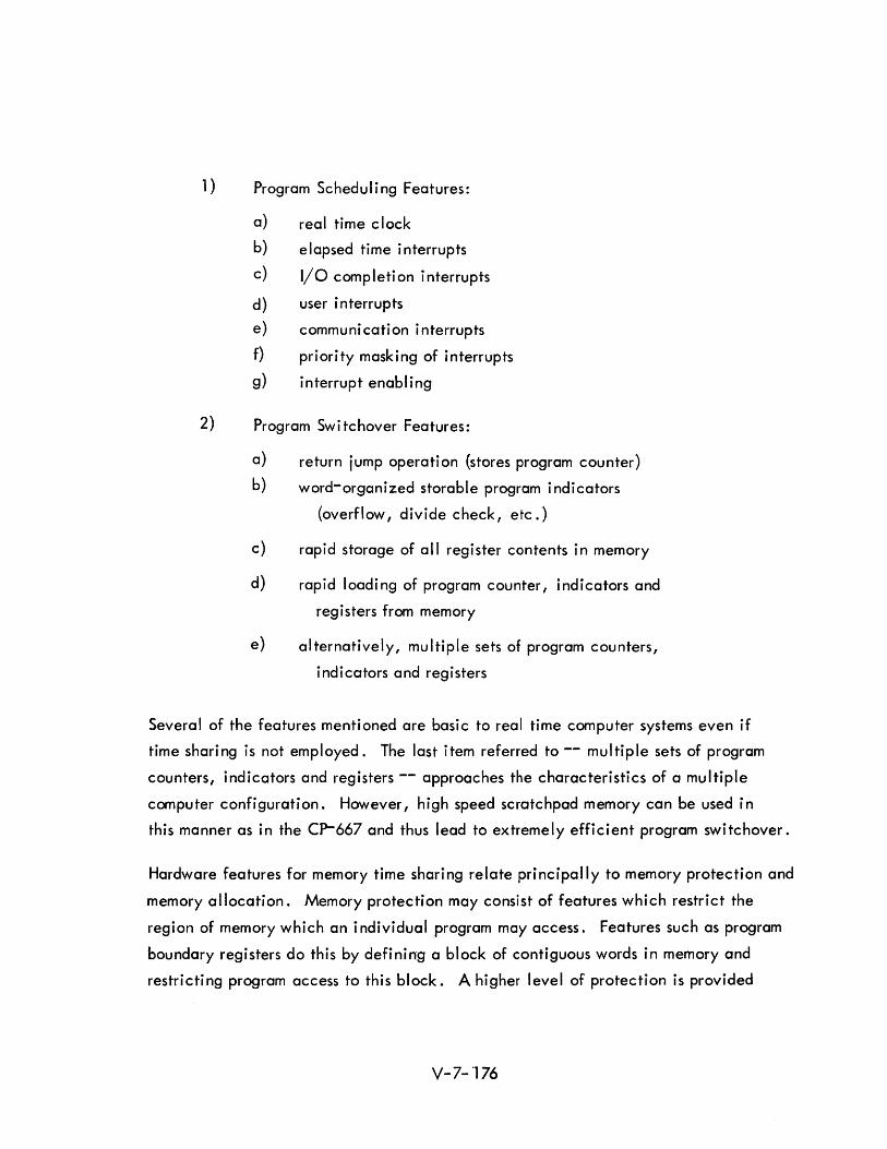
1) Program Scheduling Features:
a) real time clock
b) elapsed time interrupts
c) I/O completion interrupts
d) user interrupts
e) communi cati on interrupts
f) priority masking of interrupts
g) interrupt enabl i ng
2) Program Switchover Features:
a) return jump operati on (stores program counter)
b) word-organized storable program indicators
(overflow, divide check, etc.)
c) rapid storage of all register contents in memory
d) rapid loading of program counter, indicators and
registers from memory
e) alternatively, multiple sets of program counters,
indicators and registers
Several of the features mentioned are basic to real time computer systems even if
time sharing is not employed. The last item referred to -- multiple sets of program
counters, indicators and registers -- approaches the characteristics of a multiple
computer configuration. However, high speed scratchpad memory can be used in
this manner as in the CP-667 and thus lead to extremely efficient program switchover.
Hardware features for memory time sharing relate principally to memory protection and
memory allocation. Memory protection may consist of features which restrict the
region of memory which an individual program may access. Features such as program
boundary registers do this by defining a block of contiguous words in memory and
restricting program access to this block. A higher level of protection is provided
V-7- '176
by inhibiting writing into particular word positions. For information which does not
change, a type of memory which is unalterable by any program can be used. These
features are summarized below.
3) Memory Protecti on Features:
a) program boundary registers
b) verification of stored identifying program numbers
c) write inhibit flag bit
d) write inhibit by memory zone
e) program unalterable memory
Memory allocation features are of importance if the time-shared programs and data
do not have a fixed memory assignment. The problem which then demands solution
is that addresses appearing in instructions must be adjusted to reflect the actual
location of programs and data in memory. This is referred to as program and data
relocation, and can be accomplished by making address adjustments when the
program is loaded, or at the time it is executed. If done at load time, it can be
accomplished entirely by software -- at execution time, hardware is required.
Thi s typi call y takes the form of a base regi ster whi ch has its contents added to all
addresses. The problem of memory allocation is greatly complicated if an
individual program is assigned to several different non-contiguous blocks in memory.
In this case, memory protection is similarly complicated. The general problem of
this type is referred to as dynamic memory allocation. Much work remains to be
done in this area. Associative memories of high speed have been suggested for
dynamic memory allocation.
4) Memory Allocation Features:
a) address modification by program loader (software).
b) address modification by program loader using address
relocation flag (hardware aid)
c) base register
d) mu I ti pie base regi sters
e) associative access to base registers
V-7-177
Programming requirements for time sharing have been implicit in much of the preceding
discussion. Characteristics of time sharing must be based on system analysis, at least
to the extent that worst case requirements are examined. The most significant part
of the executive control program for time sharing is that of scheduling. Here the
decisions of cyclic versus demand processing are implemented, together with
considerations of priorities and peak requirements. Most of the hardware features
just cited require program setup: base registers, program boundary registers, inter
rupt masks, interrupt enable, etc. It shou Id be emphasized that whi Ie ACDS re
quires time sharing, it is desirable to do this in its simpler forms. 1n particular,
complex memory allocation should be avoided. On the other hand, memory
protection features are extremely desirable and should be incorporated in ACDS in
its earliest stages.
7.7.7 Mu I ti -computer Systems
The topi c of mu I ti -computer systems and mu I ti -processi ng has been previ ous Iy
discussed. This section summarizes features which are desirable in the implemen
tation of multi-computer systems as related to ACDS requirements.
7.7.7.1 Typical Configurations
Several configurations could be adjusted to meet the needs of ACDS o The principal
requirements are modularity, efficiency of use, and adequate protection to the
system in the event of module failure. Implicit in modularity is reasonable ability
for modules to detect errors in transmitted data and to have rapid system sub-
sti tuti on in the event of fai lure.
Despite the potential adequacy of a number of configurations, certain unifying
trends are apparent in multiple computer organizations. These are cited with
respect to processor/memory relationships, processor hierarchies, and peripheral
equipment.
Processor/memory relationship has tended towards the time multiplexed bus rather
than the selection of one bank of memory by one processor for a span of time. Ac
cess by two or more computers to one bank of memory is more efficient than queuing
for its use. It should be recalled that memory within a bank can still be protected
piecewise by program b~undary registers or similar techniques.
V-7-178
The use of processors of more than one size {processor hierarchies) in the same
system may have merit, particularly if a program compatible family of computers is
used. This is particularly relevant if a processor is sized for a given major task -
differences in processing requirements leading to different sizes. In a family of
computers, the notion of identical multi-computer features is significant.
Peripheral equipment has proved to be a complex problem in multi-computer systems.
On the one hand, equipment such as a printer has essentially one purpose for
lengthy spans of time. On the other hand, the printer should not have a fixed
allocation to one computer, since its failure should not imply printer failure. A
generalization of the buffered I/O channel appears to be the solution to this
problem. In effect, there need be no direct (non-switchable) communication
between processor and peripheral equipment. Rather, the I/O connection is to
memory and the processor connection is to memory, resulting in ready substitution
of ei ther modu Ie.
7.7.7.2 Multi-processing Features
As for time-sharing, multi-processing is achieved by a combination of hardware and
software. In fact, all of the time sharing features discussed in the preceding
secti on are germane to mu I ti -processing. Some additi onal hardware features are
itemized as they apply to all modules, to processor modules, to memory modules,
and to I/O control.
1) Multi-processing Features, All Modules;
a) parity bit (or equivalent) attached to all transmitted data
b) error checking on all received data
c) self-contained power regulation or isolation
d) circuits minimizing propagation of faults to busses
e) capability for rapid removal of module from system
2) Multi-processing Feature, Processor Modules;
a) ti me-shari ng features (see precedi ng secti on)
b) intercomputer communication capabi lity
c) interruptable idle state
d) system reset
V-7-179
3) Multi-processing Features, Memory Modules;
a) memory protection features in conjunction with processor
(see preceding section)
b) memory allocation features in conjunction with processor
(see preceding section)
c) time multiplexed word and address busses
d) overlapped cycles (if more than one memory bank per module)
4) Multi-processing Features, I/O Control;
a) standard interface
b) capability for multiplexed channels
c) symbolic addressing for all I/O modules
Accompanying these hardware features must be a carefully designed executive
program. Significant advances have been made in this kind of control programming
in recent years -- the question is no longer one of feasibility, but one of quality
and effectiveness. As discussed in the next section, one aspect of multi-computer
control which requires much care and planning is that of recovery from failure.
7.7.7.3 Degraded Operation
A most important consideration for tactical systems is the ability to retain partial
effectiveness in the face of one or more equipment failures. If it is assumed that
redundant modules wi II be avai lable on standby, the problem of fai lure recovery
is principally involved in failure detection and equipment substitution. In an
operati ona I sense this produces a transi ent from whi ch fu II recovery can be made
unless essential data is lost. If, on the other hand, redundant modules will not
be available when a failure occurs, system analysis of the alternatives must be
performed to determine if a change in procedure might have to be employed.
V-7-180

A fundamental factor in automatic compensation for failure (and one occasionally
neglected) is adequate failure detection. It is extremely important that most module
failures be automatically detectable in a timely fashion, either by self-indication
or by detec ti on by another modu I e of an i ncorrec t response or hangup.
After detection of failure, it must usually be assumed that the integrity of certain
preceding processing was compromised, and that rollback or data rejection should
take place. This is a complex consideration and must be carefully examined at
the system level and reflected into automatic recovery procedures. For ACDS,
specific objectives should be defined with regard to which module failures will be
compensated, the rollback mechanism, and any alterations to operating procedures
which might result.
7.7.7.4 ACDS Implications
Multi-processing has been an essential ingredient in NTDS and has established a
framework for evolutionary improvement. Whi Ie it can be anticipated that these
improvements will add complexity to control programs, these can be contained by
clear specification of objectives. From an equipment point of view, it would
appear that present organizational features will continue to endure for some time.
However, it wou"ld also seem fhat there wi II appear some time prior to 1980
rather significant organizational features which must be considered revolutionary.
These changes will be traceable mainly to new design tradeoffs associated with
microelectronics. It is too early to ascertain in detail what these changes will be,
but a para lie Ii sm of structure -- and hence a new form of mu I ti processi ng -- is
strongly indicated. The resulting new levels of performance and reliability
would in turn lead to vastly improved tactical command systems.
V-7- 181
.8.1 ,INTRODUCTION
Section 8 PROGRAMMING
One problem in the implementation and operation of real-time computer based systems,
as typified by the NTDS and ACDS, is the timely and economical acquisition of com
puter programs which increase rather than limit the system capabilities. Programming
is an art, and the success of programming projects is a function of the talent, intelli
gence, ingenuity and interest of programmers. All too often, system designers depend
on programming talent to correct hardware design errors. Under these circi.Jmstances,
program development is difficult to plan and schedules are not met. The end product
is significantly different from that envisioned, and the wasted effort contributes an
excessive amount of extra costs.
This section is a description and evaluation of techniques and concepts which may be
employed to make programming projects more tractable. Parts of the section are
devoted to a definition of terms, a description of the state-of-the-art, a prognostica
tion of the state-of-the-art, and to specific recommendations.
8.2 COMPUTER PROGRAMS AND COMPUTER PROGRAMMERS
Computer programs are the means by which a computer connected to peripheral devices
can efficiently perform required functions. The primary task of the computer pro
grammer is the generation of computer programs from well defined specifications •. In
the past, the programmer has performed other tasks needed to reduce a problem, how
ever vaguely stated, to a sequence of operations performed by a system incorporating
a computer. The programmer1s function has been the analysis of the problem and the
synthesis of computer hardware and software to produce an automati c procedure.
This concept was workable when the hardware system was lim ited to a computer with
an input mechanism, an output mechanism and some auxi I iary storage. It is not work
able when the programmer is presented with a large real-time problem and a large
V-8-1

number of arbitrari Iy se lected hardware components. In such cases, the generation of
the computer programs themse Ives may be only one element of importance as far as the
deve lopment of the overall system is concerned. The following items are at least as
important as the programs themse Ives:
1) The design of operational procedures and displays; the analysis
of the human factors;
2) The schedu ling and management of the computer programming
effort ;
3) The analysis of the problem and the specification of the manner
in which the system is to be synthesized;
4) The design and implementation of the programs which permit the
generation of computer programs in an efficient and economical
way.
There is no question that experienced programmers are needed to participate in these
tasks including participation in the specification of system hardware. But, in the
implementation of ACDS it is suggested that a comprehensive and integrated
effort be made to specify procedures for hardware and software simu Itaneously.
PROGRAMMING TOOLS
Summary
The following is a discussion of the programming tools which are important in the
context of ANTACCS. The tools are defined, described, and evaluatedo Develop
ment trends are presented. Particular attention has been given to the definition of
terms. Because the field of computer programming is dynamic, there is a wide diver
gence of opinion, even among specialists, concerning the meaning of many of the
programming terms in common use.. The definitions are not intended to be authori
tative and are inc luded only to achieve consistency and clarity.
V-8-2
8.3.2 General Discussion
The programming tools described are in common use today. They are most appropriate
for the programming of independent computers constructed on the Von Neuman mode I.
At the present stage of programming technology these programming tools may be used
to produce modu lar sub-programs. The sub-programs must later be integrated into the
system according to specifications developed during a system analysis and synthesis
period.
Programming tools serve several purposes. They assist the programmer in the construction
of a program, in debugging or eliminating mistakes, and eliminating redundant effort.
More important, when the programming effort is large, they assist in coordinating and
standardizing individual efforts. They may be generally classified as languages, input/
output control systems, checkout tools, monitors and executives.
In the programming context, a language is a defined set of symbols and the rules
governing the manner and sequence in which the symbols may be combined. Pro
gramming languages are not the same as natural languages. Confusion is possible
because those who use and are most familiar with them have found the nomenclature
and tools of analysis of natural languages to be very helpful and appropriate. Hence
there is a tendency to overemphasize simi larities and correspondences • Rather, these
"languages" are members of a c lass of formal systems of expression sim i lar to the
equations of mathematics. Although the power of programming languages is limited,
their utility must not be underestimated. By providing a powerful notation, they
allow a programmer to concentrate on a method of problem solution, rather than on
the problems associated with organization of machine instructions.
In the period immediate Iy following the introduction of general purpose computers,
it was necessary for programs to be written in machine language. In a machine lan
guage, machine instructions are written in a form the machine can use directly. The
overwhelming majority of large machines which have been built use binary codes in
ternally. For these machines the direct external representation of internal codes must
be written in the form of octal or hexadecimal numbers. Because programmers are
inherently more capable of manipulating alphabetic symbols and decimal numbers, the
process of programming in machine language is slow, laborious and error prone.
V-8-3
A resu It has been the deve lopment and the wide use of programming languages to
permit the use of symbols and decimal numbers together with language processors.
These, in turn, translate the symbolic statements into a machine language.
The use of programming languages is generally less efficient than when programmers
produce machine language programs directly. Machine language programs generally
occupy less memory and require less computer time for their execution. As a rule,
the more general purpose the programming language, the more inefficient it becomes
both from the standpoint of the computer time (required by the language processor)
and the efficiency of the machine language produced. On the other hand, pro
gramming languages are extremely valuable because of the ease with which pro
grams can be constructed, checked out, and maintained. An approach becoming
more and more popu lar is to retain ease of programming and to increase the effi
ciency of the language processor through the development of programming languages
designed especially for the application.
The individual machine instructions for input and output are usually not very powerfu I,
but are very numerous and are complicated to use. They are designed to accommodate,
at minimum hardware cost, a large variety of requirements which are not always en
countered at each computer installation. This problem has been solved by the develop
ment of input/output control programs. These programs are designed to coordinate
input and output operations and to alleviate program coding and checkout prob lems
without sacrificing processing efficiency.
The many attempts made to acce lerate the program checkout process have resu Ited in
the development of standard techniques and general purpose programs developed
especially to both assist the programmer and to discipline his program checkout efforts.
The deve lopment of coordinated sets of such programs has progressed to the point that
use of the term "checkout languages" is entirely appropriate 0
Most computer installations pass through a phase during which the availability of
computer time is no problem. Later on, however, when scheduling problems develop,
it becomes apparent that the usual program checkout run requires a minimum of ten
to fifteen minutes of which less than a minute is devoted to computer operation. The
earl iest solution to this disparity was the use of the technique of batch processing
under control of a monitor routine. In batch processing the inputs to the computer
consist of programs and data on cards or magnetic tape. The card decks are stacked
V-8-4
in the order in which the runs are to be made and, normally, the information is
transferred to magnetic tape. Under control of the monitor routine the computer
then executes the enti re sequence of programs and places the outputs on magnetic
tape. This is later translated to cards, printed or plotted. This technique not only
improves the efficiency with which the computer is used, but improves the efficiency
of the programmer by forcing him to plan in advance for the occurrence of all manner
of errors in programming and machine malfunctions.
When a digital computer is connected to devices not entirely under its direct con
trol, an interface or boundary between the devices exists. In this section on program
ming, interface will be taken to mean not only the definition of the data and control
information that passes over the boundary, but also the rules and conventions required
to integrate the devices or connect them into a useful system. Usually each device
connected into a computer, either because of the way it is used or because of the
way the hardware is constructed, has a unique interface. Executives provide the
means by which the interface problem is solved for all programs.
Executive programs relieve the programmer of the intricate problems associated with
the interface between the computer and the devices to which it is connected. They
provide overall system control. They minimize the changes which must be made in
the computer programs where the system is used in a different way or hardware com
ponents are added.
Othe r functions common Iy performed by executive programs are the schedu I ing of
tasks initiated by the external devices and the allocation of hardware facilities for
the i r execut ion.
8.3.3 Languages and Language Processors
Language processors are computer programs which translate programming languages into
machine language. Following a short general discussion of programming languages are
evaluations of several existing languages and their processors together with an evalua
tion of CS-l, the language processor and language currently used in programming for
NTDS.
Programming languages are classified four ways: machine-oriented, procedural,
problem oriented, and non-procedural. The classifications are not exclusive. For
instance, a language may be both procedural and problem oriented 0
V-8-5
Machine-oriented languages are designed for a particular machine. All assembly
languages are in this classification because of the basically one-to-one correspondence
between machine instructions and statements. The early computer languages that
differed from machine language (e.g. FORTRAN 1 and its predecessors, PACT 1, A-2,
etc.) were christened "Problem-Oriented languages" (or POLiS) by the original UNCOl
study group. This was an unfortunate choice of terms, since they could not describe a
problem to be solved, but only the procedures to solve the problem. later, this dis
tinction was made, and now purists distinguish between "Procedure-Oriented languages"
and "Problem-Oriented languages." An early example of the latter was the 9 PAC
Report Generator language. Here the problem is to produce a report. The language
provides its processor with a pictorial description of the report and the names of the
data to be contained herein, but says nothing about the procedure to be used in
produ c ing the report.
Hereafter we call such languages non-procedural. Note that current non-procedural
languages are limited to the class of problem for which the computational procedures
are predetermined. The concept, nevertheless, is important for ACDS, since there is
a high probability that the only effective programming language for use with systems
which are organized in nove I ways will be non-procedural. However, they are not
treated in detail, because none currently exist which is sufficiently related to a
future ACDS probl~m.
External computer languages, or source languages, have been previously discussed in
a genera I way. It is important to maintain the distinction between the language and its
processor. The processor is the routine which translates it into basic internal machine
language, or object language. This distinction must be kept in mind although the
language/Processor pair must frequently be discussed at the same time. Before proceed
ing to a discussion of existing language/Processor pairs, language processors in general
wi II be briefly considered.
One type of I anguage processor is call ed 1\ interpreter. 1\ An interpreter accepts expres
sions of a language, usually one statement at a time. Interpreters translate each state
ment into internal machine language and immediately execute it, however, before
translating the next statement. Thus they are simple to implement. However, the
translation is not preserved, and must be done again each time the program is run on
the computer.
V-8-6
Another type of language processors is ca lied II compilers. II (A subset, wh i ch process
symbolic assembly languages, is usually called lIass~mblers.") These accept an entire
program and translate it completely into internal machine language. Sometimes inter
mediate languages are used with two or more translation steps. The translation is
preserved for execution at any subsequent time. Compilers are more difficult to imple
ment. Currently they are usually considered more efficient than interpreters, since the
translator process is not repeated needlessly.
In discussing language processors, another distinction must be kept in mind. There may
be many different processors for each language, for different machines, or even for the
same machine. Some processors may emphasize speed of translation. Others may
emphasize conservation of memory space during translation. Others may aim at trans
lations into object code which will economize storage space or which will run as fast
as possible. Rarely can all these objectives be achieved by a single processor.
8.3.3.1 Syntax and Semanti cs
In the following discussions two terms appear, syntax and semantics, which have a
special meaning when used in connection with programming languages.
"Syntax" refers to the rules for the formation of permissable expressions without regard for
the meaning of the expressions. All expressions have a structure. That is, they are
composed of elements (individual symbols). The syntax dictates the way in which these
elements may be combined. Many programming languages permit the construction of
arithmetic formulae. A part of the syntax of the programming language are the rules
for the construction of permissable arithmetic formulae.
"Semantics" refers to the correspondence of expressions and their intended meanings or
interpretation. Another definition is the meaning jointly assigned to the constructions
of a language because of context or the relationship of statements. As an example, in
the case of the languages which permit the construction of arithmetic formulae, the
semanti cs will confi rm the fact that the variab les are num bers. However, if the lan
guage a Iso perm its the construction of Boo lean statements, the semanti cs wi II determ i ne
the operation which takes place when a statement is encountered containing variables
connected by a Boo lean operator.
V-8-7

Semantics is concerned with meaning and significance. A program designed to solve a
problem is syntactically correct if written in accordance with the rules of a language;
it has semantic content to the extent that it embodies a method of forming the required
solutions.
S.3.3.2 Symbol ic Assembly Languages
Symbol ic Assembly Languages (SAL IS) - sometimes called Mach ine-Oriented
Languages (MOLls}-are the most universally used computer languages. The
capability they afford is frequently indispensible. They will probably provide the
most convenient way of programming some problems.
In general, a SAL provides a means by which the instructions for a particular machine
may be written symbol ically. That is, locations in memory may be assigned alpha
numeric names, and the machine instructions may be referred to by mnemonic symbols.
Every useful machine instruction is assigned its mnemonic symbol. All numbers may be
written in decimal notation. The advantage of writing programs in an assembly
language is that the programmer can maintain almost complete control over every
detail of the operation. He can use almost every capability of the machine without
sacrificing either the ability to work with symbols or the relocatability of programs.
A program is relocatable when moved from one portion of the internal memory to
another and the reference to memory cells are automatically adjusted so that the
routine in its new location will be executed properly.
The disadvantage of using an assembly language is that every detail of the operation
must be specified explicitly or implicitly. As a result, the process of programming in
an assembly language is time consuming ,and the programs produced are difficult to
read or interpret because the statements can seldom be grouped into sequences
which are very meaningful to human beings.
A modern technique is the "Meta-Assembler" approach. In this case the character
istics of the object machine (the machine on which the object language is to run)
ore considered as input data to the processor. Thus the processor can produce, from
the same source language, object code to run on anyone of several machines.
v-S-S
8.3.3.3 FORTRAN
A version or dialect of FORTRAN was one of the first languages for which a widely
used operational compiler was completed. It is important for several reasons o It is
well suited to a broad range of scientific applications. FORTRAN processors have
been written for a large number of different types of computers. The concepts FORTRAN
embodies have instigated much research in computer languages and many attempts to
develop computer languages for non-scientific applicationso The problems encountered
in writing FORTRAN processors have prompted the development of most of today's
compiler technologyo
FORTRAN programs are composed of statements: arithmetic, control, input/output f
call, and specificationo Arithmetic statements are used to perform numerical calcula
tions. Control statements permit branching of control following decisions. Input/
output statements specify format statements wh ich, in turn, contain the items necessary
for defining input and output data formats and the mode of translation to representations
used internally. Call statements are used to link the main routine with subroutines.
Specification statements are used to allocate data and temporary storage areas.
Some FORTRAN dialects or variations of FORTRAN permit arithmetic operations to
be performed on integer, real, and double precision numbers. The analogous operations
for compley m .. mbers and logical constants may also be permitted. The capabilities of
a particular FORTRAN processor are a functi on both of the mach ine for wh ich it was
written and the capabi I ity of those who wrote it 0 Processors for smal I er computers have
fewer faci I ities. The newer processors contain fewer program steps, work faster, and
produce more efficient machine language programs. The extra facilities which are
provided in some cases, or the particular facilities omitted in the processors for the
smaller machines, depend on the taste and background of the writerso
A distinguishing characteristic of FORTRAN dialects is the manner in which real numbers
are represented and manipulated. The scientific notation is assumed throughout. That
is, every quantity (except for zero) is represented by two numbers: a mantissa,
wh ich is I ess than one but wh ich has a non zero high order dig it, and an expo
nent, wh ich defines the number of integral digits or number of zeros preceding the first
fractional digit. Input and output are decimal, but, if the mach ine is binary, the
V-8-9
i nterna I representations are bi nary. When machi nes have memories whi ch are addressed
in words, single precision quantities are stored in one word and double precision
quantities are stored in two words.
The basic language is most powerful for applications requiring matrix manipulations.
It is a very useful tool for most scientific applications. For the normal type of commer
cial problem it is rather inefficient, and caution should be exercised in using it on
applications which are largely logical. But it would not be difficult to enrich a
FORTRAN processor with functions and subroutines to the point that it would be use-
ful for applications involving logic and be, in some cases, quite satisfactory for
commercia I data processing.
The principa I drawback to FORTRAN is its vague and less than optimum syntax, and its
tendancy to contain a degree of dependence. Because of this, a FORTRAN program
which operates properly after being translated by a given FORTRAN processor may not
work properly after being translated by another FORTRAN processor which was written
from the same speci fi cat ions. Because the syntax is less than opt imum, the processors
are more compli cated than necessary.
8.3.3.4 COBOL
The COBOL language was developed by representatives of computer users, Government
i nsta lIations, and computer manufacturers at the instigation of the Department of Defense.
The intent of the comm ittee was to provide a problem-oriented programm i ng language for
computer users with busi ness appli cations. The language was to be machi ne independent,
amenable to further development, and easy to learn. The programs produced were to be
self-documenting. Ideally, the problems of converting programs for use on different
types or later models of computers would be eliminated and programs could be produced
by personnel relatively inexperienced in the workings or language of computers.
The comm ittee did a very good job. But, because no techni ca I breakthroughs were made,
the announced goals were achieved at the expense of other considerations which have
proved to be equally as important. A business-oriented language was achieved, but the
language is not attractive for use in any other area which has come to lIght so far. The
language is machine independent, but the programs it produces are machine dependent
to a significant extent. Programs which run efficiently on one computer do not run
efficiently on another. Some manufacturers have special added features to the language
V-8-10
which encourage the programmer to write programs which are more efficient for their
equipment, but cannot be run on competitive equipment. The language is officially
amenab Ie to deve lopment, but it is evident now that, a Ithough it is amenab Ie to
change, the basic concepts preclude the integration of new techniques in a reason
ab Ie manner. Ease of learning and se If-documentation were achieved at the expense
of enforced verbosity.
It can be predicted that the business data processing world will move rapidly away
from symbolic assembly languages. Many will adopt COBOL, but many others may
de lay the move until they see if N P L will become the de facto standard.
8.3.3.5 ALGOL
The word ALGa L is a contraction of international algorithmic language. As its name
might imply, it is the product of an international committee of computer language ex
perts. Quoting from the report which defines and describes the language, "This is a
language suitable for expressing a large class of numerical processes in a form suffi
ciently concise for direct automatic translation into the language of programmed auto
matic computers ll• It has the following important characteristics:
1) It is a procedural language. The non-procedural aspects are minimal.
2) The syntax is both concise and precise. The form in which it has
been presented will probably become the canonical form for any new
languages that are developed. It has been given the special name
IIBackus (or Backus-Naur) Normal Form ll after these members of the
development committee who invented it.
3) In the United States, acceptance and implementation have been slow.
4) It is recognized as the publication language for programs, algorithms,
and techniques of general interest. But no input/output equipment can
handle its character set.
5) To date, it has no official input/output facilities.
Several factors have precluded rapid acceptance and widespread implementation. The
language requires the use of many uncommon symbols with special meanings which are
usefu I only in the writing of ALGa L programs. Manufacturers have been re luctant to
V-8-11
provide the hardware required to read and print the symbols directly. The language is
sufficiently unique that programmers have been reluctant to invest the effort necessary
to master it. Some of the features are sufficiently difficult to implement and would be
used so rarely that only subsets of the language have been incorporated into processors.
In short, it has been a language for the expert.
On the other hand, A LGOL, as an influence on future languages wi \I assume i ncreasi ng
importance with the passage of time. Its genera lity and capabi lities are as great or
greater than the class of computers for which it is intended. Peripheral equipment
whi ch wi \I accommodate larger character sets, at such a pri ce that it can be dedi cated
to the programmer, wi \I be made avai lable. Above al\, the faci lity it affords for the
precise, concise, and unambiguous expression of procedures in a machine independent
manner wi II make it the prototype of languages for the computer expert of the future.
8.3.3.6 NELIAC
N E LlAC {from Nava I E lectroni cs Laboratory I nternat iona I A LGO L Com pi lers} is, as
one might expect, a dialect of ALGOL. It was developed concurrently with ALGOL58,
a predecessor of the current publi cation ALGOL.
The importance of the language is not the facility it provides, but in the way it has
been implemented and used.
Of greatest importance is the fact that the processor is written in its own language.
There are two major effects. It is possible to expand the compi ler to accommodate
any special features which may be desirable: it is self compiling. And, a compiler
for one computer may be written and compi led on a second computer: it is machine
independent.
Next, a decompi ler for NELIAC has been written. A decompi ler is capable of producing
symbolic programs from machine language programs. Through the use of a decompi ler
on one machine and a compi ler on another, direct translation of programs may be
achieved.
V-8-12
8.3.3.7 JOVIAL
JOVIAL is corporate procedure oriented language produced by the System Development
Corporation. It incorporates many of the features of FORTRAN and ALGOL together
with special features gained from the System Development Corporation's experience
with the development of the SAGE air defense system.
Although the language is patterned after ALGOL, use is made of self-explanatory
English words and ordinary algebraic notations in a manner similar to FORTRAN or
COBOL. Unlike most FORTRAN and COBOL processors, JOVIAL processors permit
the incorporation of assembly language instructions.
One of the most important features of the language is the COM POOL concept which
permits a programmer to refer to and manipulate COMPOOL data. The COMPOOL is
a library for a large programming system which supplies the JOVIAL compiler with data
description parameters. Thus, it is unnecessary for the individual programmer to be
concerned about or, in most cases, even be aware of data formats. By changing the
data descriptions in the COMPOOL, it is also possible to change the manner in which
the data is manipulated in all the programs making up the system.
Machine independence is achieved by introducing an intermediate language. The
JOVIAL processors incorporate a generator which translates the JOVIAL programs to
the intermediate language and a translator which converts the intermediate language
to the machi ne language of a parti cu lar computer.
Of a II the languages di scussed I JOVIA L seems to be a good mode I for a future ACDS.
The most serious objection which can be raised is that the language is quite old and
that no specia I provisions have been incorporated for programs wh i ch must be executed
in a time shared environment.
8.3.3.8 NPL
NPL is an acronym for New Programming Language, the programming language
currently being implemented for IBM's Syst.em/360. Although it is not radically new,
it must be inc luded because of the importance it is expected to have in the near future.
It is antic ipated that the language wi II be extensively used. IBM intends to market
System/360to all its customers as a single product line and NPL will be the primary and
best-supported programming language offered. Other manufacturers intend to market
V-8-13
"compatible equipment" with compatible software. Probably, some of them already
are implementing NPl for their existing equipment. Thus, NPl may become the main
programming language in general use and the single language into which the computing
industry places a substantial developmental effort.
In general, the language is based on FORTRAN, is influenced by ALGOL, incorporates
the data handling capabilities of COBOL, and recognizes problems associated with
multi-programming and multi-processing. NPL can be thought of as FORTRAN with
add~d capabilities. Some of the more important capabilities that have been added
include:
8 . 3 . 3 . 8. 1 F i Ie Hand ling
Files may be described, created, and edited. The structure (item size, identification
and format) may be defined so that the item attributes need not be considered in later
data trans lation and numeri c computation operations. Items may be stored and retri eved
with commands such as GET, PUT, MOVE and SEARCH.
8.3.3.8.2 Time Sharing
Programs written for NPL are assumed to be executed under the control of an executive
program. The syntax of the language is such that execution of a program in a time
shared environment is possible. Conversel y, to date, the executive has not been defined
and the language contai ns no instructions to the executive.
8.3.3.8.3 Data Base Definition
Quantities used in computation (variables) may be defined to be global, local or own.
Global quantities have the same value and are located in the same place for all sub
programs which use them. Local quantities may be referenced only by the subprograms
for which they are defined and during the execution of that subprogram. Own quanti
ties are used to communicate information to subroutines of the subprograms. Global
quantities, then, may be thought of as items of a COMPOOL for the program in
question.
N PL is an advanced language for the genera I user because it allows him to write
programs to be operated in a time shared environment without being required to be
aware of memory or storage a Ilocation procedures. For ACDS, however, the language
itself is not superior because the syntax is not radically improved, explicit provision
V-8-14
is not made for the assimilation of problem-oriented statements, and a solution to a
central problem for ACDS, that of facilities allocation and scheduling, has not been
defined. However, there are significant advantages of NPl for ACDS:
1) Character manipulation.
2) Data di rected I/O.
3) Real time programming features such as
provision of automatic handl ing of reentrant procedures. I "J
4) Operations on bit-strings.
8 . 3 . 3 . 9 CS- 1
CS-l is the language currently being used by the Navy in the preparation of programs
for NTDS. The following comments relate it to the languages which have been
described.
CS-l provides the facilities normally found in a machine oriented language. It is of
necessity machine dependent. The compi ler is written for the CP-642 computer.
The language provides some, but not all the faci lities found in FORTRAN. Provision
is made for control and arithmetic statements but not for input/output statements. The
level of sophistication of control and arithmetic statements is not as high as in FORTRAN.
Since it does not include input and output statements, the file definition facilities of
COBOL are not present. The syntax is very simple and uncomplicated when compared
to ALGOL. No faci lities are provided for self-compi ling.
Only those functions necessary to the NTDS application have been provided.
Facilities that were not provided are floating point arithmetic, arithmetic function
subrouti ne, extended preci sion arithmeti c, text formatting routines, etc. These latter
generally are found in compilers which must deal with a wide range of applications.
Special facilities are memory allocation, interface definition, and debugging state
ments.
The tai loring of capabi lity language has not been accompanied by an increase in
compi lotion speed. At last report, some of the statements had not been implemented.
V-8-15
8.3.4 Input/Output Control Systems
The computer programs required to read, write and coordinate the oJ=eration of input/
output equipment are some of the most difficult to design, program, and checkout.
Hence, it is standard practi ce to concentrate th is type of program into a si ng Ie pack
age presenti ng a standard interface to other compder programs. Such package, con
cerned with the interface between the computer and any other devices completely under
its control, wi 1/ be referred to as an input/output contro I system.
Input/output control systems represent a careful balance between the constraints imposed
by the hardware and the constrai nts imposed by the programs wh i ch the computer executes.
They are both machine and application dependent, but are designed to permit the pro
grammer to exercise a maximum of control with a minimum of effort.
A genera I input/output contro I system wi II read data, write data, check for erroneous
data, check for malfunctions of the peripheral devices, check for computer mal
function, maintain a record of the status of peripheral equipment and execute standard
rna Ifunct ion and error procedures. Erroneous data checks wi II inc lude checks for error
codes (parity, redundancy, error correction, etc.) and format (too much data, too litt Ie
data, numeric, alphabetic, binary, etc.). Peripheral equipment status classifications
are those for connected, disconnected, operating, malfunctioning, etc. Standard mal
function and error procedures may be automatic (reread or rewrite following the
detection of erroneous data) or i nvo Ive the operator (restart after peri phera I equ i pment
rna Ifunction) .
In existing systems, the execution of input/output control system programs represents an
excessive and unavoidable overhead. These programs require both computer memory for
storage and computer time for execution. By applying the modularity and economic
specia I purpose com ponents afforded by advances in hardware techno logy together wi th
an adequate overall system design, it wi.II be possible to so standardize the input and
output procedures that such programs can a Imost be e lim i nated. The amount of pro
gramming and computer time under actual operation devoted to input/output control
provides a criteria for effective system design.
V-8-16
8.3.4.1 Monitors
Monitors were first conceived for use with off-line computer systems; that is, with
corn puter systems for wh i ch inputs and outputs were enti re Iy under the contro I of the
central processor. In most computer installations it is not unusual for the computer
time required for the execution of a single task or run to average less than ten minutes.
The majority of these runs are used for program checkout and require less than a minute.
The time between tasks, if each task is set up after the last is removed from the equip
ment, will average at least five minutes. Monitors provide the means by which a
group or batch of tasks can be executed following a single setup. For this reason, the
computers in these installations are called batch processors, and the operation under a
mon itor system is ca lied batch processi ng .
Monitor systems usually incorporate an input/output control system, an assembler, one
or more com pi lers, a program checkout package, and a program library from wh i ch fre
quent Iy executed programs can be retri eved and run automati ca Ily. I n the past, inputs
were stacked and converted to magnetic tape, and outputs were stacked on magnetic
tape for later conversion to cards or for pri nti ng.
Even with a monitor system the centra I processor of a large system wi II be id Ie much
of the time awaiting the completion of input and output operations. A recent inno
vation involves a smaller satellite computer connected to the larger computer. The
monitor resides in the smaller computer which assembles inputs for and distributes out
puts from the larger computer. The work is processed continuously - so that it is no
longer a batch processi ng system but has evo Ived into a II conti nuous-flow" system.
The earliest such system in widespread use is the IBM 7044/7094 Direct Coupled
System.
The value of a monitor system lies not only in the computer operating economies which
are possible, but also in the reduction of manhours required to produce checked out pro
grams. To use a monitor system, the programmer is required to think through and docu
ment each step the monitor is to perform and to examine the consequences of each mistake.
In I·eality, this is a small task and inhibits an irresistible tendency in programmers to "try
it and see if it works" .
V-8-17
8.3.4.2 Program Checkout and System Test Tools
Good debugging and program testing tools, when they are properly used, reduce
immensely the computer and programmer time required to check out programso The
availabil ity of adequate tools for system test is imperative for the implementation of
large systems. Nevertheless, because their development is uninteresting, and requires
patience and an incredible attention to detail, debugging and testing tools are usually
developed subsequent to the development of all other programs.
The functions of computer program checkout tools are to provide programmers with the
ability to examine the results of the execution of his program in the minutest detail.
The consensus is that the basic program checkout tool provides the abil ity to obtain,
at specified points during the program1s execution, the status of specified portions of
ma i n memory.
It is advantageous if the presentation of the memory status takes a form wh ich is as
close to the source language of the program as possible. Numbers should be presented
in decimal, and instructions presented symbolically. To achieve this capability, there
must be a close relationship between the language processor and the checkout tools.
In one instance, this close relationship was achieved by embedding the language pro
cessor with in the checkout package.
Program checkout tools are useful only for the check out of individual programs. In
order to test time-shared or multiprogrammed systems, special system test tools are
required. Even though two or more programs may operate properly when executed
independently, the timing relationships and the facility allocations may be such that
neither operates in parallel.
A good set of system test tools has three componentso The first is capable of generating
test data with specified characteristics. The second is capable of driving the system
with these inputs and recording the system outputso The th ird component is capable of
anal yzing the outputs for anomal ies. It must be possible for all three components to be
executed concurrentl y.
V-8-18
Executives
A program wh i ch is the master controll er of all other programs wh i ch run on the com
puter is referred to as an executive. An executive performs the functions of an input/
output control system and, depending on the application, for any of the following
functions:
1) Scheduling - The scheduling and/or sequencing of the tasks the system is to perform on the basis of manual inputs, external interrupts, predetermined internal sequences, or prioritieso
2) Facilities Allocation - The allocation of the system hardware to th e tasks wh i ch are to be performed.
3) Real-Time Control - The coordination of system activities and real-time data handl ing requirements. Real-time data has the distinguishing characteristic that the computer inputs and outputs are determined by other system components. Real-time control involves the acceptance, analysis, control, coordination, and response to real-time data.
4) Data Buffering - The control, temporary storage, queuing, and movement of data th rough the system.
5) Diagnostics - The automatic detection of errors and malfunctions and the automatic execution of malfunction procedures.
6) Restart - The automatic storage and updating of the files which must be saved in order to restart the system after the malfunction of the system together with the programs required to restart the computer following its repair.
7) System Readiness - The automatic, periodic initiation of those procedures which are required to determine the operability of various system components.
8) System Performance - The automatic gathering, recording, and analysis of parameters needed to evaluate system performance.
For the NTDS systems, the amount of executive programming has been minimized o
Sophisticated schemes for real-time control have been avoided, a minimum of queuing
of real-time inputs is permitted; the diagnostics are I imited to the detection of mal
functions; restart is almost identical to starti system readiness is determined by system
V-8-19
use; and system performance parameters are not gathered automatically. The entire
program for a particular system is in memory at all times. Input and output are accom
plished in much the same way as they would be by an input/output control system. The
computers are so constructed that the information in core memory is retained after system
malfunction. The diagnostics are completely independent programs. Although the con
cepts which have been implemented by the NTDS programs are simple and effective,
the system is inflexible and the equipment is not used as efficiently as it might be.
In minimizing the executive functions for NTDS, the problems which have proved
difficult in the implementation of other more sophisticated systems have been avoided.
However, if the power of future computers is to be exploited for ACDS it wi II be manda
tory to make efficient use of modern techniques, which are currently becoming common
place, slJch as interrupt-oriented systems, multiprogramming, and multiprocessing.
Thus, ACDS will require an extensive executive which incorporates all the functions
which have been named. By performing an adequate system analysis, it is now possible
to implement a sophisticated executive without undue difficulty. Dynamic memory
allocation implies provisions for scheduling, facilities allocation and data buffering.
Stochastic inputs and demands for output require the capabilities of real time asyn
chronous contro I. Due to the large number of specia I operations and many procedures
which must be performed following malfunction of a system in which memory is dyna
mically allocated, restart after system malfunction must be judiciously automated.
Diagnostics; system readiness, and system performance should be included to maximize
system operating time and guarantee system effectiveness. Therefore, these capabi lities
wi II be incorporated.
These functions pertain only to the operation of the system itself. They are independent
of the functions of the programs which relate directly to an ACDS application. Further,
their detailed specifications would be a product not of an analysis of the ACDS problem,
but of an ana lysis of the operation of the system. Hence, it is logica I to group them
into a single program package called an executive control program.
V-8-20
8.4 COMPUTER PROGRAM PRODUCTION
8.4.1 Introduction
Navy personnel are intimately familiar with the large majority of problems which will
be encountered in the production of the computer programs for an ACDS through their
experience in the implementation of the current Naval Tactical Data Systems. Much
of this experience is directly reflected in the procedures and techniques currently
being used at the Fleet Computer Programming Centers such as at FCPCPAC which was
visited in the course of the study. This section begins, with a short summary of these
techniques and procedures, followed by a discussion of some areas requiring parti
cular emphasis and is concluded with a description of a program production process
for the future which wi II provide more effective control of the process.
8.4.2 Computer Program Production at FCPCPAC.
Although fairly standard equipment modules are employed, each NTDS is tailored to
fit the ship on which it is installed. The requirements for computer programs are
received from BuShips by the staff responsible for their development in the form of
specifications for weapon systems, weapon system configuration specifications, or
descriptions of new functions to be performed. Because standard computer hardware
modules are used and because the computer program model is fixed, requirements may
exceed system capabi lity. As a resu It, a Iternate sets of requi rements are negotiated.
Operational specifications defining those requirements which can be accommodated
are produced by FCPCPAC and approved by BuShips. These become the basis for
functiona I specifi cations. Functiona I specifi cations describe the computer program
modules which satisfy the requirements. They serve four functions. They are used for
program design, coding, and debugging, for the development of test procedures, for
the development of operator manua Is, and for the deve lopment of the fina I description
of the system.
Following the debugging of the individual computer program modules, they are integrated
at the FCPCPAC into a si ng Ie computer program wh i ch must perform accordi ng to the test
procedures. The tests are repeated following shipboard installation.
V-8-21
The FCPCPAC a Iso performs computer program maintenance and error correction.
Program modifications are based on information collected during the actual operation
of the system.
Following the debugging of the individual computer program modules, they are integrated
at the FCPCPAC into a si ng Ie computer program wh i ch must perform accordi ng to the
test procedures. The tests are repeated following shipboard installation.
The FCPCPAC also performs computer program maintenance and error correction.
Program modifications are based on information collected during the actual operation
of the system.
8.4.2.1 Program Production Management
One of the great strengths of the Navy's NTDS computer program production faci lities
is its management systems. Program development flows from genera I requirements to
detai led specifications, computer programs, and program documentation in an orderly
manner. Tasks are defi ned, estimates are made of manpower requi rements, and progress
is monitored through the use of PERT techniques.
Th is emphasis and re liance on management techniques is unusua I. In th e implementation
of some other existing real-time systems, emphasis has been placed on sophisticated
programming techniques, often at the expense of good management. Frequently,
equally good resu Its have been ach ieved by each. One may specu late on the degree
to which higher efficiencies may be achieved by introducing more sophisticated
programming teachniques into the FCPCPAC environment.
8.4.2.2 Documentation
At the FCPCPAC, the need for adequate documentation is we II understood. Documents
containing the right kind of information are generated at the proper time by the right
people. Adequate provision is made for modification. For ACDS, the process would
be enhanced if one change were made. It is recommended that increased emphasis
be placed on the detai led documentation of coding.
Documentation is expensive and it retains its valup. for limited periods. Specifications
by their very nature are of little use subsequent to the production of the item specified.
Because it is never possible to be certain that a program has been completely checked
out, even the fi na I documentation is constant Iy in need of revision.
V-8-22
In recognition of this situation, many attempts have been made to achieve self
documentation. I n genera I, none of these has been who lIy successfu I. An attempt
was made to make COBOL programs self-documenting by requiring the programmer to
use words of the Eng I ish language ina restri cted way. The resu It was more annoyi ng
than helpful. Various other attempts have been made to invent conventions which
would make assembly language or FORTRAN programs self-documenting, but none
have gained wide acceptance. Another approach is the decompi ler of NELIAC. Under
this concept a program is used to translate machine language to the programming
language. In a somewhat similar vein, IBM developed a routine for the IBM 709 com
puter which drew flow charts from machine language. In both these cases however,
the semantic values are lost and the results are usually unintelligible to anyone except
the author.
In view of the foregoing, it is improbable, that for ACDS, suitable substitutes for the
existing kinds of documentation wi II have to be found.
As was stated previously, the detai led program documentation for NTDS wi II need to
be augmented to accommodate ACDS requirements. The NTDS requirement for detai led
program documentation is limited because few people need to understand it. The size
of the programs is limited by the size of core memory, which issmall. Programs consist
of sma Iler modu les wh i ch can be understood by a si ng Ie person. Program ma i ntena nce
is performed by the author of the program or his successor. For ACDS, a precise means
must be developed for communicating the detai led contents of programs because many
people wi II need to understand them. The size and the complexity of the system will
probably be such that the system designer, the programmer, the persons involved in
system test, and the people who perform system maintenance will not be the same.
Each will need to understand the system in order to perform his function properly.
8.4.3 Software Organization
The speed with which programs can be produced and the ease with which programming
systems may be tested, maintained, and modified is a function of the software.
That is, a function of the manner in which program modules are defined and imple
mented.
V-8-23
The need for a modu lar approach for large programs has given ri se to the concepts
of macro-instructions, closed subroutines and program segments. Macro- instructions
are usually a short sequence of machine instructions used with high frequency.
Closed subroutines are longer sequences of instructions which are included in the
program only once and are linked to the main sequence whenever needed. If the
program is so long that it wi II not fit conveniently into the avai lable main or fast
memory of the computer, it must be broken into two or more independent parts.
Sophisticated language processors are capable of inserting standard sequences of
instructions into programs as subroutines or macro-instructions in the most efficient
manner. However, techniques for automatically segmenting programs are in their
infancy.
The first NTDS was constructed on a trial and error approach. With a working
system available, it has been possible to construct subsequent systems on the same
model. The computer programs for a given system are logically divided into
program segments or "modules" which are associated with specific functions.
This technique permits a new system to be formed from an old one by discarding
unwanted modules and adding new ones. Within modules, memory is allocated
by methods which are basically manual.
It will not be possible to continue using this simple approach in a time shared
system or one employing extensive auxil iary memory devices. For these systems,
no general way, both efficient and simple, has been found to relate system
functions and program modules. Further, unless every effort is made to minimize
: the duplication of instruction sequences, and the useless repetition of their execution,
the performance of the system may be seriously degraded.
In this respect, advantCiJge should be taken of some of the knowledge gained in
such systems as the SABER real time airlines'reservation systems and NASA·s
real-time control center for Gemini and Apollo (RTCC).
The SABER systems consist of two computers which share access to disk fi les and
drum auxiliary memories and are connected by means of telephone lines to air
line terminals throughout the world. The systems are used by airlines· personnel
to keep track of reservations, passengers and planes. Agents are supposed to
V-8-24

receive replies from the computer three seconds after entering or requesting informa
tion. After a cursory analysis it was decided that the flow of data to and from the
auxiliary storage system would place an upper bound on system performance. After
installation, it was discovered that the computers could not keep up with the data.
It was necessary to double the size of core memory and reorganize the programs to
accommodate the workload.
When the RTCC was implemented, a sophisticated executive was designed and
written. Subsequently, the system was analyzed using a general purpose system
simulator. The analysis showed that the executive which was designed specifically
to eliminate bottlenecks in the flow of data had introduced other bottlenecks. As
in the case of SABER, a reorganization of the program was needed so that the system
workload could be accommodated. In both cases, the lesson learned was that super
ficial analysis is dangerous economy. Detai I study must precede freezing of
specifications.
8.4.4 Hardware
This section discusses the relationship of computer hardware characteristics to com
puter program production from a programmer's standpoint.
In every case, the computer programming techniques previously discussed are
designed to allow the programmer to concentrate on user problems rather than on
hardware problems. In view of the problems associated with computer program
production, testing, and maintenance, it would be foolish to incorporate into
the system hardware which complicates the programming problem unless a compen
sating programming technique is provided at the same time. Alternative hardware
organizations which simplify the programming problem or enhance system capabilities
without complicating the programming problem must necessari Iy be evaluated on the
basis of cost and efficiency.
Based on the foregoing criteria, the following are evaluations of the software
implications for some hardware implementations and techniques.
8.4.4. 1 Mu Itiprogramming
Multiprogrammed systems must be accompanied by a sophisticated executive that
permits the programmer to concentrate on the application rather than program
scheduling problems, input/output problems, storage problems, restart problems
V-8-25

and overall system performance. They must also be accompanied by the hardware
necessary to protect the programs and their data from destruction by other programs
which have been executed in an erroneous manner.
8.4.4.2 Mu I ti-processors
Systems which incorporate multi-computers must be accompanied by executives
which permit the programmer to concentrate on the application rather than
scheduling problems, storage problems, and coordination and timing problems.
8.4.4.3 Associative Memories
The memories must be accompanied by an input/output package. The package
must be sufficiently sophisticated that the programmer need not be concerned
with exceptional conditions such as errors or malfunctions, with data formatting
and retrieval problems, or with timing problems.
8.4.4.4 Mi cro-programm i ng
Micro-programming must be accompanied by an interpretive program which
permits the programmer to write and check out programs to be written and checked
out in a machine-independent language. The programmer should not be required
to be aware of the inner working of the micro-programming capability.
8.4.4.5 Highly Parallel Computers
These computers must be accompanied by a scheme which permits the programmer
to be unaware that a problem is executed on a computer organized in this novel
way, but does not preclude him from exploiting the knowledge whenever this is
desirable.
8.4.4.6 On-line Displays
Must be accompanied by an input/output package which permits the programmer
to remain unconcerned about data formats, errors, malfunctions, and timing
problems.
V-8-26
8.4.4.7 New Input/Output and Storage Equipment
Must be accompanied by input/output packages which permit the programmer to
remain unconcerned about data formats, errors, malfunctions, and performance
and timing problems.
8.4.5 A Model for Computer Program Production
The following is a suggested model process for the production of computer programs.
Careful implementation will solve the majority of known problems associated with
the production of computer programs for systems typified by ACDS. Only
available techniques are specified, but the structure is such that future developments
will serve to further enhance its attractiveness.
Implicit in the structure are provisions for the orderly growth of the system.
Attention is given to:
1) Specification of requirements.
2) System anal ysis.
3) Software development.
4) System i nstallati on.
5) System operati on.
6) Program mai ntenance .
7) System rei i abi I i ty.
8) Hardware modifi cati on and expansi on.
9) Optimization of system performance.
10) Expansi on of system capabi I i ty .
Last, but not least, automation of the above factors is considered.
The model may not be ideal in at least three respects. Implementation will require
the liberal appl ication of both special ized knowl edge and tal entso Considerable
manpower must be expended in coordinating individual activities and in preparing
intermediate and final documentation. lastly, the process may need to be repeated
each time extensive modifications are made in the overall organization of the
system hardware.
The system, which does not exist, is described in the present tense.
V-8-27
8.4.5.1 Assumpti ons
Prior to the implementation of the computer program production, it is assumed
that adequate programming tools have been provided, an analysis of the system
has been performed, the system has been synthesi zed and the resu I ts of the
synthesis are well documented. Further, as the system develops, it must be
possible to repeat the analysi s of the system whenever necessary.
8.4.5.1.1. Programming Tools
The programming tools used fall into three categories: monitor, language, and
checkout. An on-line programming system is provided or a monitor is used to
efficiently schedule and maximize the time avai lable on the computer for pro
gram checkout, and a language and language processor are used to reduce
programming time. Checkout tools are used to minimize the time required for
the checkout of individual programs.
The monitor has no capabilities beyond those which would normally be expected.
The on-I ine programming system is simply a computerized mode of programming.
The system consists of a computer system and a number of on-line consoles for
the programmers. The consoles can be operated simultaneously. Programs are
written using a typewriter. As each statement is written, it is executed, thus
permitting coding and checkout to take place simultaneously.
The language is somewhat different from those in use today in the sense that a
carefu I di sti nc ti on is made between the processor and the language. I n genera I,
the language is tai lored to the command and control appl i cati on and can be
extended and altered. For example, it incorporates a well-developed capability,
simi lar to the COMPOOL concept of JOVIAL, which simplifies the programmers
reference to standard items of data, data formats, and processes. The processor
on the other hand, is written ina machine-independent language. It is self
compiling and incorporates the features of an algorithmic language. Programmers
are able to express problems in the most convenient way and the investment in
programs is no longer a factor in the selection of newer computers.
V-8-28
The checkout tools are also somewhat better than those in use today. A checkout
language is employed. The checkout statements are used by the compi ler to
appropriately modify machine language programs. When executed, the modified
programs produce data for a post processor. The post processor is capable of
decompilation, of providing the information required for analyzing the status
of the programs at any point, and of recording the flow of data through a series
of programs. When the program has been checkout out, a working version of
the machine language programs is produced by recompiling without the check
out statements.
8.4.5.1.2 System Synthesis
The following is a general definition of the requirements to be satisfied by a
system analysis. These requirements can be detai led to any level, hence the
entire process can and shou Id be implemented usi ng a computer.
The initial analysis of the system requirements and the subsequent synthesis of
a system are not part of the computer program production process because of the
heavy emphasis which must be placed on the organization and selection of
equipment. Completion of the initial synthesis is considered to be equivalent
to the preparation of system functional specifications of the system. The func
tional specifications define the requirements for computer program production
and contain the information necessary for the coordination of all further de
velopmental effort.
During the analysis, the system workload is defined, data flow and storage are
planned, the hardware facilities and their characteristics are specified, and
many system parameters are determ i ned.
The definition of the workload is essentially a compilation of the manual
operations and their quantitative effect on the system. Estimates must be made
of their frequency, and their interrelationships must be defined. Some operations
will be cyclic, some will be initiated frequently, but on a random basis, and
some wi II be part of sequences wh ich are required to accompl ish a larger task
which is not entirely automated.
V-8-29
The operations result in the flow of data throughout the system. This flow is
carefully planned, otherwise the system can neither accommodate peak loads
nor be used in a reasonably efficient manner. In planning this flow it is
necessary to define the data processing requirements, the requirements for
temporary storage, permanent storage requirements, and the stepwise sequence
of data handling. If priorities exist, these also are specified.
Neither the operations nor the data flow are meaningful unless they are con
sistent with avai lable hardware. As with data flow, the hardware resources
are planned to preclude the saturation of the system and to insure a reasonably
high use of hardware components. To allocate facilities is to specify the
correspondence of hardware devices with fixed requirements for storage and
processing and to specify the sequence of shared facilities use.
Initially, this type of information is used to measure the quantity of hardware
needed, its effectiveness, the impact of alternative modes of operation, and
the impact of alternate hardware and software organizations. Subsequently,
the analysis is repeated to predict overload conditions, and to measure excess
system capacity. In addition, it is used to evaluate the effect of random inputs,
to prove that system jamming cannot occur, and to measure the efficiency of
the use of hardware components. Because it is a tedious task which must be
repeated frequently, a computer program is provided.
The synthesi sis we II docume nted . The defi ni ti on of the operati ons forms the
basis for detailed operation specifications and the preparation of operator's
manuals. Definition of the data flow forms the basis for the preparation of
detailed specifications for data formats. By-products of the synthesis are
computer program specifications for the executive programs and functional
specifications for the operational programs.
8.4.5.2 The Produc ti on Process
All computer programs proceed through the same basic sequences: require
ments, functional specifications, program specifications, coding, and checkout.
The requirements are a description of the process to be programmed and the
V-8-30
constraints to be observed. There is a one-to-one relationship between functional
specifications required and job program modules. They contain a description of
what the module is to accomplish, the input, the output, and, if necessary, a
description of the algorithms or required mathematical formulas. Program
specifications describe in detai I the manner in which the functional specifications
are to be implemented. Programs are coded from the program spec ifi cati ons.
Following coding, the programs are checked out using the process described in
connection with testing.
At the time the process is initiated, a management system is established, and
a test system is designed. Coding of the executive routines is started and
functional specifications for the operational programs are prepared.
The data processing requirements available as a result of the system synthesis
are used to develop manpower schedules, assignments, and costs. Management
techniques such as PERT/COST are used to moni tor progress.
The functional specifications for the executive program are developed as a
part of the system analysis. Hence, work is started immediately on program
specifications, coding, and checkout. Thus, the executive is written and
completely tested before the testing of operational programs is initiated.
8.4.5.3 The Executive
The executive has capabilities which are developed in a minimal way. In
general, these are capabilities associated with the automation of routine
system maintenance, operation, and management tasks. For example, equipment
diagnostic routines are called into execution automatically when a failure
occurs. Not only is a remedial procedure carried out, but the point of fail-
ure is precisely located for ease of correction. As another example, periodic
confidence tests are conducted on pieces of equipment which are controlled
by the computer. Finally, the executive is capable of logging deviations
from expected performance and of providing information for future modifica
tions.
V-8-31
8.4.5.4 Testing
Program and system testing is a task of the same magnitude as system design and com
puter program productiono Hence, it is given equal attention.
Program test begins with off-line checkouL In off-line checkout the program being
tested does not share the computer with other programs and is executed without
interruptiono Off-line checkout is accomplished in two phases; unit and string test ..
Unit test is the testing of individual sub-programso String test is the testing of
sequences of sub-programs.
To complete system test, it is necessary to resort to simulation. As far as is known,
there is no other practical way to test a time shared system consisting of a limited
number of hardware components. Simulation is used, first, to verify overall per
formance as predicted by the system analysis and, second, to verify the proper opera
tion of programs when they are executed in parallel.
Performance is verified first by passing synthetic data through synthetic operational
programs 0 Synthetic data is data which is identified, occupies specified amounts of
storage and uses input/output equipment for specified lengths of time. Synthetic
programs are programs which are identified, occupy specified quantities of storage,
need specified amounts of computer time for their execution, use other synthetic
programs as subroutines and branch to other syntheti c programs. The parameters of the
synthetic data and programs are obtained from statistics of the system analysis. Th is
approach also verifies the proper operation of the executive program and exercises the
system hardware.
Subsequently, the system is tested in the presence of simulated data and real programs.
Simulated data differs from real data only in that its contents and time of entry are
predeterminedo
The testing process is so designed that the system operates properly with mixtures of
synthetic, simulated, and real data. Thus, preliminary tests of the system are accom
plishes in a full-load environment.
Implementation of a process test of this type requires the development of two types of
test programs. One type of test program is needed for the rapid generation of synthetic
V-8-32
data and programs or simulated datao The other type of program is needed to drive
the system in a way that the timing relationships of the inputs and outputs may be
measured.
Because exercise of the system in the manner described requires test equipment some
of the planning for system test must be a part of system designo The complement of
special equipment needed for system test is identical to that required for system
maintenance and to insure system readinesso
V-8-33
8.5 SPECIAL TOPICS
8.5. 1 Problem-Oriented Languages
A problem-oriented language has been defined as a programming language which is
designed for a particular application. This is not a universally accepted definitiono
In the opinion of many, the terms problem-oriented and non-procedural are synonomous.
It is agreed that the degree to which a language is problem-oriented can be measured
by evaluating the degree to which it is non-procedural, but the definition given is
preferred because for most applications, including that of ACDS, it is probable that
no completely non-procedural language can be found.
It is clear that none of the programming languages previously discussed are truly
problem-oriented as far as ACDS is concerned. They are procedure-orientedo They
can only be used by trained programmers. None of them have either the semantics or
the syntax required to express expl icitly and take advantage of a significant portion
of the concepts implied by tactical command and control, multi-computers, multi
programming, and time sharingo
In the past, the implementation of a new language for each special purpose was im
practical, except for the minor modification of an existing languageo However, with
the language processor techniques now available, this is no longer true. Hence, the
question for ACDS is not whether a problem-oriented language is desirable or feasible,
but to what extent one can be implemented and how far it will be possible to extend
the capabilities it affords from the trained programmer to the uninitiated usero
Since it is not possible to specify a problem-oriented language for ACDS at this time,
nor even its fundamental characteristics, a discussion of some languages is appropriate.
These suggest approaches which might be taken alone or in combination.
The most primitive approach to a problem-oriented language is the generator type
program. Earl y programs of th is type were report generators and sort generators.
These programs used the problem description to connect subroutines into the proper
order to form a programo This concept has been expended into very powerful business
data processing systems, for example, BEST, developed by National Cash Register
Company.
V-8-34
Another approach wh ich shows the most promise, is the program package wh ich solves
a specific problem in a general way. These include packages for solving linear pro
gramming problems and special purpose languages such as:
1) STRESS, a tool for performi ng stress anal ysi Si
2) APT, for programm i ng mach i ne tool Si
3) SKETCHPAD, for automatic drafting;
and other packages for information processing and I ist processing.
A th ird approach is a special purpose procedural language such as COBOLo In view
of the large amount of effort which has gone into the development of procedural
languages, this approach appears the least attractiveo To be effective the extent of
the vocabulary and the breadth of processing will have to be tailored to the skill levels
of the user 0
On-Line Programming
The concept of on-I ine programming is very important to ACDS. If it is implemented
in concert with a computerized documentation process, much of the programming
effort can be self-documenting. An on-I ine programming system can also be used as
a laboratory tool in the development of a problem-oriented languageo
At the present time, there exist several on-I ine programming systemso These are I
however, largely experimental, laboratory training, or research toolso Most of these
operate in a time-shared environment. Unfortunately, none of these are directed
toward the solution of the production of computer programs for an ACDS type systemo
JOSS, developed by the RAND Corporati on, represents an attempt to use a computer
as a very powerful hand calculator. MAC, developed by Massachusetts Institute of
Technology, represents an attempt to provide each user, in a time-shared environment,
with the equivalent of a private computer, complete with all the facil ities of a large
computer laboratory.. The System Development Corporation has developed a system
equivalent to MAC.
Though basically an information retrieval system with I imited on-I ine capabil ity,
ADAM, developed by MITRE, incorporates a syntax-driven compiler which permits
each user to construct h is own language.
V-8-35
8.5.3 Implicitly Programmed Systems
In his keynote address to the 1963 Fall Joint Computer Conference, Major General
C. H. Terhune, Jr., Commanding Office of the Electronic Systems Division, Air
Force Systems Command, introduced to the information processing community a new
concept which he called "implicitly programmed systems". A discussion of the
concept is appropriate both because of the interest, excitement, and confusion
which his remarks have generated and because the techniques which are used in
achieving an "implicitly programmed system" could easily be applied to ACDS.
General Terhune introduced the concept with these remarks:
"We concluded that nothing short of absolute re -thinking of computer design,
programming and operation could give the Air Force the kind of computer capability
it needs. We calion the computer industry to support such complete reorientation
by focusing on a new class of data processors which will emphasize user controlled
evolution and flexibility. In supplying this emphasis it is reasonable to assume
that new systems wou Id have certain crucial characteristics.
"Primari Iy, they should be programmed to provide the user complete freedom to
structure his system to fit his needs. He should be able to accept new types of
messages simply by describing their formats to the computer. It should be possible
for the user to create new files, and have them automatically updated, without
programming newer routines or tables. Displays and reports should not have to be
preprogrammed by professional designers. If the need for special displays were
generated spontaneously, the user should be able to describe them to the computer
in much the same way that he now queries the data base. It shouldn1t be necessary
to rewrite special purpose housekeeping functions for each new job. But the
functions should be part of a larger class of data manipulation programs, thus giving
the user complete freedom to work in the problem setting unconstrai ned by a fixed
set of subrouti nes. 11
General Terhune added:
"Technically, the freedom is not unreasonable."
V-8-36
Specialists in information processing agree that implementation of this concept or some
thing like it has been their goal for many years. They agree that the goal has not
been achieved. FurtJ--f!r, they agree that achievement, ina general sense, wi" take
some time. The possibi lity that the goal wi" be realized for the ACDS time period
is reasonab I y good.
From General Terhune's remarks it is clear that today's situation is intolerable. He
poi nts out that in order to take advantage of a digi tal computer for the solution of a
problem, today's user must develop a clear and precise picture of his requirements,
must communicate the requirements to a programmer, and then must wait for, first,
the program production and, then, the computer solution. An implicitly programmed
system would permit the user to solve his own problem immediately. In order to
extend his current capability he would employ the identical language and method
ology that he learned for routine ~ of his current capability.
Note that the essence of implicit programming is:
1) A special purpose application-oriented language/methodology
for routi ne use.
2) An open-ended characteristic of this language/methodology so
that it can be used to extend its current capability.
Note further that it is immaterial whether the language/methodology is procedural
or non-procedural. This choice is determined by the requirements of each application.
Today, one of the most promising examples of an implicitly programmed system is the
display-oriented console system. With systems of this type, the user can request or
store both alphanumeric and graphical displays. He is thus able to receive from,
and provide to, the computer information concerning relationships. In addition,
because of the intimate man-machine interaction, the computer can be used to
prompt the user with requests for information and to inform him immediately of
inconsistencies and deficiencies in the information he provides. Current projects,
now underway, give promise of yielding a complete implicitly programmed system as
previously described.
V-8-37
In the ACDS context there appears to be a clear requirement for a number of such
appl ication-oriented language/methodology techniques, tailored to each class of
users. There is no technical reason why all should not have an implicit programming
capabi I i ty.
8.6 CONCLUSIONS AND RECOMMENDATIONS
8.6.1 Conc I us ions
Innovations in field of programming are being made rapidly, though not as rapidly as
innovations in hardware technology. These occur more rapidly than the innovations
are being accepted. The following are some expected milestones and their implica
tions.
1) By 1968 - The techniques of system analysis and synthesis wi II be
sufficiently well developed that multi-programmed multi-processor
systems can be designed with precision and greater ease than at
present. Executive programs and operating systems will permit the
programmer to be concerned exclusively with the application.
These programs will already have been written by specialists. They
will normally be an item the user purchases rather than develops.
2) By 1970 - On-I i ne programm i ng system s will probab I y be the
dominant form of programming. Problem-oriented languages will
have proliferated to the point that the lack of such language for
command and control will be considered a great deficiency. Since
the language processor will be produced by a specialist who writes
to specifications, it too will be an item purchased especially for
the system. At this point, the Navy will find it desirable to use
especially trained naval personnel to generate programs in these
on-line command and control languages.
3) By 1975 - The implicitly programmed system will be a reality. The
need for the application-oriented programmer with special training
will have ~ i sapproved .
V-8-38
Subsequent to 1968, the computer specialist will probably write all his programs,
executives, diagnostics, language processors, checkout tools and the like, in a
highly algorithmic machine independent language. Thus, the effort required to
produce these programs, and consequently the cost of procuring them, will gradually
diminish. It is expected that innovations in hardware logic and facilities will be
closely tied to the requirements for processing this type of program.
With these conclusions in mind, it is recommended that the Navy consider improving
its present program production facilities to accommodate the requirements of a
future AC DS in two phases; near and long-term. I n the near-term it is recommended
that the Navy step up its use of state-of-the-art techniques so that changes in the
organization of both the equipment and the software can be easily accommodated.
In the long-term, it is recommended that the functions of personnel associated with
the implementation and use of the command and control systems accommodate
advances in command and control system tec hnol ogy 0
8.6.2 Near-term Recommendati ons
It is recommended that the Navy make certain improvements to its current program
production facilities which will have an immediate impact and provide the Navy
with the capability to assimilate further improvements.
First, it is recommended that a monitor system be installed to improve the program
checkout process. The first effect of the installation of such a system will be the
reduction in computer time required for checkout by a factor of at least five. A
second, and corollary effect will be a reduction in manhours required for checkout
by a factor of two. Second, it is recommended that the (S-l Compi ler be replaced
by a more powerful tool. In practice its use is limited to program assembly.
JOVIAL provides the most suitable current model for the command and control appl i
cation. Particular emphasis should be placed on the intermediate language and its
processor so that the investment in the programs written in the primary language need
not be lost. However, the possible rapid development of NPL or other new language
has the potential to replace JOVIAL as the model language in the future.
V-8-39
Third, a more highly automated program and system test facility should be provided.
The present procedure is to construct a computer program system and perform a length y
sequence of manual operations. Since the sequence of manual operations is well
documented, there appears no reason they could not be performed automatically.
Thus gross tests could be made rapidfy, andfinal tests could be made more repeatable.
Fourth, it is recommended that a means be provided to enhance the communication
between the user of the system, the programmers, and the system designers. The user
may not be qualified to design the system, but an interested user is surely the best
source of information concerning mistakes which ought not be repeated. Similarly,
although programmers are not qualified to design hardware, interested programmers
are the best critics of proposed equipment.
Fifth, it is recommended that the computer be used in the maintenance of documenta
tion. The major effect of this approach is the impersonal imposition of standards.
Higher qual ity and i ntell igibi I ity with less effort are corollary effects.
8.6.3 Long-term Recommendations
Future tactical command and control systems will undoubtedly increasingly incorpor
ate time-sharing, multi -programming ,and multi-processi ng concepts. It has been
pointed out previously that a thorough system analysis is required to guarantee the
performance of such systems. Also, a by-product of the analysis wi II be a well
defined software organization. With this information available, computer program
ming production ceases to be a problem. Hence, the major problems of system
implementation will shift from programming to system design and system use.
For the long-term period, it will be necessary for the Navy to make those organiza
tional and operational changes which will make effective system design possible and
encourage the development and implementation of more effective operating proce
dures and techniques.
Effective system design is an organizational and technical problem, but the develop
ment of operational techniques will require the participation of Naval personnel
who are intimately familiar with tactical problems. The programming concepts
discussed which promise to be of most value in this contract are those of appl ication
oriented languages, with implicit programming capabilities.
V-8-40

Section 9 ADVANCED USAGE TECHNIQUES
9.1 DEFINITION OF ARTIFICIAL INTELLIGENCE
Artificial intell igence efforts are typified by indefiniteness of the final system con
figurati on or program o The engineer or the programmer presents a system whose final
configuration is determined by its reaction to a learning or teaching environment.
The term "artificial intelligence" is applied to an area which has been defined by
many other titles. A favorite heading for this whole area is Bionics 1. Other portions
of the I iterature refer to:
1) Self-organizing systems
2) Adaptive or self-adaptive systems
3) Heuristics
Much of pattern recognition is usually included under one of the above headings.
The difficulty of programming computers became evident as soon as the early computers
were bu i It. One of the reacti ons to th is barri er to the use of computers was the
creation of programming languages; another reaction was investigations into the area
of artificial intell igence. The computer by modifying its own structure (self-adaptive
systems) or by modifying its program (heuristics programs) would take on part of the
task of the problem solver. This task would be in addition to its already assumed task
of computat i on.
Artificial intell igence, in th is context, endowed mach ines with a new set of attributeso
These had previously been considered as belonging only to living organisms and never
to mechanical devices. These attributes included:
1) Recognition of the goal
2) Exploratory actions
3) Evaluation of the effectiveness of the exploratory action and
achieving the goal
4) Modification of the actions (or the cause of the action),
V-9-1

The studies in the area of artificial intelligence have been e~(citing and stimulating. As
yet, however, they have produced little which allows its techniques efficiently to sup
plant more conventiona I procedures.
Heuristics generally applies to the modification of a computer program. Pattern
recognition is usually restricted to that portion of artificial intelligence analogous to
visual identification. Bionics originally was restricted to electronic simulations of
biological mechanisms. The term has become more embracing and may well replace
artificial intelligence as the preferred expression.
Motivation Behind Present Research
The motivation behind much bionics research is based upon a need to extract the
desirable features of biological mechanisms. Among these desirable features is the;
reliability of animal systems2
•
The search for patterns of reliability in animal systems represents a reversal of the original
philosophy behind computers. Computers were supposed to be far more rei iable than
peopleo Indeed, this is still true. The reliability of computers, however, depends upon
the system remaining undamaged. With computers, one is lucky to get even a wrong
answer if any part of the system undergoes failure or injury. Animal systems, on the other
hand, are not only capable of repairing damage, they are also usually capable of per
forming adequately despite the damage. As systems get more complex, the need for the
animal type of reliability becomes more urgent.
Another reason behind the investigation of bionics systems is the tremendous capability
of such systems for parallel behavior1o A certain amount of this behavior has always
existed in analog computations. Digital computers are more typically serial in operation.
The RW 400 polymorphic system was an early attempt to achieve parallel computation,
as were other efforts at simultaneous processing.
The need to achieve either speed or efficiency by imitating some of the parallel capa
bilities of biological systems forms a powerful motivation in today's research 0 The most
impressive of the parallel capabilities of the human system is that associated with recall 3
from memory •
V-9-2
Animal systems are capable of learning through experience. The motivation behind
research in heuristics has been to give computer programs a similar capability 4
•
As computers have progressed from arithmetical devices to machines used in more complex
situations, there has been a desire to develop some scheme that would allow the handl ing
of concepts5 ,6. Any person ever faced with attempting information retrieval from a
running text has felt the need to deal with concepts rather than with words.
Of course, some of the reasons behind the present research has been motivated by research
for exploration of fundamental phenomena. There is no doubt that the problems are
challenging and glamorous. Such motivatiC'n is honorable and has led to important
developments throughout the history of our culture.
Another motivation equally ancient in our culture, though not always considered honorable,
has been the desire to build a monster or synthetic animal system. The imitation of animal
like processes merely because they are animal-like pervades the literature. It is one of
the ways of submitting many theories to experimental test.
9. 1 .3 Earl y Efforts
The first important mention of artificial intelligence appeared in Turing's classic article
on thinking published in 19507 • Turing did not outline a functional machine; he described
instead the possibility of creating a computer whose responses to questions would leave one
unable to decide whether the questions had been answered by a machine or by a person.
Turing went to great effort to attack obiections to the concept of a machine actually
thinking. Though these obiections are still prevalent, a tremendous amount of research
has since been done in the area of artificial intelligence.
In 1955 papers on artificial intelligence were presented at the Western Joint Computer
Conference 0 Other early conferences included the Conference on the Mechanization of
Thought Processes held at the National Physical Laboratory at Teddington, England in
1958,and ONR sponsored conferences in May 1959 and 19608,9.
The first contracts in sel f-organiz ing systems let by the Office of Nava I Research were
those to Rosenblatt and Widrow 10. This work resulted in the Perceptron and the Adaline.
Other early work in pattern recognition was due to Bledsoe and Browning 11 •
V-9-3
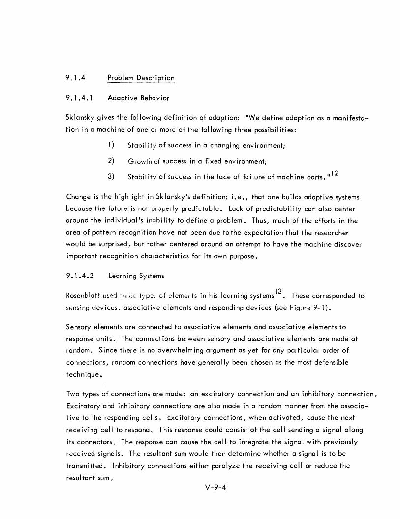
901 .4 Problem Description
9.1.4.1 Adaptive Behavior
Sklansky gives the following definition of adaption: IIWe define adaption as a manifesta
tion in a machine of one or more of the following three possibilities:
1) Stability of success in a changing environment;
2) Growth of success in a fixed environment;
3) Stabil ity of success in the face of fai lure of machine parts. 1112
Change is the highlight in Sklansky's definition; i.e., that one builds adaptive systems
because the future is not properly predictable. Lack of predictabil ity can also center
around the individual's inabi lity to define a problem. Thus, much of the efforts in the
area of pattern recognition have not been due to the expectation that the researcher
would be surprised, but rather centered around an attempt to have the mach ine discover
important recognition characteristics for its own purpose.
Learn ing Systems
Rosenb lott us~d thrl;~:~ t),P'3:: 0 f e I emerts in h is learning systems 13. These corresponded to
!,f;nsing devices, associative elements and responding devices (see Figure 9-1).
Sensory elements are connected to associative elements and associative elements to
response units. The connections between sensory and associative elements are made at
random. Since there is no overwhelming argument as yet for any particular order of
connections, random connections have genera lIy been chosen as the most defensible
technique.
Two types of connections are made: an excitatory connection and an inhibitory connection 0
Excitatory and inhibitory connections are also made in a random manner from the associa
tive to the responding cellso Excitatory connections, when activated, cause the next
receiving cell to respond 0 This response could consist of the cell send ing a signal along
its connectorso The response can cause the cell to integrate the signal with previously
received signals. The resultant sum would then determine whether a signal is to be
transmitted., Inhibitory connections either paralyze the receiving cell or reduce the
resultant sum 0
V-9-4
SENSORY
DEVICES
ASSOCIATIVE
ELEMENTS
LEGEND: EXCITATORY CONNECTION:
RESPONSE DEVICES
INHIBITORY CONNECTION: ,."._ .... ~ ~
Figure 9-1. Percept ron-Type Learn ing Network
V-9-5

In some systems the amount of time for the signal to travel along the connections is a
variable. Under other systems the receiving element, whether it be an associative cell
or a responding cell, has a variable threshold. This variation might be due either to
training or to a decay that is analogous to forgetting.
Some adaptive systems have used the technique of reward and punishment, i.e., if the
system gives the correct response, the threshold of all cells participating in this response
is lowered; if a system gives an incorrect response, the thresholds are increased.
Other systems merely punish. They use the technique of letting well enough alone when
the correct answer has been given and of only tampering with the thresholds or the amount
of time for a signa I to travel a long the connections when an incorrect answer has been
received.
An alternate technique centers around the permissive attitude of not caring whether the
system gives the correct or incorrect answer, but only that the answers are consistent;
i oe., if a binary choice is provided, the system can define which response corresponds
to lIyes li or "no", to IIleft" or IIright", to "1" or "0 11, etc. Under such a technique,
the system uses an internal type of reinforcement. It modifies itself every time an input
is received. The modification tends to make the present response to that input more likely.
Under the above systems, redundancy is a major factor since one cannot predict ahead of
time which are the important associative elements and which are the important connections.
A large number of elements tends to allow a satisfactory final state to be achieved.
In any of the systems the number of associative elements is very much greater than the
number of sensory elements" In turn, the number of sensory elements is much greater than
that of responding elements.
These elements are attempts to imitate neurons. Part of the stimulus towards redundancy
comes from the tremendous amount of neurons existing in animal systems. Electronic
neural networks have been created and their adaptive properties shown 14. Other authors
such as Griffith describe more complete neurons 15. The design features of his more com
plete neuron centers around a more thorough imitation of the neurons existing in nature"
V-9-6
9. 1 .5 Techniques for Creating and Testing Systems
The systems that have been described lack capability. For example, the Mark I Perceptron
could recognize only 8 letters anywhere in a 20 x 20 field or 20 letters placed in the
center of the field 13. It appears that in order to create a machine capable of making a
thoroughly significant contribution toward the solution of previously unsolved problems,
a large number of elements are needed.
When something is defined as machine learning, the natural tendency is to take advantage
of digital computers to achieve computer simulation and test the proposed system. This
has been the history of many efforts.
Arguments for the creation of special purpose hardware center around avoiding the slow
ness of digital computers. It is the parallel behavior of learning systems which gives hope
for superior accomplishment; it is the same parallel structure which has made simulation
on digital computers so slow. Rosenblatt points out that using special purpose equipment is
much faster than computer calculation of whether the learning process will succeed 13.
A question of computer simulation of proposed learning systems versus creation of special
purpose hardware is more than just a process of measuring the relative economic benefits.
A danger exists that simulation may distort the problem.
Computer simu lation often tends to make the researcher forget that the eventual fabrication
must use many simple (and, therefore, hopefully inexpensive) elements placed together.
Too often, what is simulated can only be fabricated when one has 0 powerful central pro
cessor as an aid.
An alternative to either computer simulation or the creation of special hardware would be
simple algorithms testing whether the system would converge to a useful configuration.
Mays states: "A Igorithms for nontrivia I networks of adaptive elements are not very well
understood •..• 1 know of proposed algorithms for such networks, but I have no satisfactory
proof that algorithms will cause convergence to a solution in a finite amount of time.
However, experimental results indicate that these algorithms cause convergence most of
the time. 1I16
V-9-7
Fitzhugh is working on an approach analogous to statistical mechanics 17. His consideration
of polystable systems may yield some analytic clues as to whether it is worthwhile to assem
ble large systems without having to go to the expense of computer simu lation.
The large number of elements needed for even simple usefu I systems is highl ighted in
Herscher and Kelley1s paper 18. They describe the functional model of the frog1s retina.
The model incorporates the four basic functions of the frog1s sight and requires 32,000
individual circu it components.
Another system referred to was Large Artificial Nerve Net (LANNET) which uses a 1024
decision element network 19. Expense can be inferred by the fact that the system is large;
its modest capability is indicated by preliminary tests reported on for the running of a
simple maze.
9.106 Pattern Recognition
The program of the 1955 Western Joint Computer Conference inc luded three pioneering
papers in pattern recognition20 , 21,22. In this early work, Dinneen was concerned with
some experiments with block capital As, and Os, some squares and some triangles. Even
with this comparatively simple universe to deal with, the paper is more concerned with
internal transformations of the input so that recognition can be attempted than with the
results of actual recognition.
Successfu I recognition was ach ieved by Rosenblatt with the Perceptron 0 As noted earl ier,
the Mark I Perceptron could recognize eight letters anywhere in a 20 x 20 field or 20
letters placed in the center of the field 13.
The Adaline of Wid row also performed pattern recognition. Rather than being concerned
with character recognition, early Adal ine or Madal ine experiements were concerned with
observing an unstable pendulum (balanced from the bottom) so that the rest of the learning
system could balance the pendulum230
The close all iance of pattern recognition and learn ing machines is emphasized by the
fact that Rosenblatt1s work and Widrow1s work are considered pioneering efforts in machine
learning and are referred to by ONR, the sponsoring agency, as their two earliest contracts
° tt °to 10 In pa ern recogm Ion 0
V-9-8
Warren McCulloch and associates performed pattern recognition experiments that
centered around the simulation of the frog's eye. Early experiments with the retina
of a frog's eye showed that a frog's vision consisted of four different operations:
1) Sustai ned contrast detecti on
2) Net convexity detection
3) Moving edge detection
4) N t d o • d . 25 e Imming etectlon
Herscher and Kelley are able to report that they have a functional model of the frog's
eye which incorporates the four basic feature abstraction functions 18. As was pre
viously stated, this required 32000 individual circuit componentso The frog's eye,
however is very simple as compared to human eyes. (The frog does not seem to see
stationary objectso He will starve to death surrounded by food if it is not moving25
.)
The solution of the problem for the frog's eye does give high promise toward the
capabil ity of producing general visilogso
9. 1.7 Character Recognition
Much of the early pattern recognition work found its first practical outlets in the area
of character recognitiono The important advances that have been made in this area
are illustrated by the two facts observed belowo They indicate that character recog
nition equipment should be commercially available as off-the-shelf items in the
1970 era.
The present state-of-the-art of character recognition is such that the Department of
Revenue of the State of Colorado has contracted for equipment that wi II recogn ize
typewriter input at the rate of 2000 characters per second. Though similar purchases
have been made by associated research branches of the Department of Defense, there
was usually the recognition that these agencies have the mission to extend the state
of-the-art. State revenue bureaus have no such motivationo
Bryan, in his work in character recognition, had to reject typewriter input and con
strained handprinting in his experiments in adaptive pattern recognition because they
caused few errors24
• His equ i pment re j ected one element of randomness. Every sensory
element was connected to every associate element. There were as many excitatory as
inhibitory elements. Randomness was applied to the selection of which lines were to
be exc i tatory.
V-9-9

9.1.8 Learning
9.1.8.1 Examples
Widrow's broom balancing experiment is an example of a type of learning that present
systems are capable of achieving. Learning in Widrow's case was to consist of the
system recognizing the position of the broom (pendulum) and moving a small truck in
its one dimensional degree of freedom in order to keep the broom from fall ing. Other
types of learning are those associated with the pattern recognition referred to previously.
Experiments have also been conducted in games such as the Tower of Hanoi and with
more serious problems such as weather prediction. The complexity attainable is still
not impressive. Earlier mention was made of the fact that maze running was considered
an adequate preliminary test to something labeled as a large neural net. Examples of
learning which are impressive because something useful and previously unattainable has
been achieved still await us. The work already done is highly impressive because
mechanical devices have exhibited behavior analogous to similar animal learning.
All or Nothing Accomplishment
Rock and Estes have performed experiments showing that learning is accompl ished on an
all or nothing basis26
• These experiments show that human subjects do not converge in
a learning situation. Things snap into place without partial learning having occurred.
Learning machines, on the other hand, tend to converge to a solution. The disparity
towards the two types of behavior is indicative of the extreme remoteness of animal
learning to supposedly imitative machine learning.
Feasibility of Useful Learning Machines
At the 1964 Fall Joint Computer Conference, Mays indicated that the pre-processing of
weather information was of the highest importance in achieving successful convergence
in experiments performed at Stanford University 16. This pre-processing reflected an
already understood method of solution on the part of the researcher. In general, the
work that has been done has centered around problems that we know how to solve 0 The
question arises as to whether there are significant problems capable of being handled by
learning machines .. Certainly the most impressive learning machine available is a human
being. With today's fear of the population explosion, we seem to be in no danger of a
V-9-10
shortage of available people far more intelligent than any machine that has been
proposed. With estimates running from 1010
neurons to 1015
neurons for the human
nervous system, it would appear that there is plenty of spare capacity to handle any
problem that could be presented to a bionic system.
Justification for using learning machines depends on environments to which humans
cannot adjust.
9. 1 .9 Heuristics
Two types of heuristics have dominated. One type is heuristic programs; the other
permits the problem solver to use heuristic techniques.
Heuristic programs lead to methods of solution. Minsky presented a list of methods used
. h .. 4 Th In eUrlstlc programs. ey are:
1) Methods w h ic h set up searches.
2) Methods which set up new problems as sub-goals.
3) Methods which set up new problems as models.
4) Methods of characterization or description.
5) Administrative methods which include:
a) d ifficu Ity estimates;
b) self-problem util ities; and
c) methods for selecting methods"
6) Methods of se I f- improvement.
Impressive results have been achieved using heuristic methods in playing games on
computers. Papers describing chess playi ng, checker playing and theorem solving
programs have been published 27,28,29,30. Though the results have been impressive,
as yet nothing practical has been achieved. Difficulties center around the relative
slowness of digital computers in doing "thinking." A reasonably trained human can
outrace the computer and is, of course, far less expensive.
V-9-11
The use of heuristic techniques by the problem solver has been more effective than
heuristic programs. Rather than attempt to foresee all the possible program difficulties,
the problem solver is allowed to use his superior intelligence and adaptability.
A man-machine partnership is created. This is in contrast to an attempt to endow the
machine with a man's heuristic capabilities. Thus, through the use of consoles, man
provides the essential ingredients of goal recognition, exploratory action, evaluation,
and, if necessary, modification of procedure.
Major emphasis is now concentrated on easing man's ability to communicate with the
machines through consoles. In contrast, heuristic programs receive only minor attention.
9.1.10 Competition with Human Processes
9.1.10.1 Associative Recall
One of the most impressive characteristics of the human memory is its ability to accom
pi ish assoc iative reca II. Unti I recently, computer memories requ ired seria Ily-performed
searches if the exact address was unknown. Hardware developments leading towards
associative memories where the total memory is searched in parallel have attempted to
remedy th is defic iency.
In the 1962 Spring Joint AFIPS Conference, Richard F. Reiss presented a paper describing
a nine-postulate machine3
• The purpose of this machine was to simulate previously held
psychological interpretations of the way the human memory operated. The operation of
these postulates on a computer would have been a slow and expensive procedure. Reiss'
paper and the non-artificial intelligence hardware researcher in the area of parallel
search memories highlight the need for solving the problem of associative recall if any
of the artificial intelligence devices are to successfully simulate simple human intelligenceo
9.1.10.2 Humanoids
Much of the work has centered around attempts to build humanoids. The computer art
has given another outlet to this drive. Many of the computer systems described in the
literature are anthropomorphic.
V-9-12
Bionic systems which imitate animal systems for the purpose of learning by modeling
are understandable. Most of these systems, however, do not reflect modeling of
biological aspects so much as they reflect an attempt to create something which would
imitate a biological mechanism.
9. 1 .10.3 Adaptive Systems
There are many adaptive systems that have been placed in computer programs that are
not identified as such in the literature. Certainly, every program has built-in modifi
cation features. Most take different paths depending upon the input data. The general
difference between those adaptive programs running on computers today and those
reported in the I iterature as adaptive programs is that in the former case the problem
solver has determined to use his intelligence to dictate the procedures that will be
followed. The latter programs find researchers using devices such as randomly selected
connections to avoid imposing control. Yet, as was previously observed, problems
solved this way are not significant problems. Behind much of this work resides the hope
that possibly a machine so constructed can learn to solve problems that are beyond us.
9. 1 • 11 The Future
9. 1. 11 • 1 Projected Program
An interdisciplinary creation of scientists whose basic training is in biology but with the
ability to take advantage of mathematical and computer tools is called for in order to
give impetus to the present work31 • One has the feeling that once those more trained
in the sciences enter the field, major advances will take place. The direction that
these advances might take are given by Gwinn and Butsch as follows:32
1) Primary Elements and Techniques in Engineering Bionics:
a) Biological laws and effects (in progress)
b) Visilog (in progress)
c) Analog of the ear (in progress)
d) Living cellular analogs (planned)
e) Biological materials and physical analogs (planned)
V-9-13
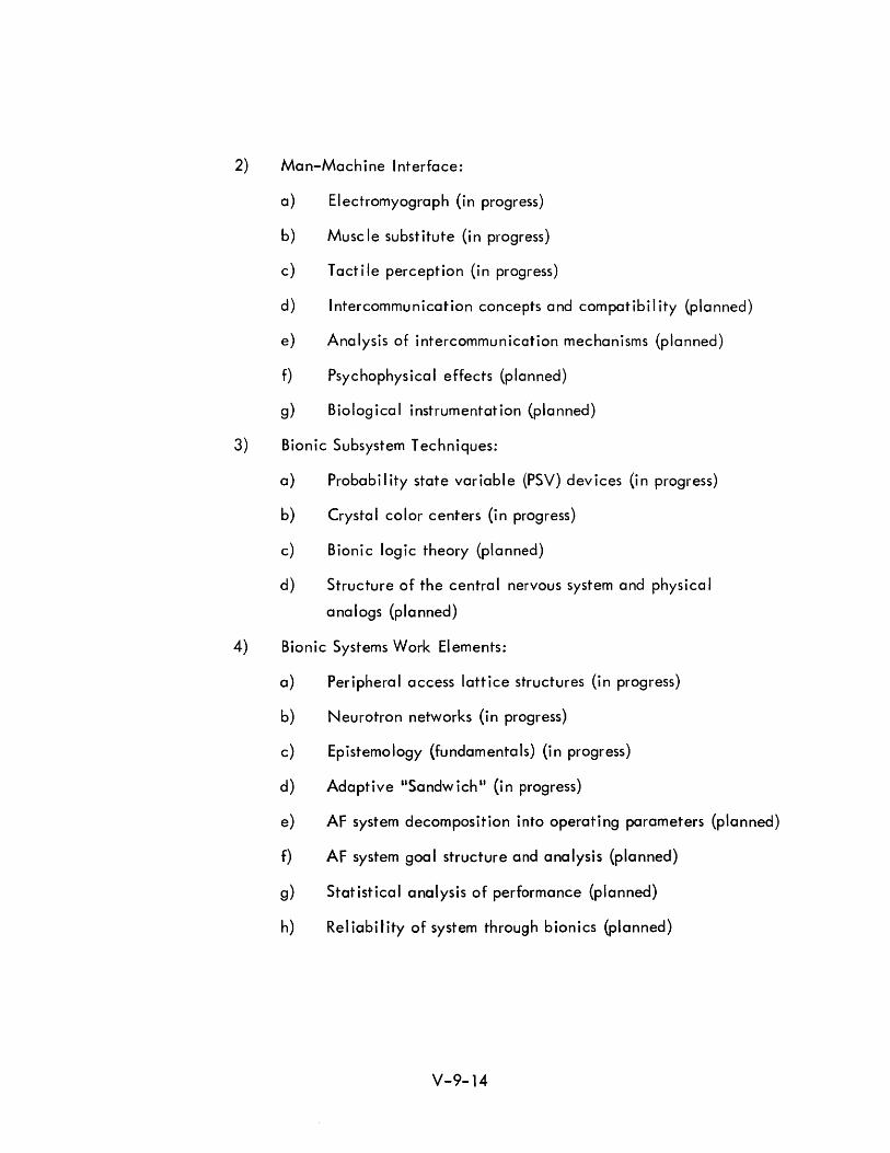
2) Man-Machine Interface:
a) Electromyograph (in progress)
b) Musc Ie substitute (in progress)
c) Tactile perception (in progress)
d) Intercommunication concepts and compatibility (planned)
e) Analysis of intercommunication mechanisms (planned)
f) Psychophysical effects (planned)
g) Biological instrumentation (planned)
3) Bionic Subsystem Techniques:
a) Probabi I ity state variable (PSV) devices (in progress)
b) Crystal color centers (in progress)
c) Bionic logic theory (planned)
d) Structure of the central nervous system and physico I
analogs (planned)
4) Bionic Systems Work Elements:
a) Peripheral access lattice structures (in progress)
b) Neurotron networks (in progress)
c) Epistemology (fundamentals) (in progress)
d) Adaptive "Sandwich" (in progress)
e) AF system decomposition into operating parameters (planned)
f) AF system goal structure and analysis (planned)
g) Statistical analysis of performance (planned)
h) Rei iabil ity of system through bion ics (planned)
V-9-14
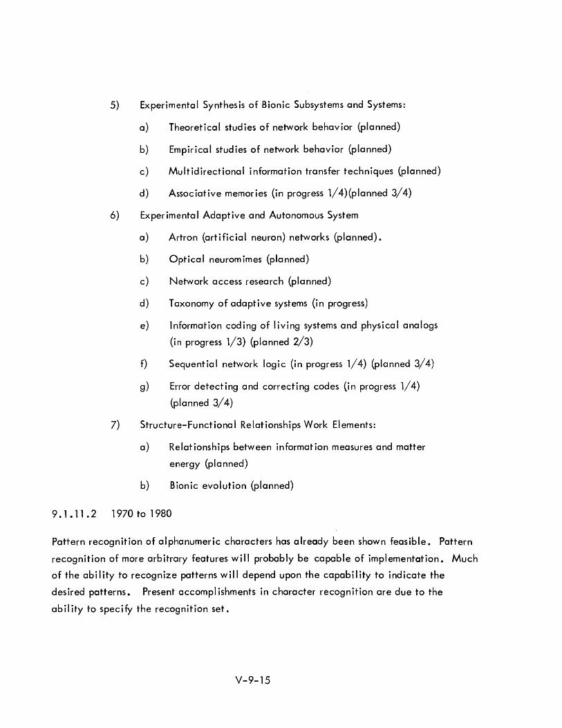
5) Experimental Synthesis of Bionic Subsystems and Systems:
a) Theoretical studies of network behavior (planned)
b) Empirical studies of network behavior {planned}
c) Multidirectional information transfer techniques (planned)
d) Associative memories (in progress 1/4)(planned 3/4)
6) Experimental Adaptive and Autonomous System
a) Artron {artificial neuron} networks {planned}.
b) Optical neuromimes (planned)
c) Network access research {planned}
d) Taxonomy of adaptive systems (in progress)
e) Information coding of living systems and physical analogs
(in progress 1/3) (planned 2/3)
f) Sequential network logic (in progress 1/4) (planned 3/4)
g) Error detecting and correcting codes (in progress 1/4)
(planned 3/4)
7) Structure-Funct iona I Re lat ionships Work EI ements:
a) Relationships between information measures and matter
energy (planned)
b) Bionic evolution (planned)
9. 1 • 11 • 2 1 970 to 1 980
Pattern recognition of al phanumeric characters has a Iready been shown feasible. Pattern
recognition of more arbitrary features will probably be capable of implementation. Much
of the ability to recognize patterns will depend upon the capability to indicate the
desired patterns. Present accompl ishments in character recogn ition are due to the
ability to specify the recognition set.
V-9-15
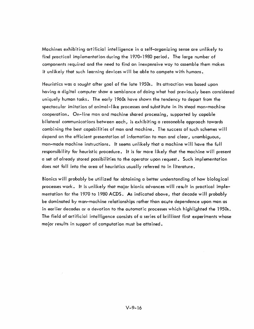
Machines exhibiting artificial intelligence in a self-organizing sense are unlikely to
find practical implementation during the 1970-1980 period. The large number of
components required and the need to find an inexpensive way to assemble them makes
it unlikely that such learning devices will be able to compete with humans.
Heuristics was a sought after goal of the late 1950s. Its attraction was based upon
having a digital computer show a semblance of doing what had previously been considered
uniquely human tasks. The early 1960s have shown the tendency to depart from the
spectacular imitation of animal-I ike processes and substitute in its stead man-machine
cooperation. On-line man and machine shared processing, supported by capable
bilateral communications between each, is exhibiting a reasonable approach towards
combining the best capabilities of man and machine. The success of such schemes will
depend on the efficient presentation of information to man and clear, unambiguous,
man-made machine instructions. It seems unlikely that a machine will have the full
responsibility for heuristic procedure. It is far more likely that the machine will present
a set of already stored possibilities to the operator upon request. Such implementation
does not fall into the area of heuristics usually referred to in literature.
Bionics will probably be utilized for obtaining a better understanding of how biological
processes work. It is unl ikely that major bionic advances wi II resu It in practica I imple
mentat ion for the 1970 to 1 980 ACDS. As i nd icated above, that decade will probab Iy
be dominated by man-machine relationships rather than acute dependence upon man as
in earlier decades or a devotion to the automatic processes which highlighted the 1950s.
The field of artificial intelligence consists of a series of brilliant first experiments whose
major results in support of computation must be attained.
V-9-16
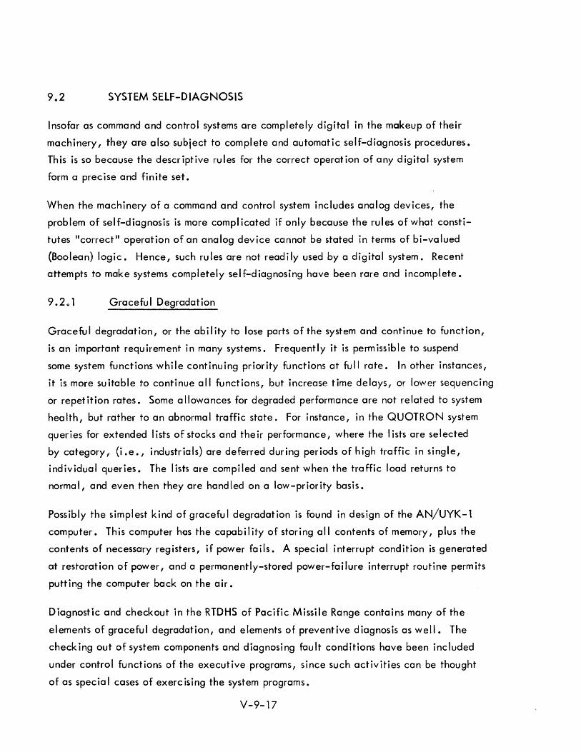
9.2 SYSTEM SElF-D IAGNOSIS
Insofar as command and control systems are completely digital in the makeup of their
machinery, they are also subject to complete and automatic self-diagnosis procedures.
This is so because the descriptive rules for the correct operation of any digital system
form a prec ise and finite set.
When the machinery of a command and control system includes analog devices, the
problem of self-diagnosis is more complicated if only because the rules of what consti
tutes "correctl! operation of an analog device cannot be stated in terms of bi-valued
(Boolean) logic. Hence, such rules are not readily used by a digital system. Recent
attempts to make systems completely self-diagnosing have been rare and incomplete.
Gracefu I Degradation
Graceful degradation, or the ability to lose parts of the system and continue to function,
is an important requirement in many systems. Frequently it is permissible to suspend
some system functions while continuing priority functions at full rate. In other instances,
it is more suitable to continue all functions, but increase time delays, or lower sequencing
or repetition rates. Some allowances for degraded performance are not related to system
health, but rather to an abnorma I traffic state. For instance, in the QUOTRON system
queries for extended lists of stocks and their performance, where the lists are selected
by category, (i.e., industrials) are deferred during periods of high traffic in single,
individual queries. The lists are compiled and sent when the traffic load returns to
normal, and even then they are handled on a low-priority basis.
Possibly the simplest kind of graceful degradation is found in design of the AN/UYK-l
computer. This computer hos the capabi I ity of storing all contents of memory, plus the
contents of necessary registers, if power fails. A special interrupt condition is generated
at restoration of power, and a permanently-stored power-failure interrupt routine permits
putting the computer back on the air.
Diagnostic and checkout in the RTDHS of Pacific Missile Range contains many of the
elements of graceful degradation, and elements of preventive diagnosis as well. The
checking out of system components and diagnosing fault conditions have been included
under control functions of the executive programs, since such activities can be thought
of as special cases of exercising the system programs.
V-9-17
The flow of system checkout from one type of test to another is essentially a control
function performed by the master control program. Use is made of the regular system
programs, since these are as much a part of the system as the hardware.
The system checkout program provides for cycl ing through a predetermined set of tests,
and for repetition of a test or tests at discretion of the console operator or from an
external request. The objective of the system checkout routine is to assure that all
system components are operating properly, and that the system operates as a whole
when the individual components are made to function together. A secondary task is
to display the system condition to the system controller or the console operators. The
system checkout program may be requ ired to demonstrate to the missi I e fl ight safety
officer that the system is functioning properly.
The ability to recycle arbitrarily through any set of checkout routines furnishes a valuable
diagnostic aid for use throughout the whole system. For instance, communications may
be repeated or radars may be driven in selectable fashion. This permits maintenance
personnel to use the com,)uter to pinpoint trouble spots.
One of the earl iest uses of redundancy to check performance was found in the UNIVAC I,
the first large-sea Ie, high-speed computer offered for commerc ia I sa Ie. UNIVAC I made
use of dual arithmetic and control units which worked in parallel. Self checking circuits
looked for comparison between the units at each clock time and set a fault and halt con
d it ion at disagreement.
Graceful degradation is found in the navigation system of Polaris submarines. There the
AN/UYK-l computer and its associated data processor (a timing, control, and sequencing
device) control the high-accuracy (sate II ite doppler) navigation set. Programs perm it
complete diagnosis of this set, and are set up to derive useful information from imcomplete
messages, and to remember previous information and select the best of it. But this navi
gation set is only an adjunct to the NAVDAC computer wh ich makes use of such inputs
as celestial and radio fixes, ship~ log, gyrocompass, etc., as well as servicing the iner
tial navigation system, and doing continuous dead reckoning. Complete failure of all
the automatic navigation systems still leaves the possibility of dead reckoning and celes
tial navigation by hand, using the time-honored methods. Still there are about three
levels of redundancy in the built-in systems, each yielding a slightly less accurate
navigation basis.
V-9-18
9.2.2 Multi-Computer Health Check
The problems of program recovery and fault discovery in multi-computer systems are
closely related. Some of the computing errors may be prevented by periodic health
checks of the system. The amount of check ing which can be done is actua Ily a function
of the time that is available between the operational processes that the computers must
perform. However, some time must be a I located for check ing. For check ing purposes
we can design a background diagnostic which will check the system when it would
otherwise be id Ie.
It may, however, be necessary to give the diagnostic program a definite priority so that
we can be assured that a certain minimum amount of checking will be done.
The scope of the diagnostics can vary greatly. Generally the diagnostics will check
communication links and the status of peripheral devices. They will also include cross
checking between the computers of the multi-computer system. The transmitting com
puter during each communication might, for example, transmit a dummy computation
result so that a carefully selected set of instructions are performed, all the circuits are
exercised, and a coded result is sent with the communication.
The receiving computer performs the same exerc ise and compares its results with that of
the other computer. A difference would initiate further checking of the communication
link and of the individual computers.
The chief aim of the diagnostic health check is to discover failures as quickly as possible
after they occur. If this is done we then have a chance of taking remedial action before
important data can become lost.
Some failures affect the data but not the programs. These can be discovered by pro
gramming methods. Failures which cause the equipment to stall cannot be discovered
by programming methods but require hardware features for their detection.
V-9-19
9.2.3 Hardware Requ irements
The ach ievement of capabi I ity for gracefu I degradation in computer systems places some
requirements on hardware design. While the programming of graceful degradation is
primarily a software function, certain hardware characteristics are essential to permit
programming of a control program that can function and determine the system
configurat ion.
Possibly the most straightforward example of the needed hardware characteristics is
found in the hardware (an~ software) of the Burroughs DUAL B-5000. The needed
characteristics are the following:
9.2.4
1) Processor interrupt logic. It must be possible for any processor
to interrupt any other in the system, and to interrupt itself.
The logic design of interrupts takes various forms, and is often
related to a wired-in priority scheme.
2) There must be a switching scheme, controllable from the master
processor (and more than one processor must, of course, be able
to control, or access and execute the master control program)
permitting refiguration of the system from the hardware and
interconnection standpoint.
3) Extensive ability for control and data communication, with
provision for alternate paths, must be built into the system.
4) The ability to add modules, either in real or extended time,
permits the system to access or release equipment (or to grow
with requirements of environment which may change with time).
In some systems this ability in real time permits functioning as
a single large system or a number of smaller ones.
Fault Isolation
Maintenance and reliability are two concerns facing the command and control system
planner. A necessary maintenance technique is that of locating and correcting a fault
when one occurs.
V-9-20
The usual approach to solving this problem is the writing of diagnostic programs for the
system computer or computers. Such programs detect and isolate computer fai lures by
exercising the command structure of the machine. Often this approach does not work
because it is predicated on an operating computer. The computer may be malfunctioning
so that the diagnostic program cannot even be read into memory.
Manual diagnostic procedures can be developed which guarantee to detect and isolate
faults when the computer is incapable of reading a diagnostic program. To accomplish
this, it is necessary to relate each operation code to the logic structure of the machine
and its reaction to the code. Using a computer to break down the logic equations of
each system device into a set of elementary functions, manua I procedures can be defined
wh ich will prov ide fau It detection and isolat ion.
It is always possible to establish a basic level of operating logic functions, even at the
lowest stage. Using this level as a base, and executing the manual procedures, it is
possible to extend this level upward until eventually the entire system is functioning
properly.
It is also always possible to take the logic equations for every digital device in a system
and break them down into simple logic functions.
The logic equations for each digital device form a system master logic file. By using
information retrieval and sorting techniques on this file it is possible to create tables
showing the interrelationship of every logical el ement in the system. These tables can
then be used to develop both manual procedures and diagnostic computer programs, by
combining elemental functions from the various tables.
The procedures can be structured to isolate faults by a process of elimination; i.e., if
a procedure does not work correctly, another is tried that uses almost the same logic.
This process of elimination is carried out until the fault is isolated.
First the necessary logic equations must be derived. The next step is to take these
equations and examine them to determine how each operation used by the system relates
to the logicso Once this has been done, it is possible to design the diagnostics needed.
V-9-21
A diagnostic is usually a straightforward series of operation codes which attempts to
diagnose the system by testing the operations in a logical sequence a But diagnostics
can also use this approach of testing the machine logic structure, rather than operation
code structure 0
By selectively introducing malfunctions into a system Boolean model, it is possible to
arrive at a diagnostic wh ich is capable of detecting all possible faults.
Once the method of designing and implementing a fault-isolating program has been
derived, it is a short step to apply it to any digital system.
V-9-22


Section 10 SOURCE MATER IALS AND REFERENCES
10.1 INTRODUCTION
This section contains source material and reference material from Sections 2 through 9,
arranged in numerical order.
10.2 SOURCE MATERIAL
The various organizations I isted in the following sub-sections have been contacted by
personnel assigned to this study. Discussions with these organizations provide a basis for
much of the information presented in this report. The discussions covered techniques
and approaches that have not been adequately described in published literature and the
opinions of experts in specific areas in these organizations were sol icited concerning
the advantages, limitations and future prospects for the various techniques and procedures
described in this report.
10.3 REFERENCES
An extensive I ist of references pertinent to the study of the various topics described in this
report are I isted by section. A study of these references has contributed to the material
presented in this report. Some of the more pertinent and important of these have been
referenced in the text and listed in the section as specific numbered references. These
numbers correspond to numbered citations in the test. Direct quotations have also been
used where noted.
V-10-1

10.4 SECTION 2 INPUT/OUTPUT SOURCE MATERIAL AND REFERENCES
Organizations Contacted
Input/output technology and equipment have been discussed with representatives from a
number of government agencies and manufacturing companies in the course of this study.
The following are a I ist of major sources of information and the techniques which have been
discussed with each.
Army Electronics Research and Development Group Fort Monmouth, New Jersey
Bridge Division of CDC Philadelphia, Pennsylvania
Control Data Corporation
Data Equipment Company Sa nta Ana, Ca Ii forn ia
Data Products Corporation
Digital Data Corp.
Fairch i Id Sem iconductors
General Dynamics Electronics San Diego, Cal ifornia
Honeywell Boston, Massachussetts
National Cash Register Dayton, Ohio
Nationa I Cash Register Hawthorne, California
Phi Ico Computer Division
Keyboards Pri nters Incremental magnetic tape Punched paper tape
Punched card equipment Pri nters
Pu nched cards Paper tape Magnetic tape
Graph i ca I input devi ces
Militarized printers
Incremental magnetic tape
Pri nters
M i Idata storage
Mildata storage
Character recognition
Punched card Printers
V-10-2
Ph i I co Research Lab Character recognition equipment
Potter Instrument Printers I ncremental magnetic tape
Rem i ngton Rand Univac New York, New York
Punched card Magnetic tape Printers Character recognition
Remington Rand Univac Philadelphia, Pennsylvania
Punched card Magneti c tape Pri nters
Remington Rand Univac St. Paul, Minnesota
Magnetic tape
Rome Air Development Center Rome, New York
Keyboards Printers
10.4.2 References
1. II A Method of Voice Communication with a Digital Computer, II S. R. Petrick and H. M. Willett, Proceedings Joint Computer Conference, New York, N.Y., Vol. 18, pp. 11-24, Deco 13-15, 1960.
2. II System Reads Three Type Fonts:' J. M. Carroll, Electronics, ppo 49, Dec. 20, 1963, McGraw Hill Publication.
3. II Programm i ng Pattern Recognition;' G. P. Dinneed, Proceedings Western Joint Computer Conference, los Angeles, California, March 1-3, 1955.
4. II Digital Data Communication Techniques:' J. M. Wier, Proceedings of the IRE, Vol. 49, No.1, pp. 196-209, Jan. 1961.
5. II Printing Equipment for Medium, Intermediate, and large Size Computers:' Staff of Cresap, McCormick and Paget, Control Engineering, Jan. 1962, pp.91-95.
6. II Digital Printers, Editorial Survey;' Instruments and Control Systems, Vol o
32, May 1959, pp. 700-7070
7. II Tape Printer Applications;'W. R. Beall, Instruments and Control Systems, Vol. 32, May 1959, ppo 708-709.
8. II Analog Input and Output System for a Real-Time Process Control Computer System;' C. A. Walton, Joint Automatic Control Conference-Proceedings 13,4.1-4.6, June 1962.
V-10-3
9. II Punched Card as Information Carrier and as Technical Problem, II K. Lindner, Feinwerktechnik, 67(2) :55-61 1963.
10. II Digital Circuit Techniques for Speed Analysis:' G. L. Clapper, I EEE-- Transactions on Communications and Electroni cs 66:296-304, May 1963.
11. II Minutes of ASA Committee X3.1"(Optical Character Recognition) and its Subcommittees, American Standards Association, Sectional Comm ittee X3 on Computers and Data Processing.
12. II Machine recognition of human language:' Ni 10 Lindgren IEEE Spectrum Mar. 1965 pp. 114- 136.
13. II The Rand Tablet: A Man-Machine Communication Device," Mr. M. R. Da vis, T. O. Ell is, p. 325.
V-10-4
10.5 SECTION 3 DISPLAY SYSTEMS REFERENCES
1) liThe Information Display Field as it Exists Today," R. M. Davis, Proceedings of the Th ird National Symposium of the Society for Information Display, February 1964.
2) IIDODDAC-An Integrated System for Data Processing, Interrogation and Display," Wo F. Bauer and W. L. Frank, Proceedings of the Eastern Joint Computer Conference, December 1961.
3) "Utilization of Lenticular Film for Full Color Display Systems," D. J 0 Morrison and H. N. Oppenheimer, Proceedings of the Fourth National Symposium of the Society for Information Display, Wash ington, D. C. , October 1964.
4) "Information Handling in the Defense Communications Complex," T. J. Heckelman, and R. H. Lazinski, Proceedings of the Eastern Joint Computer Conference, 1961.
5) liThe ICONORAM System, It G. W. N. Schmidt, Datamation, January 1965.
6) "COGS, A Generalized Display Language and System,lt J. H. Dinwiddie, Paper presented at symposium sponsored by Chespeake Bay Chapter of Association for Computing Mach inery, Baltimore, Maryland, June 1964.
7) II Input/Output Software Capability for a Man/Machine Communication Image,lI T. R. Allen and J. Eo Foote, Proceedings of the Fall Joi nt Computer Conference, October 1964.
8) IIA Computer Technique for Producing Animated Movies," K. C. Knowlton, Proceedings of the Spring Joint Computer Conference, Apri I 1964.
9) II Programmer's Handbook, IOC DPC Util ity and Test Subsystem Task Test Tool ," J. Adler, C. Brody, and G. Farrance, TM-LO 741/020/00, SDC, April 1963.
V-10-5
10.6
10.6.1
SECTION 4 DISPLAY TECHNOLOGY SOURCE MATERIAL AND REFERENCES
Organizations Contacted
Display techniques and systems have been discussed with personnel of a number of different
companies and governmental agencies in the course of this study. The following list indi
cates the companies and governmental agencies with whom display technology has been
discussed and the type of displays discussed with each:
Bunker-Ramo Corporation Canoga Park, California
General Dynamics/Electronics San Diego, California
Genera I Telephone Laboratories Bayside, Long Island, N. Y.
RCA Laboratories Pri nceton, New Jersey
Laboratory for Electroni cs Boston, Massachusetts
NCR National Cash Register EI Segundo, California
Sylvania Waltham, Massachusetts
Stanf:>rd Research Institute Menlo Park, California
Rome Air Development Center Rome, New York
V-10-6
Light-va Ive displays Conti nuous-stri p photog raph i c projection displays CRT displays
Charactron CRT displays Light-valve displays
Conti nuous-sheet electro lum i nescent displays with XY matrix addressing Acousti c/e lectro lumi nescent displays
Ferroelectric displays
Magnetic thin-fi 1m displays
Electromechanical photochromic displays CRT-Photochromic projection displays
Discrete a Iphanumeri c character displays Conti nuous-sheet electro lum i nescent displays with XY matrix selection
Magnetic thin-fi 1m displays Modu lated crysta I fi Iter displays
Light-va Ive displays,Modu lated crystal interference-filter displays Thermo-plastic displays Laser displays
10.6.2
USAER&Dl Fort Monmouth, New Jersey
U. S. Navy Bureau of Ships Washington, D. C.
Hughes Ground Systems Fullerton, California
U. S. Mari ne Corps, Bureau of Ships, Washington, D. C.
librascope Glenda Ie, Co lifornia
References
Photochromic displays laser-luminescent displays Electro lum i nescent displays Fiber-optic CRT displays lenticular fi 1m Photographic projection displays Display memories
Display equipment Display systems Photographic projection displays lenti cu lor fi 1m light valves Electroluminescent displays CRT displays large screen displays
large screen displays Console type displays
Tactica I displays large screen displays
libracote display panel
1 . liThe Information Display Field As It Exists Today, II Davis, R. M., Proceedings of the Society For Information Display, Third National Symposium on I nformation Display, pp viii-xv, San Diego California, February 1964.
2. II Displays, Papers, and lighti ng, II Stocker, A. C., I nformation Display, Vo I. 1, No.1, pp 16-26, September/October, 1964.
3. IIA Summary of the State-Of-The-Art of large Scale Mi litary Displays, II laSalle, R. H., RADC Technical Report, Rome Air Development Center, December 1964.
4. IIDisplay System Design,.1 loewe, R. T. Electronic Information Display
Systems, Spartan Books, Washington, D. C., 1963, pp. 15-37.
5. II Basic Concepts in the logic and Organization of Displays for the Norad Command and Contro I Systems, II Duffy, M. l., and Sm ith, C. D., Proceedings of Mll-E-CON 7, Washington, D. C., Sept. 9-11, 1963, pp. 251-253.
V-10-7
6. II Physical Principles of Displays - Classification, II Talmadge, H. G.,Jr., Electronic Information Display Systems, Spartan Books, Washington, D.C., 1963, pp. 69- 86.
7. IICathode-Ray-Tubes," Darne, F. R., Electronic Information Display Systems, Spartan Books, Washington, D. C., 1963, pp. 87-109.
8. "Criteria for Group Display Chains for the 1962-65 Time Period," Technical Documentary Report No. RADC-TDR-62-315, Rome Air Development Center, pp. 1-2, July 1962.
9. IIDigital-To-Visible Character Generators,1I Boyd, S. H., ElectroTechno logy, Vo I. 75, No.1, pp. 77-88, January 1965.
10. II Some Pragmati c Considerations I nfluenci ng the Se lection of Air Force Display Techniques," Kennedy, E. J., Proceedings of the Society For Information Display, Third National Symposium on Information Display, pp. 1-17, San Diego, California, February 1964.
11. IIWhichRead-Out?," Part I, II, III, IV, EEE-TheMagazineofCircuit Design Engineering, August, September, October, November, 1964.
12. II Advanced Display Techniques Through the Charactron Shaped Beam Tube ," Redman, J. H., Society for Information Display Symposium, March, 1963.
13. II Display Requirements of the I ntegrated Management Information Systems - 1968-1970, II James, P., and Dittberner, D., Information Display, Vol. 1, No.2, pp. 26-31, November/December 1964.
14. "A Synopsis of the State of the Art of Dynamic Plotting Projection Displays, II Anderson, R., Second National Symposium of the Society for Information Display, New York, October 1963.
15. II Co lordata Display, II Hughes Aircraft Co. Brochure, Fu \lerton, California, 1963.
16. II Artoc Displays, II Loewe, R. T., Electroni c Information Display Systems, Spartan Books, Washington, D. C., 1963, pp. 231-246.
17. IIDODAC - An Integrated System for Data Processing Interrogation and Display, II Bauer, W. F., and Frank, W. L., Proceedings EJCC, Washington, D. C. December 1961.
18. Unpublished Manuscript, Luxenberg, H. R., 1964.
19. IIKalvar," Nieset, R. T., Data Systems Design, Vol. 1, No.9, pp. 43-44, September 1964.
V-10-8
20. II New Approaches in Photography, II Robi liard, J. J., Photographic Science and Engineering, Vol. 8, No.1, pp. 18-34, January, February, 1964.
21. IIPhotochromic Dynamic Display," Haley, E. J., Electronic Information Display System, Spartan Books, Washington, D. C., 1963. pp.110-120.
22. II Epic Display, II Bjelland, H. L., Proceedings 3rd Nationa I Symposium on Information,Display, San Diego, California, pp. 286-299, February 1964.
23. II Rea I Time CRT Photochromic Projection D;splay, II Stetten, K. J., Society for Information Display Symposium, Washington, D. C., October 1 - 2, 1964.
24. "Solid Crystal Modulates Light Beams, II Lindberg, E., Electronics, Vol. 36, No. 51, pp. 58-61, December 20, 1963.
25. "Electroluminescence Principles and Applications," Strock, L. W., IEEE Spectrum, pp. 68-74, November, 1964.
26. "Display Applications of Electroluminescence, II Wasserman, M. S., Electronic Information Display Systems, Spartan Books, Washington, D. C., 1963, pp. 121- 125 .
27. "Electroluminescent Display Devices," Greenberg, Irving, IEEE Spectrum, pp. 75-83, November 1964.
28. "Non Linear Resistors Enhance Display Panel Contract," Blank, H. G., O'Connell, J. A., and Wasserman, M. S., Electronics, August 3,1963.
29. "Solid State Display Device," Yardo, Stephen, Proceedings of the IRE, December 1962.
30. liThe Application of Electroflors to Display Instrumentation," Alburger, J. A., Photo-Optics Workshop, Spons.::>red by Society of Photographic Instrumentation Engineers, Los Angeles, California, June 1, 1964.
31 . II Laser Display Techniques, II Rugori, A. D., Proceedi ngs Second Society for Information Display National Symposium, 1963.
32. "Laser Displays, II Fow ler, V. J., Data Systems Design, Vo I. 1, No.9, pp. 50-51, September 1964.
33. Lasers, Lengyel, B. A., John Wiley & Sons, Inc., New York, New York, 1962.
34. "A Fast, Digital-Indexed Light Deflector, II Kulcke, W., Harris, T., Kosanke, K., and Max, E., IBM Journal of R&D, Vol. 8, No.1, pp. 64-67, January 1964.
V-10-9
35. "Special Report: Advanced Displays," LaFond, C. D., and Pay, R., Missiles and Rockets, Vol. 14, No. 14, pp. 31-37, October 5, 1964.
36. II A True 3- D Display, II Ruderfer, M., Data Systems Design, Vo I. 1, No.9, pp. 11-14, October 1964.
37. liThe Little Train That Wasnlt ," Novotny, G. V., Electronics, Vol. 37, No. 30, pp. 86-89, November 30, 1964.
38. "A Review of Panel-Type Display Devices," Josephs, J. J., Proceedings of the IRE, August 1960.
39. "Optoelectronics - Key to Isolation, II Wunderman, I., and Loebner, E. E., Electronic Design, Vol. 13, No.1, pp. 30-35, January 4, 1965.
V-10-10
10.7
10.7.1
SECTION 5 COMPONENT AND PACKAGING TECHNOLOGY SOURCE MATERIAL AND REFERENCES
Organizations Contacted
Components and packaging techniques have been discussed with personnel of a
number of different companies and governmental agencies in the course of this study.
The following list indicates the companies and governmental agencies with whom
components and packaging techniques have been discussed, and the topics discussed
with each:
Motorola Semiconductor Div. Phoenix, Arizona
Remington Rand UNIVAC St. Pau I, Mi nnesota
Control Data Corp.
Autonetics Anaheim, California
Bunker-Ramo Corp. Canoga Park, California
RCA Laboratori es Princeton, New Jersey
Hughes Semi conductor Div. Newport Beach, Ca Ii forn i a
Sylvania Waltham, Massachusetts
V-l0-ll
Integrated circuit sense amplifiers
Integrated circuit storage registers
Monolithic integrated circuits Hybrid integrated circuits
Hybrid integrated circuits Integrated ci rcuit rei i abi I ity &
fai lure analysis Packaging techni ques
Integrated circuit applications Packaging techniques
Monolithic integrated circuits Integrated field-effect-transistor circuits
Integrated circuit packaging techniques
Monolithic integrated circuits Integrated circuit sense amplifiers
Integrated fi eld-effect transistors Metal-oxide-semiconductor
integrated circuits Active thin-fi 1m integrated
circuits
Integrated circuit packaging techniques
Monolithic integrated circuits Hybrid integrated circuits Active thin-film integrated
circuit
Tunnel di ode circuits
ONR Washington, D, Co
RADC Rome, New York
SRI Menlo Park, California
Fairchi Id Semiconductor Mountainview, California
Optics Technology Belmont, California
NASA Washington, D. C.
National Security Agency Fort Mead, Virginia
Hughes Ground Systems Fullerton, California
Raytheon SC Division MOlJntainview, CalifoP.ia
Signetics Corp. Mountainview, California
Honeywell Electronics DP Div. Welles ley Hi lis, Mass.
Burroughs Paoli I California
Navy BuShips
USAER&DL Fort Monmouth, New Jersey
Texas Instruments Da II as, T ex as
V-10-12
Opti cal components
Opti cal components
All-magnetic logic Cellular logic for integrated
circuits Electron beam fabrication FI uid logi c
Monol ithic integrated circuits Hybrid integrated circuits Interconnection and packaging techniques
Fiber optics Laser techn i ques
Active thin-fi 1m integrated c i rcui ts
Monolithic integrated circuits Packaging techniques
Optical techniques Integrated circuits
Environmental stabilization of electronic equipment
Monolithic integrated circuits Packagi ng techn i ques MOS circuits
Monolithic integrated circuits Field effect devices Packaging techniques
Logic circuits
Thin-film circuits
Packaging and maintainabi lity techniques
Integrated circuits
Lasers High-speed serial circuits
Multi-circuit chip fabrication Monolithic integrated circuits
Rem i ngton Rand UN I VAC Blue Bell, Pennsylvania
Fluid logic (pneumatic) Interconnection techniques
Discussions with personnel of these organizations provided a basis for much of the
information presented in this report. In addition to discussing techniques and
approaches that have not been adequate Iy descri bed in publ ished literature, the
opinions of experts in specific areas in these organizations were solicited concerning
the advantages, disadvantages, limitations and future prospects for different com- .
ponent and packaging techniques.
10.7.2 Literature
An extensive list of references pertinent to the study of components and packaging
techniques is given in the Bibl iography. A study of many of these references has
contributed to the materi al presented in this report. Some of the more pertinent
and important of these referred to in the text have been extracted from the bibli
ographyand listed in this section as specific numbered references. These numbers
correspond to numbered citations in the text. Direct quotations have been used
where noted.
V-10-13
COMPONENT AND PACKAGING TECHNOLOGY REFERENCES:
1 . II Mi croe lectron i cs - Wh i ch Approach and When ", Webster, W. M" 1964 WESCON, Los Angeles, California, August 25, 1964.
2. "Choosing Logic for Microelectronics", Skoures, A. E., Electronics, Vol. 36, No. 47, pp 23-26, October 4, 1963.
3. "Trends in Logic Circuit Design", Lambert, A., Electronics, pp 38-45, December 6 1 1963.
4. "Choice of Logic Forms for Integrated Circuits", Phelps, M., Jr., E lectri cal Desi gn News, Cahners Publ ish i ng Co., January 1964.
5. Mi Idata Study, Quarterly Progress Report # 1, August 12, 1963 to November 8, 1963, DA-63, 039-AMC-03275 (E), Honeywell Electronic Data Processi ng, 3 December 1962.
6. liThe Case for Cryogeni CS?", Ittner, W. V., Proceedings 1962 F JCC, pp 229-231, Philadelphia, Pa., December 1962.
7. "Pneumatic Log" I-IV, Holbrook, E. L., Control Engineering, July, August, November 1961, and February 1962.
8. II Fi ber Opti cs and the Laser ll, Kapany, N. So, paper presented at
the New York Academy of Sciences Conference on the Laser, New York, New York, May 4-5, 1964.
9. liThe Status of Optical Logic Elements for Nanosecond Computer Systems··, Ti ppett, J. T., 1963 Pac i fi c Computer Conference, IEEE, Pasadena, Calif., pp 47-53, March 15-16,1963.
10. IIPossible Uses of Lasers in Optical Logic Functions ll, Koster, C.,
1963 Pacific Computer Conference, IEEE, Pasadena, Calif., pp 54-62, March 15-16, 1963.
11. IIA Survey of Tunnel-Diode Digital Techniques ll, Sims, R. C.,
Beck, E. R., Jr., and Kamm, V. C., Proceedings of the IRE, Vol. 49, No.1, pp 136-146, January, 1961 .
12. "300 mcs Tunnel Diode Logic Circuits ll, Cooperman, Mo, 1963 Pacific
Computer Conference, IEEE, Pasadena, Calif., pp 166-186, March 15-16, 1963.
13. II Desi gn of an All Magneti c Computi ng System II, Crane, H. Do and Van DeRiet, E. K., IRE Transactions on Electronic Computers, Vol. EC-10, No.2, pp 207-232, June 1961 .
14. ··The Case for Magnetic Logic ll, Rogers, J., and Kings, J., Electronics,
Vol. 37, No. 17, pp 40-47, June 1, 1964.
15. IIAII Magnetic Digital Circuit Fundamentals ll, Newhall, E. Eo,
Digest of 1964 International Solid State Circuits Conference, pp 16-17, Philadelphia, Po., February 1964.
V-10-14
16. "AII Magnetic Digital Circuits and Application Problems", Baker, T. , and Dillon, C., Digest of 1964 International Solid State Circuits Conference, pp 18-19, Philadelphia Po., February 1964.
17. "Study of Applications of All-Magnetic Logic to Naval Systems", Adams, M. Bo I and Van DeRiet, I. E. I Final Report on ONR Contract No. N-onr-2332(oo), Stanford Research Institute, November, 1963.
18. "Microelectronics - Military Participation and Objectives", Alberts, R., 1964 WESCON, Los Angeles, Catif., August 25,1964.
19. "Big Computer Goes in Small Package"" Electronics, pp 28-29, March 14, 1964.
20. "Solid Logic Technology: Versatile, High-Performance Microelectronics", Davis, E. M., Harding, W. Eo, Swartz, R. So, Korning, J. Jo I
IBM Journal of Research & Development, Vol. 8, No.2 pp 102-114.
21 . "Digital Computer Aspects of Integrated Circuit Applications", Platzek, R. C. I and Goodman, H. C., Proceedings Nat'l. Winter Convention on Military Electronics, Los Angeles, Vol. III, pp 2-34 - 2-53, February 5-7, 1964.
22. "Microelectronics - Where, Shy, and When", O'Connell, E. P. and Brauer, J. S., Proceedi ngs Nat'l. Wi nter Convention on Mi litary Electronics, Los Angeles, Calif., Vol. III, pp 2-1, Feb. 5-7,1964.
23. "1964: The Year Micro Ci rcuits Grew Up", Electroni cs, pp 10-11, March 14, 1964.
24. II The Economic Impact of Integrated Circuitry", Haggarty, P. E., IEEE Spectrum, Vol. 1 f No.6, pp 80-82, June 1964.
25. "Film Technology", McLean, David, VerbCJI Pr'3sentution cJi' the IEEE Integrated Circuit Workshop, Monterey, Calif., September 17-18, 1964.
26. "Monolithic Integrated Circuits, Philips, A. B. I IEEE Spectrum, Vo I. 1, No.6, pp A -3 - 1 01, J u n e 1 964 •
27. liThe Minimization of Parasitics in Integrated Circuits by Dielectric Isolation ll
, Maxwell, D. A., Beeson, R. H., and Allison, D. F., 1964 WESCON, Los Angeles, Calif., August 25,1964.
28. IIlntegrated Linear Circuits ll , Bailey, D., Electronic Products,
pp 50, June, 1964.
29. IIlntegrated High-Frequency D.C. Amplifiers ll, Breuer, D. Ro,
TRN Space Technology Laboratories Report No. 9374. 1 - 0001 , Redondo Beach, Cal if., June 10, 1964.
30. IITypes of Integrated Circuits ll, Hogan, C. L., IEEE Spectrum,
Vol. 1, No.6, pp 63-71, June 1964.
31 . II Utilization of New Techniques and Devices in Integrated Circuits", Second Quarterly Report, AF Contract No. AF 33(657) - 11185 (Pacific Semiconductor Inc.) 1 August 1963 - 31 August 1963.
V-I0-15
32.
33.
34.
35.
36.
37.
38.
39.
40.
41 .
42.
43.
44.
45.
46.
liThe Future of Thin-Flim Active Devices", Feldman, Charles, Electronics, Vol. 37, No.4, pp 23-26, January 24, 1964.
"Thin-Film Circuit Technology: Part III-Active Thin-Film Devices", Fowler, A. Be, IEEE Spectrum, Vol. 1, No.6, pp 102-111, June 1964.
"Integrated Thin-Film Networks", Western Electronic News, pp 22-24, November 1964.
"Metal-Oxide-Semiconductor Field-Effect Transistors", Heiman, F. P., and Hofstein, S. Ro, Electronics, Vol. 37, No. 30, pp 50-61, November 30 I 1964.
liMOS and Thin-Film Transistor Circuits", Hertzog, G., Verbal Presentation at the IEEE Integrated Circuit Workshop, Monterey, Calif., September 17-18, 1964.
II Integrated-MOST Memory", Schmidt, J. D., Verbal Presentation at the IEEE Computer Memory Workshop, Lake Arrowhead, Calif., September 10-11, 1964.
"Integrated Circuit Limitations", Moore, G., Verbal Presentation at the IEEE Integrated Circuit Workshop, Monterey, Calif., September 17-18, 1964.
"Integrated Circuits", Noyce, Ro No, IEEE Student Journal, Vol. 2, No.9, pp 31-34, September 1964.
II DON UT: A Threshold Gate Computer", Coates, C. L., and Lewis, P. M., IEEE Transactions on Electronic Computers, Vol. EC-13, No.3, pp 240-247, June 1964.
"How to Achieve MAJORITY and THRESHOLD LOGIC with Semiconductors", Sauer, W. A., Electronics, Vol. 36, No. 48, pp 23-25, November 29, 1963.
II Improvement of Electronic-Computer Reliabi lity Through Use of Redundancy", Brown,W. G., Tierney, J., and Wasserman, R., IRE Transactions on Electronic Computers, Vol. EC-10, pp 407-415, September 1961 .
"Majority Voting Protects Aircraft and Pilot ll, Moreines, H.,
Worthington, R., and Thomas, F., Electronics, Vol. 37, No. 16, pp 85-91, May 18, 1964.
IIRedundant Circuit Design: Payoffs and Penalties ll, Suran, J. Je, EEE,
Vol. 12, No.9, pp 51-55, September 1964.
IIlnformation Redundancy and Adaptive Structures", Angell, J. B., Digest of Technical Papers, pp 84-85, 1964 Solid State Circuits Conference, Philadelphia, Pa., February 19,20,21, 1964.
liThe Use of Passive Redundancy in Electronic Systems II , Suran, J. J., IRE Transactions on Military Electronics, Vol. MIL-5, pp 202-208, July 1961.
V-10-16
47. "Redundancy Techniques for Computing Systems ll, Wilcox, R. Ho, and
Mann, W. C., Spartan Books, Washington, D. C. I 1962.
48. "Use of Circuit Redundancy to Increase System Reliability", Suran, J. Jo I Digest of Technical Papers, pp 82-83, 1964 Solid State Circuits Conference, Philadelphia, Po., February 19, 20, 21,1964.
49. IIDigital-Circuit Reliability through REDUNDANCY", Sorensen, A. A., Electro-Technology, pp 118-125, July 1961.
50. IIReal ization of the Rei iabi lity Potential for Mi croelectroni cs", Gould, E. B., III, and Wiley, C. A., Proceedings National Winter Convention on Military Electronics, pp 2-61-67, February 5-7, 1964, Los Angeles, California.
51. "Reliability", Bird, Carl, Informal Presentation at IEEE Integrated Circuit Workshop, Monterey, California, September 17, 18, 1964.
52. "Go-it-alone Circuits Advocated for Apollo Spaceship's Computer, II Electron i cs, Vol. 37, No. 31, pp 92-97, Dec. 14, 1964.
53. IIFailure Modes in Integrated and Partially Integrated Microelectronic Circuits, II Anderson, G. P. and Erickson, R. A., Proceedings of the Second Annual Symposium on the Physics of Failure in Electronics, Sept. 25-26,1963.
54. "Failure Modes in Thin Film Circuits, II Smith, P., Genser, M., and Serrette, R., 1964 Components Conference, Wash i ngton, D. C., May 5, 1964.
55. "Physics of Failure in Electronics," Electromechanical Design, pp 28-33, November 1964.
56. "Progress Report on Attainable Reliability of Integrated Circuits for Systems Application," Partridge, J., Hanley, D., and Hall, E., ONR Symposium on Microelectronics and Large Systems, Washington, D. C., November 17-18, 1964 .
57. IIMicroavionics: Important Considerations for Aerospace System Des;gn, ii Keonjian, E., and Danner, F., Proceedings of the 1964 National Convention on Military Electronics, pp 945-949, September 1964.
58. "Integrated Circuit Technology," Narud, J., verbal presentation at the IEEE Integrated Circuit Workshop, Monterey, California, Sept. 17-18, 1964.
59. "Digital Computer Aspects of Integrated Circuit Applications," Platzek, R. C., and Goodman, H. C., Proceedings of the 1964 Winter Convention on Military Electronics, pp 2.34-2.35, Los Angeles, Calif., Feb. 5-7,1964.
60. Interim Technical Documentary Progress Report No. ASD-TDR-7-998-3, Arinc Research Corp., Jan. 1 - Apri I 1, 1963, prepared under Contract AF 33(657)-8785, Supplement 1 .
61 . "Government Needs and Policies in the Age of Microelectronics," J. M. Bridges, The Impact of Microelectronics, pp. 31-40, McGraw Hill Publishing Co., New York, New York, 1963.
62. "Integrated Circuits in Military Equipment,1I R. N. Noyce, IEEE Spectrum, Vol. 1, No.6, pp 71-72, June 1964.
V-I0-17
63. "Promised IC Benefits HERE, II Mathews, W., Electronic News, Nov. 30, 1964.
64. II Li II iputian Ci rcuits, II Gall, P., Wall Street Journal, Apri I 1, 1964.
65. "A Breakthrough in Cost Effectiveness Through Micro-electronics, II Lowell, A.C., National Electronics Conference, Chicago, III., Oct. 20, 1964.
66. "Silicon FEB Techniques,1I Kilby, J. S., Solid State Design, Vol. 5, No.7, pp 32-37, July 1964.
67. IISpace Radiation Affects MOS FEr's," Hughes, H. L., and Giroux, R. R., Electronics, Vol. 37, No. 32, pp 58-60, Dec. 28, 1964.
68. "System Speed with Integrated Circuits,1I Powers, G., Electronic Design News, pp 20-27, May 1964.
69. II Sophisticated Thin-Fi 1m Computer Holds Aerospace System Potential, II LaFond, Charles D., Missiles and Rockets, Vol. 15, No. 16, pp 33-35, October 19, 1964.
70. II FI ip Ch ips Easier to Connect, II Carr, E. G., Electroni cs, pp 82-84, October 18, 1963.
71 . "Production-Line Packaging of Solid-State Circuits, II Garibotti, D. J., and Ullery, Lee R., Jr., Electronics, Vol. 37, No. 24, pp 73-79, Sept. 7,1964.
72. "Interconnection and Organization of Functional Electronic Blocks, II Winsker, H., and Macintyre, R., Paper presented at the 16th Annual National Aerospace Electronics Conference, May, 1964.
73. "Interconnection of Integrated Circuit Flat Packs in Autonetics Improved Minuteman Program, II Harmon, Elise F., North American Aviation Autonetics, Technical Publication T4-358/33.
74. "Advances in Electronic Circuit Packaging, II Vol. 3, Proceedings of the Third International Electronic Circuit Packaging Symposium, University of Colorado, Plenum Press, New York, 1963.
75. "Interconnection and Organization of Functional Electronic Blocks, II United Aircraft Corporation, Norden Division, Norwalk, Connecticut, Contract No. AF 33(657)-8720, Technical Documentary Report No. RTD-TDR-63-4042 1
October I 1963.
76. II UXL -- New Technique for Interconnections, II Western Electronic News, pp 24-28 , December, 1964.
77. "Modern Electronics Packaging,1I McKenzie, Alexander, A., Electronics i
pp 34-48, February 7, 1964.
78. Micro Electron.ics, Keon jian, E., McGraw Hi II Publishing Co., New York l
New York, 1963. 79. II Laser Welding for Microelectronic Interconnections," Rischall l H.I and
Shackleton, J., 1964 Electronic Components Conference, Washington, D. C.
80. IICellular Linear -Input Logic," Minnick, R. C., and Short, R. A.I Final Report on AF19(628)-448, Project 4641, Tank 4641C1, Stanford Research Institute, February 1964.
81 . II Evoluti on of the Concept of a Computer on a SI i ce, II Sack, E. A., Lyman, R. C., and Chang, G. Y., Proceedings of the IEEEI Vol. 52, No. 121 pp 1713-1720, December 1964.
V-10-18
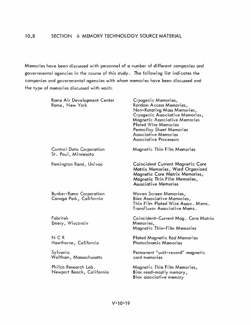
10.8 SECTION 6 MEMORY TECHNOLOGY SOURCE MATERIAL
Memories have been discussed with personnel of a number of different companies and
governmental agencies in the course of this study. The following list indicates the
companies and governmental agencies with whom memories have been discussed and
the type of memories discussed with each:
Rome Air Development Center Rome, New York
Contro I Data Corporation St. Pau I, Minnesota
Remington Rand, Univac
Bunker-Ramo Corporation Canoga Park, California
Fabritek Emery, Wisconsi n
NCR Hawthorne, Co lifornia
Sylvania Wa Itham I Massachusetts
Ph i leo Research Lab. Newport Beach I Ca Ii forni a
V-10-19
Cryogenic Memories, Random Access Memories, Non-Rotating Mass Memories, Cryogenic Associative Memories, Magnetic Associative Memories Plated Wire Memories Permo Iloy Sheet Memori es Associative Memories Assoc i ative Processors
Magnetic Thin Film Memories
Coincident Current Magnetic Core Matrix Memories, Word Organized Magnetic Core Matrix Memori es, Magnetic Th in Film Memories, Associative Memories
Woven Screen Memories, Biax Associative Memories, Thin Fi 1m Plated Wire Assoc. Mems. Transfluxor Associative Mems.
Coincident-Current Mag. Core Matrix Memories, Magnetic Thin-Fi 1m Memories
Plated Magnetic Rod Memories Photochrom i c Memori es
Permanent II unit-record ll magnetic card memori es
Magnetic Thir:l Film Memories, Biax read-mostly memory, Biax associative memory
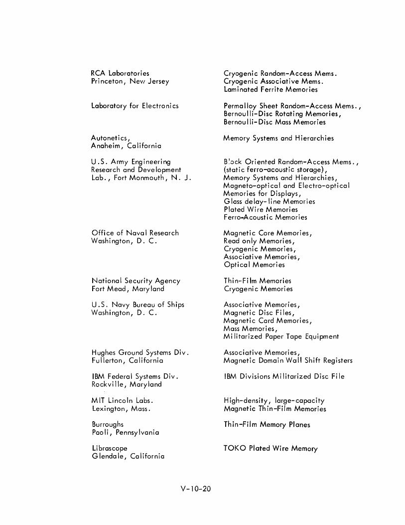
RCA Laboratories Pri nceton, NeVI Jersey
Laboratory for Electroni cs
Autoneti cs, Anaheim, California
u . S. Arm y Eng i ne e ring Research and Deve lopment Lab., Fort Monmouth, N. J.
Offi ce of Nava I Research Washi ngton, D. C.
Nationa I Security Agency Fort Mead, Mary land
u. S. Navy Bureau of Ships Washington, D. C.
Hughes Ground Systems Div. Fullerton, California
IBM Federal Systems Div. Rockvi lie, Maryland
MIT Lincoln Labs. Lexington, Mass.
Burroughs Paoli, Pennsylvania
Librascope Glendale, California
V-10-20
Cryogeni c Random-Access Mems. Cryogenic Associative Mems. Laminated Ferrite Memories
Perma Iloy Sheet Random-Access Mems. , Bernoulli-Disc Rotating Memories, Bernou lIi- Disc Mass Memories
Memory Systems and Hierarchies
B ~ock Ori ented Random-Access Mems. , {static ferro-acoustic storage}, Memory Systems and H ierarchi es, Magneto-optical and Electro-optical Memori es for Displays, Glass delay-line Memories Plated Wire Memories Ferro-Acoustic Memories
Magnetic Core Memories, Read on Iy Memori es, Cryogenic Memories, Associative Memories, Optical Memories
Thin-Fi 1m Memories Cryogeni c Memories
Associative Memories, Magnetic Disc Files, Magnetic Card Memories, Mass Memori es, Mi litarized Paper Tape Equipment
Associative Memories, Magnetic Domain Wall Shift Registers
IBM Divisions Militarized Disc File
High-density, large-capacity Magnetic Thin-Film Memories
Thin-Film Memory Planes
TOKO Plated Wire Memory
Texas Instruments Dallas, Texas
Remington Rand Univac Blue Bell, Pennsylvania
Stanford Research Institute Menlo Park, California
Fairchild Semiconductor Palo Alto, California
V-10-21
Thin-Film Memories
Plated Wire Memories, Planar Thin-Film Memory Electromechanical Mass Memories
Thin-Film Techniques
Integrated Circuit Memories

10.9 SECTION 7 MACHINE SYSTEMS ORGANIZATION REFERENCES
1. "Why Multicomputers? ," W. F. Bauer, Datamation, September 1962.
2. "Highly Parallel Machines," W. B. Comfort, Datamation, September 1962.
3. "The RW -400 - A New Pol ymorph ic Data System, II R. E. Porter, Datamation, January/February 1960.
4. liThe Burroughs D825, II J. P. Anderson, Datamation, Apri I 1964.
5. JJThe Design of the B5000 System,.. W. Longergan and P. King, Datamation, May 1964.
6. "Planning the 3600," C. T. Casale, Proceedings FJCC, 1962.
7. "PMR Real-Time Data Handling System, System Description and Programming Concept," Informatics, Inc., Unpublished Report to Headquarters, PMR, 1963.
8. "A Multiple Satellite Real-Time Control Network,1I V. White, IEEE Transactions on Military Electronics, October 1963.
9. "Generalized Multiprocessing and Multiprogramming," A. J. Critchlow, Proceedings, FJCC, 1963.
10. II Multi -Level Programming for a Real-Time System, II A. B. Shafritz, A. E. Miller, and K. Rose, Proceedings EJCC, 1966.
11. "Computer Design from the Programmers' Vi ewpoint, II W. F. Bauer, Proceedings, EJCC, 1958.
12. JlAn Automatic Sequencing Procedure with Applications to Parallel Programming, II E. So Swartz, Journal of ACM, Vol. 8, p. 513.
13. II New Concepts in Computing System Design/' G. M. Amdahl, Proceedings of the IRE, May 1962.
14. JlAnalysis of Computing Load Assignment in a Multi-Processor Computer,JJ M. Aoki, G. Estrin and R. Mandell, Proceedings, FJCC, 1963.
15. II Multi -computer Programming for a Large-Scale Real-Time Data Processing System,1I G. E. Pickering, E. G. Mutschler and G. A. Erickson, Proceedings, SFCC, 1964.
16. JJDesign for an Associative Computer, II P. M. Davies, Proc. Pacific Computer Conference, Pasadena, Cal iforn ia, March 1963.
V-10-22
17. "A Cryogenic Data Addressed Memory /' V. L. Newhouse and R. Eo Fruin, Proc. Spring Joint Computer Conf., May 1962, p. 89.
18. "A Magnetic Associative Memory,1I J. R. Kiseda, H. E. Seelbach, w. C. and M. Teig, IBM J. Res. and Dev., April 1961, pp. 106-121.
19. IIAlgorithms for Content Addressable Memories,lI G. Estrin and R. H. Fuller, 1963 Pacific Computer Conference, IEEEo
20. IJContent - Addressable Memory System Reportll No. 63-25, Nonr 233(52), R. H. Fuller, Department of Engineering, University of California, Los Angeles, California.
21. IIAn Associative Processor /' R. E. Ewing and P. M. Davies, Proc., F JCC, November 1964, pp. 147 -159.
22. HAn Organization of an Associative Cryogenic Computer ,11
R. F. Rosin, Proc. AFIPS SJCC, May 1962, pp. 203-212.
23. 1I0rgan ization of Computer Systems - The Fixed Plus Variable Structure Computer," G. Estrin, proc. WJCC, San Francisco, California, March 1960, pp. 33-37.
24. IIAssociative Logic for Highly Parallel Systems,1I R. R. Seeber and A. B. Lindquist, Proco FJCC, November 1963, pp. 489-493.
25. IIA Search Memory Subsystem for a General Purpose Computer ,II Ao Kaplan, Proc. F JCC, November 1963, pp. 193 -200.
26. IIA Hardware-Integrated GPC/Search Memory," R. G. Gall, Proc. FJCC, November 1964, pp. 159-173.
27. II Associative Memory with Ordered Retrieval, "R. R. Seeber and A. Bo Lindquist, IBM J. Res. and Dev., January 1962.
28. IIAssociative Self-Sorting Memory, II R. R. Seeber, Jr., Proc. EJCC, December 1960, pp. 179-188.
29. liThe Logic Theory Machine,1I A. Newall and H. A. Simon, IRE Trans. on Information Theory, Vol. I-T-2, 1956, No.3, pp. 61-79.
30. "A Machine for a General Purpose List Processor, II Ro L. Wigington, Trans. IEEE on Electronic Computers, Vol. EC-12, Dec. 1963, p. 707 -714.
31. liThe Best Way to Design an Automatic Calculating Machine,1I N. V. Wilkes, Manchester University Computer Inaugural Conference, Proceeding, July 1951.
V-10-23
32. "Micro-programming and the Design of the Control Circuits in an Electronic Digital Computer, II M. V. Wilkes and J. B. Stringer, Proceedings of the Cambridge Philosophical Society, April 1953.
33. "Microprogramming, M. V. Wilkes, Proc. EJC, Dec. 3-5, 1958, pp. 18-20.
34. "A Note on Microprogramming", H. T. Giantz, Journal of the Assoc iation for Computing Machinery, Apri I 1956.
35. "Micro-Programming", Robert J. Mercer, Journal of the Association for Com put i ng Mach i nery, Apr iI 1957.
36. "Microprogramming and Stored Logic, II Lowell Amdahl, Datamation, Feb. 1964, pp. 24-26.
37. "TheTRW-133 Computer", W. C. McGee, Datamation, Feb. 1964, pp. 27-29.
38. liThe PB-400 Computer, II E. O. Boutwell, Datamation, Feb. 1964, pp. 30-32.
39. liThe C-8401," L. Beck and F. Keeler, Datamation, Feb. 1964, pp. 33-35.
40. "Stored Logic Programming and Applications, II Richard H. Hill, Datamation, Feb. 1964, pp. 36-39.
41. "CIRRUS, An Economical Multiprogram Computer with Microprogra:n Control, II M. W. Allen, T. Pearcey, J. P. Penny, G. A. Rose, and T. G. Sanderson, IEEE Transactions, Dec. 1963.
42. "A Memory Organization for an Elementary list-Processing Computer, II V. O. Muth and A. K. Scidmore, IEEE Transactions on Electronic Computers, June 1963.
43. "Microprogrammed Control for Computing Systems," G. B. Gerace, IEEE Transactions on Electronic Computers, Dec. 1963.
44. Symposium on Advanced Computer Organization, AFIPS Computer Conference , Munich, 1962.
45. liThe Design of a General-Purpose Microprogram-Controlled Computer with Elementary Structure, \I Thomas W. Kampe, IRE Transactions on Electronic Computers, June, 1960.
46. "The KT Pilot Computer - A Microprogrammed Computer with a Phototransistor Fixed Memory," H. Hagiwara, K. Amo, S. Matsushita and H. Yomanchi.
V-10-24
47. liThe Atlas Computer, II C. H. Devonald, and J. A. Fotheringham, Datamation, May 1961.
48. IIIBM System/360 Engineering, II P. Fagg, J. L. Brown, J. A. Hipp, D. T. Doody, J. W. Fairclough, and J. Greene, AFIPS Proceedings F JCC, 1964.
49. liThe Central Control Unit of the Atlas Computer, II F. H. Sumner, G. Haley, and E. C. V. Chen, IFIP Congress, Munich, 1962, p. 657.
50. IIOrganization of computer systems; the fixed plus variable structure computer, II G. Estrin, Proc. Western Joint Computer Conf., 1960, pp. 33-40.
51 . IIAutomatic Assignment of Computations in a Variable Structure Computer, II G. Estrin and R. Turn, IEEE Transactions Vol. EC-12, No.6, Dec. 1963.
52. IIParallel Processing in a Restructural Computer System,1I G. Estrin, B. Bussel, R. Turn, J. Bibb, IEEE Transaction, Vol. EC-12, Dec. 1963.
53. IIlterative Circuit Computers," J. R. Halland, Proceedings of the Western J 0 i nt Computer Conference I San Franc isco, Ca 1 if. May 3-5, 1960.
54. "A Universal Computer Capable of Executing an Arbitrary Number of Sub-Programs S imu Itaneously, II J. R. Holland, Proceed ings of the Eastern J 0 i nt Computer Conference, Boston, Massachusetts, Dec. 1-3, 1960.
55. IIA Multilayer Iterative Circuit Computer, II Rodolfo Gonzales, IEEE Transactions on Electronic Computers, Dec. 1963.
56. IIA Parallel Computer Organization and Mechanizations, II
J. K. Hawkins, C. J. Munsey, IEEE Transactions, June 1963.
57. IIPattern Recognition and Detection, S. H. Unger, Proceedings of the IRE, Vol. 47, October 1959, pp. 1737-1752.
58. IIDesign of a Pattern Recognition Digital Computer - Part 1: General Introduction," B. H. McCormick, Report No. 125, Digital Computer Laboratory, University of Illinois, Champaign Urbana, III.
59. "Parallel Computing with Vertical Data, II W. Shooman, Proceedings of the Eastern Joint Computer Conference, New York, Dec. 13-15, 19600
60. "The Solomon Computer, liD. L. Slotnick, W. C. Borck and R. C. McReynolds, Proceedings of the Fall Joint Computer Conference, Philadelphia, December 1962.
V-10-25
61. "On the Use of the Solomon Parallel Processing Computer, II J. R. Ball, R. C. Boll inger, T. A. Jeeves, R. C. McReynolds, D. H. Shaffer and D. I. Caplan, Proceedings of the Fall Joint Computer Conference, Philadelphia, December 1962.
62. liThe Solomon Computer, II J. Gregory and R. McReynolds, IEEE Transaction, Dec. 1963.
63. II Iterative Circuit Computers, II Harvey l. Garner, J. S. Squire, Proceedings of the 1962 Workshop on Computer Organization.
64. II Intercommunicating Cells, Basis for a Distributed logic Computer, II C. Y. Lee, Proceedings of the Fall Joint Computer Conference, Philadelphia, December 1962.
V -10-26
10.10 SECTION 9 ADVANCED USAGE TECHNIQUES REFERENCES
1 . "Systems and Information," W . Ross Ashby, IEEE Transactions, Volume Mll-7, April-July 1963.
2. "Reliability of Biological Systems," Warren S. McCullock.
3. "An Abstract Machine Based on Classical Association Psychology," Richard F. Reiss, Spring Joint Computer Conference 1962.
4. "Some Methods of Artificial Intelligence and Heuristic Programs," Marvin Minsky, Proceed ings of the Symposium on Mechanization of Thought Process/National Physical laboratory, Teddington, England, November 1958.
5. "Adaptive Mechanisms in Digital IConcept l Processing," Manfred Kochen, Joint Automatic Control Conference of 1962.
6. "A Theory of Simple Concepts with Applications, II Janerji and Windeknecht.
7. "Can a Machine Think?,.. A. M. Turing, Mind,1950.
8. "Self-Organizing System, II Marshall Yovits and Scott Cameron, Proceed i ngs of an Interd isc ipl i nary Conference, May 1959.
9. "Principles of Self-Organization," Von Foerster and Zopf, 1960 Conference on Self-Organizing Systems
10. "Unconventional Computer of the Future, II Richard Wilcox, Naval Research Reviews, January 1964.
11. "Pattern Recognition and Reading by Machine, II Bledsoe and Browning, Proceed ings of the Eastern Joint Computer Conference, 1959.
12. "Adaption and Feedback, II J. Sklansky, Joint Automatic Control Conference of 1962.
13. "Analytic Techniques for the Study of Neural Nets," F. Rosenblatt, Joint Automatic Control Conference of 1962.
14. IIA Flexible Neural logic Network," G. J. Dusheck, T. G. Hilinski, F. L. Putzrath, IEEE Transaction, Volume MIL-7, April-July 1963.
15. IIA Model of the Plastic Neuron, II V. V. Griffith, IEEE Transaction~, Volume Mll-7, April-July 1963.
16. "Comments on learning and Adaptive Machines for Pattern Recognition, II C. Hugh Mays, 1964 Fall Joint Computer Conference
V-10-27
17. "Some Considerat ions of Polystabl e Systems, II Howard S. Fitzhugh II, IEEE Transactions, Volume MIL-7, April-July 1963.
18. "Functional Electron ic Model of the Frog Retina, II M. B. Herscher and T. P. Kelley, IEEE Transactions, Volume MIL-7, April-July 1963.
19. "Large Artificial Nerve Net (Lannet)", David F. Guinn, IEEE Transactions, Volume MIL-7, April-July 1963.
20. "Programming Pattern Recognition," G. P. Dinneen, Proceedings of the Western Joint Computer Conference, Los Angeles, California, 1955.
21. "Generalization of Pattern Recognition in a Self-Organizing System, II
Proceed ings of the 1955 Western Joint Computer
V-10-28

Appendix A
1 .0
2.0
3.0
4.0
5.0
6.0
7.0
8.0
9.0
10.0
11 .0
12.0
13.0
14.0
15.0
16.0
17.0
18.0
19.0
Appendix A STORAGE ELEMENTS
TABLE OF CONTENTS
STORAGE ELEMENTS V-A-l
Integrated Circuit Memories V-A-l
Tunnel Diode N'emories V-A-3
Planar Magnetic Thin Film Memories V-A-4
Cylindrical Magnetic Thin-Film (Plated Wire) Memories V-A-12
Permalloy Sheet Toroid M.emory V-A-20
Laminated Ferrite Memory V-A-22
Flute Memory V-A-25
Magnetic Core Memories V-A-27
Glass Delay Line Memories V-A-30
Woven Screen Memory V -A-31
Conti nuous- Sheet Cryogeni c Random-Access Memori es V -A-33
Ferroacoustic Memory V -A-37
Magnetic Surface Storage V -A-40
Associative Memories V-A-43
Cryogenic Associative Memories V -A-48
Magnetic Associative Memories V -A-50
Integrated Circuit Associative Memori es V -A-53
Associative Memory Uses and Organization V -A-54
Read-Only Memories V-A-56
A-i

LIST OF ILLUSTRATIONS
Appendix A
Figure
1 (a) Typical Word, Sense, and Digit line Geometry for Thin-Film Memory V-A-5
1 (b) Cross-section of High Density Thin-Film Storage Element V-A-5
2 Information Storage on Plated Wire V -A-15
3 Sketch of Plated-Wire Memory Plane V -A-15
4 Three-Conductor Wiring Pattern for a Permalloy Sheet Toroid V-A-20 Memory Plane
5 Laminate Details for Laminated Ferrite Memory V-A-22
6 Flute Memory Elements with Word and Bit lines Imbedded in Ferrite V-A-25 Bar
7 Typical 4-Wire Single-Turn Cell in Woven Screen Memory V-A-31
8 Cryotron Selection Tree and Associated Drive Strip V-A-34
9 Typical Ferroacoustic Storage line V-A-37
10 Typical Search Memory Block Diagram V-A-47
Appendix A
2
3
LIST OF TABLES
Advantages and Disadvantages of Different Electromechanical Mass Memori es
Magnetic Associative Memory Techniques
Associative Memory System Characteristics
A-ii
V-A-44
V-A-46
V-A-49
Appendix A STORAGE ELEMENTS
1.0 INTEGRATED CIRCUIT MEMORIES
Integrated semiconductor circuits are discussed in detai I in Components and .Packaging
(Appendix B), but their appl ication as storage elements deserves additional considera
tiono The most obvious storage application of integrated circuit techniques is in
registers where each bit position of the register is mechanized with a single integrated
circuit flip-flopo Registers mechanized with individual integrated circuits will be
available within the next year operating at cycle times in the order of 50 nanoseconds,
i.eo, the rate at which the flip-flop may be repetitively set, sensed, and reset. New
developments in integrated circuits are leading to propogation delays in the order of
2 nanoseconds per gate, but the complete cycle time for a flip-,flop is several times
the propogation delay of an individual gate. By 1970, integrated fl ip-flops may be
available with cycle times less than 20 nanoseconds. A small scratch-pad memory
mechanized with elements of this type is somewhat slower overall, of course, since
some time is required for addressing and selection.
Integrated circuit flip-flops are expected to be the primary method of mechanizing
individual registers in new machines within the next few years 0 Prior to 1970, advances
in the state of the art in integrated circuits will permit the fabrication of several stages
of a register (perhaps the entire register) on a single sil icon monolithic integrated
circuit chip. Those applications in which transistorized fl ip-flops are nOw used
will quickly give way to individual flip-flop integrated circuits, and to multi-stage
integrated circuits before 1970.
In a somewhat different approach, a prototype memory has been developed in which a
special integrated circuit storage element is used with XY matrix addressing and
selection techniques. This element, selected by a coincidence of X and Y signals, is
simpler than a conventional flip-flop {e.g., only a single output is required}o The
element was designed to operate at very low power levels (approximately 30 mi lIiwatts
per element) and for a cost per bit that is relatively low for high-speed scratch-pad
V-A-1
type memories. The designers state, IIAlthough the cost in $/bit/ nanosecond for
integrated circuit memory is higher when compared with magnetic core memory, it is
lower than magnetic thin film memories having a cycle time of 300 nanoseconds 0 Also,
a 100 to 200 nanosecond memory system having a size of say 256 words by 24 bits, can
be readily produced in quantity in 1964. 111 At present, individual chips and packages
are used for each bit of storage 0
The next step beyond the use of multi-stage integrated circuit chips is the fabrication
of several hundred bits, or more, of semiconductor storage in a single silicon chip using
XY matrix addressing and selection techniqueso This type of active circuit storage,
using bipolar transistor techniques, is anticipated for small high-speed control memory
applications by 1970. At present, however, the most udvanc:ed work in this direction
involves the use of metal-oxide semiconductor field-effect type elementso Several
companies are actively working on this type of storage array for control and scratch-pad
memories 0
One semiconductor manufacturer has reported work on a small low-cost random-access
memory array mechanized with MOS elements which is significant in that a single chip
contains an order of magnitude more components than other integrated circuits now
being manufactured. The efforts to date have produced a complete memory array of
16 four-bit words on a single silicon chip 115 mils by 145 mils in size (approximately
ten times the area of a conventional integrated circuit) 0 About 30 chips can be
fabricated on one silicon wafer with present yields of 4 to 5 good chips per wafero
The total read/write cycle time for this device is 4 microseconds -- a 2 microsecond
read time and a 2 microsecond write time. The relatively slow speed of 4 microseconds
results from the fact that the MOS is a high impedance device. The rise time is
approximately 75 nanoseconds and the fall time approximately 575 nanosecondso
Although this type device is slow compared to integrated circuit flip-flops using
bipolar transistor techniques, it is of great interest because the MOS devices are much
easier to fabricate than epitaxial integrated circuits o Since significantly fewer pro
cessing steps are involved, the fabrication of large arrays of elements with reasonable
yields is more feasible. A speed improvement of an order of magnitude is probably the
best that ca n be expected in th is type storage.
V-A-2
As integrated circuit technology and yields improve, workers in the field anticipate
the fabrication of somewhat similar arrays of storage elements permitting significantly
higher speeds through the use of planar epitaxial transistor elements rather than MOS
elementso Mro Rex Rice, of Fairchild Semiconductor, has predicted that large inte
grated circuit arrays using bipolar transistor techniques will eventually replace magnetic
core memories in appl ications where relatively high speed (e og 0, 0.5 to 1 microsecond)
is required and where a volatile type memory is acceptable. 3
He also believes that
volatile storage is acceptable for more internal memory applications than is generally
recognized. This prediction impl ies that high-speed integrated circuit storage arrays
of this type can be built at a cost that will be more than competitive with magnetic core
memories, and that power requirements per element can be reduced significantlyo The
power required per stage is a serious consideration for any active storage array since
holding power is required for each bit position in the array.
200 TUNNEL DIODE MEMORIES
Storage elements using the negative resistance characteristic of tunnel diodes
have been investigated extensively for high-speed scratch-pad type memories
with cycle times of 10 to 100 nanoseconds and capacities of 128 to 512 words. A
few years ago, it appeared that this might be the only feasible method of achieving
these characteristics; however, other techniques such as epitaxial integrated circuit
arrays and small magnetic thin-film memories offer promise of providing these charac
teristics (except possibly for the extreme fast end of the speed range) at a significantly
lower cost" Since no requirement is anticipated for such extreme speeds in a 1970 ACDS,
tunnel diode storage is not a major competitor for use in such a system. Hence, these
techniques have not been investigated in great detail since other storage techniques can
meet the future requirements for a shipboard data system at significantly lower costs 0
Even optimistic projections imply future costs for high-speed tunnel diode memories of
no less than 50 cents per bit.
V-A-3
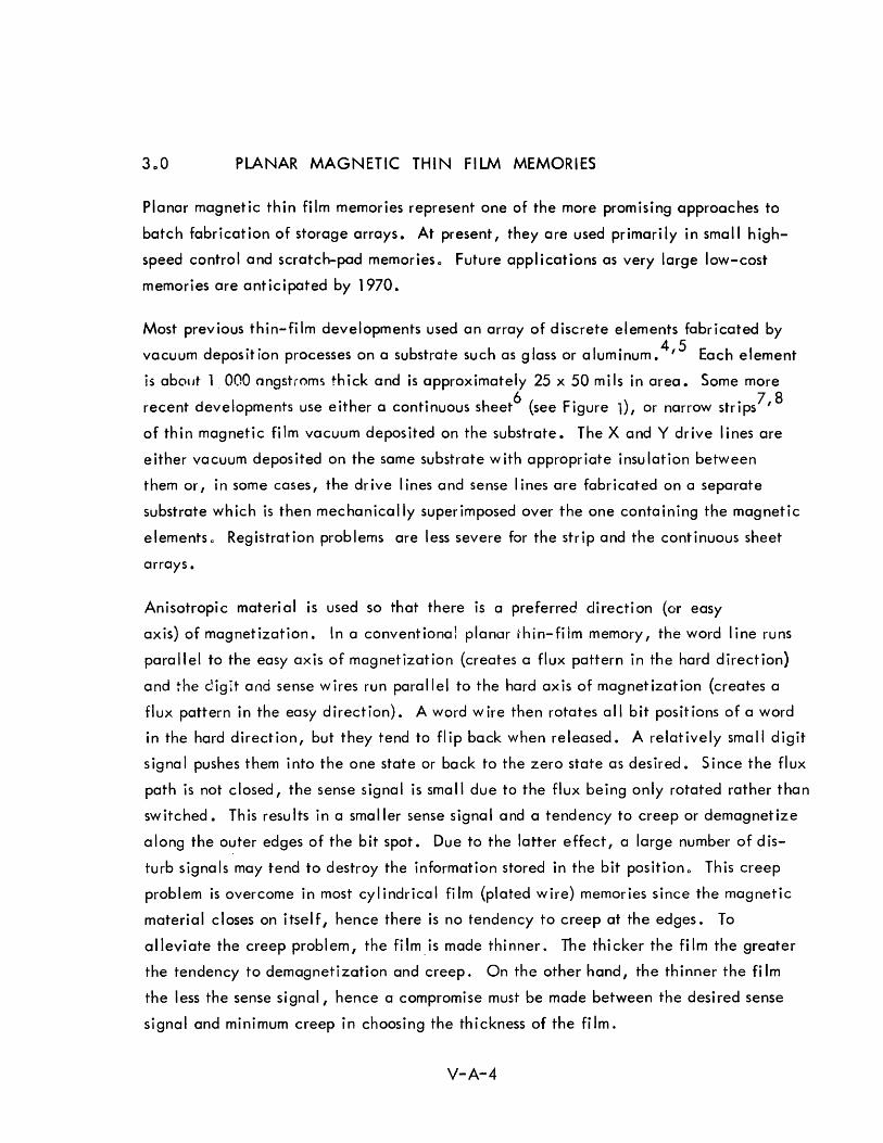
300 PLANAR MAGNETIC THIN FILM MEMORIES
Planar magnetic thin film memories represent one of the more promising approaches to
batch fabrication of storage arrays. At present, they are used primarily in small high
speed control and scratch-pad memories 0 Future appl ications as very large low-cost
memories are anticipated by 1970.
Most previous thin-fi 1m developments used an array of discrete elements fabricated by
vacuum deposition processes on a substrate such as glass or aluminum. 4,5 Each element
is abolJt 1 000 angstroms thick and is approximately 25 x 50 mils in area. Some more
recent developments use either a continuous sheet6 (see Figure 1), or narrow strips7,8
of thin magnetic film vacuum deposited on the substrate. The X and Y drive lines are
either vacuum depos ited on the same substrate with appropriate insu lation between
them or, in some cases, the drive I ines and sense I ines are fabricated on a separate
substrate which is then mechanically superimposed over the one containing the magnetic
elements 0 Registration problems are less severe for the strip and the continuous sheet
arrays.
Anisotropic material is used so that there is a preferred direction (or easy
axis) of magnetization. In a conventional planar .hin-film memory, the word line runs
parallel to the easy axis of magnetization (creates a flux pattern in the hard direction)
and the digit and sense wires run parallel to the hard axis of magnetization (creates a
flux pattern in the easy direction). A word wire then rotates all bit positions of a word
in the hard direction, but they tend to flip back when released. A relatively small digit
signa I pushes them into the one state or back to the zero state as desired. Since the flux
path is not closed, the sense signal is small due to the flux being only rotated rather than
switched. This resu Its in a smaller sense signal and a tendency to creep or demagnetize
a long the outer edges of the bit spot. Due to the latter effect, a large number of d is
turb signals may tend to destroy the information stored in the bit positiono This creep
problem is overcome in most cylindrical film (plated wire) memories since the magnetic
material closes on itself, hence there is no tendency to creep at the edges. To
alleviate the creep problem, the film.is made thinner. The thicker the film the greater
the tendency to demagnetization and creep. On the other hand, the thinner the fi 1m
the less the sense signal, hence a compromise must be made between the desired sense
signal and minimum creep in choosing the thickness of the film.
V-A-4
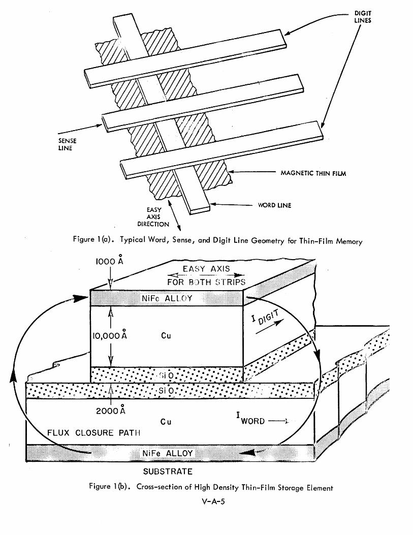
SENSE LINE
MAGNETIC THIN FILM
WRD LINE
Figure 1 (a). Typical Word, Sense, and Digit Line Geometry for Thin-Film Memory
o 1000 A
o 2000A
CLOSURE PATI-{
EASY AXIS -<1-- - ---- ~-
FOR ROTH ~;TRIPS
Cu I
WORD --1-
SUBSTRATE
Figure 1 (b). Cross-section of High Density Thin-Fi 1m Storage Element
V-A-5

A number of problems have plagued thin-film memories including:
1) Dispersion - The direction of easy axis is not uniform over the
entire film (should be less than 50).
2) Skew - The direction of the easy axis is not exactly as intended
(shou Id be less tha n 50).
3) Low word sense signal - Since the flux path is not closed and
the flux is not switched but only rotated, word sense signals
are 0.1 to 0.2 millivolt.
4) High drive signal followed by low sense signal - It is necessary
to balance out the high drive signal on the sense wire. The
drive signal is approximately 10 volts compared to a 0.1 to 0.2
mill ivolt sense signal 0
5) Magnetostriction - A material of approx imately 19 0 6% iron and
80.4% nickel is required for zero magnetostriction. If the iron
content is slightly too high, a negative stress will deteriorate the
rectangu larity of the hysteresis loop; if the nickel content is too
high, a positive stress signal will decrease the rectangularity of
the hysteres is loop.
6) Yield - Perhaps 300/0 to 500/0 yield can be obtained in small planes
(e.g. 128 x 24 bits) but it is not economically sound to build a
large memory out of a multitude of small planes because of the
interconnection and mounting problema To make an economical
large array, it is necessary to fabricate a large plane with a
large number of bit positions, but the yield problem is much worse
in this case. A 50% yield on small planes might imply an almost
negligible yield on very large planes if 100% good spots are
requ ired. Therefore, for large planes, it may be necessary to
develop some redundancy techniques so that the system can operate
with a limited number of bad spots. Because of these problems,
th is type of memory is usually operated in a word-oriented fashion
rather than a coincident current mode. This increases the cost of
the associated electronicso On the other hand, the use of domain
V-A-6
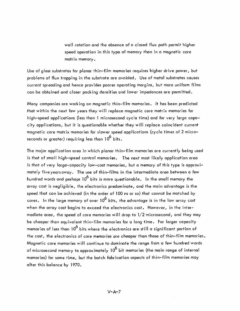
wa II rotation and the absence of a closed flux path perm it higher
speed operation in this type of memory than in a magnetic core
matrix memory 0
Use of glass substrates for planar thin-film memories requires higher drive power, but
problems of flux trapping in the substrate are avoided 0 Use of meta I substrates causes
current spreading and hence provides poorer operating margins, but more uniform films
can be obtained and closer packing densities and lower impedances are permitted 0
Many companies are working on magnetic thin-film memories. It has been predicted
that within the next few years they wi II replace magnetic core matrix memories for
high-speed appl ications (less than 1 microsecond cycle time) and for very large capa
city applications, but it is questionable whether they will replace coincident current
magnetic core matrix memories for slower speed appl ications (cycle times of 2 m icro
seconds or greater) requiring less than 106
bits.
The major applicationarea in which planar thin-film memories are currently being used
is that of small high-speed control memories. The next most likely application area
is that of very large-capacity low-cost memories, but a memory of this type is approxi
mately five years away. The use of thin-films in the intermediate area between a few
hundred words and perhaps 106 bits is more questionableo In the small memory the
array cost is negl igible, the electronics predominate, and the main advantage is the
speed that can be achieved (in the order of 100 ns or so) that cannot be matched by
cores. In the large memory of over 106 bits, the advantage is in the low array cost
when the array cost begins to exceed the electronics cost. However, in the inter
mediate area, the speed of core memories will drop to 1/2 microsecond, and they may
be cheaper than equ iva lent th i n-fi 1m memories for a long time. For larger capacity
memories of less than 106 bits where the electronics are still a significant portion of
the cost, the electronics of core memories are cheaper than those of thin-film memories.
Magnetic core memories will continue to dominate the range from a few hundred words
of microsecond memory to approximately 106 bit memories (the main range of internal
memories) for some time, but the batch fabrication aspects of th in-fi 1m memories may
alter this balance by 1970.
V-A-7
Thin-film elements can now be rotated in approximately one nanosecond, but the
associated electronics cause selection to take at least 35 nanoseconds. Thin-film
memories can provide non-destructive read out, require less power than core memories,
and are batch fabricated. However, the low sense signal level requires a good
differential amplifier; fast rise time circuits are required, and it is difficult to ade
quately control the magnetic variables to produce uniform elements. Memories of
4000 words capacity with 100 nanosecond cycle times, and 64,000 word memories
with 500 nanosecond cycle times appear reasonable for the future.
A 400 nanosecond cycle time thin-film memory being fabricated for the Johnsville
Naval Air Station is typical of current work in thin-film memories. This memory is
word-organized, contains 1024 words of 50 bits each, and operates in a 400 nano
second cycle time. The array is composed of film deposits approximately 900 angstroms
thick that are rectangular in shape, measuring 25 x 50 mil. A single film is used for
each bit. Manufacturing costs of current film stacks are between 20 cents and 50 cents
a bit,and development of a film plane within the next year costing approximately 5 cents
a bit is expected. These costs are for the fabricated planes only and do not include
electron ics •
Both X and Y axis lines are superimposed on the same printed circuit card with a plastic
deposit separating them. The digit lines are approximately 32 mils wide, each con
sisting of two 10-mil lines separated by a 12 mil gap. The two 10-mil lines are joined
at both ends of the board and are terminated in a plated-through hole for interconnection.
The drive line is approximately 23 mils wide, each consists of two 9-mil lines divided
by a 5-mil gap. The drive lines are also reconnected at both ends in plated holes,
which are fed through the opposite side of the adjoining board, and fed back parallel
to the first I ine to provide a proper termination, and to provide noise cancell ing 0 Each
memory plane consists of a total of 112 substrates which are placed on a single printed
circuit board. This is done to reduce the number of interconnections involved on the
board and to decrease the total number of film spots that are deposited on a single sub
strate, thus increasing the yield. The reverse printed circuit board is placed over the
film and the total assembly is bolted together between two holding plateso The drive
and sense lines are then terminated.
V-A-8

Higher performance thin-film memory work is represented by the memory being
developed for the REDMAN program in which the memory planes are fabricated by
depositing a continuous film of nickel cobalt on a polished aluminum substrate.6
This memory has a capacity of 4096 words of 50 bits per word organized as 8192
25-b it words.
The density is 625 bits per square inch with a 80 mil spacing on the digit lines and
60 mil spacing on the word lines providing 3200 bits on a 3 by 3 inch substrate. The
cycle time is 140 nanoseconds and the access time 100 nanoseconds. The first version
of this memory using discrete semiconductor components for the electronics is scheduled
for completion in June 1965. The next step will use all integrated circuits for the
logic circuits and sense amplifiers. Integrated circuit word drivers (500 milliamps)
and bit drivers (-:t 150 milliamps) are approximately 18 months away.
Th is program is expected to lead to array costs of 1 cent per bit and complete memory
costs of 10 cents to 15 cents per bit by 1967 for an 8,192 to 16,384 word memory
operating at a cycle time of 100 nanoseconds. The cycle time for this capacity memory
may be reduced to 50 ns by 1968 or 1969.
A sem i-automated th in-fiim fabrication system has been deve loped for the REDMAN
memory in which 50 substrates can be processed in one evacuation. The 50 substrates
are initially stacked on one side of a specially designed vacuum chamber. The sub
strates are then passed one at a time successively through a substrate heating area, a
magnetic film deposition area, a silicon oxide deposition area, and into an output
stack on the other side of th e vacuum chamber.
Another development program is pointed toward the batch fabrication of a very large
(l06
words) low-cost memory using magnetic thin-fi 1m techniques. 7 ,8 Those working
on this development believe that the real future of magnetic thin-film memories is in
the large-capacity low-cost area and that there is more to be gained in this area than
in the small-capacity high-speed area. Their approach is to fabricate high-density
planes by first depositing a thin continuous permalloy film on a thick glass substrate 0
Next, a continuous copper film is deposited on top of the permalloy film. Conventional
photo-resist, masking, and etching techniques are used to etch through both the copper
and permalloy to the glass substrate leaving thin strips of permalloy with copper on top
V-A-9

of the permalloy. This assures exact registration between the copper that will become
one of the drive wires and the permalloy film that is the actual storage media. A
similar glass substrate with permalloy and copper strips is placed at right angles over
the first one {with suitable insulation} providing a storage matrix where each bit of
storage is defined by the cross-over of two copper/permalloy strips. This permits a
two wire addressing, driving and sense system in which the upper and lower permalloy
elements at each cross-over form a semi-closed-loop magnetic structure.
The glass substrate is 8 inches long by 1.6 inches wide and approximately 1/411 to 1/2 11
thick. After etching, the lines are 2 mils wide on 8 mil centers. The permalloy film
is 300 to 1,000 angstroms in thickness and the copper conductors are 20,000 to 40,000
angstroms in thickness. The resistance of each copper lead is approximately 25 to 55
ohms. The creep problem {interference between adjacent bits in high-density planes}
is the major difficulty to be overcome. The strip technique, with the copper conductors
deposited and etched on top of the permalloy, overcomes the registration problem for
high-density planes.
Yields of 50% have been experienced in low-density planes (500/0 of the planes had no
bad elements), but the yield to be expected with the high-density planes is unknown.
A combination of fabrication techniques and the provision of some redundancy to permit
eliminating a few bad lines is being depended upon to provide a reasonable yieldo The
following advantages are cited for the use of high-density planes in this program:
1) Cost (more bits per fabrication process);
2) Fewer interconnections;
3) Short electrical lead lengths in very large memories.
The goal of the present development project is a 106
word memory with 36 bits per
word. Within the next year, a 106
bit prototype should be in operation. The total
106 word memory will require 30 memory stacks, 30 word drivers, 40 digit drivers,
and 2,000 sense amplifiers. The memory will be organized as 18,000 words (linear
select) of 2,000 bits each. The designers estimate that sense amplifiers can be built
for $20 each and the entire memory (36 x 106
bits) for $1 00, 000, or 0.3 cent per bit.
V-A-10
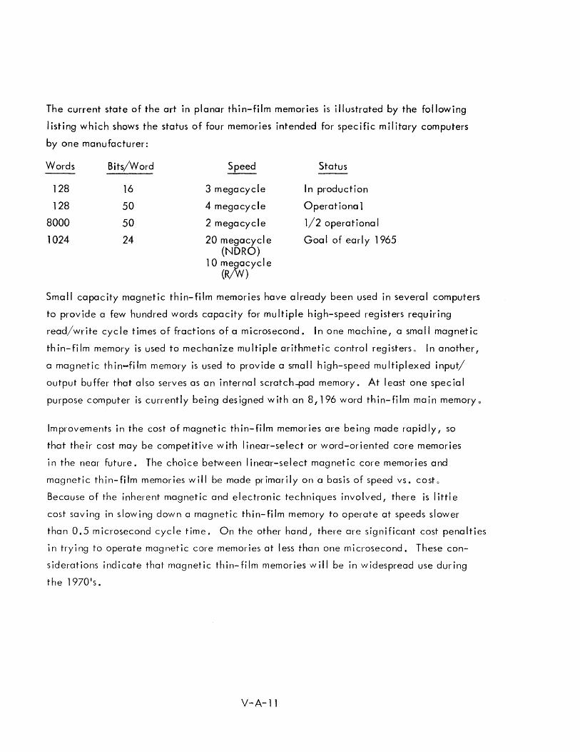
The current state of the art in planar thin-film memories is illustrated by the following
listing which shows the status of four memories intended for specific military computers
by one manufacturer:
Words Bits/Word Speed Status
128 16 3 megacycle In production
128 50 4 megacycle Operationa 1
8000 50 2 megacycle 1/2 operationa I
1024 24 20 megacycle Goa I of early 1965 (NDRO)
10 ml0cycle (R )
Small capacity magnetic thin-film memories have already been used in several computers
to provide a few hundred words capacity for multiple high-speed registers requiring
read/write cycle times of fractions of a microsecond. In one machine, a small magnetic
thin-film memory is used to mechanize multiple arithmetic control registerso In another,
a magnetic thin-film memory is used to provide a small high-speed multiplexed input/
output buffer that also serves as an internal scratch-pad memory. At least one special
purpose computer is currently being designed with an 8,196 word thin-film main memory 0
Improvements in the cost of magnetic thin-film memories are being made rapidly, so
that their cost may be competitive with linear-select or word-oriented core memories
in the near future. The choice between I inear-select magnetic core memories and
magnetic thin-film memories will be made primarily on a basis of speed vs. costo
Because of the inherent magnetic and electronic techniques involved, there is little
cost saving in slowing down a magnetic thin-film memory to operate at speeds slower
than 0.5 microsecond cycle time. On the other hand, there are significant cost penalties
in trying to operate magnetic core memories at less than one microsecond. These con
siderations indicate that magnetic thin-film memories will be in widespread use during
the 1970's.
V-A-ll
4.0 CYLINDRICAL MAGNETIC THIN-FILM (PLATED WIRE) MEMORIES
Another type of magnetic thin-film memory is fabricated by plating a magnetic film
on a wire substrat~o 9 The wire substrate then serves as one of the electrical conductors
in the system. A closed flux path is obtained by the magnetic film surrounding the
wire in a small region. A cylindrical thin film of this type offers the advantages that
the closed flux path requires smaller digit currents, produces a larger sense signal,
and is not as susceptible to creep. The fact that the wire substrate is used as either
the digit or word conductor reduces the mechanical registration problems in the fabri
cation of the memory. The major problem with this type of memory has been the
difficulty of producing satisfactory cylindrical films. Recent developments in these
fabrication techniques have made this type of memory appear very promising.
In a recent paper, IIPlated Wire Magnetic Thin Film Memories,1I 10 presented at the
1964 Intermag Conference, Danylchuk and Perneski presented the following comparison
of plated wire and planar fi 1m memories.
111) Production method and control
Comparison: Plated wire is produced and tested in a continuous, serial
process. Flat fi Ims are batch produced.
Conclusion: For plated wire, small numbers of bits may be rejected if
bad. For flat fj Ims entire arrays may have to be re jected due to fa i lure
of a single bit.
Comparison: The plated wires can be expected to be subjected to strain
during fabrication of a memory plane. Flat films, which are plated on
rigid substrates, are relatively free of strains due to handling.
Conclusion: During production a carefu I control of the magnetostriction
of the plated wire must be maintained in order to prevent adverse strain
effects.
V-A-12
"2) Output signal level
Comparison: The plated wire circumferential mode can use film
th ick nesses of 1 #l (10, OOO~) and more due to the closed fl ux path at
remanence. Flat film thicknesses, which are limited by demagnetizing
fields, are normally on the order of 1000.R.
Conclusion: Output signals are considerably higher for circumferential
mode plated wire memories, while bit packing densities are comparable
to those achieved with flat films. The axial mode plated wire has no
advantage over flat films in this category since its film thickness is also
lim ited by demagnetiz ing fie Ids.
"3) Current levels
Comparison: Optimum coupl ing ex ists between fields produced by
currents in the plated wire and the magnetic film deposited on the wire.
For flat films, both digit and word solenoids must be added to the film
array, and the opening of these solenoids are normally from 0.003" to
0.005". Also, slotted drive lines are normally necessary to permit
penetration of the field generated by the uppermost conductor to the
magnetic fi 1m in the planar construction.
Conclusion: For memory organization using plated wire as the digit line
(circumferential mode), small (15 ma) digit currents are required. Alter
natively, an axial mode memory which uses the plated w ire as a word
line, requires relatively small (200 ma) word currents. On the other hand,
since the plated wire diameter (0.005") sets a lower lim it on the area
of the solenoid enclosing the wire, word currents are 0.7 to 1 amp for the
circumferential mode/and digit currents are approximately 0.2 amp for
the ax ia I mode. For flat films dig it currents are approx imately O. 2 amp,
while word currents are approximately 0.3 amp. It must also be pointed
out that using the plated wire as a digit or word line leads to a much
higher characteristic impedance than for a corresponding flat film memory
line. II
V-A-13
In one type of cylindrical thin-film memory used in a commercial computer
the direction of magnetization of the cylindrical elements is parallel to the center
conductor rather than circumferential to it. 11
In this rod memory, a cylindrical thin film of magnetic material is deposited over a
conductive substrate, but the axial switching mode produces an open flux path element.
A multiple turn winding is placed over the plated rod for each bit positiono The
plating material is essentially isotropic and proper operation of the memory does not
depend upon anisotropy in the material.
The manufacturer claims that this magnetic rod memory is more advantageous than
either magnetic core matrix memories or planar thin-film memories in the range of
0.5 to 1.5 microseconds and hopes to lower this range to approximately 0.3 micro
second: Magnetic core matrix memories are more advantageous at slower speeds in
the range of 2 to 6 microseconds; magnetic thin-film memories are more advantageous
at very fast speeds of about 0.1 to 0.25 microseconds. They estimate that in the range
of 0.3 to 1.5 microseconds, the magnetic rod memory will have approximately the
same price per bit as a two microsecond coincident current magnetic core matrix
memory; approximately 25 cents per bit including electronics. The electronics are
compatible with and similar to those of magnetic core memories with a sense output of
80 millivolts being provided. Two major factors are cited as making the rod memory
economically feasible.
1) Rod manufacture is a continuous process including the automatic
w iring of a pair of spiral wires around the rod.
2) Tooling has been developed to permit automatic fabrication of
the memory stack (including multiple turn windings into which
the rods are inserted).
The lack of a closed flux path is recognized as a disadvantage, but the use of a high
coercivity magnetic material, permitted by the tight coupling of the multiple turn
winding, overcomes this disadvantage. As a result of the high coercivity of the
material, the tight coupling, and multiple turn windings, fast switching and large
output signals can be obtained.
V-A-14

In another type of cylindrical thin film (plated wire) memory, the direction of
magnetization of the cylindrical elements if circumferential to the plated wire providing
a closed flux path (see Figures 2 and 3). A 100,000 bit plated wire buffer memory of
this type has been del ivered to NASA for use in a spacecraft, 12 It operates at a sequen
tial bit rate of 100 kc with 500 milliwatts power consumption.13
Similar techniques
are presently being used on an RADC contract for a six-month feasibi I ity study of a
100 x 106
bit plated wire memory.
,:.R[ Of
"'AG~I ;11Arl(;~
I'L AfEO "",Rr
Figure 2. Information Storage on Plated VVire
/
WORD SELECTION DIODE MATRIX
~H-t+r+I-+~~:;""
ETCHED WORD LINES SUPPORTED BY
THIN GLASS EPOXY
Figure 3. Sketch of Plated-Wire Memory Plane
V-A-15
A 10,000 angstrom permalloy film is plated on a 5 mil beryllium copper wire,. This
wire acts as both a substrate for the plating and as the digit drive and sense wire 0
During the plating process a polarizing current is sent down the wire to give a magnetic
easy axis circumferential to the wire. The word drive conductors consist of flat metal
straps placed over the parallel digit wires.
The word drive straps are either returned under the digit wires or terminated in a
ground plane beneath the digit wires. The digit wires are placed on 15 mil centers
and the word drive straps on 45-70 mil centers. The bit density is approximately
1,500 bits per square inch.
The plated wire costs approximately 0.1 cent per bit. One million bit memories have
been quoted at approx imate I y 8 cents to 9 cents per b it for one of a kind memories,
including electronics. The target cost for the 108 bit RADC memory is 1 cent per bit,
but the actual cost will probably be lower than this.
The film switching time is approximately 40 to 80 ns. The following cycle times are
anticipated:
1) 100 ns read/write cycle for small control memories;
2) 150 ns read cycle for 4000 word NDRO memories;
3) 250 ns write cycle for 4000 word read/write memories.
This memory uses low-level sense signal switching and selection prior to the sense
ampl ifier. The same two-transistor switching matrix is used for the sense signal and the
digit drive signal. Hence, one end of the matrix is connected directly to the beryllium
copper w ire substrate that serves as dig it dr ive line and sense line.
The sense signal from the storage array is 10 to 15 millivolts. A unipolar word drive
current of 500 to 1000 milliamps, and a bipolar digit current of approximately .:!:35
mill iamps are used. Due to the low inductance resu Iting from the geometry of the
memory array plane, the back voltage on the word drive I ine is quite low (about
3 volts across 200 wires). For 108 bit memories fabricated in 105 bit banks, this
plated wire memory ach ieves an average of approximately 525 bits per wired inter
connection compared to 150 for thin-fi 1m memories by the same manufacturer.
V-A-16
The 108
bit memory for RAOC is designed In 10 banks of 107
bits each. The digit
lines will be 8 feet long and the word lines 6 feet long. The memory is to be packaged
in a 4 x 5 x 1.5 foot package including the power supplies and electronics. A portion
of this memory has been fabricated to prove feasibility. The breadboard consists of a
4 x 5 foot ground plane with a limited number of full length bit lines intersected by a
limited number of full length word lines. In the final memory, each module will consist
of a 3.5 x 4.5 foot array of four planes (essentially a 7 x 9 array folded on itself
in each direction). The 100 x 106
bit memory will be assembled from 9.4 x 10⁶
bit
modules. Each word line will control 64 words of 72 bits each (4608 bits per word line)
with the 72 digit drivers and 72 sense amplifiers switched to one of the 64 words on the
selected word line. A 10 microsecond read/write cycle is planned, but a 1 micro
second cycle can be achieved for a slightly higher cost -- possibly 20%.
A number of plated w ires with a reasonable yield are bei ng fabricated currently, but
with the present technique, it would take approximately one year (assuming a 50%
yield) to make the necessary number of wires for a 100 x 106
bit memory. As a result,
one of the goals of a manufucturif1~-1 study to be conducted next year will be to cut this
time to three months by developing methods of plating at a rate of 15 inches per minute
and of plating three wires in parallei through the same sei of baths.
The following advantages are cited for this plated wire memory;
1) Cheap;
2) High speed for this size memory;
3) Simple fabrication;
4) Closed flux path structure;
5) Non-destructive read out (NORO) on both read and write, i.e.,
Wr ite dr ive current on the word line does not destroy the stored
information in those bit lines which do not have a bit drive signal.
This permits a very large word, only a portion of which is read or
written at a given time. Hence, the selection of a word drive line
selects a large number of bit positions comprising the memory word,
but only a limited number of these comprising the machine word are
actua II y read or wr itten as determ i ned by th e bit dr ive line sw itch i ng
matr ix 0
V-A-17
The disadvantages are:
1) Relatively high power (200 watts);
2) Size (20 to 30 cu. feet);
3) We ight (400 to 500 IbSo).
These are disadvantages relative to the memory being developed under the cOiTlpetitive
study contract I but not relative to disc fi I es.
Except for very fast control or scratch-pad m(;;lnories, plated wire memories using
techn iques s im i lar to those in th ic: RADC memory are among the more prt)~1 is i rIg
competitors for the major types of storage requ ired in a 1970 ACDS.
Thic; piated wire memory study for RADC is in competition with a parallel study of a
permalloy sheet toroid memory described in the next subsection. The initial goals for
these studies aj'e:
1) Cost to mil itary user (I ess tha n 1 cent per bit)
2) Cyc let imes (under 100 microseconds)
3) Capac ities (100 x 106
bits)
4) Volume (less than 30 cu. ft.)
5) Power (less than 500 watts)
6) Weight (less than 200 Ibs.)
7) MTBF (5000 hrs.)
8) NDRO and random access to the word
9) Military specifications for shock, vibration, temperature, etc.
The studies to date indicate that all of these specifications will be met or exceeded 0
It is anticipated that the costs can be roughly comparable to the 0.2 cents to 0.25 cents
per bit for militarized disc files. If the preliminary results of the two six-month study
contracts under way at present prove out in final design and production, the random
access mass memories will equal or exceed the characteristics of the militarized disc
V-A-18
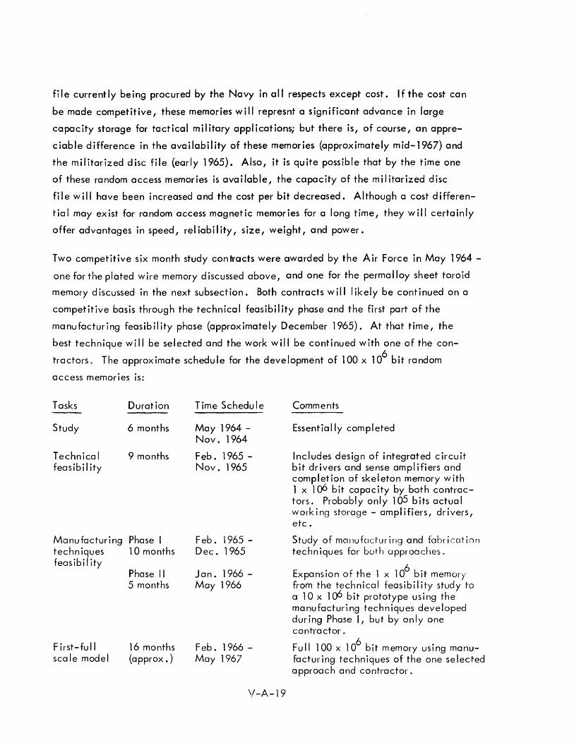
file currently being procured by the Navy in all respects except cost. If the cost can
be made competitive, these memories will represnt a significant advance in large
capacity storage for tactical military applications; but there is, of course, an appre
ciable difference in the availability of these memories (approximately mid-1967) and
the militarized disc file (early 1965). Also, it is quite possible that by the time one
of these random access memories is available, the capacity of the militarized disc
file will have been increased and the cost per bit decreased. Although a cost differen
tial may exist for random access magnetic memories for a long time, they will certainly
offer advantages in speed, reliability, size, weight, and power.
Two competitive six month study contracts were awarded by the Air Force in May 1964 -
one for the plated wire memory discussed above, and one for the permalloy sheet toroid
memory discussed in the next subsection. Both contracts will likely be continued on a
competitive basis through the technical feasibility phase and the first part of the
manufacturing feasibility phase (approximately December 1965). At that time, the
best technique will be selected and the work will be continued with one of the con
tractors 0 The approximate schedule for the development of 100 x 106
bit random
access memories is:
Tasks Duration
Study 6 months
Technical 9 months feasibility
Manufacturing Phase I techn iques 10 months feas ib i I ity
First-full scale model
Phase II 5 months
16 months (approx. )
Time Schedu Ie
May 1964 -Nov. 1964
Feb. 1965 -Nov. 1965
Feb .1965 -Dec. 1965
Jan. 1966 -May 1966
Feb. 1966 -May 1967
\I-A-19
Comments
Essentially completed
Includes design of integrated circuit bit drivers and sense amplifiers and completion of skeleton memory with 1 x 106 bit capacity by both contractors. Probably only 105 bits actual working storage - amplifiers, drivers, etc.
Study of manufacturing and fabrication techniques for both approaches.
Expans ion of the 1 x 10⁶
b it memory from the technical feasibility study to a lOx 106 b it prototype us i ng the manufacturing techniques developed during Phase I, but by only one contractor.
Fu II 100 x 106
bit memory using manufacturing techniques of the one selected approach and contractor.

5.0 PERMALLOY SHEET TOROID MEMORY
The permalloy sheet toroid memory is another approach to the batch fabrication of a
low-cost large-capacity memory. In this technique, a permalloy sheet is bonded to a
substrate. A pattern is printed on photo resist covering the sheet, and the permalloy is
etched away to leave a matrix of toroidal permalloy storage elements. Several succes
sive printing, etching, and plating processes are involved in making the connections
from one side of the array to the other through the toroids and the connections on both
sides of the board for the drive and sense wires in the array (see Figure 4).
Figure 4. Three-Corlductor Wiring Pattern for a Permalloy Sheet Toroid Memory Plane
This design effectively combines a number of known techniques into an interesting batch
fabrication technique for a large memory array. This memory is described in greater
deta iii n a paper presented by Fu II er at the 1964 I ntermag Conference. 14
This development program is "aimed at improving processing speeds by providing data
processing systems with random-access memories approaching the speed of ferrite-core
matrix-memories, but at a cost that economically permits mass memory capacitieso II
V-A-20
The goal in this development is a large capacity memory in which coincident current
selection is used to reduce the electronic costs, and in which a very large memory
plane (256 x 256 bits) is used to reduce storage wiring fabrication costs as well as drive,
selection, and sense electronics costs. In a 6.5 million bit memory module, it is planned
that the smallest unit that is individually handled in processing is a matrix plane of
65,000 bits. The cost objectives for this development are 0.3 cents per bit or less.
This is the second approach to 108
bit memory supported by the two RADC study contracts
discussed in the preceding subsection. During the study contract, 16 x 16 planes have
been fabricated. In a few of these, a II 256 bit positions are good. The contractor
is now working on 64 x 64 planes with 256 x 256 considered the next step. The ulti
mate memory wi II be made of 6.5 x 10⁶
bit modu les each containing 100 of the 256 x 256
planes .. The memory has a read/write cycle time of 35 microseconds and an access time
of 15 microseconds. It is doubtful that these speeds can be improved significantly.
Coincident current write and an unusual type of coincident select read are used in this
memory. Coincidence of two frequencies (rf) is used in read selection with the sum or
difference frequencies (resulting from the non-linear characteristics of the magnetic
toroid) being detected for sensing. This technique is NDRO and provides a signal to
noise ratio of 10 or 20 to 1 •
Problems with magnetostrictive effects due to the stress in the permalloy before it is
bonded to the substrate have been experienced, but this problem has apparently been
overcome by heat treating the permalloy after bonding to relieve the stress. Getting
the process under control and providing sufficiently clean rooms for the fabrication are
rna jor problems.
For the 108
bit memory, the permo Iloy sheet toroid approach requ ires less power
(approximately 80 watts), smaller size (12 cubic feet), and less weight (100 Ibso), but,
it will always be significantly slower than the plated wire approach. The fabrication
process is also more complex.
V-A-21
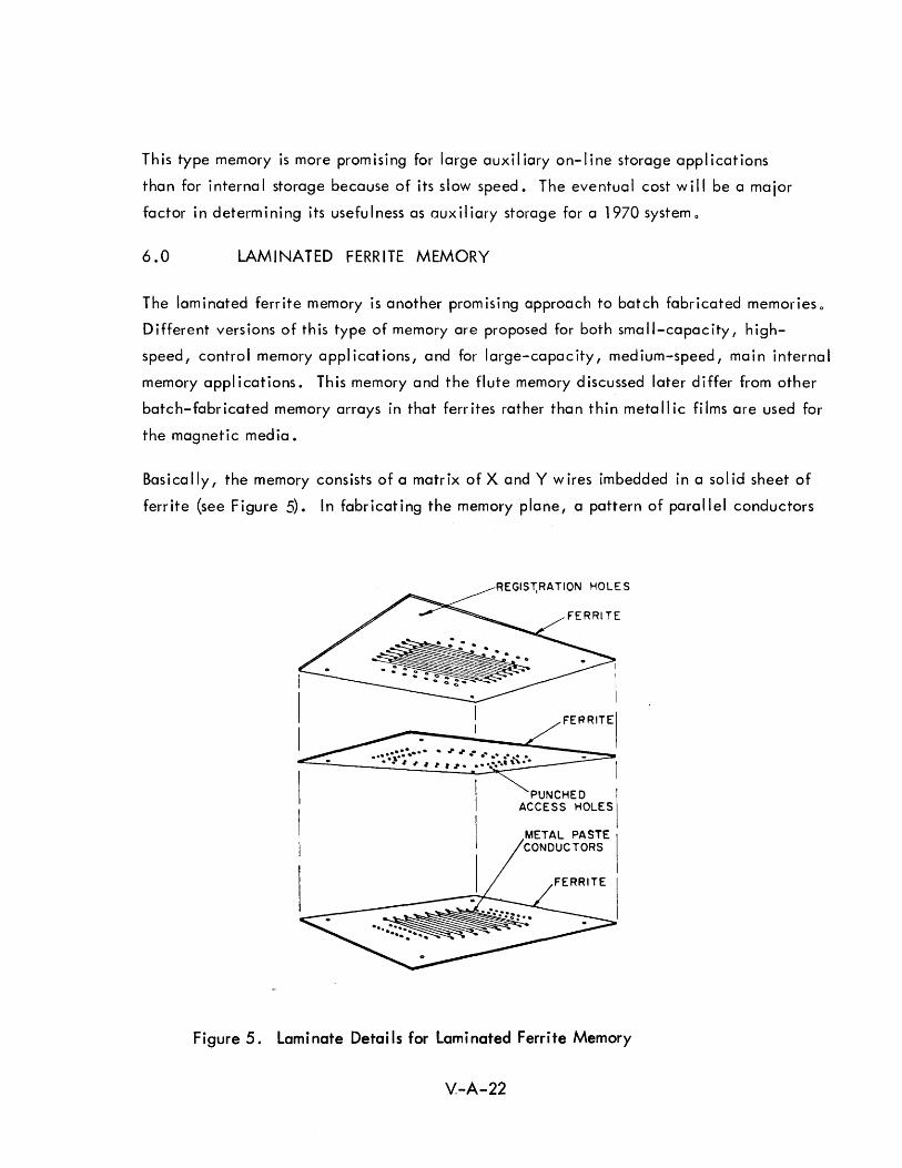
This type memory is more promising for large auxiliary on-line storage applications
than for internal storage because of its slow speed. The eventual cost will be a major
factor in determining its usefulness as auxiliary storage for a 1970 system 0
6.0 LAMINATED FERRITE MEMORY
The laminated ferrite memory is another promising approach to batch fabricated memories o
Different vers ions of th is type of memory are proposed for both sma II-capac ity, h igh
speed, control memory applications, and for large-capacity, medium-speed, main internal
memory applications. This memory and the flute memory discussed later differ from other
batch-fabr icated memory arrays in that ferr ites rather than thin meta II ic fi Ims are used for
the magnetic media.
Basica Ily, the memory consists of a matrix of X and Y w ires imbedded in a sol id sheet of
ferrite (see Figure 5). In fabricating the memory plane, a pattern of parallel conductors
ACCESS HOLES PUNCHED I
METAL PASTE I CONDUCTORS
FERRITE I
Figure 5. Laminate Details for Laminated Ferrite Memory
V-A-22
is printed on a glass substrate by a "silk-screening type process. II A film of ferrite is
spread over the conduc tor pattern on the substrate by a process ca II ed "doctor-b lad i ng • II
After the ferrite binder dries, the ferrite is peeled off the substrate with the conductors
imbedded in the ferrite sheet. This sheet is approximately 0.0025 inches thick. A
second ferr ite sheet is made with the condu ctor pattern ru nn i ng at right ang I es to that
in the first sheet. A third ferrite sheet, without imbedded conductors and only 000005
jpches thick, is inserted between the two ferrite plates with the orthogonal conductorso
n, t'h~'2c-sheet sc.,nd\,\;ich is laminated by pressing the sheets together at moderate pres
sures and h':i';;pcratures. Sint01ing l!!p laminated sheets in a controlled temperature
furnace prov ides a un i form isotrop i c .nat ~~ria I ,
The matrix of conductors provides the necessary wires for a two wire memor), sy')tem In
which the wires in the word oriented direction are used as read and write drive lines/and
the wires in the perpendicular direction are used as sense lines and digit drive lineso
The write current generates a closed flux path in a plane perpendicular to the plane of
the read/write drive wire. The current through the digit w ire rotates the magnetic
vector sl ightly. The methods of reading and writing in this type of array have been
described in detail in a paper by Shahbender, Wentworth, Hotchkiss, and Rajchman.15
The laminated ferrite memory is proposed for two different applicationso The first is as
a high-speed control memory with approximately a 100 nanoseconds read/write cycle.
In this application, a 256 word memory with 64 bits per word will require approximately
350 milliamps of drive current and will give a sense signal of:::- 10 millivolts o The
second application is as a large-capacity medium-speed internal memory with a read/
write cycle time of 1 to 3 microseconds. In this application, a drive current of approxi
mately 50 milliamps is required to produce a sense signal of 1.2 millivolts.
A 256 x 256 array is currently being developed in the laboratory and 64 x 64 bit arrays
are said to be in production with a sufficient yield in which all elements in a plane are
good. The following characteristics have been achieved in production memories with
64 words of 32 bits each:
1) Sense signal input is 20-40 millivolts;
2) Read current is 400 mill iamps;
3) Two cross-overs per bit;
4) Conductors on 15 mil centers;
5) Conductor size is 5 mi Is x 1 mi I.
V-A-23
It is necessary to operate this memory in a word organized manner, but the manufacturer
does not consider th is a lim itation. The ir argument in support of th is is: "A Ithough .
coincident current memories require less electronics, the electronics are more expensive
because of problems with noise in the sense line, tolerances, and back voltage on the
drive wires. On the other hand, word organized memories require more electronics,
but they are less expensive since less critical tolerances are placed on the material,
there is less noise on the sense line, and less critical tolerances are placed on the drive
wire signal. Therefore, the amount of electronics is greater for the word organized
memory but the total cost of the electronics may not be significantly greater because of
the lesser requirements placed on them. II
Significant success in reducing the cost of a memory depends upon the use of relatively
cheap integrated circuits to permit the electronics associated with the memory to be
made by batch-fabrication processes. In a typical memory, the wired and tested array
represents only approximately halfof the total cost of the memory, with the other half
going for the electronics. As a result, array fabrication techniques such as the laminated
ferrite can reduce the total memory cost by only 500/0, even if they are assumed to lower
the array cost to essentially zero. Concentrated efforts on reducing the cost of integrated
circuit electronics for such memories are required, if significant improvements in memory
costs are to be achieved. Hence, great emphasis is being placed on developing integrated
diode arrays for word selection. Operating large memories with currents under 50 mill iamps
wou Id perm it the use of integrated c ircu its and keep the capac ity low, but th is has not
been ach ieved yet. Strips of 10 diodes and 8 x 8 matrix arrays of diodes that have a back
voltage in excess of 60 volts and a drop of 1.5 volts at 400 milliamps have been fabricated
for use in laminated ferrite memories.
Costs for the laminated ferrite memory are estimated to be in the order of 1 cent per bit
for memories with capacities of 107 to 108
bits, speeds of 1 - 3 microseconds, and word
sizes of 200-400 bits per word. The manufacturer expects to be making laminated ferrite
memories on a commercial basis with 106
bits capacity in two years, 107
bits capacity
in four years, and 108
bits capacity in five years.
V-A-24
7.0 FLUTE MEMORY
Another promising approach to a batch fabricated memory array using ferrite material is
the flute memory which is very similar conceptually to the laminated ferrite memory.
However, the fabrication techniques are different. The characteristics and fabrication
techniques of this memory were described in a paper by Bartkus and several other authors. 16
The planes in the flute memory are fabricated by sandwiching a pre-prepared grid of wires
between two dies, each of which has matching grooves filled with a mixture of ferrite
thermosetting resin binder. The grooves containing ferrite are parallel to the word lines
of the wire grid so that when the two halves of the mold are placed together, the word
I ine is completely imbedded in the ferrite tube formed by the ferrite in the corresponding
grooves of the upper and lower halves of the mold. The bit lines of the wire grid are
orthogonal to the word lines and intersect each of the parallel ferrite strips encasing the
word lines (see Figure 6).
WORD LINE
Figure 6. Flute Memory Elements with Word and Bit Lines Imbedded in Ferrite Bar
V-A-25
A typical memory plane consists of 50 ferrite tubes intersected by 100 bit lines to give
a capacity of 5000 bits per plane. The ferrite area surround ing the intersection of a
bit line and a word line defines an individual bit position. Yields of 36% have been
realized in the batch-fabrication process. Cycle times of 250 nanoseconds are con
sidered possible by the manufacturer.
The geometry used in the version described in the paper referenced above has been
deemphasized because of the magnetic structure at each element (sim i lar to that of the
laminated ferrite memory). A new geometry, designed to provide a magnetic structure
very similar to that of a magnetic core to permit coincident current operation in large
memories, has been described by Elfant.17
In the new structure, the wire in the ferrite
bar is not completely encased by ferrite but is embedded in the upper portion of the
ferrite bar with part of the surface of the wire exposed. These ferrite bars with the
partially embedded wires are placed parallel to one another. Bare (but insulated) wires
are placed on top of these in a perpendicular direction to form a matrix. Additiona I
ferrite strips are then placed at 450
angles to these wires so that the ferrite strips cross
the intersection of the embedded and unembedded wires. The entire array is then
sintered to give the ferrite the proper magnetic properties. The 450
ferrite strips and
the ferrite in which the first wire is partially embedded give a magnetic structure at
each wire intersection that is essentially similar to a toroidal magnetic core. Elfant
states that this structure is almost as easy to fabricate as the original flute geometry and
that it has the advantage of permitting coincident current operation due to the improved
magnetic structu're similar to that of a magnetic core. This is very important for a large
capac ity memory.
The new planes being fabricated contain a matrix of 100 x 150 bits (15,000 bits per plane).
Densities of 104
bits per square inch are estimated for the future. Ten percent redundant
leads are provided to permit the elimination of a limited number of bad elements. A
special ferrite is used to permit a low firing temperature (945 to 9500
C) while providing
a relatively square hysteresis loopo
There are no indications as to whether this memory is to go into production, nor are any
projected cost estimates available. However, it is a promising approach that will be in
competition with the laminated ferrite, woven screen, plated wire, and other batch
fabricated memories during the design of a 1970 era system.
V-A-26
8.0 MAGNETIC CORE MEMORIES
Magnetic core memories consisting of individual discrete magnetic cores threaded by
selection, write, and sense wires to form a matrix or storage array have been the best
establ ished and most widely used memory technology for several years. This type of
memory is so well established and its basic principles so well understood that it is not
necessary to present a detailed description of core memories in this report. 18
There are two major types of core memories. In the first, the selection is accompl ished
by co i nc idence of a current in one w ire threaded through the core in the X direct ion
and a current in another wire threaded through the same core in the Y direction, each
conducting one half the required selection current. In the second, the selection is by
a semiconductor or magnetic decoding tree which provides excitation current to all of
the bits of the selected word with digit wires carrying inhibit currents through those bit
positions of the word in which zeros are to be stored. The former are called coincident
current core memories and the latter I inear-select or word-oriented core memories. In
general, coincident-current core memories are cheaper because of the XY matrix addres
sing and selection (i.e., less selection and addressing electronics), but slower because
of the tighter tolerances required on drive signals and the limitation on the total drive
current that can be utilized (i.e., less than two times the minimum switching current)"
Word-oriented core memories, on the other hand, tend to be more expensive because of
the linear selection circuitry required, but faster because of the less critical tolerances
and the ability to switch the core faster by providing significantly more than the minimum
sw itch i ng current.
The replacement of magnetic cores by other memory technology has been predicted
frequently. However, the magnetic core technology is so widespread and well esta
blished that it has presented a difficult and rapidly moving target for other technologieso
For example, in approximately 1960, the advanced state of the art in magnetic core memories
was represented by 4 microsecond cycle time and a cost of 25 cents to 50 cents
per bit. By 1962, the speed had increased to 2 microseconds cycle time for roughly the
same cost per biL In late 1964, the advanced state of the art is represented by 1 micro
second cycle time memories for 10 cents to 15 cents per bit. Two or three years ago, few
would have predicted the 500 nanosecond cycle time core memories now being designed
V-A-27

for de livery in commerc ia I computers in two years. Th is increase in speed and decrease
in cost has resulted from two major factors - reduction in core size from 80 mils 00
(50 mils 10) to 12 mils 00 (7 mils 10) and significant advances in semi-conductor
technology. The latter has permitted faster and higher power drive and selection
circu itry and lower cost high-go in sense ampl ifiers.
In the past, anticipated advantages of other memory technologies, such as magnetic
thin-films or cryogenics, were based on their enhanced characteristics over those anti
cipated for core memories. Unfortunately for other technologies, core memory technology
has advanced so rapid Iy that by the time the proposed characteristics of the other storage
devices were real ized, those characteristics were no longer superior to characteristics
available from magnetic core memories. In view of this past history, it is dangerous to
predict that magnetic core memories will be replaced by other technologies by a given
date, such as 1970. On the other hand, it is difficult to believe that these advances
in magnetic core technology can be continued indefinitely. Additional advances in
magnetic materials and semiconductors can be anticipated, but it is unlikely that the
size of discrete cores can be reduced significantly below 12 mils 00 and 7 mils 10 and
still permit the threading of addressing and sensing wires o As a result, magnetic core
memories will eventually give way to either integrated circuit arrays or magnetic thin-
fi Ims for small very high-speed memories and to some batch fabrication techniques, such
as plated wires or integrated ferrite structures, for very large-capacity, low-cost memorieso
Magnetic core memories will probably remain the major competitor for main internal
memories requiring cycle times of one to two microseconds and capacities of
a few hundred thousand words or less for several years. Even this position will be threat
ened by 1970 - particularly if costs of some of the batch fabricated approaches I ive up
to expectations 0
The current advanced state of the art in magnetic core memories is represented by the
following characteristics for main high-speed internal memories offered by three different
manu facturers for de livery in 1965:
V-A-28

High Speed Internal Core Memor i es
R/W Capacity Bits OEM Price Cycle Time in Words Per Word Per Bit
microsecond 8,000 words 56 12 cents
microsecond 16,000 words 40 13 cents
0 0 9 microsecond 16,000 words 12 14 cents
and the following characteristics for very large capacity auxiliary memories offered by
three different manufacturers for del ivery in 1965:
Large Capacity Core Memories
R/W Capacity OEM Price Cycle Time in Bits Per Bit
3 microseconds 1 ,000, 000 bits 3 cents
3 microseconds 100,000,000 bits 1 .5 cents
8 microseconds 20,000,000 bits 3.5 cents
12 microseconds 5,000,000 bits 1 .5 cents
The figures quoted above represent significant improvements in core memory technology.
One manufacturer privately announced a 0.5 microsecond magnetic core memory using
12 mil 00 and 7 mil 10 cores for a commercial computer to be delivered within the next
two years. A large capacity coincident current core memory has been announced as
part of a commercial computer to be del ivered in 1965. This memory is available in
banks of 262,144 words of 72 bits per word giving a total capacity per bank of 20,000,000
bits. A 20-30 mil core is used. The quoted sales price of 2-1/2 to 3 cents per bit impl ies
a manufacturing cost under 1 cent per bit. The memory is fabricated in two groups of 32
planes each containing a matrix of 256 x 1152 cores. The memory has an 8 microsecond
cycle time and 3 microsecond access time.
For any new technology to replace an establ ished technology with 15 years of cumulative
development and operational experience, the new technology must inherently offer signi
ficant advantages over the establ ished technology. This significant advantage over the
establ ished magnetic core technology is most I ikely to result from the batch fabrication
aspects of other memory technologies.
V-A-29
9.0 GLASS DELAY LINE MEMORIES
With higher speed logical components available, it may be desirable in some future
computers to operate the machine in a bit serial manner with a very high bit rate. In
this case, a high-speed bit-serial memory would be compatible with the other parts of
the machine. If a high-speed bit-serial memory is desired, glass delay lines represent
one of the more promising means of mechanizing such a memory. Glass delay lines are
similar conceptually to the ultrasonic delay lines used in early computers such as Univac
but provide higher frequencies, larger capacities, and better time and temperature
stabi I ity. 19
T ypica I characteristics for g lass memories are:
1) Average access times - 5 to 500 microseconds
2} Bit rates - 5 x 10⁶
to 20 x 106
bits per second
3} Capacities (for 100 delay lines) - 2 x 10⁶
to 5 x 10⁶
bits
4} Costs - 2 cents to 50 cents per bit
These characteristics represent a cost performance tradeoff between magnetic cores and
magnetic drums, but the bit rate of 20,000,000 bits per second is higher than can be
readily achieved with other types of memories.
Glass delay line memories usually use piezo-electric input/output transducers and either
a rod of glass {for average access times below 50 microseconds} or a flat plate of glass
(for average access times above 50 microseconds). In the latter type, carefully machined
surfaces on the glass are used as reflecting media to permit a multi-path pattern within
the glass plateo This increases the effective length of the delay line since this is a
function of the total path length.
It is doubtful that glass delay I ine memories will be suitable for the central processor in
a 1970 ACDS, but memories of this type may be useful in special purpose or peripheral
equipment ..
V-A-30
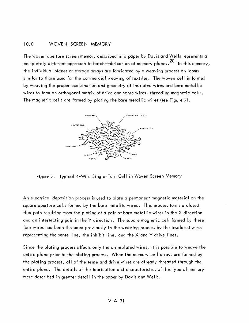
10.0 WOVEN SCREEN MEMORY
The woven aperture screen memory described in a paper by Davis and Wells represents a
completely different approach to batch-fabrication of memory planes. 20 In this memory,
the individual planes or storage arrays are fabricated by a weaving process on looms
similar to those used for the commercial weaving of textiles. The woven cell is formed
by weaving the proper combination and geometry of insulated wires and bare metallic
wires to form an orthogonal matrix of drive and sense wires, threading magnetic cells.
The magnetic cells are formed by plating the bare metallic wires (see Figure 7L
DUMMY WIRE OlAGOr...AL BUFFER CELL
DuWIt!IIY WIRE
Figure 7. Typical 4-Wire Single-Turn Cell in Woven Screen Memory
An electrical deposition process is used to plate a permanent magnetic material on the
square aperture cells formed by the bare metallic wires. This process forms a closed
flux path resulting from the plating of a pair of bare metallic wires in the X direction
and an intersecting pair in the Y direction. The square magnetic cell formed by these
four wires had been threaded previously in the weaving process by the insulated wires
representing the sense line, the inhibit line, and the X and Y drive lines.
Since the plating process affects only the uninsulated wires, it is possible to weave the
entire plane prior to the plating process. When the memory cell arrays are formed by
the plating process, all of the sense and drive wires are already threaded through the
entire plane. The details of the fabrication and characteristics of this type of memory
were described in greater detail in the paper by Davis and Wells.
V-A-31

A 108
bit memory assembled from 128 x 256 bit matrix planes would provide a 10
microsecond cycle time for 36 bit words. A memory of this capacity would be broken
into 22 modules of storage planes. There is some uncertainty as to whether a sense
preampl ifier w i.11 be requ ired for each plane. Th is is a quest ion of major significance
since 6336 such preamplifiers would be needed. If the need for these preamplifiers can
be avoided, the cost of a large capacity memory of th is type wi II be significantly reduced.
This is related to the problem discussed in connection with the laminated ferrite memory -
a true low-cost large-capacity memory requires batch fabrication and significant cost
reductions in the memory electronics as well as in the storage planes themselves.
The designers expect the cost of coincident current woven planes in assembled stack
modules to be about 0.1 to 1 cent per bit in production quantities. However, this does
not include the cost of the electronics which could be considerable if sense preamplifiers
are requ ired.
The manufacturer is also working on a woven screen memory for internal applications - a
two microsecond 8,000 word, 30 bit memory. The manufacturer expects this memory to
be more rugged, to have higher temperature tolerances, and to offer a lower cost than
equivalent magnetic core matrix memories. The anticipated operating temperature range,
about 1050 C should be of particular interest for military applications.
The development of integrated circuit sense ampl ifiers and drivers for memories will have
a significant effect on the cost of large batch fabri cated memory systems. An integrated
circu it sense ampl ifier developed under Air Force contract AF33(657)-11185 has been
considered for the woven screen memory. 21 This sense ampl ifier is capable of sensing a
400 microvolt input signal to provide a one volt output with a maximum delay of 30
nanoseconds and a cycle rate of 20 megacyc les. The write drive ampl ifier represents
a more difficult problem that has not yet been adequately solved in integrated circuit
form 0 This is expected by 1966.
A different approach to weaving a memory array is represented by recent work in Japan.
This has been reported in papers by Maeda and Matsushita22
and by Oshima, Futami,
and Kamibayashi 0
23 The magnetic structure and geometry of th is type memory is quite
different from that described aboveo Although the array is woven, plated wires are used
as the storage elements similar to those discussed previously under cylindrical thin-film
V-A-32
memories. The plated wire acts as the storage medium, and also as the digit drive lines.
In this woven array, insu lated wires woven at right angles to the plated wires act as
the word drive lines. This type of woven memory differs from the previous one in that
the closed flux path magnetic element is the plating around a single wire rather than
that formed by the rectangular intersection of four plated wires. This type of woven
memory essentially represents a different fabrication technique for plated wire or cylin
drical thin-film memories discussed in a preceding subsection rather than a different
type memory.
1100 CONTINUOUS-SHEET CRYOGENIC RANDOM-ACCESS MEMORIES
Cryogenic memories are based on the principle that at temperatures near absolute zero
degrees, the resistance of certain materials (super-conductors) may be either zero or
some finite non-zero resistance depending upon the magnitude of the magnetic field
surrounding the superconductor. In one type of continuous-sheet cryogenic memory
under development, the storage medium is a superconducting tin film. This tin film, a
lead sense line, and lead drive strips are fabricated by vacuum deposition techniques on
a two-inch square substrate.24
These metallic films are all insulated from one another
by vacuum deposited insulating films (silicon monoxide). The sense line is beneath the
storage plane and is oriented diagonally to and directly under the intersections of the
two sets of drive strips which are orthogonal to one another.
Coincidence of the X and Y drive currents at an intersection of the drive strips produces
a magnetic field sufficiently strong to switch the region of the storage plane beneath the
intersection out of the superconducting state, thus permitting magnetic flux to I ink through
the plane in that region. When the currents are removed, the flux linking the small
region of the continuous sheet is trapped, and persistent currents are establ ished in the
storage plane to support th is trapped flux. The stored information can be read by subse
quently applying a coincidence of drive currents of proper polarity, and then sensing
the voltage change on the sense line 0
In a later version, a cavity sensing technique is used rather than a zigzag sense line.24
A second continuous tin fi 1m is located a sl ight distance beneath the storage plane and
connected to it electrically along one edgeo When the proper polarity drive currents
create a magnetic field sufficient to destroy the superconducting state in the region of
V-A-33
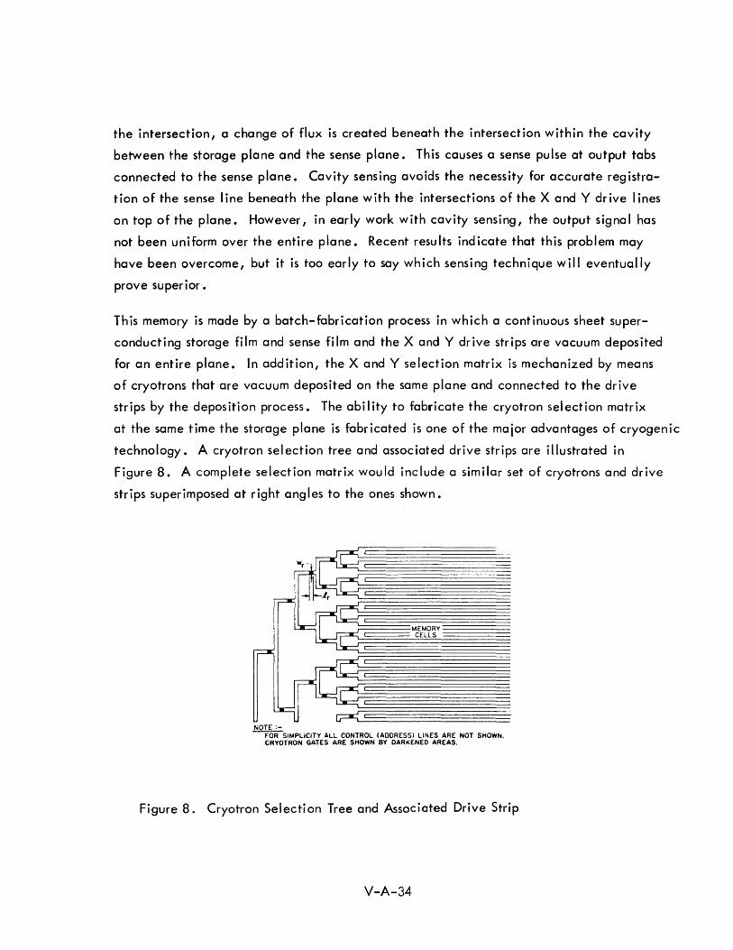
the intersection, a change of flux is created beneath the intersection within the cavity
between the storage plane and the sense plane. This causes a sense pulse at output tabs
connected to the sense plane. Cavity sensing avoids the necessity for accurate registra
tion of the sense I ine beneath the plane with the intersections of the X and Y dr ive lines
on top of the plane. However, in early work with cavity sensing, the output signa I has
not been uniform over the entire plane. Recent results indicate that this problem may
have been overcome, but it is too early to say which sensing technique will eventually
prove superior.
This memory is made by a batch-fabrication process in which a continuous sheet super
conducting storage film and sense film and the X and Y drive strips are vacuum deposited
for an entire plane. In addition, the X and Y selection matrix is mechanized by means
of cryotrons that are vacuum deposited on the same plane and connected to the drive
strips by the deposition process. The ability to fabricate the cryotron selection matrix
at the same time the storage plane is fabricated is one of the major advantages of cryogenic
technology. A cryotron selection tree and associated drive strips are illustrated in
Figure 8. A complete selection matrix would include a similar set of cryotrons and drive
strips superimposed at right angles to the ones shown.
NOTE:-
MEMORY CELLS
-roRSIMPLICITY ALL CONTROL (ADDRESS) LINES ARE NOT SHOWN. CRYOTRON GATES ARE SHOWN BY DARKENED AREAS.
Figure 8. Cryotron Selection Tree and Associated Drive Strip
V-A-34
A 16,384 bit memory plane (128 x 128), including 508 cryotrons for XY selection,
has been fabricated on a 2 by 2 inch substrate. Twenty-six vacuum deposition steps
using 16 different masks are required. The planar density is approximately 10,000 bits
per square inch. Two such planes have been operated satisfactorily. Typical anticipated
characteristics for cryogenic memories are:
1) 3 to 5 microsecond cycle time
2) 106 bits in a 10-inch square plane
3) 109
bits in a complete memory
4) 300 to 400 rna sel ect i on current
5) 1 to 2 mv sense signal
6) 109 bit memory will cost approximately $1,000,000 (or 0.1 cents
per bit)
7) 3.50
Kelvin operating temperature
Two good arrays (128 x 128) have been fabr icated, but both of these have been damaged
by repeated Iy tak ing them in and out of the I iqu id hel ium. A 262, 124 b it plane (512 x
512) with 0.0005 inch spacing between wires (2 mil line width) on a four-inch square
plane is under development in the laboratory. Planes of 1024 x 1024 on a 6 by 6 inch
substrate are an eventual goal. By 1965, this manufacturer anticipates having a 107
bit prototype memory.
The costs for a 50 plane stack of 262,000 bit planes (13 x 106 bits) have been estimated 25 by Burns to be:
1) Stack 5,000
2) Stack assembly & wiring 5,000
3) 32 address drivers 4,000
4) 50 sense amplifiers 20,000
5) 100 drivers 10,000
6) 20 timing boards 2,000
7) 4 power suppl ies 8,000
8) Hardware & control s 20 1 000
9) Refrigerator 25,000
TOTAL $ 99, 000
V-A-35
He also estimated that 262,000 word cryogenic memories can be built at a cost of
approximately 1 cent per bit,and that 1,000,000 word memories would be a fraction of
a cent per bit. On this basis, 262,000 words is not a competitive size for cryogenic
memories and 1,000,000 words {50 x 106 bits} is probably the minimum size for which
cryogenic technology should be considered.
The problems with cryogenic memories are both fundamental and economic 0 The major
technical problem is attaining uniformity.
Major cost factors in the manufacture of a cryogenic memory are:
1) The cost of a refr igerator
2) The cost of sense ampl ifiers
3) The cost of planes, which is highly dependent upon yield rate
4) The cost of interconnecting planes.
Because of the basic overhead cost in the refrigerant, the cryogenic memory is not con
sidered a good approach to a small memory, but becomes more advantageous as the size
increases. The cryogenic approach may provide a more likely way to reach capacities
of 109
bits, but other batch fabrication techniques will be better for capacities of 107
bits o The crossover between the two may occur somewhere around 108
bits.
RADC is sponsoring a cryogenic memory project that is due to be completed in
September 19650 At that time, a 3 x 10⁶
bit feasibility model will be deliveredo It is
anticipated that a 27 month manufacturing techniques contract will be initiated in
January 1965 in conjunction with WADe. This contract will call for the development
of manufacturing techniques and for a non-militarized memory with 1000 planes 1024 x
1024 eacho The goal is a 109
to 1012 bit memory with a cycle time less than one micro
second and with costs in the order of 0.01 cents per bit.
The future of cryogenic memories is questionable. To date, design and fabrication
problems, and rapid advances in other technologies have prevented the cryogenic
technology from establishing a foothold 0 Some believe that cryogenics will represent
the best approach to very large random access memories with capac ities of 109
bits and
above o
V-A-36
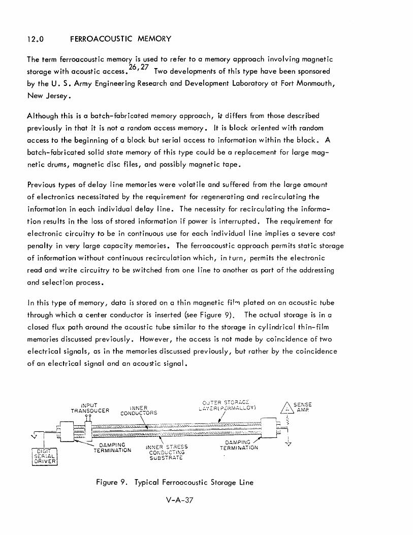
12 0 0 FERROACOUSTIC MEMORY
The term ferroacoustic memory is used to refer to a memory approach involving magnetic
storage with acoustic access.26
,27 Two developments of this type have been sponsored
by the U. S. Army Engineering Research and Development Laboratory at Fort Monmouth,
New Jersey.
Although this is a batch-fabricated memory approach, it differs from those described
previously in that it is not a random access memory. It is block oriented with random
access to the beginning of a block but serial access to information within the block 0 A
batch-fabricated solid state memory of this type could be a replacement for large mag
netic drums, magnetic disc files, and possibly magnetic tape.
Previous types of delay I ine memories were volatile and suffered from the large amount
of electronics necessitated by the requirement for regenerating and recirculating the
information in each individual delay line. The necessity for recirculating the informa
tion results in the loss of stored information if power is interrupted. The requirement for
electronic circuitry to be in continuous use for each individual line implies a severe cost
penalty in very large capacity memories. The ferroacoustic approach permits static storage
of information without continuous recirculation which, in turn, permits the electronic
read and write circuitry to be switched from one line to another as part of the addressing
and selection process.
In this type of memory, data is stored on a thin magnetic fH'"'l plated on an acoustic tube
through which a center conductor is inserted (see Figure 9). The actua I storage is in a
closed flux path around the acoustic tube similar to the storage in cylindrical thin-film
memories discussed previously. However, the access is not made by coinc idence of two
electrical signals, as in the memories discussed previously, but rather by the coincidence
of an electrical signal and an acoustic signal.
Figure 9. Typical Ferroacoustic Storage Line
V-A-37
The concept for this type of memory is based on the change of coercivity of magnetic
materials, such as permalloy plating, when the material is placed under mechanical
stress. An alternate approach is based on the fact that the anisotropic characteristics
of thin permalloy films are changed by stress.
In a memory based on these principles, a mechanical shock wave is initiated in the
acoustic tube by a suitable transducer (e.g. magnetostrictive, semiconductor, or
piezo-electric). The mechanical shock wave travels down the tube at a speed deter
mined by the propagation constant of the material. The coercivity of the magnetic
materia I plated on the tube changes as the shock wave passes under it and returns to
its normal condition after the shock wave has passed. As a result, a temporary change
in the coercivity of the magnetic media is propagated down the line.
To write or store information, an electrical signal, corresponding to the serial bit
pattern of 1 s and Os to be stored, is placed on the center conductor wh ile the acoustic
signal is traveling down the line. This electrical signal causes the magnetic cylinder
to be I inked by a varying flux pattern depending upon the bit pattern represented by the
electrical signal. The flux pattern generated by the electrical signal corresponding to
a "1" is sufficient to force the state of magnetization of the magnetic material into one
direction in an area where the coercivity has been altered by the mechanical stress wave o
The magnetic flux generated by a "0" signal wi II force the state of magnetization into
the other direction in the area where the coercivity has been changed. As a result, a
bit position is determined by the time coincidence of the electrical signal and the
acoustic signal. As the acoustic signal travels down the line, a "111 or 110 11 corresponding
to the electrical signal will be written in the position defined by the front of the shock
wave o
Read-back is achieved by transmitting an acoustic signal down the line and sensing the
changes in the electrical signal generated on the center conductor by the magneto
strictive effect of the shock wave traveling down the line. This signal varies, depending
upon the stored pattern on the line 0
The time requ ired to write or read a complete block corresponds to the time the shock
wave requires to travel from one end of the line to the othero The rate at which the
stored information is read or written corresponds to the frequency of the electrical signal
V-A-38
representing the bit patterno This frequency is limited by the physical size of the area
of magnetic material whose coercivity is altered by the shock wave at a given instant.
This in turn determines the bit density and hence the capacity of a line of a given lengtho
The information is stored statically in the magnetic media and is not carried by the
acoustic wave. This is in contrast to a normal acoustic delay line in which the informa-
t ion is actua II y carr i ed by the acoust ic wave. I n the ferroacoust ic type memory descr ibed
here, the acoustic signal acts only as an access mechanism. A single acoustic signal is
required to read a complete line or write a complete line.
The goals of the Army development program are to provide an all-electronic block
oriented random-access memory with the following characteristics:
1) Removable medium permitting non-volatile shelf storage
2) Small medium size (200 cubic inches)
3) 4,000,000 characters (28 x 106
bits) per module (approximately
equal to one reel of magnetic tape)
4) 4096 characters per block
5) 1024 blocks per module, approximately 0.002 cents per bit
($500 per module) off-line storage cost not including read/write
electron i cs
6) 1 microsecond random access to a block
7) Inherent sequential transfer within the block (ready-strobe to 1 0 5 -
3 m i" ion characters per second)
8) Read-write unit - 1/10 the power of tape unit; 1/10 the weight of
tape unit; 1/2 the size of tape unit
If this development program is successful, it wi" be of great significance to future
computer systems" At present, there is no economic all-electronic/magnetic replacement
for large capacity electromechanical storage devices such as magnetic disc files,
magnetic-card memories, and magnetic tape units. Such a replacement wi" be essen
tial to future systems if the speed, cost, reliability, and size limitations of electro
mechanical input/output and auxiliary storage equipment are to be avoided for very
V-A-39
large capacity storage functions (now handled by devices such as disc files and magnetic
tapes) •
If this ferroacoustic approach proves feasible, it offers the following advantages:
1) Stat ic storage
2) Semi-serial access not requiring a physical coincidence of
selection wires for each bit position
3) Ability to switch read and write mechanisms from one line to
another
4) Large capacity semi-random access bulk storage with no
mechanically moving parts
5) Possibility of off-line storage by plugging alternate blocks of
delay I ines into a read/write device
6) Low cost per bit of storage
A future all-electronic magnetic tape replacement will almost certainly be a block
oriented rather than a random-access-type storage device. Although a large-capac ity,
random-access, mass memory offers certain unique advantages, it is very unlikely that
such a device can compete on a cost per bit basis with semi-serial electromechanical
devices. The requirement for the physical intersection of electrical signal lines for
each bit position,and the access electronics,will not permit on-line storage costs of a
few millicents per bit by 1970. A semi-serial or block-oriented device providing ran
dom access to a block of information, but serial access within the block, will be
necessary to permit the read/write electronics to be time shared by a serial bit train.
1300 MAGNETIC SURFACE STORAGE
Magnetic surface recording is usually used in on-lineauxiliary storage and off-line
auxiliary storage 0 This technique has also been used for internal storage in the form of
drums or discs, but magnetic core storage has essentially replaced these electromechanical
devices in shipboard applications where maintenance and environment are critical factors ..
However, to date there has been no good replacement for on-line and off-line auxiliary
storage .. It is believed that some of the technologies discussed previously will replace
V-A-40
these devices/but the timing of this is uncertain. Certainly, for the next few years,
electromechanical devices using magnetic surface recording will be dominant. Off-line
storage (e.g. magnetic tape units) has been discussed in the Input/Output section, but
on-line auxiliary storage is discussed here. On-line devices of this type, frequently
referred to as mass memories, are used to provide a large-capacity, fast, semi-random
access storage. 28 ,29 They should be under direct on-line control of the computer,
addressable by the computer, eraseable, and reuseable. All devices of this type that
are currently available are electromechanical. All-electronic/magnetic on-line auxil
iary storages for military applications will be available by 1970 but all of these (with
the possible exception of the ferroacoustic storage discussed previously), will be signi
ficantly more expensive in terms of cost-per-bit for very large capacity storage. This
results largely from the fact that the all-electronic/magnetic approaches (e.g. laminated
ferrite memory, woven screen memory, flute memory / etc.) require addressing each
individual word. The electromechanical devices are block oriented in the sense that
access is made to a particular track on a disc, drum or card, and then all information
stored in that track (or block) is read or written serially by the same electronic circuitry"
. Of the all-electronic/magnetic approaches to large capacity memory that have been
discussed in previous parts of this report, only the ferroacoustic approach is block oriented
and hence offers some promise of competing with the electromechanical devices by 1970
on a purely economic basis.
The characteristics of the major types of electromechanical mass memories available today
are summarized in the comparison shown in Table 6-5. (Section 6; part I of Volume V).
The values shown were chosen as typical of each type of unit but frequently they repre
sent a wide range of possible values. In some cases, certain characteristics of an indi
vidual device may vary significantly from the values shown. The characteristics of
pr imary interest inc I ude capac ity, cost, average access time, and data transfer rate.
Some of these are difficult to compare because of the different physical characteristics
of the dev ices. For exampl e, a large magnet ic drum with a head for every track will
have a continuous data transfer rate equal to the instantaneous transfer rate if the heads
are sw'itched electronically. However, the continuous data transfer rate for a disc file
with moving heads will be significantly slower than the instantaneous transfer rate due to
the necessity for interrupti ng data transfer whi Ie moving the head from one position to the
next. Similar differences on a more detailed level exist between different devices of the
same type.
V-A-41
As a result of problems of this type, comparison tables such as the one shown in Table 6-5
present at best a gross comparison for electromechanical devices. In selecting a device
for any specific application, it is necessary to go into a more detailed comparison of the
specific pecularities and quirks of each of the leading contenders as they relate to that
application, if a proper decision is to be made. These comparisons in Table 6-5 cover
commercial devices that are not designed to military specifications - otherwise, the costs
would be much higher.
The Navy has two types of mass memories under development for shipboard use.
The first of these is a militarized version of a disc file. This is due for delivery in the
first quarter of 1965, with the following typical characteristics:
1) 100 x 106 bits capacity (in 2 modules)
2) 0.2 to 0.25 cents per bit
3) 200 mill isecond average access time
4) 3,000 watts power
5) 1,800 Ibs. weight
6) 63 cubic feet volume
The second unit, also due for del ivery in the first quarter of 1965, is ami I itarized
magnetic card unit. This unit wi II have the following characteristics:
1) 185 to 225 mill isecond access time
2) 32 containers possible per system
3) 32 magnetic cards per container
4) 32 blocks per card
5) 875 words per block
6) 36 bits per word
7) 1 x 106 bits per card
8) Cost for first 50,000,000 bits - approximately 003 to 0.4 cents per bit
9) Next 50,000,000 bits - approximately 001 cent per bit (50,000,000
bits additional for $50,000)
V-A-42
The major advantages and disadvantages of the different types of mass memories are
summarized in Table 1 0
Future improvements in these devices can be anticipated. In 1962, A. S. Hoagland
pointed out that the storage density of one manufacturer's commercial disc files increased
from 2000 bits per square inch in 1956 to 25,000 bits per square inch in 1961.30
He
then predicted that storage densities of "one million bits per square inch (e.g. approxi
mately 5000 bpi, 200 tpi) will become the state-of-the-art" within the next few years.
A few months earl ier, M. Jacoby predicted densities of 3000 bpi and 500 tpi (1 .5 mi II ion
bits per square inch) would "become commonplace in a few years". 31 He then indicated
that these densities could provide storage capacities of 10 to 100 billion bits if a possible
increase in the physical size is also considered. Thus, increases in capacity of tens to
hundreds of times over the largest present mass memories can be anticipated.
The cost per unit can be expected to decrease even with the larger capacities as the
technology is improved and more manufacturing experience is obtained. Hence, the
cost per b it of storage ca n a Iso be expected to decrease by one to two orders of magn itude -
possibly to 0.0001 cents per bit for the mass memory itself (not including control and
buffering electronics). However, militarized versions of this type of device may cost
at least an order of magnitude more.
Although the picture for the future of capacity and cost appear bright, there is I ittle hope
for significant improvements in average access times for moving-media mass memories. Due
to the inherent mechanical motions involved, we cannot expect improvements of as much
as an order of magnitude over available devices. For significant improvements in access
time, we must turn to the non-movi ng-med ia type devices.
14.0 ASSOCIATIVE MEMORIES
A completely different memory concept has received considerable attention recently in
which stored data is located by association rather than by physical location (numeric
address)o This type of memory is usually called an associative memory, a content addressed 32
memory, or a search memory. The former term is more widely accepted and will be used
in this dicussion o
V-A-43
Table 1. Advantages and Disadvantages of Different Electromechanical Mass Memories .
Type of Mass Memory Advantages Disadvantages
Fixed-Head Magnetic Fast access, no mechanical Low ca pac ity, high cost Drums head motion, high continuous per bit, poorer volumetric
data transfer rate. efficiency, large number of heads.
Moving-Head Magnetic Large capacity, low cost per Poorer volumetric efficiency, Drums bit, possibility of parallel relatively large number of
reading or writing from heads for medium speed multiple heads to greatly access or slower access if increase instantaneous data fewer heads. transfer rate.
Fixed-Head Magnetic Fast access, medium capacity, High cost per bit of storage, Discs no mechanical head motion, large electronic switching
high cont i nuous data transfer matr ix, large number of rate. heads.
One-Dimension Moving Large capac ity, possibi I ity of Relatively large number of Head Magnetic Discs mu Itiple simultaneous accesses heads, somewhat higher
if heads are positioned inde- cost per bit compared to pendently, low cost per bit two-dimension disc unit, compared to fixed head un its, medium speed access 0
possibi I ity of para Ilel read ing or writing from multiple heads to greatly increase instan-taneous data transfer rate.
Removable-Stock Discs Large off-: ine capacity, low Limited on-line capacity, cost per bit of off-line storage, higher cost per b it of combines on-line random- on-I ine storage. access capability with large off-I i ne capac ity.
Magnetic Card Memory Large off-line capacity, low Slower access, card wear cost per bit of off-line storage, and replacement necessitates combines on-I ine randon- eventual rewriting of entire access capabi I ity with large card. off-I i ne capac ity, i nd iv idua I cards can be copied, replaced or inserted 0
V-A-44

Associative memories are addressed by content rather than by a unique numeric
address. An associative memory involves sufficient logical capability to permit all
memory locations to be searched essentially simultaneously -- i.e. within some speci
fied memory cycle time. The search may be made on the basis of the entire contents
of each location or upon the basis of selected bit positions of each location. Thus, it
is possible to search for all words meeting certain criteria or for all words in which a
certain tag portion of the word meets the criteria. Searches may be made on the basis
of equal ity, greater-than-or-equal-to, less-than-or-equal-to, and between I im its.
Associative memories are also referred to as content addressed memories and search
memories. In a sense, all of these terms are misleading in that the unit is not an
associative "memory" but rather an associative "processor ll since the memory function
involves a minor portion of the total hardware and costs. The major portion of the
hardware and costs is that involved in the logical operations necessary to accompl ish
the parallel search of memory locations. For example, a magnetic associative memory
frequently requires a sense amplifier for each word location, and logical capability for
each word (in some cases for each bit portion) to permit the para Ilel search capabil ity.
These hardware elements are not requ ired for the memory function itse I f. The memory
function alone might account for only 1/4 or 1/5 of the total costs based on comparing
the cost of the assoc iative memory with that of a random-access memory with equ iva
lent capacity and access time.
Magnetic, cryogenic and semiconductor techniques have been used in mechanizing
associative memories. Magnetic associative memory techniques usually use a non
destructive-read-out magnetic element such as a mu Itiaperture core, a plated wire,
or a thin film. The different approaches to magnetic associative memories and a
comparison of four spec ific types have been presented in a paper by Shohara and are
shown in Table 2. 33
The mechanization of most search algorithms requires an argument register, a mask
register, auxiliary registers, input and output registers, a shift circuit, and logic cir
cuits o A typical search or associative memory block diagram is illustrated in Figure 10.
Different methods of mechanization of searches include parallel by bit, serial by bit,
parallel byword, and serial by word a
V-A-45
Table 2. Magnetic Associative Memory Techniques
NDRO MAGNETIC MEMORY TECHNOLOGY
CORES PLATES WIRES, RODS FILMS
*
~ SiI~GLE MULTIPLE
APERTURE APERTURE
BIAS RESTORED TOROID
LINEAR TRANSFORMER*
MAGNET -BIASED TOROID*
Not Electrically Alterable
FLUX SWITCHING
• TRANSFLUXOR . MALE
FLUX ROTATION
. BIAx
COMPARISON OF MAGNETIC ASSOCIATIVE MEMORIES
TRANSFLUXOR MALE BIAX --SOURCE DATE 2/63 1/64 12/63
CAPACITY 1024/12 8/10 16/8
INTERROGATION
MODE: PARALLEL PARALLEL SERIAL
RATE: 6 flsec 5 jJ.sec O. 1 jJ.sec
MATCH SENSE DOUBLE LOGICAL TERNARY BINARY
V-A-46
7\. THICK THIN
. BICORE
BICORE
11/63
128/24
PARALLEL
300 nsec
DOUBLE BINARY
~ »
I ~ ""'-J
WORD WRITE SELECTION
DRIVE
t ADDRESS
CONTROL LOGIC
COMMAND REGISTER
1 I NPUT REGISTER
,
FROM CONTROL COMPUTER
WORD READ SENSE AMPS
SEARCH ARRAY
SEARCH/WRITE DRIVERS
ARGUMENT REGISTER
MASK REGISTER
SCANNER
Figure 10. Typical Search Memory Block Diagram
DATA
DETECTOR ARRAY
RESPONSE ADDRESS
OUTPUT REGISTER
~ TO CONTROL COMPUTER

In a paper by McAteer, Capobianco, and Koppel, some of the characteristics for
different mechanizations of associative memories using the biax magnetic element
are compared.34
Since this table illustrates the trade-offs and characteristics to be
considered in designing and selecting an associative memory, it is reproduced as
Table 3.
15.0 CRYOGENIC ASSOCIATIVE MEMORIES
Work on cryogenic associative memories has also been underway at several
companies. 35 ,36 The cryogenic approach is probably worthwhile only for very large
capacity associative memories because of the overhead cost in the refrigerator. The
cryogenic associative memory under development at one company is essentially a two
IIcore Jl per bit type using two parallel continuous sheet planes. The associative feature
depends upon whether a corresponding spot in both planes is storing the same informa
tion. If they are not, the flux between the two planes cancels out. This continuous
sheet cryogenic memory uses lead for the super-conductive wiring, tin for the
continuous-sheet superconductive storage planes and sil icon monoxide for the
insulators. These are all deposited in approximately 20 different deposition steps with
different masks for each. Fabrication is currently mechanized, with a circular jig
holding the 20 masks in the vacuum so that each mask can be rotated into place at the
proper time.
In another cryogenic associative memory being developed, cryotrons are used for the
association logic. So far, a 10 x 12 bit associative array using 2350 cryotrons per
array has been fabricated. The present goal is a 5000 word associative memory with
48 bits per word. This is an 18 month program. A 100/0 yield on planes is expected.
If the plane yield is sufficiently high, a 10,000 word memory will be fabricated rather
than a 5,000 word memory. Both of these cryogenic associative memory developments
are being sponsored by Rome Air Development Center.
V-A-48
< I
l> I
.b..
'"
Table 3
Associative Memory System Characteristics
Relative Exact Match Relative Search Li mit Search Data
Scheme Mechanization Time Time Writing
1 Two-BIAX -per-bit 3F F2 Whole word Signal-no signal M 2+ 2k {ave} only Binary sense output k
F2 3F + k {max}
2 Two-BIAX -per-bit Whole word Signal-no signal M M only Ternary sense output
3 Two-BIAX -per-bit 3F F2 Unrestri cted Signal-signal M 2+2 {ave} as to loca-Binary sense output tion and
3F + F2 {max} number of bits
4 One-BIAX -per-bit F2 Unrestri cted Si gnal-si gnal M 3F + 2" {ave} as to loca-Bi nary sense output tion and
6F + F2 {max} number of bits
LEGEND: M = Number of bits per word k = Number of bits per word interrogated simultaneously F = Field length used in limit search
Data Reading {Additional
Array Requ i rements}
Additional array windings required
Additional array windings required
No new windings required
No new windings required
Restriction On Fields for
Li mit Search
Fixed fi e Ids only
No restri cti ons {any combina-tion of bits selected by mask permissable}
Fixed fields only
Fixed fields only
Write IIDon't Care ll
Bit Available
Yes
Yes
Yes
No
I
()'"'O o .., ."CD 0'" o-~ _0 CD g a... 00-0'<
90~ A O o ~ ." CD ." CD CD .., -""

16.0 MAGNETIC ASSOCIATIVE MEMORIES
Magnetic associative memories differ from most magnetic random-access memories
from a hardware standpoint in the following ways:
1) The sense I ines are word oriented;
2) The drive lines are bi tori ented;
3) There is a large number of sense ampl ifiers as a result of the word
orientation of the sense line;
4) The sense amplifiers have a high duty cycle which tends to make
them more expensive;
5) A large amount of logical circuitry is required.
The costs of the sense ampl ifiers and logical circuitry are the main factors contributing
to excessive costs of associative memories compared to those of random-access
memories. An associative memory also requires a non-destructive-read-out storage
element since it is not feasible to rewrite every word location for each search. The
trade -off between speed and ~ost is affected by factors such as:
1) Bipolar vs monopolar sense signal s;
2) Poor signal-to-noise ratio resulting from interrogating a larger
number of bits;
3) The number of bit positions interrogated in parallel;
4) Fixed vs unrestricted fields;
5) Parall el by word vs serial by word.
Although some magnetic associative memories use a single aperture magnetic core, it
is convenient to use a multi-aperture device such as the Transfluxor or the Biax
element. The Transfluxor approach requires two elements per bit and requires a
greater drive signal since it is necessary to actually change the direction of saturation
of the material around the interrogate hole. The Biax element requires a relatively
expensive sense ampl ifier, but it is attractive for associative memories for three
reasons:
V-A-50
1) A fast read capability;
2) A non-destructive read-out feature;
3) A bipolar sense signal.
Cylindrical thin film plated wires are also being investigated for associative memory
appl ications. The cyl indrical thin film plated wire appears attractive in that it offers
the possibility of a large sense signal resulting from the closed magnetic path, and
requires a relatively small read/write drive current.
One Bureau of Ships contract for an associative memory using the Biax approach was
recently terminated, largely because projected cost goals could not be met. This
associative memory was to store 2048 words of 36 bits each with the ability to search
the ent i re memory for an exact match, for greater than, for I ess than, for between
I·· d f . I . b·· f h 37 I I Imlts, an or Slmu taneous or successive com Inatlons 0 t ese. t a so was to
provide for arbitrary masking to control the bit positions on wh ich the search is based.
The results of the search can indicate match or no match, a count of the number of
locations upon which a match was obtained, the addresses of all positions in which a
match was obtained, or the data contained in each location in which a match was
obtai ned. Opti onall y, all matched words can be modifi ed automati call y after a search.
The basic search rate was to be 100 nanoseconds per bit position for an exact match.
Therefore, a search of all 26 bit positions of the entire memory would require 3.6
microseconds. For all other search modes, 300 nanoseconds per bit position would be
required--10.8 microseconds to search on all 36 bits. As a conventional read/write
memory, the cycle time was 6 microseconds.
In this approach, one hole of the Biax memory is wired as a conventional coincident
current read/write memory, using the Biax element in the same way that a simple
magnetic core would be used. The orthogonal hole is then used for the associative
feature. In the associative mode, given bit positions of all words are interrogated
simultaneously, and successive bit positions of the memory are interrogated
sequentially. All bits of a given word are sensed by the same sense wire, so that a
sequential signal corresponding to the sequencing through the bit positions is obtained
from an individual sense amplifier for each word position. The interrogation is con
ducted so that a negative signal from the bipolar sense signal during the active part
V-A-51
of the cycle indicates the absence of a match. Therefore, the indication of any
negative signals from a particular sense amplifier during this active period indicates a
match for equality in that word position. The determination of greater than or less
than is accompl ished by noting the bit position from which the first negative signal
occurs for a particular word. This signal, indicating a difference in that bit position,
combined with the indication of whether the control word has a one or a zero in that
bit position will then indicate which is greater.
A contract for a different associative memory using Siax elements has been issued by
Wright Air Development Center for delivery in mid-1965. This 2,048 word memory is
to achieve cost savings by using integrated circuit sense amplifiers.
Another type of magnetic associative memory using the MALE element has recently
been delivered to the Navy. This memory has a capacity of 256 words of 36 bits each.
Exact-match search time is 5 microseconds. This associative memory is to be tested
with the CP667 computer.
RADC has issued an RFP for a 32,000 word associative memory, is currently procuring
a 2,000 word room temperature associative memory (Silock), and has an associative
element (ferro-electric) study under contract. An RFP for another associative element
study is to be released soon. Associative processor studies are underway with four con
tractors. Some of these call for a hybrid approach using an associative memory in
conjunction with a random access memory.
V-A-52
17.0 INTEGRATED CIRCUIT ASSOCIATIVE MEMORIES
Several studies of the use of semiconductor circuits to mechanize associative memories
have been described. 38 Using discrete semi-conductor components makes the cost of
associative memory too expensive to permit more than a few words to be mechanized
in this way. However, the rapid advances in integrated circuit techniques may change
this significantly so that it may be feasible to mechanize several hundred words of
associative memories with integrated circuit techniques. One such approach using a
hybrid circuit technology (SLT modules) has been described by Lindquist. 39
A256 word associative memory of 72 bits per word has been mechanized with the new
SLT modules. This associative memory provides all of the search features normally
considered for associative memories (exact match, between limits, etc.). It requires
26,000 SLT modules and costs approximately $2. - $3. per bit. The interrogate time
is 200 nanoseconds.
This associative memory was designed for use in controlling the addressing of a scratch
pad m emory that is used in conjunction with a large random access memory. The
scratch -pad memory would store the more recent data and instruction words read from
main memory. The associative memory would store the addresses of these words as an
identifier. The usefulness of this approach is based on the assumption that more
recently read words are the most I ikely to be used again in the near future. As a
result, having these words available much more rapidly than other words from main
memory can significantly speed up the operation of the machine. As a word is read
from main memory, it is also stored in the next available location in the scratch-pad
memory and its address in main memory is stored in an associative memory location
related to the scratch pad location in which the word is placed. As operand or
instruction addresses are given, they are searched against the contents of the
associative memory while the access is being made to the main memory. Since the
associative memory search time and the scratch pad memory access time are much
faster than the main memory access time, recently used words in the scratch;:>ad
memory can be located and read out rapidly without waiting for the completion of
the access to the main memory.
V-A-53
18.0 ASSOCIATIVE MEMORY USES AND ORGANIZATION
Associative storage techniques can be considered in three major categories from the
use or organization standpoint:
1) Associative main internal memory.
2) Hybrid internal memory using small associative memory in
conjunction with large random-access main memory.
3) Associative processor in which logical processing elements as
well as storage are distributed in associative cells.
By even an optimistic estimate, associative memories will be at least twice the cost
of random-access memories of equivalent capacity and circuit (or switching) speed,
unless some unforeseen technological breakthrough occurs. This factor is closer
to four at present. Consequently, only a few very special applications will be
able to justify the cost of an associative main memory. This cost must be justified in
terms of the processing speed gained versus that gained by using the same money to
buy a faster memory, a larger memory, greater parallelism, or a more sophisticated
and capable computer. This cost certainly cannot be justified in an ACDS application.
The use of several hundred words of associative memory in conjunction with a large
random-access main memory is much easier to justify. A limited amount of associative
memory can greatly facilitate processing in a number of applications, while not
increasing the cost of the major part of the storage. In a sense, this hybrid use permits
paying a price for the logical capabil ity of the associative memory without increasing
the cost of the storage functi on per se for most of the memory. Th is use of a small
associative memory may well be justified for some major ACDS operations such as
target track correlation.
Many advocates of associative memories are now thinking primarily in terms of
associative processors. The reasons for this are at least twofold:
V-A-54
1) The cost of logical functions in each cell or each word must be made
very cheap if large associative memories are to be feasible; hence,
additional logic can be added economically. (Th is is a particularly
tempting argument with respect to cryogenic associative memories
where the "overhead" costs are high.)
2) A large associative memory cannot be used efficiently unless the
processing functions are distributed with the storage cells.
Associative processors may be an important factor in the computer fi eld at some time
in the future. However, the problems to be solved are such that this will not occur
prior to 1970. This is particularly true of the economic problems - a fact frequently
overlooked in discussions of the advantages of associative processors. This was
illustrated by a recent presentalion in which a proponent of a particular associative
processor approach claimed that a machine mechanized with 1,000,000 groups of
associative processing cells would do a 1,000 x 1,000 matrix operation several orders
of magnitude faster than an IBM 7090. The comparison did not point out that such a
system would require 4 x 10⁹
cryotrons, which is also several orders of magnitude
more components than an IBM 7090.
In summary, from a technical standpoint, the hybrid approach of using several hundred
words of associative memory in conjunction with a large random-access memory offers
some promise for a 1970 era ACDS. However, it is unl ikely that the state of the art
of technology and cost will permit the use of either large associative main memories
or associative processors in naval tactical systems by 1970.
V-A-55
19.0 READ-ONLY MEMORIES
If truly read-only memories are used in a future ACDS, such use will probably be
restricted to three functi ons:
1) Storage of constants and fixed subroutines;
2) Storage of I arge reference tabl es;
3) Storage of crit i cal data or programs (e. g. memory protecti on).
For these types of functions, a true read-only memory that can be changed only
manually or mechanically (e.g., by inserting a punched sheet) will be satisfactory,
but other functions may require read-mostly memories. These can be considered a
special case of read-only memories which are normall"y only read, but which are
capable of being altered electronically. The question of how frequently they may be
altered and the difficulty of this alteration is a relative matter that determines whether
they should be considered read-only or read-mostly storage. If read-mostly storage
devices are used, it wi II probabl y be for one of the foil owi ng functi ons:
1) Storage of constants and fixed subroutines;
2) Storage of subroutines of micro-operations, if a micro
programmed type of mach ine organization is selected.
Read-only and read-mostly memories are considered for appl ications such as those
listed above only if they are either significantly cheaper or significantly faster than
a more conventional read/write memory. The low cost is a significant factor for the
storage of relatively fixed data/while the high speed is important for storage of
m i cro-operati ons.
Several types of read-only memories have been developed including the card-change
able twistor, capacity-sensing read-only memories, and photographic storage.
Available read-mostly memories include the Biax, the Transfluxor/ the Piggy-Back
twistor, and non-destructive read-out versions of plated wire and planar thin-film
memories.
V-A-56
Some of the memory technologies discussed previously, such as the plated wire
memory, have a non-destructive-read-out (NORO) characteristic that permits them
to be used as read-mostly memories also.
Read-only and read-mostly memories are not considered in greater detail in this
report since their use in a future ACDS is not certain and since there are no new
developments currently underway that offer significantly higher speeds or lower costs
in a 1970 time period than those that will be offered by some of the read/write
memories discussed in this report.
20.0 OTHER MEMORY TECHNIQUES
This report obviously has not discussed all types of memory devices or developments.
Questions considered in selecting memory technologies for investigation and discussion
include whether it is:
1) Batch fabricated;
2) Expected to be a major competitor in 1970;
3) All electronic or magnetic;
4) Suitable for use in a Navy shipboard environment;
5) A type possessing characteristics likely to be required in a
1970 ACDS;
6) Representative of a particular class of memories;
7) Either an establ ished technology or a significant adva nce,
if a new technology.
These considerations lead to the omission of a number of types of memories, such as
electromechanical memories where all-electronic or magnetic alternatives now
exist - e.g. magnetic-drum or disc internal memories.
V-A-57
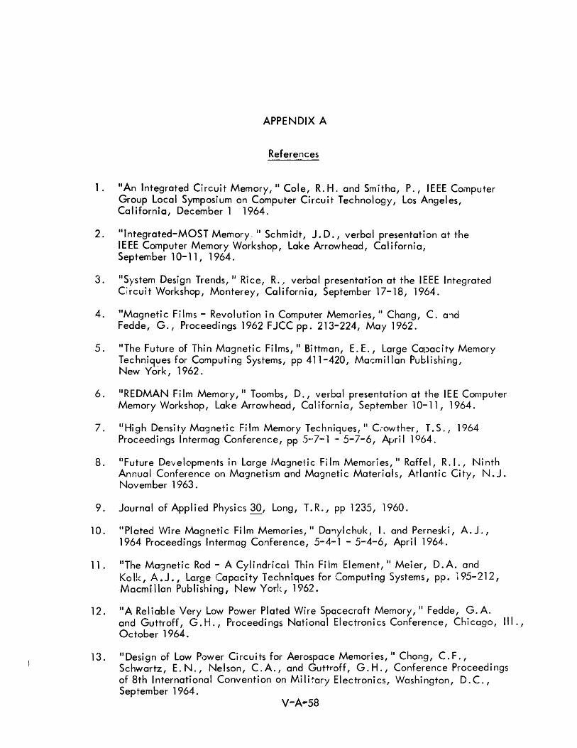
APPENDIX A
References
1. "An Integrated Circuit Memory, II Cole, R. H. and Smitha, P., IEEE Computer Group local Symposium on Computer Circuit Technology, Los Angeles, California, December 1 1964.
2. "Integrated-MOST Memory: II Schmidt, J. D., verbal presentation at the IEEE Computer Memory Workshop, Lake Arrowhead, California, September 10-11, 1964.
3. "System Design Trends, JI Rice, R.! verbal presentation at the IEEE Integrated Circuit Workshop, Monterey, California, September 17-18, 1964.
4. ttMagnetic Films - Revolution in Computer Memories, II Chang, C. a'1d Fedde, G., Proceedings 1962 FJCC pp. 213-224, May 1962.
5. liThe Future of Thin Magnetic Films, II Bittman, E.E., Large CalJacity Memory Techniques for Computing Systems, pp 411-420, Mat:millan Publishing, New York, 1962.
6. "REDMAN Film Memory, II Toombs, D., verbal presentation at the lEE Computer Memory Workshop, Lake Arrowhead, California, September 10-11, 1964.
7. IIHigh Density Magnetic Film Memory Techniques, II Crowther, T.S., 1964 Proceedings Intermag Conference, pp .5~-7-1 .- 5-7-6, April 1964.
8. flFuture Developments in Large l~a3ne1'ic Film Memories, II Raffel, R.I., Ninth Annual Conference on Magnetism and Magnetic Materials, Atlantic City, N. J. November 1963.
9. Journal of Applied Physics 30, Long, T.R., pp 1235, 1960.
10. II Plated Wire Magneti c Fi 1m Memories, II Da'1ylchuk, I. and Perneski, A. J. , 1964 Proceedings Intermag Conference, 5-4-1 - 5-4-6, April 1964.
11. liThe Magnetic Rod - A Cylindrical Thin Film Element, II Meier, D.A. and Kolk, A.J., Large Capacity Techniques for Computing Systems, pp. 195-212, Macmi.llan Publishing, New York, 1962.
12. itA Reliable Very Low Power Plated Wire Spacecraft Memory, II Fedde, G. A. and Guttroff, G.H., Proceedings National Electronics Conference, Chicago, III., October 1964.
13. IIDesign of Low Power Circuits for Aerospace Memories, II Chong, C.F., Schwartz, E.N., Nelson, C.A., and Guttroff, G.H., Conference Proceedings of 8th International Convention on Niili~ary Electronics, Washington, D.C., September 1964.
14. "System and Fabri cati on Tec hniques for a Sol i d State Random Access Mass Memory, t1 Fu II er, H. McCormack, T., and Battarel,' C., 1964 Proceedi ngs Intermag Conference, pp 5-5-1 - 5-5-4, April 1964.
15. tlLaminated Ferrite Memory, II Shahbender, R., Wentworth, C., Hotchkiss, K., li, K., and Raichman, J. A., Proceedings F JCC, Las Vegas, Nevada, Vol. 24, pp 77-90, November 12-14, 1963.
16. IIAn Approach Towards Batch-Fabricated Ferrite Memory Planes, II Bartkus, E., Brownlow, J., Crape, W., Elfant, R., Grebe, K., and Gutwin, 0., IBM Journal of Research and Development, pp 17-176, Vol. 8, No.2, Apri I 1964.
17. l1New Ferrite Structure, II Elfant, R., verbal presentation at the IEEE Computer Memory Workshop, Lake Arrowhead, California, September 10-11, 1964.
18. IIComputer Memories,lI Raichman, J.A., Proceedings IRE, 49, 1, January 1961, pp 115-116.
19. IIGlass /Vlemories," Corning Electronics, Bradford, Pa., Technical Brochure, RPP 8/63 5M.
20. IIlnvestigation of a Woven-Screen Memory System, II Davis, J.S., and Wells, P. E., Proceedings F JCC, pp. 311-326, Vol. 24, Las Vegas, Nevada, November 12-14, 1963.
21. "Integrated High-Frequency D.C. Amplifier, II Breuer, D. R., TRW S~ace Technology Laboratories Report #9374.1-0001, Redondo Beach, California, July la, 1964.
22. IIWoven Thin-Fi 1m Memories, II Maeda, H. and Matsushita, A., 1964 Intermag Conference Proceedings, pp 8-1-1 - 8-1-6, April 1964.
23. liThe Plated-Wire Memory Matrix, II Oshima, S., Futami, K., and Kamibatashi, T., 1964 Proceedings Intermag Conference, pp 5-1-1 - 5-1-6, Apri I 1964.
24. IIA Large Capacity Cryoelectric Memory with Cavity Sensing, II Burn, L. L., Christiansen, D.A., and Ga.,ge, R.A., Proceedings 1963 FJCC, pp 91-99, November 12-14, 1963.
25. IICryogenic Memories, II Burns, L. L. verbal presentation at the IEEE Computer Memory Workshop, Lake Arrowhead, California, September 10-11, 1964.
26. IIUltrasonic Approach to Data Storage, II Gratian, J.W., and Freytag, R.W., Electronics, Vol. 37, No. 15, pp 67-72, May 4,1964.
27. "Digital Computer Peripheral Memory, II First, Second, and Third Quarterly Reports (Ju I y 1 - September 30, 1963, October 1 - December 31, 1963, and January 1 - Ma"ch 3, 1964) U.S.A.E.R.&D.L. Contract No. DA 36-039-AMC-03248 (E) prepared by RCA Laboratori es.
V-A-59
28. "Review and Survey of Mass Memories, " L. C. Hobbs, Proceedings F JCC, pp 295-310, Vol. 24, November 12-14, 1963.
29. "Comparison: Major Types of Mass Memories, II L.C. Hobbs, Data Systems Design, Vol. 1, No.1, pp 18-21, January 1964.
30. ItMass Storage, II Hoagland, A.S., Proceedings IRE Vol. 50, pp 1087-1092, May 1962.
31. itA Critical Study of Mass Storage Devices and Techniques with Emphasis on Design Criteria, II M. Jacoby, IRE PG MIL, National Winter Convention on Military Electronics, 1962.
32. "Search Memories," IEEE Computer Group Local Symposium, Los Angeles, California, May 26, 1964.
33. "Survey of Present and Potential Search Memory Implementation Techniques, " Shohara, S., IEEE Computer Group Loca I Symposi urn on Searc h Memori es, Los Angeles, California, May 26, 1964.
34. "Associative Memory System Implementation and Characteristics, II McAteer, J. E., and Capobiano, J.A., and Koppel, R.L., Proceedings FJCC, pp 81-92, November 1964, San Francisco, Cal ifornia.
35. IIA Cryogenic Data Addressed Memory, II Newhouse, V.I., and Fruin, R.E., Proceedings Spring Joint Computer Conference, Vol. 21, pp 89-100, May 1-3, 1962.
36. JlDesign of a Fu II y Assoc iative Cryogenic Data Processor, II Pritchard, J. P., Jr., and Wald, L. D., 1964 Proceedings of Intermag Conference, pp 2-5-1 - 2-5-4, April 1964.
37. II Theory, Organization, and PerformanceofaSearchMemory,1I Koerner, R.J., and Scarbrough, A.D., Local Symposium on Search Memory, Los Angeles District of IEEE, May 26, 1964.
38. "Solid State Associative Cells,·n Lee, E.S., Proceedings of the 1963 Pacific Computer Conference, pp 96-108, March 16, 1963.
39. "Integrated Circuit Associative Memories, II Lindquist, H., verbal presentation at the IEEE Computer Memory Workshop, Lake Arrowhead, California, September 10-11, 1964.
V-A-60

Appendix B
COMPONENTS AND PACKAG ING
TABLE OF CONTENTS
Page
Appendix B COMPONENTS AND PACKAGING V-B-l
1 .0 Cryogenic Logic V-B-l
2.0 Fluid Logic V-B-2
3.0 Optical Logic V-B-2
4.0 Special Semiconductor Elements V-B-3
5.0 All-Magnetic Logic V-B-3
6.0 Semiconductor Integrated Circuits V-B-6
6. 1 Hybrid Discrete/Thin-Film {or Thick-Film} Circuits V-B-7
6.2 Monolithic Integrated Circuits V-B-10
6.3 Hybrid Monolithic/Thin-Film Circuits V-B-12
6.4 Active Thin-Film Element Circuits V-B-19
6.5 Metal-Oxide-Semiconductor {MOS} Circuits V-B-19
7.0 Environmental Conditions V-B-23
8.0 Batch-Fabrication Implications and Considerations V-B-26
9.0 Majority Logic and Voting Redundancy V-B-28
9. 1 Maiority Logic V-B-28
9.2 Triple Redundancy With a "Voting" Circuit V-B-30
10.0 Sources of Information and Reference Bibliography V-B-31
10. 1 Organizations Contacted V-B-31
10.2 Literature V-B-33
11 .0 Component and Packaging Technology References V-B-34
B-i


LIST OF ILLUSTRATIONS
Appendix B
Figure
2
3
4
5
6
7
8
9
10
11
12
13
14
Appendix B
2
3
4
Di agram of an I n- Li ne Cryotron
Multiaperture Ferrite Core Connected As An AND Gate for Magnetic Logic
Discrete Devices Being Placed Into Position On A Substrate By Conventional and FI ip-Chip Methods
Sequence of Photoresist and Diffusion Processes
Cross-Sectional View of a Typical Integrated Circuit
IIldeal ll Isolation Technique and Practicable Dielectric Technique
Channel Diffusion or Junction Isolation Techniques
Thin-Film Resistor
Hybrid Thin-Film Resistor and Transistor
Schematic Diagram of a Thin-Film Transistor
Silicon-on-Sapphire Field-Effect Transistor
Cross-Sectional View of an Insulated-Gate MOS Field-Effect Transi stor
Ladder Array of Enhancement Field-Effect Transistors
Propagation Delay Versus Temperature
LIST OF TABLES
Capac i tors and Resistors
Integrated Circuit Resistor Characteristics
Integrated Circuit Capacitor Characteristics
Semiconductor Network Environmental Evaluation
B-ii
V-B-1
V-B-5
V-B-8
V-B-11
V-B-l1
V-B-13
V-B-13
V-B-14
V-B-14
V-B-20
V-B-20
V-B-22
V-B-22
V-B-25
V-B-9
V-B-16
V-B-17
V-B-24
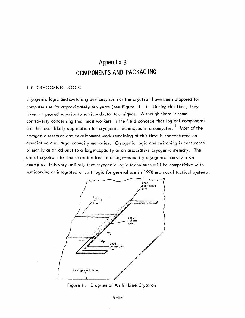
Appendix B
COMPONENTS AND PACKAG ING
1.0 CRYOGENIC LOGIC
Cryogenic logic and switching devices, such as the cryotron have been proposed for
computer use for approximately ten years (see Figure 1 ). During this time, they
have not proved superior to semiconductor techniques. Although there is some
controversy concerning this, most workers in the field concede that logical components
are the least likely application for cryogenic techniques in a computer. 1 Most of the
cryogenic research and deve lopment work remaining at this time is concentrated on
associative and large-capacity memories. Cryogenic logic and switching is considered
primari Iy as an adjunct to a large-capacity or an associative cryogenic memory. The
use of cryotrons for the selection tree in a large-capacity cryogenic memory is an
example. It is very unlikely that cryogenic logic techniques will be competitive with
semiconductor integrated circuit logic for general use in 1970 era naval tactical systems.
Lead n-----connection -------:a line
Lead ground plane
Figure 1. Diagram of An In-Line Cryotron
V-B-l
2.0 FLUID LOGIC
Fluid logic is usually mechanized by hydraulic or pneumatic systems in which small
mechanical movements are used to switch the path or flow of a hydraulic or pneumatic
medium; e.g., oil orair. 2 The major disadvantages of fluid logic are the relatively
slow response time and the size and weight compared to equivalent integrated semi
conductor circuits. The signal is limited to the velocity of sound and the switching
time is in the order of 1 millisecond. Fluid logic offers more environmental immunity
which is advantageous in adverse environments such as high temperature, electromagnetic
fields, and nuclear radiation. It emits no RFradiation and can be highly reliable.
Fluid logic may also offer advantages (e.g., lower cost) in applications where the
initial input information is in a mechanical form and a mechanical output is required.
An example of this is a desk calculator where the initial inputs are key depressions
and the outputs are mechanical printing operations.
Two or three companies have built small demonstration calculators using fluid logic.
Fluid logic is amenable to batch-fabrication in the form of injection molding techniques.
Fluid logic may be applicable to some shipboard functions, such as weapon direction
and ship's control. However, fluid logic wi II not be competitive with integrated
circuits for logical functions in the central processor and auxiliary equipment for the
information processing portion of a 1970 ACDS.
3.0 OPTICAL LOGIC
There has been considerable interest in the possibility of using optical logic devices
in computers because of the inherent speed theoretically possible when working with
light. Recent developments in fiber optics and lasers have accelerated this interest. 3, 4, 5
Some of the characteristics of lasers that make them attractive for computer use are:
1) The output is coherent and monochromatic
2) Very-high frequencies are possible
3) The beam is highly collimated
4) High-power intensity
5) Capable of either continuous or pu Ise operation.
V-8-2
Fiber optics have the capabi lity of conducting light around curved paths, and hence
t hey offer interconnection poss ibi I ities sim i lar to the use of wires in carryi ng electrons.
However, lasers and fiber optics wi II see use in memories and display areas before
they will be successfully used as logical components. Optical logic techniques offer
promise for the long-range future, but they wi II not be feasible for use in a 1970 system.
4.0 SPECIAL SEMICONDUCTOR ELEMENTS
A number of unique or special purpose semiconductor devices have been proposed for
use in computers. Of these, the most serious consideration has been given to the tunne I
diode.6
, 7 Tunne I diodes have been proposed for high-speed, small-capacity memories
as we II as high-speed logica I components. Of the various approaches to "ki lomegacyc Ie
circuits" tunnel diodes are considered the most practical, although the rates of
approximately 200 - 500 megacycles at which they have been used do not quite fall in
the kil omegacycl e range. Soon after they were introduced four or five years ago,
tunnel diodes were considered by many people to be an exciting solution to the high
speed computer circuit problem. However, difficulties in working with a two terminal
device such as the tunne I diode have seriously dampened this enthusiasm. The problems
of interconnection techniques for tunnel diode circuits operating at a frequency of
several hundred megacycles have proved to be difficult. Systems become very expensive
as a result of the discrete mechanical configurations required for interconnections and
shielding. Although tunnel diode logic circuits are feasible, they will not be
competitive with integrated circuit techniques for use in an ACDS in 1970 since such
h ig h speeds are not requ ired.
5.0 ALL-MAGNETIC LOGIC
Magnetic elements can be used in a digital system for logic as well as for storage
functions. However, magnetic elements have not en joyed the widespread use
as logical elements that they have as memory elements. This is, of course,
due to the difference in the nature and requirements of memory components and logic
components. A single word location in a memory is addressed at one time, and a
large driving current, low sense signal, and destructive readout are acceptable. On
the other hand, for a logic element it is necessary to provide some form of gain, and
to sense the state of the device without changing it.
V-B-3
A number of applications for all-magnetic logic and a number of types of logical
configurations and elements have been described in the literature. 8 , 9, 10,11
(See Figure 2 ) All-magnetic logic offers several distinct advantages, including:
1) High reliability
2) Radiation resistance
3) High temperature operat ion
4) Low standby power
5) Non-volati Ie
6) Low power requ ired at low frequenc ies
7) Cost (in some cases) .
The major disadvantages in the use of all-magnetic logic have been the inherent slow
speed and the lack of a steady state output indication. Most work on all-magnetic
logic has been in the 5 to 10 kc range. Sh ift cycle rates of 150 to 200 kc may be
possible by 1970, but speed is probably limited to a few hundred kilocycles at most.
The speed is limited by switching time, heating, and current requirements. For most
applications all-magnetic logic circuits have not proved themselves sufficiently
advantageous with respect to either cost or performance to encourage their use in
place of the simpler and more common semiconductor circuits.
The characteristics of all-magnetic logic are ideal for certain applications such as an
onboard computer in a deep space probe. In this application, very low speeds are
acceptable and radiation resistance, low standby power (since the spacecraft is in
operative for the long cruise periods of the mission), and high reliabi!ity are important.
For some shipboard functions such as peripheral equipment, weapon direction systems,
fJnJ 5hip's control systems where high speeds al'e not required, magne1ic logic may
prove a good choice. Appiication5 of ail-magnetic logic in shipboard systems were
ana Iyzed in a recent study. 12
However, for tactical data system applications, all-magnetic logic will not be
competitive with semiconductor integrated circuits. The radiation resistance
characteristic and the high reliability would be important if future developments
prove that integrated circuits are not as reliable as magnetic logic. However, it
V-S-4
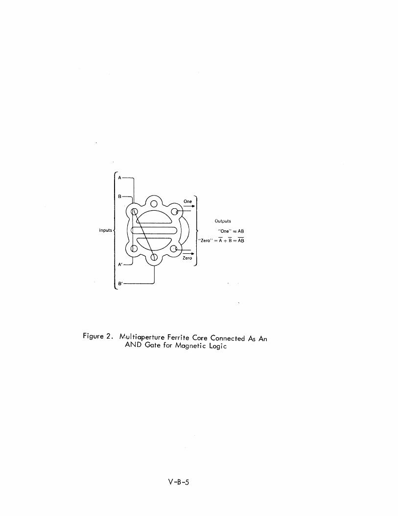
Inputs
Outputs
"One" = AS
"Zero" = A + B = AB
Figure 2. N\ul tiaperture Ferrite Core Connected As An AND Gate for Magnetic Logic
V-B-5
appears that semiconductor integrated circuits will equal or approach the reliability
of all-magnetic logic, and that the cost of these elements will be less than that for
the discrete elements used in magnetic logic. The speeds of all-magnetic logic are
not sufficient for the central processor since the multi-apertured devices found most
suitable for magnetic logic have been limited to rates of a few hundred kilocycles
per second. It is possible that new developments in thin-film integrated magnetic
circuits in the next few years may enhance the performance and significantly reduce
the cost of all-magnetic logic but it is unlikely that this will occur by 1970.
6.0 SEMICONDUCTOR INTEGRATED CIRCUITS
Integrated semiconductor circuits are by far the outstanding candidate for the logical
mechanization of a 1970 naval tactical data system. Integrated circuits have been
proved feasible and successful, and are currently being used in several military
computers. The first integrated circuit demonstration computer in 1961 showed a
lOt 1 0 0 10 bOlO bl dO 13 o Improvement In re la I Ity over a compara e Iscrete component computer 0
Hybrid integrated circuits are used in the Remington Rand CP667 computer for NTDS
and in the new IBM System/360 commercial computer 0 14, 15 Monolithic integrated
circuits have been used in the Autonetics Monica Computer, by MIT in the Apollo
computer, by AC Spark Plug in the MAGIC computer, and are being used by Litton
in the computer for the F-111 (TFX) 0 16 Estimates of the military use of integrated
circuits range from 40 to 50% of all military electronics in 1970 to approximately 75% . 1973 17, 18, 1 9 So d· 0 I· 0 0 d b I 0 d 0 0 In. mce Iglta circuitry IS more a apta e to Integrate circuit
techniques, the estimates are even higher for computer and data processing equipment -
approximately 70% by 1970. Actually, this figure will probably be closer to 9Qok
(not including the memory) for new digital equipment designed to become operational
in 1970.
Integrated circuits are not basically new components in the sense that lasers are, but
rather they represent radically new methods of fabricating and packaging semiconductor
circuitry. The reduction in the number of discrete components, resulting from fabricating
complete circuits as a single component, offers significant advantages in terms of
reliability, cost, and size. Batch-fabrication of volume quantities of integrated
circuits will result in significantly lower costs than is achieved by the present printed
circuit and hand wiring of basic components and circuit modules.
V-B-6
Based on considerations of reliability, cost, size, weight, and environmental
conditions, it is reasonable to expect that integrated circuits will account for almost
all of the logical components in a 1970 shipboard or ground-based military system.
There are five basic types of integrated circuits although these are sometimes called
by different names and in some cases grouped differently. The term hybrid is
particularly confusing since it is applied to thin-film passive components with discrete
active components and to thin-film passive components with monolithic active
components. These five types are:
1) Hybrid discrete active and thin-fi 1m (or thick-fi 1m) passive
2) Monolithic
3) Hybrid monolithic/thin-fi 1m
4) Active thin··fi 1m
5) AAel'al oxidA sem:conductor (MOS)
There r:!:":"" ::;ood reasons for the deve lopment and use of each of these. These
reasons are discussed in greater detai lin this Appendix.
6.1 HYBRID DISCRETE/THIN-FILM (or THICK-FILM) CIRCUITS
In this type of circuit, passive elements, such as resistors and capacitors, are printed
on a ceramic or glass substrate by either vacuum deposition of thin-film elements, or
by printing of thick-film elements in a process similar to silk screening. 15 Discrete
(but unpackaged) active components are connected to printed or deposited inter
connections on the same substrate (see Figure 3 ). The combination is then packaged
as a single unit. This is an interim type circuit that was developed before monolithic
and hybrid monolithic circuits were technically feasible for large scale production.
Their main area of application is where a high ratio of passive to active components is
requ ired.
This type of circuit offers the advantage that the passive components can be made
cheaply with tightly controlled tolerances. Relatively large values of capacitance
can be fabricated and resistance values can be maintained within about one per cent.
V-B-7
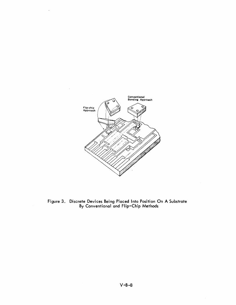
Q--o
,''-'-0
. .'/ ,0 Flip-chiP.' . / ... " .... .. , .. i Approach! ::" .. ~
\ [/ .. /'
Conventional Bonding Approach
Figure 3. Discrete Devices Being Placed Into Position On A Substrate By Conventional and Flip-Chip Methods
V-B-8
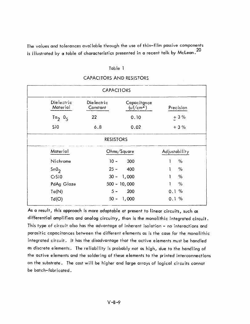
The values and tolerances available through the use of thin-film passive components
is illustrated by a table of characteristics presented in a recent talk by McLean. 20
Table 1
CAPACITORS AND RESISTORS
CAPACITORS 1-------------------------------------------------/
Die le~tric Die lectric Capac itance Material Constant (uf/cm2 ) Precision
Ta2 05 22 0.10 + 30/0 -SiO 6.8 0.02 + 3 0/0
RESISTORS 1-------------------------------------------------------------------------
Material Ohms/Square Adjustability
Nichrome 10 - 300 0/0
Sn02 25 - 400 0/0
CrSiO 30 - 1,000 0/0
PdAg Glaze 500 - 10,000 1 0/0
Ta(N) 5- 200 0.1 0/0
Td(O) 50 - 1,000 0.1 0/0
As a result, this approach is more adaptable at present to linear circuits, such as
differential amplifiers and analog circuitry, than is the monolithic integrated circuit.
This type of circuit also has the advantage of inherent isolation - no interactions and
parasitic capacitances between the different elements as is the case for the monolithic
integrated circuit. It has the disadvantage that the active elements must be handled
as discrete elements. The reliability is probably not as high, due to the handling of
the active elements and the soldering of these elements to the printed interconnections
on the substrate. The cost wi II be higher and large arrays of logical circuits cannot
be batch-fabricated.
V-B-9
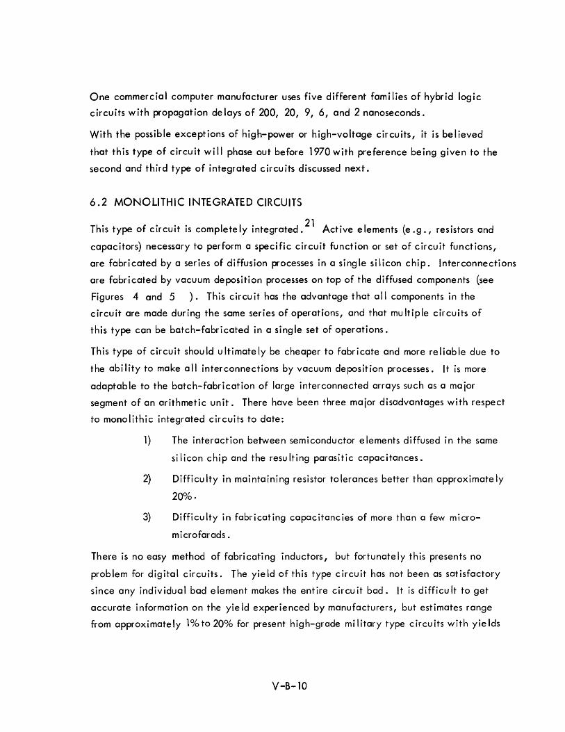
One commercial computer manufacturer uses five different fami lies of hybrid logic
circuits with propagation delays of 200, 20, 9,6, and 2 nanoseconds.
With the possible exceptions of high-power or high-voltage circuits, it is believed
that this type of circuit will phase out before 1970 with preference being given to the
second and third type of integrated circuits discussed next.
6.2 MONOLITHIC INTEGRATED CIRCUITS
Th · f·· . I I· d 21 A· I ( . d IS type 0 circuit IS comp ete y Integrate. ctlve e ements e.g., resistors an
capacitors) necessary to perform a specific circuit function or set of circuit functions,
are fabricated by a series of diffusion processes in a single silicon chip. Interconnections
are fabricated by vacuum deposition processes on top of the diffused components (see
Figures 4 and 5 ). This circuit has the advantage that all components in the
circuit are made during the same series of operations, and that mu Itiple circuits of
this type can be batch-fabricated in a single set of operations.
This type of circuit should ultimately be cheaper to fabricate and more reliable due to
the ability to make all interconnections by vacuum deposition processes. It is more
adaptable to the batch-fabrication of large interconnected arrays such as a major
segment of an arithmetic unit. There have been three major disadvantages with respect
to monolithic integrated circuits to date:
1) The interaction between semiconductor elements diffused in the same
si I icon chip and the resu Iting parasitic capacitances.
2) Difficulty in maintaining resistor tolerances better than approximately
20% •
3) Difficulty in fabricating capacitancies of more than a few micro
microfarads.
There is no easy method of fabricating inductors, but fortunately this presents no
problem for digital circuits. The yield of this type circuit has not been as satisfactory
since any individual bad element makes the entire circuit bad. It is difficult to get
accurate information on the yie Id experienced by manufacturers, but estimates range
from approximately 1%to 20% for present high-grade military type circuits with yields
V-B-10
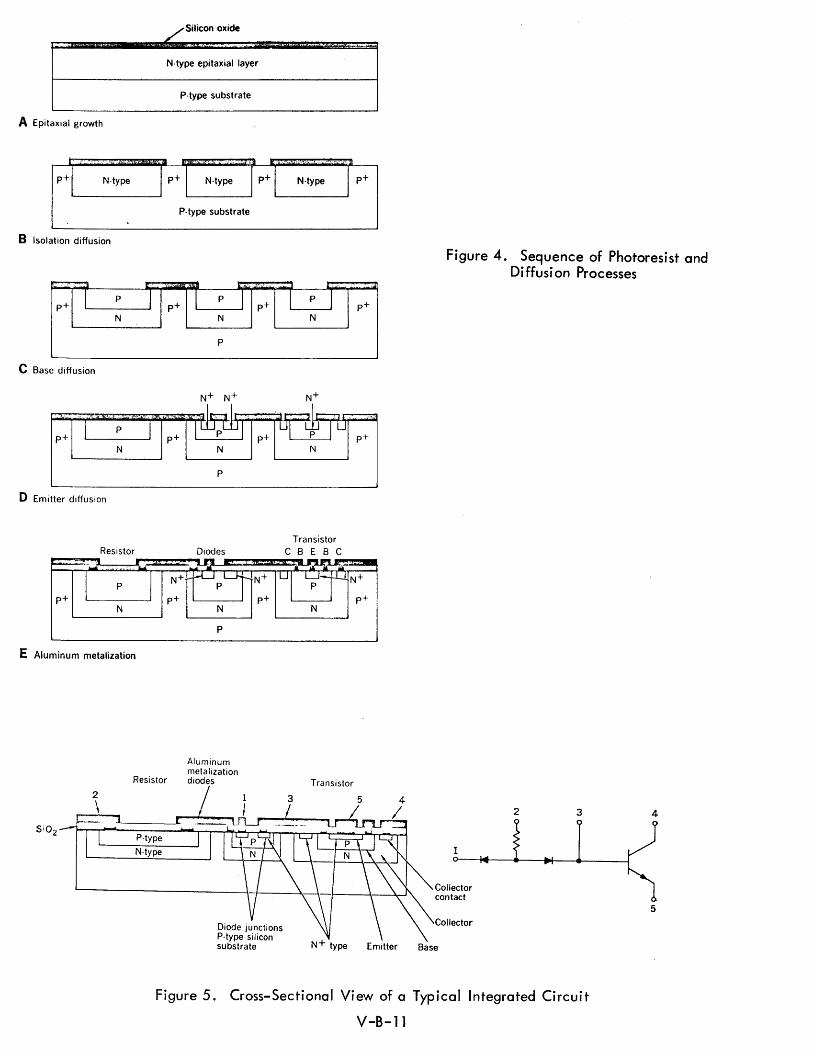
A Epitaxial growth
,~."
p+ N·type
B Isolation diffusion
~ I p
N
C Base diffusion
p+ N
o Emitter diffusion
Resistor
E Aluminum metalization
N-type epitaxial layer
P-type substrate
, ' , ;,« .,.., '
I p+ I N-type p+ I N·type
P-type substrate
1::1' jrp·rr I~ II
p p r
N N
p
N
p
Diodes
P
N
Transistor C B E B C
I p+
1 .:
p+1
Figure 4. Sequence of Photoresist and Di ffusi on Processes
Resistor
Aluminum metalization diodes Transistor
N·type 1
Collector contact
Collector
Emitter Base
2 3
Figure 5. Cross-Sectional View of a Typical Integrated Circuit
V-B-ll
4
5
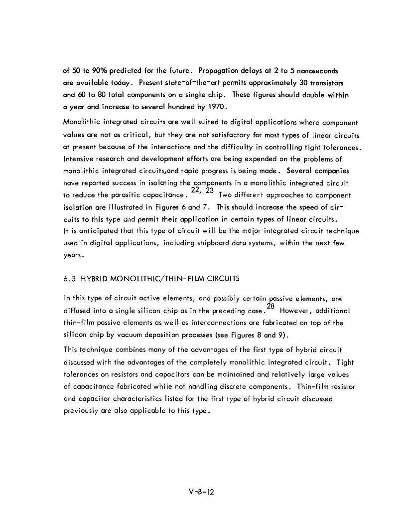
of 50 to 90% predicted for the future. Propagation delays at 2 to 5 nanoseconds
are avai lable today. Present state-of-the-art permits approximately 30 transistors
and (:IJ to 80 total components on a single chip. These figures should double within
a year and increase to several hundred by 1970.
Monolithic integrated circuits are well suited to digital applications where component
values are not as critical, but they are not satisfactory for most types of linear circuits
at present because of the interactions and the difficulty in controlling tight tolerances.
Intensive research and development,efforts are being expended on the problems of
monolithic integrated circuits,and rapid progress is being made. Several companies
have reported success in isolating the components in a monolithic integrated circ'Jit
d h 0 • 0 22, 23 T dOff h to re uce t e parasitic capacitance. wo I erert aprxoac es to component
isolation are illustrated in Figures 6 and 70 This should increase the speed of cir
cuits to this type and permit their application in certain types of linear circuits.
It is anticipated that this type of circuit will be the major integrated circuit technique
used in digital applications, including shipboard data systems, within the next few
years.
6.3 HYBRID MONOLITHIC/THIN-FILM CIRCUITS
In this type of circuit active elements, and possibly certain passive elements, are
d Off d 0 0 I 01 0 h 0 . h dO 28 H dd 0 t 0 I I use Into a sing e SI Icon c Ip as In t e prece Ing case. owever, a Ilona
thin-fi 1m passive elements as we II as interconnections are fabri cated on top of the
silicon chip by vacuum deposition processes (see Figures 8 and 9)0
This technique combines many of the advantages of the first type of hybrid circuit
discussed with the advantages of the completely monolithic integrated circuit. Tight
tolerances on resistors and capacitors can be maintained and re lative Iy large values
of capacitance fabricated while not handling discrete components. Thin-film resistor
and capacitor characteristics listed for the first type of hybrid circuit discussed
previously are also applicable to this type.
V-S-12
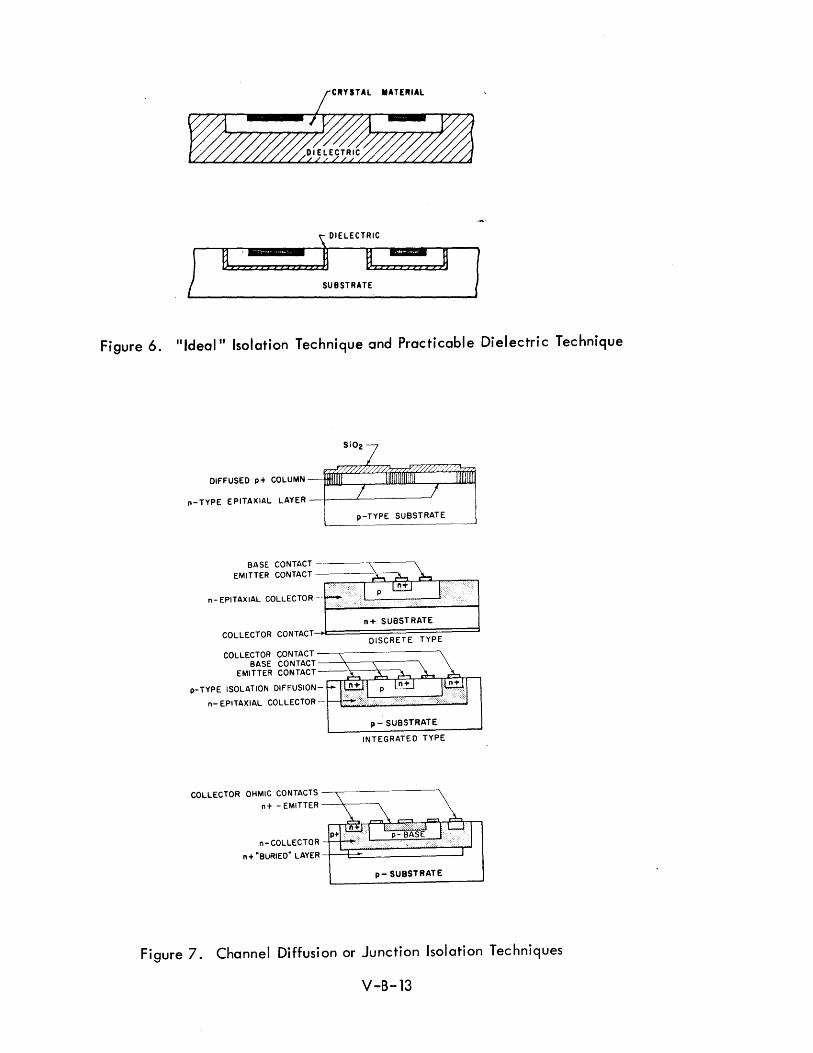
1 H -:: : j DIELECTRIC
= ij
I
u n SUBSTRATE
Figure 6. "Ideal" Isolation Technique and Practicable Dielectric Technique
SiOz
DIFFUSED p + COLU MN -1J.IW.lJJU-_..----1lWULlIUW.--r----JIWIIlLWj
n-TYPE EPITAXIAL LAYER _+-_-..L------'
p-TYPE SUBSTRATE
BASE CONTACT ---~r-----'" EMITTER CONTACT ------>..---"
~_~~~~~~A-,~~~
n - EPITAXIAL COLLECTOR
COLLECTOR CONTACT-l===========:::::J DISCRETE TYPE
COLLECTOR CONTACT ----.------------, BASE CONTACT-~~-~----'"
EMI TTER CON TACT __ .'>r.---'c------;. --~~~~~~~~~~-,
p-TYPE ISOLATION DIFFUSION-
n- EPITAXIAL COLLECTOR -r-l::!ikt=====S::l2.....J p - SUBSTRATE
INTEGRATED TYPE
COLLECTOR OHMIC CONTACTS -..------------"\
n + - EMITTER --'r---~
n-COLLECTOR
n + "BURIED" LAYER +~~:::=:::::::::::::~::J...I p- SUBSTRATE
Figure 7. Channel Diffusion or Junction Isolation Techniques
V-B-13
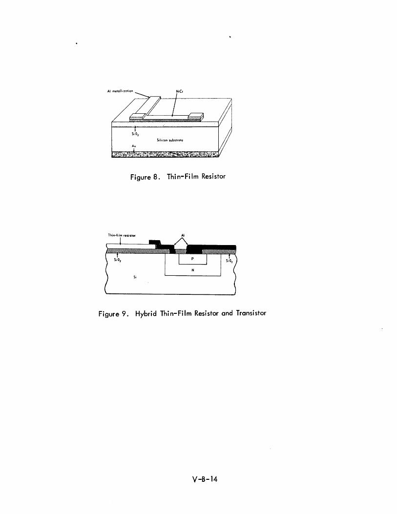
Figure 8. Thin-Film Resistor
Thin-film resistor AI
Figure 9. Hybrid Thin-Film Resistor and Transistor
V-8-14
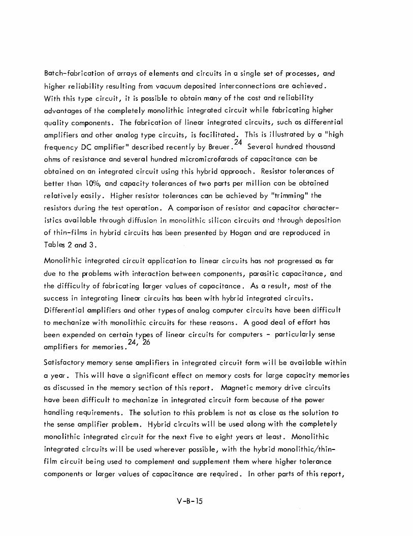
Batch-fabrication of arrays of elements and circuits in a single set of processes, and
higher reliability resulting from vacuum deposited interconnections are achieved.
With this type circuit, it is possible to obtain many of the cost and reliability
advantages of the completely monolithic integrated circuit while fabricating higher
quality components. The fabrication of linear integrated circuits, such as differential
amplifiers and other analog type circuits, is facilitated. This is illustrated by a IIhigh
frequency DC amplifier" described recently by Breuer. 24 Several hundred thousand
ohms of resistance and several hundred micromicrofarads of capacitance can be
obtained on an integrated circuit using this hybrid approach. Resistor tolerances of
better than 10%, and capacity tolerances of two parts per million can be obtained
relatively easily. Higher resistor tolerances can be achieved by "trimming" the
resistors during the test operation. A comparison of resistor and capacitor character
istics available through diffusion in monolithic silicon circuits and through deposition
of thin-fi Ims in hybrid circuits has been presented by Hogan and are reproduced in
Tables 2 and 3.
Monolithic integrated circuit application to linear circuits has not progressed as far
due to the problems with interaction between components, parasitic capacitance, and
the difficulty of fabricating larger values of capacitance. As a result, most of the
success in integrating linear circuits has been with hybrid integrated circuits.
Differential amplifiers and other typesof analog computer circuits have been difficult
to mechanize with monolithic circuits for these reasons. A good deal of effort has
been expended on certain types of linear circuits for computers - particularly sense
I'f' f . 24, 26 amp / Jers or memories.
Satisfactory memory sense ampl ifiers in integrated circuit form wi II be avai lable within
a year. This wi II have a significant effect on memory costs for large capacity memories
as discussed in the memory section of this report. Magneti c memory drive circuits
have been difficult to mechanize in integrated circuit form because of the power
handling requirements. The solution to this problem is not as close as the solution to
the sense amplifier problem. Hybrid circuits wi II be used along with the completely
monolithic integrated circuit for the next five to eight years at least. Monolithic
integrated circuits will be used wherever possible, with the hybrid monolithic/thin-
fi 1m c ircu it be ing used to complement and supplement them where higher to lerance
components or larger values of capacitance are required. In other parts of this report,
V -8-15
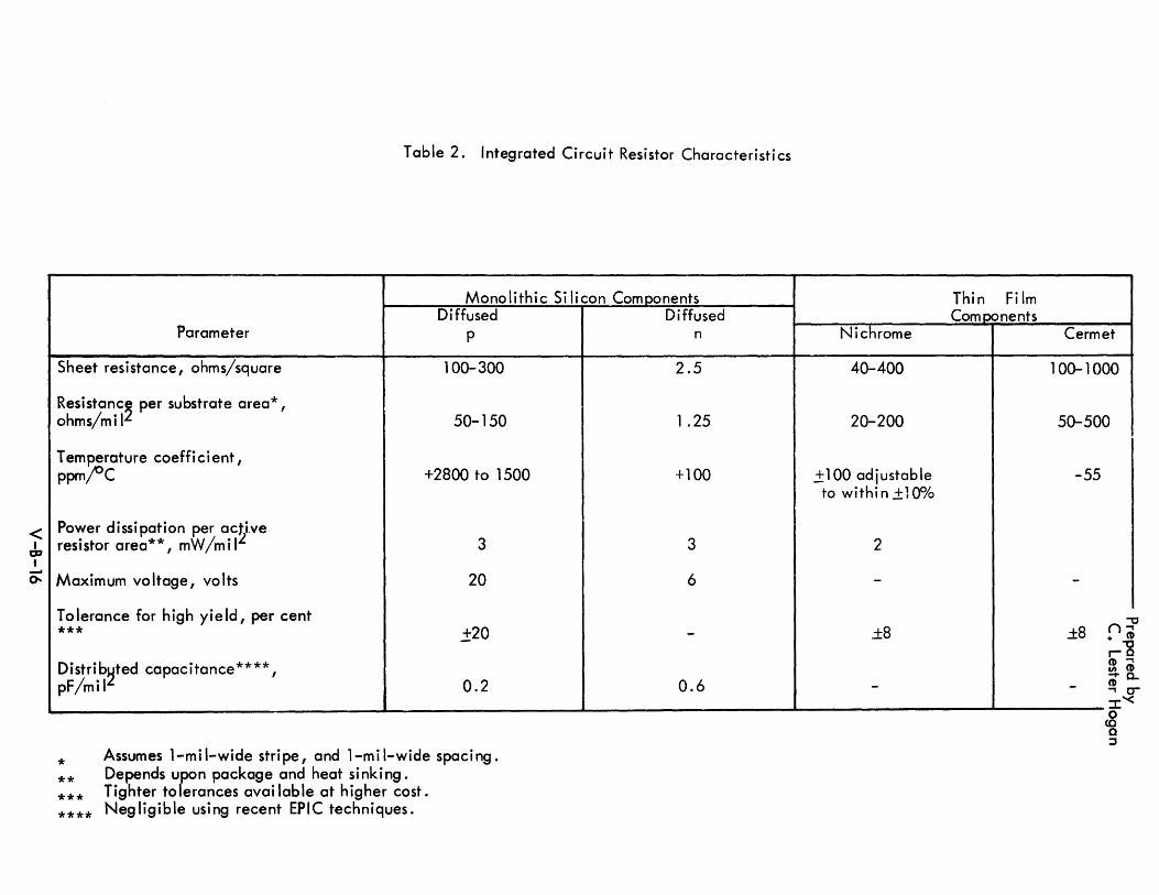
< I
O:J I -0.
Table 2. Integrated Circuit Resistor Characteristics
Monolithic Si licon Components Diffused
Parameter p
Sheet resistance, ohms/square 100-300
Resistanc~ per substrate area* , ohms/mil 50-150
Temperature coefficient, ppm;oC +2800 to 1500
Power dissipation per ac~ive resistor area**, mW /m i I 3
Maximum voltage, volts 20
Tolerance for high yield, per cent *** .±20
Distrib~ted capacitance****, pF/mil 0.2
--- ------~
* **
Assumes 1-mil-wide stripe, and 1-mil-wide spacing. Depends upon package and heat sinking.
*** ****
Tighter tolerances avai lable at higher cost. Negligible using recent EPIC techniques.
Diffused n
2.5
1 .25
+100
3
6
-
0.6
Thin Film Com p::ments
Nichrome
40-400
20-200
.± 100 adjustable to within±Hf/o
2
-
±8
-
Cermet
100-1000
50-500
-55
-
±8
-o
<0 C ::l
.."
0-0-
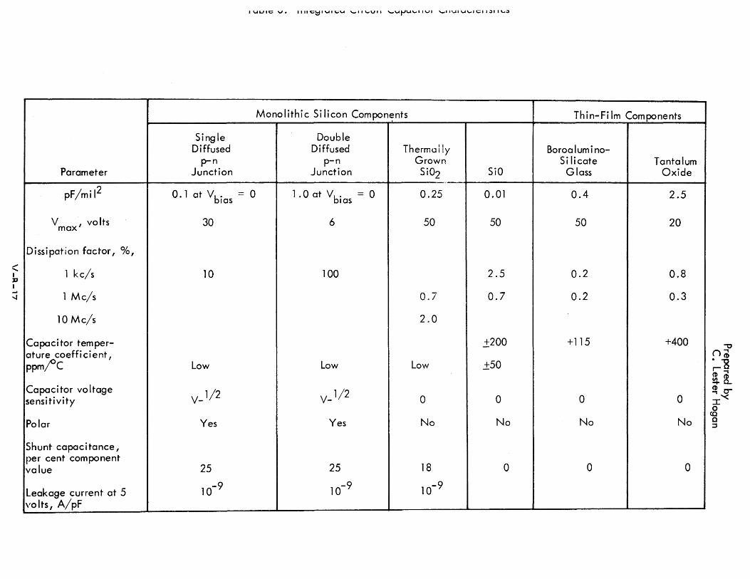
:::: I 73 I ... '"
Parameter
pF/mil2
V , volts max
Dissipation factor, ok,
1 kc/s
1 Mc/s
10 Mc/s
Capacitor temper-ature coefficient, ppm/'C
Capacitor voltage sensi tivi ty
Polar
Shunt capacitance, per cent component value
Leakage current at 5 volts, A/pF
Single Diffused
p-n Junction
0.1 at Vb" las
30
10
Low
V_ 1/ 2
Yes
25
10-9
I\ .. UJII;;; v. 111I1;;;~I\ .. UI;;;Y '-'II '-'VII '-'Yt-'Y'-'IIVI ,-,1I'1".1IY'-'II;;;II.;)II'-'.;)
Monolithic Silicon Compon~nts
Double Diffused Thermally
p-n Grown Junction Si02 SiO
= 0 1 .0 at Vb. = 0 0.25 0.01 las
6 50 50
100 2.5
0.7 0.7
2.0
.±200
Low Low ±50
V_ 1/ 2 0 0
Yes No No
25 18 0
10-9 10-9
Thin-Film Components
Boroa lum i no-Si licate Tantalum
Glass Oxide
0.4 2.5
50 20
0.2 0.8
0.2 0.3
+115 +400
0 0
No No
0 0
I
():,o • (1)
."'8 (1) .., (II (1) me.. .., c-:c'< o co o ::s
these two types are discussed interchangeably as "integrated circuits" with the
assumption that monolithic techniques will be used where possible with thin-film
passive components deposited on top of the chip where necessary to achieve required
component values or tolerances. Unless the isolation problem in the monolithic
integrated circuit is completely overcome, the hybrid monolithic thin-film approach
may also be used to permit higher speeds (below 2 nanoseconds propagation delay).
This wi II be the second major type component used in 1970 ACDS.
V -B-18
6.4 ACTIVE THIN-FILM ELEMENT CIRCUITS
In th is type of circuit, both the active components and the passive components
are fabricated by vacuum deposition of thin-film elements. (See Figure 10. )27,28
Cadmium-sulphide thin-film circuits represent the most promising approach to
thin-film active circuits at present. Predictions concerning the date at which
active thin-film elements will become feasible vary widely -- from "almost
immediatel/' to IInot less than five yearsll• The longer estimate is probably
the more accurate one with the possible exception of a related but somewhat
different approach that requires a single crystal passive substrate such as sapphire.
An insulated-gate field-effect transistor has been fabricated in this way by depositing
or growing silicon on a single crystal passive substrate (sapphire), depositing an
oxide insulator such as silicon monoxide, and depositing aluminum plates for
connections and distributed capacitance. 29 (See Figure 11.) Because of the
majority carrier nature I field effect transistor devices have been expected to
offer better radiation resistance characteristics. This device is attractive
because of its simplicity and the fact that it is quite amenable to batch-fabri-
cation of large interconnected arrays with minimum interaction.
It is doubtful that the use of thin-film active elements, such as thin-film
transistors, in a system will be feasible by 1970.
6.5 METAl-OXIDE-SEMICONDUCTOR (MOS) CIRCUITS
In this type of device a single diffusion process is required in a semiconductor
(usually silicon) chip.30 This is a field-effect device in which metal electrodes
are deposited on two sl ightly separated diffused areas (e. g. N type material for
a P type chip), an insulator (e.g. silicon monoxide) is deposited on tl-e chip
between the two diffused areas, and the th ird metal el ectrode is deposited on the
insulator (See Figures 12 and 13.)
Although MaS devices have advantages from the fabrication standpoint, they
cannot match the 5 ns speeds quoted for bipolar transistors. Present work with
field effect devices indicate potential speeds in the range of 50 - 100 ns. Most
of the success with field-effect devices to date has been with the metal-oxide
semiconductor (MaS,,) Since significantly fewer processing steps are involved,
V-B-19
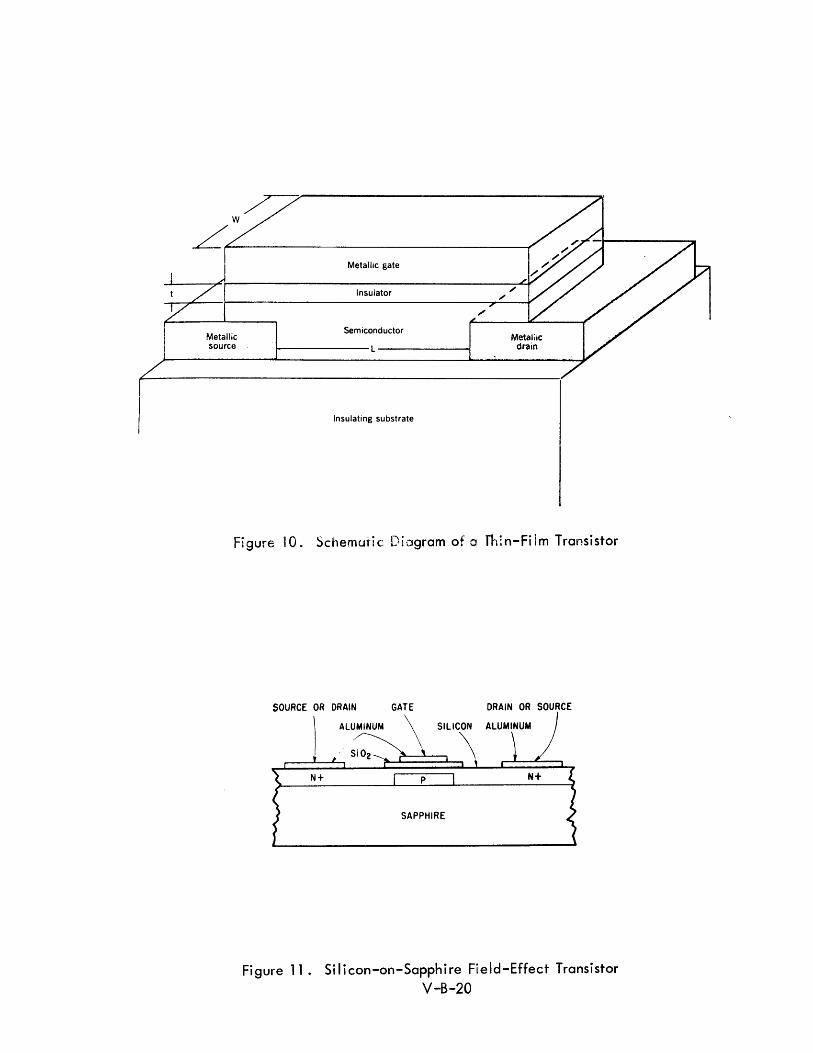
Metallic source
Metallic gate
Insulator
Semiconductor
~-----------L------------~
Insulating substrate
FigufelO. Schematic Diagram of a fh:n-Film Transistor
SOURCE OR DRAIN GATE DRAIN OR SOURCE
Figure 11. Silicon-on-Sapphire Field-Effect Transistor
V-B-20
the fabrication of large arrays of elements with reasonable yields is more feasible.
In contrast to bipolar transistors, MOS elements are high impedance devices. The
following advantages have been cited for MOS devices:
1) There is no problem with "current hogging lJ in DCTL
type circuits.
2) High fan -out can be obta i ned.
3) Complementary symmetry circuits can be made on the
same substrate with only one extra diffusion process.
4) They are simple to fabricate and large arrays of circuits
can be fabri cated.
Complementary symmetry permits one MOS transistor to be used as a load switch
for the other. 31 This increases the reliability and radiation resistance since
shifts in the characteristics of the devices have a lesser effect if the load line
is the characteristic of another MOS rather than a straight I ine resistor type
load. As the characteristics of one MOS change due to external conditions,
the characteristics of the other change also, resulting in a lesser circuit effect
from the net change. Complementary symmetry devices have been fabricated
by diffusing areas of N type material into the P type substrate, then diffusing
P type material into the N type areas.
One manufacturer has reported work on a small low-cost random-access memory
array mechanized with MOS elements/which is significant in thata single chip
contains an order of magnitude more components than other integrated circuits
now being manufactured. 32 The efforts to date have produced a complete
memory array of 16 four-bit words on a single sil icon chip 115 mils by 145 mils
in size (approximately ten times the area of conventional integrated circuit).
About 30 chips can be fabricated on one silicon waf er with present yields of four
to five good chips per wafer. The total read/write cycle time for this device is
four microseconds -- a two microsecond read time and a two microsecond write
time. The relatively slow speed of four microseconds results from the fact that
the MOS is a high impedance device. They have estimated that a speed improve
ment of an order of magnitude is probably the best that can be expected with this
approach. However, on a laboratory basis, 150 - 200 nanosecond MOS type
V-B-21

storage elements similar to those have been fabricated by another company by
tak i ng advantage of compl ementary symmetry. 3 1
Most companies have experienced a surface instability in metal oxide semi
conductors that is very temperature dependent. Two companies have reported
that this surface instability, caused by charge motion at the metal-to-oxide
interface (charge I eakage around the gate), can be overcome by phosphorous
treating of the surface.
MOS integrated circuits have recently received intensified interest. The number
of companies offering discrete MOS elements has doubled during the past year.
Although the technology is not as well established and the speed capability
is more limited, MOS integrated circuits will probably be the major competitor
for monolithic and hybrid monolithic/thin-film integrated circuits for a 1970
system - particularly where large arrays of interconnected circuits on a single
chip are appl icable.
SOURCE GATE DRAIN
HEAVILY DOPED N-TYPE REGION
N-TYPE CHANNEL
p- TYPE SUBSTRATE
Figure 12. Cross-Sectional View of an Insulated-Gate MOS Field-Effect Transistor
Figure 13. Ladder Array of Enhancement Field-Effect Transistors V-8-22
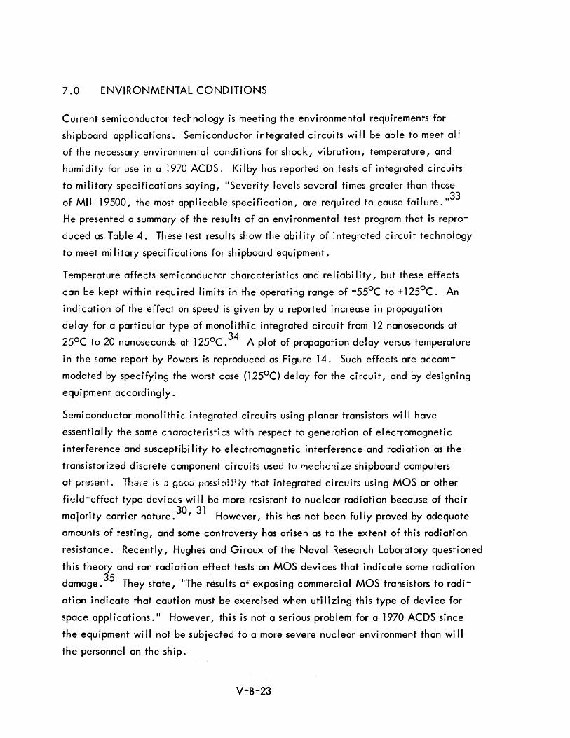
7.0 ENVIRONMENTAL CONDITIONS
Current semiconductor technology is meeting the environmental requirements for
shipboard applications. Semiconductor integrated circuits will be able to meet all
of the necessary environmental conditions for shock, vibration, temperature, and
humidity for use in a 1970 ACDS. Kilby has reported on tests of integrated circuits
to military specifications saying, "Severity levels several times greater than those
of MIL 19500, the most applicable specification, are required to cause failure. ,,33
He presented a summary of the results of an environmental test program that is repro
duced as Table 4. These test results show the ability of integrated circuit technology
to meet military specifications for shipboard equipment.
Temperature affects semi conductor characteristi cs and re I i abi Ii ty, but these effects
can be kept within required limits in the operating range of -550 C to +1250 C. An
indication of the effect on speed is given by a reported increase in propagation
delay for a particular type of monolithic integrated circuit from 12 nanoseconds at
250 C to 20 nanoseconds at 1250 C. 34 A plot of propagation delay versus temperature
in the same report by Powers is reproduced as Figure 14. Such effects are accom
modated by specifying the worst case (1250 C) delay for the circuit, and by designing
equipment accordingly.
Semiconductor monolithic integrated circuits using planar transistors will have
essentially the same characteristics with respect to generation of electromagnetic
interference and susceptibility to electromagnetic interference and radiation as the
transistorized discrete component circuits used to mechc:nize shipboard computers
at present. Thef€ i~ ,J 9UC~ possibi n ty that integrated circuits using MOS or other
field-effect type deviCt::s will be more resistant to nuclear radiation because of their
majority carrier nature. 3D , 31 However, this has not been fully proved by adequate
amounts of testing, and some controversy has arisen as to the extent of this radiation
resistance. Recently, Hughes and Giroux of the Naval Research Laboratory questioned
this theory and ran radiation effect tests on MOS devices that indicate some radiation 35 damage. They state, liThe results of exposing commercial MOS transistors to radi-
ation indicate that caution must be exercised when utilizing this type of device for
space applications." However, this is not a serious problem for a 1970 ACDS since
the equipment will not be subjected to a more severe nuclear environment than wi II
the personnel on the ship.
V-B-23
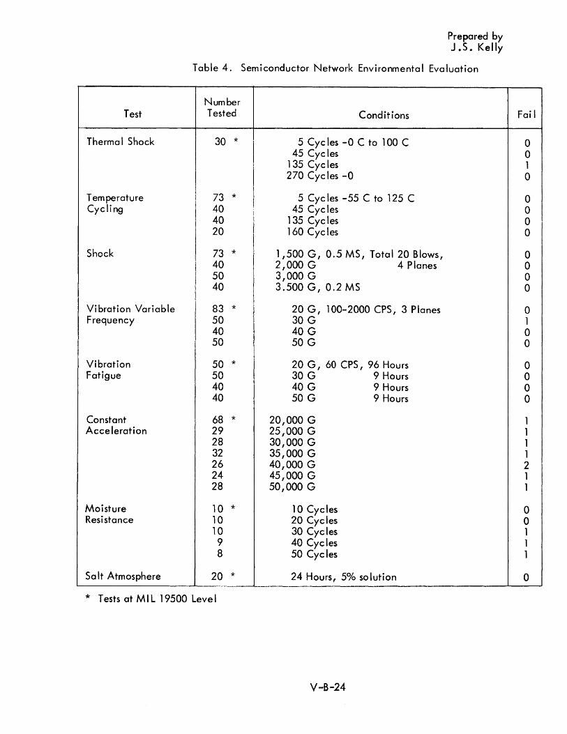
Prepared by J.S. Kelly
Table 4. Semiconductor Network Environmental Evaluation
Number Test Tested Conditions
Therma I Shock 30 * 5 Cycles -0 C to 100 C 45 Cycles
135 Cycles 270 Cyc les -0
Temperature I 73 * 5 Cycles -55 C to 125 C Cycling
I 40 45 Cycles 40 135 Cyc les 20 160 Cyc les
Shock 73 * 1,500 G, 0.5 MS, Total 20 Blows, 40 2,000 G 4 Planes 50 3,000 G 40 3.500 G, 0.2 MS
Vibration Variable 83 * 20 G, 100-2000 CPS, 3 Planes Frequency 50 30 G
40 40 G 50 50 G
Vibration 50 * 20 G, 60 CPS, 96 Hours Fatigue 50 30 G 9 Hours
40 40 G 9 Hours 40 50 G 9 Hours
Constant 68 * 20,000 G Acceleration 29 25,000 G
28 30,000 G 32 35,000 G 26 40,000 G 24 45,000 G 28 50,000 G
Moisture 10 * 10 Cycles Resistance 10 20 Cycles
10 30 Cycles 9 40 Cycles 8 50 Cycles
Sa It Atmosphere 20 * 24 Hours, 50/0 so lution --
* Tests at MIL 19500 Leve I
V-B-24
Fai I
0 0 1 0
0 0 0 0
0 0 0 0
0 1 0 0
0 0 0 0
1 1 1 1 2 1 1
0 0 1 1 1
0
Average
tpd
(nanoseco)H.h)
35 Printe ~- eireu with 19 elem
tpd = 30
25
Vee =
I--- Counte 20
15 ..;:::;:::::::::== 1iaSf-;:( . --
- .-.-
10 LtaL~'"
5
o -55 -25
·t boarc operat ng ring "nts
or-.. , rer lUU
2 x 19
3v
~ , \itl~ut
-~ s -~ - out' -----\.- -
-- - -l~~\).t c1-~r s -----_ ... -. --f--_._--
I .----- -----------t-b
(in' ~ut Z -)Utpu
Prepared by G. Powers
/ V
V // ~t S) ."'" "'~
~--~
f.-"""--1L . .- -
I"U"
~/ t------- ...: ..
------... ---
o 25 50 75 100 125
T e nl per a t u r e ( de g C)
Figure 14. Propagation Delay Versus Temperature
V-B-25
8.0 BATCH-FABRICATION IMPLICATIONS AND CONSIDERATIONS
Throughout the discussions of components and packaging and in discussions elsewhere
of memories for 1970 systems, the concept of batch-fabrication has been emphasized.
The development of this technology is the key to cost, reliability, and maintain-
abi lity improvements in a 1970 ACDS. The integrated circuit techno logies discussed
are the leading and most highly developed forms of batch-fabrication in the com
puter fi e Id .
Batch-fabrication techniques for computer circuits, memories, and display equipment
have progressed much faster in the past two years than had been genera lly anti ci pated.
Within the next five years, these techniques wi II have a dramatic impact on the
computer field. It is likely that the computer field will also supply the major
impetus for acce lerated deve lopment of batch-fabri cation techniques si nee dig ita I
equipment and systems are most amenable to the repetitive use of relatively standard
circuits. A Ithough many deve lopment projects are underway on individua I batch
fabrication techniques, very little work on the effect of these techniques on machine
organization and on the consolidation of different techniques into a batch-fabricated
computer system design has been rePorted.
Batch-fabri cation techniques are frequent Iy inc luded under the genera I term
"micro-electronics", but this is misleading. "Micro-electronics" places emphasis
on size reductions rather than on the fabrication of large numbers of circuit elements
in a single set of processing operations. Batch-fabrication offers additional
significant advantages - reduced cost, improved reliability and maintainability, and
reduced power requirements.
Fu II advantage can be taken of advances in batch-fabri cation techniques on Iy when
their effect on machine organization and systems design is better understood. Only
a sma II part of the potentia I for batch-fabri cation processes wi II be rea lized if
individual techniques, such as integrated circuits, are used to directly replace
components or subassemblies in existing types of equipment and system designs. It
is necessary to re-orient the thinking of computer designers when working with
batch-fabri cation techn iques.
V-B-26

Methods of machine organization to provide more highly repetitive logical organiza
tions are needed. Certain portions of present computers, such as successive stages
in the adder of a parallel machine, are repetitive; but other portions, such as the
control unit, tend to have unique non-repetitive logical configurations.
If large arrays of logical circuits are to be fabricated in a single set of processing
operations with acceptable yields, techniques will be required for easily eliminating
bad elements or for permitting the array to work Y"ith a limited number of bad
elements. Th is is done at present in the fabri cation of some memory arrays where
redundant rows and co lumns are provided to perm it substitution for rows or co lumns
that contain bad elements. However, there are no equivalent techniques for logical
arrays in use in present systems.
Criteria used previously to select efficient designs (e.g. minimizing the number of
flip-flops or the logical terms in a Boolean equation) will not be valid. Since
adding an additional flip-flop to a single silicon chip containing an array of
integrated circuits will have a minor effect on the cost of the array, flip-flop and
gate counts wi II be much less important than the number of circuit packages required.
Emphasis will be placed on reducing the number of packages - even at the expense
of significantly increasing the complexity of each package.
Machine organization techniques using lIinefficient logic ll in order to facilitate the
fabrication of larger arrays of logical elements in a single set of processing opera
tions will be important in future systems.
Batch-fabrication of logica I circuitry and memories wi II make it possible to fabricate
sophisticated computers and central processors in very small packages. As a result,
the imbalance between input/output and peripheral equipment on the one hand and
computers and central processors on the other hand will be intensified. Since there
is little hope at this time for equivalent improvements in the size and cost of peri
phera I equ ipment, the centra I processor ina computer system designed a few years
in the future may be mounted in the bottom of a tape unit (or of one of a large
number of other peripheral devices). Hence, for a shipboard data system, the
overa II effect of batch-fabri cation techn iques wi II be lim ited by the input/output
and the complexity, and possibly the inefficiency, of the central processor and
memory to minimize input/output and peripheral operations.
Y-B-27
These are but a few of the many questions that need to receive more intensive
investigation to assure the optimum uti Iization of batch-fabrication techniques in
future digital equipment and systems.
9.0 MAJORITY LOGIC AND VOTING REDUNDANCY
9.1 MAJORITY LOGIC
In discussing majority logic, it is necessary to consider the context in which the term
is used. Strictly speaking, majority logic is a special case of threshold logic in
which a logical element generates one logical output if over 50% of the inputs are
present and generates the opposite log i ca I output if less than 50010 of the inputs are
present. There should be an odd number of inputs to avoid ambiguity. The
threshold level is set at n + 1 where n is the number of inputs. 2
This is in contrast to a conventional Boolean logical element in which the threshold
is set at either 0% or 1000/0. In the zero thresho Id instance, one logi ca I output of
a conventional Boolean gate is generated if none of the inputs are present and the
opposite logical output if anyone or more of the inputs are present. In the 100%
threshold case, one logical output is generated if all of the inputs are present and
the opposite logical output if one or more of the inputs are missing. Any arbitrary
function can be realized with majority logic elements and conversely any majority
logic element can be simulated by a network of conventional Boolean logical
elements. Hence, any Boolean logical design can be converted to majority logic
by the proper manipu lation of the Boo lean expressions.
The use of majority logic has been proposed primarily for circuits, components, or
physical realizations which are more amenable to majority logic than to the con
ventional Boolean functions of IIANDII and IIOR". The parametron and tunnel
diode circuits are examples of devices of this type. Majority logic functions have
frequent Iy been discussed for equipment to be mechanized with tunnel diodes or
parametrons {or phase lock osci lIators}. However, ma jority log i c can a Iso be
mechanized with conventional components, such as resistors, diodes, and transistors,
and used to mechanize a computer that might otherwise be mechanized with
conventional Boolean logical elements.
V-B-28
One example of thresho Id elements and a computer mechanized with them has been
described by Coates and Lewis.36
However, these threshold elements were not
restricted to the special"majority" case. This machine called IIDONUT" was
designed and built specifically to compare the use of threshold logic elements with
conventional gates. In many cases, specific logical functions can be realized with
a sma Iler number of thresho Id gates than wou Id be required if conventiona I gates
were to be used. However, si nce thresho Id gates are not inherent Iy bistab Ie or
on-off devices, they are more sensitive to signal variations and component tolerances
than conventional gates. Hence, theoretically possible component savings may not
be actually realizable for a specified level of reliability.
The DONUT computer was bui It to answer questions concerning component savings
and relative reliability in systems mechanized with threshold logic. For this specific
machine, it was found that the number of threshold gates required was about one
quarter the number of \I NOR" gates that wou Id have been required with conventiona I
Boo lean functions. However, si nce a genera I thresho Id gate with different thresho Id
levels was used, the reduction in the number of gates was significantly greater than
if the design had been limited to gates using pure majority logic. Also, it does not
fo Ilow that a reduction in the number of gates necessari Iy produces a reduction in
the number of components. For example, if a majority gate were fabricated as a
pure thresho Id device (with a consequent reduction in to lerance capabi lity), the
number of components would probably be reduced; but, if each majority logic were
mechanized by conventional Boolean operators, such as "AND" and "OR", the
tota I number of components might easi Iy be greater rather than less. From the design
of the DONUT computer, it was concluded that IIthreshold gate logic offers a means
for trading tolerances (and to some extent speed) for numbers of components. 1137
However, this may not be a desirable trade-off, and it is not clear that a saving
would have been achieved if only majority elements were used. There is no
indication that components used in a 1970 ACDS will be more amenable to majority
logic. The semiconductor integrated circuits that are expected to dominate the
log i c mechanization of computers in that time frame are we II suited to the mechan
ization of conventional Boolean functions. Hence, majority logic, in the sense
discussed above, is not recommended for th is system.
V-B-29
9.2 TRIPLE REDUNDANCY WITH A "VOTING" CIRCUIT
The second way in which the term "majority logic" is sometimes used is in connection
with a redundancy system in which each logical function is triplicated and the "best
two-out-of-three" is taken as the correct result for the function. 38 ,39,40,41 This is
also frequently referred to as "voting logic." It is interesting to note that in this type
of mechanization, the logical function itself is usually mechanized with conventional
Boolean elements such as "AND" and "0R" gates. The only majority logic element is
the actual voting element that determines the "best-two-out-of-three" results of the
triplicated logical function and passes this on as the result. Even this may be mechanized
as a Boolean function rather than with a specific majority logic element. Hence, it is
misleading to speak of this approach as " ma jority logic. II To do so tends to confuse a
redundance technique with a type of logical element.
There are many approaches to achieving higher reliability through the use of redundancy
in a system. One of these is the triplication of portions of the system with a voting cir
cuit or majority logic element used to select the proper output if one of the three func
tions differs from the other two. This can be done at any level; i.e., logical functions,
equipment, subsystems, etc. Unfortunately, this approach in its simple form assumes a
very high degree of reliability in the majority logic element itself. In fact, it is valid
only if the majority logic element is more reliable than the logical elements used in
mechanizing the triplicated functions. Since this may not be the case for a simple
majority logic element, it may be necessary to triplicate the majority logic elements
also. Triplicating these results in three outputs which must be accepted by the next
level of logic. This requires an iterative type triplication which results in significant
increase in the number of components. 41 The use of majority logic and redundancy of
this type must be evaluated first against the need for redundancy in the system and then
agai nst other types of redundancy.
V-B-30
10.0 SOURCES OF INFORMATION AND REFERENCE BIBLIOGRAPHY
10.1 ORGANIZATIONS CONTACTED
Components and packaging techniques have been discussed with personnel of a number
of different companies and governmental agencies in the course of this study. The
following list indicates the companies and governmental agencies with whom com
ponents and packaging techniques hav;~ been :liscussed, and tt1e h;p;cs discussed
with each:
Motorola Semiconductor Div. Phoenix, Arizona
Remington Rand UNIVAC St. Pau I, Mi nnesota
Control Data Corp.
Autonetics Anaheim, California
Bun ker-Ramo Corp. Canoga Park, Cal ifornia
RCA Laboratori es Pri nceton, New Jersey
Hughes Semiconductor Div. Newport Beach, California
Sylvania Waltham, Massachusetts
ONR Washington, D. C.
V-B-31
Integrated circuit sense amplifiers Integrated circuit storage registers Monolithic integrated circuits Hybrid integrated circuits
Hybrid integrated circuits Integrated circuit reliability and
fai lure analysis Packaging techniques
Integrated circuit applications Packaging techniques
Monol i th i c integrated c i rcu i ts Integrated fi e Id-effect-transistor c i rcui ts Integrated circuit packaging techniques
Monolithic integrated circuits Integrated circuit sense amplifiers
Integrated field-effect- transistors Meta I-ox i de-sem i conductor
integrated circuits Active thin-film integrated circuits
Integrated circuit packaging techniques Monolithic integrated circuits Hybrid integrated circuits Active thin-film integrated circuit
Tun n e I d i od e c i rc u i ts
Optical components
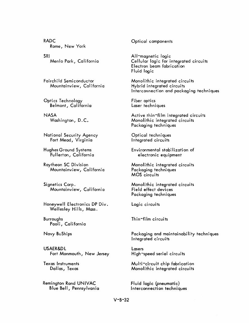
RADC Rome, New York
SRI Menlo Park, California
Fairchi Id Semiconductor Mountainview, Cal iforni a
Optics Technology Belmont, Cal ifornia
NASA Washington, D. C.
National Security Agency Fort Mead, Virginia
Hughes Ground Systems Fullerton, California
Raytheon SC Divisi on Mountainview, California
Signetics Corp. Mountainview, California
Honeywell Electronics DP Div. Wellesley Hi lis, Mass.
Burroughs Paoli, California
Navy BuShips
USAER&DL Fort Monmouth, New Jersey
Texas Instruments Dallas, Texas
Remington Rand UNIVAC Blue Bell, Pennsylvania
V-B-32
Opti cal components
All-magnetic logic Cellular logic for integrated circuits Electron beam fabri cati on Fluid logic
Monolithic integrated circuits Hybr i d integrated c i rcu its Interconnection and packaging techniques
Fiber optics Laser techni ques
Active thin-fi 1m integrated circuits Monolithic integrated circuits Packaging techniques
Optical techniques Integrated circuits
Envi ronmental stabi Ii zati on of electronic equipment
Monolithic integrated circuits Packaging techniques MOS circuits
Monolithic integrated circuits Field effect devices Packaging techniques
Logic ci rcuits
Th in-fi 1m circui ts
Packaging and maintainability techniques Integrated circuits
Lasers High-speed serial circuits
Multi-circuit chip fabrication Monolithic integrated circuits
Fluid logic (pneumatic) Interconnection techniques

Discussions with personnel of these organizations provided a basis for much of the
information presented in this report. In addition to discussing techniques and
approaches that have not been adequate Iy descri bed in publ ished literature, the
opinions of experts in specific areas in these organizations were solicited concerning
the advantages, disadvantages, limitations and future prospects for different com
ponent and packaging techni ques.
10.2 LITERATURE
An extensive list of references pertinent to the study of components and packaging
techniques is given in the Bibliography. A study of many of these references has
contributed to the material presented in this report. Some of the more pertinent
and important of these referred to in the text have been extracted from the biblio
graphy and listed in this section as specific numbered references. These numbers
correspond to numbered citati ons in the test. Di rect quotati ons have been used
wh ere noted.
V-B-33
11 .0
1 •
2.
3.
4.
5.
6.
7.
8.
9.
10.
11.
12.
13.
14.
COMPONENT AND PACKAGING TECHNOLOGY REFERENCES
II The Case for Cryogen i cs ?", Ittner, W .. V ., Proceed i ngs 1962 F JCC, pp. 229-231, Philadelphia, Po., December 1962.
"Pneumatic Log" I-IV, Holbrook, E .. L., Control Engineering, July, August, November 1961, and February 1962.
II Fiber Opti cs and the Laser ll, Kapany, N. S ., paper presented at the
New York Academy of Sciences Conference on the Laser, New York, New York, May 4-5, 1964.
liThe Status of Optical Logic Elements for Nanosecond Computer Systems II , Tippett, J. T., 1963 Pacific Computer Conference, IEEE, Pasadena, California, pp. 47-53, March 15-16,1963.
IIPossible Uses of Lasers in Optical Logic Functions ll, Koster, C.,
1963 Pacific Com~uter Conference, IEEE, Pasadena, California, pp. 54-62, Marc 15-16, 1963.
"A Survey of Tunnel-Diode Digital Techniques " , Sims, R~C., Beck, E.R., Jr., and Kamm, V.C., Proceedings of the IRE, Vol. 49, No.1, pp. 136-146, January 1961.
11300 mcs Tunnel Diode Logic Circuits", Cooperman, M., 1963 Pacific Computer Conference IEEE, Pasadena, California, pp. 166-186, March 15-16, 1963.
IIDesign of an All Magnetic Computing System II , Crane, H.D. and Van DeRiet, E. K., IRE Transactions on Electronic Computers, Vol. EC-l0, No.2, pp. 207-232, June 1961.
liThe Case for Magnetic Logic ll, Rogers, J., and Kings, J., Electronics,
Vol. 37, No. 17, pp. 40-47, June 1, 1964.
IIAII Magnetic Digital Circuit Fundamentals ll, Newhall, E .. E., Digest of
1964 International Solid State Circuits Conference, pp. 16-17, Philadelphia, Po., February 1964.
IIAII Magnetic Digital Circuits and Application Problems ll, Baker, T.,
and Dillon, C., Digest of 1964 International Solid State Circuits Conference, pp. 18-19, Philadelphia, Po., February 1964.
IIStudy of Applications of All-Magnetic Logic to Naval Systems II , Adams, M.B., and Van DeRiet, I.E., Final Report on ONR Contract No. N-onr-2332(oo), Stanford Research Insti tute, November 1963.
IIMicroelectronics - Military Participation and Objectives ll, Alberts, R.,
1964 WESCON, Los Angeles, Cal ifornia, August 25, 1964.
IIBig Computer Goes in Small Package ll, Electronics, pp. 28-29,
March 14, 1964.
V-B-34
15. "Solid Logic Technology: Versati Ie, High-Performance Microelectronics", Davis, E.M., Harding, W.E., Swartz, R.S., Korning, J .. J., IBM Journal of Research & Development, Vol. 8, No.2, pp. 102-114.
16. "Digital Computer Aspects of Integrated Circuit Applications", Platzek, R.C., and Goodman, H.C., Proceedin~s Nat'l. Winter Convention on Militar~ Electronics, Los Angeles, Co ifornia, Vol. III, pp. 2-34 - 2-53, ebruary 5-7, 1964.
17. II Microe lectronics - Where, Why, and When ll, O'Connell, E .. P. and
Brauer, J.S., Proceedings Nat l!. Winter Convention on Military Electronics, Los Angeles, California, Vol. III, pp. 2-1, Feb. 5-7,1964.
18. 111964: The Year Mi cro Circui ts Grew Upll, Electronics, pp. 10-11, Ma r c h 1 4, 1 964 .
19. II The Economi c Impact of Integrated Ci rcuitry", Haggarty, P. E . , I EEE Spectrum, Vol. 1, No.6, pp. 80-82, June 1964.
20. IIFi 1m Technology", McLean, David, Verbal Presentation at the IEEE Integrated Circuit Workshop, Monterey, California, September 17-18, 1964 .
21. "Monolithic Integrated Circuits, Philips, A.B., IEEE Spectrum, Vol. 1, No.6, pp. A -3 - 101, June 1964.
22. liThe Minimization of Parasitics in Integrated Circuits by Dielectric Isolation", Maxwell, D.A., Beeson, R.H., and Allison, D.F., 1964 WESCON, Los Angeles, California, August 25,1964.
23. "Integrated Linear Circuits", Bailey, D., Electronic Products, pp. 50, June 1964.
24. "Integrated High-Frequency D.C. Amplifiers", Breuer, D.R., TRN Space Tech nol ogy Laboratori es Report No. 9374. 1 - 000 1, Redondo Beach, California, June 10,1964.
25. "Types of Integrated Circuits", Hogan, C.L., IEEE Spectrum, Vol. 1, No.6, pp. 63-71, June 1964.
26. "Utilization of New Techniques and Devices in Integrated Circuits", Second Quarterl Re ort AF Contract No. AF 33 657 -11185 Pacific emiconductorlnc. 1 August 1963 -31 August 1963.
27. liThe Future of Thin-Fi 1m Active Devices", Feldman, Charles, Electronics, Vol. 37, No.4, pp. 23-26, January 24,1964.
28. "Thin-Film Circuit Technology: Part III-Active Thin-Film Devices ll,
Fowler, A.B., IEEE Spectrum, Vol. 1, No.6, pp. 102-111, June 1964.
V-B-35
29. IIlntegrated Thin-Fi 1m Networks", Western Electronic News, pp. 22-24, November 1964.
30. "Metal-Oxide-Semiconductor Field-Effect Transistors ll, Heiman, F.P.,
and Hofstein, S.R., Electronics, Vol. 37, No. 30, pp. 50-61, November 30, 1964.
31. liMOS and Thin-Film Transistor Circuits", Hertzog, G., Verbal Presentati on at the I EEE Integrated Ci rcu i t Worksh op, Monterey, California, September 17-18, 1964.
32. II Integrated-MOST Memoryll, Schmidt, J. D ., Verbal Presentation at the IEEE Computer Memory Workshop, Lake Arrowhead, California, September 10-11, 1964.
33. IJSilicon FEB Techniques Jl, Kilby, J.S., Solid State Design, Vol. 5,
No.7, pp. 32-37, Ju Iy 1964.
34. "System Speed with Integrated Circuits lJ, Powers, G., Electronic
Desi gn News, pp. 20-27, May 1964.
35. "Space Radiati on Affects MOS FETls", Highes, H. L., and Giroux, R. R. , Electronics, Vol. 37, No. 32, pp. 58-60, December 28, 1964.
36. "DONUT: A Threshold Gate ComputerlJ, Coates, C.L., and Lewis, P.M., IEEE Transactions on Electronic Computers, Vol. EC-13, No.3, pp. 240-247, June 1964.
37. IIHow to Achieve MAJORITY and THRESHOLD LOGIC with Semiconductors ll,
Sauer, W.A., Electronics, Vol. 36, No. 48, pp. 23-25, November 29, 1963 .
38. IIlmprovement of Electronic-Computer Reliability Through Use of Redundancyll, Brown, W. G., Tierney, J., and Wasserman, R., IRE Transactions on Electronic Computers, Vol. EC-10, pp. 407-415, September 1961 .
39. IIMajority Voting Protects Aircraft and Pilot ll, Moreines, J.,
Worthington, R., and Thomas, F., Electronics, Vol. 37, No. 16, pp. 85-91, May 18,1964.
40. IIRedundant Circuit Design: Payoffs and Penalties Jl, Suran, J.J., EEE,
Vol. 12, No.·9, pp. 51-55, September 1964.
41 . III nformati on Redundancy and Adaptive Structures II, Ange II, J. B ., Di gest of Technical Papers, 1964 Solid State Circuits Conference, Philadelphia, Pa., pp. 84 -85, February 19, 20, 21, 1964.
V-B-36

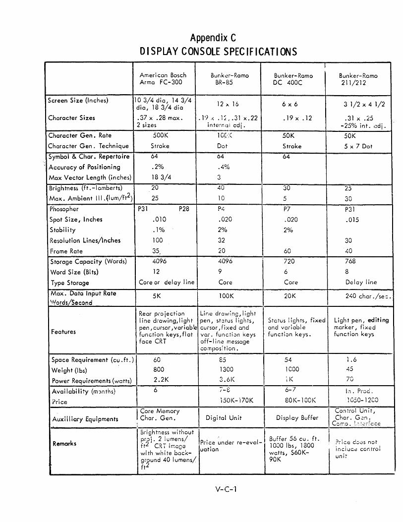
Appendix C D I SPLAY CONSOLE SPEC IF I CAT IONS
, Ameri can Bosch Bunker-Ramo Bunker-Ramo Bunker- Ramo Arma FC-300 BR-85 DC 400C 211/212
Screen Size (Inches) 10 3/4 dia, 14 3/4 12 x 16 6x6 3 1/2 x 4 1/2 dia, 18 3/4 dia
Character Sizes .37 x .28 max. . 1,/ ,< • 1 ~ I .31 x. 22 .19 x .12 .31 x .25 2 sizes interr.(]i adj. -25% int. ,~dj.
Character Gen. Rate 500K 1C~« 50K 50K
Character Gen. Technique Stroke Dot Stroke 5 x 7 Dot
Symbol & Char. Repertoire 64 64 64 "
, Accuracy of Positioning .2% .4%
Max Vector Length (inches) 18 3/4 3
Brightness (ft.-Iamberts) 20 40 30 25
Max. Ambient III. (I um/ft2) 25 10 5 30
Phosopher P31 P28 P4 P7 P31
Spot Size, Inches .010 .020 .020 .015
S tabil i ty .1% 2% 2%
Resolution Lines/Inches 100 32 30
Frame Rate 35 - 20 60 40
Storage Capacity (Words) 4096 4096 720 768
Word Size (Bits) 12 9 6 8
Type Storage Core or delay line Core Core Delay line
Max. Data Input Rate 5K lOOK 20K 240 char ./se:. 'Nerds/Second
Rear pro jection Line drawing, light line drawing,light pen, st:lTUS lights, Status I ights, fixed Light pen, editing
Features pen ,cursor ,variable cursor, fixed and and variable marker, fixed function keys,flat var. function keys function keys. function keys face CRT off-I i ne message
composition.
Space Requirement (cu. ft.) 60 85 54 1.6
Weight (Ibs) 800 1300 1COO 45
Power Requirements (watts) 2.2K 3.6K lK 70
Availability (m:mths) 6 7-8 6-7 In. Prod.
Price 150K- 'i70K 80K-l00K 1050-12CO
I Core Memory I Control Unit, Auxi II iary Equipments Char. Gen. Digital Unit Display Buffer Char. G2n.
'" r- , ... ,.:. ~I""'~ . C .... ".o. ", . .:; .. cee I
Sri ghtness wi tnout
Iprice ~nder re-evol- I I
Remarks pro i. 2 I umens/ Buffer 56 cu. ft. I ?rice. C-:'0S not ft2 CRT image uation
1000 Ibs, 1800 inciucc ccr.irol with white bac~- watts, S60K- unit giound 40 I umens/ 90K ft2
V-C-'l

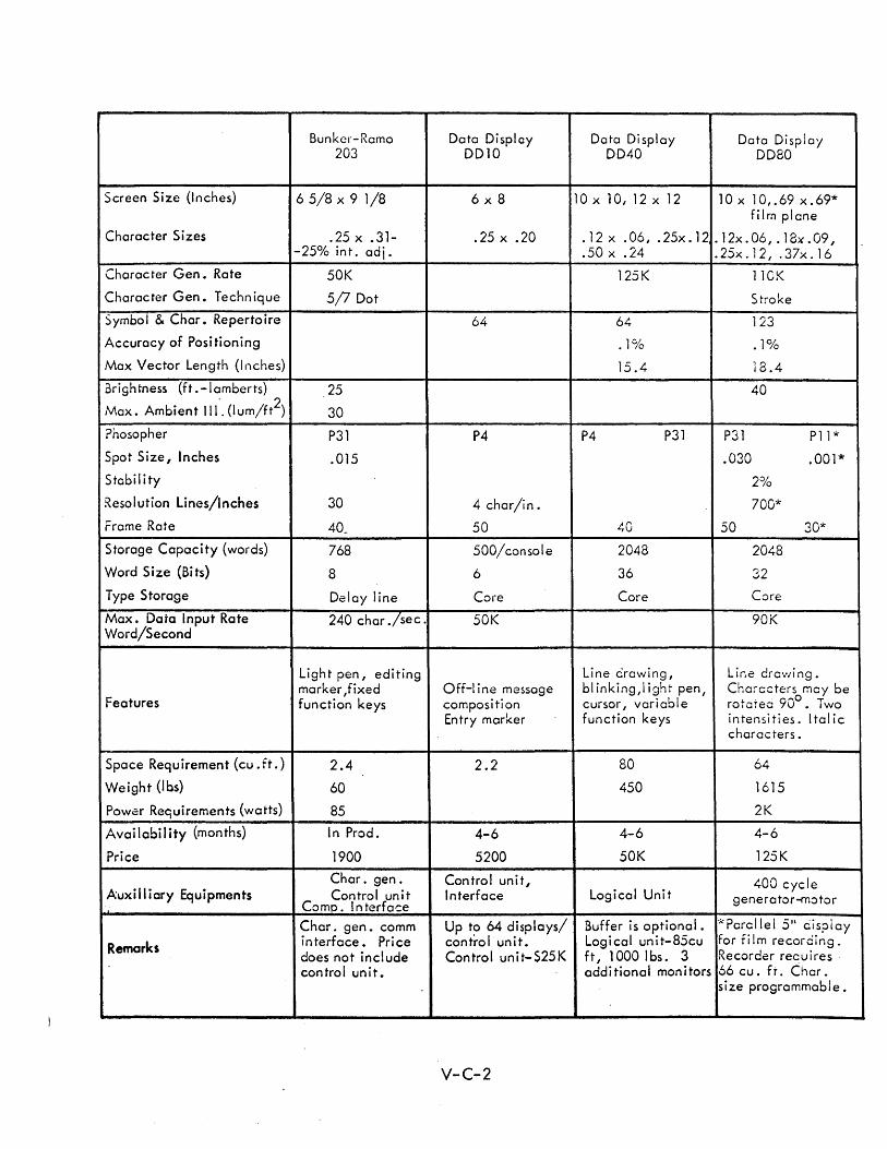
Bunker-Ramo Data Display Data Di splay Data Display 203 0010 0040 0080
Screen Size {Inches) 65/8 x 9 1/8 6x8 lOx 10, 12 x 12 lOx 1 0, .69 x. 69* film plane
Character Sizes .25 x .31- .25 x .20 . 12 x .06, . 25x. 12 . 12x. 06, . 1 8)( . 09 , -25% int. adj. .50 x .24 .25x.12, .37x.16
Character Gen. Rate 50K 125K 110K
Character Gen. Technique .5/7 Dot Stroke
Symbol & Char. Repertoire 64 64 123
Accuracy of Positioning • ]C'/o • 1°/0
Max Vector Length (Inches) 15.4 18.4
3rightness {ft. -I amberts} 25 40 . 2
Max. Ambient III. (I um/ft ) 30
?hosopher P31 P4 P4 P31 P31 P11 ....
Spot Size, Inches .015 .030 .001*
Stabi I i ty 2%
Resolution Lines/Inches 30 4 char/in. 700-k
Frame Rate 40_ 50 1,.0 50 30*
Storage Capacity (words) 768 500/console 2048 2048
Word Size (Bits) 8 6 36 32
Type Storage Delay line Core Core Core
Max. Data Input Rate 240 char ./sec. 50K 90K Word/Second
Light pen, editing Line drawing, Line drawing. marker ,fixed Off-I i ne message bl inking, I ight pen, Characters may be
Features function keys composition cursor, variable rotcteci 900• Two
Entry marker function keys intensities. Ital ic characters.
Space Requirement (cu. ft.) 2.4 2.2 80 64
Weight (Ibs) 60 450 1615
Power Requirements (watts) 85 2K
Availabi I ity (months) In Prod. 4-6 4-6 4-6
Price 1900 5200 50K 125K
Char. gen. Control uni t, 400 cycle Auxi II iary Equipments Control unit Interface Logical Unit generator-motor
Comp. Interface
Char. gen. comm Up to 64 displays/ Buffer is optional. *Parallel 5" cisplay
Remarks interface. Price con tro I un it. Logi cal unit-85cu for fi 1m recording. does not include Control unit-S25K f t, 1 000 I bs . 3 Recorder reauires control unit. additional monitors 66 cu. fr. Char.
size programmable.
V-C-2
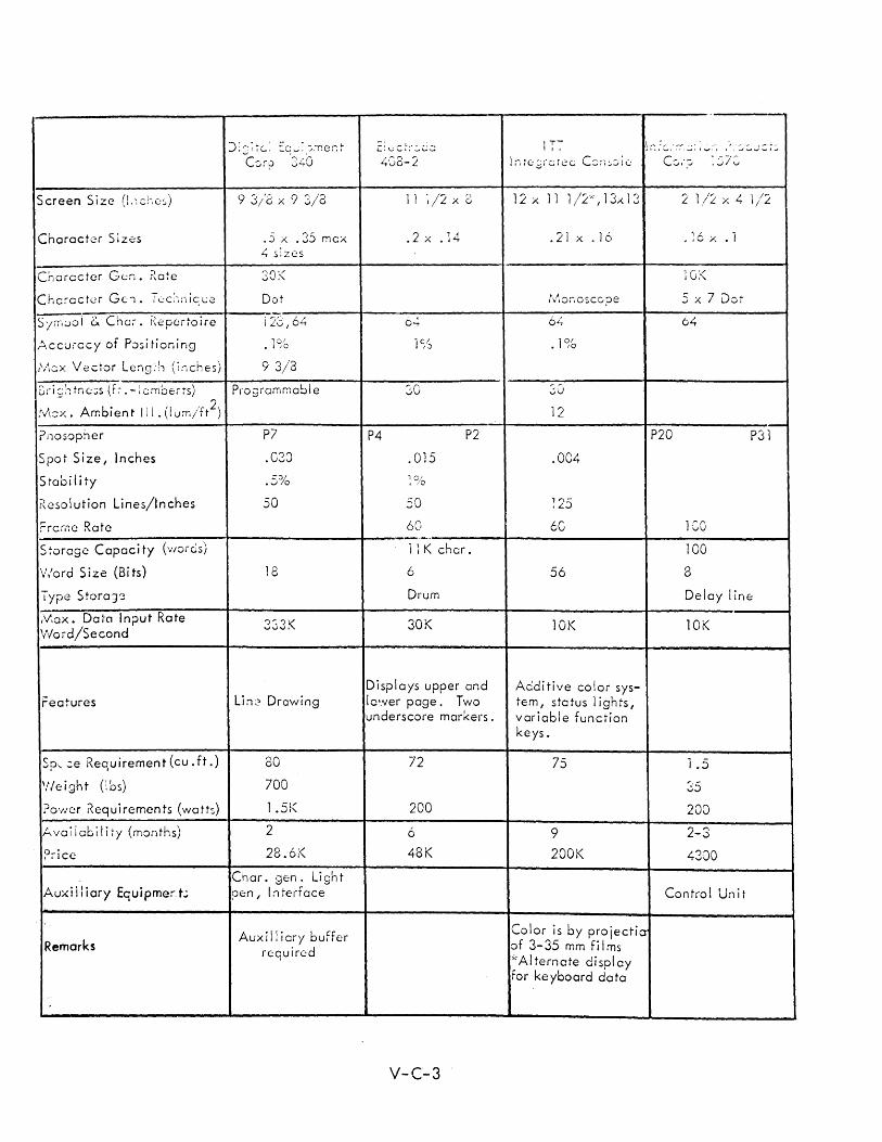
Screen Size (l:~ c:' e:;,)
Character Sizes
enarcc ter Gen. Kate
S/"r,;.)ol 6. Cha;-. Repertoire
)::!7G~ E~u:,~mer:t (:,r;) 340
9 3/8 x 9 3/3
.J x .35 mcx 4 sizes
30;<
Dot
128,64
}:I.ccurccy of Positioning .1%
[\-\ex Vector Leng;h (inches) 93/3
Dri;:h tne::;s (f t . -: cmberrs) Programmabl e
,'vbx. Ambien tIll. (I um/ft2)
(nosopfler
Spot Size, Inches
Stabi I i ty
Kcsolution Lines/Inches
f=rcr.-:e Rate
S 70rage Capaci ty (war os)
V,'ord Size (Bits)
Type S tora Jt3
,V,OX. Dal"C1 In?ut Rate V-Iord/Second
Features
Sp\...:e Requirement(cu. ft.)
'!Ieight (!os)
?O'llcr r<equirements (watts)
Ava;icbility (months)
Auxiiliary Equipmert;
Remarks
P7
.038
.5%
50
18
333K
Li:l2 Drawing
80
700
1.5i<
2
28.6:<
Char. gen. Li gh t pen, l:lterrace
Aux ill i cry buffer required
4'08-2
1 i ~ /2 x 8
.2 x .14
6";'
i%
30
P4 P2
.015 '0' I /0
50
60 --_ ... ,._ .. 11 K char.
6
Drum
30K
Displays upper and Ic'.ver page. Two underscore markers.
72
200
6
48K
V-C-3
I T 7 I.
12 x 11 1/2;:, 1 3x 1 3
.21 x .16
!\-~onosccpe
64
.1%
30
12
.004
1"-;L:J
60
56
10K
Additive color system, status lights, variable functio:l keys.
75
9
200K
Color is by projecticr of 3-35 mm fi I ms '~Alternate display tor keyboard data
P20
2 1/:2 x 4 1/2
.16 A .1
5 x 7 Dot
64
1"'rvU
100
3
P31
Delay line
10K
1.5
35
200
2-3
4300
Contra! Unit
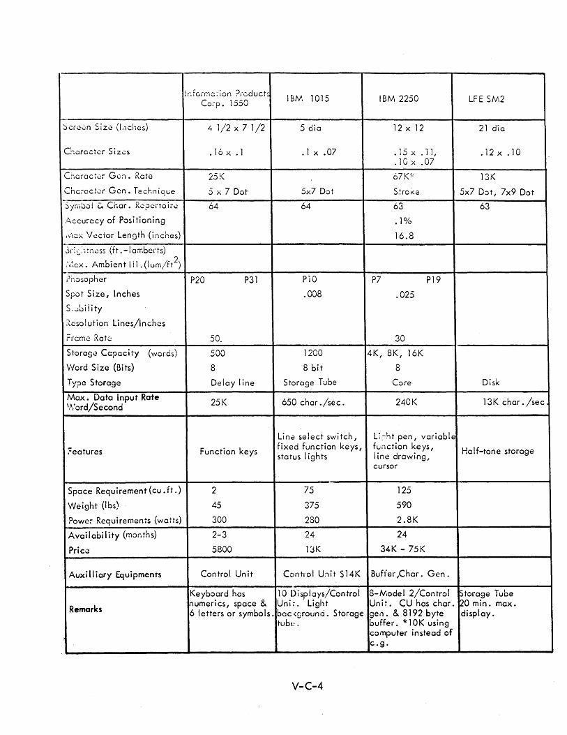
l r. fcrr.1c ;-ion PI-educt, IBM 1015 IBM 2250 LFE SM2 Co;-p. 1550
f--
Scrc..:;n Size (l.1Ches) 4 1/2 x 7 1/2 5 dia 12 x 12 21 dia
C~orQctcr Sizes .16 x . 1 .1 x .07 .15 x . 11, .12 x .10 . lG x .07
Chciac~.::r Gen. Ratc 25K 67K":: 13K
Chc:-actcr Gen. Technique 5 x 7 Dot 5x7 Dot S:roKe 5x7 Dot, 7x9 Dot --:- I I" C' R • ~yrlliJ0 u nor. CiJC:rTOlr.:: 64 64 63 63
.';ccuracy of Positioning .1%
I''/\CX V ector Length (inches) 16.8
-jr;~),rn.::ss (ft .-Ia:r.berts)
\\cx. Ambient III . (lurr./ft2)
?r.osopher P20 P31 P10 P7 P19
Spot Size I Inches .008 .025
S .... Siiity
~csolution Lines/Inches
frcme Rate 50_ 30
Storage Capacity (words) 500 1200 4K, 8K, 16K
V/ord Size (Bits) 8 8 bit 8
Type Storage Delay line Storage Tube Core Disk
Max. Data Input Rate V',' ord/Second 25K 650 char ./sec. 240K 13K char. /sec
Line select switch, Li::ht pen, variable
?eatures Function keys fixed function keys, function ke ys, Ha If-tone storage status lights i ine drawing,
cursor
Space Requirement (cu. ft.) 2 75 125
Weight (Ibs) 45 375 590
?owe:- Requirements (watts) 300 280 2.8K
Availability (months) 2-3 24 24
Price 5800 l~K 34K - 75K
Auxi II iary Equipmenrs Control Unit Control Unit $14K Buffer ,Char. Gen.
Keyboard has 10 Displays/Control 8-Model 2/Control Storage Tube
Remarks 'numerics, space & Unii. . Light Unit. CU has char. 20 min. max. 6 letters or symbols . bac<grounci. Storage gen. & 8192 byte display.
tub(! . buffer. * 1 OK using computer instead of c.g.
V-C-4
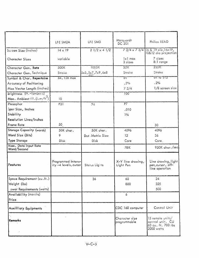
LFE SM2A LFE SM3 Marquardt Philco READ DC 201
Sc,'een Size (I nches) 14 x 19 2 1/2 x 4. 1/2 7 3/4 x 7 3/4 1 6 & 1 9 d i a , 14x 19 , 10& 12 dia proiection
Character Sizes variable 1x1 max 7 sizes 3 sizes 8: 1 range
Character Gen. Rate 500K 10GOK 52K 2L2K
Character Gen. Technique Stroke 5x5,5x7,7x9,6x8 Stroke Stroke dot
Symbol & Char. Repertoire 64 I IL() max 64 O/ot TO .) I L
Accuracy of Positioning • 2~/() .2%
Max Vector Length (inches) 7 3/4 1/8 screen size
Brightness (ft.-Iambens) ---.--
100 ?
Max. Ambient ill.(i~lm/ft'-) 10 --,-_ .... -Phosopher P31 ?4 P7
Spot Size, Inches .010
Stabil ity 10/0
Resolution Lines/Inches
Frame Rate 50 30 -
Storage. Capacity (words) 50K char. 50K char. 4096 4096
Word Size (Bi ts) 9 Dot Matri>~ Size 12 36
Type Storage Disk Disk Core Core
""lax. Data Input Rate Word/Second 78K 950K char./sec
Programmed intens- X-V line drawing, Line drawing,light Features ity -4 levels, cursor StClfliS Lig:":ts Light Pen pen, cursor, off-
I ine operation
Space Requirement (cu. ft.) 36 60 24
Weight (Ibs) 800 325
.vwer Requirements (watts) 500
Ava iI abil ity (months) 6
Price
Auxi II iary Equipments CDC 160 computer Control Unit
Remarks ChafClcter size 15 remote units/ progrtJmmable control unit. CU
60 cu. ft. 700 Ibs 2000 watts
V-C-5
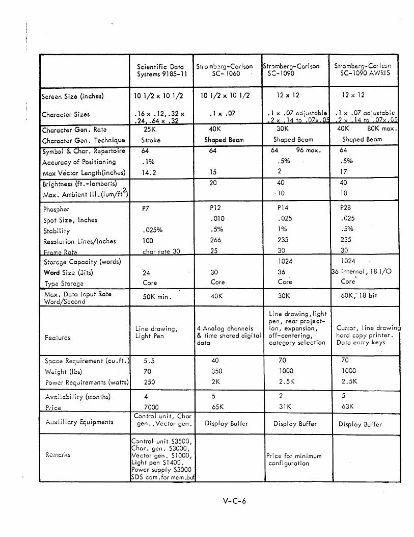
Scientific Data St .. omb·~rH-Carlson Stnmberg-Carl son Strombe:-g-Ca:- I son Systems 9185-11 SC- 1060 S:-1090 SC-l090 AV/RI S
Screen Size (Inches) 10 1/2 x 10 1 /2 1 0 1/2 x 10 1/2 12 x 12 12 x 12
Character Sizes • 16 x . 12, .32 x • 1 x .07 . .1 x .07 adiustable .1 x .07 adiustable .24 •. 64 x .32 ? x 14 t~ 07x 0.' 2 x 14 t~ 07 x 0,=
Character Gen. Rota 25K 40K 30K 40K eOK max.
Character Gen. Technique Stroke Shaped Beam Shaped Beam Shaped Beam
Symbol & Char. Repertoire 64 64 64 96 max. 64
Accuracy of Positioning .1% .50/0 .5%
Max Vector Len9th(inch~s) 14.2 15 2 17
Brightness (ft. -Iamberts) 20 40 40
Max. Ambient III. (lum/ft2) ·10 10
Phos?h~r P7 P12 P14 P28
Spot Size, Inches .010 .025 .025
Stabil ity .025% .5% 1% .5%
Resolution Lines/Inches 100 266 235 235
Frame Rct~:> char rate 30 25 30 30
Storege Capacity (words) 1024 1024
Word Size (Sits) 24 30 36 136 internal, 18 I/O
Typ~ Storage Core Core Core Core
Max. Data Input Rate Word/Second
50K min. 40K 30K 60K,' 18 bit
Line drawing,light pen, rear pro iect-
Line drawing, 4 Analog channels ion, expansion, Cur~or, I ine drawing
Fea7ures Light Pen & ti:ne shared digital off-centering, hard copy prin ter . data category selection Data entry keys
S?ace Requirement (cu.ft.) 5.5 40 70 70
'v\/eight (los) 70 350 1000 1000
Power Re'1uirem~nts (watts) 250 2K 2.5K 2.5K
Avai ~ obi I i ty (mon ths) 4 5 2 5
Ptice 7000 65K 31K 63K
Auxiilicry Equipments Control unit, Char gen. , Vector gen. Display Buffer Display Buffer Display Buffer
Control unit S3500,
R~mcrks Char. gen. $3000, Vector gen. $ 1 000, Price for minimum Light pen $140'j, confi guration Power suppl y $3000 SDS com. for mem .bJ
V-C-6
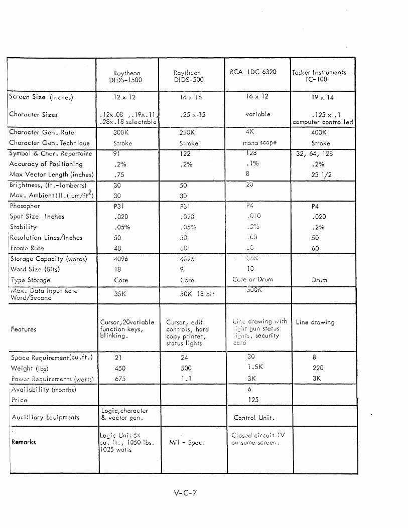
Raytheon Rayth2o:a RCA IDC 6320 Tasker Instrun:e:ats DIDS-1500 0105-500 TC-1OO
Screen Size (I nches) 12 x 12 16 x 16 16 x 12 19 x 14
Character Sizes .12x.OS , . 19x. 11, .25 x .15 variable .125 x .1 .28x .18 selectable computer controlled
Character Gen. Rate 300K 250K 4K 400K
Character Gen. Techn ique Stroke 51roke mono scope Stro~e
Symbol & Char. Repertoire 91 122 lid 32, 64, 128
Accuracy of Positioning .2% .2% .1% .2%
Max Vector Length (inches) .75 8 23 1/2
Bri:::;htness, (ft .-Iamberts) 30 50 20
Max. Ambient 111.(lum/ft2) 30 30
Phoso?her P31 P~l P4 P4
Spot Size. Inches .020 .020 .010 .020
Stabi I i ty .05% .05% ::0/ .2% .,J,O
I •
I Resolution Lines/Inches 50 50 ~CG 50 I
.r' Frame Rate 48 60 '-'u 60 -
Storage Capacity (words) 4096 4C96 :6K
Word Size (Si ts) 18 9 10
I T"~e Storage ~ I I
Core Core Cel-e or Drum Drum ... - JUU", . ,''';\cx. Data In?vt Kate
35K 50K 18 bit Word/Second
Cursor ,20vcriable Cursor, edi t L ;; .... ..:: c:-awi ng v: i ill Line drawing reatuies function keys, con tro Is, hard ,. t gun stat-.Js
bl inking. copy p:-i n ter , :i:::;;',fS, security status lights cc:d
Spac8 Requ irement(cu . ft.) 21 24 30 8
Weight (Ib.s) 450 500 1.5K 220
Po\,/-:; K.:;quircmcnts (watts) 675 1.1 3K 3K
Availability (months) 6
Price 125
Log i c, charac ter Auxidiary ECjuiprr.enrs & vector gen. Control Unit.
Logic Un i: 54 C:osed circuit TV Remarks cu. ft., 1050 Ibs. Mil - S?ec. en same screen.
1025 watts
V-C-7
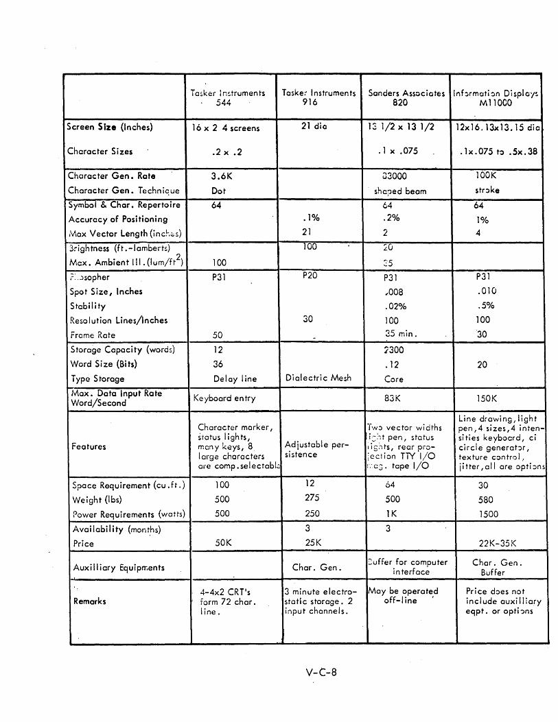
Tasker Imtruments Tasker Instruments Sanders Associates Inf:)rmatbn Display!. 544 916 820 MllOCO
Screen Size {Inches} 16 x 2 4 screens 21 dio 1 3 1/2 x 1 3 1 /2 12x 16. 13x 13. 15 di a
Character Sizes .2 x .2 .1 x .075 . 1 x . 075 t:l • Sx . 38
Character Gen. Rate 3.6K 03000 lOOK
Character Gen. Technique Dot shaped beam str:>ke
Symbol & Char. Repertoire 64 64 64
Accuracy of Positioning .1% .2% 1%
Max Vector Length (inc~,;;;s) 21 2 4
3rightness (ft .-Iamberts) 100 LU Max. Ambient III. (lum/ft
2) 100 25
?: . .)sopher P31 P20 P31 P31
Spot Size, Inches ,-008 .010
Stabil i ty .02% .5%
Resolution Lines/Inches 30 100 100
Frome Rate 50 -ro;l:: • v...J min. '30
Storage Capacity (words) 12 Jl300
'Nord Size (Bits) 36 . 12 20
Type Storage Delay line Dialectric Mesh Core
Max. Data Input Rate Word/Second
Ke yboard en try 83K 150K
Character marker, Line drawing, light
Tw:> vector widths pen,4 sizes,4 inten-status lights,
Adjustable per-i::lt pen, status sities keyboard, ci
Features many keys, 8 i i g:, ts, rear pro- circle generat:)r, I arge characters si stence iec1 ion TN 1/0 texture control, are comp.selectabL: :.,a:;. tape I/O ji tter ,a II are optbns
Space Requirement (cu. ft.) 100 12 64 30
Weight (Ibs) 500 275 500 580
Power Requirements (watts) 500 250 1K 1500
Availability (mont,hs) 3 3
Price 50K 25K 22K-35K
Auxi II iary Equiprr.ents Char. Gen. ~uffer for computer Char. Gen.
interface Buffer
: I 4-4x2 CRT's 3 minute electro- May be operated Price does not
Remarks form 72 char. static storage. 2 off-line I inc I ude auxi II iary line. input channel s. eqpt. or opti :>ns
V-C-8

)
UNCLASSIFIED Security Classification
DOCUMENT CONTROL DATA· R&D (Security classlilcation 01 title. body 01 abstract and 'nde"'n~ annotation must be entered when the overall report I. closs/lied)
1. O~IGINATIN G ACTlVI'!'Y (Corporate author) 2 e. REPORT SEC URI TV C L.ASSIFICA TION
INFORMATICS INC. UNCLASSIFIED 15300 Ventura Blvd., 2 b, GROUP
Sherman Oaks, Calif. 3. REPORT TITLE
ADVANCED NAVAL TACTICAL COMMAND AND CONTROL STUDY, VOLUME V, TECHNOLOGY
I'~~~~~~~~~~--------------------------------------------------------------------~ :; 4. DESCRIPTIVE NOTES (Type 01 report and Inclusive dates)
~ Summary of Work Cone luded in Period January 1964 to January 1965 ,: S. AUTHOR(S) (La., name. Ilr.t name, InltiaO
Cohen, 1.;Amdahl, L.; Bigelow, R., Craver, J.S.i Frank, W. L.i Granholm, J. W.; Hobbs, L.C., Mersel, J.i Morris, W. A.
o. REPO RT DA TE 7a. T-OTAL. NO. OF PAGES
15 JANUARY 1965 763 aa. CONTRACT OR GRANT NO. ga. ORIGINATOR'S REPORT NUMBER(S)
Nonr-4388 (00) b. PRO.JECT NO. - TR-65-58-2
c.
d.
sa b. OTH ER R~PORT No(S) (Any other number. that may be a •• llined thl. report)
None
, O. A VA IL. A.IL.ITV IL.IMITATION NOTICES
U.S. military agencies may obtain copies of this report directly from DDC. ,Other qualified DDC users shall request through the Advanced Warfare Systems Division of the Office of Naval Research.
,,, SUPPL EMENTARY NOTES \2. SPONSORING MILITARY ACTIVITY
None ONR
13. ABSTRACT
This volume presents results of a study to identify, analyze, and evaluate information systems' technology applicable to future tactical Navy Command and Control Systems. Included is a discussion of electronic data processing systems, memories, input/output devices, displays, computer programming, components and packaging, artificial intelligence, and self-diagnostic systems. These technical areas are analyzed on the basis of current technology and anticipated developments versus requirements of a 1970 era Naval tactical system.
DD FORM , .JAN 84 0101-807-6800 UNCLASSIFIED
Security Classification
14.
;
I I i
J ,
~ ~ i
~I
i 1
:
,
UNCLASSIFIED Secu;:ilV Classificatio:1
KEY WORDS
INPUT/OUTPUT TECHNOLOGY
DISPLAY SYSTEMS
DISPLAY TECHNOLOGY
COMPONENTS AND PACKAGING
!'.,\EMORY TECHNOLOGY
COMPUTER SYSTEMS ORGANIZATION
PROGRAN\MING
ARTIFICIAL INTELLIGENCE
SELF-DIAGNOSTIC SYSTEMS
LINK A LINK B LINK C
ROL.E WT ROL.E WT ROL.E WT
INSTRUCTIONS
\. ORIGINATING ACTIVITY: Enter the name and address of the contractor, subcontractor, grantee, Department of Defense activity or other organization (corporate author) issuing the report.
28. REPORT SECURITY CLASSIFICATION: Enter the overall security classification of the report. Indicate whether "Restricted Data" is included. Marking is to be in accordance with appropriate security regulations.
2b. GROUP: Automatic downgrading is specified in DoD Directive 5200.10 and Armed Forces Industrial Manual. Enter
I the r.roup number. Also, when applicable, show that optional I mar;~ings have been used for Group 3 and Group 4 as author-: ized.
3. REPORT TITLE: Enter the complete report title in all capital letters. Titles in all cases should be unclassified. If a meaningful title cannot be selected without classification, show title classification in all capitals in parenthesis immediately following the title.
4. DESCRIPTIVE NOTES: If appropriate, enter the type of report, e. g., interim, progress, summary, annual, or final. Give the inclusive dates when a specific reporting period is covered.
5. AUTHOR(S): Enter the name(s) of author(s) as shown on or in the report. Enter last name, first name, middle initial. If military, show rank and branch of service. The name of the principal author is an ahsolute minimum requirement.
6. REPORT DATE.: Enter the date of the report as day, month, year; or month, year. If more than one date appears on the report, use date of publication.
7.1. TOTAL NUMBER OF PAGES: The total page count should follow normal pagination procedures, i. e., enter the number of pages containing information.
7b. NUMBER OF REFERENCES: Enter the total number of references cited in the report.
Sa. CONTI~ACT OR GRANT NUMRER: If appropriate, enter tlw OIl'plicllhll' numher of the contrllct or ~rllnt under which t IH~ r('\l(lrt wo:-. wriltt~llo
Sb, &:, & Sd. Pl,OJECT NUMOER: Enter the appropriate military department identification, such as project number, subproject number, system numbers, task number, etc.
9a. ORIGINATOR'S REPORT NUMBER(S): Enter the official report number by which the document will be identified and controlled by the originating activity. This number must be unique to this report.
9b. OTHER REPORT NUMBER(S): If the report has been assigned <lny other report numbers (either by the or;~inator or by the sponsor), also enter this number(s).
10. AVAILABILITY/LIMITATION NOTICES: Enter any limitations on further dissemination of the report, other than those
imposed by security classification, using standard statements such as:
(1) "Qualified requesters may obtain copies of this report from ODe."
(2) "Foreign announcement and dissemination of this report by DDC is not authorized."
(3) "U. S. Government agencies may obtain copies of this report directly from DOC. Other qualified DOC users shall request through
(4) .,u. S. military agencies may obtain copies of this report directly from DDe. Other qualified users shall request through
"
" (5) "All distribution of this report is controlled. Qual
ified DDC users shall request through
----------------------------------------- ." If the report has been furnished to the Office of Technical
Services, Department of Commerce, for sale to the public, indicate this fact and enter the price, if known.
11. SUPPLEMENTARY NOTES: Use for additional explanatory notes.
12. SPONSORING MILITARY ACTIVITY: Enter the name of the departmental project office or laboratory sponsoring (pa~ in~ [or) the research and development. Include address.
13. ABSTRACT: Enter an abstract giving a brief and factual summary of the document indicative of the report, even though it may also appear elsewhere in the body of the technical report. If additional space is required, a continuation sheet shall be attached.
It is highly desirable that the abstract of classified reports be unclassified. Each paragraph of the abstract shall cnd with an indication of the militnry security clossificillion of the informntion in the pllrll~ruph, rcprcH('ntt~d us (TS). (S). (C). or (U).
There is no limitution on the length of the abstract. However, the suggested length is from 150 t'.> 225 words.
14. KEY WORDS: Key words are technically meaningful terms or short phrases that characterize a report and may be ufied as index entries for cataloging the report. Key words must be selected so that no security classification is required. Identifiers, such as equipment model designation, trade name, military project code name, geographic location, may be used as key words but will be followed by an indication of technical context. The assignment of links, roles, and weights is optional.
UNCLASSIFIED Security Classification