advanced and intelligent control techniques applied to the drive control and path tracking systems...
TRANSCRIPT
Autonomous Robots 11, 137–148, 2001c© 2001 Kluwer Academic Publishers. Manufactured in The Netherlands.
Advanced and Intelligent Control Techniques Applied to the Drive Controland Path Tracking Systems on a Robotic Wheelchair
FELIPE ESPINOSA, ELENA LOPEZ, RAUL MATEOS, MANUEL MAZO AND RICARDO GARCIAElectronics Department, University of Alcala, Campus Universitario s/n, 28805 Alcalá de Henares, Madrid, Spain
Abstract. This paper presents the theoretical support and experimental results of the application of advancedand intelligent control techniques to the drive control and trajectory tracking systems on a robotic wheelchair.The adaptive optimal control of the differential drive helps to improve the automatic guidance system’s safetyand comfort taking into consideration operating conditions such as load and distribution changes or motion ac-tuator limitations. Furthermore, the incorporation of an optimal controller to minimize location errors and afuzzy controller to adapt the linear velocity to the characteristics of the trajectory, provide the vehicle with ahigh degree of intelligence and autonomy, even when faced with obstacles. The global control solution imple-mented increases the features of the wheelchair for handicapped people, especially for those with a high degree ofdisability.
Keywords: adaptive and optimal drive control, optimal and fuzzy path tracking, obstacle avoidance, roboticwheelchair
1. Introduction
One of the fundamental aspects in the design of au-tonomous vehicles is related to the different controlloops implicit in the guidance. Most of the researchwork on robotic wheelchairs for handicapped people,and in general for differential drive vehicles, incor-porate classic solutions for low level control (drivecontrol) and concentrate design efforts on high levelcontrol (path tracking) (Borenstein and Koren, 1987;Mazo et al., 1995; Feng et al., 1994; Miller and Slack,1995; Yanco, 1998; Garcia et al., 1998).
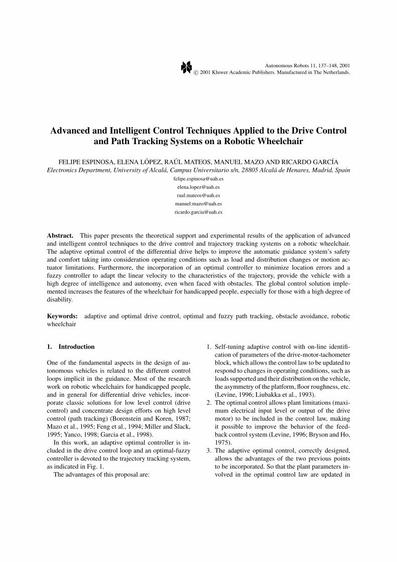
In this work, an adaptive optimal controller is in-cluded in the drive control loop and an optimal-fuzzycontroller is devoted to the trajectory tracking system,as indicated in Fig. 1.
The advantages of this proposal are:
1. Self-tuning adaptive control with on-line identifi-cation of parameters of the drive-motor-tachometerblock, which allows the control law to be updated torespond to changes in operating conditions, such asloads supported and their distribution on the vehicle,the asymmetry of the platform, floor roughness, etc.(Levine, 1996; Liubakka et al., 1993).
2. The optimal control allows plant limitations (maxi-mum electrical input level or output of the drivemotor) to be included in the control law, makingit possible to improve the behavior of the feed-back control system (Levine, 1996; Bryson and Ho,1975).
3. The adaptive optimal control, correctly designed,allows the advantages of the two previous pointsto be incorporated. So that the plant parameters in-volved in the optimal control law are updated in
138 Espinosa et al.
Figure 1. Global solution of the applied control loops on a robotic wheelchair.
accordance with the on-line changes detected(Espinosa, 1998a).
4. The lateral and orientation errors in the trajectorytracking are corrected with an optimal control law,establishing the appropriate values of angular ve-locity of the vehicle.
5. The linear velocity V of the vehicle is calculatedby means of a fuzzy control solution in accordancewith the distance to the destination and the radiusof curvature of the established path.
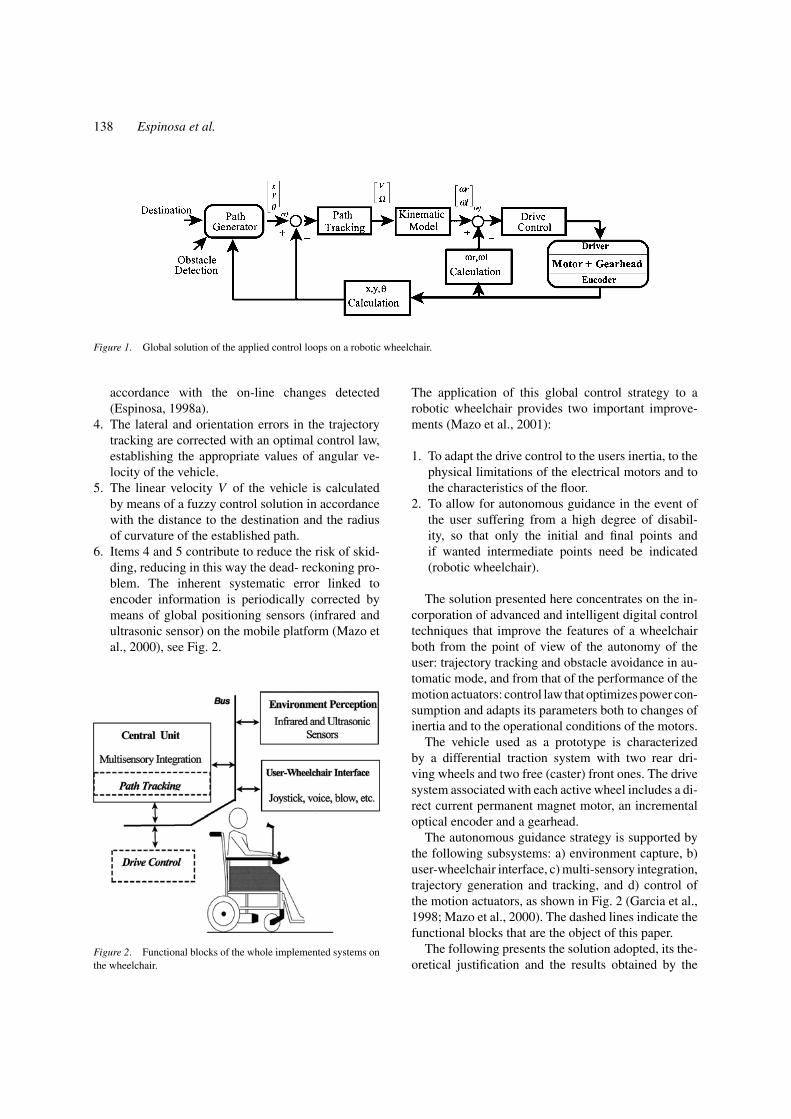
6. Items 4 and 5 contribute to reduce the risk of skid-ding, reducing in this way the dead- reckoning pro-blem. The inherent systematic error linked toencoder information is periodically corrected bymeans of global positioning sensors (infrared andultrasonic sensor) on the mobile platform (Mazo etal., 2000), see Fig. 2.
Figure 2. Functional blocks of the whole implemented systems onthe wheelchair.
The application of this global control strategy to arobotic wheelchair provides two important improve-ments (Mazo et al., 2001):
1. To adapt the drive control to the users inertia, to thephysical limitations of the electrical motors and tothe characteristics of the floor.
2. To allow for autonomous guidance in the event ofthe user suffering from a high degree of disabil-ity, so that only the initial and final points andif wanted intermediate points need be indicated(robotic wheelchair).
The solution presented here concentrates on the in-corporation of advanced and intelligent digital controltechniques that improve the features of a wheelchairboth from the point of view of the autonomy of theuser: trajectory tracking and obstacle avoidance in au-tomatic mode, and from that of the performance of themotion actuators: control law that optimizes power con-sumption and adapts its parameters both to changes ofinertia and to the operational conditions of the motors.
The vehicle used as a prototype is characterizedby a differential traction system with two rear dri-ving wheels and two free (caster) front ones. The drivesystem associated with each active wheel includes a di-rect current permanent magnet motor, an incrementaloptical encoder and a gearhead.
The autonomous guidance strategy is supported bythe following subsystems: a) environment capture, b)user-wheelchair interface, c) multi-sensory integration,trajectory generation and tracking, and d) control ofthe motion actuators, as shown in Fig. 2 (Garcia et al.,1998; Mazo et al., 2000). The dashed lines indicate thefunctional blocks that are the object of this paper.
The following presents the solution adopted, its the-oretical justification and the results obtained by the
Advanced and Intelligent Control Techniques 139
double control loop indicated in Fig. 1: low level con-trol or drive control and high level control or path track-ing. The variables involved are: angular velocities ofthe right-hand wheel ωr and the left-hand wheel ωl,position x-y and orientation θ of the wheelchair in aCartesian reference system, and the linear V and angu-lar � velocities of the vehicle.
2. Adaptive Optimal Control ofMotion Actuators
Possessing a good model of the physical system helpsenormously when designing the corresponding con-troller. In the case of mobile wheeled units, the dy-namic model of the vehicle in open loop, as regardsthe structure of the platform (Jones and Flynn, 1993),and the number and detail of effects to model (Rompe,1997) can be extremely complex. Because of this, ade-quate control of the motion actuators, allows on theone hand minimisation of the actions of internal and/orexternal disturbances and on the other, simplification ofthe design of the external feedback loops for trajectorytracking.
In the robotic wheelchair under study, the sub-unitformed by the DC motor with the wheel coupled tothe gear head spindle, and the electronic excitation(driver) and velocity measurement (tachometer) sys-tems, presents a reasonably linear behavior, apart fromthe short start-stop dead zone and the output satura-tion for high input levels. This allows for the actionof input disturbances (surface roughness, friction, etc.)and other undesired effects, for example the time vari-ation of internal parameters, to be corrected via anadaptive system such as the auto-tuned PI proposed byLiubakka et al. (1993). Moreover, if desired, the con-trol law minimises a performance index based on the
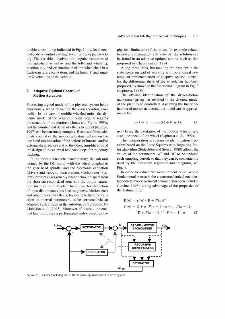
Figure 3. General block diagram of the adaptive optimal control of drive system.
physical limitations of the plant, for example relatedto power consumption and velocity, the solution canbe found in an adaptive optimal control such as thatproposed by Chandra et al. (1994).
Along these lines, but tackling the problem in thestate space instead of working with polynomial sys-tems, an implementation of adaptive optimal controlfor the differential drive of the wheelchair has beenproposed, as shown in the functional diagram in Fig. 3(Espinosa, 1998b).
The off-line identification of the driver-motor-tachometer group has resulted in the discrete modelof the plant to be controlled. Assuming the linear be-haviour of motion actuators, this model can be approxi-mated by
ω(k + 1) = a · ω(k) + b · u(k) (1)
u(k) being the excitation of the motion actuator andω(k) the speed of the wheel (Espinosa et al., 1997).
The incorporation of a recursive identification algo-rithm based on the Least Squares with forgetting fac-tor algorithm (Sodesbom and Stoica, 1980) allows thevalues of the parameters “a” and “b” to be updatedeach sampling period, so that they can be convenientlyused by the estimator, regulator and integrator, seeFig. 4.
In order to reduce the measurement noise, whosefundamental source is the electromechanical encoder-tachometer block, a current estimator has been included(Levine, 1996), taking advantage of the properties ofthe Kalman filter:
K(n) = P(n) · [R + P(n)]−1
P(n) = Q + a · P(n − 1) · a − a · P(n − 1) ·[R + P(n − 1)]−1 · P(n − 1) · a (2)
140 Espinosa et al.
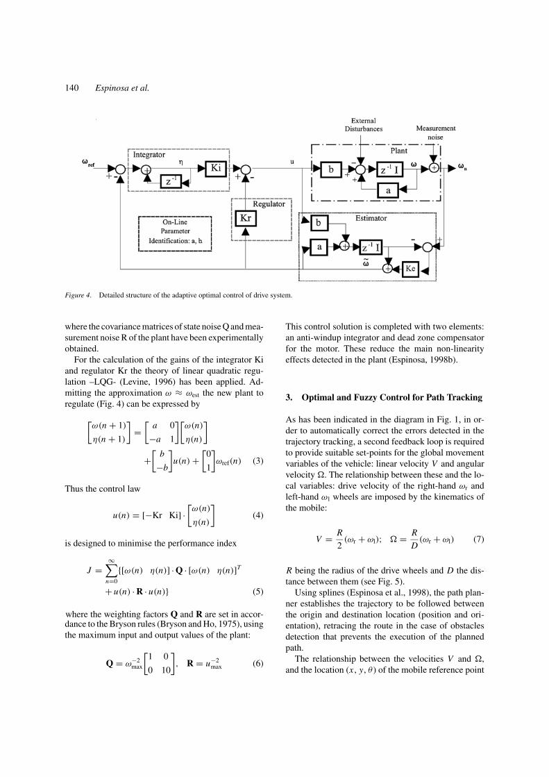
Figure 4. Detailed structure of the adaptive optimal control of drive system.
where the covariance matrices of state noise Q and mea-surement noise R of the plant have been experimentallyobtained.
For the calculation of the gains of the integrator Kiand regulator Kr the theory of linear quadratic regu-lation –LQG- (Levine, 1996) has been applied. Ad-mitting the approximation ω ≈ ωest the new plant toregulate (Fig. 4) can be expressed by
[ω(n + 1)
η(n + 1)
]=
[a 0
−a 1
][ω(n)
η(n)
]
+[
b
−b
]u(n) +
[0
1
]ωref(n) (3)
Thus the control law
u(n) = [−Kr Ki] ·[ω(n)
η(n)
](4)
is designed to minimise the performance index
J =∞∑
n=0
{[ω(n) η(n)] · Q · [ω(n) η(n)]T
+ u(n) · R · u(n)} (5)
where the weighting factors Q and R are set in accor-dance to the Bryson rules (Bryson and Ho, 1975), usingthe maximum input and output values of the plant:
Q = ω−2max
[1 0
0 10
], R = u−2
max (6)
This control solution is completed with two elements:an anti-windup integrator and dead zone compensatorfor the motor. These reduce the main non-linearityeffects detected in the plant (Espinosa, 1998b).
3. Optimal and Fuzzy Control for Path Tracking
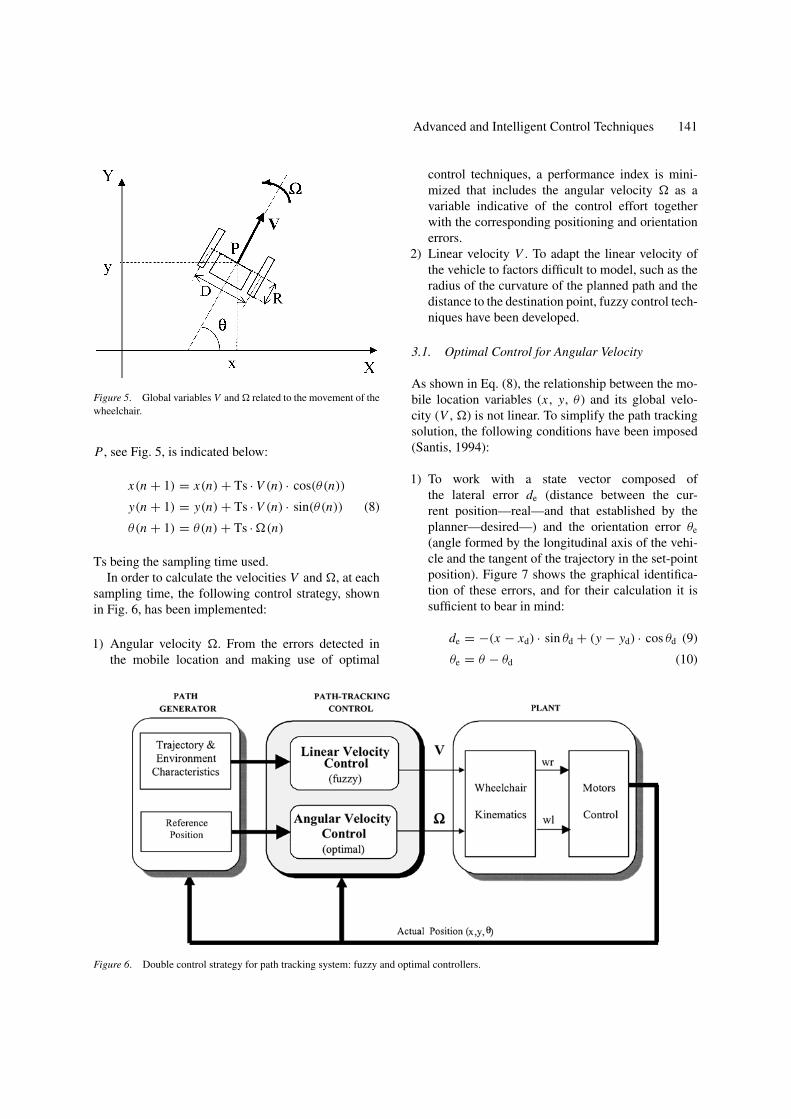
As has been indicated in the diagram in Fig. 1, in or-der to automatically correct the errors detected in thetrajectory tracking, a second feedback loop is requiredto provide suitable set-points for the global movementvariables of the vehicle: linear velocity V and angularvelocity �. The relationship between these and the lo-cal variables: drive velocity of the right-hand ωr andleft-hand ω l wheels are imposed by the kinematics ofthe mobile:
V = R
2(ωr + ωl); � = R
D(ωr + ωl) (7)
R being the radius of the drive wheels and D the dis-tance between them (see Fig. 5).
Using splines (Espinosa et al., 1998), the path plan-ner establishes the trajectory to be followed betweenthe origin and destination location (position and ori-entation), retracing the route in the case of obstaclesdetection that prevents the execution of the plannedpath.
The relationship between the velocities V and �,and the location (x , y, θ ) of the mobile reference point
Advanced and Intelligent Control Techniques 141
Figure 5. Global variables V and � related to the movement of thewheelchair.
P , see Fig. 5, is indicated below:
x(n + 1) = x(n) + Ts · V (n) · cos(θ(n))
y(n + 1) = y(n) + Ts · V (n) · sin(θ(n)) (8)
θ(n + 1) = θ(n) + Ts · �(n)
Ts being the sampling time used.In order to calculate the velocities V and �, at each
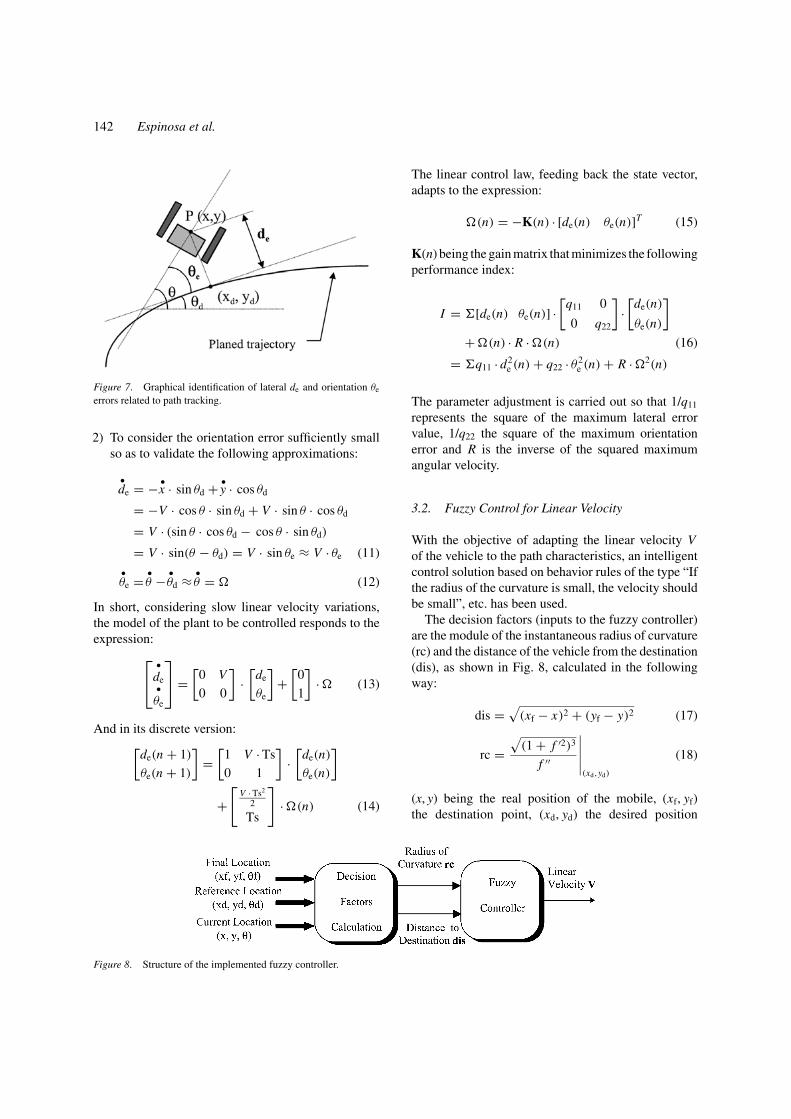
sampling time, the following control strategy, shownin Fig. 6, has been implemented:
1) Angular velocity �. From the errors detected inthe mobile location and making use of optimal
Figure 6. Double control strategy for path tracking system: fuzzy and optimal controllers.
control techniques, a performance index is mini-mized that includes the angular velocity � as avariable indicative of the control effort togetherwith the corresponding positioning and orientationerrors.
2) Linear velocity V . To adapt the linear velocity ofthe vehicle to factors difficult to model, such as theradius of the curvature of the planned path and thedistance to the destination point, fuzzy control tech-niques have been developed.
3.1. Optimal Control for Angular Velocity
As shown in Eq. (8), the relationship between the mo-bile location variables (x , y, θ ) and its global velo-city (V , �) is not linear. To simplify the path trackingsolution, the following conditions have been imposed(Santis, 1994):
1) To work with a state vector composed ofthe lateral error de (distance between the cur-rent position—real—and that established by theplanner—desired—) and the orientation error θe
(angle formed by the longitudinal axis of the vehi-cle and the tangent of the trajectory in the set-pointposition). Figure 7 shows the graphical identifica-tion of these errors, and for their calculation it issufficient to bear in mind:
de = −(x − xd) · sin θd + (y − yd) · cos θd (9)
θe = θ − θd (10)
142 Espinosa et al.
Figure 7. Graphical identification of lateral de and orientation θe
errors related to path tracking.
2) To consider the orientation error sufficiently smallso as to validate the following approximations:
•de = − •
x · sin θd + •y · cos θd
= −V · cos θ · sin θd + V · sin θ · cos θd
= V · (sin θ · cos θd − cos θ · sin θd)
= V · sin(θ − θd) = V · sin θe ≈ V · θe (11)•θe = •
θ − •θd ≈ •
θ = � (12)
In short, considering slow linear velocity variations,the model of the plant to be controlled responds to theexpression:
•de•θe
=
[0 V
0 0
]·[
de
θe
]+
[0
1
]· � (13)
And in its discrete version:[de(n + 1)
θe(n + 1)
]=
[1 V · Ts
0 1
]·[
de(n)
θe(n)
]
+[
V · Ts2
2
Ts
]· �(n) (14)
Figure 8. Structure of the implemented fuzzy controller.
The linear control law, feeding back the state vector,adapts to the expression:
�(n) = −K(n) · [de(n) θe(n)]T (15)
K(n) being the gain matrix that minimizes the followingperformance index:
I = [de(n) θe(n)] ·[
q11 0
0 q22
]·[
de(n)
θe(n)
]+ �(n) · R · �(n) (16)
= q11 · d2e (n) + q22 · θ2
e (n) + R · �2(n)
The parameter adjustment is carried out so that 1/q11
represents the square of the maximum lateral errorvalue, 1/q22 the square of the maximum orientationerror and R is the inverse of the squared maximumangular velocity.
3.2. Fuzzy Control for Linear Velocity
With the objective of adapting the linear velocity Vof the vehicle to the path characteristics, an intelligentcontrol solution based on behavior rules of the type “Ifthe radius of the curvature is small, the velocity shouldbe small”, etc. has been used.
The decision factors (inputs to the fuzzy controller)are the module of the instantaneous radius of curvature(rc) and the distance of the vehicle from the destination(dis), as shown in Fig. 8, calculated in the followingway:
dis =√
(xf − x)2 + (yf − y)2 (17)
rc =√
(1 + f ′2)3
f ′′
∣∣∣∣∣(xd,yd)
(18)
(x, y) being the real position of the mobile, (xf, yf)the destination point, (xd, yd) the desired position
Advanced and Intelligent Control Techniques 143
Figure 9. Knowledge base for the fuzzy controller.
calculated by the path planner, f the trajectory equa-tion, and f ′ and f ′′ its first and second derivatives.
Using these input variables for the fuzzy controllermakes it possible to avoid: a) high velocities ontight curves and thus, the risk of skidding, b) move-ments with sharp braking on arrival at the destinationpoint.
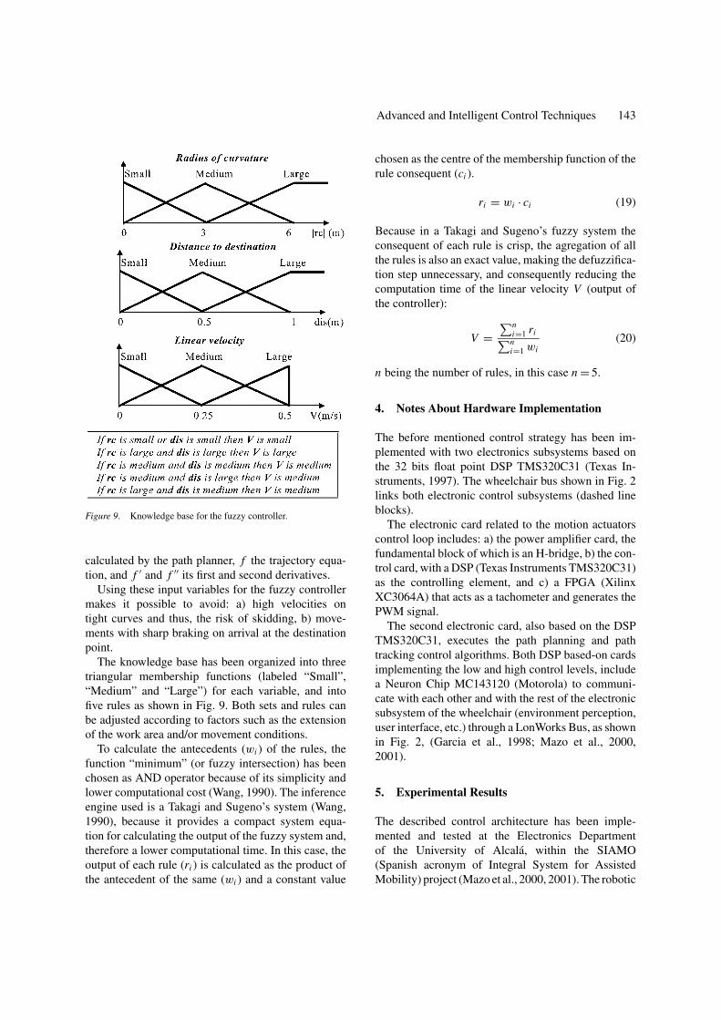
The knowledge base has been organized into threetriangular membership functions (labeled “Small”,“Medium” and “Large”) for each variable, and intofive rules as shown in Fig. 9. Both sets and rules canbe adjusted according to factors such as the extensionof the work area and/or movement conditions.
To calculate the antecedents (wi ) of the rules, thefunction “minimum” (or fuzzy intersection) has beenchosen as AND operator because of its simplicity andlower computational cost (Wang, 1990). The inferenceengine used is a Takagi and Sugeno’s system (Wang,1990), because it provides a compact system equa-tion for calculating the output of the fuzzy system and,therefore a lower computational time. In this case, theoutput of each rule (ri ) is calculated as the product ofthe antecedent of the same (wi ) and a constant value
chosen as the centre of the membership function of therule consequent (ci ).
ri = wi · ci (19)
Because in a Takagi and Sugeno’s fuzzy system theconsequent of each rule is crisp, the agregation of allthe rules is also an exact value, making the defuzzifica-tion step unnecessary, and consequently reducing thecomputation time of the linear velocity V (output ofthe controller):
V =∑n
i=1 ri∑ni=1 wi
(20)
n being the number of rules, in this case n = 5.
4. Notes About Hardware Implementation
The before mentioned control strategy has been im-plemented with two electronics subsystems based onthe 32 bits float point DSP TMS320C31 (Texas In-struments, 1997). The wheelchair bus shown in Fig. 2links both electronic control subsystems (dashed lineblocks).
The electronic card related to the motion actuatorscontrol loop includes: a) the power amplifier card, thefundamental block of which is an H-bridge, b) the con-trol card, with a DSP (Texas Instruments TMS320C31)as the controlling element, and c) a FPGA (XilinxXC3064A) that acts as a tachometer and generates thePWM signal.
The second electronic card, also based on the DSPTMS320C31, executes the path planning and pathtracking control algorithms. Both DSP based-on cardsimplementing the low and high control levels, includea Neuron Chip MC143120 (Motorola) to communi-cate with each other and with the rest of the electronicsubsystem of the wheelchair (environment perception,user interface, etc.) through a LonWorks Bus, as shownin Fig. 2, (Garcia et al., 1998; Mazo et al., 2000,2001).
5. Experimental Results
The described control architecture has been imple-mented and tested at the Electronics Departmentof the University of Alcala, within the SIAMO(Spanish acronym of Integral System for AssistedMobility) project (Mazo et al., 2000, 2001). The robotic
144 Espinosa et al.
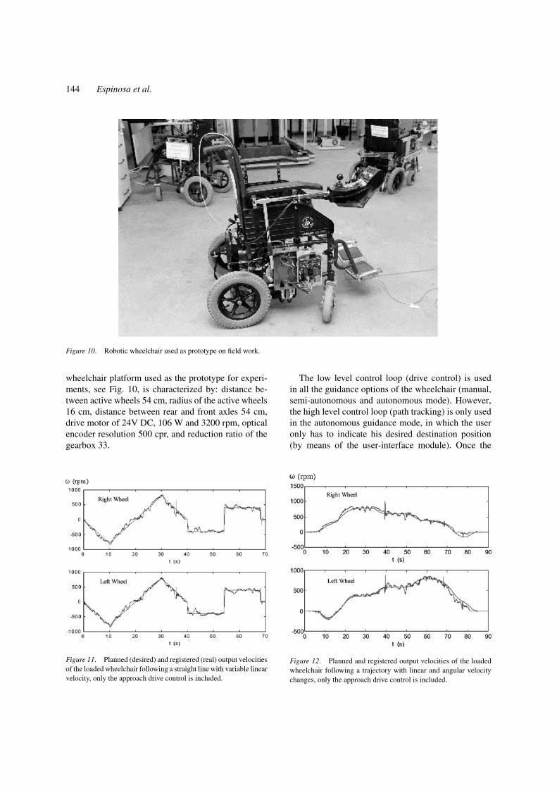
Figure 10. Robotic wheelchair used as prototype on field work.
wheelchair platform used as the prototype for experi-ments, see Fig. 10, is characterized by: distance be-tween active wheels 54 cm, radius of the active wheels16 cm, distance between rear and front axles 54 cm,drive motor of 24V DC, 106 W and 3200 rpm, opticalencoder resolution 500 cpr, and reduction ratio of thegearbox 33.
Figure 11. Planned (desired) and registered (real) output velocitiesof the loaded wheelchair following a straight line with variable linearvelocity, only the approach drive control is included.
The low level control loop (drive control) is usedin all the guidance options of the wheelchair (manual,semi-autonomous and autonomous mode). However,the high level control loop (path tracking) is only usedin the autonomous guidance mode, in which the useronly has to indicate his desired destination position(by means of the user-interface module). Once the
Figure 12. Planned and registered output velocities of the loadedwheelchair following a trajectory with linear and angular velocitychanges, only the approach drive control is included.
Advanced and Intelligent Control Techniques 145
trajectory is calculated by the path planner, the globalcontrol system has to guarantee a comfortable pathtracking for the user and maximize the performanceof the differential drive system.
The execution time of the low level control algo-rithms on the hardware platform used less than 9 ms.This permits the use of a sampling time of 10 ms for
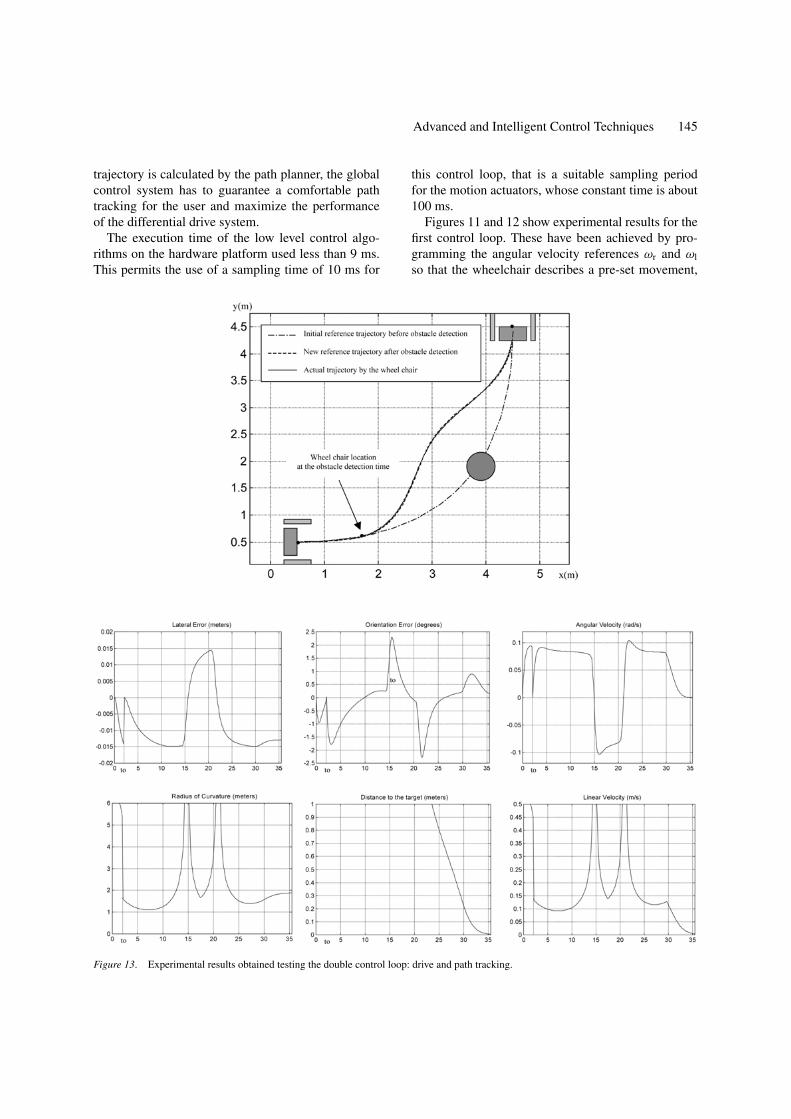
Figure 13. Experimental results obtained testing the double control loop: drive and path tracking.
this control loop, that is a suitable sampling periodfor the motion actuators, whose constant time is about100 ms.
Figures 11 and 12 show experimental results for thefirst control loop. These have been achieved by pro-gramming the angular velocity references ωr and ωl
so that the wheelchair describes a pre-set movement,
146 Espinosa et al.
without closing the path tracking loop. Comparing theangular velocity references with the real ones reg-istered by the tachometers it is possible to evaluatethe response of the wheelchair’s drive control system.Figure 11 presents the results obtained, carrying a loadof 55 kg and following a straight line with sharp andsmooth velocity changes, the initial value of the modelparameters (see Fig. 4) were off-line identified on theunloaded wheelchair. Figure 12 shows the results of asimilar test but now following a trajectory with plannedchanges of velocity and orientation.
The execution time of the path tracking controlalgorithms on the specified platform is 8.82 ms. Inthis case, the sampling period used is 20 ms, beinghigher than the low control loop one. Lower samplingperiods do not improve the global performance of thesystem, because of the inherent delay of the plant. Andthe maximum value of the sampling period of this sec-ond feedback loop is a function of the linear velocityrange. For example, if the maximum programmed ve-locity in the fuzzy controller is 1m/s, a sampling periodhigher than 200 ms produces errors of several centime-ters on the mobile location calculation according tokinematic model (Eq. 14), creating possible instabilityof the system.
Figure 13 shows the experimental results obtainedtesting the double control loop. From an initial posi-tion of (0.5, 0.5, 0), the user indicated a desired targetposition of (4.5, 4.5, π /2). Once the movement wasinitiated, an obstacle was detected and the trajectoryregenerated. So that lineality conditions in Eqs. (11)and (12) can be applied, the following limits have beenfixed: 0.1 metres for lateral error, 30 degrees for ori-entation error and 1 rad/s for angular velocity. The pa-rameters q11 = 100, q 22 = 4 and r = 1 have beenfixed in the Eq. (16). The sets and rules of the fuzzycontroller were adjusted for a maximum velocity of0.5 m/s.
6. Conclusions
The application of advanced digital control techniques,not only to the high level control (trajectory tracking)as is usually carried out on other robotic wheelchairprojects, but also to the low level control (motion ac-tuators control), allows the following benefits to beobtained:
a) Adaptation of the low level controller to the ope-rating conditions: changes of load and distribution,
platform asymmetries, floor roughness, etc. Inclu-sion of physical limitations of the plant (fundamen-tally motor drive level and speed of the wheel axle,)in the control law, reducing the operation in nonlineal behavior zones.
b) Possibility of fixing the maximum value of orien-tation and lateral deviation errors accepted in thepath tracking to adapt the angular velocity of thevehicle, as well as of establishing its linear velocityin accordance with the distance to the destinationand of the trajectory curve. With these propertiesof the high level control, decrease the risk of skid-ding and in this way the problems related to dead-reckoning.
c) Automatic path generation from an initial point toan end point, including possible intermediate points.This, as well as the capacity of automatic path re-generation in the event of obstacle detection, in-creases the degree of autonomy of the robotic wheel-chair.
Acknowledgments
This work is being financed by the CICYT (Interde-partmental Science and Technology Committee, Spain)through project TER96-1957-C03-01.
References
Borenstein, J. and Koren, Y. 1987. Motion control analysis of a mo-bile robot. Transactions of ASME, Journal of Dynamics, Measure-ment and Control, 109(2):73–79.
Bryson, A.E. and Ho, Y.C. 1975. Applied Optimal Control, HalstedPress: Washington, D.C.
Chandra, A., Dessaint, A., Saad, M., and Al-Haddad, K. 1994. Im-plementation of self-tuning algorithms for reference tracking of aDC drive using a DSP chip. IEEE Trans. on Industrial Electronics,41(1):104–109.
De Santis, R.M. 1994. Path-tracking for a tractor-trailer-like robot.The International Journal of Robotics Research, 13(6):533–544.
Espinosa, F. 1998a. Aportacion al modelado y control optimo adapta-tivo de traccion y direccion para el guiado de vehıculos autonomos.Doctoral Thesis, University of Alcala, Spain.
Espinosa, F. 1998b. Aportacion al modelado y control optimo adapta-tivo de traccion y direccion para el guiado de vehıculos autonomos.Doctoral Thesis, University of Alcala, Spain.
Espinosa, F., Mazo, M., Lopez, E., Urena, J., Rodrıguez, F.J, andGarcıa, J.J. 1998. Generacion de trayectorias y deteccion deobstaculos mediante splines en el guiado de robots moviles. Centrode Informacion Tecnologica (CIT), 9(6):125–134.
Espinosa, F., Santiso, E., Lopez, E., and Mateos, R. 1997. Design andimplementation of an electronic control system for a DC motorincorporating CACSD tools. In Proceedings of 4-th International
Advanced and Intelligent Control Techniques 147
Conference Computer Aided Engineering Education CAEE’97,Krakow, pp. II.46–II.53.
Feng, L. Koren, Y., and Borenstein, J. 1994. A model-reference adap-tive motion controller for a differential-drive mobile robot. In Pro-ceedings of the 1994 IEEE International Conference on Roboticsand Automation, San Diego, CA, May 8–13, pp. 3091–3097.
Garcıa, J.C., Marron, M., Garcıa, J.A., Sotelo, M.A., Urena, J.,Lazaro, J.L., Rodrıguez, F.J., Mazo, M., and Escudero, M.S. 1998.Field and Service Robotics, Springer: Berlin, pp. 405–410.
Holly, A. Yanco. 1998. Wheelesley, a robotic wheelchair sys-tem: Indoor navigation and user interface. In Lecture Noteson Artificial Intelligence: Assistive Technology and Artifi-cial Intelligence, V.O. Mittal, H.A. Yanco, J. Aronis, andR. Simspon (Eds.) Springer-Verlag: Berlin, pp. 256–268.http://www.ai.mit.edu/people/holly/wheelesley/.
Jones, J.L. and Flynn, A.M. 1993. Mobile Robots. Inspiration toImplementation, A.K. Peters, Ltd: Wellesley, MA, USA.
Levine, W.S. 1996. The Control Handbook. A CRC Handbook Pub-lished in Cooperation with IEEE Press.
Liubakka, M.K., Rhode, D.S., Winkelman, J.R., and Kokotovic, P.V.1993. Adaptive automotive speed control. IEEE Trans. on Auto-matic Control, 38(7):1011–1020.
Mazo, M., Garcıa, J.C., Rodrıguez, F.J., Urena, J., Lazaro, J.L., andEspinosa, F. 2000. Integral system for assisted mobility. Informa-tion Sciences, 129: pp. 1–15.
Mazo, M., Rodrıguez, F.J., Lazaro, J.L., Urena, J., Garcıa, J.C., San-tiso, E., and Revenga, P. 1995. Electronic control of a wheelchairguided by voice commands. Control Eng. Practice, 3(5): 665–674.
Mazo, M., Urena, J., Garcıa, J.C., Espinosa, F., Lazaro, J.L.,Rodrıguez, J., Bergasa, L.M., Garcıa, J.J., Boquete, L., Barea, R.,Martın, P. 2001. SIAMO: An integral system for assisted mobility.IEEE Robotics and Automation Magazine, March (In press).
Miller, D. and Slack, M. 1995. Tin Man II. Autonomous Robots,77–88. see http://www.kipr.org/.
Rompe, K. 1997. A comparison between four computing modelsof different complexity describing the steering behaviour of two-axled automobiles. The dynamics of vehicles, on roads and ontracks. In Proceedings 5th VSD-2nd International Union of The-orical and Applied Mechanics (IUTAM ) Symposium, pp. 49–56.
Sodestrom, T. and Stoica, P. 1980. System Identification, PrenticeHall International.
Texas Instruments. 1997. TMS320 DSP Development Support. Ref-erence Guide. Literature number: SPRU011E.
Li-Xin Wang. 1990. Adaptive Fuzzy Systems and Control. Designand Stability Analysis, Prentice-Hall: Englewood Cliffs, NJ.
Felipe Espinosa received his Ph. D. degree in Telecommunicationsfrom University of Alcala (Spain) in 1998. He obtained the Graduate
Level and Engineering degree (MSc) in Telecommunications fromPolytechnical University of Madrid (Spain) in 1984 and 1991 re-spectively. He has been Lecturer in the Electronics Department at theUniversity of Alcala since 1985. His main research interests includesystem identification, adaptive control and integrated developmentenvironments for control applications.
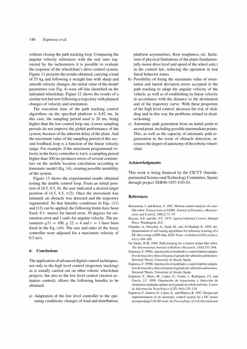
Elena Lopez received her Graduate Level in Telecommunicationsand Engineering degree (MSc) in Electronics from University ofAlcala (Spain) in 1994 and 1999 respectively. She has been Lecturerin the Electronics Department at the University of Alcala since 1995.Her research focus is on intelligent control and artificial vision forrobotic applications.
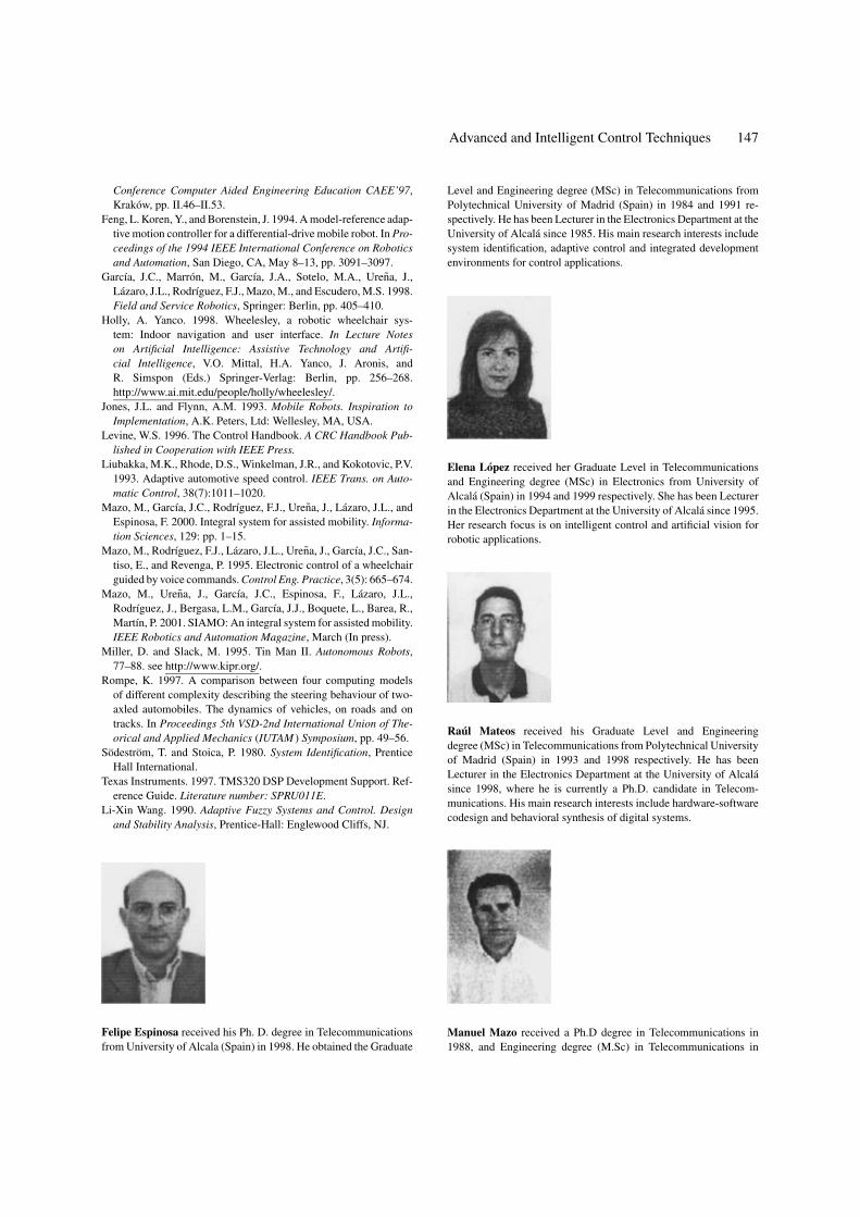
Raul Mateos received his Graduate Level and Engineeringdegree (MSc) in Telecommunications from Polytechnical Universityof Madrid (Spain) in 1993 and 1998 respectively. He has beenLecturer in the Electronics Department at the University of Alcalasince 1998, where he is currently a Ph.D. candidate in Telecom-munications. His main research interests include hardware-softwarecodesign and behavioral synthesis of digital systems.
Manuel Mazo received a Ph.D degree in Telecommunications in1988, and Engineering degree (M.Sc) in Telecommunications in
148 Espinosa et al.
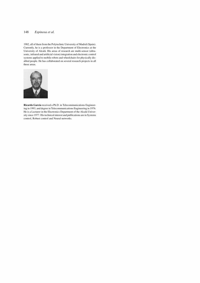
1982, all of them from the Polytechnic University of Madrid (Spain).Currently, he is a professor in the Department of Electronics at theUniversity of Alcala. His areas of research are multi-sensor (ultra-sonic, infrared and artificial vision) integration and electronic controlsystems applied to mobile robots and wheelchairs for physically dis-abled people. He has collaborated on several research projects in allthese areas.
Ricardo Garcıa received a Ph.D. in Telecommunications Engineer-ing in 1993, and degree in Telecommunications Engineering in 1976.He is a Lecturer in the Electronics Department of the Alcala Univer-sity since 1977. His technical interest and publications are in Systemscontrol, Robust control and Neural networks.