additive manufacturing with nickel feedstock - european
TRANSCRIPT
Project No. 601217-EPP-1-2018-1-BE-EPPKA2-SSA-B
This project has been funded with support from the European Commission. This publication reflects the views only of the author, and the Commission cannot be held responsible for any usewhich may be made of the information contained therein. 1
Additive Manufacturing with Nickel FeedstockDr. Evren Yasa
19.01.2021
This project has been funded with support from the European Commission. This publication reflects the views only of the author, and the Commission cannot beheld responsible for any use which may be made of the information contained therein.
Cracking phenomena in parts processed by AM • Common Defects• Porosity • Cracking
• Cold Cracking• Hot Cracking• Solid-State Cracking• Weldability
• Hot Isostatic Pressing
COMPETENCE UNIT 30: Additive Manufacturing with Nickel feedstock
2
This project has been funded with support from the European Commission. This publication reflects the views only of the author, and the Commission cannot beheld responsible for any use which may be made of the information contained therein.
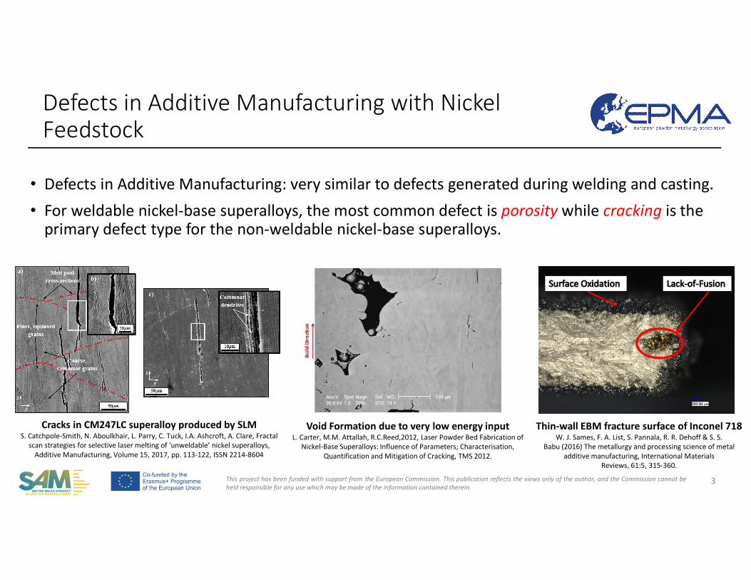
• Defects in Additive Manufacturing: very similar to defects generated during welding and casting.
• For weldable nickel-base superalloys, the most common defect is porosity while cracking is theprimary defect type for the non-weldable nickel-base superalloys.
3
Cracks in CM247LC superalloy produced by SLMS. Catchpole-Smith, N. Aboulkhair, L. Parry, C. Tuck, I.A. Ashcroft, A. Clare, Fractal
scan strategies for selective laser melting of ‘unweldable’ nickel superalloys,Additive Manufacturing, Volume 15, 2017, pp. 113-122, ISSN 2214-8604
Void Formation due to very low energy inputL. Carter, M.M. Attallah, R.C.Reed,2012, Laser Powder Bed Fabrication of
Nickel-Base Superalloys: Influence of Parameters; Characterisation, Quantification and Mitigation of Cracking, TMS 2012.
Thin-wall EBM fracture surface of Inconel 718W. J. Sames, F. A. List, S. Pannala, R. R. Dehoff & S. S.
Babu (2016) The metallurgy and processing science of metal additive manufacturing, International Materials
Reviews, 61:5, 315-360.
Defects in Additive Manufacturing with Nickel Feedstock
This project has been funded with support from the European Commission. This publication reflects the views only of the author, and the Commission cannot beheld responsible for any use which may be made of the information contained therein.
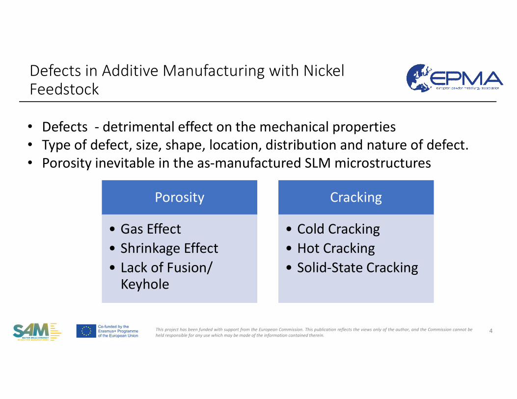
Porosity
• Gas Effect• Shrinkage Effect• Lack of Fusion/
Keyhole
Cracking
• Cold Cracking• Hot Cracking• Solid-State Cracking
Defects in Additive Manufacturing with Nickel Feedstock
4
• Defects - detrimental effect on the mechanical properties • Type of defect, size, shape, location, distribution and nature of defect.• Porosity inevitable in the as-manufactured SLM microstructures
This project has been funded with support from the European Commission. This publication reflects the views only of the author, and the Commission cannot beheld responsible for any use which may be made of the information contained therein.
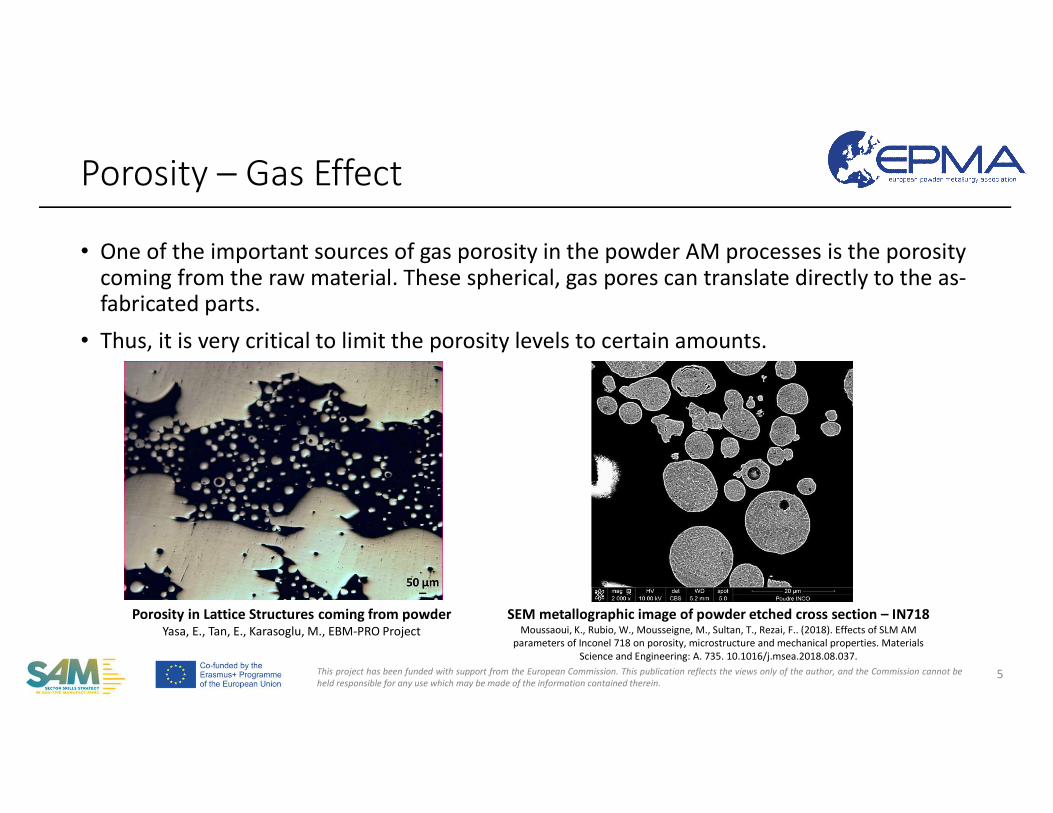
• One of the important sources of gas porosity in the powder AM processes is the porosity coming from the raw material. These spherical, gas pores can translate directly to the as-fabricated parts.
• Thus, it is very critical to limit the porosity levels to certain amounts.
Porosity – Gas Effect
5
Porosity in Lattice Structures coming from powderYasa, E., Tan, E., Karasoglu, M., EBM-PRO Project
SEM metallographic image of powder etched cross section – IN718Moussaoui, K., Rubio, W., Mousseigne, M., Sultan, T., Rezai, F.. (2018). Effects of SLM AM
parameters of Inconel 718 on porosity, microstructure and mechanical properties. Materials Science and Engineering: A. 735. 10.1016/j.msea.2018.08.037.
This project has been funded with support from the European Commission. This publication reflects the views only of the author, and the Commission cannot beheld responsible for any use which may be made of the information contained therein.
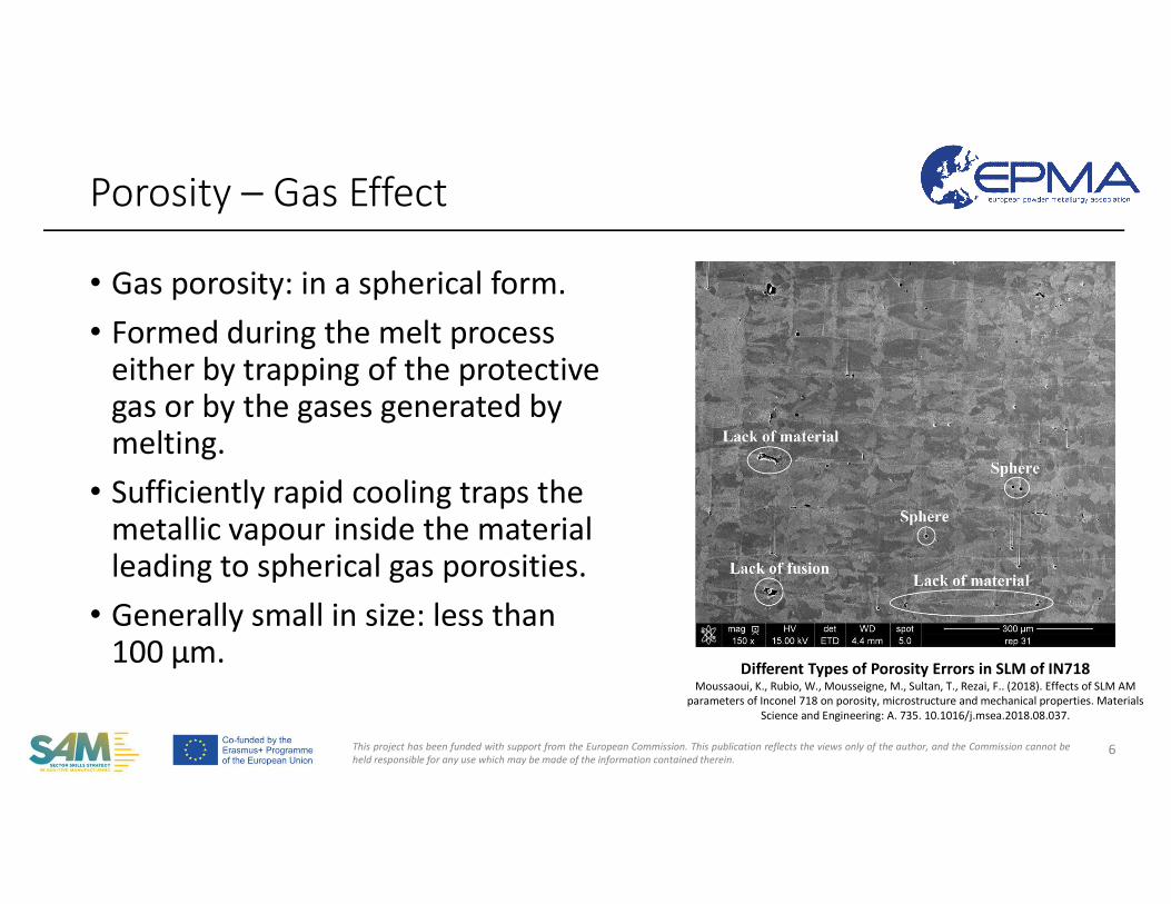
• Gas porosity: in a spherical form.• Formed during the melt process
either by trapping of the protective gas or by the gases generated by melting.
• Sufficiently rapid cooling traps the metallic vapour inside the material leading to spherical gas porosities.
• Generally small in size: less than 100 μm.
Porosity – Gas Effect
6
Different Types of Porosity Errors in SLM of IN718Moussaoui, K., Rubio, W., Mousseigne, M., Sultan, T., Rezai, F.. (2018). Effects of SLM AM
parameters of Inconel 718 on porosity, microstructure and mechanical properties. Materials Science and Engineering: A. 735. 10.1016/j.msea.2018.08.037.
This project has been funded with support from the European Commission. This publication reflects the views only of the author, and the Commission cannot beheld responsible for any use which may be made of the information contained therein.
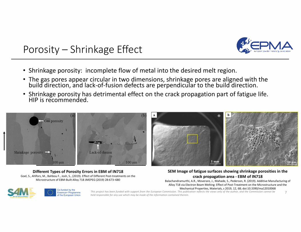
• Shrinkage porosity: incomplete flow of metal into the desired melt region. • The gas pores appear circular in two dimensions, shrinkage pores are aligned with the
build direction, and lack-of-fusion defects are perpendicular to the build direction. • Shrinkage porosity has detrimental effect on the crack propagation part of fatigue life.
HIP is recommended.
Porosity – Shrinkage Effect
7
Different Types of Porosity Errors in EBM of IN718Goel, S., Ahlfors, M., Bahbou F., Josh, S., (2019). Effect of Different Post-treatments on the
Microstructure of EBM-Built Alloy 718 JMEPEG (2019) 28:673–680
SEM Image of fatigue surfaces showing shrinkage porosities in the crack propagation area - EBM of IN718
Balachandramurthi, A.R., Moverare, J., Mahade, S., Pederson, R. (2019). Additive Manufacturing of Alloy 718 via Electron Beam Melting: Effect of Post-Treatment on the Microstructure and the
Mechanical Properties, Materials, s 2019, 12, 68; doi:10.3390/ma12010068
This project has been funded with support from the European Commission. This publication reflects the views only of the author, and the Commission cannot beheld responsible for any use which may be made of the information contained therein.
Porosity – Shrinkage Effect
8
LOM micrographs showing the different kinds of defects present in the as-built EBM Alloy
Zafer, Y.E., Goel, S., Ganvir,A., Jansson, A., Joshi, S. (2020) Encapsulation of Electron Beam Melting Produced Alloy 718 to Reduce Surface Connected Defects by Hot Isostatic Pressing,
Materials 2020, 13, 1226; doi:10.3390/ma13051226
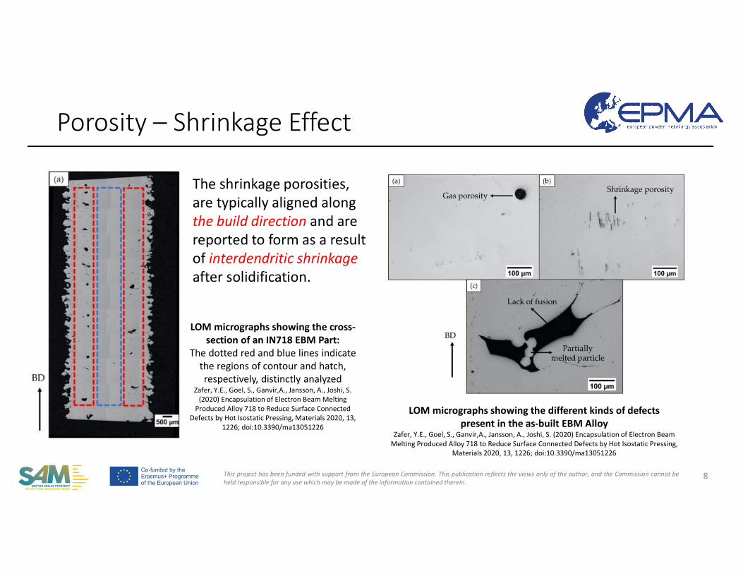
LOM micrographs showing the cross-section of an IN718 EBM Part:
The dotted red and blue lines indicate the regions of contour and hatch, respectively, distinctly analyzed
Zafer, Y.E., Goel, S., Ganvir,A., Jansson, A., Joshi, S. (2020) Encapsulation of Electron Beam Melting
Produced Alloy 718 to Reduce Surface Connected Defects by Hot Isostatic Pressing, Materials 2020, 13,
1226; doi:10.3390/ma13051226
The shrinkage porosities, are typically aligned along the build direction and are reported to form as a result of interdendritic shrinkage after solidification.
This project has been funded with support from the European Commission. This publication reflects the views only of the author, and the Commission cannot beheld responsible for any use which may be made of the information contained therein.
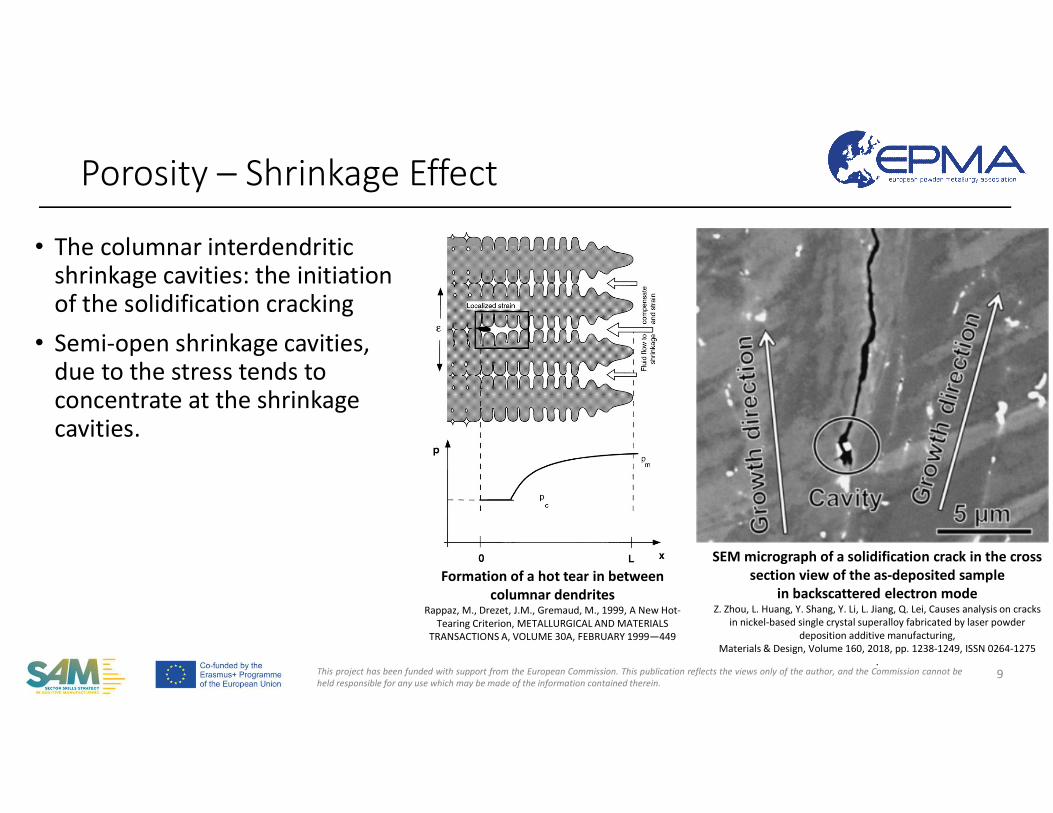
• The columnar interdendriticshrinkage cavities: the initiation of the solidification cracking
• Semi-open shrinkage cavities, due to the stress tends to concentrate at the shrinkage cavities.
Porosity – Shrinkage Effect
9
SEM micrograph of a solidification crack in the cross section view of the as-deposited sample
in backscattered electron modeZ. Zhou, L. Huang, Y. Shang, Y. Li, L. Jiang, Q. Lei, Causes analysis on cracks
in nickel-based single crystal superalloy fabricated by laser powder deposition additive manufacturing,
Materials & Design, Volume 160, 2018, pp. 1238-1249, ISSN 0264-1275.
Formation of a hot tear in between columnar dendrites
Rappaz, M., Drezet, J.M., Gremaud, M., 1999, A New Hot-Tearing Criterion, METALLURGICAL AND MATERIALS
TRANSACTIONS A, VOLUME 30A, FEBRUARY 1999—449
This project has been funded with support from the European Commission. This publication reflects the views only of the author, and the Commission cannot beheld responsible for any use which may be made of the information contained therein.
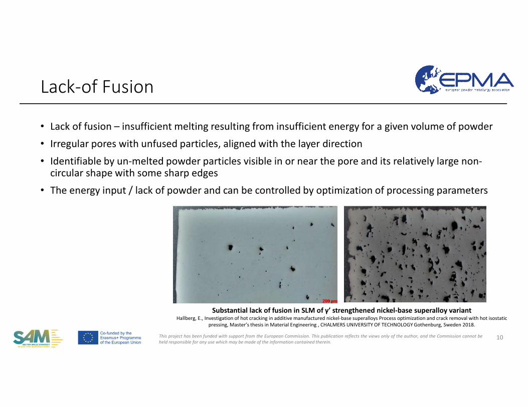
• Lack of fusion – insufficient melting resulting from insufficient energy for a given volume of powder
• Irregular pores with unfused particles, aligned with the layer direction
• Identifiable by un-melted powder particles visible in or near the pore and its relatively large non-circular shape with some sharp edges
• The energy input / lack of powder and can be controlled by optimization of processing parameters
Lack-of Fusion
10
Substantial lack of fusion in SLM of γ’ strengthened nickel-base superalloy variant Hallberg, E., Investigation of hot cracking in additive manufactured nickel-base superalloys Process optimization and crack removal with hot isostatic
pressing, Master’s thesis in Material Engineering , CHALMERS UNIVERSITY OF TECHNOLOGY Gothenburg, Sweden 2018.
This project has been funded with support from the European Commission. This publication reflects the views only of the author, and the Commission cannot beheld responsible for any use which may be made of the information contained therein.
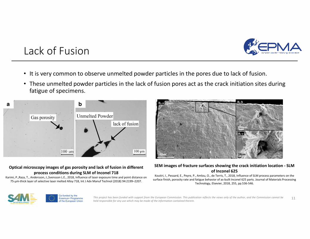
• It is very common to observe unmelted powder particles in the pores due to lack of fusion.
• These unmelted powder particles in the lack of fusion pores act as the crack initiation sites during fatigue of specimens.
Lack of Fusion
11
Optical microscopy images of gas porosity and lack of fusion in different process conditions during SLM of Inconel 718
Karimi, P.,Raza, T., Andersson, J.,Svensson L.E., 2018, Influence of laser exposure time and point distance on 75-μm-thick layer of selective laser melted Alloy 718, Int J Adv Manuf Technol (2018) 94:2199–2207.
SEM images of fracture surfaces showing the crack initiation location - SLM of Inconel 625
Koutiri, I., Pessard, E., Peyre, P., Amlou, O., de Terris, T., 2018, Influence of SLM process parameters on the surface finish, porosity rate and fatigue behavior of as-built Inconel 625 parts. Journal of Materials Processing
Technology, Elsevier, 2018, 255, pp.536-546.
This project has been funded with support from the European Commission. This publication reflects the views only of the author, and the Commission cannot beheld responsible for any use which may be made of the information contained therein.
Lack-of Fusion
12
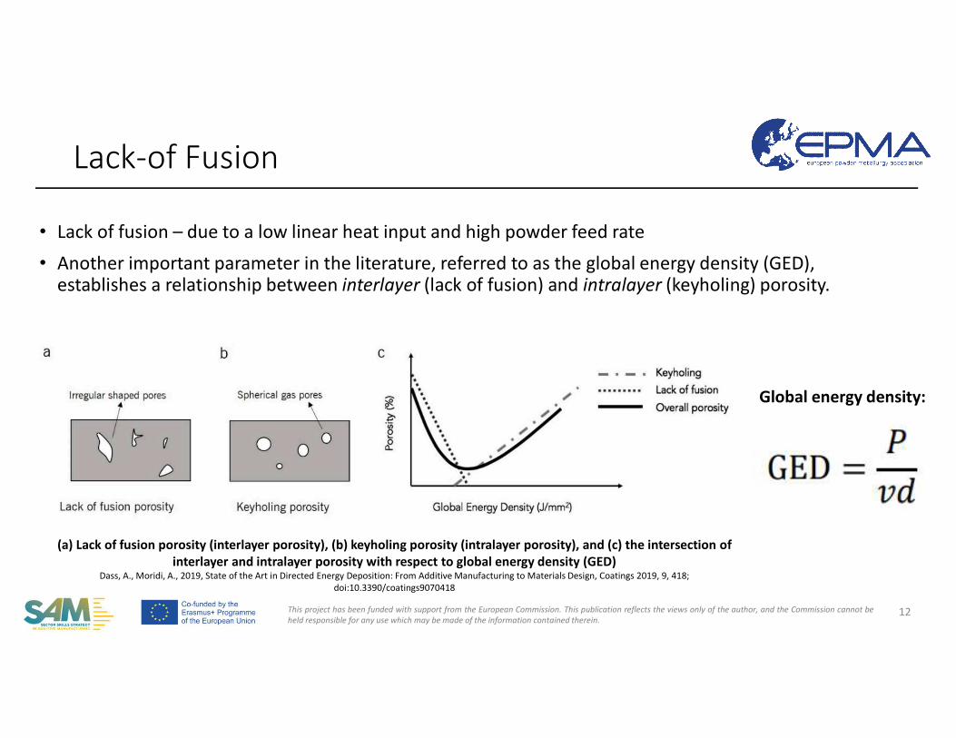
(a) Lack of fusion porosity (interlayer porosity), (b) keyholing porosity (intralayer porosity), and (c) the intersection of interlayer and intralayer porosity with respect to global energy density (GED)
Dass, A., Moridi, A., 2019, State of the Art in Directed Energy Deposition: From Additive Manufacturing to Materials Design, Coatings 2019, 9, 418; doi:10.3390/coatings9070418
• Lack of fusion – due to a low linear heat input and high powder feed rate
• Another important parameter in the literature, referred to as the global energy density (GED), establishes a relationship between interlayer (lack of fusion) and intralayer (keyholing) porosity.
Global energy density:
This project has been funded with support from the European Commission. This publication reflects the views only of the author, and the Commission cannot beheld responsible for any use which may be made of the information contained therein.
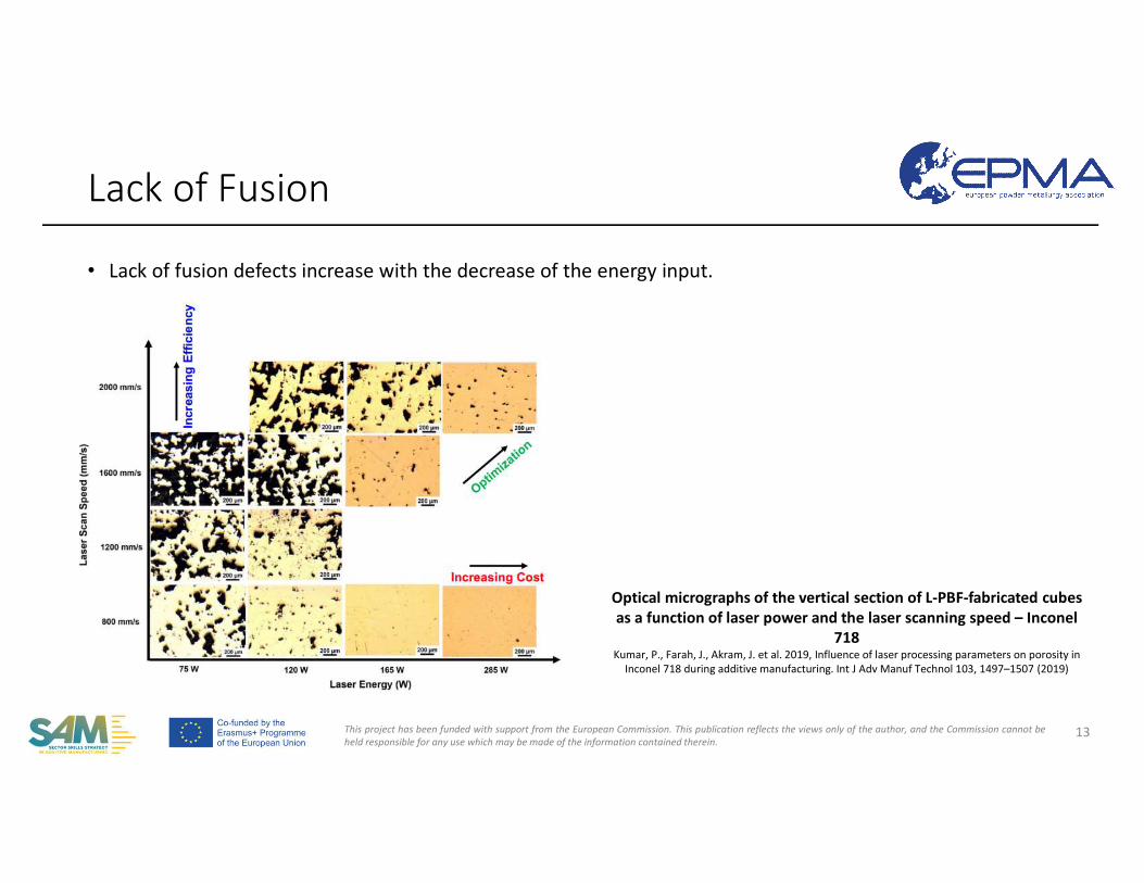
• Lack of fusion defects increase with the decrease of the energy input.
Lack of Fusion
13
Optical micrographs of the vertical section of L-PBF-fabricated cubes as a function of laser power and the laser scanning speed – Inconel
718Kumar, P., Farah, J., Akram, J. et al. 2019, Influence of laser processing parameters on porosity in
Inconel 718 during additive manufacturing. Int J Adv Manuf Technol 103, 1497–1507 (2019)
This project has been funded with support from the European Commission. This publication reflects the views only of the author, and the Commission cannot beheld responsible for any use which may be made of the information contained therein.
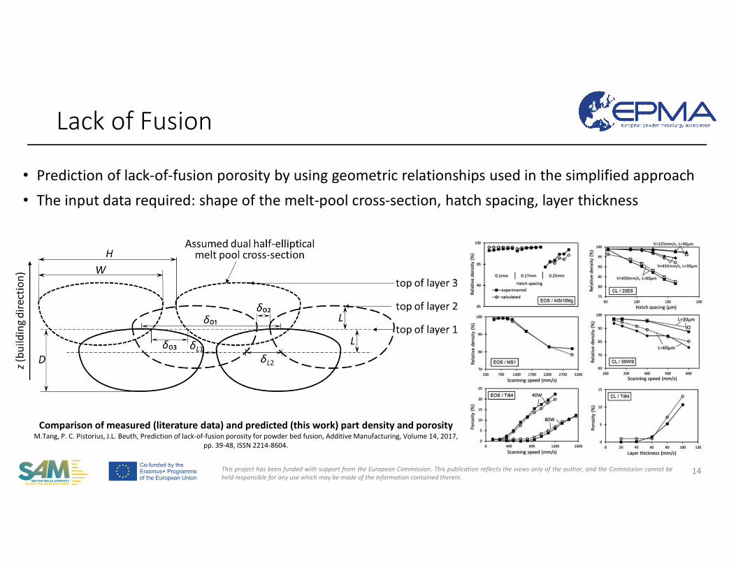
• Prediction of lack-of-fusion porosity by using geometric relationships used in the simplified approach
• The input data required: shape of the melt-pool cross-section, hatch spacing, layer thickness
Lack of Fusion
14
Comparison of measured (literature data) and predicted (this work) part density and porosityM.Tang, P. C. Pistorius, J.L. Beuth, Prediction of lack-of-fusion porosity for powder bed fusion, Additive Manufacturing, Volume 14, 2017,
pp. 39-48, ISSN 2214-8604.
This project has been funded with support from the European Commission. This publication reflects the views only of the author, and the Commission cannot beheld responsible for any use which may be made of the information contained therein.
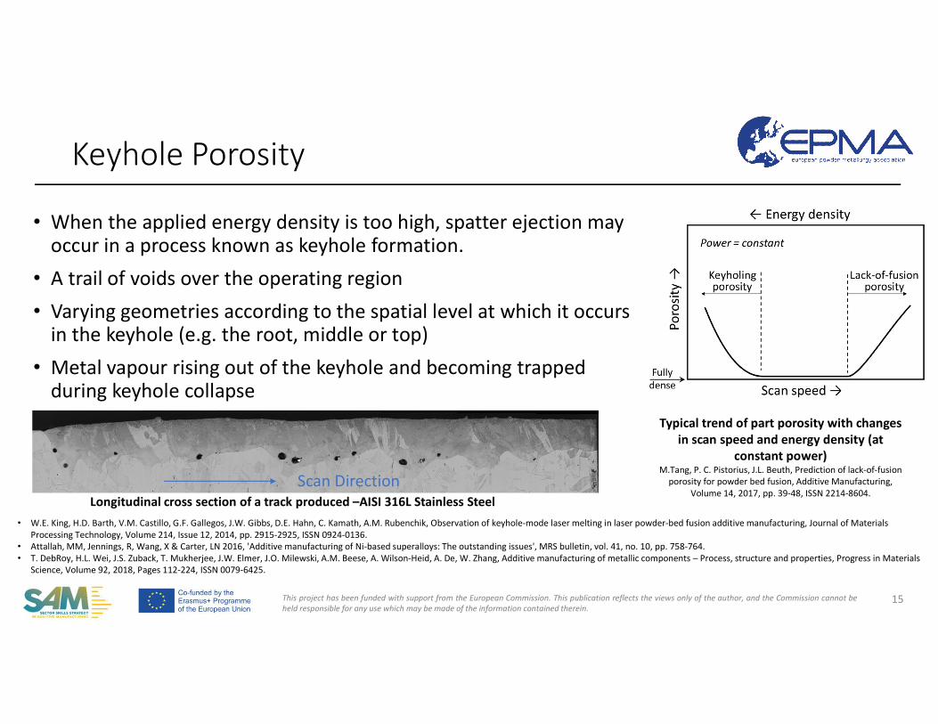
• When the applied energy density is too high, spatter ejection may occur in a process known as keyhole formation.
• A trail of voids over the operating region
• Varying geometries according to the spatial level at which it occurs in the keyhole (e.g. the root, middle or top)
• Metal vapour rising out of the keyhole and becoming trapped during keyhole collapse
Keyhole Porosity
15
Typical trend of part porosity with changes in scan speed and energy density (at
constant power)M.Tang, P. C. Pistorius, J.L. Beuth, Prediction of lack-of-fusion
porosity for powder bed fusion, Additive Manufacturing,Volume 14, 2017, pp. 39-48, ISSN 2214-8604.
• W.E. King, H.D. Barth, V.M. Castillo, G.F. Gallegos, J.W. Gibbs, D.E. Hahn, C. Kamath, A.M. Rubenchik, Observation of keyhole-mode laser melting in laser powder-bed fusion additive manufacturing, Journal of Materials Processing Technology, Volume 214, Issue 12, 2014, pp. 2915-2925, ISSN 0924-0136.
• Attallah, MM, Jennings, R, Wang, X & Carter, LN 2016, 'Additive manufacturing of Ni-based superalloys: The outstanding issues', MRS bulletin, vol. 41, no. 10, pp. 758-764. • T. DebRoy, H.L. Wei, J.S. Zuback, T. Mukherjee, J.W. Elmer, J.O. Milewski, A.M. Beese, A. Wilson-Heid, A. De, W. Zhang, Additive manufacturing of metallic components – Process, structure and properties, Progress in Materials
Science, Volume 92, 2018, Pages 112-224, ISSN 0079-6425.
Longitudinal cross section of a track produced –AISI 316L Stainless Steel Scan Direction
This project has been funded with support from the European Commission. This publication reflects the views only of the author, and the Commission cannot beheld responsible for any use which may be made of the information contained therein.
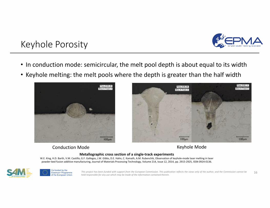
• In conduction mode: semicircular, the melt pool depth is about equal to its width• Keyhole melting: the melt pools where the depth is greater than the half width
Keyhole Porosity
16
Metallographic cross section of a single-track experimentsW.E. King, H.D. Barth, V.M. Castillo, G.F. Gallegos, J.W. Gibbs, D.E. Hahn, C. Kamath, A.M. Rubenchik, Observation of keyhole-mode laser melting in laser
powder-bed fusion additive manufacturing, Journal of Materials Processing Technology, Volume 214, Issue 12, 2014, pp. 2915-2925, ISSN 0924-0136.
Conduction Mode Keyhole Mode
This project has been funded with support from the European Commission. This publication reflects the views only of the author, and the Commission cannot beheld responsible for any use which may be made of the information contained therein.
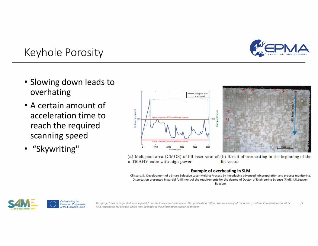
• Slowing down leads to overhating
• A certain amount of acceleration time to reach the required scanning speed
• “Skywriting"
Keyhole Porosity
17
Example of overheating in SLM Clijsters, S., Development of a Smart Selective Laser Melting Process By introducing advanced job preparation and process monitoring,
Dissertation presented in partial fulfillment of the requirements for the degree of Doctor of Engineering Science (Phd), K.U.Leuven, Belgium
This project has been funded with support from the European Commission. This publication reflects the views only of the author, and the Commission cannot beheld responsible for any use which may be made of the information contained therein.
Keyhole Porosity
18
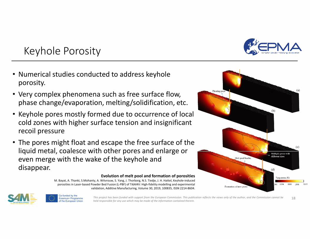
• Numerical studies conducted to address keyhole porosity.
• Very complex phenomena such as free surface flow, phase change/evaporation, melting/solidification, etc.
• Keyhole pores mostly formed due to occurrence of local cold zones with higher surface tension and insignificant recoil pressure
• The pores might float and escape the free surface of the liquid metal, coalesce with other pores and enlarge or even merge with the wake of the keyhole and disappear.
Evolution of melt pool and formation of porositiesM. Bayat, A. Thanki, S.Mohanty, A. Witvrouw, S. Yang, J. Thorborg, N.S. Tiedje, J. H. Hattel, Keyhole-induced
porosities in Laser-based Powder Bed Fusion (L-PBF) of Ti6Al4V: High-fidelity modelling and experimental validation, Additive Manufacturing, Volume 30, 2019, 100835, ISSN 2214-8604.
This project has been funded with support from the European Commission. This publication reflects the views only of the author, and the Commission cannot beheld responsible for any use which may be made of the information contained therein.
• Porosity, either inherited from the raw powders or due to the lack of fusion and shrinkage during solidification, occurs inevitably in the as-manufactured SLM microstructures.
• However, if the sources of such defects are well understood, some measures may be taken to minimize porosity in the manufactured parts.
• Porosity may be related to the used powder, equipment and process.
How to avoid porosity?
19
This project has been funded with support from the European Commission. This publication reflects the views only of the author, and the Commission cannot beheld responsible for any use which may be made of the information contained therein.
• Powder-related defect formation• Using spherical powders with a controlled particle size distribution
in relation to the utilized layer thickness.• Internal pores due to inert gas trapping coming from the powder
production• Powder handling • Feedstock powder oxidization occurring as a result of wrong
powder handling procedures, excessive reuse or prolonged storage in an unsuitable environment.
• A loosely packed powder bed to a fully dense part also contributes to porosity formation.
How to avoid porosity?
20
Sola, Antonella & Nouri, Alireza. (2019). Microstructural porosity in additive manufacturing: The formation and detection of pores in metal parts fabricated by powder bed fusion. Journal of Advanced Manufacturing and Processing. 1. 10.1002/amp2.10021.
This project has been funded with support from the European Commission. This publication reflects the views only of the author, and the Commission cannot beheld responsible for any use which may be made of the information contained therein.
• Equipment-related defect formation• Optical system alignment, quality and cleanness of the used galvano-mirrors,
control of the beam deflection mechanisms and calibration of the beam energy profile
• The gas flow management crucial to avoid porosity defects to remove recondensed matter
• Despite using a protective gas flow, it is not possible to completely avoid oxidation. Keeping the remaining oxygen levels as low as possible minimizes the risk.
How to avoid porosity?
21
Sola, Antonella & Nouri, Alireza. (2019). Microstructural porosity in additive manufacturing: The formation and detection of pores in metal parts fabricated by powder bed fusion. Journal of Advanced Manufacturing and Processing. 1. 10.1002/amp2.10021.
This project has been funded with support from the European Commission. This publication reflects the views only of the author, and the Commission cannot beheld responsible for any use which may be made of the information contained therein.
• Process-related defect formation• Process parameter optimization - energy input and power intensity • An excessive hatch spacing leading to the lack of overlapping between
adjacent scan tracks • According to the penetration depth and melt pool geometry, the layer
thickness shall be decided. If the layers are too thin, overheating may occur.Conversely, when the layers are too thick, interlayer bonding is not effectiveand lack of fusion occurs.
• Large elliptical pores are often observed at the start/end of the scan tracks due to instant changes in scan trajectory.
How to avoid porosity?
22
Sola, Antonella & Nouri, Alireza. (2019). Microstructural porosity in additive manufacturing: The formation and detection of pores in metal parts fabricated by powder bed fusion. Journal of Advanced Manufacturing and Processing. 1. 10.1002/amp2.10021.
This project has been funded with support from the European Commission. This publication reflects the views only of the author, and the Commission cannot beheld responsible for any use which may be made of the information contained therein.
Cracking phenomena in parts processed by AM • Common Defects• Porosity • Cracking
• Cold Cracking• Hot Cracking• Solid-State Cracking• Weldability
• Hot Isostatic Pressing
23
COMPETENCE UNIT 30: Additive Manufacturing with Nickel feedstock
This project has been funded with support from the European Commission. This publication reflects the views only of the author, and the Commission cannot beheld responsible for any use which may be made of the information contained therein.
• AM based on melting and solidification induce complex thermal profiles throughout the material.
• Similar to multi-pass fusion welding• Non-equilibrium solidification due to fast cooling rates• Promotion of the formation of new phases and precipitates if the
permanence time at a specific temperature for the solid-state transformation to occur
• Well-established knowledge from welding metallurgy can be transferred.
Cracking in AM of Nickel Superalloys
24
Oliveira, J. P. & Santos, Telmo & Miranda, R.M.. (2019). Revisiting fundamental welding concepts to improve additive manufacturing: From theory to practice. Progress in Materials Science. 107. 10.1016/j.pmatsci.2019.100590.
This project has been funded with support from the European Commission. This publication reflects the views only of the author, and the Commission cannot beheld responsible for any use which may be made of the information contained therein.
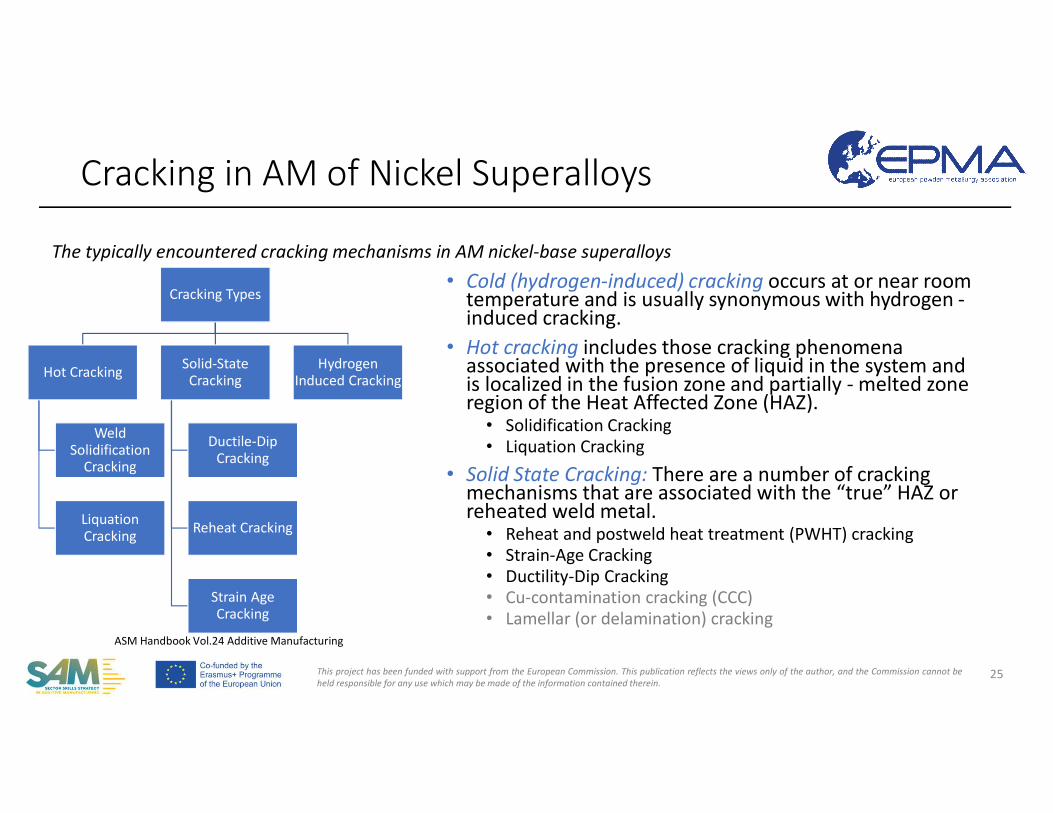
Cracking Types
Hot Cracking
Weld Solidification
Cracking
Liquation Cracking
Solid-State Cracking
Ductile-Dip Cracking
Reheat Cracking
Strain Age Cracking
Hydrogen Induced Cracking
Cracking in AM of Nickel Superalloys
25
The typically encountered cracking mechanisms in AM nickel-base superalloys
ASM Handbook Vol.24 Additive Manufacturing
• Cold (hydrogen-induced) cracking occurs at or near room temperature and is usually synonymous with hydrogen -induced cracking.
• Hot cracking includes those cracking phenomena associated with the presence of liquid in the system and is localized in the fusion zone and partially - melted zone region of the Heat Affected Zone (HAZ).
• Solidification Cracking• Liquation Cracking
• Solid State Cracking: There are a number of cracking mechanisms that are associated with the “true” HAZ or reheated weld metal.
• Reheat and postweld heat treatment (PWHT) cracking• Strain-Age Cracking• Ductility-Dip Cracking• Cu-contamination cracking (CCC)• Lamellar (or delamination) cracking
This project has been funded with support from the European Commission. This publication reflects the views only of the author, and the Commission cannot beheld responsible for any use which may be made of the information contained therein.
Cold Cracking in AM of Nickel Superalloys
26
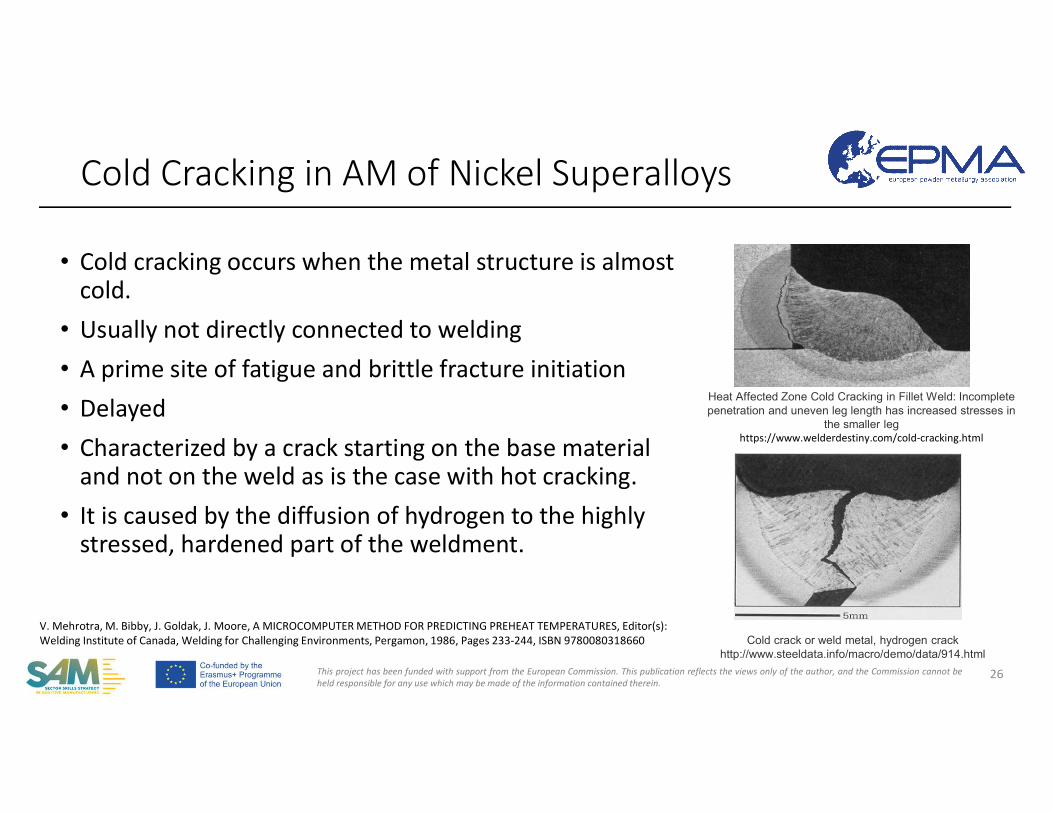
• Cold cracking occurs when the metal structure is almost cold.
• Usually not directly connected to welding • A prime site of fatigue and brittle fracture initiation• Delayed• Characterized by a crack starting on the base material
and not on the weld as is the case with hot cracking.• It is caused by the diffusion of hydrogen to the highly
stressed, hardened part of the weldment.
Heat Affected Zone Cold Cracking in Fillet Weld: Incomplete penetration and uneven leg length has increased stresses in
the smaller leghttps://www.welderdestiny.com/cold-cracking.html
Cold crack or weld metal, hydrogen crackhttp://www.steeldata.info/macro/demo/data/914.html
V. Mehrotra, M. Bibby, J. Goldak, J. Moore, A MICROCOMPUTER METHOD FOR PREDICTING PREHEAT TEMPERATURES, Editor(s): Welding Institute of Canada, Welding for Challenging Environments, Pergamon, 1986, Pages 233-244, ISBN 9780080318660
This project has been funded with support from the European Commission. This publication reflects the views only of the author, and the Commission cannot beheld responsible for any use which may be made of the information contained therein.
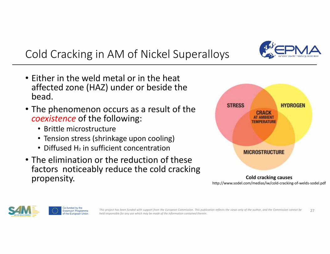
• Either in the weld metal or in the heataffected zone (HAZ) under or beside the bead.
• The phenomenon occurs as a result of the coexistence of the following:
• Brittle microstructure• Tension stress (shrinkage upon cooling)• Diffused H2 in sufficient concentration
• The elimination or the reduction of these factors noticeably reduce the cold cracking propensity.
Cold Cracking in AM of Nickel Superalloys
27
Cold cracking causeshttp://www.sodel.com/medias/iw/cold-cracking-of-welds-sodel.pdf
This project has been funded with support from the European Commission. This publication reflects the views only of the author, and the Commission cannot beheld responsible for any use which may be made of the information contained therein.
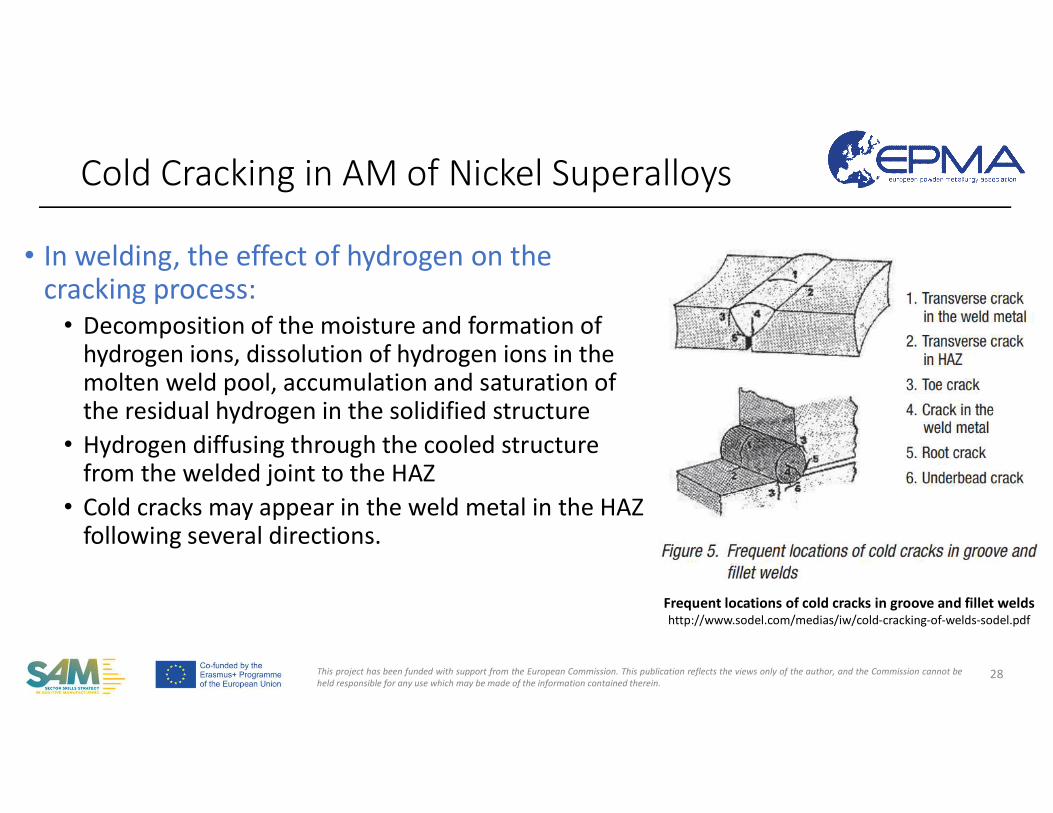
• In welding, the effect of hydrogen on the cracking process:
• Decomposition of the moisture and formation of hydrogen ions, dissolution of hydrogen ions in the molten weld pool, accumulation and saturation of the residual hydrogen in the solidified structure
• Hydrogen diffusing through the cooled structure from the welded joint to the HAZ
• Cold cracks may appear in the weld metal in the HAZ following several directions.
Cold Cracking in AM of Nickel Superalloys
28
Frequent locations of cold cracks in groove and fillet weldshttp://www.sodel.com/medias/iw/cold-cracking-of-welds-sodel.pdf
This project has been funded with support from the European Commission. This publication reflects the views only of the author, and the Commission cannot beheld responsible for any use which may be made of the information contained therein.
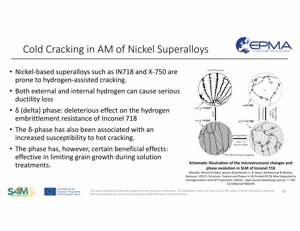
• Nickel-based superalloys such as IN718 and X-750 are prone to hydrogen-assisted cracking.
• Both external and internal hydrogen can cause serious ductility loss
• δ (delta) phase: deleterious effect on the hydrogen embrittlement resistance of Inconel 718
• The δ-phase has also been associated with an increased susceptibility to hot cracking.
• The phase has, however, certain beneficial effects: effective in limiting grain growth during solution treatments.
Cold Cracking in AM of Nickel Superalloys
29
Schematic illustration of the microstructural changes and phase evolution in SLM of Inconel 718
Mostafa, Ahmad & Rubio, Ignacio & Brailovski, V. & Jahazi, Mohammad & Medraj, Mamoun. (2017). Structure, Texture and Phases in 3D Printed IN718 Alloy Subjected to Homogenization and HIP Treatments. Metals - Open Access Metallurgy Journal. 7. 196.
10.3390/met7060196
This project has been funded with support from the European Commission. This publication reflects the views only of the author, and the Commission cannot beheld responsible for any use which may be made of the information contained therein.
• Methods to prevent hydrogen embrittlement in welding can be transferred to AM:
• Maintain dry conditions during processing since water and water vapor are major sources of hydrogen.
• Substituting alloys• Baking - hydrogen embrittlement almost reversible process• Reducing hydrogen exposure or the level of hydrogen
Cold Cracking in AM of Nickel Superalloys
30
This project has been funded with support from the European Commission. This publication reflects the views only of the author, and the Commission cannot beheld responsible for any use which may be made of the information contained therein.
• Methods to prevent hydrogen embrittlement in welding can be transferred to AM:
• Apply a relatively high pre-heat to the material• Apply a post-heat: to bake out hydrogen of the material, reducing
the levels of hydrogen available to result in hydrogen cracking.• Slower cooling rates result in more ductile microstructures. In
addition, there is a slightly longer time at an elevated temperatureto “bake out” hydrogen before the temperature gets low enough to allow cold cracking to occur.
• Ensure that the time delay between weld runs is minimized.
Cold Cracking in AM of Nickel Superalloys
31
This project has been funded with support from the European Commission. This publication reflects the views only of the author, and the Commission cannot beheld responsible for any use which may be made of the information contained therein.
• Cold (hydrogen-induced) cracking occurs at or near room temperature and is usually synonymous with hydrogen - induced cracking.
• Hot cracking includes those cracking phenomena associated with the presence of liquid in the system and is localized in the fusion zone and partially - melted zone region of the Heat Affected Zone (HAZ).
• Solidification Cracking• Liquation Cracking
• Solid State Cracking: There are a number of cracking mechanisms that are associated with the “true” HAZ or reheated weld metal.
• Reheat and postweld heat treatment (PWHT) cracking• Strain-Age Cracking• Ductility-Dip Cracking• Cu-contamination cracking (CCC)• Lamellar (or delamination) cracking
Cracking in AM of Nickel Superalloys
32
Welding Metallurgy and Weldability of Nickel-Base Alloys, by John N. DuPont, John C. Lippold, and Samuel D. Kiser Copyright © 2009 John Wiley & Sons, Inc.
This project has been funded with support from the European Commission. This publication reflects the views only of the author, and the Commission cannot beheld responsible for any use which may be made of the information contained therein.
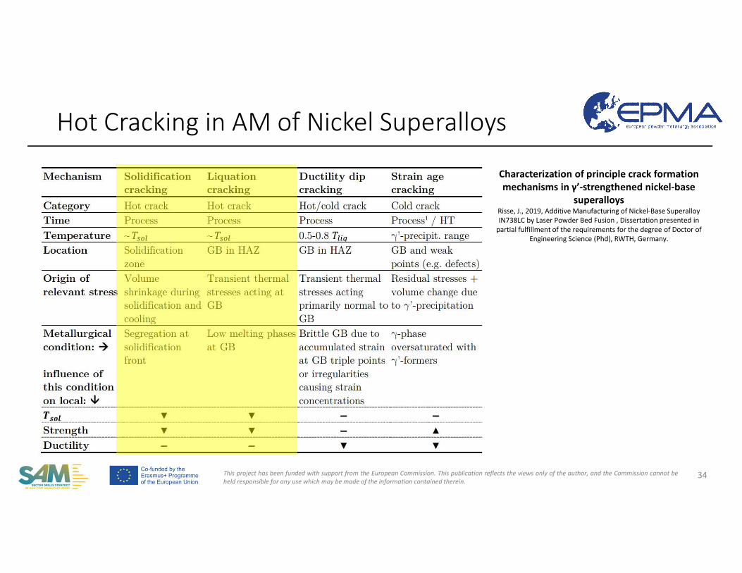
• Hot cracking: cracking phenomena that occur during fabrication due to the presence of liquid in the microstructure.
• Associated with liquid films that are present along grain boundaries in the fusion zone and the partially melted zone (PMZ) region of the heat-affected zone (HAZ)
• These liquid films may persist to temperatures well below the equilibrium solidus temperature of the bulk alloy, thus extending the solidification range of the alloy to the effective solidus temperature.
• “Hot cracking” refers to three distinct types of cracking:• (Weld) solidification cracking occurs in the fusion zone at the end of solidification. • HAZ liquation cracking occurs in the partially melted zone region and is also
intergranular
Hot Cracking in AM of Nickel Superalloys
33
This project has been funded with support from the European Commission. This publication reflects the views only of the author, and the Commission cannot beheld responsible for any use which may be made of the information contained therein.
Hot Cracking in AM of Nickel Superalloys
34
Characterization of principle crack formation mechanisms in γ’-strengthened nickel-base
superalloysRisse, J., 2019, Additive Manufacturing of Nickel-Base SuperalloyIN738LC by Laser Powder Bed Fusion , Dissertation presented in
partial fulfillment of the requirements for the degree of Doctor of Engineering Science (Phd), RWTH, Germany.
This project has been funded with support from the European Commission. This publication reflects the views only of the author, and the Commission cannot beheld responsible for any use which may be made of the information contained therein.
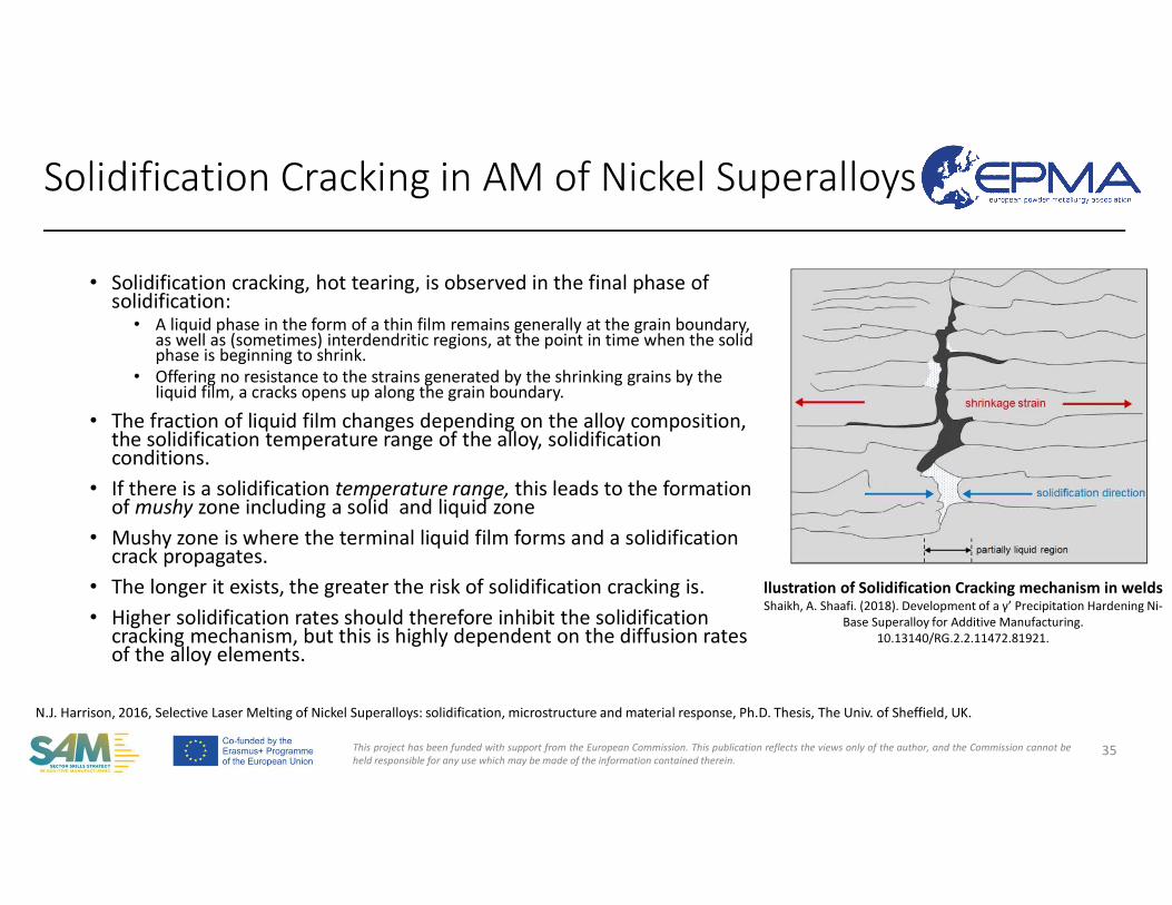
• Solidification cracking, hot tearing, is observed in the final phase of solidification:
• A liquid phase in the form of a thin film remains generally at the grain boundary, as well as (sometimes) interdendritic regions, at the point in time when the solid phase is beginning to shrink.
• Offering no resistance to the strains generated by the shrinking grains by the liquid film, a cracks opens up along the grain boundary.
• The fraction of liquid film changes depending on the alloy composition, the solidification temperature range of the alloy, solidification conditions.
• If there is a solidification temperature range, this leads to the formation of mushy zone including a solid and liquid zone
• Mushy zone is where the terminal liquid film forms and a solidification crack propagates.
• The longer it exists, the greater the risk of solidification cracking is.• Higher solidification rates should therefore inhibit the solidification
cracking mechanism, but this is highly dependent on the diffusion rates of the alloy elements.
Solidification Cracking in AM of Nickel Superalloys
35
N.J. Harrison, 2016, Selective Laser Melting of Nickel Superalloys: solidification, microstructure and material response, Ph.D. Thesis, The Univ. of Sheffield, UK.
llustration of Solidification Cracking mechanism in weldsShaikh, A. Shaafi. (2018). Development of a γ’ Precipitation Hardening Ni-
Base Superalloy for Additive Manufacturing. 10.13140/RG.2.2.11472.81921.
This project has been funded with support from the European Commission. This publication reflects the views only of the author, and the Commission cannot beheld responsible for any use which may be made of the information contained therein.
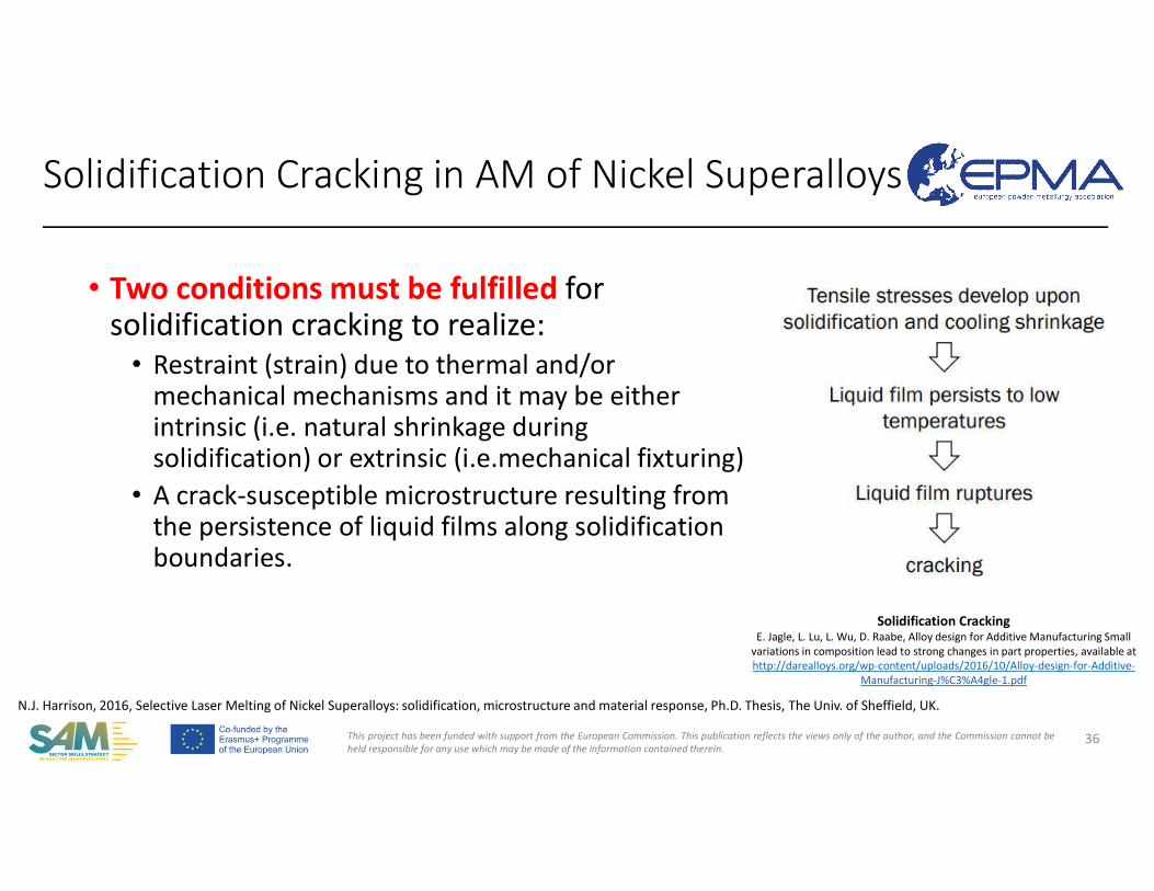
• Two conditions must be fulfilled for solidification cracking to realize:
• Restraint (strain) due to thermal and/or mechanical mechanisms and it may be either intrinsic (i.e. natural shrinkage during solidification) or extrinsic (i.e.mechanical fixturing)
• A crack-susceptible microstructure resulting from the persistence of liquid films along solidification boundaries.
36
Solidification CrackingE. Jagle, L. Lu, L. Wu, D. Raabe, Alloy design for Additive Manufacturing Small
variations in composition lead to strong changes in part properties, available at http://darealloys.org/wp-content/uploads/2016/10/Alloy-design-for-Additive-
Manufacturing-J%C3%A4gle-1.pdf
Solidification Cracking in AM of Nickel Superalloys
N.J. Harrison, 2016, Selective Laser Melting of Nickel Superalloys: solidification, microstructure and material response, Ph.D. Thesis, The Univ. of Sheffield, UK.
This project has been funded with support from the European Commission. This publication reflects the views only of the author, and the Commission cannot beheld responsible for any use which may be made of the information contained therein.
• The susceptibility to solidification cracking can be quantified for some alloys by the Solidification Cracking Temperature Range. This range is smaller or equal to the solidification temperature.
• If the solidification temperature range of a nickel superalloy is larger than another, it can be said that it is more susceptible to solidification cracking.
• Grain boundary strengthening elements (C, B, and Zr) increase susceptibility to solidification cracking due to segregating to the interdendritic regions upon melting.
• P and S have the same effect with no benefit to the alloy. • Alloying additions widening the solidification range increase susceptibility.
37
N.J. Harrison, 2016, Selective Laser Melting of Nickel Superalloys: solidification, microstructure and material response, Ph.D. Thesis, The Univ. of Sheffield, UK.Lippold, J. C., S. D. Kiser and J. N. DuPont (2011). Welding Metallurgy and Weldability of Nickel Base Alloys, WileyShaikh, A. Shaafi. (2018). Development of a γ’ Precipitation Hardening Ni-Base Superalloy for Additive Manufacturing. 10.13140/RG.2.2.11472.81921.
Solidification Cracking in AM of Nickel Superalloys
This project has been funded with support from the European Commission. This publication reflects the views only of the author, and the Commission cannot beheld responsible for any use which may be made of the information contained therein.
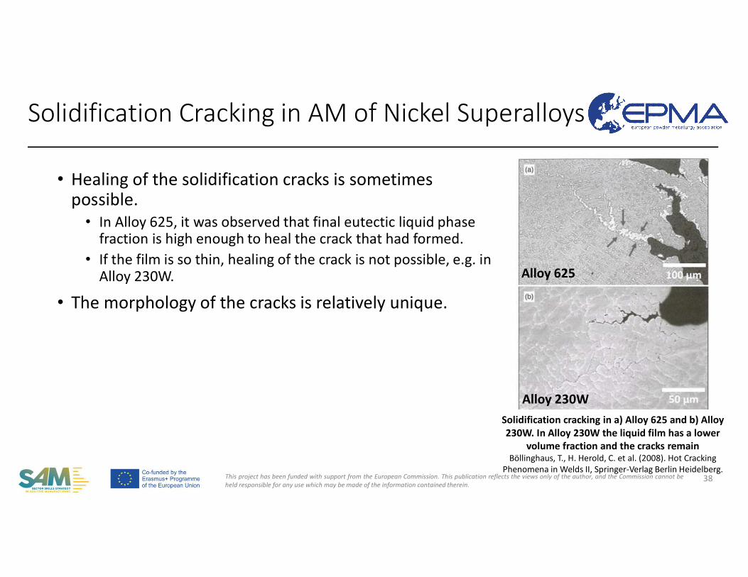
• Healing of the solidification cracks is sometimes possible.
• In Alloy 625, it was observed that final eutectic liquid phase fraction is high enough to heal the crack that had formed.
• If the film is so thin, healing of the crack is not possible, e.g. in Alloy 230W.
• The morphology of the cracks is relatively unique.
38
Solidification cracking in a) Alloy 625 and b) Alloy 230W. In Alloy 230W the liquid film has a lower
volume fraction and the cracks remainBöllinghaus, T., H. Herold, C. et al. (2008). Hot Cracking
Phenomena in Welds II, Springer-Verlag Berlin Heidelberg.
Alloy 625
Alloy 230W
Solidification Cracking in AM of Nickel Superalloys
This project has been funded with support from the European Commission. This publication reflects the views only of the author, and the Commission cannot beheld responsible for any use which may be made of the information contained therein.
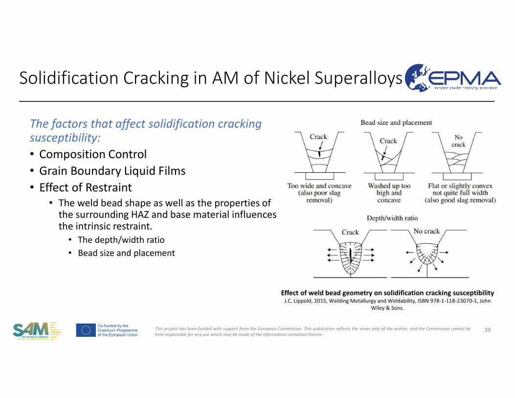
The factors that affect solidification crackingsusceptibility:• Composition Control• Grain Boundary Liquid Films• Effect of Restraint
• The weld bead shape as well as the properties of the surrounding HAZ and base material influences the intrinsic restraint.
• The depth/width ratio• Bead size and placement
39
Effect of weld bead geometry on solidification cracking susceptibilityJ.C. Lippold, 2015, Welding Metallurgy and Weldability, ISBN 978-1-118-23070-1, John
Wiley & Sons.
Solidification Cracking in AM of Nickel Superalloys
This project has been funded with support from the European Commission. This publication reflects the views only of the author, and the Commission cannot beheld responsible for any use which may be made of the information contained therein.
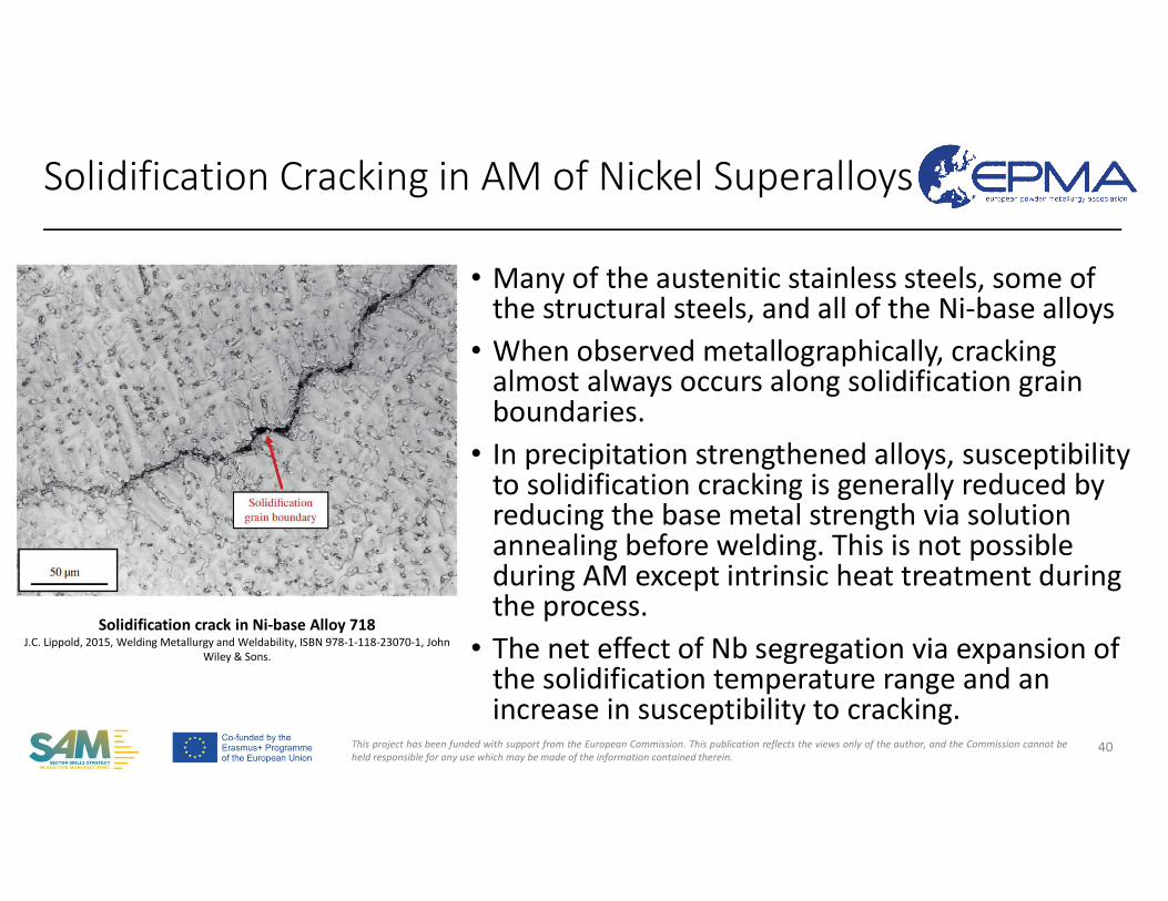
• Many of the austenitic stainless steels, some of the structural steels, and all of the Ni-base alloys
• When observed metallographically, cracking almost always occurs along solidification grain boundaries.
• In precipitation strengthened alloys, susceptibilityto solidification cracking is generally reduced by reducing the base metal strength via solution annealing before welding. This is not possible during AM except intrinsic heat treatment during the process.
• The net effect of Nb segregation via expansion of the solidification temperature range and an increase in susceptibility to cracking.
40
Solidification crack in Ni-base Alloy 718J.C. Lippold, 2015, Welding Metallurgy and Weldability, ISBN 978-1-118-23070-1, John
Wiley & Sons.
Solidification Cracking in AM of Nickel Superalloys
This project has been funded with support from the European Commission. This publication reflects the views only of the author, and the Commission cannot beheld responsible for any use which may be made of the information contained therein.
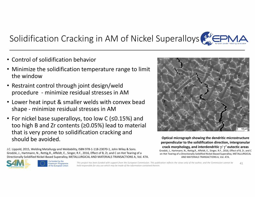
• Control of solidification behavior• Minimize the solidification temperature range to limit
the window• Restraint control through joint design/weld
procedure - minimize residual stresses in AM• Lower heat input & smaller welds with convex bead
shape - minimize residual stresses in AM• For nickel base superalloys, too low C (≤0.15%) and
too high B and Zr contents (≥0.05%) lead to material that is very prone to solidification cracking and should be avoided.
41
Optical micrograph showing the dendritic microstructure perpendicular to the solidification direction, intergranularcrack morphology, and interdendritic γ/ γ’ eutectic areas
Grodzki, J., Hartmann, N., Rettig,R., Affeldt, E., Singer, R.F., 2016, Effect of B, Zr, and C on Hot Tearing of a Directionally Solidified Nickel-Based Superalloy, METALLURGICAL
AND MATERIALS TRANSACTIONS A, Vol. 47A.
Solidification Cracking in AM of Nickel Superalloys
J.C. Lippold, 2015, Welding Metallurgy and Weldability, ISBN 978-1-118-23070-1, John Wiley & Sons.Grodzki, J., Hartmann, N., Rettig,R., Affeldt, E., Singer, R.F., 2016, Effect of B, Zr, and C on Hot Tearing of a Directionally Solidified Nickel-Based Superalloy, METALLURGICAL AND MATERIALS TRANSACTIONS A, Vol. 47A.
This project has been funded with support from the European Commission. This publication reflects the views only of the author, and the Commission cannot beheld responsible for any use which may be made of the information contained therein.
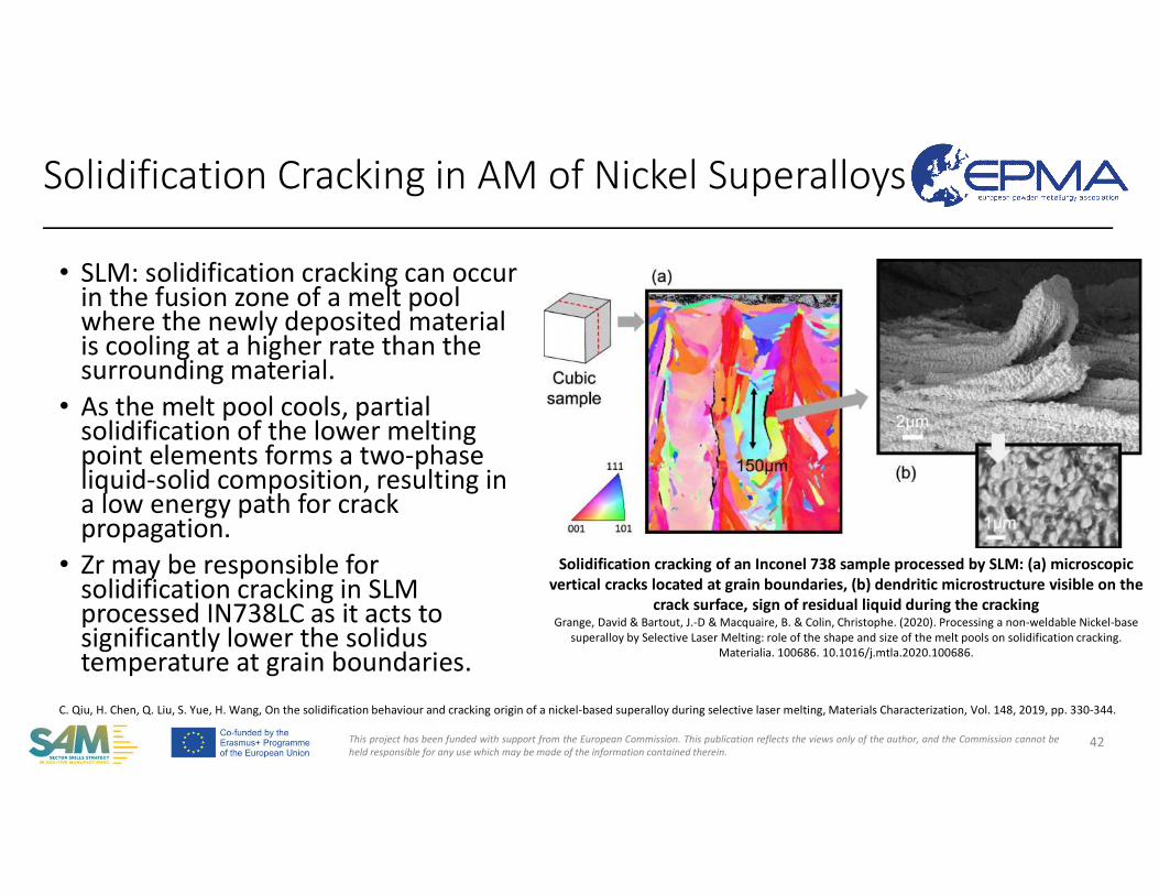
• SLM: solidification cracking can occur in the fusion zone of a melt pool where the newly deposited material is cooling at a higher rate than the surrounding material.
• As the melt pool cools, partial solidification of the lower melting point elements forms a two-phase liquid-solid composition, resulting in a low energy path for crack propagation.
• Zr may be responsible for solidification cracking in SLM processed IN738LC as it acts to significantly lower the solidus temperature at grain boundaries.
42
Solidification cracking of an Inconel 738 sample processed by SLM: (a) microscopic vertical cracks located at grain boundaries, (b) dendritic microstructure visible on the
crack surface, sign of residual liquid during the crackingGrange, David & Bartout, J.-D & Macquaire, B. & Colin, Christophe. (2020). Processing a non-weldable Nickel-base
superalloy by Selective Laser Melting: role of the shape and size of the melt pools on solidification cracking. Materialia. 100686. 10.1016/j.mtla.2020.100686.
C. Qiu, H. Chen, Q. Liu, S. Yue, H. Wang, On the solidification behaviour and cracking origin of a nickel-based superalloy during selective laser melting, Materials Characterization, Vol. 148, 2019, pp. 330-344.
Solidification Cracking in AM of Nickel Superalloys
This project has been funded with support from the European Commission. This publication reflects the views only of the author, and the Commission cannot beheld responsible for any use which may be made of the information contained therein.
43
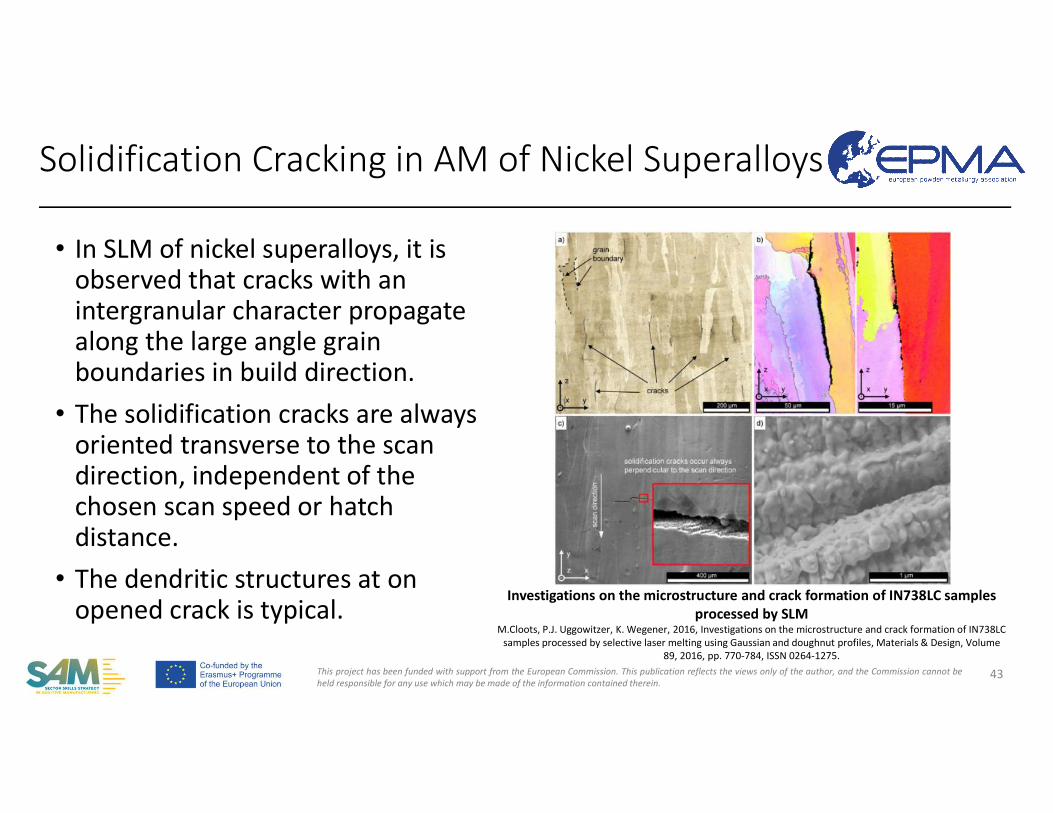
• In SLM of nickel superalloys, it is observed that cracks with an intergranular character propagate along the large angle grain boundaries in build direction.
• The solidification cracks are always oriented transverse to the scan direction, independent of the chosen scan speed or hatch distance.
• The dendritic structures at on opened crack is typical.
Investigations on the microstructure and crack formation of IN738LC samples processed by SLM
M.Cloots, P.J. Uggowitzer, K. Wegener, 2016, Investigations on the microstructure and crack formation of IN738LC samples processed by selective laser melting using Gaussian and doughnut profiles, Materials & Design, Volume
89, 2016, pp. 770-784, ISSN 0264-1275.
Solidification Cracking in AM of Nickel Superalloys
This project has been funded with support from the European Commission. This publication reflects the views only of the author, and the Commission cannot beheld responsible for any use which may be made of the information contained therein.
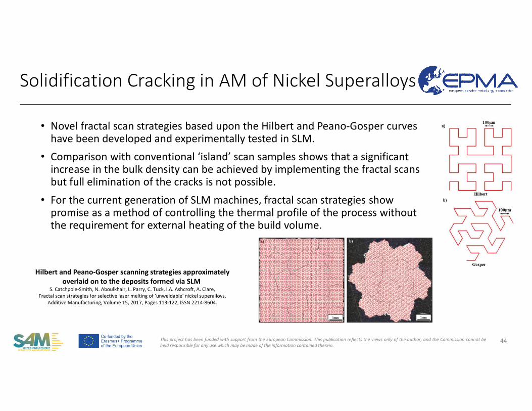
• Novel fractal scan strategies based upon the Hilbert and Peano-Gosper curves have been developed and experimentally tested in SLM.
• Comparison with conventional ‘island’ scan samples shows that a significant increase in the bulk density can be achieved by implementing the fractal scansbut full elimination of the cracks is not possible.
• For the current generation of SLM machines, fractal scan strategies show promise as a method of controlling the thermal profile of the process without the requirement for external heating of the build volume.
44
Hilbert and Peano-Gosper scanning strategies approximately overlaid on to the deposits formed via SLM
S. Catchpole-Smith, N. Aboulkhair, L. Parry, C. Tuck, I.A. Ashcroft, A. Clare,Fractal scan strategies for selective laser melting of ‘unweldable’ nickel superalloys,
Additive Manufacturing, Volume 15, 2017, Pages 113-122, ISSN 2214-8604.
Solidification Cracking in AM of Nickel Superalloys
This project has been funded with support from the European Commission. This publication reflects the views only of the author, and the Commission cannot beheld responsible for any use which may be made of the information contained therein.
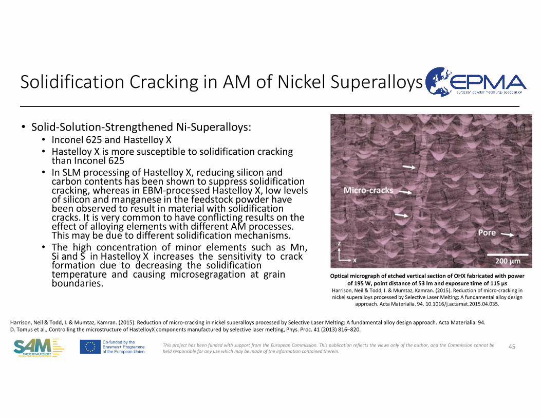
• Solid-Solution-Strengthened Ni-Superalloys:• Inconel 625 and Hastelloy X• Hastelloy X is more susceptible to solidification cracking
than Inconel 625 • In SLM processing of Hastelloy X, reducing silicon and
carbon contents has been shown to suppress solidification cracking, whereas in EBM-processed Hastelloy X, low levels of silicon and manganese in the feedstock powder have been observed to result in material with solidification cracks. It is very common to have conflicting results on the effect of alloying elements with different AM processes. This may be due to different solidification mechanisms.
• The high concentration of minor elements such as Mn, Si and S in Hastelloy X increases the sensitivity to crack formation due to decreasing the solidification temperature and causing microsegragation at grain boundaries.
45
Harrison, Neil & Todd, I. & Mumtaz, Kamran. (2015). Reduction of micro-cracking in nickel superalloys processed by Selective Laser Melting: A fundamental alloy design approach. Acta Materialia. 94.D. Tomus et al., Controlling the microstructure of HastelloyX components manufactured by selective laser melting, Phys. Proc. 41 (2013) 816–820.
Solidification Cracking in AM of Nickel Superalloys
Optical micrograph of etched vertical section of OHX fabricated with power of 195 W, point distance of 53 lm and exposure time of 115 µs
Harrison, Neil & Todd, I. & Mumtaz, Kamran. (2015). Reduction of micro-cracking in nickel superalloys processed by Selective Laser Melting: A fundamental alloy design
approach. Acta Materialia. 94. 10.1016/j.actamat.2015.04.035.
This project has been funded with support from the European Commission. This publication reflects the views only of the author, and the Commission cannot beheld responsible for any use which may be made of the information contained therein.
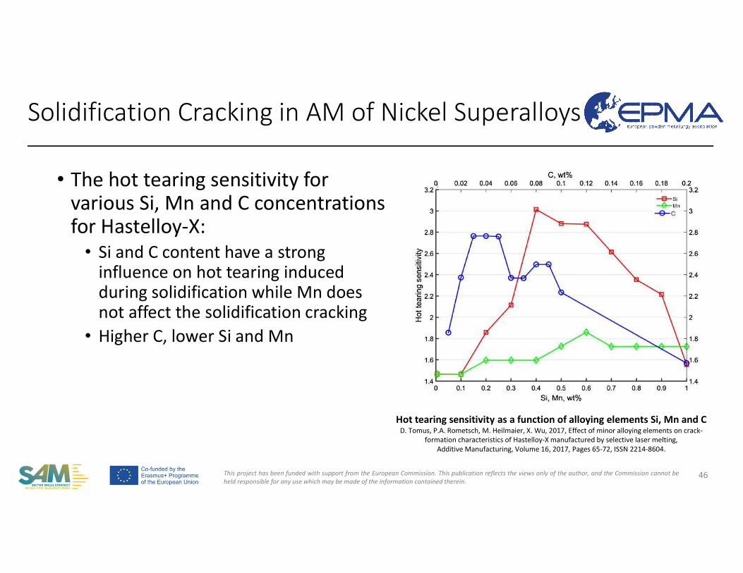
• The hot tearing sensitivity for various Si, Mn and C concentrations for Hastelloy-X:
• Si and C content have a strong influence on hot tearing induced during solidification while Mn does not affect the solidification cracking
• Higher C, lower Si and Mn
46
Hot tearing sensitivity as a function of alloying elements Si, Mn and CD. Tomus, P.A. Rometsch, M. Heilmaier, X. Wu, 2017, Effect of minor alloying elements on crack-
formation characteristics of Hastelloy-X manufactured by selective laser melting,Additive Manufacturing, Volume 16, 2017, Pages 65-72, ISSN 2214-8604.
Solidification Cracking in AM of Nickel Superalloys
This project has been funded with support from the European Commission. This publication reflects the views only of the author, and the Commission cannot beheld responsible for any use which may be made of the information contained therein.
47
E. Jagle, L. Lu, L. Wu, D. Raabe, Alloy design for Additive Manufacturing Small variations in composition lead to strong changes in part properties, available at http://darealloys.org/wp-content/uploads/2016/10/Alloy-design-for-Additive-
Manufacturing-J%C3%A4gle-1.pdf
Solidification Cracking in AM of Nickel Superalloys
This project has been funded with support from the European Commission. This publication reflects the views only of the author, and the Commission cannot beheld responsible for any use which may be made of the information contained therein.
• Material composition is of uttermost importance.• Residual stresses coming from thermal processing contributes to the
strains and need to be minimized during the AM processing to avoid solidification cracking.
• Preheating the substrate leads to a reduction in the cracking tendency primarily by relieving the strains.
• Zirconium and silicon are identified as the most critical elements sincethey segregate during the solidification process.
• Solidification cracking can be reduced by limiting the micro-segregation.
48
Solidification Cracking in AM of Nickel Superalloys
This project has been funded with support from the European Commission. This publication reflects the views only of the author, and the Commission cannot beheld responsible for any use which may be made of the information contained therein.
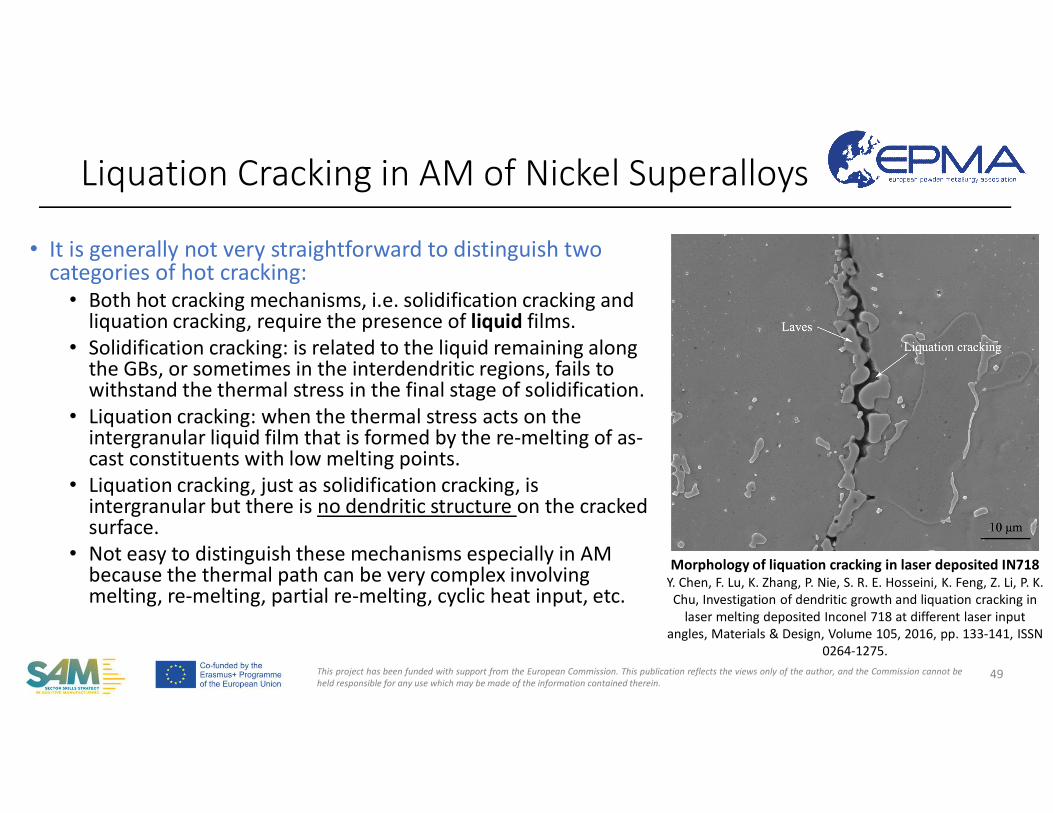
• It is generally not very straightforward to distinguish two categories of hot cracking:
• Both hot cracking mechanisms, i.e. solidification cracking and liquation cracking, require the presence of liquid films.
• Solidification cracking: is related to the liquid remaining along the GBs, or sometimes in the interdendritic regions, fails to withstand the thermal stress in the final stage of solidification.
• Liquation cracking: when the thermal stress acts on the intergranular liquid film that is formed by the re-melting of as-cast constituents with low melting points.
• Liquation cracking, just as solidification cracking, is intergranular but there is no dendritic structure on the cracked surface.
• Not easy to distinguish these mechanisms especially in AMbecause the thermal path can be very complex involving melting, re-melting, partial re-melting, cyclic heat input, etc.
Liquation Cracking in AM of Nickel Superalloys
49
Morphology of liquation cracking in laser deposited IN718Y. Chen, F. Lu, K. Zhang, P. Nie, S. R. E. Hosseini, K. Feng, Z. Li, P. K. Chu, Investigation of dendritic growth and liquation cracking in
laser melting deposited Inconel 718 at different laser input angles, Materials & Design, Volume 105, 2016, pp. 133-141, ISSN
0264-1275.
This project has been funded with support from the European Commission. This publication reflects the views only of the author, and the Commission cannot beheld responsible for any use which may be made of the information contained therein.
• Liquation cracking occurs away from the melt pool. There, the bulk material is heated fastly to a temperature lower than the liquidus of the material leading to melting of low-melting-point grain boundaryphases.
• The γ- γ’eutectic phase is an example for low-melting-point GB phase.• Combined with residual stresses, the liquid films have the potential
for liquation cracking.
Liquation Cracking in AM of Nickel Superalloys
50
This project has been funded with support from the European Commission. This publication reflects the views only of the author, and the Commission cannot beheld responsible for any use which may be made of the information contained therein.
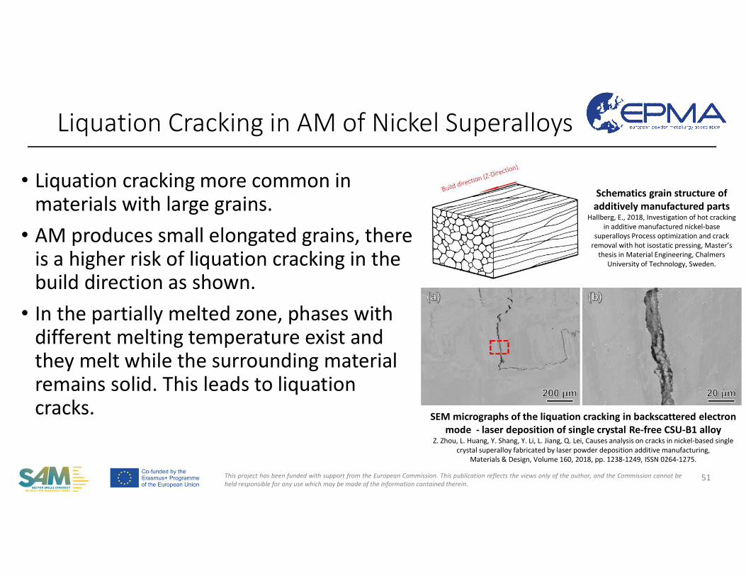
• Liquation cracking more common in materials with large grains.
• AM produces small elongated grains, there is a higher risk of liquation cracking in the build direction as shown.
• In the partially melted zone, phases with different melting temperature exist and they melt while the surrounding material remains solid. This leads to liquation cracks.
Liquation Cracking in AM of Nickel Superalloys
51
Schematics grain structure of additively manufactured parts
Hallberg, E., 2018, Investigation of hot cracking in additive manufactured nickel-base
superalloys Process optimization and crack removal with hot isostatic pressing, Master’s
thesis in Material Engineering, Chalmers University of Technology, Sweden.
SEM micrographs of the liquation cracking in backscattered electron mode - laser deposition of single crystal Re-free CSU-B1 alloy
Z. Zhou, L. Huang, Y. Shang, Y. Li, L. Jiang, Q. Lei, Causes analysis on cracks in nickel-based single crystal superalloy fabricated by laser powder deposition additive manufacturing,
Materials & Design, Volume 160, 2018, pp. 1238-1249, ISSN 0264-1275.
This project has been funded with support from the European Commission. This publication reflects the views only of the author, and the Commission cannot beheld responsible for any use which may be made of the information contained therein.
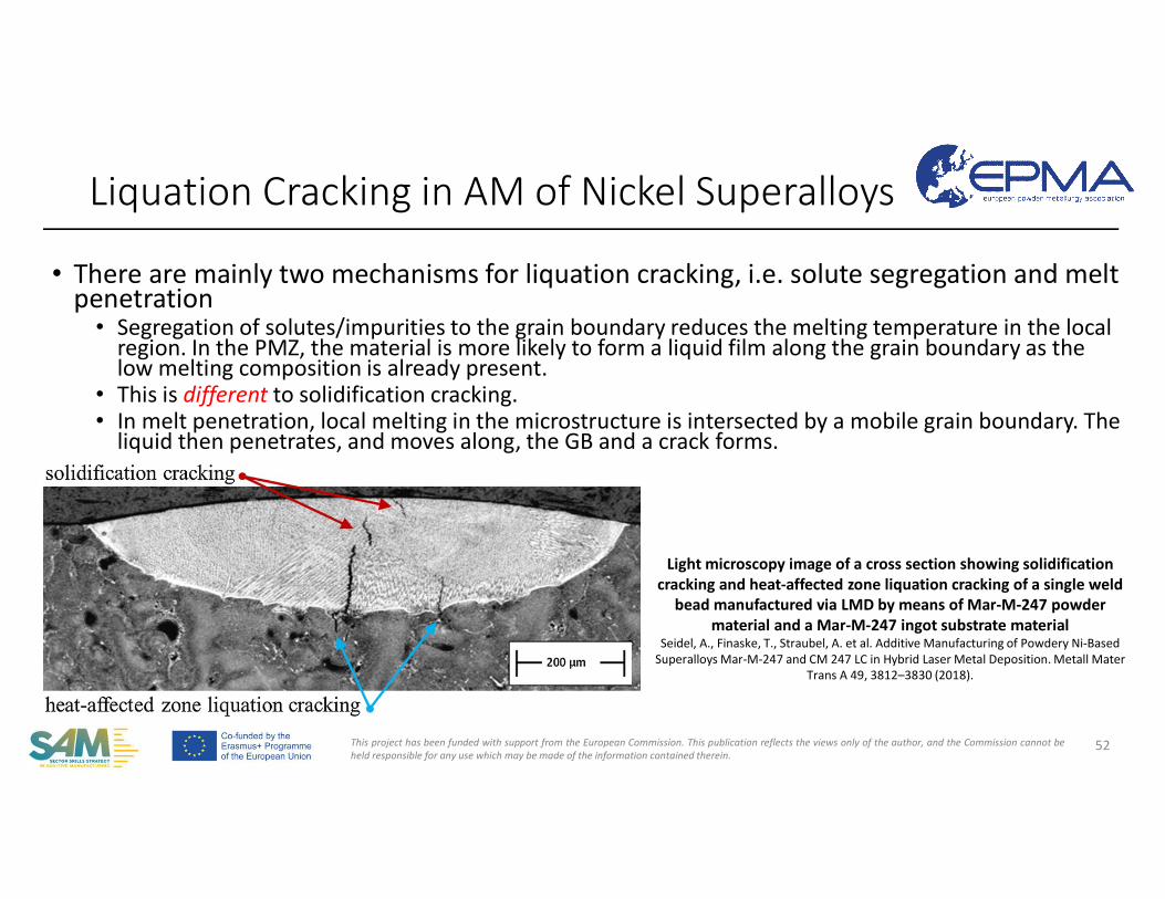
• There are mainly two mechanisms for liquation cracking, i.e. solute segregation and melt penetration
• Segregation of solutes/impurities to the grain boundary reduces the melting temperature in the local region. In the PMZ, the material is more likely to form a liquid film along the grain boundary as the low melting composition is already present.
• This is different to solidification cracking.• In melt penetration, local melting in the microstructure is intersected by a mobile grain boundary. The
liquid then penetrates, and moves along, the GB and a crack forms.
Liquation Cracking in AM of Nickel Superalloys
52
Light microscopy image of a cross section showing solidification cracking and heat-affected zone liquation cracking of a single weld
bead manufactured via LMD by means of Mar-M-247 powder material and a Mar-M-247 ingot substrate material
Seidel, A., Finaske, T., Straubel, A. et al. Additive Manufacturing of Powdery Ni-Based Superalloys Mar-M-247 and CM 247 LC in Hybrid Laser Metal Deposition. Metall Mater
Trans A 49, 3812–3830 (2018).
This project has been funded with support from the European Commission. This publication reflects the views only of the author, and the Commission cannot beheld responsible for any use which may be made of the information contained therein.
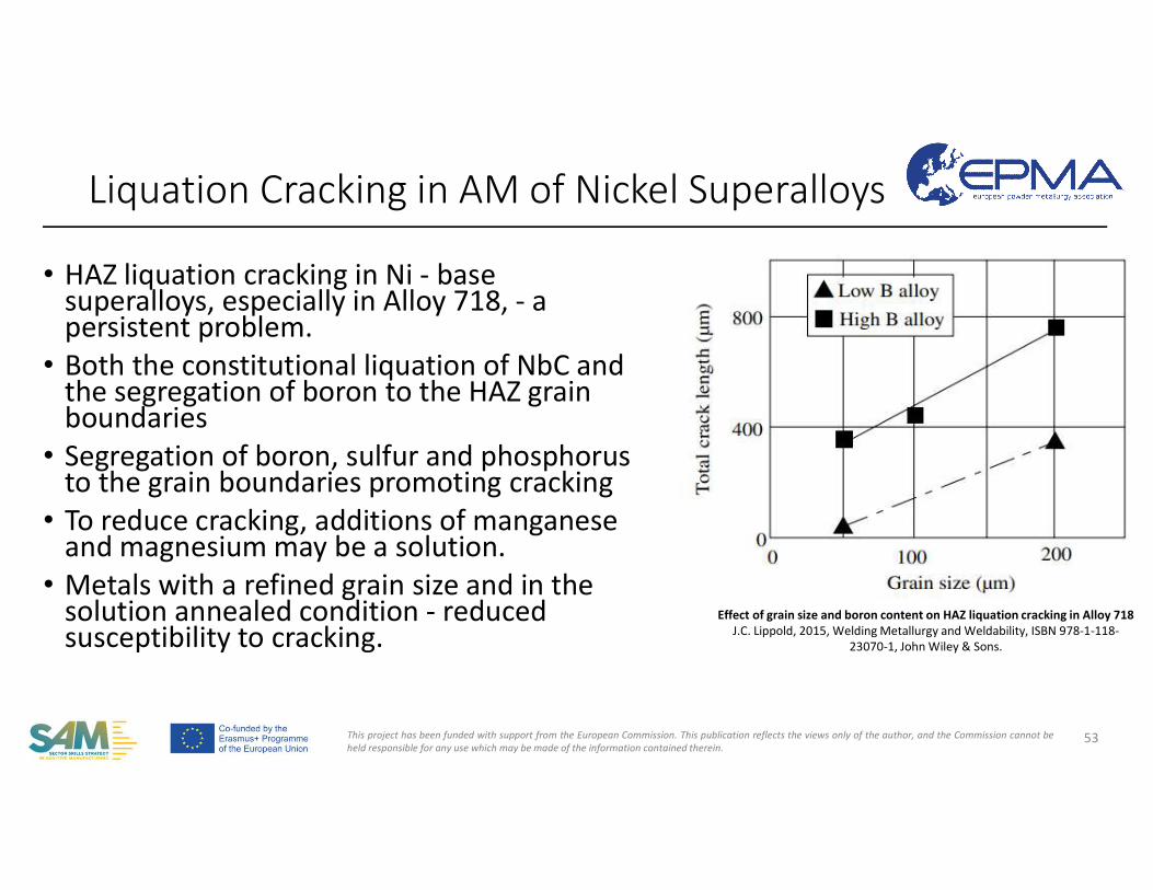
• HAZ liquation cracking in Ni - base superalloys, especially in Alloy 718, - a persistent problem.
• Both the constitutional liquation of NbC and the segregation of boron to the HAZ grain boundaries
• Segregation of boron, sulfur and phosphorus to the grain boundaries promoting cracking
• To reduce cracking, additions of manganese and magnesium may be a solution.
• Metals with a refined grain size and in the solution annealed condition - reduced susceptibility to cracking.
Liquation Cracking in AM of Nickel Superalloys
53
Effect of grain size and boron content on HAZ liquation cracking in Alloy 718J.C. Lippold, 2015, Welding Metallurgy and Weldability, ISBN 978-1-118-
23070-1, John Wiley & Sons.
This project has been funded with support from the European Commission. This publication reflects the views only of the author, and the Commission cannot beheld responsible for any use which may be made of the information contained therein.
• In Alloy 718, the presence of a high fraction of δ (delta) phase has been shown to increase cracking susceptibility.
• Due to the dissolution of the δ phase in the HAZ and the subsequent segregation of Nb to the grain boundaries where it promotes liquid film formation.
Liquation Cracking in AM of Nickel Superalloys
54
This project has been funded with support from the European Commission. This publication reflects the views only of the author, and the Commission cannot beheld responsible for any use which may be made of the information contained therein.
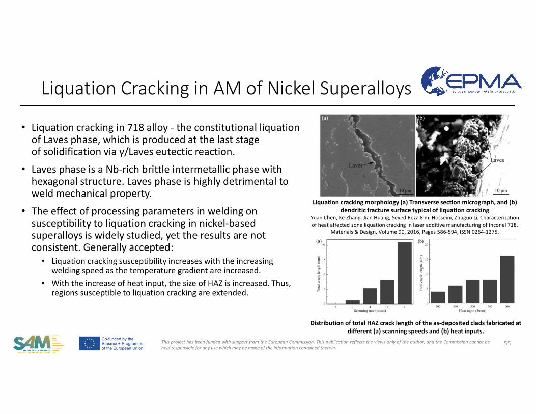
• Liquation cracking in 718 alloy - the constitutional liquation of Laves phase, which is produced at the last stage of solidification via γ/Laves eutectic reaction.
• Laves phase is a Nb-rich brittle intermetallic phase with hexagonal structure. Laves phase is highly detrimental to weld mechanical property.
• The effect of processing parameters in welding on susceptibility to liquation cracking in nickel-based superalloys is widely studied, yet the results are not consistent. Generally accepted:
• Liquation cracking susceptibility increases with the increasing welding speed as the temperature gradient are increased.
• With the increase of heat input, the size of HAZ is increased. Thus, regions susceptible to liquation cracking are extended.
Liquation Cracking in AM of Nickel Superalloys
55
Liquation cracking morphology (a) Transverse section micrograph, and (b) dendritic fracture surface typical of liquation cracking
Yuan Chen, Ke Zhang, Jian Huang, Seyed Reza Elmi Hosseini, Zhuguo Li, Characterization of heat affected zone liquation cracking in laser additive manufacturing of Inconel 718,
Materials & Design, Volume 90, 2016, Pages 586-594, ISSN 0264-1275.
Distribution of total HAZ crack length of the as-deposited clads fabricated at different (a) scanning speeds and (b) heat inputs.
This project has been funded with support from the European Commission. This publication reflects the views only of the author, and the Commission cannot beheld responsible for any use which may be made of the information contained therein.
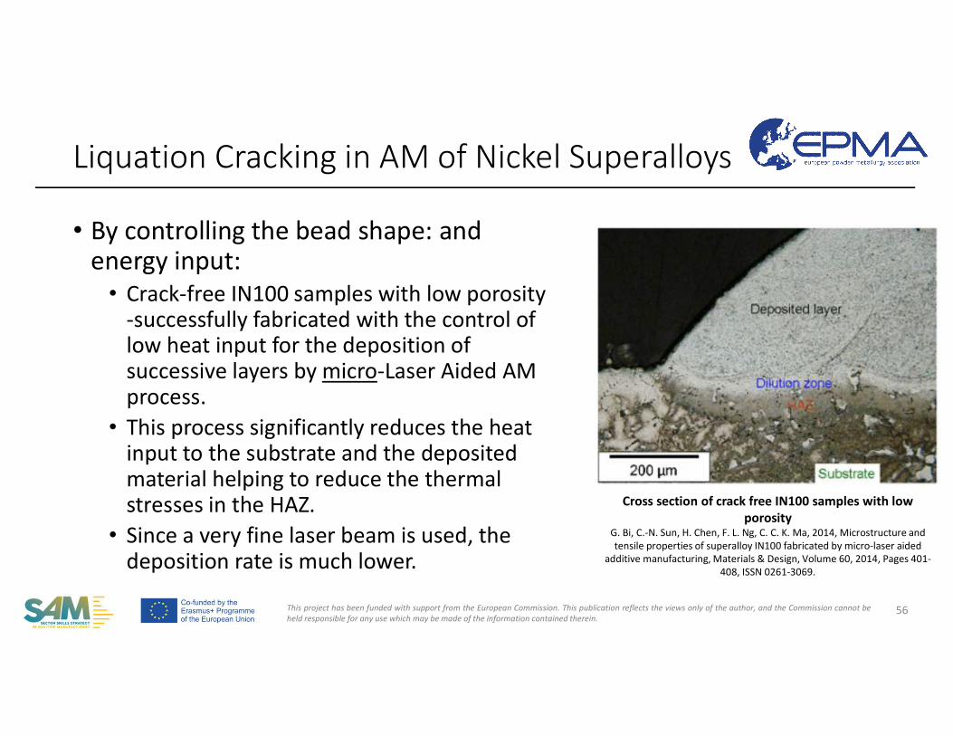
• By controlling the bead shape: and energy input:
• Crack-free IN100 samples with low porosity-successfully fabricated with the control of low heat input for the deposition of successive layers by micro-Laser Aided AM process.
• This process significantly reduces the heat input to the substrate and the deposited material helping to reduce the thermal stresses in the HAZ.
• Since a very fine laser beam is used, the deposition rate is much lower.
Liquation Cracking in AM of Nickel Superalloys
56
Cross section of crack free IN100 samples with low porosity
G. Bi, C.-N. Sun, H. Chen, F. L. Ng, C. C. K. Ma, 2014, Microstructure and tensile properties of superalloy IN100 fabricated by micro-laser aided
additive manufacturing, Materials & Design, Volume 60, 2014, Pages 401-408, ISSN 0261-3069.
This project has been funded with support from the European Commission. This publication reflects the views only of the author, and the Commission cannot beheld responsible for any use which may be made of the information contained therein.
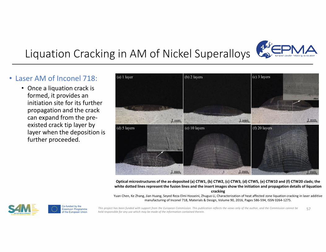
• Laser AM of Inconel 718:• Once a liquation crack is
formed, it provides an initiation site for its further propagation and the crack can expand from the pre-existed crack tip layer by layer when the deposition is further proceeded.
Liquation Cracking in AM of Nickel Superalloys
57
Optical microstructures of the as-deposited (a) CTW1, (b) CTW2, (c) CTW3, (d) CTW5, (e) CTW10 and (f) CTW20 clads; the white dotted lines represent the fusion lines and the insert images show the initiation and propagation details of liquation
crackingYuan Chen, Ke Zhang, Jian Huang, Seyed Reza Elmi Hosseini, Zhuguo Li, Characterization of heat affected zone liquation cracking in laser additive
manufacturing of Inconel 718, Materials & Design, Volume 90, 2016, Pages 586-594, ISSN 0264-1275.
This project has been funded with support from the European Commission. This publication reflects the views only of the author, and the Commission cannot beheld responsible for any use which may be made of the information contained therein.
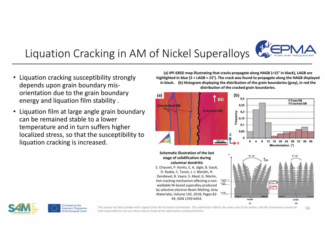
• Liquation cracking susceptibility strongly depends upon grain boundary mis-orientation due to the grain boundary energy and liquation film stability .
• Liquation film at large angle grain boundary can be remained stable to a lower temperature and in turn suffers higher localized stress, so that the susceptibility to liquation cracking is increased.
Liquation Cracking in AM of Nickel Superalloys
58
Schematic illustration of the last stage of solidification during
columnar dendritic E. Chauvet, P. Kontis, E. A. Jägle, B. Gault,
D. Raabe, C. Tassin, J.-J. Blandin, R.Dendievel, B. Vayre, S. Abed, G. Martin,Hot cracking mechanism affecting a non-weldable Ni-based superalloy produced by selective electron Beam Melting, ActaMaterialia, Volume 142, 2018, Pages 82-
94, ISSN 1359-6454.
(a) IPF-EBSD map illustrating that cracks propagate along HAGB (>15° in black), LAGB are highlighted in blue (5 < LAGB < 15°). The crack was found to propagate along the HAGB displayed
in black. (b) Histogram displaying the distribution of the grain boundaries (gray), in red the distribution of the cracked grain boundaries.
This project has been funded with support from the European Commission. This publication reflects the views only of the author, and the Commission cannot beheld responsible for any use which may be made of the information contained therein.
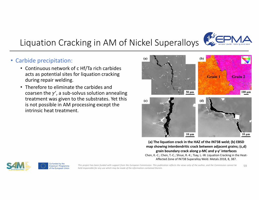
• Carbide precipitation: • Continuous network of c Hf/Ta rich carbides
acts as potential sites for liquation cracking during repair welding.
• Therefore to eliminate the carbides and coarsen the 𝛾′, a sub-solvus solution annealing treatment was given to the substrates. Yet this is not possible in AM processing except the intrinsic heat treatment.
Liquation Cracking in AM of Nickel Superalloys
59
(a) The liquation crack in the HAZ of the IN738 weld; (b) EBSD map showing interdendritic crack between adjacent grains; (c,d)
grain boundary crack along γ-MC and γ-γ’ interfacesChen, K.-C.; Chen, T.-C.; Shiue, R.-K.; Tsay, L.-W. Liquation Cracking in the Heat-
Affected Zone of IN738 Superalloy Weld. Metals 2018, 8, 387.
This project has been funded with support from the European Commission. This publication reflects the views only of the author, and the Commission cannot beheld responsible for any use which may be made of the information contained therein.
Liquation Cracking in AM of Nickel Superalloys
60
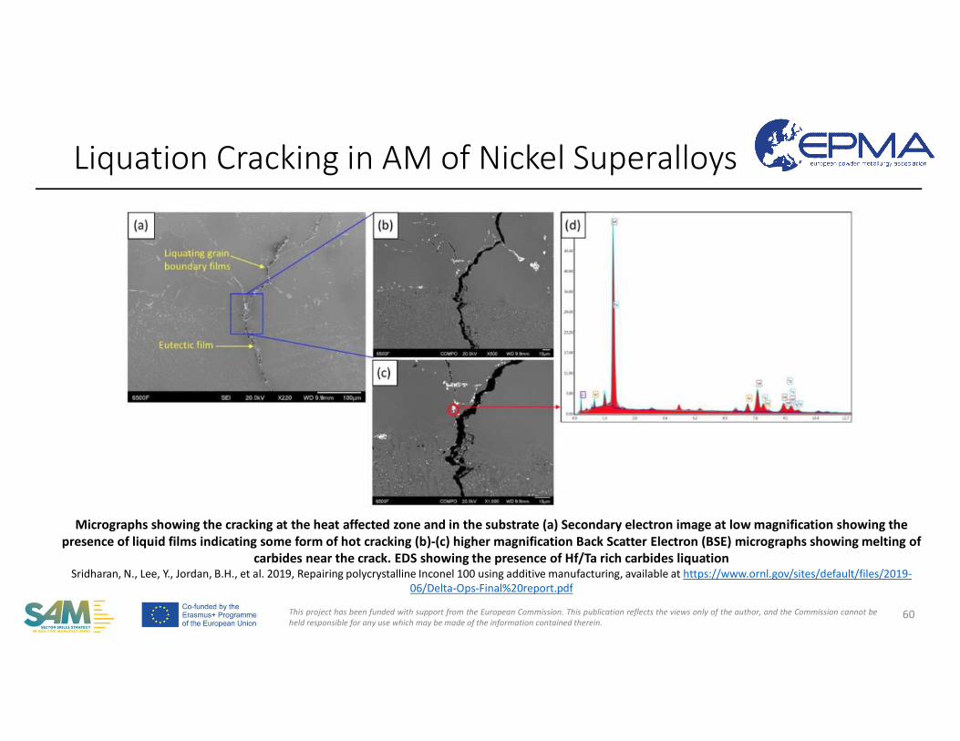
Micrographs showing the cracking at the heat affected zone and in the substrate (a) Secondary electron image at low magnification showing the presence of liquid films indicating some form of hot cracking (b)-(c) higher magnification Back Scatter Electron (BSE) micrographs showing melting of
carbides near the crack. EDS showing the presence of Hf/Ta rich carbides liquationSridharan, N., Lee, Y., Jordan, B.H., et al. 2019, Repairing polycrystalline Inconel 100 using additive manufacturing, available at https://www.ornl.gov/sites/default/files/2019-
06/Delta-Ops-Final%20report.pdf
This project has been funded with support from the European Commission. This publication reflects the views only of the author, and the Commission cannot beheld responsible for any use which may be made of the information contained therein.
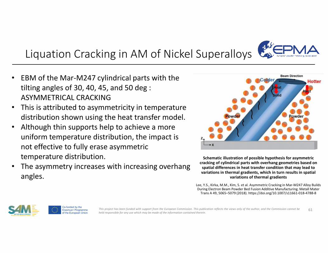
Schematic illustration of possible hypothesis for asymmetric cracking of cylindrical parts with overhang geometries based on
spatial differences in heat transfer condition that may lead to variations in thermal gradients, which in turn results in spatial
variations of thermal gradients
Lee, Y.S., Kirka, M.M., Kim, S. et al. Asymmetric Cracking in Mar-M247 Alloy Builds During Electron Beam Powder Bed Fusion Additive Manufacturing. Metall Mater
Trans A 49, 5065–5079 (2018). https://doi.org/10.1007/s11661-018-4788-8
Liquation Cracking in AM of Nickel Superalloys
61
• EBM of the Mar-M247 cylindrical parts with the tilting angles of 30, 40, 45, and 50 deg : ASYMMETRICAL CRACKING
• This is attributed to asymmetricity in temperature distribution shown using the heat transfer model.
• Although thin supports help to achieve a more uniform temperature distribution, the impact is not effective to fully erase asymmetric temperature distribution.
• The asymmetry increases with increasing overhang angles.
This project has been funded with support from the European Commission. This publication reflects the views only of the author, and the Commission cannot beheld responsible for any use which may be made of the information contained therein.
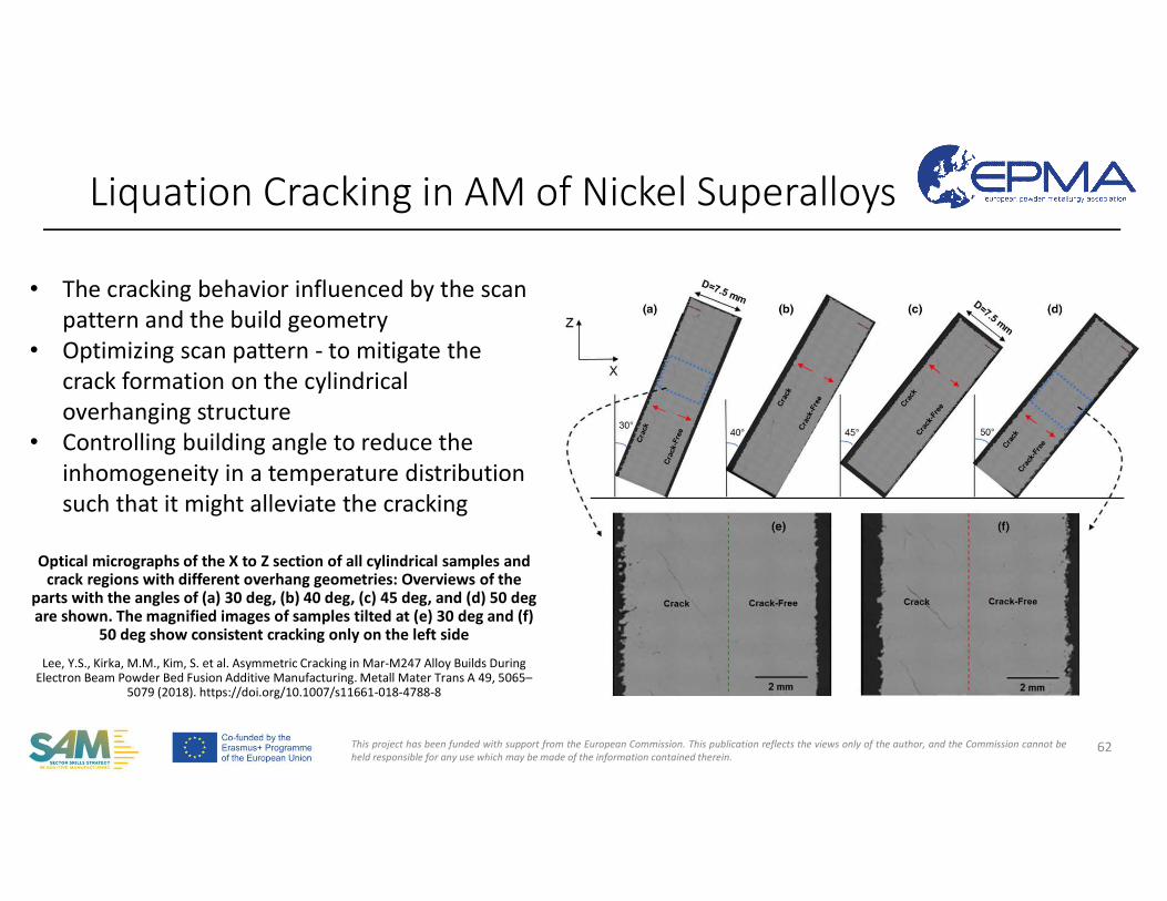
Optical micrographs of the X to Z section of all cylindrical samples and crack regions with different overhang geometries: Overviews of the
parts with the angles of (a) 30 deg, (b) 40 deg, (c) 45 deg, and (d) 50 degare shown. The magnified images of samples tilted at (e) 30 deg and (f)
50 deg show consistent cracking only on the left side
Lee, Y.S., Kirka, M.M., Kim, S. et al. Asymmetric Cracking in Mar-M247 Alloy Builds During Electron Beam Powder Bed Fusion Additive Manufacturing. Metall Mater Trans A 49, 5065–
5079 (2018). https://doi.org/10.1007/s11661-018-4788-8
Liquation Cracking in AM of Nickel Superalloys
62
• The cracking behavior influenced by the scan pattern and the build geometry
• Optimizing scan pattern - to mitigate the crack formation on the cylindrical overhanging structure
• Controlling building angle to reduce the inhomogeneity in a temperature distribution such that it might alleviate the cracking
This project has been funded with support from the European Commission. This publication reflects the views only of the author, and the Commission cannot beheld responsible for any use which may be made of the information contained therein.
• Cold (hydrogen-induced) cracking occurs at or near room temperature and is usually synonymous with hydrogen - induced cracking.
• Hot cracking includes those cracking phenomena associated with the presence of liquid in the system and is localized in the fusion zone and partially - melted zone region of the Heat Affected Zone (HAZ).
• Solidification Cracking• Liquation Cracking
• Solid State Cracking: There are a number of cracking mechanisms that are associated with the “true” HAZ or reheated weld metal.
• Reheat and postweld heat treatment (PWHT) cracking• Strain-Age Cracking• Ductility-Dip Cracking• Cu-contamination cracking (CCC)• Lamellar (or delamination) cracking
Cracking in AM of Nickel Superalloys
63
Welding Metallurgy and Weldability of Nickel-Base Alloys, by John N. DuPont, John C. Lippold, and Samuel D. Kiser Copyright © 2009 John Wiley & Sons, Inc.
This project has been funded with support from the European Commission. This publication reflects the views only of the author, and the Commission cannot beheld responsible for any use which may be made of the information contained therein.
Reheat Cracking in AM of Nickel Superalloys
64
• Also referred to as "PWHT (post-weld heat treatment) cracking" or "Reheat cracking". However, it may also occur during multi-pass welding, e.g. AM.
• The term strain - age cracking (SAC) is based on the fact that both local strain and aging must occur nearly simultaneously.
• Strain Age Cracking (SAC) due to hardening in the material when thestresses are high at the same time.
• It occurs in precipitation hardened superalloys, particularly in γ‟ strengthened alloys, due to the local accumulation of strain and the hardening of the microstructure due to precipitation.
• Defects appear as intergranular micro-cracking either in the HAZ or the deposit itself with carbides acting as crack initiation sites.
DuPont, J.N., Lippold, J.C., Kiser, S., 2009, Welding Metallurgy and Weldability of Nickel-Base Alloys, ISBN: 9780470087145, John Wiley & Sons, Inc.
This project has been funded with support from the European Commission. This publication reflects the views only of the author, and the Commission cannot beheld responsible for any use which may be made of the information contained therein.
Reheat Cracking in AM of Nickel Superalloys
65
• SAC is the biggest issue when welding γ’ strengthened Ni-base superalloysand was actually a strong reason for the success of Alloy 718.
• The reasons for performing a solution heat treatment after welding is • to restore the microstructure of the fuzion zone and HAZ and,• to relieve the stresses which build up during the welding operation.
• Most of the stress relieve occurs at the same time with the precipitation hardening during the heating cycle of PWHT. This imposes high strain on the grain boundaries.
• Additionally, the hardening of the alloy results in a reduced overall ductility.
DuPont, J.N., Lippold, J.C., Kiser, S., 2009, Welding Metallurgy and Weldability of Nickel-Base Alloys, ISBN: 9780470087145, John Wiley & Sons, Inc.
This project has been funded with support from the European Commission. This publication reflects the views only of the author, and the Commission cannot beheld responsible for any use which may be made of the information contained therein.
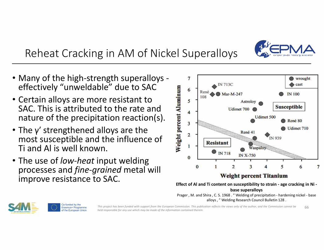
• Many of the high-strength superalloys -effectively “unweldable” due to SAC
• Certain alloys are more resistant to SAC. This is attributed to the rate and nature of the precipitation reaction(s).
• The γ′ strengthened alloys are the most susceptible and the influence of Ti and Al is well known.
• The use of low-heat input welding processes and fine-grained metal will improve resistance to SAC.
Reheat Cracking in AM of Nickel Superalloys
66
Effect of Al and Ti content on susceptibility to strain - age cracking in Ni -base superalloys
Prager , M. and Shira , C. S. 1968 . “ Welding of precipitation - hardening nickel - base alloys , ” Welding Research Council Bulletin 128 .
This project has been funded with support from the European Commission. This publication reflects the views only of the author, and the Commission cannot beheld responsible for any use which may be made of the information contained therein.
• In an effort to improve weldability and avoid SAC, a second generation of precipitation - hardening Ni - Cr alloys was developed that are strengthened by gamma double prime. The most popular of these alloys is Alloy 718.
Reheat Cracking in AM of Nickel Superalloys
67
This project has been funded with support from the European Commission. This publication reflects the views only of the author, and the Commission cannot beheld responsible for any use which may be made of the information contained therein.
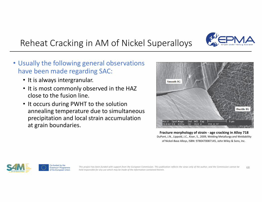
• Usually the following general observations have been made regarding SAC:
• It is always intergranular. • It is most commonly observed in the HAZ
close to the fusion line.• It occurs during PWHT to the solution
annealing temperature due to simultaneous precipitation and local strain accumulation at grain boundaries.
Reheat Cracking in AM of Nickel Superalloys
68
Fracture morphology of strain - age cracking in Alloy 718DuPont, J.N., Lippold, J.C., Kiser, S., 2009, Welding Metallurgy and Weldability
of Nickel-Base Alloys, ISBN: 9780470087145, John Wiley & Sons, Inc.
This project has been funded with support from the European Commission. This publication reflects the views only of the author, and the Commission cannot beheld responsible for any use which may be made of the information contained therein.
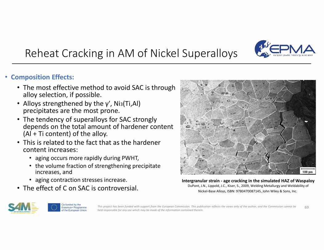
• Composition Effects: • The most effective method to avoid SAC is through
alloy selection, if possible. • Alloys strengthened by the γ′, Ni3(Ti,Al)
precipitates are the most prone.• The tendency of superalloys for SAC strongly
depends on the total amount of hardener content (Al + Ti content) of the alloy.
• This is related to the fact that as the hardener content increases:
• aging occurs more rapidly during PWHT,• the volume fraction of strengthening precipitate
increases, and • aging contraction stresses increase.
• The effect of C on SAC is controversial.
Reheat Cracking in AM of Nickel Superalloys
69
Intergranular strain - age cracking in the simulated HAZ of WaspaloyDuPont, J.N., Lippold, J.C., Kiser, S., 2009, Welding Metallurgy and Weldability of
Nickel-Base Alloys, ISBN: 9780470087145, John Wiley & Sons, Inc.
This project has been funded with support from the European Commission. This publication reflects the views only of the author, and the Commission cannot beheld responsible for any use which may be made of the information contained therein.
• Grain Size: Fine-grained materials lead to increased amount of grain boundary area leading to being more resistant to SAC than coarse-grained materials.
• The increased grain boundary area leads to stress relaxation,• Moerover, embrittling phases forming at the grain boundaries as thinner or
discontinuous layers,• Yet, negative effect on applications requiring creep resistance.
Reheat Cracking in AM of Nickel Superalloys
70
This project has been funded with support from the European Commission. This publication reflects the views only of the author, and the Commission cannot beheld responsible for any use which may be made of the information contained therein.
• If possible, the base metal in welding is preferred to be soft to allow the relaxation of the stresses developed during the process / PWHT.
• Reducing the heat input minimizes the residual stresses• It is unlikely that a full solution to SAC can be identified by simply changing process
parameters.• Preheating has been shown to be useful in reducing SAC, but the preheat
temperatures may be extremely high.• With preheating to 538°C, Alloy 713C vanes repair welded. • Preheating and welding were carried out in an inert atmosphere. • This procedure was found to substantially decrease the degree of both hot cracking
(solidification and HAZ liquation cracking) and SAC.• “SWET” (superalloy welding at elevated temperature) welding: Preheat
temperatures, 705 – 955 °C successfully avoided cracking during welding and PWHT in high strength, cast superalloy vanes
Reheat Cracking in AM of Nickel Superalloys
71
DuPont, J.N., Lippold, J.C., Kiser, S., 2009, Welding Metallurgy and Weldability of Nickel-Base Alloys, ISBN: 9780470087145, John Wiley & Sons, Inc.Duvall , D. S. and Doyle , J. R. 1973 . Repair of turbine blades and vanes, ASME publication 73 - GT - 44.Flowers , G. , Kelley , E. , Grossklaus , W. , Barber , J. , Grubbs , G. , Williams , L. 2000 . U.S. Patent Number 6,084,196 , issued July 4
This project has been funded with support from the European Commission. This publication reflects the views only of the author, and the Commission cannot beheld responsible for any use which may be made of the information contained therein.
• Effect of Post-weld Heat Treatment: Most nickel - base superalloysrequire a full solution anneal and aging treatment following welding in order to restore mechanical properties. As is the case with AM, aging after welding is usually not appropriate due to the possibility of overaging the base metal and need for homogenization.
• Rapid heating to the solution temperature may be effective in preventing SAC.• In large components, temperature gradients within the component can create
large thermal stresses. • A protective atmosphere during heat treatment is recommended. • The detrimental effect of an oxygen - rich atmosphere is thought to be due to
formation of oxides which are not able to resist plastic deformation during stress relaxation.
Reheat Cracking in AM of Nickel Superalloys
72
This project has been funded with support from the European Commission. This publication reflects the views only of the author, and the Commission cannot beheld responsible for any use which may be made of the information contained therein.
• Additive Manufacturing Considerations:• The SAC index describes the tendency of forming γ’ precipitates during the so-
called “intrinsic heat treatment” – which is repeated reheating and cooling arising from the AM fabrication:
• Improved residual stress distribution shall be preferred to avoid SAC. • Partial thinning of the used base plate, while the parts are still connected,
results in relaxation of the material and reduced residual stresses. This is yet limited by the acceptable level of shape deviation.
• Compressive surface stresses are created by sandblasting, yet the accessibility of the surface is a barrier.
Reheat Cracking in AM of Nickel Superalloys
73
ASM Handbook Vol.24 Additive ManufacturingRisse, J., 2019, Additive Manufacturing of Nickel-Base Superalloy IN738LC by Laser Powder Bed Fusion , Dissertation presented in partial fulfillment of the requirements for the degree of Doctor of Engineering Science (Phd), RWTH, Germany.Illston T. Additive Manufacturing. Patent No. DE102013108111 A1, 2013
This project has been funded with support from the European Commission. This publication reflects the views only of the author, and the Commission cannot beheld responsible for any use which may be made of the information contained therein.
• Special care must be given on post-heat treatments of AM parts. Because any such heat treatment may subject the parts to reheatcracking .
• Materials with strong precipitation reactions are susceptible to this type of solid-state cracking.
• Reheat cracking may be prevented by • controlling composition, • processing conditions,• minimizing residual stresses, stress concentrations,• stress relaxation, or by layering the substrate.
Reheat Cracking in AM of Nickel Superalloys
74
Risse, J., 2019, Additive Manufacturing of Nickel-Base Superalloy IN738LC by Laser Powder Bed Fusion , Dissertation presented in partial fulfillment of the requirements for the degree of Doctor of Engineering Science (Phd), RWTH, Germany.Illston T. Additive Manufacturing. Patent No. DE102013108111 A1, 2013
This project has been funded with support from the European Commission. This publication reflects the views only of the author, and the Commission cannot beheld responsible for any use which may be made of the information contained therein.
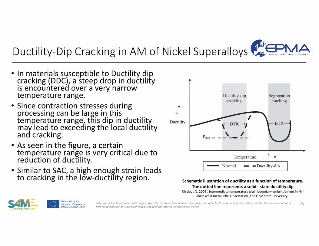
• In materials susceptible to Ductility dip cracking (DDC), a steep drop in ductility is encountered over a very narrowtemperature range.
• Since contraction stresses during processing can be large in this temperature range, this dip in ductility may lead to exceeding the local ductility and cracking.
• As seen in the figure, a certain temperature range is very critical due to reduction of ductility.
• Similar to SAC, a high enough strain leads to cracking in the low-ductility region.
Ductility-Dip Cracking in AM of Nickel Superalloys
75
Schematic illustration of ductility as a function of temperature. The dotted line represents a solid - state ductility dip
Nissley , N. 2006 . Intermediate temperature grain boundary embrittlement in Ni -base weld metal. PhD Dissertation, The Ohio State University.
This project has been funded with support from the European Commission. This publication reflects the views only of the author, and the Commission cannot beheld responsible for any use which may be made of the information contained therein.
• Wrongly referred to as «Hot cracking, hot tearing, hot fissuring, reheat cracking, micro-fissuring, and polygonization cracking»
• It is probable that the literature contains many references to liquation cracking and micro-fissuring in weld metals that are in fact DDC.
• DDC requires neither the formation of strengthening precipitates norgrain boundary impurity segregation.
• High purity, solid - solution strengthened alloys are often more susceptible to DDC than those that undergo precipitation reactions or have moderate impurity levels.
76
Nissley , N. 2006 . Intermediate temperature grain boundary embrittlement in Ni - base weld metal. PhD Dissertation, The Ohio State University.DuPont, J.N., Lippold, J.C., Kiser, S., 2009, Welding Metallurgy and Weldability of Nickel-Base Alloys, ISBN: 9780470087145, John Wiley & Sons, Inc.
Ductility-Dip Cracking in AM of Nickel Superalloys
This project has been funded with support from the European Commission. This publication reflects the views only of the author, and the Commission cannot beheld responsible for any use which may be made of the information contained therein.
• Materials having a ductility dip, typically in the temperature range of 0.5-0.8 liquidus temperature
• Accumulated strain at grain boundaries due to transient thermal stresses, which exceeds the local ductility of the material
• Formation points are grain boundary triple points or irregularities at grain boundaries which cause strain concentrations.
• With increasing deformation, the voids grow and connect, and result in cracks.
• Considering DDC as a creep-like phenomenon, the deformation mechanism, can explain the temperature range.
77
Nissley , N. 2006 . Intermediate temperature grain boundary embrittlement in Ni - base weld metal. PhD Dissertation, The Ohio State University.DuPont, J.N., Lippold, J.C., Kiser, S., 2009, Welding Metallurgy and Weldability of Nickel-Base Alloys, ISBN: 9780470087145, John Wiley & Sons, Inc.
Ductility-Dip Cracking in AM of Nickel Superalloys
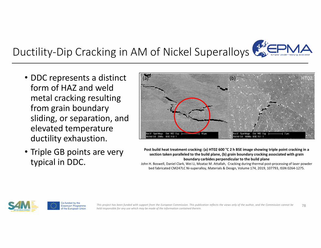
This project has been funded with support from the European Commission. This publication reflects the views only of the author, and the Commission cannot beheld responsible for any use which may be made of the information contained therein.
• DDC represents a distinct form of HAZ and weld metal cracking resulting from grain boundary sliding, or separation, and elevated temperature ductility exhaustion.
• Triple GB points are very typical in DDC.
78
Post build heat treatment cracking: (a) HT02 600ௗ°C 2ௗh BSE image showing triple point cracking in a section taken paralleled to the build plane, (b) grain boundary cracking associated with grain
boundary carbides perpendicular to the build planeJohn H. Boswell, Daniel Clark, Wei Li, Moataz M. Attallah, Cracking during thermal post-processing of laser powder
bed fabricated CM247LC Ni-superalloy, Materials & Design, Volume 174, 2019, 107793, ISSN 0264-1275.
Ductility-Dip Cracking in AM of Nickel Superalloys
This project has been funded with support from the European Commission. This publication reflects the views only of the author, and the Commission cannot beheld responsible for any use which may be made of the information contained therein.
• Ductility - dip cracking (DDC) can be a serious weldability issue, particularly in thick - section multi-pass welds where restraint levels are high. This is similar to AM.
• In nickel alloys, DDC is almost always observed along migrated grain boundaries.
• The effect of M23C6 carbide precipitation on DDC susceptibility: by controlling precipitation of M23C6 along migrated weld metal grain boundaries, improvement in DDC resistance could be achieved due to a microscopic grain boundary locking mechanism, whereby carbides of appropriate size and distribution can oppose grain boundary sliding.
79
Ductility-Dip Cracking in AM of Nickel Superalloys
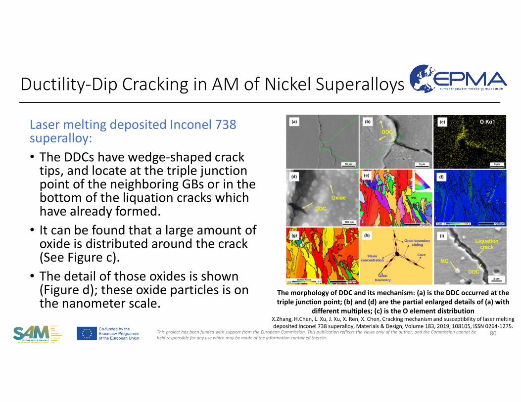
This project has been funded with support from the European Commission. This publication reflects the views only of the author, and the Commission cannot beheld responsible for any use which may be made of the information contained therein.
Laser melting deposited Inconel 738 superalloy:• The DDCs have wedge-shaped crack
tips, and locate at the triple junction point of the neighboring GBs or in the bottom of the liquation cracks which have already formed.
• It can be found that a large amount of oxide is distributed around the crack(See Figure c).
• The detail of those oxides is shown(Figure d); these oxide particles is on the nanometer scale.
80
The morphology of DDC and its mechanism: (a) is the DDC occurred at the triple junction point; (b) and (d) are the partial enlarged details of (a) with
different multiples; (c) is the O element distributionX.Zhang, H.Chen, L. Xu, J. Xu, X. Ren, X. Chen, Cracking mechanism and susceptibility of laser melting deposited Inconel 738 superalloy, Materials & Design, Volume 183, 2019, 108105, ISSN 0264-1275.
Ductility-Dip Cracking in AM of Nickel Superalloys
This project has been funded with support from the European Commission. This publication reflects the views only of the author, and the Commission cannot beheld responsible for any use which may be made of the information contained therein.
• The use of small stringer beads that minimize the overall heat input can help reduce susceptibility to DDC though not very productive. This is not so difficult to apply in AM due to its nature.
• The use of argon as protective gas improves the wettability. The utilization of pure argon/helium shielding gases generally improvesresistance to DDC, but may not be succesful to completely eliminate it. Therefore, using Argon as protective atmosphere for Nickel superalloys shall be preferred in AM.
81
Ductility-Dip Cracking in AM of Nickel Superalloys
This project has been funded with support from the European Commission. This publication reflects the views only of the author, and the Commission cannot beheld responsible for any use which may be made of the information contained therein.
Cracking phenomena in parts processed by AM • Common Defects• Porosity • Cracking
• Cold Cracking• Hot Cracking• Solid-State Cracking• Weldability
• Hot Isostatic Pressing
82
COMPETENCE UNIT 30: Additive Manufacturing with Nickel feedstock
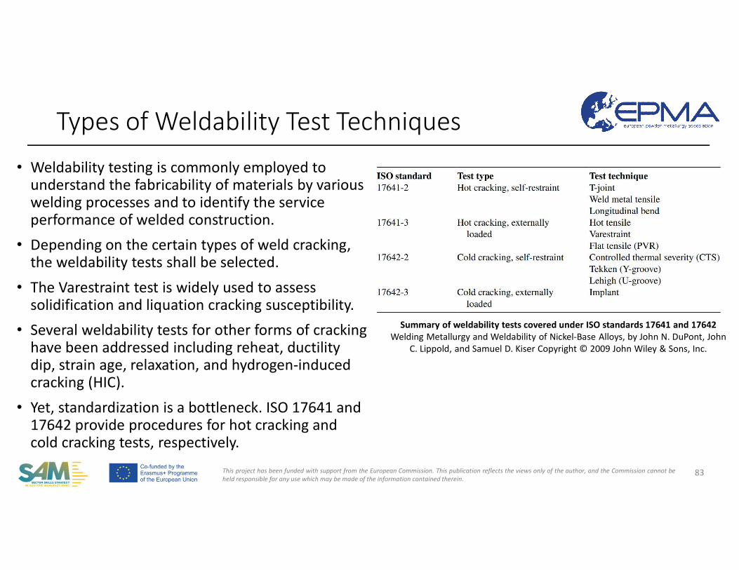
This project has been funded with support from the European Commission. This publication reflects the views only of the author, and the Commission cannot beheld responsible for any use which may be made of the information contained therein.
• Weldability testing is commonly employed to understand the fabricability of materials by various welding processes and to identify the service performance of welded construction.
• Depending on the certain types of weld cracking, the weldability tests shall be selected.
• The Varestraint test is widely used to assess solidification and liquation cracking susceptibility.
• Several weldability tests for other forms of crackinghave been addressed including reheat, ductility dip, strain age, relaxation, and hydrogen-induced cracking (HIC).
• Yet, standardization is a bottleneck. ISO 17641 and 17642 provide procedures for hot cracking and cold cracking tests, respectively.
Types of Weldability Test Techniques
83
Summary of weldability tests covered under ISO standards 17641 and 17642Welding Metallurgy and Weldability of Nickel-Base Alloys, by John N. DuPont, John
C. Lippold, and Samuel D. Kiser Copyright © 2009 John Wiley & Sons, Inc.
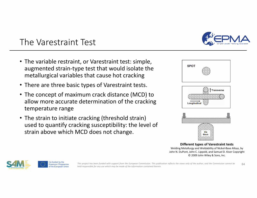
This project has been funded with support from the European Commission. This publication reflects the views only of the author, and the Commission cannot beheld responsible for any use which may be made of the information contained therein.
• The variable restraint, or Varestraint test: simple, augmented strain-type test that would isolate the metallurgical variables that cause hot cracking
• There are three basic types of Varestraint tests.• The concept of maximum crack distance (MCD) to
allow more accurate determination of the cracking temperature range
• The strain to initiate cracking (threshold strain) used to quantify cracking susceptibility: the level of strain above which MCD does not change.
The Varestraint Test
84
Different types of Varestraint testsWelding Metallurgy and Weldability of Nickel-Base Alloys, by
John N. DuPont, John C. Lippold, and Samuel D. Kiser Copyright © 2009 John Wiley & Sons, Inc.
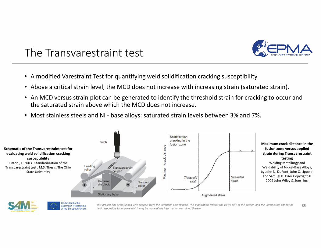
This project has been funded with support from the European Commission. This publication reflects the views only of the author, and the Commission cannot beheld responsible for any use which may be made of the information contained therein.
• A modified Varestraint Test for quantifying weld solidification cracking susceptibility
• Above a critical strain level, the MCD does not increase with increasing strain (saturated strain).
• An MCD versus strain plot can be generated to identify the threshold strain for cracking to occur and the saturated strain above which the MCD does not increase.
• Most stainless steels and Ni - base alloys: saturated strain levels between 3% and 7%.
The Transvarestraint test
85
Schematic of the Transvarestraint test for evaluating weld solidification cracking
susceptibilityFinton , T. 2003 . Standardization of the
Transvarestraint test . M.S. Thesis, The Ohio State University
Maximum crack distance in the fusion zone versus applied
strain during Transvarestrainttesting
Welding Metallurgy and Weldability of Nickel-Base Alloys,
by John N. DuPont, John C. Lippold, and Samuel D. Kiser Copyright ©
2009 John Wiley & Sons, Inc.
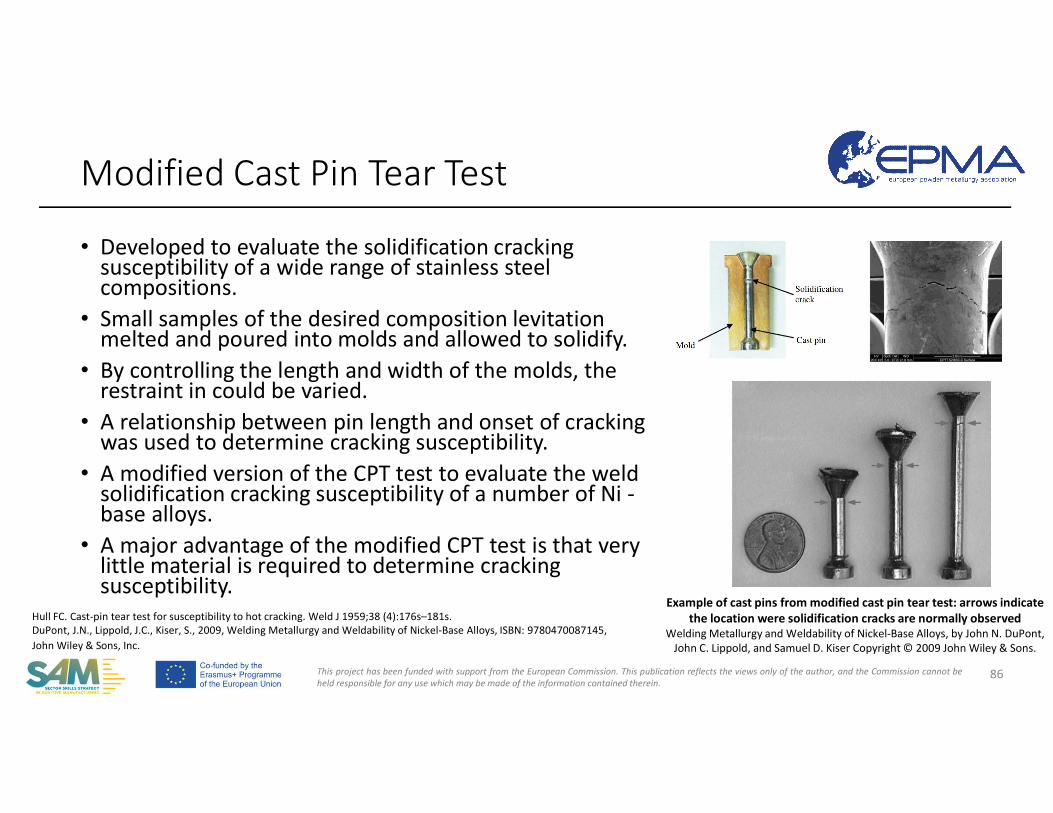
This project has been funded with support from the European Commission. This publication reflects the views only of the author, and the Commission cannot beheld responsible for any use which may be made of the information contained therein.
• Developed to evaluate the solidification cracking susceptibility of a wide range of stainless steel compositions.
• Small samples of the desired composition levitation melted and poured into molds and allowed to solidify.
• By controlling the length and width of the molds, the restraint in could be varied.
• A relationship between pin length and onset of cracking was used to determine cracking susceptibility.
• A modified version of the CPT test to evaluate the weldsolidification cracking susceptibility of a number of Ni -base alloys.
• A major advantage of the modified CPT test is that very little material is required to determine cracking susceptibility.
Modified Cast Pin Tear Test
86
Example of cast pins from modified cast pin tear test: arrows indicate the location were solidification cracks are normally observed
Welding Metallurgy and Weldability of Nickel-Base Alloys, by John N. DuPont, John C. Lippold, and Samuel D. Kiser Copyright © 2009 John Wiley & Sons.
Hull FC. Cast-pin tear test for susceptibility to hot cracking. Weld J 1959;38 (4):176s–181s.DuPont, J.N., Lippold, J.C., Kiser, S., 2009, Welding Metallurgy and Weldability of Nickel-Base Alloys, ISBN: 9780470087145, John Wiley & Sons, Inc.
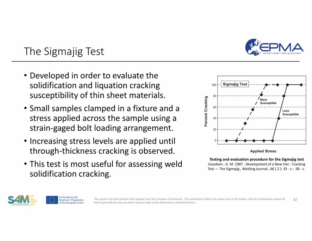
This project has been funded with support from the European Commission. This publication reflects the views only of the author, and the Commission cannot beheld responsible for any use which may be made of the information contained therein.
• Developed in order to evaluate the solidification and liquation cracking susceptibility of thin sheet materials.
• Small samples clamped in a fixture and a stress applied across the sample using a strain-gaged bolt loading arrangement.
• Increasing stress levels are applied until through-thickness cracking is observed.
• This test is most useful for assessing weld solidification cracking.
The Sigmajig Test
87
Testing and evaluation procedure for the Sigmajig testGoodwin , G. M. 1987 . Development of a New Hot - Cracking Test — The Sigmajig , Welding Journal , 66 ( 2 ): 33 - s – 38 - s .
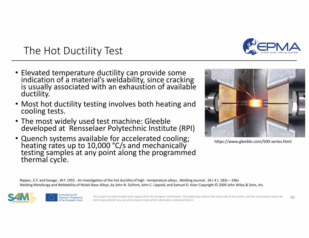
This project has been funded with support from the European Commission. This publication reflects the views only of the author, and the Commission cannot beheld responsible for any use which may be made of the information contained therein.
• Elevated temperature ductility can provide some indication of a material’s weldability, since cracking is usually associated with an exhaustion of available ductility.
• Most hot ductility testing involves both heating and cooling tests.
• The most widely used test machine: Gleeble developed at Rensselaer Polytechnic Institute (RPI)
• Quench systems available for accelerated cooling;heating rates up to 10,000 °C/s and mechanically testing samples at any point along the programmed thermal cycle.
The Hot Ductility Test
88
Nippes , E.F. and Savage , W.F. 1955 . An investigation of the hot ductility of high - temperature alloys , Welding Journal , 34 ( 4 ): 183s – 196sWelding Metallurgy and Weldability of Nickel-Base Alloys, by John N. DuPont, John C. Lippold, and Samuel D. Kiser Copyright © 2009 John Wiley & Sons, Inc.
https://www.gleeble.com/500-series.html
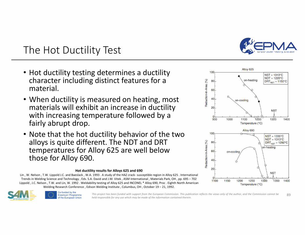
This project has been funded with support from the European Commission. This publication reflects the views only of the author, and the Commission cannot beheld responsible for any use which may be made of the information contained therein.
• Hot ductility testing determines a ductility character including distinct features for a material.
• When ductility is measured on heating, most materials will exhibit an increase in ductility with increasing temperature followed by a fairly abrupt drop.
• Note that the hot ductility behavior of the two alloys is quite different. The NDT and DRT temperatures for Alloy 625 are well below those for Alloy 690.
The Hot Ductility Test
89
Hot ductility results for Alloys 625 and 690Lin , W. Nelson , T.W. Lippold J.C. and Baeslack , W.A. 1993 . A study of the HAZ crack- susceptible region in Alloy 625 . International Trends in Welding Science and Technology , Eds. S.A. David and J.M. Vitek , ASM International , Materials Park, OH , pp. 695 – 702
Lippold , J.C. Nelson , T.W. and Lin, W. 1992 . Weldability testing of Alloy 625 and INCONEL ® Alloy 690, Proc . Eighth North American Welding Research Conference , Edison Welding Institute , Columbus, OH , October 19 – 21, 1992.
This project has been funded with support from the European Commission. This publication reflects the views only of the author, and the Commission cannot beheld responsible for any use which may be made of the information contained therein.
Cracking phenomena in parts processed by AM • Common Defects• Porosity • Cracking
• Cold Cracking• Hot Cracking• Solid-State Cracking• Weldability
• Hot Isostatic Pressing
90
COMPETENCE UNIT 30: Additive Manufacturing with Nickel feedstock
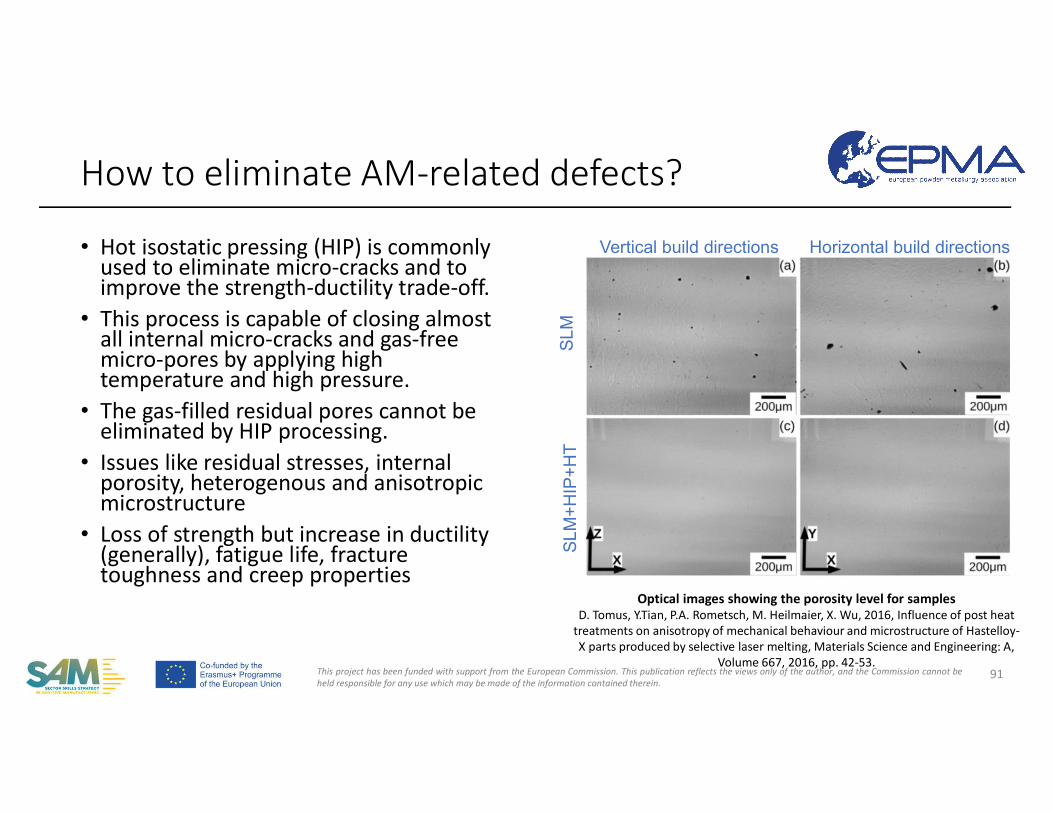
This project has been funded with support from the European Commission. This publication reflects the views only of the author, and the Commission cannot beheld responsible for any use which may be made of the information contained therein.
• Hot isostatic pressing (HIP) is commonly used to eliminate micro-cracks and to improve the strength-ductility trade-off.
• This process is capable of closing almost all internal micro-cracks and gas-free micro-pores by applying high temperature and high pressure.
• The gas-filled residual pores cannot beeliminated by HIP processing.
• Issues like residual stresses, internal porosity, heterogenous and anisotropic microstructure
• Loss of strength but increase in ductility (generally), fatigue life, fracture toughness and creep properties
How to eliminate AM-related defects?
91
Vertical build directions Horizontal build directions
SL
M+
HIP
+H
TS
LM
Optical images showing the porosity level for samplesD. Tomus, Y.Tian, P.A. Rometsch, M. Heilmaier, X. Wu, 2016, Influence of post heat
treatments on anisotropy of mechanical behaviour and microstructure of Hastelloy-X parts produced by selective laser melting, Materials Science and Engineering: A,
Volume 667, 2016, pp. 42-53.
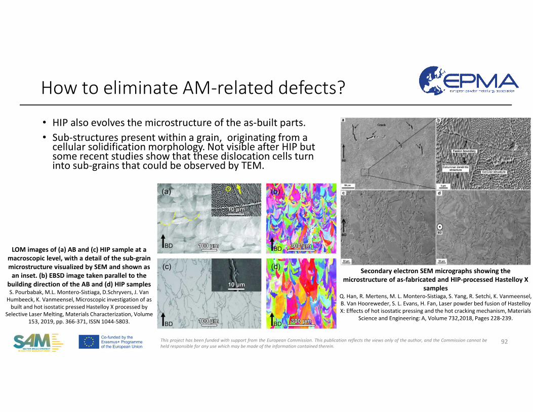
This project has been funded with support from the European Commission. This publication reflects the views only of the author, and the Commission cannot beheld responsible for any use which may be made of the information contained therein.
• HIP also evolves the microstructure of the as-built parts.• Sub-structures present within a grain, originating from a
cellular solidification morphology. Not visible after HIP but some recent studies show that these dislocation cells turn into sub-grains that could be observed by TEM.
How to eliminate AM-related defects?
92
Secondary electron SEM micrographs showing the microstructure of as-fabricated and HIP-processed Hastelloy X
samplesQ. Han, R. Mertens, M. L. Montero-Sistiaga, S. Yang, R. Setchi, K. Vanmeensel, B. Van Hooreweder, S. L. Evans, H. Fan, Laser powder bed fusion of HastelloyX: Effects of hot isostatic pressing and the hot cracking mechanism, Materials
Science and Engineering: A, Volume 732,2018, Pages 228-239.
LOM images of (a) AB and (c) HIP sample at a macroscopic level, with a detail of the sub-grain microstructure visualized by SEM and shown as
an inset. (b) EBSD image taken parallel to the building direction of the AB and (d) HIP samplesS. Pourbabak, M.L. Montero-Sistiaga, D.Schryvers, J. Van
Humbeeck, K. Vanmeensel, Microscopic investigation of as built and hot isostatic pressed Hastelloy X processed by
Selective Laser Melting, Materials Characterization, Volume 153, 2019, pp. 366-371, ISSN 1044-5803.
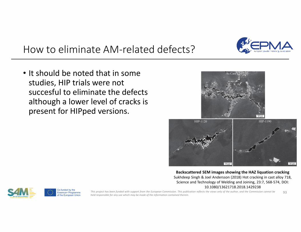
This project has been funded with support from the European Commission. This publication reflects the views only of the author, and the Commission cannot beheld responsible for any use which may be made of the information contained therein.
• It should be noted that in some studies, HIP trials were not succesful to eliminate the defects although a lower level of cracks is present for HIPped versions.
How to eliminate AM-related defects?
93
Backscattered SEM images showing the HAZ liquation crackingSukhdeep Singh & Joel Andersson (2018) Hot cracking in cast alloy 718,
Science and Technology of Welding and Joining, 23:7, 568-574, DOI: 10.1080/13621718.2018.1429238
This project has been funded with support from the European Commission. This publication reflects the views only of the author, and the Commission cannot beheld responsible for any use which may be made of the information contained therein.
• A small of porosity in AM parts is inevitable. Most types of porosities can be elimitaed using a right set of process parameters, scan strategies and limited powder specifications.
• Well-established literature from cracking in welding of Nickel superalloys has been presented. This knowledge is a great asset to build the fundamentals for AM processing.
• AM, especially LPBF, at high preheating temperatures requires further improvement of the used system technology.
• Composition control is very important for weldability of nickel-superalloys. Tighter tolerances may be applied on elemental weights. Moreover, powder characteristics play a very critical role on the overall defect mechanisms in AM processing.
• An improved atmosphere with lower levels of oxygen and moisture is required in order to avoid oxidation during the process. The powder handling should be considered as well, as this is an additional source for moisture pickup in the process chain. Moreover, hydrogen embrittlement is an issue to be tackled with.
• The described dilemma of crack formation and creep strength is principally valid for all currently available γ’-strengthened nickel-base superalloys, like IN738LC or CM247LC.
• Solidification cracking should be addressed by tight control of impurities as well as careful selection of grain boundary strengtheners, which both promote microsegregation.
• HIP is a combined solution to eliminate/minimize gas-free porosities/cracks for extended mechanical properties and can be combined with post-heat treatments after AM.
Summary - Highlights
94
This project has been funded with support from the European Commission. This publication reflects the views only of the author, and the Commission cannot beheld responsible for any use which may be made of the information contained therein.
Dr. Evren Yasa
Eskisehir Osmangazi University
Mechanical Engineering
Thank you!
95
This project has been funded with support from the European Commission. This publication reflects the views only of the author, and the Commission cannot beheld responsible for any use which may be made of the information contained therein.
• Sukhdeep Singh & Joel Andersson (2018) Hot cracking in cast alloy 718, Science and Technology of Welding and Joining, 23:7, 568-574, DOI: 10.1080/13621718.2018.1429238
• Q. Han, R. Mertens, M. L. Montero-Sistiaga, S. Yang, R. Setchi, K. Vanmeensel, B. Van Hooreweder, S. L. Evans, H. Fan, Laser powder bed fusion of Hastelloy X: Effects of hot isostatic pressing and the hot cracking mechanism, Materials Science and Engineering: A, Volume 732,2018, Pages 228-239.
• S. Pourbabak, M.L. Montero-Sistiaga, D.Schryvers, J. Van Humbeeck, K. Vanmeensel, Microscopic investigation of as built and hot isostatic pressed Hastelloy X processed by Selective Laser Melting, Materials Characterization, Volume 153, 2019, pp. 366-371, ISSN 1044-5803.
• D. Tomus, Y.Tian, P.A. Rometsch, M. Heilmaier, X. Wu, 2016, Influence of post heat treatments on anisotropy of mechanical behaviour and microstructure of Hastelloy-X parts produced by selective laser melting,Materials Science and Engineering: A, Volume 667, 2016, pp. 42-53.
• Lin , W. Nelson , T.W. Lippold J.C. and Baeslack , W.A. 1993 . A study of the HAZ crack- susceptible region in Alloy 625 . International Trends in Welding Science and Technology , Eds. S.A. David and J.M. Vitek , ASM International , Materials Park, OH , pp. 695 – 702
• Lippold , J.C. Nelson , T.W. and Lin, W. 1992 . Weldability testing of Alloy 625 and INCONEL ® Alloy 690, Proc . Eighth North American Welding Research Conference , Edison Welding Institute , Columbus, OH , October 19 – 21, 1992.
• Goodwin , G. M. 1987 . Development of a New Hot - Cracking Test — The Sigmajig , Welding Journal , 66 (2): 33 - 38.
References
96
This project has been funded with support from the European Commission. This publication reflects the views only of the author, and the Commission cannot beheld responsible for any use which may be made of the information contained therein.
• John H. Boswell, Daniel Clark, Wei Li, Moataz M. Attallah, Cracking during thermal post-processing of laser powder bed fabricated CM247LC Ni-superalloy, Materials & Design, Volume 174, 2019, 107793, ISSN 0264-1275.
• Prager , M. and Shira , C. S. 1968 . “ Welding of precipitation - hardening nickel - base alloys , ” Welding Research Council Bulletin 128 .
• Duvall , D. S. and Doyle , J. R. 1973 . Repair of turbine blades and vanes, ASME publication 73 - GT - 44.
• Risse, J., 2019, Additive Manufacturing of Nickel-Base Superalloy IN738LC by Laser Powder Bed Fusion , Dissertation presented in partial fulfillment of the requirements for the degree of Doctor of Engineering Science (Phd), RWTH, Germany.
• Illston T. Additive Manufacturing. Patent No. DE102013108111 A1, 2013
• Nissley , N. 2006 . Intermediate temperature grain boundary embrittlement in Ni - base weld metal. PhD Dissertation, The Ohio State University.
• Chen, K.-C.; Chen, T.-C.; Shiue, R.-K.; Tsay, L.-W. Liquation Cracking in the Heat-Affected Zone of IN738 SuperalloyWeld. Metals 2018, 8, 387.
• Sridharan, N., Lee, Y., Jordan, B.H., et al. 2019, Repairing polycrystalline Inconel 100 using additive manufacturing, available at https://www.ornl.gov/sites/default/files/2019-06/Delta-Ops-Final%20report.pdf
• Lee, Y.S., Kirka, M.M., Kim, S. et al. Asymmetric Cracking in Mar-M247 Alloy Builds During Electron Beam Powder Bed Fusion Additive Manufacturing. Metall Mater Trans A 49, 5065–5079 (2018). https://doi.org/10.1007/s11661-018-4788-8
References
97
This project has been funded with support from the European Commission. This publication reflects the views only of the author, and the Commission cannot beheld responsible for any use which may be made of the information contained therein.
• Chen, W., Chaturvedi, M.C. & Richards, N.L. Effect of boron segregation at grain boundaries on heat-affected zone cracking in wrought INCONEL 718. Metall Mater Trans A 32, 931–939 (2001). https://doi.org/10.1007/s11661-001-0350-0
• G. Bi, C.-N. Sun, H. Chen, F. L. Ng, C. C. K. Ma, 2014, Microstructure and tensile properties of superalloyIN100 fabricated by micro-laser aided additive manufacturing, Materials & Design, Volume 60, 2014, Pages 401-408, ISSN 0261-3069.
• Yuan Chen, Ke Zhang, Jian Huang, Seyed Reza Elmi Hosseini, Zhuguo Li, Characterization of heat affected zone liquation cracking in laser additive manufacturing of Inconel 718, Materials & Design, Volume 90, 2016,Pages 586-594, ISSN 0264-1275.
• E. Chauvet, P. Kontis, E. A. Jägle, B. Gault, D. Raabe, C. Tassin, J.-J. Blandin, R. Dendievel, B. Vayre, S. Abed, G. Martin, Hot cracking mechanism affecting a non-weldable Ni-based superalloy produced by selective electron Beam Melting, Acta Materialia, Volume 142, 2018, Pages 82-94, ISSN 1359-6454.
• Balachandramurthi, A.R., Moverare, J., Mahade, S., Pederson, R. (2019). Additive Manufacturing of Alloy 718 via Electron Beam Melting: Effect of Post-Treatment on the Microstructure and the Mechanical Properties, Materials, s 2019, 12, 68; doi:10.3390/ma12010068
• Goel, S., Ahlfors, M., Bahbou F., Josh, S., (2019). Effect of Different Post-treatments on the Microstructure of EBM-Built Alloy 718 JMEPEG (2019) 28:673–680
• Moussaoui, K., Rubio, W., Mousseigne, M., Sultan, T., Rezai, F.. (2018). Effects of SLM AM parameters of Inconel 718 on porosity, microstructure and mechanical properties. Materials Science and Engineering: A. 735. 10.1016/j.msea.2018.08.037.
References
98
This project has been funded with support from the European Commission. This publication reflects the views only of the author, and the Commission cannot beheld responsible for any use which may be made of the information contained therein.
• L. Carter, M.M. Attallah, R.C.Reed,2012, Laser Powder Bed Fabrication of Nickel-Base Superalloys: Influence of Parameters; Characterisation, Quantification and Mitigation of Cracking, TMS 2012.
• S. Catchpole-Smith, N. Aboulkhair, L. Parry, C. Tuck, I.A. Ashcroft, A. Clare, Fractal scan strategies for selective laser melting of ‘unweldable’ nickel superalloys, Additive Manufacturing, Volume 15, 2017, pp. 113-122,ISSN 2214-8604
• W. J. Sames, F. A. List, S. Pannala, R. R. Dehoff & S. S. Babu (2016) The metallurgy and processing science of metal additive manufacturing, International Materials Reviews, 61:5, 315-360.
• Kumar, P., Farah, J., Akram, J. et al. 2019, Influence of laser processing parameters on porosity in Inconel 718 during additive manufacturing. Int J Adv Manuf Technol 103, 1497–1507 (2019)
• Dass, A., Moridi, A., 2019, State of the Art in Directed Energy Deposition: From Additive Manufacturing to Materials Design, Coatings 2019, 9, 418; doi:10.3390/coatings9070418
• Koutiri, I., Pessard, E., Peyre, P., Amlou, O., de Terris, T., 2018, Influence of SLM process parameters on the surface finish, porosity rate and fatigue behavior of as-built Inconel 625 parts. Journal of Materials Processing Technology, Elsevier, 2018, 255, pp.536-546.
• Karimi, P.,Raza, T., Andersson, J.,Svensson L.E., 2018, Influence of laser exposure time and point distance on 75-μm-thick layer of selective laser melted Alloy 718, Int J Adv Manuf Technol (2018) 94:2199–2207.
• Hallberg, E., Investigation of hot cracking in additive manufactured nickel-base superalloys Process optimization and crack removal with hot isostatic pressing, Master’s thesis in Material Engineering , CHALMERS UNIVERSITY OF TECHNOLOGY Gothenburg, Sweden 2018.
References
99
This project has been funded with support from the European Commission. This publication reflects the views only of the author, and the Commission cannot beheld responsible for any use which may be made of the information contained therein.
• Z. Zhou, L. Huang, Y. Shang, Y. Li, L. Jiang, Q. Lei, Causes analysis on cracks in nickel-based single crystal superalloy fabricated by laser powder deposition additive manufacturing,
• Materials & Design, Volume 160, 2018, pp. 1238-1249, ISSN 0264-1275• Rappaz, M., Drezet, J.M., Gremaud, M., 1999, A New Hot-Tearing Criterion, METALLURGICAL AND MATERIALS TRANSACTIONS A,
VOLUME 30A, FEBRUARY 1999—449• Zafer, Y.E., Goel, S., Ganvir,A., Jansson, A., Joshi, S. (2020) Encapsulation of Electron Beam Melting Produced Alloy 718 to Reduce
Surface Connected Defects by Hot Isostatic Pressing, Materials 2020, 13, 1226; doi:10.3390/ma13051226• Mostafa, Ahmad & Rubio, Ignacio & Brailovski, V. & Jahazi, Mohammad & Medraj, Mamoun. (2017). Structure, Texture and Phases
in 3D Printed IN718 Alloy Subjected to Homogenization and HIP Treatments. Metals - Open Access Metallurgy Journal. 7. 196. 10.3390/met7060196
• M. Bayat, A. Thanki, S.Mohanty, A. Witvrouw, S. Yang, J. Thorborg, N.S. Tiedje, J. H. Hattel, Keyhole-induced porosities in Laser-based Powder Bed Fusion (L-PBF) of Ti6Al4V: High-fidelity modelling and experimental validation, Additive Manufacturing, Volume 30, 2019, 100835, ISSN 2214-8604.
• Clijsters, S., Development of a Smart Selective Laser Melting Process By introducing advanced job preparation and process monitoring, Dissertation presented in partial fulfillment of the requirements for the degree of Doctor of Engineering Science (Phd), K.U.Leuven, Belgium
• V. Mehrotra, M. Bibby, J. Goldak, J. Moore, A MICROCOMPUTER METHOD FOR PREDICTING PREHEAT TEMPERATURES, Editor(s): Welding Institute of Canada, Welding for Challenging Environments, Pergamon, 1986, Pages 233-244, ISBN 9780080318660
• Sola, Antonella & Nouri, Alireza. (2019). Microstructural porosity in additive manufacturing: The formation and detection of pores in metal parts fabricated by powder bed fusion. Journal of Advanced Manufacturing and Processing. 1. 10.1002/amp2.10021.
References
100
This project has been funded with support from the European Commission. This publication reflects the views only of the author, and the Commission cannot beheld responsible for any use which may be made of the information contained therein.
• W.E. King, H.D. Barth, V.M. Castillo, G.F. Gallegos, J.W. Gibbs, D.E. Hahn, C. Kamath, A.M. Rubenchik, Observation of keyhole-mode laser melting in laser powder-bed fusion additive manufacturing, Journal of Materials Processing Technology, Volume 214, Issue 12, 2014, pp.2915-2925, ISSN 0924-0136.
• Attallah, MM, Jennings, R, Wang, X & Carter, LN 2016, 'Additive manufacturing of Ni-based superalloys: The outstanding issues', MRS bulletin, vol. 41, no. 10, pp. 758-764.
• T. DebRoy, H.L. Wei, J.S. Zuback, T. Mukherjee, J.W. Elmer, J.O. Milewski, A.M. Beese, A. Wilson-Heid, A. De, W. Zhang, Additive manufacturing of metallic components – Process, structure and properties, Progress in Materials Science, Volume 92, 2018, Pages 112-224,ISSN 0079-6425.
• M.Tang, P. C. Pistorius, J.L. Beuth, Prediction of lack-of-fusion porosity for powder bed fusion, Additive Manufacturing, Volume 14, 2017, pp.39-48, ISSN 2214-8604.
• M.Cloots, P.J. Uggowitzer, K. Wegener, 2016, Investigations on the microstructure and crack formation of IN738LC samples processed by selective laser melting using Gaussian and doughnut profiles, Materials & Design, Volume 89, 2016, pp. 770-784, ISSN 0264-1275.
• C. Qiu, H. Chen, Q. Liu, S. Yue, H. Wang, On the solidification behaviour and cracking origin of a nickel-based superalloy during selective laser melting, Materials Characterization, Vol. 148, 2019, pp. 330-344.
• Grange, David & Bartout, J.-D & Macquaire, B. & Colin, Christophe. (2020). Processing a non-weldable Nickel-base superalloy by Selective Laser Melting: role of the shape and size of the melt pools on solidification cracking. Materialia. 100686. 10.1016/j.mtla.2020.100686.
• J.C. Lippold, 2015, Welding Metallurgy and Weldability, ISBN 978-1-118-23070-1, John Wiley & Sons.
• Böllinghaus, T., H. Herold, C. et al. (2008). Hot Cracking Phenomena in Welds II, Springer-Verlag Berlin Heidelberg.
References
101
This project has been funded with support from the European Commission. This publication reflects the views only of the author, and the Commission cannot beheld responsible for any use which may be made of the information contained therein.
• Shaikh, A. Shaafi. (2018). Development of a γ’ Precipitation Hardening Ni-Base Superalloy for Additive Manufacturing. 10.13140/RG.2.2.11472.81921.
• E. Jagle, L. Lu, L. Wu, D. Raabe, Alloy design for Additive Manufacturing Small variations in composition lead to strong changes in part properties, available at http://darealloys.org/wp-content/uploads/2016/10/Alloy-design-for-Additive-Manufacturing-J%C3%A4gle-1.pdf
• Risse, J., 2019, Additive Manufacturing of Nickel-Base Superalloy IN738LC by Laser Powder Bed Fusion , Dissertation presented in partial fulfillment of the requirements for the degree of Doctor of Engineering Science (Phd), RWTH, Germany.
• N.J. Harrison, 2016, Selective Laser Melting of Nickel Superalloys: solidification, microstructure and material response, Ph.D. Thesis, The Univ. of Sheffield, UK.
• Lippold, J. C., S. D. Kiser and J. N. DuPont (2011). Welding Metallurgy and Weldability of Nickel Base Alloys, Wiley• Shaikh, A. Shaafi. (2018). Development of a γ’ Precipitation Hardening Ni-Base Superalloy for Additive Manufacturing.
10.13140/RG.2.2.11472.81921.• Chen, W., Chaturvedi, M.C. & Richards, N.L. Effect of boron segregation at grain boundaries on heat-affected zone cracking in
wrought INCONEL 718. Metall Mater Trans A 32, 931–939 (2001). https://doi.org/10.1007/s11661-001-0350-0• Seidel, A., Finaske, T., Straubel, A. et al. Additive Manufacturing of Powdery Ni-Based Superalloys Mar-M-247 and CM 247 LC in
Hybrid Laser Metal Deposition. Metall Mater Trans A 49, 3812–3830 (2018). • Nippes , E.F. and Savage , W.F. 1955 . An investigation of the hot ductility of high - temperature alloys , Welding Journal , 34 ( 4 ):
183s – 196s• Welding Metallurgy and Weldability of Nickel-Base Alloys, by John N. DuPont, John C. Lippold, and Samuel D. Kiser Copyright ©
2009 John Wiley & Sons, Inc.• Flowers , G. , Kelley , E. , Grossklaus , W. , Barber , J. , Grubbs , G. , Williams , L. 2000 . U.S. Patent Number 6,084,196 , issued July 4
References
102
This project has been funded with support from the European Commission. This publication reflects the views only of the author, and the Commission cannot beheld responsible for any use which may be made of the information contained therein.
• Z. Zhou, L. Huang, Y. Shang, Y. Li, L. Jiang, Q. Lei, Causes analysis on cracks in nickel-based single crystal superalloy fabricated by laser powder deposition additive manufacturing, Materials & Design, Volume 160, 2018, pp. 1238-1249, ISSN 0264-1275.
• Y. Chen, F. Lu, K. Zhang, P. Nie, S. R. E. Hosseini, K. Feng, Z. Li, P. K. Chu, Investigation of dendritic growth and liquation cracking in laser melting deposited Inconel 718 at different laser input angles, Materials & Design, Volume 105, 2016, pp. 133-141, ISSN 0264-1275.
• E. Jagle, L. Lu, L. Wu, D. Raabe, Alloy design for Additive Manufacturing Small variations in composition lead to strong changes in part properties, available at http://darealloys.org/wp-content/uploads/2016/10/Alloy-design-for-Additive-Manufacturing-J%C3%A4gle-1.pdf
• D. Tomus, P.A. Rometsch, M. Heilmaier, X. Wu, 2017, Effect of minor alloying elements on crack-formation characteristics of Hastelloy-X manufactured by selective laser melting,
• Additive Manufacturing, Volume 16, 2017, Pages 65-72, ISSN 2214-8604.• Harrison, Neil & Todd, I. & Mumtaz, Kamran. (2015). Reduction of micro-cracking in nickel superalloys processed by Selective Laser
Melting: A fundamental alloy design approach. Acta Materialia. 94. 10.1016/j.actamat.2015.04.035. • S. Catchpole-Smith, N. Aboulkhair, L. Parry, C. Tuck, I.A. Ashcroft, A. Clare,• Fractal scan strategies for selective laser melting of ‘unweldable’ nickel superalloys,• Additive Manufacturing, Volume 15, 2017, Pages 113-122, ISSN 2214-8604.• Hull FC. Cast-pin tear test for susceptibility to hot cracking. Weld J 1959;38 (4):176s–181s.• DuPont, J.N., Lippold, J.C., Kiser, S., 2009, Welding Metallurgy and Weldability of Nickel-Base Alloys, ISBN: 9780470087145, John
Wiley & Sons, Inc.
References
103