addendum #1 october 30, 2018 unc charlotte atkins air
TRANSCRIPT
ADDENDUM #1 October 30, 2018 UNC Charlotte Atkins Air Handler Charlotte, North Carolina SCO #18-18334 This addendum is pursuant to the University of North Carolina General Administration Instructions to Bidders and General Conditions of the Contract in connection with the revision of Bidding Documents which have been previously issues. Addenda are issued prior to execution of Contract. All instructions contained herein shall be reflected in the Contract Sum and this Addendum will be made a part of the Contract Documents, if, as and when a Construction Contract is awarded. This Addendum forms a part of the Contract Documents and modifies the original documents dated October 17, 2018, as noted below. Acknowledge receipt of this Addendum in the space provided on the Form of Proposal. Failure to do so will subject the Bidder to disqualification. REVISIONS TO THE PROJECT MANUAL:
1. Revise the project manual by replacing spec sheets/sections/individual pages with the following project manual sheets as follows: a. Form of Proposal – Replace pages FOP-1 thru FOP-4 with attached pages. b. Table of Contents – Replaces pages 1 and 2 with attached pages.
2. Revise the project manual by replacing entire existing spec sections with the following revised
spec sections as follows: a. SECTION 230517 – Related requirements on page 1 removed. b. SECTION 230523.13 – Paragraph 3.4.A.2 revised. c. SECTION 230529 – Paragraph 3.1.A removed. d. SECTION 230553 – Paragraphs 1.2.A and 3.5.8.B.1.A revised. e. SECTION 230593 – Paragraph 3.1.E removed. f. SECTION 230713 – Paragraph 3.3.K revised. Paragraph 3.4.B.1 removed. g. SECTION 230719 – Paragraph 1.2.B revised. Paragraph 2.3.E.1 removed. h. SECTION 232113 – Paragraph 3.2 revised. i. SECTION 232116 – Paragraph 1.2.B revised. j. SECTION 232213 – Paragraph 3.8.B revised. k. SECTION 232216 – Paragraph 1.2.B revised. l. SECTION 233113 – Paragraph 1.2.B revised. Paragraph 1.5 revised. m. SECTION 233300 – Paragraph 1.2.B revised. Paragraph 1.6 removed. n. SECTION 237313 – Entire section revised.
3. Revise the project manual by replacing entire existing spec sections with the following revised
spec sections as follows: Remove SECTION 230923 in its entirety. Insert Section 255500.
REVISIONS TO DRAWINGS
1. Replace Sheet E001 with attached Sheet E001. 2. Replace Sheet E101 with attached Sheet E101. 3. Replace Sheet M003 with attached Sheet M003.
UNC Charlotte Atkins Air Handler – Addendum #1 October 30, 2018 Page 2
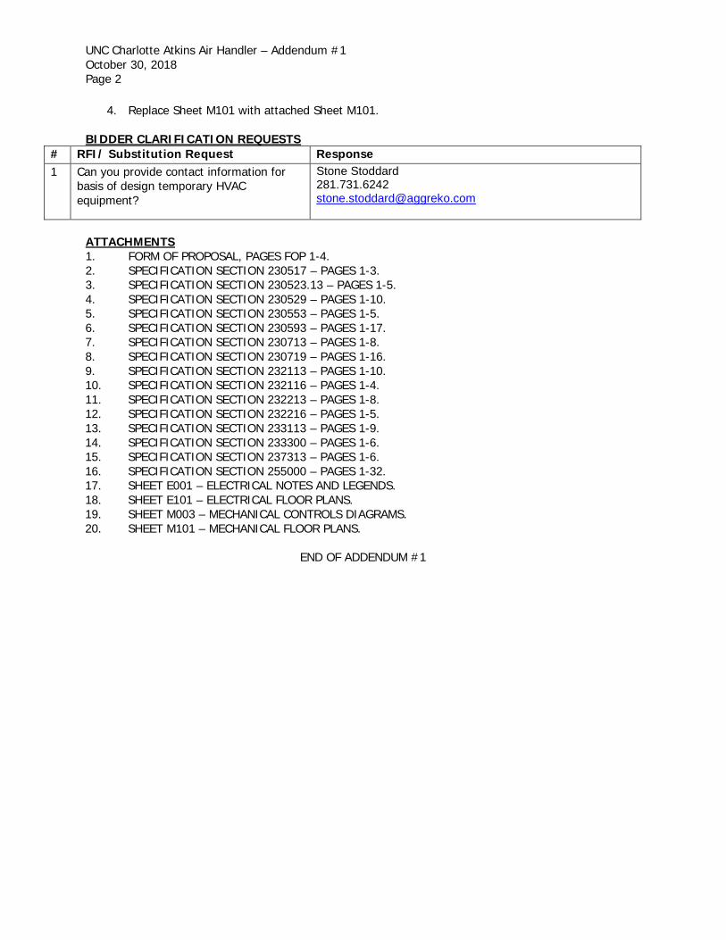
4. Replace Sheet M101 with attached Sheet M101.
BIDDER CLARIFICATION REQUESTS
# RFI/ Substitution Request Response 1 Can you provide contact information for
basis of design temporary HVAC equipment?
Stone Stoddard 281.731.6242 [email protected]
ATTACHMENTS 1. FORM OF PROPOSAL, PAGES FOP 1-4. 2. SPECIFICATION SECTION 230517 – PAGES 1-3. 3. SPECIFICATION SECTION 230523.13 – PAGES 1-5. 4. SPECIFICATION SECTION 230529 – PAGES 1-10. 5. SPECIFICATION SECTION 230553 – PAGES 1-5. 6. SPECIFICATION SECTION 230593 – PAGES 1-17. 7. SPECIFICATION SECTION 230713 – PAGES 1-8. 8. SPECIFICATION SECTION 230719 – PAGES 1-16. 9. SPECIFICATION SECTION 232113 – PAGES 1-10. 10. SPECIFICATION SECTION 232116 – PAGES 1-4. 11. SPECIFICATION SECTION 232213 – PAGES 1-8. 12. SPECIFICATION SECTION 232216 – PAGES 1-5. 13. SPECIFICATION SECTION 233113 – PAGES 1-9. 14. SPECIFICATION SECTION 233300 – PAGES 1-6. 15. SPECIFICATION SECTION 237313 – PAGES 1-6. 16. SPECIFICATION SECTION 255000 – PAGES 1-32. 17. SHEET E001 – ELECTRICAL NOTES AND LEGENDS. 18. SHEET E101 – ELECTRICAL FLOOR PLANS. 19. SHEET M003 – MECHANICAL CONTROLS DIAGRAMS. 20. SHEET M101 – MECHANICAL FLOOR PLANS.
END OF ADDENDUM #1
TABLE OF CONTENTS
UNC CHARLOTTE ATKINS AIR HANDLER
SCO ID# 18-18334
SPECIFICATIONS
COVER 1 page 000001
SEALS 1 page
DIVISION 00 – PROCUREMENT AND CONTRACTING REQUIREMENTS
000100
001200
001500
ADVERTISEMENT FOR BIDS 001000-1
NOTICE TO BIDDERS 001200-1 thru 2
TABLE OF CONTENTS 001500-1 thru 2
002000 INSTRUCTIONS TO BIDDERS AND GENERAL CONDITIONS
OF THE CONTRACT STANDARD FORM FOR CONSTRUCTION
PROJECTS UNIVERSITY OF NORTH CAROLINA GENERAL
ADMINISTRATION 002000-1
45 pages
CAPITAL PROJECTS SUPPLEMENTAL GENERAL CONDITIONS 14 pages
003000 MBE PROVISIONS AND FORMS 003000-1
DIVISION 01 - GENERAL REQUIREMENTS
010000 GENERAL REQUIREMENTS 010000-1 thru 16
011000
012100
SUMMARY 010100-1 thru 5
ALLOWANCES 012100-1 thru 3
012200
012300
019113
UNIT PRICES 012200-1 thru 2
ALTERNATES 012300-1 thru 2
GENERAL COMMISSIONING REQUIREMENTS 019113-1 thru 16
DIVISION 02 – EXISTING CONDITIONS
020200
020213
020213a
024119
ASBESTOS SURVEY REPORT 020200-1
ASBESTOS SURVEY REPORT dated July 17, 2018 87 pages
REPORT FOR THE REMOVAL OF ACM 020213-1
REMOVAL OF ACM 020213a-1 thru 18
SELECTIVE DEMOLITION 024119-1 thru 7
DIVISION 23 – HEATING, VENTILATION AND AIR CONDITIONING
230513 COMMON MOTOR REQUIREMENTS FOR HVAC EQUIPMENT 230513-1 thru 3
230517 SLEEVES AND SLEEVE SEALS FOR HVAC PIPING 230517-1 thru 3
230519 METERS AND GAGES FOR HVAC PIPING 230519-1 thru 4
230523.12 BALL VALVES FOR HVAC PIPING 230523.12-1 thru 6
230523.13 BUTTERFLY VALVES FOR HVAC PIPING 230523.13-1 thru 5
230523.14 CHECK VALVES FOR HVAC PIPING 230523.14-1 thru 5

230529 HANGERS & SUPPORTS FOR HVAC PIPING & EQUIP. 230529-1 thru 10
230553 IDENTIFICATION FOR HVAC PIPING & EQUIP. 230553-1 thru 5
230593 TESTING, ADJUSTING, AND BALANCING FOR HVAC 230593-1 thru 18
230713 DUCT INSULATION 230713-1 thru 8
230719 HVAC PIPING INSULATION 230719-1 thru 27
230800 COMMISSIONING OF HVAC SYSTEMS 230800-1 thru 6
232113 HYDRONIC PIPING 232113-1 thru 10
232116 HYDRONIC PIPING SPECIALTIES 232116-1 thru 4
232213 STEAM AND CONDENSATE HEATING PIPING 232213-1 thru 8
232216 STEAM AND CONDENSATE HEATING PIPING SPECIALTIES 232216-1 thru 5
233113 METAL DUCTS 233113-1 thru 10
233300 AIR DUCT ACCESSORIES 233300-1 thru 6
237313
INDOOR, CUSTOM AIR-HANDLING UNITS 237313-1 thru 6
DIVISION 25 – INTEGRATED AUTOMATION
255000 FACILITY MANAGEMENT AND CONTROL SYSTEM 255000-1 thru 32
DIVISION 26 - ELECTRICAL
260500
260519
ELECTRICAL GENERAL REQUIREMENTS 260500-1 thru 4
CONDUCTORS 260519-1 thru 3
260526 GROUNDING AND BONDING 260526-1 thru 2
260529 FASTENINGS AND SUPPORTS 260529-1
260533 RACEWAY AND FITTINGS 260533-1 thru 4
260534 OUTLET & JUNCTION BOXES 260534-1 thru 2
262726 WIRING DEVICES 262726-1 thru 2
262816 DISCONNECTS 262816-1 thru 2
BIDDING INFORMATION
FORM OF PROPOSAL 4 pages
FORM OF CONSTRUCTION CONTRACT 3 pages
FORM OF PERFORMANCE BOND 2 pages
FORM OF PAYMENT BOND 2 pages
SHEET FOR ATTACHING POWER OF ATTORNEY 1 page
SHEET FOR ATTACHING INSURANCE CERTIFICATES 1 page
APPROVAL OF THE ATTORNEY GENERAL 1 page
CERT. BY THE OFFICE OF STATE BUDGET AND MANAGEMENT 1 page
FORM OF PROPOSAL FOP-1
SECTION FOP – FORM OF PROPOSAL
PROJECT: University of North Carolina at Charlotte
Atkins Air Handler
SCO ID#: 18-18334 BIDDER:
DATE:
The undersigned, as bidder, hereby declares that the only person or persons interested in this proposal as
principal or principals is or are named herein and that no other person than herein mentioned has any
interest in this proposal or in the contract to be entered into; that this proposal is made without connection
with any other person, company or parties making a bid or proposal; and that it is in all respects fair and
in good faith without collusion or fraud. The bidder further declares that he has examined the site of the
work and the contract documents relative thereto, and has read all special provisions furnished prior to the
opening of bids; that he has satisfied himself relative to the work to be performed.
The Bidder proposes and agrees, if this Proposal is accepted, to contract with The University of North
Carolina at Charlotte in the form of contract specified below, to furnish all necessary materials,
equipment, machinery, tools, apparatus, means of transportation and labor necessary to complete the
construction of the Atkins Air Handler in full in complete accordance with the plans, specifications and
contract documents, to the full and entire satisfaction of the University of North Carolina at Charlotte, and
the Engineer, (McVeigh & Mangum Engineering) with a definite understanding that no money will be
allowed for extra work except as set forth in the General Conditions and the contract documents, for the
sum of:
Base Bid:
DOLLARS ($ )
Electrical Subcontractor
Lic. #
GS143-128(d) requires all single prime bidders to identify their subcontractors for the above subdivisions
of work. A contractor whose bid is accepted shall not substitute any person as subcontractor in the place
of the subcontractor listed in the original bid, except (i) if the listed subcontractor's bid is later determined
by the contractor to be non-responsible or non-responsive or the listed subcontractor refuses to enter into
a contract for the complete performance of the bid work, or (ii) with the approval of the awarding
authority for good cause shown by the contractor.
ALLOWANCES:
The following allowances (in quantities) are included in the above Base Bid and are further defined in
Specification DIVISION 01 – GENERAL REQUIREMENTS, Section 012100 “Allowances”:
1. Allowance #1: Duct Insulation Repair
2. Allowance #2 – Piping Insulation Repair
ALTERNATES:
Should any of the alternates as described in the contract documents be accepted, the amount written
below shall be the amount to be "added to" or "deducted from" the base bid. (Strike out "Add" or
"Deduct" as appropriate.) If you do not wish to include an alternate, indicate “No Bid” on the line below
the alternate.
FORM OF PROPOSAL FOP-2
1. Alternate No. 1: AHU Flooring
a. Provide .072” 3003-H22 mill-finished aluminum tread plate floor provided over the
foam-injected double wall floor in lieu of floor as specified in Section 237313
“Custom Air Handling Units”.
(Add) (Deduct) Dollars($)
2. Alternate No. 2: Motor Removal Rail
Provide a motor removal rail will be provided above all fan sections. Trolley and
hoist are provided by a separate party.
(Add) (Deduct) Dollars($)
3. Alternate No. 3: EC Motors for Return Fans
a. Base Bid: Provide return fans as specified in Section 237313 “Custom Air Handling
Units”
b. Alternate: Direct drive plenum fans shall be provided. Motors shall have an IP54
protection class rating at minimum and be electronically commutated (EC) with an
integral speed controller. VFDs combined with a permanent magnet motor is not an
acceptable alternative due to size, weight and complexity increases. Provide the
following accessories:
1. Backdraft dampers shall be provided on fan inlet of each fan in array.
Air handler manufacturers must account for any additional static pressure
from BDD.
2. Airflow probes shall be provided around the fan inlet cone. Probes shall
be provided by the fan manufacturer to ensure accurate airflow
measurement & zero resistance to airflow. All electronics and controls
required to output airflow measurement are provided by the unit ATC
contractor.
(Add) (Deduct) Dollars($)
4. Alternate No. 4: All AHU doors have thermal break design.
a. Base Bid: Provide thermal break design for only access doors downstream of cooling coils as specified in Section 237313 “Custom Air Handling Units”
b. Alternate: Provide thermal break design for all access door
(Add) (Deduct) Dollars($)
UNIT PRICES:
Unit prices quoted and accepted shall apply throughout the life of the contract, except as otherwise
specifically noted. Unit prices shall be applied, as appropriate, to compute the total value of changes in
the base bid quantity of the work all in accordance with the contract documents.
FORM OF PROPOSAL FOP-3
Item Price/Unit
UP-1 Duct Insulation Repair at Mechanical Room __________per each square foot
UP-2 Piping Insulation Repair at Mechanical Room __________per each linear foot The bidder further proposes and agrees hereby to commence work under this contract on a date to be specified in a written order of the designer and shall fully complete all work thereunder within the time specified in the Supplementary General Conditions Article 23. Applicable liquidated damages amount is
MINORITY BUSINESS PARTICIPATION REQUIREMENTS
Provide with the bid - Under GS 143-128.2(c) the undersigned bidder shall identify on its bid
(Identification of Minority Business Participation Form) the minority businesses that it will use on the
project with the total dollar value of the bids that will be performed by the minority businesses. Also list
the good faith efforts (Affidavit A) made to solicit minority participation in the bid effort.
NOTE: A contractor that performs all of the work with its own workforce may submit an Affidavit
(B) to that effect in lieu of Affidavit (A) required above. The MB Participation Form must still be
submitted even if there is zero participation.
After the bid opening - The Owner will consider all bids and alternates and determine the lowest
responsible, responsive bidder. Upon notification of being the apparent low bidder, the bidder shall then
file within 72 hours of the notification of being the apparent lowest bidder, the following:
An Affidavit (C) that includes a description of the portion of work to be executed by minority businesses,
expressed as a percentage of the total contract price, which is equal to or more than the 10% goal
established. This affidavit shall give rise to the presumption that the bidder has made the required good
faith effort and Affidavit D is not necessary;
* OR *
If less than the 10% goal, Affidavit (D) of its good faith effort to meet the goal shall be provided. The
document must include evidence of all good faith efforts that were implemented, including any
advertisements, solicitations and other specific actions demonstrating recruitment and selection of
minority businesses for participation in the contract.
Note: Bidders must always submit with their bid the Identification of Minority Business Participation Form
listing all MB contractors, vendors and suppliers that will be used. If there is no MB participation, then enter
none or zero on the form. Affidavit A or Affidavit B, as applicable, also must be submitted with the bid. Failure
to file a required affidavit or documentation with the bid or after being notified apparent low bidder is grounds for
rejection of the bid.
PROPOSAL SIGNATURE PAGE
The undersigned further agrees that in the case of failure on his part to execute the said contract and the
bonds within ten (10) consecutive calendar days after being given written notice of the award of contract,
the certified check, cash or bid bond accompanying this bid shall be paid into the funds of the owner's
account set aside for the project, as liquidated damages for such failure; otherwise the certified check,
cash or bid bond accompanying this proposal shall be returned to the undersigned.
Respectfully submitted this day of
(Name of firm or corporation making bid)
FORM OF PROPOSAL FOP-4
WITNESS: By:
Signature
Name:
(Proprietorship or Partnership) Print or type
Title
(Owner/Partner/Pres./V.Pres)
Address
ATTEST:
By: License No.
Title: Federal I.D. No.
(Corp. Sec. or Asst. Sec. only)
(CORPORATE SEAL)
Addendum received and used in computing bid:
Addendum No. 1 Addendum No. 2 Addendum No. 3 Addendum No. 4
Addendum No. 5 Addendum No. 6 Addendum No. 7 Addendum No. 8
END OF SECTION FOP-FORM OF PROPOSAL
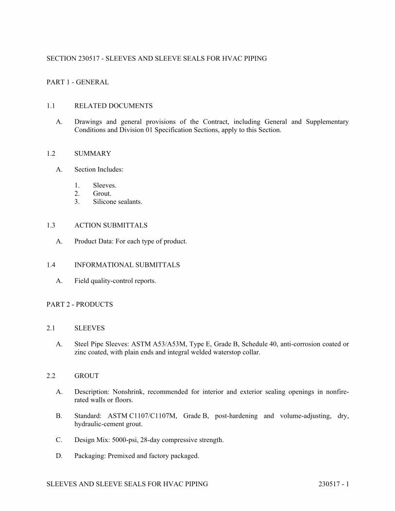
SLEEVES AND SLEEVE SEALS FOR HVAC PIPING 230517 - 1
SECTION 230517 - SLEEVES AND SLEEVE SEALS FOR HVAC PIPING
PART 1 - GENERAL
1.1 RELATED DOCUMENTS
A. Drawings and general provisions of the Contract, including General and Supplementary
Conditions and Division 01 Specification Sections, apply to this Section.
1.2 SUMMARY
A. Section Includes:
1. Sleeves.
2. Grout.
3. Silicone sealants.
1.3 ACTION SUBMITTALS
A. Product Data: For each type of product.
1.4 INFORMATIONAL SUBMITTALS
A. Field quality-control reports.
PART 2 - PRODUCTS
2.1 SLEEVES
A. Steel Pipe Sleeves: ASTM A53/A53M, Type E, Grade B, Schedule 40, anti-corrosion coated or
zinc coated, with plain ends and integral welded waterstop collar.
2.2 GROUT
A. Description: Nonshrink, recommended for interior and exterior sealing openings in nonfire-
rated walls or floors.
B. Standard: ASTM C1107/C1107M, Grade B, post-hardening and volume-adjusting, dry,
hydraulic-cement grout.
C. Design Mix: 5000-psi, 28-day compressive strength.
D. Packaging: Premixed and factory packaged.
SLEEVES AND SLEEVE SEALS FOR HVAC PIPING 230517 - 2
2.3 SILICONE SEALANTS
A. Silicone, S, NS, 25, NT: Single-component, nonsag, plus 25 percent and minus 25 percent
movement capability, nontraffic-use, neutral-curing silicone joint sealant, ASTM C920, Type S,
Grade NS, Class 25, use NT.
B. Silicone, S, P, 25, T, NT: Single-component, pourable, plus 25 percent and minus 25 percent
movement capability, traffic- and nontraffic-use, neutral-curing silicone joint sealant;
ASTM C920, Type S, Grade P, Class 25, Uses T and NT. Grade P Pourable (self-leveling)
formulation is for opening in floors and other horizontal surfaces that are not fire rated.
PART 3 - EXECUTION
3.1 SLEEVE INSTALLATION
A. Install sleeves for piping passing through penetrations in floors, partitions, roofs, and walls.
B. For sleeves that will have sleeve-seal system installed, select sleeves of size large enough to
provide 1-inch annular clear space between piping and concrete slabs and walls.
1. Sleeves are not required for core-drilled holes.
C. Install sleeves in concrete floors, concrete roof slabs, and concrete walls as new slabs and walls
are constructed.
1. Permanent sleeves are not required for holes in slabs formed by molded-PE or -PP
sleeves.
2. Cut sleeves to length for mounting flush with both surfaces.
a. Exception: Extend sleeves installed in floors of mechanical equipment areas or
other wet areas 2 inches above finished floor level.
3. Using grout or silicone sealant, seal space outside of sleeves in slabs and walls without
sleeve-seal system.
D. Install sleeves for pipes passing through interior partitions.
1. Cut sleeves to length for mounting flush with both surfaces.
2. Install sleeves that are large enough to provide 1/4-inch annular clear space between
sleeve and pipe or pipe insulation.
3. Seal annular space between sleeve and piping or piping insulation; use sealants
appropriate for size, depth, and location of joint.
E. Fire-Resistance-Rated Penetrations, Horizontal Assembly Penetrations, and Smoke-Barrier
Penetrations: Maintain indicated fire or smoke rating of walls, partitions, ceilings, and floors at
pipe penetrations. Seal pipe penetrations with fire- and smoke-stop materials.
SLEEVES AND SLEEVE SEALS FOR HVAC PIPING 230517 - 3
3.2 FIELD QUALITY CONTROL
A. Perform the following tests and inspections:
1. Leak Test: After allowing for a full cure, test sleeves and sleeve seals for leaks. Repair
leaks and retest until no leaks exist.
B. Sleeves and sleeve seals will be considered defective if they do not pass tests and inspections.
3.3 SLEEVE AND SLEEVE-SEAL SCHEDULE
A. Use sleeves and sleeve seals for the following piping-penetration applications:
1. Concrete Slabs Above Grade:
a. Piping Smaller Than NPS 6: Steel pipe sleeves.
b. Piping NPS 6 and Larger: Steel pipe sleeves.
2. Interior Partitions:
a. Piping Smaller Than NPS 6: Steel pipe sleeves.
END OF SECTION 230517
BUTTERFLY VALVES FOR HVAC PIPING 230523.13 - 1
SECTION 230523.13 - BUTTERFLY VALVES FOR HVAC PIPING
PART 1 - GENERAL
1.1 RELATED DOCUMENTS
A. Drawings and general provisions of the Contract, including General and Supplementary
Conditions and Division 01 Specification Sections, apply to this Section.
1.2 SUMMARY
A. Section Includes:
1. Iron, single-flange butterfly valves.
2. Iron, grooved-end butterfly valves.
3. High-performance butterfly valves.
4. Chainwheels.
1.3 DEFINITIONS
A. CWP: Cold working pressure.
B. EPDM: Ethylene propylene copolymer rubber.
C. NBR: Acrylonitrile-butadiene, Buna-N, or nitrile rubber.
D. SWP: Steam working pressure.
1.4 ACTION SUBMITTALS
A. Product Data: For each type of valve.
1.5 DELIVERY, STORAGE, AND HANDLING
A. Prepare valves for shipping as follows:
1. Protect internal parts against rust and corrosion.
2. Protect threads, flange faces, grooves, and weld ends.
3. Set butterfly valves closed or slightly open.
B. Use the following precautions during storage:
1. Maintain valve end protection.
2. Store valves indoors and maintain at higher-than-ambient-dew-point temperature. If
outdoor storage is necessary, store valves off the ground in watertight enclosures.
BUTTERFLY VALVES FOR HVAC PIPING 230523.13 - 2
C. Use sling to handle large valves; rig sling to avoid damage to exposed parts. Do not use
handwheels or stems as lifting or rigging points.
PART 2 - PRODUCTS
2.1 GENERAL REQUIREMENTS FOR VALVES
A. Source Limitations for Valves: Obtain each type of valve from single source from single
manufacturer.
B. ASME Compliance:
1. ASME B16.1 for flanges on iron valves.
2. ASME B16.5 for pipe flanges and flanged fittings, NPS 1/2 through NPS 24.
3. ASME B16.10 and ASME B16.34 for ferrous valve dimensions and design criteria.
4. ASME B31.1 for power piping valves.
5. ASME B31.9 for building services piping valves.
C. AWWA Compliance: Comply with AWWA C606 for grooved-end connections.
D. Valve Pressure-Temperature Ratings: Not less than indicated and as required for system
pressures and temperatures.
E. Valve Sizes: Same as upstream piping unless otherwise indicated.
F. Valve Actuator Types:
1. Gear Actuator: For valves NPS 8 and larger.
2. Handlever: For valves NPS 6 and smaller.
3. Chainwheel: Device for attachment to gear, stem, or other actuator of size and with chain
for mounting height, according to "Valve Installation" Article.
G. Valves in Insulated Piping: With 2-inch stem extensions with extended necks.
2.2 IRON, SINGLE-FLANGE BUTTERFLY VALVES
A. Iron, Single-Flange Butterfly Valves with Aluminum-Bronze Disc:
1. Description:
a. Standard: MSS SP-67, Type I.
b. CWP Rating: 150 psig.
c. Body Design: Lug type; suitable for bidirectional dead-end service at rated
pressure without use of downstream flange.
d. Body Material: ASTM A126, cast iron or ASTM A536, ductile iron.
e. Seat: EPDM.
f. Stem: One- or two-piece stainless steel.
g. Disc: Aluminum bronze.
BUTTERFLY VALVES FOR HVAC PIPING 230523.13 - 3
2.3 DUCTILE-IRON, GROOVED-END BUTTERFLY VALVES
A. Iron, Grooved-End Butterfly Valves, 175 CWP:
1. Description:
a. Standard: MSS SP-67, Type I.
b. CWP Rating: 175 psig.
c. Body Material: Coated, ductile iron.
d. Stem: Two-piece stainless steel.
e. Disc: Coated, ductile iron.
f. Seal: EPDM.
2.4 HIGH-PERFORMANCE BUTTERFLY VALVES
A. Single-Flange, High-Performance Butterfly Valves, Class 150:
1. Description:
a. Standard: MSS SP-68.
b. CWP Rating: 285 psig at 100 deg F.
c. Body Design: Lug type; suitable for bidirectional dead-end service at rated
pressure without use of downstream flange.
d. Body Material: Carbon steel, cast iron, ductile iron, or stainless steel.
e. Seat: Reinforced PTFE or metal.
f. Stem: Stainless steel; offset from seat plane.
g. Disc: Carbon steel.
h. Service: Bidirectional.
2.5 CHAINWHEELS
A. Description: Valve actuation assembly with sprocket rim, chain guides, chain.
1. Sprocket Rim with Chain Guides: Ductile or cast iron, of type and size required for
valve. Include zinc or epoxy coating.
2. Chain: Hot-dip, galvanized steel, of size required to fit sprocket rim.
PART 3 - EXECUTION
3.1 EXAMINATION
A. Examine valve interior for cleanliness, freedom from foreign matter, and corrosion. Remove
special packing materials, such as blocks, used to prevent disc movement during shipping and
handling.
B. Operate valves in positions from fully open to fully closed. Examine guides and seats made
accessible by such operations.
BUTTERFLY VALVES FOR HVAC PIPING 230523.13 - 4
C. Examine mating flange faces for damage. Check bolting for proper size, length, and material.
Verify that gasket is of proper size, that its material composition is suitable for service, and that
it is free from defects and damage.
D. Do not attempt to repair defective valves; replace with new valves.
3.2 VALVE INSTALLATION
A. Install valves with unions or flanges at each piece of equipment arranged to allow service,
maintenance, and equipment removal without system shutdown.
B. Locate valves for easy access and provide separate support where necessary.
C. Install valves in horizontal piping with stem at or above center of pipe.
D. Install valves in position to allow full stem movement.
E. Install chainwheels on operators for butterfly valves NPS 8 and larger and more than 96 inches
above floor. Extend chains to 60 inches above finished floor.
F. Install valve tags. Comply with requirements in Section 230553 "Identification for HVAC
Piping and Equipment" for valve tags and schedules.
3.3 ADJUSTING
A. Adjust or replace valve packing after piping systems have been tested and put into service but
before final adjusting and balancing. Replace valves if persistent leaking occurs.
3.4 CHILLED-WATER VALVE SCHEDULE
A. Pipe NPS 2-1/2 and Larger:
1. Iron, Single-Flange Butterfly Valves, NPS 14 to NPS 24: Aluminum-bronze disc,
150 CWP, and EPDM seat.
2. Iron, Grooved-End Butterfly Valves, NPS 2-1/2 to NPS 12: 175 CWP.
3. High-Performance Butterfly Valves: Single flange, Class 150.
3.5 HEATING-WATER VALVE SCHEDULE
A. Pipe NPS 2-1/2 and Larger:
1. Iron, Single-Flange Butterfly Valves, NPS 14 to NPS 24: Aluminum-bronze disc,
150 CWP, and EPDM seat.
2. Iron, Grooved-End Butterfly Valves, NPS 2-1/2 to NPS 12: 175 CWP.
3. High-Performance Butterfly Valves: Single flange, Class 150.
3.6 LOW-PRESSURE STEAM VALVE SCHEDULE (15 PSIG OR LESS)
A. Pipe NPS 2-1/2 and Larger: High-performance butterfly valves, single flange, Class 150.

BUTTERFLY VALVES FOR HVAC PIPING 230523.13 - 5
3.7 STEAM-CONDENSATE VALVE SCHEDULE
A. Pipe NPS 2-1/2 and Larger: High-performance butterfly valves, single flange, Class 150.
END OF SECTION 230523.13
HANGERS AND SUPPORTS FOR HVAC PIPING AND EQUIPMENT 230529 - 1
SECTION 230529 - HANGERS AND SUPPORTS FOR HVAC PIPING AND EQUIPMENT
PART 1 - GENERAL
1.1 RELATED DOCUMENTS
A. Drawings and general provisions of the Contract, including General and Supplementary
Conditions and Division 01 Specification Sections, apply to this Section.
1.2 SUMMARY
A. Section Includes:
1. Metal pipe hangers and supports.
2. Thermal-hanger shield inserts.
3. Fastener systems.
4. Pipe stands.
5. Equipment supports.
B. Related Requirements:
1. Section 233113 "Metal Ducts" for duct hangers and supports.
1.3 ACTION SUBMITTALS
A. Product Data: For each type of product.
B. Shop Drawings: Show fabrication and installation details and include calculations for the
following; include Product Data for components:
1. Trapeze pipe hangers.
2. Metal framing systems.
3. Pipe stands.
4. Equipment supports.
C. Delegated-Design Submittal: For trapeze hangers indicated to comply with performance
requirements and design criteria, including analysis data signed and sealed by the qualified
professional engineer responsible for their preparation.
1. Detail fabrication and assembly of trapeze hangers.
2. Include design calculations for designing trapeze hangers.
1.4 INFORMATIONAL SUBMITTALS
A. Welding certificates.

HANGERS AND SUPPORTS FOR HVAC PIPING AND EQUIPMENT 230529 - 2
1.5 QUALITY ASSURANCE
A. Structural-Steel Welding Qualifications: Qualify procedures and personnel according to
AWS D1.1/D1.1M, "Structural Welding Code - Steel."
B. Pipe Welding Qualifications: Qualify procedures and operators according to ASME Boiler and
Pressure Vessel Code, Section IX.
PART 2 - PRODUCTS
2.1 PERFORMANCE REQUIREMENTS
A. Delegated Design: Engage a qualified professional engineer, as defined in Section 014000
"Quality Requirements," to design trapeze pipe hangers and equipment supports.
B. Structural Performance: Hangers and supports for HVAC piping and equipment shall withstand
the effects of gravity loads and stresses within limits and under conditions indicated according
to ASCE/SEI 7.
1. Design supports for multiple pipes, including pipe stands, capable of supporting
combined weight of supported systems, system contents, and test water.
2. Design equipment supports capable of supporting combined operating weight of
supported equipment and connected systems and components.
3. Design seismic-restraint hangers and supports for piping and equipment.
2.2 METAL PIPE HANGERS AND SUPPORTS
A. Carbon-Steel Pipe Hangers and Supports:
1. Description: MSS SP-58, Types 1 through 58, factory-fabricated components.
2. Galvanized Metallic Coatings: Pregalvanized, hot-dip galvanized, or electro-galvanized.
3. Nonmetallic Coatings: Plastic coated, or epoxy powder-coated.
4. Padded Hangers: Hanger with fiberglass or other pipe insulation pad or cushion to
support bearing surface of piping.
5. Hanger Rods: Continuous-thread rod, nuts, and washer made of carbon steel.
B. Copper Pipe and Tube Hangers:
1. Description: MSS SP-58, Types 1 through 58, copper-plated steel, factory-fabricated
components.
2. Hanger Rods: Continuous-thread rod, nuts, and washer made of copper-plated steel.
2.3 TRAPEZE PIPE HANGERS
A. Description: MSS SP-58, Type 59, shop- or field-fabricated pipe-support assembly made from
structural carbon-steel shapes with MSS SP-58 carbon-steel hanger rods, nuts, saddles, and U-
bolts.
HANGERS AND SUPPORTS FOR HVAC PIPING AND EQUIPMENT 230529 - 3
2.4 THERMAL-HANGER SHIELD INSERTS
A. Insulation-Insert Material for Cold Piping: ASTM C591, Type VI, Grade 1 polyisocyanurate
with 125-psi minimum compressive strength and vapor barrier.
B. Insulation-Insert Material for Hot Piping: ASTM C591, Type VI, Grade 1 polyisocyanurate
with 125-psi minimum compressive strength.
C. For Trapeze or Clamped Systems: Insert and shield shall cover entire circumference of pipe.
D. For Clevis or Band Hangers: Insert and shield shall cover lower 180 degrees of pipe.
E. Insert Length: Extend 2 inches beyond sheet metal shield for piping operating below ambient air
temperature.
2.5 FASTENER SYSTEMS
A. Powder-Actuated Fasteners: Threaded-steel stud, for use in hardened portland cement concrete
with pull-out, tension, and shear capacities appropriate for supported loads and building
materials where used.
B. Mechanical-Expansion Anchors: Insert-wedge-type anchors for use in hardened portland
cement concrete; with pull-out, tension, and shear capacities appropriate for supported loads and
building materials where used.
1. Indoor Applications: Zinc-coated steel.
2. Outdoor Applications: Stainless steel.
2.6 PIPE STANDS
A. General Requirements for Pipe Stands: Shop- or field-fabricated assemblies made of
manufactured corrosion-resistant components to support roof-mounted piping.
B. Curb-Mounted-Type Pipe Stands: Shop- or field-fabricated pipe supports made from structural-
steel shapes, continuous-thread rods, and rollers, for mounting on permanent stationary roof
curb.
2.7 MATERIALS
A. Aluminum: ASTM B221.
B. Carbon Steel: ASTM A1011/A1011M.
C. Structural Steel: ASTM A36/A36M, carbon-steel plates, shapes, and bars; galvanized.
D. Stainless Steel: ASTM A240/A240M.
E. Threaded Rods: Continuously threaded. Zinc-plated or galvanized steel for indoor applications
and stainless steel for outdoor applications. Mating nuts and washers of similar materials as
rods.
HANGERS AND SUPPORTS FOR HVAC PIPING AND EQUIPMENT 230529 - 4
F. Grout: ASTM C1107/C1107M, factory-mixed and -packaged, dry, hydraulic-cement, nonshrink
and nonmetallic grout; suitable for interior and exterior applications.
1. Properties: Nonstaining, noncorrosive, and nongaseous.
2. Design Mix: 5000-psi, 28-day compressive strength.
PART 3 - EXECUTION
3.1 APPLICATION
A. Strength of Support Assemblies: Where not indicated, select sizes of components so strength
will be adequate to carry present and future static loads within specified loading limits.
Minimum static design load used for strength determination shall be weight of supported
components plus 200 lb.
3.2 HANGER AND SUPPORT INSTALLATION
A. Metal Pipe-Hanger Installation: Comply with MSS SP-58. Install hangers, supports, clamps,
and attachments as required to properly support piping from the building structure.
B. Metal Trapeze Pipe-Hanger Installation: Comply with MSS SP-58. Arrange for grouping of
parallel runs of horizontal piping, and support together on field-fabricated trapeze pipe hangers.
1. Pipes of Various Sizes: Support together and space trapezes for smallest pipe size or
install intermediate supports for smaller diameter pipes as specified for individual pipe
hangers.
2. Field fabricate from ASTM A36/A36M, carbon-steel shapes selected for loads being
supported. Weld steel according to AWS D1.1/D1.1M.
C. Fiberglass Pipe-Hanger Installation: Comply with applicable portions of MSS SP-58. Install
hangers and attachments as required to properly support piping from building structure.
D. Metal Framing System Installation: Arrange for grouping of parallel runs of piping, and support
together on field-assembled strut systems.
E. Thermal-Hanger Shield Installation: Install in pipe hanger or shield for insulated piping.
F. Fastener System Installation:
1. Install powder-actuated fasteners for use in lightweight concrete or concrete slabs less
than 4 inches thick in concrete after concrete is placed and completely cured. Use
operators that are licensed by powder-actuated tool manufacturer. Install fasteners
according to powder-actuated tool manufacturer's operating manual.
2. Install mechanical-expansion anchors in concrete after concrete is placed and completely
cured. Install fasteners according to manufacturer's written instructions.
G. Pipe Stand Installation:
HANGERS AND SUPPORTS FOR HVAC PIPING AND EQUIPMENT 230529 - 5
1. Pipe Stand Types except Curb-Mounted Type: Assemble components and mount on
smooth roof surface. Do not penetrate roof membrane.
2. Curb-Mounted-Type Pipe Stands: Assemble components or fabricate pipe stand and
mount on permanent, stationary roof curb. See Section 077200 "Roof Accessories" for
curbs.
H. Install hangers and supports complete with necessary attachments, inserts, bolts, rods, nuts,
washers, and other accessories.
I. Equipment Support Installation: Fabricate from welded-structural-steel shapes.
J. Install hangers and supports to allow controlled thermal and seismic movement of piping
systems, to permit freedom of movement between pipe anchors, and to facilitate action of
expansion joints, expansion loops, expansion bends, and similar units.
K. Install lateral bracing with pipe hangers and supports to prevent swaying.
L. Install building attachments within concrete slabs or attach to structural steel. Install additional
attachments at concentrated loads, including valves, flanges, and strainers, NPS 2-1/2 and larger
and at changes in direction of piping. Install concrete inserts before concrete is placed; fasten
inserts to forms and install reinforcing bars through openings at top of inserts.
M. Load Distribution: Install hangers and supports so that piping live and dead loads and stresses
from movement will not be transmitted to connected equipment.
N. Pipe Slopes: Install hangers and supports to provide indicated pipe slopes and to not exceed
maximum pipe deflections allowed by ASME B31.9 for building services piping.
O. Insulated Piping:
1. Attach clamps and spacers to piping.
a. Piping Operating above Ambient Air Temperature: Clamp may project through
insulation.
b. Piping Operating below Ambient Air Temperature: Use thermal-hanger shield
insert with clamp sized to match OD of insert.
c. Do not exceed pipe stress limits allowed by ASME B31.9 for building services
piping.
2. Install MSS SP-58, Type 39, protection saddles if insulation without vapor barrier is
indicated. Fill interior voids with insulation that matches adjoining insulation.
a. Option: Thermal-hanger shield inserts may be used. Include steel weight-
distribution plate for pipe NPS 4 and larger if pipe is installed on rollers.
3. Install MSS SP-58, Type 40, protective shields on cold piping with vapor barrier. Shields
shall span an arc of 180 degrees.
a. Option: Thermal-hanger shield inserts may be used. Include steel weight-
distribution plate for pipe NPS 4 and larger if pipe is installed on rollers.
HANGERS AND SUPPORTS FOR HVAC PIPING AND EQUIPMENT 230529 - 6
4. Shield Dimensions for Pipe: Not less than the following:
a. NPS 1/4 to NPS 3-1/2: 12 inches long and 0.048 inch thick.
b. NPS 4: 12 inches long and 0.06 inch thick.
c. NPS 5 and NPS 6: 18 inches long and 0.06 inch thick.
d. NPS 8 to NPS 14: 24 inches long and 0.075 inch thick.
e. NPS 16 to NPS 24: 24 inches long and 0.105 inch thick.
5. Pipes NPS 8 and Larger: Include wood or reinforced calcium-silicate-insulation inserts of
length at least as long as protective shield.
6. Thermal-Hanger Shields: Install with insulation same thickness as piping insulation.
3.3 EQUIPMENT SUPPORTS
A. Fabricate structural-steel stands to suspend equipment from structure overhead or to support
equipment above floor.
B. Grouting: Place grout under supports for equipment and make bearing surface smooth.
C. Provide lateral bracing, to prevent swaying, for equipment supports.
3.4 METAL FABRICATIONS
A. Cut, drill, and fit miscellaneous metal fabrications for trapeze pipe hangers and equipment
supports.
B. Fit exposed connections together to form hairline joints. Field weld connections that cannot be
shop welded because of shipping size limitations.
C. Field Welding: Comply with AWS D1.1/D1.1M procedures for shielded, metal arc welding;
appearance and quality of welds; and methods used in correcting welding work; and with the
following:
1. Use materials and methods that minimize distortion and develop strength and corrosion
resistance of base metals.
2. Obtain fusion without undercut or overlap.
3. Remove welding flux immediately.
4. Finish welds at exposed connections so no roughness shows after finishing and so
contours of welded surfaces match adjacent contours.
3.5 ADJUSTING
A. Hanger Adjustments: Adjust hangers to distribute loads equally on attachments and to achieve
indicated slope of pipe.
B. Trim excess length of continuous-thread hanger and support rods to 1-1/2 inches.
HANGERS AND SUPPORTS FOR HVAC PIPING AND EQUIPMENT 230529 - 7
3.6 PAINTING
A. Touchup: Clean field welds and abraded areas of shop paint. Paint exposed areas immediately
after erecting hangers and supports. Use same materials as used for shop painting. Comply with
SSPC-PA 1 requirements for touching up field-painted surfaces.
1. Apply paint by brush or spray to provide a minimum dry film thickness of 2.0 mils.
B. Galvanized Surfaces: Clean welds, bolted connections, and abraded areas and apply
galvanizing-repair paint to comply with ASTM A780/A780M.
3.7 HANGER AND SUPPORT SCHEDULE
A. Specific hanger and support requirements are in Sections specifying piping systems and
equipment.
B. Comply with MSS SP-58 for pipe-hanger selections and applications that are not specified in
piping system Sections.
C. Use hangers and supports with galvanized metallic coatings for piping and equipment that will
not have field-applied finish.
D. Use nonmetallic coatings on attachments for electrolytic protection where attachments are in
direct contact with copper tubing.
E. Use carbon-steel pipe hangers and supports and attachments for general service applications.
F. Use copper-plated pipe hangers and copper attachments for copper piping and tubing.
G. Use padded hangers for piping that is subject to scratching.
H. Use thermal-hanger shield inserts for insulated piping and tubing.
I. Horizontal-Piping Hangers and Supports: Unless otherwise indicated and except as specified in
piping system Sections, install the following types:
1. Adjustable, Steel Clevis Hangers (MSS Type 1): For suspension of noninsulated or
insulated, stationary pipes NPS 1/2 to NPS 30.
2. Yoke-Type Pipe Clamps (MSS Type 2): For suspension of up to 1050 deg F, pipes NPS 4
to NPS 24, requiring up to 4 inches of insulation.
3. Carbon- or Alloy-Steel, Double-Bolt Pipe Clamps (MSS Type 3): For suspension of
pipes NPS 3/4 to NPS 36, requiring clamp flexibility and up to 4 inches of insulation.
4. Steel Pipe Clamps (MSS Type 4): For suspension of cold and hot pipes NPS 1/2 to
NPS 24 if little or no insulation is required.
5. Pipe Hangers (MSS Type 5): For suspension of pipes NPS 1/2 to NPS 4, to allow off-
center closure for hanger installation before pipe erection.
6. Adjustable, Swivel Split- or Solid-Ring Hangers (MSS Type 6): For suspension of
noninsulated, stationary pipes NPS 3/4 to NPS 8.
7. Adjustable, Steel Band Hangers (MSS Type 7): For suspension of noninsulated,
stationary pipes NPS 1/2 to NPS 8.
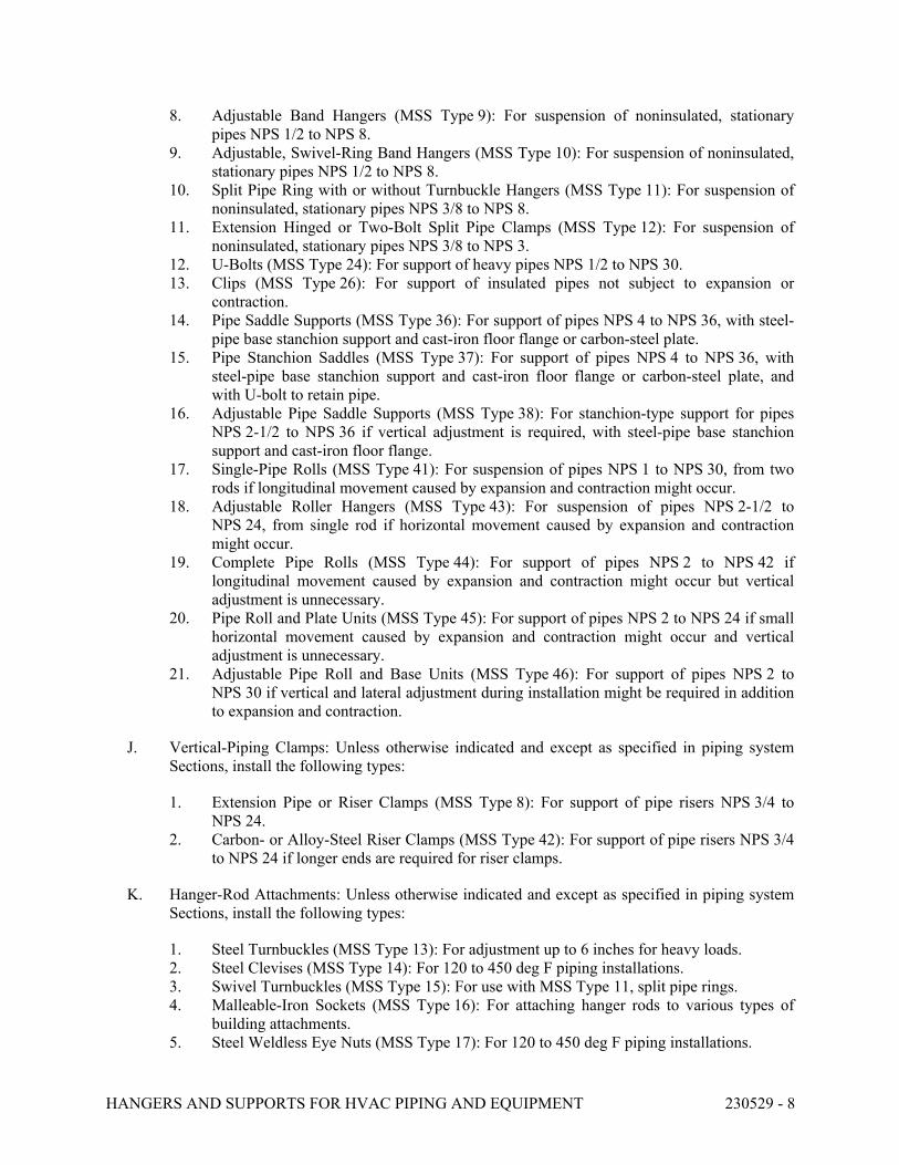
HANGERS AND SUPPORTS FOR HVAC PIPING AND EQUIPMENT 230529 - 8
8. Adjustable Band Hangers (MSS Type 9): For suspension of noninsulated, stationary
pipes NPS 1/2 to NPS 8.
9. Adjustable, Swivel-Ring Band Hangers (MSS Type 10): For suspension of noninsulated,
stationary pipes NPS 1/2 to NPS 8.
10. Split Pipe Ring with or without Turnbuckle Hangers (MSS Type 11): For suspension of
noninsulated, stationary pipes NPS 3/8 to NPS 8.
11. Extension Hinged or Two-Bolt Split Pipe Clamps (MSS Type 12): For suspension of
noninsulated, stationary pipes NPS 3/8 to NPS 3.
12. U-Bolts (MSS Type 24): For support of heavy pipes NPS 1/2 to NPS 30.
13. Clips (MSS Type 26): For support of insulated pipes not subject to expansion or
contraction.
14. Pipe Saddle Supports (MSS Type 36): For support of pipes NPS 4 to NPS 36, with steel-
pipe base stanchion support and cast-iron floor flange or carbon-steel plate.
15. Pipe Stanchion Saddles (MSS Type 37): For support of pipes NPS 4 to NPS 36, with
steel-pipe base stanchion support and cast-iron floor flange or carbon-steel plate, and
with U-bolt to retain pipe.
16. Adjustable Pipe Saddle Supports (MSS Type 38): For stanchion-type support for pipes
NPS 2-1/2 to NPS 36 if vertical adjustment is required, with steel-pipe base stanchion
support and cast-iron floor flange.
17. Single-Pipe Rolls (MSS Type 41): For suspension of pipes NPS 1 to NPS 30, from two
rods if longitudinal movement caused by expansion and contraction might occur.
18. Adjustable Roller Hangers (MSS Type 43): For suspension of pipes NPS 2-1/2 to
NPS 24, from single rod if horizontal movement caused by expansion and contraction
might occur.
19. Complete Pipe Rolls (MSS Type 44): For support of pipes NPS 2 to NPS 42 if
longitudinal movement caused by expansion and contraction might occur but vertical
adjustment is unnecessary.
20. Pipe Roll and Plate Units (MSS Type 45): For support of pipes NPS 2 to NPS 24 if small
horizontal movement caused by expansion and contraction might occur and vertical
adjustment is unnecessary.
21. Adjustable Pipe Roll and Base Units (MSS Type 46): For support of pipes NPS 2 to
NPS 30 if vertical and lateral adjustment during installation might be required in addition
to expansion and contraction.
J. Vertical-Piping Clamps: Unless otherwise indicated and except as specified in piping system
Sections, install the following types:
1. Extension Pipe or Riser Clamps (MSS Type 8): For support of pipe risers NPS 3/4 to
NPS 24.
2. Carbon- or Alloy-Steel Riser Clamps (MSS Type 42): For support of pipe risers NPS 3/4
to NPS 24 if longer ends are required for riser clamps.
K. Hanger-Rod Attachments: Unless otherwise indicated and except as specified in piping system
Sections, install the following types:
1. Steel Turnbuckles (MSS Type 13): For adjustment up to 6 inches for heavy loads.
2. Steel Clevises (MSS Type 14): For 120 to 450 deg F piping installations.
3. Swivel Turnbuckles (MSS Type 15): For use with MSS Type 11, split pipe rings.
4. Malleable-Iron Sockets (MSS Type 16): For attaching hanger rods to various types of
building attachments.
5. Steel Weldless Eye Nuts (MSS Type 17): For 120 to 450 deg F piping installations.
HANGERS AND SUPPORTS FOR HVAC PIPING AND EQUIPMENT 230529 - 9
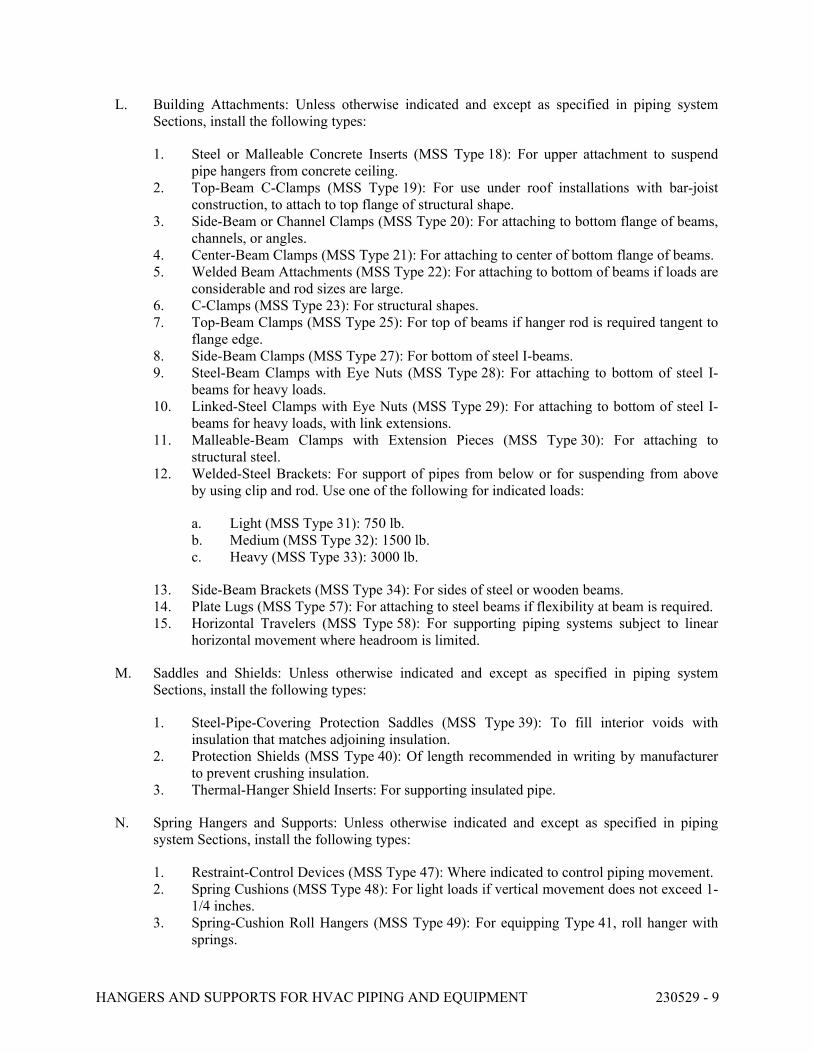
L. Building Attachments: Unless otherwise indicated and except as specified in piping system
Sections, install the following types:
1. Steel or Malleable Concrete Inserts (MSS Type 18): For upper attachment to suspend
pipe hangers from concrete ceiling.
2. Top-Beam C-Clamps (MSS Type 19): For use under roof installations with bar-joist
construction, to attach to top flange of structural shape.
3. Side-Beam or Channel Clamps (MSS Type 20): For attaching to bottom flange of beams,
channels, or angles.
4. Center-Beam Clamps (MSS Type 21): For attaching to center of bottom flange of beams.
5. Welded Beam Attachments (MSS Type 22): For attaching to bottom of beams if loads are
considerable and rod sizes are large.
6. C-Clamps (MSS Type 23): For structural shapes.
7. Top-Beam Clamps (MSS Type 25): For top of beams if hanger rod is required tangent to
flange edge.
8. Side-Beam Clamps (MSS Type 27): For bottom of steel I-beams.
9. Steel-Beam Clamps with Eye Nuts (MSS Type 28): For attaching to bottom of steel I-
beams for heavy loads.
10. Linked-Steel Clamps with Eye Nuts (MSS Type 29): For attaching to bottom of steel I-
beams for heavy loads, with link extensions.
11. Malleable-Beam Clamps with Extension Pieces (MSS Type 30): For attaching to
structural steel.
12. Welded-Steel Brackets: For support of pipes from below or for suspending from above
by using clip and rod. Use one of the following for indicated loads:
a. Light (MSS Type 31): 750 lb.
b. Medium (MSS Type 32): 1500 lb.
c. Heavy (MSS Type 33): 3000 lb.
13. Side-Beam Brackets (MSS Type 34): For sides of steel or wooden beams.
14. Plate Lugs (MSS Type 57): For attaching to steel beams if flexibility at beam is required.
15. Horizontal Travelers (MSS Type 58): For supporting piping systems subject to linear
horizontal movement where headroom is limited.
M. Saddles and Shields: Unless otherwise indicated and except as specified in piping system
Sections, install the following types:
1. Steel-Pipe-Covering Protection Saddles (MSS Type 39): To fill interior voids with
insulation that matches adjoining insulation.
2. Protection Shields (MSS Type 40): Of length recommended in writing by manufacturer
to prevent crushing insulation.
3. Thermal-Hanger Shield Inserts: For supporting insulated pipe.
N. Spring Hangers and Supports: Unless otherwise indicated and except as specified in piping
system Sections, install the following types:
1. Restraint-Control Devices (MSS Type 47): Where indicated to control piping movement.
2. Spring Cushions (MSS Type 48): For light loads if vertical movement does not exceed 1-
1/4 inches.
3. Spring-Cushion Roll Hangers (MSS Type 49): For equipping Type 41, roll hanger with
springs.
HANGERS AND SUPPORTS FOR HVAC PIPING AND EQUIPMENT 230529 - 10
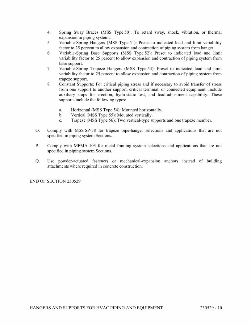
4. Spring Sway Braces (MSS Type 50): To retard sway, shock, vibration, or thermal
expansion in piping systems.
5. Variable-Spring Hangers (MSS Type 51): Preset to indicated load and limit variability
factor to 25 percent to allow expansion and contraction of piping system from hanger.
6. Variable-Spring Base Supports (MSS Type 52): Preset to indicated load and limit
variability factor to 25 percent to allow expansion and contraction of piping system from
base support.
7. Variable-Spring Trapeze Hangers (MSS Type 53): Preset to indicated load and limit
variability factor to 25 percent to allow expansion and contraction of piping system from
trapeze support.
8. Constant Supports: For critical piping stress and if necessary to avoid transfer of stress
from one support to another support, critical terminal, or connected equipment. Include
auxiliary stops for erection, hydrostatic test, and load-adjustment capability. These
supports include the following types:
a. Horizontal (MSS Type 54): Mounted horizontally.
b. Vertical (MSS Type 55): Mounted vertically.
c. Trapeze (MSS Type 56): Two vertical-type supports and one trapeze member.
O. Comply with MSS SP-58 for trapeze pipe-hanger selections and applications that are not
specified in piping system Sections.
P. Comply with MFMA-103 for metal framing system selections and applications that are not
specified in piping system Sections.
Q. Use powder-actuated fasteners or mechanical-expansion anchors instead of building
attachments where required in concrete construction.
END OF SECTION 230529
IDENTIFICATION FOR HVAC PIPING AND EQUIPMENT 230553 - 1
SECTION 230553 - IDENTIFICATION FOR HVAC PIPING AND EQUIPMENT
PART 1 - GENERAL
1.1 RELATED DOCUMENTS
A. Drawings and general provisions of the Contract, including General and Supplementary Conditions and Division 01 Specification Sections, apply to this Section.
1.2 SUMMARY
A. Section Includes:
1. Equipment labels. 2. Warning signs and labels. 3. Pipe labels. 4. Duct labels. 5. Valve tags. 6. Warning tags.
1.3 ACTION SUBMITTALS
A. Product Data: For each type of product.
B. Samples: For color, letter style, and graphic representation required for each identification material and device.
C. Equipment Label Schedule: Include a listing of all equipment to be labeled with the proposed content for each label.
D. Valve numbering scheme.
E. Valve Schedules: For each piping system to include in maintenance manuals.
PART 2 - PRODUCTS
2.1 EQUIPMENT LABELS
A. Metal Labels for Equipment:
1. Material and Thickness: stainless steel, 0.025-inch aluminum, 0.032-inch or anodized aluminum, 0.032-inch minimum thickness, and having predrilled or stamped holes for attachment hardware.
2. Letter Color: Black. 3. Background Color: White.
IDENTIFICATION FOR HVAC PIPING AND EQUIPMENT 230553 - 2
4. Minimum Label Size: Length and width vary for required label content, but not less than 2-1/2 by 3/4 inch.
5. Minimum Letter Size: 1/4 inch for name of units if viewing distance is less than 24 inches, 1/2 inch for viewing distances up to 72 inches, and proportionately larger lettering for greater viewing distances. Include secondary lettering two-thirds to three-quarters the size of principal lettering.
6. Fasteners: Stainless-steel rivets or self-tapping screws. 7. Adhesive: Contact-type permanent adhesive, compatible with label and with substrate.
B. Label Content: Include equipment's Drawing designation or unique equipment number.
C. Equipment Label Schedule: For each item of equipment to be labeled, on 8-1/2-by-11-inch bond paper. Tabulate equipment identification number, and identify Drawing numbers where equipment is indicated (plans, details, and schedules) and the Specification Section number and title where equipment is specified. Equipment schedule shall be included in operation and maintenance data.
2.2 WARNING SIGNS AND LABELS
A. Material and Thickness: Multilayer, multicolor, plastic labels for mechanical engraving, 1/16 inch thick, and having predrilled holes for attachment hardware.
B. Letter Color: White.
C. Background Color: Red.
D. Maximum Temperature: Able to withstand temperatures up to 160 deg F.
E. Minimum Label Size: Length and width vary for required label content, but not less than 2-1/2 by 3/4 inch.
F. Minimum Letter Size: 1/4 inch for name of units if viewing distance is less than 24 inches, 1/2 inch for viewing distances up to 72 inches, and proportionately larger lettering for greater viewing distances. Include secondary lettering two-thirds to three-quarters the size of principal lettering.
G. Fasteners: Stainless-steel rivets or self-tapping screws.
H. Adhesive: Contact-type permanent adhesive, compatible with label and with substrate.
I. Label Content: Include caution and warning information plus emergency notification instructions.
2.3 PIPE LABELS
A. General Requirements for Manufactured Pipe Labels: Preprinted, color-coded, with lettering indicating service, and showing flow direction according to ASME A13.1.
B. Pretensioned Pipe Labels: Precoiled, semirigid plastic formed to cover full circumference of pipe and to attach to pipe without fasteners or adhesive.
IDENTIFICATION FOR HVAC PIPING AND EQUIPMENT 230553 - 3
C. Pipe Label Contents: Include identification of piping service using same designations or abbreviations as used on Drawings; also include pipe size and an arrow indicating flow direction.
1. Flow-Direction Arrows: Integral with piping system service lettering to accommodate both directions or as separate unit on each pipe label to indicate flow direction.
2. Lettering Size: Size letters according to ASME A13.1 for piping.
2.4 VALVE TAGS
A. Description: Stamped or engraved with 1/4-inch letters for piping system abbreviation and 1/2-inch numbers.
1. Tag Material: Brass, 0.032-inch minimum thickness, and having predrilled or stamped holes for attachment hardware.
2. Fasteners: Brass wire-link chain.
B. Valve Schedules: For each piping system, on 8-1/2-by-11-inch bond paper. Tabulate valve number, piping system, system abbreviation (as shown on valve tag), location of valve (room or space), normal-operating position (open, closed, or modulating), and variations for identification. Mark valves for emergency shutoff and similar special uses.
1. Valve-tag schedule shall be included in operation and maintenance data.
2.5 WARNING TAGS
A. Description: Preprinted or partially preprinted accident-prevention tags of plasticized card stock with matte finish suitable for writing.
1. Size: Approximately 4 by 7 inches. 2. Fasteners: Brass grommet and wire. 3. Nomenclature: Large-size primary caption such as "DANGER," "CAUTION," or "DO
NOT OPERATE." 4. Color: Safety-yellow background with black lettering.
PART 3 - EXECUTION
3.1 PREPARATION
A. Clean piping and equipment surfaces of substances that could impair bond of identification devices, including dirt, oil, grease, release agents, and incompatible primers, paints, and encapsulants.
3.2 GENERAL INSTALLATION REQUIREMENTS
A. Coordinate installation of identifying devices with completion of covering and painting of surfaces where devices are to be applied.
IDENTIFICATION FOR HVAC PIPING AND EQUIPMENT 230553 - 4
B. Coordinate installation of identifying devices with locations of access panels and doors.
C. Install identifying devices before installing acoustical ceilings and similar concealment.
3.3 EQUIPMENT LABEL INSTALLATION
A. Install or permanently fasten labels on each major item of mechanical equipment.
B. Locate equipment labels where accessible and visible.
3.4 PIPE LABEL INSTALLATION
A. Piping Color Coding: Match UNCC labeling standards.
B. Pipe Label Locations: Locate pipe labels where piping is exposed or above accessible ceilings in finished spaces; machine rooms; accessible maintenance spaces such as shafts, tunnels, and plenums; and exterior exposed locations as follows:
1. Near each valve and control device. 2. Near each branch connection, excluding short takeoffs for fixtures and terminal units.
Where flow pattern is not obvious, mark each pipe at branch. 3. Near penetrations and on both sides of through walls, floors, ceilings, and inaccessible
enclosures. 4. At access doors, manholes, and similar access points that permit view of concealed
piping. 5. Near major equipment items and other points of origination and termination. 6. Spaced at maximum intervals of 25 feet along each run. Reduce intervals to 15 feet in
areas of congested piping and equipment. 7. On piping above removable acoustical ceilings. Omit intermediately spaced labels.
C. Directional Flow Arrows: Arrows shall be used to indicate direction of flow in pipes, including pipes where flow is allowed in both directions.
D. Pipe Label Color Schedule:
1. Chilled-Water Piping: White letters on a safety-blue (DC 9800) background. 2. Heating Water Piping: White letters on an oxide yellow (DC 7821) background. 3. Low-Pressure Steam Piping: White letters on a safety-yellow (DC 9400) background. 4. Steam Condensate Piping: White letters on a safety-orange (DC 9200) background.
3.5 VALVE-TAG INSTALLATION
A. Install tags on valves and control devices in piping systems, except check valves, valves within factory-fabricated equipment units, shutoff valves, faucets, convenience and lawn-watering hose connections, and HVAC terminal devices and similar roughing-in connections of end-use fixtures and units. List tagged valves in a valve schedule.
B. Valve-Tag Application Schedule: Tag valves according to size, shape, and color scheme and with captions similar to those indicated in the following subparagraphs:
IDENTIFICATION FOR HVAC PIPING AND EQUIPMENT 230553 - 5
1. Valve-Tag Size and Shape:
a. Chilled Water: 1-1/2 inches, round b. Hot Water: 1-1/2 inches, round. c. Low-Pressure Steam: 1-1/2 inches, round. d. Steam Condensate: 1-1/2 inches, round.
3.6 WARNING-TAG INSTALLATION
A. Write required message on, and attach warning tags to, equipment and other items where required.
END OF SECTION 230553
TESTING, ADJUSTING, AND BALANCING FOR HVAC 230593 - 1
SECTION 230593 - TESTING, ADJUSTING, AND BALANCING FOR HVAC
PART 1 - GENERAL
1.1 RELATED DOCUMENTS
A. Drawings and general provisions of the Contract, including General and Supplementary
Conditions and Division 01 Specification Sections, apply to this Section.
1.2 SUMMARY
A. Section Includes:
1. Balancing Air Systems:
a. Dual-duct systems.
2. Balancing Hydronic Piping Systems:
a. Constant-flow hydronic systems.
3. Balancing steam systems.
4. Testing, Adjusting, and Balancing Equipment:
a. Motors.
b. Heat-transfer coils.
5. Testing, adjusting, and balancing existing systems and equipment.
6. Control system verification.
1.3 DEFINITIONS
A. AABC: Associated Air Balance Council.
B. BAS: Building automation systems.
C. NEBB: National Environmental Balancing Bureau.
D. TAB: Testing, adjusting, and balancing.
E. TABB: Testing, Adjusting, and Balancing Bureau.
F. TAB Specialist: An independent entity meeting qualifications to perform TAB work.
G. TDH: Total dynamic head.
TESTING, ADJUSTING, AND BALANCING FOR HVAC 230593 - 2
1.4 PREINSTALLATION MEETINGS
A. TAB Conference: If requested by the Owner, conduct a TAB conference at Project site after
approval of the TAB strategies and procedures plan to develop a mutual understanding of the
details. Provide a minimum of 14 days' advance notice of scheduled meeting time and location.
1. Minimum Agenda Items:
a. The Contract Documents examination report.
b. The TAB plan.
c. Needs for coordination and cooperation of trades and subcontractors.
d. Proposed procedures for documentation and communication flow.
1.5 INFORMATIONAL SUBMITTALS
A. Qualification Data: Within 30 days of Contractor's Notice to Proceed, submit documentation
that the TAB specialist and this Project's TAB team members meet the qualifications specified
in "Quality Assurance" Article.
B. Contract Documents Examination Report: Within 30 days of Contractor's Notice to Proceed,
submit the Contract Documents review report as specified in Part 3.
C. Strategies and Procedures Plan: Within 30 days of Contractor's Notice to Proceed, submit TAB
strategies and step-by-step procedures as specified in "Preparation" Article.
D. System Readiness Checklists: Within 30 days of Contractor's Notice to Proceed, submit system
readiness checklists as specified in "Preparation" Article.
E. Examination Report: Submit a summary report of the examination review required in
"Examination" Article.
F. Certified TAB reports.
G. Sample report forms.
H. Instrument calibration reports, to include the following:
1. Instrument type and make.
2. Serial number.
3. Application.
4. Dates of use.
5. Dates of calibration.
1.6 QUALITY ASSURANCE
A. TAB Specialists Qualifications: Certified by NEBB or TABB.
1. TAB Field Supervisor: Employee of the TAB specialist and certified by NEBB or TABB.
2. TAB Technician: Employee of the TAB specialist and certified by NEBB or TABB as a
TAB technician.
TESTING, ADJUSTING, AND BALANCING FOR HVAC 230593 - 3
B. Instrumentation Type, Quantity, Accuracy, and Calibration: Comply with requirements in
ASHRAE 111, Section 4, "Instrumentation."
C. ASHRAE/IES 90.1 Compliance: Applicable requirements in ASHRAE/IES 90.1,
Section 6.7.2.3 - "System Balancing."
1.7 FIELD CONDITIONS
A. Full Owner Occupancy: Owner will occupy the site and existing building during entire TAB
period. Cooperate with Owner during TAB operations to minimize conflicts with Owner's
operations.
PART 2 - PRODUCTS (Not Applicable)
PART 3 - EXECUTION
3.1 EXAMINATION
A. Examine the Contract Documents to become familiar with Project requirements and to discover
conditions in systems designs that may preclude proper TAB of systems and equipment.
B. Examine installed systems for balancing devices, such as test ports, gage cocks, thermometer
wells, flow-control devices, balancing valves and fittings, and manual volume dampers. Verify
that locations of these balancing devices are applicable for intended purpose and are accessible.
C. Examine the approved submittals for HVAC systems and equipment.
D. Examine design data including HVAC system descriptions, statements of design assumptions
for environmental conditions and systems output, and statements of philosophies and
assumptions about HVAC system and equipment controls.
E. Examine equipment performance data including fan and pump curves.
1. Relate performance data to Project conditions and requirements, including system effects
that can create undesired or unpredicted conditions that cause reduced capacities in all or
part of a system.
2. Calculate system-effect factors to reduce performance ratings of HVAC equipment when
installed under conditions different from the conditions used to rate equipment
performance. To calculate system effects for air systems, use tables and charts found in
AMCA 201, "Fans and Systems," or in SMACNA's "HVAC Systems - Duct Design."
Compare results with the design data and installed conditions.
F. Examine system and equipment installations and verify that field quality-control testing,
cleaning, and adjusting specified in individual Sections have been performed.
G. Examine test reports specified in individual system and equipment Sections.
TESTING, ADJUSTING, AND BALANCING FOR HVAC 230593 - 4
H. Examine HVAC equipment and verify that bearings are greased, belts are aligned and tight,
filters are clean, and equipment with functioning controls is ready for operation.
I. Examine terminal units, such as variable-air-volume boxes, and verify that they are accessible
and their controls are connected and functioning.
J. Examine strainers. Verify that startup screens have been replaced by permanent screens with
indicated perforations.
K. Examine control valves for proper installation for their intended function of throttling, diverting,
or mixing fluid flows.
L. Examine heat-transfer coils for correct piping connections and for clean and straight fins.
M. Examine system pumps to ensure absence of entrained air in the suction piping.
N. Examine operating safety interlocks and controls on HVAC equipment.
O. Report deficiencies discovered before and during performance of TAB procedures. Observe and
record system reactions to changes in conditions. Record default set points if different from
indicated values.
3.2 PREPARATION
A. Prepare a TAB plan that includes the following:
1. Equipment and systems to be tested.
2. Strategies and step-by-step procedures for balancing the systems.
3. Instrumentation to be used.
4. Sample forms with specific identification for all equipment.
B. Perform system-readiness checks of HVAC systems and equipment to verify system readiness
for TAB work. Include, at a minimum, the following:
1. Airside:
a. Verify that leakage and pressure tests on air distribution systems have been
satisfactorily completed.
b. Duct systems are complete with terminals installed.
c. Volume, smoke, and fire dampers are open and functional.
d. Clean filters are installed.
e. Fans are operating, free of vibration, and rotating in correct direction.
f. Variable-frequency controllers' startup is complete and safeties are verified.
g. Automatic temperature-control systems are operational.
h. Ceilings are installed.
i. Windows and doors are installed.
j. Suitable access to balancing devices and equipment is provided.
2. Hydronics:
TESTING, ADJUSTING, AND BALANCING FOR HVAC 230593 - 5
a. Verify leakage and pressure tests on water distribution systems have been
satisfactorily completed.
b. Piping is complete with terminals installed.
c. Water treatment is complete.
d. Systems are flushed, filled, and air purged.
e. Strainers are pulled and cleaned.
f. Control valves are functioning per the sequence of operation.
g. Shutoff and balance valves have been verified to be 100 percent open.
h. Pumps are started and proper rotation is verified.
i. Pump gage connections are installed directly at pump inlet and outlet flanges or in
discharge and suction pipe prior to valves or strainers.
j. Variable-frequency controllers' startup is complete and safeties are verified.
k. Suitable access to balancing devices and equipment is provided.
3.3 GENERAL PROCEDURES FOR TESTING AND BALANCING
A. Perform testing and balancing procedures on each system according to the procedures contained
in SMACNA's "HVAC Systems - Testing, Adjusting, and Balancing" and in this Section.
B. Cut insulation, ducts, pipes, and equipment cabinets for installation of test probes to the
minimum extent necessary for TAB procedures.
1. After testing and balancing, patch probe holes in ducts with same material and thickness
as used to construct ducts.
2. After testing and balancing, install test ports and duct access doors that comply with
requirements in Section 233300 "Air Duct Accessories."
3. Install and join new insulation that matches removed materials. Restore insulation,
coverings, vapor barrier, and finish according to Section 230713 "Duct Insulation,"
Section 230716 "HVAC Equipment Insulation," and Section 230719 "HVAC Piping
Insulation."
C. Mark equipment and balancing devices, including damper-control positions, valve position
indicators, fan-speed-control levers, and similar controls and devices, with paint or other
suitable, permanent identification material to show final settings.
D. Take and report testing and balancing measurements in inch-pound (IP) units.
3.4 GENERAL PROCEDURES FOR BALANCING AIR SYSTEMS
A. Prepare test reports for both fans and outlets. Obtain manufacturer's outlet factors and
recommended testing procedures. Cross-check the summation of required outlet volumes with
required fan volumes.
B. Prepare schematic diagrams of systems' "as-built" duct layouts.
C. For variable-air-volume systems, develop a plan to simulate diversity.
D. Determine the best locations in main and branch ducts for accurate duct-airflow measurements.
TESTING, ADJUSTING, AND BALANCING FOR HVAC 230593 - 6
E. Check airflow patterns from the outdoor-air louvers and dampers and the return- and exhaust-air
dampers through the supply-fan discharge and mixing dampers.
F. Locate start-stop and disconnect switches, electrical interlocks, and motor starters.
G. Verify that motor starters are equipped with properly sized thermal protection.
H. Check dampers for proper position to achieve desired airflow path.
I. Check for airflow blockages.
J. Check condensate drains for proper connections and functioning.
K. Check for proper sealing of air-handling-unit components.
L. Verify that air duct system is sealed as specified in Section 233113 "Metal Ducts."
3.5 PROCEDURES FOR DUAL-DUCT SYSTEMS
A. Adjust the dual-duct systems as follows:
1. Verify that the system static pressure sensor is located two-thirds of the distance down
the duct from the fan discharge. On systems with separate hot-deck and cold-deck fans,
verify the location of the sensor on each deck.
2. Verify that the system is under static pressure control.
3. Select the terminal unit that is most critical to the supply-fan airflow. Measure inlet static
pressure, and adjust system static pressure control set point so the entering static pressure
for the critical terminal unit is not less than the sum of the terminal-unit manufacturer's
recommended minimum inlet static pressure plus the static pressure needed to overcome
terminal-unit discharge system losses.
4. Calibrate and balance each terminal unit's hot deck and cold deck for maximum and
minimum design airflow as follows:
a. Adjust controls so that terminal is calling for full cooling. Some controllers require
starting with minimum set point. Verify calibration procedure for specific project.
b. Measure airflow and adjust calibration factors as required for design cold-deck
maximum airflow and hot-deck minimum airflow. Record calibration factors.
c. When maximum airflow is correct, balance the air outlets downstream from
terminal units.
d. Adjust controls so that terminal is calling for full heating.
e. Measure airflow and adjust calibration factors as required for design cold-deck
minimum airflow and hot-deck maximum airflow. Record calibration factors. If no
minimum calibration is available, note any deviation from design airflow.
5. After terminals have been calibrated and balanced, test and adjust system for total
airflow. Adjust fans to deliver total design airflows within the maximum allowable fan
speed listed by fan manufacturer.
a. Set outside-air, return-air, and relief-air dampers for proper position that simulates
minimum outdoor-air conditions.
TESTING, ADJUSTING, AND BALANCING FOR HVAC 230593 - 7
b. Set terminals for maximum airflow. If system design includes diversity (cooling
coil or fan), adjust terminals for maximum and minimum airflow so that connected
total matches cooling coil or fan selection and simulates actual load in the building.
In systems with separate hot-deck and cold-deck fans, diversity consideration
applies to each individual fan.
c. Where duct conditions allow, measure airflow by Pitot-tube traverse. If necessary,
perform multiple Pitot-tube traverses to obtain total airflow.
d. Where duct conditions are not suitable for Pitot-tube traverse measurements, a coil
traverse may be acceptable.
e. If a reliable Pitot-tube traverse or coil traverse is not possible, measure airflow at
terminals and calculate the total airflow.
6. Measure the fan(s) static pressures as follows:
a. Measure static pressure directly at the fan outlet or through the flexible connection.
b. Measure static pressure directly at the fan inlet or through the flexible connection.
c. Measure static pressure across each component that makes up the air-handling
system.
d. Report any artificial loading of filters at the time static pressures are measured.
7. Set final return and outside airflow to the fan(s) while operating at maximum return
airflow and minimum outdoor airflow.
a. Balance the return-air ducts and inlets the same as described for constant-volume
air systems.
b. Verify that all terminal units are meeting design airflow under system maximum
flow.
8. Re-measure the inlet static pressure at the most critical terminal unit and adjust the
system static pressure set point to the most energy-efficient set point to maintain the
optimum system static pressure. Record set point and give to controls contractor.
9. Verify final system conditions as follows:
a. Re-measure and confirm that minimum outdoor, return, and relief airflows are
within design. Readjust to match design if necessary.
b. Re-measure and confirm that total airflow is within design.
c. Re-measure final fan operating data, rpms, volts, amps and static profile.
d. Mark final settings.
e. Test system in economizer mode. Verify proper operation and adjust if necessary.
Measure and record all operating data.
f. Verify tracking between supply and return fans.
10. Record final fan-performance data.
3.6 PROCEDURES FOR VARIABLE-AIR-VOLUME SYSTEMS
A. Adjust the variable-air-volume systems as follows:
1. Verify that the system static pressure sensor is located two-thirds of the distance down
the duct from the fan discharge.
TESTING, ADJUSTING, AND BALANCING FOR HVAC 230593 - 8
2. Verify that the system is under static pressure control.
3. Select the terminal unit that is most critical to the supply-fan airflow. Measure inlet static
pressure, and adjust system static pressure control set point so the entering static pressure
for the critical terminal unit is not less than the sum of the terminal-unit manufacturer's
recommended minimum inlet static pressure plus the static pressure needed to overcome
terminal-unit discharge system losses.
4. Calibrate and balance each terminal unit for maximum and minimum design airflow as
follows:
a. Adjust controls so that terminal is calling for maximum airflow. Some controllers
require starting with minimum airflow. Verify calibration procedure for specific
project.
b. Measure airflow and adjust calibration factor as required for design maximum
airflow. Record calibration factor.
c. When maximum airflow is correct, balance the air outlets downstream from
terminal units.
d. Adjust controls so that terminal is calling for minimum airflow.
e. Measure airflow and adjust calibration factor as required for design minimum
airflow. Record calibration factor. If no minimum calibration is available, note any
deviation from design airflow.
f. When in full cooling or full heating, ensure that there is no mixing of hot-deck and
cold-deck airstreams unless so designed.
g. On constant volume terminals, in critical areas where room pressure is to be
maintained, verify that the airflow remains constant over the full range of full
cooling to full heating. Note any deviation from design airflow or room pressure.
5. After terminals have been calibrated and balanced, test and adjust system for total
airflow. Adjust fans to deliver total design airflows within the maximum allowable fan
speed listed by fan manufacturer.
a. Set outside-air, return-air, and relief-air dampers for proper position that simulates
minimum outdoor-air conditions.
b. Set terminals for maximum airflow. If system design includes diversity, adjust
terminals for maximum and minimum airflow so that connected total matches fan
selection and simulates actual load in the building.
c. Where duct conditions allow, measure airflow by Pitot-tube traverse. If necessary,
perform multiple Pitot-tube traverses to obtain total airflow.
d. Where duct conditions are not suitable for Pitot-tube traverse measurements, a coil
traverse may be acceptable.
e. If a reliable Pitot-tube traverse or coil traverse is not possible, measure airflow at
terminals and calculate the total airflow.
6. Measure fan static pressures as follows:
a. Measure static pressure directly at the fan outlet or through the flexible connection.
b. Measure static pressure directly at the fan inlet or through the flexible connection.
c. Measure static pressure across each component that makes up the air-handling
system.
d. Report any artificial loading of filters at the time static pressures are measured.
TESTING, ADJUSTING, AND BALANCING FOR HVAC 230593 - 9
7. Set final return and outside airflow to the fan while operating at maximum return airflow
and minimum outdoor airflow.
a. Balance the return-air ducts and inlets the same as described for constant-volume
air systems.
b. Verify that terminal units are meeting design airflow under system maximum flow.
8. Re-measure the inlet static pressure at the most critical terminal unit and adjust the
system static pressure set point to the most energy-efficient set point to maintain the
optimum system static pressure. Record set point and give to controls contractor.
9. Verify final system conditions as follows:
a. Re-measure and confirm that minimum outdoor, return, and relief airflows are
within design. Readjust to match design if necessary.
b. Re-measure and confirm that total airflow is within design.
c. Re-measure final fan operating data, rpms, volts, amps, and static profile.
d. Mark final settings.
e. Test system in economizer mode. Verify proper operation and adjust if necessary.
Measure and record all operating data.
f. Verify tracking between supply and return fans.
3.7 GENERAL PROCEDURES FOR HYDRONIC SYSTEMS
A. Prepare test reports for pumps, coils, and heat exchangers. Obtain approved submittals and
manufacturer-recommended testing procedures. Crosscheck the summation of required coil and
heat exchanger flow rates with pump design flow rate.
B. Prepare schematic diagrams of systems' "as-built" piping layouts.
C. In addition to requirements in "Preparation" Article, prepare hydronic systems for testing and
balancing as follows:
1. Check liquid level in expansion tank.
2. Check highest vent for adequate pressure.
3. Check flow-control valves for proper position.
4. Locate start-stop and disconnect switches, electrical interlocks, and motor starters.
5. Verify that motor starters are equipped with properly sized thermal protection.
6. Check that air has been purged from the system.
3.8 PROCEDURES FOR CONSTANT-FLOW HYDRONIC SYSTEMS
A. Adjust flow-measuring devices installed in mains and branches to design water flows.
1. Measure flow in main and branch pipes.
2. Adjust main and branch balance valves for design flow.
3. Re-measure each main and branch after all have been adjusted.
B. Verify final system conditions as follows:
TESTING, ADJUSTING, AND BALANCING FOR HVAC 230593 - 10
1. Re-measure and confirm that total water flow is within design.
2. Re-measure final pumps' operating data, TDH, volts, amps, and static profile.
3. Mark final settings.
C. Verify that memory stops have been set.
3.9 PROCEDURES FOR STEAM SYSTEMS
A. Measure and record upstream and downstream pressure of each piece of equipment.
B. Measure and record upstream and downstream steam pressure of pressure-reducing valves.
C. Check settings and operation of automatic temperature-control valves, self-contained control
valves, and pressure-reducing valves. Record final settings.
D. Check settings and operation of each safety valve. Record settings.
E. Verify the operation of each steam trap.
3.10 PROCEDURES FOR MOTORS
A. Motors 1/2 HP and Larger: Test at final balanced conditions and record the following data:
1. Manufacturer's name, model number, and serial number.
2. Motor horsepower rating.
3. Motor rpm.
4. Phase and hertz.
5. Nameplate and measured voltage, each phase.
6. Nameplate and measured amperage, each phase.
7. Starter size and thermal-protection-element rating.
8. Service factor and frame size.
B. Motors Driven by Variable-Frequency Controllers: Test manual bypass of controller to prove
proper operation.
3.11 PROCEDURES FOR HEAT-TRANSFER COILS
A. Measure, adjust, and record the following data for each water coil:
1. Entering- and leaving-water temperature.
2. Water flow rate.
3. Water pressure drop for major (more than 20 gpm) equipment coils, excluding unitary
equipment such as reheat coils, unit heaters, and fan-coil units.
4. Dry-bulb temperature of entering and leaving air.
5. Wet-bulb temperature of entering and leaving air for cooling coils.
6. Airflow.
B. Measure, adjust, and record the following data for each electric heating coil:
TESTING, ADJUSTING, AND BALANCING FOR HVAC 230593 - 11
1. Nameplate data.
2. Airflow.
3. Entering- and leaving-air temperature at full load.
4. Voltage and amperage input of each phase at full load.
5. Calculated kilowatt at full load.
6. Fuse or circuit-breaker rating for overload protection.
C. Measure, adjust, and record the following data for each steam coil:
1. Dry-bulb temperature of entering and leaving air.
2. Airflow.
3. Inlet steam pressure.
D. Measure, adjust, and record the following data for each refrigerant coil:
1. Dry-bulb temperature of entering and leaving air.
2. Wet-bulb temperature of entering and leaving air.
3. Airflow.
3.12 CONTROLS VERIFICATION
A. In conjunction with system balancing, perform the following:
1. Verify temperature control system is operating within the design limitations.
2. Confirm that the sequences of operation are in compliance with Contract Documents.
3. Verify that controllers are calibrated and function as intended.
4. Verify that controller set points are as indicated.
5. Verify the operation of lockout or interlock systems.
6. Verify the operation of valve and damper actuators.
7. Verify that controlled devices are properly installed and connected to correct controller.
8. Verify that controlled devices travel freely and are in position indicated by controller:
open, closed, or modulating.
9. Verify location and installation of sensors to ensure that they sense only intended
temperature, humidity, or pressure.
B. Reporting: Include a summary of verifications performed, remaining deficiencies, and
variations from indicated conditions.
3.13 PROCEDURES FOR TESTING, ADJUSTING, AND BALANCING EXISTING SYSTEMS
A. Perform a preconstruction inspection of existing equipment that is to remain and be reused.
1. Measure and record the operating speed, airflow, and static pressure of each fan.
2. Measure motor voltage and amperage. Compare the values to motor nameplate
information.
3. Check the refrigerant charge.
4. Check the condition of filters.
5. Check the condition of coils.
6. Check the operation of the drain pan and condensate-drain trap.
TESTING, ADJUSTING, AND BALANCING FOR HVAC 230593 - 12
7. Check bearings and other lubricated parts for proper lubrication.
8. Report on the operating condition of the equipment and the results of the measurements
taken. Report deficiencies.
B. Before performing testing and balancing of existing systems, inspect existing equipment that is
to remain and be reused to verify that existing equipment has been cleaned and refurbished.
Verify the following:
1. New filters are installed.
2. Coils are clean and fins combed.
3. Drain pans are clean.
4. Fans are clean.
5. Bearings and other parts are properly lubricated.
6. Deficiencies noted in the preconstruction report are corrected.
C. Perform testing and balancing of existing systems to the extent that existing systems are
affected by the renovation work.
1. Compare the indicated airflow of the renovated work to the measured fan airflows, and
determine the new fan speed and the face velocity of filters and coils.
2. Verify that the indicated airflows of the renovated work result in filter and coil face
velocities and fan speeds that are within the acceptable limits defined by equipment
manufacturer.
3. If calculations increase or decrease the airflow rates and water flow rates by more than 5
percent, make equipment adjustments to achieve the calculated rates. If increase or
decrease is 5 percent or less, equipment adjustments are not required.
4. Balance each air outlet.
3.14 TOLERANCES
A. Set HVAC system's airflow rates and water flow rates within the following tolerances:
1. Supply, Return, and Exhaust Fans and Equipment with Fans: Plus or minus 10 percent.
2. Air Outlets and Inlets: Plus or minus 10 percent.
3. Heating-Water Flow Rate: Plus or minus 10 percent.
4. Cooling-Water Flow Rate: Plus or minus 10 percent.
B. Maintaining pressure relationships as designed shall have priority over the tolerances specified
above.
3.15 PROGRESS REPORTING
A. Initial Construction-Phase Report: Based on examination of the Contract Documents as
specified in "Examination" Article, prepare a report on the adequacy of design for systems
balancing devices. Recommend changes and additions to systems balancing devices to facilitate
proper performance measuring and balancing. Recommend changes and additions to HVAC
systems and general construction to allow access for performance measuring and balancing
devices.
TESTING, ADJUSTING, AND BALANCING FOR HVAC 230593 - 13
B. Status Reports: Prepare weekly progress reports to describe completed procedures, procedures
in progress, and scheduled procedures. Include a list of deficiencies and problems found in
systems being tested and balanced. Prepare a separate report for each system and each building
floor for systems serving multiple floors.
3.16 FINAL REPORT
A. General: Prepare a certified written report; tabulate and divide the report into separate sections
for tested systems and balanced systems.
1. Include a certification sheet at the front of the report's binder, signed and sealed by the
certified testing and balancing engineer.
2. Include a list of instruments used for procedures, along with proof of calibration.
3. Certify validity and accuracy of field data.
B. Final Report Contents: In addition to certified field-report data, include the following:
1. Pump curves.
2. Fan curves.
3. Manufacturers' test data.
4. Field test reports prepared by system and equipment installers.
5. Other information relative to equipment performance; do not include Shop Drawings and
Product Data.
C. General Report Data: In addition to form titles and entries, include the following data:
1. Title page.
2. Name and address of the TAB specialist.
3. Project name.
4. Project location.
5. Architect's name and address.
6. Engineer's name and address.
7. Contractor's name and address.
8. Report date.
9. Signature of TAB supervisor who certifies the report.
10. Table of Contents with the total number of pages defined for each section of the report.
Number each page in the report.
11. Summary of contents including the following:
a. Indicated versus final performance.
b. Notable characteristics of systems.
c. Description of system operation sequence if it varies from the Contract
Documents.
12. Nomenclature sheets for each item of equipment.
13. Data for terminal units, including manufacturer's name, type, size, and fittings.
14. Notes to explain why certain final data in the body of reports vary from indicated values.
15. Test conditions for fans and pump performance forms including the following:
a. Settings for outdoor-, return-, and exhaust-air dampers.
TESTING, ADJUSTING, AND BALANCING FOR HVAC 230593 - 14
b. Conditions of filters.
c. Cooling coil, wet- and dry-bulb conditions.
d. Face and bypass damper settings at coils.
e. Fan drive settings including settings and percentage of maximum pitch diameter.
f. Inlet vane settings for variable-air-volume systems.
g. Settings for supply-air, static-pressure controller.
h. Other system operating conditions that affect performance.
D. System Diagrams: Include schematic layouts of air and hydronic distribution systems. Present
each system with single-line diagram and include the following:
1. Quantities of outdoor, supply, return, and exhaust airflows.
2. Water and steam flow rates.
3. Duct, outlet, and inlet sizes.
4. Pipe and valve sizes and locations.
5. Terminal units.
6. Balancing stations.
7. Position of balancing devices.
E. Air-Handling-Unit Test Reports: For air-handling units with coils, include the following:
1. Unit Data:
a. Unit identification.
b. Location.
c. Make and type.
d. Model number and unit size.
e. Manufacturer's serial number.
f. Unit arrangement and class.
g. Discharge arrangement.
h. Sheave make, size in inches, and bore.
i. Center-to-center dimensions of sheave and amount of adjustments in inches.
j. Number, make, and size of belts.
k. Number, type, and size of filters.
2. Motor Data:
a. Motor make, and frame type and size.
b. Horsepower and rpm.
c. Volts, phase, and hertz.
d. Full-load amperage and service factor.
e. Sheave make, size in inches, and bore.
f. Center-to-center dimensions of sheave and amount of adjustments in inches.
3. Test Data (Indicated and Actual Values):
a. Total airflow rate in cfm.
b. Total system static pressure in inches wg.
c. Fan rpm.
d. Discharge static pressure in inches wg.
e. Filter static-pressure differential in inches wg.

TESTING, ADJUSTING, AND BALANCING FOR HVAC 230593 - 15
f. Cooling-coil static-pressure differential in inches wg.
g. Heating-coil static-pressure differential in inches wg.
h. Outdoor airflow in cfm.
i. Return airflow in cfm.
j. Outdoor-air damper position.
k. Return-air damper position.
F. Apparatus-Coil Test Reports:
1. Coil Data:
a. System identification.
b. Location.
c. Coil type.
d. Number of rows.
e. Fin spacing in fins per inch o.c.
f. Make and model number.
g. Face area in sq. ft..
h. Tube size in NPS.
i. Tube and fin materials.
j. Circuiting arrangement.
2. Test Data (Indicated and Actual Values):
a. Airflow rate in cfm.
b. Average face velocity in fpm.
c. Air pressure drop in inches wg.
d. Outdoor-air, wet- and dry-bulb temperatures in deg F.
e. Return-air, wet- and dry-bulb temperatures in deg F.
f. Entering-air, wet- and dry-bulb temperatures in deg F.
g. Leaving-air, wet- and dry-bulb temperatures in deg F.
h. Water flow rate in gpm.
i. Water pressure differential in feet of head or psig.
j. Entering-water temperature in deg F.
k. Leaving-water temperature in deg F.
l. Inlet steam pressure in psig.
G. Fan Test Reports: For supply, return, and exhaust fans, include the following:
1. Fan Data:
a. System identification.
b. Location.
c. Make and type.
d. Model number and size.
e. Manufacturer's serial number.
f. Arrangement and class.
g. Sheave make, size in inches, and bore.
h. Center-to-center dimensions of sheave and amount of adjustments in inches.
2. Motor Data:
TESTING, ADJUSTING, AND BALANCING FOR HVAC 230593 - 16
a. Motor make, and frame type and size.
b. Horsepower and rpm.
c. Volts, phase, and hertz.
d. Full-load amperage and service factor.
e. Sheave make, size in inches, and bore.
f. Center-to-center dimensions of sheave, and amount of adjustments in inches.
g. Number, make, and size of belts.
3. Test Data (Indicated and Actual Values):
a. Total airflow rate in cfm.
b. Total system static pressure in inches wg.
c. Fan rpm.
d. Discharge static pressure in inches wg.
e. Suction static pressure in inches wg.
H. Round, Flat-Oval, and Rectangular Duct Traverse Reports: Include a diagram with a grid
representing the duct cross-section and record the following:
1. Report Data:
a. System and air-handling-unit number.
b. Location and zone.
c. Traverse air temperature in deg F.
d. Duct static pressure in inches wg.
e. Duct size in inches.
f. Duct area in sq. ft..
g. Indicated airflow rate in cfm.
h. Indicated velocity in fpm.
i. Actual airflow rate in cfm.
j. Actual average velocity in fpm.
k. Barometric pressure in psig.
I. System-Coil Reports: For reheat coils and water coils of terminal units, include the following:
1. Unit Data:
a. System and air-handling-unit identification.
b. Location and zone.
c. Room or riser served.
d. Coil make and size.
e. Flowmeter type.
2. Test Data (Indicated and Actual Values):
a. Airflow rate in cfm.
b. Entering-water temperature in deg F.
c. Leaving-water temperature in deg F.
d. Water pressure drop in feet of head or psig.
e. Entering-air temperature in deg F.
f. Leaving-air temperature in deg F.
TESTING, ADJUSTING, AND BALANCING FOR HVAC 230593 - 17
J. Instrument Calibration Reports:
1. Report Data:
a. Instrument type and make.
b. Serial number.
c. Application.
d. Dates of use.
e. Dates of calibration.
3.17 VERIFICATION OF TAB REPORT
A. The TAB specialist's test and balance engineer shall conduct the inspection in the presence of
architect or commissioning authority.
B. Architect or Commissioning authority shall randomly select measurements, documented in the
final report, to be rechecked. Rechecking shall be limited to either 10 percent of the total
measurements recorded or the extent of measurements that can be accomplished in a normal 8-
hour business day.
C. If rechecks yield measurements that differ from the measurements documented in the final
report by more than the tolerances allowed, the measurements shall be noted as "FAILED."
D. If the number of "FAILED" measurements is greater than 10 percent of the total measurements
checked during the final inspection, the testing and balancing shall be considered incomplete
and shall be rejected.
E. If TAB work fails, proceed as follows:
1. TAB specialists shall recheck all measurements and make adjustments. Revise the final
report and balancing device settings to include all changes; resubmit the final report and
request a second final inspection.
2. If the second final inspection also fails, Owner may contract the services of another TAB
specialist to complete TAB work according to the Contract Documents and deduct the
cost of the services from the original TAB specialist's final payment.
F. Prepare test and inspection reports.
3.18 ADDITIONAL TESTS
A. Within 90 days of completing TAB, perform additional TAB to verify that balanced conditions
are being maintained throughout and to correct unusual conditions.
B. Seasonal Periods: If initial TAB procedures were not performed during near-peak summer and
winter conditions, perform additional TAB during near-peak summer and winter conditions.
END OF SECTION 230593
DUCT INSULATION 230713 - 1
SECTION 230713 - DUCT INSULATION
PART 1 - GENERAL
1.1 RELATED DOCUMENTS
A. Drawings and general provisions of the Contract, including General and Supplementary
Conditions and Division 01 Specification Sections, apply to this Section.
1.2 SUMMARY
A. Section includes insulating the following duct services:
1. Indoor, supply air.
B. Related Sections:
1. Section 230719 "HVAC Piping Insulation."
2. Section 233113 "Metal Ducts" for duct liners.
1.3 ACTION SUBMITTALS
A. Product Data: For each type of product indicated. Include thermal conductivity, water-vapor
permeance thickness, and jackets (both factory- and field-applied if any).
B. Samples: For each type of insulation and jacket indicated. Identify each Sample, describing
product and intended use. Sample sizes are as follows:
1. Sheet Form Insulation Materials: 12 inches square.
2. Sheet Jacket Materials: 12 inches square.
3. Manufacturer's Color Charts: For products where color is specified, show the full range
of colors available for each type of finish material.
1.4 INFORMATIONAL SUBMITTALS
A. Qualification Data: For qualified Installer.
B. Material Test Reports: From a qualified testing agency acceptable to authorities having
jurisdiction indicating, interpreting, and certifying test results for compliance of insulation
materials, sealers, attachments, cements, and jackets, with requirements indicated. Include dates
of tests and test methods employed.
C. Field quality-control reports.
DUCT INSULATION 230713 - 2
1.5 QUALITY ASSURANCE
A. Installer Qualifications: Skilled mechanics who have successfully completed an apprenticeship
program or another craft training program certified by the Department of Labor, Bureau of
Apprenticeship and Training.
B. Surface-Burning Characteristics: For insulation and related materials, as determined by testing
identical products according to ASTM E84, by a testing agency acceptable to authorities having
jurisdiction. Factory label insulation and jacket materials and adhesive, mastic, tapes, and
cement material containers, with appropriate markings of applicable testing agency.
1. Insulation Installed Indoors: Flame-spread index of 25 or less, and smoke-developed
index of 50 or less.
2. Insulation Installed Outdoors: Flame-spread index of 75 or less, and smoke-developed
index of 150 or less.
1.6 DELIVERY, STORAGE, AND HANDLING
A. Packaging: Insulation material containers shall be marked by manufacturer with appropriate
ASTM standard designation, type and grade, and maximum use temperature.
1.7 COORDINATION
A. Coordinate sizes and locations of supports, hangers, and insulation shields specified in
Section 230529 "Hangers and Supports for HVAC Piping and Equipment."
B. Coordinate clearance requirements with duct Installer for duct insulation application. Before
preparing ductwork Shop Drawings, establish and maintain clearance requirements for
installation of insulation and field-applied jackets and finishes and for space required for
maintenance.
C. Coordinate installation and testing of heat tracing.
1.8 SCHEDULING
A. Schedule insulation application after pressure testing systems and, where required, after
installing and testing heat tracing. Insulation application may begin on segments that have
satisfactory test results.
B. Complete installation and concealment of plastic materials as rapidly as possible in each area of
construction.
DUCT INSULATION 230713 - 3
PART 2 - PRODUCTS
2.1 INSULATION MATERIALS
A. Comply with requirements in "Duct Insulation Schedule, General," "Indoor Duct and Plenum
Insulation Schedule," and "Aboveground, Outdoor Duct and Plenum Insulation Schedule"
articles for where insulating materials shall be applied.
B. Products shall not contain asbestos, lead, mercury, or mercury compounds.
C. Products that come in contact with stainless steel shall have a leachable chloride content of less
than 50 ppm when tested according to ASTM C871.
D. Insulation materials for use on austenitic stainless steel shall be qualified as acceptable
according to ASTM C795.
E. Foam insulation materials shall not use CFC or HCFC blowing agents in the manufacturing
process.
F. Mineral-Fiber Blanket Insulation: Mineral or glass fibers bonded with a thermosetting resin.
Comply with ASTM C553, Type II and ASTM C1290, Type III with factory-applied FSK
jacket. Factory-applied jacket requirements are specified in "Factory-Applied Jackets" Article.
2.2 ADHESIVES
A. Materials shall be compatible with insulation materials, jackets, and substrates and for bonding
insulation to itself and to surfaces to be insulated unless otherwise indicated.
B. Mineral-Fiber Adhesive: Comply with MIL-A-3316C, Class 2, Grade A.
2.3 MASTICS AND COATINGS
A. Materials shall be compatible with insulation materials, jackets, and substrates.
B. Vapor-Retarder Mastic: Water based; suitable for indoor use on below ambient services.
1. Water-Vapor Permeance: Comply with ASTM C755, Section 7.2.2, Table 2, for
insulation type and service conditions.
2. Service Temperature Range: Minus 20 to plus 180 deg F.
3. Comply with MIL-PRF-19565C, Type II, for permeance requirements.
4. Color: White.
2.4 LAGGING ADHESIVES
A. Description: Comply with MIL-A-3316C, Class I, Grade A and shall be compatible with
insulation materials, jackets, and substrates.
1. Fire-resistant, water-based lagging adhesive and coating for use indoors to adhere fire-
resistant lagging cloths over duct insulation.
2. Service Temperature Range: 0 to plus 180 deg F.

DUCT INSULATION 230713 - 4
3. Color: White.
2.5 SEALANTS
A. FSK and Metal Jacket Flashing Sealants:
1. Materials shall be compatible with insulation materials, jackets, and substrates.
2. Fire- and water-resistant, flexible, elastomeric sealant.
3. Service Temperature Range: Minus 40 to plus 250 deg F.
4. Color: Aluminum.
2.6 FACTORY-APPLIED JACKETS
A. Insulation system schedules indicate factory-applied jackets on various applications. When
factory-applied jackets are indicated, comply with the following:
1. FSK Jacket: Aluminum-foil, fiberglass-reinforced scrim with kraft-paper backing;
complying with ASTM C1136, Type II.
2.7 TAPES
A. FSK Tape: Foil-face, vapor-retarder tape matching factory-applied jacket with acrylic adhesive;
complying with ASTM C1136.
1. Width: 3 inches.
2. Thickness: 6.5 mils.
3. Adhesion: 90 ounces force/inch in width.
4. Elongation: 2 percent.
5. Tensile Strength: 40 lbf/inch in width.
6. FSK Tape Disks and Squares: Precut disks or squares of FSK tape.
2.8 SECUREMENTS
A. Staples: Outward-clinching insulation staples, nominal 3/4-inch-wide, stainless steel or Monel.
PART 3 - EXECUTION
3.1 EXAMINATION
A. Examine substrates and conditions for compliance with requirements for installation tolerances
and other conditions affecting performance of insulation application.
1. Verify that systems to be insulated have been tested and are free of defects.
2. Verify that surfaces to be insulated are clean and dry.
B. Proceed with installation only after unsatisfactory conditions have been corrected.
DUCT INSULATION 230713 - 5
3.2 PREPARATION
A. Surface Preparation: Clean and dry surfaces to receive insulation. Remove materials that will
adversely affect insulation application.
3.3 GENERAL INSTALLATION REQUIREMENTS
A. Install insulation materials, accessories, and finishes with smooth, straight, and even surfaces;
free of voids throughout the length of ducts and fittings.
B. Install insulation materials, vapor barriers or retarders, jackets, and thicknesses required for
each item of duct system as specified in insulation system schedules.
C. Install accessories compatible with insulation materials and suitable for the service. Install
accessories that do not corrode, soften, or otherwise attack insulation or jacket in either wet or
dry state.
D. Install insulation with longitudinal seams at top and bottom of horizontal runs.
E. Install multiple layers of insulation with longitudinal and end seams staggered.
F. Keep insulation materials dry during application and finishing.
G. Install insulation with tight longitudinal seams and end joints. Bond seams and joints with
adhesive recommended by insulation material manufacturer.
H. Install insulation with least number of joints practical.
I. Where vapor barrier is indicated, seal joints, seams, and penetrations in insulation at hangers,
supports, anchors, and other projections with vapor-barrier mastic.
1. Install insulation continuously through hangers and around anchor attachments.
2. For insulation application where vapor barriers are indicated, extend insulation on anchor
legs from point of attachment to supported item to point of attachment to structure. Taper
and seal ends at attachment to structure with vapor-barrier mastic.
3. Install insert materials and install insulation to tightly join the insert. Seal insulation to
insulation inserts with adhesive or sealing compound recommended by insulation
material manufacturer.
J. Apply adhesives, mastics, and sealants at manufacturer's recommended coverage rate and wet
and dry film thicknesses.
K. Install insulation with factory-applied jackets as follows:
1. Draw jacket tight and smooth.
2. Cover circumferential joints with 3-inch-wide strips, of same material as insulation
jacket. Secure strips with adhesive and outward clinching staples along both edges of
strip, spaced 4 inches o.c.
3. Overlap jacket longitudinal seams at least 1-1/2 inches. Clean and dry surface to receive
self-sealing lap. Staple laps with outward clinching staples along edge at 2 inches o.c.
DUCT INSULATION 230713 - 6
a. For below ambient services, apply vapor-barrier mastic over staples.
4. Cover joints and seams with tape, according to insulation material manufacturer's written
instructions, to maintain vapor seal.
5. Where vapor barriers are indicated, apply vapor-barrier mastic on seams and joints and at
ends adjacent to duct flanges and fittings.
L. Cut insulation in a manner to avoid compressing insulation more than 75 percent of its nominal
thickness.
M. Finish installation with systems at operating conditions. Repair joint separations and cracking
due to thermal movement.
N. Repair damaged insulation facings by applying same facing material over damaged areas.
Extend patches at least 4 inches beyond damaged areas. Adhere, staple, and seal patches similar
to butt joints.
3.4 PENETRATIONS
A. Insulation Installation at Interior Wall and Partition Penetrations (That Are Not Fire Rated):
Install insulation continuously through walls and partitions.
B. Insulation Installation at Fire-Rated Wall and Partition Penetrations: Terminate insulation at fire
damper sleeves for fire-rated wall and partition penetrations. Externally insulate damper sleeves
to match adjacent insulation and overlap duct insulation at least 2 inches.
3.5 INSTALLATION OF MINERAL-FIBER INSULATION
A. Blanket Insulation Installation on Ducts and Plenums: Secure with adhesive and insulation pins.
1. Apply adhesives according to manufacturer's recommended coverage rates per unit area,
for 100 percent coverage of duct and plenum surfaces.
2. Apply adhesive to entire circumference of ducts and to all surfaces of fittings and
transitions.
3. Install either capacitor-discharge-weld pins and speed washers or cupped-head, capacitor-
discharge-weld pins on sides and bottom of horizontal ducts and sides of vertical ducts as
follows:
a. On duct sides with dimensions 18 inches and smaller, place pins along longitudinal
centerline of duct. Space 3 inches maximum from insulation end joints, and 16
inches o.c.
b. On duct sides with dimensions larger than 18 inches, place pins 16 inches o.c. each
way, and 3 inches maximum from insulation joints. Install additional pins to hold
insulation tightly against surface at cross bracing.
c. Pins may be omitted from top surface of horizontal, rectangular ducts and plenums.
d. Do not overcompress insulation during installation.
e. Impale insulation over pins and attach speed washers.
DUCT INSULATION 230713 - 7
f. Cut excess portion of pins extending beyond speed washers or bend parallel with
insulation surface. Cover exposed pins and washers with tape matching insulation
facing.
4. For ducts and plenums with surface temperatures below ambient, install a continuous
unbroken vapor barrier. Create a facing lap for longitudinal seams and end joints with
insulation by removing 2 inches from one edge and one end of insulation segment.
Secure laps to adjacent insulation section with 1/2-inch outward-clinching staples, 1 inch
o.c. Install vapor barrier consisting of factory- or field-applied jacket, adhesive, vapor-
barrier mastic, and sealant at joints, seams, and protrusions.
a. Repair punctures, tears, and penetrations with tape or mastic to maintain vapor-
barrier seal.
b. Install vapor stops for ductwork and plenums operating below 50 deg F at 18-foot
intervals. Vapor stops shall consist of vapor-barrier mastic applied in a Z-shaped
pattern over insulation face, along butt end of insulation, and over the surface.
Cover insulation face and surface to be insulated a width equal to two times the
insulation thickness, but not less than 3 inches.
5. Overlap unfaced blankets a minimum of 2 inches on longitudinal seams and end joints.
At end joints, secure with steel bands spaced a maximum of 18 inches o.c.
6. Install insulation on rectangular duct elbows and transitions with a full insulation section
for each surface. Install insulation on round and flat-oval duct elbows with individually
mitered gores cut to fit the elbow.
7. Insulate duct stiffeners, hangers, and flanges that protrude beyond insulation surface with
6-inch-wide strips of same material used to insulate duct. Secure on alternating sides of
stiffener, hanger, and flange with pins spaced 6 inches o.c.
3.6 FIELD QUALITY CONTROL
A. Perform tests and inspections.
B. Tests and Inspections:
1. Inspect ductwork, randomly selected by Architect, by removing field-applied jacket and
insulation in layers in reverse order of their installation. Extent of inspection shall be
limited to one location(s) for each duct system defined in the "Duct Insulation Schedule,
General" Article.
C. All insulation applications will be considered defective Work if sample inspection reveals
noncompliance with requirements.
3.7 DUCT INSULATION SCHEDULE, GENERAL
A. Plenums and Ducts Requiring Insulation:
1. Indoor, supply air.
DUCT INSULATION 230713 - 8
3.8 INDOOR DUCT AND PLENUM INSULATION SCHEDULE
A. Concealed, round and flat-oval, supply-air duct insulation shall be[ one of] the following:
1. Mineral-Fiber Blanket: 2 inches thick and 1.5-lb/cu. ft. nominal density.
END OF SECTION 230713
HVAC PIPING INSULATION 230719 - 1
SECTION 230719 - HVAC PIPING INSULATION
PART 1 - GENERAL
1.1 RELATED DOCUMENTS
A. Drawings and general provisions of the Contract, including General and Supplementary
Conditions and Division 01 Specification Sections, apply to this Section.
1.2 SUMMARY
A. Section includes insulating the following HVAC piping systems:
1. Condensate drain piping, indoors.
2. Chilled-water and brine piping, indoors.
3. Heating hot-water piping, indoors.
4. Steam and steam condensate piping, indoors.
B. Related Sections:
1. Section 230713 "Duct Insulation."
1.3 ACTION SUBMITTALS
A. Product Data: For each type of product indicated. Include thermal conductivity, water-vapor
permeance thickness, and jackets (both factory and field applied if any).
B. Shop Drawings: Include plans, elevations, sections, details, and attachments to other work.
1. Detail application of protective shields, saddles, and inserts at hangers for each type of
insulation and hanger.
2. Detail attachment and covering of heat tracing inside insulation.
3. Detail insulation application at pipe expansion joints for each type of insulation.
4. Detail insulation application at elbows, fittings, flanges, valves, and specialties for each
type of insulation.
5. Detail removable insulation at piping specialties.
6. Detail application of field-applied jackets.
7. Detail application at linkages of control devices.
C. Samples: For each type of insulation and jacket indicated. Identify each Sample, describing
product and intended use.
1. Preformed Pipe Insulation Materials: 12 inches long by NPS 2.
2. Sheet Form Insulation Materials: 12 inches square.
3. Jacket Materials for Pipe: 12 inches long by NPS 2.
4. Sheet Jacket Materials: 12 inches square.
HVAC PIPING INSULATION 230719 - 2
5. Manufacturer's Color Charts: For products where color is specified, show the full range
of colors available for each type of finish material.
1.4 INFORMATIONAL SUBMITTALS
A. Qualification Data: For qualified Installer.
B. Material Test Reports: From a qualified testing agency acceptable to authorities having
jurisdiction indicating, interpreting, and certifying test results for compliance of insulation
materials, sealers, attachments, cements, and jackets, with requirements indicated. Include dates
of tests and test methods employed.
C. Field quality-control reports.
1.5 QUALITY ASSURANCE
A. Installer Qualifications: Skilled mechanics who have successfully completed an apprenticeship
program or another craft training program certified by the Department of Labor, Bureau of
Apprenticeship and Training.
B. Surface-Burning Characteristics: For insulation and related materials, as determined by testing
identical products according to ASTM E84, by a testing and inspecting agency acceptable to
authorities having jurisdiction. Factory label insulation and jacket materials and adhesive,
mastic, tapes, and cement material containers, with appropriate markings of applicable testing
agency.
1. Insulation Installed Indoors: Flame-spread index of 25 or less, and smoke-developed
index of 50 or less.
2. Insulation Installed Outdoors: Flame-spread index of 75 or less, and smoke-developed
index of 150 or less.
C. Mockups: Before installing insulation, build mockups for each type of insulation and finish
listed below to demonstrate quality of insulation application and finishes. Build mockups in the
location indicated or, if not indicated, as directed by Architect. Use materials indicated for the
completed Work.
1. Piping Mockups:
a. One 10-foot section of NPS 2 straight pipe.
b. One each of a 90-degree threaded, welded, and flanged elbow.
c. One each of a threaded, welded, and flanged tee fitting.
d. One NPS 2 or smaller valve, and one NPS 2-1/2 or larger valve.
e. Four support hangers including hanger shield and insert.
f. One threaded strainer and one flanged strainer with removable portion of
insulation.
g. One threaded reducer and one welded reducer.
h. One pressure temperature tap.
i. One mechanical coupling.
HVAC PIPING INSULATION 230719 - 3
2. For each mockup, fabricate cutaway sections to allow observation of application details
for insulation materials, adhesives, mastics, attachments, and jackets.
3. Notify Architect seven days in advance of dates and times when mockups will be
constructed.
4. Obtain Architect's approval of mockups before starting insulation application.
5. Approval of mockups does not constitute approval of deviations from the Contract
Documents contained in mockups unless Architect specifically approves such deviations
in writing.
6. Maintain mockups during construction in an undisturbed condition as a standard for
judging the completed Work.
7. Demolish and remove mockups when directed.
1.6 DELIVERY, STORAGE, AND HANDLING
A. Packaging: Insulation material containers shall be marked by manufacturer with appropriate
ASTM standard designation, type and grade, and maximum use temperature.
1.7 COORDINATION
A. Coordinate sizes and locations of supports, hangers, and insulation shields specified in
Section 230529 "Hangers and Supports for HVAC Piping and Equipment."
B. Coordinate clearance requirements with piping Installer for piping insulation application.
Before preparing piping Shop Drawings, establish and maintain clearance requirements for
installation of insulation and field-applied jackets and finishes and for space required for
maintenance.
C. Coordinate installation and testing of heat tracing.
1.8 SCHEDULING
A. Schedule insulation application after pressure testing systems and, where required, after
installing and testing heat tracing. Insulation application may begin on segments that have
satisfactory test results.
B. Complete installation and concealment of plastic materials as rapidly as possible in each area of
construction.
PART 2 - PRODUCTS
2.1 INSULATION MATERIALS
A. Comply with requirements in "Piping Insulation Schedule, General," "Indoor Piping Insulation
Schedule," "Outdoor, Aboveground Piping Insulation Schedule," and "Outdoor, Underground
Piping Insulation Schedule" articles for where insulating materials shall be applied.
B. Products shall not contain asbestos, lead, mercury, or mercury compounds.
HVAC PIPING INSULATION 230719 - 4
C. Products that come in contact with stainless steel shall have a leachable chloride content of less
than 50 ppm when tested according to ASTM C871.
D. Insulation materials for use on austenitic stainless steel shall be qualified as acceptable
according to ASTM C795.
E. Foam insulation materials shall not use CFC or HCFC blowing agents in the manufacturing
process.
F. Flexible Elastomeric Insulation: Closed-cell, sponge- or expanded-rubber materials. Comply
with ASTM C534, Type I for tubular materials.
G. Mineral-Fiber, Preformed Pipe Insulation:
1. Type I, 850 deg F Materials: Mineral or glass fibers bonded with a thermosetting resin.
Comply with ASTM C547, Type I, Grade A, with factory-applied ASJ. Factory-applied
jacket requirements are specified in "Factory-Applied Jackets" Article.
H. Polyisocyanurate: Unfaced, preformed, rigid cellular polyisocyanurate material intended for use
as thermal insulation.
1. Comply with ASTM C591, Type I or Type IV, except thermal conductivity (k-value)
shall not exceed 0.19 Btu x in./h x sq. ft. x deg F at 75 deg F after 180 days of aging.
2. Flame-spread index shall be 25 or less, and smoke-developed index shall be 50 or less for
thickness up to 1 inch as tested by ASTM E84.
3. Fabricate shapes according to ASTM C450 and ASTM C585.
4. Factory-Applied Jacket: Requirements are specified in "Factory-Applied Jackets" Article.
a. Pipe Applications: ASJ.
2.2 INSULATING CEMENTS
A. Mineral-Fiber Insulating Cement: Comply with ASTM C195.
B. Expanded or Exfoliated Vermiculite Insulating Cement: Comply with ASTM C196.
C. Mineral-Fiber, Hydraulic-Setting Insulating and Finishing Cement: Comply with ASTM C449.
2.3 ADHESIVES
A. Materials shall be compatible with insulation materials, jackets, and substrates and for bonding
insulation to itself and to surfaces to be insulated unless otherwise indicated.
B. Calcium Silicate Adhesive: Fibrous, sodium-silicate-based adhesive with a service temperature
range of 50 to 800 deg F.
C. Phenolic and Polyisocyanurate Adhesive: Solvent-based resin adhesive, with a service
temperature range of minus 75 to plus 300 deg F.
D. Flexible Elastomeric and Polyolefin Adhesive: Comply with MIL-A-24179A, Type II, Class I.
E. Mineral-Fiber Adhesive: Comply with MIL-A-3316C, Class 2, Grade A.
HVAC PIPING INSULATION 230719 - 5
F. ASJ Adhesive, and FSK and PVDC Jacket Adhesive: Comply with MIL-A-3316C, Class 2,
Grade A for bonding insulation jacket lap seams and joints.
G. PVC Jacket Adhesive: Compatible with PVC jacket.
2.4 MASTICS AND COATINGS
A. Materials shall be compatible with insulation materials, jackets, and substrates.
B. Vapor-Retarder Mastic: Water based; suitable for indoor use on below-ambient services.
1. Water-Vapor Permeance: Comply with ASTM C755, Section 7.2.2, Table 2, for
insulation type and service conditions.
2. Service Temperature Range: Minus 20 to plus 180 deg F.
3. Comply with MIL-PRF-19565C, Type II, for permeance requirements.
4. Color: White.
C. Breather Mastic: Water based; suitable for indoor and outdoor use on above-ambient services.
1. Water-Vapor Permeance: ASTM E96, greater than 1.0 perm at manufacturer's
recommended dry film thickness.
2. Service Temperature Range: Minus 20 to plus 180 deg F.
3. Color: White.
2.5 LAGGING ADHESIVES
A. Description: Comply with MIL-A-3316C, Class I, Grade A and shall be compatible with
insulation materials, jackets, and substrates.
1. Fire-resistant, water-based lagging adhesive and coating for use indoors to adhere fire-
resistant lagging cloths over pipe insulation.
2. Service Temperature Range: 0 to plus 180 deg F.
3. Color: White.
2.6 SEALANTS
A. Cellular-Glass, Phenolic, and Polyisocyanurate Joint Sealants:
B. ASJ Flashing Sealants, and Vinyl, PVDC, and PVC Jacket Flashing Sealants:
1. Materials shall be compatible with insulation materials, jackets, and substrates.
2. Fire- and water-resistant, flexible, elastomeric sealant.
3. Service Temperature Range: Minus 40 to plus 250 deg F.
4. Color: White.
2.7 FACTORY-APPLIED JACKETS
A. Insulation system schedules indicate factory-applied jackets on various applications. When
factory-applied jackets are indicated, comply with the following:
1. ASJ: White, kraft-paper, fiberglass-reinforced scrim with aluminum-foil backing;
complying with ASTM C1136, Type I.

HVAC PIPING INSULATION 230719 - 6
2.8 FIELD-APPLIED JACKETS
A. Field-applied jackets shall comply with ASTM C921, Type I, unless otherwise indicated.
B. PVC Jacket: High-impact-resistant, UV-resistant PVC complying with ASTM D1784,
Class 16354-C; thickness as scheduled; roll stock ready for shop or field cutting and forming.
Thickness is indicated in field-applied jacket schedules.
1. Adhesive: As recommended by jacket material manufacturer.
2. Color: Color-code jackets based on system. Color as selected by Architect.
3. Factory-fabricated fitting covers to match jacket if available; otherwise, field fabricate.
a. Shapes: 45- and 90-degree, short- and long-radius elbows, tees, valves, flanges,
unions, reducers, end caps, soil-pipe hubs, traps, mechanical joints, and P-trap and
supply covers for lavatories.
2.9 TAPES
A. ASJ Tape: White vapor-retarder tape matching factory-applied jacket with acrylic adhesive,
complying with ASTM C1136.
1. Width: 3 inches.
2. Thickness: 11.5 mils.
3. Adhesion: 90 ounces force/inch in width.
4. Elongation: 2 percent.
5. Tensile Strength: 40 lbf/inch in width.
6. ASJ Tape Disks and Squares: Precut disks or squares of ASJ tape.
B. PVC Tape: White vapor-retarder tape matching field-applied PVC jacket with acrylic adhesive;
suitable for indoor and outdoor applications.
1. Width: 2 inches.
2. Thickness: 6 mils.
3. Adhesion: 64 ounces force/inch in width.
4. Elongation: 500 percent.
5. Tensile Strength: 18 lbf/inch in width.
2.10 SECUREMENTS
A. Staples: Outward-clinching insulation staples, nominal 3/4-inch-wide, stainless steel or Monel.
PART 3 - EXECUTION
3.1 EXAMINATION
A. Examine substrates and conditions for compliance with requirements for installation tolerances
and other conditions affecting performance of insulation application.
1. Verify that systems to be insulated have been tested and are free of defects.
2. Verify that surfaces to be insulated are clean and dry.
3. Proceed with installation only after unsatisfactory conditions have been corrected.
HVAC PIPING INSULATION 230719 - 7
3.2 PREPARATION
A. Surface Preparation: Clean and dry surfaces to receive insulation. Remove materials that will
adversely affect insulation application.
B. Surface Preparation: Clean and prepare surfaces to be insulated. Before insulating, apply a
corrosion coating to insulated surfaces as follows:
1. Stainless Steel: Coat 300 series stainless steel with an epoxy primer 5 mils thick and an
epoxy finish 5 mils thick if operating in a temperature range between 140 and 300 deg F.
Consult coating manufacturer for appropriate coating materials and application methods
for operating temperature range.
2. Carbon Steel: Coat carbon steel operating at a service temperature between 32 and 300
deg F with an epoxy coating. Consult coating manufacturer for appropriate coating
materials and application methods for operating temperature range.
C. Coordinate insulation installation with the trade installing heat tracing. Comply with
requirements for heat tracing that apply to insulation.
D. Mix insulating cements with clean potable water; if insulating cements are to be in contact with
stainless-steel surfaces, use demineralized water.
3.3 GENERAL INSTALLATION REQUIREMENTS
A. Install insulation materials, accessories, and finishes with smooth, straight, and even surfaces;
free of voids throughout the length of piping including fittings, valves, and specialties.
B. Install insulation materials, forms, vapor barriers or retarders, jackets, and thicknesses required
for each item of pipe system as specified in insulation system schedules.
C. Install accessories compatible with insulation materials and suitable for the service. Install
accessories that do not corrode, soften, or otherwise attack insulation or jacket in either wet or
dry state.
D. Install insulation with longitudinal seams at top and bottom of horizontal runs.
E. Install multiple layers of insulation with longitudinal and end seams staggered.
F. Do not weld brackets, clips, or other attachment devices to piping, fittings, and specialties.
G. Keep insulation materials dry during application and finishing.
H. Install insulation with tight longitudinal seams and end joints. Bond seams and joints with
adhesive recommended by insulation material manufacturer.
I. Install insulation with least number of joints practical.
J. Where vapor barrier is indicated, seal joints, seams, and penetrations in insulation at hangers,
supports, anchors, and other projections with vapor-barrier mastic.
1. Install insulation continuously through hangers and around anchor attachments.
HVAC PIPING INSULATION 230719 - 8
2. For insulation application where vapor barriers are indicated, extend insulation on anchor
legs from point of attachment to supported item to point of attachment to structure. Taper
and seal ends at attachment to structure with vapor-barrier mastic.
3. Install insert materials and install insulation to tightly join the insert. Seal insulation to
insulation inserts with adhesive or sealing compound recommended by insulation
material manufacturer.
4. Cover inserts with jacket material matching adjacent pipe insulation. Install shields over
jacket, arranged to protect jacket from tear or puncture by hanger, support, and shield.
K. Apply adhesives, mastics, and sealants at manufacturer's recommended coverage rate and wet
and dry film thicknesses.
L. Install insulation with factory-applied jackets as follows:
1. Draw jacket tight and smooth.
2. Cover circumferential joints with 3-inch-wide strips, of same material as insulation
jacket. Secure strips with adhesive and outward clinching staples along both edges of
strip, spaced 4 inches o.c.
3. Overlap jacket longitudinal seams at least 1-1/2 inches. Install insulation with
longitudinal seams at bottom of pipe. Clean and dry surface to receive self-sealing lap.
Staple laps with outward clinching staples along edge at 2 inches o.c.
a. For below-ambient services, apply vapor-barrier mastic over staples.
4. Cover joints and seams with tape, according to insulation material manufacturer's written
instructions, to maintain vapor seal.
5. Where vapor barriers are indicated, apply vapor-barrier mastic on seams and joints and at
ends adjacent to pipe flanges and fittings.
M. Cut insulation in a manner to avoid compressing insulation more than 75 percent of its nominal
thickness.
N. Finish installation with systems at operating conditions. Repair joint separations and cracking
due to thermal movement.
O. Repair damaged insulation facings by applying same facing material over damaged areas.
Extend patches at least 4 inches beyond damaged areas. Adhere, staple, and seal patches similar
to butt joints.
P. For above-ambient services, do not install insulation to the following:
1. Vibration-control devices.
2. Testing agency labels and stamps.
3. Nameplates and data plates.
4. Manholes.
5. Handholes.
6. Cleanouts.
HVAC PIPING INSULATION 230719 - 9
3.4 PENETRATIONS
A. Insulation Installation at Roof Penetrations: Install insulation continuously through roof
penetrations.
1. Seal penetrations with flashing sealant.
2. For applications requiring only indoor insulation, terminate insulation above roof surface
and seal with joint sealant. For applications requiring indoor and outdoor insulation,
install insulation for outdoor applications tightly joined to indoor insulation ends. Seal
joint with joint sealant.
3. Extend jacket of outdoor insulation outside roof flashing at least 2 inches below top of
roof flashing.
4. Seal jacket to roof flashing with flashing sealant.
B. Insulation Installation at Underground Exterior Wall Penetrations: Terminate insulation flush
with sleeve seal. Seal terminations with flashing sealant.
C. Insulation Installation at Aboveground Exterior Wall Penetrations: Install insulation
continuously through wall penetrations.
1. Seal penetrations with flashing sealant.
2. For applications requiring only indoor insulation, terminate insulation inside wall surface
and seal with joint sealant. For applications requiring indoor and outdoor insulation,
install insulation for outdoor applications tightly joined to indoor insulation ends. Seal
joint with joint sealant.
3. Extend jacket of outdoor insulation outside wall flashing and overlap wall flashing at
least 2 inches.
4. Seal jacket to wall flashing with flashing sealant.
D. Insulation Installation at Interior Wall and Partition Penetrations (That Are Not Fire Rated):
Install insulation continuously through walls and partitions.
E. Insulation Installation at Fire-Rated Wall and Partition Penetrations: Install insulation
continuously through penetrations of fire-rated walls and partitions.
1. Comply with requirements in Section 078413 "Penetration Firestopping" for firestopping
and fire-resistive joint sealers.
F. Insulation Installation at Floor Penetrations:
1. Pipe: Install insulation continuously through floor penetrations.
2. Seal penetrations through fire-rated assemblies. Comply with requirements in
Section 078413 "Penetration Firestopping."
3.5 GENERAL PIPE INSULATION INSTALLATION
A. Requirements in this article generally apply to all insulation materials except where more
specific requirements are specified in various pipe insulation material installation articles.
B. Insulation Installation on Fittings, Valves, Strainers, Flanges, and Unions:
HVAC PIPING INSULATION 230719 - 10
1. Install insulation over fittings, valves, strainers, flanges, unions, and other specialties with
continuous thermal and vapor-retarder integrity unless otherwise indicated.
2. Insulate pipe elbows using preformed fitting insulation or mitered fittings made from
same material and density as adjacent pipe insulation. Each piece shall be butted tightly
against adjoining piece and bonded with adhesive. Fill joints, seams, voids, and irregular
surfaces with insulating cement finished to a smooth, hard, and uniform contour that is
uniform with adjoining pipe insulation.
3. Insulate tee fittings with preformed fitting insulation or sectional pipe insulation of same
material and thickness as used for adjacent pipe. Cut sectional pipe insulation to fit. Butt
each section closely to the next and hold in place with tie wire. Bond pieces with
adhesive.
4. Insulate valves using preformed fitting insulation or sectional pipe insulation of same
material, density, and thickness as used for adjacent pipe. Overlap adjoining pipe
insulation by not less than two times the thickness of pipe insulation, or one pipe
diameter, whichever is thicker. For valves, insulate up to and including the bonnets, valve
stuffing-box studs, bolts, and nuts. Fill joints, seams, and irregular surfaces with
insulating cement.
5. Insulate strainers using preformed fitting insulation or sectional pipe insulation of same
material, density, and thickness as used for adjacent pipe. Overlap adjoining pipe
insulation by not less than two times the thickness of pipe insulation, or one pipe
diameter, whichever is thicker. Fill joints, seams, and irregular surfaces with insulating
cement. Insulate strainers so strainer basket flange or plug can be easily removed and
replaced without damaging the insulation and jacket. Provide a removable reusable
insulation cover. For below-ambient services, provide a design that maintains vapor
barrier.
6. Insulate flanges and unions using a section of oversized preformed pipe insulation.
Overlap adjoining pipe insulation by not less than two times the thickness of pipe
insulation, or one pipe diameter, whichever is thicker.
7. Cover segmented insulated surfaces with a layer of finishing cement and coat with a
mastic. Install vapor-barrier mastic for below-ambient services and a breather mastic for
above-ambient services. Reinforce the mastic with fabric-reinforcing mesh. Trowel the
mastic to a smooth and well-shaped contour.
8. For services not specified to receive a field-applied jacket except for flexible elastomeric
and polyolefin, install fitted PVC cover over elbows, tees, strainers, valves, flanges, and
unions. Terminate ends with PVC end caps. Tape PVC covers to adjoining insulation
facing using PVC tape.
9. Stencil or label the outside insulation jacket of each union with the word "union." Match
size and color of pipe labels.
C. Insulate instrument connections for thermometers, pressure gages, pressure temperature taps,
test connections, flow meters, sensors, switches, and transmitters on insulated pipes. Shape
insulation at these connections by tapering it to and around the connection with insulating
cement and finish with finishing cement, mastic, and flashing sealant.
D. Install removable insulation covers at locations indicated. Installation shall conform to the
following:
1. Make removable flange and union insulation from sectional pipe insulation of same
thickness as that on adjoining pipe. Install same insulation jacket as adjoining pipe
insulation.
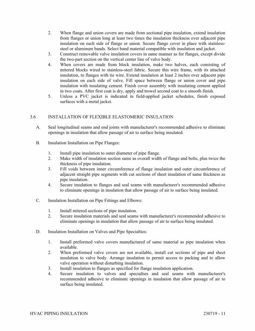
HVAC PIPING INSULATION 230719 - 11
2. When flange and union covers are made from sectional pipe insulation, extend insulation
from flanges or union long at least two times the insulation thickness over adjacent pipe
insulation on each side of flange or union. Secure flange cover in place with stainless-
steel or aluminum bands. Select band material compatible with insulation and jacket.
3. Construct removable valve insulation covers in same manner as for flanges, except divide
the two-part section on the vertical center line of valve body.
4. When covers are made from block insulation, make two halves, each consisting of
mitered blocks wired to stainless-steel fabric. Secure this wire frame, with its attached
insulation, to flanges with tie wire. Extend insulation at least 2 inches over adjacent pipe
insulation on each side of valve. Fill space between flange or union cover and pipe
insulation with insulating cement. Finish cover assembly with insulating cement applied
in two coats. After first coat is dry, apply and trowel second coat to a smooth finish.
5. Unless a PVC jacket is indicated in field-applied jacket schedules, finish exposed
surfaces with a metal jacket.
3.6 INSTALLATION OF FLEXIBLE ELASTOMERIC INSULATION
A. Seal longitudinal seams and end joints with manufacturer's recommended adhesive to eliminate
openings in insulation that allow passage of air to surface being insulated.
B. Insulation Installation on Pipe Flanges:
1. Install pipe insulation to outer diameter of pipe flange.
2. Make width of insulation section same as overall width of flange and bolts, plus twice the
thickness of pipe insulation.
3. Fill voids between inner circumference of flange insulation and outer circumference of
adjacent straight pipe segments with cut sections of sheet insulation of same thickness as
pipe insulation.
4. Secure insulation to flanges and seal seams with manufacturer's recommended adhesive
to eliminate openings in insulation that allow passage of air to surface being insulated.
C. Insulation Installation on Pipe Fittings and Elbows:
1. Install mitered sections of pipe insulation.
2. Secure insulation materials and seal seams with manufacturer's recommended adhesive to
eliminate openings in insulation that allow passage of air to surface being insulated.
D. Insulation Installation on Valves and Pipe Specialties:
1. Install preformed valve covers manufactured of same material as pipe insulation when
available.
2. When preformed valve covers are not available, install cut sections of pipe and sheet
insulation to valve body. Arrange insulation to permit access to packing and to allow
valve operation without disturbing insulation.
3. Install insulation to flanges as specified for flange insulation application.
4. Secure insulation to valves and specialties and seal seams with manufacturer's
recommended adhesive to eliminate openings in insulation that allow passage of air to
surface being insulated.
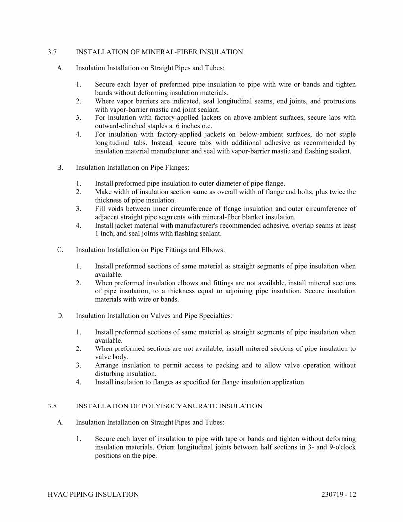
HVAC PIPING INSULATION 230719 - 12
3.7 INSTALLATION OF MINERAL-FIBER INSULATION
A. Insulation Installation on Straight Pipes and Tubes:
1. Secure each layer of preformed pipe insulation to pipe with wire or bands and tighten
bands without deforming insulation materials.
2. Where vapor barriers are indicated, seal longitudinal seams, end joints, and protrusions
with vapor-barrier mastic and joint sealant.
3. For insulation with factory-applied jackets on above-ambient surfaces, secure laps with
outward-clinched staples at 6 inches o.c.
4. For insulation with factory-applied jackets on below-ambient surfaces, do not staple
longitudinal tabs. Instead, secure tabs with additional adhesive as recommended by
insulation material manufacturer and seal with vapor-barrier mastic and flashing sealant.
B. Insulation Installation on Pipe Flanges:
1. Install preformed pipe insulation to outer diameter of pipe flange.
2. Make width of insulation section same as overall width of flange and bolts, plus twice the
thickness of pipe insulation.
3. Fill voids between inner circumference of flange insulation and outer circumference of
adjacent straight pipe segments with mineral-fiber blanket insulation.
4. Install jacket material with manufacturer's recommended adhesive, overlap seams at least
1 inch, and seal joints with flashing sealant.
C. Insulation Installation on Pipe Fittings and Elbows:
1. Install preformed sections of same material as straight segments of pipe insulation when
available.
2. When preformed insulation elbows and fittings are not available, install mitered sections
of pipe insulation, to a thickness equal to adjoining pipe insulation. Secure insulation
materials with wire or bands.
D. Insulation Installation on Valves and Pipe Specialties:
1. Install preformed sections of same material as straight segments of pipe insulation when
available.
2. When preformed sections are not available, install mitered sections of pipe insulation to
valve body.
3. Arrange insulation to permit access to packing and to allow valve operation without
disturbing insulation.
4. Install insulation to flanges as specified for flange insulation application.
3.8 INSTALLATION OF POLYISOCYANURATE INSULATION
A. Insulation Installation on Straight Pipes and Tubes:
1. Secure each layer of insulation to pipe with tape or bands and tighten without deforming
insulation materials. Orient longitudinal joints between half sections in 3- and 9-o'clock
positions on the pipe.
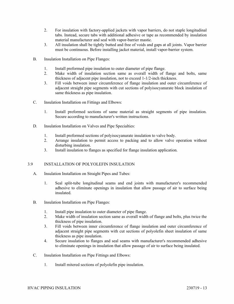
HVAC PIPING INSULATION 230719 - 13
2. For insulation with factory-applied jackets with vapor barriers, do not staple longitudinal
tabs. Instead, secure tabs with additional adhesive or tape as recommended by insulation
material manufacturer and seal with vapor-barrier mastic.
3. All insulation shall be tightly butted and free of voids and gaps at all joints. Vapor barrier
must be continuous. Before installing jacket material, install vapor-barrier system.
B. Insulation Installation on Pipe Flanges:
1. Install preformed pipe insulation to outer diameter of pipe flange.
2. Make width of insulation section same as overall width of flange and bolts, same
thickness of adjacent pipe insulation, not to exceed 1-1/2-inch thickness.
3. Fill voids between inner circumference of flange insulation and outer circumference of
adjacent straight pipe segments with cut sections of polyisocyanurate block insulation of
same thickness as pipe insulation.
C. Insulation Installation on Fittings and Elbows:
1. Install preformed sections of same material as straight segments of pipe insulation.
Secure according to manufacturer's written instructions.
D. Insulation Installation on Valves and Pipe Specialties:
1. Install preformed sections of polyisocyanurate insulation to valve body.
2. Arrange insulation to permit access to packing and to allow valve operation without
disturbing insulation.
3. Install insulation to flanges as specified for flange insulation application.
3.9 INSTALLATION OF POLYOLEFIN INSULATION
A. Insulation Installation on Straight Pipes and Tubes:
1. Seal split-tube longitudinal seams and end joints with manufacturer's recommended
adhesive to eliminate openings in insulation that allow passage of air to surface being
insulated.
B. Insulation Installation on Pipe Flanges:
1. Install pipe insulation to outer diameter of pipe flange.
2. Make width of insulation section same as overall width of flange and bolts, plus twice the
thickness of pipe insulation.
3. Fill voids between inner circumference of flange insulation and outer circumference of
adjacent straight pipe segments with cut sections of polyolefin sheet insulation of same
thickness as pipe insulation.
4. Secure insulation to flanges and seal seams with manufacturer's recommended adhesive
to eliminate openings in insulation that allow passage of air to surface being insulated.
C. Insulation Installation on Pipe Fittings and Elbows:
1. Install mitered sections of polyolefin pipe insulation.

HVAC PIPING INSULATION 230719 - 14
2. Secure insulation materials and seal seams with manufacturer's recommended adhesive to
eliminate openings in insulation that allow passage of air to surface being insulated.
D. Insulation Installation on Valves and Pipe Specialties:
1. Install cut sections of polyolefin pipe and sheet insulation to valve body.
2. Arrange insulation to permit access to packing and to allow valve operation without
disturbing insulation.
3. Install insulation to flanges as specified for flange insulation application.
4. Secure insulation to valves and specialties, and seal seams with manufacturer's
recommended adhesive to eliminate openings in insulation that allow passage of air to
surface being insulated.
3.10 FIELD-APPLIED JACKET INSTALLATION
A. Where glass-cloth jackets are indicated, install directly over bare insulation or insulation with
factory-applied jackets.
1. Draw jacket smooth and tight to surface with 2-inch overlap at seams and joints.
2. Embed glass cloth between two 0.062-inch-thick coats of lagging adhesive.
3. Completely encapsulate insulation with coating, leaving no exposed insulation.
B. Where FSK jackets are indicated, install as follows:
1. Draw jacket material smooth and tight.
2. Install lap or joint strips with same material as jacket.
3. Secure jacket to insulation with manufacturer's recommended adhesive.
4. Install jacket with 1-1/2-inch laps at longitudinal seams and 3-inch-wide joint strips at
end joints.
5. Seal openings, punctures, and breaks in vapor-retarder jackets and exposed insulation
with vapor-barrier mastic.
C. Where PVC jackets are indicated, install with 1-inch overlap at longitudinal seams and end
joints; for horizontal applications. Seal with manufacturer's recommended adhesive.
1. Apply two continuous beads of adhesive to seams and joints, one bead under lap and the
finish bead along seam and joint edge.
D. Where metal jackets are indicated, install with 2-inch overlap at longitudinal seams and end
joints. Overlap longitudinal seams arranged to shed water. Seal end joints with weatherproof
sealant recommended by insulation manufacturer. Secure jacket with stainless-steel bands 12
inches o.c. and at end joints.
3.11 FIELD QUALITY CONTROL
A. Perform tests and inspections.
B. Tests and Inspections:
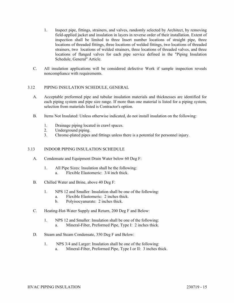
HVAC PIPING INSULATION 230719 - 15
1. Inspect pipe, fittings, strainers, and valves, randomly selected by Architect, by removing
field-applied jacket and insulation in layers in reverse order of their installation. Extent of
inspection shall be limited to three Insert number locations of straight pipe, three
locations of threaded fittings, three locations of welded fittings, two locations of threaded
strainers, two locations of welded strainers, three locations of threaded valves, and three
locations of flanged valves for each pipe service defined in the "Piping Insulation
Schedule, General" Article.
C. All insulation applications will be considered defective Work if sample inspection reveals
noncompliance with requirements.
3.12 PIPING INSULATION SCHEDULE, GENERAL
A. Acceptable preformed pipe and tubular insulation materials and thicknesses are identified for
each piping system and pipe size range. If more than one material is listed for a piping system,
selection from materials listed is Contractor's option.
B. Items Not Insulated: Unless otherwise indicated, do not install insulation on the following:
1. Drainage piping located in crawl spaces.
2. Underground piping.
3. Chrome-plated pipes and fittings unless there is a potential for personnel injury.
3.13 INDOOR PIPING INSULATION SCHEDULE
A. Condensate and Equipment Drain Water below 60 Deg F:
1. All Pipe Sizes: Insulation shall be the following:
a. Flexible Elastomeric: 3/4 inch thick.
B. Chilled Water and Brine, above 40 Deg F:
1. NPS 12 and Smaller: Insulation shall be one of the following:
a. Flexible Elastomeric: 2 inches thick.
b. Polyisocyanurate: 2 inches thick.
C. Heating-Hot-Water Supply and Return, 200 Deg F and Below:
1. NPS 12 and Smaller: Insulation shall be one of the following:
a. Mineral-Fiber, Preformed Pipe, Type I: 2 inches thick.
D. Steam and Steam Condensate, 350 Deg F and Below:
1. NPS 3/4 and Larger: Insulation shall be one of the following:
a. Mineral-Fiber, Preformed Pipe, Type I or II: 3 inches thick.
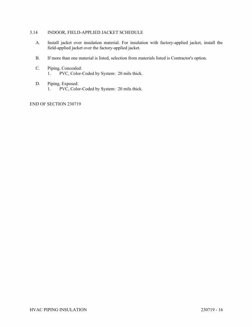
HVAC PIPING INSULATION 230719 - 16
3.14 INDOOR, FIELD-APPLIED JACKET SCHEDULE
A. Install jacket over insulation material. For insulation with factory-applied jacket, install the
field-applied jacket over the factory-applied jacket.
B. If more than one material is listed, selection from materials listed is Contractor's option.
C. Piping, Concealed:
1. PVC, Color-Coded by System: 20 mils thick.
D. Piping, Exposed:
1. PVC, Color-Coded by System: 20 mils thick.
END OF SECTION 230719
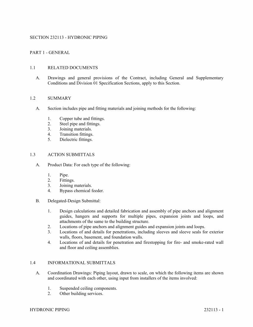
HYDRONIC PIPING 232113 - 1
SECTION 232113 - HYDRONIC PIPING
PART 1 - GENERAL
1.1 RELATED DOCUMENTS
A. Drawings and general provisions of the Contract, including General and Supplementary
Conditions and Division 01 Specification Sections, apply to this Section.
1.2 SUMMARY
A. Section includes pipe and fitting materials and joining methods for the following:
1. Copper tube and fittings.
2. Steel pipe and fittings.
3. Joining materials.
4. Transition fittings.
5. Dielectric fittings.
1.3 ACTION SUBMITTALS
A. Product Data: For each type of the following:
1. Pipe.
2. Fittings.
3. Joining materials.
4. Bypass chemical feeder.
B. Delegated-Design Submittal:
1. Design calculations and detailed fabrication and assembly of pipe anchors and alignment
guides, hangers and supports for multiple pipes, expansion joints and loops, and
attachments of the same to the building structure.
2. Locations of pipe anchors and alignment guides and expansion joints and loops.
3. Locations of and details for penetrations, including sleeves and sleeve seals for exterior
walls, floors, basement, and foundation walls.
4. Locations of and details for penetration and firestopping for fire- and smoke-rated wall
and floor and ceiling assemblies.
1.4 INFORMATIONAL SUBMITTALS
A. Coordination Drawings: Piping layout, drawn to scale, on which the following items are shown
and coordinated with each other, using input from installers of the items involved:
1. Suspended ceiling components.
2. Other building services.
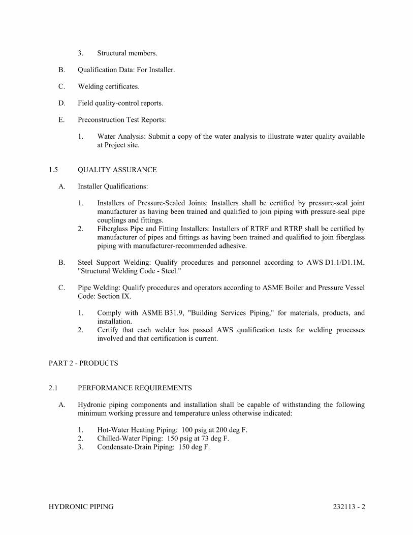
HYDRONIC PIPING 232113 - 2
3. Structural members.
B. Qualification Data: For Installer.
C. Welding certificates.
D. Field quality-control reports.
E. Preconstruction Test Reports:
1. Water Analysis: Submit a copy of the water analysis to illustrate water quality available
at Project site.
1.5 QUALITY ASSURANCE
A. Installer Qualifications:
1. Installers of Pressure-Sealed Joints: Installers shall be certified by pressure-seal joint
manufacturer as having been trained and qualified to join piping with pressure-seal pipe
couplings and fittings.
2. Fiberglass Pipe and Fitting Installers: Installers of RTRF and RTRP shall be certified by
manufacturer of pipes and fittings as having been trained and qualified to join fiberglass
piping with manufacturer-recommended adhesive.
B. Steel Support Welding: Qualify procedures and personnel according to AWS D1.1/D1.1M,
"Structural Welding Code - Steel."
C. Pipe Welding: Qualify procedures and operators according to ASME Boiler and Pressure Vessel
Code: Section IX.
1. Comply with ASME B31.9, "Building Services Piping," for materials, products, and
installation.
2. Certify that each welder has passed AWS qualification tests for welding processes
involved and that certification is current.
PART 2 - PRODUCTS
2.1 PERFORMANCE REQUIREMENTS
A. Hydronic piping components and installation shall be capable of withstanding the following
minimum working pressure and temperature unless otherwise indicated:
1. Hot-Water Heating Piping: 100 psig at 200 deg F.
2. Chilled-Water Piping: 150 psig at 73 deg F.
3. Condensate-Drain Piping: 150 deg F.
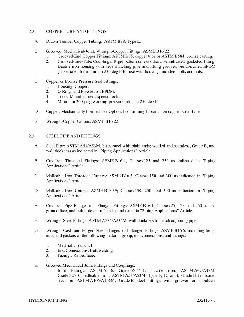
HYDRONIC PIPING 232113 - 3
2.2 COPPER TUBE AND FITTINGS
A. Drawn-Temper Copper Tubing: ASTM B88, Type L.
B. Grooved, Mechanical-Joint, Wrought-Copper Fittings: ASME B16.22.
1. Grooved-End Copper Fittings: ASTM B75, copper tube or ASTM B584, bronze casting.
2. Grooved-End-Tube Couplings: Rigid pattern unless otherwise indicated; gasketed fitting.
Ductile-iron housing with keys matching pipe and fitting grooves, prelubricated EPDM
gasket rated for minimum 230 deg F for use with housing, and steel bolts and nuts.
C. Copper or Bronze Pressure-Seal Fittings:
1. Housing: Copper.
2. O-Rings and Pipe Stops: EPDM.
3. Tools: Manufacturer's special tools.
4. Minimum 200-psig working-pressure rating at 250 deg F.
D. Copper, Mechanically Formed Tee Option: For forming T-branch on copper water tube.
E. Wrought-Copper Unions: ASME B16.22.
2.3 STEEL PIPE AND FITTINGS
A. Steel Pipe: ASTM A53/A53M, black steel with plain ends; welded and seamless, Grade B, and
wall thickness as indicated in "Piping Applications" Article.
B. Cast-Iron Threaded Fittings: ASME B16.4; Classes 125 and 250 as indicated in "Piping
Applications" Article.
C. Malleable-Iron Threaded Fittings: ASME B16.3, Classes 150 and 300 as indicated in "Piping
Applications" Article.
D. Malleable-Iron Unions: ASME B16.39; Classes 150, 250, and 300 as indicated in "Piping
Applications" Article.
E. Cast-Iron Pipe Flanges and Flanged Fittings: ASME B16.1, Classes 25, 125, and 250; raised
ground face, and bolt holes spot faced as indicated in "Piping Applications" Article.
F. Wrought-Steel Fittings: ASTM A234/A234M, wall thickness to match adjoining pipe.
G. Wrought Cast- and Forged-Steel Flanges and Flanged Fittings: ASME B16.5, including bolts,
nuts, and gaskets of the following material group, end connections, and facings:
1. Material Group: 1.1.
2. End Connections: Butt welding.
3. Facings: Raised face.
H. Grooved Mechanical-Joint Fittings and Couplings:
1. Joint Fittings: ASTM A536, Grade 65-45-12 ductile iron; ASTM A47/A47M,
Grade 32510 malleable iron; ASTM A53/A53M, Type F, E, or S, Grade B fabricated
steel; or ASTM A106/A106M, Grade B steel fittings with grooves or shoulders
HYDRONIC PIPING 232113 - 4
constructed to accept grooved-end couplings; with nuts, bolts, locking pin, locking
toggle, or lugs to secure grooved pipe and fittings.
2. Couplings: Ductile- or malleable-iron housing and EPDM gasket of central cavity
pressure-responsive design; with nuts, bolts, locking pin, locking toggle, or lugs to secure
grooved pipe and fittings.
I. Steel Pipe Nipples: ASTM A733, made of same materials and wall thicknesses as pipe in which
they are installed.
2.4 JOINING MATERIALS
A. Pipe-Flange Gasket Materials: Suitable for chemical and thermal conditions of piping system
contents.
1. ASME B16.21, nonmetallic, flat, asbestos free, 1/8-inch maximum thickness unless
otherwise indicated.
a. Full-Face Type: For flat-face, Class 125, cast-iron and cast-bronze flanges.
b. Narrow-Face Type: For raised-face, Class 250, cast-iron and steel flanges.
B. Flange Bolts and Nuts: ASME B18.2.1, carbon steel, unless otherwise indicated.
C. Plastic, Pipe-Flange Gasket, Bolts, and Nuts: Type and material recommended by piping system
manufacturer unless otherwise indicated.
D. Solder Filler Metals: ASTM B32, lead-free alloys. Include water-flushable flux according to
ASTM B813.
E. Brazing Filler Metals: AWS A5.8/A5.8M, BCuP Series, copper-phosphorus alloys for joining
copper with copper; or BAg-1, silver alloy for joining copper with bronze or steel.
F. Welding Filler Metals: Comply with AWS D10.12M/D10.12 for welding materials appropriate
for wall thickness and chemical analysis of steel pipe being welded.
2.5 DIELECTRIC FITTINGS
A. General Requirements: Assembly of copper alloy and ferrous materials with separating
nonconductive insulating material. Include end connections compatible with pipes to be joined.
B. Dielectric Unions:
1. Description:
a. Standard: ASSE 1079.
b. Pressure Rating: 125 psig minimum at 180 deg F.
c. End Connections: Solder-joint copper alloy and threaded ferrous.
C. Dielectric Flanges:
1. Description:
a. Standard: ASSE 1079.
HYDRONIC PIPING 232113 - 5
b. Factory-fabricated, bolted, companion-flange assembly.
c. Pressure Rating: 125 psig minimum at 180 deg F.
d. End Connections: Solder-joint copper alloy and threaded ferrous; threaded solder-
joint copper alloy and threaded ferrous.
D. Dielectric-Flange Insulating Kits:
1. Description:
a. Nonconducting materials for field assembly of companion flanges.
b. Pressure Rating: 150 psig.
c. Gasket: Neoprene or phenolic.
d. Bolt Sleeves: Phenolic or polyethylene.
e. Washers: Phenolic with steel backing washers.
E. Dielectric Nipples:
1. Description:
a. Standard: IAPMO PS 66.
b. Electroplated steel nipple, complying with ASTM F1545.
c. Pressure Rating: 300 psig at 225 deg F.
d. End Connections: Male threaded or grooved.
e. Lining: Inert and noncorrosive, propylene.
PART 3 - EXECUTION
3.1 PIPING APPLICATIONS
A. Hot-water heating piping, aboveground, NPS 2 and smaller, shall be any of the following:
1. Type L, drawn-temper copper tubing, wrought-copper fittings, and brazed joints.
2. Schedule 40, Grade B steel pipe; Class 125, cast-iron fittings; cast-iron flanges and flange
fittings; and threaded joints.
B. Hot-water heating piping, aboveground, NPS 2-1/2 and larger, shall be the following:
1. Schedule 40 steel pipe, wrought-steel fittings and wrought-cast or forged-steel flanges
and flange fittings, and welded and flanged joints.
2. Schedule 40 steel pipe; grooved, mechanical joint coupling and fittings; and grooved,
mechanical joints.
C. Chilled-water piping, aboveground, NPS 2 and smaller, shall be any the following:
1. Type L, drawn-temper copper tubing, wrought-copper fittings, and brazed joints.
2. Schedule 40, Grade B steel pipe; Class 125, cast-iron fittings; cast-iron flanges and flange
fittings; and threaded joints.
D. Chilled-water piping, aboveground, NPS 2-1/2 and larger, shall be any of the following:
1. Schedule 40 steel pipe, wrought-steel fittings and wrought-cast or forged-steel flanges
and flange fittings, and welded and flanged joints.
HYDRONIC PIPING 232113 - 6
2. Schedule 40 steel pipe; grooved, mechanical joint coupling and fittings; and grooved,
mechanical joints.
E. Condensate-Drain Piping: Type L, drawn-temper copper tubing, wrought-copper fittings, and
soldered joints.
3.2 PIPING INSTALLATIONS
A. Drawing plans, schematics, and diagrams indicate general location and arrangement of piping
systems. Install piping as indicated unless deviations to layout are approved on Coordination
Drawings.
B. Install piping in concealed locations unless otherwise indicated and except in equipment rooms
and service areas.
C. Install piping indicated to be exposed and piping in equipment rooms and service areas at right
angles or parallel to building walls. Diagonal runs are prohibited unless specifically indicated
otherwise.
D. Install piping above accessible ceilings to allow sufficient space for ceiling panel removal.
E. Install piping to permit valve servicing.
F. Install piping at indicated slopes.
G. Install piping free of sags and bends.
H. Install fittings for changes in direction and branch connections.
I. Install piping to allow application of insulation.
J. Select system components with pressure rating equal to or greater than system operating
pressure.
K. Install groups of pipes parallel to each other, spaced to permit applying insulation and servicing
of valves.
L. Install drains, consisting of a tee fitting, NPS 3/4 ball valve, and short NPS 3/4 threaded nipple
with cap, at low points in piping system mains and elsewhere as required for system drainage.
M. Install piping at a uniform grade of 0.2 percent upward in direction of flow.
N. Reduce pipe sizes using eccentric reducer fitting installed with level side up.
O. Install branch connections to mains using mechanically formed tee fittings in main pipe, with
the branch connected to the bottom of the main pipe. For up-feed risers, connect the branch to
the top of the main pipe.
P. Install valves according to the following:
1. Section 230523.12 "Ball Valves for HVAC Piping."
2. Section 230523.13 "Butterfly Valves for HVAC Piping."
HYDRONIC PIPING 232113 - 7
3. Section 230523.14 "Check Valves for HVAC Piping."
Q. Install unions in piping, NPS 2 and smaller, adjacent to valves, at final connections of
equipment, and elsewhere as indicated.
R. Install flanges in piping, NPS 2-1/2 and larger, at final connections of equipment and elsewhere
as indicated.
S. Install shutoff valve immediately upstream of each dielectric fitting.
T. Comply with requirements in Section 230553 "Identification for HVAC Piping and Equipment"
for identifying piping.
U. Install sleeves for piping penetrations of walls, ceilings, and floors. Comply with requirements
for sleeves specified in Section 230517 "Sleeves and Sleeve Seals for HVAC Piping."
V. Install sleeve seals for piping penetrations of concrete walls and slabs. Comply with
requirements for sleeve seals specified in Section 230517 "Sleeves and Sleeve Seals for HVAC
Piping."
3.3 DIELECTRIC FITTING INSTALLATION
A. Install dielectric fittings in piping at connections of dissimilar metal piping and tubing.
B. Dielectric Fittings for NPS 2 and Smaller: Use dielectric unions.
C. Dielectric Fittings for NPS 2-1/2 to NPS 4: Use dielectric flange kits.
D. Dielectric Fittings for NPS 5 and Larger: Use dielectric flange kits.
3.4 HANGERS AND SUPPORTS
A. Comply with requirements in Section 230529 "Hangers and Supports for HVAC Piping and
Equipment" for hanger, support, and anchor devices. Comply with the following requirements
for maximum spacing of supports.
B. Install the following pipe attachments:
1. Adjustable steel clevis hangers for individual horizontal piping less than 20 feet long.
2. Adjustable roller hangers and spring hangers for individual horizontal piping 20 feet or
longer.
3. Pipe Roller: MSS SP-58, Type 44 for multiple horizontal piping 20 feet or longer,
supported on a trapeze.
4. Spring hangers to support vertical runs.
5. Provide copper-clad hangers and supports for hangers and supports in direct contact with
copper pipe.
6. On plastic pipe, install pads or cushions on bearing surfaces to prevent hanger from
scratching pipe.
C. Install hangers for steel piping with the following maximum spacing and minimum rod sizes:
HYDRONIC PIPING 232113 - 8
1. NPS 3/4: Maximum span, 7 feet.
2. NPS 1: Maximum span, 7 feet.
3. NPS 1-1/2: Maximum span, 9 feet.
4. NPS 2: Maximum span, 10 feet.
5. NPS 2-1/2: Maximum span, 11 feet.
6. NPS 3 and Larger: Maximum span, 12 feet.
D. Install hangers for drawn-temper copper piping with the following maximum spacing and
minimum rod sizes:
1. NPS 3/4: Maximum span, 5 feet; minimum rod size, 1/4 inch.
2. NPS 1: Maximum span, 6 feet; minimum rod size, 1/4 inch.
3. NPS 1-1/4: Maximum span, 7 feet; minimum rod size, 3/8 inch.
4. NPS 1-1/2: Maximum span, 8 feet; minimum rod size, 3/8 inch.
5. NPS 2: Maximum span, 8 feet; minimum rod size, 3/8 inch.
6. NPS 2-1/2: Maximum span, 9 feet; minimum rod size, 3/8 inch.
7. NPS 3 and Larger: Maximum span, 10 feet; minimum rod size, 3/8 inch.
E. Support vertical runs at roof, at each floor, and at 10-foot intervals between floors.
3.5 PIPE JOINT CONSTRUCTION
A. Ream ends of pipes and tubes and remove burrs. Bevel plain ends of steel pipe.
B. Remove scale, slag, dirt, and debris from inside and outside of pipe and fittings before
assembly.
C. Soldered Joints: Apply ASTM B813, water-flushable flux, unless otherwise indicated, to tube
end. Construct joints according to ASTM B828 or CDA's "Copper Tube Handbook," using
lead-free solder alloy complying with ASTM B32.
D. Brazed Joints: Construct joints according to AWS's "Brazing Handbook," "Pipe and Tube"
Chapter, using copper-phosphorus brazing filler metal complying with AWS A5.8/A5.8M.
E. Threaded Joints: Thread pipe with tapered pipe threads according to ASME B1.20.1. Cut
threads full and clean using sharp dies. Ream threaded pipe ends to remove burrs and restore
full ID. Join pipe fittings and valves as follows:
1. Apply appropriate tape or thread compound to external pipe threads unless dry seal
threading is specified.
2. Damaged Threads: Do not use pipe or pipe fittings with threads that are corroded or
damaged. Do not use pipe sections that have cracked or open welds.
F. Welded Joints: Construct joints according to AWS D10.12M/D10.12, using qualified processes
and welding operators according to "Quality Assurance" Article.
G. Flanged Joints: Select appropriate gasket material, size, type, and thickness for service
application. Install gasket concentrically positioned. Use suitable lubricants on bolt threads.
HYDRONIC PIPING 232113 - 9
H. Plastic Piping Solvent-Cemented Joints: Clean and dry joining surfaces. Join pipe and fittings
according to the following:
1. Comply with ASTM F402 for safe-handling practice of cleaners, primers, and solvent
cements.
2. CPVC Piping: Join according to ASTM D2846/D2846M Appendix.
3. PVC Pressure Piping: Join ASTM D1785 schedule number, PVC pipe and PVC socket
fittings according to ASTM D2672. Join other-than-schedule number PVC pipe and
socket fittings according to ASTM D2855.
4. PVC Nonpressure Piping: Join according to ASTM D2855.
I. Fiberglass Bonded Joints: Prepare pipe ends and fittings, apply adhesive, and join according to
pipe manufacturer's written instructions.
J. Grooved Joints: Assemble joints with coupling and gasket, lubricant, and bolts. Cut or roll
grooves in ends of pipe based on pipe and coupling manufacturer's written instructions for pipe
wall thickness. Use grooved-end fittings and rigid, grooved-end-pipe couplings.
K. Plain-End Mechanical-Coupled Joints: Prepare, assemble, and test joints in accordance with
manufacturer's written installation instructions.
L. Mechanically Formed, Copper-Tube-Outlet Joints: Use manufacturer-recommended tool and
procedure, and brazed joints.
M. Pressure-Sealed Joints: Use manufacturer-recommended tool and procedure. Leave insertion
marks on pipe after assembly.
3.6 TERMINAL EQUIPMENT CONNECTIONS
A. Sizes for supply and return piping connections shall be the same as or larger than equipment
connections.
B. Install control valves in accessible locations close to connected equipment.
C. Install bypass piping with globe valve around control valve. If parallel control valves are
installed, only one bypass is required.
D. Install ports for pressure gages and thermometers at coil inlet and outlet connections. Comply
with requirements in Section 230519 "Meters and Gages for HVAC Piping."
3.7 FIELD QUALITY CONTROL
A. Prepare hydronic piping according to ASME B31.9 and as follows:
1. Leave joints, including welds, uninsulated and exposed for examination during test.
2. Provide temporary restraints for expansion joints that cannot sustain reactions due to test
pressure. If temporary restraints are impractical, isolate expansion joints from testing.
3. Flush hydronic piping systems with clean water; then remove and clean or replace
strainer screens.
HYDRONIC PIPING 232113 - 10
4. Isolate equipment from piping. If a valve is used to isolate equipment, its closure shall be
capable of sealing against test pressure without damage to valve. Install blinds in flanged
joints to isolate equipment.
5. Install safety valve, set at a pressure no more than one-third higher than test pressure, to
protect against damage by expanding liquid or other source of overpressure during test.
B. Perform the following tests on hydronic piping:
1. Use ambient temperature water as a testing medium unless there is risk of damage due to
freezing. Another liquid that is safe for workers and compatible with piping may be used.
2. While filling system, use vents installed at high points of system to release air. Use drains
installed at low points for complete draining of test liquid.
3. Isolate expansion tanks and determine that hydronic system is full of water.
4. Subject piping system to hydrostatic test pressure that is not less than 1.5 times the
system's working pressure. Test pressure shall not exceed maximum pressure for any
vessel, pump, valve, or other component in system under test. Verify that stress due to
pressure at bottom of vertical runs does not exceed 90 percent of specified minimum
yield strength or 1.7 times the "SE" value in Appendix A in ASME B31.9, "Building
Services Piping."
5. After hydrostatic test pressure has been applied for at least 10 minutes, examine piping,
joints, and connections for leakage. Eliminate leaks by tightening, repairing, or replacing
components, and repeat hydrostatic test until there are no leaks.
6. Prepare written report of testing.
C. Perform the following before operating the system:
1. Open manual valves fully.
2. Inspect pumps for proper rotation.
3. Set makeup pressure-reducing valves for required system pressure.
4. Inspect air vents at high points of system and determine if all are installed and operating
freely (automatic type), or bleed air completely (manual type).
5. Set temperature controls so all coils are calling for full flow.
6. Inspect and set operating temperatures of hydronic equipment, such as boilers, chillers,
cooling towers, to specified values.
7. Verify lubrication of motors and bearings.
END OF SECTION 232113
HYDRONIC PIPING SPECIALTIES 232116 - 1
SECTION 232116 - HYDRONIC PIPING SPECIALTIES
PART 1 - GENERAL
1.1 RELATED DOCUMENTS
A. Drawings and general provisions of the Contract, including General and Supplementary
Conditions and Division 01 Specification Sections, apply to this Section.
1.2 SUMMARY
A. Section Includes:
1. Hydronic specialty valves.
2. Air-control devices.
3. Strainers.
4. Connectors.
B. Related Requirements:
1. Section 230523.12 "Ball Valves for HVAC Piping" for specification and installation
requirements for ball valves common to most piping systems.
2. Section 230523.13 "Butterfly Valves for HVAC Piping" for specification and installation
requirements for butterfly valves common to most piping systems.
3. Section 230523.14 "Check Valves for HVAC Piping" for specification and installation
requirements for check valves common to most piping systems.
1.3 ACTION SUBMITTALS
A. Product Data: For each type of product:
1. Include construction details and material descriptions for hydronic piping specialties.
2. Include rated capacities, operating characteristics, and furnished specialties and
accessories.
3. Include flow and pressure drop curves based on manufacturer's testing for calibrated-
orifice balancing valves and automatic flow-control valves.
1.4 CLOSEOUT SUBMITTALS
A. Operation and Maintenance Data: For hydronic piping specialties to include in emergency,
operation, and maintenance manuals.
1.5 MAINTENANCE MATERIAL SUBMITTALS
A. Differential Pressure Meter: For each type of balancing valve and automatic flow control valve,
include flowmeter, probes, hoses, flow charts, and carrying case.
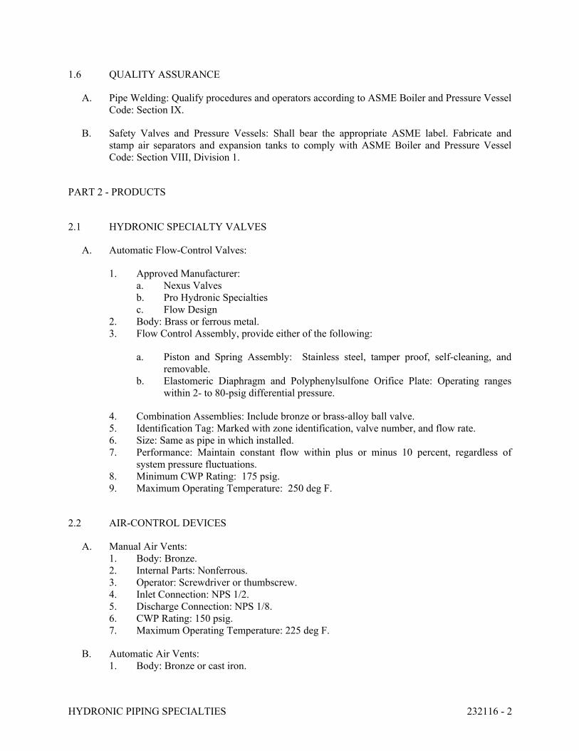
HYDRONIC PIPING SPECIALTIES 232116 - 2
1.6 QUALITY ASSURANCE
A. Pipe Welding: Qualify procedures and operators according to ASME Boiler and Pressure Vessel
Code: Section IX.
B. Safety Valves and Pressure Vessels: Shall bear the appropriate ASME label. Fabricate and
stamp air separators and expansion tanks to comply with ASME Boiler and Pressure Vessel
Code: Section VIII, Division 1.
PART 2 - PRODUCTS
2.1 HYDRONIC SPECIALTY VALVES
A. Automatic Flow-Control Valves:
1. Approved Manufacturer:
a. Nexus Valves
b. Pro Hydronic Specialties
c. Flow Design
2. Body: Brass or ferrous metal.
3. Flow Control Assembly, provide either of the following:
a. Piston and Spring Assembly: Stainless steel, tamper proof, self-cleaning, and
removable.
b. Elastomeric Diaphragm and Polyphenylsulfone Orifice Plate: Operating ranges
within 2- to 80-psig differential pressure.
4. Combination Assemblies: Include bronze or brass-alloy ball valve.
5. Identification Tag: Marked with zone identification, valve number, and flow rate.
6. Size: Same as pipe in which installed.
7. Performance: Maintain constant flow within plus or minus 10 percent, regardless of
system pressure fluctuations.
8. Minimum CWP Rating: 175 psig.
9. Maximum Operating Temperature: 250 deg F.
2.2 AIR-CONTROL DEVICES
A. Manual Air Vents:
1. Body: Bronze.
2. Internal Parts: Nonferrous.
3. Operator: Screwdriver or thumbscrew.
4. Inlet Connection: NPS 1/2.
5. Discharge Connection: NPS 1/8.
6. CWP Rating: 150 psig.
7. Maximum Operating Temperature: 225 deg F.
B. Automatic Air Vents:
1. Body: Bronze or cast iron.

HYDRONIC PIPING SPECIALTIES 232116 - 3
2. Internal Parts: Nonferrous.
3. Operator: Noncorrosive metal float.
4. Inlet Connection: NPS 1/2.
5. Discharge Connection: NPS 1/4.
6. CWP Rating: 150 psig.
7. Maximum Operating Temperature: 240 deg F.
2.3 STRAINERS
A. Y-Pattern Strainers:
1. Body: ASTM A126, Class B, cast iron with bolted cover and bottom drain connection.
2. End Connections: Threaded ends for NPS 2 and smaller; flanged ends for NPS 2-1/2 and
larger.
3. Strainer Screen: Stainless-steel, 60-mesh strainer, or perforated stainless-steel basket.
4. CWP Rating: 125 psig.
2.4 CONNECTORS
A. Stainless-Steel Bellow, Flexible Connectors:
1. Body: Stainless-steel bellows with woven, flexible, bronze, wire-reinforcing protective
jacket.
2. End Connections: Threaded or flanged to match equipment connected.
3. Performance: Capable of 3/4-inch misalignment.
4. CWP Rating: 150 psig.
5. Maximum Operating Temperature: 250 deg F.
B. Spherical, Rubber, Flexible Connectors:
1. Body: Fiber-reinforced rubber body.
2. End Connections: Steel flanges drilled to align with Classes 150 and 300 steel flanges.
3. Performance: Capable of misalignment.
4. CWP Rating: 150 psig.
5. Maximum Operating Temperature: 250 deg F.
PART 3 - EXECUTION
3.1 VALVE APPLICATIONS
A. Install shutoff-duty valves at each branch connection to supply mains and at supply connection
to each piece of equipment.
B. Install automatic, balancing valves in the return pipe of each heating or cooling terminal.

HYDRONIC PIPING SPECIALTIES 232116 - 4
3.2 HYDRONIC SPECIALTIES INSTALLATION
A. Install manual air vents at high points in piping, at heat-transfer coils, and elsewhere as required
for system air venting.
B. Install automatic air vents at high points of system piping in mechanical equipment rooms only.
Install manual vents at heat-transfer coils and elsewhere as required for air venting.
END OF SECTION 232116

STEAM AND CONDENSATE HEATING PIPING 232213 - 1
SECTION 232213 - STEAM AND CONDENSATE HEATING PIPING
PART 1 - GENERAL
1.1 RELATED DOCUMENTS
A. Drawings and general provisions of the Contract, including General and Supplementary
Conditions and Division 01 Specification Sections, apply to this Section.
1.2 SUMMARY
A. Section includes pipe and fittings for LP steam and condensate piping:
1. Steel pipe and fittings.
2. Fiberglass pipe and fittings.
3. Joining materials.
B. Related Requirements:
1. Section 232216 "Steam and Condensate Heating Piping Specialties" for strainers, flash
tanks, special-duty valves, steam traps, thermostatic air vents and vacuum breakers, and
steam and condensate meters.
1.3 ACTION SUBMITTALS
A. Product Data: For each type of the following:
1. Steel pipe and fitting.
2. Fiberglass pipe and fitting.
3. Joining material.
B. Delegated-Design Submittal:
1. Design calculations and detailed fabrication and assembly of pipe anchors and alignment
guides, hangers and supports for multiple pipes, expansion joints and loops, and
attachments of the same to the building structure.
2. Locations of pipe anchors and alignment guides and expansion joints and loops.
3. Locations of and details for penetrations, including sleeves and sleeve seals for exterior
walls, floors, basement, and foundation walls.
4. Locations of and details for penetration and firestopping for fire- and smoke-rated wall
and floor and ceiling assemblies.
1.4 INFORMATIONAL SUBMITTALS
A. Coordination Drawings: Piping layout, drawn to scale, on which the following items are shown
and coordinated with each other, using input from installers of the items involved:

STEAM AND CONDENSATE HEATING PIPING 232213 - 2
1. Suspended ceiling components.
2. Other building services.
3. Structural members.
B. Qualification Data: For Installer.
C. Welding certificates.
D. Field quality-control reports.
1.5 QUALITY ASSURANCE
A. Installer Qualifications:
1. Fiberglass Pipe and Fitting Installers: Installers of fiberglass pipe and fittings shall be
certified by the manufacturer of pipes and fittings as having been trained and qualified to
join fiberglass piping with manufacturer-recommended adhesive.
B. Steel Support Welding: Qualify procedures and personnel according to AWS D1.1/D1.1M,
"Structural Welding Code - Steel."
C. Pipe Welding: Qualify procedures and operators according to the following:
1. ASME Compliance: Comply with ASME B31.9, "Building Services Piping," for
materials, products, and installation.
2. Certify that each welder has passed AWS qualification tests for welding processes
involved and that certification is current.
PART 2 - PRODUCTS
2.1 PERFORMANCE REQUIREMENTS
A. Components and installation shall be capable of withstanding the following minimum working
pressures and temperatures unless otherwise indicated:
1. LP Steam Piping: 125 psig.
2. Condensate Piping: 30 psig at 250 deg F.
3. Air-Vent and Vacuum-Breaker Piping: Equal to pressure of the piping system to which it
is attached.
2.2 STEEL PIPE AND FITTINGS
A. Steel Pipe: ASTM A53/A53M, black steel, plain ends, welded and seamless, Grade B, and
Schedule as indicated in piping applications articles.
B. Cast-Iron Threaded Fittings: ASME B16.4; Classes 125, 150, and 300 as indicated in piping
applications articles.

STEAM AND CONDENSATE HEATING PIPING 232213 - 3
C. Malleable-Iron Threaded Fittings: ASME B16.3; Classes 150 and 300 as indicated in piping
applications articles.
D. Malleable-Iron Unions: ASME B16.39; Classes 150, 250, and 300 as indicated in piping
applications articles.
E. Cast-Iron Threaded Flanges and Flanged Fittings: ASME B16.1, Classes 125 and 250 as
indicated in piping applications articles; raised ground face, and bolt holes spot faced.
F. Wrought-Steel Fittings: ASTM A234/A234M, wall thickness to match adjoining pipe.
G. Wrought-Steel Flanges and Flanged Fittings: ASME B16.5, including bolts, nuts, and gaskets of
the following material group, end connections, and facings:
1. Material Group: 1.1.
2. End Connections: Butt welding.
3. Facings: Raised face.
H. Steel Pipe Nipples: ASTM A733, made of ASTM A53/A53M, black steel of same Type, Grade,
and Schedule as pipe in which installed.
2.3 JOINING MATERIALS
A. Pipe-Flange Gasket Materials: Suitable for chemical and thermal conditions of piping system
contents.
1. ASME B16.21, nonmetallic, flat, asbestos free, 1/8-inch maximum thickness unless
otherwise indicated.
a. Full-Face Type: For flat-face, Class 125, cast-iron and cast-bronze flanges.
b. Narrow-Face Type: For raised-face, Class 250, cast-iron and steel flanges.
B. Flange Bolts and Nuts: ASME B18.2.1, carbon steel, unless otherwise indicated.
C. Welding Filler Metals: Comply with AWS D10.12M/D10.12 for welding materials appropriate
for wall thickness and chemical analysis of steel pipe being welded.
D. Welding Materials: Comply with Section II, Part C, of ASME Boiler and Pressure Vessel Code
for welding materials appropriate for wall thickness and for chemical analysis of pipe being
welded.
PART 3 - EXECUTION
3.1 LP STEAM PIPING APPLICATIONS
A. LP Steam Piping, NPS 2 and Smaller: Schedule 40, Type S, Grade B, steel pipe; Class 125
cast-iron fittings; and threaded joints.
STEAM AND CONDENSATE HEATING PIPING 232213 - 4
B. LP Steam Piping, NPS 2-1/2 through NPS 12: Schedule 40, Type E, Grade B, steel pipe;
Class 150 wrought-steel fittings, flanges, and flange fittings; and welded and flanged joints.
C. Condensate piping above grade, NPS 2 and smaller, shall be the following:
1. Schedule 80, Type S, Grade B, steel pipe; Class 125 cast-iron fittings; and threaded
joints.
D. Condensate piping above grade, NPS 2-1/2 and larger, shall be the following:
1. Schedule 80, Type E, Grade B, steel pipe; Class 150 wrought-steel fittings, flanges, and
flange fittings; and welded and flanged joints.
3.2 ANCILLARY PIPING APPLICATIONS
A. Blowdown-Drain Piping: Same materials and joining methods as for piping specified for the
service in which blowdown drain is installed.
B. Vacuum-Breaker Piping: Outlet, same as service where installed.
C. Safety-Valve-Inlet and -Outlet Piping: Same materials and joining methods as for piping
specified for the service in which safety valve is installed.
3.3 PIPING INSTALLATION
A. Drawing plans, schematics, and diagrams indicate general location and arrangement of piping
systems. Install piping as indicated unless deviations to layout are approved on Coordination
Drawings.
B. Install piping in concealed locations unless otherwise indicated and except in equipment rooms
and service areas.
C. Install piping indicated to be exposed and piping in equipment rooms and service areas at right
angles or parallel to building walls. Diagonal runs are prohibited unless otherwise indicated.
D. Install piping above accessible ceilings to allow sufficient space for ceiling panel removal.
E. Install piping to permit valve servicing.
F. Install piping free of sags and bends.
G. Install fittings for changes in direction and branch connections.
H. Install piping to allow application of insulation.
I. Select system components with pressure rating equal to or greater than system operating
pressure.
J. Install groups of pipes parallel to each other, spaced to permit applying insulation and servicing
of valves.
STEAM AND CONDENSATE HEATING PIPING 232213 - 5
K. Install drains, consisting of a tee fitting, NPS 3/4 full port-ball valve, and short NPS 3/4
threaded nipple with cap, at low points in piping system mains and elsewhere as required for
system drainage.
L. Install steam supply piping at a minimum uniform grade of 0.2 percent downward in direction
of steam flow.
M. Install condensate return piping at a minimum uniform grade of 0.4 percent downward in
direction of condensate flow.
N. Reduce pipe sizes using eccentric reducer fitting installed with level side down.
O. Install branch connections to mains using mechanically formed tee fittings in main pipe, with
the branch connected to top of main pipe.
P. Install valves according to the following Sections or other Sections as needed:
1. Section 230523.12 "Ball Valves for HVAC Piping."
2. Section 230523.13 "Butterfly Valves for HVAC Piping."
3. Section 230523.14 "Check Valves for HVAC Piping."
Q. Install unions in piping, NPS 2 and smaller, adjacent to valves, at final connections of
equipment, and elsewhere as indicated.
R. Install flanges in piping, NPS 2-1/2 and larger, at final connections of equipment and elsewhere
as indicated.
S. Install shutoff valve immediately upstream of each dielectric fitting.
T. Install strainers on supply side of control valves, pressure-reducing valves, traps, and elsewhere
as indicated. Install NPS 3/4 nipple and full port ball valve in blowdown connection of strainers
NPS 2 and larger. Match size of strainer blowoff connection for strainers smaller than NPS 2.
U. Comply with requirements in Section 230553 "Identification for HVAC Piping and Equipment"
for identifying piping.
V. Install drip legs at low points and natural drainage points such as ends of mains, bottoms of
risers, and ahead of pressure regulators, and control valves.
1. On straight runs with no natural drainage points, install drip legs at intervals not
exceeding 300 feet.
2. Size drip legs same size as main. In steam mains NPS 6 and larger, drip leg size can be
reduced, but to no less than NPS 4.
W. Install sleeves for piping penetrations of walls, ceilings, and floors. Comply with requirements
for sleeves specified in Section 230517 "Sleeves and Sleeve Seals for HVAC Piping."
X. Install sleeve seals for piping penetrations of concrete walls and slabs. Comply with
requirements for sleeve seals specified in Section 230517 "Sleeves and Sleeve Seals for HVAC
Piping."
STEAM AND CONDENSATE HEATING PIPING 232213 - 6
3.4 STEAM AND CONDENSATE PIPING SPECIALTIES INSTALLATION
A. Comply with requirements in Section 232216 "Steam and Condensate Heating Piping
Specialties" for installation requirements for strainers, flash tanks, special-duty valves, steam
traps, thermostatic air vents and vacuum breakers, and steam and condensate meters.
3.5 HANGERS AND SUPPORTS
A. Comply with requirements in Section 230529 "Hangers and Supports for HVAC Piping and
Equipment" for installation of hangers and supports. Comply with requirements below for
maximum spacing.
B. Install the following pipe attachments:
1. Adjustable steel clevis hangers for individual horizontal piping less than 20 feet long.
2. Adjustable roller hangers and spring hangers for individual horizontal piping 20 feet or
longer.
3. Pipe Roller: MSS SP-58, Type 44 for multiple horizontal piping 20 feet or longer,
supported on a trapeze.
4. Spring hangers to support vertical runs.
C. Install hangers for steel steam supply piping with the following maximum spacing:
1. NPS 3/4: Maximum span, 9 feet.
2. NPS 1: Maximum span, 9 feet.
3. NPS 1-1/2: Maximum span, 12 feet.
4. NPS 2: Maximum span, 13 feet.
5. NPS 2-1/2: Maximum span, 14 feet.
6. NPS 3 and Larger: Maximum span, 15 feet.
D. Install hangers for steel steam condensate piping with the following maximum spacing:
1. NPS 3/4: Maximum span, 7 feet.
2. NPS 1: Maximum span, 7 feet.
3. NPS 1-1/2: Maximum span, 9 feet.
4. NPS 2: Maximum span, 10 feet.
5. NPS 2-1/2: Maximum span, 11 feet.
6. NPS 3 and Larger: Maximum span, 12 feet
E. Support vertical runs at roof, at each floor, and at 10-foot intervals between floors.
3.6 PIPE JOINT CONSTRUCTION
A. Ream ends of pipes and remove burrs. Bevel plain ends of steel pipe.
B. Remove scale, slag, dirt, and debris from inside and outside of pipe and fittings before
assembly.
STEAM AND CONDENSATE HEATING PIPING 232213 - 7
C. Threaded Joints: Thread pipe with tapered pipe threads according to ASME B1.20.1. Cut
threads full and clean using sharp dies. Ream threaded pipe ends to remove burrs and restore
full ID. Join pipe fittings and valves as follows:
1. Apply appropriate tape or thread compound to external pipe threads unless dry seal
threading is specified.
2. Damaged Threads: Do not use pipe or pipe fittings with threads that are corroded or
damaged. Do not use pipe sections that have cracked or open welds.
D. Welded Joints: Construct joints according to AWS D10.12M/D10.12, using qualified processes
and welding operators according to "Quality Assurance" Article.
E. Flanged Joints: Select appropriate gasket material, size, type, and thickness for service
application. Install gasket concentrically positioned. Use suitable lubricants on bolt threads.
3.7 TERMINAL EQUIPMENT CONNECTIONS
A. Size for supply and return piping connections shall be the same as or larger than equipment
connections.
B. Install traps and control valves in accessible locations close to connected equipment.
C. Install bypass piping with globe valve around control valve. If parallel control valves are
installed, only one bypass is required.
D. Install vacuum breakers downstream from control valve, close to coil inlet connection.
E. Install a drip leg at coil outlet.
3.8 FIELD QUALITY CONTROL
A. Prepare steam and condensate piping according to ASME B31.9, "Building Services Piping,"
and as follows:
1. Leave joints, including welds, uninsulated and exposed for examination during test.
2. Provide temporary restraints for expansion joints that cannot sustain reactions due to test
pressure. If temporary restraints are impractical, isolate expansion joints from testing.
3. Flush system with clean water. Clean strainers.
4. Isolate equipment from piping. If a valve is used to isolate equipment, its closure shall be
capable of sealing against test pressure without damage to valve. Install blinds in flanged
joints to isolate equipment.
B. Manufacturer's Field Service: Engage a factory-authorized service representative to test and
inspect components, assemblies, and equipment installations, including connections.
1. Use ambient temperature water as a testing medium unless there is risk of damage due to
freezing. Another liquid that is safe for workers and compatible with piping may be used.
2. Subject piping system to hydrostatic test pressure that is not less than 1.5 times the
working pressure. Test pressure shall not exceed maximum pressure for any vessel,
pump, valve, or other component in system under test. Verify that stress due to pressure

STEAM AND CONDENSATE HEATING PIPING 232213 - 8
at bottom of vertical runs does not exceed 90 percent of specified minimum yield
strength.
3. After hydrostatic test pressure has been applied for at least 10 minutes, examine piping,
joints, and connections for leakage. Eliminate leaks by tightening, repairing, or replacing
components, and repeat hydrostatic test until there are no leaks.
C. Prepare test and inspection reports.
END OF SECTION 232213
STEAM AND CONDENSATE HEATING PIPING SPECIALTIES 232216 - 1
SECTION 232216 - STEAM AND CONDENSATE HEATING PIPING SPECIALTIES
PART 1 - GENERAL
1.1 RELATED DOCUMENTS
A. Drawings and general provisions of the Contract, including General and Supplementary
Conditions and Division 01 Specification Sections, apply to this Section.
1.2 SUMMARY
A. Section includes the following piping specialties for steam and condensate piping:
1. Strainers.
2. Stop-check valves.
3. Safety valves.
4. Steam traps.
5. Thermostatic air vents and vacuum breakers.
6. Flexible connectors.
B. Related Requirements:
1. Section 230523.12 "Ball Valves for HVAC Piping" for specification and installation
requirements for ball valves common to most piping systems.
2. Section 230523.13 "Butterfly Valves for HVAC Piping" for specification and installation
requirements for butterfly valves common to most piping systems.
3. Section 230523.14 "Check Valves for HVAC Piping" for specification and installation
requirements for check valves common to most piping systems.
1.3 ACTION SUBMITTALS
A. Product Data: For each type of product.
1. Strainer.
2. Valve.
3. Steam trap.
4. Air vent and vacuum breaker.
5. Connector.
1.4 CLOSEOUT SUBMITTALS
A. Operation and Maintenance Data: For valves, safety valves, pressure-reducing valves, steam
traps, air vents, vacuum breakers, and meters to include in emergency, operation, and
maintenance manuals.

STEAM AND CONDENSATE HEATING PIPING SPECIALTIES 232216 - 2
1.5 QUALITY ASSURANCE
A. Pipe Welding: Qualify procedures and operators according to the following:
1. ASME Compliance: Safety valves and pressure vessels shall bear the appropriate ASME
label. Fabricate and stamp flash tanks to comply with ASME Boiler and Pressure Vessel
Code: Section VIII, Division 1.
PART 2 - PRODUCTS
2.1 PERFORMANCE REQUIREMENTS
A. Components and installation shall be capable of withstanding the following minimum working
pressures and temperatures unless otherwise indicated:
1. LP Steam Piping: 125 psig.
2. Condensate Piping: 30 psig at 250 deg F.
2.2 STRAINERS
A. Y-Pattern Strainers:
1. Body: ASTM A126, Class B cast iron, with bolted cover and bottom drain connection.
2. End Connections: Threaded ends for strainers NPS 2 and smaller; flanged ends for
strainers NPS 2-1/2 and larger.
3. Strainer Screen: Stainless-steel, 60-mesh strainer or perforated stainless-steel basket.
4. Tapped blowoff plug.
5. CWP Rating: 250-psig working steam pressure.
2.3 STOP-CHECK VALVES
A. Stop-Check Valves:
1. Body and Bonnet: Malleable iron.
2. End Connections: Flanged.
3. Disc: Cylindrical with removable liner and machined seat.
4. Stem: Brass alloy.
5. Operator: Outside screw and yoke with cast-iron handwheel.
6. Packing: PTFE-impregnated packing with two-piece packing gland assembly.
7. Pressure Class: 250.
2.4 STEAM SAFETY VALVES
A. Bronze or Brass Steam Safety Valves: ASME labeled.
1. Disc Material: Forged copper alloy.
2. End Connections: Threaded inlet and outlet.
3. Spring: Fully enclosed steel spring with adjustable pressure range and positive shutoff;
factory set and sealed.
4. Pressure Class: 250.
STEAM AND CONDENSATE HEATING PIPING SPECIALTIES 232216 - 3
5. Drip-Pan Elbow: Cast iron and having threaded inlet and outlet, with threads complying
with ASME B1.20.1.
6. Size and Capacity: As required for equipment according to ASME Boiler and Pressure
Vessel Code.
B. Cast-Iron Steam Safety Valves: ASME labeled.
1. Disc Material: Forged copper alloy with bronze nozzle.
2. End Connections: Raised-face flanged inlet and threaded or flanged outlet connections.
3. Spring: Fully enclosed cadmium-plated steel spring with adjustable pressure range and
positive shutoff, factory set and sealed.
4. Pressure Class: 250.
5. Drip-Pan Elbow: Cast iron and having threaded inlet, outlet, and drain, with threads
complying with ASME B1.20.1.
6. Exhaust Head: Cast iron and having threaded inlet and drain, with threads complying
with ASME B1.20.1.
7. Size and Capacity: As required for equipment according to ASME Boiler and Pressure
Vessel Code.
2.5 STEAM TRAPS
A. Float and Thermostatic Steam Traps:
1. Body and Bolted Cap: ASTM A126 cast iron.
2. End Connections: Threaded.
3. Float Mechanism: Replaceable, stainless steel.
4. Head and Seat: Hardened stainless steel.
5. Trap Type: Balanced pressure.
6. Thermostatic Bellows: Stainless steel or monel.
7. Thermostatic air vent capable of withstanding 45 deg F of superheat and resisting water
hammer without sustaining damage.
8. Vacuum Breaker: Thermostatic with phosphor bronze bellows, and stainless-steel cage,
valve, and seat.
9. Maximum Operating Pressure: 125 psig.
2.6 THERMOSTATIC AIR VENTS AND VACUUM BREAKERS
A. Thermostatic Air Vents:
1. Body: Cast iron, bronze, or stainless steel.
2. End Connections: Threaded.
3. Float, Valve, and Seat: Stainless steel.
4. Thermostatic Element: Phosphor bronze bellows in a stainless-steel cage.
5. Pressure Rating: 125 psig.
6. Maximum Temperature Rating: 350 deg F.
B. Vacuum Breakers:
1. Body: Cast iron, bronze, or stainless steel.
2. End Connections: Threaded.
3. Sealing Ball, Retainer, Spring, and Screen: Stainless steel.
4. O-Ring Seal: Ethylene propylene rubber.
5. Pressure Rating: 125 psig.
STEAM AND CONDENSATE HEATING PIPING SPECIALTIES 232216 - 4
6. Maximum Temperature Rating: 350 deg F.
2.7 FLEXIBLE CONNECTORS
A. Stainless-Steel Bellows, Flexible Connectors:
1. Body: Stainless-steel bellows with woven, flexible, bronze, wire-reinforced, protective
jacket.
2. End Connections: Threaded or flanged to match equipment connected.
3. Performance: Capable of 3/4-inch misalignment.
4. CWP Rating: 150 psig.
5. Maximum Operating Temperature: 250 deg F.
PART 3 - EXECUTION
3.1 VALVE APPLICATIONS
A. Install shutoff duty valves at branch connections to steam supply mains, at steam supply
connections to equipment, and at the outlet of steam traps.
B. Install safety valves on pressure-reducing stations and elsewhere as required by ASME Boiler
and Pressure Vessel Code. Install safety-valve discharge piping, without valves, to nearest floor
drain or as indicated on Drawings. Comply with ASME Boiler and Pressure Vessel Code:
Section VIII, Division 1, for installation requirements.
3.2 PIPING INSTALLATION
A. Install piping to permit valve servicing.
B. Install drains, consisting of a tee fitting, NPS 3/4 full-port ball valve, and short NPS 3/4
threaded nipple with cap, at low points in piping system mains and elsewhere as required for
system drainage.
C. Install valves according to Section 230523.11 "Globe Valves for HVAC Piping,"
Section 230523.12 "Ball Valves for HVAC Piping," Section 230523.13 "Butterfly Valves for
HVAC Piping," Section 230523.14 "Check Valves for HVAC Piping," and Section 230523.15
"Gate Valves for HVAC Piping."
D. Install unions in piping, NPS 2 and smaller, adjacent to valves, at final connections of
equipment and elsewhere as indicated.
E. Install flanges in piping, NPS 2-1/2 and larger, at final connections of equipment and elsewhere
as indicated.
F. Install shutoff valve immediately upstream of each dielectric fitting.
G. Install strainers on supply side of control valves, pressure-reducing valves, traps, and elsewhere
as indicated. Install NPS 3/4 nipple and full-port ball valve in blowdown connection of strainers
NPS 2 and larger. Match size of strainer blowoff connection for strainers smaller than NPS 2.

STEAM AND CONDENSATE HEATING PIPING SPECIALTIES 232216 - 5
3.3 STEAM-TRAP INSTALLATION
A. Install steam traps in accessible locations as close as possible to connected equipment.
B. Install full-port ball valve, strainer, and union upstream from trap; install union, check valve,
and full-port ball valve downstream from trap unless otherwise indicated.
3.4 STEAM OR CONDENSATE METER INSTALLATION
A. Install meters with lengths of straight pipe upstream and downstream according to steam meter
manufacturer's written instructions.
B. Provide data acquisition wiring. See Section 230923 "Direct Digital Control (DDC) System for
HVAC"
3.5 SAFETY VALVE INSTALLATION
A. Install safety valves according to ASME B31.9, "Building Services Piping."
B. Pipe safety-valve discharge without valves to atmosphere outside the building.
C. Install drip-pan elbow fitting adjacent to safety valve and pipe drain connection to nearest floor
drain.
D. Install exhaust head with drain to waste, on vents equal to or larger than NPS 2-1/2.
3.6 TERMINAL EQUIPMENT CONNECTIONS
A. Install traps and control valves in accessible locations close to connected equipment.
B. Install bypass piping with globe valve around control valve. If parallel control valves are
installed, only one bypass is required.
C. Install vacuum breakers downstream from control valve, close to coil inlet connection.
END OF SECTION 232216
METAL DUCTS 233113 - 1
SECTION 233113 - METAL DUCTS
PART 1 - GENERAL
1.1 RELATED DOCUMENTS
A. Drawings and general provisions of the Contract, including General and Supplementary
Conditions and Division 01 Specification Sections, apply to this Section.
1.2 SUMMARY
A. Section Includes:
1. Single-wall rectangular ducts and fittings.
2. Sheet metal materials.
3. Sealants and gaskets.
4. Hangers and supports.
B. Related Sections:
1. Section 230593 "Testing, Adjusting, and Balancing for HVAC" for testing, adjusting, and
balancing requirements for metal ducts.
2. Section 233300 "Air Duct Accessories" for dampers, sound-control devices, duct-
mounting access doors and panels, turning vanes, and flexible ducts.
1.3 DEFINITIONS
A. OSHPD: Office of Statewide Health Planning and Development (State of California).
1.4 ACTION SUBMITTALS
A. Product Data: For each type of the following products:
1. Liners and adhesives.
2. Sealants and gaskets.
B. Delegated-Design Submittal:
1. Sheet metal thicknesses.
2. Joint and seam construction and sealing.
3. Reinforcement details and spacing.
4. Materials, fabrication, assembly, and spacing of hangers and supports.
METAL DUCTS 233113 - 2
1.5 INFORMATIONAL SUBMITTALS
A. Coordination Drawings: A single set of plans or BIM model, drawn to scale, showing the items
described in this Section, and coordinated with all building trades.
B. Field quality-control reports.
PART 2 - PRODUCTS
2.1 PERFORMANCE REQUIREMENTS
A. Delegated Duct Design: Duct construction, including sheet metal thicknesses, seam and joint
construction, reinforcements, and hangers and supports, shall comply with SMACNA's "HVAC
Duct Construction Standards - Metal and Flexible" and with performance requirements and
design criteria indicated in "Duct Schedule" Article.
B. Airstream Surfaces: Surfaces in contact with airstream shall comply with requirements in
ASHRAE 62.1.
C. ASHRAE Compliance: Applicable requirements in ASHRAE 62.1, Section 5 - "Systems and
Equipment," and Section 7 - "Construction and System Startup."
D. ASHRAE/IES Compliance: Applicable requirements in ASHRAE/IES 90.1, Section 6.4.4 -
"HVAC System Construction and Insulation."
E. Duct Dimensions: Unless otherwise indicated, all duct dimensions indicated on Drawings are
inside clear dimensions and do not include insulation or duct wall thickness.
2.2 SINGLE-WALL RECTANGULAR DUCTS AND FITTINGS
A. General Fabrication Requirements: Comply with SMACNA's "HVAC Duct Construction
Standards - Metal and Flexible" based on indicated static-pressure class unless otherwise
indicated.
1. Construct ducts of galvanized sheet steel unless otherwise indicated.
B. Transverse Joints: Fabricate joints in accordance with SMACNA's "HVAC Duct Construction
Standards - Metal and Flexible," Figure 2-1, "Rectangular Duct/Transverse Joints," for static-
pressure class, applicable sealing requirements, materials involved, duct-support intervals, and
other provisions in SMACNA's "HVAC Duct Construction Standards - Metal and Flexible."
1. For ducts with longest side less than 36 inches, select joint types in accordance with
Figure 2-1.
2. For ducts with longest side 36 inches or greater, use flange joint connector Type T-22, T-
24, T-24A, T-25a, or T-25b. Factory-fabricated flanged duct connection system may be
used if submitted and approved by engineer of record.
C. Longitudinal Seams: Select seam types and fabricate in accordance with SMACNA's "HVAC
Duct Construction Standards - Metal and Flexible," Figure 2-2, "Rectangular Duct/Longitudinal
METAL DUCTS 233113 - 3
Seams," for static-pressure class, applicable sealing requirements, materials involved, duct-
support intervals, and other provisions in SMACNA's "HVAC Duct Construction Standards -
Metal and Flexible." All longitudinal seams shall be Pittsburgh lock seams unless otherwise
specified for specific application.
D. Elbows, Transitions, Offsets, Branch Connections, and Other Duct Construction: Select types
and fabricate in accordance with SMACNA's "HVAC Duct Construction Standards - Metal and
Flexible," Ch. 4, "Fittings and Other Construction," for static-pressure class, applicable sealing
requirements, materials involved, duct-support intervals, and other provisions in SMACNA's
"HVAC Duct Construction Standards - Metal and Flexible."
2.3 SHEET METAL MATERIALS
A. General Material Requirements: Comply with SMACNA's "HVAC Duct Construction
Standards - Metal and Flexible" for acceptable materials, material thicknesses, and duct
construction methods unless otherwise indicated. Sheet metal materials shall be free of pitting,
seam marks, roller marks, stains, discolorations, and other imperfections.
B. Galvanized Sheet Steel: Comply with ASTM A653/A653M.
1. Galvanized Coating Designation: G60.
2. Finishes for Surfaces Exposed to View: Mill phosphatized.
C. Reinforcement Shapes and Plates: ASTM A36/A36M, steel plates, shapes, and bars; black and
galvanized.
1. Where black- and galvanized-steel shapes and plates are used to reinforce aluminum
ducts, isolate the different metals with butyl rubber, neoprene, or EPDM gasket materials.
D. Tie Rods: Galvanized steel, 1/4-inch-minimum diameter for lengths 36 inches or less; 3/8-inch-
minimum diameter for lengths longer than 36 inches.
2.4 SEALANT AND GASKETS
A. General Sealant and Gasket Requirements: Surface-burning characteristics for sealants and
gaskets shall be a maximum flame-spread index of 25 and a maximum smoke-developed index
of 50 when tested in accordance with UL 723; certified by an NRTL.
B. Water-Based Joint and Seam Sealant:
1. Application Method: Brush on.
2. Solids Content: Minimum 65 percent.
3. Shore A Hardness: Minimum 20.
4. Water resistant.
5. Mold and mildew resistant.
6. VOC: Maximum 75 g/L (less water).
7. Maximum Static-Pressure Class: 10 inch wg, positive and negative.
8. Service: Indoor or outdoor.

METAL DUCTS 233113 - 4
9. Substrate: Compatible with galvanized sheet steel (both PVC coated and bare), stainless
steel, or aluminum sheets.
C. Flanged Joint Sealant: Comply with ASTM C920.
1. General: Single-component, acid-curing, silicone, elastomeric.
2. Type: S.
3. Grade: NS.
4. Class: 25.
5. Use: O.
D. Flange Gaskets: Butyl rubber, neoprene, or EPDM polymer with polyisobutylene plasticizer.
E. Round Duct Joint O-Ring Seals:
1. Seal shall provide maximum leakage class of 3 cfm/100 sq. ft. at 1-inch wg and shall be
rated for10-inch wg static-pressure class, positive or negative.
2. EPDM O-ring to seal in concave bead in coupling or fitting spigot.
3. Double-lipped, EPDM O-ring seal, mechanically fastened to factory-fabricated couplings
and fitting spigots.
2.5 HANGERS AND SUPPORTS
A. Hanger Rods for Noncorrosive Environments: Galvanized-steel rods and nuts.
B. Hanger Rods for Corrosive Environments: Electrogalvanized, all-thread rods or galvanized rods
with threads painted with zinc-chromate primer after installation.
C. Strap and Rod Sizes: Comply with SMACNA's "HVAC Duct Construction Standards - Metal
and Flexible," Table 5-1, "Rectangular Duct Hangers Minimum Size," and Table 5-2,
"Minimum Hanger Sizes for Round Duct."
D. Steel Cables for Galvanized-Steel Ducts: Galvanized steel complying with ASTM A603.
E. Steel Cables for Stainless-Steel Ducts: Stainless steel complying with ASTM A492.
F. Steel Cable End Connections: Galvanized-steel assemblies with brackets, swivel, and bolts
designed for duct hanger service; with an automatic-locking and clamping device.
G. Duct Attachments: Sheet metal screws, blind rivets, or self-tapping metal screws; compatible
with duct materials.
H. Trapeze and Riser Supports:
1. Supports for Galvanized-Steel Ducts: Galvanized-steel shapes and plates.
2. Supports for Stainless-Steel Ducts: Stainless-steel shapes and plates.
3. Supports for Aluminum Ducts: Aluminum or galvanized steel coated with zinc chromate.
METAL DUCTS 233113 - 5
PART 3 - EXECUTION
3.1 DUCT INSTALLATION
A. Drawing plans, schematics, and diagrams indicate general location and arrangement of duct
system. Indicated duct locations, configurations, and arrangements were used to size ducts and
calculate friction loss for air-handling equipment sizing and for other design considerations.
Install duct systems as indicated unless deviations to layout are approved on Shop Drawings and
coordination drawings.
B. Install ducts in accordance with SMACNA's "HVAC Duct Construction Standards - Metal and
Flexible" unless otherwise indicated.
C. Install ducts in maximum practical lengths with fewest possible joints.
D. Install factory- or shop-fabricated fittings for changes in direction, size, and shape and for
branch connections.
E. Unless otherwise indicated, install ducts vertically and horizontally, and parallel and
perpendicular to building lines.
F. Install ducts close to walls, overhead construction, columns, and other structural and permanent
enclosure elements of building.
G. Install ducts with a clearance of 1 inch, plus allowance for insulation thickness.
H. Route ducts to avoid passing through transformer vaults and electrical equipment rooms and
enclosures.
I. Where ducts pass through non-fire-rated interior partitions and exterior walls and are exposed to
view, cover the opening between the partition and duct or duct insulation with sheet metal
flanges of same metal thickness as the duct. Overlap openings on four sides by at least 1-1/2
inches.
J. Install fire and smoke dampers where indicated on Drawings and as required by code, and by
local authorities having jurisdiction. Comply with requirements in Section 233300 "Air Duct
Accessories" for fire and smoke dampers and specific installation requirements of the damper
UL listing.
K. Install heating coils, cooling coils, air filters, dampers, and all other duct-mounted accessories in
air ducts where indicated on Drawings.
L. Protect duct interiors from moisture, construction debris and dust, and other foreign materials
both before and after installation.
M. Elbows: Use long-radius elbows wherever they fit.
1. Fabricate 90-degree rectangular mitered elbows to include turning vanes.
2. Fabricate 90-degree round elbows with a minimum of three segments for 12 inches and
smaller and a minimum of five segments for 14 inches and larger.
METAL DUCTS 233113 - 6
N. Branch Connections: Use lateral or conical branch connections.
3.2 DUCT SEALING
A. Seal ducts for duct static-pressure, seal classes, and leakage classes specified in "Duct
Schedule" Article in accordance with SMACNA's "HVAC Duct Construction Standards - Metal
and Flexible."
B. Seal ducts at a minimum to the following seal classes in accordance with SMACNA's "HVAC
Duct Construction Standards - Metal and Flexible":
1. Comply with SMACNA's "HVAC Duct Construction Standards - Metal and Flexible."
2. Supply-Air Ducts: Seal Class A.
3.3 HANGER AND SUPPORT INSTALLATION
A. Comply with SMACNA's "HVAC Duct Construction Standards - Metal and Flexible,"
Chapter 5, "Hangers and Supports."
B. Building Attachments: Concrete inserts, powder-actuated fasteners, or structural-steel fasteners
appropriate for construction materials to which hangers are being attached.
1. Where practical, install concrete inserts before placing concrete.
2. Install powder-actuated concrete fasteners after concrete is placed and completely cured.
3. Use powder-actuated concrete fasteners for standard-weight aggregate concretes or for
slabs more than 4 inches thick.
4. Do not use powder-actuated concrete fasteners for lightweight-aggregate concretes or for
slabs less than 4 inches thick.
5. Do not use powder-actuated concrete fasteners for seismic restraints.
C. Hanger Spacing: Comply with SMACNA's "HVAC Duct Construction Standards - Metal and
Flexible," Table 5-1, "Rectangular Duct Hangers Minimum Size," and Table 5-2, "Minimum
Hanger Sizes for Round Duct," for maximum hanger spacing; install hangers and supports
within 24 inches of each elbow and within 48 inches of each branch intersection.
D. Hangers Exposed to View: Threaded rod and angle or channel supports.
E. Support vertical ducts with steel angles or channel secured to the sides of the duct with welds,
bolts, sheet metal screws, or blind rivets; support at each floor and at a maximum intervals of 16
feet.
F. Install upper attachments to structures. Select and size upper attachments with pull-out, tension,
and shear capacities appropriate for supported loads and building materials where used.
3.4 CONNECTIONS
A. Make connections to equipment with flexible connectors complying with Section 233300 "Air
Duct Accessories."
METAL DUCTS 233113 - 7
B. Comply with SMACNA's "HVAC Duct Construction Standards - Metal and Flexible" for
branch, outlet and inlet, and terminal unit connections.
3.5 FIELD QUALITY CONTROL
A. Perform tests and inspections.
B. Duct System Cleanliness Tests:
1. Visually inspect duct system to ensure that no visible contaminants are present.
2. Test sections of metal duct system, chosen randomly by Owner, for cleanliness in
accordance with "Description of Method 3 - NADCA Vacuum Test" in NADCA ACR,
"Assessment, Cleaning and Restoration of HVAC Systems."
a. Acceptable Cleanliness Level: Net weight of debris collected on the filter media
shall not exceed 0.75 mg/100 sq. cm.
C. Duct system will be considered defective if it does not pass tests and inspections.
D. Prepare test and inspection reports.
3.6 DUCT CLEANING
A. Clean new duct system(s) before testing, adjusting, and balancing.
B. For cleaning of existing ductwork, see Section 230130.52 "Existing HVAC Air Distribution
System Cleaning."
C. Use duct cleaning methodology as indicated in NADCA ACR.
D. Use service openings for entry and inspection.
1. Provide openings with access panels appropriate for duct static-pressure and leakage
class at dampers, coils, and any other locations where required for inspection and
cleaning access. Provide insulated panels for insulated or lined duct. Patch insulation and
liner as recommended by duct liner manufacturer. Comply with Section 233300 "Air
Duct Accessories" for access panels and doors.
2. Disconnect and reconnect flexible ducts as needed for cleaning and inspection.
3. Remove and reinstall ceiling to gain access during the cleaning process.
E. Particulate Collection and Odor Control:
1. When venting vacuuming system inside the building, use HEPA filtration with 99.97
percent collection efficiency for 0.3-micron-size (or larger) particles.
2. When venting vacuuming system to outdoors, use filter to collect debris removed from
HVAC system, and locate exhaust downwind and away from air intakes and other points
of entry into building.
F. Clean the following components by removing surface contaminants and deposits:
METAL DUCTS 233113 - 8
1. Air outlets and inlets (registers, grilles, and diffusers).
2. Supply, return, and exhaust fans including fan housings, plenums (except ceiling supply
and return plenums), scrolls, blades or vanes, shafts, baffles, dampers, and drive
assemblies.
3. Air-handling unit internal surfaces and components including mixing box, coil section,
air wash systems, spray eliminators, condensate drain pans, humidifiers and
dehumidifiers, filters and filter sections, and condensate collectors and drains.
4. Coils and related components.
5. Return-air ducts, dampers, actuators, and turning vanes except in ceiling plenums and
mechanical equipment rooms.
6. Supply-air ducts, dampers, actuators, and turning vanes.
7. Dedicated exhaust and ventilation components and makeup air systems.
G. Mechanical Cleaning Methodology:
1. Clean metal duct systems using mechanical cleaning methods that extract contaminants
from within duct systems and remove contaminants from building.
2. Use vacuum-collection devices that are operated continuously during cleaning. Connect
vacuum device to downstream end of duct sections so areas being cleaned are under
negative pressure.
3. Use mechanical agitation to dislodge debris adhered to interior duct surfaces without
damaging integrity of metal ducts, duct liner, or duct accessories.
4. Clean fibrous-glass duct liner with HEPA vacuuming equipment; do not permit duct liner
to get wet. Replace fibrous-glass duct liner that is damaged, deteriorated, or delaminated
or that has friable material, mold, or fungus growth.
5. Clean coils and coil drain pans in accordance with NADCA ACR. Keep drain pan
operational. Rinse coils with clean water to remove latent residues and cleaning
materials; comb and straighten fins.
6. Provide drainage and cleanup for wash-down procedures.
7. Antimicrobial Agents and Coatings: Apply EPA-registered antimicrobial agents if fungus
is present. Apply antimicrobial agents in accordance with manufacturer's written
instructions after removal of surface deposits and debris.
3.7 STARTUP
A. Air Balance: Comply with requirements in Section 230593 "Testing, Adjusting, and Balancing
for HVAC."
3.8 DUCT SCHEDULE
A. Fabricate ducts with galvanized sheet steel except as otherwise indicated and as follows:
1. Fabricate all ducts to achieve SMACNA pressure class, seal class, and leakage class as
indicated below.
B. Supply Ducts:
1. Ducts Connected to Variable-Air-Volume Air-Handling Units:
METAL DUCTS 233113 - 9
a. Pressure Class: Positive 6-inch wg.
b. Minimum SMACNA Seal Class: A.
C. Intermediate Reinforcement:
1. Galvanized-Steel Ducts: Galvanized steel.
D. Elbow Configuration:
1. Rectangular Duct: Comply with SMACNA's "HVAC Duct Construction Standards -
Metal and Flexible," Figure 4-2, "Rectangular Elbows."
a. Radius Type RE 1 with minimum 1.5 radius-to-diameter ratio.
b. Radius Type RE 3 with minimum 1.0 radius-to-diameter ratio and two vanes.
c. Mitered Type RE 2 with vanes complying with SMACNA's "HVAC Duct
Construction Standards - Metal and Flexible," Figure 4-3, "Vanes and Vane
Runners," and Figure 4-4, "Vane Support in Elbows."
E. Branch Configuration:
1. Rectangular Duct: Comply with SMACNA's "HVAC Duct Construction Standards -
Metal and Flexible," Figure 4-6, "Branch Connection."
a. Rectangular Main to Rectangular Branch: 45-degree entry.
b. Rectangular Main to Round Branch: Conical spin in.
2. Round and Flat Oval: Comply with SMACNA's "HVAC Duct Construction Standards -
Metal and Flexible," Figure 3-5, "90 Degree Tees and Laterals," and Figure 3-6, "Conical
Tees." Saddle taps are permitted in existing duct.
a. Velocity 1000 fpm or Lower: 90-degree tap.
b. Velocity 1000 to 1500 fpm: Conical tap.
c. Velocity 1500 fpm or Higher: 45-degree lateral.
END OF SECTION 233113
AIR DUCT ACCESSORIES 233300 - 1
SECTION 233300 - AIR DUCT ACCESSORIES
PART 1 - GENERAL
1.1 RELATED DOCUMENTS
A. Drawings and general provisions of the Contract, including General and Supplementary
Conditions and Division 01 Specification Sections, apply to this Section.
1.2 SUMMARY
A. Section Includes:
1. Fire dampers.
2. Flange connectors.
3. Turning vanes.
4. Duct-mounted access doors.
5. Flexible connectors.
1.3 ACTION SUBMITTALS
A. Product Data: For each type of product.
1. For duct silencers, include pressure drop and dynamic insertion loss data. Include
breakout noise calculations for high transmission loss casings.
B. Shop Drawings: For duct accessories. Include plans, elevations, sections, details and
attachments to other work.
1. Detail duct accessories fabrication and installation in ducts and other construction.
Include dimensions, weights, loads, and required clearances; and method of field
assembly into duct systems and other construction. Include the following:
a. Special fittings.
b. Manual volume damper installations.
c. Control-damper installations.
d. Fire-damper, smoke-damper, combination fire- and smoke-damper, ceiling, and
corridor damper installations, including sleeves; and duct-mounted access doors
and remote damper operators.
e. Duct security bars.
f. Wiring Diagrams: For power, signal, and control wiring.
1.4 INFORMATIONAL SUBMITTALS
A. Coordination Drawings: Reflected ceiling plans, drawn to scale, on which ceiling-mounted
access panels and access doors required for access to duct accessories are shown and
coordinated with each other, using input from Installers of the items involved.
AIR DUCT ACCESSORIES 233300 - 2
B. Source quality-control reports.
1.5 CLOSEOUT SUBMITTALS
A. Operation and Maintenance Data: For air duct accessories to include in operation and
maintenance manuals.
PART 2 - PRODUCTS
2.1 ASSEMBLY DESCRIPTION
A. Comply with NFPA 90A, "Installation of Air Conditioning and Ventilating Systems," and with
NFPA 90B, "Installation of Warm Air Heating and Air Conditioning Systems."
B. Comply with SMACNA's "HVAC Duct Construction Standards - Metal and Flexible" for
acceptable materials, material thicknesses, and duct construction methods unless otherwise
indicated. Sheet metal materials shall be free of pitting, seam marks, roller marks, stains,
discolorations, and other imperfections.
2.2 MATERIALS
A. Galvanized Sheet Steel: Comply with ASTM A653/A653M.
1. Galvanized Coating Designation: G60.
2. Exposed-Surface Finish: Mill phosphatized.
B. Reinforcement Shapes and Plates: Galvanized-steel reinforcement where installed on
galvanized sheet metal ducts; compatible materials for aluminum and stainless-steel ducts.
C. Tie Rods: Galvanized steel, 1/4-inch minimum diameter for lengths 36 inches or less; 3/8-inch
minimum diameter for lengths longer than 36 inches.
2.3 FIRE DAMPERS
A. Type: Dynamic; rated and labeled according to UL 555 by an NRTL.
B. Closing rating in ducts up to 6-inch wg static pressure class and minimum 3000-fpm velocity.
C. Fire Rating: 1-1/2 hours.
D. Frame: Curtain type with blades outside airstream; fabricated with roll-formed, 0.034-inch-
thick galvanized steel; with mitered and interlocking corners.
E. Mounting Sleeve: Factory- or field-installed, galvanized sheet steel.
1. Minimum Thickness: 0.05 thick, as indicated, and of length to suit application.
AIR DUCT ACCESSORIES 233300 - 3
2. Exception: Omit sleeve where damper-frame width permits direct attachment of
perimeter mounting angles on each side of wall or floor; thickness of damper frame must
comply with sleeve requirements.
F. Mounting Orientation: Vertical or horizontal as indicated.
G. Blades: Roll-formed, interlocking, 0.024-inch- thick, galvanized sheet steel. In place of
interlocking blades, use full-length, 0.034-inch-thick, galvanized-steel blade connectors.
H. Horizontal Dampers: Include blade lock and stainless-steel closure spring.
I. Heat-Responsive Device: Replaceable, 165 deg F rated, fusible links.
2.4 FLANGE CONNECTORS
A. Description: Add-on or roll-formed, factory-fabricated, slide-on transverse flange connectors,
gaskets, and components.
B. Material: Galvanized steel.
C. Gage and Shape: Match connecting ductwork.
2.5 TURNING VANES
A. Manufactured Turning Vanes for Metal Ducts: Curved blades of galvanized sheet steel; support
with bars perpendicular to blades set; set into vane runners suitable for duct mounting.
1. Acoustic Turning Vanes: Fabricate airfoil-shaped aluminum extrusions with perforated
faces and fibrous-glass fill.
B. Manufactured Turning Vanes for Nonmetal Ducts: Fabricate curved blades of resin-bonded
fiberglass with acrylic polymer coating; support with bars perpendicular to blades set; set into
vane runners suitable for duct mounting.
C. General Requirements: Comply with SMACNA's "HVAC Duct Construction Standards - Metal
and Flexible"; Figures 4-3, "Vanes and Vane Runners," and 4-4, "Vane Support in Elbows."
D. Vane Construction: Double wall.
E. Vane Construction: Single wall for ducts up to 48 inches wide and double wall for larger
dimensions.
2.6 DUCT-MOUNTED ACCESS DOORS
A. Duct-Mounted Access Doors: Fabricate access panels according to SMACNA's "HVAC Duct
Construction Standards - Metal and Flexible"; Figures 7-2, "Duct Access Doors and Panels,"
and 7-3, "Access Doors - Round Duct."
1. Door:
AIR DUCT ACCESSORIES 233300 - 4
a. Double wall, rectangular.
b. Galvanized sheet metal with insulation fill and thickness as indicated for duct
pressure class.
c. Vision panel.
d. Hinges and Latches: 1-by-1-inchbutt or piano hinge and cam latches.
e. Fabricate doors airtight and suitable for duct pressure class.
2. Frame: Galvanized sheet steel, with bend-over tabs and foam gaskets.
3. Number of Hinges and Locks:
a. Access Doors Less Than 12 Inches Square: No hinges and two sash locks.
b. Access Doors up to 18 Inches Square: Two hinges and two sash locks.
c. Access Doors up to 24 by 48 Inches: Continuous and two compression latches.
d. Access Doors Larger Than 24 by 48 Inches: Continuous and two compression
latches with outside and inside handles.
2.7 FLEXIBLE CONNECTORS
A. Materials: Flame-retardant or noncombustible fabrics.
B. Coatings and Adhesives: Comply with UL 181, Class 1.
C. Metal-Edged Connectors: Factory fabricated with a fabric strip 3-1/2 inches wide attached to
two strips of 2-3/4-inch-wide, 0.028-inch-thick, galvanized sheet steel or 0.032-inch-thick
aluminum sheets. Provide metal compatible with connected ducts.
D. Indoor System, Flexible Connector Fabric: Glass fabric double coated with neoprene.
1. Minimum Weight: 26 oz./sq. yd..
2. Tensile Strength: 480 lbf/inch in the warp and 360 lbf/inch in the filling.
3. Service Temperature: Minus 40 to plus 200 deg F.
2.8 DUCT ACCESSORY HARDWARE
A. Instrument Test Holes: Cast iron or cast aluminum to suit duct material, including screw cap
and gasket. Size to allow insertion of pitot tube and other testing instruments and of length to
suit duct-insulation thickness.
B. Adhesives: High strength, quick setting, neoprene based, waterproof, and resistant to gasoline
and grease.
PART 3 - EXECUTION
3.1 INSTALLATION
A. Install duct accessories according to applicable details in SMACNA's "HVAC Duct
Construction Standards - Metal and Flexible" for metal ducts and in NAIMA AH116, "Fibrous
Glass Duct Construction Standards," for fibrous-glass ducts.
AIR DUCT ACCESSORIES 233300 - 5
B. Install duct accessories of materials suited to duct materials; use galvanized-steel accessories in
galvanized-steel and fibrous-glass ducts, stainless-steel accessories in stainless-steel ducts, and
aluminum accessories in aluminum ducts.
C. Install volume dampers at points on supply, return, and exhaust systems where branches extend
from larger ducts. Where dampers are installed in ducts having duct liner, install dampers with
hat channels of same depth as liner, and terminate liner with nosing at hat channel.
1. Install steel volume dampers in steel ducts.
2. Install aluminum volume dampers in aluminum ducts.
D. Set dampers to fully open position before testing, adjusting, and balancing.
E. Install test holes at fan inlets and outlets and elsewhere as indicated.
F. Install fire dampers according to UL listing.
G. Install duct access doors on sides of ducts to allow for inspecting, adjusting, and maintaining
accessories and equipment at the following locations:
1. Adjacent to and close enough to fire or smoke dampers, to reset or reinstall fusible links.
Access doors for access to fire or smoke dampers having fusible links shall be pressure
relief access doors and shall be outward operation for access doors installed upstream
from dampers and inward operation for access doors installed downstream from dampers.
2. Upstream from turning vanes.
H. Install access doors with swing against duct static pressure.
I. Access Door Sizes:
1. One-Hand or Inspection Access: 8 by 5 inches.
2. Two-Hand Access: 12 by 6 inches.
3. Head and Hand Access: 18 by 10 inches.
4. Head and Shoulders Access: 21 by 14 inches.
5. Body Access: 25 by 14 inches.
6. Body plus Ladder Access: 25 by 17 inches.
J. Label access doors according to Section 230553 "Identification for HVAC Piping and
Equipment" to indicate the purpose of access door.
K. Install flexible connectors to connect ducts to equipment.
L. For fans developing static pressures of 5-inch wg and more, cover flexible connectors with
loaded vinyl sheet held in place with metal straps.
M. Install duct test holes where required for testing and balancing purposes.
3.2 FIELD QUALITY CONTROL
A. Tests and Inspections:
1. Operate dampers to verify full range of movement.
AIR DUCT ACCESSORIES 233300 - 6
2. Inspect locations of access doors and verify that purpose of access door can be
performed.
3. Operate fire, smoke, and combination fire and smoke dampers to verify full range of
movement and verify that proper heat-response device is installed.
4. Inspect turning vanes for proper and secure installation.
5. Operate remote damper operators to verify full range of movement of operator and
damper.
END OF SECTION 233300
INDOOR, CUSTOM AIR-HANDLING UNITS 237313 - 1
SECTION 237313 – INDOOR, CUSTOM AIR HANDLING UNITS
PART 1 - GENERAL
1.1 RELATED DOCUMENTS
A. Drawings and general provisions of the contract, including general and supplementary conditions, and other Division 01 specification sections, apply to this section.
1.2 SUMMARY
A. This section includes:
1. Custom air handlers.
1.3 QUALITY ASSURANCE
A. NFPA Compliance: Units and components shall be designed, fabricated and installed in compliance NFPA 90A.
B. UL Compliance: Electrical components used shall be listed and labeled by UL.
C. NEMA Compliance: All motors shall comply with applicable NEMA standards.
D. AMCA Compliance: All plenum fans shall bear the AMCA seal for sound and air performance. FC DWDI fans shall bear the AMCA seal for air performance.
E. ARI Compliance: Coil shall be rated in accordance with ARI standard 410 and bear the ARI seal.
F. AHRI Compliance: Air to air energy recovery components shall comply with AHRI 1060.
G. ETL Compliance: Complete unit shall be listed and labeled by ETL per standards ANSI/UL 1995 and CAN/CSA C22.2 #236-05.
1.4 SUBMITTALS
A. Product Data: Submit literature that indicates dimensions, weights, capacities, ratings, component performance, gauges and types of materials, electrical and control characteristics and connection requirements.
1.5 PRODUCT HANDLING
A. Deliver equipment to the job site with all exposed openings temporarily closed off with plywood, sheet metal or shrink-wrap. All equipment intended for indoor use must be shrink-wrapped prior to shipment.
1.6 WARRANTY
A. General Warranty: Provide manufacturer’s parts warranty on the entire unit and all components contained within for one (1) year. The warranty period begins at start up or six (6) months after shipment, whichever occurs first. The manufacturer must submit a written warranty agreeing to repair or replace components that fail in materials or workmanship within the specified warranty period. The warranty does not include parts associated with routine maintenance, such as belts, air filters, etc.
PART 2 - PRODUCTS
2.1 MANUFACTURERS
A. Provide custom air handler as manufactured by Innovent Air Handling Equipment or approved equals by EAS, Air Enterprises, Ingenia, Ventro, or Haakon.
B. Alternate manufacturers must be pre-approved and are subject to compliance with all the
INDOOR, CUSTOM AIR-HANDLING UNITS 237313 - 2
requirements listed in this specification.
C. The manufacturer must have a minimum of 25 years of experience building custom air handling equipment.
D. Air handling unit manufacturer shall have a factory certified local service team located no more than 100 miles from the project installation. Capabilities of local service team shall include reassembly support and supervision, startup, and troubleshooting assistance. Unit manufacturer or manufacturer’s representative shall list contact information for no less than (2) local certified service technicians in the submittal documents. Sales personnel cannot be listed in lieu of certified technicians.
E. Project is based on the specified equipment. Any additional re-engineering or installation costs associated with using alternate manufacturer’s equipment shall be borne by the installing contractor.
2.2 CONSTRUCTION
A. General: Construct unit as specified herein. Single wall construction is unacceptable and will be rejected. Frame and panel construction must be used with no individual panel exceeding 36” width. All panels on the unit must be fully removable without the use of cutting tools. All internal components must be removable without dismantling the structural framing of the unit. Unit shall be suitable for indoor installation as detailed on the plan drawings.
B. Unit shall be shipped for complete knockdown construction. All components of air handling unit shall be clearly labeled and palletized for field reassembly. All fasteners and blank off materials shall be provided by unit manufacturer for field installation.
C. Base: Construct base of minimum 10 ga. welded structural steel with cross supports and integral lifting lugs. Bolted bases are unacceptable. Coat base with 2 part epoxy primer and urethane modified enamel top coat. Removable lifting lugs are provided.
D. Framing: Frame is constructed of structural tube members designed to support flush-mounted double-wall panels. Vertical framing members must be easily removable, without the use of specialty tools or torches, for replacement of large internal components. Welded framing is not acceptable unless all internal components can be easily removed without cutting any welds. A closed-cell polyvinyl foam gasket with a thickness of 3/16” or greater must be applied between all framing members and panels.
E. Flooring: Floor shall be 2” thick double-wall, foam injected panel construction, with a minimum of 18 gauge galvanized steel walk on surface, and 22 gauge galvanized steel underside of paneled floor. Floor panels shall be foam injected for optimal support strength. Maximum deflection of the floor shall be L/500 (L=span in inches), and the maximum point load on the floor shall be 800 lbs (over 1 square foot).
F. Panels: Unit shall have non-load bearing, fully-removable, heavy gauge 2" double-wall panels.
G. Exterior Materials: Exterior skin shall be galvanized G90 steel for unpainted equipment.
1. No coatings applied.
H. Interior Materials: Interior skin shall be galvanized G90 steel.
I. Thermal break construction: The entire casing, must be built such that no member on the exterior of the unit, excluding fasteners, has through metal contact with any member on the interior of the unit, excluding fasteners.
J. Casing Ratings: Maximum casing panel deflection shall not exceed L/250 at the design total static pressure (where L is the longest panel span on the unit). Casing shall meet a SMACNA duct
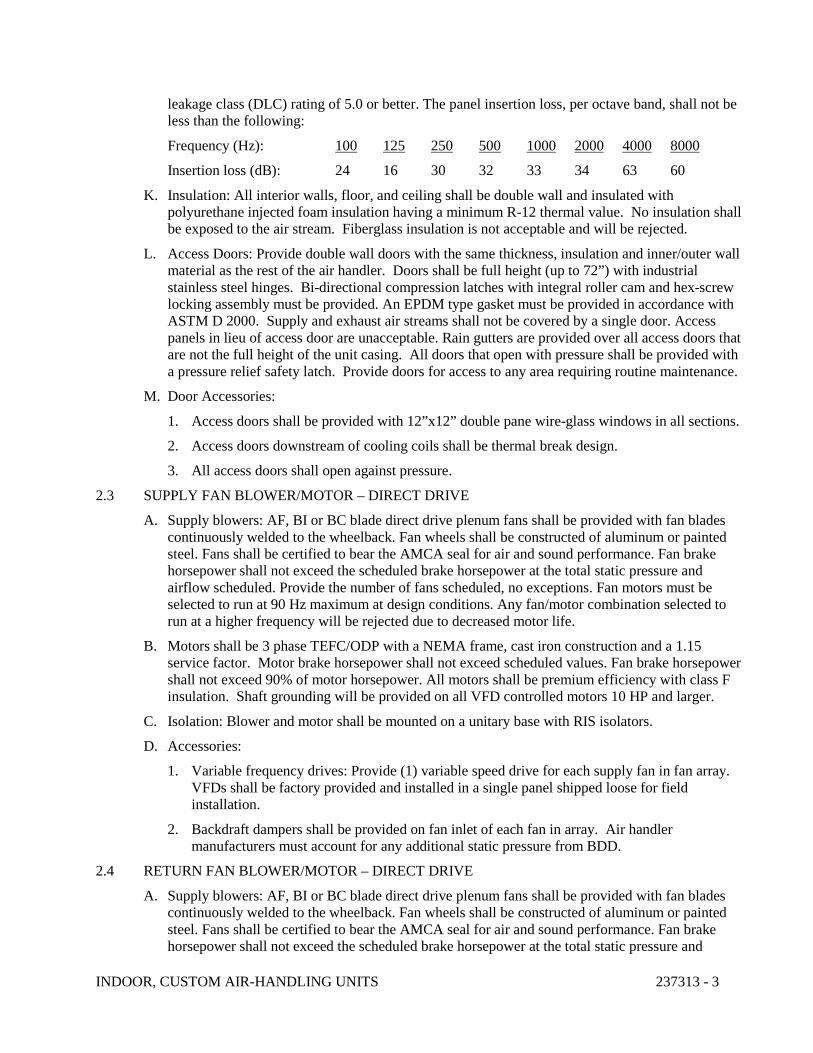
INDOOR, CUSTOM AIR-HANDLING UNITS 237313 - 3
leakage class (DLC) rating of 5.0 or better. The panel insertion loss, per octave band, shall not be less than the following:
Frequency (Hz): 100 125 250 500 1000 2000 4000 8000
Insertion loss (dB): 24 16 30 32 33 34 63 60
K. Insulation: All interior walls, floor, and ceiling shall be double wall and insulated with polyurethane injected foam insulation having a minimum R-12 thermal value. No insulation shall be exposed to the air stream. Fiberglass insulation is not acceptable and will be rejected.
L. Access Doors: Provide double wall doors with the same thickness, insulation and inner/outer wall material as the rest of the air handler. Doors shall be full height (up to 72”) with industrial stainless steel hinges. Bi-directional compression latches with integral roller cam and hex-screw locking assembly must be provided. An EPDM type gasket must be provided in accordance with ASTM D 2000. Supply and exhaust air streams shall not be covered by a single door. Access panels in lieu of access door are unacceptable. Rain gutters are provided over all access doors that are not the full height of the unit casing. All doors that open with pressure shall be provided with a pressure relief safety latch. Provide doors for access to any area requiring routine maintenance.
M. Door Accessories:
1. Access doors shall be provided with 12”x12” double pane wire-glass windows in all sections.
2. Access doors downstream of cooling coils shall be thermal break design.
3. All access doors shall open against pressure.
2.3 SUPPLY FAN BLOWER/MOTOR – DIRECT DRIVE
A. Supply blowers: AF, BI or BC blade direct drive plenum fans shall be provided with fan blades continuously welded to the wheelback. Fan wheels shall be constructed of aluminum or painted steel. Fans shall be certified to bear the AMCA seal for air and sound performance. Fan brake horsepower shall not exceed the scheduled brake horsepower at the total static pressure and airflow scheduled. Provide the number of fans scheduled, no exceptions. Fan motors must be selected to run at 90 Hz maximum at design conditions. Any fan/motor combination selected to run at a higher frequency will be rejected due to decreased motor life.
B. Motors shall be 3 phase TEFC/ODP with a NEMA frame, cast iron construction and a 1.15 service factor. Motor brake horsepower shall not exceed scheduled values. Fan brake horsepower shall not exceed 90% of motor horsepower. All motors shall be premium efficiency with class F insulation. Shaft grounding will be provided on all VFD controlled motors 10 HP and larger.
C. Isolation: Blower and motor shall be mounted on a unitary base with RIS isolators.
D. Accessories:
1. Variable frequency drives: Provide (1) variable speed drive for each supply fan in fan array. VFDs shall be factory provided and installed in a single panel shipped loose for field installation.
2. Backdraft dampers shall be provided on fan inlet of each fan in array. Air handler manufacturers must account for any additional static pressure from BDD.
2.4 RETURN FAN BLOWER/MOTOR – DIRECT DRIVE
A. Supply blowers: AF, BI or BC blade direct drive plenum fans shall be provided with fan blades continuously welded to the wheelback. Fan wheels shall be constructed of aluminum or painted steel. Fans shall be certified to bear the AMCA seal for air and sound performance. Fan brake horsepower shall not exceed the scheduled brake horsepower at the total static pressure and
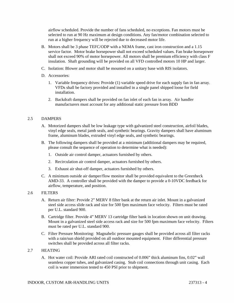
INDOOR, CUSTOM AIR-HANDLING UNITS 237313 - 4
airflow scheduled. Provide the number of fans scheduled, no exceptions. Fan motors must be selected to run at 90 Hz maximum at design conditions. Any fan/motor combination selected to run at a higher frequency will be rejected due to decreased motor life.
B. Motors shall be 3 phase TEFC/ODP with a NEMA frame, cast iron construction and a 1.15 service factor. Motor brake horsepower shall not exceed scheduled values. Fan brake horsepower shall not exceed 90% of motor horsepower. All motors shall be premium efficiency with class F insulation. Shaft grounding will be provided on all VFD controlled motors 10 HP and larger.
C. Isolation: Blower and motor shall be mounted on a unitary base with RIS isolators.
D. Accessories:
1. Variable frequency drives: Provide (1) variable speed drive for each supply fan in fan array. VFDs shall be factory provided and installed in a single panel shipped loose for field installation.
2. Backdraft dampers shall be provided on fan inlet of each fan in array. Air handler manufacturers must account for any additional static pressure from BDD
2.5 DAMPERS
A. Motorized dampers shall be low leakage type with galvanized steel construction, airfoil blades, vinyl edge seals, metal jamb seals, and synthetic bearings. Gravity dampers shall have aluminum frame, aluminum blades, extruded vinyl edge seals, and synthetic bearings.
B. The following dampers shall be provided at a minimum (additional dampers may be required, please consult the sequence of operation to determine what is needed):
1. Outside air control damper, actuators furnished by others.
2. Recirculation air control damper, actuators furnished by others.
3. Exhaust air shut-off damper, actuators furnished by others.
C. A minimum outside air damper/flow monitor shall be provided equivalent to the Greenheck AMD-33. A controller shall be provided with the damper to provide a 0-10VDC feedback for airflow, temperature, and position.
2.6 FILTERS
A. Return air filter: Provide 2” MERV 8 filter bank at the return air inlet. Mount in a galvanized steel side access slide rack and size for 500 fpm maximum face velocity. Filters must be rated per U.L. standard 900.
B. Cartridge filter. Provide 4” MERV 13 cartridge filter bank in location shown on unit drawing. Mount in a galvanized steel side access rack and size for 500 fpm maximum face velocity. Filters must be rated per U.L. standard 900.
C. Filter Pressure Monitoring: Magnahelic pressure gauges shall be provided across all filter racks with a rain/sun shield provided on all outdoor mounted equipment. Filter differential pressure switches shall be provided across all filter racks.
2.7 HEATING
A. Hot water coil: Provide ARI rated coil constructed of 0.006” thick aluminum fins, 0.02” wall seamless copper tubes, and galvanized casing. Stub coil connections through unit casing. Each coil is water immersion tested to 450 PSI prior to shipment.
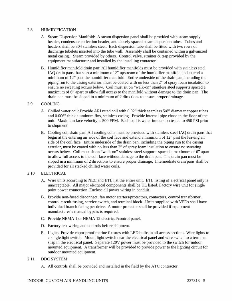
INDOOR, CUSTOM AIR-HANDLING UNITS 237313 - 5
2.8 HUMIDIFICATION
A. Steam Dispersion Manifold: A steam dispersion panel shall be provided with steam supply header, condensate collection header, and closely spaced steam dispersion tubes. Tubes and headers shall be 304 stainless steel. Each dispersion tube shall be fitted with two rows of discharge tubelets inserted into the tube wall. Assembly shall be contained within a galvanized metal casing. Steam provided by others. Control valve, strainer & trap provided by the equipment manufacturer and installed by the installing contactor.
B. Humidifier manifold drain pan: All humidifier manifolds must be provided with stainless steel IAQ drain pans that start a minimum of 2” upstream of the humidifier manifold and extend a minimum of 12” past the humidifier manifold. Entire underside of the drain pan, including the piping run to the casing exterior, must be coated with no less than 2” of spray foam insulation to ensure no sweating occurs below. Coil must sit on “walk-on” stainless steel supports spaced a maximum of 6” apart to allow full access to the manifold without damage to the drain pan. The drain pan must be sloped in a minimum of 2 directions to ensure proper drainage.
2.9 COOLING
A. Chilled water coil: Provide ARI rated coil with 0.02” thick seamless 5/8” diameter copper tubes and 0.006” thick aluminum fins, stainless casing. Provide internal pipe chase in the floor of the unit. Maximum face velocity is 500 FPM. Each coil is water immersion tested to 450 PSI prior to shipment.
B. Cooling coil drain pan: All cooling coils must be provided with stainless steel IAQ drain pans that begin at the entering air side of the coil face and extend a minimum of 12” past the leaving air side of the coil face. Entire underside of the drain pan, including the piping run to the casing exterior, must be coated with no less than 2” of spray foam insulation to ensure no sweating occurs below. Coil must sit on “walk-on” stainless steel supports spaced a maximum of 6” apart to allow full access to the coil face without damage to the drain pan. The drain pan must be sloped in a minimum of 2 directions to ensure proper drainage. Intermediate drain pans shall be provided for all stacked chilled water coils.
2.10 ELECTRICAL
A. Wire units according to NEC and ETL list the entire unit. ETL listing of electrical panel only is unacceptable. All major electrical components shall be UL listed. Factory wire unit for single point power connection. Enclose all power wiring in conduit.
B. Provide non-fused disconnect, fan motor starters/protectors, contactors, control transformer, control circuit fusing, service switch, and terminal block. Units supplied with VFDs shall have individual branch fusing per drive. A motor protector shall be provided if equipment manufacturer’s manual bypass is required.
C. Provide NEMA 1 or NEMA 12 electrical/control panel.
D. Factory test wiring and controls before shipment.
E. Lights: Provide vapor proof marine fixtures with LED bulbs in all access sections. Wire lights to a single light switch. Mount light switch near the electrical panel and wire switch to a terminal strip in the electrical panel. Separate 120V power must be provided to the switch for indoor mounted equipment. A transformer will be provided to provide power to the lighting circuit for outdoor mounted equipment.
2.11 DDC SYSTEM
A. All controls shall be provided and installed in the field by the ATC contractor.
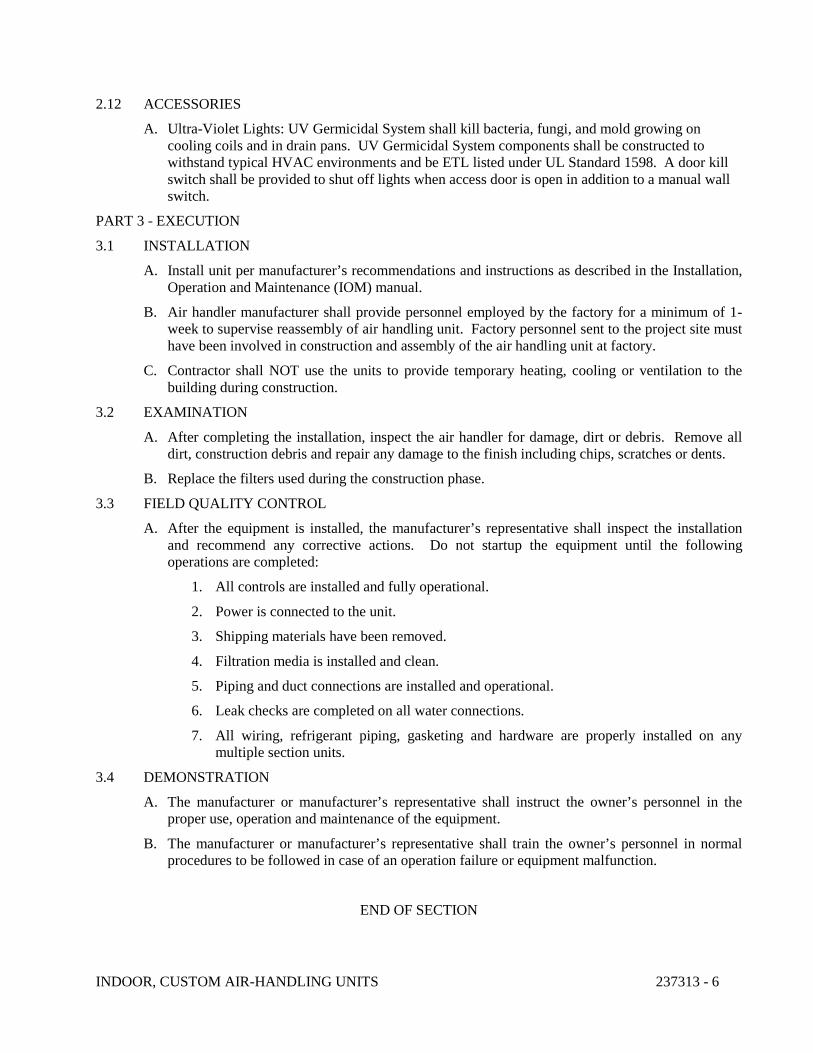
INDOOR, CUSTOM AIR-HANDLING UNITS 237313 - 6
2.12 ACCESSORIES
A. Ultra-Violet Lights: UV Germicidal System shall kill bacteria, fungi, and mold growing on cooling coils and in drain pans. UV Germicidal System components shall be constructed to withstand typical HVAC environments and be ETL listed under UL Standard 1598. A door kill switch shall be provided to shut off lights when access door is open in addition to a manual wall switch.
PART 3 - EXECUTION
3.1 INSTALLATION
A. Install unit per manufacturer’s recommendations and instructions as described in the Installation, Operation and Maintenance (IOM) manual.
B. Air handler manufacturer shall provide personnel employed by the factory for a minimum of 1-week to supervise reassembly of air handling unit. Factory personnel sent to the project site must have been involved in construction and assembly of the air handling unit at factory.
C. Contractor shall NOT use the units to provide temporary heating, cooling or ventilation to the building during construction.
3.2 EXAMINATION
A. After completing the installation, inspect the air handler for damage, dirt or debris. Remove all dirt, construction debris and repair any damage to the finish including chips, scratches or dents.
B. Replace the filters used during the construction phase.
3.3 FIELD QUALITY CONTROL
A. After the equipment is installed, the manufacturer’s representative shall inspect the installation and recommend any corrective actions. Do not startup the equipment until the following operations are completed:
1. All controls are installed and fully operational.
2. Power is connected to the unit.
3. Shipping materials have been removed.
4. Filtration media is installed and clean.
5. Piping and duct connections are installed and operational.
6. Leak checks are completed on all water connections.
7. All wiring, refrigerant piping, gasketing and hardware are properly installed on any multiple section units.
3.4 DEMONSTRATION
A. The manufacturer or manufacturer’s representative shall instruct the owner’s personnel in the proper use, operation and maintenance of the equipment.
B. The manufacturer or manufacturer’s representative shall train the owner’s personnel in normal procedures to be followed in case of an operation failure or equipment malfunction.
END OF SECTION
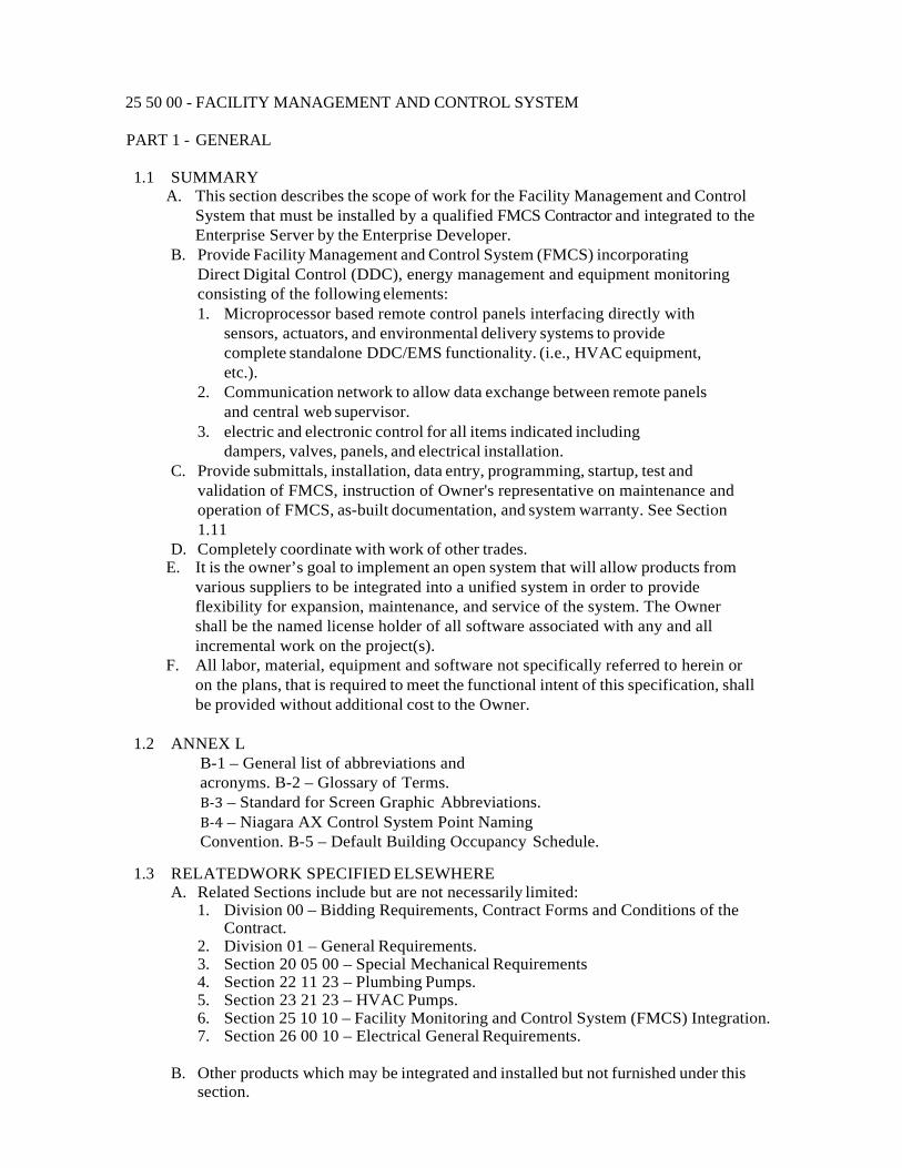
25 50 00 - FACILITY MANAGEMENT AND CONTROL SYSTEM
PART 1 - GENERAL
1.1 SUMMARY A. This section describes the scope of work for the Facility Management and Control
System that must be installed by a qualified FMCS Contractor and integrated to the Enterprise Server by the Enterprise Developer.
B. Provide Facility Management and Control System (FMCS) incorporating Direct Digital Control (DDC), energy management and equipment monitoring consisting of the following elements: 1. Microprocessor based remote control panels interfacing directly with
sensors, actuators, and environmental delivery systems to provide complete standalone DDC/EMS functionality. (i.e., HVAC equipment, etc.).
2. Communication network to allow data exchange between remote panels and central web supervisor.
3. electric and electronic control for all items indicated including dampers, valves, panels, and electrical installation.
C. Provide submittals, installation, data entry, programming, startup, test and validation of FMCS, instruction of Owner's representative on maintenance and operation of FMCS, as-built documentation, and system warranty. See Section 1.11
D. Completely coordinate with work of other trades. E. It is the owner’s goal to implement an open system that will allow products from
various suppliers to be integrated into a unified system in order to provide flexibility for expansion, maintenance, and service of the system. The Owner shall be the named license holder of all software associated with any and all incremental work on the project(s).
F. All labor, material, equipment and software not specifically referred to herein or on the plans, that is required to meet the functional intent of this specification, shall be provided without additional cost to the Owner.
1.2 ANNEX L
B-1 – General list of abbreviations and acronyms. B-2 – Glossary of Terms. B-3 – Standard for Screen Graphic Abbreviations. B-4 – Niagara AX Control System Point Naming Convention. B-5 – Default Building Occupancy Schedule.
1.3 RELATEDWORK SPECIFIED ELSEWHERE A. Related Sections include but are not necessarily limited:
1. Division 00 – Bidding Requirements, Contract Forms and Conditions of the Contract.
2. Division 01 – General Requirements. 3. Section 20 05 00 – Special Mechanical Requirements 4. Section 22 11 23 – Plumbing Pumps. 5. Section 23 21 23 – HVAC Pumps. 6. Section 25 10 10 – Facility Monitoring and Control System (FMCS) Integration. 7. Section 26 00 10 – Electrical General Requirements.
B. Other products which may be integrated and installed but not furnished under this
section.

1. Project specific equipment. 2. Metering (if applicable) 3. Electric pulse meter (if applicable) 4. Gas metering (if applicable) 5. Water metering (if applicable) 6. Fire Alarm monitoring, with a minimum of a status if it is available from the panel 7. Roof Top Units 8. Lighting (if applicable) 9. CRAC Computer Room Air Conditions
1.4 SCOPE OF WORK
A. The Facility Management and Control System (FMCS) shall be comprised of Java Application Control Engine or Controllers (JACE) within each facility. The JACE shall connect to the owner’s local or wide area network, depending on configuration. Each User shall configure a dashboard view of the pertinent data and this view shall be saved for later use. Access to the system, either locally in each building, or remotely from a central site or sites, shall be accomplished through a standard Web browser, via the Internet and/or local area network. Each JACE shall communicate directly to, BACnet MSTP (IBC) devices and other open and legacy protocol systems/devices provided under this Division. It is the owner’s goal to eliminate any gateway or redundant (redundant to the JACE functionality) device(s). 1. The existing Atkinsjace1 shall be replaced with a new N4 JACE. 2. The new JACE shall be Niagara Version 4.6.96.28. 3. Controls vendor shall transfer all existing information to new JACE and update as
required for the changes to AHU-1 as a part of this project. 4. Controls vendor shall export tag all graphics in the JACE and join JACE to the
web supervisor including but not limited to fixing any existing errors on JACE relating to join.
5. Controls vendor shall tag all points and update/build graphics in Fin for any changes.
B. The Facility Management and Control System (FMCS) as provided in this Division shall be the based on the NiagaraAX Framework (or “NiagaraAX”), a Java-based framework developed by Tridium.
C. The work provided in this specification shall be performed by multiple entities. The FMCS Contractor shall have overall responsibility for the Division work. The Enterprise Developer shall be appointed by the Owner and shall provide all work at the Enterprise Server level. Owner will oversee and provide procurement for Enterprise Developer services.
D. Systems Integrator shall provide overall management, coordination and responsibility for delivering integrated FMCS systems. The Systems Integrator shall review work performed by other Specialty Contractors such as low voltage, IT, security and control system subcontractors and coordinate the connection of these systems to the Owner’s IT infrastructure in conjunction with the Owner’s IT staff.
E. All materials and equipment used shall be standard components. All systems and components shall have been thoroughly tested and proven in actual use for at least two years.
F. All wiring shall be done in accordance with all local and national codes.
1.5 DIVISION OF WORK A. The FMCS contractor shall be responsible for all communicating thermostats, any
miscellaneous controllers (IDC and IBC), control devices, control panels, controller programming, and controller programming software, controller
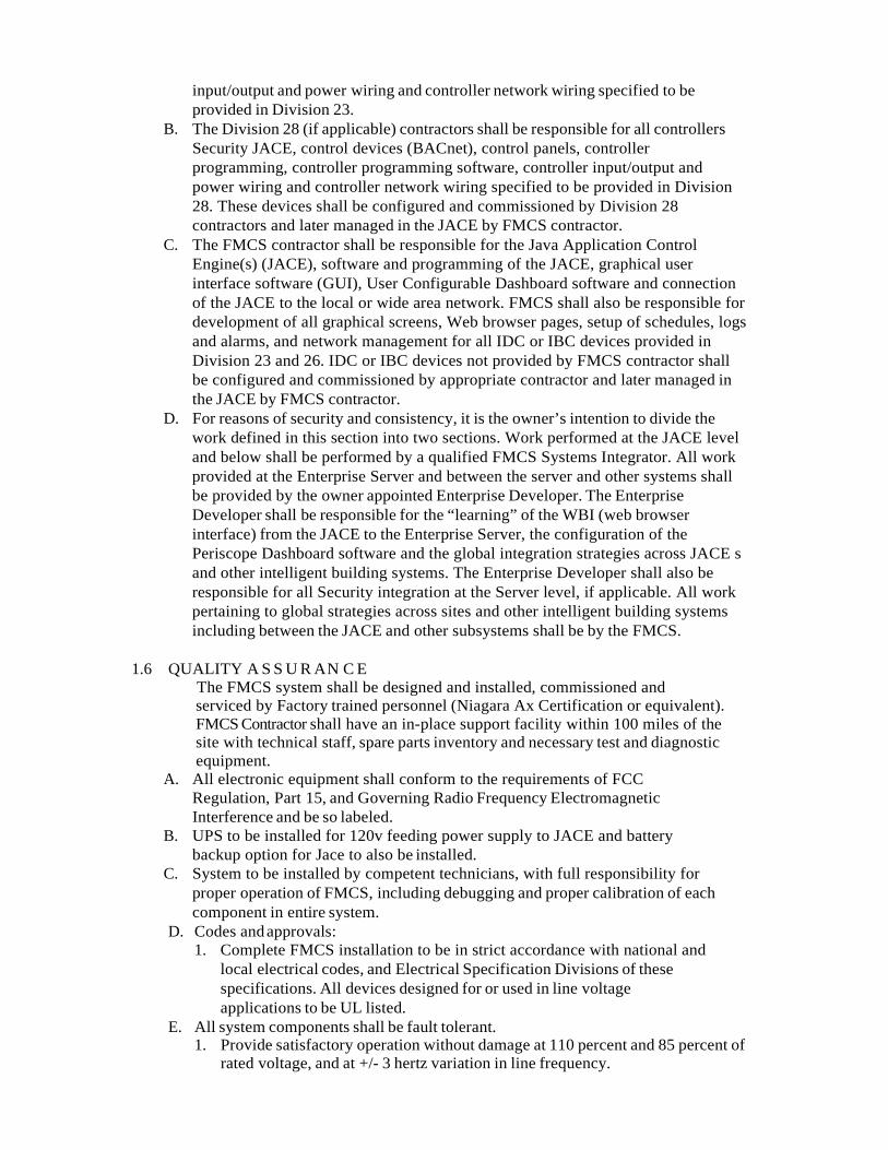
input/output and power wiring and controller network wiring specified to be provided in Division 23.
B. The Division 28 (if applicable) contractors shall be responsible for all controllers Security JACE, control devices (BACnet), control panels, controller programming, controller programming software, controller input/output and power wiring and controller network wiring specified to be provided in Division 28. These devices shall be configured and commissioned by Division 28 contractors and later managed in the JACE by FMCS contractor.
C. The FMCS contractor shall be responsible for the Java Application Control Engine(s) (JACE), software and programming of the JACE, graphical user interface software (GUI), User Configurable Dashboard software and connection of the JACE to the local or wide area network. FMCS shall also be responsible for development of all graphical screens, Web browser pages, setup of schedules, logs and alarms, and network management for all IDC or IBC devices provided in Division 23 and 26. IDC or IBC devices not provided by FMCS contractor shall be configured and commissioned by appropriate contractor and later managed in the JACE by FMCS contractor.
D. For reasons of security and consistency, it is the owner’s intention to divide the work defined in this section into two sections. Work performed at the JACE level and below shall be performed by a qualified FMCS Systems Integrator. All work provided at the Enterprise Server and between the server and other systems shall be provided by the owner appointed Enterprise Developer. The Enterprise Developer shall be responsible for the “learning” of the WBI (web browser interface) from the JACE to the Enterprise Server, the configuration of the Periscope Dashboard software and the global integration strategies across JACE s and other intelligent building systems. The Enterprise Developer shall also be responsible for all Security integration at the Server level, if applicable. All work pertaining to global strategies across sites and other intelligent building systems including between the JACE and other subsystems shall be by the FMCS.
1.6 QUALITY A S S U R AN C E
The FMCS system shall be designed and installed, commissioned and serviced by Factory trained personnel (Niagara Ax Certification or equivalent). FMCS Contractor shall have an in-place support facility within 100 miles of the site with technical staff, spare parts inventory and necessary test and diagnostic equipment.
A. All electronic equipment shall conform to the requirements of FCC Regulation, Part 15, and Governing Radio Frequency Electromagnetic Interference and be so labeled.
B. UPS to be installed for 120v feeding power supply to JACE and battery backup option for Jace to also be installed.
C. System to be installed by competent technicians, with full responsibility for proper operation of FMCS, including debugging and proper calibration of each component in entire system.
D. Codes and approvals: 1. Complete FMCS installation to be in strict accordance with national and
local electrical codes, and Electrical Specification Divisions of these specifications. All devices designed for or used in line voltage applications to be UL listed.
E. All system components shall be fault tolerant. 1. Provide satisfactory operation without damage at 110 percent and 85 percent of
rated voltage, and at +/- 3 hertz variation in line frequency.
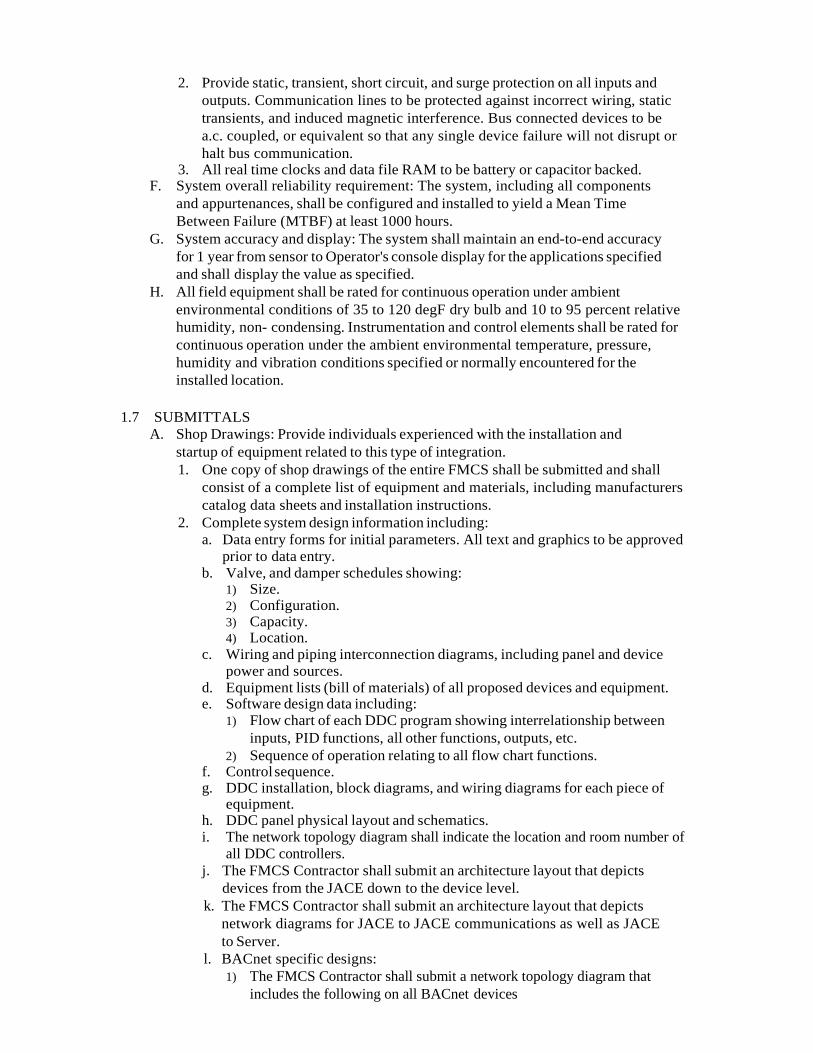
2. Provide static, transient, short circuit, and surge protection on all inputs and outputs. Communication lines to be protected against incorrect wiring, static transients, and induced magnetic interference. Bus connected devices to be a.c. coupled, or equivalent so that any single device failure will not disrupt or halt bus communication.
3. All real time clocks and data file RAM to be battery or capacitor backed. F. System overall reliability requirement: The system, including all components
and appurtenances, shall be configured and installed to yield a Mean Time Between Failure (MTBF) at least 1000 hours.
G. System accuracy and display: The system shall maintain an end-to-end accuracy for 1 year from sensor to Operator's console display for the applications specified and shall display the value as specified.
H. All field equipment shall be rated for continuous operation under ambient environmental conditions of 35 to 120 degF dry bulb and 10 to 95 percent relative humidity, non- condensing. Instrumentation and control elements shall be rated for continuous operation under the ambient environmental temperature, pressure, humidity and vibration conditions specified or normally encountered for the installed location.
1.7 SUBMITTALS
A. Shop Drawings: Provide individuals experienced with the installation and startup of equipment related to this type of integration. 1. One copy of shop drawings of the entire FMCS shall be submitted and shall
consist of a complete list of equipment and materials, including manufacturers catalog data sheets and installation instructions.
2. Complete system design information including: a. Data entry forms for initial parameters. All text and graphics to be approved
prior to data entry. b. Valve, and damper schedules showing:
1) Size. 2) Configuration. 3) Capacity. 4) Location.
c. Wiring and piping interconnection diagrams, including panel and device power and sources.
d. Equipment lists (bill of materials) of all proposed devices and equipment. e. Software design data including:
1) Flow chart of each DDC program showing interrelationship between inputs, PID functions, all other functions, outputs, etc.
2) Sequence of operation relating to all flow chart functions. f. Control sequence. g. DDC installation, block diagrams, and wiring diagrams for each piece of
equipment. h. DDC panel physical layout and schematics. i. The network topology diagram shall indicate the location and room number of
all DDC controllers. j. The FMCS Contractor shall submit an architecture layout that depicts
devices from the JACE down to the device level. k. The FMCS Contractor shall submit an architecture layout that depicts
network diagrams for JACE to JACE communications as well as JACE to Server.
l. BACnet specific designs: 1) The FMCS Contractor shall submit a network topology diagram that
includes the following on all BACnet devices
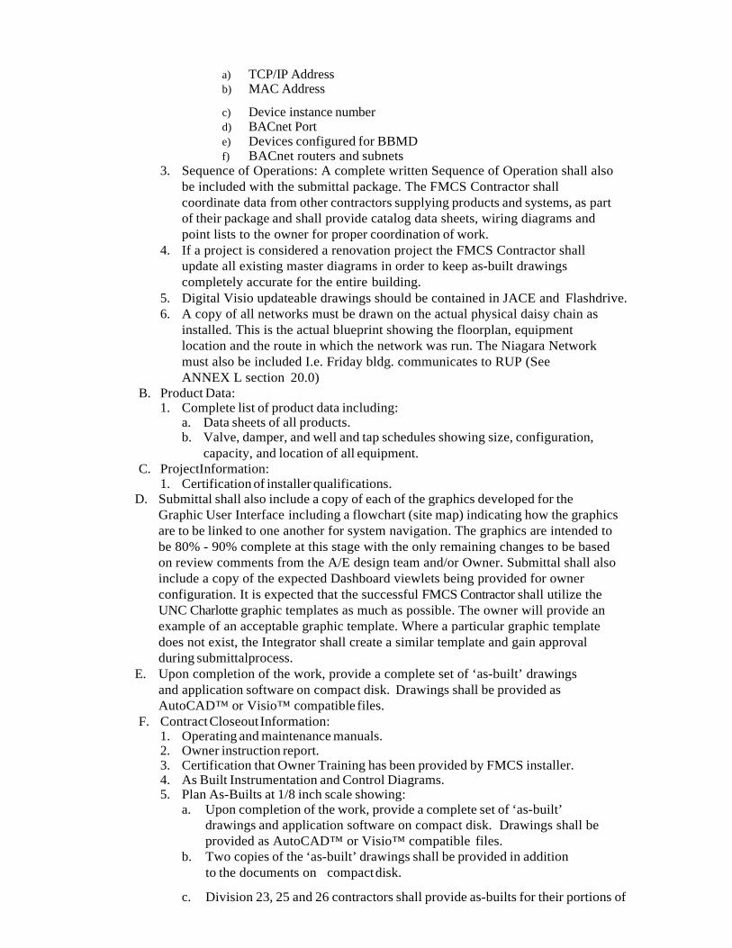
a) TCP/IP Address b) MAC Address
c) Device instance number d) BACnet Port e) Devices configured for BBMD f) BACnet routers and subnets
3. Sequence of Operations: A complete written Sequence of Operation shall also be included with the submittal package. The FMCS Contractor shall coordinate data from other contractors supplying products and systems, as part of their package and shall provide catalog data sheets, wiring diagrams and point lists to the owner for proper coordination of work.
4. If a project is considered a renovation project the FMCS Contractor shall update all existing master diagrams in order to keep as-built drawings completely accurate for the entire building.
5. Digital Visio updateable drawings should be contained in JACE and Flashdrive. 6. A copy of all networks must be drawn on the actual physical daisy chain as
installed. This is the actual blueprint showing the floorplan, equipment location and the route in which the network was run. The Niagara Network must also be included I.e. Friday bldg. communicates to RUP (See ANNEX L section 20.0)
B. Product Data: 1. Complete list of product data including:
a. Data sheets of all products. b. Valve, damper, and well and tap schedules showing size, configuration,
capacity, and location of all equipment. C. ProjectInformation:
1. Certification of installer qualifications. D. Submittal shall also include a copy of each of the graphics developed for the
Graphic User Interface including a flowchart (site map) indicating how the graphics are to be linked to one another for system navigation. The graphics are intended to be 80% - 90% complete at this stage with the only remaining changes to be based on review comments from the A/E design team and/or Owner. Submittal shall also include a copy of the expected Dashboard viewlets being provided for owner configuration. It is expected that the successful FMCS Contractor shall utilize the UNC Charlotte graphic templates as much as possible. The owner will provide an example of an acceptable graphic template. Where a particular graphic template does not exist, the Integrator shall create a similar template and gain approval during submittalprocess.
E. Upon completion of the work, provide a complete set of ‘as-built’ drawings and application software on compact disk. Drawings shall be provided as AutoCAD™ or Visio™ compatible files.
F. Contract Closeout Information: 1. Operating and maintenance manuals. 2. Owner instruction report. 3. Certification that Owner Training has been provided by FMCS installer. 4. As Built Instrumentation and Control Diagrams. 5. Plan As-Builts at 1/8 inch scale showing:
a. Upon completion of the work, provide a complete set of ‘as-built’ drawings and application software on compact disk. Drawings shall be provided as AutoCAD™ or Visio™ compatible files.
b. Two copies of the ‘as-built’ drawings shall be provided in addition to the documents on compact disk.
c. Division 23, 25 and 26 contractors shall provide as-builts for their portions of
work. d. The FMCS Contractor shall be responsible for as-builts pertaining to
overall FMCS architecture and network diagrams. All as built drawings shall also be installed into the FMCS server in a dedicated directory.
e. Communication cable circuiting drawing with DDC panels and communication devices labeled.
f. Power wiring circuiting drawing showing 120 volt circuit source and low voltage transformer locations, identifications, and circuit to each controlled device per transformer for the DDC system.
G. Any software needed to program or calibrate controls system will be provided along with any setup, configurations and data files. Also, any hardware needed to communicate with the controllers and/or devices will also be included.
1.8 JOB CONDITIONS
A. Cooperation with other Trades: Coordinate the Work of this section with that of other Sections to ensure that the Work will be carried out in an orderly fashion. It shall be this Systems Integrator’s responsibility to check the Contract documents for possible conflicts between his work and that of other crafts in equipment location, pipe, duct and conduit runs, electrical outlets and fixtures, air diffusers and structural and architectural features.
1.9 SOFTWARELICENSEAGREEMENT
A. It is the owners express goal to implement an open system that will allow products from various suppliers to be integrated into a unified Niagara system in order to provide flexibility for expansion, maintenance, and service of the system. The Owner shall be the named license holder of all software associated with any and all incremental work on the project(s). In addition, the Owner shall receive ownership of all job specific configuration documentation, data files, and application-level software developed for the project. This shall include: 1. All custom, job specific software code and documentation for all
configuration and programming that is generated for a given project and/or configured for use with the JACE, FMCS Server(s), and any related LAN / WAN / Intranet and Internet connected routers and devices.
2. Any and all required IDs and passwords for access to any component or software program shall be provided to the owner.
B. The Owner has signed a software and firmware licensing agreement for the FMS software. Such license shall grant use of all programs and application software to Owner as defined by the manufacturer's license agreement, but shall protect manufacturer's rights to disclosure of trade secrets contained within such software. Systems Integrators that participate in the integration of UNC Charlotte’s direct digital control systems must: 1. Be certified in the use, application and service of NiagaraAX software and shall
provide documentation from the manufacturer’s training center as such. However, certification in the above does not automatically qualify an integrator to bid on proposed UNC Charlotte projects. Only approved integrators listed in this specification are eligible to participate in the project.
2. Agree to use on any UNC Charlotte project any application standards, html pages, graphics templates, etc. developed by or for UNC Charlotte for the purpose of digital control, scheduling, alarming, graphics, etc.
3. Agree that the application standards, html pages, graphics templates, etc. developed only for UNC Charlotte are the property of UNC Charlotte (subject to the manufacturer’s license agreement) and shall not be reproduced, etc. for use on any other customer, project, etc. without the expressed written permission of the UNC
Charlotte facilities staff.
4. Agree that certification on the manufacturer’s software does not guarantee continued participation in UNC Charlotte’s FMS projects.
5. Agree to provide UNC Charlotte’s staff with the highest level of administrative password.
6. Agree that UNC Charlotte staff and other Systems Integrators can use the onsite UNC Charlotte software tools to modify JACE s, license files, passwords, provide software maintenance, etc., after warranty period expires.
7. The owner requires that all NiagaraAX based software and hardware on this project have the following Niagara Information Compatibility Statement (NICS). The Existing NiagaraAX Server complies with the requirements below. Organizations without the NICS below shall not be allowed to bid.
a. Brand ID = Vykon b. Station Compatibility In = * c. Station Compatibility Out = * d. Tool Compatibility In = *
1.10 WARRANTY
A. Provide all services, materials and equipment necessary for the successful operation of the entire FMCS for a period of two years after acceptance by the State Construction Office and provide hardware and software upgrade support during that period that corresponds with any upgrades performed by FM FIS.
B. Within this period, upon notice by the Owner, any defects in the work provided under this section due to faulty materials, methods of installation or workmanship shall be promptly (within 48 hours after receipt of notice) repaired or replaced by the FMCS contractor at no expense to the Owner.
C. The adjustment, required testing, and repair of the system includes all computer equipment, transmission equipment and all sensors and control devices.
D. With owner pre-approval, the on-line support services shall allow the local FMCS Contractor remote access to monitor and control the facility's building automation system. Pending owner approval, this remote connection to the facility shall be within 2 hours of the time that the problem is reported. This coverage shall be extended to include normal business hours, after business hours, weekends and holidays.
E. Warranty Access 1. Pending owner pre-approval, the Owner shall grant to the FMCS contractor,
reasonable access to the FMCS during the warranty period. The owner shall allow the contractor to access the FMCS from a remote location for the purpose of diagnostics and troubleshooting, via the Internet, during the warranty period.
1.11 ACCEPTABLE SYSTEM CONTRACTORS
A. The FMCS Contractor shall provide JACE hardware, software and DDC components. The successful FMCS Contractor shall not have password access to the Enterprise Server (Web Supervisor) and shall be restricted to JACE access.
B. The FMCS Contractor shall have a technical support group accessible that is staffed with qualified personnel, capable of providing instruction and technical support service for networked control systems.
C. FMCS Systems Contractors of the hardware and software components must be approved by UNCC prior to winning projects.
D. UNCC List of Acceptable Contractors;
1) Platinum Building Automation (JCI FX – Facilities Explorer – BACnet only).

2) Schneider Electric Controls (Invensys I/A Series -BACnet only). PART 2 - PRODUCTS
2.1 GENERAL
A. The Facility Management Control System (FMCS) shall be comprised of a network of interoperable, stand-alone digital controllers, a computer system, graphical user interface software, network devices and other devices as specified herein.
B. The installed system shall provide secure passwords access to all features, functions and data contained in the overall FMCS.
2.2 OPEN, INTEROPERABLE, INTEGRATED ARCHITECTURES
A. The intent of this specification is to provide a peer-to-peer networked, stand-alone, distributed control system with the capability to integrate themost current ANSI/ASHRAE Standard BACnet existing OPC if applicable, and other existing open and proprietary communication protocols if applicable in one open, interoperable system.
B. The supplied computer software shall employ component-based technology (OOT) for representation of all data and control devices within the system. In addition, adherence to industry standards including the most current ANSI / ASHRAE™ Standard and BACnet to assure interoperability between all system components is required.. For each BACnet device, the device supplier must provide a PICS document showing the installed device’s compliance level. Minimum compliance is Level 3; with the ability to support data read and write functionality. Physical connection of BACnet devices shall be via RS-485 (BACnet MSTP) or Ethernet (BACnet Ethernet/IP,) only by exception with prior UNCC FIS approval and only through the Jaces secondary IP port.
C. All components and controllers supplied under this Division shall be true “peer-to-peer” communicating devices. Components or controllers requiring “polling” by a host to pass data shall not be acceptable.
D. The supplied system must incorporate the ability to access all data using standard Web browsers without requiring proprietary operator interface and configuration programs. An Open Database Connectivity (ODBC) or Structured Query Language (SQL) compliant server database is required for all system database parameter storage. This data shall reside on a supplier-installed server for all database access. Systems requiring proprietary database and user interface programs shall not be acceptable.
E. A hierarchical topology is required to assure reasonable system response times and to manage the flow and sharing of data without unduly burdening the customer’s internal Intranet network. Systems employing a “flat” single tiered architecture shall not be acceptable. 1. Maximum acceptable response time from any alarm occurrence (at the point
of origin) to the point of annunciation shall not exceed 5 seconds for network connected user interfaces.
2.3 MATERIALS
A. Temperaturecontrol system: 1. Include:
a. Temperaturesensors. b. Humiditysensors. c. Controllers. d. Switches. e. Relays.
f. Valves.
g. Dampers. h. Damperoperators. i. Thermostats. j. Humidistats. k. Hygrometers. l. Other associated controls required to maintain conditions described in
detail on drawings, together with thermometers, gauges and other accessory equipment.
2. Provide complete system of wiring and air piping as necessary to fill intent of these specifications.
3. Control sequences indicated illustrate basic control functions only. 4. Provide additional controls required to meet intent of these
specifications and make a complete system. 5. Space temperature and humidity control. 6. Control of air handling units. 7. Control of exhaust systems. 8. Control of cooling systems. 9. Control of heating systems.
B. Control panels. Where electronic sensing is used, furnish amplifier relays and transformer complete with overload protection.
C. Electrical drawings indicate type of motor control required by equipment. 1. NETWORKS The Local Area Network (LAN) shall be a 100 Megabits/sec
Ethernet network supporting BACnet, Java, XML, HTTP, and OBIX for maximum flexibility for integration of building data with enterprise information systems and providing support for multiple Java Application Control Engine (JACE s), user workstations and, if specified, a local server.
D. Local area network minimum physical and media access requirements: 1. Ethernet; IEEE standard 802.3 2. Cable; 100 Base-T, UTP-8 wire, category 6 3. Minimum throughput; 100 Mbps.
2.4 NETWORK ACCESS AND SECURITY
A. Remote Access 1. For Local Area Network installations the Owner shall provide a
connection to the Internet to enable access via the customer’s Intranet to a corporate server. FMCS Contractor shall connect to IP drop provided by the Owner within 25 feet utilizing a minimum of Category 6 grade of patch cabling.
B. JACE IP communications 1. FMCS Contractor will use DHCP and DNS for IP communications.
a. No static IPs or “hardcoded” IP addresses in the JACE will be accepted. b. The FMCS Contractor shall request from UNCC FIS all required primary port
TCP/IP network configuration settings for all JACE s via standard RFI. The FMCS Contractor shall not assign any of the following configuration settings without FM FIS approval.
1) Domain name 2) Host name 3) Station Name
c. Secondary port 1) For troubleshooting purpose, The FMCS Contractor shall configure the JACE’s
secondary port to a static IP address of 192.168.1.12X, where X is equal to last digit of JACE’s serial number.
2) The subnet mask shall be configured to 255. 255. 255.0 C. Security and Authentication
1. Each operator shall be required to log on to that system with a user name and password in order to view, edit, add, or delete data.
2. The Owner shall control/set all passwords and security levels for all operators. The Owner shall provide the FMCS and Enterprise Developer with the standard passwords required to be used in the Enterprise Server and the JACE.
3. The FMCS Contractor shall not use any passwords except those provided by the owner. The system administrator shall have the ability to set passwords and security levels for all other operators.
4. The FMCS Contractor shall not leave any default usernames/passwords on the JACE. 5. Each operator password shall be able to restrict the operators’ access for viewing
and/or changing each system application, full screen editor, and object. 6. Each operator shall automatically be logged off of the system if no keyboard or
mouse activity is detected. 7. User Profile templates:
a. The FMCS Contractor shall program users in the JACE utilizing the following User profiles
User Profile View Graphic
Operator S t i t
All Setpoint
Add/Delete Users
Technician X X
View Only X
Power User X X X X
8. SSL requirements a. All communications between Niagara devices and the Enterprise server or user
interface software, i.e., IDE, shall be secured using SSL encryption. b. The following ports shall be used for SSL communications
Software Interface Protocol Specified Port Browser HTTPS 443 Niagara Station IDE FOX 4911 Niagara Platform IDE TLSv1 5011
2.5 Java Application Control Engine (JACE) A. The FMCS Contractor shall supply one or more Java Application Control Engine
(JACE) as part of this contract to manage devices/points in all specification sections with the exception of Division 28 00 00 Security. Security JACEs are provided under Division 28 00 00 and all card access, video and intrusion detection shall be integrated into the existing Enterprise software by the Systems Integrator. The Systems Integrator shall be required to integrate BACnet zone information provided by the Division 28 into the HVAC and Lighting Sequence of Operation. The number of JACEs provided by the FMCS Contractor is dependent on the type/quantity of devices and points. It is the responsibility of the FMCS Contractor to coordinate with all Division contractors to determine the quantity and type of JACEs needed to fulfill the operating sequences.
B. Java Application Control Engine (JACE) shall provide the interface between the LAN or WAN and the field control devices, and provide global supervisory control functions over the control devices connected to the JACE. It shall be capable of executing application control programs to provide: 1. Calendarfunctions 2. Scheduling 3. Trending
4. Alarm monitoring and routing 5. Timesynchronization 6. Integration of BACnet controller data
C. The Java Application Control Engine must provide the following hardware features as a minimum: 1. Two Ethernet Ports – 10/100 Mbps 2. One RS-232 port 3. One LonWorks Interface Port – 78KB FTT-10A (if applicable) 4. One RS-485 port 5. Battery Backup or equivalent 6. Flash memory for long term data backup (If battery backup or flash
memory is not supplied, the controller must contain a hard disk with at least 1 gigabyte storage capacity)
7. The JACE must be capable of operation over a temperature range of 32 to 122°F 8. The JACE must be capable of withstanding storage temperatures of between 0 and
158°F 9. The JACE must be capable of operation over a humidity range of 5 to 95%
RH, non- condensing. D. The JACE shall support standard Web browser access via the
Intranet/Internet. It shall support a minimum of 32 simultaneous users. E. JACE Alarm Notification and actions:
1. The JACE shall provide alarm recognition, storage; routing, management, and analysis to supplement distributed capabilities of equipment or application specific controllers. The JACE shall be able to route any alarm condition to any defined user location whether connected to a local network or remote via dial-up telephone connection, or wide-area network.
2. Alarm generation shall be selectable for annunciation type and acknowledgement requirements including but limited to: a. To alarm b. Return to normal c. To fault
3. Provide for the creation of a minimum of eight of alarm classes (Must contain building name) for the purpose of routing types and or classes of alarms, i.e.: security, HVAC, Fire, etc.
4. Provide timed (scheduled) routing of alarms by building name and class, object, group or node.
5. Provide alarm generation from binary object “runtime” and /or event counts for equipment maintenance. The user shall be able to reset runtime or event count values with appropriate passwordcontrol.
6. Control equipment and network failures shall be treated as alarms and annunciated. 7. Alarms shall be annunciated in any of the following manners as defined by the
user: a. Screen message text b. Email of the complete alarm message to multiple recipients.
Provide the ability to route email alarms based on: 1) Day of week 2) Time of day 3) Recipient
c. Graphic with flashing alarm object(s). 8. The following shall be recorded by the JACE for each alarm (at a minimum):
a. Time and date b. Location (building, floor, zone, office number, etc.) c. Equipment (air handler #, access way, etc.) d. Acknowledge time, date, and user who issued acknowledgement.
e. Number of occurrences since last acknowledgement. 9. Alarm actions may be initiated by user defined programmable objects created
for that purpose.
10. Defined users shall be given proper access to acknowledge any alarm, or specific types or classes of alarms defined by the user.
11. A log of all alarms shall be maintained by the JACE and/or a server (if configured in the system) and shall be available for review by the user.
12. Provide a “query” feature to allow review of specific alarms by user defined parameters.
13. A separate log for system alerts (controller failures, network failures, etc.) shall be provided and available for review by the user.
14. An Error Log to record invalid property changes or commands shall be provided and available for review by the user.
F. JACE Data Collection and Storage. 1. The JACE shall have the ability to collect data for any property of any
object and store this data for future use. See points list for required logs. 2. The data collection shall be performed by log objects, resident in the
JACE that shall have, at a minimum, the following configurable properties: a. Designating the log as interval or deviation. b. For interval logs, the object shall be configured for time of day, day of
week and the sample collection interval. c. For deviation logs, the object shall be configured for the deviation of a
variable to a fixed value. This value, when reached, will initiate logging of the object.
d. For all logs, provide the ability to set the maximum number of data stores for the log and to set whether the log will stop collecting when full, or rollover the data on a first-in, first-out basis.
3. Each log shall have the ability to have its data cleared on a time-based event or by a user-defined event or action. All log data shall be archived to a database in the Enterprise Server and the data shall be accessed from a standard Web browser and the Periscope Dashboard.
4. All log data, when accessed from a server, shall be capable of being manipulated using standard SQL, BQL & NQL statements.
5. All log data shall be available to the user in the following data formats: a. HTML b. XML c. Plain Text d. Comma or tab separated values.
6. Systems that do not provide log data in HTML and XML formats at a minimum shall not be acceptable.
7. The JACE shall have the ability to archive its log data remotely to a server on the network. Provide the ability to configure the following archiving properties, at a minimum: a. Archive on time of day b. Archive on user-defined number of data stores in the log (buffer size) c. Archive when log has reached its user-defined capacity of data stores d. Provide ability to clear logs once archive.
G. JACE Audit Log 1. Provide and maintain an Audit Log that tracks all activities performed on the
JACE. Provide the ability to specify a buffer size for the log and the ability to archive log based on time or when the log has reached its user-defined buffer size. Provide the ability to archive the log to a server. For each log

entry, provide the following data: a. Time and date b. User ID c. Change or activity: i.e., Change set point, add or delete objects, commands, etc.
H. JACE Database Backup & Storage
1. The JACE shall have the ability to automatically backup its database. The database shall be backed up based on a user-defined time interval. Enterprise Developer shall coordinate with Owner to establish/implement a backup procedure.
2. Copies of the current database and, at the most recently saved database shall be stored in the JACE. The age of the most recently saved database is dependent on the user-defined database save interval.
3. The JACE database shall be stored, at a minimum, in XML format to allow for user viewing and editing, if desired. Other formats are acceptable as well, as long as XML format is supported.
I. JACE Time Sync 1. Use the NtpPlatformServiceQnx in the
Station/Services/PlatformServices/ NtpPlatformServiceQnx. Use Time Servers [email protected] and [email protected]
J. JACE Weather Station/ODA Temperature 1. The Web Supervisor has a dedicated weather station that will be available
through the Niagara Network. While the Jace is not on the UNCC Network and for backup purposes all buildings are required to have their own Outdoor Air Temperature sensor to be used for economizer and other requirements but also be able to be overridden by the Web Supervisor Outdoor Air Temperature.
2. Also available from the Web Supervisor is Outdoor Humidity, Dew point and Wet Bulb.
3. The weather station in the Services of the Station should also be enable and set for Charlotte NC
4. At this time Air Quality is not enable due to conditions beyond our control. Therefor this property should be set to False.
K. JACE Loading.
1. UNCC desires for the SI to design the system to properly load balance across multiple JACEs. I.e.; UNCC does not want 1 Jace operating at 80% and another is operating at 20%
2.6 INTEGRATEDDEVELOPMENTENVIRONMENT(IDE) A. It is the intent of UNCC to manage and maintain all Niagara devices on the BAS
network to the same Niagara approved version. It is also the intent of UNCC to upgrade the version of Niagara once a year in April. However an upgrade to Niagara may be performed at any time based upon UNCC’s discretion. It is the FMCS Systems Contractor’s responsibility to check the currently installed/approved version of Niagara campus and to attain and perform any deployment with the current UNCC approved version.
B. An integrated development environment for development of graphic screens, control logic, security, alarm notification and data storage has been established using the Niagara Workbench Tool and currently resides on a Server in the existing data center and several laptops. The successful FMCS Contractor shall utilize its own laptop for all programming and graphical development. The Enterprise Developer shall utilize the IDE at the server via a VPN connection or
its own separate laptop IDE. The IDE residing on the central server s hal l be the most current version of the Niagara Workbench toolset and the FMCS Contractor shall utilize the exact same version when programming JACE s.
C. The server and JACE IDE tools shall be identical; however, it shall be possible to limit views and commands via a unique user profile and password in either. The IDE shall include a quick viewing of, and access to, the hierarchical structure of the database. Menu-pull downs, and toolbars shall employ buttons, commands and navigation to permit the operator to perform tasks with a minimum knowledge of the HVAC Control System and basic computing skills. These shall include, but are not limited to,
forward/backward buttons, home button, and a context sensitive locator line (similar to a URL line), that displays the location and the selected object identification.
D. System Diagnostics. The system shall automatically monitor the operation of all workstations, modems, network connections, building management panels, and controllers. The failure of any device shall be annunciated to the operator.
E. Alarm Management: 1. The system will be provided with a dedicated alarm window or console. Refer
to Sequence of Operations/Points List for Alarm strategies. The Alarm Console will notify the operator of an alarm condition, and allow the operator to view details of the alarm and acknowledge the alarm. The use of the Alarm Console can be enabled or disabled by the system administrator. Alarms shall be created and grouped per the owner’s requirements by the FMCS Contractor at the JACE level. The Enterprise Developer shall bring the JACE alarms into the existing Enterprise server and generate the strategies to send alarms to the appropriate city or contractor parties.
2. Alarms shall be capable of being routed to any of the following: a. Local Alarm Console (by FMCS Systems) b. Remote Alarm Station (by Enterprise Developer) c. Email recipient (multiple if needed) (by Enterprise Developer)
3. When the Alarm Console is enabled, a separate alarm notification window will supersede all other windows on the desktop and shall not be capable of being minimized or closed by the operator. This window will notify the operator of new alarms and un-acknowledged alarms. Alarm notification windows or banners that can be minimized or closed by the operator shall not be acceptable. Alarms shall be able to be mapped into groupings where the groupings have common displays, sounds or hyperlinks. This grouping shall be used to distinguish alarms when alarms are coming in from multiple sites or classes (i.e. buildings, regions, trades, etc) for faster recognition.
4. The system shall be provided with an alarm database management view. The view shall allow a user with appropriate password to: a. Filter or Clear old records before a certain date and time b. Clear records older than the currently highlighted record c. Clear all records d. Modify the alarm table options including which alarm details are displayed,
column width, etc. e. Export the alarm database records to .pdf, text or CSV formats. f. There will be 4 Alarm Classes, Critical Alarms Class, Non Critical Alarms
Class, Maintenance Alarms Class and Network Alarm Class. There will be 5 Alarm Consoles one for each Class and a Master where all 4 go to one console. All Alarm classes and console will have the building name included ie; Friday Critical Alarm Class and Friday Critical Alarm Console.
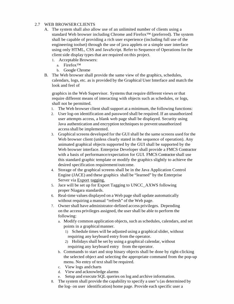
2.7 WEB BROWSER CLIENTS A. The system shall also allow use of an unlimited number of clients using a
standard Web browser including Chrome and Firefox™ (preferred). The system shall be capable of providing a rich user experience (including full use of the engineering toolset) through the use of java applets or a simple user interface using only HTML, CSS and JavaScript. Refer to Sequence of Operations for the client side display types that are required on this project. 1. Acceptable Browsers:
a. Firefox™ b. Google Chrome
B. The Web browser shall provide the same view of the graphics, schedules, calendars, logs, etc. as is provided by the Graphical User Interface and match the look and feel of
graphics in the Web Supervisor. Systems that require different views or that require different means of interacting with objects such as schedules, or logs, shall not be permitted. 1. The Web browser client shall support at a minimum, the following functions: 2. User log-on identification and password shall be required. If an unauthorized
user attempts access, a blank web page shall be displayed. Security using Java authentication and encryption techniques to prevent unauthorized access shall be implemented.
3. Graphical screens developed for the GUI shall be the same screens used for the Web browser client (unless clearly stated in the sequence of operation). Any animated graphical objects supported by the GUI shall be supported by the Web browser interface. Enterprise Developer shall provide a FMCS Contractor with a basis of performance/expectation for GUI. FMCS Contractor shall use this standard graphic template or modify the graphics slightly to achieve the desired specification requirement/outcome.
4. Storage of the graphical screens shall be in the Java Application Control Engine (JACE) and these graphics shall be “learned” by the Enterprise Server via Export tagging.
5. Jace will be set up for Export Tagging to UNCC_AXWS following proper Niagara standards.
6. Real-time values displayed on a Web page shall update automatically without requiring a manual “refresh” of the Web page.
7. Owner shall have administrator-defined access privileges. Depending on the access privileges assigned, the user shall be able to perform the following: a. Modify common application objects, such as schedules, calendars, and set
points in a graphical manner. 1) Schedule times will be adjusted using a graphical slider, without
requiring any keyboard entry from the operator. 2) Holidays shall be set by using a graphical calendar, without
requiring any keyboard entry from the operator. b. Commands to start and stop binary objects shall be done by right-clicking
the selected object and selecting the appropriate command from the pop-up menu. No entry of text shall be required.
c. View logs and charts d. View and acknowledge alarms e. Setup and execute SQL queries on log and archive information.
8. The system shall provide the capability to specify a user’s (as determined by the log- on user identification) home page. Provide each specific user a
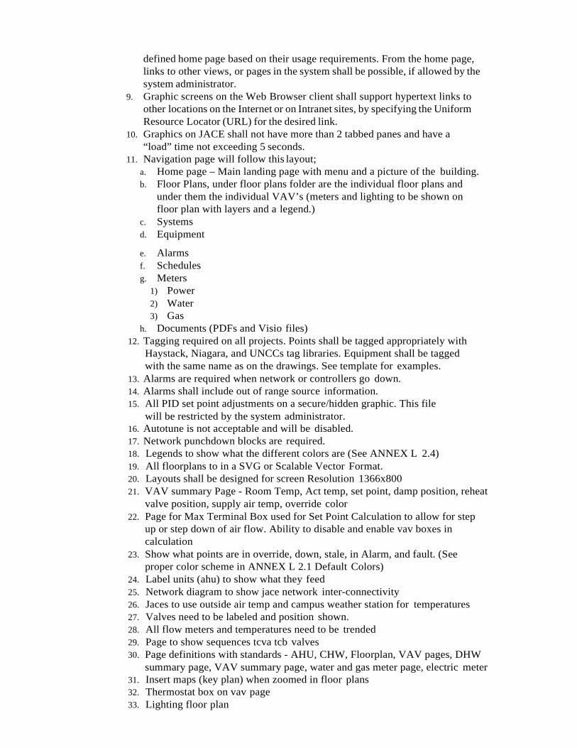
defined home page based on their usage requirements. From the home page, links to other views, or pages in the system shall be possible, if allowed by the system administrator.
9. Graphic screens on the Web Browser client shall support hypertext links to other locations on the Internet or on Intranet sites, by specifying the Uniform Resource Locator (URL) for the desired link.
10. Graphics on JACE shall not have more than 2 tabbed panes and have a “load” time not exceeding 5 seconds.
11. Navigation page will follow this layout; a. Home page – Main landing page with menu and a picture of the building. b. Floor Plans, under floor plans folder are the individual floor plans and
under them the individual VAV’s (meters and lighting to be shown on floor plan with layers and a legend.)
c. Systems d. Equipment
e. Alarms f. Schedules g. Meters
1) Power 2) Water 3) Gas
h. Documents (PDFs and Visio files) 12. Tagging required on all projects. Points shall be tagged appropriately with
Haystack, Niagara, and UNCCs tag libraries. Equipment shall be tagged with the same name as on the drawings. See template for examples.
13. Alarms are required when network or controllers go down. 14. Alarms shall include out of range source information. 15. All PID set point adjustments on a secure/hidden graphic. This file
will be restricted by the system administrator. 16. Autotune is not acceptable and will be disabled. 17. Network punchdown blocks are required. 18. Legends to show what the different colors are (See ANNEX L 2.4) 19. All floorplans to in a SVG or Scalable Vector Format. 20. Layouts shall be designed for screen Resolution 1366x800 21. VAV summary Page - Room Temp, Act temp, set point, damp position, reheat
valve position, supply air temp, override color 22. Page for Max Terminal Box used for Set Point Calculation to allow for step
up or step down of air flow. Ability to disable and enable vav boxes in calculation
23. Show what points are in override, down, stale, in Alarm, and fault. (See proper color scheme in ANNEX L 2.1 Default Colors)
24. Label units (ahu) to show what they feed 25. Network diagram to show jace network inter-connectivity 26. Jaces to use outside air temp and campus weather station for temperatures 27. Valves need to be labeled and position shown. 28. All flow meters and temperatures need to be trended 29. Page to show sequences tcva tcb valves 30. Page definitions with standards - AHU, CHW, Floorplan, VAV pages, DHW
summary page, VAV summary page, water and gas meter page, electric meter 31. Insert maps (key plan) when zoomed in floor plans 32. Thermostat box on vav page 33. Lighting floor plan
34. Show where meters are in the building, show icon on floor plan and link back to summary page.
35. Floorplan zones - don’t use conflicting colors 36. Control diagram show network addresses for each device 37. Control valve Tuning required on the graphics. 38. DomHW.px water temp, tank name 39. PX page naming convention
C. Navigation on left side of page should have the same look and operation as Web Supervisor. See ANNEX L for more details.
D. JACEs shall be on Niagara 4.1 at a minimum or at the latest version Niagara that UNCC is running on the web supervisor. Check with UNCC Facilities Information Systems.
2.8 SERVER FUNCTIONS & HARDWARE A. Provide a general, intuitive navigational path from the server to the JACEs.
Store all required O&M data sheets, drawings, help files, etc on the server from the UNCC approved Web Supervisor Contractor (Activelogix).
B. All JACEs to be JACE 8000s Vykon only jaces.
2.9 SYSTEM PROGRAMMING A. The Jace’s Graphical User Interface software (GUI) shall provide the ability to
perform system programming and graphic display engineering as part of a complete software package. Access to the programming functions and features of controllers need to be accessible through the Jace/GUI through password access as assigned by the system administrator.
B. A library of control, application, and graphic components shall be provided to enable the creation of all applications and user interface screens. Applications are to be created by selecting the desired control components from the library, dragging or pasting them on the screen, and linking them together using a built in graphical connection tool. Completed applications may be stored in the library for future use. Graphical User Interface screens shall be created in the same fashion. Data for the user displays is obtained by graphically linking the user display components to the application components to provide “real-time” data updates. Any real-time data value or component property may be connected to display its current value on a user display. Systems requiring a separate software tool to create applications and browser user interface displays shall not be acceptable.
C. Programming Methods: 1. Power Fail Protection - All System set points, proportional band, control
algorithms and any other programming parameters shall be stored such that a power failure of any duration does not necessitated reprogramming the ASC or FPC.
2. Provide the capability to copy components from the supplied libraries, or from a user- defined library to the user’s application. Component shall be linked by a graphical linking scheme by dragging a link from one component to another. Component links will support one-to-one, many-to-one, or one- to-many relationships. Linked components shall maintain their connections to other objects regardless of where they are positioned on the page and shall show link identification for links to components on other pages for easy identification. Links will vary in color depending on the type of link; i.e., internal, external, hardware, etc.
3. Configuration of each component will be done through the component’s property sheet using fill-in the blank fields, list boxes, and selection buttons requiring the use of custom programming, scripting language, or a manufacturer-specific procedural language for every component

configuration will not be accepted. 4. The software shall provide the ability to view the logic in a monitor
mode. When on-line, the monitor mode shall provide the ability to view the logic in real time for easy diagnosis of the logic execution. When off-line (debug), the monitor mode shall allow the user to set values to inputs and monitor the logic for diagnosing execution before it is applied to the system.
5. All programming shall be done in real-time. Systems requiring the uploading, editing, and downloading of database component s shall not be allowed.
6. The system shall support component duplication within a customer’s database. An application, once configured, can be copied and pasted for easy re-use and duplication. All links, other than to the hardware, shall be maintained during duplication.
7. All PIDs shall have adjustable set point exposed to the graphics in a secure/hidden page.
D. Network and Device Naming Conventions. 1. All Network names will not have spaces or underscores. I.e.;
BacnetNetwork is acceptable. Bacnet Network is not acceptable. 2. Device names will not have spaces, underscores are acceptable. VAVs must
have a room name associated with it. I.e.; VAV1_1Rm126. The #1 after VAV corresponds with the floor it is on and the digit after the underscore identifies the VAV.
3. All Network and Device names must be kept to a minimum and subject to UNCC acceptance.
2.10 COMPONENTS LIBRARIES
A. A standard library of components shall be included for development and setup of application logic, user interface displays, system services, and communication networks.
B. The components in this library shall be capable of being copied and pasted into the user’s database and shall be organized according to their function. In addition, the user shall have the capability to group components created in their application and store the new instances of these components in a user-definedlibrary.
C. In addition to the standard libraries specified here, the supplier of the system shall maintain an on-line accessible (over the Internet) library, available to all registered users to provide new or updated components and applications as they are developed.
D. Contractor will use the Niagara template station file as provided by FM FIS. The template station will be made available to the FMCS Contractor upon request via standard RFI.
E. Contractor shall not use any “non-standard” or OEM JAR files unless approved by FM FIS. A JAR is considered “non-standard” if it is not included in Tridium’s “Niagara AX Developer” release made available to developers and to OEM partners. An example of a non-standard JAR is “jcigrahicssmall.jar”. A current list of approved JARs will be made available to the FMCS Contractor upon request via standard RFI. Source codes made available to FIS to store and use.
F. Any approved non-standard JAR files become property of UNCC with a copy of the source code to store and use
G. All control components shall conform to the control component specified in the
BACnet specification. H. The component library shall include components to support the integration of
devices connected to the Java Application Control Engine (JACE). At a minimum, provide the following as part of the standard library included with the programming software: 1. LonMark/LonWorks devices. These devices shall include, but not be limited
to, devices for control of HVAC, lighting, access, and metering. Provide LonMark manufacturer-specific components to facilitate simple integration of these devices. All network variables defined in the LonMark profile shall be supported. Information (type and function) regarding network variables not defined in the LonMark profile shall be provided by the device manufacturer.
2. For devices not conforming to the LonMark standard, provide a dynamic component that can be assigned to the device based on network variable information provided by the device manufacturer. Device manufacturer shall provide an XIF file, resource file and documentation for the device to facilitate device integration.
3. For BACnet devices, provide the following components at a minimum: a. Analog In b. Analog Out c. Analog Value d. Binary e. Binary In
f. Binary Out g. Binary Value h. Multi-State In i. Multi-State Out j. Multi-State Value k. Schedule Export l. Calendar Export m. Trend Export n. Device
4. For each BACnet component, provide the ability to assign the component a BACnet device and component instance number.
5. For BACnet devices, provide the following support at a minimum: a. Segmentation b. Segmented Request c. SegmentedResponse d. ApplicationServices e. Read Property f. Read Property Multiple Write Property g. Write Property Multiple h. Confirmed Event Notification i. Unconfirmed Event Notification j. AcknowledgeAlarm k. Get Alarm Summary l. Who-has m. I-have n. Who-is o. I-am p. Subscribe COV q. Confirmed COV notification r. Unconfirmed COV notification s. Media Types t. Ethernet u. BACnet IP Annex J
v. MSTP w. BACnet Broadcast Management Device (BBMD) function x. Routing
2.11 BACNET/MSTP NETWORK MANAGEMENT
A. The Java Application Control Engine shall support the integration of device data from BACnet TCP/IP or BACnet MSTP system devices. The connection to the BACnet system shall be via an RS485, or Ethernet IP as required by the device prior UNCC approval is required for IP/Ethernet controls and only through the secondary IP port of the Jace.
B. Provide the required components in the library, included with the Graphical User Interface programming software, to support the integration of the BACnet system data into the FMCS. Components provided shall include at a minimum: 1. Read/Write BACnet AI Points 2. Read/Write BACnet AO Points 3. Read/Write BACnet AV Points 4. Read/Write BACnet BI Points 5. Read/Write BACnet BO Points
C. Read/Write BACnet BV Points, All scheduling, alarming, logging and global supervisory control functions, of the BACnet system devices, shall be performed by the Java Application Control Engine.
D. The FMCS supplier shall provide a BACnet system communications driver. The equipment system vendor that provided the equipment utilizing BACnet shall provide documentation of the system’s interface and shall provide factory support at no charge during system commissioning
E. BACnet Conformance: F. Logic controllers shall as a minimum support MS/TP BACnet LAN type. They shall
communicate directly via this BACnet LAN at 9.6, 19.2, 38.4 and 76.8 Kbps, as native BACnet devices. Logic controllers shall be of BACnet conformance class 3 and support all BACnet services necessary to provide the following BACnet functional groups: 1. Files Functional Group 2. Reinitialize Functional Group 3. Device Communications Functional Group 4. Refer to Section 22.2, BACnet Functional Groups, in the BACnet Standard, for a
complete list of the services that must be directly supported to provide each of the functional groups listed above. All proprietary services, if used in the system, shall be thoroughly documented and provided as part of the submittal data. All necessary tools shall be supplied for working with proprietary information.
G. All BacNetworks must be installed to BacnetNetwork industry standards with attention to number of devices, routers, and overall length, point and trend counts to assure proper polling of devices and points. All points and devices are required to update correctly and not go into fault, stale or offline. Proof of network reliability by means of
but not limited to BacnetNetwork Scan tool, Oscilloscope and Polling Service. Copies of these operations are to be submitted to UNCC before warranty period begins.
2.12 BACNET DEVICES (IBC)
A. The manufacturer of the hardware and software components must be primarily engaged in the manufacture of BAS as specified herein, and must have been so for a minimum of five (5) years.
B. The manufacturer shall be ISO 9001:2000 certified. This is to insure that all manufacturing, design and support policies comply with a minimum quality assurance
standard. Corporate quality assurance policies should be available for examination upon request by the owner or his agent.
C. The manufacturer of the hardware and software components shall have a technical support group accessible via a toll free number that is staffed with qualified personnel, capable of providing instruction and technical support service for networked control systems.
D. Acceptable manufacturers of the DDC hardware and software components as specified herein are as follows. Acceptance as a product manufacturer does not provide approval to be an acceptable Systems Integrator.
E. Acceptable manufacturers of the VFD hardware and software components as specified herein are as follows. Acceptance as a product manufacturer does not provide approval to be an acceptable FMCS Systems Integrator.
2.13 BACNET CONTROLLER(S) STANDARDS
A. Where possible provide BACnet Controllers that can meet the required sequence of operation and can be configured rather that custom programmed. All controllers shall be designed for easy installation and servicing including removable enclosures, removable terminals, and factory applied labels for all I/O. All internal points shall be fully supported by the Graphical User Interface (GUI), allowing the user to easily modify them and monitor them. All of the internal programming points (e.g. variables, constants, PID’s, timers, inputs and outputs) shall be exposed to the network on dedicated network variable outputs.
B. Performance Standards for Inputs - Provide software selectable universal inputs. Analog inputs - shall have the following minimum level of performance: 10 bit A to D resolution; manage thermistors with an accuracy of: ±0.9oF, and a Potentiometer. For VAV Applications provide a differential pressure input sensor built in to the controller with an adjustable range of .05” to 2” H20 (125-300PA) static pressure with a minimum accuracy of + or – 3%. Minimum response time shall be 0.5 seconds from input to output time.
C. Performance Standards for Outputs – Analog outputs shall have the following minimum level of performance: Tri-mode Voltage of 0-10 VDC (linear), digital 0-12 VDC (off/on) or PWM. All analog outputs shall be equipped with an auto-reset fuse. Output Resolution shall be a minimum 8 bits digital / analog converter. Digital outputs shall be provided with a minimum of a triac output rated at 24VAC and 1 amp. All analog outputs and power supply shall be fuse protected
D. Application Specific Controllers (ASC) - A controller designed through its I/O configuration and configurable control logic to be used for a specific type mechanical equipment. Typical applications are VAV boxes, Fan Coil Units, Roof Top Units, Unit Ventilators, Split DX Systems, and Heat Pumps. Lighting Controls, etc. All ASC’s shall conform to the BACnet standards so long as such a standard exists for its intended application. The ASC shall allow the use of its spare I/O as dumb I/O to be shared over the network to JACE where a sequence of operation can be applied to the I/O. Such applications shall include but not be limited to exhaust fan control, heaters, light control, etc. Freely Programmable Controllers (FPC) shall be a controller designed for more complex sequences of operations such as built up AHU’s, central plant operations, electrical monitoring, and control and management for chillers, boilers and generators. These FPCs are to allow for the flexibility of custom control programming to meet the needed sequences of operation.
2.14 THIRDPARTYINTEGRATION
A. The Java Application Control Engine shall support the integration of device data from the existing control system. The connection to the existing system shall be via an RS-232 or RS485 connection between the Java Application Control Engine and the existing control system {if applicable on this project}.
B. Provide the required data points from the third party integration per sequence of
operations and/or points list. C. All Third Party Networks must be installed to industry standards with attention
to number of devices, routers, and overall length, point and trend counts to assure proper polling of devices and points. All points and devices are required to update correctly and not go into fault, stale or offline. Proof of network reliability by means of but not limited to Scan tool, Oscilloscope and Polling Service. Copies of these operations are to be submitted to UNCC before warranty period begins.
2.15 SENSORS
A. All control items, except thermostats, sensors and transmitters located in rooms shall be properly identified with engraved plastic nameplates permanently attached. Nameplates shall have white letters on a black background.
B. All sensors shall be provided in NEMA 4X enclosures where exposed to the Pool environment.
C. Room thermostat, sensor and transmitter locations shall be coordinated to align vertically or horizontally with adjacent light switches or other control devices. Room thermostats and sensors shall be mounted with the bottom 5’-0” above the floor. Sensors installed in areas where they are subject to physical abuse (ex: gymnasiums) shall be furnished with protective type aspirating guards. Sensors installed on exterior walls shall be installed on non-conductive (cork) sub-base. Sensors shall have plus or minus local set point control feature.
D. Temperature Sensors: Thermistor type with an accuracy of plus or minus 0.40 degree F over the entire control range. Sensors for pipe installations shall be immersion type, brass well, and thermistor with integral lead wire. Sensors for duct application shall be insertion probe type, stainless steel probe, integral handibox, and thermistor with integral lead wire. Space temperature sensors shall be compatible with the unit controller and shall be provided in a decorative metal or plastic enclosure (Nema 4X where exposed to pool environment). Space temperature sensors shall be provided with set point and temperature indication only. Outdoor temperature sensors shall be mounted inside a protective weather and sun shield and shall be located on a North wall.
E. Humidity Sensors: Thin-film capacitive type sensor with on-board nonvolatile memory, accuracy to plus or minus two percent (2%), 12 - 30 VDC input voltage, analog output (0 - 10 VDC). Operating range shall be 5 to 95% RH and -40 to 170 degree F. Duct mounted type sensors shall have a stainless steel insertion element, sealed to prohibit corrosion. Sensors shall be selected for wall, duct or outdoor type installation as appropriate.
H. Differential Air Pressure Switch: Differential pressure switches for proving fan operation or sense dirty air filters shall be SPDT type, UL approved, and selected for the appropriate operating range of the equipment to which it is applied. Sensor shall have ¼” compression type fittings and shall have an adjustable set point. Furnish with ¼” barbed type static pressure tips.
I. Current Switches (Type 1): For proving fan or pump operational status, provide solid or split-core type current status switches with adjustable set point and solid-state internal circuitry. Current switch shall have induced power, trip point set adjustment to plus or minus 1% over a range of 1 to 135 amps, trip and power LED, and field adjustable to indicate both On-Off conditions and loss of load (broken belt, etc.).
Units shall have a five-year manufacturer’s warranty. J. Current Switches (Type 2): For proving fan or pump operational status,
provide solid or split-core type current switches (“Go/No” type). Current switch shall have induced power, 100 percent solid state with no moving parts. Units shall have a five-year manufacturer’s warranty.
K. Low Temperature Sensors: For sensing low temperatures in air handling units, provide SPST type switch, 35 to 45 degree F range, manual reset, vapor charged twenty foot long sensing element, and 120- volt electrical power connection.
L. Pressure Transmitters: For sensing static pressure in a duct system (usually for VAV systems), provide a pressure transmitter with integral capacitance type sensing action, solid state circuitry, accuracy of plus or minus 1% of range, zero and span adjustments, 10 to 35 VDC operating voltage, 4 to 20mA output, and integral inlet port connections. Select pressure range suitable for the application.
M. Firestat: For sensing sudden increases in duct temperature (ex: fire condition), provide 120 volt UL Listed SPST switch with adjustable setpoint that breaks the circuit on a rise in temperature above the setpoint and de-energizes the air handling unit fan.
N. Aquastat: For sensing temperature of a fluid within a pipe system, provide 120-volt SPST strap-on type aquastat, temperature control range of 100 to 240 degree F (adjustable).
O. Air Flow Monitoring Device: 1. Provide airflow/temperature measurement devices (ATMD) where indicated
on the plans. Fan inlet measurement devices shall not be substituted for duct or plenum measurement devices indicated on the plans.
2. Each ATMD shall consist of one or more sensor probes and a single, remotely mounted, microprocessor-based transmitter capable of independently processing up to 16 independently wired sensorassemblies. a. Each sensor assembly shall contain two individually wired, hermetically
sealed bead-in-glass thermistors. b. Thermistors shall be mounted in the sensor assembly using a marine-
grade, waterproof epoxy. Thermistor leads shall be protected and not exposed to the environment.
c. The airflow rate of each sensor assembly shall be equally weighted and averaged by the transmitter prior to output.
d. The temperature of each sensor assembly shall be velocity weighted and averaged by the transmitter prior to output.
e. Each transmitter shall have a 16-character alpha-numeric display capable of displaying airflow, temperature, system status, configuration settings and diagnostics.
3. All Sensor Probes a. Each sensor assembly shall independently determine the airflow rate
and temperature at each measurementpoint. b. Each sensor assembly shall be calibrated at a minimum of 16 airflow rates
and 3 temperatures to standards that are traceable to the National Institute of Standards and Technology (NIST).
c. Airflow accuracy shall be +/-2% of Reading over the entire operating airflow range. 1) Devices whose accuracy is the combined accuracy of the transmitter
and sensor probes must demonstrate that the total accuracy meets the performance requirements of this specification throughout the measurement range.
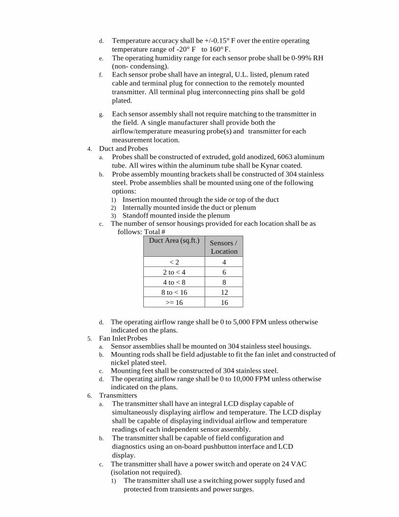
d. Temperature accuracy shall be +/-0.15° F over the entire operating temperature range of -20° F to 160° F.
e. The operating humidity range for each sensor probe shall be 0-99% RH (non- condensing).
f. Each sensor probe shall have an integral, U.L. listed, plenum rated cable and terminal plug for connection to the remotely mounted transmitter. All terminal plug interconnecting pins shall be gold plated.
g. Each sensor assembly shall not require matching to the transmitter in the field. A single manufacturer shall provide both the airflow/temperature measuring probe(s) and transmitter for each measurement location.
4. Duct and Probes a. Probes shall be constructed of extruded, gold anodized, 6063 aluminum
tube. All wires within the aluminum tube shall be Kynar coated. b. Probe assembly mounting brackets shall be constructed of 304 stainless
steel. Probe assemblies shall be mounted using one of the following options: 1) Insertion mounted through the side or top of the duct 2) Internally mounted inside the duct or plenum 3) Standoff mounted inside the plenum
c. The number of sensor housings provided for each location shall be as follows: Total #
Duct Area (sq.ft.) Sensors / Location
< 2 4 2 to < 4 6 4 to < 8 8 8 to < 16 12
>= 16 16
d. The operating airflow range shall be 0 to 5,000 FPM unless otherwise indicated on the plans.
5. Fan Inlet Probes a. Sensor assemblies shall be mounted on 304 stainless steel housings. b. Mounting rods shall be field adjustable to fit the fan inlet and constructed of
nickel plated steel. c. Mounting feet shall be constructed of 304 stainless steel. d. The operating airflow range shall be 0 to 10,000 FPM unless otherwise
indicated on the plans. 6. Transmitters
a. The transmitter shall have an integral LCD display capable of simultaneously displaying airflow and temperature. The LCD display shall be capable of displaying individual airflow and temperature readings of each independent sensor assembly.
b. The transmitter shall be capable of field configuration and diagnostics using an on-board pushbutton interface and LCD display.
c. The transmitter shall have a power switch and operate on 24 VAC (isolation not required). 1) The transmitter shall use a switching power supply fused and
protected from transients and power surges.
2) The transmitter shall use “watch-dog” circuitry to assure reset after power disruption, transients and brown-outs.
d. All interconnecting pins, headers and connections on the main circuit board, option cards and cable receptacles shall be gold plated.
e. The operating temperature range for the transmitter shall be -20° F to 120° F. The transmitter shall be installed at a location that is protected from weather and water.
f. The transmitter shall be capable of communicating with other devices using the following interface option: Linear analog output signals for airflow and temperature: Field selectable, fuse protected and isolated, 0-10VDC/4-20mA (4-wire)
7. The ATMD shall be UL listed as an entire assembly. 8. The manufacturer’s authorized representative shall review and approve
placement and operating airflow rates for each measurement location indicated on the plans.
2.16 DAMPERS AND ACTUATORS
A. Damper actuators shall be sized by the FMCS Contractor for the intended application. Unless noted otherwise, dampers will be furnished by the FMCS Contractor for all field installed dampers that are not included as part of the equipment. In general, provide opposed blade type dampers for modulating control and parallel type dampers for two- position control applications.
B. Control Dampers. Provide all automatic control dampers not specified to be integral with other equipment. Frames shall be 5 inches wide and of no less than 16-gauge galvanized steel. Inter-blade linkage shall be within the frame and out of the air stream. Blades shall not be over 8 inches wide nor less than 16-gauge galvanized steel triple V type for rigidity. Bearings shall be acetal, oilite, nylon or ball-bearing with ½ inch diameter plated steel shafts. Dampers shall be suitable for temperature ranges of -40 to 180F. All proportional control dampers shall be opposed or parallel blade type as hereinafter specified and all two-position dampers shall be parallel blade types. Dampers shall be sized to meet flow requirements of the application. The sheet metal contractor shall furnish and install baffles to fit the damper to duct size. Baffles shall not exceed 6". Dampers with dimensions of 24 inches and less shall be rated for 3,000 fpm velocity and shall withstand a maximum system pressure of 5.0 in. wc. Dampers with dimensions of 36 inches and less shall be rated for 2,500 fpm velocity and shall withstand a maximum system pressure of 4.0 in. wc. Dampers with dimensions of 48 inches and less shall be rated for 2,000 fpm velocity and shall withstand a maximum system pressure of 2.5 in. wc. Side seals shall be stainless steel of the tight-seal spring type. Dampers shall be minimum leakage type to conserve energy and the temperature control manufacturer shall submit leakage data for all low leakage control dampers with the temperature control submittal. M axi mu m leakage for low leakage dampers in excess of sixteen inches square shall be 8 CFM per square foot at static pressure of 1 inch of WC. Low leakage damper blade edges shall be fitted with replaceable, snap-on, inflatable seals to limit damper leakage. Testing and ratings shall be in accordance with AMCA Standard 500. Damper blade width shall be no greater than 8 inches, and dampers over 48 inches wide by 74 inches high shall be sectionalized. Testing and ratings to be in accordance with AMCA Standard 500.
C. Damper Actuators: Damper actuators shall be provided for all automatic dampers. Damper actuators controlled through the DDC system shall be low voltage electronic type, either modulating or two-position, as required to achieve the
intended sequence of operation. Provide with spring return when required for fail-safe operation. Modulating dampers shall be positive positioning in response to a 2 – 10 VDC or 4 - 20mA control signal. Actuator shall include the capability of adding auxiliary switches for position indication. Furnish actuators other than spring return type with a release button (clutch) or handle on the actuator to allow for manual override. Power supply to the actuator shall be by 120 VAC, 24 VAC, or 24 VDC and the actuator shall be furnished with a factory installed 3-foot cable with end fitting for field connection. All actuators shall be UL Listed by the manufacturer.
2.17 VARIABLEFREQUENCYDRIVES
A. All Variable Frequency drives shall be ABB VFD or equivalent. Variable frequency drives shall be UL listed and sized for the power and loads applied. Drives shall include built-in EN 61800-3 Category C2 radio frequency interference
(RFI) filters and be constructed to operate in equipment rooms and shall not be susceptible to electromagnetic disturbances typically encountered in such environments. Similarly, the drives must not excessively disturb the environment within which it is used. All VFDs over 3 horsepower shall be provided with an AC choke. VFDs shall be installed in strict conformance to the manufacturer’s installation instructions, and shall be rated to operate over a temperature range of 14 to 104 F.
B. VFD automatic operation shall be provided with a BACnet MSTP, BACNET TCP/IP, Modbus RTU or Modbus TCP/IP communications protocols. Each VFD shall be fan cooled and have an integral keypad and graphical display unit with wizards and built in manuals for user interface.
A. Three types of faults shall be monitored, “FAULT” shall shut the motor down, “FAULT Auto-reset” shall shut the motor down and try to restart it for a programmable number of tries, and “FAULT Trip” shall shut the motor down after a FAULT Auto-reset fails to restart the motor. Coded faults shall be automatically displayed for the following faults: 1. Over current 2. Over voltage 3. Earth ground 4. Emergency stop 5. System (component failure) 6. Under voltage 7. Phase missing 8. Heat sink under temperature 9. Heat sink over temperature 10. Motor stalled 11. Motor over temperature 12. Motorunderload 13. Cooling fan failure 14. Inverter bridge over temperature 15. Analog input control under current 16. Keypad failure 17. Other product unique monitored conditions
B. In addition to annunciating faults, at the time of fault occurrence the VFD shall capture and make available to the user certain system data for subsequent analysis during fault trouble shooting, including duration of operation (days, hours, minutes, seconds),output frequency, motor current, motor voltage, motor power, motor torque, DC voltage, unit temperature, run status, rotation direction, and any warnings. The last 30 fault occurrences shall be retained as well as the fault data listed in the previous sentence of each fault. New faults beyond 30 shall

overwrite the oldest faults. C. The display unit keypad shall provide start up wizard and allow setting
operational parameters including minimum and maximum frequency, and acceleration and deceleration times. The display shall offer user monitoring of frequency, unit temperature, motor speed, current, torque, power, voltage, and temperature.
2.18 CONTROL VALVES
A. Control Valves: (Globe Type) Valves shall be 2-way or 3-way pattern as shown constructed for tight shutoff and shall operate satisfactory against system pressures and differentials. Two-position valves shall be ‘line’ size. Proportional control valves shall be sized for a maximum pressure drop of 5.0 psi at rated flow (except as may be noted on the drawings). Two-way water valves shall have equal percentage flow characteristics and three-way valves shall have equal percentage flow characteristics straight through and linear through the bypass. Provide valve position indicator on all valves. Leakage rate shall be no more than 0.05% of Cv.
1. Valves 1/2 inch through 1 1/2 inch shall be screwed pattern except where solder connections are specified for valves 1/2 or 3/4 inches. Three-way valves bypass port shall be of one size reduced Cv to preclude the need for a bypass port balancing valve. Valve and cartridge replacement tool shall be configured for maintenance or replacement without draining the coil to prevent water spill; however, an integral isolation valve on the control valve outlet will also be acceptable. Valves shall close off against 58 psi minimum.
2. Two inch valves shall be “screwed” configuration and 2-1/2 inch and larger valves shall be “flanged” configuration and ANSI-rated to withstand the pressures and temperatures encountered. Valves shall have stainless-steel stems and spring loaded Teflon packaging with replaceable discs.
B. Control Valves: (Characterized Ball Valves) Control valves ½ to 2 inches shall be 2-way or 3-way forged brass screwed pattern as shown constructed for tight shutoff and shall operate satisfactory against system pressures and differentials. Two-position valves shall be ‘line’ size. Proportional control valves shall be sized for a maximum pressure drop of 5.0 psi at rated flow (except as may be noted on the drawings). Two-way water valves shall have equal percentage flow characteristics and three-way valves shall have equal percentage flow characteristics straight through and linear flow through the bypass. Leakage rate shall be ANSI Class IV (no more than 0.01% of Cv). Valves shall be rated for no less than 350 psig at no less than 250 degrees F. provide a removable handle to operate valves manually during actuator power loss or failure.
C. Two-way valves shall close off against 100 psi minimum, and three-way valves shall close off against 40 psi minimum. Valves shall have stainless-steel or chemically nickel-plated brass stem and throttling port. Valves shall be tagged with Cv rating and model number.
D. Butterfly Control Valves: Valves shall be Honeywell or equivalent. Where specified butterfly control valves over 2” in size shall be cast iron body type for 2-way or 3-way applications specified constructed for tight shutoff and shall operate satisfactory against system pressures and differentials. Valves shall have tapped lugs for standard flange connection, and designed for isolation and removal of downstream piping at full rated pressure. Two-position valves shall be ‘line’ size. Proportional control valves shall be sized for a maximum pressure drop of 5.0 psi at rated flow (except as may be noted on the drawings). Valves shall be rated for bubble tight shutoff at no less than 150 psi. Valve disc shall be aluminum bronze.

Valve stems shall be stainless steel, with inboard top and bottom bronze bearings, and an external corrosion resistant top bearing to absorb actuator side thrust.
2.19 ELECTRICAL MISCELLANEOUS
A. Panels: All enclosures for DDC controllers and devices shall be fabricated in accordance with UL Standards from code gauge steel. Enclosures shall be provided with a continuous hinge on the door and a flush latching mechanism. Enclosures shall be shop painted with standard grade enamel coating. Back panels shall be furnished when required to facilitate installation of boards or accessories. All enclosures installed outdoors shall be constructed to NEMA 3R standards. All controllers shall be installed within an approved enclosure unless the controller will be installed within the control cabinet section of the equipment that it is intended to control. Enclosures shall facilitate the mounting of gauges, switches, pilot lights, and the like, on the face panel when required. Control devices that are mounted on the face of the panel shall be identified with engraved nameplates.
B. Power Transformers: Step-down power transformers shall be provided for all DDC controllers and associated accessory devices as required. Transformers shall be sized and selected to accommodate all connected accessory items. Transformers shall be UL Listed Class 2 type with 120 VAC primary, 24 VAC secondary.
C. Relays: Miscellaneous control relays shall be provided as required to energize or control equipment and devices within the control system. Relays shall be located as close as practical to the controlled device (motor, motor starter, etc.). Where approved by NC State Building Codes, relays may be installed within starters and equipment control panels where space is available. Relays installed outside of the controlled device shall be provided with a NEMA enclosure suitable for the location where installed.
2.20 ELECTRICAL AND COMMUNICATION WIRING
A. Wiring: All wiring devices and accessories shall comply with the requirements of NC State Building Codes. All wiring shall be installed in a neat and professional manner. Control wiring shall not be installed in power circuit conduits or raceways unless specifically approved for that purpose. All wiring, except plenum wiring (where allowed), shall be run in electrical conduits. Plenum cable will be allowed in concealed locations where accessible. All cable must be installed with 90° angles and strapped according the NC State Building Codes.
B. Provide all interlock and control wiring. Provide wiring as required by functions as specified and as recommended by equipment and device manufacturers to achieve the specified control functions.
C. Low voltage conductors shall be stranded bare or tinned-copper with premium grade polymer alloy insulation. For shielded cable, furnish multi-conductor of overall polyester supported aluminum foil with stranded tinned copper drain wire to facilitate grounding. Coaxial shield shall be copper braided type. Provide shielded cable where recommended by the equipment or device manufacturer, grounded in strict accordance with the manufacture’s recommendations.
D. Magnetic starters and disconnect switches shall not be used as junction boxes. Provide auxiliary junction boxes as required. Terminations for Fire Alarm Control Panel (FACP) interface shall be accomplished by the Electrical Contractor or his designated subcontractor.
E. FMCS Contractor shall provide power for all control devices and components from the closest available power source or as indicated on the power Drawings. When acceptable to the equipment manufacturer, low voltage power may be
obtained from the internal equipment power source or transformer. Electrical Power for Systems Contractor’s use has been provided at j-boxes located on plans.
2.21 IT or Telecommunication Rooms
A. IT or telecommunication rooms shall be monitored with a minimum of temperature and humidity. Temperature shall be shown on the floor plans. Humidity Alarm - below 30% or above 70% and Temperature Alarm - when over 80°F.
B. HVAC Units/CRAC Units that supply air for rooms with over $100,000 in equipment or supplies conditioned air for over 500 square feet shall be required to have an integration card which shall communicate with the BAS system for alarm monitoring.
PART 3 -EXECUTION
3.1 GENERAL
A. The Facility Management and Control System (FMCS) shall be designed, installed, and commissioned in a turnkey fully implemented and operational manner; including all labor not noted in the “Work by Others” paragraph of Part I of this section of these specifications, and not noted in other sections of these specifications.
3.2 SEQUENCE OF OPERATION
A. General: 1. HVAC systems shall be controlled with Direct Digital Control (DDC)
according to sequence contained in this section of specifications and shall be stand-alone. a. Additional points or software programming not listed but which are
required to meet following sequences of operation shall be provided. 2. House controllers, relays, transducers, and other components required for
stand- alone control in NEMA 1 enclosure with lockable door. 3. All VFD's shall be monitored by FMCS for trouble conditions. Signal shall
be a set of dry contacts wired to BAS. Operator will use VFD control panel for diagnostics.
4. Set points: a. All set points given in the sequence of operations or in the drawings are
for system startup and are preliminary. Optimum operating set points must be determined during actual occupancy and will be affected by many factors. These may include: 1) Weatherconditions. 2) Buildingoccupancy. 3) Building utilization patterns. 4) Variations in building construction. 5) Variations in operating characteristics of actual installed building
equipment. b. It is the responsibility of the building operators to determine those settings
and operating methods which provide the best balance of operating efficiency and occupant comfort. This is an ongoing process. Optimum settings change as operating conditions change.
c. Current switches for motor starters shall be set to indicate failure of motor, for motors with VFDs, the setting shall be below normal minimum operating point. For belt driven motors, the setting shall be capable of detecting belt breakage.
5. The position of all valve and damper actuators shall be communicated to the FMCS. a. Modulating actuators: Utilize feedback signal integral to actuator (or
equivalent external device). 6. Two position actuators: Utilize auxiliary contacts integral to actuator (or
equivalent external device) to indicate full open position. Full closed position shall also be indicated where specifically required by sequence of operation.
7. Position feedback shall not be required for air terminal unit, unit heater, or fan coil unit actuators.
8. Where space temperature sensors have set point adjustment and unoccupied mode override button, the unoccupied mode shall be overridden to occupied mode of operation for one hour (adj.), unless specified otherwise.
9. Standalone Operation a. All DDC controllers that are attached to the FMCS must operate in a
“standalone/Occupied” fashion during the loss of communications on any Ethernet network, serial subnetwork, supervisory system, subsystem or peer system
b. All DDC controllers shall revert to the stand-alone mode upon detecting a loss of communication with the relevant system for more than 5 minutes (adj.).
c. If it is not equipped with a RTC 1) The unit shall default to occupied mode.
d. If equipped with a RTC 1) The controller shall revert to a default schedule residing in the DDC
controllers programming logic. 2) The FMCS Contractor shall submit the default stand-alone schedule
to the owner for approval during the submittal process. 3) The last value (preferred) or a hardcoded default value shall be used for
all set points to maintain acceptable operational levels during communication outages.
10. All Utility Metering History Points: All points that are used for metering and/or are being used in a calculation that is being collected in history shall have the transient flag removed. The Transient Flag Removal program will be provided to installing contractor by FIS Control Dept.
11. Sequence of operation for equipment will be provided by the Universities DOR (Designer of Records).
3.3 OWNER TRAINING
A. General: Owner training shall be executed in four phases. The System Integrator will provide at no cost to the owner, Phase I, Phase II, Phase III and Phase IV training classes. A proposed training agenda will be submitted to the Commissioning Agent in writing, and approved by the Commissioning Agent before the training takes place.
1. The first phase shall take place at the customer job site and will be scheduled at a time
preceding owner acceptance. The purpose of the training is to provide an introduction and an overview of the FMS, and ensure owner’s laptop is updated with control tools (software and cabling) and functional with installed controllers. (Phase I and Phase II may be combined.)
2. The second phase of training shall be a follow-up training to address specific building system and questions of the operators. Training shall take place at the customer job
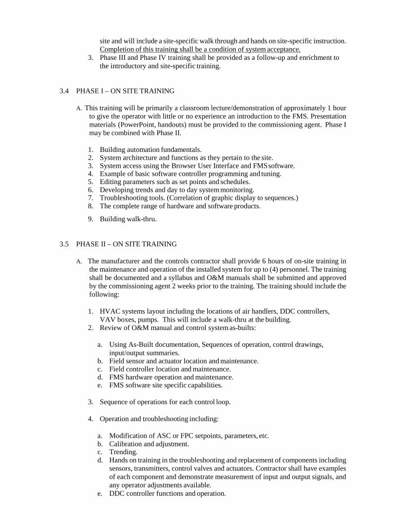
site and will include a site-specific walk through and hands on site-specific instruction. Completion of this training shall be a condition of system acceptance.
3. Phase III and Phase IV training shall be provided as a follow-up and enrichment to the introductory and site-specific training.
3.4 PHASE I – ON SITE TRAINING
A. This training will be primarily a classroom lecture/demonstration of approximately 1 hour to give the operator with little or no experience an introduction to the FMS. Presentation materials (PowerPoint, handouts) must be provided to the commissioning agent. Phase I may be combined with Phase II.
1. Building automation fundamentals. 2. System architecture and functions as they pertain to the site. 3. System access using the Browser User Interface and FMS software. 4. Example of basic software controller programming and tuning. 5. Editing parameters such as set points and schedules. 6. Developing trends and day to day system monitoring. 7. Troubleshooting tools. (Correlation of graphic display to sequences.) 8. The complete range of hardware and software products.
9. Building walk-thru.
3.5 PHASE II – ON SITE TRAINING
A. The manufacturer and the controls contractor shall provide 6 hours of on-site training in the maintenance and operation of the installed system for up to (4) personnel. The training shall be documented and a syllabus and O&M manuals shall be submitted and approved by the commissioning agent 2 weeks prior to the training. The training should include the following:
1. HVAC systems layout including the locations of air handlers, DDC controllers,
VAV boxes, pumps. This will include a walk-thru at the building. 2. Review of O&M manual and control system as-builts:
a. Using As-Built documentation, Sequences of operation, control drawings,
input/output summaries. b. Field sensor and actuator location and maintenance. c. Field controller location and maintenance. d. FMS hardware operation and maintenance. e. FMS software site specific capabilities.
3. Sequence of operations for each control loop.
4. Operation and troubleshooting including:
a. Modification of ASC or FPC setpoints, parameters, etc. b. Calibration and adjustment. c. Trending. d. Hands on training in the troubleshooting and replacement of components including
sensors, transmitters, control valves and actuators. Contractor shall have examples of each component and demonstrate measurement of input and output signals, and any operator adjustments available.
e. DDC controller functions and operation.

3.6 PHASE III – ON SITE TRAINING
A. No later than 6 months and no earlier than 4 months from building acceptance, the SI will repeat Phase I and Phase II training. Training to be consolidated into one 4 hour session.
3.7 PHASE IV – ON THE JOB TRAINING
A. SI and/or controls contractor shall coordinate all site visits and provide opportunity for university personnel to receive OJT during warranty work. Additionally, provide 2 days of OJT control loop tuning with owner utilizing owner laptop.
B. The DDC contractor shall provide an additional 4 hours on-site training session twelve (12)
months after project completion. The purpose of the session will be to review any operational problems that have developed. In addition, the contractor will lead Facilities Operations personnel through a comprehensive annual preventative maintenance of the controls system. This shall be scheduled at least one (1) month in advance.
3.8 WARRANTY ACCESS
A. The Owner shall grant the Contractor, reasonable access to the BAS system during the warranty period. The owner shall provide at no cost to the contractor web browser access (VPN) for remote service and troubleshooting during warranty period.
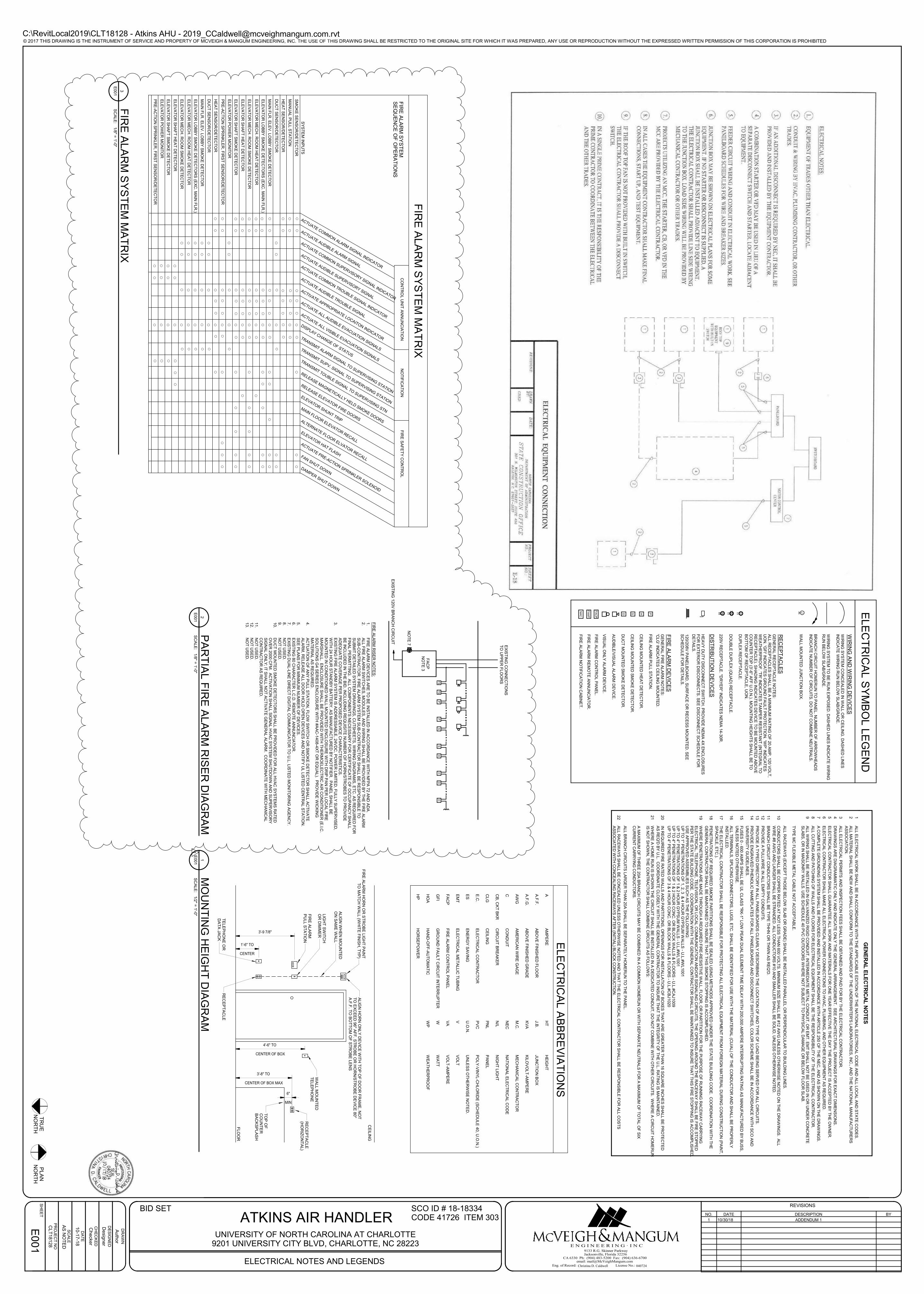
JD HS
FA
CP
NA
C
P
FA
AP
EL
EC
TR
ICA
L A
BB
RE
VIA
TIO
NS
AA.F
.F.
A.F
.G.
AW
G
CCB
, CK
T B
KR
CLG
E.C
.
ES
EM
T
FA
CP
GF
I
HO
A
HP
AM
PE
RE
AB
OV
E F
INIS
HE
D F
LO
OR
AB
OV
E F
INIS
HE
D G
RA
DE
AM
ER
ICA
N W
IRE
GA
GE
CO
ND
UIT
CIR
CU
IT B
RE
AK
ER
CE
ILIN
G
ELE
CT
RIC
AL C
ON
TR
AC
TO
R
EN
ER
GY
SA
VIN
G
ELE
CT
RIC
AL M
ET
ALLIC
TU
BIN
G
FIR
E A
LA
RM
CO
NT
RO
L P
AN
EL
GR
OU
ND
FA
ULT
CIR
CU
IT IN
TE
RR
UP
TE
R
HA
ND
-OF
F-A
UT
OM
AT
IC
HO
RS
EP
OW
ER
HT
J.B
.
KV
A
M.C
.
NE
C
N/L
PN
L
PV
C
U.O
.N.
VVA
WWP
HE
IGH
T
JU
NC
TIO
N B
OX
KIL
OV
OLT
-AM
PE
RE
ME
CH
AN
ICA
L C
ON
TR
AC
TO
R
NA
TIO
NA
L E
LE
CT
RIC
AL C
OD
E
NIG
HT
LIG
HT
PA
NE
L
PO
LY
-VIN
YL-C
HLO
RID
E (S
CH
ED
ULE
40, U
.O.N
.)
UN
LE
SS
OT
HE
RW
ISE
NO
TE
D.
VO
LT
VO
LT
-AM
PE
RE
WA
TT
WE
AT
HE
RP
RO
OF
EL
EC
TR
ICA
L S
YM
BO
L L
EG
EN
D
FIR
E A
LA
RM
PU
LL S
TA
TIO
N.
CE
ILIN
G M
OU
NT
ED
SM
OK
E D
ET
EC
TO
R.
CE
ILIN
G M
OU
NT
ED
HE
AT
DE
TE
CT
OR
.
DU
CT
MO
UN
TE
D S
MO
KE
DE
TE
CT
OR
.
AU
DIB
LE
/VIS
UA
L A
LA
RM
DE
VIC
E.
VIS
UA
L O
NLY
ALA
RM
DE
VIC
E.
DU
PLE
X R
EC
EP
TA
CLE
.
WIR
ING
SY
ST
EM
CO
NC
EA
LE
D IN
WA
LL O
R C
EIL
ING
. DA
SH
ED
LIN
ES
IN
DIC
AT
E W
IRIN
G R
UN
BE
LO
W S
LA
B/G
RA
DE
.
WIR
ING
SY
ST
EM
TO
BE
RU
N E
XP
OS
ED
. DA
SH
ED
LIN
ES
IND
ICA
TE
WIR
ING
R
UN
BE
LO
W S
LA
B/G
RA
DE
.
BR
AN
CH
CIR
CU
IT H
OM
ER
UN
TO
PA
NE
L. N
UM
BE
R O
F A
RR
OW
HE
AD
S
IND
ICA
TE
NU
MB
ER
OF
CIR
CU
ITS
. DO
NO
T C
OM
BIN
E N
EU
TR
ALS
.
WA
LL M
OU
NT
ED
JU
NC
TIO
N B
OX
.
WIR
ING
AN
D W
IRIN
G D
EV
ICE
S
RE
CE
PT
AC
LE
SG
EN
ER
AL R
EC
EP
TA
CLE
NO
TE
S:
ALL R
EC
EP
TA
CLE
S S
HA
LL B
E A
MIN
IMU
M R
AT
ING
OF
20 A
MP
, 120 V
OLT
, U
ON
. 'GF
I' IND
ICA
TE
S G
RO
UN
D F
AU
LT
PR
OT
EC
TIO
N. 'W
P' IN
DIC
AT
ES
W
EA
TH
ER
PR
OO
F. 'T
R' IN
DIC
AT
ES
TA
MP
ER
RE
SIS
TA
NT
(INT
EG
RA
L T
O
RE
CE
PT
AC
LE
). SH
AD
ING
IND
ICA
TE
S D
EV
ICE
TO
BE
MO
UN
TE
D A
BO
VE
C
OU
NT
ER
TO
P (3
'-6'' A
FF
U.O
.N.). M
OU
NT
ING
HE
IGH
TS
SH
ALL B
E T
O
BO
TT
OM
OF
RE
CE
PT
AC
LE
, UO
N.
DO
UB
LE
DU
PLE
X (Q
UA
D) R
EC
EP
TA
CLE
.
220V
RE
CE
PT
AC
LE
. "DR
YE
R" IN
DIC
AT
ES
NE
MA
14-3
0R
.
FIR
E A
LA
RM
DE
VIC
ES
GE
NE
RA
L F
IRE
ALA
RM
NO
TE
S:
'CLG
' IND
ICA
TE
S C
EIL
ING
MO
UN
TE
D.
DIS
TR
IBU
TIO
N D
EV
ICE
S
HE
AV
Y D
UT
Y D
ISC
ON
NE
CT
SW
ITC
H. P
RO
VID
E N
EM
A 4
X E
NC
LO
SU
RE
S
FO
R E
XT
ER
IOR
DIS
CO
NN
EC
TS
. SE
E D
ISC
ON
NE
CT
SC
HE
DU
LE
FO
R
DE
TA
ILS
.
120/2
08V
PA
NE
LB
OA
RD
, SU
RF
AC
E O
R R
EC
ES
S M
OU
NT
ED
. SE
E
SC
HE
DU
LE
FO
R D
ET
AIL
S.
FIR
E A
LA
RM
CO
NT
RO
L P
AN
EL.
FIR
E A
LA
RM
NO
TIF
ICA
TIO
N C
AB
INE
T.
FIR
E A
LA
RM
RE
MO
TE
AN
NU
NC
IAT
OR
.
CENTER
1'-6" TO
RE
CE
PT
AC
LE
TE
LE
PH
ON
E O
R
DA
TA
JA
CK
WA
LL M
OU
NT
ED
TE
LE
PH
ON
E
RE
CE
PT
AC
LE
(HO
RIZ
ON
TA
L)
TO
P O
FC
OU
NT
ER
BA
CK
SP
LA
SH
CENTER OF BOX MAX
3'-8" TO
FLO
OR
CE
ILIN
G
CENTER OF BOX
4'-6" TO
3'-9 7/8"
ALIG
N H
OR
N O
NLY
DE
VIC
E W
ITH
TO
P O
F D
OO
R F
RA
ME
, NO
T
TO
EX
CE
ED
96" A
FF
. ST
RO
BE
OR
HO
RN
/ST
RO
BE
DE
VIC
E 8
0''
A.F
.F. T
O B
OT
TO
M O
F S
TR
OB
E L
EN
S
FIR
E A
LA
RM
PU
LL S
TA
TIO
N
LIG
HT
SW
ITC
HO
R D
IMM
ER
ALIG
N W
HE
N M
OU
NT
ED
ON
SA
ME
WA
LL
FIR
E A
LA
RM
HO
RN
OR
ST
RO
BE
LIG
HT
PA
INT
T
O M
AT
CH
WA
LL (W
HIT
E F
INIS
H, T
YP
)
MIN
6"
FS
TS
PS
DP
SD
HH
FIR
E A
LA
RM
RIS
ER
NO
TE
S:
FA
CP
FA
CP
NO
TE
3
NO
TE
7
EX
IST
ING
120V
BR
AN
CH
CIR
CU
IT
1.
FIR
E A
LA
RM
DE
VIC
ES
AR
E T
O B
E IN
ST
ALLE
D IN
AC
CO
RD
AN
CE
WIT
H N
FP
A 7
2 A
ND
AD
A.
2.
ALL F
IRE
ALA
RM
SW
ITC
HE
S, M
OD
ULE
S, A
ND
WIR
ING
SH
ALL B
E P
RO
VID
ED
BY
TH
E F
IRE
ALA
RM
S
UB
-CO
NT
RA
CT
OR
. FIR
E A
LA
RM
SY
ST
EM
SU
B-C
ON
TR
AC
TO
R S
HA
LL B
E R
ES
PO
NS
IBLE
TO
S
UB
MIT
DE
TA
ILE
D S
YS
TE
M D
RA
WIN
GS
, CU
TS
HE
ET
S, W
IRIN
G D
IAG
RA
MS
, ET
C. A
S R
EQ
UIR
ED
FO
R
FIN
AL P
ER
MIT
TIN
G. A
LL C
OM
PO
NE
NT
S N
EC
ES
SA
RY
FO
R C
ER
TIF
ICA
TE
OF
OC
CU
PA
NC
Y S
HA
LL
BE
INC
LU
DE
D IN
TH
E B
ID, IN
CLU
DIN
G R
EQ
UIS
ITE
NU
MB
ER
OF
HO
RN
/ST
RO
BE
S T
O P
RO
VID
E
AD
EQ
UA
TE
CO
VE
RA
GE
PE
R P
RO
PO
SE
D D
EV
ICE
CH
AR
AC
TE
RIS
TIC
S.
3.
EX
IST
ING
FIR
E A
LA
RM
SY
ST
EM
IS A
DD
RE
SS
AB
LE
, 24V
DC
, PO
WE
R L
IMIT
ED
, FU
LLY
SU
PE
RV
ISE
D,
WIT
H 2
4 H
OU
R S
TA
ND
BY
BA
TT
ER
Y. A
S M
AN
UF
AC
TU
RE
D B
Y N
OT
IFIE
R. P
AN
EL S
HA
LL B
E
MO
UN
TE
D IN
CO
ND
ITIO
NE
D W
ALL M
OU
NT
ED
EN
CLO
SU
RE
WIT
H D
RIP
PA
N P
ER
LO
CA
L F
IRE
M
AR
SH
ALL. E
NC
LO
SU
RE
SH
ALL B
E P
RO
VID
ED
WIT
H T
HE
RM
OE
LE
CT
RIC
AIR
CO
ND
ITIO
NE
R (E
.I.C.
SO
LU
TIO
NS
G4 S
ER
IES
EN
CLO
SU
RE
WIT
H #
AA
C-1
408-4
XT
OR
EQ
UA
L). P
RO
VID
E W
ICK
ING
M
AT
ER
IAL A
S R
EQ
UIR
ED
.4.
AC
TU
AT
ION
OF
AN
Y P
ULL S
TA
TIO
N, F
LO
W S
WIT
CH
OR
SM
OK
E D
ET
EC
TO
R S
HA
LL A
CT
IVA
TE
A
LA
RM
, RE
LE
AS
E A
LL D
OO
R H
OLD
OP
EN
DE
VIC
ES
AN
D N
OT
IFY
UL L
IST
ED
CE
NT
RA
L S
TA
TIO
N.
5.
SE
E P
LA
NS
FO
R M
INIM
UM
NU
MB
ER
OF
DE
VIC
ES
.6.
EX
IST
ING
80 C
HA
RA
CT
ER
L.C
.D. R
EM
OT
E A
NN
UN
CIA
TO
R.
7.
EX
IST
ING
DU
AL-L
INE
DIR
EC
T D
IGIT
AL C
OM
MU
NIC
AT
OR
TO
U.L
. LIS
TE
D M
ON
ITO
RIN
G A
GE
NC
Y.
8.
NO
T U
SE
D.
9.
NO
T U
SE
D.
10.
DU
CT
MO
UN
TE
D S
MO
KE
DE
TE
CT
OR
S S
HA
LL B
E P
RO
VID
ED
FO
R A
LL H
VA
C S
YS
TE
MS
RA
TE
D
OV
ER
2000 C
FM
. AC
TIV
AT
ION
SH
ALL S
IGN
AL H
VA
C S
YS
TE
M S
HU
TD
OW
N A
ND
SU
PE
RV
ISO
RY
S
IGN
AL O
NLY
; IT S
HA
LL N
OT
AC
TIV
AT
E G
EN
ER
AL A
LA
RM
. CO
OR
DIN
AT
E W
ITH
ME
CH
AN
ICA
L
CO
NT
RA
CT
OR
AS
RE
QU
IRE
D.
11.
NO
T U
SE
D.
12.
NO
T U
SE
D.
13.
NO
T U
SE
D.
EX
IST
ING
CO
NN
EC
TIO
NS
TO
UP
PE
R F
LO
OR
S
FIR
E A
LA
RM
SY
ST
EM
MA
TR
IX
TRANSMIT TOUBLE SIGNAL TO SUPERVISING STN
RELEASE MAGNETICALLY HELD SMOKE DOORS
RELEASE ELEVATOR FIRE DOORS
ELEVATOR SHUNT TRIP
TRANSMIT ALARM SIGNAL TO SUPERVISING STATION
TRANSMIT SUPV. SIGNAL TO SUPERVISING STATION
ACTUATE COMMON ALARM SIGNAL INDICATOR
ACTUATE AUDIBLE ALARM SIGNAL
ACTUATE COMMON SUPERVISORY SIGNAL INDICATOR
ACTUATE AUDIBLE TROUBLE SIGNAL
ACTIVATE APPROPRIATE LOCAITON INDICATOR
ACTUATE AUDIBLE SUPERVISORY SIGNAL
ACTUATE COMMON TROUBLE SIGNAL INDICATOR
DISPLAY CHANGE OF STATUS
ACTUATE ALL VISIBLE EVACUATION SIGNALS
ACTUATE ALL AUDIBLE EVACUATION SIGNALS
ELE
VA
TO
R P
OW
ER
MO
NIT
OR
SY
ST
EM
INP
UT
S
ELE
VA
TO
R L
OB
BY
SM
OK
E D
ET
EC
TO
RS
(EX
C. M
AIN
FLR
.)
ELE
VA
TO
R S
HA
FT
SM
OK
E D
ET
EC
TO
R
ELE
VA
TO
R M
EC
H. R
OO
M H
EA
T D
ET
EC
TO
R
ELE
VA
TO
R M
EC
H. R
OO
M S
MO
KE
DE
TE
CT
OR
ELE
VA
TO
R S
HA
FT
HE
AT
DE
TE
CT
OR
MA
IN F
LR
. ELE
V. L
OB
BY
SM
OK
E D
ET
EC
TO
R
SM
OK
E S
EN
SO
R/D
ET
EC
TO
R
MA
NU
AL P
ULL S
TA
TIO
N
CO
NT
RO
L U
NIT
AN
NU
NC
IAT
ION
FIR
E A
LA
RM
SY
ST
EM
SE
QU
EN
CE
OF
OP
ER
AT
ION
S
HE
AT
SE
NS
OR
/DE
TE
CT
OR
DU
CT
SE
NS
OR
/DE
TE
CT
OR
PR
E-A
CT
ION
SP
RIN
KLE
R, F
IRS
T S
EN
SO
R/D
ET
EC
TO
R
ACTUATE PRE-ACTION SPRINKLER SOLENOID
FAN SHUT DOWN
DAMPER SHUT DOWN
ALTERNATE FLOOR ELVATOR RECALL
ELEVATOR HAT FLASH
NO
TIF
ICA
TIO
NF
IRE
SA
FE
TY
CO
NT
RO
L
MAIN FLOOR ELEVATOR RECALL
ELE
VA
TO
R P
OW
ER
MO
NIT
OR
ELE
VA
TO
R L
OB
BY
SM
OK
E D
ET
EC
TO
RS
(EX
C. M
AIN
FLR
.)
ELE
VA
TO
R S
HA
FT
SM
OK
E D
ET
EC
TO
R
ELE
VA
TO
R M
EC
H. R
OO
M H
EA
T D
ET
EC
TO
R
ELE
VA
TO
R M
EC
H. R
OO
M S
MO
KE
DE
TE
CT
OR
ELE
VA
TO
R S
HA
FT
HE
AT
DE
TE
CT
OR
MA
IN F
LR
. ELE
V. L
OB
BY
SM
OK
E D
ET
EC
TO
R
HE
AT
SE
NS
OR
/DE
TE
CT
OR
DU
CT
SE
NS
OR
/DE
TE
CT
OR
PR
E-A
CT
ION
SP
RIN
KLE
R, F
IRS
T S
EN
SO
R/D
ET
EC
TO
R
© 2017 THIS DRAWING IS THE INSTRUMENT OF SERVICE AND PROPERTY OF MCVEIGH & MANGUM ENGINEERING, INC. THE USE OF THIS DRAWING SHALL BE RESTRICTED TO THE ORIGINAL SITE FOR WHICH IT WAS PREPARED, ANY USE OR REPRODUCTION WITHOUT THE EXPRESSED WRITTEN PERMISSION OF THIS CORPORATION IS PROHIBITED
REVISIONS
E N G I N E E R I N G · I N C
Eng. of Record: License No.:
9133 R.G. Skinner ParkwayJacksonville, Florida 32256
CA 6330 Ph: (904) 483-5200 Fax: (904) 636-6700 email: [email protected]
PR
OJE
CT
NO
SC
ALE
DR
AW
N
CH
EC
KE
D
DA
TE
DE
SIG
NE
D
SH
EE
T
AS
NO
TE
D
SCO ID # 18-18334CODE 41726 ITEM 303
TR
UE
N
OR
TH
PLA
N
NO
RT
H
C:\RevitLocal2019\CLT18128 - Atkins AHU - [email protected]
ELECTRICAL NOTES AND LEGENDS
UNIVERSITY OF NORTH CAROLINA AT CHARLOTTE9201 UNIVERSITY CITY BLVD, CHARLOTTE, NC 28223
040724Christina D. Caldwell
ATKINS AIR HANDLER
Ch
ecker
Auth
or
10-1
7-1
8
CL
T18
12
8
E0
01
De
sig
ner
BID SET
GE
NE
RA
L E
LE
CT
RIC
AL
NO
TE
S
1A
LL
EL
EC
TR
ICA
L W
OR
K S
HA
LL B
E IN
AC
CO
RD
AN
CE
WIT
H T
HE
AP
PL
ICA
BL
E E
DIT
ION
OF
TH
E N
AT
ION
AL
ELE
CT
RIC
AL C
OD
E A
ND
ALL L
OC
AL
AN
D S
TA
TE
CO
DE
S.
2A
LL
MA
TE
RIA
L S
HA
LL
BE
NE
W A
ND
SH
ALL C
ON
FO
RM
TO
TH
E S
TA
ND
AR
DS
OF
TH
E U
ND
ER
WR
ITE
R'S
LA
BO
RA
TO
RIE
S, IN
C., A
ND
TH
E N
AT
ION
AL M
AN
UF
AC
TU
RE
RS
AS
SO
CIA
TIO
N.
3A
LL
ELE
CT
RIC
AL
PE
RM
ITS
AN
D IN
SP
EC
TIO
N F
EE
S S
HA
LL B
E O
BT
AIN
ED
AN
D P
AID
FO
R B
Y T
HE
ELE
CT
RIC
AL C
ON
TR
AC
TO
R.
4D
RA
WIN
GS
AR
E D
IAG
RA
MM
AT
IC O
NL
Y A
ND
IND
ICA
TE
ON
LY
TH
E G
EN
ER
AL A
RR
AN
GE
ME
NT
. SE
E A
RC
HIT
EC
TU
RA
L D
RA
WIN
GS
FO
R E
XA
CT
DIM
EN
SIO
NS
.
5E
LE
CT
RIC
AL C
ON
TR
AC
TO
R S
HA
LL G
UA
RA
NT
EE
ALL W
OR
K A
ND
MA
TE
RIA
LS
FO
R O
NE
YE
AR
EF
FE
CT
IVE
TH
E D
AY
TH
E P
RO
JE
CT
IS A
CC
EP
TE
D B
Y T
HE
OW
NE
R.
6E
LE
CT
RIC
AL
CO
NT
RA
CT
OR
SH
AL
L M
AK
E A
LL
ELE
CT
RIC
AL
PO
WE
R C
ON
NE
CT
ION
S T
O H
VA
C, P
LU
MB
ING
, AN
D O
TH
ER
EQ
UIP
ME
NT
AS
RE
QU
IRE
D.
7A
CO
MP
LE
TE
GR
OU
ND
ING
SY
ST
EM
SH
ALL B
E P
RO
VID
ED
AN
D IN
ST
ALL
ED
IN A
CC
OR
DA
NC
E W
ITH
AR
TIC
LE
250
OF
TH
E N
EC
, AN
D A
S S
HO
WN
ON
TH
E D
RA
WIN
GS
.
8A
LL
CU
TT
ING
AN
D P
AT
CH
ING
OF
WA
LL
S A
ND
FLO
OR
S F
OR
ELE
CT
RIC
AL E
QU
IPM
EN
T S
HA
LL B
E T
HE
RE
SP
ON
SIB
ILIT
Y O
F T
HE
EL
EC
TR
ICA
L C
ON
TR
AC
TO
R.
9A
LL
WIR
ING
SH
AL
L B
E IN
ST
AL
LE
D IN
GA
LV
AN
IZE
D R
IGID
CO
ND
UIT
, INT
ER
ME
DIA
TE
ME
TA
L C
ON
DU
IT, O
R E
MT
. EM
T S
HA
LL N
OT
BE
US
ED
IN O
R U
ND
ER
CO
NC
RE
TE
SLA
BS
, OR
IN M
AS
ON
RY
WA
LLS
. US
E S
CH
ED
UL
E 4
0 P
VC
OU
TD
OO
RS
WH
ER
E N
OT
SU
BJE
CT
TO
PH
YS
ICA
L D
AM
AG
E O
R B
EL
OW
FLO
OR
SLA
B.
TY
PE
MC
FLE
XIB
LE
ME
TA
L C
AB
LE
NO
T A
CC
EP
TA
BL
E.
ALL
RA
CE
WA
YS
(EX
CE
PT
TH
OS
E B
EL
OW
SLA
B O
R G
RA
DE
) SH
AL
L B
E IN
ST
AL
LE
D P
AR
ALLE
L O
R P
ER
PE
ND
ICU
LA
R T
O B
UIL
DIN
G L
INE
S.
10
CO
ND
UC
TO
RS
SH
ALL
BE
CO
PP
ER
RA
TE
D A
T N
OT
LE
SS
TH
AN
60
0 V
OLT
S. M
INIM
UM
SIZ
E S
HA
LL B
E #
12
AW
G U
NL
ES
S O
TH
ER
WIS
E N
OT
ED
ON
TH
E D
RA
WIN
GS
. ALL
WIR
E #
8 A
WG
AN
D L
AR
GE
R S
HA
LL B
E S
TR
AN
DE
D. A
LL
CO
ND
UC
TO
RS
#1
0 A
ND
SM
ALLE
R S
HA
LL B
E S
OLID
, UN
LE
SS
OT
HE
RW
ISE
NO
TE
D.
11
BR
AN
CH
CIR
CU
IT C
ON
DU
CT
OR
S S
HA
LL
BE
TY
PE
TH
HN
OR
TH
WN
AS
RE
Q'D
.
12
PR
OV
IDE
A P
ULL
WIR
E IN
ALL
EM
PT
Y C
ON
DU
ITS
.
13
PR
OV
IDE
A T
YP
ED
DIR
EC
TO
RY
IN A
LL P
AN
ELB
OA
RD
S C
LE
AR
LY
DE
SC
RIB
ING
TH
E L
OC
AT
ION
OF
AN
D T
YP
E O
F L
OA
D B
EIN
G S
ER
VE
D F
OR
ALL
CIR
CU
ITS
.
14
PR
OV
IDE
EN
GR
AV
ED
PH
EN
OL
IC N
AM
EP
LA
TE
S F
OR
ALL P
AN
EL
BO
AR
DS
AN
D D
ISC
ON
NE
CT
SW
ITC
HE
S, C
OLO
R S
CH
EM
E S
HA
LL
BE
IN A
CC
OR
DA
NC
E W
ITH
SC
O A
ND
UN
IVE
RS
ITY
GU
IDE
LIN
ES
.
15
FU
SE
S 0
- 600
AM
PS
SH
ALL B
E U
L C
LA
SS
"RK
-1" L
OW
PE
AK
DU
AL E
LE
ME
NT
TIM
E D
ELA
Y W
ITH
200,0
00 A
MP
ER
E IN
TE
RR
UP
TIN
G R
AT
ING
AS
MA
NU
FA
CT
UR
ED
BY
BU
SS
,U
NLE
SS
NO
TE
D O
TH
ER
WIS
E.
16
ALL
TE
RM
INA
LS
, SP
LIC
ING
CO
NN
EC
TO
RS
, LU
GS
, ET
C. S
HA
LL B
E ID
EN
TIF
IED
FO
R U
SE
WIT
H T
HE
MA
TE
RIA
L (C
U/A
L) O
F T
HE
CO
ND
UC
TO
R A
ND
SH
AL
L B
E P
RO
PE
RLY
INS
TA
LLE
D.
17
TH
E E
LE
CT
RIC
AL C
ON
TR
AC
TO
R S
HA
LL
BE
RE
SP
ON
SIB
LE
FO
R P
RO
TE
CT
ING
ALL
ELE
CT
RIC
AL
EQ
UIP
ME
NT
FR
OM
FO
RE
IGN
MA
TE
RIA
L D
UR
ING
CO
NS
TR
UC
TIO
N (P
AIN
T,
SP
AC
KLE
, ET
C.).
18
PE
NE
TR
AT
ION
S O
F R
EQ
UIR
ED
SM
OK
E P
AR
TIT
ION
S S
HA
LL
BE
SE
ALE
D U
SIN
G M
ET
HO
DS
AP
PR
OV
ED
UN
DE
R T
HE
ST
AT
E B
UIL
DIN
G C
OD
E. C
OO
RD
INA
TIO
N W
ITH
TH
EG
EN
ER
AL
CO
NT
RA
CT
OR
SH
ALL
BE
MA
INT
AIN
ED
TO
INS
UR
E T
HA
T T
HIS
SM
OK
E S
TO
PP
ING
IS A
CC
OM
PL
ISH
ED
.
19
WH
ER
E P
EN
ET
RA
TIO
NS
AR
E M
AD
E T
HR
OU
GH
A R
EQ
UIR
ED
FIR
E-R
ES
IST
IVE
WA
LL, F
LO
OR
, OR
PA
RT
ITIO
N F
OR
TH
E P
UR
PO
SE
OF
RU
NN
ING
RA
CE
WA
Y C
AR
RY
ING
ELE
CT
RIC
AL, T
ELE
PH
ON
E, T
ELE
VIS
ION
, OR
LO
CA
L C
OM
MU
NIC
AT
ION
AN
D/O
R S
IGN
ALIN
G C
IRC
UIT
S, T
HE
OP
EN
ING
AR
OU
ND
TH
E R
AC
EW
AY
SH
AL
L B
E F
IRE
ST
OP
PE
DP
ER
TH
E S
TA
TE
BU
ILD
ING
CO
DE
. CO
OR
DIN
AT
ION
WIT
H T
HE
GE
NE
RA
L C
ON
TR
AC
TO
R S
HA
LL
BE
MA
INT
AIN
ED
TO
INS
UR
E T
HA
T T
HIS
FIR
E S
TO
PP
ING
IS A
CC
OM
PL
ISH
ED
.U
SE
AP
PR
OV
ED
AS
SE
MB
LIE
S S
UC
H A
S T
HE
FO
LL
OW
ING
:U
P T
O 1
'' PE
NE
TR
AT
ION
S O
F 1
, 2, 3
& 4
HO
UR
GY
PS
UM
WA
LLS
- U.L
.#W
L10
01
UP
TO
4'' P
EN
ET
RA
TIO
NS
OF
1 &
2 H
OU
R G
YP
SU
M W
ALL
S - U
.L.#
WL10
01
UP
TO
4'' P
EN
ET
RA
TIO
NS
OF
1 &
2 H
OU
R C
ON
C. O
R B
LO
CK
WA
LLS
& F
LO
OR
S - U
.L.#
CA
J10
09
UP
TO
4'' P
EN
ET
RA
TIO
NS
OF
3 &
4 H
OU
R C
ON
C. O
R B
LO
CK
WA
LLS
& F
LO
OR
S - U
.L.#
CB
J10
20
20
IN R
EQ
UIR
ED
FIR
E R
AT
ED
WA
LL
S A
ND
PA
RT
ITIO
NS
, OP
EN
ING
S F
OR
INS
TA
LLA
TIO
N O
F B
OX
ES
TH
AT
AR
E G
RE
AT
ER
TH
AN
16
SQ
UA
RE
INC
HE
S S
HA
LL
BE
PR
OT
EC
TE
DA
S R
EQ
'D B
Y U
.L. C
OO
RD
INA
TE
CLO
SE
LY
WIT
H T
HE
GE
NE
RA
L C
ON
TR
AC
TO
R T
O IN
SU
RE
TH
AT
TH
E IN
TE
GR
ITY
OF
TH
E U
.L. R
AT
ING
IS M
AIN
TA
INE
D.
21
WH
ER
E A
HO
ME
RU
N IS
SH
OW
N T
HE
CIR
CU
IT S
HA
LL B
E IN
ST
ALLE
D IN
A D
ED
ICA
TE
D C
ON
DU
IT, D
O N
OT
CO
MB
INE
WIT
H O
TH
ER
CIR
CU
ITS
. WH
ER
E A
CIR
CU
IT H
OM
ER
UN
IS N
OT
SH
OW
N, T
HE
CO
NT
RA
CT
OR
SH
ALL C
OM
BIN
E C
IRC
UIT
S A
S F
OL
LO
WS
:
A M
AX
IMU
M O
F T
HR
EE
20A
BR
AN
CH
CIR
CU
ITS
MA
Y B
E C
OM
BIN
ED
IN A
CO
MM
ON
HO
ME
RU
N O
R W
ITH
SE
PA
RA
TE
NE
UT
RA
LS
FO
R A
MA
XIM
UM
OF
TO
TA
L O
F S
IXC
UR
RE
NT
CA
RR
YIN
G C
ON
DU
CT
OR
S.
ALL
BR
AN
CH
CIR
CU
ITS
LA
RG
ER
TH
AN
20
A S
HA
LL
BE
SE
PA
RA
TE
LY
HO
ME
RU
N T
O T
HE
PA
NE
L.
22
ALL
RA
CE
WA
YS
SH
AL
L B
E C
ON
CE
AL
ED
UN
LE
SS
OT
HE
RW
ISE
NO
TE
D A
ND
TH
AT
TH
E E
LE
CT
RIC
AL C
ON
TR
AC
TO
R S
HA
LL B
E R
ES
PO
NS
IBLE
FO
R A
LL C
OS
TS
AS
SO
CIA
TE
D W
ITH
CO
NC
EA
LIN
G R
AC
EW
AY
S A
FT
ER
(INIT
IAL) B
LO
CK
CO
NS
TR
UC
TIO
N.
NO. DATE DESCRIPTION BY
1 10/30/18 ADDENDUM 1
SC
ALE
:1/2
" = 1
'-0"
E001
1M
OU
NT
ING
HE
IGH
T D
IAG
RA
MS
CA
LE
:1
/8" =
1'-0
"E
00
1
2P
AR
TIA
L F
IRE
AL
AR
M R
ISE
R D
IAG
RA
M
SC
AL
E:
1/8
" = 1
'-0"
E0
01
3F
IRE
AL
AR
M S
YS
TE
M M
AT
RIX
1
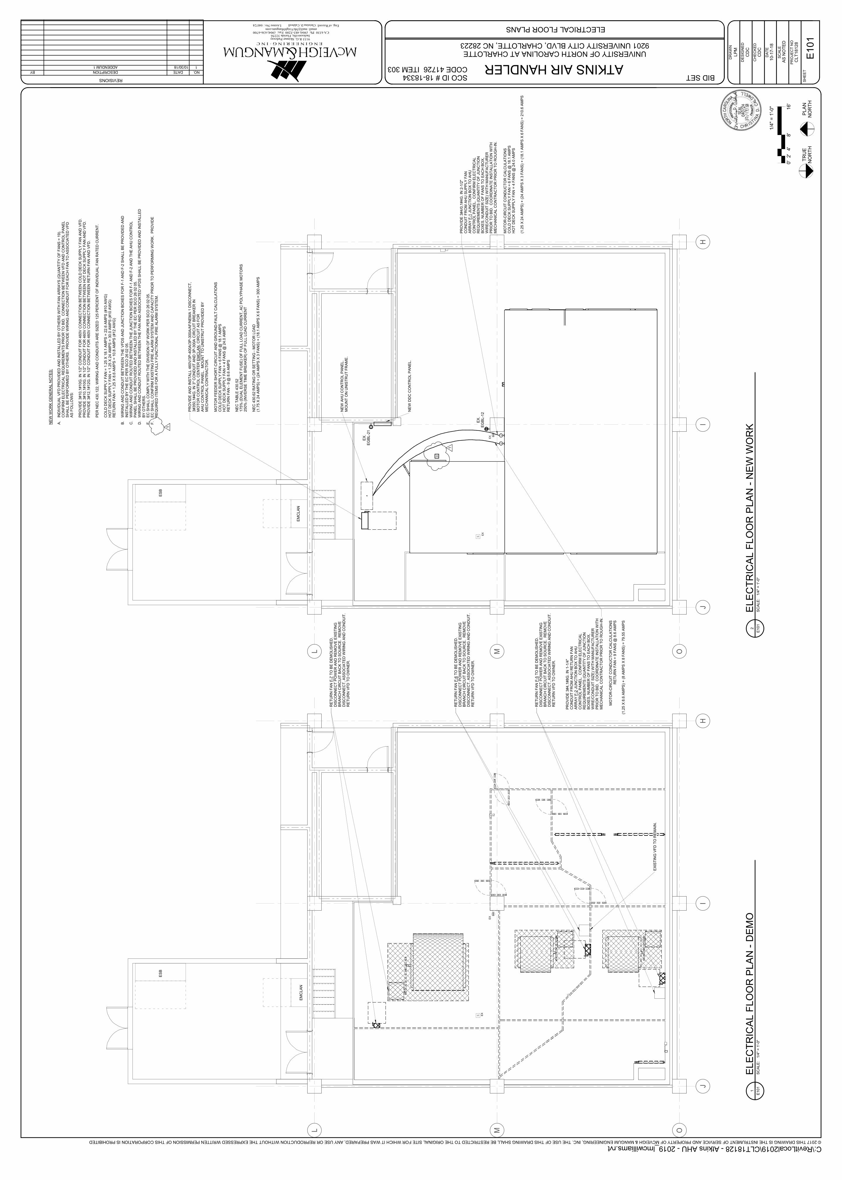
SS
JJ
D
OML
JI
H
EX
IST
ING
VF
D T
O R
EM
AIN
.
RE
TU
RN
FA
N F
-7T
O B
E D
EM
OLIS
HE
D.
DIS
CO
NN
EC
T P
OW
ER
AN
D R
EM
OV
E E
XIS
TIN
GB
RA
NC
H C
IRC
UIT
BA
CK
TO
SO
UR
CE
. R
EM
OV
E
DIS
CO
NN
EC
T, A
SS
OC
IAT
ED
WIR
ING
AN
D C
ON
DU
IT.
RE
TU
RN
VF
D T
O O
WN
ER
.
RE
TU
RN
FA
N F
-6T
O B
E D
EM
OLIS
HE
D.
DIS
CO
NN
EC
T P
OW
ER
AN
D R
EM
OV
E E
XIS
TIN
GB
RA
NC
H C
IRC
UIT
BA
CK
TO
SO
UR
CE
. R
EM
OV
E
DIS
CO
NN
EC
T, A
SS
OC
IAT
ED
WIR
ING
AN
D C
ON
DU
IT.
RE
TU
RN
VF
D T
O O
WN
ER
.
RE
TU
RN
FA
N F
-5T
O B
E D
EM
OLIS
HE
D.
DIS
CO
NN
EC
T P
OW
ER
AN
D R
EM
OV
E E
XIS
TIN
GB
RA
NC
H C
IRC
UIT
BA
CK
TO
SO
UR
CE
. R
EM
OV
E
DIS
CO
NN
EC
T, A
SS
OC
IAT
ED
WIR
ING
AN
D C
ON
DU
IT.
RE
TU
RN
VF
D T
O O
WN
ER
.
EX
EX
EM
CLA
N
ES
B
OML
JI
H
NE
W A
HU
CO
NT
RO
L P
AN
EL.
MO
UN
T O
N U
NIS
TR
UT
FR
AM
E.
NE
W D
DC
CO
NT
RO
L P
AN
EL.
PR
OV
IDE
AN
D IN
ST
ALL 4
60V
/3P
-400A
/3P
-300A
/AF
/NE
MA
1 D
ISC
ON
NE
CT
, 3#350,1
#4G
. IN
3"
CO
ND
UIT
AN
D 3
P-3
00A
CIR
CU
IT B
RE
AK
ER
IN
MO
TO
R C
ON
TR
OL C
EN
TE
R E
MC
LA
N, C
IRC
UIT
A5 F
OR
A
HU
CO
NT
RO
L P
AN
EL. M
OU
NT
TO
UN
IST
RU
T P
RO
VID
ED
BY
ME
CH
AN
ICA
L C
ON
TR
AC
TO
R.
PR
OV
IDE
3#4,1
#8G
. IN
1-1
/4"
CO
ND
UIT
FR
OM
AH
U R
ET
UR
N F
AN
AR
RA
Y F
-2JU
NC
TIO
N B
OX
TO
AH
UC
ON
TR
OL P
AN
EL. C
ON
FIR
M E
LE
CT
RIC
AL
RE
QU
IRE
ME
NT
S (
QU
AN
TIT
Y O
F J
UN
CT
ION
BO
XE
S, N
UM
BE
R O
F F
AN
S T
O E
AC
H B
OX
,W
IRE
/CO
ND
UIT
SIZ
E)
WIT
H M
AN
UF
AC
TU
RE
RP
RIO
R T
O B
ID. C
OO
RD
INA
TE
IN
ST
ALLA
TIO
N W
ITH
ME
CH
AN
ICA
L C
ON
TR
AC
TO
R P
RIO
R T
O R
OU
GH
-IN
.
PR
OV
IDE
3#4/0
,1#4G
. IN
2-1
/2"
CO
ND
UIT
FR
OM
AH
U S
UP
PLY
FA
NA
RR
AY
F-1
JU
NC
TIO
N B
OX
TO
AH
UC
ON
TR
OL P
AN
EL. C
ON
FIR
M E
LE
CT
RIC
AL
RE
QU
IRE
ME
NT
S (
QU
AN
TIT
Y O
F J
UN
CT
ION
BO
XE
S, N
UM
BE
R O
F F
AN
S T
O E
AC
H B
OX
,W
IRE
/CO
ND
UIT
SIZ
E)
WIT
H M
AN
UF
AC
TU
RE
RP
RIO
R T
O B
ID. C
OO
RD
INA
TE
IN
ST
ALLA
TIO
N W
ITH
ME
CH
AN
ICA
L C
ON
TR
AC
TO
R P
RIO
R T
O R
OU
GH
-IN
.
EX
EX
EM
CLA
N
ES
B
EX
.E
GB
L-2
1
EX
.E
GB
L-1
2
MO
TO
R-C
IRC
UIT
CO
ND
UC
TO
R C
ALC
ULA
TIO
NS
CO
LD
DE
CK
SU
PP
LY
FA
N =
6 F
AN
S @
18.1
AM
PS
HO
T D
EC
K S
UP
PLY
FA
N =
4 F
AN
S @
24.0
AM
PS
(1.2
5 X
24 A
MP
S)
+ (
24 A
MP
S X
3 F
AN
S)
+ (
18.1
AM
PS
X 6
FA
NS
) =
210.6
AM
PS
MO
TO
R-C
IRC
UIT
CO
ND
UC
TO
R C
ALC
ULA
TIO
NS
RE
TU
RN
FA
N =
9 F
AN
S @
8.6
AM
PS
(1.2
5 X
8.6
AM
PS
) +
(8 A
MP
S X
8 F
AN
S)
= 7
9.5
5 A
MP
S
MO
TO
R F
EE
DE
R S
HO
RT
-CIR
CU
IT A
ND
GR
OU
ND
-FA
ULT
CA
LC
ULA
TIO
NS
CO
LD
DE
CK
SU
PP
LY
FA
N =
6 F
AN
S @
18.1
AM
PS
HO
T D
EC
K S
UP
PLY
FA
N =
4 F
AN
S @
24.0
AM
PS
RE
TU
RN
FA
N -
9 @
8.6
AM
PS
NE
C T
AB
LE
430.5
2175%
(D
UA
L E
LE
ME
NT
FU
SE
) O
F F
ULL L
OA
D C
UR
RE
NT
, A
C P
OLY
PH
AS
E M
OT
OR
S250%
(IN
VE
RS
E T
IME
BR
EA
KE
R)
OF
FU
LL L
OA
D C
UR
RE
NT
NE
C 4
30.6
2 R
AT
ING
OR
SE
TT
ING
-M
OT
OR
LO
AD
(1.7
5 X
24 A
MP
S)
+ (
24 A
MP
S X
3 F
AN
S)
+ (
18.1
AM
PS
X 6
FA
NS
) =
300 A
MP
S
1
© 2017 THIS DRAWING IS THE INSTRUMENT OF SERVICE AND PROPERTY OF MCVEIGH & MANGUM ENGINEERING, INC. THE USE OF THIS DRAWING SHALL BE RESTRICTED TO THE ORIGINAL SITE FOR WHICH IT WAS PREPARED, ANY USE OR REPRODUCTION WITHOUT THE EXPRESSED WRITTEN PERMISSION OF THIS CORPORATION IS PROHIBITED
REVISIONS
E N G I N E E R I N G · I N C
Eng. of Record:License No.:
9133 R.G. Skinner ParkwayJacksonville, Florida 32256
CA 6330 Ph: (904) 483-5200 Fax: (904) 636-6700 email: [email protected]
PR
OJE
CT
NO
SC
ALE
DR
AW
N
CH
EC
KE
D
DA
TE
DE
SIG
NE
D
SH
EE
T
AS
NO
TE
D
SCO ID # 18-18334CODE 41726 ITEM 303
TR
UE
N
OR
TH
PLA
N
NO
RT
H
C:\RevitLocal2019\CLT18128 - Atkins AHU - 2019_lmcwilliams.rvt
ELECTRICAL FLOOR PLANS
UNIVERSITY OF NORTH CAROLINA AT CHARLOTTE9201 UNIVERSITY CITY BLVD, CHARLOTTE, NC 28223
040724 Christina D. Caldwell
ATKINS AIR HANDLER
CD
C
LP
M
10-1
7-1
8
CL
T18
12
8
E1
01
CD
C
BID SET
SC
ALE
:1/4
" =
1'-0"
E101
1E
LE
CT
RIC
AL
FL
OO
R P
LA
N -
DE
MO
SC
ALE
:1/4
" =
1'-0"
E101
2E
LE
CT
RIC
AL
FL
OO
R P
LA
N -
NE
W W
OR
K
0'
2'
8'
16'
4'
1/4
" =
1'-0"
NE
W W
OR
K G
EN
ER
AL N
OT
ES
:
A.
IND
IVID
UA
L V
FD
PR
OV
IDE
D A
ND
IN
ST
ALLE
D B
Y O
TH
ER
S W
ITH
FA
N A
RR
AY
S (
QU
AN
TIT
Y O
F F
AN
S =
19).
CO
NF
IRM
ELE
CT
RIC
AL R
EQ
UIR
EM
EN
TS
PR
IOR
TO
BID
. C
ON
NE
CT
ION
BE
TW
EE
N V
FD
AN
D C
ON
TR
OL P
AN
EL
SH
ALL B
E P
ER
FO
RM
ED
BY
OT
HE
RS
. P
RO
VID
E W
IRIN
G A
ND
CO
ND
UIT
FO
R E
AC
H F
AN
TO
AS
SO
CIA
TE
D V
FD
AS
FO
LLO
WS
:
PR
OV
IDE
3#10,1
#10G
. IN
1/2
" C
ON
DU
IT F
OR
460V
CO
NN
EC
TIO
N B
ET
WE
EN
CO
LD
DE
CK
SU
PP
LY
FA
N A
ND
VF
D.
PR
OV
IDE
3#10,1
#10G
. IN
1/2
" C
ON
DU
IT F
OR
460V
CO
NN
EC
TIO
N B
ET
WE
EN
HO
T D
EC
K S
UP
PLY
FA
N A
ND
VF
D.
PR
OV
IDE
3#12,1
#12G
. IN
1/2
" C
ON
DU
IT F
OR
460V
CO
NN
EC
TIO
N B
ET
WE
EN
RE
TU
RN
FA
N A
ND
VF
D.
PE
R N
EC
430.1
22, W
IRIN
G A
ND
CO
ND
UIT
S A
RE
SIZ
ED
125 P
ER
CE
NT
OF
IN
DIV
IDU
AL F
AN
RA
TE
D C
UR
RE
NT
.
CO
LD
DE
CK
SU
PP
LY
FA
N =
1.2
5 X
18.1
AM
PS
= 2
2.6
AM
PS
(#10 A
WG
)H
OT
DE
CK
SU
PP
LY
FA
N =
1.2
5 X
24 A
MP
S =
30.0
AM
PS
(#10 A
WG
)R
ET
UR
N F
AN
= 1
.25 X
8.6
AM
PS
= 1
0.8
AM
PS
(#12 A
WG
)
B.
WIR
ING
AN
D C
ON
DU
IT B
ET
WE
EN
TH
E V
FD
S A
ND
JU
NC
TIO
N B
OX
ES
FO
R F
-1 A
ND
F-2
SH
ALL B
E P
RO
VID
ED
AN
DIN
ST
ALLE
D B
Y T
HE
EC
PE
R S
CO
26 0
2 0
5.
C.
WIR
ING
AN
D C
ON
DU
IT R
OU
TE
D B
ET
WE
EN
TH
E J
UN
CT
ION
BO
XE
S F
OR
F-1
AN
D F
-2 A
ND
TH
E A
HU
CO
NT
RO
LP
AN
EL S
HA
LL B
E P
RO
VID
ED
AN
D IN
ST
ALLE
D B
Y T
HE
EC
PE
R S
CO
26 0
2 0
5.
D.
WIR
ING
AN
D C
ON
DU
IT R
OU
TE
D B
ET
WE
EN
TH
E F
AN
AN
D A
SS
OC
IAT
ED
VF
DS
SH
ALL B
E P
RO
VID
ED
AN
D IN
ST
ALLE
DB
Y O
TH
ER
S.
E.
EC
SH
ALL C
OM
PLY
WIT
H T
HE
DIV
ISIO
N O
F W
OR
K P
ER
SC
O 2
6 0
2 0
5.
F.
EC
SH
ALL C
ON
FIR
M E
XIS
TIN
G F
IRE
ALA
RM
SY
ST
EM
AN
D C
AP
AC
ITY
PR
IOR
TO
PE
RF
OR
MIN
G W
OR
K. P
RO
VID
E
RE
QU
IRE
D IT
EM
S F
OR
A F
ULLY
FU
NC
TIO
NA
L F
IRE
ALA
RM
SY
ST
EM
.
NO.DATEDESCRIPTIONBY
110/30/18ADDENDUM 1
1

AI -
Co
olin
g S
upp
ly A
ir T
em
p
T
AI –
He
ating
Su
pp
ly A
ir T
em
p
T
RF
AO
- C
oo
ling
Va
lve
CH
WS
CH
WR
M
CH
W
CH
WS
CH
WR
HL
AI
- P
refilter
Diffe
ren
tia
l P
ressure
HL
AI
- P
refilter
Diffe
ren
tia
l P
ressure
AO
- H
ea
tin
g V
alv
e
HW
S
HW
R
M
HW
M
HW
S
HW
R
M
FR
EE
ZE
PR
OT
EC
TIO
N V
AL
VE
S
insid
eo
uts
ide
HL
AI
- B
uild
ing
Sta
tic P
ressu
re
M
AO
- E
xh
aust
Air
Da
mp
erN
.C.
BI -
Re
turn
Air S
mo
ke
De
tecto
r
HL
BI
- H
igh
Sta
tic S
hu
tdo
wnH
LBI
- H
igh
Sta
tic S
hu
tdo
wn
M
MA
O -
Mix
ed
Air D
am
pers
N.O
.
N.C
.
AO
- M
in O
A A
ir D
am
pe
r
M
N.C
.
AO
- E
con
om
ize
r A
ir D
am
pe
r
MA
O -
Mix
ed
Air D
am
pers
N.O
.
AI -
Retu
rn A
ir T
em
p
T
AI -
Mix
ed A
ir T
em
p
T
AI -
Mix
ed A
ir T
em
p
T
M
BO
- R
etu
rn F
an S
tart
/Sto
p
BI -
Re
turn
Fan
Sta
tus
AO
- R
etu
rn F
an
VF
D S
pee
d
BI -
Re
turn
Fa
n V
FD
Fa
ult
CT
VF
D
BI -
Fre
eze
sta
t
T
BI -
Fre
eze
sta
t
T
BO
- S
up
ply
Fa
n S
tart
/Sto
p
BI
- S
up
ply
Fa
n S
tatu
s
AO
- S
up
ply
Fan
VF
D S
pee
d
BI -
Su
pply
Fan
VF
D F
ault
CT
VF
D
Hot
Du
ct
Lo
ca
te ¾
dis
tance
do
wn
lo
nge
st d
uct
AI
- H
ot
Du
ct S
tatic P
ressu
re
Co
ldD
uct
Lo
ca
te ¾
dis
tance
do
wn
lo
nge
st d
uct
HL
AI
- C
old
Du
ct S
tatic P
ressu
re
M
HL
BO
- S
up
ply
Fa
n S
tart
/Sto
p
BI
- S
up
ply
Fa
n S
tatu
s
AO
- S
up
ply
Fan
VF
D S
pee
d
BI -
Su
pply
Fan
VF
D F
ault
CT
VF
D
M
AI -
Re
turn
Air H
um
idity
H
BO
- H
um
idifie
r E
na
ble
AI
- S
up
ply
Air
Hu
mid
ity
AO
- H
um
idifie
r
H
ST
M
M
EA
D-2
D-1
D-3
D-4
D-5
HLA
I -
Fin
al F
ilter
Diffe
ren
tia
l P
ressure
HL A
I -
Fin
al F
ilter
Diffe
ren
tia
l P
ressure
OA
RA
SF
SF
OA A
I -
Outs
ide
Air
flo
w
AI
- R
etu
rn A
irflo
w
AI
- H
ot D
uct
Air
flo
w
AI
- C
old
Duct A
irflo
w1
1
Run C
onditio
ns -
Schedule
d:
The u
nit s
hall
run b
ased u
pon a
n o
pera
tor
adju
sta
ble
schedule
.
Fre
eze P
rote
ction:
The u
nit s
hall
shut dow
n a
nd g
enera
te a
n a
larm
upon r
eceiv
ing a
fre
ezesta
t sta
tus. O
uts
ide A
ir a
nd E
xhaust A
ir d
am
pers
shall
clo
se. C
hill
ed W
ate
r and
Hot W
ate
r contr
ol valv
es s
hall
open to m
inim
um
positio
n o
f 30%
(adj.).
R
etu
rn A
ir d
am
per
shall
main
tain
last positio
n.
Hig
h S
tatic
Shutd
ow
n:
The u
nit s
hall
shut dow
n a
nd g
enera
te a
n a
larm
upon r
eceiv
ing a
nhig
h s
tatic s
hutd
ow
nsig
nal.
Retu
rn A
ir S
moke D
ete
ction:
The u
nit s
hall
shut dow
n a
nd g
enera
te a
n a
larm
upon r
eceiv
ing a
supply
air s
moke d
ete
cto
r sta
tus.
AH
U O
ptim
al S
tart
:T
he u
nit s
hall
sta
rt p
rior
to s
chedule
d o
ccupancy b
ased o
n the tim
e n
ecessary
for
the z
ones to r
each their o
ccupie
d s
etp
oin
ts. T
he s
tart
tim
e s
hall
auto
matically
adju
st based
on c
hanges in o
uts
ide a
ir tem
pera
ture
and z
one tem
pera
ture
s.
Supply
Fans:
The s
upply
fans s
hall
run a
nytim
e the u
nit is c
om
manded to r
un, unle
ss s
hutd
ow
n o
n s
afe
ties. T
o p
revent short
cyclin
g, th
esupply
fan s
hall
have a
user
definable
(adj.)
min
imum
runtim
e.
Ala
rms s
hall
be p
rovid
ed a
s follo
ws:
•S
upply
Fan F
ailu
re: C
om
manded o
n, but th
e s
tatu
s is o
ff.
•S
upply
Fan in H
and: C
om
manded o
ff, but th
e s
tatu
s is o
n.
•S
upply
Fan R
untim
e E
xceeded: S
tatu
s r
untim
e e
xceeds a
user
definable
lim
it (
adj.).
Supply
Air D
uct S
tatic P
ressure
Contr
ol:
The c
ontr
olle
r shall
modula
te the s
upply
fan V
FD
speed to m
ain
tain
the d
uct sta
tic p
ressure
setp
oin
t fo
r each s
upply
air d
eck. T
he s
peed s
hall
not dro
p
belo
w 3
0%
(adj.).
The s
tatic p
ressure
setp
oin
t shall
be r
eset based o
n z
one c
oolin
g/h
eating r
equirem
ents
.•
The initia
l duct sta
tic p
ressure
setp
oin
t shall
be 2
.0in
H2O
(adj.).
•A
s c
oolin
g/h
eating d
em
and incre
ases, th
e s
etp
oin
t shall
incre
menta
lly r
eset up to a
maxim
um
of 2.3
in H
2O
(adj.).
•
As c
oolin
g/h
eating d
em
and d
ecre
ases, th
e s
etp
oin
t shall
incre
menta
lly r
eset dow
n to a
min
imum
of 1.8
in H
2O
(adj.).
• T
he r
eset sequence s
hall
main
tain
the m
ost open d
am
per
to o
pen m
ore
than the m
inim
um
valu
e (
60%
) but not m
ore
than the m
axim
um
valu
e
(90%
). T
his
is a
dynam
ic c
alc
ula
tion, w
hic
h o
ccurs
every
tw
o m
inute
s w
henever
the s
yste
m is o
pera
ting. It e
nsure
s that th
e s
upply
sta
tic is
suffic
ient to
supply
the r
equired a
irflow
at th
e w
ors
t case term
inal but not m
ore
than n
ecessary
, so that th
e a
ir term
inals
do n
ot have to o
pera
te
with a
pre
ssure
dro
p g
reate
r th
an r
equired to m
ain
tain
the a
irflow
set poin
t of each indiv
idual te
rmin
al in
the s
yste
m. A
s the s
yste
m o
pera
tes, if
the m
ost open d
am
per
opens m
ore
than 9
0%
, th
e s
yste
m r
ecalc
ula
tes the p
ressure
reduction v
ariable
and the a
mount of re
set is
reduced. If
the m
ost open d
am
per
clo
ses to less than 6
0%
, th
e s
yste
m r
ecalc
ula
tes the p
ressure
reduction v
ariable
and the r
eset is
incre
ased.
Ala
rms s
hall
be p
rovid
ed a
s follo
ws:
•H
igh S
upply
Air S
tatic P
ressure
: If the s
upply
air s
tatic p
ressure
is 2
5%
(adj.)
gre
ate
r th
an s
etp
oin
t.•
Low
Supply
Air S
tatic P
ressure
: If the s
upply
air s
tatic p
ressure
is 2
5%
(adj.)
less than s
etp
oin
t.•
Supply
Fan V
FD
Fault.
Retu
rn F
an:
The r
etu
rn fan s
hall
run w
henever
the s
upply
fan r
uns.
Ala
rms s
hall
be p
rovid
ed a
s follo
ws:
•R
etu
rn F
an F
ailu
re: C
om
manded o
n, but th
e s
tatu
s is o
ff.
•R
etu
rn F
an in H
and: C
om
manded o
ff, but th
e s
tatu
s is o
n.
•R
etu
rn F
an R
untim
e E
xceeded: S
tatu
s r
untim
e e
xceeds a
user
definable
lim
it (
adj.).
Retu
rn F
an C
ontr
ol:
The r
etu
rn fan V
FD
shall
modula
te in u
nis
on w
ith the s
upply
air fans to m
ain
tain
the r
etu
rn a
ir c
fm. R
etu
rn a
ir c
fm s
hall
equal hot deck s
upply
cfm
(+
) cold
deck s
upply
cfm
(-)
genera
l exhaust cfm
(-)
space o
ffset cfm
.
Ala
rms s
hall
be p
rovid
ed a
s follo
ws:
•R
etu
rn F
an V
FD
Fault.
Cold
Deck -
Coolin
g S
upply
Air T
em
pera
ture
Setp
oin
t -
Optim
ized:
The c
oolin
g s
upply
air tem
pera
ture
setp
oin
t shall
be r
eset based o
n o
uts
ide a
ir r
equirem
ents
as follo
ws:
•T
he initia
l coolin
g s
upply
air tem
pera
ture
setp
oin
t shall
be 5
5°F
(adj.).
•A
s o
uts
ide a
ir tem
pera
ture
incre
ases, th
e s
etp
oin
t shall
incre
menta
lly r
esetdow
n to a
min
imum
of 53°F
(adj.).
T
he s
upply
air s
etp
oin
t shall
reach m
inim
um
by 7
5°F
.•
As o
uts
ide a
ir tem
pera
ture
decre
ases, th
e s
etp
oin
t shall
incre
menta
lly r
esetup to a
maxim
um
of 72°F
(adj.).
T
he s
upply
air s
etp
oin
t shall
reach m
axim
um
by 5
5°F
.
If the r
etu
rn a
ir h
um
idity is b
etw
een 6
5%
and 7
0%
, th
e s
upply
air tem
pera
ture
shall
be r
eset to
its
min
imum
valu
e.
Cold
Deck -
Coolin
g C
oil
Valv
e:
The c
ontr
olle
r shall
measure
the
coolin
g s
upply
air tem
pera
ture
and a
nd m
odula
te the c
oolin
g c
oil
valv
e to m
ain
tain
its
coolin
g s
etp
oin
t.
The c
oolin
g s
hall
be e
nable
d w
henever:
•O
uts
ide a
ir tem
pera
ture
is g
reate
r th
an 6
0°F
(adj.).
•A
ND
the e
conom
izer
is d
isable
d o
r fu
lly o
pen.
•A
ND
the s
upply
fan s
tatu
s is o
n.
The c
oolin
g c
oil
valv
e s
hall
open to 5
0%
(adj.)
whenever
the fre
ezesta
t (if pre
sent)
is o
n.
Ala
rms s
hall
be p
rovid
ed a
s follo
ws:
•H
igh C
oolin
gS
upply
Air T
em
p: If the c
oolin
g s
upply
air tem
pera
ture
is 5
°F (
adj.)
gre
ate
r th
an s
etp
oin
t
Hot D
eck -
Heating S
upply
Air T
em
pera
ture
Setp
oin
t -
Optim
ized:
The
heating s
upply
air tem
pera
ture
setp
oin
t shall
be r
eset based o
n z
one h
eating r
equirem
ents
as follo
ws:
•T
he initia
l heating s
upply
air tem
pera
ture
setp
oin
t shall
be 8
2°F
(adj.).
•A
s h
eating d
em
and incre
ases, th
e s
etp
oin
t shall
incre
menta
lly r
esetup to a
maxim
um
of 90°F
(adj.).
•A
s h
eating d
em
and d
ecre
ases, th
e s
etp
oin
t shall
incre
menta
lly r
esetdow
n to a
min
imum
of 72°F
(adj.).
Hot D
eck -
Heating C
oil
Valv
e:
The c
ontr
olle
r shall
measure
the
heating s
upply
air tem
pera
ture
and m
odula
te the h
eating c
oil
valv
e to m
ain
tain
its
setp
oin
t.
The h
eating
shall
be e
nable
d w
henever:
•O
uts
ide a
ir tem
pera
ture
is less than 6
5°F
(adj.).
•A
ND
the s
upply
fan s
tatu
s is o
n.
The h
eating c
oil
valv
e s
hall
open w
henever:
•H
eating s
upply
air tem
pera
ture
dro
ps fro
m 4
0°F
to 3
5°F
(adj.).
•O
R the fre
ezesta
t is
on.
Ala
rms s
hall
be p
rovid
ed a
s follo
ws:
•H
igh H
eating
Supply
Air T
em
p: If the h
eating s
upply
air tem
pera
ture
is g
reate
r th
an
120°F
(a
dj.).
•Low
Heating S
upply
Air T
em
p: If the h
eating s
upply
air tem
pera
ture
is 5
°F
(adj.)
less than s
etp
oin
t.
Build
ing S
tatic P
ressure
Contr
ol:
The c
ontr
olle
r shall
measure
the b
uild
ing s
tatic p
ressure
and m
odula
te the e
xhaust air d
am
per
to m
ain
tain
build
ing s
tatic p
ressure
setp
oin
t of 0.0
5in
H2O
(a
dj.).
The e
xhaust air d
am
per
shall
main
tain
a m
inim
um
positio
n (
adj.).
The e
xhaust air d
am
per
shall
be e
nable
d w
hen the s
upply
fan s
tatu
s is p
roven
and c
lose w
hen the u
nit is o
ff.
Ala
rms s
hall
be p
rovid
ed a
s follo
ws:
•H
igh B
uild
ing S
tatic P
ressure
: If the b
uild
ing s
tatic p
ressure
is 2
5%
(adj.)
gre
ate
r th
an s
etp
oin
t.•
Low
Build
ing S
tatic P
ressure
: If the b
uild
ing s
tatic p
ressure
is 2
5%
(adj.)
less than s
etp
oin
t.
Econom
izer:
The c
ontr
olle
r shall
measure
the m
ixed a
ir tem
pera
ture
and m
odula
te the e
conom
izer
dam
pers
in s
equence to m
ain
tain
a s
etp
oin
t2°F
less than the c
oolin
g
supply
air tem
pera
ture
setp
oin
t. T
he m
inim
um
outs
ide a
ir d
am
pers
shall
modula
te to m
ain
tain
min
imum
ventila
tion c
fm a
s s
chedule
d, w
henever
occupie
d.
The e
conom
izer
shall
be e
nable
d w
henever:
•O
uts
ide a
ir tem
pera
ture
is less than 6
5°F
(adj.).
•A
ND
the o
uts
ide a
ir e
nth
alp
y is less than 2
2B
tu/lb (
adj.)
•A
ND
the o
uts
ide a
ir tem
pera
ture
is less than the r
etu
rn a
ir tem
pera
ture
.•
AN
D the o
uts
ide a
ir e
nth
alp
y is less than the r
etu
rn a
ir e
nth
alp
y.
•A
ND
the s
upply
fan s
tatu
s is o
n.
When the e
conom
izer
is e
nable
d, th
e d
am
pers
shall
modula
te a
s follo
ws:
• D
-1shall
be o
pen to m
axim
um
positio
n.
• D
-2and D
-3shall
modula
te to m
ain
tain
cold
deck m
ixed a
ir tem
pera
ture
.•
D-4
and D
-5 s
hall
modula
te to m
ain
tain
build
ing s
tatic p
ressure
setp
oin
t.
When the e
conom
izer
is d
isable
d, th
e d
am
pers
shall
modula
te a
s follo
ws:
• D
-1shall
modula
te to m
ain
tain
cfm
setp
oin
t.•
D-3
and D
-4shall
be o
pen.
• D
-2shall
be c
losed.
• D
-5shall
opera
te p
er
build
ing p
ressurization s
equence.
The e
conom
izer
shall
clo
se w
henever:
•M
ixed a
ir tem
pera
ture
dro
ps b
elo
w 4
0°F
(adj.).
•O
R o
n loss o
f supply
fan s
tatu
s.
•O
R the fre
ezesta
t (if pre
sent)
is o
n.
The o
uts
ide a
nd e
xhaust air d
am
pers
shall
clo
se a
nd the r
etu
rn a
ir d
am
per
shall
open w
hen the u
nit is o
ff. If O
ptim
al S
tart
Up is a
vaila
ble
the m
ixed a
ir
dam
per
shall
opera
te a
s d
escribed in the o
ccupie
d m
ode e
xcept th
at th
e o
uts
ide a
ir d
am
per
shall
modula
te to fully
clo
sed.
Min
imum
Outs
ide A
ir V
entila
tion:
When in the o
ccupie
d m
ode, th
e c
ontr
olle
r shall
measure
the o
uts
ide a
irflow
and m
odula
te the o
uts
ide a
ir d
am
pers
to m
ain
tain
the p
roper
min
imum
outs
ide
air v
entila
tion, overr
iddin
g n
orm
al dam
per
contr
ol. O
ndro
ppin
gouts
ide a
irflow
, th
e c
ontr
olle
r shall
modula
te the o
uts
ide a
ir d
am
pers
open to
main
tain
the
schedule
d o
uts
ide a
irflow
setp
oin
t (a
dj.).
Hum
idifie
r C
ontr
ol:
The c
ontr
olle
r shall
measure
the r
etu
rn a
ir h
um
idity a
nd m
odula
te the h
um
idifie
r to
main
tain
a s
etp
oin
t of 50%
rh (
adj.).
The
hum
idifie
r shall
be e
nable
d
whenever
the s
upply
fan s
tatu
s is o
n.
The
hum
idifie
r shall
turn
off
whenever:
•S
upply
air h
um
idity r
ises fro
m90%
rh to
95%
rh (
adj.).
•O
R o
n loss o
f supply
fan s
tatu
s.
Ala
rms s
hall
be p
rovid
ed a
s follo
ws:
•H
igh S
upply
Air H
um
idity: If the s
upply
air h
um
idity is g
reate
r th
an 9
0%
rh (
adj.).
•Low
Supply
Air H
um
idity: If the s
upply
air h
um
idity is less than 3
0%
rh (
adj.).
Pre
filter
Diffe
rential P
ressure
Monitor:
The c
ontr
olle
r shall
monitor
the d
iffe
rential pre
ssure
acro
ss the p
refilter.
Ala
rms s
hall
be p
rovid
ed a
s follo
ws:
•P
refilter
Change R
equired: P
refilter
diffe
rential pre
ssure
exceeds a
user
definable
lim
it (
adj.).
Fin
al F
ilter
Diffe
rential P
ressure
Monitor:
The c
ontr
olle
r shall
monitor
the d
iffe
rential pre
ssure
acro
ss the fin
al filter.
Ala
rms s
hall
be p
rovid
ed a
s follo
ws:
•F
inal F
ilter
Change R
equired: F
inal filter
diffe
rential pre
ssure
exceeds a
user
definable
lim
it (
adj.).
Mix
ed
Air T
em
pera
ture
:T
he c
ontr
olle
r shall
monitor
the
mix
ed a
irte
mpera
ture
and u
se a
s r
equired
for
econom
izer
contr
ol.
Ala
rms s
hall
be p
rovid
ed a
s follo
ws:
•H
igh
Mix
ed A
ir T
em
p: If the
mix
ed a
ir tem
pera
ture
is g
reate
r th
an 9
0°F
(adj.).
•Low
Mix
ed A
ir T
em
p: If the
mix
ed a
ir tem
pera
ture
is less than 4
0°F
(adj.).
Retu
rn A
ir H
um
idity:
The c
ontr
olle
r shall
monitor
the
retu
rn a
irhum
idity
and u
se a
s r
equired
for
econom
izer
contr
ol and/o
rhum
idity c
ontr
ol.
Ala
rms s
hall
be p
rovid
ed a
s follo
ws:
•H
igh
Retu
rn A
ir H
um
idity: If the
retu
rn a
ir h
um
idity is g
reate
r th
an
70%
(adj.).
•Low
Retu
rn A
ir H
um
idity: If the
retu
rn a
ir h
um
idity is less than
35%
(adj.).
Retu
rnA
ir T
em
pera
ture
:T
he c
ontr
olle
r shall
monitor
the
retu
rn a
irte
mpera
ture
and u
se a
s r
equired
for
econom
izer
contr
ol.
Ala
rms s
hall
be p
rovid
ed a
s follo
ws:
•H
igh
Retu
rn A
ir T
em
p: If the
retu
rn a
ir tem
pera
ture
is g
reate
r th
an 9
0°F
(adj.).
•Low
Retu
rn A
ir T
em
p: If the
retu
rn a
ir tem
pera
ture
is less than 4
5°F
(adj.)
Fre
eze P
rote
ction V
alv
es:
Whenever
the o
utd
oor
air tem
pera
ture
is b
elo
w 3
5ºF
(adj.)
and the fan s
yste
m s
moke p
urg
e s
equence is a
ctivate
d, th
e fre
eze p
rote
ction v
alv
es s
hall
gra
dually
open (
30 s
econds)
to a
llow
hot w
ate
r to
flo
w thro
ugh the c
hill
ed w
ate
r coils
. T
he c
hill
ed w
ate
r contr
ol valv
e s
hall
be fully
open d
uring this
sequence.
1
1
1
1
1
1
1
1
© 2017 THIS DRAWING IS THE INSTRUMENT OF SERVICE AND PROPERTY OF MCVEIGH & MANGUM ENGINEERING, INC. THE USE OF THIS DRAWING SHALL BE RESTRICTED TO THE ORIGINAL SITE FOR WHICH IT WAS PREPARED, ANY USE OR REPRODUCTION WITHOUT THE EXPRESSED WRITTEN PERMISSION OF THIS CORPORATION IS PROHIBITED
REVISIONS
E N G I N E E R I N G · I N C
Eng. of Record:License No.:
9133 R.G. Skinner ParkwayJacksonville, Florida 32256
CA 6330 Ph: (904) 483-5200 Fax: (904) 636-6700 email: [email protected]
PR
OJE
CT
NO
SC
ALE
DR
AW
N
CH
EC
KE
D
DA
TE
DE
SIG
NE
D
SH
EE
T
AS
NO
TE
D
SCO ID # 18-18334CODE 41726 ITEM 303
C:\RevitLocal2019\CLT18128 - Atkins AHU - 2019_lmcwilliams.rvt
MECHANICAL CONTROLS DIAGRAMS
UNIVERSITY OF NORTH CAROLINA AT CHARLOTTE9201 UNIVERSITY CITY BLVD, CHARLOTTE, NC 28223
040327 Larry P McWilliams
ATKINS AIR HANDLER
SR
C
LP
M
10-1
7-1
8
CL
T18
12
8
M00
3
LP
M
BID SET
SC
ALE
:N
TS
M003
1A
HU
-1 C
ON
TR
OL
S S
CH
EM
AT
IC
SC
ALE
:N
TS
M003
2A
HU
-1 S
EQ
UE
NC
E O
F O
PE
RA
TIO
N
SC
ALE
:N
TS
M003
3A
HU
-1 P
OIN
TS
LIS
T
NO.DATEDESCRIPTIONBY
110/30/18ADDENDUM 1
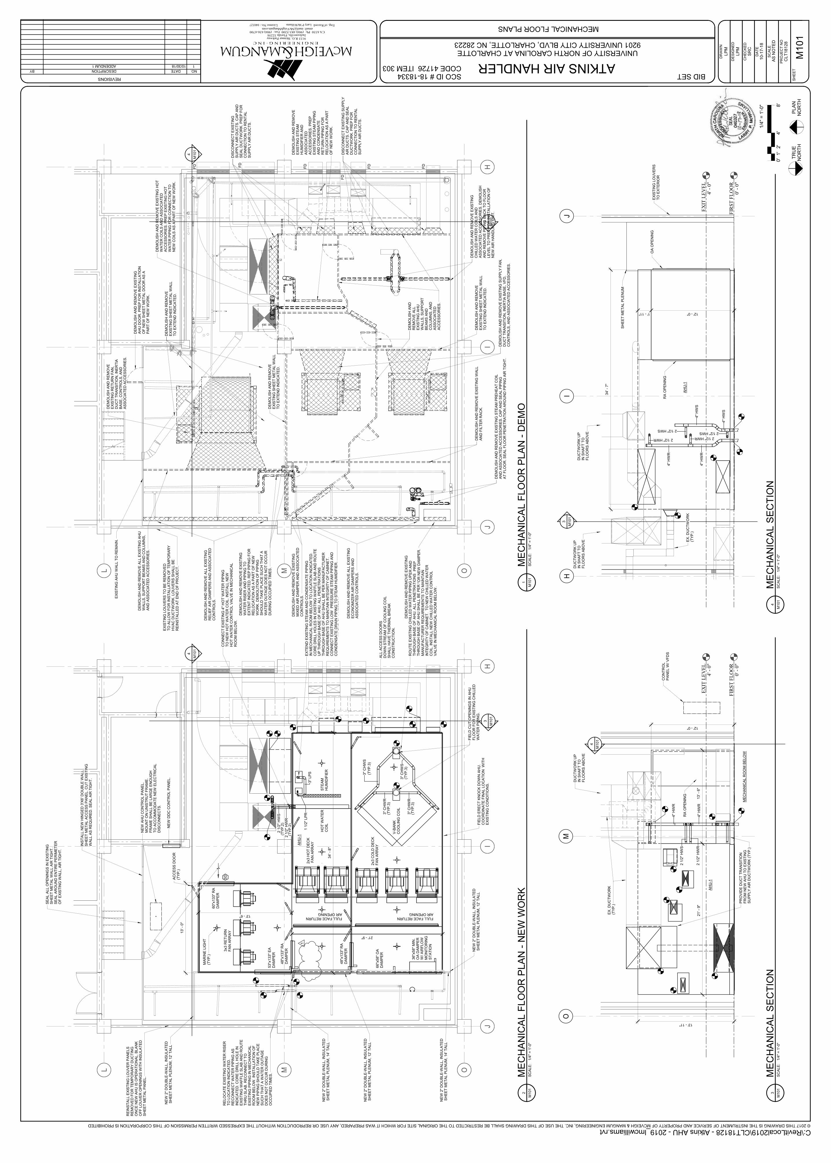
OML
JI
H
OML
JI
H
DE
MO
LIS
H A
ND
RE
MO
VE
E
XIS
TIN
G R
ET
UR
N F
AN
,D
UC
T T
RA
NS
ITIO
N, IN
ER
TIA
B
AS
E, C
ON
TR
OLS
, A
ND
A
SS
OC
IAT
ED
AC
CE
SS
OR
IES
.
DE
MO
LIS
H A
ND
RE
MO
VE
EX
IST
ING
ST
EA
M P
RE
HE
AT
CO
ILA
ND
AS
SO
CIA
TE
D A
CC
ES
SO
RIE
S. C
AP
AN
D S
EA
L P
IPIN
G
AT
FLO
OR
. S
EA
L F
LO
OR
PE
NE
TR
AT
ION
AR
OU
ND
PIP
ING
AIR
TIG
HT
.
DE
MO
LIS
H A
ND
RE
MO
VE
ALL E
XIS
TIN
G
RE
LIE
F A
IR D
AM
PE
RS
AN
D A
SS
OC
IAT
ED
C
ON
TR
OLS
.
DE
MO
LIS
H A
ND
RE
MO
VE
ALL E
XIS
TIN
G
EC
ON
OM
IZE
R A
IR D
AM
PE
RS
AN
D
AS
SO
CIA
TE
D C
ON
TR
OLS
.
DE
MO
LIS
H A
ND
RE
MO
VE
EX
IST
ING
M
IN. O
UT
SID
E A
IR D
AM
PE
R A
ND
A
SS
OC
IAT
ED
CO
NT
RO
LS
. P
RE
P
EX
IST
ING
LO
UV
ER
FO
R N
EW
DA
MP
ER
.
DE
MO
LIS
H A
ND
RE
MO
VE
EX
IST
ING
M
IXE
D A
IR D
AM
PE
R A
ND
AS
SO
CIA
TE
D
CO
NT
RO
LS
.
DIS
CO
NN
EC
T E
XIS
TIN
G
SU
PP
LY
AIR
DU
CT
S. C
AP
AN
D
SE
AL D
UC
TW
OR
K. P
RE
P F
OR
C
ON
NE
CT
ION
TO
RE
NT
AL
SU
PP
LY
AIR
DU
CT
S.
DIS
CO
NN
EC
T E
XIS
TIN
G S
UP
PLY
A
IR D
UC
TS
. C
AP
AN
D S
EA
L
DU
CT
WO
RK
. P
RE
P F
OR
C
ON
NE
CT
ION
TO
RE
NT
AL
SU
PP
LY
AIR
DU
CT
S.
FD FD
FD
FD
FD
FD
DE
MO
LIS
H A
ND
RE
MO
VE
EX
IST
ING
SU
PP
LY
FA
N,
DU
CT
TR
AN
SIT
ION
, IN
ER
TIA
BA
SE
, V
FD
, C
ON
TR
OLS
, A
ND
AS
SO
CIA
TE
D A
CC
ES
SO
RIE
S.
DE
MO
LIS
H A
ND
RE
MO
VE
EX
IST
ING
C
HIL
LE
D W
AT
ER
CO
ILS
AN
D
AS
SO
CIA
TE
D A
CC
ES
SO
RIE
S. D
EM
OLIS
H
AN
D R
EM
OV
E P
IPIN
G B
AC
K T
O F
LO
OR
LE
VE
L T
O P
RE
P F
OR
IN
ST
ALLA
TIO
N O
F
NE
W A
IR H
AN
DLIN
G U
NIT
.
DE
MO
LIS
H A
ND
RE
MO
VE
EX
IST
ING
WA
LL
AN
D F
ILT
ER
RA
CK
.D
EM
OLIS
H A
ND
RE
MO
VE
E
XIS
TIN
G S
HE
ET
ME
TA
L W
ALL
TO
EX
TE
ND
IN
DIC
AT
ED
.
DE
MO
LIS
H A
ND
RE
MO
VE
EX
IST
ING
HO
T
WA
TE
R C
OIL
S A
ND
AS
SO
CIA
TE
D
AC
CE
SS
OR
IES
. P
RE
P E
XIS
TIN
G H
OT
W
AT
ER
PIP
ING
FO
R C
ON
NE
CT
ION
TO
N
EW
CO
ILS
AS
A P
AR
T O
F N
EW
WO
RK
.
DE
MO
LIS
H A
ND
RE
MO
VE
E
XIS
TIN
G S
TE
AM
H
UM
IDIF
IER
AN
D
AS
SO
CIA
TE
D
AC
CE
SS
OR
IES
. P
RE
P
EX
IST
ING
ST
EA
M P
IPIN
G
AN
D C
ON
DE
NS
AT
E
RE
TU
RN
PIP
ING
FO
R
RE
LO
CA
TIO
N A
S A
PA
RT
O
F N
EW
WO
RK
.
DE
MO
LIS
H A
ND
RE
MO
VE
ALL E
XIS
TIN
G A
HU
W
ALLS
, S
UP
PO
RT
BE
AM
S A
ND
CO
LU
MN
S,
AN
D A
SS
OC
IAT
ED
AC
CE
SS
OR
IES
.
DE
MO
LIS
H A
ND
R
EM
OV
E A
LL
EX
IST
ING
AH
U
WA
LLS
, S
UP
PO
RT
B
EA
MS
AN
D
CO
LU
MN
S, A
ND
A
SS
OC
IAT
ED
A
CC
ES
SO
RIE
S.
DE
MO
LIS
H A
ND
RE
MO
VE
E
XIS
TIN
G S
HE
ET
ME
TA
L W
ALL
TO
EX
TE
ND
IN
DIC
AT
ED
.
DE
MO
LIS
H A
ND
RE
MO
VE
E
XIS
TIN
G S
HE
ET
ME
TA
L W
ALL
TO
EX
TE
ND
IN
DIC
AT
ED
.
DE
MO
LIS
H A
ND
RE
MO
VE
EX
IST
ING
W
AT
ER
RIS
ER
AN
D P
IPIN
G T
O
EX
TE
NT
IN
DIC
AT
ED
. R
EP
PIP
ING
FO
R
RE
LO
CA
TIO
N A
S A
PA
RT
OF
NE
W
WO
RK
. D
EM
OLIT
ION
OF
PIP
ING
S
HO
ULD
TA
KE
PLA
CE
SU
CH
TH
AT
A
WA
TE
R O
UT
AG
E D
OE
S N
OT
OC
CU
R
DU
RIN
G O
CC
UP
IED
TIM
ES
.
EX
IST
ING
AH
U W
ALL T
O R
EM
AIN
.
DE
MO
LIS
H A
ND
RE
MO
VE
EX
IST
ING
A
HU
DO
OR
. P
RE
P F
OR
IN
ST
ALLA
TIO
N
OF
NE
W S
HE
ET
ME
TA
L D
OO
R A
S A
P
AR
T O
F N
EW
WO
RK
.
3
M101
4
M101
EX
IST
ING
LO
UV
ER
S T
O B
E R
EM
OV
ED
TO
ALLO
W F
OR
IN
ST
ALLA
TIO
N O
F T
EM
PO
RA
RY
HV
AC
DU
CT
WO
RK
. LO
UV
ER
S S
HA
LL B
ER
EIN
ST
ALLE
D A
T E
ND
OF
PR
OJE
CT
.
EX
IST
ING
LO
UV
ER
S M
AY
BE
RE
MO
VE
DT
O A
LLO
W F
OR
AC
CE
SS
TO
SIT
E A
ND
LO
AD
ING
/UN
LO
AD
ING
OF
MA
TE
RIA
LS
. LO
UV
ER
S S
HA
LL B
E R
EIN
ST
ALLE
D
AT
EN
D O
F P
RO
JE
CT
.
OML
JI
H
OML
JI
H
NE
W 2
" D
OU
BLE
-WA
LL, IN
SU
LA
TE
DS
HE
ET
ME
TA
L P
LE
NU
M, 12' T
ALL
AH
U-1
INS
TA
LL N
EW
HIN
GE
D 3
'X6' D
OU
BLE
WA
LL
SH
EE
T M
ET
AL A
CC
ES
S P
AN
EL. C
UT
EX
IST
ING
W
ALL A
S R
EQ
UIR
ED
. S
EA
L A
IR T
IGH
T.
SE
AL A
LL O
PE
NIN
GS
IN
EX
IST
ING
SH
EE
T M
ET
AL W
ALL A
IR T
IGH
T.
SE
AL A
RO
UN
D E
NT
IRE
PE
RIM
ET
ER
O
F E
XIS
TIN
G W
ALL, A
IR T
IGH
T.
FIE
LD
ER
EC
T K
NO
CK
DO
WN
AH
U.
CO
OR
DIN
AT
E F
INA
L L
OC
AT
ION
W
ITH
EX
IST
ING
CO
ND
ITIO
NS
.
FIE
LD
CU
T O
PE
NIN
GS
IN
AH
UF
LO
OR
FO
R E
XIS
TIN
G C
HIL
LE
DW
AT
ER
PIP
ING
.
CO
NN
EC
T E
XIS
TIN
G 4
" H
OT
WA
TE
R P
IPIN
GT
O N
EW
HO
T W
AT
ER
CO
IL. IN
ST
ALL N
EW
H
OT
WA
TE
R C
ON
TR
OL V
ALV
E IN
ME
CH
AN
ICA
LR
OO
M B
ELO
W.
RO
UT
E E
XIS
TIN
G C
HIL
LE
D W
AT
ER
PIP
ING
UP
TH
RO
UG
H B
AS
E O
F A
HU
. A
LL P
EN
ET
RA
TIO
NS
T
HR
OU
GH
BA
SE
OF
AH
U S
HA
LL B
E P
ER
M
AN
UF
AC
TU
RE
R R
EQ
UIR
EM
EN
TS
TO
MA
INT
AIN
IN
TE
GR
ITY
OF
CA
BIN
ET
. T
O N
EW
CH
ILLE
D W
AT
ER
C
OIL
. IN
ST
ALL N
EW
CH
ILLE
D W
AT
ER
CO
NT
RO
L
VA
LV
E IN
ME
CH
AN
ICA
L R
OO
M B
ELO
W.
EX
TE
ND
EX
IST
ING
ST
EA
M A
ND
CO
ND
EN
SA
TE
PIP
ING
IN
ME
CH
AN
ICA
L R
OO
M B
ELO
W T
O L
OC
AT
ION
IN
DIC
AT
ED
. C
OR
E D
RIL
L H
OLE
S IN
EX
IST
ING
WA
FF
LE
SLA
B A
ND
RO
UT
EU
P T
HR
OU
GH
BA
SE
OF
AH
U. A
LL P
EN
ET
RA
TIO
NS
T
HR
OU
GH
BA
SE
OF
AH
U S
HA
LL B
E P
ER
MA
NU
FA
CT
UR
ER
R
EQ
UIR
EM
EN
TS
TO
MA
INT
AIN
IN
TE
GR
ITY
OF
CA
BIN
ET
. C
ON
NE
CT
EX
IST
ING
LO
W P
RE
SS
UR
E S
TE
AM
PIP
ING
AN
D
CO
ND
EN
SA
TE
DR
AIN
PIP
ING
TO
ST
EA
M H
UM
IDIF
IER
.
RE
INS
TA
LL E
XIS
TIN
G L
OU
VE
R P
AN
ELS
RE
MO
VE
D F
OR
TE
MP
OR
AR
Y D
UC
TIN
GO
NC
E N
EW
AH
U IS
OP
ER
AT
ION
AL. B
LA
NK
OF
F L
OU
VE
R O
PE
NIN
GS
WIT
H IN
SU
LA
TE
DS
HE
ET
ME
TA
L P
AN
EL.
NE
W 2
" D
OU
BLE
-WA
LL, IN
SU
LA
TE
DS
HE
ET
ME
TA
L P
LE
NU
M, 14' T
ALL
NE
W 2
" D
OU
BLE
-WA
LL, IN
SU
LA
TE
DS
HE
ET
ME
TA
L P
LE
NU
M, 12' T
ALL
3x3 R
ET
UR
N
FA
N A
RR
AY
NE
W A
HU
CO
NT
RO
L P
AN
EL.
MO
UN
T O
N U
NIS
TR
UT
FR
AM
E.
FR
AM
E S
HA
LL B
E L
AR
GE
EN
OU
GH
TO
AC
CO
MM
OD
AT
E N
EW
ELE
CT
RIC
AL
DIS
CO
NN
EC
TS
.
NE
W D
DC
CO
NT
RO
L P
AN
EL.
2 1
/2"
HW
S
2 1
/2"
HW
R(T
YP
.2)
(TY
P.2
)
3"
CH
WS
3"
CH
WR
3"
CH
WR
3"
CH
WS
(TY
P.3
)
(TY
P.3
)
(TY
P.3
)
(TY
P.3
)
3"
LP
S1 1
/2"
LP
R
60"x
133"
RA
DA
MP
ER
AC
CE
SS
DO
OR
(TY
P.)
RE
LO
CA
TE
EX
IST
ING
WA
TE
R R
ISE
R
TO
LO
CA
TIO
N IN
DIC
AT
ED
. R
EC
ON
NE
CT
WA
TE
R P
IPIN
G A
S
IND
ICA
TE
D. C
OR
E D
RIL
L H
OLE
IN
E
XIS
TIN
G W
AF
FLE
SLA
B A
ND
RO
UT
ET
HR
U S
LA
B. R
EC
ON
NE
CT
TO
E
XIS
TIN
G P
IPIN
G IN
ME
CH
AN
ICA
L
RO
OM
BE
LO
W. IN
ST
ALLA
TIO
N O
F
NE
W P
IPIN
G S
HO
ULD
TA
KE
PLA
CE
S
UC
H T
HA
T A
WA
TE
R O
UT
AG
E
DO
ES
NO
T O
CC
UR
DU
RIN
G
OC
CU
PIE
D T
IME
S.
NE
W 2
" D
OU
BLE
-WA
LL, IN
SU
LA
TE
DS
HE
ET
ME
TA
L P
LE
NU
M, 12' T
ALL
NE
W 2
" D
OU
BLE
-WA
LL, IN
SU
LA
TE
DS
HE
ET
ME
TA
L P
LE
NU
M, 14' T
ALL
48"x
133"
RA
DA
MP
ER
48"x
133"
RA
DA
MP
ER
53"x
133"
EA
DA
MP
ER
13
' -
0"
MA
RIN
E L
IGH
T(T
YP
.)
2x3 H
OT
DE
CK
FA
N A
RR
AY
2x3 C
OLD
DE
CK
FA
N A
RR
AY
ALL A
CC
ES
S D
OO
RS
DO
WN
ST
RE
AM
OF
CO
OLIN
G C
OIL
SH
ALL H
AV
E T
HE
RM
AL B
RE
AK
C
ON
ST
RU
CT
ION
.
3
M101
FULL FACE RETURN AIR OPENING
FULL FACE RETURN AIR OPENING
66"x
58"
OA
DA
MP
ER
13' - 6"
36"x
58"
MIN
. O
A D
AM
PE
R
W/ A
IRF
LO
W
MO
NIT
OR
ING
ST
AT
ION
V-B
AN
K
CO
OLIN
G C
OIL
HO
T W
AT
ER
CO
ILS
TE
AM
HU
MID
IFIE
R
21' - 9"
34
' -
8"
SD
4
M101
1
FIR
ST
FL
OO
R0' -
0"
EX
IT L
EV
EL
4' -
0"
OM
4
M101
PR
OV
IDE
DU
CT
TR
AN
SIT
ION
FR
OM
NE
W A
HU
TO
EX
IST
ING
SU
PP
LY
AIR
DU
CT
WO
RK
(T
YP
.)
RA
OP
EN
ING
4"
HW
R
4"
HW
R
2 1
/2"
HW
S
2 1
/2"
HW
R
AH
U-1
EX
. D
UC
TW
OR
K(T
YP
.)
ME
CH
AN
ICA
L R
OO
M B
ELO
W
DU
CT
WO
RK
UP
IN S
HA
FT
TO
F
LO
OR
S A
BO
VE
13' - 11"
12' - 0"
21
' - 9
9/3
2"
21' -
9"
13
' -
6"
FIR
ST
FL
OO
R0' -
0"
EX
IT L
EV
EL
4' -
0"
JI
H3
M101
4"
HW
S
4"
HW
R
4"
HW
S
4"
HW
R
2 1/2" HWS
2 1/2" HWR2 1/2" HWR
2 1/2" HWS
RA
OP
EN
ING
SH
EE
T M
ET
AL P
LE
NU
M
OA
OP
EN
ING
EX
IST
ING
LO
UV
ER
S
TO
EX
TE
RIO
R
EX
. D
UC
TW
OR
K(T
YP
.)
AH
U-1
DU
CT
WO
RK
UP
IN S
HA
FT
TO
F
LO
OR
S A
BO
VE
DU
CT
WO
RK
UP
IN S
HA
FT
TO
F
LO
OR
S A
BO
VE
12' - 0"1' - 11"
34
' -
7"
© 2017 THIS DRAWING IS THE INSTRUMENT OF SERVICE AND PROPERTY OF MCVEIGH & MANGUM ENGINEERING, INC. THE USE OF THIS DRAWING SHALL BE RESTRICTED TO THE ORIGINAL SITE FOR WHICH IT WAS PREPARED, ANY USE OR REPRODUCTION WITHOUT THE EXPRESSED WRITTEN PERMISSION OF THIS CORPORATION IS PROHIBITED
REVISIONS
E N G I N E E R I N G · I N C
Eng. of Record:License No.:
9133 R.G. Skinner ParkwayJacksonville, Florida 32256
CA 6330 Ph: (904) 483-5200 Fax: (904) 636-6700 email: [email protected]
PR
OJE
CT
NO
SC
ALE
DR
AW
N
CH
EC
KE
D
DA
TE
DE
SIG
NE
D
SH
EE
T
AS
NO
TE
D
SCO ID # 18-18334CODE 41726 ITEM 303
TR
UE
N
OR
TH
PLA
N
NO
RT
H
C:\RevitLocal2019\CLT18128 - Atkins AHU - 2019_lmcwilliams.rvt
MECHANICAL FLOOR PLANS
UNIVERSITY OF NORTH CAROLINA AT CHARLOTTE9201 UNIVERSITY CITY BLVD, CHARLOTTE, NC 28223
040327 Larry P McWilliams
ATKINS AIR HANDLER
SR
C
LP
M
10-1
7-1
8
CL
T18
12
8
M10
1
LP
M
BID SET
SC
ALE
:1/4
" =
1'-0"
M101
1M
EC
HA
NIC
AL F
LO
OR
PL
AN
-D
EM
OS
CA
LE
:1/4
" =
1'-0"
M101
2M
EC
HA
NIC
AL
FL
OO
R P
LA
N -
NE
W W
OR
K
0'
1'
4'
8'
2'
1/4
" =
1'-0"
NO.DATEDESCRIPTIONBY
110/30/18ADDENDUM 1
SC
ALE
:1/4
" =
1'-0"
M101
3M
EC
HA
NIC
AL S
EC
TIO
NS
CA
LE
:1/4
" =
1'-0"
M101
4M
EC
HA
NIC
AL S
EC
TIO
N
CO
NT
RO
LP
AN
EL W
/ V
FD
S