accessories for photoelectric sensors - murri oy
TRANSCRIPT

378 For more information, visit us online!
Complete optical accessories – from mounting brackets, reflectors, lenses and holding systems etc. for standard applications and ap-plications under more difficult ambient conditions.
Special accessories for photoelectric sensors
Photoelectric Sensors

379■ www.balluff.com
Special Accessories for Photoelectric SensorsContents
Reflectors Round 380Block-shaped 381For special applications 383For laser retroreflective light sensors 384Reflective foils 386
Fasteners Mounting brackets 388Holding system 394Mounting cuff 396Mounting clamps 396Clamps 396Adapter plate 396
Sensor accessories Apertures 397Weld protection 399Planoconvex lens 400Polarizing filters 400Air shields 400Lenses 401Intermediate ring 401Neutral density filters 402Protective nuts 403Deflection heads 404Diagonal mirrors 405 Accessories for fiber optics Adapters 406Holders 406 Cutting tool 406Lens 407Deflection head 407Focus lenses 407Metal helical tubes 407Optical fibers 407 Basic information
and definitions can be found on page 884.

380 For more information, visit us online!
Size Reflector Ø 46 mm Reflector Ø 21 mm Reflector Ø 21 mm
Fasteners Glue Glue GlueOrdering code BAM00UW BAM00W4 BAM00UR
Part number BOS R-2 BOS R-3 BOS R-15Material PMMA/ABS PMMA/ABS PCTriple size 2.5 mm 2 mm 2 mmSpecial features More chemical resistantTemperature range –20...+60 °C –20...+60 °C –20...+99°C
Size Reflector Ø 84 mm Reflector Ø 62 mm Reflector Ø 51 mm
Fasteners M4 screw Two M4 screws Rivet with mounting tabsOrdering code BAM00UK BAM0126 BAM00UP
Part number BOS R-1 BOS R-10 BOS R-14Material PMMA/ABS PMMA/ABS PCTriple size 4 mm 4 mm 4 mmMounting accessories BOS 21-AD-1Special features More chemical resistantTemperature range –20...+60 °C –20...+60 °C 0...+100 °C
Special Accessories for Photoelectric SensorsRound reflectors
Reflectors are assigned to the
accessories that we mark in gray.

381■ www.balluff.com
Special Accessories for Photoelectric SensorsBlock-shaped reflectors
Size Reflector 51×61 mm Reflector 35×42 mm Reflector 23×80 mm Reflector 18×120 mm
Fasteners Two M4 screws Two M3 screws Two M4 screws Two M4 screwsOrdering code BAM00WL BAM00W0 BAM01LA BAM00WA
Part number BOS R-9 BOS R-26 BOS R-48 BOS R-5Material PMMA/ABS PMMA PMMA/ABS PMMA/ABSTriple size 4 mm 4 mm 4 mm 4 mmMounting accessories BOS 5-HW-5Temperature range –20...+60 °C 0...+50 °C –20...+60 °C –20...+60 °C
Size Reflector 100×100 mm Reflector 84×84 mm Reflector 51×72 mm Reflector 60×40 mm
Fasteners Two M3 screws Two M3 screws Two M4 screws Two M3 screwsOrdering code BAM01JN BAM00UL BAM00UZ BAM01JP
Part number BOS R-47 BOS R-11 BOS R-25 BOS R-46Material PMMA/ABS PMMA/ABS PMMA PMMA/ABSTriple size 4 mm 4 mm 4 mm 4 mmTemperature range –20...+60 °C –20...+60 °C 0...+50 °C –20...+60 °C
92
100
100
92
9
52
60
34
40
7.5
3.5
7.5 23
59 71
80
Ø4.5
Photoelectric sensors
Photoelectric standard sensors
Photoelectric special sensors
Photoelectric distance sensors for analog distance measurement
Special accessories for photoelectric sensors
Reflectors
Fasteners
Sensor accessories
Accessories for fiber optics

382 For more information, visit us online!
Size Reflector 33×12 mm Reflector 33×12 mm Reflector 33×12 mm
Fasteners Side screws Rear and side screws Rear screwsOrdering code BAM00W3 BAM00W1 BAM00W2
Part number BOS R-29 BOS R-27 BOS R-28Material PMMA PMMA PMMATriple size 2.3 mm 2.3 mm 2.3 mmMounting accessories BOS 5-HW-1/2 BOS 5-HW-1/2Temperature range 0...+50 °C 0...+50 °C 0...+50 °C
Special Accessories for Photoelectric SensorsBlock-shaped reflectors
Size Reflector 18×60 mm
Fasteners Two M4 screwsOrdering code BAM00W7
Part number BOS R-33Material PMMA/ABSTriple size 4 mmMounting accessoriesTemperature range –20...+60 °C
Reflectors are assigned to the
accessories that we mark in gray.

383■ www.balluff.com
Special Accessories for Photoelectric SensorsReflectors for special applications
Size Reflector 60×40 mm Reflector 60×40 mm Reflector 60×40 mm Reflector 14×23 mm
Fasteners Two M3 screws Two M3 screws Two M3 screws Two M1.5 screwsOrdering code BAM00W8 BAM01CM BAM01HE BAM01NH
Part number BOS R-34 BOS R-36 BOS R-44 BOS R-49Material Hot thermoplastic PMMA/ABS Solidchem Hot thermoplasticTriple size 4 mm 4 mm 4 mm 0.9 mmSpecial features Heat-resistant Anti-fogging Chemical-resistant Heat-resistant;
For laser applicationsTemperature range –20...+150°C –20...+60 °C –20...+140°C –20...+110°C
52
5
9
5
52
34
40
60
7.5
3.5
M3
52
34
40
60
7.5
3.5
M3
52
34
40
60
7.5
3.5
M3
Size Reflector Ø 52 mm
Fasteners ClampsOrdering code BAM01H6
Part number BOS R-31Material BorosilicateTriple size 4 mmSpecial features Glass reflectorTemperature range –20...+500°C
1
4.9
13.8
9.7
23
19
Ø2
Photoelectric sensors
Photoelectric standard sensors
Photoelectric special sensors
Photoelectric distance sensors for analog distance measurement
Special accessories for photoelectric sensors
Reflectors
Fasteners
Sensor accessories
Accessories for fiber optics

384 For more information, visit us online!
Special Accessories for Photoelectric SensorsReflectors for laser retroreflective sensors
Size Reflector 51×62 mm Reflector 40×10 mm Reflector 14×23 mm Reflector 11×11 mm
Fasteners Two M4 screws Two M3 screws Two M1.5 screws M3 screwOrdering code BAM00UY BAM01H9 BAM00UM BAM01H8
Part number BOS R-22 BOS R-41 BOS R-12 BOS R-39Material PMMA/ABS PMMA/ABS PMMA/ABS PMMA/ABSTriple size 1.2 mm 1.2 mm 0.9 mm 0.9 mmMounting accessories BOS 5-HW-6Special features For laser retroreflective
sensorsTemperature range –20...+60 °C –20...+60 °C –20...+60 °C
5.8
11
8
M3
11
10
M3
25
31
40
2 3.7
Reflectors are assigned to the
accessories that we mark in gray.

385■ www.balluff.com
Special Accessories for Photoelectric SensorsReflectors for laser retroreflective sensors
Reflector Ø 25 mm Reflector Ø 25 mm Reflector Ø 21 mm Reflector Ø 19 mm Reflector Ø 10 mm
Glue M4 screw Glue M3 screw M3 screwBAM00UN BAM01HC BAM00UT BAM01HA BAM01H7
BOS R-13 BOS R-43 BOS R-16 BOS R-42 BOS R-38PMMA/ABS PMMA/ABS PMMA/ABS PMMA/ABS PMMA/ABS1.2 mm 1.2 mm 1.2 mm 0.9 mm 0.9 mm
For laser retroreflective sensors
–20...+60 °C –20...+60 °C –20...+60 °C –20...+60 °C –20...+60 °C
5.6
10
8
M3
4.4
199
M3
7.5
8
M4
25
Photoelectric sensors
Photoelectric standard sensors
Photoelectric special sensors
Photoelectric distance sensors for analog distance measurement
Special accessories for photoelectric sensors
Reflectors
Fasteners
Sensor accessories
Accessories for fiber optics

386 For more information, visit us online!
Size Reflective foils (standard) Reflective foils (standard) Reflective foils (standard)
(not for polarized light)
Fasteners Self-adhesive Self-adhesive Self-adhesive100 × 100 mm
Ordering code BAM01JM
Part number BOS R-5050 mm × 25 cm
Ordering code BAM00WC
Part number BOS R-6-0,25 50 mm × 45 m
Ordering code BAM00WE
Part number BOS R-6-45 50 mm × 25 cm
Ordering code BAM00WF
Part number BOS R-7-0,2550 mm × 22 m
Ordering code BAM00WH
Part number BOS R-7-22 50 mm × 25 cm
Ordering code BAM00WJ
Part number BOS R-8-0,2525 mm × 22 m
Ordering code BAM00WK
Part number BOS R-8-22Material PMMA PMMA PMMASpecial features Not for polarized lightTemperature range –20...+60 °C –20...+60 °C –20...+60 °C
Special Accessories for Photoelectric SensorsReflective foils
Reflectors are assigned to the
accessories that we mark in gray.

387■ www.balluff.com
Reflective tape 40×35 mm Reflective tape 100×50 mm Reflective tape 300×200 mm
Self-adhesive Self-adhesive Self-adhesiveBAM00W5 BAM01CF BAM01HF
BOS R-30 (standard) BOS R-40 BOS R-45
PMMA PMMA PMMASpecial for laser sensors Standard and laser sensors for large surfaces
–20...+60 °C –20...+60 °C –20...+60 °C
Special Accessories for Photoelectric SensorsReflective foils
200
0.8
300
Photoelectric sensors
Photoelectric standard sensors
Photoelectric special sensors
Photoelectric distance sensors for analog distance measurement
Special accessories for photoelectric sensors
Reflectors
Fasteners
Sensor accessories
Accessories for fiber optics

388 For more information, visit us online!
Description Mounting bracket Mounting bracket
Use For BOS 21K For BOS 21KOrdering code BAM00T9 BAM00TA
Part number BOS 21-HW-1 BOS 21-HW-2
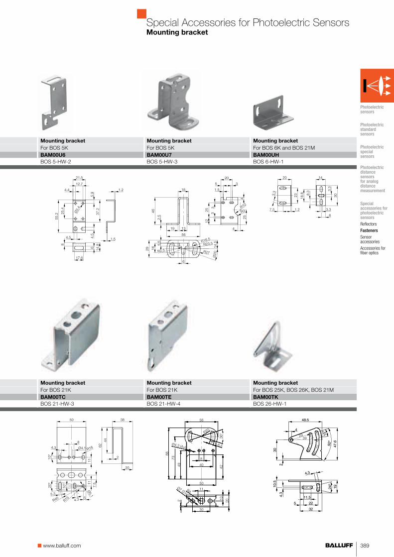
Description Mounting bracket Mounting bracket Mounting bracket Mounting bracket
Use For BOS 2K For BOS 2K For BOS 2K For BOS 5KOrdering code BAM00T4 BAM00T6 BAM00T5 BAM00U5
Part number BOS 2-HW-1 BOS 2-HW-2 BOS 2-HW-3 BOS 5-HW-1
Special Accessories for Photoelectric SensorsMounting brackets
Reflectors are assigned to the
accessories that we mark in gray.
389■ www.balluff.com
Mounting bracket Mounting bracket Mounting bracket
For BOS 21K For BOS 21K For BOS 25K, BOS 26K, BOS 21MBAM00TC BAM00TE BAM00TK
BOS 21-HW-3 BOS 21-HW-4 BOS 26-HW-1
Mounting bracket Mounting bracket Mounting bracket
For BOS 5K For BOS 5K For BOS 6K and BOS 21MBAM00U6 BAM00U7 BAM00UH
BOS 5-HW-2 BOS 5-HW-3 BOS 6-HW-1
Special Accessories for Photoelectric SensorsMounting bracket
Photoelectric sensors
Photoelectric standard sensors
Photoelectric special sensors
Photoelectric distance sensors for analog distance measurement
Special accessories for photoelectric sensors
Reflectors
Fasteners
Sensor accessories
Accessories for fiber optics

390 For more information, visit us online!
Special Accessories for Photoelectric SensorsMounting brackets
Description Mounting bracket Mounting bracket
Use For BOS 23K For BOS 23Ordering code BAM01FK BAM01FM
Part number BAM MB-X0-006-B05-4 BAM MB-X0-007-B05-4Material Stainless steel Stainless steel
58
5
65
27.25
2
44.25
17
41
17.4
35
31
4.3
8.5
31°
R14.1
Stainless
Steel
2
26.58
32
25
4.3
13.5
64.5
15.5
27
50°
32
30
30°
30°
14.58
R29.9
R29.9
Stainless
Steel
Description Mounting bracket
Use For BOS 50K/23KOrdering code BAM01E8
Part number BAM MB-X0-005-B04-4Material Stainless steel
2
61.3
23
54
29
32°
R5
93.5
25.5
86.5
75.7
65.777.2
98.5
Ø5.5
32
R2.75
Ø4.5
R61
R29
R3
46
Stainless
Steel
Reflectors are assigned to the
accessories that we mark in gray.

391■ www.balluff.com
Special Accessories for Photoelectric SensorsMounting bracket
Description Mounting bracket Mounting bracket Mounting bracket
Use For BOS 63M, BOD 63M For BOS 65K For BOD 66MOrdering code BAM00P6 BAM0125 BAM00P9
Part number BOS 63-HW-1 BOS 65-HW-1 BOD 66-HW-1Material Stainless steel Stainless steel Stainless steel
Photoelectric sensors
Photoelectric standard sensors
Photoelectric special sensors
Photoelectric distance sensors for analog distance measurement
Special accessories for photoelectric sensors
Reflectors
Fasteners
Sensor accessories
Accessories for fiber optics

392 For more information, visit us online!
Description Mounting bracket Mounting bracket Mounting bracket
Use For BOS 18 For BOS 18F/BOS 18KW For BOS 18Ordering code BAM00RY BAM00RZ BAM00T0
Part number BOS 18,0-HW-1 BOS 18,0-HW-2 BOS 18,0-HW-3
20
35
Ø414.5
35 Ø25
Ø18.5
28
35°
12
12 R5
12
2
35°
20
12
12 R5
17.5°
35
Ø25
Ø18.5
35
2
20
4.4
20
Ø18.5
32
R12
12
Ø25 43
25
35°R5 Ø4
2
43
Ø18.5
140
100
2
25
125
8
35
Ø4.25
50
40
30
42
40
30
M18×1
50
10.8
36.54
10
6.5
Description Mounting bracket Mounting bracket
Use For BOS 18 For BOS 18 laser sensorsOrdering code BAM00T1 BAM00T2
Part number BOS 18,0-HW-4 BOS 18,0-HW-6
Reflectors are assigned to the
accessories that we mark in gray.
Special Accessories for Photoelectric SensorsMounting brackets

393■ www.balluff.com
Description Mounting bracket Mounting bracket Mounting bracket
Use For BOS 74K For BOS R-10 and BOS R-25
For BOS R-26 reflectors
Ordering code BAM00UJ BAM00U8 BAM00U9
Part number BOS 74-HW-1 BOS 5-HW-4 BOS 5-HW-5
Description Mounting bracket
Use For BOS R-9 and BOS R-22
Ordering code BAM00UA
Part number BOS 5-HW-6
Special Accessories for Photoelectric SensorsMounting brackets
Photoelectric sensors
Photoelectric standard sensors
Photoelectric special sensors
Photoelectric distance sensors for analog distance measurement
Special accessories for photoelectric sensors
Reflectors
Fasteners
Sensor accessories
Accessories for fiber optics

394 For more information, visit us online!
Description Holding system
Use For flexible mounting; for all cylindrical sensors with M18 outside thread and 8×8 sensors. May be combined with other Balluff accessories.
Ordering code BAM00R8
Part number BOS 18-HS-1
Special Accessories for Photoelectric SensorsHolding system
Mounting rods are knurled all the way around. This prevents any position change.
Holding systems are assigned to the
accessories that we mark in gray.
395■ www.balluff.com
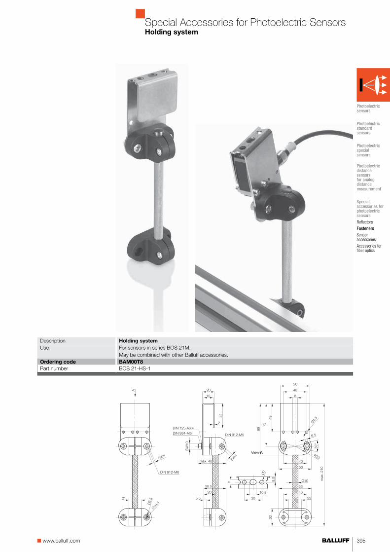
Special Accessories for Photoelectric SensorsHolding system
Description Holding system
Use For sensors in series BOS 21M. May be combined with other Balluff accessories.
Ordering code BAM00T8
Part number BOS 21-HS-1
View A
Photoelectric sensors
Photoelectric standard sensors
Photoelectric special sensors
Photoelectric distance sensors for analog distance measurement
Special accessories for photoelectric sensors
Reflectors
Fasteners
Sensor accessories
Accessories for fiber optics

396 For more information, visit us online!
Special Accessories for Photoelectric SensorsMounting cuff, clamping blocks, clamping holder, adapter plate
Description Mounting cuff Mounting clamp with ball joint Mounting clamp with ball joint
Use For cylindrical sensors with M12 outside thread
For cylindrical sensors with M18 outside thread
For cylindrical sensors with M30 outside thread
Ordering code BAM01KM BAM00T3 BAM00TN
Part number BOS 12,0-KB-1 BOS 18,0-KB-1 BOS 30,0-KB-1
Description Clamping holder Clamping holder Adapter plate
Use Sensors with dovetail for BOS 21M
Sensors with dovetail for BOS 21M
For BOS 21M, BOS 25K, BOS 26K and BOS R-1
Ordering code BAM00TF BAM00TH BAM00T7
Part number BOS 21-KH-1 BOS 21-KH-2 BOS 21-AD-1
Mounting cuffs, clamping blocks, clamping holder,
adapter plate and apertures are assigned
to the accessories that we have marked in gray.

397■ www.balluff.com
Description Round aperture Double slit aperture Slit aperture
Use For BLE/BLS 18 For BLE/BLS 18 For BLE/BLS 12MOrdering code BAM00R6 BAM00R7 BAM00PW
Part number BOS 18-BL-1 BOS 18-BL-2 BOS 12-BL-1Aper-
ture on
emitter
Aper-
ture on
receiver
Range Aper-
ture on
emitter
Aper-
ture on
receiver
Range Slit
width
Range Object
size
8 mm 3 mm 1 mm 0.5 mm > 1 mm8 mm 2 mm 1.5 mm 1 mm > 1.5 mm2 mm 2 mm 2 mm 2 mm > 2 mm
Special Accessories for Photoelectric SensorsApertures
The round and slit apertures restrict the beam diameter. This allows you to detect small parts over a large range. The emitter and receiver must be exactly aligned with each other.
Advantages:■ Small parts detection, i.e.
1 mm drill, aperture on emitter only
■ Through-beams may be mounted close to one another
■ Highly reflective parts directly next to the light path do not interfere.
Photoelectric sensors
Photoelectric standard sensors
Photoelectric special sensors
Photoelectric distance sensors for analog distance measurement
Special accessories for photoelectric sensors
Reflectors
Fasteners
Sensor accessories
Accessories for fiber optics

398 For more information, visit us online!
Special Accessories for Photoelectric SensorsApertures
Description Horizontal slit aperture Horizontal slit aperture Horizontal slit aperture
Use For BOS 5K through-beam sensors
For BOS 5K through-beam sensors
For BOS 5K through-beam sensors
Ordering code BAM00TZ BAM00U0 BAM00U1
Part number BOS 5-BL-4 BOS 5-BL-5 BOS 5-BL-6Aperture size 0.5 mm horizontal 1 mm horizontal 2 mm horizontalRange 0.7 (2 m) 1.5 (3 m) 3.0 (5.5 m)Min. object 0.4 (7 mm) 0.7 (7 mm) 1.5 (7 mm)Packaging unit 2 pcs. 2 pcs. 2 pcs.
Description Vertical slit aperture Vertical slit aperture Vertical slit aperture
Use For BOS 5K through-beam sensors
For BOS 5K through-beam sensors
For BOS 5K through-beam sensors
Ordering code BAM00TU BAM00TW BAM00TY
Part number BOS 5-BL-1 BOS 5-BL-2 BOS 5-BL-3Aperture size 0.5 mm, vertical 1 mm, vertical 2 mm, verticalRange* 1.0 (2.5 m) 1.5 (3.5 m) 3.5 (6 m)Min. object* 0.5 (7 mm) 1.0 (7 mm) 2.0 (7 mm)Packaging unit 2 pcs. 2 pcs. 2 pcs.
*Values in brackets apply to slit apertures on one side
Reflectors are assigned to the
accessories that we mark in gray.

399■ www.balluff.com
Special Accessories for Photoelectric SensorsApertures, weld protection
Description Round aperture Round aperture Round aperture
Use For BOS 5K through-beam sensors
For BOS 5K through-beam sensors
For BOS 5K through-beam sensors
Ordering code BAM00U2 BAM00U3 BAM00U4
Part number BOS 5-BL-7 BOS 5-BL-8 BOS 5-BL-9Aperture size 0.5 mm Ø 1 mm Ø 2 mm ØRange 0.08 (0.8 m) 0.3 (1.5 m) 1.2 (2.5 m)Min. object 0.3 (5 mm) 0.6 (5 mm) 1.5 (7 mm)Packaging unit 2 pcs. 2 pcs. 2 pcs.
Description Weld protection Weld protection
Use For BOS 23K For BOS 50K
Ordering code BAM01L8 BAM01U6
Part number BAM PC-XO-006-23K-1 BAM PC-XO-006-50K-1
28.1
15.5
30.8
16.5
34.3
92.3
25.4 15.5
22.5
30.8
16.5
34.3
59.3
19.9
Photoelectric sensors
Photoelectric standard sensors
Photoelectric special sensors
Photoelectric distance sensors for analog distance measurement
Special accessories for photoelectric sensors
Reflectors
Fasteners
Sensor accessories
Accessories for fiber optics
Sensor not included in the standard scope of delivery!
Sensor not included in the standard scope of delivery!

400 For more information, visit us online!
Description Planoconvex lens Polarizing filter Air shield Air shield
Use For all BOS 18 diffuse sensors for background suppression and small parts detection
Only for BOS 18M-...-1RD...
For BOS 12 and tube with 4 mm inner diameter
For BOS 18 and tube with 4 mm inner diameter
Focal length/focusOrdering code BAM00RF BAM00RE BAM00PY BAM00R9
Part number BOS 18-PK-1 BOS 18-PF-1 BOS 12-LT-1 BOS 18-LT-1Material Housing: PA6 Housing: PA6
Planoconvex lens: glass Polarization filter: IR polarization
Special Accessories for Photoelectric SensorsPlanoconvex lens, polarizing filter, air tube
Benefits■ Sensing distance
adjustable 0...40 mm■ Low switching point
shift, e.g. for different colors or surface properties
■ Background suppression facilitates detection of objects on reflective background
■ Small parts detection down to 0.05 mm through focusing planoconvex lens with a working range of approx. 0...13 mm
Polarizing filters are used for reliably sensing highly reflective objects. They prevent faulty switching.
Reflecting or shiny parts will then not cause faulty switching. The polarizing filters guarantee that only the light reflected back by the reflector is de-tected. They reduce the sensing range by 50%.
The air tube with a compressed air source prevents premature contamination of the optics.
The air tube with a compressed air source prevents premature contamination of the optics.
Planoconvex lens, polarizing filter, air tube,
lenses and intermediate ring are assigned to
the accessories that we mark gray.

401■ www.balluff.com
Lens Lens Lens Lens Intermediate ring
For BKT 67 for increasing the sensing distance (light spot 2×7 mm)
For BKT 67 standard lenses(light spot 1.5×4 mm)
For BKT 67 for increasing the sensing distance(light spot 2×8 mm)
For BKT 67 for increasing the sensing distance(light spot 2.5×11 mm)
Intermediate ring with lens for increased resolution for BKT 67 in combination with M-PK-2. It is screwed in between the sensor and the 9 mm lens.
18 mm 9 mm 28 mm 50 mmBAM0120 BAM0121 BAM0122 BAM00P3 BAM00P2
BKT M-PK-1 BKT M-PK-2 BKT M-PK-3 BKT M-PK-5 BKT M-PK-4Lens: glass Lens: glass Lens: glass Lens: glass Lens: glassVersion: aluminum Version: aluminum Version: aluminum Version: aluminum Version: aluminum
Special Accessories for Photoelectric SensorsLenses, intermediate ring
Ø25
11.5
15.5
Ø33
21.5
25.5
Ø20
Ø32
Ø33
6
48
Ø20
4
Photoelectric sensors
Photoelectric standard sensors
Photoelectric special sensors
Photoelectric distance sensors for analog distance measurement
Special accessories for photoelectric sensors
Reflectors
Fasteners
Sensor accessories
Accessories for fiber optics

402 For more information, visit us online!
Description Cover nut Cover nut
Use For BOS 08 For BOS 12TransmissionOrdering code BAM01Y5 BAM01Y6
Part number BAM PC-X0-005-08M-4 BOS PC-XO-005-12M-4
Special Accessories for Photoelectric SensorsNeutral density filters
The protective end cap (cap nut) is made with tempered glass and can be used with all M12 photoelectric sensors. The protective glass is used to protect the optics from mechanical or thermal damage, such as weld splatter.
Neutral filter and protective nuts are
assigned to the accessories that we mark
in gray.
M8x1
Ø12
10

403■ www.balluff.com
Cover nut Cover nut
For BOS 18 For BOS 18 with flat front surface
BAM00RL BAM01NC
BOS 18-SM-1 BAM PC-XO-005-18M-4
Special Accessories for Photoelectric SensorsProtective nuts
The protective cap can be used in combina-tion with all BOS 18M and BOS 18K sensors. It protects the sensor optics from external effects, such as welding splatter.For increased protection, the BOS 18-SM-2 is made of metal, providing even better protection for the sensor optics. The heat-protecting glass closes off flush with the front surface of the cover nut. This prevents dust deposits from forming, which can impact the range. A ring between the sensor and protective glass makes sure the system is sealed.
The protective end cap is made with tempered glass and can be used with all M18 photoelectric sensors. The protective glass is used to protect the optics from mechanical or thermal damage, such as weld splatter.
Photoelectric sensors
Photoelectric standard sensors
Photoelectric special sensors
Photoelectric distance sensors for analog distance measurement
Special accessories for photoelectric sensors
Reflectors
Fasteners
Sensor accessories
Accessories for fiber optics

404 For more information, visit us online!
Description 90° deflection head 90° deflection head 90° deflection head
Use For diffuse, retroreflective and through-beam sensorsBOS 18 (except laser)
For diffuse, retroreflective and through-beam sensorsBOS 18 (except laser)
For diffuse, retroreflective and through-beam sensorsBOS 18
Ordering code BAM00RP BAM00RT BAM00RR
Part number BOS 18-UK-1 BOS 18-UK-2 BOS 18-UK-10
Special Accessories for Photoelectric SensorsDeflection heads
Deflection heads, suitable combinations
All BOS 18 photoelectric sensors can be equipped with a 90° deflection head. The table shows the appropriate deflection head for each switch type and indicates the corresponding reduction factor (RF) to apply to the range. With a through-beam sensor, the emitter and the receiver can be equipped with a 90° deflection head. Each deflection head reduces the range by approx. 15% ... 50%.
BOS 18-UK-1 BOS 18-UK-2 BOS 18-UK-10
Diffuse sensor
BOS 18...-XA-...100 mm RF = 45 % RF = 50 %BOS 18...-XB-...200 mm RF = 25 % RF = 50 %BOS 18...-PB-...200 mm RF = 25 % RF = 50 %BOS 18...-XD-...400 mm RF = 25 % RF = 30 %BOS 18...-PD-...400 mm RF = 25 % RF = 30 %Retroreflective sensor
BOS 18...-RB-...2 m RF = 20 % RF = 20 %BOS 18...-RD-...4 m RF = 20 % RF = 20 %Through-beam sensor
BLE 18...-P-...16 m RF = 15 % RF = 30 %BLS 18...-XX-...16 m RF = 15 % RF = 30 %
Range 100%
Emitter
Emitter
Emitter
Emitter
Receiver
Receiver
Receiver
Receiver
Deflection heads and angled mirrors are
assigned to the accessories that we mark
in gray.

405■ www.balluff.com
Angled mirror Angled mirror
For diffuse and through-beam sensors BOS 12
For laser through-beam sensors BOS 12
BAM00R0 BAM00R1
BOS 12-WS-1 BOS 12-WS-2
Special Accessories for Photoelectric SensorsAngled mirrors
When using the angled mirror, the sensing range is reduced by 30% for the M12 diffuse and M12 through-beam sensors. Not suit-able for retroreflective sensors.
Photoelectric sensors
Photoelectric standard sensors
Photoelectric special sensors
Photoelectric distance sensors for analog distance measurement
Special accessories for photoelectric sensors
Reflectors
Fasteners
Sensor accessories
Accessories for fiber optics

406 For more information, visit us online!
Description Adapter Holder Lens (Long Range) Optics (adjustable)
Use For BFO 18V glass fiber optics for connecting to BOS 30M
For glass fiber optics and sensors with a corresponding diameter
screwed to fiber optics BFO00C4,400 mm true-color sensor
screwed to fiber optics BFO00C4,200 mm true-color sensor
Ordering code BAM00NM BAM00PO BAM01PA BAM01U2
Part number BFO 30-A1 BFO 08,0-KB-1 BAM LS-FO-001-M6-L BAM LS-FO-002-FPackaging unit 1 pc. 1 pc. 1 pc. 1 pc.
Special Accessories for Photoelectric SensorsAdapter, holder, cutting tool, optics
Description Adapter Adapter Cutting tool
Use For plastic fiber optics∅ 1 mm for connecting to fiber optic base units
For plastic fiber optics∅ 1.3 mm for connecting to fiber optic base units
For trimmingplastic fiber optics∅ 1 mm or ∅ 2.2 mm
Ordering code BAM0003 BAM00P1 BAM000E
Part number BFO D10-LA-DC-10 BFO D13-LA-EC-10 BFO CTPackaging unit 2 pcs. 2 pcs. 1 pc.
Adapter, holder, cutting tool, adapter lens,
deflection head, focus lens and metal helical
tube are assigned to the accessories that
we mark in gray.
Ø19
3.4
M18x1
4
BFO D22...
24
10
32...38
M6 x 0.75
13
38.9
Ø 18
Ø 20.1
M3 x 0.35
Ø 25.1

407■ www.balluff.com
Special Accessories for Photoelectric SensorsAdapter lens, deflection head,
focus lens, metal helical tube, optical fiber
Description Adapter lens 90° deflection head Focus lens Focus lens
Use For through-beam optical fibers M2.6×0.45
For through-beam optical fibers M2.6×0.45
For coaxial diffuse sensor optical fibers M4×0.7
For coaxial diffuse sensor optical fibers M4×0.7
Ordering code BAM00NN BAM00NP BAM00NR BAM00NT
Part number BFO 02-PK-1 BFO 02-UK-1 BFO 04-FL-1 BFO 04-FL-2Sensing distance/range with corresponding fiber optics
×10 ×0.7 19 mm±2 mm 7 mm±2 mm
Packaging unit 2 pcs. 2 pcs. 1 pc. 1 pc.
Description Optical fiber M4
with SMA connector
Optical fiber M6
with SMA connector
Metal corrugated tube
(stainless steel)
Metal corrugated tube
(stainless steel)
Use For BFS000LTrue color sensor
For BFS000LTrue color sensor
For fiber optics M6×0.75 For fiber optics M4×0.7
Ordering code BFO00C9 BFO00C4 BAM00NY BAM00NU
Part number BFO D22-XB-UB-EAK-15-SA1-02 BFO D22-XB-LB-EAK-15-SA1-02 BFO 06-FS-1 BFO 04-FS-1Sensing distance/range with corresponding fiber optics
80 mm 80 mm
Packaging unit 1 pc. 1 pc. 1 pc. 1 pc.
Photoelectric sensors
Photoelectric standard sensors
Photoelectric special sensors
Photoelectric distance sensors for analog distance measurement
Special accessories for photoelectric sensors
Reflectors
Fasteners
Sensor accessories
Accessories for fiber optics

884 For more information, visit us online!
Basic Information and Definitions

885■ www.balluff.com
Basic Information and DefinitionsContents
General basic information
Electrical 886Mechanical 890Quality 887
Specific basic information
Photoelectric sensors 892Inductive sensors 902Capacitive sensors 916Magnetic cylinder sensors 924

886 For more information, visit us online!
Basic Information and DefinitionsElectric properties
Smallest bending radius
Special cable
Cable types
The SP- cable is a irradiated cross-linked PUR- cable that has good resistance to weld splatter. A special connection cable is used for sensors that need to be used at higher ambient temperatures.
The permitted tightening torque is indicated in the data sheets or on the sensor packaging.
Tightening torques
PUR cable, PUR insulated
PVC cable, PVC insulated
tensioned untensioned drag chain and
roll deflection
4×D 3×D 4×D...7.5×D only with "SP" wire
No. of wires × conductor
cross-section
Outside diameter
typical
2×0.14 mm² 2.5...3.5 mm2×0.34 mm² 4.5...5.5 mm3×0.14 mm² 2.7...4.5 mm3×0.25 mm² 4...5 mm3×0.34 mm² 4.5...5.5 mm4×0.25 mm² 4.5...5.5 mm
No. of wires ×
conductor cross-section
Outside diameter
typical
2×0.08 mm² 3...4 mm2×0.14 mm² 3...4.1 mm2×0.34 mm² 4...5.5 mm3×0.06 mm² 2...2.5 mm3×0.09 mm² 2.5...3 mm3×0.14 mm² 2.5...3.5 mm3×0.25 mm² 3.5...4.5 mm3×0.34 mm² 4...5.5 mm3×0.75 mm² 6.5...7 mm4×0.14 mm² 3...4 mm4×0.25 mm² 4...5.5 mm8×0.25 mm² 6...8 mm
Cable properties

887■ www.balluff.com
Basic Information and DefinitionsQuality
General basic information
Electrical
Mechanical
Quality
Specific basic information
Quality and the environment
Quality management system
as per DIN EN ISO 9001:2008
Environmental management
system as per
DIN EN ISO 14001:2009
Testing laboratory
Balluff products comply with
EU directives
Product approvals
Balluff companies
Balluff GmbH GermanyBalluff SIE Sensorik GmbH GermanyBalluff Controles Elétricos Ltda. Brazil Balluff Sensors (Chengdu) Co., Ltd. ChinaBalluff Ltd. Great BritainBalluff Automation S.R.L. ItalyBalluff Canada Inc. CanadaBalluff de México S.A. de C.V. MexicoBalluff GmbH AustriaBalluff Sp. z o.o. PolandBalluff Hy-Tech AG SwitzerlandBalluff Sensortechnik AG SwitzerlandBalluff S.L. SpainBalluff CZ, s.r.o Czech RepublicBalluff Elektronika Kft. HungaryBalluff Inc. USA
Product approvals are awarded by domestic and international institu-tions. Their symbols affirm that our products meet the specifications of these institutions.
"US Safety System" and "Canadian Standards Association" under the auspices of Underwriters Laboratories Inc. (cUL).
CCC-Code by the Chinese CQC.
Products that require labeling are subject to a conformity evaluation process according to the EU directive and the product is labeled with the CE marking. Balluff products fall under the following EU directive:
Balluff companies
Balluff GmbH GermanyBalluff Sensors (Chengdu) Co., Ltd. ChinaBalluff Elektronika KFT Hungary
2004/108/EC EMC directive2006/95/EC Low Voltage Directive valid for
products with supply voltage ≥ 75 V DC/≥ 50 V AC
94/9/EC ATEX-directive valid for products with Ex-label
The Balluff testing laboratory operates in accordance with ISO/IEC 17025 and is accredited by DAkks for testing electromagnetic compatibility (EMC).

888 For more information, visit us online!
Basic Information and DefinitionsElectric properties
EMC (Electromagnetic
Compatibility)
Environmental simulation
EX area
Standards
Low-voltage switchgear and controlgear EN 60947-5-2/IEC 60947-5-2NAMUR-sensors EN 60947-5-6/IEC 60947-5-6
Vibration, sinusoidal EN 60068-2-6/IEC 60068-2-6Shock EN 60068-2-27/IEC 60068-2-27Continuous shock EN 60068-2-29/IEC 60068-2-29
Electrical equipment for explosive atmospheres, general requirements.
EN 50014
Succeeded by:Electrical equipment for gas explosive atmospheres, general requirements.
EN 60079-0
Electrical apparatus for explosive areas – intrinsic safety "i".
EN 50020
For conformity, see product marking.
Emissions, RF noise voltage and RF noise radiation from electrical equipment
EN 55011
Interference immunity against discharging static electricity (ESD)
EN 61000-4-2/IEC 61000-4-2
Radio frequency immunity against high-frequency electromagnetic fields (RFI)
EN 61000-4-3/IEC 61000-4-3
Immunity to fast transients (bursts) EN 61000-4-4/IEC 61000-4-4
Interference immunity against conducted interference, induced by high-frequency fields
EN 61000-4-6/IEC 61000-4-6
Immunity to voltage dips and voltage interruptions EN 61000-4-11/IEC 61000-4-11
Surge-voltage stability EN 60947-5-2/IEC 60947-5-2
II EN 60947-5-2/IEC 60947-5-2
IP 60...67 EN 60529/IEC 60529IP 68 per BWN Pr. 20 Balluff factory standard (BWN): Temperature storage
48 h at 60 °C, 8 temperature cycles according to EN 60068-2-14/IEC 60068-2-14 between the bench-mark temperatures according to the data sheet, 1 h storage in water, insulation inspection, 24 h storage in water, insulation test, 8 temperature cycles ac-cording to EN 60068-2-14 IEC 60068-2-14 between the benchmark temperatures according to the data sheet, 7 days storage in water, insulation test.
P 68 according to BWN Pr. 27 Balluff Factory Standard (BWN): Testing products for use in the foods industry.
IP 69K DIN 40050 part 9: Protection against entry of water under high pressure- or steam jet cleaning.
Sensors
Protection class
Degree of protection
889■ www.balluff.com
Basic Information and DefinitionsElectric properties
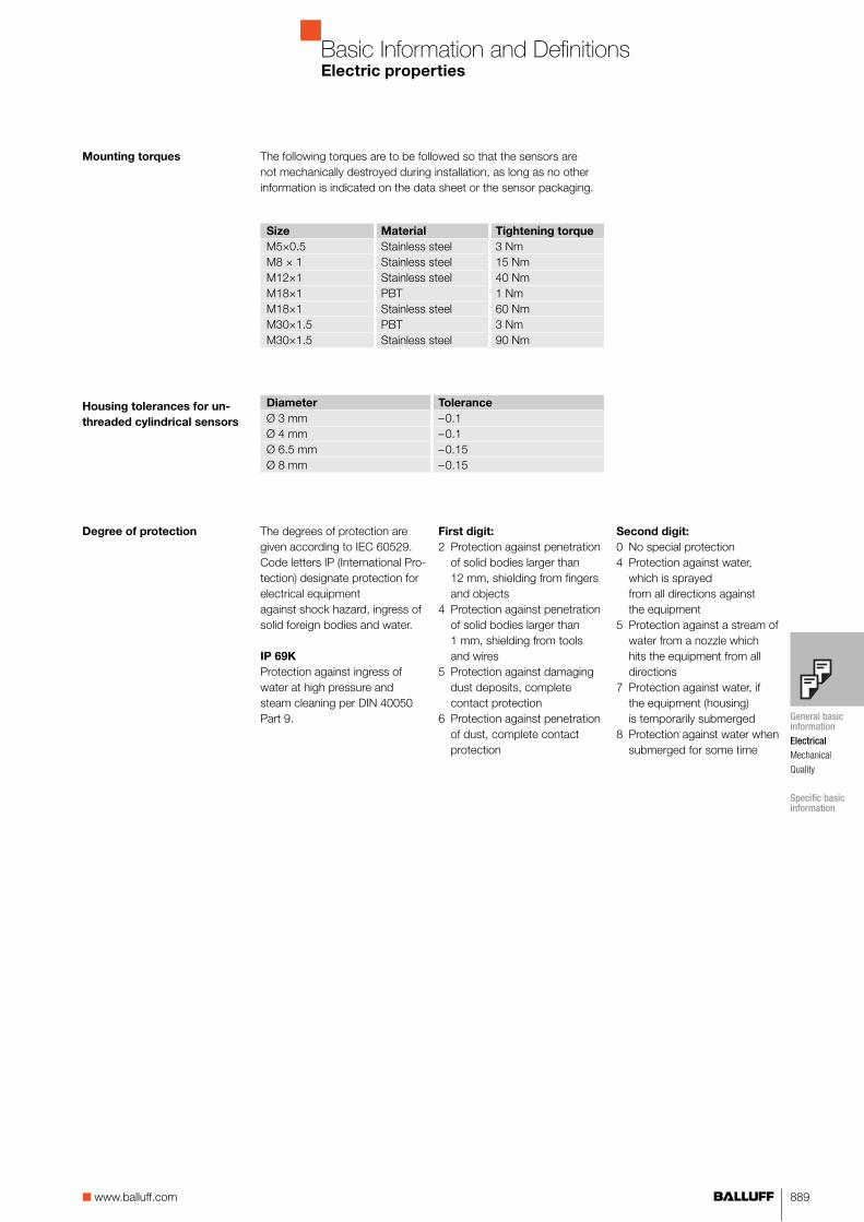
Mounting torques
Housing tolerances for un-
threaded cylindrical sensors
Size Material Tightening torque
M5×0.5 Stainless steel 3 NmM8 × 1 Stainless steel 15 NmM12×1 Stainless steel 40 NmM18×1 PBT 1 NmM18×1 Stainless steel 60 NmM30×1.5 PBT 3 NmM30×1.5 Stainless steel 90 Nm
Diameter Tolerance
Ø 3 mm –0.1Ø 4 mm –0.1Ø 6.5 mm –0.15Ø 8 mm –0.15
Degree of protection
The following torques are to be followed so that the sensors are not mechanically destroyed during installation, as long as no other information is indicated on the data sheet or the sensor packaging.
The degrees of protection are given according to IEC 60529.Code letters IP (International Pro-tection) designate protection for electrical equipment against shock hazard, ingress of solid foreign bodies and water.
IP 69K
Protection against ingress of water at high pressure and steam cleaning per DIN 40050 Part 9.
First digit:
2 Protection against penetration of solid bodies larger than 12 mm, shielding from fingers and objects4 Protection against penetration of solid bodies larger than 1 mm, shielding from tools and wires5 Protection against damaging dust deposits, complete contact protection6 Protection against penetration of dust, complete contact protection
Second digit:
0 No special protection4 Protection against water, which is sprayed from all directions against the equipment5 Protection against a stream of water from a nozzle which hits the equipment from all directions7 Protection against water, if the equipment (housing) is temporarily submerged8 Protection against water when submerged for some time
General basic information
Electrical
Mechanical
Quality
Specific basic information
890 For more information, visit us online!
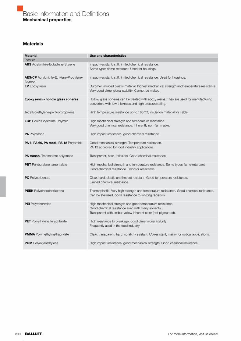
Basic Information and DefinitionsMechanical properties
Material Use and characteristics
PlasticsABS Acrylonitrile-Butadiene-Styrene Impact-resistant, stiff, limited chemical resistance.
Some types flame-retardant. Used for housings.
AES/CP Acrylonitrile-Ethylene-Propylene-Styrene
Impact-resistant, stiff, limited chemical resistance. Used for housings.
EP Epoxy resin Duromer, molded plastic material, highest mechanical strength and temperature resistance. Very good dimensional stability. Cannot be melted.
Epoxy resin - hollow glass spheres Hollow glass spheres can be treated with epoxy resins. They are used for manufacturing converters with low thickness and high pressure rating.
Tetrafluorethylene-perfluorpropylene High temperature resistance up to 180 °C, insulation material for cable.
LCP Liquid Crystalline Polymer High mechanical strength and temperature resistance. Very good chemical resistance. Inherently non-flammable.
PA Polyamide High impact resistance, good chemical resistance.
PA 6, PA 66, PA mod., PA 12 Polyamide Good mechanical strength. Temperature resistance. PA 12 approved for food industry applications.
PA transp. Transparent polyamide Transparent, hard, inflexible. Good chemical resistance.
PBT Polybutylene terephtalate High mechanical strength and temperature resistance. Some types flame-retardant. Good chemical resistance. Good oil resistance.
PC Polycarbonate Clear, hard, elastic and impact resistant. Good temperature resistance. Limited chemical resistance.
PEEK Polyetheretherketone Thermoplastic. Very high strength and temperature resistance. Good chemical resistance. Can be sterilized, good resistance to ionizing radiation.
PEI Polyetherimide High mechanical strength and good temperature resistance. Good chemical resistance even with many solvents. Transparent with amber-yellow inherent color (not pigmented).
PET Polyethylene terephtalate High resistance to breakage, good dimensional stability.Frequently used in the food industry.
PMMA Polymethylmethacrylate Clear, transparent, hard, scratch-resistant, UV-resistant, mainly for optical applications.
POM Polyoxymethylene High impact resistance, good mechanical strength. Good chemical resistance.
Materials

891■ www.balluff.com
Basic Information and DefinitionsMechanical properties
Material Use and characteristics
PlasticsPP Polypropylene Very good electrical properties. Impact resistant, tough, mechanically resilient.
Very low water uptake. Good to very good chemical resistance.
PPE Polyphenylene ether Tough, inflexible, high mechanical strength over a wide temperature range. Good chemical resistance. Good hot water resistance.
PSU Polysulfone High temperature resistance, high impact resistance, good chemical resistance, FDA approved (food grade).
PTFE Polytetrafluoroethylene Best temperature and chemical resistance, FDA approved (food grade).
PUR Polyurethane Elastic, abrasion-resistant, impact-resistant. Good resistance to oils, greases, solvents (used for gaskets and cable jackets).
PVC Polyvinyl chloride Good mechanical strength and chemical resistance (cable).
PVDF Polyvinylidene fluoride Thermoplastic. High mechanical strength and temperature resistance. Good chemical resistance (similar to PTFE).
MetalWrought aluminum alloy Standard-aluminum for machined cutting. Can be anodized.
Used for housings and mounting components.
CuZn Brass Standard-housing material with surface protection.
Stainless steel Excellent corrosion resistance and strength. Quality 1.4034, 1.4104: Standard-material; quality 1.4305, 1.4301: Standard-material for the food industry; quality 1.4401, 1.4404, 1.4571: With increased requirements on chemical resistance at elevated temperatures for the food industry.
GD-Al die-cast aluminum- Low specific gravity. Good strength and resistance. Some types can be anodized.
GD-Zn die-cast zinc- Good resistance and strength. Usually with protective surface coating.
OtherGlass Good chemical resistance and strength. Used primarily in optical applications (lenses,
cover lenses).
Ceramic Very good strength and chemical resistance. Electrically insulating. Excellent temperature resistance.
General basic information
Electrical
Mechanical
Quality
Specific basic information

892 For more information, visit us online!
Basic Information and DefinitionsPhotoelectric sensors
The alarm output at the receiver (PNP open collector – 30 mA) trig-gers a warning signal in the case of functional interruptions, which can be caused by contamination or mechanical de-adjustment. The alarm output is activated if the received signal lies in the alarm range for a defined amount of time.
stable
unstable
stable
Switching threshold
Stability (green LED)
Alarm
Alarm output
For series BOS 18M Teach-in and BOS 65K, the entire product fam-ily, including diffuse and retroreflective sensors, is equipped with an alarm output.
The turn-off delay is the time which the sensor requires for actuation when the target object leaves the sensing zone, at a transmission efficiency factor of 0.5.
Turn-off delay
Receiver
EmitterBeam splitter
Detection- area
LensReflector
Emitter and receiver use a common lens. The emitter light passes through the beam splitter and the lens to the reflector. The reflector bounces the emitter light back to the lens. This gives retroreflective sensors that work with autocollimation a small, round beam profile. Additional benefits: no dead zone for scanning and for the reflec-tor, better small parts detection, and the switching characteristic is independent of the approach direction.
Autocollimation
Dark switching
according to DIN 44030
Light receiver Amplifier Consumer
non-illuminated conducting switched onilluminated not fully modulated switched off
The switching delay is the time which the sensor requires for actua-tion when the target object leaves the sensing zone, at a transmis-sion efficiency factor of 2.
Turn-on delay
A sensor with an analog output does not switch at a particular target distance. Its analog output emits a distance-dependent output signal. The output voltage corresponds to the object location within the sensing range. These systems operate on the same principle as sensors with background suppression. They generate a linear output signal within a certain range (measur-ing range).
Distance sensors
with analog output

893■ www.balluff.com
Basic Information and DefinitionsPhotoelectric sensors
The ambient light is the portion of light that is received by the receiver, but does not originate at the associated emitter.
Ambient light
Through-beam sensors consist of separate emitter- and receiverunits which have to be aligned opposite each other at the two sides of the detection range. A target interrupts the light beam and causes the receiver to switch, regardless of the surface characteristics. In unfavorable conditions (e.g. dust, moisture, oil), you achieve the best results with through-beam sensors. Ranges of up to 50 m can be achieved.
Target
Emitter Receiver
Through-beam sensor
Sensors for color recognition detect objects based on their color. The sensor is calibrated so that it recognizes objects having a certain color. Then, different colored objects do not generate a switching signal.
Color sensing
Polyurethane jacket
■ Temperature T = +85 °C ■ Excellent chemical resistance■ Flexible■ No embrittlement from oils
and cooling emulsions.
Corrugated metal tube,
silicon jacketed
■ Temperature T = +150 °C■ Highly flexible■ Crush-resistant■ Can be sterilized.
Metal jacket
■ Temperature T = +150 °C■ Resistant to hot swarf■ Flexible■ Crush-resistant
Optical conductors are made of glass or plastic with a diameter of as little as 50 µm and bunched in bundles of several hundred individual fibers to form so-called fiber optics. The fiber ends are ground and polished to meet the quality criteria of the optical industry. The individual fibers are coated with a very thin layer of lubricant. This reduces friction against the outer jacket and between the fibers, so that broken fibers are prevented even when the cable is continu-ously flexed. The transmission properties are guaranteed through this over a long span of time.The ends of the bundles are potted with the connection sleeve and the jacket. Balluff fiber optics thus have an IP 67 rating (IP 65 for metal jacket). Moisture and aggressive media cannot hurt either the fibers or the slide coating, so the optical properties remain unaf-fected. This design distributes axial pull forces evenly over all the fibers, and protects the individual fibers from excessive pull loads.
Fiber optics
In order to achieve a smaller light spot, the light beam of the emitter is focused through lenses. Through the focusing and the light spot caused by it, the switch is better suited to recognize small parts and details. Focusing is often used with retroreflective sensors with background suppression, as well as with retroflective sensors.
Focusing
General basic information
Specific basic information
Photoelectric sensors
Inductive sensors
Capacitive sensors
Magnetic cylinder sensors

894 For more information, visit us online!
Basic Information and DefinitionsPhotoelectric sensors
Light switching
according to DIN 44030
Light receiver Amplifier Consumer
Illuminated Fully modulated Switched onNon-illuminated Not fully modulated switched off
The hysteresis is the distance between the switchpoints for a target approaching and then receding from a photoelectric switch.
Hysteresis
Background suppression
(BGA)
Through the background suppression, objects within a set switch-ing distance are detected, without being impeded by the reflective background, and nearly independent of color and surface of the object (object reflection).Background suppression is achieved by cutting the beam from the emitter to the receiver. To do so, it divides the visible field into an active area and the background. In addition, by dividing the receiver into at least two adjacent areas (e. g. by using a dual diode or a PSD- element) and by means of a geometric arrangement (triangula-tion), the actual position of the object within the sensing range can be determined. Through this, the object and the background can be distinguished accurately. Diffuse sensors with background suppres-sion are characterized by low gray value shift and hysteresis.
The standard target photoelectric sensors are referred to as the Kodak-gray card. This is a cardboard sheet whose surface has a defined degree of reflectivity. The side with 90 % reflection deter-mines the range of diffuse sensors, with 18 % reflection to determine the gray value shift.
Kodak gray card
Gray value shift is the switching distance difference when calibrat-ing using different object reflectivities. The sensor is calibrated for a distance using a Kodak-gray card with 90 % reflection. With the Kodak-gray card with 18 % reflection, the distance achieved with it is measured. The difference between these two switchpoints in % is referred to as the gray value shift. The smaller the gray value shift, the more color-independently the sensor operates.
Gray value shift
Fork sensors are through-beam designs in which the emitter and receiver are arranged across from each other in a U-shaped housing. Through the housing type, alignment and electrical connection are simplified. Different ranges are available by selecting different housing configurations. Fork openings of 5...220 mm are possible in various increments. The built-in potentiometer and apertures allow you to adjust the fork sensors easily for detecting parts down to a diameter of 60 µm.
Fork sensor

895■ www.balluff.com
Basic Information and DefinitionsPhotoelectric sensors
Light is used as a sensor medium in many areas of technology and daily life. Used in controllers- and regulation equipment as a sensor medium. Generally a change in the light intensity in an optical beam (between emitter and receiver) caused by a target object is evaluated. Depending on the properties of this object and the characteristics of the optical beam, the light beam is either interrupted or reflected, or even scattered.Predominantly clocked infrared light-LEDs are used as emitters, and phototransistors are used as receivers. The output signal is for the most part independent of the ambient light conditions, since visible light can be easily filtered out.With critical detection procedures, diffuse sensors and -beams can be used with red light-LEDs, because the light beam and the detection point can be measured visually and can be adjusted more easily. For the various usage conditions, Balluff offers three sensor variants: diffuse sensors, retroreflective light sensors, and one-way photoelectric sensors.
Light as a sensor medium
The output leads can be connected to the wrong potential without destroying the sensor. Together with their polarity reversal protection, these sensors are completely protected against miswiring.
Short-circuit protected
Correction factors
(for diffuse sensors)For objects with varying reflection characteristics, the range can be determined by using the correction factors shown. See the adjacent table.
Correction factor Object, surface
1 Paper, white, matte 200 g/m²1.2...1.6 Metal, shiny1.2...1.8 Aluminum, black anodized1 Styrofoam, white0.6 Cotton fabric, white0.5 PVC, gray 0.4 Wood, rough0.3 Cardboard, black, shiny0.1 Cardboard, black, matte
The purpose of laser protection classes is to protect persons from laser radiation by specifying limit values. Based on this, the lasers used are classified according to a scale reflecting the degree of hazard. The calculations and associated limit values relevant for the classification are described in the standard EN 60825-1:2001-11. The grouping is based on a combination of output power and wave-length, taking into account emission duration, number of pulses and angle extension.
Balluff sensors work in the following laser protection classes:Class 1: Not dangerous, no protective measures.Class 2: Low output, lid-closing reflex sufficient for protection.With devices of protection class 2, the eye closes on its own due to the lid closing reflex before it has been open to the beam for too long. Laser warning signs on the device and possibly also on the machine in which a laser is being used are sufficient. Additional pro-tective measures are not required. When using devices of protection classes 1 and 2, no laser safety officer is necessary in the company.
Lasers, laser class
General basic information
Specific basic information
Photoelectric sensors
Inductive sensors
Capacitive sensors
Magnetic cylinder sensors

896 For more information, visit us online!
Basic Information and DefinitionsPhotoelectric sensors
Light transmission by total
reflection
Without the total reflection at boundary layers described above, fiber optics of today's quality would not be feasible. They consist of a cylindrical, light-conducting core and a surrounding thin-wall jacket. The optical density n of the core is greater than that of the jacket. A light beam is always completely reflected at the junction between core and jacket, and can therefore never leave the core in a radial direction. Theoretically, the light is not weakened by these reflections; however, contamination and small defects both in the core material as well as the boundary layer do cause losses (attenuation) and effectively limit the fiber optic length over which reliable information can be transmit-ted.
Emitter/Receiver
Actual beamEmitter-/receiver beam
Standard target 90 % reflective
With diffuse types, the emitter and receiver are integrated into a single housing. The alignment to a detection object is largely uncriti-cal. A target object (e. g. a standard target which is 90 % reflective) bounces a part of the light from its surface back to the receiver. If the standard target reaches the response curve (see image), the output signal changes. The sensing distance depends on the size, shape, color and properties of the reflective object surface. Using a Kodak-gray card with 90 % reflectivity (like white paper), distances of up to 2 m can be obtained.
Photoelectric sensor
To locate invisible marks on objects, so-called luminescent materi-als (contained in special chalks, inks, paints etc.) are used which can only be made visible under ultraviolet (UV) light. The fluorescent materials convert the invisible UV light (short wavelength, here 380 nm) into visible light (between blue 450 nm and dark red 780 nm). This effect is called photoluminescence. The visible light can then be detected as usual by the receiver component of the sensor.
Luminescence
The permitted humidity is 35 to 85 % (not condensed).Permitted humidity
Light refraction Light beams experience a change in direction (interruption) at the border between two optical media with different optical thicknesses
(e.g. glass/air). The degree of interruption depends on the quotients of the optical thicknesses of both media and on the angle of inci-dence ε to the optical axis.
If a light beam travels from a dense medium, n, into a thinner one, n', its course there will show a greater angle ε'. However, above εcrit. (boundary angle at which the broken beam runs parallel to the boundary layer), it again enters the medium with the thickness n; this means that a total reflection is pending.
Total reflection

897■ www.balluff.com
Basic Information and DefinitionsPhotoelectric sensors
When do you need them?
A part of the emitter light in retroreflective systems is reflected directly back to the receiver from target objects with shiny surfaces, e. g. stainless steel, aluminum or tinplate. Simple Retroreflective light sen-sors can therefore not reliably distinguish reflected light from the ob-ject and reflected light. Erroneous readings therefore cannot be ruled out. For this reason, Balluff retroreflective light sensors are alternatively equipped with polarizing filters, 0which, together with a Balluff
reflector, an optically activated prismatic mirror, form a selective barrier against the reflected light from the object, but still allow the reflector light to occur.
Polarizing filters
How do they work?
Light consists of a wide variety of individual beams, which all sinusoidally oscillate on their dispersal axes. Their oscillation levels, however, are independent of one another and can take on any angle position desired (see image).If they meet a polarizing filter (fine line grid), then only the beams oscillating parallel to the grid level are let through, and the verti-cally oscillating ones are entirely deleted. Of all the other oscillation planes, only the portion which consists of parallel components is allowed to pass.
To suppress mirror reflections
Behind the filter, the light only oscillates parallel to the polariza-tion plane. For this light, an additional 90º rotated polarizing filter becomes an impassable barrier.With a 90º rotated polarizing filter in front of both the emitter- and receiver of a retroreflective system, you can therefore prevent the reflected light of a reflecting target object from falsely triggering the signal of the photo-receiver.
For reliable detection of reflective target objects
On the other hand, the light reflected from the triple mirror, with its polarization plane rotated by 90º as described above, is allowed to pass unhindered by this filter.The receiver of a retroreflective system is thereby fully shielded even when a reflecting target object enters the beam, so that the object is still reliably detected.
General basic information
Specific basic information
Photoelectric sensors
Inductive sensors
Capacitive sensors
Magnetic cylinder sensors

898 For more information, visit us online!
Basic Information and DefinitionsPhotoelectric sensors
ReflectorEmitter/Receiver
Target
With retroreflective light sensors, the emitter and the receiver are in a single housing. A reflector on the opposite side of the beam bounces the emitter's light back to the receiver.A target object interrupts the reflected light beam and causes a change in the output signal. With reflective interfaces, it is advisable that the light reflected from the object is to be blanked out with a polarizing filter in front of the receiver optics, in order to prevent pos-sible error signals.
Retroreflective sensor
Diffuse reflection occurs on an uneven and rough surface. It can be illustrated through a wide variety of poorly reflective and differently aligned miniature mirrors. Incidental light is widely "scattered" from such a surface. The reflection losses are higher the darker and more matte finished the surface is. Diffuse sensors, for example, detect diffuse reflecting light from target objects.
Reflection What is it?
Light beams extend to a straight line in free space. Upon striking an object, they are reflected. Depending on the surface composition of the object, one of three types of reflection occurs: total reflection, retroreflection, and diffuse reflection.
The total reflection reaches a highly reflective (mirroring) surface. The angle of incidence is thereby the same as the angle of reflection (eI = eE ). The reflection losses are in the ideal case negligible.
The retroreflection is caused by two mirrors aligned vertically to each other. A light beam is again projected back through double reflection in the same direction. The angle of incidence can thus be altered in a relatively wide range.
The two-dimensional principle of retroreflection described above can be carried over to a spatial system with three mirrors which are oriented at right angles to each other (one corner of a cube standing on its point). A light beam entering this system is totally reflected by all three surfaces and exits parallel to the incident beam. Triple mirrors are called optically active, because they also turn the polarization level of the reflected light beam by 90°. This property first enables a secure recognition of reflective detection objects, together with a polarization filter with retroreflective light sensors.
Reflectors
(optically active triple mirrors)
Each six triple mirrors are to be arranged into a hexagon and ar-ranged in a honeycomb next to each other. Their orientation with respect to the light beam is then totally unproblematic. These are generally made of plastics with high optical density, injected as sheets or pressed into flexible tape.

899■ www.balluff.com
Basic Information and DefinitionsPhotoelectric sensors
Switching distance s The switching distance is the distance between the standard target and the "sensing surface" of the light sensor for causing a signal change (per EN 60947-5-2).
The rated switching distance
is a switching distance- char-acteristic, which does not take into account manufacturing tolerances, sample differences, operating temperatures, supply voltages, etc.
Real switching distance sr The actual switching distance is the switching distance at mea-sured voltage Ue, taking into account the manufacturing toler-ances at an ambient temperature of (T = +23 °C ±0.5).
Usable switching distance su The usable switching dis-tance is the permitted switch-ing distance within fixed voltage- and temperature limits (0.80 sn ≤ su ≤ 1.20 sn).
Blind zone The blind zone is the range between the sensing surface and the minimum switching distance in which a detection object can-not be detected.
Detection range sd The detection range is the area in which the switching distance of a photoelectric sensor to the standard target can be set.
Rated switching distance sn
120 %
Kod
ak-g
ray
card
sn
sr
su
sd
80 %
Blin
d zo
ne
0 %
Sen
sing
sur
face
135 % 100 %
Photoelectric sensors use mainly the following transmission compo-nents:■ Red light LED: visible light, well-suited as an orientation aid and
for sensor adjustment.■ Infrared LED (IR): Invisible beam with high energy.■ Red light laser: Visible light, optimal for detecting small parts and
high ranges due to the physical properties of the laser.
Emitter light
General basic information
Specific basic information
Photoelectric sensors
Inductive sensors
Capacitive sensors
Magnetic cylinder sensors

900 For more information, visit us online!
Basic Information and DefinitionsPhotoelectric sensors
Triangulation With a triangulation, the emitter- and the receiver beam are cut by a photoelectric sensor at a pointed angle. A target object will only be
detected in the range where the beams overlap.The emitter light which is reflected or diffused from objects outside this limited zone cannot be registered by the photo-receiver.With the triangulation, relatively small changes in distance can be recognized (e.g. slots, offsets on shafts). Color and shape of the object have very little effect on the registration.
Emitter
Receiver
Target
Sensor settings are no longer carried out with potentiometers or slide switches with Teach-in-sensors. Everything is controlled by pressing a button. The microcontroller integrated in Teach-in-sensors enables the complete control of the setting process by buttons. Through defined setting steps, there is the advantage that the sensor cannot be set in an unreliable range. The microcontroller also assumes control of the contamination indicator and the contamination output.A wide variety of Balluff Teach-in-switches have remote control; the setting process via Teach-in can also be triggered externally via cable.
Teach-in
The temperature drift is the switching point shift at temperature changes in % of sr.
Temperature drift
The test input of the emitter interrupts its light impulses and, through that, enables the function check of emitter and receiver. If Test+ is used, then Test– has to be at 0 V, and if Test– is used, then Test+ has to be placed at 10...30 V. The receiver-output has to switch ev-ery time if there is a voltage of 10...30 V DC (Test+) or 0 V DC (Test–) at the test input. Contamination or maladjustment of the optical axis causes the emitter signal to reach the receiver only weakly, if at all. Therefore, the output will not switch, even though the test input is activated. The test function corresponds to a remote monitoring of the photoelectric sensor and enables a preventive system control.
Test input
The transmission is a measure for the light transmission ability of a medium. It is defined as the ratio of: – passed to – entering light (in %). Diffuse transmission is the term which is used when the light is partially or completely diffused.
Transmission
Photoelectric sensor Background suppression Retroreflective sensor Through-beam sensor
Rated switching distance sn 100 mm 200 mm 400 mm 1 m 2 m 120 mm 250 mm 1.1 m 2 m 4 m 8 m 5 m 8 m 16 m 50 mActual switching distance (in % of sn) 125 125 125 135 150 135 135 135 150 150 150 150 150 150 150Switching hysteresis (in %) ≤ 20 ≤ 20 ≤ 25 ≤ 15 ≤ 15 ≤ 1 ≤ 1 ≤ 1 ≤ 10 ≤ 10 ≤ 10 ≤ 15 ≤ 15 ≤ 15 ≤ 15Ø the response beam at sn/2 typical (mm) 20 25 150 300 300 6 10 25 50 100 150Ø of the active area (mm) 8 12 12 20
Technical data, general

901■ www.balluff.com
Basic Information and DefinitionsPhotoelectric sensors
Output (red LED)
Dar
k-on
Ligh
t-on
stable
unstable
stable
Switching-threshold
Stability (green LED)
The contamination indicator (green) lights in the safe zone if the input energy exceeds the threshold energy by at least 30 %.The threshold energy, at which a signal change affects the output, is defined at 100 %.From this, the safe zone results■ if the input signal exceeds at least 130 % of the
threshold energy■ if the input signal exceeds at least 70 % of the threshold energy.
Contamination indicator
Degree of contamination Pure air Ideal conditions
Trace contamination Relatively clean air in indoor rooms
Slight contamination Workshop- and storage rooms
Moderate contamination Dirty and dusty environments; switching distance is reduced to s = 0.5 su
High contamination Heavy precipitation, whirled-up particles and swarf: Functional failure of the photoelectric sensor is possible.
Highest contamination Coal dust precipitating on the lens. Photoelectric sensor function may fail.
Ambient temperature The ambient temperature is the temperature range in which the function of the photoelectric switch is guaranteed. Balluff Standard: –15 °C ≤ Ta ≤ +55 °C
Contamination (influence on the response range)
Contamination reduces the specified response range of sensors and fiber optics compared to clean air, because the dirt- and dust particles■ deposit on the lenses and
impair their light transmission,■ and absorb and scatter light in the beam path.
An oil-free source of compressed air can be used to prevent the ef-fects of dirt and contamination due to impure air.
The power supply connections can be reversed without destroying the sensor. In combination with the short-circuit protection, there is protection against total reversal.
Polarity reversal protection
General basic information
Specific basic information
Photoelectric sensors
Inductive sensors
Capacitive sensors
Magnetic cylinder sensors
958
Worldwide Sales
Headquarters
GermanyBalluff GmbHSchurwaldstrasse 973765 Neuhausen a.d.F.Phone +49 7158 173-0Fax +49 7158 [email protected]
Subsidiaries and
Representatives
ArgentinaNortécnica S.R.L103 – Heredia 638B1672BKDVilla Lynch – San MartinPcia. de Buenos AiresPhone +54 11 47573129Fax +54 11 [email protected]
AustraliaBalluff-Leuze Pty. Ltd.12 Burton CourtBayswater VIC 3153Phone +61 397 204100Fax +61 397 [email protected]
AustriaBalluff GmbH Industriestrasse B162345 Brunn am GebirgePhone +43 2236 32521-0Fax +43 2236 [email protected]
BelarusAutomaticacentre OOO.Nezavisimosti Av. 185,Block 19, Office 3220125 MinskPhone +375 17 2181713Fax +375 17 [email protected]
BelgiumBalluff bvbaResearchpark Haasrode 1820Interleuvenlaan 62, 3001 LeuvenPhone +32 16 397800Fax +32 16 [email protected]
BrazilBalluff Controles Elétricos Ltda.Rua Francisco Foga, 25Distrito IndustrialCEP 13280.000 Vinhedo – Sao PauloPhone +55 19 38769999Fax +55 19 [email protected]
BulgariaBPS AG41, Nedelcho Bonchev St.1528 SofiaPhone +359 2 9609875Fax +359 2 [email protected]
CanadaBalluff Canada Inc.2840 Argentia Road, Unit 2Mississauga, Ontario L5N 8G4Phone +1 905 816-1494Toll-free 1-800-927-9654Fax +1 905 [email protected]
ChileBalluff ControlesElétricos Ltda.,Brazil
ChinaBalluff (Shanghai) Trading Co. Ltd.Room 1006, Pujian Road 145, Shanghai 200127Phone +86 21 5089 9970Fax +86 21 5089 [email protected]
ColumbiaBalluff ControlesElétricos Ltda.,Brazil
CroatiaHSTEC d.d.Zagrebacka 10023000 ZadarPhone +385 23 205-405Fax +385 23 [email protected]
Czech RepublicBalluff CZ, s.r.oPelušková 1400198 00 Praha 9 – KyjePhone +420 281 000 666Fax +420 281 [email protected]
DenmarkBalluff ApSÅbogade 158200 Århus NPhone +45 70 234929Fax +45 70 [email protected]
EgyptEGEC24 St., 302 Taksym El Kodah-smouha,First Floor, Department 1AlexandriaPhone +20 3 4299771Fax +20 3 [email protected]
FinlandMurri OyKoukkukatu 115700 LahtiPhone +358 3 8824000Fax +358 3 [email protected]
FranceBalluff SASZI Nord de Torcy-Bat 3Rue des Tanneurs – BP 4877201 Marne La Vallée Cedex 1Phone +33 1 64111990Fax +33 1 [email protected]
GreeceS. NAZOS S.A.10 KLM Thessalonikis-KilkisP.O. Box 57008ThessalonikiPhone +30 2310 462120Fax +30 2310 [email protected]
Great Britain and IrelandBalluff Ltd.4 Oakwater AvenueCheadle Royal Business ParkCheadle, Cheshire SK8 3SRPhone +44 161 282-4700Fax +44 161 [email protected]
Hong KongSensortech CompanyNo. 43, 18th StreetHong Lok Yuen,Tai Po, NTPhone +852 26510188Fax +852 [email protected]
HungaryBalluff Elektronika Kft.Pápai út. 55.8200 VeszprémPhone +36 88 421808Fax +36 88 [email protected]
IndiaBalluff India405 Raikar ChambersDeonar Village Road,Govandi, Mumbai 400088Phone +91 22 25568097Fax +91 22 [email protected]
IndonesiaPT. Multiguna CemerlangBumi Serpong Damai Sektor XIMultipurpose Industrial Building Block H 3-31Serpong Tangerang15314 Banten Phone +62 21 75875555 Fax +62 21 [email protected]
IcelandSmith & NorlandNóatúni 4105 ReykjavíkPhone +354 520 3000Fax +354 520 [email protected]
IsraelAncitech Ltd.19, Hamashbir St.Industrial Zone Holon 58853 HolonPhone +972 3 5568351Fax +972 3 [email protected]
ItalyBalluff Automation S.R.L.Via Morandi 410095 Grugliasco, TorinoPhone +39 11 3150711Fax +39 11 [email protected]
JapanBalluff Co., Ltd.Ishikawa Bldg. 2nd Fl.1-5-5 Yanagibashi, Taito-KuTokyo 111-0052Tel. +81 03 5833-5440Fax +81 03 [email protected]
Kazakhstanelcos electric control systems2A, Molodezhniy Str. 3D Block O., Offices 318-319050061 Almaty Phone +7 727 3340536 Fax +7 727 3340539 [email protected]
Latvia and EstoniaSIA InterautomatikaBrīvības g. 4101024 RīgaPhone +371 67522010Fax +371 [email protected]
LithuaniaUAB InterautomatikaKęstučio 4708127 VilniusPhone +370 5 2607810Fax +370 5 [email protected]
MalaysiaProfacto Solution & Services Sdn. Bhd.No. 23-1 Jalan Bandar Empat BalasPusat Bandar Puchong,47100 Puchong, SelangorPhone +60 35882 2684Fax +60 35882 [email protected]
Team Automation Systems (M) Sdn. Bhd.2A, Jalan MP17, Taman Merdeka Permai, Batu Berendam, 75250 MelakaPhone +60 6 3366223Fax +60 6 [email protected]
MexicoBalluff de México S.A. de C.V.Anillo Vial II Fray Junípero Serra No. 4416Colonia La Vista Residencial, CP 76232Delegación Epigmenio GonzálezQueretaro, Qro.Phone +52 442 2124882Fax +52 442 [email protected]
NetherlandsBalluff B.V.Europalaan 6a5232 BC 's-HertogenboschPhone +31 73 6579702Fax +31 73 [email protected]
New Zealand Balluff-Leuze Pty. Ltd.,Australia
NorwayPrimatec asLillesandsveien 444877 GrimstadPhone +47 37 258700Fax +47 37 [email protected]
PhilippinesTechnorand Sales Corporation803 Wilshire Annapolis Plaza,No. 11 Annapolis Street, San Juan, Metro Manila 1500Phone +63 2 7245006Fax +63 2 [email protected]
PolandBalluff Sp. z o.o.Ul. Muchoborska 1654-424 WrocławPhone +48 71 3384929Fax +48 71 [email protected]

959■ www.balluff.com
Worldwide Sales
PortugalLA2P Lda.Rua Teofilo Braga, 156 AEscrit. F – Edificio S. DomingosCabeco Do Mouro2785-122 S. Domingos De RanaPhone +351 21 4447070Fax +351 21 [email protected]
RomaniaEast Electric s.r.l.256 Basarabia Blvd.030352 BucurestiPhone +40 31 4016301Fax +40 31 [email protected]
RussiaBalluff OOOM. Kaluzhskaja Street 15 Building 17, Office 500119071 MoscowTel. +7 495 78071-94Fax +7 495 [email protected]
SerbiaENEL d.o.o.Ul. Vasilja Pavlovica 1014000 ValjevoPhone +381 14 291161Fax +381 14 [email protected]
SingaporeBalluff Asia Pte. Ltd.18 Sin Ming Lane#06-41 Midview City, Singapore 573960Phone +65 62524384Fax +65 [email protected]
SlovakiaBalluff Slovakia s.r.o.Blagoevova 985104 BratislavaPhone +421 2 67200062Fax +421 2 [email protected]
SloveniaSenzorji SB d.o.o.,Proizvodnja, trgovina in storitve d.o.o.Livadna ulica 12204 Miklavž na Dravskem poljuPhone +386 2 6290300Fax +386 2 [email protected]
SpainBalluff S.L.Edificio Forum SCVPlanta 5°, Oficina 4° Carretera Sant Cugat a RubiKm01, 40-5008190 Sant Cugat del VallésBarcelonaPhone +34 93 5441313Fax +34 93 [email protected]
South AfricaPAL Distributers CC291A Pine Avenue, FerndaleRandburg, GautengPhone +27 11 7814381Fax +27 11 [email protected]
South KoreaMahani Electric Co. Ltd.792-7 Yeoksam-DongKangnam-Gu, SeoulPostal code: 135-080Phone +82 2 21943300Fax +82 2 [email protected]
SwedenBalluff ABGamlestadsvägen 2, B1941502 GöteborgPhone +46 31 3408630Fax +46 31 [email protected]
SwitzerlandBalluff Sensortechnik AGRiedstrasse 68953 DietikonPhone +41 43 3223240Fax +41 43 [email protected]
TaiwanCanaan Electric Corp.6F-5, No. 63 Sec. 2 Chang An East Road10455 TaipeiPhone +886 22 5082331Fax +886 22 [email protected]
ThailandCompomax Co. Ltd.16 Soi Ekamai 4, Sukhumvit 63 Rd.Prakanongnua, Vadhana,Bangkok 10110Phone +66 2 7269595Fax +66 2 [email protected]
TurkeyBalluff Sensor OtomasyonSanayi Ve Ticaret Ltd. Sti.Perpa Ticaret Is MerkeziA Blok, Kat 1-2-3No: 0013-001434381 Okmeydani/IstanbulPhone +90 212 3200411 Fax +90 212 [email protected]
UkraineMicronlogistik Ltd.Ul. Promyischlennaya Street 3765031 OdessaPhone +380 48 7781278Fax +380 48 [email protected]
United Arab EmiratesMultiline Technical Co.TCA, behind ADCB Bank46530 Abu DhabiPhone +971 2 6457760Fax +971 2 [email protected]
USABalluff Inc.8125 Holton DriveFlorence, KY 41042-0937Phone +1 859 727-2200,Toll-free 1-800-543-8390Fax +1 859 [email protected]
VenezuelaBalluff Controles Elétricos Ltda., Brazil
VietnamAnh Nghi Son Service Trading Co., Ltd.D3 KDC Mieu Noi Dinh Tien Hoang St., W3, Binh Thanh Dist.,Ho Chi Minh City+84 8 35170401+84 8 [email protected]

960
Selection
Integration
Instruction
Application
Industrial identification
Project support
Vision sensors
IO-Link
Industrial networking
and connectivity
Product
System components
Decision help
Tec
TecSupportYour added value for planning and commissioning

961■ www.balluff.com
We offer ...
■ Decision help for the correct product selection■ Complex product and application support ■ Integration support■ Customer-specific product and commissioning training ■ Intensive technical support during the entire phase of the project ■ Assumption of time-consuming project work
We support you during the project implementation,
commissioning and integration
■ Would you like to monitor and track production processes? ■ Would you like to identify, control, monitor and optimize objects?■ Would you like to optimize and simplify your system wiring?
We provide you with specific support for Balluff system
components
■ Vision sensors BVS for optical identification■ Industrial networking and connectivity for wiring and networking■ IO-Link – network technology for reliable data transfer and greater
efficiency■ Industrial identification – RFID for transparency in material flow
Support
We are happy to help!Phone +49 7158 173-401
+49 7158 173-727
e-Mail [email protected]
TecSupportYour added value for planning and commissioning


963■ www.balluff.com
Customized ServicesAccording to your specifications. In the best quality.
Application advice
through our TecSupport: Discuss your technical require-ments. And take advantage of our expertise.
Real-world examples:■ Selection of the correct identification procedure for an assembly line■ IO-Link concept as a cost-effective alternative to conventional wiring■ System consulting for radio frequency identification (RFID): identification of large steel pipes in
adverse environments■ Recognizing multiple containers on a pallet in goods receiving
Commissioning: Order expert knowledge. And benefit from a quick start of production.
Real-world examples:■ Setting up an optical checkpoint with the BVS vision sensor■ Consulting and support during the programming of BIS RFID systems■ Installation and commissioning of a color detection application with the BFS color sensor
Fully customized products:
Order individual versions ac-cording to your requirements: from preassembly to engineer-ing services. And take advan-tage of the optimum.
Real-world examples:■ Extending the housing of a BHS high-pressure resistant inductive sensor■ Extra threads for the housing cover of a micropulse transducer BTL■ Customer-specific holder for an RFID data carrier ■ Adaptation of the characteristics for analog sensors BAW
Workshops: make use of well-founded manufacturer knowledge. And benefit from application security.
■ Professional sensor use: Select operating principles, install sensors professionally and ensure the reliable operation of your application.
■ Linear position sensing: This is how you measure precisely and wear-free.■ RFID: The right data at the right time at the right place.■ Vision sensor: Using an image processing sensor, ensure manufacturing quality in three steps.■ Vision sensor identification: Reliably identify data matrix codes with
an image-processing sensor. ■ Industrial networking with IO-Link: Manage signals intelligently and cost-effectively.
The right solutions
High application security
Less time required
Significant cost reduction
Balluff offers highly efficient sensor technology with high-perfor-mance mini sensors and compact connection technology. And more. Because with our extensive services, you can obtain support direct from the manufacturer: from the design and planning of your projects, to testing and setup on-site, to training and support. Over the entire life cycle of our products.
This creates greater planning security and provides faster com-missioning and an earlier start of production. This leads to higher productivity and more cost-effectiveness. And this relieves you of additional stress in your everyday work, giving you more time to focus on your core business.
You can find more information in our Services brochure or send us ane-mail: [email protected]

964
Balluff Products in 3D
Retrieving Product Information OnlineVarious CAD and electronic diagram formats available
CAD formats on the Cadenas PARTserver
■ All catalog products are available: inductive sensors, photoelectric sensors, sensors for pneumatic cylinders, micropulse transducers, industrial RFID systems, vision sensors BVS, mechanical single and multiple position switches, industrial networking and connectivity, and so on.
■ sizephics reduced to the essentials for optimized performance

965■ www.balluff.com
Retrieving Product Information OnlineVarious CAD and electronic diagram formats available
The benefits to you
■ Faster and more efficient designing■ Free availability of all Balluff catalog products■ All common CAD formats■ Convenient preview in 3D■ Configurable products
And here is how it works
■ Go to the 3D data at www.balluff.com
■ You are redirected to the Cadenas PARTserver■ Select a sensor and perform an optional check via 3D preview■ Add it to the shopping cart■ Once you have entered your details, the CAD files of your choice
are sent to you by e-mail
EPLAN macros – Electrical project planning made easy
And now users of EPLAN electrical project planning software can also profit from this free service. On our Web site planners and designers can download macros for selected Balluff products at no charge and implement them in their design. These macros include all the necessary graphics, technical and commercial information for the electrical design and documentation. Benefit from significant time and cost savings.


As a recognized partner in all sectors of the automation industry, Balluff offers comprehensive
expertise in sensor technology and networking. We supply advanced technology and
state-of-the-art electronics to our customers, who benefit from excellent service, application-
specific solutions and individual consultation. You too can benefit from the excellent quality of
our products and services.
SENSOR SOLUTIONS AND SYSTEMS
www.balluff.comPhone +49 7158 173-0
Balluff GmbH
Schurwaldstrasse 9
73765 Neuhausen a.d.F.
Germany
Tel. +49 7158 1730
Fax +49 7158 5010
www.balluff.comDoc. No. 862399/Mat No. 163386 E Edition 1302; subject to changes. Replaces edition 0811.
Object Detection
Linear Position Sensing and Measurement
Condition Monitoring and Fluid Sensors
Industrial Identification
Industrial Networking and Connectivity
Accessories
Systems and Service