ac induction motor basics 1 stmicroelectronics st7mc technical training st7mc technical training ac...
TRANSCRIPT

AC Induction Motor Basics 1
STMicroelectronics
ST7MC Technical TrainingST7MC Technical Training
AC Induction Motor Basics

AC Induction Motor Basics 2
2 ®
AC Induction Motor BasicsAC Induction Motor Basics
• Basic principles of AC motor
• System overview / Brushless motor drive requirements
• Technical appendixPWM generationSinewave generation concepts
AC Induction Motor Basics 3
3 ®
The induction motorThe induction motor
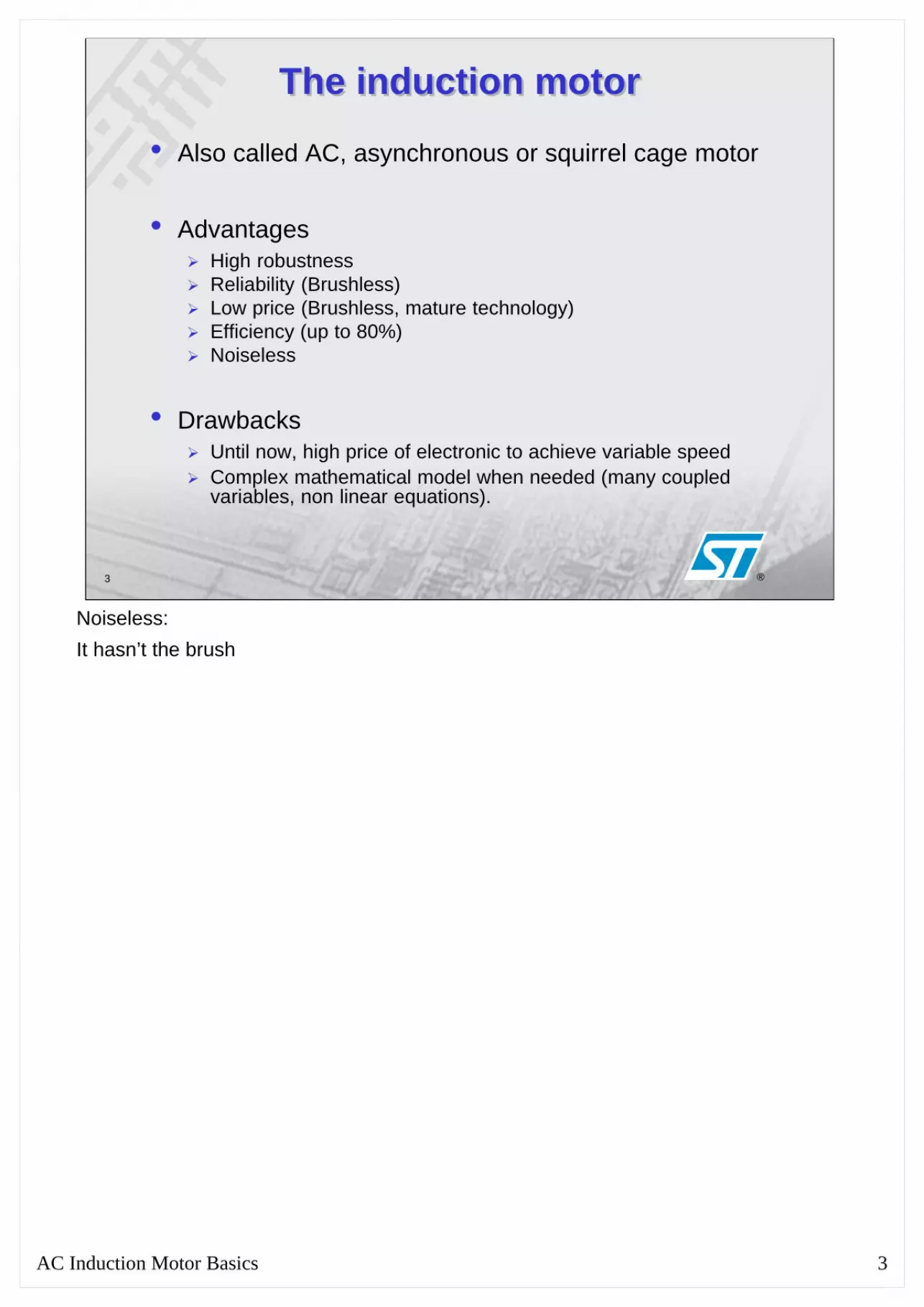
• Also called AC, asynchronous or squirrel cage motor
• AdvantagesHigh robustnessReliability (Brushless)Low price (Brushless, mature technology)Efficiency (up to 80%)Noiseless
• DrawbacksUntil now, high price of electronic to achieve variable speedComplex mathematical model when needed (many coupled variables, non linear equations).
Noiseless:It hasn’t the brush
AC Induction Motor Basics 4
4 ®
Induction motor principle (1/2)Induction motor principle (1/2)
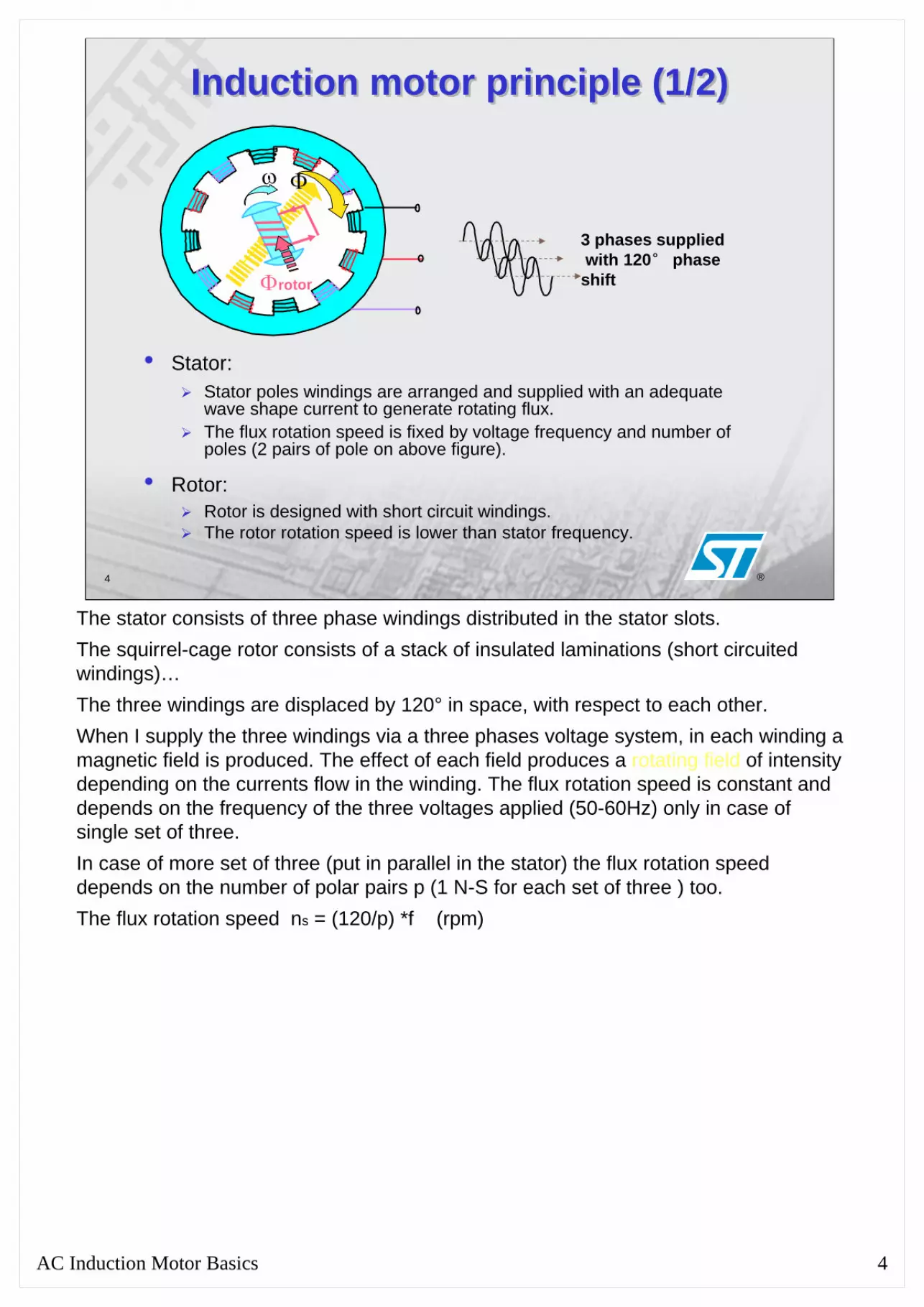
• Stator: Stator poles windings are arranged and supplied with an adequatewave shape current to generate rotating flux.The flux rotation speed is fixed by voltage frequency and number of poles (2 pairs of pole on above figure).
• Rotor: Rotor is designed with short circuit windings.The rotor rotation speed is lower than stator frequency.
Φ
Φrotor
ω
3 phases suppliedwith 120° phase shift
The stator consists of three phase windings distributed in the stator slots.The squirrel-cage rotor consists of a stack of insulated laminations (short circuited windings)…The three windings are displaced by 120° in space, with respect to each other.When I supply the three windings via a three phases voltage system, in each winding a magnetic field is produced. The effect of each field produces a rotating field of intensity depending on the currents flow in the winding. The flux rotation speed is constant and depends on the frequency of the three voltages applied (50-60Hz) only in case of single set of three.In case of more set of three (put in parallel in the stator) the flux rotation speed depends on the number of polar pairs p (1 N-S for each set of three ) too. The flux rotation speed ns = (120/p) *f (rpm)

AC Induction Motor Basics 5
5 ®
Induction motor principle (2/2)Induction motor principle (2/2)• Statoric rotating field induces current in rotor (transformator
principle: short-circuited windings of the rotor can be seen as the secondary side).
• As a reaction, a field is also generated in rotor, in opposite direction of the statoric one.
• Interaction between statoric and induced rotoric field creates arotating torque: the rotor is dragged with lower speed so that the fluxes will tend to match their positions.
• Synchronism is never reached (asynchronous motor), because no more current would then be induced.
The statoric rotating field produces f.e.m induced called air gap voltage in each of the stator phases at frequency f.These f.e.m. induce currents in rotor that produce an opposite field respect to the statoric one.The interaction between the air gap field (statoric field) and the rotoric one produces a rotating torque so that the rotor is in rotation.The rotor rotation speed is lower than the speed of the statoric rotating field(called synchronism speed).Synchronism is never reached (asynchronous motor).

AC Induction Motor Basics 6
6 ®
Basic torque vs speed characteristicBasic torque vs speed characteristic
Rotor rotation speed = w
TorqueMaximum torque
Startingtorque
Stator Flux rotation speed = W
Workingtorque
Slip
Loading torque (typical HVAC load)
Break down domain Motor stops if entered
Working domain (some Hz)Speed intrinsically regulated inside
If the rotor is rotating at the synchronous speed (wr = ws) there will be no relative motion between flux and the rotor so there will be no induced rotor voltages, rotor currents and torque.At any other sleep wr of the rotor (in the same direction of the flux rotation) the rotor is slipping with respect to the flux at e relative speed called the slip speed wsl.
Where wsl is ws – wr.The slip (difference between the speeds) depends on the load entity.In the motor characteristic there are two domains.The break down domain is an instable zone for the motor, here the speed decreases with the torque.The working domain is a stable zone for the motor, here decreasing the torque the speed increases. The motor tends to run at constant speed with different load torques. This is true until the load torque is lower than the maximum motor (maximum induction) torque otherwise the motor goes to the instable zone and is stopped.

AC Induction Motor Basics 7
7 ®
Changing the available torqueChanging the available torque• By increasing the stator voltage*
* stator frequency is kept constant
Torque
RotorSpeed
Workingtorque
Maximumavailable torque
Startingtorque
Maximumavailable torque
The torque increases with the stator voltage because the flux increases with the stator voltage.

AC Induction Motor Basics 8
8 ®
Changing the rotation speedChanging the rotation speed
Increasing stator frequency*
Torque
Stator Frequency
Workingtorque
Rotor rotation Speed
With Voltage vs Frequency Adaptation
* Voltage value = k x frequency to keep constant the maximum torque(V/ f = Cte gives constant current and therefore constant statoric field),
method currently named "scalar control"
In the scalar control the flux is a constant, so the statoric voltage change with the frequency in order to maintain a constant flux.The torque-speed characteristics shift horizontally in parallel for different values of f.To explain this, consider two frequencies f1 and f2 I achieve two synchronous speed, to have an equal load-torque, at both these frequencies the two slips have to be equalso, in the plane, equal torque and equal slips speed result in parallel but horizontally shifted characteristics.

AC Induction Motor Basics 9
9 ®
ASYNCHRONOUS MOTOR CONTROLASYNCHRONOUS MOTOR CONTROL
• Basic principles of AC motor
• System overview
• Technical appendixPWM generation key pointsSinewave generation issuesAC Motor Control methods
AC Induction Motor Basics 10
10
®
System block diagramSystem block diagram
Mai
ns re
ctifi
er a
nd P
ower
Fact
or C
orre
ctio
n
Mai
ns E
MC
filte
r
Aux. power supply
Three phaseconverter
Communication interface
Mot
orSe
nsor
Com
m
Mai
nsM
ains
ACDC
DCAC 3ph
Mot
or
Micro controller unit
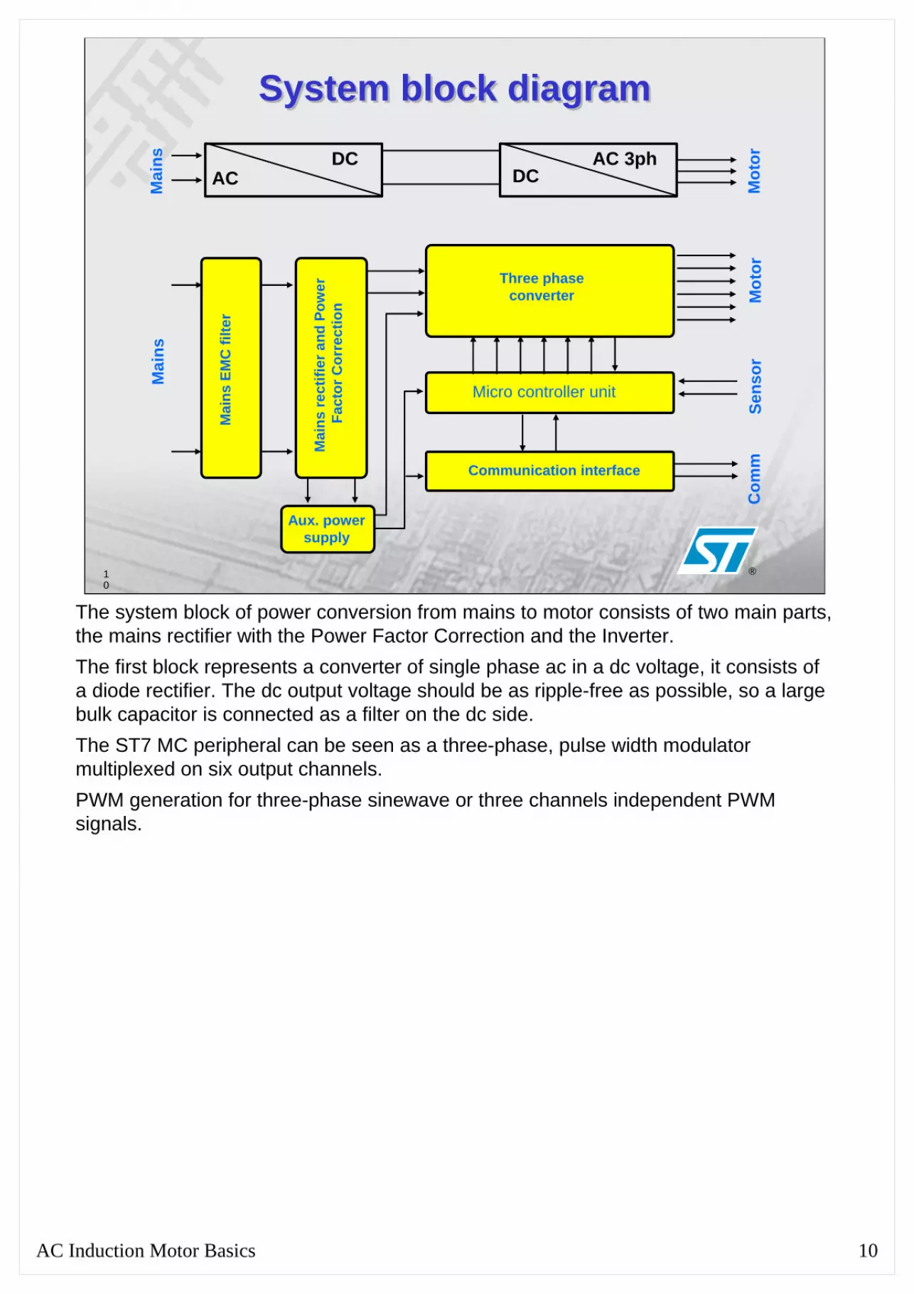
The system block of power conversion from mains to motor consists of two main parts, the mains rectifier with the Power Factor Correction and the Inverter.The first block represents a converter of single phase ac in a dc voltage, it consists of a diode rectifier. The dc output voltage should be as ripple-free as possible, so a large bulk capacitor is connected as a filter on the dc side. The ST7 MC peripheral can be seen as a three-phase, pulse width modulator multiplexed on six output channels. PWM generation for three-phase sinewave or three channels independent PWM signals.

AC Induction Motor Basics 11
11
®
How to get AC voltage out of a MCU?How to get AC voltage out of a MCU?• DAC function can be easily
achieved using PWM output
• Digital PWM signal can be filtered by:
RC network (to get 0..5V analog voltage directly out of MCU for instance)LR network (motor windings for instance). Smooth only the current.
• Anyway half-bridge dedicated complementary PWM signals are needed to drive standard power stages (triple half-bridge topology)
PWM
Analog
MCU I/O port
PWM Analog
MCU signals
Smoothed current
PWM
PWM
HV
Switch mode DC to AC inverters provide a sinusoidal AC voltage from a DC voltage. In an ac-motor load the voltage at its terminals is desired to be sinusoidal and adjustable in its magnitude and frequency. To achieve the analog AC sinusoidal voltage need to filter the digital PWM signal, if a motor-load is connected, the PWM signal is filtered via its windings (LR network) and the current smoothed by the windings inductances appears sinusoidal. Otherwise a RC network is connected in the MCU out port, in this case the sinusoidal voltage appears directly in this port.
AC Induction Motor Basics 12
12
®
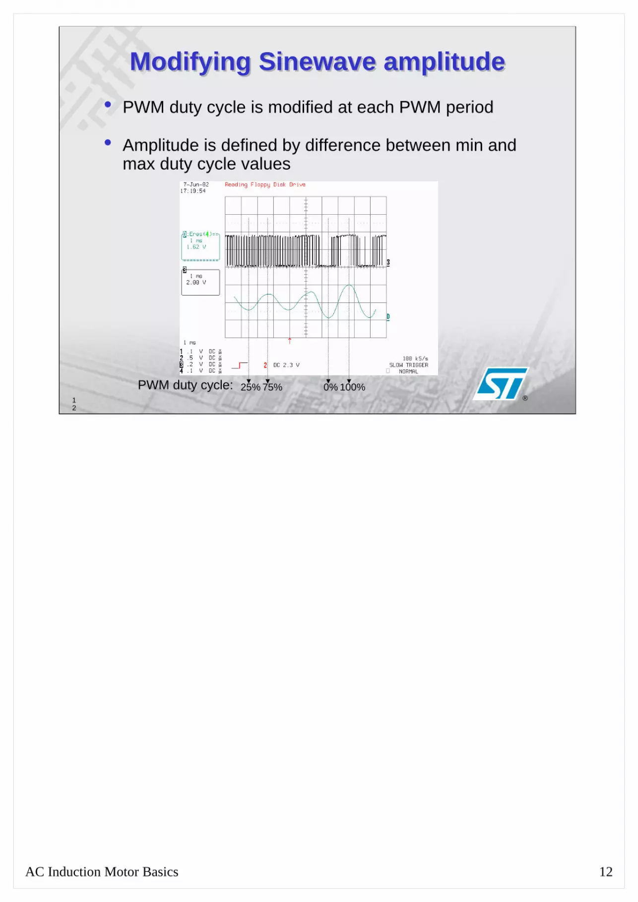
Modifying Sinewave amplitudeModifying Sinewave amplitude• PWM duty cycle is modified at each PWM period
• Amplitude is defined by difference between min and max duty cycle values
PWM duty cycle: 25% 75% 0% 100%

AC Induction Motor Basics 13
13
®
Modifying Sinewave frequencyModifying Sinewave frequency• PWM duty cycle is modified at each PWM period
• Frequency is defined by duty cycle variation speed

AC Induction Motor Basics 14
14
®
Generating three-phase voltageGenerating three-phase voltage
Inverter command:3 x complementary PWM outputs(1 timer with 3 compare registers)3 x dead time generator(to avoid cross conduction).
Compare registers are periodicallyloaded with sine values
Current is smoothed by motorinductances
IGBT or MOSFET
+ Freewheeling diode
Mains
MotorMCU
High voltage driver
5V 15V
High side switch
Low side switch
A three-phase voltage may be achieved using a Pulse-width Modulated (PWM) inverter in three half-bridge topology.The inverter has to control the magnitude and the frequency of the ac voltage. This is achieved via a pulse-width modulation of the inverter switches.

AC Induction Motor Basics 15
15
®
AC Induction Motor Basics 16
16
®
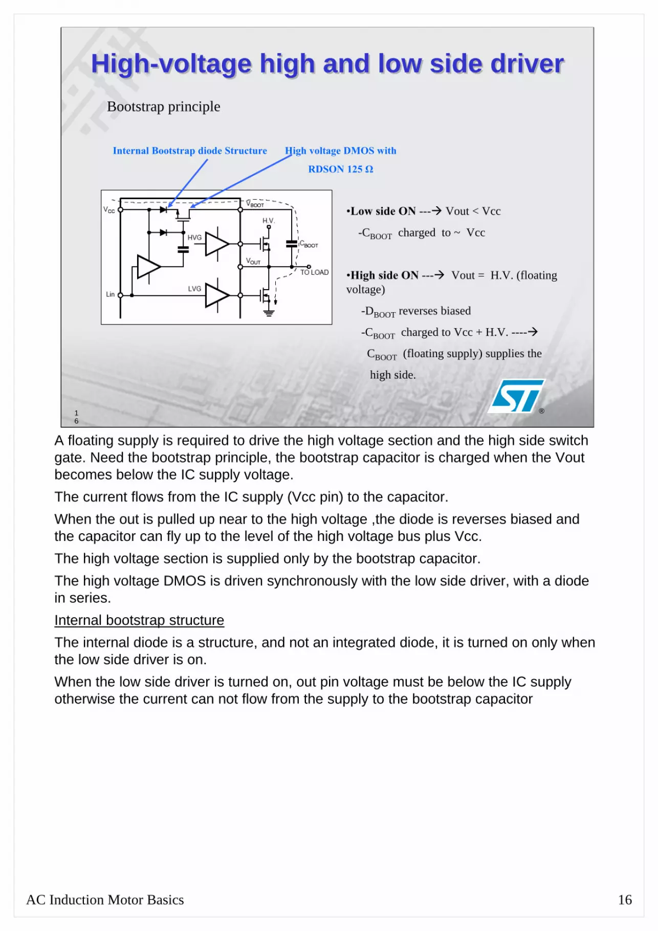
High-voltage high and low side driverHigh-voltage high and low side driver
•Low side ON --- Vout < Vcc
-CBOOT charged to ~ Vcc
•High side ON --- Vout = H.V. (floating voltage)
-DBOOT reverses biased
-CBOOT charged to Vcc + H.V. ----
CBOOT (floating supply) supplies the
high side.
Internal Bootstrap diode Structure High voltage DMOS with
RDSON 125 Ω
Bootstrap principle
A floating supply is required to drive the high voltage section and the high side switch gate. Need the bootstrap principle, the bootstrap capacitor is charged when the Vout becomes below the IC supply voltage.The current flows from the IC supply (Vcc pin) to the capacitor.When the out is pulled up near to the high voltage ,the diode is reverses biased and the capacitor can fly up to the level of the high voltage bus plus Vcc.The high voltage section is supplied only by the bootstrap capacitor.The high voltage DMOS is driven synchronously with the low side driver, with a diode in series.Internal bootstrap structureThe internal diode is a structure, and not an integrated diode, it is turned on only when the low side driver is on.When the low side driver is turned on, out pin voltage must be below the IC supply otherwise the current can not flow from the supply to the bootstrap capacitor
AC Induction Motor Basics 17
17
®
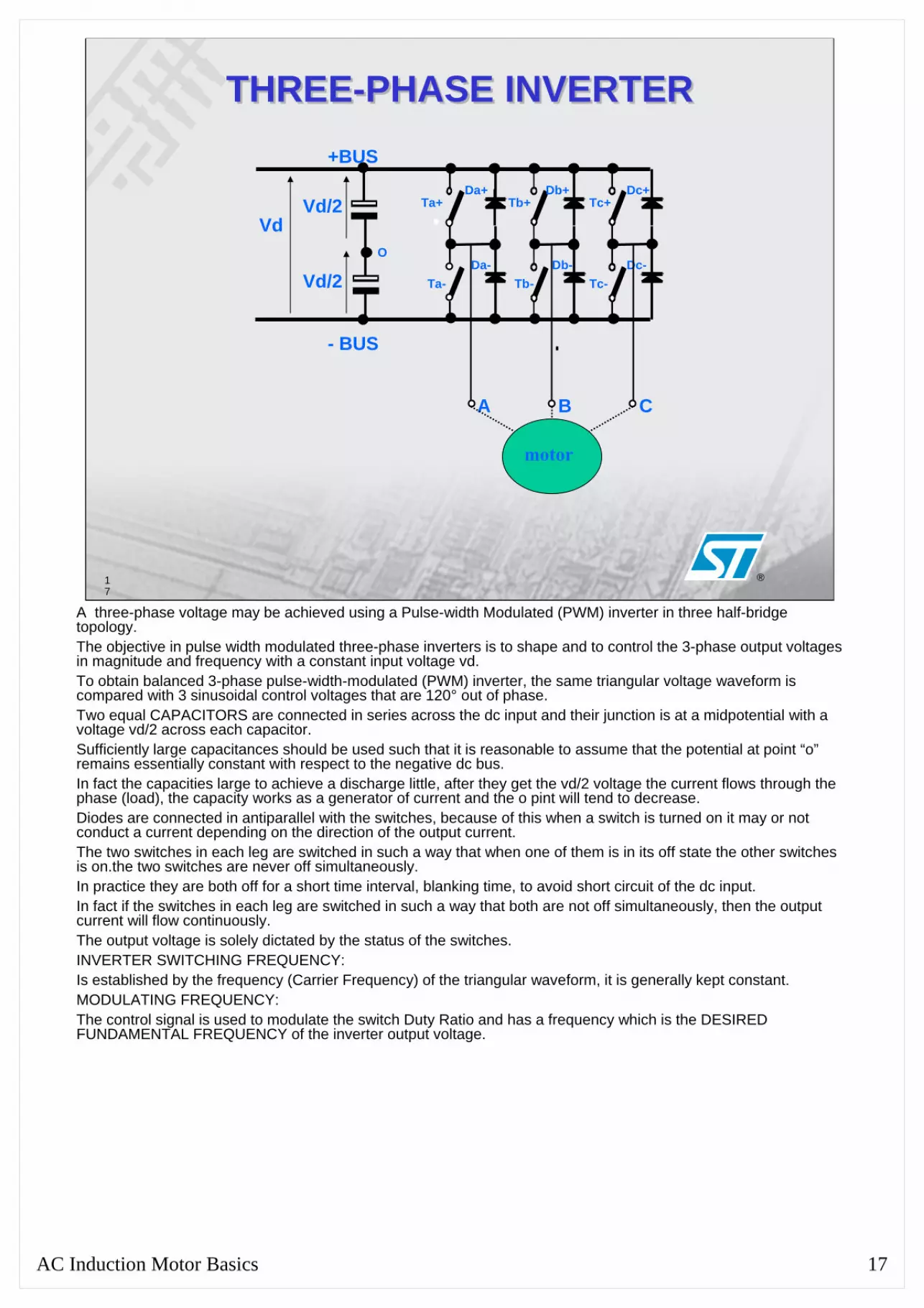
THREE-PHASE INVERTERTHREE-PHASE INVERTER
VdVd/2
Vd/2
Ta+
Ta-
Tb+
Tb-
Tc+
Tc-
Da+ Db+ Dc+
- BUS
+BUS
Da- Db- Dc-
A B C
O
motor
A three-phase voltage may be achieved using a Pulse-width Modulated (PWM) inverter in three half-bridge topology.The objective in pulse width modulated three-phase inverters is to shape and to control the 3-phase output voltages in magnitude and frequency with a constant input voltage vd.To obtain balanced 3-phase pulse-width-modulated (PWM) inverter, the same triangular voltage waveform is compared with 3 sinusoidal control voltages that are 120° out of phase.Two equal CAPACITORS are connected in series across the dc input and their junction is at a midpotential with a voltage vd/2 across each capacitor.Sufficiently large capacitances should be used such that it is reasonable to assume that the potential at point “o”remains essentially constant with respect to the negative dc bus.In fact the capacities large to achieve a discharge little, after they get the vd/2 voltage the current flows through the phase (load), the capacity works as a generator of current and the o pint will tend to decrease.Diodes are connected in antiparallel with the switches, because of this when a switch is turned on it may or not conduct a current depending on the direction of the output current.The two switches in each leg are switched in such a way that when one of them is in its off state the other switches is on.the two switches are never off simultaneously.In practice they are both off for a short time interval, blanking time, to avoid short circuit of the dc input.In fact if the switches in each leg are switched in such a way that both are not off simultaneously, then the output current will flow continuously.The output voltage is solely dictated by the status of the switches.INVERTER SWITCHING FREQUENCY:Is established by the frequency (Carrier Frequency) of the triangular waveform, it is generally kept constant.MODULATING FREQUENCY:The control signal is used to modulate the switch Duty Ratio and has a frequency which is the DESIRED FUNDAMENTAL FREQUENCY of the inverter output voltage.

AC Induction Motor Basics 18
18
®
Three-Phase Inverter ModulationThree-Phase Inverter Modulation
The phase voltage for the phase A is:
VAN = Vd Ta+ ONVAN = 0 Ta- ON
Vd
Motor
N
L1
L2L3
VdTa+
Ta-
+BUS
A
t
VAN

AC Induction Motor Basics 19
19
®
AC Induction Motor Basics 20
20
®
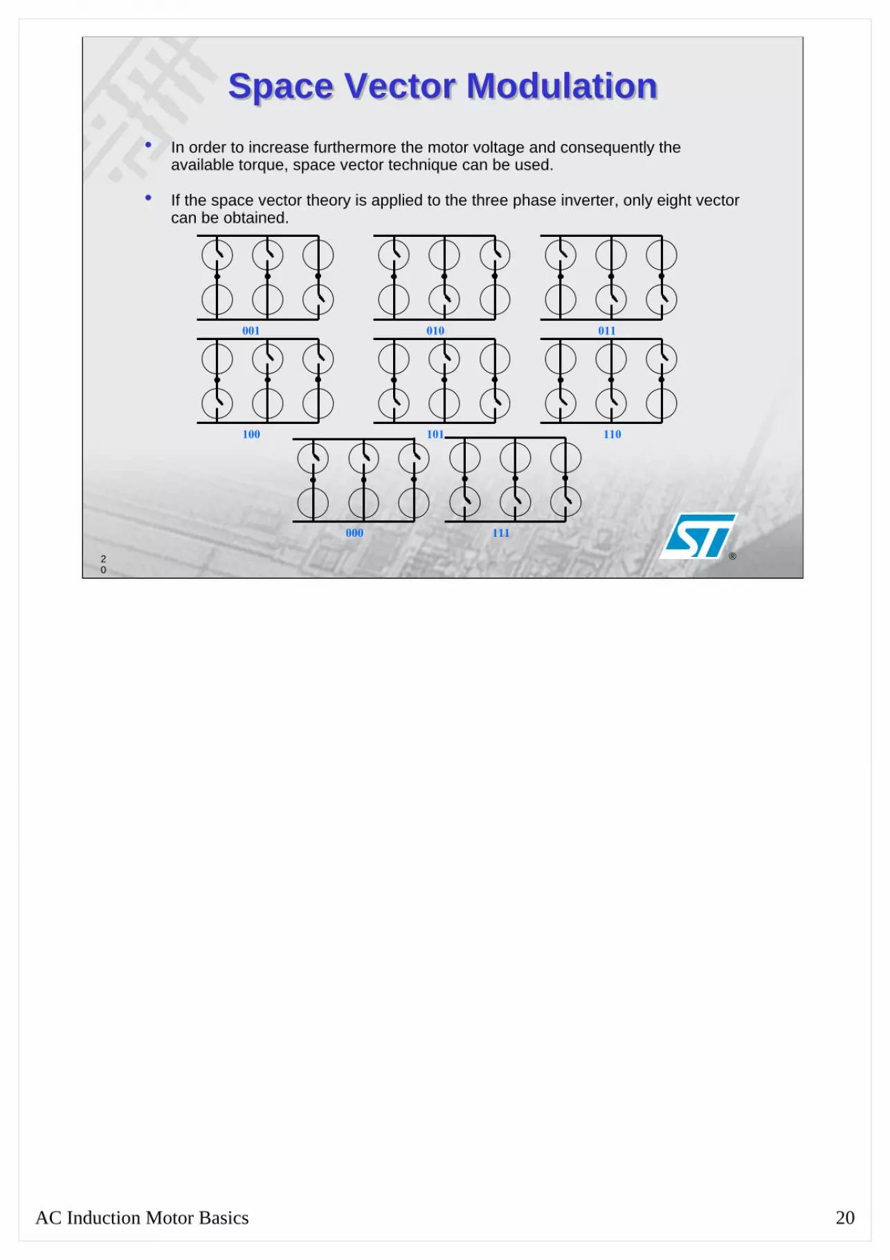
Space Vector ModulationSpace Vector Modulation• In order to increase furthermore the motor voltage and consequently the
available torque, space vector technique can be used.
• If the space vector theory is applied to the three phase inverter, only eight vector can be obtained.
001 010 011
100 101 110
000 111

AC Induction Motor Basics 21
21
®
Inverter states and space vector representation
Inverter states and space vector representation
Im
Re
V2
110
V3
V4
V5 V6
010
000 111
001 101
100011 V0 V7V1
AC Induction Motor Basics 22
22
®
Inverter states and space vector representation
Inverter states and space vector representation
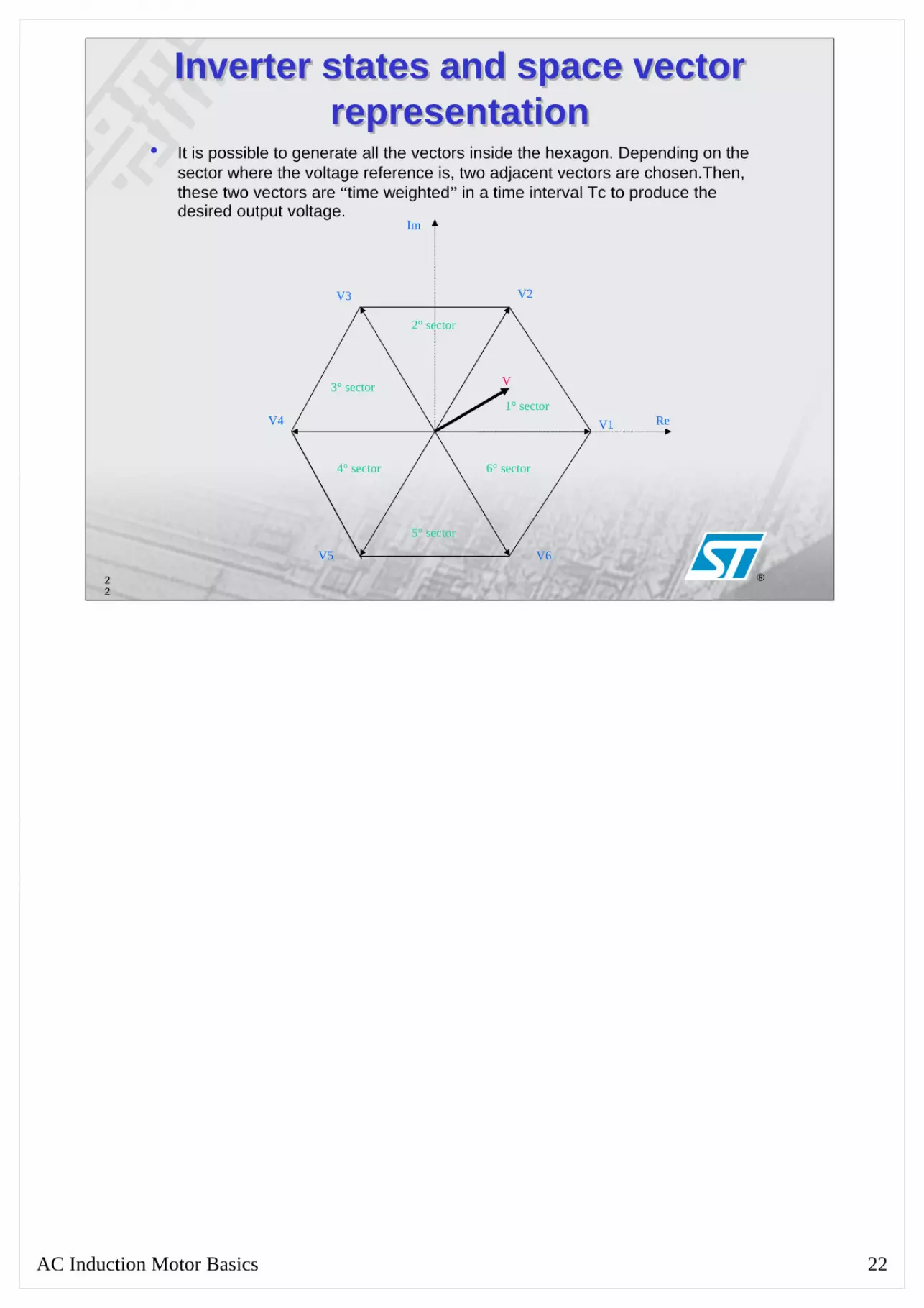
• It is possible to generate all the vectors inside the hexagon. Depending on the sector where the voltage reference is, two adjacent vectors are chosen.Then, these two vectors are “time weighted” in a time interval Tc to produce the desired output voltage.
Im
Re
V2V3
V4
V5 V6
V1
V
1° sector
2° sector
3° sector
4° sector
5° sector
6° sector

AC Induction Motor Basics 23
23
®
AC Induction Motor Basics 24
24
®
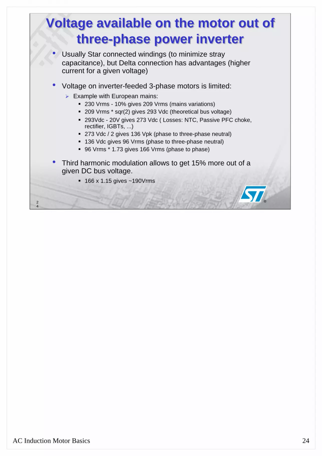
Voltage available on the motor out of three-phase power inverter
Voltage available on the motor out of three-phase power inverter
• Usually Star connected windings (to minimize stray capacitance), but Delta connection has advantages (higher current for a given voltage)
• Voltage on inverter-feeded 3-phase motors is limited:Example with European mains:
230 Vrms - 10% gives 209 Vrms (mains variations)209 Vrms * sqr(2) gives 293 Vdc (theoretical bus voltage)293Vdc - 20V gives 273 Vdc ( Losses: NTC, Passive PFC choke, rectifier, IGBTs, ...)273 Vdc / 2 gives 136 Vpk (phase to three-phase neutral)136 Vdc gives 96 Vrms (phase to three-phase neutral)96 Vrms * 1.73 gives 166 Vrms (phase to phase)
• Third harmonic modulation allows to get 15% more out of a given DC bus voltage.
166 x 1.15 gives ~190Vrms