ac-dc lcd tv power architecture and led backlight
TRANSCRIPT
AC-DC LCD TV Power Architecture and
LED Backlight

LCD TV Power Architecture and LED Backlight• LCD-TV Market
– Power Reduction Trend – Edge LED LCD TV Backlight
• 26” to 42” H-V LIPS Reference Design
• 46/47” Power Reference (PSU) for any Backlight solution– Interleaved Frequency Clamp CrM PFC with NCP1631– Quasi Resonance Valley lock out Flyback Converter with NCP1379– ECO Standby SMPS Solution with NCP1053A
• 46/47” Backlight solution– LIPS Inverter– Edge LED Driver
• Conclusion
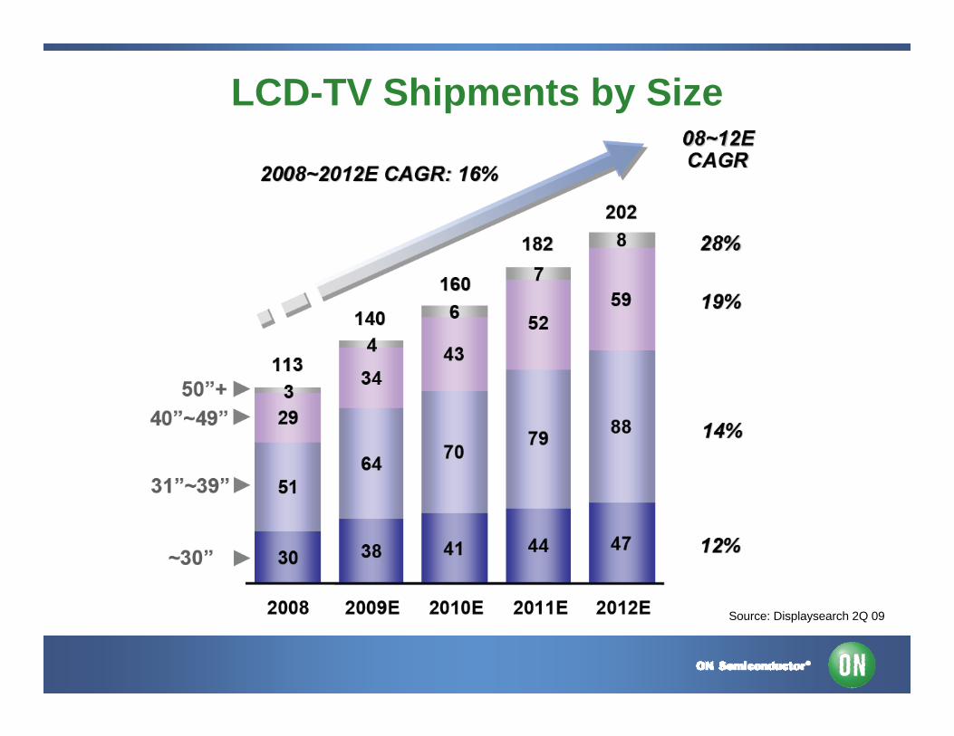
LCD-TV Shipments by Size
Source: Displaysearch 2Q 09
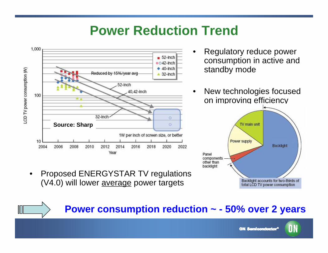
Power Reduction Trend• Regulatory reduce power
consumption in active and standby mode
• New technologies focused on improving efficiency
Source: Sharp
• Proposed ENERGYSTAR TV regulations (V4.0) will lower average power targets
Power consumption reduction ~ - 50% over 2 years
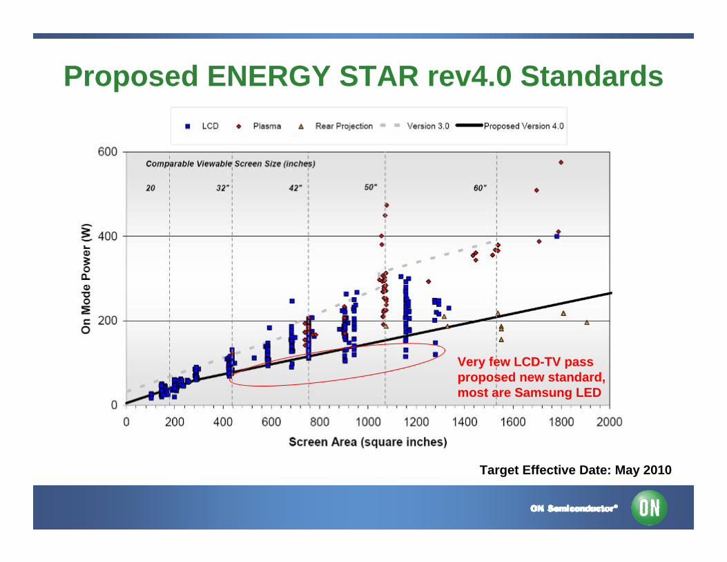
Proposed ENERGY STAR rev4.0 Standards
Target Effective Date: May 2010
Very few LCD-TV passproposed new standard,most are Samsung LED

LCD-TV LED Backlighting
LED TVs is forecast to grow to 20-32% (~64 M#) by 2012
Source: DisplaySearch July 2009
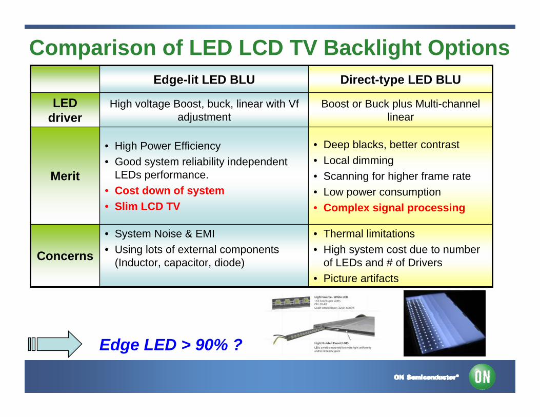
Comparison of LED LCD TV Backlight Options
• Thermal limitations• High system cost due to number
of LEDs and # of Drivers• Picture artifacts
• System Noise & EMI• Using lots of external components
(Inductor, capacitor, diode)Concerns
Boost or Buck plus Multi-channel linear
High voltage Boost, buck, linear with Vf adjustment
LED driver
Direct-type LED BLUEdge-lit LED BLU
Merit
• Deep blacks, better contrast • Local dimming • Scanning for higher frame rate• Low power consumption• Complex signal processing
• High Power Efficiency• Good system reliability independent
LEDs performance.• Cost down of system• Slim LCD TV
Edge LED > 90% ?

Power Architectures Remain Varied
PFCCRM
Interleave FCCrMCCM
70 - 400+ W
Signal PowerFlyback
Resonant HB30 – 80 W
Backlight PowerFlyback / Resonant HB
24V / 150V+ for LEDHV-LIPS for CCFL / EEFL
50 – 300 W
Traditional 24 V Backlight and HV-LIPS approachThin TV design impacts solutions choices as well
ECO Standby< 5 W

32” HV-LIPS Reference Design• For 32” (highest volume size) with possible extension to 26/42”
– Available since March 2009– For CCFL ( >> 95% of backlight) with possible extension to EEFL– Single PCB with LCD and Inverter Power Supply
• Very Cost effective solution– No extra Standby SMPS– Straightforward CrM PFC
• Key ON Semiconductor ICs– NCP1607 as CrM PFC controller– NCP1351 or NCP1219 as Flyback with low power standby mode
• LX6503 Microsemi Backlight controller– Full Bridge High Voltage Inverter without High Side Driver (discrete circuit)– Jin balance solution
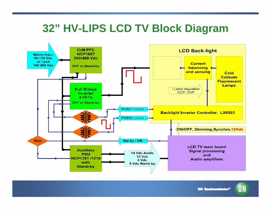
32” HV-LIPS LCD TV Block Diagram
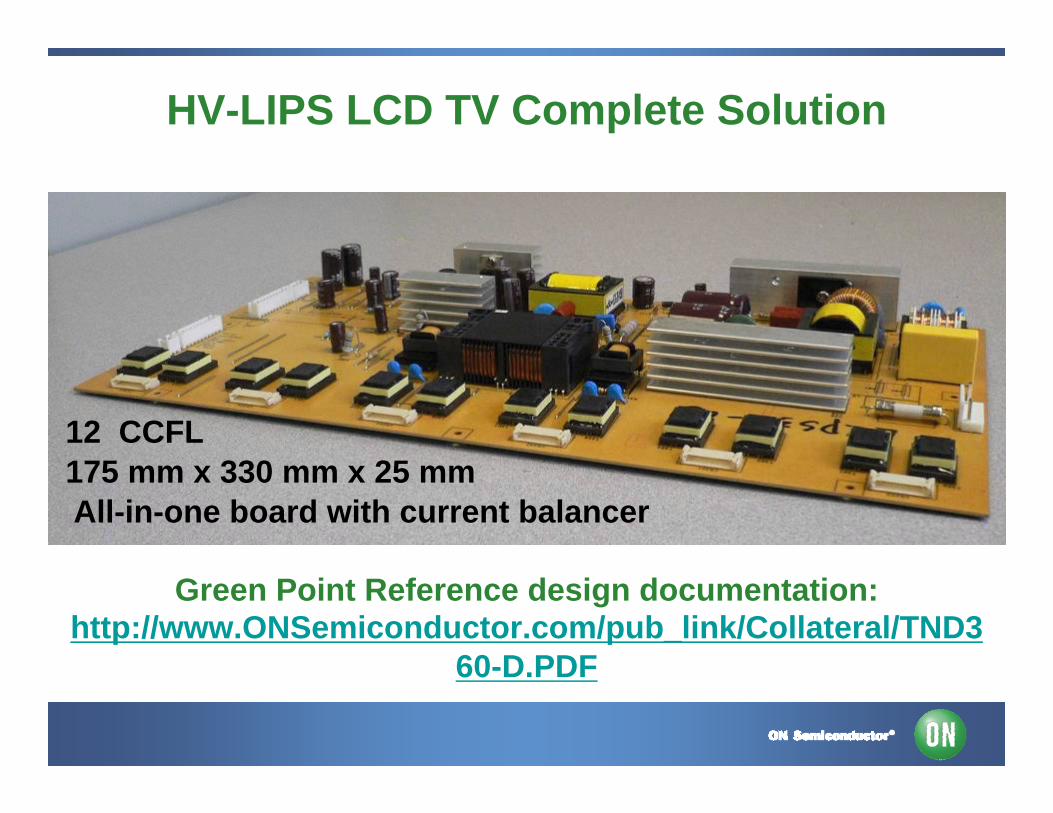
HV-LIPS LCD TV Complete Solution
Green Point Reference design documentation:http://www.ONSemiconductor.com/pub_link/Collateral/TND3
60-D.PDF
12 CCFL175 mm x 330 mm x 25 mmAll-in-one board with current balancer
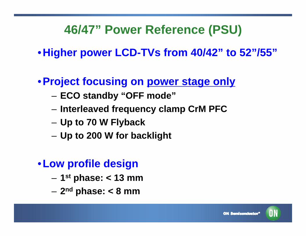
46/47” Power Reference (PSU)
•Higher power LCD-TVs from 40/42” to 52”/55”
•Project focusing on power stage only– ECO standby “OFF mode”– Interleaved frequency clamp CrM PFC – Up to 70 W Flyback – Up to 200 W for backlight
•Low profile design– 1st phase: < 13 mm – 2nd phase: < 8 mm
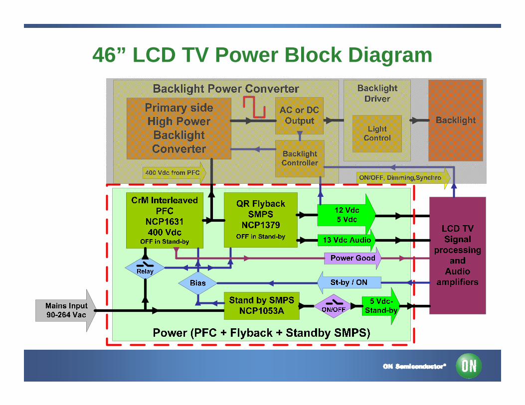
46” LCD TV Power Block Diagram
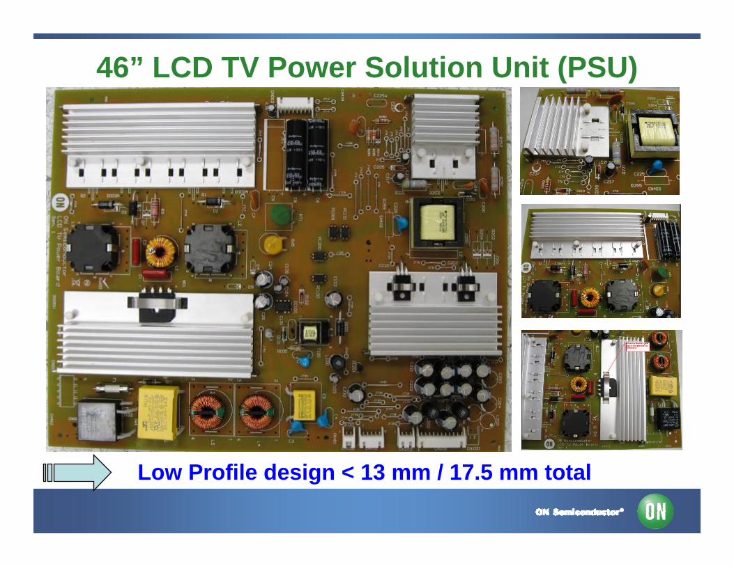
46” LCD TV Power Solution Unit (PSU)
Low Profile design < 13 mm / 17.5 mm total

46” LCD TV PFC Solution
•Up to 300 W Interleaved Frequency Clamp CrMPFC– Better EMI and EMC – Lower Irms for output C– Better for SLIM design– Standard parts (= 32”CrM)
•New controller NCP1631
•Easy SLIM narrow range version
Interleaved FCCrM PFC for > 200 W & SLIM design
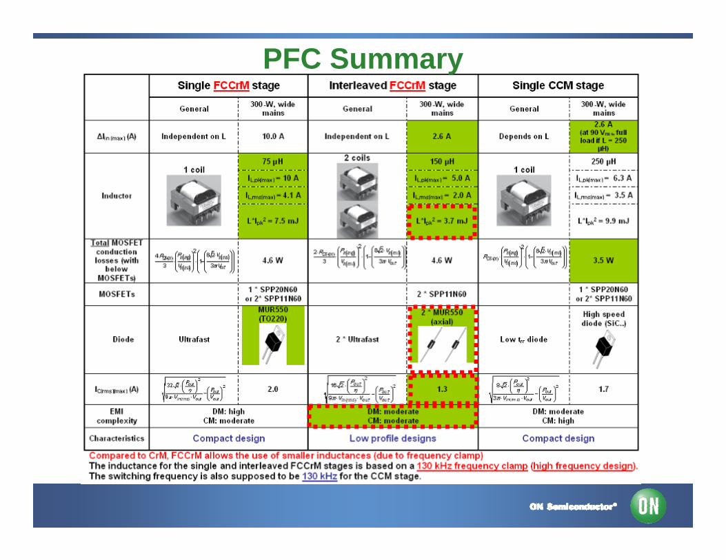
PFC Summary
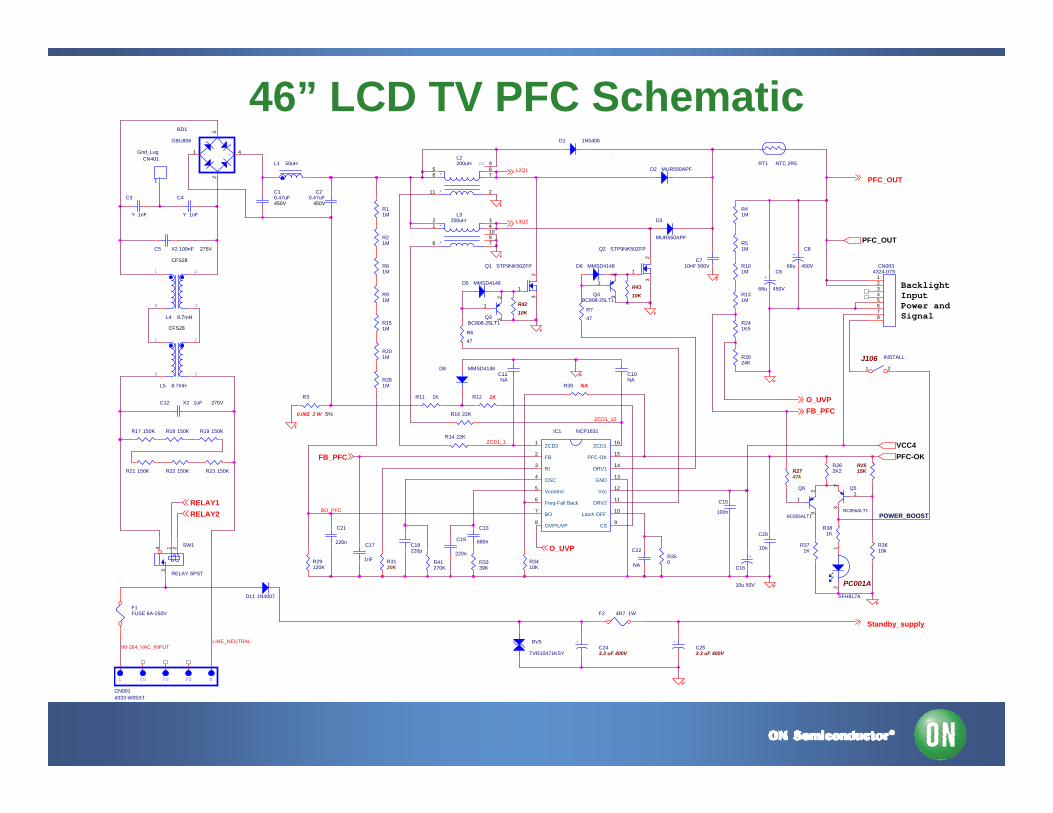
46” LCD TV PFC Schematic
ZCD1_1
ZCD1_10
POWER_BOOSTBO_PFC
R3
0.065 2 W 5%
C13
680n
F1FUSE 6A-250V
R23 150K
Q5
BC856ALT13
1
2
R39 NA
Q6
BC856ALT1 3
1
2
R41270K
R4310K
R11 1K
+C6
68u 450V
*
*
ncL2200uH
85
211
6 7
9
R3024K
D3
MUR550APF
C5 X2 100nF 275V
C10NA
R18 150K
L NFGFG FG
CN0014333-W05ST
Q4BC808-25LT1
3
1
2
R3410K
LINE_NEUTRAL
Q3BC808-25LT1
3
1
2
CN0034324-07S
12345678
RV5
TVR10471KSY
R3610k
R3120K
R11M
1 2
34
L4 8.7mH
CFS28
R41M
CN401Gnd_Lug
1
RT1 NTC 2R5
R262K2
R101M
J106 INSTALL
1 2
R2747k
D5 MMSD4148
C18220p
D6 MMSD4148
C11NA
R17 150K
SW1
RELAY SPST
43
1 2
C21
220n
D11 1N4007
R3339K
*
*
L3200uH
41
76
2 3
910
D2 MUR550APF
R281M
BacklightInputPower andSignal
R19 150K
+C253.3 uF 400V
R350
C20.47uF
450VC3
Y 1nF
90-264_VAC_INPUT
F2 4R7 1W
C4
Y 1nF
+-
BD1
GBU806
4
2
1
3
C10.47uF450V
C22
NA
Q2 STP9NK50ZFP
3
1
2
C12 X2 1uF 275V
L1 50uH
R6
47
R16 22K
R371K
R241K5
R81M
R21 150K
PC001ASFH817A
21
R7
47
R22 150K
C15
100n
R201M
IC1 NCP1631
ZCD21
FB2
Rt3
OSC4
Vcontrol5
Freq-Fall Back6
BO7
OVP/UVP8
CS9
Latch OFF10
DRV211
Vcc 12GND
13DRV1
14PFC-OK
15ZCD1
16
R91M
R29120K
R151M
D8 MMSD4148
R12 1K
C710nF 500V
R21M
+
C16
10u 50V
R14 22K
R51M
D1 1N5406
1 2
34
L5 8.7mH
CFS28
C20
10n
R131M
R2515K
R381K
R4210K
C19
220n
+C243.3 uF 400V
+C8
68u 450V
C17
1nF
Q1 STP9NK50ZFP
3
1
2
PFC_OUT
VCC4PFC-OK
Standby_supply
PFC_OUT
FB_PFC
O_UVP
FB_PFCO_UVP
RELAY2RELAY1
L3Q2
L2Q1
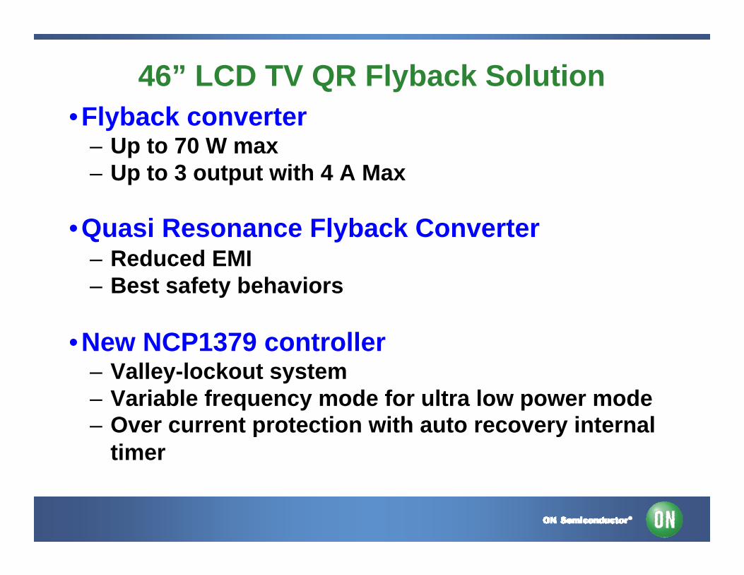
46” LCD TV QR Flyback Solution•Flyback converter
– Up to 70 W max – Up to 3 output with 4 A Max
•Quasi Resonance Flyback Converter– Reduced EMI – Best safety behaviors
•New NCP1379 controller– Valley-lockout system – Variable frequency mode for ultra low power mode – Over current protection with auto recovery internal
timer
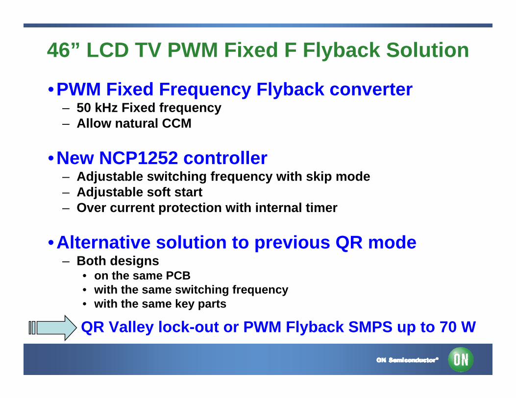
46” LCD TV PWM Fixed F Flyback Solution
•PWM Fixed Frequency Flyback converter– 50 kHz Fixed frequency – Allow natural CCM
•New NCP1252 controller– Adjustable switching frequency with skip mode – Adjustable soft start– Over current protection with internal timer
•Alternative solution to previous QR mode– Both designs
• on the same PCB • with the same switching frequency• with the same key parts
QR Valley lock-out or PWM Flyback SMPS up to 70 W
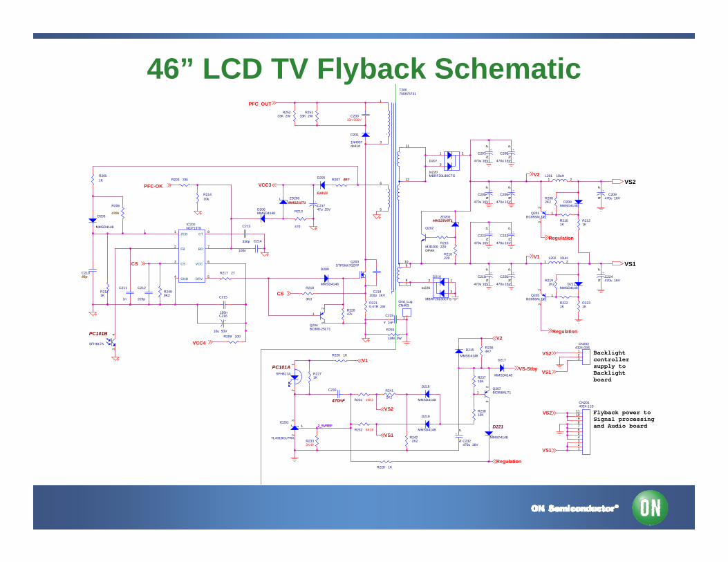
46” LCD TV Flyback Schematic
2_5VREF
D207
MBRF20L80CTGto220
1 2
3
Flyback power toSignal processingand Audio board
R228 1K
Backlightcontrollersupply toBacklightboard
D215
MMSD4148
R23810K
R203 33k
R2210.47R 2W CN403
Gnd_Lug
1
+C206
470u 16V
PN
D216
MMSD4148
PC101B
SFH817A
43
CN2024324-03S
123
R2121K
L201 10uH1 2
+C219
470u 16V
PN R219
2K2
+C216
10u 50V
+C209
470u 16V
PN
L202 10uH1 2
R209 100
R231 16K2
+C207
470u 16V
PN
*
**
*
*
T200750875731
3
7
1
5
612
11
8
109
R2231K
R226 1K
C218100p 1KV
D206MMSD4148
C212
220p C215
100n
D203
MMSD4148 NCP1379IC200
VCC 6
ZCD1
CT8
FB2
DRV 5GND4
CS3
BO7
R255
10M 2W
R2422K2
D205
BAV21
C225
Y 1nF
+C205
470u 16V
PN
D211MMSD4148
R22047k
R21410k
R2051K
ZD200MMSZ15T1
+C221
470u 16V
PN
Q201BC858ALT1
3
1
2
D209
MMSD4148R218
3K3
Q207BC858ALT1
3
1
2
+C224470u 16V
PN
Q205BC858ALT1
3
1
2
PC101ASFH817A
21
CN2014324-11S
123456789
1011
ZD201MMSZ6V8T1
Q202
MJD200DPAK
D221
MMSD4148
D210
MBRF20L80CTG
to220
12
3
+
C232470u 16V
PN
R241
2K2
R2082K2
R232 6K19
R215220
+C21747u 25V
R23710K
+C220
470u 16V
PN
R207 4R7
R2111K
D219
MMSD4148
D208MMSD4148
D217
MMSD4148
C20010n 500V
C21068p
R2498K2
D201
1N4937do41d
R25133K 2W
R206
470k
R2101K
Q203STP5NK70ZFP
C211
1n
+C222
470u 16V
PN
R213
470
R2221K
C213
330p
Q204BC808-25LT1
3
1
2
+C208
470u 16V
PN
C230
470nF
IC201
TL431BCLPRA
32
1
C214
100nR216220
R25233K 2W
R2332K49
R2271K
R2364K7
R217 27
VS2
VS1CS
CS
PFC_OUT
PFC-OK
VCC4
V1
Regulation
V2
VS2
Regulation
VS2
VS1
VS1
VS1
VS2
V2
Regulation
V1VS-Stby
VCC3
2_5VREF
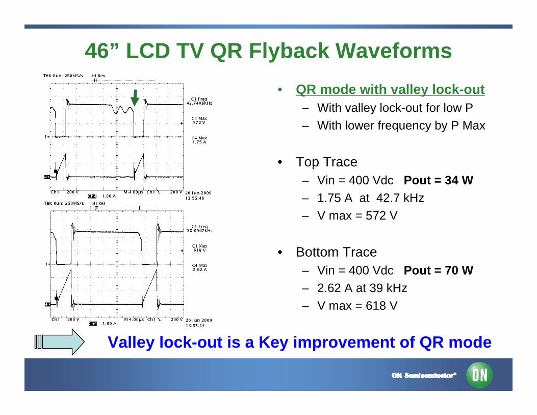
46” LCD TV QR Flyback Waveforms• QR mode with valley lock-out
– With valley lock-out for low P– With lower frequency by P Max
• Top Trace– Vin = 400 Vdc Pout = 34 W– 1.75 A at 42.7 kHz – V max = 572 V
• Bottom Trace– Vin = 400 Vdc Pout = 70 W– 2.62 A at 39 kHz– V max = 618 V
Valley lock-out is a Key improvement of QR mode
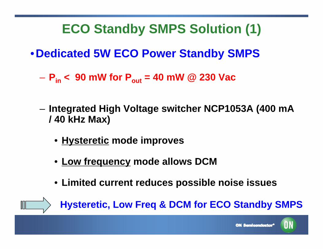
ECO Standby SMPS Solution (1)
•Dedicated 5W ECO Power Standby SMPS
– Pin < 90 mW for Pout = 40 mW @ 230 Vac
– Integrated High Voltage switcher NCP1053A (400 mA / 40 kHz Max)
• Hysteretic mode improves
• Low frequency mode allows DCM
• Limited current reduces possible noise issues
Hysteretic, Low Freq & DCM for ECO Standby SMPS
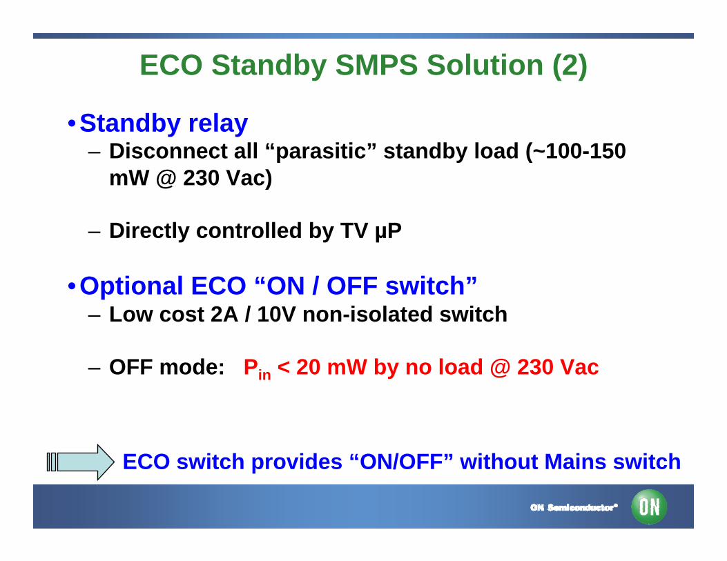
ECO Standby SMPS Solution (2)
•Standby relay– Disconnect all “parasitic” standby load (~100-150
mW @ 230 Vac)
– Directly controlled by TV µP
•Optional ECO “ON / OFF switch”– Low cost 2A / 10V non-isolated switch
– OFF mode: Pin < 20 mW by no load @ 230 Vac
ECO switch provides “ON/OFF” without Mains switch
20
30
40
50
60
70
80
0.03 0.04 0.05 0.10 0.25 0.50 1.00 1.50 2.00 4.00 5.00
Output Power (W)
Effic
ienc
y (%
)
Efficiency / 230V
Efficiency / 120V
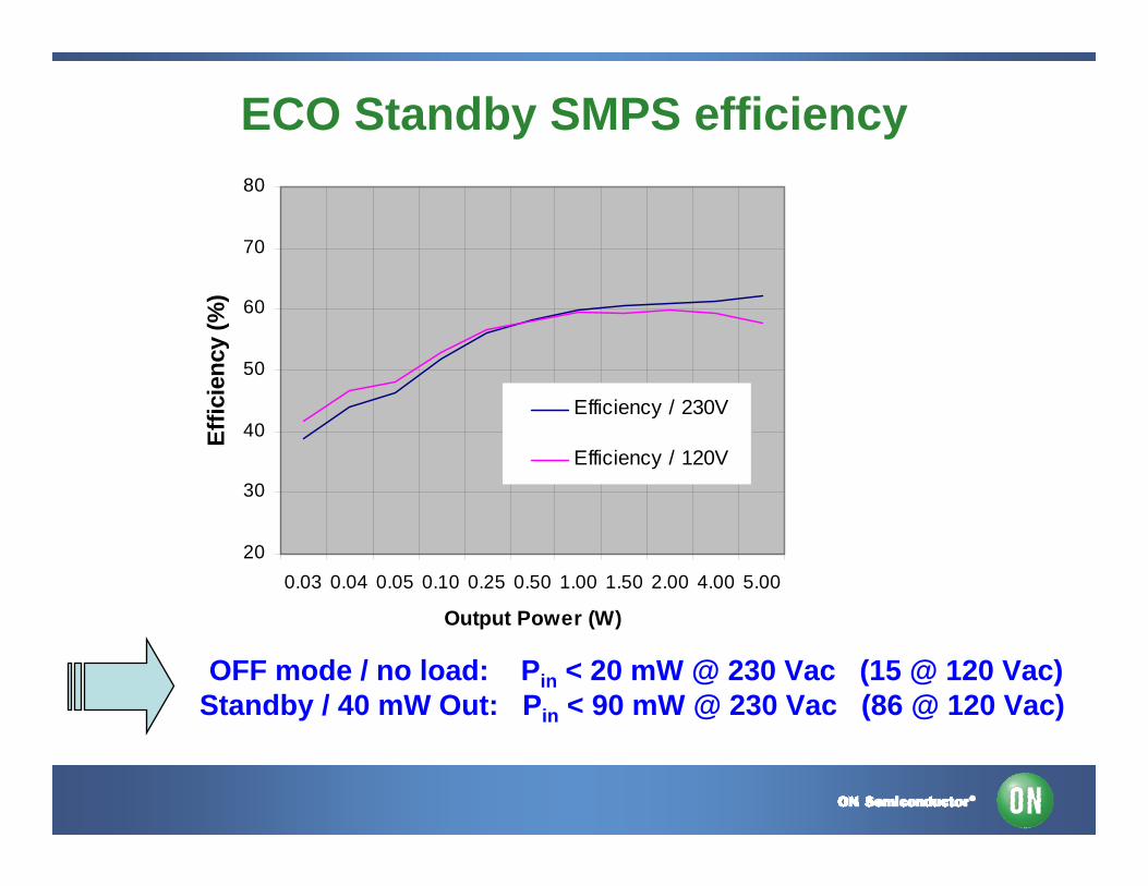
ECO Standby SMPS efficiency
OFF mode / no load: Pin < 20 mW @ 230 Vac (15 @ 120 Vac) Standby / 40 mW Out: Pin < 90 mW @ 230 Vac (86 @ 120 Vac)
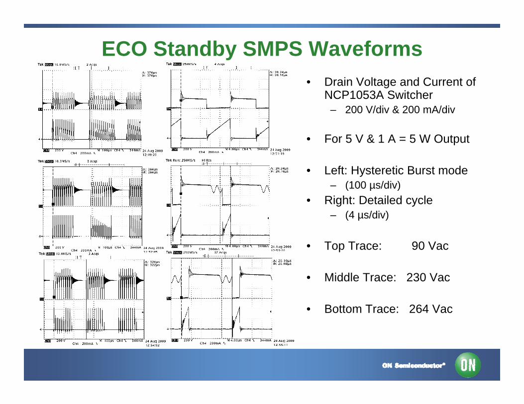
ECO Standby SMPS Waveforms• Drain Voltage and Current of
NCP1053A Switcher– 200 V/div & 200 mA/div
• For 5 V & 1 A = 5 W Output
• Left: Hysteretic Burst mode– (100 µs/div)
• Right: Detailed cycle – (4 µs/div)
• Top Trace: 90 Vac
• Middle Trace: 230 Vac
• Bottom Trace: 264 Vac
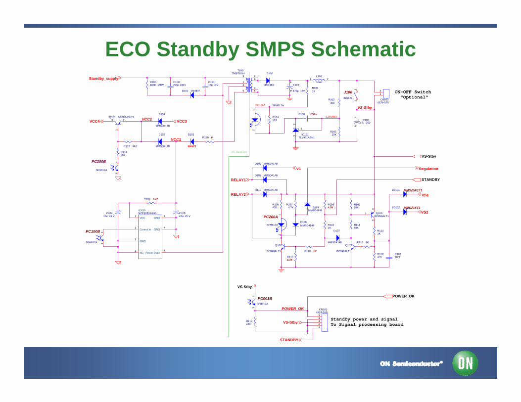
ECO Standby SMPS Schematic
VS-Stby
VCC2
VCC1
PC100A
C10710nF
SFH817A
21
R103 8.2K
R1101K
R1011K
Q103
BC848ALT1
CN1014324-05S
12345
Q100BC858ALT1
3
1
2
R120 0
Q101 BC808-25LT13
12
R10410K
+C104
10u 25 V
R11922K
J100INSTALL
12
D100
MBR360
NCP1053P44GIC100
VCC1 GND 8
Control in2
Power Drain 5NC4
GND3
GND 7
R118470
IC101TLV431ASN1
32
1
R115 1K
R1142K2
D104
MMSD4148
1.25VREF
R116 1K
R113 4K7
PC001BSFH817A
43
R100100K 1/4W
D102
BAV21
ZD101 MMSZ5V1T1
R11110K
D108 MMSD4148
CN1004324-02S
12
D105
MMSD4148
R10910K
C100220p 400V
L100
10uH1 2
R10230K
R1174.7K
R1074.7K
PC100B
SFH817A
43
D110 MMSD4148
ZD102 MMSZ15T1
D106MMSD4148
R10510K
T100750871014
7
83
14
5 6
9
R106470
+ C102
470µ 16V
PN
R1121K
R1084.7K
+ C10347µ 25V
PN
+C10547u 25 V
D101 1N4937
D103MMSD4148
D109 MMSD4148
PC200A
SFH817A
21
C106 100 n
PC200B
SFH817A
43
D107
MMSD4148Q102
BC848ALT1
C10110p 1KV
STANDBY
VS-Stby
POWER_OK
RELAY1
VS-Stby
V1
RELAY2
VCC3VCC4
Standby_supply
STANDBY
VS1
Regulation
VS-Stby
VS2
ON-OFF Switch "Optional"
POWER_OK
Standby power and signalTo Signal processing board
HV Barrier
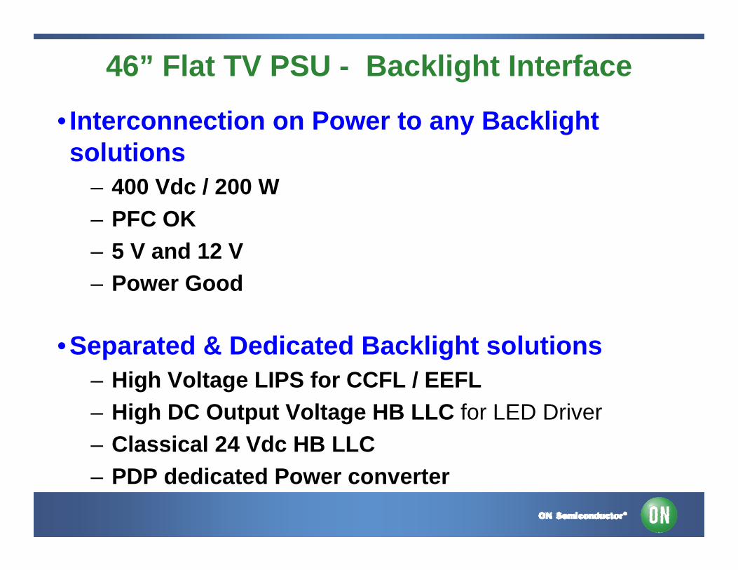
46” Flat TV PSU - Backlight Interface
• Interconnection on Power to any Backlight solutions
– 400 Vdc / 200 W– PFC OK – 5 V and 12 V– Power Good
•Separated & Dedicated Backlight solutions– High Voltage LIPS for CCFL / EEFL– High DC Output Voltage HB LLC for LED Driver– Classical 24 Vdc HB LLC– PDP dedicated Power converter
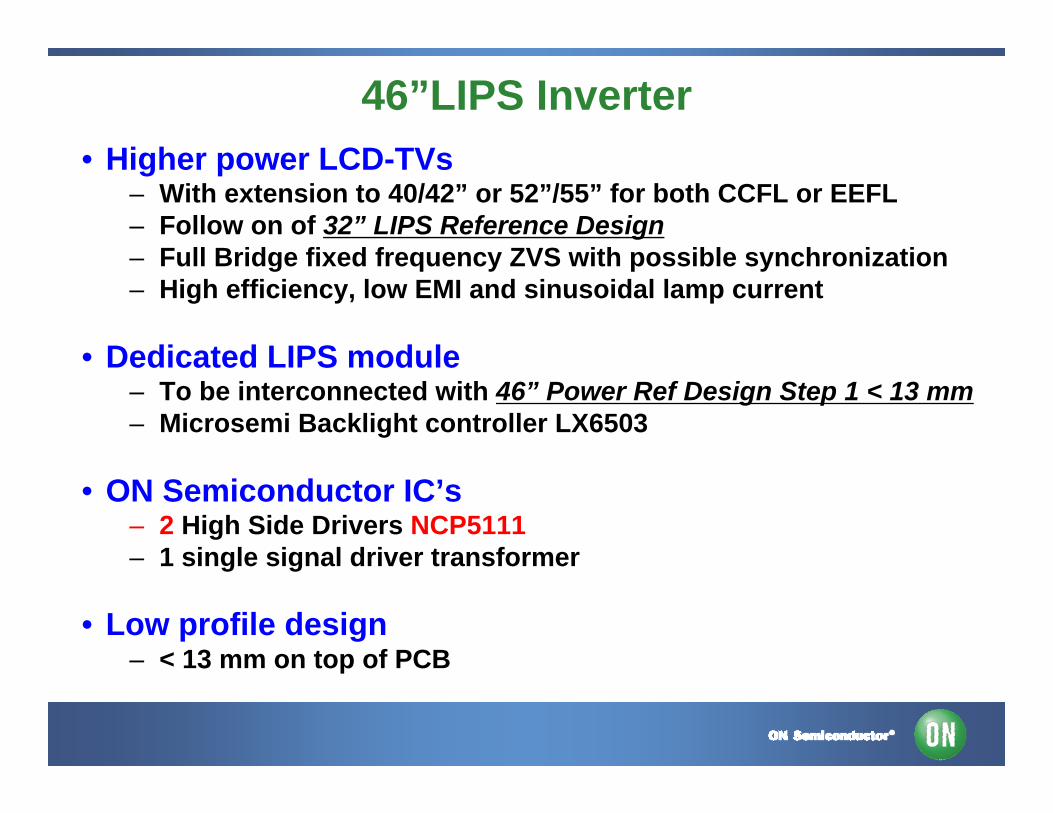
46”LIPS Inverter• Higher power LCD-TVs
– With extension to 40/42” or 52”/55” for both CCFL or EEFL– Follow on of 32” LIPS Reference Design– Full Bridge fixed frequency ZVS with possible synchronization– High efficiency, low EMI and sinusoidal lamp current
• Dedicated LIPS module– To be interconnected with 46” Power Ref Design Step 1 < 13 mm– Microsemi Backlight controller LX6503
• ON Semiconductor IC’s– 2 High Side Drivers NCP5111– 1 single signal driver transformer
• Low profile design– < 13 mm on top of PCB
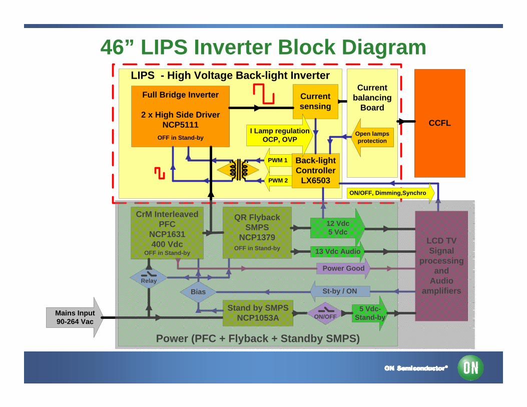
Power (PFC + Flyback + Standby SMPS)
LIPS - High Voltage Back-light Inverter
CrM Interleaved PFC
NCP1631400 Vdc
OFF in Stand-by
Full Bridge Inverter
2 x High Side Driver NCP5111
OFF in Stand-by
QR FlybackSMPS
NCP1379OFF in Stand-by
Mains Input90-264 Vac
12 Vdc 5 Vdc
St-by / ONBias
LCD TV Signal
processing and
Audio amplifiers
Back-light Controller
LX6503
CCFL
Current sensing
I Lamp regulation OCP, OVP
PWM 2
PWM 1
13 Vdc Audio
Current balancing
Board
Stand by SMPSNCP1053A
5 Vdc-Stand-by
Open lamps protection
Relay
Power Good
ON/OFF, Dimming,Synchro
ON/OFF
46” LIPS Inverter Block Diagram
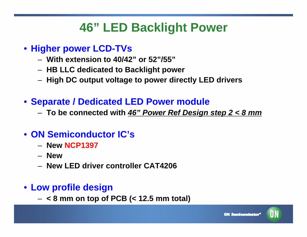
46” LED Backlight Power • Higher power LCD-TVs
– With extension to 40/42” or 52”/55”– HB LLC dedicated to Backlight power– High DC output voltage to power directly LED drivers
• Separate / Dedicated LED Power module– To be connected with 46” Power Ref Design step 2 < 8 mm
• ON Semiconductor IC’s– New NCP1397– New – New LED driver controller CAT4206
• Low profile design– < 8 mm on top of PCB (< 12.5 mm total)
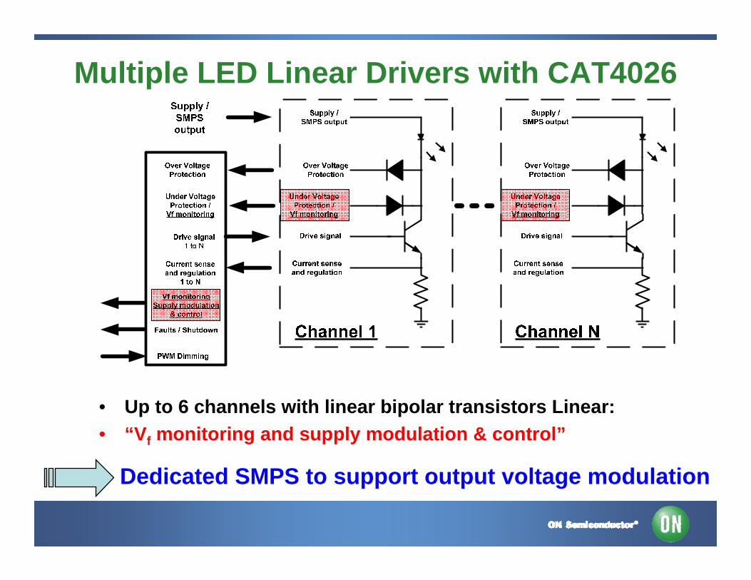
Multiple LED Linear Drivers with CAT4026
• Up to 6 channels with linear bipolar transistors Linear: • “Vf monitoring and supply modulation & control”
Dedicated SMPS to support output voltage modulation
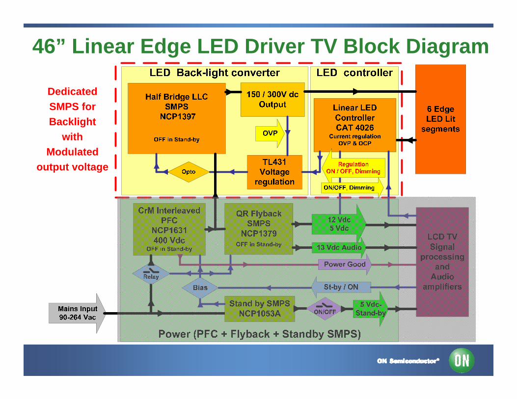
46” Linear Edge LED Driver TV Block Diagram
DedicatedSMPS forBacklight
with Modulated
output voltage
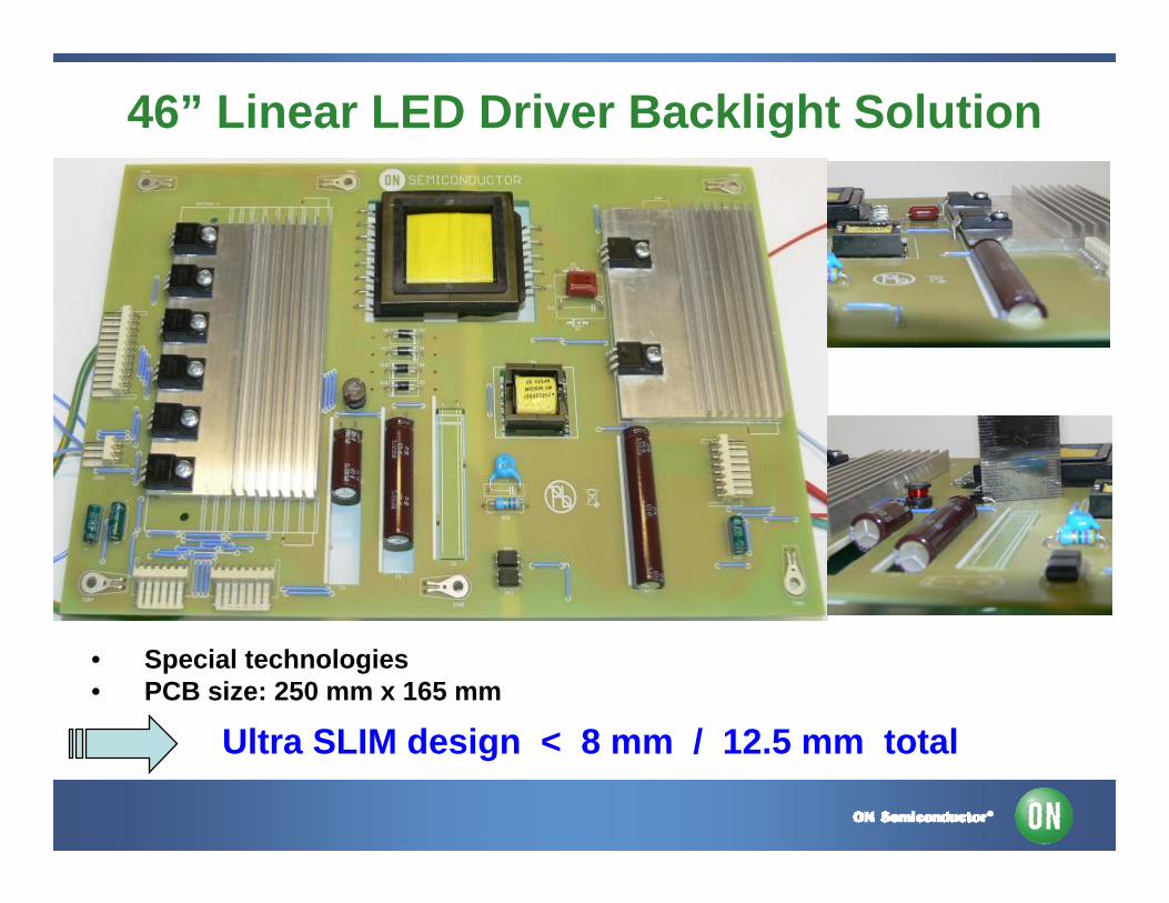
46” Linear LED Driver Backlight Solution
Ultra SLIM design < 8 mm / 12.5 mm total
• Special technologies • PCB size: 250 mm x 165 mm
HB LLC for Ultra Slim SMPS
• Limited number of components
• Zero Voltage Switching (ZVS)
• Zero Current Switching (ZCS)
• Higher power density
High efficiency and EMI friendly for low profile SMPS
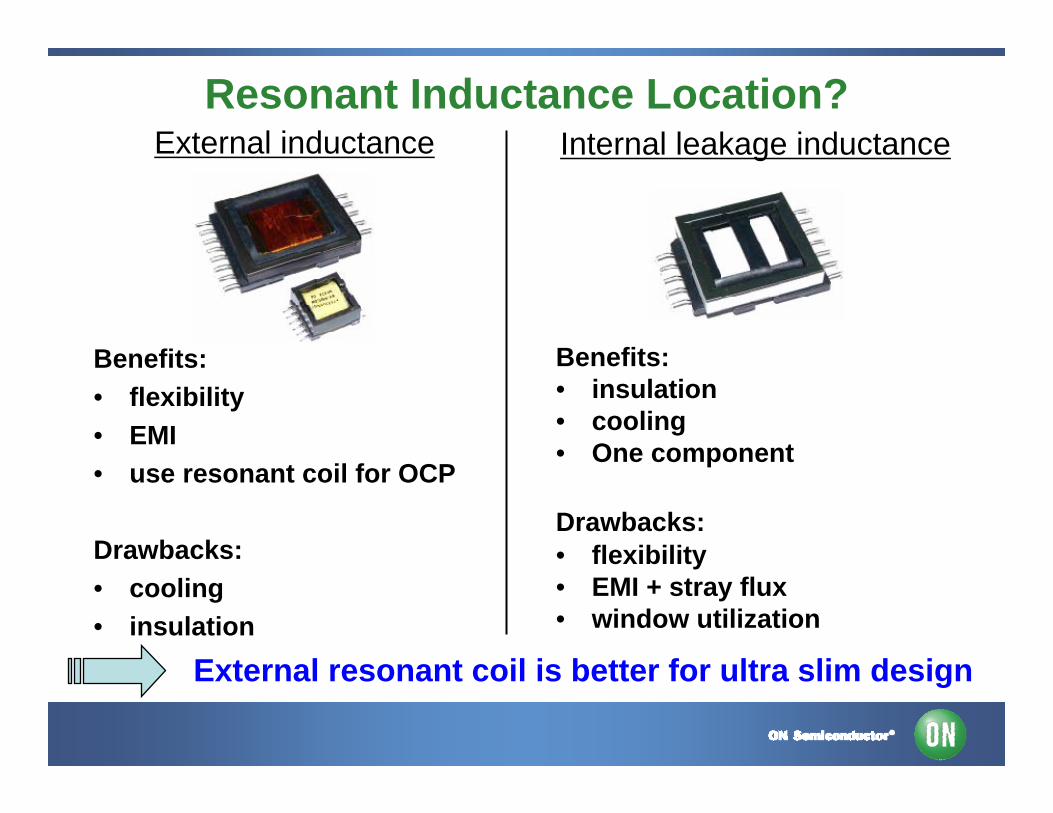
Resonant Inductance Location?
Benefits:• flexibility• EMI• use resonant coil for OCP
Drawbacks:• cooling• insulation
External resonant coil is better for ultra slim design
External inductance Internal leakage inductance
Benefits:• insulation • cooling • One component
Drawbacks:• flexibility• EMI + stray flux• window utilization
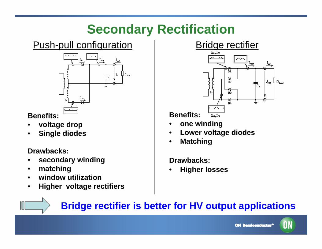
Secondary Rectification
Benefits:• voltage drop• Single diodes
Drawbacks:• secondary winding• matching • window utilization• Higher voltage rectifiers
Bridge rectifier is better for HV output applications
Push-pull configuration Bridge rectifier
Benefits:• one winding • Lower voltage diodes• Matching
Drawbacks:• Higher losses

NCP1397 - LLC Stage Controller
NCP1397 is cost effective and highly safe solution
Features:- operation from 50 kHz up to 500 kHz- 600 V driver- Startup sequence via an externally adjustable soft-start- Brown-out protection combined with latch input- Disable input for ON/OFF control (skip mode)
Benefits for backlight application:• No driver transformer• Simple skip mode • Simple OCP
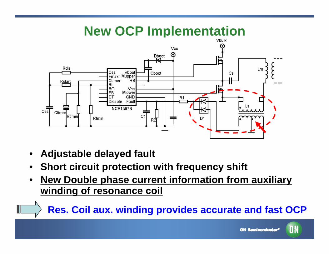
New OCP Implementation
Res. Coil aux. winding provides accurate and fast OCP
• Adjustable delayed fault • Short circuit protection with frequency shift • New Double phase current information from auxiliary
winding of resonance coil
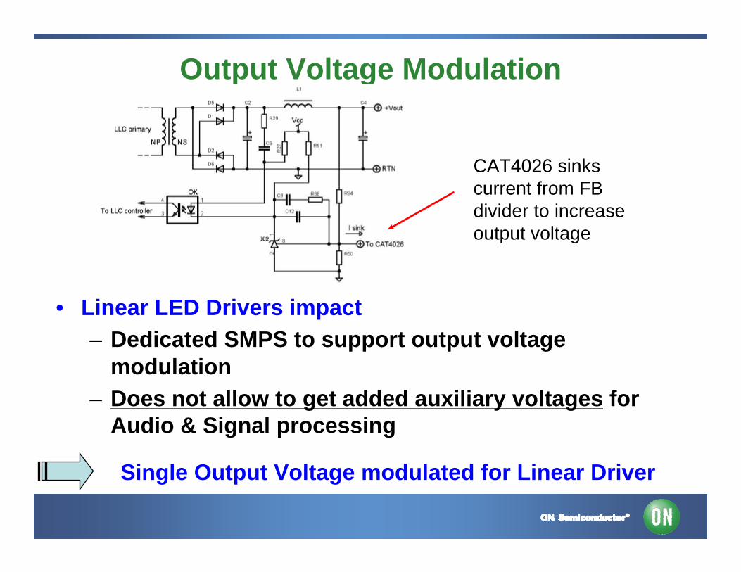
Output Voltage Modulation
CAT4026 sinkscurrent from FBdivider to increaseoutput voltage
• Linear LED Drivers impact– Dedicated SMPS to support output voltage
modulation – Does not allow to get added auxiliary voltages for
Audio & Signal processing
Single Output Voltage modulated for Linear Driver
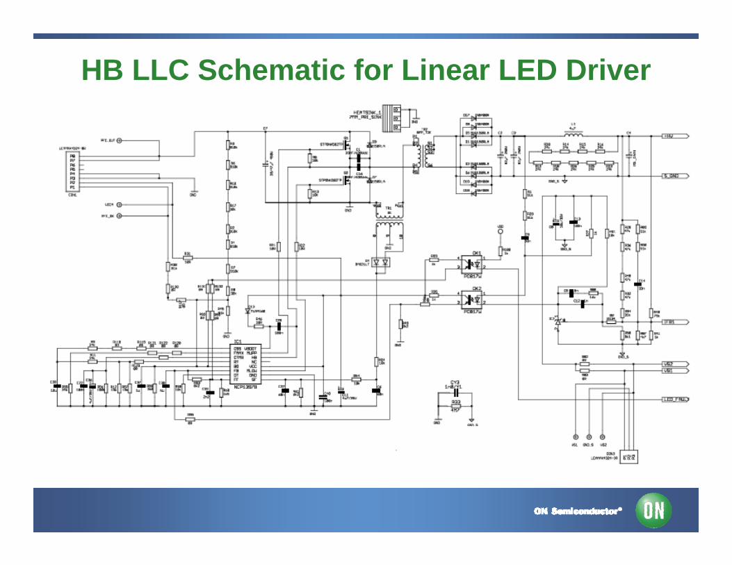
HB LLC Schematic for Linear LED Driver
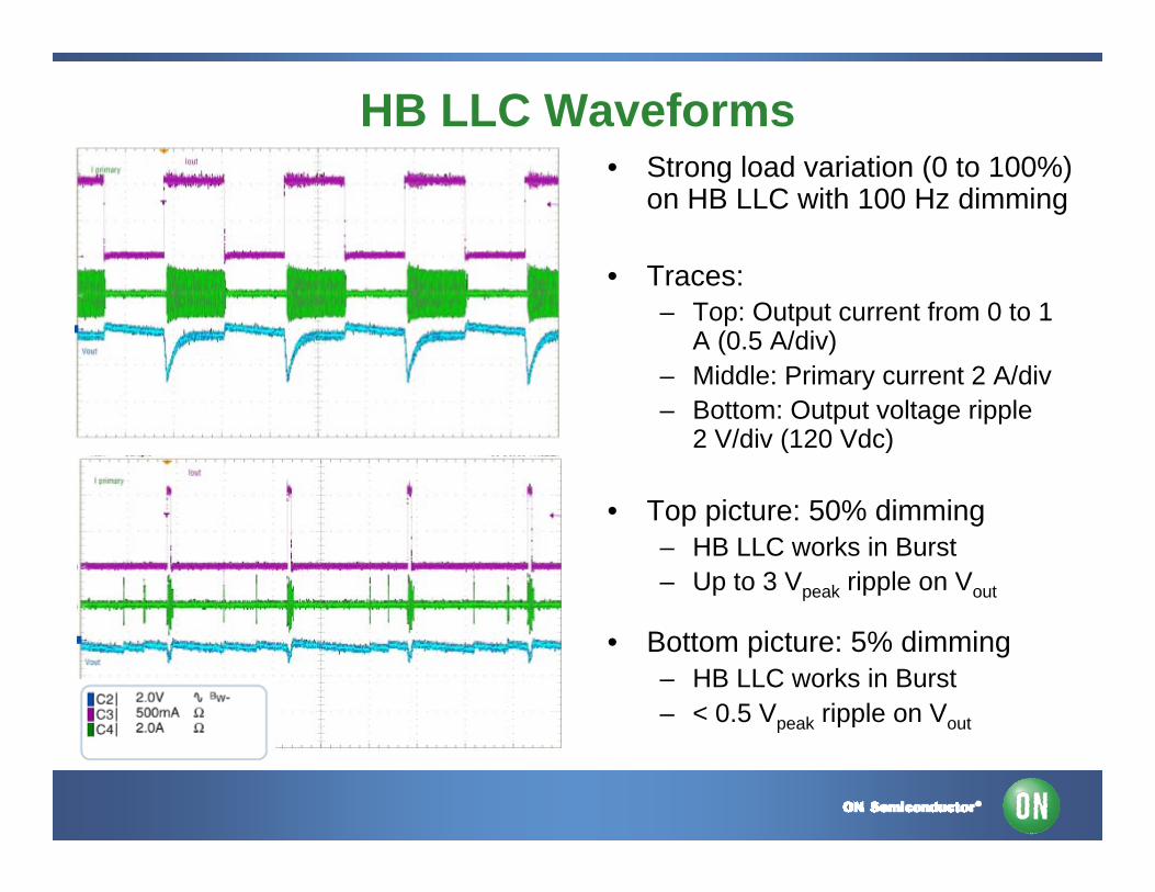
• Strong load variation (0 to 100%) on HB LLC with 100 Hz dimming
• Traces:– Top: Output current from 0 to 1
A (0.5 A/div)– Middle: Primary current 2 A/div– Bottom: Output voltage ripple
2 V/div (120 Vdc)
• Top picture: 50% dimming– HB LLC works in Burst– Up to 3 Vpeak ripple on Vout
• Bottom picture: 5% dimming– HB LLC works in Burst– < 0.5 Vpeak ripple on Vout
HB LLC Waveforms
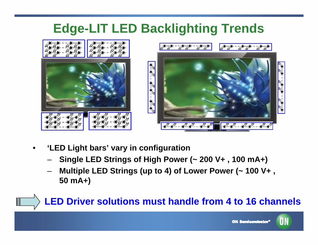
Edge-LIT LED Backlighting Trends
• ‘LED Light bars’ vary in configuration– Single LED Strings of High Power (~ 200 V+ , 100 mA+)– Multiple LED Strings (up to 4) of Lower Power (~ 100 V+ ,
50 mA+)
LED Driver solutions must handle from 4 to 16 channels
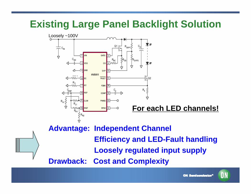
Existing Large Panel Backlight Solution
Advantage: Independent Channel Efficiency and LED-Fault handlingLoosely regulated input supply
Drawback: Cost and Complexity
Loosely ~100V
For each LED channels!
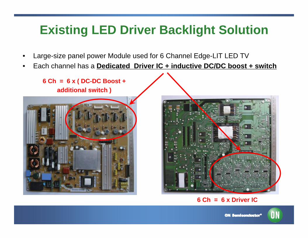
Existing LED Driver Backlight Solution
• Large-size panel power Module used for 6 Channel Edge-LIT LED TV• Each channel has a Dedicated Driver IC + inductive DC/DC boost + switch
6 Ch = 6 x ( DC-DC Boost + additional switch )
6 Ch = 6 x Driver IC
Multi-channel “Linear” Edge-Lit Solution
• Cost effective solution to address a wide number of channels
• VF Monitoring to dynamically adjusts Anode voltage
• Efficiency target range >90%, 94% typ. (varies with LED mismatch)
• Thermal dissipation addressed by external Power BJT’s
• Address various LED string faults
“Linear LED Driver”: A cost effective solution for multiple channels
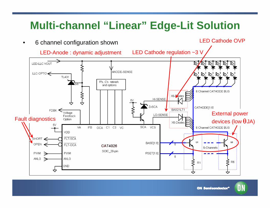
Multi-channel “Linear” Edge-Lit Solution• 6 channel configuration shown
Fault diagnosticsExternal power devices (low θJA)
LED Cathode regulation ~3 VLED-Anode : dynamic adjustment
LED Cathode OVP
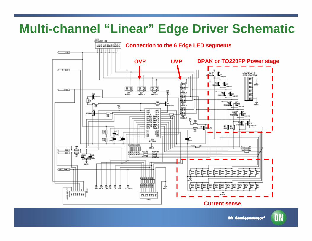
Multi-channel “Linear” Edge Driver Schematic
DPAK or TO220FP Power stage
Current sense
OVP UVP
Connection to the 6 Edge LED segments
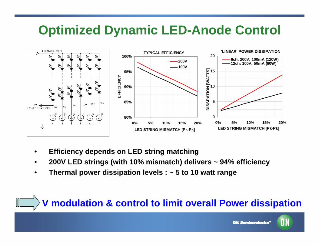
Optimized Dynamic LED-Anode ControlTYPICAL EFFICIENCY
80%
85%
90%
95%
100%
0% 5% 10% 15% 20%LED STRING MISMATCH [Pk-Pk]
EFFI
CIEN
CY
200V100V
'LINEAR' POWER DISSIPATION
0
5
10
15
20
0% 5% 10% 15% 20%LED STRING MISMATCH [Pk-Pk]
DIS
SP
ATIO
N [W
ATT
S]
6ch: 200V, 100mA (120W)12ch: 100V, 50mA (60W)
V modulation & control to limit overall Power dissipation
• Efficiency depends on LED string matching • 200V LED strings (with 10% mismatch) delivers ~ 94% efficiency • Thermal power dissipation levels : ~ 5 to 10 watt range
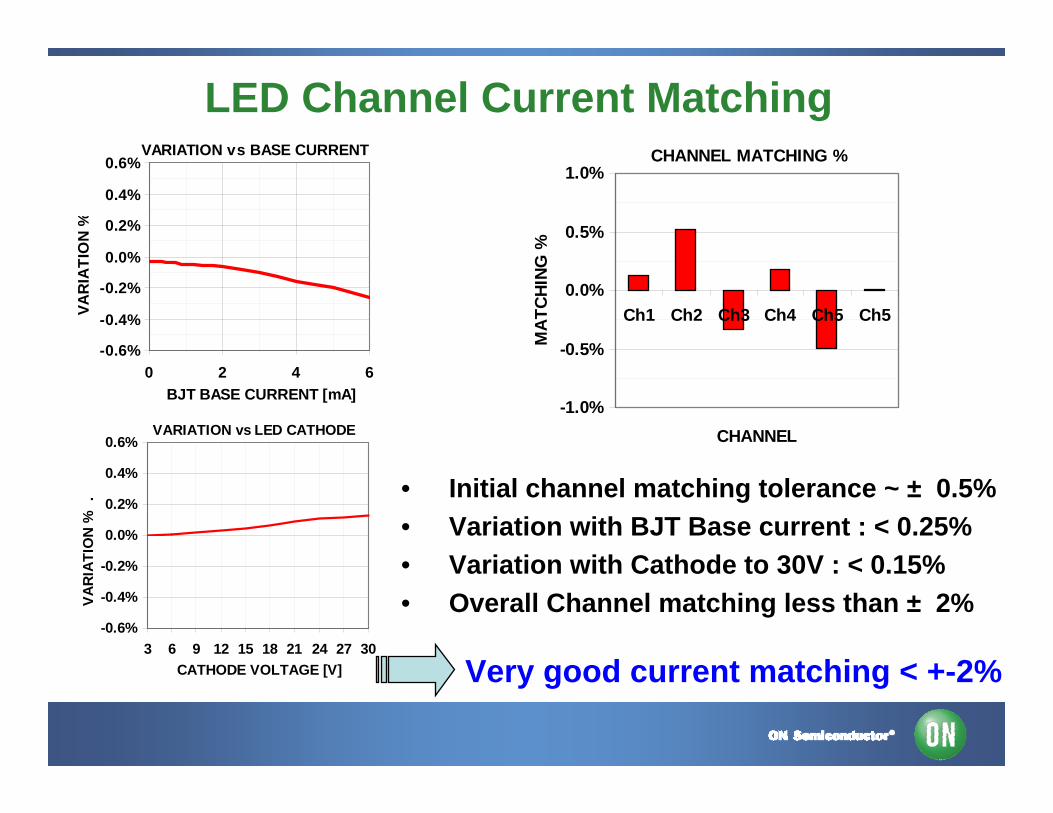
LED Channel Current MatchingVARIATION vs BASE CURRENT
-0.6%
-0.4%
-0.2%
0.0%
0.2%
0.4%
0.6%
0 2 4 6BJT BASE CURRENT [mA]
VA
RIA
TIO
N %
VARIATION vs LED CATHODE
-0.6%
-0.4%
-0.2%
0.0%
0.2%
0.4%
0.6%
3 6 9 12 15 18 21 24 27 30CATHODE VOLTAGE [V]
VAR
IATI
ON
% .
CHANNEL MATCHING %
-1.0%
-0.5%
0.0%
0.5%
1.0%
Ch1 Ch2 Ch3 Ch4 Ch5 Ch5
CHANNEL
MA
TCH
ING
%
• Initial channel matching tolerance ~ ± 0.5%• Variation with BJT Base current : < 0.25%• Variation with Cathode to 30V : < 0.15%• Overall Channel matching less than ± 2%
Very good current matching < +-2%
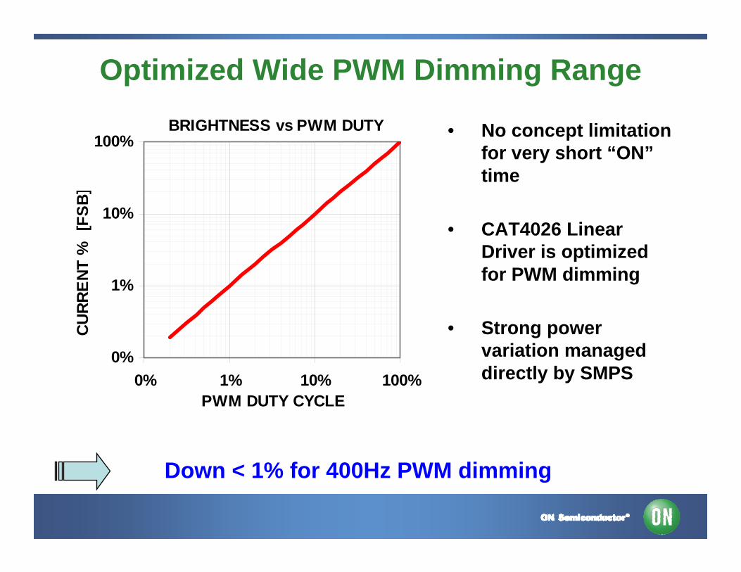
Optimized Wide PWM Dimming Range
• No concept limitation for very short “ON”time
• CAT4026 Linear Driver is optimized for PWM dimming
• Strong power variation managed directly by SMPS
BRIGHTNESS vs PWM DUTY
0%
1%
10%
100%
0% 1% 10% 100%PWM DUTY CYCLE
CU
RR
ENT
% [
FSB]
Down < 1% for 400Hz PWM dimming
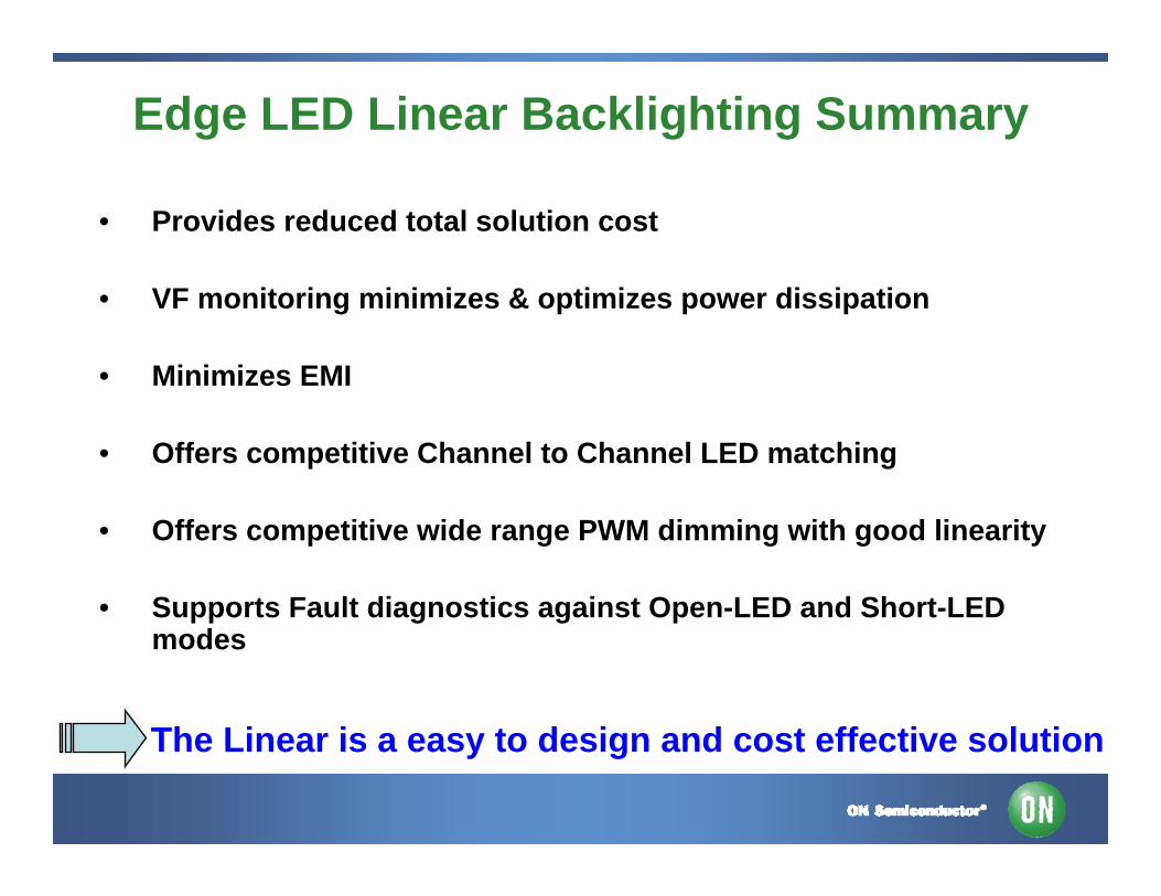
Edge LED Linear Backlighting Summary
• Provides reduced total solution cost
• VF monitoring minimizes & optimizes power dissipation
• Minimizes EMI
• Offers competitive Channel to Channel LED matching
• Offers competitive wide range PWM dimming with good linearity
• Supports Fault diagnostics against Open-LED and Short-LED modes
The Linear is a easy to design and cost effective solution
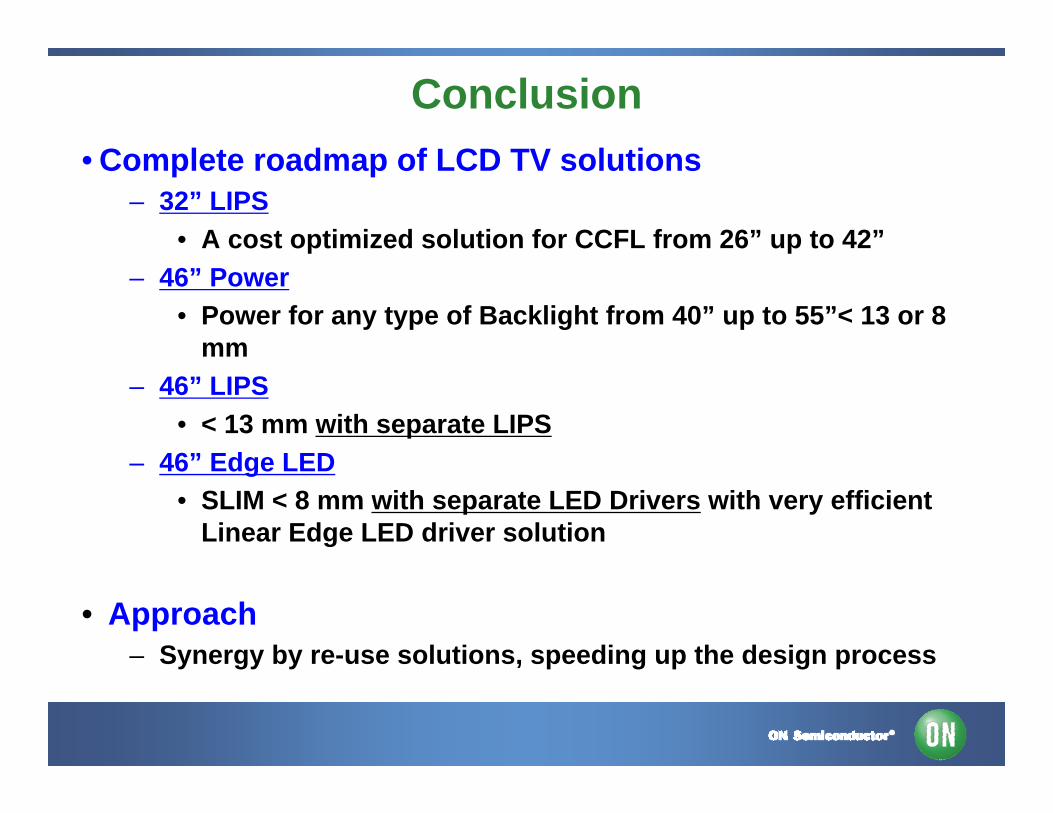
Conclusion• Complete roadmap of LCD TV solutions
– 32” LIPS• A cost optimized solution for CCFL from 26” up to 42”
– 46” Power• Power for any type of Backlight from 40” up to 55”< 13 or 8
mm– 46” LIPS
• < 13 mm with separate LIPS– 46” Edge LED
• SLIM < 8 mm with separate LED Drivers with very efficient Linear Edge LED driver solution
• Approach– Synergy by re-use solutions, speeding up the design process
For More Information
• View the extensive portfolio of power management products from ON Semiconductor at www.onsemi.com
• View reference designs, design notes, and other material supporting the design of highly efficient power supplies at www.onsemi.com/powersupplies