a versatile linear insertion sorter based on an fifo scheme
TRANSCRIPT
ARTICLE IN PRESS
Microelectronics Journal 40 (2009) 1705–1713
Contents lists available at ScienceDirect
Microelectronics Journal
0026-26
doi:10.1
� Corr
E-m
rcumpli
fmartin
journal homepage: www.elsevier.com/locate/mejo
A versatile linear insertion sorter based on an FIFO scheme
Roberto Perez-Andrade, Rene Cumplido �, Claudia Feregrino-Uribe, Fernando Martin Del Campo
Department of Computer Science National Institute for Astrophysics, Optics and Electronics, Puebla, Mexico
a r t i c l e i n f o
Article history:
Received 24 June 2008
Received in revised form
20 August 2009
Accepted 26 August 2009Available online 16 September 2009
Keywords:
Hardware sorters
Linear sorters
FIFO
92/$ - see front matter & 2009 Elsevier Ltd. A
016/j.mejo.2009.08.006
esponding author.
ail addresses: [email protected] (R. Per
[email protected] (R. Cumplido), cferegrino@ina
@inaoep.mx (F. Martin Del Campo).
a b s t r a c t
A linear sorter based on a first-in first-out (FIFO) scheme is presented. It is capable of discarding the
oldest stored datum and inserting the incoming datum while keeping the rest of the stored data sorted
in a single clock cycle. This type of sorter can be used as a co-processor or as a module in specialized
architectures that continuously require to process data for non-linear filters based on order statistics.
This FIFO sorting process is described by four different parallel functions that exploit the natural
hardware parallelism. The architecture is composed of identical processing elements; thus it can be
easily adapted to any data lengths, according to the specific application needs. The use of compact
identical processing elements results in a high performance yet small architecture. Some examples are
presented in order to understand the functionality and initialization of the proposed sorter. The results
of synthesizing the proposed architecture targeting a field programmable gate array (FPGA) are
presented and compared against other reported hardware-based sorters. The scalability results for
several sorted elements with different bits widths are also presented.
& 2009 Elsevier Ltd. All rights reserved.
1. Introduction
Sorting is one of the most important operations performed bycomputers. Given their practical importance, algorithms forsorting data have been the focus of extensive research, resultingin several algorithms proposed to address specific problems. First,serial sorting algorithms were investigated. Then parallel sortingalgorithms became a very active area of research, and severalmodels of parallel computations have been considered anddeveloped, deriving in sorting algorithms that later on wereimplemented in hardware. All developed serial algorithmsimplemented in software are evaluated by their time complexityand other properties such as the time-memory trade-offs (theamount of additional memory required to run the algorithm andthe memory for storing the initial sequence), stability, andsensitivity to the initial distribution of the data (best and worstcases). In parallel processing, when processors share a commonmemory, the idea of contiguous memory locations is identical tothat in serial processors. Therefore, this situation can be analyzedidentically as the serial case.
When the processors do not share memory and they commu-nicate with each other through an interconnection network, the
ll rights reserved.
ez-Andrade).
oep.mx (C. Feregrino-Uribe),
time complexity is expressed in terms of parallel comparisons andexchanges between adjacent processors [1,2].
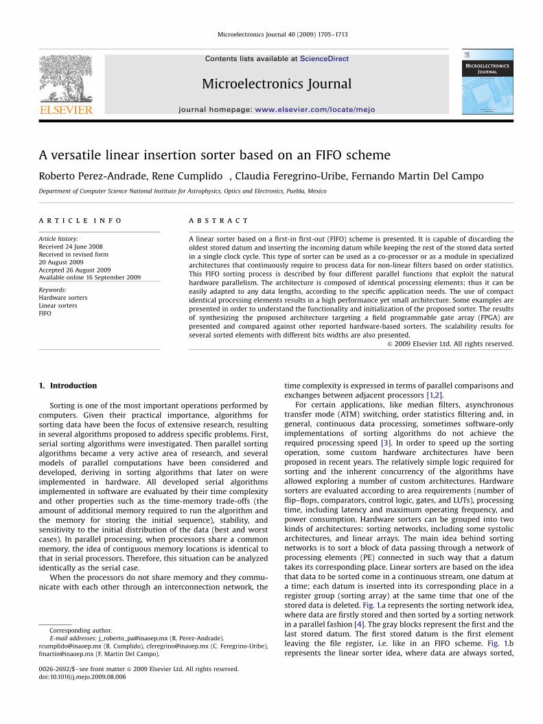
For certain applications, like median filters, asynchronoustransfer mode (ATM) switching, order statistics filtering and, ingeneral, continuous data processing, sometimes software-onlyimplementations of sorting algorithms do not achieve therequired processing speed [3]. In order to speed up the sortingoperation, some custom hardware architectures have beenproposed in recent years. The relatively simple logic required forsorting and the inherent concurrency of the algorithms haveallowed exploring a number of custom architectures. Hardwaresorters are evaluated according to area requirements (number offlip–flops, comparators, control logic, gates, and LUTs), processingtime, including latency and maximum operating frequency, andpower consumption. Hardware sorters can be grouped into twokinds of architectures: sorting networks, including some systolicarchitectures, and linear arrays. The main idea behind sortingnetworks is to sort a block of data passing through a network ofprocessing elements (PE) connected in such way that a datumtakes its corresponding place. Linear sorters are based on the ideathat data to be sorted come in a continuous stream, one datum ata time; each datum is inserted into its corresponding place in aregister group (sorting array) at the same time that one of thestored data is deleted. Fig. 1.a represents the sorting network idea,where data are firstly stored and then sorted by a sorting networkin a parallel fashion [4]. The gray blocks represent the first and thelast stored datum. The first stored datum is the first elementleaving the file register, i.e. like in an FIFO scheme. Fig. 1.brepresents the linear sorter idea, where data are always sorted,
ARTICLE IN PRESS
Fig. 1. Sorting network and linear sorter.
Fig. 2. Sorting network example.
R. Perez-Andrade et al. / Microelectronics Journal 40 (2009) 1705–17131706
thus the first and the last datum are merged inside the sortingarray. On these sorters, a deleting mechanism must be used inorder free space for incoming data. Some examples of thesemechanisms are deleting the oldest datum, selecting one datumor deleting the greatest or the smallest one.
This work is based on the idea of sorting the data as they areintroduced into the sorting array, discarding the oldest datum inthe sorting array while maintaining the data sorted, all that in asingle clock cycle. This FIFO scheme can be used in applicationsthat are continuously processing data in serial fashion like non-linear filters such as the rank-order filters, weighted orderstatistics (WOS) filters, and stack filters. These non-linear filtersare based on order statistics, thus require to access an ordered listof the random variables X1, X2, X3,y, Xn. An ascending sequencecan be represented as follows:
X1rX2rX3r ; . . . ; Xn ð1Þ
where indexes indicate the rank-order number. The idea on rank-order filters is to select a value Xi, where iA{1, 2, 3,y, n} from thesequence in Eq. (1) and then to use this Xi value as a sample of thesorted data.
Several signal processing applications based on order statisticsrequire a sorter with an FIFO-like behavior. For example, in imageprocessing, non-linear filters such as: rank order, max/min, mean,morphological, and adaptive trimmed mean are commonly usedas they offer benefits such as edge preservation, robustness,adaptation to noise statistics, and preservation of image details[5,6]. Other applications can be found in radar and sonar systemswhere the detection procedures involve the comparison of thereceived signal amplitude to a threshold. This threshold isobtained by using a constant false alarm ratio (CFAR) algorithm,which requires keeping sorted the incoming echo samples [7].More examples of applications in signal processing are: smooth-ing of time-series, maximum likelihood estimation, and one-dimensional non-linear filtering [8].
These applications require accessing a value from a specificposition within a sorted array, more than one value simulta-neously, or even the whole set of values in the array to performparallel operations, thus making traditional FIFO memories with asingle output port unsuitable. The proposed architecture for theinsertion sort algorithm has an FIFO-like behavior, i.e. it discardsthe oldest datum when a new one arrives, while allowing flexibleaccess to its contents.
2. Related work
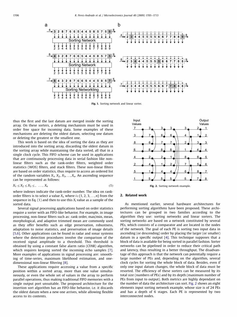
As mentioned earlier, several hardware architectures forperforming sorting algorithms have been proposed. These archi-tectures can be grouped in two families according to thealgorithm they use: sorting networks and linear sorters. Thesorting networks are based on a network constituted by severalPEs, which consists of a comparator and are located in the nodesof the network. The goal of each PE is sorting two input data inascending (or descending) order by placing the larger (or smaller)datum in a specific output [4]. This technique supposes that ablock of data is available for being sorted in parallel fashion. Sorternetworks can be pipelined in order to reduce their critical pathand latency, thus resulting in a better throughput. The disadvan-tage of this approach is that the network can potentially require alarge number of PEs and, depending on the algorithm, severalclock cycles for sorting the whole block of data. Besides, even ifonly one input datum changes, the whole block of data must beresorted. The efficiency of these sorters can be measured by itstotal size (numbers of PEs) and by its depth (maximum number ofPEs from input to output). Both metrics are highly dependant onthe number of data the architecture can sort. Fig. 2 shows an eightelements input sorting network example, whose size is of 24 PEsand has a depth of 6 stages. Each PE is represented by twointerconnected nodes.
ARTICLE IN PRESS
Fig. 3. Linear sorter example.
R. Perez-Andrade et al. / Microelectronics Journal 40 (2009) 1705–1713 1707
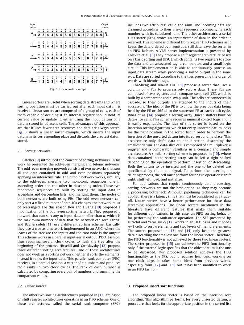
Linear sorters are useful when sorting data streams and wheresorting operation must be carried out after each input datum isreceived. Linear sorters are composed of a group of cells, each ofthem capable of deciding if an internal register should hold itscurrent value or update it, either using the input datum or adatum stored in adjacent cells. The advantages of this approachare that it uses fewer area resources and data are always sorted.Fig. 3 shows a linear sorter example, which inserts the inputdatum in its corresponding place and discards the greatest datumstored.
2.1. Sorting networks
Batcher [9] introduced the concept of sorting networks. In hiswork he presented the odd–even merging and bitonic networks.The odd–even merging network consists of two networks that sortall the data contained in odd and even positions separately,applying an interactive rule. The bitonic network works, similarlyto the odd–even, merging two monotonic sequences, one inascending order and the other in descending order. These twomonotonic sequences are built by sorting the input data inascending and descending lists, and merging them. The nodes ofboth networks are built using PEs. The odd–even network canonly sort a n fixed number of data. If n changes, the network mustbe rearranged. For this reason Kou and Huang [10] proposed amodification of the odd–even sorting network. They proposed anetwork that can sort any m input data smaller than n, which isthe maximum number of data that the network can sort. Tabriziand Bagherzadeh [11] use a different sorting scheme: basically,they use a tree as a network implemented in an ASIC, where theleaves of the tree are the inputs and the root node is the output.This scheme works in a parallel input-serial output (PISO) fashion,thus requiring several clock cycles to flush the tree after thebeginning of the process. Hirschil and Yaroslavsky [12] proposethree different sorting architectures. One of these architecturesdoes not work as a sorting network neither it sorts the elements;instead it ranks the input data. This parallel rank computer (PRC)receives, in a parallel fashion, a vector of n numbers and producestheir ranks in two clock cycles. The rank of each number iscalculated by comparing every pair of numbers and summing thecomparison values.
2.2. Linear sorters
The other two sorting architectures proposed in [12] are basedon shift register architectures operating in an FIFO scheme. One ofthese architectures, called the serial rank computer (SRC),
includes two attributes: value and rank. The incoming data arearranged according to their arrival sequence accompanying eachnumber with its calculated rank. The other architecture, a serialFIFO sorter (SFS), stores an input vector of data in the order itreceived. This scheme is different from regular FIFO schemes as itkeeps the data ordered by magnitude, still data leave the sorter inan FIFO fashion. A VLSI sorter implementation is presented byColavita et al. [3] They propose a shift register architecture basedon a basic sorting unit (BSU), which contains two registers to storethe data and an associated tag, a comparator, and a small logiccircuit. This implementation is able to continuously process aninput data stream while producing a sorted output in the sameway. Data are sorted according to the tags preserving the order ofwords with identical tags.
Chi-Sheng and Bin-Da Liu [13] propose a sorter that uses acolumn of n PEs to progressively sort n data. These PEs arecomposed of two registers and a compare-swap cell (CS), which isbuilt by a comparator and a swap unit. The cells are connected incascade, so their outputs are attached to the inputs of theirsuccessors. The idea of the PE is to allow the previous data beingheld by the PE or shifted to the successor PE at each clock cycle.Ribas et al. [14] propose a sorting array (linear shifter) built ondata-slice cells. This scheme requires minimal control logic and itis easily expandable. The idea of this sorter is based on theinsertion sorting algorithm, which for every unsorted datum looksfor the right position in the sorted list in order to perform theinsertion of the unsorted datum into its corresponding place. Thisarchitecture only shifts data to one direction, discarding thesmallest datum. The data-slice cell is composed of a multiplexer, aregister and a comparator, resulting in a compact and simplearchitecture. A similar sorting scheme is proposed in [15], wheredata contained in the sorting array can be left o right shifteddepending on the operation to perform, insertion, or descarding.Both the datum to be inserted and the one to be deleted arespecificated by the input signal. To perform the inserting ordeleting process, the cell must perform four basic operations: shiftright, shift left, load, and initialize.
For applications that require continuously data processing,sorting networks are not the best option, as they may becomea processing bottleneck. Although pipelining techniques can beapplied, there is a latency time that must be considered as a trade-off. Linear sorters have a better performance for these datastreaming applications. The linear sorters mentioned in theliterature have different features that make them suitablefor different applications, in this case, an FIFO sorting behaviorfor performing the rank-order operation. The SFS presented byHirschil and Yaroslavsky [12] works in an FIFO basis and it needsn+1 cells to sort n elements and two levels of memory elements.The sorters proposed in [13] and [14] only keep the greatestdata discarding the smallest one from the linear sorter. Therefore,the FIFO functionality is not achieved by these two linear sorters.The sorter proposed in [15] can achieve the FIFO functionalityonly if the external logic specifies that the oldest datum is the oneto be discarded. Our proposed solution achieves the FIFOfunctionality, as the SFS, but it requires less logic, working onone clock edge. It takes some ideas from previous works,especially from [12] and [13], but it has been modified to workin an FIFO fashion.
3. Proposed insert sort functions
The proposed linear sorter is based on the insertion sortalgorithm. This algorithm performs, for every unsorted datum, aprocedure that looks for the appropriate position in the sorted list
ARTICLE IN PRESS
R. Perez-Andrade et al. / Microelectronics Journal 40 (2009) 1705–17131708
to insert the incoming datum [14]. The algorithm is presented inthe next pseudo-code:
Fig. 4. Sorting array.
function InsertSortfor each unsorted D {
i=0;while(ion) and (D4R[i]) ) {
R[i]=R[i+1];i= i+1;
}if (i= =0)
discard D;elseR[i�1]=D;
}end function;
Fig. 5. Insertion cases.
On each iteration, this algorithm inserts an incoming datuminto the vector R of length n (n40) in ascending form and discardsthe datum with the smaller value, which is located in R[0]. Toensure a proper behavior it is assumed that the value stored inR[n] exists and is larger than any value to be sorted, i.e. itrepresents infinity. In case that the incoming datum is smallerthan R[0], it will not be inserted into the array and will bediscarded as indicated by the sentence discard D.
The while sentence can be easily converted to a for loop withbounded limits. This transformation makes the algorithm suitableto be parallelized. The next code shows the result of thistransformation.
function InsertSortfor each unsorted D {
for(i=0; io n; i++){if(D 4 R[i]){
R[i]=R[i+1];if(D o =R[i+1])
R[i]=D;}
}
}end function;As vector R has a finite length, a discarding condition must beused in order to provide an empty space for the incoming datum.In [14], the condition used for deleting is to discard the smalleststored datum, meanwhile in [15], the datum to be discarded isindicated by an external input signal. In the proposed architecture,an FIFO scheme is used i.e. the oldest datum in the array isdiscarded, allowing for the incoming datum to be inserted in itscorresponding position. In order to achieve an FIFO-like operation,it is necessary to keep a life period value for each sorted data. Ifthe datum is shifted, then its corresponding life period value isshifted as well. The life period value is increased by one everytime a new datum is inserted. When the life period value hasexpired, that is, when it reaches a value equal to the number ofelements in the array (n), the corresponding datum is discarded,making an empty space in the vector and thus allowing theinsertion of a new datum. For this scheme, three differentoperations may be performed in order to keep the array sorted:shift the datum and life period value to the left, to the right, orhold the datum. To know the direction the data should be shiftedto, every element in the array must know on which side, onrelation to itself, the datum that is going to be discarded is located.Also, it must know on which side the incoming datum must bestored.
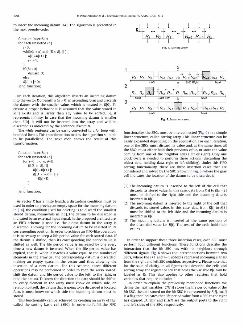
This functionality can be achieved by creating an array of PEs,called the sorting basic cell (SBC). In order to fulfill the FIFO
functionality, the SBCs must be interconnected (Fig. 4) in a simplelinear structure, called sorting array. This linear structure can beeasily expanded depending on the application. For each iteration,one of the SBCs must discard its value and, at the same time, allthe SBCs must either hold their previous value, or store the valuecoming from one of the neighbor cells (left or right). Only oneclock cycle is needed to perform these actions (discarding theoldest data, holding data, right or left shifting). Under this FIFOsorting functionality, there are three insertion cases that areconsidered and solved by the SBC (shown in Fig. 5, where the graycell indicates the location of the datum to be discarded):
(1)
The incoming datum is inserted to the left of the cell thatdiscards its stored value. In this case, data from R[i] to R[n�2]must be shifted to the right side and the incoming data isinserted in R[i].(2)
The incoming datum is inserted to the right of the cell thatdiscards its stored value. In this case, data from R[i] to R[3]must be shifted to the left side and the incoming datum isinserted in R[i].(3)
The incoming datum is inserted at the same position ofthe discarded value i.e. R[i]. The rest of the cells hold theirvalues.In order to support these three insertion cases, each SBC mustperform four different functions. These functions describe theinteraction that the ith SBC has with its neighbors throughdifferent signals. Fig. 6 shows the interconnections between twoSBCs, where the i+1 and i�1 indexes represent incoming signalsfrom the right and left SBC neighbor, respectively. Please note thatfor the sake of clarity, in all figures that describe the cells andsorting array, the register or cell that holds the variable R[i] will belabeled as Ri. This also applies to other registers that holdvariables that require an index i.
In order to explain the previously mentioned functions, wedefine the next variables: CNT[i] stores the life period value of theith SBC, the data stored on the ith SBC is represented by R[i], cnt[i]is a flag that indicates that life period value from a SBC to the righthas expired. D_right and D_left are the output ports to the rightand left sides of the SBC, respectively.

ARTICLE IN PRESS
Fig. 6. Connection of two SBCs.
R. Perez-Andrade et al. / Microelectronics Journal 40 (2009) 1705–1713 1709
function SBC_SendDataD=Incoming Data;if (R[i] 4 D){
D_right=R[i];D_left=D;
}else{D_right=D;D_left=R[i];
}end function;
The SBC_SendData function sends to its left and right neighborsthe value it currently stores and the incoming data, D_left andD_right SBC, respectively. If the first condition is met, it indicatesthat this SBC must send to its right, its current value (R[i]) and tothe left, the incoming datum, otherwise it must send to its left, itscurrent value and to the right, the incoming datum.
function SBC_ResetPeriodLifeD=Incoming Data;if(CNT[i]= =n) or (R[i] 4D xor cnt[i+1]= =1){
if (R[i] 4D) and not (R[i+1] 4D){CNT[i]=0;
}if not (R[i] 4D) and (R[i�1]4D){
CNT[i]=0;}
}end function;
The SBC_ResetPeriodLife function sets to zero the life periodvalue if certain conditions are met. The first condition of thisfunction checks if the CNT[i] has reached its maximum value or ifthe incoming datum D must be inserted in the ith SBC (exclusiveor between the cnt[i+1] and R[i] 4D). The inner conditions checkthose cases where the SBC’s counter must be set to zero. Thisaction takes place when the incoming datum will be stored on theith SBC, therefore setting the life period value to zero is needed.These conditions allow to set to zero the life period value in onlyone SBC inside the sorting array at a same time.
function SBC_UpdateValuesD=Incoming Data;if(CNT[i]= =n) or (R[i]4D xor cnt[i+1]= =1){
if (R[i]4D){R[i]=R[i+1];CNT[i]=CNT[i+1];
}else{R[i]=R[i�1];CNT[i]=CNT[i�1];
}
} end function;The SBC_UpdateValues function is in charge of updating thestore value and the life period value coming from one of theneighbors. In order to know which neighbor to take the new valueform, two conditions must be met. The first condition checks if theCNT[i] has reached its maximum value or if the incoming datum D
must be inserted in the ith SBC (exclusive or between the cnt[i+1]and R[i]4D), similar to the SBC_ResetPeriodLife function. Thesecond condition selects which neighbor (left or right) the R[i] andCNT[i] variables of the ith SBC must take their value from. Eventhough the first condition is the same as the one shown in theSBC_ResetPeriodLife function, they are separated because there isa priority order; if both conditions are met then only theSBC_ResetPeriodLife function should be performed.
function SBC_PropagateFlagif(CNT[i]= =n or cnt[i+1]= =1){
cnt[i]=1;
} else{cnt[i]=0;
}end function;This final function, SBC_PropagateFlag, checks if the life periodvalue of the SBC has expired or the right SBC life period value hasexpired; if so, then the cnt[i] flag is set to 1. The flag cnt[i] must notbe confused with CNT[i], because the first one is used by thefunctions as one of the conditions to update the ith SBC,meanwhile the second one is the life period value of the ith SBC.These four functions describe the interactions the ith SBC has withits neighbors and how these interactions allow the sorting array toperform the three insertion cases previously described.
It is important to emphasize that the proposed sorter differsfrom other sorters as it implements an FIFO-like scheme wherethe oldest datum in the sorting array is discarded to make roomfor every incoming data. Although our sorter performs the sameFIFO functionality of the SFS presented in [12], they differ in theirinternal functionality. The SFS stores an input vector of data in theorder that it is received, discarding the oldest datum i.e. the FIFOscheme. At each clock cycle, one datum enters taking itscorresponding place inside the sorter according to its value andother datum leaves the sorter. These two characteristics are metby our sorter too. Also, both sorters need to store the life periodvalue, however, the SFS sorter requires two levels of memoryelements: main and auxiliary; meanwhile our sorter only requiresone memory level. Moreover, the SFS needs n+1 cells to sort n
elements, requiring an overflow cell. On the other side, our sorterneeds only n cells to sort n elements. Although both the SFS andour sorter operate in one clock cycle, the SFS works during bothclock edges: rising and falling edges. During the rising edge itinserted the incoming datum by shifting the needed data to theoverflow cell side, having n+1 sorted elements. In the next falling

ARTICLE IN PRESS
Fig. 7. Architecture of the SBC.
R. Perez-Andrade et al. / Microelectronics Journal 40 (2009) 1705–17131710
edge, the oldest stored datum in the n+1 cells is discarded byshifting until the position of the overflow cell reaches the oldestdatum. Our sorter is able to perform all described operations in asingle clock edge, which is a desired featured in digitalarchitectures.
Fig. 8. Sorting array example functionality.
4. Sorting base cell
The proposed SBC has a register with synchronous load to storethe data, a counter with synchronous reset and load to store theperiod life of the data, a ‘major than’ comparator, four 2–1multiplexers and control logic (Fig. 7). In order to build the localcontrol unit of the SBC, the conditions presented in the fourfunctions previously described were mapped into booleanequations. This control logic consists of four boolean equations,which control the register, the counter, and the multiplexers.Eq. (2) is used as a condition in SBC_ResetPeriodLife andSBC_UpdateValues functions. Also this equation controls whenthe register and the counter must take the neighbor value.The origin of the data (left or right side) is selected by Eq. (3),which is used in function SBC_UpdateValues. The functionSBC_ResetPeriodLife is represented by Eq. (4) and it indicates ifthe counter must be set to zero. Finally, Eq. (5) detects andpropagates if the life period value of one of the SBCs to the righthas expired as indicated by the SBC_PropagateFlag function.
load¼ ðpi � cntiþ1Þþexpired ð2Þ
LR¼ pi dload ð3Þ
reset¼ load d½ðpi�1 dpiÞþðpi dpiþ1Þ� ð4Þ
cnti ¼ cntiþ1þexpired ð5Þ
where the signal pi is the comparator output as described by theSBC_SendData function. If all comparators inside the sorting arrayare inverted to a ‘minor than’ comparator, then the sorting arraywould work in a descending fashion. The signals pi+ 1 and pi�1
correspond to the right and left SBC neighbors, respectively. Thesignal expired indicates when the life period value has reached itsmaximum value inside of one SBC and cnti+ 1 is the flag comingfrom the SBC immediately to the right. This signal helps to detectif the life period value of one SBC to the right has expired. In orderto perform correctly the insert sort algorithm, the left-most pi�1
signal value is always 1 and the right-most pi +1 signal value isalways 0. This can be viewed as the left-most datum having thesmallest value while the right-most has the largest one.
To ensure proper behavior, all registers Ri must be initialized tozero, while life counter values CNT must be initialized according toCNT[i]= i. The CNT counter word size depends on the sortingarray’s length, being a function of
dlog2 ne ð6Þ
where n is the sorting array length.Figs. 8 and 9 exemplify how the SBC’s control signals work in
two different situations. In both figures, the first row contains thesorted data currently stored in the sorting array in ascendingform, the second row contains the corresponding life periodvalues, and the following rows contain the control signals’ valuesneeded to perform the insertion operation. The gray columnindicates the oldest data to be discarded, whose period life valueis 12. Different clock cycles are represented by different tables inthe same figure. Only one SBC can have the reset signal asserted ateach clock cycle. When one SBC asserts the reset signal, it meansthat this SBC is where the incoming datum D will take place in thenext clock cycle. The expired signal is only asserted when the SBC’speriod life value has reached the same value of the sorting arraylength, meaning that this is the oldest datum stored (shown bythe gray columns). Similarly to the reset signal, only one SBC canhave the expired signal asserted at each clock cycle. Note how cnti
ARTICLE IN PRESS
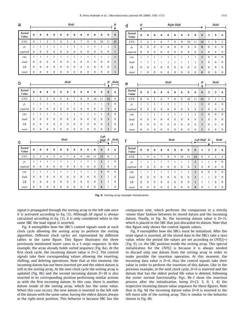
Fig. 9. Sorting array example initialization.
R. Perez-Andrade et al. / Microelectronics Journal 40 (2009) 1705–1713 1711
signal is propagated through the sorting array to the left side onceit is activated according to Eq. (5). Although LR signal is alwayscalculated according to Eq. (3), it is only considered when in thesame SBC the load signal is asserted.
Fig. 8 exemplifies how the SBC’s control signals work at eachclock cycle allowing the sorting array to perform the sortingalgorithm. Different clock cycles are represented by differenttables in the same figure. This figure illustrates the threepreviously mentioned insert cases in a 3 steps sequence. In thisexample, the array already holds sorted sequence (Fig. 8a). At thefirst clock cycle, the incoming datum value is D=2. The controlsignals take their corresponding values allowing the inserting,shifting, and deleting operations. Note that at this moment, theincoming datum has not been inserted yet and the oldest datum isstill in the sorting array. At the next clock cycle the sorting array isupdated (Fig. 8b) and the second incoming datum D=18 is alsoinserted in its corresponding position performing similar actionsas with the first incoming datum. In this case, there is anotherdatum inside of the sorting array, which has the same value.When this case occurs, the new datum is inserted to the left sideof the datum with the same value, having the oldest datum alwaysat the right-most position. This behavior is because SBC has the
comparator unit, which performs the comparison in a strictly‘minor than’ fashion between its stored datum and the incomingdatum. Finally, in Fig. 8c, the incoming datum value is D=11,which is placed in the SBC that just discarded its datum. Note thatthis figure only shows the control signals values.
Fig. 9 exemplifies how the SBCs must be initialized. After thereset signal is asserted, all the stored data in the SBCs take a zerovalue, while the period life values are set according to CNT[i]= i
(Fig. 9), i.e. the SBC position inside the sorting array. This specialinitialization for the CNT[i] is because it is always neededto discard only one datum from the sorting array in order tomake possible the insertion operation. At this moment, theincoming data value is D=6, thus the control signals take theirvalue in order to perform the insertion of this datum. Like in theprevious example, in the next clock cycle, D=6 is inserted and thedatum that has the oldest period life value is deleted, followingthe sorter normal functionality. Figs. 9b–f show the insertionprocess after the initialization, being D={3, 5, 0, 1, 4} therespective incoming datum value sequence for these figures. Notethat in Fig. 9d the incoming datum value D=0 is inserted in theleft-most side of the sorting array. This is similar to the behaviorshown in Fig. 8b.

ARTICLE IN PRESS
Table 1Performance results with other sorting architectures.
Sorter FPGA used Speed (MHz) Latency clock cycles Gate count Flip flops LUT’s count Data sorted Word size (bits)
Bitonic Virtex II 127 14 153k 7,680* NA 32 16
Odd–Even Virtex II 147 14 137k 6,112* NA 32 16
Column Virtex II 66 32 23k 1,024* NA 32 16
Shifter Virtex II 216 32 12k 512* NA 32 16
SFS Virtex E 115 49 35k 1,372 3,430 7�7 8
PRC Virtex E 159 2 384k 1,634 11,809 7�7 8
SRC Virtex E 96 49 19k 784 2,548 7�7 8
FIFO Scheme Virtex E 72 49 15k 325 1,895 49 8FIFO Scheme Virtex II 126 32 25k 672 2,726 32 16FIFO Scheme Virtex 5 234 32 24k 672 1,894 32 16
Table 2Comparison with others sorting architectures.
Number of Sorter
Bitonic Odd–even Column Linear shifter SFS FIFO scheme
Multiplexers n(log2 n+log n)/2 n(log2 n–log n+4)/2–2 2n n 5n+5 4n�2
Comparators n(log2 n+log n)/4 n(log2 n–log n+4)/4–1 n n 2n+2 2n
Registers n(log2 n+log n)/2 n(log2 n–log n+4)/2–2 2n n 4n+4 2n
Counters 0 0 0 0 n+1 n
Clock Cycles (log2 n+ log n)/2 (log2 n+ log n )/2 4n n n n
R. Perez-Andrade et al. / Microelectronics Journal 40 (2009) 1705–17131712
5. Results
For the purpose of validation and comparison against otherworks, the proposed architecture was modeled using the VHDLHardware Description Language and synthesized with Xilinx ISE 9.2targeted for a Virtex-II XC2V3000 FPGA device and for a VirtexEXCV200E. The design was also synthesized for a Virtex 5 XC5VLX220FPGA device in order to show results for scalability in a more up todate device. Table 1 summarizes the FPGA hardware resourceutilization and timing performance for the proposed architectureand related sorters, using the Virtex-II and VirtexE devices. Table 2shows a comparison of the proposed architecture against otherworks in terms of the number of hardware elements they require. InTable 2, n refers to the number of values being sorted.
The data for the bitonic, odd–even, column, and shifter sorterswere taken from [14], while data for the SFS, PRC, and SRC sorterswere taken from [12]. Note that a direct comparison between ourproposed sorter and other sorters is not possible, except by the SFSsorter, which performs the same FIFO functionality. Even thoughour proposed sorter is not the fastest among all the sorters shownin Table 1, it uses less hardware resources (gates, FFs, and LUTs)than the SFS sorter that performs similar functions. The SFS sorteris faster than the proposed linear sorter, but this SFS needs longestclock period to ensure the signal stability as it works during bothclock edges. Both sorters are able to discard a datum and to inserta new datum in a single clock cycle while maintaining the rest ofthe data sorted. Network sorters on the other hand would requirea larger number of clock cycles to sort the data even if only asingle datum is replaced. It is important to mention that thenumbers of flip–flops required by the first 4 sorters in Table 1 arenot explicitly reported in [14]. These values (marked with *), wereestimated by analyzing the structure of the sorters and taking intoaccount the number of values and word sizes shown in Table 2.
Although the bitonic and odd–even sorters have a greatermaximum frequency operation and a smaller latency than ourFIFO scheme, they need to re-sort the data once a datum haschanged. This make them impracticable for a continuously dataprocessing. Also both sorters require less time to sort the n data
than the linear sorters, however they require that all data to besorted is available at the same time, which is not always possiblespecially in applications that produce data in a stream fashion.Moreover, they require a larger number of hardware elements.
According to Table 2, the linear shifter requires the leastquantity of hardware elements, followed by the column shifter.Although the proposed architecture requires more hardwareelements than the column shifter, it is capable of sorting n datain as many clock cycles, similar to the linear shifter and the SFSsorter. Even though the proposed architecture and the SFSperforms the sorting operation based on an FIFO way, differingin their internal functionality, the FIFO scheme presented requiresless hardware elements than the SFS.
Table 3 shows the scalability results of the sorting architecturefor the Virtex 5 device. For this comparison, different word sizesand sorting array lengths combinations were used. The scalabilitydata results are grouped by number of sorted elements (amount ofSBCs) and their word size in bits. All frequencies are greater than150 MHz, thus area results are the main concern. Fig. 10 shows theLUTs results in a graph for clarity purpose. By increasing the fileregister size, the number of LUTs used grows more than twice asthe SBC amount is increased at the same proportion.
6. Conclusion
Sorting is one of the most important operations used incomputers. When implementing statistical signal processingalgorithms, it is commonly required to access values from asorted array in a number of different ways. Some algorithms mayrequire accessing the largest or smallest value in the array, thedatum stored in a specific position, or even data within a rangeaccording to the application. Additionally, as incoming data areprocessed in a stream fashion, an FIFO-like behavior is requiredwhere the oldest datum in the array has to be removed beforemaking room for any new datum. In this work, a compact andefficient hardware implementation of a linear sorter based on anFIFO scheme was presented. The architecture, composed of an

ARTICLE IN PRESS
Table 3Scalability results of the sorting architecture.
SBC amount 8 BITS 12 BITS 16 BITS
FF LUT MHz FF LUT MHz FF LUT MHz
8 88 232 291 120 327 318 152 377 289
16 192 568 264 256 850 266 320 840 237
32 416 1306 219 544 1806 228 672 1894 231
64 896 2931 198 1152 3815 193 1408 3981 206
128 1920 6422 171 2432 7683 172 2944 8826 173
256 4096 15,196 158 5120 17,747 151 6144 19,862 152
SBC amount 20 BITS 24 BITS
FF LUT MHz FF LUT MHz
8 184 435 277 216 500 264
16 384 1014 255 448 1138 264
32 800 2114 217 928 2357 233
64 1664 4603 196 1920 5083 203
128 3456 9899 172 3968 11,189 172
256 7168 21,701 151 8192 23,170 150
Scalability
LUTs
25,0008 Bits 12 Bits 16 Bits 20 Bits 24 Bits
20,000
15,000
10,000
5,000
-8 16 32 64 128 256
SBCs
Fig. 10. LUTs comparison results.
R. Perez-Andrade et al. / Microelectronics Journal 40 (2009) 1705–1713 1713
array of identical processing elements, implements the insert sortalgorithm in a compact and efficient way by performing a numberof tasks in a single clock cycle. The architecture is based on fourfunctions whose characteristics are translated into four booleanequations, working as an internal control logic for each of theseprocessing elements. The architecture can be easily adapted to anylength and data width according to specific application needs andused as a co-processor or as a module to implement a sortingarray in specialized architectures. The nature of this architectureexploits the parallel properties of the insert sort algorithm andachieves excellent performance due to the use of identicalprocessing elements that perform a number of tasks in parallelwithout the need of a complex control unit.
Acknowledgments
First author thanks the National Council for Science andTechnology from Mexico (CONACyT) for the financial supportthrough the scholarship number 204500.
References
[1] Donald E. Knuth, Art of Computer Programming, Volume 3: Sorting andSearching, AddisonWesley Professional, second ed., 1998.
[2] D. Bitton, J.D. DeWitt, D.K. Hsiao, J. Menon, A taxonomy of parallel sorting,ACM Computing Surveys 16 (3) (1984) 287–318.
[3] A.A. Colavita, A. Cicuttin, F. Fratnik, G. Capello, SORTCHIP: A VLSI implemen-tation of a hardware algorithm for continuous data sorting, IEEE Journal ofSolid-State Circuits 38 (6) (2003) 1076–1079.
[4] Thomson Leighton, Introduction to Parallel Algorithms and Architectures:Arrays, Trees and Hypercubes, Morgan Kaufman Publishers, 1992.
[5] Ioannis Pitas, Digital Image Processing Algorithms and Applications, Wiley-Interscience, February 2000.
[6] Rafel C. Gonzalez, Richard E. Woods, Digital image processing, third ed.,Prentice Hall, 2007.
[7] Merrill Skolnik, Introduction to radar systems, third ed., McGraw-Hill, 2002.[8] N. Balakrishnan, C.R. Rao, Handbook or Statistics 17: Order Statistics:
Applications, Elsevier Science Pub Co., 1998.[9] K.E. Batcher, Sorting networks and their applications, in: Proceedings of the
AFIPS Spring Joint Computer Conference, vol. 32, 1968, pp. 307–314.[10] Chung J. Kou, Zhi W. Huang, Modified odd–even merge-sort network for
arbitrary number of inputs, in: Proceedings of the IEEE InternationalConference on Multimedia and Expo, 2001, ICME 2001, pp. 929–932.
[11] N. Tabrizi, N. Bagherzadeh, An ASIC design of a novel pipelined and parallelsorting accelerator for a multiprocessor-on-a-Chip, ASICON 2005, in:Proceedings of the 6th International Conference On ASIC, vol. 1, 2005, pp.46–49.
[12] B. Hirschil, L.P. Yaroslavsky, FPGA implementations of sorters for non-linearfilters, Eusipco 2004, in: Proceedings of the XII European Signal ProcessingConference, vol. 1, Vienna, Austria, pp. 541–544.
[13] Chi-Sheng Lin, Bin-Da Liu, Design of a pipelined and expandable sortingarchitecture with simple control scheme, in: Proceedings of the IEEEInternational Symposium on Circuits and Systems, ISCAS 2002, vol. 4,pp. 26–29.
[14] L. Ribas, D. Castells, J. Carrabina, A linear sorter core based on a programmablesorting array, in: Proceedings of the XIX Conference on Design of Circuits andIntegrated Systems, DCIS 2004, Bordeaux, France, pp. 635–640.
[15] Chen-Yi Lee, Jer-Min Tsai, A Shift register architecture for high-speed datasorting, The Journal of VLSI Signal Processing Systems 11 (3) (1995) 273–280.