a uml profile utilizing enterprise information system configuration
TRANSCRIPT
A UML Profile utilizing Enterprise Information System Configuration
M. Nikolaidou12, A. Tsadimas12, N. Alexopoulou12, A. Dais2, D. Anagnostopoulos1
{[email protected], [email protected], [email protected], [email protected], [email protected]} 1 Harokopio University of Athens,
El. Venizelou Str, 17671Athens, Greece 2 Department of Informatics and Telecommunications,
University of Athens, Panepistimiopolis, 15771, Athens, Greece
Abstract Enterprise information system configuration is a complex process dealing with interrelated issues. A four-stage methodology has been proposed in order to effectively explore configuration issues. The main advantage of the proposed methodology is the adoption of a common meta-model for the representation of systems throughout all configuration stages, ensuring interoperability and model consistency. In practice, configuration stages are supported by automated or semi-automated tools, each of which adopts its own meta-model for system representation. In order to apply the methodology using existing autonomous tools, model exchangeability (thus meta-model transformation) and tool co-ordination must be facilitated by standard, open methods. Thus, the common meta-model is implemented in a standard, exchangeable format, as XML. To provide a standard method to visualize the common meta-model, facilitate the designer to interact with it and co-ordinate specific tool invocation, a UML 2.0 profile was defined. Different UML 2.0 diagrams are integrated to support different views of the system. The representation of relationships and restrictions among discrete meta-model entities must be facilitated to identify and explore the dependencies between configuration stages. Constraints are extensively used for this purpose. A case study where the proposed profile utilized the configuration of a large-scale banking system is also presented.
1. Introduction 1
Modern enterprise information systems are based on distributed architectures, consisting of a combination of Intranet and Internet web-based applications. They are built on multi-tiered client-server models [1], as the J2EE architecture. Such platforms distinguish application logic from the user-interface and contribute to system configurability and extendibility. Although, vendors actively promote information system development using aforementioned architectures, the proposed solutions, although expensive, often fail to provide the desired
This research was supported by Pythagoras program (MIS 89198) co-funded by the Greek Government (25%) and the European Union (75%).
performance [2]. This is due to the fact configuration issues, although interrelated, are solved in isolation, while application internal complexity is neglected when estimating the quality of service (QoS) imposed to the network supporting them.
A four-staged methodology for configuring web-based enterprise information systems was proposed in [3], aiming at a) exploring unclear dependencies between application configuration and the underlying network and b) depicting application logic in detail. The main advantage of the proposed methodology is the adoption of a common meta-model for the representation of systems throughout all configuration stages, ensuring interoperability and model consistency. Representation of different kinds of applications is facilitated, while custom architectures can also be described. Configuration stages are supported by software tools especially built for this purpose. All of them adopt the common meta-model proposed, thus model exchangeability is not an issue. A custom UML-like graphical interface was also especially built to facilitate the interaction with the system designer.
The methodology proposed in [3] may be applied in enterprise information system configuration in general. In practice, configuration stages are supported by existing autonomous automated or semi-automated tools [4, 5, 6], each of which adopts its own meta-model for system representation. In order to apply the methodology using existing, heterogeneous tools, the following issues should be addressed: • Model exchangeability (thus meta-model
transformation) • Tool invocation and co-ordination • Provision of an integrated, east-to-use interface. In order to facilitate model exchangeability, the common meta-model is realized in XML. The partial transformation of the common meta-model into tool-specific meta-model must be facilitated prior using an existing tool for a specific configuration stage.
Proceedings of the 11th IEEE International Conference on Engineering of Complex Computer Systems (ICECCS'06)0-7695-2530-X/06 $20.00 © 2006
In order to provide a standard method to visualize the meta-model and facilitate the designer to interact with it, it was decided to create a UML 2.0 profile [7]. Specific tool invocation and co-ordination must also be facilitated either by the profile or the meta-model itself or by both. A UML 2.0 profile should be integrated in existing well-known UML software platforms (for example Rational Modeler), thus there is no need to built custom environments as the one presented in [3]. Since it is a common modeling standard, it provides the means to typically map UML meta-model entities (used for system graphical representation) to the proposed meta-model entities (used for system description).
Although, UML is mainly used for software engineering (e.g. when designing and implementing application components). UML concepts may also be applied in system engineering as proposed by OMG in the Enterprise Distributed Object Computing (EDOC) profile [8]. EDOC profile aims at proposing system models to designers using UML concepts for the five viewpoints of RM-ODP framework [9]. According to RM-ODP, in the Engineering Viewpoint, the type of system architecture (e.g. client-server) is defined, the network architecture is described and system components are associated to network nodes (resource allocation). As indicated in [10], EDOC profile supports Engineering Viewpoint mainly using component diagrams for both the application configuration and the network infrastructure. The proposed configuration methodology focuses strictly on Engineering Viewpoint, dealing with application configuration and network design issues without taking into account application development progress. Thus, a model is provided to describe application logic in terms of the service requirements imposed to the network infrastructure. In contrast to EDOC, different UML diagrams are adopted for representing system entities already defined in the meta-model, thus enabling system designer to explore discrete configuration issues.
In this paper, we focus on the formal definition of the Enterprise Information System Configuration Profile, facilitating the configuration of enterprise information system (EIS) architectures. The profile enables the description of EIS entities needed to autonomous explore the Configuration Viewpoint of the system. Since each configuration stage may be related to a different aspect of the system, discrete views of the system model are accommodated. Different UML 2.0 diagrams are integrated [11] to support different views of the system. The representation of relationships and restrictions among discrete system entities must also be facilitated to identify and explore the dependencies between configuration stages. Constraints are extensively used for this purpose.
The rest of the paper is organized as follows: In section 2, the system configuration methodology and the
proposed implementation framework are presented. In section 3, the formal definition of the UML Profile is presented. UML 2.0 extensions and constraints needed to efficiently model system architecture and the provided functionality with respect to configuration methodology are also discussed. Implementation issues are addressed in section 4. Our effort to implement the profile in an existing UML modeling tool is briefly discussed. A case study using the proposed profile and methodology to configure a distributed banking system is presented in section 5. Conclusions reside in section 6.
2. EIS Configuration Methodology The system configuration framework (Nikolaidou et.
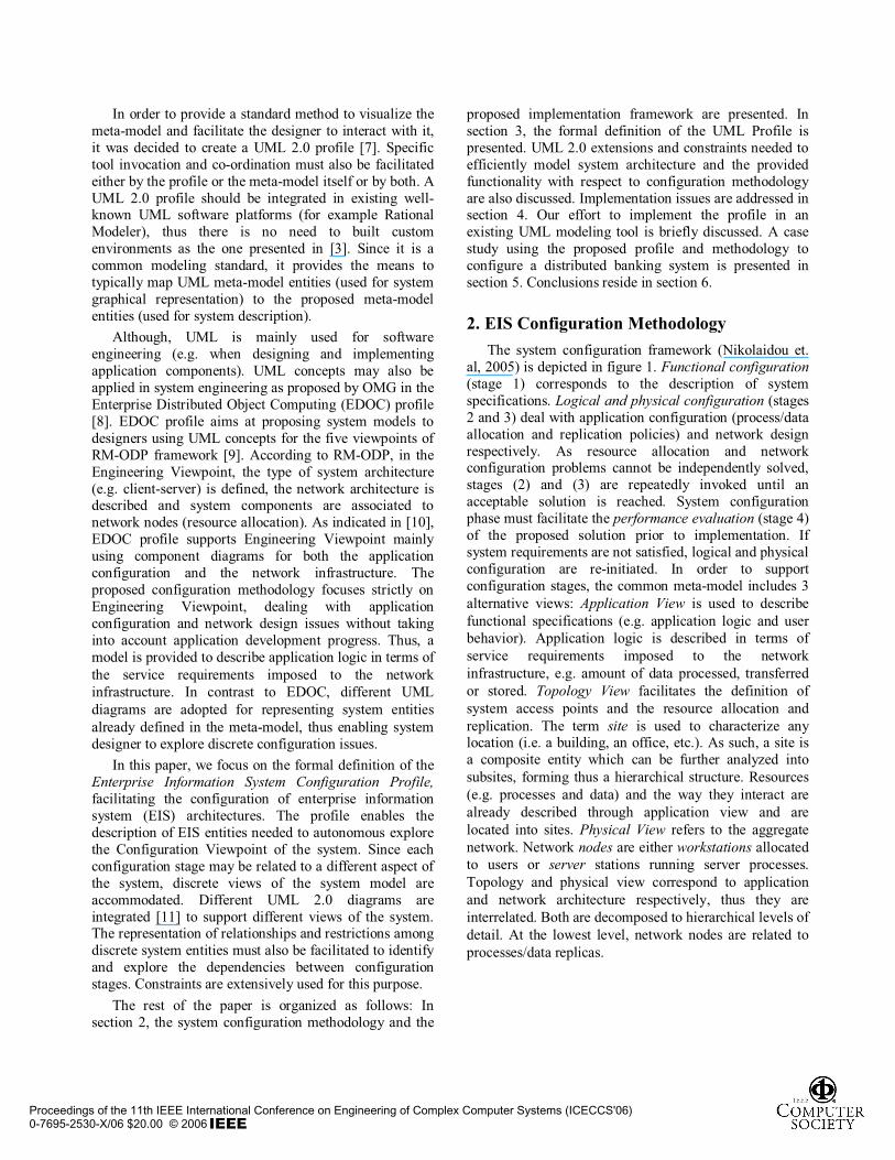
al, 2005) is depicted in figure 1. Functional configuration(stage 1) corresponds to the description of system specifications. Logical and physical configuration (stages 2 and 3) deal with application configuration (process/data allocation and replication policies) and network design respectively. As resource allocation and network configuration problems cannot be independently solved, stages (2) and (3) are repeatedly invoked until an acceptable solution is reached. System configuration phase must facilitate the performance evaluation (stage 4) of the proposed solution prior to implementation. If system requirements are not satisfied, logical and physical configuration are re-initiated. In order to support configuration stages, the common meta-model includes 3alternative views: Application View is used to describe functional specifications (e.g. application logic and user behavior). Application logic is described in terms of service requirements imposed to the network infrastructure, e.g. amount of data processed, transferred or stored. Topology View facilitates the definition of system access points and the resource allocation and replication. The term site is used to characterize any location (i.e. a building, an office, etc.). As such, a site is a composite entity which can be further analyzed into subsites, forming thus a hierarchical structure. Resources (e.g. processes and data) and the way they interact are already described through application view and are located into sites. Physical View refers to the aggregate network. Network nodes are either workstations allocated to users or server stations running server processes. Topology and physical view correspond to application and network architecture respectively, thus they are interrelated. Both are decomposed to hierarchical levels of detail. At the lowest level, network nodes are related to processes/data replicas.
Proceedings of the 11th IEEE International Conference on Engineering of Complex Computer Systems (ICECCS'06)0-7695-2530-X/06 $20.00 © 2006
Functional Configuration
Physical Configuration
Performance Evaluation
SystemDesigner
Topology View
Application View
Physical View
Operates on / support by relationship
Application description relationship
Logical Configuration
Performance accepted
yes
no
EIS ModelConfiguration Methodology
Figure 1. System Configuration Methodology Logical and physical configuration stages are usually supported by automated or semi-automated tools using mathematics, heuristics or a combination of both. These tools may be repeatedly invoked for different model abstraction levels [5, 6]. To evaluate system performance, a simulation tool as the one described in [12] can be used. The simulator uses as input the overall distributed system model and produces performance results. Since each of these tools supports its own representation meta-model (for example queuing networks, Petri-nets, objects), there a need to properly create and instantiate the “internal” system model prior invoking the tool.
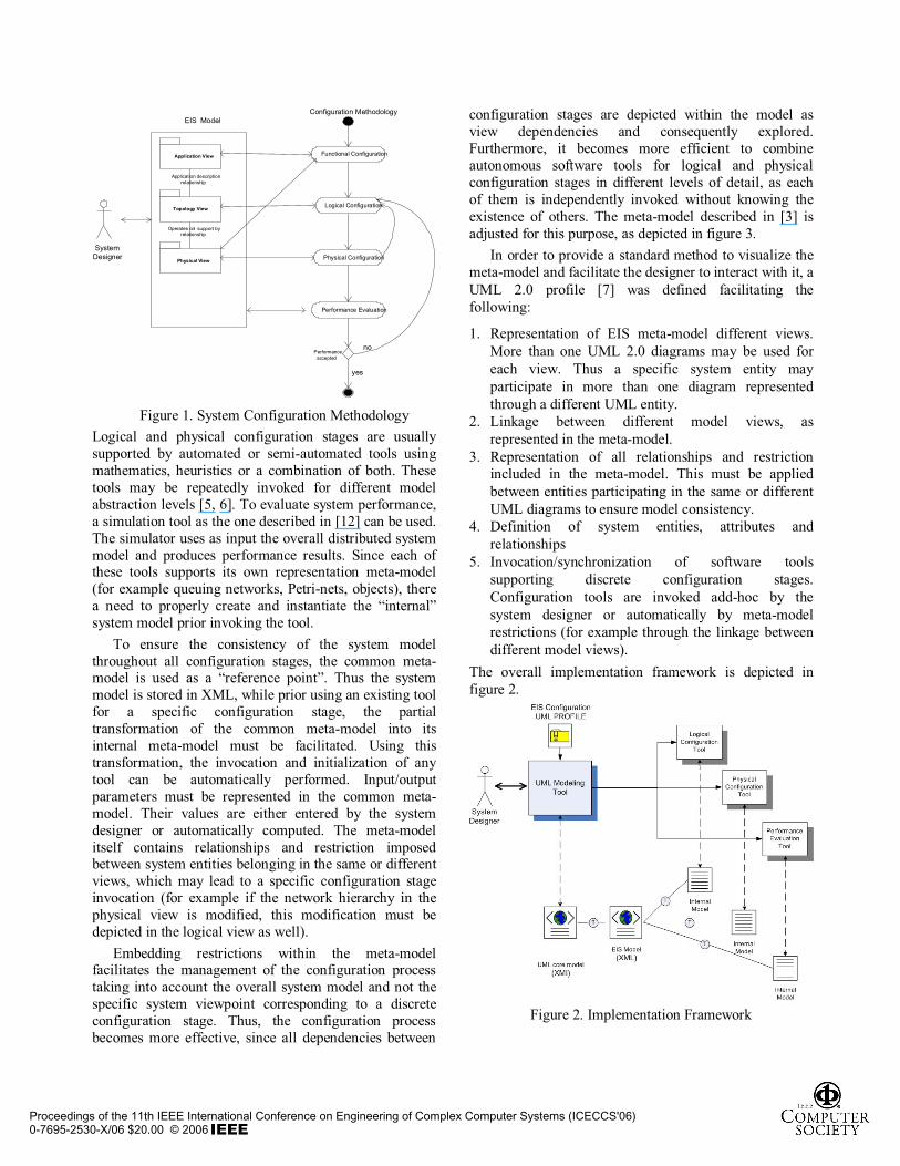
To ensure the consistency of the system model throughout all configuration stages, the common meta-model is used as a “reference point”. Thus the system model is stored in XML, while prior using an existing tool for a specific configuration stage, the partial transformation of the common meta-model into its internal meta-model must be facilitated. Using this transformation, the invocation and initialization of any tool can be automatically performed. Input/output parameters must be represented in the common meta-model. Their values are either entered by the system designer or automatically computed. The meta-model itself contains relationships and restriction imposed between system entities belonging in the same or different views, which may lead to a specific configuration stage invocation (for example if the network hierarchy in the physical view is modified, this modification must be depicted in the logical view as well).
Embedding restrictions within the meta-model facilitates the management of the configuration process taking into account the overall system model and not the specific system viewpoint corresponding to a discrete configuration stage. Thus, the configuration process becomes more effective, since all dependencies between
configuration stages are depicted within the model as view dependencies and consequently explored. Furthermore, it becomes more efficient to combine autonomous software tools for logical and physical configuration stages in different levels of detail, as each of them is independently invoked without knowing the existence of others. The meta-model described in [3] is adjusted for this purpose, as depicted in figure 3.
In order to provide a standard method to visualize the meta-model and facilitate the designer to interact with it, a UML 2.0 profile [7] was defined facilitating the following:
1. Representation of EIS meta-model different views. More than one UML 2.0 diagrams may be used for each view. Thus a specific system entity may participate in more than one diagram represented through a different UML entity.
2. Linkage between different model views, as represented in the meta-model.
3. Representation of all relationships and restriction included in the meta-model. This must be applied between entities participating in the same or different UML diagrams to ensure model consistency.
4. Definition of system entities, attributes and relationships
5. Invocation/synchronization of software tools supporting discrete configuration stages. Configuration tools are invoked add-hoc by the system designer or automatically by meta-model restrictions (for example through the linkage between different model views).
The overall implementation framework is depicted in figure 2.
Figure 2. Implementation Framework
Proceedings of the 11th IEEE International Conference on Engineering of Complex Computer Systems (ICECCS'06)0-7695-2530-X/06 $20.00 © 2006
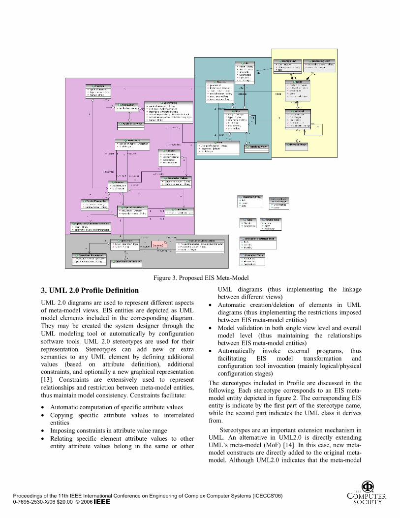
Figure 3. Proposed EIS Meta-Model
3. UML 2.0 Profile Definition UML 2.0 diagrams are used to represent different aspects of meta-model views. EIS entities are depicted as UML model elements included in the corresponding diagram.They may be created the system designer through the UML modeling tool or automatically by configuration software tools. UML 2.0 stereotypes are used for their representation. Stereotypes can add new or extra semantics to any UML element by defining additional values (based on attribute definition), additional constraints, and optionally a new graphical representation [13]. Constraints are extensively used to represent relationships and restriction between meta-model entities, thus maintain model consistency. Constraints facilitate:
• Automatic computation of specific attribute values • Copying specific attribute values to interrelated
entities • Imposing constraints in attribute value range • Relating specific element attribute values to other
entity attribute values belong in the same or other
UML diagrams (thus implementing the linkage between different views)
• Automatic creation/deletion of elements in UML diagrams (thus implementing the restrictions imposed between EIS meta-model entities)
• Model validation in both single view level and overall model level (thus maintaining the relationships between EIS meta-model entities)
• Automatically invoke external programs, thus facilitating EIS model transformation and configuration tool invocation (mainly logical/physical configuration stages)
The stereotypes included in Profile are discussed in the following. Each stereotype corresponds to an EIS meta-model entity depicted in figure 2. The corresponding EIS entity is indicate by the first part of the stereotype name, while the second part indicates the UML class it derives from.
Stereotypes are an important extension mechanism in UML. An alternative in UML2.0 is directly extending UML’s meta-model (MoF) [14]. In this case, new meta-model constructs are directly added to the original meta-model. Although UML2.0 indicates that the meta-model
Proceedings of the 11th IEEE International Conference on Engineering of Complex Computer Systems (ICECCS'06)0-7695-2530-X/06 $20.00 © 2006
and stereotype extension mechanism have some overlap in the aspects of extension capability, it does not explain in which circumstances each one of them is best suited [15]. In the case of EIS modeling, it was decided to link UML stereotypes to EIS meta-model, rather than defining a new MoF, since our main goal was to use existing software tools to implement the proposed configuration methodology. Thus, our aim was to extend existing UML modeling platforms (for example Rational Modeler).
In the following, EIS configuration profile is briefly presented.
Application ViewFor each application operating in the EIS, a discrete Application View is defined. Applications are conceived as sets of interacting modules (either server or client), such as Application Servers, Database Server, etc. Each module offers specific services. File Server modules are used for file storage. User behavior is also described in the Application View, through user profiles activating client modules. Each profile includes user requests, which invoke specific services. Service implementation consists of simple tasks occurring upon module activation, called operations. These are selected from a predefined operation set, that is, the operation dictionary. Thus, an Application View comprises an external part showing the interactions among services and hence among application modules, and several internal parts, one for every service appearing in the external part (see figure 2).
The external Application View is represented as a UML use case diagram. Use cases in UML are means for specifying system functionality. As such, they are suitable for the representation of services. Services represent a coherent unit of functionality provided by a system, thus they are modeled as use cases (service use casestereotype), and the owning modules as packages (module package stereotype). A FileServer Module Package is used to manage files, thus a fileList must be filled. For each file the name, size and specific characteristics (whether it is executable or data, shareable, updatable and replicable) must be defined, the fileList contains records of this specific structure. The relation among services can be pertinently modeled using the Include relationship defined between use cases. User profiles are represented by UserProfileActor, which is defined as a stereotype of the Actor classifier. An Actor in UML use case diagrams may initiate a function represented by a use case. Likewise, a user profile may initiate the execution of a specific service. Therefore, the relationship between a user profile and a component is represented by the stereotype Initiates which is defined as a specialization of Association classifier connecting an actor to a use case in use case diagrams. An example of an external Application View is depicted in figure 4 (Case Study section).
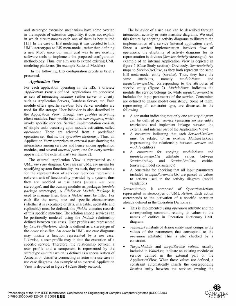
The behavior of a use case can be described through interaction, activity or state machine diagrams. We used this feature by adopting activity diagrams to illustrate the implementation of a service (internal application view). Since a service implementation involves flow of operations, the eligibility of activity diagrams for its representation is obvious (Service Activity stereotype). An example of an internal Application View is depicted in figure 5 (Case Study section). Obviously, ServiceActivitymaps to ServiceUseCase, as they both represent the same EIS meta-model entity (service). Thus, they have the same attributes, namely moduleName and inputParameterList, corresponding to the attributes of service entity (figure 2). ModuleName indicates the module the service belongs to, while inputParameterListincludes the input parameters of the service. Constraints are defined to ensure model consistency. Some of them, representing all constraint type, are discussed in the following. • A constraint indicating that only one activity diagram
can be defined per service (ensuring service entity restrictions and implement linkage between the external and internal part of the Application View)
• A constraint indicating that each ServiceUseCasemust be related to an existing ModulePackage(representing the relationship between service and module entities)
• A constraint for copying moduleName and inputParameterList attribute values between ServiceActivity and ServiceUseCase entities (ensuring model consistency)
• A constraint for checking that all input parameters included in inputParameterList are passed as values to actions used in the activity diagram (model validation)
ServiceActivity is composed of OperationActionsrepresented as stereotypes of UML Action. Each action corresponds to the activation of a specific operation already defined in the Operation Dictionary. • This is implemented using operation attribute and the
corresponding constraint relating its values to the names of entities in Operation Dictionary UML diagram.
• ValueList attribute of Action entity must comprise the values of the parameters that correspond to the operation attribute. This is also checked by a constraint.
• TargetModule and targetService values, usually included in ValueList, indicate an existing module or service defined in the external part of the ApplicationView. When these values are defined, a constraint automatically inserts the corresponding Invokes entity between the services owning the
Proceedings of the 11th IEEE International Conference on Engineering of Complex Computer Systems (ICECCS'06)0-7695-2530-X/06 $20.00 © 2006
specific action and the target service in the external part of the Application View (thus implementing the constraints imposed between invocation and operation action EIS meta-model entity values).
Operation Dictionary Use case diagrams are chosen for the representation of operation dictionary, since each operation represents a functionality unit in the same way that a use case represents a functionality unit in UML. Operations used in activity diagrams for describing process component are characterized as application operations (application use case stereotype). Operations must be ultimately decomposed into elementary ones (i.e. processing, storing and transferring) to estimate the QoS required from the underlying network (elementary use case stereotype).Intermediate operations are needed to simplify operation decomposition (intermediate use case stereotype) (see figure 2).
It is important for the system designer to further extend the operation dictionary to describe the functionality of specific applications. The designer may add operations (as use cases) in the Operation Dictionary diagram except of elementary ones. When defining a new operation, the system designer must add it in the diagram, specify its parameters and relate it to existing operations involved in its description. All these actions are controlled by constraints.
Physical View Physical view comprises the network infrastructure. UML deployment diagrams are commonly used to represent network architectures [16]. The overall network (NetworkPackage) is decomposed to subnetworks (NetworkPackage), producing thus a hierarchical structure. LANs typically form the lowest level of the decomposition. Devices, such as servers (ServerDevice)and workstations (WorkstationDevice) are associated with LANs of the lowest level. Devices may include a processing unit (ProcessUnitDevice), and a storage unit (StorageUnitDevice). Constraints mainly represented relationships and restrictions between Physical and Topology views of EIS meta-model and relate aforementioned stereotypes to corresponding Topology view stereotypes, thus they are discussed in the following paragraph.
Topology View Topology view comprises sites, processes (defined as instances of application modules), file replicas (stored in corresponding File Server processes) and users (defined as instances of user profiles) (see figure 2). Two types of sites are supported: composite, composed by others, and atomic, not further decomposed, constituting therefore the
lowest level of site hierarchy. Users, processes and files are associated to atomic sites. In essence, the hierarchy indicates where (in which location) each process runs and user is placed. The site hierarchy should correspond to the network hierarch depicted in the physical view, while processes, files and users are related to nodes (server or workstation) included in the physical view.
The representation of Topology View is based on UML component diagrams. Component diagrams representing topology views and deployment diagrams representing physical views are interrelated. This is facilitated by the relationship between node and component model entities already supported in core UML meta-model. Sites are represented as Packages(SitePackage stereotype) SitePackages relate to each other through membership relation, as introduced in UML 2.0. SitePackages are related to ServerComponents,ClientComponents and UserProfileActors by the membership relation as well. Processes, files and users are modeled as UML component (Serve/ FileServer/ Client ProcessComponent stereotypes, FileComponentstereotype UserComponent stereotype) and ClientReplica Component). The defined stereotypes are analytically described in the Topology View table of Appendix A. Avg/Max network and processing req attributes indicate the corresponding site/ process requirements. They are automatically computed during logical configuration. Sine this is performed progressively, they might be computed more than once.
Both views can be either defined by the system designer or automatically composed by logical and physical configuration tools. The introduction of progressive site refinement, as well as the mapping of site range onto network range, enables the identification of dependencies between application configuration and network topology [3]. A topology view example and the corresponding physical view are depicted in figures 7 and 9 (Case Study section). Some of the constraints implementing the restrictions imposed between Topology and Physical Views are discussed in the following: • Network and site hierarchy must be identical, thus
corresponding network and site packages must have corresponding parents. A corresponding constraint is defined for both entities.
• A constraint is defined to add/delete network/site packages in the corresponding diagram, in order to make network and site hierarchies identical.
• A constraint is used to initiate the corresponding logical or physical configuration tool, whenever the site or network hierarch is changed.
• A constraint is used to relate processes, files and users to existing application modules, file server modules and user profiles in an application view.
Proceedings of the 11th IEEE International Conference on Engineering of Complex Computer Systems (ICECCS'06)0-7695-2530-X/06 $20.00 © 2006
Topology View may contain components related to entities belonging in different Application Views.
• Constraints are used to ensure that server process components are related to server devices, user components are related to workstation devices, and file are related to storage unit devices belonging to server devices where a file server component is allocated.
It is obvious, that constraint definition is a powerful mechanism to represent the dependencies between Topology and Physical View in a similar fashion for both the user (system designer) and configuration software tools.
4. Implementation Issues The implementation of the proposed UML 2.0 profile in a UML modeling tool is essential to provide the implementation framework proposed in figure 3. The selected UML tool must facilitate mechanisms to extend provided functionality (e.g. by importing profiles) and export models in XML based on existing UML classes and profile specific stereotypes. Tool selection process was not an easy task. Although there were a lot of tools supporting UML 2.0, most of them are not easily extended, while at the same time exporting capabilities are limited. There are tools facilitating the definition of stereotypes and they properties, but do not support the API needed to implement constraints for automatic entity creation, entity validation and external program invocation. Most tools do not support XMI export for all the UML objects based on the stereotypes of all the diagrams used in EIS Configuration Profile.
We explored the possibility of implementing the profile in the Rational Modeler environment [17]. The extensibility features in the Rational Modeler are built on the open-source Eclipse components. The following extensions had to be implemented: stereotypes, their attributes and constraints, and script-like programs, as pluglets, to access and modify model information and Eclipse plug-ins that use model information to further enhance the workbench of the proposed alternative views. Although the definition of stereotypes and their attributes was trivial, we experienced a lot of difficulty using its API due to poor documentation, performance and bugs. Furthermore, we explored ULM 2.0 Object Constraint Language (OCL) [18], to represent and manage constraints within Rational Modeler. In order to write unambiguous constraints, so-called formal languages have been developed and OCL is one of them. Since Rational Modeler supports OCL, we explored related features. Although it was efficient of attribute related constraints, we could not implement constraints related to API programming.
We implemented most of the features of the proposed profile in Rational Rose tool [19], in order to test the overall concept. Rational Rose tool, although does not support UML 2.0, is a stable programming environment with a documented API, supporting the implementation of stereotypes, facilitating the definition of profiles and providing advanced export capabilities. Although UML 2.0 specific features, as membership notation used for the connections between sites and process/user profile instances in the Topology view were simplified, Rational Rose provided a rapid prototype environment to test our ideas in less than a month time. Though, the interaction with EIS meta-model stored in XML, was not seamlessly performed, since the transformation of XMI export for UML entities into the proposed meta-model and vise-versa was tricky since it was not UML 2.0 compliant.
Although a lot of work is done in UML 2.0 modeling tools, there are still not mature enough to facilitate a reliable API. Nevertheless, they are rapidly improving. We are currently struggling with the latest version of Modeler, hoping to solve remaining programming issues.
The profile is currently tested in terms of completeness and expressiveness, using large-scale EIS architectures as test cases.
5. Case Study In the following, the configuration process of a typical banking system using EIS Configuration Profile is discussed. We focus on teller transaction to demonstrate profile capabilities. The system supports 38 discrete teller transactions. The amount of transactions/day varies according to branch size, while the average amount of teller transactions in large branches is over 10.000 per day. The required response time is 15-18 sec for most transactions.
The system architecture is based on server-based computing. A central database is installed in headquarters, while transaction logs are maintained in local databases each branch. Transactions are coordinated by a transaction monitoring system – TMS (Tuxido), also installed in headquarters. Transactions are composed by 24 discrete atomic transactions initiated by TMS. Each transaction consists of 3 to 7 atomic ones. All atomic transactions are implemented by stored procedures running in the central database. To enhance security and facilitate a single authentication point, all user programs run on a dedicated execution server (CITRIX), while in user terminals only the corresponding client (CITRIX client) is installed.
Proceedings of the 11th IEEE International Conference on Engineering of Complex Computer Systems (ICECCS'06)0-7695-2530-X/06 $20.00 © 2006
Application View The following application modules were identified: File Server, CentralDB, LocalDB, TMS and Citrix. Since LocalDB represents logging, only a simple insert service was implemented for recording the log. CentralDBsupports 33 stored procedures, represented as a different service. TMS Module includes 24 services corresponding to discrete atomic transactions. Citrix Module includes 38 services corresponding to discrete teller transactions. They involve the invocation and processing of forms, the activation of atomic transactions through TMS and log recording. Tellers are modeled as User Profiles initiating CITRIX Client modules corresponding to each teller transaction.
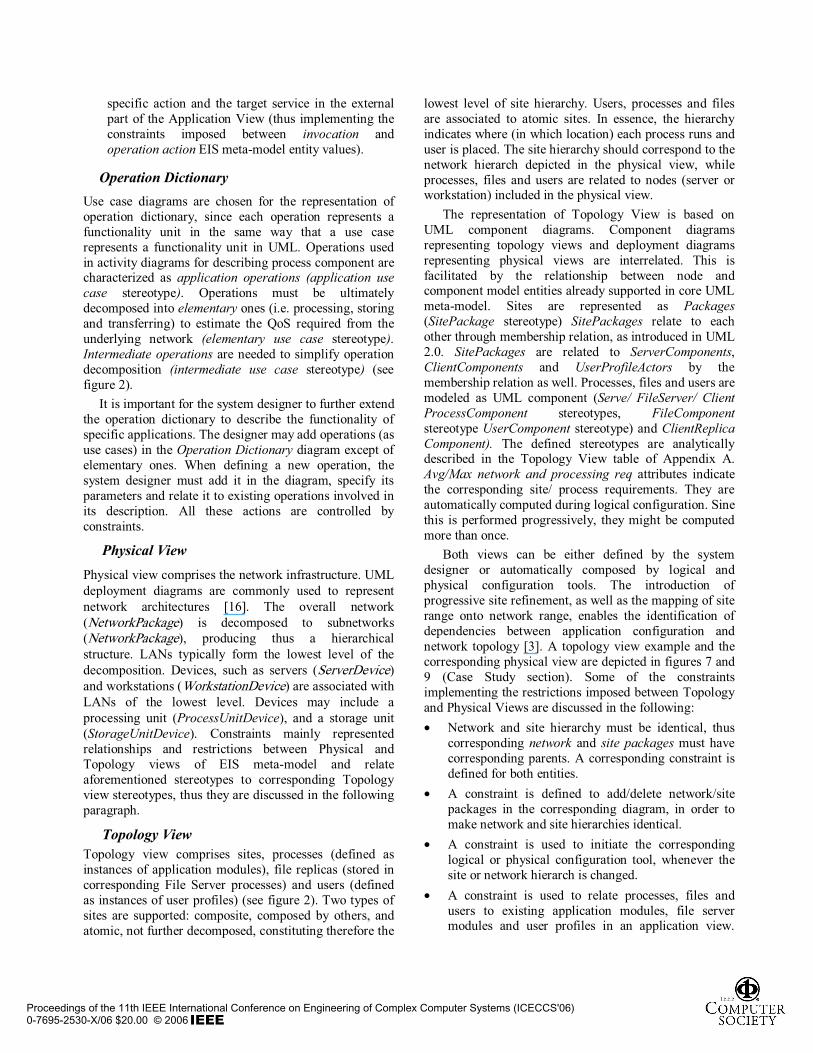
Figure 4 represents a fraction of the Application View emphasizing services needed for the representation of transactions trx31600 - Cash deposit, and trx2000 - Request business loan. As depicted in the figure services are represented as use case stereotypes and modules as package stereotypes.
Figure 4: Fraction of the Application view – Transactions trx31600 and trx2000
The trx31600 service of the Citrix Module is initiated by trx31600_invoke service of the CitrixClient Client Module. In figure 4, the corresponding Service Usecase is selected. Additional stereotype attributes are stored in Documentation field supported within Rational Rose platform (bottom left corner of figure 4). They are added by system designer through custom menu created using Rational Rose API. In this case, only the module attribute is filled, since the service has no input parameters (inputParameterList attribute is emply). The corresponding activity diagram is considered as a subdiagram of Application View UseCase diagram. It is represented in figure 5. As shown in the figure, trx31600 is composed by the activation of the appropriate forms, the activation of the central database through the TMS
and local database update. Each discrete step is represented by an action instantiating a predefined operation included in the Operation Dictionary.
Figure 5: Trx31600 activity diagram When defining an action, all input parameters values of the corresponding operation must filled. They must be either constant or already defined as trx31600 service input parameters. As show in figure 5, all operation input parameters must be constant, since trx31600 service has no inputParameterList. The corresponding validation constraint is implemented as a custom script initiated by Validate menu (upper right corner of figure 5). Some of the actions, as request (selected in figure 5), result in the invocation of other services. A constraint automatically adds the corresponding invoke entity between service use cases in the Application View (figure 3). The invoke entity has the same name as the action.
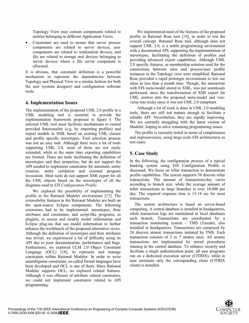
Operation Dictionary Figure 6 represents a fragment of the operation dictionary. All operations are decomposed into elementary ones (processing, diskIO, network). The system designer may add new operations in the dictionary. In the figure 6, the addition form_access operation is presented. Three steps should be accomplished: parameter definition, definition of dependencies to existing operations and validation performance. Related constraint checks if all the parameters defined for an operation are passed as values to called operations used for its execution. Parameter and dependency definition is performed through pop-up forms. Form_access operation parameters are FileServer, form_name and processing. Form_access operation “uses” two other operations in order to be executed: processing and write. First, calls processing (which is elementary operation) and then write and then again processing. Parameters values of the called operation must be defined. The pop-up window entitled “Fill Outgoing Dependencies” depicts write operation parameter definition.
Proceedings of the 11th IEEE International Conference on Engineering of Complex Computer Systems (ICECCS'06)0-7695-2530-X/06 $20.00 © 2006
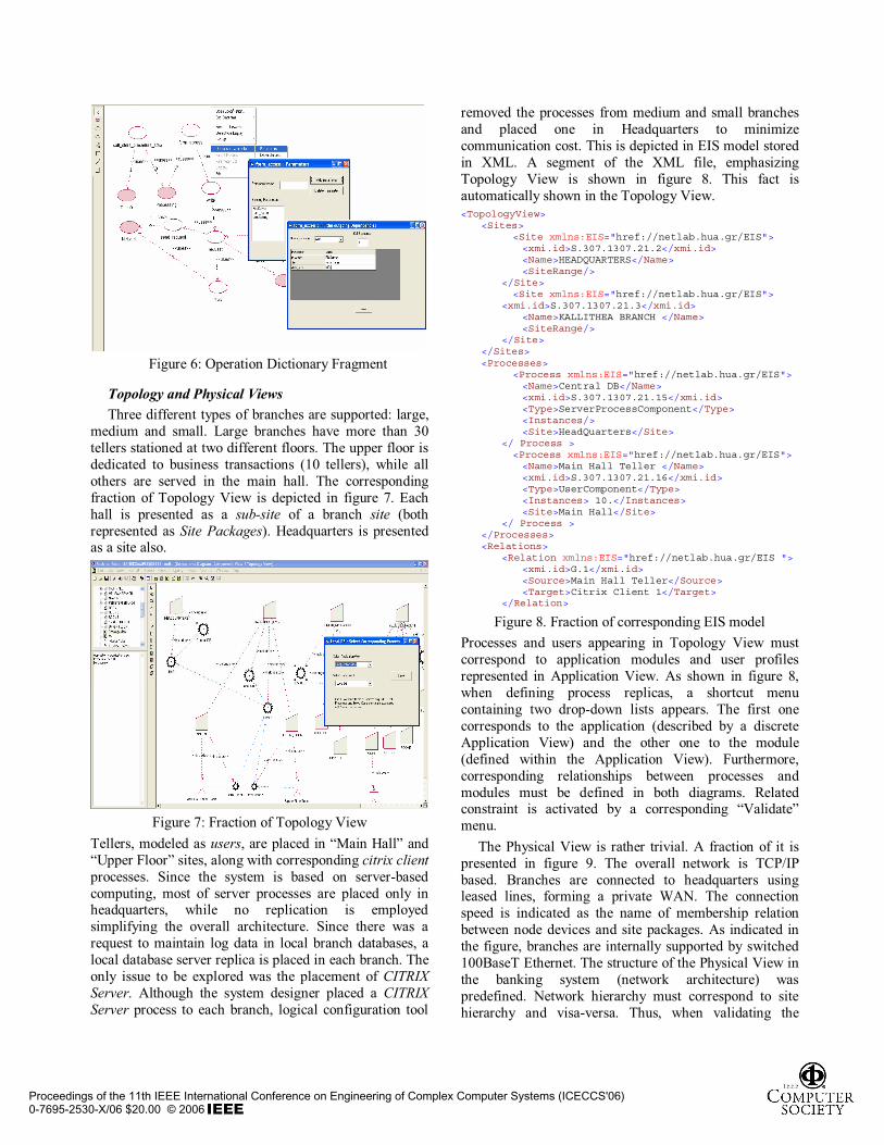
Figure 6: Operation Dictionary Fragment
Topology and Physical Views Three different types of branches are supported: large,
medium and small. Large branches have more than 30 tellers stationed at two different floors. The upper floor is dedicated to business transactions (10 tellers), while all others are served in the main hall. The corresponding fraction of Topology View is depicted in figure 7. Each hall is presented as a sub-site of a branch site (both represented as Site Packages). Headquarters is presented as a site also.
Figure 7: Fraction of Topology View Tellers, modeled as users, are placed in “Main Hall” and “Upper Floor” sites, along with corresponding citrix clientprocesses. Since the system is based on server-based computing, most of server processes are placed only in headquarters, while no replication is employed simplifying the overall architecture. Since there was a request to maintain log data in local branch databases, a local database server replica is placed in each branch. The only issue to be explored was the placement of CITRIX Server. Although the system designer placed a CITRIX Server process to each branch, logical configuration tool
removed the processes from medium and small branches and placed one in Headquarters to minimize communication cost. This is depicted in EIS model stored in XML. A segment of the XML file, emphasizing Topology View is shown in figure 8. This fact is automatically shown in the Topology View. <TopologyView>
<Sites><Site xmlns:EIS="href://netlab.hua.gr/EIS"><xmi.id>S.307.1307.21.2</xmi.id><Name>HEADQUARTERS</Name><SiteRange/>
</Site><Site xmlns:EIS="href://netlab.hua.gr/EIS">
<xmi.id>S.307.1307.21.3</xmi.id><Name>KALLITHEA BRANCH </Name><SiteRange/>
</Site></Sites><Processes>
<Process xmlns:EIS="href://netlab.hua.gr/EIS"><Name>Central DB</Name><xmi.id>S.307.1307.21.15</xmi.id><Type>ServerProcessComponent</Type><Instances/>
<Site>HeadQuarters</Site></ Process ><Process xmlns:EIS="href://netlab.hua.gr/EIS"><Name>Main Hall Teller </Name><xmi.id>S.307.1307.21.16</xmi.id><Type>UserComponent</Type><Instances> 10.</Instances>
<Site>Main Hall</Site></ Process >
</Processes><Relations>
<Relation xmlns:EIS="href://netlab.hua.gr/EIS "><xmi.id>G.1</xmi.id><Source>Main Hall Teller</Source><Target>Citrix Client 1</Target>
</Relation>
Figure 8. Fraction of corresponding EIS model Processes and users appearing in Topology View must correspond to application modules and user profiles represented in Application View. As shown in figure 8, when defining process replicas, a shortcut menu containing two drop-down lists appears. The first one corresponds to the application (described by a discrete Application View) and the other one to the module (defined within the Application View). Furthermore, corresponding relationships between processes and modules must be defined in both diagrams. Related constraint is activated by a corresponding “Validate” menu.
The Physical View is rather trivial. A fraction of it is presented in figure 9. The overall network is TCP/IP based. Branches are connected to headquarters using leased lines, forming a private WAN. The connection speed is indicated as the name of membership relation between node devices and site packages. As indicated in the figure, branches are internally supported by switched 100BaseT Ethernet. The structure of the Physical View in the banking system (network architecture) was predefined. Network hierarchy must correspond to site hierarchy and visa-versa. Thus, when validating the
Proceedings of the 11th IEEE International Conference on Engineering of Complex Computer Systems (ICECCS'06)0-7695-2530-X/06 $20.00 © 2006
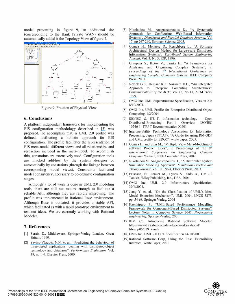
model presenting in figure 9, an additional site (corresponding to the Bank Private WAN) should be automatically added it the Topology View of figure 7.
Figure 9: Fraction of Physical View
6. Conclusions A platform independent framework for implementing the EIS configuration methodology described in [3] was proposed. To accomplish that, a UML 2.0 profile was defined, facilitating a holistic approach for EIS configuration. The profile facilitates the representation of EIS meta-model different views and all relationships and restriction included in the meta-model. To accomplish this, constraints are extensively used. Configuration tools are invoked add-hoc by the system designer or automatically by constraints (through the linkage between corresponding model views). Constraints facilitated model consistency, necessary to co-ordinate configuration stages.
Although a lot of work is done in UML 2.0 modeling tools, there are still not mature enough to facilitate a reliable API, although they are rapidly improving. The profile was implemented in Rational Rose environment. Although Rose is outdated, it provides a stable API, which facilitated as with a rapid prototype environment to test out ideas. We are currently working with Rational Modeler.
7. References [1] Serain D., Middleware, Springer-Verlag London, Great
Britain, 1999. [2] Savino-Vázquez N.N. et al., “Predicting the behaviour of
three-tiered applications: dealing with distributed-object technology and databases”, Performance Evaluation, Vol. 39, no 1-4, Elsevier Press, 2000.
[3] Nikolaidou M., Anagnostopoulos D., “A Systematic Approach for Configuring Web-Based Information Systems”, Distributed and Parallel Database Journal, Vol 17, pp 267-290, Springer Science, 2005.
[4] Gomaa H., Menasce D., Kerschberg L., “A Software Architectural Design Method for Large-scale Distributed Information Systems”, Distributed System Engineering Journal, Vol. 3, No 3, IOP, 1996.
[5] Graupner S., Kotov V., Trinks H., “A Framework for Analyzing and Organizing Complex Systems”, in Proceedings of the 7th International Conference on Engineering Complex Computer Systems, IEEE Computer Press, 2001.
[6] Nezlek G.S., Hemant K.J., Nazareth D.L., “An Integrated Approach to Enterprise Computing Architectures”, Communications of the ACM, Vol 42, No 11, ACM Press, 1999.
[7] OMG Inc, UML Superstructure Specification, Version 2.0, 8/10/2004.
[8] OMG Inc, UML Profile for Enterprise Distributed Object Computing, 1/2/2004.
[9] ISO/IEC & ITU-T, Information technology – Open Distributed Processing – Part 1 – Overview – ISO/IEC 10746-1 | ITU-T Recommendation X.901.
[10] Interoperability Technology Association for Information Processing, Japan (INTAP), “A Guide for using RM-ODP and UML profile for EDOC”, white paper, 2005.
[11] Gomaa H. and Shin M., “Multiple View Meta-Modeling of software Product Lines”, in Proceedings of the 8th
International Conference on Engineering Complex Computer Systems, IEEE Computer Press, 2002.
[12] Nikolaidou M. Anagnostopoulos D., "A Distributed System Simulation Modeling Approach", Simulation Practice and Theory Journal, Vol. 11, No 4, Elsevier Press, 2003.
[13] Eriksson, H., Penker M., Lyons S., Fado D., UML 2 Toolkit, Wiley Publishing, Inc., USA, 2004.
[14] OMG Inc, UML 2.0 Infrastructure Specification, 30/4/2004.
[15] Jiang Y, et. al,. “On the Classification of UML’s Meta Model Extension Mechanism”, UML 2004, LNCS 3273, pp. 54-68, Springer Verlag, 2004
[16] Kaehkipuro P., “UML-Based Performance Modelling Framework for Component-Based Distributed Systems”, Lecture Notes in Computer Science 2047, Performance Engineering, Springer-Verlag, 2001
[17] IBM Co, Introducing Rational Software Modeler, http://www-128.ibm.com/developerworks/rational/ library/05/329_kunal/
[18] OMG Inc, UML 2.0 OCL Specification 14/10/2003. [19] Rational Software Corp, Using the Rose Extensibility
Interface, White Paper, 2001.
Proceedings of the 11th IEEE International Conference on Engineering of Complex Computer Systems (ICECCS'06)0-7695-2530-X/06 $20.00 © 2006