a survey on narrow band power line carrier communication
TRANSCRIPT
A Survey on Narrow Band Power Line Carrier Communication for Efficient and Secure Data
Transmission in Smart Grid Applications
Chandralekha M1, Sumathi S2 {[email protected], [email protected]}
RNS Institute of Technology, Bengaluru 560098, India1,2
Abstract. The Power line carrier communication (PLCC) is in existence for many years but still is an active research area, mainly because it offers economical, geographical and technical advantage as it uses the electric grid for transmitting the data. To reduce the consumption of carbon-based fuel for power generation and its impact to the environment, the world is moving towards an efficient distributed energy production and management system called the smart grid. In smart grid the requirement of a consistent communication setup is very high, as it requires two-way information flow for efficient management of distributed energy resources in order to provide quality power to the consumers. In smart grid architecture, as many automation, controlling and monitoring systems are interconnected, the security is another challenging issue. Among different communication technologies, PLCC is the only alternate which could be compared to the wireless technology due to the duple usage of power line to transfer both power and data. In this context, PLCC is gaining wide acceptance as it can contribute in establishing smart grids in both developed and developing nations. In this paper we provide an overview of PLCC technology, power line channel modelling, coding schemes, modulation techniques and the application of PLCC.
Keywords: Power line carrier communication, OFDM (Orthogonal Frequency Division Multiplexing), forward error correction (FEC), mapping, smart grid, channel modelling.
1 Introduction
The basic principle of PLCC involves superimposing a high frequency carrier signal which contains the data at low energy levels over the 50 Hz power signal and then transmitted through power line. The carrier signal is received by PLCC receiver located on the same electrical network and then decoded to retrieve the transmitted data.
The history of PLCC is dated late 1920s, the power line communication was initially used in high voltage power lines for telecommunication application over long distance. The preliminary implementation of PLCC in medium voltage and low voltage power line are seen in 1950s and the solution was based on ultra-narrowband PLCC for applications like remote street light control [1]. Usage of medium and low voltage power distribution line for data transmission started in early 1990s. From late 2000s to date witnessed lot of research work in this technology, low data rate narrowband PLCC were evolved during this time. During last decade, next generation broadband PLCC technology is being introduced with high data rate
I3CAC 2021, June 07-08, Chennai, IndiaCopyright © 2021 EAIDOI 10.4108/eai.7-6-2021.2308770
up to 200MB/s utilizing frequency band of 1.5MHz to 30MHz[18]. Broadband PLCC find application in last mile internet services and high-speed in-house networking.
There are two classification in PLCC technology, first based on the distance it covers and the second based on the frequency range. Based on coverage there are three categories of PLCC [2],
• Short range – for short distance ranging from 0 to 80km. • Medium Range – for distance between 80 to 250km. • Long range – for distance greater than 250km.
Classification based on the bandwidth of the frequency with which PLCC operate are [2], • Ultra-narrowband (UNB) PLCC – Offers low data rate of up to 100b/s and operates
in band 300hz to 3Khz. • Narrowband PLCC – There are two types in this, low data rate (LDR) and high data
rate (HDR) and operates in the rage from 3Khz to 500Khz. As the name suggest the first one offers low data rate transmission whereas the later offers transmission rate ranging from few kilo bytes per second up to 500 kbps.
• Broadband PLCC – This provides high data transmission up to 200 megabytes per second and operates in the frequency band 1.5Mhz to 30Mhz.
In present days, high data rate (HDR) narrowband PLCC (NB PLCC) offering data rate up to 500kb/s is gaining interest as it finds specialized application in smart grid (SG). In this paper the focus is on HDR NB PLCC.
2 Regulation in PLCC technology
This section focuses on standards and regulation governing HDR NB PLCC. Like any other technology, the need for standardizing in PLCC technology is very high. With existing and future advanced modulation technologies, it is expected that more and more PLCC devices from different manufacturers will be sharing the same power line for data transmission. Without standardization in place, devices working for various application in the same power grid will interfere with one another resulting in inferior service to all stakeholders. Another importance aspect of standardisation in PLCC technology is to offer interoperability among PLCC devices in the network which are made to different PLCC standard. It may be also needed for the PLCC device to interact with devices of other communication protocol (wireless) for last mile connectivity. It is also required to comply to electromagnetic compatibility limits as the PLCC device coexist with other telecommunication equipment in its environment [3][4].
In different counties there are different guidelines which regulates the PLCC devices. The main governing body that regulate the use of the NB PLCC devices are: European Committee for Electrotechnical Standardization (CENELEC), Association of Radio Industries and Businesses (ARIB), Standardization Administration of People's Republic of China (SAC) and Federal Communications Commission (FCC). Table 1 shows the government regulations for PLCC in different regions.
Europe is advancing in implementing PLCC and is a prominent market for PLCC equipment. BS EN50065-1 standard is followed in Europe which specifies the requirements a PLCC equipment shall adhere. This standard specifies general requirements, the band of frequency and electromagnetic disturbances requirements to operate PLCC devices in low
voltage power lines. The standard specifies the frequency rage range from 3kHz to 148.5kHz which is further sub divided into four bands namely CENELEC-A, CENELEC-B, CENELEC-C and CENELEC-D band respectively. A-band (3-95 kHz), is dedicated for utility firms for the control and monitoring of power grid. There is no regulatory restriction for the usage ofB-band (95-125 kHz). The standard allots C-band (125-140 kHz) home/building automation and D-band (140-148.5 kHz), is meant for annunciation and security application. Electromagnetic compatibility for PLCC devices is regulated by BS EN50561- 1 standard, this specifies the limits and methods of measurement.
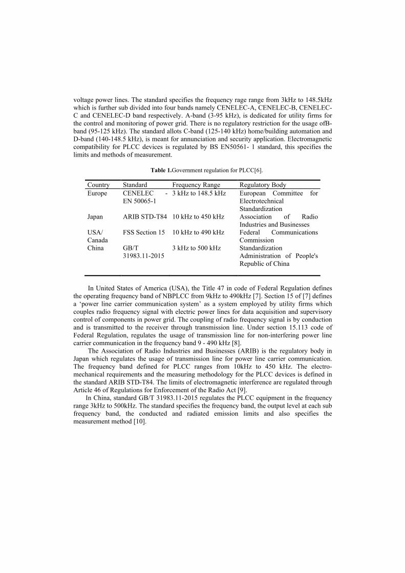
Table 1.Government regulation for PLCC[6].
Country Standard Frequency Range Regulatory Body Europe CENELEC -
EN 50065-1 3 kHz to 148.5 kHz European Committee for
Electrotechnical Standardization
Japan ARIB STD-T84 10 kHz to 450 kHz Association of Radio Industries and Businesses
USA/ Canada
FSS Section 15 10 kHz to 490 kHz Federal Communications Commission
China GB/T 31983.11-2015
3 kHz to 500 kHz Standardization Administration of People's Republic of China
In United States of America (USA), the Title 47 in code of Federal Regulation defines
the operating frequency band of NBPLCC from 9kHz to 490kHz [7]. Section 15 of [7] defines a ‘power line carrier communication system’ as a system employed by utility firms which couples radio frequency signal with electric power lines for data acquisition and supervisory control of components in power grid. The coupling of radio frequency signal is by conduction and is transmitted to the receiver through transmission line. Under section 15.113 code of Federal Regulation, regulates the usage of transmission line for non-interfering power line carrier communication in the frequency band 9 - 490 kHz [8].
The Association of Radio Industries and Businesses (ARIB) is the regulatory body in Japan which regulates the usage of transmission line for power line carrier communication. The frequency band defined for PLCC ranges from 10kHz to 450 kHz. The electro-mechanical requirements and the measuring methodology for the PLCC devices is defined in the standard ARIB STD-T84. The limits of electromagnetic interference are regulated through Article 46 of Regulations for Enforcement of the Radio Act [9].
In China, standard GB/T 31983.11-2015 regulates the PLCC equipment in the frequency range 3kHz to 500kHz. The standard specifies the frequency band, the output level at each sub frequency band, the conducted and radiated emission limits and also specifies the measurement method [10].
3 Standards in HDR NB PLCC
An outline of active HDR NB PLCC standards developed for smart grid application is reviewed here. Most HDR NB PLCC uses multicarrier modulation mainly Orthogonal Frequency Division Multiplexing (OFDM).Standards developed by Standard development organizations (SDO) International Telecommunication Union (ITU) and the Institute of Electrical and Electronics Engineer (IEEE) which uses OFDM is reviewed here.
ITU-T G.9901 [11] titled “Narrowband orthogonal frequency division multiplexing power line communication transceivers – Power spectral density specification.” This standard defines the control limits for spectral content, power spectral density (PSD) and masking requirements. It provides means to aid the saving of transmission PSD. The measurement methodology of PSD over transmission electric power line is defined in the standard. Further, the standard also specifies the limit of radio frequency signal energy for a constant terminal impedance. The system architecture, physical layer (PHY), and data link layer (DLL) defined in this standard is in line with the specifications given in ITU-T G.9904 (PRIME), ITU-T G.9902 (G.hnem) and ITU-T G.9903 (G3-PLC) [11].The transmitted output voltage specification of CENELEC frequency ranges from 3-148.5 kHz in accordance with EN50065-1 is applied. This defines the frequency range for different application and terminal output voltage in the operating band.
ITU-T G.9902 [12] titled “Narrowband orthogonal frequency division multiplexing power line communication transceivers for ITU-T G.hnem networks”. This standard provides the detailed specification of PHY layer and DLL for the OFDM based PLCC transmitter and receiver operating over both direct current (DC) and alternating current (AC) power lines. The frequency is up to 500 kHz for G.hnem network. This standard caters to both in-home and outdoor communications. The standard applies to communication in low voltage (LV) and medium-voltage (MV) power lines. It has defined the provisions for communication across distribution transformer in both LV-MV and MV-LV direction. This standard is used for smart grid applications like advanced metering infrastructure (AMI), control metering of electric vehicles charging, building automation and in-home network communications [12]. The coexistence mechanism defined under clause 5.1.2.3 of specification enable ITU-T G.9902 to coexist with multiple PLCC technology operating in the same power line channel.
ITU-T G.9903 Narrowband orthogonal frequency division multiplexing power line communication transceivers for G3-PLC networks. Like ITU-T G.9902, ITU-T G.9903 standard provides the detailed specification of PHY layer and DLL for the OFDM based PLCC transmitter and receiver operating over both direct current (DC) and alternating current (AC) power lines. The frequency is up to 500 kHz for G3-PLC network. This standard caters to both in-home and outdoor communications. The standard applies to communication in low voltage (LV) and medium-voltage (MV) power lines [13]. Through frequency division and via the preamble-based coexistence mechanism, the standard provides means of coexistence with other NB PLCC technologies.
ITU-T G.9904 Narrowband orthogonal frequency division multiplexing power line communication transceivers for PRIME networks.Like ITU-T G.9902 and ITU-T G.9903, standard provides the detailed specification of PHY layer and DLL for the OFDM based PLCC transmitter and receiver operating over both direct current (DC) and alternating current (AC) power lines. The frequency is up to 500 kHz for Powerline Intelligent Metering Evolution (PRIME). This standard caters to both in-home and outdoor communications. The standard applies to communication in low voltage (LV) and medium-voltage (MV) power lines [14]. There is no mention about coexistence.
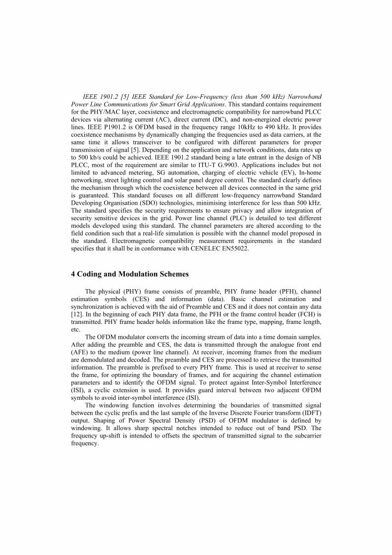
IEEE 1901.2 [5] IEEE Standard for Low-Frequency (less than 500 kHz) Narrowband Power Line Communications for Smart Grid Applications. This standard contains requirement for the PHY/MAC layer, coexistence and electromagnetic compatibility for narrowband PLCC devices via alternating current (AC), direct current (DC), and non-energized electric power lines. IEEE P1901.2 is OFDM based in the frequency range 10kHz to 490 kHz. It provides coexistence mechanisms by dynamically changing the frequencies used as data carriers, at the same time it allows transceiver to be configured with different parameters for proper transmission of signal [5]. Depending on the application and network conditions, data rates up to 500 kb/s could be achieved. IEEE 1901.2 standard being a late entrant in the design of NB PLCC, most of the requirement are similar to ITU-T G.9903. Applications includes but not limited to advanced metering, SG automation, charging of electric vehicle (EV), In-home networking, street lighting control and solar panel degree control. The standard clearly defines the mechanism through which the coexistence between all devices connected in the same grid is guaranteed. This standard focuses on all different low-frequency narrowband Standard Developing Organisation (SDO) technologies, minimising interference for less than 500 kHz. The standard specifies the security requirements to ensure privacy and allow integration of security sensitive devices in the grid. Power line channel (PLC) is detailed to test different models developed using this standard. The channel parameters are altered according to the field condition such that a real-life simulation is possible with the channel model proposed in the standard. Electromagnetic compatibility measurement requirements in the standard specifies that it shall be in conformance with CENELEC EN55022.
4 Coding and Modulation Schemes
The physical (PHY) frame consists of preamble, PHY frame header (PFH), channel estimation symbols (CES) and information (data). Basic channel estimation and synchronization is achieved with the aid of Preamble and CES and it does not contain any data [12]. In the beginning of each PHY data frame, the PFH or the frame control header (FCH) is transmitted. PHY frame header holds information like the frame type, mapping, frame length, etc.
The OFDM modulator converts the incoming stream of data into a time domain samples. After adding the preamble and CES, the data is transmitted through the analogue front end (AFE) to the medium (power line channel). At receiver, incoming frames from the medium are demodulated and decoded. The preamble and CES are processed to retrieve the transmitted information. The preamble is prefixed to every PHY frame. This is used at receiver to sense the frame, for optimizing the boundary of frames, and for acquiring the channel estimation parameters and to identify the OFDM signal. To protect against Inter-Symbol Interference (ISI), a cyclic extension is used. It provides guard interval between two adjacent OFDM symbols to avoid inter-symbol interference (ISI).
The windowing function involves determining the boundaries of transmitted signal between the cyclic prefix and the last sample of the Inverse Discrete Fourier transform (IDFT) output. Shaping of Power Spectral Density (PSD) of OFDM modulator is defined by windowing. It allows sharp spectral notches intended to reduce out of band PSD. The frequency up-shift is intended to offsets the spectrum of transmitted signal to the subcarrier frequency.
The medium here is electric transmission line and hence is very harsh communication
medium. Properties and characteristics of power line channel depends on many factors like frequency, environment, time and number of connected loads in the grid. Another issue associated with this type of wired communication medium is the electromagnetic interference offered by different type of equipment connected in the grid and is prominent at lower frequency band ranging from 10 - 200 kHz. The power line channel has background noise and is also subject to impulsive noise frequently appearing on power signal frequency of 50Hz. The channel experiences group delays of few hundred microseconds [13].
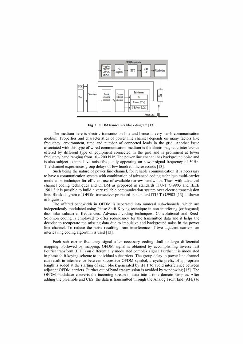
Such being the nature of power line channel, for reliable communication it is necessary to have a communication system with combination of advanced coding technique multi-carrier modulation technique for efficient use of available narrow bandwidth. Thus, with advanced channel coding techniques and OFDM as proposed in standards ITU-T G.9903 and IEEE 1901.2 it is possible to build a very reliable communication system over electric transmission line. Block diagram of OFDM transceiver proposed in standard ITU-T G.9903 [13] is shown in Figure 1.
The offered bandwidth in OFDM is separated into numeral sub-channels, which are independently modulated using Phase Shift Keying technique in non-interfering (orthogonal) dissimilar subcarrier frequencies. Advanced coding techniques, Convolutional and Reed-Solomon coding is employed to offer redundancy for the transmitted data and it helps the decoder to recuperate the missing data due to impulsive and background noise in the power line channel. To reduce the noise resulting from interference of two adjacent carriers, an interleaving coding algorithm is used [13].
Each sub carrier frequency signal after necessary coding shall undergo differential mapping. Followed by mapping, OFDM signal is obtained by accomplishing inverse fast Fourier transform (IFFT) on differentially modulated complex signal. Further it is modulated in phase shift keying scheme to individual subcarriers. The group delay in power line channel can result in interference between successive OFDM symbol, a cyclic prefix of appropriate length is added at the starting of each block generated by IFFT to avoid interference between adjacent OFDM carriers. Further out of band transmission is avoided by windowing [13]. The OFDM modulator converts the incoming stream of data into a time domain samples. After adding the preamble and CES, the data is transmitted through the Analog Front End (AFE) to
Fig. 1.OFDM transceiver block diagram [13].
the medium (power line channel). At receiver, incoming frames from the medium are demodulated and decoded. The preamble and CES are processed to retrieve the transmitted information [12].
The Power Spectral Density (PSD) and the frequency band for different modulation and transmission scheme is defined in ITU-T G.9901 [11], hence for a total of 128 subcarriers, the resulting IFFT size will be 256 [13]. The interleaving frequency bandwidth between the OFDM subcarriers is given by Fs/N, where N is the IFFT size and Fs is the sampling frequency. For CENELEC band and FCC band it evaluates to 1.56 kHz and 4.69 kHz respectively. Practically to avoid the inter-carrier interference (ICI), the number of actual subcarriers used will be much less than the theoretical value of 128. As per ITU-T G.9903 [13], the number of usable subcarriers is defined as 36 for the CENELEC-A band, 16 for the CENELEC-B band and 72 for the FCC band.
There are two modes in which the transceiver system works, normal and robust modes [13]. In normal mode, the forward error correction (FEC) is performed using Reed-Solomon (RS) coding and a convolutional encoder and differential modulation schemes DBPSK, DQPSK, and D8PSK is employed. In robust mode, for FEC in addition to Reed-Solomon and convolutional encoders a repetition coding is also employed to make the symbol robust.
The power line channel characteristic changes as on when an equipment is connected and withdrawn from the grid. Thus, an adaptive Channel estimation algorithm is desired. A feedback system is employed, wherein the receiver sends a feedback to transmitter about the quality of the received signal. Based on this feedback, the transmitter decides appropriate modulation scheme for transmission of subsequent packets of data to the receiver. It is also possible for the system to differentiates the subcarriers with low signal to noise ratio (SNR) and won’t transmit data through that sub carrier [13].
4.1 Forward Error Correction Coding
In normal mode, the FEC encoder consists of a Reed-Solomon (RS) and convolutional encoding. A repeat by four encoders is employed in robust mode of FEC, where the output bits from convolutional encoder is repeated by four times to improve the redundancy. There is one more option called the super robust mode, where the output bits from convolutional encoder is repeated by six times [5][13].
Reed-Solomon Encoder. The base of RS encoder is Galois Field Arithmetic. The data from scrambler is coded in short systematic coding using Galois Field [13]. The polynomial for the code generation is given by equation (1) [13],
(1) where T is the number of correctable symbol error, T=8 for normal mode and T=4 for robust mode. α is the primitive element that satisfies the field generation polynomial equation p(x) given by equation (2) [13],
(2) The Galois field 28 element of a data byte (d7, d6,….,d0) for primitive element α is identified as d7α7+ d6α6….+ d1α+ d0.
The standard ITU-TG.9903 allows the splitting of packets into two RS block, in such case the “TwoRSBlocks” bit is set as one in the FCH. In such case the data packet from scrambler is divided into two equal RS blocks. The two equal blocks are then pass through two RS encoder individually and same is the case with convolutional encoding that it shall be encoded separately. If needed shall be separately repetition coded and separately zero bit padded and then interleaved as a whole. Thus, repeat RS encoding increases the complexity but reduce the number of lost bits. Both differential and coherent modulation schemes can be adopted.
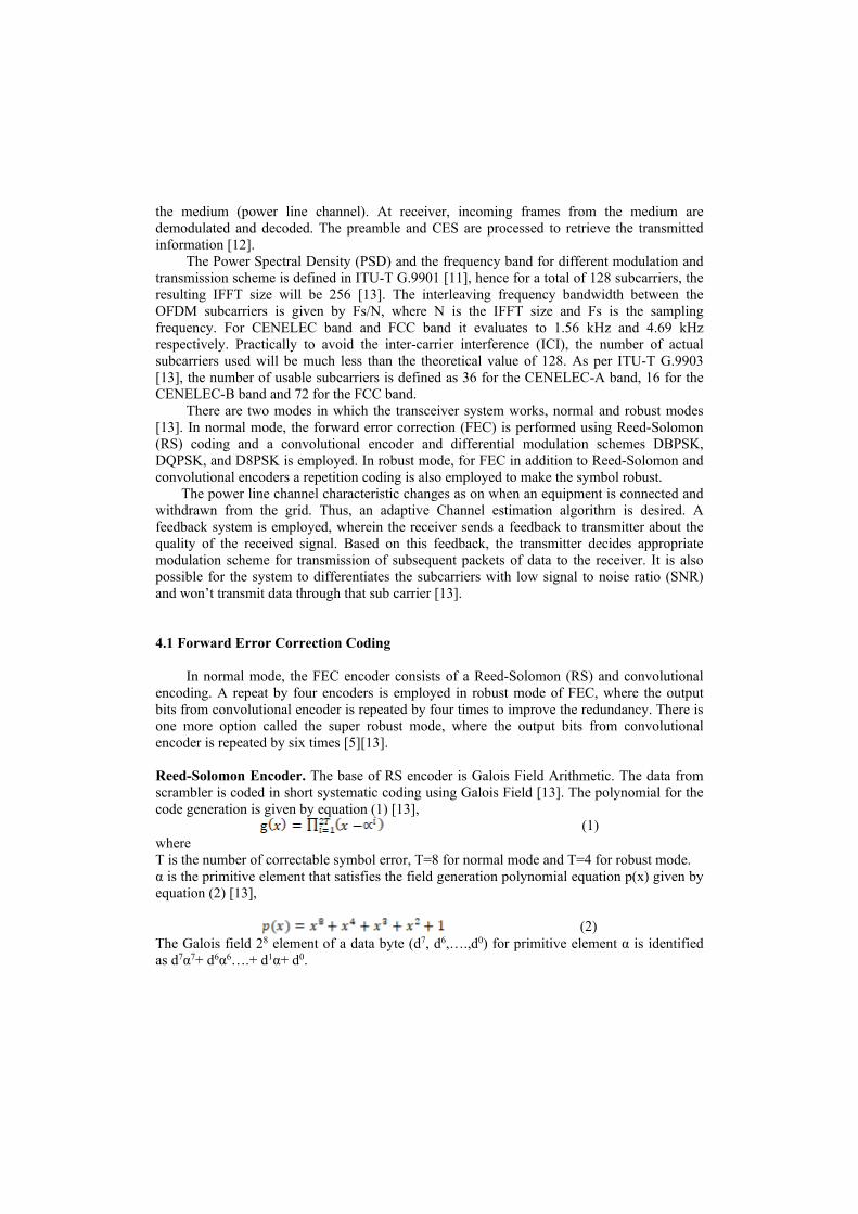
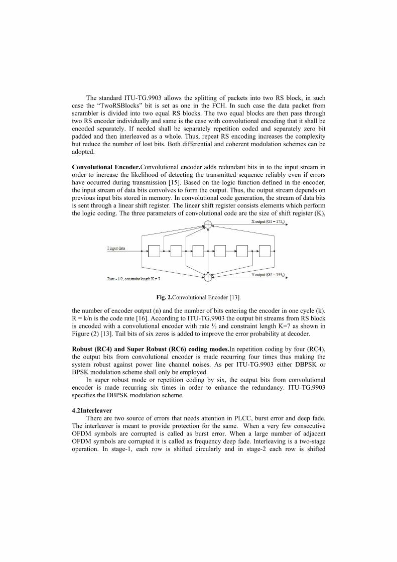
Convolutional Encoder.Convolutional encoder adds redundant bits in to the input stream in order to increase the likelihood of detecting the transmitted sequence reliably even if errors have occurred during transmission [15]. Based on the logic function defined in the encoder, the input stream of data bits convolves to form the output. Thus, the output stream depends on previous input bits stored in memory. In convolutional code generation, the stream of data bits is sent through a linear shift register. The linear shift register consists elements which perform the logic coding. The three parameters of convolutional code are the size of shift register (K),
the number of encoder output (n) and the number of bits entering the encoder in one cycle (k). R = k/n is the code rate [16]. According to ITU-TG.9903 the output bit streams from RS block is encoded with a convolutional encoder with rate ½ and constraint length K=7 as shown in Figure (2) [13]. Tail bits of six zeros is added to improve the error probability at decoder. Robust (RC4) and Super Robust (RC6) coding modes.In repetition coding by four (RC4), the output bits from convolutional encoder is made recurring four times thus making the system robust against power line channel noises. As per ITU-TG.9903 either DBPSK or BPSK modulation scheme shall only be employed.
In super robust mode or repetition coding by six, the output bits from convolutional encoder is made recurring six times in order to enhance the redundancy. ITU-TG.9903 specifies the DBPSK modulation scheme.
4.2Interleaver
There are two source of errors that needs attention in PLCC, burst error and deep fade. The interleaver is meant to provide protection for the same. When a very few consecutive OFDM symbols are corrupted is called as burst error. When a large number of adjacent OFDM symbols are corrupted it is called as frequency deep fade. Interleaving is a two-stage operation. In stage-1, each row is shifted circularly and in stage-2 each row is shifted
Fig. 2.Convolutional Encoder [13].
circularly. Thus, preventing frequency deep fade error and burst error to occur. Both elementary and block interleaver can be chosen according to the legacy mode.
4.3Coherent and Differential Mapping schemes
Conformance of transmitted symbol to the tone map and mask specified by the standard is ensured by mapping algorithm. The static system parameters, the start, stop and notch frequencies is predefined in tone mask. Adaptive selection of modulation based on channel estimation algorithm for communication between two modems is defined in tone map. The standard proposes two types of modulation mapping, coherent and differential mapping. In coherent modulation, data bits are mapped using the preamble phase vector ϕ of the same carrier as its reference. In differential modulation scheme, the data bits are mapped using the phase vector of same sub carrier and the previous symbol as its phase reference.
Table 2.Mapping and bit rate comparison.
Mapping Bits per constellation symbol Bit rate BPSK One 1 bit rate QPSK Two ½ bit rate 8PSK Three 1/3 bit rate 16QAM Four ¼ bit rate
Modulation size of mapping algorithm is the number of bits per symbol in constellation
diagram. As the number of bits per symbol increases in mapping algorithm, the gap between the points in constellation diagram decreases and thereby increasing the interference resulting in data errors. Comparison of different mapping and symbol rate is given in Table 2.
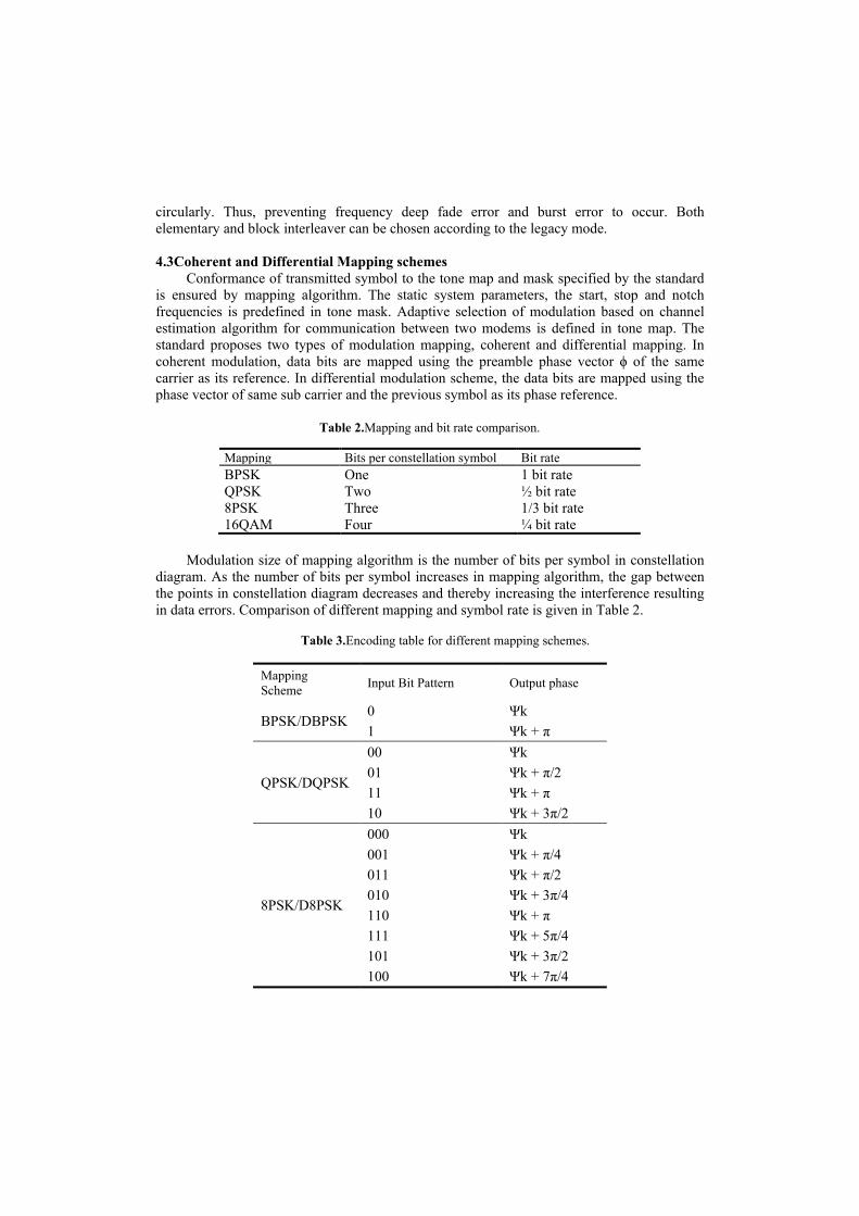
Table 3.Encoding table for different mapping schemes.
Mapping Scheme Input Bit Pattern Output phase
BPSK/DBPSK 0 Ψk 1 Ψk + π
QPSK/DQPSK
00 Ψk 01 Ψk + π/2 11 Ψk + π 10 Ψk + 3π/2
8PSK/D8PSK
000 Ψk 001 Ψk + π/4 011 Ψk + π/2 010 Ψk + 3π/4 110 Ψk + π 111 Ψk + 5π/4 101 Ψk + 3π/2 100 Ψk + 7π/4
The data encoding for coherent and differential mapping is given in Table 3. ψk is the output phase of the kth subcarrier. In case of differential mapping, the last bit in input bit pattern is from the previous symbol (from first interleaver matrix in case of first data symbol). In binary phase shift keying, “0” is represented by zero degrees and binary ''1'' is represented by a phase shift of 180 degrees. In the case of quadrature phase shift keying, the two bits are mapped such that the binary ''00'', ''01'', ''11'' and ''10'' is represented by phase shifts of 00, 900, 1800 and 2700 respectively. Similarly, in 8PSK 3 bits is mapped for the phase shifts of 00, 450, 900, 1350, 1800, 2250, 2700 and 3150 to indicate 000, 001, 011, 010, 110, 111, 101 and 100 respectively.
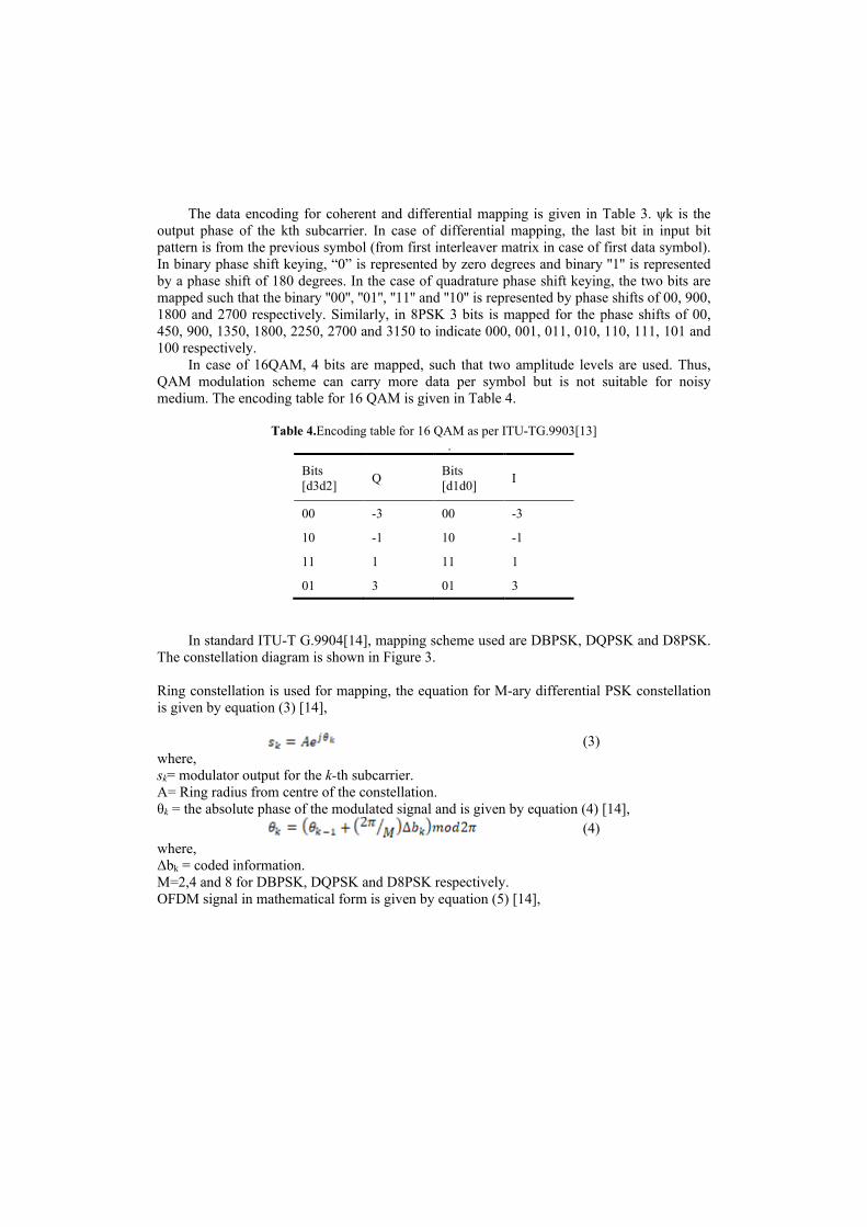
In case of 16QAM, 4 bits are mapped, such that two amplitude levels are used. Thus, QAM modulation scheme can carry more data per symbol but is not suitable for noisy medium. The encoding table for 16 QAM is given in Table 4.
Table 4.Encoding table for 16 QAM as per ITU-TG.9903[13]
.
Bits [d3d2] Q Bits
[d1d0] I
00 -3 00 -3
10 -1 10 -1
11 1 11 1
01 3 01 3
In standard ITU-T G.9904[14], mapping scheme used are DBPSK, DQPSK and D8PSK.
The constellation diagram is shown in Figure 3.
Ring constellation is used for mapping, the equation for M-ary differential PSK constellation is given by equation (3) [14],
(3) where, sk= modulator output for the k-th subcarrier. A= Ring radius from centre of the constellation. θk = the absolute phase of the modulated signal and is given by equation (4) [14],
(4) where, Δbk = coded information. M=2,4 and 8 for DBPSK, DQPSK and D8PSK respectively. OFDM signal in mathematical form is given by equation (5) [14],
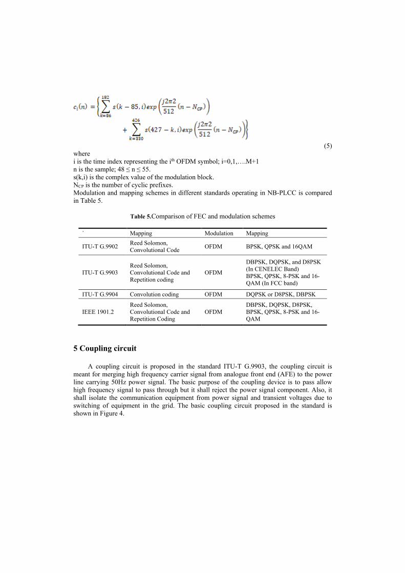
(5)
where i is the time index representing the ith OFDM symbol; i=0,1,….M+1 n is the sample; 48 ≤ n ≤ 55. s(k,i) is the complex value of the modulation block. NCP is the number of cyclic prefixes. Modulation and mapping schemes in different standards operating in NB-PLCC is compared in Table 5.
Table 5.Comparison of FEC and modulation schemes
` Mapping Modulation Mapping
ITU-T G.9902 Reed Solomon, Convolutional Code OFDM BPSK, QPSK and 16QAM
ITU-T G.9903 Reed Solomon, Convolutional Code and Repetition coding
OFDM
DBPSK, DQPSK, and D8PSK (In CENELEC Band) BPSK, QPSK, 8-PSK and 16-QAM (In FCC band)
ITU-T G.9904 Convolution coding OFDM DQPSK or D8PSK, DBPSK
IEEE 1901.2 Reed Solomon, Convolutional Code and Repetition Coding
OFDM DBPSK, DQPSK, D8PSK, BPSK, QPSK, 8-PSK and 16-QAM
5 Coupling circuit
A coupling circuit is proposed in the standard ITU-T G.9903, the coupling circuit is meant for merging high frequency carrier signal from analogue front end (AFE) to the power line carrying 50Hz power signal. The basic purpose of the coupling device is to pass allow high frequency signal to pass through but it shall reject the power signal component. Also, it shall isolate the communication equipment from power signal and transient voltages due to switching of equipment in the grid. The basic coupling circuit proposed in the standard is shown in Figure 4.
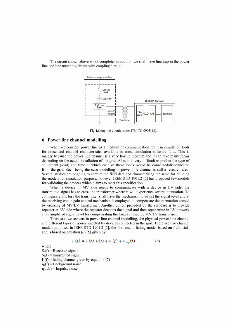
The circuit shown above is not complete, in addition we shall have line trap in the power
line and line matching circuit with coupling circuit.
6 Power line channel modelling When we consider power line as a medium of communication, built in simulation tools
for noise and channel characteristics available in most simulation software fails. This is mainly because the power line channel is a very hostile medium and it can take many forms depending on the actual installation of the grid. Also, it is very difficult to predict the type of equipment (load) and time at which each of these loads would be connected/disconnected from the grid. Such being the case modelling of power line channel is still a research area. Several studies are ongoing to capture the field data and characterising the same for building the models for simulation purpose, however IEEE STD 1901.2 [5] has proposed few models for validating the devices which claims to meet this specification.
When a device in MV side needs to communicate with a device in LV side, the transmitted signal has to cross the transformer where it will experience severe attenuation. To compensate this loss the transmitter shall have the mechanism to adjust the signal level and at the receiving end, a gain control mechanism is employed to compensate the attenuation caused by crossing of MV/LV transformer. Another option provided by the standard is to provide repeater at LV side where the repeater decodes the signal and then repenetrate in LV network at an amplified signal level for compensating the losses caused by MV/LV transformer.
There are two aspects in power line channel modelling, the physical power line channel and different types of noises injected by devices connected in the grid. There are two channel models proposed in IEEE STD 1901.2 [5], the first one, a fading model based on field trials and is based on equation (6) [5] given by,
(6)
where Sr(f) = Received signal. St(f) = transmitted signal. H(f) = fading channel given by equation (7) ηc(f) = Background noise ηimp(f) = Impulse noise.
Fig 4.Coupling circuit as per ITU-TG.9903[13].
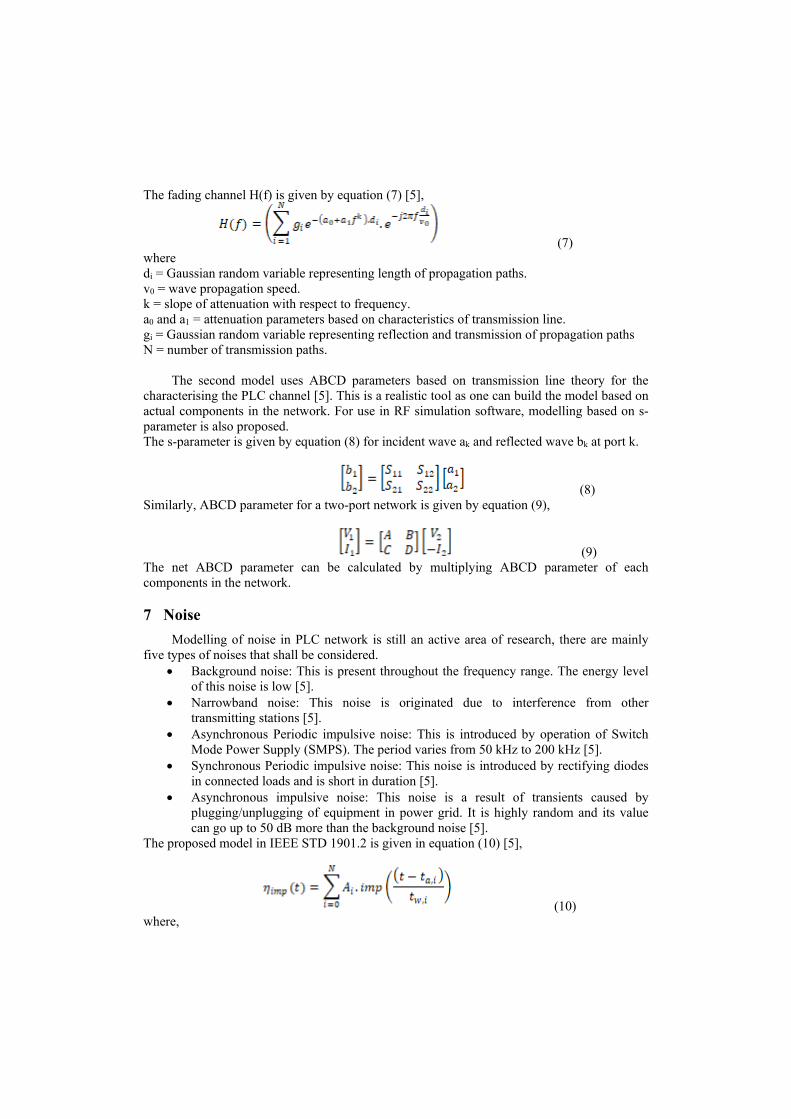
The fading channel H(f) is given by equation (7) [5],
(7) where di = Gaussian random variable representing length of propagation paths. v0 = wave propagation speed. k = slope of attenuation with respect to frequency. a0 and a1 = attenuation parameters based on characteristics of transmission line. gi = Gaussian random variable representing reflection and transmission of propagation paths N = number of transmission paths.
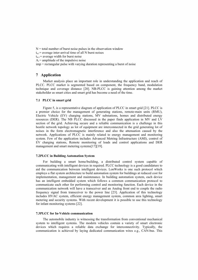
The second model uses ABCD parameters based on transmission line theory for the characterising the PLC channel [5]. This is a realistic tool as one can build the model based on actual components in the network. For use in RF simulation software, modelling based on s-parameter is also proposed. The s-parameter is given by equation (8) for incident wave ak and reflected wave bk at port k.
(8) Similarly, ABCD parameter for a two-port network is given by equation (9),
(9) The net ABCD parameter can be calculated by multiplying ABCD parameter of each components in the network. 7 Noise
Modelling of noise in PLC network is still an active area of research, there are mainly five types of noises that shall be considered.
• Background noise: This is present throughout the frequency range. The energy level of this noise is low [5].
• Narrowband noise: This noise is originated due to interference from other transmitting stations [5].
• Asynchronous Periodic impulsive noise: This is introduced by operation of Switch Mode Power Supply (SMPS). The period varies from 50 kHz to 200 kHz [5].
• Synchronous Periodic impulsive noise: This noise is introduced by rectifying diodes in connected loads and is short in duration [5].
• Asynchronous impulsive noise: This noise is a result of transients caused by plugging/unplugging of equipment in power grid. It is highly random and its value can go up to 50 dB more than the background noise [5].
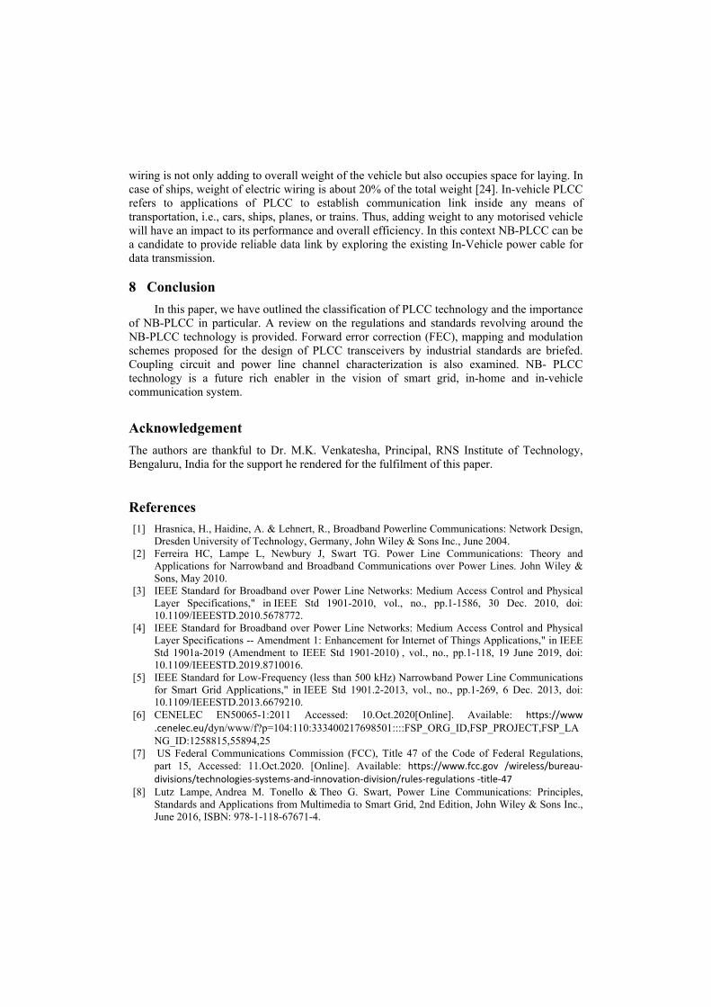
The proposed model in IEEE STD 1901.2 is given in equation (10) [5],
(10) where,
N = total number of burst noise pulses in the observation window ta,i = average inter-arrival time of all N burst noises tw,i = average width for burst noise Ai = amplitude of the impulsive noise imp = rectangular pulse with varying duration representing a burst of noise 7 Application
Market analysis place an important role in understanding the application and reach of PLCC. PLCC market is segmented based on component, the frequency band, modulation technique and coverage distance [20]. NB-PLCC is gaining attention among the market stakeholder as smart cities and smart grid has become a need of the time. 7.1 PLCC in smart grid
Figure 5, is a representative diagram of application of PLCC in smart grid [21]. PLCC is a premier choice for the management of generating stations, remote-main units (RMU), Electric Vehicle (EV) charging stations, MV substations, homes and distributed energy resources (DER). The NB PLCC discussed in the paper finds application in MV and LV section of the grid. Achieving secure and a reliable communication is a challenge in this hostile network topology as lot of equipment are interconnected in the grid generating lot of noises in the form electromagnetic interference and also the attenuation caused by the network. Applications of PLCC is mainly related to energy management and monitoring system. Few of the application includes Advanced Metring Infrastructure (AMI), control of EV charging stations, Remote monitoring of loads and control applications and DER management and smart metering systems[17][19].
7.2PLCC in Building Automation System
For building a smart home/building, a distributed control system capable of communicating with intelligent devices in required. PLCC technology is a good candidature to aid the communication between intelligent devices. LonWorks is one such protocol which employs a flat system architecture to build automation system for buildings at reduced cost for implementation, management and maintenance. In building automation system, each device has an intelligent embedded system which follows a common communication protocol to communicate each other for performing control and monitoring function. Each device in the communication network will have a transceiver and an Analog front end to couple the radio frequency signal from transceiver to the power line [23]. Application of this technology includes HVAC system, efficient energy management system, common area lighting, smart metering and security systems. With recent development it is possible to use this technology for infant monitoring systems [22].
7.3PLCC for In-Vehicle communication
The automobile industry is witnessing the transformation from conventional mechanical system to intelligent systems. The modern vehicles contain a variety of smart electronic devices which requires a reliable data exchange for interconnectivity. Typically, the communication is achieved by laying dedicated communication wires e.g., CAN-bus. This
wiring is not only adding to overall weight of the vehicle but also occupies space for laying. In case of ships, weight of electric wiring is about 20% of the total weight [24]. In-vehicle PLCC refers to applications of PLCC to establish communication link inside any means of transportation, i.e., cars, ships, planes, or trains. Thus, adding weight to any motorised vehicle will have an impact to its performance and overall efficiency. In this context NB-PLCC can be a candidate to provide reliable data link by exploring the existing In-Vehicle power cable for data transmission. 8 Conclusion
In this paper, we have outlined the classification of PLCC technology and the importance of NB-PLCC in particular. A review on the regulations and standards revolving around the NB-PLCC technology is provided. Forward error correction (FEC), mapping and modulation schemes proposed for the design of PLCC transceivers by industrial standards are briefed. Coupling circuit and power line channel characterization is also examined. NB- PLCC technology is a future rich enabler in the vision of smart grid, in-home and in-vehicle communication system.
Acknowledgement The authors are thankful to Dr. M.K. Venkatesha, Principal, RNS Institute of Technology, Bengaluru, India for the support he rendered for the fulfilment of this paper.
References
[1] Hrasnica, H., Haidine, A. & Lehnert, R., Broadband Powerline Communications: Network Design, Dresden University of Technology, Germany, John Wiley & Sons Inc., June 2004.
[2] Ferreira HC, Lampe L, Newbury J, Swart TG. Power Line Communications: Theory and Applications for Narrowband and Broadband Communications over Power Lines. John Wiley & Sons, May 2010.
[3] IEEE Standard for Broadband over Power Line Networks: Medium Access Control and Physical Layer Specifications," in IEEE Std 1901-2010, vol., no., pp.1-1586, 30 Dec. 2010, doi: 10.1109/IEEESTD.2010.5678772.
[4] IEEE Standard for Broadband over Power Line Networks: Medium Access Control and Physical Layer Specifications -- Amendment 1: Enhancement for Internet of Things Applications," in IEEE Std 1901a-2019 (Amendment to IEEE Std 1901-2010) , vol., no., pp.1-118, 19 June 2019, doi: 10.1109/IEEESTD.2019.8710016.
[5] IEEE Standard for Low-Frequency (less than 500 kHz) Narrowband Power Line Communications for Smart Grid Applications," in IEEE Std 1901.2-2013, vol., no., pp.1-269, 6 Dec. 2013, doi: 10.1109/IEEESTD.2013.6679210.
[6] CENELEC EN50065-1:2011 Accessed: 10.Oct.2020[Online]. Available: https://www .cenelec.eu/dyn/www/f?p=104:110:333400217698501::::FSP_ORG_ID,FSP_PROJECT,FSP_LANG_ID:1258815,55894,25
[7] US Federal Communications Commission (FCC), Title 47 of the Code of Federal Regulations, part 15, Accessed: 11.Oct.2020. [Online]. Available: https://www.fcc.gov /wireless/bureau-divisions/technologies-systems-and-innovation-division/rules-regulations -title-47
[8] Lutz Lampe, Andrea M. Tonello & Theo G. Swart, Power Line Communications: Principles, Standards and Applications from Multimedia to Smart Grid, 2nd Edition, John Wiley & Sons Inc., June 2016, ISBN: 978-1-118-67671-4.
[9] ARIB STD-T84, Accessed: 5. Oct.2020 [Online], Available: https://www.arib.or.jp/english/std_tr/ telecommunications/desc/std-t84.html
[10] SAC GB/T 31983.11-2015, Accessed: 3.Oct. 2020[Online]. Available: https://books .google.co.in/books?id=N6n8DwAAQBAJ&printsec=frontcover&source=gbs_ge_summary_r&cad=0#v=onepage&q&f=false
[11] Narrowband orthogonal frequency division multiplexing power line communication transceivers – power spectral density specification, ITU-T, G.9901, Jun. 2017. [Online]. Available: https://www.itu.int/rec/T-REC-G.9901-201706-I/en
[12] Narrowband orthogonal frequency division multiplexing power line communication transceivers for ITU-T G.hnem networks, ITU-T G.9902, Oct. 2012. [Online]. Available: https://www.itu.int/rec/T-REC-G.9902-201210-I/en
[13] Narrowband orthogonal frequency division multiplexing power line communication transceivers for G3-PLC networks, ITU-T G.9903, Aug 2017. [Online]. Available: https://www.itu.int/rec/T-REC-G.9903-201708-I/en
[14] Narrowband orthogonal frequency division multiplexing power line communication transceivers for PRIME networks, ITU-T G.9904, Oct. 2012. [Online]. Available: https://www.itu.int/rec/T-REC-G.9904-201210-I/en
[15] V. Kavinilavu, S. Salivahanan, V. S. K. Bhaaskaran, S. Sakthikumaran, B. Brindha and C. Vinoth, "Implementation of Convolutional encoder and Viterbi decoder using Verilog HDL," 2011 3rd International Conference on Electronics Computer Technology, Kanyakumari, 2011, pp. 297-300, doi: 10.1109/ICECTECH.2011.5941609.
[16] Convolutional encoder Accessed: 7.Oct. 2020[Online] https://www.tutorialspoint.com/error-correcting-codes-binary-convolutional-code
[17] Sendin, Alberto & Berganza, Inigo & Arzuaga, Aitor & Osorio, Xabier & Urrutia, Iker & Angueira, Pablo. (2013). Enhanced Operation of Electricity Distribution Grids Through Smart Metering PLC Network Monitoring, Analysis and Grid Conditioning. Energies. 6. 539-556. 10.3390/en6010539.
[18] "IEEE Standard for Medium Frequency (less than 12 MHz) Power Line Communications for Smart Grid Applications," in IEEE Std 1901.1-2018 , vol., no., pp.1-192, 14 May 2018, doi: 10.1109/IEEESTD.2018.8360785.
[19] T. A. Papadopoulos, C. G. Kaloudas, A. I. Chrysochos and G. K. Papagiannis, "Application of Narrowband Power-Line Communication in Medium-Voltage Smart Distribution Grids," in IEEE Transactions on Power Delivery, vol. 28, no. 2, pp. 981-988, April 2013, doi: 10.1109/TPWRD.2012.2230344.
[20] “Power Line Communication Market Analysis”, Accessed [Online] on 12 Oct 2020, Available: https://www.maximizemarketresearch.com/market-report/power-line-communication-market/2560/
[21] “Communication network solutions for transmission and distribution grids” Accessed [Online] on 12 Oct 2020, Available: https://assets.new.siemens.com/siemens/assets/api/uuid:8b4809cf50679ccae32f511471c3eb92d064c814/version:1501223616/cgem-160662-communication-network-solutions-16-seiter-row-lowres-v080rz.pdf
[22] “ LonWorks and PLCC”, Accessed [Onlone] on 15 Oct 2020, Available: https://megachips.com/bacnet-lonworks-and-hd-plc-choosing-the-best-open-protocol-for-your-building-automation-system/
[23] “Introduction to the LonWorks® Platform”, Accessed [Onlone] on 15 Oct 2020, Available: https://www.echelon.com/assets/blt893a8b319e8ec8c7/078-0183-1B_Intro_to_LonWorks_Rev_2.pdf
[24] Pittolo, Alberto & De Piante, Marco & Versolatto, Fabio & Tonello, Andrea. (2016). In-Vehicle PLC: In-Car and In-Ship Channel Characterization. IEEE Vehicular Technology Magazine. 1-1. 10.1109/MVT.2015.2480098.3