a micromechanics model for environmental stress corrosion in gfrp
TRANSCRIPT
2 Int. J. of Materials and Product Technology, Vol. 19, Nos. 1–2, 2003
Copyright © 2003 Inderscience Enterprises Ltd.
A micromechanics model for environmental stress corrosion in GFRP
Amar Khennane and Robert E. Melchers Department of Civil, Surveying and Environmental Engineering, The University of Newcastle, NSW 2308, Australia Abstract: Understanding the mechanisms of environmental stress corrosion is very important for assessing the durability and damage tolerance predictions of composites using glass as the main reinforcement. A mechanistic model describing these mechanisms for unidirectional GFRP in tension is described. The model is based both on the chemical behaviour of glass, and in particular that of glass flaws, and on more recent models of stress corrosion. These were combined with fracture mechanics, the shear lag theory, and a probability model for flaw size. The results are very encouraging. The model shows that it is possible to obtain mechanisms of GFRP breakdown, which corresponds to observed experimental behaviour.
Keywords: glass fibres, environmental degradation, modelling, computational simulation, statistics, stress corrosion, flaws.
Reference to this article should be made as follows: Khennane, A. and Melchers, R.E. (2003) ‘A micromechanics model for environmental stress corrosion in GFRP’, Int. J. of Materials and Product Technology, Vol. 19, Nos. 1–2, pp. 2–14.
Biographical notes: Amar Khennane has over ten years experience in lecturing and research overseas and in Australia. He holds a BE from Tizi-Ouzou, Algeria, an M.Sc. from Heriot Watt, UK, and a PhD, from UQ, Australia. Before joining the Faculty of Engineering and Surveying at the University of Southern Queensland, he was a researcher with the Cooperative Research Centre for Advanced Composite Structures, Ltd, Australia. His research interests are in composite materials: micro-mechanics, durability and through life estimation of composite structures, and computational thermo-mechanics of concrete at elevated temperatures.
Robert E. Melchers has been Professor of Civil Engineering, The University of Newcastle, Australia since 1986. He holds a BE and MEngSc from Monash University and a PhD from Cambridge University, England. He has published two books on structural and systems reliability and is a member of the editorial boards of five international journals. His research and consulting areas include risk and reliability assessment for complex structures and system and structural deterioration including that for structural composites and for corrosion of steel.
1 Introduction
According to Milkovich [12], there is a high probability that military and space industries will not be served by an adequate composite industry unless current suppliers can develop substantial markets in non-military and space areas. For this scenario to succeed, the civilian areas of application must provide a large market, and this can only be fulfilled
A micromechanics model for environmental stress corrosion in GFRP 3
through infrastructure applications. Indeed, with considerable potential for composite materials in infrastructure applications, the cost of raw material and technologies is likely to decline for all applications. An important reason for the wider introduction of composite materials in infrastructure is their good resistance to environmental degradation. However, to date, composite materials have penetrated only a small portion of the potential infrastructure market. In part, this is because of the relative “new-ness” of the material. The durability of composites was seen in terms of the aerospace and military industries and deals mainly with periods of time not exceeding the operating life of an aircraft, which is relatively short. In civil engineering applications, structural components must be able to demonstrate satisfactory performances, with 50 or 100 years being the typical requirements. The issue of long-term durability is therefore very important.
For the durability of composites, environmental stress corrosion is important, particularly when glass fibres are used as the main reinforcement. In this paper, a short review of the present understanding of stress corrosion of GFRP is presented. This is then used for the development of a life predicting strategy. Efforts to develop such strategies have revealed important and critical gaps in both the fundamental mechanistic information and in numerical analysis.
2 Environmental stress corrosion
2.1 Mechanisms of stress corrosion
Depending on the nature of the matrix and the surroundings, the environment components such as moisture, acid or alkaline solution will diffuse into composite materials. This diffusion process occurs at the molecular level. This induces changes in the mechanical and physical properties of the resin, such as plasticisation and swelling in the case of moisture. Also stress corrosion of the fibres takes place as soon as the environment reaches the surfaces of the fibres. This phenomenon of stress corrosion has been studied by many researchers, e.g. Schutte [20]. For aqueous environments, more details are given in Schmitz and Metcalfe [19], Lyons and Phillips [11] and Phillips [14]. For dilute acids, reference might be made to Hogg and Hull [8], Aveston and Sillwood [1], Lhym and Schultz [10]. In contrast to aqueous or acidic environments, there are relatively few publications dealing with the behaviour of glass fibre in an alkaline medium [24].
The main characteristics of stress corrosion of glass reinforced composites can be described as follows. A very important feature is the planar nature of the fracture surfaces. In contrast to fracture in the absence of a corrosive environment, the initial fracture surface is planar with only a small amount of fibre pullout. The mirror zone is due to stress corrosion and the hackle zones due to brittle fracture. This failure is always associated with tensile strains and does not occur in regions of compressive strain. The time to failure depends on the environment type and is closely related its interaction with the glass fibres. In the case of moisture, only the terminal end, which associates Na+ ion to the glass network of the glass network, is responsible for the dissolution. Charles [3] proposed a detailed mechanism to explain this dissolution.
Stress corrosion in acidic environments is different from that in aqueous environments. It takes place at a much accelerated rate, and is due largely to an ion exchange between metallic cations such as Ca2+, Al3+, Fe3+, Na+ and K+ in the fibres and
4 A. Khennane and R.E. Melchers
the hydrogen ions in the acid resulting in direct leaching of the glass surfaces. Price and Hull [16] reported that spontaneous fracture of glass fibres was found to occur when the fibres were subjected to mineral acids with and without applied stress. The patterns of stress corrosion in an alkaline environment are not different from those observed in aqueous or acidic environments. Brittle fracture of the fibre is preceded by an incubation period. According to Swit [24], the corrosion mechanism is due to the hydroxyl ion present in the solution which dissolves the silica network.
2.2 Role of flaws
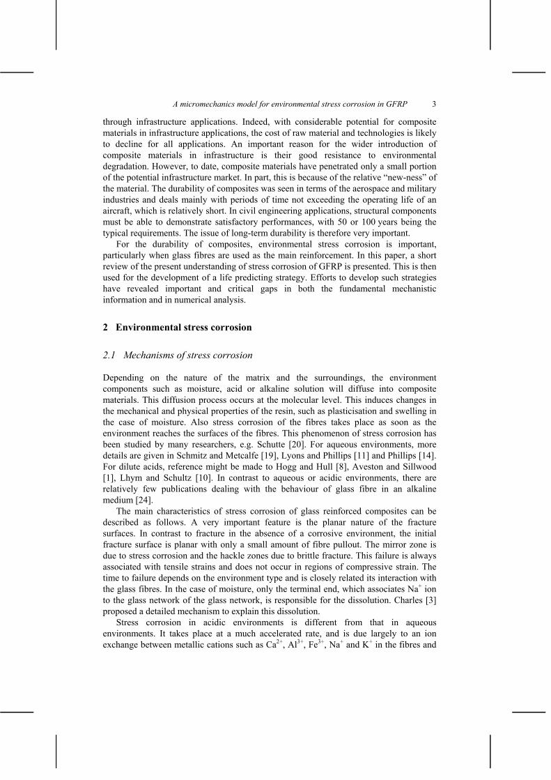
Stress-corrosion failure of GFRP is closely linked to the flaws in the fibres. These flaws are so small that conventional methods of examination are difficult to use and even if successful, the results do not readily describe the effect of the flaws on strength. As a result, indirect methods have been used to characterise their shapes and distributions. It has been suggested in Schmitz and Metcalfe [18] that two distributions of flaws are present on the fibres. One distribution of flaws controls failure for long lengths (Type A) and the other one (Type B) controls failure for short lengths. Type A flaws are 2 cm apart on the average and are believed to be deep pits or scratches. Type B flaws have an average separation of 10–2 cm or less and are believed to be shallow etch pits formed by water vapour attack. Another view suggested by Bartenev [2] is that three different types of flaws, corresponding to three levels of strength 0, 1, 2, are present on the surface of a glass fibre (Figure 1). The level of strength 0 results from heat treatment, which leads to microcracks having a depth comparable to half the radius. The strength level 1corresponds to surface submicrocracks generated during the drawing of the fibre. In general, their depth is less than the surface layer of 0.01 m. Strength level 2corresponds to the existence of microruptures on the surface of the fibre; these also occur during drawing. The stress level 3 corresponds to the strength of flaw-less glass. This description is more precise in terms of size and shapes of the individual flaws, but it does not consider the distribution of the different flaws over the fibre length. It is possible that Type A and Type B flaws of Schmitz and Metcalfe [18] correspond respectively to the 1and 2 flaws of Bartenev [2]. Using the descriptions given above, the following section attempts to demonstrate that this equivalence is likely.
Figure 1 Schematic representation of flaws on the surface of a glass fibre [2].
3 2 0
5
0.01
x
1
A micromechanics model for environmental stress corrosion in GFRP 5
3 Modelling stress corrosion in GFRP
3.1 Fibre model
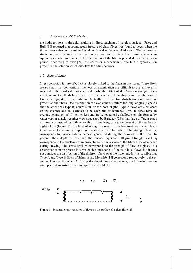
Based on the work of Wierderhorn and Bolz [25] on stress corrosion of glass in water, Sekine and his co-workers [1–23] developed a mechanistic model to predict the rupture the rupture lifetime of a glass fibre in an acidic environment. This approach assumes that the shape of the front of the stress-corrosion crack in a glass fibre is an arc of radius requal to that of the fibre as shown in Figure 2.
From geometrical considerations of the cracked area, the rupture life of an E-glass fibre can be estimated as [9, 21–23]:
004 e2 2
rRT
FrRT RTt
C r r (1)
where C is a constant depending on the activation energy of the reaction of water (or acid) to glass, R is the gas constant, T is the absolute temperature, is an empirical constant that also depends on the environment type, is the applied stress, is the half angle formed by two radii as represented in Figure 2, and r is the radius of the fibre.
A
B
C
DE O
a
Figure 2 Shape of a stress-corrosion crack in a glass fibre.
6 A. Khennane and R.E. Melchers
3.2 Shear lag model
In a unidirectional composite, the stress in an individual fibre depends on the overall applied stress and also on how the stress is transferred from a broken fibre to the surroundings. This results in a complex stress distribution, which depends on the probability of fibre fracture and the sequencing of fibre fracture. Numerical simulation of this phenomenon seems to be an appropriate solution strategy. Therefore, in order to simulate the fracture process of unidirectional GFRP subject to environmental stress corrosion, a mathematical description is needed of the redistribution of stresses in broken fibres to the neighbouring unbroken ones. This is readily available through the shear lag approach [4,5,7,13,17].
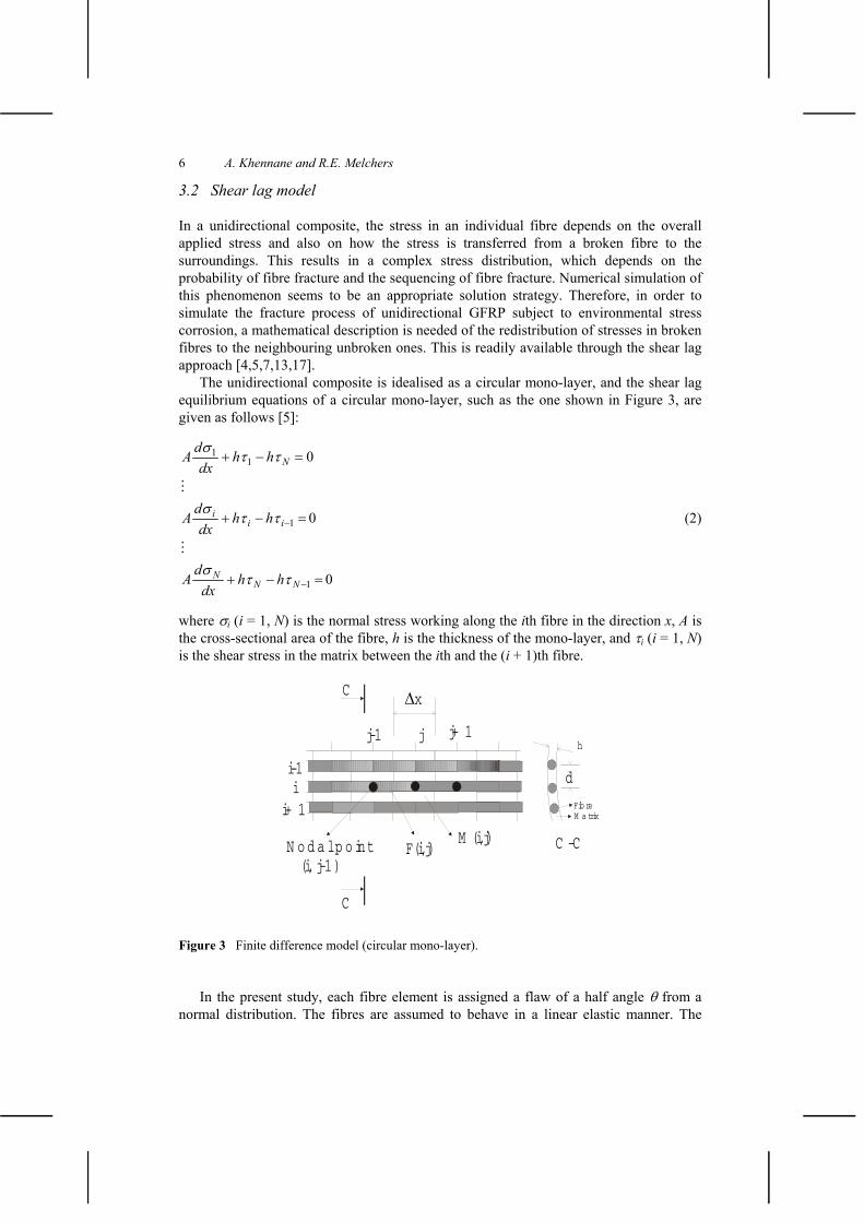
The unidirectional composite is idealised as a circular mono-layer, and the shear lag equilibrium equations of a circular mono-layer, such as the one shown in Figure 3, are given as follows [5]:
0
0
0
1
1
11
NNN
iii
N
hhdx
dA
hhdx
dA
hhdx
dA
(2)
where i (i = 1, N) is the normal stress working along the ith fibre in the direction x, A is the cross-sectional area of the fibre, h is the thickness of the mono-layer, and i (i = 1, N)is the shear stress in the matrix between the ith and the (i + 1)th fibre.
h
d
Fib reM a trix
F(i,j)
i-1i
i+ 1
j-1 j j+ 1
N o d a l p o int (i, j-1)
M (i,j)
xC
C
C -C
Figure 3 Finite difference model (circular mono-layer).
In the present study, each fibre element is assigned a flaw of a half angle from a normal distribution. The fibres are assumed to behave in a linear elastic manner. The
A micromechanics model for environmental stress corrosion in GFRP 7
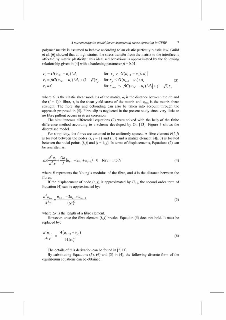
polymer matrix is assumed to behave according to an elastic perfectly plastic law. Guild et al. [6] showed that at high strains, the stress transfer from the matrix to the interface is affected by matrix plasticity. This idealised behaviour is approximated by the following relationship given in [4] with a hardening parameter = 0.01:
yiii
iiiyyiiii
iiiyiiii
duuGduuGduuG
duuGduuG
)1(/)(for0/)(for)(1/)(
/)(for/)(
1maxi
11
11
(3)
where G is the elastic shear modulus of the matrix, di is the distance between the ith and the (i + 1)th fibre, y is the shear yield stress of the matrix and max is the matrix shear strength. The fibre slip and debonding can also be taken into account through the approach proposed in [5]. Fibre slip is neglected in the present study since very little or no fibre pullout occurs in stress corrosion.
The simultaneous differential equations (2) were solved with the help of the finite difference method according to a scheme developed by Oh [13]. Figure 3 shows the discretised model.
For simplicity, the fibres are assumed to be uniformly spaced. A fibre element F(i, j)is located between the nodes (i, j – 1) and (i, j) and a matrix element M(i, j) is located between the nodal points (i, j) and (i + 1, j). In terms of displacements, Equations (2) can be rewritten as:
Niuuud
GhxdudEA iii
i to1for02 112
2 (4)
where E represents the Young’s modulus of the fibre, and d is the distance between the fibres.
If the displacement of node (i, j) is approximated by Ui, j, the second order term of Equation (4) can be approximated by:
21,1,
2,
2 2
x
uuu
xd
ud jii,jjiji (5)
where x is the length of a fibre element. However, once the fibre element (i, j) breaks, Equation (5) does not hold. It must be
replaced by:
2, 1 ,,
2 2
4
3i j i ji j u ud u
d x x (6)
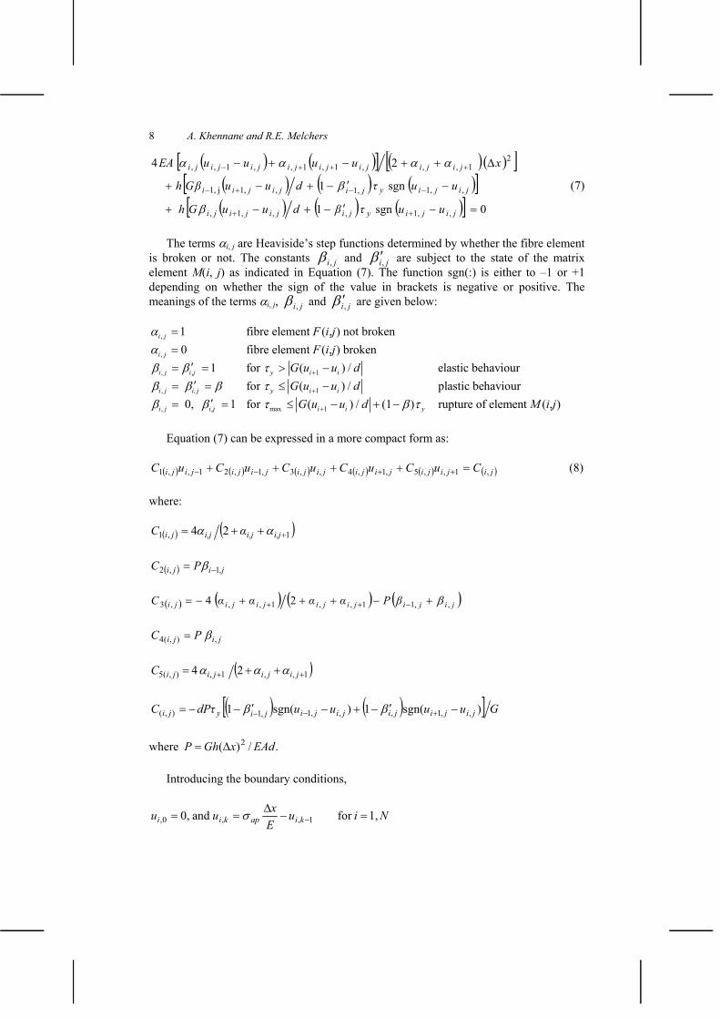
The details of this derivation can be found in [5,13]. By substituting Equations (5), (6) and (3) in (4), the following discrete form of the
equilibrium equations can be obtained:
8 A. Khennane and R.E. Melchers
0sgn1
sgn1
24
,1,,,,1,
,1,1,,,1j1,
21,,,1,1,,1,,
jijiyjijijiji
jijiyjijijii
jijijijijijijiji
uuduuG h
uuduuGh
xuuuuEA
(7)
The terms i, j are Heaviside’s step functions determined by whether the fibre element is broken or not. The constants ji, and ji, are subject to the state of the matrix element M(i, j) as indicated in Equation (7). The function sgn(:) is either to –1 or +1 depending on whether the sign of the value in brackets is negative or positive. The meanings of the terms i, j, ji, and ji, are given below:
,
,
, , 1
, 1
, , max 1
1 fibre element ( , ) not broken0 fibre element ( , ) broken
1 for ( ) / elastic behaviour for ( ) / plastic behaviour 0, 1 for (
i j
i j
i j i j y i i
i j i, j y i i
i j i j i
F i jF i j
G u u dG u u d
G u u ) / (1 ) rupture of element ( , )i yd M i j
Equation (7) can be expressed in a more compact form as:
jijijijijijijijijijiji CuCuCuCuCuC ,1,,5,1,4,,3,1,21,,1 (8)
where:
1,1 24 i,ji,ji,jjiC
,jiji PC 1,2
jijijijijijiji PC ,1,1,,1,,,3 24
jiji PC ,),(4
1,,1,),(5 24 jijijijiC
GuuuudPC jijijijijijiyji )sgn(1)sgn(1 ,,1,,,1,1),(
where ./)( 2 EAdxGhP
Introducing the boundary conditions,
NiuExuu kiapkii 1,forand0, 1,,0,
A micromechanics model for environmental stress corrosion in GFRP 9
Equation (8) can be rewritten as a set of N (k – 1) linear equations that can be solved by the elimination method. The solution process is carried out as follows:
For each fibre element is assigned a half angle generated from an appropriate statistical distribution of flaw size.
Form the linear system of equation and solve to obtain the nodal displacements and the stresses in the elements.
Use Equation (1) to estimate the failure time for each element. The smallest time, t,is chosen as the one that will give the next fibre break.
Check whether the composite has failed or not.
If the composite has failed, stop the process and record its life as the sum of the individual time elements tf = ti.If the composite has not failed, and since stress corrosion will have occurred during the time t update the half angle for all the non-broken elements.
For broken elements update the constants of state and repeat the above process until failure occurs.
The composite is considered as having failed if one of two failure criteria is satisfied. The most obvious failure mode is the formation of a cleavage plane, i.e. all the fibres elements situated in one plane across the elements are broken. The second failure mode is due to the lack of equilibrium of the composite under stress. Numerically, this corresponds to the occurrence of a singular stiffness matrix. For example, this failure mode occurs when two cleavage planes are joined by matrix failure.
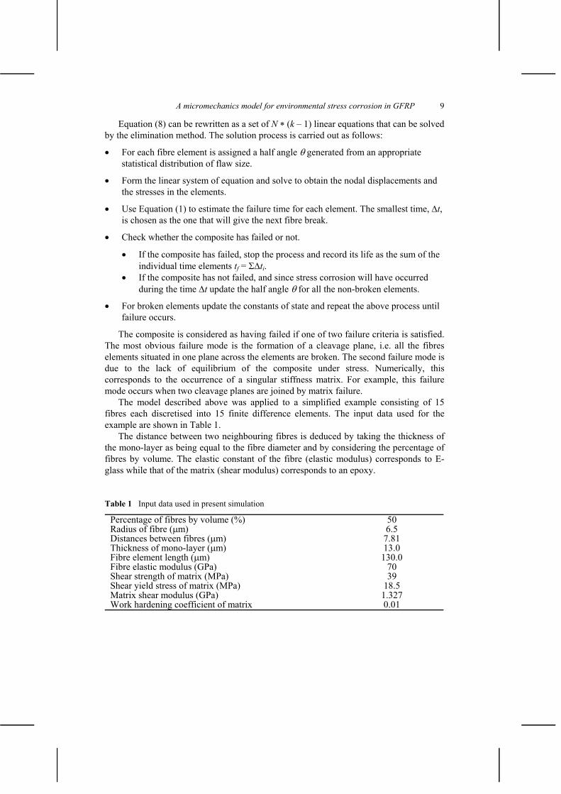
The model described above was applied to a simplified example consisting of 15 fibres each discretised into 15 finite difference elements. The input data used for the example are shown in Table 1.
The distance between two neighbouring fibres is deduced by taking the thickness of the mono-layer as being equal to the fibre diameter and by considering the percentage of fibres by volume. The elastic constant of the fibre (elastic modulus) corresponds to E-glass while that of the matrix (shear modulus) corresponds to an epoxy.
Table 1 Input data used in present simulation
Percentage of fibres by volume (%) 50 Radius of fibre ( m) 6.5 Distances between fibres ( m) 7.81 Thickness of mono-layer ( m) 13.0 Fibre element length ( m) 130.0 Fibre elastic modulus (GPa) 70 Shear strength of matrix (MPa) 39 Shear yield stress of matrix (MPa) 18.5 Matrix shear modulus (GPa) 1.327 Work hardening coefficient of matrix 0.01
10 A. Khennane and R.E. Melchers
4 Results and discussion
Two different environments were considered: water and acid. Two probability distributions for flaw size were considered for illustration. Both of them are normal with a mean of 2.5 and a variance of 0.5 for the first and a mean of 1.7 and a variance of 0.3 for the second. For each simulation run, the flaws in each fibre element were selected randomly by sampling from the adopted flaw size distribution. The applied stress was increased in increments of 0.1 GPa for the first distribution and in increments of 0.3 GPa for the second one. Fifty runs or simulations were carried out for each stress level.
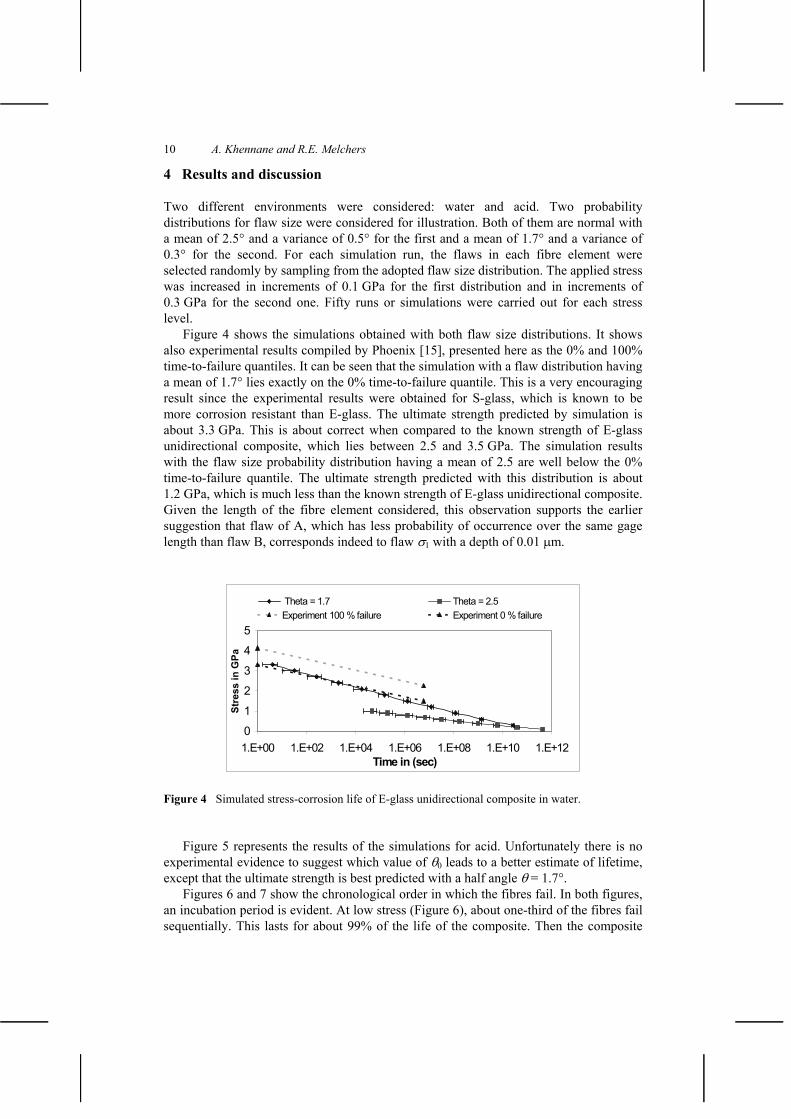
Figure 4 shows the simulations obtained with both flaw size distributions. It shows also experimental results compiled by Phoenix [15], presented here as the 0% and 100% time-to-failure quantiles. It can be seen that the simulation with a flaw distribution having a mean of 1.7 lies exactly on the 0% time-to-failure quantile. This is a very encouraging result since the experimental results were obtained for S-glass, which is known to be more corrosion resistant than E-glass. The ultimate strength predicted by simulation is about 3.3 GPa. This is about correct when compared to the known strength of E-glass unidirectional composite, which lies between 2.5 and 3.5 GPa. The simulation results with the flaw size probability distribution having a mean of 2.5 are well below the 0% time-to-failure quantile. The ultimate strength predicted with this distribution is about 1.2 GPa, which is much less than the known strength of E-glass unidirectional composite. Given the length of the fibre element considered, this observation supports the earlier suggestion that flaw of A, which has less probability of occurrence over the same gage length than flaw B, corresponds indeed to flaw 1 with a depth of 0.01 m.
Figure 4 Simulated stress-corrosion life of E-glass unidirectional composite in water.
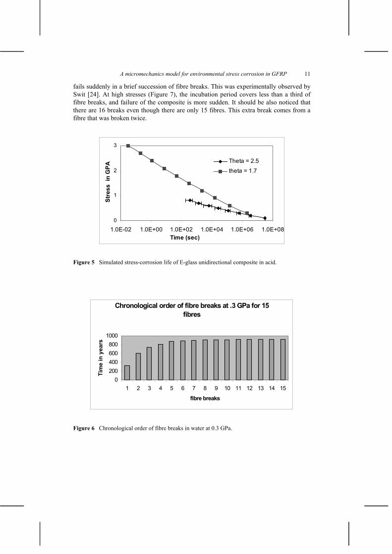
Figure 5 represents the results of the simulations for acid. Unfortunately there is no experimental evidence to suggest which value of 0 leads to a better estimate of lifetime, except that the ultimate strength is best predicted with a half angle = 1.7 .
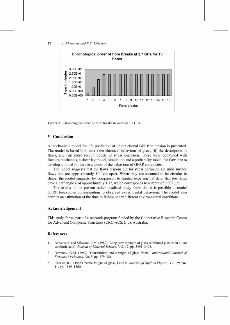
Figures 6 and 7 show the chronological order in which the fibres fail. In both figures, an incubation period is evident. At low stress (Figure 6), about one-third of the fibres fail sequentially. This lasts for about 99% of the life of the composite. Then the composite
0
1
2
3
4
5
1.E+00 1.E+02 1.E+04 1.E+06 1.E+08 1.E+10 1.E+12Time in (sec)
Stre
ss in
GPa
Theta = 1.7 Theta = 2.5Experiment 100 % failure Experiment 0 % failure
A micromechanics model for environmental stress corrosion in GFRP 11
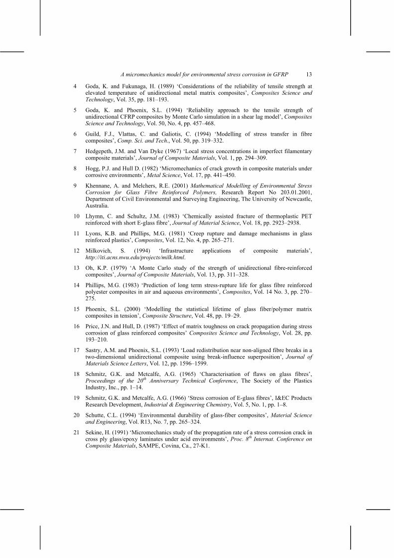
fails suddenly in a brief succession of fibre breaks. This was experimentally observed by Swit [24]. At high stresses (Figure 7), the incubation period covers less than a third of fibre breaks, and failure of the composite is more sudden. It should be also noticed that there are 16 breaks even though there are only 15 fibres. This extra break comes from a fibre that was broken twice.
0
1
2
3
1.0E-02 1.0E+00 1.0E+02 1.0E+04 1.0E+06 1.0E+08Time (sec)
Stre
ss i
n G
PA
Theta = 2.5 theta = 1.7
Figure 5 Simulated stress-corrosion life of E-glass unidirectional composite in acid.
Chronological order of fibre breaks at .3 GPa for 15 fibres
0200400600800
1000
1 2 3 4 5 6 7 8 9 10 11 12 13 14 15
fibre breaks
Tim
e in
yea
rs
Figure 6 Chronological order of fibre breaks in water at 0.3 GPa.
12 A. Khennane and R.E. Melchers
Chronological order of fibre breaks at 2.7 GPa for 15 fibres
0.00E+005.00E+001.00E+011.50E+012.00E+012.50E+013.00E+01
1 2 3 4 5 6 7 8 9 10 11 12 13 14 15 16
Fibre breaks
Tim
e in
min
utes
Figure 7 Chronological order of fibre breaks in water at 0.7 GPa.
5 Conclusion
A mechanistic model for life prediction of unidirectional GFRP in tension is presented. The model is based both on (i) the chemical behaviour of glass, (ii) the description of flaws, and (iii) more recent models of stress corrosion. These were combined with fracture mechanics, a shear lag model, simulation and a probability model for flaw size to develop a model for the description of the behaviour of GFRP composite.
The model suggests that the flaws responsible for stress corrosion are mild surface flaws that are approximately 10–2 cm apart. When they are assumed to be circular in shape, the model suggests, by comparison to limited experimental data, that the flaws have a half angle of approximately 1.7 , which corresponds to a depth of 0.009 m.
The results of the present rather idealised study show that it is possible to model GFRP breakdown corresponding to observed experimental behaviour. The model also permits an estimation of the time to failure under different environmental conditions.
Acknowledgement
This study forms part of a research program funded by the Cooperative Research Centre for Advanced Composite Structures (CRC-ACS, Ltd), Australia.
References
1 Aveston, J. and Sillwood, J.M. (1982) ‘Long term strength of glass reinforced plastics in dilute sulphuric acid’, Journal of Material Science, Vol. 17, pp. 3491–3498.
2 Bartenev, G.M. (1969) ‘Constitution and strength of glass fibers’, International Journal of Fracture Mechanics, No. 5, pp. 179–186.
3 Charles, R.J. (1958) ‘Static fatigue of glass, I and II’ Journal of Applied Physics, Vol. 29, No. 11, pp. 1549–1560.
A micromechanics model for environmental stress corrosion in GFRP 13
4 Goda, K. and Fukunaga, H. (1989) ‘Considerations of the reliability of tensile strength at elevated temperature of unidirectional metal matrix composites’, Composites Science and Technology, Vol. 35, pp. 181–193.
5 Goda, K. and Phoenix, S.L. (1994) ‘Reliability approach to the tensile strength of unidirectional CFRP composites by Monte Carlo simulation in a shear lag model’, CompositesScience and Technology, Vol. 50, No. 4, pp. 457–468.
6 Guild, F.J., Vlattas, C. and Galiotis, C. (1994) ‘Modelling of stress transfer in fibre composites’, Comp. Sci. and Tech., Vol. 50, pp. 319–332.
7 Hedgepeth, J.M. and Van Dyke (1967) ‘Local stress concentrations in imperfect filamentary composite materials’, Journal of Composite Materials, Vol. 1, pp. 294–309.
8 Hogg, P.J. and Hull D. (1982) ‘Micromechanics of crack growth in composite materials under corrosive environments’, Metal Science, Vol. 17, pp. 441–450.
9 Khennane, A. and Melchers, R.E. (2001) Mathematical Modelling of Environmental Stress Corrosion for Glass Fibre Reinforced Polymers, Research Report No 203.01.2001, Department of Civil Environmental and Surveying Engineering, The University of Newcastle, Australia.
10 Lhymn, C. and Schultz, J.M. (1983) ‘Chemically assisted fracture of thermoplastic PET reinforced with short E-glass fibre’, Journal of Material Science, Vol. 18, pp. 2923–2938.
11 Lyons, K.B. and Phillips, M.G. (1981) ‘Creep rupture and damage mechanisms in glass reinforced plastics’, Composites, Vol. 12, No. 4, pp. 265–271.
12 Milkovich, S. (1994) ‘Infrastructure applications of composite materials’, http://iti.acns.nwu.edu/projects/milk.html.
13 Oh, K.P. (1979) ‘A Monte Carlo study of the strength of unidirectional fibre-reinforced composites’, Journal of Composite Materials, Vol. 13, pp. 311–328.
14 Phillips, M.G. (1983) ‘Prediction of long term stress-rupture life for glass fibre reinforced polyester composites in air and aqueous environments’, Composites, Vol. 14 No. 3, pp. 270–275.
15 Phoenix, S.L. (2000) ‘Modelling the statistical lifetime of glass fiber/polymer matrix composites in tension’, Composite Structure, Vol. 48, pp. 19–29.
16 Price, J.N. and Hull, D. (1987) ‘Effect of matrix toughness on crack propagation during stress corrosion of glass reinforced composites’ Composites Science and Technology, Vol. 28, pp. 193–210.
17 Sastry, A.M. and Phoenix, S.L. (1993) ‘Load redistribution near non-aligned fibre breaks in a two-dimensional unidirectional composite using break-influence superposition’, Journal of Materials Science Letters, Vol. 12, pp. 1596–1599.
18 Schmitz, G.K. and Metcalfe, A.G. (1965) ‘Characterisation of flaws on glass fibres’, Proceedings of the 20th Anniversary Technical Conference, The Society of the Plastics Industry, Inc., pp. 1–14.
19 Schmitz, G.K. and Metcalfe, A.G. (1966) ‘Stress corrosion of E-glass fibres’, I&EC Products Research Development, Industrial & Engineering Chemistry, Vol. 5, No. 1, pp. 1–8.
20 Schutte, C.L. (1994) ‘Environmental durability of glass-fiber composites’, Material Science and Engineering, Vol. R13, No. 7, pp. 265–324.
21 Sekine, H. (1991) ‘Micromechanics study of the propagation rate of a stress corrosion crack in cross ply glass/epoxy laminates under acid environments’, Proc. 8th Internat. Conference on Composite Materials, SAMPE, Covina, Ca., 27-K1.

14 A. Khennane and R.E. Melchers
22 Sekine, H., Hu, N. and Fukunaga, H. (1995) ‘Direct numerical simulation of the extension of stress-corrosion cracks in glass fibers embedded in laminates in acid environments’, Composites Science and Technology, Vol. 53, pp. 317–323.
23 Sekine, H. and Beaumont, P.W.R (1998) ‘A physically based micromechanical theory and diagrams of macroscopic stress-corrosion cracking in GFRP laminates’, Eighth Japan–US Conference on Composite Materials, pp. 199–208.
24 Swit, G. (2000) ‘Durability of stressed E-glass fibre in alkaline medium’, in Cardon, Fukuda, Reifsneider and Verchery (Eds.): Recent Developments in Durability Analysis of Composite Systems, Balkema, Rotterdam, pp. 473–476.
25 Wierderhorn, S.M. and Bolz, L.H. (1970) ‘Stress corrosion and static fatigue of glass’, Journalof the American Ceramic Society, Vol. 53, No. 10, pp. 543–548.