a methodology for vlsi implementation of cellular automata algorithms using vhdl
TRANSCRIPT

A methodology for VLSI implementation of Cellular Automata algorithmsusing VHDL
G.Ch. Sirakoulis, I. Karafyllidis* , A. Thanailakis, V. Mardiris
Democritus University of Thrace, Department of Electrical and Computer Engineering, Laboratory of Electrical and Electronic Materials Technology,GR-671 00 Xanthi, Greece
Received 17 January 2000; revised 3 July 2000; accepted 4 July 2000
Abstract
A methodology for the VLSI implementation of Cellular Automata (CA) algorithms using the VHSIC Hardware Description Language(VHDL) is proposed for the first time. This methodology builds a bridge between the CAs as models of physical systems and processes andthe CAs as a VLSI architecture. A translation algorithm is developed that has as input the CA algorithms that simulate physical systems andprocesses, and as output the corresponding VHDL code. The parameters of this translation algorithm are defined by the user and can beautomatically mapped into synthesizable VHDL. An example, where this methodology is applied to the hardware implementation of a CAalgorithm for automated visual inspection, is presented.q 2001 Elsevier Science Ltd. All rights reserved.
Keywords: Cellular Automata; Modeling; Simulation; VLSI implementation; VHDL
1. Introduction
Cellular Automata (CAs) were first introduced by vonNeumann [1] in 1948, in an ambitious project: to showthat complex phenomena can in principle be reduced tothe dynamics of many identical, very simple primitives,capable of interacting and maintaining their identity.Following a suggestion by Ulam, von Neumann adopted afully discrete approach, in which space, time, and even thedynamical variables were defined to be discrete. The result-ing cellular automaton theory describes CAs as models ofphysical systems where space and time are discrete andinteractions are only local. Furthermore, as it was referredby Wolfram [2], any physical system satisfying differentialequations may be approximated as a CA, by introducingfinite differences and discrete variables. CAs are very effec-tive in simulating physical systems and solving scientificproblems, because they can capture the essential featuresof systems where global behavior arises from the collectiveeffect of simple components that interact locally [3,4].
Physical systems of both microscopic and macroscopiclevel, containing many discrete elements with local interac-tions, are often conveniently modeled as CAs [5]. CAs havebeen applied successfully to several physical systems,processes and scientific problems where local interactions
are involved, such as photolithography [6–10], electricaltree growth in solid insulating materials [11,12], predictionof forest fire spreading [13], lava flow [14], traffic simulation[15], and immune system modeling [16].
On the other hand, CAs have also been used as a VLSIarchitecture, and have been applied among others to imageprocessing [17,18], data encryption [19], byte error correct-ing code [20], and as pseudorandom number generators[21]. Special computing machines have also been developedbased on the CA architecture [22,23] and, furthermore,special cellular automata algorithms (which from now onwill be referred to as CA algorithms) have been implemen-ted on massively parallel computers, such as the CellularAutomaton Machine (CAM) [24].
Models for physical systems, or processes, based on CAslead to CA algorithms, which are fast when implemented onserial computers, because they exploit the inherent paralle-lism of the CA structure. The main difference between CAsas models for physical systems and CAs as a VLSI archi-tecture lies in the CA state space. The state space of CAsthat model physical systems is usually continuous, whereasthe state space of CAs that are used as a VLSI architecture isdiscrete. It is, therefore, clear that the discretization of theCA state space is the first step towards the design of thecorresponding dedicated processors, which will execute CAalgorithms that simulate physical systems and processes.The aim of this work is to build, for the first time, a bridgebetween CAs as models for physical systems and processes,
Advances in Engineering Software 32 (2001) 189–202
0965-9978/01/$ - see front matterq 2001 Elsevier Science Ltd. All rights reserved.PII: S0965-9978(00)00085-5
www.elsevier.com/locate/advengsoft
* Corresponding author. Tel.:130-541-79548; fax:130-541-29813.E-mail address:[email protected] (I. Karafyllidis).

and CAs as a VLSI architecture, as it is shown in Fig. 1,leading to the execution of CA algorithms by dedicatedprocessors.
In the last few years, CA algorithms have been used tosimulate more and more complex systems and processes,and many researchers have written CA algorithms in high-level programming languages such as C or C11. Theresearch workers can estimate the performance of CA algo-rithms and verify their functional correctness usingcommonly available software compilers. However, toimplement these CA algorithms in hardware, synchronous,very large scale integrated (VLSI) circuits should be used asan implementation medium. These implementations lead todedicated processors that can be designed using commer-cially available VLSI CAD systems, (e.g.cadence).Furthermore, the implementation of the algorithms couldbe achieved after the manual translation of the parts of thealgorithms, to become hardware, into a synthesizable subsetof a hardware description language (HDL), such as Verilogor VHDL. VHDL is one of the most important and widelyused hardware description languages of the present time,and the applications written in VHDL are increasing insize and complexity, prompting the use of parallel algo-rithms to achieve an acceptable simulation performance[25,26].
In Fig. 2, the CA algorithms with continuous state space,applied to several physical systems, processes, or otherscientific problems are described as simulation models writ-ten in a high-level programming language (i.e. C or C11).
On the other hand, the dedicated processors, resulting fromthe above CA algorithms, have discrete state space and areimplemented in hardware with the use of a hardwaredescription language. The methodology proposed in thiswork is based on the translation of the high-level program-ming language CA algorithm to the synthesizable hardwareCA algorithm, using VHDL. This methodology is diagram-matically depicted in Fig. 2. We have developed a transla-tion algorithm, which has as its input the high-levelprogramming language code and produces automaticallythe VHDL code. No previous user knowledge of VHDL isrequired, since the VHDL code is directly produced by thetranslation algorithm from the high-level programminglanguage code. The VHDL code thus obtained can be intro-duced as input to a commercial VLSI CAD system, whichwill automatically produce the layout of the correspondingdedicated processor. As a result of this methodology,research workers may use widely available standard
G.Ch. Sirakoulis, I. Karafyllidis / Advances in Engineering Software 32 (2001) 189–202190
Fig. 1. The methodology presented in this paper as a bridge between CAs asmodels for physical systems and processes (continuous state space) andCAs as a VLSI architecture (discrete state space).
Fig. 2. The methodology proposed in this work built in a translation algo-rithm. The high-level programming language (i.e. C11) code is the inputto this algorithm and the corresponding VHDL code is its output.

high-levelprogramming languages to write CA algorithmsand verify their functionality, and also use commerciallyavailable synthesis tools to automatically implement thesealgorithms into hardware.
If the proposed methodology for the VLSI implementa-tion of CA algorithms using VHDL is expanded and appro-priately modified, it is possible to include VLSIimplementation of Neural Networks, but this is beyondthe scope of the present work.
This paper is organized as follows. The necessary back-ground on Cellular Automata is presented in Section 2. Thegeneral methodology for the hardware implementation ofCA algorithms using VHDL and the translation algorithmare presented in Section 3. An example, where the metho-dology is applied for the hardware implementation of a CAalgorithm for automated visual inspection, is presented inSection 4. Finally, conclusions are drawn in Section 5.
2. Cellular Automata
A CA consists of a regular uniformn-dimensional lattice(or array). At each site of the lattice (cell) a physical quan-tity takes values. This physical quantity is the global state ofthe CA, and the value of this quantity at each cell is the localstate of this cell. Each cell is restricted to local neighbor-hood interaction only, and as a result it is incapable ofimmediate global communication. The neighborhood of acell is taken to be the cell itself and some of (or all) theimmediately adjacent cells. The states at each cell areupdated simultaneously at discrete time steps, based onthe states in their neighborhood at the preceding time step.The algorithm used to compute the next cell state is referredto as the CA local rule. Usually the same local rule applies toall cells of the CA.
A CA is characterized by five properties:
1. The number of the spatial dimensions of its latticen.2. The lattice size, i.e. the width of each side of the CA array
w. wj is the width of thejth side of the array, wherej �1;2;3…n:
3. The width of the neighborhood of the celld. dj is thewidth of the neighborhood at thejth side of the array.
4. The state of the CA cells.5. The CA local rule, which is an arbitrary functionF.
The state of a cell at time stept 1 1 is computed accord-ing to F. F is a function of the state of this cell and of thestates of the cells in its neighborhood at time stept. The caseof a two-dimensional CA with neighborhood widthsd1 � 3andd2 � 3; is shown in Fig. 3. In this case, the neighbor-hood of the (i, j) cell consists of the (i, j) cell itself and of alleight cells that are adjacent to it. The CA local rule, whichcalculates the state of the (i, j) cell at time stept 1 1; is afunction of the (i, j) cell’s own state and of the states of alleight cells in its neighborhood at time stept:
Ct11i; j � F�Ct
i21; j21;Cti21;j ;C
ti21;j11;C i; j21;C
ti; j ;C
ti; j11;
Cti11; j21;C
ti11; j ;C
ti11; j11�
�1�
Cti; j andCt11
i; j are the states of the (i, j) cell at time stepst andt 1 1; respectively.
CAs have enough expressive power to represent phenom-ena of arbitrary complexity, and at the same time they canbe simulated exactly by digital computers. Mathematicaltools for simulating physical systems and processes, namelyPartial Differential Equations (PDEs), contain much moreinformation than is usually needed, because variables maytake an infinite number of values in a continuous space.PDEs are used to compute values of physical quantities atpoints in continuous time. But the values of physical quan-tities are usually measured over finite volumes at discretetime steps [4,27]. CAs are used to compute values of physi-cal quantities over finite volumes (CA cells) at discrete timesteps. The CA approach is consistent with the modernnotion of unified space–time, where space (memory, i.e.CA cell state) and time (processing unit, i.e. CA localrule) are inseparable, i.e. located at a CA cell [28–30].
3. Methodology for hardware implementation of CAalgorithms using VHDL
As shown in Fig. 2, at first a physical system or processthat can be modeled using CAs (i.e. having local interac-tions) is chosen to be simulated. Then a CA model isconstructed following the general principles of the CAtheory, as briefly described above. Based on this CAmodel, a simulation algorithm is written in a high-levelprogramming language. Subsequently, the translation algo-rithm receives this CA algorithm as its input, and
G.Ch. Sirakoulis, I. Karafyllidis / Advances in Engineering Software 32 (2001) 189–202 191
Fig. 3. The neighborhood of the (i,j) cell is formed by the (i,j) cell itself andthe eight adjacent cells.

automatically produces as output a synthesizable VHDLcode. Finally, the VHDL code that corresponds to the afore-mentioned CA algorithm is applied as input to a commercialVLSI CAD system, and the layout of the correspondingdedicated processor is automatically produced. These arethe steps of our methodology, presented in full detail inthe following subsections.
3.1. Choosing the physical system or process to be modeledby CA
Physical systems or processes containing many discreteelements with local interactions are often convenientlymodeled using CAs. Non-trivial CAs are obtained wheneverthe dependence on the values at each site is nonlinear, aswhen the system exhibits some form of “growth inhibition”.In most direct cases, the CA lattice is in position space. At amacroscopic level, the sites may represent points in a crystallattice, with values given by some quantized (such as spincomponent) or corresponding to the types of atoms or units.The dynamical Ising model (with kinetic energy termsincluded) and other lattice spin systems are simple CAs,made nondeterministic by “noise” in the local rules at afinite temperature. At a more macroscopic level, each sitein a CA may represent a region containing many molecules(with a scale size perhaps given by an appropriate correla-tion length), and its value may label one of several possiblediscrete phases or compositions. In another way, the spatialstructure of turbulent fluids may be modeled using CAs,because the velocity field can be approximated by a latticeof cells, each containing one or no eddies, with interactionsbetween neighbouring cells. CAs may also potentiallydescribe physical systems in wave-vector or momentumspace, with site values representing excitations in the corre-sponding modes. As models for physical systems orprocesses, CAs have also some limitations. CAs shouldnot be used to simulate systems where speeds are compar-able to that of light, because of the anisotropy induced bythe discrete space. However, in contrast to standard simula-tions, CAs do not only seek a mere numerical agreementwith a physical system, but they attempt to match the simu-lated system’s own structure, its topology, its symmetriesand, in short, every one of its “deep” properties, which fulfill
the aforementioned criteria of CA theory. Furthermore, theexact computability of CAs is a precious asset for the studyof these properties.
3.2. CA algorithm
The development of CA algorithms for the simulation ofphysical systems or processes, based on the CA theorydescribed in Section 2 and in the previous subsection, willbe presented in this subsection. This is a general purpose CAalgorithm, which can, in most of cases, satisfy the simula-tion needs of any physical system or process subject to thepreviously described conditions without any specific scien-tific limitations. To avoid any unnecessary programmingspecifications about the CA algorithm presented here, onlythe general framework of this algorithm will be described.To be more specific, our goal is to depict briefly the algo-rithmic steps usually followed by researchers, in order todevelop a CA algorithm that simulates the physical systemor process they are interested in, using a high-level program-ming language. The developed CA algorithm constitutes aninput to the translation algorithm. Fig. 4 shows the frame-work of this CA algorithm. In the beginning, the user speci-fies the parameters of the CA algorithm. First, the usershould define the grid of the CA algorithm, meaning thelattice size (i.e. the width of each sidew of the CA array.wj is the width of thejth side of the array, wherej �1;2;3…n�: Thus, the user defines the number of cells.Then, the width of the neighborhood of each cell,dj,isdefined. For example, in two-dimensional (2-D) CAs, theVon-Neumann neighborhood of a cell is defined as a set thatcontains the cell itself and all neighbours of that cell that liea unit distance away from it, on the 2-D grid, whereas theneighborhood of the (i, j) cell, consisting of the cell itselfand of all eight cells that are immediately adjacent to it, isknown as the Moore neighborhood. After the definition ofthe above two parameters of the CA algorithm, the usershould define the boundary conditions of the CA, andfurthermore specify the initial conditions of the CA. TheCA local rule, which is an arbitrary functionF, calculatesthe state of the (i, j) cell at time stept 1 1; and it is a functionof the (i, j) cell’s own state and of the states of the cells in itsneighborhood at time stept. An example of a possible CA
G.Ch. Sirakoulis, I. Karafyllidis / Advances in Engineering Software 32 (2001) 189–202192
Fig. 4. The framework of a CA algorithm.

rule, modeling a physical process or a physical system,applied to a Moore neighborhood is given by Eq. (1) inSection 2. Subsequently, a termination condition shouldbe applied. This condition is usually a number of timestepsTe defined by the user or, in other cases, a well-definedpre-condition that should be satisfied by the evolution of theCA algorithm. If the number of time steps taken is less thanTe, or the pre-condition has not been satisfied as yet, thealgorithm continues by taking another time step. If thenumber of time steps taken is equal to or greater thanTe,or if the pre-condition has been satisfied, the algorithmterminates. Following the above general algorithmic steps,the user is able to develop a CA algorithm to model a physi-cal system or process, using a high-level programminglanguage, e.g. C11.
3.3. Translation algorithm
After the CA algorithm has been checked for its perfor-mance and its functional correctness, the translation algo-rithm, developed in this research work, is used. As wasmentioned above, the translation algorithm receives as itsinput the CA algorithm, written in a high-level languagecode (which from now on will be referred to as CA code),and provides automatically at its output a synthesizableVHDL code. To achieve its goal, the translation algorithmcollects information from the CA code by checking itsprimary parameters. More specifically, the translation algo-rithm searches the CA code to detect the lattice size and theneighborhood width used by the CA code, in order toconstruct the necessary parts of the VHDL code. In addition,it searches the CA code to detect the CA rule, modeling theparticular physical process or physical system, applied tothe particular number of CA cells of the neighborhood.This helps the translation algorithm to construct, later on,the VHDL code for the hardware implementation of the CAcode. The primary parameters of the CA code, which areused by the translation algorithm, are shown underlined andshaded in Fig. 5, the other parameters being not used. Itshould be pointed out that the whole process of readingthe parameters of the CA code by the translation algorithmis done automatically and it is kept away from the user’s
eyes. It is clear that the translation algorithm operates in adynamical way depending on the previous definitions madeby the writer of the CA code. Finally, the user should beaware that the translation algorithm for the CA code does nofunctionality checking, so she/he should check in advance ifthe construction with these primary parameters of the CAcode models the specific physical system or process in anacceptable way. In other words, the user should feel securethat the translation algorithm will provide a VHDL code thatis 100% synthesizable.
3.4. Production of the VHDL code
The VHDL code is the output of the translation algorithm.VHDL is one of the most important and widely used hard-ware description languages, and the applications written inVHDL are increasing in size and complexity. There aremany reasons for implementing an algorithm, which simu-lates a system, using a hardware description language, andespecially VHDL, instead of using standard VLSI designCAD tools. Mainly, because the VHDL models presentthe most reliable design process with the minimum costand time and, furthermore, because they are capable ofavoiding design errors. In our methodology, the primaryparameters of the translation algorithm, as depicted in Fig.5, are used to produce the VHDL code. More specifically,the CA rule is used to produce the interface and the beha-vioral parts of the VHDL code, whereas the lattice size andthe neighborhood width of the CA model are used toproduce the structural part of the VHDL code. No previoususer knowledge of VHDL is required, since the VHDL codeis directly produced from the high-level programminglanguage code through the translation algorithm. However,there is always a possibility, if the user so wishes, of func-tional simulation of the VHDL code with the use of theappropriate test benches. These test benches should be inexact accordance with the needs of the physical system orprocess that was modeled using CAs. The results of thesimulation of the VHDL code are guaranteed to be foundin complete agreement with the compilation results of theCA algorithm, produced during the phase of estimating theCAs algorithm performance and of verifying its functional
G.Ch. Sirakoulis, I. Karafyllidis / Advances in Engineering Software 32 (2001) 189–202 193
Fig. 5. Translation of the CA algorithm, using the specified parameters of the CA algorithm shown underlined and shaded.

correctness. The VHDL code is ready to accomplish thedesign processes of analysis, elaboration, and simulation,so that the next design process of synthesis (i.e. the transla-tion of register-transfer-level (RTL) design into a gate-levelnetlist) can take place. The process of design synthesispresupposes the usage of a commercial VLSI CAD system,which will automatically produce, after the completion ofthe VHDL code synthesis, the schematic and the layout ofthe corresponding dedicated processor.
3.5. Hardware implementation of CA algorithm
In the hardware implementation, there are four main
factors that determine the cost/performance ratio of an inte-grated circuit, namely circuit design and layout, ease ofmask generation, silicon-area utilization, and maximizationof achievable clock speed. For a given technology, the latteris inversely proportional to the maximum length of criticalsignal paths. In terms of these four parameters, CellularAutomata are perhaps the computational structures bestsuited for a VLSI realization. In fact, the circuit designreduces to the design of a single, relatively simple cell,the main component, as has been mentioned above, in theVHDL code, and the layout is uniform. The whole mask fora large CA lattice (i.e. not only the cells with their internalconnections, but also the interconnections between cells)can be generated by a step-and-repeat procedure, which inour methodology is also implemented in VHDL code.Essentially, no silicon area is wasted on long interconnec-tion lines in the case of VLSI implementation of the VHDLcode. Furthermore, because of the localization of proces-sing, the length of critical paths is minimal and independentof the number of cells. Using a commercial VLSI CADsystem, the schematic of the corresponding dedicatedprocessor will be automatically produced from the abovesynthesizable VLSI code. In this way, following the basicsteps of the VLSI physical design (i.e. placement and rout-ing), as these processes are executed by any commercialVLSI CAD system, the layout of the dedicated processorthat executes the CA algorithm is produced. The task of thehardware implementation of the CA algorithm that simu-lates the physical system or process under consideration hasbeen accomplished.
4. An example of hardware implementation of a CAalgorithm using VHDL
An example of the methodology for hardware implemen-tation of CA algorithms using VHDL, described in theprevious section, will be presented here. A physical system,namely an automated visual inspection system for circularobjects, was chosen to be simulated. A CA model for circu-lar object inspection was constructed following the generalprinciples of the CA theory. Based on this CA model, asimulation algorithm has been written in C11. Afterwards,the translation algorithm, written in high-level scriptinglanguage, received this CA algorithm as its input and auto-matically produced a synthesizable VHDL code (IEEE Std1076-1993). Finally, the VHDL code, corresponding to theaforementioned CA algorithm, was synthesized with theSYNERGY synthesizer, and it was applied as input tothe CADENCE VLSI CAD system, which produced thelayout of the corresponding dedicated processor. Thesesteps are presented in detail in the following subsections.
4.1. Choosing the physical system to be modeled by CA
Although automation in mass production lines hasreached a very high level, detection of exterior defects on
G.Ch. Sirakoulis, I. Karafyllidis / Advances in Engineering Software 32 (2001) 189–202194
Fig. 6. Simulation results of the inspection process in the cases of: (a) acircular object with no defects, att � 0; (b) a circular object with nodefects, att � 4; and (c) a circular object with no defects, att � 7:

products in many production lines is still being carried outvisually by workers. The reasons include difficulties inobtaining repeatability in segmentation procedures, longprocessing times and still relatively high prices. Automatedvisual inspection, however, offers benefits such as: (i)reduced inspection manpower, (ii) possibility of 100%inspection, (iii) enhanced product reliability and hencelower warranty cost, and (iv) faster and more accurateproduction process control, since automated inspectioncan quickly spot trends in product quality [18].
The implementation of an automated visual inspection
system depends on the type of object to be inspected.Examples of such systems are: inspection systems forprinted circuit boards, wafers, tablets and capsules. Theinspection of circular objects is particularly useful.Typical applications are found in the pharmaceuticalindustry (tablet inspection), and in the confectioneryindustry (i.e. inspection of chocolate covering inbiscuits, level of bake etc.). Some schemes on therecognition and inspection of circular objects havebeen reported in the literature [31,32]. These algorithms,however, require extensive and hence long processingtimes (perimeter length and area computation, circular
G.Ch. Sirakoulis, I. Karafyllidis / Advances in Engineering Software 32 (2001) 189–202 195
Fig. 7. Simulation results of the inspection process in the cases of: (a) acircular object with a perimeter defect, att � 0; (b) a circular object with aperimeter defect, att � 4; and (c) a circular object with a perimeter defect,at t � 7:
Fig. 8. Simulation results of the inspection process in the cases of: (a) acircular object with a defect in its interior, att � 0; (b) a circular object witha defect in its interior, att � 4; and (c) a circular object with a defect in itsinterior, att � 7:

G.Ch. Sirakoulis, I. Karafyllidis / Advances in Engineering Software 32 (2001) 189–202196
Fig. 9. The pseudocode of the CA algorithm.
Fig. 10. The pseudocode of the translation algorithm.
Hough transform implementation, and feature extractionbased on moments).
The technique proposed in this paper, to model an auto-mated visual inspection system, is based on a CA algorithm,to be described in the next section, and it does not requirefeature extraction. It is suitable for applications such asinspection tasks and robotics, where the need for shortprocessing times is crucial. The CA algorithm transformsthe area of the inspected object into a number of evolutionsteps in the CA space.
4.2. CA algorithm
The CA architecture proposed here consists of a 2-DCartesian lattice of cells. Interconnections between thecells are constrained within the Von-Neumann local neigh-borhood. As mentioned above, the Von-Neumann neighbor-hood of a cell is defined as the set that contains the cell itselfand all neighbours of that cell that lie a unit distance awayfrom it on the 2-D grid. The CA local rule, which calculatesthe state of the (i, j) cell at time stept 1 1; is a function ofthe (i, j) cell’s own state and of the states of all four cells inits neighborhood at time stept:
Ct11i; j � Ct
i21; j 1 Cti; j21 1 Ct
i; j 1 Cti; j11 1 Ct
i11; j �2�whereCt
i; j and Ct11i; j are the states of the (i, j) cell at time
stepst and t 1 1; respectively, and the operation1 is thelogical OR operation.
For the purpose of the proposed algorithm it is assumed thatan × nbinary image is loaded, as the initial global state of a 2-D CA of the same dimensions. It operates under the local CArule presented above, using a one to one mapping from thebinary image space to the CA grid, and letting each cell’s local
state assume the opposite value of that of the respective binaryelement of the image that has the same spatial co-ordinates.Thus, an image background CA evolution in time createsdiamond-shaped expanding waveforms, which are initiatedat each point of the image periphery. For increasing valuesof time, the expanding waveforms sweep the whole area of theimage space, and the image is proportionally shrunk onsuccessive time steps of the CA evolution, according to Eq.(2), until the whole image area is covered by the backgroundvalues. This state of the CA is the final global state. Since theexpanding waveforms sweep the whole image area, it is easilydeduced that the total number of time steps of the CA evolu-tion, taken until the final global state is reached, is proportionalto the image area.
A circular object, to be inspected, is an acceptable one ifit has no defects. Fig. 6a shows the binary image of such anobject, loaded as the initial global state on a 23× 23 CA. Adefect may be located either on its perimeter, as shown inFig. 7a, or at any point in its interior, as shown in Fig. 8a.The total number of time steps of the CA evolution, corre-sponding to Figs. 7a and 8a, until the final global state isreached, is smaller than the total number of time stepsrequired in the case shown in Fig. 6a. The global states ofthe CA, after four time steps, are shown in Figs. 6b, 7b and8b, respectively. The global states of the CA, after seventime steps, are shown in Figs. 6c, 7c and 8c, respectively.The final global state in the cases of Figs. 6a, 7a and 8a arereached after ten, nine and eight time steps, respectively. Inother words, if the CA reaches its final global state in lessthan ten time steps, then the circular object, the binaryimage of which was loaded as global initial state of theCA, has a defect and, therefore, it should be rejected. Thepseudocode of the CA algorithm is shown in Fig. 9.
G.Ch. Sirakoulis, I. Karafyllidis / Advances in Engineering Software 32 (2001) 189–202 197
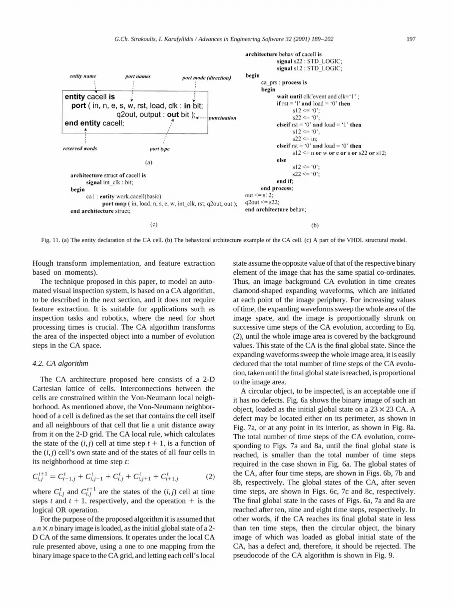
Fig. 11. (a) The entity declaration of the CA cell. (b) The behavioral architecture example of the CA cell. (c) A part of the VHDL structural model.

4.3. Translation algorithm
After the production of the CA algorithm that simulatesthe automated visual inspection system, the translation algo-rithm, developed in the present research work, is used. Aswas mentioned above, the translation algorithm receives theCA algorithm, written in the C11 programming language,as its input and provides automatically as output a synthe-sizable VHDL code. To achieve this goal, the translationalgorithm collects information from the CA code by check-ing its parameters.
The translation algorithm is written in a high-level
scripting language and its pseudocode is shown in Fig.10. In the beginning, the CA code is read by the trans-lation algorithm. After the CA code is read, the transla-tion algorithm searches the CA code to detect the CArule used to model the particular physical system. Whenthe CA rule is found, the translation algorithm producesthe VHDL code for the main component, i.e. the CAcell. This will be the behavioral part of the final VHDLcode, containing process and signal assignment state-ments. In other words, this part describes the functionalpart of the imposed CA code. Subsequently, the transla-tion algorithm searches the CA code to detect the lattice
G.Ch. Sirakoulis, I. Karafyllidis / Advances in Engineering Software 32 (2001) 189–202198
Fig. 12. (a) The schematic of the dedicated processor. (b) Block level layout of the dedicated processor.

size and the neighborhood width used by the CA code,in order to construct the structural part of the finalVHDL code. The structural part implements the finalmodule as a composition of subsystems, like the afore-mentioned main component. The final synthesizableVHDL code is produced by the translation algorithmand, after being synthesized, this VHDL code canproduce the schematic of the corresponding dedicatedprocessor.
4.4. The VHDL code produced
The final VHDL code produced as output of the transla-tion algorithm will be presented in detail in this subsection.The final VHDL code produced, including both behavioral
and structural parts, addresses the basic VHDL concepts(i.e. interfaces, behavior, structure, test benches) includedin the IEEE Standard 1076-1993. To be more specific, theentity declaration of the CA cell describes the input/outputports of the module, which happen to be the main compo-nents in our VHDL code.
The entity declaration of the CA cell is shown in Fig. 11a,where some of the VHDL terminology is also presented.The architecture body of the behavioral part of the VHDLcode displays the implementation of the entity CA cell. Thebehavioral architecture describes the algorithm performedby the CA local rule and contains process statements, eachcontaining sequential statements, including signal assign-ment statements, and wait statements. The behavioral archi-tecture example of the CA cell is shown in Fig. 11b. In this
G.Ch. Sirakoulis, I. Karafyllidis / Advances in Engineering Software 32 (2001) 189–202 199
Fig. 12. (continued)

figure is presented the architecture behavior of the CA cell,which is used by the final VHDL code. The lattice size andthe neighborhood width, used by the CA code, define thestructural part of the final VHDL code. The structural archi-tecture of the VHDL code implements the final module as a
composition of subsystems, like the entity of the CA cell. Itcontains signal declarations for internal interconnections,where the entity ports are also treated as signals. In addition,it includes component instances of previously declaredentity/architecture pairs, port maps in components, meaning
G.Ch. Sirakoulis, I. Karafyllidis / Advances in Engineering Software 32 (2001) 189–202200
Fig. 13. (a) Timing diagram for an object with no defects. Ten time steps are required to reach the final global state, as can be seen from the outputs of thecounter. (b) Timing diagram for an object with defects in its interior. In this case, six time steps are required to reach the final global state.

to connect signals to component ports, and wait statements.A part of the VHDL structural model is shown in Fig. 11c.
The final VHDL code has a mixed behavioral and struc-tural form, and more specifically its architecture containsboth behavioral and structural parts, such as concurrentstatements. The design processing of the finally producedVHDL code, i.e. analysis, elaboration and simulation, wasdone with the help of the HDL desktop of the CADENCEDesign Framework 2 software. Test benches wereconstructed for the simulation needs of the VHDL code,and the LEAPFROG simulator of CADENCE was used tosimulate the operation of the dedicated processor describedby the VHDL code obtained.
To estimate the performance of the translation algorithmand to verify its functional correctness, the results producedby the CA algorithm were compared with the resultsproduced by the LEAPFROG simulator, and they werefound to be in complete agreement. Next, the design processof synthesis, meaning the translation of the register-transfer-level (RTL) design into a gate-level netlist, takes placeusing the SYNERGY design synthesis tool. Finally, theVHDL code that corresponds to the aforementioned CAalgorithm, after being synthesized by the LEAPFROGsynthesizer, is used to produce the schematic and the layoutof the corresponding dedicated processor.
4.5. Hardware implementation of the CA algorithm
The hardware implementation of the CA algorithm,obtained from the synthesized VHDL code, is shown inFig. 12a. This is the symbol schematic of the dedicatedprocessor produced by the synthesized VHDL code. Theblock-level layout of the chip, including the pads, imple-mented using a 0.7mm, N-well CMOS process provided bythe European Silicon Structures (ES2), is shown in Fig. 12b.Inputs to the dedicated processor are the 16 lines throughwhich the image is transferred to the CA, the clock, and thereset and load control signals, as well as the power andground connections, whereas outputs are the five outputsof a counter. It should be mentioned that the fifth outputof the counter stands for a limit check, since the counter hasbeen declared as type integer in the VHDL code. The imageis serially loaded and the CA starts operating. The criterionof accept/reject operation is related to the time required forall the CA cells to take background values. This condition isdetected by the counter, which counts the number of cyclesrequired to reach the final global state. The simulation andtest language (STL), a high-level language, has been used toexamine the functionality of the dedicated processor. Twotypical timing diagrams, one for an object with no defectsand another for an object with defects, are shown in Fig. 13aand b, respectively. The most significant bit of the fouroutputs is the first bit (from top to bottom). Thus, therequired total numbers of time steps for the CA to reachthe final global states are ten and six, respectively.
5. Conclusions
A methodology for the VLSI implementation of CAalgorithms using the VHSIC Hardware DescriptionLanguage (VHDL) was presented for the first time inthis paper. This methodology builds a bridge betweenCAs as models of physical systems and processes, andCAs as a VLSI architecture. The translation algorithmdeveloped in this work has as input the CA algorithmsthat simulate physical systems and processes and asoutput the corresponding VHDL code. The parametersof this translation algorithm are defined by the user andcan be automatically mapped into synthesizable VHDL.No previous user knowledge of VHDL is required, sincethe VHDL code is directly produced from the high-levelprogramming language code. After the production ofVHDL code, this code can be applied as input to acommercial VLSI CAD system, which will automati-cally produce the layout of the corresponding dedicatedprocessor.
An example, where this methodology was applied tothe hardware implementation of a CA algorithm forautomated visual inspection, was also presented. A CAalgorithm suitable for circular object inspection wasconstructed for the needs of this example. Finally, theVHDL code produced by the translation algorithm wassynthesized by the SYNERGY synthesizer, was appliedas input to the CADENCE VLSI CAD system, andproduced the layout and the timing diagrams of thecorresponding dedicated processor.
References
[1] von Neumann J. Theory of self-reproducing automata. Urbana:University of Illinois, 1966.
[2] Wolfram S. Statistical mechanics of Cellular Automata. Reviews ofModern Physics 1983;55:601–44.
[3] Vichniac GY. Simulating physics with Cellular Automata. Physica D1984;10:96–116.
[4] Toffoli T. Cellular Automata as an alternative to (rather than anapproximation of) differential equations in modeling physics. PhysicaD 1984;10:117–27.
[5] Feynman RP. Simulating physics with computers. International Jour-nal of Theoretical Physics. 1982;21:467–88.
[6] Karafyllidis I, Thanailakis A. Simulation of the two-dimensionalphotoresist etching process in integrated circuit fabrication usingCellular Automata. Modelling and Simulation in Materials Scienceand Engineering 1995;3:629–42.
[7] Karafyllidis I, Thanailakis A. Simulation of the image reversal submi-cron process in integrated circuit fabrication. Semiconductor Scienceand Technology 1996;11:214–20.
[8] Hagouel PI, Neureuther AR, Zenk AM. Negative resist corner round-ing. Envelope volume modeling . Journal of Vacuum Science andTechnology B 1996;14:4257–61.
[9] Hagouel PI, Karafyllidis I, Neureuther AR. Dependence of developednegative resist profiles on exposure energy dose: experiment, modeling,and simulation. Microelectronic Engineering 1998;41(42):351–4.
[10] Karafyllidis I, Hagouel PI, Neureuther AR. Negative resist profiles in248 nm photolithography: experiment, modeling and simulation.Semiconductor Science and Technology 1998;13:603–10.
G.Ch. Sirakoulis, I. Karafyllidis / Advances in Engineering Software 32 (2001) 189–202 201

[11] Danikas MG, Karafyllidis I, Thanailakis A, Bruning AM. A model forelectrical tree growth in solid insulating materials using cellular auto-mata. In: Proceedings of the IEEE International Symposium on Elec-trical Insulation, Montreal, Quebec, Canada, 1996. p. 887–90.
[12] Danikas MG, Karafyllidis I, Thanailakis A, Bruning AM. Simulationof electrical tree growth in solid dielectrics containing voids of arbi-trary shape. Modelling and Simulation in Materials Science and Engi-neering 1996;4:535–52.
[13] Karafyllidis I, Thanailakis A. A model for predicting forest firespreading using cellular automata. Ecological Modelling1997;99:87–97.
[14] Spezzano G, Talia D, Di Gregorio S, Rongo R, Spataro W. A parallelcellular tool for interactive modeling and simulation. IEEE Computa-tional Science and Engineering 1996;3:33–43.
[15] Emmerich H, Rank E. An improved cellular automaton model fortraffic flow simulation. Physica A 1997;234:676–86.
[16] Sieburg HB, McCutchan JA, Cleey OK, Cabalerro L, Ostlund JJ.Simulation of HIV infection in artificial immune systems. PhysicaD 1990;45:208–27.
[17] Karafyllidis I, Andreadis I, Tzionas P, Tsalides Ph, Thanailakis A. ACellular Automaton for the determination of the mean velocity ofmoving objects and its VLSI implementation. Pattern Recognition1996;29:689–99.
[18] Andreadis I, Karafyllidis I, Tzionas P, Thanailakis A, Tsalides Ph. Anew hardware module for automated visual inspection based on aCellular Automaton architecture. Journal of Intelligent and RoboticSystems 1996;16:89–102.
[19] Chaudhuri PP, Chaudhuri DR, Nandi S, Chattopadhyay S. AdditiveCellular Automata: theory and applications. New York: IEEE Press,1997.
[20] Sasidhar K, Chattopadhyay S, Chaudhuri PP. CAA decoder for cellu-lar automata based error correcting code. IEEE Transactions onComputers 1996;45:1003–16.
[21] Hortensius P, McLeod R, Pries W, Miller M, Card H. Cellular Auto-
mata-based pseudorandom number generators for built-in self-Test.IEEE Transactions on Computer Aided Design 1989;8:842–59.
[22] Toffoli T, Margolus N. Programmable matter: concepts and realiza-tion. Physica D 1991;47:263–72.
[23] de Garis H. CAM-Brain: the genetic programming of an artificialbrain which grows/evolves at electronic speeds in a Cellular Auto-mata machine. In: Proceedings of the first IEEE Conference on Evolu-tionary Computation, New York, USA, 1994. p. 337–39.
[24] Toffoli T. CAM: a high-performance Cellular Automaton machine.Physica D 1984;10:195–204.
[25] Liao S, Tjiang S, Gupta R. An efficient implementation of reactivityfor modeling hardware in the Scenic design environment. In: Proceed-ings of the 34th Design Automation Conference, 1997. p. 70–5.
[26] van Hoogstraeten W, Corporaal H.advise. Performance evaluation ofparallel VHDL simulation. In: Proceedings of the 30th Annual Simu-lation Symposium. Los Alamitos, CA: IEEE Computer Society Press,1997. p. 146–56
[27] Omohundro S. Modeling cellular automata with partial differentialequations. Physica D 1984;10:128–34.
[28] Matzke DJ. Impact of locality and dimensionality limits on architec-tural trends. In: Proceedings of the Workshop on Physics and Compu-tation, PhysComp’94, Los Alamitos, CA. 1994. p. 30–5.
[29] Omtzigt ETL. Computational spacetimes. In: Proceedings of theWorkshop on Physics and Computation, PhysComp’94, Los Alami-tos, CA. 1994. p. 239–45.
[30] Wilding NB, Trew AS, Hawick KA, Pawley GS. Scientific modelingwith massively parallel SIMD computers. Proceedings of the IEEE1991;79:574–85.
[31] Magee M, Weniger R, Wenzel D. Multidimensional pattern classifi-cation of bottles using diffuse and specular illumination. PatternRecognition 1993;26:1639–54.
[32] Ho CT, Chen LH. A fast ellipse/circle detector using geometricsymmetry. Pattern Recognition 1995;28:117–24.
G.Ch. Sirakoulis, I. Karafyllidis / Advances in Engineering Software 32 (2001) 189–202202