a methodological approach to the formal specification of real-time systems by transformation of...
TRANSCRIPT
A Methodological Approach to the Formal
Specification of Real-Time Systems by
Transformation of UML-RT Design Models
K.Benghazi Akhlaki a,∗, M.I Capel Tunon a,J.A Holgado Terriza a, L.E Mendoza Morales b
aDepartamento de Lenguajes y Sistemas Informaticos, ETSI Informatica yTelecomunicacion,Universidad de Granada, 18071 Granada, Spain
bDepartamento de Procesos y Sistemas, Universidad Simon Bolıvar, Apartado89000, Baruta, Caracas 1080-A, Venezuela
Abstract
By following a methodological approach, introduced in a previous work, a correctsystem specification in terms of CSP+T process algebra is systematically obtainedfrom the UML-RT model of a real-time software system. Among other contribu-tions, this article aims at integrating collaboration diagrams into our approach tofacilitate the specification of capsules in UML-RT design models. Thus, an improvedsystematic transformation procedure to derive a correct and complete formal sys-tem specification of real-time systems is established here. Temporal requirementsintegration in the design and system specification stages of a real-time system is alsoaddressed, so that the approach now opens up the possibility to carry out schedul-ing and dependability analysis at the design phase of the system development lifecycle for hard real-time systems. The article also discusses a practical applicationto present a systematic transformation from a UML-RT model of a well knownmanufacturing-industry paradigmatic case, the “Production Cell”.
Key words: CSP+T, Formal specification, Real-time software systems, UML-RT.
∗ Corresponding author.Email addresses: [email protected] (K.Benghazi Akhlaki), [email protected] (M.I
Capel Tunon), [email protected] (J.A Holgado Terriza), [email protected] (L.EMendoza Morales).
Preprint submitted to Elsevier Science 10 July 2006
1 Introduction
UML (Unified Modelling Language) [1] has become one of the most widely-used standards for modelling and designing industrial software systems, essen-tially because it is a semiformal notation, relatively easy to use and well sup-ported by tools. An extension to UML, called UML-RT [2], has been defined onthe basis of ROOM language [3], which is a useful architectural definition lan-guage specifically developed for modelling complex real-time systems (RTS),and one which is becoming a standard in the industry for RTS development.However, the lack of formal semantics for UML and UML-RT makes it verydifficult to assure the correctness of any critical hard RTS after completingits development. It is nevertheless true that formal methods (FMs) [14] havebeen demonstrated to be effectively applicable to RTS and they are advocatedas a means of providing a higher level of confidence in the correct function-ing of software. They also constitute a sound basis for building a developmentframework to derive provably correct RTS. In spite of these facts, FMs are notcurrently accepted in the industry as the standard way to specify the softwarerequirements of systems, at least not at the same level as semiformal ones, likethe UML notations. The reason for this reluctance to use them is probablydue to the fact that FMs are harder to master and too expensive to be usedextensively than the semiformal ones [1].
In previous contributions we have presented a software specification procedurethat combines semiformal modelling languages and the CSP+T formal specifi-cation language. It is well known [5,6] that the combination of UML modellingnotation with formal specification languages may overcome the lack of UMLconstructs to describe non-functional requirements, like the specification oftemporal constraints during the execution of a system. Thus, the proposedapproach, discused in [4], aims at overcoming UML-RT deficiencies for RTSspecification by the deployment of a new and sound integration scheme be-tween CSP+T formal constructs and UML-RT analysis entities. It is based ona transformation procedure that starts out from an initial UML-RT model ob-tained by integrating the class diagram, a new class of extended state diagramsthat describe how the system behaves over time, and other aspects regardingthe architectural design of the system. A formal specification of the intendedsystem is subsequently obtained by applying the set of transformation rules.As result of the transformation procedure, the initial UML-RT model of thesystem is mapped into CSP+T syntactical terms, describing the architecturaldesign as well as the detailed design of its constituent communicating concur-rent processes.
Typically, the complete specification of the structure of a complex RTS isobtained through a combination of class and collaboration diagrams [2]. Forthis reason, we are now motivated to complement our previous methodological
2
proposal with the inclusion of collaboration diagrams as part of the UML-RTinitial model description, in order to obtain a more complete and modifiablesystem specification. Similar approaches have been proposed in articles byother authors. For instance, the work presented in [7] maps UML-RT capsulesto the formal language Circus [8]. Our approach differs from the aforemen-tioned one in that it integrates the specification of timing properties and givesa complete view of the system behaviour (i.e., it includes behavioural, staticand timing aspects), so that formal system specification of RTS becomes fea-sible in an easier and more flexible way. So as to show the applicability ofthe new proposal, we have used the method to carry out the specification,including real-time constraints, of two basic components of the “ProductionCell”, which is a well known manufacturing-industry paradigmatic case.
The rest of this paper is structured as follows: section 2 provides an overview ofthe UML-RT, section 3 introduces some basic aspects of CSP and describes theCSP+T specification language and section 4 explains the system specificationmethod proposed here. In Section 5 we present the specification of two centralelements of the Production Cell components (the Robot and the Press). Thework related to this research is discussed in more detail in section 6. Finally,some conclusions are drawn and the references are listed.
2 UML-RT
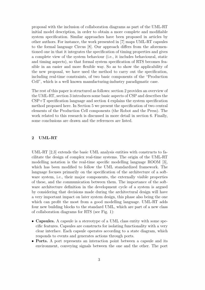
UML-RT [2,3] extends the basic UML analysis entities with constructs to fa-cilitate the design of complex real-time systems. The origin of the UML-RTmodelling notation is the real-time specific modelling language ROOM [3],which has been modified to follow the UML standardized framework. Thelanguage focuses primarily on the specification of the architecture of a soft-ware system, i.e., their major components, the externally visible propertiesof these, and the communication between them. The importance of the soft-ware architecture definition in the development cycle of a system is arguedby considering that decisions made during the architectural design will havea very important impact on later system design, this phase also being the onewhich can profit the most from a good modelling language. UML-RT addsfour new building blocks to the standard UML, which are part of a new classof collaboration diagrams for RTS (see Fig. 1):
• Capsules. A capsule is a stereotype of a UML class entity with some spe-cific features. Capsules are constructs for isolating functionality with a veryclear interface. Each capsule operates according to a state diagram, whichresponds to events and generates actions through ports.
• Ports. A port represents an interaction point between a capsule and itsenvironment, conveying signals between the one and the other. The port
3
/ y : CapsP
+ / y2
: ProtB
+ / x2 : ProtB
+ / y1
: ProtC~
+ / x4 : ProtA
/ y : CapsP
+ / y2
: ProtB
+ / x2 : ProtB
+ / y1
: ProtC~
+ / x1
: ProtA~
+ / x1
: ProtA~+ / x4 : ProtA
# / x3 : ProtC# / x3 : ProtC
CapsClassQ
/ y : CapsP
+ / y2
: ProtB
+ / x2 : ProtB
+ / y1
: ProtC~
+ / x4 : ProtA
/ y : CapsP
+ / y2
: ProtB
+ / x2 : ProtB
+ / y1
: ProtC~
+ / x1
: ProtA~
+ / x1
: ProtA~+ / x4 : ProtA
# / x3 : ProtC# / x3 : ProtC
CapsClassQ
Fig. 1. Ports notation - Collaboration Diagram
notation is shown as a small hollow square symbol. Public visibility is de-noted if the port symbol is placed overlapping the boundary of the rectanglethat represents the capsule in a collaboration diagram (see x4, x1, and x2ports in Fig. 1), or if the port is shown inside the rectangle symbol, then it ishidden and its visibility becomes private (see x3, y1, y2). When viewed fromwithin the capsule, two types of ports are defined: relay and end ports. Arelay port transmits signals between a capsule and its subcapsules (see x2,y2). An end port is a component that represents the transmission of signalsbetween the capsule and its associated statechart describing the capsule’sinteraction behaviour (see x1, x3).
• Protocols. A protocol captures a set of valid communications (signal ex-changes) between two or more capsules (i.e., ProtA, ProtB, ProtC in Fig.1). A protocol comprises of a set of participants (ports), each of which playsa specific role in the protocol. Binary protocols, involving just two ports(x3and y1 ports of ProtC), are by far the most common and the simplest tospecify. One advantage of these protocols is that only one role —called thebase role— needs to be specified. The other called the —conjugate —can bederived from the base role by simply inverting the incoming and outgoingsignal sets.The role of base and conjugate ports can be seen in the aboveexample, in which the conjugate y1 : ProtC ∼ sends the incoming signals,declared in the protocol, and the base x3 : ProtC receives them, representedas the outgoing signals.
• Connectors. A connector is an abstraction of a message passing channelthat connects two or more ports. Each connector is typed by a protocol thatdefines the possible interactions that can take place across that connector.
3 CSP and CSP+T
CSP (Communicating Sequential Processes) [9,10], is an event-based notationprimarily aimed at describing the sequencing of events that occur within aprocess behaviour and the synchronisation (or communication) between dif-ferent processes. CSP constitutes a comfortable paradigm for programmingmulticomputers and has additional invaluable advantages such as the veri-fiability and portability of the programs that can be derived using this no-
4
tation. CSP is based on a theoretical calculus that provides us with a set ofmathematically well-defined process terms (valid concurrent processes) derivedfrom an abstract grammar which includes operators to express the concurrent,non-deterministic composition of these terms. Syntactical operators —calledcommands— specify the behaviour of the device that executes them and theirresult can be successful or a failure. If the execution of a single commandsucceeds, it can have an effect on the internal state of the device (e.g. theassignment command), or on the device’s environment (output command) oron both (input command). The execution of a structured command impliesthe execution of one or all of its constituent commands depending on its type:concurrent composition (‖), alternative (|), repetitive (∗), guards (→). Everyprocess P defines its own set of communication symbols, termed the com-munication alphabet α(P ). These communications represent the events thatprocess P receives from its environment (made up of all the other processesin the system) or those that occur internally, such as the event τ which isnot externally visible. External events can be understood as being the puresynchronization between an asynchronous process and its environment. Anytype of event causes a state change of the process in which it is observed.The communication interface Comm act(P) of a given process P contains allthe CSP-like communications, i.e., the synchronous, one-to-one communica-tions between parallel processes —called Interface(P)— in which process Pcan engage. It also includes the alphabet α(P ), representing signals and eventsoccurring in P . Therefore, the communications of process P are given by theset Comm act(P ) = Interface(P )∪α(P ). Theoretical CSP and other similarprocess description formal languages have been called process algebras.
CSP+T [11] is a new real-time specification language which extends CSP byintroducing a new set of constructs to allow the description of complex eventtimings from within a single sequential process, thereby providing a valuableinsight into the behavioural specification of real-time systems. The syntax ofCSP+T, which is a superset of that of CSP, has been adapted to our method.The notational elements of CSP+T regarding the specification of temporalconstraints are described as follows:
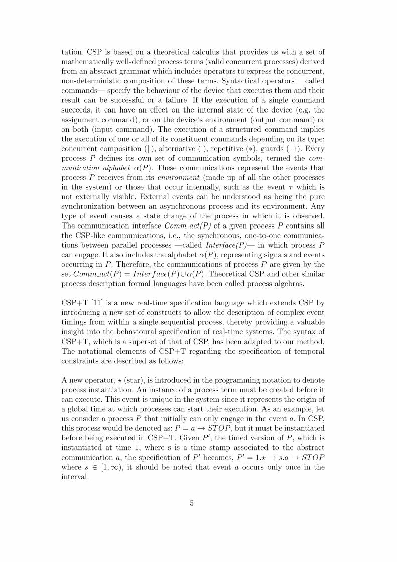
A new operator, ? (star), is introduced in the programming notation to denoteprocess instantiation. An instance of a process term must be created before itcan execute. This event is unique in the system since it represents the origin ofa global time at which processes can start their execution. As an example, letus consider a process P that initially can only engage in the event a. In CSP,this process would be denoted as: P = a → STOP , but it must be instantiatedbefore being executed in CSP+T. Given P ′, the timed version of P , which isinstantiated at time 1, where s is a time stamp associated to the abstractcommunication a, the specification of P ′ becomes, P ′ = 1.? → s.a → STOPwhere s ∈ [1,∞), it should be noted that event a occurs only once in theinterval.
5
A new event operator ./ is introduced to be used jointly with a “markervariable” to record the instant at which the event occurs. ev ./ v means thatthe time at which ev is observed during a process execution is in the markervariable v. The value of time stamps is taken from the set of positive realnumbers, so that successive events form a non-decreasing monotonic sequence.As several successive events can instantiate the same variable at differenttimes, if we specify the process P as follows: P = 1.? → a ./ var → STOP , foreach process execution, the marker variable var will record the correspondingtime value at which event a occurred, and it will always satisfy var > 1.The scope of marker variables is strictly limited to one sequential process.They cannot be referenced or accessed in any other way within a concurrentcomposition of processes.
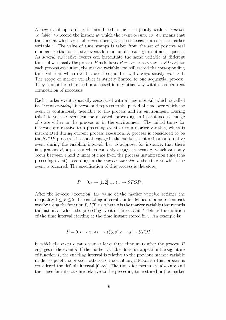
Each marker event is usually associated with a time interval, which is calledits “event-enabling” interval and represents the period of time over which theevent is continuously available to the process and its environment. Duringthis interval the event can be detected, provoking an instantaneous changeof state either in the process or in the environment. The initial times forintervals are relative to a preceding event or to a marker variable, which isinstantiated during current process execution. A process is considered to bethe STOP process if it cannot engage in the marker event or in an alternativeevent during the enabling interval. Let us suppose, for instance, that thereis a process P , a process which can only engage in event a, which can onlyoccur between 1 and 2 units of time from the process instantiation time (thepreceding event), recording in the marker variable v the time at which theevent a occurred. The specification of this process is therefore:
P = 0.? → [1, 2].a ./ v → STOP .
After the process execution, the value of the marker variable satisfies theinequality 1 ≤ v ≤ 2. The enabling interval can be defined in a more compactway by using the function I, I(T, v), where v is the marker variable that recordsthe instant at which the preceding event occurred, and T defines the durationof the time interval starting at the time instant stored in v. An example is:
P = 0.? → a ./ v → I(3, v).c → d → STOP ,
in which the event c can occur at least three time units after the process Pengages in the event a. If the marker variable does not appear in the signatureof function I, the enabling interval is relative to the previous marker variablein the scope of the process, otherwise the enabling interval for that process isconsidered the default interval [0,∞). The times for events are absolute andthe times for intervals are relative to the preceding time stored in the marker
6
variable.
The semantics of the parallel composition of two processes with enabling in-tervals which must be synchronized depend on whether the values of these in-tervals are identical, partially overlapping or disjoint. In the first case, the pro-cesses synchronize on the common initial events, as established in CSP commu-nication semantics, i.e., given P = E1.Q and Rc = E2.S, then P ‖ Q 6= STOPiff α(Q)∩α(S) 6= ∅∧E1∩E2 6= ∅. In the case of disjointed enabling intervals(E1 ∩ E2 = ∅), the parallel composition of processes behaves as the STOPprocess.
4 Formal Specification and Transformation Methodology from UML-RT
In previous work [4] we extended UML-SD with new annotations inspired inCSP+T to capture timing constraints. We also proposed a procedure to designa UML-RT model constituted of the extended UML-SD and class diagrams,and a new set of mapping rules to transform a designed UML model intoCSP+T syntactical terms. In order to carry out a more complete specificationof an RTS, in this paper we integrate the previous procedure and rules andorganize them into a structured and complete methodological approach. Thephases and steps that must be followed to obtain a detailed RTS specificationare more clearly defined now.
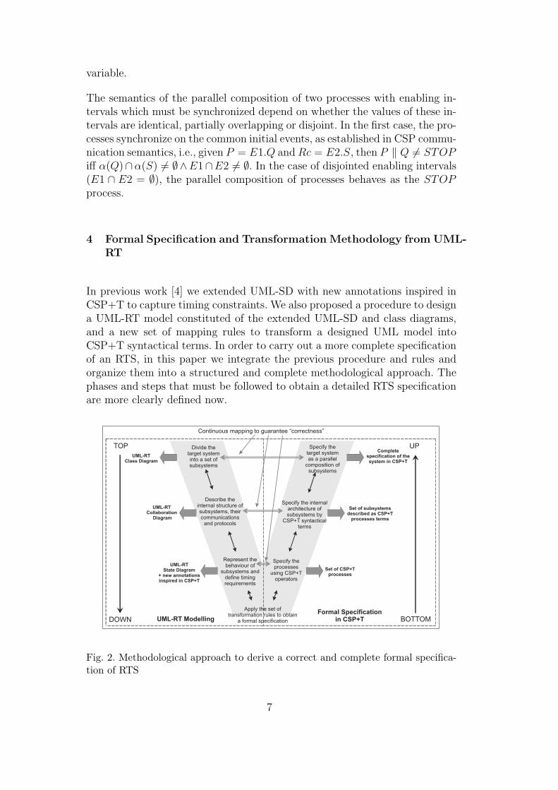
Fig. 2. Methodological approach to derive a correct and complete formal specifica-tion of RTS
7

As it can be seen in Fig. 2 (inspired in V-Model [12]), the proposed method-ology starts from the UML-RT model and allows, by following a top-downstrategy, the integration of UML state diagrams (UML-SD) and collaborationdiagrams in order to completely describe the behaviour of the subsystems(capsules) and the specification of real-time constraints defined on systemprocesses. This transformation is carried out within a common methodologi-cal framework given by the UML notation. In a more technical way, we cansay that the proposed method is a new systematic transformation procedurefor obtaining the complete specification of an RTS by giving structured op-erational semantics, in terms of CSP+T process algebra, to the semiformalUML-RT analysis entities. This result is obtained in the second phase, byapplying a bottom-up strategy.
The transformation of UML-RT diagrams of system components into CSP+Tprocesses is carried out by a system of rules and it was established in a pre-vious work [4], so that the final system design is correct by construction. AsFig. 2 shows, mapping links are continuously established between the UML-RT diagrams of components in which the system is structured and their formalspecifications in terms of CSP+T processes. These links aim to signify howCSP+T syntactical terms are used to represent the real-time constraints andthe internal components and connectors that constitute the system architec-ture, at different levels of description detail, during the entire transformationprocess.
4.1 Top-Down Modelling Process
There is a general agreement that, in order to build systems with a guaranteedlevel of quality in a cost effective manner, it is essential to construct a globalmodel, integrating all aspects of the system at the design phase of the systemdevelopment life cycle. The complete view of the system is obtained by com-bining an initial class diagram, which illustrates the architecture of softwarecomponents and the dependencies between them, with models consisting ofclass diagrams, collaboration diagrams and UML-SD, which complementaryrepresent static, behavioural and timing aspects of the system. A collabora-tion diagram captures the internal structure of each component. Associatedto each capsule, a UML-SD includes extra notations for specifying low-levelinteractions between components, as well as it describes the behavioural as-pects and the state changes of each component over the course of time of anRTS model.
The methodological procedure is a compositional strategy that consists offirst dividing the target system into a set of subsystems. Each of these canbe understood as an independent system and usually represents physical de-
8
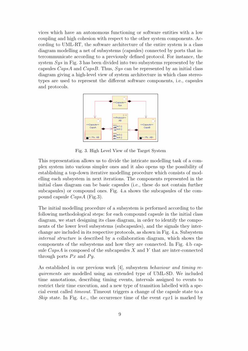
vices which have an autonomous functioning or software entities with a lowcoupling and high cohesion with respect to the other system components. Ac-cording to UML-RT, the software architecture of the entire system is a classdiagram modelling a net of subsystems (capsules) connected by ports that in-tercommunicate according to a previously defined protocol. For instance, thesystem Sys in Fig. 3 has been divided into two subsystems represented by thecapsules CapsA and CapsB. Thus, Sys can be represented by an initial classdiagram giving a high-level view of system architecture in which class stereo-types are used to represent the different software components, i.e., capsulesand protocols.
CapsB
+ / Pb : AB~
<<Capsule>>
Sys
<<Capsule>>
CapsA
+ / Pa : AB
<<Capsule>>
AB
ev1 ()
ev2 ()
ev3 ()
ev4 ()
<<Protocol>>
CapsB
+ / Pb : AB~
<<Capsule>>
Sys
<<Capsule>>
CapsA
+ / Pa : AB
<<Capsule>>
AB
ev1 ()
ev2 ()
ev3 ()
ev4 ()
<<Protocol>>
Fig. 3. High Level View of the Target System
This representation allows us to divide the intricate modelling task of a com-plex system into various simpler ones and it also opens up the possibility ofestablishing a top-down iterative modelling procedure which consists of mod-elling each subsystem in next iterations. The components represented in theinitial class diagram can be basic capsules (i.e., these do not contain furthersubcapsules) or compound ones. Fig. 4.a shows the subcapsules of the com-pound capsule CapsA (Fig.3).
The initial modelling procedure of a subsystem is performed according to thefollowing methodological steps: for each compound capsule in the initial classdiagram, we start designing its class diagram, in order to identify the compo-nents of the lower level subsystems (subcapsules), and the signals they inter-change are included in its respective protocols, as shown in Fig. 4.a. Subsysteminternal structure is described by a collaboration diagram, which shows thecomponents of the subsystems and how they are connected. In Fig. 4.b cap-sule CapsA is composed of the subcapsules X and Y that are inter-connectedthrough ports Px and Py.
As established in our previous work [4], subsystem behaviour and timing re-quirements are modelled using an extended type of UML-SD. We includedtime annotations, describing timing events, intervals assigned to events torestrict their time execution, and a new type of transition labelled with a spe-cial event called timeout. Timeout triggers a change of the capsule state to aSkip state. In Fig. 4.c., the occurrence time of the event eyx1 is marked by
9
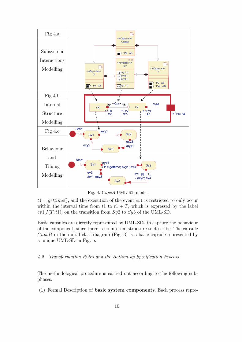
Fig 4.a
Subsystem
Interactions
Modelling
Fig 4.b
Internal
Structure
Modelling
Fig 4.c
Behaviour
and
Timing
Modelling
/ X / Y
+ / Pa : AB+ / Px
: XY
+ / Py
: XY~
+ / Pya
: AB
Cab1Cxy
+ / Pa : AB
/ X
+ / Px
: XY
/ Y
+ / Py
: XY~
+ / Pya
: AB
Cab1Cxy
CapsA
+ / Pa : AB
<<Capsule>>
X
+ / Px : XY
<<Capsule>> Y
+ / Py : XY~
+ / Pya : AB
<<Capsule>>XY
exy1 ()
exy2 ()
exy3 ()
eyx1 ()
<<Protocol>>
Sy1 Sy2
Sy3
eyx1
/ t1= gettime; exy1; ev3
Start
ev1
/ exy2; ev4
eyx1
/ t1= gettime; exy1; ev3
Start
ev1
/ exy2; ev4
[I(T,t1)]ev2
/ev4; exy3
ev2
/ev4; exy3
Sx1 Sx2
Sx3
Startexy1
exy2exy3
/eyx1
Startexy1
exy2exy3
/eyx1
Fig. 4. CapsA UML-RT model
t1 = gettime(), and the execution of the event ev1 is restricted to only occurwithin the interval time from t1 to t1 + T , which is expressed by the labelev1[I(T, t1)] on the transition from Sy2 to Sy3 of the UML-SD.
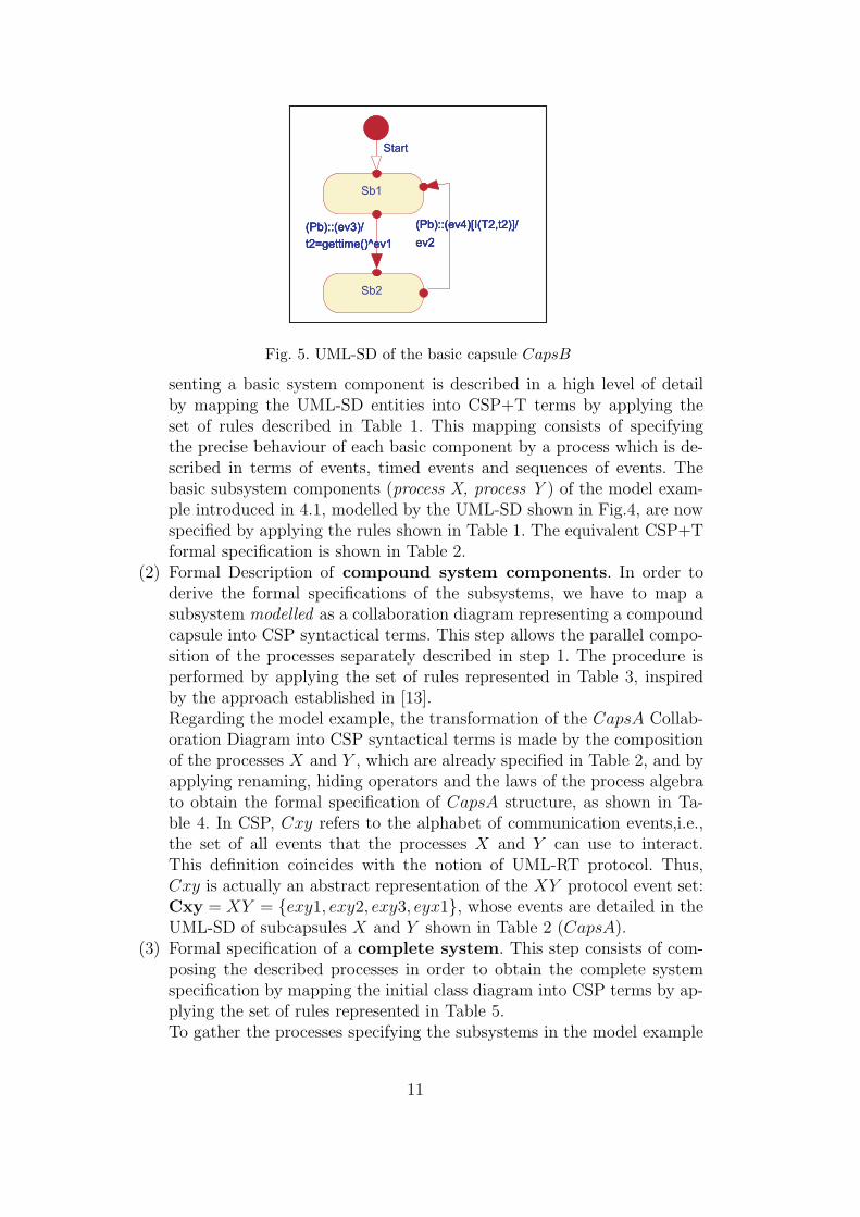
Basic capsules are directly represented by UML-SDs to capture the behaviourof the component, since there is no internal structure to describe. The capsuleCapsB in the initial class diagram (Fig. 3) is a basic capsule represented bya unique UML-SD in Fig. 5.
4.2 Transformation Rules and the Bottom-up Specification Process
The methodological procedure is carried out according to the following sub-phases:
(1) Formal Description of basic system components. Each process repre-
10
Sb1
Sb2
(Pb)::(ev3)/
t2=gettime()^ev1
(Pb)::(ev4)[I(T2,t2)]/
ev2
(Pb)::(ev3)/
t2=gettime()^ev1
(Pb)::(ev4)[I(T2,t2)]/
ev2
Start
Sb1
Sb2
(Pb)::(ev3)/
t2=gettime()^ev1
(Pb)::(ev4)[I(T2,t2)]/
ev2
(Pb)::(ev3)/
t2=gettime()^ev1
(Pb)::(ev4)[I(T2,t2)]/
ev2
Start
Fig. 5. UML-SD of the basic capsule CapsB
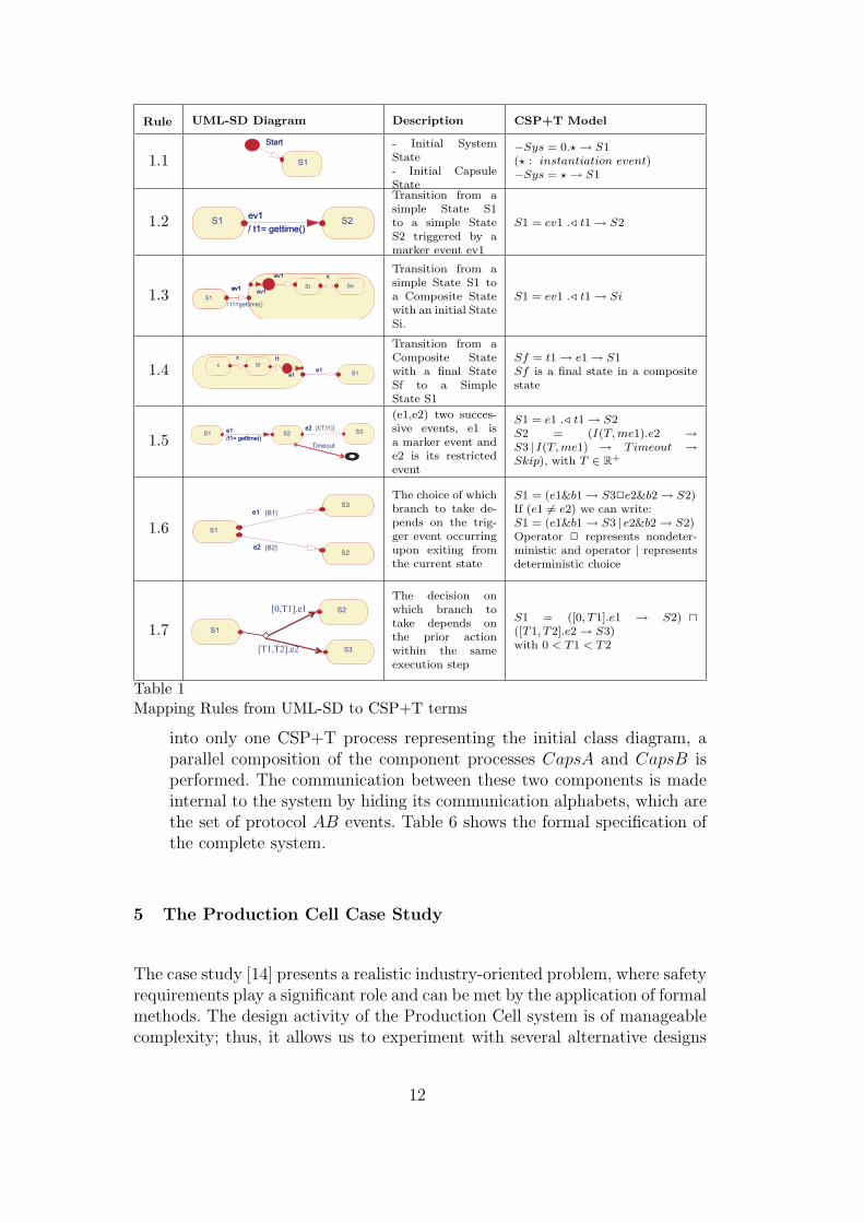
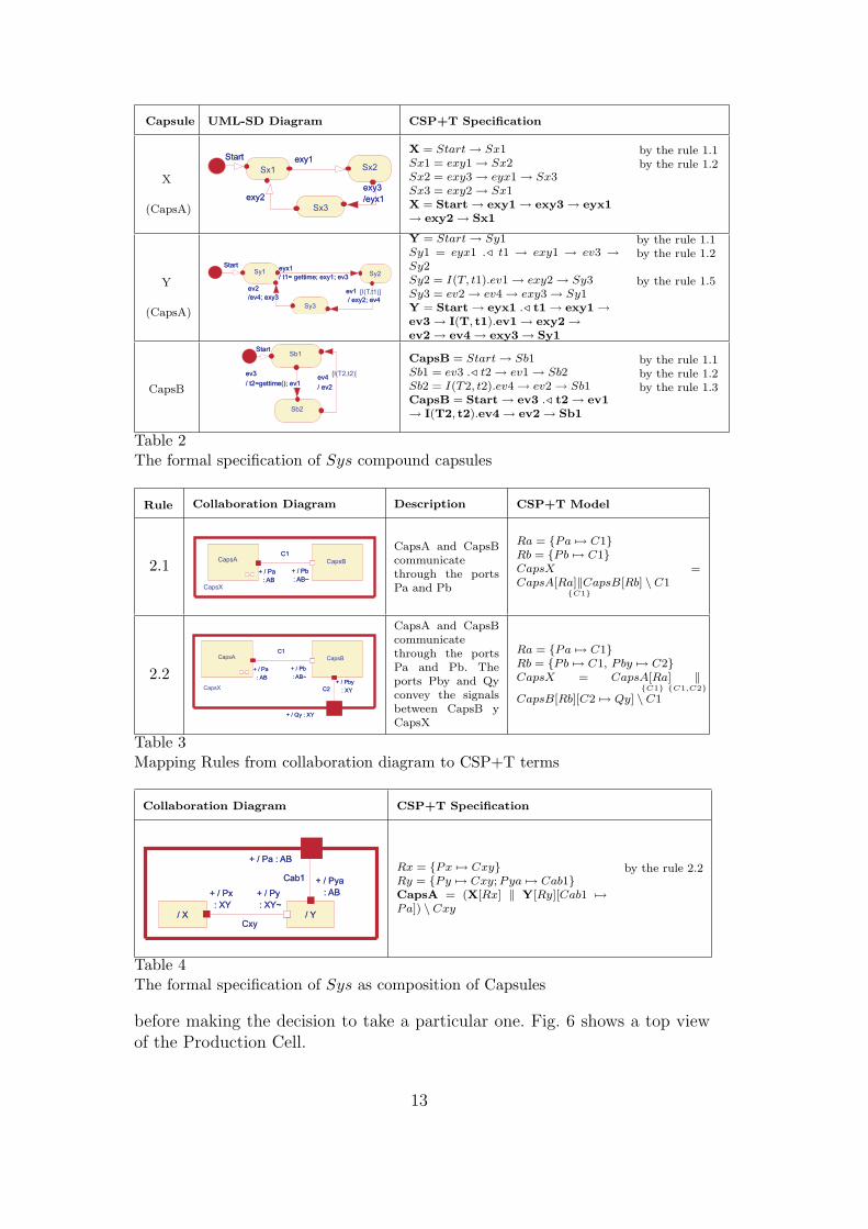
senting a basic system component is described in a high level of detailby mapping the UML-SD entities into CSP+T terms by applying theset of rules described in Table 1. This mapping consists of specifyingthe precise behaviour of each basic component by a process which is de-scribed in terms of events, timed events and sequences of events. Thebasic subsystem components (process X, process Y ) of the model exam-ple introduced in 4.1, modelled by the UML-SD shown in Fig.4, are nowspecified by applying the rules shown in Table 1. The equivalent CSP+Tformal specification is shown in Table 2.
(2) Formal Description of compound system components. In order toderive the formal specifications of the subsystems, we have to map asubsystem modelled as a collaboration diagram representing a compoundcapsule into CSP syntactical terms. This step allows the parallel compo-sition of the processes separately described in step 1. The procedure isperformed by applying the set of rules represented in Table 3, inspiredby the approach established in [13].Regarding the model example, the transformation of the CapsA Collab-oration Diagram into CSP syntactical terms is made by the compositionof the processes X and Y , which are already specified in Table 2, and byapplying renaming, hiding operators and the laws of the process algebrato obtain the formal specification of CapsA structure, as shown in Ta-ble 4. In CSP, Cxy refers to the alphabet of communication events,i.e.,the set of all events that the processes X and Y can use to interact.This definition coincides with the notion of UML-RT protocol. Thus,Cxy is actually an abstract representation of the XY protocol event set:Cxy = XY = {exy1, exy2, exy3, eyx1}, whose events are detailed in theUML-SD of subcapsules X and Y shown in Table 2 (CapsA).
(3) Formal specification of a complete system. This step consists of com-posing the described processes in order to obtain the complete systemspecification by mapping the initial class diagram into CSP terms by ap-plying the set of rules represented in Table 5.To gather the processes specifying the subsystems in the model example
11
Rule UML-SD Diagram Description CSP+T Model
1.1 S1
StartStart - Initial SystemState- Initial CapsuleState
−Sys = 0.? → S1(? : instantiation event)−Sys = ? → S1
1.2 S1 S2ev1
/ t1= gettime()
ev1
/ t1= gettime()
Transition from asimple State S1to a simple StateS2 triggered by amarker event ev1
S1 = ev1 ./ t1 → S2
1.3 S1
aev1ev1 Si Sx
xev1
ev1ev1
xev1
S1
aev1ev1 Si Sx
xev1
ev1ev1
xev1
/ t1=gettime()
Transition from asimple State S1 toa Composite Statewith an initial StateSi.
S1 = ev1 ./ t1 → Si
1.4 S1e1e1
e1e1
x Sf
xx t1t1
Transition from aComposite Statewith a final StateSf to a SimpleState S1
Sf = t1 → e1 → S1Sf is a final state in a compositestate
1.5 Timeout
S1 S2 S3e2e1
/t1= gettime()
e1
/t1= gettime()
[I(T,t1)]e2
(e1,e2) two succes-sive events, e1 isa marker event ande2 is its restrictedevent
S1 = e1 ./ t1 → S2S2 = (I(T, me1).e2 →S3 | I(T, me1) → T imeout →Skip), with T ∈ R+
1.6 S1
S2
S3e1e1
e2e2
[B1]
[B2]
The choice of whichbranch to take de-pends on the trig-ger event occurringupon exiting fromthe current state
S1 = (e1&b1 → S32e2&b2 → S2)If (e1 6= e2) we can write:S1 = (e1&b1 → S3 | e2&b2 → S2)Operator 2 represents nondeter-ministic and operator | representsdeterministic choice
1.7 S1
S3
S2[0,T1].e1
[T1,T2].e2
The decision onwhich branch totake depends onthe prior actionwithin the sameexecution step
S1 = ([0, T1].e1 → S2) u([T1, T2].e2 → S3)with 0 < T1 < T2
Table 1Mapping Rules from UML-SD to CSP+T terms
into only one CSP+T process representing the initial class diagram, aparallel composition of the component processes CapsA and CapsB isperformed. The communication between these two components is madeinternal to the system by hiding its communication alphabets, which arethe set of protocol AB events. Table 6 shows the formal specification ofthe complete system.
5 The Production Cell Case Study
The case study [14] presents a realistic industry-oriented problem, where safetyrequirements play a significant role and can be met by the application of formalmethods. The design activity of the Production Cell system is of manageablecomplexity; thus, it allows us to experiment with several alternative designs
12
Capsule UML-SD Diagram CSP+T Specification
X
(CapsA)
Sx1 Sx2
Sx3
Start exy1
exy2exy3
/eyx1
Start exy1
exy2exy3
/eyx1
X = Start → Sx1Sx1 = exy1 → Sx2Sx2 = exy3 → eyx1 → Sx3Sx3 = exy2 → Sx1X = Start → exy1 → exy3 → eyx1→ exy2 → Sx1
by the rule 1.1by the rule 1.2
Y
(CapsA)
Sy1 Sy2
Sy3
eyx1
/ t1= gettime; exy1; ev3
Start
ev1
/ exy2; ev4
eyx1
/ t1= gettime; exy1; ev3
Start
ev1
/ exy2; ev4
[I(T,t1)]ev2
/ev4; exy3
ev2
/ev4; exy3
Y = Start → Sy1Sy1 = eyx1 ./ t1 → exy1 → ev3 →Sy2Sy2 = I(T, t1).ev1 → exy2 → Sy3Sy3 = ev2 → ev4 → exy3 → Sy1Y = Start → eyx1 ./ t1 → exy1 →ev3 → I(T, t1).ev1 → exy2 →ev2 → ev4 → exy3 → Sy1
by the rule 1.1by the rule 1.2
by the rule 1.5
CapsB
Sb1
Sb2
ev3
/ t2=gettime(); ev1
Start
ev4
/ ev2
ev3
/ t2=gettime(); ev1
Start
ev4
/ ev2
[I(T2,t2)]
CapsB = Start → Sb1Sb1 = ev3 ./ t2 → ev1 → Sb2Sb2 = I(T2, t2).ev4 → ev2 → Sb1CapsB = Start → ev3 ./ t2 → ev1→ I(T2, t2).ev4 → ev2 → Sb1
by the rule 1.1by the rule 1.2by the rule 1.3
Table 2The formal specification of Sys compound capsules
Rule Collaboration Diagram Description CSP+T Model
2.1 + / Pb
: AB~
+ / Pa
: AB
C1
+ / Pb
: AB~
+ / Pa
: AB
C1CapsA CapsB
CapsX
CapsA and CapsBcommunicatethrough the portsPa and Pb
Ra = {Pa 7→ C1}Rb = {Pb 7→ C1}CapsX =CapsA[Ra]
{C1}‖CapsB[Rb] \ C1
2.2 + / Pb
: AB~
+ / Pa
: AB
C1
+ / Pb
: AB~
+ / Pa
: AB
C1CapsA CapsB
CapsX
+ / Qy : XY+ / Qy : XY
+ / Pby
: XY
+ / Pby
: XYC2C2
CapsA and CapsBcommunicatethrough the portsPa and Pb. Theports Pby and Qyconvey the signalsbetween CapsB yCapsX
Ra = {Pa 7→ C1}Rb = {Pb 7→ C1, P by 7→ C2}CapsX = CapsA[Ra]
{C1} {C1,C2}‖
CapsB[Rb][C2 7→ Qy] \ C1
Table 3Mapping Rules from collaboration diagram to CSP+T terms
Collaboration Diagram CSP+T Specification
/ X / Y
+ / Pa : AB
+ / Px
: XY
+ / Py
: XY~
+ / Pya
: AB
Cxy
+ / Pa : AB
/ X
+ / Px
: XY/ Y
+ / Py
: XY~
+ / Pya
: AB
Cxy
Cab1Cab1Rx = {Px 7→ Cxy}Ry = {Py 7→ Cxy; Pya 7→ Cab1}CapsA = (X[Rx] ‖ Y[Ry][Cab1 7→Pa]) \ Cxy
by the rule 2.2
Table 4The formal specification of Sys as composition of Capsules
before making the decision to take a particular one. Fig. 6 shows a top viewof the Production Cell.
13
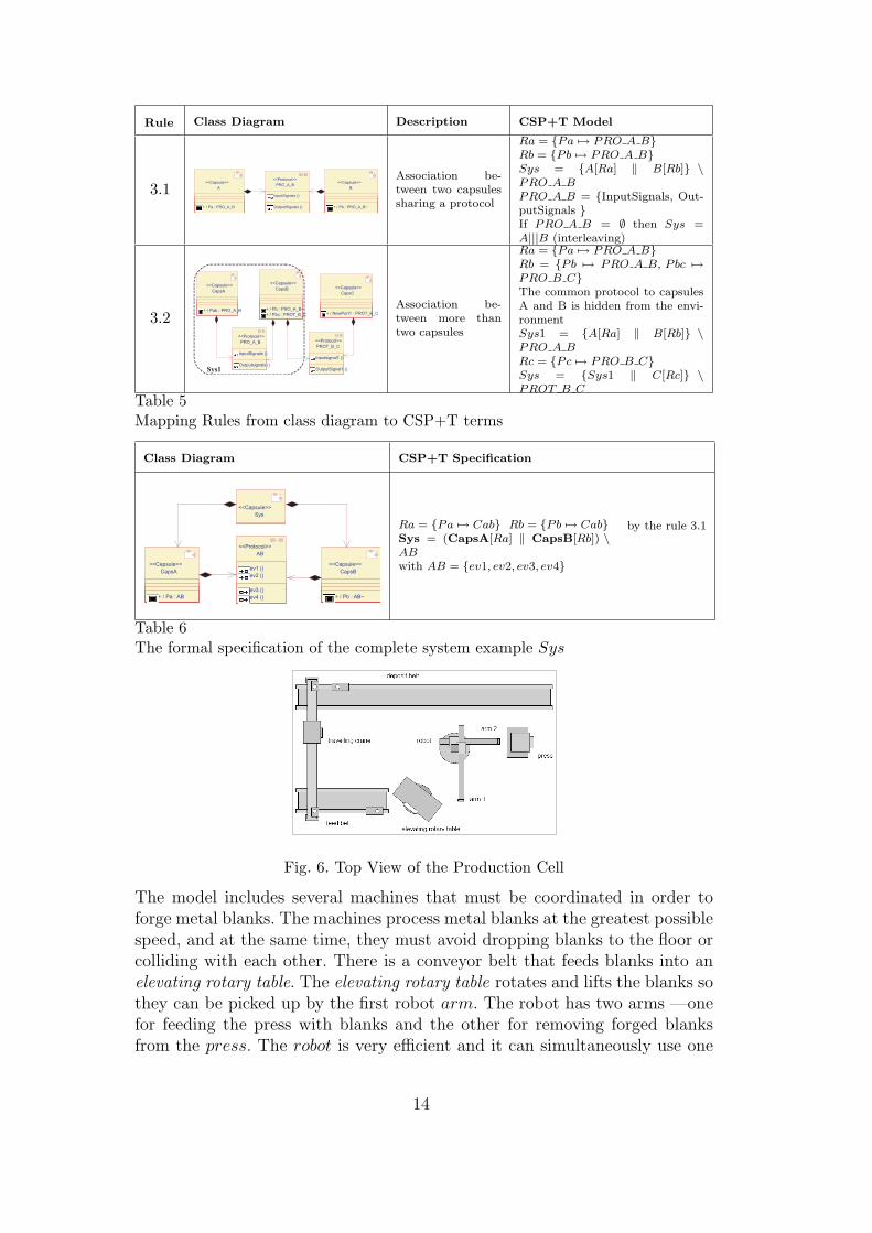
Rule Class Diagram Description CSP+T Model
3.1 A
+ / Pa : PRO_A_B
<<Capsule>>
B
+ / Pb : PRO_A_B~
<<Capsule>>PRO_A_B
InputSignals ()
OutputSignals ()
<<Protocol>> Association be-tween two capsulessharing a protocol
Ra = {Pa 7→ PRO A B}Rb = {Pb 7→ PRO A B}Sys = {A[Ra] ‖ B[Rb]} \PRO A BPRO A B = {InputSignals, Out-putSignals }If PRO A B = ∅ then Sys =A|||B (interleaving)
3.2
CapsA
+ / Pab : PRO_A_B
<<Capsule>>CapsB
+ / Pb : PRO_A_B~
+ / Pbc : PROT_B_C
<<Capsule>>
PRO_A_B
<<Protocol>>
InputSignals ()
Outputsignals ()
PROT_B_C
<<Protocol>>
Inputsignal1 ()
OutputSignal1 ()
CapsC
+ / NewPort1 : PROT_B_C
<<Capsule>>
Sys1
Association be-tween more thantwo capsules
Ra = {Pa 7→ PRO A B}Rb = {Pb 7→ PRO A B, Pbc 7→PRO B C}The common protocol to capsulesA and B is hidden from the envi-ronmentSys1 = {A[Ra] ‖ B[Rb]} \PRO A BRc = {Pc 7→ PRO B C}Sys = {Sys1 ‖ C[Rc]} \PROT B C
Table 5Mapping Rules from class diagram to CSP+T terms
Class Diagram CSP+T Specification
CapsB
+ / Pb : AB~
<<Capsule>>
Sys
<<Capsule>>
CapsA
+ / Pa : AB
<<Capsule>>
AB
ev1 ()
ev2 ()
ev3 ()
ev4 ()
<<Protocol>>
Ra = {Pa 7→ Cab} Rb = {Pb 7→ Cab}Sys = (CapsA[Ra] ‖ CapsB[Rb]) \ABwith AB = {ev1, ev2, ev3, ev4}
by the rule 3.1
Table 6The formal specification of the complete system example Sys
Fig. 6. Top View of the Production Cell
The model includes several machines that must be coordinated in order toforge metal blanks. The machines process metal blanks at the greatest possiblespeed, and at the same time, they must avoid dropping blanks to the floor orcolliding with each other. There is a conveyor belt that feeds blanks into anelevating rotary table. The elevating rotary table rotates and lifts the blanks sothey can be picked up by the first robot arm. The robot has two arms —onefor feeding the press with blanks and the other for removing forged blanksfrom the press. The robot is very efficient and it can simultaneously use one
14
arm to place a forged blank into the deposit belt and the other arm to conveya new blank to the press.
5.1 Robot and Press
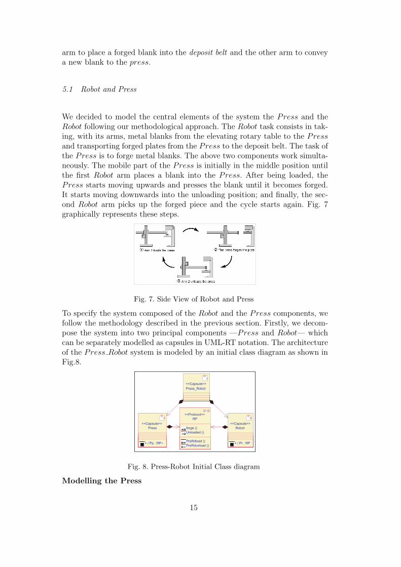
We decided to model the central elements of the system the Press and theRobot following our methodological approach. The Robot task consists in tak-ing, with its arms, metal blanks from the elevating rotary table to the Pressand transporting forged plates from the Press to the deposit belt. The task ofthe Press is to forge metal blanks. The above two components work simulta-neously. The mobile part of the Press is initially in the middle position untilthe first Robot arm places a blank into the Press. After being loaded, thePress starts moving upwards and presses the blank until it becomes forged.It starts moving downwards into the unloading position; and finally, the sec-ond Robot arm picks up the forged piece and the cycle starts again. Fig. 7graphically represents these steps.
Fig. 7. Side View of Robot and Press
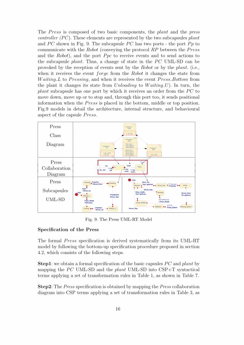
To specify the system composed of the Robot and the Press components, wefollow the methodology described in the previous section. Firstly, we decom-pose the system into two principal components —Press and Robot— whichcan be separately modelled as capsules in UML-RT notation. The architectureof the Press Robot system is modeled by an initial class diagram as shown inFig.8.
Press_Robot
<<Capsule>>
Press
+ / Pp : RP~
<<Capsule>>
Robot
+ / Pr : RP
<<Capsule>>
RP
forge ()
Unloaded ()
PrsRdload ()
PrsRdunload ()
<<Protocol>>
Press_Robot
<<Capsule>>
Press
+ / Pp : RP~
<<Capsule>>
Robot
+ / Pr : RP
<<Capsule>>
RP
forge ()
Unloaded ()
PrsRdload ()
PrsRdunload ()
<<Protocol>>
Fig. 8. Press-Robot Initial Class diagram
Modelling the Press
15
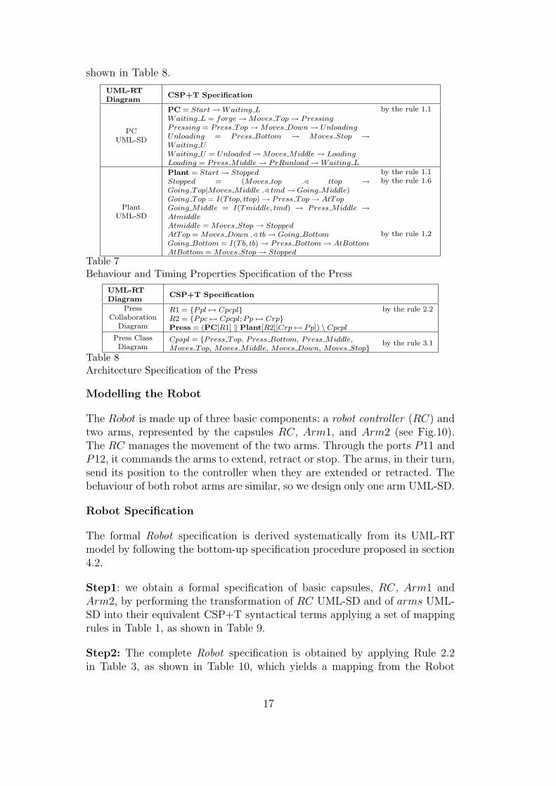
The Press is composed of two basic components, the plant and the presscontroller (PC ). These elements are represented by the two subcapsules plantand PC shown in Fig. 9. The subcapsule PC has two ports - the port Pp tocommunicate with the Robot (conveying the protocol RP between the Pressand the Robot), and the port Ppc to receive events and to send actions tothe subcapsule plant. Thus, a change of state in the PC UML-SD can beprovoked by the reception of events sent by the Robot or by the plant. (i.e.,when it receives the event forge from the Robot it changes the state fromWaiting L to Pressing, and when it receives the event Press Bottom fromthe plant it changes its state from Unloading to Waiting U). In turn, theplant subcapsule has one port by which it receives an order from the PC tomove down, move up or to stop and, through this port too, it sends positionalinformation when the Press is placed in the bottom, middle or top position.Fig.9 models in detail the architecture, internal structure, and behaviouralaspect of the capsule Press.
Press
Class
Diagram
PressCollaboration
Diagram
Press
Subcapsules
UML-SD
Fig. 9. The Press UML-RT Model
Specification of the Press
The formal Press specification is derived systematically from its UML-RTmodel by following the bottom-up specification procedure proposed in section4.2, which consists of the following steps.
Step1: we obtain a formal specification of the basic capsules PC and plant bymapping the PC UML-SD and the plant UML-SD into CSP+T syntacticalterms applying a set of transformation rules in Table 1, as shown in Table 7.
Step2: The Press specification is obtained by mapping the Press collaborationdiagram into CSP terms applying a set of transformation rules in Table 3, as
16
shown in Table 8.
UML-RTDiagram
CSP+T Specification
PCUML-SD
PC = Start → Waiting LWaiting L = forge → Moves Top → PressingPressing = Press Top → Moves Down → UnloadingUnloading = Press Bottom → Moves Stop →Waiting UWaiting U = Unloaded → Moves Middle → LoadingLoading = Press Middle → PrRunload → Waiting L
by the rule 1.1
PlantUML-SD
Plant = Start → StoppedStopped = (Moves top ./ ttop →Going Top|Moves Middle ./ tmd → Going Middle)Going Top = I(Ttop, ttop) → Press Top → AtTopGoing Middle = I(Tmiddle, tmd) → Press Middle →AtmiddleAtmiddle = Moves Stop → StoppedAtTop = Moves Down ./ tb → Going BottomGoing Bottom = I(Tb, tb) → Press Bottom → AtBottomAtBottom = Moves Stop → Stopped
by the rule 1.1by the rule 1.6
by the rule 1.2
Table 7Behaviour and Timing Properties Specification of the Press
UML-RTDiagram
CSP+T Specification
PressCollaboration
Diagram
R1 = {Ppl 7→ Cpcpl}R2 = {Ppc 7→ Cpcpl; Pp 7→ Crp}Press = (PC[R1] ‖ Plant[R2][Crp 7→ Pp]) \ Cpcpl
by the rule 2.2
Press ClassDiagram
Cpspl = {Press Top, Press Bottom, Press Middle,Moves Top, Moves Middle, Moves Down, Moves Stop} by the rule 3.1
Table 8Architecture Specification of the Press
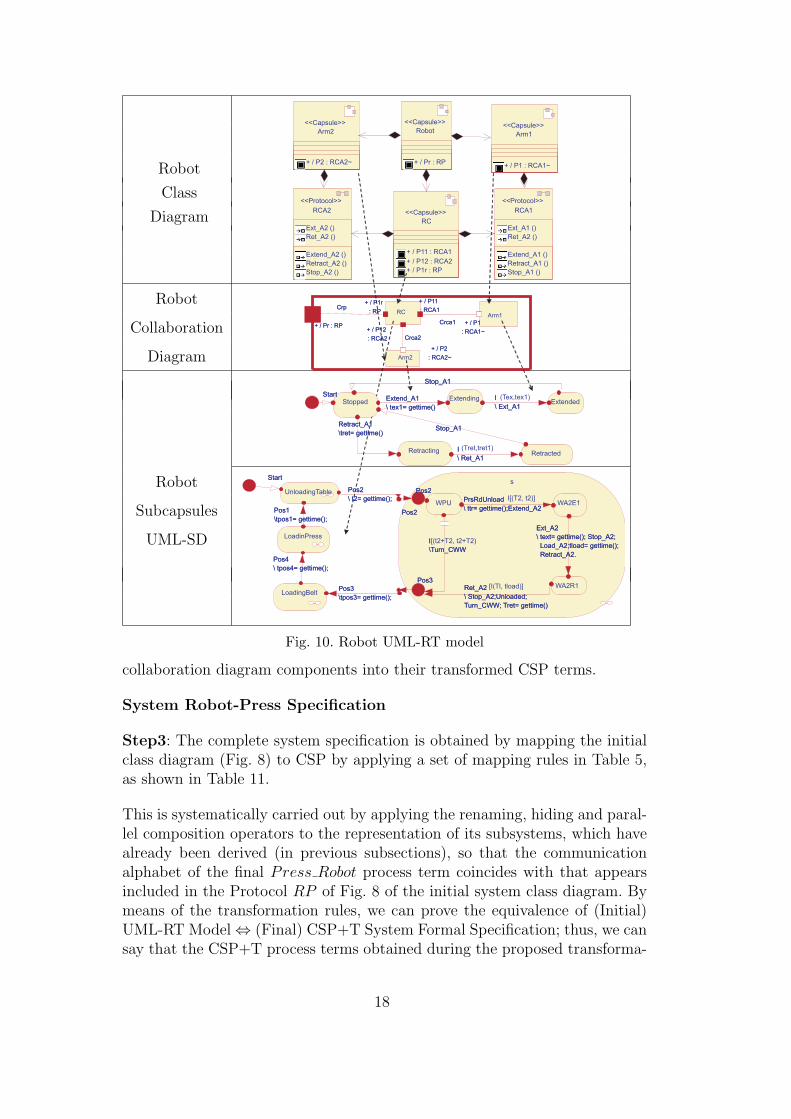
Modelling the Robot
The Robot is made up of three basic components: a robot controller (RC) andtwo arms, represented by the capsules RC, Arm1, and Arm2 (see Fig.10).The RC manages the movement of the two arms. Through the ports P11 andP12, it commands the arms to extend, retract or stop. The arms, in their turn,send its position to the controller when they are extended or retracted. Thebehaviour of both robot arms are similar, so we design only one arm UML-SD.
Robot Specification
The formal Robot specification is derived systematically from its UML-RTmodel by following the bottom-up specification procedure proposed in section4.2.
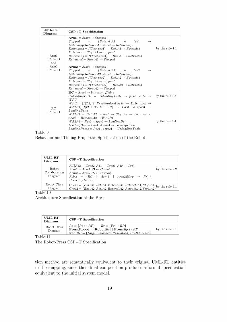
Step1: we obtain a formal specification of basic capsules, RC, Arm1 andArm2, by performing the transformation of RC UML-SD and of arms UML-SD into their equivalent CSP+T syntactical terms applying a set of mappingrules in Table 1, as shown in Table 9.
Step2: The complete Robot specification is obtained by applying Rule 2.2in Table 3, as shown in Table 10, which yields a mapping from the Robot
17
Robot
Class
Diagram
Robot
Collaboration
Diagram
Robot
Subcapsules
UML-SD
Fig. 10. Robot UML-RT model
collaboration diagram components into their transformed CSP terms.
System Robot-Press Specification
Step3: The complete system specification is obtained by mapping the initialclass diagram (Fig. 8) to CSP by applying a set of mapping rules in Table 5,as shown in Table 11.
This is systematically carried out by applying the renaming, hiding and paral-lel composition operators to the representation of its subsystems, which havealready been derived (in previous subsections), so that the communicationalphabet of the final Press Robot process term coincides with that appearsincluded in the Protocol RP of Fig. 8 of the initial system class diagram. Bymeans of the transformation rules, we can prove the equivalence of (Initial)UML-RT Model ⇔ (Final) CSP+T System Formal Specification; thus, we cansay that the CSP+T process terms obtained during the proposed transforma-
18
UML-RTDiagram
CSP+T Specification
Arm1UML-SD
andArm2
UML-SD
Arm1 = Start → StoppedStopped = (Extend A1 ./ tex1 →Extending|Retract A1 ./ tret → Retracting)Extending = I(Tex, tex1) → Ext A1 → ExtendedExtended = Stop A1 → StoppedRetracting = I(Tret, tret1) → Ret A1 → RetractedRetracted = Stop A1 → Stopped
Arm2 = Start → StoppedStopped = (Extend A2 ./ tex2 →Extending|Retract A2 ./ tret → Retracting)Extending = I(Tex, tex2) → Ext A2 → ExtendedExtended = Stop A2 → StoppedRetracting = I(Tret, tret2) → Ret A2 → RetractedRetracted = Stop A2 → Stopped
by the rule 1.1
RCUML-SD
RC = Start → UnloadingTableUnloadingTable = UnloadingTable → pos2 ./ t2 →WPUWPU = (I(T2, t2).P rsRdunload ./ ttr → Extend A2 →WA2E1)|(I[t2 + T2, te + T2] → Pos3 ./ tpos3 →LoadingBelt)WA2E1 = Ext A2 ./ text → Stop A2 → Load A2 ./tload → Retract A2 → WA2R1WA2R1 = Pos3 ./ tpos3 → LoadingBeltLoadingBelt = Pos4 ./ tpos4 → LoadingPressLoadingPress = Pos1 ./ tpos1 → UnloadingTable
by the rule 1.3
by the rule 1.4
Table 9Behaviour and Timing Properties Specification of the Robot
UML-RTDiagram
CSP+T Specification
RobotCollaboration
Diagram
RC[P12 7→ Crca2; P11 7→ Crca1; P1r 7→ Crp}Arm1 = Arm1[P1 7→ Ccrca1]Arm2 = Arm2[P2 7→ Ccrca2]Robot = (RC ‖ Arm1 ‖ Arm2)[Crp 7→ Pr] \{Ccrca1, Crca2}
by the rule 2.2
Robot ClassDiagram
Crca1 = {Ext A1, Ret A1, Extend A1, Retract A1, Stop A1}Crca2 = {Ext A2, Ret A2, Extend A2, Retract A2, Stop A2}by the rule 3.1
Table 10Architecture Specification of the Press
UML-RTDiagram
CSP+T Specification
Robot ClassDiagram
Rp = {Pp 7→ RP} Rr = {Pr 7→ RP}Press Robot = (Robot[Rr] ‖ Press[Rp]) \RPwith RP = {forge, unloaded, PrsRdload, PrsRdunload}
by the rule 3.1
Table 11The Robot-Press CSP+T Specification
tion method are semantically equivalent to their original UML-RT entitiesin the mapping, since their final composition produces a formal specificationequivalent to the initial system model.
19
6 Related work
The basis for the transformation method given in the previous sections is aformalisation obtained by applying a set of transformation rules which giveformal semantics to the semi-formal analysis entities of UML-RT. The mostimportant differences with analogous works are indicated below.
Semantics for UML-RT active classes through a mapping into Circus —a spec-ification language that combines CSP, Z, and specification statements— isproposed in [7]. The formalisation proposed for UML-RT structure diagramsis similar to the one in [13], which formalises this kind of diagram in CSPonly, whereas disregards other views and elements of the architecture, likestatecharts and protocols. The work reported in [15] briefly presents some no-tions that could be used as a basis for a mapping from UML-RT into CSP.But taking these notions as the fundamentals of a specification method willonly complicate the derivation of a complete specification of complex systems,including all their aspects, without making any additional assumptions aboutthe dynamic system semantics, as well as giving a coherent interpretation oftemporal constraints. The latter work briefly covers simple capsule statecharts,and does not give any additional contribution on other UML-RT elements orincorporates temporal constraints.
An informal translation of UML-RT into CSP-OZ is also reported in [16]by means of a case study. Despite the benefit of linking UML-RT to CSP-OZ and Java, this work does not seem to be concerned with the soundness oftransformations for UML-RT. It has never been indicated how the architecturecan be obtained if the system execution must fulfil timing constraints.
Finally, it is important to mention that there are researchers who deal withthe analysis of time using UML sequence and statechart diagrams. The workcarried out in [17] focused on the consistency of sequence diagrams and stat-echarts, and that carried out in [18] studies the timing consistency of UMLsequence diagrams. The difference between the proposals appearing in thesereferences and our own work is that these researches do not take into accounthow the real-time constraints can be managed through the entire analysis-design process. Our method allows the transformation of the analysis-designentities used in UML-RT into a CSP+T terms that include real-time con-straints, and thus opens up the possibility of verifying a software system designthat also includes real-time constraints.
20
7 Conclusions and Future work
In this paper we have presented a complete methodological approach to deriv-ing a correct and complete formal specification of RTS. The method describedis a new systematic transformation procedure for obtaining the complete de-sign of an RTS by giving structured operational semantics in terms of CSP+Tprocess algebra to the semi-formal UML-RT analysis entities.
Our methodological approach introduced in a previous paper, is complementedin this work with the integration of collaboration diagrams in order to cap-ture the internal structures of system components and their connections. Thisnew contribution strengthens our method since we can systematically obtaina detailed system specification from an initial UML model of high level ofabstraction. We have profited from the UML Object Oriented Paradigm inorder to obtain a compositional technique based on specifying each systemcapsule individually and subsequently composing them by using CSP+T op-erators. Timing properties specification has been included in the proposal, sothat they are taken into account to ensure that RTS properties are fulfilled.
In order to gain insight to our method performance if applied to measure othersoftware architectures, we are trying to measure the method applicability byfollowing a feature analysis case study, similar to the one presented in [19,20].Future research directions are connected with the application of the proposedmethodology to formal engineering of real-time systems software, specificallyin three main fields: (1) software design automation, (2) automatic verificationtools to check formal specifications against a UML-RT model of the system,(3) code generation, for different programming languages and platforms, froma formal specification.
References
[1] Object Management Group, UML Superstructure Specification - version 2.0,Object Management Group, Massachusetts, USA, 2004.
[2] B. Selic, J. Rumbaugh, UML For Modeling Complex Real-Time Systems,ObjecTime Technical Report, ObjecTime, New York, 1998.
[3] B. Selic, G. Gullekson, P. Ward, Real-Time Object-Oriented Modeling, JohnWiley & Sons, Ltd., New York, 1994.
[4] M. Capel, K. Benghazi, J. Holgado, Combining the description features of UML-RT and CSP+T specifications applied to a complete design of real-time system,International Journal of Information Technology 2 (2) (2005) 137–146.
[5] A. Evans, A. Clark, Foundations of the unified modeling language.
21
[6] S.-K. Kim, D. Carrington, Formalizing the UML Class Diagram Using Object-Z, Lecture Notes in Computer Science 1723: UML 99 - The Unified ModelingLanguage: Beyond the Standard, Springer-Verlag, Berlin, 1999, pp. 83–98.
[7] R. Ramos, A. Sampaio, A. Mota, A Semantics for UML-RT Active Classes viaMapping into Circus, Lecture Notes in Computer Science 3535: InternationalConference of Formal Methods for Open Object-Based Distributed SystemsFMOODS 2005, Springer-Verlag, Berlin, 2005, pp. 99–114.
[8] J. Woodcock, A. Cavalcanti, The Semantics of Circus, Lecture Notes inComputer Science 2272: Formal Specification and Development in Z and B: 2ndInternational Conference of B and Z Users ZB 2002, Springer-Verlag, Berlin,2002, pp. 184–203.
[9] C. Hoare, Communicating Sequential Processes, International Series inComputer Science, Prentice-Hall International Ltd., Hertfordshire UK, 1985.
[10] A. Roscoe, The Theory and Practice of Concurrency, Prentice-HallInternational Ltd., Hertfordshire UK, 1997.
[11] J. Zic, Time-constrained buffer specifications in CSP+T and timed CSP, ACMTransaction on Programming Languages and Systems 16 (6) (1994) 1661–1674.
[12] V-Modell XT Team, V-Modell R©XT, version 1.2.0, Bundesministerium desInnern, Berlin, 2004.
[13] C. Fischer, E.-R. Olderog, H. Wehrheim, A CSP View on UML-RT StructureDiagram, Lecture Notes in Computer Science 2029: Fundamental Approachesto Software Engineering, Springer-Verlag, Berlin, 2001, pp. 91–108.
[14] T. Lindner, Task Description, Lecture Notes in Computer Science 891: FormalDevelopment of Reactive Systems: Case Study Production Cell, Springer-Verlag, Berlin, 1995, pp. 7–19.
[15] G. Engels, J. Kuster, R. Heckel, L. Groenewegen, A methodology for specifyingand analyzing consistency of object-oriented behavioral models, in: ESEC/FSE-9: Proceedings of the 8th European software engineering conference held jointlywith 9th ACM SIGSOFT international symposium on Foundations of softwareengineering, ACM Press, New York, NY, USA, 2001, pp. 186–195.
[16] M. Moller, E.-R. Olderog, H. Rasch, H. Wehrheim, Linking CSP-OZ withUML and Java: A Case Study, Lecture Notes in Computer Science 2999: 4thInternational Conference of Integrated Formal Methods IFM 2004, Springer-Verlag, Berlin, 2005, pp. 267–286.
[17] J. Kuster, J. Stroop, Consistent design of embedded real-time systems withUML-RT, in: Proc. Fourth IEEE International Symposium on Object-OrientedReal-Time Distributed Computing ISORC - 2001, IEEE Computer SocietyPress, Magdeburg, Germany, 2001, pp. 31–40.
[18] X. Li, J. Lilius, Timing Analysis of UML Sequence Diagrams, Lecture Notesin Computer Science 1723: UML 99 - The Unified Modeling Language: Beyondthe Standard, Springer-Verlag, Berlin, 2005, pp. 661–674.
22
[19] J. Erickson, K. Siau, Toward practical measures of complexity in real-timemodeling methods, in: Proc. Eleventh Americas Conference on InformationSystems AMCIS - 2005, Association for Information Systems, Omaha, USA,2005, pp. 3067–3074.
[20] B. Kitchenham, L. Jones, Evaluating software engineering methods and tools,part 8: Analysing a feature analysis evaluation, SIGSOFT Software EngineeringNotes 22 (5) (1997) 10–12.
23