a m p h e n o l fi l t e r e d c o n n e c t o r s - biakom
TRANSCRIPT
A m p h e n o lFi l t e r e dC o n n e c t o r sF i l t e red ARINCConnectors
F i l t e red MIL-C-24308C o n n e c t o r s
Quadrax Connectors
Amphenol Canada Corp.an ISO 9001 company

Amphenol Canada, a subsidiary of A m p h e n o lCorporation, is an international leader in the manufac-ture of filter connectors and has been pioneering EMI andEMP technologies for more than 40 years.
Located in Toronto, Canada, our modern 60,000 sq. ft.facility employs ap p rox i m a t e ly 250 people, and isdedicated to the manufacture of filter connectors. Wedesign, develop and manufacture EMI and EMP filterconnectors which are used world-wide in Military,Aerospace,Communication and Commercial applications.Our products are unique, o f fering stre s s - i s o l a t e d ,
solderless technology in tubular, p l a n a r, and chip capacitor designs.
Amphenol Canada is vertically integrated and, with theexception of diodes, has the capability of manufacturing allelements of our filter connectors. We also have thesupport of other Amphenol divisions in an integratedworking relationship as one of the largest connectormanufacturing companies in the world.
Our expertise in understanding and supporting ourcustomers’ filter interconnect needs has earned us areputation of quality and excellence among the world’sleading users of electronic components.
A bout The Company
C o n n e c t i n g S o l u t i o n sC o n n e c t i n g S o l u t i o n s
A m p h e n o l C u s t o m P r o d u c t s
Amphenol custom pro d u c t s .Helping to make design
d reams re a l i t y.
Table of Contents
Introduction to Filter Connectors Advantages of Filter Connectors .............................................................................................................................. 2Filter Connector Design ....................................................................... . . . . . . . . . . . . . . . . . . . . . . . . . . . . . . . . . . . . . . . . . . . . . . . . .. . .. ............... 2Filter Connector Selection .................................................................................................................... . . . . . . . . . ............. 3
Filtered ARINC 600 and 404 connectors (485 series)Introduction and Design Features ........................................................................................................... . . . ................ 4Cross-section and Material Specification ............................................................................................... ................... 5Electrical Characteristics .......................................................................................................... . . . . . . . . . . . . ....................... 6ARINC 600 Dimensions ................................................................................................................... . . . . . . ........... 7 and 8ARINC 600 Insert Arrangements ......................................................................................................................... . ..... 9ARINC 404 Dimensions ..................................................................................................................................10 and 1 1ARINC 404 Insert Arrangements ................................................................................... . . . . . . . . . . . . . . . . . . .. . . . . ................... 1 2ARINC 404 and 600 Termination Styles .......................................................................................... . . . . . . . . . . . . .. . . . ........ 1 2Transient Suppression for Lightning and EMP Applications ...................................................................... . . . ....... 1 3Diode Electrical Characteristics ................................................................................................................. . . . . . ......... 1 4Termination Module .................................................................................................................................................. . . . .15ARINC Accessories ......................................................................................................................................................1 6ARINC Part Numbering System ................................................................................................................... . . . ..........1 6
Quadrax Connectors and ContactsIntroduction and Design Features..................................................................................................... . . . . . . . . . . . . . . . . . . . . ...... 1 7Quadrax Contact Part Numbering System..................................................................................................... . . . . ...... 1 8Quadrax Insert Arrangements................................................................................................................................ . . . . .. 1 9Quadrax Contact Electrical Pe r fo r m a n c e. . . . . . . . . . . . . . . . . . . . . . . . . . . . . . . . . . . . . . . . . . . . . . . . . . . . . . . . . . . . . . . . . . . . . . . . . . . . . . . . . . . . . . . . . . . . . . . . . . . . . . . . . .. . . . .. . . . . . 2 0
Filtered D-Sub Connectors (308 Series)Introduction and Design Features .............................................................................................................. . . . . . . . ....... 2 1Cross-section and Material Specification ............................................................................................... . . . . . . . . . . . . ..... 22Electrical Characteristics ............................................................................................................................................ 2 3Dimensions .............................................................................................. . . . . . . . . . . . . . . . . . . . . . . . . . . . . . . . . . . . . . . . . .............................. 24Termination Styles .................................................................................... . . . . . . . . . . . . . . . . . . . . . . . . . . . . . . . . . . . . . . . . . . . . . . . . . . . .................2 5Mounting Styles .................................................................................................................................................25 and2 6Part Numbering System ................................................................................................................... . . . . . . . .. . . . . . . . . . . . . . ..... 26Insert Arrangements and Panel Cutout ................................................................................................. . . . . . . . . . . . . . . . ..... 27
FX SeriesFilter Terminal Blocks, Discrete Filters and Specials .... . . . . . . . . . . . . . . . . . . . . . . . . . . . . . . . . . . . . . . . . .................................................28
A m p h e n o l F i l t e r e d C o n n e c t o r s 2
Filter connectors have been used for over thirt yyears to provide cost and space effe c t i ve solutions toEMI problems in a wide range of military andc o m m e rcial applications including avionics systems,s a t e l l i t e s , m i s s i l e s , c o m mu n i c a t i o n s , c o n t rol systemsand tempest equipment. A low pass filter connectorincorporates capacitors and fe rrite inductors intothe connector body. The two capacitor typesc o m m o n ly used in filter connectors for military or
avionics applications are planar arr ays and tubularc ap a c i t o r s . Each of these capacitor types is anefficient filter at high frequencies (>1 GHz) and hasbeen proven to be extre m e ly reliable when suitablyassembled into a connector. Both planar and tubulardesigns fe a t u re A m p h e n o l ’s unique solderlessconstruction which reduces stress on the ceramicelements and results in superior physical andthermal shock cap a b i l i t i e s .
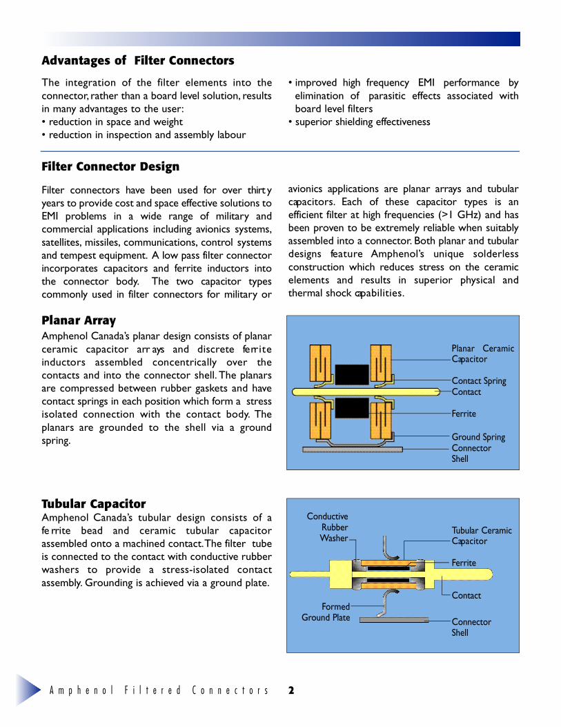
Amphenol Canada’s planar design consists of planarceramic capacitor arr ays and discrete fe rr i t einductors assembled concentrically over thecontacts and into the connector shell. The planarsare compressed between rubber gaskets and havecontact springs in each position which form a stressisolated connection with the contact body. Theplanars are grounded to the shell via a groundspring.
Tubular CapacitorAmphenol Canada’s tubular design consists of afe rrite bead and ceramic tubular cap a c i t o rassembled onto a machined contact.The filter tubeis connected to the contact with conductive rubberwashers to provide a stress-isolated contactassembly. Grounding is achieved via a ground plate.
Planar CeramicC ap a c i t o r
Contact SpringC o n t a c t
Fe rr i t e
G round SpringC o n n e c t o rS h e l l
Tubular CeramicC ap a c i t o r
Fe rr i t e
C o n t a c t
C o n n e c t o rS h e l l
C o n d u c t i veR u b b e rWa s h e r
Fo r m e dG round Plate
The integration of the filter elements into theconnector, rather than a board level solution, resultsin many advantages to the user:• reduction in space and weight• reduction in inspection and assembly labour
• improved high frequency EMI performance byelimination of parasitic effects associated withboard level filters
• superior shielding effe c t i ve n e s s
Advantages of Filter Connectors
Filter Connector Design
Planar Array
A m p h e n o l F i l t e r e d C o n n e c t o r s3
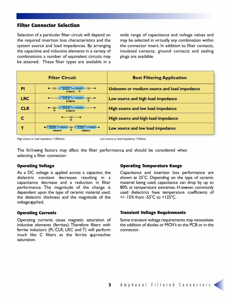
Filter Connector Selection
High source or load impedance >100ohms Low source or load impedance <10ohms
Selection of a particular filter circuit will depend onthe required insertion loss characteristics and thesystem source and load impedances. By arrangingthe capacitive and inductive elements in a variety ofcombinations a number of equivalent circuits maybe attained. These filter types are available in a
wide range of capacitance and voltage values andmay be selected in virtually any combination withinthe connector insert. In addition to filter contacts,insulated contacts, ground contacts and sealingplugs are available.
The fo l l owing factors may affect the filter perfo r m a n c e, and should be considered whenselecting a filter connector:
As a DC voltage is applied across a cap a c i t o r, t h edielectric constant decreases resulting in ac apacitance decrease and a reduction in filterp e r fo r m a n c e. The magnitude of the change isdependent upon the type of ceramic material used,the dielectric thickness and the magnitude of thevoltage ap p l i e d .
C apacitance and insertion loss performance ares h own at 25oC. Depending on the type of ceramicmaterial being used, c apacitance can drop by up to80% at temperature extre m e s . H oweve r, c o m m o n lyused dielectrics have temperature coefficients of+/- 15% from -55oC to +125oC.
Operating currents cause magnetic saturation ofi n d u c t i ve elements (fe rr i t e s ) . T h e re fo re filters withfe rrite inductors (Pi, C L R , LRC and T) will perfo r mmuch like C filters as the fe rrite ap p ro a c h e ss a t u r a t i o n .
Some transient voltage re q u i rements may necessitatethe addition of diodes or MOV ’s to the PCB or in thec o n n e c t o r.
Filter Circuit Best Filtering Application
P I U n k n own or medium source and load impedance
L R C L ow source and high load impedance
C L R High source and low load impedance
C High source and high load impedance
T L ow source and low load impedance
Operating Voltage Operating Temperature Range
Operating Currents Transient Voltage Requirements
A m p h e n o l F i l t e r e d C o n n e c t o r s 4
485 Series Introduction and Design Fe a t u r e s
The Amphenol 485 series is a range of filteredARINC 404 and 600 rack and panel connectorsdesigned to provide space and cost-effe c t i vesolutions to EMC compliance issues in avionicsproducts. Amphenol’s filtered ARINC connectorsare used extensively on Boeing, McDonnell Douglasand Airbus avionics equipment and a wide range ofother military and commercial applications. Themajority of the Amphenol filtered A R I N C
connector designs incorporate planar capacitorarray technology in a solderless, stress-isolatedconfiguration. This results in superior thermal andphysical shock performance and unparalleled longterm re l i a b i l i t y. These products have beenextensively qualified to the requirements of ARINC600-9 and MIL-C-81659 and there are numerousqualification test reports available for review.
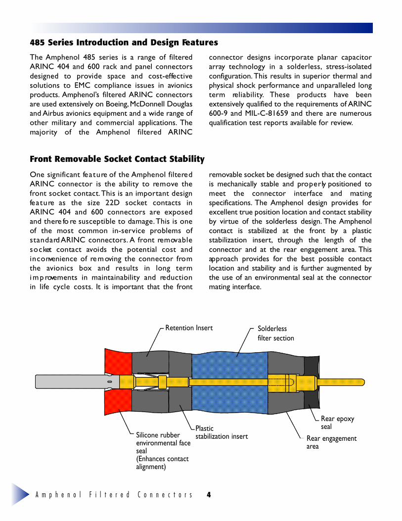
Front Removable Socket Contact Stability
One significant fe a t u re of the Amphenol filtere dARINC connector is the ability to re m ove thef ront socket contact.This is an important designfe a t u re as the size 22D socket contacts inARINC 404 and 600 connectors are exposedand there fo re susceptible to damage.This is oneof the most common in-service problems ofs t a n d a rd ARINC connectors. A front re m ov a b l es o c ket contact avoids the potential cost andi n c o nvenience of re m oving the connector fro mthe avionics box and results in long termi m p rovements in maintainability and re d u c t i o nin life cycle costs. It is important that the fro n t
re m ovable socket be designed such that the contactis mechanically stable and pro p e r ly positioned tomeet the connector interface and matings p e c i f i c a t i o n s . The Amphenol design provides fo rexcellent true position location and contact stabilityby virtue of the solderless design. The A m p h e n o lcontact is stabilized at the front by a plasticstabilization insert , t h rough the length of theconnector and at the rear engagement are a . T h i sap p roach provides for the best possible contactlocation and stability and is further augmented bythe use of an env i ronmental seal at the connectormating interface.
Retention Insert Solderlessfilter section
Rear epoxysealPlastic
stabilization insertSilicone rubberenvironmental faceseal(Enhances contactalignment)
Rear engagementarea
A m p h e n o l F i l t e r e d C o n n e c t o r s5
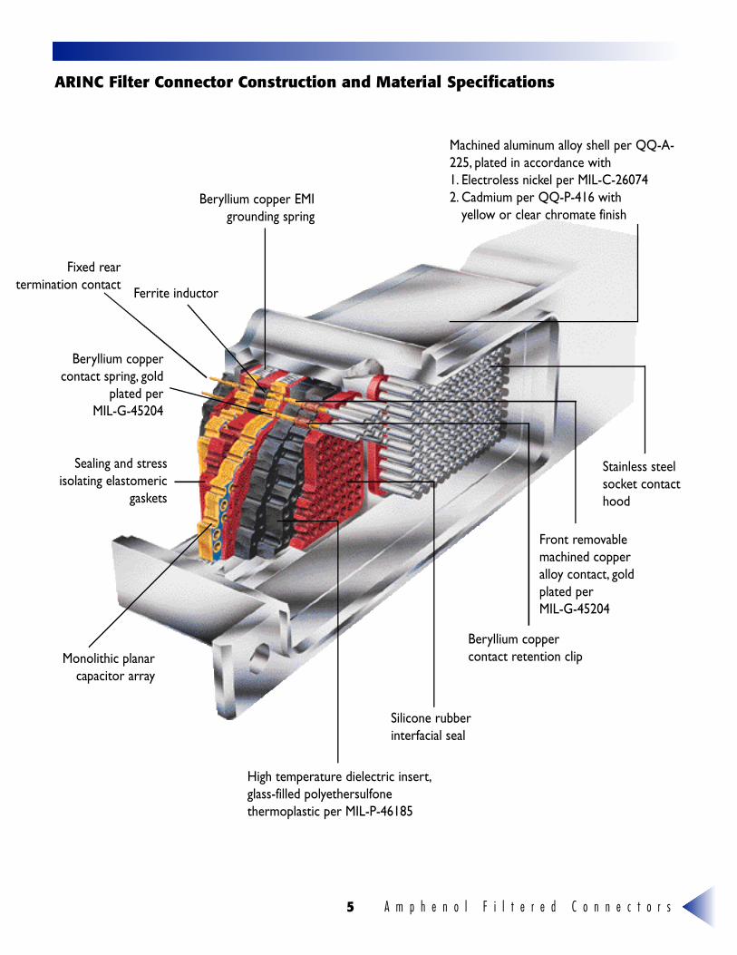
A RINC Filter Connector Construction and Material Specifications
Machined aluminum alloy shell per QQ-A-225, plated in accordance with 1. Electroless nickel per MIL-C-260742. Cadmium per QQ-P-416 with
yellow or clear chromate finish
Stainless steelsocket contacthood
Front removablemachined copperalloy contact, goldplated per MIL-G-45204
Beryllium coppercontact retention clip
Silicone rubberinterfacial seal
Monolithic planarcapacitor array
Sealing and stressisolating elastomeric
gaskets
Beryllium coppercontact spring, gold
plated per MIL-G-45204
Fixed reartermination contact
Beryllium copper EMIgrounding spring
Ferrite inductor
High temperature dielectric insert,glass-filled polyethersulfonethermoplastic per MIL-P-46185
A m p h e n o l F i l t e r e d C o n n e c t o r s 6
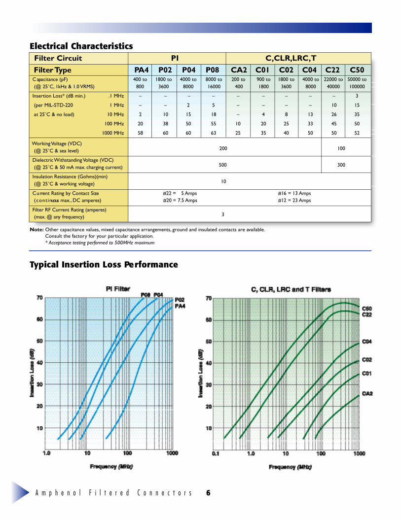
Filter Circuit PI C,CLR,LRC,TFilter Ty p e PA 4 P 0 2 P 0 4 P 0 8 C A 2 C 0 1 C 0 2 C 0 4 C 2 2 C 5 0C apacitance (pF) 400 to 1800 to 4000 to 8000 to 200 to 900 to 1800 to 4000 to 22000 to 50000 to(@ 25˚C, 1kHz & 1.0 V R M S ) 8 0 0 3 6 0 0 8 0 0 0 1 6 0 0 0 4 0 0 1 8 0 0 3 6 0 0 8 0 0 0 4 0 0 0 0 1 0 0 0 0 0
I n s e rtion Loss* (dB min.) .1 MHz – – – – – – – – – 3
(per MIL-STD-220 1 MHz – – 2 5 – – – – 1 0 1 5
at 25˚C & no load) 10 MHz 2 1 0 1 5 1 8 – 4 8 1 3 2 6 3 5
100 MHz 2 0 3 8 5 0 5 5 1 0 2 0 2 5 3 3 4 5 5 0
1000 MHz 5 8 6 0 6 0 6 3 2 5 3 5 4 0 5 0 5 0 5 2
Working Voltage (VDC)(@ 25˚C & sea leve l ) 200 100
Dielectric Withstanding Voltage (VDC)(@ 25˚C & 50 mA max. charging curre n t ) 5 0 0 3 0 0
Insulation Resistance (Gohms)(min)(@ 25˚C & working vo l t a g e ) 1 0
C u rrent Rating by Contact Size #22 = 5 A m p s #16 = 13 A m p s( c o n t i nuous max., DC ampere s ) #20 = 7.5 A m p s #12 = 23 A m p s
Filter RF Current Rating (ampere s )( m a x . @ any fre q u e n c y ) 3
Electrical Characteristics
Typical Insertion Loss Pe rf o r m a n c e
Note: Other capacitance values, mixed capacitance arrangements, ground and insulated contacts are available.Consult the factory for your particular application.* Acceptance testing performed to 500MHz maximum
A m p h e n o l F i l t e r e d C o n n e c t o r s7
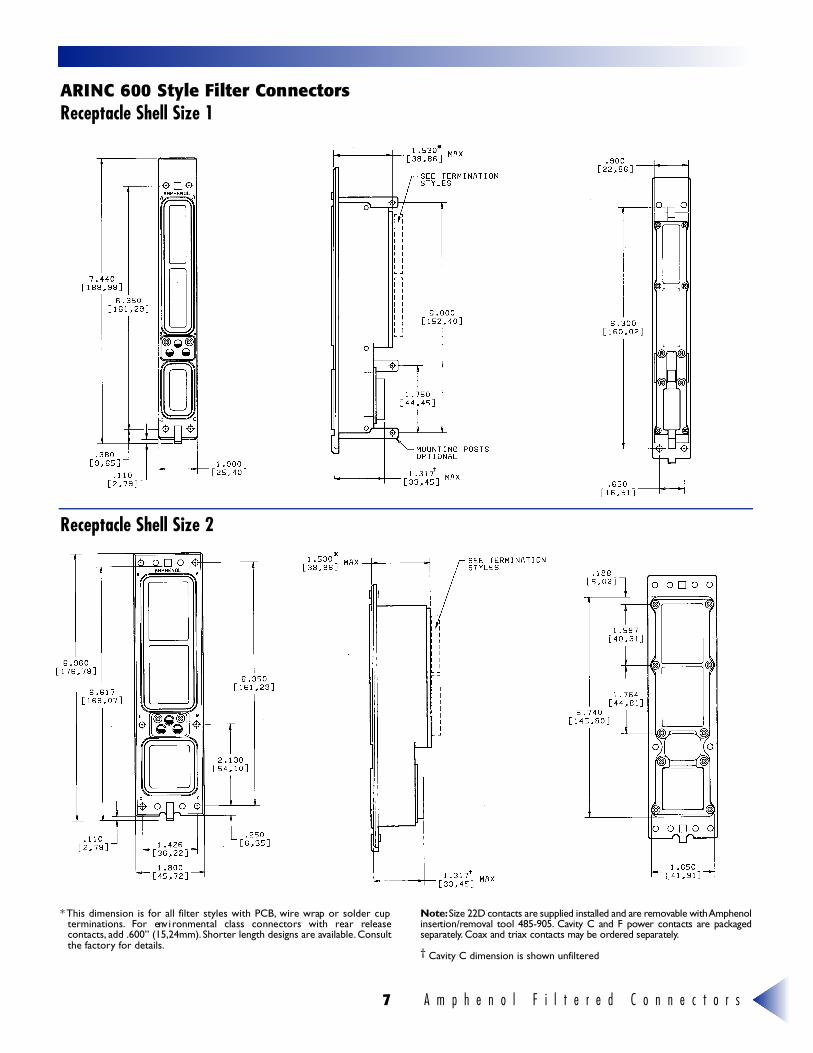
A RINC 600 Style Filter ConnectorsReceptacle Shell Size 1
Receptacle Shell Size 2
* This dimension is for all filter styles with PCB, wire wrap or solder cupt e r m i n a t i o n s . For env i ronmental class connectors with rear re l e a s econtacts, add .600” (15,24mm). Shorter length designs are available. Consultthe factory for details.
N o t e :Size 22D contacts are supplied installed and are re m ovable with A m p h e n o li n s e rt i o n / re m oval tool 485-905. C avity C and F power contacts are packageds e p a r a t e ly. Coax and triax contacts may be ord e red separately.
† Cavity C dimension is shown unfiltered
A m p h e n o l F i l t e r e d C o n n e c t o r s 8
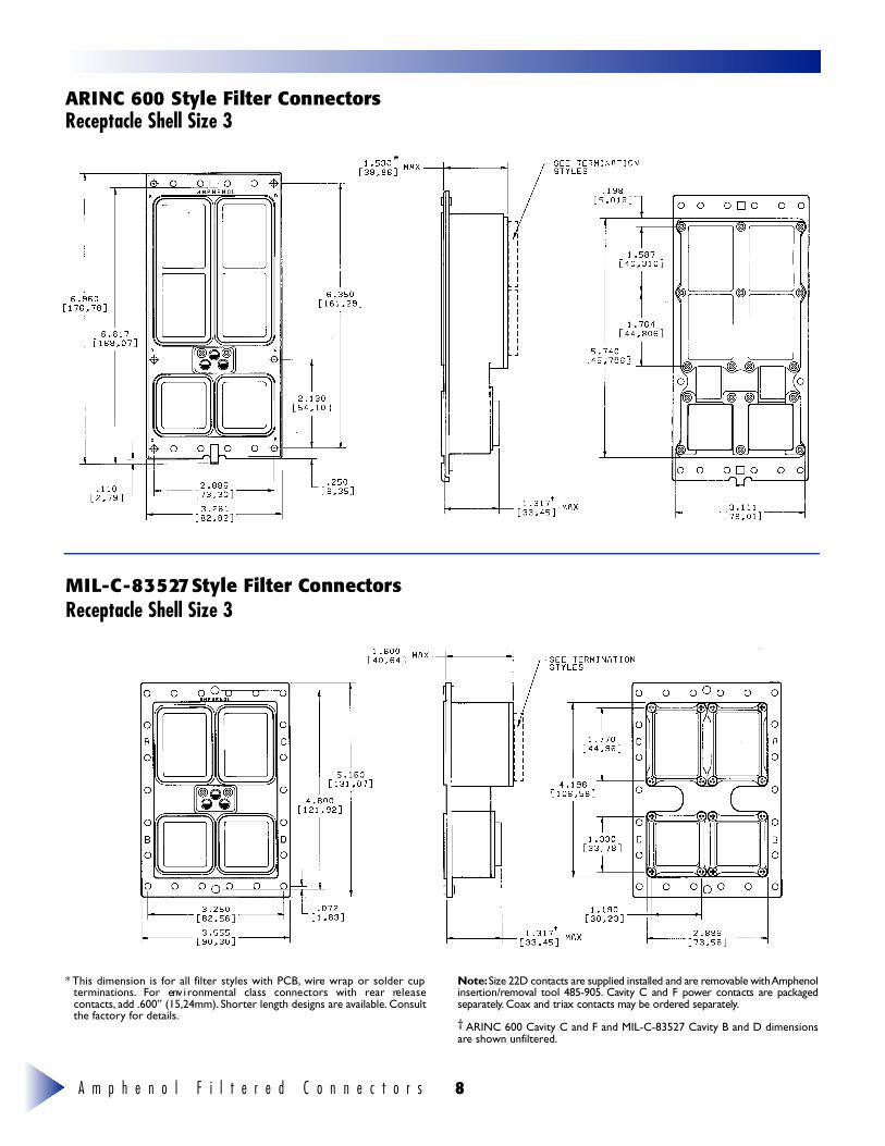
A RINC 600 Style Filter ConnectorsReceptacle Shell Size 3
MIL -C - 8 3 5 27 Style Filter ConnectorsReceptacle Shell Size 3
* This dimension is for all filter styles with PCB, wire wrap or solder cupt e r m i n a t i o n s . For env i ronmental class connectors with rear re l e a s econtacts, add .600” (15,24mm). Shorter length designs are available. Consultthe factory for details.
N o t e :Size 22D contacts are supplied installed and are re m ovable with A m p h e n o li n s e rt i o n / re m oval tool 485-905. C avity C and F power contacts are packageds e p a r a t e ly. Coax and triax contacts may be ord e red separately.
† ARINC 600 Cavity C and F and MIL-C-83527 Cavity B and D dimensionsare shown unfiltered.
A m p h e n o l F i l t e r e d C o n n e c t o r s9
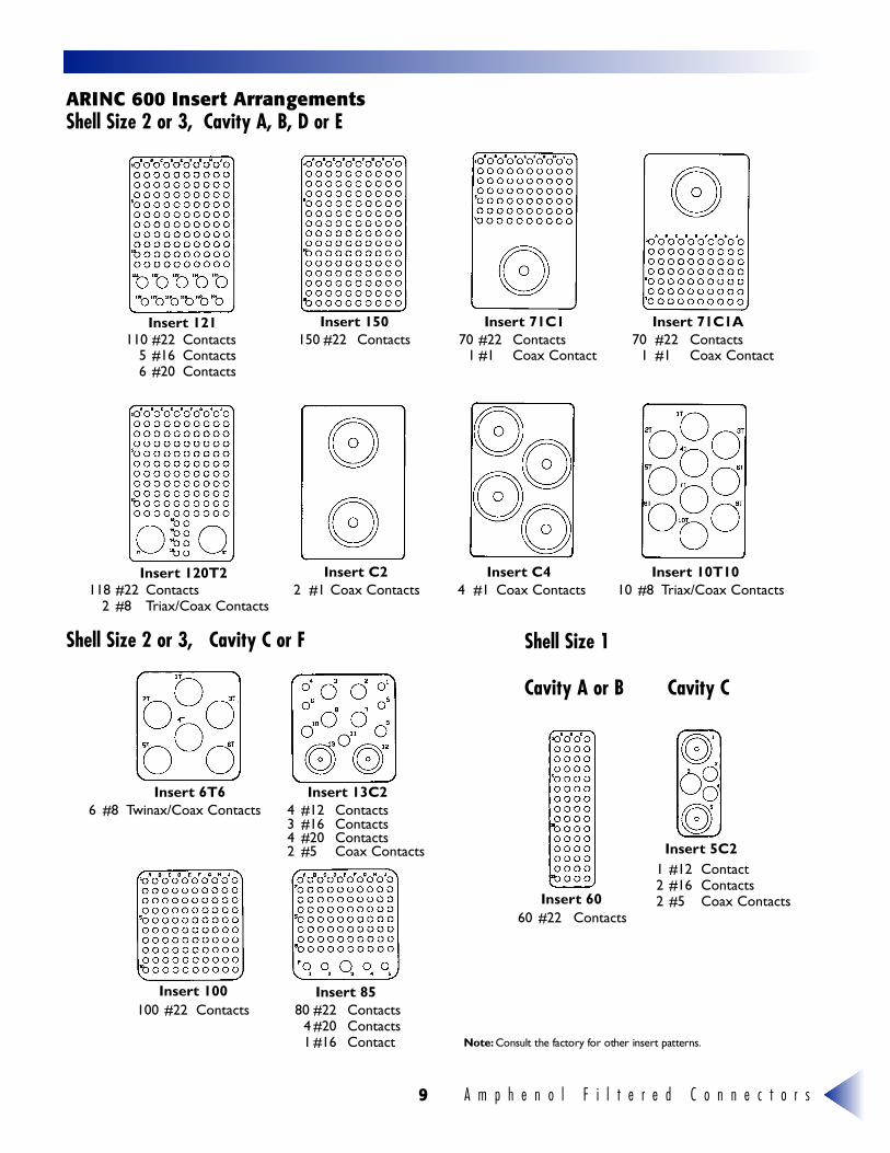
A RINC 600 Insert ArrangementsShell Size 2 or 3, Cavity A, B, D or E
Shell Size 2 or 3, Cavity C or F Shell Size 1
Cavity A or B Cavity C
110 #22 Contacts5 #16 Contacts6 #20 Contacts
70 #22 Contacts1 #1 Coax Contact
150 #22 Contacts 70 #22 Contacts1 #1 Coax Contact
118 #22 Contacts2 #8 Triax/Coax Contacts
2 #1 Coax Contacts
6 #8 Twinax/Coax Contacts 4 #12 Contacts3 #16 Contacts4 #20 Contacts2 #5 Coax Contacts
100 #22 Contacts 80 #22 Contacts4 #20 Contacts1 #16 Contact
4 #1 Coax Contacts 10 #8 Triax/Coax Contacts
60 #22 Contacts
1 #12 Contact 2 #16 Contacts2 #5 Coax Contacts
Insert 121
Insert 120T2
Insert 6T6
Insert 100 Insert 85
Insert 13C2
Insert 60
Insert 5C2
Insert C2 Insert C4 Insert 10T10
Insert 150 Insert 71C1 Insert 71C1A
N o t e : Consult the factory for other insert patterns.
A m p h e n o l F i l t e r e d C o n n e c t o r s 1 0
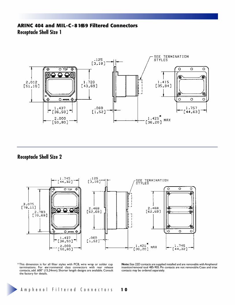
A RINC 404 and MIL -C - 8 1659 Filtered ConnectorsReceptacle Shell Size 1
Receptacle Shell Size 2
* This dimension is for all filter styles with PCB, wire wrap or solder cupt e r m i n a t i o n s . For env i ronmental class connectors with rear re l e a s econtacts, add .600” (15,24mm). Shorter length designs are available. Consultthe factory for details.
N o t e :Size 22D contacts are supplied installed and are re m ovable with A m p h e n o li n s e rt i o n / re m oval tool 485-905. Pin contacts are not re m ov a b l e.Coax and triaxcontacts may be ord e red separately.
A m p h e n o l F i l t e r e d C o n n e c t o r s1 1
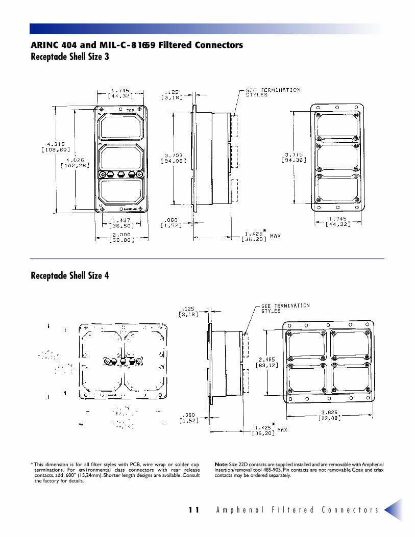
A RINC 404 and MIL -C - 8 1659 Filtered ConnectorsReceptacle Shell Size 3
Receptacle Shell Size 4
* This dimension is for all filter styles with PCB, wire wrap or solder cupt e r m i n a t i o n s . For env i ronmental class connectors with rear re l e a s econtacts, add .600” (15,24mm). Shorter length designs are available. Consultthe factory for details.
N o t e :Size 22D contacts are supplied installed and are re m ovable with A m p h e n o li n s e rt i o n / re m oval tool 485-905. Pin contacts are not re m ov a b l e.Coax and triaxcontacts may be ord e red separately.
A m p h e n o l F i l t e r e d C o n n e c t o r s 1 2
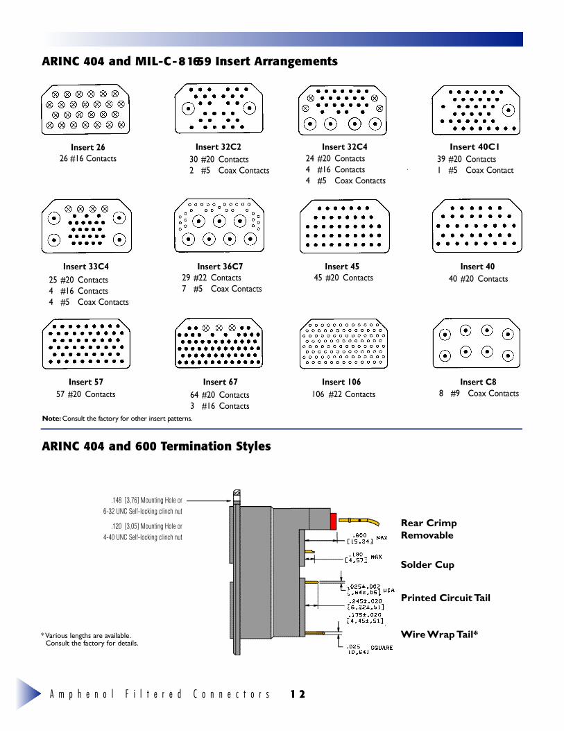
A RINC 404 and MIL -C - 8 1659 Insert Arrangements
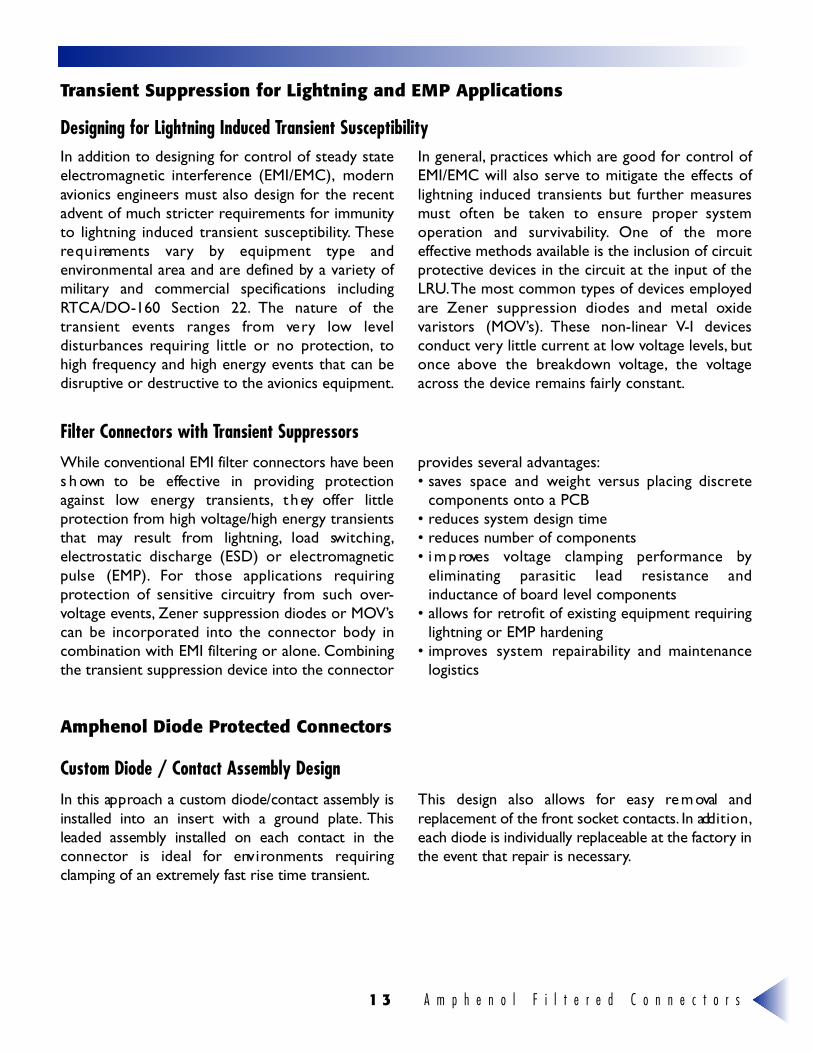
A RINC 404 and 600 Termination Styles
Insert 2626 #16 Contacts
Insert 32C2
Insert 33C4
Insert 57 Insert 67 Insert 106 Insert C8
Insert 36C7 Insert 45 Insert 40
Insert 32C4 Insert 40C130 #20 Contacts2 #5 Coax Contacts
24 #20 Contacts4 #16 Contacts4 #5 Coax Contacts
29 #22 Contacts7 #5 Coax Contacts
45 #20 Contacts 40 #20 Contacts
8 #9 Coax Contacts
25 #20 Contacts4 #16 Contacts4 #5 Coax Contacts
57 #20 Contacts 64 #20 Contacts3 #16 Contacts
106 #22 Contacts
39 #20 Contacts1 #5 Coax Contact
BO @{àAÍÈÈC
BO@{àAHÈHC
* Various lengths are available.Consult the factory for details.
N o t e : Consult the factory for other insert patterns.
.148 [3,76] Mounting Hole or 6-32 UNC Self-locking clinch nut
.120 [3,05] Mounting Hole or4-40 UNC Self-locking clinch nut
Rear CrimpRemovable
Solder Cup
Printed Circuit Tail
Wire Wrap Tail*
A m p h e n o l F i l t e r e d C o n n e c t o r s1 3
Transient Suppression for Lightning and EMP Applications
Designing for Lightning Induced Transient Susceptibility
Filter Connectors with Transient Suppressors
Custom Diode / Contact Assembly Design
Amphenol Diode Protected Connectors
In addition to designing for control of steady stateelectromagnetic interference (EMI/EMC), modernavionics engineers must also design for the recentadvent of much stricter requirements for immunityto lightning induced transient susceptibility. Thesere q u i rements vary by equipment type andenvironmental area and are defined by a variety ofm i l i t a ry and commercial specifications includingRT CA/DO-160 Section 22. The nature of thetransient events ranges from ve ry low leve ldisturbances requiring little or no protection, tohigh frequency and high energy events that can bedisruptive or destructive to the avionics equipment.
In general, practices which are good for control ofEMI/EMC will also serve to mitigate the effects oflightning induced transients but further measuresmust often be taken to ensure proper systemoperation and surv i v a b i l i t y. One of the moreeffective methods available is the inclusion of circuitprotective devices in the circuit at the input of theLRU.The most common types of devices employedare Zener suppression diodes and metal oxidevaristors (MOV ’s ) . These non-linear V-I dev i c e sconduct very little current at low voltage levels, butonce above the breakdown voltage, the voltageacross the device remains fairly constant.
While conventional EMI filter connectors have beens h own to be effe c t i ve in providing pro t e c t i o nagainst low energy transients, t h ey offer littleprotection from high voltage/high energy transientsthat may result from lightning, load sw i t c h i n g ,electrostatic discharge (ESD) or electromagneticpulse (EMP). For those applications re q u i r i n gprotection of sensitive circuitry from such over-voltage events, Zener suppression diodes or MOV’scan be incorporated into the connector body incombination with EMI filtering or alone. Combiningthe transient suppression device into the connector
provides several advantages:• saves space and weight versus placing discrete
components onto a PCB• reduces system design time• reduces number of components• i m p roves voltage clamping performance by
eliminating parasitic lead resistance andinductance of board level components
• allows for retrofit of existing equipment requiringlightning or EMP hardening
• improves system repairability and maintenancelogistics
In this ap p roach a custom diode/contact assembly isinstalled into an insert with a ground plate. T h i sleaded assembly installed on each contact in theconnector is ideal for env i ronments re q u i r i n gclamping of an extre m e ly fast rise time transient.
This design also allows for easy re m oval andreplacement of the front socket contacts. In add i t i o n ,each diode is individually replaceable at the factory inthe event that repair is necessary.
A m p h e n o l F i l t e r e d C o n n e c t o r s 1 4
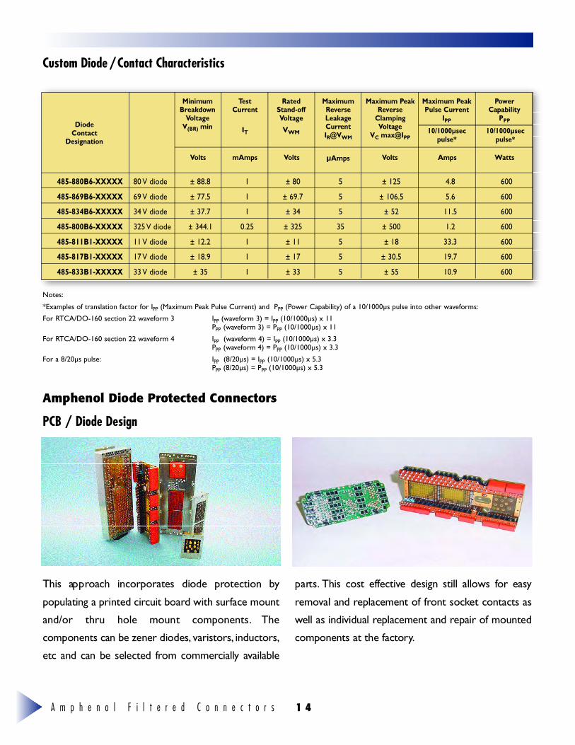
Custom Diode/Contact Characteristics
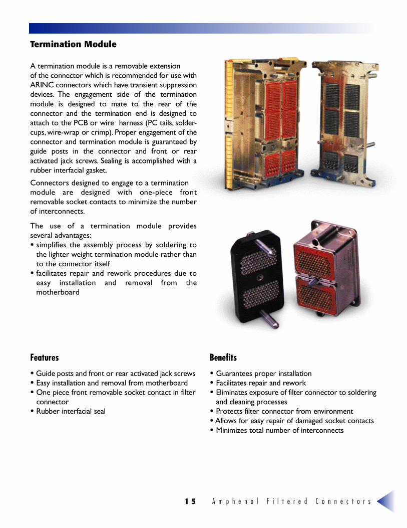
This ap p roach incorporates diode protection by
populating a printed circuit board with surface mount
and/or thru hole mount components. T h e
components can be zener diodes, v a r i s t o r s , i n d u c t o r s ,
etc and can be selected from commerc i a l ly av a i l a b l e
p a rt s . This cost effe c t i ve design still allows for easy
re m oval and replacement of front socket contacts as
well as individual replacement and repair of mounted
components at the factory.
Amphenol Diode Protected Connectors
PCB / Diode Design
DiodeContact
Designation
MinimumBreakdown
VoltageV(BR) min
TestCurrent
IT
RatedStand-offVoltage
VWM
MaximumReverseLeakageCurrentIR@VWM
Maximum PeakPulse Current
IPP
10/1000µsecpulse*
10/1000µsecpulse*
PowerCapability
PPP
WattsAmpsVoltsµAmpsVoltsmAmpsVolts
Maximum PeakReverse
ClampingVoltage
VC max@IPP
485-880B6-XXXXX 80 V diode ± 88.8 1 ± 80 5 ± 125 4.8 600
485-869B6-XXXXX 69 V diode ± 77.5 1 ± 69.7 5 ± 106.5 5.6 600
485-834B6-XXXXX 34 V diode ± 37.7 1 ± 34 5 ± 52 11.5 600
485-800B6-XXXXX 325 V diode ± 344.1 0.25 ± 325 35 ± 500 1.2 600
485-811B1-XXXXX 11 V diode ± 12.2 1 ± 11 5 ± 18 33.3 600
485-817B1-XXXXX 17 V diode ± 18.9 1 ± 17 5 ± 30.5 19.7 600
485-833B1-XXXXX 33 V diode ± 35 1 ± 33 5 ± 55 10.9 600
Notes:
*Examples of translation factor for IPP (Maximum Peak Pulse Current) and PPP (Power Capability) of a 10/1000µs pulse into other waveforms:
For RTCA/DO-160 section 22 waveform 3 IPP (waveform 3) = IPP (10/1000µs) x 11PPP (waveform 3) = PPP (10/1000µs) x 11
For RTCA/DO-160 section 22 waveform 4 IPP (waveform 4) = IPP (10/1000µs) x 3.3PPP (waveform 4) = PPP (10/1000µs) x 3.3
For a 8/20µs pulse: IPP (8/20µs) = IPP (10/1000µs) x 5.3PPP (8/20µs) = PPP (10/1000µs) x 5.3
A m p h e n o l F i l t e r e d C o n n e c t o r s1 5
A termination module is a re m ovable extensionof the connector which is recommended for use withARINC connectors which have transient suppre s s i o nd ev i c e s . The engagement side of the terminationmodule is designed to mate to the rear of theconnector and the termination end is designed toattach to the PCB or wire harness (PC tails, s o l d e r-c u p s , w i re - w r ap or crimp). P roper engagement of theconnector and termination module is guaranteed byguide posts in the connector and front or re a ractivated jack screw s . Sealing is accomplished with arubber interfacial gaske t .
Connectors designed to engage to a terminationmodule are designed with one-piece fro n tremovable socket contacts to minimize the numberof interconnects.
The use of a termination module provides several advantages:• simplifies the assembly process by soldering to
the lighter weight termination module rather thanto the connector itself
• facilitates repair and rework procedures due toeasy installation and re m oval from themotherboard
• Guide posts and front or rear activated jack screw s• Easy installation and re m oval from motherboard• One piece front re m ovable socket contact in filter
c o n n e c t o r• Rubber interfacial seal
Features
• Guarantees proper installation• Facilitates repair and rewo r k• Eliminates exposure of filter connector to soldering
and cleaning pro c e s s e s• P rotects filter connector from env i ro n m e n t• A l l ows for easy repair of damaged socket contacts• Minimizes total number of interc o n n e c t s
Benefits
Termination Module
A m p h e n o l F i l t e r e d C o n n e c t o r s 1 6
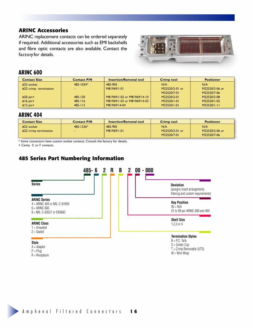
A RINC AccessoriesARINC replacement contacts can be ord e red separatelyif re q u i re d . A dditional accessories such as EMI backshellsand fibre optic contacts are also av a i l a b l e. Contact thef a c t o ry for details.
485 Series Pa rt Numbering Information
ARINC 600
ARINC 404
Contact Size Contact P/N Insertion/Removal tool Crimp tool Positioner#22 socket 485-1034* 485-905 N/A N/A#22 crimp termination - M81969/1-01 M22520/2-01 or M22520/2-06 or
M22520/7-01 M22520/7-06#20 pin+ 485-120 M81969/1-02 or M81969/14-10 M22520/2-01 M22520/2-08#16 pin+ 485-116 M81969/1-03 or M81969/14-03 M22520/1-01 M22520/1-02#12 pin+ 485-112 M81969/14-04 M22520/1-01 M22520/1-11
Contact Size Contact P/N Insertion/Removal tool Crimp tool Positioner#22 socket 485-1236* 485-905 N/A N/A#22 crimp termination - M81969/1-01 M22520/2-01 or M22520/2-06 or
M22520/7-01 M22520/7-06
* Some connectors have custom socket contacts. Consult the factory for details.+ Cavity C or F contacts
Series Deviation(assigns insert arrangements.filtering and custom requirements)
Key Position00 = N/A01 to 99 per ARINC 600 and 404
Shell Size1,2,3 or 4
Termination StylesB = P.C. TailsS = Solder CupT = Crimp Removable (UTS)W = Wire Wrap
ARINC Series4 = ARINC 404 or MIL-C-816596 = ARINC 6008 = MIL-C-83527 or EN3682
ARINC Class1 = Unsealed2 = Sealed
StyleA = AdapterP = PlugR = Receptacle
4 8 5 - 6 2 R B 2 00 - 000
A m p h e n o l F i l t e r e d C o n n e c t o r s1 7
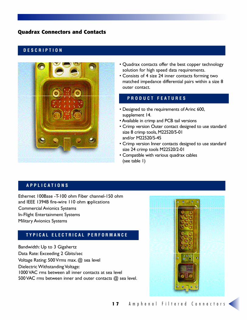
• Quadrax contacts offer the best copper technologysolution for high speed data re q u i re m e n t s .
• Consists of 4 size 24 inner contacts forming twomatched impedance diffe rential pairs within a size 8outer contact.
• Designed to the re q u i rements of Arinc 600,supplement 14.
• Available in crimp and PCB tail versions • Crimp version Outer contact designed to use standard
size 8 crimp tools, M22520/5-01 and/or M22520/5-45
• Crimp version Inner contacts designed to use standardsize 24 crimp tools M22520/2-01
• Compatible with various quadrax cables (see table 1)
Ethernet 100Base -T-100 ohm Fiber channel-150 ohmand IEEE 1394B fire - w i re 110 ohm ap p l i c a t i o n sC o m m e rcial Avionics SystemsIn-Flight Entertainment SystemsM i l i t a ry Avionics Systems
B a n d w i d t h : Up to 3 Gigahert zData Rate: Exceeding 2 Gbits/secVoltage Rating: 500 Vrms max. @ sea leve lDielectric Withstanding Vo l t a g e :1000 VAC rms between all inner contacts at sea leve l500 VAC rms between inner and outer contacts @ sea leve l .
D E S C R I P T I O N
A P P L I C A T I O N S
T Y P I C A L E L E C T R I C A L P E R F O R M A N C E
P R O D U C T F E A T U R E S
Quadrax Connectors and Contacts
A m p h e n o l F i l t e r e d C o n n e c t o r s 1 8
P A R T N U M B E R I N G I N F O R M A T I O N
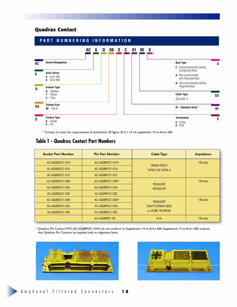
Quadrax Contact
Contact Size
08
6
AC
Q
C 01 X X XQ6AC S
0 8
Series Designation
Arinc Series 4 - Arinc 404 6 - Arinc 600
Q - QuadraxT - TwinaxC - Coax
08 - Size 8
Contact TypeS S - SocketP - Pin
Contact Type
XBoot Type
E - Environmental with sealing & Alignment Boot
A - Non-environmentalwith Alignment Boot
N - Non-environmental withoutAlignment Boot
Cable Type
(See table 1)XX
01 - Standard Arinc* 01
Termination
C - CrimpP - PCB
C
Socket Part Number Pin Part Number Cable Type Impedance
AC-6Q08SC01-01N AC-6Q08PC01-01N*DRAKA FILICA
100 ohm
AC-6Q08SC01-01A AC-6Q08PC01-01A F4703-3 & F4704-4
AC-6Q08SC01-01E AC-6Q08PC01-01E
AC-6Q08SC01-02N AC-6Q08PC01-02N*TENSOLITE
100 ohm
AC-6Q08SC01-02A AC-6Q08PC01-02A NF24Q100
AC-6Q08SC01-02E AC-6Q08PC01-02E
AC-6Q08SC01-03N AC-6Q08PC01-03N* TENSOLITE 150 ohm
AC-6Q08SC01-03A AC-6Q08PC01-03A 26473102006X-4(LD)
AC-6Q08SC01-03E AC-6Q08PC01-03E or GORE RCN8328
--- AC-6Q08PP01-XX N/A 100 ohm
Table 1 - Quadrax Contact Part Numbers
* Quadrax Pin Contact P/N's AC-6Q08PC01-XXN do not conform to Supplement 14 to Arinc 600. Supplement 14 to Arinc 600 requiresthat Quadrax Pin Contacts be supplied with an alignment boot.
* Contact to meet the requirements of attachment 20 figure 20-2.1.1A of supplement 14 to Arinc 600.
A m p h e n o l F i l t e r e d C o n n e c t o r s1 9
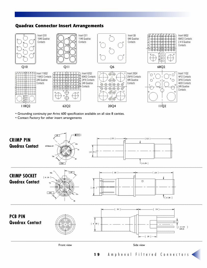
Quadrax Connector Insert Arrangements
Insert Q10 10#8 QuadraxContacts
Insert 118Q2118#22 Contacts2#8 QuadraxContacts
Insert 62Q260#22 Contacts2#16 Contacts2#8 QuadraxContacts
Insert 20Q420#16 Contacts4#8 QuadraxContacts
Insert 11Q24#12 Contacts3#16 Contacts4#20 Contacts2#8 QuadraxContacts
Insert Q11 11#8 QuadraxContacts
Insert Q6 6#8 QuadraxContacts
Insert 68Q2 68#22 Contacts2 # 8 QuadraxContacts
• Grounding continuity per Arinc 600 specification available on all size 8 cav i t i e s .• Contact Factory for other insert arr a n g e m e n t s
CRIMP PINQuadrax Contact
CRIMP SOCKETQuadrax Contact
PCB PINQuadrax Contact
Front view Side view
Q10 Q11 Q6 68Q2
118Q2 62Q2 20Q4 11Q2
A m p h e n o l F i l t e r e d C o n n e c t o r s 2 0
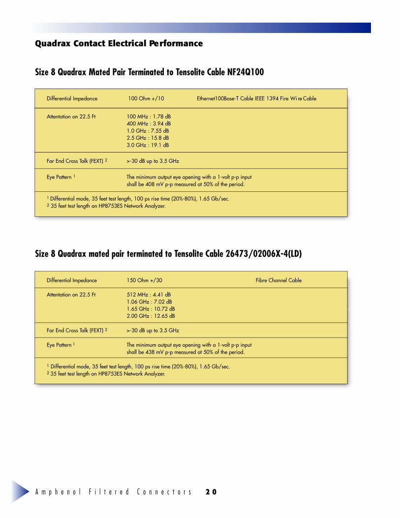
Quadrax Contact Electrical Pe rf o r m a n c e
Size 8 Quadrax Mated Pair Terminated to Tensolite Cable NF24Q100
D i ff e rential Impedance 100 Ohm +/10 E t h e rnet100Base-T Cable IEEE 1394 Fire Wi re Cable
Attentation on 22.5 Ft 100 MHz : 1.78 dB400 MHz : 3.94 dB1.0 GHz : 7.55 dB2.5 GHz : 15.8 dB3.0 GHz : 19.1 dB
Far End Cross Talk (FEXT) 2 >-30 dB up to 3.5 GHz
Eye Pattern 1 The minimum output eye opening with a 1-volt p-p inputshall be 408 mV p-p measured at 50% of the period.
1 Differential mode, 35 feet test length, 100 ps rise time (20%-80%), 1.65 Gb/sec.2 35 feet test length on HP8753ES Network Analyzer.
Differential Impedance 150 Ohm +/30 Fibre Channel Cable
Attentation on 22.5 Ft 512 MHz : 4.41 dB1.06 GHz : 7.02 dB1.65 GHz : 10.72 dB2.00 GHz : 12.65 dB
Far End Cross Talk (FEXT) 2 >-30 dB up to 3.5 GHz
Eye Pattern 1 The minimum output eye opening with a 1-volt p-p inputshall be 438 mV p-p measured at 50% of the period.
1 Differential mode, 35 feet test length, 100 ps rise time (20%-80%), 1.65 Gb/sec.2 35 feet test length on HP8753ES Network Analyzer.
Size 8 Quadrax mated pair terminated to Tensolite Cable 26473/02006X-4(LD)
A m p h e n o l F i l t e r e d C o n n e c t o r s2 1
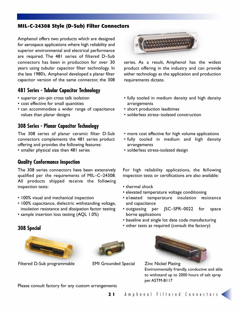
Amphenol offers two products which are designedfor aerospace applications where high reliability andsuperior environmental and electrical performanceare required. The 481 series of filtered D–Subconnectors has been in production for over 30years using tubular capacitor filter technology. Inthe late 1980’s, Amphenol developed a planar filter capacitor version of the same connector, the 308
s e r i e s . As a re s u l t , Amphenol has the widestproduct offering in the industry and can provideeither technology as the application and productionrequirements dictate.
MIL -C - 2 4 3 08 Style (D-Sub) Filter Connectors
Quality Conformance Inspection
• superior pin–pin cross talk isolation• cost effective for small quantities • can accommodate a wider range of capacitance
values than planar designs
• fully tooled in medium density and high densityarrangements
• short production leadtimes• solderless stress–isolated construction
The 308 series connectors have been extensivelyqualified per the requirements of MIL–C–24308.All products shipped re c e i ve the fo l l ow i n ginspection tests:
• 100% visual and mechanical inspection• 100% capacitance, dielectric withstanding voltage,
insulation resistance and dissipation factor testing• sample insertion loss testing (AQL 1.0%)
For high reliability ap p l i c a t i o n s , the fo l l ow i n ginspection tests or certifications are also available:
• thermal shock• elevated temperature voltage conditioning• e l evated temperature insulation re s i s t a n c e
and capacitance• outgassing per JSC–SPR–0022 for space
borne applications• baseline and single lot date code manufacturing• other tests as required (consult the factory)
Filtered D-Sub programmable
Please consult factory for any custom arrangements
EMI Grounded Special Zinc Nickel PlatingEnvironmentally friendly, conductive and ableto withstand up to 2000 hours of salt sprayper ASTM-B117
308 Special
481 Series - Tubular Capacitor Technology
308 Series - Planar Capacitor TechnologyThe 308 series of planar ceramic filter D-Subconnectors complements the 481 series productoffering and provides the following features:• smaller physical size then 481 series
• more cost effective for high volume applications• f u l ly tooled in medium and high density
arrangements• solderless stress-isolated design
A m p h e n o l F i l t e r e d C o n n e c t o r s 2 2
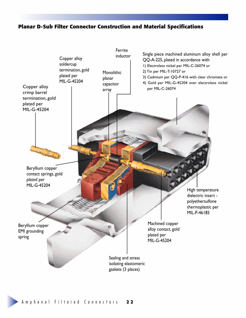
Planar D-Sub Filter Connector Construction and Material Specifications
Copper alloycrimp barreltermination, goldplated per MIL-G-45204
Copper alloysoldercuptermination, goldplated per MIL-G-45204
Monolithicplanarcapacitorarray
Ferriteinductor Single piece machined aluminum alloy shell per
QQ-A-225, plated in accordance with 1) Electroless nickel per MIL-C-26074 or2) Tin per MIL-T-10727 or3) Cadmium per QQ-P-416 with clear chromate or4) Gold per MIL-G-45204 over electroless nickel
per MIL-C-26074
Beryllium copperEMI groundingspring
Beryllium coppercontact springs, goldplated per MIL-G-45204
Sealing and stressisolating elastomericgaskets (3 places)
Machined copperalloy contact, goldplated per MIL-G-45204
High temperaturedielectric insert -polyethersulfonethermoplastic perMIL-P-46185
A m p h e n o l F i l t e r e d C o n n e c t o r s2 3
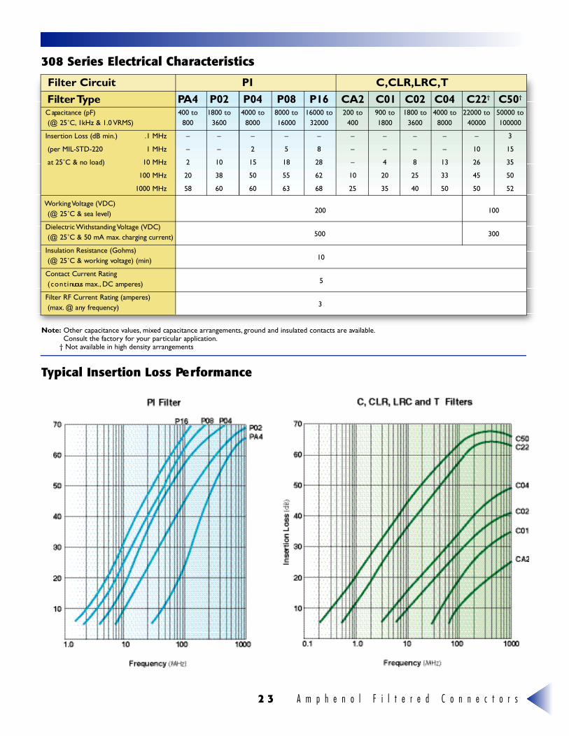
Filter Circuit PI C,CLR,LRC,TFilter Ty p e PA 4 P 0 2 P 0 4 P 0 8 P 1 6 C A 2 C 0 1 C 0 2 C 0 4 C 2 2† C 5 0†
C apacitance (pF) 400 to 1800 to 4000 to 8000 to 16000 to 200 to 900 to 1800 to 4000 to 22000 to 50000 to(@ 25˚C, 1kHz & 1.0 V R M S ) 8 0 0 3 6 0 0 8 0 0 0 1 6 0 0 0 3 2 0 0 0 4 0 0 1 8 0 0 3 6 0 0 8 0 0 0 4 0 0 0 0 1 0 0 0 0 0
I n s e rtion Loss (dB min.) .1 MHz – – – – – – – – – – 3
(per MIL-STD-220 1 MHz – – 2 5 8 – – – – 1 0 1 5
at 25˚C & no load) 10 MHz 2 1 0 1 5 1 8 2 8 – 4 8 1 3 2 6 3 5
100 MHz 2 0 3 8 5 0 5 5 6 2 1 0 2 0 2 5 3 3 4 5 5 0
1000 MHz 5 8 6 0 6 0 6 3 6 8 2 5 3 5 4 0 5 0 5 0 5 2
Working Voltage (VDC)(@ 25˚C & sea leve l ) 2 0 0 100
Dielectric Withstanding Voltage (VDC)(@ 25˚C & 50 mA max. charging curre n t ) 5 0 0 3 0 0
Insulation Resistance (Gohms)(@ 25˚C & working vo l t a g e ) (min) 1 0
Contact Current Rating( c o n t i nuous max., DC ampere s ) 5
Filter RF Current Rating (ampere s )( m a x . @ any fre q u e n c y ) 3
3 08 Series Electrical Characteristics
Typical Insertion Loss Pe rf o r m a n c e
Note: Other capacitance values, mixed capacitance arrangements, ground and insulated contacts are available.Consult the factory for your particular application.
† Not available in high density arrangements
A m p h e n o l F i l t e r e d C o n n e c t o r s 2 4
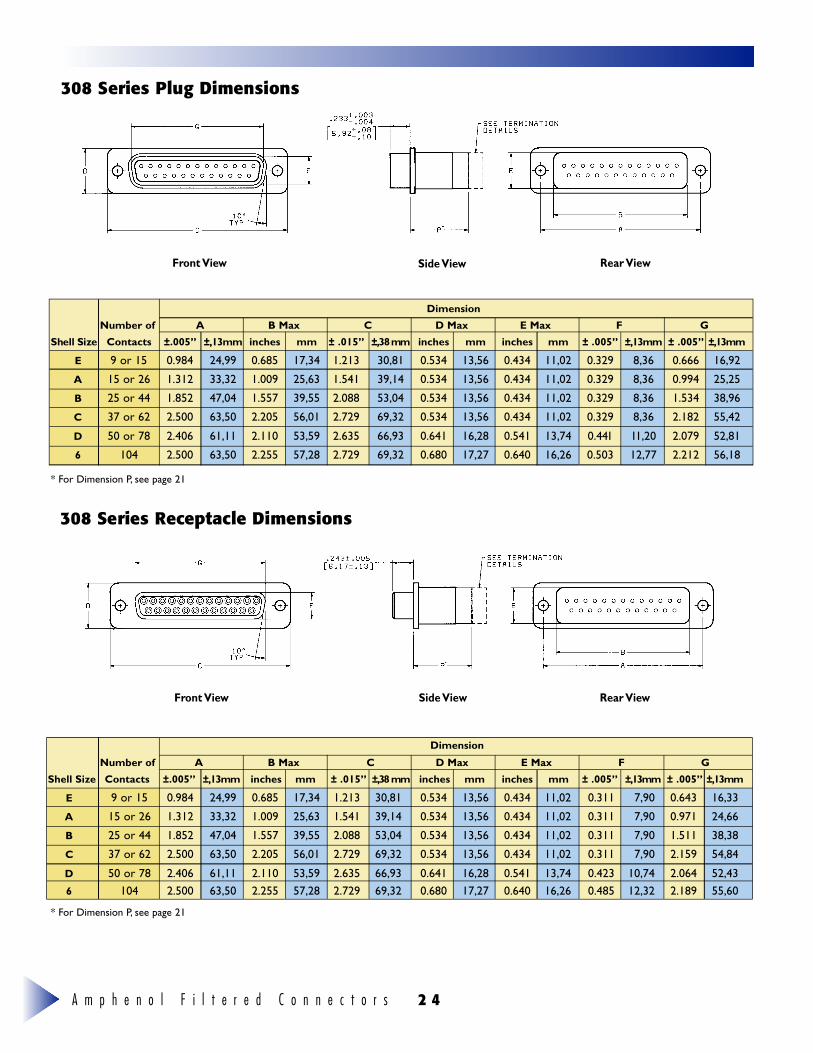
3 08 Series Plug Dimensions
3 08 Series Receptacle Dimensions
Dimension
Number of A B Max C D Max E Max F G
Shell Size Contacts ±.005” ± , 1 3 m m inches mm ± .015” ± , 38m m inches mm inches mm ± .005” ± , 1 3 m m ± .005” ± , 1 3 m m
E 9 or 15 0.984 24,99 0.685 17,34 1.213 30,81 0.534 13,56 0.434 11,02 0.311 7,90 0.643 16,33
A 15 or 26 1.312 33,32 1.009 25,63 1.541 39,14 0.534 13,56 0.434 11,02 0.311 7,90 0.971 24,66
B 25 or 44 1.852 47,04 1.557 39,55 2.088 53,04 0.534 13,56 0.434 11,02 0.311 7,90 1.511 38,38
C 37 or 62 2.500 63,50 2.205 56,01 2.729 69,32 0.534 13,56 0.434 11,02 0.311 7,90 2.159 54,84
D 50 or 78 2.406 61,11 2.110 53,59 2.635 66,93 0.641 16,28 0.541 13,74 0.423 10,74 2.064 52,436 104 2.500 63,50 2.255 57,28 2.729 69,32 0.680 17,27 0.640 16,26 0.485 12,32 2.189 55,60
Dimension
Front View
Front View
Side View
Side View
Rear View
Rear View
* For Dimension P, see page 21
Number of A B Max C D Max E Max F G
Shell Size Contacts ±.005” ± , 1 3 m m inches mm ± .015” ± , 38m m inches mm inches mm ± .005” ± , 1 3 m m ± .005” ± , 1 3 m m
E 9 or 15 0.984 24,99 0.685 17,34 1.213 30,81 0.534 13,56 0.434 11,02 0.329 8,36 0.666 16,92
A 15 or 26 1.312 33,32 1.009 25,63 1.541 39,14 0.534 13,56 0.434 11,02 0.329 8,36 0.994 25,25
B 25 or 44 1.852 47,04 1.557 39,55 2.088 53,04 0.534 13,56 0.434 11,02 0.329 8,36 1.534 38,96
C 37 or 62 2.500 63,50 2.205 56,01 2.729 69,32 0.534 13,56 0.434 11,02 0.329 8,36 2.182 55,42
D 50 or 78 2.406 61,11 2.110 53,59 2.635 66,93 0.641 16,28 0.541 13,74 0.441 11,20 2.079 52,81
6 104 2.500 63,50 2.255 57,28 2.729 69,32 0.680 17,27 0.640 16,26 0.503 12,77 2.212 56,18
h i u u i u i g g k k
* For Dimension P, see page 21
A m p h e n o l F i l t e r e d C o n n e c t o r s2 5
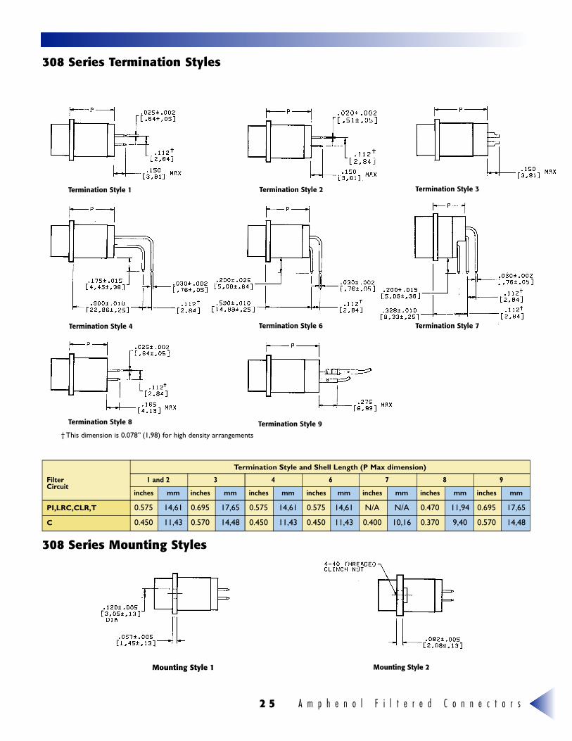
Termination Style and Shell Length (P Max dimension)
3 08 Series Termination Styles
3 08 Series Mounting Styles
Termination Style 1
Termination Style 4 Termination Style 6 Termination Style 7
Termination Style 8 Termination Style 9
Termination Style 2 Termination Style 3
Filter 1 and 2 3 4 6 7 8 9Circuit
inches mm inches mm inches mm inches mm inches mm inches mm inches mm
PI,LRC,CLR,T 0.575 14,61 0.695 17,65 0.575 14,61 0.575 14,61 N/A N/A 0.470 11,94 0.695 17,65
C 0.450 11,43 0.570 14,48 0.450 11,43 0.450 11,43 0.400 10,16 0.370 9,40 0.570 14,48
Mounting Style 1 Mounting Style 2
† This dimension is 0.078” (1,98) for high density arrangements
A m p h e n o l F i l t e r e d C o n n e c t o r s 2 6
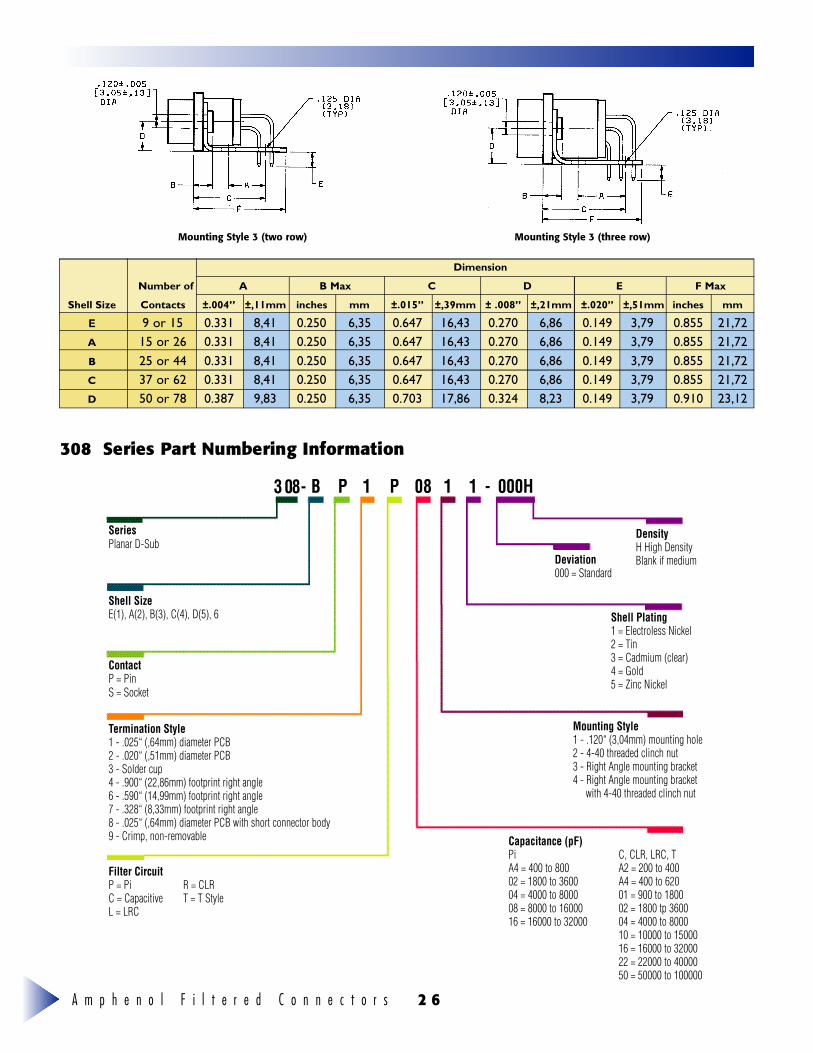
3 08 Series Pa rt Numbering Information
Dimension
Number of A B Max C D E F Max
Shell Size Contacts ±.004” ±,11mm inches mm ±.015” ±,39mm ± .008” ±,21mm ±.020” ±,51mm inches mm
E 9 or 15 0.331 8,41 0.250 6,35 0.647 16,43 0.270 6,86 0.149 3,79 0.855 21,72A 15 or 26 0.331 8,41 0.250 6,35 0.647 16,43 0.270 6,86 0.149 3,79 0.855 21,72B 25 or 44 0.331 8,41 0.250 6,35 0.647 16,43 0.270 6,86 0.149 3,79 0.855 21,72C 37 or 62 0.331 8,41 0.250 6,35 0.647 16,43 0.270 6,86 0.149 3,79 0.855 21,72D 50 or 78 0.387 9,83 0.250 6,35 0.703 17,86 0.324 8,23 0.149 3,79 0.910 23,12
Mounting Style 3 (two row) Mounting Style 3 (three row)
SeriesPlanar D-Sub
DensityH High DensityBlank if mediumDeviation
000 = Standard
Shell Plating1 = Electroless Nickel2 = Tin3 = Cadmium (clear)4 = Gold5 = Zinc Nickel
Mounting Style1 - .120“ (3,04mm) mounting hole2 - 4-40 threaded clinch nut3 - Right Angle mounting bracket4 - Right Angle mounting bracket
with 4-40 threaded clinch nut
Capacitance (pF)PiA4 = 400 to 80002 = 1800 to 360004 = 4000 to 800008 = 8000 to 1600016 = 16000 to 32000
C, CLR, LRC, TA2 = 200 to 400A4 = 400 to 62001 = 900 to 180002 = 1800 tp 360004 = 4000 to 800010 = 10000 to 1500016 = 16000 to 3200022 = 22000 to 4000050 = 50000 to 100000
Shell SizeE(1), A(2), B(3), C(4), D(5), 6
ContactP = PinS = Socket
Filter CircuitP = PiC = CapacitiveL = LRC
R = CLRT = T Style
Termination Style1 - .025“ (,64mm) diameter PCB2 - .020“ (,51mm) diameter PCB3 - Solder cup4 - .900“ (22,86mm) footprint right angle6 - .590“ (14,99mm) footprint right angle7 - .328“ (8,33mm) footprint right angle8 - .025“ (,64mm) diameter PCB with short connector body9 - Crimp, non-removable
3 08- B P 1 P 08 1 1 - 000H
A m p h e n o l F i l t e r e d C o n n e c t o r s2 7
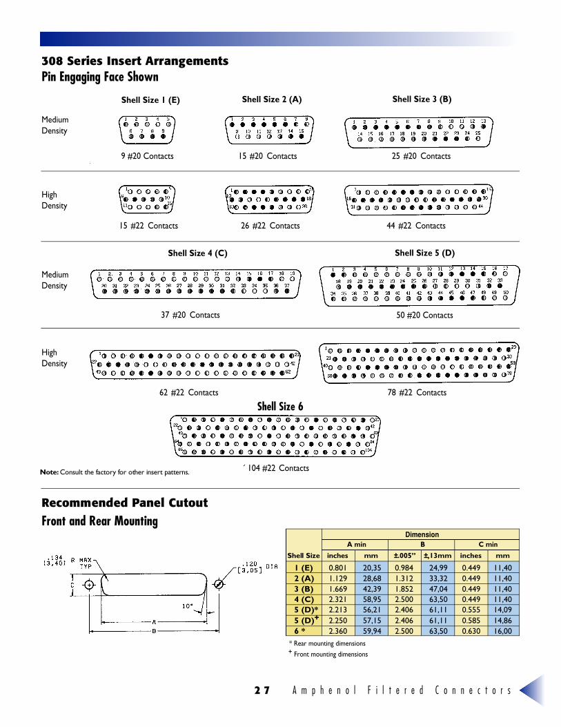
3 08 Series Insert ArrangementsPin Engaging Face Shown
Recommended Panel CutoutFront and Rear Mounting
1 (E) 0.801 20,35 0.984 24,99 0.449 11,402 (A) 1.129 28,68 1.312 33,32 0.449 11,403 (B) 1.669 42,39 1.852 47,04 0.449 11,404 (C) 2.321 58,95 2.500 63,50 0.449 11,405 (D)* 2.213 56,21 2.406 61,11 0.555 14,095 (D)+ 2.250 57,15 2.406 61,11 0.585 14,866 * 2.360 59,94 2.500 63,50 0.630 16,00
Shell Size i n c h e s m m ±.005” ±,13mm inches mm
Dimension
* Rear mounting dimensions+ Front mounting dimensions
A min B C min
50 #20 Contacts
Shell Size 1 (E)
Medium Density
HighDensity
HighDensity
Medium Density
Shell Size 2 (A) Shell Size 3 (B)
Shell Size 4 (C) Shell Size 5 (D)
Shell Size 6
9 #20 Contacts 15 #20 Contacts 25 #20 Contacts
15 #22 Contacts 26 #22 Contacts 44 #22 Contacts
37 #20 Contacts
62 #22 Contacts 78 #22 Contacts
104 #22 ContactsN o t e : Consult the factory for other insert patterns.
A m p h e n o l F i l t e r e d C o n n e c t o r s 2 8
D E S C R I P T I O N
O R D E R I N G I N F O R M A T I O N
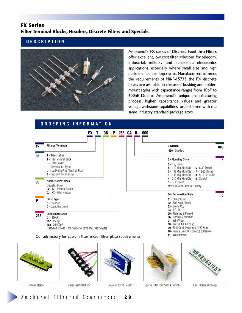
Filtered Header Filtered Terminal Block Snap-in Filtered Header Special Filter Plate Shell Assembly Filter Header, Wirewrap
FX Series F i l ter Terminal Blocks, Headers, Discrete Filters and Specials
Capacitance Code
P
06
FX
P
04 0- 00006T-FX 2 5 2
252
Filtered Terminals
Number of Positions Discrete - Blank02 - 12 - Terminal Blocks02 - XX - Filter Headers
P - Pi circuitC - Capacitive circuit
01 - 100pF252 - 2500pF203 - 20,000pF(Last digit of code is the number of zeros after first 2 digits)
Filter Type
06 T - Description T - Filter Terminal BlockH - Filter HeaderE - Discrete Filter EyeletL - Low Profile Filter Terminal BlockB - Discrete Filter Bushing
Deviation
000 - Standard000
0 - Mounting Style
0 - Thru Hole1 - .110 Mtg. Hole Dia. 6 - 8-32 Thread2 - .138 Mtg. Hole Dia. 7 - 12-32 Thread3 - .145 Mtg. Hole Dia. 8 - 5/16-32 Thread4 - .210 Mtg. Hole Dia. 9 - Special5 - 6-32 Thread Metric Threads - Consult Factory
04 - Termination Style
01 - Straight Lead02 - Nail Head (Turret)03 - Solder Cup04 - P.C. Tail05 - Flattened & Pierced06 - Hooked Termination07 - Wire Wrap08 - Press Fit (FX-L only)09 - Male Quick Disconnect (.250 Blade)10 - Female Quick Disconnect (.250 Blade)11 - Wire Harness
0
C
A m p h e n o l ’s FX series of Discrete Feed-thru Filterso f fer excellent, l ow cost filter solutions for telecom,i n d u s t r i a l , m i l i t a ry and aerospace electro n i c sap p l i c a t i o n s , e s p e c i a l ly where small size and highp e r formance are import a n t . M a nu f a c t u red to meetthe re q u i rements of Mil-F-15733, the FX discre t efilters are available in threaded bushing and solder-mount styles with capacitance ranges from 10pF to6 0 0 n F. Due to A m p h e n o l ’s unique manu f a c t u r i n gp ro c e s s , higher capacitance values and gre a t e rvoltage withstand capabilities are achieved with thesame industry standard package sizes.
Consult factory for custom filter and/or filter plate requirements.

A m p h e n o l F i l t e r e d C o n n e c t o r s2 9
S L - 3 7 9 - 3Rack and
Panel Connectors F i l t e re dC o n n e c t o r s
D - S u b m i n i a t u reC o n n e c t o r s
S L - 3 7 8 - 3Rack and Pa n e l
C o n n e c t o r s M i c ro m i n i a t u reC o n n e c t o r s
A e ro s p a c eP ro d u c t s
Amphenol Canada20 Melford DriveScarborough, ON Canada M1B 2X6Phone: 416-291-4401Fax: 416-292-0647
Amphenol Aerospace40-60 Delaware AvenueSidney, NY 138 38-1395Phone: (607) 563-5453Fax: (607) 563-5351
Amphenol Aerospace22952 Alcade DriveSuite 110Laguna Hills, CA 92653Phone: (949) 855-4454Fax: (949) 855-9115
Amphenol Aerospace57 E. Hattendorf AvenueSuite 150Roselle, IL 60172Phone: (630) 893-1713Fax: (603) 893-3958
Amphenol Aerospace7506 East Independence Blvd.Charlotte, NC 28227Phone: (704) 531-9053Fax: (704) 531-9054
Amphenol Backplane Systems 18 Celina AvenueNashua, NH 03063Phone: (603) 883-5100Fax: (603) 883-0171
Amphenol PCB 2 Technology Drive Peabody, MA 01960 Phone: (978) 532-8800 Fax: (978) 532-6800
Amphenol Phoenix Interconnect 15445 Redhill Ave., Suite A Tustin, CA 92780 Phone: (416) 291-4401 Fax: (416) 292-0647
Communication and NetworkProducts DivisionOne Kennedy AvenueDanbury, CT 06810Phone: (203) 743-9272
Fiber Optic Products1925A Ohio StreetLisle, IL 60532Phone: (630) 960-1010
Sine Systems * Pyle ConnectorsCorporation25325 Joy BoulevardMt. Clemens, MI 48046Phone: (810) 465-3131
Chicago Office 650 W. Grand Avenue, Suite 304Elmhurst, IL 60126Phone: (630) 832-4600
Spectra Strip720 Sherman AvenueHamden, CT 06514Phone: (203) 281-3200
Technical Products International2110 Notre Dame AvenueWinnipeg, MB, R3H 0K1 CanadaPhone: (204) 697-2222
Times Fiber Communications, Inc.358 Hall AvenueWallingford, CT 06492Phone: (203) 265-8500Amphenol MexicoPresidente Masaryk 61, Piso 2C.P. 11570 Mexico D.F.MexicoPhone: (52-5) 254-7283Fax: (52-5) 531-9659
Advanced Circuit Technology118 Northeastern BoulevardNashua, NH 03062Phone: (603) 880-6000
Amphenol ScandinaviaP.O. Box 2047Johannelundsvagen 2194 02 Upplands VaesbySwedenPhone: 46-8-594-10440
Amphenol Socapex S.A.S.Promenade de l’Arve, BP 2974311 Thyez CedexFrancePhone: 33-4-5089-2800
Amphenol-TFC (Changzhou)Communications Equipment Co., Ltd.96 Hehai Road, Changzhou New & HighTech & IndustrialDevelopment ZoneChangzhou 213000, Jiangsu, PRCPhone: 86-519-510-6004
Amphenol Taiwan59, Lung-Shou Street, Sec. 1Lu-Chu-Hsiang, Taoyuan HsienTaiwanRepublic of ChinaPhone: 886-3-379-5677
Amphenol-Tuchel Electronics GmbHAugust-Haeusser-Strasse 1074080 HeilbronnGermanyPhone: 49-7131-929-0
Amphetronix LimitedP.O. Box No. 1, Plot No. 105105 Bhosari Industrial AreaPune 411026, IndiaPhone: 91-20-790363
IsraelBar-Tec Ltd.11 Barliam St., P.O. Box 279Kfar Saba 44102IsraelPhone: (972-9) 974097Fax: (972-9) 974324
Amphenol Australia Limited2 Fiveways Blvd., KeysborougVictoria 3173, Melbourne, AustraliaPhone: 61-3-8796-8888
Amphenol European Sales OperationsHoofdveste 193992 DHThe NetherlandsPhone: 31-30-635-8001
Amphenol Dae Shin Limited#182-1 Dodan-Dong, Wonmi-kuBucheon-City, Kyungki-DoKoreaPhone: 82-32-680-3800
Amphenol do Brasil LTDAMorumbi TowerAvenida Roque Petroni Junior 99913th Floor CEP 04707-910Sao Paulo, BrazilPhone: 55-11-5185-2881
Amphenol East Asia Limited10/F Wah Luen Industrial Centre15-21 Wong Chuk Yeung StreetFotan, Hong KongPhone: 852-2669-2663
Amphenol EspanaCalle Cuba No. 6, 2-528820 Coslada MadridSpainPhone: 349-1-673-2235
Amphenol Gesellschaft mbHJohnstrasse 422 Stoch, Top 3AVienna, AustriaPhone: 43-1-985-1511
Amphenol InterconnectProducts Corporation20 Valley StreetEndicott, NY 13760Phone: (607) 754-4444
Amphenol Italia, S.P.A.Galleria Gandhi, 2-2720017 - Mazzo di Rho (Milano)ItalyPhone: (390-2) 939-04192Fax: (390-2) 935-03206Telex: 334623 AMPHIT I
Amphenol Japan, K.K.2-3-27, Kudan MinamiChiyoda-ku, Tokyo 102JapanPhone: 81-3-3263-5611
Amphenol LimitedThanet WayWhitstable, KentEngland CT5 3JFPhone: 44-1227-773-200
Amphenol Ges mbHTautenhayngasse 22A-1150 Wien (Vienna)AustriaPhone: (43-1) 985-15-11Fax: (43-1) 982-61-01Telex: (847) 132661 AMPHWA
Amphenol East Asia, Ltd.80 Genting Lane09-04 Genting BlockRuby Industrial ComplexSingapore 1334Phone: (65) 7433022Fax: (65) 7432466Telex: RS 23499 AMPHNL
N o t i c e : Specifications are subject to change without notice. Contact your nearest Amphenol sales office for the latest specifications.All statements, i n formation and data given herein are believed to be accurate and reliable but are presented without guaranty,w a rr a n t y, or responsibility of any kind, e x p ress or implied. Statements or suggestions concerning possible use of our products aremade without re p resentation or warranty that any such use is free of patent infringement, and are not recommended to infringea ny patent. The user should not assume that all safety measures are indicated or that other measures may not be re q u i re d .Amphenol is a re g i s t e red trademark.
A mphenol Canada Cor p.
20 Melford Drive, Scarborough, Ontario, Canada M1B 2X6
Telephone (416) 291-4401 Fax (416) 292-0647