a general decomposition for reversible logic
TRANSCRIPT
A General Decomposition for Reversible Logic Marek Perkowski, Lech Jozwiak#, Pawel Kerntopf+, Alan Mishchenko, Anas Al-Rabadi,
Alan Coppola@, Andrzej Buller*, Xiaoyu Song, Md. Mozammel Huq Azad Khan&,Svetlana N. Yanushkevich^, Vlad P. Shmerko^, Malgorzata Chrzanowska-Jeske
PORTLAND QUANTUM LOGIC GROUP
Portland State University, Portland, Oregon 97207-0751, USA,#Technical University o f Eindhoven, Eindhoven, The Netherlands, +Warsaw University of Technology, Warsaw, Poland,
@ Cypress Semiconductor Northwest and Oregon Graduate Institute, Oregon, USA , * Information Sciences Division,Advanced Telecommunications Research Institute International (ATR), Kyoto, Japan, & Department of Computer
Science and Engineering, East West University, Bangladesh, ^ University of Calgary, Calgary, Canada.
AbstractLogic synthesis for reversible logic differs considerably from standard logic synthesis. The gates are multi-output and theunutilized outputs from these gates are called “garbage”. One of the synthesis tasks is to reduce the number of garbagesignals. Previous approaches to reversible logic synthesis minimized either only the garbage or (predominantly) the numberof gates. Here we present for the first time a method that minimizes concurrently the number of gates, their total delay and thetotal garbage. Our method adopts for reversible logic many ideas developed previously for standard logic synthesis (such asAshenhurst/Curtis Decomposition, Dietmeyer’s Composition, non-linear preprocessing for BDDs), methods created in Reed-Muller Logic (such as Pseudo-Kronecker Decision Diagrams with Complemented Edges, Pseudo-Kronecker Lattice Diagramsand their generalizations) and introduces also new methods specific to reversible logic.
1. IntroductionReversible logic.Reversible are circuits (gates) in which the number of inputs is equal to the number of outputs and there is a one-to-onemapping between vectors of inputs and outputs; thus the vector of input states can be always reconstructed from the vectorof output states. A gate with k inputs and k outputs is called a k*k gate. All gates in a reversible circuit have to be reversible.A circuit is conservative when it preserves the numbers of all logic values in each input-output pair. A balanced functionhas half of minterms with value 1 and half with value 0. A circuit without constants on inputs, which includes only reversiblegates, realizes on all outputs only balanced functions. Therefore, garbage outputs are necessary in order to realize non-balanced functions. There are reversible circuits (such as Fredkin gate) that are conservative, but most such circuits are notconservative (for instance Toffoli gate is not conservative). Similarly, not all conservative gates are reversible. Additionalconstraint of reversible logic is that the fanout of every signal, including primary inputs, must be one. The graph of thereversible circuit must be a DAG (Directed Acyclic Graphs), which means - there can be no any loops of gates or internalloops in a gate.
Motivation to study reversible logic.As proved by Landauer [45], using traditional irreversible logic gates such as AND or multiplexer leads inevitably to energydissipation in a circuit, regardless of the realization of the circuit. Bennett [4] showed that for power not to be dissipated in anarbitrary circuit, it is necessary that this circuit be built from reversible gates. Power loss due to irreversible gates isnegligible for current logic technologies, therefore other methods of low power design are still predominantly researched.However, if the Moore’s Law will continue to be in effect, energy losses due to non-reversible design would becomeessential in 2020 or earlier. Moreover, quantum logic is reversible, and the problem of searching for efficient designs ofquantum circuits [16] includes as its sub-problem the problem of synthesis using classical reversible gates, being the topic ofthis paper. Many of the methods presented here in formulation for classical logic, can be, however, adapted to quantum logicas well, because reversibility is its most significant property from the gate composition point of view. Of course, Bennett’stheorem is only a necessary and not sufficient condition. Its extreme importance lies in the technological necessity that everyfuture technology will have to use reversible gates in order to reduce power. Therefore, the results presented here will beuseful for arbitrary reversible technology, not only quantum, but also CMOS, DNA, optical [57], etc.
The problem we want to solve.
The goal of this paper is to develop a methodology to synthesize binary combinational reversible logic circuits in regular andnon-regular structures, in binary logic, for multi-output functions, and minimizing a complex cost function. This function is aweighted sum of the number of garbage outputs, the number of levels of the circuit, and the number of gates. Suchproblem has never been formulated in the past, to the best of our knowledge. Our method will be only approximate, but atleast we attempt to formulate a realistic synthesis problem in contrast to the previous research. We will assume that theprogram disposes a library of reversible 3*3 gates (cells), each of them with an area cost and a delay cost. Arbitrary numberof constants 0 and 1 is available. The weights in the cost function should be selected for each technology separately, forinstance, garbage, related to the size of qubit register, is absolutely critical for current quantum technology, but number oflevels may be more important for CMOS reversible/adiabatic circuits.
Previous work on reversible logic synthesis. In the seminal paper [29], Fredkin and Toffoli formulated the problem of reversible logic synthesis. They also showedexamples, illustrating why classical logic synthesis methods cannot be directly applied to design of reversible circuits. Theydid not, however, present any cost function or synthesis method, nor did they give any hints how such goals can be achieved.
Surprisingly little have been published since then on logic synthesis algorithms for reversible logic. The universality of setsof 3*3 conservative gates with respect to all 3*3 conservative circuits was considered for cascades by Sasao and Kinoshita[67]. They also proved in [68] that an arbitrary n-variable Boolean function can be implemented by (n+3)*(n+3) circuitsusing 3*3 Fredkin gates (which they called P elements). Lemma 4.3 of [68] shows that an arbitrary logic function can berealized with three input constants and some P elements. The feature of this realization is that it produces a small garbage.Unfortunately, their approach leads to long (of the order of 2 n) cascades of gates. Such cascades are thus slow and expensive.The method is also not general as it assumes design using a limited set of reversible gates, namely Fredkin gates. There is noargument in reversible technologies to restrict the gates to only Fredkin, or even only conservative reversible gates.Moreover, the cascade structure considered by Sasao is quite restricted and no constructive method was shown to synthesizean arbitrary function using Fredkin gates The method was for single-output functions only. Despite these weaknesses, thepaper of Sasao and Kinoshita is important as a first paper on reversible logic synthesis, that proposed to use cascades. Apaper by Storme et al. [71] analyzed the group theoretic properties of all 3*3 reversible functions and found the classes ofmost powerful gates. An interesting result of this paper is that every 3*3 reversible function can be realized by a cascade ofsome cells (3*3 functions) found in [71], and the libraries of small subsets of complete gates were proposed based oncounting results. These libraries have 3*3 reversible gates that are “most powerful” as able to create all 3*3 functions withshortest cascades. Similar results (without negations) were obtained in [38]. The findings from [71,38,39,40,41] can be usedto create libraries of cells, that can be next used with “technology matching” algorithms to select the best cell combination fora given 3*3 or 4*4 reversible function. The advantage of this approach is that equivalence classes with respect to signalpermutations, negations, and linear transformations were also considered. Thus the results of this paper allow for morerealistic and optimal synthesis of 3*3 and small k*k circuits than the results of Sasao and Kinoshita. Observe that the resultsare for 3-output functions rather than for single-output functions. However, the constructive method for synthesis was notgiven, as the paper was based on exhaustive analysis using algebraic software for group theory.
In contrast, several approaches to reversible logic synthesis proposed by Picton [57,58,59,60] attempt to minimize the numberof gates, but produce very large garbage and usually also delay. In our previous papers [54,55,56] we proposed severalmethods aimed at simultaneous minimization of the number of gates, delay and garbage, but some of these methods give highquality results mainly for symmetric functions [55,56]. Other methods assumed levelized realizations (such as modifieddecision diagrams and lattices [54]) which can also lead to designs with high garbage for some functions. Therefore, wecontinued to work towards really general synthesis methods for reversible logic that would be counterparts of the well-knownsynthesis methods based on functional decompositions in standard binary logic. Each new method that we developed wassubsequently compared on small functions with previous methods to understand better its advantages and disadvantages. Ageneral reversible logic synthesis problem is difficult and we concentrate first on finding high quality solutions for rather smallfunctions. Some of our approaches work also for very large functions, but their quality is sacrificed.
The result of this paper.Here we introduce a general method of hierarchical decomposition of arbitrary reversible functions into arbitrary reversiblelogic gates. If the original function is not reversible, it is completed to a reversible function either in the preprocessing stage orduring the decomposition (section 5), by adding additional constant input signals and garbage outputs. To distinguish this newgeneral decomposition from the well-known functional decomposition approaches of Shannon, Ashenhurst and Curtis we callit the Multi-purpose Portland Decomposition, the MP-decomposition for short. In contrast to the previously published papers,the MP-decomposition can use arbitrary number of arbitrary types of reversible gates at the same time. It is also not restricted
to certain decomposition structures, e.g. regular lattices. This decomposition has four types and two modes. Eeach type can beexecuted in one of two modes: forward mode and backward mode. The decomposition types are output decomposition, inputdecomposition and Curtis decomposition. The forward mode means that the processing is performed on the original reversiblefunction, the backward mode means that the processing is performed on a function that is a reverse of the original function(see section 5). While the output decomposition is new, the input composition and the Curtis decomposition types areadaptations of standard binary logic decompositions to reversible binary logic.
Additional remarks.This is a general overview paper and an introduction to reversible logic synthesis research performed by our group. Forsimplicity of explanation, we resigned from presenting formally the representations, formulas, algorithms and data structures.Instead, we have concentrated on the main ideas useful to create synthesis methods for reversible logic, in order to outline thegeneral issues related to selecting reversible gates, creating network structures, and synthesis approaches. For instance, weillustrate all the methods using Karnaugh maps, but the software that we are going to develop will use BDDs to represent alldata involved in reversible logic: ON and OFF sets of values, characteristic functions for functions and relations, SPFDs, andrepresentation of gates as binary vector permutations and matrices. To improve the tutorial value of the paper, a complete listof references is given. However, knowing all details presented in them is not necessary for understanding of our paper.
2. Binary Reversible GatesMany universal reversible gates have been considered (see [18,38,39,40,41,71]), here only some of them will be used.There exists only one 1*1 gate, which is an inverter (we do not count a wire as a gate). This gate is very important since itdoes not introduce garbage outputs. Thus the representation and synthesis methods should allow to use inverters inintermediate representations whenever possible; like for instance using decision diagrams (DDs) with complemented edgesrather than standard DDs. There are several 2*2 gates in reversible logic and they are all linear. A gate is linear when all itsoutputs are linear functions of input variables. Let A, B, and C be inputs and P, Q and R outputs of a gate. The 2*2Feynman gate, (called also controlled-not or quantum XOR), realizes functions P = A, Q = A ⊕⊕⊕⊕ B, where operator ⊕⊕⊕⊕denotes EXOR.. When A = 0 then Q = B, when A = 1 then Q = ¬¬¬¬ B. With B=0 the 2*2 Feynman gate is used as a fan-out(or copying) gate. Every linear reversible function can be built by composing only 2*2 Feynman gates and inverters. Thereexist 8! = 40,320 3*3 reversible logic gates, some of them with interesting properties, but here we are interested in synthesismethods using arbitrary reversible gates, so we will restrict ourselves to only few gate types. There exist two well-knownuniversal 3*3 reversible gates: Fredkin gate [29] and Toffoli gate (also called 3*3 Feynman gate or Controlled-Controlled–not).
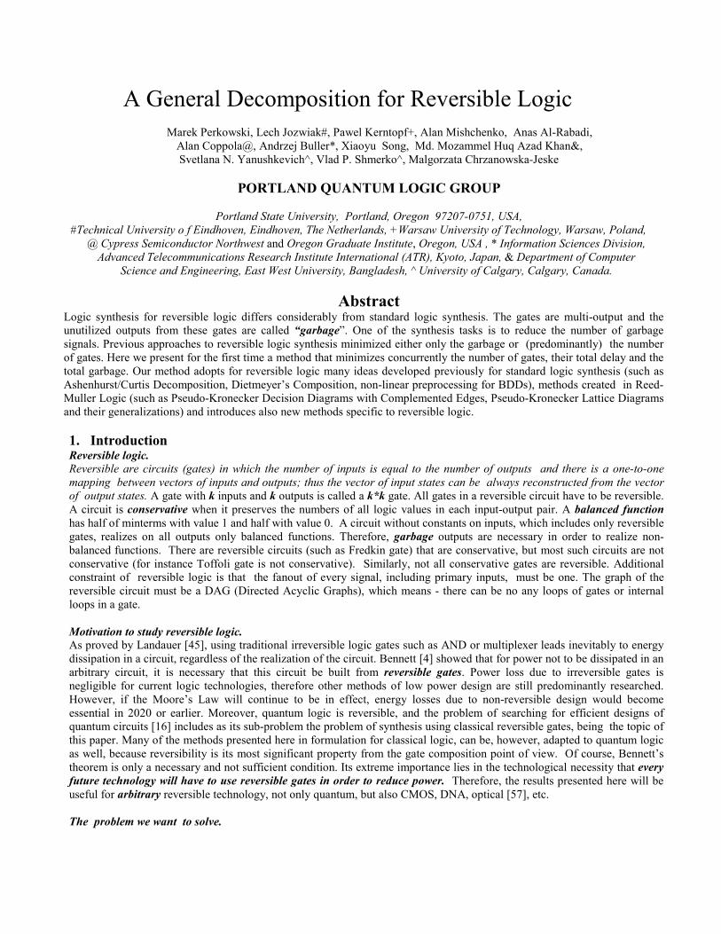
The 3*3 Fredkin gate is described by the following equations: P = A, Q = if A then C else B, R = if A then B elseC. In terms of classical logic this gate is just two multiplexers controlled in a flipped (permuted) way from the same controlinput A. The circuit and the symbol notation for 3*3 Fredkin gate are shown in Figure 1. As we see, the 3*3 Fredkin gate is apermutation gate. It permutes the data inputs of its two multiplexers under control of the control input of these multiplexers.This control input is also an output from Fredkin gate. The fact that output P replicates input A is very useful because itallows to avoid fanout gates. This fact is used for instance to implement gates that correspond to the same level of a reversibledecision diagram, lattice diagram or other levelized diagram, PLA-like circuits for SOP or ESOP and other regular structures
Figure 1. Notation for Fredkin Gate.(a) the circuit, (b) the simplified symbolof the gate
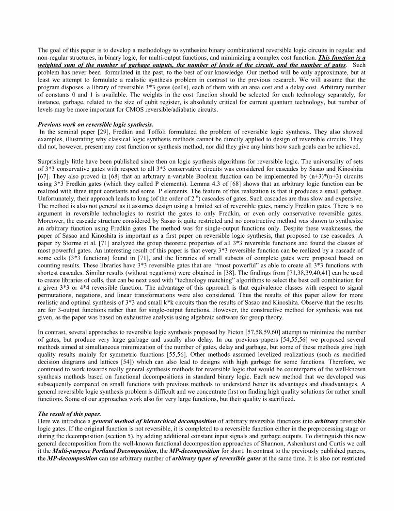
Figure 2. Possible realizations ofReversible gates.(a) Toffoli gate, (b) Feynman 2*2gate, (c) Kerntopf gate.
of gates. The cells are just cascaded: output P goes to input A of the next cell at the same level (let us recall that fanout is notallowed in reversible logic). Fredkin gates are examples of what we define here as one-through gates, which means gates inwhich one input variable is also an output. The 3*3 Toffoli gate (Figure 2a) is described by these equations: P = A, Q =B, R = AB ⊕⊕⊕⊕ C, Toffoli gate is an example of two-through gates, because two of its inputs are given to the output.
The Kerntopf gate [38,56], Figure 2c, is described by equations: P = 1 ⊕⊕⊕⊕ A ⊕⊕⊕⊕ B ⊕⊕⊕⊕ C ⊕⊕⊕⊕ AB, Q = 1 ⊕⊕⊕⊕ AB ⊕⊕⊕⊕ B⊕⊕⊕⊕ C ⊕⊕⊕⊕ BC,
R = 1 ⊕⊕⊕⊕ A ⊕⊕⊕⊕ B⊕⊕⊕⊕ AC. When C=1 then P = A + B, Q = A * B, R = ¬¬¬¬B, so AND/OR gate is realized on outputs P and Q
with C as the controlling input value. When C = 0 then P = ¬¬¬¬ A * ¬¬¬¬ B, Q = A + ¬¬¬¬B, R = A ⊕⊕⊕⊕ B. Therefore for controlinput value 0 the gate realizes NAND and IMPLICATION on its outputs P and Q, respectively. As we see, the 3*3 Kerntopfgate is not a one-through nor a two-through gate.
Example 1. We will show that each output function realized by the Kerntopf gate belongs to the same NP equivalence class(negation/permutation of inputs) as Davio and Shannon expansion operators. (Positive Davio is used once in Toffoli gate andShannon operator is used twice in Fredkin gate).
P = 1 ⊕⊕⊕⊕ A ⊕⊕⊕⊕ B ⊕⊕⊕⊕ C ⊕⊕⊕⊕ AB = A ⊕⊕⊕⊕ B¬¬¬¬A ⊕⊕⊕⊕ C ⊕⊕⊕⊕ 1 = (A+B) ⊕⊕⊕⊕ ¬¬¬¬C = ¬¬¬¬ A ¬¬¬¬B ⊕⊕⊕⊕ C = Davio(¬¬¬¬ A, ¬¬¬¬ B, C),
Q = 1 ⊕⊕⊕⊕ AB ⊕⊕⊕⊕ B⊕⊕⊕⊕ C ⊕⊕⊕⊕ BC = 1 ⊕⊕⊕⊕ AB ⊕⊕⊕⊕ (B+C) = AB ⊕⊕⊕⊕ ¬¬¬¬ (B+C) = AB ⊕⊕⊕⊕ ¬¬¬¬B¬¬¬¬C = Shannon(B ,¬¬¬¬ C, A),
R = 1 ⊕⊕⊕⊕ A ⊕⊕⊕⊕ B ⊕⊕⊕⊕ AC = ¬¬¬¬ B⊕⊕⊕⊕ A¬¬¬¬C = Davio( A, ¬¬¬¬ C, ¬¬¬¬ B ).Similar transformations can be performed on all H gates introduced in [38]. The functions in them belong also to linear classof 3 inputs. In particular, H gates include the gate called “Kerntopf gate” utilized in [56]. Because the negations can beincluded into gates, a set of standard cells with such negations inside the cells can be introduced. We will call them “extendedstandard cells”.
Let us assume that we have a technology in which permutations and negations are easily realizable. Every balanced functionof not more than 3 variables belongs to one of six NPN equivalence classes. Their representatives are: (a) for one variable –variable (negation), (b) for two variables – EXOR, (c) for three variables - Davio, Shannon (multiplexer), EXOR, andmajority operators. Therefore every 3*3 reversible gate is a combination of three out of six functions, possibly withpermutations and/or negations of some inputs and negations of some outputs. The knowledge of this fact will help to buildthese gates in current or future technologies. In the technologies that we are aware of, both permutations and negations arerelatively easy to obtain. The above characterization of reversible gates is also used in logic synthesis algorithms that applythese gates. Kerntopf gate [38] has a theoretical advantage of having more cofactors than other gates, thus being able to realizemore subfunctions with some inputs set to constants. This property was used in [56] to design symmetric functions and regularstructure of a reversible FPGA. Despite of this advantage of Kerntopf gate over classical Fredkin and Toffoli gates, so farthere are no optical, quantum or CMOS realizations of this gate. We introduce this gate here for the reason of demonstratingthe generality of our decompositional synthesis approach. It should be also noted that although the Kerntopf gate looks morecomplex for CMOS realization, it is not necessarily so for other realization technologies. Realization of 3*3 binary reversiblegates using 2*2 and 1*1 unitary quantum gates is discussed in [22]. Many cascades of length 5 realizing universal binary logicreversible gates have been shown using these quantum gates, therefore it seems likely that every universal 3*3 gate ofreversible logic, including all Kerntopf’s H gates and Storme’s et al gates, would require 5 quantum gates.
3. PreprocessingBecause some of the presented below decompositions require complex data processing to find a high quality solution, largemulti-output functions should be first partitioned to smaller functions. This is based on their representations such as BinaryDecision Diagrams, Pseudo-Kronecker Decision Diagrams (PKDD) [23], Pseudo-Kronecker Diagrams with ComplementedEdges (PKDDCE), Linearly Transformed Binary Decision Diagrams (LTBDDs), Function-driven Decision Diagrams (fDDs)[39], or other similar diagrams. The goal of representing functions in such a representation is to find the “natural” structure ofthe function, helpful for its subsequent partitioning to blocks of logic and subsets of variables. Let us remind that in PKDD anexpansion variable goes through an entire level of a diagram. Observe as well that a Toffoli gate uses Davio Expansion as oneof its outputs and forwards two of its inputs to outputs. Therefore, a fast natural mapping from a PKDD or PKDDCE diagramto a reversible netlist with Toffoli gates exists. First a PKDD, PKDDCE, or other similar diagram is mapped to Feynman,Fredkin and Toffoli gates and inverters, in such a way that there is no feedback loops and no fan-out larger than one fromprimary inputs and gates. We will discuss the Toffoli gate mapping as an example, but we have created similar rules forFeynman, Fredkin and Kerntopf gates (the rules use also inverters). After the mapping, every Toffoli gate in the mapped
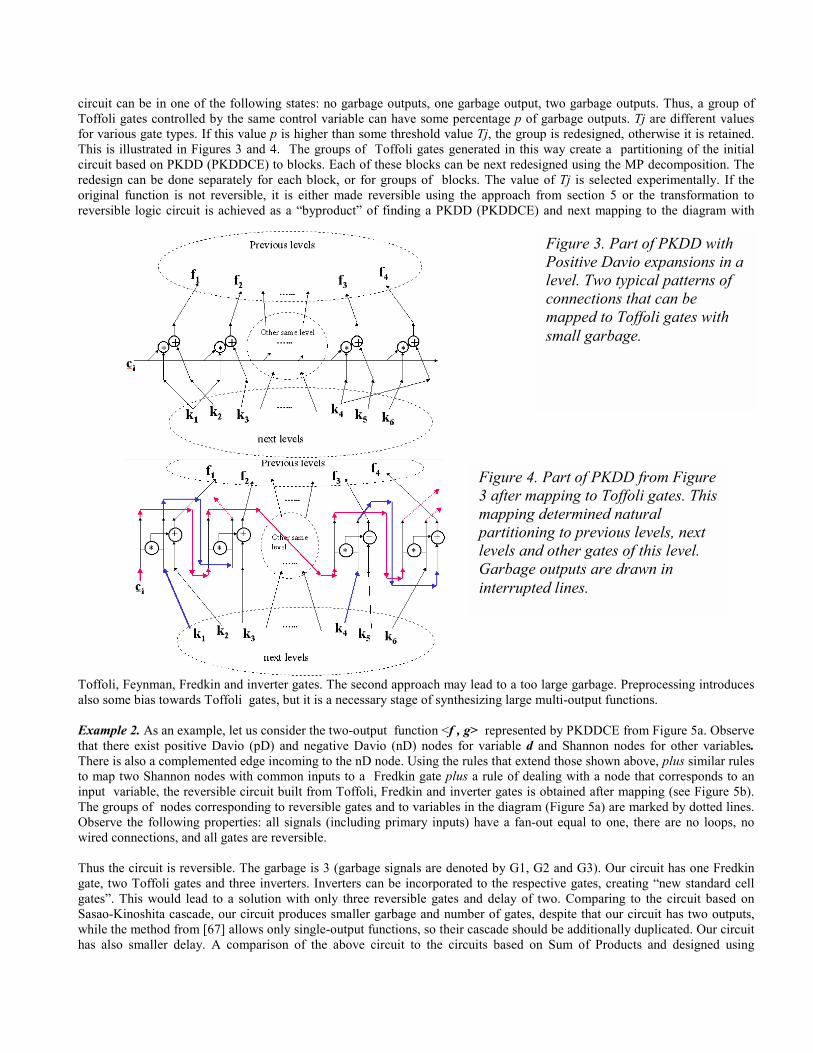
circuit can be in one of the following states: no garbage outputs, one garbage output, two garbage outputs. Thus, a group ofToffoli gates controlled by the same control variable can have some percentage p of garbage outputs. Tj are different valuesfor various gate types. If this value p is higher than some threshold value Tj, the group is redesigned, otherwise it is retained.This is illustrated in Figures 3 and 4. The groups of Toffoli gates generated in this way create a partitioning of the initialcircuit based on PKDD (PKDDCE) to blocks. Each of these blocks can be next redesigned using the MP decomposition. Theredesign can be done separately for each block, or for groups of blocks. The value of Tj is selected experimentally. If theoriginal function is not reversible, it is either made reversible using the approach from section 5 or the transformation toreversible logic circuit is achieved as a “byproduct” of finding a PKDD (PKDDCE) and next mapping to the diagram with
Toffoli, Feynman, Fredkin and inverter gates. The second approach may lead to a too large garbage. Preprocessing introducesalso some bias towards Toffoli gates, but it is a necessary stage of synthesizing large multi-output functions.
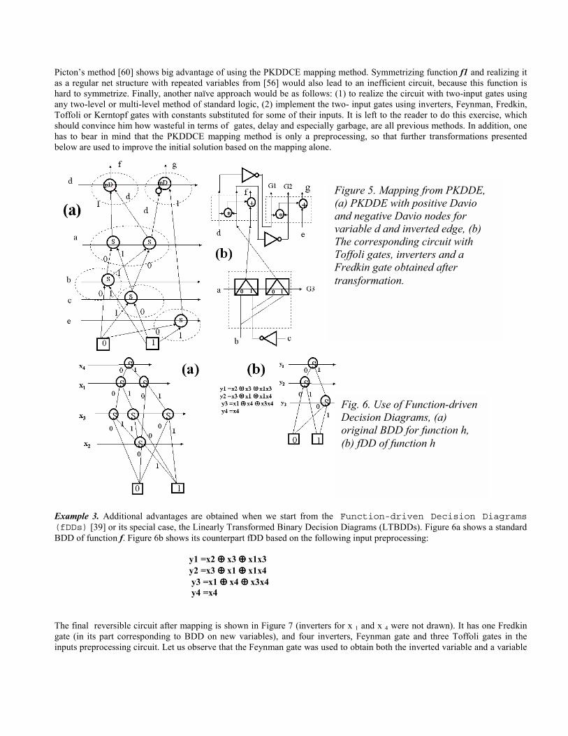
Example 2. As an example, let us consider the two-output function <f , g> represented by PKDDCE from Figure 5a. Observethat there exist positive Davio (pD) and negative Davio (nD) nodes for variable d and Shannon nodes for other variables.There is also a complemented edge incoming to the nD node. Using the rules that extend those shown above, plus similar rulesto map two Shannon nodes with common inputs to a Fredkin gate plus a rule of dealing with a node that corresponds to aninput variable, the reversible circuit built from Toffoli, Fredkin and inverter gates is obtained after mapping (see Figure 5b).The groups of nodes corresponding to reversible gates and to variables in the diagram (Figure 5a) are marked by dotted lines.Observe the following properties: all signals (including primary inputs) have a fan-out equal to one, there are no loops, nowired connections, and all gates are reversible.
Thus the circuit is reversible. The garbage is 3 (garbage signals are denoted by G1, G2 and G3). Our circuit has one Fredkingate, two Toffoli gates and three inverters. Inverters can be incorporated to the respective gates, creating “new standard cellgates”. This would lead to a solution with only three reversible gates and delay of two. Comparing to the circuit based onSasao-Kinoshita cascade, our circuit produces smaller garbage and number of gates, despite that our circuit has two outputs,while the method from [67] allows only single-output functions, so their cascade should be additionally duplicated. Our circuithas also smaller delay. A comparison of the above circuit to the circuits based on Sum of Products and designed using
Figure 4. Part of PKDD from Figure3 after mapping to Toffoli gates. Thismapping determined naturalpartitioning to previous levels, nextlevels and other gates of this level.Garbage outputs are drawn ininterrupted lines.
Figure 3. Part of PKDD withPositive Davio expansions in alevel. Two typical patterns ofconnections that can bemapped to Toffoli gates withsmall garbage.
Picton’s method [60] shows big advantage of using the PKDDCE mapping method. Symmetrizing function f1 and realizing itas a regular net structure with repeated variables from [56] would also lead to an inefficient circuit, because this function ishard to symmetrize. Finally, another naïve approach would be as follows: (1) to realize the circuit with two-input gates usingany two-level or multi-level method of standard logic, (2) implement the two- input gates using inverters, Feynman, Fredkin,Toffoli or Kerntopf gates with constants substituted for some of their inputs. It is left to the reader to do this exercise, whichshould convince him how wasteful in terms of gates, delay and especially garbage, are all previous methods. In addition, onehas to bear in mind that the PKDDCE mapping method is only a preprocessing, so that further transformations presentedbelow are used to improve the initial solution based on the mapping alone.
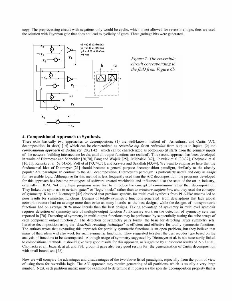
Example 3. Additional advantages are obtained when we start from the Function-driven Decision Diagrams(fDDs) [39] or its special case, the Linearly Transformed Binary Decision Diagrams (LTBDDs). Figure 6a shows a standardBDD of function f. Figure 6b shows its counterpart fDD based on the following input preprocessing:
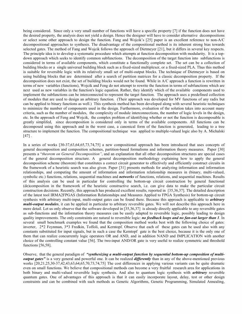
The final reversible circuit after mapping is shown in Figure 7 (inverters for x 1 and x 4 were not drawn). It has one Fredkingate (in its part corresponding to BDD on new variables), and four inverters, Feynman gate and three Toffoli gates in theinputs preprocessing circuit. Let us observe that the Feynman gate was used to obtain both the inverted variable and a variable
y1 =x2 ⊕⊕⊕⊕ x3 ⊕⊕⊕⊕ x1x3y2 =x3 ⊕⊕⊕⊕ x1 ⊕⊕⊕⊕ x1x4 y3 =x1 ⊕⊕⊕⊕ x4 ⊕⊕⊕⊕ x3x4 y4 =x4
Fig. 6. Use of Function-drivenDecision Diagrams, (a)original BDD for function h,(b) fDD of function h
Figure 5. Mapping from PKDDE,(a) PKDDE with positive Davioand negative Davio nodes forvariable d and inverted edge, (b)The corresponding circuit withToffoli gates, inverters and aFredkin gate obtained aftertransformation.
copy. The preprocessing circuit with negations only would be cyclic, which is not allowed for reversible logic, thus we usedthe solution with Feynman gate that does not lead to cyclicity of gates. Three garbage bits were generated.
4. Compositional Approach to Synthesis.There exist basically two approaches to decomposition: (1) the well-known method of Ashenhurst and Curtis (A/Cdecomposition, in short) [14] which can be characterized as recursive top-down reduction from outputs to inputs. (2) thecompositional approach of Dietmeyer [20,21,42] which can be characterized as bottom-up (it starts from the primary inputsof the network, building intermediate levels, until all output functions are realized). This second approach has been developedin works of Dietmeyer and Schneider [20,70], Fang and Wojcik [25], Michalski [47], Jozwiak et al [30-37], Chojnacki et al[10,11], Rawski et al [63,64,65], Volf et al [73,74,75], and Kravets and Sakallah [43,44]. We want to emphasize here that thefundamental idea of Dietmeyer [21] should become a general-purpose decomposition paradigm, similarly to the alreadypopular A/C paradigm. In contrast to the A/C decomposition, Dietmeyer’s paradigm is particularly useful and easy to adaptfor reversible logic. Although so far this method is less frequently used than the A/C decomposition, the programs developedfor this approach has become prototypes of software created worldwide and influenced also the state of the art in industry,originally in IBM. Not only these programs were first to introduce the concept of composition rather than decomposition.They linked the synthesis to certain “gates” or “logic blocks” rather than to arbitrary subfunctions and they used the conceptsof symmetry. Kim and Dietmeyer [42] observed that previous systems for multilevel synthesis from PLA-like macros led topoor results for symmetric functions. Designs of totally symmetric functions generated from descriptions that lack globalnetwork structure had on average more than twice as many literals as the best designs, while the designs of nonsymmetricfunctions had on average 20 % more literals than the best designs. Taking advantage of symmetry in multilevel synthesisrequires detection of symmetry sets of multiple-output function F. Extensive work on the detection of symmetry sets wasreported in [70]. Detecting of symmetry in multi-output functions may be performed by sequentially testing the cube arrays ofeach component output function fi. The detection of symmetry pairs forms the basis for detecting larger symmetry sets.Iterative decomposition using the “heuristic recoding technique” is efficient and effective for totally symmetric functions.The authors wrote that expanding this approach for partially symmetric functions is an open problem, but they believe thatmany of their ideas will also work for such symmetric functions. They suggested to select the best recoder type based on theanalysis of functions to be decomposed. Although usage of symmetry suggested by Dietmeyer et al. is not necessarily linkedto compositional methods, it should give very good results for this approach, as suggested by subsequent results of Volf et al.,Chojnacki et al., Jozwiak at al. and PSU group. It gave also very good results for the generalization of Curtis decompositionwith small bound sets [28].
Now we will compare the advantages and disadvantages of the two above listed paradigms, especially from the point of viewof using them for reversible logic. The A/C approach may require generating of all partitions, which is usually a very largenumber. Next, each partition matrix must be examined to determine if it possesses the specific decomposition property that is
Figure 7. The reversiblecircuit corresponding tothe fDD from Figure 6b.
being considered. Since only a very small number of functions will have a specific property [7] if the function does not havethe desired property, the analysis does not yield a design. Hence the designer will have to consider alternative decompositionsor select some other approach to design the function. Fang and Wojcik’s [25] paper is an excellent reference to non-A/Cdecompositional approaches to synthesis. The disadvantage of the compositional method is its inherent strong bias towardsselected gates. The method of Fang and Wojcik follows the approach of Dietmeyer [21], but it differs in several key respects.The principle idea is to develop a systematic procedure which attempts at function decomposition with modularity. It is a top-down approach which seeks to identify common subfunctions. The decomposition of the target function into subfunctions isconsidered in terms of available components, which constitute a functionally complete set. The set can be a collection ofbuilding blocks or a single universal building block such as a fixed-sized multiplexer, or a fixed-sized PLA. Thus this methodis suitable for reversible logic with its relatively small set of multi-output blocks. The technique of Dietmeyer is based onusing building blocks that are determined after a search of partition matrices for a classic decomposition property. If thedecomposition does not exist, the set of building blocks would not be found. While in A/C approach a function is rewritten interms of new variables (functions), Wojcik and Feng do not attempt to rewrite the function in terms of subfunctions which arenext used as new variables in the function's logic equation. Rather, they identify which of the available components used toimplement the subfunctions can be interconnected to represent the target function. The approach uses a predefined collectionof modules that are used to design an arbitrary function. (Their approach was developed for MV functions of any radix butcan be applied to binary functions as well.) This synthesis method has been developed along with several heuristic techniquesto minimize the number of components used in the design. Furthermore, evaluation of the solution takes into account manycriteria, such as the number of modules, the complexity of module interconnections, the number of logic levels in the design,etc. In the approach of Feng and Wojcik, the complex problem of identifying whether or not the function is decomposable isgreatly simplifed, since decomposition is considered only in terms of the available components. All functions can bedecomposed using this approach and in the worst case, a canonical form of the function is generated, leading to a treestructure to implement the function. The compositional technique was applied to multiple-valued logic also by A. Michalski[47] .
In a series of works [30-37,63,64,65,73,74,75] a new compositional approach has been introduced that uses concepts ofgeneral decomposition and composition schemes, partition-based formalisms and information theory measures. Paper [30]presents a “theorem on General Decomposition”, and an explanation that all other decomposition structures are special casesof the general decomposition structure. A general decomposition methodology explaining how to apply the generaldecomposition scheme (theorem) that constitutes a correct circuit generator to effectively and efficiently construct circuits inthe framework of a heuristic search was also given. Paper [31] presents methods for analyzing information and informationrelationships, and computing the amount of information and information relationship measures in (binary, multi-valued,symbolic etc.) functions, relations, sequential machines and networks of functions, relations, and sequential machines. Resultsof this analysis can be used in particular for controlling the bottom-up circuit construction by general functional(de)composition in the framework of the heuristic constructive search, i.e. can give data to make the particular circuitconstruction decisions. Recently, this approach has produced excellent results, reported in [35,36,37]. The detailed descriptionof the latest tool IRMA2FPGAS (Information Relationships and Measures Applied to FPGA Synthesis) for bottom-up circuitsynthesis with arbitrary multi-input, multi-output gates can be found there. Because this approach is applicable to arbitrarymulti-output modules, it can be applied in particular to arbitrary reversible gates. We will not describe this approach here inmore detail. Let us only observe that the software developed in [35,36,37] is already directly applicable to any reversible gatesas sub-functions and the information theory measures can be easily adapted to reversible logic, possibly leading to designquality improvements. The only constraints are natural to reversible logic: no feedback loops and no fan-out larger than 1. Inseveral small benchmark examples we found that the composition method works best with the following choice of gates:inverter, 2*2 Feynman, 3*3 Fredkin, Toffoli, and Kerntopf. Observe that each of these gates can be used also with anyconstants substituted for input signals, but in such a case the Kerntopf gate is the best choice, because it is the only one ofthem that can realize concurrently logic operators OR and AND, and in addition NAND and IMPLICATION with anotherchoice of the controlling constant value [56]. The two-input AND/OR gate is very useful to realize symmetric and thresholdfunctions [56,58].
Observe, that the general paradigm of “synthesizing a multi-output function by sequential bottom-up composition of multi-output gates” is a very general and powerful one. It can be realized differently than in any of the above-mentioned previousworks [20,21,25,30-37,42,43,63,64,65,70,73,74,75] The cost differences in applying various variants can be quite dramaticeven on small functions. We believe that compositional methods can become a very fruitful research area for applications inboth binary and multi-valued reversible logic synthesis. And also to quantum logic synthesis with arbitrary reversiblequantum gates. One of advantages of this approach is that it can easily incorporate layout, delay, test or other designconstraints and can be combined with such methods as Genetic Algorithms, Genetic Programming, Simulated Annealing,
Tabu Search, or Array Genetic Algorithms. In this paper we will only show examples of compositional synthesis usingreversible gates. The interested reader is referred to literature for details.
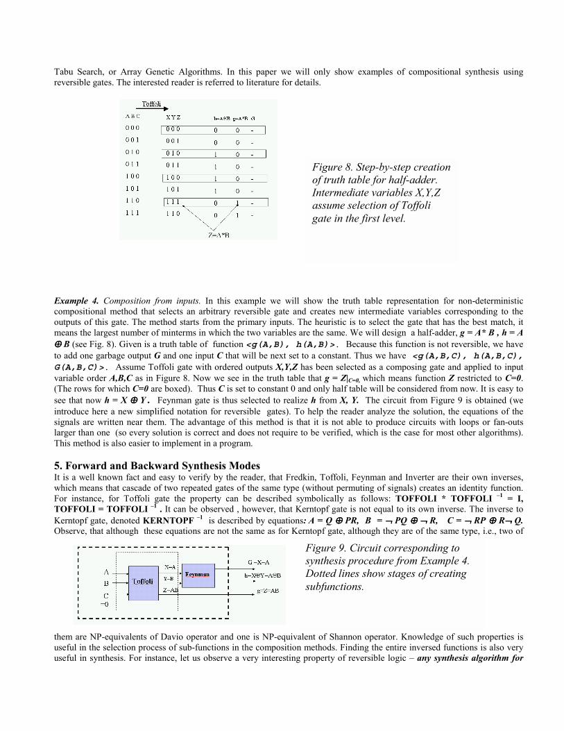
Example 4. Composition from inputs. In this example we will show the truth table representation for non-deterministiccompositional method that selects an arbitrary reversible gate and creates new intermediate variables corresponding to theoutputs of this gate. The method starts from the primary inputs. The heuristic is to select the gate that has the best match, itmeans the largest number of minterms in which the two variables are the same. We will design a half-adder, g = A* B , h = A⊕⊕⊕⊕ B (see Fig. 8). Given is a truth table of function <g(A,B), h(A,B)>. Because this function is not reversible, we haveto add one garbage output G and one input C that will be next set to a constant. Thus we have <g(A,B,C), h(A,B,C),G(A,B,C)>. Assume Toffoli gate with ordered outputs X,Y,Z has been selected as a composing gate and applied to inputvariable order A,B,C as in Figure 8. Now we see in the truth table that g = Z|C=0, which means function Z restricted to C=0.(The rows for which C=0 are boxed). Thus C is set to constant 0 and only half table will be considered from now. It is easy tosee that now h = X ⊕⊕⊕⊕ Y. Feynman gate is thus selected to realize h from X, Y. The circuit from Figure 9 is obtained (weintroduce here a new simplified notation for reversible gates). To help the reader analyze the solution, the equations of thesignals are written near them. The advantage of this method is that it is not able to produce circuits with loops or fan-outslarger than one (so every solution is correct and does not require to be verified, which is the case for most other algorithms).This method is also easier to implement in a program.
5. Forward and Backward Synthesis ModesIt is a well known fact and easy to verify by the reader, that Fredkin, Toffoli, Feynman and Inverter are their own inverses,which means that cascade of two repeated gates of the same type (without permuting of signals) creates an identity function.For instance, for Toffoli gate the property can be described symbolically as follows: TOFFOLI * TOFFOLI –1 = I,TOFFOLI = TOFFOLI –1 . It can be observed , however, that Kerntopf gate is not equal to its own inverse. The inverse toKerntopf gate, denoted KERNTOPF –1 is described by equations: A = Q ⊕⊕⊕⊕ PR, B = ¬¬¬¬ PQ ⊕⊕⊕⊕ ¬¬¬¬ R, C = ¬¬¬¬ RP ⊕⊕⊕⊕ R¬¬¬¬ Q.Observe, that although these equations are not the same as for Kerntopf gate, although they are of the same type, i.e., two of
them are NP-equivalents of Davio operator and one is NP-equivalent of Shannon operator. Knowledge of such properties isuseful in the selection process of sub-functions in the composition methods. Finding the entire inversed functions is also veryuseful in synthesis. For instance, let us observe a very interesting property of reversible logic – any synthesis algorithm for
Figure 8. Step-by-step creationof truth table for half-adder.Intermediate variables X,Y,Zassume selection of Toffoligate in the first level.
Figure 9. Circuit corresponding tosynthesis procedure from Example 4.Dotted lines show stages of creatingsubfunctions.
reversible logic can be applied both in standard, forward, way, in which output signals are functions of input signals, andin a reverse way, in which input signals are functions of output signals (Kmap inversed). Because of reversibility of a multi-output function F that we want to decompose, one can find a specification of function F -1 being an inverse of F, apply theinput decomposition to it, and next find the structure from inverse modules, in which output pins of every gate are replacedwith input pins. This approach is functionally equivalent to decomposing a function from outputs to inputs. Let us observe thatthis property of “synthesis from a reverse specification” does not exist for standard logic, and is a unique property ofreversible logic, which makes the compositional synthesis methods especially attractive. Such approach may lead to betterresults than the straightforward synthesis of function F (similarly as it is useful to search a graph heuristically both forwardand backwards, when the resources are limited). This methodology can be used to extend any synthesis method for reversiblelogic to operate in two directions: forward and backwards. Because we never know which direction will give better results,any algorithm presented below can be applied twice, one in each direction, and the better result can be selected. If a multi-output function is not reversible, it can be completed to a reversible function using one of the known methods based onsuccessive adding of primary inputs and primary outputs. Although the above described property directly results from thedefinition of reversible logic, amazingly it was not observed in the literature as a synthesis method. It can be also applied to bi-directional search for the best circuit (such type of search is known for its efficiency in some AI problems).
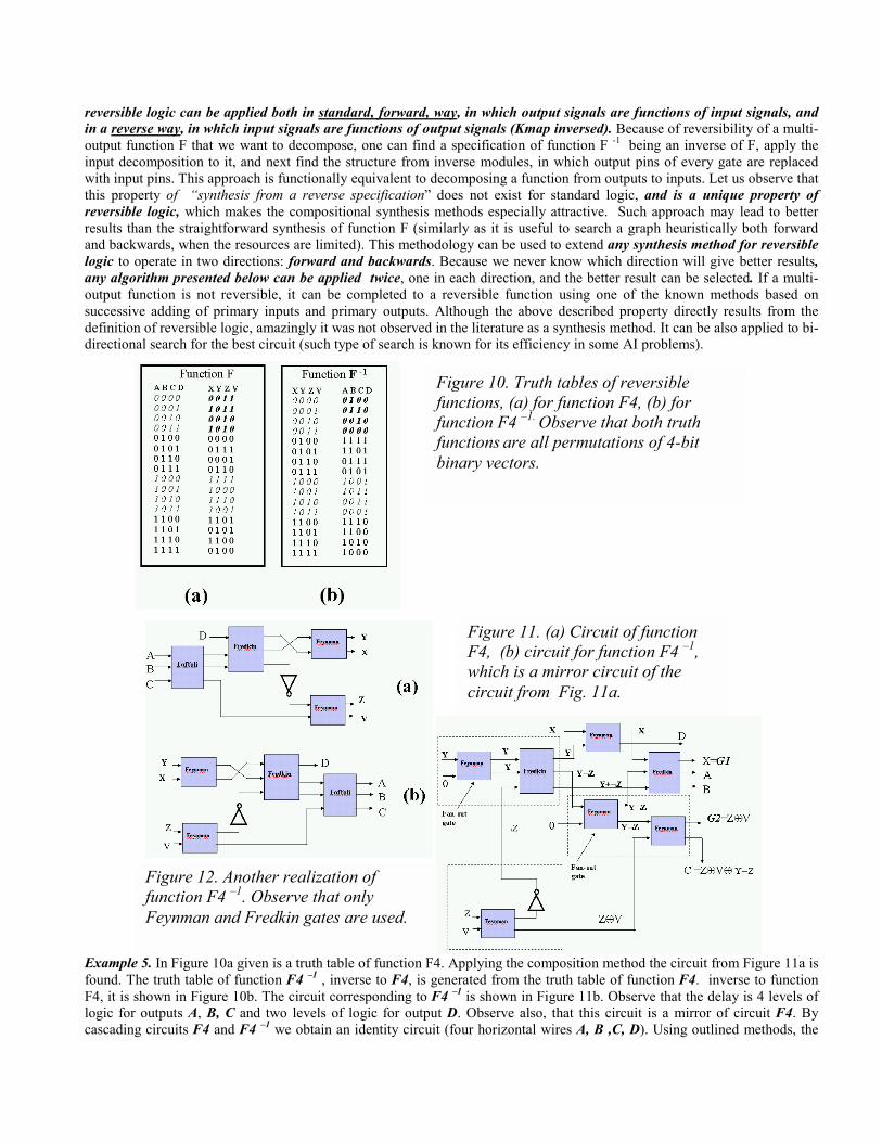
Example 5. In Figure 10a given is a truth table of function F4. Applying the composition method the circuit from Figure 11a isfound. The truth table of function F4 –1 , inverse to F4, is generated from the truth table of function F4. inverse to functionF4, it is shown in Figure 10b. The circuit corresponding to F4 –1 is shown in Figure 11b. Observe that the delay is 4 levels oflogic for outputs A, B, C and two levels of logic for output D. Observe also, that this circuit is a mirror of circuit F4. Bycascading circuits F4 and F4 –1 we obtain an identity circuit (four horizontal wires A, B ,C, D). Using outlined methods, the
Figure 10. Truth tables of reversiblefunctions, (a) for function F4, (b) forfunction F4 –1. Observe that both truthfunctions are all permutations of 4-bitbinary vectors.
Figure 12. Another realization offunction F4 –1. Observe that onlyFeynman and Fredkin gates are used.
Figure 11. (a) Circuit of functionF4, (b) circuit for function F4 –1,which is a mirror circuit of thecircuit from Fig. 11a.

function F4 –1 is synthesized again, Figure 12. Observe, that in this version two constant inputs and two garbage outputs G1and G2 are added and the delay is increased. However, it was assumed here to use only Fredkin gates (because Toffoli gateshave been not built in some technologies, or because Fredkin gates are simpler or faster in other technologies). This circuitillustrates also the possibility of post-logic-synthesis circuit transformation to improve speed. To help the reader analyze thissolution, equations were written for signals. This way, it is seen that D = X ⊕⊕⊕⊕ Y so the circuit can be redesigned (adding morefan-out gates) to have a delay of one for output D. Observe also, that each group of gates inside an dotted-line box can becombined to a single gate. These are only some examples of rule-based “technology mapping” transformations executed onthe circuit, that take reversible logic properties into account. This stage of post-processing follows MP decomposition and isnot discussed in this paper. We illustrated also techniques of creating fan-out greater than one using Feynman gate andcreating simple two-input gates using Fredkin gates, which are the ”last-resort” methods, that can be applied when a bettersolution cannot be found by searching and matching (de)composition methods. This circuit illustrates also the fundamentalproperty that we pay for each additional constant with one garbage output, so adding constants should be avoided. However,finding a circuit without constants (see Figure 11b), is often very difficult and requires an extensive search. Because ofbranching properties of DAGs of circuits, searching from backwards can be sometimes simpler (for a given library of cells)that searching forwards. Having only cells that are their own inverses, or having the cells and their reverses in library wouldnot require both searches, but would increase the search space. All these issues should be investigated experimentally. Findingcircuits from Figs. 11 and 12 is left as an exercise to the Reader. Any of the presented above method should give these results.
6. Reversible Output Decomposition ModeThe (non-deterministic) procedure of the Output Decomposition type for a multi-output function is the following:
(1) Create set of available signals AS, initialize it to all primary outputs.(2) Take any k signals (other than primary inputs, including, possibly, also garbage outputs),(3) Select an k * k reversible gate G and link the outputs of this gate to these signals.
From the reversibility property of this gate calculate the functions realized by the k inputs of gate G. In a generalcase of arbitrary reversible gate, it can be done using BDDs or matrix calculus methods in case of quantum logic.
(4) Add the input signals of G (other than constants) to AS and remove the output signals of G from AS.(5) Iterate (2) – (4) until AS becomes an empty set.
Example 6. Simple example circuit (half-adder) for composition and decomposition methods is shown in Figure 13.
METHOD 1. Reversible Decomposition method, from outputs to inputs. Given are output functions g = AB and h = A⊕⊕⊕⊕B.These two outputs are taken and a 2*2 Feynman gate is applied to them as the output module. This creates intermediate twonew functions Q = AB and P = A+B on inputs of this gate. It is directly recognized from module library that these bothfunctions can be realized by a Kerntopf gate with inputs A, B, C and with its input C = 1. One garbage output ¬¬¬¬B is created. Aswe see, in this example, the original multi-output function <g,h> is completed to reversible function <f, g, ¬¬¬¬B> of arguments<A ,B, C=1> as a “byproduct” of the synthesis process.
METHOD 2. Composition method, from inputs to outputs. Inputs A and B are taken. Various gates are matches in order toselect a gate that has the smallest difference with the desired outputs. The Kerntopf gate with C=1 is selected to create functionsQ = AB (which is the required output) and P=A+B (which is a function with small difference to other required output A ⊕⊕⊕⊕ B).Representations of intermediate functions P, Q and R in terms of input variables A, B, C=1 are calculated and inserted to thedata base of available functions. Applying Feynman gate to Q and P creates functions AB and A ⊕⊕⊕⊕ B, which are primaryoutput functions, so the procedure is completed. Signal R = ¬¬¬¬ B is not used so it makes as a garbage output. This result isoptimal, since the number of gates and garbage/constant inputs cannot be reduced.
METHOD 3. Decomposition method, from outputs to inputs of an inverse function. Because function of a half-adder isnot reversible (as seen in Figure 14a), it is first completed to a reversible function from Figure 14c,d (completion of a functionto a reversible function requires usually adding both inputs and outputs and is not a unique operation). Next from reversiblefunction <R(A,B,C), P(A,B,C), Q(A,B,C)> its inverse function is calculated as <A(R,P,Q), B(R,P,Q), C(R,P,Q)>, usingBoolean equation or BDD methods. To this new function METHOD 1 is applied and a schematic is drawn. Next, all inputsand outputs in the schematic are inversed and the functions of blocks are replaced with their inverse functions.