a compact dual-polarized dual-band stacked patch antenna
TRANSCRIPT
IEICE Electronics Express, Vol.xx, No.xx, xx-xx
1
Copyright © 20XX The Institute of Electronics, Information and Communication Engineers
LETTER
A compact dual-polarized dual-band stacked patch antenna for WLAN applications
Guo-Jun Xie1, Fu-Shun Zhang1, Denghui Li1, Hongyin Zhang2 and Fan Zhang1a)
Abstract This paper presents a compact dual-polarized dual-band stacked patch antenna suitable for WLAN. The dual polarization characteristic is achieved by using a cross-slot coupling feed. The designed antenna can operate in the high frequency band (5 GHz) by using a circular patch. Under the combined action of the circular patch, a narrow annular parasitic patch and a special barrel-shaped metal platform with the slotted sidewall, a good impedance matching in the low frequency band (2.45 GHz) is obtained. The metal platform not only serves as a reflector of the antenna, but also plays a key part in obtaining good impedance matching of the antenna at low frequency. The measured results demonstrate that the operating frequency of the antenna is 2.25-2.8 GHz (VSWR < 2.0) at low frequency band and 5.02-6.0 GHz (VSWR < 2.0) at high frequency band. Moreover, a stable radiation pattern is obtained. Key words: stacked patch antenna, dual-polarized, dual-band, WLAN Classification: Microwave and millimeter wave devices, circuits, and hardware
1. Introduction
In recent years, dual-band or multi-band antennas have been widely used in the wireless local area network (WLAN) and mobile communication fields. The dual polarization antenna has the characteristic of high channel capacity and can effectively alleviate multipath fading. Therefore, dual-polarized antennas with dual-band or multi-band characteristics have attracted extensive attention.
In the published literature, multi-resonance technology is usually an effective method for antennas to obtain dual-band or multi-band radiation characteristics. Dual-band radiation characteristics of the dual-polarized antennas in [1,2,3,4,5,6,7,8,9,10,11,12,13,14,15,16] and multi-band radiation characteristics of the dual-polarized antennas in [17,18] are obtained by using multi-resonance technology. Multiple resonance modes can be excited by the mutual coupling between multiple
radiators with different operating frequencies or different radiation structures derived from the same radiator. By using this method, it is not necessary to feed the high-frequency and low-frequency radiation structures of the antenna respectively, thus simplifying the feeding structure. Furthermore, the dual-band and three-band radiation characteristics of the single polarization antennas in [19] and [20] are achieved respectively by using the multiple resonance method. By assembling different types of antennas with different operating frequency bands, dual-band dual-polarized antennas can also be obtained [21, 22, 23, 24, 25, 26, 27, 28]. However, these different types of antennas need to be fed respectively. Among the above literature, only the dual-band dual-polarized antennas in [12, 13, 14, 15, 16] are suitable for WLAN. The dual-band dual-polarized antennas in [12, 13] can cover the entire frequency band (2.4-2.45 GHz, 5-5.8 GHz) of WLAN. In [12], the dual-band dual polarization characteristic is obtained by using a plurality of multi-resonance butterfly arrays. In [13], a dual-polarized dual-band antenna is obtained by using two concentric square patches. However, the electrical dimensions of these antennas in [12, 13] are large. The operating frequency bands of these antennas in [14, 15, 16] are narrow, and they cannot completely cover the frequency band of WLAN. In addition, the antennas proposed in [29] and [30] are suitable for WLAN and have multi-band and dual-band radiation characteristics respectively, but they cannot satisfy dual-polarized radiation characteristic. The antennas in [31] and [32] can also be applied to WLAN, but their impedance bandwidth is narrow, and both of them cannot satisfy the dual-polarized radiation characteristic.
A compact dual-polarized dual-band stacked patch antenna applicable to WLAN is presented in this paper. A cross-slot coupling feed structure is used to obtain the dual-polarized characteristic. A circular patch, a narrow ring patch and a compact special metal platform are used to obtain the dual-band characteristic. Since the transverse dimension of the metal platform is small, the proposed antenna obtains a small overall dimensions. The impedance bandwidths of the antenna are 21.8% and 17.8% at the low and high frequency bands respectively. In addition, a stable radiation pattern is obtained.
1National Key Laboratory of Antennas and Microwave Technology, Xidian University, Xi’an 710071, China
2Nanjing Research Institute of Electronics Technology Guorui Road No.8, Yuhuatai District, Nanjing
a) [email protected] DOI: 10.1587/elex.XX.XXXXXXXX Received XXXX X, XXXX Accepted XXXX X, XXXX Published XXXX X, XXXX
This article has been accepted and published on J-STAGE in advance of copyediting. Content is final as presented.
DOI: 10.1587/elex.17.20200179Received May 16, 2020Accepted June 02, 2020Publicized June 12, 2020
Copyright © The Institute of Electronics, Information and Communication Engineers 2020
IEICE Electronics Express, Vol.xx, No.xx, xx-xx
2
Patch1
Upper PCBPatch2
Cross-slot
Metal Platform
U-shaped Feed-line1
D1
D2
Z
YX
U-shaped Feed-line2
L1
Middle PCB
Lower PCB
Ground
φ
θ
Lf1
Wf0
Wf0Wf1
Ls1
Ls2
Ws1Ws2
Dg
X
Y
φ
(a) (b)
DM
Port1Port2
Pin
Wp
Lp1
Lp2Wp
Lf2
Wf2
Wf0
Wf0 Y
XD4
D3
φ
(c)
Patch2Patch1
H1
H2H3
H6 H5L2U-shaped
Feed-line1
U-shaped Feed-line2
Cross-slot
Coaxial Cable
Y
Z
H4
θ
(d)
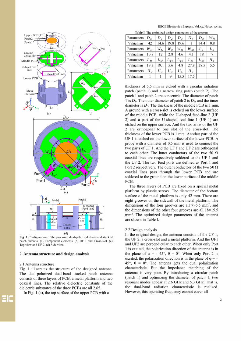
Fig. 1 Configuration of the proposed dual-polarized dual-band stacked patch antenna. (a) Component elements. (b) UF 1 and Cross-slot. (c) Top view and UF 2. (d) Side view.
2. Antenna structure and design analysis
2.1 Antenna structure Fig. 1 illustrates the structure of the designed antenna. The dual-polarized dual-band stacked patch antenna consists of three layers of PCB, a metal platform and two coaxial lines. The relative dielectric constants of the dielectric substrates of the three PCBs are all 2.65.
In Fig. 1 (a), the top surface of the upper PCB with a
Table I. The optimized design parameters of the antenna
thickness of 5.5 mm is etched with a circular radiation patch (patch 1) and a narrow ring patch (patch 2). The patch 1 and patch 2 are concentric. The diameter of patch 1 is D1. The outer diameter of patch 2 is D2, and the inner diameter is D3. The thickness of the middle PCB is 1 mm. A ground with a cross-slot is etched on the lower surface of the middle PCB, while the U-shaped feed-line 2 (UF 2) and a part of the U-shaped feed-line 1 (UF 1) are etched on the upper surface. And the two arms of the UF 2 are orthogonal to one slot of the cross-slot. The thickness of the lower PCB is 1 mm. Another part of the UF 1 is etched on the lower surface of the lower PCB. A probe with a diameter of 0.5 mm is used to connect the two parts of UF 1. And the UF 1 and UF 2 are orthogonal to each other. The inner conductors of the two 50 Ω coaxial lines are respectively soldered to the UF 1 and the UF 2. The two feed ports are defined as Port 1 and Port 2 respectively. The outer conductors of the two 50 Ω coaxial lines pass through the lower PCB and are soldered to the ground on the lower surface of the middle PCB.
The three layers of PCB are fixed on a special metal platform by plastic screws. The diameter of the bottom surface of the metal platform is only 42 mm. There are eight grooves on the sidewall of the metal platform. The dimensions of the four grooves are all 7×6.5 mm2, and the dimensions of the other four grooves are all 18×15.5 mm2. The optimized design parameters of the antenna are shown in Table I.
2.2 Design analysis In the original design, the antenna consists of the UF 1, the UF 2, a cross-slot and a metal platform. And the UF1 and UF2 are perpendicular to each other. When only Port 1 is excited, the polarization direction of the antenna is in the plane of φ = - 45°, θ = 0°. When only Port 2 is excited, the polarization direction is in the plane of φ = + 45°, θ = 0°. The antenna gets the dual polarization characteristic. But the impedance matching of the antenna is very poor. By introducing a circular patch (patch 1) and optimizing the diameter of patch 1, two resonant modes appear at 2.6 GHz and 5.3 GHz. That is, the dual-band radiation characteristic is realized. However, this operating frequency cannot cover all
Parameters D M D 1 D 2 D 3 D 4 D g W f0
Value/mm 42 14.6 19.8 19.6 1 34.4 0.8
Parameters W f1 W f2 W p W s1 W s2 L 1 L 2
Value/mm 10.8 12 2.8 4.6 4.1 18 7
Parameters L f1 L f2 L p1 L p2 L s1 L s2 H 1
Value/mm 19.3 19.1 5.6 4.8 27.8 28.5 5.5
Parameters H 2 H 3 H 4 H 5 H 6
Value/mm 1 1 9 15.5 17.5

IEICE Electronics Express, Vol.xx, No.xx, xx-xx
3
Fig. 2 Effect of patch 1 and patch 2 on VSWR of port 1 of the antenna.
frequency bands of the WLAN. The parasitic ring patch (patch 2) is added outside the patch 1, and in the low frequency band the electric length of the radiator increases. The impedance matching of the antenna at the low frequency (2.45 GHz) is effectively improved, and the resonant frequency is decreased. In addition, under the coupling effect of patch 1 and patch 2, the antenna has a good impedance matching at high frequency (5.8 GHz). Fig. 2 shows the VSWR of port 1 of the antenna with or without patch 1 and patch 2. Under the combined action of patch 1 and patch 2, the operating frequency bands of port 1 of the antenna are 2.32-2.74 GHz and 5.0-5.9 GHz (VSWR < 2.0).
In the design process of the antenna, the barrel-shaped metal platform is used as the reflector, and the sidewall of the metal platform is used as a part of the reflector, which reduces the transverse size of the antenna. However, a closed space is formed between the stacked patch and the metal platform, and the electromagnetic waves in the space have adverse effects on the impedance matching and radiation pattern through multiple reflections. We found that slotting the sidewall of the metal platform to release some clutter can effectively reduce these adverse effects. The choice of the size of these grooves is crucial. Fig. 3 shows the VSWR of port 1 of the antenna when the sidewall structure is in the following four states:
State 1: without sidewall (the metal platform is a flat plate with a diameter of 42 mm and a thickness of 1 mm);
State 2: with sidewall, without grooves; State 3: with sidewall, with grooves, H5=6.5 mm; State 4: with sidewall, with grooves, H5=15.5 mm. From Fig. 3, the antenna resonates only at high
frequency band (5.05 GHz-5.9 GHz) when the metal platform has no sidewall. When the sidewall of the metal platform is not slotted, the antenna resonates at both low and high frequencies. Its operating frequency bands are 2.71 GHz-2.87 GHz and 5.07 GHz-5.87 GHz. When the sidewall of the metal platform has eight grooves, and the depth of the four wider grooves is H5=15.5 mm, the
Fig. 3 Simulated VSWR of port 1 of the antenna in state 1-4.
(a) (b)
Fig. 4 Photographs of the designed antenna. (a) Oblique view. (b) Backside view.
Fig. 5 Measured and simulated VSWRs of the antenna.
operating frequency bands are 2.32-2.74 GHz and 5.0-5.9 GHz. This antenna is the proposed one. Therefore, the metal platform used in this paper is not only the reflector of the antenna, but also an important part of the antenna to obtain the dual-band radiation characteristic.
3. Results of simulated and measured
The physical pictures of the designed antenna are depicted in Fig. 4. Fig. 5 describes the measured and simulated results of VSWR of the designed antenna. From the simulated results of VSWR in Fig. 5, the VSWR of Port 1 is less than 2.0 in the frequency bands of 2.32-2.74 GHz and 5.0-5.9 GHz, and the VSWR of Port 2 is less than 2.0 in the frequency bands of 2.32-2.63 GHz and 5.01-6.03 GHz. Therefore, the simulated
IEICE Electronics Express, Vol.xx, No.xx, xx-xx
4
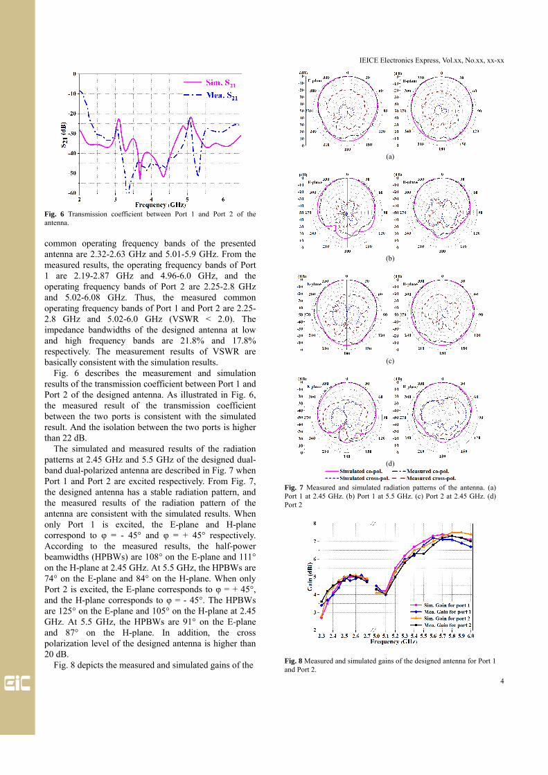
Fig. 6 Transmission coefficient between Port 1 and Port 2 of the antenna.
common operating frequency bands of the presented antenna are 2.32-2.63 GHz and 5.01-5.9 GHz. From the measured results, the operating frequency bands of Port 1 are 2.19-2.87 GHz and 4.96-6.0 GHz, and the operating frequency bands of Port 2 are 2.25-2.8 GHz and 5.02-6.08 GHz. Thus, the measured common operating frequency bands of Port 1 and Port 2 are 2.25-2.8 GHz and 5.02-6.0 GHz (VSWR < 2.0). The impedance bandwidths of the designed antenna at low and high frequency bands are 21.8% and 17.8% respectively. The measurement results of VSWR are basically consistent with the simulation results.
Fig. 6 describes the measurement and simulation results of the transmission coefficient between Port 1 and Port 2 of the designed antenna. As illustrated in Fig. 6, the measured result of the transmission coefficient between the two ports is consistent with the simulated result. And the isolation between the two ports is higher than 22 dB.
The simulated and measured results of the radiation patterns at 2.45 GHz and 5.5 GHz of the designed dual-band dual-polarized antenna are described in Fig. 7 when Port 1 and Port 2 are excited respectively. From Fig. 7, the designed antenna has a stable radiation pattern, and the measured results of the radiation pattern of the antenna are consistent with the simulated results. When only Port 1 is excited, the E-plane and H-plane correspond to φ = - 45° and φ = + 45° respectively. According to the measured results, the half-power beamwidths (HPBWs) are 108° on the E-plane and 111° on the H-plane at 2.45 GHz. At 5.5 GHz, the HPBWs are 74° on the E-plane and 84° on the H-plane. When only Port 2 is excited, the E-plane corresponds to φ = + 45°, and the H-plane corresponds to φ = - 45°. The HPBWs are 125° on the E-plane and 105° on the H-plane at 2.45 GHz. At 5.5 GHz, the HPBWs are 91° on the E-plane and 87° on the H-plane. In addition, the cross polarization level of the designed antenna is higher than 20 dB.
Fig. 8 depicts the measured and simulated gains of the
(a)
(b)
(c)
(d)
Fig. 7 Measured and simulated radiation patterns of the antenna. (a) Port 1 at 2.45 GHz. (b) Port 1 at 5.5 GHz. (c) Port 2 at 2.45 GHz. (d) Port 2
Fig. 8 Measured and simulated gains of the designed antenna for Port 1 and Port 2.

IEICE Electronics Express, Vol.xx, No.xx, xx-xx
5
Table II. Comparison of different antennas applied to WLAN
λ0: Wavelength at the starting frequency in free-space. RB: Relative bandwidth with VSWR < 2.0. LP: Linear polarization. CP: Circular polarization.
antenna when the two ports are excited respectively. The results of measurement show that the gains at 2.45 GHz and 5.5 GHz are 4.4 dBi and 6.8 dBi respectively when only Port 1 is excited. And the gains at 2.45 GHz and 5.5 GHz are 4.7 dBi and 6.3 dBi respectively when only Port 2 is excited.
Table II shows the comparison between the proposed antenna and several antennas applied to WLAN. Compared with the references in Table II, the dual-polarized dual-band antenna proposed in this paper has wider impedance bandwidth.
4. Conclusion
This paper presents a compact dual-polarized dual-band stacked patch antenna fixed on a metal platform. Two orthogonal U-shaped feed-lines are used to excite a cross-slot to obtain the dual-polarized radiation characteristic. Under the combined action of a circular patch, an annular patch and a barrel-shaped metal platform with the slotted sidewall, the required dual-band radiation characteristic is obtained. At the same time, this metal platform acts as a reflector of the antenna, and the sidewall of the metal platform is also a part of the reflector, so that the antenna obtains a small transverse dimension. The operating frequency bands of the presented dual-band dual-polarized antenna are 2.25-2.8 GHz and 5.02-6.0 GHz that can cover the whole WLAN bands. And the proposed antenna has a compact dimensions of 42 × 42 × 17.5 mm3. The transmission coefficient between the two ports of the antenna is less than - 22 dB. And the radiation pattern is stable. Based on these characteristics, the antenna proposed in this paper is expected to be applied to dual-band wireless communication systems with a small platform.
References
[1] A. Alieldin, et al.: “A dual-broadband dual-polarized fylfot-shaped antenna for mobile base stations using MIMO over-lapped antenna subarrays,” IEEE Access 6 (2018) 50260 (DOI: 10.1109/ACCESS.2018.2868817).
[2] B. Feng, et al.: “A dual-wideband dual-polarized magnetoelectric dipole antenna with dual wide beamwidths for 5G MIMO microcell applications,” IEEE Access 7 (2019) 43346 (DOI: 10.1109/ACCESS.2019.2906882).
[3] B. Feng, et al.: “A dual-band dual-polarized stacked microstrip antenna with high-isolation and band-notch characteristics for 5G microcell communications,” IEEE Trans. Antennas Propag. 67 (2019) 4506 (DOI: 10.1109/TAP.2019.2911619).
[4] C. –Xu. Mao, et al.: “A shared-aperture dual-band dual-polarized filtering-antenna-array with improved frequency response,” IEEE Trans. Antennas Propag. 65 (2017) 1836 (DOI: 10.1109/TAP.2017.2670325).
[5] R. S. Malfajani and B. A. Arand: “Dual-band orthogonally polarized single-layer reflectarray antenna,” IEEE Trans. Antennas Propag. 65 (2017) 6145 (DOI: 10.1109/TAP.2017.2754459).
[6] H. Tang, et al.: “Differential dual-band dual-polarized dielectric resonator antenna,” IEEE Trans. Antennas Propag. 65 (2017) 855 (DOI: 10.1109/TAP.2016.2630661).
[7] Y. Wang and Z. Du: “Dual-polarized dual-band microstrip antenna with similar-shaped radiation pattern,” IEEE Trans. Antennas Propag. 63 (2015) 5923 (DOI: 10.1109/TAP.2015.2487520).
[8] M. -T. Tan and B. –Z. Wang: “A compact dual-band dual-polarized loop-slot planar antenna,” IEEE Antennas Wireless Propag. Lett. 14 (2015) 1742 (DOI: 10.1109/LAWP.2015.2421731).
[9] Y. X. Sun and K. W. Leung: “Dual-band and wideband dual-polarized cylindrical dielectric resonator antennas,” IEEE Antennas Wireless Propag. Lett. 12 (2013) 384 (DOI: 10.1109/LAWP.2013.2251993).
[10] B. A. Zeb and K. P. Esselle: “High-gain dual-band dual-polarised electromagnetic band gap resonator antenna with an all-dielectric superstructure,” IET Microw. Antennas & Propag. 9 (2015) 1059 (DOI: 10.1049/iet-map.2014.0798).
[11] S. Mukherjee and A. Biswas: “Design of dual band and dual-polarised dual band SIW cavity backed bow-tie slot antennas,” IET Microw. Antennas & Propag. 10 (2016) 1002 (DOI: 10.1049/iet-map.2015.0786).
[12] W. C. Zheng, et al.: “Dual-band dual-polarized compact bowtie antenna array for anti-interference MIMO WLAN,” IEEE Trans. Antennas Propag. 62 (2014) 237 (DOI: 10.1109/TAP.2013.2287287).
[13] M. Mattsson, et al.: “Dual-band dual-polarized full-wave rectenna based on differential field sampling,” IEEE Antennas Wireless Propag. Lett. 17 (2018) 956 (DOI: 10.1109/LAWP.2018.2825783). A. Satoh and S. Suzuki: “Future of electronics,” submitted to IEICE Trans. Electron.
[14] H. Zhai, et al.: “A low-profile dual-band dual-polarized antenna with an AMC surface for WLAN applications,” IEEE Antennas Wireless Propag. Lett. 16 (2017) 2692 (DOI: 10.1109/LAWP.2017.2741465).
[15] K. Wincza and S. Gruszczynski: “Series-fed dual-band dual-polarized antenna lattice fed by slot-coupled power dividers,” IEEE Antennas Wireless Propag. Lett. 15 (2016) 1065 (DOI: 10.1109/LAWP.2015.2492606).
[16] X. –Qi. Zhu, et al.: “Miniaturized dual-band and dual-polarized antenna for MBAN applications,” IEEE Trans. Antennas Propag. 64 (2016) 2805 (DOI: 10.1109/TAP.2016.2556701).
IEICE Electronics Express, Vol.xx, No.xx, xx-xx
6
[17] A. Alieldin, et al.: “A triple-band dual-polarized indoor base station antenna for 2G, 3G, 4G and sub-6 GHz 5G applications,” IEEE Access 6 (2018) 49209 (DOI: 10.1109/ACCESS.2018.2868414).
[18] O. P. Falade, et al.: “Stacked-patch dual-polarized antenna for triple-band handheld terminals,” IEEE Antennas Wireless Propag. Lett. 12 (2013) 202 (DOI: 10.1109/LAWP.2013.2245392).
[19] Z. Zeng, et al.: “Multi-band multi-mode endfire antenna based on mirroring and scaling method,” IEICE Electron. Express 15 (2018) 20180643 (DOI: 10.1587/elex.15.20180643).
[20] C. Li, et al.: “A dual-band circularly polarized antenna with wide HPBWs for CNSS applications,” IEICE Electron. Express 15 (2018) 20180409 (DOI: 10.1587/elex.15.20180409).
[21] Z. Zhao, et al.: “A dual-polarized dual-band antenna with high gain for 2G/3G/LTE indoor communications,” IEEE Access 6 (2018) 61623 (DOI: 10.1109/ACCESS.2018.2876302).
[22] Y. He, et al.: “A novel dual-broadband dual-polarized electrical downtilt base station antenna for 2G/3G applications,” IEEE Access 5 (2017) 15241 (DOI: 10.1109/ACCESS.2017.2720591).
[23] L. Y. Nie, et al.: “A low-profile coplanar dual-polarized and dual-band base station antenna array,” IEEE Trans. Antennas Propag. 66 (2018) 6921 (DOI: 10.1109/TAP.2018.2869222).
[24] H. Huang, et al.: “A novel dual-broadband and dual-polarized antenna for 2G/3G/LTE base stations,” IEEE Trans. Antennas Propag. 64 (2016) 4113 (DOI: 10.1109/TAP.2016.2589966).
[25] Y. Zhu, et al.: “Decoupling and low-profile design of dual-band dual-polarized base-station antennas using frequency selective surface,” IEEE Trans. Antennas Propag. 67 (2019) 5272 (DOI: 10.1109/TAP.2019.2916730).
[26] Y. Liu, et al.: “A compact dual-band dual-polarized antenna with filtering structures for sub-6 GHz base station applications,” IEEE Antennas Wireless Propag. Lett. 17 (2018) 1764 (DOI: 10.1109/LAWP.2018.2864604).
[27] H. Huang, et al.: “A dual-broadband, dual-polarized base station antenna for 2G/3G/4G applications,” IEEE Antennas Wireless Propag. Lett. 16 (2017) 1111 (DOI: 10.1109/LAWP.2016.2623315).
[28] Kun Wang, et al.: “A dual-wideband dual-polarized aperture-shared patch antenna with high isolation,” IEEE Antennas Wireless Propag. Lett. 17 (2018) 735 (DOI: 10.1109/LAWP.2018.2812699).
[29] M. T. Islam, et al.: “Small multi-band microstrip antenna for wireless applications,” IEICE Electron. Express 7 (2010) 1629 (DOI: 10.1587/elex.7.1629).
[30] M. –T. Tan and B. –Z. Wang: “A dual-band circularly polarized planar monopole antenna for WLAN/Wi-Fi applications,” IEEE Antennas Wireless Propag. Lett. 15 (2016) 670 (DOI: 10.1109/LAWP.2015.2466596).
[31] M. N. Moghadasi, et al.: “Highly compact meander line antenna using DGS technique for WLAN communication systems,” IEICE Electron. Express 8 (2011) 722 (DOI: 10.1587/elex.8.722).
[32] M. Amin, et al.: “Gain enhancement in cubic DRA with modified microstrip feed for WLAN applications,” IEICE Electron. Express 14 (2017) 20170960 (DOI: 10.1587/elex.14.20170960).