92-23577-97 rev. 0 rkkl-b072 6 ton gas/electric package
TRANSCRIPT
92-23577-97-00
ISO 9001:2008
INSTALLATION INSTRUCTIONSPackage Gas Electric FeaturingEarth-Friendly R-410A RefrigerantRKKL (6 TON) SERIES
e a r t h f r i e n d l y r e f r i g e r a n te a r
t
t h
r y rd l y
d l
y
e n
d
r i e
n
if r
i
h
2
I.TABLE OF CONTENTSI. Table of Contents ..................................................................................................2II. Introduction ............................................................................................................3III. Checking Product Received ..................................................................................3IV. Specifications.........................................................................................................3
A. General .............................................................................................................3B. Major Components............................................................................................3C. R-410A Refrigerant ...........................................................................................31. Specifications of R-410A...............................................................................32. Quick Reference Guide for R-410A ..............................................................43. Evaporator Coil/TXV .....................................................................................44. Tools Required for Installing and Servicing R-410A Models.........................4
V. Safety Information..................................................................................................4VI. Unit Dimensions.....................................................................................................5VII. Installation..............................................................................................................8
A. General .............................................................................................................81. Pre-Installation Check ..................................................................................82. Location Considerations...............................................................................8
B. Outside Installation............................................................................................9C. Attaching Exhaust and Combustion Air Inlet Hoods .......................................10D. Cover Panel Installation/Conversion Procedure .............................................10E. Clearances ......................................................................................................10F. Rooftop Installation .........................................................................................10G.Ductwork .........................................................................................................11H. Return Air ........................................................................................................12
VIII. Gas Supply, Condensate Drain and Piping .........................................................14A. Gas Connection ..............................................................................................14B. LP Conversion.................................................................................................15C. NOx Models ....................................................................................................15D. Adjusting or Checking Furnace Input ..............................................................16E. Condensate Drain ...........................................................................................18
IX. Wiring...................................................................................................................18A. Power Supply ..................................................................................................18B. Hook Up ..........................................................................................................20C. Internal Wiring .................................................................................................20D. Thermostat ......................................................................................................20
X. Furnace Section Controls and Ignition System....................................................21Normal Furnace Operating Sequence.................................................................21Operating Instructions .........................................................................................21Burners ................................................................................................................22Manual Reset Overtemperature Control..............................................................22Pressure Switch...................................................................................................22Limit Control ........................................................................................................23
XI. System Operating Information .............................................................................23Advise the Customer ...........................................................................................23Furnace Section Maintenance.............................................................................23Lubrication ...........................................................................................................24Cooling Section Maintenance..............................................................................24Replacement Parts ..............................................................................................25Troubleshooting...................................................................................................25Wiring Diagrams ..................................................................................................25Charging ..............................................................................................................25
XII. General Data ..................................................................................................26-28XIII. Miscellaneous ......................................................................................................29
Electrical Data .....................................................................................................29Airflow Performance ............................................................................................30Wiring Diagrams.............................................................................................31-33Charge Charts .....................................................................................................34Troubleshooting..............................................................................................35-37
3
II. INTRODUCTIONThis booklet contains the installation and operating instructions for your combination gasheating/electric cooling unit. There are some precautions that should be taken to derivemaximum satisfaction from it. Improper installation can result in unsatisfactory operationor dangerous conditions.
Read this booklet and any instructions packaged with separate equipment required tomake up the system prior to installation. Give this booklet to the owner and explain itsprovisions. The owner should retain this booklet for future reference.
III. CHECKING PRODUCT RECEIVEDUpon receiving the unit, inspect it for any damage from shipment. Claims for damage,either shipping or concealed, should be filed immediately with the shipping company.IMPORTANT: Check the unit model number, heating size, electrical characteristics, andaccessories to determine if they are correct.
IV. SPECIFICATIONSA. GENERALThe Combination Gas Heating/Electric Cooling Rooftop is available in 100,000 and135,000 BTU/Hr. heating inputs and cooling capacity of 6 nominal tons of cooling. Unitsare convertible from bottom supply and return to side supply and return by relocation ofsupply and return air access panels. See cover installation detail.
The units are weatherized for mounting outside of the building.
The information on the rating plate is in compliance with the FTC and DOE rating for sin-gle phase units. The following information is for three phase units which are not coveredunder the DOE certification program.
1. The energy consumption of the ignition system used with this unit is 9 watts.
2. The efficiency rating of this unit is a product thermal efficiency rating determinedunder continuous operating conditions independent of any installed system.
B. MAJOR COMPONENTSThe unit includes a hermetically-sealed refrigerating system (consisting of a scroll com-pressor, condenser coil, evaporator coil with thermostatic expansion valve), a circulationair blower, a condenser fan, a heat exchanger assembly, gas burner and control assem-bly, combustion air motor and fan, and all necessary internal electrical wiring. The cool-ing system of these units is factory-evacuated, charged with R-410A refrigerant and per-formance tested. Refrigerant amount and type are indicated on rating plate.
C. R410A REFRIGERANTAll units are factory charged with R-410A refrigerant.
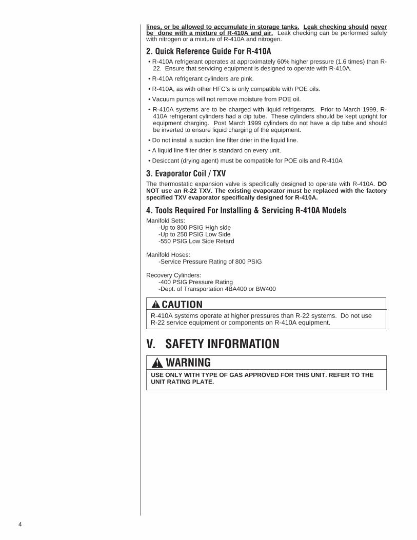
1. Specification of R-410A:Application: R-410A is not a drop-in replacement for R-22; equipment designs mustaccommodate its higher pressures. It cannot be retrofitted into R-22 units.
Pressure: The pressure of R-410A is approximately 60% (1.6 times) greater than R-22. Recovery and recycle equipment, pumps, hoses and the like need to have designpressure ratings appropriate for R-410A. Manifold sets need to range up to 800 psighigh-side and 250 psig low-side with a 550 psig low-side retard. Hoses need to have aservice pressure rating of 800 psig. Recovery cylinders need to have a 400 psig servicepressure rating. DOT 4BA400 or DOT BW400.
Combustibility: At pressures above 1 atmosphere, mixture of R-410A and air canbecome combustible. R-410A and air should never be mixed in tanks or supply
! WARNINGTHE MANUFACTURER’S WARRAN-TY DOES NOT COVER ANY DAM-AGE OR DEFECT TO THE AIR CON-DITIONER CAUSED BY THEATTACHMENT OR USE OF ANYCOMPONENTS, ACCESSORIES ORDEVICES (OTHER THAN THOSEAUTHORIZED BY THE MANUFAC-TURER) INTO, ONTO OR IN CON-JUNCTION WITH THE AIR CONDI-TIONER. YOU SHOULD BE AWARETHAT THE USE OF UNAUTHO-RIZED COMPONENTS, ACCES-SORIES OR DEVICES MAYADVERSELY AFFECT THE OPERA-TION OF THE AIR CONDITIONERAND MAY ALSO ENDANGER LIFEAND PROPERTY. THE MANUFAC-TURER DISCLAIMS ANY RESPON-SIBILITY FOR SUCH LOSS ORINJURY RESULTING FROM THEUSE OF SUCH UNAUTHORIZEDCOMPONENTS, ACCESSORIES ORDEVICES. ! WARNING
UNITS ARE NOT DESIGN CERTIFIED TO BE INSTALLED INSIDE THE STRUC-TURE. DOING SO CAN CAUSE INADEQUATE UNIT PERFORMANCE AS WELLAS PROPERTY DAMAGE AND CARBON MONOXIDE POISONING RESULTINGIN PERSONAL INJURY OR DEATH.
Recognize this symbol as an indi-cation of Important SafetyInformation!
!
! WARNINGINSTALL THIS UNIT ONLY IN ALOCATION AND POSITION ASSPECIFIED IN THE LOCATIONREQUIREMENTS AND CONSIDERA-TIONS SECTION OF THESEINSTRUCTIONS. PROVIDE ADE-QUATE COMBUSTION AND VENTI-LATION AIR TO THE UNIT SPACEAS SPECIFIED IN THE VENTINGSECTION OF THESE INSTRUC-TIONS.
! WARNINGPROVIDE ADEQUATE COMBUS-TION AND VENTILATION AIR TOTHE UNIT SPACE AS SPECIFIED INTHE COMBUSTION AND VENTILA-TION AIR SECTION OF THESEINSTRUCTIONS.
4
lines, or be allowed to accumulate in storage tanks. Leak checking should neverbe done with a mixture of R-410A and air. Leak checking can be performed safelywith nitrogen or a mixture of R-410A and nitrogen.
2. Quick Reference Guide For R-410A• R-410A refrigerant operates at approximately 60% higher pressure (1.6 times) than R-22. Ensure that servicing equipment is designed to operate with R-410A.
• R-410A refrigerant cylinders are pink.
• R-410A, as with other HFC’s is only compatible with POE oils.
• Vacuum pumps will not remove moisture from POE oil.
• R-410A systems are to be charged with liquid refrigerants. Prior to March 1999, R-410A refrigerant cylinders had a dip tube. These cylinders should be kept upright forequipment charging. Post March 1999 cylinders do not have a dip tube and shouldbe inverted to ensure liquid charging of the equipment.
• Do not install a suction line filter drier in the liquid line.
• A liquid line filter drier is standard on every unit.
• Desiccant (drying agent) must be compatible for POE oils and R-410A
3. Evaporator Coil / TXVThe thermostatic expansion valve is specifically designed to operate with R-410A. DONOT use an R-22 TXV. The existing evaporator must be replaced with the factoryspecified TXV evaporator specifically designed for R-410A.
4. Tools Required For Installing & Servicing R-410A ModelsManifold Sets:
-Up to 800 PSIG High side-Up to 250 PSIG Low Side-550 PSIG Low Side Retard
Manifold Hoses:-Service Pressure Rating of 800 PSIG
Recovery Cylinders:-400 PSIG Pressure Rating-Dept. of Transportation 4BA400 or BW400
V. SAFETY INFORMATION
! CAUTIONR-410A systems operate at higher pressures than R-22 systems. Do not useR-22 service equipment or components on R-410A equipment.
! WARNINGUSE ONLY WITH TYPE OF GAS APPROVED FOR THIS UNIT. REFER TO THEUNIT RATING PLATE.
5
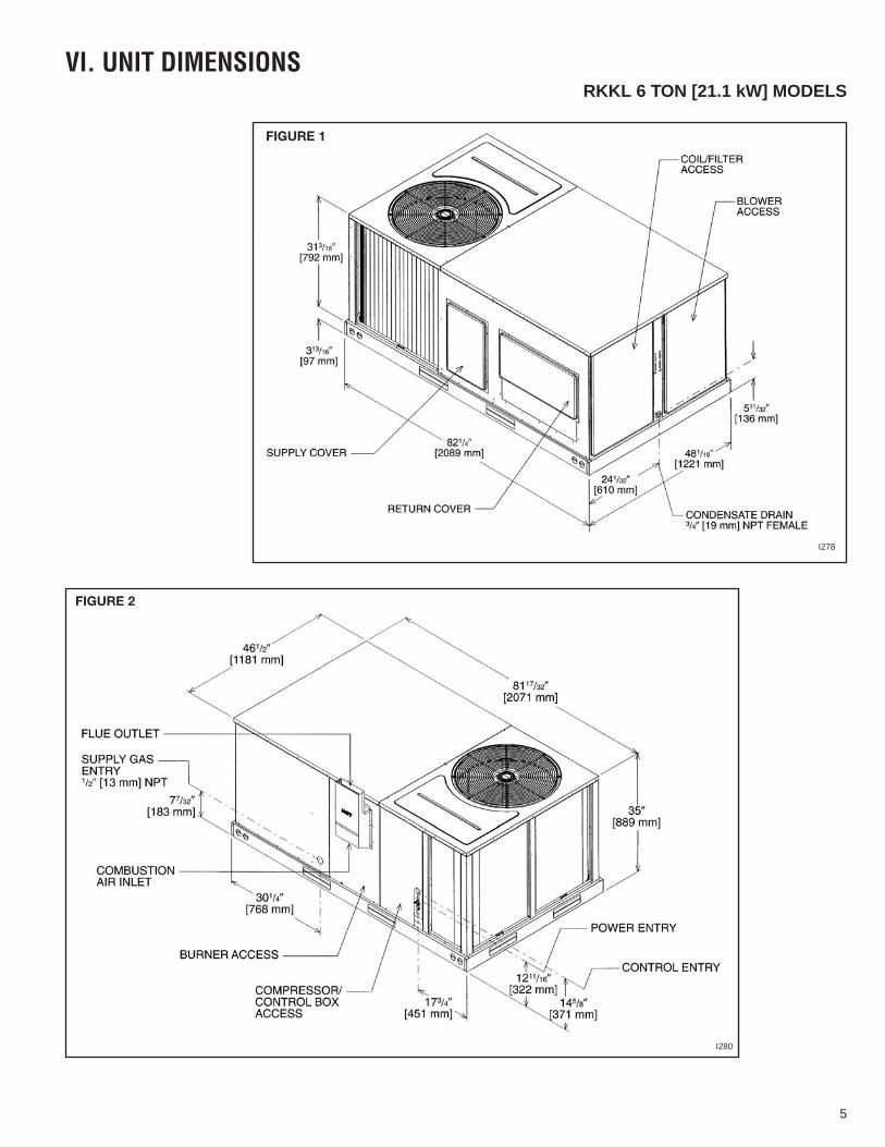
FIGURE 1
FIGURE 2
VI. UNIT DIMENSIONS
I278
I280
RKKL 6 TON [21.1 kW] MODELS
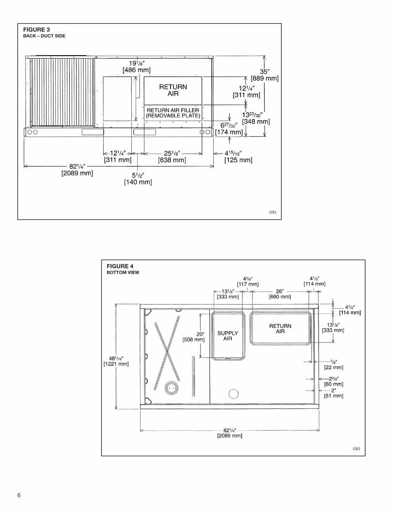
FIGURE 3BACK – DUCT SIDE
I281
FIGURE 4BOTTOM VIEW
I282
6
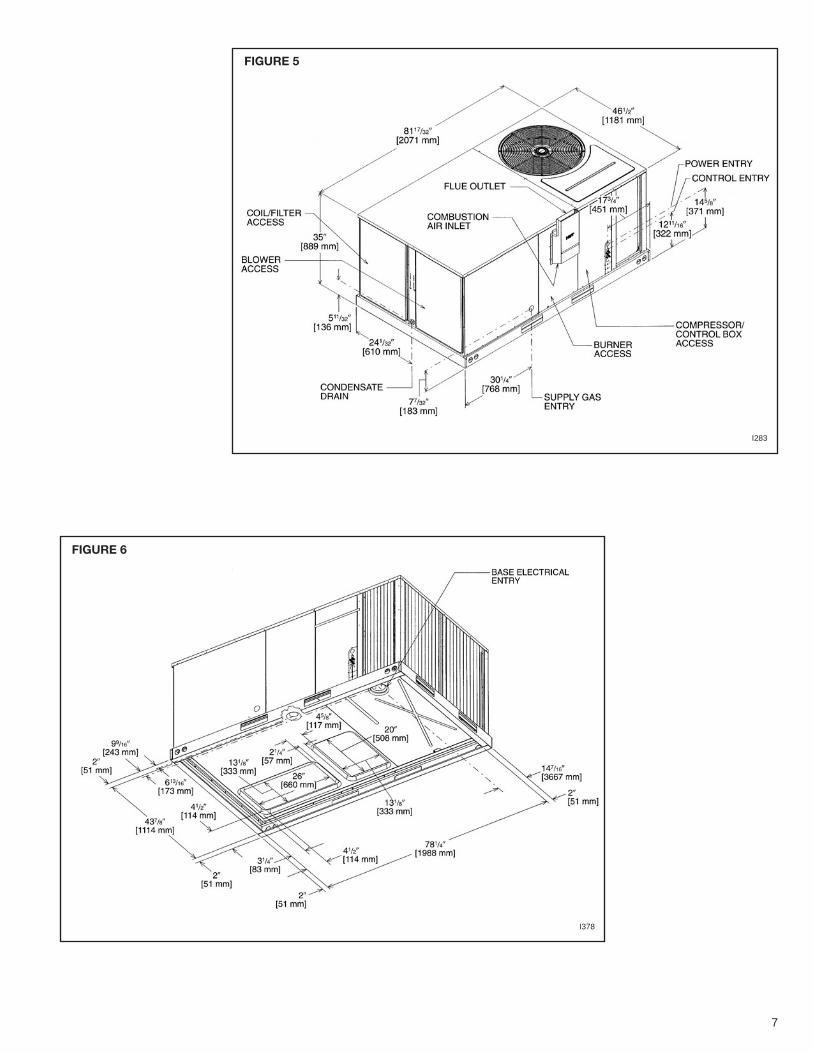
FIGURE 5
I283
FIGURE 6
I378
7
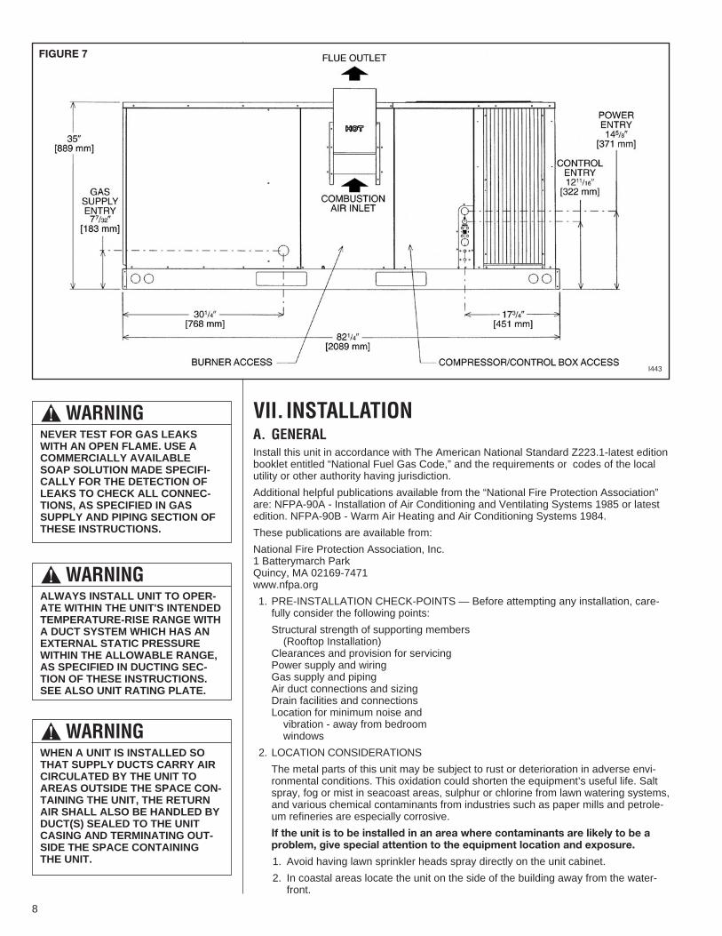
VII. INSTALLATIONA. GENERALInstall this unit in accordance with The American National Standard Z223.1-latest editionbooklet entitled “National Fuel Gas Code,” and the requirements or codes of the localutility or other authority having jurisdiction.
Additional helpful publications available from the “National Fire Protection Association”are: NFPA-90A - Installation of Air Conditioning and Ventilating Systems 1985 or latestedition. NFPA-90B - Warm Air Heating and Air Conditioning Systems 1984.
These publications are available from:
National Fire Protection Association, Inc.1 Batterymarch ParkQuincy, MA 02169-7471www.nfpa.org
1. PRE-INSTALLATION CHECK-POINTS — Before attempting any installation, care-fully consider the following points:
Structural strength of supporting members(Rooftop Installation)
Clearances and provision for servicingPower supply and wiringGas supply and pipingAir duct connections and sizingDrain facilities and connectionsLocation for minimum noise andvibration - away from bedroomwindows
2. LOCATION CONSIDERATIONS
The metal parts of this unit may be subject to rust or deterioration in adverse envi-ronmental conditions. This oxidation could shorten the equipment’s useful life. Saltspray, fog or mist in seacoast areas, sulphur or chlorine from lawn watering systems,and various chemical contaminants from industries such as paper mills and petrole-um refineries are especially corrosive.
If the unit is to be installed in an area where contaminants are likely to be aproblem, give special attention to the equipment location and exposure.
1. Avoid having lawn sprinkler heads spray directly on the unit cabinet.
2. In coastal areas locate the unit on the side of the building away from the water-front.
! WARNINGALWAYS INSTALL UNIT TO OPER-ATE WITHIN THE UNIT'S INTENDEDTEMPERATURE-RISE RANGE WITHA DUCT SYSTEM WHICH HAS ANEXTERNAL STATIC PRESSUREWITHIN THE ALLOWABLE RANGE,AS SPECIFIED IN DUCTING SEC-TION OF THESE INSTRUCTIONS.SEE ALSO UNIT RATING PLATE.
! WARNINGWHEN A UNIT IS INSTALLED SOTHAT SUPPLY DUCTS CARRY AIRCIRCULATED BY THE UNIT TOAREAS OUTSIDE THE SPACE CON-TAINING THE UNIT, THE RETURNAIR SHALL ALSO BE HANDLED BYDUCT(S) SEALED TO THE UNITCASING AND TERMINATING OUT-SIDE THE SPACE CONTAININGTHE UNIT.
! WARNINGNEVER TEST FOR GAS LEAKSWITH AN OPEN FLAME. USE ACOMMERCIALLY AVAILABLESOAP SOLUTION MADE SPECIFI-CALLY FOR THE DETECTION OFLEAKS TO CHECK ALL CONNEC-TIONS, AS SPECIFIED IN GASSUPPLY AND PIPING SECTION OFTHESE INSTRUCTIONS.
FIGURE 7
I443
8
3. Shielding by a fence or shrubs may give some protection.
1. Frequent washing of the cabinet, fan blade and coil with fresh water will removemost of the salt or other contaminants that build up on the unit.
2. Regular cleaning and waxing of the cabinet with a good automobile polish will pro-vide some protection.
3. A good liquid cleaner may be used several times a year to remove matter that willnot wash off with water.
Several different types of protective coatings are offered in some areas. These coatingsmay provide some benefit, but the effectiveness of such coating materials cannot be ver-ified by the equipment manufacturer.
The best protection is frequent cleaning, maintenance and minimal exposure tocontaminants.
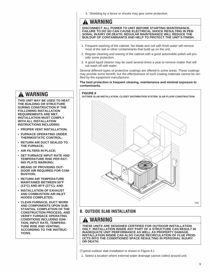
B. OUTSIDE SLAB INSTALLATION
(Typical outdoor slab installation is shown in Figure 8.)
1. Select a location where external water drainage cannot collect around unit.
! WARNINGTHIS UNIT MAY BE USED TO HEATTHE BUILDING OR STRUCTUREDURING CONSTRUCTION IF THEFOLLOWING INSTALLATIONREQUIREMENTS ARE MET.INSTALLATION MUST COMPLYWITH ALL INSTALLATIONINSTRUCTIONS INCLUDING:
• PROPER VENT INSTALLATION;
• FURNACE OPERATING UNDERTHERMOSTATIC CONTROL;
• RETURN AIR DUCT SEALED TOTHE FURNACE;
• AIR FILTERS IN PLACE;
• SET FURNACE INPUT RATE ANDTEMPERATURE RISE PER RAT-ING PLATE MARKING;
• MEANS OF PROVIDING OUT-DOOR AIR REQUIRED FOR COM-BUSTION;
• RETURN AIR TEMPERATUREMAINTAINED BETWEEN 55°F(13°C) AND 80°F (27°C); AND
• INSTALLATION OF EXHAUSTAND COMBUSTION AIR INLETHOODS COMPLETED;
• CLEAN FURNACE, DUCT WORKAND COMPONENTS UPON SUB-STANTIAL COMPLETION OF THECONSTRUCTION PROCESS, ANDVERIFY FURNACE OPERATINGCONDITIONS INCLUDING IGNI-TION, INPUT RATE, TEMPERA-TURE RISE AND VENTING,ACCORDING TO THE INSTRUC-TIONS.
! WARNINGTHESE UNITS ARE DESIGNED CERTIFIED FOR OUTDOOR INSTALLATIONONLY. INSTALLATION INSIDE ANY PART OF A STRUCTURE CAN RESULT ININADEQUATE UNIT PERFORMANCE AS WELL AS PROPERTY DAMAGE.INSTALLATION INSIDE CAN ALSO CAUSE RECIRCULATION OF FLUE PROD-UCTS INTO THE CONDITIONED SPACE RESULTING IN PERSONAL INJURYOR DEATH.
! WARNINGDISCONNECT ALL POWER TO UNIT BEFORE STARTING MAINTENANCE.FAILURE TO DO SO CAN CAUSE ELECTRICAL SHOCK RESULTING IN PER-SONAL INJURY OR DEATH. REGULAR MAINTENANCE WILL REDUCE THEBUILDUP OF CONTAMINANTS AND HELP TO PROTECT THE UNIT’S FINISH.
FIGURE 8OUTSIDE SLAB INSTALLATION. CLOSET DISTRIBUTION SYSTEM. SLAB FLOOR CONSTRUCTION.
I298
9
2. Provide a level slab sufficiently high enough above grade to prevent surface waterfrom entering the unit
3. The location of the unit should be such as to provide proper access for inspectionand servicing as shown in Figure 10.
4. Locate unit where operating sounds will not disturb owner or neighbors.
5. Locate unit so roof runoff water does not pour directly on the unit. Provide gutter orother shielding at roof level. Do not locate unit in an area where excessive snowdrifting may occur or accumulate.
6. Where snowfall is anticipated, the height of the unit above the ground level must beconsidered. Mount unit high enough to be above anticipated maximum area snowfalland to allow combustion air to enter the combustion air inlet.
7. Select an area which will keep the areas of the vent, air intake, and A/C condenserfins free and clear of obstructions such as weeds, shrubs, vines, snow, etc. Informthe user accordingly.
8. Remove compressor shipping supports (if so equipped) after installation.
C. ATTACHING EXHAUST AND COMBUSTION AIR INLET HOODSIMPORTANT: Do not operate this unit without the exhaust/combustion air inlet hoodproperly installed. This hood is shipped in a carton in the blower compartment insidethe unit and must be attached when the unit is installed. See Figure 3.
To attach exhaust/combustion air inlet hood:
1. Remove screws securing blower access panel and remove access panel. For location ofblower access panel, see Figure 2.
2. Remove exhaust/combustion air inlet hood from the carton, located inside the blowercompartment.
3. Attach blower access panel.
4. Attach the combustion air inlet/exhaust hood with screws. Reference Figure 3 for properlocation. Screws are in carton with the hood.
5. Vent the unit using the flue exhaust hood, as supplied from the factory, without alterationor addition.
D. COVER PANEL INSTALLATION/CONVERSION PROCEDURE
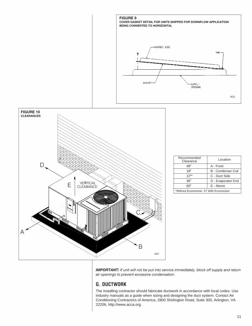
DOWNFLOW TO HORIZONTAL
1. Remove the screws and covers from the outside of the supply and return sections.
2. Install the covers in the bottom supply and return openings with the painted side up.See Figure 9. Use the existing gasket to seal the covers.
3. Secure the supply cover to the base of the unit with 1 screw, engaging prepunchedtab in unit base.
4. Secure the return cover to the base of the unit with screws engaging prepunchedholes in the unit base.
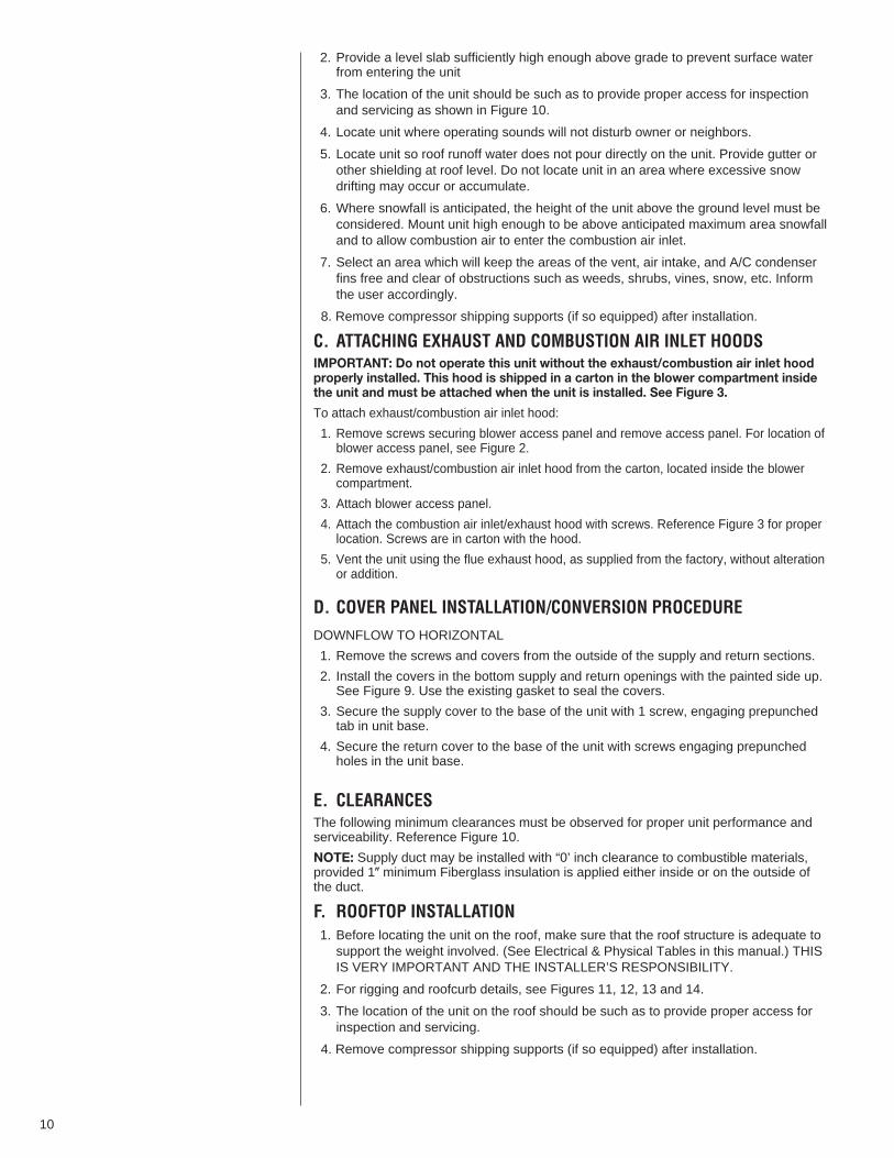
E. CLEARANCESThe following minimum clearances must be observed for proper unit performance andserviceability. Reference Figure 10.
NOTE: Supply duct may be installed with “0’ inch clearance to combustible materials,provided 1� minimum Fiberglass insulation is applied either inside or on the outside ofthe duct.
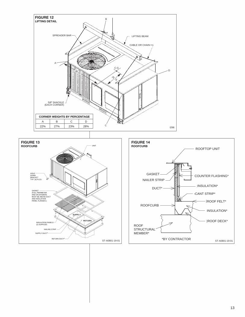
F. ROOFTOP INSTALLATION1. Before locating the unit on the roof, make sure that the roof structure is adequate tosupport the weight involved. (See Electrical & Physical Tables in this manual.) THISIS VERY IMPORTANT AND THE INSTALLER’S RESPONSIBILITY.
2. For rigging and roofcurb details, see Figures 11, 12, 13 and 14.
3. The location of the unit on the roof should be such as to provide proper access forinspection and servicing.
4. Remove compressor shipping supports (if so equipped) after installation.
10
IMPORTANT: If unit will not be put into service immediately, block off supply and returnair openings to prevent excessive condensation.
G. DUCTWORKThe installing contractor should fabricate ductwork in accordance with local codes. Useindustry manuals as a guide when sizing and designing the duct system. Contact AirConditioning Contractors of America, 2800 Shirlington Road, Suite 300, Arlington, VA22206, http://www.acca.org.
FIGURE 10CLEARANCES
I297
FIGURE 9COVER GASKET DETAIL FOR UNITS SHIPPED FOR DOWNFLOW APPLICATIONBEING CONVERTED TO HORIZONTAL
I631
11
RecommendedClearance Location
48� A - Front
18� B - Condenser Coil
12�* C - Duct Side
36� D - Evaporator End
60� E - Above
*Without Economizer. 57 With Economizer
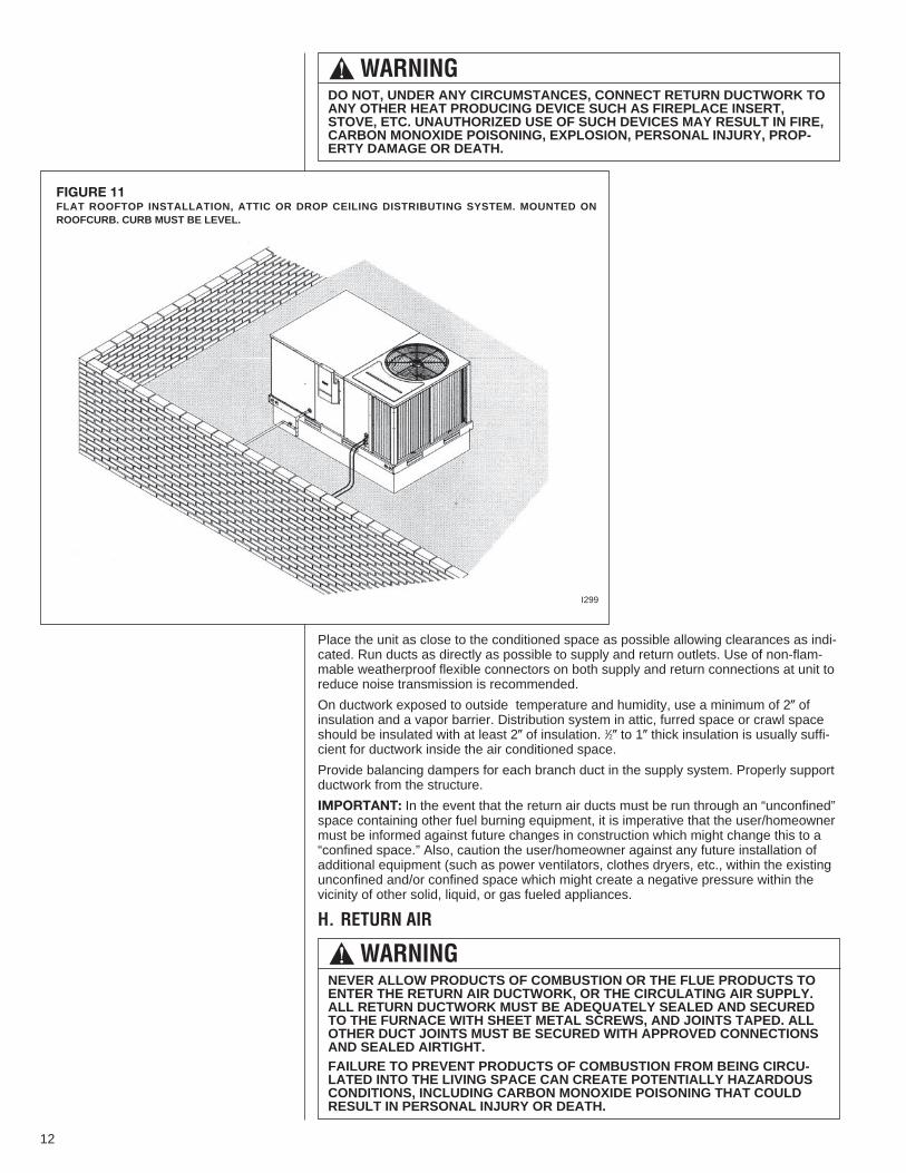
Place the unit as close to the conditioned space as possible allowing clearances as indi-cated. Run ducts as directly as possible to supply and return outlets. Use of non-flam-mable weatherproof flexible connectors on both supply and return connections at unit toreduce noise transmission is recommended.
On ductwork exposed to outside temperature and humidity, use a minimum of 2� ofinsulation and a vapor barrier. Distribution system in attic, furred space or crawl spaceshould be insulated with at least 2� of insulation. 1⁄2� to 1� thick insulation is usually suffi-cient for ductwork inside the air conditioned space.
Provide balancing dampers for each branch duct in the supply system. Properly supportductwork from the structure.
IMPORTANT: In the event that the return air ducts must be run through an “unconfined”space containing other fuel burning equipment, it is imperative that the user/homeownermust be informed against future changes in construction which might change this to a“confined space.” Also, caution the user/homeowner against any future installation ofadditional equipment (such as power ventilators, clothes dryers, etc., within the existingunconfined and/or confined space which might create a negative pressure within thevicinity of other solid, liquid, or gas fueled appliances.
H. RETURN AIR
FIGURE 11FLAT ROOFTOP INSTALLATION, ATTIC OR DROP CEILING DISTRIBUTING SYSTEM. MOUNTED ONROOFCURB. CURB MUST BE LEVEL.
I299
! WARNINGNEVER ALLOW PRODUCTS OF COMBUSTION OR THE FLUE PRODUCTS TOENTER THE RETURN AIR DUCTWORK, OR THE CIRCULATING AIR SUPPLY.ALL RETURN DUCTWORK MUST BE ADEQUATELY SEALED AND SECUREDTO THE FURNACE WITH SHEET METAL SCREWS, AND JOINTS TAPED. ALLOTHER DUCT JOINTS MUST BE SECURED WITH APPROVED CONNECTIONSAND SEALED AIRTIGHT.FAILURE TO PREVENT PRODUCTS OF COMBUSTION FROM BEING CIRCU-LATED INTO THE LIVING SPACE CAN CREATE POTENTIALLY HAZARDOUSCONDITIONS, INCLUDING CARBON MONOXIDE POISONING THAT COULDRESULT IN PERSONAL INJURY OR DEATH.
! WARNINGDO NOT, UNDER ANY CIRCUMSTANCES, CONNECT RETURN DUCTWORK TOANY OTHER HEAT PRODUCING DEVICE SUCH AS FIREPLACE INSERT,STOVE, ETC. UNAUTHORIZED USE OF SUCH DEVICES MAY RESULT IN FIRE,CARBON MONOXIDE POISONING, EXPLOSION, PERSONAL INJURY, PROP-ERTY DAMAGE OR DEATH.
12
ROOFTOP UNI
COUNTER FLAGASKETNAILER STRIP
DUCT*
ROOFCURB
INSULATION*
CANT STRIP*
ROOF FE
INSULATI
ROOF DE
TURALER*
FIGURE 14ROOFCURB
FIGURE 13ROOFCURB
RETURN DUCT*
SUPPLY DUCT*
NAILING STRIP
INSULATION PANELS(2) SUPPLIED
GASKET(FULL PERIMETERAND ON DIVIDERS, MUST BE ABOVE DUCTAND INSULATIONPANEL FLANGES.)
HOLDDOWNBRACKETTYP. (4) PLCS.
UNIT
I296
ST-A0801-19-01
CORNER WEIGHTS BY PERCENTAGE
A B C D
22% 27% 23% 28%
SPREADER BAR
A
B
D
C
LIFTING BEAM
CABLE OR CHAIN
5/8� SHACKLE(EACH CORNER)
38.2525.75
C.G.
ST-A0801-19-01
ROOFTOP UNIT
COUNTER FLASHING*
INSULATION*
CANT STRIP*
ROOF FELT*
INSULATION*
ROOF DECK*
*BY CONTRACTOR
ROOFSTRUCTURALMEMBER*
ROOFCURB
DUCT*
NAILER STRIP
GASKET
RETURN
SUPPLY
FIGURE 12LIFTING DETAIL
13
VIII. GAS SUPPLY, CONDENSATE DRAIN ANDVIII. PIPINGA. GAS CONNECTIONIMPORTANT: Connect this unit only to gas supplied by a commercial utility.
1. Install gas piping in accordance with local codes and regulations of the local utilitycompany. In the absence of local codes, the installation must conform to the specifi-cations of the National Fuel Gas Code, ANSI Z223.1 - latest edition.
NOTE: The use of flexible gas connectors is not recommended. If local codes allowthe use of a corrugated stainless steel flexible gas appliance connector, always usea new listed connector. Do not use a connector which has previously serviced anoth-er gas appliance.
NOTE: The Commonwealth of Massachusetts requires the gas shut-off valve to be aT-handle gas cock.
2. Connect the gas line to the gas pipe inlet opening provided into the 1/2� inlet valve.See Figure 8 or 11 for typical piping.
3. Size the gas line to the furnace adequately to prevent undue pressure drop andnever less than 1/2� nominal pipe size.
4. Install a drip leg or sediment trap in the gas supply line as close to the unit as possi-ble.
5. Install an outside ground joint union to connect the gas supply to the control assem-bly at the burner tray.
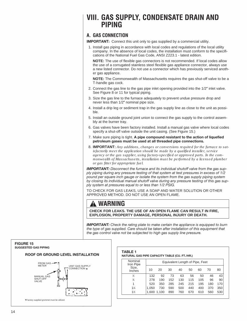
6. Gas valves have been factory installed. Install a manual gas valve where local codesspecify a shut-off valve outside the unit casing. (See Figure 15.)
7. Make sure piping is tight. A pipe compound resistant to the action of liquefiedpetroleum gases must be used at all threaded pipe connections.
8. IMPORTANT: Any additions, changes or conversions required for the furnace to sat-isfactorily meet the application should be made by a qualified installer, serviceagency or the gas supplier, using factory-specified or approved parts. In the com-monwealth of Massachusetts, installation must be performed by a licensed plumberor gas fitter for appropriate fuel.
IMPORTANT: Disconnect the furnace and its individual shutoff valve from the gas sup-ply piping during any pressure testing of that system at test pressures in excess of 1/2pound per square inch gauge or isolate the system from the gas supply piping systemby closing its individual manual shutoff valve during any pressure testing of this gas sup-ply system at pressures equal to or less than 1/2 PSIG.
TO CHECK FOR GAS LEAKS, USE A SOAP AND WATER SOLUTION OR OTHERAPPROVED METHOD. DO NOT USE AN OPEN FLAME.
IMPORTANT: Check the rating plate to make certain the appliance is equipped to burnthe type of gas supplied. Care should be taken after installation of this equipment thatthe gas control valve not be subjected to high gas supply line pressure.
FIGURE 15SUGGESTED GAS PIPING
FROM GASMETER
*Factory supplied grommet must be utilized.
MANUAL GASSHUT-OFFVALVE
UNIT GAS SUPPLYCONNECTION *
ROOF OR GROUND LEVEL INSTALLATION
! WARNINGCHECK FOR LEAKS. THE USE OF AN OPEN FLAME CAN RESULT IN FIRE,EXPLOSION, PROPERTY DAMAGE, PERSONAL INJURY OR DEATH.
NominalIron PipeSize,Inches
Equivalent Length of Pipe, Feet
10 20 30 40 50 60 70 80
1⁄2 132 92 73 63 56 50 46 433⁄4 278 190 152 130 115 105 96 901 520 350 285 245 215 195 180 17011⁄4 1,050 730 590 500 440 400 370 35011⁄2 1,600 1,100 890 760 670 610 560 530
TABLE 1NATURAL GAS PIPE CAPACITY TABLE (CU. FT./HR.)
14
In making gas connections, avoid strains as they may cause noise and damage the con-trols. Use a backup wrench on the valve to avoid damage.
The capacities of gas pipe of different diameters and lengths in cu. ft. per hr. with pres-sure drop of 0.3 in. and specific gravity of 0.60 (natural gas) are shown in Table 1.
After determining the pipe length, select the pipe size which will provide the minimumcubic feet per hour required for the gas input rating of the furnace. By formula:
Gas Input of Furnace(BTU/HR)
Cu. Ft. Per Hr. Required =Heating Value of Gas(BTU/FT3)
The gas input of the furnace is marked on the furnace rating plate. The heating value ofthe gas (BTU/FT3) may be determined by consulting the local natural gas utility or theL.P. gas supplier.
B. LP CONVERSION
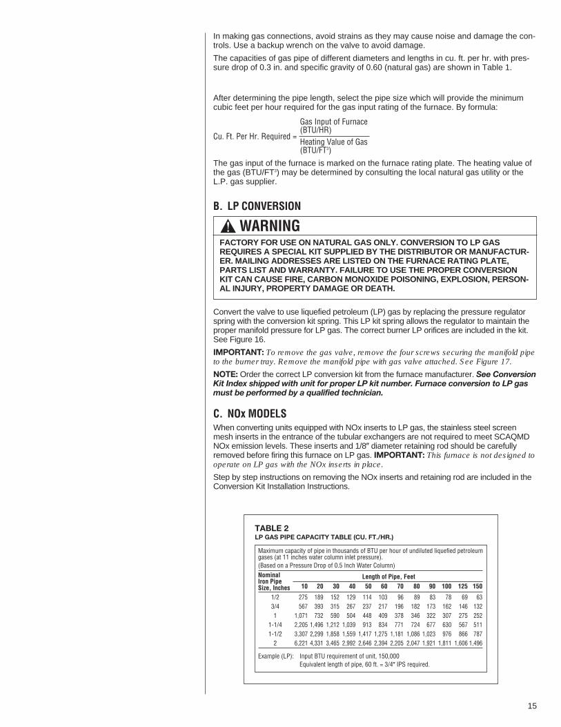
Convert the valve to use liquefied petroleum (LP) gas by replacing the pressure regulatorspring with the conversion kit spring. This LP kit spring allows the regulator to maintain theproper manifold pressure for LP gas. The correct burner LP orifices are included in the kit.See Figure 16.
IMPORTANT: To remove the gas valve, remove the four screws securing the manifold pipeto the burner tray. Remove the manifold pipe with gas valve attached. See Figure 17.
NOTE: Order the correct LP conversion kit from the furnace manufacturer. See ConversionKit Index shipped with unit for proper LP kit number. Furnace conversion to LP gasmust be performed by a qualified technician.
C. NOx MODELSWhen converting units equipped with NOx inserts to LP gas, the stainless steel screenmesh inserts in the entrance of the tubular exchangers are not required to meet SCAQMDNOx emission levels. These inserts and 1/8� diameter retaining rod should be carefullyremoved before firing this furnace on LP gas. IMPORTANT: This furnace is not designed tooperate on LP gas with the NOx inserts in place.
Step by step instructions on removing the NOx inserts and retaining rod are included in theConversion Kit Installation Instructions.
! WARNINGFACTORY FOR USE ON NATURAL GAS ONLY. CONVERSION TO LP GASREQUIRES A SPECIAL KIT SUPPLIED BY THE DISTRIBUTOR OR MANUFACTUR-ER. MAILING ADDRESSES ARE LISTED ON THE FURNACE RATING PLATE,PARTS LIST ANDWARRANTY. FAILURE TO USE THE PROPER CONVERSIONKIT CAN CAUSE FIRE, CARBON MONOXIDE POISONING, EXPLOSION, PERSON-AL INJURY, PROPERTY DAMAGE OR DEATH.
Maximum capacity of pipe in thousands of BTU per hour of undiluted liquefied petroleumgases (at 11 inches water column inlet pressure).(Based on a Pressure Drop of 0.5 Inch Water Column)
TABLE 2LP GAS PIPE CAPACITY TABLE (CU. FT./HR.)
NominalIron PipeSize, Inches 10 20 30 40 50 60 70 80 90 100 125 150
275 189 152 129 114 103 96 89 83 78 69 63567 393 315 267 237 217 196 182 173 162 146 132
1,071 732 590 504 448 409 378 346 322 307 275 2522,205 1,496 1,212 1,039 913 834 771 724 677 630 567 5113,307 2,299 1,858 1,559 1,417 1,275 1,181 1,086 1,023 976 866 7876,221 4,331 3,465 2,992 2,646 2,394 2,205 2,047 1,921 1,811 1,606 1,496
1/23/41
1-1/41-1/22
Length of Pipe, Feet
Example (LP): Input BTU requirement of unit, 150,000Equivalent length of pipe, 60 ft. = 3/4� IPS required.
15
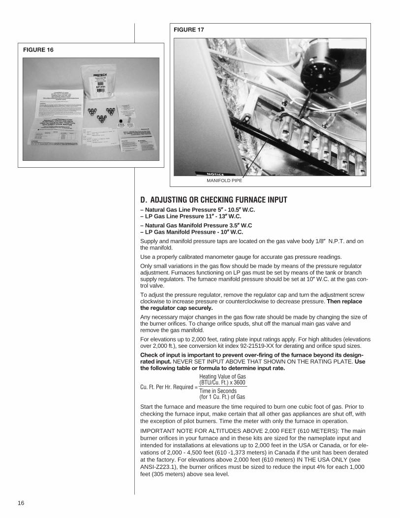
D. ADJUSTING OR CHECKING FURNACE INPUT– Natural Gas Line Pressure 5�� - 10.5��W.C.– LP Gas Line Pressure 11�� - 13��W.C.
– Natural Gas Manifold Pressure 3.5�� W.C– LP Gas Manifold Pressure - 10��W.C.
Supply and manifold pressure taps are located on the gas valve body 1/8� N.P.T. and onthe manifold.
Use a properly calibrated manometer gauge for accurate gas pressure readings.
Only small variations in the gas flow should be made by means of the pressure regulatoradjustment. Furnaces functioning on LP gas must be set by means of the tank or branchsupply regulators. The furnace manifold pressure should be set at 10�W.C. at the gas con-trol valve.
To adjust the pressure regulator, remove the regulator cap and turn the adjustment screwclockwise to increase pressure or counterclockwise to decrease pressure. Then replacethe regulator cap securely.
Any necessary major changes in the gas flow rate should be made by changing the size ofthe burner orifices. To change orifice spuds, shut off the manual main gas valve andremove the gas manifold.
For elevations up to 2,000 feet, rating plate input ratings apply. For high altitudes (elevationsover 2,000 ft.), see conversion kit index 92-21519-XX for derating and orifice spud sizes.
Check of input is important to prevent over-firing of the furnace beyond its design-rated input. NEVER SET INPUT ABOVE THAT SHOWN ON THE RATING PLATE. Usethe following table or formula to determine input rate.
Heating Value of Gas(BTU/Cu. Ft.) x 3600
Cu. Ft. Per Hr. Required =Time in Seconds(for 1 Cu. Ft.) of Gas
Start the furnace and measure the time required to burn one cubic foot of gas. Prior tochecking the furnace input, make certain that all other gas appliances are shut off, withthe exception of pilot burners. Time the meter with only the furnace in operation.
IMPORTANT NOTE FOR ALTITUDES ABOVE 2,000 FEET (610 METERS): The mainburner orifices in your furnace and in these kits are sized for the nameplate input andintended for installations at elevations up to 2,000 feet in the USA or Canada, or for ele-vations of 2,000 - 4,500 feet (610 -1,373 meters) in Canada if the unit has been deratedat the factory. For elevations above 2,000 feet (610 meters) IN THE USA ONLY (seeANSI-Z223.1), the burner orifices must be sized to reduce the input 4% for each 1,000feet (305 meters) above sea level.
FIGURE 16
FIGURE 17
MANIFOLD PIPE
16

Alternate Method for Canadian High-Altitude Derate for Residential and LightCommercial Gas/Electric Package Units
In Canada, unless an orifice change is specifically mandated by local codes, an alter-nate method of altitude deration through a reduction in manifold pressure is acceptableas described in Table 4.
The information in Table 1 is based on a heating value of 1000 BTU per cubic feet ofnatural gas, and 2500 BTU per cubic feet of LP gas.
Important: Actual input rates must be measured on-site with manifold pressureadjustment to ensure that an actual 10% reduction in input rate is achieved.
Once this field adjustment has been made, the label shown in Figure 19 must be affixedin a conspicuous location on the front of the furnace cabinet.
NOTE: This label is supplied in the information package shipped with each unit.
ONE 1 21 1 30 1 34 1 39 3 4540,000TEN 13 30 15 0 15 36 16 30 37 30
ONE 0 54 1 0 1 3 1 6 2 3060,000TEN 9 0 10 0 10 24 11 0 25 0
ONE 0 41 0 45 0 47 0 50 1 5380,000TEN 6 45 7 30 7 48 8 15 18 45
ONE 0 33 0 36 0 38 0 40 1 30100,000TEN 5 24 6 0 6 15 6 36 15 0
METER TIME IN MINUTES AND SECONDS FOR NORMALINPUT RATING OF FURNACES EQUIPPED FOR NATURAL
OR LP GAS
INPUTBTU/HR
METERSIZE
CU. FT.
HEATING VALUE OF GAS BTU PER CU. FT.900 1000 1040 1100 2500
MIN. SEC. MIN. SEC. MIN. SEC. MIN. SEC. MIN. SEC.
TABLE 3FIGURE 18CONDENSATE DRAIN
DO NOT OVERTIGHTEN DRAIN FITTING
17
Altitude
40,000 32,00060,000 48,00080,000 64,000 #450’-2000’ 100,000 80,000 3.5” W.C.120,000 96,000135,000 108,000 #4336,000 28,80054,000 43,200
2001’- 72,000 57,600 #454500’ 90,000 72,000 2.9” W.C.
108,000 86,400121,500 97,200 #43
Input Output OrificeSize
ManifoldPressure
TABLE 4ALTERNATE METHOD FOR CANADIAN HIGH-ALTITUDE DERATE
NATURAL GAS
Altitude
40,000 32,00060,000 48,00080,000 64,000 #550’-2000’ 100,000 80,000 10” W.C.120,000 96,000135,000 108,00036,000 28,80054,000 43,200
2001’- 72,000 57,600 #554500’ 90,000 72,000 8.1” W.C.108,000 86,400121,500 97,200
Input Output OrificeSize
ManifoldPressure
LP GAS
FIGURE 19MANIFOLD PRESSURE CHANGE LABEL
The manifold pressure of this appliance hasbeen field adjusted to obtain the correct inputrating for installation at altitudes between2,000 feet and 4,500 feet elevation.
La pression du distributeur d’alimentation de cetappareil a ete ajuste sur les lieux afin d’obtenir labonne puissance d’entrée pour une installation
entre 2000 et 4500 pieds d’altitude.

E. CONDENSATE DRAINThe condensate drain connection of the evaporator is threaded 3/4� nominal P.V.C.pipe. IMPORTANT: Install a condensate trap to ensure proper condensate drainage.See Figure 18.
IX. WIRINGA. POWER SUPPLY
1. All wiring should be made in accordance with the National Electrical Code.Consult the local power company to determine the availability of sufficient power tooperate the unit. Check the voltage at power supply to make sure it corresponds tothe unit’s RATED VOLTAGE REQUIREMENT. Install a branch circuit disconnectnear the rooftop, in accordance with the N.E.C., C.E.C. or local codes. A bracket isprovided with the unit for mounting of the disconnect. See Figure 19.
2. It is important that proper electrical power is available at the unit. Voltage should notvary more than 10% from that stamped on the unit nameplate. On three phase units,phases must be balanced within 3%.
3. For branch circuit wiring (main power supply to unit disconnect), the minimum wire sizefor the length of run can be determined from Table 3 using the circuit ampacity found onthe unit rating plate. Use the smallest wire size allowable in Table 4 from the unit dis-connect to unit.
FIGURE 20RECOMMENDED BRANCH CIRCUIT DISCONNECT LOCATION
TO POWER
TO THERMOSTAT
BRANCHCIRCUITDISCONNECT
I317A
AWG Copper AWG Aluminum Connector Type and SizeWire Size Wire Size (or equivalent)
#12 #10 T & B Wire Nut PT2#10 # 8 T & B Wire Nut PT3# 8 # 6 Sherman Split Bolt TSP6# 6 # 4 Sherman Split Bolt TSP4# 4 # 2 Sherman Split Bolt TSP2
TABLE 6
200 6 4 4 4 3 3 2 2
150 8 6 6 4 4 4 3 3
100 10 8 8 6 6 6 4 4
50 14 12 10 10 8 8 6 6
15 20 25 30 35 40 45 50
BRANCH CIRCUIT AMPACITY
SUPPLY WIRELENGTH-FEET
*Taken from National Electric Code
TABLE 5BRANCH CIRCUIT COPPER WIRE SIZE(Based on 1% Voltage Drop)*
18
! WARNINGTURN OFF THE MAIN ELECTRICAL POWER AT THE BRANCH CIRCUIT DIS-CONNECT CLOSEST TO THE UNIT BEFORE ATTEMPTING ANY WIRING. FAIL-URE TO DO SO CAN CAUSE ELECTRICAL SHOCK RESULTING IN PERSONALINJURY OR DEATH.
NOTE: A bracket is provided with the unit for mounting the branch circuit disconnect tothe unit. This is the recommended location for the disconnect. See Figure 19.
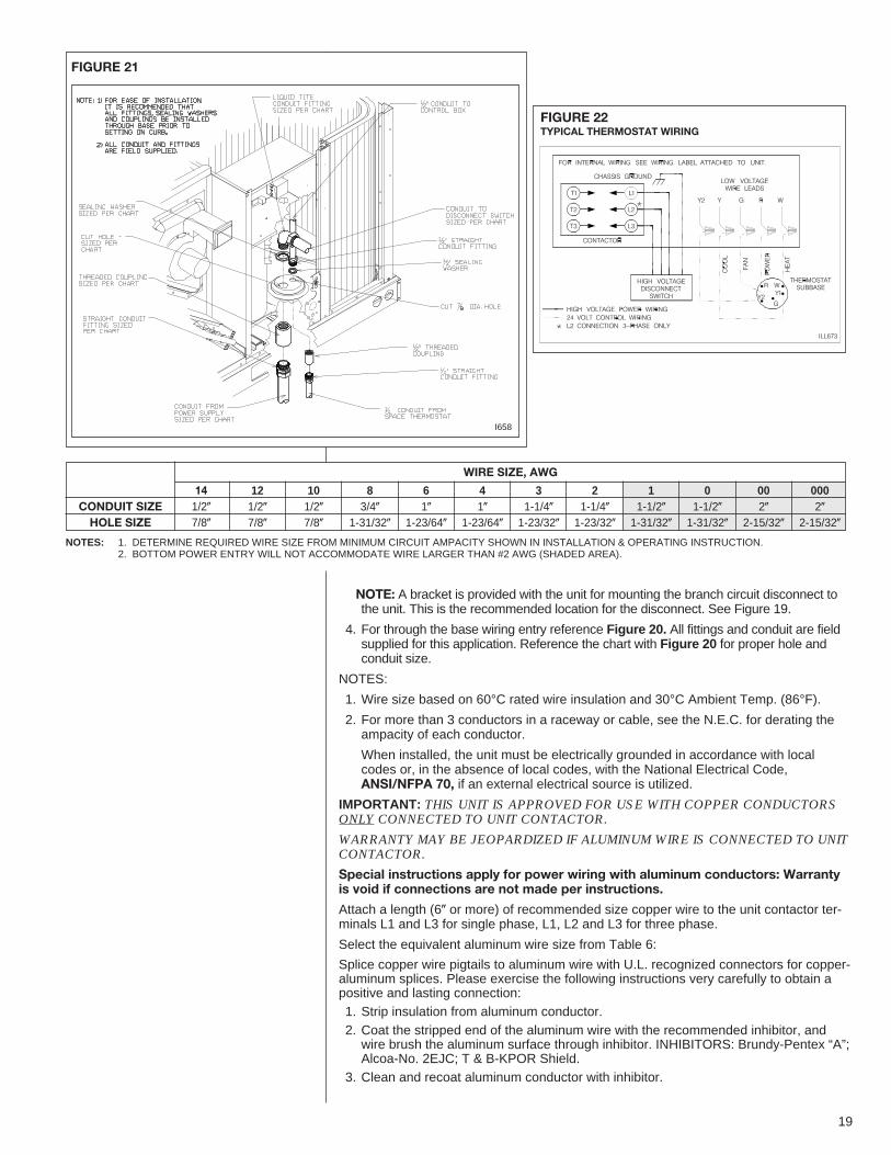
4. For through the base wiring entry reference Figure 20. All fittings and conduit are fieldsupplied for this application. Reference the chart with Figure 20 for proper hole andconduit size.
NOTES:
1. Wire size based on 60°C rated wire insulation and 30°C Ambient Temp. (86°F).
2. For more than 3 conductors in a raceway or cable, see the N.E.C. for derating theampacity of each conductor.
When installed, the unit must be electrically grounded in accordance with localcodes or, in the absence of local codes, with the National Electrical Code,ANSI/NFPA 70, if an external electrical source is utilized.
IMPORTANT: THIS UNIT IS AP PROVED FOR USE WITH COPPER CONDUCTORSONLY CONNECTED TO UNIT CONTACTOR.
WARRANTY MAY BE JEOPARDIZED IF ALUMINUM WIRE IS CONNECTED TO UNITCONTACTOR.
Special instructions apply for power wiring with aluminum conductors: Warrantyis void if connections are not made per instructions.
Attach a length (6� or more) of recommended size copper wire to the unit contactor ter-minals L1 and L3 for single phase, L1, L2 and L3 for three phase.
Select the equivalent aluminum wire size from Table 6:
Splice copper wire pigtails to aluminum wire with U.L. recognized connectors for copper-aluminum splices. Please exercise the following instructions very carefully to obtain apositive and lasting connection:1. Strip insulation from aluminum conductor.2. Coat the stripped end of the aluminum wire with the recommended inhibitor, andwire brush the aluminum surface through inhibitor. INHIBITORS: Brundy-Pentex “A”;Alcoa-No. 2EJC; T & B-KPOR Shield.
3. Clean and recoat aluminum conductor with inhibitor.
WIRE SIZE, AWG
FIGURE 21
FIGURE 22TYPICAL THERMOSTAT WIRING
141/2�
7/8�
121/2�
7/8�
101/2�
7/8�
83/4�
1-31/32�
61�
1-23/64�
41�
1-23/64�
31-1/4�
1-23/32�
21-1/4�
1-23/32�
11-1/2�
1-31/32�
01-1/2�
1-31/32�
002�
2-15/32�
0002�
2-15/32�
CONDUIT SIZEHOLE SIZE
I658
NOTES: 1. DETERMINE REQUIRED WIRE SIZE FROM MINIMUM CIRCUIT AMPACITY SHOWN IN INSTALLATION & OPERATING INSTRUCTION.2. BOTTOM POWER ENTRY WILL NOT ACCOMMODATE WIRE LARGER THAN #2 AWG (SHADED AREA).
19
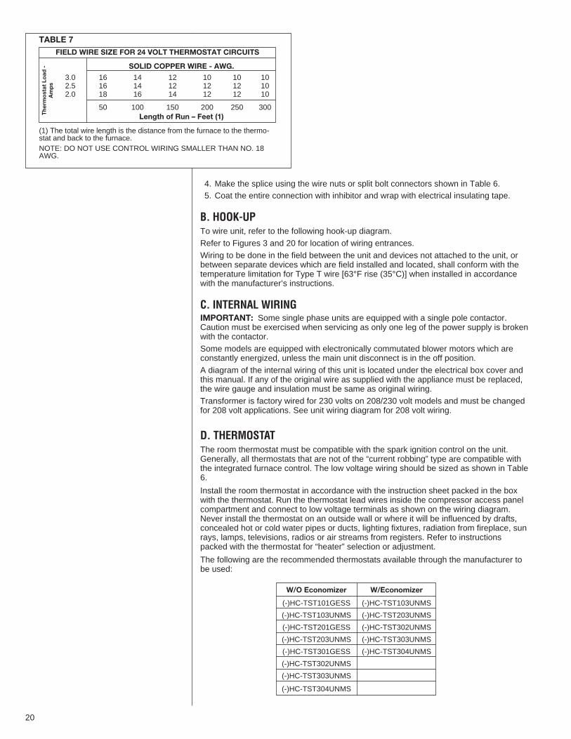
4. Make the splice using the wire nuts or split bolt connectors shown in Table 6.5. Coat the entire connection with inhibitor and wrap with electrical insulating tape.
B. HOOK-UPTo wire unit, refer to the following hook-up diagram.Refer to Figures 3 and 20 for location of wiring entrances.Wiring to be done in the field between the unit and devices not attached to the unit, orbetween separate devices which are field installed and located, shall conform with thetemperature limitation for Type T wire [63°F rise (35°C)] when installed in accordancewith the manufacturer’s instructions.
C. INTERNAL WIRINGIMPORTANT: Some single phase units are equipped with a single pole contactor.Caution must be exercised when servicing as only one leg of the power supply is brokenwith the contactor.Some models are equipped with electronically commutated blower motors which areconstantly energized, unless the main unit disconnect is in the off position.A diagram of the internal wiring of this unit is located under the electrical box cover andthis manual. If any of the original wire as supplied with the appliance must be replaced,the wire gauge and insulation must be same as original wiring.Transformer is factory wired for 230 volts on 208/230 volt models and must be changedfor 208 volt applications. See unit wiring diagram for 208 volt wiring.
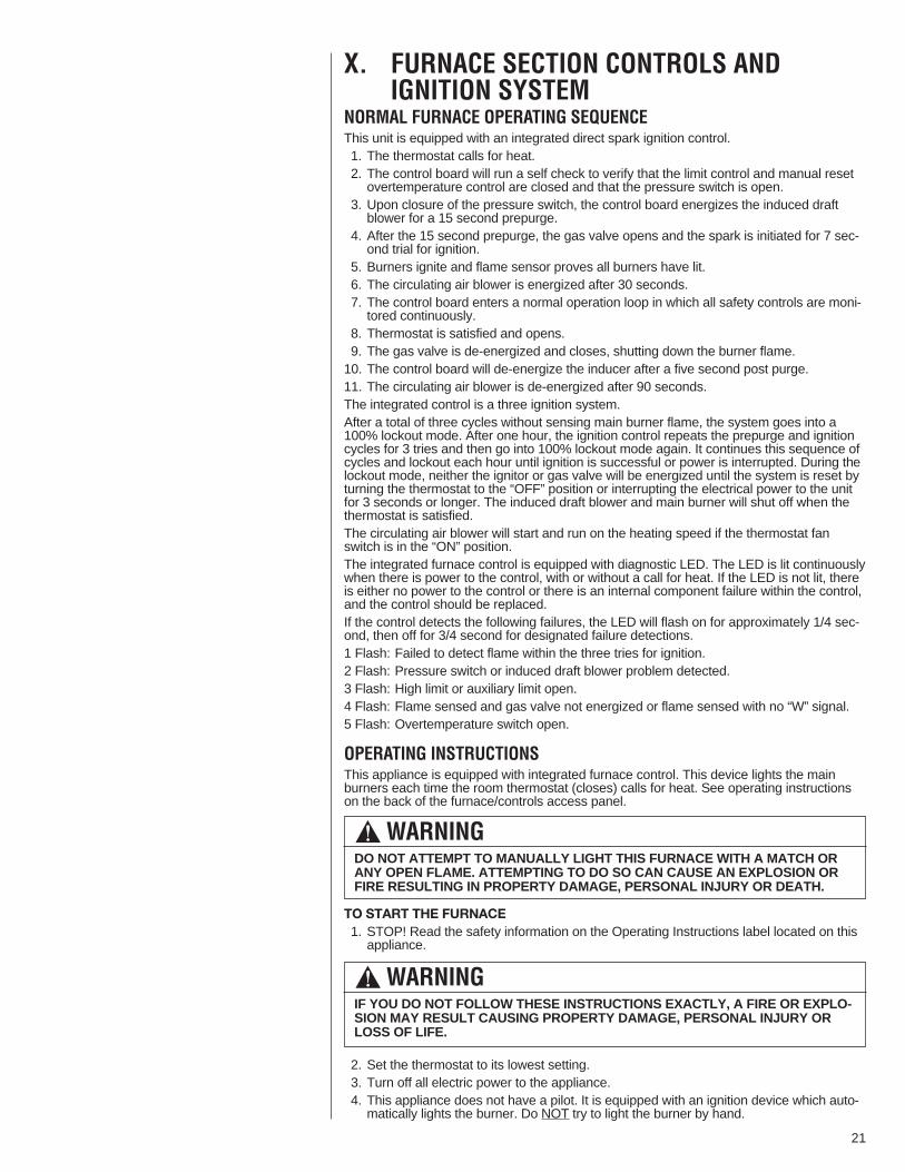
D. THERMOSTATThe room thermostat must be compatible with the spark ignition control on the unit.Generally, all thermostats that are not of the “current robbing” type are compatible withthe integrated furnace control. The low voltage wiring should be sized as shown in Table6.
Install the room thermostat in accordance with the instruction sheet packed in the boxwith the thermostat. Run the thermostat lead wires inside the compressor access panelcompartment and connect to low voltage terminals as shown on the wiring diagram.Never install the thermostat on an outside wall or where it will be influenced by drafts,concealed hot or cold water pipes or ducts, lighting fixtures, radiation from fireplace, sunrays, lamps, televisions, radios or air streams from registers. Refer to instructionspacked with the thermostat for “heater” selection or adjustment.
The following are the recommended thermostats available through the manufacturer tobe used:
FIELD WIRE SIZE FOR 24 VOLT THERMOSTAT CIRCUITS
SOLID COPPER WIRE - AWG.
3.0 16 14 12 10 10 102.5 16 14 12 12 12 102.0 18 16 14 12 12 10
50 100 150 200 250 300Length of Run – Feet (1)T
herm
ostat Load -
Amps
TABLE 7
(1) The total wire length is the distance from the furnace to the thermo-stat and back to the furnace.NOTE: DO NOT USE CONTROL WIRING SMALLER THAN NO. 18AWG.
20
W/O Economizer W/Economizer
(-)HC-TST101GESS (-)HC-TST103UNMS
(-)HC-TST103UNMS (-)HC-TST203UNMS
(-)HC-TST201GESS (-)HC-TST302UNMS
(-)HC-TST203UNMS (-)HC-TST303UNMS
(-)HC-TST301GESS (-)HC-TST304UNMS
(-)HC-TST302UNMS
(-)HC-TST303UNMS
(-)HC-TST304UNMS
X. FURNACE SECTION CONTROLS ANDIGNITION SYSTEM
NORMAL FURNACE OPERATING SEQUENCEThis unit is equipped with an integrated direct spark ignition control.1. The thermostat calls for heat.2. The control board will run a self check to verify that the limit control and manual resetovertemperature control are closed and that the pressure switch is open.
3. Upon closure of the pressure switch, the control board energizes the induced draftblower for a 15 second prepurge.
4. After the 15 second prepurge, the gas valve opens and the spark is initiated for 7 sec-ond trial for ignition.
5. Burners ignite and flame sensor proves all burners have lit.6. The circulating air blower is energized after 30 seconds.7. The control board enters a normal operation loop in which all safety controls are moni-tored continuously.
8. Thermostat is satisfied and opens.9. The gas valve is de-energized and closes, shutting down the burner flame.10. The control board will de-energize the inducer after a five second post purge.11. The circulating air blower is de-energized after 90 seconds.The integrated control is a three ignition system.After a total of three cycles without sensing main burner flame, the system goes into a100% lockout mode. After one hour, the ignition control repeats the prepurge and ignitioncycles for 3 tries and then go into 100% lockout mode again. It continues this sequence ofcycles and lockout each hour until ignition is successful or power is interrupted. During thelockout mode, neither the ignitor or gas valve will be energized until the system is reset byturning the thermostat to the “OFF” position or interrupting the electrical power to the unitfor 3 seconds or longer. The induced draft blower and main burner will shut off when thethermostat is satisfied.The circulating air blower will start and run on the heating speed if the thermostat fanswitch is in the “ON” position.The integrated furnace control is equipped with diagnostic LED. The LED is lit continuouslywhen there is power to the control, with or without a call for heat. If the LED is not lit, thereis either no power to the control or there is an internal component failure within the control,and the control should be replaced.If the control detects the following failures, the LED will flash on for approximately 1/4 sec-ond, then off for 3/4 second for designated failure detections.1 Flash: Failed to detect flame within the three tries for ignition.2 Flash: Pressure switch or induced draft blower problem detected.3 Flash: High limit or auxiliary limit open.4 Flash: Flame sensed and gas valve not energized or flame sensed with no “W” signal.5 Flash: Overtemperature switch open.
OPERATING INSTRUCTIONSThis appliance is equipped with integrated furnace control. This device lights the mainburners each time the room thermostat (closes) calls for heat. See operating instructionson the back of the furnace/controls access panel.
TO START THE FURNACE1. STOP! Read the safety information on the Operating Instructions label located on thisappliance.
2. Set the thermostat to its lowest setting.3. Turn off all electric power to the appliance.4. This appliance does not have a pilot. It is equipped with an ignition device which auto-matically lights the burner. Do NOT try to light the burner by hand.
! WARNINGDO NOT ATTEMPT TO MANUALLY LIGHT THIS FURNACE WITH A MATCH ORANY OPEN FLAME. ATTEMPTING TO DO SO CAN CAUSE AN EXPLOSION ORFIRE RESULTING IN PROPERTY DAMAGE, PERSONAL INJURY OR DEATH.
! WARNINGIF YOU DO NOT FOLLOW THESE INSTRUCTIONS EXACTLY, A FIRE OR EXPLO-SION MAY RESULT CAUSING PROPERTY DAMAGE, PERSONAL INJURY ORLOSS OF LIFE.
21

5. Remove control door/access panel.6. Move switch to the “OFF” position.7. Wait five (5) minutes to clear out any gas. Then smell for gas, including near the floor.If you smell gas, STOP!• Do not try to light any appliance.• Do not touch any electric switch; do not use any phone in your building.• Immediately call your gas supplier from a neighbor’s phone. Follow the gas suppli-er’s instructions.
• If you cannot reach your gas supplier, call the fire department.If you don’t smell gas, go to the next step.
8. Move “OFF” position to “ON” position.9. Replace the control door.10. Turn on all electric power to the appliance.11. Set the thermostat to the desired setting.12. If the appliance will not operate, follow the instructions below on how to shut down the
furnace.
The initial start-up on a new installation may require the control system to be energized forsome time until air has bled through the system and fuel gas is available at the burners.
TO SHUT DOWN FURNACE1. Set the thermostat to the lowest setting.2. Turn off all electric power to the appliance if service is to be performed.3. Remove control door.4. Move switch to the “OFF” position.5. Replace control door.
BURNERSBurners for these units have been designed so that field adjustment is not required.Burners are tray-mounted and accessible for easy cleaning when required.
MANUAL RESET OVERTEMPERATURE CONTROLTwo manual reset overtemperature controls (one on 80,000 BTUH) are located on theburner shield. These devices senses blockage in the heat exchanger or insufficient com-bustion air. This shuts off the main burners if excessive temperatures occur in the burnercompartment.Operation of this control indicates an abnormal condition. Therefore, the unit should beexamined by a qualified installer, service agency, or the gas supplier before being placedback into operation.
PRESSURE SWITCHThis furnace has a pressure switch for sensing a blocked exhaust or a failed induced draftblower. It is normally open and closes when the induced draft blower starts, indicating airflow through the combustion chamber.
! WARNINGSHOULD OVERHEATING OCCUR OR THE GAS SUPPLY FAIL TO SHUT OFF,SHUT OFF THE MANUAL GAS VALVE TO THE APPLIANCE BEFORE SHUTTINGOFF THE ELECTRICAL SUPPLY. FAILURE TO DO SO CAN RESULT IN ANEXPLOSION OR FIRE CAUSING PROPERTY DAMAGE, SEVERE PERSONALINJURY OR DEATH!
! WARNINGDO NOT JUMPER THIS DEVICE! DO NOT reset the over temperature controlwithout taking corrective action to assure that an adequate supply of combus-tion air is maintained under all conditions of operation. Failure to do so canresult in carbon monoxide poisoning or death. Replace this control only with theidentical replacement part.
22
! WARNINGTHE SPARK IGNITOR AND IGNITION LEAD FROM THE IGNITION CONTROL AREHIGH VOLTAGE. KEEP HANDS OR TOOLS AWAY TO PREVENT ELECTRICALSHOCK. SHUT OFF ELECTRICAL POWER BEFORE SERVICING ANY OF THECONTROLS. FAILURE TO ADHERE TO THIS WARNING CAN RESULT IN PER-SONAL INJURY OR DEATH.
LIMIT CONTROLThe supply air high temperature limit cut-off is set at the factory and cannot be adjusted. Itis calibrated to prevent the air temperature leaving the furnace from exceeding the maxi-mum outlet air temperature.
IMPORTANT: Replace this control only with the identical replacement part.
XI. SYSTEM OPERATING INFORMATIONADVISE THE CUSTOMER1. Change the air filters regularly. The heating system operates better, more efficientlyand more economically.
2. Arrange the furniture and drapes so that the supply air registers and the return airgrilles are unobstructed.
3. Close doors and windows. This reduces the heating and cooling load on the system.4. Avoid excessive use of exhaust fans.5. Do not permit the heat generated by television, lamps or radios to influence the ther-mostat operation.
6. Except for the mounting platform, keep all combustible articles three feet from the unitand exhaust system.
7. IMPORTANT: Replace all blower doors and compartment cover after servicing theunit. Do not operate the unit without all panels and doors securely in place.
8. Do not allow snow or other debris to accumulate in the vicinity of the appliance.
FURNACE SECTION MAINTENANCEThe unit’s furnace should operate for many years without excessive scale build-up in fluepassageways; however, it is recommended that a qualified installer, service agency, or thegas supplier annually inspect the flue passageways, the exhaust system and the burnersfor continued safe operation, paying particular attention to deterioration from corrosion orother sources.If during inspection the flue passageways and exhaust system are determined to requirecleaning, the following procedures should be followed (by a qualified installer, serviceagency, or gas supplier):1. Turn off the electrical power to the unit and set the thermostat to the lowesttemperature.
2. Shut off the gas supply to the unit either at the meter or at manual valve in thesupply piping.
3. Remove the furnace controls access panel and the control box cover.4. Disconnect the gas supply piping from the gas valve.5. Disconnect the wiring to the induced draft blower motor, gas valve, flame sensor, andflame roll-out control, and ignitor cable. Mark all wires disconnected for properreconnection.
6. Remove the screws (4) connecting the burner tray to the heat exchanger mountingpanel.
7. Remove the burner tray and the manifold assembly from the unit.8. Remove the screws (5) connecting the induced draft blower to the collector box andscrews (18) connecting the collector box to the heat exchanger center panel. Removethe induced draft blower and the collector box from the unit.
9. Remove the screws (3) connecting the divider plate to the heat exchanger centerpanel.
10. Remove the turbulators from inside the heat exchangers by inserting the blade of ascrewdriver under the locking tabs. Pop the tabs out of the expanded grooves of theheat exchanger. Slide the turbulators out of the heat exchangers.
! WARNINGLABEL ALL WIRES PRIOR TO DISCONNECTION WHEN SERVICING CONTROLS.WIRING ERRORS CAN CAUSE IMPROPER AND DANGEROUS OPERATIONRESULTING IN FIRE, ELECTRICAL SHOCK, PROPERTY DAMAGE, PERSONALINJURY OR DEATH.
! WARNINGDO NOT JUMPER THIS DEVICE! DOING SO CAN CAUSE A FIRE OR EXPLOSIONRESULTING IN PROPERTY DAMAGE, PERSONAL INJURY OR DEATH.
23
11. Direct a water hose into the outlet of the heat exchanger top. Flush the inside of eachheat exchanger tube with water. Blow out each tube with air to remove excessivemoisture.
12. Reassemble (steps 1 through 10 in reverse order). Be careful not to strip out thescrew holes used to mount the collector box and inducer blower. Replaceinducer blower gasket and collector box gasket with factory replacements ifdamaged.
The manufacturer recommends that a qualified installer, service agency or the gas suppli-er visually inspect the burner flames for the desired flame appearance at the beginning ofthe heating season and approximately midway in heating season.The manufacturer also recommends that a qualified installer, service agency or the gassupplier clean the flame sensor with steel wool at the beginning of the heating season.
LUBRICATIONIMPORTANT: DO NOT attempt to lubricate the bearings on the blower motor or theinduced draft blower motor. Addition of lubricants can reduce the motor life and void thewarranty.The blower motor and induced draft blower motor are prelubricated by the manufacturerand do not require further attention.A qualified installer, service agency or the gas supplier must periodically clean themotors to prevent the possibility of overheating due to an accumulation of dust and dirton the windings or on the motor exterior. And, as suggested elsewhere in these instruc-tions, the air filters should be kept clean because dirty filters can restrict air flow and themotor depends upon sufficient air flowing across and through it to prevent overheating.
COOLING SECTION MAINTENANCE
It is recommended that at the beginning of each cooling season a qualified installer orservice agency inspect and clean the cooling section of this unit. The following areasshould be addressed: evaporator coil. condenser coil, condenser fan motor and venturiarea.To inspect the evaporator coil:1. Remove the filter access panel and the blower/evaporator coil access panel.Remove the filters.
2. Shine a flashlight on the evaporator coil (both sides) and inspect for accumulation oflint, insulation, etc.
3. If coil requires cleaning, follow the steps shown below.
Cleaning Evaporator Coil1. The coil should be cleaned when it is dry. If the coil is coated with dirt or lint, vacuumit with a soft brush attachment. Be careful not to bend the coil fins.
! WARNINGDISCONNECT MAIN ELECTRICAL POWER TO THE UNIT BEFORE ATTEMPT-ING MAINTENANCE. FAILURE TO DO SO MAY RESULT IN ELECTRICALSHOCK OR SEVERE PERSONAL INJURY OR DEATH.
! WARNINGDISCONNECT MAIN ELECTRICAL POWER TO THE UNIT BEFORE ATTEMPT-ING MAINTENANCE. FAILURE TO DO SO CAN CAUSE ELECTRICAL SHOCKRESULTING IN SEVERE PERSONAL INJURY OR DEATH.
! WARNINGLABEL ALL WIRES PRIOR TO DISCONNECTION WHEN SERVICING THE UNIT.WIRING ERRORS CAN CAUSE IMPROPER AND DANGEROUS OPERATIONRESULTING IN FIRE, ELECTRICAL SHOCK, PROPERTY DAMAGE, SEVEREPERSONAL INJURY OR DEATH.
24
! WARNINGHOLES IN THE EXHAUST TRANSITION OR HEAT EXCHANGER CAN CAUSETOXIC FUMES TO ENTER THE HOME. THE EXHAUST TRANSITION OR HEATEXCHANGER MUST BE REPLACED IF THEY HAVE HOLES OR CRACKS INTHEM. FAILURE TO DO SO CAN CAUSE CARBON MONOXIDE POISONINGRESULTING IN PERSONAL INJURY OR DEATH.

25
2. If the coil is coated with oil or grease, clean it with a mild detergent-and-water solu-tion. Rinse the coil thoroughly with water. IMPORTANT: Do not use excessive waterpressure. Excessive water pressure can bend the fins and tubing of the coil and leadto inadequate unit performance. Be careful not to splash water excessively into unit.
3. Inspect the drain pan and condensate drain at the same time the evaporator coil ischecked. Clean the drain pan by flushing with water and removing any matters ofobstructions which may be present.
4. Go to next section for cleaning the condenser coil.Cleaning Condenser Coil, Condenser Fan, Circulation Air Blower and Venturi1. Remove the compressor access panel. Disconnect the wires to the condenser fanmotor in the control box (see wiring diagram). Remove the wires from the opening inthe bottom of the control box.
2. Remove the screws securing the condenser top panel and remove the panel withcondenser fan motor and grille attached.
3. The coil should be cleaned when it is dry. If the coil is coated with dirt or lint, vacuumit with a soft brush attachment. Be careful not to bend the coil fins.
4. If the coil is coated with oil or grease, clean it with a mild detergent-and-water solu-tion. Rinse the coil thoroughly with water. IMPORTANT: Do not use excessive waterpressure. Excessive water pressure can bend the fins and tubing of the coil and leadto inadequate unit performance. Be careful not to splash water excessively into unit.
5. The venturi should also be inspected for items of obstruction such as collections ofgrass, dirt or spider webs. Remove any that are present.
6. Inspect the circulating air blower wheel and motor for accumulation of lint, dirt orother obstruction and clean it necessary. Inspect the blower motor mounts and theblower housing for loose mounts or other damage. Repair or replace if necessary.
Re-assembly1. Place the condenser top panel back on the unit and replace all screws.2. Run the fan motor wires through the hole in the bottom of the control box. Reconnectfan motor wires per the wiring diagram attached to the back of the cover.
3. Replace the filter and blower/evaporator coil access panels.4. Replace the control box cover and controls access panel.5. Restore electrical power to the unit and check for proper operation, especially thecondenser fan motor.
REPLACEMENT PARTSContact your local distributor for a complete parts list.
TROUBLESHOOTINGRefer to Troubleshooting Chart included in this manual.
WIRING DIAGRAMSRefer to the appropriate wiring diagram included in this manual.
CHARGINGRefer to the appropriate charge chart included in this manual.

XII. GENERAL DATA - RKKL MODELSNOMINAL SIZES 6 TON [21.1 kW]
NOTES:1. Cooling Performance is rated at 95° F ambient, 80° F entering dry bulb, 67° F entering wet bulb. Gross capacity does not include the effect of fan motor heat. ARI capacityis net and includes the effect of fan motor heat. Units are suitable for operation to ±20% of nominal cfm. Units are certified in accordance with the Unitary Air ConditionerEquipment certification program, which is based on ARI Standard 210/240 or 360.
2. EER and/or SEER are rated at ARI conditions and in accordance with DOE test procedures.
3. Heating Performance limit settings and rating data were established and approved under laboratory test conditions using American National Standard Institute standards.Ratings shown are for elevations up to 2000 feet. For elevations above 2000 feet, ratings should be reduced at the rate of 4% for each 1000 feet above sea level.
4. Outdoor Sound Rating shown is tested in accordance with ARI Standard 270.
Model RKKL - Series B072CL10E B072CL13E B072CM10E B072CM13E
Cooling Performance11
Gross Cooling Capacity Btu [kW] 73,000 [21.39] 73,000 [21.39] 73,000 [21.39] 73,000 [21.39]EER/SEER2 11.2/NA 11.2/NA 11.2/NA 11.2/NANominal CFM/ARI Rated CFM [L/s] 2400/2050 [1133/967] 2400/2050 [1133/967] 2400/2050 [1133/967] 2400/2050 [1133/967]ARI Net Cooling Capacity Btu [kW] 70,000 [20.51] 70,000 [20.51] 70,000 [20.51] 70,000 [20.51]Net Sensible Capacity Btu [kW] 49,700 [14.56] 49,700 [14.56] 49,700 [14.56] 49,700 [14.56]Net Latent Capacity Btu [kW] 20,300 [5.95] 20,300 [5.95] 20,300 [5.95] 20,300 [5.95]Integrated Part Load Value3 N/A N/A N/A N/ANet System Power kW 6.21 6.21 6.21 6.21
Heating Performance (Gas)4
Heating Performance (Gas)4 100,000 [29.3] 135,000 [39.55] 100,000 [29.3] 135,000 [39.55]Heating Performance (Gas)4 81,000 [23.73] 109,400 [32.05] 81,000 [23.73] 109,400 [32.05]Temperature Rise Range °F [°C] 20-50 [11.1/27.8] 30-60 [16.7/33.3] 20-50 [11.1/27.8] 30-60 [16.7/33.3]Steady State Efficiency (%) 81 81 81 81No. Burners 5 6 5 6No. Stages 1 1 1 1Gas Connection Pipe Size in. [mm] 0.5 [12.7] 0.5 [12.7] 0.5 [12.7] 0.5 [12.7]
CompressorNo/Type 1/Scroll 1/Scroll 1/Scroll 1/Scroll
Outdoor Sound Rating (dB)5 83 83 83 83
Outdoor Coil - Fin Type Louvered Louvered Louvered LouveredTube Type Rifled Rifled Rifled RifledTube Size in. [mm] OD 0.375 [9.5] 0.375 [9.5] 0.375 [9.5] 0.375 [9.5]Face Area sq. ft. [sq. m] 16.56 [1.54] 16.56 [1.54] 16.56 [1.54] 16.56 [1.54]Rows / FPI [FPcm] 2 / 22 [9] 2 / 22 [9] 2 / 22 [9] 2 / 22 [9]
Indoor Coil - Fin Type Corrugated Corrugated Corrugated CorrugatedTube Type Rifled Rifled Rifled RifledTube Size in. [mm] 0.375 [9.5] 0.375 [9.5] 0.375 [9.5] 0.375 [9.5]Face Area sq. ft. [sq. m] 6.5 [0.6] 6.5 [0.6] 6.5 [0.6] 6.5 [0.6]Rows / FPI [FPcm] 4 / 12 [5] 4 / 12 [5] 4 / 12 [5] 4 / 12 [5]Refrigerant Control TX Valves TX Valves TX Valves TX ValvesDrain Connection No./Size in. [mm] 1/1 [25.4] 1/1 [25.4] 1/1 [25.4] 1/1 [25.4]
Outdoor Fan - Type Propeller Propeller Propeller PropellerNo. Used/Diameter in. [mm] 1/24 [609.6] 1/24 [609.6] 1/24 [609.6] 1/24 [609.6]Drive Type/No. Speeds Direct/1 Direct/1 Direct/1 Direct/1CFM [L/s] 4000 [1888] 4000 [1888] 4000 [1888] 4000 [1888]No. Motors/HP 1 at 1/3 HP 1 at 1/3 HP 1 at 1/3 HP 1 at 1/3 HPMotor RPM 1075 1075 1075 1075
Indoor Fan - Type FC Centrifugal FC Centrifugal FC Centrifugal FC CentrifugalNo. Used/Diameter in. [mm] 1/11x10 [279x254] 1/11x10 [279x254] 1/11x10 [279x254] 1/11x10 [279x254]Drive Type/No. Speeds Belt/Variable Belt/Variable Belt/Variable Belt/VariableNo. Motors 1 1 1 1Motor HP 1 1/2 1 1/2 1 1/2 1 1/2Motor RPM 1725 1725 1725 1725Motor Frame Size 0 0 0 0
Filter - Type Disposable Disposable Disposable DisposableFurnished Yes Yes Yes Yes(NO.) Size Recommended in. [mm x mm x mm] (4)2x16x16 [51x406x406] (4)2x16x16 [51x406x406] (4)2x16x16 [51x406x406] (4)2x16x16 [51x406x406]
Refrigerant Charge Oz. [g] 191 [5415] 191 [5415] 191 [5415] 191 [5415]
WeightsNet Weight lbs. [kg] 689 [312.5] 689 [312.5] 689 [312.5] 689 [312.5]Ship Weight lbs. [kg] 696 [315.7] 696 [315.7] 696 [315.7] 696 [315.7]
Continued ->
26
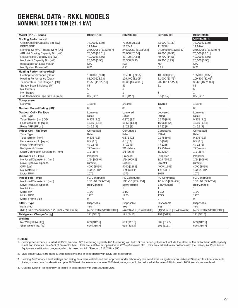
GENERAL DATA - RKKL MODELSNOMINAL SIZES 6 TON [21.1 kW]
NOTES:1. Cooling Performance is rated at 95° F ambient, 80° F entering dry bulb, 67° F entering wet bulb. Gross capacity does not include the effect of fan motor heat. ARI capacityis net and includes the effect of fan motor heat. Units are suitable for operation to ±20% of nominal cfm. Units are certified in accordance with the Unitary Air ConditionerEquipment certification program, which is based on ARI Standard 210/240 or 360.
2. EER and/or SEER are rated at ARI conditions and in accordance with DOE test procedures.
3. Heating Performance limit settings and rating data were established and approved under laboratory test conditions using American National Standard Institute standards.Ratings shown are for elevations up to 2000 feet. For elevations above 2000 feet, ratings should be reduced at the rate of 4% for each 1000 feet above sea level.
4. Outdoor Sound Rating shown is tested in accordance with ARI Standard 270.
Model RKKL - Series B072DL10E B072DL13E B072DM10E B072DM13E
Cooling Performance11
Gross Cooling Capacity Btu [kW] 73,000 [21.39] 73,000 [21.39] 73,000 [21.39] 73,000 [21.39]EER/SEER2 11.2/NA 11.2/NA 11.2/NA 11.2/NANominal CFM/ARI Rated CFM [L/s] 2400/2050 [1133/967] 2400/2050 [1133/967] 2400/2050 [1133/967] 2400/2050 [1133/967]ARI Net Cooling Capacity Btu [kW] 70,000 [20.51] 70,000 [20.51] 70,000 [20.51] 70,000 [20.51]Net Sensible Capacity Btu [kW] 49,700 [14.56] 49,700 [14.56] 49,700 [14.56] 49,700 [14.56]Net Latent Capacity Btu [kW] 20,300 [5.95] 20,300 [5.95] 20,300 [5.95] 20,300 [5.95]Integrated Part Load Value3 N/A N/A N/A N/ANet System Power kW 6.21 6.21 6.21 6.21
Heating Performance (Gas)4
Heating Performance (Gas)4 100,000 [29.3] 135,000 [39.55] 100,000 [29.3] 135,000 [39.55]Heating Performance (Gas)4 81,000 [23.73] 109,400 [32.05] 81,000 [23.73] 109,400 [32.05]Temperature Rise Range °F [°C] 20-50 [11.1/27.8] 30-60 [16.7/33.3] 20-50 [11.1/27.8] 30-60 [16.7/33.3]Steady State Efficiency (%) 81 81 81 81No. Burners 5 6 5 6No. Stages 1 1 1 1Gas Connection Pipe Size in. [mm] 0.5 [12.7] 0.5 [12.7] 0.5 [12.7] 0.5 [12.7]
CompressorNo/Type 1/Scroll 1/Scroll 1/Scroll 1/Scroll
Outdoor Sound Rating (dB)5 83 83 83 83
Outdoor Coil - Fin Type Louvered Louvered Louvered LouveredTube Type Rifled Rifled Rifled RifledTube Size in. [mm] OD 0.375 [9.5] 0.375 [9.5] 0.375 [9.5] 0.375 [9.5]Face Area sq. ft. [sq. m] 16.56 [1.54] 16.56 [1.54] 16.56 [1.54] 16.56 [1.54]Rows / FPI [FPcm] 2 / 22 [9] 2 / 22 [9] 2 / 22 [9] 2 / 22 [9]
Indoor Coil - Fin Type Corrugated Corrugated Corrugated CorrugatedTube Type Rifled Rifled Rifled RifledTube Size in. [mm] 0.375 [9.5] 0.375 [9.5] 0.375 [9.5] 0.375 [9.5]Face Area sq. ft. [sq. m] 6.5 [0.6] 6.5 [0.6] 6.5 [0.6] 6.5 [0.6]Rows / FPI [FPcm] 4 / 12 [5] 4 / 12 [5] 4 / 12 [5] 4 / 12 [5]Refrigerant Control TX Valves TX Valves TX Valves TX ValvesDrain Connection No./Size in. [mm] 1/1 [25.4] 1/1 [25.4] 1/1 [25.4] 1/1 [25.4]
Outdoor Fan - Type Propeller Propeller Propeller PropellerNo. Used/Diameter in. [mm] 1/24 [609.6] 1/24 [609.6] 1/24 [609.6] 1/24 [609.6]Drive Type/No. Speeds Direct/1 Direct/1 Direct/1 Direct/1CFM [L/s] 4000 [1888] 4000 [1888] 4000 [1888] 4000 [1888]No. Motors/HP 1 at 1/3 HP 1 at 1/3 HP 1 at 1/3 HP 1 at 1/3 HPMotor RPM 1075 1075 1075 1075
Indoor Fan - Type FC Centrifugal FC Centrifugal FC Centrifugal FC CentrifugalNo. Used/Diameter in. [mm] 1/11x10 [279x254] 1/11x10 [279x254] 1/11x10 [279x254] 1/11x10 [279x254]Drive Type/No. Speeds Belt/Variable Belt/Variable Belt/Variable Belt/VariableNo. Motors 1 1 1 1Motor HP 1 1/2 1 1/2 1 1/2 1 1/2Motor RPM 1725 1725 1725 1725Motor Frame Size 0 0 0 0
Filter - Type Disposable Disposable Disposable DisposableFurnished Yes Yes Yes Yes(NO.) Size Recommended in. [mm x mm x mm] (4)2x16x16 [51x406x406] (4)2x16x16 [51x406x406] (4)2x16x16 [51x406x406] (4)2x16x16 [51x406x406]
Refrigerant Charge Oz. [g] 191 [5415] 191 [5415] 191 [5415] 191 [5415]
WeightsNet Weight lbs. [kg] 689 [312.5] 689 [312.5] 689 [312.5] 689 [312.5]Ship Weight lbs. [kg] 696 [315.7] 696 [315.7] 696 [315.7] 696 [315.7]
Continued ->
27
28
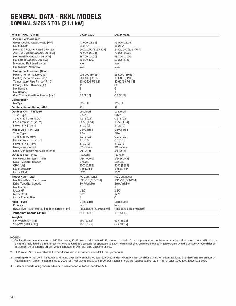
GENERAL DATA - RKKL MODELSNOMINAL SIZES 6 TON [21.1 kW]
NOTES:1. Cooling Performance is rated at 95° F ambient, 80° F entering dry bulb, 67° F entering wet bulb. Gross capacity does not include the effect of fan motor heat. ARI capacityis net and includes the effect of fan motor heat. Units are suitable for operation to ±20% of nominal cfm. Units are certified in accordance with the Unitary Air ConditionerEquipment certification program, which is based on ARI Standard 210/240 or 360.
2. EER and/or SEER are rated at ARI conditions and in accordance with DOE test procedures.
3. Heating Performance limit settings and rating data were established and approved under laboratory test conditions using American National Standard Institute standards.Ratings shown are for elevations up to 2000 feet. For elevations above 2000 feet, ratings should be reduced at the rate of 4% for each 1000 feet above sea level.
4. Outdoor Sound Rating shown is tested in accordance with ARI Standard 270.
Model RKKL - Series B072YL13E B072YM13E
Cooling Performance11
Gross Cooling Capacity Btu [kW] 73,000 [21.39] 73,000 [21.39]EER/SEER2 11.2/NA 11.2/NANominal CFM/ARI Rated CFM [L/s] 2400/2050 [1133/967] 2400/2050 [1133/967]ARI Net Cooling Capacity Btu [kW] 70,000 [20.51] 70,000 [20.51]Net Sensible Capacity Btu [kW] 49,700 [14.56] 49,700 [14.56]Net Latent Capacity Btu [kW] 20,300 [5.95] 20,300 [5.95]Integrated Part Load Value3 N/A N/ANet System Power kW 6.21 6.21
Heating Performance (Gas)4
Heating Performance (Gas)4 135,000 [39.55] 135,000 [39.55]Heating Performance (Gas)4 109,400 [32.05] 109,400 [32.05]Temperature Rise Range °F [°C] 30-60 [16.7/33.3] 30-60 [16.7/33.3]Steady State Efficiency (%) 81 81No. Burners 6 6No. Stages 1 1Gas Connection Pipe Size in. [mm] 0.5 [12.7] 0.5 [12.7]
CompressorNo/Type 1/Scroll 1/Scroll
Outdoor Sound Rating (dB)5 83 83
Outdoor Coil - Fin Type Louvered LouveredTube Type Rifled RifledTube Size in. [mm] OD 0.375 [9.5] 0.375 [9.5]Face Area sq. ft. [sq. m] 16.56 [1.54] 16.56 [1.54]Rows / FPI [FPcm] 2 / 22 [9] 2 / 22 [9]
Indoor Coil - Fin Type Corrugated CorrugatedTube Type Rifled RifledTube Size in. [mm] 0.375 [9.5] 0.375 [9.5]Face Area sq. ft. [sq. m] 6.5 [0.6] 6.5 [0.6]Rows / FPI [FPcm] 4 / 12 [5] 4 / 12 [5]Refrigerant Control TX Valves TX ValvesDrain Connection No./Size in. [mm] 1/1 [25.4] 1/1 [25.4]
Outdoor Fan - Type Propeller PropellerNo. Used/Diameter in. [mm] 1/24 [609.6] 1/24 [609.6]Drive Type/No. Speeds Direct/1 Direct/1CFM [L/s] 4000 [1888] 4000 [1888]No. Motors/HP 1 at 1/3 HP 1 at 1/3 HPMotor RPM 1075 1075
Indoor Fan - Type FC Centrifugal FC CentrifugalNo. Used/Diameter in. [mm] 1/11x10 [279x254] 1/11x10 [279x254]Drive Type/No. Speeds Belt/Variable Belt/VariableNo. Motors 1 1Motor HP 1 1/2 1 1/2Motor RPM 1725 1725Motor Frame Size 0 0
Filter - Type Disposable DisposableFurnished Yes Yes(NO.) Size Recommended in. [mm x mm x mm] (4)2x16x16 [51x406x406] (4)2x16x16 [51x406x406]
Refrigerant Charge Oz. [g] 191 [5415] 191 [5415]
WeightsNet Weight lbs. [kg] 689 [312.5] 689 [312.5]Ship Weight lbs. [kg] 696 [315.7] 696 [315.7]
29
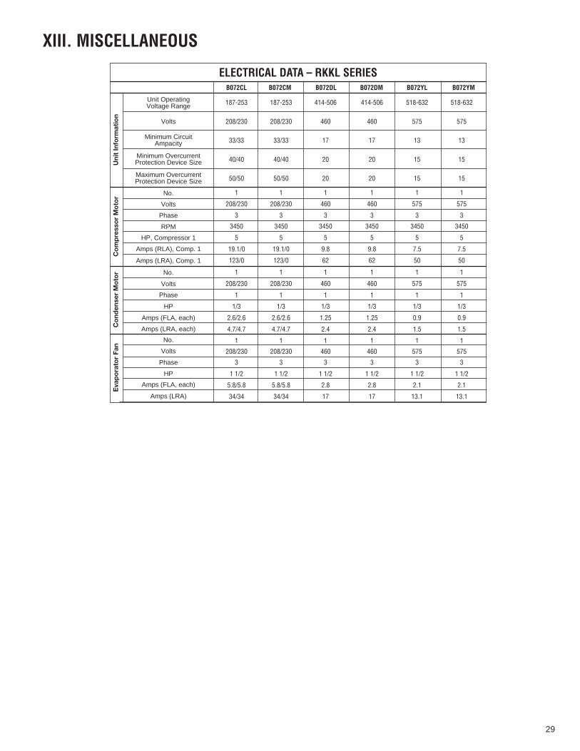
XIII. MISCELLANEOUS
187-253 187-253 414-506 414-506 518-632 518-632
208/230 208/230 460 460 575 575
33/33 33/33 17 17 13 13
40/40 40/40 20 20 15 15
50/50 50/50 20 20 15 15
1 1 1 1 1 1
208/230 208/230 460 460 575 575
3 3 3 3 3 3
3450 3450 3450 3450 3450 3450
5 5 5 5 5 5
19.1/0 19.1/0 9.8 9.8 7.5 7.5
123/0 123/0 62 62 50 50
1 1 1 1 1 1
208/230 208/230 460 460 575 575
1 1 1 1 1 1
1/3 1/3 1/3 1/3 1/3 1/3
2.6/2.6 2.6/2.6 1.25 1.25 0.9 0.9
4.7/4.7 4.7/4.7 2.4 2.4 1.5 1.5
1 1 1 1 1 1
208/230 208/230 460 460 575 575
3 3 3 3 3 3
1 1/2 1 1/2 1 1/2 1 1/2 1 1/2 1 1/2
5.8/5.8 5.8/5.8 2.8 2.8 2.1 2.1
34/34 34/34 17 17 13.1 13.1
Unit Inform
ation
Compressor Motor
Condenser Motor
Evaporator Fan
ELECTRICAL DATA – RKKL SERIESB072CL B072CM B072DL B072DM B072YL B072YM
Unit OperatingVoltage Range
Volts
Minimum CircuitAmpacity
Minimum OvercurrentProtection Device Size
Maximum OvercurrentProtection Device Size
No.
Volts
Phase
RPM
HP, Compressor 1
Amps (RLA), Comp. 1
Amps (LRA), Comp. 1
No.
Volts
Phase
HP
Amps (FLA, each)
Amps (LRA, each)
No.
Volts
Phase
HP
Amps (FLA, each)
Amps (LRA)

CAPACITY: 6 TON [21.10 kW]
VOLTAG
E 208/230-460 & 575—3 Phase
EXTERN
AL STATIC PRESSURE—INCH
ES OF WATER [kPA]
0.1
0.2
0.3
0.4
0.5
0.6
0.7
0.8
0.9
1.0
1.1
1.2
1.3
1.4
1.5
[.02
][.
05]
[.07
][.
10]
[.12
][.
15]
[.17
][.
20]
[.22
][.
25]
[.27
][.
30]
[.32
][.
35]
[.37
]
AIRFLOW PERFORMANCE –6 TON [21.10 kW
] THREE PHASE BELT DRIVE
RPM
WRPM
WRPM
WRPM
WRPM
WRPM
WRPM
WRPM
WRPM
WRPM
WRPM
WRPM
WRPM
WRPM
WRPM
W—
——
——
—785
560
850
605
895
650
930
670
975
720
1010
760
1050
800
1090
850
1120
890
1150
940
1180
980
1210
1015
——
——
785
580
830
615
875
660
915
700
955
740
990
770
1020
815
1070
855
1105
925
1135
960
1165
1015
1195
1075
1220
1115
——
775
600
815
625
860
675
895
720
930
750
975
800
1015
840
1050
900
1085
940
1120
1000
1145
1035
1175
1090
1205
1150
1230
1205
——
810
650
840
680
880
740
920
870
955
820
995
880
1030
920
1065
960
1100
1025
1130
1060
1160
1130
1190
1180
1220
1250
1240
1295
780
660
825
700
865
750
910
810
945
850
980
880
1015
930
1050
1000
1080
1045
1120
1100
1145
1160
1180
1220
1205
1260
1230
1330
1255
1380
815
720
855
760
890
830
930
870
960
910
1000
960
1035
1005
1065
1060
1100
1130
1135
1180
1160
1250
1200
1325
1220
1370
1240
1425
——
845
780
880
835
920
900
950
945
990
990
1025
1050
1055
1110
1085
1155
1120
1215
1150
1335
1185
1355
1220
1430
1235
1470
1255
1525
——
870
855
910
915
945
975
980
1020
1020
1085
1045
1140
1080
1200
1110
1260
1135
1300
1175
1390
1205
1450
1230
1530
1250
1580
1295
1630
——
900
945
940
1005
975
1060
1005
1105
1040
1175
1065
1225
1100
1295
1135
1350
1165
1425
1200
1505
1225
1580
1240
1635
1270
1665
——
——
930
1075
970
1100
1000
1145
1030
1200
1060
1260
1090
1335
1125
1395
1155
1470
1185
1540
1220
1615
1235
1675
1255
1730
——
——
——
960
1150
1000
1195
1025
1240
1055
1305
1085
1350
1115
1440
1145
1510
1180
1560
1210
1620
1235
1740
1250
1775
1295
1825
——
——
——
1800 [850]
1900 [897]
2000 [944]
2100 [991]
2200 [1038]
2300 [1085]
2400 [1133]
2500 [1180]
2600 [1227]
2700 [1274
2800 [1321]
AIR
FLOW
CFM [L/s]
DRIVE PACKAGE
LM
MOTOR H.P. [W]
1-1/2 [1119]
1-1/2 [1119]
BLOWER SHEAVE
6.4�PITCH DIAMETER
6.4�PITCH DIAMETER
MOTOR SHEAVE
2.8�- 3.8�PITCH DIAMETER—ADJ.
3.4�- 4.4�PITCH DIAMETER—ADJ.
TURNS OPEN
01
23
45
60
12
34
56
RPM
1100
1050
1000
945
895
845
7801295
1230
1195
1145
1100
1050
1000
NOTE
: L-Drive left of bold line, M-Drive right of bold line.
NOTES:
1.Factory sheave settings are shown in bold print.
2.Re-adjustment of sheave required to achieve rated airflow at ARI minimum E.S.P.
3.Do not operate above blower RPM shown as motor overloading will occur.
[ ] Designates Metric Conversions
30
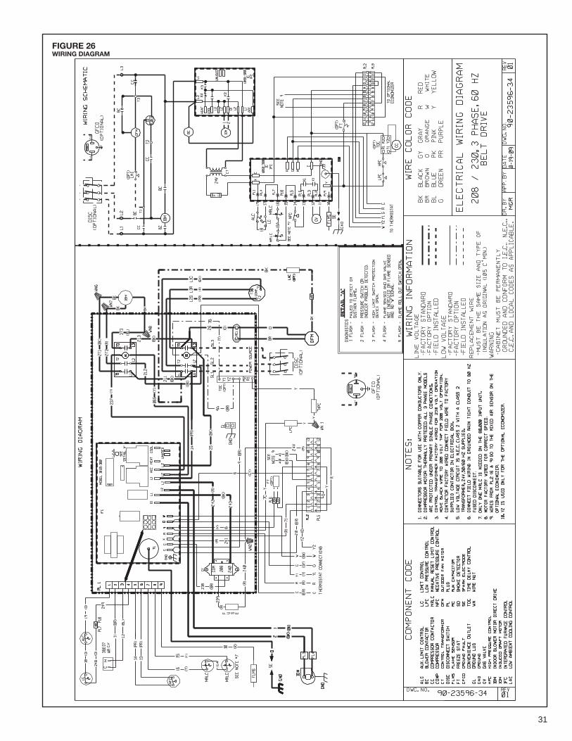
FIGURE 26WIRING DIAGRAM
31
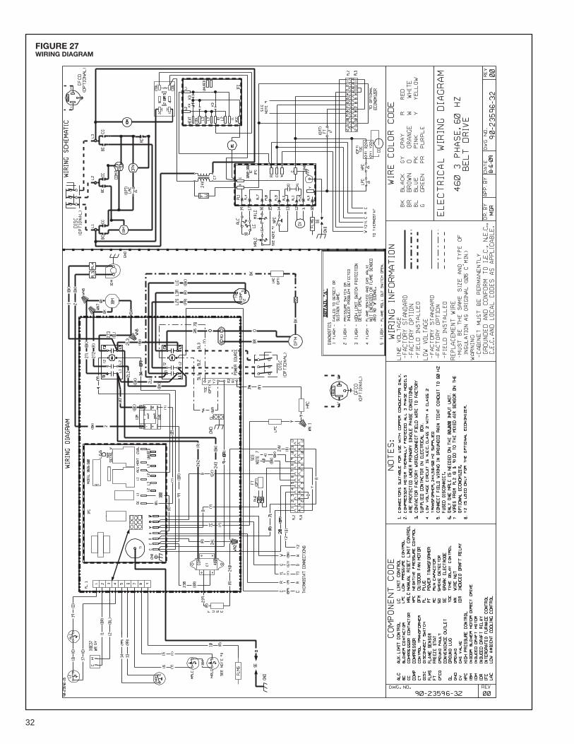
FIGURE 27WIRING DIAGRAM
32

FIGURE 28WIRING DIAGRAM
33

FIGURE 28SYSTEM CHARGE CHARTS
SYSTEM CHARGE CHART - REFRIGERANT 410A6 TON, CIRCUIT 1
92-102259-18-00
115
105
95
85
75
65
55
175
200
225
250
275
300
325
350
375
400
425
450
475
500
525
100 105 110 115 120 125 130 135 140 145 150 155 160 165
Liq
uid
Pre
ssu
re, p
sig
Suction Pressure, psig
Ou
tdo
or
Dry
Bu
lbT
em
pe
ratu
re, F
6 TON COOLING
34
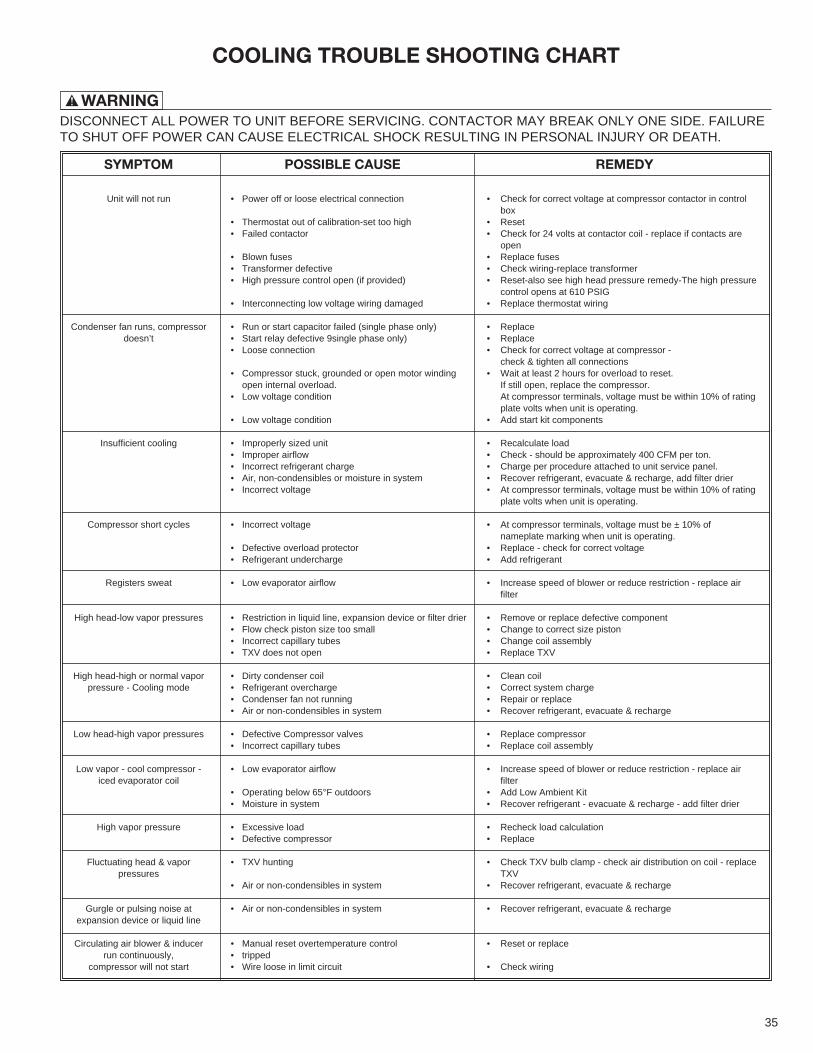
WARNING!
COOLING TROUBLE SHOOTING CHART
DISCONNECT ALL POWER TO UNIT BEFORE SERVICING. CONTACTOR MAY BREAK ONLY ONE SIDE. FAILURETO SHUT OFF POWER CAN CAUSE ELECTRICAL SHOCK RESULTING IN PERSONAL INJURY OR DEATH.
SYMPTOM POSSIBLE CAUSE REMEDY
Unit will not run • Power off or loose electrical connection • Check for correct voltage at compressor contactor in controlbox
• Thermostat out of calibration-set too high • Reset• Failed contactor • Check for 24 volts at contactor coil - replace if contacts are
open• Blown fuses • Replace fuses• Transformer defective • Check wiring-replace transformer• High pressure control open (if provided) • Reset-also see high head pressure remedy-The high pressure
control opens at 610 PSIG• Interconnecting low voltage wiring damaged • Replace thermostat wiring
Condenser fan runs, compressor • Run or start capacitor failed (single phase only) • Replacedoesn’t • Start relay defective 9single phase only) • Replace
• Loose connection • Check for correct voltage at compressor -check & tighten all connections
• Compressor stuck, grounded or open motor winding • Wait at least 2 hours for overload to reset.open internal overload. If still open, replace the compressor.
• Low voltage condition At compressor terminals, voltage must be within 10% of ratingplate volts when unit is operating.
• Low voltage condition • Add start kit components
Insufficient cooling • Improperly sized unit • Recalculate load• Improper airflow • Check - should be approximately 400 CFM per ton.• Incorrect refrigerant charge • Charge per procedure attached to unit service panel.• Air, non-condensibles or moisture in system • Recover refrigerant, evacuate & recharge, add filter drier• Incorrect voltage • At compressor terminals, voltage must be within 10% of rating
plate volts when unit is operating.
Compressor short cycles • Incorrect voltage • At compressor terminals, voltage must be ± 10% ofnameplate marking when unit is operating.
• Defective overload protector • Replace - check for correct voltage• Refrigerant undercharge • Add refrigerant
Registers sweat • Low evaporator airflow • Increase speed of blower or reduce restriction - replace airfilter
High head-low vapor pressures • Restriction in liquid line, expansion device or filter drier • Remove or replace defective component• Flow check piston size too small • Change to correct size piston• Incorrect capillary tubes • Change coil assembly• TXV does not open • Replace TXV
High head-high or normal vapor • Dirty condenser coil • Clean coilpressure - Cooling mode • Refrigerant overcharge • Correct system charge
• Condenser fan not running • Repair or replace• Air or non-condensibles in system • Recover refrigerant, evacuate & recharge
Low head-high vapor pressures • Defective Compressor valves • Replace compressor• Incorrect capillary tubes • Replace coil assembly
Low vapor - cool compressor - • Low evaporator airflow • Increase speed of blower or reduce restriction - replace airiced evaporator coil filter
• Operating below 65°F outdoors • Add Low Ambient Kit• Moisture in system • Recover refrigerant - evacuate & recharge - add filter drier
High vapor pressure • Excessive load • Recheck load calculation• Defective compressor • Replace
Fluctuating head & vapor • TXV hunting • Check TXV bulb clamp - check air distribution on coil - replacepressures TXV
• Air or non-condensibles in system • Recover refrigerant, evacuate & recharge
Gurgle or pulsing noise at • Air or non-condensibles in system • Recover refrigerant, evacuate & rechargeexpansion device or liquid line
Circulating air blower & inducer • Manual reset overtemperature control • Reset or replacerun continuously, • tripped
compressor will not start • Wire loose in limit circuit • Check wiring
35
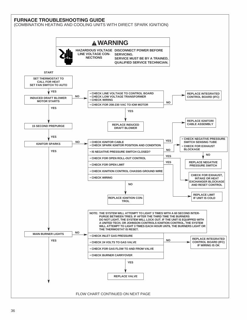
FURNACE TROUBLESHOOTING GUIDE(COMBINATION HEATING AND COOLING UNITS WITH DIRECT SPARK IGNITION)
SET THERMOSTAT TOCALL FOR HEAT
SET FAN SWITCH TO AUTO
START
WARNINGDISCONNECT POWER BEFORESERVICING.SERVICE MUST BE BY A TRAINED,QUALIFIED SERVICE TECHNICIAN.
HAZARDOUS VOLTAGELINE VOLTAGE CON-
NECTIONS
FLOW CHART CONTINUED ON NEXT PAGE
NO
YESYES
YES
YES
NO
NO
NO
!
INDUCED DRAFT BLOWERMOTOR STARTS
15 SECOND PREPURGE
REPLACE INTEGRATEDCONTROL BOARD (IFC)
REPLACE INDUCEDDRAFT BLOWER
NO
REPLACE NEGATIVEPRESSURE SWITCH
REPLACE INTEGRATEDCONTROL BOARD (IFC)
IF WIRING IS OK
CHECK FOR EXHAUST,INTAKE OR HEAT
EXCHANGER BLOCKAGEAND RESET CONTROLNO
REPLACE IGNITION CON-TROL
YES
REPLACE VALVE
• CHECK LINE VOLTAGE TO CONTROL BOARD• CHECK LOW VOLTAGE TRANSFORMER• CHECK WIRING
• CHECK FOR 208-230 VAC TO IOM MOTOR
• CHECK IGNITOR CABLE• CHECK SPARK IGNITOR POSITION AND CONDITION
• IS NEGATIVE PRESSURE SWITCH CLOSED?
• CHECK FOR OPEN ROLL-OUT CONTROL
• CHECK FOR OPEN LIMIT
• CHECK IGNITION CONTROL CHASSIS GROUND WIRE
• CHECK WIRING
• CHECK INLET GAS PRESSURE
• CHECK 24 VOLTS TO GAS VALVE
• CHECK FOR GAS FLOW TO AND FROM VALVE
• CHECK BURNER CARRYOVER
NOTE: THE SYSTEM WILL ATTEMPT TO LIGHT 3 TIMES WITH A 60 SECOND INTER-PURGE BETWEEN TRIES. IF AFTER THE THIRD TIME THE BURNERSDO NOT LIGHT, THE SYSTEM WILL LOCK OUT. IF THE UNIT IS EQUIPPED WITHA UNITED TECH. OR JOHNSON CONTROLS IGNITION CONTROL, THE SYSTEMWILL ATTEMPT TO LIGHT 3 TIMES EACH HOUR UNTIL THE BURNERS LIGHT ORTHE THERMOSTAT IS RESET.
YES
YES
IGNITOR SPARKS
MAIN BURNER LIGHTS
NO
• CHECK NEGATIVE PRESSURESWITCH SENSING TUBE• CHECK FOR EXHAUSTBLOCKAGE
YES
YES
YES
REPLACE IGNITOR/CABLE ASSEMBLY
REPLACE LIMITIF UNIT IS COLD
NO
36
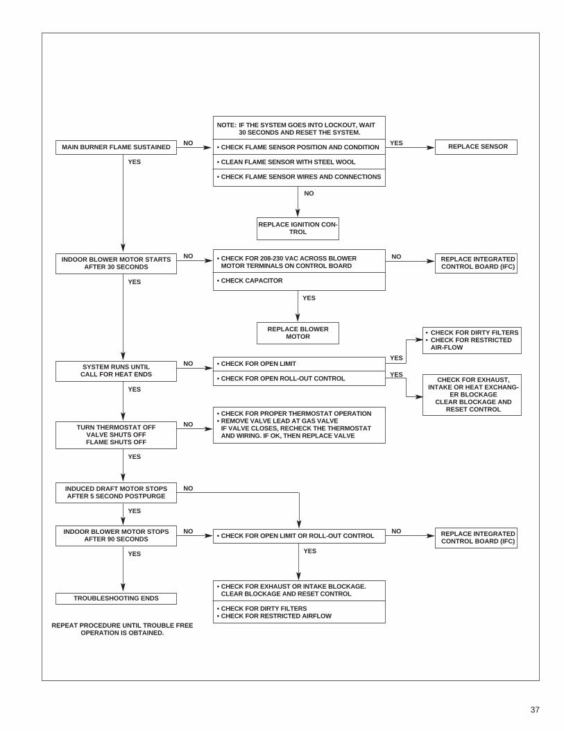
NOTE: IF THE SYSTEM GOES INTO LOCKOUT, WAIT30 SECONDS AND RESET THE SYSTEM.
• CHECK FLAME SENSOR POSITION AND CONDITION
• CLEAN FLAME SENSOR WITH STEEL WOOL
• CHECK FLAME SENSOR WIRES AND CONNECTIONS
• CHECK FOR 208-230 VAC ACROSS BLOWERMOTOR TERMINALS ON CONTROL BOARD
• CHECK CAPACITOR
YES
YES
NOMAIN BURNER FLAME SUSTAINED
YES
NOINDOOR BLOWER MOTOR STARTSAFTER 30 SECONDS
REPLACE SENSOR
NO REPLACE INTEGRATEDCONTROL BOARD (IFC)
NO REPLACE INTEGRATEDCONTROL BOARD (IFC)
NO
REPLACE IGNITION CON-TROL
YES
YES
REPLACE BLOWERMOTOR
• CHECK FOR OPEN LIMIT
• CHECK FOR OPEN ROLL-OUT CONTROL
• CHECK FOR PROPER THERMOSTAT OPERATION• REMOVE VALVE LEAD AT GAS VALVEIF VALVE CLOSES, RECHECK THE THERMOSTATAND WIRING. IF OK, THEN REPLACE VALVE
• CHECK FOR OPEN LIMIT OR ROLL-OUT CONTROL
YES
NOSYSTEM RUNS UNTILCALL FOR HEAT ENDS
• CHECK FOR EXHAUST OR INTAKE BLOCKAGE.CLEAR BLOCKAGE AND RESET CONTROL
• CHECK FOR DIRTY FILTERS• CHECK FOR RESTRICTED AIRFLOW
TROUBLESHOOTING ENDS
REPEAT PROCEDURE UNTIL TROUBLE FREEOPERATION IS OBTAINED.
YES
NOTURN THERMOSTAT OFFVALVE SHUTS OFFFLAME SHUTS OFF
YES
NOINDUCED DRAFT MOTOR STOPSAFTER 5 SECOND POSTPURGE
YES
YES
• CHECK FOR DIRTY FILTERS• CHECK FOR RESTRICTEDAIR-FLOW
CHECK FOR EXHAUST,INTAKE OR HEAT EXCHANG-
ER BLOCKAGECLEAR BLOCKAGE AND
RESET CONTROL
YES
NOINDOOR BLOWER MOTOR STOPSAFTER 90 SECONDS
37

38

39

40 CM 1009