900 rmk r02 - polaris inc
TRANSCRIPT
WARNING
WARNING
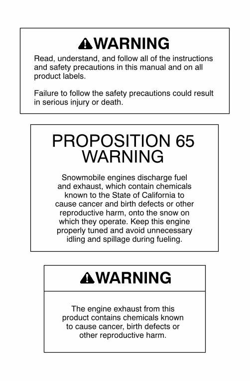
Read, understand, and follow all of the instructionsand safety precautions in this manual and on allproduct labels.
Failure to follow the safety precautions could resultin serious injury or death.
The engine exhaust from thisproduct contains chemicals knownto cause cancer, birth defects or
other reproductive harm.
PROPOSITION 65WARNING
Snowmobile engines discharge fueland exhaust, which contain chemicalsknown to the State of California to
cause cancer and birth defects or otherreproductive harm, onto the snow onwhich they operate. Keep this engineproperly tuned and avoid unnecessary
idling and spillage during fueling.


2
Copyright 2004 Polaris Sales Inc. All information contained within this publication isbased on the latest product information at the time of publication. Due to constantimprovements in the design and quality of production components, some minordiscrepancies may result between the actual vehicle and the information presented in thispublication. Depictions and/or procedures in this publication are intended for referenceuse only. No liability can be accepted for omissions or inaccuracies. Any reprinting orreuse of the depictions and/or procedures contained within, whether whole or in part, isexpressly prohibited.
Printed in U.S.A.
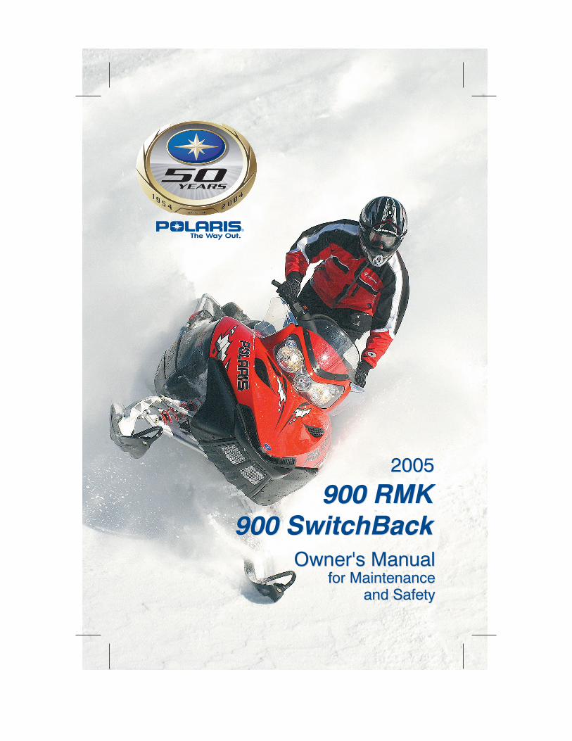
2005 900 RMK/SwitchBack Owner’s Manual P/N 9919077
3
WELCOMEThank you for purchasing a Polaris vehicle, and welcome to ourworld-wide family of Polaris owners. We proudly produce an excitingline of utility and recreational products.
S Snowmobiles
S All-terrain vehicles (ATVs)
S Personal Watercraft
S Sport Boats
S RANGER utility vehicles
S Victory motorcycles
We believe Polaris sets a standard of excellence for all utility andrecreational vehicles manufactured in the world today. Many years ofexperience have gone into the engineering, design, and development ofyour Polaris vehicle, making it the finest machine we’ve everproduced.
For safe and enjoyable operation of your vehicle, be sure to follow theinstructions and recommendations in this owner’s manual. Yourmanual contains instructions for minor maintenance, but informationabout major repairs is outlined in the Polaris Service Manual andshould be performed only by a Factory Certified Master Service Dealer(MSD) Technician.
Your Polaris dealer knows your vehicle best and is interested in yourtotal satisfaction. Be sure to return to your dealership for all of yourservice needs during, and after, the warranty period.
We also take great pride in our Parts, Apparel and Accessories (PAA)products, available through our online store at www.purepolaris.com.Have your accessories and clothing delivered right to your door!
POLARIS and POLARIS THE WAY OUT are registered trademarks ofPolaris Industries Inc.

4
5
TABLE OF CONTENTSIntroduction 7. . . . . . . . . . . . . . . . . . . . . . . . . . . . . . .This section contains helpful information for owners and drivers andillustrates the location of important identification numbers that shouldbe recorded in the owner’s manual.
Safety 10. . . . . . . . . . . . . . . . . . . . . . . . . . . . . . . . . . . .This section describes safe vehicle operation and identifies warningdecals and their locations.
Features 27. . . . . . . . . . . . . . . . . . . . . . . . . . . . . . . . . .This section identifies the locations of your snowmobile’s controls andfeatures.
The Perfect Fit 41. . . . . . . . . . . . . . . . . . . . . . . . . . . .This section explains how to tailor the suspension and other featuresfor an optimum riding experience.
Pre-Ride Inspections 55. . . . . . . . . . . . . . . . . . . . . .This section explains procedures that must be performed before riding.
Operation 61. . . . . . . . . . . . . . . . . . . . . . . . . . . . . . . . .This section explains proper engine break-in, operation of features andgeneral operating procedures.
Maintenance 74. . . . . . . . . . . . . . . . . . . . . . . . . . . . . .This section defines your role, and your dealer’s role, in yoursnowmobile’s regular maintenance.
Polaris Products 111. . . . . . . . . . . . . . . . . . . . . . . . .Troubleshooting 112. . . . . . . . . . . . . . . . . . . . . . . . .Warranty 117. . . . . . . . . . . . . . . . . . . . . . . . . . . . . . . .Index 123. . . . . . . . . . . . . . . . . . . . . . . . . . . . . . . . . . . .

6
7
INTRODUCTIONImportant Notes for Owners and DriversAfter reading this manual, store it in the snowmobile for convenientreference. It should remain with the snowmobile when sold.
Some of the illustrations and photos used in this manual are generalrepresentations. Your model may differ.
Follow the maintenance program outlined in this manual. Preventivemaintenance ensures that critical components of the snowmobile areinspected by your dealer at specific mileage intervals.
You and your dealer must complete the registration form included withyour snowmobile and forward it to us. This completed form isnecessary to ensure warranty coverage.
Protect and preserve your right to ride by joining your local trail ridingclubs.

8
INTRODUCTIONPreservation of the EnvironmentPolaris is committed to supporting an environmental educationcampaign. We encourage state and provincial governments across thesnowbelt to adopt rigorous safety training programs that encourageprotection of our environment, including wildlife and vegetation.
Snowmobile clubs and other organizations are working together toprotect our environment. Please support their efforts and operate yoursnowmobile with consideration for the protection and preservation ofour environment.
Noise LevelOne of the most publicized issues about snowmobiles is noise. TheSociety of Automotive Engineers (SAE), the standard-setting body forsnowmobile development, recommends that snowmobiles conform toprescribed sound levels.
Polaris snowmobiles are engineered to conform to these SAEstandards. Our muffler systems are designed to reduce noise levels andmust not be altered or removed. The sound of your snowmobile maynot be welcome to non-snowmobilers, so you have a responsibility tooperate your snowmobile with concern for others. We do our part bymanufacturing quieter machines; we ask your help to further reduce theimpact of noise by operating your snowmobile safely and responsibly.
Air PollutionPolaris engineers continuously investigate ways to reduce emissionlevels of two-stroke engines. We expect our efforts to lead to thereduction of potential air pollution.
In addition to our technological research, we encourage governmentagencies, manufacturers, distributors, dealers, ecologists, and otherinterested parties to work together to develop data on environmentaltopics.
9
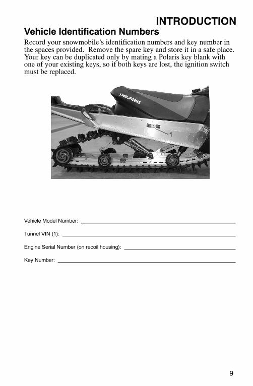
INTRODUCTIONVehicle Identification NumbersRecord your snowmobile’s identification numbers and key number inthe spaces provided. Remove the spare key and store it in a safe place.Your key can be duplicated only by mating a Polaris key blank withone of your existing keys, so if both keys are lost, the ignition switchmust be replaced.
Vehicle Model Number:
Tunnel VIN (1):
Engine Serial Number (on recoil housing):
Key Number:
1
10
SAFETYOperator SafetyThe following signal words and symbols appear throughout thismanual and on your vehicle. Your safety is involved when these wordsand symbols are used. Become familiar with their meanings beforereading the manual.
The safety alert symbol, on your vehicle or in this manual, alertsyou to the potential for injury.
WARNINGThe safety alert warning indicates a potential hazard that mayresult in serious injury or death.
CAUTIONThe safety alert caution indicates a potential hazard that mayresult in minor injury or damage to the vehicle.
CAUTIONA caution indicates a situation that may result in damage to thevehicle.
NOTE:
A note will alert you to important information or instructions.
11
SAFETYOperator SafetyFollow the recommended maintenance program outlined beginning onpage 74 of this manual to ensure that all critical components on thesnowmobile are thoroughly inspected by your dealer at specificmileage intervals.
WARNINGDriving a snowmobile requires your full attention. DO NOT drinkalcohol or use drugs or medications before or while driving orriding as a passenger. They will reduce your alertness and slowyour reaction time.Snowmobiles are capable of traveling at high speeds. Use extracaution to ensure operator safety. Make sure your snowmobile isin excellent operating condition at all times. Always check majorand vital safety components before every ride.All Polaris snowmobiles are designed and tested to provide safeoperation when used as directed. Failure of critical machinecomponents may result from operation with any modifications,especially those that increase speed or power. DO NOTMODIFY YOUR MACHINE. The snowmobile may becomeaerodynamically unstable at speeds higher than those for which itis designed. Loss of control may occur at higher speeds.Modifications may also create a safety hazard and lead to bodilyinjury.The warranty on your entire machine is terminated if anyequipment has been added, or any modifications have beenmade, to increase the speed or power of the snowmobile.
12
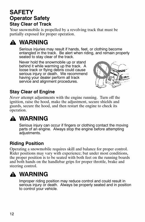
SAFETYOperator SafetyStay Clear of TrackYour snowmobile is propelled by a revolving track that must bepartially exposed for proper operation.
WARNINGSerious injuries may result if hands, feet, or clothing becomeentangled in the track. Be alert when riding, and remain properlyseated to stay clear of the track.Never hold the snowmobile up or standbehind it while warming up the track. Aloose track or flying debris could causeserious injury or death. We recommendhaving your dealer perform all trackservice and alignment procedures.
Stay Clear of EngineNever attempt adjustments with the engine running. Turn off theignition, raise the hood, make the adjustment, secure shields andguards, secure the hood, and then restart the engine to check itsoperation.
WARNINGSerious injury can occur if fingers or clothing contact the movingparts of an engine. Always stop the engine before attemptingadjustments.
Riding PositionOperating a snowmobile requires skill and balance for proper control.Rider positions may vary with experience; but under most conditions,the proper position is to be seated with both feet on the running boardsand both hands on the handlebar grips for proper throttle, brake andsteering control.
WARNINGImproper riding position may reduce control and could result inserious injury or death. Always be properly seated and in positionto control your vehicle.
13
SAFETYOperator SafetySurvival PreparationFor your safety, always ride in a group of other snowmobilers. Alwaystell someone where you’re going and how long you expect to be gone.If it isn’t possible to ride with others, and you must travel into remoteareas, always carry survival equipment that’s appropriate to theconditions you may encounter. Such equipment may include, but isnot limited to: extra clothing, a sleeping bag, a flashlight, food andwater, a signaling mirror, a means of building a fire, and a two-wayradio or cellular telephone.
For added protection, carry the following items on your snowmobile atall times:
SSpare Drive Belt SExtra Set of Spark PlugsSTow Rope SExtra OilSFuel Deicer SWinter Survival KitSTrail Map SOwner’s ManualSFirst Aid Kit
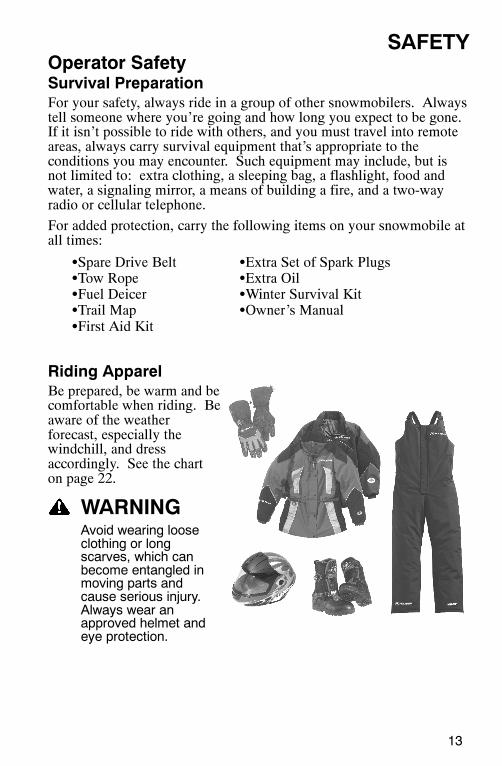
Riding ApparelBe prepared, be warm and becomfortable when riding. Beaware of the weatherforecast, especially thewindchill, and dressaccordingly. See the charton page 22.
WARNINGAvoid wearing looseclothing or longscarves, which canbecome entangled inmoving parts andcause serious injury.Always wear anapproved helmet andeye protection.
14
SAFETYOperator SafetyDisabled OperatorsSafe operation of this rider-active vehicle requires good judgement andphysical skills. Operators with cognitive or physical disabilities havean increased risk of loss of control, which could result in serious injuryor death.
Rider CapacityYour Polaris snowmobile is designed for a single rider only. Do notcarry a passenger.
Excessive Speed
WARNINGHigh speed driving, especially at night, could result in seriousinjury or death. Always reduce speed when driving at night or ininclement weather.
Always observe all state and local laws governing snowmobileoperation and speed limits. Always be alert and pay attention to thetrail ahead. Multiplying speed (MPH) by 1.5 will equal theapproximate number of feet per second your machine travels. If yourspeed is 40 MPH, your machine is traveling about 60 feet per second.If you look back for only two seconds, your machine will travel about120 feet. If your speed is 60 MPH, your machine will travel about 180feet.
Traveling at night requires extra caution. Check headlight and taillightto ensure proper operation, and don’t over-drive your headlight beam.Always be able to bring your machine to a stop in the distanceilluminated by the headlight.
15
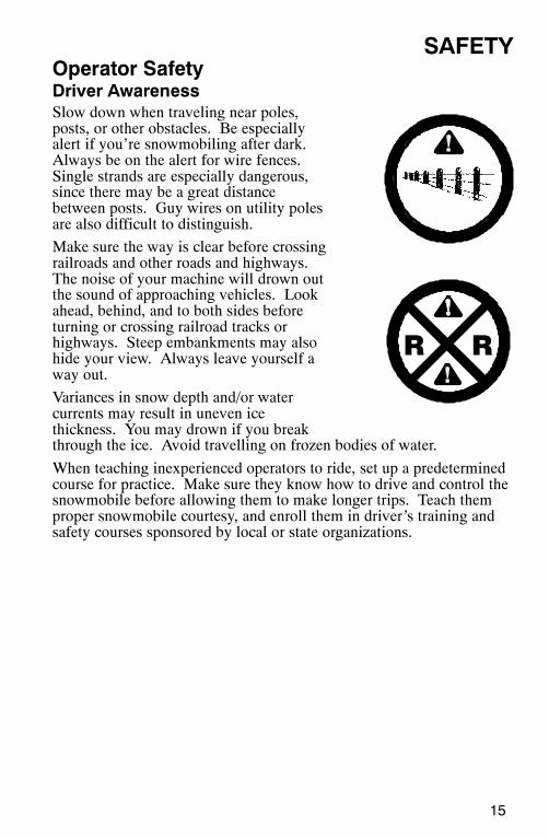
SAFETYOperator SafetyDriver AwarenessSlow down when traveling near poles,posts, or other obstacles. Be especiallyalert if you’re snowmobiling after dark.Always be on the alert for wire fences.Single strands are especially dangerous,since there may be a great distancebetween posts. Guy wires on utility polesare also difficult to distinguish.
Make sure the way is clear before crossingrailroads and other roads and highways.The noise of your machine will drown outthe sound of approaching vehicles. Lookahead, behind, and to both sides beforeturning or crossing railroad tracks orhighways. Steep embankments may alsohide your view. Always leave yourself away out.
Variances in snow depth and/or watercurrents may result in uneven icethickness. You may drown if you breakthrough the ice. Avoid travelling on frozen bodies of water.
When teaching inexperienced operators to ride, set up a predeterminedcourse for practice. Make sure they know how to drive and control thesnowmobile before allowing them to make longer trips. Teach themproper snowmobile courtesy, and enroll them in driver’s training andsafety courses sponsored by local or state organizations.
16
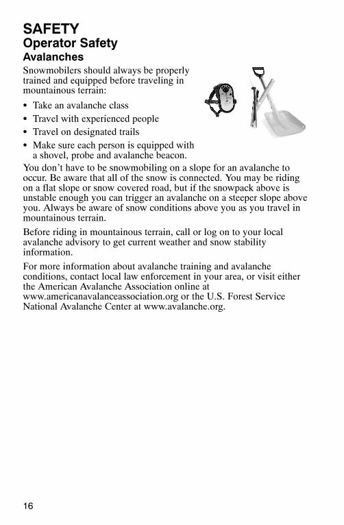
SAFETYOperator SafetyAvalanchesSnowmobilers should always be properlytrained and equipped before traveling inmountainous terrain:
S Take an avalanche classS Travel with experienced peopleS Travel on designated trailsS Make sure each person is equipped witha shovel, probe and avalanche beacon.
You don’t have to be snowmobiling on a slope for an avalanche tooccur. Be aware that all of the snow is connected. You may be ridingon a flat slope or snow covered road, but if the snowpack above isunstable enough you can trigger an avalanche on a steeper slope aboveyou. Always be aware of snow conditions above you as you travel inmountainous terrain.
Before riding in mountainous terrain, call or log on to your localavalanche advisory to get current weather and snow stabilityinformation.
For more information about avalanche training and avalancheconditions, contact local law enforcement in your area, or visit eitherthe American Avalanche Association online atwww.americanavalanceassociation.org or the U.S. Forest ServiceNational Avalanche Center at www.avalanche.org.
17
SAFETYOperator SafetyIce and Snow Build-up
WARNINGIce and snow build-up may interfere with the steering of yourmachine, resulting in serious injury or death. Keep theunderhood area free of snow and ice.
Before driving, manually turn the skis to the left and right to be sureice and snow are not interfering with full left and right steering. Ifdifficulty is encountered, remove ice and snow build-up that may beobstructing the steering linkage.
Driving on Slippery Surfaces
WARNINGNever attempt an abrupt change of direction when operating onslippery surfaces. Proceed slowly and use extra caution.
Driving on ice or hard-packed snow reduces steering and brakingcontrol, which may result in loss of control and serious injury ordeath. Slow down and use extra caution when operating onslippery surfaces.
Driving DownhillWhen riding downhill, shift your weight to the rear of the machine andreduce your speed to a minimum. Apply just enough throttle to keepthe clutch engaged, allowing the engine’s compression to help slow themachine and keep it from rolling freely downhill.
WARNINGWhen driving on long downhill stretches, pump the brakes.Riding the brakes may cause the brake system to overheat,which may result in brake failure.Excessive or repetitive use of the brakes for high speed stops willalso cause an overheated brake system. This condition may leadto a sudden loss of brakes and/or fire and may result in seriousinjury or death.
18
SAFETYOperator SafetyDriving in Hilly Terrain
WARNINGClimbing a hill or crossing the face of a slope may result in loss ofbalance and machine roll-over, causing serious injury or death.Use caution and good judgement when driving in hilly terrain.
Use extra caution when operating in hilly terrain. If climbing a hill isunavoidable, keep your weight low and forward. If you must cross theface of a slope, keep your weight on the uphill side of the machine tomaintain proper balance and avoid possible roll-over.
Slow down when reaching the crest of a hill. Be prepared to react toobstacles, sharp drops or other people or vehicles that may be on theother side of the hill.
If you’re unable to continue up a hill, turn the machine downhill beforeit loses momentum. If this isn’t possible, spin the track just enough todig in to prevent it from rolling back down the hill. Stop the engineand set the parking brake (if equipped). Keeping away from thedownhill side of the machine, pull the rear of the snowmobile aroundand point the front end and skis downhill. Remount the machine,restart the engine, release the parking brake, and descend the hillcarefully.
19
SAFETYOperator SafetyDrive BeltDo not operate the engine with the drive belt removed.Any servicing that requires operation without a belt must be performedby your dealer. Operation of the engine with the belt removed mayresult in injury or damage to the engine.
Intake SilencerDo not operate the engine with the intake silencer or filter removed.Damage to the engine may occur if the intake silencer or filter areremoved.
ClutchesDo not attempt to service the clutches.All clutch service must be performed by your dealer. The clutch is acomplex mechanism that rotates at high speeds. Each clutch isdynamically balanced before installation. Any tampering may disruptthis precision balancing and create an unstable condition.
Cold Weather Drive-AwayWhenever your snowmobile has been parked for a length of time,especially overnight, always make sure the skis and track are loosenedfrom ice and snow before attempting to drive. Apply the throttle withenough authority to put the machine into motion, but always operatewithin safety limits.
ManeuverabilityWhile much control and maneuverability is achieved through thesteering system and skis, maximum control is achieved by the shiftingof your body weight. Maneuverability will change for lighter operatorsor machines designed to carry a load.
20
SAFETYOperator SafetyInadequate Snow Conditions
WARNINGDo not drive for prolonged periods on blacktop, gravel, or ice.Doing so could cause irreversible track damage and lead toserious injury.
Since snow provides the only lubrication for the power slidesuspension and, on liquid cooled models, cooling for the engine,adequate snow cover is a requirement for operation of your machine.Driving in too little snow will result in excessive wear and damage tothe slide rail, track and/or engine.
If the machine becomes stuck in snow, clear the running board area ofsnow, then step down the snow in front of the machine so that whenthe throttle is opened, the snowmobile will be able to climb up andover the snow.
CAUTIONWhen operating on icy surfaces or hard-packed snow, avoidoverheating the slide rail and track. Lack of lubrication andcooling will cause overheating of the slide rail and track, resultingin premature wear and failure. If frequently operating in lowcooling conditions, see your dealer for an optional wheel kit thatwill reduce the wear from overheating.
21
SAFETYOperator SafetyDriving ResponsiblyEvery snowmobile handles differently, and even the most docileconditions may become dangerous if operators drive improperly. Ifyou’re new to snowmobiling, acquaint yourself with the machine andwith what it will and won’t do under various conditions. Evenseasoned drivers should spend some time getting the feel for a machinebefore attempting ambitious maneuvers.
S A snowmobile depends on the rider’s body position for proper bal-ance in executing turns, traversing hills, etc. Always start on asmooth, level area to begin building your operating experience.
S Before allowing someone else use your snowmobile, know the ex-tent of their operating skills. Check to see if they’ve taken a snow-mobile safety course and have an operator’s certificate. For theirprotection, as well as yours, make sure they take a snowmobile safe-ty course. Everyone can benefit from the course.
S Don’t “jump” your snowmobile. Jumping may injure your back be-cause of spinal compression. The seat and suspension of your snow-mobile have been designed to provide protection under normalriding conditions. Your snowmobile is not intended for this kind ofuse.
S Be courteous to oncoming traffic by dimming your headlights andreducing your speed.
S When traveling in a group of snowmobiles, don’t tailgate (follow tooclosely). Allow ample stopping distances, and keep track of thosefollowing you. Drive defensively to avoid accidents.
S Remove the key from the ignition when you leave the snowmobileunattended.
22
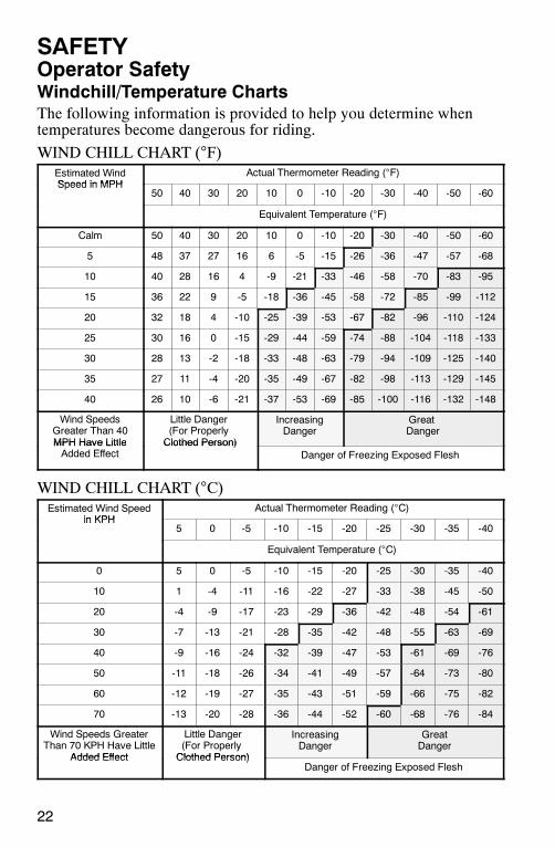
SAFETYOperator SafetyWindchill/Temperature ChartsThe following information is provided to help you determine whentemperatures become dangerous for riding.
WIND CHILL CHART (°F)Estimated WindSpeed in MPH
Actual Thermometer Reading (°F)Speed in MPH
50 40 30 20 10 0 -10 -20 -30 -40 -50 -60
Equivalent Temperature (°F)
Calm 50 40 30 20 10 0 -10 -20 -30 -40 -50 -60
5 48 37 27 16 6 -5 -15 -26 -36 -47 -57 -68
10 40 28 16 4 -9 -21 -33 -46 -58 -70 -83 -95
15 36 22 9 -5 -18 -36 -45 -58 -72 -85 -99 -112
20 32 18 4 -10 -25 -39 -53 -67 -82 -96 -110 -124
25 30 16 0 -15 -29 -44 -59 -74 -88 -104 -118 -133
30 28 13 -2 -18 -33 -48 -63 -79 -94 -109 -125 -140
35 27 11 -4 -20 -35 -49 -67 -82 -98 -113 -129 -145
40 26 10 -6 -21 -37 -53 -69 -85 -100 -116 -132 -148
Wind SpeedsGreater Than 40MPH Have Little
Little Danger(For ProperlyClothed Person)
IncreasingDanger
GreatDanger
MPH Have LittleAdded Effect
Clothed Person)Danger of Freezing Exposed Flesh
WIND CHILL CHART (°C)Estimated Wind Speed
in KPHActual Thermometer Reading (°C)
in KPH5 0 -5 -10 -15 -20 -25 -30 -35 -40
Equivalent Temperature (°C)
0 5 0 -5 -10 -15 -20 -25 -30 -35 -40
10 1 -4 -11 -16 -22 -27 -33 -38 -45 -50
20 -4 -9 -17 -23 -29 -36 -42 -48 -54 -61
30 -7 -13 -21 -28 -35 -42 -48 -55 -63 -69
40 -9 -16 -24 -32 -39 -47 -53 -61 -69 -76
50 -11 -18 -26 -34 -41 -49 -57 -64 -73 -80
60 -12 -19 -27 -35 -43 -51 -59 -66 -75 -82
70 -13 -20 -28 -36 -44 -52 -60 -68 -76 -84
Wind Speeds GreaterThan 70 KPH Have Little
Added Effect
Little Danger(For ProperlyClothed Person)
IncreasingDanger
GreatDanger
Added Effect Clothed Person)Danger of Freezing Exposed Flesh
23
SAFETYSafety Decals and LocationsWarning decals have been placed on the snowmobile for yourprotection. Read and follow the instructions of the decals and otherwarnings on the snowmobile carefully. If any of the decals depicted inthis manual differ from the decals on your snowmobile, always readand follow the instructions of the decals on the snowmobile.
If any decal becomes illegible or comes off, contact your Polaris dealerto purchase a replacement. Replacement safety decals are provided byPolaris at no charge. The part number is printed on the decal.
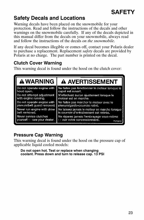
Clutch Cover WarningThis warning decal is found under the hood on the clutch cover:
Pressure Cap WarningThis warning decal is found under the hood on the pressure cap ofapplicable liquid cooled models:
Do not open hot. Test or replace when changingcoolant. Press down and turn to release cap. 13 PSI
24
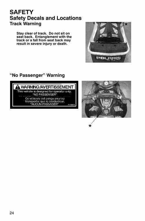
SAFETYSafety Decals and LocationsTrack Warning
Stay clear of track. Do not sit onseat back. Entanglement with thetrack or a fall from seat back mayresult in severe injury or death.
“No Passenger” Warning
25
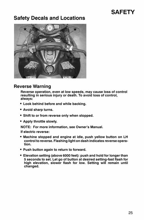
SAFETYSafety Decals and Locations
Reverse WarningReverse operation, even at low speeds, may cause loss of controlresulting in serious injury or death. To avoid loss of control,always:
S Look behind before and while backing.
S Avoid sharp turns.
S Shift to or from reverse only when stopped.
S Apply throttle slowly.
NOTE: For more information, see Owner’s Manual.If electric reverse:
S Machine stopped and engine at idle, push yellow button on LHcontrol to reverse. Flashing lightondash indicates reverse opera-tion.
S Push button again to return to forward.
S Elevation setting (above 6000 feet): push and hold for longer than5 seconds to set. Let go of button at desired setting-fast flash forhigh elevation, slower flash for low. Setting will remain untilchanged.
26
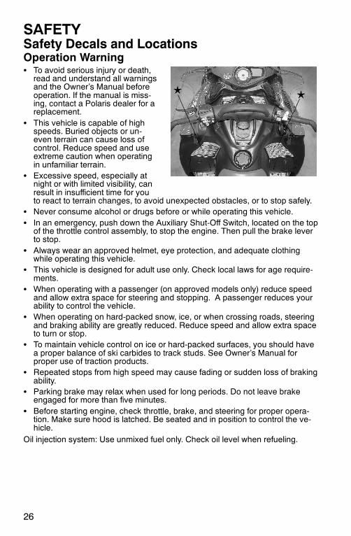
SAFETYSafety Decals and LocationsOperation WarningS To avoid serious injury or death,
read and understand all warningsand the Owner’s Manual beforeoperation. If the manual is miss-ing, contact a Polaris dealer for areplacement.
S This vehicle is capable of highspeeds. Buried objects or un-even terrain can cause loss ofcontrol. Reduce speed and useextreme caution when operatingin unfamiliar terrain.
S Excessive speed, especially atnight or with limited visibility, canresult in insufficient time for youto react to terrain changes, to avoid unexpected obstacles, or to stop safely.
S Never consume alcohol or drugs before or while operating this vehicle.S In an emergency, push down the Auxiliary Shut-Off Switch, located on the top
of the throttle control assembly, to stop the engine. Then pull the brake leverto stop.
S Always wear an approved helmet, eye protection, and adequate clothingwhile operating this vehicle.
S This vehicle is designed for adult use only. Check local laws for age require-ments.
S When operating with a passenger (on approved models only) reduce speedand allow extra space for steering and stopping. A passenger reduces yourability to control the vehicle.
S When operating on hard-packed snow, ice, or when crossing roads, steeringand braking ability are greatly reduced. Reduce speed and allow extra spaceto turn or stop.
S To maintain vehicle control on ice or hard-packed surfaces, you should havea proper balance of ski carbides to track studs. See Owner’s Manual forproper use of traction products.
S Repeated stops from high speed may cause fading or sudden loss of brakingability.
S Parking brake may relax when used for long periods. Do not leave brakeengaged for more than five minutes.
S Before starting engine, check throttle, brake, and steering for proper opera-tion. Make sure hood is latched. Be seated and in position to control the ve-hicle.
Oil injection system: Use unmixed fuel only. Check oil level when refueling.
10
43
2
1
14
6
8
1211
1315
9
7
5
7
27
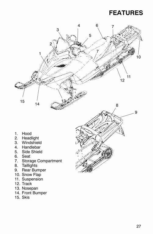
FEATURES
1. Hood2. Headlight3. Windshield4. Handlebar5. Side Shield6. Seat7. Storage Compartment8. Taillights9. Rear Bumper10. Snow Flap11. Suspension12. Track13. Nosepan14. Front Bumper15. Skis
28
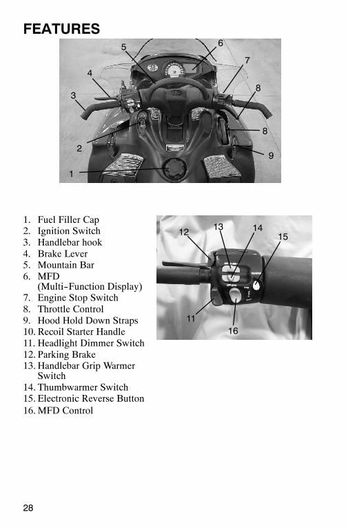
FEATURES
1. Fuel Filler Cap2. Ignition Switch3. Handlebar hook4. Brake Lever5. Mountain Bar6. MFD
(Multi--Function Display)7. Engine Stop Switch8. Throttle Control9. Hood Hold Down Straps10. Recoil Starter Handle11. Headlight Dimmer Switch12. Parking Brake13. Handlebar Grip Warmer
Switch14. Thumbwarmer Switch15. Electronic Reverse Button16.MFD Control
1
7
8
2
4
6
9
8
3
5
11
12 13 1415
16
29
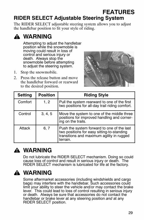
FEATURESRIDER SELECT Adjustable Steering SystemThe RIDER SELECT adjustable steering system allows you to adjustthe handlebar position to fit your style of riding.
WARNINGAttempting to adjust the handlebarposition while the snowmobile ismoving could result in loss ofcontrol and serious injury ordeath. Always stop thesnowmobile before attemptingto adjust the steering system.
1. Stop the snowmobile.2. Press the release button and move
the handlebar forward or rearwardto the desired position.
Setting Position Riding Style
Comfort 1, 2 Pull the system rearward to one of the firsttwo positions for all-day trail riding comfort.
Control 3, 4, 5 Move the system to one of the middle threepositions for improved handling and corner-ing on the trails.
Attack 6, 7 Push the system forward to one of the lasttwo positions for easy sitting-to-standingtransitions and maximum agility in ruggedterrain.
WARNINGDo not lubricate the RIDER SELECT mechanism. Doing so couldcause loss of control and result in serious injury or death. TheRIDER SELECT mechanism is lubricated for life at the factory.
WARNINGSome aftermarket accessories (including windshields and cargobags) may interfere with the handlebar. Such accessories couldlimit your ability to steer the vehicle and/or may contact the brakelever. This could lead to loss of control resulting in serious injuryor death. Always be sure that accessories do not contact thehandlebar or brake lever at any steering position and at anyRIDER SELECT position.
1
1
30
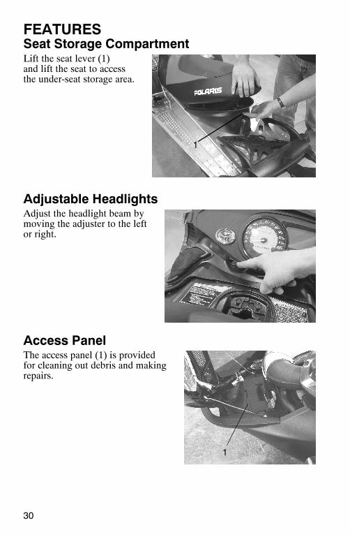
FEATURESSeat Storage CompartmentLift the seat lever (1)and lift the seat to accessthe under-seat storage area.
Adjustable HeadlightsAdjust the headlight beam bymoving the adjuster to the leftor right.
Access PanelThe access panel (1) is providedfor cleaning out debris and makingrepairs.
31
FEATURESDetonation Elimination Technology (D.E.T.)A detonation sensor monitors the engine and responds to detonation byautomatically reducing the engine timing and adding fuel. This resultsin decreased engine RPM and performance.
DET TroubleshootingUse this chart to determine causes and solutions for detonation. Ifnone of these conditions exists and the sensor remains activated, seeyour Polaris dealer for diagnosis.
Possible Cause Solution
Poor quality fuel Replace with higher quality fuel
Improper engine modifications Do not modify the engine
Effect of DETThe DET system prevents damage to the engine from detonation whiledeveloping the maximum power of the engine safely. If the systemsenses detonation beyond a preset limit, it retards ignition timing andadds fuel to reduce the detonation and prevent engine damage.
When the detonation returns to a permissible level, the system willreturn spark and fuel to normal, allowing the engine to run at ratedpower levels.
Sensor Fail-SafeThe DET includes a sensor fail-safe system to prevent the engine fromdamage if the sensor fails, becomes disconnected or is unable to detectdetonation. The rider will experience a loss in power. The sensor mustbe reconnected or repaired to regain full power.
NOTE: The check engine light will flash six times if the sensor failsor becomes disconnected.
32
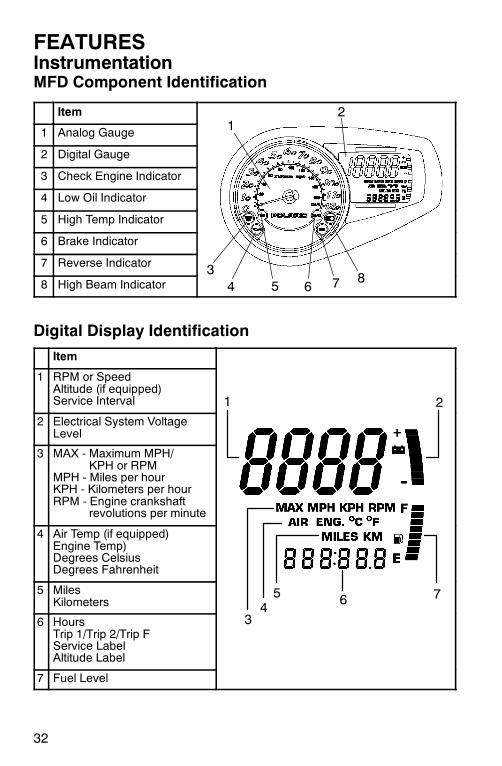
FEATURESInstrumentationMFD Component Identification
Item
1 Analog Gauge
2 Digital Gauge
3 Check Engine Indicator
4 Low Oil Indicator
5 High Temp Indicator
6 Brake Indicator
7 Reverse Indicator
8 High Beam Indicator
Digital Display Identification
Item
1 RPM or SpeedAltitude (if equipped)Service Interval
2 Electrical System VoltageLevel
3 MAX - Maximum MPH/KPH or RPM
MPH - Miles per hourKPH - Kilometers per hourRPM - Engine crankshaft
revolutions per minute
4 Air Temp (if equipped)Engine Temp)Degrees CelsiusDegrees Fahrenheit
5 MilesKilometers
6 HoursTrip 1/Trip 2/Trip FService LabelAltitude Label
7 Fuel Level
12
6543
87
7
1 2
345 6
33
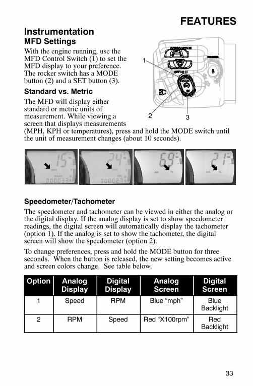
FEATURESInstrumentationMFD SettingsWith the engine running, use theMFD Control Switch (1) to set theMFD display to your preference.The rocker switch has a MODEbutton (2) and a SET button (3).
Standard vs. MetricThe MFD will display eitherstandard or metric units ofmeasurement. While viewing ascreen that displays measurements(MPH, KPH or temperatures), press and hold the MODE switch untilthe unit of measurement changes (about 10 seconds).
Speedometer/TachometerThe speedometer and tachometer can be viewed in either the analog orthe digital display. If the analog display is set to show speedometerreadings, the digital screen will automatically display the tachometer(option 1). If the analog is set to show the tachometer, the digitalscreen will show the speedometer (option 2).
To change preferences, press and hold the MODE button for threeseconds. When the button is released, the new setting becomes activeand screen colors change. See table below.
Option AnalogDisplay
DigitalDisplay
AnalogScreen
DigitalScreen
1 Speed RPM Blue “mph” BlueBacklight
2 RPM Speed Red “X100rpm” RedBacklight
1
2 3
34
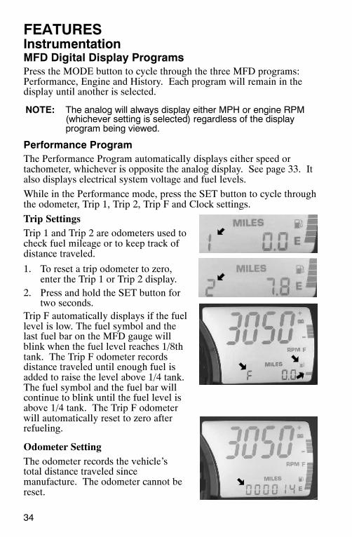
FEATURESInstrumentationMFD Digital Display ProgramsPress the MODE button to cycle through the three MFD programs:Performance, Engine and History. Each program will remain in thedisplay until another is selected.
NOTE: The analog will always display either MPH or engine RPM(whichever setting is selected) regardless of the displayprogram being viewed.
Performance ProgramThe Performance Program automatically displays either speed ortachometer, whichever is opposite the analog display. See page 33. Italso displays electrical system voltage and fuel levels.
While in the Performance mode, press the SET button to cycle throughthe odometer, Trip 1, Trip 2, Trip F and Clock settings.
Trip SettingsTrip 1 and Trip 2 are odometers used tocheck fuel mileage or to keep track ofdistance traveled.
1. To reset a trip odometer to zero,enter the Trip 1 or Trip 2 display.
2. Press and hold the SET button fortwo seconds.
Trip F automatically displays if the fuellevel is low. The fuel symbol and thelast fuel bar on the MFD gauge willblink when the fuel level reaches 1/8thtank. The Trip F odometer recordsdistance traveled until enough fuel isadded to raise the level above 1/4 tank.The fuel symbol and the fuel bar willcontinue to blink until the fuel level isabove 1/4 tank. The Trip F odometerwill automatically reset to zero afterrefueling.
Odometer SettingThe odometer records the vehicle’stotal distance traveled sincemanufacture. The odometer cannot bereset.
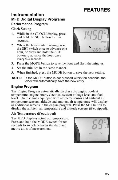
35
FEATURESInstrumentationMFD Digital Display ProgramsPerformance ProgramClock Setting
1. While in the CLOCK display, pressand hold the SET button for fiveseconds.
2. When the hour starts flashing pressthe SET switch once to advance onehour, or press and hold the SETbutton to advance the hour onceevery 0.2 seconds.
3. Press the MODE button to save the hour and flash the minutes.4. Set the minutes in the same manner.5. When finished, press the MODE button to save the new setting.
NOTE: If the MODE button is not pressed within ten seconds, theclock will automatically save the new entry.
Engine ProgramThe Engine Program automatically displays the engine coolanttemperature, engine hours, electrical system voltage level and fuellevel. On machines equipped with altimeter sensor and ambient airtemperature sensors, altitude and ambient air temperature will displayas additional screens in the engine program. Press the SET button todisplay the ambient air temperature and altitude screens (if equipped).
Air Temperature (if equipped)The MFD displays actual air temperature.Press and hold the MODE switch for tenseconds to switch between standard andmetric units of measurement.
36
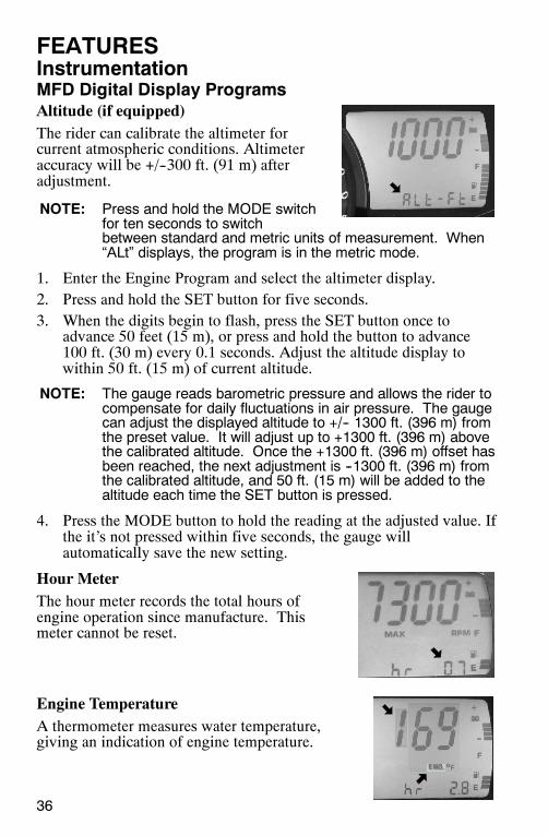
FEATURESInstrumentationMFD Digital Display ProgramsAltitude (if equipped)The rider can calibrate the altimeter forcurrent atmospheric conditions. Altimeteraccuracy will be +/--300 ft. (91 m) afteradjustment.
NOTE: Press and hold the MODE switchfor ten seconds to switchbetween standard and metric units of measurement. When“ALt” displays, the program is in the metric mode.
1. Enter the Engine Program and select the altimeter display.2. Press and hold the SET button for five seconds.3. When the digits begin to flash, press the SET button once to
advance 50 feet (15 m), or press and hold the button to advance100 ft. (30 m) every 0.1 seconds. Adjust the altitude display towithin 50 ft. (15 m) of current altitude.
NOTE: The gauge reads barometric pressure and allows the rider tocompensate for daily fluctuations in air pressure. The gaugecan adjust the displayed altitude to +/-- 1300 ft. (396 m) fromthe preset value. It will adjust up to +1300 ft. (396 m) abovethe calibrated altitude. Once the +1300 ft. (396 m) offset hasbeen reached, the next adjustment is --1300 ft. (396 m) fromthe calibrated altitude, and 50 ft. (15 m) will be added to thealtitude each time the SET button is pressed.
4. Press the MODE button to hold the reading at the adjusted value. Ifthe it’s not pressed within five seconds, the gauge willautomatically save the new setting.
Hour MeterThe hour meter records the total hours ofengine operation since manufacture. Thismeter cannot be reset.
Engine TemperatureA thermometer measures water temperature,giving an indication of engine temperature.
37
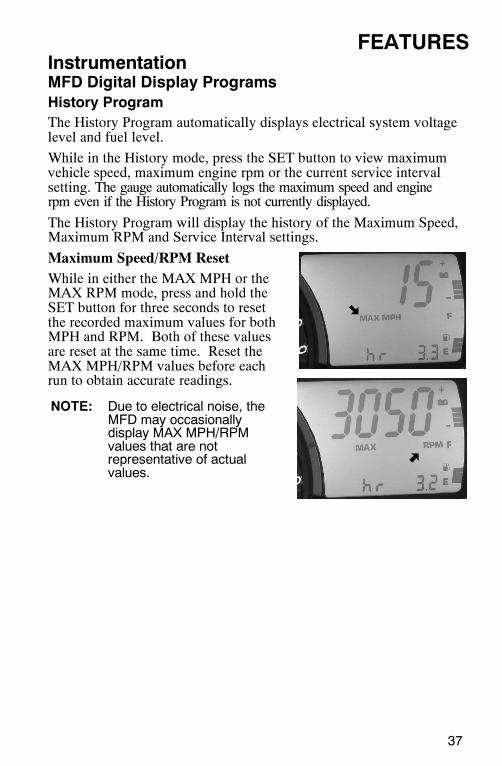
FEATURESInstrumentationMFD Digital Display ProgramsHistory ProgramThe History Program automatically displays electrical system voltagelevel and fuel level.
While in the History mode, press the SET button to view maximumvehicle speed, maximum engine rpm or the current service intervalsetting. The gauge automatically logs the maximum speed and enginerpm even if the History Program is not currently displayed.
The History Program will display the history of the Maximum Speed,Maximum RPM and Service Interval settings.
Maximum Speed/RPM ResetWhile in either the MAX MPH or theMAX RPM mode, press and hold theSET button for three seconds to resetthe recorded maximum values for bothMPH and RPM. Both of these valuesare reset at the same time. Reset theMAX MPH/RPM values before eachrun to obtain accurate readings.
NOTE: Due to electrical noise, theMFD may occasionallydisplay MAX MPH/RPMvalues that are notrepresentative of actualvalues.
38
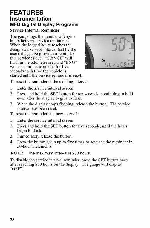
FEATURESInstrumentationMFD Digital Display ProgramsService Interval ReminderThe gauge logs the number of enginehours between service reminders.When the logged hours reaches thedesignated service interval (set by theuser), the gauge provides a reminderthat service is due. “SErVCE” willflash in the odometer area and “ENG”will flash in the icon area for fiveseconds each time the vehicle isstarted until the service reminder is reset.
To reset the reminder at the existing interval:
1. Enter the service interval screen.2. Press and hold the SET button for ten seconds, continuing to hold
even after the display begins to flash.3. When the display stops flashing, release the button. The service
interval has been reset.To reset the reminder at a new interval:
1. Enter the service interval screen.2. Press and hold the SET button for five seconds, until the hours
begin to flash.3. Immediately release the button.4. Press the button again up to five times to advance the reminder in
50-hour increments.
NOTE: The maximum interval is 250 hours.
To disable the service interval reminder, press the SET button onceafter reaching 250 hours on the display. The gauge will display“OFF”.
39
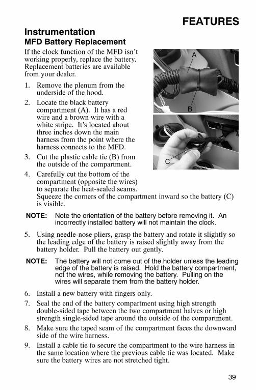
FEATURESInstrumentationMFD Battery ReplacementIf the clock function of the MFD isn’tworking properly, replace the battery.Replacement batteries are availablefrom your dealer.
1. Remove the plenum from theunderside of the hood.
2. Locate the black batterycompartment (A). It has a redwire and a brown wire with awhite stripe. It’s located aboutthree inches down the mainharness from the point where theharness connects to the MFD.
3. Cut the plastic cable tie (B) fromthe outside of the compartment.
4. Carefully cut the bottom of thecompartment (opposite the wires)to separate the heat-sealed seams.Squeeze the corners of the compartment inward so the battery (C)is visible.
NOTE: Note the orientation of the battery before removing it. Anincorrectly installed battery will not maintain the clock.
5. Using needle-nose pliers, grasp the battery and rotate it slightly sothe leading edge of the battery is raised slightly away from thebattery holder. Pull the battery out gently.
NOTE: The battery will not come out of the holder unless the leadingedge of the battery is raised. Hold the battery compartment,not the wires, while removing the battery. Pulling on thewires will separate them from the battery holder.
6. Install a new battery with fingers only.7. Seal the end of the battery compartment using high strength
double-sided tape between the two compartment halves or highstrength single-sided tape around the outside of the compartment.
8. Make sure the taped seam of the compartment faces the downwardside of the wire harness.
9. Install a cable tie to secure the compartment to the wire harness inthe same location where the previous cable tie was located. Makesure the battery wires are not stretched tight.
A
B
C
40
FEATURESInstrumentationGauge Cleaning1. Wipe the gauge face as needed using a clean cloth and a mild soap
and water solution. Wipe dry with clean, soft cloth.2. Clean the back side of the gauge using a clean cloth and a mild
soap and water solution. Do not remove the electrical connectorsor protective rubber boot. Do not spray the back side of the gaugeor the wire harness with a pressure washer or other water source.
CAUTIONTo prevent damage to the lens, do not use alcohol for cleaning.Do not allow chemicals or sprays to come into contact with thelens. Immediately clean off any gasoline that splashes on thegauge during refueling.
1
2
43
41
THE PERFECT FITIQ Front Suspension AdjustmentsBreak in the suspension for approximately 150 miles (240 km) beforemaking any fine-tuning adjustments.
Settings will vary from rider to rider, depending on rider weight,vehicle speed, riding style, and trail conditions. We recommendstarting with factory settings and then customizing each adjustmentindividually to suit rider preference. The machine should bemethodically tested, one change at a time, under the same conditions(trail and snow conditions, vehicle speed, riding position, etc.) aftereach adjustment until the best ride is achieved.
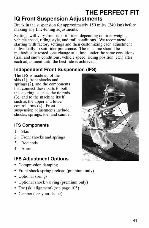
Independent Front Suspension (IFS)The IFS is made up of theskis (1), front shocks andsprings (2), and the componentsthat connect these parts to boththe steering, such as the tie rods(3), and to the machine itself,such as the upper and lowercontrol arms (4). Frontsuspension adjustments includeshocks, springs, toe, and camber.
IFS Components1. Skis2. Front shocks and springs3. Rod ends4. A-arms
IFS Adjustment OptionsS Compression dampingS Front shock spring preload (premium only)S Optional springsS Optional shock valving (premium only)S Toe (ski alignment) (see page 105)S Camber (see your dealer)
1
2
3
4
5
42
THE PERFECT FITIQ Front Suspension Adjustments
WARNINGAlways verify ski alignment before making adjustments to theIFS. See page 105 to check alignment. If the skis are misaligned,see your dealer, as the camber adjustment may also be affected.
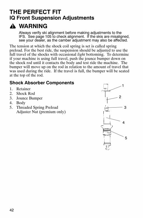
The tension at which the shock coil spring is set is called springpreload. For the best ride, the suspension should be adjusted to use thefull travel of the shocks with occasional light bottoming. To determineif your machine is using full travel, push the jounce bumper down onthe shock rod until it contacts the body and test ride the machine. Thebumper will move up on the rod in relation to the amount of travel thatwas used during the ride. If the travel is full, the bumper will be seatedat the top of the rod.
Shock Absorber Components1. Retainer2. Shock Rod3. Jounce Bumper4. Body5. Threaded Spring Preload
Adjuster Nut (premium only)
A
43
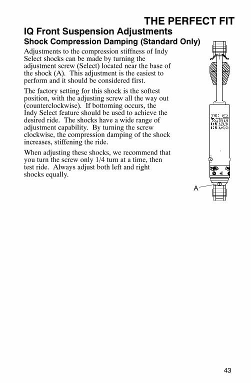
THE PERFECT FITIQ Front Suspension AdjustmentsShock Compression Damping (Standard Only)Adjustments to the compression stiffness of IndySelect shocks can be made by turning theadjustment screw (Select) located near the base ofthe shock (A). This adjustment is the easiest toperform and it should be considered first.
The factory setting for this shock is the softestposition, with the adjusting screw all the way out(counterclockwise). If bottoming occurs, theIndy Select feature should be used to achieve thedesired ride. The shocks have a wide range ofadjustment capability. By turning the screwclockwise, the compression damping of the shockincreases, stiffening the ride.
When adjusting these shocks, we recommend thatyou turn the screw only 1/4 turn at a time, thentest ride. Always adjust both left and rightshocks equally.
CB
44
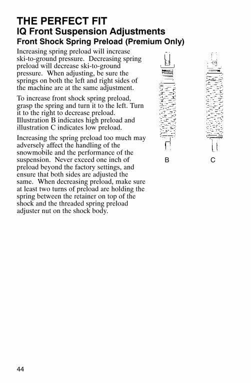
THE PERFECT FITIQ Front Suspension AdjustmentsFront Shock Spring Preload (Premium Only)Increasing spring preload will increaseski-to-ground pressure. Decreasing springpreload will decrease ski-to-groundpressure. When adjusting, be sure thesprings on both the left and right sides ofthe machine are at the same adjustment.
To increase front shock spring preload,grasp the spring and turn it to the left. Turnit to the right to decrease preload.Illustration B indicates high preload andillustration C indicates low preload.
Increasing the spring preload too much mayadversely affect the handling of thesnowmobile and the performance of thesuspension. Never exceed one inch ofpreload beyond the factory settings, andensure that both sides are adjusted thesame. When decreasing preload, make sureat least two turns of preload are holding thespring between the retainer on top of theshock and the threaded spring preloadadjuster nut on the shock body.
45
THE PERFECT FITIQ Front Suspension AdjustmentsShock Valving (Premium Only)Some shocks can be revalved if spring preload alone isn’t sufficientand further adjustment is desired to control suspension stiffness.
WARNINGChanging shock valving on shocks requires special tools and asound knowledge of mechanical theory, tool use, and shopprocedures to perform the work safely and correctly. Shockscontain high-pressure nitrogen gas. Use extreme caution whenhandling high-pressure service equipment. We recommend thatthis work be performed by a Polaris dealer.
Front SpringsThe front springs can be changed if spring preload alone isn’t sufficientand further adjustment is desired to control suspension stiffness. Seeyour Polaris dealer for more information.
46
THE PERFECT FITIQ Rear Suspension AdjustmentsRider weight, riding style, trail conditions, and vehicle speed all affectsuspension action.
Each rear suspension can be adjusted to suit rider preference anddeliver excellent performance for a given set of conditions. However,all suspension designs and adjustments involve a compromise, ortrade-off. For example, a suspension set up for snow-cross racingwould provide a very stiff ride on the trail. A suspension set up fortrail riding would bottom out harshly on a snow-cross course.
A decal outlining rear suspension set-up options is located either underthe hood or on the clutch cover. It provides a guideline for initialsuspension set-up. Additional adjustments can be made from thispoint. Make adjustments to one area at a time so you can evaluate thechange. For further assistance, see your dealer.
Suspension Performance TipsS Rider weight usually determines the position at which the spring pre-load should be set. However, this may vary with riding style. Witha little experimentation, each rider can find a preferred set-up. Theseadjustments are easy to make, involve very little time or effort, andgreatly affect the ride.
S In deep snow, a new slider will offer improved performance overworn slider. It can also improve top speed.
S Polaris offers track kits for improved flotation in deep snow. Seeyour dealer for assistance.
NOTE: Keep the suspension pivot points lubricated. This will reducemoisture and rust build-up and ensure proper function of thesuspension components. Grease rear suspension pivotsbefore adjusting the rear suspension. Refer to SuspensionMaintenance beginning on page 107.
47
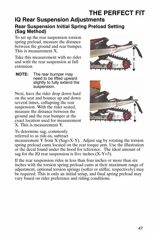
THE PERFECT FITIQ Rear Suspension AdjustmentsRear Suspension Initial Spring Preload Setting(Sag Method)To set up the rear suspension torsionspring preload, measure the distancebetween the ground and rear bumper.This is measurement X.
Take this measurement with no riderand with the rear suspension at fullextension.
NOTE: The rear bumper mayneed to be lifted upwardslightly to fully extend thesuspension.
Next, have the rider drop down hardon the seat and bounce up and downseveral times, collapsing the rearsuspension. With the rider seated,measure the distance between theground and the rear bumper at theexact location used for measurementX. This is measurement Y.
To determine sag, commonlyreferred to as ride-in, subtractmeasurement Y from X (Sag=X-Y). Adjust sag by rotating the torsionspring preload cams located on the rear torque arm. Use the illustrationor the decal found under the hood for reference. The ideal amount ofsag for the IQ rear suspension is five inches (X-Y=5).
If the rear suspension rides in less than four inches or more than sixinches with the torsion spring preload cams at their maximum range ofadjustment, optional torsion springs (softer or stiffer, respectively) maybe required. This is only an initial setup, and final spring preload mayvary based on rider preference and riding conditions.
48
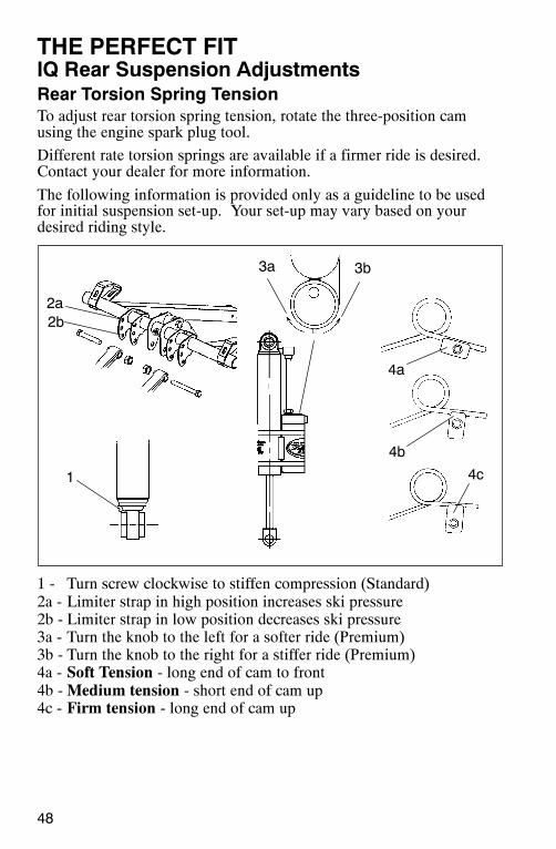
THE PERFECT FITIQ Rear Suspension AdjustmentsRear Torsion Spring TensionTo adjust rear torsion spring tension, rotate the three-position camusing the engine spark plug tool.
Different rate torsion springs are available if a firmer ride is desired.Contact your dealer for more information.
The following information is provided only as a guideline to be usedfor initial suspension set-up. Your set-up may vary based on yourdesired riding style.
1 - Turn screw clockwise to stiffen compression (Standard)2a - Limiter strap in high position increases ski pressure2b - Limiter strap in low position decreases ski pressure3a - Turn the knob to the left for a softer ride (Premium)3b - Turn the knob to the right for a stiffer ride (Premium)4a - Soft Tension - long end of cam to front4b -Medium tension - short end of cam up4c - Firm tension - long end of cam up
4b
4a
4c1
3a 3b
2a2b
A
49
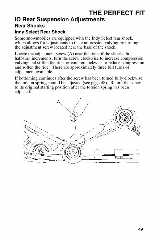
THE PERFECT FITIQ Rear Suspension AdjustmentsRear ShocksIndy Select Rear ShockSome snowmobiles are equipped with the Indy Select rear shock,which allows for adjustments to the compression valving by turningthe adjustment screw located near the base of the shock.
Locate the adjustment screw (A) near the base of the shock. Inhalf-turn increments, turn the screw clockwise to increase compressionvalving and stiffen the ride, or counterclockwise to reduce compressionand soften the ride. There are approximately three full turns ofadjustment available.
If bottoming continues after the screw has been turned fully clockwise,the torsion spring should be adjusted (see page 48). Return the screwto its original starting position after the torsion spring has beenadjusted.
A
50
THE PERFECT FITIQ Rear Suspension AdjustmentsRear Shocks
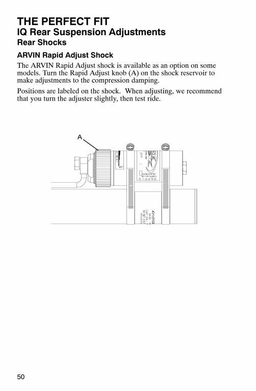
ARVIN Rapid Adjust ShockThe ARVIN Rapid Adjust shock is available as an option on somemodels. Turn the Rapid Adjust knob (A) on the shock reservoir tomake adjustments to the compression damping.
Positions are labeled on the shock. When adjusting, we recommendthat you turn the adjuster slightly, then test ride.
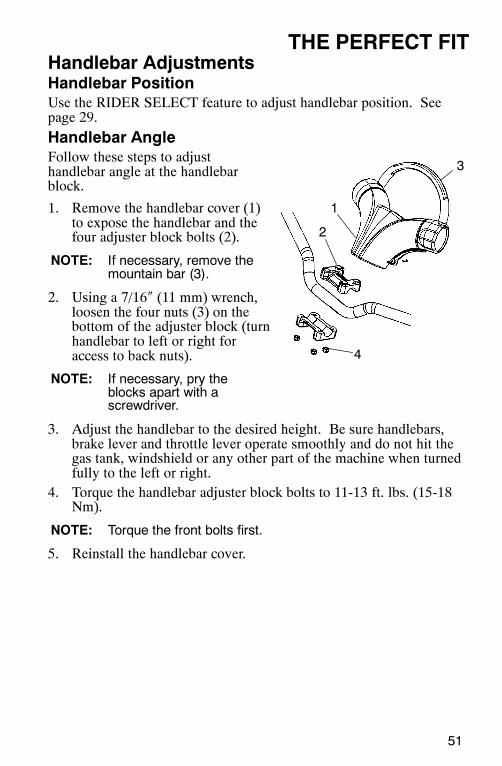
51
THE PERFECT FITHandlebar AdjustmentsHandlebar PositionUse the RIDER SELECT feature to adjust handlebar position. Seepage 29.
Handlebar AngleFollow these steps to adjusthandlebar angle at the handlebarblock.
1. Remove the handlebar cover (1)to expose the handlebar and thefour adjuster block bolts (2).
NOTE: If necessary, remove themountain bar (3).
2. Using a 7/16″ (11 mm) wrench,loosen the four nuts (3) on thebottom of the adjuster block (turnhandlebar to left or right foraccess to back nuts).
NOTE: If necessary, pry theblocks apart with ascrewdriver.
3. Adjust the handlebar to the desired height. Be sure handlebars,brake lever and throttle lever operate smoothly and do not hit thegas tank, windshield or any other part of the machine when turnedfully to the left or right.
4. Torque the handlebar adjuster block bolts to 11-13 ft. lbs. (15-18Nm).
NOTE: Torque the front bolts first.
5. Reinstall the handlebar cover.
1
2
4
3
52
THE PERFECT FITAccessoriesPolaris offers a wide range of accessories for your snowmobile to helpmake each ride more enjoyable.
NOTE: The accessory tether switch is available for all models.Order PN 2870668.
Use only Polaris parts and accessories on your Polaris snowmobile.Use of unapproved parts and accessories may result in:
S Non-compliance with government/industry requirementsS Voiding of warrantyS Injury to self or others
This applies, but is not limited to the following areas: brakes, clutches,fuel systems, and exhaust systems.
NOTE: Exhaust systems are critical safety areas that must useapproved Polaris parts. Please see your Polaris dealer forservice.
53
THE PERFECT FITTraction Products (SwitchBack only)StudsBefore equipping your machine with traction products, be aware of thelaws in your area pertaining to the use of traction products.
Use only Polaris traction products on your snowmobile. Trackwarranties are void if track damage or failure results from improper orexcessive stud installation or the use of non-Polaris traction products.
See your dealer about installing studs and/or carbides.
CAUTIONAlways install wear strips before installing studs. Failure to installwear strips may result in cooler or tunnel damage. See page 54.Never add shims to the wear strip. Track damage will resultbecause of lack of clearance between upper carrier wheels andtrack.Use of studs longer than the recommended length on machinesequipped with center coolers will result in center cooler damageor damage to the tunnel.
Track studding will enhance braking control on hard-packed snow orice, but extreme caution is still required on such surfaces. Steeringability may be reduced on hard-packed snow or ice.
When studded tracks are used, increased wear to the brake pads willresult from increased braking. Extended-wear brake pad kits areavailable. See your dealer.
CAUTIONAggressive studding patterns may require grinding protrudingstud bolts flush to prevent idler wheel damage. Maintain tracktension on studded tracks on the tight side of the spec to preventheat exchanger damage. Center of stud must be at least 1 1/8″(2.86 cm) from outside edge of the track.
54
THE PERFECT FITTraction Products (SwitchBack only)n Carbide SkagsA skag is a replaceable bar attached to the underside of the ski to assistin turning the snowmobile and to prevent ski wear caused by contactwith roads and other bare terrain. Use carbide skags with studdedtracks to help maintain proper vehicle steering and control. See page106.
If your machine has carbide skags, it may be necessary to add trackstuds to maintain proper vehicle control. Maintain a proper balancebetween the number of studs and the length of carbide on the skags(the more studs you use, the longer the carbide on the skags should be).See your dealer’s track studding chart.
Wear StripsTo avoid excessive tunnel wear, tunnel wear strips must be installedwhenever track studding is used. Install Wear Strip Kit P/N 2875415.
Wear strips are designed for a specific stud length. See your dealer’sstudding chart for recommended traction accessories.
CAUTIONWhenever wear strips are relocated, be sure there’s adequatestud clearance to the heat exchangers. Lack of clearance mayresult in damage to heat exchangers.
55
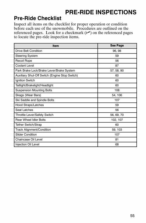
PRE-RIDE INSPECTIONSPre-Ride ChecklistInspect all items on the checklist for proper operation or conditionbefore each use of the snowmobile. Procedures are outlined on thereferenced pages. Look for a checkmark (n) on the referenced pagesto locate the pre-ride inspection items.
Item See PageItem See Page
Drive Belt Condition 96, 98
Steering System 59
Recoil Rope 56
Coolant Level 87
Park Brake Lock/Brake Lever/Brake System 57, 58, 90
Auxiliary Shut-Off Switch (Engine Stop Switch) 60
Ignition Switch 60
Taillight/Brakelight/Headlight 60
Suspension Mounting Bolts 108
Skags (Wear Bars) 54, 106
Ski Saddle and Spindle Bolts 107
Hood Straps/Latches 59
Seat Latches 56
Throttle Lever/Safety Switch 56, 69, 70
Rear Wheel Idler Bolts 102, 107
Tether Switch/Strap 60
Track Alignment/Condition 59, 103
Slider Condition 107
Chaincase Oil Level 81
Injection Oil Level 68
56
PRE-RIDE INSPECTIONSBefore Starting the Engine
WARNINGWorn, damaged, or malfunctioning components may causeserious injury or death. Before starting the engine, check allcomponents to be sure of proper operation.
Read and Understand Your Owner’s ManualRead the Owner’s Manual completely and refer to it often. The manualis your guide to safe and enjoyable snowmobiling experience.
n Throttle LeverThe throttle and brake are the primary controls of your snowmobile.Always make sure both are functioning properly.
Squeeze the throttle lever to make sure it compresses evenly andsmoothly. When released, the lever should immediately return to theidle position without binding or hesitation. If the throttle does notfunction smoothly, or if you discover excessive lever freeplay, DONOT start the engine. Have the throttle serviced immediately.
n Throttle Safety SwitchTest the throttle safety switch system before the machine is operated.See page 69 for procedure.
n Check Seat LatchesEnsure that the seat latches are securely in place before every use of thesnowmobile.
n Hood LatchesThe hood of the snowmobile protects the operator from moving partsas well as aiding in sound emission control and other functions. Underno circumstances should your snowmobile be operated with the hoodopen or removed. Always ensure that the hood straps are in goodcondition and that the latches are securely in place before operating thesnowmobile.
n Recoil RopeInspect the recoil rope and handle for excessive wear, and make surethe knot securing the rope inside the handle is secure. If excessivewear is found, see your Polaris dealer for replacement.
57
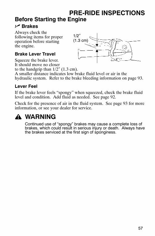
PRE-RIDE INSPECTIONSBefore Starting the Enginen BrakesAlways check thefollowing items for properoperation before startingthe engine.
Brake Lever TravelSqueeze the brake lever.It should move no closerto the handgrip than 1/2″ (1.3 cm).A smaller distance indicates low brake fluid level or air in thehydraulic system. Refer to the brake bleeding information on page 93.
Lever FeelIf the brake lever feels “spongy” when squeezed, check the brake fluidlevel and condition. Add fluid as needed. See page 92.
Check for the presence of air in the fluid system. See page 93 for moreinformation, or see your dealer for service.
WARNINGContinued use of “spongy” brakes may cause a complete loss ofbrakes, which could result in serious injury or death. Always havethe brakes serviced at the first sign of sponginess.
1/2″(1.3 cm)
43
12
58
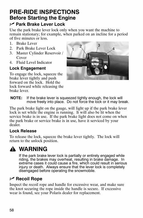
PRE-RIDE INSPECTIONSBefore Starting the Enginen Park Brake Lever LockUse the park brake lever lock only when you want the machine toremain stationary; for example, when parked on an incline for a periodof five minutes or less.1. Brake Lever2. Park Brake Lever Lock3. Master Cylinder Reservoir /
Cover4. Fluid Level Indicator
Lock EngagementTo engage the lock, squeeze thebrake lever tightly and pushforward on the lock. Hold thelock forward while releasing thebrake lever.
NOTE: If the brake lever is squeezed tightly enough, the lock willmove freely into place. Do not force the lock or it may break.
The park brake light on the gauge, will light up if the park brake leverlock is set while the engine is running. It will also be lit when theservice brake is in use. If the park brake light does not come on whenthe park brake or service brake is in use, have it serviced by yourdealer.
Lock ReleaseTo release the lock, squeeze the brake lever tightly. The lock willreturn to the unlock position.
WARNINGIf the park brake lever lock is partially or entirely engaged whileriding, the brakes may overheat, resulting in brake damage. Inextreme cases it could cause a fire, which could result in seriousinjury or death. Always ensure that the lever lock is completelydisengaged before operating the snowmobile.
n Recoil RopeInspect the recoil rope and handle for excessive wear, and make surethe knot securing the rope inside the handle is secure. If excessivewear is found, see your Polaris dealer for replacement.
59
PRE-RIDE INSPECTIONSBefore Starting the Engine
n Hood LatchesThe hood of the snowmobile protects the operator from moving partsas well as aiding in sound emission control and other functions. Underno circumstances should your snowmobile be operated with the hoodopen or removed. Always ensure that the hood straps are in goodcondition and that the latches are securely in place before operating thesnowmobile.
n Steering SystemManually turn the skis completely to the right and to the left. If anydifficulty is encountered, remove any ice and snow build-up that maybe obstructing the steering linkage.
n Track
WARNINGOperating the snowmobile with a damaged track increases thepossibility of track failure, which could cause loss of controlresulting in serious injury or death. Always inspect the track fordamage before using the vehicle.
Use of traction products such as studs increases the possibility of trackdamage and/or failure. Driving at high speeds for extended periods oftime in marginal lubrication could severely damage track rods, breaktrack edges and cause other track damage. Examples of marginallubrication would include frozen bodies of water without snow cover,icy trails, and no-snow conditions.
NOTE: Track damage or failure caused by operation on ice or poorlubrication conditions voids the track warranty.
Deep Lug Tracks (if equipped)The 2.4” powder track is designed specifically for deep snowapplications. Operation in low snow conditions at high speeds maycause track lug separation. Track lug separation is not covered underthe Polaris limited warranty policy. Polaris does not recommendoperation above 70 mph with this track.
CAUTIONHigh speed use on hardpacked surfaces is not recommended formodels equipped with a deep lug track. Track lug damage mayoccur. Keep high speed use to a minimum, including frequentslow-speed intervals for track cooling.
60
PRE-RIDE INSPECTIONSStart the Engine and Checkn Engine Stop Switch: Check the auxiliary shut-off switch for
proper operation. Push the switch down to stop the engine. Pull itup to allow restarting.
n Ignition Switch: Make sure the engine stops when the ignitionswitch is turned to OFF.
n Tether Switch: If your machine has a tether switch, remove thetether from the switch to make sure the engine stops immediately.
n Lighting: Check the headlight (high and low beam), taillight, andbrake light. Replace burned out lamps before operating.
n Mirror Adjustment: If equipped, adjust your mirrors so they canbe used to their full advantage.
n Operating Area: Before driving away, check your surroundings.Be aware of obstacles and make sure bystanders are a safe distancefrom the machine.
61
OPERATIONStarting the Engine
WARNINGBefore starting the engine, always refer to all safety warningspertaining to snowmobile operation. Never start your snowmobilewithout checking all components to be sure of proper operation.See Check Before Starting the Engine beginning on page 56.
Do not depress the throttle until the engine starts.
1. Turn the key to the ON position.2. Pull the engine stop switch up to the RUN position.3. Grasp the recoil rope handle and pull slowly until the recoil engages;
then pull abruptly.4. Repeat as needed until the engine starts.
NOTE: It may require as many as eight to ten pulls to prime the fuelsystem and start the engine if the fuel tank has beencompletely emptied.
CAUTIONDon’t pull the starter rope to the fully extended position and don’tallow it to snap back into the housing. Damage may result.To avoid injury and/or engine damage, do not operate the electricstarter or pull-rope starter while the engine is running.
62
OPERATIONEngine Break-InNo single action on your part is as important to long, trouble-freemachine life as proper break-in of a new or rebuilt engine. Premix thefirst tank of gasoline with one pint of Polaris injection oil for each fivegallons of fuel. This, in addition to the lubrication supplied by theinjection system, will assure proper engine break-in.
CAUTIONExcessive heat build-up during the first three hours of operationwill damage close-fitted engine parts. Do not operate at fullthrottle or high speeds for extended periods during the first threehours of use. Vary the throttle openings and machine speeds toreduce friction on all close-fitting machined parts, allowing themto break in slowly without damage.Use of any lubricants other than those recommended by Polarismay cause serious engine damage. We recommend the use ofPolaris lubricants for your vehicle.Drive with extra caution during the break-in period. Performregular checks on fluid levels, lines, and all other important areasof the machine.
63
OPERATIONEngine Break-InOil Injection SystemAlways fill the oil reservoir when refueling.
CAUTIONSerious engine damage can occur without the proper lubrication.Check the oil tank level often during the first tank of fuel. If the oillevel doesn’t go down, contact your dealer immediately.
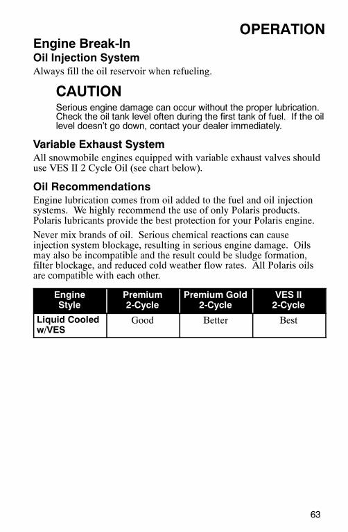
Variable Exhaust SystemAll snowmobile engines equipped with variable exhaust valves shoulduse VES II 2 Cycle Oil (see chart below).
Oil RecommendationsEngine lubrication comes from oil added to the fuel and oil injectionsystems. We highly recommend the use of only Polaris products.Polaris lubricants provide the best protection for your Polaris engine.
Never mix brands of oil. Serious chemical reactions can causeinjection system blockage, resulting in serious engine damage. Oilsmay also be incompatible and the result could be sludge formation,filter blockage, and reduced cold weather flow rates. All Polaris oilsare compatible with each other.
EngineStyle
Premium2-Cycle
Premium Gold2-Cycle
VES II2-Cycle
Liquid Cooledw/VES
Good Better Best
64
OPERATIONTrack Warm-Up
WARNINGA loose track or flying debris could cause serious injury or death.Stand clear of the front of the machine and the moving track.Never hold the snowmobile up or stand behind it while warmingup the track. Do not use excessive throttle during warm-up orwhen the track is free-hanging. Be sure the rear support isstable.
WARNINGUse of traction products such as studs, ice growsers, etc. willincrease the possibility of track damage and/or failure. This couldcause loss of control, resulting in serious injury or death. Alwaysinspect for track damage before operating the snowmobile.
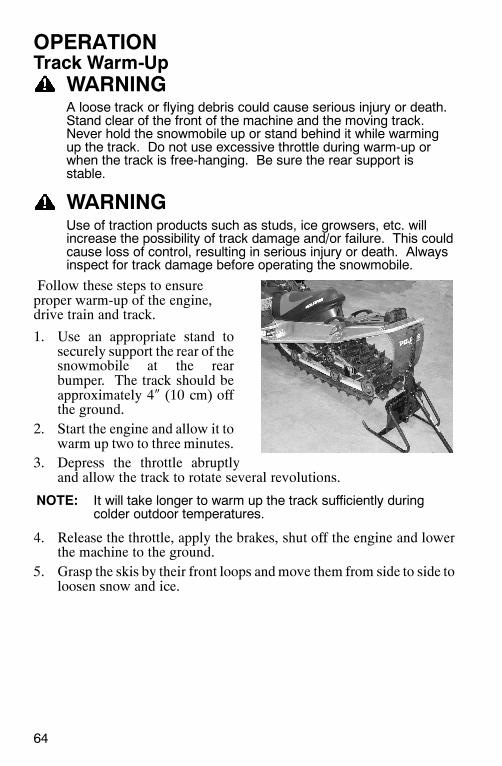
Follow these steps to ensureproper warm-up of the engine,drive train and track.
1. Use an appropriate stand tosecurely support the rear of thesnowmobile at the rearbumper. The track should beapproximately 4″ (10 cm) offthe ground.
2. Start the engine and allow it towarm up two to three minutes.
3. Depress the throttle abruptlyand allow the track to rotate several revolutions.
NOTE: It will take longer to warm up the track sufficiently duringcolder outdoor temperatures.
4. Release the throttle, apply the brakes, shut off the engine and lowerthe machine to the ground.
5. Grasp the skis by their front loops andmove them from side to side toloosen snow and ice.
65
OPERATIONSlide Rail and Track Cooling
CAUTIONInadequate cooling and lubrication will lead to overheating of theslide rail and track, resulting in premature wear and failure.Reduce speeds and frequently drive into fresh snow to allowadequate cooling and polishing of the slide rail and tracksurfaces. Avoid operating on ice, hard-packed surfaces or roads.
CAUTIONHigh speed use on hardpacked surfaces is not recommended formodels equipped with a deep lug track. Track lug damage mayoccur. Keep high speed use to a minimum, including frequentslow-speed intervals for track cooling.
66
OPERATIONFuel
WARNINGGasoline is highly flammable and explosive under certainconditions.S Always exercise extreme caution whenever handling gasoline.S Always refuel outdoors or in a well-ventilated area.S Always turn off the engine before refueling.S Do not overfill the tank. Do not fill the tank neck.S Do not smoke or allow open flames or sparks in or near thearea where refueling is performed or where gasoline is stored.S If gasoline spills on your skin or clothing, immediately wash it offwith soap and water and change clothing.S Never start the engine or let it run in an enclosed area. Engineexhaust fumes are poisonous and can cause loss of conscious-ness or death in a short time.
WARNINGThe engine exhaust from this product contains chemicals knownto cause cancer, birth defects or other reproductive harm.Operate this vehicle only outdoors or in well-ventilated areas.
67
OPERATIONFuelFor peak performance, Polaris recommends the use of 91 octane orhigher fuel. Although 87 octane fuel is usable, some engineperformance will be lost and fuel economy will decrease. Do not usefuel lower than 87 octane.
CAUTIONOperating with obstructed fuel systems will result in seriousengine damage. Perform maintenance as recommended.Damage to the fuel pump will occur if the snowmobile is operatedwith an empty fuel tank. Do not allow the snowmobile to run outof fuel. Always refuel when the level is low.Prolonged exposure to petroleum based products may damagepaint. Always protect painted surfaces when handling fuel.
Fuel LevelThe fuel symbol and the last fuel bar on the MFD gauge will blinkwhen the fuel level reaches 1/8th tank. There will be approximatelyone gallon of fuel remaining. Refuel as soon as possible. Do not allowthe snowmobile to run out of fuel.
Fuel System DeicersIf you use non-oxygenated fuel, Polaris recommends the regular use ofisopropyl-based fuel system deicer. Add one to two ounces per gallon(8-16 milliliters per liter) of gasoline to prevent engine damageresulting from fuel system icing and lean fuel mixtures. Never usedeicers or additives containing methanol. Polaris also recommends theuse of Carbon Clean Plus. See page 111 for the part numbers of Polarisproducts.
If you use oxygenated fuel containing ethanol, additional alcoholdeicers or water absorbing additives should not be used.
68
OPERATIONOiln Low Oil Indicator LightThe low oil indicator light will alert the operator if the oil level is low.Visually check the oil level in the bottle. Add oil before furtheroperation of the snowmobile. See page 63 for oil recommendations.
n Low Oil LevelAlways maintain the oil level above thetank’s low level line. This is especiallyimportant when the machine is operatedin mountainous terrain. Maintaining theproper oil level will prevent systemaeration and possible loss of pumpingaction, which could result in enginedamage.
If necessary, the engine may be operatedas long as oil is visible in the oil tank. Ifoil is not visible, continued operationmay cause serious engine damage. Seepage 63 for oil recommendations.
CAUTIONOperating the snowmobile without adequate engine lubricationcan result in serious engine damage. Always check the oil levelwhen refueling. Add oil as needed to maintain the level abovethe low level mark.
The Polaris oil cap on the oil bottle is vented to allow proper oil flow.See your Polaris dealer for recommended replacement parts.
69
OPERATIONn Engine Stop SwitchPush down on the engine stopswitch (A) to ground out theignition and stop the enginequickly. Pull the switch up to theON position to allow restarting.
n Throttle Safety SwitchThe throttle safety switch is designed to stop the engine whenever allpressure is removed from the throttle lever and the throttle cable orvalves do not return to the normal closed position.
WARNINGOperating the snowmobile with a faulty throttle safety switch canresult in serious injury or death in the event of an accident. If thethrottle safety switch does not shut off the engine during a throttlesystem malfunction, immediately push down the engine stopswitch. Do not start the engine again until the malfunction hasbeen corrected by your dealer.
Test the throttle safety switchsystem daily before operation.
1. Sit on the seat.2. Start the engine and allow it to
idle.3. Hold the throttle lever pin
stationary by exerting pressureon the pivot pin in the directionshown in the illustration (B).
4. Apply a slight amount of throttle. A properly functioning switchmust shut down the engine.
A
B
70
OPERATIONThrottle Lever
WARNINGAn improperly functioning throttle lever may cause erraticmachine behavior and loss of control, which could result inserious injury or death. If the throttle lever does not work properly,DO NOT start the engine.
If the engine stops abruptly when the throttle lever is released:
1. Turn the ignition switch to OFF.2. Visually inspect the throttle cable and throttle body to determinewhat
caused the safety switch to activate.3. Test the throttle lever by compressing and releasing it several times.
The lever and cable must return to the idle position quickly andcompletely.
4. If the throttle lever operates properly, turn the ignition switch on andgo through normal starting procedures.
5. If the engine doesn’t start, take the snowmobile to an authorizedPolaris dealer for service.
Excessive freeplay in the throttle cable may cause the safety switch toactivate, preventing the engine from starting. If this occurs, return themachine to an authorized Polaris dealer for service.
If an emergency exists and it’s necessary to start the engine, the throttlesafety switch and engine stop switch may be disconnected from thewire harness. When these switches are disconnected, the ignition keyswitch must be used to shut off the engine. DO NOT continue tooperate the machine with the throttle safety switch disconnected.Return the machine to an authorized Polaris dealer for service as soonas possible.
71
OPERATIONEmergency StoppingThe following chart lists methods for stopping the snowmobile in theevent of an emergency. See page 69 for more information about theengine stop switch and throttle safety switch.
SYSTEM WHAT IT DOES THROTTLECONDITION
Ignition Switch Interrupts ignition circuit All
Brake Slows jackshaft All
Engine Stop Switch Interrupts ignition circuit All
Throttle Safety Switch Interrupts ignition circuit All
Tether Switch (Option) Interrupts ignition circuit All
Emergency StartingIf the recoil starter system fails, an emergency start strap is provided inthe tool kit.
1. Open the hood.2. Remove the left side panel.3. Remove the air box (pull
aggressively).4. Using the belt removal
tool, follow the directionson the air box to relievebelt tension.
5. Starting at one of the towerstruts, wind the strap counterclockwise around the clutch as shown.
WARNINGSerious injury can result from wrapping the start strap aroundyour hand while using the emergency starting procedure. DONOT wrap the start strap around your hand. Keep all bystandersand loose clothing away from the snowmobile when using theemergency starting procedure.
6. Pull the strap abruptly so the strap comes free of the clutch whilestarting the engine. Repeat until the engine starts.
7. Reinstall the air box and side panel.8. Close and secure the hood.
72
OPERATIONElectronic Reverse (PERCt)Electronic reverse will activate only if the engine RPM is below 4000.
WARNINGImproper reverse operation, even at low speeds, may cause lossof control, resulting in serious injury or death. Damage will occurto the chaincase or transmission if shifting is attempted when theengine is operating above idle speed.S Shift to or from reverse only when the snowmobile is stoppedand when engine speed is at idle.S Look behind the vehicle before and while backing.S Avoid sharp turns.S Apply throttle slowly.
Engaging Reverse1. Stop the snowmobile and leave the engine idling.2. Make sure the area behind your vehicle is clear.3. Push the yellow reverse button on the left-hand control for one
second, then release. The engine will automatically reduce RPMand start a reverse rotation. A flashing reverse light on theinstrument panel will indicate that the machine is in reverse.
4. Apply the throttle slowly to make sure the machine is in reverse.
NOTE: The maximum engine RPM will be 6000 when in reverse.
NOTE: If the engine stops running, the snowmobile will be in forwardgear when it’s restarted.
Disengaging Reverse1. Stop the snowmobile and leave the engine idling.2. Push the yellow reverse button for one second and release. The
engine will slow and and begin to rotate forward. The light on theinstrument panel will shut off.
3. Apply the throttle slowly to make sure the machine is in forward.
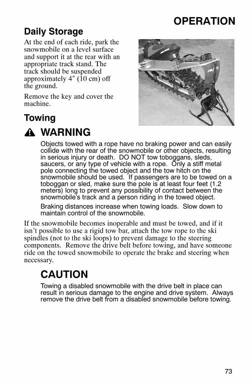
73
OPERATIONDaily StorageAt the end of each ride, park thesnowmobile on a level surfaceand support it at the rear with anappropriate track stand. Thetrack should be suspendedapproximately 4″ (10 cm) offthe ground.
Remove the key and cover themachine.
Towing
WARNINGObjects towed with a rope have no braking power and can easilycollide with the rear of the snowmobile or other objects, resultingin serious injury or death. DO NOT tow toboggans, sleds,saucers, or any type of vehicle with a rope. Only a stiff metalpole connecting the towed object and the tow hitch on thesnowmobile should be used. If passengers are to be towed on atoboggan or sled, make sure the pole is at least four feet (1.2meters) long to prevent any possibility of contact between thesnowmobile’s track and a person riding in the towed object.Braking distances increase when towing loads. Slow down tomaintain control of the snowmobile.
If the snowmobile becomes inoperable and must be towed, and if itisn’t possible to use a rigid tow bar, attach the tow rope to the skispindles (not to the ski loops) to prevent damage to the steeringcomponents. Remove the drive belt before towing, and have someoneride on the towed snowmobile to operate the brake and steering whennecessary.
CAUTIONTowing a disabled snowmobile with the drive belt in place canresult in serious damage to the engine and drive system. Alwaysremove the drive belt from a disabled snowmobile before towing.
74
MAINTENANCEPolaris Recommended Maintenance ProgramTo ensure many trouble-free miles of snowmobiling enjoyment, followrecommended regular maintenance and perform service checks asoutlined in this manual.
The recommended maintenance schedule on your snowmobile calls forservice and maintenance inspections at 150 miles (240 km), 500 miles(800 km) and 1000 miles (1600 km). These inspections should beperformed by a qualified service technician. For continued optimumperformance and component life, continue maintenance checks at 1000mile (1600 km) intervals.
All necessary replacement parts and labor incurred, with the exceptionof authorized warranty repairs, become the responsibility of theregistered owner. If, during the course of the warranty period, partfailures occur as a result of owner neglect in performing recommendedregular maintenance, the cost of repairs are the responsibility of theowner.
Personal safety is critical when attempting to service or makeadjustments to your snowmobile. If you’re not familiar with safeservice or adjustment procedures and the use of tools, or if you don’tfeel comfortable performing these tasks yourself, contact an authorizedPolaris dealer for service.
75
MAINTENANCEPeriodic Maintenance Interval TableThe following chart is a guide based on average riding conditions. Youmay need to increase frequency based on riding conditions. Wheninspection reveals the need for replacement parts, always use genuinePolaris parts, available from your Polaris dealer.
SeeP
FrequencyItem Page 150 mi.
(240 km)500 mi.(800 km)
1000 mi.(1600 km)
2000 mi.(3200 km)
Pre-Season
Clutch
Clutch Offset Alignment(without belt)
95I I I
Drive Belt Condition 96 I I I I
Clutches (disassemble) 95 C C C
Belt Tension -- I I I I
Clutch Sheaves 95 I I I I
Engine
Engine Mounts -- I I I I
Recoil Rope -- I I I I
Engine Mounting Plate -- I I I
Engine Torque Stop 98 I I I I
Cylinder Head Bolts -- I I I
Cylinder Base Nuts -- I I I I
Ignition Timing BTDC -- I I I
VES System -- C C C I
Coolant Level 87 I I R I
Water Pump Drive Belt -- I I I
Coolant Hose -- I I I I
Heat Exchangers -- I I I I I
Coolant Circulation -- I I I
Coolant Leaks -- I I I I
Spark Plug Condition 83 I I I I I
Exhaust Pipe 86 I I
Exhaust RetainingSprings
86 I I I I
I - Inspect (clean, adjust, tighten, lubricate, replace if necessary)C - Clean R - Replace L - Lubricate
76
MAINTENANCEPeriodic Maintenance Interval Table
SeeP
FrequencyItem Page 150 mi.
(240 km)500 mi.(800 km)
1000 mi.(1600 km)
2000 mi.(3200 km)
Pre-Season
Brakes
Hose Routing -- I I I I
Hose Condition -- I I I I
Fluid Leaks -- I I I I
Brake Pads 90 I I I I
Brake Disc -- I I I I
Parking Brakes 58 I I I I
Brake System 56, 90 I
Brake fluid 92 R
Fuel Management
Idle RPM -- I I I
Throttle Lever 56, 70 I I I I I
Oil Pump Lever(synchronize)
--I I I
Throttle Cable 80 L L L
Vent Lines -- I I I I
Throttle Position Sensor -- I I I
Fuel Filter -- R R
Fuel Lines -- I I I I I
Oil Filter 85 R R
Oil Lines 85 I I I
Air Box/Plenum -- I I I I I
Fuel injectors I I I
Electrical
Auxiliary Shut-Off Switch 60 I I I I I
Throttle Safety Switch 56, 69 I I I I I
Ignition Switch -- I I I I I
Taillight 60 I I I I I
Brakelight 60 I I I I I
Headlight 60 I I I I I
77
MAINTENANCEPeriodic Maintenance Interval Table
See FrequencyItem Page 150 mi.
(240 km)500 mi.(800 km)
1000 mi.(1600 km)
2000 mi.(3200 km)
Pre-Season
CHASSIS
Ski Toe Alignment -- I I I
SuspensionMounting Bolts
--I I I I I
Steering Fasteners -- I I I I C
Rear SuspensionFasteners
--I I I I I
Suspension Shock Oil -- I I I I
Cooling Fins and Shroud -- I I I I
Drive Shaft Bearings 107 L L L I
Jackshaft Bearings 109 L L L I
Skags (Wear Bars) - I I I I I
Ski Saddle/Spindle Bolts -- I I I I I
Drive Chain Tension 87 I I I I I
Hood Straps 59 I I I I I
Rear Wheel Idler Bolts 102 I I I I I
Idler Bolt Jam Nut 102 I I I I I
Rear Suspension PivotShafts
80L L L
Camber Alignment -- I I I
Handlebar Centering -- I
Tether Switch and Strap 60 I I I I I
Track Alignment 103 I I I I I
Track Tension 101 I I I I I
Front Limiter Strap -- I I I I I
Slider Condition 107 I
Chaincase Oil 81 I I I R I
I - Inspect (clean, adjust, tighten, lubricate, replace if necessary)C - Clean R - Replace L - Lubricate
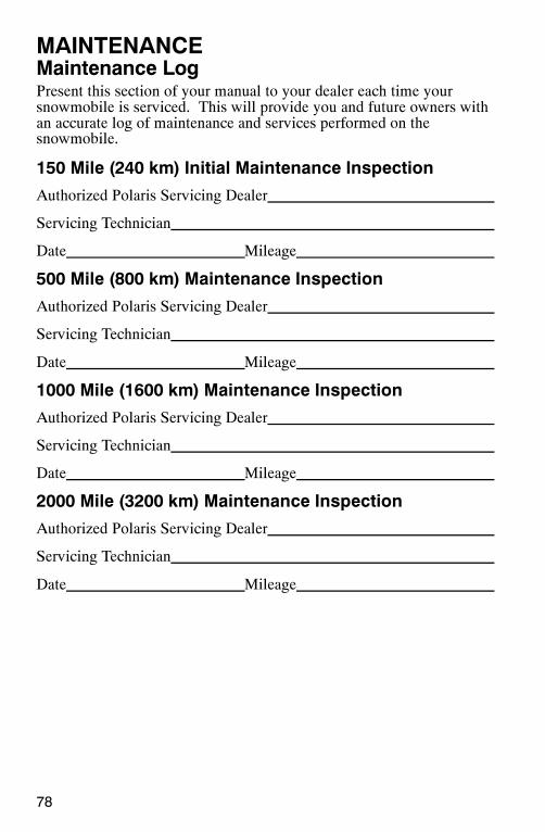
78
MAINTENANCEMaintenance LogPresent this section of your manual to your dealer each time yoursnowmobile is serviced. This will provide you and future owners withan accurate log of maintenance and services performed on thesnowmobile.
150 Mile (240 km) Initial Maintenance Inspection
Authorized Polaris Servicing Dealer
Servicing Technician
Date Mileage
500 Mile (800 km) Maintenance Inspection
Authorized Polaris Servicing Dealer
Servicing Technician
Date Mileage
1000 Mile (1600 km) Maintenance Inspection
Authorized Polaris Servicing Dealer
Servicing Technician
Date Mileage
2000 Mile (3200 km) Maintenance Inspection
Authorized Polaris Servicing Dealer
Servicing Technician
Date Mileage
79
MAINTENANCEMaintenance LogAdditional Services Performed
Authorized Polaris Servicing Dealer
Servicing Technician
Date Mileage
Type of ServiceAdditional Services Performed
Authorized Polaris Servicing Dealer
Servicing Technician
Date Mileage
Type of Service
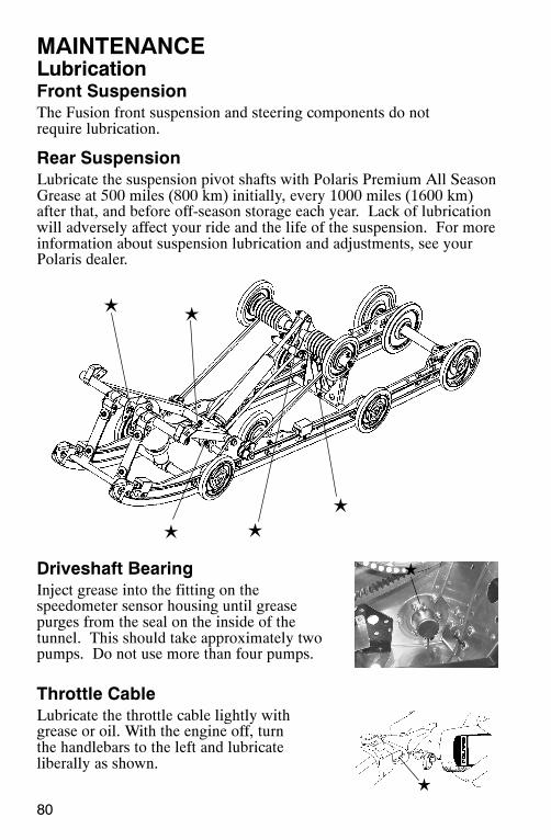
80
MAINTENANCELubricationFront SuspensionThe Fusion front suspension and steering components do notrequire lubrication.
Rear SuspensionLubricate the suspension pivot shafts with Polaris Premium All SeasonGrease at 500 miles (800 km) initially, every 1000 miles (1600 km)after that, and before off-season storage each year. Lack of lubricationwill adversely affect your ride and the life of the suspension. For moreinformation about suspension lubrication and adjustments, see yourPolaris dealer.
Driveshaft BearingInject grease into the fitting on thespeedometer sensor housing until greasepurges from the seal on the inside of thetunnel. This should take approximately twopumps. Do not use more than four pumps.
Throttle CableLubricate the throttle cable lightly withgrease or oil. With the engine off, turnthe handlebars to the left and lubricateliberally as shown.
L
L
LL
L
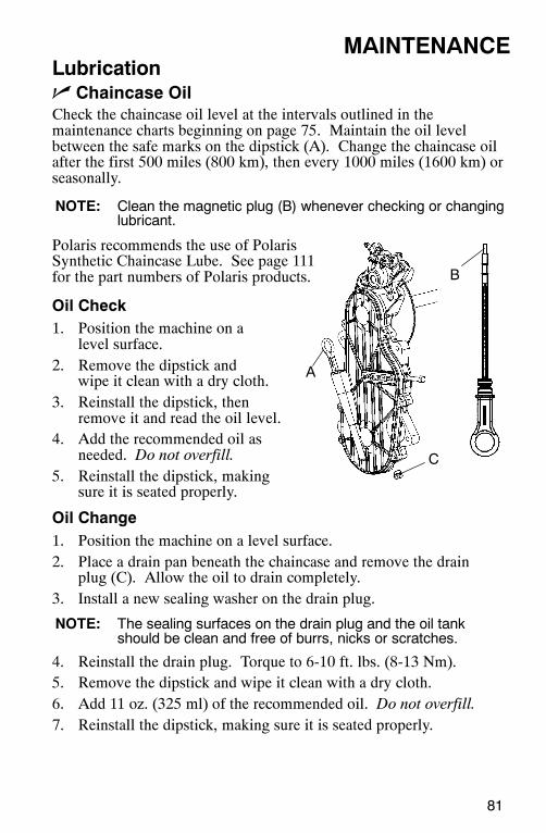
A
B
C
81
MAINTENANCELubricationn Chaincase OilCheck the chaincase oil level at the intervals outlined in themaintenance charts beginning on page 75. Maintain the oil levelbetween the safe marks on the dipstick (A). Change the chaincase oilafter the first 500 miles (800 km), then every 1000 miles (1600 km) orseasonally.
NOTE: Clean the magnetic plug (B) whenever checking or changinglubricant.
Polaris recommends the use of PolarisSynthetic Chaincase Lube. See page 111for the part numbers of Polaris products.
Oil Check1. Position the machine on a
level surface.2. Remove the dipstick and
wipe it clean with a dry cloth.3. Reinstall the dipstick, then
remove it and read the oil level.4. Add the recommended oil as
needed. Do not overfill.5. Reinstall the dipstick, making
sure it is seated properly.
Oil Change1. Position the machine on a level surface.2. Place a drain pan beneath the chaincase and remove the drain
plug (C). Allow the oil to drain completely.3. Install a new sealing washer on the drain plug.
NOTE: The sealing surfaces on the drain plug and the oil tankshould be clean and free of burrs, nicks or scratches.
4. Reinstall the drain plug. Torque to 6-10 ft. lbs. (8-13 Nm).5. Remove the dipstick and wipe it clean with a dry cloth.6. Add 11 oz. (325 ml) of the recommended oil. Do not overfill.7. Reinstall the dipstick, making sure it is seated properly.
82
MAINTENANCEGeneral MaintenanceSpark PlugsA new engine can cause temporary spark plug fouling due to thepreservative added during the assembly process. Avoid prolonged idlespeeds, which cause plug fouling and carbonization.
Change the spark plugs every 2000-2500 miles (3200-4000 km).
CAUTIONUsing non-recommended spark plugs can result in serious enginedamage. A spark plug with a heat range too high will alwayscause engine damage if the engine is operated in conditions moresevere than intended for that plug. Always use the spark plugsrecommended for your snowmobile.
S Use recommended spark plugs with the proper gap.S Use only resistor-type spark plugs.S Torque spark plugs to 18-22 ft. lbs. (24-30 Nm).S Always carry spare spark plugs.
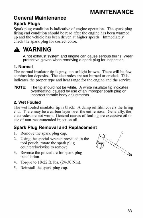
2
83
MAINTENANCEGeneral MaintenanceSpark PlugsSpark plug condition is indicative of engine operation. The spark plugfiring end condition should be read after the engine has been warmedup and the vehicle has been driven at higher speeds. Immediatelycheck the spark plug for correct color.
WARNINGA hot exhaust system and engine can cause serious burns. Wearprotective gloves when removing a spark plug for inspection.
1. NormalThe normal insulator tip is gray, tan or light brown. There will be fewcombustion deposits. The electrodes are not burned or eroded. Thisindicates the proper type and heat range for the engine and the service.
NOTE: The tip should not be white. A white insulator tip indicatesoverheating, caused by use of an improper spark plug orincorrect throttle body adjustments.
2. Wet FouledThe wet fouled insulator tip is black. A damp oil film covers the firingend. There may be a carbon layer over the entire nose. Generally, theelectrodes are not worn. General causes of fouling are excessive oil oruse of non-recommended injection oil.
Spark Plug Removal and Replacement1. Remove the spark plug cap.2. Using the special wrench provided in the
tool pouch, rotate the spark plugcounterclockwise to remove.
3. Reverse the procedure for spark pluginstallation.
4. Torque to 18-22 ft. lbs. (24-30 Nm).5. Reinstall the spark plug cap.
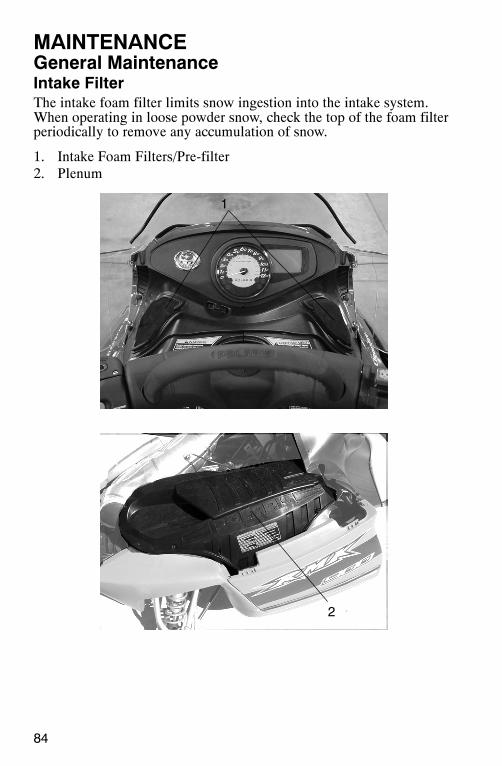
1
2
84
MAINTENANCEGeneral MaintenanceIntake FilterThe intake foam filter limits snow ingestion into the intake system.When operating in loose powder snow, check the top of the foam filterperiodically to remove any accumulation of snow.
1. Intake Foam Filters/Pre-filter2. Plenum
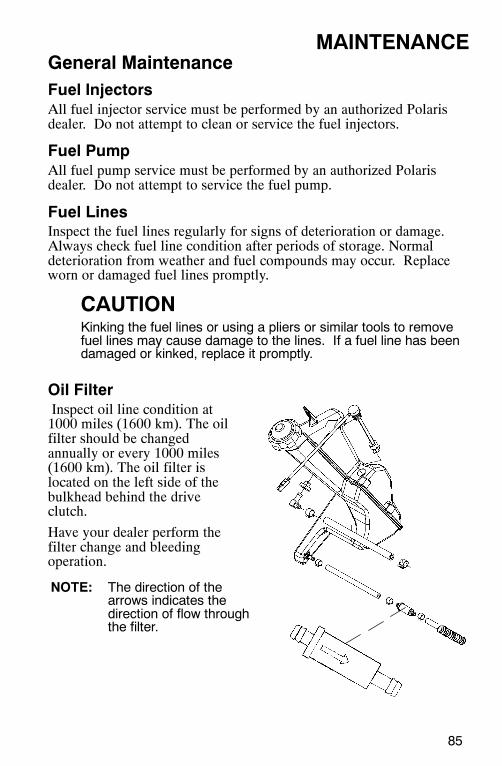
85
MAINTENANCEGeneral MaintenanceFuel InjectorsAll fuel injector service must be performed by an authorized Polarisdealer. Do not attempt to clean or service the fuel injectors.
Fuel PumpAll fuel pump service must be performed by an authorized Polarisdealer. Do not attempt to service the fuel pump.
Fuel LinesInspect the fuel lines regularly for signs of deterioration or damage.Always check fuel line condition after periods of storage. Normaldeterioration from weather and fuel compounds may occur. Replaceworn or damaged fuel lines promptly.
CAUTIONKinking the fuel lines or using a pliers or similar tools to removefuel lines may cause damage to the lines. If a fuel line has beendamaged or kinked, replace it promptly.
Oil FilterInspect oil line condition at1000 miles (1600 km). The oilfilter should be changedannually or every 1000 miles(1600 km). The oil filter islocated on the left side of thebulkhead behind the driveclutch.
Have your dealer perform thefilter change and bleedingoperation.
NOTE: The direction of thearrows indicates thedirection of flow throughthe filter.

86
MAINTENANCEGeneral MaintenanceExhaust SystemCheck the exhaust system for wear or damage at approximately 2000miles (3200 km). To inspect, allow the engine and exhaust system tocool completely. Open the hood and inspect the muffler and pipes forcracks or damage. Check for weak or missing retaining springs ordamper/support grommets.
WARNINGHot exhaust system parts can cause serious burns. Allowadequate time for the exhaust system to cool. Never perform thisprocedure with the engine running.
CoolantThe coolant supplied in the system is a 50/50 mixture ofethylene-glycol and distilled water. This mixture provides protectionagainst freezing at temperatures to -34° F (-37° C). If greaterprotection is required, the percentage of antifreeze to water may beincreased. Use Premium 60/40 anti-freeze coolant, which is alreadypremixed and ready to use. Do not dilute with water. Never exceed a60% antifreeze/40% water mixture. Contact your dealer if greaterprotection is required. See page 111 for Polaris products.
NOTE: Never add tap water to the cooling system. Minerals causedeposits and may react adversely with the metals in theengine and cooling system.

87
MAINTENANCEGeneral MaintenanceCoolant High Temperature Indicator LightThe high temperature indicator light is controlled by a switch in theECU. If the engine coolant reaches a certain temperature, the switchcompletes a circuit that turns the light on. If you must drive yourmachine after the high temperature indicator light has come on, driveslowly and stop frequently to allow the engine to cool down. See yourdealer.
n Coolant LevelThe engine coolant level is controlled by the recovery system. Therecovery system components are:
S Coolant bottle or overflow tankS Engine filler neckS Pressure capS Connecting hosesAlways maintain the coolant level between the minimum andmaximum marks on the coolant bottle (when engine is cold) to preventoverheating and serious engine damage.
CAUTIONOperating the snowmobile with insufficient coolant will result inoverheating and serious engine damage. Always maintain thecoolant level as recommended.
Flushing the Cooling SystemTo ensure that the coolant maintains its ability to protect the engine,the system should be completely drained every two years and a freshmixture of antifreeze and distilled water should be added. This servicemust be done when the engine is cold. Ask your Polaris dealer tocheck the coolant when he performs the fall tune-up on yoursnowmobile.
88
MAINTENANCEGeneral MaintenanceBleeding the Cooling SystemUse of a non-standard pressure cap will not allow the recovery systemto function properly. If the pressure cap needs replacement, contactyour dealer for the correct part.
WARNINGSteam and hot liquids will cause serious burns to your skin.Never bleed the cooling system or remove the pressure cap whenthe engine is warm or hot.
CAUTIONIf coolant flow becomes restricted or plugged, coolant loss, airlock or engine damage may result. Most cooling systems areequipped with a filter that should be periodically inspected orreplaced.
1. Remove the pressure cap and fill the coolant bottle with properlymixed coolant to the maximum mark.
2. Elevate the front end of the machine slightly to aid in bleeding ofthe heat exchangers.
3. Remove the bleed screw from the water outlet manifold and/or thethermostat housing. Allow the coolant to bleed through the systemuntil it runs out the bleed holes. Reinstall the bleed screw into themanifold.
4. Add coolant to the coolant bottle to the maximum mark.5. Start the engine and run at a fast idle for two to three minutes.
Loosen the bleed screw occasionally to purge any trapped air.6. Stop the engine and check the coolant bottle level. Fill as required.7. Feel the heat exchangers under the running boards. If the system is
bled properly, they’ll be warm to the touch. If they’re not, repeatstep 5. Lift the front of the machine slightly to assist in thebleeding.
8. Replace the pressure cap and carefully lower the front end of themachine.
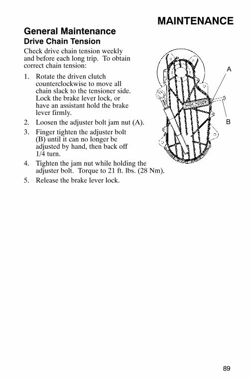
A
B
89
MAINTENANCEGeneral MaintenanceDrive Chain TensionCheck drive chain tension weeklyand before each long trip. To obtaincorrect chain tension:
1. Rotate the driven clutchcounterclockwise to move allchain slack to the tensioner side.Lock the brake lever lock, orhave an assistant hold the brakelever firmly.
2. Loosen the adjuster bolt jam nut (A).3. Finger tighten the adjuster bolt
(B) until it can no longer beadjusted by hand, then back off1/4 turn.
4. Tighten the jam nut while holding theadjuster bolt. Torque to 21 ft. lbs. (28 Nm).
5. Release the brake lever lock.
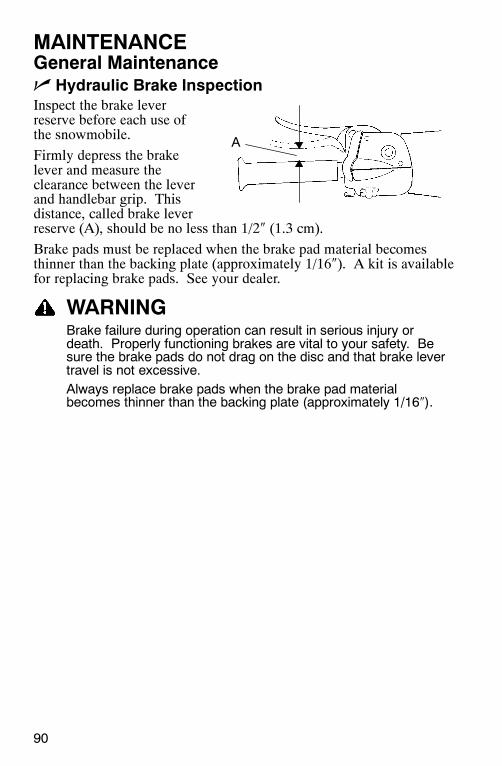
90
MAINTENANCEGeneral Maintenancen Hydraulic Brake InspectionInspect the brake leverreserve before each use ofthe snowmobile.
Firmly depress the brakelever and measure theclearance between the leverand handlebar grip. Thisdistance, called brake leverreserve (A), should be no less than 1/2″ (1.3 cm).
Brake pads must be replaced when the brake pad material becomesthinner than the backing plate (approximately 1/16″). A kit is availablefor replacing brake pads. See your dealer.
WARNINGBrake failure during operation can result in serious injury ordeath. Properly functioning brakes are vital to your safety. Besure the brake pads do not drag on the disc and that brake levertravel is not excessive.Always replace brake pads when the brake pad materialbecomes thinner than the backing plate (approximately 1/16″).
A
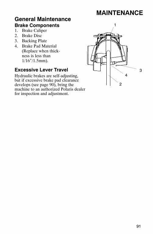
91
MAINTENANCEGeneral MaintenanceBrake Components1. Brake Caliper2. Brake Disc3. Backing Plate4. Brake Pad Material
(Replace when thick-ness is less than1/16″/1.5mm).
Excessive Lever TravelHydraulic brakes are self-adjusting,but if excessive brake pad clearancedevelops (see page 90), bring themachine to an authorized Polaris dealerfor inspection and adjustment.
1
2
34
92
MAINTENANCEGeneral MaintenanceBrake Fluid
WARNINGAfter opening a bottle of brake fluid, always discard any unusedportion. Never store or use a partial bottle. Brake fluid ishygroscopic, meaning it rapidly absorbs moisture from the air.The moisture causes the boiling temperature of the brake fluid todrop, which can lead to early brake fade and the possibility ofaccident or serious injury.
WARNINGKeep the master cylinder cover free of dirt and debris. The ventslits allow for diaphragm movement, and if they become plugged,movement of brake fluid below the diaphragm may be restricted,altering brake function.
CAUTIONBrake fluid will damage decals, paint and some plastics. Alwayswipe up spills immediately.
Replace brake fluid at least every two years with Polaris DOT 4 hightemperature brake fluid. See page 111 for the part numbers of Polarisproducts.
The brake fluid level can be seen through a plastic sight glass in thebrake reservoir. If the fluid is sufficient, the sight glass will be black.If the sight glass is any color other than black, add brake fluid.
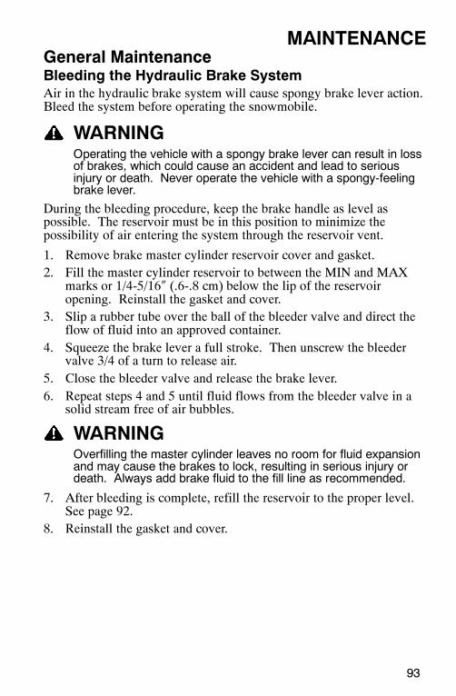
93
MAINTENANCEGeneral MaintenanceBleeding the Hydraulic Brake SystemAir in the hydraulic brake system will cause spongy brake lever action.Bleed the system before operating the snowmobile.
WARNINGOperating the vehicle with a spongy brake lever can result in lossof brakes, which could cause an accident and lead to seriousinjury or death. Never operate the vehicle with a spongy-feelingbrake lever.
During the bleeding procedure, keep the brake handle as level aspossible. The reservoir must be in this position to minimize thepossibility of air entering the system through the reservoir vent.
1. Remove brake master cylinder reservoir cover and gasket.2. Fill the master cylinder reservoir to between the MIN and MAX
marks or 1/4-5/16″ (.6-.8 cm) below the lip of the reservoiropening. Reinstall the gasket and cover.
3. Slip a rubber tube over the ball of the bleeder valve and direct theflow of fluid into an approved container.
4. Squeeze the brake lever a full stroke. Then unscrew the bleedervalve 3/4 of a turn to release air.
5. Close the bleeder valve and release the brake lever.6. Repeat steps 4 and 5 until fluid flows from the bleeder valve in a
solid stream free of air bubbles.
WARNINGOverfilling the master cylinder leaves no room for fluid expansionand may cause the brakes to lock, resulting in serious injury ordeath. Always add brake fluid to the fill line as recommended.
7. After bleeding is complete, refill the reservoir to the proper level.See page 92.
8. Reinstall the gasket and cover.

2
1
3
94
MAINTENANCEGeneral MaintenanceNOTE: Do not touch a halogen bulb with bare fingers. Oil from skin
leaves a residue, causing a hot spot that will shorten the lifeof the lamp.
Removing Halogen Bulbs1. Remove the plenum covering
from the headlight assembly.2. Lift the rubber boot to expose
the bulb.3. Push down on the spring (1)
to release it from the housing.4. With the wire harness (2) attached
to the bulb (3), withdraw the bulb from the housing.5. Grasp the bulb by its metal base and carefully separate the bulb
from the harness.
Installing Halogen Bulbs1. Hold the bulb by its metal base and install it into the wire harness.2. Insert the bulb into the housing.3. Connect the spring to the housing.4. Carefully flip the spring back into the housing, placing it around
the wire harness.5. Reinstall the plenum covering on the headlight assembly.6. Verify headlight aim.
Replacing Taillight Bulbs1. Remove the screws securing the
taillight lens.2. Push the bulb in and twist
counterclockwise and replace the bulb.3. Replace the taillight lens.
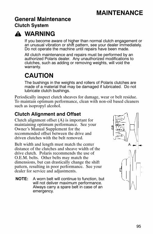
A
95
MAINTENANCEGeneral MaintenanceClutch System
WARNINGIf you become aware of higher than normal clutch engagement oran unusual vibration or shift pattern, see your dealer immediately.Do not operate the machine until repairs have been made.All clutch maintenance and repairs must be performed by anauthorized Polaris dealer. Any unauthorized modifications toclutches, such as adding or removing weights, will void thewarranty.
CAUTIONThe bushings in the weights and rollers of Polaris clutches aremade of a material that may be damaged if lubricated. Do notlubricate clutch bushings.
Periodically inspect clutch sheaves for damage, wear or belt residue.To maintain optimum performance, clean with non-oil based cleanerssuch as isopropyl alcohol.
Clutch Alignment and OffsetClutch alignment offset (A) is important formaintaining optimum performance. See yourOwner’s Manual Supplement for therecommended offset between the drive anddriven clutches with the belt removed.
Belt width and length must match the centerdistance of the clutches and sheave width of thedrive clutch. Polaris recommends the use ofO.E.M. belts. Other belts may match thedimensions, but can drastically change the shiftpattern, resulting in poor performance. See yourdealer for service and adjustments.
NOTE: A worn belt will continue to function, butwill not deliver maximum performance.Always carry a spare belt in case of anemergency.
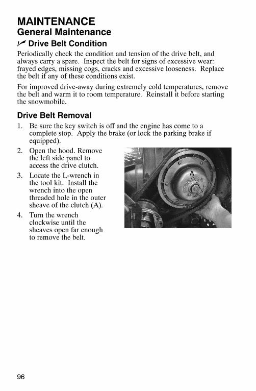
A
96
MAINTENANCEGeneral Maintenancen Drive Belt ConditionPeriodically check the condition and tension of the drive belt, andalways carry a spare. Inspect the belt for signs of excessive wear:frayed edges, missing cogs, cracks and excessive looseness. Replacethe belt if any of these conditions exist.
For improved drive-away during extremely cold temperatures, removethe belt and warm it to room temperature. Reinstall it before startingthe snowmobile.
Drive Belt Removal1. Be sure the key switch is off and the engine has come to a
complete stop. Apply the brake (or lock the parking brake ifequipped).
2. Open the hood. Removethe left side panel toaccess the drive clutch.
3. Locate the L-wrench inthe tool kit. Install thewrench into the openthreaded hole in the outersheave of the clutch (A).
4. Turn the wrenchclockwise until thesheaves open far enoughto remove the belt.
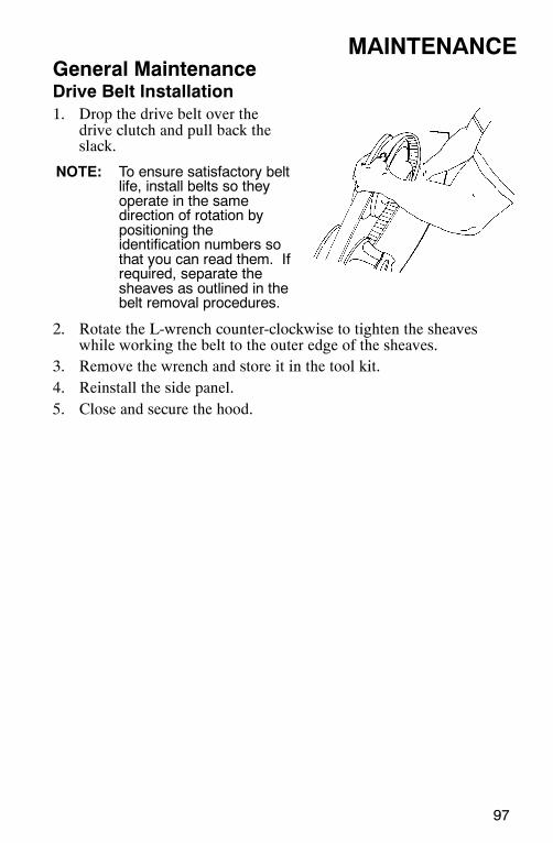
97
MAINTENANCEGeneral MaintenanceDrive Belt Installation1. Drop the drive belt over the
drive clutch and pull back theslack.
NOTE: To ensure satisfactory beltlife, install belts so theyoperate in the samedirection of rotation bypositioning theidentification numbers sothat you can read them. Ifrequired, separate thesheaves as outlined in thebelt removal procedures.
2. Rotate the L-wrench counter-clockwise to tighten the sheaveswhile working the belt to the outer edge of the sheaves.
3. Remove the wrench and store it in the tool kit.4. Reinstall the side panel.5. Close and secure the hood.
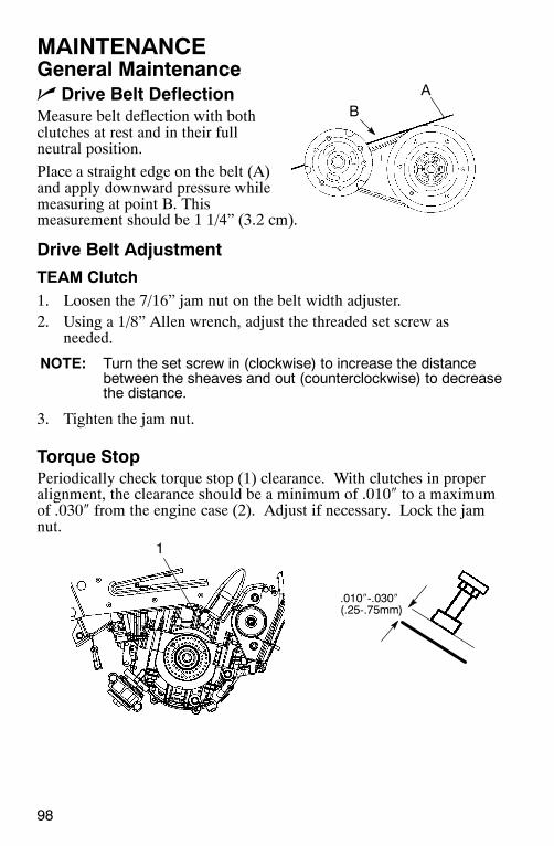
AB
1
.010″-.030″(.25-.75mm)
98
MAINTENANCEGeneral Maintenancen Drive Belt DeflectionMeasure belt deflection with bothclutches at rest and in their fullneutral position.
Place a straight edge on the belt (A)and apply downward pressure whilemeasuring at point B. Thismeasurement should be 1 1/4” (3.2 cm).
Drive Belt Adjustment
TEAM Clutch1. Loosen the 7/16” jam nut on the belt width adjuster.2. Using a 1/8” Allen wrench, adjust the threaded set screw as
needed.
NOTE: Turn the set screw in (clockwise) to increase the distancebetween the sheaves and out (counterclockwise) to decreasethe distance.
3. Tighten the jam nut.
Torque StopPeriodically check torque stop (1) clearance. With clutches in properalignment, the clearance should be a minimum of .010″ to a maximumof .030″ from the engine case (2). Adjust if necessary. Lock the jamnut.
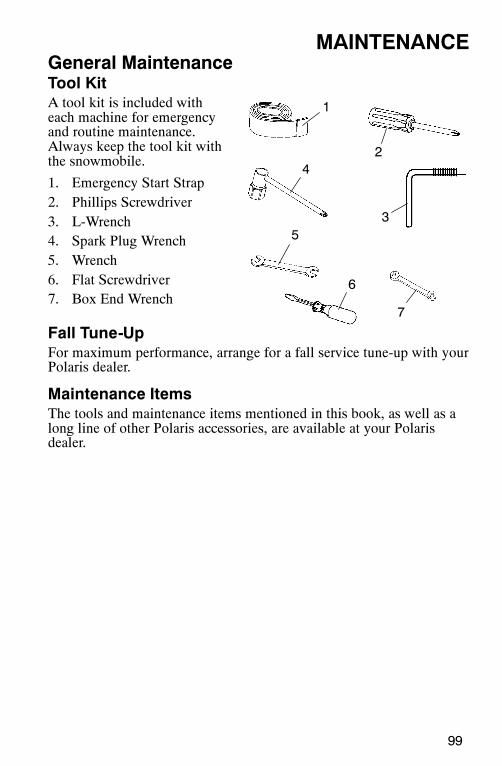
3
1
24
5
6
7
99
MAINTENANCEGeneral MaintenanceTool KitA tool kit is included witheach machine for emergencyand routine maintenance.Always keep the tool kit withthe snowmobile.
1. Emergency Start Strap2. Phillips Screwdriver3. L-Wrench4. Spark Plug Wrench5. Wrench6. Flat Screwdriver7. Box End Wrench
Fall Tune-UpFor maximum performance, arrange for a fall service tune-up with yourPolaris dealer.
Maintenance ItemsThe tools and maintenance items mentioned in this book, as well as along line of other Polaris accessories, are available at your Polarisdealer.
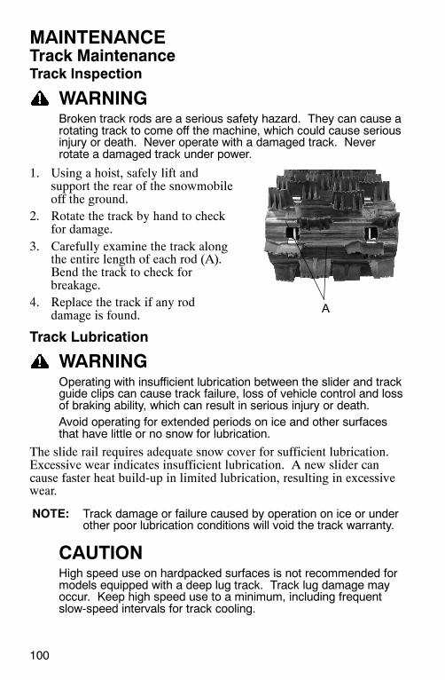
A
100
MAINTENANCETrack MaintenanceTrack Inspection
WARNINGBroken track rods are a serious safety hazard. They can cause arotating track to come off the machine, which could cause seriousinjury or death. Never operate with a damaged track. Neverrotate a damaged track under power.
1. Using a hoist, safely lift andsupport the rear of the snowmobileoff the ground.
2. Rotate the track by hand to checkfor damage.
3. Carefully examine the track alongthe entire length of each rod (A).Bend the track to check forbreakage.
4. Replace the track if any roddamage is found.
Track Lubrication
WARNINGOperating with insufficient lubrication between the slider and trackguide clips can cause track failure, loss of vehicle control and lossof braking ability, which can result in serious injury or death.Avoid operating for extended periods on ice and other surfacesthat have little or no snow for lubrication.
The slide rail requires adequate snow cover for sufficient lubrication.Excessive wear indicates insufficient lubrication. A new slider cancause faster heat build-up in limited lubrication, resulting in excessivewear.
NOTE: Track damage or failure caused by operation on ice or underother poor lubrication conditions will void the track warranty.
CAUTIONHigh speed use on hardpacked surfaces is not recommended formodels equipped with a deep lug track. Track lug damage mayoccur. Keep high speed use to a minimum, including frequentslow-speed intervals for track cooling.
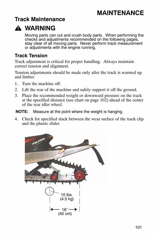
101
MAINTENANCETrack Maintenance
WARNINGMoving parts can cut and crush body parts. When performing thechecks and adjustments recommended on the following pages,stay clear of all moving parts. Never perform track measurementor adjustments with the engine running.
Track TensionTrack adjustment is critical for proper handling. Always maintaincorrect tension and alignment.
Tension adjustments should be made only after the track is warmed upand limber.
1. Turn the machine off.2. Lift the rear of the machine and safely support it off the ground.3. Place the recommended weight or downward pressure on the track
at the specified distance (see chart on page 102) ahead of the centerof the rear idler wheel.
NOTE: Measure at the point where the weight is hanging.
4. Check for specified slack between the wear surface of the track clipand the plastic slider.
16″(40 cm)
10 lbs.(4.5 kg)
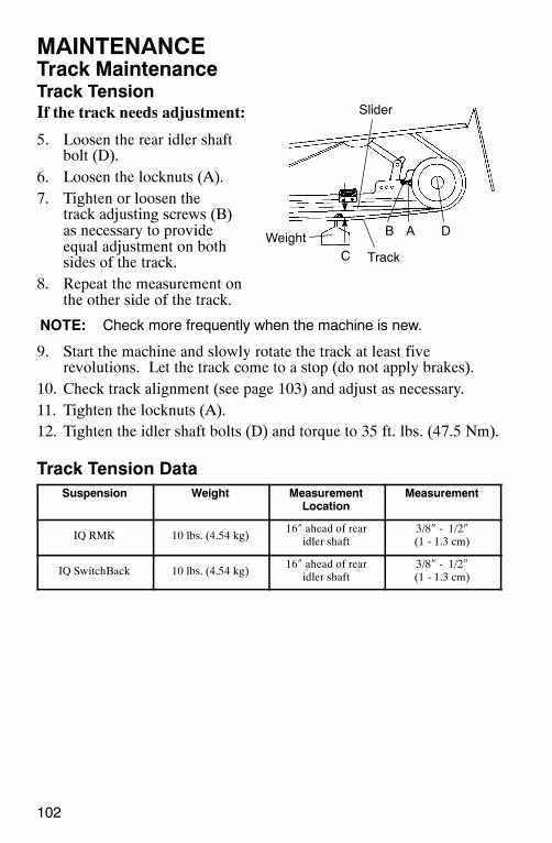
102
MAINTENANCETrack MaintenanceTrack TensionIf the track needs adjustment:
5. Loosen the rear idler shaftbolt (D).
6. Loosen the locknuts (A).7. Tighten or loosen the
track adjusting screws (B)as necessary to provideequal adjustment on bothsides of the track.
8. Repeat the measurement onthe other side of the track.
NOTE: Check more frequently when the machine is new.
9. Start the machine and slowly rotate the track at least fiverevolutions. Let the track come to a stop (do not apply brakes).
10. Check track alignment (see page 103) and adjust as necessary.11. Tighten the locknuts (A).12. Tighten the idler shaft bolts (D) and torque to 35 ft. lbs. (47.5 Nm).
Track Tension DataSuspension Weight Measurement
LocationMeasurement
IQ RMK 10 lbs. (4.54 kg)16″ ahead of rear
idler shaft3/8″ - 1/2″(1 - 1.3 cm)
IQ SwitchBack 10 lbs. (4.54 kg)16″ ahead of rear
idler shaft3/8″ - 1/2″(1 - 1.3 cm)
C
B A D
Track
Slider
Weight
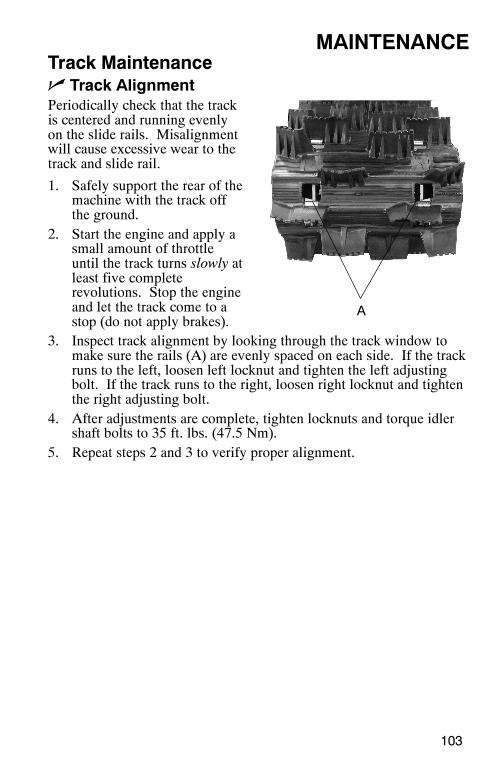
A
103
MAINTENANCETrack Maintenancen Track AlignmentPeriodically check that the trackis centered and running evenlyon the slide rails. Misalignmentwill cause excessive wear to thetrack and slide rail.
1. Safely support the rear of themachine with the track offthe ground.
2. Start the engine and apply asmall amount of throttleuntil the track turns slowly atleast five completerevolutions. Stop the engineand let the track come to astop (do not apply brakes).
3. Inspect track alignment by looking through the track window tomake sure the rails (A) are evenly spaced on each side. If the trackruns to the left, loosen left locknut and tighten the left adjustingbolt. If the track runs to the right, loosen right locknut and tightenthe right adjusting bolt.
4. After adjustments are complete, tighten locknuts and torque idlershaft bolts to 35 ft. lbs. (47.5 Nm).
5. Repeat steps 2 and 3 to verify proper alignment.
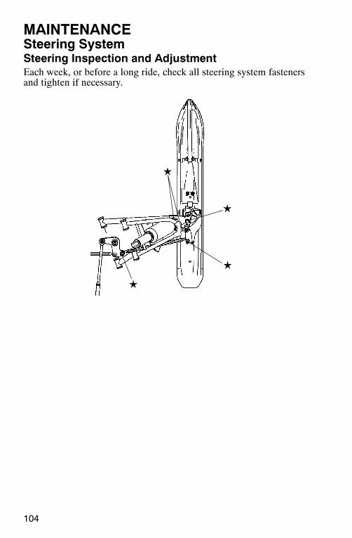
104
MAINTENANCESteering SystemSteering Inspection and AdjustmentEach week, or before a long ride, check all steering system fastenersand tighten if necessary.
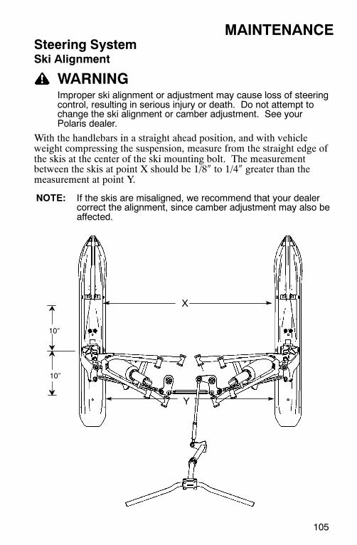
X
Y
10″
10″
105
MAINTENANCESteering SystemSki Alignment
WARNINGImproper ski alignment or adjustment may cause loss of steeringcontrol, resulting in serious injury or death. Do not attempt tochange the ski alignment or camber adjustment. See yourPolaris dealer.
With the handlebars in a straight ahead position, and with vehicleweight compressing the suspension, measure from the straight edge ofthe skis at the center of the ski mounting bolt. The measurementbetween the skis at point X should be 1/8″ to 1/4″ greater than themeasurement at point Y.
NOTE: If the skis are misaligned, we recommend that your dealercorrect the alignment, since camber adjustment may also beaffected.
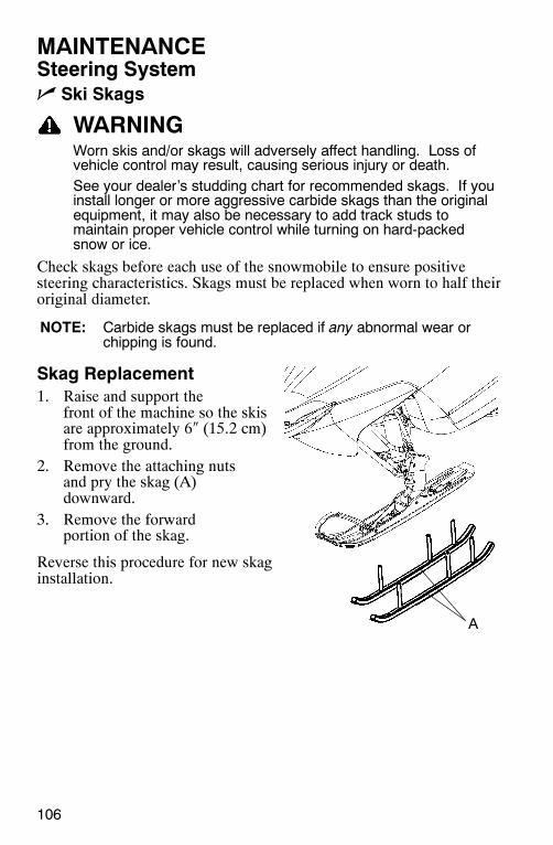
A
106
MAINTENANCESteering Systemn Ski Skags
WARNINGWorn skis and/or skags will adversely affect handling. Loss ofvehicle control may result, causing serious injury or death.See your dealer’s studding chart for recommended skags. If youinstall longer or more aggressive carbide skags than the originalequipment, it may also be necessary to add track studs tomaintain proper vehicle control while turning on hard-packedsnow or ice.
Check skags before each use of the snowmobile to ensure positivesteering characteristics. Skags must be replaced when worn to half theiroriginal diameter.
NOTE: Carbide skags must be replaced if any abnormal wear orchipping is found.
Skag Replacement1. Raise and support the
front of the machine so the skisare approximately 6″ (15.2 cm)from the ground.
2. Remove the attaching nutsand pry the skag (A)downward.
3. Remove the forwardportion of the skag.
Reverse this procedure for new skaginstallation.
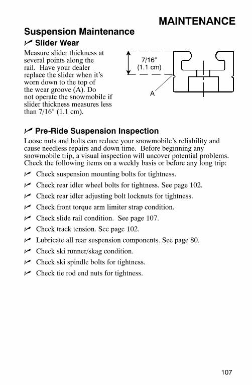
A
7/16″(1.1 cm)
107
MAINTENANCESuspension Maintenancen Slider WearMeasure slider thickness atseveral points along therail. Have your dealerreplace the slider when it’sworn down to the top ofthe wear groove (A). Donot operate the snowmobile ifslider thickness measures lessthan 7/16″ (1.1 cm).
n Pre-Ride Suspension InspectionLoose nuts and bolts can reduce your snowmobile’s reliability andcause needless repairs and down time. Before beginning anysnowmobile trip, a visual inspection will uncover potential problems.Check the following items on a weekly basis or before any long trip:
n Check suspension mounting bolts for tightness.
n Check rear idler wheel bolts for tightness. See page 102.
n Check rear idler adjusting bolt locknuts for tightness.
n Check front torque arm limiter strap condition.
n Check slide rail condition. See page 107.
n Check track tension. See page 102.
n Lubricate all rear suspension components. See page 80.
n Check ski runner/skag condition.
n Check ski spindle bolts for tightness.
n Check tie rod end nuts for tightness.

108
MAINTENANCESuspension Maintenance
Extended StorageOff-season or extended storage of your snowmobile requires preventivemeasures to aid against deterioration and to prolong the useful life ofmany components. See page 111 for the part numbers of Polarisproducts.
Cleaning and PreservationProper storage starts with cleaning, washing, and waxing the hood,chassis, and plastic parts. Wipe down remaining surfaces with a dampcloth. Clean and touch up with paint any rusted or previously paintedsurfaces. Be sure that corrosive salt and acids are removed fromsurfaces before beginning preservation with waxes and rust inhibitors(grease, oil or paint).
The machine should be stored in a dry garage or shed, out of directsunlight, and covered with a fabric snowmobile cover. Plastic tarp maycause condensation to form and damage snowmobile components.
Controls and LinkageAll bushings, spindle shafts, tie rod ends, and cables should receive alight coat of oil or grease.
109
MAINTENANCEExtended StorageBearingsGrease the jackshaft and drive shaft clutch side bearings with PolarisPremium All-Season Grease or a similar high quality grease to preventcorrosion.
Clutch and Drive SystemRemove the drive belt and store in a cool dry location. Do notlubricate clutch components, except the driven clutch shaft bushing asoutlined in the Master Repair Manual. See your dealer.
Engine ProtectionProper preparation of the engine and fuel system is vital to theprevention of rust and corrosion on precision engine parts duringstorage. Whenever the machine is stored for a period of more than 60days, the engine must be fogged with fogging oil. Follow the enginefogging instructions provided on the container.
Always add Premium Carbon Clean or a fuel conditioner/stabilizer tothe fuel tank. Follow the instructions on the container, running theengine for five minutes to get additives through the entire fuel system.Top off with fresh fuel. Do not allow the snowmobile to run out offuel. See page 67.
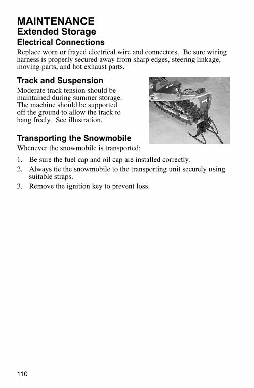
110
MAINTENANCEExtended StorageElectrical ConnectionsReplace worn or frayed electrical wire and connectors. Be sure wiringharness is properly secured away from sharp edges, steering linkage,moving parts, and hot exhaust parts.
Track and SuspensionModerate track tension should bemaintained during summer storage.The machine should be supportedoff the ground to allow the track tohang freely. See illustration.
Transporting the SnowmobileWhenever the snowmobile is transported:
1. Be sure the fuel cap and oil cap are installed correctly.2. Always tie the snowmobile to the transporting unit securely using
suitable straps.3. Remove the ignition key to prevent loss.

111
POLARIS PRODUCTSPart No. Description
Engine Lubricants
2870791 Fogging Oil (12 oz. Aerosol)
2871098 Premium 2-Cycle Engine Oil (qt.)
2871097 Premium 2-Cycle Engine Oil (gal.)
2871240 Premium 2-Cycle Engine Oil (2.5 gal.)
2871721 Premium Gold Synthetic 2-Cycle Engine Oil (qt.)
2871722 Premium Gold Synthetic 2-Cycle Engine Oil (gal.)
2872347 Premium Gold Synthetic 2-Cycle Engine Oil (2.5 gal.)
2874438 VES II Synthetic 2-Cycle Engine Oil (qt.)
2874439 VES II Synthetic 2-Cycle Engine Oil (gal.)
2874443 VES II Synthetic 2-Cycle Engine Oil (2.5 gal.)
Chaincase Lubricants
2873105 Synthetic Chaincase Lubricant (qt.)
2872951 Synthetic Chaincase Lubricant (12 oz.)
Grease / Specialized Lubricants
2871312 Grease Gun Kit, Premium All Season (3 oz.)
2871322 Premium All Season Grease (3 oz. cartridge)
2871423 Premium All Season Grease (14 oz. cartridge)
2871329 Dielectric Grease (Nyogelt)
Coolant
2871323 Anitfreeze, 60/40 Premix (gal.)
2871534 Anitfreeze, 60/40 Premix (qt.)
Additives / Miscellaneous
2871326 Carbon Clean Plus (12 oz.)
2870652 Fuel Stabilizer (16 oz.)
2870990 DOT3 Brake Fluid (12 oz.)
2872893 Engine Degreaser (12 oz.)
2870505 Isopropyl
2872889 Brake and Clutch Cleaner
2872890 Carb and Throttle Body Cleaner
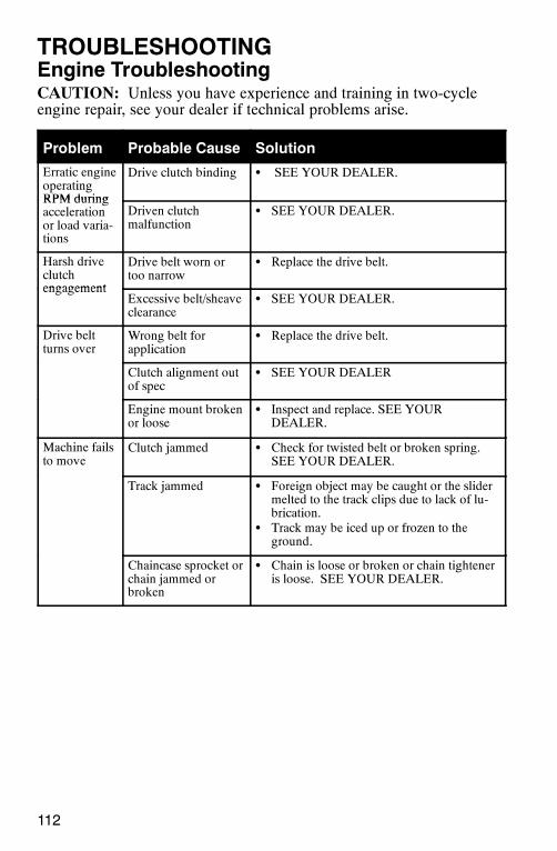
112
TROUBLESHOOTINGEngine TroubleshootingCAUTION: Unless you have experience and training in two-cycleengine repair, see your dealer if technical problems arise.
Problem Probable Cause Solution
Erratic engineoperatingRPM during
Drive clutch binding S SEE YOUR DEALER.
RPM duringaccelerationor load varia-tions
Driven clutchmalfunction
S SEE YOUR DEALER.
Harsh driveclutchengagement
Drive belt worn ortoo narrow
S Replace the drive belt.
engagementExcessive belt/sheaveclearance
S SEE YOUR DEALER.
Drive beltturns over
Wrong belt forapplication
S Replace the drive belt.
Clutch alignment outof spec
S SEE YOUR DEALER
Engine mount brokenor loose
S Inspect and replace. SEE YOURDEALER.
Machine failsto move
Clutch jammed S Check for twisted belt or broken spring.SEE YOUR DEALER.
Track jammed S Foreign object may be caught or the slidermelted to the track clips due to lack of lu-brication.
S Track may be iced up or frozen to theground.
Chaincase sprocket orchain jammed orbroken
S Chain is loose or broken or chain tighteneris loose. SEE YOUR DEALER.
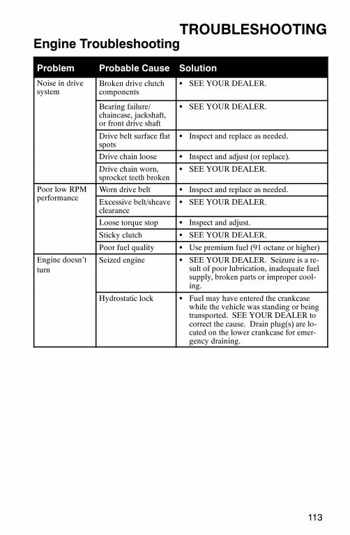
113
TROUBLESHOOTINGEngine Troubleshooting
Problem Probable Cause Solution
Noise in drivesystem
Broken drive clutchcomponents
S SEE YOUR DEALER.
Bearing failure/chaincase, jackshaft,or front drive shaft
S SEE YOUR DEALER.
Drive belt surface flatspots
S Inspect and replace as needed.
Drive chain loose S Inspect and adjust (or replace).
Drive chain worn,sprocket teeth broken
S SEE YOUR DEALER.
Poor low RPMf
Worn drive belt S Inspect and replace as needed.performance Excessive belt/sheave
clearanceS SEE YOUR DEALER.
Loose torque stop S Inspect and adjust.
Sticky clutch S SEE YOUR DEALER.
Poor fuel quality S Use premium fuel (91 octane or higher)
Engine doesn’tturn
Seized engine S SEE YOUR DEALER. Seizure is a re-sult of poor lubrication, inadequate fuelsupply, broken parts or improper cool-ing.
Hydrostatic lock S Fuel may have entered the crankcasewhile the vehicle was standing or beingtransported. SEE YOUR DEALER tocorrect the cause. Drain plug(s) are lo-cated on the lower crankcase for emer-gency draining.
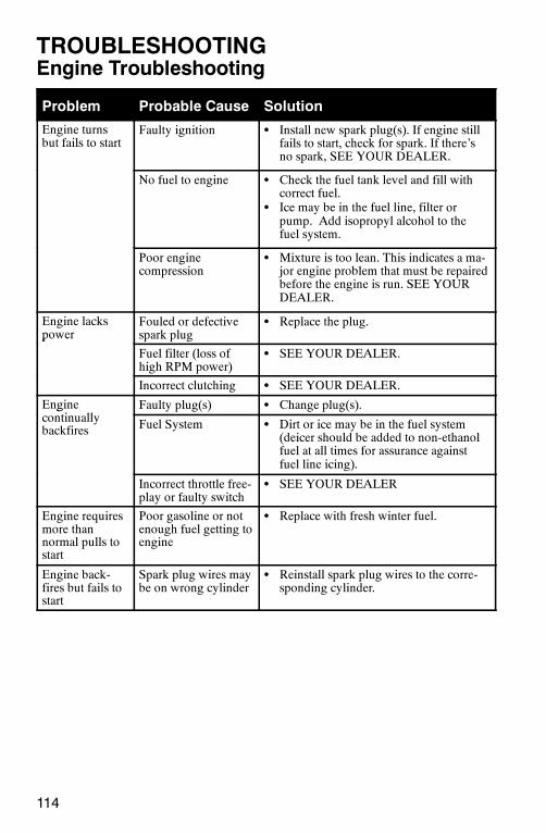
114
TROUBLESHOOTINGEngine Troubleshooting
Problem Probable Cause Solution
Engine turnsbut fails to start
Faulty ignition S Install new spark plug(s). If engine stillfails to start, check for spark. If there’sno spark, SEE YOUR DEALER.
No fuel to engine S Check the fuel tank level and fill withcorrect fuel.
S Ice may be in the fuel line, filter orpump. Add isopropyl alcohol to thefuel system.
Poor enginecompression
S Mixture is too lean. This indicates a ma-jor engine problem that must be repairedbefore the engine is run. SEE YOURDEALER.
Engine lackspower
Fouled or defectivespark plug
S Replace the plug.power
Fuel filter (loss ofhigh RPM power)
S SEE YOUR DEALER.
Incorrect clutching S SEE YOUR DEALER.
Enginei ll
Faulty plug(s) S Change plug(s).gcontinuallybackfires Fuel System S Dirt or ice may be in the fuel system
(deicer should be added to non-ethanolfuel at all times for assurance againstfuel line icing).
Incorrect throttle free-play or faulty switch
S SEE YOUR DEALER
Engine requiresmore thannormal pulls tostart
Poor gasoline or notenough fuel getting toengine
S Replace with fresh winter fuel.
Engine back-fires but fails tostart
Spark plug wires maybe on wrong cylinder
S Reinstall spark plug wires to the corre-sponding cylinder.
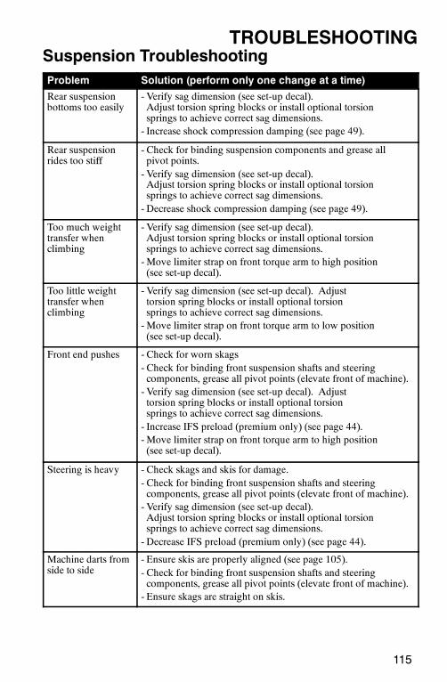
115
TROUBLESHOOTINGSuspension TroubleshootingProblem Solution (perform only one change at a time)
Rear suspensionbottoms too easily
- Verify sag dimension (see set-up decal).Adjust torsion spring blocks or install optional torsionsprings to achieve correct sag dimensions.- Increase shock compression damping (see page 49).
Rear suspensionrides too stiff
- Check for binding suspension components and grease allpivot points.- Verify sag dimension (see set-up decal).Adjust torsion spring blocks or install optional torsionsprings to achieve correct sag dimensions.- Decrease shock compression damping (see page 49).
Too much weighttransfer whenclimbing
- Verify sag dimension (see set-up decal).Adjust torsion spring blocks or install optional torsionsprings to achieve correct sag dimensions.-Move limiter strap on front torque arm to high position(see set-up decal).
Too little weighttransfer whenclimbing
- Verify sag dimension (see set-up decal). Adjusttorsion spring blocks or install optional torsionsprings to achieve correct sag dimensions.-Move limiter strap on front torque arm to low position(see set-up decal).
Front end pushes - Check for worn skags- Check for binding front suspension shafts and steeringcomponents, grease all pivot points (elevate front of machine).- Verify sag dimension (see set-up decal). Adjusttorsion spring blocks or install optional torsionsprings to achieve correct sag dimensions.- Increase IFS preload (premium only) (see page 44).-Move limiter strap on front torque arm to high position(see set-up decal).
Steering is heavy - Check skags and skis for damage.- Check for binding front suspension shafts and steeringcomponents, grease all pivot points (elevate front of machine).- Verify sag dimension (see set-up decal).Adjust torsion spring blocks or install optional torsionsprings to achieve correct sag dimensions.- Decrease IFS preload (premium only) (see page 44).
Machine darts fromside to side
- Ensure skis are properly aligned (see page 105).- Check for binding front suspension shafts and steeringcomponents, grease all pivot points (elevate front of machine).- Ensure skags are straight on skis.
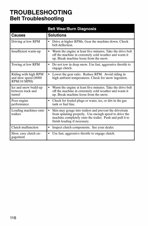
116
TROUBLESHOOTINGBelt Troubleshooting
Belt Wear/Burn Diagnosis
Causes Solutions
Driving at low RPM S Drive at higher RPMs. Gear the machine down. Checkbelt deflection.
Insufficient warm-up S Warm the engine at least five minutes. Take the drive beltoff the machine in extremely cold weather and warm itup. Break machine loose from the snow.
Towing at low RPM S Do not tow in deep snow. Use fast, aggressive throttle toengage clutch.
Riding with high RPMand slow speed (8000RPM/10 MPH)
S Lower the gear ratio. Reduce RPM. Avoid riding inhigh ambient temperatures. Check for snow ingestion.
Ice and snow build-upbetween track andtunnel
S Warm the engine at least five minutes. Take the drive beltoff the machine in extremely cold weather and warm itup. Break machine loose from the snow.
Poor engineperformance
S Check for fouled plugs or water, ice, or dirt in the gastank or fuel line.
Loading machines ontotrailers
S Skis may gouge into trailers and prevent the drivetrainfrom spinning properly. Use enough speed to drive themachine completely onto the trailer. Push and pull it tofinish loading if necessary.
Clutch malfunction S Inspect clutch components. See your dealer.
Slow, easy clutch en-gagement
S Use fast, aggressive throttle to engage clutch.
117
WARRANTYService And Warranty InformationObtaining Service and Warranty AssistanceRead and understand the service data and the Polaris warrantyinformation contained in this manual. Contact your Polaris dealer forreplacement parts, service or warranty. Your dealer receives frequentupdates on changes, modifications and tips on snowmobilemaintenance, which may supersede information contained in thismanual. Your dealer is also familiar with Polaris policies andprocedures and will be happy to assist you.When contacting us about parts, service, or warranty, always providethe following information:
1. Serial number 5. Details of trouble experienced2. Model number 6. Length of time and conditions of operation3. Dealer name 7. Previous correspondence4. Date of purchase
Use the page provided near the front of your Owner’s Manual to recordthe identification numbers of your snowmobile and its engine.
Polaris Customer ServiceUnited States: 1-763-417-8650
Canada: 1-204-925-7100
Polaris Anti-Theft SystemThe Polaris anti-theft system (PATS) monitoring program is designedto aid owners of registered snowmobiles in recovery of stolenmachines.
Administration1. Polaris snowmobile owner reports theft.
A. In addition to notifying the proper law enforcement offi-cials, the owner must call Polaris Customer Service.
B. Owners must provide their name, address, telephone num-ber and the model and serial number of stolen machines.
2. Polaris warranty will provide all dealerships with a monthlyupdated list of all stolen units to further monitor thefts.
3. Polaris warranty will aid in notifying the proper owner when a unitis recovered.

118
WARRANTYLimited WarrantyPolaris Sales Inc., 2100 Highway 55, Medina, MN 55340, provides a ONE YEAR LIM-ITED WARRANTY on all components of the Polaris snowmobile against defects inmaterial or workmanship. This warranty covers the parts and labor charges for repair orreplacement of defective parts that are covered by this warranty. The warranty begins onthe date of purchase. This warranty is transferrable to another consumer, during the war-ranty period, through a Polaris dealer.
RegistrationAt the time of sale, the Warranty Registration Form must be completed by your dealerand submitted to Polaris within ten days. Upon receipt of this registration, Polaris willrecord the registration for warranty. No verification of registration will be sent to thepurchaser as the copy of the Warranty Registration Form will be the warranty entitle-ment. If you have not signed the original registration and received the customer copy,please contact your dealer immediately. NO WARRANTY COVERAGE WILL BEALLOWED UNLESS THE SNOWMOBILE IS REGISTERED WITH POLARIS.
Initial dealer preparation and setup of your snowmobile is very important in ensuringtrouble-free operation. Purchasing a snowmobile in the crate or without proper dealersetup will void your warranty coverage.
Warranty Coverage and ExclusionsLimitations of warranties and remediesThis warranty excludes any failures not caused by a defect in material or workmanship.The warranty does not cover accidental damage, normal wear and tear, abuse or improperhandling. The warranty also does not cover any snowmobile that has been structurallyaltered, neglected, improperly maintained, used for racing or used for purposes otherthan for which it was manufactured. The warranty does not cover any damages that oc-cur during trailer transit or as a result of unauthorized service or parts. In addition, thiswarranty does not cover physical damage to paint or finish, stress cracks, tearing or punc-turing of upholstery material, corrosion or defects in parts, components or the snowmo-bile due to fire, explosions or any other cause beyond Polaris’ control.
This warranty does not cover the use of unauthorized lubricants, chemicals, or fuels thatare not compatible with the snowmobile.
The exclusive remedy for breach of this warranty shall be, at Polaris’ exclusive option,repair or replacement of any defective materials, or components or products. THE REM-EDIES SET FORTH IN THIS WARRANTY ARE THE ONLY REMEDIES AVAIL-ABLE TO ANY PERSON FOR BREACH OF THIS WARRANTY. POLARIS SHALLHAVE NO LIABILITY TO ANY PERSON FOR INCIDENTAL, CONSEQUENTIALOR SPECIAL DAMAGES OF ANY DESCRIPTION, WHETHER ARISING OUT OFEXPRESS OR IMPLIED WARRANTY OR ANY OTHER CONTRACT, NEG-LIGENCE, OR OTHER TORT OR OTHERWISE. Some states do not permit the exclu-sion or limitation of incidental or consequential damages or implied warranties, so theabove limitations or exclusions may not apply to you if inconsistent with controllingstate law.
119
WARRANTYLimitations of warranties and remediesALL IMPLIED WARRANTIES (INCLUDING BUT NOT LIMITED TO THE IM-PLIED WARRANTIES OF MERCHANTABILITY AND FITNESS FOR A PARTICU-LAR PURPOSE) ARE LIMITED IN DURATION TO THE ABOVE ONE YEARWARRANTY PERIOD. POLARIS FURTHER DISCLAIMS ALL EXPRESS WAR-RANTIES NOT STATED IN THIS WARRANTY. Some states do not allow limitationson how long an implied warranty lasts, so the above limitation may not apply to you ifinconsistent with controlling state law.
How to Obtain Warranty ServiceIf your snowmobile requires warranty service, you must take it to a Polaris dealer autho-rized to repair Polaris snowmobiles. When requesting warranty service you must presentyour copy of the Warranty Registration form to the dealer. (The cost of transportation toand from the dealer is YOUR responsibility). Polaris recommends that you use youroriginal selling dealer; however, you may use any Polaris Servicing Dealer to performwarranty service.
Please work with your dealer to resolve any warranty issues. Your dealer will contact theappropriate personnel at Polaris if additional assistance is needed.
This warranty gives you specific legal rights, and you may also have other rights whichvary from state to state.
If any of the above terms are void because of state or federal law, all other warranty termswill remain in effect.
Engine Oil1. Mixing oil brands or using non-recommended oil may cause engine damage. Werecommend the use of Polaris engine oil.
2. Damage resulting from the use of non-recommended lubricants may not be coveredby warranty.
120
WARRANTYConditions and ExclusionsIn order to qualify for warranty, the product must have been properly set up and tested bya Polaris Dealer (if applicable). Failure of any dealer to perform the required vehicle Pre--Delivery Inspection, perform all applicable service bulletins and have the consumer signthe PDI form prior to delivery may void the warranty. Failure to provide proof of re-quired periodic maintenance upon request may result in denial of warranty coverage. Useof the recommended Polaris products for lubrication and maintenance as directed by theOwner’s manual is highly recommended. Should a failure occur during the warrantyperiod resulting from the use of non-recommended products, warranty coverage may bedenied.
Warranty does not apply to parts exposed to friction surfaces, stresses, environmentalconditions and/or contamination. The following items are excluded from warranty con-sideration if the failure was due to wear or not the direct result of a defect:
Skis Ski wear rodsTracks Slide railsSuspension components Finished and unfinished surfacesBrake components Carburetor/Throttle body componentsSeat components Engine componentsClutches and components Drive beltsSteering components Hydraulic componentsBatteries Circuit breakers/FusesLight bulbs/Sealed beam lamps Electronic componentsIdler wheels
Warranty applies to the product only and does not allow for coverage of personal loss.Some items are considered “consumable,” meaning they are considered part of normalmaintenance or part of completing an effective repair. The following items are excludedfrom warranty coverage in the event of a warranty claim:
Spark Plugs Lubricants such as oil, grease, etc.Filters Batteries (unless defective)Fuel Cosmetic damage/repairSealants CoolantsHotel fees MealsTowing charges Shipping/ handling feesMileage Product pick-up/deliveryRentals/Loss of product use Loss of vacation/personal time
This warranty also excludes failures resulting from improper lubrication; improper en-gine timing; improper fuel; surface imperfections caused by external stress, heat, cold orcontamination; operator error or abuse; improper component alignment, tension, adjust-ment or altitude compensation; failure due to snow, water, dirt or other foreign substanceingestion/contamination; improper maintenance; modified components; use of aftermar-ket components resulting in failure; unauthorized repairs; repairs made after the warrantyperiod expires or by an unauthorized repair center; use of the product in competition orfor commercial purposes. Warranty will not apply to any product which has been dam-aged by abuse, accident, fire or any other casualty not determined a defect of materials orworkmanship.

121
WARRANTYPolaris Second Year Engine Service ContractSecond Year Engine Service Contract is standard on all eligible new and unusedsnowmobiles that were Snow Checked through an authorized Polaris dealer during theMarch/April Snow Check promotion. The free Second Year Engine Service Contract ishonored by all authorized Polaris snowmobile dealers in North America and istransferable 120 days after the original purchase date, free of charge, through any Polarissnowmobile dealer. Coverage on Snow Check units is automatic. Although you do notreceive a warranty card, your dealership should have printed a copy of the warrantyregistration form. This form is your proof of warranty.
Consumer ExclusionsS Each repair visit after the first twelve months of standard warranty coverage is subject
to a $50 deductible.S The free Second Year Engine Service Contract applies to the first 5,000 miles or two
(2) calendar years from date of purchase, whichever comes first. Tampering with theodometer shall void all warranties/service contracts. No extensions to coverage underthis engine service contract can be given. Used snowmobiles are not eligible underthis program.
S Snowmobiles used for commercial purposes or for racing are excluded from cover-age.
CoverageCoverage for second year engine failures due to defects in materials and workmanshipwill be determined by Polaris in its sole discretion. Coverage is automatic with noadditional paperwork required. The free Second Year Engine Service Contract is subjectto a $50 deductible per visit. Regular, documented service maintenance visits arerequired to validate this warranty.
A partial list of items excluded from coverage includes:
S Damage due to accident, fire, explosion, theft, or other causes beyond Polaris’ control.S Damage caused by the failure of other components of the snowmobile.S Failures caused by improper fuel or oil.S Piston seizures, unless caused by a defective engine component.S Failures caused due to improper adjustments.
S Failure due to unauthorized service.S Failures due to lack of service as required in the owner’s manual or Polaris updates.
This includes off-season storage as listed in the owner’s manual.S Failure due to use of unauthorized parts or modifications.S Normal wear parts, including but not limited to spark plugs, hoses, batteries, controls,
and recoil ropes are excluded from coverage. Gaskets are covered, as are intake andexhaust manifolds excluding paint coverage.
S Electrical coverage is limited to the ECU box, coils, stator plate, and sensors. Wiringand other electrical components are excluded from coverage.
S Cooling system coverage is limited to the water pump assembly and components, fan,fan bearings, temperature sensor, gasket and seals.
S Non wear related throttle body parts are covered. The fuel pump is covered.S Clutches and related clutch parts, including but not limited to, the drive belt, are ex-
cluded from coverage.S Electrical components are excluded from coverage.S Gearcases and transmissions are excluded from coverage.
122
WARRANTYExported VehiclesEXCEPT WHERE SPECIFICALLY REQUIRED BY LAW, THERE IS NO WAR-RANTY OR SERVICE BULLETIN COVERAGE ON THIS VEHICLE IF IT IS SOLDOUTSIDE THE COUNTRY OF THE SELLING DEALER’S AUTHORIZED LOCA-TION.This policy does not apply to vehicles that have received authorization for export fromPolaris Industries. Dealers may not give authorization for export. You should consult anauthorized dealer to determine this vehicle’s warranty or service bulletin coverage if youhave any questions.This policy does not apply to vehicles registered to government officials or military per-sonnel on assignment outside the country of the selling dealer’s authorized location.This policy does not apply to Safety Recalls.
How to Get ServiceIn the Country where your vehicle was purchased:Warranty or Service Bulletin repairs must be done by an authorized Polaris dealer. If youmove or are traveling within the country where your vehicle was purchased, Warranty orService Bulletin repairs may be requested from any authorized Polaris dealer who sellsthe same line as your vehicle.Outside the Country where your vehicle was purchased:If you are traveling temporarily outside the country where your vehicle was purchased,you should take your vehicle to an authorized Polaris dealer. You must show the dealerphoto identification from the country of the selling dealer’s authorized location as proofof residence. Upon residence verification, the servicing dealer will be authorized to per-form the warranty repair.If You Move:If you move to another country, be sure to contact Polaris Customer Assistance and thecustoms department of the destination country before you move. Vehicles importationrules vary considerably from country to country. You may be required to present docu-mentation of your move to Polaris Industries in order to continue your warranty cover-age. You may also be required to obtain documentation from Polaris Industries in orderto register your vehicle in your new country.If Purchased From A Private Party:If you purchase a Polaris product from a private citizen outside of the country in whichthe vehicle was originally purchased, all warranty coverage will be denied.
NoticeIf your vehicle is registered outside of the country where it was purchased, and you havenot followed the procedure set out above, your vehicle will no longer be eligible for war-ranty or service bulletin coverage of any kind. (Vehicles registered to Government offi-cials or military personnel on assignment outside of the country where the vehicle waspurchased will continue to be covered by the basic warranty.)
For questions call Polaris Customer Assistance (see page 117).
123
INDEXA
Access Panel 30. . . . . . . . . . . . . . . . . . .Accessories 52. . . . . . . . . . . . . . . . . . . .Adjustable Headlights 30. . . . . . . . . . . .Avalanches 16. . . . . . . . . . . . . . . . . . . .
BBearings 109. . . . . . . . . . . . . . . . . . . . .Before Starting the Engine 56-59. . . . . .Belt Troubleshooting 116. . . . . . . . . . .Bleeding the Cooling System 88. . . . . .Bleeding the Hydraulic Brake System 93Brake Components 91. . . . . . . . . . . . . .Brake Fluid 92. . . . . . . . . . . . . . . . . . . .Brake Lever Travel 57. . . . . . . . . . . . . .Brake, Park 58. . . . . . . . . . . . . . . . . . . .Bulb Replacement 94. . . . . . . . . . . . . . .
CChaincase Oil 81. . . . . . . . . . . . . . . . . .Cleaning and Preservation 108. . . . . . . .Clutch Alignment 95. . . . . . . . . . . . . . .Clutch and Drive System 109. . . . . . . .Clutch Cover 23. . . . . . . . . . . . . . . . . . .Clutch System 95. . . . . . . . . . . . . . . . . .Clutches 19. . . . . . . . . . . . . . . . . . . . . .Cold Weather Drive-Away 19. . . . . . . .Controls and Linkage 108. . . . . . . . . . .Coolant 86. . . . . . . . . . . . . . . . . . . . . . .Coolant Level 87. . . . . . . . . . . . . . . . . .
DDaily Storage 73. . . . . . . . . . . . . . . . . .Detonation Elimination Technology 31.Digital Display Identification 32. . . . . .Disabled Operators 14. . . . . . . . . . . . . .Drive Belt 19. . . . . . . . . . . . . . . . . . . . .Drive Belt Adjustment 98. . . . . . . . . . .Drive Belt Condition 96. . . . . . . . . . . . .Drive Belt Deflection 98. . . . . . . . . . . .Drive Belt Installation 97. . . . . . . . . . . .Drive Belt Removal 96. . . . . . . . . . . . .Drive Chain Tension 89. . . . . . . . . . . . .Driver Awareness 15. . . . . . . . . . . . . . .Driveshaft Bearing 80. . . . . . . . . . . . . .Driving Downhill 17. . . . . . . . . . . . . . .Driving in Hilly Terrain 18. . . . . . . . . .Driving on Slippery Surfaces 17. . . . . .Driving Responsibly 21. . . . . . . . . . . . .
EElectrical Connections 110. . . . . . . . . .Electronic Reverse 72. . . . . . . . . . . . . .Emergency Starting 71. . . . . . . . . . . . . .Emergency Stopping 71. . . . . . . . . . . . .
EEngine Break-In 62. . . . . . . . . . . . . . . .Engine Protection 109. . . . . . . . . . . . . .Engine Safety 12. . . . . . . . . . . . . . . . . .Engine Stop Switch 60, 69. . . . . . . . . .Engine Troubleshooting 112-114. . . . . .Excessive Speed 14. . . . . . . . . . . . . . . .Exhaust System 86. . . . . . . . . . . . . . . . .
FFall Tune-Up 99. . . . . . . . . . . . . . . . . . .FEATURES 27-40. . . . . . . . . . . . . . . . .Flushing the Cooling System 87. . . . . .Front Springs 45. . . . . . . . . . . . . . . . . .Fuel 66-67. . . . . . . . . . . . . . . . . . . . . . . .Fuel Injectors 85. . . . . . . . . . . . . . . . . .Fuel Level 67. . . . . . . . . . . . . . . . . . . . .Fuel Lines 85. . . . . . . . . . . . . . . . . . . . .Fuel Pump 85. . . . . . . . . . . . . . . . . . . .Fuel System Deicers 67. . . . . . . . . . . . .
G-HGauge Cleaning 40. . . . . . . . . . . . . . . .General Maintenance 85-99. . . . . . . . . .Halogen Bulbs 94. . . . . . . . . . . . . . . . .Handlebar Adjustments 51. . . . . . . . . . .Handlebar Angle 51. . . . . . . . . . . . . . . .Handlebar Position 51. . . . . . . . . . . . . .Headlights 30. . . . . . . . . . . . . . . . . . . . .High Temperature Indicator 87. . . . . . .Hydraulic Brake Inspection 90. . . . . . . .
IIce and Snow Build-up 17. . . . . . . . . . .IFS 41. . . . . . . . . . . . . . . . . . . . . . . . . .IFS Components 41. . . . . . . . . . . . . . . .Instrumentation 32-40. . . . . . . . . . . . . . .Intake Filter 84. . . . . . . . . . . . . . . . . . . .Intake Silencer 19. . . . . . . . . . . . . . . . .INTRODUCTION 7-9. . . . . . . . . . . . . .
LLighting Check 60. . . . . . . . . . . . . . . . .Low Oil Indicator 68. . . . . . . . . . . . . . .Low Oil Level 68. . . . . . . . . . . . . . . . . .Lubrication 80-81. . . . . . . . . . . . . . . . . .
MMAINTENANCE 74-110. . . . . . . . . . . .Maintenance Interval Table 75-77. . . . . .Maintenance Log 78-79. . . . . . . . . . . . .Maneuverability 19. . . . . . . . . . . . . . . .MFD Battery Replacement 39. . . . . . . .MFD Component Identification 32. . . .
124
INDEXM
MFD Digital Display Programs 34-38. .MFD Settings 33. . . . . . . . . . . . . . . . . .Mirror Adjustment 60. . . . . . . . . . . . . .
OOil 68. . . . . . . . . . . . . . . . . . . . . . . . . . .Oil Filter 85. . . . . . . . . . . . . . . . . . . . . .Oil Injection System 63. . . . . . . . . . . . .Oil Recommendations 63. . . . . . . . . . . .OPERATION 61-73. . . . . . . . . . . . . . . .Operation 26. . . . . . . . . . . . . . . . . . . . .Operator Safety 10-22. . . . . . . . . . . . . . .
PPassenger 24. . . . . . . . . . . . . . . . . . . . .PERC 72. . . . . . . . . . . . . . . . . . . . . . . .POLARIS PRODUCTS 111. . . . . . . . .Pre-Ride Checklist 55. . . . . . . . . . . . . .PRE-RIDE INSPECTIONS 55-60. . . . .Pre-Ride Suspension Inspection 107. . .Pressure Cap 23. . . . . . . . . . . . . . . . . . .
RRecommended Maintenance Program 74Reverse 25, 72. . . . . . . . . . . . . . . . . . . .Rider Capacity 14. . . . . . . . . . . . . . . . .RIDER SELECT
Adjustable Steering System 29. . . .Riding Apparel 13. . . . . . . . . . . . . . . . .Riding Position 12. . . . . . . . . . . . . . . . .
SSAFETY 10-26. . . . . . . . . . . . . . . . . . . .Safety Decals and Locations 23-26. . . . .Sag 47. . . . . . . . . . . . . . . . . . . . . . . . . .Seat Storage Compartment 30. . . . . . . .Second Year Engine Service Contract 121Service And Warranty Information 117.Shock Absorber Components 42. . . . . .Shock Damping 43. . . . . . . . . . . . . . . .Shock Spring Preload, Front 44. . . . . . .Shock Valving 45. . . . . . . . . . . . . . . . . .Shock, Rapid Adjust, ARVIN 50. . . . . .Shock, Rear, Indy Select 49. . . . . . . . . .Shocks, Rear, Edge 49-50. . . . . . . . . . . .Signal words 10. . . . . . . . . . . . . . . . . . .Skag Replacement 106. . . . . . . . . . . . . .Ski Alignment 105. . . . . . . . . . . . . . . . .Ski Skags 106. . . . . . . . . . . . . . . . . . . .Slide Rail and Track Cooling 65. . . . . .Slider Wear 107. . . . . . . . . . . . . . . . . . .Snow Conditions 20. . . . . . . . . . . . . . .Spark Plugs 82-83. . . . . . . . . . . . . . . . . .Spring Preload 47. . . . . . . . . . . . . . . . .
SStart the Engine and Check 60. . . . . . . .Starting the Engine 61. . . . . . . . . . . . . .Starting, Emergency 71. . . . . . . . . . . . .Steering Adjustment 104. . . . . . . . . . . .Steering Inspection 104. . . . . . . . . . . . .Steering System 59, 104-106. . . . . . . . .Stopping 71. . . . . . . . . . . . . . . . . . . . . .Storage 73, 108-110. . . . . . . . . . . . . . . .Storage Compartment 30. . . . . . . . . . . .Survival Preparation 13. . . . . . . . . . . . .Suspension 110. . . . . . . . . . . . . . . . . . .Suspension Maintenance 107-108. . . . . .Suspension Performance Tips 46. . . . . .Suspension Troubleshooting 115. . . . . .Suspension, Front 41-45. . . . . . . . . . . . .Suspension, Rear 46-47. . . . . . . . . . . . . .Suspension, Rear, Edge 48-50. . . . . . . . .Symbols 10. . . . . . . . . . . . . . . . . . . . . .
TTABLE OF CONTENTS 5. . . . . . . . . .Taillight/Brakelight Replacement 94. . .Tether Switch 60. . . . . . . . . . . . . . . . . .THE PERFECT FIT 41-54. . . . . . . . . . .Throttle Cable 80. . . . . . . . . . . . . . . . . .Throttle Lever 70. . . . . . . . . . . . . . . . . .Throttle Safety Switch 69. . . . . . . . . . .Tool Kit 99. . . . . . . . . . . . . . . . . . . . . . .Torque Stop 98. . . . . . . . . . . . . . . . . . .Torsion Spring Tension 48. . . . . . . . . . .Towing 73. . . . . . . . . . . . . . . . . . . . . . .Track 24, 110. . . . . . . . . . . . . . . . . . . . .Track Alignment 103. . . . . . . . . . . . . . .Track Cooling 65. . . . . . . . . . . . . . . . . .Track Inspection 59, 100. . . . . . . . . . . .Track Lubrication 100. . . . . . . . . . . . . .Track Maintenance 100-103. . . . . . . . . .Track Safety 12. . . . . . . . . . . . . . . . . . .Track Tension 101-102. . . . . . . . . . . . . .Track Tension Data 102. . . . . . . . . . . . .Track Warm-Up 64. . . . . . . . . . . . . . . .Traction Products (SwitchBack) 53-54. .Transporting the Snowmobile 110. . . . .TROUBLESHOOTING 112-115. . . . . .
V-WVariable Exhaust System 63. . . . . . . . . .Vehicle Identification Numbers 9. . . . . .Warning Labels 23-26. . . . . . . . . . . . . . .WARRANTY 117-122. . . . . . . . . . . . . .Wear Strips 54. . . . . . . . . . . . . . . . . . . .WELCOME 3. . . . . . . . . . . . . . . . . . . .Windchill/Temperature Charts 22. . . . . .