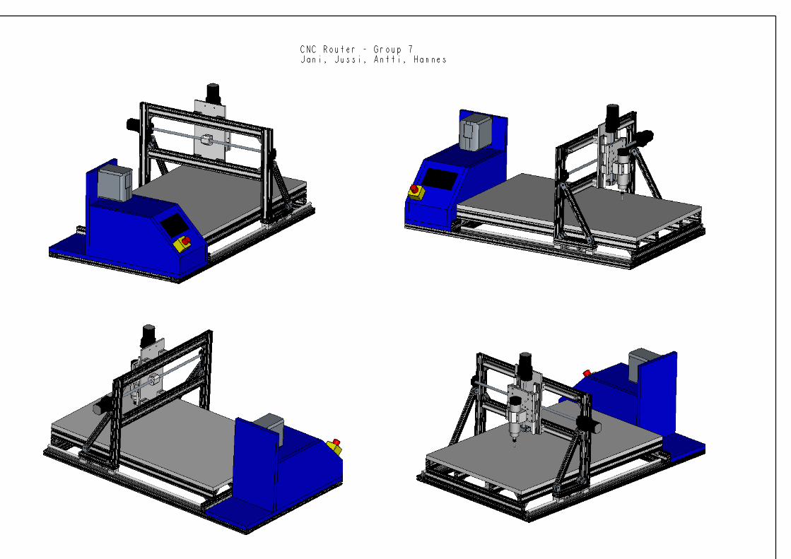
8 x standard-fastening set 6 - aalto university wiki
TRANSCRIPT
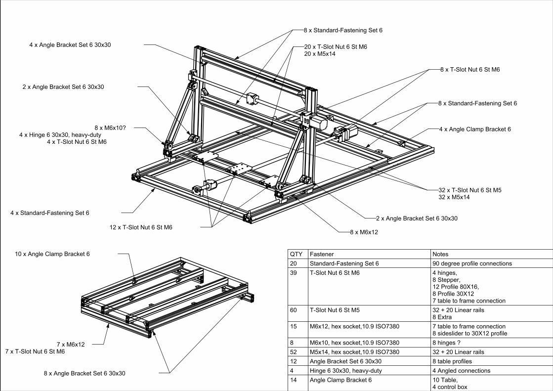
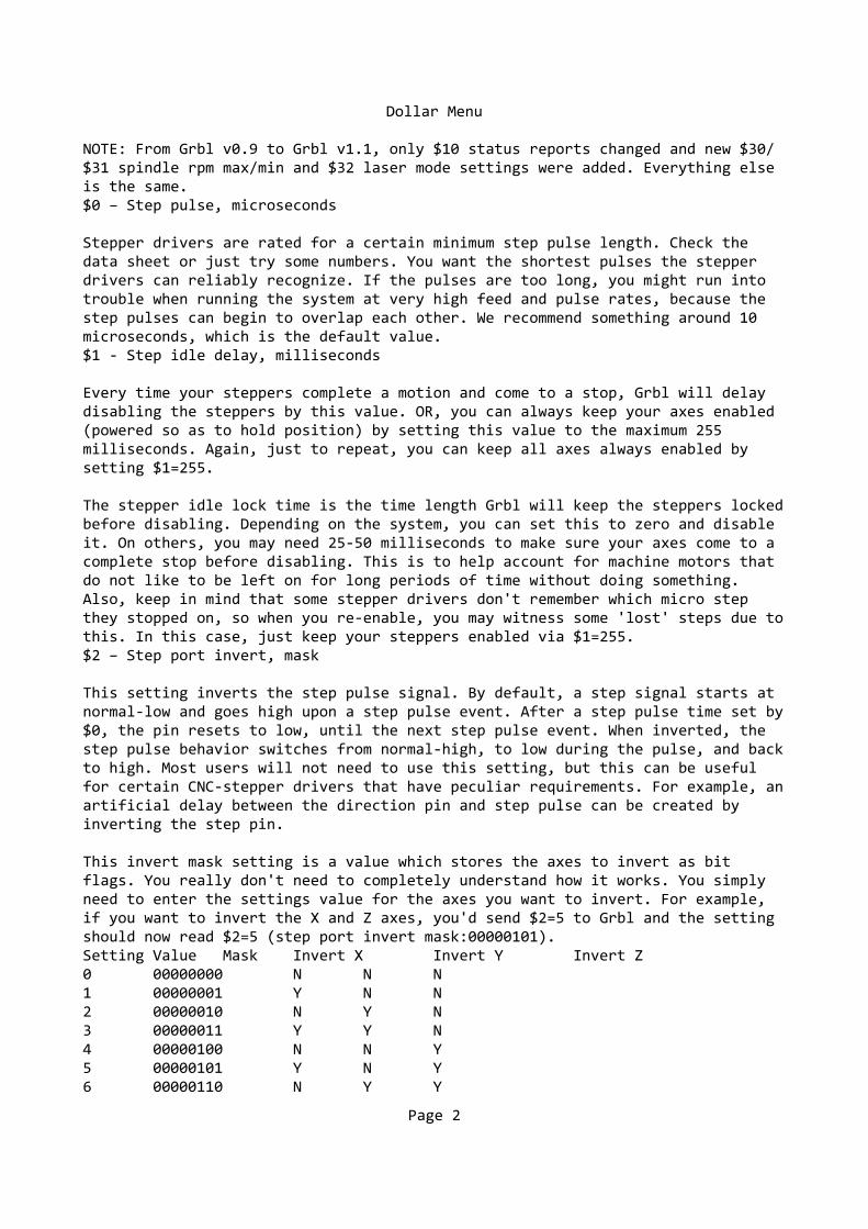
QTY Fastener Notes20 Standard-Fastening Set 6 90 degree profile connections39 T-Slot Nut 6 St M6 4 hinges,
8 Stepper,12 Profile 80X16,8 Profile 30X127 table to frame connection
60 T-Slot Nut 6 St M5 32 + 20 Linear rails8 Extra
15 M6x12, hex socket,10.9 ISO7380 7 table to frame connection8 sideslider to 30X12 profile
8 M6x10, hex socket,10.9 ISO7380 8 hinges ?52 M5x14, hex socket,10.9 ISO7380 32 + 20 Linear rails12 Angle Bracket Set 6 30x30 8 table profiles4 Hinge 6 30x30, heavy-duty 4 Angled connections14 Angle Clamp Bracket 6 10 Table,
4 control box
8 x Standard-Fastening Set 6
8 x Standard-Fastening Set 6
4 x Standard-Fastening Set 62 x Angle Bracket Set 6 30x30
2 x Angle Bracket Set 6 30x30
8 x M6x10?4 x Hinge 6 30x30, heavy-duty
4 x T-Slot Nut 6 St M6
8 x T-Slot Nut 6 St M6
12 x T-Slot Nut 6 St M6
32 x T-Slot Nut 6 St M532 x M5x14
20 x T-Slot Nut 6 St M620 x M5x14
4 x Angle Clamp Bracket 6
8 x M6x12
4 x Angle Bracket Set 6 30x30
10 x Angle Clamp Bracket 6
7 x M6x127 x T-Slot Nut 6 St M6
8 x Angle Bracket Set 6 30x30
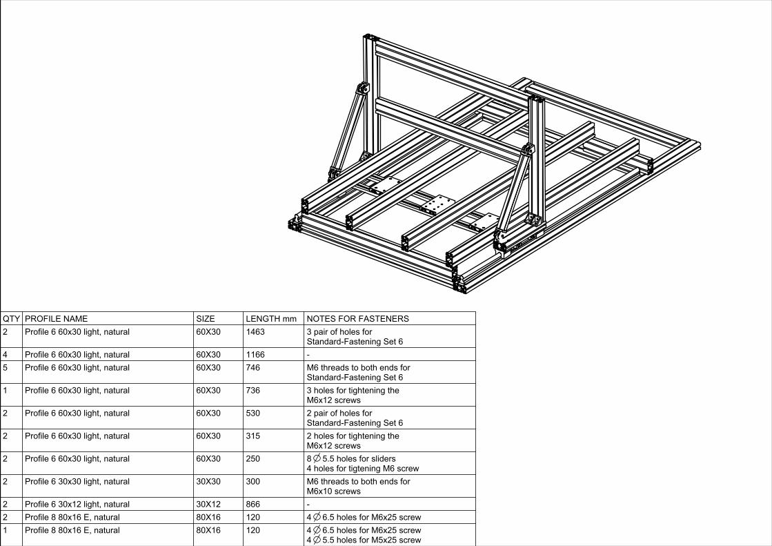
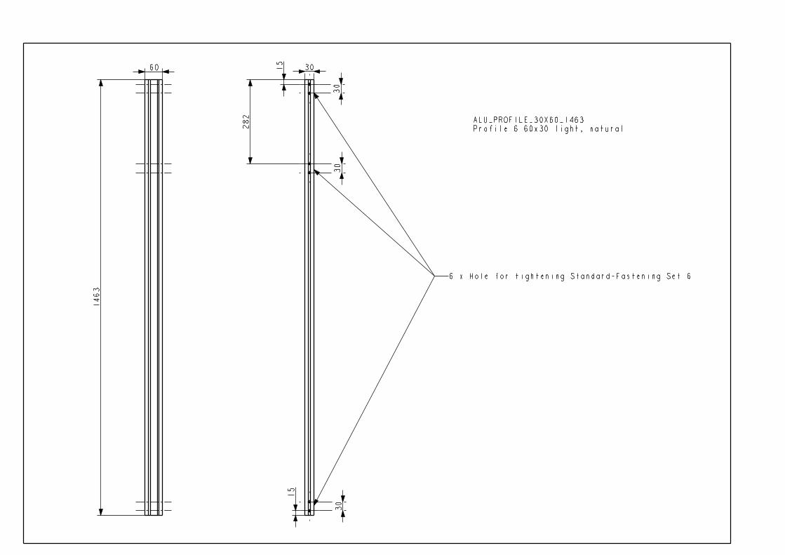
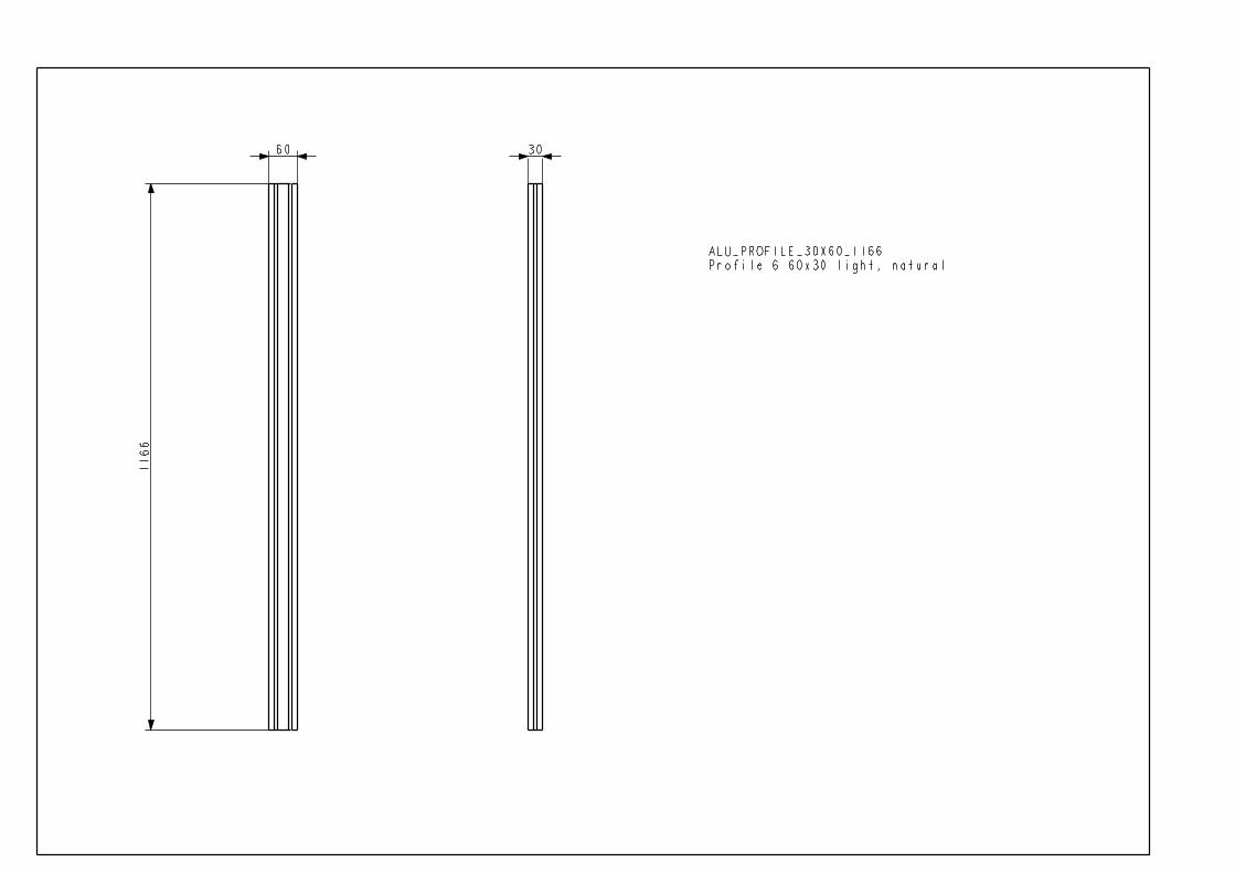
QTY PROFILE NAME SIZE LENGTH mm NOTES FOR FASTENERS2 Profile 6 60x30 light, natural 60X30 1463 3 pair of holes for
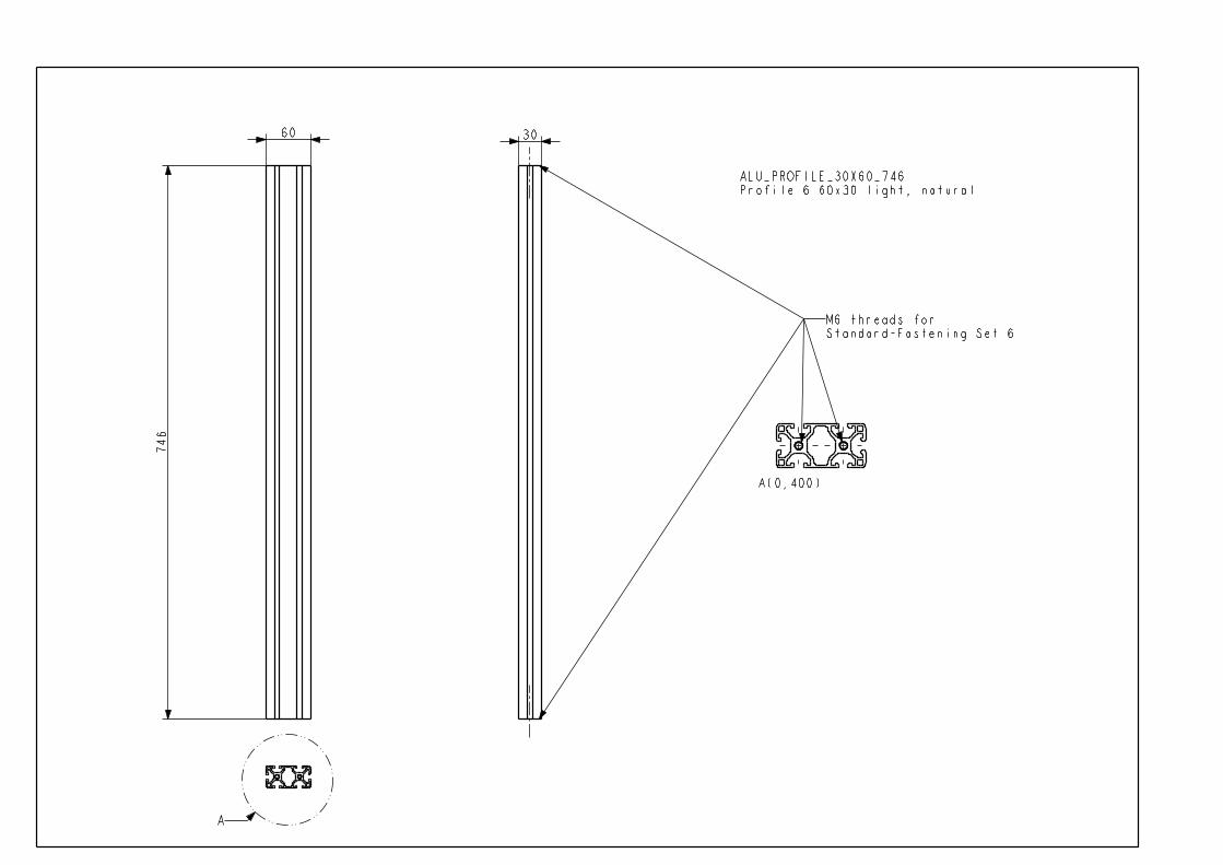
Standard-Fastening Set 64 Profile 6 60x30 light, natural 60X30 1166 -5 Profile 6 60x30 light, natural 60X30 746 M6 threads to both ends for
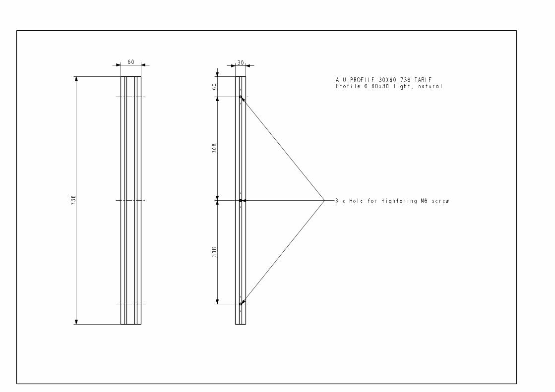
Standard-Fastening Set 61 Profile 6 60x30 light, natural 60X30 736 3 holes for tightening the
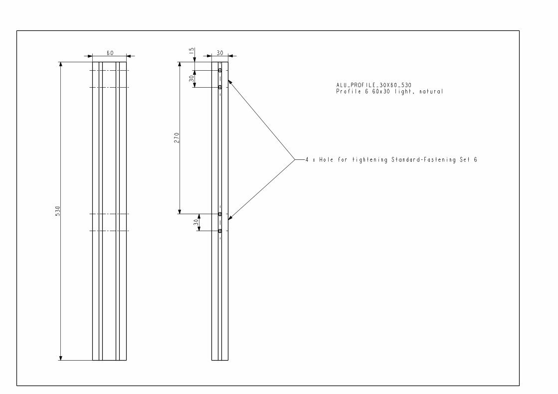
M6x12 screws2 Profile 6 60x30 light, natural 60X30 530 2 pair of holes for
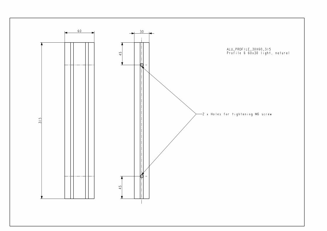
Standard-Fastening Set 62 Profile 6 60x30 light, natural 60X30 315 2 holes for tightening the
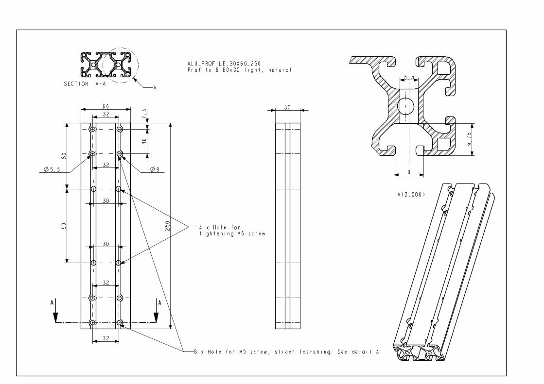
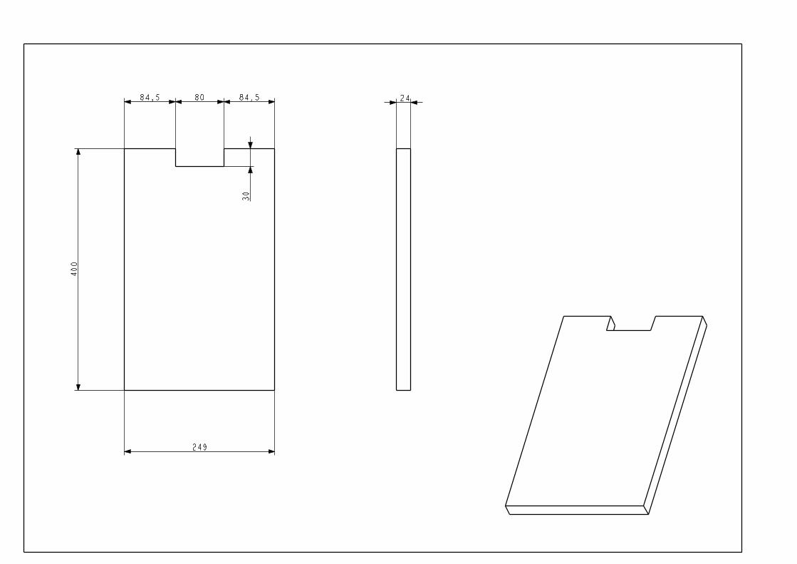
M6x12 screws2 Profile 6 60x30 light, natural 60X30 250 8 5.5 holes for sliders
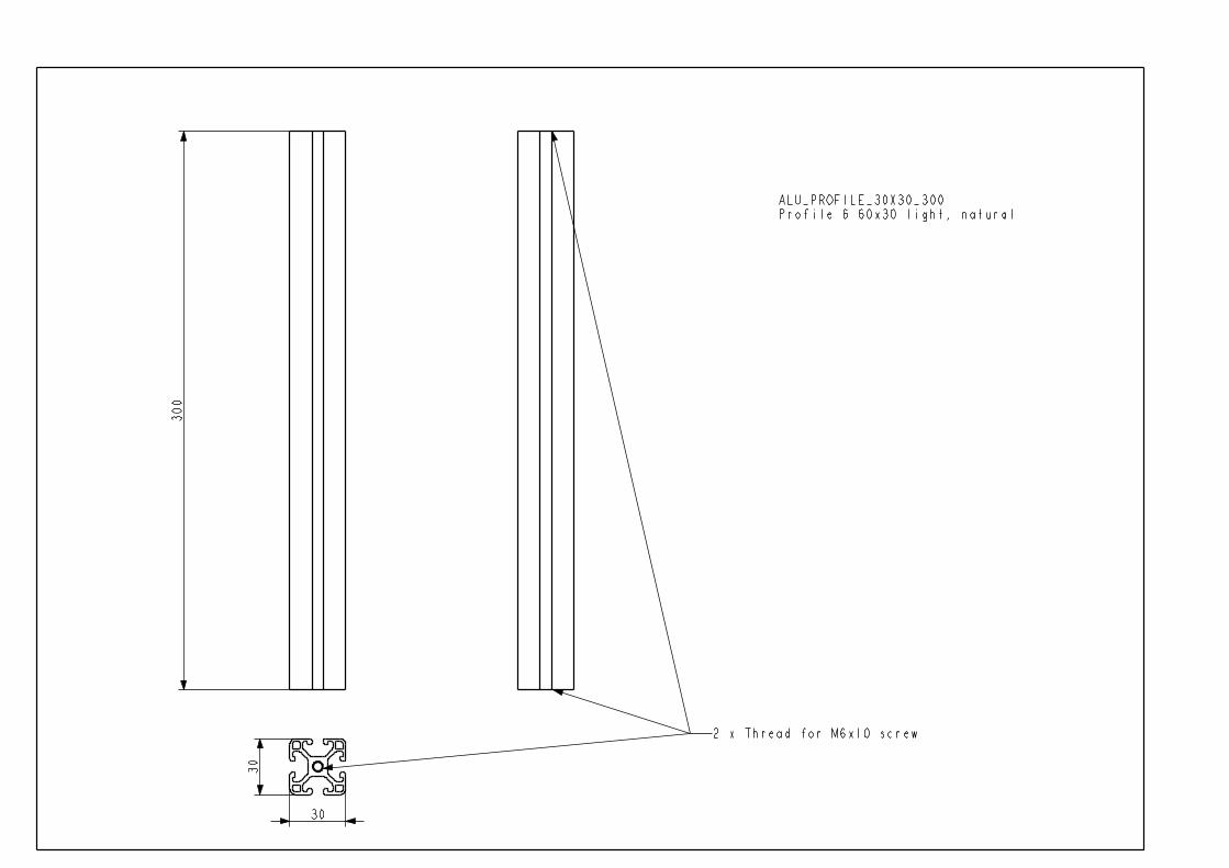
4 holes for tigtening M6 screw2 Profile 6 30x30 light, natural 30X30 300 M6 threads to both ends for
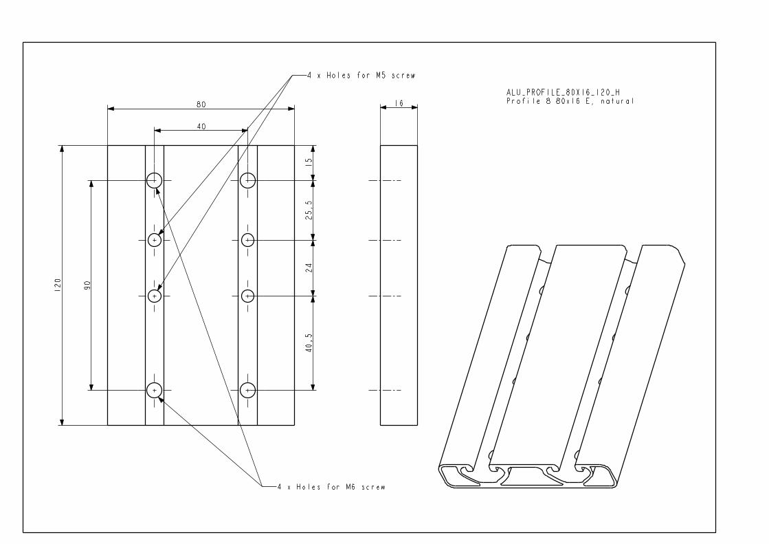
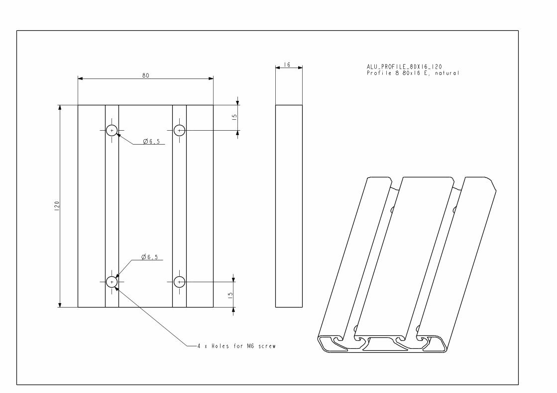
M6x10 screws2 Profile 6 30x12 light, natural 30X12 866 -2 Profile 8 80x16 E, natural 80X16 120 4 6.5 holes for M6x25 screw1 Profile 8 80x16 E, natural 80X16 120 4 6.5 holes for M6x25 screw
4 5.5 holes for M5x25 screw

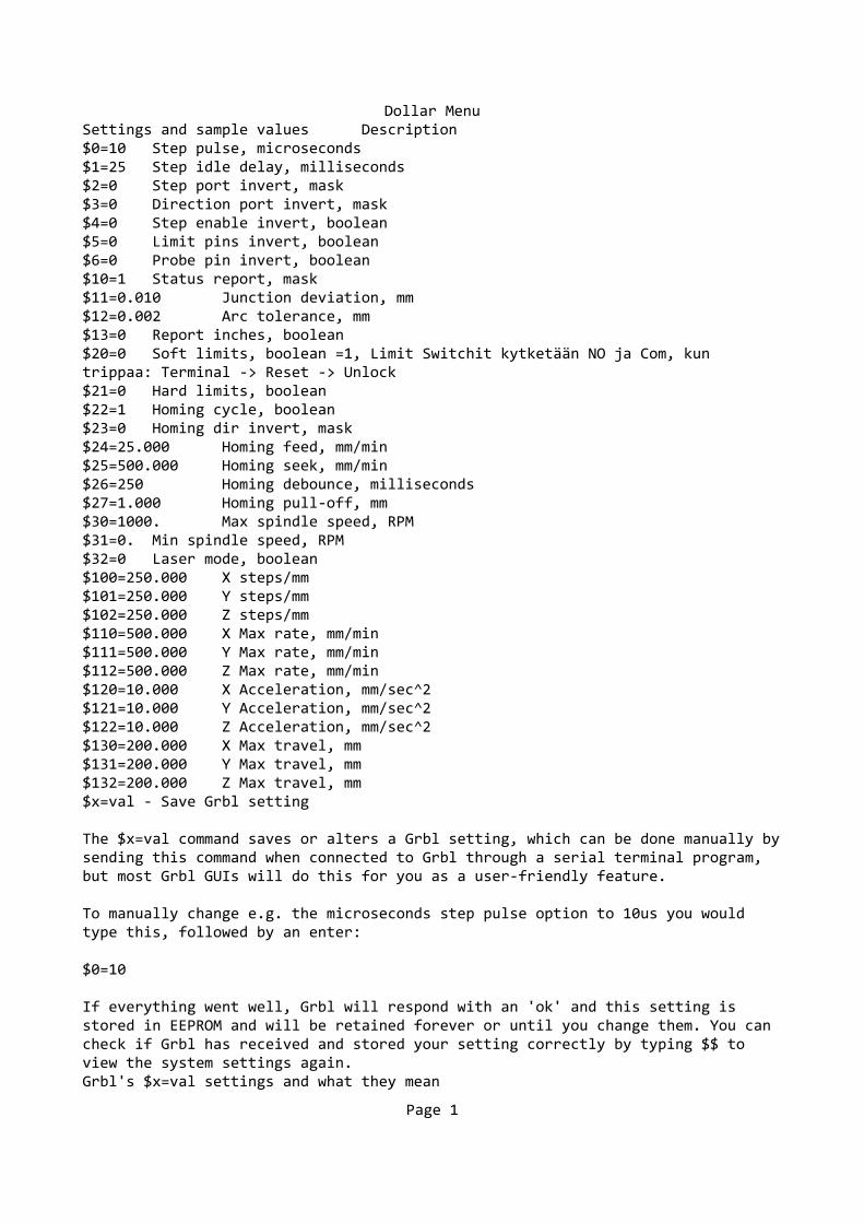
Dollar Menu Settings and sample values Description
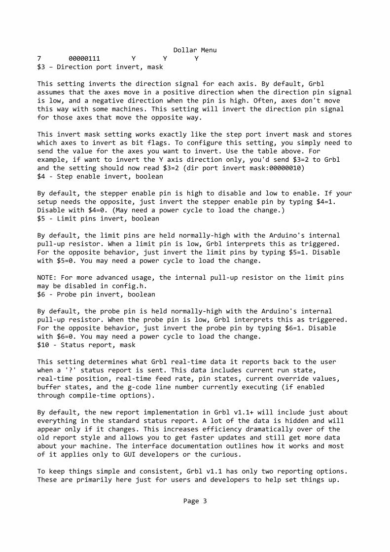
$0=10 Step pulse, microseconds $1=25 Step idle delay, milliseconds
$2=0 Step port invert, mask $3=0 Direction port invert, mask $4=0 Step enable invert, boolean $5=0 Limit pins invert, boolean $6=0 Probe pin invert, boolean
$10=1 Status report, mask $11=0.010 Junction deviation, mm $12=0.002 Arc tolerance, mm
$13=0 Report inches, boolean $20=0 Soft limits, boolean =1, Limit Switchit kytketään NO ja Com, kun
trippaa: Terminal -> Reset -> Unlock $21=0 Hard limits, boolean $22=1 Homing cycle, boolean $23=0 Homing dir invert, mask
$24=25.000 Homing feed, mm/min $25=500.000 Homing seek, mm/min
$26=250 Homing debounce, milliseconds $27=1.000 Homing pull-off, mm $30=1000. Max spindle speed, RPM
$31=0. Min spindle speed, RPM $32=0 Laser mode, boolean
$100=250.000 X steps/mm $101=250.000 Y steps/mm $102=250.000 Z steps/mm $110=500.000 X Max rate, mm/min $111=500.000 Y Max rate, mm/min $112=500.000 Z Max rate, mm/min
$120=10.000 X Acceleration, mm/sec^2 $121=10.000 Y Acceleration, mm/sec^2 $122=10.000 Z Acceleration, mm/sec^2
$130=200.000 X Max travel, mm $131=200.000 Y Max travel, mm $132=200.000 Z Max travel, mm
$x=val - Save Grbl setting
The $x=val command saves or alters a Grbl setting, which can be done manually bysending this command when connected to Grbl through a serial terminal program, but most Grbl GUIs will do this for you as a user-friendly feature.
To manually change e.g. the microseconds step pulse option to 10us you would type this, followed by an enter:
$0=10
If everything went well, Grbl will respond with an 'ok' and this setting is stored in EEPROM and will be retained forever or until you change them. You can check if Grbl has received and stored your setting correctly by typing $$ to view the system settings again.Grbl's $x=val settings and what they mean
Page 1
Dollar Menu
NOTE: From Grbl v0.9 to Grbl v1.1, only $10 status reports changed and new $30/ $31 spindle rpm max/min and $32 laser mode settings were added. Everything else is the same.$0 – Step pulse, microseconds
Stepper drivers are rated for a certain minimum step pulse length. Check the data sheet or just try some numbers. You want the shortest pulses the stepper drivers can reliably recognize. If the pulses are too long, you might run into trouble when running the system at very high feed and pulse rates, because the step pulses can begin to overlap each other. We recommend something around 10 microseconds, which is the default value.$1 - Step idle delay, milliseconds
Every time your steppers complete a motion and come to a stop, Grbl will delay disabling the steppers by this value. OR, you can always keep your axes enabled (powered so as to hold position) by setting this value to the maximum 255 milliseconds. Again, just to repeat, you can keep all axes always enabled by setting $1=255.
The stepper idle lock time is the time length Grbl will keep the steppers lockedbefore disabling. Depending on the system, you can set this to zero and disable it. On others, you may need 25-50 milliseconds to make sure your axes come to a complete stop before disabling. This is to help account for machine motors that do not like to be left on for long periods of time without doing something. Also, keep in mind that some stepper drivers don't remember which micro step they stopped on, so when you re-enable, you may witness some 'lost' steps due tothis. In this case, just keep your steppers enabled via $1=255.$2 – Step port invert, mask
This setting inverts the step pulse signal. By default, a step signal starts at normal-low and goes high upon a step pulse event. After a step pulse time set by$0, the pin resets to low, until the next step pulse event. When inverted, the step pulse behavior switches from normal-high, to low during the pulse, and backto high. Most users will not need to use this setting, but this can be useful for certain CNC-stepper drivers that have peculiar requirements. For example, anartificial delay between the direction pin and step pulse can be created by inverting the step pin.
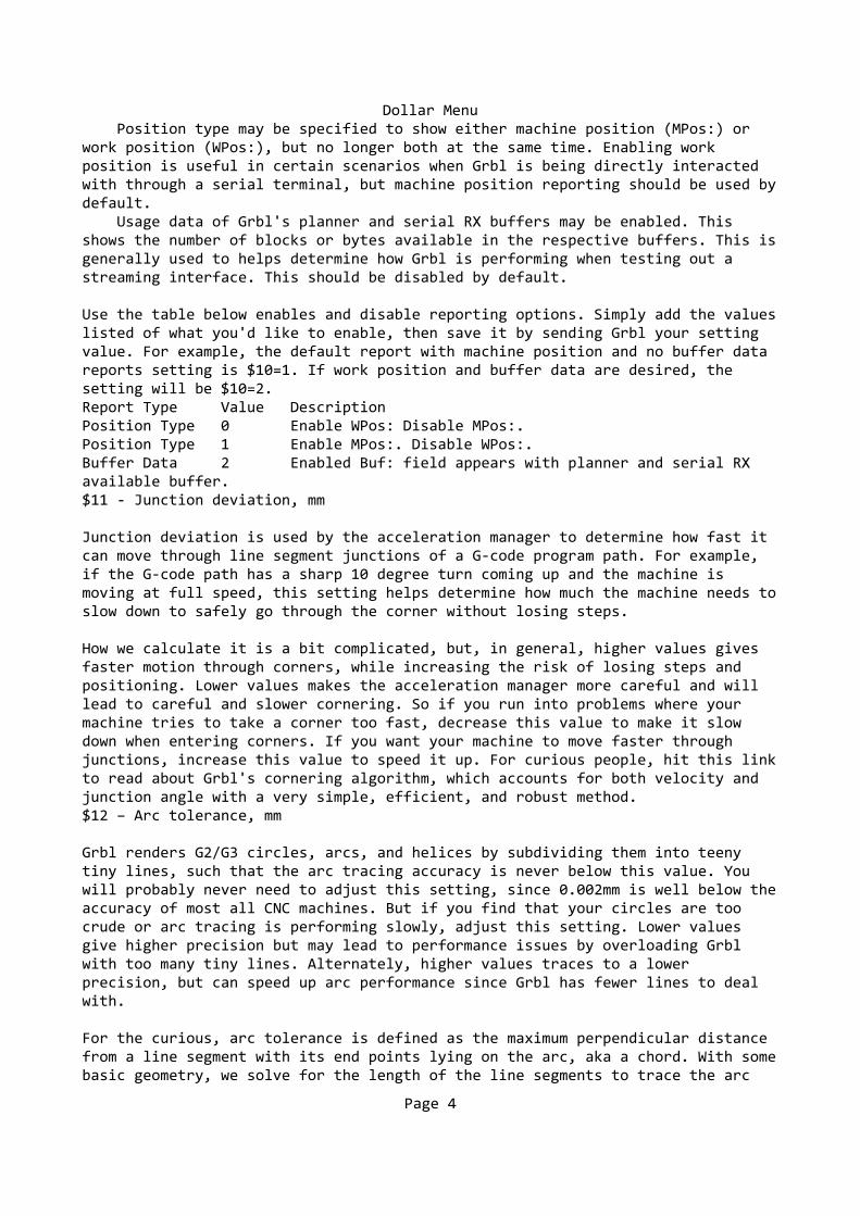
This invert mask setting is a value which stores the axes to invert as bit flags. You really don't need to completely understand how it works. You simply need to enter the settings value for the axes you want to invert. For example, if you want to invert the X and Z axes, you'd send $2=5 to Grbl and the setting should now read $2=5 (step port invert mask:00000101).
Setting Value Mask Invert X Invert Y Invert Z 0 00000000 N N N 1 00000001 Y N N 2 00000010 N Y N 3 00000011 Y Y N 4 00000100 N N Y 5 00000101 Y N Y 6 00000110 N Y Y
Page 2
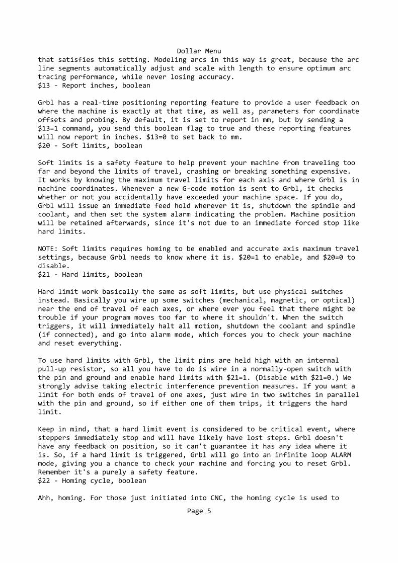
Dollar Menu 7 00000111 Y Y Y
$3 – Direction port invert, mask
This setting inverts the direction signal for each axis. By default, Grbl assumes that the axes move in a positive direction when the direction pin signalis low, and a negative direction when the pin is high. Often, axes don't move this way with some machines. This setting will invert the direction pin signal for those axes that move the opposite way.
This invert mask setting works exactly like the step port invert mask and storeswhich axes to invert as bit flags. To configure this setting, you simply need tosend the value for the axes you want to invert. Use the table above. For example, if want to invert the Y axis direction only, you'd send $3=2 to Grbl and the setting should now read $3=2 (dir port invert mask:00000010)$4 - Step enable invert, boolean
By default, the stepper enable pin is high to disable and low to enable. If yoursetup needs the opposite, just invert the stepper enable pin by typing $4=1. Disable with $4=0. (May need a power cycle to load the change.)$5 - Limit pins invert, boolean
By default, the limit pins are held normally-high with the Arduino's internal pull-up resistor. When a limit pin is low, Grbl interprets this as triggered. For the opposite behavior, just invert the limit pins by typing $5=1. Disable with $5=0. You may need a power cycle to load the change.
NOTE: For more advanced usage, the internal pull-up resistor on the limit pins may be disabled in config.h.$6 - Probe pin invert, boolean
By default, the probe pin is held normally-high with the Arduino's internal pull-up resistor. When the probe pin is low, Grbl interprets this as triggered. For the opposite behavior, just invert the probe pin by typing $6=1. Disable with $6=0. You may need a power cycle to load the change.$10 - Status report, mask
This setting determines what Grbl real-time data it reports back to the user when a '?' status report is sent. This data includes current run state, real-time position, real-time feed rate, pin states, current override values, buffer states, and the g-code line number currently executing (if enabled through compile-time options).
By default, the new report implementation in Grbl v1.1+ will include just about everything in the standard status report. A lot of the data is hidden and will appear only if it changes. This increases efficiency dramatically over of the old report style and allows you to get faster updates and still get more data about your machine. The interface documentation outlines how it works and most of it applies only to GUI developers or the curious.
To keep things simple and consistent, Grbl v1.1 has only two reporting options. These are primarily here just for users and developers to help set things up.
Page 3
Dollar Menu Position type may be specified to show either machine position (MPos:) or work position (WPos:), but no longer both at the same time. Enabling work position is useful in certain scenarios when Grbl is being directly interacted with through a serial terminal, but machine position reporting should be used bydefault. Usage data of Grbl's planner and serial RX buffers may be enabled. This shows the number of blocks or bytes available in the respective buffers. This isgenerally used to helps determine how Grbl is performing when testing out a streaming interface. This should be disabled by default.
Use the table below enables and disable reporting options. Simply add the valueslisted of what you'd like to enable, then save it by sending Grbl your setting value. For example, the default report with machine position and no buffer data reports setting is $10=1. If work position and buffer data are desired, the setting will be $10=2.
Report Type Value Description Position Type 0 Enable WPos: Disable MPos:. Position Type 1 Enable MPos:. Disable WPos:.
Buffer Data 2 Enabled Buf: field appears with planner and serial RX available buffer.$11 - Junction deviation, mm
Junction deviation is used by the acceleration manager to determine how fast it can move through line segment junctions of a G-code program path. For example, if the G-code path has a sharp 10 degree turn coming up and the machine is moving at full speed, this setting helps determine how much the machine needs toslow down to safely go through the corner without losing steps.
How we calculate it is a bit complicated, but, in general, higher values gives faster motion through corners, while increasing the risk of losing steps and positioning. Lower values makes the acceleration manager more careful and will lead to careful and slower cornering. So if you run into problems where your machine tries to take a corner too fast, decrease this value to make it slow down when entering corners. If you want your machine to move faster through junctions, increase this value to speed it up. For curious people, hit this linkto read about Grbl's cornering algorithm, which accounts for both velocity and junction angle with a very simple, efficient, and robust method.$12 – Arc tolerance, mm
Grbl renders G2/G3 circles, arcs, and helices by subdividing them into teeny tiny lines, such that the arc tracing accuracy is never below this value. You will probably never need to adjust this setting, since 0.002mm is well below theaccuracy of most all CNC machines. But if you find that your circles are too crude or arc tracing is performing slowly, adjust this setting. Lower values give higher precision but may lead to performance issues by overloading Grbl with too many tiny lines. Alternately, higher values traces to a lower precision, but can speed up arc performance since Grbl has fewer lines to deal with.
For the curious, arc tolerance is defined as the maximum perpendicular distance from a line segment with its end points lying on the arc, aka a chord. With somebasic geometry, we solve for the length of the line segments to trace the arc
Page 4
Dollar Menuthat satisfies this setting. Modeling arcs in this way is great, because the arcline segments automatically adjust and scale with length to ensure optimum arc tracing performance, while never losing accuracy.$13 - Report inches, boolean
Grbl has a real-time positioning reporting feature to provide a user feedback onwhere the machine is exactly at that time, as well as, parameters for coordinateoffsets and probing. By default, it is set to report in mm, but by sending a $13=1 command, you send this boolean flag to true and these reporting features will now report in inches. $13=0 to set back to mm.$20 - Soft limits, boolean
Soft limits is a safety feature to help prevent your machine from traveling too far and beyond the limits of travel, crashing or breaking something expensive. It works by knowing the maximum travel limits for each axis and where Grbl is inmachine coordinates. Whenever a new G-code motion is sent to Grbl, it checks whether or not you accidentally have exceeded your machine space. If you do, Grbl will issue an immediate feed hold wherever it is, shutdown the spindle and coolant, and then set the system alarm indicating the problem. Machine position will be retained afterwards, since it's not due to an immediate forced stop likehard limits.
NOTE: Soft limits requires homing to be enabled and accurate axis maximum travelsettings, because Grbl needs to know where it is. $20=1 to enable, and $20=0 to disable.$21 - Hard limits, boolean
Hard limit work basically the same as soft limits, but use physical switches instead. Basically you wire up some switches (mechanical, magnetic, or optical) near the end of travel of each axes, or where ever you feel that there might be trouble if your program moves too far to where it shouldn't. When the switch triggers, it will immediately halt all motion, shutdown the coolant and spindle (if connected), and go into alarm mode, which forces you to check your machine and reset everything.
To use hard limits with Grbl, the limit pins are held high with an internal pull-up resistor, so all you have to do is wire in a normally-open switch with the pin and ground and enable hard limits with $21=1. (Disable with $21=0.) We strongly advise taking electric interference prevention measures. If you want a limit for both ends of travel of one axes, just wire in two switches in parallelwith the pin and ground, so if either one of them trips, it triggers the hard limit.
Keep in mind, that a hard limit event is considered to be critical event, where steppers immediately stop and will have likely have lost steps. Grbl doesn't have any feedback on position, so it can't guarantee it has any idea where it is. So, if a hard limit is triggered, Grbl will go into an infinite loop ALARM mode, giving you a chance to check your machine and forcing you to reset Grbl. Remember it's a purely a safety feature.$22 - Homing cycle, boolean
Ahh, homing. For those just initiated into CNC, the homing cycle is used to
Page 5

Dollar Menuaccurately and precisely locate a known and consistent position on a machine every time you start up your Grbl between sessions. In other words, you know exactly where you are at any given time, every time. Say you start machining something or are about to start the next step in a job and the power goes out, you re-start Grbl and Grbl has no idea where it is due to steppers being open-loop control. You're left with the task of figuring out where you are. If you have homing, you always have the machine zero reference point to locate from, so all you have to do is run the homing cycle and resume where you left off.
To set up the homing cycle for Grbl, you need to have limit switches in a fixed position that won't get bumped or moved, or else your reference point gets messed up. Usually they are setup in the farthest point in +x, +y, +z of each axes. Wire your limit switches in with the limit pins, add a recommended RC-filter to help reduce electrical noise, and enable homing. If you're curious,you can use your limit switches for both hard limits AND homing. They play nice with each other.
Prior to trying the homing cycle for the first time, make sure you have setup everything correctly, otherwise homing may behave strangely. First, ensure your machine axes are moving in the correct directions per Cartesian coordinates (right-hand rule). If not, fix it with the $3 direction invert setting. Second, ensure your limit switch pins are not showing as 'triggered' in Grbl's status reports. If are, check your wiring and settings. Finally, ensure your $13x max travel settings are somewhat accurate (within 20%), because Grbl uses these values to determine how far it should search for the homing switches.
By default, Grbl's homing cycle moves the Z-axis positive first to clear the workspace and then moves both the X and Y-axes at the same time in the positive direction. To set up how your homing cycle behaves, there are more Grbl settingsdown the page describing what they do (and compile-time options as well.)
Also, one more thing to note, when homing is enabled. Grbl will lock out all G-code commands until you perform a homing cycle. Meaning no axes motions, unless the lock is disabled ($X) but more on that later. Most, if not all CNC controllers, do something similar, as it is mostly a safety feature to prevent users from making a positioning mistake, which is very easy to do and be saddened when a mistake ruins a part. If you find this annoying or find any weird bugs, please let us know and we'll try to work on it so everyone is happy.:)
NOTE: Check out config.h for more homing options for advanced users. You can disable the homing lockout at startup, configure which axes move first during a homing cycle and in what order, and more.$23 - Homing dir invert, mask
By default, Grbl assumes your homing limit switches are in the positive direction, first moving the z-axis positive, then the x-y axes positive before trying to precisely locate machine zero by going back and forth slowly around the switch. If your machine has a limit switch in the negative direction, the homing direction mask can invert the axes' direction. It works just like the step port invert and direction port invert masks, where all you have to do is
Page 6
Dollar Menusend the value in the table to indicate what axes you want to invert and search for in the opposite direction.$24 - Homing feed, mm/min
The homing cycle first searches for the limit switches at a higher seek rate, and after it finds them, it moves at a slower feed rate to home into the preciselocation of machine zero. Homing feed rate is that slower feed rate. Set this towhatever rate value that provides repeatable and precise machine zero locating.$25 - Homing seek, mm/min
Homing seek rate is the homing cycle search rate, or the rate at which it first tries to find the limit switches. Adjust to whatever rate gets to the limit switches in a short enough time without crashing into your limit switches if they come in too fast.$26 - Homing debounce, milliseconds
Whenever a switch triggers, some of them can have electrical/mechanical noise that actually 'bounce' the signal high and low for a few milliseconds before settling in. To solve this, you need to debounce the signal, either by hardware with some kind of signal conditioner or by software with a short delay to let the signal finish bouncing. Grbl performs a short delay, only homing when locating machine zero. Set this delay value to whatever your switch needs to getrepeatable homing. In most cases, 5-25 milliseconds is fine.$27 - Homing pull-off, mm
To play nice with the hard limits feature, where homing can share the same limitswitches, the homing cycle will move off all of the limit switches by this pull-off travel after it completes. In other words, it helps to prevent accidental triggering of the hard limit after a homing cycle. Make sure this value is large enough to clear the limit switch. If not, Grbl will throw an alarm error for failing to clear it.$30 - Max spindle speed, RPM
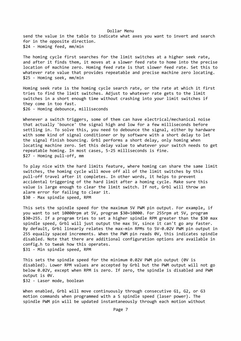
This sets the spindle speed for the maximum 5V PWM pin output. For example, if you want to set 10000rpm at 5V, program $30=10000. For 255rpm at 5V, program $30=255. If a program tries to set a higher spindle RPM greater than the $30 maxspindle speed, Grbl will just output the max 5V, since it can't go any faster. By default, Grbl linearly relates the max-min RPMs to 5V-0.02V PWM pin output in255 equally spaced increments. When the PWM pin reads 0V, this indicates spindledisabled. Note that there are additional configuration options are available in config.h to tweak how this operates.$31 - Min spindle speed, RPM
This sets the spindle speed for the minimum 0.02V PWM pin output (0V is disabled). Lower RPM values are accepted by Grbl but the PWM output will not go below 0.02V, except when RPM is zero. If zero, the spindle is disabled and PWM output is 0V.$32 - Laser mode, boolean
When enabled, Grbl will move continuously through consecutive G1, G2, or G3 motion commands when programmed with a S spindle speed (laser power). The spindle PWM pin will be updated instantaneously through each motion without
Page 7
Dollar Menustopping. Please read the GRBL laser documentation and your laser device documentation prior to using this mode. Lasers are very dangerous. They can instantly damage your vision permanantly and cause fires. Grbl does not assume any responsibility for any issues the firmware may cause, as defined by its GPL license.
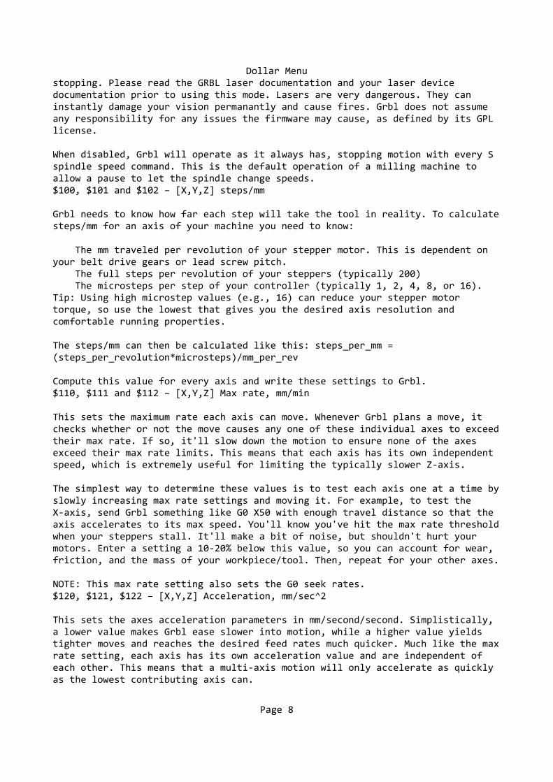
When disabled, Grbl will operate as it always has, stopping motion with every S spindle speed command. This is the default operation of a milling machine to allow a pause to let the spindle change speeds.$100, $101 and $102 – [X,Y,Z] steps/mm
Grbl needs to know how far each step will take the tool in reality. To calculatesteps/mm for an axis of your machine you need to know:
The mm traveled per revolution of your stepper motor. This is dependent on your belt drive gears or lead screw pitch. The full steps per revolution of your steppers (typically 200) The microsteps per step of your controller (typically 1, 2, 4, 8, or 16). Tip: Using high microstep values (e.g., 16) can reduce your stepper motor torque, so use the lowest that gives you the desired axis resolution and comfortable running properties.
The steps/mm can then be calculated like this: steps_per_mm = (steps_per_revolution*microsteps)/mm_per_rev
Compute this value for every axis and write these settings to Grbl.$110, $111 and $112 – [X,Y,Z] Max rate, mm/min
This sets the maximum rate each axis can move. Whenever Grbl plans a move, it checks whether or not the move causes any one of these individual axes to exceedtheir max rate. If so, it'll slow down the motion to ensure none of the axes exceed their max rate limits. This means that each axis has its own independent speed, which is extremely useful for limiting the typically slower Z-axis.
The simplest way to determine these values is to test each axis one at a time byslowly increasing max rate settings and moving it. For example, to test the X-axis, send Grbl something like G0 X50 with enough travel distance so that the axis accelerates to its max speed. You'll know you've hit the max rate thresholdwhen your steppers stall. It'll make a bit of noise, but shouldn't hurt your motors. Enter a setting a 10-20% below this value, so you can account for wear, friction, and the mass of your workpiece/tool. Then, repeat for your other axes.
NOTE: This max rate setting also sets the G0 seek rates.$120, $121, $122 – [X,Y,Z] Acceleration, mm/sec^2
This sets the axes acceleration parameters in mm/second/second. Simplistically, a lower value makes Grbl ease slower into motion, while a higher value yields tighter moves and reaches the desired feed rates much quicker. Much like the maxrate setting, each axis has its own acceleration value and are independent of each other. This means that a multi-axis motion will only accelerate as quickly as the lowest contributing axis can.
Page 8
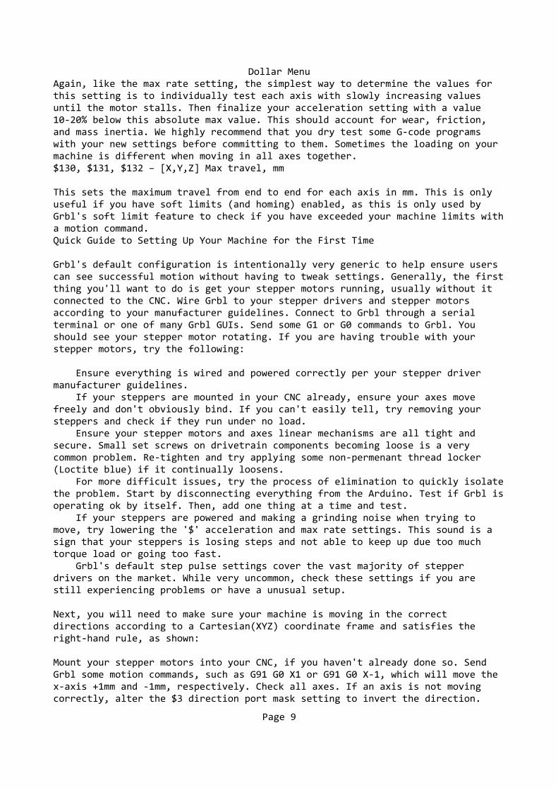
Dollar MenuAgain, like the max rate setting, the simplest way to determine the values for this setting is to individually test each axis with slowly increasing values until the motor stalls. Then finalize your acceleration setting with a value 10-20% below this absolute max value. This should account for wear, friction, and mass inertia. We highly recommend that you dry test some G-code programs with your new settings before committing to them. Sometimes the loading on your machine is different when moving in all axes together.$130, $131, $132 – [X,Y,Z] Max travel, mm
This sets the maximum travel from end to end for each axis in mm. This is only useful if you have soft limits (and homing) enabled, as this is only used by Grbl's soft limit feature to check if you have exceeded your machine limits witha motion command.Quick Guide to Setting Up Your Machine for the First Time
Grbl's default configuration is intentionally very generic to help ensure users can see successful motion without having to tweak settings. Generally, the firstthing you'll want to do is get your stepper motors running, usually without it connected to the CNC. Wire Grbl to your stepper drivers and stepper motors according to your manufacturer guidelines. Connect to Grbl through a serial terminal or one of many Grbl GUIs. Send some G1 or G0 commands to Grbl. You should see your stepper motor rotating. If you are having trouble with your stepper motors, try the following:
Ensure everything is wired and powered correctly per your stepper driver manufacturer guidelines. If your steppers are mounted in your CNC already, ensure your axes move freely and don't obviously bind. If you can't easily tell, try removing your steppers and check if they run under no load. Ensure your stepper motors and axes linear mechanisms are all tight and secure. Small set screws on drivetrain components becoming loose is a very common problem. Re-tighten and try applying some non-permenant thread locker (Loctite blue) if it continually loosens. For more difficult issues, try the process of elimination to quickly isolatethe problem. Start by disconnecting everything from the Arduino. Test if Grbl isoperating ok by itself. Then, add one thing at a time and test. If your steppers are powered and making a grinding noise when trying to move, try lowering the '$' acceleration and max rate settings. This sound is a sign that your steppers is losing steps and not able to keep up due too much torque load or going too fast. Grbl's default step pulse settings cover the vast majority of stepper drivers on the market. While very uncommon, check these settings if you are still experiencing problems or have a unusual setup.
Next, you will need to make sure your machine is moving in the correct directions according to a Cartesian(XYZ) coordinate frame and satisfies the right-hand rule, as shown:
Mount your stepper motors into your CNC, if you haven't already done so. Send Grbl some motion commands, such as G91 G0 X1 or G91 G0 X-1, which will move the x-axis +1mm and -1mm, respectively. Check all axes. If an axis is not moving correctly, alter the $3 direction port mask setting to invert the direction.
Page 9
Dollar Menu
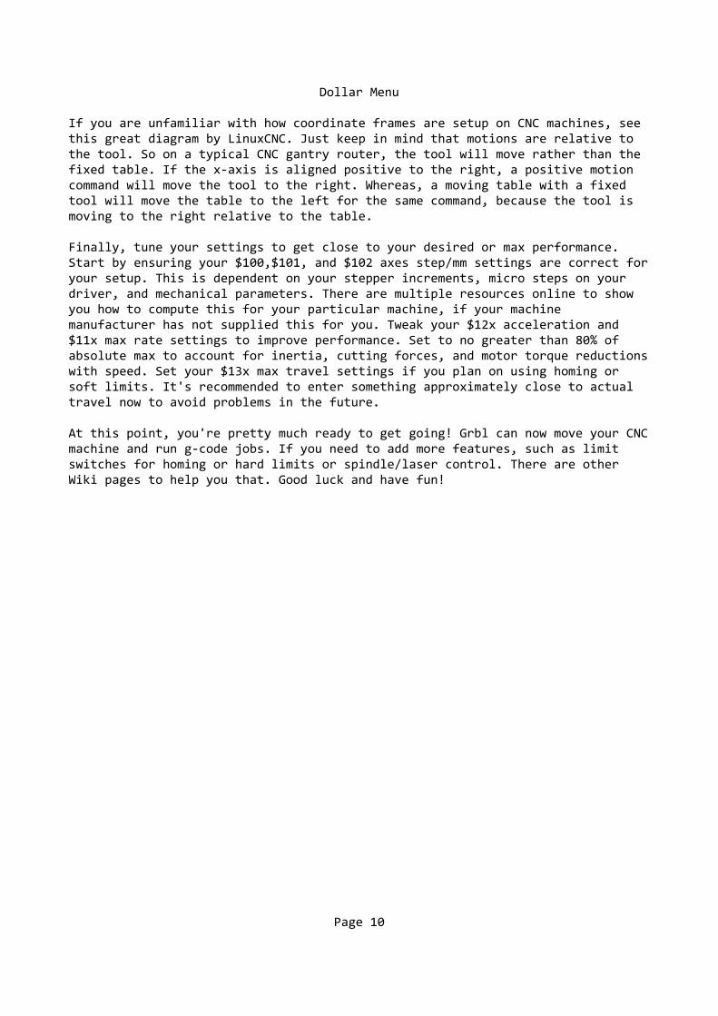
If you are unfamiliar with how coordinate frames are setup on CNC machines, see this great diagram by LinuxCNC. Just keep in mind that motions are relative to the tool. So on a typical CNC gantry router, the tool will move rather than the fixed table. If the x-axis is aligned positive to the right, a positive motion command will move the tool to the right. Whereas, a moving table with a fixed tool will move the table to the left for the same command, because the tool is moving to the right relative to the table.
Finally, tune your settings to get close to your desired or max performance. Start by ensuring your $100,$101, and $102 axes step/mm settings are correct foryour setup. This is dependent on your stepper increments, micro steps on your driver, and mechanical parameters. There are multiple resources online to show you how to compute this for your particular machine, if your machine manufacturer has not supplied this for you. Tweak your $12x acceleration and $11x max rate settings to improve performance. Set to no greater than 80% of absolute max to account for inertia, cutting forces, and motor torque reductionswith speed. Set your $13x max travel settings if you plan on using homing or soft limits. It's recommended to enter something approximately close to actual travel now to avoid problems in the future.
At this point, you're pretty much ready to get going! Grbl can now move your CNCmachine and run g-code jobs. If you need to add more features, such as limit switches for homing or hard limits or spindle/laser control. There are other Wiki pages to help you that. Good luck and have fun!
Page 10
ⅠⅠⅠⅠ. Introduction...................................................................................................... 1. Checks upon Delivery.............................................................................................................2 2. Nameplate Description of HY Series Inverter ........................................................................2
ⅡⅡⅡⅡ. Safety Precautions..........................................................................................4
1. Before the Power-up ...............................................................................................................4 2. During the Power-up...............................................................................................................5 3. During the Operation ..............................................................................................................5
ⅢⅢⅢⅢ. Standards and Specifications........................................................................6
1. Particular Specifications .........................................................................................................6 2. General Specifications ............................................................................................................7
ⅣⅣⅣⅣ. Storage and Installation .................................................................................. 1. Storage ....................................................................................................................................8 2. Installation Site and Environment...........................................................................................9 3. Installation and Direction........................................................................................................9
ⅤⅤⅤⅤ. Wiring .............................................................................................................9
1. Main Circuit Wiring Schematic Diagram ...............................................................................9 2. Description of Terminal Block..............................................................................................10 3. Basic Connection Diagram ...................................................................................................12 4. Precautions on Wiring...........................................................................................................13
ⅥⅥⅥⅥ. Instruction of the Digital Operator................................................................ 1. Description of the Digital Operator .......................................................................................... 2. Description of Indicator Lamp Status...................................................................................15 3. Description of Operation Examples......................................................................................18
ⅦⅦⅦⅦ. Commissioning ................................................................................................. 1. Checks before the Commissioning .......................................................................................19 2. Commissioning Methods ......................................................................................................19
ⅧⅧⅧⅧ. Function List ....................................................................................................
ⅨⅨⅨⅨ. Descriptions of Functions................................................................................
ⅩⅩⅩⅩ. Care & Maintenance, Fault Information and Troubleshooting.................. 1. Precautions about Inspection and Maintenance....................................................................70 2. Periodical Inspection and Maintenance items ............Ошибка! Закладка не определена. 3. Fault Indication and Troubleshooting.........................Ошибка! Закладка не определена. 4. Faults and Analysis .....................................................Ошибка! Закладка не определена.
ⅪⅪⅪⅪ. Selection of Peripheral Devices and DispositionОшибка! Закладка не определена.
1. Options........................................................................Ошибка! Закладка не определена. 2. Disposition..................................................................Ошибка! Закладка не определена.
ⅫⅫⅫⅫ. User Preferences Table ................................................................................78 Note: Due to product uPdates, the manual is subject to change without notice. ⅠⅠⅠⅠ. Introduction Thank you for purchasing and using the general-purpose inverter of HY series of multi-functions and high performance. Please read carefully the operation manual before putting the inverter to use so as to correctly install and operate the inverter, give full play to its functions and ensure the safety. Please keep the operation manual handy for future reference, maintenance, inspection and repair. Due to the inverter of a kind of electrical and electronic product it must be installed, tested and adjusted with parameters by specialized engineering persons of motors. The marks of and other symbols in the manual remind you of the safety and prevention cautions during the handling, installation, running and inspection. Please follow these instructions to make sure the safe use of the inverter. In case of any doubt please contact our local agent for consultation. Our professional persons are willing and ready to serve you. The manual is subject to change without notice.
Danger indicates wrong use may kill or injure people.
Caution indicates wrong use may damage the inverter or mechanical system.
!!!! Danger ! Be sure to turn off the input power supply before wiring. ! Do not touch any internal electrical circuit or component when the charging lamp is still on after the
AC power supply is disconnected, which means the inverter still has high voltage inside and it is very dangerous.
! Do not check components and signals on the circuit boards during the operation. ! Do not dissemble or modify any internal connecting cord, wiring or component of the inverter by
yourself. ! Be sure to make correct ground connection of the earth terminal of the inverter. ! Never remodel it or exchange control boards and components by yourself. It may expose you to an
electrical shock or explosion, etc.
Caution
! Do not make any voltage-withstanding test with any component inside the inverter. These semi-conductor parts are subject to the damage of high voltage.
! Never connect the AC main circuit power supply to the output terminals U.V W of the inverter. ! The main electric circuit boards of CMOS and IC of the inverter are subject to the effect and damage
of static electricity. Don’t touch the main circuit boards.
!!!!
!!!!Danger Caution
!!!!
! Installation, testing and maintenance must be performed by qualified professional personnel. ! The inverter should be discarded as industrial waste. It is forbidden to burn it.
1. Checks upon Delivery
The inverter has been strictly and well packed before ex-work. In consideration of various factors during the transportation special attention should be paid to the following points before the assembly and installation. If there is anything abnormal please notify the dealer or the relevant people of our company.
! Check if the inverter has got any damage or deformation during the transportation and
handling. ! Check if there is one piece of HY series inverter and one copy of the instruction manual
available when unpacking it. ! Check the information on the nameplate to see if the specifications meet your order
(Operating voltage and KVA value). ! Check if there is something wrong with the inner parts, wiring and circuit board. ! Check if each terminal is tightly locked and if there is any foreign article inside the inverter. ! Check if the operator buttons are all right. ! Check if the optional components you ordered are contained.
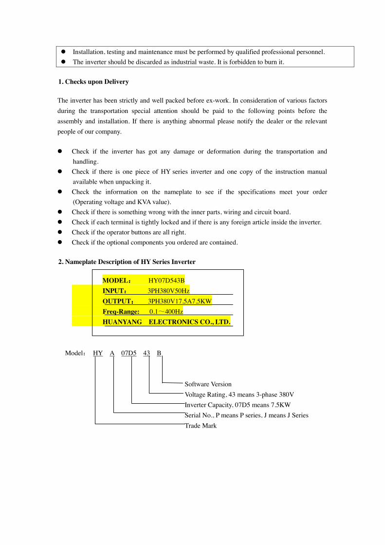
2. Nameplate Description of HY Series Inverter
MODEL:::: HY07D543B INPUT:::: 3PH380V50Hz OUTPUT:::: 3PH380V17.5A7.5KW Freq-Range: 0.1~400Hz HUANYANG ELECTRONICS CO., LTD.
Model: HY A 07D5 43 B
Software Version Voltage Rating, 43 means 3-phase 380V Inverter Capacity, 07D5 means 7.5KW Serial No., P means P series, J means J Series Trade Mark
ⅡⅡⅡⅡ. Safety Precautions
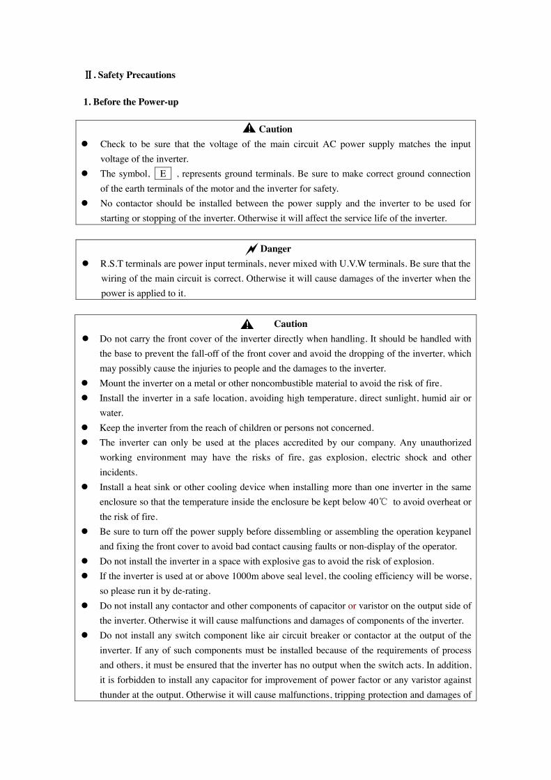
1. Before the Power-up
Caution ! Check to be sure that the voltage of the main circuit AC power supply matches the input
voltage of the inverter. ! The symbol, E , represents ground terminals. Be sure to make correct ground connection
of the earth terminals of the motor and the inverter for safety. ! No contactor should be installed between the power supply and the inverter to be used for
starting or stopping of the inverter. Otherwise it will affect the service life of the inverter.
Danger ! R.S.T terminals are power input terminals, never mixed with U.V.W terminals. Be sure that the
wiring of the main circuit is correct. Otherwise it will cause damages of the inverter when the power is applied to it.
Caution
! Do not carry the front cover of the inverter directly when handling. It should be handled with the base to prevent the fall-off of the front cover and avoid the dropping of the inverter, which may possibly cause the injuries to people and the damages to the inverter.
! Mount the inverter on a metal or other noncombustible material to avoid the risk of fire. ! Install the inverter in a safe location, avoiding high temperature, direct sunlight, humid air or
water. ! Keep the inverter from the reach of children or persons not concerned. ! The inverter can only be used at the places accredited by our company. Any unauthorized
working environment may have the risks of fire, gas explosion, electric shock and other incidents.
! Install a heat sink or other cooling device when installing more than one inverter in the same enclosure so that the temperature inside the enclosure be kept below 40℃ to avoid overheat or the risk of fire.
! Be sure to turn off the power supply before dissembling or assembling the operation keypanel and fixing the front cover to avoid bad contact causing faults or non-display of the operator.
! Do not install the inverter in a space with explosive gas to avoid the risk of explosion. ! If the inverter is used at or above 1000m above seal level, the cooling efficiency will be worse,
so please run it by de-rating. ! Do not install any contactor and other components of capacitor or varistor on the output side of
the inverter. Otherwise it will cause malfunctions and damages of components of the inverter. ! Do not install any switch component like air circuit breaker or contactor at the output of the
inverter. If any of such components must be installed because of the requirements of process and others, it must be ensured that the inverter has no output when the switch acts. In addition, it is forbidden to install any capacitor for improvement of power factor or any varistor against thunder at the output. Otherwise it will cause malfunctions, tripping protection and damages of
!!!!
!!!!
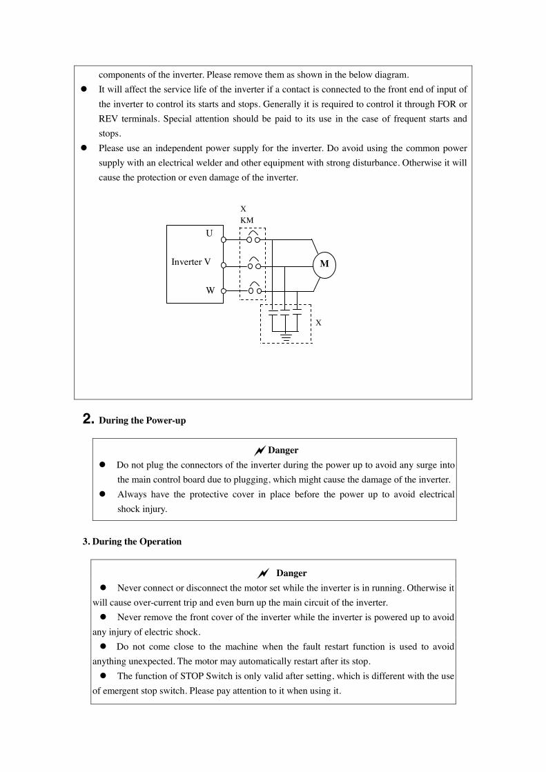
components of the inverter. Please remove them as shown in the below diagram. ! It will affect the service life of the inverter if a contact is connected to the front end of input of
the inverter to control its starts and stops. Generally it is required to control it through FOR or REV terminals. Special attention should be paid to its use in the case of frequent starts and stops.
! Please use an independent power supply for the inverter. Do avoid using the common power supply with an electrical welder and other equipment with strong disturbance. Otherwise it will cause the protection or even damage of the inverter.
2. During the Power-up
Danger ! Do not plug the connectors of the inverter during the power up to avoid any surge into
the main control board due to plugging, which might cause the damage of the inverter. ! Always have the protective cover in place before the power up to avoid electrical
shock injury.
3. During the Operation
Danger ! Never connect or disconnect the motor set while the inverter is in running. Otherwise it
will cause over-current trip and even burn up the main circuit of the inverter. ! Never remove the front cover of the inverter while the inverter is powered up to avoid
any injury of electric shock. ! Do not come close to the machine when the fault restart function is used to avoid
anything unexpected. The motor may automatically restart after its stop. ! The function of STOP Switch is only valid after setting, which is different with the use
of emergent stop switch. Please pay attention to it when using it.
U Inverter V
W
M
KM X
X
Caution ! Do not touch the heat sink, braking resistor, or other heat elements to avoid being scald. ! Be sure that the motor and machine is within the applicable speed ranges before
starting operation because the inverter is quite easy to run from lower speed to higher speed. ! Do not check the signals on circuit boards while the inverter is running to avoid danger. ! Be careful when changing the inverter settings. The inverter has been adjusted and set
before ex-work. Do not adjust it wantonly. Please make proper adjustments according to the required functions. ! Do consider the vibration, noise and the speed limit of the motor bearings and the
mechanical devices when the inverter is running at or above the frequency of 50Hz.
ⅢⅢⅢⅢ. Standards and Specifications
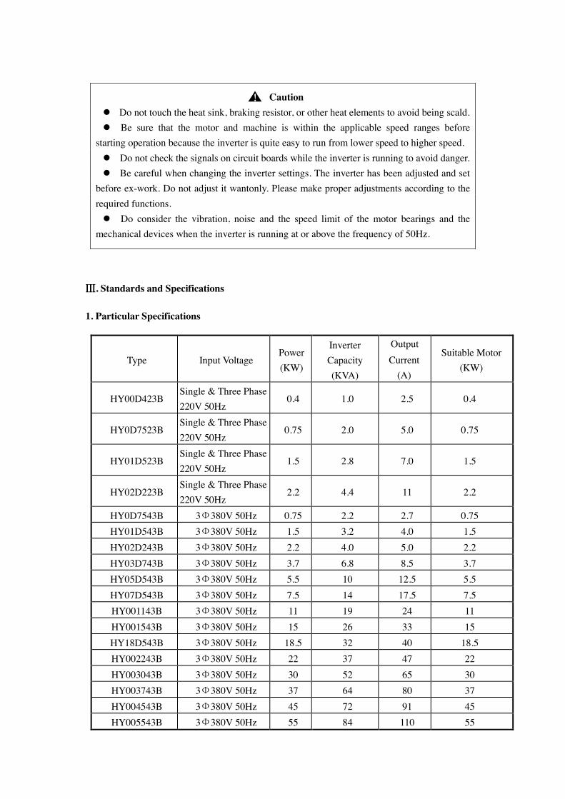
1. Particular Specifications
Type Input Voltage Power (KW)
Inverter Capacity (KVA)
Output Current
(A)
Suitable Motor (KW)
HY00D423B Single & Three Phase 220V 50Hz
0.4 1.0 2.5 0.4
HY0D7523B Single & Three Phase 220V 50Hz
0.75 2.0 5.0 0.75
HY01D523B Single & Three Phase 220V 50Hz
1.5 2.8 7.0 1.5
HY02D223B Single & Three Phase 220V 50Hz
2.2 4.4 11 2.2
HY0D7543B 3Φ380V 50Hz 0.75 2.2 2.7 0.75 HY01D543B 3Φ380V 50Hz 1.5 3.2 4.0 1.5 HY02D243B 3Φ380V 50Hz 2.2 4.0 5.0 2.2 HY03D743B 3Φ380V 50Hz 3.7 6.8 8.5 3.7 HY05D543B 3Φ380V 50Hz 5.5 10 12.5 5.5 HY07D543B 3Φ380V 50Hz 7.5 14 17.5 7.5 HY001143B 3Φ380V 50Hz 11 19 24 11 HY001543B 3Φ380V 50Hz 15 26 33 15 HY18D543B 3Φ380V 50Hz 18.5 32 40 18.5 HY002243B 3Φ380V 50Hz 22 37 47 22 HY003043B 3Φ380V 50Hz 30 52 65 30 HY003743B 3Φ380V 50Hz 37 64 80 37 HY004543B 3Φ380V 50Hz 45 72 91 45 HY005543B 3Φ380V 50Hz 55 84 110 55
!!!!
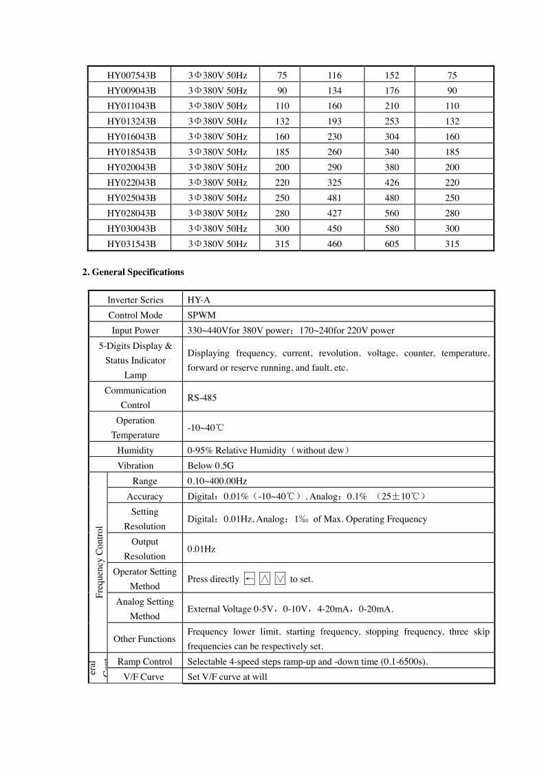
HY007543B 3Φ380V 50Hz 75 116 152 75 HY009043B 3Φ380V 50Hz 90 134 176 90 HY011043B 3Φ380V 50Hz 110 160 210 110 HY013243B 3Φ380V 50Hz 132 193 253 132 HY016043B 3Φ380V 50Hz 160 230 304 160 HY018543B 3Φ380V 50Hz 185 260 340 185 HY020043B 3Φ380V 50Hz 200 290 380 200 HY022043B 3Φ380V 50Hz 220 325 426 220 HY025043B 3Φ380V 50Hz 250 481 480 250 HY028043B 3Φ380V 50Hz 280 427 560 280 HY030043B 3Φ380V 50Hz 300 450 580 300 HY031543B 3Φ380V 50Hz 315 460 605 315
2. General Specifications
Inverter Series HY-A Control Mode SPWM Input Power 330~440Vfor 380V power;170~240for 220V power
5-Digits Display & Status Indicator
Lamp
Displaying frequency, current, revolution, voltage, counter, temperature, forward or reserve running, and fault, etc.
Communication Control
RS-485
Operation Temperature
-10~40℃
Humidity 0-95% Relative Humidity(without dew) Vibration Below 0.5G
Range 0.10~400.00Hz Accuracy Digital:0.01%(-10~40℃), Analog:0.1% (25±10℃) Setting
Resolution Digital:0.01Hz, Analog:1‰ of Max. Operating Frequency
Output Resolution
0.01Hz
Operator Setting Method
Press directly ← ∧ ∨ to set.
Analog Setting Method
External Voltage 0-5V,0-10V,4-20mA,0-20mA.
Freq
uenc
y Co
ntro
l
Other Functions Frequency lower limit, starting frequency, stopping frequency, three skip frequencies can be respectively set.
Ramp Control Selectable 4-speed steps ramp-up and -down time (0.1-6500s).
eral
C
ont
V/F Curve Set V/F curve at will
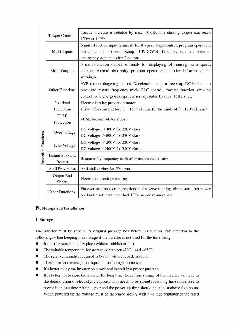
Torque Control Torque increase is settable by max. 10.0%. The starting torque can reach 150% at 1.0Hz.
Multi-Inputs 6 multi-function input terminals for 8–speed steps control, program operation, switching of 4-speed Ramp, UP/DOWN function, counter, external emergency stop and other functions.
Multi-Outputs 5 multi-function output terminals for displaying of running, zero speed, counter, external abnormity, program operation and other information and warnings.
Other Functions AVR (auto voltage regulation), Deceleration stop or free-stop, DC brake, auto reset and restart, frequency track, PLC control, traverse function, drawing control, auto energy-savings, carrier adjustable by max. 16KHz, etc.
Overload Protection
Electronic relay protection motor Drive(for constant torque 150%/1 min. for the kinds of fan 120%/1min.)
FUSE Protection
FUSE broken, Motor stops.
Over-voltage DC Voltage >400V for 220V class DC Voltage >800V for 380V class
Low Voltage DC Voltage <200V for 220V class DC Voltage <400V for 380V class
Instant Stop and Restart
Restarted by frequency track after instantaneous stop.
Stall Prevention Anti-stall during Acc/Dec run Output End
Shorts Electronic circuit protecting
Prot
ectio
n Fu
nctio
ns
Other Functions Fin over-heat protection, restriction of reverse running, direct start after power on, fault reset, parameter lock PID, one-drive-more, etc.
ⅣⅣⅣⅣ. Storage and Installation
1. Storage
The inverter must be kept in its original package box before installation. Pay attention to the followings when keeping it in storage if the inverter is not used for the time being: ! It must be stored in a dry place without rubbish or dust. ! The suitable temperature for storage is between -20℃ and +65℃. ! The relative humidity required is 0-95% without condensation. ! There is no corrosive gas or liquid in the storage ambience. ! It’s better to lay the inverter on a rack and keep it in a proper package. ! It is better not to store the inverter for long time. Long time storage of the inverter will lead to
the deterioration of electrolytic capacity. If it needs to be stored for a long time make sure to power it up one time within a year and the power-up time should be at least above five hours. When powered up the voltage must be increased slowly with a voltage regulator to the rated
voltage value.
2. Installation Site and Environment
The inverter should be installed at the following location: ! Ambient temperature -5℃ to 40℃ with good ventilation. ! No water drop and low moisture. ! Free from direct sunshine, high temperature and heavy dust fall. ! Free from corrosive gas or liquid. ! Less dust, oil gas and metallic particles ! Free from vibration and easy for service and inspection. ! Free from the interference of electromagnetic noise.
Attention: The ambient conditions of the inverter will affect its service life.
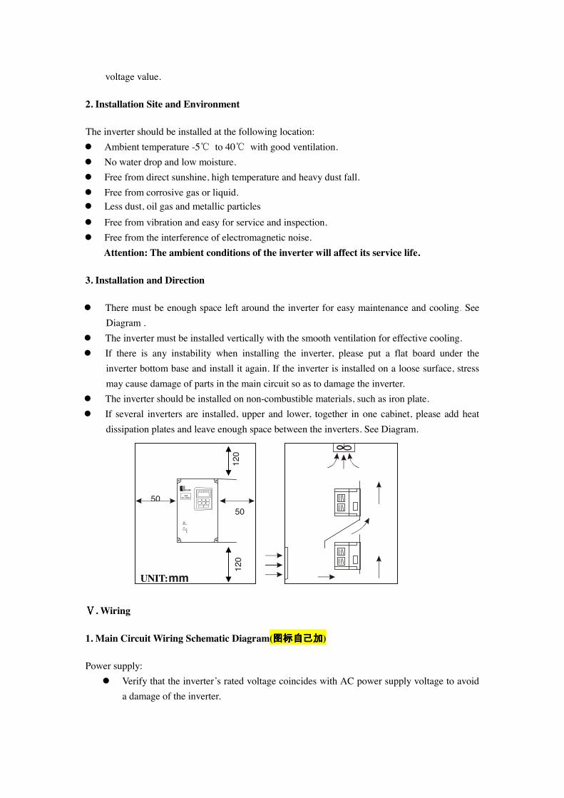
3. Installation and Direction
! There must be enough space left around the inverter for easy maintenance and cooling. See Diagram .
! The inverter must be installed vertically with the smooth ventilation for effective cooling. ! If there is any instability when installing the inverter, please put a flat board under the
inverter bottom base and install it again. If the inverter is installed on a loose surface, stress may cause damage of parts in the main circuit so as to damage the inverter.
! The inverter should be installed on non-combustible materials, such as iron plate. ! If several inverters are installed, upper and lower, together in one cabinet, please add heat
dissipation plates and leave enough space between the inverters. See Diagram.
ⅤⅤⅤⅤ. Wiring
1. Main Circuit Wiring Schematic Diagram(图标自己加图标自己加图标自己加图标自己加)
Power supply: ! Verify that the inverter’s rated voltage coincides with AC power supply voltage to avoid
a damage of the inverter.
UNIT:mm
50 50
120
120
No fuse breaker: ! Refer to the related list.
Ground fault circuit interrupter:
! Use one of anti-high harmonic. Electromagnetic contactor:
! Note: Do not use the electromagnetic contactor as the on/off button of power supply for the inverter.
AC reactor:
! It is recommended to install an AC reactor for power factor improvement if the input capacity is more than 1000KVA.
Inverter:
! Be sure to make correct connections of the main circuit wires and control signal wires of the inverter.
! Be sure to make correct setting of parameters for the inverter.
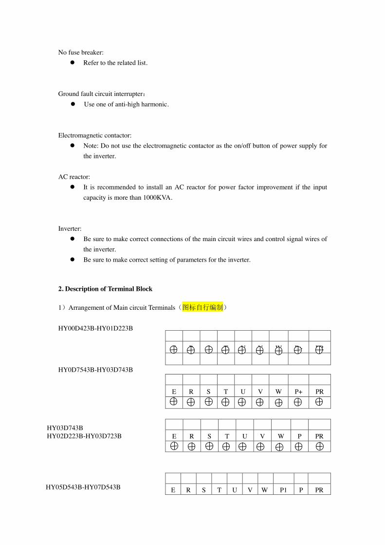
2. Description of Terminal Block
1)Arrangement of Main circuit Terminals(图标自行编制) HY00D423B-HY01D223B HY0D7543B-HY03D743B
E R S T U V W P+ PR
E R S T U V W P PR
E R S T U V W P1 P PR
E R S T U V W P+ PR
HY03D743B HY02D223B-HY03D723B
HY05D543B-HY07D543B
R S T E P N U V W
R S T E P P1 N U V W
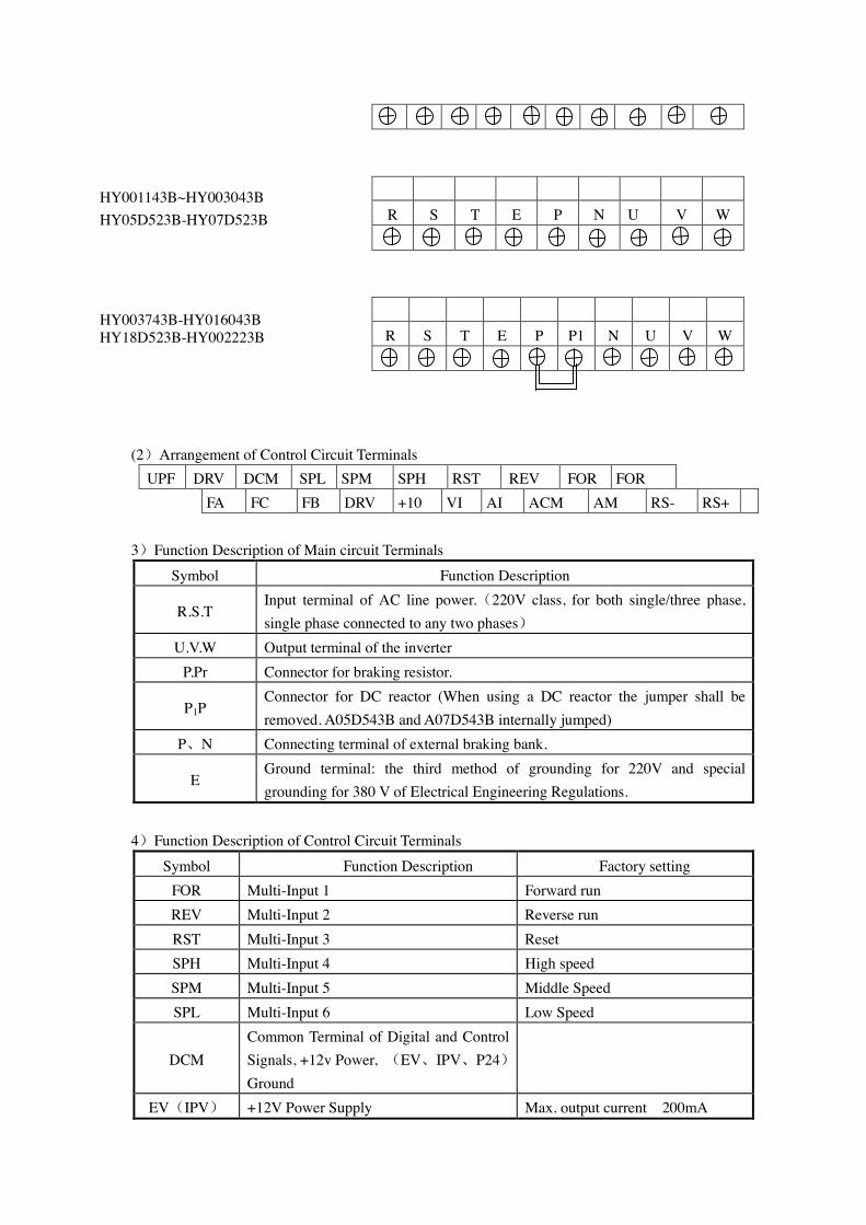
(2)Arrangement of Control Circuit Terminals UPF DRV DCM SPL SPM SPH RST REV FOR FOR
FA FC FB DRV +10 VI AI ACM AM RS- RS+
3)Function Description of Main circuit Terminals
Symbol Function Description
R.S.T Input terminal of AC line power.(220V class, for both single/three phase, single phase connected to any two phases)
U.V.W Output terminal of the inverter P.Pr Connector for braking resistor.
P1P Connector for DC reactor (When using a DC reactor the jumper shall be removed. A05D543B and A07D543B internally jumped)
P、N Connecting terminal of external braking bank.
E Ground terminal: the third method of grounding for 220V and special grounding for 380 V of Electrical Engineering Regulations.
4)Function Description of Control Circuit Terminals
Symbol Function Description Factory setting FOR Multi-Input 1 Forward run REV Multi-Input 2 Reverse run RST Multi-Input 3 Reset SPH Multi-Input 4 High speed SPM Multi-Input 5 Middle Speed SPL Multi-Input 6 Low Speed
DCM Common Terminal of Digital and Control Signals, +12v Power, (EV、IPV、P24)Ground
EV(IPV) +12V Power Supply Max. output current 200mA
HY003743B-HY016043B HY18D523B-HY002223B
HY001143B~HY003043B HY05D523B-HY07D523B
P24 +12V Power Supply Max. output current 200mA +10 Power Supply for Speed Setting +10V
VI Analog Voltage Frequency Reference Input
0~+10V corresponding to the highest operating frequency
AI Analog Current Frequency Reference Input
4~20mA corresponding to the highest operating frequency
ACM Common Terminal of Analog and Control Signals
DRV Multi-Output 1 (Optical couple output) UPF Multi-Output 2 (Optical couple output)
DC24V/100mA
FA(EFA)、 FB(EFB)、 FC(EFC)
Multi-Output 3 (N/O or N/C) 3A/250VAC
KA(EKA)、 KB(EKB)
Multi-Output 4 (N/O) 3A/250VAC
AM Output terminals of digital frequency 0~10V RS+ RS- RS485 Communication port
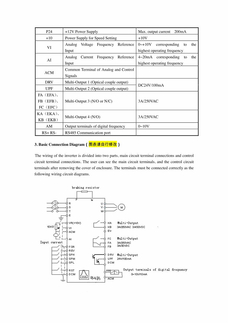
3. Basic Connection Diagram((((图表请自行修改))))
The wiring of the inverter is divided into two parts, main circuit terminal connections and control circuit terminal connections. The user can see the main circuit terminals, and the control circuit terminals after removing the cover of enclosure. The terminals must be connected correctly as the following wiring circuit diagrams.
4. Precautions on Wiring
1) For the main circuit wiring: ! While wiring the sizes and specifications of wires should be selected and the wiring should
be executed according to the electrical engineering regulations to ensure the safety. ! It is better to use shielded wire or wire and conduit for power cord and ground the shielded
layer or two ends of wire conduit. ! Be sure to install a Non Fuse Breaker (NFB) between the power supply and the input
terminals (R.S.T). (If using ground fault circuit interrupter, please choose one corresponding to high frequency)
! Never connect AC power to the output terminal (U.V.W) of the inverter. ! Output wires mustn’t be in touch of the metal part of the inverter enclosure, or it will result in
earth short-circuit. ! Phase-shifting capacitors, LC, RC noise filters, etc, can never be connected to the output
terminals of the inverter. ! The main circuit wire must be enough far away from other control equipments. ! When the wiring between the inverter and the motor exceeds 15 meters for 220V class or 30
meters for 380V class, much higher dV/dT will be produced inside the coil of the motor, which will cause the destruction to the interlay or insulation of the motor. Please use a dedicated AC motor for the inverter or add a reactor at the inverter.
! Please lower the carrier frequency when there is a longer distance between the inverter and the motor. Because the higher the carrier frequency is the bigger the leakage current of high-order harmonics in the cables will be. The leakage current will have unfavorable effect on the inverter and other equipment.
2) For control circuit wiring (signal line) ! The signal line should be separately laid in a different conduit with the main circuit wire to
avoid any possible interference. ! Please use the shielded cable with the size of 0.5-2mm2 for signal lines. ! Use the control terminals on the control panel correctly according to your needs. 3) Grounding ! Grounding terminal E. Be sure to make correct grounding
220V class: The third grounding method (Grounding resistance should be 100Ω or lower.) 380V class: The special third grounding method (Grounding resistance should be 10Ω or lower.)
! Choose grounding wires according to the basic length and size of the technical requirements of the electric equipment.
! Do avoid sharing grounding wire with other large power equipment such as electric welder,
power machine, etc. The grounding wire should be kept away from the power supply wires for large power equipment.
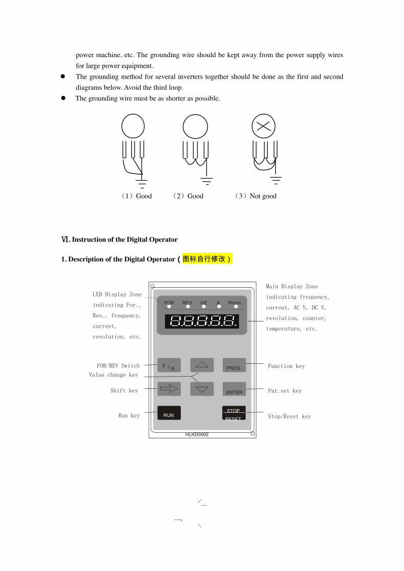
! The grounding method for several inverters together should be done as the first and second diagrams below. Avoid the third loop.
! The grounding wire must be as shorter as possible.
(1)Good (2)Good (3)Not good ⅥⅥⅥⅥ. Instruction of the Digital Operator
1. Description of the Digital Operator((((图标自行修改)
FOR REV HZ A R/min LED Display Zone
indicating For.,
Rev., frequency,
current,
revolution, etc.
Main Display Zone
indicating frequency,
current, AC V, DC V,
revolution, counter,
temperature, etc.
Function key FOR/REV Switch Value change key
Shift key
Run key
Par.set key
Stop/Reset key
F / R PROG
ENTER
RUN STOP RESET
HLKD0002
RUN
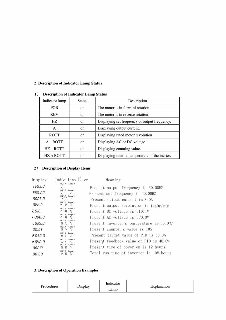
2. Description of Indicator Lamp Status
1)))) Description of Indicator Lamp Status Indicator lamp Status Description
FOR on The motor is in forward rotation.
REV on The motor is in reverse rotation.
HZ on Displaying set frequency or output frequency.
A on Displaying output current.
ROTT on Displaying rated motor revolution
A ROTT on Displaying AC or DC voltage.
HZ ROTT on Displaying counting value.
HZ A ROTT on Displaying internal temperature of the inerter.
2)))) Description of Display Items
3. Description of Operation Examples
Procedures Display Indicator
Lamp Explanation
Present inverter’s temperature is 35.0℃
Meaning Indic.lamp on
Present output frequency is 50.00HZ
3.0A 1440r/min
510.1V 380.0V
Present target value of PID is 50.0%
I
Present set frequency is 50.00HZ Present output current is
Present output revolution is Present DC voltage is Present AC voltage is Present counter’s value is 105
Present feedback value of PID is 48.0% Present time of power-on is 12 hours Total run time of inverter is 108 hours
Display
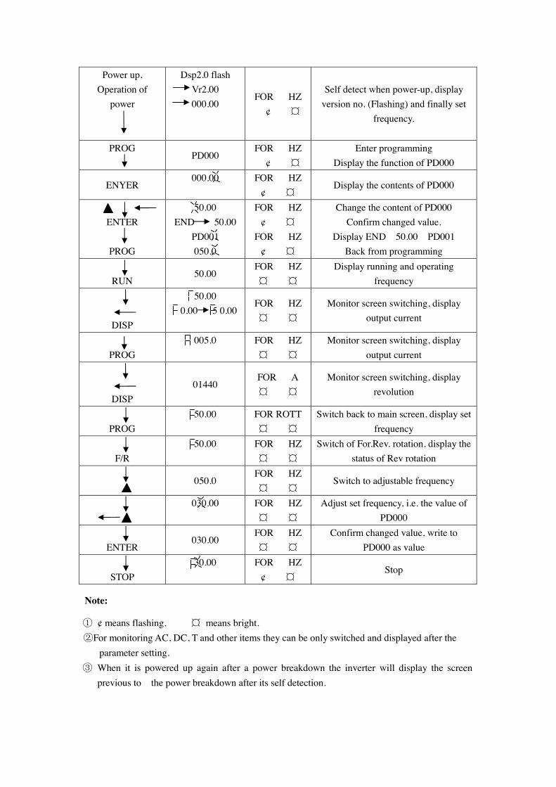
Power up, Operation of
power
Dsp2.0 flash Vr2.00 000.00
FOR HZ ¢ ¤
Self detect when power-up, display version no. (Flashing) and finally set
frequency.
PROG
PD000 FOR HZ
¢ ¤ Enter programming
Display the function of PD000
ENYER 000.00 FOR HZ
¢ ¤ Display the contents of PD000
ENTER
PROG
50.00 END 50.00
PD001 050.0
FOR HZ ¢ ¤
FOR HZ ¢ ¤
Change the content of PD000 Confirm changed value.
Display END 50.00 PD001 Back from programming
RUN
50.00 FOR HZ ¤ ¤
Display running and operating frequency
DISP
50.00 0.00 5 0.00
FOR HZ ¤ ¤
Monitor screen switching, display output current
PROG
005.0 FOR HZ ¤ ¤
Monitor screen switching, display output current
DISP 01440
FOR A ¤ ¤
Monitor screen switching, display revolution
PROG
50.00 FOR ROTT ¤ ¤
Switch back to main screen, display set frequency
F/R
50.00 FOR HZ ¤ ¤
Switch of For.Rev. rotation, display the status of Rev rotation
050.0 FOR HZ ¤ ¤
Switch to adjustable frequency
030.00 FOR HZ ¤ ¤
Adjust set frequency, i.e. the value of PD000
ENTER
030.00 FOR HZ ¤ ¤
Confirm changed value, write to PD000 as value
STOP
30.00 FOR HZ ¢ ¤
Stop
Note:
① ¢ means flashing. ¤ means bright. ②For monitoring AC, DC, T and other items they can be only switched and displayed after the
parameter setting. ③ When it is powered up again after a power breakdown the inverter will display the screen
previous to the power breakdown after its self detection.
ⅦⅦⅦⅦ. Commissioning
1. Important Checks before the Commissioning
! If there is any wrong connected wires? Pay special attention to the terminal of U.V.W; Make sure the power supply wires are connected to R.S.T, not U.V.W.
! If there is any metal powder or wires left on the base plate of the inverter or the terminal block, which may cause short circuit.
! If screws are tightly locked and if the connecting parts are loose. ! If there is any short circuit or earth fault at outputs.
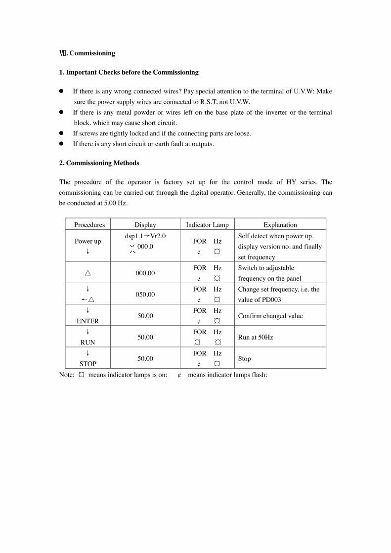
2. Commissioning Methods
The procedure of the operator is factory set up for the control mode of HY series. The commissioning can be carried out through the digital operator. Generally, the commissioning can be conducted at 5.00 Hz.
Procedures Display Indicator Lamp Explanation
Power up ↓
dsp1.1→Vr2.0 000.0
FOR Hz ¢ ¤
Self detect when power up, display version no. and finally set frequency
△ 000.00 FOR Hz ¢ ¤
Switch to adjustable frequency on the panel
↓ ←△
050.00 FOR Hz ¢ ¤
Change set frequency, i.e. the value of PD003
↓ ENTER
50.00 FOR Hz ¢ ¤
Confirm changed value
↓ RUN
50.00 FOR Hz ¤ ¤
Run at 50Hz
↓ STOP
50.00 FOR Hz ¢ ¤
Stop
Note: ¤ means indicator lamps is on; ¢ means indicator lamps flash;
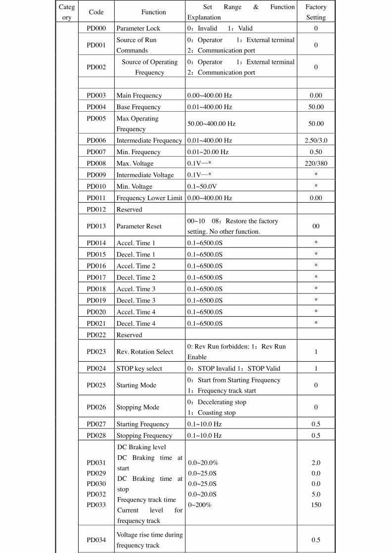
Category
Code Function Set Range & Function
Explanation Factory Setting
PD000 Parameter Lock 0:Invalid 1:Valid 0
PD001 Source of Run Commands
0:Operator 1:External terminal 2:Communication port
0
PD002 Source of Operating
Frequency 0:Operator 1:External terminal 2:Communication port
0
PD003 Main Frequency 0.00~400.00 Hz 0.00
PD004 Base Frequency 0.01~400.00 Hz 50.00
PD005 Max Operating Frequency
50.00~400.00 Hz 50.00
PD006 Intermediate Frequency 0.01~400.00 Hz 2.50/3.0
PD007 Min. Frequency 0.01~20.00 Hz 0.50 PD008 Max. Voltage 0.1V—* 220/380
PD009 Intermediate Voltage 0.1V—* *
PD010 Min. Voltage 0.1~50.0V *
PD011 Frequency Lower Limit 0.00~400.00 Hz 0.00
PD012 Reserved
PD013 Parameter Reset 00~10 08:Restore the factory setting. No other function.
00
PD014 Accel. Time 1 0.1~6500.0S *
PD015 Decel. Time 1 0.1~6500.0S * PD016 Accel. Time 2 0.1~6500.0S *
PD017 Decel. Time 2 0.1~6500.0S *
PD018 Accel. Time 3 0.1~6500.0S *
PD019 Decel. Time 3 0.1~6500.0S *
PD020 Accel. Time 4 0.1~6500.0S *
PD021 Decel. Time 4 0.1~6500.0S * PD022 Reserved
PD023 Rev. Rotation Select 0: Rev Run forbidden; 1:Rev Run Enable
1
PD024 STOP key select 0:STOP Invalid 1:STOP Valid 1
PD025 Starting Mode 0:Start from Starting Frequency 1:Frequency track start
0
PD026 Stopping Mode 0:Decelerating stop 1:Coasting stop
0
PD027 Starting Frequency 0.1~10.0 Hz 0.5 PD028 Stopping Frequency 0.1~10.0 Hz 0.5
PD031 PD029 PD030 PD032 PD033
DC Braking level DC Braking time at start DC Braking time at stop Frequency track time Current level for frequency track
0.0~20.0% 0.0~25.0S 0.0~25.0S 0.0~20.0S 0~200%
2.0 0.0 0.0 5.0 150
PD034 Voltage rise time during frequency track
0.5
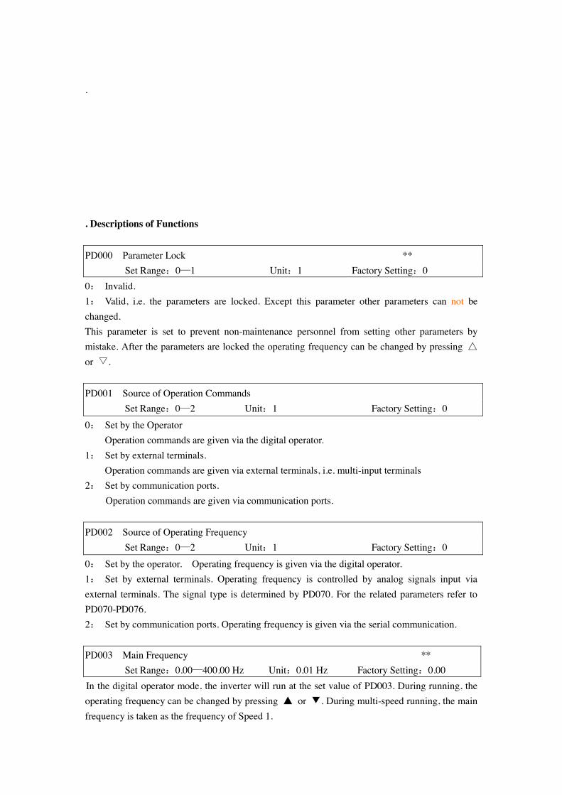
. . Descriptions of Functions
PD000 Parameter Lock ** Set Range:0—1 Unit:1 Factory Setting:0
0: Invalid. 1: Valid, i.e. the parameters are locked. Except this parameter other parameters can not be changed. This parameter is set to prevent non-maintenance personnel from setting other parameters by mistake. After the parameters are locked the operating frequency can be changed by pressing △ or ▽. PD001 Source of Operation Commands Set Range:0—2 Unit:1 Factory Setting:0
0: Set by the Operator Operation commands are given via the digital operator. 1: Set by external terminals. Operation commands are given via external terminals, i.e. multi-input terminals 2: Set by communication ports.
Operation commands are given via communication ports.
PD002 Source of Operating Frequency Set Range:0—2 Unit:1 Factory Setting:0
0: Set by the operator. Operating frequency is given via the digital operator. 1: Set by external terminals. Operating frequency is controlled by analog signals input via external terminals. The signal type is determined by PD070. For the related parameters refer to PD070-PD076. 2: Set by communication ports. Operating frequency is given via the serial communication. PD003 Main Frequency ** Set Range:0.00—400.00 Hz Unit:0.01 Hz Factory Setting:0.00 In the digital operator mode, the inverter will run at the set value of PD003. During running, the operating frequency can be changed by pressing ▲ or ▼. During multi-speed running, the main frequency is taken as the frequency of Speed 1.
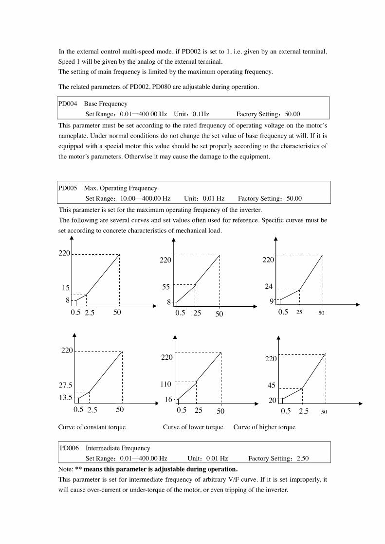
In the external control multi-speed mode, if PD002 is set to 1, i.e. given by an external terminal, Speed 1 will be given by the analog of the external terminal. The setting of main frequency is limited by the maximum operating frequency.
The related parameters of PD002, PD080 are adjustable during operation.
PD004 Base Frequency Set Range:0.01—400.00 Hz Unit:0.1Hz Factory Setting:50.00
This parameter must be set according to the rated frequency of operating voltage on the motor’s nameplate. Under normal conditions do not change the set value of base frequency at will. If it is equipped with a special motor this value should be set properly according to the characteristics of the motor’s parameters. Otherwise it may cause the damage to the equipment.
PD005 Max. Operating Frequency Set Range:10.00—400.00 Hz Unit:0.01 Hz Factory Setting:50.00
This parameter is set for the maximum operating frequency of the inverter. The following are several curves and set values often used for reference. Specific curves must be set according to concrete characteristics of mechanical load.
Curve of constant torque Curve of lower torque Curve of higher torque
PD006 Intermediate Frequency Set Range:0.01—400.00 Hz Unit:0.01 Hz Factory Setting:2.50
Note: ** means this parameter is adjustable during operation. This parameter is set for intermediate frequency of arbitrary V/F curve. If it is set improperly, it will cause over-current or under-torque of the motor, or even tripping of the inverter.
220
15 8
0.5 2.5 50
220
27.5 13.5
0.5 2.5 50
8
220
0.5 25 50
55
220
9 0.5 25 50
24
16
220
0.5 25 50
110
220
20 0.5 2.5 50
45
This set value of intermediate frequency is limited by the set value of base frequency.
PD007 Min. Frequency Set Range:0.1—20.00 Hz Unit:0.01 Hz Factory Setting:0.50 This parameter is set for the min. starting frequency of V/F curve. The following table has specific factory settings of V/F curve, accel./decal., time and carrier for the inverter of A series:
PD008 Max. Voltage Set Range:0.1—* Unit:0.1V Factory Setting:220/380V
This parameter should be set according to the rated value of the motor’s nameplate. The factory setting is 380V for 380V class motor and 220V for 220V class motor. The setting range of this parameter is restricted by the voltage rating of the inverter. In case of the motor relatively far away from the inverter this set value can be increased properly.
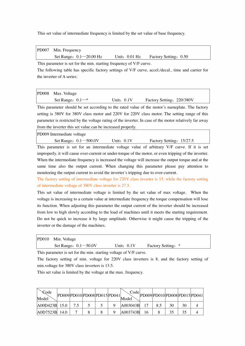
PD009 Intermediate voltage Set Range:0.1—500.0V Unit:0.1V Factory Setting:15/27.5 This parameter is set for an intermediate voltage value of arbitrary V/F curve. If it is set improperly, it will cause over-current or under-torque of the motor, or even tripping of the inverter. When the intermediate frequency is increased the voltage will increase the output torque and at the same time also the output current. When changing this parameter please pay attention to monitoring the output current to avoid the inverter’s tripping due to over-current. The factory setting of intermediate voltage for 220V class inverter is 15, while the factory setting of intermediate voltage of 380V class inverter is 27.5. This set value of intermediate voltage is limited by the set value of max voltage. When the voltage is increasing to a certain value at intermediate frequency the torque compensation will lose its function. When adjusting this parameter the output current of the inverter should be increased from low to high slowly according to the load of machines until it meets the starting requirement. Do not be quick to increase it by large amplitude. Otherwise it might cause the tripping of the inverter or the damage of the machines. PD010 Min. Voltage Set Range:0.1—50.0V Unit:0.1V Factory Setting:* This parameter is set for the min. starting voltage of V/F curve. The factory setting of min. voltage for 220V class inverters is 8, and the factory setting of min.voltage for 380V class inverters is 13.5. This set value is limited by the voltage at the max. frequency.
Code Model
PD009 PD010 PD008 PD015 PD041 Code Model
PD009 PD010 PD008 PD015 PD041
A00D423B 15.0 7.5 5 5 9 A003043B 17 8.5 30 30 4 A0D7523B 14.0 7 8 8 9 A003743B 16 8 35 35 4
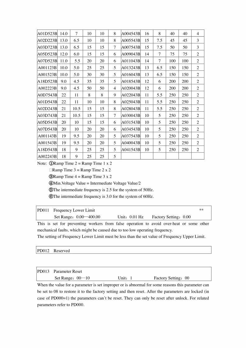
A01D523B 14.0 7 10 10 8 A004543B 16 8 40 40 4 A02D223B 13.0 6.5 10 10 8 A005543B 15 7.5 45 45 3 A03D723B 13.0 6.5 15 15 7 A007543B 15 7.5 50 50 3 A05D523B 12.0 6.0 15 15 6 A009043B 14 7 75 75 2 A07D523B 11.0 5.5 20 20 6 A011043B 14 7 100 100 2 A001123B 10.0 5.0 25 25 5 A013243B 13 6.5 150 150 2 A001523B 10.0 5.0 30 30 5 A016043B 13 6.5 150 150 2 A18D523B 9.0 4.5 35 35 5 A018543B 12 6 200 200 2 A002223B 9.0 4.5 50 50 4 A020043B 12 6 200 200 2 A0D7543B 22 11 8 8 9 A022043B 11 5.5 250 250 2 A01D543B 22 11 10 10 8 A025043B 11 5.5 250 250 2 A02D243B 21 10.5 15 15 8 A028043B 11 5.5 250 250 2 A03D743B 21 10.5 15 15 7 A030043B 10 5 250 250 2 A05D543B 20 10 15 15 6 A031543B 10 5 250 250 2 A07D543B 20 10 20 20 6 A034543B 10 5 250 250 2 A001143B 19 9.5 20 20 5 A037543B 10 5 250 250 2 A001543B 19 9.5 20 20 5 A040043B 10 5 250 250 2 A18D543B 18 9 25 25 5 A041543B 10 5 250 250 2 A002243B 18 9 25 25 5 Note: ①①①①Ramp Time 2 = Ramp Time 1 x 2
�Ramp Time 3 = Ramp Time 2 x 2 ③③③③Ramp Time 4 = Ramp Time 3 x 2 ④④④④Min.Voltage Value = Intermediate Voltage Value/2 ⑤⑤⑤⑤The intermediate frequency is 2.5 for the system of 50Hz. ⑥⑥⑥⑥The intermediate frequency is 3.0 for the system of 60Hz.
PD011 Frequency Lower Limit ** Set Range:0.00—400.00 Unit:0.01 Hz Factory Setting:0.00
This is set for preventing workers from false operation to avoid over-heat or some other mechanical faults, which might be caused due to too low operating frequency. The setting of Frequency Lower Limit must be less than the set value of Frequency Upper Limit.
PD012 Reserved
PD013 Parameter Reset Set Range:00—10 Unit:1 Factory Setting:00 When the value for a parameter is set improper or is abnormal for some reasons this parameter can be set to 08 to restore it to the factory setting and then reset. After the parameters are locked (in case of PD000=1) the parameters can’t be reset. They can only be reset after unlock. For related parameters refer to PD000.
PD014Accel. Time 1 ** Set Range:0.1—6500.0S Unit:0.1S Factory Setting: *
PD015 Decel. Time 1 ** Set Range:0.1—6500.0S Unit:0.1S Factory Setting: *
PD016 Accel. Time 2 ** Set Range:0.1—6500.0S Unit:0.1S Factory Setting: *
PD17 Decel. Time 2 ** Set Range:0.1—6500.0S Unit:0.1S Factory Setting: * PD18 Accel. Time 3 **
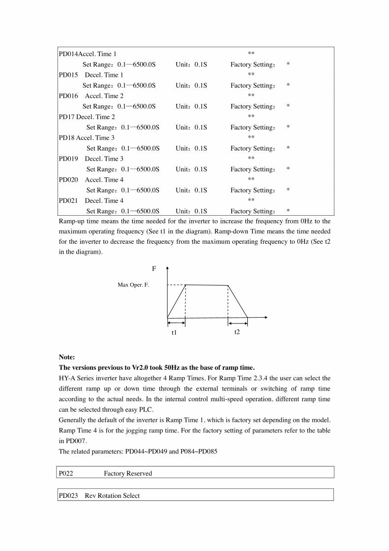
Set Range:0.1—6500.0S Unit:0.1S Factory Setting: * PD019 Decel. Time 3 ** Set Range:0.1—6500.0S Unit:0.1S Factory Setting: * PD020 Accel. Time 4 ** Set Range:0.1—6500.0S Unit:0.1S Factory Setting: * PD021 Decel. Time 4 ** Set Range:0.1—6500.0S Unit:0.1S Factory Setting: * Ramp-up time means the time needed for the inverter to increase the frequency from 0Hz to the maximum operating frequency (See t1 in the diagram). Ramp-down Time means the time needed for the inverter to decrease the frequency from the maximum operating frequency to 0Hz (See t2 in the diagram).
Note: The versions previous to Vr2.0 took 50Hz as the base of ramp time. HY-A Series inverter have altogether 4 Ramp Times. For Ramp Time 2.3.4 the user can select the different ramp up or down time through the external terminals or switching of ramp time according to the actual needs. In the internal control multi-speed operation, different ramp time can be selected through easy PLC. Generally the default of the inverter is Ramp Time 1, which is factory set depending on the model. Ramp Time 4 is for the jogging ramp time. For the factory setting of parameters refer to the table in PD007. The related parameters: PD044~PD049 and P084~PD085
P022 Factory Reserved
PD023 Rev Rotation Select
Max Oper. F.
F
t2 t1
Set Range:0—1 Unit:1 Factory Setting:1 0: Rev Rotation disable 1: Rev Rotation Enable This function is suitable for the motor, which is not allowed to rotate reversely, to prevent workers from false operation. When the reverse rotation is disabled, the motor can only rotate forward, not reverse.
PD024 STOP key Set Range:0—1 Unit:1 Factory Setting:1 0:STOP invalid. 1:STOP valid. This parameter set is only valid when PD001 is set to l or 2. When the control mode is set for external terminals or communication control, STOP key on the panel can be chosen to be valid or invalid. When choosing it as valid, STOP key can stop the inverter in running. When it needs to restart, the former running signal must be released before restarting the inverter.
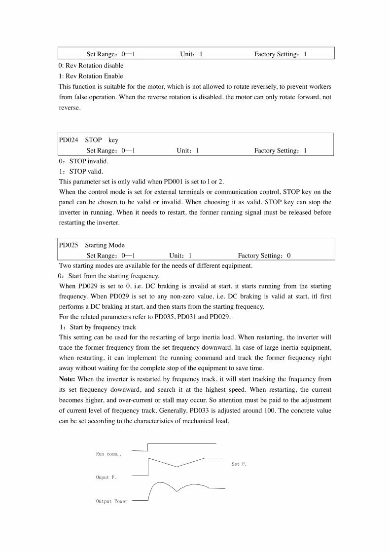
PD025 Starting Mode Set Range:0—1 Unit:1 Factory Setting:0 Two starting modes are available for the needs of different equipment. 0:Start from the starting frequency. When PD029 is set to 0, i.e. DC braking is invalid at start, it starts running from the starting frequency. When PD029 is set to any non-zero value, i.e. DC braking is valid at start, itl first performs a DC braking at start, and then starts from the starting frequency. For the related parameters refer to PD035, PD031 and PD029. 1:Start by frequency track This setting can be used for the restarting of large inertia load. When restarting, the inverter will trace the former frequency from the set frequency downward. In case of large inertia equipment, when restarting, it can implement the running command and track the former frequency right away without waiting for the complete stop of the equipment to save time. Note: When the inverter is restarted by frequency track, it will start tracking the frequency from its set frequency downward, and search it at the highest speed. When restarting, the current becomes higher, and over-current or stall may occur. So attention must be paid to the adjustment of current level of frequency track. Generally, PD033 is adjusted around 100. The concrete value can be set according to the characteristics of mechanical load.
Run comm..
Ouput F.
Output Power
Set F.
PD026 Stopping Mode Set Range:0—1 Unit:1 Factory Setting:0
Two stopping modes are available for the needs of different equipment. 0:Decelerating Stop When PD030 is set to 0, DC braking is invalid. When DC braking is invalid, the inverter will decelerate to the stopping frequency, and then stop outputs, and the motor will coast to stop. When PD030 is set to any non-zero value, DC braking is valid, and the inverter will first decelerate to the stopping frequency, and then stop by DC braking. DC braking at stop is usually used for high position stop or for positioning control. It must be noticed that frequent uses of DC braking will cause over-heat of the motor. For the related parameters refer to PD028, PD031 and PD030. 1:Coasting Stop When the inverter receives a STOP command, it will immediately stop output and the motor will coast to stop. When the coasting stop mode is selected, DC braking is invalid. PD027 Starting Frequency Set Range:0.1—10.0 Hz Unit:0.1Hz Factory Setting:0.5
Starting frequency is the initial frequency when the inverter is started. If the starting frequency is set to 4.0Hz, the inverter will run between 4.0 Hz and the maximum operating frequency after its start at 4.0Hz . The actual maximum operating frequency is limited by the upper limit of frequency. For the related parameters refer to PD025, PD031 and PD029.
PD028 Stopping Frequency Set Range:0.1—10.0 Hz Unit:0.1Hz Factory Setting:0.5 When stopping the inverter will decrease its frequency to the stopping frequency and then stop running or start DC braking to stop. If PD030 is set to 0, DC braking is invalid at stop and the inverter will stop running. If PD030 is set for valid, the inverter will stop by DC braking. For the related parameters refer to PD026, PD031 and PD030. PD029 DC Braking Time at Start Set Range:0.0—25.0S Unit:0.1S Factory Setting:0.0
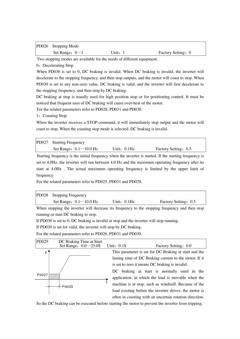
This parameter is set for DC Braking at start and the lasting time of DC Braking current to the motor. If it is set to zero it means DC braking is invalid. DC braking at start is normally used in the application, in which the load is movable when the machine is at stop, such as windmill. Because of the load existing before the inverter drives, the motor is often in coasting with an uncertain rotation direction.
So the DC braking can be executed before starting the motor to prevent the inverter from tripping.
F
T
Pd027
Pd029
This setting is valid only when PD025 is set to 0. For the related parameters refer to PD025, PD031 and PD027.
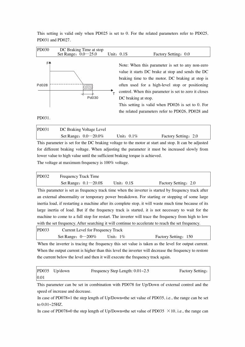
PD030 DC Braking Time at stop
Set Range:0.0—25.0 Unit:0.1S Factory Setting:0.0 Note: When this parameter is set to any non-zero value it starts DC brake at stop and sends the DC braking time to the motor. DC braking at stop is often used for a high-level stop or positioning control. When this parameter is set to zero it closes DC braking at stop. This setting is valid when PD026 is set to 0. For the related parameters refer to PD026, PD028 and
PD031.
PD031 DC Braking Voltage Level Set Range:0.0—20.0% Unit:0.1% Factory Setting:2.0 This parameter is set for the DC braking voltage to the motor at start and stop. It can be adjusted for different braking voltage. When adjusting the parameter it must be increased slowly from lower value to high value until the sufficient braking torque is achieved. The voltage at maximum frequency is 100% voltage.
PD032 Frequency Track Time
Set Range:0.1—20.0S Unit:0.1S Factory Setting:2.0
This parameter is set as frequency track time when the inverter is started by frequency track after an external abnormality or temporary power breakdown. For starting or stopping of some large inertia load, if restarting a machine after its complete stop, it will waste much time because of its large inertia of load. But if the frequency track is started, it is not necessary to wait for the machine to come to a full stop for restart. The inverter will trace the frequency from high to low with the set frequency. After searching it will continue to accelerate to reach the set frequency. PD033 Current Level for Frequency Track
Set Range:0—200% Unit:1% Factory Setting:150 When the inverter is tracing the frequency this set value is taken as the level for output current. When the output current is higher than this level the inverter will decrease the frequency to restore the current below the level and then it will execute the frequency track again.
PD035 Up/down Frequency Step Length: 0.01~2.5 Factory Setting:0.01 This parameter can be set in combination with PD078 for Up/Down of external control and the speed of increase and decrease. In case of PD078=1 the step length of Up/Down=the set value of PD035, i.e., the range can be set to 0.01~25HZ. In case of PD078=0 the step length of Up/Down=the set value of PD035 ×10, i.e., the range can
F
T
Pd028
Pd030
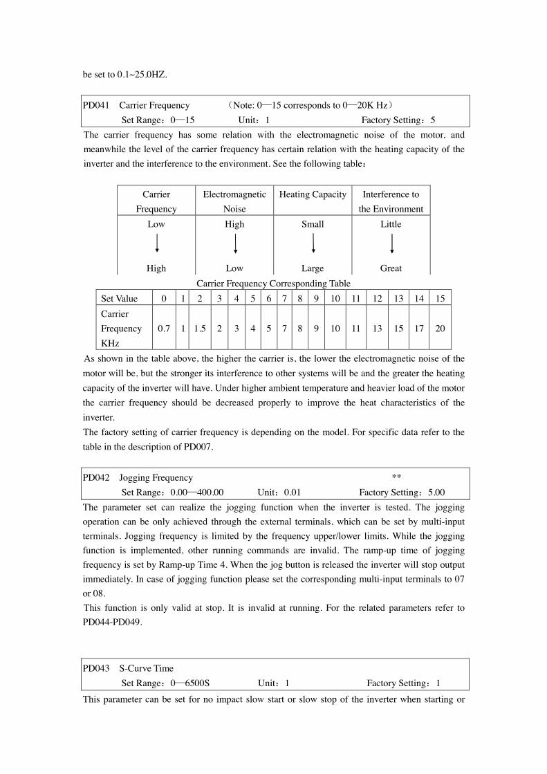
be set to 0.1~25.0HZ.
PD041 Carrier Frequency (Note: 0—15 corresponds to 0—20K Hz) Set Range:0—15 Unit:1 Factory Setting:5 The carrier frequency has some relation with the electromagnetic noise of the motor, and meanwhile the level of the carrier frequency has certain relation with the heating capacity of the inverter and the interference to the environment. See the following table:
Carrier
Frequency Electromagnetic
Noise Heating Capacity Interference to
the Environment Low
High
High
Low
Small
Large
Little
Great Carrier Frequency Corresponding Table
Set Value 0 1 2 3 4 5 6 7 8 9 10 11 12 13 14 15 Carrier Frequency KHz
0.7 1 1.5 2 3 4 5 7 8 9 10 11 13 15 17 20
As shown in the table above, the higher the carrier is, the lower the electromagnetic noise of the motor will be, but the stronger its interference to other systems will be and the greater the heating capacity of the inverter will have. Under higher ambient temperature and heavier load of the motor the carrier frequency should be decreased properly to improve the heat characteristics of the inverter. The factory setting of carrier frequency is depending on the model. For specific data refer to the table in the description of PD007.
PD042 Jogging Frequency ** Set Range:0.00—400.00 Unit:0.01 Factory Setting:5.00 The parameter set can realize the jogging function when the inverter is tested. The jogging operation can be only achieved through the external terminals, which can be set by multi-input terminals. Jogging frequency is limited by the frequency upper/lower limits. While the jogging function is implemented, other running commands are invalid. The ramp-up time of jogging frequency is set by Ramp-up Time 4. When the jog button is released the inverter will stop output immediately. In case of jogging function please set the corresponding multi-input terminals to 07 or 08. This function is only valid at stop. It is invalid at running. For the related parameters refer to PD044-PD049. PD043 S-Curve Time
Set Range:0—6500S Unit:1 Factory Setting:1
This parameter can be set for no impact slow start or slow stop of the inverter when starting or
stopping. When starting S-curve the inverter will make accelerating or decelerating curve of different speed rates according to Ramp Time. When PD043 is set as 0, S-curve is invalid, i.e. it will accelerate or decelerate in linear. Without consideration of stall the actual accel/decal time = (PD008+PD043)/2. The parameter is only valid when PD008 is less than PD043.
PD044 Multi-input 1(FOR function) Factory Setting: 02 PD045 Multi-input 2(REV function) Factory Setting: 03 PD046 Multi-input 3(RST function) Factory Setting: 10 PD047 Multi-input 4(SPH function) Factory Setting: 17 PD048 Multi-input 5(SPM function) Factory Setting: 18 PD049 Multi-input 6(SPL function) Factory Setting: 19 Set Range:00—32 Unit:No
00: Invalid. The terminal is set for empty to prevent false actions. 01: RUN Running. It can be combined with other terminals to compose multiple
control modes. 02: FOR Forward Rotation 03: REV Reverse Rotation 04: STOP Stopping 05: FOR/REV Switching of FOR/REV rotation 06: JOG Jogging 07: Jog FOR Rotation 08: Jog REV Rotation 09: Emergent Stop: Emergent stop. It can receive external emergent stop command or other
fault signals 10: RST Reset. This terminal can be used for reset after a fault is removed. 11: Reserved 12: Over-heat of heat sink or motor: This contact can be used to detect over-heat of the heat
sink or motor to protect the motor and inverter. 13: External Control Timer 1 Start: When the contact is closed, the timer will start and begin to
count time. When the timer reaches the set point the corresponding multi-inputs will act.
14: External Control Timer 2 Start 15~16:Reserved 17: High speed High, middle and low speed can compose three kinds of operation mode 18: Middle speed with different frequencies. In the three terminals the high-end signal has 19: Low speed priority. Low, Middle and High Speed are determined respectively by
Frequency 2, 3, 4. 20: Multi-speed 1 7-speed setting can be composed through Multi-speed 1, 2, 3. 21: Multi-speed 2 22: Multi-speed 3 23: Ramp Time 1: This terminal can be used to select the ramp time of the inverter. 24: Ramp Time 2: 4 kinds of ramp time are available for choice.
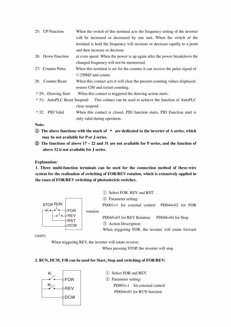
25: UP Function When the switch of this terminal acts the frequency setting of the inverter will be increased or decreased by one unit. When the switch of the terminal is hold the frequency will increase or decrease rapidly to a point and then increase or decrease
26: Down Function at even speed. When the power is up again after the power breakdown the changed frequency will not be memorized.
27: Counter Pulse When this terminal is set for the counter it can receive the pulse signal of ≤250HZ and counts.
28: Counter Reset When this contact acts it will clear the present counting values displayed, restore C00 and restart counting.
﹡29:Drawing Start When this contact is triggered the drawing action starts. ﹡31:AutoPLC Reset Suspend This contact can be used to achieve the function of AutoPLC
clear suspend. ﹡32: PID Valid When this contact is closed, PID function starts. PID Function start is
only valid during operation. Note: ①①①① The above functions with the mark of ﹡﹡﹡﹡ are dedicated to the inverter of A series, which
may be not available for P or J series. ②②②② The functions of above 17 – 22 and 31 are not available for P series, and the function of
above 32 is not available for J series. Explanation: 1. Three multi-function terminals can be used for the connection method of three-wire system for the realization of switching of FOR/REV rotation, which is extensively applied in the cases of FOR/REV switching of photoelectric switches.
① Select FOR, REV and RST. ② Parameter setting: PD001=1 for external control PD044=02 for FOR rotation PD045=03 for REV Rotation PD046=04 for Stop ③ Action Description:
When triggering FOR, the inverter will rotate forward (start); When triggering REV, the inverter will rotate reverse; When pressing STOP, the inverter will stop. 2. RUN, DCM, F/R can be used for Start, Stop and switching of FOR/REV:
① Select FOR and REV ② Parameter setting:
PD001=1 for external control PD044=01 for RUN function
FORREVRSTDCM
STOP RUN
FOR
REV
DCM
K1
K2
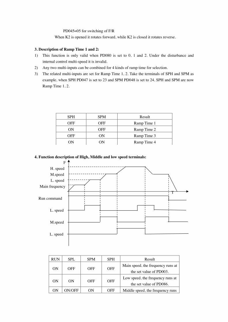
PD045=05 for switching of F/R When K2 is opened it rotates forward, while K2 is closed it rotates reverse. 3. Description of Ramp Time 1 and 2: 1) This function is only valid when PD080 is set to 0, 1 and 2. Under the disturbance and
internal control multi-speed it is invalid. 2) Any two multi-inputs can be combined for 4 kinds of ramp time for selection. 3) The related multi-inputs are set for Ramp Time 1, 2. Take the terminals of SPH and SPM as
example, when SPH PD047 is set to 23 and SPM PD048 is set to 24, SPH and SPM are now Ramp Time 1, 2.
SPH SPM Result OFF OFF Ramp Time 1 ON OFF Ramp Time 2 OFF ON Ramp Time 3 ON ON Ramp Time 4
4. Function description of High, Middle and low speed terminals: F
H. speed M.speed L. speed
Main frequency T Run command
L. speed
M.speed
L. speed
RUN SPL SPM SPH Result
ON OFF OFF OFF Main speed, the frequency runs at
the set value of PD003.
ON ON OFF OFF Low speed, the frequency runs at
the set value of PD086. ON ON/OFF ON OFF Middle speed, the frequency runs
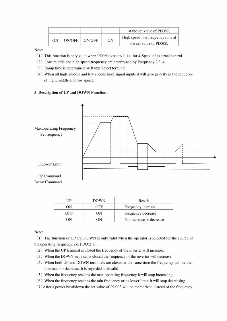
at the set value of PD087.
ON ON/OFF ON/OFF ON High speed, the frequency runs at
the set value of PD088. Note: (1)This function is only valid when PD080 is set to 1, i.e. for 4-Speed of external control. (2)Low, middle and high speed frequency are determined by Frequency 2,3, 4. (3)Ramp time is determined by Ramp Select terminal. (4)When all high, middle and low speeds have signal inputs it will give priority in the sequence
of high, middle and low speed. 5. Description of UP and DOWN Function: Max.operating Frequency Set frequency
F.Lower Limit Up Command Down Command
UP DOWN Result ON OFF Frequency increase OFF ON Frequency decrease ON ON Not increase or decrease
Note: (1)The function of UP and DOWN is only valid when the operator is selected for the source of the operating frequency, i.e. PD002=0. (2)When the UP terminal is closed the frequency of the inverter will increase. (3)When the DOWN terminal is closed the frequency of the inverter will decrease. (4)When both UP and DOWN terminals are closed at the same time the frequency will neither
increase nor decrease. It is regarded as invalid. (5)When the frequency reaches the max operating frequency it will stop increasing. (6)When the frequency reaches the min frequency or its lower limit, it will stop decreasing. (7)After a power breakdown the set value of PD003 will be memorized instead of the frequency.
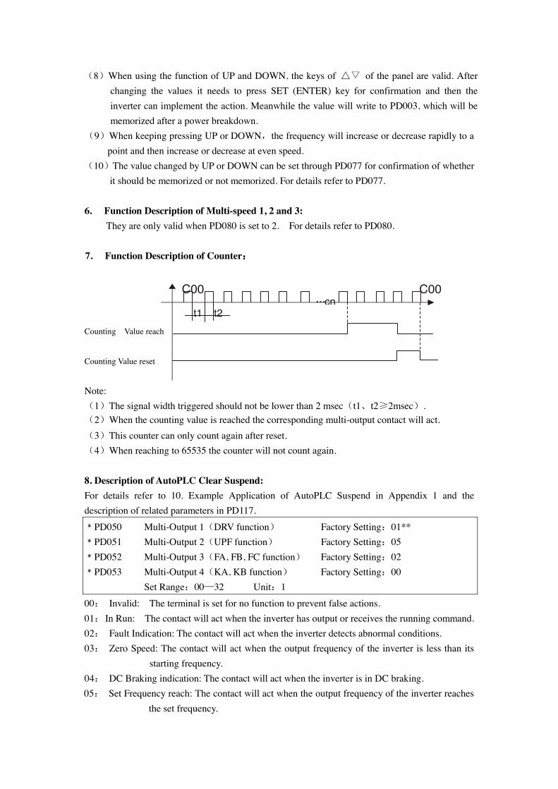
(8)When using the function of UP and DOWN, the keys of △▽ of the panel are valid. After changing the values it needs to press SET (ENTER) key for confirmation and then the inverter can implement the action. Meanwhile the value will write to PD003, which will be memorized after a power breakdown.
(9)When keeping pressing UP or DOWN,the frequency will increase or decrease rapidly to a point and then increase or decrease at even speed.
(10)The value changed by UP or DOWN can be set through PD077 for confirmation of whether it should be memorized or not memorized. For details refer to PD077.
6. Function Description of Multi-speed 1, 2 and 3:
They are only valid when PD080 is set to 2. For details refer to PD080.
7. Function Description of Counter:::: Counting Value reach
Counting Value reset
Note: (1)The signal width triggered should not be lower than 2 msec(t1、t2≥2msec). (2)When the counting value is reached the corresponding multi-output contact will act. (3)This counter can only count again after reset. (4)When reaching to 65535 the counter will not count again. 8. Description of AutoPLC Clear Suspend: For details refer to 10. Example Application of AutoPLC Suspend in Appendix 1 and the description of related parameters in PD117.
﹡PD050 Multi-Output 1(DRV function) Factory Setting:01** ﹡PD051 Multi-Output 2(UPF function) Factory Setting:05 ﹡PD052 Multi-Output 3(FA, FB, FC function) Factory Setting:02 ﹡PD053 Multi-Output 4(KA, KB function) Factory Setting:00 Set Range:00—32 Unit:1
00: Invalid: The terminal is set for no function to prevent false actions. 01: In Run: The contact will act when the inverter has output or receives the running command. 02: Fault Indication: The contact will act when the inverter detects abnormal conditions. 03: Zero Speed: The contact will act when the output frequency of the inverter is less than its
starting frequency. 04: DC Braking indication: The contact will act when the inverter is in DC braking. 05: Set Frequency reach: The contact will act when the output frequency of the inverter reaches
the set frequency.
t1 t2 … cn
C00 C00
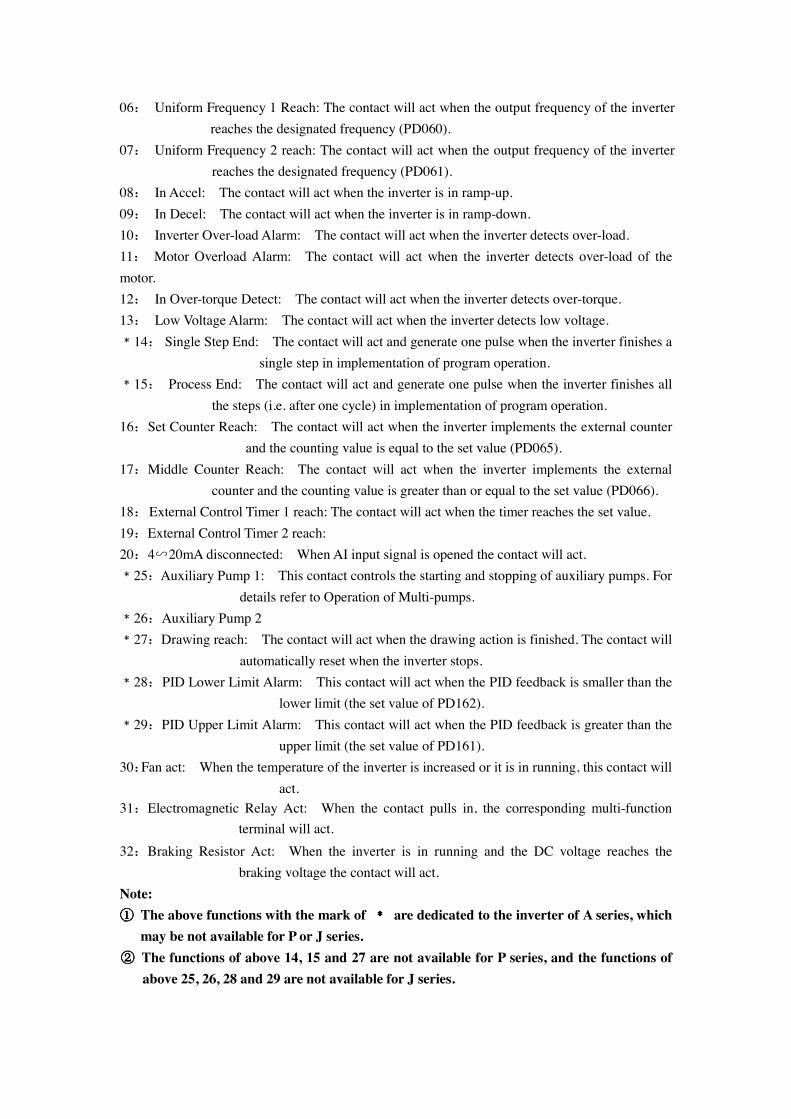
06: Uniform Frequency 1 Reach: The contact will act when the output frequency of the inverter reaches the designated frequency (PD060).
07:。Uniform Frequency 2 reach: The contact will act when the output frequency of the inverter reaches the designated frequency (PD061).
08: In Accel: The contact will act when the inverter is in ramp-up. 09: In Decel: The contact will act when the inverter is in ramp-down. 10: Inverter Over-load Alarm: The contact will act when the inverter detects over-load. 11: Motor Overload Alarm: The contact will act when the inverter detects over-load of the motor. 12: In Over-torque Detect: The contact will act when the inverter detects over-torque. 13: Low Voltage Alarm: The contact will act when the inverter detects low voltage. ﹡14: Single Step End: The contact will act and generate one pulse when the inverter finishes a
single step in implementation of program operation. ﹡15: Process End: The contact will act and generate one pulse when the inverter finishes all
the steps (i.e. after one cycle) in implementation of program operation. 16:Set Counter Reach: The contact will act when the inverter implements the external counter
and the counting value is equal to the set value (PD065). 17:Middle Counter Reach: The contact will act when the inverter implements the external
counter and the counting value is greater than or equal to the set value (PD066). 18: External Control Timer 1 reach: The contact will act when the timer reaches the set value. 19:External Control Timer 2 reach: 20:4∽20mA disconnected: When AI input signal is opened the contact will act. ﹡25:Auxiliary Pump 1: This contact controls the starting and stopping of auxiliary pumps. For
details refer to Operation of Multi-pumps. ﹡26:Auxiliary Pump 2 ﹡27:Drawing reach: The contact will act when the drawing action is finished. The contact will
automatically reset when the inverter stops. ﹡28: PID Lower Limit Alarm: This contact will act when the PID feedback is smaller than the
lower limit (the set value of PD162). ﹡29:PID Upper Limit Alarm: This contact will act when the PID feedback is greater than the
upper limit (the set value of PD161). 30:Fan act: When the temperature of the inverter is increased or it is in running, this contact will
act. 31:Electromagnetic Relay Act: When the contact pulls in, the corresponding multi-function
terminal will act. 32:Braking Resistor Act: When the inverter is in running and the DC voltage reaches the
braking voltage the contact will act. Note: ①①①① The above functions with the mark of ﹡﹡﹡﹡ are dedicated to the inverter of A series, which
may be not available for P or J series. ②②②② The functions of above 14, 15 and 27 are not available for P series, and the functions of
above 25, 26, 28 and 29 are not available for J series.
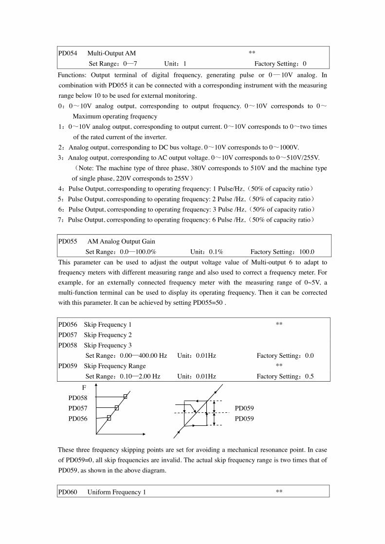
PD054 Multi-Output AM ** Set Range:0—7 Unit:1 Factory Setting:0
Functions: Output terminal of digital frequency, generating pulse or 0— 10V analog. In combination with PD055 it can be connected with a corresponding instrument with the measuring range below 10 to be used for external monitoring. 0:0~10V analog output, corresponding to output frequency. 0~10V corresponds to 0~
Maximum operating frequency 1:0~10V analog output, corresponding to output current. 0~10V corresponds to 0~two times
of the rated current of the inverter. 2:Analog output, corresponding to DC bus voltage. 0~10V corresponds to 0~1000V. 3:Analog output, corresponding to AC output voltage. 0~10V corresponds to 0~510V/255V. (Note: The machine type of three phase, 380V corresponds to 510V and the machine type
of single phase, 220V corresponds to 255V) 4:Pulse Output, corresponding to operating frequency: 1 Pulse/Hz,(50% of capacity ratio) 5:Pulse Output, corresponding to operating frequency: 2 Pulse /Hz,(50% of capacity ratio) 6:Pulse Output, corresponding to operating frequency: 3 Pulse /Hz,(50% of capacity ratio) 7:Pulse Output, corresponding to operating frequency: 6 Pulse /Hz,(50% of capacity ratio) PD055 AM Analog Output Gain Set Range:0.0—100.0% Unit:0.1% Factory Setting:100.0 This parameter can be used to adjust the output voltage value of Multi-output 6 to adapt to frequency meters with different measuring range and also used to correct a frequency meter. For example, for an externally connected frequency meter with the measuring range of 0~5V, a multi-function terminal can be used to display its operating frequency. Then it can be corrected with this parameter. It can be achieved by setting PD055=50 .
PD056 Skip Frequency 1 ** PD057 Skip Frequency 2 PD058 Skip Frequency 3 Set Range:0.00—400.00 Hz Unit:0.01Hz Factory Setting:0.0 PD059 Skip Frequency Range ** Set Range:0.10—2.00 Hz Unit:0.01Hz Factory Setting:0.5
F PD058 PD057 PD059 PD056 PD059
These three frequency skipping points are set for avoiding a mechanical resonance point. In case of PD059=0, all skip frequencies are invalid. The actual skip frequency range is two times that of PD059, as shown in the above diagram.
PD060 Uniform Frequency 1 **
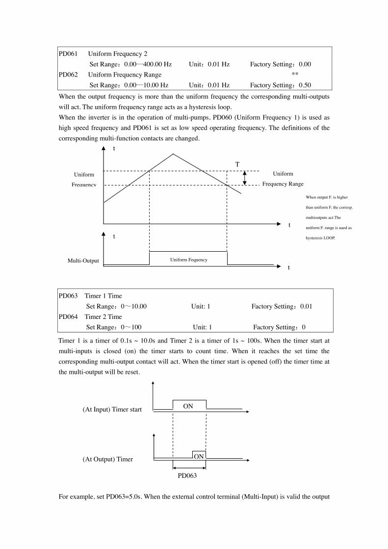
PD061 Uniform Frequency 2 Set Range:0.00—400.00 Hz Unit:0.01 Hz Factory Setting:0.00 PD062 Uniform Frequency Range ** Set Range:0.00—10.00 Hz Unit:0.01 Hz Factory Setting:0.50 When the output frequency is more than the uniform frequency the corresponding multi-outputs will act. The uniform frequency range acts as a hysteresis loop. When the inverter is in the operation of multi-pumps, PD060 (Uniform Frequency 1) is used as high speed frequency and PD061 is set as low speed operating frequency. The definitions of the corresponding multi-function contacts are changed.
PD063 Timer 1 Time Set Range:0~10.00 Unit: 1 Factory Setting:0.01 PD064 Timer 2 Time Set Range:0~100 Unit: 1 Factory Setting:0
Timer 1 is a timer of 0.1s ~ 10.0s and Timer 2 is a timer of 1s ~ 100s. When the timer start at multi-inputs is closed (on) the timer starts to count time. When it reaches the set time the corresponding multi-output contact will act. When the timer start is opened (off) the timer time at the multi-output will be reset.
(At Input) Timer start
(At Output) Timer
For example, set PD063=5.0s. When the external control terminal (Multi-Input) is valid the output
Uniform
Frequency
Multi-Output Uniform Fequency
Uniform
Frequency Range
t
t
t
t
T
When output F. is higher
than uniform F, the corresp.
multioutputs act.The
uniform F. range is uaed as
hysteresis LOOP.
PD063
ON
ON
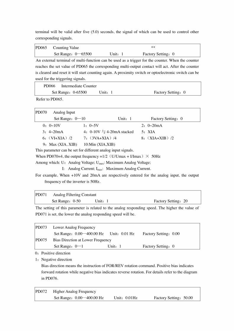
terminal will be valid after five (5.0) seconds, the signal of which can be used to control other corresponding signals.
PD065 Counting Value ** Set Range:0—65500 Unit:1 Factory Setting:0 An external terminal of multi-function can be used as a trigger for the counter. When the counter reaches the set value of PD065 the corresponding multi-output contact will act. After the counter is cleared and reset it will start counting again. A proximity switch or optoelectronic switch can be used for the triggering signals.
PD066 Intermediate Counter Set Range:0-65500 Unit:1 Factory Setting:0
Refer to PD065. PD070 Analog Input Set Range:0—10 Unit:1 Factory Setting:0
0:0~10V 1:0~5V 2:0~20mA 3:4~20mA 4:0-10V 与 4-20mA stacked 5:XIA 6:(VI+XIA)/2 7:(3VA+XIA)/4 8:(XIA+XIB)/2
9:Max (XIA, XIB) 10:Min (XIA,XIB) This parameter can be set for different analog input signals. When PD070=4, the output frequency =1/2(U/Umax + I/Imax)× 50Hz Among which: U:Analog Voltage; Umax: Maximum Analog Voltage; I: Analog Current; Imax: Maximum Analog Current. For example, When +10V and 20mA are respectively entered for the analog input, the output
frequency of the inverter is 50Hz. PD071 Analog Filtering Constant
Set Range:0-50 Unit:1 Factory Setting:20
The setting of this parameter is related to the analog responding speed. The higher the value of PD071 is set, the lower the analog responding speed will be. PD073 Lower Analog Frequency Set Range:0.00—400.00 Hz Unit:0.01 Hz Factory Setting:0.00 PD075 Bias Direction at Lower Frequency Set Range:0—1 Unit:1 Factory Setting:0
0:Positive direction 1:Negative direction
Bias direction means the instruction of FOR/REV rotation command. Positive bias indicates forward rotation while negative bias indicates reverse rotation. For details refer to the diagram in PD076.
PD072 Higher Analog Frequency Set Range:0.00—400.00 Hz Unit:0.01Hz Factory Setting:50.00

PD074 Bias Direction at Higher Frequency Set Range:0—1 Unit:1 Factory Setting:0
0:Positive direction 1:Negative direction
Bias direction means the instruction of FOR/REV rotation command. Positive bias indicates forward rotation while negative bias indicates reverse rotation. For details refer to the diagram in PD076.
PD076 Analog Negative Bias Reverse Set Range:0—1 Unit:1 Factory Setting:0 0:Negative bias Rev is not allowable. 1:Negative bias Rev is allowable. The parameter group is set for the measuring range and zero point of the external analog terminals and can be combined for any kind of curve to control the operation of the motor.
Rev. Area 50 Hz For. Area
0 5V 10V 4mA 12mA 20mA
F 50 0 10V 4mA 20mA F 40 0V 2V 10V 4 20mA 10 40 F
Setting:PD073=50 PD075=1 PD072=50 PD074=0 PD076=1
Note: this curve can be easily used in complicated applications in combination with other curves. When using it the instruction of FOR/REV run from external terminals is still valid. When switching, the curve will turn reverse.
Setting:PD073=50 PD075=0 PD072=0 PD074=0 PD076=0
Note: this curve is a kind of special application of reverse ramp setting. When using transmitter for the control of pressure, temperature and others and while the control has higher pressure and output signals but requiring the corresponding commands of stop or deceleration on the inverter this curve can satisfy the demand properly.
Setting:PD073=10 PD075=1 PD072=40 PD074=0 PD076=1
Note: this method is used extensively. The user can use it flexibly.
Setting:PD073=10 PD075=1 PD072=40 PD074=0 PD076=1
Note; this curve is the extension of the above curve. 2V~10V(4.8mA~20mA) corresponds to 0Hz~40HZ; the signal of 0V~2V(4~4.8mA)is invalid. It can be used to avoid noice disturbance. In harsh environment it is better not to use signals below 1V for setting the operating frequency of the inverter.
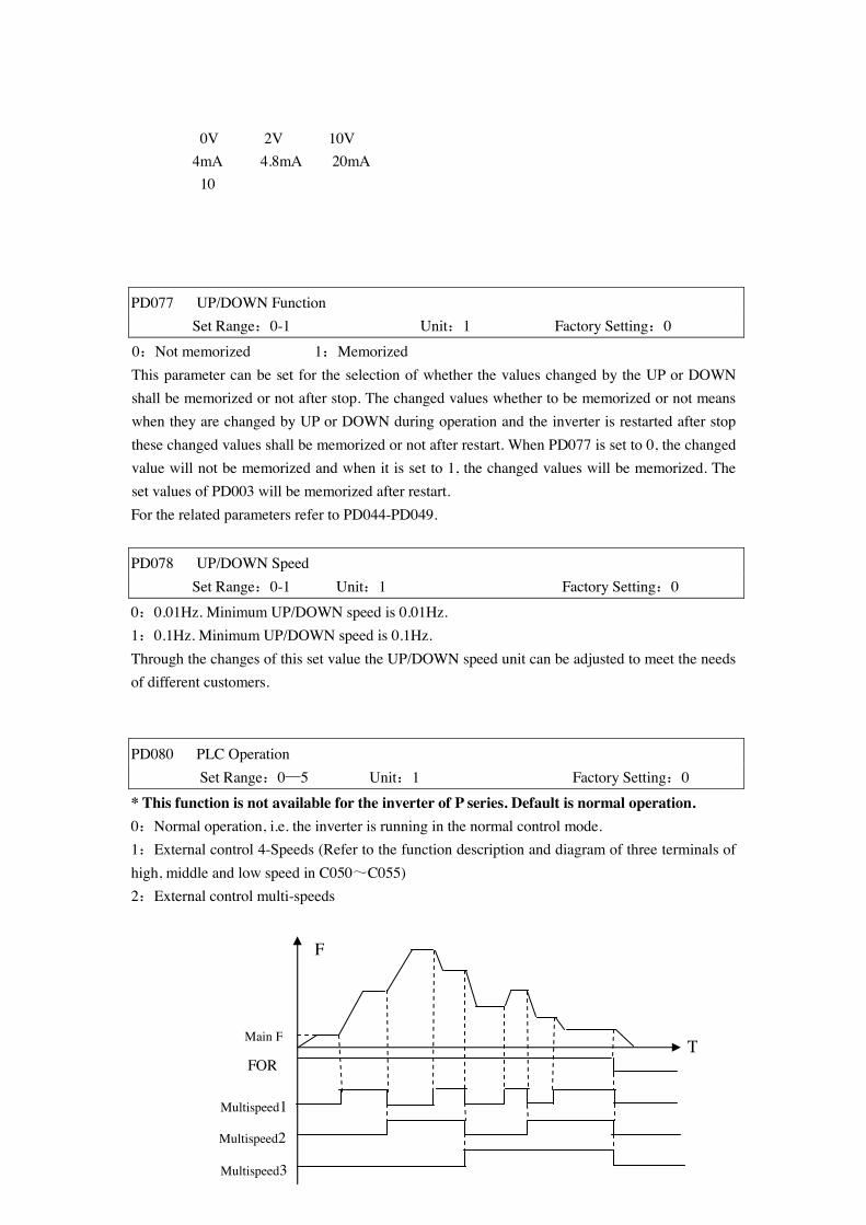
0V 2V 10V 4mA 4.8mA 20mA 10
PD077 UP/DOWN Function Set Range:0-1 Unit:1 Factory Setting:0
0:Not memorized 1:Memorized This parameter can be set for the selection of whether the values changed by the UP or DOWN shall be memorized or not after stop. The changed values whether to be memorized or not means when they are changed by UP or DOWN during operation and the inverter is restarted after stop these changed values shall be memorized or not after restart. When PD077 is set to 0, the changed value will not be memorized and when it is set to 1, the changed values will be memorized. The set values of PD003 will be memorized after restart. For the related parameters refer to PD044-PD049. PD078 UP/DOWN Speed
Set Range:0-1 Unit:1 Factory Setting:0
0:0.01Hz. Minimum UP/DOWN speed is 0.01Hz. 1:0.1Hz. Minimum UP/DOWN speed is 0.1Hz. Through the changes of this set value the UP/DOWN speed unit can be adjusted to meet the needs of different customers.
PD080 PLC Operation Set Range:0—5 Unit:1 Factory Setting:0
* This function is not available for the inverter of P series. Default is normal operation. 0:Normal operation, i.e. the inverter is running in the normal control mode. 1:External control 4-Speeds (Refer to the function description and diagram of three terminals of high, middle and low speed in C050~C055) 2:External control multi-speeds Multispeed1
Multispeed2
Multispeed3
FOR
Main F T
F
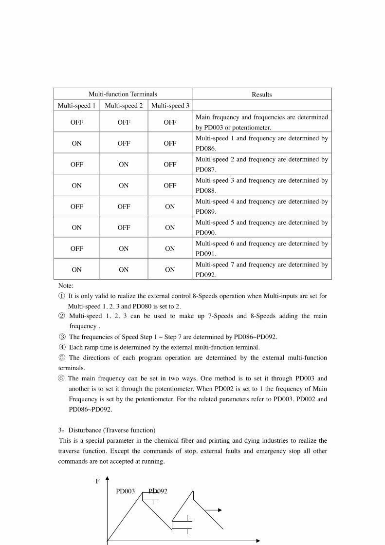
Multi-function Terminals Results
Multi-speed 1 Multi-speed 2 Multi-speed 3
OFF OFF OFF Main frequency and frequencies are determined by PD003 or potentiometer.
ON OFF OFF Multi-speed 1 and frequency are determined by PD086.
OFF ON OFF Multi-speed 2 and frequency are determined by PD087.
ON ON OFF Multi-speed 3 and frequency are determined by PD088.
OFF OFF ON Multi-speed 4 and frequency are determined by PD089.
ON OFF ON Multi-speed 5 and frequency are determined by PD090.
OFF ON ON Multi-speed 6 and frequency are determined by PD091.
ON ON ON Multi-speed 7 and frequency are determined by PD092.
Note: ① It is only valid to realize the external control 8-Speeds operation when Multi-inputs are set for
Multi-speed 1, 2, 3 and PD080 is set to 2. ② Multi-speed 1, 2, 3 can be used to make up 7-Speeds and 8-Speeds adding the main
frequency . ③ The frequencies of Speed Step 1 ~ Step 7 are determined by PD086~PD092. ④ Each ramp time is determined by the external multi-function terminal. ⑤ The directions of each program operation are determined by the external multi-function terminals. ⑥ The main frequency can be set in two ways. One method is to set it through PD003 and
another is to set it through the potentiometer. When PD002 is set to 1 the frequency of Main Frequency is set by the potentiometer. For the related parameters refer to PD003, PD002 and PD086~PD092.
3:Disturbance (Traverse function) This is a special parameter in the chemical fiber and printing and dying industries to realize the traverse function. Except the commands of stop, external faults and emergency stop all other commands are not accepted at running. F PD003 PD092
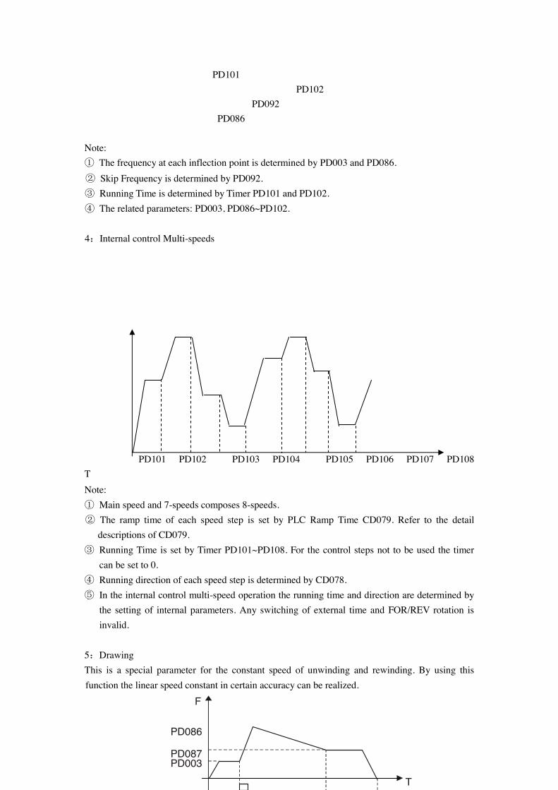
PD101 PD102 PD092 PD086 Note: ① The frequency at each inflection point is determined by PD003 and PD086. ② Skip Frequency is determined by PD092. ③ Running Time is determined by Timer PD101 and PD102. ④ The related parameters: PD003, PD086~PD102.
4:Internal control Multi-speeds PD101 PD102 PD103 PD104 PD105 PD106 PD107 PD108 T Note: ① Main speed and 7-speeds composes 8-speeds. ② The ramp time of each speed step is set by PLC Ramp Time CD079. Refer to the detail
descriptions of CD079. ③ Running Time is set by Timer PD101~PD108. For the control steps not to be used the timer
can be set to 0. ④ Running direction of each speed step is determined by CD078. ⑤ In the internal control multi-speed operation the running time and direction are determined by
the setting of internal parameters. Any switching of external time and FOR/REV rotation is invalid.
5:Drawing This is a special parameter for the constant speed of unwinding and rewinding. By using this function the linear speed constant in certain accuracy can be realized.
F
T
PD086
PD087 PD003
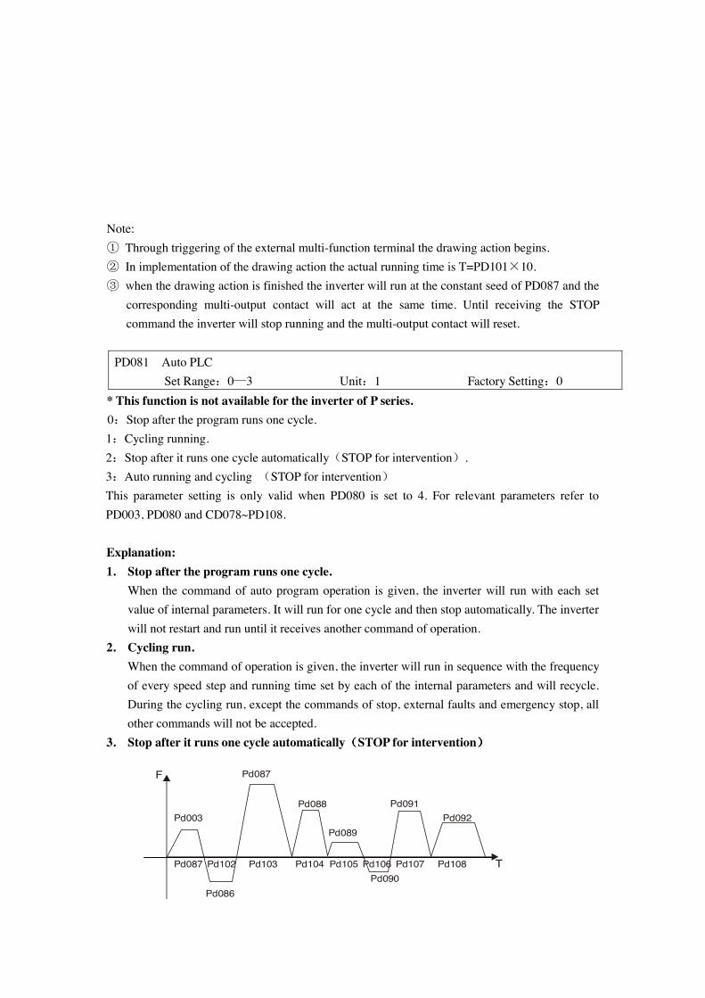
Note: ① Through triggering of the external multi-function terminal the drawing action begins. ② In implementation of the drawing action the actual running time is T=PD101×10. ③ when the drawing action is finished the inverter will run at the constant seed of PD087 and the
corresponding multi-output contact will act at the same time. Until receiving the STOP command the inverter will stop running and the multi-output contact will reset.
PD081 Auto PLC Set Range:0—3 Unit:1 Factory Setting:0
* This function is not available for the inverter of P series. 0:Stop after the program runs one cycle. 1:Cycling running. 2:Stop after it runs one cycle automatically(STOP for intervention). 3:Auto running and cycling (STOP for intervention) This parameter setting is only valid when PD080 is set to 4. For relevant parameters refer to PD003, PD080 and CD078~PD108. Explanation: 1. Stop after the program runs one cycle.
When the command of auto program operation is given, the inverter will run with each set value of internal parameters. It will run for one cycle and then stop automatically. The inverter will not restart and run until it receives another command of operation.
2. Cycling run. When the command of operation is given, the inverter will run in sequence with the frequency of every speed step and running time set by each of the internal parameters and will recycle. During the cycling run, except the commands of stop, external faults and emergency stop, all other commands will not be accepted.
3. Stop after it runs one cycle automatically((((STOP for intervention))))
Pd003
Pd087
Pd088
Pd089
Pd091Pd092
Pd086
Pd087 Pd102 Pd103 Pd104 Pd105 Pd106 Pd107 Pd108Pd090
T
F

Note: ① When the command of auto program operation is given the inverter will run with each parameters. But it will stop first and then restart at changing of each step and will stop automatically after running for one cycle. The inverter will not restart and run until it receives another command of operation. ② The frequencies of each speed step are set by PD003 and PD086~PD092. ③ The running times of each speed step are set by PD101~PD108. ④ The running direction is set by P082 PD082 PLC Running Direction Set Range:0—255 Unit:1 Factory Setting:0 This parameter is only valid when PD080 is set to 4. This parameter setting determine the running direction of each frequency of PD086~PD092 and PD003 in the program operation. The setting method is as follows: The rotation direction is set first in the binary 8 bits mode, and then converted to a decimal value for the setting of this parameter. For instance:
Bit0—7
7 6 5 4 3 2 1 0 0 1 0 0 1 0 1 0
0:For. 1:Rev. Main Speed(PD003) For. Frequency 1(PD086) Rev.
Frequency 2(PD087) For. Frequency 3(PD088) Rev. Frequency 4(PD089) For. Frequency 5(PD090) For. Frequency 6(PD091) Rev. Frequency 7(PD092) For. The parameter value 01001010 is converted to a decimal value:
1×26+1×23+1×21=64+8+2=74 Then PD082=74 PD084 PLC Ramp Time Set Range:0~65535 Unit:1S Factory Setting:0
This parameter is only valid when PD080 is set to 4. This parameter is set to determine the ramp time values for Step 1~4 of the internal control multi-speed. The setting method is as follows: ① Determine each Ramp Time in the binary 2 bit mode
Bit1 Bit0 Ramp Time
0 0 Ramp Time 1 PD014, PD015
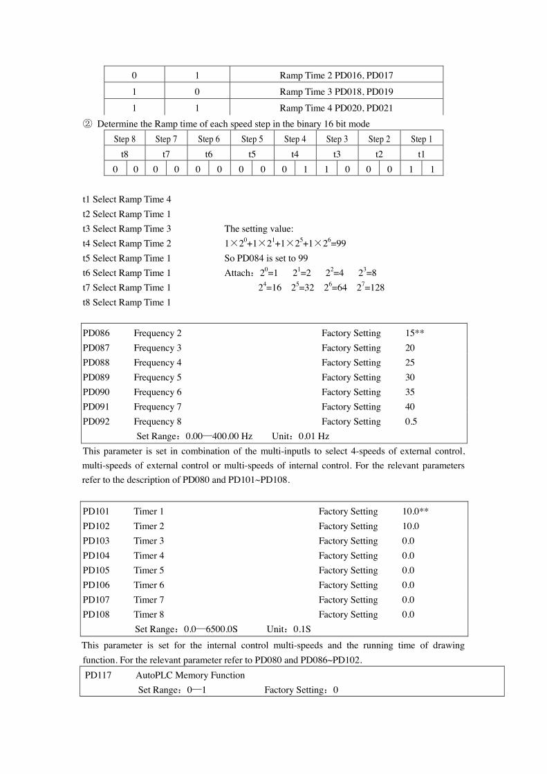
0 1 Ramp Time 2 PD016, PD017
1 0 Ramp Time 3 PD018, PD019
1 1 Ramp Time 4 PD020, PD021 ② Determine the Ramp time of each speed step in the binary 16 bit mode
Step 8 Step 7 Step 6 Step 5 Step 4 Step 3 Step 2 Step 1 t8 t7 t6 t5 t4 t3 t2 t1
0 0 0 0 0 0 0 0 0 1 1 0 0 0 1 1 t1 Select Ramp Time 4 t2 Select Ramp Time 1 t3 Select Ramp Time 3 The setting value: t4 Select Ramp Time 2 1×20+1×21+1×25+1×26=99 t5 Select Ramp Time 1 So PD084 is set to 99 t6 Select Ramp Time 1 Attach:20=1 21=2 22=4 23=8 t7 Select Ramp Time 1 24=16 25=32 26=64 27=128 t8 Select Ramp Time 1 PD086 Frequency 2 Factory Setting 15** PD087 Frequency 3 Factory Setting 20 PD088 Frequency 4 Factory Setting 25 PD089 Frequency 5 Factory Setting 30 PD090 Frequency 6 Factory Setting 35 PD091 Frequency 7 Factory Setting 40 PD092 Frequency 8 Factory Setting 0.5 Set Range:0.00—400.00 Hz Unit:0.01 Hz This parameter is set in combination of the multi-inputls to select 4-speeds of external control, multi-speeds of external control or multi-speeds of internal control. For the relevant parameters refer to the description of PD080 and PD101~PD108.
PD101 Timer 1 Factory Setting 10.0** PD102 Timer 2 Factory Setting 10.0 PD103 Timer 3 Factory Setting 0.0 PD104 Timer 4 Factory Setting 0.0 PD105 Timer 5 Factory Setting 0.0 PD106 Timer 6 Factory Setting 0.0 PD107 Timer 7 Factory Setting 0.0 PD108 Timer 8 Factory Setting 0.0 Set Range:0.0—6500.0S Unit:0.1S This parameter is set for the internal control multi-speeds and the running time of drawing function. For the relevant parameter refer to PD080 and PD086~PD102. PD117 AutoPLC Memory Function Set Range:0—1 Factory Setting:0
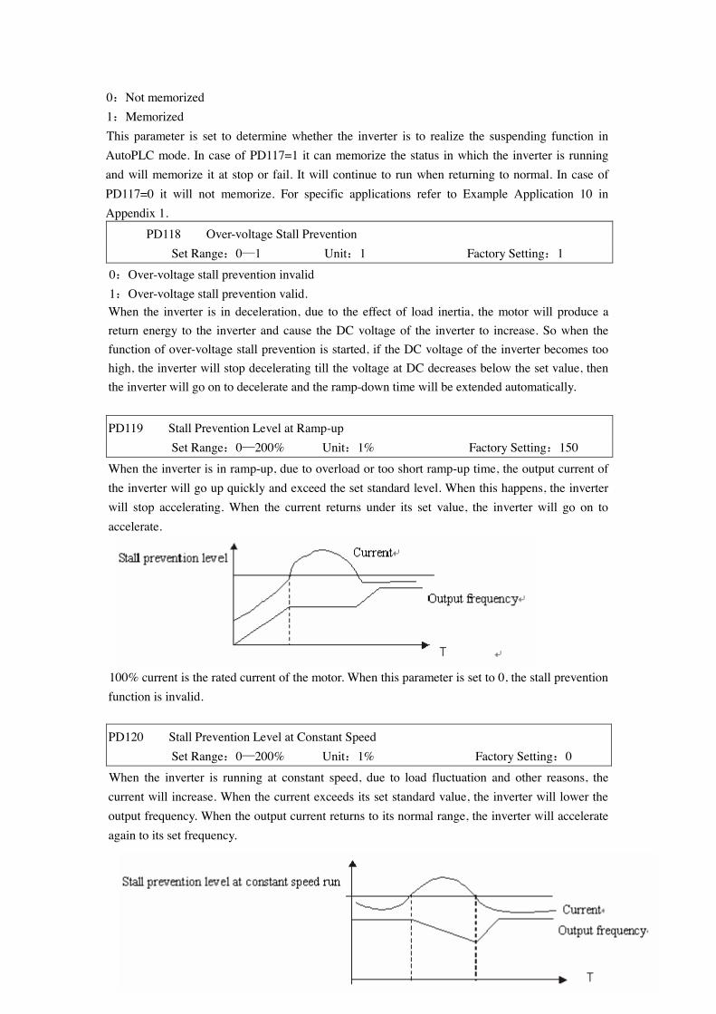
0:Not memorized 1:Memorized This parameter is set to determine whether the inverter is to realize the suspending function in AutoPLC mode. In case of PD117=1 it can memorize the status in which the inverter is running and will memorize it at stop or fail. It will continue to run when returning to normal. In case of PD117=0 it will not memorize. For specific applications refer to Example Application 10 in Appendix 1. PD118 Over-voltage Stall Prevention Set Range:0—1 Unit:1 Factory Setting:1
0:Over-voltage stall prevention invalid 1:Over-voltage stall prevention valid. When the inverter is in deceleration, due to the effect of load inertia, the motor will produce a return energy to the inverter and cause the DC voltage of the inverter to increase. So when the function of over-voltage stall prevention is started, if the DC voltage of the inverter becomes too high, the inverter will stop decelerating till the voltage at DC decreases below the set value, then the inverter will go on to decelerate and the ramp-down time will be extended automatically. PD119 Stall Prevention Level at Ramp-up Set Range:0—200% Unit:1% Factory Setting:150
When the inverter is in ramp-up, due to overload or too short ramp-up time, the output current of the inverter will go up quickly and exceed the set standard level. When this happens, the inverter will stop accelerating. When the current returns under its set value, the inverter will go on to accelerate.
100% current is the rated current of the motor. When this parameter is set to 0, the stall prevention function is invalid. PD120 Stall Prevention Level at Constant Speed Set Range:0—200% Unit:1% Factory Setting:0
When the inverter is running at constant speed, due to load fluctuation and other reasons, the current will increase. When the current exceeds its set standard value, the inverter will lower the output frequency. When the output current returns to its normal range, the inverter will accelerate again to its set frequency.

100% current is the Rated Current of the motor. When this parameter is set to 0 the stall prevention function is invalid.
PD121 Decel. Time for Stall Prevention at Constant Speed Factory Setting:5.0
When the inverter is used for the loads of kinds of fan and pump PD120 can be set to 120. When the current of the inverter is greater than 120% the output frequency will decrease and the current will also decrease accordingly. After the current returns to normal the frequency will return to normal slowly, so as to achieve the stall prevention function. The decreasing speed of the frequency is determined by PD121. For the Related parameters refer to CD 122.
PD122 Stall Prevention Level at Deceleration Set Range:0—200% Unit:1 Factory Setting:150 Refer to PD118. 100% current is the rated current of the motor. PD123 Over-torque Detect Mode
Set Range:0—3 Unit:1 Factory Setting:0
0:When reaching the frequency it starts to detect over-torque and when over-torque is detected it continues to run. 1:When reaching the frequency it starts to detect over-torque and when over-torque is detected it stop running. 2:It detects over-torque during running and when over-torque is detected it continues to run. 3:It detects over-torque during running and when over-torque is detected it stop running. PD124 Over-torque Detect Level Set Range:0—200% Unit:1% Factory Setting:0
When the output current exceeds the over-torque detection level and also exceeds half of the set time of over-torque detection (factory setting: 1.0s), the over-torque detection will indicate, and the corresponding multi-function alarm contact will act. When it exceeds the set time, the inverter will turn to self-protection. When this parameter is set to 0, the over-torque detection will be
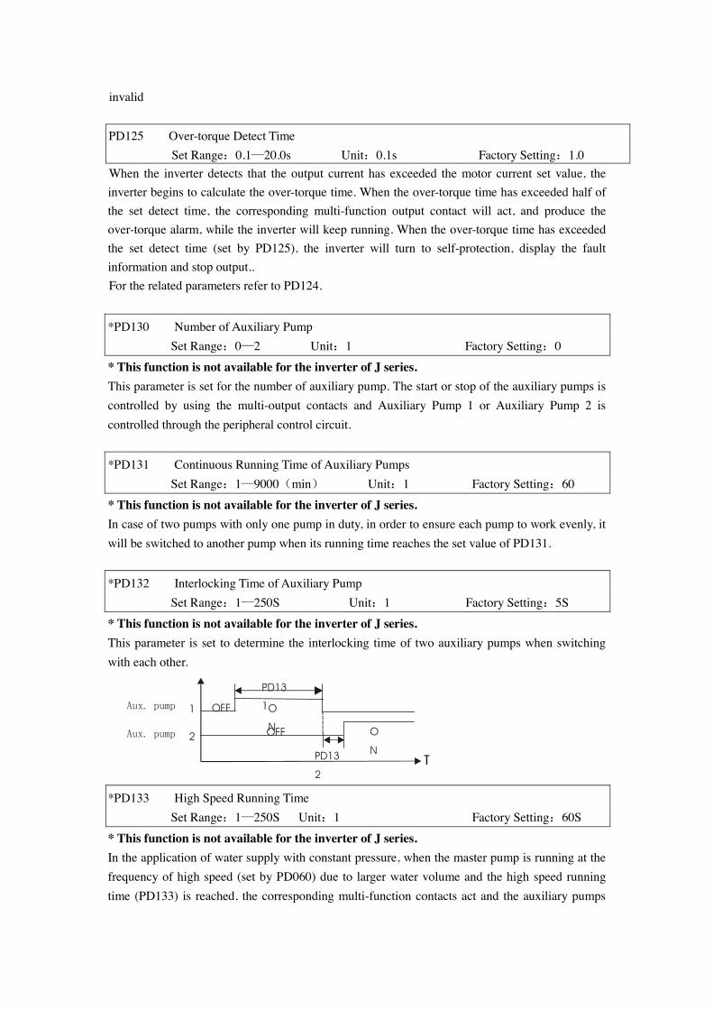
invalid PD125 Over-torque Detect Time Set Range:0.1—20.0s Unit:0.1s Factory Setting:1.0 When the inverter detects that the output current has exceeded the motor current set value, the inverter begins to calculate the over-torque time. When the over-torque time has exceeded half of the set detect time, the corresponding multi-function output contact will act, and produce the over-torque alarm, while the inverter will keep running. When the over-torque time has exceeded the set detect time (set by PD125), the inverter will turn to self-protection, display the fault information and stop output.. For the related parameters refer to PD124. *PD130 Number of Auxiliary Pump
Set Range:0—2 Unit:1 Factory Setting:0
* This function is not available for the inverter of J series. This parameter is set for the number of auxiliary pump. The start or stop of the auxiliary pumps is controlled by using the multi-output contacts and Auxiliary Pump 1 or Auxiliary Pump 2 is controlled through the peripheral control circuit.
*PD131 Continuous Running Time of Auxiliary Pumps
Set Range:1—9000(min) Unit:1 Factory Setting:60
* This function is not available for the inverter of J series. In case of two pumps with only one pump in duty, in order to ensure each pump to work evenly, it will be switched to another pump when its running time reaches the set value of PD131.
*PD132 Interlocking Time of Auxiliary Pump
Set Range:1—250S Unit:1 Factory Setting:5S
* This function is not available for the inverter of J series. This parameter is set to determine the interlocking time of two auxiliary pumps when switching with each other. *PD133 High Speed Running Time Set Range:1—250S Unit:1 Factory Setting:60S
* This function is not available for the inverter of J series. In the application of water supply with constant pressure, when the master pump is running at the frequency of high speed (set by PD060) due to larger water volume and the high speed running time (PD133) is reached, the corresponding multi-function contacts act and the auxiliary pumps
O
N OFF
PD13
1
PD13
2
OFF
O
N
Aux. pump 1
Aux. pump 2
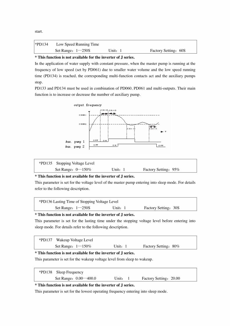
start.
*PD134 Low Speed Running Time Set Range:1—250S Unit:1 Factory Setting:60S
* This function is not available for the inverter of J series. In the application of water supply with constant pressure, when the master pump is running at the frequency of low speed (set by PD061) due to smaller water volume and the low speed running time (PD134) is reached, the corresponding multi-function contacts act and the auxiliary pumps stop. PD133 and PD134 must be used in combination of PD060, PD061 and multi-outputs. Their main function is to increase or decrease the number of auxiliary pump. *PD135 Stopping Voltage Level Set Range:0—150% Unit:1 Factory Setting:95%
* This function is not available for the inverter of J series. This parameter is set for the voltage level of the master pump entering into sleep mode. For details refer to the following description.
*PD136 Lasting Time of Stopping Voltage Level Set Range:1—250S Unit:1 Factory Setting:30S
* This function is not available for the inverter of J series. This parameter is set for the lasting time under the stopping voltage level before entering into sleep mode. For details refer to the following description.
*PD137 Wakeup Voltage Level Set Range:1—150% Unit:1 Factory Setting:80%
* This function is not available for the inverter of J series. This parameter is set for the wakeup voltage level from sleep to wakeup.
*PD138 Sleep Frequency Set Range:0.00—400.0 Unit: 1 Factory Setting:20.00 * This function is not available for the inverter of J series. This parameter is set for the lowest operating frequency entering into sleep mode.
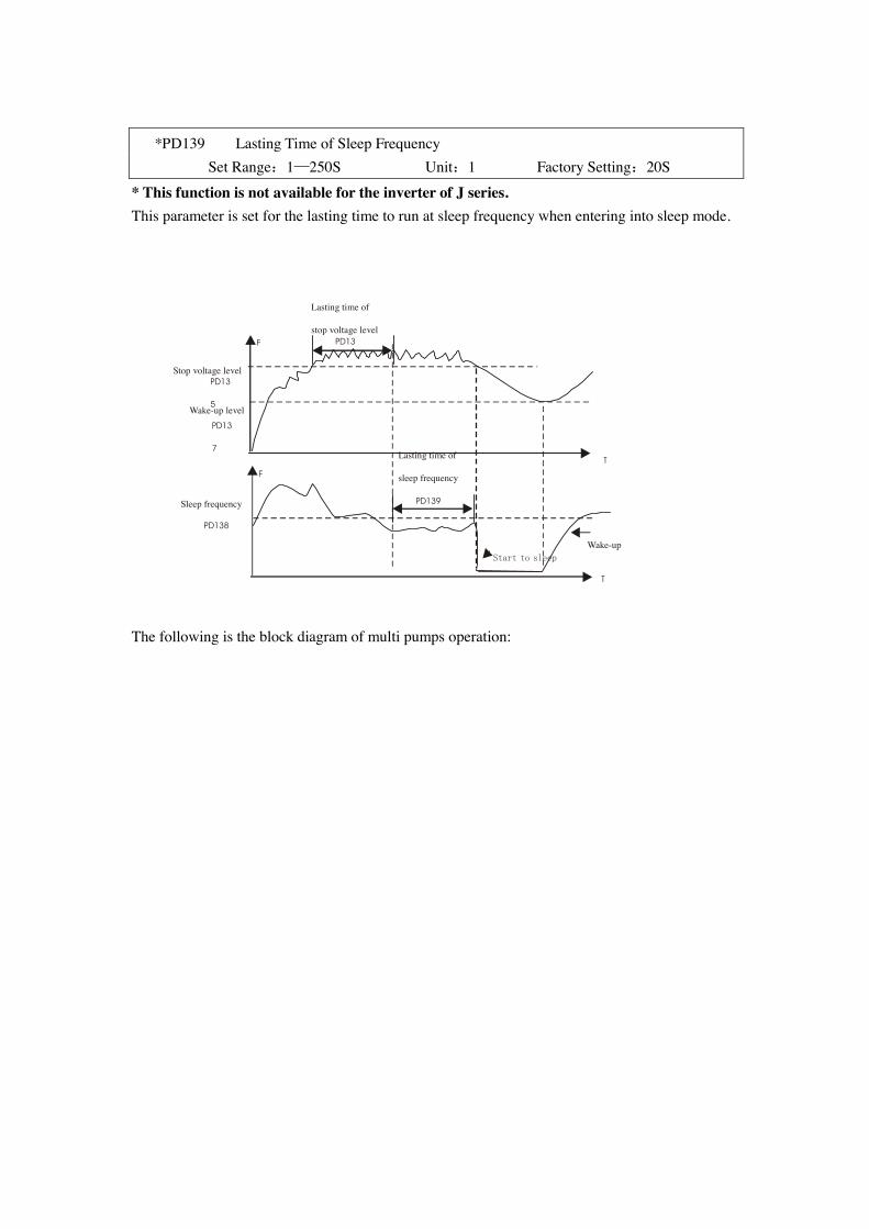
*PD139 Lasting Time of Sleep Frequency Set Range:1—250S Unit:1 Factory Setting:20S
* This function is not available for the inverter of J series. This parameter is set for the lasting time to run at sleep frequency when entering into sleep mode. The following is the block diagram of multi pumps operation:
F
T
T
F
PD13
Lasting time of
stop voltage level
PD139
Lasting time of
sleep frequency
Start to sleep Wake-up
Sleep frequency
PD138
Stop voltage level PD13
5 Wake-up level
PD13
7
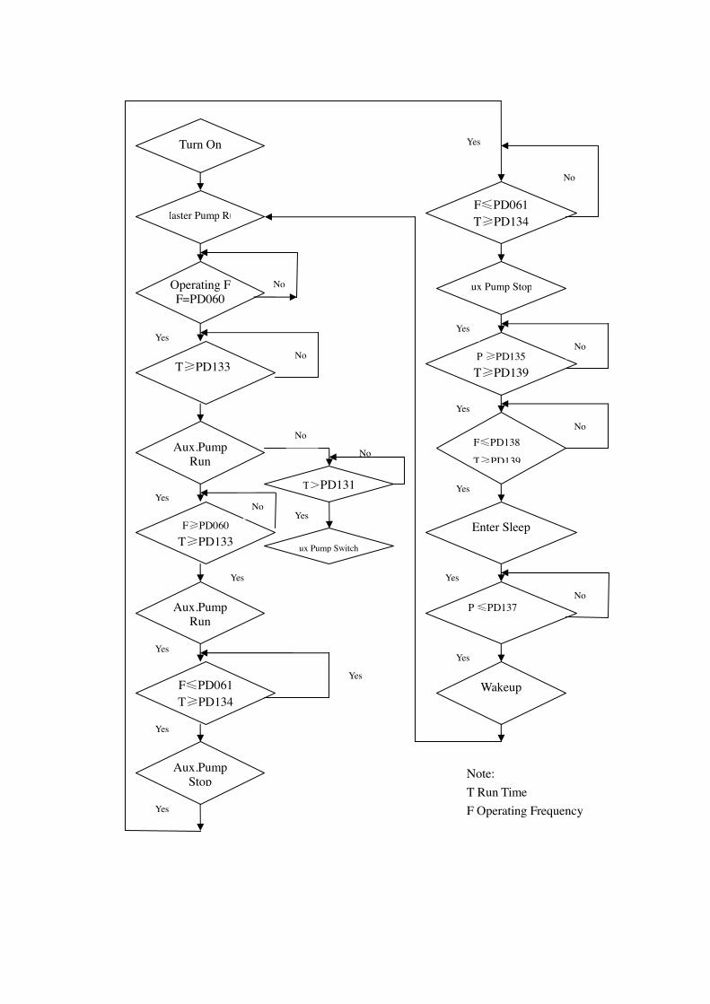
Turn On
Master Pump Run
Operating F F=PD060
T≥PD133
Aux.Pump Run
F≥PD060 T≥PD133
F≤PD061 T≥PD134
Aux.Pump Run
Aux.Pump Stop
F≤PD061 T≥PD134
Aux Pump Stop
P ≥PD135 T≥PD139
F≤PD138
T≥PD139
Enter Sleep
P ≤PD137
Wakeup
No
No
Yes
Yes No
No
T>PD131
Aux Pump Switch
Yes
No
Yes
Yes
Yes
Yes
Yes
Yes
Yes
Yes
Yes
Yes
Yes
No
No
No
No
Note: T Run Time F Operating Frequency
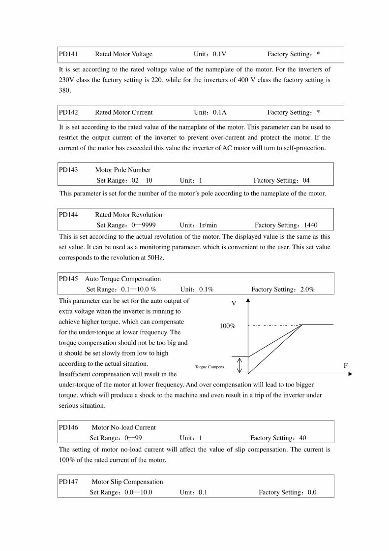
PD141 Rated Motor Voltage Unit:0.1V Factory Setting:*
It is set according to the rated voltage value of the nameplate of the motor. For the inverters of 230V class the factory setting is 220, while for the inverters of 400 V class the factory setting is 380.
PD142 Rated Motor Current Unit:0.1A Factory Setting:*
It is set according to the rated value of the nameplate of the motor. This parameter can be used to restrict the output current of the inverter to prevent over-current and protect the motor. If the current of the motor has exceeded this value the inverter of AC motor will turn to self-protection. PD143 Motor Pole Number
Set Range:02—10 Unit:1 Factory Setting:04
This parameter is set for the number of the motor’s pole according to the nameplate of the motor. PD144 Rated Motor Revolution Set Range:0—9999 Unit:1r/min Factory Setting:1440
This is set according to the actual revolution of the motor. The displayed value is the same as this set value. It can be used as a monitoring parameter, which is convenient to the user. This set value corresponds to the revolution at 50Hz. PD145 Auto Torque Compensation
Set Range:0.1—10.0 % Unit:0.1% Factory Setting:2.0%
This parameter can be set for the auto output of extra voltage when the inverter is running to achieve higher torque, which can compensate for the under-torque at lower frequency. The torque compensation should not be too big and it should be set slowly from low to high according to the actual situation. Insufficient compensation will result in the under-torque of the motor at lower frequency. And over compensation will lead to too bigger torque, which will produce a shock to the machine and even result in a trip of the inverter under serious situation.
PD146 Motor No-load Current Set Range:0—99 Unit:1 Factory Setting:40
The setting of motor no-load current will affect the value of slip compensation. The current is 100% of the rated current of the motor. PD147 Motor Slip Compensation Set Range:0.0—10.0 Unit:0.1 Factory Setting:0.0
100%
V
F Torgue Compens.
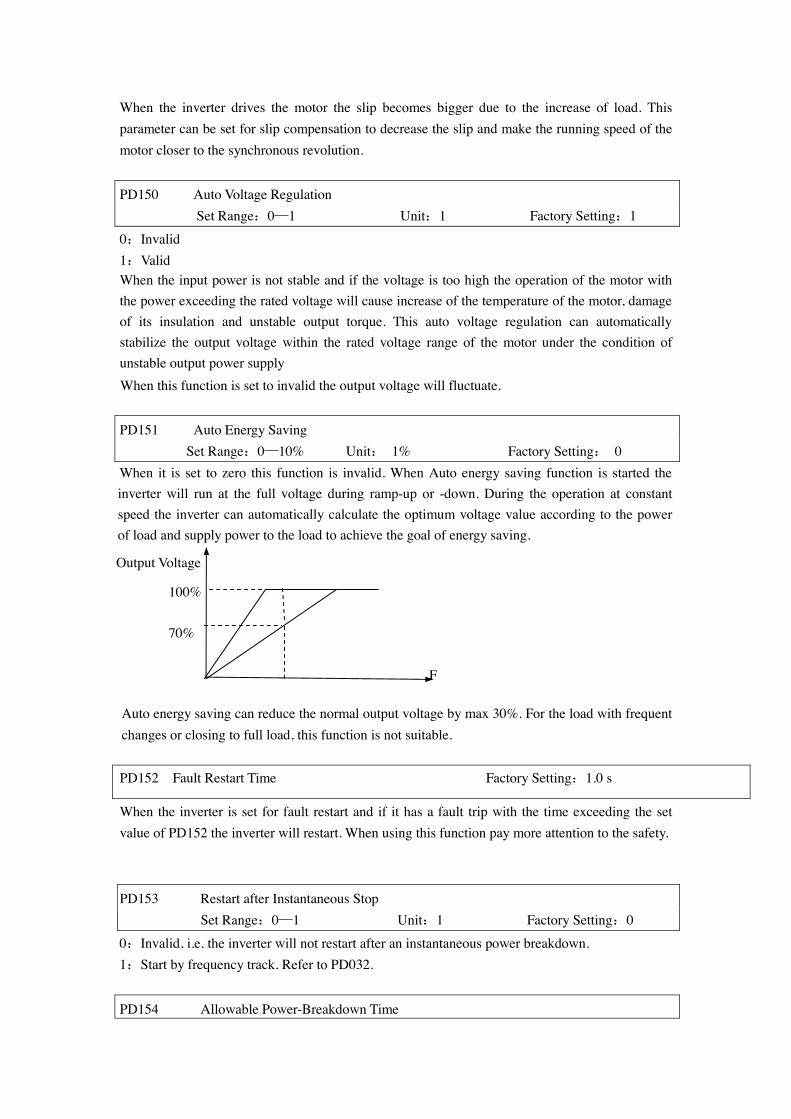
When the inverter drives the motor the slip becomes bigger due to the increase of load. This parameter can be set for slip compensation to decrease the slip and make the running speed of the motor closer to the synchronous revolution. PD150 Auto Voltage Regulation Set Range:0—1 Unit:1 Factory Setting:1
0:Invalid 1:Valid When the input power is not stable and if the voltage is too high the operation of the motor with the power exceeding the rated voltage will cause increase of the temperature of the motor, damage of its insulation and unstable output torque. This auto voltage regulation can automatically stabilize the output voltage within the rated voltage range of the motor under the condition of unstable output power supply When this function is set to invalid the output voltage will fluctuate. PD151 Auto Energy Saving
Set Range:0—10% Unit: 1% Factory Setting: 0 When it is set to zero this function is invalid. When Auto energy saving function is started the inverter will run at the full voltage during ramp-up or -down. During the operation at constant speed the inverter can automatically calculate the optimum voltage value according to the power of load and supply power to the load to achieve the goal of energy saving.
100%
70% Auto energy saving can reduce the normal output voltage by max 30%. For the load with frequent changes or closing to full load, this function is not suitable. PD152 Fault Restart Time Factory Setting:1.0 s
When the inverter is set for fault restart and if it has a fault trip with the time exceeding the set value of PD152 the inverter will restart. When using this function pay more attention to the safety. PD153 Restart after Instantaneous Stop
Set Range:0—1 Unit:1 Factory Setting:0
0:Invalid, i.e. the inverter will not restart after an instantaneous power breakdown. 1:Start by frequency track. Refer to PD032.
PD154 Allowable Power-Breakdown Time
Output Voltage
F
Set Range:0.1—5.0S Unit:0.1S Factory Setting:0.5 This parameter is set for the maximum allowable power failure time. If exceeding the set time the inverter will continue to stop output after power on. To restart the inverter it needs to follow the general starting procedures. PD155 Number of Abnormal Restart Set Range:00—10 Unit:1 Factory Setting:00 After the abnormal conditions (such as over-current and over-voltage) happens the inverter will automatically reset and restart. If the starting mode is set to normal mode it will start according to the normal procedures. If it is set to start by frequency track it will start in the frequency track mode. After starting it will restore the set number again if there is no more abnormality happened within 60 seconds. If there is still any error and it reaches the set number the inverter will stop output. It can only be started after reset. When PD155 is set to zero the inverter will not carry out the functions of automatic reset and restart. *PD156 Proportional Constant (P) ** Set Range:0.0~1000.0% Unit:0.1% Factory Setting:100%
* This function is not available for the inverter of J series. This proportional constant is set for the error value gain. In case of I=0, D=0, it is only for proportional control.
*PD157 Integral Time (I) ** Set Range:0.1~3600.0s Unit:0.1s Factory Setting:5.0s
* This function is not available for the inverter of J series. The integral time (I) is set for the responding speed for PID. The larger the I value is set the slower the responding speed will be. To the contrary, if the responding speed is quick but the integral time value is set too small, it will cause oscillation.
*PD158 Differential Time (D) ** Set Range:0.01~10.00s Unit:0.01s Factory Setting:0
* This function is not available for the inverter of J series. This differential time (D) is set for the depression operation of PID. The larger the D value is, the more obvious the depression operation will be. When D is set to zero, this function is invalid.
*PD159 Target Value ** Set Range:0~100.0% Unit:1% Factory Setting:*
* This function is not available for the inverter of J series. This target value can be set through external voltage signal or the digital operator.100% target value is corresponding to the analog frequency at +10V. PID closed-loop control is usually used in the process control with physical quantity not changing fast, such as the controls of pressure and temperature, etc. The feedback signal is usually taken
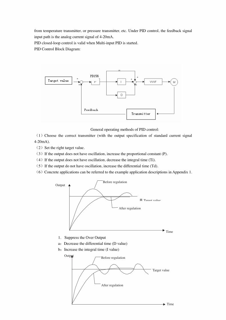
from temperature transmitter, or pressure transmitter, etc. Under PID control, the feedback signal input path is the analog current signal of 4-20mA. PID closed-loop control is valid when Multi-input PID is started. PID Control Block Diagram:
General operating methods of PID control: (1)Choose the correct transmitter (with the output specification of standard current signal 4-20mA). (2)Set the right target value. (3)If the output does not have oscillation, increase the proportional constant (P). (4)If the output does not have oscillation, decrease the integral time (Ti). (5)If the output do not have oscillation, increase the differential time (Td). (6)Concrete applications can be referred to the example application descriptions in Appendix 1.
1. Suppress the Over Output a:Decrease the differential time (D value) b:Increase the integral time (I value)
Output
目 Target value
After regulation
Before regulation
Time
Output
Target value
Time
After regulation
Before regulation
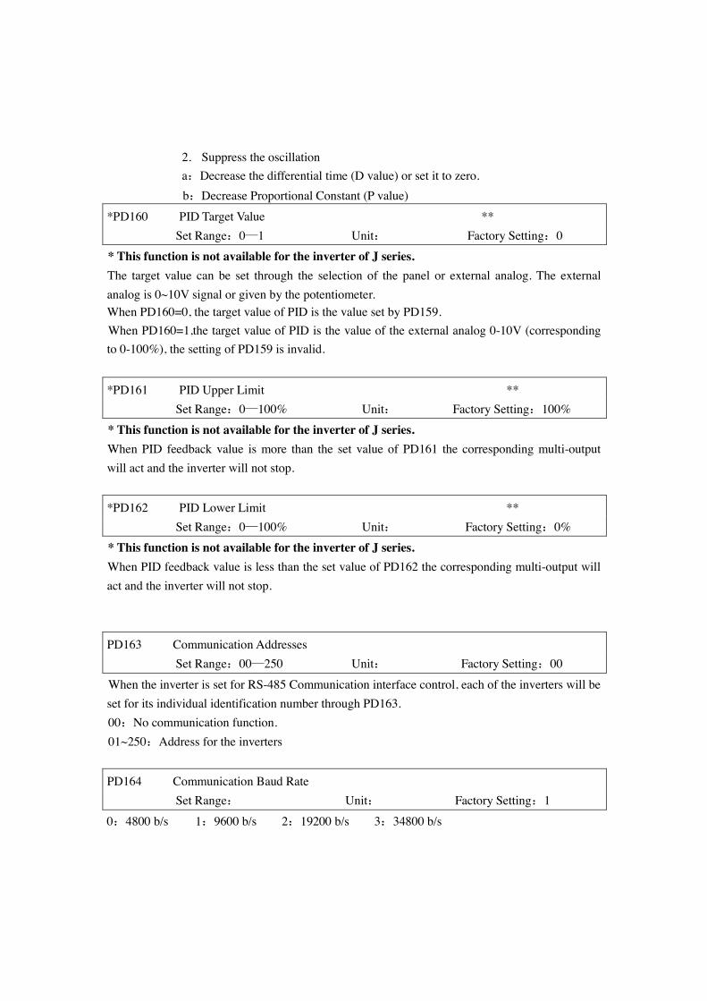
2. Suppress the oscillation a:Decrease the differential time (D value) or set it to zero.
b:Decrease Proportional Constant (P value)
*PD160 PID Target Value ** Set Range:0—1 Unit: Factory Setting:0 * This function is not available for the inverter of J series. The target value can be set through the selection of the panel or external analog. The external analog is 0~10V signal or given by the potentiometer. When PD160=0, the target value of PID is the value set by PD159. When PD160=1,the target value of PID is the value of the external analog 0-10V (corresponding to 0-100%), the setting of PD159 is invalid.
*PD161 PID Upper Limit ** Set Range:0—100% Unit: Factory Setting:100% * This function is not available for the inverter of J series. When PID feedback value is more than the set value of PD161 the corresponding multi-output will act and the inverter will not stop.
*PD162 PID Lower Limit ** Set Range:0—100% Unit: Factory Setting:0% * This function is not available for the inverter of J series. When PID feedback value is less than the set value of PD162 the corresponding multi-output will act and the inverter will not stop.
PD163 Communication Addresses Set Range:00—250 Unit: Factory Setting:00
When the inverter is set for RS-485 Communication interface control, each of the inverters will be set for its individual identification number through PD163. 00:No communication function. 01~250:Address for the inverters
PD164 Communication Baud Rate Set Range: Unit: Factory Setting:1
0:4800 b/s 1:9600 b/s 2:19200 b/s 3:34800 b/s
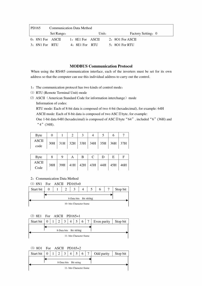
PD165 Communication Data Method Set Range: Unit: Factory Setting:0
0:8N1 For ASCII 1:8E1 For ASCII 2:8O1 For ASCII 3:8N1 For RTU 4:8E1 For RTU 5:8O1 For RTU
MODBUS Communication Protocol When using the RS485 communication interface, each of the inverters must be set for its own address so that the computer can use this individual address to carry out the control. 1:The communication protocol has two kinds of control mode: ⑴ RTU (Remote Terminal Unit) mode ⑵ ASCII(American Standard Code for information interchange)mode
Information of codes: RTU mode: Each of 8-bit data is composed of two 4-bit (hexadecimal), for example: 64H ASCII mode: Each of 8-bit data is composed of two ASCⅡbyte, for example: One 1-bit data 64H (hexadecimal) is composed of ASCⅡbyte“64”, included“6”(36H) and “4”(34H).
Byte 0 1 2 3 4 5 6 7
ASCII code
30H 31H 32H 33H 34H 35H 36H 37H
Byte 8 9 A B C D E F
ASCII Code
38H 39H 41H 42H 43H 44H 45H 46H
2:Communication Data Method ⑴ 8N1 For ASCII PD165=0 Start bit 0 1 2 3 4 5 6 7 Stop bit ⑵ 8E1 For ASCII PD165=1 Start bit 0 1 2 3 4 5 6 7 Even parity Stop bit ⑶ 8O1 For ASCII PD165=2 Start bit 0 1 2 3 4 5 6 7 Odd parity Stop bit
8-Data bits Bit string
10- bits Character frame
8-Data bits Bit string
11- bits Character frame
8-Data bits Bit string
11- bits Character frame
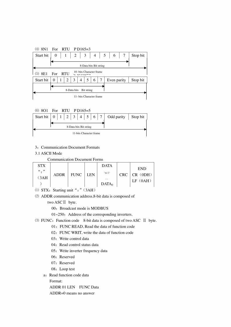
⑷ 8N1 For RTU P D165=3 Start bit 0 1 2 3 4 5 6 7 Stop bit ⑸ 8E1 For RTU C D162=4 Start bit 0 1 2 3 4 5 6 7 Even parity Stop bit ⑹ 8O1 For RTU P D165=5 Start bit 0 1 2 3 4 5 6 7 Odd parity Stop bit
3:Communication Document Formats 3.1 ASCII Mode
Communication Document Forms STX “:” (3AH)
ADDR FUNC LEN
DATA(n-1)
。。。
DATA0
CRC END
CR(0DH) LF(0AH)
⑴ STX:Starting unit“:”(3AH) ⑵ ADDR communication address,8-bit data is composed of
two ASCⅡ byte. 00:Broadcast mode is MODBUS 01~250:Address of the corresponding inverters.
⑶ FUNC:Function code 8-bit data is composed of two ASC Ⅱ byte. 01:FUNC READ, Read the data of function code
02:FUNC WRIT, write the data of function code 03:Write control data 04:Read control status data 05:Write inverter frequency data 06:Reserved 07:Reserved 08:Loop test
a:Read function code data Format: ADDR 01 LEN FUNC Data ADDR=0 means no answer
8-Data bits Bit string
10- bits Character frame
8-Data bits Bit string
11- bits Character frame
8-Data bits Bit string
11-bits Character frame
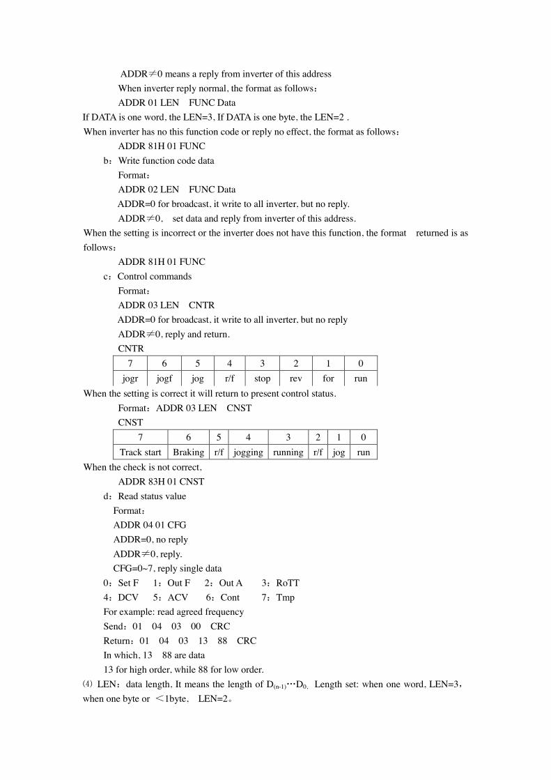
ADDR≠0 means a reply from inverter of this address When inverter reply normal, the format as follows: ADDR 01 LEN FUNC Data
If DATA is one word, the LEN=3, If DATA is one byte, the LEN=2 . When inverter has no this function code or reply no effect, the format as follows:
ADDR 81H 01 FUNC b:Write function code data Format: ADDR 02 LEN FUNC Data
ADDR=0 for broadcast, it write to all inverter, but no reply. ADDR≠0, set data and reply from inverter of this address.
When the setting is incorrect or the inverter does not have this function, the format returned is as follows:
ADDR 81H 01 FUNC c:Control commands Format: ADDR 03 LEN CNTR
ADDR=0 for broadcast, it write to all inverter, but no reply ADDR≠0, reply and return. CNTR
7 6 5 4 3 2 1 0 jogr jogf jog r/f stop rev for run
When the setting is correct it will return to present control status. Format:ADDR 03 LEN CNST CNST
7 6 5 4 3 2 1 0 Track start Braking r/f jogging running r/f jog run
When the check is not correct, ADDR 83H 01 CNST
d:Read status value Format: ADDR 04 01 CFG ADDR=0, no reply ADDR≠0, reply. CFG=0~7, reply single data 0:Set F 1:Out F 2:Out A 3:RoTT 4:DCV 5:ACV 6:Cont 7:Tmp For example: read agreed frequency Send:01 04 03 00 CRC Return:01 04 03 13 88 CRC In which, 13 88 are data 13 for high order, while 88 for low order.
⑷ LEN:data length, It means the length of D(n-1)…D0, Length set: when one word, LEN=3,when one byte or <1byte, LEN=2。
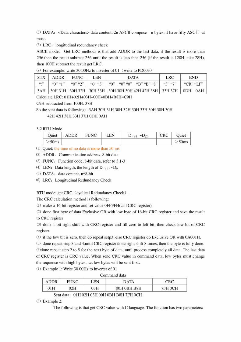
⑸ DATA:<Data characters> data content. 2n ASCII compose n bytes, it have fifty ASCⅡ at most. ⑹ LRC:longitudinal redundancy check ASCII mode: Get LRC methods is that add ADDR to the last data, if the result is more than 256,then the result subtract 256 until the result is less then 256 (if the result is 128H, take 28H), then 100H subtract the result get LRC. ⑺ For example: write 30.00Hz to inverter of 01(write to PD003) STX ADDR FUNC LEN DATA LRC END “:” “0” “1” “0” “2” “0” “3” “0” “0” “0” “B” “B” “8” “3” “7” “CR” “LF”
3AH 30H 31H 30H 32H 30H 33H 30H 30H 30H 42H 42H 38H 33H 37H 0DH 0AH Calculate LRC: 01H+02H+03H+00H+0BH+B8H=C9H C9H subtracted from 100H: 37H So the sent data is following:3AH 30H 31H 30H 32H 30H 33H 30H 30H 30H
42H 42H 38H 33H 37H 0DH 0AH
3.2 RTU Mode Quiet ADDR FUNC LEN D(n-1)~D(0) CRC Quiet >50ms >50ms
⑴ Quiet: the time of no data is more than 50 ms ⑵ ADDR:Communication address, 8-bit data ⑶ FUNC:Function code, 8-bit data, refer to 3.1-3 ⑷ LEN:Data length, the length of D(n-1)~D0 ⑸ DATA:data content, n*8-bit ⑹ LRC:Longitudinal Redundancy Check
RTU mode: get CRC(cyclical Redundancy Check). The CRC calculation method is following: ⑴ make a 16-bit register and set value 0FFFFH(call CRC register) ⑵ done first byte of data Exclusive OR with low byte of 16-bit CRC register and save the result to CRC register ⑶ done 1 bit right shift with CRC register and fill zero to left bit, then check low bit of CRC register. ⑷ if the low bit is zero, then do repeat setp3, else CRC register do Exclusive OR with 0A001H. ⑸ done repeat step 3 and 4,until CRC register done right shift 8 times, then the byte is fully done. ⑹done repeat step 2 to 5 for the next byte of data, until process completely all data. The last data of CRC register is CRC value. When send CRC value in command data, low bytes must change the sequence with high bytes, i.e. low bytes will be sent first. ⑺ Example 1: Write 30.00Hz to inverter of 01
Command data ADDR FUNC LEN DATA CRC
01H 02H 03H 00H 0BH B8H 7FH 0CH Sent data:01H 02H 03H 00H 0BH B8H 7FH 0CH ⑻ Example 2: The following is that get CRC value with C language. The function has two parameters:
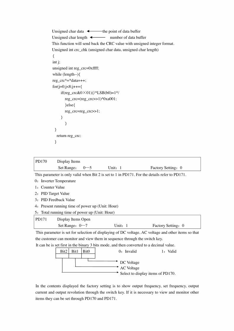
Unsigned char data the point of data buffer Unsigned char length number of data buffer This function will send back the CRC value with unsigned integer format. Unsigned int crc_chk (unsigned char data, unsigned char length)
{ int j; unsigned int reg_crc=0xffff; while (length--){ reg_crc^=*data=++; for(j=0;j<8;j++={ if(reg_crc&0×01){/*LSB(b0)=1*/ reg_crc=(reg_crc>>1)^0xa001; }else{ reg_crc=reg_crc>>1; } } } return reg_crc; }
PD170 Display Items Set Range: 0—5 Unit:1 Factory Setting:0
This parameter is only valid when Bit 2 is set to 1 in PD171. For the details refer to PD171. 0:Inverter Temperature 1:Counter Value 2:PID Target Value 3:PID Feedback Value 4:Present running time of power up (Unit: Hour) 5:Total running time of power up (Unit: Hour) PD171 Display Items Open Set Range:0—7 Unit:1 Factory Setting:0
This parameter is set for selection of displaying of DC voltage, AC voltage and other items so that the customer can monitor and view them in sequence through the switch key. It can be is set first in the binary 3 bits mode, and then converted to a decimal value. Bit2 Bit1 Bit0 0:Invalid 1:Valid DC Voltage AC Voltage Select to display items of PD170. In the contents displayed the factory setting is to show output frequency, set frequency, output current and output revolution through the switch key. If it is necessary to view and monitor other items they can be set through PD170 and PD171.
1
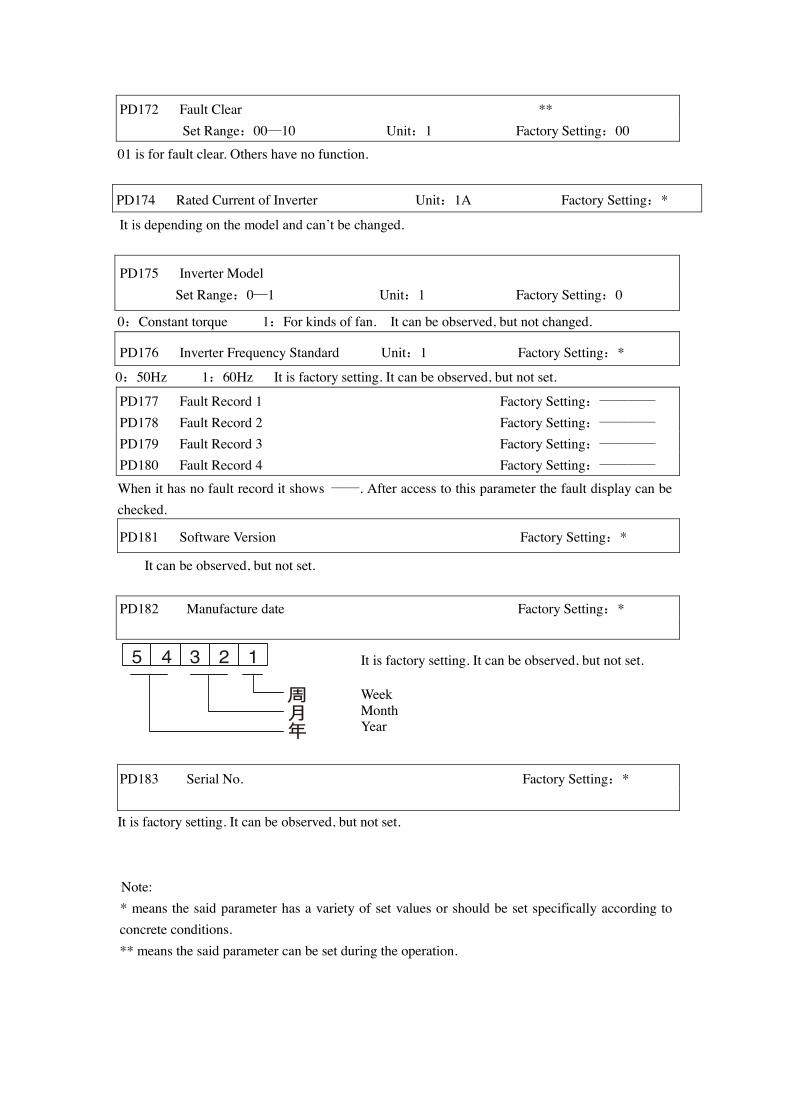
PD172 Fault Clear ** Set Range:00—10 Unit:1 Factory Setting:00
01 is for fault clear. Others have no function.
PD174 Rated Current of Inverter Unit:1A Factory Setting:*
It is depending on the model and can’t be changed.
PD175 Inverter Model Set Range:0—1 Unit:1 Factory Setting:0
0:Constant torque 1:For kinds of fan. It can be observed, but not changed.
PD176 Inverter Frequency Standard Unit:1 Factory Setting:*
0:50Hz 1:60Hz It is factory setting. It can be observed, but not set.
PD177 Fault Record 1 Factory Setting:———— PD178 Fault Record 2 Factory Setting:———— PD179 Fault Record 3 Factory Setting:———— PD180 Fault Record 4 Factory Setting:————
When it has no fault record it shows ——. After access to this parameter the fault display can be checked.
PD181 Software Version Factory Setting:*
It can be observed, but not set. PD182 Manufacture date Factory Setting:*
5 4 3 2 1
周月年
PD183 Serial No. Factory Setting:* It is factory setting. It can be observed, but not set.
Note: * means the said parameter has a variety of set values or should be set specifically according to concrete conditions. ** means the said parameter can be set during the operation.
It is factory setting. It can be observed, but not set. Week Month Year