7210 sas-d, e, k 2f1c2t, k 2f6c4t, k 3sfp+ 8c basic
TRANSCRIPT

Nokia — Proprietary and confidential.Use pursuant to applicable agreements.
7210 SERVICE ACCESS SWITCH | RELEASE 10.0.R6
7210 SAS-D, E, K 2F1C2T, K 2F6C4T, K 3SFP+ 8C Basic System Configuration Guide
3HE 13775 AAAC TQZZA
Edition: 01
August 2018
7210 SAS-D, E, K 2F1C2T, K 2F6C4T, K 3SFP+ 8C Basic System Configuration Guide

2
7210 SAS-D, E, K 2F1C2T, K 2F6C4T, K 3SFP+ 8CBasic System Configuration Guide
3HE 13775 AAAC TQZZA Edition: 01
Nokia is a registered trademark of Nokia Corporation. Other products and company names mentioned herein may be trademarks or tradenames of their respective owners.
The information presented is subject to change without notice. No responsibility is assumed for inaccuracies contained herein.
© 2018 Nokia.
Contains proprietary/trade secret information which is the property of Nokia and must not be made available to, or copied or used by anyone outside Nokia without its written authorization. Not to be used or disclosed except in accordance with applicable agreements.

7210 SAS-D, E, K 2F1C2T, K 2F6C4T, K 3SFP+ 8C Basic System Configuration Guide
Edition: 01 3HE 13775 AAAC TQZZA 3
Table of Contents
1 Getting Started..............................................................................131.1 About This Guide.......................................................................................131.1.1 Document Structure and Content ..............................................................141.2 7210 SAS Modes of Operation..................................................................141.3 7210 SAS Port Modes ...............................................................................171.4 7210 SAS System Configuration Process .................................................20
2 CLI Usage ......................................................................................212.1 In This Chapter ..........................................................................................212.2 CLI Structure .............................................................................................222.3 Navigating in the CLI .................................................................................242.3.1 CLI Contexts..............................................................................................242.3.2 Basic CLI Commands................................................................................252.3.3 CLI Environment Commands ....................................................................272.3.4 CLI Monitor Commands.............................................................................282.4 Getting Help in the CLI ..............................................................................292.5 The CLI Command Prompt........................................................................312.6 Displaying Configuration Contexts ............................................................322.7 EXEC Files ................................................................................................342.8 Entering CLI Commands ...........................................................................352.8.1 Command Completion...............................................................................352.8.2 Unordered Parameters ..............................................................................352.8.3 Editing Keystrokes.....................................................................................352.8.4 Absolute Paths ..........................................................................................362.8.5 History .......................................................................................................382.8.6 Entering Numerical Ranges.......................................................................382.8.7 Pipe/Match.................................................................................................402.8.8 Redirection ................................................................................................432.9 Basic Command Reference.......................................................................452.9.1 Command Hierarchies...............................................................................452.9.1.1 Global CLI Commands ..............................................................................462.9.1.2 Monitor Commands ...................................................................................462.9.1.3 Environment Commands ...........................................................................472.9.1.4 Show Commands ......................................................................................472.9.2 Command Descriptions .............................................................................482.9.2.1 Global Commands.....................................................................................492.9.2.2 Monitor Commands ...................................................................................682.9.2.3 Environment Commands ...........................................................................832.9.2.4 Show Commands ......................................................................................87
3 File System Management.............................................................893.1 In This Chapter ..........................................................................................893.2 The File System.........................................................................................903.2.1 Compact Flash Devices.............................................................................903.2.2 USB Storage Device..................................................................................92
4
7210 SAS-D, E, K 2F1C2T, K 2F6C4T, K 3SFP+ 8CBasic System Configuration Guide
3HE 13775 AAAC TQZZA Edition: 01
3.2.3 URLs..........................................................................................................923.2.4 Wildcards...................................................................................................933.3 File Management Tasks ............................................................................953.3.1 Modifying File Attributes ............................................................................953.3.2 Creating Directories...................................................................................963.3.3 Copying Files.............................................................................................963.3.4 Moving Files ..............................................................................................973.3.5 Removing Files and Deleting Directories ..................................................983.3.6 Displaying Directory and File Information..................................................983.4 File Command Reference........................................................................1013.4.1 Command Hierarchy................................................................................1013.4.1.1 Configuration Commands........................................................................1013.4.2 Configuration Commands........................................................................1023.4.2.1 File Commands .......................................................................................102
4 Boot Options ...............................................................................1154.1 In This Chapter ........................................................................................1154.2 System Initialization.................................................................................1164.2.1 Flash Contents of the node shipped from factory....................................1184.2.2 System Boot Options on 7210 SAS-D and 7210 SAS-E Devices ..........1194.2.3 System Boot Options on 7210 SAS-K 2F1C2T,
7210 SAS-K 2F6C4T, and 7210 SAS-K 3SFP+ 8C Devices ..................1204.2.3.1 Storage Locations for Index Files (ndx, sdx) and Images for
7210 SAS-K 2F1C2T, 7210 SAS-K 2F6C4T, and 7210 SAS-K 3SFP+ 8C ...........................................................................121
4.2.4 System Boot Options – Manual Mode ....................................................1224.2.5 System Boot Options – Auto-init..............................................................1234.3 Configuration and Image Loading ...........................................................1254.3.1 Ping Check in Auto-init Mode ..................................................................1304.3.1.1 Configuration Guidelines for use of Auto-init and Manual Mode ............1314.3.1.2 Persistence..............................................................................................1324.3.1.3 Configuration Guidelines for Use of Software Images with the
128MB 7210 SAS-D Platform..................................................................1324.3.1.4 Out-of-Band Ethernet Management Port.................................................1334.3.1.5 Configuration Guidelines for Use of IPv6 for Out-of-band
Management of the Node ........................................................................1334.3.1.6 Security for Console Port and Ethernet Management Port .....................1344.3.1.7 Reset the Node to Factory Default Setting ..............................................1344.4 Initial System Startup Process Flow........................................................1394.5 Configuration Notes.................................................................................1404.6 Configuring Boot File Options with CLI....................................................1414.7 BOF Configuration Overview...................................................................1424.8 Basic BOF Configuration .........................................................................1434.9 Common Configuration Tasks .................................................................1454.9.1 Searching for the BOF.............................................................................1454.9.2 Accessing the CLI....................................................................................1484.9.2.1 Console Connection ................................................................................1484.9.2.2 7210 SAS-E Console Port .......................................................................1494.9.2.3 7210 SAS-D Console Port.......................................................................149

7210 SAS-D, E, K 2F1C2T, K 2F6C4T, K 3SFP+ 8C Basic System Configuration Guide
Edition: 01 3HE 13775 AAAC TQZZA 5
4.9.2.4 7210 SAS-K 2F1C2T Console Port .........................................................1504.9.2.5 7210 SAS-K 2F6C4T Console Port .........................................................1514.9.2.6 7210 SAS-K 3SFP+ 8C Console Port .....................................................1524.10 Configuring BOF Parameters ..................................................................1534.11 Service Management Tasks ....................................................................1544.11.1 System Administration Commands .........................................................1544.11.2 Viewing the Current Configuration ..........................................................1544.11.3 Modifying and Saving a Configuration.....................................................1554.11.4 Deleting BOF Parameters .......................................................................1564.11.5 Saving a Configuration to a Different Filename.......................................1584.11.6 Rebooting ................................................................................................1594.12 BOF Command Reference ......................................................................1614.12.1 Command Hierarchies.............................................................................1614.12.1.1 Configuration Commands........................................................................1614.12.1.2 Show Commands ....................................................................................1624.12.2 Command Descriptions ...........................................................................1634.12.2.1 Configuration Commands........................................................................1634.12.2.2 Show Commands ....................................................................................185
5 System Management .................................................................1915.1 In This Chapter ........................................................................................1915.2 System Management Parameters ...........................................................1925.2.1 System Information..................................................................................1925.2.1.1 System Name..........................................................................................1925.2.1.2 System Contact .......................................................................................1925.2.1.3 System Location ......................................................................................1935.2.1.4 System Coordinates ................................................................................1935.2.1.5 Naming Objects .......................................................................................1935.2.1.6 Common Language Location Identifier....................................................1945.2.2 System Time ...........................................................................................1945.2.2.1 Time Zones..............................................................................................1945.2.2.2 Network Time Protocol (NTP)..................................................................1965.2.2.3 SNTP Time Synchronization ...................................................................1985.2.2.4 CRON......................................................................................................1985.3 High Availability .......................................................................................2005.3.1 HA Features ............................................................................................2005.3.1.1 Redundancy ............................................................................................2005.4 Temperature Threshold Alarm and Fan Speed .......................................2035.5 Network Synchronization.........................................................................2045.5.1 Central Synchronization Sub-System......................................................2055.5.2 Synchronization Options Available on 7210 SAS Platforms....................2075.5.3 Synchronization Status Messages (SSM) ...............................................2085.5.4 Synchronous Ethernet .............................................................................2095.5.4.1 Clock Source Quality Level Definitions....................................................2105.5.5 IEEE 1588v2 PTP....................................................................................2135.5.5.1 PTP Clock Synchronization .....................................................................2205.5.5.2 Performance Considerations ...................................................................2225.5.5.3 PTP Capabilities ......................................................................................2235.5.5.4 PTP Ordinary Slave Clock for Frequency................................................224

6
7210 SAS-D, E, K 2F1C2T, K 2F6C4T, K 3SFP+ 8CBasic System Configuration Guide
3HE 13775 AAAC TQZZA Edition: 01
5.5.6 PTP Boundary Clock for Frequency and Time ........................................2245.5.7 Configuration Guidelines and Restrictions for PTP ................................2255.5.8 Configuration to Change Reference from SyncE to PTP on
7210 SAS-D ETR ...................................................................................2265.6 Management of 1830 VWM ....................................................................2295.6.1 Introduction to Management of 1830 VWM Devices ...............................2295.6.2 Feature Description .................................................................................2305.6.2.1 1830 CWDM shelf layout and description ...............................................2315.6.2.2 1830 DWDM Shelf Layout and Description .............................................2325.6.3 Configuration Guidelines and Restrictions ..............................................2345.6.3.1 LED functionality .....................................................................................2355.7 Link Layer Discovery Protocol (LLDP).....................................................2375.8 System Resource Allocation....................................................................2415.8.1 Allocation of Ingress Internal TCAM resources .......................................2415.8.2 Allocation of Egress Internal TCAM Resources ......................................2435.8.2.1 System Resource Allocation Examples...................................................2445.9 System Configuration Process Overview ................................................2475.10 Configuration Notes.................................................................................2485.10.1 General....................................................................................................2485.11 Configuring System Management with CLI .............................................2495.12 System Management...............................................................................2505.12.1 Saving Configurations .............................................................................2505.13 Basic System Configuration ...................................................................2515.14 Common Configuration Tasks .................................................................2525.14.1 System Information..................................................................................2525.14.1.1 System Information Parameters ..............................................................2525.14.1.2 System Time Elements............................................................................2555.14.2 Configuring Backup Copies .....................................................................2735.15 System Administration Parameters .........................................................2755.15.1 Validating the Golden Bootstrap Image...................................................2755.15.2 Updating the Golden Bootstrap Image ....................................................2755.15.3 Disconnect...............................................................................................2765.15.4 Set-time ...................................................................................................2765.15.5 Display-config ..........................................................................................2775.15.6 Tech-support ...........................................................................................2785.15.7 Save ........................................................................................................2785.15.8 Reboot .....................................................................................................2795.15.9 Post-Boot Configuration Extension Files .................................................2805.15.9.1 Show Command Output and Console Messages....................................2815.16 System Timing.........................................................................................2835.16.1 Edit Mode ................................................................................................2845.16.2 Configuring Timing References ...............................................................2845.16.3 Using the Revert Command ....................................................................2855.17 Configuring System Monitoring Thresholds.............................................2865.17.1 Creating Events .......................................................................................2865.17.2 System Alarm Contact Inputs ..................................................................2875.17.2.1 Configuring an Alarm Input in 7210 SAS-D, 7210 SAS-K 2F1C2T,
7210 SAS-K 2F6C4T, and 7210 SAS-K 3SFP+ 8C devices ...................2885.18 Configuring 1830 VWM ...........................................................................289

7210 SAS-D, E, K 2F1C2T, K 2F6C4T, K 3SFP+ 8C Basic System Configuration Guide
Edition: 01 3HE 13775 AAAC TQZZA 7
5.19 Configuring System Resource Profile .....................................................2925.20 Configuring LLDP ....................................................................................2935.21 System Command Reference .................................................................2955.21.1 Command Hierarchies.............................................................................2955.21.1.1 Configuration Commands........................................................................2965.21.1.2 Show Commands ....................................................................................3045.21.1.3 Clear Commands.....................................................................................3055.21.1.4 Debug Commands...................................................................................3055.21.2 Command Descriptions ...........................................................................3075.21.2.1 Configuration Commands........................................................................3085.21.2.2 Show Commands ....................................................................................4295.21.2.3 Clear Commands.....................................................................................4845.21.2.4 Debug Commands...................................................................................486
6 Standards and Protocol Support ..............................................489

8
7210 SAS-D, E, K 2F1C2T, K 2F6C4T, K 3SFP+ 8CBasic System Configuration Guide
3HE 13775 AAAC TQZZA Edition: 01

7210 SAS-D, E, K 2F1C2T, K 2F6C4T, K 3SFP+ 8C Basic System Configuration Guide
Edition: 01 3HE 13775 AAAC TQZZA 9
List of Tables
1 Getting Started..............................................................................13Table 1 Supported Modes of Operation and Configuration Methods ....................16Table 2 Supported Port Modes by Mode of Operation ..........................................18Table 3 7210 SAS Platforms Supporting Port Modes ...........................................19Table 4 Configuration Process ..............................................................................20
2 CLI Usage ......................................................................................21Table 5 Console Control Commands ...................................................................25Table 6 Command Syntax Symbols .....................................................................27Table 7 CLI Environment Commands ..................................................................27Table 8 CLI Monitor Command Contexts ..............................................................28Table 9 Online Help Commands ..........................................................................29Table 10 Command Editing Keystrokes .................................................................35Table 11 CLI Range Use Limitations ......................................................................39Table 12 Regular Expression Symbols ..................................................................41Table 13 Special Characters ..................................................................................42Table 14 Encapsulation Type Values ......................................................................79Table 15 Show Alias Output Fields .........................................................................87
3 File System Management.............................................................89Table 16 URL Types and Syntax .............................................................................93Table 17 File Command Local and Remote File System Support ...........................94
4 Boot Options ...............................................................................115Table 18 Console Configuration Parameter Values ..............................................148Table 19 Show BOF Output Fields ........................................................................186Table 20 Show BOF Output Fields (supported only on 7210 SAS-E) ...................188
5 System Management .................................................................191Table 21 System-defined Time Zones ..................................................................195Table 22 Over-Temperature Threshold for 7210 SAS devices .............................203Table 23 Revertive, non-Revertive Timing Reference Switching Operation .........206Table 24 Synchronization Options on 7210 SAS-D ETR,
7210 SAS-K 2F1C2T, 7210 SAS-K 2F6C4T, and 7210 SAS-K 3SFP+ 8C .207
Table 25 Synchronization Message Coding and Source Priorities – SSM Received .................................................................................................211
Table 26 Synchronization Message Coding and Source Priorities – SSM Transmitted .............................................................................................212
Table 27 IP/UDP Unicast and Ethernet Multicast Support ....................................214Table 28 Local Clock Parameters When Profile is Set to ieee1588-2008 .............217Table 29 Local Clock Parameters When Profile is Set to itu-telecom-freq ............217Table 30 Local Clock Parameters When Profile is Set to g8275dot1-2014 ...........218Table 31 Support Message Rates for Slave and Master Clock States ..................223

10
7210 SAS-D, E, K 2F1C2T, K 2F6C4T, K 3SFP+ 8CBasic System Configuration Guide
3HE 13775 AAAC TQZZA Edition: 01
Table 32 LED Functionality for 7210 SAS and 1830 VWM (CWDM) ....................235Table 33 LED functionality for 7210 SAS and 1830 VWM (DWDM) .....................236Table 34 System-defined Time Zones ..................................................................256Table 35 Card Type Acronyms for 1830 CWDM Devices .....................................325Table 36 Card Type Acronyms for 1830 DWDM Devices .....................................325Table 37 Show System Connections Output Fields ..............................................431Table 38 Show System CPU Output Fields ..........................................................432Table 39 Show cron Schedule Output Fields ........................................................434Table 40 Show System Information Output Fields ................................................437Table 41 Show Script Output Fields ......................................................................440Table 42 Show Script Policy Output Fields ...........................................................443Table 43 Show Memory Pool Output Fields .........................................................445Table 44 Show NTP Output Fields ........................................................................447Table 45 Show Oper-group Output Fields .............................................................451Table 46 Show System Resource-profile Output Fields ........................................453Table 47 Show System SNTP Output Fields ........................................................457Table 48 Show System Threshold Output Fields ..................................................459Table 49 Show System Time Output Fields .........................................................461Table 50 Show VWM-shelf Output Fields .............................................................466Table 51 Show System tod-suite Output Fields ...................................................470Table 52 Show System Time-range Output Fields ...............................................472Table 53 System Timing Output Fields ................................................................472Table 54 Show sync-if-timing Output Fields ..........................................................474Table 55 Show Chassis Output Fields ..................................................................480Table 56 Show Alarm Contact Input Fields ...........................................................483Table 57 Show Fan Statistics Output Fields ..........................................................488

7210 SAS-D, E, K 2F1C2T, K 2F6C4T, K 3SFP+ 8C Basic System Configuration Guide
Edition: 01 3HE 13775 AAAC TQZZA 11
List of Figures
2 CLI Usage ......................................................................................21Figure 1 Root Commands........................................................................................22Figure 2 Operational Root Commands ....................................................................23
4 Boot Options ...............................................................................115Figure 3 Bootstrap Load Process – System Initialization Part 1............................117Figure 4 Files on the Flash ....................................................................................119Figure 5 Bootstrap Process – System Initialization Part 2A ..................................126Figure 6 Auto Mode with Partial BOF ....................................................................127Figure 7 Bootstrap Process – System Initialization Part 2B ..................................128Figure 8 Bootstrap Process – System Initialization Part 2C ..................................129Figure 9 TiMOS Boot – System Initialization Part 3 ..............................................130Figure 10 System Startup Process Flow .................................................................139Figure 11 7210 SAS-E Front Panel Console Port ...................................................149Figure 12 7210 SAS-D Front Panel Console Port ...................................................150Figure 13 7210 SAS-K 2F1C2T Front Panel Console Port (non-ETR)....................150Figure 14 77210 SAS-K 2F1C2T Front Panel Console Port (ETR).........................151Figure 15 7210 SAS-K 2F6C4T Front Panel Console Port (non-ETR)....................151Figure 16 7210 SAS-K 2F6C4T Front Panel Console Port (ETR)...........................151Figure 17 7210 SAS-K 3SFP+ 8C Front Panel Console Port .................................152
5 System Management .................................................................191Figure 18 Conventional Network Timing Architecture (North American
Nomenclature) .........................................................................................204Figure 19 A Logical Model of the Synchronization Reference Selection on
7210 SAS Platforms ................................................................................206Figure 20 Peer Clocks .............................................................................................215Figure 21 Ethernet Multicast Ports ..........................................................................216Figure 22 Messaging Sequence Between the PTP Slave Clock and PTP
Master Clocks..........................................................................................220Figure 23 PTP Slave Clock and Master Clock Synchronization Timing
Computation ............................................................................................221Figure 24 Logical Model for Using PTP/1588 for Network Synchronization
on 7210 SAS Platforms ...........................................................................222Figure 25 Slave Clock..............................................................................................224Figure 26 Boundary Clock .......................................................................................225Figure 27 Optical Ring with 7210 SAS and 1830 VWM Passive Optical unit ..........230Figure 28 1830 CWDM Shelf Layout .......................................................................231Figure 29 1830 DWDM Shelf layout ........................................................................232Figure 30 LLDP Internal Architecture for a Network Node ......................................239Figure 31 Customer Use Example For LLDP ..........................................................240Figure 32 System Configuration and Implementation Flow .....................................247

12
7210 SAS-D, E, K 2F1C2T, K 2F6C4T, K 3SFP+ 8CBasic System Configuration Guide
3HE 13775 AAAC TQZZA Edition: 01

7210 SAS-D, E, K 2F1C2T, K 2F6C4T, K 3SFP+ 8C Basic System Configuration Guide
Getting Started
Edition: 01 3HE 13775 AAAC TQZZA 13
1 Getting Started
This chapter provides process flow information to configure basic router and system parameters, perform operational functions with directory and file management, and boot option tasks. It also provides an overview of the document organization and content, and describes the terminology used in this guide.
1.1 About This Guide
This guide describes system concepts and provides configuration examples to configure the boot option file (BOF), and perform system and file management functions on the following 7210 SAS platforms, operating in one of the modes described in Table 1. If multiple modes of operation apply, they are explicitly noted in the topic.
• 7210 SAS-D
• 7210 SAS-E
• 7210 SAS-K 2F1C2T
• 7210 SAS-K 2F6C4T
• 7210 SAS-K 3SFP+ 8C
See section 1.2 for information about the modes of operation supported by the 7210 SAS product family.
Note: Unless explicitly noted otherwise, the phrase “Supported on all 7210 SAS platforms described in this document” is used to indicate that the topic and CLI commands apply to all the 7210 SAS platforms in the following list, when operating in the specified modes only.
• access-uplink mode of operation
7210 SAS-D, 7210 SAS-E, 7210 SAS-K 2F1C2T, 7210 SAS-K 2F6C4T, and 7210 SAS-K 3SFP+ 8C
• network mode of operation
7210 SAS-K 2F6C4T and 7210 SAS-K 3SFP+ 8C,
When configured in the access-uplink or network mode of operation, the 7210 SAS platform implicitly operates in the standalone mode.

Getting Started
14
7210 SAS-D, E, K 2F1C2T, K 2F6C4T, K 3SFP+ 8CBasic System Configuration Guide
3HE 13775 AAAC TQZZA Edition: 01
1.1.1 Document Structure and Content
This guide uses the following structure to describe features and configuration content.
• This guide is organized into functional chapters and provides concepts and descriptions of the implementation flow. Each chapter describes a software area and provides CLI syntax and command usage to configure parameters for the functional area.
• Command outputs shown in this guide are examples only; actual displays may differ depending on supported functionality and user configuration.
• Unless explicitly noted, the CLI commands and their configuration is similar for both network and access-uplink operating modes for features applicable to both modes of operation.
1.2 7210 SAS Modes of Operation
Unless explicitly noted, the phrase “mode of operation” and “operating mode” refers to the current operating mode of the 7210 SAS router. Each operating mode provides configuration access to a specific group of CLI commands.
The following modes of operation are supported by the 7210 SAS product family.
• access-uplink
In the access-uplink operating mode, the 7210 SAS router uplinks to the network using Layer 2 Ethernet VLAN switching (without IP/MPLS).
Note: This guide generically covers Release 10.0 content and may include some content that will be released in later maintenance loads. Refer to the 7210 SAS OS Software Release Notes 10.0Rx, part number 3HE14066000xTQZZA, for information about features supported in each load of the Release 10.0 software.
Note: Not all CLI commands are supported on all 7210 SAS platforms in all modes of operation. Users can only configure CLI commands supported by the current operating mode of the router. Refer to the 7210 SAS OS Software Release Notes 10.0Rx, part number 3HE14066000xTQZZA, and to the appropriate 7210 SAS software user guide for information about features and capabilities supported by a 7210 SAS platform when operating in a specific mode.
7210 SAS-D, E, K 2F1C2T, K 2F6C4T, K 3SFP+ 8C Basic System Configuration Guide
Getting Started
Edition: 01 3HE 13775 AAAC TQZZA 15
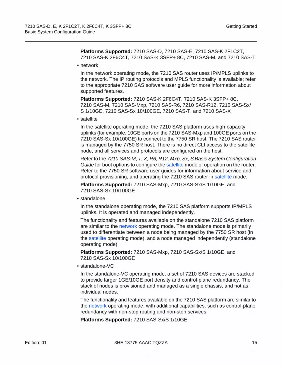
Platforms Supported: 7210 SAS-D, 7210 SAS-E, 7210 SAS-K 2F1C2T, 7210 SAS-K 2F6C4T, 7210 SAS-K 3SFP+ 8C, 7210 SAS-M, and 7210 SAS-T
• network
In the network operating mode, the 7210 SAS router uses IP/MPLS uplinks to the network. The IP routing protocols and MPLS functionality is available; refer to the appropriate 7210 SAS software user guide for more information about supported features.
Platforms Supported: 7210 SAS-K 2F6C4T, 7210 SAS-K 3SFP+ 8C, 7210 SAS-M, 7210 SAS-Mxp, 7210 SAS-R6, 7210 SAS-R12, 7210 SAS-Sx/S 1/10GE, 7210 SAS-Sx 10/100GE, 7210 SAS-T, and 7210 SAS-X
• satellite
In the satellite operating mode, the 7210 SAS platform uses high-capacity uplinks (for example, 10GE ports on the 7210 SAS-Mxp and 100GE ports on the 7210 SAS-Sx 10/100GE) to connect to the 7750 SR host. The 7210 SAS router is managed by the 7750 SR host. There is no direct CLI access to the satellite node, and all services and protocols are configured on the host.
Refer to the 7210 SAS-M, T, X, R6, R12, Mxp, Sx, S Basic System Configuration Guide for boot options to configure the satellite mode of operation on the router. Refer to the 7750 SR software user guides for information about service and protocol provisioning, and operating the 7210 SAS router in satellite mode.
Platforms Supported: 7210 SAS-Mxp, 7210 SAS-Sx/S 1/10GE, and 7210 SAS-Sx 10/100GE
• standalone
In the standalone operating mode, the 7210 SAS platform supports IP/MPLS uplinks. It is operated and managed independently.
The functionality and features available on the standalone 7210 SAS platform are similar to the network operating mode. The standalone mode is primarily used to differentiate between a node being managed by the 7750 SR host (in the satellite operating mode), and a node managed independently (standalone operating mode).
Platforms Supported: 7210 SAS-Mxp, 7210 SAS-Sx/S 1/10GE, and 7210 SAS-Sx 10/100GE
• standalone-VC
In the standalone-VC operating mode, a set of 7210 SAS devices are stacked to provide larger 1GE/10GE port density and control-plane redundancy. The stack of nodes is provisioned and managed as a single chassis, and not as individual nodes.
The functionality and features available on the 7210 SAS platform are similar to the network operating mode, with additional capabilities, such as control-plane redundancy with non-stop routing and non-stop services.
Platforms Supported: 7210 SAS-Sx/S 1/10GE

Getting Started
16
7210 SAS-D, E, K 2F1C2T, K 2F6C4T, K 3SFP+ 8CBasic System Configuration Guide
3HE 13775 AAAC TQZZA Edition: 01
For 7210 SAS platforms that support multiple explicit modes of operation (Table 1), the operating mode must be configured in the Boot Option File (BOF) to ensure the router boots up in the specified mode. For example, the 7210 SAS-M supports access-uplink and network modes of operation, and the 7210 SAS-Sx/S 1/10GE supports satellite, standalone, and standalone-VC mode of operations. In some cases, the 7210 SAS router operates in a specific mode implicitly, and explicit configuration is not required.
Refer to the appropriate Basic System Configuration Guide for boot options and information about how to boot the 7210 SAS platform in a specific operating mode.
Table 1 lists the supported modes of operation and the configuration methods for the 7210 SAS platforms. Unless explicitly noted otherwise, the operating mode is supported on all variants of the specific 7210 SAS platform.
Table 1 Supported Modes of Operation and Configuration Methods
7210 SAS Platform Mode of Operation and Configuration Method
Network Access-Uplink Standalone Standalone-VC Satellite
7210 SAS-D Implicit Implicit
7210 SAS-E Implicit Implicit
7210 SAS-K 2F1C2T Implicit Implicit
7210 SAS-K 2F6C4T 2 Port Mode 4 Configuration
Port Mode 4 Configuration
Implicit
7210 SAS-K 3SFP+ 8C 2 Port Mode 4 Configuration
Port Mode 4 Configuration
Implicit
7210 SAS-M Explicit BOF Configuration
Explicit BOF Configuration
Implicit
7210 SAS-Mxp Implicit 3 Explicit BOF Configuration
Explicit BOF Configuration
7210 SAS-R6 1 Implicit Implicit
7210 SAS-R12 1 Implicit Implicit
7210 SAS-Sx/S 1/10GE Implicit 3 Explicit BOF Configuration
Explicit BOF Configuration
Explicit BOF Configuration
7210 SAS-Sx 10/100GE Implicit 3 Explicit BOF Configuration
Explicit BOF Configuration
Explicit BOF Configuration
7210 SAS-T Explicit BOF Configuration
Explicit BOF Configuration
Implicit

7210 SAS-D, E, K 2F1C2T, K 2F6C4T, K 3SFP+ 8C Basic System Configuration Guide
Getting Started
Edition: 01 3HE 13775 AAAC TQZZA 17
Notes:
1. Supports MPLS uplinks only and implicitly operates in network mode
2. By default, the 7210 SAS-K 2F6C4T and 7210 SAS-K 3SFP+ 8C boot up in the network mode of operation. These platforms also allow the use of access-uplink port mode (without explicit BOF configuration), which provides the option to use Layer 2 uplinks instead of IP/MPLS uplinks to the network core, similar to the 7210 SAS-K 2F1C2T router.
3. Implicitly operates in network mode when standalone mode of operation is configured
4. See section 1.3 for information about port mode configuration
1.3 7210 SAS Port Modes
Unless explicitly noted, the phrase “port mode” refers to the current port configuration of the 7210 SAS node. The 7210 SAS platform supports the configuration of the following port modes.
• access port mode
Access ports are configured for customer-facing traffic if Service Access Points (SAPs) are required. The appropriate encapsulation type must be configured to distinguish the services on the port; services are configured on the port based on the encapsulation value.
Access ports can be configured on all the 7210 SAS platforms.
• access-uplink port mode
Access-uplink ports provide native Ethernet connectivity in service provider transport or in an infrastructure network. With this option, the encap-type can be configured to only QinQ. Access-uplink SAPs, which are QinQ SAPs, can only be configured on an access-uplink port to allow the operator to differentiate multiple services being carried over a single uplink port.
This is the default port mode of a 7210 SAS node in the access-uplink mode of operation.
• network port mode
Network ports are configured for network-facing traffic in the service provider transport or infrastructure network, and provide IP/MPLS uplinks.
7210 SAS-X 1 Implicit Implicit
Table 1 Supported Modes of Operation and Configuration Methods (Continued)
7210 SAS Platform Mode of Operation and Configuration Method
Network Access-Uplink Standalone Standalone-VC Satellite

Getting Started
18
7210 SAS-D, E, K 2F1C2T, K 2F6C4T, K 3SFP+ 8CBasic System Configuration Guide
3HE 13775 AAAC TQZZA Edition: 01
This is the default port mode of a 7210 SAS node in the network or standalone mode of operation.
• hybrid port mode
Hybrid ports are configured for access and network facing traffic, and allow a single port to operate in both access and network modes.
Port modes available for configuration on a 7210 SAS node are determined by the current mode of operation of the router.
Table 2 lists the port mode configuration support per 7210 SAS mode of operation.
Note:
1. Port modes are configured on the 7750 SR host and managed by the host.
Table 3 lists the port mode configuration supported by the 7210 SAS product family. Refer to the appropriate Interface Configuration Guide for detailed information about configuring the port modes for a specific platform.
Note: The 7210 SAS-K 2F6C4T and 7210 SAS-K 3SFP+ 8C are unique; all port modes listed in Table 2 are available for configuration on the router, regardless of the current mode of operation.
Table 2 Supported Port Modes by Mode of Operation
Mode of Operation Supported Port Mode
Access Network Hybrid Access-uplink
Access-Uplink ✓ ✓
Network ✓ ✓ ✓
Satellite 1
Standalone ✓ ✓ ✓
Standalone-VC ✓ ✓ ✓

7210 SAS-D, E, K 2F1C2T, K 2F6C4T, K 3SFP+ 8C Basic System Configuration Guide
Getting Started
Edition: 01 3HE 13775 AAAC TQZZA 19
Notes:
1. Network ports are supported only if the node is operating in network mode.
2. Hybrid ports are supported only if the node is operating in network mode.
3. Access-uplink ports are supported only if the node is operating in access-uplink mode.
Table 3 7210 SAS Platforms Supporting Port Modes
Platform Port Mode
Access Network Hybrid Access-uplink
7210 SAS-D Yes No No Yes
7210 SAS-E Yes No No Yes
7210 SAS-K 2F1C2T Yes No No Yes
7210 SAS-K 2F6C4T Yes Yes Yes Yes
7210 SAS-K 3SFP+ 8C Yes Yes Yes Yes
7210 SAS-M Yes Yes 1 Yes 2 Yes 3
7210 SAS-Mxp Yes Yes Yes No
7210 SAS-R6 IMM (IMMv1) and IMM-b (IMMv2)
Yes Yes Yes No
7210 SAS-R6 IMM-c 100GE (IMM-c 1CFP4 or IMM-c 1QSFP28)
Yes Yes No No
7210 SAS-R12 IMM-b Yes Yes Yes No
7210 SAS-R12 IMM-c 100GE (IMM-c 1CFP4 or IMM-c 1QSFP28)
Yes Yes No No
7210 SAS-Sx/S 1/10GE Yes Yes Yes No
7210 SAS-Sx 10/100GE Yes Yes Yes No
7210 SAS-T Yes Yes 1 Yes 2 Yes 3
7210 SAS-X Yes Yes Yes No

Getting Started
20
7210 SAS-D, E, K 2F1C2T, K 2F6C4T, K 3SFP+ 8CBasic System Configuration Guide
3HE 13775 AAAC TQZZA Edition: 01
1.4 7210 SAS System Configuration Process
Table 4 describes the tasks necessary to configure boot option files (BOF) and system and file management functions. Each chapter in this book is presented in an overall logical configuration flow. Each section describes a software area and provides CLI syntax and command usage to configure parameters for a functional area. After the hardware installation has been properly completed, proceed with the 7210 SAS device configuration tasks in the following order:
Table 4 Configuration Process
Area Task Chapter
CLI Usage The CLI structure CLI Usage
Basic CLI commands Basic CLI Commands
Configure environment commands
CLI Environment Commands
Configure monitor commands CLI Monitor Commands
Operational functions Directory and file management
File System Management
Boot options Configure boot option files (BOF)
Boot Options
System configuration Configure system functions, including host name, address, domain name, and time parameters.
System Management
Reference List of IEEE, IETF, and other proprietary entities.
Standards and Protocol Support

7210 SAS-D, E, K 2F1C2T, K 2F6C4T, K 3SFP+ 8C Basic System Configuration Guide
CLI Usage
Edition: 01 3HE 13775 AAAC TQZZA 21
2 CLI Usage
2.1 In This Chapter
This chapter provides information about using the command-line interface (CLI).
Topics in this chapter include:
• CLI Structure
• Navigating in the CLI
• Getting Help in the CLI
• The CLI Command Prompt
• Displaying Configuration Contexts
• EXEC Files
• Entering CLI Commands

CLI Usage
22
7210 SAS-D, E, K 2F1C2T, K 2F6C4T, K 3SFP+ 8CBasic System Configuration Guide
3HE 13775 AAAC TQZZA Edition: 01
2.2 CLI Structure
Nokia’s Operating System (OS) CLI is a command-driven interface accessible through the console, Telnet, and secure shell (SSH). The CLI can be used for configuration and management of routers.
The CLI command tree is a hierarchical inverted tree. At the highest level is the ROOT level. Below this level are other tree levels with the major command groups; for example, configuration commands and show commands are levels below ROOT.
The CLI is organized so related commands with the same scope are at the same level or in the same context. Sublevels or subcontexts have related commands with a more refined scope.
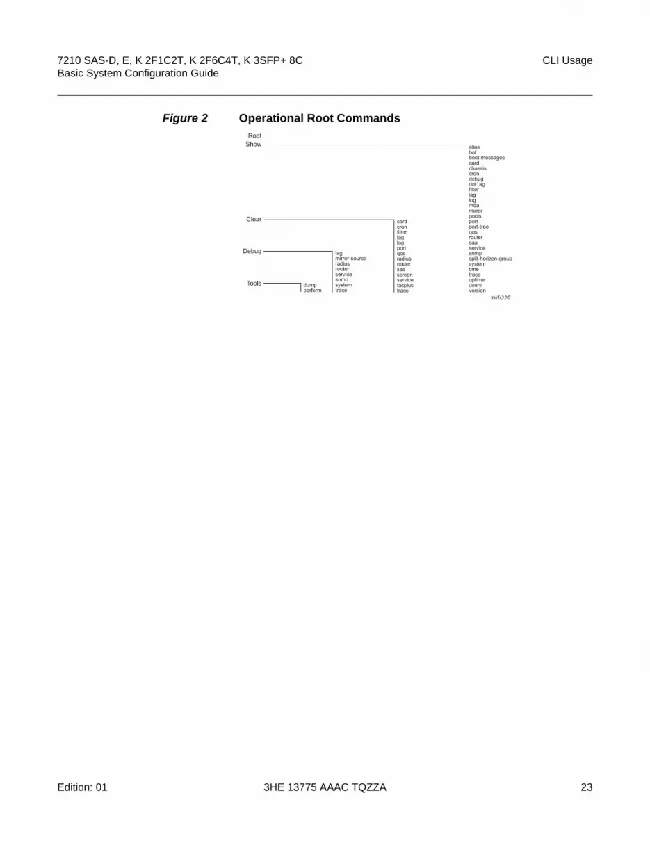
Figure 1 and Figure 2 show the major contexts for router configuration. The figures are sample representations of high-level commands; not all commands are included.
Figure 1 Root Commands
sw0555
RootAdmin
BOF
Configure
Environment
File
Monitor
Help
Password
aliascreatemorereduced-promptsaved-ind-promptterminaltime-display
helphelp edithelp globals
filterlagportqosrouterservice
attribcdcopydeletedirformatmdmoverdscptypeversion
cardcrondot1agfilterlaglogmirrorportqosroutersaaservicesplit-horizon-groupsystem
addressautonegotiateconsole-speeddns-domainduplexpersistprimary-configprimary-dnsprimary-imagesavesecondary-configsecondary-dnssecondary-imageping-addressstatic-routetertiary-configtertiary-dnstertiary-imageuplinkA-addressuplinkA-autoneguplinkA-duplexuplinkA-speeduplinkA-portuplinkA-routeuplinkA-vlanuplinkB-addressuplinkB-autoneguplinkB-duplexuplinkB-speeduplinkB-portuplinkB-routeuplink-vlanwait
check-golden-bootstrapdebug-save disconnect display-config radius-disc reboot save set-time update-golden-bootstraprollback
7210 SAS-D, E, K 2F1C2T, K 2F6C4T, K 3SFP+ 8C Basic System Configuration Guide
CLI Usage
Edition: 01 3HE 13775 AAAC TQZZA 23
Figure 2 Operational Root Commands
sw0556
RootShow
Clear
Debug
Tools dumpperform
lagmirror-sourceradiusrouterservicesnmpsystemtrace
cardcronfilterlaglogportqosradiusroutersaascreenservicetacplustrace
aliasbofboot-messagescardchassiscrondebugdot1agfilterlaglogmdamirrorpoolsportport-treeqos router saa servicesnmpsplit-horizon-groupsystem time trace uptime users version

CLI Usage
24
7210 SAS-D, E, K 2F1C2T, K 2F6C4T, K 3SFP+ 8CBasic System Configuration Guide
3HE 13775 AAAC TQZZA Edition: 01
2.3 Navigating in the CLI
The following sections describe additional navigational and syntax information.
• CLI Contexts
• Basic CLI Commands
• CLI Environment Commands
• CLI Monitor Commands
2.3.1 CLI Contexts
Use the CLI to access, configure, and manage Nokia’s 7210 SAS devices. CLI commands are entered at the command line prompt. Access to specific CLI commands is controlled by the permissions set by your system administrator. Entering a CLI command makes navigation possible from one command context (or level) to another.
When you initially enter a CLI session, you are in the ROOT context. Navigate to another level by entering the name of successively lower contexts. For example, enter either the configure or show commands at the ROOT context to navigate to the config or show context, respectively. For example, at the command prompt, enter config. The active context displays in the command prompt.
A:ALU-7210# configA:ALU-7210>config#
In a CLI context, you can enter commands at that context level by entering the text. It is also possible to include a command in a lower context as long as the command is formatted in the correct command and parameter syntax.
The following example shows two methods to navigate to a service SAP ingress level:
Method 1:
A:ALU-7210# config service epipe 6 sap 1/1/2 ingress
Method 2:
A:ALU-7210# configureA:ALU-7210>config# serviceA:ALU-7210>config>service# epipe 6A:ALU-7210>config>service>epipe# sap 1/1/2A:ALU-7210>config>service>epipe>sap# ingress

7210 SAS-D, E, K 2F1C2T, K 2F6C4T, K 3SFP+ 8C Basic System Configuration Guide
CLI Usage
Edition: 01 3HE 13775 AAAC TQZZA 25
A:ALU-7210>config>service>epipe>sap>ingress#
The CLI returns an error message when the syntax is incorrect.
A:ALU-7210>config>service>epipe# sapp^
Error: Bad command.A:ALU-7210>config>service>epipe#
2.3.2 Basic CLI Commands
The console control commands are the commands that are used for navigating within the CLI and displaying information about the console session. Most of these commands are implemented as global commands. They can be entered at any level in the CLI hierarchy with the exception of the password command which must be entered at the ROOT level. Table 5 describes the console control commands.
Table 5 Console Control Commands
Command Description
<Ctrl-c> Aborts the pending command.
<Ctrl-z> Terminates the pending command line and returns to the ROOT context.
back Navigates the user to the parent context.
clear Clears statistics for a specified entity or clears and resets the entity.
echo Echos the text that is typed in. Primary use is to display messages to the screen within an exec file.
exec Executes the contents of a text file as if they were CLI commands entered at the console.
exit Returns the user to the previous higher context.
exit all Returns the user to the ROOT context.
help
?
Displays help in the CLI.
history Displays a list of the most recently entered commands.
info Displays the running configuration for a configuration context.
logout Terminates the CLI session.

CLI Usage
26
7210 SAS-D, E, K 2F1C2T, K 2F6C4T, K 3SFP+ 8CBasic System Configuration Guide
3HE 13775 AAAC TQZZA Edition: 01
The list of all system global commands is displayed by entering help globals in the CLI. For example:
A:ALU-7210>config>service# help globalsback - Go back a level in the command treeecho - Echo the text that is typed inenable-admin - Enable the user to become a system administratorexec - Execute a file - use -echo to show the commands and
prompts on the screenexit - Exit to intermediate mode - use option all to exit to
root prompthelp - Display helphistory - Show command historyinfo - Display configuration for the present nodelogout - Log off this systemoam + OAM Test Suiteping - Verify the reachability of a remote hostpwc - Show the present working contextsleep - Sleep for specified number of secondsssh - SSH to a hosttelnet - Telnet to a hosttraceroute - Determine the route to a destination addresstree - Display command tree structure from the context of
executionwrite - Write text to another user
A:ALU-7210>config>service#
oam Provides OAM test suite options. See the OAM section of the 7210 SAS-D, E, K 2F1C2T, K 2F6C4T, K 3SFP+ 8C OAM and Diagnostics Guide for more information about OAM test suite options.
password Changes the user CLI login password. The password can only be changed at the ROOT level.
ping Verifies the reachability of a remote host.
pwc Displays the present or previous working context of the CLI session.
sleep Causes the console session to pause operation (sleep) for one second or for the specified number of seconds. Primary use is to introduce a pause within the execution of an exec file.
ssh Opens a secure shell connection to a host.
telnet Telnet to a host.
traceroute Determines the route to a destination address.
tree Displays a list of all commands at the current level and all sublevels.
write Sends a console message to a specific user or to all users with active console sessions.
Table 5 Console Control Commands (Continued)
Command Description

7210 SAS-D, E, K 2F1C2T, K 2F6C4T, K 3SFP+ 8C Basic System Configuration Guide
CLI Usage
Edition: 01 3HE 13775 AAAC TQZZA 27
Table 6 describes command syntax symbols.
2.3.3 CLI Environment Commands
The CLI environment commands are found in the root>environment context of the CLI tree and control session preferences for a single CLI session. Table 7 describes the CLI environment commands.
Table 6 Command Syntax Symbols
Symbol Description
| A vertical line indicates that one of the parameters within the brackets or braces is required.
tcp-ack {true | false}
[ ] Brackets indicate optional parameters.
redirects [number seconds]
< > Angle brackets in the CLI indicate that you must enter text based on the parameter inside the brackets (in the 7210 SAS manuals, italics are used to indicate the same rule.
interface <interface-name>
{ } Braces indicate that one of the parameters must be selected.
default-action {drop | forward}
[{ }] Braces within square brackets indicates that you must choose one of the optional parameters.
sdp sdp-id [{mpls}] vpls service-id [svc-sap-type {null-star|dot1q|dot1q-preserve}]
Bold Commands in bold indicate commands and keywords.
Italic In the 7210 SAS manuals, commands in italics indicate parameters that you must enter a value for.
Table 7 CLI Environment Commands
Command Description
alias Enables the substitution of a command line by an alias.
create Enables or disables the use of a create parameter check.
more Configures whether CLI output should be displayed one screen at a time awaiting user input to continue.

CLI Usage
28
7210 SAS-D, E, K 2F1C2T, K 2F6C4T, K 3SFP+ 8CBasic System Configuration Guide
3HE 13775 AAAC TQZZA Edition: 01
2.3.4 CLI Monitor Commands
Monitor commands display specified statistical information related to the monitor subject (such as filter, port, QoS, router, service) at a configurable interval until a count is reached. The CLI monitor commands are found in the root>monitor context of the CLI tree.
The monitor command output displays a snapshot of the current statistics. The output display refreshes with subsequent statistical information at each configured interval and is displayed as a delta to the previous display.
The <Ctrl-c> keystroke interrupts a monitoring process. Monitor command configurations cannot be saved. You must enter the command for each monitoring session. Note that if the maximum limits are configured, you can monitor the statistical information for a maximum of 60 * 999 sec ~ 1000 minutes.
Table 8 describes the CLI monitor command contexts.
reduced-prompt Configures the maximum number of higher-level CLI context nodes to display by name in the CLI prompt for the current CLI session.
saved-ind-prompt Saves the indicator in the prompt.
terminal Configures the terminal screen length for the current CLI session.
time-display Specifies whether time should be displayed in local time or UTC.
Table 7 CLI Environment Commands (Continued)
Command Description
Table 8 CLI Monitor Command Contexts
Command Description
filter Enables IP, IPv6, and MAC filter monitoring at a configurable interval until that count is reached.
lag Enables Link Aggregation Group (LAG) monitoring to display statistics for individual port members and the LAG.
port Enables port traffic monitoring. The specified ports statistical information displays at the configured interval until the configured count is reached.
service Monitors commands for a particular service.

7210 SAS-D, E, K 2F1C2T, K 2F6C4T, K 3SFP+ 8C Basic System Configuration Guide
CLI Usage
Edition: 01 3HE 13775 AAAC TQZZA 29
2.4 Getting Help in the CLI
The help system commands and the ? key display different types of help in the CLI. Table 9 describes the different help commands.
The tree and tree detail system commands are help commands useful when searching for a command in a lower-level context.
The following example displays a partial list of the tree and tree detail command output entered at the config level.
Table 9 Online Help Commands
Command Description
help ? List all commands in the current context.
string ? List all commands available in the current context that start with string.
command ? Displays the command syntax and associated keywords.
command keyword ? List the associated arguments for keyword in command.
string<Tab> Complete a partial command name (auto-completion) or list available commands that match string.

CLI Usage
30
7210 SAS-D, E, K 2F1C2T, K 2F6C4T, K 3SFP+ 8CBasic System Configuration Guide
3HE 13775 AAAC TQZZA Edition: 01
A:ALU-7210>config# treeconfigure+---card| +---card-type| +---mda| | +---access| | +---mda-type| | +---network| | +---shutdown| +---shutdown+---cron| +---action| | +---expire-time| | +---lifetime| | +---max-completed| | +---results| | +---script| | +---shutdown| +---schedule| | +---action| | +---count| | +---day-of-month| | +---description| | +---end-time| | +---hour| | +---interval| | +---minute| | +---month| | +---shutdown| | +---type| | +---weekday| +---script| | +---description| | +---location| | +---shutdown| +---time-range| | +---absolute| | +---daily| | +---description| | +---weekdays| | +---weekend| | +---weekly| +---tod-suite| | +---description| | +---egress| | | +---filter| | | +---qos| | | +---scheduler-policy| | +---ingress| | | +---filter| | | +---qos| | | +---scheduler-policy+---dot1ag| +---domain| | +---association|...
*A:ALA-12>config# tree detailconfigure+---card <slot-number>| no card <slot-number>| +---card-type <card-type>| | no card-type| +---mda <mda-slot>| | no mda <mda-slot>| | +---access| | +---mda-type <mda-type>| | | no mda-type| | +---network| | +---no shutdown| | | shutdown| +---no shutdown| | shutdown+---cron| +---action <action-name> [owner <action-owner>]| | no action <action-name> [owner <action-owner>]| | +---expire-time {<seconds>|forever}| | +---lifetime {<seconds>|forever}| | +---max-completed <unsigned>| | +---no results| | | results <file-url>| | +---no script| | | script <script-name> [owner <script-owner>]| | +---no shutdown| | | shutdown| +---no schedule <schedule-name> [owner <schedule-owner>]| | schedule <schedule-name> [owner <schedule-owner>]| | +---action <action-name> [owner <action-owner>]| | | no action| | +---count <number>| | | no count| | +---day-of-month {<day-number> [..<day-number>]|all}| | | no day-of-month| | +---description <description-string>| | | no description| | +---end-time [<date>|<day-name>] <time>| | | no end-time| | +---hour {<hour-number> [..<hour-number>]|all}| | | no hour| | +---interval <seconds>| | | no interval| | +---minute {<minute-number> [..<minute-number>]|all}| | | no minute| | +---month {<month-number> [..<month-number>]|<month-name> [..<month-nam>]|all}| | | no month| | +---no shutdown| | | shutdown| | +---type <schedule-type>| | +---weekday {<weekday-number> [..<weekday-number>]|<day-name> [..<day-nme>]|all}|...

7210 SAS-D, E, K 2F1C2T, K 2F6C4T, K 3SFP+ 8C Basic System Configuration Guide
CLI Usage
Edition: 01 3HE 13775 AAAC TQZZA 31
2.5 The CLI Command Prompt
By default, the CLI command prompt indicates the device being accessed and the current CLI context. For example, the prompt: A:ALA-1>config>router>if# indicates the active context, the user is on the device with hostname ALA-1 in the configure>router>interface context. In the prompt, the separator used between contexts is the “>” symbol.
At the end of the prompt, there is either a pound sign (“#”) or a dollar sign (“$”). A “#” at the end of the prompt indicates the context is an existing context. A “$” at the end of the prompt indicates the context has been newly created. New contexts are newly created for logical entities when the user first navigates into the context.
Since there can be a large number of sublevels in the CLI, the environment command reduced-prompt no of nodes in prompt allows the user to control the number of levels displayed in the prompt.
All special characters (#, $, etc.) must be enclosed within double quotes, otherwise it is seen as a comment character and all characters on the command line following the # are ignored. For example:
*A:ALU-7210>config>router# interface "primary#1"
When changes are made to the configuration file a “*” appears in the prompt string (*A:ALU-7210) indicating that the changes have not been saved. When an admin save command is executed the “*” disappears. This behavior is controlled in the saved-ind-prompt command in the environment context.

CLI Usage
32
7210 SAS-D, E, K 2F1C2T, K 2F6C4T, K 3SFP+ 8CBasic System Configuration Guide
3HE 13775 AAAC TQZZA Edition: 01
2.6 Displaying Configuration Contexts
The info and info detail commands display configuration for the current level. The info command displays non-default configurations. The info detail command displays the entire configuration for the current level, including defaults. The following example shows the output that displays using the info command and the output that displays using the info detail command.
*A:ALA>config>service>vpls# info----------------------------------------------
stpshutdown
exitsap 1/1/14:100 createexitsap 1/1/15:100 createexitno shutdown
----------------------------------------------*A:ALA>config>service>vpls# info detail----------------------------------------------
no descriptionno disable-learningno disable-agingno discard-unknownfdb-table-size 250fdb-table-high-wmark 95fdb-table-low-wmark 90local-age 300stp
shutdownpriority 32768hello-time 2forward-delay 15max-age 20hold-count 6mode rstp
exitmac-move
move-frequency 2retry-timeout 10shutdown
exitsap 1/1/14:100 create
no descriptionno tod-suitelimit-mac-move blockableno disable-agingno max-nbr-mac-addrno discard-unknown-sourceno mac-pinningstp
path-cost 10priority 128no edge-portauto-edge

7210 SAS-D, E, K 2F1C2T, K 2F6C4T, K 3SFP+ 8C Basic System Configuration Guide
CLI Usage
Edition: 01 3HE 13775 AAAC TQZZA 33
link-type pt-ptno root-guardno shutdown
exitdot1agexitno authentication-policyno l2pt-terminationno bpdu-translationingress
qos 1no match-qinq-dot1pno filter
exitegress
no qinq-mark-top-onlyno filterno agg-rate-limit
exitno collect-statsno accounting-policyno shutdown
exitsap 1/1/15:100 create
no descriptionno tod-suitelimit-mac-move blockableno disable-agingno max-nbr-mac-addrno discard-unknown-sourceno mac-pinningstp
path-cost 10priority 128no edge-portauto-edgelink-type pt-ptno root-guardno shutdown
exitdot1agexitno authentication-policyno l2pt-terminationno bpdu-translationingress
qos 1no match-qinq-dot1pno filter
exitegress
no qinq-mark-top-onlyno filterno agg-rate-limit
exitno collect-statsno accounting-policyno shutdown
exit

CLI Usage
34
7210 SAS-D, E, K 2F1C2T, K 2F6C4T, K 3SFP+ 8CBasic System Configuration Guide
3HE 13775 AAAC TQZZA Edition: 01
2.7 EXEC Files
The exec command allows you to execute a text file of CLI commands as if it were typed at a console device.
The exec command and the associated exec files can be used to conveniently execute a number of commands that are always executed together in the same order. For example, an exec command can be used by a user to define a set of commonly used standard command aliases.
The echo command can be used within an exec command file to display messages on screen while the file executes.

7210 SAS-D, E, K 2F1C2T, K 2F6C4T, K 3SFP+ 8C Basic System Configuration Guide
CLI Usage
Edition: 01 3HE 13775 AAAC TQZZA 35
2.8 Entering CLI Commands
2.8.1 Command Completion
The CLI supports both command abbreviation and command completion. If the keystrokes entered are enough to match a valid command, the CLI displays the remainder of the command syntax when the <Tab> key or space bar is pressed. When typing a command, the <Tab> key or space bar invokes auto-completion. If the keystrokes entered are definite, auto-completion will complete the command. If the letters are not sufficient to identify a specific command, pressing the <Tab> key or space bar will display commands matching the letters entered. System commands are available in all CLI context levels.
2.8.2 Unordered Parameters
In a context, the CLI accepts command parameters in any order as long as the command is formatted in the correct command keyword and parameter syntax. Command completion will still work as long as enough recognizable characters of the command are entered.
The following output shows different static-route command syntax and an example of the command usage.
*A:ALA-1>config>router# static-route- [no] static-route {<ip-prefix/prefix-length>|<ip-prefix> <netmask>}
[preference <preference>] [metric <metric>] [enable|disable] next-hop<gateway>
- [no] static-route {<ip-prefix/prefix-length>|<ip-prefix> <netmask>}[preference <preference>] [metric <metric>] [enable|disable] black-hole
2.8.3 Editing Keystrokes
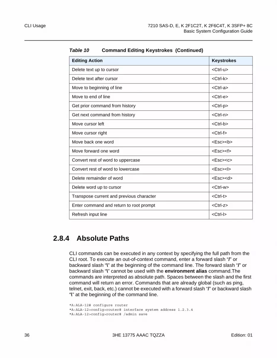
When entering a command, special keystrokes allow for editing of the command. Table 10 describes the command editing keystrokes.
Table 10 Command Editing Keystrokes
Editing Action Keystrokes
Delete current character <Ctrl-d>
CLI Usage
36
7210 SAS-D, E, K 2F1C2T, K 2F6C4T, K 3SFP+ 8CBasic System Configuration Guide
3HE 13775 AAAC TQZZA Edition: 01
2.8.4 Absolute Paths
CLI commands can be executed in any context by specifying the full path from the CLI root. To execute an out-of-context command, enter a forward slash “/” or backward slash “\” at the beginning of the command line. The forward slash “/” or backward slash “\” cannot be used with the environment alias command.The commands are interpreted as absolute path. Spaces between the slash and the first command will return an error. Commands that are already global (such as ping, telnet, exit, back, etc.) cannot be executed with a forward slash “/” or backward slash “\” at the beginning of the command line.
*A:ALA-12# configure router*A:ALA-12>config>router# interface system address 1.2.3.4*A:ALA-12>config>router# /admin save
Delete text up to cursor <Ctrl-u>
Delete text after cursor <Ctrl-k>
Move to beginning of line <Ctrl-a>
Move to end of line <Ctrl-e>
Get prior command from history <Ctrl-p>
Get next command from history <Ctrl-n>
Move cursor left <Ctrl-b>
Move cursor right <Ctrl-f>
Move back one word <Esc><b>
Move forward one word <Esc><f>
Convert rest of word to uppercase <Esc><c>
Convert rest of word to lowercase <Esc><l>
Delete remainder of word <Esc><d>
Delete word up to cursor <Ctrl-w>
Transpose current and previous character <Ctrl-t>
Enter command and return to root prompt <Ctrl-z>
Refresh input line <Ctrl-l>
Table 10 Command Editing Keystrokes (Continued)
Editing Action Keystrokes
7210 SAS-D, E, K 2F1C2T, K 2F6C4T, K 3SFP+ 8C Basic System Configuration Guide
CLI Usage
Edition: 01 3HE 13775 AAAC TQZZA 37
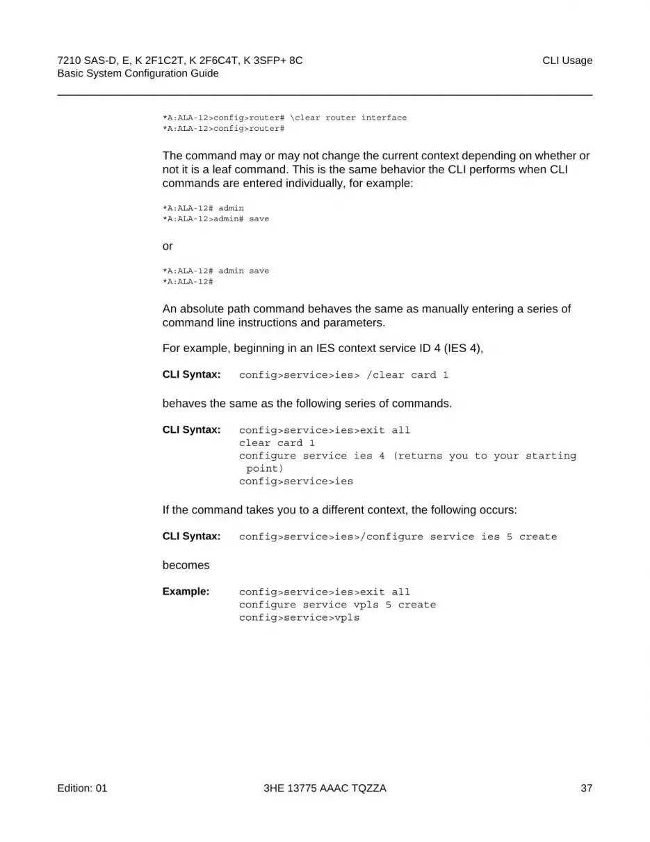
*A:ALA-12>config>router# \clear router interface*A:ALA-12>config>router#
The command may or may not change the current context depending on whether or not it is a leaf command. This is the same behavior the CLI performs when CLI commands are entered individually, for example:
*A:ALA-12# admin*A:ALA-12>admin# save
or
*A:ALA-12# admin save*A:ALA-12#
An absolute path command behaves the same as manually entering a series of command line instructions and parameters.
For example, beginning in an IES context service ID 4 (IES 4),
CLI Syntax: config>service>ies> /clear card 1
behaves the same as the following series of commands.
CLI Syntax: config>service>ies>exit allclear card 1configure service ies 4 (returns you to your starting point)
config>service>ies
If the command takes you to a different context, the following occurs:
CLI Syntax: config>service>ies>/configure service ies 5 create
becomes
Example: config>service>ies>exit allconfigure service vpls 5 createconfig>service>vpls

CLI Usage
38
7210 SAS-D, E, K 2F1C2T, K 2F6C4T, K 3SFP+ 8CBasic System Configuration Guide
3HE 13775 AAAC TQZZA Edition: 01
2.8.5 History
The CLI maintains a history of the most recently entered commands. The history command displays the most recently entered CLI commands.
*A:ALA-1# history1 environment terminal length 482 environment no create3 show version4 configure port 1/1/15 info6 \configure router isis7 \port 1/1/18 con port 1/1/19 \con port 1/1/1
10 \configure router bgp11 info12 \configure system login-control13 info14 history15 show version16 history
*A:ALA-1# !3A:cses-E11# show versionTiMOS-B-0.0.I2838 both/i386 NOKIA SR 7750 Copyright (c) 2016 Nokia.All rights reserved. All use subject to applicable license agreements.Built on Mon Jan 10 18:33:16 PST 2016 by builder in /rel0.0/I2838/panos/mainA:cses-E11#TiMOS-B-0.0.I232 both/i386 NOKIA SAS-E 7210 Copyright (c) 2016 Nokia.All rights reserved. All use subject to applicable license agreements.Built on Sat Oct 11 18:15:40 IST 2016 by panosbld in /panosbld/ws/panos/main*A:ALU-7210#
2.8.6 Entering Numerical Ranges
The 7210 SAS CLI allows the use of a single numerical range as an argument in the command line. A range in a CLI command is limited to positive integers and is denoted with two numbers enclosed in square brackets with two periods (“..”) between the numbers:
[x..y]
where x and y are positive integers and y-x is less than 1000.
For example, it is possible to shut down ports 1 through 10 in Slot 1 on MDA 1. A port is denoted with slot/mda/port, where slot is the slot number, mda is the MDA number and, port is the port number. To shut down ports 1 through 10 on Slot 1 and MDA 1, the command is entered as follows:
configure port 1/1/[1..10] shutdown

7210 SAS-D, E, K 2F1C2T, K 2F6C4T, K 3SFP+ 8C Basic System Configuration Guide
CLI Usage
Edition: 01 3HE 13775 AAAC TQZZA 39
<Ctrl-C> can be used to abort the execution of a range command.
Table 11 describes CLI range use limitations.
Table 11 CLI Range Use Limitations
Limitation Description
Only a single range can be specified. It is not possible to shut down ports 1 through 10 on MDA 1 and MDA 2, as the command would look like
configure port 1/[1..2]/[1..10]
and requires two ranges in the command, [1..2] for the MDA and [1..10] for the port number.
Ranges within quotation marks are interpreted literally.
In the CLI, enclosing a string in quotation marks (“string”) causes the string to be treated literally and as a single parameter. For example, several commands in the CLI allow the configuration of a descriptive string. If the string is more than one word and includes spaces, it must be enclosed in quotation marks. A range that is enclosed in quotes is also treated literally. For example,
configure router interface "A[1..10]" no shutdown
creates a single router interface with the name “A[1..10]”. However, a command such as:
configure router interface A[1..10] no shutdown
creates 10 interfaces with names A1, A2 .. A10.
The range cannot cause a change in contexts.
Commands should be formed in such a way that there is no context change upon command completion. For example,
configure port 1/1/[1..10]
will attempt to change ten different contexts. When a range is specified in the CLI, the commands are executed in a loop. On the first loop execution, the command changes contexts, but the new context is no longer valid for the second iteration of the range loop. A “Bad Command” error is reported and the command aborts.
Command completion may cease to work when entering a range.
After entering a range in a CLI command, command and key completion, which occurs by pressing the <Tab> or spacebar, may cease to work. If the command line entered is correct and unambiguous, the command works correctly; otherwise, an error is returned.

CLI Usage
40
7210 SAS-D, E, K 2F1C2T, K 2F6C4T, K 3SFP+ 8CBasic System Configuration Guide
3HE 13775 AAAC TQZZA Edition: 01
2.8.7 Pipe/Match
The 7210 SAS devices support the pipe feature to search one or more files for a specific character string or pattern.
When using the pipe/match command, the variables and attributes must be spelled correctly. The attributes follow the command and must come before the expression/pattern. The following displays examples of the pipe/match command to complete different tasks:
• Task: Capture all the lines that include “echo” and redirect the output to a file on the compact flash:
admin display-config | match “echo” > cf3cf1:\echo_list.txt
• Task: Display all the lines that do not include “echo”:
admin display-config | match invert-match “echo”
• Task: Display the first match of “vpls” in the configuration file:
admin display-config | match max-count 1 “vpls”
• Task: Display everything in the configuration after finding the first instance of “interface”:
admin display-config | match post-lines 999999 interface
Command syntax:
match pattern context {parents | children | all} [ignore-case] [max-count lines-count] [expression]
match pattern [ignore-case] [invert-match] [pre-lines pre-lines] [post-lines lines-count] [max-count lines-count] [expression]
where:
pattern string or regular expressioncontext keyword: display context associated with the matching lineparents keyword: display parent context informationchildren keyword: display child context informationall keyword: display both parent and child context informationignore-case keywordmax-count keyword: display only a specific number of instances of matching lineslines-count 1 — 2147483647expression keyword: pattern is interpreted as a regular expressioninvert-match keywordpre-lines keyword: display some lines prior to the matching linepre-lines 0 — 100post-lines keyword: display some lines after the matching linelines-count 1 — 2147483647

7210 SAS-D, E, K 2F1C2T, K 2F6C4T, K 3SFP+ 8C Basic System Configuration Guide
CLI Usage
Edition: 01 3HE 13775 AAAC TQZZA 41
For example:
*A:Dut-G# show log log-id 99 | match ignore-case sap"Processing of an access port state change event is finished and the status of all affected SAPs on port 1/1/21 has been updated.""Service Id 4001, SAP Id 1/1/21:0.* configuration modified"
A:Dut-C# show log log-id 98 | match max-count 1 "service 1001""Status of service 1001 (customer 1) changed to administrative state: up, operational state: up"
*A:Dut-G# admin display-config | match post-lines 4 max-count 2 expression "vpls"#--------------------------------------------------...
vpls 1 customer 1 svc-sap-type null-star createdescription "Default tls description for service id 1"stp
shutdownexit
vpls 2 customer 1 svc-sap-type null-star createdescription "Default tls description for service id 2"stp
shutdownexit
...#--------------------------------------------------
Table 12 describes regular expression symbols and interpretation (similar to what is used for route policy regexp matching). Table 13 describes special characters.
Table 12 Regular Expression Symbols
String Description
. Matches any single character.
[ ] Matches a single character that is contained within the brackets.
[abc] matches “a”, “b”, or “c”. [a-z] matches any lowercase letter.
[A-Z] matches any uppercase letter.
[0-9] matches any number.
[^ ] Matches a single character that is not contained within the brackets.
[^abc] matches any character other than “a”, “b”, or “c”.
[^a-z] matches any single character that is not a lowercase letter.
^ Matches the start of the line (or any line, when applied in multiline mode).
$ Matches the end of the line (or any line, when applied in multiline mode).
() Defines a “marked subexpression”.
Every matched instance will be available to the next command as a variable.

CLI Usage
42
7210 SAS-D, E, K 2F1C2T, K 2F6C4T, K 3SFP+ 8CBasic System Configuration Guide
3HE 13775 AAAC TQZZA Edition: 01
* A single character expression followed by “*” matches zero or more copies of the expression.
{m,n} Matches at least m and at most n repetitions of the term
{m} Matches exactly m repetitions of the term
{m,} Matches m or more repetitions of the term
? The preceding item is optional and matched at most once.
+ The preceding item is matched one or more times.
- Used between start and end of a range.
\ An escape character to indicate that the following character is a match criteria and not a grouping delimiter.
> Redirect output.
Table 13 Special Characters
Options Similar to Description
[:upper:] [A-Z] uppercase letters
[:lower:] [a-z] lowercase letters
[:alpha:] [A-Za-z] upper- and lowercase letters
\w [A-Za-z_] word characters
[:alnum:] [A-Za-z0-9] digits, upper- and lowercase letters
[:digit:] [0-9] digits
\d [0-9] digits
[:xdigit:] [0-9A-Fa-f] hexadecimal digits
[:punct:] [.,!?:...] punctuation
[:blank:] [ \t] space and Tab
[:space:] [ \t\n\r\f\v] blank characters
\s [ \t\n\r\f\v] blank characters
Table 12 Regular Expression Symbols (Continued)
String Description
7210 SAS-D, E, K 2F1C2T, K 2F6C4T, K 3SFP+ 8C Basic System Configuration Guide
CLI Usage
Edition: 01 3HE 13775 AAAC TQZZA 43
2.8.8 Redirection
The 7210 SAS supports redirection (“>”), which allows the operator to store the output of a CLI command as a local or remote file. Redirection of output can be used to automatically store results of commands in files (both local and remote).
‘ping <customer_ip> > cf3cf1:/ping/result.txt’‘ping <customer_ip> > ftp://[email protected]/ping/result.txt’
In some cases only part of the output might be applicable. The pipe/match and redirection commands can be combined:
ping 10.0.0.1 | match expression “time.\d+” > cf3cf1:/ping/time.txtThis records only the RTT portion (including the word “time”).

CLI Usage
44
7210 SAS-D, E, K 2F1C2T, K 2F6C4T, K 3SFP+ 8CBasic System Configuration Guide
3HE 13775 AAAC TQZZA Edition: 01

7210 SAS-D, E, K 2F1C2T, K 2F6C4T, K 3SFP+ 8C Basic System Configuration Guide
CLI Usage
Edition: 01 3HE 13775 AAAC TQZZA 45
2.9 Basic Command Reference
2.9.1 Command Hierarchies
• Global CLI Commands
• Monitor Commands
• Environment Commands
• Show Commands

CLI Usage
46
7210 SAS-D, E, K 2F1C2T, K 2F6C4T, K 3SFP+ 8CBasic System Configuration Guide
3HE 13775 AAAC TQZZA Edition: 01
2.9.1.1 Global CLI Commands
— back— clear — echo [text-to-echo] [extra-text-to-echo] [more-text] — enable-admin— exec [-echo] [-syntax] filename— exit [all]— help— history— info [detail]— logout— password— ping {ip-address | dns-name} [rapid | detail] [ttl time-to-live] [tos type-of-service] [size bytes]
[pattern pattern] [source ip-address] [interval seconds] [{next-hop ip-address} | {interface interface-name} |bypass-routing] [count requests] [do-not-fragment] [router [router-instance|service-name service-name][timeout timeout]
— pwc [previous]— sleep [seconds]— ssh [ip-addr | dns-name |username@ip-addr] [-l username] [-v SSH-version] [router router-
instance] — telnet [ip-address| dns-name] [port] [router router-instance] — traceroute {ip-address | dns-name}[ttl value] [wait milliseconds] [no-dns] [source ip-address]
[tos type-of-service]— tree [detail]— write {user | broadcast} message-string
2.9.1.2 Monitor Commands
monitor— filter
— ip ip-filter-id entry entry-id [interval seconds] [repeat repeat] [absolute | rate]— ipv6 ipv6-filter-id entry entry-id [interval seconds] [repeat repeat] [absolute|rate]— mac mac-filter-id entry entry-id [interval seconds] [repeat repeat] [absolute | rate]
— lag lag-id [lag-id...(up to 5 max)] [interval seconds] [repeat repeat] [absolute | rate]— port port-id [port-id...(up to 5 max)] [interval seconds] [repeat repeat] [absolute | rate]— service
— id service-id— sap sap-id [interval seconds] [repeat repeat] [absolute | rate]— sdp sdp-id [far-end] ip-address [interval seconds] [repeat repeat] [absolute |
rate]— management-access-filter
— ip entry entry-id [interval seconds ] [repeat repeat] [absolute|rate]— ipv6 entry entry-id [interval seconds ] [repeat repeat] [absolute|rate]

7210 SAS-D, E, K 2F1C2T, K 2F6C4T, K 3SFP+ 8C Basic System Configuration Guide
CLI Usage
Edition: 01 3HE 13775 AAAC TQZZA 47
2.9.1.3 Environment Commands
root— environment
— alias alias-name alias-command-name— no alias alias-name— [no] create— [no] more— reduced-prompt [no. of nodes in prompt]— no reduced-prompt— [no] saved-ind-prompt— terminal
— length lines— time-display {local | utc}— [no] time-stamp
2.9.1.4 Show Commands
show— alias
CLI Usage
48
7210 SAS-D, E, K 2F1C2T, K 2F6C4T, K 3SFP+ 8CBasic System Configuration Guide
3HE 13775 AAAC TQZZA Edition: 01
2.9.2 Command Descriptions
• Global Commands
• Monitor Commands
• Environment Commands
• Show Commands

7210 SAS-D, E, K 2F1C2T, K 2F6C4T, K 3SFP+ 8C Basic System Configuration Guide
CLI Usage
Edition: 01 3HE 13775 AAAC TQZZA 49
2.9.2.1 Global Commands
enable-admin
Syntax enable-admin
Context <global>
Description
The enable-admin command is in the default profile. By default, all users are given access to this command.
Once the enable-admin command is entered, the user is prompted for a password. If the password matches, the user is given unrestricted access to all the commands.
The minimum length of the password is determined by the minimum-length command. The complexity requirements for the password is determined by the complexity command.
The following displays a password configuration example:
A:ALA-1>config>system>security# info----------------------------------------------...
passwordaging 365minimum-length 8attempts 5 time 5 lockout 20admin-password "rUYUz9XMo6I" hash
exit...----------------------------------------------A:ALA-1>config>system>security#
There are two ways to verify that a user is in the enable-admin mode:
• show users — Administrator can know which users are in this mode.
• Enter the enable-admin command again at the root prompt and an error message will be returned.
A:ALA-1# show users===============================================================================User Type From Login time Idle time===============================================================================admin Console -- 10AUG2006 13:55:24 0d 19:42:22admin Telnet 10.20.30.93 09AUG2004 08:35:23 0d 00:00:00 A-------------------------------------------------------------------------------Number of users : 2
Note: See the description for the admin-password command. If the admin-password is configured in the config>system>security>password context, then any user can enter a special administrative mode by entering the enable-admin command.

CLI Usage
50
7210 SAS-D, E, K 2F1C2T, K 2F6C4T, K 3SFP+ 8CBasic System Configuration Guide
3HE 13775 AAAC TQZZA Edition: 01
'A' indicates user is in admin mode===============================================================================A:ALA-1#A:ALA-1# enable-adminMINOR: CLI Already in admin mode.A:ALA-1#
back
Syntax back
Context <GLOBAL>
SupportedPlatforms
Supported on all 7210 SAS platforms as described in this document
Description This command moves the context back one level of the command hierarchy. For example, if the current level is the config router ospf context, the back command moves the cursor to the config router context level.
clear
Syntax clear
Context <GLOBAL>
SupportedPlatforms
Supported on all 7210 SAS platforms as described in this document
Description This command clears statistics for a specified entity or clears and resets the entity.
Parameters cron — Clears CRON history.
filter — Clears IP (ipv4 and ipv6), MAC, and log filter counters.
lag — Clears LAG-related entities.
log — Closes and reinitializes the log specified by log-id.
port — Clears port statistics.
qos — Clears QoS statistics.
radius — Clears the RADIUS server state.
router — Clears router commands affecting the router instance in which they are entered.
Values arp, authentication, bfd, dhcp, forwarding-table, icmp-redirect-route, interface, isis, ldp, mpls, ospf, rip, rsvp
saa — Clears the SAA test results.
screen — Clears the console or telnet screen.

7210 SAS-D, E, K 2F1C2T, K 2F6C4T, K 3SFP+ 8C Basic System Configuration Guide
CLI Usage
Edition: 01 3HE 13775 AAAC TQZZA 51
service — Clears service ID and statistical entities.
system — Clears (re-enables) a previously failed reference.
tacplus — Clears the TACACS+ server state.
trace — Clears the trace log.
echo
Syntax echo [text-to-echo] [extra-text-to-echo] [more-text]
Context <GLOBAL>
SupportedPlatforms
Supported on all 7210 SAS platforms as described in this document
Description This command echoes arguments on the command line. The primary use of this command is to allow messages to be displayed to the screen in files executed with the exec command.
Parameters text-to-echo — Specifies a text string to be echoed up to 256 characters.
extra-text-to-echo — Specifies more text to be echoed up to 256 characters.
more-text — Specifies more text to be echoed up to 256 characters.
exec
Syntax exec [-echo] [-syntax] {filename | [eof_string]}
Context <GLOBAL>
SupportedPlatforms
Supported on all 7210 SAS platforms as described in this document
Description This command executes the contents of a text file as if they were CLI commands entered at the console.
Exec commands do not have no versions.
Related Commands
boot-bad-exec - Configures a URL for a CLI script to exec following a failed configuration boot.
boot-good-exec - Configures a URL for a CLI script to exec following a successful configuration boot.
Parameters -echo — Echo the contents of the exec file to the session screen as it executes.
Default Echo disabled.

CLI Usage
52
7210 SAS-D, E, K 2F1C2T, K 2F6C4T, K 3SFP+ 8CBasic System Configuration Guide
3HE 13775 AAAC TQZZA Edition: 01
-syntax — Perform a syntax check of the file without executing the commands. Syntax checking will be able to find invalid commands and keywords, but it will not be able to validate erroneous user- supplied parameters.
Default Execute file commands.
filename — The text file with CLI commands to execute.
<< — Stdin can be used as the source of commands for the exec command. When stdin is used as the exec command input, the command list is terminated with <Ctrl-C>, “EOF<Return>” or “eof_string<Return>”.
If an error occurs entering an exec file sourced from stdin, all commands after the command returning the error will be silently ignored. The exec command will indicate the command error line number when the stdin input is terminated with an end-of-file input.
eof_string — The ASCII printable string used to indicate the end of the exec file when stdin is used as the exec file source. <Ctrl-C> and “EOF” can always be used to terminate an exec file sourced from stdin.
Default <Ctrl-C>, EOF
exit
Syntax exit [all]
Context <GLOBAL>
SupportedPlatforms
Supported on all 7210 SAS platforms as described in this document
Description This command returns to the context from which the current level was entered. For example, if you navigated to the current level on a context by context basis, then the exit command only moves the cursor back one level.
A:Dut-G# configureA:Dut-G>config# serviceA:Dut-G>config>service# vpls 1A:Dut-G>config>service>vpls# exitA:Dut-G>config>service# exitA:Dut-G>config# exit
If you navigated to the current level by entering a command string, then the exit command returns the cursor to the context in which the command was initially entered.
A:Dut-G# configure service vpls 1A:Dut-G>config>service>vpls# exitA:Dut-G#The exit all command moves the cursor all the way back to the root level.
A:Dut-G# configureA:Dut-G>config# serviceA:Dut-G>config>service# vpls 1

7210 SAS-D, E, K 2F1C2T, K 2F6C4T, K 3SFP+ 8C Basic System Configuration Guide
CLI Usage
Edition: 01 3HE 13775 AAAC TQZZA 53
A:Dut-G>config>service>vpls# exit allA:Dut-G#
Parameters all — Exits back to the root CLI context.
help
Syntax help
help edit
help global
help special-characters
Context <GLOBAL>
SupportedPlatforms
Supported on all 7210 SAS platforms as described in this document
Description This command provides a brief description of the help system. The following information displays:
Help may be requested at any point by hitting a question mark '?'.In case of an executable node, the syntax for that node will be displayed with an explanation of all parameters.In case of sub-commands, a brief description is provided.Global Commands:Help on global commands can be observed by issuing "help globals" at any time.Editing Commands:Help on editing commands can be observed by issuing "help edit" at any time.
Parameters help — Displays a brief description of the help system.
help edit — Displays help on editing.
Available editing keystrokes:Delete current character.....................Ctrl-dDelete text up to cursor.....................Ctrl-uDelete text after cursor.....................Ctrl-kMove to beginning of line....................Ctrl-aMove to end of line..........................Ctrl-eGet prior command from history...............Ctrl-pGet next command from history................Ctrl-nMove cursor left.............................Ctrl-bMove cursor right............................Ctrl-fMove back one word...........................Esc-bMove forward one word........................Esc-fConvert rest of word to uppercase............Esc-cConvert rest of word to lowercase............Esc-lDelete remainder of word.....................Esc-dDelete word up to cursor.....................Ctrl-wTranspose current and previous character.....Ctrl-tEnter command and return to root prompt......Ctrl-zRefresh input line...........................Ctrl-l

CLI Usage
54
7210 SAS-D, E, K 2F1C2T, K 2F6C4T, K 3SFP+ 8CBasic System Configuration Guide
3HE 13775 AAAC TQZZA Edition: 01
help global — Displays help on global commands.
Available global commands:back - Go back a level in the command treeecho - Echo the text that is typed inexec - Execute a file - use -echo to show the commands and
prompts on the screenexit - Exit to intermediate mode - use option all to exit to
root prompthelp - Display helphistory - Show command historyinfo - Display configuration for the present nodelogout - Log off this systemoam + OAM Test Suiteping - Verify the reachability of a remote hostpwc - Show the present working contextsleep - Sleep for specified number of secondsssh - SSH to a hosttelnet - Telnet to a hosttraceroute - Determine the route to a destination addresstree - Display command tree structure from the context of
executionwrite - Write text to another user
help special-characters — Displays help on special characters.Use the following CLI commands to display more information about commands and command syntax:
? — Lists all commands in the current context.
string? — Lists all commands available in the current context that start with the string.
command ? — Display command’s syntax and associated keywords.
string<Tab> or string<Space> — Complete a partial command name (auto-completion) or list available commands that match the string.
history
Syntax history
Context <GLOBAL>
SupportedPlatforms
Supported on all 7210 SAS platforms as described in this document
Description This command lists the last 30 commands entered in this session.
Re-execute a command in the history with the !n command, where n is the line number associated with the command in the history output.
For example:
A:ALA-1# history68 info

7210 SAS-D, E, K 2F1C2T, K 2F6C4T, K 3SFP+ 8C Basic System Configuration Guide
CLI Usage
Edition: 01 3HE 13775 AAAC TQZZA 55
69 exit70 info71 filter72 exit all73 configure74 router75 info76 interface "test"77 exit78 reduced-prompt79 info80 interface "test"81 icmp unreachables exit all82 exit all83 reduced-prompt84 configure router85 interface86 info87 interface "test"88 info89 reduced-prompt90 exit all91 configure92 card 193 card-type94 exit95 router96 exit97 history
A:ALA-1# !91A:ALA-1# configureA:ALA-1>config#
info
Syntax info [detail]
Context <GLOBAL>
SupportedPlatforms
Supported on all 7210 SAS platforms as described in this document
Description This command displays the running configuration for the configuration context.
The output of this command is similar to the output of a show config command. This command, however, lists the configuration of the context where it is entered and all branches below that context level.
By default, the command only enters the configuration parameters that vary from the default values. The detail keyword causes all configuration parameters to be displayed.
For example,
*A:STU-1>config>service# info detail----------------------------------------------

CLI Usage
56
7210 SAS-D, E, K 2F1C2T, K 2F6C4T, K 3SFP+ 8CBasic System Configuration Guide
3HE 13775 AAAC TQZZA Edition: 01
customer 1 createdescription "Default customer"no contactno phone
exities 1 customer 1 create
no descriptioninterface "new" create
no descriptionaddress 21.0.0.2/8no macarp-timeout 14400icmp
redirects 100 10unreachables 100 10ttl-expired 100 10
exitsap 1/1/18:0.* create
no descriptioningress
no match-qinq-dot1pno filter
exitegress
no qinq-mark-top-onlyno filter
exitno shutdown
exitno shutdown
exitno shutdown
exitvpls 100 customer 1 svc-sap-type dot1q create
no descriptionno disable-learningno disable-agingno discard-unknownfdb-table-size 250fdb-table-high-wmark 95fdb-table-low-wmark 90local-age 300stp
shutdownpriority 32768hello-time 2forward-delay 15max-age 20hold-count 6mode rstp
exitmac-move
move-frequency 2retry-timeout 10shutdown
exitsap 1/1/14:100 create
no descriptionno tod-suite

7210 SAS-D, E, K 2F1C2T, K 2F6C4T, K 3SFP+ 8C Basic System Configuration Guide
CLI Usage
Edition: 01 3HE 13775 AAAC TQZZA 57
limit-mac-move blockableno disable-agingno max-nbr-mac-addrno discard-unknown-sourceno mac-pinningstp
path-cost 10priority 128no edge-portauto-edgelink-type pt-ptno root-guardno shutdown
exitdot1agexitno authentication-policyno l2pt-terminationno bpdu-translationingress
qos 1no match-qinq-dot1pno filter
exitegress
no qinq-mark-top-onlyno filterno agg-rate-limit
exitno collect-statsno accounting-policyno shutdown
exitsap 1/1/15:100 create
no descriptionno tod-suitelimit-mac-move blockableno disable-agingno max-nbr-mac-addrno discard-unknown-sourceno mac-pinningstp
path-cost 10priority 128no edge-portauto-edgelink-type pt-ptno root-guardno shutdown
exitdot1agexitno authentication-policyno l2pt-terminationno bpdu-translationingress
qos 1no match-qinq-dot1pno filter

CLI Usage
58
7210 SAS-D, E, K 2F1C2T, K 2F6C4T, K 3SFP+ 8CBasic System Configuration Guide
3HE 13775 AAAC TQZZA Edition: 01
exitegress
no qinq-mark-top-onlyno filterno agg-rate-limit
exitno collect-statsno accounting-policyno shutdown
exitno shutdown
exities 4001 customer 1 create
no descriptioninterface "inband" create
no descriptionaddress 192.168.1.11/24no macarp-timeout 14400icmp
redirects 100 10unreachables 100 10ttl-expired 100 10
exitsap 1/1/24:0.* create
no descriptioningress
no match-qinq-dot1pno filter
exitegress
no qinq-mark-top-onlyno filter
exitno shutdown
exitno shutdown
exitinterface "direct" create
no descriptionaddress 10.135.16.97/24no macarp-timeout 14400icmp
redirects 100 10unreachables 100 10ttl-expired 100 10
exitsap 1/1/21:0.* create
no descriptioningress
no match-qinq-dot1pno filter
exitegress
no qinq-mark-top-onlyno filter
exitno shutdown

7210 SAS-D, E, K 2F1C2T, K 2F6C4T, K 3SFP+ 8C Basic System Configuration Guide
CLI Usage
Edition: 01 3HE 13775 AAAC TQZZA 59
exitno shutdown
exitno shutdown
exit----------------------------------------------*A:STU-1>config>service#
Parameters detail — Displays all configuration parameters including parameters at their default values.
logout
Syntax logout
Context <GLOBAL>
SupportedPlatforms
Supported on all 7210 SAS platforms as described in this document
Description This command logs out of the router session.
When the logout command is issued from the console, the login prompt is displayed, and any log IDs directed to the console are discarded. When the console session resumes (regardless of the user), the log output to the console resumes.
When a Telnet session is terminated from a logout command, all log IDs directed to the session are removed. When a user logs back in, the log IDs must be re-created.
password
Syntax password
Context <ROOT>
SupportedPlatforms
Supported on all 7210 SAS platforms as described in this document
Description This command changes a user CLI login password.
When a user logs in after the administrator forces a new-password-at-login, or the password has expired (aging), then this command is automatically invoked.
When invoked, the user is prompted to enter the old password, the new password, and then the new password again to verify the correct input.
If a user fails to create a new password after the administrator forces a new-password-at-login or after the password has expired, the user is not allowed access to the CLI.

CLI Usage
60
7210 SAS-D, E, K 2F1C2T, K 2F6C4T, K 3SFP+ 8CBasic System Configuration Guide
3HE 13775 AAAC TQZZA Edition: 01
ping
Syntax ping {ip-address | dns-name} [rapid | detail] [ttl time-to-live] [tos type-of-service] [size bytes] [pattern pattern] [source ip-address] [interval seconds] [{next-hop ip-address} | {interface interface-name} | bypass-routing] [count requests] [do-not-fragment] [router router-instance|service-name service-name][timeout timeout]
Context <GLOBAL>
SupportedPlatforms
Supported on all 7210 SAS platforms as described in this document
Description This command is the TCP/IP utility to verify IP reachability.
Parameters ip-address | dns-name — The remote host to ping. The IP address or the DNS name (if DNS name resolution is configured) can be specified.
Values
rapid | detail — The rapid parameter specifies to send ping requests rapidly. The results are reported in a single message, not in individual messages for each ping request. By default, five ping requests are sent before the results are reported. To change the number of requests, include the count option.
The detail parameter includes in the output the interface on which the ping reply was received.
Example output:
*A:ALU-7210# ping 192.xxx.xxx.xxxPING 192.xxx.xxx.xxx 56 data bytes64 bytes from 192.xxx.xxx.xxx: icmp_seq=1 ttl=64 time<10ms.64 bytes from 1192.xxx.xxx.xxx: icmp_seq=2 ttl=64 time<10ms.64 bytes from 192.xxx.xxx.xxx: icmp_seq=3 ttl=64 time<10ms.64 bytes from 192.xxx.xxx.xxx: icmp_seq=4 ttl=64 time<10ms.64 bytes from 192.xxx.xxx.xxx: icmp_seq=5 ttl=64 time<10ms.
---- 192.xxx.xxx.xxx PING Statistics ----5 packets transmitted, 5 packets received, 0.00% packet lossround-trip min < 10ms, avg < 10ms, max < 10ms, stddev < 10ms*A:ALU-7210#
ipv4-address - a.b.c.d
ipv6-address - x:x:x:x:x:x:x:x[-interface]
x:x:x:x:x:x:x:x [-interface]
x:x:x:x:x:x:d.d.d.d
x: 0 — FFFF H
d: 0 — 255 D

7210 SAS-D, E, K 2F1C2T, K 2F6C4T, K 3SFP+ 8C Basic System Configuration Guide
CLI Usage
Edition: 01 3HE 13775 AAAC TQZZA 61
ttl time-to-live — The IP Time To Live (TTL) value to include in the ping request, expressed as a decimal integer.
Values 0 to128
tos type-of-service — The type-of-service (TOS) bits in the IP header of the ping packets, expressed as a decimal integer.
Values 0 to 255
size bytes — The size in bytes of the ping request packets.
Values 0 to 65507
Default 56 bytes (actually 64 bytes because 8 bytes of ICMP header data are added to the packet)
pattern pattern — A 16-bit pattern string to include in the ping packet, expressed as a decimal integer.
Values 0 to 65535
source ip-address — The source IP address to use in the ping requests in dotted decimal notation.
Values
Default The IP address of the egress IP interface.
interval seconds — The interval in seconds between consecutive ping requests, expressed as a decimal integer.
Values 1 to 10000
Default 1
next-hop ip-address — Disregards the routing table and sends this packet to the specified next hop address. This address must be on an adjacent router that is attached to a subnet that is common between this and the next-hop router.
Values
ipv4-address - a.b.c.d
ipv6-address - x:x:x:x:x:x:x:x[-interface]
x:x:x:x:x:x:x:x [-interface]
x:x:x:x:x:x:d.d.d.d
x: 0 — FFFF H
d: 0 — 255 D
ipv4-address - a.b.c.d
ipv6-address - x:x:x:x:x:x:x:x[-interface]
x:x:x:x:x:x:d.d.d.d[-interface]
x - [0..FFFF]H
d - [0..255]D

CLI Usage
62
7210 SAS-D, E, K 2F1C2T, K 2F6C4T, K 3SFP+ 8CBasic System Configuration Guide
3HE 13775 AAAC TQZZA Edition: 01
Default Per the routing table.
interface interface-name — Specifies the interface name.
bypass-routing — Sends the ping request to a host on a directly attached network bypassing the routing table. The host must be on a directly attached network or an error is returned.
count requests — The number of ping requests to send to the remote host, expressed as a decimal integer.
Values 1 to 10000
Default 5
do-not-fragment — Specifies that the request frame should not be fragmented. This option is particularly useful in combination with the size parameter for maximum MTU determination.
router router-instance — Specifies the router name or service ID.
Values
Default Base
timeout timeout — Specifies the timeout in seconds.
Values 1 to 10
Default 5
service-name service-name — Specifies a unique service name to identify the service.
Values 64 chars maximum
pwc
Syntax pwc [previous]
Context <GLOBAL>
SupportedPlatforms
Supported on all 7210 SAS platforms as described in this document
Description This command displays the present or previous working context of the CLI session. The pwc command provides a user who is in the process of dynamically configuring a chassis a way to display the current or previous working context of the CLI session. The pwc command displays a list of the CLI nodes that hierarchically define the current context of the CLI instance of the user. For example:
router-name: Base, management
service-id: 1 to 2147483647
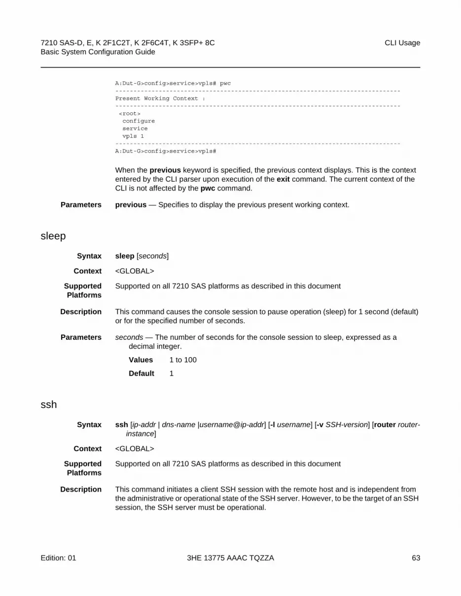
7210 SAS-D, E, K 2F1C2T, K 2F6C4T, K 3SFP+ 8C Basic System Configuration Guide
CLI Usage
Edition: 01 3HE 13775 AAAC TQZZA 63
A:Dut-G>config>service>vpls# pwc-------------------------------------------------------------------------------Present Working Context :-------------------------------------------------------------------------------<root>configureservicevpls 1
-------------------------------------------------------------------------------A:Dut-G>config>service>vpls#
When the previous keyword is specified, the previous context displays. This is the context entered by the CLI parser upon execution of the exit command. The current context of the CLI is not affected by the pwc command.
Parameters previous — Specifies to display the previous present working context.
sleep
Syntax sleep [seconds]
Context <GLOBAL>
SupportedPlatforms
Supported on all 7210 SAS platforms as described in this document
Description This command causes the console session to pause operation (sleep) for 1 second (default) or for the specified number of seconds.
Parameters seconds — The number of seconds for the console session to sleep, expressed as a decimal integer.
Values 1 to 100
Default 1
ssh
Syntax ssh [ip-addr | dns-name |username@ip-addr] [-l username] [-v SSH-version] [router router-instance]
Context <GLOBAL>
SupportedPlatforms
Supported on all 7210 SAS platforms as described in this document
Description This command initiates a client SSH session with the remote host and is independent from the administrative or operational state of the SSH server. However, to be the target of an SSH session, the SSH server must be operational.

CLI Usage
64
7210 SAS-D, E, K 2F1C2T, K 2F6C4T, K 3SFP+ 8CBasic System Configuration Guide
3HE 13775 AAAC TQZZA Edition: 01
Quitting SSH while in the process of authentication is accomplished by either executing a ctrl-c or "~." (tilde and dot) assuming the “~” is the default escape character for SSH session.
Parameters ip-address | host-name — The remote host to which to open an SSH session. The IP address or the DNS name (providing DNS name resolution is configured) can be specified.
-l user — The username to use when opening the SSH session.
router router-instance — Specify the router name or service ID.
Values 7210 SAS-D, 7210 SAS-K 2F1C2T, 7210 SAS-K 2F6C4T, 7210 SAS-K 3SFP+ 8C: Base, management
7210 SAS-E: Base, management, vpls-management
Default Base
telnet
Syntax telnet [ip-address | dns-name] [port] [router router-instance]
Context <GLOBAL>
SupportedPlatforms
Supported on all 7210 SAS platforms as described in this document
Description This command opens a Telnet session to a remote host. Telnet servers in 7210 SAS networks limit a Telnet clients to three retries to login. The Telnet server disconnects the Telnet client session after three retries. The number of retry attempts for a Telnet client session is not user-configurable.
Parameters ip-address — The IP address or the DNS name (providing DNS name resolution is configured) can be specified.
Values
dns-name — Specifies the DNS name (if DNS name resolution is configured).
Values 128 characters maximum
port — The TCP port number to use to Telnet to the remote host, expressed as a decimal integer.
Values 1 to 65535
Default 23
ipv4-address a.b.c.d
ipv6-address x:x:x:x:x:x:x:x (eight 16-bit pieces)
x:x:x:x:x:x:d.d.d.d
x: [0 .. FFFF]H
d: [0 .. 255]D

7210 SAS-D, E, K 2F1C2T, K 2F6C4T, K 3SFP+ 8C Basic System Configuration Guide
CLI Usage
Edition: 01 3HE 13775 AAAC TQZZA 65
router router-instance — Specifies the router name or service ID.
Values router-name: Base, management, vpls-management (supported only on 7210 SAS-E)
Default Base
traceroute
Syntax traceroute {ip-address | dns-name} [ttl ttl] [wait milliseconds] [no-dns] [source ip-address] [tos type-of-service] [router router-instance]
Context <GLOBAL>
SupportedPlatforms
Supported on all 7210 SAS platforms as described in this document
Description The TCP/IP traceroute utility determines the route to a destination address. Aborting a traceroute with the <Ctrl-C> command could require issuing a second <Ctrl-C> command before the prompt is returned.
A:ALA-1# traceroute 192.168.xx.xx4traceroute to 192.168.xx.xx4, 30 hops max, 40 byte packets1 192.168.xx.xx4 0.000 ms 0.000 ms 0.000 ms
A:ALA-1#
Parameters ip-address | dns-name — The remote address to traceroute. The IP address or the DNS name (if DNS name resolution is configured) can be specified.
Values
ttl ttl — The maximum Time-To-Live (TTL) value to include in the traceroute request, expressed as a decimal integer.
Values 1 to 255
wait milliseconds — The time in milliseconds to wait for a response to a probe, expressed as a decimal integer.
Values 1 to 60000
Default 5000
ipv4-address a.b.c.d
ipv6-address x:x:x:x:x:x:x:x (eight 16-bit pieces)
x:x:x:x:x:x:d.d.d.d
x: [0 .. FFFF]H
d: [0 .. 255]D

CLI Usage
66
7210 SAS-D, E, K 2F1C2T, K 2F6C4T, K 3SFP+ 8CBasic System Configuration Guide
3HE 13775 AAAC TQZZA Edition: 01
no-dns — When the no-dns keyword is specified, a DNS lookup for the specified host name will not be performed.
Default DNS lookups are performed
source ip-address — The source IP address to use as the source of the probe packets in dotted decimal notation. If the IP address is not one of the device’s interfaces, an error is returned.
tos type-of-service — The type-of-service (TOS) bits in the IP header of the probe packets, expressed as a decimal integer.
Values 0 to 255
router router-instance — Specifies the router name or service ID.
Values
Default Base
tree
Syntax tree [detail]
Context <GLOBAL>
SupportedPlatforms
Supported on all 7210 SAS platforms as described in this document
Description This command displays the command hierarchy structure from the present working context.
Parameters detail — Includes parameter information for each command displayed in the tree output.
write
Syntax write {user | broadcast} message-string
Context <GLOBAL>
SupportedPlatforms
Supported on all 7210 SAS platforms as described in this document
Description This command sends a console message to a specific user or to all users with active console sessions.
router-name: Base, management, vpls-management (supported only on 7210 SAS-E)
service-id: 1 to 2147483647

7210 SAS-D, E, K 2F1C2T, K 2F6C4T, K 3SFP+ 8C Basic System Configuration Guide
CLI Usage
Edition: 01 3HE 13775 AAAC TQZZA 67
Parameters user — The name of a user with an active console session to which to send a console message.
Values Any valid CLI username
broadcast — Specifies that the message-string is to be sent to all users logged into the router.
message-string — The message string to send. Allowed values are any string up to 250 characters composed of printable, 7-bit ASCII characters. If the string contains special characters (#, $, spaces, etc.), the entire string must be enclosed within double quotes.

CLI Usage
68
7210 SAS-D, E, K 2F1C2T, K 2F6C4T, K 3SFP+ 8CBasic System Configuration Guide
3HE 13775 AAAC TQZZA Edition: 01
2.9.2.2 Monitor Commands
filter
Syntax filter
Context monitor
SupportedPlatforms
Supported on all 7210 SAS platforms as described in this document
Description This command enables the context to configure criteria to monitor IP and MAC filter statistics.
ip
Syntax ip ip-filter-id entry entry-id [interval seconds] [repeat repeat] [absolute | rate]
Context monitor>filtermonitor>management-access-filter
SupportedPlatforms
Supported on all 7210 SAS platforms as described in this document
Description This command enables IP filter monitoring. The statistical information for the specified IP filter entry displays at the configured interval until the configured count is reached. The first screen displays the current statistics related to the specified IP filter. The subsequent statistical information listed for each interval is displayed as a delta to the previous display.
When the keyword rate is specified, the “rate per second” for each statistic is displayed instead of the delta.
Monitor commands are similar to show commands but only statistical information displays. Monitor commands display the selected statistics according to the configured number of times at the interval specified.
Parameters ip-filter-id — Displays detailed information for the specified filter ID and its filter entries.
Values 1 to 65535
entry-id — Displays information on the specified filter entry ID for the specified filter ID only.
Values 1 to 65535
seconds — Configures the interval for each display in seconds.
Values 3 to 60
Default 5 seconds

7210 SAS-D, E, K 2F1C2T, K 2F6C4T, K 3SFP+ 8C Basic System Configuration Guide
CLI Usage
Edition: 01 3HE 13775 AAAC TQZZA 69
repeat — Configures how many times the command is repeated.
Values 1 to 999
Default 10
absolute — The raw statistics are displayed, without processing. No calculations are performed on the delta or rate statistics.
rate — The rate-per-second for each statistic is displayed instead of the delta.
Output
Sample Output
A:ALA-1>monitor# filter ip 10 entry 1 interval 3 repeat 3 absolute===============================================================================Monitor statistics for IP filter 10 entry 1===============================================================================At time t = 0 sec (Base Statistics)-------------------------------------------------------------------------------Ing. Matches: 0 Egr. Matches : 0-------------------------------------------------------------------------------At time t = 3 sec (Mode: Absolute)-------------------------------------------------------------------------------Ing. Matches: 0 Egr. Matches : 0-------------------------------------------------------------------------------At time t = 6 sec (Mode: Absolute)-------------------------------------------------------------------------------Ing. Matches: 0 Egr. Matches : 0-------------------------------------------------------------------------------At time t = 9 sec (Mode: Absolute)-------------------------------------------------------------------------------Ing. Matches: 0 Egr. Matches : 0===============================================================================A:ALA-1>monitor#
A:ALA-1>monitor# filter ip 10 entry 1 interval 3 repeat 3 rate===========================================================================Monitor statistics for IP filter 10 entry 1===========================================================================At time t = 0 sec (Base Statistics)---------------------------------------------------------------------------Ing. Matches: 0 Egr. Matches : 0---------------------------------------------------------------------------At time t = 3 sec (Mode: Rate)---------------------------------------------------------------------------Ing. Matches: 0 Egr. Matches : 0---------------------------------------------------------------------------At time t = 6 sec (Mode: Rate)---------------------------------------------------------------------------Ing. Matches: 0 Egr. Matches : 0---------------------------------------------------------------------------At time t = 9 sec (Mode: Rate)---------------------------------------------------------------------------Ing. Matches: 0 Egr. Matches : 0===========================================================================A:ALA-1>monitor#

CLI Usage
70
7210 SAS-D, E, K 2F1C2T, K 2F6C4T, K 3SFP+ 8CBasic System Configuration Guide
3HE 13775 AAAC TQZZA Edition: 01
ipv6
Syntax ipv6 ipv6-filter-id entry entry-id [interval seconds] [repeat repeat] [absolute | rate]
Context monitor>filtermonitor>management-access-filter
SupportedPlatforms
Supported on all 7210 SAS platforms as described in this document
Description This command enables IPv6 filter monitoring. The statistical information for the specified IPv6 filter entry displays at the configured interval until the configured count is reached.
The first screen displays the current statistics related to the specified IPv6 filter. The subsequent statistical information listed for each interval is displayed as a delta to the previous display.
When the keyword rate is specified, the “rate per second” for each statistic is displayed instead of the delta.
Monitor commands are similar to show commands but only statistical information displays. Monitor commands display the selected statistics according to the configured number of times at the interval specified.
Parameters iv6p-filter-id — Displays detailed information for the specified IPv6 filter ID and its filter entries.
Values 1 to 65535
entry-id — Displays information on the specified IPv6 filter entry ID for the specified filter ID only.
Values 1 to 65535
seconds — Configures the interval for each display in seconds.
Values 3 to 60
Default 10 seconds
repeat — Configures how many times the command is repeated.
Values 1 to 999
Default 10
absolute — The raw statistics are displayed, without processing. No calculations are performed on the delta or rate statistics.
rate — The rate-per-second for each statistic is displayed instead of the delta.
Output

7210 SAS-D, E, K 2F1C2T, K 2F6C4T, K 3SFP+ 8C Basic System Configuration Guide
CLI Usage
Edition: 01 3HE 13775 AAAC TQZZA 71
Sample Output
*A:7210SAS>monitor>filter# ipv6 10 entry 10 interval 3 repeat 3 absolute
===============================================================================Monitor statistics for IPv6 filter 10 entry 10===============================================================================-------------------------------------------------------------------------------At time t = 0 sec (Base Statistics)-------------------------------------------------------------------------------Ing. Matches : 0 pktsEgr. Matches : 0 pkts
-------------------------------------------------------------------------------At time t = 3 sec (Mode: Absolute)-------------------------------------------------------------------------------Ing. Matches : 0 pktsEgr. Matches : 0 pkts
-------------------------------------------------------------------------------At time t = 6 sec (Mode: Absolute)-------------------------------------------------------------------------------Ing. Matches : 0 pktsEgr. Matches : 0 pkts
-------------------------------------------------------------------------------At time t = 9 sec (Mode: Absolute)-------------------------------------------------------------------------------Ing. Matches : 0 pktsEgr. Matches : 0 pkts
===============================================================================*A:7210SAS>monitor>filter#
mac
Syntax mac mac-filter-id entry entry-id [interval seconds] [repeat repeat] [absolute | rate]
Context monitor>filter
SupportedPlatforms
Supported on all 7210 SAS platforms as described in this document
Description This command enables MAC filter monitoring. The statistical information for the specified MAC filter entry displays at the configured interval until the configured count is reached.
The first screen displays the current statistics related to the specified MAC filter. The subsequent statistical information listed for each interval is displayed as a delta to the previous display. When the keyword rate is specified, the “rate per second” for each statistic is displayed instead of the delta.
Monitor commands are similar to show commands but only statistical information displays. Monitor commands display the selected statistics according to the configured number of times at the interval specified.

CLI Usage
72
7210 SAS-D, E, K 2F1C2T, K 2F6C4T, K 3SFP+ 8CBasic System Configuration Guide
3HE 13775 AAAC TQZZA Edition: 01
Parameters mac-filter-id — The MAC filter policy ID.
Values 1 to 65535
entry-id — Displays information on the specified filter entry ID for the specified filter ID only.
Values 1 to 65535
seconds — Configures the interval for each display in seconds.
Values 3 to 60
Default 5 seconds
repeat — Configures how many times the command is repeated.
Values 1 to 999
Default 10
absolute — When the absolute keyword is specified, the raw statistics are displayed, without processing. No calculations are performed on the delta or rate statistics.
rate — When the rate keyword is specified, the rate-per-second for each statistic is displayed instead of the delta.
Output
Sample Output
A:ALA-1>monitor>filter# mac 50 entry 10 interval 3 repeat 3 absolute===============================================================================Monitor statistics for Mac filter 50 entry 10===============================================================================At time t = 0 sec (Base Statistics)-------------------------------------------------------------------------------Ing. Matches: 0 Egr. Matches : 0------------------------------------------------------------------------------At time t = 3 sec (Mode: Absolute)-------------------------------------------------------------------------------Ing. Matches: 0 Egr. Matches : 0-------------------------------------------------------------------------------At time t = 6 sec (Mode: Absolute)-------------------------------------------------------------------------------Ing. Matches: 0 Egr. Matches : 0-------------------------------------------------------------------------------At time t = 9 sec (Mode: Absolute)-------------------------------------------------------------------------------Ing. Matches: 0 Egr. Matches : 0===============================================================================
A:ALA-1>monitor>filter# mac 50 entry 10 interval 3 repeat 3 rate===============================================================================Monitor statistics for Mac filter 50 entry 10===============================================================================At time t = 0 sec (Base Statistics)-------------------------------------------------------------------------------Ing. Matches: 0 Egr. Matches : 0

7210 SAS-D, E, K 2F1C2T, K 2F6C4T, K 3SFP+ 8C Basic System Configuration Guide
CLI Usage
Edition: 01 3HE 13775 AAAC TQZZA 73
-------------------------------------------------------------------------------At time t = 3 sec (Mode: Rate)-------------------------------------------------------------------------------Ing. Matches: 0 Egr. Matches : 0-------------------------------------------------------------------------------At time t = 6 sec (Mode: Rate)-------------------------------------------------------------------------------Ing. Matches: 0 Egr. Matches : 0-------------------------------------------------------------------------------At time t = 9 sec (Mode: Rate)-------------------------------------------------------------------------------Ing. Matches: 0 Egr. Matches : 0===============================================================================A:ALA-1>monitor>filter#
lag
Syntax lag lag-id [lag-id...(up to 5 max)] [interval seconds] [repeat repeat] [absolute | rate]
Context monitor
SupportedPlatforms
Supported on all 7210 SAS platforms as described in this document
Description This command monitors traffic statistics for Link Aggregation Group (LAG) ports. Statistical information for the specified LAG ID(s) displays at the configured interval until the configured count is reached.
The first screen displays the current statistics related to the specified LAG ID. The subsequent statistical information listed for each interval is displayed as a delta to the previous display. When the keyword rate is specified, the “rate per second” for each statistic is displayed instead of the delta.
Monitor commands are similar to show commands but only statistical information displays. Monitor commands display the selected statistics according to the configured number of times at the interval specified.
Parameters lag-id — The number of the LAG.
Values 1 to 6
Default none — The LAG ID value must be specified.
seconds — Configures the interval for each display in seconds.
Values 3 to 60
Default 5 seconds
repeat — Configures how many times the command is repeated.
Values 1 to 999
Default 10

CLI Usage
74
7210 SAS-D, E, K 2F1C2T, K 2F6C4T, K 3SFP+ 8CBasic System Configuration Guide
3HE 13775 AAAC TQZZA Edition: 01
absolute — When the absolute keyword is specified, the raw statistics are displayed, without processing. No calculations are performed on the delta or rate statistics.
rate — When the rate keyword is specified, the rate-per-second for each statistic is displayed instead of the delta.
Output LAG Traffic Statistics
Sample Output
A:ALA-12# monitor lag 2===============================================================================Monitor statistics for LAG ID 2===============================================================================Port-id Input Input Output Output Input OutputBytes Packets Bytes Packets Errors Errors-------------------------------------------------------------------------------At time t = 0 sec (Base Statistics)-------------------------------------------------------------------------------1/1/1 2168900 26450 64 1 0 01/1/2 10677318 125610 2273750 26439 0 01/1/3 2168490 26445 0 0 0 0-------------------------------------------------------------------------------Totals 15014708 178505 2273814 26440 0 0-------------------------------------------------------------------------------At time t = 5 sec (Mode: Delta)-------------------------------------------------------------------------------1/1/1 0 0 0 0 001/1/2 258 3 86 1 0 01/1/3 82 1 0 0 0 0-------------------------------------------------------------------------------Totals 340 4 86 1 0 0===============================================================================A:ALA-12#
management-access-filter
Syntax management-access-filter
Context monitor
SupportedPlatforms
Supported on all 7210 SAS platforms as described in this document
Description This command enables the context to monitor management-access filters. These filters are configured in the config>system>security>mgmt-access-filter context.
ip
Syntax ip entry entry-id [interval seconds] [repeat repeat] [absolute | rate]
Context monitor>management-access-filter

7210 SAS-D, E, K 2F1C2T, K 2F6C4T, K 3SFP+ 8C Basic System Configuration Guide
CLI Usage
Edition: 01 3HE 13775 AAAC TQZZA 75
SupportedPlatforms
Supported on all 7210 SAS platforms as described in this document
Description This command monitors statistics for the MAF IP filter entry.
Parameters entry entry-id — Specifies an existing IP MAF entry ID.
Values 1 to 9999
interval seconds — Configures the interval for each display in seconds.
Values 3 to 60
Default 10
repeat repeat — Configures how many times the command is repeated.
Values 1 to 999
Default 10
absolute — The raw statistics are displayed, without processing. No calculations are performed on the delta or rate statistics.
rate — The rate-per-second for each statistic is displayed instead of the delta.
ipv6
Syntax ipv6 entry-id [interval seconds] [repeat repeat] [absolute | rate]
Context monitor>management-access-filter
SupportedPlatforms
Supported on all 7210 SAS platforms as described in this document
Description This command monitors statistics for the MAF IPv6 filter entry.
Parameters entry entry-id — Specifies an existing IP MAF entry ID.
Values 1 to 9999
interval seconds — Configures the interval for each display in seconds.
Values 3 to 60
Default 10
repeat repeat — Configures how many times the command is repeated.
Values 1 to 999
Default 10
absolute — The raw statistics are displayed, without processing. No calculations are performed on the delta or rate statistics.
rate — The rate-per-second for each statistic is displayed instead of the delta.

CLI Usage
76
7210 SAS-D, E, K 2F1C2T, K 2F6C4T, K 3SFP+ 8CBasic System Configuration Guide
3HE 13775 AAAC TQZZA Edition: 01
port
Syntax port port-id [port-id...(up to 5 max)] [interval seconds] [repeat repeat] [absolute | rate]
Context monitor
SupportedPlatforms
Supported on all 7210 SAS platforms as described in this document
Description This command enables port traffic monitoring. The specified ports statistical information displays at the configured interval until the configured count is reached.
The first screen displays the current statistics related to the specified ports. The subsequent statistical information listed for each interval is displayed as a delta to the previous display. When the keyword rate is specified, the “rate per second” for each statistic is displayed instead of the delta.
Monitor commands are similar to show commands but only statistical information displays. Monitor commands display the selected statistics according to the configured number of times at the interval specified.
Parameters port-id — Specifies up to 5 port IDs.
seconds — Configures the interval for each display in seconds.
Values 3 to 60
Default 5 seconds
repeat — Configures how many times the command is repeated.
Values 1 to 999
Default 10
absolute — The raw statistics are displayed, without processing. No calculations are performed on the delta or rate statistics.
rate — The rate-per-second for each statistic is displayed instead of the delta.
Output
Sample Output
A:ALA-12>monitor# port 1/1/4 interval 3 repeat 3 absolute===============================================================================Monitor statistics for Port 1/1/4===============================================================================
Input Output-------------------------------------------------------------------------------At time t = 0 sec (Base Statistics)-------------------------------------------------------------------------------Octets 0 0Packets 39 175Errors 0 0-------------------------------------------------------------------------------

7210 SAS-D, E, K 2F1C2T, K 2F6C4T, K 3SFP+ 8C Basic System Configuration Guide
CLI Usage
Edition: 01 3HE 13775 AAAC TQZZA 77
At time t = 3 sec (Mode: Absolute)-------------------------------------------------------------------------------Octets 0 0Packets 39 175Errors 0 0-------------------------------------------------------------------------------At time t = 6 sec (Mode: Absolute)-------------------------------------------------------------------------------Octets 0 0Packets 39 175Errors 0 0-------------------------------------------------------------------------------At time t = 9 sec (Mode: Absolute)-------------------------------------------------------------------------------Octets 0 0Packets 39 175Errors 0 0===============================================================================A:ALA-12>monitor#
A:ALA-12>monitor# port 1/1/4 interval 3 repeat 3 rate===============================================================================Monitor statistics for Port 1/1/4===============================================================================
Input Output-------------------------------------------------------------------------------At time t = 0 sec (Base Statistics)-------------------------------------------------------------------------------Octets 0 0Packets 39 175Errors 0 0-------------------------------------------------------------------------------At time t = 3 sec (Mode: Rate)-------------------------------------------------------------------------------Octets 0 0Packets 0 0Errors 0 0-------------------------------------------------------------------------------At time t = 6 sec (Mode: Rate)-------------------------------------------------------------------------------Octets 0 0Packets 0 0Errors 0 0-------------------------------------------------------------------------------At time t = 9 sec (Mode: Rate)-------------------------------------------------------------------------------Octets 0 0Packets 0 0Errors 0 0===============================================================================A:ALA-12>monitor#
service
Syntax service

CLI Usage
78
7210 SAS-D, E, K 2F1C2T, K 2F6C4T, K 3SFP+ 8CBasic System Configuration Guide
3HE 13775 AAAC TQZZA Edition: 01
Context monitor
SupportedPlatforms
Supported on all 7210 SAS platforms as described in this document
Description This command enables the context to configure criteria to monitor specific service SAP criteria.
id
Syntax id service-id
Context monitor>service
SupportedPlatforms
Supported on all 7210 SAS platforms as described in this document
Description This command displays statistics for a specific service, specified by the service-id, at the configured interval until the configured count is reached.
The first screen displays the current statistics related to the service-id. The subsequent statistical information listed for each interval is displayed as a delta to the previous display. When the keyword rate is specified, the “rate per second” for each statistic is displayed instead of the delta.
Monitor commands are similar to show commands but only statistical information displays. Monitor commands display the selected statistics according to the configured number of times at the interval specified.
Parameters service-id — The unique service identification number which identifies the service in the service domain.
sap
Syntax sap sap-id [interval seconds] [repeat repeat] [absolute | rate]
Context monitor>service>id
SupportedPlatforms
Supported on all 7210 SAS platforms as described in this document
Description This command monitors statistics for a SAP associated with this service.
This command displays statistics for a specific SAP, identified by the port-id and encapsulation value, at the configured interval until the configured count is reached.

7210 SAS-D, E, K 2F1C2T, K 2F6C4T, K 3SFP+ 8C Basic System Configuration Guide
CLI Usage
Edition: 01 3HE 13775 AAAC TQZZA 79
The first screen displays the current statistics related to the SAP. The subsequent statistical information listed for each interval is displayed as a delta to the previous display. When the keyword rate is specified, the “rate per second” for each statistic is displayed instead of the delta.
Monitor commands are similar to show commands but only statistical information displays. Monitor commands display the selected statistics according to the configured number of times at the interval specified.
Parameters sap-id — Specifies the physical port identifier portion of the SAP definition.
Values
port-id — Specifies the physical port ID in the slot/mda/port format.
If the card in the slot has Media Dependent Adapters (MDAs) installed, the port-id must be in the slot_number/MDA_number/port_number format. For example, 1/2/3 specifies port 3 on MDA 2 in slot 1.
qtag1, qtag2 — Specifies the encapsulation value used to identify the SAP on the port or sub-port. If this parameter is not specifically defined, the default value is 0.
Values qtag1: 0 to 4094qtag2 : * | 0 to 4094
The values depends on the encapsulation type configured for the interface. Table 14 describes the allowed values for the port and encapsulation types.
sap-id: null [port-id | lag-id]
dot1q [port-id | lag-id]:* | qtag
qinq [port-id | lag-id]:qtag1.qtag2
port-id slot/mda/port
lag-id lag-id
lag keyword
id 1 to 200
qtag1 0 to 4094
qtag2 *, 0 to 4094
Table 14 Encapsulation Type Values
Port Type Encap-Type Allowed Values Comments
Ethernet Null 0 The SAP is identified by the port.
Ethernet Dot1q 0 — 4094 The SAP is identified by the 802.1Q tag on the port. Note that a 0 qtag1 value also accepts untagged packets on the dot1q port.

CLI Usage
80
7210 SAS-D, E, K 2F1C2T, K 2F6C4T, K 3SFP+ 8CBasic System Configuration Guide
3HE 13775 AAAC TQZZA Edition: 01
interval seconds — Configures the interval for each display in seconds.
Values 11 to 60
Default 11 seconds
repeat repeat — Configures how many times the command is repeated.
Values 1 to 999
Default 10
absolute — The absolute rate-per-second value for each statistic is displayed.
rate — The rate-per-second for each statistic is displayed instead of the delta.
Output
Sample Output
A:7210SAS-E>monitor>service>id# sap 1/1/1:100===============================================================================Monitor statistics for Service 10000 SAP 1/1/1:100===============================================================================-------------------------------------------------------------------------------At time t = 110 sec (Mode: Delta)--------------------------------------------------------------------------------------------------------------------------------------------------------------Ingress QoS Classifier Usage-------------------------------------------------------------------------------Classifiers Allocated: 16 Meters Allocated : 8Classifiers Used : 2 Meters Used : 2-------------------------------------------------------------------------------Sap Statistics-------------------------------------------------------------------------------Packets OctetsIngress Stats: 1013264 0Egress Stats: 163674 0-------------------------------------------------------------------------------Sap STP Statistics-------------------------------------------------------------------------------Forward transitions : 0 Bad BPDUs rcvd : 0Cfg BPDUs rcvd : 0 Cfg BPDUs tx : 0TCN BPDUs rcvd : 0 TCN BPDUs tx : 0RST BPDUs rcvd : 0 RST BPDUs tx : 0MST BPDUs rcvd : 0 MST BPDUs tx : 0-------------------------------------------------------------------------------Sap per Meter Stats-------------------------------------------------------------------------------
Ethernet QinQ qtag1: 0 — 4094
qtag2: 0 — 4094
The SAP is identified by two 802.1Q tags on the port. Note that a 0 qtag1 value also accepts untagged packets on the dot1q port.
Table 14 Encapsulation Type Values (Continued)
Port Type Encap-Type Allowed Values Comments

7210 SAS-D, E, K 2F1C2T, K 2F6C4T, K 3SFP+ 8C Basic System Configuration Guide
CLI Usage
Edition: 01 3HE 13775 AAAC TQZZA 81
Packets OctetsIngress Meter 1 (Unicast)For. InProf : 0 0For. OutProf : 210645 0Ingress Meter 11 (Multipoint)For. InProf : 0 0For. OutProf : 87238 0===============================================================================A:7210SAS-E>monitor>service>id#
sdp
Syntax sdp {sdp-id | far-end ip-address} [interval seconds] [repeat repeat] [absolute | rate]
Context monitor>service>id
Description Platforms supported: 7210 SAS-K 2F6C4T and 7210 SAS-K 3SFP+ 8C
This command monitors statistics for a SDP binding associated with this service.
Parameters sdp-id — Specifies the SDP identifier.
Values 1 to 17407
absolute — When the absolute keyword is specified, the absolute rate-per-second value for each statistic is displayed.
far-end ip-address — The system address of the far-end 7210 SAS for the SDP in dotted decimal notation.
interval seconds — Configures the interval for each display in seconds.
Values 11 to 60
Default 11 seconds
rate — When the rate keyword is specified, the rate-per-second for each statistic is displayed instead of the delta.
repeat repeat — Configures how many times the command is repeated.
Values 1 to 999
Default 10
Output
Sample Output
A:ALA-12# monitor service id 100 sdp 10 repeat 3===============================================================================Monitor statistics for Service 100 SDP binding 10===============================================================================At time t = 0 sec (Base Statistics)-------------------------------------------------------------------------------I. Fwd. Pkts. : 0 I. Dro. Pkts. : 0

CLI Usage
82
7210 SAS-D, E, K 2F1C2T, K 2F6C4T, K 3SFP+ 8CBasic System Configuration Guide
3HE 13775 AAAC TQZZA Edition: 01
E. Fwd. Pkts. : 0 E. Fwd. Octets : 0-------------------------------------------------------------------------------At time t = 11 sec (Mode: Delta)-------------------------------------------------------------------------------I. Fwd. Pkts. : 0 I. Dro. Pkts. : 0E. Fwd. Pkts. : 0 E. Fwd. Octets : 0-------------------------------------------------------------------------------At time t = 22 sec (Mode: Delta)-------------------------------------------------------------------------------I. Fwd. Pkts. : 0 I. Dro. Pkts. : 0E. Fwd. Pkts. : 0 E. Fwd. Octets : 0-------------------------------------------------------------------------------At time t = 33 sec (Mode: Delta)-------------------------------------------------------------------------------I. Fwd. Pkts. : 0 I. Dro. Pkts. : 0E. Fwd. Pkts. : 0 E. Fwd. Octets : 0===============================================================================A:ALA-12#

7210 SAS-D, E, K 2F1C2T, K 2F6C4T, K 3SFP+ 8C Basic System Configuration Guide
CLI Usage
Edition: 01 3HE 13775 AAAC TQZZA 83
2.9.2.3 Environment Commands
alias
Syntax alias alias-name alias-command-line
no alias alias-name
Context environment
SupportedPlatforms
Supported on all 7210 SAS platforms as described in this document
Description This command enables the substitution of a command line by an alias. Use the alias command to create alternative or easier to remember/understand names for an entity or command string. If the string contains special characters (#, $, spaces, etc.), the entire string must be enclosed within double quotes. Only a single command can be present in the command string. The alias command can be entered in any context but must be created in the root>environment context.
For example, to create an alias named soi to display OSPF interfaces, enter:
alias soi “show router ospf interface”
Parameters alias-name — The alias name. Do not use a valid command string for the alias. If the alias specified is an actual command, this causes the command to be replaced by the alias.
alias-command-line — The command line to be associated.
create
Syntax [no] create
Context environment
SupportedPlatforms
Supported on all 7210 SAS platforms as described in this document
Description By default, the create command is required to create a new OS entity.
The no form of the command disables requiring the create keyword.
Default create — The create keyword is required.

CLI Usage
84
7210 SAS-D, E, K 2F1C2T, K 2F6C4T, K 3SFP+ 8CBasic System Configuration Guide
3HE 13775 AAAC TQZZA Edition: 01
more
Syntax [no] more
Context environment
SupportedPlatforms
Supported on all 7210 SAS platforms as described in this document
Description This command enables per-screen CLI output, meaning that the output is displayed on a screen-by- screen basis. The terminal screen length can be modified with the terminal command.
The following prompt appears at the end of each screen of paginated output:
Press any key to continue (Q to quit)
The no form of the command displays the output all at once. If the output length is longer than one screen, the entire output will be displayed, which may scroll the screen.
Default more
reduced-prompt
Syntax reduced-prompt [number of nodes in prompt]
no reduced-prompt
Context environment
SupportedPlatforms
Supported on all 7210 SAS platforms as described in this document
Description This command configures the maximum number of higher CLI context levels to display in the CLI prompt for the current CLI session. This command is useful when configuring features that are several node levels deep, causing the CLI prompt to become too long.
By default, the CLI prompt displays the system name and the complete context in the CLI.
The number of nodes specified indicates the number of higher-level contexts that can be displayed in the prompt. For example, if reduced prompt is set to 2, the two highest contexts from the present working context are displayed by name with the hidden (reduced) contexts compressed into a ellipsis (“…”).
A:ALA-1>environment# reduced-prompt 2A:ALA-1>vonfig>router# interface to-103A:ALA-1>...router>if#
The setting is not saved in the configuration. It must be reset for each CLI session or stored in an exec script file.

7210 SAS-D, E, K 2F1C2T, K 2F6C4T, K 3SFP+ 8C Basic System Configuration Guide
CLI Usage
Edition: 01 3HE 13775 AAAC TQZZA 85
The no form of the command reverts to the default.
Default no reduced-prompt — Displays all context nodes in the CLI prompt.
Parameters number of nodes in prompt — The maximum number of higher-level nodes displayed by name in the prompt, expressed as a decimal integer.
Values 0 to 15
Default 2
saved-ind-prompt
Syntax [no] saved-ind-prompt
Context environment
SupportedPlatforms
Supported on all 7210 SAS platforms as described in this document
Description This command enables saved indicator in the prompt. When changes are made to the configuration file a “*” appears in the prompt string indicating that the changes have not been saved. When an admin save command is executed the “*” disappears.
*A:ALA-48# admin saveWriting file to ftp://xxx.xxx.xx.xx/./sim48/sim48-config.cfgSaving configuration .... Completed.A:ALA-48#
terminal
Syntax terminal
no terminal
Context environment
SupportedPlatforms
Supported on all 7210 SAS platforms as described in this document
Description This command enables the context to configure the terminal for the current CLI session.
length
Syntax length lines
Context environment>terminal
SupportedPlatforms
Supported on all 7210 SAS platforms as described in this document

CLI Usage
86
7210 SAS-D, E, K 2F1C2T, K 2F6C4T, K 3SFP+ 8CBasic System Configuration Guide
3HE 13775 AAAC TQZZA Edition: 01
Description This command enables the context to configure the terminal screen length for the current CLI session. Terminal dimensions are set to 24 lines long by 80 characters wide.
Default 24
Parameters lines — The number of lines for the terminal screen length, expressed as a decimal integer.
Values 1 to 512
time-display
Syntax time-display {local | utc}
Context environment
SupportedPlatforms
Supported on all 7210 SAS platforms as described in this document
Description This command displays time stamps in the CLI session based on local time or Coordinated Universal Time (UTC).
The system keeps time internally in UTC and is capable of displaying the time in either UTC or local time based on the time zone configured.
This configuration command is only valid for times displayed in the current CLI session. This includes displays of event logs, traps and all other places where a time stamp is displayed.
In general all time stamps are shown in the time selected. This includes log entries destined for console/session, memory, or SNMP logs. Log files on compact flash are maintained and displayed in UTC format.
Default time-display local
time-stamp
Syntax time-stamp
Context environment
SupportedPlatforms
Supported on all 7210 SAS platforms as described in this document
Description This command displays time stamps in the CLI session.

7210 SAS-D, E, K 2F1C2T, K 2F6C4T, K 3SFP+ 8C Basic System Configuration Guide
CLI Usage
Edition: 01 3HE 13775 AAAC TQZZA 87
2.9.2.4 Show Commands
alias
Syntax alias
Context <root>
SupportedPlatforms
Supported on all 7210 SAS platforms as described in this document
Description This command displays a list of existing aliases.
Output Show Alias Fields
The following output is an example of alias information, and Table 15 describes the output fields.
Sample Output
A:ALA-103>config>system# show alias==============================================================================Alias-Name Alias-command-name==============================================================================sri show router interfacesse show service service-using epipessvpls show service service-using vplsssi show service service-using ies------------------------------------------------------------------------------Number of aliases : 5==============================================================================A:ALA-103>config>system#
Table 15 Show Alias Output Fields
Label Description
Alias-Name Displays the name of the alias.
Alias-command-name The command and parameter syntax that define the alias.
Number of aliases The total number of aliases configured on the router.

CLI Usage
88
7210 SAS-D, E, K 2F1C2T, K 2F6C4T, K 3SFP+ 8CBasic System Configuration Guide
3HE 13775 AAAC TQZZA Edition: 01

7210 SAS-D, E, K 2F1C2T, K 2F6C4T, K 3SFP+ 8C Basic System Configuration Guide
File System Management
Edition: 01 3HE 13775 AAAC TQZZA 89
3 File System Management
3.1 In This Chapter
This chapter provides information about file system management.
Topics in this chapter include:
• The File System
• File Management Tasks

File System Management
90
7210 SAS-D, E, K 2F1C2T, K 2F6C4T, K 3SFP+ 8CBasic System Configuration Guide
3HE 13775 AAAC TQZZA Edition: 01
3.2 The File System
The 7210 SAS file system is used to store files used and generated by the system, for example, image files, configuration files, logging files and accounting files.
The file commands allow you to copy, create, move, and delete files and directories, navigate to a different directory, and display file or directory contents and the image version.
3.2.1 Compact Flash Devices
The file system is based on a DOS file system. 7210 SAS devices provide different storage options, such as internal flash or USB. The following is the support available on different platforms.
• The 7210 SAS-E supports an internal flash (named cf1:\) and a USB port (named uf1:\) for USB-based storage device.
• The 7210 SAS-D supports only an internal flash (named cf1:\).
• The 7210 SAS-K 2F1C2T supports two storage options. The USB slot or the SD card slot on the rear panel is called cf1:\ and it provides an option to use a supported SD card. It also provides an option to secure access to it. The USB port on the front panel is called uf1:\ and allows users to plug in supported USB storage devices.
• The 7210 SAS-K 2F6C4T and 7210 SAS-K 3SFP+ 8C support two storage options. The SD card slot on the rear panel is called cf1:\ and supports the use of an SD card. It also provides an option to secure access to it. The USB port on the front panel is named uf1:\ and allows users to plug in supported USB storage devices.
The preceding device names are relative device names as they refer to the devices local to the control processor with the current console session. As in the DOS file system, the colon (“:”) at the end of the name indicates it is a device.
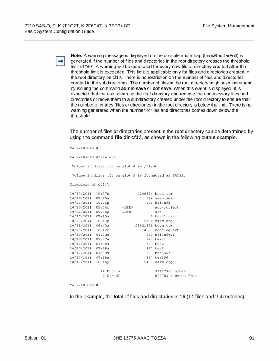
7210 SAS-D, E, K 2F1C2T, K 2F6C4T, K 3SFP+ 8C Basic System Configuration Guide
File System Management
Edition: 01 3HE 13775 AAAC TQZZA 91
The number of files or directories present in the root directory can be determined by using the command file dir cf1:\, as shown in the following output example.
*A:7210-SAS #
*A:7210-SAS #file dir
Volume in drive cf1 on slot A is /flash.
Volume in drive cf1 on slot A is formatted as FAT32.
Directory of cf1:\
10/12/2011 10:37p 4248394 boot.tim10/17/2011 07:28a 524 sasm.sdx10/26/2011 10:06p 828 bof.cfg10/27/2011 09:04p <DIR> act-collect10/27/2011 09:06p <DIR> act10/17/2011 07:30a 0 test1.txt10/26/2011 10:43p 5360 sasm.cfg10/11/2011 06:42a 28821599 both.tim10/26/2011 10:42p 14597 bootlog.txt10/19/2011 04:22a 832 bof.cfg.110/17/2011 07:37a 827 test110/17/2011 07:38a 827 tes210/17/2011 07:38a 827 tes310/17/2011 07:39a 827 tes356710/17/2011 07:38a 827 tes35610/18/2011 10:46p 5481 sasm.cfg.1
14 File(s) 33117369 bytes.2 Dir(s) 80470016 bytes free.
*A:7210-SAS #
In the example, the total of files and directories is 16 (14 files and 2 directories).
Note: A warning message is displayed on the console and a trap (tmnxRootDirFull) is generated if the number of files and directories in the root directory crosses the threshold limit of “80”. A warning will be generated for every new file or directory created after the threshold limit is exceeded. This limit is applicable only for files and directories created in the root directory on cf1:\. There is no restriction on the number of files and directories created in the subdirectories. The number of files in the root directory might also increment by issuing the command admin save or bof save. When this event is displayed, it is expected that the user clean up the root directory and remove the unnecessary files and directories or move them to a subdirectory created under the root directory to ensure that the number of entries (files or directories) in the root directory is below the limit. There is no warning generated when the number of files and directories comes down below the threshold.

File System Management
92
7210 SAS-D, E, K 2F1C2T, K 2F6C4T, K 3SFP+ 8CBasic System Configuration Guide
3HE 13775 AAAC TQZZA Edition: 01
3.2.2 USB Storage Device
The 7210 SAS platform supports a USB interface that provides storage functionality. It allows the use of USB sticks providing them an alternate storage location with larger capacity than the internal flash.
The USB storage device can be used to store TiMOS images, configuration files, accounting records, and log files. The BOF can point to images on USB and be used to load TiMOS images and configuration files.
The 7210 SAS-K 2F1C2T, 7210 SAS-K 2F6C4T, and 7210 SAS-K 3SFP+ 8C provide an option to load the boot loader (boot.tim) from the USB storage device plugged into any one of the USB ports. This option is not available on the 7210 SAS-E.
3.2.3 URLs
The arguments for the 7210 SAS file commands are modeled after standard universal resource locators (URLs). A URL refers to a file (a file-url) or a directory (a directory-url).
The 7210 SAS supports operations on both the local file system and remote files. For the purposes of categorizing the applicability of commands to local and remote file operations, URLs are divided into three types: local, ftp and tftp. Table 16 describes the syntax for each of the URL types.
Note: USB devices are supported on all 7210 SAS platforms as described in this document, except the 7210 SAS-D.
Note:
• The USB devices and capacities that are supported for use with 7210 SAS are listed in the 7210 SAS OS Software Release Notes.
• When a USB device is unplugged or removed from the system, a major alarm is raised. The alarm can be cleared using the shutdown command.
• 7210 SAS also auto-detects the device type when any of the supported devices are connected to the USB interface. Only approved USB mass storage devices and optical clip-on devices can be plugged in to the USB port and are recognized as valid devices. All other unsupported devices will result in an error log being printed.
• Nokia recommended to use the shutdown command before removing the USB storage device.

7210 SAS-D, E, K 2F1C2T, K 2F6C4T, K 3SFP+ 8C Basic System Configuration Guide
File System Management
Edition: 01 3HE 13775 AAAC TQZZA 93
The system accepts either forward slash (“/”) or backslash (“\”) characters to delimit directory and/or filenames in URLs. Similarly, the 7210 SAS SCP client application can use either slash or backslash characters, but not all SCP clients treat backslash characters as equivalent to slash characters. In particular, UNIX systems will often interpret the backslash character as an “escape” character. This can cause problems when using an external SCP client application to send files to the SCP server. If the external system treats the backslash like an escape character, the backslash delimiter will get stripped by the parser and will not be transmitted to the SCP server.
For example, a destination directory specified as “cf1:\dir1\file1” will be transmitted to the SCP server as “cf1:dir1file1” where the backslash escape characters are stripped by the SCP client system before transmission. On systems where the client treats the backslash like an “escape” character, a double backslash “\\” or the forward slash “/” can typically be used to correctly delimit directories and the filename.
3.2.4 Wildcards
The 7210 SAS supports the standard DOS wildcard characters. The asterisk (*) can represent zero or more characters in a string of characters, and the question mark (?) can represent any one character.
Example: A:ALA-1>file cf1:\ # copy test*.cfg siliconvalley
Table 16 URL Types and Syntax
URL Type Syntax Notes
local-url [cflash-id:\]path
[usb-flash-id:\]path
cflash-id is the compact flash device name.
Values: cf1:
usb-flash-id is the USB device name.
Values: uf1:
ftp-url ftp://[username[:password]@]host/path An absolute ftp path from the root of the remote file system.
username is the ftp username
password is the ftp user password
host is the remote host
path is the path to the directory or file
ftp://[username[:password]@]host/./path A relative ftp path from the user’s home directory. Note the period and slash (“./”) in this syntax compared to the absolute path.
tftp-url tftp://host[/path]/filename tftp is only supported for operations on file URLs.

File System Management
94
7210 SAS-D, E, K 2F1C2T, K 2F6C4T, K 3SFP+ 8CBasic System Configuration Guide
3HE 13775 AAAC TQZZA Edition: 01
cf1:\testfile.cfg1 file(s) copied.A:ALA-1>file cf1:\ # cd siliconvalleyA:ALA-1>file cf1:\siliconvalley\ # dir Volume in drive cf1 on slot A has no label.Directory of cf1:\siliconvalley\05/10/2006 11:32p <DIR> .05/10/2006 11:14p <DIR> ..05/10/2006 11:32p 7597 testfile.cfg
1 File(s) 7597 bytes.2 Dir(s) 1082368 bytes free.
A:ALA-1>file cf1:\siliconvalley\ #
All the commands can operate on the local file system. Table 17 describes which commands also support remote file operations.
Table 17 File Command Local and Remote File System Support
Command local-url ftp-url tftp-url
attrib X
cd X X
copy X X X
delete X X
dir X X
md X
move X X
rd X
scp Source only
type X X X
version X X X

7210 SAS-D, E, K 2F1C2T, K 2F6C4T, K 3SFP+ 8C Basic System Configuration Guide
File System Management
Edition: 01 3HE 13775 AAAC TQZZA 95
3.3 File Management Tasks
The following sections are basic system tasks that can be performed:
• Modifying File Attributes
• Creating Directories
• Copying Files
• Moving Files
• Removing Files and Deleting Directories
• Displaying Directory and File Information
3.3.1 Modifying File Attributes
The system administrator can change the read-only attribute in the local file. Enter the attrib command with no options to display the contents of the directory and the file attributes.
Use the following CLI syntax to modify file attributes.
CLI Syntax: file>attrib [+r | -r] file-url
The following output shows an example of the command syntax.
Example: # filefile cf3:\ # attribfile cf3:\ # attrib +r BOF.SAVfile cf3:\ # attrib
The following output shows the file configuration.
A:ALA-1>file cf1:\ # attribcf1:\bootlog.txtcf1:\bof.cfgcf1:\boot.ldrcf1:\bootlog_prev.txtcf1:\BOF.SAV
Note: When a file system operation is performed with a command that can potentially delete or overwrite a file system entry (such as a copy, delete, move, rd, or scp command), a prompt appears to confirm the action. The force keyword performs the copy, delete, move, rd, and scp actions without displaying the confirmation prompt.

File System Management
96
7210 SAS-D, E, K 2F1C2T, K 2F6C4T, K 3SFP+ 8CBasic System Configuration Guide
3HE 13775 AAAC TQZZA Edition: 01
A:ALA-1>file cf1:\ # attrib +r BOF.SAVA:ALA-1>file cf1:\ # attribcf1:\bootlog.txtcf1:\bof.cfgcf1:\boot.ldrcf1:\bootlog_prev.txt
R cf1:\BOF.SAV
3.3.2 Creating Directories
Use the md command to create a new directory in the local file system, one level at a time.
Enter the cd command to navigate to different directories.
Use the following CLI syntax to create a new directory.
CLI Syntax: file> md file-url
The following output shows an example of the command syntax.
Example: file cf1:\ # md test1file cf1:\ # cd test1file cf1:\test1\ # md test2file cf1:\test1\ # cd test2file cf1:\test1\test2\ # md test3file cf1:\test1\test2\ # cd test3file cf1:\test1\test2\test3 #
3.3.3 Copying Files
Use the copy command to upload or download an image file, configuration file, or other file types to or from a flash card or a TFTP server.
The scp command copies files between hosts on a network. It uses SSH for data transfer, and uses the same authentication and provides the same security as SSH.
The source file for the scp command must be local. The file must reside on the router. The destination file has to be of the following format: user@host:file-name. The destination does not need to be local.
Use the following CLI syntax to copy files.

7210 SAS-D, E, K 2F1C2T, K 2F6C4T, K 3SFP+ 8C Basic System Configuration Guide
File System Management
Edition: 01 3HE 13775 AAAC TQZZA 97
CLI Syntax: file> copy source-file-url dest-file-url [force]scp local-file-url destination-file-url [router
router-name | service-id] [force]
The following output shows an example of the copy command syntax.
Example: A:ALA-1>file cf1:\ # copy 104.cfg cf1:\test1\test2\test3\test.cfg
A:ALA-1>file cf1:\ # scp file [email protected]:cf1:\file1
A:ALA-1>file cf1:\ # scp file2 [email protected]:/user2/file2
A:ALA-1>file cf1:\ # scp cf1:/file3 [email protected]:cf1:\file3
3.3.4 Moving Files
Use the move command to move a file or directory from one location to another.
Use the following CLI syntax to move files.
CLI Syntax: file> move old-file-url new-file-url [force]
The following output shows an example of the command syntax.
Example: A:ALA-1>file cf1:\test1\test2\test3\ # move test.cfg cf1:\test1
cf1:\test1\test2\test3\test.cfgA:ALA-1>file cf1:\test1\test2\test3\ # cd ..A:ALA-1>file cf1:\test1\test2\ # cd ..A:ALA-1>file cf1:\test1\ # dir
Directory of cf1:\test1\05/04/2006 07:58a <DIR> .05/04/2006 07:06a <DIR> ..05/04/2006 07:06a <DIR> test205/04/2006 07:58a 25278 test.cfg1 File(s) 25278 bytes.3 Dir(s) 1056256 bytes free.
A:ALA-1>file cf1:\test1\ #
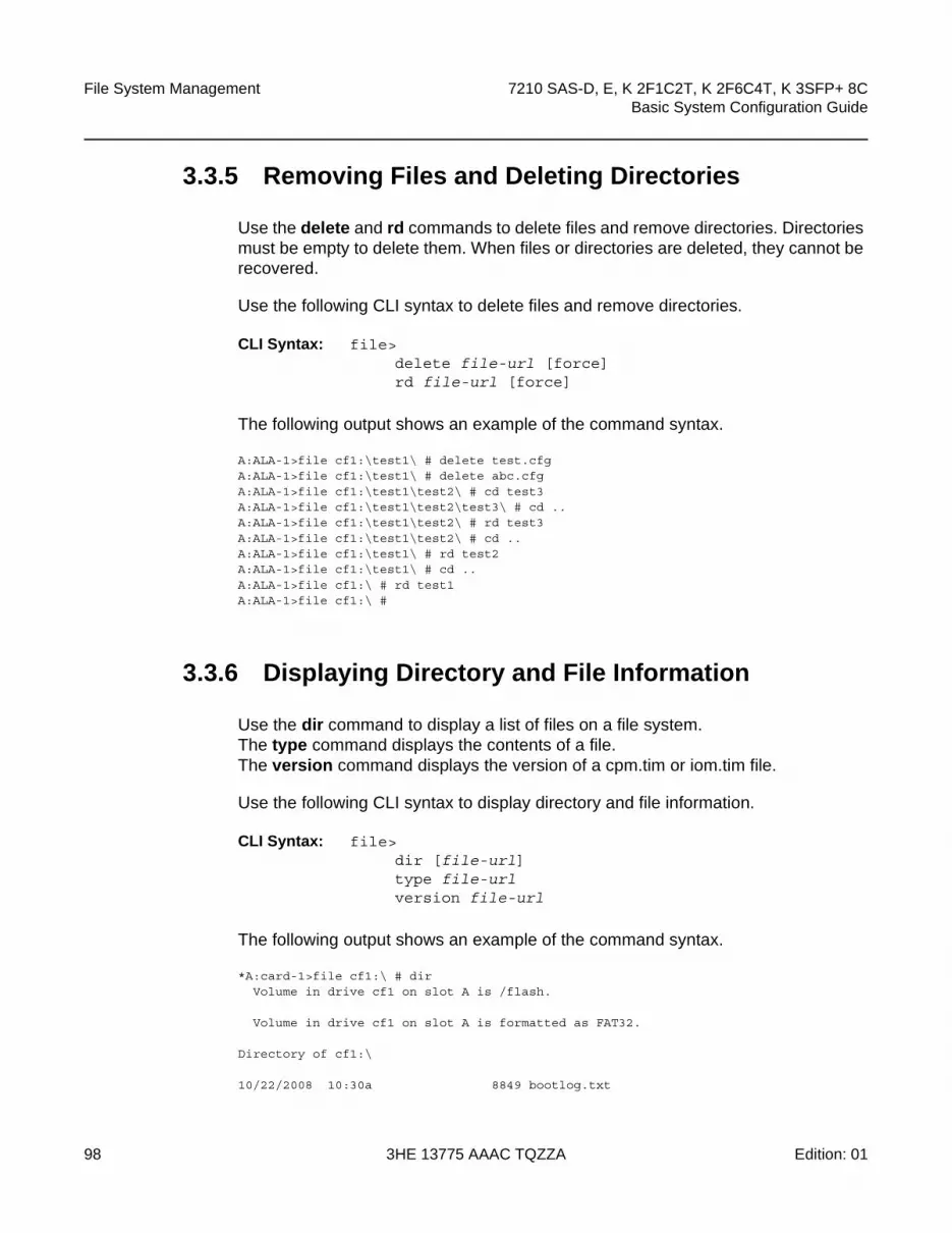
File System Management
98
7210 SAS-D, E, K 2F1C2T, K 2F6C4T, K 3SFP+ 8CBasic System Configuration Guide
3HE 13775 AAAC TQZZA Edition: 01
3.3.5 Removing Files and Deleting Directories
Use the delete and rd commands to delete files and remove directories. Directories must be empty to delete them. When files or directories are deleted, they cannot be recovered.
Use the following CLI syntax to delete files and remove directories.
CLI Syntax: file> delete file-url [force]rd file-url [force]
The following output shows an example of the command syntax.
A:ALA-1>file cf1:\test1\ # delete test.cfgA:ALA-1>file cf1:\test1\ # delete abc.cfgA:ALA-1>file cf1:\test1\test2\ # cd test3A:ALA-1>file cf1:\test1\test2\test3\ # cd ..A:ALA-1>file cf1:\test1\test2\ # rd test3A:ALA-1>file cf1:\test1\test2\ # cd ..A:ALA-1>file cf1:\test1\ # rd test2A:ALA-1>file cf1:\test1\ # cd ..A:ALA-1>file cf1:\ # rd test1A:ALA-1>file cf1:\ #
3.3.6 Displaying Directory and File Information
Use the dir command to display a list of files on a file system.The type command displays the contents of a file. The version command displays the version of a cpm.tim or iom.tim file.
Use the following CLI syntax to display directory and file information.
CLI Syntax: file> dir [file-url]type file-urlversion file-url
The following output shows an example of the command syntax.
*A:card-1>file cf1:\ # dirVolume in drive cf1 on slot A is /flash.
Volume in drive cf1 on slot A is formatted as FAT32.
Directory of cf1:\
10/22/2008 10:30a 8849 bootlog.txt
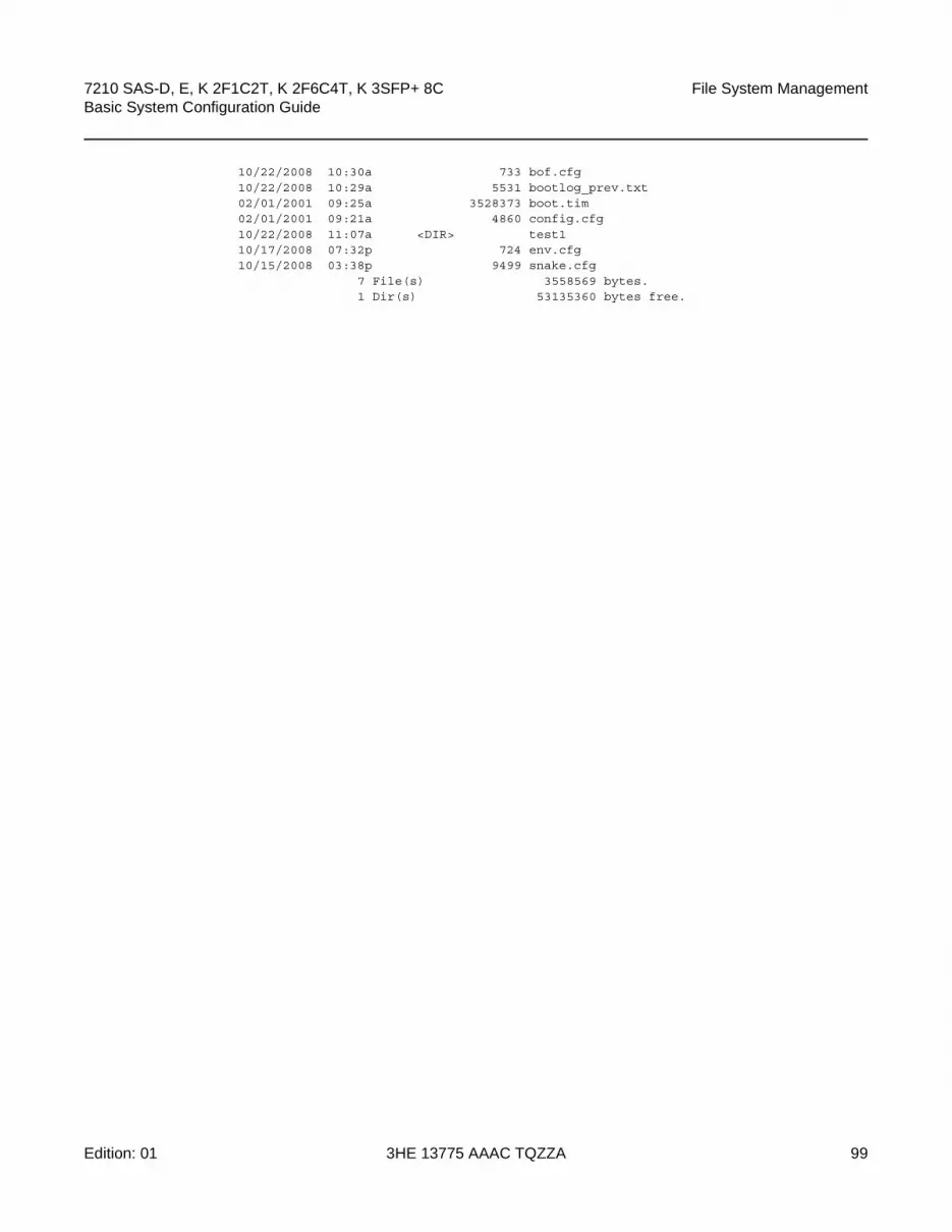
7210 SAS-D, E, K 2F1C2T, K 2F6C4T, K 3SFP+ 8C Basic System Configuration Guide
File System Management
Edition: 01 3HE 13775 AAAC TQZZA 99
10/22/2008 10:30a 733 bof.cfg10/22/2008 10:29a 5531 bootlog_prev.txt02/01/2001 09:25a 3528373 boot.tim02/01/2001 09:21a 4860 config.cfg10/22/2008 11:07a <DIR> test110/17/2008 07:32p 724 env.cfg10/15/2008 03:38p 9499 snake.cfg
7 File(s) 3558569 bytes.1 Dir(s) 53135360 bytes free.

File System Management
100
7210 SAS-D, E, K 2F1C2T, K 2F6C4T, K 3SFP+ 8CBasic System Configuration Guide
3HE 13775 AAAC TQZZA Edition: 01

7210 SAS-D, E, K 2F1C2T, K 2F6C4T, K 3SFP+ 8C Basic System Configuration Guide
File System Management
Edition: 01 3HE 13775 AAAC TQZZA 101
3.4 File Command Reference
3.4.1 Command Hierarchy
3.4.1.1 Configuration Commands
file — attrib [+r | -r] file-url— attrib— cd [file-url]— copy source-file-url dest-file-url [force]— delete file-url [force]— dir [file-url] [sort-order {d | n | s}] [reverse]— format cflash cflash-id [reliable]— md file-url— move old-file-url new-file-url [force]— rd file-url rf [force]— repair [cflash-id]— scp local-file-url destination-file-url [router router-instance] [force]— [no] shutdown cflash-id— type file-url— version file-url [check]

File System Management
102
7210 SAS-D, E, K 2F1C2T, K 2F6C4T, K 3SFP+ 8CBasic System Configuration Guide
3HE 13775 AAAC TQZZA Edition: 01
3.4.2 Configuration Commands
3.4.2.1 File Commands
shutdown
Syntax [no] shutdown [cflash-id]
Context file
Description Platforms Supported: 7210 SAS-K 2F1C2T, 7210 SAS-K 2F6C4T, 7210 SAS-K 3SFP+ 8C
This command is available for use only with removable storage drives. The removable storage drives differ among the 7210 SAS platforms. It cannot be used with the internal non-removable compact flash. See the following values for list of removable flash devices per 7210 SAS platform.
The no shutdown [cflash-id] command enables the drive.
Default no shutdown
Parameters cflash-id — Specifies the device identifier (see the following values for each platform) to be shut down or enabled. When a specific cflash-id is specified, then that drive is shutdown.
Values uf1: - 7210 SAS-E
cf1: | uf1: - 7210 SAS-K 2F1C2T, 7210 SAS-K 2F6C4T, and 7210 SAS-K 3SFP+ 8C
Default n/a
attrib
Syntax attrib [+r | -r] file-url
attrib
Context file
SupportedPlatforms
Supported on all 7210 SAS platforms as described in this document
Description This command sets or clears the read-only attribute for a file in the local file system. To list all files and their current attributes enter attrib or attrib x where x is either the filename or a wild-card (*).

7210 SAS-D, E, K 2F1C2T, K 2F6C4T, K 3SFP+ 8C Basic System Configuration Guide
File System Management
Edition: 01 3HE 13775 AAAC TQZZA 103
When an attrib command is entered to list a specific file or all files in a directory, the file’s attributes are displayed with or without an “R” preceding the filename. The “R” implies that the +r is set and that the file is read-only. Files without the “R” designation implies that the -r is set and that the file is read-write-all. For example:
ALA-1>file cf1:\ # attribcf1:\bootlog.txtcf1:\bof.cfgcf1:\boot.ldrcf1:\sr1.cfgcf1:\testcf1:\bootlog_prev.txtRcf1:\BOF.SAV
Parameters file-url — Specifies the URL for the local file.
Values
+r — Sets the read-only attribute on the specified file.
-r — Clears/resets the read-only attribute on the specified file.
<local-url>|<remote-url> - [255 chars max]
local-url - [<cflash-id>/]|<usb-flash-id>/][<file-path>]
remote-url - [{ftp://|tftp://}<login>:<pswd>@
<remote-locn>/][<file-path>]
remote-locn - [ <hostname> | <ipv4-address> | "["<ipv6-address>"]" ]
ipv4-address - a.b.c.d
ipv6-address - x:x:x:x:x:x:x:x[-interface]
x:x:x:x:x:x:d.d.d.d[-interface]
x - [0..FFFF]H
d - [0..255]D
interface - 32 chars max, for link local addresses
cflash-id or usb-flash-id -
cf1: - 7210 SAS-D
cf1: | uf1: - 7210 SAS-E
cf1: | uf1: - 7210 SAS-K 2F1C2T, 7210 SAS-K 2F6C4T, and 7210 SAS-K 3SFP+ 8C

File System Management
104
7210 SAS-D, E, K 2F1C2T, K 2F6C4T, K 3SFP+ 8CBasic System Configuration Guide
3HE 13775 AAAC TQZZA Edition: 01
cd
Syntax cd [file-url]
Context file
SupportedPlatforms
Supported on all 7210 SAS platforms as described in this document
Description This command displays or changes the current working directory in the local file system.
Parameters file-url — Specifies the URL for the local file.
Values
<none> — Displays the current working directory.
.. — Signifies the parent directory. This can be used in place of an actual directory name in a directory-url.
directory-url — Specifies the destination directory.
<local-url>|<remote-url> - [255 chars max]
local-url - [<cflash-id>/]|<usb-flash-id>/][<file-path>]
remote-url - [{ftp://|tftp://}<login>:<pswd>@
<remote-locn>/][<file-path>]
remote-locn - [ <hostname> | <ipv4-address> | "["<ipv6-address>"]" ]
ipv4-address - a.b.c.d
ipv6-address - x:x:x:x:x:x:x:x[-interface]
x:x:x:x:x:x:d.d.d.d[-interface]
x - [0..FFFF]H
d - [0..255]D
interface - 32 chars max, for link local addresses
cflash-id or usb-flash-id -
cf1: -7210 SAS-D
cf1: | uf1: - 7210 SAS-E
cf1: | uf1: - 7210 SAS-K 2F1C2T, 7210 SAS-K 2F6C4T, and 7210 SAS-K 3SFP+ 8C

7210 SAS-D, E, K 2F1C2T, K 2F6C4T, K 3SFP+ 8C Basic System Configuration Guide
File System Management
Edition: 01 3HE 13775 AAAC TQZZA 105
copy
Syntax copy source-file-url dest-file-url [force]
Context file
SupportedPlatforms
Supported on all 7210 SAS platforms as described in this document
Description This command copies a file or all files in a directory from a source URL to a destination URL. At least one of the specified URLs should be a local URL. The optional wild-card (*) can be used to copy multiple files that share a common (partial) prefix and/or (partial) suffix. When a file is copied to a destination with the same file name, the original file is overwritten by the new file specified in the operation. The following prompt appears if the destination file already exists:
“Overwrite destination file (y/n)?”
For example:
To copy a file named srcfile in a directory called test on cf1 to a file called destfile in a directory called production on cf1, the syntax is:
sr1>file cf1:\ # copy cf2-/test/srcfile/production/destfile
To FTP a file named 121201.cfg in directory mydir stored on cf1 to a network FTP server with IP address 131.12.31.79 in a directory called backup with a destination file name of 121201.cfg, the FTP syntax is:
copy /mydir/121201.cfg 131.12.31.79/backup/121201.cfg
Parameters source-file-url — Specifies the location of the source file or directory to be copied.
dest-file-url — Specifies the destination of the copied file or directory.
Values
<local-url>|<remote-url> - [255 chars max]
local-url - [<cflash-id>/]|<usb-flash-id>/][<file-path>]
remote-url - [{ftp://|tftp://}<login>:<pswd>@
<remote-locn>/][<file-path>]
remote-locn - [ <hostname> | <ipv4-address> | "["<ipv6-address>"]" ]
ipv4-address - a.b.c.d
ipv6-address - x:x:x:x:x:x:x:x[-interface]
x:x:x:x:x:x:d.d.d.d[-interface]
x - [0..FFFF]H
d - [0..255]D
interface - 32 chars max, for link local addresses

File System Management
106
7210 SAS-D, E, K 2F1C2T, K 2F6C4T, K 3SFP+ 8CBasic System Configuration Guide
3HE 13775 AAAC TQZZA Edition: 01
force — Forces an immediate copy of the specified files.
file copy force executes the command without displaying a user prompt message
delete
Syntax delete file-url [force]
Context file
SupportedPlatforms
Supported on all 7210 SAS platforms as described in this document
Description This command deletes the specified file.
The optional wild-card “*” can be used to delete multiple files that share a common (partial) prefix and/or (partial) suffix. When the wild-card is entered, the following prompt displays for each file that matches the wild-card:
“Delete file <filename> (y/n)?”
Parameters file-url — Specifies the file name to delete.
Values
cflash-id or usb-flash-id -
cf1: - 7210 SAS-D
cf1: | uf1: - 7210 SAS-E
cf1: | uf1: - 7210 SAS-K 2F1C2T, 7210 SAS-K 2F6C4T, and 7210 SAS-K 3SFP+ 8C
<local-url>|<remote-url> - [255 chars max]
local-url - [<cflash-id>/]|<usb-flash-id>/][<file-path>]
remote-url - [{ftp://|tftp://}<login>:<pswd>@
<remote-locn>/][<file-path>]
remote-locn - [ <hostname> | <ipv4-address> | "["<ipv6-address>"]" ]
ipv4-address - a.b.c.d
ipv6-address - x:x:x:x:x:x:x:x[-interface]
x:x:x:x:x:x:d.d.d.d[-interface]
x - [0..FFFF]H
d - [0..255]D
interface - 32 chars max, for link local addresses
cflash-id or usb-flash-id -
cf1: - 7210 SAS-D

7210 SAS-D, E, K 2F1C2T, K 2F6C4T, K 3SFP+ 8C Basic System Configuration Guide
File System Management
Edition: 01 3HE 13775 AAAC TQZZA 107
force — Forces an immediate deletion of the specified files.
file delete * force deletes all the wildcard matching files without displaying a user prompt message.
dir
Syntax dir [file-url] [sort-order {d | n | s}] [reverse]
Context file
SupportedPlatforms
Supported on all 7210 SAS platforms as described in this document
Description This command displays a list of files and subdirectories in a directory.
Parameters file-url — Specifies the path or directory name; use the file-url with the optional wildcard (*) to reduce the number of files to list.
Values
cf1: | uf1: - 7210 SAS-E
cf1: | uf1: - 7210 SAS-K 2F1C2T, 7210 SAS-K 2F6C4T, and 7210 SAS-K 3SFP+ 8C
<local-url>|<remote-url> - [255 chars max]
local-url - [<cflash-id>/]|<usb-flash-id>/][<file-path>]
remote-url - [{ftp://|tftp://}<login>:<pswd>@
<remote-locn>/][<file-path>]
remote-locn - [ <hostname> | <ipv4-address> | "["<ipv6-address>"]" ]
ipv4-address - a.b.c.d
ipv6-address - x:x:x:x:x:x:x:x[-interface]
x:x:x:x:x:x:d.d.d.d[-interface]
x - [0..FFFF]H
d - [0..255]D
interface - 32 chars max, for link local addresses
cflash-id or usb-flash-id -
cf1: - 7210 SAS-D
cf1: | uf1: - 7210 SAS-E
cf1: | uf1: - 7210 SAS-K 2F1C2T, 7210 SAS-K 2F6C4T, and 7210 SAS-K 3SFP+ 8C

File System Management
108
7210 SAS-D, E, K 2F1C2T, K 2F6C4T, K 3SFP+ 8CBasic System Configuration Guide
3HE 13775 AAAC TQZZA Edition: 01
sort-order {d | n | s} — Specifies the sort order.
Values d — date
n — name
s — size
reverse — Specifies to reverse the sort order.
file
Syntax file
Context root
SupportedPlatforms
Supported on all 7210 SAS platforms as described in this document
Description This command enables the context to enter and perform file system operations. When entering the file context, the prompt changes to reflect the present working directory. Navigating the file system with the cd .. command results in a changed prompt.
The exit all command leaves the file system/file operation context and returns to the <root> CLI context. The state of the present working directory is maintained for the CLI session. Entering the file command returns the cursor to the working directory where the exit command was issued.
format
Syntax format cflash cflash-id
Context root>file
Description Platforms Supported: 7210 SAS-K 2F1C2T, 7210 SAS-K 2F6C4T, 7210 SAS-K 3SFP+ 8C
This command formats the compact flash. The compact flash must be shut down before starting the format.
Parameters cflash-id — Specifies the compact flash type.
Values cf1: | uf1: - 7210 SAS-K 2F1C2T, 7210 SAS-K 2F6C4T, and 7210 SAS-K 3SFP+ 8C

7210 SAS-D, E, K 2F1C2T, K 2F6C4T, K 3SFP+ 8C Basic System Configuration Guide
File System Management
Edition: 01 3HE 13775 AAAC TQZZA 109
md
Syntax md file-url
Context file
SupportedPlatforms
Supported on all 7210 SAS platforms as described in this document
Description This command creates a new directory in a file system.
Directories can only be created one level at a time.
Parameters file-url — Specifies the directory name to be created.
Values
move
Syntax move old-file-url new-file-url [force]
Context file
SupportedPlatforms
Supported on all 7210 SAS platforms as described in this document
Description This command moves a local file, system file, or a directory. If the target already exists, the command fails and an error message displays.
<local-url>|<remote-url> - [255 chars max]
local-url - [<cflash-id>/]|<usb-flash-id>/][<file-path>]
remote-url - [{ftp://|tftp://}<login>:<pswd>@
<remote-locn>/][<file-path>]
remote-locn - [ <hostname> | <ipv4-address> | "["<ipv6-address>"]" ]
ipv4-address - a.b.c.d
ipv6-address - x:x:x:x:x:x:x:x[-interface]
x:x:x:x:x:x:d.d.d.d[-interface]
x - [0..FFFF]H
d - [0..255]D
interface - 32 chars max, for link local addresses
cflash-id or usb-flash-id -
cf1: - 7210 SAS-D
cf1: | uf1: - 7210 SAS-E
cf1: | uf1: - 7210 SAS-K 2F1C2T, 7210 SAS-K 2F6C4T, and 7210 SAS-K 3SFP+ 8C

File System Management
110
7210 SAS-D, E, K 2F1C2T, K 2F6C4T, K 3SFP+ 8CBasic System Configuration Guide
3HE 13775 AAAC TQZZA Edition: 01
The following prompt appears if the destination file already exists:
“Overwrite destination file (y/n)?”
Parameters old-file-url — Specifies the file or directory to be moved.
new-file-url — Specifies the new destination to place the old-file-url.
Values
force — Forces an immediate move of the specified files.
file move force executes the command without displaying a user prompt message.
rd
Syntax rd file-url rf [force]
Context file
SupportedPlatforms
Supported on all 7210 SAS platforms as described in this document
Description This command is used to delete a directory.
If a directory has files and no sub-directories, the force option must be used to force delete the directory and files it contains.
<local-url>|<remote-url> - [255 chars max]
local-url - [<cflash-id>/]|<usb-flash-id>/][<file-path>]
remote-url - [{ftp://|tftp://}<login>:<pswd>@
<remote-locn>/][<file-path>]
remote-locn - [ <hostname> | <ipv4-address> | "["<ipv6-address>"]" ]
ipv4-address - a.b.c.d
ipv6-address - x:x:x:x:x:x:x:x[-interface]
x:x:x:x:x:x:d.d.d.d[-interface]
x - [0..FFFF]H
d - [0..255]D
interface - 32 chars max, for link local addresses
cflash-id or usb-flash-id -
cf1: - 7210 SAS-D
cf1: | uf1: - 7210 SAS-E
cf1: | uf1: - 7210 SAS-K 2F1C2T, 7210 SAS-K 2F6C4T, and 7210 SAS-K 3SFP+ 8C

7210 SAS-D, E, K 2F1C2T, K 2F6C4T, K 3SFP+ 8C Basic System Configuration Guide
File System Management
Edition: 01 3HE 13775 AAAC TQZZA 111
Parameters file-url — The directory to be removed.
Values
rf — Specifies that the parameter forces a recursive delete.
force — Forces an immediate deletion of the specified directory.
For example, rd file-url force executes the command without displaying a user prompt message.
repair
Syntax repair [cflash-id]
Context file
SupportedPlatforms
Supported on all 7210 SAS platforms as described in this document
Description This command checks a compact flash device for errors and repairs any errors found.
Parameters cflash-id — Specifies the compact flash slot ID to be shut down or enabled. When a specific cflash-id is specified, that drive is shutdown. If no cflash-id is specified, the drive referred to by the current working directory is assumed.
Values cf1:|uf1: - 7210 SAS-E
cf1: - 7210 SAS-D
<local-url>|<remote-url> - [255 chars max]
local-url - [<cflash-id>/]|<usb-flash-id>/][<file-path>]
remote-url - [{ftp://|tftp://}<login>:<pswd>@
<remote-locn>/][<file-path>]
remote-locn - [ <hostname> | <ipv4-address> | "["<ipv6-address>"]" ]
ipv4-address - a.b.c.d
ipv6-address - x:x:x:x:x:x:x:x[-interface]
x:x:x:x:x:x:d.d.d.d[-interface]
x - [0..FFFF]H
d - [0..255]D
interface - 32 chars max, for link local addresses
cflash-id or usb-flash-id -
cf1: - 7210 SAS-D
cf1: | uf1: - 7210 SAS-E
cf1: | uf1: - 7210 SAS-K 2F1C2T, 7210 SAS-K 2F6C4T, and 7210 SAS-K 3SFP+ 8C

File System Management
112
7210 SAS-D, E, K 2F1C2T, K 2F6C4T, K 3SFP+ 8CBasic System Configuration Guide
3HE 13775 AAAC TQZZA Edition: 01
cf1: | uf1: - 7210 SAS-K 2F1C2T, 7210 SAS-K 2F6C4T, and 7210 SAS-K 3SFP+ 8C
Default The current compact flash device.
scp
Syntax scp local-file-url destination-file-url [router router-instance] [force]
Context file
SupportedPlatforms
Supported on all 7210 SAS platforms as described in this document
Description This command copies a local file to a remote host file system. It uses ssh for data transfer, and uses the same authentication and provides the same security as ssh. The following prompt appears:
“Are you sure (y/n)?” The destination must specify a user and a host.
Parameters local-file-url — Specifies the local source file or directory.
destination-file-url — Specifies the destination file.
user — Specifies the SSH user.
host — Specifies the remote host IP address of DNS name.
file-path — Specifies the destination path.
router-instance — Specifies the router name or service ID.
Values
[cflash-id/][file-path]> - [Up to 256 characters]
cflash-id or usb-flash-id -
cf1: - 7210 SAS-D
cf1: | uf1: - 7210 SAS-E
cf1: | uf1: - 7210 SAS-K 2F1C2T, 7210 SAS-K 2F6C4T, and 7210 SAS-K 3SFP+ 8C
<user>@<hostname>:<file-path> - [255 chars max]
user - [32 chars max]
hostname - [ <dns-name> | <ipv4-address> | "["<ipv6-address>"]" ]
ipv4-address - a.b.c.d
ipv6-address - x:x:x:x:x:x:x:x[-interface]
x:x:x:x:x:x:d.d.d.d[-interface]
x - [0..FFFF]H

7210 SAS-D, E, K 2F1C2T, K 2F6C4T, K 3SFP+ 8C Basic System Configuration Guide
File System Management
Edition: 01 3HE 13775 AAAC TQZZA 113
force — Forces an immediate copy of the specified file.
file scp local-file-url destination-file-url [router] force executes the command without
displaying a user prompt message.
type
Syntax type file-url
Context file
SupportedPlatforms
Supported on all 7210 SAS platforms as described in this document
Description This command displays the contents of a text file.
Parameters file-url — Specifies the file name of the target file.
Values
d - [0..255]D
interface - 32 chars max, mandatory for link local addresses
dns-name - [128 chars max]
file-path - [200 chars max]
directory length 99 chars max each
<router-instance> : <router-name>
7210 SAS-E: router-name - "Base"|"management"|"vpls-management"
7210 SAS-D, 7210 SAS-K 2F1C2T, 7210 SAS-K 2F6C4T, 7210 SAS-K 3SFP+ 8C: router-name - “Base"|"management"
Default - Base
<local-url>|<remote-url> - [255 chars max]
local-url - [<cflash-id>/]|<usb-flash-id>/][<file-path>]
remote-url - [{ftp://|tftp://}<login>:<pswd>@
<remote-locn>/][<file-path>]
remote-locn - [ <hostname> | <ipv4-address> | "["<ipv6-address>"]" ]
ipv4-address - a.b.c.d
ipv6-address - x:x:x:x:x:x:x:x[-interface]
x:x:x:x:x:x:d.d.d.d[-interface]
x - [0..FFFF]H
d - [0..255]D
interface - 32 chars max, for link local addresses
cflash-id or usb-flash-id -

File System Management
114
7210 SAS-D, E, K 2F1C2T, K 2F6C4T, K 3SFP+ 8CBasic System Configuration Guide
3HE 13775 AAAC TQZZA Edition: 01
version
Syntax version file-url [check]
Context file
SupportedPlatforms
Supported on all 7210 SAS platforms as described in this document
Description This command displays the version of a TiMOS file.
Parameters file-url — Specifies the file name of the target file.
Values
check — Validates the .tim file.
cf1: - 7210 SAS-D
cf1: | uf1: - 7210 SAS-E
cf1: | uf1: - 7210 SAS-K 2F1C2T, 7210 SAS-K 2F6C4T, and 7210 SAS-K 3SFP+ 8C
<local-url>|<remote-url> - [255 chars max]
local-url - [<cflash-id>/]|<usb-flash-id>/][<file-path>]
remote-url - [{ftp://|tftp://}<login>:<pswd>@
<remote-locn>/][<file-path>]
remote-locn - [ <hostname> | <ipv4-address> | "["<ipv6-address>"]" ]
ipv4-address - a.b.c.d
ipv6-address - x:x:x:x:x:x:x:x[-interface]
x:x:x:x:x:x:d.d.d.d[-interface]
x - [0..FFFF]H
d - [0..255]D
interface - 32 chars max, for link local addresses
cflash-id or usb-flash-id -
cf1: - 7210 SAS-D
cf1: | uf1: - 7210 SAS-E
cf1: | uf1: - 7210 SAS-K 2F1C2T, 7210 SAS-K 2F6C4T, and 7210 SAS-K 3SFP+ 8C

7210 SAS-D, E, K 2F1C2T, K 2F6C4T, K 3SFP+ 8C Basic System Configuration Guide
Boot Options
Edition: 01 3HE 13775 AAAC TQZZA 115
4 Boot Options
4.1 In This Chapter
This chapter provides information about configuring boot option parameters.
Topics in this chapter include:
• System Initialization
• Configuration and Image Loading
• Initial System Startup Process Flow
• Configuration Notes

Boot Options
116
7210 SAS-D, E, K 2F1C2T, K 2F6C4T, K 3SFP+ 8CBasic System Configuration Guide
3HE 13775 AAAC TQZZA Edition: 01
4.2 System Initialization
When the system is powered ON, it executes the bootstrap image, for example, the boot.tim file, from the file system located on a flash device (cf1:) or the USB (on the 7210 SAS-K 2F1C2T, 7210 SAS-K 2F6C4T, and 7210 SAS-K 3SFP+ 8C) that is built in to the 7210 SAS routers. The boot.tim file is the image that reads and executes the system initialization commands configured in the Boot Option File (BOF). The default behavior is to initially search for the boot.tim file on cf1:. This behavior cannot be modified.
If the boot.tim file is not present, or is not a valid file that can be loaded, the Golden bootstrap image is loaded by the boot ROM on 7210 SAS-D or 7210 SAS-E. The Golden bootstrap image is equivalent to a boot.tim file except that it is present outside the file system and can be updated and checked using special CLI commands. On the 7210 SAS-K 2F1C2T, 7210 SAS-K 2F6C4T, or 7210 SAS-K 3SFP+ 8C, if the boot.tim is not found in the default location (cf:\boot.tim), the software searches for the boot.tim at other storage locations (such as uf1:\) and uses the boot.tim located there to boot the system.
When the system executes boot.tim, options are available to the user to modify the BOF manually and save it, or to boot using an existing BOF. The bootstrap image then processes the BOF present in the flash as described in Configuration and Image Loading.
On systems that are shipped without a BOF, when the system is powered ON for the first time, there will be no BOF in the system. Therefore, provisions are given to create a new BOF or alternatively get the BOF from the network. There are two options:
• Boot by manually creating a BOF (manual boot).
• Boot by retrieving the BOF from the network, using DHCP to get the network location of the BOF (auto-init). Auto-init is the default boot procedure if there is no manual-intervention during the first-time boot of the node.
Refer to the appropriate 7210 SAS platform installation guide for information about the availability and use of system boot options for the specific platform.
Note: Some 7210 SAS platforms (for example, the 7210 SAS-K 2F1C2T, 7210 SAS-K 2F6C4T, and 7210 SAS-K 3SFP+ 8C) do not ship with an image. It is expected that the user will use the external flash or the USB device with boot-loader image (boot.tim) to boot the system. The user must insert the device (either the compact flash into the external compact flash slot; the SD card into the SD card slot; or the USB storage device into the USB port) before powering on the system. For more information about the prerequisites, refer to the appropriate 7210 SAS installation guide.

7210 SAS-D, E, K 2F1C2T, K 2F6C4T, K 3SFP+ 8C Basic System Configuration Guide
Boot Options
Edition: 01 3HE 13775 AAAC TQZZA 117
On systems that ship with the BOF, the user can use the starter BOF or interrupt the boot process to manually edit the BOF to change it contents and create a new BOF. Refer to the appropriate 7210 SAS platform installation guide for more information.
Figure 3 shows the bootstrap load process.
Figure 3 Bootstrap Load Process – System Initialization Part 1
The following sections provide more details of the various boot options and how the system processes these options and loads the boot loader (boot.tim), the TiMOS image (both.tim), and the configuration file to make the system operational and ready for use.
Note:
• When the operator executes the reset command in the boot loader prompt or admin reboot auto-init in the TiMOS CLI, 7210 SAS resets the current BOF and reboots.
• The 7210 SAS-E can be managed through an external physical network, which secures the management network by restricting access to service customers and service data.
• Out-of-band (OOB) Ethernet management ports are only supported on the 7210 SAS-E.
sw0450
Power on/Reboot - StartBootrom code
R
R
Load goldenbootstrap
image
Loadboot.tim
Yes
Yes
Yes
No
No
No
Was Goldenimage requested due to bootstrap
image upgrade failure?
boot.tim presentand valid
boot.tim adifferent version from
last good bootstrap image
Indicate bootstrap-updatedflag to timos and the
bootstrap image
Indicate bootstrap-no-updateflag to timos and the
bootstrap image

Boot Options
118
7210 SAS-D, E, K 2F1C2T, K 2F6C4T, K 3SFP+ 8CBasic System Configuration Guide
3HE 13775 AAAC TQZZA Edition: 01
The following is an example of console display output when the boot.tim file is located on cf1 and the system boots successfully.
Nokia 7210 Boot ROM. Copyright 2016 Nokia.All rights reserved. All use is subject to applicable license agreements.Running POST tests from ROMTesting ROM load area...done
Relocating code...Jumping to RAM
Performing second stage RAM test....passed
Board Serial Number is 'SN123456789'Bootlog started for Version V-0.0.I317Build V-0.0.I317 bootrom/mpc 7xxxBuilt on Tue Jan 6 02:23:14 IST 2016 by panosbld in /panosbld/ws/panos/main
?Attempting to load from file cf1:/boot.timVersion L-0.0.I312, Fri Jan 2 04:26:32 IST 2016 by panosbld in /panosbld/ws/panos/maintext:(3002475-->12623392) + data:(550940-->2414128)Starting at 0xb000000...
Total Memory: 512MB Chassis Type: sas Card Type: badami_7210TiMOS-L-0.0.I312 boot/mpc NOKIA SAS-E 7210 Copyright (c) 2016 Nokia.All rights reserved. All use subject to applicable license agreements.Built on Fri Jan 2 04:26:32 IST 2016 by panosbld in /panosbld/ws/panos/main
TiMOS BOOT LOADER
...
4.2.1 Flash Contents of the node shipped from factory
Figure 4 shows the typical flash directory structure and filenames when the node is shipped from the factory.
Note: The Golden image (referenced in Figure 3) is only supported on the 7210 SAS-D and 7210 SAS-E.

7210 SAS-D, E, K 2F1C2T, K 2F6C4T, K 3SFP+ 8C Basic System Configuration Guide
Boot Options
Edition: 01 3HE 13775 AAAC TQZZA 119
Figure 4 Files on the Flash
Files on the compact flash are the following:
• bof.cfg — Boot option file
• boot.tim — Bootstrap image
• config.cfg — Default configuration file
• TIMOS-m.n.Yz:
m — Major release number
n — Minor release number
Y: A — Alpha release
B — Beta release
M — Maintenance release
R — Released software
z — Version number
both.tim — CPM and IOM image file
4.2.2 System Boot Options on 7210 SAS-D and 7210 SAS-E Devices
The 7210 SAS-D and 7210 SAS-E support booting the system using any of the following options:
• Internal flash (cf1:\)
• Network (with auto-init)
• Network (without auto-init)
bof.cfg boot.tim config.cfg TIMOS-m.n.Yz
both.tim
ROOT
26427

Boot Options
120
7210 SAS-D, E, K 2F1C2T, K 2F6C4T, K 3SFP+ 8CBasic System Configuration Guide
3HE 13775 AAAC TQZZA Edition: 01
Refer to the appropriate 7210 SAS platform installation guide for more information about the system boot options and usage examples.
4.2.3 System Boot Options on 7210 SAS-K 2F1C2T, 7210 SAS-K 2F6C4T, and 7210 SAS-K 3SFP+ 8C Devices
The 7210 SAS-K 2F1C2T, 7210 SAS-K 2F6C4T, and 7210 SAS-K 3SFP+ 8C support booting the system using any of the following options:
• Internal flash at the rear of the node(cf1:\)
• External USB flash (uf1:\)
• Network (with and without auto-init)
On the 7210 SAS-K 2F1C2T, 7210 SAS-K 2F6C4T, and 7210 SAS-K 3SFP+ 8C, there are multiple storage locations that the software can look at to obtain the boot loader (boot.tim) and there is no support for the golden boot loader. During boot-up, the system attempts to boot from the first successful option out of the 3 options available in the BOF (primary, secondary, and tertiary location).
The boot ROM is capable of searching any of the following locations during first-time boot-up for a boot.tim, in the following order.
Note:
• The use of a both.tim (TiMOS image) file on a USB storage device is only supported on the 7210 SAS-E.
• The 7210 SAS platforms do not support the use of a boot.tim file on a USB storage device for booting up.
Note: Users must plug in a USB storage device or SD card, with the correct TiMOS images into one of these locations before powering on the system.
• cf1:\ (SD card slot or USB slot)
• uf1:\ (external USB)

7210 SAS-D, E, K 2F1C2T, K 2F6C4T, K 3SFP+ 8C Basic System Configuration Guide
Boot Options
Edition: 01 3HE 13775 AAAC TQZZA 121
If the boot ROM does not find the boot.tim in any of the locations, the boot procedure fails. If the boot ROM finds the boot.tim in any one of the locations, the system finds the BOF.cfg on the same storage device under the root directory (for example, if it finds the boot.tim on uf1:\, it looks for the bof.cfg in uf1:\bof.cfg). If the BOF is found, it obtains the location of both.tim (TiMOS software), the configuration file, and other boot parameters and uses the same to boot the system. If it does not find the BOF, it attempts auto-init to retrieve the BOF from the network (and create a new BOF as part of the auto-init process).
Refer to the appropriate 7210 SAS platform installation guide for more information about the system boot options and usage examples.
4.2.3.1 Storage Locations for Index Files (ndx, sdx) and Images for 7210 SAS-K 2F1C2T, 7210 SAS-K 2F6C4T, and 7210 SAS-K 3SFP+ 8C
The 7210 SAS-K 2F1C2T, 7210 SAS-K 2F6C4T, and 7210 SAS-K 3SFP+ 8C software sets the default location for accounting records, logs, and other frequently written objects to point to cf1:\.
The following storage locations are supported in the 7210 SAS-K 2F1C2T, 7210 SAS-K 2F6C4T, and 7210 SAS-K 3SFP+ 8C.
• The default location for accounting records and logs needs to be set by software to cf1:\. It can be changed by the user to uf1:\.
• The boot.tim and BOF can be on cf1:\ (recommended) or uf1:\.
• TiMOS images (both.tim) can be located on either cf1:\ or uf1:\ with appropriate configuration of the BOF (that is, primary, secondary and tertiary locations pointing to the appropriate place).
• The ndx file and sdx file is generated at the location specified in the BOF parameter for the configuration file. If the user does not specify the location in the BOF, these files are located at the same location as the default configuration file. The default configuration file is created at the same place where the TiMOS image with which the system booted up is located.
• Nokia recommends to use the following guidelines for storing the TiMOS, boot.tim, BOF.cfg, ndx, sdx and nvsys.info files.
− Store the boot.tim and BOF.cfg on cf1:\. Create a backup of the boot.tim and BOF.cfg on uf1:\.
− Store the both.tim, configuration file (and as a result the ndx, sdx, and nvsys.info) on cf1:\. Create a backup of these files on uf1:\, or create a backup on the SAM/network management station regularly.

Boot Options
122
7210 SAS-D, E, K 2F1C2T, K 2F6C4T, K 3SFP+ 8CBasic System Configuration Guide
3HE 13775 AAAC TQZZA Edition: 01
4.2.4 System Boot Options – Manual Mode
If the user opts for the manual-mode boot procedure for the first time boot, the required parameters must be specified for a successful system boot. Manual mode configurations require authentication. The default password is “password”. BOF parameters that should be configured include the following:
• Image path
• Configuration file path
• UplinkA parameters (port number, vlan ID, IP/mask, static route)
• UplinkB parameters (port number, vlan ID, IP/mask, static route)
• eth-mgmt-disabled (only supported on 7210 SAS-E)
Provisions to configure two uplinks is given in the BOF for port redundancy. If the image path and configuration file path are local, the IP address and routing information for uplinkA and uplinkB are not required. The user can optionally obtain IP parameters through DHCP by configuring 0 (zero) for the uplink port IP address. In this case, the DHCP server should be configured to grant the IP address and the default gateway information used to reach the server where the image and configuration files are present. After the BOF configuration is completed, a BOF with configured parameters is created in the flash that can be used for subsequent reboots. The bootstrap image then processes the BOF parameters to boot the system. BOF processing is described in Configuration and Image Loading.
For 7210 SAS-E devices, the eth-mgmt-disabled command enables or disables the out-of-band Ethernet management port during the boot-up procedure. The 7210 SAS-D devices do not support out-of-band Ethernet management port. For a 7210 SAS node that has a previous BOF, the boot process uses the existing parameters for uplinkA and uplinkB ports to boot the TIMOS image. The OOB port is disabled, by default. The user has an option to enable the Ethernet management port and use it for booting up the system.
Note: OOB Ethernet management port is only supported on the 7210 SAS-E.

7210 SAS-D, E, K 2F1C2T, K 2F6C4T, K 3SFP+ 8C Basic System Configuration Guide
Boot Options
Edition: 01 3HE 13775 AAAC TQZZA 123
4.2.5 System Boot Options – Auto-init
During the first boot or a reboot after the execution of CLI command admin reboot auto-init, if the user does not intervene to create the BOF in the manual mode, the system, by default, goes to the auto-init procedure after a wait time. The default wait time is 3 seconds. There are two designated ports used for auto-init. These are the front panel ports, port 1 and port 2. Auto-init requires a DHCP server to be configured in the network, which should be reachable by the system. DHCP requests are directed out of one uplink port at a time. All other ports of the system would be operationally down.
If a DHCP server is present in the network, the system expects to receive an IP address, the default gateway information, and the BOF path in the response returned by the DHCP server. Upon receiving these parameters from the DHCP server, the system applies the IP configuration and downloads the BOF from the path given by the DHCP server. The BOF is then saved into the flash and is used for subsequent reboots. The bootstrap image then processes the BOF parameters to boot the system. BOF processing is described in Configuration and Image Loading.
The user is provided with an option to provide some of the BOF parameters before the box attempts to use DHCP for obtaining the BOF and the image files. It gives an opportunity to the user to modify some of the link parameters (for example, speed) and the DHCP request (for example, VLAN ID) to suit the deployment needs. The parameters that can be configured are the uplink ports to use, VLAN ID used, speed of the link, duplex setting for the link, and auto-negotiation capability for the link. To change this value, the user needs to have console access and break the boot sequence and type in the keyword auto to provide some of the BOF parameters (follow the prompts to provide these parameters). After this is done, and exit is typed, the boot loader software uses these parameters to configure the link appropriately and sends out the DHCP requests to obtain the BOF. The BOF obtained through DHCP must contain the location of the image file and configuration file (and values for other BOF parameters). If the DHCP process is successful, the BOF that is obtained from the network is copied to the local flash. Nokia recommends that the user configure similar values for the BOF parameters that were modified locally, that is, if the user specified new values for BOF parameters such as speed, VLAN ID, auto-negotiate, and others. Before the start of DHCP requests, the BOF downloaded from the network should contain the same values for those BOF parameters. See Figure 5 for more information.
The system first attempts to use uplinkA and uplinkB parameters to receive a successful response from the DHCP server. If there is no response from the DHCP server on both the uplink ports, the boot procedure is restarted, during which the user can opt to enter the manual mode or allow the system to default to auto-init again.

Boot Options
124
7210 SAS-D, E, K 2F1C2T, K 2F6C4T, K 3SFP+ 8CBasic System Configuration Guide
3HE 13775 AAAC TQZZA Edition: 01
When the system fails to download images through auto-init, the system looks for and loads the TiMOS image using the 'both.tim' file located on the local flash (that is, cf1:\both.tim on 7210 SAS-D and 7210 SAS-E, and cf1:\both.tim, uf1:\both.tim, cf1:\*TIMOS*\both.tim, and uf1:\*TIMOS*\both.timon the 7210 SAS-K 2F1C2T, 7210 SAS-K 2F6C4T, and 7210 SAS-K 3SFP+ 8C). After successful boot-up using the TiMOS image found on the local flash, the user has the option to either continue using the same image by entering the command admin auto-init stop within a fixed amount of time as prompted on the screen. If the user executes this command, a BOF is created and saved on the local flash with the image location pointing to the image on the flash. If the user does not execute this command, the system reboots again attempting to find an image through the auto-init process (that is, sending out DHCP requests).

7210 SAS-D, E, K 2F1C2T, K 2F6C4T, K 3SFP+ 8C Basic System Configuration Guide
Boot Options
Edition: 01 3HE 13775 AAAC TQZZA 125
4.3 Configuration and Image Loading
The bootstrap image processes the initialization parameters from the BOF. The bootstrap image attempts to locate the configuration file as configured in the BOF. Up to three locations can be configured for the system to search for the configuration file. The locations can be local or remote. The first location searched is the primary configuration location. If not found, the secondary configuration location is searched, and lastly, the tertiary configuration location is searched. If the configuration file is in a remote location, the bootstrap process saves it on the flash as cf1:/default.cfg. Users must not delete this file or create a file with this name. The configuration file includes chassis, MDA, and port configurations, as well as system, routing, and service configurations. Like the configuration file, three locations can be configured for the system to search for the files that contain the runtime image. The locations can be local or remote. The first location searched is the primary image location. If not found, the secondary image location is searched, and lastly, the tertiary image location is searched. Figure 5, Figure 6, Figure 7, Figure 8, and Figure 9 show the bootstrap process.
The following diagrams and paragraphs provide details about how the 7210 SAS platform boots up on power ON, and how it obtains the TiMOS image file, the BOF, the configuration file loads, the image, and the configuration file to bring up the platform.

Boot Options
126
7210 SAS-D, E, K 2F1C2T, K 2F6C4T, K 3SFP+ 8CBasic System Configuration Guide
3HE 13775 AAAC TQZZA Edition: 01
Figure 5 Bootstrap Process – System Initialization Part 2A
sw0451
Wait for “wait” seconds foruser key input
Read BOF file for IPaddress, static route
Configure IP on uplink port
Booting first-timeOR
Booting after factorydefault?
Booting first-timeOR
Booting after reset-to-factorydefault?
reset factory defaultHard-Reboot
CLI Userconnected?
Config filedownloadsuccess?
imagedownloadsuccess?
“wait” isconfigurable
in BOF
Check forPrimary/
Secondary/Tertiary config
Check for Primary/Secondary/ Tertiary
Image
DownloadPersistence File,if “persist” is ON
in BOF
POWER ON
Manual Mode
TIMOSBOOT UP
RESTART
RESTART
BOOT UP
AutoMode
R
B
M
T
A
R
Yes
Yes
Yes
Yes
Yes
No
No
No
No
No

7210 SAS-D, E, K 2F1C2T, K 2F6C4T, K 3SFP+ 8C Basic System Configuration Guide
Boot Options
Edition: 01 3HE 13775 AAAC TQZZA 127
Figure 6 Auto Mode with Partial BOF
sw0452
Retry Userlogin
User loginsuccessful?
Is Old BOFpresent?
Save BOFsuccessful?
PartialBOF?
Set bootflag toAUTO_BOOT
Revert to Old BOF and Setbootflag to NORMAL_BOOT
Provision BOF parameters (Partially) - Supported parametersare uplink port, Speed, Duplex, Auto-Negotiable, VLAN ID;
Type keyword “auto” at the prompt toprovide partial BOF parameters to use
for autoimit
Manual Mode
BOOT UPRESTART
RESTART
AutoMode
M
RB
A
R
Yes
Ctrl-D
Yes Yes
PartialBOF
Yes
No
No
No
No

Boot Options
128
7210 SAS-D, E, K 2F1C2T, K 2F6C4T, K 3SFP+ 8CBasic System Configuration Guide
3HE 13775 AAAC TQZZA Edition: 01
Figure 7 Bootstrap Process – System Initialization Part 2B
Save BOF?
Provision the BOF parameters (Major ones are mentioned below)Image and config Path (Primary/Secondary/Tertiary), Safe-boot IP,
uplink (Port, VLAN, IP/Mask, static-route), uplinkB (Port, VLAN,IP/Mask, static-route), persist
User loginsuccessful?R
B
Manual ModeM
NoCtrl-D
Yes
No
Is OldBOF present?
RESTART
BOOT UP
RESTART
R
No
Yes
Yes
Yes
26430
Retry Userlogin
Set bootflag toNORMAL_BOOT
Revert to Old BOF
If the IP information needs tobe obtained from DHCP server,
IP Address is configuredas 0 instead of specifying any
IP Address. DHCP servershould grant IP address/maskand the Gateway IP address.

7210 SAS-D, E, K 2F1C2T, K 2F6C4T, K 3SFP+ 8C Basic System Configuration Guide
Boot Options
Edition: 01 3HE 13775 AAAC TQZZA 129
Figure 8 Bootstrap Process – System Initialization Part 2C
When the runtime image is successfully downloaded, control is passed from the bootstrap image. The runtime image attempts to load the configurations from the downloaded configuration file. If no configuration file location is present in the BOF, the system is loaded with default configuration. Also, during the auto-init, if the configuration file or image file download fails from the network, the system is the auto-init procedure.
sw0453
DHCPresponsereceived?
Receive IP, static-route,BOF path in
DHCP response
Configure new IP on the uplink port onwhich DHCP response was received and
download BOF
Send DHCP broadcast requests onthe uplink ports one at a time
(designated for auto-boot)
Load and boot up with image;Wait for 5 minutes for User interventions;
Check local image(both.tim) on flash-
If found?
Execute CLIcommand
‘autoinit’ stop?
BOOT process completeSend trap to SNMP
SaveBOF?
BOF downloadsuccess?
SaveBOF?
BOOT UP
RESTART
Auto Mode
B
A
Yes
Yes
YesYes
No
NoNo
No
No
R

Boot Options
130
7210 SAS-D, E, K 2F1C2T, K 2F6C4T, K 3SFP+ 8CBasic System Configuration Guide
3HE 13775 AAAC TQZZA Edition: 01
Figure 9 TiMOS Boot – System Initialization Part 3
4.3.1 Ping Check in Auto-init Mode
If the system is booted up using the auto-init procedure, the runtime image performs a ping check to make sure that the system has IP connectivity. The runtime image, after loading the configurations from the configuration file, tries three times to ping the IP address specified as the ping-address parameter in the BOF, at 2, 8, and 16 minute intervals. If the ping does not succeed, the system is rebooted with BOF reset after 1 minute and the whole boot process is repeated. If the address in the BOF is zero or the ping address is not given, the ping check is not done.
sw0476
Apply downloadedConfiguration
Load TIMOS
TIMOS BOOT UPT
BOOT processcomplete
Send trap to SNMP
Reset factorydefault,
Hard-Reboot
BOOT processcomplete
Send trap to SNMP
Ping Safe-Boot IP, ifconfigured (in BOF)
Three trials with5 min interval
Yes
Yes
No
No
Booting first-timeor Booting after reset-to-factory
default?
Is PING reply receivedfor Safe-Boot IP within
15 min?

7210 SAS-D, E, K 2F1C2T, K 2F6C4T, K 3SFP+ 8C Basic System Configuration Guide
Boot Options
Edition: 01 3HE 13775 AAAC TQZZA 131
4.3.1.1 Configuration Guidelines for use of Auto-init and Manual Mode
• The Ethernet management port does not support auto-init mode. The use of DHCP to obtain the BOF from the network and other system parameters is currently not supported on Ethernet management port.
• In auto-init mode, DHCP requests sent out by the node are in two formats. The system attempts to communicate with the DHCP server in these two formats, one after another (if necessary).
− Initially, the DHCP requests are sent out with a priority VLAN tag (VLAN ID = 0, dot1p PCP bits set to 7).
− If no response is received from the DHCP server during the preceding request period, DHCP requests are sent without VLAN tags (that is, null-tagged packets).
• In auto-init mode, the DHCP client expects the following options to contain the BOF name and the server IP address. The BOF can be downloaded through FTP or TFTP based on the information a client receives from the DHCP server. The following are the ways in which the DHCP client will try to obtain the file:
− Using the vendor-specific option: The client searches for the option “43” in the DHCP reply. This provides the URL, which has to be accessed through FTP. For example, ftp://abcd:[email protected]/test/bof.cfg. If this file is found, the client retrieves this file.
− Collating server-name and file-name: If the option “43” is not found in the DHCP reply, a URL has to be formed by using the TFTP server name and the BOF retrieved via TFTP. The IP address of the TFTP server is obtained from DHCP Option “66” or the “sname” field of a DHCP message and filename on the TFTP server is obtained from DHCP Option “67” or the “file” field of a DHCP message.
• In the manual mode, if the OOB port is enabled (that is, no eth-mgmt-disabled is configured), the OOB port is used to download the TIMOS image file and configuration file specified in the BOF, and the system boot is successfully completed. If a system boot fails, the uplinkA and uplinkB parameters are used to retrieve the TIMOS image and configuration files.
Boot Options
132
7210 SAS-D, E, K 2F1C2T, K 2F6C4T, K 3SFP+ 8CBasic System Configuration Guide
3HE 13775 AAAC TQZZA Edition: 01
4.3.1.2 Persistence
Optionally, the BOF persist parameter can specify whether the system should preserve system indexes when a save command is executed. During a subsequent boot, the index file is read along with the configuration file. As a result, a number of system indexes are preserved between reboots, including the interface index. If persistence is not required and the configuration file is successfully processed, the system becomes operational. If persist is required, a matching x.ndx file must be located and successfully processed before the system can become operational. Matching files (configuration and index files) must have the same filename prefix such as test123.cfg and test123.ndx and are created at the same time when a save command is executed. Note that the persistence option must be enabled to deploy the Network Management System (NMS). The default is off.
Traps, logs, and console messages are generated if problems occur and SNMP shuts down for all SNMP gets and sets; however, traps are issued.
4.3.1.3 Configuration Guidelines for Use of Software Images with the 128MB 7210 SAS-D Platform
The new 7210 SAS-D platforms with 128MB flash can boot entirely new software releases. The older images cannot be used with the new devices. The older 7210 SAS-D platforms with 64MB flash can use any image. All new devices are shipped with the latest boot ROM. The system boot ROM, boot loader, and TiMOS image introduce the following checks to prevent use of older releases with the new hardware.
• If a user issues an admin reboot upgrade with an older boot.tim, boot ROM detects it and fails to load the boot loader; instead, the boot ROM uses the golden boot loader, loads it for booting with the boot ROM and finally loads both.tim.
• If a user issues an admin reboot upgrade with an older boot.tim, and an older both.tim, boot ROM detects it and fails to load the boot loader; instead, the boot ROM uses the golden boot loader and stops booting as the user specifies an earlier version of the both.tim, which the system cannot use. This process results in loss of management connectivity.

7210 SAS-D, E, K 2F1C2T, K 2F6C4T, K 3SFP+ 8C Basic System Configuration Guide
Boot Options
Edition: 01 3HE 13775 AAAC TQZZA 133
• If a user issues an admin reboot upgrade with an older boot.tim, an older both.tim as primary, and a newer both.tim as secondary, the boot ROM detects it and fails to load the boot loader; instead, the boot ROM uses the golden boot loader. The boot loader checks the primary location for a compatible both.tim image, and because the image is an earlier version, the boot fails. The boot loader then checks the secondary location for a compatible both.tim image, and because the image is a newer version image, the boot loader successfully boots the system.
• The admin>update-golden-bootstrap CLI command does not update the golden bootstrap image with the boot.tim specified in the parameter value if the boot.tim is not a new image.
4.3.1.4 Out-of-Band Ethernet Management Port
7210 SAS platforms support OOB Ethernet management ports for management of the node. An OOB Ethernet port can be used to download the TiMOS image file and the configuration file by creating a BOF manually. The OOB Ethernet management port allows for use of both IPv4 and IPv6. Refer to Configuration Guidelines for Use of IPv6 for Out-of-band Management of the Node for information about the platforms that can support IPv6 for the OOB Ethernet management port.
Refer to the release notes to know the software release in which support for the out-of-band Ethernet management port is available and for software release availability of IPv6 support.
4.3.1.5 Configuration Guidelines for Use of IPv6 for Out-of-band Management of the Node
• The management port on the management router instance only supports host functionality.
• It is necessary to have an IPv4 address configured in the BOF. A BOF that contains only IPv6 addresses is not supported.
• IPv6 duplicate address detection is not supported.
• IPv6 auto-configuration is not supported.
• IPv6 over IPv4 tunneling is not supported.
Note: Out-of-band (OOB) Ethernet management ports are only supported on the 7210 SAS-E.

Boot Options
134
7210 SAS-D, E, K 2F1C2T, K 2F6C4T, K 3SFP+ 8CBasic System Configuration Guide
3HE 13775 AAAC TQZZA Edition: 01
• IPv6 path MTU discovery is not supported.
• The router discovery option is not supported on the out-of-band Ethernet management port.
4.3.1.6 Security for Console Port and Ethernet Management Port
The 7210 SAS supports disabling the console port and out-of-band Ethernet management port. In remote deployments, operators can choose to disable user access to the node through the console and through the Ethernet management port to prevent unauthorized and malicious access. Operators can use the bof>console-disabled command to disable the console and the bof>eth-mgmt-disabled command to disable the use of Ethernet management ports.
4.3.1.7 Reset the Node to Factory Default Setting
From release 4.0 and onwards, the default BOF password can be modified by the user. To edit BOF parameters, the user needs to provide the correct password. If the user forgets the password and fails to provide a correct password after three attempts, the system prompts the user to reset the BOF password to factory default. As a security measure, to prevent a malicious user from using it to gain access to the configuration files, when the password is reset to default, the system also resets the flash to factory defaults (that is, it removes all the files from the flash except for the boot image file (cf1:\boot.tim) and TiMOS image file (cf1:\both.tim)) and reboots the node with the factory default settings. The node is rebooted after the password is reset to boot up with the factory default settings. After boot-up, the user needs to setup the box using the same steps as used to boot the box the first time when it was received from the factory. The user can use the factory default password “password” to edit the BOF parameters after the boot-up subsequent to reboot and choose to change the password again. The BOF password can be changed only in the TiMOS CLI.
Note: Access to the console is only disabled when the TiMOS image is loaded. Console access remains unchanged during the boot loader stage of the boot-up process.

7210 SAS-D, E, K 2F1C2T, K 2F6C4T, K 3SFP+ 8C Basic System Configuration Guide
Boot Options
Edition: 01 3HE 13775 AAAC TQZZA 135
The following logs show the system prompts displayed on the console when the user forgets the password and chooses to reset the password to the factory default setting. Also shown are the BOF contents after and before the reset. Note that the BOF parameters are set to the default after password reset.
TiMOS BOOT LOADER
CPLD Version: 2.1Time from clock is FRI AUG 19 09:22:46 2011 UTCUSB: USB EHCI 1.00scanning bus for devices...1 USB Device(s) foundNumber of blocks in device 0 is 0Number of bytes per block in device 0 is 0Switching serial output to sync mode... done
Looking for cf1:/bof.cfg ... OK, reading
Contents of Boot Options File on cf1:primary-image ftp://*:*@xxx.xxx.xx.xx/xxx/xx/xxx/xx/xxx/both.timprimary-config cf1:\sasm.cfg
#eth-mgmt Port Settings:no eth-mgmt-disabledeth-mgmt-address xx.xxx.xx.xxx/24 activeeth-mgmt-route x.x.x.x/0 next-hop xx.xx.xx.xeth-mgmt-autonegeth-mgmt-duplex fulleth-mgmt-speed 100
#uplinkA Port Settings:uplinkA-port 1/1/1
uplinkA-autoneguplinkA-duplex fulluplinkA-speed 1000uplinkA-address 0uplinkA-vlan 0
#uplinkB Port Settings:uplinkB-port 1/1/2
uplinkB-autoneguplinkB-duplex fulluplinkB-speed 1000uplinkB-address 0uplinkB-vlan 0
#System Settings:wait 3
Note:
• The BOF password can be changed from the default value to any other user-defined value only at the TiMOS level.
• It is highly recommended that the user does not rename cf1:\boot.tim and cf1:\both.tim if the system needs to retain them during the password recovery procedure. Additionally, it is highly recommended that the user make a backup of all the image files, configuration files and other data.

Boot Options
136
7210 SAS-D, E, K 2F1C2T, K 2F6C4T, K 3SFP+ 8CBasic System Configuration Guide
3HE 13775 AAAC TQZZA Edition: 01
persist offconsole-speed 115200uplink-mode networkacl-mode IPv6-Noneuse-expansion-card-type m4-ds1-cesno console-disabled
Hit a key within 3 seconds to change boot parameters...
Enter password to edit the Boot Options FileOr CTRL-D to exit the prompt
Password:Incorrect password
Password:Incorrect password
Password:Incorrect password
Authentication failed, Do you want to reset password?(yes/no)
*******************************************************************On reset,the node's flash contents will be set to factory defaults.All files on the flash will be removed. If present, filescf1:/boot.tim and cf1:/both.tim are not removed.Please ensure that you have a backup of the requiredfiles before you proceed.
*******************************************************************
'yes' or 'no' ?'yes' or 'no' ? yes
*********************************************** Chassis must not be powered off nor ****** cards removed while password reset ****** is in progress ***********************************************Password reset complete. Restarting...
At this point, the password has been reset and the node is rebooted to boot up with factory default settings.
Resetting...OKøNokia 7210 Boot ROM. Copyright 2016 Nokia.
All rights reserved. All use is subject to applicable license agreements.Running POST tests from ROMTesting ROM load area...done
Relocating code...Jumping to RAM
Performing second stage RAM test....passed
Board Serial Number is 'NS1023C1436'

7210 SAS-D, E, K 2F1C2T, K 2F6C4T, K 3SFP+ 8C Basic System Configuration Guide
Boot Options
Edition: 01 3HE 13775 AAAC TQZZA 137
Bootlog started for Version 9-V-0.0.I1111Build V-0.0.I1111 bootrom/mpc 7xxxBuilt on Wed Jun 29 21:55:30 IST 2016 by builder in /builder/0.0/panos/main
?Attempting to load from file cf1:/boot.timVersion L-4.0.beta-private, Sat Aug 20 12:59:26 IST 2016 by abc /abc/ws-40b/panos/maintext:(3706043-->13139264) + data:(528557-->2068192)Starting at 0xb000000...
Total Memory: 1GB Chassis Type: sas Card Type: badami_7210TiMOS-L-4.0.beta-private boot/mpc NOKIA SAS 7210 Copyright (c) 2016 Nokia.All rights reserved. All use subject to applicable license agreements.Built on Sat Aug 20 12:59:26 IST 2016 by abc in /abc/ws-40b/panos/main
TiMOS BOOT LOADER
CPLD Version: 2.1Time from clock is FRI AUG 19 09:24:05 2016 UTCUSB: USB EHCI 1.00scanning bus for devices...1 USB Device(s) foundNumber of blocks in device 0 is 0Number of bytes per block in device 0 is 0Switching serial output to sync mode... done
Looking for cf1:/bof.cfg ... not foundCould not find bof.cfg on any of the local drives.
Default Settings----------------#eth-mgmt Port Settings:
eth-mgmt-disabled#uplinkA Port Settings:uplinkA-port 1/1/1
uplinkA-autoneguplinkA-duplex fulluplinkA-speed 1000uplinkA-address 0uplinkA-vlan 0
#uplinkB Port Settings:uplinkB-port 1/1/2
uplinkB-autoneguplinkB-duplex fulluplinkB-speed 1000uplinkB-address 0uplinkB-vlan 0
#System Settings:wait 3persist offconsole-speed 115200uplink-mode networkacl-mode IPv6-Noneuse-expansion-card-type m4-ds1-cesno console-disabled
Hit a key within 1 second to change boot parameters...Enter password to edit the Boot Options FileOr CTRL-D to exit the prompt

Boot Options
138
7210 SAS-D, E, K 2F1C2T, K 2F6C4T, K 3SFP+ 8CBasic System Configuration Guide
3HE 13775 AAAC TQZZA Edition: 01
Password:
Note: At this prompt, the default password “password” must be entered.

7210 SAS-D, E, K 2F1C2T, K 2F6C4T, K 3SFP+ 8C Basic System Configuration Guide
Boot Options
Edition: 01 3HE 13775 AAAC TQZZA 139
4.4 Initial System Startup Process Flow
Figure 10 displays the process to start your system. This example assumes that the boot loader and BOF image and configuration files are successfully located.
Figure 10 System Startup Process Flow
sw0534
Start
BOOT.TIM Files FoundBOF Files Found
Establish Router Connection (Console Port)
Configure/Modify BOF File Locations Primary ImagePrimary Config
Secondary ImageSecondary Config
Tertiary ImageTertiary Config
Power Cycle Router
Save Config Changes
Boot Options
140
7210 SAS-D, E, K 2F1C2T, K 2F6C4T, K 3SFP+ 8CBasic System Configuration Guide
3HE 13775 AAAC TQZZA Edition: 01
4.5 Configuration Notes
This section describes BOF configuration guidelines and caveats.
• The loading sequence is based on the order in which it is placed in the configuration file. Elements are loaded as they are read in at boot time.
7210 SAS-D, E, K 2F1C2T, K 2F6C4T, K 3SFP+ 8C Basic System Configuration Guide
Boot Options
Edition: 01 3HE 13775 AAAC TQZZA 141
4.6 Configuring Boot File Options with CLI
This section provides information about configuring BOF parameters with CLI.
Topics in this section include:
• Configuring Boot File Options with CLI
• BOF Configuration Overview
• Basic BOF Configuration
• Common Configuration Tasks
• Configuring BOF Parameters
• Service Management Tasks

Boot Options
142
7210 SAS-D, E, K 2F1C2T, K 2F6C4T, K 3SFP+ 8CBasic System Configuration Guide
3HE 13775 AAAC TQZZA Edition: 01
4.7 BOF Configuration Overview
Nokia routers do not contain a boot EEPROM. The bootstrap image is loaded from the boot.tim file. The BOF performs the following tasks:
1. sets up the uplink ports or the Ethernet management port (speed, duplex, auto) (only on platforms that support the Ethernet management port)
2. assigns the IP address (either statically or using DHCP) for the uplink or Ethernet management port
3. assigns the VLAN to the uplink port
4. creates static routes to provide network connectivity
5. sets the console port speed
6. configures the Domain Name System (DNS) name and DNS servers
7. configures the primary, secondary, and tertiary configuration source
8. configures the primary, secondary, and tertiary image source
9. configures operational parameters

7210 SAS-D, E, K 2F1C2T, K 2F6C4T, K 3SFP+ 8C Basic System Configuration Guide
Boot Options
Edition: 01 3HE 13775 AAAC TQZZA 143
4.8 Basic BOF Configuration
The parameters that specify location of the image filename that the router will try to boot from and the configuration file are in the BOF.
The most basic BOF configuration should have the following:
• uplink port or Ethernet Management port parameters
• primary image location
• primary configuration location
The following is an example of a basic BOF configuration for 7210 SAS-E devices.
*A:7210>show# bof===============================================================================BOF (Memory)===============================================================================
primary-image ftp://*:*@xxx.xxx.xxx.xx//import/panos_builds/nightly/0.0/I783/STU-sultan
primary-config ftp://*:*@xx.xxx.xx.xxx/tftpboot/STU/2597-ver2.cfgsecondary-config tftp://xx.xxx.xx.xxx/STU/2597-ver2.cfg
#eth-mgmt Port Settings:no eth-mgmt-disabledeth-mgmt-address xx.xxx.xx.xx/24eth-mgmt-route xx.xxx.x.x/16 next-hop xx.xxx.xx.xeth-mgmt-route xxx.xxx.x.x/16 next-hop xx.xxx.xx.xeth-mgmt-route xxx.xxx.x.x/16 next-hop xx.xxx.xx.xeth-mgmt-autonegeth-mgmt-duplex fulleth-mgmt-speed 100
#uplinkA Port Settings:uplinkA-port 1/1/1
uplinkA-autoneguplinkA-duplex fulluplinkA-speed 1000uplinkA-address 0uplinkA-vlan 0
#uplinkB Port Settings:uplinkB-port 1/1/2
uplinkB-autoneguplinkB-duplex fulluplinkB-speed 1000uplinkB-address 0uplinkB-vlan 0
#System Settings:wait 3persist offconsole-speed 115200no console-disabled
===============================================================================*A:7210>show#

Boot Options
144
7210 SAS-D, E, K 2F1C2T, K 2F6C4T, K 3SFP+ 8CBasic System Configuration Guide
3HE 13775 AAAC TQZZA Edition: 01
The following displays an example of BOF output for 7210 SAS-D device:
*A:SAS-D>show# bof===============================================================================BOF (Memory)===============================================================================
primary-image ftp://*:*@xxx.xxx.xxx.xx//home/***/images/SASD-both.timprimary-config cf1:\****.cfg
#uplinkA Port Settings:uplinkA-port 1/1/10uplinkA-address xx.xxx.xx.xxx/24
uplinkA-autoneguplinkA-duplex fulluplinkA-speed 1000uplinkA-address 0uplinkA-vlan 0
uplinkA-route xx.xxx.x.x/16 next-hop xx.xxx.xx.xuplinkA-route xxx.xxx.x.x/16 next-hop xx.xxx.xx.xuplinkA-route xxx.xx.x.x/16 next-hop xx.xxx.xx.x
#System Settings:wait 3persist offconsole-speed 115200no console-disabled
===============================================================================*A:SAS-D>show#
The following displays an example of BOF output for 7210 SAS-K 2F1C2T, 7210 SAS-K 2F6C4T, or 7210 SAS-K 3SFP+ 8C devices:
A:Dut-A# show bof===============================================================================BOF (Memory)===============================================================================
primary-image ftp://*:*@xxx.xxx.xxx.x/./images/xen-both.timprimary-config ftp://*:*@xxx.xxx.xxx.x/./images/dut-a.cfg
#eth-mgmt Port Settings:eth-mgmt-disabled
#uplinkA Port Settings:uplinkA-port 1/1/5uplinkA-autoneguplinkA-duplex fulluplinkA-speed 1000uplinkA-address xxx.xxx.xxx.x/24uplinkA-vlan 0uplinkA-route xxx.xxx.x.x/16 next-hop xxx.xxx.xxx.x
#System Settings:wait 3persist offconsole-speed 115200no console-disabled
===============================================================================A:Dut-A#

7210 SAS-D, E, K 2F1C2T, K 2F6C4T, K 3SFP+ 8C Basic System Configuration Guide
Boot Options
Edition: 01 3HE 13775 AAAC TQZZA 145
4.9 Common Configuration Tasks
The following sections are basic system tasks that must be performed:
• Searching for the BOF
• Accessing the CLI
Refer to the appropriate 7210 SAS hardware installation guide for more information about hardware installation and initial router connections.
4.9.1 Searching for the BOF
The BOF should be on the same drive as the bootstrap image file. If the system cannot load or cannot find the BOF, the system checks whether the boot sequence was manually interrupted; otherwise, the system continues with the auto-init mode. The system prompts for a different image and configuration location.
The following example displays an example of the output when the boot sequence is interrupted for 7210 SAS-E devices.
Hit a key within 3 seconds to change boot parameters...
Enter password to edit the Boot Options FileOr CTRL-D to exit the prompt
You must supply some required Boot Options. At any prompt, you can type:"restart" - restart the query mode."reboot" - reboot."exit" - boot with with existing values."reset" - reset the bof and reboot.
Press ENTER to begin, or 'flash' to enter firmware update, or the shell password...
Software Location-----------------
You must enter the URL of the TiMOS software.The location can be on a Compact Flash device,or on the network.
Here are some examplescf1:/timos1.0R1ftp://user:[email protected]/./timos1.0R1ftp://user:passwd@[xx::xx/./timos1.0R1tftp://xxx.xxx.x.xxx/./timos1.0R1tftp://xx::x/./timos1.0R1
The existing Image URL is 'ftp://*:*@xx.xx.xxx.xx//home/***/images/both.tim'Press ENTER to keep it.

Boot Options
146
7210 SAS-D, E, K 2F1C2T, K 2F6C4T, K 3SFP+ 8CBasic System Configuration Guide
3HE 13775 AAAC TQZZA Edition: 01
Software Image URL:Using: 'ftp://*:*@xx.xx.xxx.xx//home/****/images/both.tim'
Configuration File Location---------------------------
You must enter the location of configurationfile to be used by TiMOS. The file can be ona Compact Flash device, or on the network.
Here are some examplescf1:/config.cfgftp://user:[email protected]/./config.cfgftp://user:passwd@[xxx::x]/./config.cfgtftp://xxx.xxx.x.xxx/./config.cfgtftp://xxx:x/./config.cfg
The existing Config URL is 'ftp://*:*@xx.xxx.xx.xxx/tftpboot/STU/config.cfgPress ENTER to keep it, or the word 'none' for no Config URL.Config File URL: none
Network Configuration---------------------
Boot Interface Management-------------------------
You specified a network location for either thesoftware or the configuration file. You need toconfigure either eth-mgmt or uplinkA or uplinkB ports.You will be asked to configure the port number, IP address,static routes, and VLAN Id in case of uplink ports.
eth-mgmt Port Setting--------------------
Existing eth-mgmt port settings are:
eth-mgmt-porteth-mgmt-address xx.xxx.xx.xx/24eth-mgmt-route xx.xxx.x.x/16 next-hop xx.xxx.xx.xeth-mgmt-route xxx.xxx.x.x/16 next-hop xx.xxx.xx.x
eth-mgmt port is configured for Boot Interface Management,Press ENTER to proceed with existing port settingsOr "disable" to disable the port for Boot Interface ManagementOr "edit" to change the port settings:
uplinkA Port Setting--------------------
Existing uplinkA port settings are:
#uplinkA Port Settings:uplinkA-port 1/1/1uplinkA-autoneguplinkA-duplex fulluplinkA-speed 1000uplinkA-address 0uplinkA-vlan 0
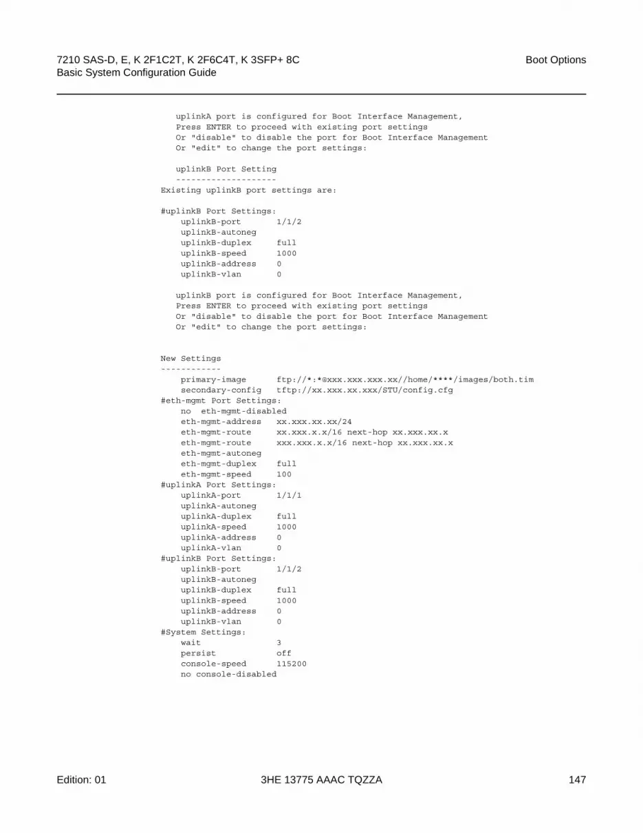
7210 SAS-D, E, K 2F1C2T, K 2F6C4T, K 3SFP+ 8C Basic System Configuration Guide
Boot Options
Edition: 01 3HE 13775 AAAC TQZZA 147
uplinkA port is configured for Boot Interface Management,Press ENTER to proceed with existing port settingsOr "disable" to disable the port for Boot Interface ManagementOr "edit" to change the port settings:
uplinkB Port Setting--------------------
Existing uplinkB port settings are:
#uplinkB Port Settings:uplinkB-port 1/1/2uplinkB-autoneguplinkB-duplex fulluplinkB-speed 1000uplinkB-address 0uplinkB-vlan 0
uplinkB port is configured for Boot Interface Management,Press ENTER to proceed with existing port settingsOr "disable" to disable the port for Boot Interface ManagementOr "edit" to change the port settings:
New Settings------------
primary-image ftp://*:*@xxx.xxx.xxx.xx//home/****/images/both.timsecondary-config tftp://xx.xxx.xx.xxx/STU/config.cfg
#eth-mgmt Port Settings:no eth-mgmt-disabledeth-mgmt-address xx.xxx.xx.xx/24eth-mgmt-route xx.xxx.x.x/16 next-hop xx.xxx.xx.xeth-mgmt-route xxx.xxx.x.x/16 next-hop xx.xxx.xx.xeth-mgmt-autonegeth-mgmt-duplex fulleth-mgmt-speed 100
#uplinkA Port Settings:uplinkA-port 1/1/1uplinkA-autoneguplinkA-duplex fulluplinkA-speed 1000uplinkA-address 0uplinkA-vlan 0
#uplinkB Port Settings:uplinkB-port 1/1/2uplinkB-autoneguplinkB-duplex fulluplinkB-speed 1000uplinkB-address 0uplinkB-vlan 0
#System Settings:wait 3persist offconsole-speed 115200no console-disabled

Boot Options
148
7210 SAS-D, E, K 2F1C2T, K 2F6C4T, K 3SFP+ 8CBasic System Configuration Guide
3HE 13775 AAAC TQZZA Edition: 01
4.9.2 Accessing the CLI
To access the CLI to configure the software for the first time, perform the following steps.
• When the power to the chassis is turned on, the 7210 SAS software automatically begins the boot sequence.
• When the boot loader and BOF image and configuration files are successfully located, establish a router connection (console session).
4.9.2.1 Console Connection
To establish a console connection, you will need the following:
• an ASCII terminal or a PC running terminal emulation software set to the parameters described in Table 18
• a standard serial cable connector for connecting to a RS232 port (provides a RJ45 connector)
Table 18 describes the console configuration parameter values necessary for establishing a console connection.
To establish a console connection, perform the following steps.
Step 1. Connect the terminal to the console port on the front panel using the serial cable.
Step 2. Power on the terminal.
Step 3. Establish the connection by pressing the <Enter> key a few times on your terminal keyboard.
Table 18 Console Configuration Parameter Values
Parameter Value
Baud 115 200
Data bits 8
Parity None
Stop bits 1
Flow control None

7210 SAS-D, E, K 2F1C2T, K 2F6C4T, K 3SFP+ 8C Basic System Configuration Guide
Boot Options
Edition: 01 3HE 13775 AAAC TQZZA 149
Step 4. At the router prompt, enter the login and password.
The default login is admin.
The default password is admin.
4.9.2.2 7210 SAS-E Console Port
The 7210 SAS-E is a multilayer service-aware Layer 2 switch. It supports up to 24 connections, including 12 100/1000 fiber-optic SFP ports and 12 10/100/1000 Base-T copper SFP ports. The 7210 SAS-E has one 10/100 Base-TX management port for dedicated management access.
Figure 11 shows an example of the console port on a 7210 SAS-E front panel.
Figure 11 7210 SAS-E Front Panel Console Port
4.9.2.3 7210 SAS-D Console Port
The 7210 SAS-D is a service-aware Layer 2 switch with support for QinQ Layer 2 uplinks. The switch functions as an Ethernet demarcation and back-haul unit with support for four 10/100/1000 Base-T fixed copper ports and six 100/1000 SFP ports with line-rate switching on all the ports.
Figure 12 shows an example of the console port on a 7210 SAS-D front panel.
hw0371Console Port

Boot Options
150
7210 SAS-D, E, K 2F1C2T, K 2F6C4T, K 3SFP+ 8CBasic System Configuration Guide
3HE 13775 AAAC TQZZA Edition: 01
Figure 12 7210 SAS-D Front Panel Console Port
4.9.2.4 7210 SAS-K 2F1C2T Console Port
The 7210 SAS-K 2F1C2T is a 1GE demarcation device targeted for business services, mobile backhaul, and vertical and strategic industry segments.
The 7210 SAS-K 2F1C2T provides two 100/1000 SFP ports. Each port can be used for a direct connection to subscriber customer premises equipment (CPE) or as an uplink to another aggregation node. The 7210 SAS-K 2F1C2T also provides two 10/100/1000 Base-T fixed copper ports and one combo port.
The 7210 SAS-K 2F1C2T has a non-ETR (standard) variant and an ETR variant.
Figure 13 and Figure 14 show examples of the console port on the front panel of the 7210 SAS-K 2F1C2T and 7210 SAS-K 2F1C2T ETR variants.
Figure 13 7210 SAS-K 2F1C2T Front Panel Console Port (non-ETR)
AC Power
DC Powerhw0372
Console Port
Console Port
hw0383
Console Port
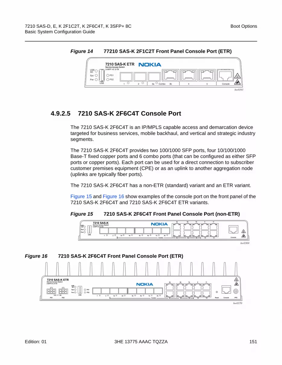
7210 SAS-D, E, K 2F1C2T, K 2F6C4T, K 3SFP+ 8C Basic System Configuration Guide
Boot Options
Edition: 01 3HE 13775 AAAC TQZZA 151
Figure 14 77210 SAS-K 2F1C2T Front Panel Console Port (ETR)
4.9.2.5 7210 SAS-K 2F6C4T Console Port
The 7210 SAS-K 2F6C4T is an IP/MPLS capable access and demarcation device targeted for business services, mobile backhaul, and vertical and strategic industry segments.
The 7210 SAS-K 2F6C4T provides two 100/1000 SFP ports, four 10/100/1000 Base-T fixed copper ports and 6 combo ports (that can be configured as either SFP ports or copper ports). Each port can be used for a direct connection to subscriber customer premises equipment (CPE) or as an uplink to another aggregation node (uplinks are typically fiber ports).
The 7210 SAS-K 2F6C4T has a non-ETR (standard) variant and an ETR variant.
Figure 15 and Figure 16 show examples of the console port on the front panel of the 7210 SAS-K 2F6C4T and 7210 SAS-K 2F6C4T ETR variants.
Figure 15 7210 SAS-K 2F6C4T Front Panel Console Port (non-ETR)
Figure 16 7210 SAS-K 2F6C4T Front Panel Console Port (ETR)
hw0393
hw0369
hw0370

Boot Options
152
7210 SAS-D, E, K 2F1C2T, K 2F6C4T, K 3SFP+ 8CBasic System Configuration Guide
3HE 13775 AAAC TQZZA Edition: 01
4.9.2.6 7210 SAS-K 3SFP+ 8C Console Port
The 7210 SAS-K 3SFP+ 8C is an IP/MPLS capable ETR device designed for delivering differentiated services for mobile backhaul, business services, and vertical industry segments such as railways and transportation. It supports both IP/MPLS and Ethernet-based Layer 2 VPN services and Layer 3 services, and provides a rich set of Ethernet OAM and IP/MPLS OAM tools to aid in troubleshooting, fault resolution, and service performance monitoring.
The 7210 SAS-K 3SFP+ 8C provides three 1GE/10GE SFP+ ports and eight combo ports. The combo ports can be configured as either Base-T or SFP ports, or a mix of both. This flexible configuration can provide up to eight 100/1000 SFP ports or up to eight 10/100/1000 Mb/s RJ-45 Base-T fixed copper ports. A mixed configuration of both SFP and copper ports can provide up to eight 1 Gb/s Ethernet ports.
Figure 17 shows the console port on the front panel of the 7210 SAS-K 3SFP+ 8C that is used to establish a terminal connection to the port.
Figure 17 7210 SAS-K 3SFP+ 8C Front Panel Console Port
4b 6b 8b 10b
5b 7b 9b 11b
PS1 PS2Service Access Switch3-SFP+ 8-C
Power Input100-240 Vac 50/60Hz USB Reset
USBSDSys
PwrPS1PS2
1 2 3 4a 5a 6a 7a 8a 9a 10a 11aCombo
Console PPS
hw0394Console Port
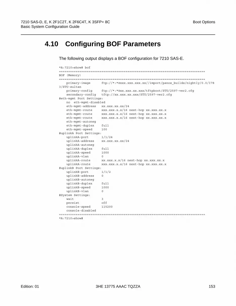
7210 SAS-D, E, K 2F1C2T, K 2F6C4T, K 3SFP+ 8C Basic System Configuration Guide
Boot Options
Edition: 01 3HE 13775 AAAC TQZZA 153
4.10 Configuring BOF Parameters
The following output displays a BOF configuration for 7210 SAS-E.
*A:7210>show# bof===============================================================================BOF (Memory)===============================================================================
primary-image ftp://*:*@xxx.xxx.xxx.xx//import/panos_builds/nightly/0.0/I783/STU-sultan
primary-config ftp://*:*@xx.xxx.xx.xxx/tftpboot/STU/2597-ver2.cfgsecondary-config tftp://xx.xxx.xx.xxx/STU/2597-ver2.cfg
#eth-mgmt Port Settings:no eth-mgmt-disabledeth-mgmt-address xx.xxx.xx.xx/24eth-mgmt-route xxx.xxx.x.x/16 next-hop xx.xxx.xx.xeth-mgmt-route xxx.xxx.x.x/16 next-hop xx.xxx.xx.xeth-mgmt-route xxx.xxx.x.x/16 next-hop xx.xxx.xx.xeth-mgmt-autonegeth-mgmt-duplex fulleth-mgmt-speed 100
#uplinkA Port Settings:uplinkA-port 1/1/24uplinkA-address xx.xxx.xx.xx/24uplinkA-autoneguplinkA-duplex fulluplinkA-speed 1000uplinkA-vlan 0uplinkA-route xx.xxx.x.x/16 next-hop xx.xxx.xx.xuplinkA-route xxx.xxx.x.x/16 next-hop xx.xxx.xx.x
#uplinkB Port Settings:uplinkB-port 1/1/2uplinkB-address 0uplinkB-autoneguplinkB-duplex fulluplinkB-speed 1000uplinkB-vlan 0
#System Settings:wait 3persist offconsole-speed 115200console-disabled
===============================================================================*A:7210>show#

Boot Options
154
7210 SAS-D, E, K 2F1C2T, K 2F6C4T, K 3SFP+ 8CBasic System Configuration Guide
3HE 13775 AAAC TQZZA Edition: 01
4.11 Service Management Tasks
This section discusses the following service management tasks:
• System Administration Commands
• Viewing the Current Configuration
• Modifying and Saving a Configuration
• Deleting BOF Parameters
• Saving a Configuration to a Different Filename
• Rebooting
4.11.1 System Administration Commands
Use the following administrative commands to perform management tasks.
CLI Syntax: A:ALA-1# adminauto-init stopcheck-golden-bootstrapdebug-save [<file-url>]disconnect [address <ip-address> | username
<user-name> |{console|telnet|ftp|ssh}]display-config[no]enable-techreboot [auto-init][now]save [file-url] [detail] [index]set-time <date> <time>tech-support <file-url>update-golden-bootstrap [file-url]
4.11.2 Viewing the Current Configuration
Use one of the following CLI commands to display the current configuration. The detail option displays all default values. The index option displays only the persistent indices. The info command displays context-level information.
CLI Syntax: admin# display-config [detail|index]info detail
The following output shows an example of a configuration file.

7210 SAS-D, E, K 2F1C2T, K 2F6C4T, K 3SFP+ 8C Basic System Configuration Guide
Boot Options
Edition: 01 3HE 13775 AAAC TQZZA 155
*A:sim169# admin display-config# TiMOS-B-0.0.I218 both/i386 NOKIA SAS-E 7210 Copyright (c) 2016 Nokia.# All rights reserved. All use subject to applicable license agreements.# Built on Fri Sep 26 20:46:58 IST 2016 by panosbld in /panosbld/ws/panos/main
# Generated THU JUN 23 19:19:22 2016 UTC
exit allconfigure#--------------------------------------------------echo "System Configuration"#--------------------------------------------------
systemname "7210-3"contact "Fred Information Technology"location "Bldg.1-floor 2-Room 201"clli-code "abcdefg1234"coordinates "N 45 58 23, W 34 56 12"ccm 1exitsnmpexitlogin-control
idle-timeout 1440motd text "7210-3"
exittime
sntpshutdown
exitzone UTC
exitthresholds
rmonexit
exitexit...
...#--------------------------------------------------
# Finished FRI Nov 21 15:06:16 2016 UTCA:*A:sim169##
4.11.3 Modifying and Saving a Configuration
If you modify a configuration file, the changes remain in effect only during the current power cycle unless a save command is executed. Changes are lost if the system is powered down or the router is rebooted without saving.

Boot Options
156
7210 SAS-D, E, K 2F1C2T, K 2F6C4T, K 3SFP+ 8CBasic System Configuration Guide
3HE 13775 AAAC TQZZA Edition: 01
• Specify the file URL location to save the running configuration. If a destination is not specified, the files are saved to the location where the files were found for that boot sequence. The same configuration can be saved with different filenames to the same location or to different locations.
• The detail option adds the default parameters to the saved configuration.
• The index option forces a save of the index file.
• Changing the active and standby addresses without reboot standby CPM may cause a boot-env sync to fail.
The following command saves a configuration.
CLI Syntax: bof# save [cflash-id]
Example: A:ALA-1# bofA:ALA-1>bof# save cf1:A:ALA-1>bof#
The following command saves the system configuration.
CLI Syntax: admin# save [file-url] [detail] [index]
Example: A:ALA-1# admin save cf1:\test123.cfgSaving config.# Saved to cf1:\test123.cfg... completeA:ALA-1#
4.11.4 Deleting BOF Parameters
You can delete specific BOF parameters. The no form of these commands removes the parameter from configuration. The changes remain in effect only during the current power cycle unless a save command is executed. Changes are lost if the system is powered down or the router is rebooted without saving.
Deleting the BOF file and rebooting causes the system to enter auto-mode.
Use the following CLI syntax to save and remove BOF configuration parameters.
Note: If the persist option is enabled and the admin save file-url command is executed with an FTP path used as the file-url parameter, two FTP sessions simultaneously open to the FTP server. The FTP server must be configured to allow multiple sessions from the same login; otherwise, the configuration and index files will not be saved correctly.

7210 SAS-D, E, K 2F1C2T, K 2F6C4T, K 3SFP+ 8C Basic System Configuration Guide
Boot Options
Edition: 01 3HE 13775 AAAC TQZZA 157
CLI Syntax: bof# save [cflash-id]
Example: A:ALA-1# bofA:ALA-1>bof# save cf1:A:ALA-1>bof#
The following is the CLI syntax for the 7210 SAS-E.
CLI Syntax: *A:7210>bof# no console-speed no dns-domain no eth-mgmt-address no eth-mgmt-autoneg no eth-mgmt-disable eth-mgmt-duplex no eth-mgmt-route eth-mgmt-speed persist no ping-address no primary-config no primary-dns no primary-image save no secondary-config no secondary-dns no secondary-image no tertiary-config no tertiary-dns no tertiary-image no uplinkA-address no uplinkA-autoneg no uplinkA-duplex no uplinkA-speed no uplinkA-port no uplinkA-route no uplinkA-vlan no uplinkB-address no uplinkB-autoneg no uplinkB-duplex no uplinkB-speed no uplinkB-port no uplinkB-route no uplinkB-vlan wait
The following is the CLI syntax for the 7210 SAS-D.
CLI Syntax: *A:7210>bof#no console-speed

Boot Options
158
7210 SAS-D, E, K 2F1C2T, K 2F6C4T, K 3SFP+ 8CBasic System Configuration Guide
3HE 13775 AAAC TQZZA Edition: 01
no dns-domainpersistno ping-addressno primary-configno primary-dnsno primary-imagesaveno secondary-configno secondary-dnsno secondary-imageno tertiary-configno tertiary-dnsno tertiary-imageno uplinkA-addressno uplinkA-autoneg no uplinkA-duplex no uplinkA-speed no uplinkA-portno uplinkA-routeno uplinkA-vlanno uplinkB-addressno uplinkB-autoneg no uplinkB-duplex no uplinkB-speed no uplinkB-portno uplinkB-routeno uplinkB-vlanwait
4.11.5 Saving a Configuration to a Different Filename
Save the current configuration with a unique filename to have additional backup copies and to edit parameters with a text editor. You can save your current configuration to an ASCII file.
Use either of the following CLI syntax to save a configuration to a different location.
CLI Syntax: bof# save [cflash-id]
Example: A:ALA-1# bofA:ALA-1>bof# save cf1:A:ALA-1>bof#
or
CLI Syntax: admin# save [file-url] [detail] [index]

7210 SAS-D, E, K 2F1C2T, K 2F6C4T, K 3SFP+ 8C Basic System Configuration Guide
Boot Options
Edition: 01 3HE 13775 AAAC TQZZA 159
Example: A:ALA-1>admin# save cf1:\testABC.cfgSaving config.# Saved to cf1:\testABC.cfg... completeA:ALA-1#
4.11.6 Rebooting
When an admin>reboot command is issued, the system reboots. Changes are lost unless the configuration is saved. Use the admin>save file-url command to save the current configuration. The user is prompted to confirm the reboot operation. If the now option is not specified, the user is prompted to confirm the reboot operation.
Use the following CLI syntax to reboot.
CLI Syntax: admin# reboot [auto-init][now]
Example: A:ALA-1>admin# reboot A:DutA>admin# reboot
Are you sure you want to reboot (y/n)? y
Resetting...OK
Nokia 7210 Boot ROM. Copyright 2016 Nokia.All rights reserved. All use is subject to applicable license agreements.Running POST tests from ROMTesting ROM load area...done
Relocating code...Jumping to RAM...
When an admin reboot auto-init command is issued, the system resets the existing BOF file and reboots. The system startup process after the admin reboot auto-init command is executed is the same as the first-time system boot as described in System Initialization.
Use the following CLI to reset the BOF and reboot.
Note: Since the BOF is reset, the system may not boot up with the last saved system configuration unless the new BOF file also uses the same configuration file. If it is required that the system boot up with the last saved system configuration, it is recommended to use the admin>save file-url command to save the current system configuration and modify the BOF to use this.
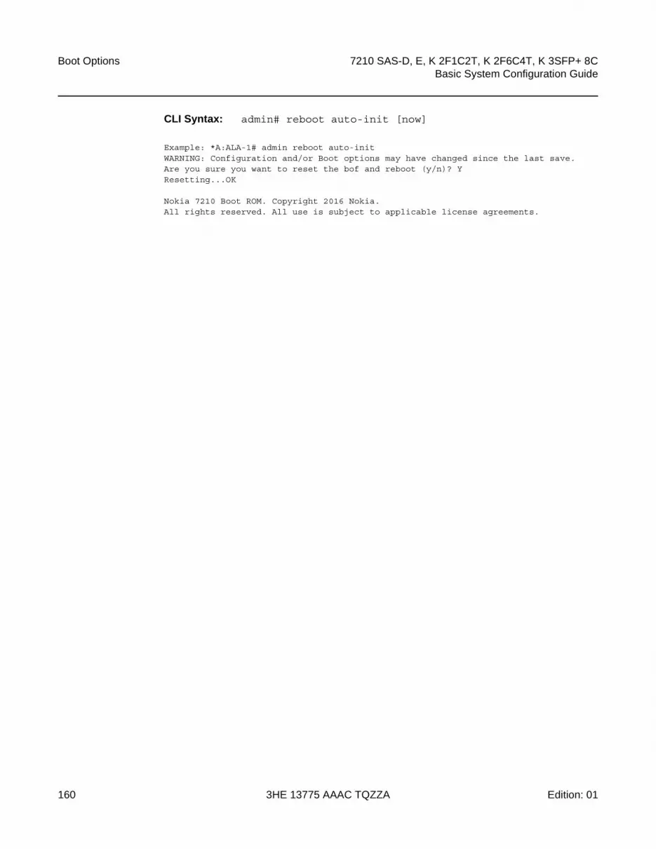
Boot Options
160
7210 SAS-D, E, K 2F1C2T, K 2F6C4T, K 3SFP+ 8CBasic System Configuration Guide
3HE 13775 AAAC TQZZA Edition: 01
CLI Syntax: admin# reboot auto-init [now]
Example: *A:ALA-1# admin reboot auto-initWARNING: Configuration and/or Boot options may have changed since the last save.Are you sure you want to reset the bof and reboot (y/n)? YResetting...OK
Nokia 7210 Boot ROM. Copyright 2016 Nokia.All rights reserved. All use is subject to applicable license agreements.

7210 SAS-D, E, K 2F1C2T, K 2F6C4T, K 3SFP+ 8C Basic System Configuration Guide
Boot Options
Edition: 01 3HE 13775 AAAC TQZZA 161
4.12 BOF Command Reference
4.12.1 Command Hierarchies
4.12.1.1 Configuration Commands
bof— bof-password— [no] console-disabled— console-speed baud-rate— no console-speed— dns-domain dns-name — no dns-domain— [no] eth-mgmt-address ip-prefix/ip-prefix-length — [no] eth-mgmt-autoneg — [no] eth-mgmt-disabled — eth-mgmt-duplex {full | half} — [no] eth-mgmt-route ip-prefix/ip-prefix-length next-hop ip-address — eth-mgmt-speed speed — persist {on | off}— ping-address ip-address— no ping-address— primary-config file-url — no primary-config— primary-dns ip-address— no primary-dns— primary-image file-url — no primary-image— save [cflash-id ]— secondary-config file-url — no secondary-config— [no] secondary-dns ip-address— secondary-image file-url — no secondary-image— tertiary-config file-url — no tertiary-config— tertiary-dns ip-address— no tertiary-dns— tertiary-image file-url — no tertiary-image— wait seconds
Note: Not all the commands are supported on all the 7210 SAS platforms.

Boot Options
162
7210 SAS-D, E, K 2F1C2T, K 2F6C4T, K 3SFP+ 8CBasic System Configuration Guide
3HE 13775 AAAC TQZZA Edition: 01
— uplinkA-address ip-address/mask— no uplinkA-address— uplinkA-autoneg— no uplinkA-autoneg— uplinkA-duplex— uplinkA-port port-id— no uplinkA-port— [no] uplinkA-route ip-address/mask next-hop ip-address— uplinkA-speed— uplinkA-vlan 0..4094— no uplinkA-vlan— uplinkB-address ip-address/mask— no uplinkB-address— uplinkB-autoneg— no uplinkB-autoneg— uplinkB-duplex— uplinkB-port port-id— no uplinkB-port— [no] uplinkB-route ip-address/mask next-hop ip-address— uplinkB-speed— uplinkB-vlan 0..4094— no uplinkB-vlan— wait seconds
4.12.1.2 Show Commands
show— bof [cflash-id | booted] — boot-messages

7210 SAS-D, E, K 2F1C2T, K 2F6C4T, K 3SFP+ 8C Basic System Configuration Guide
Boot Options
Edition: 01 3HE 13775 AAAC TQZZA 163
4.12.2 Command Descriptions
• Configuration Commands
• Show Commands
4.12.2.1 Configuration Commands
• File Management Commands
• BOF Processing Control Commands
• Console Port Configuration Commands
• Image and Configuration Management Commands
• DNS Configuration Commands
4.12.2.1.1 File Management Commands
bof
Syntax bof
Context <ROOT>
SupportedPlatforms
Supported on all 7210 SAS platforms as described in this document
Description This command creates or edits the boot option file (BOF) for the specified local storage device.
A BOF file specifies where the system searches for runtime images, configuration files, and other operational parameters during system initialization.
BOF parameters can be modified. Changes can be saved to a specified compact flash. The BOF must be located in the root directory of either an internal or external compact flash local to the system and have the mandatory filename of bof.cfg.
When modifications are made to in-memory parameters that are currently in use or operating, the changes are effective immediately. For example, if the console-speed is changed, the change takes place immediately.
Only one entry of the BOF configuration command statement can be saved once the statement has been found to be syntactically correct.
No default boot option file exists.

Boot Options
164
7210 SAS-D, E, K 2F1C2T, K 2F6C4T, K 3SFP+ 8CBasic System Configuration Guide
3HE 13775 AAAC TQZZA Edition: 01
save
Syntax save [cflash-id]
Context bof
SupportedPlatforms
Supported on all 7210 SAS platforms as described in this document
Description This command uses the boot option parameters currently in memory and writes them from the boot option file to the compact flash.
The BOF is located in the root directory of the internal compact flash drive local to the system and have the mandatory filename of bof.cfg. Saves must be explicitly executed. BOF is saved at the same location as the location of boot.tim used for booting the system.
Command usage:
• bof save — Saves the BOF to the flash drive.
• bof save cf1: — Saves the BOF to cf1:
Parameters cflash-id — Specifies the compact flash ID where the bof.cfg is to be saved.
cf1: - 7210 SAS-D
cf1: | uf1: - 7210 SAS-E
cf1: | uf1: - 7210 SAS-K 2F1C2T, 7210 SAS-K 2F6C4T, and 7210 SAS-K 3SFP+ 8C
4.12.2.1.2 BOF Processing Control Commands
wait
Syntax wait seconds
Context bof
SupportedPlatforms
Supported on all 7210 SAS platforms as described in this document
Description This command configures a pause, in seconds, at the start of the boot process which allows system initialization to be interrupted at the console.
When system initialization is interrupted the operator is allowed to manually override the parameters defined in the boot option file (BOF).
Only one wait command can be defined in the BOF.
Default 3

7210 SAS-D, E, K 2F1C2T, K 2F6C4T, K 3SFP+ 8C Basic System Configuration Guide
Boot Options
Edition: 01 3HE 13775 AAAC TQZZA 165
Parameters seconds — Specifies the time to pause at the start of the boot process, in seconds.
Values 1 to 10
4.12.2.1.3 Console Port Configuration Commands
bof-password
Syntax bof-password password
Context bof
SupportedPlatforms
Supported on all 7210 SAS platforms as described in this document
Description This command enables the context to configure a BOF password. The user will have to provide this password to edit the BOF parameters in the boot loader.
It also implements a mechanism for password recovery, if the user forgets the password. If the user forgets the password, it can be reset to factory default. As a security measure, to prevent a malicious user for using it gain access to the configuration files, when the password is reset to default, the system also resets the flash to factory defaults (that is, it removes all the files from the flash except for the boot image file (cf1:\boot.tim) and TiMOS image file (cf1:\both.tim)) and reboots the node with the factory default settings. After boot up, the user needs to setup the box using the same steps as used to boot the box the first time when it was received from the factory. User can use the factory default password “password” to edit the BOF parameters after the boot up subsequent to reboot and choose to change the password again.
Default password
Parameters password — Specifies the BOF password.
Values Maximum of 20 characters.
console-disabled
Syntax [no] console-disabled
Context bof
Note: It is highly recommended that user does not rename cf1:\boot.tim and cf1:\both.tim, if the system needs to retain them during the password recovery procedure. Additionally, it is highly recommended that the user takes a backup of all the image files, configuration files and other data.

Boot Options
166
7210 SAS-D, E, K 2F1C2T, K 2F6C4T, K 3SFP+ 8CBasic System Configuration Guide
3HE 13775 AAAC TQZZA Edition: 01
SupportedPlatforms
Supported on all 7210 SAS platforms as described in this document
Description This command enables or disables the serial port console for use.
In remote deployments this command provides additional security mechanism for the user. The console can be disabled to prevent unauthorized access to the system.
The no form of this command enables the console. This is the default value.
Default no console-disabled
console-speed
Syntax console-speed baud-rate
no console-speed
Context bof
SupportedPlatforms
Supported on all 7210 SAS platforms as described in this document
Description This command configures the console port baud rate.
When this command is issued while editing the BOF file used for the most recent boot, both the BOF file and the active configuration are changed immediately.
The no form of this command reverts to the default value.
Default 115200 bps
Parameters baud-rate — Specifies the console port baud rate, expressed as a decimal integer.
Values 9600, 19200, 38400, 57600, 115200
Note: The console is always available for use when the device is booting up. This command is applicable only after the TiMOS image (that is the both.tim) is up and running successfully. If the user executes this command in the BOF CLI context, the command takes effect only during the next boot. A BOF save operation must be performed after executing the console-disabled command.

7210 SAS-D, E, K 2F1C2T, K 2F6C4T, K 3SFP+ 8C Basic System Configuration Guide
Boot Options
Edition: 01 3HE 13775 AAAC TQZZA 167
4.12.2.1.4 Image and Configuration Management Commands
persist
Syntax persist {on | off}
Context bof
SupportedPlatforms
Supported on all 7210 SAS platforms as described in this document
Description This command specifies whether the system will preserve system indexes when a save command is executed. During a subsequent boot, the index file is read along with the configuration file. As a result, a number of system indexes are preserved between reboots, including the interface index, and so on. This reduces resynchronizations of the Network Management System (NMS) with the affected network element.
In the event that persist is on and the reboot with the appropriate index file fails, SNMP is operationally shut down to prevent the management system from accessing and possibly synchronizing with a partially booted or incomplete network element. To enable SNMP access, enter the config>system>snmp>no shutdown command.
If persist is enabled and the admin save <url> command is executed with an FTP path used as the <url> parameter, two FTP sessions simultaneously open to the FTP server. The FTP server must be configured to allow multiple sessions from the same login, otherwise, the configuration and index files will not be saved correctly.
Default off
Parameters on — Create when saving the configuration.
off — Disables the system index saves between reboots.
Note:
• Persistency files (.ndx) are saved on the same disk as the configuration files and the image files.
• When a user sets the location for the persistency file, the system will check to ensure that the disk has enough free space. If this there is not enough free space, the persistency will not become active and a trap will be generated. Then, it is up to the operator to free adequate disk space. In the meantime, the system will perform a space availability check every 30 seconds. As soon as the space is available the persistency will become active on the next (30 second) check.

Boot Options
168
7210 SAS-D, E, K 2F1C2T, K 2F6C4T, K 3SFP+ 8CBasic System Configuration Guide
3HE 13775 AAAC TQZZA Edition: 01
primary-config
Syntax primary-config file-url
no primary-config
Context bof
SupportedPlatforms
Supported on all 7210 SAS platforms as described in this document
Description This command specifies the name and location of the primary configuration file.
The system attempts to use the configuration specified in primary-config. If the specified file cannot be located, the system automatically attempts to obtain the configuration from the location specified in secondary-config and then the tertiary-config.
Note that if an error in the configuration file is encountered, the boot process aborts.
The no form of this command removes the primary-config configuration.
Parameters file-url — The primary configuration file location, expressed as a file URL.
Values
primary-image
Syntax primary-image file-url
no primary image
Context bof
SupportedPlatforms
Supported on all 7210 SAS platforms as described in this document
Description This command specifies the primary directory location for runtime image file loading.
The system attempts to load all runtime image files configured in the primary-image first. If this fails, the system attempts to load the runtime images from the location configured in the secondary-image. If the secondary image load fails, the tertiary image specified in tertiary-image is used.
file-url [local-url | remote-url] (up to 180 characters)
local-url [<cflash-id/> | <usb-flash-id>][file-path]
remote-url [{ftp://|tftp://} login:pswd@remote-locn/][file-path]
cflash-id cf1:
usb-flash-id uf1:

7210 SAS-D, E, K 2F1C2T, K 2F6C4T, K 3SFP+ 8C Basic System Configuration Guide
Boot Options
Edition: 01 3HE 13775 AAAC TQZZA 169
The no form of this command removes the primary-image configuration.
Parameters file-url — Specifies the location-url can be either local (this flash) or a remote FTP server.
Values
secondary-config
Syntax secondary-config file-url
no secondary-config
Context bof
SupportedPlatforms
Supported on all 7210 SAS platforms as described in this document
Description This command specifies the name and location of the secondary configuration file.
The system attempts to use the configuration as specified in secondary-config if the primary config cannot be located. If the secondary-config file cannot be located, the system attempts to obtain the configuration from the location specified in the tertiary-config.
Note that if an error in the configuration file is encountered, the boot process aborts.
The no form of this command removes the secondary-config configuration.
Parameters file-url — Specifies the secondary configuration file location, expressed as a file URL.
Values
file-url [local-url | remote-url] (up to 180 characters)
local-url [<cflash-id/> | <usb-flash-id>][file-path]
remote-url [{ftp://|tftp://} login:pswd@remote-locn/][file-path]
cflash-id cf1:
usb-flash-id uf1:
file-url [local-url | remote-url] (up to 180 characters)
local-url [<cflash-id/> | <usb-flash-id>][file-path]
remote-url [{ftp://|tftp://} login:pswd@remote-locn/][file-path]
cflash-id cf1:
usb-flash-id uf1:

Boot Options
170
7210 SAS-D, E, K 2F1C2T, K 2F6C4T, K 3SFP+ 8CBasic System Configuration Guide
3HE 13775 AAAC TQZZA Edition: 01
secondary-image
Syntax secondary-image file-url
no secondary-image
Context bof
SupportedPlatforms
Supported on all 7210 SAS platforms as described in this document
Description This command specifies the secondary directory location for runtime image file loading.
The system attempts to load all runtime image files configured in the primary-image first. If this fails, the system attempts to load the runtime images from the location configured in the secondary-image. If the secondary image load fails, the tertiary image specified in tertiary-image is used.
The no form of this command removes the secondary-image configuration.
Parameters file-url — Specifies that the file-url can be either local (this local flash) or a remote FTP server.
Values
tertiary-config
Syntax tertiary-config file-url
no tertiary-config
Context bof
SupportedPlatforms
Supported on all 7210 SAS platforms as described in this document
Description This command specifies the name and location of the tertiary configuration file.
The system attempts to use the configuration specified in tertiary-config if both the primary and secondary config files cannot be located. If this file cannot be located, the system boots with the factory default configuration.
Note that if an error in the configuration file is encountered, the boot process aborts.
file-url [local-url | remote-url] (up to 180 characters)
local-url [<cflash-id/> | <usb-flash-id>][file-path]
remote-url [{ftp://|tftp://} login:pswd@remote-locn/][file-path]
cflash-id cf1:
usb-flash-id uf1:
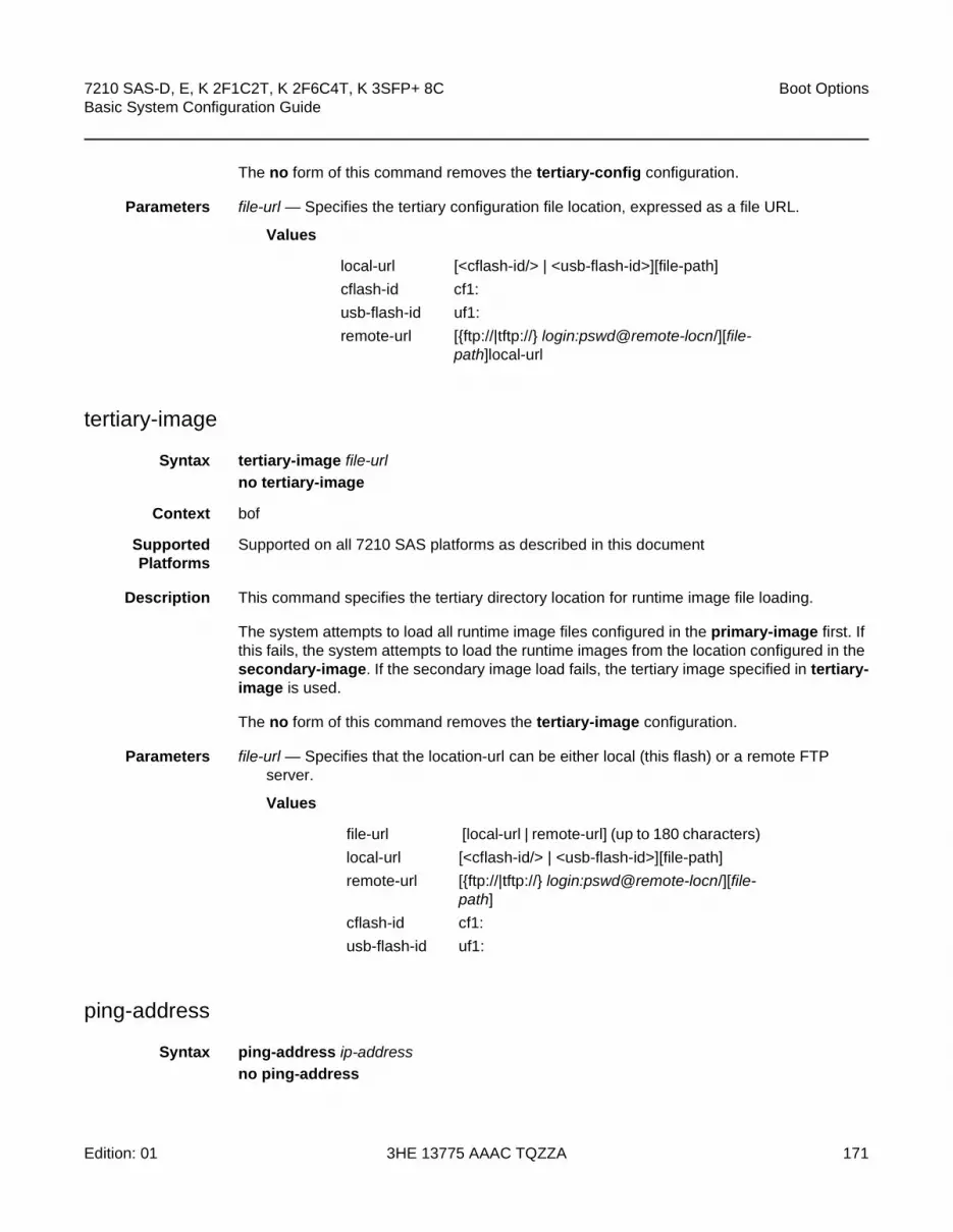
7210 SAS-D, E, K 2F1C2T, K 2F6C4T, K 3SFP+ 8C Basic System Configuration Guide
Boot Options
Edition: 01 3HE 13775 AAAC TQZZA 171
The no form of this command removes the tertiary-config configuration.
Parameters file-url — Specifies the tertiary configuration file location, expressed as a file URL.
Values
tertiary-image
Syntax tertiary-image file-url
no tertiary-image
Context bof
SupportedPlatforms
Supported on all 7210 SAS platforms as described in this document
Description This command specifies the tertiary directory location for runtime image file loading.
The system attempts to load all runtime image files configured in the primary-image first. If this fails, the system attempts to load the runtime images from the location configured in the secondary-image. If the secondary image load fails, the tertiary image specified in tertiary-image is used.
The no form of this command removes the tertiary-image configuration.
Parameters file-url — Specifies that the location-url can be either local (this flash) or a remote FTP server.
Values
ping-address
Syntax ping-address ip-address
no ping-address
local-url [<cflash-id/> | <usb-flash-id>][file-path]
cflash-id cf1:
usb-flash-id uf1:
remote-url [{ftp://|tftp://} login:pswd@remote-locn/][file-path]local-url
file-url [local-url | remote-url] (up to 180 characters)
local-url [<cflash-id/> | <usb-flash-id>][file-path]
remote-url [{ftp://|tftp://} login:pswd@remote-locn/][file-path]
cflash-id cf1:
usb-flash-id uf1:

Boot Options
172
7210 SAS-D, E, K 2F1C2T, K 2F6C4T, K 3SFP+ 8CBasic System Configuration Guide
3HE 13775 AAAC TQZZA Edition: 01
Context bof
SupportedPlatforms
Supported on all 7210 SAS platforms as described in this document
Description This command specifies the IP address which would be used for ping-test after the system boots.
The no form of this command removes the ping-address configuration. Setting a value of 0 also removes the ping-address configuration.
Parameters ip-address — Specifies an IPv4 ip-address in the form a.b.c.d; for example, 10.1.2.10.
uplinkA-address
Syntax uplinkA-address ip-address/mask
no uplinkA-address
Context bof
SupportedPlatforms
Supported on all 7210 SAS platforms as described in this document
Description This command configures the uplink-A address.
The no form of this command sets the uplinkA to use DHCP to get the IP and the show bof value reflects 0 for this parameter.
Parameters ip-address — Specifies he IP address of the Boot Option File (BOF). This address must be unique within the subnet and specified in dotted decimal notation.
Values a.b.c.d
mask — Specifies the subnet mask length when the IP prefix is specified in CIDR notation. When the IP prefix is specified in CIDR notation, a forward slash (/) separates the ip-addr from the mask-length parameter. The mask length parameter indicates the number of bits used for the network portion of the IP address; the remainder of the IP address is used to determine the host portion of the IP address.
Values 1 to 30
uplinkB-address
Syntax uplinkB-address ip-address/mask
no uplinkB-address
Context bof
SupportedPlatforms
Supported on all 7210 SAS platforms as described in this document

7210 SAS-D, E, K 2F1C2T, K 2F6C4T, K 3SFP+ 8C Basic System Configuration Guide
Boot Options
Edition: 01 3HE 13775 AAAC TQZZA 173
Description This command configures the uplink-B address.
The no form of this command sets the uplinkB to use DHCP to get the IP and the show bof value reflects 0 for this parameter.
Parameters ip-address — Specifies the IP address of the Boot Option File (BOF). This address must be unique within the subnet and specified in dotted decimal notation.
Values a.b.c.d
mask — Specifies the subnet mask length when the IP prefix is specified in CIDR notation. When the IP prefix is specified in CIDR notation, a forward slash (/) separates the ip-addr from the mask-length parameter. The mask length parameter indicates the number of bits used for the network portion of the IP address; the remainder of the IP address is used to determine the host portion of the IP address.
Values 1 to 30
uplinkA-autoneg
Syntax [no] uplinkA-autoneg
Context bof
SupportedPlatforms
Supported on all 7210 SAS platforms as described in this document
Description This command enables speed and duplex Auto-negotiation on the uplinkA port in the running configuration and the Boot Option File (BOF).
The no form of this command disables the Auto-negotiate feature on this port.
#uplinkA Port Settings:uplinkA-port 1/1/26no uplinkA-autoneguplinkA-duplex fulluplinkA-speed 10000uplinkA-address 0uplinkA-vlan 0
Default uplinkA-autoneg — Auto-negotiation is enabled on the management Ethernet port.
Note: The uplinkA-autoneg command is not valid for 10GE ports, therefore, whenever the user selects 10GE ports as uplinkA-port, the uplinkA-autoneg command is defaulted to no uplinkA-autoneg, speed as uplinkA-speed 10000, duplex as uplinkA-duplex full, as shown below.

Boot Options
174
7210 SAS-D, E, K 2F1C2T, K 2F6C4T, K 3SFP+ 8CBasic System Configuration Guide
3HE 13775 AAAC TQZZA Edition: 01
uplinkB-autoneg
Syntax [no] uplinkB-autoneg
Context bof
SupportedPlatforms
Supported on all 7210 SAS platforms as described in this document
Description This command enables speed and duplex Auto-negotiation on the uplinkB port in the running configuration and the Boot Option File (BOF).
The no form of this command disables the Auto-negotiate feature on this port.
#uplinkB Port Settings:uplinkB-port 1/1/26no uplinkB-autoneguplinkB-duplex fulluplinkB-speed 10000uplinkB-address 0uplinkB-vlan 0
Default uplinkB-autoneg — Auto-negotiation is enabled on the management Ethernet port.
uplinkA-duplex
Syntax uplinkA-duplex {full | half}
Context bof
SupportedPlatforms
Supported on all 7210 SAS platforms as described in this document
Description This command configures the duplex mode of the uplinkA port when Auto-negotiation is disabled in the running configuration and the Boot Option File (BOF).
This command also enables the context for the configuration of the duplex mode of the Ethernet port. If the port is configured to Auto-negotiate, this parameter will be ignored.
Note: The uplinkB-autoneg command is not valid for 10GE ports, therefore, whenever the user selects 10GE ports as uplinkB-port, the uplinkB-autoneg command is defaulted to no uplinkB-autoneg, speed as uplinkB-speed 10000, duplex as uplinkB-duplex full, as shown below.

7210 SAS-D, E, K 2F1C2T, K 2F6C4T, K 3SFP+ 8C Basic System Configuration Guide
Boot Options
Edition: 01 3HE 13775 AAAC TQZZA 175
#uplinkA Port Settings:uplinkA-port 1/1/26no uplinkA-autoneguplinkA-duplex fulluplinkA-speed 10000uplinkA-address 0uplinkA-vlan 0
Default uplinkA-duplex full
Parameters full — Sets the link to full duplex mode.
half — Sets the link to half duplex mode.
uplinkB-duplex
Syntax uplinkB-duplex {full | half}
Context bof
SupportedPlatforms
Supported on all 7210 SAS platforms as described in this document
Description This command configures the duplex mode of the uplinkB port when Auto-negotiation is disabled in the running configuration and the Boot Option File (BOF).
This configuration command allows for the configuration of the duplex mode of the Ethernet port. If the port is configured to Auto-negotiate, this parameter will be ignored.
#uplinkB Port Settings:uplinkB-port 1/1/26no uplinkB-autoneguplinkB-duplex fulluplinkB-speed 10000uplinkB-address 0uplinkB-vlan 0
Default uplinkB-duplex full
Note: The uplinkA-autoneg command is not valid for 10GE ports, therefore, whenever the user selects 10GE ports as uplinkA-port, the uplinkA-autoneg command is defaulted to no uplinkA-autoneg, speed as uplinkA-speed 10000, duplex as uplinkA-duplex full, as shown below.
Note: The uplinkB-autoneg command is not valid for 10GE ports, therefore, whenever the user selects 10GE ports as uplinkB-port, the uplinkB-autoneg command is defaulted to no uplinkB-autoneg, speed as uplinkB-speed 10000, duplex as uplinkB-duplex full, as shown below.

Boot Options
176
7210 SAS-D, E, K 2F1C2T, K 2F6C4T, K 3SFP+ 8CBasic System Configuration Guide
3HE 13775 AAAC TQZZA Edition: 01
Parameters full — Sets the link to full duplex mode.
half — Sets the link to half duplex mode.
uplinkA-port
Syntax uplinkA-port port-id
no uplinkA-port
Context bof
SupportedPlatforms
Supported on all 7210 SAS platforms as described in this document
Description This command configures the primary port to be used for boot up.
The no form of this command removes all the uplinkA parameters from the BOF.
Parameters port-id — Specifies the primary port to be used for boot up in the slot/mda/port format.
uplinkB-port
Syntax uplinkB-port port-id
no uplinkB-port
Context bof
SupportedPlatforms
Supported on all 7210 SAS platforms as described in this document
Description This command configures the secondary port to be used for bootup.
The no form of this command removes all the uplinkB parameters from the BOF.
Parameters port-id — Specifies the secondary port to be used for boot up in the slot/mda/port format.
uplinkA-route
Syntax [no] uplinkA-route ip-address/mask next-hop ip-address
Context bof
SupportedPlatforms
Supported on all 7210 SAS platforms as described in this document
Description This command configures an uplink-A static route.

7210 SAS-D, E, K 2F1C2T, K 2F6C4T, K 3SFP+ 8C Basic System Configuration Guide
Boot Options
Edition: 01 3HE 13775 AAAC TQZZA 177
Parameters ip-address — Specifies the IP address of the BOF. This address must be unique within the subnet and specified in dotted decimal notation.
Values a.b.c.d
mask — Specifies the subnet mask length when the IP prefix is specified in CIDR notation. When the IP prefix is specified in CIDR notation, a forward slash (/) separates the ip-addr from the mask-length parameter. The mask length parameter indicates the number of bits used for the network portion of the IP address; the remainder of the IP address is used to determine the host portion of the IP address.
Values 0 to 32
next-hop ip-address — Specifies the next hop IP address used to reach the destination.
uplinkB-route
Syntax [no] uplinkB-route ip-address/mask next-hop ip-address
Context bof
SupportedPlatforms
Supported on all 7210 SAS platforms as described in this document
Description This command configures an uplink-B static route.
Parameters ip-address — Specifies the IP address of the Boot Option File (BOF). This address must be unique within the subnet and specified in dotted decimal notation.
Values a.b.c.d
mask — Specifies the subnet mask length when the IP prefix is specified in CIDR notation. When the IP prefix is specified in CIDR notation, a forward slash (/) separates the ip-addr from the mask-length parameter. The mask length parameter indicates the number of bits used for the network portion of the IP address; the remainder of the IP address is used to determine the host portion of the IP address.
Values 0 to 32
next-hop ip-address — Specifies the next-hop IP address used to reach the destination.
uplinkA-speed
Syntax uplinkA-speed speed
Context bof
SupportedPlatforms
Supported on all 7210 SAS platforms as described in this document
Description This command configures the speed for the uplink portA when auto-negotiation is disabled in the running configuration and the Boot Option File (BOF).

Boot Options
178
7210 SAS-D, E, K 2F1C2T, K 2F6C4T, K 3SFP+ 8CBasic System Configuration Guide
3HE 13775 AAAC TQZZA Edition: 01
If the port is configured to Auto-negotiate, this parameter is ignored.
#uplinkA Port Settings:uplinkA-port 1/1/26no uplinkA-autoneguplinkA-duplex fulluplinkA-speed 10000uplinkA-address 0uplinkA-vlan 0
Default uplinkA-speed 1000 m/bps
Parameters 10 — Sets the link to 10 M/bps speed.
100 — Sets the link to 100 M/bps speed.
1000 — Sets the link to 1000 M/bps speed.
uplinkB-speed
Syntax uplinkB-speed speed
Context bof
SupportedPlatforms
Supported on all 7210 SAS platforms as described in this document
Description This command configures the speed for the uplink portB when auto-negotiation is disabled in the running configuration and the Boot Option File (BOF).
If the port is configured to Auto-negotiate, this parameter is ignored.
#uplinkB Port Settings:uplinkB-port 1/1/26no uplinkB-autoneguplinkB-duplex fulluplinkB-speed 10000uplinkB-address 0
Note: The uplinkA-autoneg command is not valid for 10GE ports, therefore, whenever the user selects 10GE ports as uplinkA-port, the uplinkA-autoneg command is defaulted to no uplinkA-autoneg, speed as uplinkA-speed 10000, duplex as uplinkA-duplex full, as shown below.
Note: The uplinkB-autoneg command is not valid for 10GE ports, therefore, whenever the user selects 10GE ports as uplinkB-port, the uplinkB-autoneg command is defaulted to no uplinkB-autoneg, speed as uplinkB-speed 10000, duplex as uplinkB-duplex full, as shown below:

7210 SAS-D, E, K 2F1C2T, K 2F6C4T, K 3SFP+ 8C Basic System Configuration Guide
Boot Options
Edition: 01 3HE 13775 AAAC TQZZA 179
uplinkB-vlan 0
Default uplinkB-speed 1000 — 1000 M/bps operation.
Parameters 10 — Sets the link to 10 M/bps speed.
100 — Sets the link to 100 M/bps speed.
1000 — Sets the link to 1000 M/bps speed.
uplinkA-vlan
Syntax uplinkA-vlan 0..4094
no uplinkA-vlan
Context bof
SupportedPlatforms
Supported on all 7210 SAS platforms as described in this document
Description This command specifies a VLAN ID to be used on uplink-A.
The no form of this command is used to send untagged packets on uplink-A.
uplinkB-vlan
Syntax uplinkB-vlan 0..4094
no uplinkA-vlan
Context bof
SupportedPlatforms
Supported on all 7210 SAS platforms as described in this document
Description This command specifies a VLAN ID to be used on uplink-B.
The no form of this command is used to send untagged packets on uplink-B.
eth-mgmt-address
Syntax [no] eth-mgmt-address ip-prefix\ip-prefix-length
Context bof
Description Platforms Supported: 7210 SAS-E

Boot Options
180
7210 SAS-D, E, K 2F1C2T, K 2F6C4T, K 3SFP+ 8CBasic System Configuration Guide
3HE 13775 AAAC TQZZA Edition: 01
This command assigns an IP address to the management Ethernet port in the running configuration and the BOF. Deleting a BOF address entry is not allowed using a telnet session.
The no form of this command deletes the IP address assigned to the Ethernet port.
Default no eth-mgmt-address
Parameters ip-prefix\ip-prefix-length — Specifies the IP address in dotted decimal notation.
Values
eth-mgmt-autoneg
Syntax [no] eth-mgmt-autoneg
Context bof
Description Platforms Supported: 7210 SAS-E
This command enables speed and duplex Auto-negotiation on the management Ethernet port in the running configuration and the BOF.
The no form of this command disables the Auto-negotiate feature on this port.
Default eth-mgmt-autoneg — Auto-negotiation is enabled on the management Ethernet port.
eth-mgmt-disabled
Syntax [no] eth-mgmt-disabled
Context bof
Description Platforms Supported: 7210 SAS-E
This command enables or disables the out-of-band management Ethernet port for use during boot up.
The no form of this command enables the port.
ipv4-prefix a.b.c.d (host bits must be 0)
ipv6-prefix - x:x:x:x:x:x:x:x (eight 16-bit pieces)
x:x:x:x:x:x:d.d.d.d
x - [0 to FFFF]H
d - [0 to 255]D
ipv4-prefix-length 0 to 32
ipv6-prefix-length 0 to 128

7210 SAS-D, E, K 2F1C2T, K 2F6C4T, K 3SFP+ 8C Basic System Configuration Guide
Boot Options
Edition: 01 3HE 13775 AAAC TQZZA 181
Default eth-mgmt-disabled
eth-mgmt-duplex
Syntax eth-mgmt-duplex {full | half}
Context bof
Description Platforms Supported: 7210 SAS-E
This command configures the duplex mode of the management Ethernet port when Auto-negotiation is disabled in the running configuration and the BOF.
This command also enables the context for the configuration of the duplex mode of the Ethernet port. If the port is configured to Auto-negotiate, this parameter will be ignored.
Default eth-mgmt-duplex full
Parameters full — Sets the link to full duplex mode.
half — Sets the link to half duplex mode.
eth-mgmt-route
Syntax [no] eth-mgmt-route ip-prefix/ip-prefix-length next-hop ip-address
Context bof
Description Platforms Supported: 7210 SAS-E
This command creates a static route entry for the management Ethernet port in the running configuration and the Boot Option File (BOF).
This command enables manual configuration of static routing table entries. These static routes are only used by traffic generated by the Ethernet port. To reduce configuration, manual address aggregation should be applied where possible.
A static default (0.0.0.0 or 0) route cannot be configured on the management Ethernet port. A maximum of ten static routes can be configured on the management Ethernet port.
The no form of this command deletes the static route.
Parameters ip-prefix\ip-prefix-length — Specifies the destination address of the static route in dotted decimal notation.
Values
ipv4-prefix a.b.c.d (host bits must be 0)
ipv6-prefix - x:x:x:x:x:x:x:x (eight 16-bit pieces)

Boot Options
182
7210 SAS-D, E, K 2F1C2T, K 2F6C4T, K 3SFP+ 8CBasic System Configuration Guide
3HE 13775 AAAC TQZZA Edition: 01
next-hop ip-address — Specifies the next-hop IP address used to reach the destination.
eth-mgmt-speed
Syntax eth-mgmt-speed speed
Context bof
Description Platforms Supported: 7210 SAS-E
This command configures the speed for the management Ethernet port when Auto-negotiation is disabled in the running configuration and the BOF.
If the port is configured to Auto-negotiate, this parameter is ignored.
Default speed 100
Parameters 10 — Sets the link to 10 M/bps speed.
100 — Sets the link to 100 M/bps speed.
4.12.2.1.5 DNS Configuration Commands
dns-domain
Syntax dns-domain dns-name
no dns-domain
Context bof
SupportedPlatforms
Supported on all 7210 SAS platforms as described in this document
Description This command configures the domain name used when performing DNS address resolution. This is a required parameter if DNS address resolution is required. Only a single domain name can be configured. If multiple domain statements are configured, the last one encountered is used.
The no form of this command removes the domain name from the configuration.
x:x:x:x:x:x:d.d.d.d
x - [0 to FFFF]H
d - [0 to 255]D
ipv4-prefix-length 0 to 32
ipv6-prefix-length 0 to 128

7210 SAS-D, E, K 2F1C2T, K 2F6C4T, K 3SFP+ 8C Basic System Configuration Guide
Boot Options
Edition: 01 3HE 13775 AAAC TQZZA 183
Default no dns-domain
Parameters dns-name — Specifies the DNS domain name up to 32 characters.
primary-dns
Syntax primary-dns ip-address
no primary-dns
Context bof
SupportedPlatforms
Supported on all 7210 SAS platforms as described in this document
Description This command configures the primary DNS server used for DNS name resolution. DNS name resolution can be used when executing ping, traceroute, and service-ping, and also when defining file URLs. DNS name resolution is not supported when DNS names are embedded in configuration files.
The no form of this command removes the primary DNS server from the configuration.
Default no primary-dns
Parameters ip-address — Specifies the IP address of the primary DNS server.
Values
secondary-dns
Syntax [no] secondary-dns ip-address
Context bof
SupportedPlatforms
Supported on all 7210 SAS platforms as described in this document
Description This command configures the secondary DNS server for DNS name resolution. The secondary DNS server is used only if the primary DNS server does not respond.
DNS name resolution can be used when executing ping, traceroute, and service-ping, and also when defining file URLs. DNS name resolution is not supported when DNS names are embedded in configuration files.
ipv4-address - a.b.c.d
ipv6-address - x:x:x:x:x:x:x:x (eight 16-bit pieces)
x:x:x:x:x:x:d.d.d.d
x - [0 to FFFF]H
d - [0 to 255]D

Boot Options
184
7210 SAS-D, E, K 2F1C2T, K 2F6C4T, K 3SFP+ 8CBasic System Configuration Guide
3HE 13775 AAAC TQZZA Edition: 01
The no form of this command removes the secondary DNS server from the configuration.
Default no secondary-dns
Parameters ip-address — Specifies the IP address of the secondary DNS server.
Values
tertiary-dns
Syntax tertiary-dns ip-address
no tertiary-dns
Context bof
SupportedPlatforms
Supported on all 7210 SAS platforms as described in this document
Description This command configures the tertiary DNS server for DNS name resolution. The tertiary DNS server is used only if the primary DNS server and the secondary DNS server do not respond.
DNS name resolution can be used when executing ping, traceroute, and service-ping, and also when defining file URLs. DNS name resolution is not supported when DNS names are embedded in configuration files.
The no form of this command removes the tertiary DNS server from the configuration.
Default no tertiary-dns
Parameters ip-address — Specifies the IP address of the tertiary DNS server.
Values
ipv4-address - a.b.c.d
ipv6-address - x:x:x:x:x:x:x:x (eight 16-bit pieces)
x:x:x:x:x:x:d.d.d.d
x - [0 to FFFF]H
d - [0 to 255]D
ipv4-address - a.b.c.d
ipv6-address - x:x:x:x:x:x:x:x (eight 16-bit pieces)
x:x:x:x:x:x:d.d.d.d
x - [0 to FFFF]H
d - [0 to 255]D

7210 SAS-D, E, K 2F1C2T, K 2F6C4T, K 3SFP+ 8C Basic System Configuration Guide
Boot Options
Edition: 01 3HE 13775 AAAC TQZZA 185
4.12.2.2 Show Commands
bof
Syntax bof [cflash-id | booted]
Context show
SupportedPlatforms
Supported on all 7210 SAS platforms as described in this document
Description This command displays the BOF executed on last system boot or on the specified device.
If no device is specified, the BOF used in the last system boot displays. If the BOF has been modified since the system boot, a message displays.
Parameters cflash-id — Specifies the cflash directory name.
cf1: - 7210 SAS-D
cf1: | uf1: - 7210 SAS-E
cf1: | uf1: - 7210 SAS-K 2F1C2T, 7210 SAS-K 2F6C4T, and 7210 SAS-K 3SFP+ 8C
booted — Displays the boot option file used to boot the system.
Output Show BOF Fields
The following output is an example of BOF information, and Table 19 and Table 20 describe the output fields.
Sample Output
*A:ALA# show bof cf1:===============================================================================BOF on cf1:===============================================================================
primary-image ftp://*:*@xx.xxx.xx.xx/./images/auto-boot/solution/bothx.timsecondary-image ftp://*:*@xx.xxx.xx.xx/./images/auto-boot/solution/bothx.timtertiary-image ftp://*:*@xx.xxx.xx.xx/./images/auto-boot/solution/both.timprimary-dns xxx.xxx.xxx.xxxdns-domain in.lucent.comping 10.135.16.90
#uplinkA Port Settings:uplinkA-port 1/1/1uplinkA-address xxx.xxx.x.xx/24
uplinkA-autoneguplinkA-duplexfulluplinkA-speed1000
uplinkA-vlan 0uplinkA-route xx.xxx.x.x/16 next-hop xxx.xxx.x.x
#uplinkB Port Settings:uplinkB-port 1/1/2uplinkB-address 0
uplinkB-autoneg

Boot Options
186
7210 SAS-D, E, K 2F1C2T, K 2F6C4T, K 3SFP+ 8CBasic System Configuration Guide
3HE 13775 AAAC TQZZA Edition: 01
uplinkB-duplexfulluplinkB-speed1000
uplinkB-vlan 0#System Settings:
wait 3persist onconsole-speed 115200no console-disabled
===============================================================================*A:ALA#*A:ALA# show bof booted===============================================================================System booted with BOF===============================================================================
primary-image ftp://*:*@xx.xxx.xx.xx/./images/auto-boot/solution/bothx.timsecondary-image ftp://*:*@xx.xxx.xx.xx/./images/auto-boot/solution/bothx.timtertiary-image ftp://*:*@xx.xxx.xx.xx/./images/auto-boot/solution/both.timprimary-dns xxx.xxx.xxx.xxxdns-domain in.lucent.comping-address xx.xxx.xx.xx
#uplinkA Port Settings:uplinkA-port 1/1/1uplinkA-address xxx.xxx.x.xx/24
uplinkA-autoneguplinkA-duplexfulluplinkA-speed1000
uplinkA-vlan 0uplinkA-route xx.xxx.x.x/16 next-hop xxx.xxx.x.x
#uplinkB Port Settings:uplinkB-port 1/1/2uplinkB-address 0
uplinkA-autoneguplinkA-duplexfulluplinkA-speed1000
uplinkB-vlan 0#System Settings:
wait 3persist onconsole-speed 115200no console-disabled
===============================================================================*A:ALA#
Table 19 Show BOF Output Fields
Label Description
primary-image The primary location of the directory that contains the runtime images of both CPM and IOM.
primary-config The primary location of the file that contains the configuration.
primary-dns The primary DNS server for resolution of host names to IP addresses.

7210 SAS-D, E, K 2F1C2T, K 2F6C4T, K 3SFP+ 8C Basic System Configuration Guide
Boot Options
Edition: 01 3HE 13775 AAAC TQZZA 187
secondary-image The secondary location of the directory that contains the runtime images of both CPM and IOM.
secondary-config The secondary location of the file that contains the configuration.
secondary-dns The secondary DNS server for resolution of host names to IP addresses.
tertiary-image The tertiary location of the directory that contains the runtime images of both CPM and IOM.
tertiary-config The tertiary location of the file that contains the configuration.
tertiary-dns The tertiary DNS server for resolution of host names to IP addresses.
persist on — Persistent indexes between system reboots is enabled.
off — Persistent indexes between system reboots is disabled.
wait The time configured for the boot to pause while waiting for console input.
autonegotiate No autonegotiate — Autonegotiate not enabled.
autonegotiate — Autonegotiate is enabled.
console speed The console port baud rate.
ping-address The IPv4 IP address to be used for ping-test after auto-init.
dns domain The domain name used when performing DNS address resolution.
uplinkA-address Displays the Uplink-A IP address.
uplinkA-autoneg Displays the Auto-negotiation of the management Ethernet port
uplinkA-duplex Displays Full duplex operation.
uplinkA-speed Displays the 1000 M/bps operation.
uplinkA-port Displays the primary port to be used for auto-boot.
uplinkA-route Displays the static route associated with Uplink-A.
uplinkA-vlan Displays the VLAN ID to be used on Uplink-A.
uplinkB-address Displays the Uplink-B IP address.
uplinkB-autoneg Displays the Auto-negotiation of the management Ethernet port
uplinkB-duplex Displays Full duplex operation.
uplinkB-speed Displays the 1000 M/bps operation.
Table 19 Show BOF Output Fields (Continued)
Label Description

Boot Options
188
7210 SAS-D, E, K 2F1C2T, K 2F6C4T, K 3SFP+ 8CBasic System Configuration Guide
3HE 13775 AAAC TQZZA Edition: 01
boot-messages
Syntax boot-messages
Context show
SupportedPlatforms
Supported on all 7210 SAS platforms as described in this document
Description This command displays boot messages generated during the last system boot.
Output The following output shows boot messages.
Sample Output
===============================================================================cf1:/bootlog.txt===============================================================================Bootlog started for Version V-0.0.I317Build V-0.0.I317 bootrom/mpc 7xxxBuilt on Tue Jan 6 02:23:14 IST 2016 by panosbld in /panosbld/ws/panos/main
?Attempting to load from file cf1:/boot.timVersion L-0.0.I312, Fri Jan 2 04:26:32 IST 2016 by panosbld in /panosbld/ws/panos/
uplinkB-port Displays the secondary port to be used for auto-boot.
uplinkB-route Displays the static route associated with Uplink-B.
uplinkB-vlan Displays the VLAN ID to be used on Uplink-B.
console-disabled Displays the status of serial port console.
Table 20 Show BOF Output Fields (supported only on 7210 SAS-E)
Label Description
eth-mgmt-disabled Displays if Ethernet management is disabled.
eth-mgmt-address Displays the Ethernet management address.
eth-mgmt-route Displays the Ethernet Management route.
eth-mgmt-autoneg Displays if auto-negotiate is enabled.
eth-mgmt-duplex Displays the mode of the Ethernet management port.
eth-mgmt-speed Displays the Ethernet management speed.
Table 19 Show BOF Output Fields (Continued)
Label Description

7210 SAS-D, E, K 2F1C2T, K 2F6C4T, K 3SFP+ 8C Basic System Configuration Guide
Boot Options
Edition: 01 3HE 13775 AAAC TQZZA 189
maintext:(3002475-->12623392) + data:(550940-->2414128)Starting at 0xb000000...
Total Memory: 512MB Chassis Type: sas Card Type: badami_7210TiMOS-L-0.0.I312 boot/mpc NOKIA SAS-E 7210 Copyright (c) 2016 Nokia.All rights reserved. All use subject to applicable license agreements.Built on Fri Jan 2 04:26:32 IST 2016 by panosbld in /panosbld/ws/panos/main
TiMOS BOOT LOADERExtended checks enabled with overhead of 36BTime from clock is THU JAN 08 16:04:05 2016 UTCSwitching serial output to sync mode... done
Looking for cf1:/bof.cfg ... OK, reading
Contents of Boot Options File on cf1:primary-image ftp://*:*@xxx.xxx.xxx.xx/import/panos_nightly_builds/1.0/B1-
12/STU-sultan/both.timprimary-config cf1:\config.cfg
#uplinkA Port Settings:uplinkA-port 1/1/13
uplinkA-autoneguplinkA-duplexfulluplinkA-speed1000
uplinkA-address xx.xxx.xx.xxx/24uplinkA-vlan nulluplinkA-route xx.xxx.x.x/16 next-hop xx.xxx.xx.xuplinkA-route xxx.xxx.x.x/16 next-hop xx.xxx.xx.x
#uplinkB Port Settings:uplinkB-port 1/1/2uplinkB-address 0
uplinkB-autoneguplinkB-duplexfulluplinkB-speed1000
uplinkB-vlan 0#System Settings:
wait 3persist offconsole-speed 115200
Hit a key within 1 second to change boot parms...Configuring Network with uplinkA Port Setting.....Primary config file present at: cf1:\config.cfg
Primary image location: ftp://*:*@xxx.xxx.xxx.xx/import/panos_nightly_builds/1.0/B1-12/STU-sultan/both.timInitializing uplinkA port using IP addr xx.xxx.xx.xxx.Loading image ftp://*:*@xxx.xxx.xxx.xx/import/panos_nightly_builds/1.0/B1-12/STU-sultan/both.timVersion B-1.0.B1-12, Wed Jan 7 00:58:35 IST 2016 by builder in /builder/ws/panos/maintext:(27022791-->84574868) + data:(1921023-->10720420)Executing TiMOS image at 0x100000
Total Memory: 512MB Chassis Type: sas Card Type: badami_7210TiMOS-B-1.0.B1-12 both/mpc NOKIA 7210 Copyright (c) 2016 Nokia.All rights reserved. All use subject to applicable license agreements.Built on Wed Jan 7 00:58:35 IST 2016 by builder in /builder/ws/panos/main

Boot Options
190
7210 SAS-D, E, K 2F1C2T, K 2F6C4T, K 3SFP+ 8CBasic System Configuration Guide
3HE 13775 AAAC TQZZA Edition: 01
___ ___ ___ ___/\ \ /\__\ /\ \ /\ \\:\ \ ___ /::| | /::\ \ /::\ \\:\ \ /\__\ /:|:| | /:/\:\ \ /:/\ \ \/::\ \ _\/__/ /:/|:|__|__ /:/ \:\ \ _\:\~\ \ \
/:/\:\__\ /\__\ /:/ |::::\__\ /:/__/ \:\__\ /\ \:\ \ \__\/:/ \/__/ /:/ / \/__/~~/:/ / \:\ \ /:/ / \:\ \:\ \/__/
/:/ / /:/ / /:/ / \:\ /:/ / \:\ \:\__\\/__/ \/__/ /:/ / \:\/:/ / \:\/:/ /
/:/ / \::/ / \::/ /\/__/ \/__/ \/__/
Time from clock is THU JAN 08 16:05:20 2016 UTC
Attempting to exec primary configuration file:'cf1:\config.cfg' ...
System ConfigurationSystem Security ConfigurationLog ConfigurationSystem Security Cpm Hw Filters ConfigurationQoS Slope and Queue Policies ConfigurationPort Scheduler Policies ConfigurationCard ConfigurationPort ConfigurationManagement Router ConfigurationRouter (Network Side) ConfigurationStatic Route ConfigurationService ConfigurationRouter (Service Side) ConfigurationExecuted 234 lines in 0.1 seconds from file cf1:\config.cfg
INFO: CLI #1008 The SNMP daemon is disabled. To enable SNMP, execute the command 'config>system>snmp no shutdown'.TiMOS-B-1.0.B1-12 both/mpc NOKIA SAS-E 7210 Copyright (c) 2016 Nokia.All rights reserved. All use subject to applicable license agreements.Built on Wed Jan 7 00:58:35 IST 2016 by builder in /builder/ws/panos/main
Login:
7210 SAS-D, E, K 2F1C2T, K 2F6C4T, K 3SFP+ 8C Basic System Configuration Guide
System Management
Edition: 01 3HE 13775 AAAC TQZZA 191
5 System Management
5.1 In This Chapter
This chapter provides information about configuring basic system management parameters.
Topics in this chapter include:
• System Management Parameters
• High Availability
• Temperature Threshold Alarm and Fan Speed
• Network Synchronization
• Management of 1830 VWM
• Link Layer Discovery Protocol (LLDP)
• System Resource Allocation
• System Configuration Process Overview
• Configuration Notes

System Management
192
7210 SAS-D, E, K 2F1C2T, K 2F6C4T, K 3SFP+ 8CBasic System Configuration Guide
3HE 13775 AAAC TQZZA Edition: 01
5.2 System Management Parameters
System management commands allow you to configure basic system management functions such as the system name, the router location and coordinates, and CLLI code as well as time zones, Network Time Protocol (NTP), Simple Network Time Protocol (SNTP) properties, CRON and synchronization properties.
5.2.1 System Information
System information components include:
• System Name
• System Contact
• System Location
• System Coordinates
• Naming Objects
• Common Language Location Identifier
5.2.1.1 System Name
The system name is the MIB II (RFC 1907, Management Information Base for Version 2 of the Simple Network Management Protocol (SNMPv2)) sysName object. By convention, this text string is the fully-qualified domain name of the node. The system name can be any ASCII printable text string of up to 32 characters.
5.2.1.2 System Contact
The system contact is the MIB II sysContact object. By convention, this text string is a textual identification of the contact person for this managed node, together with information about how to contact this person.The system contact can be any ASCII printable text string of up to 80 characters.

7210 SAS-D, E, K 2F1C2T, K 2F6C4T, K 3SFP+ 8C Basic System Configuration Guide
System Management
Edition: 01 3HE 13775 AAAC TQZZA 193
5.2.1.3 System Location
The system location is the MIB II sysLocation object, which is a text string conventionally used to describe the physical location of the node, for example, “Bldg MV-11, 1st Floor, Room 101”. The system location can be any ASCII printable text string of up to 80 characters.
5.2.1.4 System Coordinates
The system coordinates is the Nokia Chassis MIB tmnxChassisCoordinates object. This text string indicates the Global Positioning System (GPS) coordinates of the location of the chassis.
Two-dimensional GPS positioning provides latitude and longitude information as a four dimensional vector:
<direction, hours, minutes, seconds>
where direction is one of the four basic values: N, S, W, E, hours ranges from 0 to 180 (for latitude) and 0 to 90 for longitude, and minutes and seconds range from 0 to 60.
<W, 122, 56, 89> is an example of longitude and <N, 85, 66, 43> is an example of latitude.
System coordinates can be expressed in different notations, examples include:
• N 45 58 23, W 34 56 12
• N37 37' 00 latitude, W122 22' 00 longitude
• N36*39.246' W121*40.121
The system coordinates can be any ASCII printable text string up to 80 characters.
5.2.1.5 Naming Objects
It is discouraged to configure named objects with a name that starts with “_tmnx_” and with “_” in general.

System Management
194
7210 SAS-D, E, K 2F1C2T, K 2F6C4T, K 3SFP+ 8CBasic System Configuration Guide
3HE 13775 AAAC TQZZA Edition: 01
5.2.1.6 Common Language Location Identifier
A Common Language Location Identifier (CLLI) code string for the device is an 11-character standardized geographic identifier that uniquely identifies the geographic location of places and certain functional categories of equipment unique to the telecommunications industry. The CLLI code is stored in the Nokia Chassis MIB tmnxChassisCLLICode object.
The CLLI code can be any ASCII printable text string of up to 11 characters.
5.2.2 System Time
Routers are equipped with a real-time system clock for time keeping purposes. When set, the system clock always operates on Coordinated Universal Time (UTC), but the software has options for local time translation as well as system clock synchronization.
System time parameters include:
• Time Zones
• Network Time Protocol (NTP)
• SNTP Time Synchronization
• CRON
5.2.2.1 Time Zones
Setting a time zone in 7210 SAS devices allows for times to be displayed in the local time rather than in UTC. The 7210 SAS has both user-defined and system defined time zones.
A user-defined time zone has a user-assigned name of up to four printable ASCII characters and unique from the system-defined time zones. For user-defined time zones, the offset from UTC is configured as well as any summer time adjustment for the time zone.
Table 21 describes the system-defined time zones, including time zones with and without summer time correction.

7210 SAS-D, E, K 2F1C2T, K 2F6C4T, K 3SFP+ 8C Basic System Configuration Guide
System Management
Edition: 01 3HE 13775 AAAC TQZZA 195
Table 21 System-defined Time Zones
Acronym Time Zone Name UTC Offset
Europe:
GMT Greenwich Mean Time UTC
BST British Summer Time UTC +1
IST Irish Summer Time UTC +1*
WET Western Europe Time UTC
WEST Western Europe Summer Time UTC +1
CET Central Europe Time UTC +1
CEST Central Europe Summer Time UTC +2
EET Eastern Europe Time UTC +2
EEST Eastern Europe Summer Time UTC +3
MSK Moscow Time UTC +3
MSD Moscow Summer Time UTC +4
US and Canada
AST Atlantic Standard Time UTC -4
ADT Atlantic Daylight Time UTC -3
EST Eastern Standard Time UTC -5
EDT Eastern Daylight Saving Time UTC -4
ET Eastern Time Either as EST or EDT, depending on place and time of year
CST Central Standard Time UTC -6
CDT Central Daylight Saving Time UTC -5
CT Central Time Either as CST or CDT, depending on place and time of year
MST Mountain Standard Time UTC -7
MDT Mountain Daylight Saving Time UTC -6

System Management
196
7210 SAS-D, E, K 2F1C2T, K 2F6C4T, K 3SFP+ 8CBasic System Configuration Guide
3HE 13775 AAAC TQZZA Edition: 01
5.2.2.2 Network Time Protocol (NTP)
NTP is the Network Time Protocol defined in RFC 1305, Network Time Protocol (Version 3) Specification, Implementation and Analysis. It allows for the participating network nodes to keep time more accurately, and more importantly, they can maintain time in a more synchronized fashion between all participating network nodes.
NTP uses stratum levels to define the number of hops from a reference clock. The reference clock is considered to be a stratum-0 device that is assumed to be accurate with little or no delay. Stratum-0 servers cannot be used in a network. However, they can be directly connected to devices that operate as stratum-1 servers. A stratum-1 server is an NTP server with a directly-connected device that provides Coordinated Universal Time (UTC), such as a GPS or atomic clock. The 7210 SAS devices cannot act as stratum-1 servers but can act as stratum-2 devices as a network connection to an NTP server is required.
MT Mountain Time Either as MST or MDT, depending on place and time of year
PST Pacific Standard Time UTC -8
PDT Pacific Daylight Saving Time UTC -7
PT Pacific Time Either as PST or PDT, depending on place and time of year
HST Hawaiian Standard Time UTC -10
AKST Alaska Standard Time UTC -9
AKDT Alaska Standard Daylight Saving Time UTC -8
Australia
AWST Western Standard Time (e.g., Perth) UTC +8
ACST Central Standard Time (e.g., Darwin) UTC +9.5
AEST Eastern Standard/Summer Time (e.g., Canberra)
UTC +10
Table 21 System-defined Time Zones (Continued)
Acronym Time Zone Name UTC Offset

7210 SAS-D, E, K 2F1C2T, K 2F6C4T, K 3SFP+ 8C Basic System Configuration Guide
System Management
Edition: 01 3HE 13775 AAAC TQZZA 197
The higher stratum levels are separated from the stratum-1 server over a network path. As a result, a stratum-2 server receives its time over a network link from a stratum-1 server. A stratum-3 server receives its time over a network link from a stratum-2 server.
When the internal PTP process is used as a source of time for System Time and OAM time, it must be specified as a server for NTP. If PTP is specified, the preferred parameter must also be specified. After PTP has established a UTC traceable time from an external grandmaster, it shall always be the source for time into NTP even if PTP goes into time holdover.
The following NTP elements are supported:
• Server mode — In this mode, the node advertises the ability to act as a clock source for other network elements. The node will, by default, transmit NTP packets in NTP version 4 mode.
• Authentication keys — Authentication keys implement increased security support in carrier and other networks. Both DES and MD5 authentication are supported, as well as multiple keys.
• Operation in symmetric active mode — This capability requires that NTP be synchronized with a specific node that is considered more trustworthy or accurate than other nodes carrying NTP in the system. This mode requires that a specific peer is set.
• Broadcast modes —When operating in this mode, the node will receive or send using a broadcast address.
• Alert when NTP server is not available — When none of the configured servers are reachable on the node, the system reverts to manual timekeeping and issues a critical alarm. When a server becomes available, a trap is issued indicating that standard operation has resumed.
• NTP and SNTP — If both NTP and SNTP are enabled on the node, SNTP transitions to an operationally down state. If NTP is removed from the configuration or shut down, SNTP resumes an operationally up state.
• Gradual clock adjustment — As several applications (such as Service Assurance Agent (SAA)) can use the clock, and if determined that a major (128 ms or more) adjustment needs to be performed, the adjustment is performed by programmatically stepping the clock. If a minor (less than 128 ms) adjustment must be performed, the adjustment is performed by either speeding up or slowing down the clock.
Note: Use of the internal PTP time source for NTP will promote the internal NTP server to stratum-1 level. This may impact the NTP network topology.

System Management
198
7210 SAS-D, E, K 2F1C2T, K 2F6C4T, K 3SFP+ 8CBasic System Configuration Guide
3HE 13775 AAAC TQZZA Edition: 01
• To avoid the generation of too many events/traps, the NTP module will rate limit the generation of events/traps to three per second. At that point a single trap will be generated that indicates that event/trap squashing is taking place.
5.2.2.3 SNTP Time Synchronization
For synchronizing the system clock with outside time sources, the 7210 SAS devices includes a Simple Network Time Protocol (SNTP) client. As defined in RFC 2030, SNTP Version 4 is an adaptation of the Network Time Protocol (NTP). SNTP provides time accuracy within 100 milliseconds of the time source. SNTP can only receive the time from NTP servers; it cannot be used to provide time services to other systems. SNTP is a compact, client-only version of NTP. SNTP does not authenticate traffic.
SNTP can be configured in both unicast client modes (point-to-point) and broadcast client modes (point-to-multipoint). SNTP should be used only at the extremities of the synchronization subnet. SNTP clients should operate only at the highest stratum (leaves) of the subnet and in configurations where no NTP or SNTP client is dependent on another SNTP client for synchronization. SNTP time servers should operate only at the root (stratum 1) of the subnet and only in configurations where no other source of synchronization other than a reliable radio clock is available.
In the 7210 SAS software, the SNTP client can be configured for either broadcast or unicast client mode.
5.2.2.4 CRON
The CRON feature supports the Service Assurance Agent (SAA) functions as well as the ability to schedule turning on and off policies to meet “Time of Day” requirements. CRON functionality includes the ability to specify the commands that need to be run, when they will be scheduled, including one-time only functionality (oneshot), interval and calendar functions, as well as where to store the output of the results. In addition, CRON can specify the relationship between input, output, and schedule. Scheduled reboots, peer turn ups, service assurance agent tests and more can all be scheduled with Cron, as well as OAM events, such as connectivity checks, or troubleshooting runs.
CRON features are saved to the configuration file.
CRON features run serially with at least 255 separate schedules and scripts. Each instance can support a schedule where the event is executed any number of times.

7210 SAS-D, E, K 2F1C2T, K 2F6C4T, K 3SFP+ 8C Basic System Configuration Guide
System Management
Edition: 01 3HE 13775 AAAC TQZZA 199
The following CRON elements are supported:
• Action — Parameters for a script including the maximum amount of time to keep the results from a script run, the maximum amount of time a script may run, the maximum number of script runs to store, and the location to store the results.
• Schedule — The schedule function configures the type of schedule to run, including one-time only (oneshot), periodic, or calendar-based runs. All runs are determined by month, day of month or weekday, hour, minute, and interval (seconds).
• Script — The script command opens a new nodal context, which contains information about a script.
• Time Range — ACLs and QoS policy configurations may be enhanced to support time-based matching. CRON configuration includes time matching with the schedule subcommand. Schedules are based on events; time-range defines an end-time used as a match criteria.
• Time of Day — Time of Day (TOD) suites are useful when configuring many types of time-based policies or when a large number of SAPs require the same type of TOD changes. The TOD suite may be configured while using specific ingress or egress ACLs or QoS policies, and is an enhancement of the ingress and egress CLI trees.

System Management
200
7210 SAS-D, E, K 2F1C2T, K 2F6C4T, K 3SFP+ 8CBasic System Configuration Guide
3HE 13775 AAAC TQZZA Edition: 01
5.3 High Availability
This section describes the high availability (HA) routing options and features available to service providers that help diminish vulnerability at the network or service provider edge and alleviate the effect of a lengthy outage on IP networks.
High availability is an important feature in service provider routing systems due to the unprecedented growth of IP services and applications in service provider networks driven by the demand from enterprise and residential communities. Downtime can be very costly, and, in addition to lost revenue, customer information and business-critical communications can be lost. High availability is the combination of continuous uptime over long periods (Mean Time Between Failures (MTBF)) and the speed at which failover or recovery occurs (Mean Time To Repair (MTTR).
The popularity of high availability routing is evident at the network or service provider edge where thousands of connections are hosted and rerouting options around a failed piece of equipment can often be limited. As service providers converge business-critical services such as real-time voice (VoIP), video, and VPN applications over their IP networks, high availability becomes much more stringent compared to the requirements for best-effort data. Network and service availability become critical aspects when providing advanced IP services that dictate that IP routers that are used to construct the foundations of these networks be resilient to component and software outages.
5.3.1 HA Features
This section describes high availability features for devices.
5.3.1.1 Redundancy
The redundancy features enable the duplication of data elements to maintain service continuation in case of outages or component failure.
5.3.1.1.1 Component Redundancy
Component redundancy is critical to reduce MTTR for the system and primarily consists of the following features.
For 7210 SAS-E devices:

7210 SAS-D, E, K 2F1C2T, K 2F6C4T, K 3SFP+ 8C Basic System Configuration Guide
System Management
Edition: 01 3HE 13775 AAAC TQZZA 201
• Redundant power supply — Supports the use of two power supplies for redundant power. A power module can be removed without impact on traffic when redundant power supplies are in use. The power supply is hot-swappable.
• Fan module — Failure of one or more fans does not impact traffic. Failure of a single fan is detected and notified. The fan tray/module is hot-swappable.
For 7210 SAS-D devices:
• 7210 SAS-D has an integrated AC or DC power supply. A redundant external backup power supply is available only on the 7210 SAS-D ETR variant. Use of redundant external backup power is optional.
• Fan module — 7210 SAS-D 128 MB devices support passive cooling. The device has a fan to allow air circulation (and not cooling). By default, the fan mode is set to auto mode. In auto mode, by default, the software determines when to turn the fan on and when to switch it off. This can be changed by the operator using the CLI command config>system>fan. Operators have an option to switch off the fan permanently or turn it on permanently.
• Hot swap — Power supply integrated into the chassis. Hot swapping is not supported. The external power supply backup connection can be added or removed at any time on the 7210 SAS-D ETR.
For 7210 SAS-K 2F1C2T devices:
• The 7210 SAS-K 2F1C2T non-ETR (standard) unit supports a single external AC power supply.
• The 7210 SAS-K 2F1C2T ETR unit supports power redundancy and provides two power input pins on the rear of the unit. The user has the option to use AC, -48V DC, or +24V DC power.
• There are no fans in either of the 7210 SAS-K 2F1C2T non-ETR or ETR variants; these units are passively cooled.
For 7210 SAS-K 2F6C4T devices:
• The 7210 SAS-K 2F6C4T non-ETR (standard) unit supports a single external AC power supply.
• The 7210 SAS-K 2F6C4T ETR unit supports power redundancy and provides two power input connectors on the front panel of the unit. The unit currently only supports an external AC power supply.
• There are no fans in either of the 7210 SAS-K 2F6C4T non-ETR or ETR variants; these units are passively cooled.
For 7210 SAS-K 3SFP+ 8C devices:

System Management
202
7210 SAS-D, E, K 2F1C2T, K 2F6C4T, K 3SFP+ 8CBasic System Configuration Guide
3HE 13775 AAAC TQZZA Edition: 01
• The 7210 SAS-K 3SFP+ 8C supports power redundancy and provides two power input connectors on the front panel of the unit. The unit currently only supports an external AC power supply.
• There are no fans in the 7210 SAS-K 3SFP+ 8C; the unit is passively cooled.

7210 SAS-D, E, K 2F1C2T, K 2F6C4T, K 3SFP+ 8C Basic System Configuration Guide
System Management
Edition: 01 3HE 13775 AAAC TQZZA 203
5.4 Temperature Threshold Alarm and Fan Speed
Table 22 describes the over-temperature thresholds for 7210 SAS devices:
The 7210 SAS platform system software controls the fans by monitoring the internal temperature of the chassis. The software manages the speed of the fans so as to maintain the internal temperature within the operational limits.
The 7210 SAS-D and 7210 SAS-D ETR platforms support fanless operation. The platforms have a fan for air circulation only, and not for cooling. The fan operates in automatic mode by default, and can be disabled by the operator.
Table 22 Over-Temperature Threshold for 7210 SAS devices
Device Variants Min. Temperature(in degree centigrade)
Max. Temperature(in degree centigrade)
7210 SAS-D 0 45
7210 SAS-D ETR -40 60
7210 SAS-E 0 58
7210 SAS-K 2F1C2T 0 65
7210 SAS-K 2F1C2T ETR -25 85
7210 SAS-K 2F6C4T 0 76
7210 SAS-K 2F6C4T ETR -25 85
7210 SAS-K 3SFP+ 8C -25 90

System Management
204
7210 SAS-D, E, K 2F1C2T, K 2F6C4T, K 3SFP+ 8CBasic System Configuration Guide
3HE 13775 AAAC TQZZA Edition: 01
5.5 Network Synchronization
This section describes network synchronization capabilities available on 7210 SAS platforms. These capabilities involve multiple approaches to network timing; namely Synchronous Ethernet, PTP/1588v2, adaptive timing, and others. These features address barriers to entry by:
• Providing synchronization quality required by the mobile space, such as radio operations and circuit emulation services (CES) transport.
• Augmenting and potentially replacing the existing (SONET/SDH) timing infrastructure and delivering high quality network timing for time sensitive applications in the wireline space.
Figure 18 shows how network synchronization is commonly distributed in a hierarchical master-slave topology at the physical layer.
Figure 18 Conventional Network Timing Architecture (North American Nomenclature)
Note: Network synchronization is only supported on the 7210 SAS-D ETR, 7210 SAS-K 2F1C2T, 7210 SAS-K 2F6C4T, and 7210 SAS-K 3SFP+ 8C.
OSSG287
ST 2
ST 3 ST 3 ST 3 ST 3 ST 3
ST 2
Primary Reference Clock
Stratum 1Gateway
Class 1 or 2 CO
ST 4 ST 4 ST 4ST 4 ST 4 ST 4 ST 4
Stratum 2Class 2 or 3
Central Office
Stratum 3Class 4 or 5
Toll/End Office
Stratum 4Customer
Prem
Primary Reference
Secondary Reference

7210 SAS-D, E, K 2F1C2T, K 2F6C4T, K 3SFP+ 8C Basic System Configuration Guide
System Management
Edition: 01 3HE 13775 AAAC TQZZA 205
The architecture shown in Figure 18 provides the following benefits.
• It limits the need for high quality clocks at each network element and only requires that they reliably replicate input to remain traceable to its reference.
• It uses reliable physical media to provide transport of the timing signal. It does not consume any bandwidth and requires limited additional processing.
The synchronization network is designed so a clock always receives timing from a clock of equal or higher stratum or quality level. This ensures that if an upstream clock has a fault condition (for example, loses its reference and enters a holdover or free-run state) and begins to drift in frequency, the downstream clock will be able to follow it. For greater reliability and robustness, most offices and nodes have at least two synchronization references that can be selected in priority order (such as primary and secondary).
Further levels of resiliency can be provided by designing a capability in the node clock that will operate within prescribed network performance specifications without any reference for a specified timeframe. A clock operating in this mode is said to hold the last known state over (or holdover) until the reference lock is once again achieved. Each level in the timing hierarchy is associated with minimum levels of network performance.
Each synchronization-capable port can be independently configured to transmit data using the node reference timing. In addition, some TDM channels can use adaptive timing or loop timing.
Transmission of a reference clock through a chain of Ethernet equipment requires that all equipment supports Synchronous Ethernet. A single piece of equipment that is not capable of performing Synchronous Ethernet breaks the chain. Ethernet frames will still get through but downstream devices should not use the recovered line timing as it will not be traceable to an acceptable stratum source.
5.5.1 Central Synchronization Sub-System
The timing subsystem for the platforms has a central clock located on the CPM. The timing subsystem performs many of the duties of the network element clock as defined by Telcordia (GR-1244-CORE) and ITU-T G.781.
The central clock uses the available timing inputs to train its local oscillator. The number of timing inputs available to train the local oscillator varies per platform. The priority order of these references must be specified. This is an ordered list of inputs: (ref1, ref2). The CPM clock output can drive the clocking for all line cards in the system. The routers support selection of the node reference using Quality Level (QL)

System Management
206
7210 SAS-D, E, K 2F1C2T, K 2F6C4T, K 3SFP+ 8CBasic System Configuration Guide
3HE 13775 AAAC TQZZA Edition: 01
indications. The recovered clock will be able to derive its timing from one of the references available on that platform. See Figure 19 for a description of synchronization reference selection for the 7210 SAS platforms.
Figure 19 shows how on the 7210 SAS-D ETR, 7210 SAS-K 2F1C2T, and 7210 SAS-K 2F6C4T, the recovered clock is able to derive the timing from any of the following references:
• Synchronous Ethernet ports
• 1588v2/PTP slave port
On the 7210 SAS-K 3SFP+ 8C, the recovered clock can derive timing from synchronous Ethernet ports only.
Figure 19 A Logical Model of the Synchronization Reference Selection on 7210 SAS Platforms
When QL selection mode is disabled, the reversion setting controls when the central clock can reselect a previously failed reference.
Table 23 describes the selection followed for two references in both revertive and non-revertive modes:
26998
SyncE
1588
ref1
Internal(Node)TimingReference
ref2
ptp
Quality Level Override
Qualifier
Qualifier
Qualifier
QualityLevel
QualityLevel
QualityLevel
Mode 1) Priority reference orderMode 2) QL then priority reference order
ReferenceSelector
Digital PhaseLocked Loop(DPLL)

7210 SAS-D, E, K 2F1C2T, K 2F6C4T, K 3SFP+ 8C Basic System Configuration Guide
System Management
Edition: 01 3HE 13775 AAAC TQZZA 207
5.5.2 Synchronization Options Available on 7210 SAS Platforms
Table 24 describes the synchronization options for various 7210 SAS platforms:
Table 23 Revertive, non-Revertive Timing Reference Switching Operation
Status of Reference A
Status of Reference B
Active Reference Non-revertive Case
Active Reference Revertive Case
OK OK A A
Failed OK B B
OK OK B A
OK Failed A A
OK OK A A
Failed Failed Holdover Holdover
OK Failed A A
Failed Failed Holdover Holdover
Failed OK B B
Failed Failed Holdover Holdover
OK OK A or B A
Table 24 Synchronization Options on 7210 SAS-D ETR, 7210 SAS-K 2F1C2T, 7210 SAS-K 2F6C4T, and 7210 SAS-K 3SFP+ 8C
Platform 7210 SAS-D ETR 7210 SAS-K 2F1C2T 7210 SAS-K 2F6C4T 7210 SAS-K 3SFP+ 8C
SyncE with SSM (SFP and 10G/XFP ports)
Supported Supported on both 7210 SAS-K 2F1C2T variants (non-ETR and ETR)
Supported on both 7210 SAS-K 2F6C4T variants (non-ETR and ETR)
Supported
SyncE with fixed copper ports (Master/Slave support)
only supported on fixed copper ports. Both Master and Slave options are supported.
Supported on both 7210 SAS-K 2F1C2T variants (non-ETR and ETR)
Supported on both 7210 SAS-K 2F6C4T variants (non-ETR and ETR)
Supported

System Management
208
7210 SAS-D, E, K 2F1C2T, K 2F6C4T, K 3SFP+ 8CBasic System Configuration Guide
3HE 13775 AAAC TQZZA Edition: 01
5.5.3 Synchronization Status Messages (SSM)
The SSM provides a mechanism to allow the synchronization distribution network to both determine the quality level of the clock sourcing a specific synchronization trail and to allow a network element to select the best of multiple input synchronization trails. Synchronization status messages have been defined for various transport protocols including SONET/SDH, T1/E1, and synchronous Ethernet, for interaction with office clocks, such as SSUs, and embedded network element clocks.
SSM allows equipment to autonomously provision and reconfigure (by reference switching) their synchronization references, while helping to avoid the creation of timing loops. These messages are particularly useful to allow synchronization reconfigurations when timing is distributed in both directions around a ring.
1588v2/PTP with port-based timestamps (both for frequency and time – also known as PTP pure mode)
Not recommended for use
Ordinary clock (slave) and boundary clock are supported on both 7210 SAS-K 2F1C2T variants (non-ETR and ETR)
Ordinary clock (slave) and boundary clock are supported on both 7210 SAS-K 2F6C4T variants (non-ETR and ETR)
Ordinary clock (slave) and boundary clock are supported
1588v2/PTP with port-based timestamps (time only with SyncE used for frequency recovery – also known as PTP hybrid mode)
Supported Supported Supported Supported
Table 24 Synchronization Options on 7210 SAS-D ETR, 7210 SAS-K 2F1C2T, 7210 SAS-K 2F6C4T, and 7210 SAS-K 3SFP+ 8C (Continued)
Platform 7210 SAS-D ETR 7210 SAS-K 2F1C2T 7210 SAS-K 2F6C4T 7210 SAS-K 3SFP+ 8C
Note: Synchronous status messages are supported on devices that support synchronous Ethernet.

7210 SAS-D, E, K 2F1C2T, K 2F6C4T, K 3SFP+ 8C Basic System Configuration Guide
System Management
Edition: 01 3HE 13775 AAAC TQZZA 209
5.5.4 Synchronous Ethernet
Traditionally, Ethernet-based networks employ the physical layer transmitter clock to be derived from an inexpensive +/-100ppm crystal oscillator and the receiver locks onto it. There is no need for long-term frequency stability because the data is packeted and can be buffered. For the same reason, there is no need for consistency between the frequencies of different links. However, the physical layer transmitter clock can be derived from a high-quality frequency reference by replacing the crystal with a frequency source traceable to a primary reference clock. This would not affect the operation of any of the Ethernet layers, because the change would be transparent. The receiver at the far end of the link would lock onto the physical layer clock of the received signal, and therefore gain access to a highly accurate and stable frequency reference. Then, in a manner analogous to conventional hierarchical master-slave network synchronization, this receiver could lock the transmission clock of its other ports to this frequency reference and a fully time synchronous network could be established.
The advantage of using synchronous Ethernet, compared with methods that rely on sending timing information in packets over an unclocked physical layer, is that it is not influenced by impairments introduced by the higher levels of the networking technology (packet loss, packet delay variation). Therefore, the frequency accuracy and stability may be expected to exceed those of networks with unsynchronized physical layers.
Synchronous Ethernet allows operators to gracefully integrate existing systems and future deployments into a conventional industry-standard synchronization hierarchy. The concept behind synchronous Ethernet is analogous to SONET/SDH system timing capabilities. It allows the operator to select any (optical) Ethernet port as a candidate timing reference. The recovered timing from this port will be used to time the system (for example, the CPM will lock to this provisioned reference selection). The operator could then ensure that any system output would be locked to a stable traceable frequency source.
The use of synchronous Ethernet as a candidate reference and/or use of synchronous Ethernet for distribution of recovered reference, is supported on the 7210 SAS-K 2F1C2T, 7210 SAS-K 2F6C4T, 7210 SAS-K 3SFP+ 8C and 7210 SAS-D ETR platforms. It is not supported on 7210 SAS-E and 7210 SAS-D (non-ETR).
Synchronous Ethernet using fiber Ethernet ports, including 10G ports (if available), is supported on the 7210 SAS-K 2F1C2T, 7210 SAS-K 2F6C4T, 7210 SAS-K 3SFP+ 8C and 7210 SAS-D ETR platforms.

System Management
210
7210 SAS-D, E, K 2F1C2T, K 2F6C4T, K 3SFP+ 8CBasic System Configuration Guide
3HE 13775 AAAC TQZZA Edition: 01
Synchronous Ethernet using fixed copper ports is supported on the 7210 SAS-K 2F1C2T, 7210 SAS-K 2F6C4T, 7210 SAS-K 3SFP+ 8C and 7210 SAS-D ETR platforms. The fixed copper ports can be used as a candidate reference (Master) or for distribution of recovered reference (Slave). If the port is a fixed copper Ethernet port and in 1000BASE-T mode of operation, there is a dependency on the 802.3 link timing for the synchronous Ethernet functionality (refer to ITU-T G.8262). The 802.3 standard link master-slave timing states must align with the desired direction of synchronous Ethernet timing flow. When a fixed copper Ethernet port is specified as an input reference for the node or when it is removed as an input reference for the node, 802.3 link autonegotiation is triggered to ensure that the link timing aligns correctly.
The SSM of synchronous Ethernet uses an Ethernet OAM PDU that uses the slow protocol subtype. For a complete description of the format and processing, refer to ITU-T G.8264.
5.5.4.1 Clock Source Quality Level Definitions
The following clock source quality levels have been identified for the purpose of tracking network timing flow. These levels make up all of the defined network deployment options given in Recommendation G.803 and G.781. The Option I network is a network developed on the original European SDH model, and the Option II network is a network developed on the North American SONET model.
In addition to the QL values received over SSM of an interface, the standards also define additional codes for internal use. These include the following.
• QL INVx is generated internally by the system if and when an unallocated SSM value is received, where x represents the binary value of this SSM. Within the 7210 SAS, all these independent values are assigned as the singled value of QL-INVALID.
• QL FAILED is generated internally by the system if and when the terminated network synchronization distribution trail is in the signal fail state.
On the 7210 SAS, there is also an internal quality level of QL-UNKNOWN. This is used to differentiate from a received QL-STU code but is equivalent for the purposes of QL selection.
Note: The SFP, XFP or SFP+ transceivers used with the SFP, XFP, and SFP+ ports must support Synchronous Ethernet.
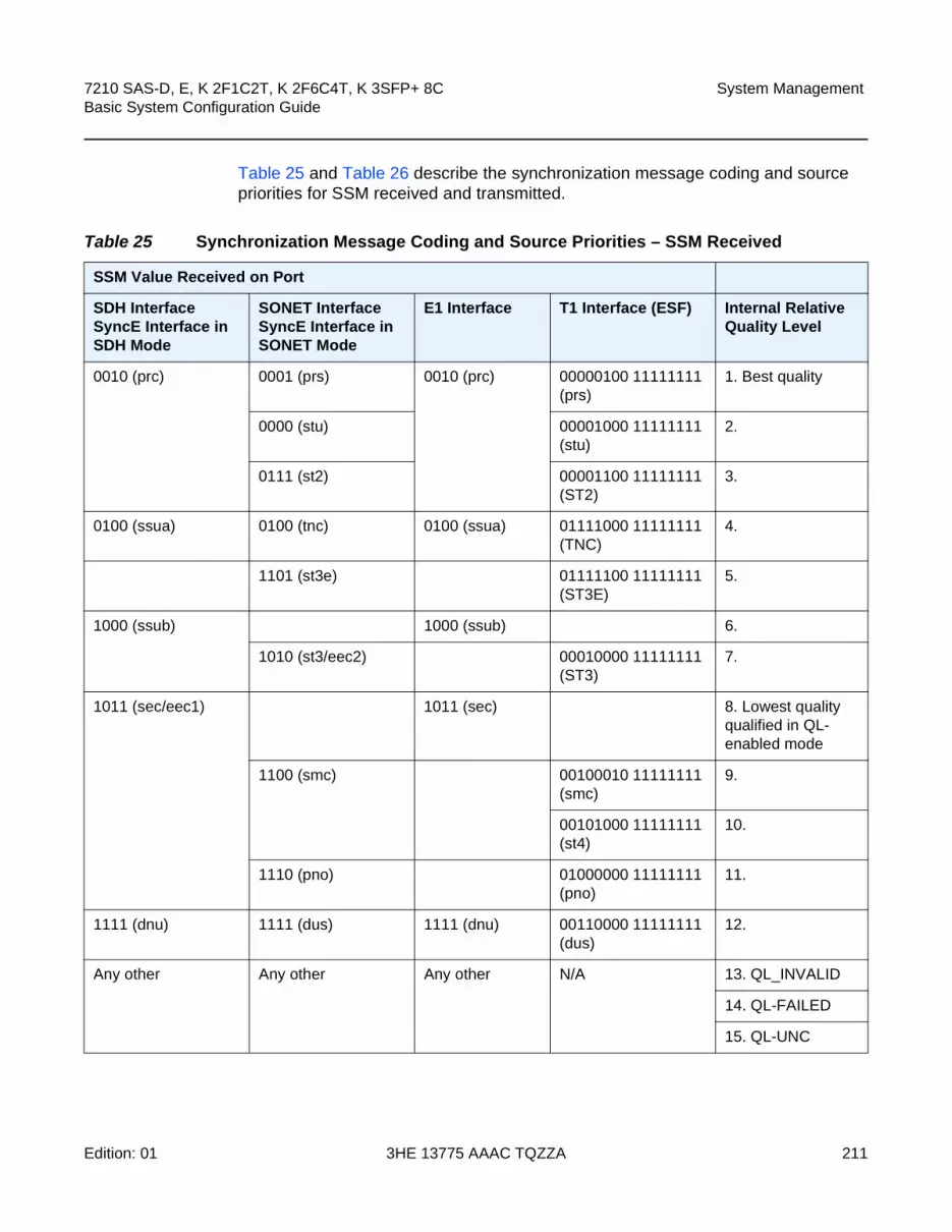
7210 SAS-D, E, K 2F1C2T, K 2F6C4T, K 3SFP+ 8C Basic System Configuration Guide
System Management
Edition: 01 3HE 13775 AAAC TQZZA 211
Table 25 and Table 26 describe the synchronization message coding and source priorities for SSM received and transmitted.
Table 25 Synchronization Message Coding and Source Priorities – SSM Received
SSM Value Received on Port
SDH Interface SyncE Interface in SDH Mode
SONET InterfaceSyncE Interface in SONET Mode
E1 Interface T1 Interface (ESF) Internal Relative Quality Level
0010 (prc) 0001 (prs) 0010 (prc) 00000100 11111111 (prs)
1. Best quality
0000 (stu) 00001000 11111111 (stu)
2.
0111 (st2) 00001100 11111111 (ST2)
3.
0100 (ssua) 0100 (tnc) 0100 (ssua) 01111000 11111111 (TNC)
4.
1101 (st3e) 01111100 11111111 (ST3E)
5.
1000 (ssub) 1000 (ssub) 6.
1010 (st3/eec2) 00010000 11111111 (ST3)
7.
1011 (sec/eec1) 1011 (sec) 8. Lowest quality qualified in QL-enabled mode
1100 (smc) 00100010 11111111 (smc)
9.
00101000 11111111 (st4)
10.
1110 (pno) 01000000 11111111 (pno)
11.
1111 (dnu) 1111 (dus) 1111 (dnu) 00110000 11111111 (dus)
12.
Any other Any other Any other N/A 13. QL_INVALID
14. QL-FAILED
15. QL-UNC

System Management
212
7210 SAS-D, E, K 2F1C2T, K 2F6C4T, K 3SFP+ 8CBasic System Configuration Guide
3HE 13775 AAAC TQZZA Edition: 01
Table 26 Synchronization Message Coding and Source Priorities – SSM Transmitted
SSM Values to be Transmitted by Interface of Yype
Internal Relative Quality Level
SDH Interface SyncE Interface in SDH Mode
SONET InterfaceSyncE Interface in SONET Mode
E1 Interface T1 Interface (ESF)
1. Best quality 0010 (prc) 0001 (PRS) 0010 (prc) 00000100 11111111 (PRS)
2. 0100 (ssua) 0000 (stu) 0100 (ssua) 00001000 11111111 (stu)
3. 0100 (ssua) 0111 (st2) 0100 (ssua) 00001100 11111111 (st2)
4. 0100 (ssua) 0100 (tnc) 0100 (ssua) 01111000 11111111 (tnc)
5. 1000 (ssub) 1101 (st3e) 1000 (ssub) 01111100 11111111 (st3e)
6. 1000 (ssub) 1010 (st3/eec2) 1000 (ssub) 00010000 11111111 (st3)
7. 1011 (sec/eec1) 1010 (st3/eec2) 1011 (sec) 00010000 11111111 (st3)
8. Lowest quality qualified in QL-enabled mode
1011 (sec/ eec1) 1100 (smc) 1011 (sec) 00100010 11111111 (smc)
9. 1111 (dnu) 1100 (smc) 1111 (dnu) 00100010 11111111 (smc)
10. 1111 (dnu) 1111 (dus) 1111 dnu 00101000 11111111 (st4)
11. 1111 (dnu) 1110 (pno) 1111 (dnu) 01000000 11111111 (pno)
12. 1111 (dnu) 1111 (dus) 1111 (dnu) 00110000 11111111 (dus)
13. QL_INVALID 1111 (dnu) 1111 (dus) 1111 (dnu) 00110000 11111111 (dus)
14. QL-FAILED 1111 (dnu) 1111 (dus) 1111 (dnu) 00110000 11111111 (dus)
15. QL-UNC 1011 (sec/eec1) 1010 (st3/eec2) 1011 (sec) 00010000 11111111 (st3)

7210 SAS-D, E, K 2F1C2T, K 2F6C4T, K 3SFP+ 8C Basic System Configuration Guide
System Management
Edition: 01 3HE 13775 AAAC TQZZA 213
5.5.5 IEEE 1588v2 PTP
PTP is a timing-over-packet protocol defined in the IEEE 1588v2 standard 1588 PTP 2008.
PTP can be deployed as an alternative timing-over-packet option to ACR. PTP provides the capability to synchronize network elements to a Stratum-1 clock or primary reference clock (PRC) traceable source over a network that may or may not be PTP-aware. PTP has several advantages over ACR. It is a standards-based protocol, has lower bandwidth requirements, can transport both frequency and time, and can potentially provide better performance.
The following is a list of the four basic types of PTP devices:
• ordinary clock
• boundary clock
• end-to-end transparent clock
• peer-to-peer transparent clock
The 7210 SAS supports the ordinary clock in slave mode and the boundary clock. The boundary clock and ordinary clock slave can be used for both frequency and time distribution. The 7210 SAS does not support ordinary clock in master mode, end-to-end transparent clock, or peer-to-peer transparent clock.
Figure 20 shows how the 7210 SAS communicates with peer 1588v2 clocks.These peers can be ordinary clock slaves or boundary clocks. The communication can be based on either unicast IPv4 sessions transported through IP interfaces or Ethernet multicast PTP packets transported through an Ethernet port.
Table 27 describes IP/UDP unicast and multicast support for the 7210 SAS platforms.
Note:
• Precision Time Protocol (PTP) is only supported on the 7210 SAS-D ETR, 7210 SAS-K 2F1C2T, 7210 SAS-K 2F6C4T, and 7210 SAS-K 3SFP+ 8C.
• References to G.8275.1 and Ethernet encapsulation apply only to the 7210 SAS-K 2F6C4T and 7210 SAS-K 3SFP+ 8C.
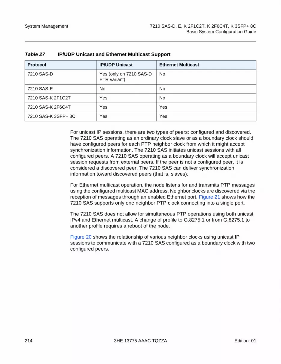
System Management
214
7210 SAS-D, E, K 2F1C2T, K 2F6C4T, K 3SFP+ 8CBasic System Configuration Guide
3HE 13775 AAAC TQZZA Edition: 01
For unicast IP sessions, there are two types of peers: configured and discovered. The 7210 SAS operating as an ordinary clock slave or as a boundary clock should have configured peers for each PTP neighbor clock from which it might accept synchronization information. The 7210 SAS initiates unicast sessions with all configured peers. A 7210 SAS operating as a boundary clock will accept unicast session requests from external peers. If the peer is not a configured peer, it is considered a discovered peer. The 7210 SAS can deliver synchronization information toward discovered peers (that is, slaves).
For Ethernet multicast operation, the node listens for and transmits PTP messages using the configured multicast MAC address. Neighbor clocks are discovered via the reception of messages through an enabled Ethernet port. Figure 21 shows how the 7210 SAS supports only one neighbor PTP clock connecting into a single port.
The 7210 SAS does not allow for simultaneous PTP operations using both unicast IPv4 and Ethernet multicast. A change of profile to G.8275.1 or from G.8275.1 to another profile requires a reboot of the node.
Figure 20 shows the relationship of various neighbor clocks using unicast IP sessions to communicate with a 7210 SAS configured as a boundary clock with two configured peers.
Table 27 IP/UDP Unicast and Ethernet Multicast Support
Protocol IP/UDP Unicast Ethernet Multicast
7210 SAS-D Yes (only on 7210 SAS-D ETR variant)
No
7210 SAS-E No No
7210 SAS-K 2F1C2T Yes No
7210 SAS-K 2F6C4T Yes Yes
7210 SAS-K 3SFP+ 8C Yes Yes

7210 SAS-D, E, K 2F1C2T, K 2F6C4T, K 3SFP+ 8C Basic System Configuration Guide
System Management
Edition: 01 3HE 13775 AAAC TQZZA 215
Figure 20 Peer Clocks
Figure 21 shows the relationship of various neighbor clocks using multicast Ethernet sessions to a 7210 SAS configured as a boundary clock.
sw0393
Ordinary ClockMaster 10.4.1.1
Ordinary ClockSlave
10.2.1.1
7210 SAS10.0.1.1
Peer 10.3.1.1Peer 10.4.1.1
Ordinary ClockSlave
10.1.1.1
Boundary Clock10.3.1.1
Configured Peers
Discovered Peers

System Management
216
7210 SAS-D, E, K 2F1C2T, K 2F6C4T, K 3SFP+ 8CBasic System Configuration Guide
3HE 13775 AAAC TQZZA Edition: 01
Figure 21 Ethernet Multicast Ports
The IEEE 1588v2 standard includes the concept of PTP profiles. These profiles are defined by industry groups or standards bodies that define how IEEE 1588v2 is to be used for a particular application.
The 7210 SAS currently supports three profiles:
• IEEE 1588v2 (default profile)
• ITU-T Telecom profile (G.8265.1)
• ITU-T Telecom profile for time with full timing support (G.8275.1), on 7210 SAS-K 2F6C4T and 7210 SAS-K 3SFP+ 8C devices only
When a 7210 SAS receives Announce messages from one or more configured peers or multicast neighbors, it executes a Best Master Clock Algorithm (BMCA) to determine the state of communication between itself and the peers. The system uses the BMCA to create a hierarchical topology, allowing the flow of synchronization information from the best source (the grandmaster clock) out through the network to all boundary and slave clocks. Each profile has a dedicated BMCA.
sw_0127
7210 SASBoundary Clock
Port 1/2/1
Port 1/1/1 Port 1/3/1
Boundary Clock
Boundary Clock
Ordinary ClockSlave
Ethernet Multicast LAN
Ordinary ClockMaster
End to End Transparent Clock
Note: 7210 SAS platforms do not support the ordinary clock master configuration.

7210 SAS-D, E, K 2F1C2T, K 2F6C4T, K 3SFP+ 8C Basic System Configuration Guide
System Management
Edition: 01 3HE 13775 AAAC TQZZA 217
If the profile setting for the clock is ieee1588-2008, the precedence order for the best master selection algorithm is as follows:
• priority1
• clock class
• clock accuracy
• PTP variance (offsetScaledLogVariance)
• priority2
• clock identity
• steps removed from the grandmaster
Table 28 describes how the 7210 SAS sets its local parameters.
If the profile setting for the clock is itu-telecom-freq (ITU G.8265.1 profile), the precedence order for the best master selection algorithm is the following:
• clock class
• PTSF (Packet Timing Signal Fail) - Announce Loss (miss 3 Announce messages or do not get an Announce message for 6 seconds)
• priority
Table 29 describes how the 7210 SAS sets its local parameters.
Table 28 Local Clock Parameters When Profile is Set to ieee1588-2008
Parameter Value
clockClass 248 – the 7210 SAS is configured as a boundary clock
255 – the 7210 SAS is configured as an ordinary clock slave
clockAccuracy FE - unknown
offsetScaledLogVariance FFFF – not computed
clockIdentity Chassis MAC address following the guidelines of section 7.5.2.2.2 of IEEE 1588-2008
Table 29 Local Clock Parameters When Profile is Set to itu-telecom-freq
Parameter Value
clockClass 80-110 – value corresponding to the QL out of the central clock of the 7210 SAS as per Table 1/G.8265.1
255 – the 7210 SAS is configured as an ordinary clock slave

System Management
218
7210 SAS-D, E, K 2F1C2T, K 2F6C4T, K 3SFP+ 8CBasic System Configuration Guide
3HE 13775 AAAC TQZZA Edition: 01
The ITU-T profile is for use in an environment with only ordinary clock masters and slaves for frequency distribution. The default profile should be used for all other cases.
If the profile setting for the clock is g8275dot1-2014, the precedence order for the best master selection algorithm is very similar to that used for the default profile. It ignores the priority1 parameter, includes a localPriority parameter, and includes the ability to force a port to never enter the slave state (master-only). The precedence is as follows:
• clock class
• clock accuracy
• PTP variance (offsetScaledLogVariance)
• priority2
• localPriority
• clock identity
• steps removed from the grandmaster
Table 30 describes how the 7210 SAS sets its local parameters.
The 7210 SAS can support a limited number of configured peers (possible master or neighbor boundary clocks) and a limited number of discovered peers (slaves).These peers use the unicast negotiation procedures to request service from the 7210 SAS clock. A neighbor boundary clock counts for two peers (both a configured and a discovered peer) toward the maximum limit.
Table 30 Local Clock Parameters When Profile is Set to g8275dot1-2014
Parameter Value
clockClass 165 – the 7210 SAS is configured as a boundary clock and the boundary clock was previously locked to a grandmaster with a clock class of 6
248 – the 7210 SAS is configured as a boundary clock
255 – the 7210 SAS is configured as an ordinary clock slave
clockAccuracy FE – unknown
offsetScaledLogVariance FFFF – not computed
clockIdentity Chassis MAC address following the guidelines of section 7.5.2.2.2 of IEEE 1588-2008

7210 SAS-D, E, K 2F1C2T, K 2F6C4T, K 3SFP+ 8C Basic System Configuration Guide
System Management
Edition: 01 3HE 13775 AAAC TQZZA 219
On the 7210 SAS-D ETR, 7210 SAS-K 2F1C2T, 7210 SAS-K 2F6C4T, and 7210 SAS-K 3SFP+ 8C there are limits on the number of slaves enforced in the implementation for unicast and multicast PTP slaves. Contact your Nokia technical support representative for information about the specific unicast message limits related to PTP.
When PTP is configured, the PTP load must be monitored to ensure that the load does not exceed the capabilities (configured values) to ensure that sufficient CPU processing cycles are available for PTP. There are several commands that can be used to monitor this.
• show system cpu identifies the load of the PTP software process. If the “capacity usage” reaches 100%, the PTP software process on the 7210 SAS is at its limit of transmitting and/or receiving PTP packets.
Because the user cannot control the number of PTP messages being received by the 7210 SAS over its Ethernet ports, the following statistics commands can be used to identify the source of the message load.
• show system ptp statistics displays aggregate packet rates
• show system ptp port and show system ptp port port-id [detail] display received packet rates
Figure 22 shows the unicast negotiation procedure performed between a slave and a peer clock that is selected to be the master clock. The slave clock will request Announce messages from all peer clocks but only request Sync and Delay_Resp messages from the clock selected to be the master clock.
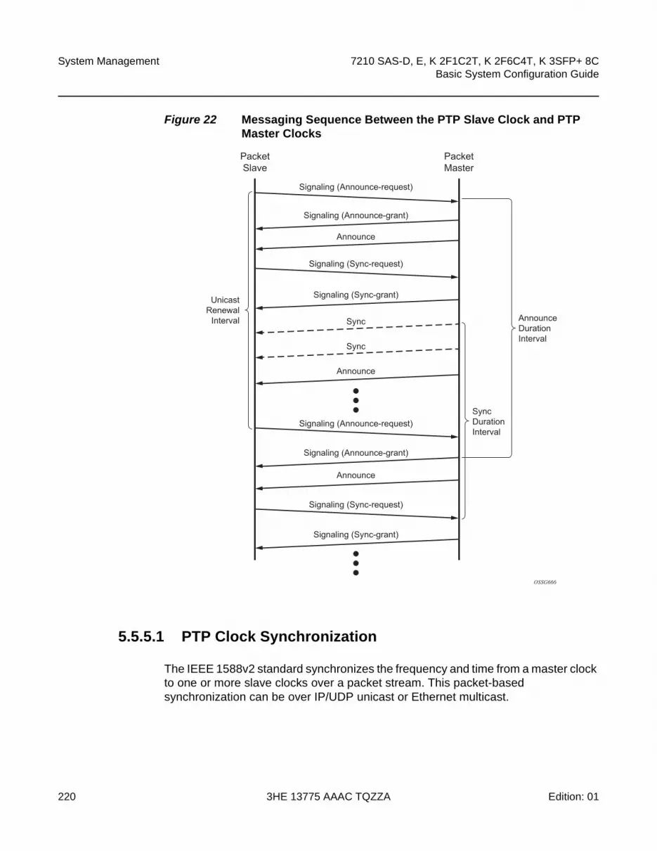
System Management
220
7210 SAS-D, E, K 2F1C2T, K 2F6C4T, K 3SFP+ 8CBasic System Configuration Guide
3HE 13775 AAAC TQZZA Edition: 01
Figure 22 Messaging Sequence Between the PTP Slave Clock and PTP Master Clocks
5.5.5.1 PTP Clock Synchronization
The IEEE 1588v2 standard synchronizes the frequency and time from a master clock to one or more slave clocks over a packet stream. This packet-based synchronization can be over IP/UDP unicast or Ethernet multicast.
OSSG666
AnnounceDurationInterval
SyncDurationInterval
Signaling (Announce-grant)
Signaling (Announce-grant)
Signaling (Sync-grant)
Signaling (Sync-grant)
Sync
Sync
Announce
Announce
Announce
Signaling (Announce-request)
Signaling (Sync-request)
Signaling (Sync-request)
Signaling (Announce-request)
PacketMaster
PacketSlave
UnicastRenewal
Interval

7210 SAS-D, E, K 2F1C2T, K 2F6C4T, K 3SFP+ 8C Basic System Configuration Guide
System Management
Edition: 01 3HE 13775 AAAC TQZZA 221
As part of the basic synchronization timing computation, a number of event messages are defined for synchronization messaging between the PTP slave clock and PTP master clock. A one-step or two-step synchronization operation can be used, with the two-step operation requiring a follow-up message after each synchronization message.
During startup, the PTP slave clock receives the synchronization messages from the PTP master clock before a network delay calculation is made. Before any delay calculation, the delay is assumed to be zero. A drift compensation is activated after a number of synchronization message intervals occur. The expected interval between the reception of synchronization messages is user-configurable.
Figure 23 shows the basic synchronization timing computation between the PTP slave clock and PTP best master, as well as the offset of the slave clock referenced to the best master signal during startup.
Figure 23 PTP Slave Clock and Master Clock Synchronization Timing Computation
Note: The 7210 SAS-D ETR supports only two-step master port operation. All platforms can operate slave ports that receive from a one-step or two-step master port.
Slave
t1, t2, t3, t4 are measured valuest2 - t1 = Delay + Offset = 51 - 44 = 7t4 - t3 = Delay - Offset = 57 - 56 = 1Delay = ((t2-t1) + (t4 - t3))/2 = 4Offset = ((t2 - t1) - (t4 - t3))/2 = 3
O = Offset = Slave - Master
O D
40
D = Delay
OSSG644
42
44
46
48
50
52
54
56
58
60
62
64
Master
40
42
1t 44
38
46
48
50
52
54
56
58t2
60
62
t3
t2
Sync
Follow_up (t1)
Delay_req
Delay_resp (t4)

System Management
222
7210 SAS-D, E, K 2F1C2T, K 2F6C4T, K 3SFP+ 8CBasic System Configuration Guide
3HE 13775 AAAC TQZZA Edition: 01
When using IEEE 1588v2 for distribution of a frequency reference, the slave calculates a message delay from the master to the slave based on the timestamps exchanged. A sequence of these calculated delays will contain information about the relative frequencies of the master clock and slave clock but will have a noise component related to the packet delay variation (PDV) experienced across the network. The slave must filter the PDV effects to extract the relative frequency data and adjust the slave frequency to align with the master frequency.
When using IEEE 1588v2 for distribution of time, the 7210 SAS uses the four timestamps exchanged using the IEEE 1588v2 messages to determine the offset between the 7210 SAS time base and the external master clock time base. The 7210 SAS determines the offset adjustment, and in between these adjustments, it maintains the progression of time using the frequency from the central clock of the node. This allows time to be maintained using a synchronous Ethernet input source even if the IEEE 1588v2 communications fail. When using IEEE 1588v2 for time distribution, the central clock should at a minimum have the PTP input reference enabled. Figure 24 shows the logical model for using PTP/1588 for network synchronization on the 7210 SAS.
Figure 24 Logical Model for Using PTP/1588 for Network Synchronization on 7210 SAS Platforms
5.5.5.2 Performance Considerations
Although IEEE 1588v2 can be used on a network that is not PTP-aware, the use of PTP-aware network elements (boundary clocks) within the packet-switched network improves synchronization performance by reducing the impact of PDV between the grand master clock and the slave clock. In particular, when IEEE 1588v2 is used to distribute high-accuracy time, such as for mobile base station phase requirements, the network architecture requires the deployment of PTP awareness in every device between the grandmaster and the mobile base station slave.
sw0455
Central ClockTime Module
Central ClockFrequency
Module (EEC)
1588 MasterPorts
1588 SlavePorts
1588messages
1588messages
TO to portsNodal reference (TO)
ref1Frequency recoveredfrom 1588 messageexchange
ref1 & ref2allowed
only in PTPhybrid mode
ref2
ptp
Periodic Timeoffset calculated
from 1588 messageexchange
Timestampsbased on centralclock frequency
and offset

7210 SAS-D, E, K 2F1C2T, K 2F6C4T, K 3SFP+ 8C Basic System Configuration Guide
System Management
Edition: 01 3HE 13775 AAAC TQZZA 223
In addition, performance is also improved by the removal of any PDV caused by internal queuing within the boundary clock or slave clock. This is accomplished with hardware that is capable of detecting and timestamping the IEEE 1588v2 packets at the Ethernet interface. This capability is referred to as port-based timestamping.
5.5.5.3 PTP Capabilities
PTP messages are supported through IPv4 unicast with a fixed IP header size. Table 31 describes the support message rates for slave and master states. The ordinary clock can be used in only slave mode. The boundary clock can be in both of these states.
State and statistics data for each master clock are available to assist in the detection of failures or unusual situations.
Table 31 Support Message Rates for Slave and Master Clock States
Support Message Slave Clock Master Clock
Request Rate Grant Rate
Min Max
Announce 1 packet every 2 seconds
1 packet every 2 seconds
1 packet every 2 seconds
Sync User-configurable with an option to configure 8/16 packets per second
8 packets/second 16 packets/second
Delay_Resp User-configurable with an option to configure 8/16 packets per second
8 packets/second 16 packets/second
Duration 300 seconds 1 second 1000 seconds
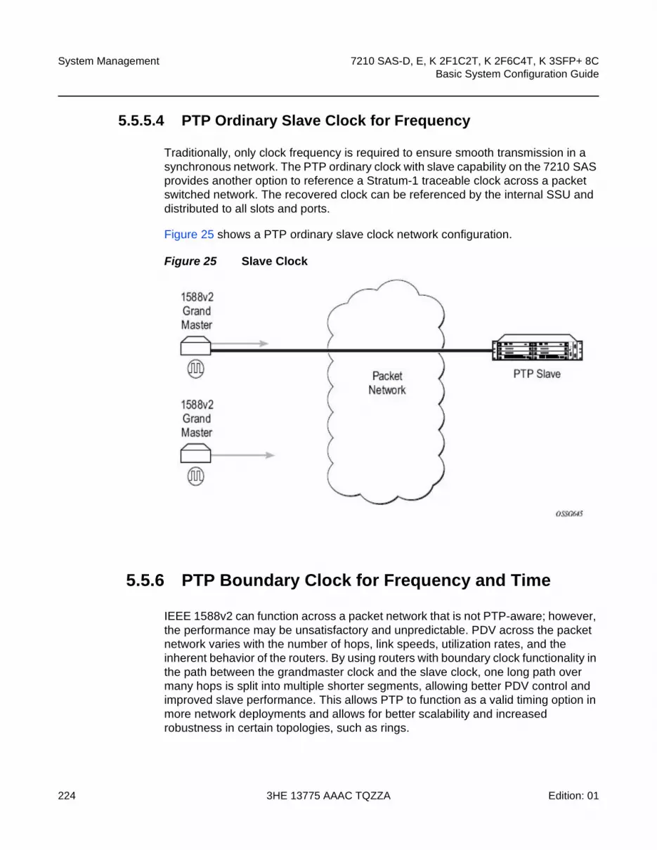
System Management
224
7210 SAS-D, E, K 2F1C2T, K 2F6C4T, K 3SFP+ 8CBasic System Configuration Guide
3HE 13775 AAAC TQZZA Edition: 01
5.5.5.4 PTP Ordinary Slave Clock for Frequency
Traditionally, only clock frequency is required to ensure smooth transmission in a synchronous network. The PTP ordinary clock with slave capability on the 7210 SAS provides another option to reference a Stratum-1 traceable clock across a packet switched network. The recovered clock can be referenced by the internal SSU and distributed to all slots and ports.
Figure 25 shows a PTP ordinary slave clock network configuration.
Figure 25 Slave Clock
5.5.6 PTP Boundary Clock for Frequency and Time
IEEE 1588v2 can function across a packet network that is not PTP-aware; however, the performance may be unsatisfactory and unpredictable. PDV across the packet network varies with the number of hops, link speeds, utilization rates, and the inherent behavior of the routers. By using routers with boundary clock functionality in the path between the grandmaster clock and the slave clock, one long path over many hops is split into multiple shorter segments, allowing better PDV control and improved slave performance. This allows PTP to function as a valid timing option in more network deployments and allows for better scalability and increased robustness in certain topologies, such as rings.

7210 SAS-D, E, K 2F1C2T, K 2F6C4T, K 3SFP+ 8C Basic System Configuration Guide
System Management
Edition: 01 3HE 13775 AAAC TQZZA 225
Figure 26 shows how a boundary clock can simultaneously function as a PTP slave of an upstream grandmaster (ordinary clock) or boundary clock, and as a PTP master of downstream slaves (ordinary clock) and/or boundary clocks. The time scale recovered in the slave side of the boundary clock is used by the master side of the boundary clock. This allows time to be distributed across the boundary clock.
Figure 26 Boundary Clock
5.5.7 Configuration Guidelines and Restrictions for PTP
• The PTP slave capability is available on all the ports on the 7210 SAS-D ETR.
• The 7210 SAS-D ETR, 7210 SAS-K 2F1C2T, 7210 SAS-K 2F6C4T, and 7210 SAS-K 3SFP+ 8C use CPU processing cycles for frequency and time recovery.
• On the 7210 SAS-D ETR, Nokia highly recommends that PTP be used only in hybrid mode. Hybrid mode allows users to use reduced PTP packet rates and to scale better.
• On the 7210 SAS-D ETR, use of both PTP and SyncE as a reference simultaneously is not allowed. Either PTP or SyncE can be configured as a reference but not both at the same time.
• On 7210 SAS devices, only a single profile (IEEE 1588v2, G.8265.1, or G.8275.1) can be enabled for all PTP communications (both toward its master and slaves connected to it) at a time.
• The PTP G.8275.1 profile is only supported on the 7210 SAS-K 2F6C4T and 7210 SAS-K 3SFP+ 8C. When using the profile, the following restrictions apply.
− The delay and sync requests are set to 16 pps by default and are not configurable.

System Management
226
7210 SAS-D, E, K 2F1C2T, K 2F6C4T, K 3SFP+ 8CBasic System Configuration Guide
3HE 13775 AAAC TQZZA Edition: 01
− The announce rate is set to 8 pps by default and is not configurable.
− A change of profile to G.8275.1 or from G.8275.1 to another profile requires a reboot of the node.
− Only a single multicast slave is supported per port.
• PTP with Ethernet encapsulation is only supported with the G.8275.1 profile.
• PTP over IP encapsulation is not supported with the G.8275.1 profile. It is only supported with the IEEE 1588v2 and G.8265.1 profiles.
• PTP slave capability is available on all ports on the 7210 SAS-K 2F1C2T, 7210 SAS-K 2F6C4T, and 7210 SAS-K 3SFP+ 8C.
• When changing the clock-type to or from a boundary clock on the 7210 SAS-K 2F1C2T, 7210 SAS-K 2F6C4T, and 7210 SAS-K 3SFP+ 8C, the node must be rebooted for the change to take effect. Ensure that measures are taken to minimize service disruption during the reboot process.
• On the 7210 SAS-K 2F6C4T and 7210 SAS-K 3SFP+ 8C, to enable PTP hybrid mode, the user must execute the command config>system>ptp>clock>freq-source ssu. To enable pure PTP mode, the user must execute the command config>system>ptp>clock>freq-source ptp. A change of value from ssu to ptp, or vice-versa, requires a reboot of the node after the configuration changes are saved in order for the change to take effect.
• On the 7210 SAS-D ETR, 7210 SAS-K 2F1C2T, 7210 SAS-K 2F6C4T, and 7210 SAS-K 3SFP+ 8C, port-based time-stamping is enabled for all PTP packets by default when PTP is enabled. When PTP is enabled, PTP packets are not forwarded transparently through the node, regardless of the service used and whether PTP is configured as a system clock reference. If PTP is enabled, to enable transparent PTP forwarding again, disable PTP, save the configuration, and reboot the node.
5.5.8 Configuration to Change Reference from SyncE to PTP on 7210 SAS-D ETR
The following are the configuration steps to change reference from SyncE to PTP. This procedure is required only on 7210 SAS-D ETR nodes.
1. Initially for standalone PTP:configure >system >ptp >no shutdown
config> system> sync-if-timing> beginptpno shutdownexitref-order ptp [Must be configured]
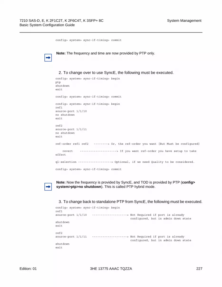
7210 SAS-D, E, K 2F1C2T, K 2F6C4T, K 3SFP+ 8C Basic System Configuration Guide
System Management
Edition: 01 3HE 13775 AAAC TQZZA 227
config> system> sync-if-timing> commit
2. To change over to use SyncE, the following must be executed.config> system> sync-if-timing> beginptpshutdownexit
config> system> sync-if-timing> commit
config> system> sync-if-timing> beginref1source-port 1/1/10no shutdownexit
ref2source-port 1/1/11no shutdownexit
ref-order ref1 ref2 --------> Or, the ref-order you want [But Must be configured]
revert ---------------------> If you want ref-order you have setup to takeeffect
ql-selection -------------------> Optional, if we need Quality to be considered.
config> system> sync-if-timing> commit
3. To change back to standalone PTP from SyncE, the following must be executed.config> system> sync-if-timing> beginref1source-port 1/1/10 --------------------> Not Required if port is already
configured, but in admin down stateshutdownexit
ref2source-port 1/1/11 --------------------> Not Required if port is already
configured, but in admin down stateshutdownexit
Note: The frequency and time are now provided by PTP only.
Note: Now the frequency is provided by SyncE, and TOD is provided by PTP (config> system>ptp>no shutdown). This is called PTP hybrid mode.
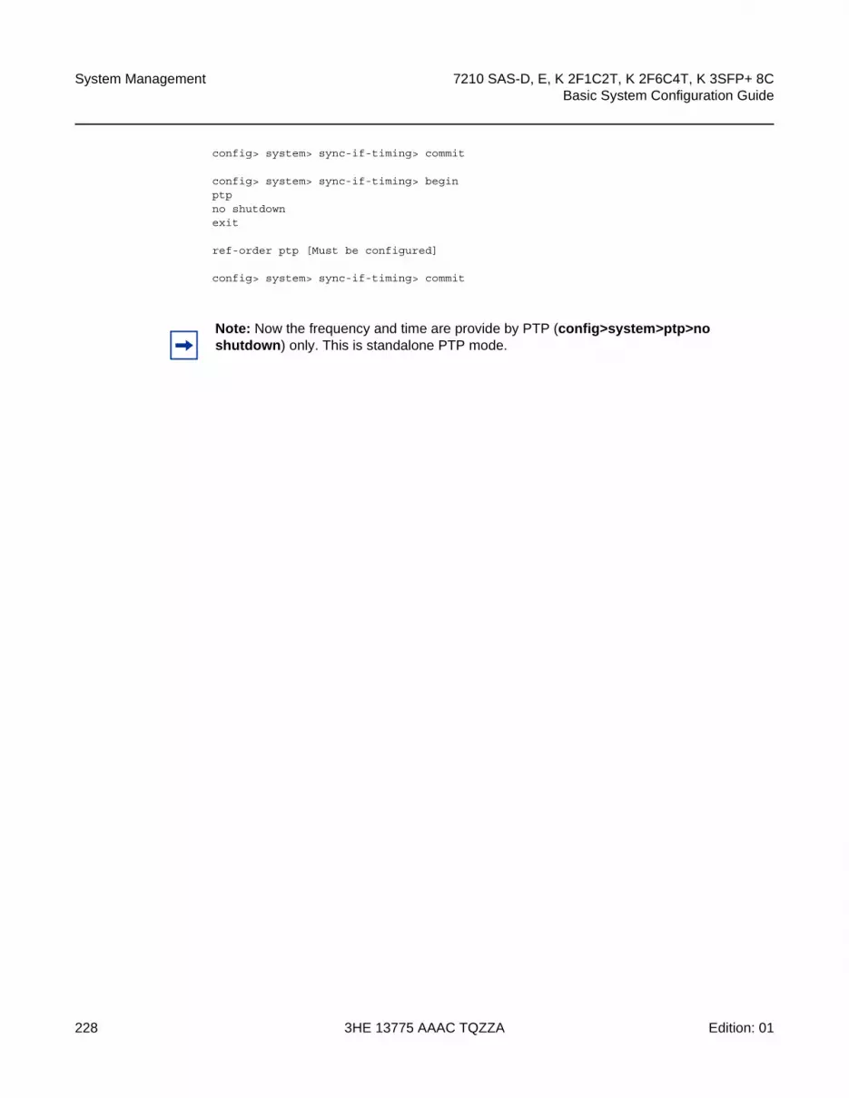
System Management
228
7210 SAS-D, E, K 2F1C2T, K 2F6C4T, K 3SFP+ 8CBasic System Configuration Guide
3HE 13775 AAAC TQZZA Edition: 01
config> system> sync-if-timing> commit
config> system> sync-if-timing> beginptpno shutdownexit
ref-order ptp [Must be configured]
config> system> sync-if-timing> commit
Note: Now the frequency and time are provide by PTP (config>system>ptp>no shutdown) only. This is standalone PTP mode.

7210 SAS-D, E, K 2F1C2T, K 2F6C4T, K 3SFP+ 8C Basic System Configuration Guide
System Management
Edition: 01 3HE 13775 AAAC TQZZA 229
5.6 Management of 1830 VWM
The 7210 SAS supports use and management of the 1830 VWM CWDM and 1830 VWM DWDM clip-on device. 1830 VWM is a family of cost-optimized managed WDM passive devices that are add-on shelves/NEs and provide CWDM/DWDM extension to devices that do not have in-built CWDM/DWDM capabilities. The 1830 VWM can act as a Fixed Channel Optical Add-Drop Multiplexer (FOADM) or multiplexer and demultiplexer unit. It allows the operators to use the existing fiber (or use less fiber) and increase the bandwidth capacity available for carrying service traffic.
Refer to the 1830 VWM Product User Guides for more information about the product and features.
To manage the device, the user needs to plug in the 1830 VWM shelf to the USB port on the 7210 SAS-E devices.
5.6.1 Introduction to Management of 1830 VWM Devices
The 1830 VWM device can be used in point-to-point or ring deployments to multiplex multiple CWDM/DWDM channels over a single fiber. This functionality either reuses the existing fiber or uses a single fiber to meet the requirements for the always increasing demand for service bandwidth. Up to 8 fixed CWDM channels are multiplexed over a single fiber using this unit.
Figure 27 shows 5 CWDM channels that are multiplexed over a single fiber. There are two types of ring locations. One is a channel termination location, with the 1830 PSS-32 that optically terminates all the channels using either the 4-channel or the 8-channel termination module. These sites use the CWDM passive units to add or drop channels in both directions (east and west) for traffic to be processed by the node. Additionally, these sites provide express lanes for all the other channels (that is, those not processed locally by the node). The 1830 VWM provides the option to add or drop up to 1, 2, or 4 channels of fixed wavelength to be processed locally by the node.
Note: This feature is only supported on the 7210 SAS-E.

System Management
230
7210 SAS-D, E, K 2F1C2T, K 2F6C4T, K 3SFP+ 8CBasic System Configuration Guide
3HE 13775 AAAC TQZZA Edition: 01
Figure 27 Optical Ring with 7210 SAS and 1830 VWM Passive Optical unit
5.6.2 Feature Description
The 1830 VWM clip-on device can be connected to a master-shelf, that is, the 7210 SAS node using the USB interface or the OMC interface, depending on which interface is supported by the 7210 SAS platform. Each of these clip-on devices is identified using the shelf ID set using the rotary dial provided on the device. To assist inventory management, the user must configure the VWM shelf ID of the clip-on device attached to the 7210 SAS node using the CLI command config>system> vwm-shelf id vwm-type type create. The VWM shelf ID must match the shelf ID set using the rotary dial on the clip-on device. 7210 SAS devices use the configured VWM shelf ID to communicate with the clip-on device. If these shelf IDs do not match, the 7210 SAS cannot communicate to the device and does not provide any information about the device. The 7210 SAS cannot detect a mismatch between the configured VWM shelf ID and the shelf ID set on the rotary dial. Depending on the type of interface, USB or OMC, only a fixed number of 1830 devices can be managed by the 7210 SAS node. The software fails any attempt to configure more 1830 devices than what can be supported by the interface in use. The users can use the show command provided by the 7210 SAS devices to display the shelf inventory information and alarm status information provided by the clip-on device. In addition to inventory management, the 7210 SAS supports provisioning of cards inserted into the slots available on 1830 VWM devices. The user must provision the card and card type (also known as module type) before the card can be managed by the 7210 SAS. The 7210 SAS detects and reports mismatches in provisioning of the card. It also detects and reports insertion and removal of the card/module from the slot on the 1830 VWM device.
sw04547210 SAS-M7210 SAS-X7210 SAS-M
1830 PSS-32 7210 SAS-M
7210 SAS-T
1830 PSS-16
7210 SAS-M 7705 SAS-X7210 SAS-M

7210 SAS-D, E, K 2F1C2T, K 2F6C4T, K 3SFP+ 8C Basic System Configuration Guide
System Management
Edition: 01 3HE 13775 AAAC TQZZA 231
The 1830 DWDM supports active and passive units. The first 1830 DWDM device that is connected to a 7210 SAS node using the OMC port or the USB port must be equipped with active DWDM controllers, while passive DWDM controllers can be used in the other chassis connected to the first device in a stacked configuration. That is, the first 1830 DWDM device that is connected to the OMC port or the USB port of the 7210 node cannot be a passive 1830 DWDM device, while subsequent chassis in the stacked configuration can be equipped with passive DWDM controllers. See the 1830 VWM User Guide for more information about equipping active or passive DWDM controllers on the other chassis in the stacked configuration
5.6.2.1 1830 CWDM shelf layout and description
Figure 28 shows the 1830 CWDM passive device.
Figure 28 1830 CWDM Shelf Layout
Slot#1 in Figure 28 accepts only the controller card and is named using the acronym EC-CW for the 1830 CWDM device. The 7210 SAS does not require provisioning of this card. This card type is implicitly specified when the user configures the 1830 VWM shelf type. Only when this card is present and connected to the 7210 SAS, the 7210 SAS provides inventory and equipment management capability. If it is not
Note: The 7210 SAS also auto detects the device type when any of the supported devices are connected to the USB interface. Only approved USB mass storage devices and optical clip-on devices can be plugged in to the USB port and are recognized as valid devices. All other unsupported devices result in an error log being printed. A shelf created by the user will be operationally down when an unrecognized device is plugged into the USB port. The user can interchange the device connected to the USB port without requiring a reboot. For example, when the 7210 SAS is operating with a clip-on device, the user can pull out the clip-on device, plug-in a USB mass-storage device to copy over image files or other files, and plug back a clip-on device.
Note: In Figure 28 and Figure 29, the 1830 VWM shelves are shown as an illustrations. For definitive information about 1830 VWM devices and support, consult the 1830 VWM product manuals.
hw0385
Slot #1Power & Control
Slot #2OADM or Mux/Demux (Line card)
Slot #3OADM or Mux/Demux (Line card)

System Management
232
7210 SAS-D, E, K 2F1C2T, K 2F6C4T, K 3SFP+ 8CBasic System Configuration Guide
3HE 13775 AAAC TQZZA Edition: 01
present, this management functionality is lost. It is possible to operate the 1830 CWDM device as a passive filter without the controller card in slot #1. It cannot be managed with the 7210 SAS. Slot #2 and slot #3 can be equipped with supported CWDM filter cards. The user must provision the cards that will be populated in these slots. 7210 SAS software checks and ensures that the equipped card type matches the provisioned card type and logs an event if it does not match.
5.6.2.2 1830 DWDM Shelf Layout and Description
Figure 29 shows the 1830 DWDM shelf and the entities that can be managed by 7210 SAS.
Figure 29 1830 DWDM Shelf layout
• Slot #1 and slot #2 are capable of hosting DWDM power and controller modules (either EC-DW or EC-DWA). These slots host the equipment controller; power is provided by the Service NE (using EC-DW unit) or the TRU (using EC-DWA unit), in accordance with the system configuration and the equipment controller used. On the top side of the equipment controller, there is a rotary switch to set the SHELF_ID. In a stacked configuration, each shelf ID must be uniquely set. The shelf ID must be the same for both active and stand-by controllers in one shelf.
• Slot #1 and slot #2 are not directly provisioned by the user on the 7210 SAS. The user has to provision and configure the VWM type that the 7210 SAS manages. The VWM type can be EC-CW, EC-DW, or EC-DWA, indicating that the shelf is a CWDM passive shelf, or a DWDM passive shelf or active shelf.
hw0386
Slot #1Power & Control
Slot #3Filter/Amplifier/BPM (Line card)
Slot #2Power & Control
Slot #4Filter/Amplifier/BPM (Line card)
Slot #5FANS or1-Wire
7210 SAS-D, E, K 2F1C2T, K 2F6C4T, K 3SFP+ 8C Basic System Configuration Guide
System Management
Edition: 01 3HE 13775 AAAC TQZZA 233
• The first 1830 DWDM device that is connected to a 7210 SAS node using the OMC port or the USB port must be equipped with active DWDM controllers, while passive DWDM controllers can be used in the other chassis connected to the first device in a stacked configuration. That is, the first 1830 DWDM device that is connected to the OMC port or the USB port of the 7210 SAS node cannot be a passive 1830 DWDM device, while subsequent chassis in the stacked configuration can be equipped with passive DWDM controllers.
• Slot #3 and slot #4 are capable of hosting DWDM filters (MUX/Demux), optical amplifiers and Bulk Power Management (BPM) modules. These slots need to be provisioned on the 7210 SAS to allow management by 7210 SAS. The following cards can be managed by the 7210 SAS.
− The 7210 SAS supports all DWDM filters (remote and manual filter and all of 2-channel, 4-channel and 8-channel).
− The 7210 SAS supports the fan module.
− The 7210 SAS does not support the BPM module (which allows for aggregation of 44 DWDM channels using the SFD44 unit).
• The following events are tracked by the 7210 SAS host related to these modules in slot #3 and slot #4.
− The 7210 SAS tracks line card and module removal and insertion.
− The 7210 SAS tracks provisioning mismatches if the provisioned line card does not match the equipped line card.
− For remote filters, the LoS alarm is reported by the card or module. The LoS alarm is cleared by the EC-DW or EC-DWA based on the threshold configured VOA.
− The 7210 SAS does not support the monitoring of power levels for remote filters and does not allow the configuration of power thresholds for the automatic power monitoring feature supported by the remote filter units.
− The 7210 SAS detects 1830 fan module insertion and removal and reports this event.
• Slot #5 hosts the fans or the inventory extension module (INVMOD). Provisioning of this slot is not supported when being managed by the 7210 SAS. Only the fan module can be equipped in this slot when the 1830 VWM device is managed by the 7210 SAS. The inventory extension module cannot be equipped in this slot when the 1830 VWM device is managed by the 7210 SAS.
System Management
234
7210 SAS-D, E, K 2F1C2T, K 2F6C4T, K 3SFP+ 8CBasic System Configuration Guide
3HE 13775 AAAC TQZZA Edition: 01
5.6.3 Configuration Guidelines and Restrictions
The 7210 SAS supports management of the 1830 VWM CWDM and DWDM clip-on devices and inventory management, and displays the clip-on device details such as part numbers, clip-on type, manufacturing dates, firmware revision, and status of alarms. It also supports provisioning of the modules that can be inserted into the slot available on the 1830 VWM device. The following are the configuration and restrictions guidelines for support of 1830 VWM devices:
• The shelf ID on the rotary dial must be set to a digit between 1-7. Digits higher than 7 are not supported on 7210 SAS devices.
• The 1830 VWM clip-on device is connected to a master-shelf (for example, a 7210 SAS device). Each of the clip-on devices are identified using the shelf ID set using the rotary dial provided on the device. To aid inventory management, the user must configure the VWM shelf ID of the clip-on device attached to the USB or OMC interface. The VWM shelf ID must match the shelf ID set using the rotary dial on the clip-on device. The 7210 SAS uses the configured VWM shelf ID to communicate with the clip-on device. If these shelf IDs do not match, the 7210 SAS cannot interact with the other devices and does not provide any information about the device. The 7210 SAS cannot detect a mismatch between the configured VWM shelf ID and the shelf ID set on the rotary dial.
• 7210 SAS provides a show command to display the alarm status information provided by the clip-on device.
• 7210 SAS prints an error log if unsupported devices are plugged into the USB port. Only approved USB mass storage devices and optical clip-on devices are recognized as valid devices. All other devices are unsupported and result in an error log being printed. A shelf created by the user is operationally down when an unrecognized device is plugged into the USB port.
• Only a single 1830 CWDM or DWDM device can be managed using the USB interface.
• The management capabilities available through the USB port and the OMC port are similar.
• The first 1830 DWDM device that is connected to a 7210 SAS node using the OMC port or the USB port must be equipped with active DWDM controllers, while passive DWDM controllers can be used in the other chassis connected to the first device in a stacked configuration. That is, the first 1830 DWDM device that is connected to the OMC port or the USB port of the 7210 SAS node cannot be a passive 1830 DWDM device, while subsequent chassis in the stacked configuration can be equipped with passive DWDM controllers. For more information about stacking configuration, refer to the 1830 VWM product manuals.

7210 SAS-D, E, K 2F1C2T, K 2F6C4T, K 3SFP+ 8C Basic System Configuration Guide
System Management
Edition: 01 3HE 13775 AAAC TQZZA 235
• The number of DWDM or CWDM devices in a stacked configuration supported when the stack is managed by 7210 SAS is limited. Contact a Nokia representative for more information about the number of units supported.
• In a stacked or cascaded configuration, all 1830 VWM units connected to the 7210 SAS are of a similar type: EC-CW, EC-DW, or EC-DWA. It cannot be a mix of CWDM and DWDM types.
5.6.3.1 LED functionality
Table 32 and Table 33 describe the LED functionality of the device.
Note: 1830 VWM devices allow for a mix of passive DWDM and active DWDM devices in a stacked configuration and are supported on the 7210 SAS.
Table 32 LED Functionality for 7210 SAS and 1830 VWM (CWDM)
Events 7210 Major Alarm LED Optical Shelf Controller LED
Optical Shelf Line card LED
Shelf Admin Up and shelf is physically connected to 7210. The shelf becomes operational up by default
No color Green Amber/green based on whether line card provisioned correctly or not
Shelf is Operationally Up No color Green Amber/green based on whether card-type provisioned correctly or not
Line card Admin up and operational down when card-type not provisioned correctly (that is, mismatch between provisioned and equipped type)
Red Green Amber for that line card LED
Line card Admin up and Operational up when card-type correctly provisioned
No color Green Green for that line card LED
Line card removed Amber LED glows Green No LED glows (line card is removed)
Line card inserted back No color Green LED turns to green

System Management
236
7210 SAS-D, E, K 2F1C2T, K 2F6C4T, K 3SFP+ 8CBasic System Configuration Guide
3HE 13775 AAAC TQZZA Edition: 01
Table 33 LED functionality for 7210 SAS and 1830 VWM (DWDM)
Events 7210 Major Alarm LED Optical shelf Controller LED
Optical Shelf Line card LED
Shelf is administratively up and physically connected to 7210 SAS (the shelf becomes operationally up by default)
No color Green Amber/green based on whether line card provisioned correctly or not
Shelf is operationally up No color Green Amber/green based on whether card-type provisioned correctly or not
Line card administratively up and operationally down when card type not provisioned correctly (that is, mismatch between provisioned and equipped type)
Amber Green Amber for that line card LED
Line card administratively up and operationally up when card type correctly provisioned
No color Green Green for that line card LED
Line card removed Amber LED glows Green No LED glows (line card is removed)
Line card inserted back No color Green LED turns to green

7210 SAS-D, E, K 2F1C2T, K 2F6C4T, K 3SFP+ 8C Basic System Configuration Guide
System Management
Edition: 01 3HE 13775 AAAC TQZZA 237
5.7 Link Layer Discovery Protocol (LLDP)
The IEEE 802.1ab Link Layer Discovery Protocol (LLDP) is a uni-directional protocol that uses the MAC layer to transmit specific information related to the capabilities and status of the local device. The LLDP can send as well as receive information from a remote device stored in the related MIB(s).
The LLDP does not contain a mechanism to solicit information received from other LLDP agents. The protocol also does not provide means to confirm the receipt of information. LLDP provides the flexibility of enabling a transmitter and receiver separately. The following LLDP configurations are allowed.
• An LLDP agent can only transmit information.
• An LLDP agent can only receive information.
• An LLDP agent can transmit and receive information.
The information fields in each LLDP frame are contained in an LLDP Data Unit (LLDPDU) as a sequence of variable length information elements. Each information element includes Type, Length, and Value fields (TLVs).
• Type indicates the nature of information being transmitted.
• Length indicates the length of the information string in octets.
• Value is the actual information that is transmitted (for example, a binary bit map or an alphanumeric string that can contain one or more fields).
Each LLDPDU contains four mandatory TLVs and optional TLVs selected by the network management. The following is the format of an LLDPDU:
• Chassis ID TLV
• Port ID TLV
• Time To Live TLV
• Zero or more optional TLVs, depending on the maximum size of the LLDPDU allowed
• End of LLDPDU TLV
An LLDP agent or port is identified by a concatenated string formed by the chassis ID TLV and the port ID TLV. This string is used by a recipient to identify an LLDP port or agent. The combination of the port ID and chassis ID TLVs remains unchanged until the port or agent is operational.

System Management
238
7210 SAS-D, E, K 2F1C2T, K 2F6C4T, K 3SFP+ 8CBasic System Configuration Guide
3HE 13775 AAAC TQZZA Edition: 01
The TTL (Time To Live) field of a time-to-live TLV can be either zero or a non-zero value. A zero value in the TTL field notifies the receiving LLDP agent to immediately discard all information related to the sending LLDP agent. A non-zero value in the TTL field indicates the time duration for which the receiving LLDP agent should retain the sending LLDP agent information. The receiving LLDP agent discards all information related to the sending LLDP agent after the time interval indicated in the TTL field is complete.
The End Of LLDPDU TLV indicates the end of the LLDPDU.
The following is the information included in the protocol defined by the IEEE 802.1ab standard.
• Connectivity and management information about the local station to adjacent stations on the same IEEE 802 LAN is advertised.
• Network management information from adjacent stations on the same IEEE 802 LAN is received.
• LLDP operates with all IEEE 802 access protocols and network media.
• Network management information schema and object definitions that are suitable for storing connection information about adjacent stations is established.
• LLDP provides compatibility with a number of MIBs, as shown in Figure 30.
Figure 30 shows the LLDP internal architecture for a network node.
Note: A TTL value of zero can be used to signal that the sending LLDP port has initiated a port shutdown procedure.

7210 SAS-D, E, K 2F1C2T, K 2F6C4T, K 3SFP+ 8C Basic System Configuration Guide
System Management
Edition: 01 3HE 13775 AAAC TQZZA 239
Figure 30 LLDP Internal Architecture for a Network Node
To detect and address network problems and inconsistencies in the configuration, the network operators can discover the topology information using LLDP. The standard-based tools address the complex network scenarios where multiple devices from different vendors are interconnected using Ethernet interfaces.
Figure 31 shows an MPLS network that uses Ethernet interfaces in the core, or as an access or handoff interface to connect to different kinds of Ethernet-enabled devices such as service gateway and routers, QinQ switches, DSLAMs, or customer equipment.
The topology information of the network in Figure 31 can be discovered if IEEE 802.1ab LLDP is running on each of the Ethernet interfaces in the network.
OSSG262
OrganizationallyDefined Local DeviceLLDP MIB Extension
(Optional)
LLDP Local SystemMIB
OrganizationallyDefined Remote DeviceLLDP MIB Extensions
(Optional)
LLDP Remote SystemsMIB
PTOPO MIB(Optional)
Entity MIB(Optional)
LLDP/LSAP
Remote Device InformationLocal Device Information
LLDP Frames
Interface MIB(Optional)
Other MIBs(Optional)
LLDP Agent
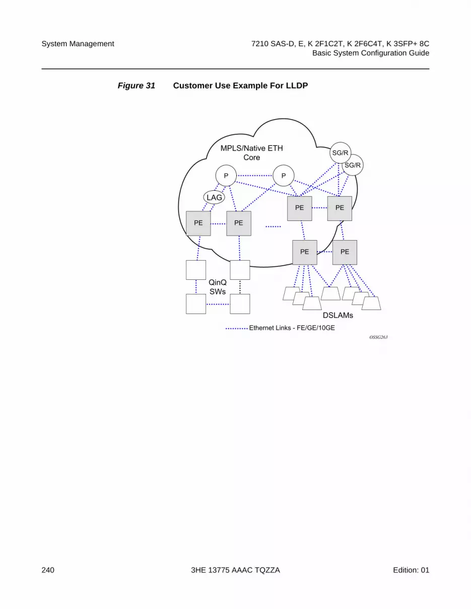
System Management
240
7210 SAS-D, E, K 2F1C2T, K 2F6C4T, K 3SFP+ 8CBasic System Configuration Guide
3HE 13775 AAAC TQZZA Edition: 01
Figure 31 Customer Use Example For LLDP
OSSG263
Ethernet Links - FE/GE/10GE
MPLS/Native ETHCore
LAG
QinQSWs
DSLAMs
P
PE PE
PE PE
PE PE
PSG/R
SG/R

7210 SAS-D, E, K 2F1C2T, K 2F6C4T, K 3SFP+ 8C Basic System Configuration Guide
System Management
Edition: 01 3HE 13775 AAAC TQZZA 241
5.8 System Resource Allocation
5.8.1 Allocation of Ingress Internal TCAM resources
The system statically allocates ingress TCAM resources for use by SAP ingress QoS classification, SAP ingress access control lists (ACLs), identifying and sending CFM OAM packets to CPU for local processing, and so on. The resource allocation is not user-configurable. With the introduction of new capabilities such as IPv6 classification, UP MEP support, and G8032-fast-flood, the static allocation of resources by software does not meet requirements of different customers who need to use different features.
The user can allocate a fixed amount of resources per system to be used for QoS, ACLs, CFM/Y.1731 MEPs and other features. Some of these parameters are boot-time and others are run-time. A change in current value of the parameter that is designated ‘boot-time’ needs a reboot of the node before the new value takes effect. Change in the current value of the parameter that is designated ‘run-time’ takes effect immediately if the software determines resources are available for use to accommodate the change.
During system bootup, the system reads all the resource profile parameters and allocates resources to the features in the order of which they appear in the configuration file.
The resources are shared; therefore, the user must ensure that the sum total of resources does not exceed the limit supported by the IMM or node. If the system determines that it cannot allocate the requested resources, it disables the feature. For example, if the system determines that it cannot allocate resources for g8032-fast-flood, it disables the feature from use (that is, G8032 eth-rings does not use fast-flood mechanisms). Another example is that if the system determines that it cannot allocate resources for IPv4-based SAP ingress ACL classification, the system does not allow users to use the IPv4-based SAP ingress ACL classification feature and fails the configuration when it comes upon the first SAP in the configuration file that uses an IPv4-based SAP ingress ACL policy.
For boot-time parameters, such as g8032-fast-flood-enable, it is the user’s responsibility to ensure that the configuration of services matches the resource allocated. If the system determines that it cannot allocate resources to services, it fails the configuration file at the first instance where it encounters a command to which resources cannot be allocated. The available resources can be allocated to different features. Refer to the scaling guide for the amount of resources available per platform and per feature.

System Management
242
7210 SAS-D, E, K 2F1C2T, K 2F6C4T, K 3SFP+ 8CBasic System Configuration Guide
3HE 13775 AAAC TQZZA Edition: 01
For ACL and QoS resources, the user has the option to allocate resources to limit usage per feature, regardless of the match criteria used (that is, the sum of all resources used for different SAP ingress classification match-criteria is limited by the amount allocated for SAP ingress classification) and can further allocate resources for use by specific match criteria. The user can enable any of the match criteria from among those supported and associate a fixed amount of resources with each of the match criteria in fixed sizes (the chunk size is dependent on the platform).
The system attempts to allocate resources in the order it appears in the configuration file and fails any match criteria if it does not have any more resources to allocate. The user is also provided with the keyword max to indicate that the system needs to allocate resources when it is first required, as long as the maximum resources allocated for that feature is not exceeded or the maximum resources available in the system is not exceeded. The 7210 SAS allocates resources to each of the features and the match-criteria in fixed-size chunks.
The no form of the command disables the use of corresponding match criteria. During runtime, the command succeeds, if no SAPs are currently using the criteria. Similarly, reduction of resources from the current value to a lower value succeeds, if no SAPs are currently using the criteria. If the system can successfully execute the command, it can free up the resources that were in use by that slice or chunk and makes it available for use by other features. This implies the user either deletes a SAP or removes the ingress ACL policy association with a SAP to free up resources. By executing these commands the system releases some entries in a specific chunk or releases an entire chunk. If an entire chunk is freed, it is returned to the system free pool for use by other features. If some entries in the chunk are freed, it is made available for use by other SAPs using the same feature to which the chunk has been allocated to.
The no form of the commands that are designated as boot-time does not take effect immediately. It takes effect after the reboot. Before reboot it is the user’s responsibility to free up resources required for use by the feature that has been enabled to take effect after the reboot. Not doing so results in failure when the configuration file is executed on boot up.
Refer to the CLI and feature description chapters in the appropriate 7210 SAS platform user guide for more information about CLI commands and features that use system resource allocation.
7210 SAS-D, E, K 2F1C2T, K 2F6C4T, K 3SFP+ 8C Basic System Configuration Guide
System Management
Edition: 01 3HE 13775 AAAC TQZZA 243
5.8.2 Allocation of Egress Internal TCAM Resources
In the current releases, the system statically allocates egress TCAM resources for use by different criteria in SAP ACLs and other purposes. Resource allocation is not user-configurable. With the introduction of new capabilities such as IPv6 match criteria in egress, the static allocation of resources by software does not meet requirements of different customers who need to use different features. Therefore, ingress internal TCAM resource allocation capabilities has been extended to the egress internal TCAM resources.
Refer to the CLI and feature description chapters in the appropriate 7210 SAS platform user guide for more information about CLI commands and features that use system resource allocation.
Note: This feature is not supported on the 7210 SAS-E.
Note: Boot-time commands under the config>system>resource-profile will not take effect when a configuration file is executed using the exec CLI command. Boot-time commands under the config>system>resource-profile are read and acted upon by the system only during boot.

System Management
244
7210 SAS-D, E, K 2F1C2T, K 2F6C4T, K 3SFP+ 8CBasic System Configuration Guide
3HE 13775 AAAC TQZZA Edition: 01
5.8.2.1 System Resource Allocation Examples
Example one:
config> system> resource-profile...acl-sap-ingress 3mac-match-enable maxipv4-match-enable 1no ipv6_128-ipv4-match-enableno ipv6_64-only-match-enableexit…..
In CLI example one, the system takes the following actions.
• The system allocates 3 chunks for use by the SAP ingress ACL entries.
• The system allocates 1 chunk for use by SAP ingress ACL entries using IPv4 criteria. The system fails the configuration when the number of ACL entries using IPv4 criteria exceeds the configured limit (that is, the system does not allocate in excess of the configured limit of 1 chunk).
Note:
• On the 7210 SAS-K 2F1C2T, 7210 SAS-K 2F6C4T, and 7210 SAS-K 3SFP+ 8C, resources must be allocated among SAP ingress QoS and ingress ACLs. Users do not need to further allocate resources individually for MAC and IPv4 or IPv6 criteria.
• The qos-sap-ingress-resource and acl-sap ingress commands under the system>resource-profile>ingress-internal-tcam context allocate resources to ingress QoS and ingress ACLs.
− On the 7210 SAS-D and 7210 SAS-E, resources are allocated in slices with 256 entries per slice.
− On the 7210 SAS-K 2F1C2T and 7210 SAS-K 2F6C4T, resources are allocated with 510 entries per slice.
− On the 7210 SAS-K 3SFP+ 8C, resources are allocated with 192 entries per slice.
• The acl-sap egress command in the system>resource-profile>egress-internal-tcam context allocates resources to egress ACLs.
− On the 7210 SAS-D, resources are allocated in slices with 128 entries per slice.
− On the 7210 SAS-K 2F1C2T and 7210 SAS-K 2F6C4T, resources are allocated with 510 entries per slice.
− On the 7210 SAS-K 3SFP+ 8C, resources are allocated with 180 entries per slice.

7210 SAS-D, E, K 2F1C2T, K 2F6C4T, K 3SFP+ 8C Basic System Configuration Guide
System Management
Edition: 01 3HE 13775 AAAC TQZZA 245
• The system allocates a chunk for use by SAP ingress ACL entries using MAC criteria. After the user has specified max, the system allocates 1 chunk for use when the user associates an ingress ACL policy (with mac-criteria entries defined) with a SAP. The system can allocate more chunks (up to 2) because the user has specified the max keyword. More chunks are allocated when the user configures SAPs that use MAC criteria and all of the entries in the allocated chunks are used up. The system fails the configuration when the number of ACL entries with MAC criteria exceeds the limit of 2 chunks allocated to the SAP ingress ACL match (that is, the system does not allocate in excess of the configured limit of 3 chunks = up-to 2 for MAC criteria and 1 for IPv6 criteria).
• The system fails the user attempt to use SAP ingress ACLs with the IPv6 match criteria (and the other applicable combinations) because the user has disabled the use of these criteria.
Example 2:
config> system> resource-profile>ingress-internal-tcam>...acl-sap-ingress 3mac-match-enable maxipv4-match-enable 1no ipv6_128-ipv4-match-enableipv6_64-only-match-enable maxexit...
In the CLI example 2, the system takes the following actions.
• The system allocates 3 chunks for use by the SAP ingress ACL entries. These resources are available for use with MAC criteria, IPv4 criteria, and IPv6 64-bit match criteria.
• The system allocates 1 chunk for use by SAP ingress ACL entries using ipv4-criteria. The system fails the configuration when the number of ACL entries using ipv4-criteria exceeds the configured limit (that is, the system does not allocate in excess of the configured limit of 1 chunk).
• The system allocates 1 chunk for use by SAP ingress ACL entries using mac-criteria when the user associates an ingress ACL policy (with mac-criteria entries defined) with a SAP. The system can allocate more chunks when the user specifies the max keyword if a chunk is available for use. In this particular example, assuming that the user configures a SAP with a ingress ACL policy that uses ipv6-64-bit criteria, because there are no more chunks available, the mac-criteria cannot allocate more than 1 chunk, even though it specifies the max keyword. The system fails the configuration when the number of ACL entries with mac-criteria exceeds the limit of 1 chunk allocated to a SAP ingress ACL mac-criteria (that is, the system does not allocate in excess of the configured limit of 3 chunks, 1 for mac-criteria, 1 for ipv4-criteria, and 1 for ipv6-criteria).

System Management
246
7210 SAS-D, E, K 2F1C2T, K 2F6C4T, K 3SFP+ 8CBasic System Configuration Guide
3HE 13775 AAAC TQZZA Edition: 01
• The System allocates a chunk for use by a SAP ingress ACL entries using ipv6-64-bit criteria when the user associates an ingress ACL policy (with ipv6-64-bit-criteria entries defined) with a SAP. The system can allocate more chunks when the user specifies the max keyword. In this particular example, as there are no more chunks available, ipv6-64-bit criteria cannot allocate more than 1 chunk, even though it specifies the max keyword. The system fails the configuration when the number of ACL entries with ipv6-64-bit criteria exceeds the limit of one chunk allocated to an SAP ingress ACL match (that is, the system does not allocate in excess of the configured limit of 3 chunks, 1 for mac-criteria, 1 for ipv4-criteria, and 1 for ipv6-64-bit criteria).
• The system fails the user attempt to use SAP ingress ACLs with ipv6-128 bit match criteria (and the other applicable combinations), as the user has disabled use of these criteria.
In the CLI example 2, the user can execute no ipv4-match-enable to disable use of the ipv4-criteria. The system checks if there are SAPs using ipv4-criteria and fails the command if one exists; otherwise, the chunk is freed and is used with either mac-criteria or ipv6-64-bit criteria. The entire chunk is allocated to mac-criteria if the first SAP that needs resources requests for mac-criteria and there are no entries in the chunk already allocated to mac-criteria, leaving no more resources for use by ipv6-64-bit criteria or the entire chunk is allocated to ipv6-64-bit criteria, if the first SAP that needs resources requests for ipv6-64-bit criteria and there are no entries in the chunk already allocated to ipv6-64-bit criteria, leaving no resources for use by mac-criteria.

7210 SAS-D, E, K 2F1C2T, K 2F6C4T, K 3SFP+ 8C Basic System Configuration Guide
System Management
Edition: 01 3HE 13775 AAAC TQZZA 247
5.9 System Configuration Process Overview
Figure 32 shows the process to provision basic system parameters.
Figure 32 System Configuration and Implementation Flow
END
START
CONFIGURE SYSTEM INFORMATION
CONFIGURE TIME PARAMETERS

System Management
248
7210 SAS-D, E, K 2F1C2T, K 2F6C4T, K 3SFP+ 8CBasic System Configuration Guide
3HE 13775 AAAC TQZZA Edition: 01
5.10 Configuration Notes
This section describes system configuration caveats.
5.10.1 General
• 7210 SAS devices must be correctly initialized and the boot loader and BOFs successfully executed to access the CLI.
7210 SAS-D, E, K 2F1C2T, K 2F6C4T, K 3SFP+ 8C Basic System Configuration Guide
System Management
Edition: 01 3HE 13775 AAAC TQZZA 249
5.11 Configuring System Management with CLI
This section provides information about configuring system management features with the CLI.
Topics in this chapter include:
• System Management
• Basic System Configuration
• Common Configuration Tasks
• System Administration Parameters
• System Timing
• Configuring System Monitoring Thresholds
• Configuring 1830 VWM
• Configuring System Resource Profile
• Configuring LLDP

System Management
250
7210 SAS-D, E, K 2F1C2T, K 2F6C4T, K 3SFP+ 8CBasic System Configuration Guide
3HE 13775 AAAC TQZZA Edition: 01
5.12 System Management
5.12.1 Saving Configurations
Whenever configuration changes are made, the modified configuration must be saved so the changes will not be lost when the system is rebooted. The system uses the configuration and image files, as well as other operational parameters necessary for system initialization, according to the locations specified in the BOF parameters. For more information about boot option files, see Boot Options.
Configuration files are saved by executing implicit or explicit command syntax.
• An explicit save writes the configuration to the location specified in the save command syntax (the file-url option).
• An implicit save writes the configuration to the file specified in the primary configuration location.
If the file-url option is not specified in the save command syntax, the system attempts to save the current configuration to the current BOF primary configuration source. If the primary configuration source (path and/or filename) has changed since the last boot, the new configuration source is used.
The save command includes an option to save both default and non-default configuration parameters (the detail option).
The index option specifies that the system preserves system indexes when a save command is executed, regardless of the persistent status in the BOF. During a subsequent boot, the index file is read along with the configuration file. As a result, a number of system indexes are preserved between reboots, including the interface index, LSP IDs, path IDs, etc. This reduces resynchronizations of the network management system (NMS) with the affected network element.
If the save attempt fails at the destination, an error occurs and is logged. The system does not try to save the file to the secondary or tertiary configuration sources unless the path and filename are explicitly named with the save command.

7210 SAS-D, E, K 2F1C2T, K 2F6C4T, K 3SFP+ 8C Basic System Configuration Guide
System Management
Edition: 01 3HE 13775 AAAC TQZZA 251
5.13 Basic System Configuration
This section provides information about configuring system parameters and provides configuration examples of common configuration tasks. The minimal system parameters that should be configured are the following:
• System Information Parameters
• System Time Elements
The following example shows a basic system configuration.
A:ALA-12>config>system# info#------------------------------------------echo "System Configuration "#------------------------------------------
name "ALA-12"coordinates "Unknown"snmpexitsecurity
snmpcommunity "private" rwa version both
exitexittime
ntpserver 192.168.15.221no shutdown
exitsntp
shutdownexitzone GMT
exit----------------------------------------------A:ALA-12>config>system#

System Management
252
7210 SAS-D, E, K 2F1C2T, K 2F6C4T, K 3SFP+ 8CBasic System Configuration Guide
3HE 13775 AAAC TQZZA Edition: 01
5.14 Common Configuration Tasks
This section provides a brief overview of the tasks that must be performed to configure system parameters and provides the CLI commands.
• System Information
• Configuring Backup Copies
5.14.1 System Information
This section covers the basic system information parameters to configure the physical location of the router, contact information, location information such as the place the router is located (for example, an address), floor or room number, global positioning system (GPS) coordinates, and system name.
Use the following CLI syntax to configure the following system components:
• System Information Parameters
• System Time Elements
5.14.1.1 System Information Parameters
General system information parameters include the following:
• Name
• Contact
• Location
• CLLI Code
• Coordinates
5.14.1.1.1 Name
Use the name command to configure a name for the device. The name is used in the prompt string. Only one system name can be configured; if multiple system names are configured, the last one encountered overwrites the previous entry. Use the following CLI syntax to configure the system name.

7210 SAS-D, E, K 2F1C2T, K 2F6C4T, K 3SFP+ 8C Basic System Configuration Guide
System Management
Edition: 01 3HE 13775 AAAC TQZZA 253
CLI Syntax: config>systemname system-name
Example: config>system# name ALA-12
The following example displays the system name.
sysName@domain>config>system# info#------------------------------------------echo "System Configuration "#------------------------------------------
name "ALA-12". . .
exit----------------------------------------------
sysName@domain>config>system#
5.14.1.1.2 Contact
Use the contact command to specify the name of a system administrator, IT staff member, or other administrative entity.
CLI Syntax: config>systemcontact contact-name
Example: config>system# contact “Fred Information Technology”
5.14.1.1.3 Location
Use the location command to specify the system location of the device. For example, enter the city, building address, floor, or room number where the router is located.
Use the following CLI syntax to configure the location.
CLI Syntax: config>systemlocation location
Example: config>system# location “Bldg.1-floor 2-Room 201”

System Management
254
7210 SAS-D, E, K 2F1C2T, K 2F6C4T, K 3SFP+ 8CBasic System Configuration Guide
3HE 13775 AAAC TQZZA Edition: 01
5.14.1.1.4 CLLI Code
The Common Language Location Code (CLLI code) is an 11-character standardized geographic identifier that is used to uniquely identify the geographic location of a router.
Use the following CLI command syntax to define the CLLI code.
CLI Syntax: config>systemclli-code clli-code
Example: config>system# clli-code abcdefg1234
5.14.1.1.5 Coordinates
Use the optional coordinates command to specify the GPS location of the device. If the string contains special characters (#, $, spaces, etc.), the entire string must be enclosed within double quotes.
Use the following CLI syntax to configure the location:
CLI Syntax: config>systemcoordinates coordinates
Example: config>system# coordinates "N 45 58 23, W 34 56 12"
The following example displays the configuration output of the general system commands.
sysName@domain>config>system# info#------------------------------------------echo "System Configuration "#------------------------------------------name "ALA-12"
contact "Fred Information Technology"location "Bldg.1-floor 2-Room 201"clli-code "abcdefg1234"coordinates "N 45 58 23, W 34 56 12"
. . .exit
----------------------------------------------A:ALA-12>config>system#

7210 SAS-D, E, K 2F1C2T, K 2F6C4T, K 3SFP+ 8C Basic System Configuration Guide
System Management
Edition: 01 3HE 13775 AAAC TQZZA 255
5.14.1.2 System Time Elements
The system clock maintains time according to Coordinated Universal Time (UTC). Configure information time zone and summer time (daylight savings time) parameters to correctly display time according to the local time zone.
Time elements include the following:
• Zone
• Summer Time Conditions
• NTP
• SNTP
• CRON
• Time Range
• Time of Day
5.14.1.2.1 Zone
The zone command sets the time zone and/or time zone offset for the device. The 7210 SAS supports system-defined and user-defined time zones. Table 34 describes system-defined time zones.
CLI Syntax: config>system>timezone std-zone-name|non-std-zone-name [hh [:mm]]
Example: config>system>time# config>system>time# zone GMT
The following example displays the zone output.
A:ALA-12>config>system>time# info----------------------------------------------ntp
server 192.168.15.221no shutdown
exitsntp
shutdownexitzone UTC----------------------------------------------A:ALA-12>config>system>time#

System Management
256
7210 SAS-D, E, K 2F1C2T, K 2F6C4T, K 3SFP+ 8CBasic System Configuration Guide
3HE 13775 AAAC TQZZA Edition: 01
Table 34 System-defined Time Zones
Acronym Time Zone Name UTC Offset
Europe:
GMT Greenwich Mean Time UTC
WET Western Europe Time UTC
WEST Western Europe Summer Time UTC +1 hour
CET Central Europe Time UTC +1 hour
CEST Central Europe Summer Time UTC +2 hours
EET Eastern Europe Time UTC +2 hours
EEST Eastern Europe Summer Time UTC +3 hours
MSK Moscow Time UTC +3 hours
MSD Moscow Summer Time UTC +4 hours
US and Canada:
AST Atlantic Standard Time UTC -4 hours
ADT Atlantic Daylight Time UTC -3 hours
EST Eastern Standard Time UTC -5 hours
EDT Eastern Daylight Saving Time UTC -4 hours
CST Central Standard Time UTC -6 hours
CDT Central Daylight Saving Time UTC -5 hours
MST Mountain Standard Time UTC -7 hours
MDT Mountain Daylight Saving Time UTC -6 hours
PST Pacific Standard Time UTC -8 hours
PDT Pacific Daylight Saving Time UTC -7 hours
HST Hawaiian Standard Time UTC -10 hours
AKST Alaska Standard Time UTC -9 hours
AKDT Alaska Standard Daylight Saving Time
UTC -8 hours
Australia and New Zealand:
AWST Western Standard Time (e.g., Perth)
UTC +8 hours

7210 SAS-D, E, K 2F1C2T, K 2F6C4T, K 3SFP+ 8C Basic System Configuration Guide
System Management
Edition: 01 3HE 13775 AAAC TQZZA 257
5.14.1.2.2 Summer Time Conditions
The config>system>time>dst-zone context configures the start and end dates and offset for summer time or daylight savings time to override system defaults or for user defined time zones.
When configured, the time will be adjusted by adding the configured offset when summer time starts and subtracting the configured offset when summer time ends.
CLI Syntax: config>system>timedst-zone zone-name
end {end-week} {end-day} {end-month} [hours-minutes]
offset offsetstart {start-week} {start-day} {start-month}
[hours-minutes]
Example: config>system# timeconfig>system>time# dst-zone ptconfig>system>time>dst-zone# start second sunday april 02:00
end first sunday october 02:00config>system>time>dst-zone# offset 0
If the time zone configured is listed in Table 34, then the starting and ending parameters and offset do not need to be configured with this command unless there is a need to override the system defaults. The command will return an error if the start and ending dates and times are not available either in Table 34 or entered as optional parameters in this command.
ACST Central Standard Time (e.g., Darwin)
UTC +9.5 hours
AEST Eastern Standard/Summer Time (e.g., Canberra)
UTC +10 hours
NZT New Zealand Standard Time UTC +12 hours
NZDT New Zealand Daylight Saving Time UTC +13 hours
Table 34 System-defined Time Zones (Continued)
Acronym Time Zone Name UTC Offset

System Management
258
7210 SAS-D, E, K 2F1C2T, K 2F6C4T, K 3SFP+ 8CBasic System Configuration Guide
3HE 13775 AAAC TQZZA Edition: 01
The following example displays the configured parameters.
A:ALA-48>config>system>time>dst-zone# info----------------------------------------------
start second sunday april 02:00end first sunday october 02:00offset 0
----------------------------------------------A:ALA-48>config>system>time>dst-zone# offset 0
5.14.1.2.3 NTP
Network Time Protocol (NTP) is defined in RFC 1305, Network Time Protocol (Version 3) Specification, Implementation and Analysis. It allows for participating network nodes to keep time more accurately and maintain time in a synchronized manner between all participating network nodes.
NTP time elements include the following:
• Authentication-check
• Authentication-key
• Broadcast
• Broadcastclient
• NTP-server
• Peer
• Server
Authentication-check
The authentication-check command provides the option to skip the rejection of NTP PDUs that do not match the authentication key or authentication type requirements. The default behavior when authentication is configured is to reject all NTP protocol PDUs that have a mismatch in either the authentication key ID, type, or key.
When authentication-check is configured, NTP PDUs are authenticated on receipt. However, mismatches cause a counter to be increased, one counter for the key ID, one for the type, and one for key value mismatches.
CLI Syntax: config>system>time>ntpauthentication-check
Example: config>system>time>ntp#
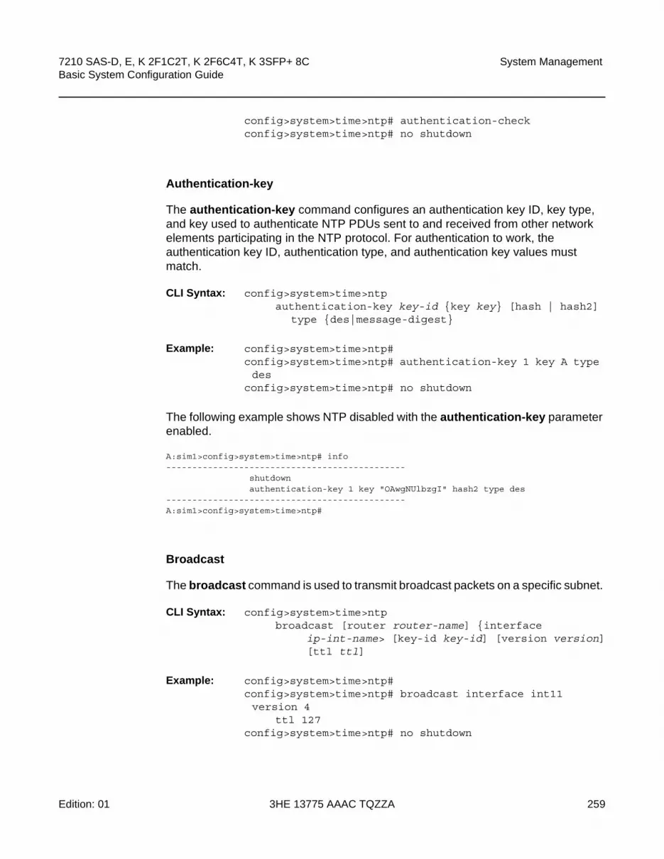
7210 SAS-D, E, K 2F1C2T, K 2F6C4T, K 3SFP+ 8C Basic System Configuration Guide
System Management
Edition: 01 3HE 13775 AAAC TQZZA 259
config>system>time>ntp# authentication-checkconfig>system>time>ntp# no shutdown
Authentication-key
The authentication-key command configures an authentication key ID, key type, and key used to authenticate NTP PDUs sent to and received from other network elements participating in the NTP protocol. For authentication to work, the authentication key ID, authentication type, and authentication key values must match.
CLI Syntax: config>system>time>ntpauthentication-key key-id {key key} [hash | hash2]
type {des|message-digest}
Example: config>system>time>ntp# config>system>time>ntp# authentication-key 1 key A type des
config>system>time>ntp# no shutdown
The following example shows NTP disabled with the authentication-key parameter enabled.
A:sim1>config>system>time>ntp# info----------------------------------------------
shutdownauthentication-key 1 key "OAwgNUlbzgI" hash2 type des
----------------------------------------------A:sim1>config>system>time>ntp#
Broadcast
The broadcast command is used to transmit broadcast packets on a specific subnet.
CLI Syntax: config>system>time>ntpbroadcast [router router-name] {interface
ip-int-name> [key-id key-id] [version version][ttl ttl]
Example: config>system>time>ntp# config>system>time>ntp# broadcast interface int11 version 4
ttl 127config>system>time>ntp# no shutdown

System Management
260
7210 SAS-D, E, K 2F1C2T, K 2F6C4T, K 3SFP+ 8CBasic System Configuration Guide
3HE 13775 AAAC TQZZA Edition: 01
The following example in the system>time context shows NTP enabled with the broadcast command configured.
A:sim1>config>system>time# info detail----------------------------------------------
ntpno shutdownauthentication-checkntp-serverbroadcast interface int11 version 4 ttl 127
exitA:sim1>config>system>time#
The following example in the config context shows NTP enabled with the broadcast command configured. At this level, the NTP broadcast commands are displayed at the end of the output after the router interfaces are shown.
A:sim1>config info
....
#--------------------------------------------------echo "System Time NTP Configuration"#--------------------------------------------------
systemtime
ntpbroadcast interface toboth
exitexit
exitA:sim1>config
Broadcastclient
The broadcastclient command enables listening to NTP broadcast messages on the specified interface.
CLI Syntax: config>system>time>ntpbroadcastclient [router router-name] {interface ip-
int-name} [authenticate]
Example: config>system>time>ntp# config>system>time>ntp# broadcastclient interface int11config>system>time>ntp# no shutdown

7210 SAS-D, E, K 2F1C2T, K 2F6C4T, K 3SFP+ 8C Basic System Configuration Guide
System Management
Edition: 01 3HE 13775 AAAC TQZZA 261
The following example shows NTP enabled with the broadcastclient parameter enabled.
A:ALA-12>config>system>time# info----------------------------------------------
ntpbroadcastclient interface int11no shutdown
exitdst-zone PT
start second sunday april 02:00end first sunday october 02:00offset 0
exitzone UTC
----------------------------------------------A:ALA-12>config>system>time#
NTP-server
This command configures the node to assume the role of an NTP server. Unless the server command is used, this node will function as an NTP client only and will not distribute the time to downstream network elements. If an authentication key ID is specified in this command, the NTP server requires client packets to be authenticated.
CLI Syntax: config>system>time>ntpntp-server [transmit key-id]
Example: config>system>time>ntp# config>system>time>ntp# ntp-server transmit 1config>system>time>ntp# no shutdown
The following example shows NTP enabled with the ntp-server command configured.
A:sim1>config>system>time>ntp# info----------------------------------------------
no shutdownntp-server
----------------------------------------------A:sim1>config>system>time>ntp#

System Management
262
7210 SAS-D, E, K 2F1C2T, K 2F6C4T, K 3SFP+ 8CBasic System Configuration Guide
3HE 13775 AAAC TQZZA Edition: 01
Peer
Configuration of an NTP peer configures symmetric active mode for the configured peer. Although any system can be configured to peer with any other NTP node, Nokia recommends to configure authentication and to configure known time servers as their peers. Use the no form of the command to remove the configured peer.
CLI Syntax: config>system>time>ntppeer ip-address [version version] [key-id key-id] [prefer]
Example: config>system>time>ntp# config>system>time>ntp# peer 192.168.1.1 key-id 1config>system>time>ntp# no shutdown
The following example shows NTP enabled with the peer command configured.
A:sim1>config>system>time>ntp# info----------------------------------------------
no shutdownpeer 192.168.1.1 key-id 1
----------------------------------------------A:sim1>config>system>time>ntp#
Server
The server command is used when the node operates in client mode with the NTP server specified in the address field. Use the no form of this command to remove the server with the specified address from the configuration.
Up to five NTP servers can be configured.
CLI Syntax: config>system>time>ntpserver {ip-address |ptp} [key-id key-id] [version
version] [prefer]
Example: config>system>time>ntp# config>system>time>ntp# server 192.168.1.1 key-id 1config>system>time>ntp# no shutdown
The following example shows NTP enabled with the server command configured.
A:7210SAS>config>system>time>ntp# info----------------------------------------------
ntp-serverserver ptp preferbroadcast interface "a1"no shutdown

7210 SAS-D, E, K 2F1C2T, K 2F6C4T, K 3SFP+ 8C Basic System Configuration Guide
System Management
Edition: 01 3HE 13775 AAAC TQZZA 263
----------------------------------------------A:7210SAS>config>system>time>ntp#
5.14.1.2.4 SNTP
SNTP is a compact, client-only version of the NTP. SNTP can only receive the time from SNTP/NTP servers; it cannot be used to provide time services to other systems. SNTP can be configured in either broadcast or unicast client mode.
SNTP time elements include the following:
• Broadcast-client
• Server-address
CLI Syntax: config>systemtime
sntpbroadcast-client server-address ip-address [version
version-number] [normal|preferred] [interval seconds]
no shutdown
Broadcast-client
The broadcast-client command enables listening at the global device level to SNTP broadcast messages on interfaces with broadcast client enabled.
CLI Syntax: config>system>time>sntpbroadcast-client
Example: config>system>time>sntp# config>system>time>sntp# broadcast-client config>system>time>sntp# no shutdown
The following example shows SNTP enabled with the broadcast-client command enabled.
A:ALA-12>config>system>time# info----------------------------------------------
sntpbroadcast-clientno shutdown
exitdst-zone PT
start second sunday april 02:00

System Management
264
7210 SAS-D, E, K 2F1C2T, K 2F6C4T, K 3SFP+ 8CBasic System Configuration Guide
3HE 13775 AAAC TQZZA Edition: 01
end first sunday october 02:00offset 0
exitzone GMT
----------------------------------------------A:ALA-12>config>system>time#
Server-address
The server-address command configures an SNTP server for SNTP unicast client mode.
CLI Syntax: config>system>time>sntp#server-address ip-address version version-number]
[normal|preferred] [interval seconds]
Example: config>system>time>sntp#config>system>time# server-address 10.10.0.94 version
1 preferred interval 100
The following example shows SNTP enabled with the server-address command configured.
A:ALA-12>config>system>time# info----------------------------------------------
sntpserver-address 10.10.0.94 version 1 preferred interval 100no shutdown
exitdst-zone PT start-date 2006/04/04 12:00 end-date 2006/10/25 12:00zone GMT
----------------------------------------------A:ALA-12>config>system>time#
5.14.1.2.5 CRON
The cron command supports the Service Assurance Agent (SAA) functions as well as the ability to schedule turning on and off policies to meet “Time of Day” requirements. CRON functionality includes the ability to specify the commands that need to be run, when they will be scheduled, including one-time only functionality (oneshot), interval and calendar functions, as well as where to store the output of the results. In addition, CRON can specify the relationship between input, output and schedule. Scheduled reboots, peer turn ups, service assurance agent tests and more can all be scheduled with CRON, as well as OAM events, such as connectivity checks, or troubleshooting runs.

7210 SAS-D, E, K 2F1C2T, K 2F6C4T, K 3SFP+ 8C Basic System Configuration Guide
System Management
Edition: 01 3HE 13775 AAAC TQZZA 265
CRON elements include:
• Schedule
• Script
• Time Range
• Time of Day
Schedule
The schedule command configures the type of schedule to run, including one-time only (oneshot), periodic, or calendar-based runs. All runs are determined by month, day of month or weekday, hour, minute, and interval (seconds). If end-time and interval are both configured, whichever condition is reached first is applied.
CLI Syntax: config>system>cronschedule schedule-name [owner schedule-owner]
count numberday-of-month {day-number [..day-number]|all}description description-stringend-time [date|day-name] timehour {hour-number [..hour-number] | all}interval seconds minute {minute-number [..minute-number]|all} month {month-number [..month-number]|month-
name [..month-name]|all}no shutdown type {periodic|calendar|oneshot} weekday {weekday-number [..weekday-
number]|day-name [..day-name]|all}shutdown
Example: config>system>cron# schedule test2config>system>cron>sched# day-of-month 17config>system>cron>sched# end-time 2007/07/17 12:00config>system>cron>sched# minute 0 15 30 45config>system>cron>sched# weekday fridayconfig>system>cron>sched# shut
The following example schedules a script named “test2” to run every 15 minutes on the 17th of each month and every Friday until noon on July 17, 2007:
*A:SR-3>config>system>cron# info----------------------------------------------
schedule "test2"shutdownday-of-month 17
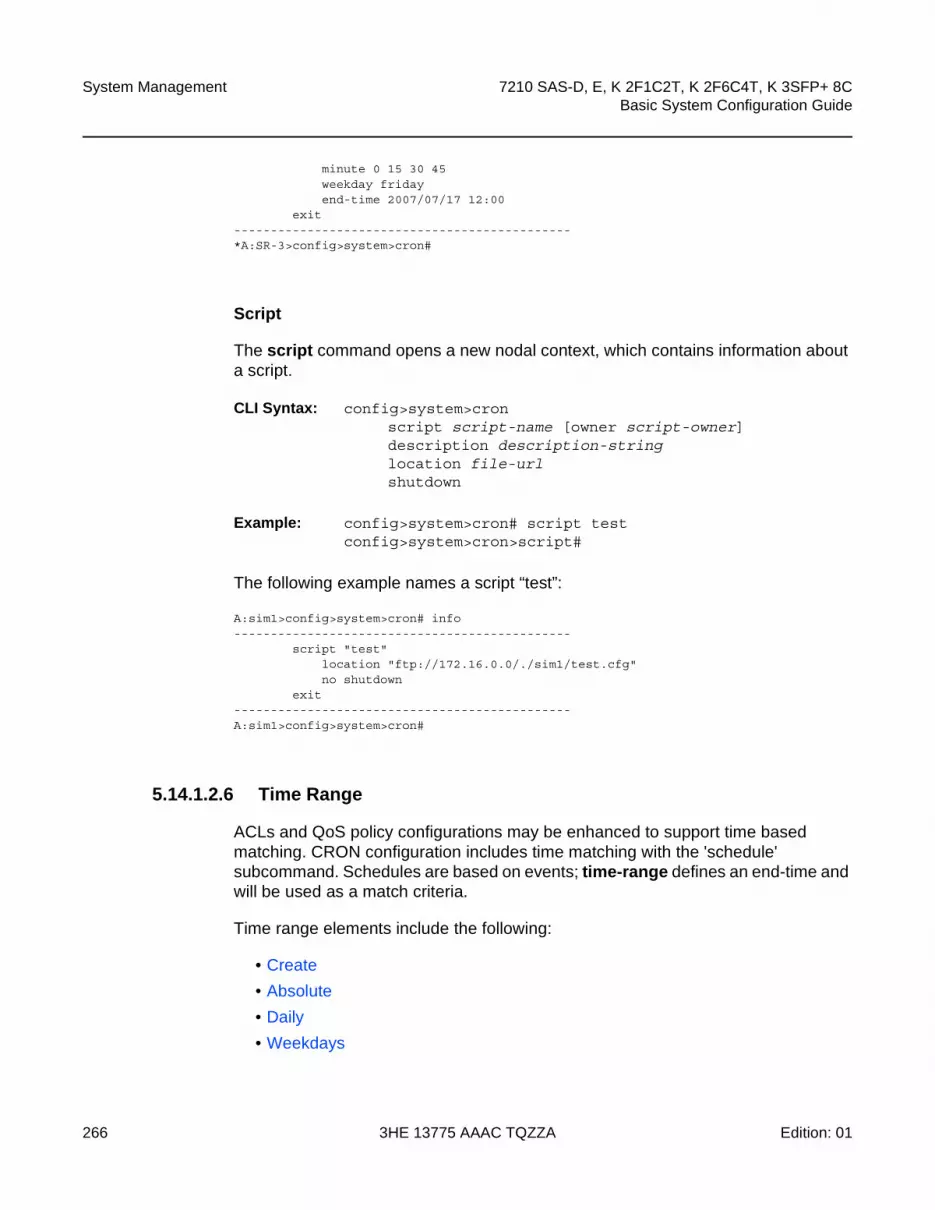
System Management
266
7210 SAS-D, E, K 2F1C2T, K 2F6C4T, K 3SFP+ 8CBasic System Configuration Guide
3HE 13775 AAAC TQZZA Edition: 01
minute 0 15 30 45weekday fridayend-time 2007/07/17 12:00
exit----------------------------------------------*A:SR-3>config>system>cron#
Script
The script command opens a new nodal context, which contains information about a script.
CLI Syntax: config>system>cronscript script-name [owner script-owner]description description-stringlocation file-url shutdown
Example: config>system>cron# script testconfig>system>cron>script#
The following example names a script “test”:
A:sim1>config>system>cron# info----------------------------------------------
script "test"location "ftp://172.16.0.0/./sim1/test.cfg"no shutdown
exit----------------------------------------------A:sim1>config>system>cron#
5.14.1.2.6 Time Range
ACLs and QoS policy configurations may be enhanced to support time based matching. CRON configuration includes time matching with the 'schedule' subcommand. Schedules are based on events; time-range defines an end-time and will be used as a match criteria.
Time range elements include the following:
• Create
• Absolute
• Daily
• Weekdays

7210 SAS-D, E, K 2F1C2T, K 2F6C4T, K 3SFP+ 8C Basic System Configuration Guide
System Management
Edition: 01 3HE 13775 AAAC TQZZA 267
• Weekend
• Weekly
Create
Use this command to enable the time-range context.
The following example creates a time range called test1.
CLI Syntax: config>system>crontime-range name create
Example: config>system>cron# time-range test1 createconfig>system>cron>time-range$
Absolute
The absolute command configures a start and end time that will not repeat.
CLI Syntax: config>system>cron>time-range$absolute absolute-time end absolute-time
Example: config>system>cron>time-range$ absolute start 2006/05/05,11:00 end
2006/05/06,11:01config>system>cron>time-range$
The following example shows an absolute time range beginning on May 5, 2006 at 11:00 and ending May 6, 2006 at 11:01.
A:sim1>config>system>cron>time-range# show cron time-range detail===============================================================================Cron time-range details===============================================================================Name : test1Triggers : 0Status : InactiveAbsolute : start 2006/05/05,11:00 end 2006/05/06,11:01===============================================================================A:sim1>config>system>cron>time-range#

System Management
268
7210 SAS-D, E, K 2F1C2T, K 2F6C4T, K 3SFP+ 8CBasic System Configuration Guide
3HE 13775 AAAC TQZZA Edition: 01
Daily
The daily command configures the start and end of a periodic schedule for every day of the week (Sunday through Saturday).
CLI Syntax: config>system>cron>time-range$daily start time-of-day end time-of-day
Example: config>system>cron>time-range$ daily start 11:00 end 12:00
config>system>cron>time-range$
The following example shows a daily time range beginning at 11:00 and ending at 12:00.
A:sim1>config>system>cron>time-range# show cron time-range detail===============================================================================Cron time-range details===============================================================================Name : 1Triggers : 0Status : InactivePeriodic : daily Start 11:00 End 12:00===============================================================================A:sim1>config>system>cron>time-range#
Weekdays
The weekdays command configures the start and end of a periodic schedule for weekdays (Monday through Friday).
CLI Syntax: config>system>cron>time-range$weekdays start time-of-day end time-of-day
Example: config>system>cron>time-range$ weekdays start 11:00 end 12:00
config>system>cron>time-range$
The following command shows a time range beginning at 11:00 and ending at 12:00. This schedule runs all weekdays during this time period.
A:sim1>config>system>cron>time-range# show cron time-range detail===============================================================================Cron time-range details===============================================================================Name : 1Triggers : 0Status : InactivePeriodic : weekdays Start 11:00 End 12:00

7210 SAS-D, E, K 2F1C2T, K 2F6C4T, K 3SFP+ 8C Basic System Configuration Guide
System Management
Edition: 01 3HE 13775 AAAC TQZZA 269
===============================================================================A:sim1>config>system>cron>time-range#
Weekend
The weekend command configures the start and end of a periodic schedule for weekends (Saturday and Sunday). The resolution must be at least one minute apart, for example, start at 11:00 and end at 11:01. A start time and end time of 11:00 is invalid.
CLI Syntax: config>system>cron>time-range$weekend start time-of-day end time-of-day
Example: config>system>cron>time-range$ weekend start 11:00 end 12:00
config>system>cron>time-range$
The following command shows a weekend time range beginning at 11:00am and ending at 12:00pm, both Saturday and Sunday.
To specify 11:00am to 12:00pm on Saturday or Sunday only, use the Absolute parameter for one day, or the Weekly parameter for every Saturday or Sunday accordingly. In addition, see the schedule parameter to schedule oneshot or periodic events in the config>system>cron context.
A:sim1>config>system>cron>time-range# show cron time-range detail===============================================================================Cron time-range details===============================================================================Name : 1Triggers : 0Status : InactivePeriodic : weekend Start 11:00 End 12:00
Weekly
The weekly command configures the start and end of a periodic schedule for the same day every week, for example, every Friday. The start and end dates must be the same. The resolution must be at least one minute apart, for example, start at 11:00 and end at 11:01. A start time and end time of 11:00 is invalid.
CLI Syntax: config>system>cron>time-range$weekly start time-in-week end time-in-week

System Management
270
7210 SAS-D, E, K 2F1C2T, K 2F6C4T, K 3SFP+ 8CBasic System Configuration Guide
3HE 13775 AAAC TQZZA Edition: 01
Example: config>system>cron>time-range$ start fri,01:01 end fri,01:02
config>system>cron>time-range$
The following command shows a weekly time range beginning on Friday at 1:01am ending Friday at 1:02am.
A:sim1>config>system>cron>time-range$ info----------------------------------------------
weekly start fri,01:01 end fri,01:02----------------------------------------------A:sim1>config>system>cron>time-range$
5.14.1.2.7 Time of Day
Time of Day (TOD) suites are useful when configuring many types of time-based policies or when a large number of subscribers or SAPs require the same type of TOD changes. The TOD suite may be configured while using specific ingress or egress ACLs or QoS policies, and is an enhancement of the ingress and egress CLI trees.
Time of day elements include the following:
• SAPs
• Egress
• Filters
• Ingress
SAPs
• If a TOD suite is assigned to a SAP; statistics collection are not collected for that SAP.
• When an item is configured both on the SAP level and in the TOD suite assigned to the SAP, the TOD suite defined value takes precedence.
• A policy or filter assignment configured directly on a SAP has a lower priority than any assignment in a TOD suite. Therefore, it is possible that a new direct configuration has no immediate effect. If the configuration is made by CLI, a warning is given.

7210 SAS-D, E, K 2F1C2T, K 2F6C4T, K 3SFP+ 8C Basic System Configuration Guide
System Management
Edition: 01 3HE 13775 AAAC TQZZA 271
Egress
This command is an enhancement for specific egress policies. Use this command to create time range based associations of previously created filter lists, QoS and scheduler policies. Multiple policies may be included and each must be assigned a different priority; in case time ranges overlap, the priority will be used to determine the prevailing policy. Only a single reference to a policy may be included without a time range.
Filters
In a TOD suite, filters that have entries with time ranges may not be selected. Similarly, filter entries with a time range may not be created while a TOD suite refers to that filter. QoS policies and filters referred to by a TOD suite must have the scope “template” (default).
The following syntax is used to configure TOD-suite egress parameters.
CLI Syntax: config>system>crontod-suite tod-suite-name create
egress filter ip ip-filter-id [time-range time-
range-name][priority priority]filter ipv6 ipv6-filter-id [time-range
time-range-name][priority priority]filter mac mac-filter-id [time-range time-
range-name] [priority priority]
Example: config>system>cron>tod-suite$ egress filter ip 100config>system>cron>tod-suite$
The following command shows an egress IP filter association with filter ID 100.
sim1>config>filter# ip-filter 100 createA:sim1>config>filter>ip-filter$ entry 10 createA:sim1>config>filter>ip-filter>entry$A:sim1>config>system>cron>tod-suite# egress filter ip 100A:sim1>config>system>cron>tod-suite# info detail----------------------------------------------
no descriptionegress
filter ip 100exit
----------------------------------------------A:sim1>config>system>cron>tod-suite#

System Management
272
7210 SAS-D, E, K 2F1C2T, K 2F6C4T, K 3SFP+ 8CBasic System Configuration Guide
3HE 13775 AAAC TQZZA Edition: 01
Ingress
This command is an enhancement for specific ingress policies including filter lists and QoS policies. Use this command to create time range based associations of previously created filter lists and QoS policies. Multiple policies may be included and each must be assigned a different priority; in case time ranges overlap, the priority will be used to determine the prevailing policy. Only a single reference to a policy may be included without a time range. To configure a daily time range across midnight, use a combination of two entries. An entry that starts at hour zero will take over from an entry that ends at hour 24.
CLI Syntax: config>system>crontod-suite tod-suite-name create
ingressfilter ip ip-filter-id [time-range time-
range-name][priority priority]filter ipv6 ipv6-filter-id [time-range
time-range-name]filter mac mac-filter-id [time-range time-
range-name] [priority priority]qos policy-id [time-range time-range-
name] [priority priority]
Example: config>system>cron>tod-suite$ ingress filter ip 100config>system>cron>tod-suite$
The following command shows an ingress IP filter association with filter ID 100.
sim1>config>filter# ip-filter 100 createA:sim1>config>filter>ip-filter$ entry 10 createA:sim1>config>filter>ip-filter>entry$...A:sim1>config>system>cron>tod-suite# ingress filter ip 100A:sim1>config>system>cron>tod-suite# info detail----------------------------------------------
no descriptioningress
filter ip 100exit
----------------------------------------------A:sim1>config>system>cron>tod-suite#
Example: config>system>cron>tod-suite$ ingress qos 101config>system>cron>tod-suite$
The following command shows an association with ingress QoS-SAP policy 101.
A:sim1>config>qos# sap-egress 101 create...

7210 SAS-D, E, K 2F1C2T, K 2F6C4T, K 3SFP+ 8C Basic System Configuration Guide
System Management
Edition: 01 3HE 13775 AAAC TQZZA 273
A:sim1>config>system>cron>tod-suite# ingress qos 101A:sim1>config>system>cron>tod-suite# info detail----------------------------------------------
no descriptioningress
qos 101exit
----------------------------------------------A:sim1>config>system>cron>tod-suite#
5.14.2 Configuring Backup Copies
The config-backup command allows you to specify the maximum number of backup versions of configuration and index files kept in the primary location.
For example, assume the config-backup count is set to 5 and the configuration file is called xyz.cfg. When a save command is executed, the file xyz.cfg is saved with a .1 extension. Each subsequent config-backup command increments the numeric extension until the maximum count is reached. The oldest file (5) is deleted as more recent files are saved.
xyz.cfg
xyz.cfg.1
xyz.cfg.2
xyz.cfg.3
xyz.cfg.4
xyz.cfg.5
xyz.ndx
Each persistent index file is updated at the same time as the associated configuration file. When the index file is updated, the save is performed to xyz .cfg and the index file is created as xyz.ndx. Synchronization between the active and standby is performed for all configurations and their associated persistent index files.
CLI Syntax: config>systemconfig-backup count
Example: config>system#config>system# config-backup 7
The following example shows the config-backup configuration.
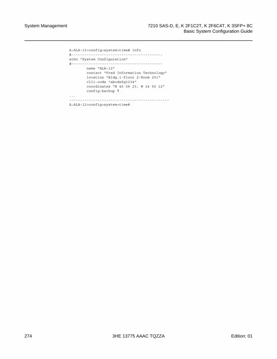
System Management
274
7210 SAS-D, E, K 2F1C2T, K 2F6C4T, K 3SFP+ 8CBasic System Configuration Guide
3HE 13775 AAAC TQZZA Edition: 01
A:ALA-12>config>system>time# info#------------------------------------------echo "System Configuration"#------------------------------------------
name "ALA-12"contact "Fred Information Technology"location "Bldg.1-floor 2-Room 201"clli-code "abcdefg1234"coordinates "N 45 58 23, W 34 56 12"config-backup 7
...----------------------------------------------A:ALA-12>config>system>time#

7210 SAS-D, E, K 2F1C2T, K 2F6C4T, K 3SFP+ 8C Basic System Configuration Guide
System Management
Edition: 01 3HE 13775 AAAC TQZZA 275
5.15 System Administration Parameters
Use the following CLI syntax to configure various system administration parameters.
Administrative parameters include the following:
• Validating the Golden Bootstrap Image
• Updating the Golden Bootstrap Image
• Disconnect
• Set-time
• Display-config
• Tech-support
• Save
• Reboot
• Post-Boot Configuration Extension Files
5.15.1 Validating the Golden Bootstrap Image
The admin>check-golden-bootstrap command validates the current golden bootstrap image, and displays its version. A default golden bootstrap image is installed on every 7210 SAS-E unit.
CLI Syntax: admin check-golden-bootstrap
Example: admin# check-golden-bootstrap
The following example displays the output.
version TiMOS-L-0.0.I312Golden Bootstrap Image validation successful
5.15.2 Updating the Golden Bootstrap Image
The admin>update-golden-bootstrap command validates the input file, which must be a 7210 SAS-E bootstrap image, and updates the golden bootstrap image with the contents of this file.
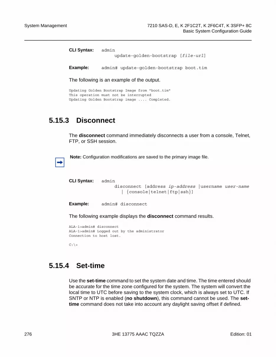
System Management
276
7210 SAS-D, E, K 2F1C2T, K 2F6C4T, K 3SFP+ 8CBasic System Configuration Guide
3HE 13775 AAAC TQZZA Edition: 01
CLI Syntax: adminupdate-golden-bootstrap [file-url]
Example: admin# update-golden-bootstrap boot.tim
The following is an example of the output.
Updating Golden Bootstrap Image from "boot.tim"This operation must not be interruptedUpdating Golden Bootstrap image .... Completed.
5.15.3 Disconnect
The disconnect command immediately disconnects a user from a console, Telnet, FTP, or SSH session.
CLI Syntax: admindisconnect [address ip-address |username user-name
| {console|telnet|ftp|ssh}]
Example: admin# disconnect
The following example displays the disconnect command results.
ALA-1>admin# disconnectALA-1>admin# Logged out by the administratorConnection to host lost.
C:\>
5.15.4 Set-time
Use the set-time command to set the system date and time. The time entered should be accurate for the time zone configured for the system. The system will convert the local time to UTC before saving to the system clock, which is always set to UTC. If SNTP or NTP is enabled (no shutdown), this command cannot be used. The set-time command does not take into account any daylight saving offset if defined.
Note: Configuration modifications are saved to the primary image file.

7210 SAS-D, E, K 2F1C2T, K 2F6C4T, K 3SFP+ 8C Basic System Configuration Guide
System Management
Edition: 01 3HE 13775 AAAC TQZZA 277
CLI Syntax: adminset-time date time
Example: admin# set-time 2007/02/06 04:10:00
The following example displays the set-time command results.
ALA-2# admin set-time 2007/02/06 04:10:00ALA-2# show timeThu Feb 2 04:10:04 GMT 2007ALA-2#
5.15.5 Display-config
The display-config command displays the running configuration of the system.
CLI Syntax: admindisplay-config [detail] [index]
Example: admin# display-config detail
The following example displays a portion of the display-config detail command results.
A:ALA-12>admin# display-config detail#------------------------------------------echo "System Configuration"#------------------------------------------
systemname "ALA-12"contact "Fred Information Technology"location "Bldg.1-floor 2-Room 201"clli-code "abcdefg1234"coordinates "N 45 58 23, W 34 56 12"config-backup 7boot-good-exec "ftp://test:[email protected]/./1xx.cfg.A"boot-bad-exec "ftp://test:[email protected]/./1xx.cfg.1"lacp-system-priority 1no synchronizesnmp
shutdownengineID "0000197f000000000467ff00"packet-size 1500general-port 161
exitlogin-control
ftpinbound-max-sessions 3
exittelnet

System Management
278
7210 SAS-D, E, K 2F1C2T, K 2F6C4T, K 3SFP+ 8CBasic System Configuration Guide
3HE 13775 AAAC TQZZA Edition: 01
inbound-max-sessions 5outbound-max-sessions 2
exitidle-timeout 1440pre-login-message "Property of Service Routing Inc.Unauthorized
access prohibited."motd text “Notice to all users: Software upgrade scheduled 3/2 1:00 AM"
exitsecurity
management-access-filterdefault-action permitentry 1
no description...
5.15.6 Tech-support
The tech-support command creates a system core dump.
5.15.7 Save
The save command saves the running configuration to a configuration file. When the debug-save parameter is specified, debug configurations are saved in the configuration file. If this parameter is not specified, debug configurations are not saved between reboots.
CLI Syntax: adminsave [file-url] [detail] [index] debug-save [file-url]
Example: admin# save ftp://test:[email protected]/./1.cfgadmin# debug-save debugsave.txt
The following example displays the save command results.
A:ALA-1>admin# save ftp://test:[email protected]/./1x.cfgWriting file to ftp://test:[email protected]/./1x.cfgSaving configuration ...Completed.ALA-1>admin# debug-save ftp://test:[email protected]/./debugsave.txtWriting file to ftp://julie:[email protected]/./debugsave.txtSaving debug configuration .....Completed.A:ALA-1>admin#
Note: This command should only be used with explicit authorization and direction from the Nokia Technical Assistance Center (TAC).

7210 SAS-D, E, K 2F1C2T, K 2F6C4T, K 3SFP+ 8C Basic System Configuration Guide
System Management
Edition: 01 3HE 13775 AAAC TQZZA 279
5.15.8 Reboot
The reboot command reboots the router, including redundant cards in redundant systems. If the now option is not specified, you are prompted to confirm the reboot operation.
CLI Syntax: adminreboot [auto-init][now]
Example: admin# reboot now
The following example displays the reboot command results.
A:ALA-1>admin# reboot nowAre you sure you want to reboot (y/n)? yRebooting...Using preloaded VxWorks boot loader....
When an admin reboot auto-init command is issued, the system resets the existing BOF and reboots. The system startup process after the admin reboot auto-init command is executed is the same as the first-time system boot as described in System Initialization.
Use the following CLI to reset the BOF and reboot.
CLI Syntax: admin# reboot auto-init [now]
Example: *A:ALA-1# admin reboot auto-initWARNING: Configuration and/or Boot options may have changed since the last save.Are you sure you want to reset the bof and reboot (y/n)? YResetting...OK
Nokia 7210 Boot ROM. Copyright 2016 Nokia.All rights reserved. All use is subject to applicable license agreements.
Note: Since the BOF is reset, the system may not boot up with the last saved system configuration unless the new BOF also uses the same configuration file. If it is required that the system boot up with the last saved system configuration, Nokia recommends to use the admin>save file-url command to save the current system configuration and modify the BOF to use this.

System Management
280
7210 SAS-D, E, K 2F1C2T, K 2F6C4T, K 3SFP+ 8CBasic System Configuration Guide
3HE 13775 AAAC TQZZA Edition: 01
5.15.9 Post-Boot Configuration Extension Files
Two post-boot configuration extension files are supported and are triggered when either a successful or failed boot configuration file is processed. The commands specify URLs for the CLI scripts to be run following the completion of the boot-up configuration. A URL must be specified or no action is taken. The commands are persistent between router boots and reboots and are included in the configuration saves (admin save).
CLI Syntax: config>system boot-bad-exec file-urlboot-good-exec file-url
Example: config>system# boot-bad-exec ftp://test:[email protected]/./
fail.cfgconfig>system# boot-good-exec ftp://test:[email protected]/./
ok.cfg
The following example displays the command output.
*A:ALA# configure system*A:ALA>config>system# info----------------------------------------------#--------------------------------------------------echo "System Configuration"#--------------------------------------------------
name "ALA"boot-good-exec "cf1:\good.cfg"boot-bad-exec "cf1:\bad.cfg"snmp
shutdownexitlogin-control
idle-timeout disablepre-login-message "ala-1" name
exittime
ntpauthentication-key 1 key "SV3BxZCsIvI" hash type message-digestserver 10.135.16.130peer 10.0.0.1 key-id 1no shutdown
exitsntp
server-address 10.135.16.90 preferredno shutdown
exitzone UTC
exitthresholds

7210 SAS-D, E, K 2F1C2T, K 2F6C4T, K 3SFP+ 8C Basic System Configuration Guide
System Management
Edition: 01 3HE 13775 AAAC TQZZA 281
rmonexit
exit#--------------------------------------------------echo "System Security Configuration"#--------------------------------------------------
securityhash-control read-version all write-version 1telnet-serverftp-serversnmp
community "private" rwa version bothcommunity "public" r version both
exitsource-address
application ftp 10.135.16.97application snmptrap 10.135.16.97application ping 10.135.16.97application dns 10.135.16.97
exitexit
----------------------------------------------*A:ALA>config>system#
5.15.9.1 Show Command Output and Console Messages
The show system information command displays the current value of the bad or good exec URLs and indicates whether a post-boot configuration extension file was executed when the system was booted. If an extension file was executed, the show system information command also indicates if it completed successfully or not.
When executing a post-boot configuration extension file, status messages are output to the console screen before the “Login” prompt.
The following is an example of a failed boot-up configuration that caused a boot-bad-exec file containing another error to be executed.
Attempting to exec configuration file:’ftp://test:[email protected]/./12.cfg’ ...System ConfigurationLog ConfigurationMAJOR: CLI #1009 An error occurred while processing a CLI command -File ftp://test:[email protected]/./12.cfg, Line 195: Command "log" failed.CRITICAL: CLI #1002 An error occurred while processing the configuration file.The system configuration is missing or incomplete.MAJOR: CLI #1008 The SNMP daemon is disabled.If desired, enable SNMP with the ’config>system>snmp no shutdown’ command.Attempting to exec configuration failure extension file:’ftp://test:[email protected]/./fail.cfg’ ...Config fail extensionEnabling SNMP daemonMAJOR: CLI #1009 An error occurred while processing a CLI command -File ftp://test:[email protected]/./fail.cfg, Line 5: Command "abc log" failed.

System Management
282
7210 SAS-D, E, K 2F1C2T, K 2F6C4T, K 3SFP+ 8CBasic System Configuration Guide
3HE 13775 AAAC TQZZA Edition: 01
TiMOS-B-x.0.Rx both/hops NOKIA Copyright (c) 2016 Nokia.All rights reserved. All use subject to applicable license agreements.Built on Thu Nov 20 19:19:11 PST 2016 by builder in /rel5x.0/b1/Rx/panos/main
Login:

7210 SAS-D, E, K 2F1C2T, K 2F6C4T, K 3SFP+ 8C Basic System Configuration Guide
System Management
Edition: 01 3HE 13775 AAAC TQZZA 283
5.16 System Timing
When synchronous Ethernet is enabled, the operator can select an Ethernet port as a candidate for timing reference. The timing information recovered from this port is used to time the system.
CLI Syntax for 7210 SAS-D:
*A:sas-d>config>system>sync-if-timing# info detail----------------------------------------------
no ql-selectionref-order ref1 ref2ref1
shutdownno source-portno ql-override
exitref2
shutdownno source-portno ql-override
exitptp
shutdownno ql-override
exitno revert
----------------------------------------------*A:sas-d>config>system>sync-if-timing#
CLI Syntax for 7210 SAS-K 2F1C2T, 7210 SAS-K 2F6C4T, or 7210 SAS-K 3SFP+ 8C:
A:Dut-A>config>system>sync-if-timing# info detail----------------------------------------------
no ql-selectionref-order ref1 ref2 ptpref1
shutdownno source-portno ql-override
exitref2
shutdownno source-portno ql-override
Note: In the current release, the derived time is distributed only through other Ethernet ports.

System Management
284
7210 SAS-D, E, K 2F1C2T, K 2F6C4T, K 3SFP+ 8CBasic System Configuration Guide
3HE 13775 AAAC TQZZA Edition: 01
exitptp
shutdownno ql-override
exitno revert
----------------------------------------------A:Dut-A>config>system>sync-if-timing#
5.16.1 Edit Mode
To enter the mode to edit timing references, you must enter the begin keyword at the config>system>sync-if-timing# prompt.
Use the following CLI syntax to enter the edit mode.
CLI Syntax: config>system>sync-if-timingbegin
The following error message is displayed when the user tries to modify sync-if-timing parameters without entering the keyword begin.
ort 2/1/1MINOR: CLI The sync-if-timing must be in edit mode by calling begin before anychanges can be made.MINOR: CLI Unable to set source port for ref1 to 2/1/1.A:ALA-12>config>system>sync-if-timing>ref1#
5.16.2 Configuring Timing References
On the 7210 SAS-D, ref1 must be configured to use one of ports 1/1/1 to 1/1/4 and ref2 must be configured to use either port 1/1/5 or 1/1/6. The software enforces this check. Ports 1/1/7 to 1/1/10 can be configured as either ref1 or ref2.
There is no port restriction on the 7210 SAS-K 2F1C2T, 7210 SAS-K 2F6C4T, or 7210 SAS-K 3SFP+ 8C; any port can be configured for ref1 or ref2.
The following is an example configuration of timing reference parameters.
Note: Use the option commit to save or abort to discard the changes made in a session.

7210 SAS-D, E, K 2F1C2T, K 2F6C4T, K 3SFP+ 8C Basic System Configuration Guide
System Management
Edition: 01 3HE 13775 AAAC TQZZA 285
Example:
config>system# sync-if-timingconfig>system>sync-if-timing# beginconfig>system>sync-if-timing# ref1config>system>sync-if-timing>ref1# source-port 1/1/1config>system>sync-if-timing>ref1# no shutdownconfig>system>sync-if-timing>ref1# exitconfig>system>sync-if-timing# ref2config>system>sync-if-timing>ref2# source-port 1/1/2config>system>sync-if-timing>ref2# no shutdownconfig>system>sync-if-timing>ref2# exitconfig>system>sync-if-timing>commit
The following displays the timing reference parameters.
*7210-SAS>config>system>sync-if-timing#info detail
----------------------------------------------ref-order ref1 ref2ref1source-port 1/1/1no shutdownexitref2source-port 1/1/2no shutdownexitno revert----------------------------------------------
5.16.3 Using the Revert Command
If the current reference goes offline or becomes unstable, the revert command allows the clock to revert to a higher-priority reference.
When revert is ‘switching enabled’ a valid timing reference of the highest priority is used. If a reference with a higher priority becomes valid, a reference switchover to that reference is initiated. If a failure on the current reference occurs, the next highest reference takes over.
If non-revertive switching is enabled, the valid active reference always remains selected even if a higher priority reference becomes available. If the active reference becomes invalid, a reference switch over to a valid reference with the highest priority is initiated. The failed reference is eligible for selection once it becomes operational.
CLI Syntax: config>system>sync-if-timingno revert

System Management
286
7210 SAS-D, E, K 2F1C2T, K 2F6C4T, K 3SFP+ 8CBasic System Configuration Guide
3HE 13775 AAAC TQZZA Edition: 01
5.17 Configuring System Monitoring Thresholds
5.17.1 Creating Events
The event command controls the generation and notification of threshold crossing events configured with the alarm command. When a threshold crossing event is triggered, the rmon event configuration optionally specifies whether an entry in the RMON-MIB log table is created to record the occurrence of the event. It can also specify whether an SNMP notification (trap) is generated for the event. There are two notifications for threshold crossing events: a rising alarm and a falling alarm.ping-address.
Creating an event entry in the RMON-MIB log table does not create a corresponding entry in the event logs. However, when the event is set to trap the generation of a rising alarm or falling alarm, a notification creates an entry in the event logs and is distributed to whichever log destinations are configured: console, session, memory, file, syslog, or SNMP trap destination. The logger message includes a rising or falling threshold crossing event indicator, the sample type (absolute or delta), the sampled value, the threshold value, the rmon-alarm-id, the associated rmon-event-id, and the sampled SNMP object identifier.
The alarm command configures an entry in the RMON-MIB alarm table. The alarm command controls the monitoring and triggering of threshold crossing events. In order for notification or logging of a threshold crossing event to occur, there must be at least one associated rmon event configured.
The agent periodically takes statistical sample values from the MIB variable specified for monitoring and compares them to thresholds that have been configured with the alarm command. The alarm command configures the MIB variable to be monitored, the polling period (interval), sampling type (absolute or delta value), and rising and falling threshold parameters. If a sample has crossed a threshold value, the associated event is generated.
Preconfigured CLI threshold commands are available. Preconfigured commands hide some of the complexities of configuring RMON alarm and event commands and perform the same function. In particular, the preconfigured commands do not require the user to know the SNMP object identifier to be sampled. The preconfigured threshold configurations include memory warnings and alarms and compact flash usage warnings and alarms.
To create events, use the following CLI.

7210 SAS-D, E, K 2F1C2T, K 2F6C4T, K 3SFP+ 8C Basic System Configuration Guide
System Management
Edition: 01 3HE 13775 AAAC TQZZA 287
Example: config>system>thresholds# cflash-cap-warn cf1-B: rising-threshold 2000000 falling-threshold 1999900 interval 240 trap startup-alarm either
Example: config>system>thresholds# memory-use-alarm rising-threshold 50000000 falling-threshold 45999999 interval 500 both startup-alarm either
Example: config>system>thresh# rmon
Example: config>system>thresh>rmon# event 5 both description "alarm testing" owner "Timos CLI"
The following example displays the command output.
A:ALA-49>config>system>thresholds# info----------------------------------------------
rmonevent 5 description "alarm testing" owner "Timos CLI"
exitcflash-cap-warn cf1-B: rising-threshold 2000000 falling-threshold
1999900 interval 240 trapmemory-use-alarm rising-threshold 50000000 falling-threshold
45999999 interval 500----------------------------------------------A:ALA-49>config>system>thresholds#
5.17.2 System Alarm Contact Inputs
The 7210 SAS platform hardware supports alarm contact inputs that allow an operator to monitor and report changes in the external environmental conditions. In a remote or outdoor deployment, alarm contact inputs allow an operator to detect conditions, for example, air conditioner fault, open door.
An operator can configure generation of events when alarm contact inputs transition between the open and close states. For each generated event, the operator can specify the following:
• action associated with each state transition
• severity associated with each state transition
• log message associated with each state transition

System Management
288
7210 SAS-D, E, K 2F1C2T, K 2F6C4T, K 3SFP+ 8CBasic System Configuration Guide
3HE 13775 AAAC TQZZA Edition: 01
5.17.2.1 Configuring an Alarm Input in 7210 SAS-D, 7210 SAS-K 2F1C2T, 7210 SAS-K 2F6C4T, and 7210 SAS-K 3SFP+ 8C devices
Unlike the 7210 SAS-E, the 7210 SAS-D, 7210 SAS-K 2F1C2T, 7210 SAS-K 2F6C4T, and 7210 SAS-K 3SFP+ 8C do not support alarm contact inputs; instead, they provide an option to configure the console port as an alarm input pin. A single alarm input pin can be enabled for use with the console port, allowing operators to monitor external events and alert the operator.
The RXD and TXD pins of the console input is used to provide a single alarm input pin functionality. The RXD and TXD pins of the console port is used by software to detect external events. The operating system detects an open or closed circuit, triggers an alarm, and logs it when an event is detected.
By default, the console port does not provide alarm input pin functionality. The CLI command configure>system>console>use-console-alarm-input is used to enable the use of console port as an alarm input pin. After this command is executed, the console port can no longer be used as a console port, and the system generates a log message to convey this restriction. Additionally, the user must configure the alarm-contact-input parameters for the console by using the CLI command config> system>alarm-contact-input console-1.
Note: The user must enable a Telnet session with the node before enabling the console as an alarm input. Once the alarm input functionality is enabled, the user can configure the alarm-contact-input no shutdown using the Telnet session.
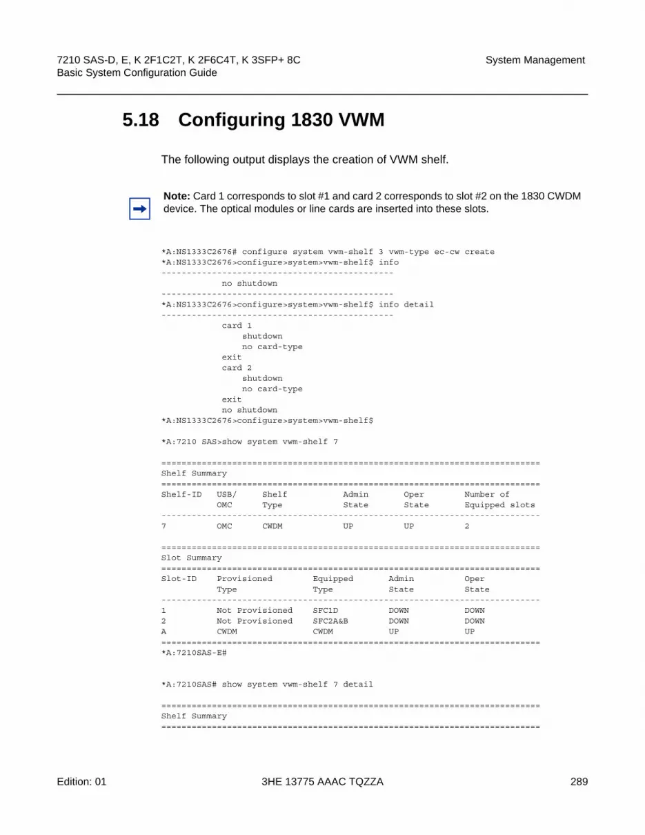
7210 SAS-D, E, K 2F1C2T, K 2F6C4T, K 3SFP+ 8C Basic System Configuration Guide
System Management
Edition: 01 3HE 13775 AAAC TQZZA 289
5.18 Configuring 1830 VWM
The following output displays the creation of VWM shelf.
*A:NS1333C2676# configure system vwm-shelf 3 vwm-type ec-cw create*A:NS1333C2676>configure>system>vwm-shelf$ info----------------------------------------------
no shutdown----------------------------------------------*A:NS1333C2676>configure>system>vwm-shelf$ info detail----------------------------------------------
card 1shutdownno card-type
exitcard 2
shutdownno card-type
exitno shutdown
*A:NS1333C2676>configure>system>vwm-shelf$
*A:7210 SAS>show system vwm-shelf 7
===========================================================================Shelf Summary===========================================================================Shelf-ID USB/ Shelf Admin Oper Number of
OMC Type State State Equipped slots---------------------------------------------------------------------------7 OMC CWDM UP UP 2
===========================================================================Slot Summary===========================================================================Slot-ID Provisioned Equipped Admin Oper
Type Type State State---------------------------------------------------------------------------1 Not Provisioned SFC1D DOWN DOWN2 Not Provisioned SFC2A&B DOWN DOWNA CWDM CWDM UP UP===========================================================================*A:7210SAS-E#
*A:7210SAS# show system vwm-shelf 7 detail
===========================================================================Shelf Summary===========================================================================
Note: Card 1 corresponds to slot #1 and card 2 corresponds to slot #2 on the 1830 CWDM device. The optical modules or line cards are inserted into these slots.

System Management
290
7210 SAS-D, E, K 2F1C2T, K 2F6C4T, K 3SFP+ 8CBasic System Configuration Guide
3HE 13775 AAAC TQZZA Edition: 01
Shelf-ID USB/ Shelf Admin Oper Number ofOMC Type State State Equipped slots
---------------------------------------------------------------------------7 OMC CWDM UP UP 2
===========================================================================Slot Summary===========================================================================Slot-ID Provisioned Equipped Admin Oper
Type Type State State---------------------------------------------------------------------------1 SFC1D SFC1D UP UP2 SFC2A&B SFC2A&B UP UPA CWDM CWDM UP UP
===========================================================================1830 VWM Shelf Controller-A Hardware Data===========================================================================No of Slots : 2Part Number : 3KC19297AAAB01CLEI code : WOCUAZNUTAUnit Mnemonic : EC-CWSerial Number : EZ444555666Manufacturing Date : 12112000Administrative state : UPOperational state : UPFirmware version : --------------Current Alarm state : Cleared
===========================================================================1830 VWM Slot/Module Hardware Data===========================================================================Slot Number : 1Provisioned type : SFC1DEquipped type : Equipped (SFC1D)Part Number : 3KC19289AEAA01CLEI code : ----------Unit Mnemonic : SFC1DSerial Number : EZ121130171Manufacturing Date : 03192012Operational state : UPFirmware version : --------------Current Alarm state : Cleared
===========================================================================1830 VWM Slot/Module Hardware Data===========================================================================Slot Number : 2Provisioned type : SFC2A&BEquipped type : Equipped (SFC2A&B)Part Number : 3KC19289AKAACLEI code : WOCUAZNUTAUnit Mnemonic : SFC2A&BSerial Number : EZ120630634Manufacturing Date : 12122000Operational state : UPFirmware version : --------------Current Alarm state : Cleared===========================================================================

7210 SAS-D, E, K 2F1C2T, K 2F6C4T, K 3SFP+ 8C Basic System Configuration Guide
System Management
Edition: 01 3HE 13775 AAAC TQZZA 291
The following output displays the deletion of a VWM shelf.
*7210SAS>configure>system>vwm-shelf$ info----------------------------------------------
card 2card-type SF
----------------------------------------------7210SAS>configure>system>vwm-shelf$
*7210SAS>configure>system>vwm-shelf$ info----------------------------------------------
card 2card-type SFC1Dno shutdown
exitno shutdown
----------------------------------------------*A AS-M>configure>system>vwm-shelf$ card 2 no card-type*A AS-M>configure>system>vwm-shelf$ info----------------------------------------------
no shutdown----------------------------------------------

System Management
292
7210 SAS-D, E, K 2F1C2T, K 2F6C4T, K 3SFP+ 8CBasic System Configuration Guide
3HE 13775 AAAC TQZZA Edition: 01
5.19 Configuring System Resource Profile
The following output displays system resource profile defaults:
*A:Dut-A>config>system>res-prof# info detail----------------------------------------------
ingress-internal-tcamno qos-sap-ingress-resourceacl-sap-ingress 1
no mac-ipv4-ipv6-128-match-enableexit
exitegress-internal-tcam
acl-sap-egress 2no mac-ipv4-ipv6-128-match-enable
exitno eth-cfm-primary-vlan-enable
exit----------------------------------------------*A:Dut-A>config>system>res-prof#

7210 SAS-D, E, K 2F1C2T, K 2F6C4T, K 3SFP+ 8C Basic System Configuration Guide
System Management
Edition: 01 3HE 13775 AAAC TQZZA 293
5.20 Configuring LLDP
The following output displays LLDP defaults.
A:7210-SAS>config>system>lldp# info detail----------------------------------------------
no tx-intervalno tx-hold-multiplierno reinit-delayno notification-intervalno tx-credit-maxno message-fast-txno message-fast-tx-initno shutdown
----------------------------------------------
The following example displays an LLDP port configuration.
*A:7210-SAS>config>port>ethernet>lldp# info----------------------------------------------
dest-mac nearest-bridgeadmin-status tx-rxtx-tlvs port-desc sys-captx-mgmt-address system
exit----------------------------------------------*A:7210-SAS>config>port>ethernet>lldp#
The following example displays a global system LLDP configuration.
A:7210-SAS>config>system>lldp# info----------------------------------------------
tx-interval 10tx-hold-multiplier 2reinit-delay 5notification-interval 10
----------------------------------------------A:7210-SAS>config>system>lldp#

System Management
294
7210 SAS-D, E, K 2F1C2T, K 2F6C4T, K 3SFP+ 8CBasic System Configuration Guide
3HE 13775 AAAC TQZZA Edition: 01

7210 SAS-D, E, K 2F1C2T, K 2F6C4T, K 3SFP+ 8C Basic System Configuration Guide
System Management
Edition: 01 3HE 13775 AAAC TQZZA 295
5.21 System Command Reference
5.21.1 Command Hierarchies
• Configuration Commands
− System Information Commands
− VWM shelf Management Commands (only supported on 7210 SAS-E)
− System Alarm Commands
− PTP Commands for 7210 SAS-D ETR, 7210 SAS-K 2F1C2T, 7210 SAS-K 2F6C4T, and 7210 SAS-K 3SFP+ 8C
− System Time Commands
− CRON Commands
− Script Control Commands
− System Administration (Admin) Commands
− System Alarm Contact Commands
− System Console Commands
− System Synchronization Commands
− LLDP System Commands
− System Resource-Profile Commands for 7210 SAS-D
− System Resource-Profile Commands for 7210 SAS-K 2F1C2T, 7210 SAS-K 2F6C4T, and 7210 SAS-K 3SFP+ 8C
− System Resource-Profile Commands for 7210 SAS-E
− Fan Controller Commands for 7210 SAS-D and 7210 SAS-D ETR Variant with 128MB flash
• Show Commands
• Clear Commands
• Debug Commands
Note: Not all CLI commands are supported on all the 7210 SAS platforms. Some commands are available only on some platforms. The support for a particular command for a given platform is either stated explicitly in the command reference OR in the CLI command description, as applicable.

System Management
296
7210 SAS-D, E, K 2F1C2T, K 2F6C4T, K 3SFP+ 8CBasic System Configuration Guide
3HE 13775 AAAC TQZZA Edition: 01
5.21.1.1 Configuration Commands
5.21.1.1.1 System Information Commands
config— system
— boot-bad-exec file-url— no boot-bad-exec — boot-good-exec — boot-good-exec— clli-code clli-code— no clli-code— config-backup count— no config-backup— contact contact-name— no contact— coordinates coordinates— no coordinates— lacp-system-priority lacp-system-priority— no lacp-system-priority— lldp— location location— no location— login-control— name system-name— no name— power-supply [power-supply-id] type — power-supply [power-supply-id] type — [no] oper-group name [create]
— hold-time— [no] group-down time in seconds— [no] group-up time in seconds
5.21.1.1.2 VWM shelf Management Commands (only supported on 7210 SAS-E)
config— system
— [no] vwm-shelf vwm-shelf-id [vwm-type vwm-type] [create]— card card-id
— [no] card-type card-type— [no] shutdown
— [no] shutdown

7210 SAS-D, E, K 2F1C2T, K 2F6C4T, K 3SFP+ 8C Basic System Configuration Guide
System Management
Edition: 01 3HE 13775 AAAC TQZZA 297
5.21.1.1.3 System Alarm Commands
config— system
— thresholds— kb-memory-use-alarm cflash-id rising-threshold threshold [falling-
threshold threshold] interval seconds [rmon-event-type] [startup-alarm alarm-type]
— no kb-memory-use-alarm cflash-id— cflash-cap-warn cflash-id rising-threshold threshold [falling-threshold
threshold] interval seconds [rmon-event-type] [startup-alarm alarm-type]— no cflash-cap-warn cflash-id — kb-memory-use-alarm rising-threshold threshold [falling-threshold
threshold] interval seconds [rmon-event-type] [startup-alarm alarm-type]— no kb-memory-use-alarm— kb-memory-use-warn rising-threshold threshold [falling-threshold
threshold] interval seconds [rmon-event-type] [startup-alarm alarm-type]— no kb-memory-use-warn— memory-use-alarm rising-threshold threshold [falling-threshold threshold]
interval seconds [rmon-event-type] [startup-alarm alarm-type]— no memory-use-alarm— memory-use-warn rising-threshold threshold [falling-threshold threshold]
interval seconds [rmon-event-type] [startup-alarm alarm-type]— no memory-use-warn— [no] rmon
— alarm rmon-alarm-id variable-oid oid-string interval seconds [sample-type] [startup-alarm alarm-type] [rising-event rmon-event-id rising-threshold threshold] [falling event rmon-event-id falling-threshold threshold] [owner owner-string]
— no alarm rmon-alarm-id— event rmon-event-id [event-type] [description description-string]
[owner owner-string]— no event rmon-event-id
5.21.1.1.4 PTP Commands for 7210 SAS-D ETR, 7210 SAS-K 2F1C2T, 7210 SAS-K 2F6C4T, and 7210 SAS-K 3SFP+ 8C
config— system
— ptp— anno-rx-timeout count — no anno-rx-timeout — clock
— freq-source freq-source— no freq-source
— clock-type boundary— clock-type ordinary {slave}— domain domain-value— no domain— local-priority priority — log-anno-interval log-interval

System Management
298
7210 SAS-D, E, K 2F1C2T, K 2F6C4T, K 3SFP+ 8CBasic System Configuration Guide
3HE 13775 AAAC TQZZA Edition: 01
— no log-anno-interval — log-sync-interval value — no log-sync-interval— network-type {sdh | sonet} — peer ip-address [create]— no peer ip-address
— local-priority priority — [no] shutdown
— port port-id [create]— no port port-id
— address {01:1b:19:00:00:00 | 01:80:c2:00:00:0e}— local-priority priority — master-only {true | false} — [no] shutdown
— priority1 priority-value— no priority1— priority2 priority-value— no priority2— profile {g8265dot1-2010 | ieee1588-2008 | g8275dot1-2014}— [no] shutdown
5.21.1.1.5 System Time Commands
root— admin
— set-time [date] [time]
config— system
— time— [no] ntp
— [no] authentication-check— authentication-key key-id key key [hash | hash2] type {des |
message-digest}— no authentication-keykey-id— [no] broadcast [router router-name] {interface ip-int-name} [key-id
key-id] [version version] [ttl ttl]— [no] broadcast [router router-name] {interface ip-int-name}— broadcastclient [router router-name] {interface ip-int-name}
[authenticate]— [no] broadcastclient [router router-name] {interface ip-int-name}— [no] ntp-server [authenticate]— [no] peer ip-address [version version] [key-id key-id] [prefer]— [no] server {ip-address| ptp} [version version] [key-id key-id] [prefer]— [no] shutdown
— [no] sntp— [no] broadcast-client — server-address ip-address [version version-number] [normal |
preferred] [interval seconds]— no server-address ip-address— [no] shutdown

7210 SAS-D, E, K 2F1C2T, K 2F6C4T, K 3SFP+ 8C Basic System Configuration Guide
System Management
Edition: 01 3HE 13775 AAAC TQZZA 299
— [no] dst-zone [std-zone-name | non-std-zone-name]— end {end-week} {end-day} {end-month} [hours-minutes]— offset offset— start {start-week} {start-day} {start-month} [hours-minutes]
— zone std-zone-name | non-std-zone-name [hh [:mm]] — no zone
5.21.1.1.6 CRON Commands
config>system— [no] cron
— [no] schedule schedule-name [owner schedule-owner]— count number— [no] day-of-month {day-number [..day-number] all}— [no] description description-string — [no] end-time [date|day-name] time— [no] hour {..hour-number [..hour-number]|all} — [no] interval seconds — [no] minute {minute-number [..minute-number]|all} — [no] month {month-number [..month-number]|month-name [..month-name]|all}— [no] script-policy policy-name [owner policy-owner]— [no] shutdown— type {schedule-type} — [no] weekday {weekday-number [..weekday-number]|day-name [..day-
name]|all}— [no] time-range name [create]
— absolute start start-absolute-time end end-absolute-time— no absolute start start-absolute-time— daily start start-time-of-day end end-time-of-day— no daily start start-time-of-day— [no] description description-string — weekdays start start-time-of-day end end-time-of-day— no weekdays start start-time-of-day— weekend start start-time-of-day end end-time-of-day— no weekend start start-time-of-day— weekly start start-time-in-week end end-time-in-week— no weekly start start-time-in-week
— [no] tod-suite tod-suite-name [create]— [no] description description-string — egress
— filter ip ip-filter-id [time-range time-range-name] [priority priority] — filter mac mac-filter-id [time-range time-range-name] [priority priority]— filter ipv6 ipv6-filter-id [time-range time-range-name] [priority priority] — no filter ip ip-filter-id [time-range time-range-name] — no filter mac mac-filter-id [time-range time-range-name— no filter ipv6 ipv6-filter-id [time-range time-range-name]
— ingress— filter ip ip-filter-id [time-range time-range-name] [priority priority] — filter mac mac-filter-id [time-range time-range-name] [priority priority] — filter ipv6 ipv6-filter-id [time-range time-range-name] [priority priority]— no filter ip ip-filter-id [time-range time-range-name]

System Management
300
7210 SAS-D, E, K 2F1C2T, K 2F6C4T, K 3SFP+ 8CBasic System Configuration Guide
3HE 13775 AAAC TQZZA Edition: 01
— no filter mac mac-filter-id [time-range time-range-name— no filter ipv6 ipv6-filter-id [time-range time-range-name]— qos policy-id [time-range time-range-name] [priority priority] — no qos policy-id [time-range time-range-name]
5.21.1.1.7 Script Control Commands
config— system
— script-control— [no] script script-name [owner script-owner]
— description description-string— no description— location file-url— no location— [no] shutdown
— [no] script-policy policy-name [owner policy-owner]— expire-time {seconds | forever}— lifetime {seconds | forever}— max-completed unsigned— results file-url— no results— script script-name [owner script-owner]— no script— [no] shutdown
5.21.1.1.8 System Administration (Admin) Commands
root— admin
— auto-init stop— check-golden-bootstrap— debug-save file-url— disconnect {address ip-address | username user-name | console | telnet | ftp | ssh}— display-config [detail | index]— [no] enable-tech— radius-discovery— reboot [upgrade][auto-init] [now]— save [file-url] [detail] [index]— set-time date / time— tech-support [file-url]— update-golden-bootstrap [file-url]

7210 SAS-D, E, K 2F1C2T, K 2F6C4T, K 3SFP+ 8C Basic System Configuration Guide
System Management
Edition: 01 3HE 13775 AAAC TQZZA 301
5.21.1.1.9 System Alarm Contact Commands
config— system
— alarm-contact-input alarm-contact-input-id— [no] alarm-output-severity [critical | major | minor | none]— [no] clear-alarm-msg {alarm-msg-txt}— description description-string— normal-state [open | closed]— [no] shutdown— [no] trigger-alarm-msg {alarm-msg-txt}
5.21.1.1.10 System Console Commands
config— system
— console— [no] use-console-alarm-input
5.21.1.1.11 System Synchronization Commands
config— system
— sync-if-timing— abort— begin— commit— ptp
— ql-override {prs | stu | st2 | tnc | st3e | st3 | prc | ssua | ssub | sec}— no ql-override— [no] shutdown
— [no] ql-selection— ref-order first second third— no ref-order— ref1
— ql-override {prs | stu | st2 | tnc | st3e | st3 | prc | ssua | ssub | sec | eec1 | eec2}
— no ql-override— [no] shutdown— source-port port-id— no source-port
— ref2— ql-override {prs | stu | st2 | tnc | st3e | st3 | prc | ssua | ssub | sec |
eec1 | eec2}— no ql-override— [no] shutdown— source-port port-id— no source-port

System Management
302
7210 SAS-D, E, K 2F1C2T, K 2F6C4T, K 3SFP+ 8CBasic System Configuration Guide
3HE 13775 AAAC TQZZA Edition: 01
— [no] revert
5.21.1.1.12 LLDP System Commands
config>system— lldp
— message-fast-tx time— no message-fast-tx— message-fast-tx-init count— no message-fast-tx-init— notification-interval time— no notification-interval— reinit-delay time— no reinit-delay— [no] shutdown— tx-credit-max count— no tx-credit-max— tx-hold-multiplier multiplier— no tx-hold-multiplier— tx-interval interval— no tx-interval
5.21.1.1.13 System Resource-Profile Commands for 7210 SAS-D
config— system
— resource-profile— egress-internal-tcam
— acl-sap-egress [num-resources]— no acl-sap-egress
— ipv6-128bit-match-enable num-resources— no ipv6-128bit-match-enable— mac-ipv4-match-enable num-resources— no mac-ipv4-match-enable— mac-ipv6-64bit-match-enable num-resources— no mac-ipv6-64bit-match-enable— mac-match-enable num-resources— no mac-match-enable
— egress-sap-aggregate-meter num-resources— no egress-sap-aggregate-meter num-resources
— ingress-internal-tcam— acl-sap-ingress [num-resources]— no acl-sap-ingress
— ipv4-ipv6-128-match-enable num-resources— no ipv4-ipv6-128-match-enable— ipv4-match-enable num-resources— no ipv4-match-enable— ipv6-64-only-match-enable num-resources— no ipv6-64-only-match-enable

7210 SAS-D, E, K 2F1C2T, K 2F6C4T, K 3SFP+ 8C Basic System Configuration Guide
System Management
Edition: 01 3HE 13775 AAAC TQZZA 303
— mac-match-enable num-resources — no mac-match-enable
— eth-cfm [num-resources] — no eth-cfm
— up-mep num-resources — no up-mep
— qos-sap-ingress-resource num-resources— no qos-sap-ingress-resource
— ipv4-mac-match-enable num-resources— no ipv4-mac-match-enable— ipv4-match-enable num-resources— no ipv4-match-enable— ipv6-ipv4-match-enable num-resources— no ipv6-ipv4-match-enable— mac-match-enable num-resources— no mac-match-enable
— sap-aggregate-meter num-resources— no sap-aggregate-meter
5.21.1.1.14 System Resource-Profile Commands for 7210 SAS-K 2F1C2T, 7210 SAS-K 2F6C4T, and 7210 SAS-K 3SFP+ 8C
config— system
— resource-profile— egress-internal-tcam
— acl-sap-egress [num-resources]— no acl-sap-egress
— mac-ipv4-ipv6-128-match-enable num-resources— no mac-ipv4-ipv6-128-match-enable
— eth-cfm-primary-vlan-enable— no eth-cfm-primary-vlan-enable
— ingress-internal-tcam— acl-sap-ingress [num-resources]— no acl-sap-ingress
— mac-ipv4-ipv6-128-match-enable num-resources— no mac-ipv4-ipv6-128-match-enable
— no qos-sap-ingress-resource— qos-sap-ingress-resource num-resources
— mac-ipv4-ipv6-128-match-enable num-resources— no mac-ipv4-ipv6-128-match-enable
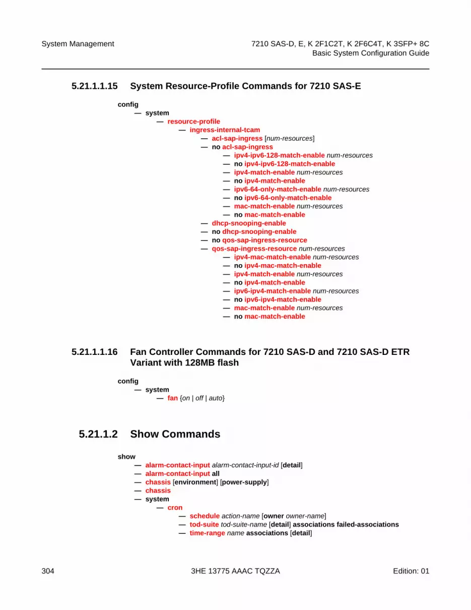
System Management
304
7210 SAS-D, E, K 2F1C2T, K 2F6C4T, K 3SFP+ 8CBasic System Configuration Guide
3HE 13775 AAAC TQZZA Edition: 01
5.21.1.1.15 System Resource-Profile Commands for 7210 SAS-E
config— system
— resource-profile— ingress-internal-tcam
— acl-sap-ingress [num-resources]— no acl-sap-ingress
— ipv4-ipv6-128-match-enable num-resources— no ipv4-ipv6-128-match-enable— ipv4-match-enable num-resources— no ipv4-match-enable— ipv6-64-only-match-enable num-resources— no ipv6-64-only-match-enable— mac-match-enable num-resources — no mac-match-enable
— dhcp-snooping-enable— no dhcp-snooping-enable— no qos-sap-ingress-resource— qos-sap-ingress-resource num-resources
— ipv4-mac-match-enable num-resources— no ipv4-mac-match-enable— ipv4-match-enable num-resources— no ipv4-match-enable— ipv6-ipv4-match-enable num-resources— no ipv6-ipv4-match-enable— mac-match-enable num-resources— no mac-match-enable
5.21.1.1.16 Fan Controller Commands for 7210 SAS-D and 7210 SAS-D ETR Variant with 128MB flash
config— system
— fan {on | off | auto}
5.21.1.2 Show Commands
show— alarm-contact-input alarm-contact-input-id [detail]— alarm-contact-input all — chassis [environment] [power-supply]— chassis— system
— cron— schedule action-name [owner owner-name]— tod-suite tod-suite-name [detail] associations failed-associations — time-range name associations [detail]

7210 SAS-D, E, K 2F1C2T, K 2F6C4T, K 3SFP+ 8C Basic System Configuration Guide
System Management
Edition: 01 3HE 13775 AAAC TQZZA 305
— connections [address ip-address [port port-number] [detail]— cpu [sample-period seconds] — information— lldp— lldp — memory-pools— ntp [{peers | peer peer-address} | {servers | server server-address} | [all]] [detail]— resource-profile [active|configured] — ptp [peer ip-address [detail] | peers [detail] | unicast | statistics | standby]— sntp— sync-if-timing— script-control
— script [script-name] [owner script-owner]— script-policy script-policy-name [owner owner-name]— script-policy run-history [run-state]
— thresholds— time— vwm-shelf vwm-shelf-id [detail] — time
— oper-group [group-name]— oper-group group-name [detail]— oper-group group-name [monitoring]— uptime
5.21.1.3 Clear Commands
clear— cron— screen — system
— ptp inactive-peers— ptp peer ip-address statistics— ptp statistics— script-control
— script-policy— completed [script-policy-name] [owner owner-name]
— sync-if-timing {ref1 | ref2}
5.21.1.4 Debug Commands
debug— sync-if-timing
— force-reference {ref1 | ref2 | ptp}— no force-reference
— [no] system— ntp [router router-name] [interface ip-int-name]

System Management
306
7210 SAS-D, E, K 2F1C2T, K 2F6C4T, K 3SFP+ 8CBasic System Configuration Guide
3HE 13775 AAAC TQZZA Edition: 01
5.21.1.4.1 Fan controller debug command (applicable only to 7210 SAS-D and 7210 SAS-DETR variant with 128MB flash)
tools— dump
— fan-stats

7210 SAS-D, E, K 2F1C2T, K 2F6C4T, K 3SFP+ 8C Basic System Configuration Guide
System Management
Edition: 01 3HE 13775 AAAC TQZZA 307
5.21.2 Command Descriptions
• Configuration Commands
• Show Commands
• Clear Commands
• Debug Commands
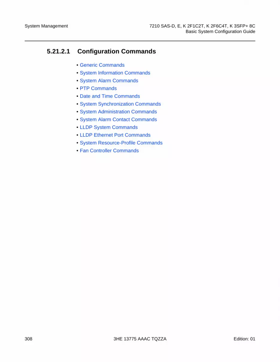
System Management
308
7210 SAS-D, E, K 2F1C2T, K 2F6C4T, K 3SFP+ 8CBasic System Configuration Guide
3HE 13775 AAAC TQZZA Edition: 01
5.21.2.1 Configuration Commands
• Generic Commands
• System Information Commands
• System Alarm Commands
• PTP Commands
• Date and Time Commands
• System Synchronization Commands
• System Administration Commands
• System Alarm Contact Commands
• LLDP System Commands
• LLDP Ethernet Port Commands
• System Resource-Profile Commands
• Fan Controller Commands

7210 SAS-D, E, K 2F1C2T, K 2F6C4T, K 3SFP+ 8C Basic System Configuration Guide
System Management
Edition: 01 3HE 13775 AAAC TQZZA 309
5.21.2.1.1 Generic Commands
shutdown
Syntax [no] shutdown
Context config>system>ptpconfig>system>ptp>peerconfig>system>ptp>portconfig>system>time>ntpconfig>system>time>sntpconfig>system>cron>schedconfig>system>script-control>script-policyconfig>system>script-control>scriptconfig>system>alarms
SupportedPlatforms
Supported on all 7210 SAS platforms as described in this document
Description This command administratively disables the entity. When disabled, an entity does not change, reset, or remove any configuration settings or statistics.
The operational state of the entity is disabled as well as the operational state of any entities contained within. Many objects must be shut down before they may be deleted.
The no form of this command places the entity into an administratively enabled state.
Default no shutdown
description
Syntax description description-string
no description
Context config>system>cron>schedconfig>system>cron>tod-suiteconfig>system>script-control>script
SupportedPlatforms
Supported on all 7210 SAS platforms as described in this document
Description This command creates a text description stored in the configuration file for a configuration context.
The description command associates a text string with a configuration context to help identify the content in the configuration file.
The no form of this command removes the string from the configuration.

System Management
310
7210 SAS-D, E, K 2F1C2T, K 2F6C4T, K 3SFP+ 8CBasic System Configuration Guide
3HE 13775 AAAC TQZZA Edition: 01
Parameters string — The description character string. Allowed values are any string up to 80 characters composed of printable, 7-bit ASCII characters. If the string contains special characters (#, $, spaces, etc.), the entire string must be enclosed within double quotes.

7210 SAS-D, E, K 2F1C2T, K 2F6C4T, K 3SFP+ 8C Basic System Configuration Guide
System Management
Edition: 01 3HE 13775 AAAC TQZZA 311
5.21.2.1.2 System Information Commands
boot-bad-exec
Syntax boot-bad-exec file-url
no boot-bad-exec
Context config>system
SupportedPlatforms
Supported on all 7210 SAS platforms as described in this document
Description This command configures a URL for a CLI script to exec following a failure of a boot-up configuration. The command specifies a URL for the CLI scripts to be run following the completion of the boot-up configuration. A URL must be specified or no action is taken.
The commands are persistent between router reboots and are included in the configuration saves (admin save).
Related Commands
exec — This command executes the contents of a text file as if they were CLI commands entered at the console.
Default no boot-bad-exec
Parameters file-url — Specifies the location and name of the CLI script file executed following failure of the boot-up configuration file execution. When this parameter is not specified, no CLI script file is executed.
Values
boot-good-exec
Syntax boot-good-exec file-url
no boot-good-exec
Context config>system
file url: local-url | remote-url: 255 chars max
local-url: [<cflash-id/> | <usb-flash-id>][file-path]
remote-url: [{ftp://} login:pswd@remote-locn/][file-path]
remote-locn [hostname | ipv4-address]
ipv4-address a.b.c.d
cflash-id: cf1:
usb-flash-id uf1:

System Management
312
7210 SAS-D, E, K 2F1C2T, K 2F6C4T, K 3SFP+ 8CBasic System Configuration Guide
3HE 13775 AAAC TQZZA Edition: 01
SupportedPlatforms
Supported on all 7210 SAS platforms as described in this document
Description This command configures a URL for a CLI script to exec following the success of a boot-up configuration.
Related Commands
exec — This command executes the contents of a text file as if they were CLI commands entered at the console.
Default no boot-good-exec
Parameters file-url — Specifies the location and name of the file executed following successful completion of the boot-up configuration file execution. When this parameter is not specified, no CLI script file is executed.
Values
clli-code
Syntax clli-code clli-code
no clli-code
Context config>system
SupportedPlatforms
Supported on all 7210 SAS platforms as described in this document
Description This command creates a Common Language Location Identifier (CLLI) code string for the router. A CLLI code is an 11-character standardized geographic identifier that uniquely identifies geographic locations and certain functional categories of equipment unique to the telecommunications industry.
No CLLI validity checks other than truncating or padding the string to eleven characters are performed.
Only one CLLI code can be configured, if multiple CLLI codes are configured the last one entered overwrites the previous entry.
The no form of the command removes the CLLI code.
file url: local-url | remote-url: 255 chars max
local-url: [<cflash-id/> | <usb-flash-id>][file-path]
remote-url: [{ftp://} login:pswd@remote-locn/][file-path]
remote-locn [hostname | ipv4-address]
ipv4-address a.b.c.d
cflash-id: cf1:
usb-flash-id uf1:

7210 SAS-D, E, K 2F1C2T, K 2F6C4T, K 3SFP+ 8C Basic System Configuration Guide
System Management
Edition: 01 3HE 13775 AAAC TQZZA 313
Parameters clli-code — The 11 character string CLLI code. Any printable, seven bit ASCII characters can be used within the string. If the string contains special characters (#, $, spaces, etc.), the entire string must be enclosed within double quotes. If more than 11 characters are entered, the string is truncated. If less than 11 characters are entered the string is padded with spaces.
config-backup
Syntax config-backup count
no config-backup
Context config>system
SupportedPlatforms
Supported on all 7210 SAS platforms as described in this document
Description This command configures the maximum number of backup versions maintained for configuration files and BOF.
For example, assume the config-backup count is set to 5 and the configuration file is called xyz.cfg. When a save command is executed, the file xyz.cfg is saved with a .1 extension. Each subsequent config-backup command increments the numeric extension until the maximum count is reached.
xyz.cfg
xyz.cfg.1
xyz.cfg.2
xyz.cfg.3
xyz.cfg.4
xyz.cfg.5
xyz.ndx
Each persistent index file is updated at the same time as the associated configuration file. When the index file is updated, then the save is performed to xyz.cfg and the index file is created as xyz.ndx. Synchronization between the active and standby is performed for all configurations and their associated persistent index files.
The no form of the command returns the configuration to the default value.
Default 5
Parameters count — the maximum number of backup revisions
Values 1 to 9

System Management
314
7210 SAS-D, E, K 2F1C2T, K 2F6C4T, K 3SFP+ 8CBasic System Configuration Guide
3HE 13775 AAAC TQZZA Edition: 01
console
Syntax console
Context config>system
SupportedPlatforms
Supported on all 7210 SAS platforms as described in this document
Description This command enables the context to configure console as an alarm-input-pin.
use-console-alarm-input
Syntax [no] use-console-alarm-input
Context config>system>console
Description Platforms Supported: 7210 SAS-D, 7210 SAS-K 2F1C2T, 7210 SAS-K 2F6C4T, 7210 SAS-K 3SFP+ 8C
This command provides an option to the user to use the console port on the 7210 SAS-D, 7210 SAS-K 2F1C2T, 7210 SAS-K 2F6C4T, or 7210 SAS-K 3SFP+ 8C as an alarm-input pin. When this command is executed, the console port can be used as an alarm input pin. A single alarm-input pin can be enabled for use with the console port, allowing operators to monitor external events and alert the operator. For this command to take effect, the console must be enabled in the BOF.
The RXD and TXD pins of the console input is used to provide a single alarm input pin functionality and is used by the software to detect external events. The operating system detects an open or a close circuit and triggers an alarm and logs it when an event is detected.
After this command is executed, the console port can no longer be used as a console port, and the system generates a log message to convey this restriction. Additionally, user needs to configure the alarm-contact-input parameter for console, by using the CLI command config>system> alarm-contact-input console-1 (the console alarm-contact-input is identified with the ID = console-1).
The no form of the command disables use of console port as alarm-input interface.
Default no use-console-alarm-input
contact
Syntax contact contact-name
no contact
Context config>system

7210 SAS-D, E, K 2F1C2T, K 2F6C4T, K 3SFP+ 8C Basic System Configuration Guide
System Management
Edition: 01 3HE 13775 AAAC TQZZA 315
SupportedPlatforms
Supported on all 7210 SAS platforms as described in this document
Description This command creates a text string that identifies the contact name for the device.
Only one contact can be configured, if multiple contacts are configured the last one entered will overwrite the previous entry.
The no form of the command reverts to default.
Parameters contact-name — The contact name character string. The string can be up to 80 characters. Any printable, seven-bit ASCII characters can be used within the string. If the string contains special characters (#, $, spaces, etc.), the entire string must be enclosed within double quotes.
coordinates
Syntax coordinates coordinates
no coordinates
Context config>system
SupportedPlatforms
Supported on all 7210 SAS platforms as described in this document
Description This command creates a text string that identifies the system coordinates for the device location. For example, the command coordinates “37.390 -122.0550" is read as latitude 37.390 north and longitude 122.0550 west.
Only one set of coordinates can be configured. If multiple coordinates are configured, the last one entered overwrites the previous entry.
The no form of the command reverts to the default value.
Parameters coordinates — The coordinates describing the device location character string. The string may be up to 80 characters. Any printable, seven-bit ASCII characters can be used within the string. If the string contains special characters (#, $, spaces, etc.), the entire string must be enclosed within double quotes. If the coordinates are subsequently used by an algorithm that locates the exact position of this node then the string must match the requirements of the algorithm.
lacp-system-priority
Syntax lacp-system-priority lacp-system-priority
no lacp-system-priority
Context config>system

System Management
316
7210 SAS-D, E, K 2F1C2T, K 2F6C4T, K 3SFP+ 8CBasic System Configuration Guide
3HE 13775 AAAC TQZZA Edition: 01
SupportedPlatforms
Supported on all 7210 SAS platforms as described in this document
Description This command configures the Link Aggregation Control Protocol (LACP) system priority on aggregated Ethernet interfaces. LACP allows the operator to aggregate multiple physical interfaces to form one logical interface.
Default 32768
Parameters lacp-system-priority — Specifies the LACP system priority
Values 1 to 65535
location
Syntax location location
no location
Context config>system
SupportedPlatforms
Supported on all 7210 SAS platforms as described in this document
Description This command creates a text string that identifies the system location for the device.
Only one location can be configured. If multiple locations are configured, the last one entered overwrites the previous entry.
The no form of the command reverts to the default value.
Parameters location — Enter the location as a character string. The string may be up to 80 characters. Any printable, seven-bit ASCII characters can be used within the string. If the string contains special characters (#, $, spaces, etc.), the entire string must be enclosed within double quotes.
login-control
Syntax login-control
Context config>system
SupportedPlatforms
Supported on all 7210 SAS platforms as described in this document
Description This command enables the context to configure login control.

7210 SAS-D, E, K 2F1C2T, K 2F6C4T, K 3SFP+ 8C Basic System Configuration Guide
System Management
Edition: 01 3HE 13775 AAAC TQZZA 317
name
Syntax name system-name
no name
Context config>system
SupportedPlatforms
Supported on all 7210 SAS platforms as described in this document
Description This command creates a system name string for the device.
For example, system-name parameter ALA-1 for the name command configures the device name as ALA-1.
ABC>config>system# name "ALA-1"ALA-1>config>system#
Only one system name can be configured. If multiple system names are configured, the last one encountered overwrites the previous entry.
The no form of the command reverts to the default value.
Default The default system name is set to the chassis serial number which is read from the backplane EEPROM.
Parameters system-name — Enter the system name as a character string. The string may be up to 32 characters. Any printable, seven-bit ASCII characters can be used within the string. If the string contains special characters (#, $, spaces, etc.), the entire string must be enclosed within double quotes.
oper-group
Syntax oper-group name [create]
no oper-group
Context config>system
Description Platforms Supported: 7210 SAS-D, 7210 SAS-K 2F1C2T, 7210 SAS-K 2F6C4T, 7210 SAS-K 3SFP+ 8C
This command creates a system-wide group name which can be used to associate a number of service objects (for example, ports). The status of the group is derived from the status of its members. The status of the group can then be used to influence the status of non-member objects. For example, when a group status is marked as down, the objects that monitor the group change their status accordingly.
The no form of the command removes the group. All the object associations need to be removed before the no command can be executed.

System Management
318
7210 SAS-D, E, K 2F1C2T, K 2F6C4T, K 3SFP+ 8CBasic System Configuration Guide
3HE 13775 AAAC TQZZA Edition: 01
Default no oper-group
Parameters name — Specifies the operational group identifier up to 32 characters.
Values 32 characters max
create — This keyword is required when first creating the configuration context. Once the context is created, it is possible to navigate into the context without the create keyword.
Values Keyword
hold-time
Syntax hold-time
Context config>system>oper-group
Description Platforms Supported: 7210 SAS-D, 7210 SAS-K 2F1C2T, 7210 SAS-K 2F6C4T, 7210 SAS-K 3SFP+ 8C
This command enables the context to configure hold time information.
group-down
Syntax [no] group-down time in seconds
Context config>system>oper-group>hold-time
Description Platforms Supported: 7210 SAS-D, 7210 SAS-K 2F1C2T, 7210 SAS-K 2F6C4T, 7210 SAS-K 3SFP+ 8C
This command configures the number of seconds to wait before notifying clients monitoring this group when its operational status transitions from down to up. A value of zero indicates that transitions are reported immediately to monitoring clients.
The no form sets the values back to the defaults.
Default 0
Parameters time in seconds — Specifies the wait time in seconds.
Values 0 to 3600
group-up
Syntax [no] group-up time in seconds
Context config>system>oper-group>hold-time

7210 SAS-D, E, K 2F1C2T, K 2F6C4T, K 3SFP+ 8C Basic System Configuration Guide
System Management
Edition: 01 3HE 13775 AAAC TQZZA 319
Description Platforms Supported: 7210 SAS-D, 7210 SAS-K 2F1C2T, 7210 SAS-K 2F6C4T, 7210 SAS-K 3SFP+ 8C
This command configures the number of seconds to wait before notifying clients monitoring this group when its operational status transitions from up to down.
The no form sets the values back to the default.
Default 4
Parameters time in seconds — Specifies the wait time in seconds.
Values 0 to 3600
power-supply
Syntax power-supply [power-supply-id] type
Context config>system
Description Platforms Supported: 7210 SAS-D ETR
This command enables the context to configure a power-supply.
On the 7210 SAS-D ETR, by default, the software does not generate any traps or alarms for PS2, when the external power- supply failure has been detected. The user is provided with an option to configure the external backup power-supply type. Only if the user configures the power-supply type as 'ac' or 'dc' the system generates alarm or trap on a power-supply failure. The user can disable generation of alarms or traps by setting the value to 'none'.

System Management
320
7210 SAS-D, E, K 2F1C2T, K 2F6C4T, K 3SFP+ 8CBasic System Configuration Guide
3HE 13775 AAAC TQZZA Edition: 01
Parameters power-supply-id — Identifies the power-supply for which the type is to be applied.
Values [2] - Identifies the optional external backup power supply on the 7210 SAS-D ETR
type — Identifies the type of power-supply.
Values Keywords - dc | ac | none
power-supply
Syntax power-supply [power-supply-id] type
Context config>system
Description Platforms Supported: 7210 SAS-K 2F1C2T ETR
This command enables the context to configure the external power-supply type and also provide an option to the user to enable or disable notifications related to power supply. This command is recommended to be used when redundant power supplies are used with the 7210 SAS-K 2F1C2T ETR.
Note:
• By setting the value to none, the software does not send out a trap to the management station to clear the alarm, if there was one pending. The none value only clears the trap locally and resets the LED color, if there are no other major or critical alarms pending. It is expected that the management station takes appropriate action on receiving the configuration change event or trap.
• This CLI command does not affect generation of trap or alarm for the integrated power supply. Traps or alarms are always generated on detection of failure of the integrated power supply, when an external power supply is in use.
• The 7210 SAS-D ETR does not have the capability to detect whether the external power-supply type is an AC or DC version. Therefore, the user-configured value is not validated by the software. The user is responsible for ensuring whether the value is correct and corresponds to what they are using. If users provide an incorrect value, the software continues to display the configured value and generate traps or alarms.
• The power-supply command is only supported on the 7210 SAS-D ETR. If the power-supply command is used on the 7210 SAS-D, the software returns an error message.
• When a single power supply is used, failure of that power supply brings the node down and user has an option to use EFM OAM dying gasp or SNMP IP based dying gasp for sending out power loss notification.
Note: When a single power supply is used, failure of that power supply brings the node down and user has an option to use EFM OAM dying gasp or SNMP IP based dying gasp for sending out power loss notification.

7210 SAS-D, E, K 2F1C2T, K 2F6C4T, K 3SFP+ 8C Basic System Configuration Guide
System Management
Edition: 01 3HE 13775 AAAC TQZZA 321
On the 7210 SAS-K 2F1C2T ETR, by default, the software does not generate any traps or alarms when the external power-supply failure has been detected. The user is provided with an option to configure the external power-supply and its type. Only if the user configures the power-supply type as 'ac' or 'dc' the system generates alarm or trap on a power-supply failure. The user can disable generation of alarms or traps by setting the value to none.
Parameters power-supply-id — Identifies the power-supply for which the type is to be applied.
Values [1 | 2] - Identifies the optional external backup power supply on the 7210 SAS-K 2F1C2T ETR
type — Identifies the type of power-supply.
Values dc |ac | none
vwm-shelf
Syntax [no] vwm-shelf vwm-shelf-id [vwm-type vwm-type] [create]
Context config>system
Description Platforms Supported: 7210 SAS-E
This command enables the context to configure the shelf information for 1830 VWM clip-on device.
Note:
• By setting the value to none, the software does not send out a trap to the management station to clear the alarm, if there was one pending. The none value only clears the trap locally and resets the LED color, if there are no other major or critical alarms pending. It is expected that the management station takes appropriate action on receiving the configuration change event or trap.
• The 7210 SAS-K 2F1C2T ETR does not have the capability to detect whether the external power-supply type is an AC or DC version. Therefore, the user-configured value is not validated by the software. The user is responsible for ensuring whether the value is correct and corresponds to what they are using. If users provide an incorrect value, the software continues to display the configured value and generate traps or alarms on detection of the power supply failure.
• The power-supply command is only supported on the 7210 SAS-K 2F1C2T ETR. If the power-supply command is used on the 7210 SAS-K 2F1C2T, the software returns an error message.

System Management
322
7210 SAS-D, E, K 2F1C2T, K 2F6C4T, K 3SFP+ 8CBasic System Configuration Guide
3HE 13775 AAAC TQZZA Edition: 01
The user must create the VWM clip-on device and provision the shelf ID to allow the 7210 software to communicate with the shelf and retrieve information. The value specified in the parameter vwm-shelf-id must match the shelf ID set using the rotary dial on the clip-on device. If these shelf IDs do not match, 7210 SAS devices will not be able to interact to the device and does not provide any information about the device. 7210 software cannot detect a mismatch between the value of the configured vwm-shelf-id and the shelf ID set on the rotary dial.
A fixed number of 1830 VWM devices can be managed by the 7210 SAS devices. The limit depends on the interface used to connect to the 1830 device. The user must provision all the shelves that are connected to the 7210 SAS device.
The vwm-type provides the context to configure the shelf type information for 1830 VWM clip-on device. The user must provision the shelf-type of the connected 1830 device. The software uses this information to match with the shelf-type retrieved from the device and raise a trap/event when there is a mismatch and marks the shelf as operationally down. Additionally, in a cascaded configuration, if there is a mismatch in provisioning of the shelf, 7210 does not attempt to retrieve information of the shelves that follow the mis-configured shelf.
The no form of the command removes the configured shelf ID and the software removes all the information it has for the shelf.
Parameters vwm-shelf-id — Shelf ID used to identify the 1830 VWM clip-on device attached to 7210.
Values 1 to 7
vwm-type — Enables the context to configure the shelf type information for 1830 VWM clip-on device.
Values [ec-cw|ec-dw|ec-dwa]
ec-cw — Identifies the controller card to be of type passive 1830 VWM CWDM controller.
ec-dw — Identifies the controller type to be passive 1830 VWM DWDM controller.
ec-dwa — Identifies the controller type to be active 1830 VWM DWDM controller.
Notes:
• The vwm-shelf-id can take values in the range 1 to 7. This implies that the rotary switch on the connected optical clip-on device must be set to a value in this range.
• For management of DWDM using 7210 SAS-E through USB interface through OMC interface, the main shelf (that is, the first shelf) to which the node is connected should have EC-DWA. If connected through OMC interface shelf-id can be 1-7 and if connected through USB interface shelf-id should be 0.
• If the main shelf has any other shelf-id (that is 1-7), the shelf will not become operational.
create — Keyword used to create the vwm-shelf-id.

7210 SAS-D, E, K 2F1C2T, K 2F6C4T, K 3SFP+ 8C Basic System Configuration Guide
System Management
Edition: 01 3HE 13775 AAAC TQZZA 323
card
Syntax card card-id
Context config>system>vwm-shelf
Description Platforms Supported: 7210 SAS-E
This command enables the context to provision the information for the modules that can be plugged into the slots on the 1830 VWM clip-on device.
This command gives the user better control over the modules plugged into the 1830 CWDM device slots. User can preprovision acceptable modules by configuring the card-type parameter with the appropriate vwm-acronym. Modules are identified using the card type acronyms listed below.
The no form of the command removes the configured card ID and the software forgets all the information it has for the card. Software will not raise any events/traps/alarms for the card and clear all pending events/traps/alarms/LEDs.
Parameters card-id — The card ID used to identify the card on the 1830 VWM clip-on device attached to 7210 SAS. Card ID 1 identifies the module in slot #1 of the 1830 CWDM device and Card ID 2 identifies the module in slot #2 of the 1830 CWDM device.
Values [1 | 2]
shutdown
Syntax [no] shutdown
Context config>system>vwm-shelf
Description Platforms Supported: 7210 SAS-E
This command enables the user to administratively disable the management of the clip-on device identified by the parameter vwm-shelf-id. When this command is executed, 7210 software will clear all pending events/traps/alarms related to this shelf.
The no form of the command enables the user to administratively enable the management of the clip-on device. The software raises appropriate events/traps/alarms for the device.
Default no shutdown
card-type
Syntax [no] card-type card-type
Context config>system>vwm-shelf>card

System Management
324
7210 SAS-D, E, K 2F1C2T, K 2F6C4T, K 3SFP+ 8CBasic System Configuration Guide
3HE 13775 AAAC TQZZA Edition: 01
Description Platforms Supported: 7210 SAS-E
This command gives the user better control over the modules plugged into the 1830 CWDM device slots. The user can preprovision acceptable modules by configuring the card-type parameter with the appropriate card-type vwm-acronym. The modules are identified using the acronyms listed below.
The 7210 SAS validates the configured card-types with the card-type acronym retrieved from the clip-on device and checks the following:
• If the configured card-type matches the card-type acronym retrieved from the clip-on device, the 7210 SAS allows management of the module.
• If the configured card-type does not match the card-type acronym retrieved from the clip-on device, the 7210 SAS raises an event to alert the user of mismatch in configuration. The event results in a major alarm with the major LED set. In such a case, the card status displays “Provisioning Mismatch” error.
• The mismatch event/trap is cleared if the module is replaced with the one that has a correct card-type acronym. Any pending trap/event, major alarm and major LED is cleared.
If the user has preprovisioned the card set to administratively up and the module is missing, the7210 SAS raises an event/trap. The event results in a major alarm with the major LED set to the appropriate color. If the user has preprovisioned the card and administratively shut it down, the 7210 SAS does not attempt to match the module’s identifier (if the module is equipped in the slot) and clear any pending alarms. The 7210 SAS retrieves any information about the equipped module to aid the user with provisioning.
The no form of the command removes and clears the card-type information. Until the card-type is provisioned, the 7210 SAS software does not raise any events/traps/alarms for the card and clear all pending events/traps/alarms/LEDs.
Parameters card-type — Identifier used to match the configured slot module with the equipped slot module.
Values CWDM:
SFC1A SFC1B SFC1C SFC1D SFC1E SFC1F SFC1G SFC1H SFC2A&B SFC2C&D SFC2E&F SFC2G&H SFC4A-D SFC4E-H SFC8
DWDM:
ANY | EALPFG | SFD8A_R | SFD8B_R | SFD8C_R | SFD8D_R | SFD4A_R | SFD4B_R | SFD4C_R | SFD4D_R | SFD4E_R | SFD4F_R | SFD4G_R | SFD4H_R | SFD2A_R | SFD2B_R | SFD2C_R | SFD2D_R | SFD2E_R | SFD2F_R | SFD2G_R | SFD2H_R | SFD2I_R | SFD2L_R | SFD2M_R | SFD2N_R | SFD2O_R | SFD2P_R | SFD2Q_R | SFD2R_R | SFD8A | SFD8B | SFD8C | SFD8D | SFD4A | SFD4B | SFD4C | SFD4D | SFD4E | SFD4F | SFD4G | SFD4H | SFD2A | SFD2B | SFD2C | SFD2D | SFD2E | SFD2F | SFD2G | SFD2H | SFD2I | SFD2L | SFD2M | SFD2N | SFD2O | SFD2P | SFD2Q | SFD2R

7210 SAS-D, E, K 2F1C2T, K 2F6C4T, K 3SFP+ 8C Basic System Configuration Guide
System Management
Edition: 01 3HE 13775 AAAC TQZZA 325
ascii-string - can use ASCII alphabets or numbers.
Table 35 and Table 36 describe the acronyms defined by the optical group. See the 1830 VWM Product Overview Guide for more information. This is used to preprovision the acceptable modules that can be equipped in the slots of the clip-on device.
Table 35 Card Type Acronyms for 1830 CWDM Devices
Module Description Acronym
1830 VWM 1-CH CWDM FILTER (AB VARIANT) - CH1 (1471nm) SFC1A
1830 VWM 1-CH CWDM FILTER (AC VARIANT) - CH1 (1491nm) SFC1B
1830 VWM 1-CH CWDM FILTER (AD VARIANT) - CH1 (1511nm) SFC1C
1830 VWM 1-CH CWDM FILTER (AE VARIANT) - CH1 (1531nm) SFC1D
1830 VWM 1-CH CWDM FILTER (AF VARIANT) - CH1 (1551nm) SFC1E
1830 VWM 1-CH CWDM FILTER (AG VARIANT) - CH1 (1571nm) SFC1F
1830 VWM 1-CH CWDM FILTER (AH VARIANT) - CH1 (1591nm) SFC1G
1830 VWM 1-CH CWDM FILTER (AI VARIANT) - CH1 (1611nm) SFC1H
1830 VWM 2-CH CWDM FILTER (AK VARIANT) - CH1,2 SFC2A&B
1830 VWM 2-CH CWDM FILTER (AL VARIANT) – CH3,4 SFC2C&D
1830 VWM 2-CH CWDM FILTER (AM VARIANT) – CH5,6 SFC2E&F
1830 VWM 2-CH CWDM FILTER (AN VARIANT) – CH7,8 SFC2G&H
1830 VWM 4-CH CWDM FILTER (AP VARIANT) - CH1,2,3,4 SFC4A-D
1830 VWM 4-CH CWDM FILTER (AP VARIANT) – CH5,6,7,8 SFC4E-H
1830 VWM 8-CH CWDM FILTER (AA VARIANT) - CH1,2,3,4,5,6,7,8 SFC8
Table 36 Card Type Acronyms for 1830 DWDM Devices
Module Description Acronym
1830VWM Fan Unit (AA variant) FANCLIP
Inventory Extension Module INVMOD
1830VWM EC-DW (AA variant) EC-DW
1830VWM EC-DW Active (AA variant) EC-DWA
Remote Filer Modules

System Management
326
7210 SAS-D, E, K 2F1C2T, K 2F6C4T, K 3SFP+ 8CBasic System Configuration Guide
3HE 13775 AAAC TQZZA Edition: 01
1830VWM Remote Filter 8CH (AA VAR) SFD8A_R
1830VWM Remote Filter 8CH (AB Var) SFD8B_R
1830VWM Remote Filter 8CH (AC Var) SFD8C_R
1830VWM Remote Filter 8CH (AD Var) SFD8D_R
1830VWM Remote Filter 4CH (AE Var) SFD4A_R
1830VWM Remote Filter 4CH (AF Var) SFD4B_R
1830VWM Remote Filter 4CH (AG Var) SFD4C_R
1830VWM Remote Filter 4CH (AH Var) SFD4D_R
1830VWM Remote Filter 4CH (AJ Var) SFD4E_R
1830VWM Remote Filter 4CH (AK Var) SFD4F_R
1830VWM Remote Filter 4CH (AL Var) SFD4G_R
1830VWM Remote Filter 4CH (AM Var) SFD4H_R
1830VWM Remote Filter 2CH (AN Var) SFD2A_R
1830VWM Remote Filter 2CH (AP Var) SFD2B_R
1830VWM Remote Filter 2CH (AQ Var) SFD2C_R
1830VWM Remote Filter 2CH (AR Var) SFD2D_R
1830VWM Remote Filter 2CH (AS Var) SFD2E_R
1830VWM Remote Filter 2CH (AT Var) SFD2F_R
1830VWM Remote Filter 2CH (AU Var) SFD2G_R
1830VWM Remote Filter 2CH (AV Var) SFD2H_R
1830VWM Remote Filter 2CH (AW Var) SFD2I_R
1830VWM Remote Filter 2CH (AZ Var) SFD2L_R
1830VWM Remote Filter 2CH (BA Var) SFD2M_R
1830VWM Remote Filter 2CH (BB Var) SFD2N_R
1830VWM Remote Filter 2CH (BC Var) SFD2O_R
1830VWM Remote Filter 2CH (BD Var) SFD2P_R
1830 VWM SSY SFD Automatic 2CH (BC Var) SFD2Q_R
Table 36 Card Type Acronyms for 1830 DWDM Devices (Continued)
Module Description Acronym

7210 SAS-D, E, K 2F1C2T, K 2F6C4T, K 3SFP+ 8C Basic System Configuration Guide
System Management
Edition: 01 3HE 13775 AAAC TQZZA 327
1830 VWM SSY SFD Automatic 2CH (BD Var) SFD2R_R
DWDM Filters with manual control
1830VWM Manual Filter 8CH (AAVar) SFD8A
1830VWM Manual Filter 8CH (AB Var) SFD8B
1830VWM Manual Filter 8CH (AC Var) SFD8C
1830VWM Manual Filter 8CH (AD Var) SFD8D
1830VWM Manual Filter 4CH (AE Var) SFD4A
1830VWM Manual Filter 4CH (AF Var) SFD4B
1830VWM Manual Filter 4CH (AG Var) SFD4C
1830VWM Manual Filter 4CH (AH Var) SFD4D
1830VWM Manual Filter 4CH (AJ Var) SFD4E
1830VWM Manual Filter 4CH (AK Var) SFD4F
1830VWM Manual Filter 4CH (AL Var) SFD4G
1830VWM Manual Filter 4CH (AM Var) SFD4H
1830VWM Manual Filter 2CH (AN Var) SFD2A
1830VWM Manual Filter 2CH (AP Var) SFD2B
1830VWM Manual Filter 2CH (AQ Var) SFD2C
1830VWM Manual Filter 2CH (AR Var) SFD2D
1830VWM Manual Filter 2CH (AS Var) SFD2E
1830VWM Manual Filter 2CH (AT Var) SFD2F
1830VWM Manual Filter 2CH (AU Var) SFD2G
1830VWM Manual Filter 2CH (AV Var) SFD2H
1830VWM Manual Filter 2CH (AWVar) SFD2I
1830VWM Manual Filter 2CH (AX Var) SFD2L
1830VWM Manual Filter 2CH (AY Var) SFD2M
1830VWM Manual Filter 2CH (AZ Var) SFD2N
1830VWM Manual Filter 2CH (BAVar) SFD2O
Table 36 Card Type Acronyms for 1830 DWDM Devices (Continued)
Module Description Acronym

System Management
328
7210 SAS-D, E, K 2F1C2T, K 2F6C4T, K 3SFP+ 8CBasic System Configuration Guide
3HE 13775 AAAC TQZZA Edition: 01
shutdown
Syntax [no] shutdown
Context config>system>vwm-shelf>card
Description Platforms Supported: 7210 SAS-E
This command administratively enables or disables the management of a specific module inserted in a slot on the clip-on device. When this command is executed, the 7210 SAS software clears all pending events/traps/alarms/LED related to this card.
The no form of the command administratively enables the management of the card on the clip-on device. The software raises appropriate events/traps/alarms for the card.
Default no shutdown
1830VWM Manual Filter 2CH (BB Var) SFD2P
1830VWM Manual Filter 2CH (BC Var) SFD2Q
1830VWM Manual Filter 2CH (BD Var) SFD2R
Amplifier Modules
1830 VWM Fixed Gain Ampl (AAVar) EALPFG
Table 36 Card Type Acronyms for 1830 DWDM Devices (Continued)
Module Description Acronym

7210 SAS-D, E, K 2F1C2T, K 2F6C4T, K 3SFP+ 8C Basic System Configuration Guide
System Management
Edition: 01 3HE 13775 AAAC TQZZA 329
5.21.2.1.3 System Alarm Commands
alarm
Syntax alarm rmon-alarm-id variable-oid oid-string interval seconds [sample-type] [startup-alarm alarm-type] [rising-event rmon-event-id rising-threshold threshold] [falling-event rmon-event-id falling threshold threshold] [owner owner-string]
no alarm rmon-alarm-id
Context config>system>thresholds>rmon
SupportedPlatforms
Supported on all 7210 SAS platforms as described in this document
Description This command configures an entry in the RMON-MIB alarm Table. The alarm command controls the monitoring and triggering of threshold crossing events. In order for notification or logging of a threshold crossing event to occur there must be at least one associated rmon>event configured.
The agent periodically takes statistical sample values from the MIB variable specified for monitoring and compares them to thresholds that have been configured with the alarm command. This command configures the MIB variable to be monitored, the polling period (interval), sampling type (absolute or delta value), and rising and falling threshold parameters. If a sample has crossed a threshold value, the associated event is generated.
Use the no form of this command to remove an rmon-alarm-id from the configuration.
Parameters rmon-alarm-id — The rmon-alarm-id is a numerical identifier for the alarm being configured. The number of alarms that can be created is limited to 1200.
Values 1 to 65535
Default None
variable-oid oid-string — The oid-string is the SNMP object identifier of the particular variable to be sampled. Only SNMP variables that resolve to an ASN.1 primitive type of integer (integer, Integer32, Counter32, Counter64, Gauge, or TimeTicks) may be sampled. The oid-string may be expressed using either the dotted string notation or as object name plus dotted instance identifier. For example, “1.3.6.1.2.1.2.2.1.10.184582144” or “ifInOctets.184582144”.
The oid-string has a maximum length of 255 characters
Default None
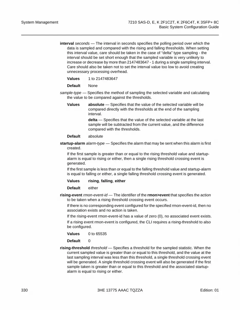
System Management
330
7210 SAS-D, E, K 2F1C2T, K 2F6C4T, K 3SFP+ 8CBasic System Configuration Guide
3HE 13775 AAAC TQZZA Edition: 01
interval seconds — The interval in seconds specifies the polling period over which the data is sampled and compared with the rising and falling thresholds. When setting this interval value, care should be taken in the case of “delta” type sampling - the interval should be set short enough that the sampled variable is very unlikely to increase or decrease by more than 2147483647 - 1 during a single sampling interval. Care should also be taken not to set the interval value too low to avoid creating unnecessary processing overhead.
Values 1 to 2147483647
Default None
sample-type — Specifies the method of sampling the selected variable and calculating the value to be compared against the thresholds.
Values absolute — Specifies that the value of the selected variable will be compared directly with the thresholds at the end of the sampling interval.
delta — Specifies that the value of the selected variable at the last sample will be subtracted from the current value, and the difference compared with the thresholds.
Default absolute
startup-alarm alarm-type — Specifies the alarm that may be sent when this alarm is first created.
If the first sample is greater than or equal to the rising threshold value and startup-alarm is equal to rising or either, then a single rising threshold crossing event is generated.
If the first sample is less than or equal to the falling threshold value and startup-alarm is equal to falling or either, a single falling threshold crossing event is generated.
Values rising, falling, either
Default either
rising-event rmon-event-id — The identifier of the rmon>event that specifies the action to be taken when a rising threshold crossing event occurs.
If there is no corresponding event configured for the specified rmon-event-id, then no association exists and no action is taken.
If the rising-event rmon-event-id has a value of zero (0), no associated event exists.
If a rising event rmon-event is configured, the CLI requires a rising-threshold to also be configured.
Values 0 to 65535
Default 0
rising-threshold threshold — Specifies a threshold for the sampled statistic. When the current sampled value is greater than or equal to this threshold, and the value at the last sampling interval was less than this threshold, a single threshold crossing event will be generated. A single threshold crossing event will also be generated if the first sample taken is greater than or equal to this threshold and the associated startup-alarm is equal to rising or either.
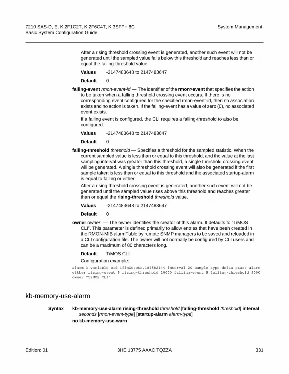
7210 SAS-D, E, K 2F1C2T, K 2F6C4T, K 3SFP+ 8C Basic System Configuration Guide
System Management
Edition: 01 3HE 13775 AAAC TQZZA 331
After a rising threshold crossing event is generated, another such event will not be generated until the sampled value falls below this threshold and reaches less than or equal the falling-threshold value.
Values -2147483648 to 2147483647
Default 0
falling-event rmon-event-id — The identifier of the rmon>event that specifies the action to be taken when a falling threshold crossing event occurs. If there is no corresponding event configured for the specified rmon-event-id, then no association exists and no action is taken. If the falling-event has a value of zero (0), no associated event exists.
If a falling event is configured, the CLI requires a falling-threshold to also be configured.
Values -2147483648 to 2147483647
Default 0
falling-threshold threshold — Specifies a threshold for the sampled statistic. When the current sampled value is less than or equal to this threshold, and the value at the last sampling interval was greater than this threshold, a single threshold crossing event will be generated. A single threshold crossing event will also be generated if the first sample taken is less than or equal to this threshold and the associated startup-alarm is equal to falling or either.
After a rising threshold crossing event is generated, another such event will not be generated until the sampled value rises above this threshold and reaches greater than or equal the rising-threshold threshold value.
Values -2147483648 to 2147483647
Default 0
owner owner — The owner identifies the creator of this alarm. It defaults to “TiMOS CLI”. This parameter is defined primarily to allow entries that have been created in the RMON-MIB alarmTable by remote SNMP managers to be saved and reloaded in a CLI configuration file. The owner will not normally be configured by CLI users and can be a maximum of 80 characters long.
Default TiMOS CLI
Configuration example:alarm 3 variable-oid ifInOctets.184582144 interval 20 sample-type delta start-alarmeither rising-event 5 rising-threshold 10000 falling-event 5 falling-threshold 9000 owner "TiMOS CLI"
kb-memory-use-alarm
Syntax kb-memory-use-alarm rising-threshold threshold [falling-threshold threshold] interval seconds [rmon-event-type] [startup-alarm alarm-type]
no kb-memory-use-warn

System Management
332
7210 SAS-D, E, K 2F1C2T, K 2F6C4T, K 3SFP+ 8CBasic System Configuration Guide
3HE 13775 AAAC TQZZA Edition: 01
Context config>system>thresholds
SupportedPlatforms
Supported on all 7210 SAS platforms as described in this document
Description This command configures memory use, in kilobytes, alarm thresholds.
The no form of the command removes the parameters from the configuration.
Parameters rising-threshold threshold — Specifies a threshold for the sampled statistic. When the current sampled value is greater than or equal to this threshold, and the value at the last sampling interval was less than this threshold, a single threshold crossing event will be generated. A single threshold crossing event will also be generated if the first sample taken is greater than or equal to this threshold and the associated startup-alarm is equal to rising or either.
After a rising threshold crossing event is generated, another such event will not be generated until the sampled value falls below this threshold and reaches less than or equal the falling-threshold value.
Values -2147483648 to 2147483647
Default 0
falling-threshold threshold — Specifies a threshold for the sampled statistic. When the current sampled value is less than or equal to this threshold, and the value at the last sampling interval was greater than this threshold, a single threshold crossing event will be generated. A single threshold crossing event will also be generated if the first sample taken is less than or equal to this threshold and the associated startup-alarm is equal to falling or either.
After a falling threshold crossing event is generated, another such event will not be generated until the sampled value rises above this threshold and reaches greater than or equal the rising-threshold value.
Values -2147483648 to 2147483647
Default 0
interval seconds — Specifies the polling period over which the data is sampled and compared with the rising and falling thresholds
Values 1 to 2147483647
rmon-event-type — Specifies the type of notification action to be taken when this event occurs
Values log — In the case of log, an entry is made in the RMON-MIB log table for each event occurrence. This does not create a TiMOS logger entry. The RMON-MIB log table entries can be viewed using the show>system>thresholds CLI command.
trap — In the case of trap, a TiMOS logger event is generated. The TiMOS logger utility then distributes the notification of this event to its configured log destinations which may be CONSOLE, telnet session, memory log, cflash file, syslog, or SNMP trap destinations logs.

7210 SAS-D, E, K 2F1C2T, K 2F6C4T, K 3SFP+ 8C Basic System Configuration Guide
System Management
Edition: 01 3HE 13775 AAAC TQZZA 333
both — In the case of both, both a entry in the RMON-MIB logTable and a TiMOS logger event are generated.
none — In the case of none, no action is taken.
Default both
startup-alarm alarm-type — Specifies the alarm that may be sent when this alarm is first created. If the first sample is greater than or equal to the rising threshold value and startup-alarm is equal to rising or either, then a single rising threshold crossing event is generated. If the first sample is less than or equal to the falling threshold value and startup-alarm is equal to falling or either, a single falling threshold crossing event is generated.
Values rising, falling, either
Default either
kb-memory-use-warn
Syntax kb-memory-use-warn rising-threshold threshold [falling-threshold threshold] interval seconds [rmon-event-type] [startup-alarm alarm-type]
no kb-memory-use-warn
Context config>system>thresholds
SupportedPlatforms
Supported on all 7210 SAS platforms as described in this document
Description This command configures memory usage, in kilobytes, for warning thresholds
Parameters rising-threshold threshold — Specifies a threshold for the sampled statistic. When the current sampled value is greater than or equal to this threshold, and the value at the last sampling interval was less than this threshold, a single threshold crossing event will be generated. A single threshold crossing event will also be generated if the first sample taken is greater than or equal to this threshold and the associated startup-alarm is equal to rising or either.
After a rising threshold crossing event is generated, another such event will not be generated until the sampled value falls below this threshold and reaches less than or equal the falling-threshold value.
Values -2147483648 to 2147483647
Default 0
falling-threshold threshold — Specifies a threshold for the sampled statistic. When the current sampled value is less than or equal to this threshold, and the value at the last sampling interval was greater than this threshold, a single threshold crossing event will be generated. A single threshold crossing event will also be generated if the first sample taken is less than or equal to this threshold and the associated startup-alarm is equal to falling or either.

System Management
334
7210 SAS-D, E, K 2F1C2T, K 2F6C4T, K 3SFP+ 8CBasic System Configuration Guide
3HE 13775 AAAC TQZZA Edition: 01
After a falling threshold crossing event is generated, another such event will not be generated until the sampled value rises above this threshold and reaches greater than or equal the rising-threshold value.
Values -2147483648 to 2147483647
Default 0
interval seconds — Specifies the polling period over which the data is sampled and compared with the rising and falling thresholds
Values 1 to 2147483647
rmon-event-type — Specifies the type of notification action to be taken when this event occurs
Values log — In the case of log, an entry is made in the RMON-MIB log table for each event occurrence. This does not create a TiMOS logger entry. The RMON-MIB log table entries can be viewed using the show>system>thresholds CLI command.
trap — In the case of trap, a TiMOS logger event is generated. The TiMOS logger utility then distributes the notification of this event to its configured log destinations which may be CONSOLE, telnet session, memory log, cflash file, syslog, or SNMP trap destinations logs.
both — In the case of both, both a entry in the RMON-MIB logTable and a TiMOS logger event are generated.
none — In the case of none, no action is taken.
Default both
startup-alarm alarm-type — Specifies the alarm that may be sent when this alarm is first created. If the first sample is greater than or equal to the rising threshold value and startup-alarm is equal to rising or either, then a single rising threshold crossing event is generated. If the first sample is less than or equal to the falling threshold value and startup-alarm is equal to falling or either, a single falling threshold crossing event is generated.
Values rising, falling, either
Default either
cflash-cap-alarm
Syntax cflash-cap-alarm cflash-id rising-threshold threshold [falling-threshold threshold] interval seconds [rmon-event-type] [startup-alarm alarm-type]
no cflash-cap-alarm cflash-id
Context config>system>thresholds
SupportedPlatforms
Supported on all 7210 SAS platforms as described in this document

7210 SAS-D, E, K 2F1C2T, K 2F6C4T, K 3SFP+ 8C Basic System Configuration Guide
System Management
Edition: 01 3HE 13775 AAAC TQZZA 335
Description This command enables capacity monitoring of the compact flash specified in this command. The severity level is alarm. Both a rising and falling threshold can be specified.
The no form of this command removes the configured compact flash threshold alarm.
Parameters cflash-id — The cflash-id specifies the name of the cflash device to be monitored.
Values cf1:|cf2:|uf1: , cf1-A:
rising-threshold threshold — Specifies a threshold for the sampled statistic. When the current sampled value is greater than or equal to this threshold, and the value at the last sampling interval was less than this threshold, a single threshold crossing event will be generated. A single threshold crossing event will also be generated if the first sample taken is greater than or equal to this threshold and the associated ‘startup-alarm’ is equal to ‘rising’ or ‘either’.
After a rising threshold crossing event is generated, another such event will not be generated until the sampled value falls below this threshold and reaches less than or equal the ‘falling-threshold’ value.
Values -2147483648 to 2147483647
Default 0
falling-threshold threshold — Specifies a threshold for the sampled statistic. When the current sampled value is less than or equal to this threshold, and the value at the last sampling interval was greater than this threshold, a single threshold crossing event will be generated. A single threshold crossing event will also be generated if the first sample taken is less than or equal to this threshold and the associated startup-alarm is equal to falling or either.
After a rising threshold crossing event is generated, another such event will not be generated until the sampled value raises above this threshold and reaches greater than or equal the rising-threshold value.
Values -2147483648 to 2147483647
Default 0
interval seconds — Specifies the polling period, in seconds, over which the data is sampled and compared with the rising and falling thresholds.
Values 1 to 2147483647
rmon-event-type — Specifies the type of notification action to be taken when this event occurs.
Values log — An entry is made in the RMON-MIB log table for each event occurrence. This does not create a TiMOS logger entry. The RMON-MIB log table entries can be viewed using the show>system>thresholds CLI command.
trap — A TiMOS logger event is generated. The TiMOS logger utility then distributes the notification of this event to its configured log destinations which may be CONSOLE, telnet session, memory log, cflash file, syslog, or SNMP trap destinations logs.

System Management
336
7210 SAS-D, E, K 2F1C2T, K 2F6C4T, K 3SFP+ 8CBasic System Configuration Guide
3HE 13775 AAAC TQZZA Edition: 01
both — Both a entry in the RMON-MIB logTable and a TiMOS logger event are generated.
none — No action is taken.
Default both
startup-alarm alarm-type — Specifies the alarm that may be sent when this alarm is first created.
If the first sample is greater than or equal to the rising threshold value and startup-alarm is equal to rising or either, then a single rising threshold crossing event is generated.
If the first sample is less than or equal to the falling threshold value and startup-alarm is equal to falling or either, a single falling threshold crossing event is generated.
Values rising, falling, either
Default either
Configuration example:
cflash-cap-alarm cf1-A: rising-threshold 50000000 falling-threshold 49999900 interval 120 rmon-event-type both start-alarm rising.
cflash-cap-warn
Syntax cflash-cap-warn cflash-id rising-threshold threshold [falling-threshold threshold] interval seconds [rmon-event-type] [startup-alarm alarm-type]
no cflash-cap-warn cflash-id
Context config>system>thresholds
SupportedPlatforms
Supported on all 7210 SAS platforms as described in this document
Description This command enables capacity monitoring of the compact flash specified in this command. The severity level is warning. Both a rising and falling threshold can be specified. The no form of this command removes the configured compact flash threshold warning.
Parameters cflash-id — Specifies the name of the cflash device to be monitored.
Values cf1:|cf2:|uf1:, cf1-A:
rising-threshold threshold — Specifies a threshold for the sampled statistic. When the current sampled value is greater than or equal to this threshold, and the value at the last sampling interval was less than this threshold, a single threshold crossing event will be generated. A single threshold crossing event will also be generated if the first sample taken is greater than or equal to this threshold and the associated startup-alarm is equal to rising or either.

7210 SAS-D, E, K 2F1C2T, K 2F6C4T, K 3SFP+ 8C Basic System Configuration Guide
System Management
Edition: 01 3HE 13775 AAAC TQZZA 337
After a rising threshold crossing event is generated, another such event will not be generated until the sampled value falls below this threshold and reaches less than or equal the falling-threshold value.
Values -2147483648 to 2147483647
Default 0
falling-threshold threshold — Specifies a threshold for the sampled statistic. When the current sampled value is less than or equal to this threshold, and the value at the last sampling interval was greater than this threshold, a single threshold crossing event will be generated. A single threshold crossing event will also be generated if the first sample taken is less than or equal to this threshold and the associated startup-alarm is equal to falling or either.
After a rising threshold crossing event is generated, another such event will not be generated until the sampled value raises above this threshold and reaches greater than or equal the rising-threshold value.
Values -2147483648 to 2147483647
Default 0
interval seconds — Specifies the polling period over which the data is sampled and compared with the rising and falling thresholds.
Values 1 to 2147483647
rmon-event-type — Specifies the type of notification action to be taken when this event occurs.
Values log — In the case of log, an entry is made in the RMON-MIB log table for each event occurrence. This does not create a TiMOS logger entry. The RMON-MIB log table entries can be viewed using the show>system>thresholds CLI command.
trap — In the case of trap, a TiMOS logger event is generated. The TiMOS logger utility then distributes the notification of this event to its configured log destinations which may be CONSOLE, telnet session, memory log, cflash file, syslog, or SNMP trap destinations logs.
both — In the case of both, both a entry in the RMON-MIB logTable and a TiMOS logger event are generated.
none — In the case of none, no action is taken.
Default both
startup-alarm alarm-type — Specifies the alarm that may be sent when this alarm is first created. If the first sample is greater than or equal to the rising threshold value and startup-alarm is equal to rising or either, then a single rising threshold crossing event is generated. If the first sample is less than or equal to the falling threshold value and startup-alarm is equal to falling or either, a single falling threshold crossing event is generated.
Values rising, falling, either
Default either

System Management
338
7210 SAS-D, E, K 2F1C2T, K 2F6C4T, K 3SFP+ 8CBasic System Configuration Guide
3HE 13775 AAAC TQZZA Edition: 01
Configuration example:
cflash-cap-warn cf1-B: rising-threshold 2000000 falling-threshold 1999900 interval 240 rmon-event-type trap start-alarm either
event
Syntax event rmon-event-id [event-type] [description description-string] [owner owner-string]
no event rmon-event-id
Context config>system>thresholds>rmon
SupportedPlatforms
Supported on all 7210 SAS platforms as described in this document
Description This command configures an entry in the RMON-MIB event table. The event command controls the generation and notification of threshold crossing events configured with the alarm command. When a threshold crossing event is triggered, the rmon>event configuration optionally specifies if an entry in the RMON-MIB log table should be created to record the occurrence of the event. It may also specify that an SNMP notification (trap) should be generated for the event. The RMON-MIB defines two notifications for threshold crossing events: Rising Alarm and Falling Alarm.
Creating an event entry in the RMON-MIB log table does not create a corresponding entry in the TiMOS event logs. However, when the event-type is set to trap, the generation of a Rising Alarm or Falling Alarm notification creates an entry in the TiMOS event logs and that is distributed to whatever TiMOS log destinations are configured: CONSOLE, session, memory, file, syslog, or SNMP trap destination.
The TiMOS logger message includes a rising or falling threshold crossing event indicator, the sample type (absolute or delta), the sampled value, the threshold value, the RMON-alarm-id, the associated RMON-event-id and the sampled SNMP object identifier.
Use the no form of this command to remove an rmon-event-id from the configuration.
Parameters rmon-event-type — The rmon-event-type specifies the type of notification action to be taken when this event occurs.
Values log — In the case of log, an entry is made in the RMON-MIB log table for each event occurrence.
This does not create a TiMOS logger entry. The RMON-MIB log table entries can be viewed using the show>system>thresholds CLI command.
trap — In the case of trap, a TiMOS logger event is generated. The TiMOS logger utility then distributes the notification of this event to its configured log destinations which may be CONSOLE, telnet session, memory log, cflash file, syslog, or SNMP trap destinations logs.

7210 SAS-D, E, K 2F1C2T, K 2F6C4T, K 3SFP+ 8C Basic System Configuration Guide
System Management
Edition: 01 3HE 13775 AAAC TQZZA 339
both — In the case of both, both a entry in the RMON-MIB logTable and a TiMOS logger event are generated.
none — In the case of none, no action is taken.
Default both
description — The description is a user configurable string that can be used to identify the purpose of this event. This is an optional parameter and can be 80 characters. If the string contains special characters (#, $, spaces, etc.), the entire string must be enclosed within double quotes.
owner owner — Identifies the creator of this alarm. It defaults to “TiMOS CLI”. This parameter is defined primarily to allow entries that have been created in the RMON-MIB alarmTable by remote SNMP managers to be saved and reloaded in a CLI configuration file. The owner will not normally be configured by CLI users and can be a maximum of 80 characters.
Default TiMOS CLIConfiguration example:
event 5 rmon-event-type both description “alarm testing” owner “TiMOS CLI”
memory-use-alarm
Syntax memory-use-alarm rising-threshold threshold [falling-threshold threshold] interval seconds [rmon-event-type] [startup-alarm alarm-type]
no memory-use-alarm
Context config>system>thresholds
SupportedPlatforms
Supported on all 7210 SAS platforms as described in this document
Description The memory thresholds are based on monitoring the TIMETRA-SYSTEM-MIB sgiMemoryUsed object. This object contains the amount of memory currently used by the system. The severity level is Alarm. The absolute sample type method is used.
The no form of this command removes the configured memory threshold warning.
Parameters rising-threshold threshold — Specifies a threshold for the sampled statistic. When the current sampled value is greater than or equal to this threshold, and the value at the last sampling interval was less than this threshold, a single threshold crossing event will be generated. A single threshold crossing event will also be generated if the first sample taken is greater than or equal to this threshold and the associated startup-alarm is equal to rising or either.

System Management
340
7210 SAS-D, E, K 2F1C2T, K 2F6C4T, K 3SFP+ 8CBasic System Configuration Guide
3HE 13775 AAAC TQZZA Edition: 01
After a rising threshold crossing event is generated, another such event will not be generated until the sampled value falls below this threshold and reaches less than or equal the falling-threshold value.
Values -2147483648 to 2147483647
Default 0
falling-threshold threshold — Specifies a threshold for the sampled statistic. When the current sampled value is less than or equal to this threshold, and the value at the last sampling interval was greater than this threshold, a single threshold crossing event will be generated. A single threshold crossing event will also be generated if the first sample taken is less than or equal to this threshold and the associated startup-alarm is equal to falling or either.
After a rising threshold crossing event is generated, another such event will not be generated until the sampled value raises above this threshold and reaches greater than or equal the rising-threshold threshold value.
Values -2147483648 to 2147483647
Default 0
interval seconds — Specifies the polling period over which the data is sampled and compared with the rising and falling thresholds
Values 1 to 2147483647
rmon-event-type — Specifies the type of notification action to be taken when this event occurs
Values log — In the case of log, an entry is made in the RMON-MIB log table for each event occurrence. This does not create an OS logger entry. The RMON-MIB log table entries can be viewed using the CLI command.
trap — In the case of trap, a TiMOS logger event is generated. The TiMOS logger utility then distributes the notification of this event to its configured log destinations which may be CONSOLE, telnet session, memory log, cflash file, syslog, or SNMP trap destinations logs.
both — In the case of both, both a entry in the RMON-MIB logTable and a TiMOS logger event are generated.
none — In the case of none, no action is taken.
Default both
startup-alarm alarm-type — Specifies the alarm that may be sent when this alarm is first created. If the first sample is greater than or equal to the rising threshold value and startup-alarm is equal to rising or either, then a single rising threshold crossing event is generated. If the first sample is less than or equal to the falling threshold value and startup-alarm is equal to falling or either, a single falling threshold crossing event is generated.
Values rising, falling, either
Default either

7210 SAS-D, E, K 2F1C2T, K 2F6C4T, K 3SFP+ 8C Basic System Configuration Guide
System Management
Edition: 01 3HE 13775 AAAC TQZZA 341
Configuration example:
memory-use-alarm rising-threshold 50000000 falling-threshold 45999999 interval 500 rmon-event-type both start-alarm either
memory-use-warn
Syntax memory-use-warn rising-threshold threshold [falling-threshold threshold] interval seconds [rmon-event-type] [startup-alarm alarm-type]
no memory-use-warn
Context config>system>thresholds
SupportedPlatforms
Supported on all 7210 SAS platforms as described in this document
Description The memory thresholds are based on monitoring MemoryUsed object. This object contains the amount of memory currently used by the system. The severity level is Alarm.
The absolute sample type method is used.
The no form of this command removes the configured compact flash threshold warning.
Parameters rising-threshold threshold — Specifies a threshold for the sampled statistic. When the current sampled value is greater than or equal to this threshold, and the value at the last sampling interval was less than this threshold, a single threshold crossing event will be generated. A single threshold crossing event will also be generated if the first sample taken is greater than or equal to this threshold and the associated startup-alarm is equal to rising or either.
After a rising threshold crossing event is generated, another such event will not be generated until the sampled value falls below this threshold and reaches less than or equal the falling-threshold value.
Values -2147483648 to 2147483647
Default 0
falling-threshold threshold — Specifies a threshold for the sampled statistic. When the current sampled value is less than or equal to this threshold, and the value at the last sampling interval was greater than this threshold, a single threshold crossing event will be generated. A single threshold crossing event will also be generated if the first sample taken is less than or equal to this threshold and the associated startup-alarm is equal to falling or either.
After a rising threshold crossing event is generated, another such event will not be generated until the sampled value raises above this threshold and reaches greater than or equal the rising-threshold threshold value.
Values -2147483648 to 2147483647
Default 0

System Management
342
7210 SAS-D, E, K 2F1C2T, K 2F6C4T, K 3SFP+ 8CBasic System Configuration Guide
3HE 13775 AAAC TQZZA Edition: 01
interval seconds — Specifies the polling period over which the data is sampled and compared with the rising and falling thresholds.
Values 1 to 2147483647
rmon-event-type — Specifies the type of notification action to be taken when this event occurs.
Values log — In the case of log, an entry is made in the RMON-MIB log table for each event occurrence.
This does not create a TiMOS logger entry. The RMON-MIB log table entries can be viewed using the show>system>thresholds CLI command.
trap — In the case of trap, a TiMOS logger event is generated. The TiMOS logger utility then distributes the notification of this event to its configured log destinations which may be CONSOLE, telnet session, memory log, cflash file, syslog, or SNMP trap destinations logs.
both — In the case of both, both a entry in the RMON-MIB logTable and a TiMOS logger event are generated.
none — In the case of none, no action is taken.
Values log, trap, both, none
Default both
startup-alarm alarm-type — Specifies the alarm that may be sent when this alarm is first created. If the first sample is greater than or equal to the rising threshold value and startup-alarm is equal to rising or either, then a single rising threshold crossing event is generated. If the first sample is less than or equal to the falling threshold value and startup-alarm is equal to falling or either, a single falling threshold crossing event is generated.
Values rising, falling, either
Default either
Configuration example:
memory-use-warn rising-threshold 500000 falling-threshold 400000 interval 800 rmon-event-type log start-alarm falling
rmon
Syntax rmon
Context config>system>thresholds
SupportedPlatforms
Supported on all 7210 SAS platforms as described in this document
Description This command creates the context to configure generic RMON alarms and events.
7210 SAS-D, E, K 2F1C2T, K 2F6C4T, K 3SFP+ 8C Basic System Configuration Guide
System Management
Edition: 01 3HE 13775 AAAC TQZZA 343
Generic RMON alarms can be created on any SNMP object-ID that is valid for RMON monitoring (for example, an integer-based datatype).
The configuration of an event controls the generation and notification of threshold crossing events configured with the alarm command.
thresholds
Syntax thresholds
Context config>system
SupportedPlatforms
Supported on all 7210 SAS platforms as described in this document
Description This command enables the context to configure monitoring thresholds.

System Management
344
7210 SAS-D, E, K 2F1C2T, K 2F6C4T, K 3SFP+ 8CBasic System Configuration Guide
3HE 13775 AAAC TQZZA Edition: 01
5.21.2.1.4 PTP Commands
ptp
Syntax ptp
Context config>system
Description Platforms Supported: 7210 SAS-D ETR, 7210 SAS-K 2F1C2T, 7210 SAS-K 2F6C4T, 7210 SAS-K 3SFP+ 8C
This command enables the context to configure parameters for IEEE 1588-2008, Precision Time Protocol.
anno-rx-timeout
Syntax anno-rx-timeout count
no anno-rx-timeout
Context config>system>ptp
Description Platforms Supported: 7210 SAS-K 2F6C4T, 7210 SAS-K 3SFP+ 8C
This command configures the PTP Announce Receipt Timeout count in the Announce message.
The no form of this command sets the count to the default value.
Default 3
Parameters count — Specifies the PTP Announce Receipt Timeout count.
Values 2 to 10
clock
Syntax clock
Context config>system>ptp
Description Platforms Supported: 7210 SAS-D ETR, 7210 SAS-K 2F1C2T, 7210 SAS-K 2F6C4T, 7210 SAS-K 3SFP+ 8C
This command enables the context to configure the source of frequency reference for PTP.

7210 SAS-D, E, K 2F1C2T, K 2F6C4T, K 3SFP+ 8C Basic System Configuration Guide
System Management
Edition: 01 3HE 13775 AAAC TQZZA 345
freq-source
Syntax freq-source freq-source
no freq-source
Context config>system>ptp>clock
Description Platforms Supported: 7210 SAS-D ETR, 7210 SAS-K 2F1C2T, 7210 SAS-K 2F6C4T, 7210 SAS-K 3SFP+ 8C
This command provides a stable frequency reference obtained through one of the line references (SyncE) for the PTP clock. This is achieved by specifying the frequency source for PTP to be ssu. This mode of operation where PTP is used only for time recovery and SyncE is used for frequency recovery is known as PTP hybrid mode.
If set to ssu, PTP is running in hybrid mode (if PTP is also in a no shutdown state), using the recovered frequency provided by the central clock through the configured reference (SyncE). When this parameter is set to ssu, PTP cannot be configured as a reference in the ref-order. The CLI will block this configuration. The reverse is also true; that is, if PTP is configured under ref-order, this parameter cannot be set to ssu.
If set to ptp, PTP is running in pure mode, potentially being configured as a frequency reference in ref-order.
The no form of this command sets it to the default value.
Default ptp
Parameters freq-source — Specifies if PTP is used for frequency and time recovery or only for time recovery. If ptp is specified, PTP is used for both frequency and time recovery. If ssu is specified, PTP is used only for time recovery.
Values ptp, ssu
clock-type
Syntax clock-type boundary
clock-type ordinary {slave}
Context config>system>ptp
Description Platforms Supported: 7210 SAS-D ETR, 7210 SAS-K 2F1C2T, 7210 SAS-K 2F6C4T, 7210 SAS-K 3SFP+ 8C
Note: If the freq-source value is changed, the system must be rebooted after the configuration changes are saved in order for the new value to take effect.

System Management
346
7210 SAS-D, E, K 2F1C2T, K 2F6C4T, K 3SFP+ 8CBasic System Configuration Guide
3HE 13775 AAAC TQZZA Edition: 01
This command configures the type of clock. The clock-type can only be changed when PTP is shut down.
Default ordinary slave
Parameters boundary — Configures the clock as a boundary clock capable of functioning as both a master and slave concurrently.
ordinary slave — Configures the clock as an ordinary PTP slave.
domain
Syntax domain domain-value
no domain
Context config>system>ptp
Description Platforms Supported: 7210 SAS-D ETR, 7210 SAS-K 2F1C2T, 7210 SAS-K 2F6C4T, 7210 SAS-K 3SFP+ 8C
This command configures the PTP domain.
The no form of the command reverts to the default configuration.
The domain can be changed only if PTP is shut down.
If the PTP profile is changed, the domain is changed to the default domain for the new PTP profile.
Default 0 for ieee1588-20084 for g8265dot1-201024 for g8275dot1-2014
Parameters domain-value — Specifies the PTP domain.
Values 0 to 255 for ieee1588-20080 to 255 for g8265dot1-201024 to 43 for g8275dot1-2014
local-priority
Syntax local-priority priority
local-priority local-priority (under the peer context)
Note: Some profiles may require a domain number in a restricted range. It is up to the operator to ensure that the value aligns with what is expected within the profile.

7210 SAS-D, E, K 2F1C2T, K 2F6C4T, K 3SFP+ 8C Basic System Configuration Guide
System Management
Edition: 01 3HE 13775 AAAC TQZZA 347
Context config>system>ptp config>system>ptp>peer config>system>ptp>port
Description Platforms Supported: 7210 SAS-D ETR, 7210 SAS-K 2F1C2T, 7210 SAS-K 2F6C4T, 7210 SAS-K 3SFP+ 8C; the ptp and port contexts apply to the 7210 SAS-K 2F6C4T and 7210 SAS-K 3SFP+ 8C only
This command configures the local priority used to choose between PTP masters in the best master clock algorithm (BMCA). This setting is relevant when the profile is set to g8265dot1-2010 or g8275dot1-2014. The parameter is ignored when the profile is set to ieee1588-2008.
The value 1 is the highest priority and 255 is the lowest priority.
For g8265dot1-2010, this command sets the priority to use to select between master clocks with the same quality.
For g8275dot1-2014, this command sets the value of the localPriority associated with the Announce messages received from the external clocks (ptp>peer or ptp>port), or the local clock (PTP).
Default 128
Parameters priority — Specifies the value of the local priority
Values 0 to 255
log-anno-interval
Syntax log-anno-interval log-interval
no log-anno-interval
Context config>system>ptp
Description Platforms Supported: 7210 SAS-K 2F6C4T, 7210 SAS-K 3SFP+ 8C
This command configures the PTP Announce interval.
The no form of the command sets it to the default value.
Default 1
Parameters log-interval — Specifies the PTP Announce interval, specified as the logarithm to the base 2, in seconds.
Values –3 to 4, where –3 = 0.125 s, –2 = 0.25 s, –1 = 0.5 s, 0 = 1 s, 1 = 2 s, 2 = 4 s, 3 = 8 s, 4 = 16 s

System Management
348
7210 SAS-D, E, K 2F1C2T, K 2F6C4T, K 3SFP+ 8CBasic System Configuration Guide
3HE 13775 AAAC TQZZA Edition: 01
log-sync-interval
Syntax log-sync-interval value
no log-sync-interval
Context config>system>ptp
Description Platforms Supported: 7210 SAS-D ETR, 7210 SAS-K 2F1C2T, 7210 SAS-K 2F6C4T, 7210 SAS-K 3SFP+ 8C
This command configures the PTP Sync and PTP Delay-Req message rate that a PTP slave requests of a PTP master. The value specified is used as the rate for both PTP Sync and Delay-Req messages. The user can set a lower packets/s rate, typically when using SyncE for frequency and PTP for time only.
This command applies only if the profile is set to ieee1588-2008 or g8265dot1-2010. It does not apply when g8275dot1-2014 is configured. When the profile is set to g8275dot1-2014, the value is set to –4 (16 packets/s) and cannot be changed.
For multicast messages used on PTP Ethernet ports, this command configures the message interval used for synchronization messages transmitted by the local node when the port is in the master state.
The no form of the command sets it to the default value for the profile. For the 7210 SAS-D ETR, it is recommended that the packet rate be set to either –4 or –3.
Default –6 (64 pps) for ieee1588-2008 or g8265dot1-2010
–4 (16 pps) for g8275dot1-2014
Parameters value — Specifies the rate for both PTP Sync and Delay-Req messages.
Values –6 to –3, where –6 = 64 packets/s, –5 = 32 packets/s, –4 = 16 packets/s, –3 = 8 packets/s
network-type
Syntax network-type {sdh | sonet}
Context config>system>ptp
Description Platforms Supported: 7210 SAS-D ETR, 7210 SAS-K 2F1C2T, 7210 SAS-K 2F6C4T, 7210 SAS-K 3SFP+ 8C
This command configures the codeset to be used for the encoding of QL values into PTP clockClass values when the profile is configured for G.8265.1. The codeset is defined in G.8265.1, Table 1.

7210 SAS-D, E, K 2F1C2T, K 2F6C4T, K 3SFP+ 8C Basic System Configuration Guide
System Management
Edition: 01 3HE 13775 AAAC TQZZA 349
This setting only applies to the range of values observed in the clockClass values transmitted out of the node in Announce messages. The 7210 SAS supports the reception of any valid value in G.8265.1, Table 1.
Default sdh
Parameters sdh — Specifies the values used on a G.781 Option 1 compliant network.
sonet — Specifies the values used on a G.781 Option 2 compliant network.
peer
Syntax peer ip-address [create]
no peer ip-address
Context config>system>ptp
Description Platforms Supported: 7210 SAS-D ETR, 7210 SAS-K 2F1C2T, 7210 SAS-K 2F6C4T, 7210 SAS-K 3SFP+ 8C
This command enables the context to configure parameters associated with remote PTP peers.
Up to 20 remote PTP peers can be configured.
The no form of the command deletes the specified peer.
If the clock-type is ordinary slave or boundary, and PTP is not shut down, the last peer cannot be deleted. This prevents the user from having PTP enabled without any peer configured and enabled.
Parameters ip-address — The IPv4 address of the remote peer.
Values a.b.c.d
create — Keyword required to create the peer.
shutdown
Syntax [no] shutdown
Context configure>system>ptp>peer
Description Platforms Supported: 7210 SAS-D ETR, 7210 SAS-K 2F1C2T, 7210 SAS-K 2F6C4T, 7210 SAS-K 3SFP+ 8C
This command disables or enables a specific PTP peer. Shutting down a peer sends cancel unicast negotiation messages on any established unicast sessions. When shut down, all received packets from the peer are ignored.

System Management
350
7210 SAS-D, E, K 2F1C2T, K 2F6C4T, K 3SFP+ 8CBasic System Configuration Guide
3HE 13775 AAAC TQZZA Edition: 01
If the clock-type is ordinary slave or boundary, and PTP is not shut down, the last enabled peer cannot be shut down. This prevents the user from having PTP enabled without any peer configured and enabled.
Default no shutdown
port
Syntax port port-id [create]
no port port-id
Context config>system>ptp
Description Platforms Supported: 7210 SAS-K 2F6C4T, 7210 SAS-K 3SFP+ 8C
This command configures PTP over Ethernet on the physical port. The PTP process transmits and receives PTP messages through the port using Ethernet encapsulation (as opposed to UDP/IPv4 encapsulation).
The frames are transmitted with no VLAN tags even if the port is configured for dot1q or qinq modes for encap-type. In addition, the received frames from the external PTP clock must also be untagged.
There are two reserved multicast addresses allocated for PTP messages (see Annex F IEEE Std 1588-2008 and the address command). Either address can be configured for the PTP messages sent through this port.
This command applies only if the PTP profile is set to g8275dot1-2014.
Changing the encapsulation or the port type of the Ethernet port is not permitted when PTP Ethernet multicast operation is configured on the port. To change the encapsulation or port type, the physical port must be shut down.
The no form of the command deletes the specified port.
Parameters port-id — Specifies a physical port.
Values slot/mda/port
create — Keyword required when creating a port.
address
Syntax address {01:1b:19:00:00:00 | 01:80:c2:00:00:0e}
Context config>system>ptp>port
Description Platforms Supported: 7210 SAS-K 2F6C4T, 7210 SAS-K 3SFP+ 8C

7210 SAS-D, E, K 2F1C2T, K 2F6C4T, K 3SFP+ 8C Basic System Configuration Guide
System Management
Edition: 01 3HE 13775 AAAC TQZZA 351
This command configures the MAC address to be used as the multicast destination address for transmitted PTP messages.
This command applies only if profile is set to g8275dot1-2014.
The IEEE Std 1588-2008 Annex F defines two reserved addresses for PTP messages:
• 01-1B-19-00-00-00 — for all messages except peer delay mechanism messages
• 01-80-C2-00-00-0E — for peer delay mechanism messages
The system will accept PTP messages received using either destination MAC address, regardless of the address configured by this command.
Default 01:1b:19:00:00:00
master-only
Syntax master-only {true | false}
Context config>system>ptp>port
Description Platforms Supported: 7210 SAS-K 2F6C4T, 7210 SAS-K 3SFP+ 8C
This command prevents the local port from ever entering the slave state. This can be used to ensure that the 7210 SAS never draws synchronization from the attached external device.
This command applies only if profile is set to g8275dot1-2014.
shutdown
Syntax [no] shutdown
Context configure>system>ptp>port
Description Platforms Supported: 7210 SAS-K 2F6C4T, 7210 SAS-K 3SFP+ 8C
This command disables or enables a specific PTP port. When shut down, all PTP Ethernet messages are dropped on the IOM. They are not counted in the PTP message statistics. No PTP packets are transmitted by the node toward this port.
If the clock-type is ordinary slave or boundary, and PTP is not shut down, the last enabled port cannot be shut down. This prevents the user from having PTP enabled without any means to synchronize the local clock to a parent clock.
This command applies only if profile is set to g8275dot1-2014.
Default no shutdown
System Management
352
7210 SAS-D, E, K 2F1C2T, K 2F6C4T, K 3SFP+ 8CBasic System Configuration Guide
3HE 13775 AAAC TQZZA Edition: 01
priority1
Syntax priority1 priority
no priority1
Context config>system>ptp
Description Platforms Supported: 7210 SAS-D ETR, 7210 SAS-K 2F1C2T, 7210 SAS-K 2F6C4T, 7210 SAS-K 3SFP+ 8C
This command configures the priority1 value of the local clock. This command applies only if the profile is set to ieee1588-2008. This value is used by the BMCA to determine which clock should provide timing for the network. It is also used as the advertised value in Announce messages and as the local clock value in data set comparisons.
The no form of the command reverts to the default configuration.
Default 128
Parameters priority — Specifies the value of the priority1 field.
Values 0 to 255
priority2
Syntax priority2 priority
no priority2
Context config>system>ptp
Description Platforms Supported: 7210 SAS-D ETR, 7210 SAS-K 2F1C2T, 7210 SAS-K 2F6C4T, 7210 SAS-K 3SFP+ 8C
This command configures the priority2 value of the local clock. This parameter is only used when the profile is set to ieee1588-2008 or g8275dot1-2014. This value is used by the BMCA to determine which clock should provide timing for the network. It is also used as the advertised value in Announce messages and as the local clock value in data set comparisons.
The no form of the command reverts to the default configuration.
Default 128
Parameters priority — Specifies the value of the priority2 field.
Values 0 to 255

7210 SAS-D, E, K 2F1C2T, K 2F6C4T, K 3SFP+ 8C Basic System Configuration Guide
System Management
Edition: 01 3HE 13775 AAAC TQZZA 353
profile
Syntax profile {g8265dot1-2010 | ieee1588-2008 | g8275dot1-2014}
Context config>system>ptp
Description Platforms Supported: 7210 SAS-D ETR, 7210 SAS-K 2F1C2T, 7210 SAS-K 2F6C4T, 7210 SAS-K 3SFP+ 8C
This command configures the profile to be used for the internal PTP clock. This principally defines the BMCA behavior.
The profile cannot be changed unless PTP is shut down.
When the profile is changed, the domain is changed to the default value for the new profile.
Layer 3 PTP commands apply if the profile is set to either ieee1588-2008 or g8265dot1-2010. Layer 2 PTP commands apply if the profile is set to g8275dot1-2014. The command descriptions indicate whether the command is applicable for a specific profile.
Default ieee1588-2008
Parameters g8265dot1-2010 — Conforms to the ITU-T G.8265.1 specification.
ieee1588-2008 — Conforms to the 2008 version of the IEEE 1588 standard.
g8275dot1-2014 — Conforms to the ITU-T G.8275.1 specification; applicable only to the 7210 SAS-K 2F6C4T and 7210 SAS-K 3SFP+ 8C.

System Management
354
7210 SAS-D, E, K 2F1C2T, K 2F6C4T, K 3SFP+ 8CBasic System Configuration Guide
3HE 13775 AAAC TQZZA Edition: 01
5.21.2.1.5 Date and Time Commands
set-time
Syntax set-time [date] [time]
Context admin
SupportedPlatforms
Supported on all 7210 SAS platforms as described in this document
Description This command configures the local system time.
The time entered should be accurate for the time zone configured for the system. The system will convert the local time to UTC before saving to the system clock which is always set to UTC. This command does not take into account any daylight saving offset if defined.
Parameters date — The local date and time accurate to the minute in the YYYY/MM/DD format.
Values YYYY is the four-digit year
MM is the two-digit month
DD is the two-digit date
time — The time (accurate to the second) in the hh:mm[:ss] format. If no seconds value is entered, the seconds are reset to 00.
Values hh is the two-digit hour in 24 hour format (00=midnight, 12=noon)
mm is the two-digit minute
Default 0
time
Syntax time
Context config>system
SupportedPlatforms
Supported on all 7210 SAS platforms as described in this document
Description This command enables the context to configure the system time zone and time synchronization parameters.

7210 SAS-D, E, K 2F1C2T, K 2F6C4T, K 3SFP+ 8C Basic System Configuration Guide
System Management
Edition: 01 3HE 13775 AAAC TQZZA 355
Network Time Protocol Commands
ntp
Syntax [no] ntp
Context config>system>time
SupportedPlatforms
Supported on all 7210 SAS platforms as described in this document
Description This command enables the context to configure Network Time Protocol (NTP) and its operation. This protocol defines a method to accurately distribute and maintain time for network elements. Furthermore this capability allows for the synchronization of clocks between the various network elements. Use the no form of the command to stop the execution of NTP and remove its configuration.
authentication-check
Syntax [no] authentication-check
Context config>system>time>ntp
SupportedPlatforms
Supported on all 7210 SAS platforms as described in this document
Description This command enables the context to skip the rejection of NTP PDUs that do not match the authentication key-id, type or key requirements. The default behavior when authentication is configured is to reject all NTP protocol PDUs that have a mismatch in either the authentication key-id, type or key.
When authentication-check is enabled, NTP PDUs are authenticated on receipt. However, mismatches cause a counter to be increased, one counter for type and one for key-id, one for type, value mismatches. These counters are visible in a show command.
The no form of this command allows authentication mismatches to be accepted; the counters however are maintained.
Default authentication-checks
authentication-key
Syntax authentication-key key-id {key key} [hash | hash2] type {des | message-digest}
no authentication-key key-id
Context config>system>time>ntp

System Management
356
7210 SAS-D, E, K 2F1C2T, K 2F6C4T, K 3SFP+ 8CBasic System Configuration Guide
3HE 13775 AAAC TQZZA Edition: 01
SupportedPlatforms
Supported on all 7210 SAS platforms as described in this document
Description This command sets the authentication key-id, type and key used to authenticate NTP PDUs sent to or received by other network elements participating in the NTP protocol. For authentication to work, the authentication key-id, type and key value must match.
The no form of the command removes the authentication key.
Parameters key-id — Configure the authentication key-id that will be used by the node when transmitting or receiving Network Time Protocol packets.
Entering the authentication-key command with a key-id value that matches an existing configuration key will result in overriding the existing entry.
Recipients of the NTP packets must have the same authentication key-id, type, and key value in order to use the data transmitted by this node. This is an optional parameter.
Values 1 to 255
Default None
key — The authentication key associated with the configured key-id, the value configured in this parameter is the actual value used by other network elements to authenticate the NTP packet.
The key can be any combination of ASCII characters up to maximum 32 characters in length for message-digest (md5) or maximum 8 characters in length for des (length limits are not encrypted). If spaces are used in the string, enclose the entire string in quotation marks (“.”).
hash — Specifies the key is entered in an encrypted form. If the hash or hash2 parameter is not used, the key is assumed to be in a non-encrypted, clear text form. For security, all keys are stored in encrypted form in the configuration file with the hash or hash2 parameter specified.
hash2 — Specifies the key is entered in a more complex encrypted form that involves more variables then the key value alone, this means that hash2 encrypted variable can’t be copied and pasted. If the hash or hash2 parameter is not used, the key is assumed to be in a non-encrypted, clear text form. For security, all keys are stored in encrypted form in the configuration file with the hash or hash2 parameter specified.
type — Determines if DES or message-digest authentication is used.
This is a required parameter; either DES or message-digest must be configured.
Values des — Specifies that DES authentication is used for this key
message-digest — Specifies that MD5 authentication in accordance with RFC 2104 is used for this key.
broadcast
Syntax broadcast [router router-name] {interface ip-int-name} [key-id key-id] [version version] [ttl

7210 SAS-D, E, K 2F1C2T, K 2F6C4T, K 3SFP+ 8C Basic System Configuration Guide
System Management
Edition: 01 3HE 13775 AAAC TQZZA 357
ttl]
no broadcast [router router-name] {interface ip-int-name}
Context config>system>time>ntp
Description Platforms Supported: 7210 SAS-D and 7210 SAS-E
This command configures the node to transmit NTP packets on a given interface. Broadcast and multicast messages can easily be spoofed, thus, authentication is strongly recommended.
The no form of this command removes the address from the configuration.
Parameters router-name — Specifies the router name used to transmit NTP packets. Base is the default and the only router name supported currently.
Values Base
Default Base
ip-int-name — Specifies the local interface on which to transmit NTP broadcast packets. If the string contains special characters (#, $, spaces, etc.), the entire string must be enclosed within double quotes.
Values 32 character maximum
key-id key-id — Identifies the configured authentication key and authentication type used by this node to receive and transmit NTP packets to and from an NTP server and peers. If an NTP packet is received by this node both authentication key and authentication type must be valid otherwise the packet will be rejected and an event/trap generated.
Values 1 to 255
Default none
version version — Specifies the NTP version number that is generated by this node. This parameter does not need to be configured when in client mode in which case all versions will be accepted.
Values 2 to 4
Default 4
ttl ttl — Specifies the IP Time To Live (TTL) value.
Values 1 to 255
Default none
broadcastclient
Syntax broadcastclient [router router-name] {interface ip-int-name} [authenticate]
no broadcastclient [router router-name] {interface ip-int-name}

System Management
358
7210 SAS-D, E, K 2F1C2T, K 2F6C4T, K 3SFP+ 8CBasic System Configuration Guide
3HE 13775 AAAC TQZZA Edition: 01
Context config>system>time>ntp
Description Platforms Supported: 7210 SAS-D and 7210 SAS-E
When configuring NTP, the node can be configured to receive broadcast packets on a given subnet. Broadcast and multicast messages can easily be spoofed, thus, authentication is strongly recommended. If broadcast is not configured then received NTP broadcast traffic will be ignored. Use the show command to view the state of the configuration.
The no form of this command removes the address from the configuration.
Parameters router-name — Specifies the router name used to receive NTP packets.
Values Base
Default Base
ip-int-name — Specifies the local interface on which to receive NTP broadcast packets. If the string contains special characters (#, $, spaces, etc.), the entire string must be enclosed within double quotes.
Values 32 character maximum
authenticate — Specifies whether or not to require authentication of NTP PDUs. When enabled, NTP PDUs are authenticated upon receipt.
ntp-server
Syntax ntp-server [authenticate]
no ntp-server
Context config>system>time>ntp
SupportedPlatforms
Supported on all 7210 SAS platforms as described in this document
Description This command configures the node to assume the role of an NTP server. Unless the server command is used, this node will function as an NTP client only and will not distribute the time to downstream network elements.
Default no ntp-server
Parameters authenticate — Specifies authentication as a requirement. If authentication is required, the authentication key-id received in a message must have been configured in the authentication-key command, and that key-id’s type and key value must also match.
peer
Syntax peer ip-address [key-id key-id] [version version] [prefer]

7210 SAS-D, E, K 2F1C2T, K 2F6C4T, K 3SFP+ 8C Basic System Configuration Guide
System Management
Edition: 01 3HE 13775 AAAC TQZZA 359
no peer ip-address
Context config>system>time>ntp
SupportedPlatforms
Supported on all 7210 SAS platforms as described in this document
Description This command configures symmetric active mode for the configured peer. Although any system can be configured to peer with any other NTP node it is recommended to configure authentication and to configure known time servers as their peers.
The no form of the command removes the configured peer.
Parameters ip-address — Configures the IP address of the peer that requires a peering relationship to be set up. This is a required parameter.
Values Any valid IP-address
Default None
key-id key-id — Specifies the key-id that identifies the configured authentication key and authentication type used by this node to transmit NTP packets to an NTP peer. If an NTP packet is received by this node, the authentication key-id, type, and key value must be valid otherwise the packet will be rejected and an event/trap generated. Successful authentication requires that both peers must have configured the same authentication key-id, type and key value.
Values 1 to 255
Default None
version version — Specifies the NTP version number that is generated by this node. This parameter does not need to be configured when in client mode in which case all three nodes are accepted.
Values 2 to 4
Default 4
prefer — When configuring more than one peer, one remote system can be configured as the preferred peer. When a second peer is configured as preferred, then the new entry overrides the old entry.
server
Syntax server {ip address | ptp} [key-id key-id] [version version] [prefer]
no server ip address
Context config>system>time>ntp
SupportedPlatforms
Supported on all 7210 SAS platforms as described in this document

System Management
360
7210 SAS-D, E, K 2F1C2T, K 2F6C4T, K 3SFP+ 8CBasic System Configuration Guide
3HE 13775 AAAC TQZZA Edition: 01
Description This command is used when the node should operate in client mode with the ntp server specified in the address field of this command. The no construct of this command removes the server with the specified address from the configuration.
Up to five NTP servers can be configured.
If the internal PTP process is to be used as a source of time for System Time and OAM time then it must be specified as a server for NTP. If PTP is specified then the prefer parameter must also be specified. Once PTP has established a UTC traceable time from an external grandmaster then it shall always be the source for time into NTP even if PTP goes into time holdover.
Parameters ip-address — Configures the IP address of a node that acts as an NTP server to this network element. This is a required parameter.
Values Any valid IP address a.b.c.d
ptp — Configures the internal PTP process as a time server into the NTP process. The prefer parameter is mandatory with this server option.
key-id key-id — Enter the key-id that identifies the configured authentication key and authentication type used by this node to transmit NTP packets to an NTP server. If an NTP packet is received by this node, the authentication key-id, type, and key value must be valid otherwise the packet will be rejected and an event/trap generated. This is an optional parameter.
Values 1 to 255
version version — Configures the NTP version number that is expected by this node. This is an optional parameter.
Values 2 to 4
Default 4
prefer — When configuring more than one peer, one remote system can be configured as the preferred peer. When a second peer is configured as preferred, then the new entry overrides the old entry.
SNTP Commands
sntp
Syntax [no] sntp
Note: Use of the internal PTP time source for NTP will promote the internal NTP server to stratum 1 level. This may impact the NTP network topology.

7210 SAS-D, E, K 2F1C2T, K 2F6C4T, K 3SFP+ 8C Basic System Configuration Guide
System Management
Edition: 01 3HE 13775 AAAC TQZZA 361
Context config>system>time
SupportedPlatforms
Supported on all 7210 SAS platforms as described in this document
Description This command enables the context to edit the Simple Network Time Protocol (SNTP).
SNTP can be configured in either broadcast or unicast client mode. SNTP is a compact, client-only version of the NTP. SNTP can only receive the time from SNTP/NTP servers. It cannot be used to provide time services to other systems.
The system clock is adjusted automatically during system initialization and periodically to ensure that the local time is close to server’s time. However, if the time difference between the SNTP/NTP server and the system clock is more than 2.5 seconds, the software corrects the system time gradually adjusted over an interval.
SNTP is created in an administratively enabled state (no shutdown).
The no form of the command removes the SNTP instance and configuration. SNTP does not need to be administratively disabled when removing the SNTP instance and configuration.
Default no sntp
broadcast-client
Syntax [no] broadcast-client
Context config>system>time>sntp
SupportedPlatforms
Supported on all 7210 SAS platforms as described in this document
Description This command enables listening to SNTP/NTP broadcast messages on interfaces with broadcast client enabled at global device level.
SNTP must be shutdown prior to changing either to or from broadcast mode.
The no form of the command disables broadcast client mode.
Default no broadcast-client
server-address
Syntax server-address ip-address [version version-number] [normal | preferred]
[interval seconds]
no server-address
Context config>system>time>sntp

System Management
362
7210 SAS-D, E, K 2F1C2T, K 2F6C4T, K 3SFP+ 8CBasic System Configuration Guide
3HE 13775 AAAC TQZZA Edition: 01
SupportedPlatforms
Supported on all 7210 SAS platforms as described in this document
Description This command creates an SNTP server for unicast client mode.
Parameters ip-address — Specifies the IP address of the SNTP server.
version version-number — Specifies the SNTP version supported by this server.
Values 1 to 3
Default 3
normal | preferred — Specifies the preference value for this SNTP server. When more than one time-server is configured, one server can have preference over others. The value for that server should be set to preferred. Only one server in the table can be a preferred server.
Default normal
interval seconds — Specifies the frequency at which this server is queried.
Values 64 to 1024
Default 64
CRON Commands
cron
Syntax cron
Context config>system
SupportedPlatforms
Supported on all 7210 SAS platforms as described in this document
Description This command enables the context to create scripts, script parameters and schedules which support the Service Assurance Agent (SAA) functions.
CRON features are saved to the configuration file on both primary and backup control modules. If a control module switchover occurs, CRON events are restored when the new configuration is loaded. If a control module switchover occurs during the execution of a cron script, the failover behavior will be determined by the contents of the script.
schedule
Syntax [no] schedule schedule-name [owner schedule-owner]
Context config>system>cron

7210 SAS-D, E, K 2F1C2T, K 2F6C4T, K 3SFP+ 8C Basic System Configuration Guide
System Management
Edition: 01 3HE 13775 AAAC TQZZA 363
SupportedPlatforms
Supported on all 7210 SAS platforms as described in this document
Description This command configures the type of schedule to run, including one-time only (oneshot), periodic or calendar-based runs. All runs are determined by month, day of month or weekday, hour, minute and interval (seconds).
The no form of the command removes the context from the configuration.
Parameters schedule-name — Name of the schedule.
owner schedule-owner — Owner name of the schedule.
count
Syntax count number
Context config>system>cron>sched
SupportedPlatforms
Supported on all 7210 SAS platforms as described in this document
Description This command configures the total number of times a CRON “interval” schedule is run. For example, if the interval is set to 600 and the count is set to 4, the schedule runs 4 times at 600 second intervals.
Parameters number — The number of times the schedule is run.
Values 1 to 65535
Default 65535
day-of-month
Syntax [no] day-of-month {day-number [..day-number] all}
Context config>system>cron>sched
SupportedPlatforms
Supported on all 7210 SAS platforms as described in this document
Description This command configures which days of the month that the schedule will occur. Multiple days of the month can be specified. When multiple days are configured, each of them will cause the schedule to trigger. If a day-of-month is configured without configuring month, weekday, hour and minute, the event will not execute.
Using the weekday command as well as the day-of-month command will cause the script to run twice. For example, consider that “today” is Monday January 1. If “Tuesday January 5” is configured, the script will run on Tuesday (tomorrow) as well as January 5 (Friday).

System Management
364
7210 SAS-D, E, K 2F1C2T, K 2F6C4T, K 3SFP+ 8CBasic System Configuration Guide
3HE 13775 AAAC TQZZA Edition: 01
The no form of this command removes the specified day-of-month from the list.
Parameters day-number — The positive integers specify the day of the month counting from the first of the month. The negative integers specify the day of the month counting from the last day of the month. For example, configuring day-of-month -5, 5 in a month that has 31 days will specify the schedule to occur on the 27th and 5th of that month.
Integer values must map to a valid day for the month in question. For example, February 30 is not a valid date.
Values 1 to 31, -31 to -1 (maximum 62 day-numbers)
all — Specifies all days of the month.
end-time
Syntax [no] end-time [date | day-name] time
Context config>system>cron>sched
SupportedPlatforms
Supported on all 7210 SAS platforms as described in this document
Description This command is used concurrently with type periodic or calendar. Using the type of periodic, end-time determines at which interval the schedule will end. Using the type of calendar, end-time determines on which date the schedule will end.
When no end-time is specified, the schedule runs forever.
Parameters date — Specifies the date to schedule a command
Values YYYY:MM:DD in year:month:day number format.
day-name — Specifies the day of the week to schedule a command.
Values sunday|monday|tuesday|wednesday|thursday|friday|saturday
time — Specifies the time of day to schedule a command.
Values hh:mm in hour:minute format
hour
Syntax [no] hour {..hour-number [..hour-number]| all}
Context config>system>cron>sched
SupportedPlatforms
Supported on all 7210 SAS platforms as described in this document

7210 SAS-D, E, K 2F1C2T, K 2F6C4T, K 3SFP+ 8C Basic System Configuration Guide
System Management
Edition: 01 3HE 13775 AAAC TQZZA 365
Description This command configures which hour to schedule a command. Multiple hours of the day can be specified. When multiple hours are configured, each of them will cause the schedule to trigger. Day-of-month or weekday must also be specified. All days of the month or weekdays can be specified. If an hour is configured without configuring month, weekday, day-of-month, and minute, the event will not execute.
The no form of this command removes the specified hour from the configuration.
Parameters hour-number — Specifies the hour to schedule a command.
Values 0 to 23 (maximum 24 hour-numbers)
all — Specifies all hours.
interval
Syntax [no] interval seconds
Context config>system>cron>sched
SupportedPlatforms
Supported on all 7210 SAS platforms as described in this document
Description This command configures the interval between runs of an event.
Parameters seconds — Specifies the interval, in seconds, between runs of an event.
Values 30 to 4,294,967,295
minute
Syntax [no] minute {minute-number [..minute-number]| all}
Context config>system>cron>sched
SupportedPlatforms
Supported on all 7210 SAS platforms as described in this document
Description This command configures the minute to schedule a command. Multiple minutes of the hour can be specified. When multiple minutes are configured, each of them will cause the schedule to occur. If a minute is configured, but no hour or day is configured, the event will not execute. If a minute is configured without configuring month, weekday, day-of-month, and hour, the event will not execute.
The no form of this command removes the specified minute from the configuration.
Parameters minute-number — Specifies the minute to schedule a command.
Values 0 to 59 (maximum 60 minute-numbers)
all — Specifies all minutes.

System Management
366
7210 SAS-D, E, K 2F1C2T, K 2F6C4T, K 3SFP+ 8CBasic System Configuration Guide
3HE 13775 AAAC TQZZA Edition: 01
month
Syntax [no] month {month-number [..month-number]|month-name [..month-name]| all}
Context config>system>cron>sched
SupportedPlatforms
Supported on all 7210 SAS platforms as described in this document
Description This command configures the month when the event should be executed. Multiple months can be specified. When multiple months are configured, each of them will cause the schedule to trigger. If a month is configured without configuring weekday, day-of-month, hour and minute, the event will not execute.
The no form of this command removes the specified month from the configuration.
Parameters month-number — Specifies a month number.
Values 1 to 12 (maximum 12 month-numbers)
all — Specifies all months.
month-name — Specifies a month by name.
Values january, february, march, april, may, june, july, august, september, october, november, december (maximum 12 month names)
type
Syntax type {schedule-type}
Context config>system>cron>sched
SupportedPlatforms
Supported on all 7210 SAS platforms as described in this document
Description This command specifies how the system should interpret the commands contained within the schedule node.
Parameters schedule-type — Specifies the type of schedule for the system to interpret the commands contained within the schedule node.
Values periodic — Specifies a schedule which runs at a given interval. interval must be specified for this feature to run successfully.
calendar — Specifies a schedule which runs based on a calendar. weekday, month, day-of-month, hour and minute must be specified for this feature to run successfully.
7210 SAS-D, E, K 2F1C2T, K 2F6C4T, K 3SFP+ 8C Basic System Configuration Guide
System Management
Edition: 01 3HE 13775 AAAC TQZZA 367
oneshot — Specifies a schedule which runs one time only. As soon as the first event specified in these parameters takes place and the associated event occurs, the schedule enters a shutdown state. month, weekday, day-of-month, hour and minute must be specified for this feature to run successfully.
Default periodic
weekday
Syntax [no] weekday {weekday-number [..weekday-number]|day-name [..day-name]| all}
Context config>system>cron>sched
SupportedPlatforms
Supported on all 7210 SAS platforms as described in this document
Description This command configures which days of the week that the schedule will fire on. Multiple days of the week can be specified. When multiple days are configured, each of them will cause the schedule to occur. If a weekday is configured without configuring month, day-of-month, hour and minute, the event will not execute.
Using the weekday command as well as the day-of month command will cause the script to run twice. For example, consider that “today” is Monday January 1. If “Tuesday January 5” is configured, the script will run on Tuesday (tomorrow) as well as January 5 (Friday).
The no form of this command removes the specified weekday from the configuration.
Parameters day-number — Specifies a weekday number.
Values 1 to 7 (maximum 7 week-day-numbers)
day-name — Specifies a day by name.
Values sunday, monday, tuesday, wednesday, thursday, friday, saturday (maximum 7 weekday names)
all — Specifies all days of the week.
Time Range Commands
time-range
Syntax [no] time-range name [create]
Context config>system>cron

System Management
368
7210 SAS-D, E, K 2F1C2T, K 2F6C4T, K 3SFP+ 8CBasic System Configuration Guide
3HE 13775 AAAC TQZZA Edition: 01
SupportedPlatforms
Supported on all 7210 SAS platforms as described in this document
Description This command configures a time range.
The no form of the command removes the name from the configuration.
Parameters name — Configures a name for the time range up to 32 characters.
absolute
Syntax absolute start start-absolute-time end end-absolute-time
no absolute start absolute-time
Context config>system>cron>time-range
SupportedPlatforms
Supported on all 7210 SAS platforms as described in this document
Description This command configures an absolute time interval that will not repeat.
The no form of the command removes the absolute time range from the configuration.
Parameters start absolute-time — Specifies starting parameters for the absolute time-range.
Values
end absolute-time — Specifies end parameters for the absolute time-range.
Values
absolute-time: year/month/day,hh:mm
year: 2005 to 2099
month: 1 to 12
day: 1 to 31
hh: 0 to 23
mm: 0 to 59
absolute-time: year/month/day,hh:mm
year: 2005 to 2099
month: 1 to 12
day: 1 to 31
hh: 0 to 23
mm: 0 to 59

7210 SAS-D, E, K 2F1C2T, K 2F6C4T, K 3SFP+ 8C Basic System Configuration Guide
System Management
Edition: 01 3HE 13775 AAAC TQZZA 369
daily
Syntax daily start start-time-of-day end end-time-of-day
no daily start start-time-of-day
Context config>system>cron>time-range
SupportedPlatforms
Supported on all 7210 SAS platforms as described in this document
Description This command configures the start and end of a schedule for every day of the week. To configure a daily time-range across midnight, use a combination of two entries. An entry that starts at hour zero will take over from an entry that ends at hour 24.
The no form of the command removes the daily time parameters from the configuration.
Parameters start-time-of-day — Specifies the starting time for the time range.
Values
end-time-of-day — Specifies the ending time for the time range.
Values
weekdays
Syntax weekdays start start-time-of-day end end-time-of-day
no weekdays start start-time-of-day
Context config>system>cron>time-range
SupportedPlatforms
Supported on all 7210 SAS platforms as described in this document
Description This command configures the start and end of a weekday schedule.
The no form of the command removes the weekday parameters from the configuration.
Parameters start-time-of-day — Specifies the starting time for the time range.
Values
Syntax: hh:mm
hh 0 to 23
mm 0 to 59
Syntax: hh:mm
hh 0 to 24
mm 0 to 59

System Management
370
7210 SAS-D, E, K 2F1C2T, K 2F6C4T, K 3SFP+ 8CBasic System Configuration Guide
3HE 13775 AAAC TQZZA Edition: 01
end-time-of-day — Specifies the ending time for the time range.
Values
weekend
Syntax weekend start start-time-of-day end end-time-of-day
no weekend start start-time-of-day
Context config>system>cron>time-range
SupportedPlatforms
Supported on all 7210 SAS platforms as described in this document
Description This command configures a time interval for every weekend day in the time range.
The resolution must be at least one minute apart, for example, start at 11:00 and end at 11:01. An 11:00 start and end time is invalid. This example configures a start at 11:00 and an end at 11:01 on both Saturday and Sunday.
The no form of the command removes the weekend parameters from the configuration.
Parameters start-time-of-day — Specifies the starting time for the time range.
Values
end-time-of-day — Specifies the ending time for the time range.
Values
Syntax: hh:mm
hh 0 to 23
mm 0 to 59
Syntax: hh:mm
hh 0 to 24
mm 0 to 59
Syntax: hh:mm
hh 0 to 23
mm 0 to 59
Syntax: hh:mm
hh 0 to 24
mm 0 to 59

7210 SAS-D, E, K 2F1C2T, K 2F6C4T, K 3SFP+ 8C Basic System Configuration Guide
System Management
Edition: 01 3HE 13775 AAAC TQZZA 371
weekly
Syntax weekly start start-time-in-week end end-time-in-week
no weekly start start-time-in-week
Context config>system>cron>time-range
SupportedPlatforms
Supported on all 7210 SAS platforms as described in this document
Description This command configures a weekly periodic interval in the time range.
The command configures the start and end of a schedule for the same day every week, for example, every Friday. The start and end dates must be the same. The resolution must be at least one minute apart, for example, start at 11:00 and end at 11:01. A start time and end time of 11:00 is invalid.
The no form of the command removes the weekly parameters from the configuration.
Default no time-range
Parameters start-time-in-week — Specifies the start day and time of the week.
Values
end-time-in-week — Specifies the end day and time of the week.
Values
Syntax: day,hh:mm
day sun, mon, tue, wed, thu, fri, sat
sunday, monday, tuesday, wednesday, thursday, friday, saturday
hh 0 to 23
mm 0 to 59
Syntax: day,hh:mm
day sun, mon, tue, wed, thu, fri, sat
sunday, monday, tuesday, wednesday, thursday, friday, saturday
hh 0 to 24
mm 0 to 59

System Management
372
7210 SAS-D, E, K 2F1C2T, K 2F6C4T, K 3SFP+ 8CBasic System Configuration Guide
3HE 13775 AAAC TQZZA Edition: 01
Time of Day Commands
tod-suite
Syntax [no] tod-suite tod-suite name create
Context config>system>cron
SupportedPlatforms
Supported on all 7210 SAS platforms as described in this document
Description This command creates the tod-suite context.
Default no tod-suite
egress
Syntax egress
Context config>system>cron>tod-suite
SupportedPlatforms
Supported on all 7210 SAS platforms as described in this document
Description This command enables the TOD suite egress parameters.
ingress
Syntax ingress
Context config>system>cron>tod-suite
SupportedPlatforms
Supported on all 7210 SAS platforms as described in this document
Description This command enables the TOD suite ingress parameters.
filter
Syntax filter ip ip-filter-id [time-range time-range-name] [priority priority]
filter mac mac-filter-id [time-range time-range-name] [priority priority]
filter ipv6 ipv6-filter-id [time-range time-range-name] [priority priority]
no ip ip-filter-id [time-range time-range-name]
no ipv6 ipv6-filter-id [time-range time-range-name]

7210 SAS-D, E, K 2F1C2T, K 2F6C4T, K 3SFP+ 8C Basic System Configuration Guide
System Management
Edition: 01 3HE 13775 AAAC TQZZA 373
no filter mac mac-filter-id [time-range time-range-name]
Context config>system>cron>tod-suite>egressconfig>system>cron>tod-suite>ingress
SupportedPlatforms
Supported on all 7210 SAS platforms as described in this document
Description This command creates time-range based associations of previously created filter policies. Multiple policies may be included and each must be assigned a different priority; in case time-ranges overlap, the priority will be used to determine the prevailing policy. Only a single reference to a policy may be included without a time-range.
Parameters ip-filter ip-filter-id — Specifies an IP filter for this tod-suite.
Values 1 to 65535
ipv6-filter ip-filter-id — Specifies an IPv6 filter for this tod-suite.
Values 1 to 65535
time-range time-range-name — Name for the specified time-range. If the time-range is not populated the system will assume the assignment to mean “all times”. Only one entry without a time-range is allowed for every type of policy. The system does not allow the user to specify more than one policy with the same time-range and priority.
Values Up to 32 characters
priority priority — Priority of the time-range. Only one time-range assignment of the same type and priority is allowed.
Values 1 to 10
mac mac-filter-id — Specifies a MAC filter for this tod-suite.
Values 1 to 65535
qos
Syntax qos policy-id [time-range time-range-name] [priority priority]
no qos policy-id [time-range time-range-name] [
Context config>system>cron>tod-suite>ingress
SupportedPlatforms
Supported on all 7210 SAS platforms as described in this document
Description This command creates time-range based associations of previously created QoS policies. Multiple policies may be included and each must be assigned a different priority; in case time-ranges overlap, the priority will be used to determine the prevailing policy. Only a single reference to a policy may be included without a time-range.
The no form of the command reverts to the default.
System Management
374
7210 SAS-D, E, K 2F1C2T, K 2F6C4T, K 3SFP+ 8CBasic System Configuration Guide
3HE 13775 AAAC TQZZA Edition: 01
Parameters policy-id — Specifies an egress QoS policy for this tod-suite.
Values 1 to 65535
time-range time-range-name — Name for the specified time-range. If the time-range is not populated the system will assume the assignment to mean “all times”. Only one entry without a time-range is allowed for every type of policy. The system does not allow the user to specify more than one policy with the same time-range and priority.
Values 32 characters maximum
Default “NO-TIME-RANGE” policy
priority priority — Priority of the time-range. Only one time-range assignment of the same type and priority is allowed.
Values 1 to 10
Default 5
Script Control Commands
script-control
Syntax script-control
Context config>system
Description Platforms Supported: 7210 SAS-D, 7210 SAS-K 2F1C2T, 7210 SAS-K 2F6C4T, 7210 SAS-K 3SFP+ 8C
This command enables the context to configure command script parameters.
script-policy
Syntax [no] script-policy policy-name [owner policy-owner]
Context config>system>script-controlconfig>system>cron>schedule
Description Platforms Supported: 7210 SAS-D, 7210 SAS-K 2F1C2T, 7210 SAS-K 2F6C4T, 7210 SAS-K 3SFP+ 8C
This command is used to configure the CLI script policy.
Parameters policy-name — Specifies the name of the policy. Can be up to 32 characters.
policy-owner — Specifies the name of the policy owner. Can be up to 32 characters.

7210 SAS-D, E, K 2F1C2T, K 2F6C4T, K 3SFP+ 8C Basic System Configuration Guide
System Management
Edition: 01 3HE 13775 AAAC TQZZA 375
The owner is an arbitrary name and not necessarily a user name. Commands in the scripts are not authorized against the owner. The configure system security cli-script authorization x cli-user command determines the user context against which commands in the scripts are authorized.
Default “TiMOS CLI”
expire-time
Syntax expire-time {seconds | forever}
Context config>system>script-control>script-policy
Description Platforms Supported: 7210 SAS-D, 7210 SAS-K 2F1C2T, 7210 SAS-K 2F6C4T, 7210 SAS-K 3SFP+ 8C
This command configures the maximum amount of time to keep the run history status entry from a script run.
Default expire-time 3600
Parameters seconds — Specifies the time to keep the run history status entry, in seconds.
Values 0 to 21474836
forever — Specifies to keep the run history status entry indefinitely.
lifetime
Syntax lifetime {seconds | forever}
Context config>system>script-control>script-policy
Description Platforms Supported: 7210 SAS-D, 7210 SAS-K 2F1C2T, 7210 SAS-K 2F6C4T, 7210 SAS-K 3SFP+ 8C
This command configures the maximum amount of time that a script may run.
Default lifetime 3600
Parameters seconds — Specifies the maximum amount of time that a script may run, in seconds.
Values 0 to 21474836
forever — Specifies to allow a script to run indefinitely.
max-completed
Syntax max-completed unsigned

System Management
376
7210 SAS-D, E, K 2F1C2T, K 2F6C4T, K 3SFP+ 8CBasic System Configuration Guide
3HE 13775 AAAC TQZZA Edition: 01
Context config>system>script-control>script-policy
Description Platforms Supported: 7210 SAS-D, 7210 SAS-K 2F1C2T, 7210 SAS-K 2F6C4T, 7210 SAS-K 3SFP+ 8C
This command configures the maximum number of script run history status entries to keep.
Default max-completed 1
Parameters unsigned — Specifies the maximum number of script run history status entries to keep.
Values 1 to 1500
Default 1
results
Syntax results file-url
no results
Context config>system>script-control>script-policy
Description Platforms Supported: 7210 SAS-D, 7210 SAS-K 2F1C2T, 7210 SAS-K 2F6C4T, 7210 SAS-K 3SFP+ 8C
This command configures the location where the system writes the output of an event script’s execution.
The no form of the command removes the file location from the configuration. Scripts will not execute if there is no result location defined.
Default no results
Parameters file-url — Specifies the location to send CLI output from script runs. The file-url is a location, directory, and filename prefix to which a data and timestamp suffix is added when the results files are created during a script run, as follows:file-url_YYYYMMDD-hhmmss.uuuuuu.outwhere:
YYYYMMDD — datehhmmss — hours, minutes, and secondsuuuuuu — microseconds (padded to 6 characters with leading zeros)
Values local-url | remote-url
local-url — [cflash-id/] [file-path]200 chars maximum, including cflash-iddirectory length 99 characters maximum each
remote url — [{ftp:// | tftp://}login:password@remote-location/][file-path]255 characters maximumdirectory length 99 characters maximum each

7210 SAS-D, E, K 2F1C2T, K 2F6C4T, K 3SFP+ 8C Basic System Configuration Guide
System Management
Edition: 01 3HE 13775 AAAC TQZZA 377
remote-location — [hostname | ipv4-address | ipv6-address]
ipv4-address — a.b.c.d
ipv6-address — x:x:x:x:x:x:x:x[-interface]x:x:x:x:x:x:d.d.d.d[-interface]x — [0 to FFFF]Hd — [0 to 255]Dinterface — 32 characters maximum, for link local addresses
cflash-id — cf1:, cf1-A:, cf1-B:, cf2:, cf2-A:, cf2-B:, cf3:, cf3-A:, cf3-B:
script
Syntax script script-name [owner script-owner]
no script
Context config>system>script-control>script-policyconfig>system>script-control
Description Platforms Supported: 7210 SAS-D, 7210 SAS-K 2F1C2T, 7210 SAS-K 2F6C4T, 7210 SAS-K 3SFP+ 8C
This command configures a script to be run.
The no form of the command removes the script.
Default no script
Parameters script-name — Specifies the name of the script. Can be up to 32 characters.
script-owner — Specifies the name of the script owner. Can be up to 32 characters.
The owner is an arbitrary name and not necessarily a user name. Commands in the scripts are not authorized against the owner. The configure system security cli-script authorization x cli-user command determines the user context against which commands in the scripts are authorized.
Default “TiMOS CLI”
location
Syntax location file-url
no location
Context config>system>script-control>script
Description Platforms Supported: 7210 SAS-D, 7210 SAS-K 2F1C2T, 7210 SAS-K 2F6C4T, 7210 SAS-K 3SFP+ 8C
This command identifies the location of a script to be scheduled.

System Management
378
7210 SAS-D, E, K 2F1C2T, K 2F6C4T, K 3SFP+ 8CBasic System Configuration Guide
3HE 13775 AAAC TQZZA Edition: 01
The no form of the command removes the location.
Default no location
Parameters file-url — Specifies the location to search for scripts.
Values local-url | remote-url
local-url — [cflash-id/] [file-path]200 chars max, including cflash-iddirectory length 99 characters max each
remote url — [{ftp:// | tftp://}login:password@remote-location/][file-path]255 characters maxdirectory length 99 characters max each
remote-location — [hostname | ipv4-address | ipv6-address]
ipv4-address — a.b.c.d
ipv6-address — x:x:x:x:x:x:x:x[-interface]x:x:x:x:x:x:d.d.d.d[-interface]x — [0 to FFFF]Hd — [0 to 255]Dinterface — 32 characters max, for link local addresses
cflash-id — cf1:, cf1-A:, cf1-B:, cf2:, cf2-A:, cf2-B:, cf3:, cf3-A:, cf3-B:
System Time Commands
dst-zone
Syntax [no] dst-zone [std-zone-name | non-std-zone-name]
Context config>system>time
SupportedPlatforms
Supported on all 7210 SAS platforms as described in this document
Description This command configures the start and end dates and offset for summer time or daylight savings time to override system defaults or for user defined time zones.
When configured, the time is adjusted by adding the configured offset when summer time starts and subtracting the configured offset when summer time ends.
If the time zone configured is listed in Table 21, then the starting and ending parameters and offset do not need to be configured with this command unless it is necessary to override the system defaults. The command returns an error if the start and ending dates and times are not available either in Table 21 on or entered as optional parameters in this command.

7210 SAS-D, E, K 2F1C2T, K 2F6C4T, K 3SFP+ 8C Basic System Configuration Guide
System Management
Edition: 01 3HE 13775 AAAC TQZZA 379
Up to five summer time zones may be configured, for example, for five successive years or for five different time zones. Configuring a sixth entry will return an error message. If no summer (daylight savings) time is supplied, it is assumed no summer time adjustment is required.
The no form of the command removes a configured summer (daylight savings) time entry.
Parameters std-zone-name — The standard time zone name. The standard name must be a system-defined zone in Table 21. For zone names in the table that have an implicit summer time setting, for example MDT for Mountain Daylight Saving Time, the remaining start-date, end-date and offset parameters need to be provided unless it is necessary to override the system defaults for the time zone.
Values std-zone-name ADT, AKDT, CDT, CEST, EDT, EEST, MDT, PDT, WEST, NDT, NZDT
non-std-zone-name — The non-standard time zone name. Create a user-defined name created using the zone command.
Values 5 characters maximum
end
Syntax end {end-week} {end-day} {end-month} [hours-minutes]
Context config>system>time>dst-zone
SupportedPlatforms
Supported on all 7210 SAS platforms as described in this document
Description This command configures start of summer time settings.
Parameters end-week — Specifies the starting week of the month when the summer time will end.
Values first, second, third, fourth, last
Default first
end-day — Specifies the starting day of the week when the summer time will end.
Values sunday, monday, tuesday, wednesday, thursday, friday, saturday
Default sunday
end-month — The starting month of the year when the summer time will take effect.
Values january, february, march, april, may, june, july, august, september, october, november, december
Default january
hours — Specifies the hour at which the summer time will end.
Values 0 to 24
Default 0

System Management
380
7210 SAS-D, E, K 2F1C2T, K 2F6C4T, K 3SFP+ 8CBasic System Configuration Guide
3HE 13775 AAAC TQZZA Edition: 01
minutes — Specifies the number of minutes, after the hours defined by the hours parameter, when the summer time will end.
Values 0 to 59
Default 0
offset
Syntax offset offset
Context config>system>time>dst-zone
SupportedPlatforms
Supported on all 7210 SAS platforms as described in this document
Description This command specifies the number of minutes that will be added to the time when summer time takes effect. The same number of minutes will be subtracted from the time when the summer time ends.
Parameters offset — The number of minutes added to the time at the beginning of summer time and subtracted at the end of summer time, expressed as an integer.
Values 0 to 60
Default 60
start
Syntax start {start-week} {start-day} {start-month} [hours-minutes]
Context config>system>time>dst-zone
SupportedPlatforms
Supported on all 7210 SAS platforms as described in this document
Description This command configures start of summer time settings.
Parameters start-week — Specifies the starting week of the month when the summer time will take. effect
Values first, second, third, fourth, last
Default first
start-day — Specifies the starting day of the week when the summer time will take effect.
Values sunday, monday, tuesday, wednesday, thursday, friday, saturday
Default sunday

7210 SAS-D, E, K 2F1C2T, K 2F6C4T, K 3SFP+ 8C Basic System Configuration Guide
System Management
Edition: 01 3HE 13775 AAAC TQZZA 381
start-month — The starting month of the year when the summer time will take effect.
Values january, february, march, april, may, june, july, august, september, october, november, december
Default january
hours — Specifies the hour at which the summer time will take effect.
Default 0
minutes — Specifies the number of minutes, after the hours defined by the hours parameter, when the summer time will take effect.
Default 0
zone
Syntax zone [std-zone-name | non-std-zone-name] [hh [:mm]]
no zone
Context config>system>time
SupportedPlatforms
Supported on all 7210 SAS platforms as described in this document
Description This command sets the time zone and/or time zone offset for the device.
The 7210 SAS supports system-defined and user-defined time zones. The system-defined time zones are listed in Table 21.
For user-defined time zones, the zone and the UTC offset must be specified.
The no form of the command reverts to the default of Coordinated Universal Time (UTC). If the time zone in use was a user-defined time zone, the time zone will be deleted. If a dst-zone command has been configured that references the zone, the summer commands must be deleted before the zone can be reset to UTC.
Default zone utc - The time zone is set for Coordinated Universal Time (UTC).
Parameters std-zone-name — The standard time zone name. The standard name must be a system-defined zone in Table 21. For zone names in the table that have an implicit summer time setting, for example MDT for Mountain Daylight Saving Time, the remaining start-date, end-date and offset parameters need to be provided unless it is necessary to override the system defaults for the time zone.
For system-defined time zones, a different offset cannot be specified. If a new time zone is needed with a different offset, the user must create a new time zone. Note that some system-defined time zones have implicit summer time settings which causes the switchover to summer time to occur automatically; configuring the dst-zone parameter is not required.

System Management
382
7210 SAS-D, E, K 2F1C2T, K 2F6C4T, K 3SFP+ 8CBasic System Configuration Guide
3HE 13775 AAAC TQZZA Edition: 01
A user-defined time zone name is case-sensitive and can be up to 5 characters in length.
Values A user-defined value can be up to 4 characters or one of the following values:
GMT, BST, IST, WET, WEST, CET, CEST, EET, EEST, MSK, MSD, AST, ADT, EST, EDT, ET, CST, CDT, CT, MST, MDT, MT, PST, PDT, PT, HST, AKST, AKDT, WAST, CAST, EAST
non-std-zone-name — the non-standard time zone name
Values 5 characters maximum
hh [:mm] — The hours and minutes offset from UTC time, expressed as integers. Some time zones do not have an offset that is an integral number of hours. In these instances, the minutes-offset must be specified. For example, the time zone in Pirlanngimpi, Australia UTC + 9.5 hours.
Values hours: -11 to 12
minutes: 0 to 59
Default hours: 0
minutes: 0

7210 SAS-D, E, K 2F1C2T, K 2F6C4T, K 3SFP+ 8C Basic System Configuration Guide
System Management
Edition: 01 3HE 13775 AAAC TQZZA 383
5.21.2.1.6 System Synchronization Commands
sync-if-timing
Syntax sync-if-timing
Context config>system
Description Platforms Supported: 7210 SAS-D ETR, 7210 SAS-K 2F1C2T, 7210 SAS-K 2F6C4T, 7210 SAS-K 3SFP+ 8C
This command enables the context to create or modify timing reference parameters. The ref-order must be specified in order for this command to be enabled.
Default disabled
abort
Syntax abort
Context config>system>sync-if-timing
Description Platforms Supported: 7210 SAS-D ETR, 7210 SAS-K 2F1C2T, 7210 SAS-K 2F6C4T, 7210 SAS-K 3SFP+ 8C
This command discards changes that have been made to the synchronous interface timing configuration during a session.
begin
Syntax begin
Context config>system>sync-if-timing
Description Platforms Supported: 7210 SAS-D ETR, 7210 SAS-K 2F1C2T, 7210 SAS-K 2F6C4T, 7210 SAS-K 3SFP+ 8C
This command enables the context to create or edit the system synchronous interface timing configuration.
commit
Syntax commit
Context config>system>sync-if-timing
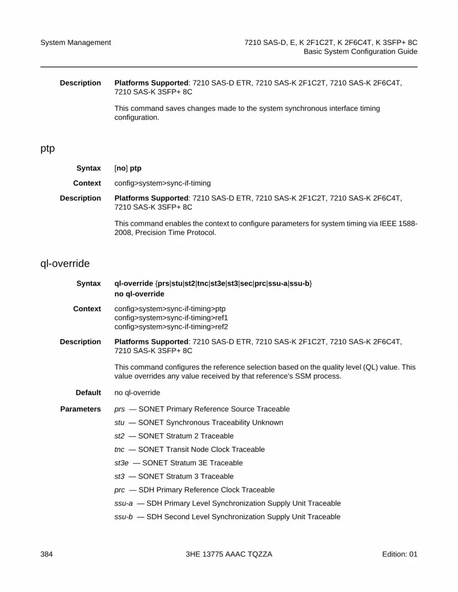
System Management
384
7210 SAS-D, E, K 2F1C2T, K 2F6C4T, K 3SFP+ 8CBasic System Configuration Guide
3HE 13775 AAAC TQZZA Edition: 01
Description Platforms Supported: 7210 SAS-D ETR, 7210 SAS-K 2F1C2T, 7210 SAS-K 2F6C4T, 7210 SAS-K 3SFP+ 8C
This command saves changes made to the system synchronous interface timing configuration.
ptp
Syntax [no] ptp
Context config>system>sync-if-timing
Description Platforms Supported: 7210 SAS-D ETR, 7210 SAS-K 2F1C2T, 7210 SAS-K 2F6C4T, 7210 SAS-K 3SFP+ 8C
This command enables the context to configure parameters for system timing via IEEE 1588-2008, Precision Time Protocol.
ql-override
Syntax ql-override {prs|stu|st2|tnc|st3e|st3|sec|prc|ssu-a|ssu-b}
no ql-override
Context config>system>sync-if-timing>ptpconfig>system>sync-if-timing>ref1config>system>sync-if-timing>ref2
Description Platforms Supported: 7210 SAS-D ETR, 7210 SAS-K 2F1C2T, 7210 SAS-K 2F6C4T, 7210 SAS-K 3SFP+ 8C
This command configures the reference selection based on the quality level (QL) value. This value overrides any value received by that reference's SSM process.
Default no ql-override
Parameters prs — SONET Primary Reference Source Traceable
stu — SONET Synchronous Traceability Unknown
st2 — SONET Stratum 2 Traceable
tnc — SONET Transit Node Clock Traceable
st3e — SONET Stratum 3E Traceable
st3 — SONET Stratum 3 Traceable
prc — SDH Primary Reference Clock Traceable
ssu-a — SDH Primary Level Synchronization Supply Unit Traceable
ssu-b — SDH Second Level Synchronization Supply Unit Traceable

7210 SAS-D, E, K 2F1C2T, K 2F6C4T, K 3SFP+ 8C Basic System Configuration Guide
System Management
Edition: 01 3HE 13775 AAAC TQZZA 385
sec — SDH Synchronous Equipment Clock Traceable
ql-selection
Syntax [no] ql-selection
Context config>system>sync-if-timing
Description Platforms Supported: 7210 SAS-D ETR, 7210 SAS-K 2F1C2T, 7210 SAS-K 2F6C4T, 7210 SAS-K 3SFP+ 8C
This command enables the selection of the system timing reference to take into account the quality level. This command turns SSM encoding on or off as a means of timing reference selection.
Default no ql-selection
ref-order
Syntax ref-order first second third
ref-order ptp
no ref-order
Context config>system>sync-if-timing
Description Platforms Supported: 7210 SAS-D ETR, 7210 SAS-K 2F1C2T, 7210 SAS-K 2F6C4T, 7210 SAS-K 3SFP+ 8C
The synchronous equipment timing subsystem can lock to different timing reference inputs, those specified in the ref1, ref2 and ptp command configuration. This command organizes the priority order of the timing references.
If a reference source is disabled, then the clock from the next reference source as defined by ref-order is used. If all reference sources are disabled, then clocking is derived from a local oscillator.
If a sync-if-timing reference is linked to a source port that is operationally down, the port is no longer qualified as a valid reference. Depending on the platform used, either SFP or Fixed copper ports can be used as a reference.
The no form of the command resets the reference order to the default values.
Note: On the 7210 SAS-D ETR, ref1 must be configured to use one of ports 1/1/1 to 1/1/4 and ref2 must be configured to use either port 1/1/5 or 1/1/6. The software enforces this check. Ports 1/1/7 to 1/1/10 can be configured as either ref1 or ref2.

System Management
386
7210 SAS-D, E, K 2F1C2T, K 2F6C4T, K 3SFP+ 8CBasic System Configuration Guide
3HE 13775 AAAC TQZZA Edition: 01
Default ref1 ref2 ptp
Parameters first — Specifies the first timing reference to use in the reference order sequence.
second — Specifies the second timing reference to use in the reference order sequence.
third — Specifies the third timing reference to use in the reference order sequence. This parameter is only supported on 7210 SAS-K devices.
ptp — Specifies that PTP must be used as a timing reference.
ref1
Syntax ref1
Context config>system>sync-if-timing
Description Platforms Supported: 7210 SAS-D ETR, 7210 SAS-K 2F1C2T, 7210 SAS-K 2F6C4T, 7210 SAS-K 3SFP+ 8C
This command enables the context to configure parameters for the first timing reference.
ref2
Syntax ref2
Context config>system>sync-if-timing
Description Platforms Supported: 7210 SAS-D ETR, 7210 SAS-K 2F1C2T, 7210 SAS-K 2F6C4T, 7210 SAS-K 3SFP+ 8C
This command enables the context to configure parameters for the second timing reference.
revert
Syntax [no] revert
Context config>system>sync-if-timing
Description Platforms Supported: 7210 SAS-D ETR, 7210 SAS-K 2F1C2T, 7210 SAS-K 2F6C4T, 7210 SAS-K 3SFP+ 8C
This command enables the clock to revert to a higher priority reference if the current reference goes offline or becomes unstable.
If revertive switching is enabled, the highest-priority valid timing reference will be used. If a reference with a higher priority becomes valid, a reference switch over to that reference will be initiated. If a failure on the current reference occurs, the next highest reference takes over.

7210 SAS-D, E, K 2F1C2T, K 2F6C4T, K 3SFP+ 8C Basic System Configuration Guide
System Management
Edition: 01 3HE 13775 AAAC TQZZA 387
If non-revertive switching is enabled, the valid active reference always remains selected, even if a higher-priority reference becomes available. If this reference becomes invalid, a reference switch over to a valid reference with the highest priority will be initiated. When the failed reference becomes operational, it is eligible for selection.
Default no revert
source-port
Syntax source-port port-id
no source-port
Context config>system>sync-if-timing>ref1config>system>sync-if-timing>ref2
Description Platforms Supported: 7210 SAS-D ETR, 7210 SAS-K 2F1C2T, 7210 SAS-K 2F6C4T, 7210 SAS-K 3SFP+ 8C
This command configures the source port for timing reference ref1 or ref2. If the port is unavailable or the link is down, then the reference sources are re-evaluated according to the reference order configured in the ref-order command.
The no form of the command deletes the source port from the reference.
Parameters port-id — Identifies the physical port in the slot/mda/port format.

System Management
388
7210 SAS-D, E, K 2F1C2T, K 2F6C4T, K 3SFP+ 8CBasic System Configuration Guide
3HE 13775 AAAC TQZZA Edition: 01
5.21.2.1.7 System Administration Commands
admin
Syntax admin
Context <ROOT>
SupportedPlatforms
Supported on all 7210 SAS platforms as described in this document
Description This command enables the context to configure administrative system commands. Only authorized users can execute the commands in the admin context.
check-golden-bootstrap
Syntax check-golden-bootstrap
Context admin
Description Platforms Supported: 7210 SAS-D and 7210 SAS-E
This command validates the current golden bootstrap image, and displays its version, if found to be valid. If the golden bootstrap image is not found to be a valid, an error message is displayed to that effect.
auto-init
Syntax auto-init stop
Context admin
SupportedPlatforms
Supported on all 7210 SAS platforms as described in this document
Description When the system boots up for the first-time, auto-init can potentially use the TiMOS images available on the local flash to boot up and provide a user login prompt. With this command, user is provided with an option to stop the auto-init process and complete successful boot. After executing this command, the system saves the BOF with the BOF parameter primary-image pointing to the both.tim on the local flash.
If the user does not use this command to stop the auto-init process, the system reboots and attempts to find the BOF again using DHCP.

7210 SAS-D, E, K 2F1C2T, K 2F6C4T, K 3SFP+ 8C Basic System Configuration Guide
System Management
Edition: 01 3HE 13775 AAAC TQZZA 389
debug-save
Syntax debug-save file-url
Context admin
SupportedPlatforms
Supported on all 7210 SAS platforms as described in this document
Description This command saves existing debug configuration. Debug configurations are not preserved in configuration saves.
Parameters file-url — The file URL location to save the debug configuration.
Values
disconnect
Syntax disconnect {address ip-address | username user-name | console | telnet | ftp | ssh}
Context admin
SupportedPlatforms
Supported on all 7210 SAS platforms as described in this document
Description This command disconnects a user from a console, Telnet, FTP, or SSH session.
If any of the console, Telnet, FTP, or SSH options are specified, then only the respective console, Telnet, FTP, or SSH sessions are affected.
If no console, Telnet, FTP, or SSH options are specified, then all sessions from the IP address or from the specified user are disconnected.
Any task that the user is executing is terminated. FTP files accessed by the user will not be removed.
A major severity security log event is created specifying what was terminated and by whom.
file url: local-url | remote-url: 255 chars maximum
local-url: [<cflash-id>/ | <usb-flash-id>][file-path], 200 chars maximum, including the cflash-id directory length, 99 chars maximum each
remote-url: [{ftp://} login:pswd@remote-locn/][file-path] remote-locn [hostname | ipv4-address]
ipv4-address a.b.c.d
255 chars max, directory length 99 chars maximum each
cflash-id: cf1:
usb-flash-id uf1:

System Management
390
7210 SAS-D, E, K 2F1C2T, K 2F6C4T, K 3SFP+ 8CBasic System Configuration Guide
3HE 13775 AAAC TQZZA Edition: 01
Parameters address ip-address — the IP address to disconnect, specified in dotted decimal notation
Values
username user-name — The name of the user.
console — Disconnects the console session.
telnet — Disconnects the Telnet session.
ftp — Disconnects the FTP session.
ssh — Disconnects the SSH session.
display-config
Syntax display-config [detail | index]
Context admin
SupportedPlatforms
Supported on all 7210 SAS platforms as described in this document
Description This command displays the system’s running configuration.
By default, only non-default settings are displayed.
Specifying the detail option displays all default and non-default configuration parameters.
Parameters detail — Displays default and non-default configuration parameters.
index — Displays only persistent-indices.
reboot
Syntax reboot [upgrade][auto-init] [now]
Context admin
SupportedPlatforms
Supported on all 7210 SAS platforms as described in this document
Description This command reboots the system or initiates an upgrade of the firmware along with a reboot of the node or initiate an auto-init boot procedure along with a reboot of the node.
ipv4-address a.b.c.d
ipv6-address - x:x:x:x:x:x:x:x (eight 16-bit pieces)
x:x:x:x:x:x:d.d.d.d
x - [0..FFFF]H
d - [0..255]D

7210 SAS-D, E, K 2F1C2T, K 2F6C4T, K 3SFP+ 8C Basic System Configuration Guide
System Management
Edition: 01 3HE 13775 AAAC TQZZA 391
If no options are specified, the user is prompted to confirm the reboot operation. For example:
ALA-1>admin# rebootAre you sure you want to reboot (y/n)?
If the now option is specified, boot confirmation messages appear.
Parameters upgrade — Enables card firmware (CPLD and ROM) to be upgraded during chassis reboot. The 7210 SAS OS and the boot.tim support functionality to perform automatic firmware upgrades. The automatic upgrade must be enabled in the 7210 SAS OS Command Line Interface (CLI) when rebooting the system.
When the upgrade keyword is specified, a chassis flag is set for the BOOT Loader (boot.tim) and on the subsequent boot of the 7210 SAS OS on the chassis, any firmware images requiring upgrading will be upgraded automatically.
If an 7210 SAS is rebooted with the admin reboot command (without the upgrade keyword), the firmware images are left intact.
During any firmware upgrade, automatic or manual, it is imperative that during the upgrade procedure:
• Power must NOT be switched off or interrupted.
• The system must NOT be reset.
• No cards are inserted or removed.
Any of the above conditions may render cards inoperable requiring a return of the card for resolution.
now — Forces a reboot of the router immediately without an interactive confirmation.
auto-init — Specifies to reset the BOF and initiates a reboot.
save
Syntax save [file-url] [detail] [index]
Context admin
SupportedPlatforms
Supported on all 7210 SAS platforms as described in this document
Description This command saves the running configuration to a configuration file. For example:
A:ALA-1>admin# save ftp://test:[email protected]/./100.cfgSaving configuration .........Completed.
By default, the running configuration is saved to the primary configuration file.
Parameters file-url — The file URL location to save the configuration file.
Values

System Management
392
7210 SAS-D, E, K 2F1C2T, K 2F6C4T, K 3SFP+ 8CBasic System Configuration Guide
3HE 13775 AAAC TQZZA Edition: 01
Default the primary configuration file location
detail — Saves both default and non-default configuration parameters.
index — Forces a save of the persistent index file regardless of the persistent status in the BOF file. The index option can also be used to avoid an additional boot required while changing your system to use the persistence indices.
enable-tech
Syntax [no] enable-tech
Context admin
SupportedPlatforms
Supported on all 7210 SAS platforms as described in this document
Description This command enables the shell and kernel commands.
tech-support
Syntax tech-support file-url
<file-url> :<local-url>|<remote-url> - [255 chars max]
local-url - [<cflash-id>/ | <usb-flash-id>][file-path]
remote-url - [{ftp://|tftp://}<login>:<pswd>@<remote-locn>/][<file-path>]
remote-locn - [<hostname> | <ipv4-address> | "["<ipv6-address>"]" ]
ipv4-address a.b.c.d
ipv6-address - x:x:x:x:x:x:x:x[-interface]
x:x:x:x:x:x:d.d.d.d[-interface]
x - [0..FFFF]H
d - [0..255]D
interface - 32 chars max, for link
local addresses
cflash-id - cf1:
usb-flash-id -uf1:
Note: This command should only be used with authorized direction from the Nokia Technical Assistance Center (TAC).

7210 SAS-D, E, K 2F1C2T, K 2F6C4T, K 3SFP+ 8C Basic System Configuration Guide
System Management
Edition: 01 3HE 13775 AAAC TQZZA 393
Context admin
SupportedPlatforms
Supported on all 7210 SAS platforms as described in this document
Description This command creates a system core dump.
Parameters file-url — The file URL location to save the binary file.
update-golden-bootstrap
Syntax update-golden-bootstrap [file-url]
Context admin
Description Platforms Supported: 7210 SAS-D and 7210 SAS-E
This command updates the golden bootstrap image with the file-url, after validating it as a bootstrap image for the 7210 SAS platforms.Only on 7210 SAS-D newer platforms, the admin>update-golden-bootstrap CLI command does not update the golden-bootstrap image with the boot.tim specified in the parameter value, if the boot.tim is not a newer image.
Note: This command should only be used with authorized direction from the Nokia Technical Assistance Center (TAC).
file url: local-url | remote-url: 255 chars max
local-url: [<cflash-id>/ | <usb-flash-id>][file-path], 200 chars max, including the cflash-id directory length, 99 chars max each
remote-url: [{ftp://} login:pswd@remote-locn/][file-path]
remote-locn [ hostname | ipv4-address]
ipv4-address a.b.c.d
255 chars max, directory length 99 chars max each
cflash-id: cf1:
usb-flash-id uf1:

System Management
394
7210 SAS-D, E, K 2F1C2T, K 2F6C4T, K 3SFP+ 8CBasic System Configuration Guide
3HE 13775 AAAC TQZZA Edition: 01
Default cf1:/boot.tim
Parameters file-url — Specifies the file URL.
Values
file-url: local-url: 255 characters maximum
local-url: [cflash-id/][file-path]
cflash-id: cf1:

7210 SAS-D, E, K 2F1C2T, K 2F6C4T, K 3SFP+ 8C Basic System Configuration Guide
System Management
Edition: 01 3HE 13775 AAAC TQZZA 395
5.21.2.1.8 System Alarm Contact Commands
alarm-contact-input
Syntax alarm-contact-input alarm-contact-input-id
Context config>system>alarm-contact-input
SupportedPlatforms
Supported on all 7210 SAS platforms as described in this document
Description This command enables the context to configure one of four available alarm contact input pins.
Parameters alarm-contact-input-id — Identifies the alarm contact input pin.
Values 1 to 4 (for 7210 SAS-E)
Values console-1 (for 7210 SAS-D, 7210 SAS-K 2F1C2T, 7210 SAS-K 2F6C4T, 7210 SAS-K 3SFP+ 8C when using console as alarm input pin)
alarm-output-severity
Syntax [no] alarm-output-severity {critical | major | minor | none}
Context config>system>alarm-contact-input
SupportedPlatforms
Supported on all 7210 SAS platforms as described in this document
Description This command enables the context to relay alarms from the alarm-contact input to the alarm-contact output by associating an appropriate alarm-contact output with the alarm-contact input. The system generates or clears the alarm-contact output when it triggers or clears the alarm for the associated alarm-contact input.
If multiple alarm-contact input pins share an alarm-contact output, the system generates the alarm-contact output even if any one of the alarm-contact input is triggered and the system clears alarm-contact output only when all the alarm-contact input pins are cleared.
The severity parameter configured by the user determines the appropriate alarm-contact output to be used for generation and clearing the alarm.
Note: The system relays the alarm-contact input to the appropriate alarm-contact output only if the alarm-contact output is available on the platform.
Default major
Parameters critical — A critical alarm output is generated or cleared.
major — A major alarm output is generated or cleared.

System Management
396
7210 SAS-D, E, K 2F1C2T, K 2F6C4T, K 3SFP+ 8CBasic System Configuration Guide
3HE 13775 AAAC TQZZA Edition: 01
minor — A minor alarm output is generated or cleared.
none — No alarm output is generated or cleared.
clear-alarm-msg
Syntax [no] clear-alarm-msg {alarm-msg-text}
Context config>system>alarm-contact-input
SupportedPlatforms
Supported on all 7210 SAS platforms as described in this document
Description This command enables the context to configure a text message for use along with SNMP trap and Log message that are sent when the system clears an alarm. The system generates a default message if the message is not configured. The system does not generate a trap or log if no form of the command is enabled.
Parameters alarm-msg-text — A printable character string, up to 80 characters.
description
Syntax description description-string
Context config>system>alarm-contact-input
SupportedPlatforms
Supported on all 7210 SAS platforms as described in this document
Description This command describes an alarm contact input pin. The description provides an indication of the usage or attribute of the pin. It is stored in the CLI configuration file and helps the user in identifying the purpose of the pin.
Parameters description-string — The description character string, up to 80 characters.
normal-state
Syntax normal-state [open | closed]
Context config>system>alarm-contact-input
SupportedPlatforms
Supported on all 7210 SAS platforms as described in this document
Description This command configures the normal state to be associated with the alarm-contact input. When the system detects a transition from the normal state, an alarm is generated. The alarm is cleared when the system detects a transition is back to the normal state.

7210 SAS-D, E, K 2F1C2T, K 2F6C4T, K 3SFP+ 8C Basic System Configuration Guide
System Management
Edition: 01 3HE 13775 AAAC TQZZA 397
Default open
Parameters open — The normal-state is identified as ‘open’. When the system detects a transition to the ‘closed’ state, an alarm is generated. The alarm is cleared when the system detects a transition back to the ‘Open’ state.
closed — The normal-state is identified as ‘closed’. When the system detects a transition to the ‘open’ state, and alarm is generated. The alarm is cleared when the system detects a transition back to the ‘closed’ state.
shutdown
Syntax [no] shutdown
Context config>system>alarm-contact-input
SupportedPlatforms
Supported on all 7210 SAS platforms as described in this document
Description This command stops tracking the state changes associated with the alarm contact input. The system does not generate or clear the alarms for the alarm-contact input, but if an alarm is generated for the alarm-contact-input, the system clears the alarm when the shutdown command is executed.
The no form of the command starts tracking the state changes associated with the alarm contact input.
Default shutdown
trigger-alarm-msg
Syntax [no] trigger-alarm-msg {alarm-msg-text}
Context config>system>alarm-contact-input
SupportedPlatforms
Supported on all 7210 SAS platforms as described in this document
Description This command enables the context to configure a text message for use along with SNMP trap and Log message that are sent when the system generates an alarm. The system generates a default message if the message is not configured. The system does not generate a trap or log if no form of the command is enabled.
Parameters alarm-msg-text — A printable character string, up to 80 characters.

System Management
398
7210 SAS-D, E, K 2F1C2T, K 2F6C4T, K 3SFP+ 8CBasic System Configuration Guide
3HE 13775 AAAC TQZZA Edition: 01
5.21.2.1.9 LLDP System Commands
lldp
Syntax lldp
Context config>system
SupportedPlatforms
Supported on all 7210 SAS platforms as described in this document
Description This command enables the context to configure system-wide Link Layer Discovery Protocol parameters.
message-fast-tx
Syntax message-fast-tx time
no message-fast-tx
Context config>system>lldp
SupportedPlatforms
Supported on all 7210 SAS platforms as described in this document
Description This command configures the duration of the fast transmission period.
Parameters time — Specifies the fast transmission period in seconds.
Values 1 to 3600
Default 1
message-fast-tx-init
Syntax message-fast-tx-init count
no message-fast-tx-init
Context config>system>lldp
SupportedPlatforms
Supported on all 7210 SAS platforms as described in this document
Description This command configures the number of LLDPDUs to send during the fast transmission period.
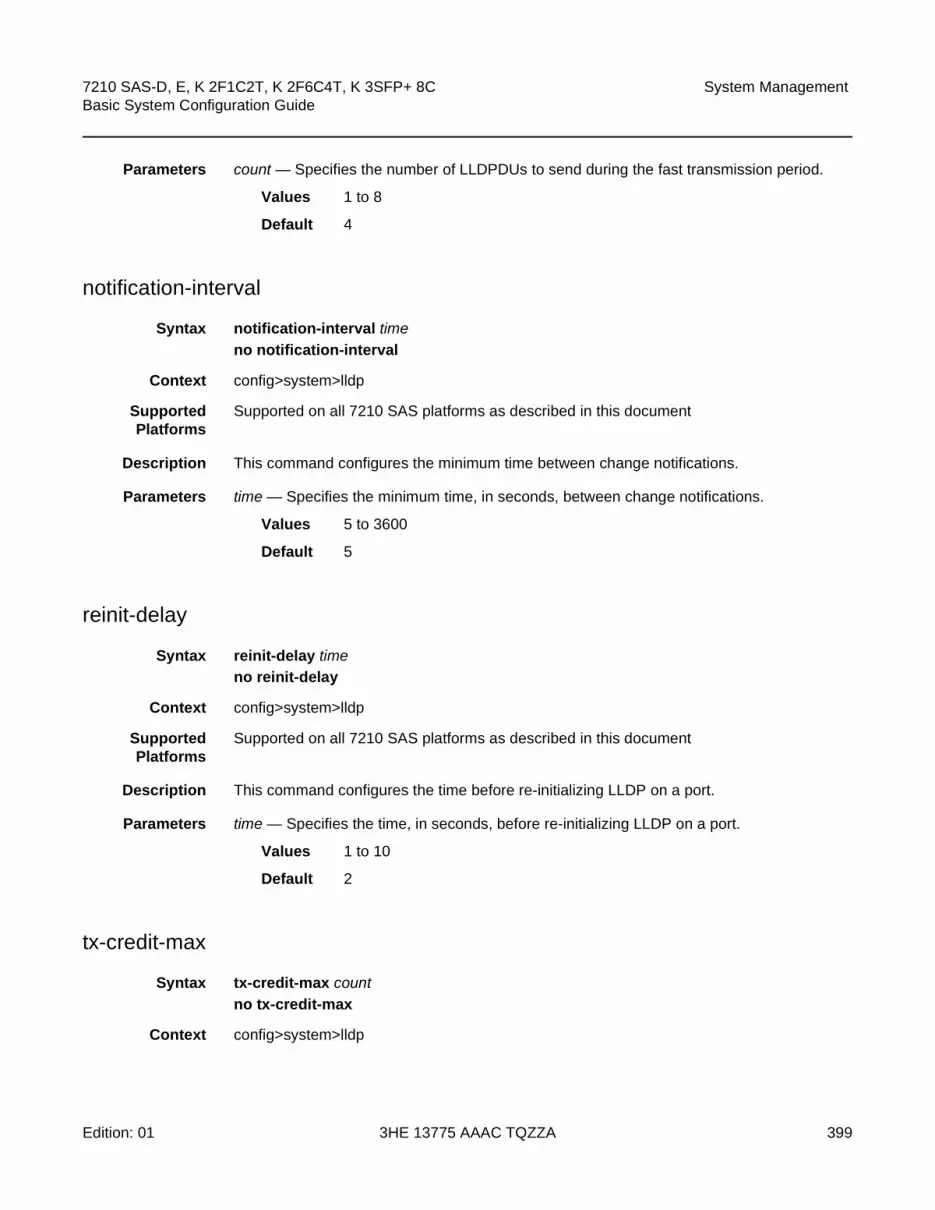
7210 SAS-D, E, K 2F1C2T, K 2F6C4T, K 3SFP+ 8C Basic System Configuration Guide
System Management
Edition: 01 3HE 13775 AAAC TQZZA 399
Parameters count — Specifies the number of LLDPDUs to send during the fast transmission period.
Values 1 to 8
Default 4
notification-interval
Syntax notification-interval time
no notification-interval
Context config>system>lldp
SupportedPlatforms
Supported on all 7210 SAS platforms as described in this document
Description This command configures the minimum time between change notifications.
Parameters time — Specifies the minimum time, in seconds, between change notifications.
Values 5 to 3600
Default 5
reinit-delay
Syntax reinit-delay time
no reinit-delay
Context config>system>lldp
SupportedPlatforms
Supported on all 7210 SAS platforms as described in this document
Description This command configures the time before re-initializing LLDP on a port.
Parameters time — Specifies the time, in seconds, before re-initializing LLDP on a port.
Values 1 to 10
Default 2
tx-credit-max
Syntax tx-credit-max count
no tx-credit-max
Context config>system>lldp
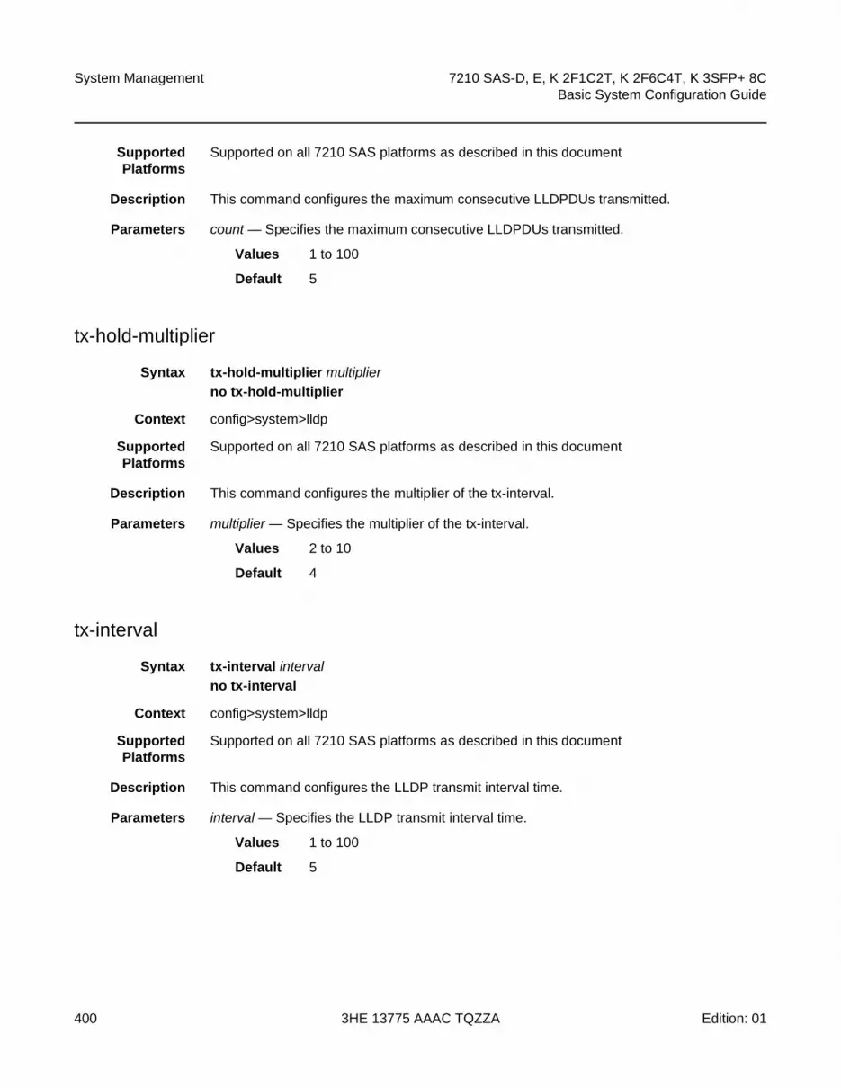
System Management
400
7210 SAS-D, E, K 2F1C2T, K 2F6C4T, K 3SFP+ 8CBasic System Configuration Guide
3HE 13775 AAAC TQZZA Edition: 01
SupportedPlatforms
Supported on all 7210 SAS platforms as described in this document
Description This command configures the maximum consecutive LLDPDUs transmitted.
Parameters count — Specifies the maximum consecutive LLDPDUs transmitted.
Values 1 to 100
Default 5
tx-hold-multiplier
Syntax tx-hold-multiplier multiplier
no tx-hold-multiplier
Context config>system>lldp
SupportedPlatforms
Supported on all 7210 SAS platforms as described in this document
Description This command configures the multiplier of the tx-interval.
Parameters multiplier — Specifies the multiplier of the tx-interval.
Values 2 to 10
Default 4
tx-interval
Syntax tx-interval interval
no tx-interval
Context config>system>lldp
SupportedPlatforms
Supported on all 7210 SAS platforms as described in this document
Description This command configures the LLDP transmit interval time.
Parameters interval — Specifies the LLDP transmit interval time.
Values 1 to 100
Default 5

7210 SAS-D, E, K 2F1C2T, K 2F6C4T, K 3SFP+ 8C Basic System Configuration Guide
System Management
Edition: 01 3HE 13775 AAAC TQZZA 401
5.21.2.1.10 LLDP Ethernet Port Commands
lldp
Syntax lldp
Context config>port>ethernet
SupportedPlatforms
Supported on all 7210 SAS platforms as described in this document
Description This command enables the context to configure Link Layer Discovery Protocol (LLDP) parameters on the specified port.
dest-mac
Syntax dest-mac {bridge-mac}
Context config>port>ethernet>lldp
SupportedPlatforms
Supported on all 7210 SAS platforms as described in this document
Description This command configures destination MAC address parameters.
Parameters bridge-mac — Specifies destination bridge MAC type to use by LLDP.
Values nearest-bridge — Specifies to use the nearest bridge.
nearest-non-tpmr — Specifies to use the nearest non-Two-Port MAC Relay (TPMR).
nearest-customer — Specifies to use the nearest customer.
admin-status
Syntax admin-status {rx | tx | tx-rx | disabled}
Context config>port>ethernet>lldp>dstmac
SupportedPlatforms
Supported on all 7210 SAS platforms as described in this document
Description This command configures the administratively desired status of the local LLDP agent.
Parameters rx — Specifies the LLDP agent will receive, but will not transmit LLDP frames on this port.

System Management
402
7210 SAS-D, E, K 2F1C2T, K 2F6C4T, K 3SFP+ 8CBasic System Configuration Guide
3HE 13775 AAAC TQZZA Edition: 01
tx — Specifies that the LLDP agent will transmit LLDP frames on this port and will not store any information about the remote systems connected.
tx-rx — Specifies that the LLDP agent will transmit and receive LLDP frames on this port.
disabled — Specifies that the LLDP agent will not transmit or receive LLDP frames on this port. If there is remote systems information which is received on this port and stored in other tables, before the port's admin status becomes disabled, then the information will naturally age out.
notification
Syntax [no] notification
Context config>port>ethernet>lldp>dstmac
SupportedPlatforms
Supported on all 7210 SAS platforms as described in this document
Description This command enables LLDP notifications.
The no form of the command disables LLDP notifications.
tx-mgmt-address
Syntax tx-mgmt-address [system]
no tx-mgmt-address
Context config>port>ethernet>lldp>dstmac
SupportedPlatforms
Supported on all 7210 SAS platforms as described in this document
Description This command configures which management address to transmit.
The no form of the command resets value to the default.
Default no tx-mgmt-address
Parameters system — Specifies to use the system IP address. Note that the system address will only be transmitted once it has been configured if this parameter is specified.
tx-tlvs
Syntax tx-tlvs [port-desc] [sys-name] [sys-desc] [sys-cap]
no tx-tlvs
Context config>port>ethernet>lldp>dstmac

7210 SAS-D, E, K 2F1C2T, K 2F6C4T, K 3SFP+ 8C Basic System Configuration Guide
System Management
Edition: 01 3HE 13775 AAAC TQZZA 403
SupportedPlatforms
Supported on all 7210 SAS platforms as described in this document
Description This command specifies which LLDP TLVs to transmit.
The no form of the command resets the value to the default.
Default no tx-tlvs
Parameters port-desc — Indicates that the LLDP agent should transmit port description TLVs.
sys-name — Indicates that the LLDP agent should transmit system name TLVs.
sys-desc — Indicates that the LLDP agent should transmit system description TLVs.
sys-cap — Indicates that the LLDP agent should transmit system capabilities TLVs.

System Management
404
7210 SAS-D, E, K 2F1C2T, K 2F6C4T, K 3SFP+ 8CBasic System Configuration Guide
3HE 13775 AAAC TQZZA Edition: 01
5.21.2.1.11 System Resource-Profile Commands
resource-profile
Syntax [no] resource-profile
Context config>system
SupportedPlatforms
Supported on all 7210 SAS platforms as described in this document
Description This command enables the context to configure resource-profile parameters on the system.
egress-internal-tcam
Syntax egress-internal-tcam
Context config>system>resource-profile
Description Platforms Supported: 7210 SAS-D, 7210 SAS-K 2F1C2T, 7210 SAS-K 2F6C4T, 7210 SAS-K 3SFP+ 8C
This command enables the context to allocate resources from the egress internal TCAM pool.
The egress-internal-tcam resource pool is shared by multiple features. The resources are allocated in chunks of fixed sizes. The user is provided an option to allocate the available resources based on their scaling requirements for the features. The resource usage for different features is provided in the CLI description. It is not possible for a chunk to be shared by multiple features. Software allocates resources from the chunk to the feature to which it is allocated until it runs out of all resources in the chunk. If available, the user can allocate more chunks to the feature by taking away chunks of resources from other features that do not need to be enabled.
To free up the resources for use by other features, users need to modify the configuration such that the chunks of resources in use by other features are freed. For example, to free up a chunk of resources allocated to egress ACLs mac-criteria and allocate it to ip-criteria, the user will need to remove the association of all the SAPs with egress ACLs that use a MAC criteria policy, then change the resource profile configuration to allocate the chunk to ip-criteria, and then create and associate the SAPs with ip-criteria. As another example, the user can free up a chunk of resources used by egress ACLs and allocate it towards a SAP egress aggregate meter (on platforms that support this feature). To do this, the user will need to remove the association of all the SAPs with egress ACLs, change the resource profile configuration to reduce the chunk of resources allocated to egress ACLs (and reduce the value of chunks in use by the egress ACLs match criteria), then allocate the chunk of resources to the SAP egress aggregate meter feature, and then configure the SAPs with the aggregate meter rate.

7210 SAS-D, E, K 2F1C2T, K 2F6C4T, K 3SFP+ 8C Basic System Configuration Guide
System Management
Edition: 01 3HE 13775 AAAC TQZZA 405
The egress-internal-tcam resource pool is shared among the following features on different platforms:
• 7210 SAS-D: egress ACLs (MAC, IPv4 and IPv6 criteria) and per-SAP egress aggregate meter
• 7210 SAS-K 2F1C2T, 7210 SAS-K 2F6C4T, and 7210 SAS-K 3SFP+ 8C: egress ACLS (MAC, IPv4 and IPv6 criteria) and primary VLAN
acl-sap-egress
Syntax [no] acl-sap-egress [num-resources]
Context config>system>resource-profile>egress-internal-tcam
Description Platforms Supported: 7210 SAS-D, 7210 SAS-K 2F1C2T, 7210 SAS-K 2F6C4T, 7210 SAS-K 3SFP+ 8C
This command enables the context to allocate maximum resources for use by egress filter policies using any of the supported match criteria. This command limits the total amount of chunks allocated for use by egress filter policies to the value specified by num-resources. In other words, the cumulative sum of chunks allocated to different match criteria supported by filter policies cannot exceed the value configured with num-resources.
Note:
• When reassigning chunks of resources among features, a reboot of the node might be required. Refer to the CLI description of the specific feature for information.
• The egress-internal-tcam pool of resources is allocated per node on the 7210 SAS-D, 7210 SAS-K 2F1C2T, 7210 SAS-K 2F6C4T, and 7210 SAS-K 3SFP+ 8C.
• The number of chunks and the number of resources per chunk varies among the different platforms. Contact your Nokia technical support representative for more information.
• For some features, a minimum number of chunks (greater than 1) must be allocated to enable the feature functionality. If this is not done, the software cannot allocate the required number of resources and it will fail the command associated with the feature.

System Management
406
7210 SAS-D, E, K 2F1C2T, K 2F6C4T, K 3SFP+ 8CBasic System Configuration Guide
3HE 13775 AAAC TQZZA Edition: 01
When the user allocates resources for use by SAP egress ACL policies using this command, the system allocates resources in chunks of 128 entries for the 7210 SAS-D, 510 entries for the 7210 SAS-K 2F1C2T, and 7210 SAS-K 2F6C4T, and 180 entries for the 7210 SAS-K 3SFP+ 8C. The resources are used only for filter entries configured under IPv4 criteria or MAC criteria.
For the 7210 SAS-K 2F1C2T, 7210 SAS-K 2F6C4T, and 7210 SAS-K 3SFP+ 8C, if the user needs to use IPv6 criteria, resources must be allocated using the CLI command mac-ipv4-ipv6-128-match-enable under this command context. The resources allocated using this command are used for filter entries configured under IPv6 criteria, IPv4 criteria, or MAC criteria. Each IPv6, IPv4, or MAC filter entry consumes two resources from this pool, reducing the number of filter entries that can be accommodated in a single chunk to 255 entries for the 7210 SAS-K 2F1C2T and 7210 SAS-K 2F6C4T, and 108 entries for the 7210 SAS-K 3SFP+ 8C. The user can choose to allocate all the chunks allocated for SAP egress ACL policies for IPv6 criteria or allocate only a portion of it.
For details on resource allocation for the match criteria used in egress filter policies, refer to the 7210 SAS-D, E, K 2F1C2T, K 2F6C4T, K 3SFP+ 8C Router Configuration Guide.
On the 7210 SAS-D, 7210 SAS-K 2F1C2T, and 7210 SAS-K 2F6C4T, if the no form of the command is used, the software does not allocate any resources for use by egress filter policies. If no resources are allocated for use, then the software fails all attempts to associate a service entity (for example, SAP, IP interface) with a filter policy using any of the match criteria. On the 7210 SAS-K 3SFP+ 8C, the no form of the command is blocked in the CLI and cannot be used.
Note:
• On the 7210 SAS-D, the resources in the egress-internal-tcam resource pool are shared with other features (for example, SAP egress aggregate meter). To assign resources to this feature, resources may be reallocated from other features by disabling the policy association with a SAP.
• On the 7210 SAS-D, some of the egress ACL match criteria require a minimum number of resources greater than 1 to be allocated before the match criteria can be used. Use of the SAP egress aggregate meter and the use of egress ACLs with the following match criteria: mac-ipv4 match, ipv6-128bit match, and mac-ipv6-64bit match, are mutually exclusive. All these match criteria require a minimum of two resources. SAP egress aggregate meter and egress ACLs MAC match criteria can be enabled simultaneously, with each feature sharing the available resources equally among them.
• On the 7210 SAS-K 2F1C2T, 7210 SAS-K 2F6C4T, and 7210 SAS-K 3SFP+ 8C, when resources are allocated to egress ACLs from the egress internal TCAM pool, these resources can be used by MAC criteria entries, IPv4 entries, and entries that use only IPv6 64-bit addresses.

7210 SAS-D, E, K 2F1C2T, K 2F6C4T, K 3SFP+ 8C Basic System Configuration Guide
System Management
Edition: 01 3HE 13775 AAAC TQZZA 407
Parameters num-resources — Specifies the amount of resources that can be allocated for use by ACL policies.
The Max keyword allocates 2 slices in the current release.
Values
egress-sap-aggregate-meter
Syntax [no] egress-sap-aggregate-meter num-resources
Context config>system>resource-profile>egress-internal-tcam
Description Platforms Supported: 7210 SAS-D
This command enables the context to allocate resources for use by SAP egress aggregate policer from the egress-internal-tcam resource pool. This command limits the total amount of chunks allocated for use by SAP egress aggregate meter to the value specified by num-resources.
Platforms Min value (per node)
Max value (per node)
Default Values
7210 SAS-D (per node) 0 2 2
7210 SAS-K 2F1C2T
(per node)
0 2 0
7210 SAS-K 2F6C4T
(per node)
0 2 0
7210 SAS-K 2F6C4T
(per node)
n/a Max (2) Max (2)
Note:
• The resources in the egress-internal-tcam resource pool are shared with other features (For example: SAP egress aggregate meter, etc.). To assign resources to this feature, resources may be reallocated from other features by disabling the policies association with a SAP, and others.
• On the 7210 SAS platforms, some of the Egress ACL match criteria require a minimum amount of resources greater than 1, to be allocated before the match criteria can be used. In other words, use of SAP egress aggregate meter is mutually exclusive to use of egress ACLs with the following match criteria - mac-ipv4 match, ipv6-128bit match, mac-ipv6-64bit match. All these match criteria require a minimum of 2 resources. SAP egress aggregate meter and egress ACLs MAC match criteria can be enabled simultaneously, with each feature sharing the available resources equally among them.

System Management
408
7210 SAS-D, E, K 2F1C2T, K 2F6C4T, K 3SFP+ 8CBasic System Configuration Guide
3HE 13775 AAAC TQZZA Edition: 01
With the no form of the command, software does not allocate any resources for use by SAP egress aggregate policer. If no resources are allocated for use, then the software fails all attempts to enable the configuration of the command for a SAP.
Default no egress-sap-aggregate-meter
Parameters num-resources — Specifies the maximum amount of resources for use by this filter match criteria.
Values 0 to 2
Default 0
ipv6-128bit-match-enable
Syntax [no] ipv6-128bit-match-enable num-resources
Context config>system>resource-profile>egress-internal-tcam>acl-sap-egress
Description Platforms Supported: 7210 SAS-D
This command enables the context to allocate maximum resources for use by egress filter policies using IPv6 criteria with 128-bit IPv6 addresses.
The resources cannot be shared with any other egress filter policies that specify other match criteria. Refer to the 7210 SAS-D, E, K 2F1C2T, K 2F6C4T, K 3SFP+ 8C Router Configuration Guide for more information on resource allocation details and fields available for use.
With the no form of the command, the software does not allocate any resources for use by egress filter policies using ipv6 criteria with 128-bit IPv6 addresses. If no resources are allocated for use, then the software fails all attempts to associate a service entity (for example: SAP, IP interface, etc.) with a filter policy using this match criteria.
Default no ipv6-128bit-match-enable
Parameters num-resources — Specifies the maximum amount of resources for use by this filter match criteria. A minimum value of 2 (indicating two chunks of resources) must be allocated to use this match-criteria. If not, association of a policy with ipv6-128bit criteria to a SAP will fail. It is mutually exclusive to use of SAP egress aggregate meter.
Values
Platforms Min value (per node)
Max value (per node)
Default Values
7210 SAS-D (per node) 0 2 0

7210 SAS-D, E, K 2F1C2T, K 2F6C4T, K 3SFP+ 8C Basic System Configuration Guide
System Management
Edition: 01 3HE 13775 AAAC TQZZA 409
eth-cfm-primary-vlan-enable
Syntax [no] eth-cfm-primary-vlan-enable
Context config>system>resource-profile>egress-internal-tcam
Description Platforms Supported: 7210 SAS-K 2F1C2T and 7210 SAS-K 3SFP+ 8C
This command enables the context of resources for primary VLAN functionality for UP MEPs. There are 128 entries allocated in the egress ACL pool.
The no form of the command frees up the resources allocated to this feature.
Default no eth-cfm-primary-vlan-enable
mac-ipv4-ipv6-128-match-enable
Syntax [no] mac-ipv4-ipv6-128-match-enable num-resources
Context config>system>resource-profile>egress-internal-tcam>acl-sap-egress
Description Platforms Supported: 7210 SAS-K 2F1C2T, 7210 SAS-K 2F6C4T, 7210 SAS-K 3SFP+ 8C
This command enables IPv6 128-bit address match.
When resources are allocated to egress ACLs from the egress internal TCAM pool using the command config>system>resource-profile>egress-internal-tcam>acl-sap-egress, these resources can be used by either MAC criteria entries or IPv4 entries. In order to enable IPv6 128-bit address match, the user must allocate resources using this command.
The resources allocated can be shared by MAC criteria, IPv4 criteria, IPv6 64-bit address criteria and IPv6 128-bit address criteria. Each match entry (for all criteria) consumes two resources from this pool, reducing the number of filter entries that can be accommodated in a single chunk to 255 entries for the 7210 SAS-K 2F1C2T and 7210 SAS-K 2F6C4T, and 108 entries for the 7210 SAS-K 3SFP+ 8C.
With the no form of the command, the software does not allocate any resources for use by egress filter policies using IPv6 criteria with 128-bit IPv6 addresses. If no resources are allocated for use, then the software fails all attempts to associate a service entity (for example, SAP, IP interface) with a filter policy using this match criteria.
Default no mac-ipv4-ipv6-128-match-enable
Note: The user must ensure that sufficient resources are free before executing this command. The command tools> dump> system-resources is used to determine the amount of free resources in the egress ACL pool. The scaling of ACL entries reduces when resources are allocated to this feature using this command.

System Management
410
7210 SAS-D, E, K 2F1C2T, K 2F6C4T, K 3SFP+ 8CBasic System Configuration Guide
3HE 13775 AAAC TQZZA Edition: 01
Parameters num-resources — Specifies the maximum amount of resources for use by this filter match criteria.
Values 0 to 2 (7210 SAS-K 2F1C2T and 7210 SAS-K 2F6C4T)
0 to 4 (7210 SAS-K 3SFP+ 8C)
Default 0
mac-ipv4-match-enable
Syntax [no] mac-ipv4-match-enable num-resources
Context config>system>resource-profile>egress-internal-tcam>acl-sap-egress
Description Platforms Supported: 7210 SAS-D
This command enables the context to allocate maximum resources for use by egress filter policies using IPv4 criteria or MAC criteria. The resources allocated are allocated on a first-come-first-serve basis among service entities (For example: SAP, IP interface, etc) using IPv4 and MAC criteria egress filter policies.
The resources cannot be shared with any other egress filter policies that specify other match criteria. Refer to the 7210 SAS-D, E, K 2F1C2T, K 2F6C4T, K 3SFP+ 8C Router Configuration Guide for more information on resource allocation details and fields available for use.
With the no form of the command, the software does not allocate any resources for use by egress filter policies using MAC or IPv4 criteria. If no resources are allocated for use, then the software fails all attempts to associate a service entity (For example: SAP, IP interface, and others.) with a filter policy using this match criteria.
Default mac-ipv4-match-enable 2 (to maintain backward compatibility with earlier releases)
Parameters num-resources — Specifies the maximum amount of resources for use by this filter match criteria. A minimum value of 2 (indicating two chunks of resources) must be allocated to use this match-criteria. If not, association of a policy with mac and ipv4 criteria to a SAP will fail. It is mutually exclusive to use of SAP egress aggregate meter.
Values
mac-ipv6-64bit-match-enable
Syntax [no] mac-ipv6-64bit-match-enable num-resources
Platforms Min value (per node)
Max value (per node)
Default Values
7210 SAS-D (per node) 0 2 0

7210 SAS-D, E, K 2F1C2T, K 2F6C4T, K 3SFP+ 8C Basic System Configuration Guide
System Management
Edition: 01 3HE 13775 AAAC TQZZA 411
Context config>system>resource-profile>egress-internal-tcam>acl-sap-egress
Description Platforms Supported: 7210 SAS-D
This command enables the context to allocate maximum resources for use by egress filter policies using MAC criteria or IPv6 criteria using only the upper 64-bits of the IPv6 addresses. The resources allocated are allocated on a first-come-first-serve basis among service entities (For example: SAP, IP interface, and more) using IPv6 64-bit and MAC criteria egress filter policies.
The resources cannot be shared with any other egress filter policies that specify other match criteria. Refer to the 7210 SAS-D, E, K 2F1C2T, K 2F6C4T, K 3SFP+ 8C Router Configuration Guide for more information on resource allocation details and fields available for use.
With the no form of the command, the software does not allocate any resources for use by egress filter policies using MAC or IPv6 64-bit criteria. If no resources are allocated for use, then the software fails all attempts to associate a service entity (e.g. SAP, IP interface, etc.) with a filter policy using this match criteria.
Default no mac-ipv6-64bit-match-enable
Parameters num-resources — Specifies the maximum amount of resources for use by this filter match criteria. A minimum value of 2 (indicating two chunks of resources) must be allocated to use this match-criteria. If not, association of a policy with mac and ipv6 64bit criteria to a SAP will fail. It is mutually exclusive to use of SAP egress aggregate meter.
Values
mac-match-enable
Syntax [no] mac-match-enable
Context config>system>resource-profile>egress-internal-tcam>acl-sap-egress
Description Platforms Supported: 7210 SAS-D
This command enables the context to allocate maximum resources for use by egress filter policies using MAC criteria. The resources allocated are allocated on a first-come-first-serve basis among service entities (For example: SAP, IP interface, etc.) using MAC criteria egress filter policies. This option provides for use of all available resources exclusively by MAC criteria egress filter policies and provide larger number of policies to be used.
Platforms Min value (per node)
Max value (per node)
Default Values
7210 SAS-D(per node) 0 2 0

System Management
412
7210 SAS-D, E, K 2F1C2T, K 2F6C4T, K 3SFP+ 8CBasic System Configuration Guide
3HE 13775 AAAC TQZZA Edition: 01
The resources cannot be shared with any other egress filter policies that specify other match criteria. Refer to the 7210 SAS-D, E, K 2F1C2T, K 2F6C4T, K 3SFP+ 8C Router Configuration Guide for more information on resource allocation details and fields available for use.
With the no form of the command, the software does not allocate any resources for use by egress filter policies using MAC criteria. If no resources are allocated for use, then the software fails all attempts to associate a service entity (For example: SAP, IP interface, etc.) with a filter policy using this match criteria.
It is possible to use MAC policies by allocating resources that are shared with other match criteria. This option allows for better scaling.
Default no mac-match-enable
Parameters num-resources — Specifies the maximum amount of resources for use by this filter match criteria.
Values 0 to 2
Default 0
ingress-internal-tcam
Syntax ingress-internal-tcam
Context config>system>resource-profile
SupportedPlatforms
Supported on all 7210 SAS platforms as described in this document
Description This command enables the context to allocate ingress internal TCAM resources.
The ingress-internal-tcam resource pool is shared by multiple features. The resources are allocated in chunks of fixed sizes. The user is provided an option to allocate the available resources based on their scaling requirements for the features. The resource usage for different features is provided in the CLI description. It is not possible for a chunk to be shared by multiple features. Software allocates resources from the chunk to the feature to which it is allocated until it runs out of all resources in the chunk. If available, the user can allocate more chunks to the feature by taking away chunks of resources from other features that do not need to be enabled.
To free up the resources for use by other features, users need to modify the configuration such that the chunks of resources in use by other features are freed. For example, to free up a chunk of resources allocated to ingress ACLs mac-criteria and allocate it to ip-criteria, the user will need to remove the association of all the SAPs with ingress ACLs that use a MAC criteria policy, then change the resource profile configuration to allocate the chunk to ip-criteria, and then create and associate the SAPs with ip-criteria. As another example, the user can free up a chunk of resources used by ingress ACLs and allocate it towards a SAP

7210 SAS-D, E, K 2F1C2T, K 2F6C4T, K 3SFP+ 8C Basic System Configuration Guide
System Management
Edition: 01 3HE 13775 AAAC TQZZA 413
ingress QoS classification. To do this, the user will need to remove the association of all the SAPs with ingress ACLs, change the resource profile configuration to reduce the chunk of resources allocated to ingress ACLs (and reduce the value of chunks in use by the ingress ACLs match criteria), then allocate the chunk of resources to the SAP ingress QoS classification feature, and then configure the SAPs with the SAP ingress QoS policies.
The ingress-internal-tcam resource pool is shared among the following features on different platforms:
• 7210 SAS-E: SAP ingress QoS classification (using IPv4, IPv6, and MAC match-criteria to match header fields), ingress ACLs (using IPv4, IPv6, and MAC match-criteria)
• 7210 SAS-D: SAP ingress QoS classification (using IPv4, IPv6, and MAC match-criteria to match header fields), ingress ACLs (using IPv4, IPv6, and MAC match-criteria), Ethernet CFM UP MEP, SAP ingress aggregate meter
• 7210 SAS-K 2F1C2T, 7210 SAS-K 2F6C4T, 7210 SAS-K 3SFP+ 8C: SAP ingress QoS classification (using IPv4, IPv6, and MAC match-criteria to match header fields), ingress ACLs (using IPv4, IPv6 and MAC match-criteria)
acl-sap-ingress
Syntax [no] acl-sap-ingress [num-resources]
Context config>system>resource-profile>ingress-internal-tcam
SupportedPlatforms
Supported on all 7210 SAS platforms as described in this document
Description This command enables the context to allocate maximum resources for use by ingress filter policies using any of the supported match criteria. This command limits the total amount of chunks allocated for use by ingress filter policies to the value specified by num-resources. In other words, the cumulative sum of chunks allocated to different match criteria supported by ingress filter policies cannot exceed the value configured with num-resources.
Note:
• When reassigning chunks of resources among features, a reboot of the node might be required. Refer to the CLI description of the specific feature for information.
• The ingress-internal-tcam pool of resources is allocated per node on the 7210 SAS-D, 7210 SAS-E, 7210 SAS-K 2F1C2T, 7210 SAS-K 2F6C4T, and 7210 SAS-K 3SFP+ 8C.
• The number of chunks and the number of resources per chunk varies among the different platforms. Contact your Nokia technical support representative for more information.
• For some features, a minimum number of chunks (greater than 1) must be allocated to enable the feature functionality. If this is not done, the software cannot allocate the required number of resources and it will fail the command associated with the feature.

System Management
414
7210 SAS-D, E, K 2F1C2T, K 2F6C4T, K 3SFP+ 8CBasic System Configuration Guide
3HE 13775 AAAC TQZZA Edition: 01
When the user allocates resources for use by SAP ingress ACL policies using this command, the system allocates resources in chunks of 256 entries for the 7210 SAS-D and 7210 SAS-E, 510 entries for the 7210 SAS-K 2F1C2T and 7210 SAS-K 2F6C4T, and 192 entries for the 7210 SAS-K 3SFP+ 8C. The resources are used only for filter entries configured under IPv4 criteria or MAC criteria.
For the 7210 SAS-K 2F1C2T, 7210 SAS-K 2F6C4T, and 7210 SAS-K 3SFP+ 8C, if the user needs to use IPv6 criteria, resources must be allocated using the CLI command mac-ipv4-ipv6-128-match-enable under this command context. The resources allocated using this command are used for filter entries configured under IPv6 criteria, IPv4 criteria, or MAC criteria. Each IPv6, IPv4, or MAC filter entry consumes two resources from this pool, reducing the number of filter entries that can be accommodated in a single chunk to 255 entries for the 7210 SAS-K 2F1C2T and 7210 SAS-K 2F6C4T, and 96 entries for the 7210 SAS-K 3SFP+ 8C. The user can choose to allocate all the chunks allocated for SAP ingress ACL filters for IPv6 criteria or allocate only a portion of it.
For details on resource allocation for the match criteria used in ingress filter policies, refer to the 7210 SAS-D, E, K 2F1C2T, K 2F6C4T, K 3SFP+ 8C Router Configuration Guide.
On the 7210 SAS-D, 7210 SAS-K 2F1C2T, and 7210 SAS-K 2F6C4T, if the no form of the command is used, the software does not allocate any resources for use by ingress filter policies. If no resources are allocated for use, then the software fails all attempts to associate a service entity (for example, SAP, IP interface) with a filter policy using any of the match criteria. On the 7210 SAS-K 3SFP+ 8C, the no form of the command is blocked in the CLI and cannot be used.
Parameters num-resources — Specifies the amount of resources that can be allocated for use by ACL policies.
Values
Values max (7210 SAS-K 3SFP+ 8C)
Note: On the 7210 SAS-K 2F1C2T, 7210 SAS-K 2F6C4T, and 7210 SAS-K 3SFP+ 8C, when resources are allocated to ingress ACLs from the ingress internal TCAM pool, these resources can be used by MAC criteria entries, IPv4 entries and entries that use only IPv6 64-bit addresses.
Platforms Min value (per node)
Max value (per node)
Default Values
7210 SAS-D (per node) 0 3 2
7210 SAS-E (per node) 0 5 max
7210 SAS-K 2F1C2T (per node)
0 5 1
7210 SAS-K 2F6C4T (per node)
0 5 1
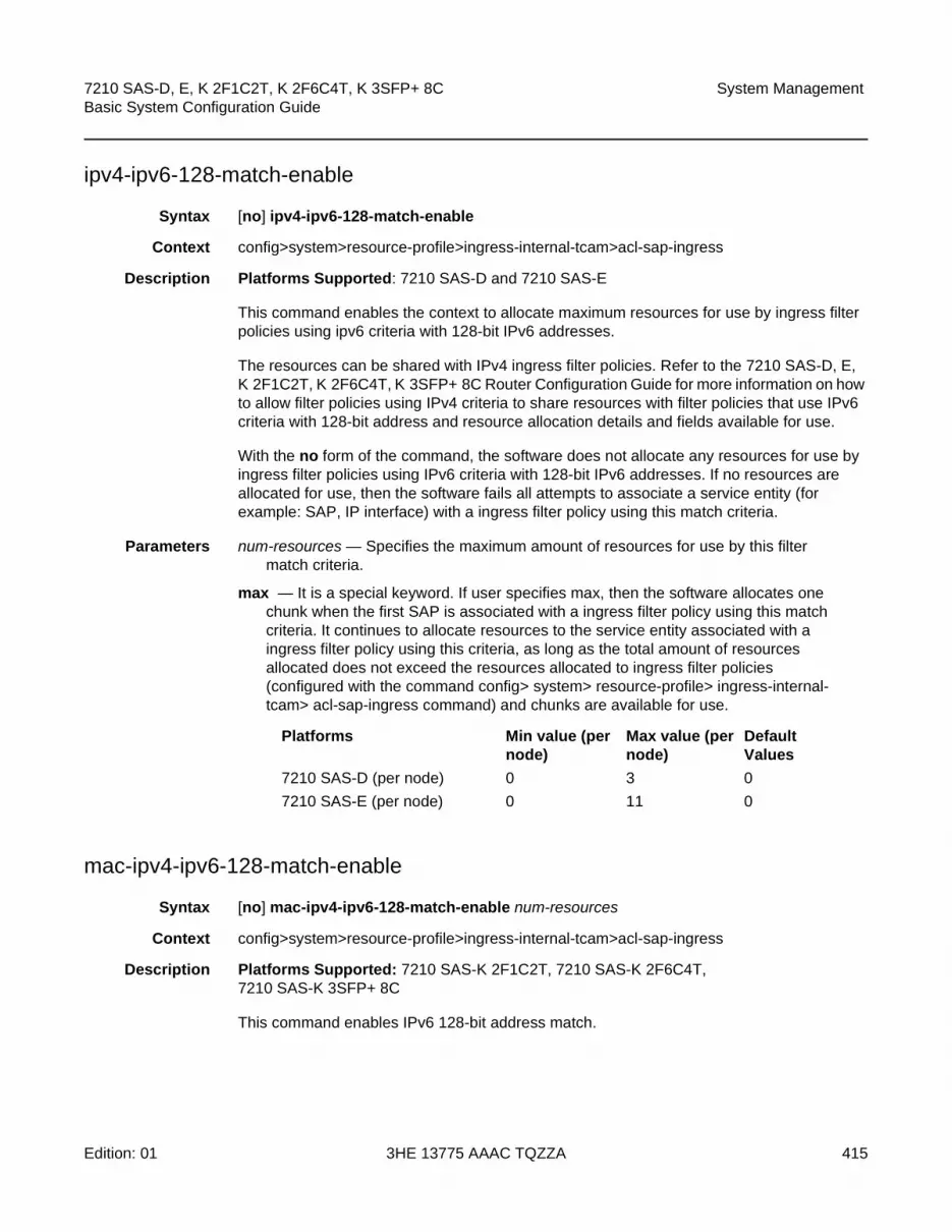
7210 SAS-D, E, K 2F1C2T, K 2F6C4T, K 3SFP+ 8C Basic System Configuration Guide
System Management
Edition: 01 3HE 13775 AAAC TQZZA 415
ipv4-ipv6-128-match-enable
Syntax [no] ipv4-ipv6-128-match-enable
Context config>system>resource-profile>ingress-internal-tcam>acl-sap-ingress
Description Platforms Supported: 7210 SAS-D and 7210 SAS-E
This command enables the context to allocate maximum resources for use by ingress filter policies using ipv6 criteria with 128-bit IPv6 addresses.
The resources can be shared with IPv4 ingress filter policies. Refer to the 7210 SAS-D, E, K 2F1C2T, K 2F6C4T, K 3SFP+ 8C Router Configuration Guide for more information on how to allow filter policies using IPv4 criteria to share resources with filter policies that use IPv6 criteria with 128-bit address and resource allocation details and fields available for use.
With the no form of the command, the software does not allocate any resources for use by ingress filter policies using IPv6 criteria with 128-bit IPv6 addresses. If no resources are allocated for use, then the software fails all attempts to associate a service entity (for example: SAP, IP interface) with a ingress filter policy using this match criteria.
Parameters num-resources — Specifies the maximum amount of resources for use by this filter match criteria.
max — It is a special keyword. If user specifies max, then the software allocates one chunk when the first SAP is associated with a ingress filter policy using this match criteria. It continues to allocate resources to the service entity associated with a ingress filter policy using this criteria, as long as the total amount of resources allocated does not exceed the resources allocated to ingress filter policies (configured with the command config> system> resource-profile> ingress-internal-tcam> acl-sap-ingress command) and chunks are available for use.
mac-ipv4-ipv6-128-match-enable
Syntax [no] mac-ipv4-ipv6-128-match-enable num-resources
Context config>system>resource-profile>ingress-internal-tcam>acl-sap-ingress
Description Platforms Supported: 7210 SAS-K 2F1C2T, 7210 SAS-K 2F6C4T, 7210 SAS-K 3SFP+ 8C
This command enables IPv6 128-bit address match.
Platforms Min value (per node)
Max value (per node)
Default Values
7210 SAS-D (per node) 0 3 0
7210 SAS-E (per node) 0 11 0

System Management
416
7210 SAS-D, E, K 2F1C2T, K 2F6C4T, K 3SFP+ 8CBasic System Configuration Guide
3HE 13775 AAAC TQZZA Edition: 01
When resources are allocated to ingress ACLs from the ingress internal TCAM pool using the command config>system>resource-profile>ingress-internal-tcam>acl-sap-ingress, these resources can be used by MAC criteria entries, IPv4 entries and entries that use only IPv6 64-bit addresses. In order to enable IPv6 128-bit address match, the user must allocate resources using this command.
The resources allocated can be shared by MAC criteria, IPv4 criteria, IPv6 64-bit address criteria and IPv6 128-bit address criteria. Each match entry (for all criteria) consumes two resources from this pool, reducing the number of filter entries that can be accommodated in a single chunk to 255 entries for the 7210 SAS-K 2F1C2T and 7210 SAS-K 2F6C4T, and 96 entries for the 7210 SAS-K 3SFP+ 8C.
With the no form of the command, the software does not allocate any resources for use by egress filter policies using IPv6 criteria with 128-bit IPv6 addresses. If no resources are allocated for use, then the software fails all attempts to associate a service entity (for example, SAP, IP interface) with a filter policy using this match criteria.
Default no mac-ipv4-ipv6-128-match-enable
Parameters num-resources — Specifies the maximum amount of resources for use by this filter match criteria.
Values 0 to 5 (7210 SAS-K 2F1C2T, 7210 SAS-K 2F6C4T)0 to 7 (7210 SAS-K 3SFP+ 8C)
Default 0
ipv4-mac-match-enable
Syntax [no] ipv4-mac-match-enable
Context config>system>resource-profile>ingress-internal-tcam>qos-sap-ingress-resource
Description Platforms Supported: 7210 SAS-D and 7210 SAS-E
This command enables the context to allocate maximum resources for use by SAP ingress QoS policies using both MAC (any) and IPv4 criteria (any) criteria in a policy.
The available resources is used by software to allocate resources for SAP ingress policies using the following criteria - either both IPv4 criteria any and MAC criteria any, only mac criteria any, only ipv4 criteria, dot1p-only criteria, ipv4 dscp-only criteria and ipv6 dscp-only criteria. It is not used for SAP ingress policies that use ipv6 criteria any.
See the7210 SAS-D, E Quality of Service Guide for more information about resource allocation and fields available for use.
With the no form of the command, the software does not allocate any resources for use by SAP ingress QoS policies using both MAC and IPv4 criteria. If no resources are allocated for use, then software fails all attempts to associate a service entity (For example: SAP, IP interface, etc.) with a ingress filter policy or SAP ingress QoS policy using this match criteria.

7210 SAS-D, E, K 2F1C2T, K 2F6C4T, K 3SFP+ 8C Basic System Configuration Guide
System Management
Edition: 01 3HE 13775 AAAC TQZZA 417
Parameters num-resources — Specifies the maximum amount of resources for use by this match criteria.
max - It is a special keyword. If user specifies max, then the software allocates one chunk when the first SAP is associated with a ingress filter policy using this match criteria. It continues to allocate resources to SAPs associated with a ingress filter policy using this criteria, as long as the total amount of resources allocated does not exceed the resources allocated to ingress filter policies (configured with the command config> system> resource-profile> ingress-internal-tcam>qos-sap-ingress-resource command) and chunks are available for use.
mac-ipv4-ipv6-128-match-enable
Syntax [no] mac-ipv4-ipv6-128-match-enable num-resources
Context config>system>resource-profile>ingress-internal-tcam>qos-sap-ingress-resource
Description Platforms Supported: 7210 SAS-K 2F1C2T, 7210 SAS-K 2F6C4T, 7210 SAS-K 3SFP+ 8C
This command enables the context to allocate maximum resources for use by SAP ingress QoS classification policies using IPv6 criteria with 128-bit IPv6 (source and destination IPv6) addresses.
When resources are allocated to SAP ingress classification from the ingress internal TCAM pool using the command config>system>resource-profile>ingress-internal-tcam>qos-sap-ingress-resource, these resources can be used by either MAC criteria entries or IPv4 criteria entries. In order to enable IPv6 128-bit address match, the user must allocate resources using this command.
The resources allocated can be shared by MAC criteria, IPv4 criteria, IPv6 64-bit address criteria and IPv6 128-bit address criteria. Each match entry (for all criteria) consumes two resources from this pool, reducing the number of classification entries that can be accommodated in a single chunk to 255 entries for the 7210 SAS-K 2F1C2T and 7210 SAS-K 2F6C4T, and 96 entries for the 7210 SAS-K 3SFP+ 8C.
With the no form of the command, the software does not allocate any resources for use by SAP ingress QoS classification rules using IPv6 criteria. If no resources are allocated for use, then the software fails all attempts to associate a service entity (for example: SAP or IP interface) with a policy using the IPv6 match criteria.
Default no mac-ipv4-ipv6-128-match-enable
Platforms Min value (per node)
Max value (per node)
Default Values
7210 SAS-D (per node) 0 3 max
7210 SAS-E (per node) 0 11 max

System Management
418
7210 SAS-D, E, K 2F1C2T, K 2F6C4T, K 3SFP+ 8CBasic System Configuration Guide
3HE 13775 AAAC TQZZA Edition: 01
Parameters num-resources — Specifies the maximum amount of resources for use by this match criteria.
Values 0 to 5 (7210 SAS-K 2F1C2T, 7210 SAS-K 2F6C4T)0 to 7 (7210 SAS-K 3SFP+ 8C)
Default 0
ipv4-match-enable
Syntax [no] ipv4-match-enable
Context config>system>resource-profile>ingress-internal-tcam>acl-sap-ingress
Description Platforms Supported: 7210 SAS-D and 7210 SAS-E
This command enables the context to allocate maximum resources for use by ingress filter policies using ipv4 criteria.
The resource cannot be shared with ingress filter policies using mac criteria or ipv6 criteria. Refer to the 7210 SAS-D, E, K 2F1C2T, K 2F6C4T, K 3SFP+ 8C Router Configuration Guide for more information on resource allocation details and fields available for use.
With the no form of the command, the software does not allocate any resources for use by ingress filter policies using ipv4 criteria. If no resources are allocated for use, then software fails all attempts to associate a service entity (For example: SAP, IP interface) with a ingress filter policy using this match criteria.
Parameters num-resources — Specifies the maximum amount of resources for use by this filter match criteria.
max — Allocates one chunk when the first SAP is associated with a ingress filter policy using this match criteria. It continues to allocate resources to SAPs associated with a ingress filter policy using this criteria, as long as the total amount of resources allocated does not exceed the resources allocated to ingress filter policies (configured with the command config> system> resource-profile> ingress-internal-tcam>acl-sap-ingress command) and chunks are available for use.
ipv4-match-enable
Syntax [no] ipv4-match-enable
Context config>system>resource-profile>ingress-internal-tcam>qos-sap-ingress-resource
Platforms Min value (per node)
Max value (per node)
Default Values
7210 SAS-D (per node) 0 3 max
7210 SAS-E (per node) 0 11 max

7210 SAS-D, E, K 2F1C2T, K 2F6C4T, K 3SFP+ 8C Basic System Configuration Guide
System Management
Edition: 01 3HE 13775 AAAC TQZZA 419
Description Platforms Supported: 7210 SAS-D and 7210 SAS-E
This command enables the context to allocate maximum resources for use by SAP ingress QoS policies using IPv4 criteria (any).
The resource cannot be shared with SAP ingress QoS filter policies using mac criteria or ipv6 criteria. Refer to the 7210 SAS-K 2F1C2T, K 2F6C4T, K 3SFP+ 8C Quality of Service Guide for more information on resource allocation details and fields available for use.
With the no form of the command, the software does not allocate any resources for use by SAP ingress QoS policies using ipv4 criteria. If no resources are allocated for use, then software fails all attempts to associate a service entity (For example: SAP, IP interface, etc.) with a SAP ingress QoS policy using this match criteria.
Parameters num-resources — Specifies the maximum amount of resources for use by this match criteria.
max — Allocates one chunk when the first SAP is associated with a SAP ingress QoS policy using this match criteria. It continues to allocate resources to SAPs associated with a SAP ingress QoS policy using this criteria, as long as the total amount of resources allocated does not exceed the resources allocated to SAP ingress QoS policies (configured with the command config> system> resource-profile> ingress-internal-tcam> qos-sap-ingress-resource command) and chunks are available for use.
ipv6-64-only-match-enable
Syntax [no] ipv6-64-only-match-enable
Context config>system>resource-profile>ingress-internal-tcam>acl-sap-ingress
Description Platforms Supported: 7210 SAS-D and 7210 SAS-E
This command enables the context to allocate maximum resources for use by ingress filter policies using ipv6 criteria with 64-bit IPv6 addresses. Refer to the 7210 SAS-D, E, K 2F1C2T, K 2F6C4T, K 3SFP+ 8C Router Configuration Guide for more information on resource allocation details and fields available for use.
The resources cannot be shared with IPv4 filter policies or IPv6 filter policies specifying 128-bit addresses.
With the no form of the command, the software does not allocate any resources for use by filter policies using ipv6 criteria with 64-bit IPv6 addresses. If no resources are allocated for use, then software fails all attempts to associate a service entity (For example: SAP, IP interface, etc.) with a ingress filter policy using this match criteria.
Platforms Min value (per node)
Max value (per node) Default Values
7210 SAS-D (per node) 0 3 maximum
7210 SAS-E (per node) 0 11 maximum

System Management
420
7210 SAS-D, E, K 2F1C2T, K 2F6C4T, K 3SFP+ 8CBasic System Configuration Guide
3HE 13775 AAAC TQZZA Edition: 01
Parameters num-resources — Specifies the maximum amount of resources for use by this filter match criteria.
max — Allocates one chunk when the first SAP is associated with a ingress filter policy using this match criteria. It continues to allocate resources to SAPs associated with a ingress filter policy using this criteria, as long as the total amount of resources allocated does not exceed the resources allocated to ingress filter policies (configured with the command config> system> resource-profile> ingress-internal-tcam>acl-sap-ingress command) and chunks are available for use.
mac-match-enable
Syntax [no] mac-match-enable
Context config>system>resource-profile>ingress-internal-tcam>acl-sap-ingress
Description Platforms Supported: 7210 SAS-D and 7210 SAS-E
This command enables the context to allocate maximum resources for use by ingress filter policies using mac criteria.
The resources cannot be shared with policies that use either IPv4 or IPv6 match criteria. For more details about the resource allocation for ingress filter policy and fields available for use with ingress filter policy, refer to the 7210 SAS-D, E, K 2F1C2T, K 2F6C4T, K 3SFP+ 8C Router Configuration Guide.
With the no form of the command, the software does not allocate any resources for use by ingress filter policies using mac criteria. If no resources are allocated for use, then software fails all attempts to associate a service entity (For example: SAP, IP interface, etc.) with a ingress filter policy using this match criteria.
Parameters num-resources — Specifies the maximum amount of resources for use by this filter match criteria.
max — Allocates one chunk when the first SAP is associated with a ingress filter policy using this match criteria. It continues to allocate resources to SAPs associated with a ingress filter policy using this criteria, as long as the total amount of resources allocated does not exceed the resources allocated to ingress filter policies (configured with the command config> system> resource-profile> ingress-internal-tcam>acl-sap-ingress command) and chunks are available for use.
Note: On the 7210 SAS-D, mac-criteria SAP ingress QoS policies get to use an additional 128 classification entries with 64 meters. These entries are allocated to mac-criteria SAP ingress QoS resource pool by default and cannot be reassigned to any another feature or any other match criteria.
Platforms Min value (per node)
Max value (per node)
Default Values
7210 SAS-D (per node) 0 3 maximum
7210 SAS-E(per node) 0 11 maximum

7210 SAS-D, E, K 2F1C2T, K 2F6C4T, K 3SFP+ 8C Basic System Configuration Guide
System Management
Edition: 01 3HE 13775 AAAC TQZZA 421
mac-match-enable
Syntax [no] mac-match-enable
Context config>system>resource-profile>ingress-internal-tcam> qos-sap-ingress-resource
Description Platforms Supported: 7210 SAS-D and 7210 SAS-E
This command enables the context to allocate maximum resources for use by SAP ingress QoS policies using MAC criteria (any).
The resources cannot be shared with policies that use either IPv4 or IPv6 match criteria. For more details about the resource allocation for SAP ingress QoS policy, refer to the 7210 SAS-K 2F1C2T, K 2F6C4T, K 3SFP+ 8C Quality of Service Guide.
With the no form of the command, the software does not allocate any resources for use by SAP ingress QoS policies using mac criteria. If no resources are allocated for use, then software fails all attempts to associate a service entity (for example, SAP, IP interface) with a SAP ingress QoS policy using this match criteria.
Parameters num-resources — Specifies the maximum amount of resources for use by this filter match criteria.
max — Allocates one chunk when the first SAP is associated with a ingress filter policy using this match criteria. It continues to allocate resources to SAPs associated with SAP ingress QoS policy using this criteria, as long as the total amount of resources allocated does not exceed the resources allocated to SAP ingress QoS policies (configured with the command config> system> resource-profile> ingress-internal-tcam>qos-sap-ingress-resource command) and chunks are available for use.
NOTE: On the 7210 SAS-D, mac-criteria SAP ingress QoS policies get to use an additional 128 classification entries with 64 meters. These entries are allocated to mac-criteria SAP ingress QoS resource pool by default and cannot be reassigned to any another feature or any other match criteria.
Platforms Min value (per node)
Max value (per node)
Default Values
7210 SAS-D (per node) 0 3 maximum
7210 SAS-E (per node) 0 11 maximum
Platforms Min value (per node)
Max value (per node) Default Values
7210 SAS-D (per node) 0 3 maximum
7210 SAS-E (per node) 0 11 maximum

System Management
422
7210 SAS-D, E, K 2F1C2T, K 2F6C4T, K 3SFP+ 8CBasic System Configuration Guide
3HE 13775 AAAC TQZZA Edition: 01
dhcp-snooping-enable
Syntax [no] dhcp-snooping-enable
Context config>system>resource-profile>ingress-internal-tcam
Description Platforms Supported: 7210 SAS-E
This command enables the context to allocate resources for use by DHCP snooping features from the ingress internal TCAM resource pool. Before using the dhcp-snooping feature, user must allocate resources to it using this command, else software will disallow configuration of DHCP snooping command under the service. To allocate resources to the dhcp snooping features, user will need to reduce the resources used by other features, such as ingress ACLs, or SAP ingress QoS, or others, which have been allocated resources from the ingress internal tcam resource pool and allocate it to this feature. Executing this command allocates only a single chunk of resources for use by dhcp-snooping feature.
The command tools>dump> system-resources can be used to check the resource usage. The sample output below shows that a single slice with 256 entries has been allocated to the DHCP snooping feature.
| Total | Allocated | Free
-------------------------------+-----------+-----------+------------>> DHCP Snooping Sap Entries | 251| 50| 250
With the no form of the command, software does not allocate any resources for use by dhcp snooping feature and the feature cannot be used any more. A reboot is required after executing the no form of the command for it to take effect.
Default no dhcp-snooping-enable
eth-cfm
Syntax [no] eth-cfm
Context config>system>resource-profile>ingress-internal-tcam
Description Platforms Supported: 7210 SAS-D
This command enables the context to allocate resources for CFM UP MEPs.
With the no form of the command, the software does not allocate any resources for use by CFM UP MEPs.
Note: CFM Down MEPs do not require explicit resource allocation by the user.

7210 SAS-D, E, K 2F1C2T, K 2F6C4T, K 3SFP+ 8C Basic System Configuration Guide
System Management
Edition: 01 3HE 13775 AAAC TQZZA 423
Parameters num-resources — Specifies the maximum amount of resources for use by eth-cfm.
up-mep
Syntax [no] up-mep
Context config>system>resource-profile>ingress-internal-tcam>eth-cfm
Description Platforms Supported: 7210 SAS-D
This command enables the context to allocate resources for CFM UP MEPs.
Resources for UP MEPs created on SAP and SDP Bindings are allocated from this pool.
With the no form of the command, the software does not allocate any resources for use by CFM UP MEPs. If no resources are allocated for use, then software fails all attempts to configure an UP MEP.
Default 0
Parameters num-resources — Specifies the maximum amount of resources for use by up-mep.
Values 0 to 2
ipv6-ipv4-match-enable
Syntax ipv6-ipv4-match-enable
no ipv6-ipv4-match-enable
Context config>system>resource-profile>ingress-internal-tcam>qos-sap-ingress-resource
Description Platforms Supported: 7210 SAS-D and 7210 SAS-E
This command enables the context to allocate resources from the SAP ingress QoS resource pool for ipv6-criteria by using the command config>system>resource-profile>ingress-internal-tcam>qos-sap-ingress-resource>ipv6-ipv4-match-enable before using IPv6 criteria SAP ingress QoS policies.
Platforms Min value (per node)
Max value (per node)
Default
7210 SAS-D (per node) 0 1 0
Note:
• CFM Down MEPs do not require explicit resource allocation by the user.
• Resource allocation for UP MEPs is only supported on the 7210 SAS-D.

System Management
424
7210 SAS-D, E, K 2F1C2T, K 2F6C4T, K 3SFP+ 8CBasic System Configuration Guide
3HE 13775 AAAC TQZZA Edition: 01
These resources can be shared with SAP ingress policies that use IPv4 criteria. For more details about the resource allocation for SAP ingress QoS policy, refer to the 7210 SAS-D, E, K 2F1C2T, K 2F6C4T, K 3SFP+ 8C Router Configuration Guide.
With the no form of the command, the software does not allocate any resources for use by ingress SAP QoS policies using IPv6 criteria. If no resources are allocated for use, then software fails all attempts to associate a service entity (For example: SAP, IP interface, etc.) with a ingress filter policy using this match criteria.
Parameters num-resources — Specifies the maximum amount of resources for use by this SAP ingress Qos policy match criteria.
max — Allocates one chunk when the first SAP is associated with a SAP ingress QoS policy using this match criteria. It continues to allocate resources to SAPs associated with SAP ingress QoS policy using this criteria, as long as the total amount of resources allocated does not exceed the resources allocated to SAP ingress QoS policies (configured with the command config> system> resource-profile> ingress-internal-tcam> qos-sap-ingress-resource command) and chunks are available for use.
Values
qos-sap-ingress-resource
Syntax qos-sap-ingress-resource
no qos-sap-ingress-resource
Context config>system>resource-profile>ingress-internal-tcam
SupportedPlatforms
Supported on all 7210 SAS platforms as described in this document
Description This command enables the context to allocate maximum resources for use by SAP ingress QoS policies using any of the supported match criteria. This command limits the total amount of chunks allocated for use by SAP ingress QoS policies to the value specified by num-resources. In other words, the cumulative sum of chunks allocated to different match criteria supported by SAP ingress QoS policies cannot exceed the value configured with num-resources.
If no resources are allocated for use, then the software fails all attempts to associate a service entity (for example: SAP, IP interface, and other service entities) with a SAP ingress QoS policy using any of the match criteria.
Platforms Min value (per node)
Max value (per node)
Default Values
7210 SAS-D (per node) 0 6 maximum
7210 SAS-E (per node) 0 3 maximum
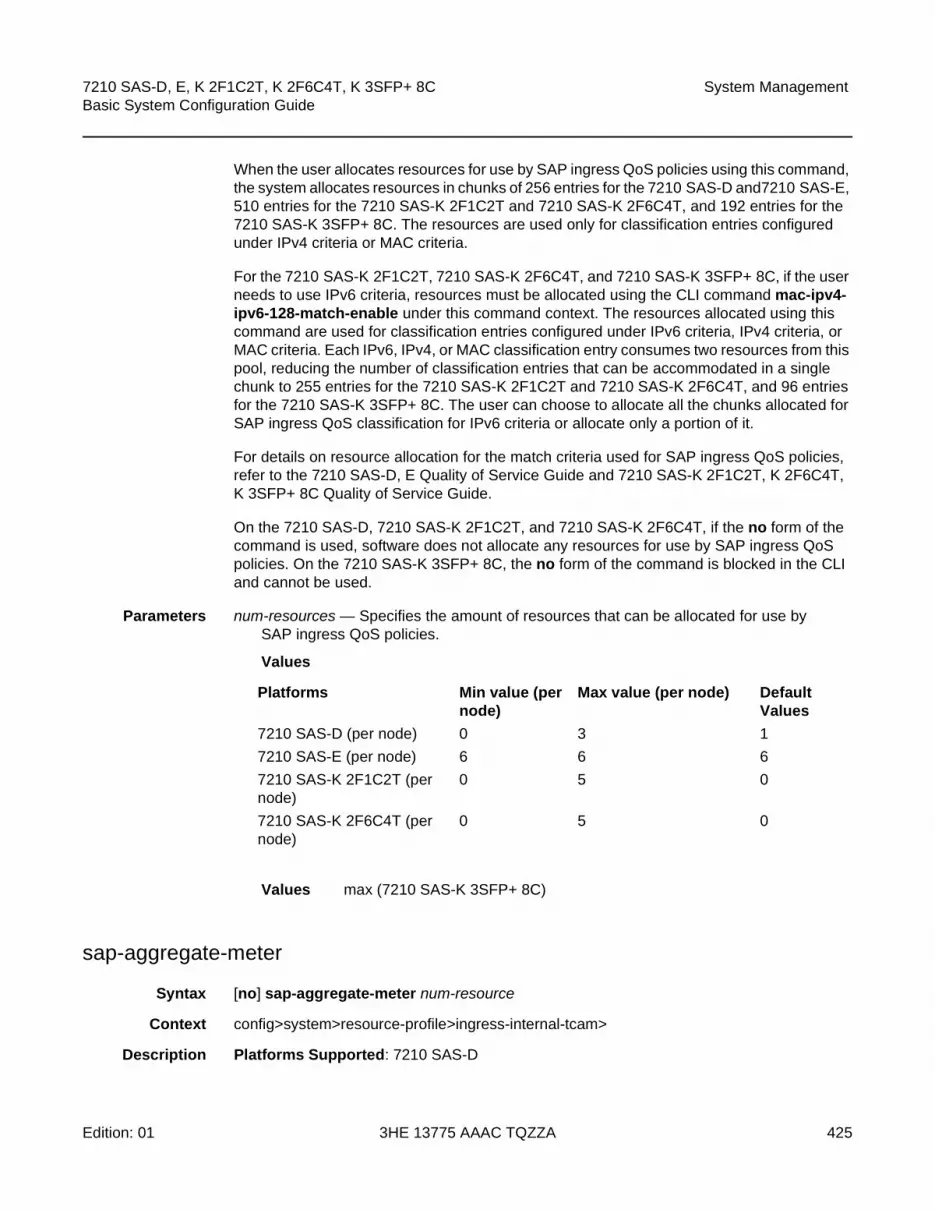
7210 SAS-D, E, K 2F1C2T, K 2F6C4T, K 3SFP+ 8C Basic System Configuration Guide
System Management
Edition: 01 3HE 13775 AAAC TQZZA 425
When the user allocates resources for use by SAP ingress QoS policies using this command, the system allocates resources in chunks of 256 entries for the 7210 SAS-D and7210 SAS-E, 510 entries for the 7210 SAS-K 2F1C2T and 7210 SAS-K 2F6C4T, and 192 entries for the 7210 SAS-K 3SFP+ 8C. The resources are used only for classification entries configured under IPv4 criteria or MAC criteria.
For the 7210 SAS-K 2F1C2T, 7210 SAS-K 2F6C4T, and 7210 SAS-K 3SFP+ 8C, if the user needs to use IPv6 criteria, resources must be allocated using the CLI command mac-ipv4-ipv6-128-match-enable under this command context. The resources allocated using this command are used for classification entries configured under IPv6 criteria, IPv4 criteria, or MAC criteria. Each IPv6, IPv4, or MAC classification entry consumes two resources from this pool, reducing the number of classification entries that can be accommodated in a single chunk to 255 entries for the 7210 SAS-K 2F1C2T and 7210 SAS-K 2F6C4T, and 96 entries for the 7210 SAS-K 3SFP+ 8C. The user can choose to allocate all the chunks allocated for SAP ingress QoS classification for IPv6 criteria or allocate only a portion of it.
For details on resource allocation for the match criteria used for SAP ingress QoS policies, refer to the 7210 SAS-D, E Quality of Service Guide and 7210 SAS-K 2F1C2T, K 2F6C4T, K 3SFP+ 8C Quality of Service Guide.
On the 7210 SAS-D, 7210 SAS-K 2F1C2T, and 7210 SAS-K 2F6C4T, if the no form of the command is used, software does not allocate any resources for use by SAP ingress QoS policies. On the 7210 SAS-K 3SFP+ 8C, the no form of the command is blocked in the CLI and cannot be used.
Parameters num-resources — Specifies the amount of resources that can be allocated for use by SAP ingress QoS policies.
Values
Values max (7210 SAS-K 3SFP+ 8C)
sap-aggregate-meter
Syntax [no] sap-aggregate-meter num-resource
Context config>system>resource-profile>ingress-internal-tcam>
Description Platforms Supported: 7210 SAS-D
Platforms Min value (per node)
Max value (per node) Default Values
7210 SAS-D (per node) 0 3 1
7210 SAS-E (per node) 6 6 6
7210 SAS-K 2F1C2T (per node)
0 5 0
7210 SAS-K 2F6C4T (per node)
0 5 0

System Management
426
7210 SAS-D, E, K 2F1C2T, K 2F6C4T, K 3SFP+ 8CBasic System Configuration Guide
3HE 13775 AAAC TQZZA Edition: 01
This command enables the context to allocate maximum resources for use by meters/policers used to implement SAP ingress aggregate meter functionality from the global pool of ingress CAM resources. Before using the command configure> service> sap> ingress> aggregate-meter-rate user must ensure that resources are allocated to aggregate meters using this command.
This command allocates meter resources from the available global ingress CAM resource pool. By default, when resources are allocated to SAP ingress QoS policy, along with the CAM classification entries, meter resources are also allocated. If the user needs to use SAP aggregate meter functionality they cannot allocate all the available resources in the global resource pool to SAP ingress QoS policies and ETH-CFM UP MEP. They need to allocate some resources for use by SAP aggregate meter (or SAP ingress ACLs or G8032-fast-flood feature).
By default, when resources are allocated for ingress ACLs, only classification entries are used and meters resources are not used. SAP aggregate meter resources can use meters from this pool of meter resources. In other words, SAP aggregate meters are stolen from the unused meters in the resources allocated to ingress ACLs.
If the user allocates resources for ingress ACLs and then configures resources for SAP aggregate meter using this command, then the software does the following:
• It does not allocate any additional chunks/resources from the available global ingress CAM resource pool to SAP aggregate meter, if it can allocate the required number of meters from the chunks/resources allocated to ingress ACLs. For example, if user has allocated 2 chunks of 510 entries each for ingress ACLs and then configures sap-aggregate-meter to use 2 chunks to use about 510 aggregate meters, then the software will not allocate any additional entries from the available global resource pool.
• If the number of ingress ACL resources allocated by user is less than the number of resources assigned by the user to sap-aggregate-meter (or if no resources are allocated to G8032), then it allocates the difference from the available global ingress CAM resource pool. For example, if user has allocated 1 chunk of 510 entries for ingress ACLs and then configures sap-aggregate-meter to use 2 chunks to use about 510 aggregate meters, then the software will allocate 1 additional chunk (2 chunks required for SAP aggregate - 1 chunk alloted to ingress ACLs) for use with SAP aggregate meter. The classification entries associated with additional chunk alloted for SAP aggregate-meter can be used by the ingress ACLs policies. It cannot be used by SAP ingress QoS policies and eth-cfm UP MEP.
Similar checks as above are performed when user allocates resources for SAP aggregate meters using this command and then configures resources for ingress ACLs (or for G8032-fast-flood feature). That is, the software does the following:
Note: For the command to take effect, the node must be rebooted after making the change.
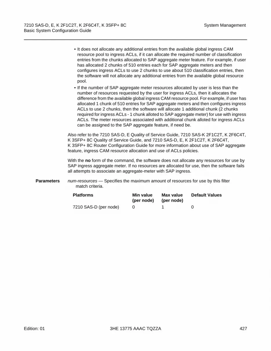
7210 SAS-D, E, K 2F1C2T, K 2F6C4T, K 3SFP+ 8C Basic System Configuration Guide
System Management
Edition: 01 3HE 13775 AAAC TQZZA 427
• It does not allocate any additional entries from the available global ingress CAM resource pool to ingress ACLs, if it can allocate the required number of classification entries from the chunks allocated to SAP aggregate meter feature. For example, if user has allocated 2 chunks of 510 entries each for SAP aggregate meters and then configures ingress ACLs to use 2 chunks to use about 510 classification entries, then the software will not allocate any additional entries from the available global resource pool.
• If the number of SAP aggregate meter resources allocated by user is less than the number of resources requested by the user for ingress ACLs, then it allocates the difference from the available global ingress CAM resource pool. For example, if user has allocated 1 chunk of 510 entries for SAP aggregate meters and then configures ingress ACLs to use 2 chunks, then the software will allocate 1 additional chunk (2 chunks required for ingress ACLs - 1 chunk alloted to SAP aggregate meter) for use with ingress ACLs. The meter resources associated with additional chunk alloted for ingress ACLs can be assigned to the SAP aggregate feature, if need be.
Also refer to the 7210 SAS-D, E Quality of Service Guide, 7210 SAS-K 2F1C2T, K 2F6C4T, K 3SFP+ 8C Quality of Service Guide, and 7210 SAS-D, E, K 2F1C2T, K 2F6C4T, K 3SFP+ 8C Router Configuration Guide for more information about use of SAP aggregate feature, ingress CAM resource allocation and use of ACLs policies.
With the no form of the command, the software does not allocate any resources for use by SAP ingress aggregate meter. If no resources are allocated for use, then the software fails all attempts to associate an aggregate-meter with SAP ingress.
Parameters num-resources — Specifies the maximum amount of resources for use by this filter match criteria.
Platforms Min value (per node)
Max value (per node)
Default Values
7210 SAS-D (per node) 0 1 0
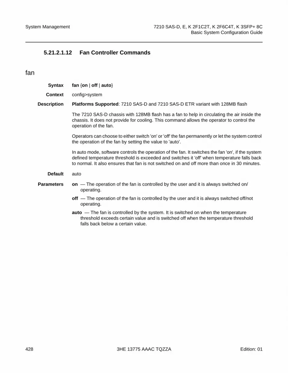
System Management
428
7210 SAS-D, E, K 2F1C2T, K 2F6C4T, K 3SFP+ 8CBasic System Configuration Guide
3HE 13775 AAAC TQZZA Edition: 01
5.21.2.1.12 Fan Controller Commands
fan
Syntax fan {on | off | auto}
Context config>system
Description Platforms Supported: 7210 SAS-D and 7210 SAS-D ETR variant with 128MB flash
The 7210 SAS-D chassis with 128MB flash has a fan to help in circulating the air inside the chassis. It does not provide for cooling. This command allows the operator to control the operation of the fan.
Operators can choose to either switch 'on' or 'off' the fan permanently or let the system control the operation of the fan by setting the value to 'auto'.
In auto mode, software controls the operation of the fan. It switches the fan 'on', if the system defined temperature threshold is exceeded and switches it 'off' when temperature falls back to normal. It also ensures that fan is not switched on and off more than once in 30 minutes.
Default auto
Parameters on — The operation of the fan is controlled by the user and it is always switched on/operating.
off — The operation of the fan is controlled by the user and it is always switched off/not operating.
auto — The fan is controlled by the system. It is switched on when the temperature threshold exceeds certain value and is switched off when the temperature threshold falls back below a certain value.

7210 SAS-D, E, K 2F1C2T, K 2F6C4T, K 3SFP+ 8C Basic System Configuration Guide
System Management
Edition: 01 3HE 13775 AAAC TQZZA 429
5.21.2.2 Show Commands
5.21.2.2.1 System Commands
connections
Syntax connections [address ip-address [interface interface-name]] [port port-number] [detail]
Context show>system
SupportedPlatforms
Supported on all 7210 SAS platforms as described in this document
Description This command displays UDP and TCP connection information.If no command line options are specified, a summary of the TCP and UDP connections displays.
Parameters ip-address — Displays only the connection information for the specified IP address.
Values
port-number — Displays only the connection information for the specified port number.
Values 0 to 65535
detail — Appends TCP statistics to the display output.
Output Standard Connection Output
The following outputs are examples of system connections information, and Table 37 describes the output fields.
Sample Output
A:ALA-12# show system connections===============================================================================Connections :===============================================================================Proto RecvQ TxmtQ Local Address Remote Address State-------------------------------------------------------------------------------TCP 0 0 0.0.0.0.21 0.0.0.0.0 LISTENTCP 0 0 0.0.0.0.23 0.0.0.0.0 LISTEN
ipv4-address: a.b.c.d (host bits must be 0)
ipv6-address - x:x:x:x:x:x:x:x (eight 16-bit pieces)
x:x:x:x:x:x:d.d.d.d
x - [0..FFFF]H
d - [0..255]D

System Management
430
7210 SAS-D, E, K 2F1C2T, K 2F6C4T, K 3SFP+ 8CBasic System Configuration Guide
3HE 13775 AAAC TQZZA Edition: 01
TCP 0 0 0.0.0.0.179 0.0.0.0.0 LISTENTCP 0 0 10.0.0.xxx.51138 10.0.0.104.179 SYN_SENTTCP 0 0 10.0.0.xxx.51139 10.0.0.91.179 SYN_SENTTCP 0 0 10.10.10.xxx.646 0.0.0.0.0 LISTENTCP 0 0 10.10.10.xxx.646 10.10.10.104.49406 ESTABLISHEDTCP 0 0 10.1.0.1.51140 10.1.0.2.179 SYN_SENTTCP 0 993 192.168.x.xxx.23 192.168.x.xx.xxxx ESTABLISHEDUDP 0 0 0.0.0.0.123 0.0.0.0.0 ---UDP 0 0 0.0.0.0.646 0.0.0.0.0 ---UDP 0 0 0.0.0.0.17185 0.0.0.0.0 ---UDP 0 0 10.10.10.xxx.646 0.0.0.0.0 ---UDP 0 0 xxx.0.0.1.50130 xxx.0.0.1.17185 ----------------------------------------------------------------------------------No. of Connections: 14===============================================================================A:ALA-12#
Sample Detailed Output
A:ALA-12# show system connections detail-------------------------------------------------------------------------------TCP Statistics
-------------------------------------------------------------------------------packets sent : 659635data packets : 338982 (7435146 bytes)data packet retransmitted : 73 (1368 bytes)ack-only packets : 320548 (140960 delayed)URG only packet : 0window probe packet : 0window update packet : 0control packets : 32packets received : 658893acks : 338738 for (7435123 bytes)duplicate acks : 23ack for unsent data : 0packets received in-sequence : 334705 (5568368 bytes)completely duplicate packet : 2 (36 bytes)packet with some dup. data : 0 (0 bytes)out-of-order packets : 20 (0 bytes)packet of data after window : 0 (0 bytes)window probe : 0window update packet : 3packets received after close : 0discarded for bad checksum : 0discarded for bad header offset field : 0discarded because packet too short : 0connection request : 4connection accept : 24connections established (including accepts) : 27connections closed : 26 (including 2 drops)embryonic connections dropped : 0segments updated rtt : 338742 (of 338747 attempts)retransmit timeouts : 75connections dropped by rexmit timeout : 0persist timeouts : 0keepalive timeouts : 26keepalive probes sent : 0connections dropped by keepalive : 1
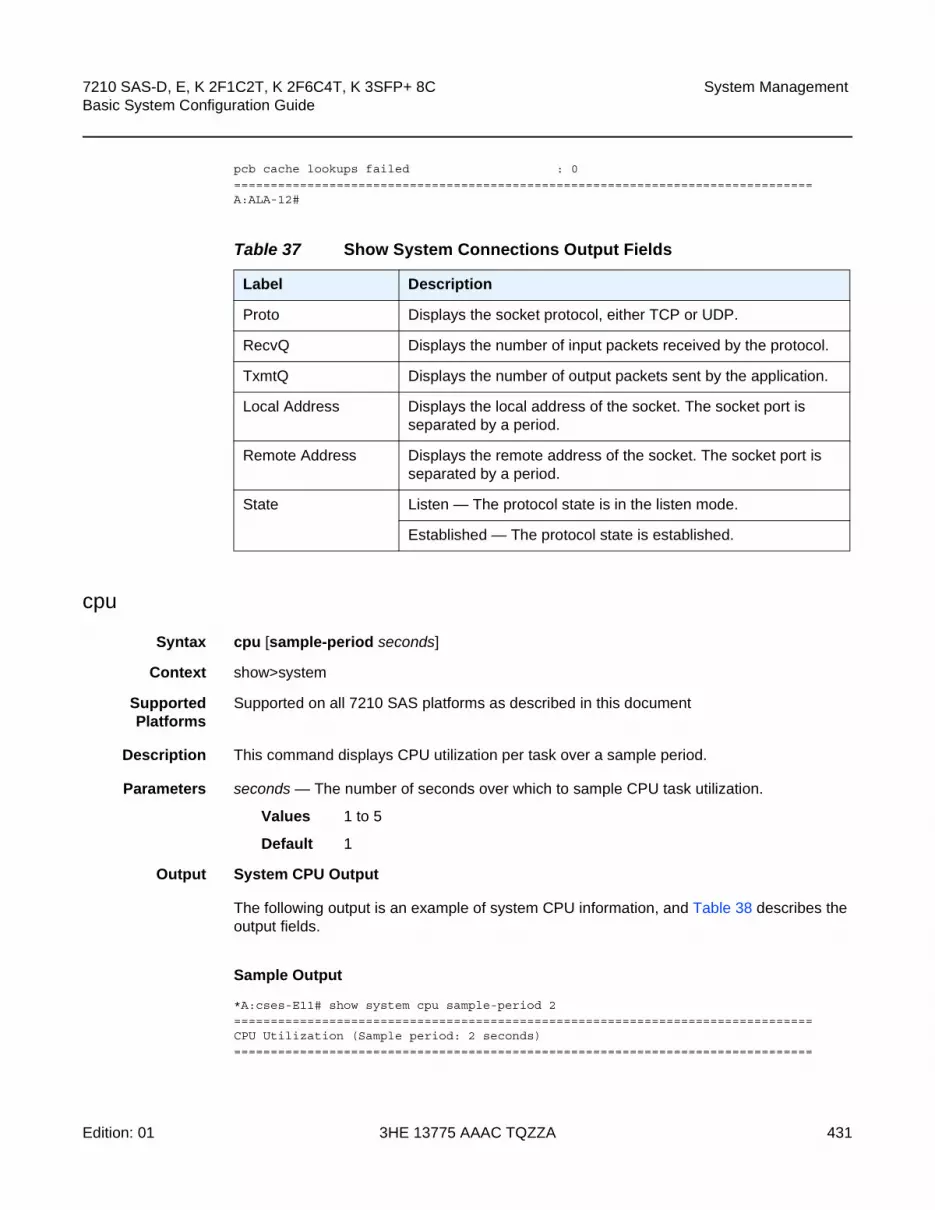
7210 SAS-D, E, K 2F1C2T, K 2F6C4T, K 3SFP+ 8C Basic System Configuration Guide
System Management
Edition: 01 3HE 13775 AAAC TQZZA 431
pcb cache lookups failed : 0===============================================================================A:ALA-12#
cpu
Syntax cpu [sample-period seconds]
Context show>system
SupportedPlatforms
Supported on all 7210 SAS platforms as described in this document
Description This command displays CPU utilization per task over a sample period.
Parameters seconds — The number of seconds over which to sample CPU task utilization.
Values 1 to 5
Default 1
Output System CPU Output
The following output is an example of system CPU information, and Table 38 describes the output fields.
Sample Output
*A:cses-E11# show system cpu sample-period 2===============================================================================CPU Utilization (Sample period: 2 seconds)===============================================================================
Table 37 Show System Connections Output Fields
Label Description
Proto Displays the socket protocol, either TCP or UDP.
RecvQ Displays the number of input packets received by the protocol.
TxmtQ Displays the number of output packets sent by the application.
Local Address Displays the local address of the socket. The socket port is separated by a period.
Remote Address Displays the remote address of the socket. The socket port is separated by a period.
State Listen — The protocol state is in the listen mode.
Established — The protocol state is established.

System Management
432
7210 SAS-D, E, K 2F1C2T, K 2F6C4T, K 3SFP+ 8CBasic System Configuration Guide
3HE 13775 AAAC TQZZA Edition: 01
Name CPU Time CPU Usage Capacity(uSec) Usage
-------------------------------------------------------------------------------BFD 10 ~0.00% ~0.00%
Cards & Ports 8,332 0.41% 0.08%
IS-IS 1,213 0.06% 0.06%ISA 2,496 0.12% 0.07%LDP 0 0.00% 0.00%Logging 32 ~0.00% ~0.00%
MSDP 0 0.00% 0.00%Management 5,969 0.29% 0.15%OAM 907 0.04% 0.02%OSPF 25 ~0.00% ~0.00%
Redundancy 3,635 0.18% 0.13%SIM 1,462 0.07% 0.04%SNMP Daemon 0 0.00% 0.00%Services 2,241 0.11% 0.05%Stats 0 0.00% 0.00%Subscriber Mgmt 2,129 0.10% 0.04%System 8,802 0.43% 0.17%Traffic Eng 0 0.00% 0.00%
WEB Redirect 125 ~0.00% ~0.00%-------------------------------------------------------------------------------Total 2,014,761 100.00%
Idle 1,945,113 96.54%Usage 69,648 3.45%
Busiest Core Utilization 69,648 3.45%===============================================================================*A:cses-E11#
Table 38 Show System CPU Output Fields
Label Description
CPU Utilization The total amount of CPU time.
Name The process or protocol name.
CPU Time (uSec) The CPU time each process or protocol has used in the specified time.
CPU Usage The sum of CPU usage of all the processes and protocols.

7210 SAS-D, E, K 2F1C2T, K 2F6C4T, K 3SFP+ 8C Basic System Configuration Guide
System Management
Edition: 01 3HE 13775 AAAC TQZZA 433
cron
Syntax cron
Context show>system
SupportedPlatforms
Supported on all 7210 SAS platforms as described in this document
Description This command enters the show CRON context.
schedule
Syntax schedule [schedule-name] [owner schedule-owner]
Context show>system>cron
Description Platforms Supported: 7210 SAS-D, 7210 SAS-K 2F1C2T, 7210 SAS-K 2F6C4T, 7210 SAS-K 3SFP+ 8C
This command displays cron schedule parameters.
Parameters schedule-name — Displays information for the specified scheduler name.
schedule-owner — Displays information for the specified scheduler owner.
Output The following output is an example of cron schedule information, and Table 39 describes the output fields.
Sample Output
A:sim1>show>system>cron schedule test===============================================================================CRON Schedule Information===============================================================================Schedule : test
Capacity Usage Displays the level the specified service is being utilized. When this number hits 100%, this part of the system is busied out. There may be extra CPU cycles still left for other processes, but this service is running at capacity.
This column does not reflect the true CPU utilization value; that data is still available in the CPU Usage column. This column is the busiest task in each group, where busiest is defined as either actually running or blocked attempting to acquire a lock.
Table 38 Show System CPU Output Fields (Continued)
Label Description

System Management
434
7210 SAS-D, E, K 2F1C2T, K 2F6C4T, K 3SFP+ 8CBasic System Configuration Guide
3HE 13775 AAAC TQZZA Edition: 01
Schedule owner : TiMOS CLIDescription : noneAdministrative status : enabledOperational status : enabledScript Policy : testScript Policy Owner : TiMOS CLIScript : testScript Owner : TiMOS CLIScript source location : ftp://*****:******@192.168.15.1/home/testlab_bgp
/cron/test1.cfgScript results location : ftp://*****:******@192.168.15.1/home/testlab_bgp
/cron/resSchedule type : periodicInterval : 0d 00:01:00 (60 seconds)Repeat count : 10Next scheduled run : 0d 00:00:42End time : noneWeekday : tuesdayMonth : noneDay of month : noneHour : noneMinute : noneNumber of schedule runs : 10Last schedule run : 2008/01/01 17:20:52Number of schedule failures : 0Last schedule failure : no errorLast failure time : never===============================================================================A:sim1>show>cron
Table 39 Show cron Schedule Output Fields
Label Description
Schedule name Displays the schedule name.
Schedule owner Displays the owner name of the action.
Description Displays the schedule’s description.
Administrative status
Enabled
The administrative status is enabled.
Disabled
Administratively disabled.
Operational status Enabled
The operational status is enabled.
Disabled
Operationally disabled.
Script Policy Displays the script policy name
Script Policy Owner Displays the name of script policy owner.

7210 SAS-D, E, K 2F1C2T, K 2F6C4T, K 3SFP+ 8C Basic System Configuration Guide
System Management
Edition: 01 3HE 13775 AAAC TQZZA 435
Script Displays the name of the script.
Script owner Displays the name of the of script owner.
Script source location Displays the location of scheduled script.
Script results location Displays the location where the script results have been sent.
Schedule type Periodic
Displays a schedule which ran at a given interval.
Calendar
Displays a schedule which ran based on a calendar.
Oneshot
Displays a schedule which ran one time only.
Interval Displays the interval between runs of an event.
Repeat count Displays the total number of times a CRON “interval” schedule is run.
Next scheduled run Displays the time for the next scheduled run.
End time Displays the end time of the schedule.
Weekday Displays the configured weekday.
Month Displays the configured month.
Day of Month Displays the configured day of month.
Hour Displays the configured hour.
Minute Displays the configured minute.
Number of scheduled runs
Displays the number of scheduled sessions.
Last scheduled run Displays the last scheduled session.
Number of scheduled failures
Displays the number of scheduled sessions that failed to execute.
Last scheduled failure Displays the last scheduled session that failed to execute.
Last failure time Displays the system time of the last failure.
Table 39 Show cron Schedule Output Fields (Continued)
Label Description

System Management
436
7210 SAS-D, E, K 2F1C2T, K 2F6C4T, K 3SFP+ 8CBasic System Configuration Guide
3HE 13775 AAAC TQZZA Edition: 01
information
Syntax information
Context show>system
SupportedPlatforms
Supported on all 7210 SAS platforms as described in this document
Description This command displays general system information including basic system, SNMP server, last boot and DNS client information.
Output System Information Output
The following output is an example of system information, and Table 40 describes the output fields.
Sample Output
===============================================================================System Information===============================================================================System Name : PE4-M2System Type :System Version : B-9.0.F-privateSystem Contact :System Location :System Coordinates :System Up Time : 10 days, 06:50:01.84 (hr:min:sec)
SNMP Port : 161SNMP Engine ID : 0000197f0000c408416161a3SNMP Engine Boots : 571SNMP Max Message Size : 1500SNMP Admin State : DisabledSNMP Oper State : DisabledSNMP Index Boot Status : Not PersistentSNMP Sync State : N/A
Tel/Tel6/SSH/FTP Admin : Disabled/Disabled/Enabled/DisabledTel/Tel6/SSH/FTP Oper : Down/Down/Up/Down
BOF Source : cf1:Image Source : primaryConfig Source : primaryLast Booted Config File : cf1:\mvpn_head.cfgLast Boot Cfg Version : MON SEP 26 04:48:37 2016 UTCLast Boot Config Header: N/ALast Boot Index Version : N/ALast Boot Index Header : N/ALast Saved Config : N/ATime Last Saved : N/AChanges Since Last Save : YesUser Last Modified : adminTime Last Modified : 2016/10/25 04:07:16Max Cfg/BOF Backup Rev : 5
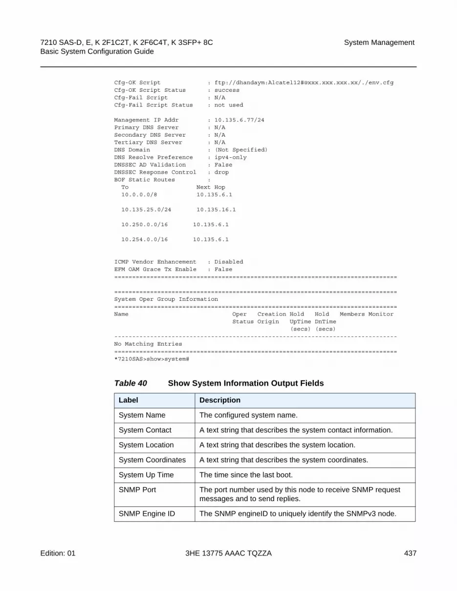
7210 SAS-D, E, K 2F1C2T, K 2F6C4T, K 3SFP+ 8C Basic System Configuration Guide
System Management
Edition: 01 3HE 13775 AAAC TQZZA 437
Cfg-OK Script : ftp://dhandaym:Alcatel12#@xxx.xxx.xxx.xx/./env.cfgCfg-OK Script Status : successCfg-Fail Script : N/ACfg-Fail Script Status : not used
Management IP Addr : 10.135.6.77/24Primary DNS Server : N/ASecondary DNS Server : N/ATertiary DNS Server : N/ADNS Domain : (Not Specified)DNS Resolve Preference : ipv4-onlyDNSSEC AD Validation : FalseDNSSEC Response Control : dropBOF Static Routes :
To Next Hop10.0.0.0/8 10.135.6.1
10.135.25.0/24 10.135.16.1
10.250.0.0/16 10.135.6.1
10.254.0.0/16 10.135.6.1
ICMP Vendor Enhancement : DisabledEFM OAM Grace Tx Enable : False===============================================================================
===============================================================================System Oper Group Information===============================================================================Name Oper Creation Hold Hold Members Monitor
Status Origin UpTime DnTime(secs) (secs)
-------------------------------------------------------------------------------No Matching Entries===============================================================================*7210SAS>show>system#
Table 40 Show System Information Output Fields
Label Description
System Name The configured system name.
System Contact A text string that describes the system contact information.
System Location A text string that describes the system location.
System Coordinates A text string that describes the system coordinates.
System Up Time The time since the last boot.
SNMP Port The port number used by this node to receive SNMP request messages and to send replies.
SNMP Engine ID The SNMP engineID to uniquely identify the SNMPv3 node.

System Management
438
7210 SAS-D, E, K 2F1C2T, K 2F6C4T, K 3SFP+ 8CBasic System Configuration Guide
3HE 13775 AAAC TQZZA Edition: 01
SNMP Max Message Size
The maximum SNMP packet size generated by this node.
SNMP Admin State Enabled — SNMP is administratively enabled and running.
Disabled — SNMP is administratively shutdown and not running.
SNMP Oper State Enabled — SNMP is operationally enabled.
Disabled — SNMP is operationally disabled.
SNMP Index Boot Status
Persistent — System indexes are saved between reboots.
Not Persistent — System indexes are not saved between reboots.
Telnet/SSH/FTP Admin
Displays the administrative state of the Telnet, SSH, and FTP sessions.
Telnet/SSH/FTP Oper
Displays the operational state of the Telnet, SSH, and FTP sessions.
BOF Source The location of the BOF.
Image Source Primary — Indicates that the directory location for runtime image file was loaded from the primary source.
Secondary — Indicates that the directory location for runtime image file was loaded from the secondary source.
Tertiary — Indicates that the directory location for runtime image file was loaded from the tertiary source.
Config Source Primary — Indicates that the directory location for configuration file was loaded from the primary source.
Secondary — Indicates that the directory location for configuration file was loaded from the secondary source.
Tertiary — Indicates that the directory location for configuration file was loaded from the tertiary source.
Last Booted Config File
The URL and filename of the last loaded configuration file.
Last Boot Cfg Version The date and time of the last boot.
Last Boot Config Header
Displays header information such as image version, date built, date generated.
Last Boot Index Version
The version of the persistence index file read when the card was last rebooted.
Table 40 Show System Information Output Fields (Continued)
Label Description

7210 SAS-D, E, K 2F1C2T, K 2F6C4T, K 3SFP+ 8C Basic System Configuration Guide
System Management
Edition: 01 3HE 13775 AAAC TQZZA 439
script-control
Syntax script-control
Last Boot Index Header
The header of the persistence index file read when the card was last rebooted.
Last Saved Config The location and filename of the last saved configuration file.
Time Last Saved The date and time of the last time configuration file was saved.
Changes Since Last Save
Yes — There are unsaved configuration file changes.
No — There are no unsaved configuration file changes.
Time Last Modified The date and time of the last modification.
Max Cfg/BOF Backup Rev
The maximum number of backup revisions maintained for a configuration file. This value also applies to the number of revisions maintained for the BOF file.
Cfg-OK Script URL — The location and name of the CLI script file executed following successful completion of the boot-up configuration file execution.
Cfg-OK Script Status Successful/Failed — The results from the execution of the CLI script file specified in the Cfg-OK Script location.
Not used — No CLI script file was executed.
Cfg-Fail Script URL — The location and name of the CLI script file executed following a failed boot-up configuration file execution.
Not used — No CLI script file was executed.
Cfg-Fail Script Status Successful/Failed — The results from the execution of the CLI script file specified in the Cfg-Fail Script location.
Not used — No CLI script file was executed.
DNS Server The IP address of the DNS server.
DNS Domain The DNS domain name of the node.
BOF Static Routes To — The static route destination.
Next Hop — The next hop IP address used to reach the destination.
Metric — Displays the priority of this static route versus other static routes.
None — No static routes are configured.
Table 40 Show System Information Output Fields (Continued)
Label Description

System Management
440
7210 SAS-D, E, K 2F1C2T, K 2F6C4T, K 3SFP+ 8CBasic System Configuration Guide
3HE 13775 AAAC TQZZA Edition: 01
Context show>system
Description Platforms Supported: 7210 SAS-D, 7210 SAS-K 2F1C2T, 7210 SAS-K 2F6C4T, 7210 SAS-K 3SFP+ 8C
This command enables the context to display script information.
script
Syntax script [script-name] [owner script-owner]
Context show>system>script-control
Description Platforms Supported: 7210 SAS-D, 7210 SAS-K 2F1C2T, 7210 SAS-K 2F6C4T, 7210 SAS-K 3SFP+ 8C
This command displays script parameters.
Parameters script-name — Displays information for the specified script.
script-owner — Displays information for the specified script owner.
Output The following output is an example of script information, andTable 41 describes the output fields.
Sample Output
7210SAS>show>system>script-control# script===============================================================================Script Information===============================================================================Script : testOwner name : TiMOS CLIDescription : asdAdministrative status : enabledOperational status : enabledScript source location : ftp://*****:******@xxx.xxx.xxx.1/home/testlab_bgp
/test1.cfgLast script error : noneLast change : 2015/01/07 17:10:03===============================================================================7210SAS>show>cron#
Table 41 Show Script Output Fields
Label Description
Script Displays the name of the script.
Script owner Displays the owner name of script.

7210 SAS-D, E, K 2F1C2T, K 2F6C4T, K 3SFP+ 8C Basic System Configuration Guide
System Management
Edition: 01 3HE 13775 AAAC TQZZA 441
script-policy
Syntax script-policy script-policy-name [owner owner-name]
script-policy run-history [run-state]
Context show>system>script-control
Description Platforms Supported: 7210 SAS-D, 7210 SAS-K 2F1C2T, 7210 SAS-K 2F6C4T, 7210 SAS-K 3SFP+ 8C
This command displays script policy information.
Parameters script-policy-name — Displays policy information for the specified script. 32 characters maximum.
owner-name — Displays information for the specified script owner. 32 characters maximum.
Default TiMOS CLI
run-state — Displays information for script policies in the specified state.
Values executing, initializing, terminated
Output The following output is an example of script policy information, and Table 42 describes the output fields.
Sample Output
show system script-control script-policy run-history terminated===============================================================================Script-policy Run History===============================================================================Script policy "test"Owner "TiMOS CLI"-------------------------------------------------------------------------------
Administrative status
Enabled — Administrative status is enabled.
Disabled — Administratively disabled.
Operational status Enabled — Operational status is enabled.
Disabled — Operationally disabled.
Script source location
Displays the location of scheduled script.
Last script error Displays the system time of the last error.
Last change Displays the system time of the last change.
Table 41 Show Script Output Fields (Continued)
Label Description

System Management
442
7210 SAS-D, E, K 2F1C2T, K 2F6C4T, K 3SFP+ 8CBasic System Configuration Guide
3HE 13775 AAAC TQZZA Edition: 01
Script Run #17-------------------------------------------------------------------------------Start time : 2006/11/06 20:30:09 End time : 2006/11/06 20:35:24Elapsed time : 0d 00:05:15 Lifetime : 0d 00:00:00State : terminated Run exit code : noErrorResult time : 2006/11/06 20:35:24 Keep history : 0d 00:49:57Error time : neverResults file : ftp://*:*@192.168.xx.xx/home/testlab_bgp/cron/_20061106-203008.outRun exit : Success-------------------------------------------------------------------------------Script Run #18-------------------------------------------------------------------------------Start time : 2006/11/06 20:35:24 End time : 2006/11/06 20:40:40Elapsed time : 0d 00:05:16 Lifetime : 0d 00:00:00State : terminated Run exit code : noErrorResult time : 2006/11/06 20:40:40 Keep history : 0d 00:55:13Error time : neverResults file : ftp://*:*@192.168.xx.xx/home/testlab_bgp/cron/_20061106-203523.outRun exit : Success-------------------------------------------------------------------------------*A:Redundancy#
*A:Redundancy# show system script-control script-policy run-history executing===============================================================================Script-policy Run History===============================================================================Script policy "test"Owner "TiMOS CLI"-------------------------------------------------------------------------------Script Run #20-------------------------------------------------------------------------------Start time : 2006/11/06 20:46:00 End time : neverElapsed time : 0d 00:00:56 Lifetime : 0d 00:59:04State : executing Run exit code : noErrorResult time : never Keep history : 0d 01:00:00Error time : neverResults file : ftp://*:*@192.168.15.18/home/testlab_bgp/cron/_20061106-204559.out===============================================================================*A:show#
*A:# show system script-control script-policy run-history initializing===============================================================================Script-policy Run History===============================================================================Script policy "test"Owner "TiMOS CLI"-------------------------------------------------------------------------------Script Run #21-------------------------------------------------------------------------------Start time : never End time : neverElapsed time : 0d 00:00:00 Lifetime : 0d 01:00:00State : initializing Run exit code : noErrorResult time : never Keep history : 0d 01:00:00Error time : neverResults file : none-------------------------------------------------------------------------------

7210 SAS-D, E, K 2F1C2T, K 2F6C4T, K 3SFP+ 8C Basic System Configuration Guide
System Management
Edition: 01 3HE 13775 AAAC TQZZA 443
Script Run #22-------------------------------------------------------------------------------Start time : never End time : neverElapsed time : 0d 00:00:00 Lifetime : 0d 01:00:00State : initializing Run exit code : noErrorResult time : never Keep history : 0d 01:00:00Error time : neverResults file : none-------------------------------------------------------------------------------Script Run #23-------------------------------------------------------------------------------Start time : never End time : neverElapsed time : 0d 00:00:00 Lifetime : 0d 01:00:00State : initializing Run exit code : noErrorResult time : never Keep history : 0d 01:00:00Error time : neverResults file : none===============================================================================*A:show#
Table 42 Show Script Policy Output Fields
Label Description
Script policy Displays the name of the script policy.
Script policy owner Displays the name of the script policy owner.
Administrative status
Enabled — Administrative status is enabled.
Disabled — Administrative status is disabled.
Script Displays the name of the script.
Script owner Displays the name of the script owner.
Script source location
Displays the location of scheduled script.
Max running allowed
Displays the maximum number of allowed sessions.
Max completed run histories
Displays the maximum number of sessions previously run.
Max lifetime allowed Displays the maximum amount of time the script may run.
Completed run histories
Displays the number of completed sessions.
Executing run histories
Displays the number of sessions in the process of executing.
Initializing run histories
Displays the number of sessions ready to run/queued but not executed.

System Management
444
7210 SAS-D, E, K 2F1C2T, K 2F6C4T, K 3SFP+ 8CBasic System Configuration Guide
3HE 13775 AAAC TQZZA Edition: 01
memory-pools
Syntax memory-pools
Context show>system
SupportedPlatforms
Supported on all 7210 SAS platforms as described in this document
Description This command displays system memory status.
Output Memory Pools Output
The following output is an example of memory pool information, and Table 43 describes the output fields.
Sample Output
A:ALA-1# show system memory-pools===============================================================================Memory Pools===============================================================================Name Max Allowed Current Size Max So Far In Use-------------------------------------------------------------------------------System No limit 24,117,248 24,117,248 16,974,832Icc 8,388,608 1,048,576 1,048,576 85,200RTM/Policies No limit 5,242,912 5,242,912 3,944,104OSPF No limit 3,145,728 3,145,728 2,617,384MPLS/RSVP No limit 9,769,480 9,769,480 8,173,760LDP No limit 0 0 0IS-IS No limit 0 0 0RIP No limit 0 0 0VRRP No limit 1,048,576 1,048,576 96Services No limit 2,097,152 2,097,152 1,589,824IOM No limit 205,226,800 205,226,800 202,962,744SIM No limit 1,048,576 1,048,576 392IGMP No limit 0 0 0MMPI No limit 0 0 0MFIB No limit 0 0 0PIP No limit 79,943,024 79,943,024 78,895,248MBUF 67,108,864 5,837,328 5,837,328 4,834,280-------------------------------------------------------------------------------Current Total Size : 343,495,200 bytesTotal In Use : 324,492,768 bytes
Max time tun history saved
Displays the maximum amount of time to keep the results from a script run.
Last change Displays the system time a change was made to the configuration.
Table 42 Show Script Policy Output Fields (Continued)
Label Description

7210 SAS-D, E, K 2F1C2T, K 2F6C4T, K 3SFP+ 8C Basic System Configuration Guide
System Management
Edition: 01 3HE 13775 AAAC TQZZA 445
Available Memory : 640,178,652 bytes===============================================================================A:ALA-1#
ntp
Syntax ntp [{peers | peer peer-address} | {servers | server server-address} |[all]] [detail]
Context show>system
SupportedPlatforms
Supported on all 7210 SAS platforms as described in this document
Description This command displays NTP protocol configuration and state.
Output Show NTP Output
The following output is an example of NTP information, and Table 44 describes the output fields.
Sample Output
A:7210>config>system>time>ntp# show system ntp===============================================================================NTP Status===============================================================================Enabled : Yes Stratum : 3Admin Status : up Oper Status : upServer enabled : No Server keyId : noneSystem Ref Id : 192.168.15.221 Auth Check : Yes
Table 43 Show Memory Pool Output Fields
Label Description
Name The name of the system or process.
Max Allowed Integer — The maximum allocated memory size.
No Limit — No size limit.
Current Size The current size of the memory pool.
Max So Far The largest amount of memory pool used.
In Use The current amount of the memory pool currently in use.
Current Total Size The sum of the Current Size column.
Total In Use The sum of the In Use column.
Available Memory The amount of available memory.

System Management
446
7210 SAS-D, E, K 2F1C2T, K 2F6C4T, K 3SFP+ 8CBasic System Configuration Guide
3HE 13775 AAAC TQZZA Edition: 01
===============================================================================A:7210
A:7210# show system ntp all===============================================================================NTP Status===============================================================================Configured : Yes Stratum : 1Admin Status : up Oper Status : upServer Enabled : Yes Server Authenticate : NoClock Source : PTPAuth Check : YesCurrent Date & Time: 2013/03/19 20:18:50 UTC==============================================================================================================================================================NTP Active Associations===============================================================================State Reference ID St Type A Poll Reach Offset(ms)Remote-------------------------------------------------------------------------------chosen PTP 0 srvr - 256 YYYYYYYY 0.000PTPcandidate GPS 1 srvr - 256 YYYYYYYY -0.054xxx.xxx.xxx.xxx===============================================================================A:7210#
A:7210>config>system>time>ntp# show system ntp detail===============================================================================NTP Status===============================================================================Enabled : Yes Stratum : 3Admin Status : up Oper Status : upServer enabled : No Server keyId : noneSystem Ref Id : 192.168.15.221 Auth Check : YesAuth Errors : 0 Auth Errors Ignored : 0Auth Key Id Errors : 0 Auth Key Type Errors : 0===============================================================================NTP Configured Broadcast/Multicast Interfaces===============================================================================vRouter Interface Address Type Auth Poll-------------------------------------------------------------------------------Base i3/1/1 Host-ones bcast yes offmanagement management 224.0.1.1 mcast no offBase t2 bclnt no n/amanagement management 224.0.1.1 mclnt no n/a===============================================================================A:7210>config>system>time>ntp#
A:7210>config>system>time>ntp# show system ntp detail all===============================================================================NTP Status===============================================================================Enabled : Yes Stratum : 3Admin Status : up Oper Status : upServer enabled : No Server keyId : none

7210 SAS-D, E, K 2F1C2T, K 2F6C4T, K 3SFP+ 8C Basic System Configuration Guide
System Management
Edition: 01 3HE 13775 AAAC TQZZA 447
System Ref Id : 192.168.15.221 Auth Check : YesAuth Errors : 0 Auth Errors Ignored : 0Auth Key Id Errors : 0 Auth Key Type Errors : 0===============================================================================NTP Configured Broadcast/Multicast Interfaces===============================================================================vRouter Interface Address Type Auth Poll-------------------------------------------------------------------------------Base i3/1/1 Host-ones bcast yes offmanagement management 224.0.1.1 mcast no offBase t2 bclnt no n/amanagement management 224.0.1.1 mclnt no n/a===============================================================================NTP Active Associations===============================================================================State Remote Reference ID St Type Auth Poll R Offset-------------------------------------------------------------------------------reject 192.168.15.221 192.168.14.50 2 srvr none 64 y 0.901chosen 192.168.15.221 192.168.1.160 4 mclnt none 64 y 1.101===============================================================================A:7210>config>system>time>ntp#
Table 44 Show NTP Output Fields
Label Description
Enabled yes — NTP is enabled.
no — NTP is disabled.
Admin Status yes — Administrative state is enabled.
no — Administrative state is disabled.
NTP Server Displays NTP server state of this node.
Stratum Displays stratum level of this node.
Oper Status yes — The operational state is enabled.
no — The operational state is disabled.
Auth Check Displays the authentication requirement
System Ref. ID IP address of this node or a 4-character ASCII code showing the state.
Auth Error Displays the number of authentication errors.
Auth Errors Ignored Displays the number of authentication errors ignored.
Auth key ID Errors Displays the number of key identification errors.
Auth Key Type Errors Displays the number of authentication key type errors.

System Management
448
7210 SAS-D, E, K 2F1C2T, K 2F6C4T, K 3SFP+ 8CBasic System Configuration Guide
3HE 13775 AAAC TQZZA Edition: 01
Reject The peer is rejected and will not be used for synchronization. Rejection reasons could be the peer is unreachable, the peer is synchronized to this local server so synchronizing with it would create a sync loop, or the synchronization distance is too large. This is the normal startup state.
Invalid The peer is not maintaining an accurate clock. This peer will not be used for synchronization.
Excess The peer's synchronization distance is greater than ten other peers. This peer will not be used for synchronization.
Outlyer The peer is discarded as an outlier. This peer will not be used for synchronization.
Candidate The peer is accepted as a possible source of synchronization.
Selected The peer is an acceptable source of synchronization, but its synchronization distance is greater than six other peers.
Chosen The peer is chosen as the source of synchronization.
ChosenPPS The peer is chosen as the source of synchronization, but the actual synchronization is occurring from a pulse-per-second (PPS) signal.
Remote The IP address of the remote NTP server or peer with which this local host is exchanging NTP packets.
Reference ID When stratum is between 0 and 15 this field shows the IP address of the remote NTP server or peer with which the remote is exchanging NTP packets. For reference clocks, this field shows the identification assigned to the clock, such as, “.GPS.” For an NTP server or peer, if the client has not yet synchronized to a server/peer, the status cannot be determined and displays the following codes:
Table 44 Show NTP Output Fields (Continued)
Label Description

7210 SAS-D, E, K 2F1C2T, K 2F6C4T, K 3SFP+ 8C Basic System Configuration Guide
System Management
Edition: 01 3HE 13775 AAAC TQZZA 449
Peer Codes:
ACST — The association belongs to any cast server.
AUTH — Server authentication failed. Please wait while the association is restarted.
AUTO — Autokey sequence failed. Please wait while the association is restarted.
BCST — The association belongs to a broadcast server.
CRPT — Cryptographic authentication or identification failed. The details should be in the system log file or the cryptostats statistics file, if configured. No further messages will be sent to the server.
DENY — Access denied by remote server. No further messages will be sent to the server.
DROP — Lost peer in symmetric mode. Please wait while the association is restarted.
RSTR — Access denied due to local policy. No further messages will be sent to the server.
INIT — The association has not yet synchronized for the first time.
MCST — The association belongs to a manycast server.
NKEY — No key found. Either the key was never installed or is not trusted.
RATE — Rate exceeded. The server has temporarily denied access because the client exceeded the rate threshold.
RMOT — The association from a remote host running ntpdc has had unauthorized attempted access.
STEP — A step change in system time has occurred, but the association has not yet re-synchronized.
System Codes
INIT — The system clock has not yet synchronized for the first time.
STEP — A step change in system time has occurred, but the system clock has not yet re-synchronized.
St Stratum level of this node.
Auth yes — Authentication is enabled.
no — Authentication is disabled.
Poll Polling interval in seconds.
Table 44 Show NTP Output Fields (Continued)
Label Description

System Management
450
7210 SAS-D, E, K 2F1C2T, K 2F6C4T, K 3SFP+ 8CBasic System Configuration Guide
3HE 13775 AAAC TQZZA Edition: 01
oper-group
Syntax oper-group [group-name]
oper-group group-name [detail]
oper-group group-name [monitoring]
Context show>system
Description Platforms Supported: 7210 SAS-D, 7210 SAS-K 2F1C2T, 7210 SAS-K 2F6C4T, 7210 SAS-K 3SFP+ 8C
This command displays the oper-group information, member count, monitor-client count, and status in a single line for each of the configured oper-groups.
Output Show oper-group Output
The following output is an example of oper-group information, and Table 45 describes the output fields.
Sample Output
*A:7210SAS>show>system# oper-group
===============================================================================System Oper Group Information===============================================================================Name Oper Creation Hold Hold Members Monitor
Status Origin UpTime DnTime(secs) (secs)
-------------------------------------------------------------------------------test up manual 4 0 1 1-------------------------------------------------------------------------------Entries found: 1===============================================================================*A:7210SAS>show>system#
*A:7210SAS>show>system# oper-group test monitoring
===============================================================================
R Yes — The NTP peer or server has been reached at least once in the last 8 polls.
No — The NTP peer or server has not been reached at least once in the last 8 polls.
Offset The time between the local and remote UTC time, in milliseconds.
Table 44 Show NTP Output Fields (Continued)
Label Description

7210 SAS-D, E, K 2F1C2T, K 2F6C4T, K 3SFP+ 8C Basic System Configuration Guide
System Management
Edition: 01 3HE 13775 AAAC TQZZA 451
System Oper Group Information===============================================================================Oper Group : testCreation Origin : manual Oper Status : upHold DownTime : 0 secs Hold UpTime : 4 secsMembers : 0 Monitoring : 0===============================================================================
resource-profile
Syntax resource-profile [[active | configured]]
Context show>system
SupportedPlatforms
Supported on all 7210 SAS platforms as described in this document
Description This command displays the resource-profile protocol configuration and state.
Parameters active | configured — Displays active or configured values. Active values are those in use by the system currently. Configured values are those that have been changed by the user and has not taken effect. For the system resource-profile parameters that need a reboot to take effect, the active and configured values can be different. It typically requires a node reboot or a card reset for it to take effect.
Output Show resource-profile Output
The following output is an example of resource-profile information, and Table 46 describes the output fields.
Sample Output for 7210 SAS-D
Table 45 Show Oper-group Output Fields
Label Description
Name Displays the name of the oper-group.
Oper Status The operational status of the oper-group.
Creation Origin Displays if it was created manually.
Hold Up Time The configured HOLD UP time.
Hold Dn Time The configured HOLD down time.
Members Displays the number of members of the oper-group.
Monitor Displays the number of monitoring clients.

System Management
452
7210 SAS-D, E, K 2F1C2T, K 2F6C4T, K 3SFP+ 8CBasic System Configuration Guide
3HE 13775 AAAC TQZZA Edition: 01
*A:7210SAS>show>system# resource-profile
===============================================================================Active System Resource Profile Information===============================================================================-------------------------------------------------------------------------------IPv6 FIB-------------------------------------------------------------------------------max-ipv6-routes : disable
--------------------------------------------------------------------------------------------------------------------------------------------------------------Ingress Internal CAM-------------------------------------------------------------------------------Sap Ingress Qos resource : 2 Sap Aggregate Meter : 1-------------------------------------------------------------------------------IPv4 Resource : max Mac Resource : maxIPv4-IPv6 Resource : disable
-------------------------------------------------------------------------------Sap Ingress ACL resource : 1-------------------------------------------------------------------------------IPv4 Resource : max Mac Resource : maxIPv4-IPv6 128 bit Resource : disable IPv6 64 bit Resource : disable
--------------------------------------------------------------------------------------------------------------------------------------------------------------Eth CFM : disable-------------------------------------------------------------------------------up-mep : disable
--------------------------------------------------------------------------------------------------------------------------------------------------------------Egress Internal CAM--------------------------------------------------------------------------------------------------------------------------------------------------------------Sap Egress ACL resource : 2-------------------------------------------------------------------------------Mac and IPv4 Resource : 2 Mac-only Resource : disableIPv6 128 bit Resource : disable Mac and IPv6 64 bit Resour*: disable
-------------------------------------------------------------------------------===============================================================================* indicates that the corresponding row element may have been truncated.*A:7210SAS>show>system#
Sample Output for 7210 SAS-EA:7210SAS>show>system# resource-profile
===============================================================================Active System Resource Profile Information===============================================================================Ingress Queue Mode : none--------------------------------------------------------------------------------------------------------------------------------------------------------------Ingress Internal CAM-------------------------------------------------------------------------------Sap Ingress Qos resource : 6

7210 SAS-D, E, K 2F1C2T, K 2F6C4T, K 3SFP+ 8C Basic System Configuration Guide
System Management
Edition: 01 3HE 13775 AAAC TQZZA 453
-------------------------------------------------------------------------------IPv4 Resource : max Mac Resource : maxIPv4-IPv6 Resource : disable
-------------------------------------------------------------------------------Sap Ingress ACL resource : 5-------------------------------------------------------------------------------IPv4 Resource : max Mac Resource : maxIPv4-IPv6 128 bit Resource : disable IPv6 64 bit Resource : disable
---------------------------------------------------------------------------------------------------------------------------------------------------------------------------------------------------------------------------------------------Egress Internal CAM--------------------------------------------------------------------------------------------------------------------------------------------------------------Sap Egress ACL resource : 2-------------------------------------------------------------------------------Mac and IPv4 Resource : 1 Mac-only Resource : 1IPv6 128 bit Resource : disable Mac and IPv6 64 bit Resour*: disable
-------------------------------------------------------------------------------===============================================================================* indicates that the corresponding row element may have been truncated.*A:SASE>show>system#A:7210SAS>show>system#
Sample Output for 7210 SAS-K 2F2T1C
*A:7210SAS>show>system# resource-profile
===============================================================================Active System Resource Profile Information===============================================================================-------------------------------------------------------------------------------Ingress Internal CAM : 5-------------------------------------------------------------------------------Mac-IPv4-IPv6 Resource : disable-------------------------------------------------------------------------------Sap Ingress ACL resource : 1-------------------------------------------------------------------------------Mac-IPv4-IPv6 Resource : disable-------------------------------------------------------------------------------Egress Internal CAM : 2--------------------------------------------------------------------------------------------------------------------------------------------------------------Sap Egress ACL resource : disable-------------------------------------------------------------------------------Mac-IPv4-IPv6 Resource : disable===============================================================================# indicates that the value will take effect only after reboot or clear card.*A:7210SAS>show>system#
Table 46 Show System Resource-profile Output Fields
Label Description
Ingress Internal CAM Displays the applications sharing ingress CAM resource.

System Management
454
7210 SAS-D, E, K 2F1C2T, K 2F6C4T, K 3SFP+ 8CBasic System Configuration Guide
3HE 13775 AAAC TQZZA Edition: 01
Sap Ingress ACL resource
Displays the resources configured for use by SAP Ingress ACL policies.
IPv4 Resource Displays the resources configured for use by ingress ACL policies that use ipv4-criteria.
Disable – No resources are allocated for use by this feature. Therefore, no policies of this type can be associated to a SAP.
IPv4-IPv6 Resource Displays the resources configured for use by ingress ACL policies that use ipv6 128-bit address match-criteria.
Disable – No resources are allocated for use by this feature. Hence, no policies of this type can be associated to a SAP.
Mac Resource Displays the resources configured for use by ingress ACL policies that use mac-criteria.
Disable – No resources are allocated for use by this feature. Hence, no policies of this type can be associated to a SAP.
IPv6-64 bit Resource Displays the resources configured for use by ingress ACL policies that use ipv6 64-bit address match-criteria.
Disable – No resources are allocated for use by this feature. Hence, no policies of this type can be associated to a SAP.
Eth CFM Groups the context for resources consumed by Ethernet CFM applications.
up-mep Displays the resources configured for use by UP MEP.
Disable – No resources are allocated for use by this feature. Therefore, no UP MEPs can be created.
Sap Ingress QoS resource
The total amount of ingress internal CAM chunks configured for use by SAP ingress classification.
Mac and IPv4 Resource
The total amount of egress internal CAM chunks configured for use by MAC and IPv4 egress ACL match criteria policies.
Mac-only Resource The total amount of egress internal CAM chunks configured for use only by MAC egress ACL match criteria policies.
IPv6 128 bit Resource
The total amount of egress internal CAM chunks configured for use only by IPv6 egress ACL match criteria policies (128-bit IPv6 address can be specified in the match criteria).
Mac and IPv6 64 bit Resource
The total amount of egress internal CAM chunks configured for use by MAC and IPv6 egress ACL match criteria policies (only 64-bit higher order bits of the IPv6 address can be specified in the match criteria).
Table 46 Show System Resource-profile Output Fields (Continued)
Label Description

7210 SAS-D, E, K 2F1C2T, K 2F6C4T, K 3SFP+ 8C Basic System Configuration Guide
System Management
Edition: 01 3HE 13775 AAAC TQZZA 455
ptp
Syntax ptp [peer ip-address [detail] | peers [detail] | unicast | statistics]
Context show>system
Description Platforms Supported: 7210 SAS-D ETR, 7210 SAS-K 2F1C2T, 7210 SAS-K 2F6C4T, 7210 SAS-K 3SFP+ 8C
This command displays the parameters for IEEE 1588-2008/ Precision Time Protocol Clock Information.
Output PTP Information
Sample Output:
A:7210SAS>show>system# ptp
===============================================================================IEEE 1588/PTP Clock Information===============================================================================-------------------------------------------------------------------------------Local Clock-------------------------------------------------------------------------------Clock Type : boundary PTP Profile : IEEE 1588-2008Domain : 0 Network Type : sdhAdmin State : up Oper State : upClock Id : 4c5fd2fffe29049e Clock Class : 248 (default)Clock Accuracy : unknown Clock Variance : ffff (not computed)Clock Priority1 : 128 Clock Priority2 : 128PTP Recovery State: disabledFrequency Offset : n/a-------------------------------------------------------------------------------Parent Clock-------------------------------------------------------------------------------IP Address : xxx.x.x.xParent Clock Id : 4c5fd2fffe295072 Remote PTP Port : 5GM Clock Id : 00b0aefffe02e5e5 GM Clock Class : 6GM Clock Accuracy : within 100 ns GM Clock Variance : 0x6400 (3.7E-09)GM Clock Priority1: 128 GM Clock Priority2 : 128
Sap Egress ACL resource
Displays the egress ACL resource allocation configured for various match criteria.
Egress Internal CAM Displays the resource allocation configured for the egress internal CAM.
IPv6 FIB Displays the amount of IPv6 FIB size configured for use by IPv6 routing.
Table 46 Show System Resource-profile Output Fields (Continued)
Label Description

System Management
456
7210 SAS-D, E, K 2F1C2T, K 2F6C4T, K 3SFP+ 8CBasic System Configuration Guide
3HE 13775 AAAC TQZZA Edition: 01
===============================================================================-------------------------------------------------------------------------------Time Information-------------------------------------------------------------------------------Timescale : PTPCurrent Time : 2012/12/13 11:05:43 (UTC)Frequency Traceable : yesTime Traceable : yesTime Source : GPS==============================================================================================================================================================A:7210SAS>show>system#
*A:7210SAS>show>system>ptp
===============================================================================IEEE 1588/PTP Clock Information===============================================================================-------------------------------------------------------------------------------Local Clock-------------------------------------------------------------------------------Clock Type : ordinary,slave PTP Profile : ITU-T G.8275.1Domain : 24 Network Type : sdhAdmin State : up Oper State : upAnnounce Interval : 8 pkt/s Announce Rx Timeout: 3 intervalsPeer Limit : none (Base Router) G.8275.1 Priority: 128Clock Id : 1c03fffffe000000 Clock Class : 255 (slave-only)Clock Accuracy : unknown Clock Variance : ffff (not computed)Clock Priority1 : 128 Clock Priority2 : 128PTP Port State : listening Last Changed : 08/26/2014 12:42:53PTP Recovery State: initial Last Changed : 08/26/2014 12:41:35Frequency Offset : +0.000 ppb-------------------------------------------------------------------------------Parent Clock-------------------------------------------------------------------------------Local Clock is Parent ClockParent Clock Id : 1c03fffffe000000 Remote PTP Port : 0GM Clock Id : 1c03fffffe000000 GM Clock Class : 255 (slave-only)GM Clock Accuracy : unknown GM Clock Variance : ffff (not computed)GM Clock Priority1: 128 GM Clock Priority2 : 128-------------------------------------------------------------------------------Time Information-------------------------------------------------------------------------------Timescale : ArbitraryCurrent Time : 2014/08/26 12:44:39.2 (ARB)Frequency Traceable : noTime Traceable : noTime Source : internal oscillator===============================================================================A:7210SAS>show>system#
*A:7210SAS>show>system> port 1/1/1
===============================================================================IEEE 1588/PTP Ethernet Port Information===============================================================================Port : 1/1/1PTP Admin State : up PTP Oper State : downLocal MAC Addr : 1c:05:01:01:00:01 Mulicast MAC Addr : 01:1b:19:00:00:00

7210 SAS-D, E, K 2F1C2T, K 2F6C4T, K 3SFP+ 8C Basic System Configuration Guide
System Management
Edition: 01 3HE 13775 AAAC TQZZA 457
G.8275.1 notSlave : false G.8275.1 Priority : 128PTP Port Number : 1 PTP Port State : listeningCfg Anno Rate : 8 pkt/s Cfg Sync/Delay Rate: 16 pkt/sNeighbors : 0 Timestamp Point : cpm===============================================================================A:7210SAS>show>system#
sntp
Syntax sntp
Context show>system
SupportedPlatforms
Supported on all 7210 SAS platforms as described in this document
Description This command displays SNTP protocol configuration and state.
Output SNTP Output
The following output is an example of SNTP information, and Table 47 describes the output fields.
Sample Output
*A:pc-4.0# show system sntp===============================================================================SNTP Status===============================================================================Admin Status : up Oper Status : up Mode : broadcast==============================================================================================================================================================SNTP Servers===============================================================================SNTP Server Version Preference Interval-------------------------------------------------------------------------------10.135.16.90 3 Preferred 64-------------------------------------------------------------------------------No. of SNTP Servers: 1===============================================================================*A:pc-4.0#
Table 47 Show System SNTP Output Fields
Label Description
SNTP Server The SNTP server address for SNTP unicast client mode.
Version The SNTP version number, expressed as an integer.

System Management
458
7210 SAS-D, E, K 2F1C2T, K 2F6C4T, K 3SFP+ 8CBasic System Configuration Guide
3HE 13775 AAAC TQZZA Edition: 01
thresholds
Syntax thresholds
Context show>system
SupportedPlatforms
Supported on all 7210 SAS platforms as described in this document
Description This command display system monitoring thresholds.
Output Thresholds Output
The following output is an example of system threshold information, and Table 48 describes the output fields.
Sample Output
A:ALA-48# show system thresholds================================================================Threshold Alarms================================================================Variable: tmnxCpmFlashUsed.1.11.1Alarm Id : 1 Last Value : 835Rising Event Id : 1 Threshold : 5000Falling Event Id : 2 Threshold : 2500Sample Interval : 2147483* SampleType : absoluteStartup Alarm : either Owner : TiMOS CLIVariable: tmnxCpmFlashUsed.1.11.1Alarm Id : 2 Last Value : 835Rising Event Id : 3 Threshold : 10000Falling Event Id : 4 Threshold : 5000Sample Interval : 2147483* SampleType : absoluteStartup Alarm : rising Owner : TiMOS CLIVariable: sgiMemoryUsed.0Alarm Id : 3 Last Value : 42841056Rising Event Id : 5 Threshold : 4000Falling Event Id : 6 Threshold : 2000Sample Interval : 2147836 SampleType : absoluteStartup Alarm : either Owner : TiMOS CLI================================================================
Preference Normal — When more than one time server is configured, one server can be configured to have preference over another.
Preferred — Indicates that this server has preference over another.
Interval The frequency, in seconds, that the server is queried.
Table 47 Show System SNTP Output Fields (Continued)
Label Description
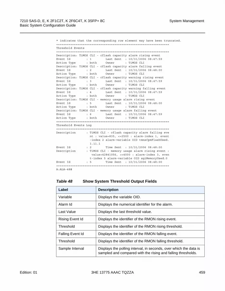
7210 SAS-D, E, K 2F1C2T, K 2F6C4T, K 3SFP+ 8C Basic System Configuration Guide
System Management
Edition: 01 3HE 13775 AAAC TQZZA 459
* indicates that the corresponding row element may have been truncated.================================================================Threshold Events================================================================Description: TiMOS CLI - cflash capacity alarm rising eventEvent Id : 1 Last Sent : 10/31/2006 08:47:59Action Type : both Owner : TiMOS CLIDescription: TiMOS CLI - cflash capacity alarm falling eventEvent Id : 2 Last Sent : 10/31/2006 08:48:00Action Type : both Owner : TiMOS CLIDescription: TiMOS CLI - cflash capacity warning rising eventEvent Id : 3 Last Sent : 10/31/2006 08:47:59Action Type : both Owner : TiMOS CLIDescription: TiMOS CLI - cflash capacity warning falling eventEvent Id : 4 Last Sent : 10/31/2006 08:47:59Action Type : both Owner : TiMOS CLIDescription: TiMOS CLI - memory usage alarm rising eventEvent Id : 5 Last Sent : 10/31/2006 08:48:00Action Type : both Owner : TiMOS CLIDescription: TiMOS CLI - memory usage alarm falling eventEvent Id : 6 Last Sent : 10/31/2006 08:47:59Action Type : both Owner : TiMOS CLI================================================================Threshold Events Log================================================================Description : TiMOS CLI - cflash capacity alarm falling eve
nt : value=835, <=2500 : alarm-index 1, event-index 2 alarm-variable OID tmnxCpmFlashUsed.1.11.1
Event Id : 2 Time Sent : 10/31/2006 08:48:00Description : TiMOS CLI - memory usage alarm rising event :
value=42841056, >=4000 : alarm-index 3, event-index 5 alarm-variable OID sgiMemoryUsed.0
Event Id : 5 Time Sent : 10/31/2006 08:48:00================================================================A:ALA-48#
Table 48 Show System Threshold Output Fields
Label Description
Variable Displays the variable OID.
Alarm Id Displays the numerical identifier for the alarm.
Last Value Displays the last threshold value.
Rising Event Id Displays the identifier of the RMON rising event.
Threshold Displays the identifier of the RMON rising threshold.
Falling Event Id Displays the identifier of the RMON falling event.
Threshold Displays the identifier of the RMON falling threshold.
Sample Interval Displays the polling interval, in seconds, over which the data is sampled and compared with the rising and falling thresholds.

System Management
460
7210 SAS-D, E, K 2F1C2T, K 2F6C4T, K 3SFP+ 8CBasic System Configuration Guide
3HE 13775 AAAC TQZZA Edition: 01
time
Syntax time
Context show>system
SupportedPlatforms
Supported on all 7210 SAS platforms as described in this document
Description This command displays the system time and zone configuration parameters.
Output System Time Output
The following output is an example of system time information, and Table 49 describes the output fields.
Sample Output
Sample Type Displays the method of sampling the selected variable and calculating the value to be compared against the thresholds.
Startup Alarm Displays the alarm that may be sent when this alarm is first created.
Owner Displays the owner of this alarm.
Description Displays the event cause.
Event Id Displays the identifier of the threshold event.
Last Sent Displays the date and time the alarm was sent.
Action Type log — An entry is made in the RMON-MIB log table for each event occurrence. This does not create a TiMOS logger entry. The RMON-MIB log table entries can be viewed using the show>system>thresholds CLI command.
trap — A TiMOS logger event is generated. The TiMOS logger utility then distributes the notification of this event to its configured log destinations which may be CONSOLE, telnet session, memory log, cflash file, syslog, or SNMP trap destinations logs.
both — Both a entry in the RMON-MIB logTable and a TiMOS logger event are generated.
none — No action is taken
Owner Displays the owner of the event.
Table 48 Show System Threshold Output Fields (Continued)
Label Description

7210 SAS-D, E, K 2F1C2T, K 2F6C4T, K 3SFP+ 8C Basic System Configuration Guide
System Management
Edition: 01 3HE 13775 AAAC TQZZA 461
A:ALA-1# show system time===============================================================================Date & Time===============================================================================Current Date & Time : 2006/05/05 23:03:13 DST Active : yesCurrent Zone : PDT Offset from UTC : -7:00-------------------------------------------------------------------------------Non-DST Zone : PST Offset from UTC : -8:00Zone type : standard-------------------------------------------------------------------------------DST Zone : PDT Offset from Non-DST : 0:60Starts : first sunday in april 02:00Ends : last sunday in october 02:00============================================================================A:ALA-1#
A:ALA-1# show system time (with no DST zone configured)===============================================================================Date & Time===============================================================================Current Date & Time : 2006/05/12 11:12:05 DST Active : noCurrent Zone : APA Offset from UTC : -8:00-------------------------------------------------------------------------------Non-DST Zone : APA Offset from UTC : -8:00Zone Type : non-standard-------------------------------------------------------------------------------No DST zone configured===============================================================================A:ALA-1#
Table 49 Show System Time Output Fields
Label Description
Date & Time The system date and time using the current time zone.
DST Active Yes — Daylight Savings Time is currently in effect.
No — Daylight Savings Time is not currently in effect.
Zone The zone names for the current zone, the non-DST zone, and the DST zone if configured.
Zone type Non-standard — The zone is user-defined.
Standard — The zone is system defined.
Offset from UTC The number of hours and minutes added to universal time for the zone, including the DST offset for a DST zone
Offset from Non-DST The number of hours (always 0) and minutes (0—60) added to the time at the beginning of Daylight Saving Time and subtracted at the end Daylight Saving Time.
Starts The date and time Daylight Saving Time begins.

System Management
462
7210 SAS-D, E, K 2F1C2T, K 2F6C4T, K 3SFP+ 8CBasic System Configuration Guide
3HE 13775 AAAC TQZZA Edition: 01
vwm-shelf
Syntax vwm-shelf vwm-shelf-id [detail]
Context show>system
Description Platforms Supported: 7210 SAS-E
Lists all the shelves connected to the 7210 SAS node and display the administrative and operational state of the connected shelves.
Output VWM-Shelf output
The following outputs are examples of VWM-shelf information, and Table 50 describes the output fields.
Sample Output for 7210 SAS-E devices for CWDM:
*A:7210SAS>show>system# vwm-shelf
===========================================================================Shelf Summary===========================================================================Shelf-ID USB/ Shelf Admin Oper Number of
OMC Type State State Equipped slots---------------------------------------------------------------------------7 OMC CWDM UP UP 2
===========================================================================Slot Summary===========================================================================Slot-ID Provisioned Equipped Admin Oper
Type Type State State---------------------------------------------------------------------------1 Not Provisioned SFC1D DOWN DOWN2 Not Provisioned SFC2A&B DOWN DOWNA CWDM CWDM UP UP===========================================================================*A:7210SAS>show>system#
show system vwm-shelf 7 detail
===========================================================================Shelf Summary===========================================================================Shelf-ID USB/ Shelf Admin Oper Number of
OMC Type State State Equipped slots---------------------------------------------------------------------------
Ends The date and time Daylight Saving Time ends.
Table 49 Show System Time Output Fields (Continued)
Label Description

7210 SAS-D, E, K 2F1C2T, K 2F6C4T, K 3SFP+ 8C Basic System Configuration Guide
System Management
Edition: 01 3HE 13775 AAAC TQZZA 463
7 OMC CWDM UP UP 2
===========================================================================Slot Summary===========================================================================Slot-ID Provisioned Equipped Admin Oper
Type Type State State---------------------------------------------------------------------------1 SFC1D SFC1D UP UP2 SFC2A&B SFC2A&B UP UPA CWDM CWDM UP UP
===========================================================================1830 VWM Shelf Controller-A Hardware Data===========================================================================No of Slots : 2Part Number : 3KC19297AAAB01CLEI code : WOCUAZNUTAUnit Mnemonic : EC-CWSerial Number : EZ444555666Manufacturing Date : 12112000Administrative state : UPOperational state : UPFirmware version : --------------Current Alarm state : Cleared
===========================================================================1830 VWM Slot/Module Hardware Data===========================================================================Slot Number : 1Provisioned type : SFC1DEquipped type : Equipped (SFC1D)Part Number : 3KC19289AEAA01CLEI code : ----------Unit Mnemonic : SFC1DSerial Number : EZ121130171Manufacturing Date : 03192012Operational state : UPFirmware version : --------------Current Alarm state : Cleared
===========================================================================1830 VWM Slot/Module Hardware Data===========================================================================Slot Number : 2Provisioned type : SFC2A&BEquipped type : Equipped (SFC2A&B)Part Number : 3KC19289AKAACLEI code : WOCUAZNUTAUnit Mnemonic : SFC2A&BSerial Number : EZ120630634Manufacturing Date : 12122000Operational state : UPFirmware version : --------------Current Alarm state : Cleared===========================================================================
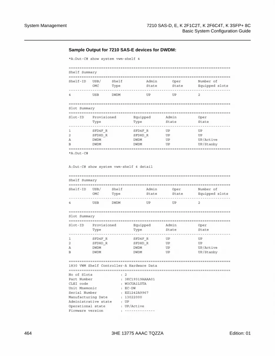
System Management
464
7210 SAS-D, E, K 2F1C2T, K 2F6C4T, K 3SFP+ 8CBasic System Configuration Guide
3HE 13775 AAAC TQZZA Edition: 01
Sample Output for 7210 SAS-E devices for DWDM:
*A:Dut-C# show system vwm-shelf 4
===========================================================================Shelf Summary===========================================================================Shelf-ID USB/ Shelf Admin Oper Number of
OMC Type State State Equipped slots---------------------------------------------------------------------------4 USB DWDM UP UP 2
===========================================================================Slot Summary===========================================================================Slot-ID Provisioned Equipped Admin Oper
Type Type State State---------------------------------------------------------------------------1 SFD4F_R SFD4F_R UP UP2 SFD8D_R SFD8D_R UP UPA DWDM DWDM UP UP/ActiveB DWDM DWDM UP UP/Stanby===========================================================================*A:Dut-C#
A:Dut-C# show system vwm-shelf 4 detail
===========================================================================Shelf Summary===========================================================================Shelf-ID USB/ Shelf Admin Oper Number of
OMC Type State State Equipped slots---------------------------------------------------------------------------4 USB DWDM UP UP 2
===========================================================================Slot Summary===========================================================================Slot-ID Provisioned Equipped Admin Oper
Type Type State State---------------------------------------------------------------------------1 SFD4F_R SFD4F_R UP UP2 SFD8D_R SFD8D_R UP UPA DWDM DWDM UP UP/ActiveB DWDM DWDM UP UP/Stanby
===========================================================================1830 VWM Shelf Controller-A Hardware Data===========================================================================No of Slots : 2Part Number : 3KC19319AAAA01CLEI code : WOCUA1LUTAUnit Mnemonic : EC-DWSerial Number : EZ1242A9967Manufacturing Date : 13022000Administrative state : UPOperational state : UP/ActiveFirmware version : --------------

7210 SAS-D, E, K 2F1C2T, K 2F6C4T, K 3SFP+ 8C Basic System Configuration Guide
System Management
Edition: 01 3HE 13775 AAAC TQZZA 465
Current Alarm state : Cleared
===========================================================================1830 VWM Shelf Controller-B Hardware Data===========================================================================No of Slots : 2Part Number : 3KC19371AAAA01CLEI code : ----------Unit Mnemonic : EC-DWSerial Number : RT135100009Manufacturing Date : 13122000Administrative state : UPOperational state : UP/StanbyFirmware version : --------------Current Alarm state : Cleared
===========================================================================1830 VWM Slot/Module Hardware Data===========================================================================Slot Number : 1Provisioned type : SFD4F_REquipped type : Equipped (SFD4F_R)Part Number : 3KC19350ADAA01CLEI code : WOFFAD8BAAUnit Mnemonic : SFD4F_RSerial Number : RT135100001Manufacturing Date : 13122000Operational state : UPFirmware version : --------------Current Alarm state : Cleared
===========================================================================1830 VWM Slot/Module Hardware Data===========================================================================Slot Number : 2Provisioned type : SFD8D_REquipped type : Equipped (SFD8D_R)Part Number : 3KC19350ADAA01CLEI code : WOFFAD8BAAUnit Mnemonic : SFD8D_RSerial Number : RT135100001Manufacturing Date : 13122000Operational state : UPFirmware version : --------------Current Alarm state : Cleared
===========================================================================1830 VWM Fan Hardware Data===========================================================================Slot Number : 1Part Number :CLEI code :Unit Mnemonic :Serial Number :Manufacturing Date :Operational state : DOWNFirmware version :===========================================================================*A:Dut-C#

System Management
466
7210 SAS-D, E, K 2F1C2T, K 2F6C4T, K 3SFP+ 8CBasic System Configuration Guide
3HE 13775 AAAC TQZZA Edition: 01
time
Syntax time
Table 50 Show VWM-shelf Output Fields
Label Description
Shelf-ID Configured shelf-ID for the 1830 VWM shelf connected to the 7210. It must match the rotary dial setting on the 1830 device.
USB/l2C Type of connection used to connect to the 1830 VWM shelf.
Admin State The administrative state of the shelf. It is shown as UP if user has enabled the shelf in the configuration.
Oper State Operational state of the shelf. It is set to up if the admin state is UP and the 7210 node is able to communicate successfully with the shelf.
Number of Equipped slots
Number of line cards in use on the shelf.
Slot-ID Card identifier used to identify the card inserted into the slot #1 of the 1830 device.
Provisioned Type User provisioned card-type to identify the module inserted into the 1830 device.
Equipped Type The card-type currently inserted into the slot on the 1830 device.
No of Slots The number of slots available on the 1830 device.
Part Number The 1830 VWM CWDM device part number.
CLEI code CLEI code of the 1830 device.
Unit Mnemonic The Mnemonic string used to identify the card.
Serial Number The 1830 device serial number.
Manufacturing Date The manufacturing date of the card.
Administrative state The administrative state of the 1830 device. If the shelf or card is provisioned and if no shutdown is executed, the this field displays UP, else it displays 'Down'.
Operational state The operational state of the 1830 device. It is set to UP if the 7210 SAS device is able to communicate and retrieve information from the 1830 device connected to it. It is set to Down otherwise.
Current Alarm state Displays if alarm is active or cleared.

7210 SAS-D, E, K 2F1C2T, K 2F6C4T, K 3SFP+ 8C Basic System Configuration Guide
System Management
Edition: 01 3HE 13775 AAAC TQZZA 467
Context show
SupportedPlatforms
Supported on all 7210 SAS platforms as described in this document
Description This command displays the current day, date, time and time zone.
The time is displayed either in the local time zone or in UTC depending on the setting of the root level time-display command for the console session.
Output Current time output
Sample Output
A:ALA-49# show timeTue Oct 31 12:17:15 GMT 2006
tod-suite
Syntax tod-suite [detail]
tod-suite associations
tod-suite failed-associations
Context show>cron
SupportedPlatforms
Supported on all 7210 SAS platforms as described in this document
Description This command displays information on the configured time-of-day suite.
Output CRON TOD Suite Output
The following output is an example of TOD suite information, and Table 51 describes the output fields:
Sample Output
A:kerckhot_4# show cron tod-suite suite_sixteen detail===============================================================================Cron tod-suite details===============================================================================Name : suite_sixteenType / Id Time-range Prio State-------------------------------------------------------------------------------Ingress Qos Policy
1160 day 5 Inact1190 night 6 Activ
Ingress Scheduler PolicySchedPolCust1_Day day 5 InactSchedPolCust1_Night night 6 Activ
Egress Qos Policy
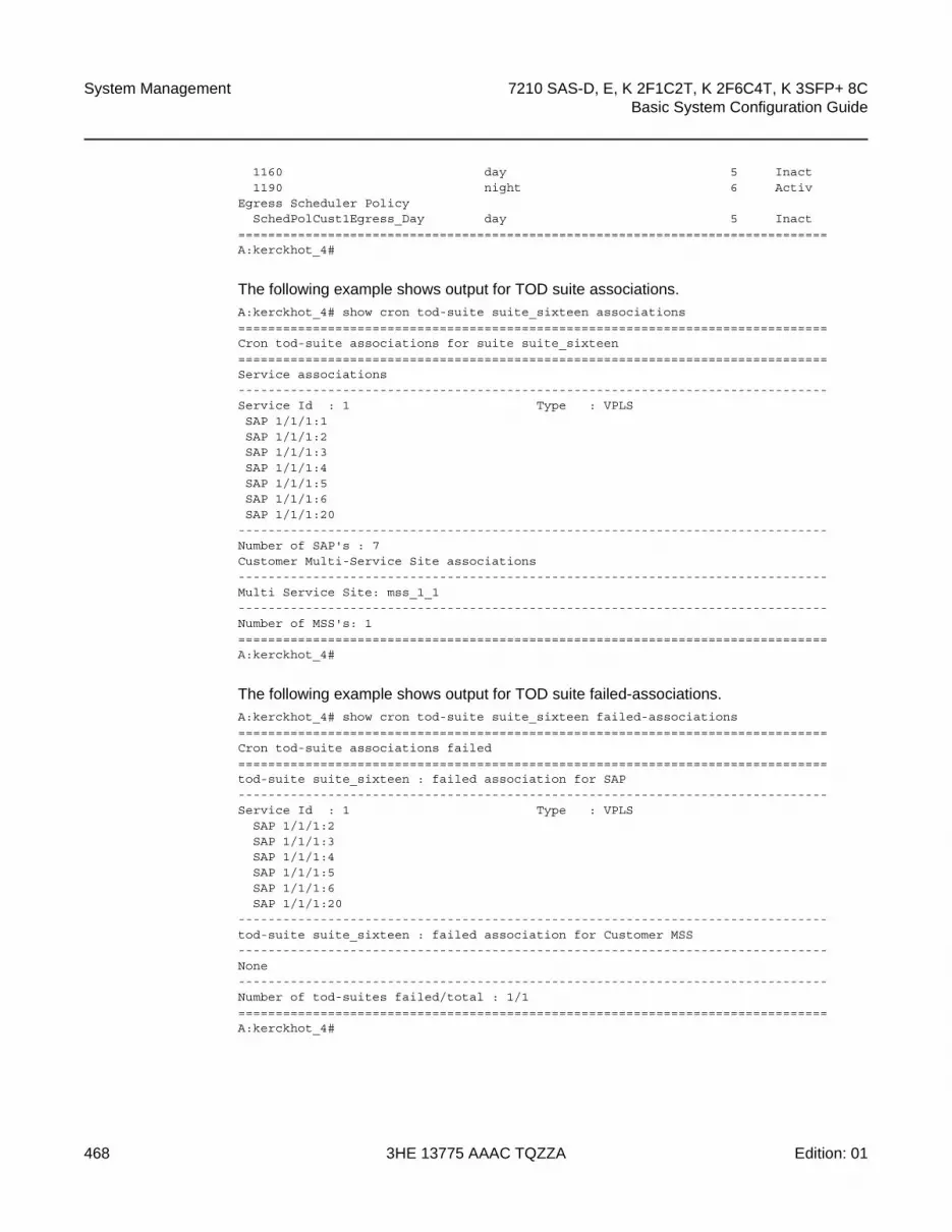
System Management
468
7210 SAS-D, E, K 2F1C2T, K 2F6C4T, K 3SFP+ 8CBasic System Configuration Guide
3HE 13775 AAAC TQZZA Edition: 01
1160 day 5 Inact1190 night 6 Activ
Egress Scheduler PolicySchedPolCust1Egress_Day day 5 Inact
===============================================================================A:kerckhot_4#
The following example shows output for TOD suite associations.A:kerckhot_4# show cron tod-suite suite_sixteen associations===============================================================================Cron tod-suite associations for suite suite_sixteen===============================================================================Service associations-------------------------------------------------------------------------------Service Id : 1 Type : VPLSSAP 1/1/1:1SAP 1/1/1:2SAP 1/1/1:3SAP 1/1/1:4SAP 1/1/1:5SAP 1/1/1:6SAP 1/1/1:20
-------------------------------------------------------------------------------Number of SAP's : 7Customer Multi-Service Site associations-------------------------------------------------------------------------------Multi Service Site: mss_1_1-------------------------------------------------------------------------------Number of MSS's: 1===============================================================================A:kerckhot_4#
The following example shows output for TOD suite failed-associations.A:kerckhot_4# show cron tod-suite suite_sixteen failed-associations===============================================================================Cron tod-suite associations failed===============================================================================tod-suite suite_sixteen : failed association for SAP-------------------------------------------------------------------------------Service Id : 1 Type : VPLS
SAP 1/1/1:2SAP 1/1/1:3SAP 1/1/1:4SAP 1/1/1:5SAP 1/1/1:6SAP 1/1/1:20
-------------------------------------------------------------------------------tod-suite suite_sixteen : failed association for Customer MSS-------------------------------------------------------------------------------None-------------------------------------------------------------------------------Number of tod-suites failed/total : 1/1===============================================================================A:kerckhot_4#

7210 SAS-D, E, K 2F1C2T, K 2F6C4T, K 3SFP+ 8C Basic System Configuration Guide
System Management
Edition: 01 3HE 13775 AAAC TQZZA 469
Zooming in on one of the failed SAPs, the assignments of QoS and scheduler policies are shown not as intended:A:kerckhot_4# show service id 1 sap 1/1/1:2===============================================================================Service Access Points(SAP)===============================================================================Service Id : 1SAP : 1/1/1:2 Encap : q-tagDot1Q Ethertype : 0x8100 QinQ Ethertype : 0x8100Admin State : Up Oper State : UpFlags : NoneLast Status Change : 10/05/2006 18:11:34Last Mgmt Change : 10/05/2006 22:27:48Max Nbr of MAC Addr: No Limit Total MAC Addr : 0Learned MAC Addr : 0 Static MAC Addr : 0Admin MTU : 1518 Oper MTU : 1518Ingress qos-policy : 1130 Egress qos-policy : 1130Intend Ing qos-pol*: 1190 Intend Egr qos-po*: 1190Shared Q plcy : n/a Multipoint shared : DisabledIngr IP Fltr-Id : n/a Egr IP Fltr-Id : n/aIngr Mac Fltr-Id : n/a Egr Mac Fltr-Id : n/atod-suite : suite_sixteen qinq-pbit-marking : bothEgr Agg Rate Limit : maxARP Reply Agent : Unknown Host Conn Verify : DisabledMac Learning : Enabled Discard Unkwn Srce: DisabledMac Aging : Enabled Mac Pinning : DisabledL2PT Termination : Disabled BPDU Translation : Disabled
Multi Svc Site : NoneI. Sched Pol : SchedPolCust1Intend I Sched Pol : SchedPolCust1_NightE. Sched Pol : SchedPolCust1EgressIntend E Sched Pol : SchedPolCust1Egress_NightAcct. Pol : None Collect Stats : DisabledAnti Spoofing : None Nbr Static Hosts : 0===============================================================================A:kerckhot_4#
If a time-range is specified for a filter entry, use the show filter command to view results:A:kerckhot_4# show filter ip 10===============================================================================IP Filter===============================================================================Filter Id : 10 Applied : NoScope : Template Def. Action : DropEntries : 2-------------------------------------------------------------------------------Filter Match Criteria : IP-------------------------------------------------------------------------------Entry : 1010time-range : day Cur. Status : InactiveLog Id : n/aSrc. IP : 0.0.0.0/0 Src. Port : NoneDest. IP : 10.10.100.1/24 Dest. Port : NoneProtocol : Undefined Dscp : UndefinedICMP Type : Undefined ICMP Code : UndefinedFragment : Off Option-present : Off

System Management
470
7210 SAS-D, E, K 2F1C2T, K 2F6C4T, K 3SFP+ 8CBasic System Configuration Guide
3HE 13775 AAAC TQZZA Edition: 01
Sampling : Off Int. Sampling : OnIP-Option : 0/0 Multiple Option: OffTCP-syn : Off TCP-ack : OffMatch action : ForwardNext Hop : 172.22.228.28Ing. Matches : 0 Egr. Matches : 0Entry : 1020time-range : night Cur. Status : ActiveLog Id : n/aSrc. IP : 0.0.0.0/0 Src. Port : NoneDest. IP : 10.10.1.1/16 Dest. Port : NoneProtocol : Undefined Dscp : UndefinedICMP Type : Undefined ICMP Code : UndefinedFragment : Off Option-present : OffSampling : Off Int. Sampling : OnIP-Option : 0/0 Multiple Option: OffTCP-syn : Off TCP-ack : OffMatch action : ForwardNext Hop : 172.22.184.101Ing. Matches : 0 Egr. Matches : 0===============================================================================A:kerckhot_4#
If a filter is referred to in a TOD Suite assignment, use the show filter associations command to view the output:A:kerckhot_4# show filter ip 160 associations===============================================================================IP Filter===============================================================================Filter Id : 160 Applied : NoScope : Template Def. Action : DropEntries : 0-------------------------------------------------------------------------------Filter Association : IP-------------------------------------------------------------------------------Tod-suite "english_suite"- ingress, time-range "day" (priority 5)
===============================================================================A:kerckhot_4#
Table 51 Show System tod-suite Output Fields
Label Description
Associations Shows which SAPs this tod-suite is associated with.
failed-associations Shows the SAPs or Multiservice sites where the TOD Suite could not be applied successfully.
Detail Shows the details of this tod-suite.

7210 SAS-D, E, K 2F1C2T, K 2F6C4T, K 3SFP+ 8C Basic System Configuration Guide
System Management
Edition: 01 3HE 13775 AAAC TQZZA 471
time-range
Syntax time-range name associations [detail]
Context show>cron
SupportedPlatforms
Supported on all 7210 SAS platforms as described in this document
Description This command displays information on the configured time ranges.
Output Time Range Output
The following output is an example of system time-range information, and Table 52 describes the output fields.
Sample Output
The following example shows time-range detail output.A:ala# show cron time-range time-range2 detail===============================================================================Cron time-range===============================================================================Name : time-range1Periodic : Start * * * * End * * * *Absolute : Start * * * * End * * * *
The following example shows output for time-range associations with previously created IP and MAC filters.A:ala# show cron time-range day associations===============================================================================Cron time-range associations===============================================================================Name : day State : Inactive-------------------------------------------------------------------------------IP Filter associations-------------------------------------------------------------------------------IP filter Id : 10, entry 1010-------------------------------------------------------------------------------MAC Filter associations-------------------------------------------------------------------------------None-------------------------------------------------------------------------------Tod-suite associations-------------------------------------------------------------------------------Tod-suite : suite_sixteen, for Ingress Qos Policy "1160"Tod-suite : suite_sixteen, for Ingress Scheduler Policy "SchedPolCust1_Day"Tod-suite : suite_sixteen, for Egress Qos Policy "1160"Tod-suite : suite_sixteen, for Egress Scheduler Policy "SchedPolCust1Egress_Day===============================================================================

System Management
472
7210 SAS-D, E, K 2F1C2T, K 2F6C4T, K 3SFP+ 8CBasic System Configuration Guide
3HE 13775 AAAC TQZZA Edition: 01
uptime
Syntax uptime
Context show
SupportedPlatforms
Supported on all 7210 SAS platforms as described in this document
Description This command displays the time since the system started.
Output Uptime Output
The following output is an example of uptime information, and Table 53 describes the output fields.
Sample Output
A:ALA-1# show uptimeSystem Up Time : 11 days, 18:32:02.22 (hr:min:sec)
A:ALA-1#
sync-if-timing
Syntax sync-if-timing
Context show>system
Description Platforms Supported: 7210 SAS-D ETR, 7210 SAS-K 2F1C2T, 7210 SAS-K 2F6C4T, 7210 SAS-K 3SFP+ 8C
Table 52 Show System Time-range Output Fields
Label Description
Associations Shows the time-range as it is associated with the TOD suites and ACL entries as well as the SAPs using them.
Detail Shows the details of this time-range.
Table 53 System Timing Output Fields
Label Description
System Up Time Displays the length of time the system has been up in days, hr:min:sec format.

7210 SAS-D, E, K 2F1C2T, K 2F6C4T, K 3SFP+ 8C Basic System Configuration Guide
System Management
Edition: 01 3HE 13775 AAAC TQZZA 473
This command displays synchronous interface timing information.
Output System Timing Output
The following outputs are examples of synchronous interface timing information, and Table 54 describes the output fields.
Sample output for 7210 SAS-D ETR:
*7210-SASD># show system sync-if-timing
===============================================================================System Interface Timing Operational Info===============================================================================System Status CPM A : Master Locked
Reference Input Mode : RevertiveQuality Level Selection : EnabledSystem Quality Level : prc
Reference Order : ref1 ref2
Reference Input 1Admin Status : upRx Quality Level : prcQuality Level Override : noneQualified For Use : YesSelected For Use : YesSource Port : 1/1/3
Reference Input 2Admin Status : upRx Quality Level : prcQuality Level Override : noneQualified For Use : YesSelected For Use : No
Not Selected Due To : on standbySource Port : 1/1/5
===============================================================================
Sample output for 7210 SAS-K 2F1C2T, 7210 SAS-K 2F6C4T, or 7210 SAS-K 3SFP+ 8C
*A:SAH01-051>show>system# sync-if-timing
===============================================================================System Interface Timing Operational Info===============================================================================System Status CPM A : Master Free Run
Reference Input Mode : Non-revertiveQuality Level Selection : DisabledReference Selected : noneSystem Quality Level : st3
Reference Order : ref1 ref2
Reference Input 1

System Management
474
7210 SAS-D, E, K 2F1C2T, K 2F6C4T, K 3SFP+ 8CBasic System Configuration Guide
3HE 13775 AAAC TQZZA Edition: 01
Admin Status : downRx Quality Level : unknownQuality Level Override : noneQualified For Use : No
Not Qualified Due To : disabledSelected For Use : No
Not Selected Due To : disabledSource Port : None
Reference Input 2Admin Status : downRx Quality Level : unknownQuality Level Override : noneQualified For Use : No
Not Qualified Due To : disabledSelected For Use : No
Not Selected Due To : disabledSource Port : None
Reference PTPAdmin Status : downRx Quality Level : unknownQuality Level Override : noneQualified For Use : No
Not Qualified Due To : disabledSelected For Use : No
Not Selected Due To : disabled===============================================================================*A:SAH01-051>show>system#
Table 54 Show sync-if-timing Output Fields
Label Description
System Status CPM A Indicates the system status of CPM A.
Reference Input Mode Indicates the reference input mode.
Reference Order Indicates the reference order.
Reference Input 1 Displays information about reference input 1
Admin Status down — Indicates the ref1 or ref2 configuration is administratively shutdown.
up — Indicates the ref1 or ref2 configuration is administratively enabled.
diag — Indicates the reference has been forced using the force-reference command.
Qualified for Use Indicates if the reference input 1 (or input 2) is qualified for use.
Selected for Use Indicates if reference input 1(or input 2) is selected for use.
Source Port Displays the source port information.
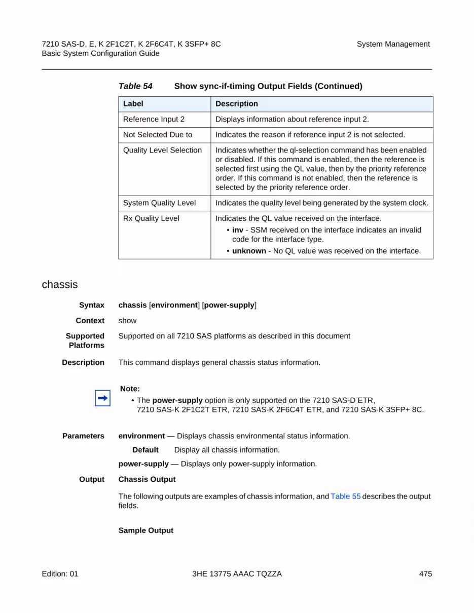
7210 SAS-D, E, K 2F1C2T, K 2F6C4T, K 3SFP+ 8C Basic System Configuration Guide
System Management
Edition: 01 3HE 13775 AAAC TQZZA 475
chassis
Syntax chassis [environment] [power-supply]
Context show
SupportedPlatforms
Supported on all 7210 SAS platforms as described in this document
Description This command displays general chassis status information.
Parameters environment — Displays chassis environmental status information.
Default Display all chassis information.
power-supply — Displays only power-supply information.
Output Chassis Output
The following outputs are examples of chassis information, and Table 55 describes the output fields.
Sample Output
Reference Input 2 Displays information about reference input 2.
Not Selected Due to Indicates the reason if reference input 2 is not selected.
Quality Level Selection Indicates whether the ql-selection command has been enabled or disabled. If this command is enabled, then the reference is selected first using the QL value, then by the priority reference order. If this command is not enabled, then the reference is selected by the priority reference order.
System Quality Level Indicates the quality level being generated by the system clock.
Rx Quality Level Indicates the QL value received on the interface.
• inv - SSM received on the interface indicates an invalid code for the interface type.
• unknown - No QL value was received on the interface.
Table 54 Show sync-if-timing Output Fields (Continued)
Label Description
Note:
• The power-supply option is only supported on the 7210 SAS-D ETR, 7210 SAS-K 2F1C2T ETR, 7210 SAS-K 2F6C4T ETR, and 7210 SAS-K 3SFP+ 8C.
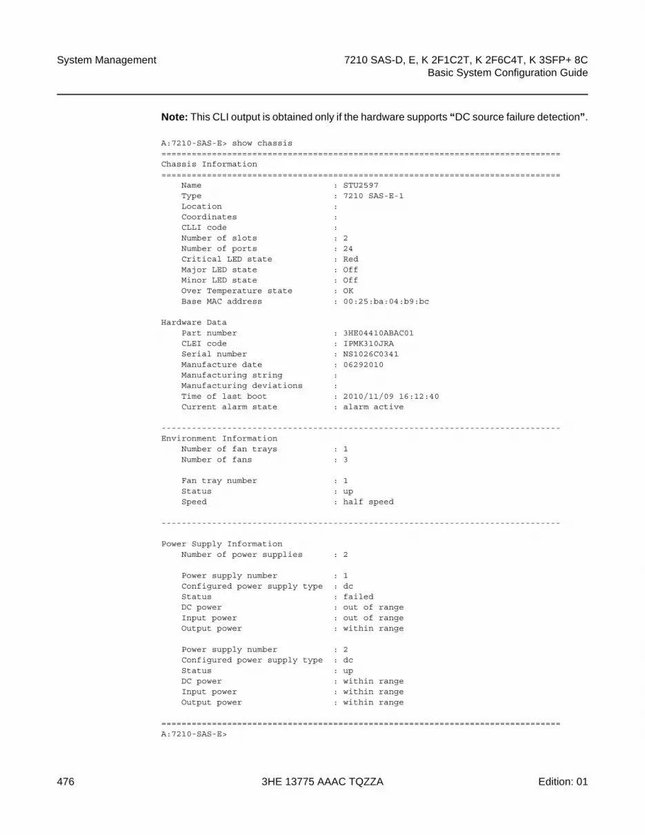
System Management
476
7210 SAS-D, E, K 2F1C2T, K 2F6C4T, K 3SFP+ 8CBasic System Configuration Guide
3HE 13775 AAAC TQZZA Edition: 01
Note: This CLI output is obtained only if the hardware supports “DC source failure detection”.
A:7210-SAS-E> show chassis===============================================================================Chassis Information===============================================================================
Name : STU2597Type : 7210 SAS-E-1Location :Coordinates :CLLI code :Number of slots : 2Number of ports : 24Critical LED state : RedMajor LED state : OffMinor LED state : OffOver Temperature state : OKBase MAC address : 00:25:ba:04:b9:bc
Hardware DataPart number : 3HE04410ABAC01CLEI code : IPMK310JRASerial number : NS1026C0341Manufacture date : 06292010Manufacturing string :Manufacturing deviations :Time of last boot : 2010/11/09 16:12:40Current alarm state : alarm active
-------------------------------------------------------------------------------Environment Information
Number of fan trays : 1Number of fans : 3
Fan tray number : 1Status : upSpeed : half speed
-------------------------------------------------------------------------------
Power Supply InformationNumber of power supplies : 2
Power supply number : 1Configured power supply type : dcStatus : failedDC power : out of rangeInput power : out of rangeOutput power : within range
Power supply number : 2Configured power supply type : dcStatus : upDC power : within rangeInput power : within rangeOutput power : within range
===============================================================================A:7210-SAS-E>
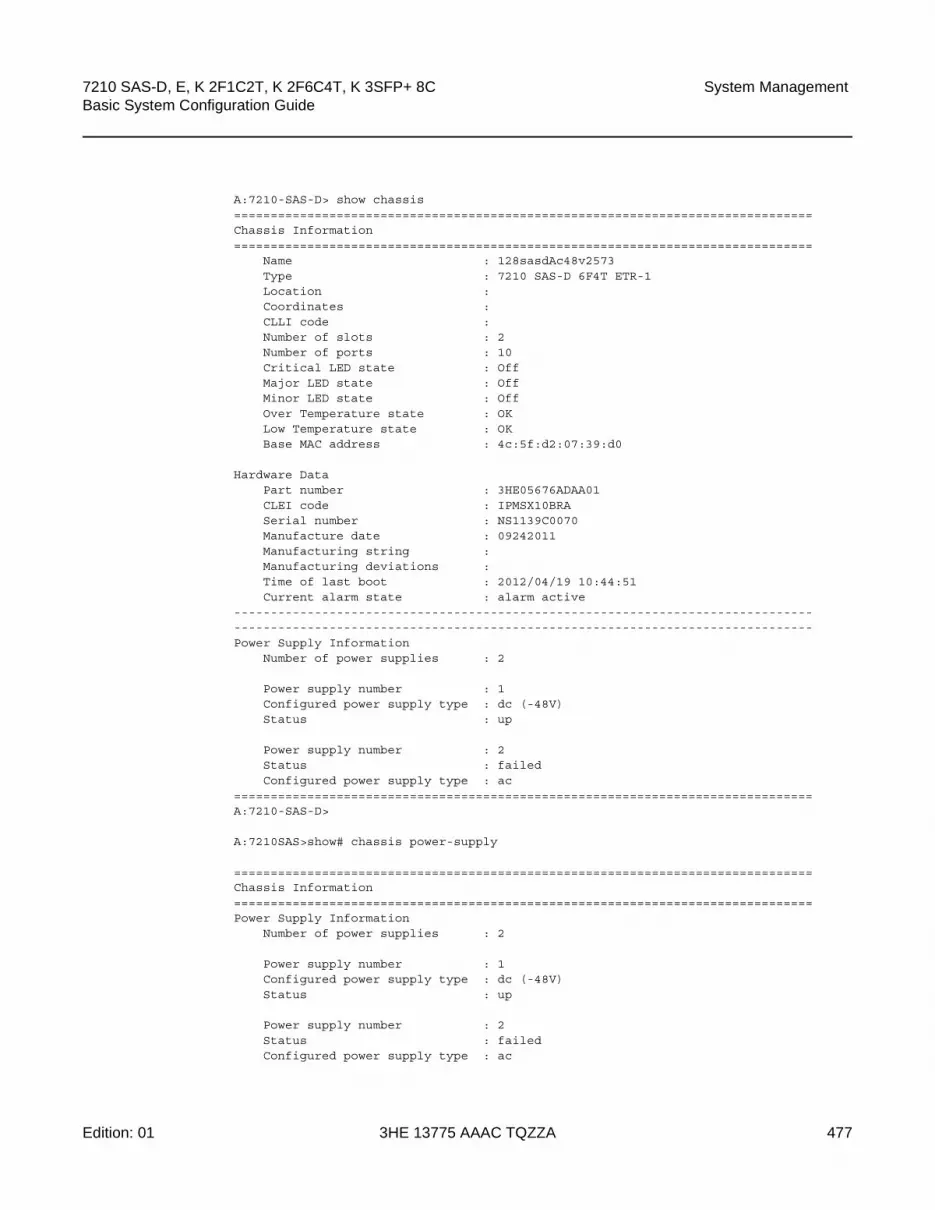
7210 SAS-D, E, K 2F1C2T, K 2F6C4T, K 3SFP+ 8C Basic System Configuration Guide
System Management
Edition: 01 3HE 13775 AAAC TQZZA 477
A:7210-SAS-D> show chassis===============================================================================Chassis Information===============================================================================
Name : 128sasdAc48v2573Type : 7210 SAS-D 6F4T ETR-1Location :Coordinates :CLLI code :Number of slots : 2Number of ports : 10Critical LED state : OffMajor LED state : OffMinor LED state : OffOver Temperature state : OKLow Temperature state : OKBase MAC address : 4c:5f:d2:07:39:d0
Hardware DataPart number : 3HE05676ADAA01CLEI code : IPMSX10BRASerial number : NS1139C0070Manufacture date : 09242011Manufacturing string :Manufacturing deviations :Time of last boot : 2012/04/19 10:44:51Current alarm state : alarm active
--------------------------------------------------------------------------------------------------------------------------------------------------------------Power Supply Information
Number of power supplies : 2
Power supply number : 1Configured power supply type : dc (-48V)Status : up
Power supply number : 2Status : failedConfigured power supply type : ac
===============================================================================A:7210-SAS-D>
A:7210SAS>show# chassis power-supply
===============================================================================Chassis Information===============================================================================Power Supply Information
Number of power supplies : 2
Power supply number : 1Configured power supply type : dc (-48V)Status : up
Power supply number : 2Status : failedConfigured power supply type : ac

System Management
478
7210 SAS-D, E, K 2F1C2T, K 2F6C4T, K 3SFP+ 8CBasic System Configuration Guide
3HE 13775 AAAC TQZZA Edition: 01
===============================================================================A:7210SAS>show#
Output for Chassis for 7210 SAS-K 2F2T1C
*A:SAH01-051>show# chassis
===============================================================================Chassis Information===============================================================================
Name : SAH01-051Type : 7210 SAS-K-1Location :Coordinates :CLLI code :Number of slots : 2Number of ports : 5
System LED state : AmberOver Temperature state : OKBase MAC address : 00:03:fa:27:15:4eNumber of MAC addresses : 12Hardware Data
Part number :CLEI code :Serial number : SAH01-051Manufacture date :Manufacturing string : (Not Specified)Manufacturing deviations : (Not Specified)Manufacturing assembly number :Temperature : 49CTime of last boot : 2014/01/14 05:13:50Current alarm state : alarm active
-------------------------------------------------------------------------------Environment Information
Number of fan trays : 0Number of fans : 0
-------------------------------------------------------------------------------Power Supply Information
Number of power supplies : 1
Power supply number : 1Configured power supply type : unknownStatus : upDC power : within range
===============================================================================*A:SAH01-051>show#
Output for Chassis Environment.
*A:SASE>show# chassis environment
===============================================================================Chassis Information===============================================================================Environment Information
Number of fan trays : 1Number of fans : 3

7210 SAS-D, E, K 2F1C2T, K 2F6C4T, K 3SFP+ 8C Basic System Configuration Guide
System Management
Edition: 01 3HE 13775 AAAC TQZZA 479
Fan tray number : 1Status : upSpeed : half speed
===============================================================================*A:SASE>show#
Output for older 7210 SAS-E devices (without input-fail-detection)
*A:7210-SAS-E# show chassis power-supply===============================================================================Chassis Information===============================================================================Power Supply Information
Number of power supplies : 2Power supply number : 1Defaulted power supply type : noneStatus : not equippedPower supply number : 2Configured power supply type : dc (+24V)Status : up
===============================================================================*A:7210-SAS-E#
*A:7210-SAS-E# show chassis power-supply===============================================================================Chassis Information===============================================================================Power Supply Information
Number of power supplies : 2Power supply number : 1Configured power supply type : ac singleStatus : upAC power : within rangePower supply number : 2Configured power supply type : dc (-48V)Status : up
===============================================================================*A:7210-SAS-E#
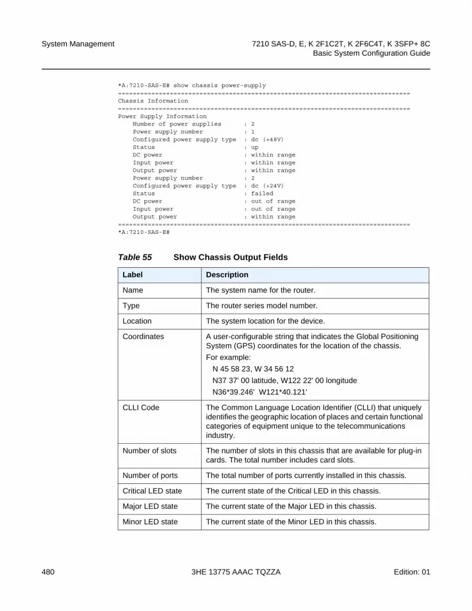
System Management
480
7210 SAS-D, E, K 2F1C2T, K 2F6C4T, K 3SFP+ 8CBasic System Configuration Guide
3HE 13775 AAAC TQZZA Edition: 01
*A:7210-SAS-E# show chassis power-supply===============================================================================Chassis Information===============================================================================Power Supply Information
Number of power supplies : 2Power supply number : 1Configured power supply type : dc (+48V)Status : upDC power : within rangeInput power : within rangeOutput power : within rangePower supply number : 2Configured power supply type : dc (+24V)Status : failedDC power : out of rangeInput power : out of rangeOutput power : within range
===============================================================================*A:7210-SAS-E#
Table 55 Show Chassis Output Fields
Label Description
Name The system name for the router.
Type The router series model number.
Location The system location for the device.
Coordinates A user-configurable string that indicates the Global Positioning System (GPS) coordinates for the location of the chassis.
For example:
N 45 58 23, W 34 56 12
N37 37' 00 latitude, W122 22' 00 longitude
N36*39.246' W121*40.121'
CLLI Code The Common Language Location Identifier (CLLI) that uniquely identifies the geographic location of places and certain functional categories of equipment unique to the telecommunications industry.
Number of slots The number of slots in this chassis that are available for plug-in cards. The total number includes card slots.
Number of ports The total number of ports currently installed in this chassis.
Critical LED state The current state of the Critical LED in this chassis.
Major LED state The current state of the Major LED in this chassis.
Minor LED state The current state of the Minor LED in this chassis.

7210 SAS-D, E, K 2F1C2T, K 2F6C4T, K 3SFP+ 8C Basic System Configuration Guide
System Management
Edition: 01 3HE 13775 AAAC TQZZA 481
Base MAC address The base chassis Ethernet MAC address.
Part number The part number.
CLEI code The code used to identify the router.
Serial number The part number. Not user modifiable.
Manufacture date The chassis manufacture date. Not user modifiable.
Manufacturing string Factory-inputted manufacturing text string. Not user modifiable.
Time of last boot The date and time the most recent boot occurred.
Current alarm state Displays the alarm conditions for the specific board.
Number of fan trays The total number of fan trays installed in this chassis.
Number of fans The total number of fans installed in this chassis.
Operational status Current status of the fan tray.
Fan speed Half speed — The fans are operating at half speed.
Full speed — The fans are operating at full speed.
Number of power supplies
The number of power supplies installed in the chassis.
Power supply number The ID for each power supply installed in the chassis.
AC power Within range — AC voltage is within range.
Out of range — AC voltage is out of range.
DC power Within range — DC voltage is within range.
Out of range — DC voltage is out of range.
Over temp Within range — The current temperature is within the acceptable range.
Out of range — The current temperature is above the acceptable range.
Status Up — The specified power supply is up.
Down — The specified power supply is down.
Table 55 Show Chassis Output Fields (Continued)
Label Description (Continued)

System Management
482
7210 SAS-D, E, K 2F1C2T, K 2F6C4T, K 3SFP+ 8CBasic System Configuration Guide
3HE 13775 AAAC TQZZA Edition: 01
alarm-contact-input
Syntax alarm- contact-input all
Context show>alarm-contact-input
SupportedPlatforms
Supported on all 7210 SAS platforms as described in this document
Description This command displays information of all the alarm contact input pins.
Output alarm-contact-input Output
The following output is an example of alarm contact input information, and Table 56 describes the output fields.
Sample Output
*A:7210-2# show alarm-contact-input 1===============================================================================Alarm Contact Input===============================================================================
Alarm Input Pin Number : 1Alarm Input Pin Current State : DisabledAlarm Output Pin Used : Major
===============================================================================*A:7210-2#
*A:7210-2# show alarm-contact-input 1 detail===============================================================================Alarm Contact Input===============================================================================
Alarm Input Pin Number : 1Alarm Input Pin Description :Alarm Input Pin Current State : DisabledAlarm Output Pin Used : MajorLast State Change : 05/19/2010 11:28:09
===============================================================================*A:7210-2#
*A:7210SAS>show# alarm-contact-input console-1===============================================================================Alarm Contact Input===============================================================================
Alarm Input Pin Number : console-1Alarm Input Pin Current State : alarmAlarm Output Pin Used : Major
===============================================================================*A:7210SAS>show#
*A:7210-2# show alarm-contact-input all===============================================================================Alarm Contact Input

7210 SAS-D, E, K 2F1C2T, K 2F6C4T, K 3SFP+ 8C Basic System Configuration Guide
System Management
Edition: 01 3HE 13775 AAAC TQZZA 483
===============================================================================Alarm Input Pin Number : 1Alarm Input Pin Description :Alarm Input Pin Current State : DisabledAlarm Output Pin Used : MajorLast State Change : 05/19/2010 11:28:09Alarm Input Pin Number : 2Alarm Input Pin Description :Alarm Input Pin Current State : DisabledAlarm Output Pin Used : MajorLast State Change : 05/19/2010 11:28:09Alarm Input Pin Number : 3Alarm Input Pin Description :Alarm Input Pin Current State : DisabledAlarm Output Pin Used : MajorLast State Change : 05/19/2010 11:28:09Alarm Input Pin Number : 4Alarm Input Pin Description :Alarm Input Pin Current State : DisabledAlarm Output Pin Used : MajorLast State Change : 05/19/2010 11:28:09
===============================================================================*A:7210-2#
Table 56 Show Alarm Contact Input Fields
Label Description
Alarm input pin Number Indicates the pin alarm input pin number.
Alarm input pin Description Describes the alarm indicating its usage or attribute.
Alarm input pin current state Indicates the current state of the alarm contact input pin.
Alarm output pin used Indicates the alarm output pin used.
Last state change time Indicates the previous state change time.

System Management
484
7210 SAS-D, E, K 2F1C2T, K 2F6C4T, K 3SFP+ 8CBasic System Configuration Guide
3HE 13775 AAAC TQZZA Edition: 01
5.21.2.3 Clear Commands
screen
Syntax screen
Context clear
SupportedPlatforms
Supported on all 7210 SAS platforms as described in this document
Description This command clears the Telnet or console screen.
ptp
Syntax ptp inactive-peers
ptp statistics
ptp peer ip-address statistics
Context clear>system
Description Platforms Supported: 7210 SAS-D ETR, 7210 SAS-K 2F1C2T, 7210 SAS-K 2F6C4T, 7210 SAS-K 3SFP+ 8C
This command clears PTP statistics.
Parameters inactive-peers — Removes PTP peers which are not currently exchanging PTP packets with the router.
peer ip-address statistics — Clears statistics for the specified peer.
statistics — Clears all PTP statistics.
script-control
Syntax script-control
Context clear>system
Description Platforms Supported: 7210 SAS-D, 7210 SAS-K 2F1C2T, 7210 SAS-K 2F6C4T, 7210 SAS-K 3SFP+ 8C
This command clears script information.

7210 SAS-D, E, K 2F1C2T, K 2F6C4T, K 3SFP+ 8C Basic System Configuration Guide
System Management
Edition: 01 3HE 13775 AAAC TQZZA 485
script-policy
Syntax script-policy
Context clear>system>script-control
Description Platforms Supported: 7210 SAS-D, 7210 SAS-K 2F1C2T, 7210 SAS-K 2F6C4T, 7210 SAS-K 3SFP+ 8C
This command enables the context to clear script policy information.
completed
Syntax completed [script-policy-name] [owner owner-name]
Context clear>system>script-control>script-policy
Description Platforms Supported: 7210 SAS-D, 7210 SAS-K 2F1C2T, 7210 SAS-K 2F6C4T, 7210 SAS-K 3SFP+ 8C
This command clears completed script run history entries.
Parameters script-policy-name — Specifies to only clear history entries for the specified script-policy. 32 characters maximum.
owner-name — Specifies to only clear history entries for script-policies with the specified owner. 32 characters maximum.
Default TiMOS CLI
sync-if-timing
Syntax sync-if-timing {ref1 | ref2}
Context clear>system
Description Platforms Supported: 7210 SAS-D ETR, 7210 SAS-K 2F1C2T, 7210 SAS-K 2F6C4T, 7210 SAS-K 3SFP+ 8C
This command individually clears (re-enable) a previously failed reference. As long as the reference is one of the valid options, this command is always executed. An inherent behavior enables the revertive mode which causes a re-evaluation of all available references.
Parameters ref1 — Clears the first timing reference.
ref2 — Clears the second timing reference.
System Management
486
7210 SAS-D, E, K 2F1C2T, K 2F6C4T, K 3SFP+ 8CBasic System Configuration Guide
3HE 13775 AAAC TQZZA Edition: 01
5.21.2.4 Debug Commands
sync-if-timing
Syntax sync-if-timing
Context debug
Description Platforms Supported: 7210 SAS-D ETR, 7210 SAS-K 2F1C2T, 7210 SAS-K 2F6C4T, 7210 SAS-K 3SFP+ 8C
This command debugs synchronous interface timing references.
force-reference
Syntax force-reference {ref1 | ref2 | ptp}
no force-reference
Context debug>sync-if-timing
Description Platforms Supported: 7210 SAS-D ETR, 7210 SAS-K 2F1C2T, 7210 SAS-K 2F6C4T, 7210 SAS-K 3SFP+ 8C
This command enables the context to force the system synchronous timing output to use a specific reference.
When the debug force-reference command is executed, the current system synchronous timing output is immediately referenced from the specified reference input. If the specified input is not available (shutdown), or in a disqualified state, the timing output will enter the holdover state based on the previous input reference.
Parameters ref1 — The clock will use the first timing reference.
ref2 — The clock will use the second timing reference.
ptp — The clock will use PTP as a timing reference.
Note: This command should be used for testing and debugging purposes only. After the system timing reference input has been forced, it will not revert back to another reference at any time. The state of this command is not persistent between system boots.

7210 SAS-D, E, K 2F1C2T, K 2F6C4T, K 3SFP+ 8C Basic System Configuration Guide
System Management
Edition: 01 3HE 13775 AAAC TQZZA 487
system
Syntax [no] system
Context debug
SupportedPlatforms
Supported on all 7210 SAS platforms as described in this document
Description This command displays system debug information.
ntp
Syntax [no] router router-name interface ip-int-name
Context debug>system
SupportedPlatforms
Supported on all 7210 SAS platforms as described in this document
Description This command enables and configures debugging for NTP.
The no form of the command disables debugging for NTP.
Parameters router-name — Base.
Default base
ip-int-name — Maximum 32 characters; must begin with a letter. If the string contains special characters (#, $, spaces, etc.), the entire string must be enclosed within double quotes.
5.21.2.4.1 Fan Controller debug commands
fan-stats
Syntax fan-stats
Context tools>dump
Description Platforms Supported: 7210 SAS-D ETR
This command provides details of the fan operation.
Output Fan Operation
Table 57 describes fan-stats output fields.

System Management
488
7210 SAS-D, E, K 2F1C2T, K 2F6C4T, K 3SFP+ 8CBasic System Configuration Guide
3HE 13775 AAAC TQZZA Edition: 01
Sample Output
A:7210SAS# tools dump system fan-stats
Fan Configuration Mode : AutoFan Status : OffAuto Mode Duration : 70 hr:24 minFan ON Count : 2
Table 57 Show Fan Statistics Output Fields
Label Description
Fan Configuration Mode Displays the user configured mode for fan operation. It can be On/Off/Auto.
Fan Status Displays the current status of the fan. It can be On / Off.
Auto Mode Duration Displays the total duration since the fan has been in auto mode.
Displayed in HH:MM format to indicate hours and minutes. Valid only when the Fan configuration mode is auto.
Fan ON count Displays the total number of times the Fan has been switched 'ON' in auto mode. Valid only in auto mode.
Note: When the fan mode is changed by the user, the values displayed above are automatically reset by the software.
7210 SAS-D, E, K 2F1C2T, K 2F6C4T, K 3SFP+ 8C Basic System Configuration Guide
Standards and Protocol Support
Edition: 01 3HE 13775 AAAC TQZZA 489
6 Standards and Protocol Support
BGP
draft-ietf-idr-add-paths-04, Advertisement of Multiple Paths in BGP is supported on M(N), T(N), X, Mxp, Sx/S-1/10GE, Sx-10/100GE, R6, and R12
draft-ietf-sidr-origin-validation-signaling-04, BGP Prefix Origin Validation State Extended Community is supported on K12, K30, M(N), T(N), X, Mxp, Sx/S-1/10GE, Sx-10/100GE, Sx/S-1/10GE-VC, R6, and R12
RFC 1772, Application of the Border Gateway Protocol in the Internet is supported on K12, K30, M(N), T(N), X, Mxp, Sx/S-1/10GE, Sx-10/100GE, Sx/S-1/10GE-VC, R6, and R12
RFC 1997, BGP Communities Attribute is supported on K12, K30, M(N), T(N), X, Mxp, Sx/S-1/10GE, Sx-10/100GE, Sx/S-1/10GE-VC, R6, and R12
RFC 2385, Protection of BGP Sessions via the TCP MD5 Signature Option is supported on K12, K30, M(N), T(N), X, Mxp, Sx/S-1/10GE, Sx-10/100GE, Sx/S-1/10GE-VC, R6, and R12
RFC 2439, BGP Route Flap Damping is supported on K12, K30, M(N), T(N), X, Mxp, Sx/S-1/10GE, Sx-10/100GE, Sx/S-1/10GE-VC, R6, and R12
RFC 2545, Use of BGP-4 Multiprotocol Extensions for IPv6 Inter-Domain Routing is supported on K12, M(N), T(N), X, Mxp, Sx/S-1/10GE, Sx-10/100GE, Sx/S-1/10GE-VC, R6, and R12
RFC 2858, Multiprotocol Extensions for BGP-4 is supported on K12, K30, M(N), T(N), X, Mxp, Sx/S-1/10GE, Sx-10/100GE, Sx/S-1/10GE-VC, R6, and R12
RFC 2918, Route Refresh Capability for BGP-4 is supported on K12, K30, M(N), T(N), X, Mxp, Sx/S-1/10GE, Sx-10/100GE, Sx/S-1/10GE-VC, R6, and R12
RFC 3107, Carrying Label Information in BGP-4 is supported on K12, K30, M(N), T(N), X, Mxp, Sx/S-1/10GE, Sx-10/100GE, Sx/S-1/10GE-VC, R6, and R12
RFC 3392, Capabilities Advertisement with BGP-4 is supported on K12, K30, M(N), T(N), X, Mxp, Sx/S-1/10GE, Sx-10/100GE, Sx/S-1/10GE-VC, R6, and R12
RFC 4271, A Border Gateway Protocol 4 (BGP-4) is supported on K12, K30, M(N), T(N), X, Mxp, Sx/S-1/10GE, Sx-10/100GE, Sx/S-1/10GE-VC, R6, and R12
RFC 4360, BGP Extended Communities Attribute is supported on K12, K30, M(N), T(N), X, Mxp, Sx/S-1/10GE, Sx-10/100GE, Sx/S-1/10GE-VC, R6, and R12
RFC 4364, BGP/MPLS IP Virtual Private Networks (VPNs) is supported on K12, K30, M(N), T(N), X, Mxp, Sx/S-1/10GE, Sx-10/100GE, R6, and R12
Note: The information presented is subject to change without notice.
Nokia assumes no responsibility for inaccuracies contained herein.

Standards and Protocol Support
490
7210 SAS-D, E, K 2F1C2T, K 2F6C4T, K 3SFP+ 8CBasic System Configuration Guide
3HE 13775 AAAC TQZZA Edition: 01
RFC 4456, BGP Route Reflection: An Alternative to Full Mesh Internal BGP (IBGP) is supported on K12, K30, M(N), T(N), X, Mxp, Sx/S-1/10GE, Sx-10/100GE, Sx/S-1/10GE-VC, R6, and R12
RFC 4659, BGP-MPLS IP Virtual Private Network (VPN) Extension for IPv6 VPN is supported on K12, M(N), T(N), X, Mxp, Sx/S-1/10GE, Sx-10/100GE, R6, and R12
RFC 4724, Graceful Restart Mechanism for BGP (Helper Mode) is supported on K12, K30, M(N), T(N), X, Mxp, Sx/S-1/10GE, Sx-10/100GE, Sx/S-1/10GE-VC, R6, and R12
RFC 4760, Multiprotocol Extensions for BGP-4 is supported on K12, K30, M(N), T(N), X, Mxp, Sx/S-1/10GE, Sx-10/100GE, Sx/S-1/10GE-VC, R6, and R12
RFC 4798, Connecting IPv6 Islands over IPv4 MPLS Using IPv6 Provider Edge Routers (6PE) is supported on K12, M(N), T(N), X, Mxp, Sx/S-1/10GE, Sx-10/100GE, R6, and R12
RFC 4893, BGP Support for Four-octet AS Number Space is supported on K12, K30, M(N), T(N), X, Mxp, Sx/S-1/10GE, Sx-10/100GE, Sx/S-1/10GE-VC, R6, and R12
RFC 5004, Avoid BGP Best Path Transitions from One External to Another is supported on K12, K30, M(N), T(N), X, Mxp, Sx/S-1/10GE, Sx-10/100GE, Sx/S-1/10GE-VC, R6, and R12
RFC 5291, Outbound Route Filtering Capability for BGP-4 is supported on K12, K30, M(N), T(N), X, Mxp, Sx/S-1/10GE, Sx-10/100GE, Sx/S-1/10GE-VC, R6, and R12
RFC 5668, 4-Octet AS Specific BGP Extended Community is supported on K12, K30, M(N), T(N), X, Mxp, Sx/S-1/10GE, Sx-10/100GE, Sx/S-1/10GE-VC, R6, and R12
RFC 6811, Prefix Origin Validation is supported on K12, K30, M(N), T(N), X, Mxp, Sx/S-1/10GE, Sx-10/100GE, Sx/S-1/10GE-VC, R6, and R12
Circuit Emulation
RFC 4553, Structure-Agnostic Time Division Multiplexing (TDM) over Packet (SAToP) is supported on M(N)
RFC 5086, Structure-Aware Time Division Multiplexed (TDM) Circuit Emulation Service over Packet Switched Network (CESoPSN) is supported on M(N)
RFC 5287, Control Protocol Extensions for the Setup of Time-Division Multiplexing (TDM) Pseudowires in MPLS Networks is supported on M(N)

7210 SAS-D, E, K 2F1C2T, K 2F6C4T, K 3SFP+ 8C Basic System Configuration Guide
Standards and Protocol Support
Edition: 01 3HE 13775 AAAC TQZZA 491
Ethernet
IEEE 802.1AB, Station and Media Access Control Connectivity Discovery is supported on D, E, K5, K12, K30, M(A,N), T(A,N), X, Mxp, Sx/S-1/10GE, Sx-10/100GE, Sx/S-1/10GE-VC, R6, and R12
IEEE 802.1ad, Provider Bridges is supported on D, E, K5, K12, K30, M(A,N), T(A,N), X, Mxp, Sx/S-1/10GE, Sx-10/100GE, Sx/S-1/10GE-VC, R6, and R12
IEEE 802.1ag, Connectivity Fault Management is supported on D, E, K5, K12, K30, M(A,N), T(A,N), X, Mxp, Sx/S-1/10GE, Sx-10/100GE, Sx/S-1/10GE-VC, R6, and R12
IEEE 802.1ah, Provider Backbone Bridges is supported on M(N), X, and T(N)
IEEE 802.1ax, Link Aggregation is supported on D, E, K5, K12, K30, M(A,N), T(A,N), X, Mxp, Sx/S-1/10GE, Sx-10/100GE, Sx/S-1/10GE-VC, R6, and R12
IEEE 802.1D, MAC Bridges is supported on D, E, K5, K12, K30, M(A,N), T(A,N), X, Mxp, Sx/S-1/10GE, Sx-10/100GE, Sx/S-1/10GE-VC, R6, and R12
IEEE 802.1p, Traffic Class Expediting is supported on D, E, K5, K12, K30, M(A,N), T(A,N), X, Mxp, Sx/S-1/10GE, Sx-10/100GE, Sx/S-1/10GE-VC, R6, and R12
IEEE 802.1Q, Virtual LANs is supported on D, E, K5, K12, K30, M(A,N), T(A,N), X, Mxp, Sx/S-1/10GE, Sx-10/100GE, Sx/S-1/10GE-VC, R6, and R12
IEEE 802.1s, Multiple Spanning Trees is supported on D, E, K5, K12, K30, M(A,N), T(A,N), X, Mxp, Sx/S-1/10GE, Sx-10/100GE, Sx/S-1/10GE-VC, R6, and R12
IEEE 802.1w, Rapid Reconfiguration of Spanning Tree is supported on D, E, K5, K12, K30, M(A,N), T(A,N), X, Mxp, Sx/S-1/10GE, Sx-10/100GE, Sx/S-1/10GE-VC, R6, and R12
IEEE 802.1X, Port Based Network Access Control is supported on D, E, K5, K12, K30, M(A,N), T(A,N), X, Mxp, Sx/S-1/10GE, Sx-10/100GE, Sx/S-1/10GE-VC, R6, and R12
IEEE 802.3ab, 1000BASE-T is supported on D, E, K5, K12, K30, M(A,N), T(A,N), X, Mxp, Sx/S-1/10GE, Sx-10/100GE, Sx/S-1/10GE-VC, R6, and R12
IEEE 802.3ac, VLAN Tag is supported on D, E, K5, K12, K30, M(A,N), T(A,N), X, Mxp, Sx/S-1/10GE, Sx-10/100GE, Sx/S-1/10GE-VC, R6, and R12
IEEE 802.3ad, Link Aggregation is supported on D, E, K5, K12, K30, M(A,N), T(A,N), X, Mxp, Sx/S-1/10GE, Sx-10/100GE, Sx/S-1/10GE-VC, R6, and R12
IEEE 802.3ae, 10 Gb/s Ethernet is supported on K30, M(A,N), T(A,N), X, Mxp, Sx/S-1/10GE, Sx-10/100GE, Sx/S-1/10GE-VC, R6, and R12
IEEE 802.3ah, Ethernet in the First Mile is supported on D, E, K5, K12, K30, M(A,N), T(A,N), X, Mxp, Sx/S-1/10GE, Sx-10/100GE, Sx/S-1/10GE-VC, R6, and R12
IEEE 802.3ba, 40 Gb/s and 100 Gb/s Ethernet is supported on R6, R12, and Sx-10/100GE
IEEE 802.3i, Ethernet is supported on D, E, K5, K12, K30, M(A,N), T(A,N), X, Mxp, Sx/S-1/10GE, Sx-10/100GE, Sx/S-1/10GE-VC, R6, and R12

Standards and Protocol Support
492
7210 SAS-D, E, K 2F1C2T, K 2F6C4T, K 3SFP+ 8CBasic System Configuration Guide
3HE 13775 AAAC TQZZA Edition: 01
IEEE 802.3u, Fast Ethernet is supported on D, E, K5, K12, K30, M(A,N), T(A,N), X, Mxp, Sx/S-1/10GE, Sx-10/100GE, Sx/S-1/10GE-VC, R6, and R12
IEEE 802.3z, Gigabit Ethernet is supported on D, E, K5, K12, K30, M(A,N), T(A,N), X, Mxp, Sx/S-1/10GE, Sx-10/100GE, Sx/S-1/10GE-VC, R6, and R12
ITU-T G.8032, Ethernet Ring Protection Switching is supported on D, E, K5, K12, K30, M(A,N), T(A,N), X, Mxp, Sx/S-1/10GE, Sx-10/100GE, Sx/S-1/10GE-VC, R6, and R12
ITU-T Y.1731, OAM functions and mechanisms for Ethernet based networks is supported on D, E, K5, K12, K30, M(A,N), T(A,N), X, Mxp, Sx/S-1/10GE, Sx-10/100GE, Sx/S-1/10GE-VC, R6, and R12
Fast Reroute
draft-ietf-rtgwg-lfa-manageability-08, Operational management of Loop Free Alternates is supported on K12, K30, M(N), T(N), X, Mxp, Sx/S-1/10GE, Sx-10/100GE, Sx/S-1/10GE-VC, R6, and R12
RFC 5286, Basic Specification for IP Fast Reroute: Loop-Free Alternates is supported on K12, K30, M(N), T(N), X, Mxp, Sx/S-1/10GE, Sx-10/100GE, Sx/S-1/10GE-VC, R6, and R12
Internet Protocol (IP) — General
draft-grant-tacacs-02, The TACACS+ Protocol is supported on D, E, K5, K12, K30, M(A,N), T(A,N), X, Mxp, Sx/S-1/10GE, Sx-10/100GE, Sx/S-1/10GE-VC, R6, and R12
RFC 768, User Datagram Protocol is supported on D, E, K5, K12, K30, M(A,N), T(A,N), X, Mxp, Sx/S-1/10GE, Sx-10/100GE, Sx/S-1/10GE-VC, R6, and R12
RFC 793, Transmission Control Protocol is supported on D, E, K5, K12, K30, M(A,N), T(A,N), X, Mxp, Sx/S-1/10GE, Sx-10/100GE, Sx/S-1/10GE-VC, R6, and R12
RFC 854, TELNET Protocol Specifications is supported on D, E, K5, K12, K30, M(A,N), T(A,N), X, Mxp, Sx/S-1/10GE, Sx-10/100GE, Sx/S-1/10GE-VC, R6, and R12
RFC 951, Bootstrap Protocol (BOOTP) is supported on D, E, K5, K12, K30, M(A,N), T(A,N), X, Mxp, Sx/S-1/10GE, Sx-10/100GE, Sx/S-1/10GE-VC, R6, and R12
RFC 1034, Domain Names - Concepts and Facilities is supported on D, E, K5, K12, K30, M(A,N), T(A,N), X, Mxp, Sx/S-1/10GE, Sx-10/100GE, Sx/S-1/10GE-VC, R6, and R12
RFC 1035, Domain Names - Implementation and Specification is supported on D, E, K5, K12, K30, M(A,N), T(A,N), X, Mxp, Sx/S-1/10GE, Sx-10/100GE, Sx/S-1/10GE-VC, R6, and R12

7210 SAS-D, E, K 2F1C2T, K 2F6C4T, K 3SFP+ 8C Basic System Configuration Guide
Standards and Protocol Support
Edition: 01 3HE 13775 AAAC TQZZA 493
RFC 1350, The TFTP Protocol (revision 2) is supported on D, E, K5, K12, K30, M(A,N), T(A,N), X, Mxp, Sx/S-1/10GE, Sx-10/100GE, Sx/S-1/10GE-VC, R6, and R12
RFC 1534, Interoperation between DHCP and BOOTP is supported on D, E, K5, K12, K30, M(A,N), T(A,N), X, Mxp, Sx/S-1/10GE, Sx-10/100GE, Sx/S-1/10GE-VC, R6, and R12
RFC 1542, Clarifications and Extensions for the Bootstrap Protocol is supported on D, E, K5, K12, K30, M(A,N), T(A,N), X, Mxp, Sx/S-1/10GE, Sx-10/100GE, Sx/S-1/10GE-VC, R6, and R12
RFC 2131, Dynamic Host Configuration Protocol is supported on D, E, K5, K12, K30, M(A,N), T(A,N), X, Mxp, Sx/S-1/10GE, Sx-10/100GE, Sx/S-1/10GE-VC, R6, and R12
RFC 2347, TFTP Option Extension is supported on D, E, K5, K12, K30, M(A,N), T(A,N), X, Mxp, Sx/S-1/10GE, Sx-10/100GE, Sx/S-1/10GE-VC, R6, and R12
RFC 2348, TFTP Blocksize Option is supported on D, E, K5, K12, K30, M(A,N), T(A,N), X, Mxp, Sx/S-1/10GE, Sx-10/100GE, Sx/S-1/10GE-VC, R6, and R12
RFC 2349, TFTP Timeout Interval and Transfer Size Options is supported on D, E, K5, K12, K30, M(A,N), T(A,N), X, Mxp, Sx/S-1/10GE, Sx-10/100GE, Sx/S-1/10GE-VC, R6, and R12
RFC 2428, FTP Extensions for IPv6 and NATs is supported on D, E, K12, K30, M(A,N), T(A,N), X, Mxp, Sx/S-1/10GE, Sx-10/100GE, Sx/S-1/10GE-VC, R6, and R12
RFC 2865, Remote Authentication Dial In User Service (RADIUS) is supported on D, E, K5, K12, K30, M(A,N), T(A,N), X, Mxp, Sx/S-1/10GE, Sx-10/100GE, Sx/S-1/10GE-VC, R6, and R12
RFC 2866, RADIUS Accounting is supported on D, E, K5, K12, K30, M(A,N), T(A,N), X, Mxp, Sx/S-1/10GE, Sx-10/100GE, Sx/S-1/10GE-VC, R6, and R12
RFC 3046, DHCP Relay Agent Information Option (Option 82) is supported on D, E, K5, K12, K30, M(A,N), T(A,N), X, Mxp, Sx/S-1/10GE, Sx-10/100GE, Sx/S-1/10GE-VC, R6, and R12
RFC 3596, DNS Extensions to Support IP version 6 is supported on D, E, K12, K30, M(A,N), T(A,N), X, Mxp, Sx/S-1/10GE, Sx-10/100GE, Sx/S-1/10GE-VC, R6, and R12
RFC 3768, Virtual Router Redundancy Protocol (VRRP) is supported on K12, K30, M(N), T(N), X, Mxp, Sx/S-1/10GE, Sx-10/100GE, Sx/S-1/10GE-VC, R6, and R12
RFC 4250, The Secure Shell (SSH) Protocol Assigned Numbers is supported on D, E, K5, K12, K30, M(A,N), T(A,N), X, Mxp, Sx/S-1/10GE, Sx-10/100GE, Sx/S-1/10GE-VC, R6, and R12
RFC 4251, The Secure Shell (SSH) Protocol Architecture is supported on D, E, K5, K12, K30, M(A,N), T(A,N), X, Mxp, Sx/S-1/10GE, Sx-10/100GE, Sx/S-1/10GE-VC, R6, and R12

Standards and Protocol Support
494
7210 SAS-D, E, K 2F1C2T, K 2F6C4T, K 3SFP+ 8CBasic System Configuration Guide
3HE 13775 AAAC TQZZA Edition: 01
RFC 4252, The Secure Shell (SSH) Authentication Protocol (password only) is supported on D, E, K5, K12, K30, M(A,N), T(A,N), X, Mxp, Sx/S-1/10GE, Sx-10/100GE, Sx/S-1/10GE-VC, R6, and R12
RFC 4253, The Secure Shell (SSH) Transport Layer Protocol is supported on D, E, K5, K12, K30, M(A,N), T(A,N), X, Mxp, Sx/S-1/10GE, Sx-10/100GE, Sx/S-1/10GE-VC, R6, and R12
RFC 4254, The Secure Shell (SSH) Connection Protocol is supported on D, E, K5, K12, K30, M(A,N), T(A,N), X, Mxp, Sx/S-1/10GE, Sx-10/100GE, Sx/S-1/10GE-VC, R6, and R12
RFC 4632, Classless Inter-domain Routing (CIDR): The Internet Address Assignment and Aggregation Plan is supported on D, E, K5, K12, K30, M(A,N), T(A,N), X, Mxp, Sx/S-1/10GE, Sx-10/100GE, Sx/S-1/10GE-VC, R6, and R12
RFC 5880, Bidirectional Forwarding Detection (BFD) is supported on K12, K30, M(N), T(N), X, Mxp, Sx/S-1/10GE, Sx-10/100GE, Sx/S-1/10GE-VC, R6, and R12
RFC 5881, Bidirectional Forwarding Detection (BFD) IPv4 and IPv6 (Single Hop) is supported on K12, K30, M(N), T(N), X, Mxp, Sx/S-1/10GE, Sx-10/100GE, Sx/S-1/10GE-VC, R6, and R12
RFC 5883, Bidirectional Forwarding Detection (BFD) for Multihop Paths is supported on K12, K30, M(N), T(N), X, Mxp, Sx/S-1/10GE, Sx-10/100GE, Sx/S-1/10GE-VC, R6, and R12
RFC 6528, Defending against Sequence Number Attacks is supported on D, E, K5, K12, K30, M(A,N), T(A,N), X, Mxp, Sx/S-1/10GE, Sx-10/100GE, Sx/S-1/10GE-VC, R6, and R12
IP — Multicast
RFC 1112, Host Extensions for IP Multicasting is supported on K12, K30, M(N), T(N), X, Mxp, Sx/S-1/10GE, Sx-10/100GE, Sx/S-1/10GE-VC, R6, and R12
RFC 2236, Internet Group Management Protocol, Version 2 is supported on K12, K30, M(N), T(N), X, Mxp, Sx/S-1/10GE, Sx-10/100GE, Sx/S-1/10GE-VC, R6, and R12
RFC 3306, Unicast-Prefix-based IPv6 Multicast Addresses is supported on D, E, K5, K12, K30, M(A,N), T(A,N), X, Mxp, Sx/S-1/10GE, Sx-10/100GE, Sx/S-1/10GE-VC, R6, and R12
RFC 3376, Internet Group Management Protocol, Version 3 is supported on K12, K30, M(N), T(N), X, Mxp, Sx/S-1/10GE, Sx-10/100GE, Sx/S-1/10GE-VC, R6, and R12
RFC 3446, Anycast Rendevous Point (RP) mechanism using Protocol Independent Multicast (PIM) and Multicast Source Discovery Protocol (MSDP) is supported on K12, K30, M(N), T(N), X, Mxp, Sx/S-1/10GE, Sx-10/100GE, Sx/S-1/10GE-VC, R6, and R12

7210 SAS-D, E, K 2F1C2T, K 2F6C4T, K 3SFP+ 8C Basic System Configuration Guide
Standards and Protocol Support
Edition: 01 3HE 13775 AAAC TQZZA 495
RFC 4601, Protocol Independent Multicast - Sparse Mode (PIM-SM): Protocol Specification (Revised) is supported on K12, K30, M(N), T(N), X, Mxp, Sx/S-1/10GE, Sx-10/100GE, Sx/S-1/10GE-VC, R6, and R12
RFC 4604, Using Internet Group Management Protocol Version 3 (IGMPv3) and Multicast Listener Discovery Protocol Version 2 (MLDv2) for Source-Specific Multicast is supported on K12, K30, M(N), T(N), X, Mxp, Sx/S-1/10GE, Sx-10/100GE, Sx/S-1/10GE-VC, R6, and R12
RFC 4607, Source-Specific Multicast for IP is supported on K12, K30, M(N), T(N), X, Mxp, Sx/S-1/10GE, Sx-10/100GE, Sx/S-1/10GE-VC, R6, and R12
RFC 4608, Source-Specific Protocol Independent Multicast in 232/8 is supported on K12, K30, M(N), T(N), X, Mxp, Sx/S-1/10GE, Sx-10/100GE, Sx/S-1/10GE-VC, R6, and R12
RFC 4610, Anycast-RP Using Protocol Independent Multicast (PIM) is supported on K12, K30, M(N), T(N), X, Mxp, Sx/S-1/10GE, Sx-10/100GE, Sx/S-1/10GE-VC, R6, and R12
RFC 5059, Bootstrap Router (BSR) Mechanism for Protocol Independent Multicast (PIM) is supported on K12, K30, M(N), T(N), X, Mxp, Sx/S-1/10GE, Sx-10/100GE, Sx/S-1/10GE-VC, R6, and R12
RFC 5384, The Protocol Independent Multicast (PIM) Join Attribute Format is supported on K12, K30, M(N), T(N), X, Mxp, Sx/S-1/10GE, Sx-10/100GE, Sx/S-1/10GE-VC, R6, and R12
RFC 6513, Multicast in MPLS/BGP IP VPNs is supported on T(N), Mxp, R6, and R12
RFC 6514, BGP Encodings and Procedures for Multicast in MPLS/IP VPNs is supported on T(N), Mxp, R6, and R12
RFC 6515, IPv4 and IPv6 Infrastructure Addresses in BGP Updates for Multicast VPNs is supported on T(N), Mxp, R6, and R12
RFC 6625, Wildcards in Multicast VPN Auto-Discover Routes is supported on T(N), Mxp, R6, and R12
RFC 6826, Multipoint LDP In-Band Signaling for Point-to-Multipoint and Multipoint-to-Multipoint Label Switched Path is supported on T(N), Mxp, R6, and R12
RFC 7385, IANA Registry for P-Multicast Service Interface (PMSI) Tunnel Type Code Points is supported on T(N), Mxp, R6, and R12
IP — Version 4
RFC 791, Internet Protocol is supported on D, E, K5, K12, K30, M(A,N), T(A,N), X, Mxp, Sx/S-1/10GE, Sx-10/100GE, Sx/S-1/10GE-VC, R6, and R12
RFC 792, Internet Control Message Protocol is supported on D, E, K5, K12, K30, M(A,N), T(A,N), X, Mxp, Sx/S-1/10GE, Sx-10/100GE, Sx/S-1/10GE-VC, R6, and R12
Standards and Protocol Support
496
7210 SAS-D, E, K 2F1C2T, K 2F6C4T, K 3SFP+ 8CBasic System Configuration Guide
3HE 13775 AAAC TQZZA Edition: 01
RFC 826, An Ethernet Address Resolution Protocol is supported on D, E, K5, K12, K30, M(A,N), T(A,N), X, Mxp, Sx/S-1/10GE, Sx-10/100GE, Sx/S-1/10GE-VC, R6, and R12
RFC 1519, Classless Inter-Domain Routing (CIDR): an Address Assignment and Aggregation Strategy is supported on D, E, K5, K12, K30, M(A,N), T(A,N), X, Mxp, Sx/S-1/10GE, Sx-10/100GE, Sx/S-1/10GE-VC, R6, and R12
RFC 1812, Requirements for IPv4 Routers is supported on D, E, K5, K12, K30, M(A,N), T(A,N), X, Mxp, Sx/S-1/10GE, Sx-10/100GE, Sx/S-1/10GE-VC, R6, and R12
RFC 1981, Path MTU Discovery for IP version 6 is supported on K12, K30, M(N), T(N), X, Mxp, Sx/S-1/10GE, Sx-10/100GE, Sx/S-1/10GE-VC, R6, and R12
RFC 2401, Security Architecture for Internet Protocol is supported on K12, K30, M(N), T(N), X, Mxp, Sx/S-1/10GE, Sx-10/100GE, Sx/S-1/10GE-VC, R6, and R12
RFC 2460, Internet Protocol, Version 6 (IPv6) Specification is supported on K12, K30, M(N), T(N), X, Mxp, Sx/S-1/10GE, Sx-10/100GE, Sx/S-1/10GE-VC, R6, and R12
IP — Version 6
RFC 2464, Transmission of IPv6 Packets over Ethernet Networks is supported on K12, K30, M(N), T(N), X, Mxp, Sx/S-1/10GE, Sx-10/100GE, Sx/S-1/10GE-VC, R6, and R12
RFC 3021, Using 31-Bit Prefixes on IPv4 Point-to-Point Links is supported on K12, K30, M(N), T(N), X, Mxp, Sx/S-1/10GE, Sx-10/100GE, Sx/S-1/10GE-VC, R6, and R12
RFC 3122, Extensions to IPv6 Neighbor Discovery for Inverse Discovery Specification is supported on K12, K30, M(N), T(N), X, Mxp, Sx/S-1/10GE, Sx-10/100GE, Sx/S-1/10GE-VC, R6, and R12
RFC 3587, IPv6 Global Unicast Address Format is supported on K12, K30, M(N), T(N), X, Mxp, Sx/S-1/10GE, Sx-10/100GE, Sx/S-1/10GE-VC, R6, and R12
RFC 4007, IPv6 Scoped Address Architecture is supported on K12, K30, M(N), T(N), X, Mxp, Sx/S-1/10GE, Sx-10/100GE, Sx/S-1/10GE-VC, R6, and R12
RFC 4193, Unique Local IPv6 Unicast Addresses is supported on K12, K30, M(N), T(N), X, Mxp, Sx/S-1/10GE, Sx-10/100GE, Sx/S-1/10GE-VC, R6, and R12
RFC 4291, Internet Protocol Version 6 (IPv6) Addressing Architecture is supported on K12, K30, M(N), T(N), X, Mxp, Sx/S-1/10GE, Sx-10/100GE, Sx/S-1/10GE-VC, R6, and R12
RFC 4443, Internet Control Message Protocol (ICMPv6) for the Internet Protocol Version 6 (IPv6) Specification is supported on K12, K30, M(N), T(N), X, Mxp, Sx/S-1/10GE, Sx-10/100GE, Sx/S-1/10GE-VC, R6, and R12

7210 SAS-D, E, K 2F1C2T, K 2F6C4T, K 3SFP+ 8C Basic System Configuration Guide
Standards and Protocol Support
Edition: 01 3HE 13775 AAAC TQZZA 497
RFC 4861, Neighbor Discovery for IP version 6 (IPv6) is supported on K12, K30, M(N), T(N), X, Mxp, Sx/S-1/10GE, Sx-10/100GE, Sx/S-1/10GE-VC, R6, and R12
RFC 4862, IPv6 Stateless Address Autoconfiguration (Router Only) is supported on K12, K30, M(N), T(N), X, Mxp, Sx/S-1/10GE, Sx-10/100GE, Sx/S-1/10GE-VC, R6, and R12
RFC 5095, Deprecation of Type 0 Routing Headers in IPv6 is supported on K12, K30, M(N), T(N), X, Mxp, Sx/S-1/10GE, Sx-10/100GE, Sx/S-1/10GE-VC, R6, and R12
RFC 5952, A Recommendation for IPv6 Address Text Representation is supported on K12, K30, M(N), T(N), X, Mxp, Sx/S-1/10GE, Sx-10/100GE, Sx/S-1/10GE-VC, R6, and R12
RFC 6106, IPv6 Router Advertisement Options for DNS Configuration is supported on K12, K30, M(N), T(N), X, Mxp, Sx/S-1/10GE, Sx-10/100GE, Sx/S-1/10GE-VC, R6, and R12
RFC 6164, Using 127-Bit IPv6 Prefixes on Inter-Router Links is supported on K12, K30, M(N), T(N), X, Mxp, Sx/S-1/10GE, Sx-10/100GE, Sx/S-1/10GE-VC, R6, and R12
IPsec
RFC 2401, Security Architecture for the Internet Protocol is supported on K12, K30, M(N), T(N), X, Mxp, Sx/S-1/10GE, Sx-10/100GE, Sx/S-1/10GE-VC, R6, and R12
RFC 2406, IP Encapsulating Security Payload (ESP) is supported on K12, K30, M(N), T(N), X, Mxp, Sx/S-1/10GE, Sx-10/100GE, Sx/S-1/10GE-VC, R6, and R12
IS-IS
draft-ietf-isis-mi-02, IS-IS Multi-Instance is supported on K12, K30, M(N), T(N), X, Mxp, Sx/S-1/10GE, Sx-10/100GE, Sx/S-1/10GE-VC, R6, and R12
draft-kaplan-isis-ext-eth-02, Extended Ethernet Frame Size Support is supported on K12, K30, M(N), T(N), X, Mxp, Sx/S-1/10GE, Sx-10/100GE, Sx/S-1/10GE-VC, R6, and R12
ISO/IEC 10589:2002, Second Edition, Nov. 2002, Intermediate system to Intermediate system intra-domain routeing information exchange protocol for use in conjunction with the protocol for providing the connectionless-mode Network Service (ISO 8473) is supported on K12, K30, M(N), T(N), X, Mxp, Sx/S-1/10GE, Sx-10/100GE, Sx/S-1/10GE-VC, R6, and R12
RFC 1195, Use of OSI IS-IS for Routing in TCP/IP and Dual Environments is supported on K12, K30, M(N), T(N), X, Mxp, Sx/S-1/10GE, Sx-10/100GE, Sx/S-1/10GE-VC, R6, and R12

Standards and Protocol Support
498
7210 SAS-D, E, K 2F1C2T, K 2F6C4T, K 3SFP+ 8CBasic System Configuration Guide
3HE 13775 AAAC TQZZA Edition: 01
RFC 3359, Reserved Type, Length and Value (TLV) Codepoints in Intermediate System to Intermediate System is supported on K12, K30, M(N), T(N), X, Mxp, Sx/S-1/10GE, Sx-10/100GE, Sx/S-1/10GE-VC, R6, and R12
RFC 3719, Recommendations for Interoperable Networks using Intermediate System to Intermediate System (IS-IS) is supported on K12, K30, M(N), T(N), X, Mxp, Sx/S-1/10GE, Sx-10/100GE, Sx/S-1/10GE-VC, R6, and R12
RFC 3787, Recommendations for Interoperable IP Networks using Intermediate System to Intermediate System (IS-IS) is supported on K12, K30, M(N), T(N), X, Mxp, Sx/S-1/10GE, Sx-10/100GE, Sx/S-1/10GE-VC, R6, and R12
RFC 4971, Intermediate System to Intermediate System (IS-IS) Extensions for Advertising Router Information is supported on K12, K30, M(N), T(N), X, Mxp, Sx/S-1/10GE, Sx-10/100GE, Sx/S-1/10GE-VC, R6, and R12
RFC 5120, M-ISIS: Multi Topology (MT) Routing in IS-IS is supported on K12, M(N), T(N), X, Mxp, Sx/S-1/10GE, Sx-10/100GE, R6, and R12
RFC 5130, A Policy Control Mechanism in IS-IS Using Administrative Tags is supported on K12, K30, M(N), T(N), X, Mxp, Sx/S-1/10GE, Sx-10/100GE, Sx/S-1/10GE-VC, R6, and R12
RFC 5301, Dynamic Hostname Exchange Mechanism for IS-IS is supported on K12, K30, M(N), T(N), X, Mxp, Sx/S-1/10GE, Sx-10/100GE, Sx/S-1/10GE-VC, R6, and R12
RFC 5302, Domain-wide Prefix Distribution with Two-Level IS-IS is supported on K12, K30, M(N), T(N), X, Mxp, Sx/S-1/10GE, Sx-10/100GE, Sx/S-1/10GE-VC, R6, and R12
RFC 5303, Three-Way Handshake for IS-IS Point-to-Point Adjacencies is supported on K12, K30, M(N), T(N), X, Mxp, Sx/S-1/10GE, Sx-10/100GE, Sx/S-1/10GE-VC, R6, and R12
RFC 5304, IS-IS Cryptographic Authentication is supported on K12, K30, M(N), T(N), X, Mxp, Sx/S-1/10GE, Sx-10/100GE, Sx/S-1/10GE-VC, R6, and R12
RFC 5305, IS-IS Extensions for Traffic Engineering TE is supported on K12, K30, M(N), T(N), X, Mxp, Sx/S-1/10GE, Sx-10/100GE, Sx/S-1/10GE-VC, R6, and R12
RFC 5306, Restart Signaling for IS-IS (Helper Mode) is supported on K12, K30, M(N), T(N), X, Mxp, Sx/S-1/10GE, Sx-10/100GE, Sx/S-1/10GE-VC, R6, and R12
RFC 5308, Routing IPv6 with IS-IS is supported on K12, M(N), T(N), X, Mxp, Sx/S-1/10GE, Sx-10/100GE, R6, and R12
RFC 5309, Point-to-Point Operation over LAN in Link State Routing Protocols is supported on K12, K30, M(N), T(N), X, Mxp, Sx/S-1/10GE, Sx-10/100GE, Sx/S-1/10GE-VC, R6, and R12
RFC 5310, IS-IS Generic Cryptographic Authentication is supported on K12, K30, M(N), T(N), X, Mxp, Sx/S-1/10GE, Sx-10/100GE, Sx/S-1/10GE-VC, R6, and R12

7210 SAS-D, E, K 2F1C2T, K 2F6C4T, K 3SFP+ 8C Basic System Configuration Guide
Standards and Protocol Support
Edition: 01 3HE 13775 AAAC TQZZA 499
RFC 6232, Purge Originator Identification TLV for IS-IS is supported on K12, K30, M(N), T(N), X, Mxp, Sx/S-1/10GE, Sx-10/100GE, Sx/S-1/10GE-VC, R6, and R12
RFC 6233, IS-IS Registry Extension for Purges is supported on K12, K30, M(N), T(N), X, Mxp, Sx/S-1/10GE, Sx-10/100GE, Sx/S-1/10GE-VC, R6, and R12
Management
draft-ieft-snmpv3-update-mib-05, Management Information Base (MIB) for the Simple Network Management Protocol (SNMP) is supported on D, E, K5, K12, K30, M(A,N), T(A,N), X, Mxp, Sx/S-1/10GE, Sx-10/100GE, Sx/S-1/10GE-VC, R6, and R12
draft-ietf-idr-bgp4-mib-05, Definitions of Managed Objects for the Fourth Version of Border Gateway Protocol (BGP-4) is supported on K12, K30, M(N), T(N), X, Mxp, Sx/S-1/10GE, Sx-10/100GE, Sx/S-1/10GE-VC, R6, and R12
draft-ietf-isis-wg-mib-06, Management Information Base for Intermediate System to Intermediate System (IS-IS) is supported on K12, K30, M(N), T(N), X, Mxp, Sx/S-1/10GE, Sx-10/100GE, Sx/S-1/10GE-VC, R6, and R12
draft-ietf-mpls-ldp-mib-07, Definitions of Managed Objects for the Multiprotocol Label Switching, Label Distribution Protocol (LDP) is supported on K12, K30, M(N), T(N), X, Mxp, Sx/S-1/10GE, Sx-10/100GE, Sx/S-1/10GE-VC, R6, and R12
draft-ietf-mpls-lsr-mib-06, Multiprotocol Label Switching (MPLS) Label Switching Router (LSR) Management Information Base Using SMIv2 is supported on K12, K30, M(N), T(N), X, Mxp, Sx/S-1/10GE, Sx-10/100GE, Sx/S-1/10GE-VC, R6, and R12
draft-ietf-mpls-te-mib-04, Multiprotocol Label Switching (MPLS) Traffic Engineering Management Information Base is supported on K12, K30, M(N), T(N), X, Mxp, Sx/S-1/10GE, Sx-10/100GE, Sx/S-1/10GE-VC, R6, and R12
draft-ietf-ospf-mib-update-08, OSPF Version 2 Management Information Base is supported on K12, K30, M(N), T(N), X, Mxp, Sx/S-1/10GE, Sx-10/100GE, Sx/S-1/10GE-VC, R6, and R12
ianaaddressfamilynumbers-mib, IANA-ADDRESS-FAMILY-NUMBERS-MIB is supported on K12, K30, M(N), T(N), X, Mxp, Sx/S-1/10GE, Sx-10/100GE, Sx/S-1/10GE-VC, R6, and R12
ianaiftype-mib, IANAifType-MIB is supported on D, E, K5, K12, K30, M(A,N), T(A,N), X, Mxp, Sx/S-1/10GE, Sx-10/100GE, Sx/S-1/10GE-VC, R6, and R12
ianaiprouteprotocol-mib, IANA-RTPROTO-MIB is supported on K12, K30, M(N), T(N), X, Mxp, Sx/S-1/10GE, Sx-10/100GE, Sx/S-1/10GE-VC, R6, and R12
IEEE8021-CFM-MIB, IEEE P802.1ag(TM) CFM MIB is supported on D, E, K5, K12, K30, M(A,N), T(A,N), X, Mxp, Sx/S-1/10GE, Sx-10/100GE, Sx/S-1/10GE-VC, R6, and R12

Standards and Protocol Support
500
7210 SAS-D, E, K 2F1C2T, K 2F6C4T, K 3SFP+ 8CBasic System Configuration Guide
3HE 13775 AAAC TQZZA Edition: 01
IEEE8021-PAE-MIB, IEEE 802.1X MIB is supported on D, E, K5, K12, K30, M(A,N), T(A,N), X, Mxp, Sx/S-1/10GE, Sx-10/100GE, Sx/S-1/10GE-VC, R6, and R12
IEEE8023-LAG-MIB, IEEE 802.3ad MIB is supported on D, E, K5, K12, K30, M(A,N), T(A,N), X, Mxp, Sx/S-1/10GE, Sx-10/100GE, Sx/S-1/10GE-VC, R6, and R12
LLDP-MIB, IEEE P802.1AB(TM) LLDP MIB is supported on D, E, K5, K12, K30, M(A,N), T(A,N), X, Mxp, Sx/S-1/10GE, Sx-10/100GE, Sx/S-1/10GE-VC, R6, and R12
RFC 1157, A Simple Network Management Protocol (SNMP) is supported on D, E, K5, K12, K30, M(A,N), T(A,N), X, Mxp, Sx/S-1/10GE, Sx-10/100GE, Sx/S-1/10GE-VC, R6, and R12
RFC 1215, A Convention for Defining Traps for use with the SNMP is supported on D, E, K5, K12, K30, M(A,N), T(A,N), X, Mxp, Sx/S-1/10GE, Sx-10/100GE, Sx/S-1/10GE-VC, R6, and R12
RFC 1724, RIP Version 2 MIB Extension is supported on Mxp
RFC 2021, Remote Network Monitoring Management Information Base Version 2 using SMIv2 is supported on D, E, K5, K12, K30, M(A,N), T(A,N), X, Mxp, Sx/S-1/10GE, Sx-10/100GE, Sx/S-1/10GE-VC, R6, and R12
RFC 2115, Management Information Base for Frame Relay DTEs Using SMIv2 is supported on D, E, K5, K12, K30, M(A,N), T(A,N), X, Mxp, Sx/S-1/10GE, Sx-10/100GE, Sx/S-1/10GE-VC, R6, and R12
RFC 2138, Remote Authentication Dial In User Service (RADIUS) is supported on D, E, K5, K12, K30, M(A,N), T(A,N), X, Mxp, Sx/S-1/10GE, Sx-10/100GE, Sx/S-1/10GE-VC, R6, and R12
RFC 2206, RSVP Management Information Base using SMIv2 is supported on K12, K30, M(N), T(N), X, Mxp, Sx/S-1/10GE, Sx-10/100GE, Sx/S-1/10GE-VC, R6, and R12
RFC 2213, Integrated Services Management Information Base using SMIv2 is supported on D, E, K5, K12, K30, M(A,N), T(A,N), X, Mxp, Sx/S-1/10GE, Sx-10/100GE, Sx/S-1/10GE-VC, R6, and R12
RFC 2494, Definitions of Managed Objects for the DS0 and DS0 Bundle Interface Type is supported on M(N)
RFC 2571, An Architecture for Describing SNMP Management Frameworks is supported on D, E, K5, K12, K30, M(A,N), T(A,N), X, Mxp, Sx/S-1/10GE, Sx-10/100GE, Sx/S-1/10GE-VC, R6, and R12
RFC 2572, Message Processing and Dispatching for the Simple Network Management Protocol (SNMP) is supported on D, E, K5, K12, K30, M(A,N), T(A,N), X, Mxp, Sx/S-1/10GE, Sx-10/100GE, Sx/S-1/10GE-VC, R6, and R12
RFC 2573, SNMP Applications is supported on D, E, K5, K12, K30, M(A,N), T(A,N), X, Mxp, Sx/S-1/10GE, Sx-10/100GE, Sx/S-1/10GE-VC, R6, and R12
RFC 2574, User-based Security Model (USM) for version 3 of the Simple Network Management Protocol (SNMPv3) is supported on D, E, K5, K12, K30, M(A,N), T(A,N), X, Mxp, Sx/S-1/10GE, Sx-10/100GE, Sx/S-1/10GE-VC, R6, and R12

7210 SAS-D, E, K 2F1C2T, K 2F6C4T, K 3SFP+ 8C Basic System Configuration Guide
Standards and Protocol Support
Edition: 01 3HE 13775 AAAC TQZZA 501
RFC 2575, View-based Access Control Model (VACM) for the Simple Network Management Protocol (SNMP) is supported on D, E, K5, K12, K30, M(A,N), T(A,N), X, Mxp, Sx/S-1/10GE, Sx-10/100GE, Sx/S-1/10GE-VC, R6, and R12
RFC 2578, Structure of Management Information Version 2 (SMIv2) is supported on D, E, K5, K12, K30, M(A,N), T(A,N), X, Mxp, Sx/S-1/10GE, Sx-10/100GE, Sx/S-1/10GE-VC, R6, and R12
RFC 2579, Textual Conventions for SMIv2 is supported on D, E, K5, K12, K30, M(A,N), T(A,N), X, Mxp, Sx/S-1/10GE, Sx-10/100GE, Sx/S-1/10GE-VC, R6, and R12
RFC 2787, Definitions of Managed Objects for the Virtual Router Redundancy Protocol is supported on K12, M(N), T(N), X, Mxp, Sx/S-1/10GE, Sx-10/100GE, Sx/S-1/10GE-VC, R6, and R12
RFC 2819, Remote Network Monitoring Management Information Base is supported on D, E, K5, K12, K30, M(A,N), T(A,N), X, Mxp, Sx/S-1/10GE, Sx-10/100GE, Sx/S-1/10GE-VC, R6, and R12
RFC 2856, Textual Conventions for Additional High Capacity Data Types is supported on D, E, K5, K12, K30, M(A,N), T(A,N), X, Mxp, Sx/S-1/10GE, Sx-10/100GE, Sx/S-1/10GE-VC, R6, and R12
RFC 2863, The Interfaces Group MIB is supported on D, E, K5, K12, K30, M(A,N), T(A,N), X, Mxp, Sx/S-1/10GE, Sx-10/100GE, Sx/S-1/10GE-VC, R6, and R12
RFC 2864, The Inverted Stack Table Extension to the Interfaces Group MIB is supported on D, E, K5, K12, K30, M(A,N), T(A,N), X, Mxp, Sx/S-1/10GE, Sx-10/100GE, Sx/S-1/10GE-VC, R6, and R12
RFC 2933, Internet Group Management Protocol MIB is supported on D, E, K5, K12, K30, M(A,N), T(A,N), X, Mxp, Sx/S-1/10GE, Sx-10/100GE, Sx/S-1/10GE-VC, R6, and R12
RFC 3014, Notification Log MIB is supported on D, E, K5, K12, K30, M(A,N), T(A,N), X, Mxp, Sx/S-1/10GE, Sx-10/100GE, Sx/S-1/10GE-VC, R6, and R12
RFC 3164, The BSD syslog Protocol is supported on D, E, K5, K12, K30, M(A,N), T(A,N), X, Mxp, Sx/S-1/10GE, Sx-10/100GE, Sx/S-1/10GE-VC, R6, and R12
RFC 3165, Definitions of Managed Objects for the Delegation of Management Scripts is supported on D, E, K5, K12, K30, M(A,N), T(A,N), X, Mxp, Sx/S-1/10GE, Sx-10/100GE, Sx/S-1/10GE-VC, R6, and R12
RFC 3231, Definitions of Managed Objects for Scheduling Management Operations is supported on D, E, K5, K12, K30, M(A,N), T(A,N), X, Mxp, Sx/S-1/10GE, Sx-10/100GE, Sx/S-1/10GE-VC, R6, and R12
RFC 3273, Remote Network Monitoring Management Information Base for High Capacity Networks is supported on D, E, K5, K12, K30, M(A,N), T(A,N), X, Mxp, Sx/S-1/10GE, Sx-10/100GE, Sx/S-1/10GE-VC, R6, and R12
RFC 3416. Version 2 of the Protocol Operations for the Simple Network Management Protocol (SNMP) is supported on D, E, K5, K12, K30, M(A,N), T(A,N), X, Mxp, Sx/S-1/10GE, Sx-10/100GE, Sx/S-1/10GE-VC, R6, and R12

Standards and Protocol Support
502
7210 SAS-D, E, K 2F1C2T, K 2F6C4T, K 3SFP+ 8CBasic System Configuration Guide
3HE 13775 AAAC TQZZA Edition: 01
RFC 3417, Transport Mappings for the Simple Network Management Protocol (SNMP) (SNMP over UDP over IPv4) is supported on D, E, K5, K12, K30, M(A,N), T(A,N), X, Mxp, Sx/S-1/10GE, Sx-10/100GE, Sx/S-1/10GE-VC, R6, and R12
RFC 3419, Textual Conventions for Transport Addresses is supported on D, E, K5, K12, K30, M(A,N), T(A,N), X, Mxp, Sx/S-1/10GE, Sx-10/100GE, Sx/S-1/10GE-VC, R6, and R12
RFC 3584, Coexistence between Version 1, Version 2, and Version 3 of the Internet-standard Network Management Framework is supported on D, E, K5, K12, K30, M(A,N), T(A,N), X, Mxp, Sx/S-1/10GE, Sx-10/100GE, Sx/S-1/10GE-VC, R6, and R12
RFC 3593, Textual Conventions for MIB Modules Using Performance History Based on 15 Minute Intervals is supported on K5, K12, K30, M(A,N), T(A,N), X, Mxp, Sx/S-1/10GE, Sx-10/100GE, Sx/S-1/10GE-VC, R6, and R12
RFC 3635, Definitions of Managed Objects for the Ethernet-like Interface Types is supported on D, E, K5, K12, K30, M(A,N), T(A,N), X, Mxp, Sx/S-1/10GE, Sx-10/100GE, Sx/S-1/10GE-VC, R6, and R12
RFC 3826, The Advanced Encryption Standard (AES) Cipher Algorithm in the SNMP User-based Security Model is supported on D, E, K5, K12, K30, M(A,N), T(A,N), X, Mxp, Sx/S-1/10GE, Sx-10/100GE, Sx/S-1/10GE-VC, R6, and R12
RFC 3877, Alarm Management Information Base (MIB) is supported on D, E, K5, K12, K30, M(A,N), T(A,N), X, Mxp, Sx/S-1/10GE, Sx-10/100GE, Sx/S-1/10GE-VC, R6, and R12
RFC 3895, Definitions of Managed Objects for the DS1, E1, DS2, and E2 Interface Types is supported on M(N)
RFC 4001, Textual Conventions for Internet Network Addresses is supported on D, E, K5, K12, K30, M(A,N), T(A,N), X, Mxp, Sx/S-1/10GE, Sx-10/100GE, Sx/S-1/10GE-VC, R6, and R12
RFC 4022, Management Information Base for the Transmission Control Protocol (TCP) is supported on D, E, K5, K12, K30, M(A,N), T(A,N), X, Mxp, Sx/S-1/10GE, Sx-10/100GE, Sx/S-1/10GE-VC, R6, and R12
RFC 4113, Management Information Base for the User Datagram Protocol (UDP) is supported on D, E, K5, K12, K30, M(A,N), T(A,N), X, Mxp, Sx/S-1/10GE, Sx-10/100GE, Sx/S-1/10GE-VC, R6, and R12
RFC 4220, Traffic Engineering Link Management Information Base is supported on K12, K30, M(N), T(N), X, Mxp, Sx/S-1/10GE, Sx-10/100GE, Sx/S-1/10GE-VC, R6, and R12
RFC 4292, IP Forwarding Table MIB is supported on K12, K30, M(N), T(N), X, Mxp, Sx/S-1/10GE, Sx-10/100GE, Sx/S-1/10GE-VC, R6, and R12
RFC 4293, Management Information Base for the Internet Protocol (IP) is supported on D, E, K5, K12, K30, M(A,N), T(A,N), X, Mxp, Sx/S-1/10GE, Sx-10/100GE, Sx/S-1/10GE-VC, R6, and R12

7210 SAS-D, E, K 2F1C2T, K 2F6C4T, K 3SFP+ 8C Basic System Configuration Guide
Standards and Protocol Support
Edition: 01 3HE 13775 AAAC TQZZA 503
RFC 6241, Network Configuration Protocol (NETCONF) is supported on K5, K12, R6, and R12
RFC 6242, Using the NETCONF Protocol over Secure Shell (SSH) is supported on K5, K12, R6, and R12
MPLS — General
RFC 3031, Multiprotocol Label Switching Architecture is supported on K12, K30, M(N), T(N), X, Mxp, Sx/S-1/10GE, Sx-10/100GE, Sx/S-1/10GE-VC, R6, and R12
RFC 3032, MPLS Label Stack Encoding is supported on K12, K30, M(N), T(N), X, Mxp, Sx/S-1/10GE, Sx-10/100GE, Sx/S-1/10GE-VC, R6, and R12
RFC 3443, Time To Live (TTL) Processing in Multi-Protocol Label Switching (MPLS) Networks is supported on K12, K30, M(N), T(N), X, Mxp, Sx/S-1/10GE, Sx-10/100GE, Sx/S-1/10GE-VC, R6, and R12
RFC 4182, Removing a Restriction on the use of MPLS Explicit NULL is supported on K12, K30, M(N), T(N), X, Mxp, Sx/S-1/10GE, Sx-10/100GE, Sx/S-1/10GE-VC, R6, and R12
RFC 5332, MPLS Multicast Encapsulations is supported on T(N), Mxp, R6, and R12
MPLS — GMPLS
draft-ietf-ccamp-rsvp-te-srlg-collect-04, RSVP-TE Extensions for Collecting SRLG Information is supported on K12, K30, M(N), T(N), X, Mxp, Sx/S-1/10GE, Sx-10/100GE, Sx/S-1/10GE-VC, R6, and R12
MPLS — LDP
draft-pdutta-mpls-ldp-adj-capability-00, LDP Adjacency Capabilities is supported on K12, K30, M(N), T(N), X, Mxp, Sx/S-1/10GE, Sx-10/100GE, Sx/S-1/10GE-VC, R6, and R12
draft-pdutta-mpls-ldp-v2-00, LDP Version 2 is supported on K12, K30, M(N), T(N), X, Mxp, Sx/S-1/10GE, Sx-10/100GE, Sx/S-1/10GE-VC, R6, and R12
draft-pdutta-mpls-tldp-hello-reduce-04, Targeted LDP Hello Reduction is supported on K12, K30, M(N), T(N), X, Mxp, Sx/S-1/10GE, Sx-10/100GE, Sx/S-1/10GE-VC, R6, and R12
RFC 3037, LDP Applicability is supported on K12, K30, M(N), T(N), X, Mxp, Sx/S-1/10GE, Sx-10/100GE, Sx/S-1/10GE-VC, R6, and R12
RFC 3478, Graceful Restart Mechanism for Label Distribution Protocol (Helper Mode) is supported on K12, K30, M(N), T(N), X, Mxp, Sx/S-1/10GE, Sx-10/100GE, Sx/S-1/10GE-VC, R6, and R12

Standards and Protocol Support
504
7210 SAS-D, E, K 2F1C2T, K 2F6C4T, K 3SFP+ 8CBasic System Configuration Guide
3HE 13775 AAAC TQZZA Edition: 01
RFC 5036, LDP Specification is supported on K12, K30, M(N), T(N), X, Mxp, Sx/S-1/10GE, Sx-10/100GE, Sx/S-1/10GE-VC, R6, and R12
RFC 5283, LDP Extension for Inter-Area Label Switched Paths (LSPs) is supported on K12, K30, M(N), T(N), X, Mxp, Sx/S-1/10GE, Sx-10/100GE, Sx/S-1/10GE-VC, R6, and R12
RFC 5443, LDP IGP Synchronization is supported on K12, K30, M(N), T(N), X, Mxp, Sx/S-1/10GE, Sx-10/100GE, Sx/S-1/10GE-VC, R6, and R12
RFC 5561, LDP Capabilities is supported on K12, K30, M(N), T(N), X, Mxp, Sx/S-1/10GE, Sx-10/100GE, Sx/S-1/10GE-VC, R6, and R12
RFC 6388, Label Distribution Protocol Extensions for Point-to-Multipoint and Multipoint-to-Multipoint Label Switched Paths is supported on T(N), Mxp, R6, and R12
MPLS — MPLS-TP
RFC 5586, MPLS Generic Associated Channel is supported on T(N), R6, and R12
RFC 5921, A Framework for MPLS in Transport Networks is supported on T(N), R6, and R12
RFC 5960, MPLS Transport Profile Data Plane Architecture is supported on T(N), R6, and R12
RFC 6370, MPLS Transport Profile (MPLS-TP) Identifiers is supported on T(N), R6, and R12
RFC 6378, MPLS Transport Profile (MPLS-TP) Linear Protection is supported on T(N), R6, and R12
RFC 6426, MPLS On-Demand Connectivity and Route Tracing is supported on T(N), R6, and R12
RFC 6428, Proactive Connectivity Verification, Continuity Check and Remote Defect indication for MPLS Transport Profile is supported on T(N), R6, and R12
RFC 6478, Pseudowire Status for Static Pseudowires is supported on T(N), R6, and R12
RFC 7213, MPLS Transport Profile (MPLS-TP) Next-Hop Ethernet Addressing is supported on T(N), R6, and R12
MPLS — OAM
RFC 6424, Mechanism for Performing Label Switched Path Ping (LSP Ping) over MPLS Tunnels is supported on K12, K30, M(N), T(N), X, Mxp, Sx/S-1/10GE, Sx-10/100GE, Sx/S-1/10GE-VC, R6, and R12
RFC 6425, Detecting Data Plane Failures in Point-to-Multipoint Multiprotocol Label Switching (MPLS) - Extensions to LSP Ping is supported on T(N), Mxp, R6, and R12

7210 SAS-D, E, K 2F1C2T, K 2F6C4T, K 3SFP+ 8C Basic System Configuration Guide
Standards and Protocol Support
Edition: 01 3HE 13775 AAAC TQZZA 505
MPLS — RSVP-TE
RFC 2702, Requirements for Traffic Engineering over MPLS is supported on K12, K30, M(N), T(N), X, Mxp, Sx/S-1/10GE, Sx-10/100GE, Sx/S-1/10GE-VC, R6, and R12
RFC 2747, RSVP Cryptographic Authentication is supported on K12, K30, M(N), T(N), X, Mxp, Sx/S-1/10GE, Sx-10/100GE, Sx/S-1/10GE-VC, R6, and R12
RFC 2961, RSVP Refresh Overhead Reduction Extensions is supported on K12, K30, M(N), T(N), X, Mxp, Sx/S-1/10GE, Sx-10/100GE, Sx/S-1/10GE-VC, R6, and R12
RFC 3097, RSVP Cryptographic Authentication -- Updated Message Type Value is supported on K12, K30, M(N), T(N), X, Mxp, Sx/S-1/10GE, Sx-10/100GE, Sx/S-1/10GE-VC, R6, and R12
RFC 3209, RSVP-TE: Extensions to RSVP for LSP Tunnels is supported on K12, K30, M(N), T(N), X, Mxp, Sx/S-1/10GE, Sx-10/100GE, Sx/S-1/10GE-VC, R6, and R12
RFC 3477, Signalling Unnumbered Links in Resource ReSerVation Protocol - Traffic Engineering (RSVP-TE) is supported on K12, K30, M(N), T(N), X, Mxp, Sx/S-1/10GE, Sx-10/100GE, Sx/S-1/10GE-VC, R6, and R12
RFC 4090, Fast Reroute Extensions to RSVP-TE for LSP Tunnels is supported on K12, K30, M(N), T(N), X, Mxp, Sx/S-1/10GE, Sx-10/100GE, Sx/S-1/10GE-VC, R6, and R12
RFC 4561, Definition of a Record Route Object (RRO) Node-Id Sub-Object is supported on K12, K30, M(N), T(N), X, Mxp, Sx/S-1/10GE, Sx-10/100GE, Sx/S-1/10GE-VC, R6, and R12
RFC 4875, Extensions to Resource Reservation Protocol - Traffic Engineering (RSVP-TE) for Point-to-Multipoint TE Label Switched Paths (LSPs) is supported on T(N), Mxp, R6, and R12
RFC 4950, ICMP Extensions for Multiprotocol Label Switching is supported on K12, K30, M(N), T(N), X, Mxp, Sx/S-1/10GE, Sx-10/100GE, Sx/S-1/10GE-VC, R6, and R12
RFC 5817, Graceful Shutdown in MPLS and Generalized MPLS Traffic Engineering Networks is supported on K12, K30, M(N), T(N), X, Mxp, Sx/S-1/10GE, Sx-10/100GE, Sx/S-1/10GE-VC, R6, and R12
OSPF
draft-ietf-ospf-prefix-link-attr-06, OSPFv2 Prefix/Link Attribute Advertisement is supported on K12, K30, M(N), T(N), X, Mxp, Sx/S-1/10GE, Sx-10/100GE, Sx/S-1/10GE-VC, R6, and R12
RFC 1765, OSPF Database Overflow is supported on K12, K30, M(N), T(N), X, Mxp, Sx/S-1/10GE, Sx-10/100GE, Sx/S-1/10GE-VC, R6, and R12

Standards and Protocol Support
506
7210 SAS-D, E, K 2F1C2T, K 2F6C4T, K 3SFP+ 8CBasic System Configuration Guide
3HE 13775 AAAC TQZZA Edition: 01
RFC 2328, OSPF Version 2 is supported on K12, K30, M(N), T(N), X, Mxp, Sx/S-1/10GE, Sx-10/100GE, Sx/S-1/10GE-VC, R6, and R12
RFC 3101, The OSPF Not-So-Stubby Area (NSSA) Option is supported on K12, K30, M(N), T(N), X, Mxp, Sx/S-1/10GE, Sx-10/100GE, Sx/S-1/10GE-VC, R6, and R12
RFC 3509, Alternative Implementations of OSPF Area Border Routers is supported on K12, K30, M(N), T(N), X, Mxp, Sx/S-1/10GE, Sx-10/100GE, Sx/S-1/10GE-VC, R6, and R12
RFC 3623, Graceful OSPF Restart Graceful OSPF Restart (Helper Mode) is supported on K12, K30, M(N), T(N), X, Mxp, Sx/S-1/10GE, Sx-10/100GE, Sx/S-1/10GE-VC, R6, and R12
RFC 3630, Traffic Engineering (TE) Extensions to OSPF Version 2 is supported on K12, K30, M(N), T(N), X, Mxp, Sx/S-1/10GE, Sx-10/100GE, Sx/S-1/10GE-VC, R6, and R12
RFC 4222, Prioritized Treatment of Specific OSPF Version 2 Packets and Congestion Avoidance is supported on K12, K30, M(N), T(N), X, Mxp, Sx/S-1/10GE, Sx-10/100GE, Sx/S-1/10GE-VC, R6, and R12
RFC 4552, Authentication/Confidentiality for OSPFv3 is supported on K12, M(N), T(N), X, Mxp, Sx/S-1/10GE, Sx-10/100GE, R6, and R12
RFC 4576, Using a Link State Advertisement (LSA) Options Bit to Prevent Looping in BGP/MPLS IP Virtual Private Networks (VPNs) is supported on K12, K30, M(N), T(N), X, Mxp, Sx/S-1/10GE, Sx-10/100GE, R6, and R12
RFC 4577, OSPF as the Provider/Customer Edge Protocol for BGP/MPLS IP Virtual Private Networks (VPNs) is supported on K12, K30, M(N), T(N), X, Mxp, Sx/S-1/10GE, Sx-10/100GE, R6, and R12
RFC 4970, Extensions to OSPF for Advertising Optional Router Capabilities is supported on K12, K30, M(N), T(N), X, Mxp, Sx/S-1/10GE, Sx-10/100GE, Sx/S-1/10GE-VC, R6, and R12
RFC 5185, OSPF Multi-Area Adjacency is supported on K12, K30, M(N), T(N), X, Mxp, Sx/S-1/10GE, Sx-10/100GE, Sx/S-1/10GE-VC, R6, and R12
RFC 5187, OSPFv3 Graceful Restart (Helper Mode) is supported on K12, K30, M(N), T(N), X, Mxp, Sx/S-1/10GE, Sx-10/100GE, R6, and R12
RFC 5243, OSPF Database Exchange Summary List Optimization is supported on K12, K30, M(N), T(N), X, Mxp, Sx/S-1/10GE, Sx-10/100GE, Sx/S-1/10GE-VC, R6, and R12
RFC 5250, The OSPF Opaque LSA Option is supported on K12, K30, M(N), T(N), X, Mxp, Sx/S-1/10GE, Sx-10/100GE, Sx/S-1/10GE-VC, R6, and R12
RFC 5309, Point-to-Point Operation over LAN in Link State Routing Protocols is supported on K12, K30, M(N), T(N), X, Mxp, Sx/S-1/10GE, Sx-10/100GE, Sx/S-1/10GE-VC, R6, and R12
RFC 5340, OSPF for IPv6 is supported on K12, K30, M(N), T(N), X, Mxp, Sx/S-1/10GE, Sx-10/100GE, Sx/S-1/10GE-VC, R6, and R12

7210 SAS-D, E, K 2F1C2T, K 2F6C4T, K 3SFP+ 8C Basic System Configuration Guide
Standards and Protocol Support
Edition: 01 3HE 13775 AAAC TQZZA 507
RFC 5838, Support of Address Families in OSPFv3 is supported on K12, K30, M(N), T(N), X, Mxp, Sx/S-1/10GE, Sx-10/100GE, Sx/S-1/10GE-VC, R6, and R12
RFC 6987, OSPF Stub Router Advertisement is supported on K12, K30, M(N), T(N), X, Mxp, Sx/S-1/10GE, Sx-10/100GE, Sx/S-1/10GE-VC, R6, and R12
Pseudowire
draft-ietf-l2vpn-vpws-iw-oam-04, OAM Procedures for VPWS Interworking is supported on K12, K30, M(N), T(N), X, Mxp, Sx/S-1/10GE, Sx-10/100GE, Sx/S-1/10GE-VC, R6, and R12
RFC 3916, Requirements for Pseudo- Wire Emulation Edge-to-Edge (PWE3) is supported on K12, K30, M(N), T(N), X, Mxp, Sx/S-1/10GE, Sx-10/100GE, Sx/S-1/10GE-VC, R6, and R12
RFC 3985, Pseudo Wire Emulation Edge-to-Edge (PWE3) is supported on K12, K30, M(N), T(N), X, Mxp, Sx/S-1/10GE, Sx-10/100GE, Sx/S-1/10GE-VC, R6, and R12
RFC 4385, Pseudo Wire Emulation Edge-to-Edge (PWE3) Control Word for Use over an MPLS PSN is supported on K12, K30, M(N), T(N), X, Mxp, Sx/S-1/10GE, Sx-10/100GE, Sx/S-1/10GE-VC, R6, and R12
RFC 4446, IANA Allocations for Pseudowire Edge to Edge Emulation (PWE3) is supported on K12, K30, M(N), T(N), X, Mxp, Sx/S-1/10GE, Sx-10/100GE, Sx/S-1/10GE-VC, R6, and R12
RFC 4447, Pseudowire Setup and Maintenance Using the Label Distribution Protocol (LDP) is supported on K12, K30, M(N), T(N), X, Mxp, Sx/S-1/10GE, Sx-10/100GE, Sx/S-1/10GE-VC, R6, and R12
RFC 4448, Encapsulation Methods for Transport of Ethernet over MPLS Networks is supported on K12, K30, M(N), T(N), X, Mxp, Sx/S-1/10GE, Sx-10/100GE, Sx/S-1/10GE-VC, R6, and R12
RFC 5659, An Architecture for Multi-Segment Pseudowire Emulation Edge-to-Edge is supported on K12, K30, M(N), T(N), X, Mxp, Sx/S-1/10GE, Sx-10/100GE, Sx/S-1/10GE-VC, R6, and R12
RFC 6073, Segmented Pseudowire is supported on K12, K30, M(N), T(N), X, Mxp, Sx/S-1/10GE, Sx-10/100GE, Sx/S-1/10GE-VC, R6, and R12
RFC 6310, Pseudowire (PW) Operations, Administration, and Maintenance (OAM) Message Mapping is supported on K12, K30, M(N), T(N), X, Mxp, Sx/S-1/10GE, Sx-10/100GE, Sx/S-1/10GE-VC, R6, and R12
RFC 6391, Flow-Aware Transport of Pseudowires over an MPLS Packet Switched Network is supported on Mxp, R6, and R12
RFC 6718, Pseudowire Redundancy is supported on K12, K30, M(N), T(N), X, Mxp, Sx/S-1/10GE, Sx-10/100GE, Sx/S-1/10GE-VC, R6, and R12

Standards and Protocol Support
508
7210 SAS-D, E, K 2F1C2T, K 2F6C4T, K 3SFP+ 8CBasic System Configuration Guide
3HE 13775 AAAC TQZZA Edition: 01
RFC 6870, Pseudowire Preferential Forwarding Status bit is supported on K12, K30, M(N), T(N), X, Mxp, Sx/S-1/10GE, Sx-10/100GE, Sx/S-1/10GE-VC, R6, and R12
RFC 7023, MPLS and Ethernet Operations, Administration, and Maintenance (OAM) Interworking is supported on K12, K30, M(N), T(N), X, Mxp, Sx/S-1/10GE, Sx-10/100GE, Sx/S-1/10GE-VC, R6, and R12
RFC 7267, Dynamic Placement of Multi-Segment Pseudowires is supported on K12, K30, M(N), T(N), X, Mxp, Sx/S-1/10GE, Sx-10/100GE, Sx/S-1/10GE-VC, R6, and R12
Quality of Service
RFC 2430, A Provider Architecture for Differentiated Services and Traffic Engineering (PASTE) is supported on D, E, K5, K12, K30, M(A,N), T(A,N), X, Mxp, Sx/S-1/10GE, Sx-10/100GE, Sx/S-1/10GE-VC, R6, and R12
RFC 2474, Definition of the Differentiated Services Field (DS Field) in the IPv4 and IPv6 Headers is supported on D, E, K5, K12, K30, M(A,N), T(A,N), X, Mxp, Sx/S-1/10GE, Sx-10/100GE, Sx/S-1/10GE-VC, R6, and R12
RFC 2598, An Expedited Forwarding PHB is supported on D, E, K5, K12, K30, M(A,N), T(A,N), X, Mxp, Sx/S-1/10GE, Sx-10/100GE, Sx/S-1/10GE-VC, R6, and R12
RFC 3140, Per Hop Behavior Identification Codes is supported on D, E, K5, K12, K30, M(A,N), T(A,N), X, Mxp, Sx/S-1/10GE, Sx-10/100GE, Sx/S-1/10GE-VC, R6, and R12
RFC 3260, New Terminology and Clarifications for Diffserv is supported on D, E, K5, K12, K30, M(A,N), T(A,N), X, Mxp, Sx/S-1/10GE, Sx-10/100GE, Sx/S-1/10GE-VC, R6, and R12
RIP
RFC 1058, Routing Information Protocol is supported on Mxp
RFC 2082, RIP-2 MD5 Authentication is supported on Mxp
RFC 2453, RIP Version 2 is supported on Mxp
Timing
GR-1244-CORE, Clocks for the Synchronized Network: Common Generic Criteria, Issue 3, May 2005 is supported on D-ETR, K5, K12, K30, M(A,N), T(A,N), X, Mxp, Sx/S-1/10GE, Sx-10/100GE, R6, and R12
GR-253-CORE, SONET Transport Systems: Common Generic Criteria. Issue 3, September 2000 is supported on D-ETR, K5, K12, K30, M(A,N), T(A,N), X, Mxp, Sx/S-1/10GE, Sx-10/100GE, R6, and R12

7210 SAS-D, E, K 2F1C2T, K 2F6C4T, K 3SFP+ 8C Basic System Configuration Guide
Standards and Protocol Support
Edition: 01 3HE 13775 AAAC TQZZA 509
IEEE 1588-2008, IEEE Standard for a Precision Clock Synchronization Protocol for Networked Measurement and Control Systems is supported on D-ETR, K5, K12, K30, M(A,N), T(A,N), X, Mxp, Sx-1/10GE, R6, and R12
ITU-T G.781, Synchronization layer functions, issued 09/2008 is supported on D-ETR, K5, K12, K30, M(A,N), T(A,N), X, Mxp, Sx/S-1/10GE, Sx-10/100GE, R6, and R12
ITU-T G.813, Timing characteristics of SDH equipment slave clocks (SEC), issued 03/2003 is supported on D-ETR, K5, K12, K30, M(A,N), T(A,N), X, Mxp, Sx/S-1/10GE, Sx-10/100GE, R6, and R12
ITU-T G.8261, Timing and synchronization aspects in packet networks, issued 04/2008 is supported on D-ETR, K5, K12, M(A,N), T(A,N), X, Mxp, Sx/S-1/10GE, Sx-10/100GE, R6, and R12
ITU-T G.8262, Timing characteristics of synchronous Ethernet equipment slave clock (EEC), issued 08/2007 is supported on D-ETR, K5, K12, K30, M(A,N), T(A,N), X, Mxp, Sx/S-1/10GE, Sx-10/100GE, R6, and R12
ITU-T G.8264, Distribution of timing information through packet networks, issued 10/2008 is supported on D-ETR, K5, K12, K30, M(A,N), T(A,N), X, Mxp, Sx/S-1/10GE, Sx-10/100GE, R6, and R12
ITU-T G.8265.1, Precision time protocol telecom profile for frequency synchronization, issued 10/2010 is supported on D-ETR, K5, K12, M(A,N), T(A,N), X, Mxp, Sx-1/10GE, R6, and R12
ITU-T G.8275.1, Precision time protocol telecom profile for phase/time synchronization with full timing support from the network, issued 07/2014 is supported on K12, K30, M(N), T(N), X, Mxp, R6, and R12
RFC 5905, Network Time Protocol Version 4: Protocol and Algorithms Specification is supported on D, E, K5, K12, K30, M(A,N), T(A,N), X, Mxp, Sx/S-1/10GE, Sx-10/100GE, Sx/S-1/10GE-VC, R6, and R12
VPLS
RFC 4761, Virtual Private LAN Service (VPLS) Using BGP for Auto-Discovery and Signaling is supported on K12, K30, M(N), T(N), X, Mxp, Sx/S-1/10GE, Sx-10/100GE, Sx/S-1/10GE-VC, R6, and R12
RFC 4762, Virtual Private LAN Service (VPLS) Using Label Distribution Protocol (LDP) Signaling is supported on K12, K30, M(N), T(N), X, Mxp, Sx/S-1/10GE, Sx-10/100GE, Sx/S-1/10GE-VC, R6, and R12
RFC 5501, Requirements for Multicast Support in Virtual Private LAN Services is supported on K12, K30, M(N), T(N), X, Mxp, Sx/S-1/10GE, Sx-10/100GE, Sx/S-1/10GE-VC, R6, and R12
RFC 6074, Provisioning, Auto-Discovery, and Signaling in Layer 2 Virtual Private Networks (L2VPNs) is supported on K12, K30, M(N), T(N), X, Mxp, Sx/S-1/10GE, Sx-10/100GE, Sx/S-1/10GE-VC, R6, and R12

Standards and Protocol Support
510
7210 SAS-D, E, K 2F1C2T, K 2F6C4T, K 3SFP+ 8CBasic System Configuration Guide
3HE 13775 AAAC TQZZA Edition: 01

Customer Document and Product Support
Customer documentationCustomer Documentation Welcome Page
Technical SupportProduct Support Portal
Documentation feedbackCustomer Documentation Feedback

© 2018 Nokia.3HE 13775 AAAC TQZZA