6 detection of scc
TRANSCRIPT
Michael Baker Jr., Inc. OPS TTO8 – Stress Corrosion Cracking Study
Page 37 of 128 OPS TTO8 FINAL DRAFT R8_GMP 10-6-04.doc
10/12/2004
6 Detection of SCC
6.1 Scope Statement
“Compile a report summarizing the history of SCC on pipelines, explaining the causes and factors contributing to SCC initiation and growth, and discussing methods for prevention, detection and mitigation of SCC on pipelines, including effectiveness of ILI tools and other in-the-bell hole examination methods to detect SCC.”
The scope statement was broken down into components of Understanding Stress Corrosion Cracking (SCC) in Pipelines (Chapter 4); Prevention of an SCC Problem (Chapter 5); Detection of SCC (Chapter 6); and Mitigation of SCC (Chapter 7).
This chapter summarizes the current state of knowledge of understanding how to detect SCC, or perhaps more directly, how to detect a SCC problem in pipelines.
6.2 Detection Methods
6.2.1 Hydrostatic Testing
Hydrostatic testing has been used to locate SCC in pipelines and, when properly implemented, assures that critical defects existing at the time of the test are identified. Because of its straightforward approach and interpretation, it is the mainstay of all regulatory codes, and is currently generally accepted to be the best available technique to ensure the integrity of the pipe at the time of testing. Stress corrosion cracks can result in overload failures during a hydrostatic test. Hydrostatic testing failures occur when stress corrosion cracks reduce the load carrying capability of a pipeline sufficiently to allow a fracture toughness dependent or plastic collapse rupture. Hydrostatic testing ruptures do not propagate a significant distance because water is essentially non-compressible and, therefore, the stress level drops rapidly after a rupture occurs.
The U.S. federal safety regulations (49 CFR 192 Subpart J and 49 CFR 195 Subpart E) require that pipelines that operate at pressures at or above 30% of specified minimum yield strength (SMYS) and are used to transport natural gas or hazardous liquids be pressure tested at a pressure equal to 125% of the maximum allowable operating pressure (MAOP) in the case of gas pipelines and 125% of the maximum operating pressure (MOP) in the case of liquid pipelines, following construction or replacement. Water as a test medium is required for the pressure test except in cases where the pipeline is remote to buildings intended for human occupancy. In the latter case, air or inert gas can be used for testing. For pipelines operating at an MAOP of 72% of SMYS, a minimum test pressure of 90% of the SMYS will achieve the minimum requirements. The federal regulations require that this test pressure be maintained for 8 hours.
Periodic hydrostatic testing also is a common method used to ensure the integrity of operating pipelines that contain growing defects, such as general or pitting corrosion, fatigue, corrosion fatigue, or stress corrosion cracking. The testing protocol varies for different pipeline operators, depending on details of the system, but most meet the minimum federal requirements for new
Michael Baker Jr., Inc. OPS TTO8 – Stress Corrosion Cracking Study
Page 38 of 128 OPS TTO8 FINAL DRAFT R8_GMP 10-6-04.doc
10/12/2004
construction. Typically, a desired pressure range is established, with the minimum pressure selected to ensure integrity and the maximum test pressure designed to minimize failure of non-injurious features, such as stable weld flaws, in the pipeline. Factors considered in the selection of a minimum pressure include the estimated population of defects in the pipeline, the estimated growth rate of these defects, and the MAOP of the pipeline. If there are a large number of slow-growing defects and the MAOP of the pipeline is relatively low, it may be desirable to establish a low minimum test pressure to avoid a large number of hydrostatic test failures. On the other hand, a higher minimum test pressure is needed to avoid frequent retesting for fast-growing defects and high operating pressures.
Some pipeline companies use a short duration high-pressure spike (e.g., 100 to 110% of SMYS for 1 hour) to remove long flaws capable of producing a rupture, followed by a long duration low-pressure test (e.g., 90% of SMYS for 24 hours) to locate leaks in the pipeline (Brongers 2000). The purpose of pressurizing to a high level for one hour is to remove potentially deleterious defects, while the purpose of holding at a reduced pressure for a long period is to avoid pressure reversals. A pressure reversal is where a defect survives hydrostatic testing at a high pressure only to subsequently fail at a lower pressure upon repressurization. PRCI studies (Kiefner 1986) have shown that a rupture at MAOP, as a result of a pressure reversal, is highly unlikely (<1/10,000) when the test pressure is at least 1.25 times the MAOP. If MAOP equals 72% of SMYS, this implies a minimum test pressure of 90% of SMYS. Furthermore, experimental fracture mechanics studies of specimens from ERW X52 and X65 steel pipe showed that the amount of ductile crack tearing (crack advance) at loads up to 110% of SMYS is less than 25% of the typical amount of SCC growth expected in one year. Thus, this typical test procedure is not likely to cause significant ductile crack tearing or pressure reversals (Brongers 2000).
6.2.1.1 Benefits
Because of its straightforward approach and interpretation, hydrostatic testing is the mainstay of all regulatory codes, and is currently generally accepted to be the best available technique to ensure the integrity of the pipe at the time of testing. It will remove all axial defects, regardless of geometry, that have critical dimensions at the test pressure. Hydrostatic testing also might open up incipient leaks so that they can be detected. In the case of in-line inspection and other integrity programs, such as SCCDA, there is a finite probability that a near critical defect will be missed by the assessment method. In the case of crack-like defects, such as fatigue cracks and stress corrosion cracks, hydrostatic testing also will blunt and impart a compressive residual stress at the crack tip of sub-critical defects that remain in the pipeline following testing. The blunting and compressive residual stresses will inhibit subsequent fatigue or SCC crack growth (Hohl 1999, Beavers 1996).
6.2.1.2 Limitations
Following a hydrostatic test, sub-critical cracks will still remain in the pipeline and, potentially, may be just smaller than the size that would have failed in the hydrostatic test. As described above, hydrostatic testing can cause tearing of these sub-critical flaws leading to a pressure reversal, where the pipeline fails in service or at a lower pressure in a subsequent hydrostatic test. Typically, the amount of tearing and the magnitude of these pressure reversals are small but, in rare circumstances, large pressure reversals exceeding 100 psig can occur. At operating pressure, these remaining sub-
Michael Baker Jr., Inc. OPS TTO8 – Stress Corrosion Cracking Study
Page 39 of 128 OPS TTO8 FINAL DRAFT R8_GMP 10-6-04.doc
10/12/2004
critical cracks also may continue to grow by SCC, fatigue or corrosion fatigue. Therefore, hydrostatic retesting, or other detection methods, must be performed on a pipeline containing growing defects to ensure pipeline integrity.
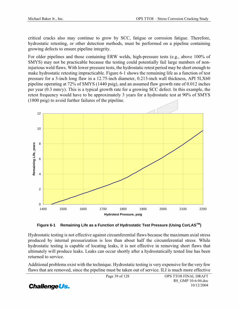
For older pipelines and those containing ERW welds, high-pressure tests (e.g., above 100% of SMYS) may not be practicable because the testing could potentially fail large numbers of non-injurious weld flaws. With lower pressure tests, the hydrostatic retest period may be short enough to make hydrostatic retesting impracticable. Figure 6-1 shows the remaining life as a function of test pressure for a 3-inch long flaw in a 12.75-inch diameter, 0.213-inch wall thickness, API 5LX60 pipeline operating at 72% of SMYS (1440 psig), and an assumed flaw growth rate of 0.012 inches per year (0.3 mm/y). This is a typical growth rate for a growing SCC defect. In this example, the retest frequency would have to be approximately 3 years for a hydrostatic test at 90% of SMYS (1800 psig) to avoid further failures of the pipeline.
0
2
4
6
8
10
12
1400 1500 1600 1700 1800 1900 2000 2100 2200
Hydrotest Pressure, psig
Rem
aini
ng L
ife, y
ears
Figure 6-1 Remaining Life as a Function of Hydrostatic Test Pressure (Using CorLASTM)
Hydrostatic testing is not effective against circumferential flaws because the maximum axial stress produced by internal pressurization is less than about half the circumferential stress. While hydrostatic testing is capable of locating leaks, it is not effective in removing short flaws that ultimately will produce leaks. Leaks can occur shortly after a hydrostatically tested line has been returned to service.
Additional problems exist with the technique. Hydrostatic testing is very expensive for the very few flaws that are removed, since the pipeline must be taken out of service. ILI is much more effective
Michael Baker Jr., Inc. OPS TTO8 – Stress Corrosion Cracking Study
Page 40 of 128 OPS TTO8 FINAL DRAFT R8_GMP 10-6-04.doc
10/12/2004
from the standpoint that a large number of smaller flaws can be identified and potentially removed. There are issues with water disposal, especially for liquid lines where the test water may contain some contamination from the product, and a good source of water is sometimes hard to find.
6.2.2 In-Line Inspection (ILI)
6.2.2.1 ILI Technologies
ILI can be utilized for detection of SCC in hazardous liquids pipelines, but appears to be less amenable for gas pipelines, due to the need for a liquid slug acting as a couplant when utilizing the most sensitive, i.e., ultrasonic, technologies. In the opinion of an operator forum contacted during this study: “UT technology is [the] only reliable in-line inspection tool technology (i.e. TFI and EMAT not proven).” Magnetic Flux Leakage (MFL) Transverse Field Inspection (TFI) has been used in gas pipelines to attempt detection of SCC and, in the opinion of an operator forum contacted during this study: “..has not had a high success rate.” Electro Magnetic Acoustic Transducer (EMAT) is a newer NDT technology used for ILI tools to detect SCC.
Detection of anomalies oriented in the longitudinal direction is best accomplished with the shear wave UT tool, which introduces shear waves in the circumferential direction. Liquid coupled tools are the most accurate and common tools used for crack detection. The quality of the inspection is a function of both the ability to detect small cracks and also the ability to accurately determine the flaw size. UT ILI is most commonly used in liquid pipelines.
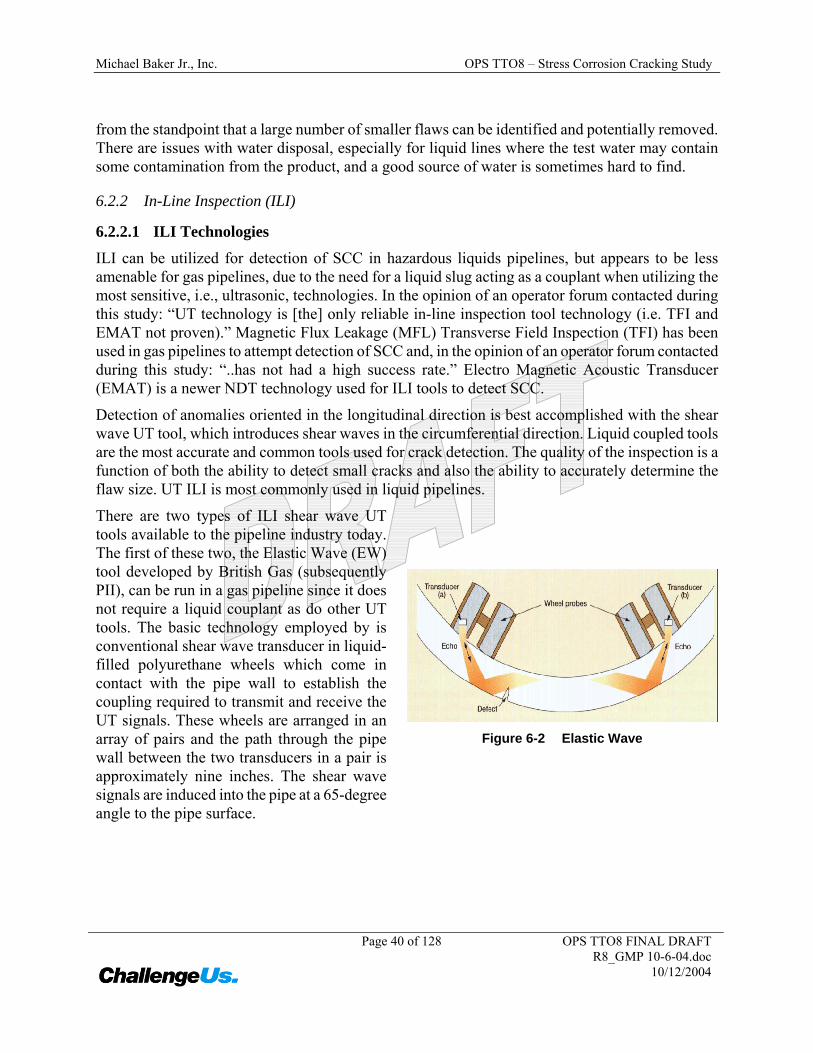
There are two types of ILI shear wave UT tools available to the pipeline industry today. The first of these two, the Elastic Wave (EW) tool developed by British Gas (subsequently PII), can be run in a gas pipeline since it does not require a liquid couplant as do other UT tools. The basic technology employed by is conventional shear wave transducer in liquid-filled polyurethane wheels which come in contact with the pipe wall to establish the coupling required to transmit and receive the UT signals. These wheels are arranged in an array of pairs and the path through the pipe wall between the two transducers in a pair is approximately nine inches. The shear wave signals are induced into the pipe at a 65-degree angle to the pipe surface.
Figure 6-2 Elastic Wave
Michael Baker Jr., Inc. OPS TTO8 – Stress Corrosion Cracking Study
Page 41 of 128 OPS TTO8 FINAL DRAFT R8_GMP 10-6-04.doc
10/12/2004
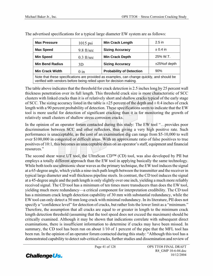
The advertised specifications for a typical large diameter EW system are as follows:
Max Pressure 1015 psi Min Crack Length 2.5 in
Max Speed 9.8 ft/sec Sizing Accuracy ± 0.4 in
Min Speed 0.3 ft/sec Min Crack Depth 25% W.T.
Min Bend Radius 3D Sizing Accuracy ±25%of depth
Min Crack Width 0 in Probability of Detection 90%
Note that these specifications are provided as examples, can change quickly, and should be verified with vendors before being relied upon for decision making.
The table above indicates that the threshold for crack detection is 2.5 inches long by 25 percent wall thickness penetration over its full length. This threshold crack size is more characteristic of SCC clusters with linked cracks than it is of relatively short and shallow cracks typical of the early stage of SCC. The sizing accuracy listed in the table is ±25 percent of the depth and ± 0.4 inches of crack length with a 90 percent probability of detection. These specifications seem to indicate that the EW tool is more useful for detection of significant cracking than it is for monitoring the growth of relatively small clusters of shallow stress corrosion cracks.
In the opinion of an operator forum contacted during this study: The EW tool “…provides poor discrimination between SCC and other reflectors, thus giving a very high positive rate. Such performance is unacceptable, as the cost of an examination dig can range from $5-10,000 to well over $100,000 in congested or difficult areas. With an approximate ratio of false positives to true positives of 10:1, this becomes an unacceptable drain on an operator’s staff, equipment and financial resources.”
The second shear wave UT tool, the UltraScan CD™ (CD) tool, was also developed by PII but employs a totally different approach than the EW tool in applying basically the same technology. While both tools use ultrasonic shear waves as the primary technique, the EW tool induces the signal at a 65-degree angle, which yields a nine-inch path length between the transmitter and the receiver in typical large diameter and wall thickness pipeline steels. In contrast, the CD tool induces the signal at a 45-degree angle and the path length is only slightly over one inch, yielding a much more reliably received signal. The CD tool has a minimum of ten times more transducers than does the EW tool, yielding much more redundancy—a critical component for interpretation credibility. The CD tool has a minimum crack length detection capability of 30 mm with substantial redundancy, while the EW tool can only detect a 50 mm long crack with minimal redundancy. In its literature, PII does not specify a “confidence level” for detection of cracks, but rather lists the lower limit as a “minimum.” Therefore, the assumption that all cracks are equal to or greater in length to the minimum crack length detection threshold (assuming that the tool speed does not exceed the maximum) should be critically examined. Although it may be shown that indications correlate with subsequent direct examinations, there is insufficient information to determine if cracks may have been missed. In summary, the CD tool has been run on about 1/10 of 1 percent of the pipe that the MFL tool has been run. In the opinion of an operator forum contacted during this study: “Although this tool has a demonstrated capability to detect sub-critical cracks, further studies and dissemination and review of
Michael Baker Jr., Inc. OPS TTO8 – Stress Corrosion Cracking Study
Page 42 of 128 OPS TTO8 FINAL DRAFT R8_GMP 10-6-04.doc
10/12/2004
results are needed to determine the actual reliability ranges.” Thus, it may be appropriate to conclude that the technology is promising, but the detection capability of the tool has not been firmly established.
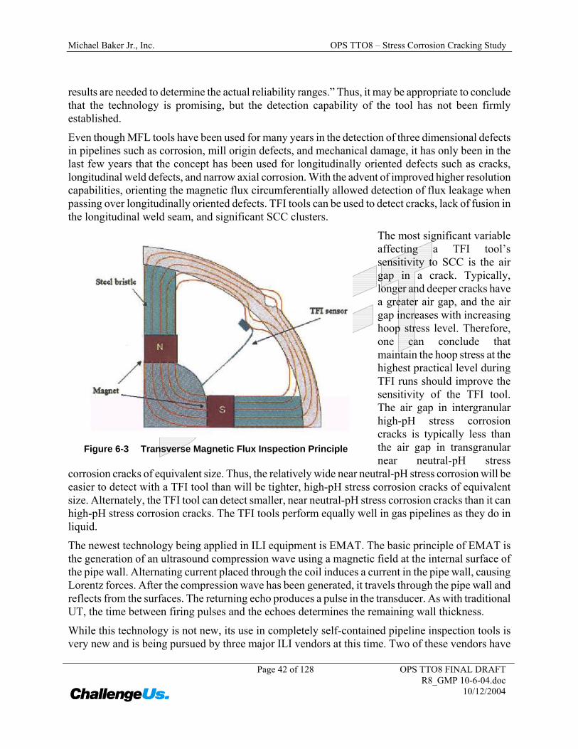
Even though MFL tools have been used for many years in the detection of three dimensional defects in pipelines such as corrosion, mill origin defects, and mechanical damage, it has only been in the last few years that the concept has been used for longitudinally oriented defects such as cracks, longitudinal weld defects, and narrow axial corrosion. With the advent of improved higher resolution capabilities, orienting the magnetic flux circumferentially allowed detection of flux leakage when passing over longitudinally oriented defects. TFI tools can be used to detect cracks, lack of fusion in the longitudinal weld seam, and significant SCC clusters.
The most significant variable affecting a TFI tool’s sensitivity to SCC is the air gap in a crack. Typically, longer and deeper cracks have a greater air gap, and the air gap increases with increasing hoop stress level. Therefore, one can conclude that maintain the hoop stress at the highest practical level during TFI runs should improve the sensitivity of the TFI tool. The air gap in intergranular high-pH stress corrosion cracks is typically less than the air gap in transgranular near neutral-pH stress
corrosion cracks of equivalent size. Thus, the relatively wide near neutral-pH stress corrosion will be easier to detect with a TFI tool than will be tighter, high-pH stress corrosion cracks of equivalent size. Alternately, the TFI tool can detect smaller, near neutral-pH stress corrosion cracks than it can high-pH stress corrosion cracks. The TFI tools perform equally well in gas pipelines as they do in liquid.
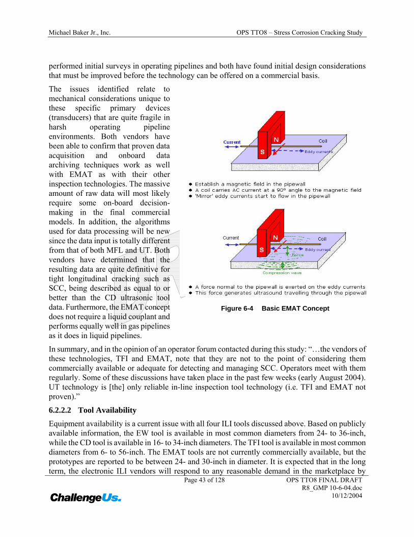
The newest technology being applied in ILI equipment is EMAT. The basic principle of EMAT is the generation of an ultrasound compression wave using a magnetic field at the internal surface of the pipe wall. Alternating current placed through the coil induces a current in the pipe wall, causing Lorentz forces. After the compression wave has been generated, it travels through the pipe wall and reflects from the surfaces. The returning echo produces a pulse in the transducer. As with traditional UT, the time between firing pulses and the echoes determines the remaining wall thickness.
While this technology is not new, its use in completely self-contained pipeline inspection tools is very new and is being pursued by three major ILI vendors at this time. Two of these vendors have
Figure 6-3 Transverse Magnetic Flux Inspection Principle
Michael Baker Jr., Inc. OPS TTO8 – Stress Corrosion Cracking Study
Page 43 of 128 OPS TTO8 FINAL DRAFT R8_GMP 10-6-04.doc
10/12/2004
performed initial surveys in operating pipelines and both have found initial design considerations that must be improved before the technology can be offered on a commercial basis.
The issues identified relate to mechanical considerations unique to these specific primary devices (transducers) that are quite fragile in harsh operating pipeline environments. Both vendors have been able to confirm that proven data acquisition and onboard data archiving techniques work as well with EMAT as with their other inspection technologies. The massive amount of raw data will most likely require some on-board decision-making in the final commercial models. In addition, the algorithms used for data processing will be new since the data input is totally different from that of both MFL and UT. Both vendors have determined that the resulting data are quite definitive for tight longitudinal cracking such as SCC, being described as equal to or better than the CD ultrasonic tool data. Furthermore, the EMAT concept does not require a liquid couplant and performs equally well in gas pipelines as it does in liquid pipelines.
In summary, and in the opinion of an operator forum contacted during this study: “…the vendors of these technologies, TFI and EMAT, note that they are not to the point of considering them commercially available or adequate for detecting and managing SCC. Operators meet with them regularly. Some of these discussions have taken place in the past few weeks (early August 2004). UT technology is [the] only reliable in-line inspection tool technology (i.e. TFI and EMAT not proven).”
6.2.2.2 Tool Availability
Equipment availability is a current issue with all four ILI tools discussed above. Based on publicly available information, the EW tool is available in most common diameters from 24- to 36-inch, while the CD tool is available in 16- to 34-inch diameters. The TFI tool is available in most common diameters from 6- to 56-inch. The EMAT tools are not currently commercially available, but the prototypes are reported to be between 24- and 30-inch in diameter. It is expected that in the long term, the electronic ILI vendors will respond to any reasonable demand in the marketplace by
Figure 6-4 Basic EMAT Concept
Michael Baker Jr., Inc. OPS TTO8 – Stress Corrosion Cracking Study
Page 44 of 128 OPS TTO8 FINAL DRAFT R8_GMP 10-6-04.doc
10/12/2004
providing additional sizes, as well as the additional equipment and personnel required to serve the market.
6.2.2.3 ILI Crack Characterization
Once detected, a crack must then be characterized, i.e. its specific dimensions must be determined to allow for further evaluation. This characterization process breaks out all the various crack types into families of cracks that contain similar signal elements. No comparative confidence levels are specifically cited for SCC.
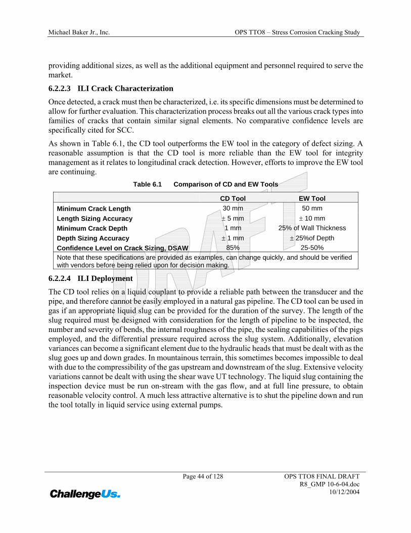
As shown in Table 6.1, the CD tool outperforms the EW tool in the category of defect sizing. A reasonable assumption is that the CD tool is more reliable than the EW tool for integrity management as it relates to longitudinal crack detection. However, efforts to improve the EW tool are continuing.
Table 6.1 Comparison of CD and EW Tools
CD Tool EW Tool Minimum Crack Length 30 mm 50 mm Length Sizing Accuracy ± 5 mm ± 10 mm Minimum Crack Depth 1 mm 25% of Wall Thickness Depth Sizing Accuracy ± 1 mm ± 25%of Depth Confidence Level on Crack Sizing, DSAW 85% 25-50% Note that these specifications are provided as examples, can change quickly, and should be verified with vendors before being relied upon for decision making.
6.2.2.4 ILI Deployment
The CD tool relies on a liquid couplant to provide a reliable path between the transducer and the pipe, and therefore cannot be easily employed in a natural gas pipeline. The CD tool can be used in gas if an appropriate liquid slug can be provided for the duration of the survey. The length of the slug required must be designed with consideration for the length of pipeline to be inspected, the number and severity of bends, the internal roughness of the pipe, the sealing capabilities of the pigs employed, and the differential pressure required across the slug system. Additionally, elevation variances can become a significant element due to the hydraulic heads that must be dealt with as the slug goes up and down grades. In mountainous terrain, this sometimes becomes impossible to deal with due to the compressibility of the gas upstream and downstream of the slug. Extensive velocity variations cannot be dealt with using the shear wave UT technology. The liquid slug containing the inspection device must be run on-stream with the gas flow, and at full line pressure, to obtain reasonable velocity control. A much less attractive alternative is to shut the pipeline down and run the tool totally in liquid service using external pumps.
Michael Baker Jr., Inc. OPS TTO8 – Stress Corrosion Cracking Study
Page 45 of 128 OPS TTO8 FINAL DRAFT R8_GMP 10-6-04.doc
10/12/2004
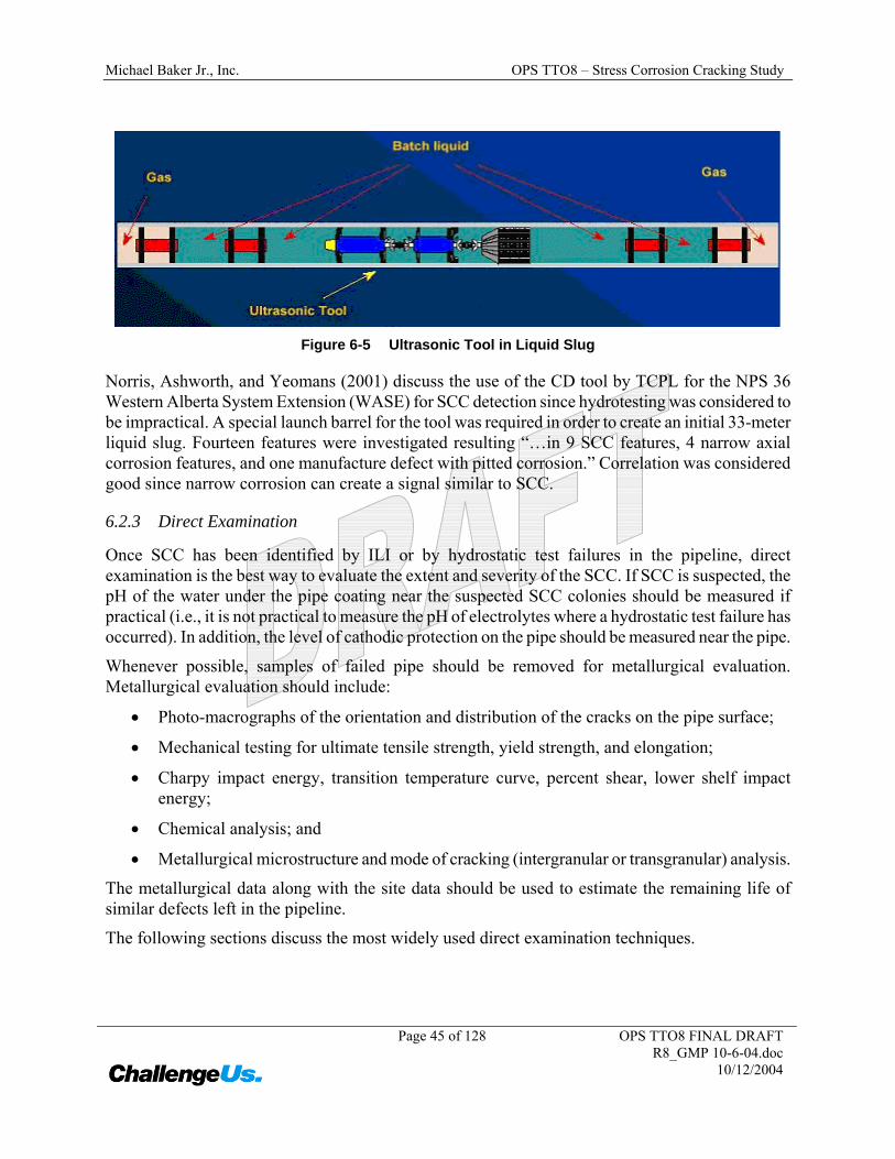
Figure 6-5 Ultrasonic Tool in Liquid Slug
Norris, Ashworth, and Yeomans (2001) discuss the use of the CD tool by TCPL for the NPS 36 Western Alberta System Extension (WASE) for SCC detection since hydrotesting was considered to be impractical. A special launch barrel for the tool was required in order to create an initial 33-meter liquid slug. Fourteen features were investigated resulting “…in 9 SCC features, 4 narrow axial corrosion features, and one manufacture defect with pitted corrosion.” Correlation was considered good since narrow corrosion can create a signal similar to SCC.
6.2.3 Direct Examination
Once SCC has been identified by ILI or by hydrostatic test failures in the pipeline, direct examination is the best way to evaluate the extent and severity of the SCC. If SCC is suspected, the pH of the water under the pipe coating near the suspected SCC colonies should be measured if practical (i.e., it is not practical to measure the pH of electrolytes where a hydrostatic test failure has occurred). In addition, the level of cathodic protection on the pipe should be measured near the pipe.
Whenever possible, samples of failed pipe should be removed for metallurgical evaluation. Metallurgical evaluation should include:
• Photo-macrographs of the orientation and distribution of the cracks on the pipe surface;
• Mechanical testing for ultimate tensile strength, yield strength, and elongation;
• Charpy impact energy, transition temperature curve, percent shear, lower shelf impact energy;
• Chemical analysis; and
• Metallurgical microstructure and mode of cracking (intergranular or transgranular) analysis.
The metallurgical data along with the site data should be used to estimate the remaining life of similar defects left in the pipeline.
The following sections discuss the most widely used direct examination techniques.
Michael Baker Jr., Inc. OPS TTO8 – Stress Corrosion Cracking Study
Page 46 of 128 OPS TTO8 FINAL DRAFT R8_GMP 10-6-04.doc
10/12/2004
6.2.3.1 Visual Examination
Visual inspection is the oldest and most common form of nondestructive examination (NDE) used to inspect for corrosion. Visual inspection is a quick and economical method of detecting various types of defects before they cause failure. Its reliability depends upon the ability and experience of the inspector. The inspector must know how to search for significant flaws and how to recognize areas where failure could occur.
The main disadvantage of visual inspection is that the surface to be inspected must be relatively clean and accessible to the naked eye. Surface preparation can range from wiping with a cloth to blast cleaning and treating with chemicals to show the surface details. Typically, visual inspection is less sensitive than other surface NDE methods. In fact, in most cases, SCC colonies are not visible to the naked eye.
6.2.3.2 Magnetic Particle
Magnetic particle inspection (MPI) is an NDE method primarily used to detect surface-breaking flaws in ferromagnetic materials such as steel and iron. MPI can also be used to locate sub-surface flaws; however, its effectiveness quickly diminishes depending on the flaw depth and type.
The MPI method, along with liquid penetrant inspection, is one of the oldest and most widely utilized forms of NDE. Magnetic particle testing uses magnetic fields and small magnetic particles, such as iron filings, to detect flaws in components. The magnetic particles can be applied dry, or wet by suspending them in a colored or fluorescent liquid. The technique uses the principle that magnetic lines of force (flux) will be distorted by the presence of a flaw in a manner that will reveal the flaw’s presence. The flaw (for example, a crack) is then located from the "flux leakage," following the application of fine iron particles, to the area under examination. There are variations in the way the magnetic field is applied, but they are all dependant on the above principle.
Surface irregularities and scratches can give misleading indications. Therefore, it is necessary to ensure careful preparation of the surface before magnetic particle testing is undertaken. Note that some preparation techniques applicable in other circumstances can mask defects by peening over the cracks and should be avoided.
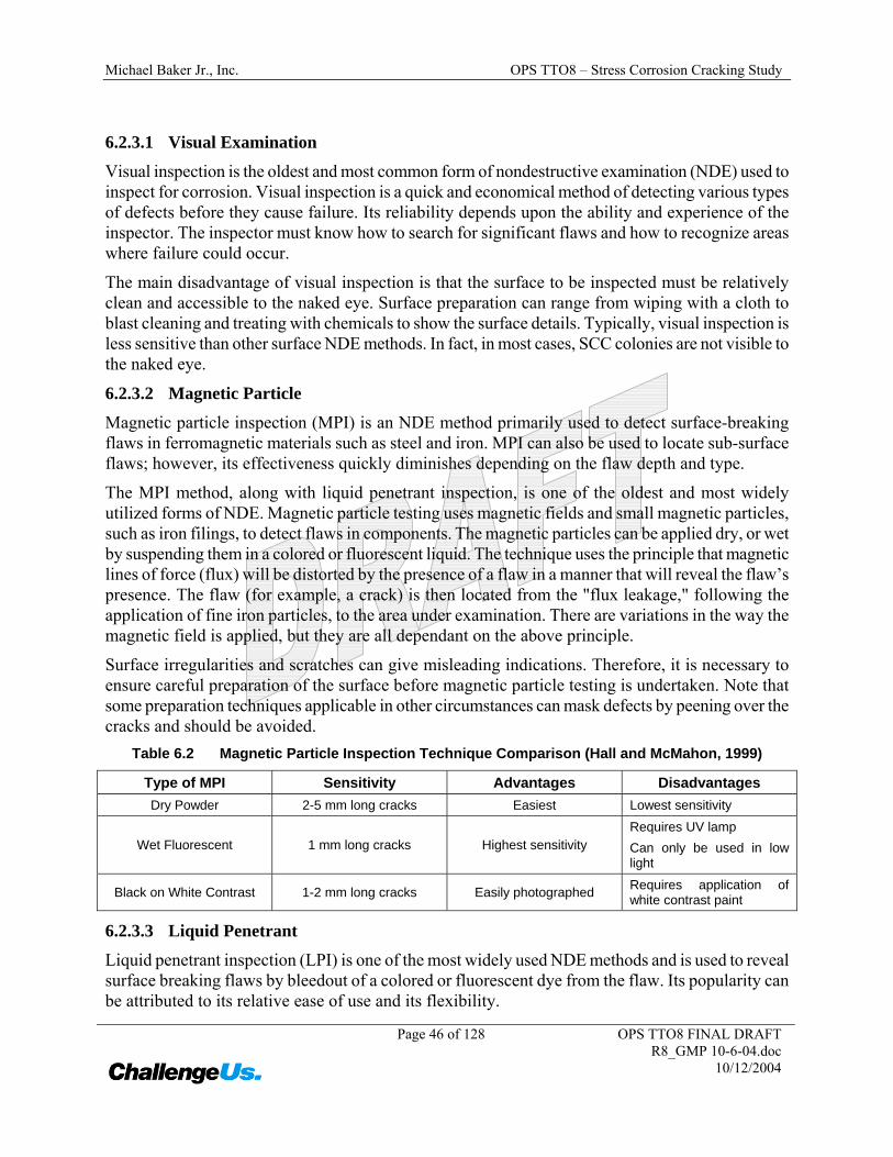
Table 6.2 Magnetic Particle Inspection Technique Comparison (Hall and McMahon, 1999)
Type of MPI Sensitivity Advantages Disadvantages Dry Powder 2-5 mm long cracks Easiest Lowest sensitivity
Wet Fluorescent 1 mm long cracks Highest sensitivity Requires UV lamp Can only be used in low light
Black on White Contrast 1-2 mm long cracks Easily photographed Requires application of white contrast paint
6.2.3.3 Liquid Penetrant
Liquid penetrant inspection (LPI) is one of the most widely used NDE methods and is used to reveal surface breaking flaws by bleedout of a colored or fluorescent dye from the flaw. Its popularity can be attributed to its relative ease of use and its flexibility.
Michael Baker Jr., Inc. OPS TTO8 – Stress Corrosion Cracking Study
Page 47 of 128 OPS TTO8 FINAL DRAFT R8_GMP 10-6-04.doc
10/12/2004
The technique is based on the ability of a liquid to be drawn into a "clean" surface-breaking flaw by capillary action. After a period of time called the "dwell," excess surface penetrant is removed and a developer applied, which acts as a “blotter.” The developer draws the penetrant from the flaw to reveal its presence. Colored (contrast) penetrants require good white light while fluorescent penetrants need to be used in darkened conditions with an ultraviolet "black light."
Penetrant inspection can be used on any metallic material. It is essential that the material be carefully cleaned first, otherwise the penetrant will not be able to get into the defect. If surface penetrant is not fully removed, misleading indications will result.
Like all NDE methods, LPI has both advantages and disadvantages. The primary advantages and disadvantages when compared to other NDE methods are summarized below.
Primary Advantages
• The method has high sensitivity to small surface discontinuities.
• The method has few material limitations, i.e. metallic and nonmetallic, magnetic and nonmagnetic, conductive and nonconductive materials may be inspected.
• Parts with complex geometric shapes are routinely inspected.
• Indications are produced directly on the surface of the part and constitute a visual representation of the flaw.
• Aerosol spray cans make penetrant materials very portable.
• Penetrant materials and associated equipment are relatively inexpensive.
• Can be used to accurately determine defect depth for removal by grinding.
Primary Disadvantages
• Precleaning is critical as contaminants can mask defects.
• The inspector must have direct access to the surface being inspected.
• Surface finish and roughness can affect inspection sensitivity.
• Multiple process operations must be performed and controlled.
• Post cleaning of acceptable parts or materials is required.
• Chemical handling and proper disposal is required
6.2.3.4 Eddy Current
Eddy current testing is an electromagnetic technique and can only be used on conductive materials. Its applications range from crack detection, to the rapid sorting of small components for flaws, size variations or material variation.
When an energized coil is brought near to the surface of a metal component, eddy currents are induced into the specimen. These currents set up a magnetic field that tends to oppose the original
Michael Baker Jr., Inc. OPS TTO8 – Stress Corrosion Cracking Study
Page 48 of 128 OPS TTO8 FINAL DRAFT R8_GMP 10-6-04.doc
10/12/2004
magnetic field. The impedance of the coil in close proximity to the specimen is affected by the presence of the induced eddy currents in the specimen.
When the eddy currents in the specimen are distorted by the presence of the flaws or material variations, the impedance in the coil is altered. This change is measured and displayed in a manner that indicates the type of flaw or material condition.
6.2.3.5 Ultrasonic Shear Wave
Ultrasonic inspection uses sound waves of short wavelength and high frequency to detect flaws or measure material thickness. Usually, pulsed beams of high frequency ultrasound are used via a hand held transducer (probe), which is placed on the specimen. Any sound from the pulse that is reflected and returns to the transducer (like an echo) is shown on a screen, which gives the amplitude of the pulse and the time taken to return to the transducer. Flaws anywhere through the specimen thickness reflect the sound back to the transducer.
Using the ultrasonic shear wave technique, the depth and length of a stress corrosion crack can, in principle, be measured. However, a stress corrosion crack is rarely isolated, and other nearby cracks in a cluster can cause interference that can lead to erroneous readings. In a recent critical evaluation of ten technologies for measuring crack size in the ditch, ultrasonics appeared to have the most promise, but it was not considered to have satisfactory accuracy in general (Francini 2000). Because of its complexity, considerable technician training and skill are required to perform ultrasonic shear wave inspection.
6.2.3.6 Potential Drop
Both DC and AC potential drop techniques can be used to determine fatigue crack depth (Donald and Ruschau, 1991). The two techniques require electrical contact with the metal surface to inject the current and to measure the potential difference across the crack. By virtue of the skin effect, AC potential drop (ACPD) has the advantage of lower current requirements and greater sensitivity to surface-breaking cracks than its DC counterpart. In the case of uniform field ACPD measurements, it is possible to deduce crack depths and crack shapes without the use of calibration blocks, and there is a well-developed theoretical base for this variant. Calibration blocks are required if smaller hand-held ACPD units are used because the incident field is highly non-uniform.
6.2.3.7 Alternating Current Field Measurement
AC field measurement (ACFM) is an electromagnetic technique which offers the capability of detection and sizing of surface-breaking cracks without the need for calibration or cleaning to bare metal (see for example Zhou, Lugg and Collins 1999). ACFM is a natural extension of ACPD with the uniform injected current replaced by a uniform field induced by a driver coil, and the contact electrodes replaced by a set of orthogonal pick-up coils. The measurements are performed by scanning the probe along the crack, using a sophisticated mathematical model to deduce the crack depth and length from the field perturbations via a PC. Like ACPD, ACFM is well suited to the sizing of surface cracks in magnetic steels and has been adapted for underwater use in the offshore industry.
Michael Baker Jr., Inc. OPS TTO8 – Stress Corrosion Cracking Study
Page 49 of 128 OPS TTO8 FINAL DRAFT R8_GMP 10-6-04.doc
10/12/2004
6.2.4 Predictive Modeling
A number of investigators have attempted to employ a variety of techniques to predict stress corrosion crack initiation and growth. The method that follows established guidelines is the Engineering Critical Assessment (ECA) based on fracture mechanics principles. It is noted, however, that although Canada and other nations allow the use of ECA to determine the disposition of crack-like anomalies, United States standards require repair or replacement (Jaske, Vieth, and Beavers 2002). An ECA includes estimation of failure conditions for flow strength and toughness-controlled fracture and the potential for crack growth by fatigue, SCC, or corrosion fatigue.
6.2.5 Comparison
The methods described above have varying degrees of effectiveness in investigating SCC, but each method has limitations. Hydrostatic testing will identify critical flaws, but will give no indication of the location of sub-critical flaws. Nevertheless, the technique has the advantage of ensuring integrity throughout the segment at the time of the hydrostatic test. Critical cracks detected by hydrostatic testing will be smaller than critical cracks at MOP. The time to grow cracks from hydrostatic test critical cracks to MOP critical cracks is very important to the analysis of SCC. Direct examination is effective for external flaw identification, but the operator must have well-defined excavation limits. ILI tool runs for crack detection are limited by the tool speed and pipe size, require expert oversight and have extra considerations for gas pipelines (e.g. the need for a liquid couplant for UT tools).
In general, examination techniques focus first on crack location, next on crack length determination, and finally on crack depth determination. Some techniques can only give crack location, with little additional information for crack characterization. There is no available technique that is 100% reliable not only for finding the locations of SCC, but further determining both crack length and depth characteristics.
Analytical approaches allow insight, but are generally difficult to prove applicable unless coupled with other types of data developed from some examination technique.
6.3 Direct Assessment
Stress corrosion cracking direct assessment (SCCDA) is a structured process that is intended to assist pipeline operators in assessing the extent of SCC on a section of buried pipeline, thus contributing to improved safety by reducing the impact of external SCC on pipeline integrity. SCCDA requires the integration of data from historical records, indirect surveys, field examinations, and from pipe surface evaluations (i.e., direct examinations) combined with the physical characteristics and operating history of the pipeline. SCCDA is a continuous improvement process. Through successive applications, SCCDA should identify and address locations where SCC has occurred, is occurring, or might occur. SCCDA provides the advantage and benefit of locating areas where SCC might occur in the future rather than only areas where SCC has already occurred.
NACE currently is developing a recommended practice for SCCDA. SCCDA, as described in this standard, is specifically intended to address buried onshore petroleum (natural gas, crude oil, and refined products) production, transmission, and distribution pipelines constructed from line pipe
Michael Baker Jr., Inc. OPS TTO8 – Stress Corrosion Cracking Study
Page 50 of 128 OPS TTO8 FINAL DRAFT R8_GMP 10-6-04.doc
10/12/2004
steels. This recommended practice addresses the situation in which a pipeline company has identified a portion of its pipeline as an area of interest with respect to SCC based on its history, operations, and risk assessment process, and has decided that direct assessment is an appropriate approach for integrity assessment. This procedure is designed for application to both forms of external SCC (near neutral-pH SCC and high-pH SCC).
The standard provides guidance for managing SCC by selecting potential pipeline segments, selecting dig sites within those segments, inspecting the pipe, collecting and analyzing data during the dig, establishing a mitigation program, defining the reevaluation interval, and evaluating the effectiveness of the SCCDA process.
SCCDA is complementary with other inspection methods such as ILI or hydrostatic testing, and is not necessarily an alternative or replacement for these methods in all instances. SCCDA also is complementary with other direct assessment procedures such as those given in NACE Standard RP0502-2002 and the proposed NACE Standard RP0104-2004. ILI or hydrostatic testing may not be warranted if the initial SCCDA indicates that “significant”2 and extensive cracking is not present on a pipeline system. SCCDA can be used to prioritize a pipeline system for ILI or hydrostatic testing if significant and extensive SCC is found. SCCDA also may detect other pipeline integrity threats, such as mechanical damage, external corrosion, microbiologically influenced corrosion (MIC), etc. When such threats are detected, additional assessments and/or inspections should be performed.
In the NACE SCCDA process, initial selection of pipeline segments on gas pipelines for assessment of risk for high pH SCC is based on Appendix A3 of ASME B31.8S, Section A3.3. Appendix A3 considers the following factors: operating stress, operating temperature, distance from compressor station, age of pipeline, and coating type. A pipeline segment is considered susceptible to high-pH SCC if all of the following factors are met.
• The operating stress exceeds 60 percent of specified minimum yield strength (SMYS);
• The operating temperature exceeds 38ºC (100º F);
• The segment is less than 32 km (20 mi.) downstream from a compressor station;
• The age of the pipeline is greater than 10 years; and
• The coating type is other than fusion-bonded epoxy.
ASME B31.8S addresses gas pipelines, but the same factors and approach are used in the standard for liquid petroleum pipelines, considering the distance downstream from a pump station as one of the factors for selecting potentially susceptible segments. Appendix A3 of ASME B31.8S does not currently address near neutral-pH SCC. The same factors and criteria are used in the standard for the selection of pipeline segments for assessment of risk of near neutral-pH SCC, with the exclusion of the temperature criterion.
2. An SCC cluster is assessed to be “significant” based on the CEPA definition, if the deepest crack, in a series of interacting cracks, is greater than 10 percent of the wall thickness and the total interacting length of the cracks is equal to or greater than 75 percent of the critical length of a 50 percent through-wall flaw that would fail at a stress level of 110 percent of SMYS. CEPA also defines the interaction criteria. Note that these definitions are currently being reviewed by CEPA.
Michael Baker Jr., Inc. OPS TTO8 – Stress Corrosion Cracking Study
Page 51 of 128 OPS TTO8 FINAL DRAFT R8_GMP 10-6-04.doc
10/12/2004
The SCCDA process consists of four steps: Pre-Assessment, Indirect Examinations, Direct Examinations, and Post Assessment. Further details of each step are given below.
6.3.1 Pre-Assessment Step
In the Pre-Assessment Step, historic and currently available data are collected and analyzed to prioritize the segments within a pipeline system with respect to potential SCC susceptibility and to select specific sites within those segments for direct examinations. The types of data collected are typically available from in-house construction records, operating and maintenance histories, alignment sheets, corrosion survey records, other above-ground inspection records, government sources, and inspection reports from prior integrity evaluations or maintenance actions. These data can be divided into five categories; pipe related, construction related, soils/environmental, corrosion protection, and pipeline operations. The most relevant pipe-related parameters for mill-coated pipe are surface preparation and coating type. The type of seam weld also may be significant. The most relevant construction-related factors for pipe coated over the ditch are surface preparation and coating type. Weather conditions and factors contributing to residual stresses may also be important. With respect to soils/environment, moisture content and soil type have been correlated with locations of SCC in some cases. With respect to corrosion protection, CP-related parameters are contributing factors because adequate CP can prevent SCC except under certain disbonded coatings (which can shield the current from the pipe). With respect to pipeline operations, SCC history and pressure fluctuations are important. Temperature history also is important for high-pH SCC. For liquid lines, changes in product also can influence operating conditions, such as the pressure profile between pumping stations.
Ideally, the specific sites for direct examination (i.e., dig sites) should be selected to maximize the probability of finding SCC if it does exist on the pipe. Unfortunately, there are no well-established methods for predicting with a high degree of certainty the presence of SCC, based on above-ground measurements. However, industry experience can provide some guidance for selecting more probable sites. The critical factors for high-pH SCC and near neutral-pH SCC are similar, but some differences exist. Also, the most relevant factors may differ from one pipeline to another, or even one segment to another, depending on the history of the line. Some companies have found that predictive models can be effective at identifying and ranking areas along a pipeline that are susceptible to near neutral-pH SCC. Such models can be effective only if reliable pipe and terrain conditions are used and the predictive model is verified and enhanced through investigative excavations. For site selection, the following factors should be considered for locating SCC.
• A history of SCC in area of interest
• Unique characteristics associated with previous SCC locations
• Locations with coating anomalies
• ILI indications of dents
• ILI indications of general corrosion (with shielding coatings)
• Locations where the stresses, pressure fluctuations, and temperatures were highest
Michael Baker Jr., Inc. OPS TTO8 – Stress Corrosion Cracking Study
Page 52 of 128 OPS TTO8 FINAL DRAFT R8_GMP 10-6-04.doc
10/12/2004
• Locations where there has been a history of coating deterioration
6.3.2 Indirect Inspection Step
In the Indirect Inspection Step, additional data are collected, as deemed necessary by the pipeline operator, to aid prioritization of segments and site selection. The necessity to conduct indirect inspections and the nature of these inspections depends on the nature and extent of the data obtained in the pre-assessment step and the data needs for site selection. Typical data collected in this step may include close interval survey (CIS) data, direct current voltage gradient (DCVG) data, and information on terrain conditions (soil type, topography, and drainage) along the right of way.
6.3.3 Direct Examination Step
The Direct Examination Step includes procedures to field verify the sites selected in the first two steps, and conduct the field digs. Above-ground measurements and inspections are performed to field verify the factors used to select the dig sites. For example, the presence and severity of coating faults may be confirmed. If predictive models based on terrain conditions are used, the topography, drainage, and soil type require verification. The digs are then performed and if any SCC is detected, the severity, extent, and type of SCC at the individual dig sites are assessed. The data that can be used in post assessment and predictive model development are then collected.
The types and extent of data collected at the dig sites are at the discretion of the pipeline operator and depends on the planned usages of the data. Limited data, consisting of the assessment of cracking, may be appropriate in cases in which the operator is assessing a pipeline segment for the presence or absence of SCC. More extensive data collection procedures would be required if the operator is attempting to develop a predictive model for SCC on a pipeline system. If cracks are found, at a minimum, their dimensions should be recorded to confirm continued serviceability of the pipeline.
6.3.4 Post Assessment Step
In the Post Assessment Step, data collected from the previous three steps are analyzed to determine whether SCC mitigation is required. If mitigation is deemed necessary, the operator prioritizes the mitigative actions, defines the interval to the next full integrity reassessment and evaluates the effectiveness of the SCCDA approach. Each pipeline company is responsible for selecting post-assessment options, including developing, implementing, and verifying a plan to define reassessment intervals, and evaluating the effectiveness of the SCCDA approach.
There are two types of mitigation: discrete mitigation and general mitigation. Discrete mitigation is selected to address isolated locations at which “significant” SCC has been detected during the course of the field investigation program. Typically, this form of mitigation is limited to areas where the affected pipe length is relatively short—less than 91 m (300 ft) in length. Mitigation options include repair or removal of the affected pipe length, hydrostatically testing the pipeline segment, and performing an engineering critical assessment to evaluate the risk and identify further mitigation methods.
Michael Baker Jr., Inc. OPS TTO8 – Stress Corrosion Cracking Study
Page 53 of 128 OPS TTO8 FINAL DRAFT R8_GMP 10-6-04.doc
10/12/2004
General mitigation is selected to address pipeline segments when the risk of “significant” SCC could potentially be widespread within a particular segment or segments of a pipeline. Typically, this form of mitigation is used to address areas in which the affected pipe length is relatively long. General forms of mitigation include hydrostatic testing of the affected segment or segments, ILI when appropriate tools are available, extensive pipe replacements and re-coating.
Periodic reassessment is the process in which segments of a pipeline are re-investigated at an appropriate time interval. It is at the operator’s discretion to establish the number of additional investigations required on a given segment and the reassessment intervals based on information such as the extent and severity of the SCC detected during the original investigation, the estimated rate of propagation of the crack clusters, remaining life of the pipe containing the clusters, the total length of the pipe segment, the total length of potentially susceptible pipe within the segment, and the potential consequences of a failure within a given segment.
Methods used to assess SCCDA effectiveness include comparison of results for selected dig sites with results for control digs, comparison of results of SCCDA for selected segments with results of ILI using crack detection tools, statistical analysis of data from SCCDA digs to identify statistically significant factors associated with the occurrence and/or severity of cracking, successive applications of SCCDA to a pipeline segment, and assessment of SCC predictive models with respect to reliability of predicting locations and severity of SCC.
In the post-assessment step, it also is important to evaluate the criteria used for initial selection of susceptible segments. It might be necessary to modify these criteria for a pipeline or system based on the results of SCCDA digs.
6.4 References
Beavers, J.A. and E.L. Hagerdorn. 1996. Low pH SCC; Mechanical Effects on Crack Propagation. PRCI. L51760.
Brongers, M.P.H., J.A. Beavers, C.E. Jaske, and B.S. Delanty. 2000. Effect of Hydrostatic Testing on Ductile Tearing of X-65 Line Pipe Steel with Stress Corrosion Cracks. NACE International Corrosion2000. Paper No. 00355.
Buchheim, P.E., and M. Gerrit. 2001. An Overview of API RP 579 Fitness for Service and the Role of Corrosion/Materials Engineers. NACE International Corrosion 2001. Paper No. 01521.
Donald, J.K. and J. Ruschau. 1991. "Direct Current Potential Difference Fatigue Crack Measurement Techniques" Fatigue crack measurement: techniques and applications K J Marsh, R A Smith and R O Ritchie (eds), EMAS, Warley, West Midlands, 11-38.
Francini, R.B., B.N. Leis, J.B. Nestleroth, and David W. Detly. 2000. Stress Corrosion Crack Depth Measurement. Final Report to PRCI on Project PR-3-8718.
Hall, R.J. and M.C. McMahon. 1999. Stress Corrosion Cracking Study. U.S. Department of Transportation, Research and Special Programs Administration, Office of Pipeline Safety. May.
Michael Baker Jr., Inc. OPS TTO8 – Stress Corrosion Cracking Study
Page 54 of 128 OPS TTO8 FINAL DRAFT R8_GMP 10-6-04.doc
10/12/2004
Hohl, G. and G. Knauf. 1999. Field Hydrotesting and its Significance to Modern Pipelines. In Proceedings EPRG/PRCI 12th Biennial Joint Technical meeting on Pipeline Research. Paper 32. May.
Jaske, C.E., P.H. Vieth, and J.A. Beavers. 2002. Assessment of Crack-Like Flaws in Pipelines. NACE International Corrosion 2002. Paper No. 02089.
Kiefner, J.F. 1986. “Evaluating Pipeline Integrity – Flaw Behavior During and Following High Pressure Testing.” In Proceedings from the Seventh Symposium on Line Pipe Research, PRCI. L51495. p. 15-1. October.
NACE Standard RP0104-2004. Pipeline Stress Corrosion Cracking Direct Assessment Methodology (proposed).
NACE Standard RP0502-2002. Pipeline External Corrosion Direct Assessment Methodology.
Norris, J.D., B.P. Ashworth, and M. Yeomans. 2001. Reconfirming the Integrity of a Gas Transmission Pipeline Following an SCC Induced Incident. NACE International Corrosion 2001. Paper No. 01631.
Zhou, J., M.C. Lugg and R. Collins. 1999. A Nonuniform Model for Alternating Current Field Measurement of Fatigue Cracks in Metals. Int.J.Appl.Electromag.Mech. 10 221-235.