3d printing and additive manufacturing capability modelling
TRANSCRIPT
3D Printing and Additive Manufacturing Capability Modelling
Vaughan Michell University of Reading, Whiteknights, Reading, U.K.
Keywords: 3D Printing, Capability, Affordance, Capability-Affordance Model, Additive Manufacturing.
Abstract: The use of 3D, or additive manufacturing, is becoming more widespread and is seen as a new industrial revolution due to the advantages of a material deposition approach compared to material removal. However, little work has been done to identify and formalise the capabilities of this new technology. This paper formally analyses the generic 3D printing process of additive manufacturing and compares it with the traditional subtractive manufacturing process using the capability affordance model to determine its unique capabilities. The CAM model defines a capability as a mechanism and space-time path. Results show that whilst the mechanisms differ in terms of force and heat drivers, it is the space time path topology that is key to manufacturing capability differences. We apply a topological analysis to identify the unique affordance path of 3D printing which clearly demonstrates its superiority in complex and integrated part manufacture. Finally we outline the differences in the key capability affordance factors for manufacturing in the two methods. This paper builds on earlier work concerning the capability affordance model as a knowledge model to analyse and understand capabilities and the unique advantages and possibilities of 3D printing.
1 INTRODUCTION
Rapid prototyping (RP) is an additive manufacturing technology based on the addition of materials layer by layer instead of traditional cutting and removal of material in subtractive manufacturing (SM) (Berman, 2012). RP was developed to provide a general fabrication machine enabling construction of complex 3 dimensional (3D) shapes and to use designs directly from CAD (Choi and Samavedam, 2002). The term rapid prototyping – RP is often used to describe the rapid fabrication of parts and prototypes layer by layer (Berman, 2012). The term additive manufacturing (AM) is used to generally denote technology where fabrication of parts and products occur by adding or depositing material.
Three dimensional printing (3DP) is really a versatile consumer adaptation of rapid prototyping technologies evolved from additive manufacturing by adding a 3rd vertical z dimension to the general architecture of a typical x-y inkjet or laser printer. This greatly reduces the cost of the RP/AM machine by several orders of magnitude, making it affordable to companies and end users alike. Instead of ink, 3D printing deposits material, usually hot plastics or their derivatives. The print head thus becomes a means to deposit the material as a fluid deposition of 3d
cylinders or ‘slugs’ of material in successive layers (Berman, 2012). Pham and Guilt (Pham and Guilt, 2012) identified up to eight different technology approaches to additive manufacturing. For comparison purposes this paper focuses on a frequently used 3DP technology where a heater melts a suitable material and temperature sensors ensure the correct flow viscosity. To enable a continuous feed of material a series of rollers is used to drive the plastic filament at the correct rate to be melted.
1.1 3D Printing Fabrication
3D printers enable CAD models to be converted to a series of layers that can be printed one layer at a time. This layer based model is typically in the form of a stereo lithography or STL file. The STL file records the surface shape/section of each layer, The internal structure is reduced to a series of diagonal webs to reduce both the volume and density of the construction and the time taken to print it compared to a solid layer. STL files can be generated from traditional CAD packages by electronically slicing the design.
The key to 3DP business success is reducing costs and complexity of part creation whilst integrating with consumer software (Pham and Guilt, 2012). For this reason printing plastics have focused on
73Michell V.3D Printing and Additive Manufacturing Capability Modelling.DOI: 10.5220/0006222400730083In Proceedings of the Sixth International Symposium on Business Modeling and Software Design (BMSD 2016), pages 73-83ISBN: 978-989-758-190-8Copyright c© 2016 by SCITEPRESS – Science and Technology Publications, Lda. All rights reserved
thermoplastics PLA and ABS (Bassett et al., 2015). However thermoplastics have their own
limitations of strength and robustness as PLA suffers from degradation. The 3D object is built by depositing material from the minimum of a point ‘blob’ to an x-y plane of material. Moving the bed on which the material is deposited along the perpendicular z axis away from the print head enables the model to grow vertically. Additional control of the deposition process is usually achieved by heating the build bed or enclosing the build volume with a case to optimise the conditions for solidification without cracking.
Another fabrication benefit is the ability of a 3D laser scanner to digitise the spatial position of points on the surface of a scanned object The CAD compatibility enables a 3D model to be built from data capture of the surface of any scanned object. This enables scanned object models to then be quickly scaled and printed out on a 3D printer subject to the size limitations of the deposition mechanism used and the build bed in a form or ‘scanning to production’ of a finished part.
3DP has proliferated among manufacturing companies, designers, end users and hobbyists as it meets attributes of successful innovation as it is cheaper than subtractive manufacturing, compatible with CAD/CAM, less complex, easy to try out and produces rapid end results. (Pham and Guilt, 2012).
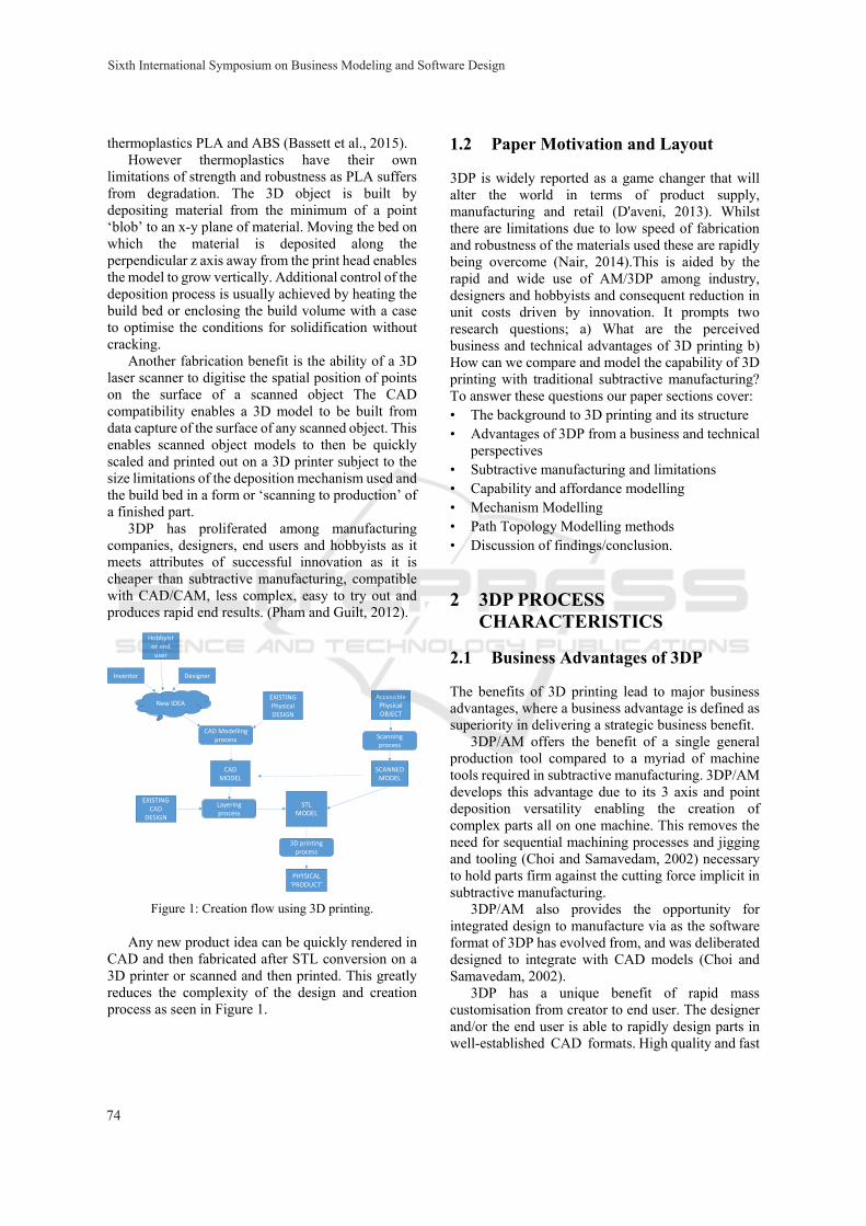
Figure 1: Creation flow using 3D printing.
Any new product idea can be quickly rendered in CAD and then fabricated after STL conversion on a 3D printer or scanned and then printed. This greatly reduces the complexity of the design and creation process as seen in Figure 1.
1.2 Paper Motivation and Layout
3DP is widely reported as a game changer that will alter the world in terms of product supply, manufacturing and retail (D'aveni, 2013). Whilst there are limitations due to low speed of fabrication and robustness of the materials used these are rapidly being overcome (Nair, 2014).This is aided by the rapid and wide use of AM/3DP among industry, designers and hobbyists and consequent reduction in unit costs driven by innovation. It prompts two research questions; a) What are the perceived business and technical advantages of 3D printing b) How can we compare and model the capability of 3D printing with traditional subtractive manufacturing? To answer these questions our paper sections cover: • The background to 3D printing and its structure • Advantages of 3DP from a business and technical
perspectives • Subtractive manufacturing and limitations • Capability and affordance modelling • Mechanism Modelling • Path Topology Modelling methods • Discussion of findings/conclusion.
2 3DP PROCESS CHARACTERISTICS
2.1 Business Advantages of 3DP
The benefits of 3D printing lead to major business advantages, where a business advantage is defined as superiority in delivering a strategic business benefit.
3DP/AM offers the benefit of a single general production tool compared to a myriad of machine tools required in subtractive manufacturing. 3DP/AM develops this advantage due to its 3 axis and point deposition versatility enabling the creation of complex parts all on one machine. This removes the need for sequential machining processes and jigging and tooling (Choi and Samavedam, 2002) necessary to hold parts firm against the cutting force implicit in subtractive manufacturing.
3DP/AM also provides the opportunity for integrated design to manufacture via as the software format of 3DP has evolved from, and was deliberated designed to integrate with CAD models (Choi and Samavedam, 2002).
3DP has a unique benefit of rapid mass customisation from creator to end user. The designer and/or the end user is able to rapidly design parts in well-established CAD formats. High quality and fast
CAD MODEL
STL MODEL
PHYSICAL ‘PRODUCT’
SCANNED MODEL
New IDEAEXISTING PhysicalDESIGN
EXISTING CAD
DESIGN
Scanning process
CAD Modelling process
Layering process
3D printing process
Accessible Physical OBJECT
Inventor Designer
Hobbyist or end user
Sixth International Symposium on Business Modeling and Software Design
74
fabrication can also be cheaply outsourced by sending it to company to print anywhere in the world.
This greatly simplifies and reduces the cost of the traditional mass customisation models that require complex processes and equipment, for example used by companies like Dell (Berman, 2012). This enables any customer to create a new product, design or adjust their product off line and send it directly to a manufacturer in a ‘democratisation of the design process’ (Hoy, 2013).
With 3DP/ the number of devices required to enable design to production is reduced to one low cost unit, reducing the learning curve and start-up costs, hence encouraging adoption. (Nair, 2014).
2.2 Technical Advantages of 3DP
We define a technical advantage as an advantage in the process, or mechanism of use, of a technology. One of the critical advantages of AM over traditional material removal and moulding methods is the ability to develop unique shapes. This property is a function of the topology of the printing device due to its point deposition of material so that objects can be built in single 3D points and layers at a time (Rosen, 2007).
The creation of a part from a single point enables almost any shape to be built (Rosen, 2007) subject to the need for support at overhangs and specific angles and fine topographies on certain 3DP process types. This differs from SM processes that require extensive force application to remove material via traditional lathe and milling machinery. AM deposition is relatively force free apart from the weight of deposited material that can distort the design when setting. Depending on the resolution of the print head and materials used, this enables extremely fine, small and optimally engineered parts to be produced without the force problems caused by material removal. The point disposition ability at any location within a build volume, coupled with digital design, also enables parts to be made ‘within a part’ as there is no necessity for cutter insertion and removal space as in traditional manufacturing. For example the creation of ball type bearings inside a complete ball race can be executed in a single AM operation (Conner et al., 2014). The point deposition ability of AM enables sub-assemblies and products to be built as complete volumes and surfaces, significantly reducing the need for assembly and reducing costs. For example a complete nylon ball bearing assembly can be produced in one operation as one part vs 18 separate parts assembled using traditional manufacturing due to SM machining limitations (Conner et al., 2014).
The 3DP point deposition ability further enables parts to be created as a fine mesh or space frame, greatly reducing weight, in contrast to machining from solid. This enables maximisation of strength per unit volume (Pham and Guilt, 2012).The ability to deposit in points and layers also supports integrated materials structure variations within a part and the creation of cellular materials to support energy, thermal and acoustic design variations (Rosen, 2007). This enables ‘designed property gradients’ where the density of the product can be designed to vary to suit design needs (Rosen, 2007). 3DP further enables the creation of generic ‘graded’ ‘cellular materials’ such as lattices, honeycombs etc to suit design needs for density and other physical property variations (Rosen, 2007).
A potential revolutionary advantage of the material deposition technique is that it enables the embedding of different material types or even whole components as the part is fabricated. This facilitates variation in composition of the object material properties and additional elements such as areas of electrical conductivity or embedded components to suit design needs (Doubrovski et al., 2011).
3 SUBTRACTIVE MANUFACTURING (SM)
3.1 Limitations of SM
This section explores the traditional subtractive manufacturing process of material removal using a range of different machine tools based on different cutter topologies.
The capability of traditional machine tools are limited by the cutter path which is determined by the cutter shape and mechanics. For example a lathe has two degrees of freedom about an axial symmetry, resulting in a capability for producing axially symmetric parts. A milling cutter has three degrees of freedom about x, y, z axes to produce a diverse range of convex and concave parts. In contrast a drill has effectively only one degree of vertical freedom to create a hole of varying depth.
In traditional SM the lack of a universal cutting machine and limitations of cutter path and finite cutter size means the order in which a complex part is manufactured must be considered to avoid unwanted tool interactions (Matthews, 2007). This order of processing (OOP) limitation adds complexity by imposing machining precedence constraints and conditions on the direction of tool application or
3D Printing and Additive Manufacturing Capability Modelling
75
approachability, limiting what is feasible to fabricate (Gupta et al., 1997).
One complication is accessibility (AC), where the arrangement of certain shapes drives the order of machining, otherwise there would be no cutter access.
Gupta et al., (Gupta et al., 1997) defined feature accessibility as a condition where the volume of space required for accessibility Av has not been lost by a volume already removed from the workpiece.
For example, if the accessible volume of a piece of material X intersects with the removal volume of Y, the cutter must approach a through the volume occupied by Y and hence Y must be machined before X (Matthews, 2007).
Also if X and Y have different approach directions, and machining X provides a surface to act as datum for measurement or tolerance, then X must be machined first. This is a Datum Dependency (DD) limitation of SM (Matthews, 2007).
Another concern is approachability (AP): if X is machined before Y then Y will not be able to approached or accessed to create the shape (Gupta et al., 1997). For example eg a hole may need to be machined first to provide access to cut a slot.
3.2 Cutter Path Limitations (Cpl)
At the fine scale level for SM we must also consider limitations due to cutter size and geometry.
Whilst convex parts can be relatively easily machined with SM, concave parts eg edges and pockets or blind holes to be cut into the part are limited by the need to ensure cutter access.
Gupta et al (Gupta et al, 1997) defined three types of limitations for cutter path access:
CPL1: The curvature of the tool must be less than the curvature of a concave edge – otherwise the tool cannot follow and cut the edge (dcur);
CPL2: Where two closed edges form a narrow passage to be cut by the tool the diameter of the passage must be less than the tool (dpas) to enable the cutting of the passage by the tool;
CPL3: Concave corners formed by the cutter path must be larger than the tool (dcor) to enable cutter access;
CPL4: as the tool size increases the cutting trajectory (ie the minimum amount of arc that you can cut with this size cutter decreases ie is a limit on dtra) beyond which you will cut a bigger arc than specified;
CPL5: The max diameter of tool also must be less than the smallest diameter feature (min dmax).
This results in Gupta’s set of cutter path trajectory
limitations for the maximum cutter diameter:
du = min (dcur, dpas, dcor, dtra, dmax) (1)
Some topologies eg producing a part within a part (PP) using subtractive manufacturing are almost impossible with SM as it requires a tool to enter the interior of a billet of material and then the operation of that tool via a cutter path wholly within the billet.
The geometry of the cutting tool with respect to the part is also subject to two further cutter geometry (CG) limitations. The tool cutting edge angle with respect to the cutter motion ά and the inclination of the tool cutting edge with respect to the part, ie the rake angle β must be within ranges to avoid skimming or gouging the material and adversely affecting surface quality (Blackenfelt, 2001).
3.3 SM Conceptual Model
Based on the above discussion we can now develop an outline conceptual model for subtractive manufacturing. Consider the following: where Ps is a part to be created by the subtractive manufacturing process, B = material billet from which the part is machined, and Fi is the i’th machined feature (eg hole, passage, curved surface etc) where i = 1,…n . Then the part is the billet minus the union of all the features.
Ps = B – ∪Fi (2)
But each of the i in number features are topological elements that in SM are created by the intersection of the swept volume of the j in number cutter operations Sc required to machine the features with the billet volume B such that:
Ps = B – (B sum ( (j= 1-n) Scj) (3)
But as we have seen the swept volume is limited by cutter approach geometry, size and access limitations and the prohibited volumes discussed earlier. Hence a generic model for traditional machine tool material removal manufacturing is:
Ps = B – (B sum ( (j= 1-n) Scj ) - CPV (4)
Subject to the constraints that the j cutter paths are processed in the appropriate order and within processing constraints (AC, DD, AP, CG ) and cutter path limitations (CPL). Where Sc is the swept volume of cutter, CPV are the cutter prohibited volumes, such as a part within a part etc. We will reuse this equation later, but we now focus on how we can identify and measure capability.
Sixth International Symposium on Business Modeling and Software Design
76
4 CAPABILITY & AFFORDANCE
4.1 Overview
Capability is a function of an action process, and the nature of the interaction between two or more objects or resources (Michell, 2011). Capabilities can be modelled by understanding the way possible actions or affordances can or cannot occur. Gibson (Gibson, 1979) defined affordance as the ‘property that the environment or physical system offered the animal to enable a possible useful transformation for the benefit of the animal’. Affordances refer to descriptions of (verb-noun) object abilities such as a road is ‘walkonable’ or the ‘cup affords drinking’ (Gibson, 1979) indicating that the structure/disposition of a road or cup– enables it to be walked on or drunk from. Affordances focus on the possibilities of how the object could be used by the animal or person. Affordances require a driving agent, an animal or natural process for them to occur. Turvey’s affordance model related animal properties Z and properties of other entities X in an environment and showed that affordance depended on the state or properties of the animal/object and their ‘dispositions’ (Turvey, 1992). Using the concept of affordance we developed a model of capability – the capability affordance model (CAM) (Michell, 2012).
The model decomposed the affordance-effectivity disposition into (i) a causal energy mechanism eg force, temperature or electrical difference that enables, the capability to occur. This energy flow is transferred or dissipated through a (ii) space-time affordance path that varies with the characteristics of the animal and objects used in the interaction (Michell and Roubtsova, 2014).
As affordances require animal or natural changes to occur to make them realisable we define the affordance mechanism as the cause and effect transformation at the interface between two or more interacting resources and its properties that enable the transformation (Michell 2013). Mechanism thus refers to the behaviour and properties of the energy transfer that drives the transformation. For example a potential difference enabling an electric motor to rotate, or human energy is transferred to enable the capability of a manual device like a syringe to ‘afford’ injection. Affordance mechanisms AM can be typically modelled as force, heat or other energy equations. However, for comparison purposes it is not necessary to include the detailed mathematics, only to understand their differences. The affordance path AP is the set of possible space-time movement and geometric configuration conditions that must exist to
enable the affordance mechanisms to act and execute the capability (Michell, 2012). In the syringe injection case the affordance mechanism is the force from the doctor’s hands holding and pressing the plunger of a syringe to give a patient an injection. This force is transmitted along (a linear in this case) affordance path from the plunger into the drug fluid which is driven out into the patient (Michell and Roubtsova, 2014). The affordance transmission path for any capable action forms an affordance chain from the originating source of energy through the operating parts of the device.
We can identify the energy mechanism and the (affordance) path of the energy by observing the chain of actions to make the man-machine capability work (Michell and Roubtsova, 2014). At the point of executing the capability to inject for example the affordance chain, eg for injection will be a force transfer from hand to syringe, to drug fluid pressure, to patient. (See Michell and Roubtsova, 2014 for details).A specific man- machine combination will however have specific values and measures of specific factors such as force, velocity and energy, path topology and device volume and geometry limits. These must be within a certain range for the capability to occur. These capability affordance factors (CAF) such as the range of angles the syringe can be held at, or the minimum force to grip a syringe or maximum force possible before breaking it will characterise the capability and enables us to model and compare capabilities (Michell and Roubtsova, 2014). To study and compare the capabilities of additive vs subtractive manufacturing we therefore need to identify the a) energy transfer mechanisms of the two sets of machines and b) their resulting transmission or affordance path and c) the critical affordance factors and range of values that make it possible.
5 MECHANISM MODELLING
5.1 SM Mechanism Affordance Chain
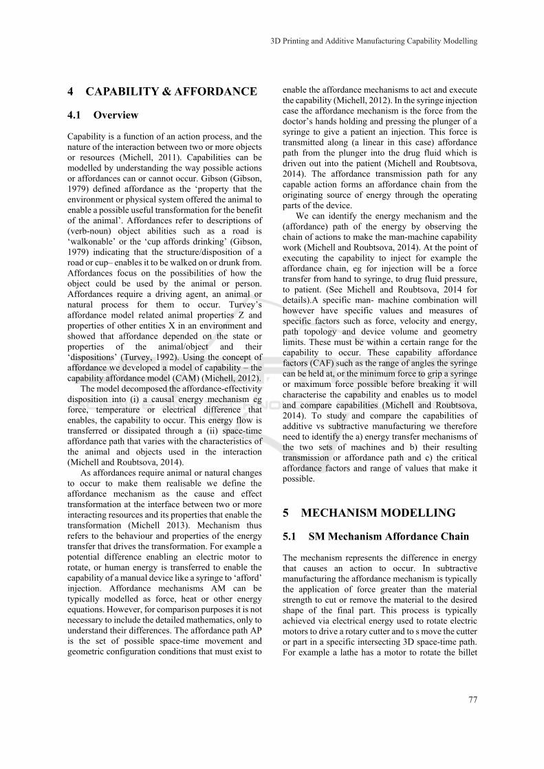
The mechanism represents the difference in energy that causes an action to occur. In subtractive manufacturing the affordance mechanism is typically the application of force greater than the material strength to cut or remove the material to the desired shape of the final part. This process is typically achieved via electrical energy used to rotate electric motors to drive a rotary cutter and to s move the cutter or part in a specific intersecting 3D space-time path. For example a lathe has a motor to rotate the billet
3D Printing and Additive Manufacturing Capability Modelling
77
about an axis, whilst the cutter is stationary and moved at right angles to the work. In contrast in a milling machine the cutter is rotated via an electric motor and the billet is clamped to table that can move in x, y and z directions with three degrees of freedom.
Figure 2: Example SM Mechanisms.
In subtractive manufacturing, unlike 3DP, there is no universal tool solution. A part, if complex, is produced with a series of machining actions on different machining centres, such as a lathe, mill, drill etc. Hence the affordance path comprises a series of cutting actions on separate machines, separated by moving the part between machine set up operations, where the billet is locked into the correct position and orientation for cutting. Each cutting operation comprises a relative simple mechanism or short affordance chain representing the application of a cutting force along a space time path in relation to a constrained billet as dictated by the machine and cutter geometry as in Figure 2.
5.2 Mechanism Driven CAF for Subtractive Manufacturing
Due to the forces involved in machining hard materials fixture constraints to hold the part being machined against the cutting forces may be required to be designed, positioned and applied, hence increasing the complexity and cost of setting up the additive manufacturing operation (Matthews, 2007).
There are upper and lower bounds in the forces required to remove unwanted material from a lump of metal or billet. For example there must be sufficient average torque Tm to cut the part but less than the maximum machine torque to damage material. A related factor is the tool spindle speed w, which again must be greater than a minimum value to ensure a smooth surface finish, but less than the critical value to cause burning or melting of the tool or part. In addition as tools are liable to be bent with high forces, the average cutting force Fm must be sufficient to cut smoothly with minimum tool deflection and less than the force required to cause part damage or failure such
to limit the average cutter deflection dc will limit the capability of the tool to produce a quality part. Further the cutting force Fm must be less than the critical value necessary to cause significant tool wear (Blackenfelt, 2001).
The force required to cut a material and the material properties will dictate potential distortion especially in features of the manufactured product that have thin walls (Matthews, 2007). Further there is a limit to feature production of very fine parts. For example very thin cylinders or point features are not able to be machined due to these force limitations. Similarly the creation of a mesh from a solid billet would be extremely difficult, time consuming and very costly.
5.3 Mechanism for Additive Manufacturing
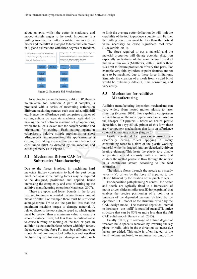
Additive manufacturing deposition mechanisms can vary widely from heated molten plastic to laser sintering (Norton, 2001). For capability comparison we will focus on the most typical mechanism used in the cheaper 3D printers – based on heated plastic deposition. In a typical 3D printer of this form there are 4 component mechanisms that form an affordance chain of interacting actions (Figure 3).
Firstly a material feed process is usually via electrically driven rollers applying a rotary constraining force to a fibre of the plastic working material which is dragged into an electrically driven heating element. This heats the plastic to a pliable temperature φ and viscosity within a range that enables the melted plastic to flow through the nozzle in a continuous stream according to the feed controller.
The plastic flows through the nozzle at a steady velocity Vp driven by the force Ff imparted to the plastic filament by the rotation of the pinch rollers.
For deposition path planning & control, the heater and nozzle are typically fixed to a framework of motor driven slides (similar to a 2D inkjet printer) that enables the precise positioning of a point or a line/area of the deposited material dictated by the optimised STL model of the structure driven by the CAD design model. The material deposited internal to the shape – the ‘infill’ is not solid but an STL lattice structure that can be 80% or more less than the full CAD solid model (Bassett et al., 2015).
Finally full x, y, z coverage of a three degree of freedom build space is achieved by lowering the x-y plane or build table in the z direction as successive layers are added. This table is often heated, or the build volume enclosed, to minimise warping of the
Lathe – fixed tool moved into path of rotating billet
Mechanism: Cutting force Fl perpendicular to rotation
Cutter Path: =helical about lathe axis
Milling machine – fixed billet moved into path of rotating tool
Mechanism: Cutting force Fm in direction of bed travel (x, y, z)
Cutter Path: 3d space‐time volume – with limitsaccording to approach and cutter geometries
Apply cutting Velocity Vl, Force Fl
Constrain billet with set up Forces Fcl
Remove constraints
Move part to milling machine
Constrain billet with set up Forces Fcm
Apply cutting Velocity Vm, Force Fm
Remove constraints
Clean finished part
Mill feature of part on milling
machine
Turn feature of part on a lathe
Sixth International Symposium on Business Modeling and Software Design
78
part which would otherwise occur with rapid cooling back to room temperature.
Figure 3: 3D Printer Key Components and Mechanism.
5.4 Mechanism Driven CAF for Additive Manufacturing
A capability affordance factors that limit and define whether the affordance and capability will occur for 3DP are based on the heat transfer and feed rate variables for the melted material deposition mechanism a sample of which is discussed below, but a wider range can be seen in (Choi and Samavedam, 2002).
Firstly the material melting temperature θ must be within a range that enables flow, but not burning of the PLA/ABS material. For example 175 < θpla < 200 degrees, 225 < θabs < 230 degrees (Basset et al, 2015). Secondly the build bed must be heated within a given temperature range to avoid warping as the part cools. For example 20 < γpla < 70 degrees, and for ABS 105 < γ < 105 degrees (Basset et al., 2015). The material filament feed rate Vf must be within a range consistent with smooth deposition to avoid gaps or bunching, or unwanted spreading of the material.
The material viscosity μ at this temperature must be sufficiently liquid to flow, but not too low to result in puddling and spreading. The x,y,z velocity of the nozzle travel Vn-xyz must also be in proportion to the material viscosity and flow rate and be above a minimum where material bunching will occur and less than a maximum that would cause gaps in the deposition. The deposition layer height hd is important for part surface finish and fineness and is dependent on nozzle diameter, but must be above a minimum value that would unacceptably increase the time to produce the part (Basset et al., 2015). The infill structure density р must also be within a range of values that enables sufficiently rapid printing, but not too sparse to cause problems with structural integrity
Various combinations of these factors will affect the capability and mathematical models have been built to establish the range of control parameters and the physics and heat transfer involved (Ganeriwala
and Zohdi, 2014). For example the plastic feed rate must be related to the x, y, z velocity for a given material viscosity to avoid gaps or lumps in the deposited plastic. Feed rate and viscosity will affect the layer thickness, which in turn will affect surface accuracy as a series of stacked layers or ‘stair step effect. (Choi and Samavedam, 2002). The mechanism driven factors for AM and 3DP can be seen in Figure 5.
6 PATH MODELLING METHODS
To compare 3DP capability with traditional manufacturing we need to develop a conceptual model of the affordance path that takes into account the path geometry and the mechanism of the different methods. Both manufacturing methods involve the forming/sculpting of three dimensional solids, one by removing material from a solid block or billet of material by force and the other by deposition. Much research has been conducted into traditional manufacturing focusing on cutter path geometries (Feng and Cusiak, 1995) and the study of tool vibration effects (Blackenfelt, 2001). Other work has focused on identifying the optimum sequence and type of machining (Gupta et al, 1997) or machining process simulation (Blackenfelt, 2001) and the problem of modelling machining features (Tapie et al., 2012). However using a mathematical geometric approach to modelling these methods is unduly complex and unnecessary for our comparison purposes.
An alternative method that is appropriate to accommodate the massive variation in machine tools and machined or 3dp manufactured objects is to model the situation from a topological set theory perspective. Consideration of the problem suggests that for subtractive manufacturing we need to model the intersection of a polygonal volume with a cutter path with different degrees of freedom. The additive manufacturing (3DP) model can be considered as the intersection of a bound build volume space with a three degree of freedom deposition path.
Topological modelling defines spatial relationships for geometries that are preserved under rotation and scaling transformations (Egenhofer et al., 1994). Such modelling can be used to define topological relationships between two spatial objects (Borrmann et al., 2006). Based on the fact that boundaries and interiors have been identified as the crucial descriptions of polygonal intersections (Wagner, 1988), Egenhofer developed a point set model of topological spatial relations between
3DP Affordance Chain
HEATER MECHANISM
TEMPERATURE CONTROLLER
Z AXIS MECHANISM
Deposition Positioning
Material state preparation
Deposition Path Planning & Control
CAD MODEL
x‐y printer drive
Table & z axis
Mechanical pinch rollers
FEED CONTROLLER
POSITION CONTROLLER
Material Feed Mechanism
STL MODEL
X,Y AXIS MECHANISM
Velocity V, Force Ff
Heat to temp φ
Deposition path, x, y
Deposition z location
Cool finished part to room temperature
3DP Mechanism Block Diagram
Solid plastic filament
3D Printing and Additive Manufacturing Capability Modelling
79
regions or areas (Egenhofer and Franzosa, 1991). The point set approach considered a set of points x and a set of points y with neighbouring and overlapping topologies defined by the set theory. Egenhofer defined the results of the intersections of the boundaries and interiors of two shapes in terms of non-empty ¬ Ø and empty sets Ø , resulting in nine feasible topological relations.
6.1 Three Dimensional Modelling
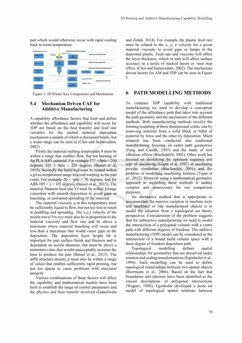
The 2D model was formally extended by specification of the interior, boundary and exterior point sets of spatial object by Egenhofer et al, who described the topological relations between two volumetric cells A and B. He considered A and B as arbitrary objects composed of sets of points (Egenhofer, 1994). These comprised three ‘object parts’; interior designated by ᵒ, boundary designated by δ and exterior designated by ⁻ and the two point sets;{Aᵒ, δA, A⁻} and {Bᵒ, δB, B⁻}.
The combinations of intersections between interior, boundary and exterior point sets result in the nine intersection model (9-IM).
Figure 4: The 9-IM Topological Intersection Model.
Borrmann et al’s work describes a generic intersection matrix for intersections of point, line, area and 3d body (Borrmann et al., 2006). This gives a number of intersection volumes that include; non-touching (disjoint), equal volumes, a volume containing and touching a volume and a volume totally within a volume (Borrmann and Rank, 2009). Whilst their work focused on modelling intersections of architectural buildings, as these are simply intersecting polygons, the same approach can be adapted to manufacturing of polygonal parts. This is equivalent of the intersection of the billet and the cutter path. For our purposes we only consider the body intersection which we can use to model the 3D billet, cutter path or deposition path.
Using the same principle, the ‘equal volumes’ topology can be used to describe the 3D printer situation, where the material deposition volume of a 3D printer is equal to the full 3D build space available. This represents a ‘total topological
relationship’ (Billen and Kurata, 2008), where any point, line, area or the full work volume can be reached with the three degrees of freedom of deposition of the 3D printer
Earlier in equation 3 we defined Ps as a part produced by subtractive manufacturing. As topological relations are indicated by the presence or absence of intersections in the 9-IM model, we can rewrite the model for AM and SM and apply the set theoretic approach to show which relationship holds.
For an additive manufacturing process the completed part Pa should be exactly the same as the part produced by subtractive manufacturing Ps. For Pa the topological path model is a function of the swept deposition volume Pd and the available build volume limits V. The finished part depends on the volume of deposited material defined by the set of points Pd in relation to the overall volume available to build in V.
Ps = Pa = V Pd (5)
Hence using the same 9-IM matrix M (V, Pd) we can represents the possible topology for the 3D printer AM approach. Where A in the original 9M matrix represents the deposition path volume Pd from the deposition of melted plastic points in layers. B represents the available free space V to build in.
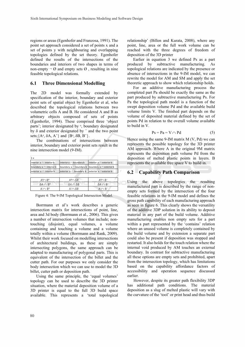
6.2 Capability Path Comparison
Using the above topologies the resulting manufactured part is described by the range of non-empty sets formed by the intersection of the four feasible relations in the 9-IM model and defines the gross path capability of each manufacturing approach as seen in figure 6. This clearly shows the versatility of the additive 3DP solution in its ability to deposit material in any part of the build volume. Additive manufacturing enables non empty sets for a part within a part represented by the ‘contains’ relation where an unused volume is completely contained by the build volume and by extension a separate part could also be present if deposition was stopped and restarted. It also holds for the touch relation where the internal void produced by AM touches an external boundary. In contrast for subtractive manufacturing all these options are empty sets and prohibited, apart from the intersection topology, which has limitations based on the capability affordance factors of accessibility and operation sequence discussed earlier.
However, despite its greater path flexibility 3DP has additional path conditions. The material deposition as a slug of melted plastic will vary with the curvature of the ‘tool’ or print head and thus build
I =
interior a interior b interior a boundary b interior a exterior b
boundary a interior b boundary a boundary b boundary a exterior b
exterior a interior b exterior a boundary b exterior a exterior b
Aᵒ Bᵒ Aᵒ δB Aᵒ B⁻
δA Bᵒ δA δB δA B⁻A⁻ Bᵒ A⁻ δB A⁻ B⁻
Sixth International Symposium on Business Modeling and Software Design
80
orientation of the part will also affect final part quality (Nelaturi and Shapiro, 2015). In addition the cooling of the melted material in certain geometries may result in drooping and warping and hence certain features and overhangs may require additional build support structure to be added during construction to prevent this. In contrast the path driven capability affordance factors for subtractive manufacturing as discussed earlier are far more numerous, complex and onerous. See figures 5 and 7 for both sets of factors.
7 SUMMARY & CONCLUSIONS
7.1 Summary
We have analysed the perceived business and technical advantages of 3D printing and shown how these are derived by the mechanism and path limitations of the AM and SM approaches. We have compared the capability of 3D printing with traditional subtractive manufacturing using a capability affordance comparison method and a topological model. The model demonstrated that the mechanism of subtractive manufacturing is largely based on force application and that this leads to the requirements for extensive jigs and fixtures to hold the part in place. This compared to the heat transfer mechanism aided by a small filament force of 3D printing. The 3DP mechanism in contrast relies on gravity and the precise location of a point of material to constrain the finished part. However, the 3DP heat transfer mechanism produces a greater number of more difficult to control factors such as flow rate, viscosity etc as seen in Figure 5.
In contrast the topological model comparison emphasises how traditional subtractive manufacturing methods are limited by the path geometry of the cutters used and the need for cutter access This is emphasised by the fact that a 3D printer with three degrees of freedom of point material deposition has a ‘total topological relationship’,
compared with the ‘partial topological relationship’ of subtractive machining methods. SM is further limited by the need, especially for complex parts, to carefully consider the order of subtractive operations, demonstrated by the larger range of geometric critical affordance factors than 3DP seen in Figure 7.
However, whilst additive manufacturing has a far greater capability to produce complex and intricate parts, the machine parameters involved with the deposition approach can be more difficult to get right to ensure a quality part compared with tried and trusted subtractive force driven mechanisms where much more is known about the kinematics and thermodynamics involved ensuring consistent quality part production.
7.2 Conclusion
A have explored the key business and technology benefits of 3DP additive manufacturing compared with traditional subtractive manufacturing. We applied the capability affordance model (CAM) defining capability as an energy mechanism operating through a space time path. We have shown via topology analysis that the key capability difference and advantage for 3DP is in its superior space time affordance path due to the three degrees of freedom to build from a point to enable construction of complex single part objects and meshes, parts within parts and very fine constructions. This is superior to the limited topology available to additive manufacturing due to the need for cutter access and geometry limitations. However the force focused mechanism of additive manufacturing does enable more consistent surface quality and durability compared to the heat flow focused mechanism of 3DP with its more complex capability affordance factors that lead to this variation. However, the low cost, ease of use and design friendly format of 3DP enables significant benefits to small and medium manufacturers in producing innovative product capabilities over traditional methods.
3D Printing and Additive Manufacturing Capability Modelling
81
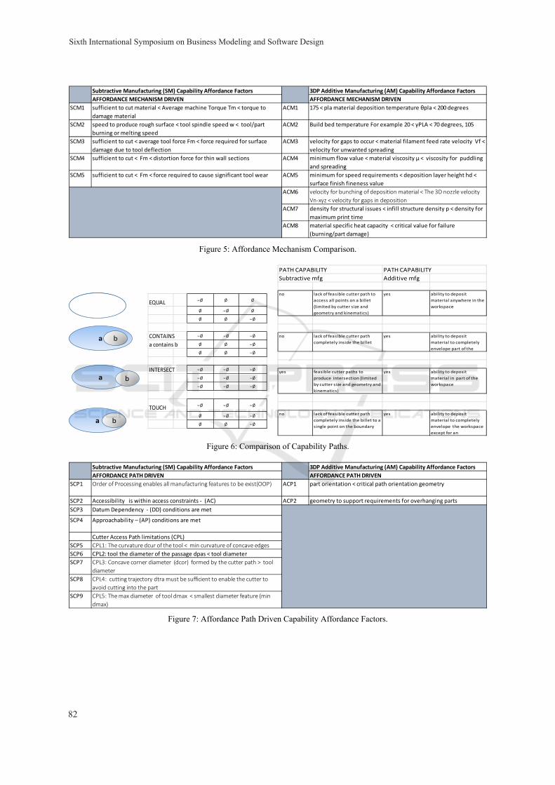
Figure 5: Affordance Mechanism Comparison.
Figure 6: Comparison of Capability Paths.
Figure 7: Affordance Path Driven Capability Affordance Factors.
Subtractive Manufacturing (SM) Capability Affordance Factors 3DP Additive Manufacturing (AM) Capability Affordance Factors
AFFORDANCE MECHANISM DRIVEN AFFORDANCE MECHANISM DRIVEN
SCM1 sufficient to cut material < Average machine Torque Tm < torque to
damage material
ACM1 175 < pla material deposition temperature θpla < 200 degrees
SCM2 speed to produce rough surface < tool spindle speed w < tool/part
burning or melting speed
ACM2 Build bed temperature For example 20 < γPLA < 70 degrees, 105
SCM3 sufficient to cut < average tool force Fm < force required for surface
damage due to tool deflection
ACM3 velocity for gaps to occur < material filament feed rate velocity Vf <
velocity for unwanted spreading
SCM4 sufficient to cut < Fm < distortion force for thin wall sections ACM4 minimum flow value < material viscosity μ < viscosity for puddling
and spreading
SCM5 sufficient to cut < Fm < force required to cause significant tool wear ACM5 minimum for speed requirements < deposition layer height hd <
surface finish fineness value
ACM6 velocity for bunching of deposition material < The 3D nozzle velocity
Vn‐xyz < velocity for gaps in deposition
ACM7 density for structural issues < infill structure density р < density for
maximum print time
ACM8 material specific heat capacity < critical value for failure
(burning/part damage)
a b
a b
a b
EQUAL ¬ Ø Ø Ø
Ø ¬ Ø Ø
Ø Ø ¬ Ø
CONTAINS ¬ Ø ¬ Ø ¬ Ø
a contains b Ø Ø ¬ Ø
Ø Ø ¬ Ø
INTERSECT ¬ Ø ¬ Ø ¬ Ø
¬ Ø ¬ Ø ¬ Ø
¬ Ø ¬ Ø ¬ Ø
TOUCH ¬ Ø ¬ Ø ¬ Ø
Ø ¬ Ø ¬ Ø
Ø Ø ¬ Ø
PATH CAPABILITY PATH CAPABILITY
Subtractive mfg Additive mfg
no lack of feasible cutter path to
access all points on a billet
(limited by cutter size and
geometry and kinematics)
yes ability to deposit
material anywhere in the
workspace
no lack of feasible cutter path
completely inside the billet
yes ability to deposit
material to completely
envelope part of the
yes feasible cutter paths to
produce intersection (limited
by cutter size and geometry and
kinematics)
yes ability to deposit
material in part of the
workspace
no lack of feasible cutter path
completely inside the billet to a
single point on the boundary
yes ability to deposit
material to completely
envelope the workspace
except for an
Subtractive Manufacturing (SM) Capability Affordance Factors 3DP Additive Manufacturing (AM) Capability Affordance Factors
AFFORDANCE PATH DRIVEN AFFORDANCE PATH DRIVEN
SCP1 Order of Processing enables all manufacturing features to be exist(OOP) ACP1 part orientation < critical path orientation geometry
SCP2 Accessibility is within access constraints ‐ (AC) ACP2 geometry to support requirements for overhanging parts
SCP3 Datum Dependency ‐ (DD) conditions are met
SCP4 Approachability – (AP) conditions are met
Cutter Access Path limitations (CPL)
SCP5 CPL1: The curvature dcur of the tool < min curvature of concave edges
SCP6 CPL2: tool the diameter of the passage dpas < tool diameter
SCP7 CPL3: Concave corner diameter (dcor) formed by the cutter path > tool
diameter
SCP8 CPL4: cutting trajectory dtra must be sufficient to enable the cutter to
avoid cutting into the part
SCP9 CPL5: The max diameter of tool dmax < smallest diameter feature (min
dmax)
Sixth International Symposium on Business Modeling and Software Design
82
REFERENCES
Bassett, K., Carriveau, R., & Ting, D. K. (2015). 3D printed wind turbines part 1: Design considerations and rapid manufacture potential. Sustainable Energy Technologies and Assessments, 11, 186-193.
Berman, B. (2012). 3-D printing: The new industrial revolution. Business horizons, 55(2), 155-162.
Blackenfelt, M. (2001). Managing complexity by product modularisation
Billen, R., & Kurata, Y. (2008). Refining Topological Relations between Regions Considering Their Shapes. In Geographic Information Science (pp. 20-37). Springer Berlin Heidelberg.
Borrmann, A., Van Treeck, C., & Rank, E. (2006, June). Towards a 3D spatial query language for building information models. In Proc. Joint Int. Conf. of Computing and Decision Making in Civil and Building Engineering (ICCCBE-XI) (Vol. 2).
Borrmann, A., & Rank, E. (2009). Topological analysis of 3D building models using a spatial query language. Advanced Engineering Informatics, 23(4), 370-385.
Choi, S. H., & Samavedam, S. (2002). Modelling and optimisation of rapid prototyping. Computers in industry, 47(1), 39-53.
Conner, B. P., Manogharan, G. P., Martof, A. N., Rodomsky, L. M., Rodomsky, C. M., Jordan, D. C., & Limperos, J. W. (2014). Making sense of 3-D printing: Creating a map of additive manufacturing products and services. Additive Manufacturing, 1, 64-76.
D'aveni, R. A. (2013). 3-D printing will change the world. Harvard business review, 91(3), 34-35.
Depoorter, B. (2013). Intellectual Property Infringements & 3D Printing: Decentralized Piracy. Hastings LJ, 65, 1483.
Doubrovski, E. L., Verlinden, J. C., & Geraedts, J. M. P. (2011) From factory to replicator
Egenhofer, M. J., & Franzosa, R. D. (1991). Point-set topological spatial relations. International Journal of Geographical Information System, 5(2), 161-174.
Egenhofer‡, M. J., Clementini, E., & Di Felice, P. (1994). Topological relations between regions with holes†. International Journal of Geographical Information Science, 8(2), 129-142.
Egenhofer, M. J. (1994). Deriving the composition of binary topological relations. Journal of Visual Languages & Computing, 5(2), 133-149.
Feng, C. X., & Kusiak, A. (1995). Constraint-based design of parts. Computer-Aided Design, 27(5), 343-352.
Ganeriwala, R., & Zohdi, T. I. (2014). Multiphysics modeling and simulation of selective laser sintering manufacturing processes. Procedia CIRP, 14, 299-304.
Gibson, J.: The Ecological Approach to Visual Perception. Houghton Mifflin Company, Boston (1979) California Management Review.
Gupta, Satyandra K., William C. Regli, Diganta Das, and Dana S. Nau. "Automated manufacturability analysis: a survey." Research in Engineering Design 9, no. 3 (1997): 168-190.
Hoy, M. B. (2013). 3D printing: making things at the
library. Medical reference services quarterly, 32(1), 93-99.
Matthews, J. A. (2007). A constraint-based approach for assessing the capabilities of existing designs to handle product variation (Doctoral dissertation, University Library).
Michell, V.A.(2011) A Focused Approach to Business Capability. First International Symposium on Business Modelling and Software Design – BMSD 2011, Sofia, Bulgaria, pp. 105–113.
Michell V. (2012) The Capability Affordance Model: Comparing Medical Capabilities. In: B. Shishkov (Ed.) Business Modeling and Software Design – BMSD’12 Revised Selected Papers, Springer-Verlag – Lecture Notes in Business Information Processing, Berlin-Heidelberg
Michell, V., & Roubtsova, E. (2014). Modelling Capability and Affordance as Properties of Human/Machine Resource Systems. In Proceedings of the 4th International Symposium on Business Modeling and Software Design, BMSD
Nair 2014 democratising-manufacturing-3d-printing-is-set-to-change-the-startup-landscape. Available at http://www.thestar.com.my/business/sme/2014/03/26/democratising-manufacturing-3d-printing-is-set-to-change-the-startup-landscape/[ Accessed 04 May 2016]
Nelaturi, S., & Shapiro, V. (2015). Representation and analysis of additively manufactured parts. Computer-Aided Design, 67(C), 13-23.
Norton, A. (2001). Utilising Rapid Product Development and Late Customisation Methodologies within Manufacturing SMEs. PDF article to link: https://www. google. com/# q= Rapid+ Product+ De velopment+ and+ Late+ Customisation, 15-16.
Pham, D. T., & Gault, R. S. (1998). A comparison of rapid prototyping technologies. International Journal of machine tools and manufacture, 38(10), 1257-1287.
Rosen, D. W. (2007). Computer-aided design for additive manufacturing of cellular structures. Computer-Aided Design and Applications, 4(5), 585-594.
Tapie, L., Mawussi, B., & Bernard, A. (2012). Topological model for machining of parts with complex shapes. Computers in Industry, 63(5), 528-541.
Turvey, M.T. (1992). Affordances and Prospective Control: An Outline of the Ontology. Ecological Psychology 4(3), 173–187.
3D Printing and Additive Manufacturing Capability Modelling
83