3d-printed concentrator arrays for external light trapping on thin film solar cells
TRANSCRIPT

Solar Energy Materials & Solar Cells 139 (2015) 19–26
Contents lists available at ScienceDirect
Solar Energy Materials & Solar Cells
http://d0927-02
n CorrE-m
journal homepage: www.elsevier.com/locate/solmat
3D-printed concentrator arrays for external light trapping on thin filmsolar cells
Lourens van Dijk a,n, E.A. Pepijn Marcus a, A. Jolt Oostra b, Ruud E.I. Schropp c,d,Marcel Di Vece a
a Nanophotonics – Physics of Devices, Debye Institute for Nanomaterials Science, Utrecht University, High Tech Campus, Building 21, 5656 AE Eindhoven,The Netherlandsb Zernike Institute for Advanced Materials, University of Groningen, Nijenborgh 4, 9747 AG Groningen, The Netherlandsc Energy Research Centre of the Netherlands (ECN), High Tech Campus, Building 21, 5656 AE Eindhoven, The Netherlandsd Eindhoven University of Technology (TU/e), Department of Applied Physics, Plasma and Materials Processing, 5600 MB Eindhoven, The Netherlands
a r t i c l e i n f o
Article history:Received 3 February 2015Accepted 4 March 2015
Keywords:3D printingAnti-reflectionExternal light trappingNon-imaging opticsOrganic solar cellsParabolic concentrator array
x.doi.org/10.1016/j.solmat.2015.03.00248/& 2015 The Authors. Published by Elsevier
esponding author.ail address: [email protected] (L. van Dijk).
a b s t r a c t
After our recent demonstration of a 3D-printed external light trap on a small solar cell, we now consider itspotential for large solar panels. An external light trap consists of a parabolic concentrator and a spacer thatredirects the photons that are reflected by the solar cell back towards the solar cell. These retro-reflectionsenable higher absorptance and improved power conversion efficiency. Scaling a single external light trapsuch that it covers a large solar panel has disadvantages in terms of height and cost of the external lighttrap. These disadvantages can be overcome by deploying an array of concentrators as the top part of theexternal light trap. We present an optimization study of concentrator arrays for external light trapping. Wefabricated 3D-printed external light traps with a square, hexagonal and circular compound parabolicconcentrator to test their suitability for concentrator arrays. The 3D-printed traps were placed on top of anorganic solar cell which resulted in a significant enhancement of the external quantum efficiency. Therequired transmittance of these concentrator arrays is calculated as a function of the parameters of boththe concentrator and the solar cell. We compare the theoretical and experimentally determined opticalperformance of the different concentrators. Finally, the prospects of external light trapping are analyzedand we give guidelines for improvements of the external light trap design.& 2015 The Authors. Published by Elsevier B.V. This is an open access article under the CC BY-NC-ND license
(http://creativecommons.org/licenses/by-nc-nd/4.0/).
1. Introduction
Thin solar cells benefit from low bulk recombination of excitedcharge carriers. Hence the performance of a thick solar cell generallyimproves by reducing its thickness provided that the absorptancestays constant. Therefore, large efforts have been made to obtainhigh absorptance in thin solar cells by modifications of the solar cellsurface to obtain internal light trapping [1,2]. However, theseinternal cell modifications often have a negative impact on thematerial quality and the electrical performance of the solar cell. Forexample, by texturing the surface of crystalline silicon (c-Si) solarcells the surface recombination velocity increases due to theenlarged surface area [3,4]. For other cells like nanocrystalline silicon(nc-Si) the growth of a solar cell on top of a textured scatteringsurfaces is challenging [5–7] while for organic solar cells texturing is
B.V. This is an open access article u
less effective [8]. It is thus challenging to realize the full theoreticalpotential of internal light trapping for most solar cells and there is aneed for better light trapping methods [9]. We demonstrate anexternal light trapping method that can complement or even replaceinternal light trapping and which moreover can be directly appliedon all solar cells.
Fig. 1 illustrates the concept of an external light trap: a con-centrator focuses the sunlight through a small aperture before thelight reaches the photovoltaic device. Most of the reflected (andradiatively emitted) light by the solar cell is reflected back to thesolar cell by the reflective coating of the cage. Therefore, there is ahigher probability for a photon to be absorbed. This photon recy-cling enables higher power conversion efficiency [10–14]. More-over, external light trapping enables new photovoltaic devicesthat, for example, can facilitate spectrum splitting [15,16].
The theoretical energy conversion efficiency limit of externallight trapping surpasses that of conventional internal light trapping[17,18,13]. This is mainly due to the improved electrical quality of
nder the CC BY-NC-ND license (http://creativecommons.org/licenses/by-nc-nd/4.0/).

Fig. 1. Schematic illustration of a parabolic concentrator array for external lighttrapping. Light is focused through a small aperture. The spacing between theconcentrator and the solar cell allows the light beam to expand. Most of the lightthat is reflected by the solar cell is reflected back to the solar cell. A small fraction(determined by the aperture area) of the light can escape out of the cage.
L. van Dijk et al. / Solar Energy Materials & Solar Cells 139 (2015) 19–2620
thin solar cells and the potential recycling of radiative emission.Recently, we demonstrated a broadband absorption enhancementby applying one external light trap on a ∼1 cm2 nanocrystallinesilicon solar cell [14]. A light trap that covers a larger solar cell areacan be made of a single tall concentrator, but this translates to highmaterial costs and weight, and moreover it is aesthetically unat-tractive. The use of an array of small concentrators overcomes thesedisadvantages. We present an optimization study of the design ofconcentrator arrays suited for external light trapping. Furthermore,we compare the theoretical and experimental transmittance of asquare, hexagonal and circular 3D-printed parabolic concentrator.Previously, a light trap incorporating a micro-lens array has beenshown to be successful on an organic solar cell [19,20]. Here, a lowcost fabrication method is presented that requires less fabricationsteps and is industrially scalable.
To test the performance of the external light traps we useorganic solar cells (OSCs). For these cells there are currently noadequate light trapping methods. The absorptance of a thin OSC isrelatively low. Although a thick OSC has a high absorptance, a thickcell design is not desirable: due to the high bulk recombinationloss the internal quantum efficiency (IQE) is relatively low [21,22].
Internal light trapping schemes based on the Lambertian scat-tering can realize a significant path length enhancement factor forhigh refractive index solar cells as the escape probability scales asP n1/escape
2= . However, they are less effective for low refractive indexsolar cells like organic solar cell materials (n∼2) [23–25,8].
Moreover, it is difficult to scatter the broadband sunlight effec-tively in OSCs. Macroscopic surface textures efficiently scatter thelight in relative thick crystalline silicon solar cells. However, thismethod cannot be directly applied to thin OSCs as scattering bygeometric features smaller than the wavelength of light is noteffective [26].
Due to the lack of a sufficient light trapping method there hasbeen interest for alternative light trapping methods like arrangingsolar cells in a macroscopic V-shape in which incoming light hitsboth flanks of a V-shaped solar cell several times [22,27,28]. This isan effective method to enhance the total absorption, but it com-plicates the fabrication considerably. Due to the enlarged area thelight is effectively diluted which reduces the injection level andthe corresponding open circuit voltage of the solar cell. Moreover,the enlarged surface area will increase surface recombination anddeteriorate the dark current. These disadvantages are absent forexternal light trapping where the optical path is prolonged with-out using more solar cell material.
2. Experimental: design of the concentrator
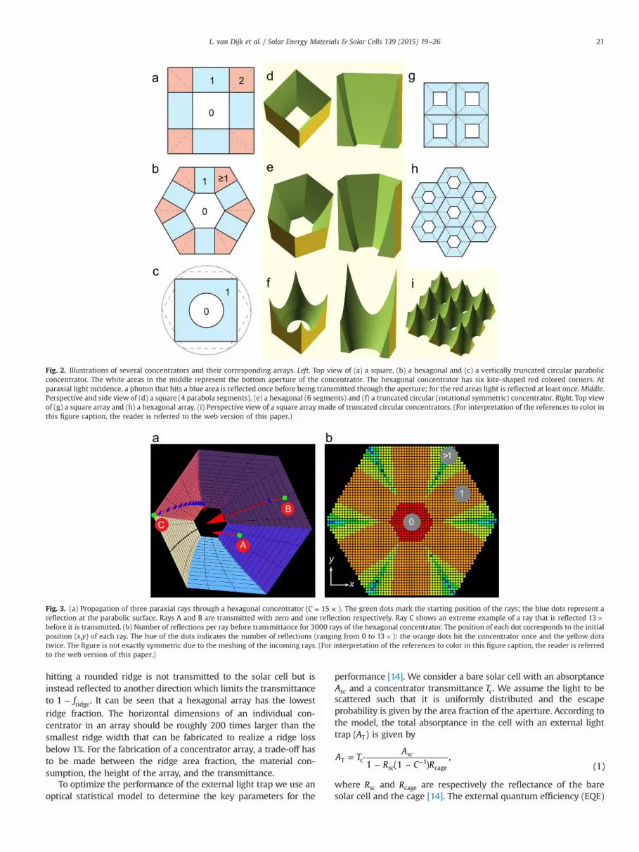
Metallic parabolic concentrators with a square and a hexagonaltop shapes can be arranged in an array. Figs. 2a and d show asquare concentrator that is composed of four parabolic segments.These square concentrators can be arranged in a square array asshown in Fig. 2g. In a similar way a hexagonal array can be madeas shown in Fig. 2b, e and h. Circular concentrators cannot com-pletely fill a plane. To overcome this filling problem the circularconcentrators can be truncated at four sides to enable the for-mation of a square array as illustrated in Fig. 2c, f and i. In a similarway a hexagonal array of circular concentrators can be made. Inbetween the neighboring concentrators there are sharp peakswhich are fragile and challenging to fabricate.
The transmittance of the concentrator is a key-parameter for theperformance of the external light trap. Incoming light that travels ina straight line towards the aperture of the concentrator is trans-mitted without being reflected by the concentrator. The main part ofthe light is reflected one or more times at the reflective concentratorsurface before going through the aperture to enter the cage. Theexact number of reflections depends on the geometry of the para-bolic concentrator. At each reflection a small fraction of the light isabsorbed by parasitic losses at the reflective surface of the con-centrator. The averaged transmittance of a concentrator thereforedecreases with increasing geometric concentration factor (C), whereC is defined as the following area ratio:
CA
A.cell
aperture=
To determine the optimal concentrator geometry we calculatedthe average transmittance of incoming light propagating parallelto the central axis of the concentrator. The transmittance of lightoriginating from other angles depends on the parabolic shape ofthe concentrator [29]. Diffuse light is only partly transmitted bythe concentrator. The maximum transmitted power P( )trans of iso-tropically distributed diffused light P( )diff is P C P(1/ )trans diff= · [30].Sun tracking will yield the best averaged transmittance of theconcentrator as all rays of the direct sunlight will be transmittedthrough the aperture. However, external light trapping can bemore cost effective without diurnal sun tracking which is possible:at low concentration factors C( 10 )< × a static concentrator canstill accept the direct sunlight for around 8 h per day [31].
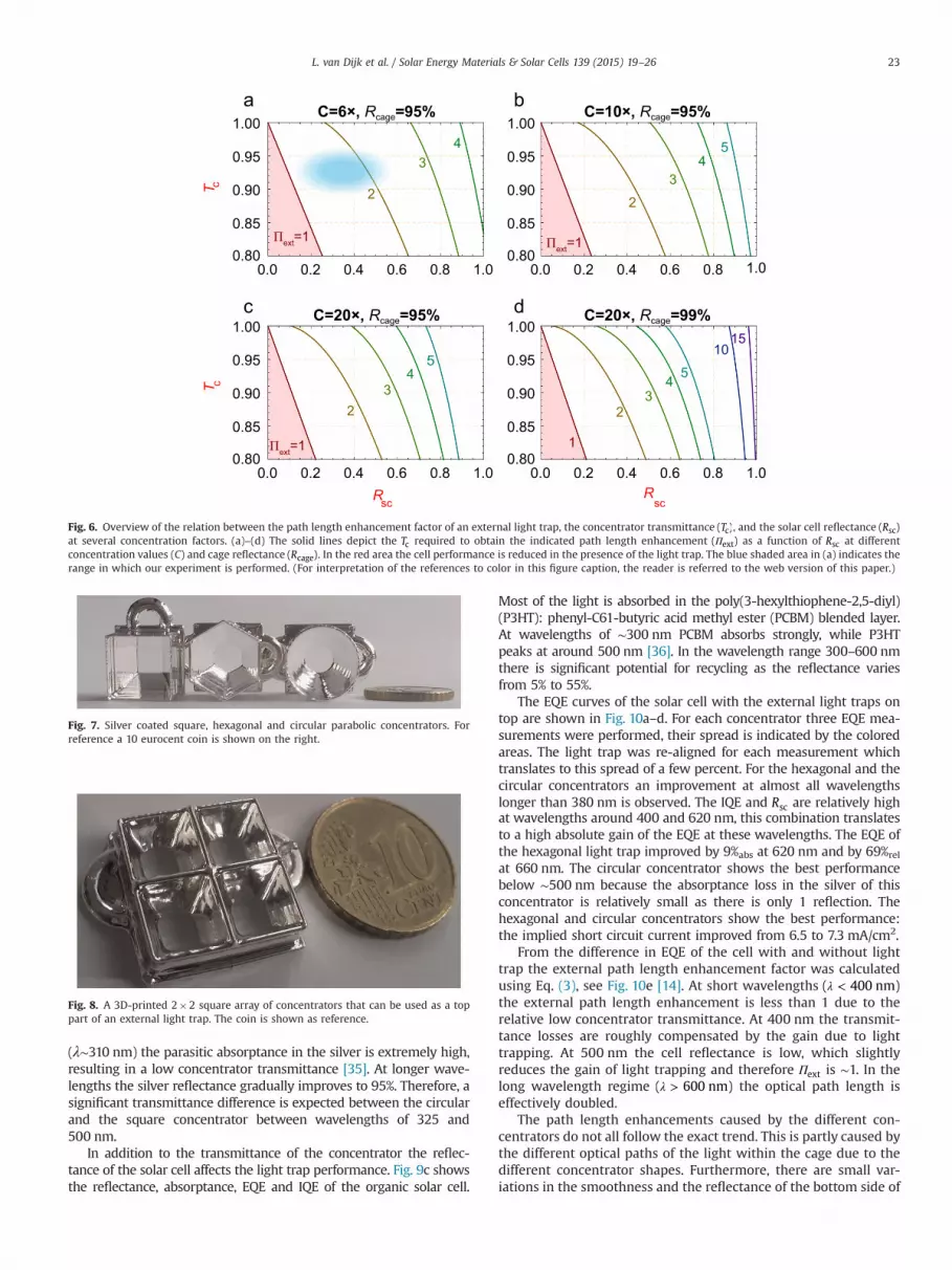
It is difficult to determine the transmittance of a hexagonalconcentrator analytically and therefore we performed ray tracing.Fig. 3a shows three different rays at paraxial incidence with adifferent number of reflections at the concentrator surface.Depending on the origin, a ray hits the hexagonal concentrator acertain number of times. Fig. 3b indicates the number of reflec-tions for a large number of rays. The average number of reflectionsfor this concentrator with C 15= × is 1.43. From this ray tracing thetransmittance is approximated by the average transmittance of allrays assuming a wavelength and angle-independent reflectioncoefficient of 95%.
Fig. 4 shows the calculated transmittance of the concentrators asa function of the concentration factor. The right inset depicts theaverage number of reflections at the concentrators before a ray istransmitted. For the circular and square concentrators this averageconverges to 1 and 2 reflection(s) respectively. Therefore, the trans-mittance of these concentrators converges to R and R2 respectively.There is no convergence for the hexagonal concentrator.
Rounded ridges in between neighboring concentrators willinevitably form during fabrication due to, for example, limited fab-rication accuracy and limited material strength. We assume thatthese limitations translate to ridges having a width Δ. The fraction ofthe total area covered by ridges f( )ridge is shown in Fig. 5. Light
≥1
0
0
0
1
1
1
2
Fig. 2. Illustrations of several concentrators and their corresponding arrays. Left. Top view of (a) a square, (b) a hexagonal and (c) a vertically truncated circular parabolicconcentrator. The white areas in the middle represent the bottom aperture of the concentrator. The hexagonal concentrator has six kite-shaped red colored corners. Atparaxial light incidence, a photon that hits a blue area is reflected once before being transmitted through the aperture; for the red areas light is reflected at least once. Middle.Perspective and side view of (d) a square (4 parabola segments), (e) a hexagonal (6 segments) and (f) a truncated circular (rotational symmetric) concentrator. Right. Top viewof (g) a square array and (h) a hexagonal array. (i) Perspective view of a square array made of truncated circular concentrators. (For interpretation of the references to color inthis figure caption, the reader is referred to the web version of this paper.)
A
B
C
y
x
0
1
>1
Fig. 3. (a) Propagation of three paraxial rays through a hexagonal concentrator C( 15 )= × . The green dots mark the starting position of the rays; the blue dots represent areflection at the parabolic surface. Rays A and B are transmitted with zero and one reflection respectively. Ray C shows an extreme example of a ray that is reflected 13�before it is transmitted. (b) Number of reflections per ray before transmittance for 3000 rays of the hexagonal concentrator. The position of each dot corresponds to the initialposition (x,y) of each ray. The hue of the dots indicates the number of reflections (ranging from 0 to 13� ): the orange dots hit the concentrator once and the yellow dotstwice. The figure is not exactly symmetric due to the meshing of the incoming rays. (For interpretation of the references to color in this figure caption, the reader is referredto the web version of this paper.)
L. van Dijk et al. / Solar Energy Materials & Solar Cells 139 (2015) 19–26 21
hitting a rounded ridge is not transmitted to the solar cell but isinstead reflected to another direction which limits the transmittanceto f1 ridge− . It can be seen that a hexagonal array has the lowest
ridge fraction. The horizontal dimensions of an individual con-centrator in an array should be roughly 200 times larger than thesmallest ridge width that can be fabricated to realize a ridge lossbelow 1%. For the fabrication of a concentrator array, a trade-off hasto be made between the ridge area fraction, the material con-sumption, the height of the array, and the transmittance.
To optimize the performance of the external light trap we use anoptical statistical model to determine the key parameters for the
performance [14]. We consider a bare solar cell with an absorptanceAsc and a concentrator transmittance Tc. We assume the light to bescattered such that it is uniformly distributed and the escapeprobability is given by the area fraction of the aperture. According tothe model, the total absorptance in the cell with an external lighttrap A( )T is given by
A TA
R C R1 (1 ),
(1)T c
sc
sc1
cage
= ·− − −
where Rsc and Rcage are respectively the reflectance of the baresolar cell and the cage [14]. The external quantum efficiency (EQE)

1
Concentration Factor
Tran
smitt
ance
Fig. 4. Plot of the transmittance of a circular, square and hexagonal concentratorsas a function of the concentration factor (C) at a reflectance (R) of the concentratorsurface set to 95%. The average number of reflections at the concentrators increaseswith C. At the bottom of the figure some top views of the circular concentrator areillustrated. The left inset of the square concentrator illustrates how the differentareas (of 0� , 1� and 2� reflections) changes with C: with increase of C the greenjoined corner of the four different segments moves towards the left top along thedashed diagonal. The right inset shows the average number of reflections at theconcentrator as a function of the concentration factor. (For interpretation of thereferences to color in this figure caption, the reader is referred to the web version ofthis paper.)
5 10 15 20 25 30 35 400
1
2
3
432 71 100 122 141 158 173 187 200
d (Δ)
Square
Hexagonal
Concentrator Area (×1000 Δ2)
Rid
ge F
ract
ion
(%)
ΔRidge
Fig. 5. The ridge area fraction f( )ridge is plotted as a function of the cross-sectionalarea of different single concentrators. The inset illustrates a ridge having a width(Δ). At the top of the graph the length of the sides of the square concentrator isshown. For comparison, the area and the dimension d( concentrator area )= areexpressed in units of Δ.
L. van Dijk et al. / Solar Energy Materials & Solar Cells 139 (2015) 19–2622
of the cell with light trap EQEtrap is given by
AEQE IQE, (2)trap T= ·
with IQE being the internal quantum efficiency of the cell.With this statistical model we can derive the equivalent optical
thickness of a solar cell with an external light trap. Therefore weintroduce the optical path length enhancement factor ( )extΠ whichindicates how many times a photon statistically passes the solarcell. In other words, the effective optical thickness is given by extΠmultiplied by the thickness of the cell. From absorption mea-surement with and without external light trap applied we cancalculate the effective external path length enhancement factoraccording to
AA
AR
log(1 )log(1 )
log(1 )log( )
.(3)ext
T
sc
T
scΠ =
−−
=−
In the low absorbing limit T R R( 1)c cage sc= = = the value of extΠinterestingly equals C. By substituting AT (from Eq. (1)) into Eq. (3)
one finds that extΠ gradually drops to one with decrease of the cellreflectance [14].
This theoretical framework enables us to determine the criticaldesign parameters of the external light trap. A reduction of theaperture (which is equivalent to an increase of the concentrationfactor) results in significantly enhanced light trapping as theescape probability becomes more restricted. However, at a certainaperture size the device performance will become most sig-nificantly limited by other parameters, see Eq. (1).
We calculated the achievable path length enhancement factorfrom the concentrator transmittance, the reflectance of the solarcell and the concentration factor of the external light trap. Byreversing this procedure we determined the concentrator trans-mittance required for a desired path length enhancement factor.
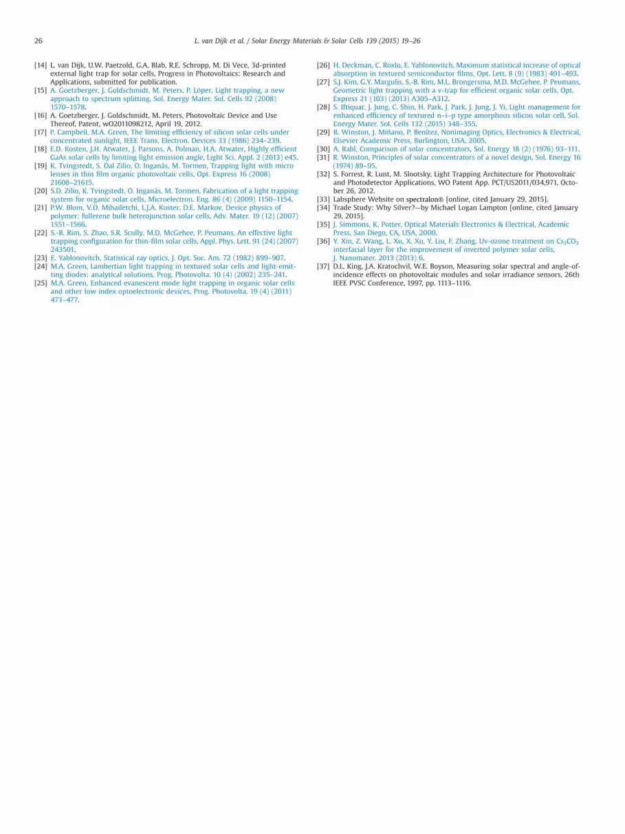
Fig. 6a illustrates the concentrator transmittance at C¼6� andR 0.95cage = required to obtain an effective path length enhancementfactor of 1� to 4� as a function of the cell reflectance. When
1extΠ = , the gain due to light trapping equals the transmittancelosses. The net absorptance is reduced by the light trap when
1extΠ < as indicated by the red zone in the parameter space.For solar cells with a high reflectance the external trap enables the
highest degree of light trapping and efficiency improvement, even ata relatively low concentrator transmittance. On the other hand, forsolar cells with a low reflectivity a relatively high concentratortransmittance is required for a significant performance boost.
External light trapping is thus of less direct interest for highlyabsorbing solar cells. In the end, however, external light trapping canenable more efficient solar cell designs. For example, the combina-tion of a thin, non-textured solar cell of high electrical quality and ahigh optical quality external light trap that has the potential tooutperform conventional light trapping methods [17,13].
Figs. 6b and c show the same scan of the parameter space atC 10= × and C 20= × which improves the light trapping. At aconcentration factor of 20� and a cage reflectance of R 0.95cage =the escape loss via the aperture and the absorptance in the cageare both 5% per cycle. Interestingly, the loss at the concentrator is aone-time event, while the loss at the reflective cage accumulatesfor each recycle event. The absolute optical loss at the cagedepends on the intensity of the (multiple times) reflected beamand is thus related to the reflectivity of the solar cell. The netoptical absorptance loss is mainly determined by the dominantloss mechanism. Therefore, only diminishing returns are obtainedupon a further increase of the concentration factor: the loss by thecage becomes dominant. For a further improvement it is reward-ing to improve the reflectance of the cage as shown for R 0.99cage =in Fig. 6d. This reduction of the parasitic cage absorption can berealized by using a highly reflective white paint [32,33].
3. Results and discussion
Figs. 7 and 8 show the fabricated concentrators with a con-centration factor of C 6= ×. They were 3D-printed, chemicallypolished with acetone vapor and metalized [14]. The cage and theconcentrators were coated with silver, which is also used in opticaltelescopes because of its high reflectance [34]. The flat, reflectivebottom side of the concentrator forms the top of the cage whichreflects the light back to the solar cell. The light traps were placed ontop of an organic solar cell which is illustrated in Fig. 9a. The pro-cessing details of the solar cell are described in the supplemental.
The effectiveness of the light trap is largely determined by theconcentrator transmittance, which in our experiment is limited bythe reflectance of the sputter coated silver. Fig. 9b shows thereflectance of silver R( )silver measured at normal incidence. Alsoshown is Rsilver
2 which represents the two reflection at the cornerareas of the square concentrator. Close to the plasma wavelength
0.0 0.2 0.4 0.6 0.8 1.00.80
0.85
0.90
0.95
1.00
0.0 0.2 0.4 0.6 0.8 1.00.80
0.85
0.90
0.95
1.00
0.0 0.2 0.4 0.6 0.8 1.00.80
0.85
0.90
0.95
1.00
0.0 0.2 0.4 0.6 0.8 1.00.80
0.85
0.90
0.95
1.00
Πext=1
RscR
sc
T cT c
43
Πext=1
5
2
43
Πext=1 1
5
10
2
43
15
C=6×, Rcage=95%
C=20×, Rcage=95%
C=10×, Rcage=95%
C=20×, Rcage=99%
5
2
43
2
Fig. 6. Overview of the relation between the path length enhancement factor of an external light trap, the concentrator transmittance T( )c , and the solar cell reflectance R( )scat several concentration factors. (a)–(d) The solid lines depict the Tc required to obtain the indicated path length enhancement ( )extΠ as a function of Rsc at differentconcentration values (C) and cage reflectance R( )cage . In the red area the cell performance is reduced in the presence of the light trap. The blue shaded area in (a) indicates therange in which our experiment is performed. (For interpretation of the references to color in this figure caption, the reader is referred to the web version of this paper.)
Fig. 7. Silver coated square, hexagonal and circular parabolic concentrators. Forreference a 10 eurocent coin is shown on the right.
Fig. 8. A 3D-printed 2�2 square array of concentrators that can be used as a toppart of an external light trap. The coin is shown as reference.
L. van Dijk et al. / Solar Energy Materials & Solar Cells 139 (2015) 19–26 23
(λ∼310 nm) the parasitic absorptance in the silver is extremely high,resulting in a low concentrator transmittance [35]. At longer wave-lengths the silver reflectance gradually improves to 95%. Therefore, asignificant transmittance difference is expected between the circularand the square concentrator between wavelengths of 325 and500 nm.
In addition to the transmittance of the concentrator the reflec-tance of the solar cell affects the light trap performance. Fig. 9c showsthe reflectance, absorptance, EQE and IQE of the organic solar cell.
Most of the light is absorbed in the poly(3-hexylthiophene-2,5-diyl)(P3HT): phenyl-C61-butyric acid methyl ester (PCBM) blended layer.At wavelengths of ∼300 nm PCBM absorbs strongly, while P3HTpeaks at around 500 nm [36]. In the wavelength range 300–600 nmthere is significant potential for recycling as the reflectance variesfrom 5% to 55%.
The EQE curves of the solar cell with the external light traps ontop are shown in Fig. 10a–d. For each concentrator three EQE mea-surements were performed, their spread is indicated by the coloredareas. The light trap was re-aligned for each measurement whichtranslates to this spread of a few percent. For the hexagonal and thecircular concentrators an improvement at almost all wavelengthslonger than 380 nm is observed. The IQE and Rsc are relatively highat wavelengths around 400 and 620 nm, this combination translatesto a high absolute gain of the EQE at these wavelengths. The EQE ofthe hexagonal light trap improved by 9%abs at 620 nm and by 69%rel
at 660 nm. The circular concentrator shows the best performancebelow ∼500 nm because the absorptance loss in the silver of thisconcentrator is relatively small as there is only 1 reflection. Thehexagonal and circular concentrators show the best performance:the implied short circuit current improved from 6.5 to 7.3 mA/cm2.
From the difference in EQE of the cell with and without lighttrap the external path length enhancement factor was calculatedusing Eq. (3), see Fig. 10e [14]. At short wavelengths ( 400 nm)λ <the external path length enhancement is less than 1 due to therelative low concentrator transmittance. At 400 nm the transmit-tance losses are roughly compensated by the gain due to lighttrapping. At 500 nm the cell reflectance is low, which slightlyreduces the gain of light trapping and therefore extΠ is ∼1. In thelong wavelength regime ( 600 nm)λ > the optical path length iseffectively doubled.
The path length enhancements caused by the different con-centrators do not all follow the exact trend. This is partly caused bythe different optical paths of the light within the cage due to thedifferent concentrator shapes. Furthermore, there are small var-iations in the smoothness and the reflectance of the bottom side of

300 400 500 600 7000.0
0.2
0.4
0.6
0.8
1.0
300 400 500 600 7000.0
0.2
0.4
0.6
0.8
1.0
Wavelength (nm)
Wavelength (nm)R
sc, A
, EQ
E, I
QE
R
Rsc
EQE
IQE
A
Rsilver
Rsilver2
Fig. 9. (a) Illustration of the layer stack of the organic solar cell. (b) Reflectance of silver at normal incidence for one and two consecutive reflections (Rsilver and Rsilver2 ).
(c) Plot of the experimentally determined absorptance (A), the reflectance R( )sc , the external quantum efficiency (EQE), and the internal quantum efficiency A(IQE EQE/ )= ofthe organic solar cell without external light trap.
300 400 500 600 7000.0
0.1
0.2
0.3
0.4
0.5
0.6
300 400 500 600 7000.0
0.1
0.2
0.3
0.4
0.5
0.6
300 400 500 600 7000.0
0.1
0.2
0.3
0.4
0.5
0.6
300 400 500 600 7000.0
0.1
0.2
0.3
0.4
0.5
0.6
300 400 500 600 7000.0
0.5
1.0
1.5
2.0
ΠE
xt
EQ
EE
QE
Wavelength (nm) Wavelength (nm)
Wavelength (nm)
Fig. 10. The external quantum efficiency of the bare solar cell and the cell combined with an external light trap with (a) the square concentrator, (b) the hexagonalconcentrator, (c) the circular concentrator and (d) an individual concentrator in the 2�2 square array. The gray line shows the solar cell response for the cell without a lighttrap (bare). For each concentrator a best fit to the averaged experimental data is shown (black dashed line). The EQE of the bare cell corresponds to an implied short circuitcurrent J( )sc of 6.5 mA/cm2. (e) Illustrates the corresponding path length enhancement factor for the external light traps. The vertical line at 1ExtΠ = is shown as reference.(For interpretation of the references to color in this figure caption, the reader is referred to the web version of this paper.)
L. van Dijk et al. / Solar Energy Materials & Solar Cells 139 (2015) 19–2624
the concentrator (which forms the top reflector of the cage). Lightis reflected only once in the circular concentrator, therefore it has ahigher transmittance and a higher extΠ at short wavelengths thanthe square and hexagonal concentrators.
We made a fit to the experimental EQE data by inserting theparameters of the solar cell and the concentrator into our optical
model (see dashed black lines in Fig. 10a–d). The formula for the fitis obtained by substituting Eq. (1) into Eq. (2) from which
T R C R IQEEQE ( , , , , , )External light trap C sc cage λ is derived. The con-
centrator transmittance T( )C was set as variable. There is anexcellent agreement between the fitted curves and the experi-mental EQE data.

Table 1Theoretical and fitted concentrator transmittance T( )C for several concentrators.
Theoretical TC (%) Fitted TC (%)
Square 94 89–91Hexagonal 94 92–95Circular 96 93–94Square array 86 80–84
L. van Dijk et al. / Solar Energy Materials & Solar Cells 139 (2015) 19–26 25
When the light trap is applied there is a range of angle of inci-dence (AOI) at the solar cell, while without the light trap the lightcomes in at normal incidence. In order to keep the optical modeluniversal the IQE is assumed to be independent of the AOI and to bethe same for the cell with and without external light trap. However,depending on the type of solar cell, this non-normal AOI can haveseveral effects on the cell performance: an increased AOI can reducethe IQE especially at short wavelengths due to the relative highabsorption in electrically dead top layers [37,27,14]. For this reasonwe presume that the experimental data at short wavelengths( 350 nm)λ < is a few percent lower than the fit.
The theoretical and measured average transmittance of thefabricated concentrators C( 6 )= × are listed in Table 1. At least 4%of the light is lost due to the absorptance in the concentrator. Thetheoretical transmittance of the concentrator is calculated at areflectance of 95% at the concentrator surface. The transmittanceof the square array is significantly lower than the single squareconcentrator due to the ridge fraction.
The theoretical and experimental values of TC differ by a fewpercent for which we can indicate several causes. First, the 3D-printing process results in small contour errors with respect to theintended 3D-model. Secondly, the vapor smoothing of the con-centrator does not lead to a perfectly smooth surface. These errorsare expected to be most severe at the sharp corners of the square andhexagonal concentrators. Finally, in the optical model we assumed anormal angle of incidence at the reflective concentrator surface.However, this angle depends on the curvature of the concentratorleading to a spread in the angle of incidences at the solar cell.
4. Conclusions
We demonstrated that external light trapping is of interest for allsolar cells as its effectiveness does not depend on the refractiveindex or texture of the solar cell and it is easy to apply. As the deviceis an add-on it guarantees that there is no negative impact on theelectrical properties of the solar cell. We proposed several possibledesigns for an array of concentrators that can be integrated in anexternal light trap that covers a large solar cell area. The use of 3D-printed light traps with a square, hexagonal and circular parabolicconcentrators resulted in a significantly improved EQE of an organicsolar cell. Excellent agreement was found between the fit based onour model and the experimental data, which shows the predictivepower of the model. Moreover, an effective path length enhance-ment factor larger than 2 is observed while the EQE improved by upto 69%rel, corresponding to an increase of the short circuit current of13%. This indicates that external light trapping is an interestingalternative or supplement for internal light trapping.
To determine the critical design parameters of the light trap wecalculated the achievable path length enhancement as a functionof several parameters of the light trap and the solar cell. Thetransmittance loss in the concentrator has to be fully compensatedby light trapping, and therefore a high concentrator transmittanceis essential for a high device performance. For further optimizationwe indicated how the achievable concentrator transmittancedepends on the concentration factor, fabrication accuracy, cage
reflectivity, concentrator shape and concentrator size. Our theo-retical analysis shows that a hexagonal array of circular con-centrators has the best optical performance.
High fabrication accuracy is essential to realize a high trans-mittance and performance. Once a sufficiently high concentratortransmittance has been realized the concentration factor and thecage reflectance become more critical. We thus demonstrated howan external light trap made from an array of concentrators caneffectively improve the efficiency of solar cells and we showed aclear pathway for further optimization.
Acknowledgments
The authors acknowledge the insightful discussions with and thehelp of J. Rath, J. van de Groep, Gerhard A. Blab, T. Budel, K. Bakker,and Jasper J. Michels. The authors are grateful to the AmsterdamNanocenter at the FOM institute AMOLF for the use of their clean-room facilities. This work was supported in part by the fundingprovided by the NanonextNL program and the Dutch Ministry ofEconomic Affairs, Agriculture and Innovation and the EuropeanUnion's Seventh Framework Program (FP7/2007-2013, Grant agree-ment n281027).
Appendix A. Supplementary data
Supplementary data associated with this article can be found inthe online version at http://dx.doi.org/10.1016/j.solmat.2015.03.002.
References
[1] J. Zhao, A. Wang, M.A. Green, F. Ferrazza, 19.8% efficient “honeycomb” texturedmulticrystalline and 24.4% monocrystalline silicon solar cells, Appl. Phys. Lett.73 (14) (1998) 1991–1993.
[2] K. Masuko, M. Shigematsu, T. Hashiguchi, D. Fujishima, M. Kai, N. Yoshimura,T. Yamaguchi, Y. Ichihashi, T. Mishima, N. Matsubara, T. Yamanishi,T. Takahama, M. Taguchi, E. Maruyama, S. Okamoto, Achievement of more than25% conversion efficiency with crystalline silicon heterojunction solar cell,IEEE J. Photovolta. 4 (6) (2014) 1433–1435.
[3] M. Kerr, J. Schmidt, A. Cuevas, J. Bultman, Surface recombination velocity ofphosphorus-diffused silicon solar cell emitters passivated with plasmaenhanced chemical vapor deposited silicon nitride and thermal silicon oxide,J. Appl. Phys. 89 (7) (2001) 3821–3826.
[4] D. Macdonald, A. Cuevas, M.J. Kerr, C. Samundsett, D. Ruby, S. Winderbaum,A. Leo, Texturing industrial multicrystalline silicon solar cells, Sol. Energy 76(1) (2004) 277–283.
[5] T. Matsui, M. Tsukiji, H. Saika, T. Toyama, H. Okamoto, Influence of substratetexture on microstructure and photovoltaic performances of thin film poly-crystalline silicon solar cells, J. Cryst. Growth 299 (2002) 1152–1156.
[6] R. Schropp, J. Rath, H. Li, Growth mechanism of nanocrystalline silicon at thephase transition and its application in thin film solar cells, J. Cryst. Growth 311(2009) 760–764.
[7] Y. Kuang, M. Di Vece, J.K. Rath, L. van Dijk, R.E.I. Schropp, Elongated nanos-tructures for radial junction solar cells, Rep. Prog. Phys. 76 (10) (2013) 106502.
[8] Z. Tang, W. Tress, O. Inganas, Light trapping in thin film organic solar cells,Mater. Today 17 (8) (2014) 389–396.
[9] A. Polman, H.A. Atwater, Photonic design principles for ultrahigh-efficiencyphotovoltaics, Nat. Mater. 11 (2012) 174–177.
[10] C. Ulbrich, M. Peters, B. Bläsi, T. Kirchartz, A. Gerber, U. Rau, Enhanced lighttrapping in thin-film solar cells by a directionally selective filter, Opt. Express18 (2010) A133–A138.
[11] A. Braun, E.A. Katz, D. Feuermann, B.M. Kayes, J.M. Gordon, Photovoltaic per-formance enhancement by external recycling of photon emission, EnergyEnviron. Sci. 6 (5) (2013) 1499–1503.
[12] E.D. Kosten, B.M. Kayes, H.A. Atwater, Experimental demonstration ofenhanced photon recycling in angle-restricted GaAs solar cells, EnergyEnviron. Sci. 7 (2014) 1907–1912.
[13] E.D. Kosten, B.K. Newman, J.V. Lloyd, A. Polman, H.A. Atwater, Limiting lightescape angle in silicon photovoltaics: ideal and realistic cells, IEEE J. Photo-volta., http://dx.doi.org/10.1109/JPHOTOV.2014.2360566.
L. van Dijk et al. / Solar Energy Materials & Solar Cells 139 (2015) 19–2626
[14] L. van Dijk, U.W. Paetzold, G.A. Blab, R.E. Schropp, M. Di Vece, 3d-printedexternal light trap for solar cells, Progress in Photovoltaics: Research andApplications, submitted for publication.
[15] A. Goetzberger, J. Goldschmidt, M. Peters, P. Löper, Light trapping, a newapproach to spectrum splitting, Sol. Energy Mater. Sol. Cells 92 (2008)1570–1578.
[16] A. Goetzberger, J. Goldschmidt, M. Peters, Photovoltaic Device and UseThereof, Patent, wO2011098212, April 19, 2012.
[17] P. Campbell, M.A. Green, The limiting efficiency of silicon solar cells underconcentrated sunlight, IEEE Trans. Electron. Devices 33 (1986) 234–239.
[18] E.D. Kosten, J.H. Atwater, J. Parsons, A. Polman, H.A. Atwater, Highly efficientGaAs solar cells by limiting light emission angle, Light Sci. Appl. 2 (2013) e45.
[19] K. Tvingstedt, S. Dal Zilio, O. Inganäs, M. Tormen, Trapping light with microlenses in thin film organic photovoltaic cells, Opt. Express 16 (2008)21608–21615.
[20] S.D. Zilio, K. Tvingstedt, O. Inganäs, M. Tormen, Fabrication of a light trappingsystem for organic solar cells, Microelectron. Eng. 86 (4) (2009) 1150–1154.
[21] P.W. Blom, V.D. Mihailetchi, L.J.A. Koster, D.E. Markov, Device physics ofpolymer: fullerene bulk heterojunction solar cells, Adv. Mater. 19 (12) (2007)1551–1566.
[22] S.-B. Rim, S. Zhao, S.R. Scully, M.D. McGehee, P. Peumans, An effective lighttrapping configuration for thin-film solar cells, Appl. Phys. Lett. 91 (24) (2007)243501.
[23] E. Yablonovitch, Statistical ray optics, J. Opt. Soc. Am. 72 (1982) 899–907.[24] M.A. Green, Lambertian light trapping in textured solar cells and light-emit-
ting diodes: analytical solutions, Prog. Photovolta. 10 (4) (2002) 235–241.[25] M.A. Green, Enhanced evanescent mode light trapping in organic solar cells
and other low index optoelectronic devices, Prog. Photovolta. 19 (4) (2011)473–477.
[26] H. Deckman, C. Roxlo, E. Yablonovitch, Maximum statistical increase of opticalabsorption in textured semiconductor films, Opt. Lett. 8 (9) (1983) 491–493.
[27] S.J. Kim, G.Y. Margulis, S.-B. Rim, M.L. Brongersma, M.D. McGehee, P. Peumans,Geometric light trapping with a v-trap for efficient organic solar cells, Opt.Express 21 (103) (2013) A305–A312.
[28] S. Iftiquar, J. Jung, C. Shin, H. Park, J. Park, J. Jung, J. Yi, Light management forenhanced efficiency of textured n–i–p type amorphous silicon solar cell, Sol.Energy Mater. Sol. Cells 132 (2015) 348–355.
[29] R. Winston, J. Miñano, P. Benítez, Nonimaging Optics, Electronics & Electrical,Elsevier Academic Press, Burlington, USA, 2005.
[30] A. Rabl, Comparison of solar concentrators, Sol. Energy 18 (2) (1976) 93–111.[31] R. Winston, Principles of solar concentrators of a novel design, Sol. Energy 16
(1974) 89–95.[32] S. Forrest, R. Lunt, M. Slootsky, Light Trapping Architecture for Photovoltaic
and Photodetector Applications, WO Patent App. PCT/US2011/034,971, Octo-ber 26, 2012.
[33] Labsphere Website on spectralon® [online, cited January 29, 2015].[34] Trade Study: Why Silver?—by Michael Logan Lampton [online, cited January
29, 2015].[35] J. Simmons, K. Potter, Optical Materials Electronics & Electrical, Academic
Press, San Diego, CA, USA, 2000.[36] Y. Xin, Z. Wang, L. Xu, X. Xu, Y. Liu, F. Zhang, Uv-ozone treatment on Cs2CO3
interfacial layer for the improvement of inverted polymer solar cells,J. Nanomater. 2013 (2013) 6.
[37] D.L. King, J.A. Kratochvil, W.E. Boyson, Measuring solar spectral and angle-of-incidence effects on photovoltaic modules and solar irradiance sensors, 26thIEEE PVSC Conference, 1997, pp. 1113–1116.