3d laser imaging for concealed object identification
TRANSCRIPT

3D laser imaging for concealed object identification Ion Berechet
*a, Gérard Berginc
**b, Stefan Berechet
***a
aSISPIA SARL, 18 allée Henri Dunant, 94300 Vincennes, France
bTHALES OPTRONIQUE SA, 2 avenue Gay-Lussac CS 90502 - 782995 Elancourt Cedex, France
ABSTRACT
This paper deals with new optical non-conventional 3D laser imaging. Optical non-conventional imaging explores the
advantages of laser imaging to form a three-dimensional image of the scene. 3D laser imaging can be used for three-
dimensional medical imaging, topography, surveillance, robotic vision because of ability to detect and recognize objects.
In this paper, we present a 3D laser imaging for concealed object identification. The objective of this new 3D laser
imaging is to provide the user a complete 3D reconstruction of the concealed object from available 2D data limited in
number and with low representativeness. The 2D laser data used in this paper come from simulations that are based on
the calculation of the laser interactions with the different interfaces of the scene of interest and from experimental results.
We show the global 3D reconstruction procedures capable to separate objects from foliage and reconstruct a three-
dimensional image of the considered object. In this paper, we present examples of reconstruction and completion of
three-dimensional images and we analyse the different parameters of the identification process such as resolution, the
scenario of camouflage, noise impact and lacunarity degree.
Keywords: 3D laser imaging, concealed object identification, complete 3D reconstruction and global 3D reconstruction
procedure.
1. INTRODUCTION
Optical non-conventional imaging explores the advantages of laser imaging to form a three-dimensional image of the
scene. 3D laser imaging can be used for three-dimensional medical imaging, topography, surveillance, robotic vision
because of ability to detect and recognize objects. Laser radar (Ladar) technology has enjoyed significant advances over
the past decade. The applications of such technologies range from surveillance, targeting and weapons guidance to target
identification. Synthetic images of three-dimensional objects are based on extraction of laser backscattered signals
[1],[2],[3],[4]. The principle of 3D laser radar is based on the use of movable light sources and detectors to collect
information on laser scattering, and to reconstruct the 3D object. 3D reconstruction algorithm is a major component in
these optical systems for identification of camouflaged objects. The objective of our paper is to present a 3D laser
imaging for concealed object identification. The objective of this new 3D laser imaging is to provide the user a complete
3D reconstruction of the concealed object from available 2D data limited in number and with low representativeness. The
2D laser data used in this paper come from simulations that are based on the calculation of the laser interactions with the
different interfaces of the scene of interest and from experimental results. We show the global 3D reconstruction
procedures capable to separate objects from foliage and reconstruct a three-dimensional image of the considered object.
In this paper, we present examples of reconstruction and completion of three-dimensional images and we analyse the
different parameters of the identification process such as resolution, the scenario of camouflage, noise impact and
lacunarity degree.
This paper is organized as follows.
*[email protected]; phone +33 143 285 712; fax +33 143 285 724; sispia.fr
**[email protected]; phone +33 130 967 214; fax +33 130 967 054; thales.com
***[email protected]; phone +33 143 285 712; fax +33 143 285 724; sispia.fr
Invited Paper
Reflection, Scattering, and Diffraction from Surfaces IV, edited by Leonard M. Hanssen,Proc. of SPIE Vol. 9205, 92050L · © 2014 SPIE · CCC code: 0277-786X/14/$18
doi: 10.1117/12.2061232
Proc. of SPIE Vol. 9205 92050L-1
Downloaded From: http://proceedings.spiedigitallibrary.org/ on 09/12/2014 Terms of Use: http://spiedl.org/terms

The section 2 covers the 3D laser imaging based on three-dimensional reflective tomographic reconstruction. In the
section 3, we present the global 3D reconstruction and completion procedures. The section 4 contains the results of noise
impact analyses and effect of fragmented 2D data acquisition on 3D reconstruction. In the section 5, we present an
example of global 3D reconstruction and completion for concealed object identification.
2. THREE-DIMENSIONAL REFLECTIVE TOMOGRAPHIC RECONSTRUCTION
Our technique is based upon a 3D tomographic reconstruction [8],[9],[11],[12]
. The laser images are related to the intensity
scattered by the target illuminated by the laser source. Then the obtained image sequence is processed by a tomographic
algorithm allowing transforming the 2D laser images sequence in a 3D reconstructed volume. Input data are conventional
2D intensity laser images taken in a plane containing the platform trajectory and a fixed point in the scene. The 3D
reconstruction for the set of images of the considered scenario is carried out by using a Radon transform: the filtered
back-projection.
Using the Fourier Slice Theorem, we can express the object function f(x,y) as a function of the parallel projections P(t)
and the impulse response h(t,) of a filter with which the projection must be processed:
m
m
t
t
dtdtyxhtPyxf
)sin()cos()(),(0
(1)
This formula can be extended in three dimensions assuming that the third dimension is consisting on a set of 2D parallel
reconstructions along a perpendicular axis.
The practical algorithm (Figure 1) is the following:
- Images acquisition of the optronic scene: the platform and a point in the scene have to belong to a plane and the
distance between the platform and the target remains almost constant. If not the case, we must recalculate the
different images to have the same optical magnification.
- Read-out of the complete image sequence.
- Weighting of the pixels as a function of the gap to the image center.
- Convolution of the weighted pixels with the smoothing filter response.
- Calculation of the volumic pixels (voxels) in every slice using back-projection formulas,
- Volume reconstruction obtained by integration of the back-projections.
Proc. of SPIE Vol. 9205 92050L-2
Downloaded From: http://proceedings.spiedigitallibrary.org/ on 09/12/2014 Terms of Use: http://spiedl.org/terms

Calculation of the
2D- images sequence741,
;.0.360.
D A
I(.x. r..= IPWx.y.A,{x.y.fllflkx.y.Mr-r
vox« Vo«9TM^gFNUeO prclocteS psi tact:"
DV=
2 Weight of the
projected pixels
Volume reconstruction
obtained by integration
of the backproprojections
Filtration (Shepp- Logan.
Hamming. Hann. )
lC- Calculation of the voxels
in every slide using
backproprojection formulas
Figure 1. Three-dimensional reflective reconstruction process
In Figure 2(b), we give a reconstructed image corresponding to the scenario of the Figure 2(a). We consider a scenario
with a vehicle which is not occluded by some elements of the optronic scene. We simulate the backscattered intensity;
the physics based model includes the different electromagnetic interaction mechanisms. The surface of hard objects is
considered as randomly rough surfaces and we compute the laser signature (i.e., laser cross-section) of the object. To
estimate the laser interaction with the randomly rough surfaces, we use the second-order Small Slope Approximation
method [11]
. All the scattering coefficients (coherent and incoherent components of the electromagnetic field) are
functions of the azimuth angles, and the cross-polarized terms do not vanish. And we define the Mueller matrix, which
gives all the combinations of the polarization states of the scattered electromagnetic waves. The randomly rough surfaces
of the complex object are characterized by electromagnetic parameters (permittivity. . . ) and roughness parameters
(standard deviations of rough surface height and autocorrelation functions). For the simulated vehicle, we use a pulse
laser with a wavelength of 1.54 µm. We consider that the windows of the vehicle (windscreen, side and rear windows)
are made of glass (BK7 type) and the surfaces of the vehicle are considered as metallic. The Figure 2(c) gives the
reconstruction obtained from a real laser image sequence at 543nm and we consider the same type of vehicle.
Figure 2. Simulated (b) and experimental (c) reconstructions of the considered scenario (a).
Proc. of SPIE Vol. 9205 92050L-3
Downloaded From: http://proceedings.spiedigitallibrary.org/ on 09/12/2014 Terms of Use: http://spiedl.org/terms

3. GLOBAL 3D RECONSTRUCTION AND COMPLETION PROCEDURES
This section presents the global 3D reconstruction and completion procedures to separate objects from foliage and
reconstruct a three-dimensional image of the considered object. The global procedures are the followings:
2D image treatment algorithm from scene data acquisition
3D reflective tomographic algorithm for the global scene
extraction of 3D object from 3D reconstructed scene
3D completion algorithm for concealed 3D object
3D visualization for user identification
3.1 2D image treatment algorithm from scene data acquisition
Some raw images need a treatment process like synchronization and registration. In the Figure 3 we present an exemple
of treated 2D images using the correlative images algorithm developed in our project.
Figure 3. Exemple of treated 2D image (b) from initial 2D image (a) and correlation matrix (c) between the two data
3.2 3D reflective tomographic algorithm - application for non-concealed object
We obtain the three-dimensional reconstruction by a cone-beam algorithm [5],[6],[7]
, which is a convolution back-
projection algorithm deduced from the Radon transform. This algorithm uses a set of two-dimensional projections which
contain the data collected by the pixels of a focal plane area. These data are related to the intensity backscattered by the
scene illuminated by a laser pulse. The scene is flood-illuminated with a single laser pulse (1540 nm), the eye-safe
property of wavelengths around 1500 nm is perfectly suited to active laser imagery applications.
The results of the reflective 3D reconstruction algorithm are showed in Figure 4, Figure 5 and Figure 6.
Proc. of SPIE Vol. 9205 92050L-4
Downloaded From: http://proceedings.spiedigitallibrary.org/ on 09/12/2014 Terms of Use: http://spiedl.org/terms

4 4 4 88888gggIII
1
888888°88
8
Mence de Pagtable des puts paMes
50 100 150 200
1
8
100
150
250
Rgeman.'5'.ñtr6e
50 100 150 200 250 300 350
20
10
10
(a) (b)
(c) (d)
Figure 4. 3D reconstruction for a not concealed object: (a) sinogram example; (b) matrix of weighing pixels; (c)
Blackman filter used and (d) example of filtered projection.
Figure 5. 3D reconstruction for a not concealed object: the result is a 3D intensity matrix. We show three slices XY,
ZY, XZ along the three principal axes.
Proc. of SPIE Vol. 9205 92050L-5
Downloaded From: http://proceedings.spiedigitallibrary.org/ on 09/12/2014 Terms of Use: http://spiedl.org/terms

jeep
150
120
100
80
60
40
20
40
Nuage de points exteneurs,eep seuil de reference +4
120140
250
Figure 6. 3D reconstruction for a not concealed object: a qualitative representation of the isodensity surface. The
volume contains 250x140x120 voxels.
3.3 3D completion algorithm - application for sparse 3D reconstruction
In practice, the problem [13]
is to complete the incomplete 3D point clouds which are the results of three–dimensional
reconstruction and to generate external 3D surface of object at satisfactory levels for reliable identification by user.
Figure 7 shows an example of three-dimensional incomplete reconstruction.
(a) (b)
Figure 7. Example of sparse 3D reconstruction: isodensity (a) and 3D point clouds (b)
The implementation of a data-driving algorithmic process [6][7][9]
can help fill data in the incomplete areas and generate
the object surface. This algorithmic process is based on partition of initial incomplete point clouds in significant areas by
integration of cloud minimum energy, completion of incomplete significant areas and surface generation using a Multi-
Layer Perceptron (MLP) [14]
approach with sensibility calculation for higher capacity of generalization and fusion of
partially generated surfaces.
To ensure the MLP generalization capability, absolutely necessary for the point generation in the incomplete areas, we
use an algorithmic approach based on sensitivity calculation [15]
. Otherwise, we describe below this approach known as
the "optimal brain damage" or "optimal brain surgeon" adapted for our problem.
Also, we describe the algorithmic bases for the situation relative to YX , horizontal plan. Similarly, we can applied
this approach for ZX , or ZY , vertical plan situations.
Proc. of SPIE Vol. 9205 92050L-6
Downloaded From: http://proceedings.spiedigitallibrary.org/ on 09/12/2014 Terms of Use: http://spiedl.org/terms

Consider that the vector W (QRW ) is a concatenation of all coefficients of a MLP model adjusted for
zyx to),( . For an input vector ),( yx we need to associate a desired output )( Rzz dd . The output is obtained
by a relationship of type ).,( yxfz
The square error E between the desired output idz and the resulting output zi is given by:
N
i
dii zzE1
2
2
1 (2)
To achieve the model capability to generate points into incomplete areas we will:
- Minimize the quadratic error
- Reduce the size of the model by reducing the size of W
- Adjust the values of W, following a decrease of laws ensuring E.
The variation E of the squared error E is:
22
2
2
2
2
1
2
1WOww
ww
Ew
w
Ew
w
EE
ji
ji
jii
i
ii
i
i
(3)
Assuming that the model has converged, then E is a local minimum and therefore the first term of the variation E is
zero. Then:
WHWwwww
Ew
w
EE T
ji
ji
jii
i
i
2
1
2
1
2
1 22
2
2
(4)
where
ji
ijww
EH
2
(5)
If we eliminate the coefficient qw , we will have:
0 qq ww (6)
For the vector whose component q is 1 and all others equal to 0 we have:
0. q
T
q wWe (7)
To avoid learning after the removal of the coefficient qw , the optimization constraint is written as:
q
T
q
T wWeWHWL 2
1 (8)
Where is a Lagrange multiplier.
Minimizing on W and on q, we have:
q
H
wL
)(2
11
2
(9)
Proc. of SPIE Vol. 9205 92050L-7
Downloaded From: http://proceedings.spiedigitallibrary.org/ on 09/12/2014 Terms of Use: http://spiedl.org/terms

Generated surface &
Upper 3D
point clouds
q
qeH
H
wW 1
1)(
(10)
In practice, the coefficient qw is eliminated leading to the smallest value of L .
After the removal of this coefficient, all other remaining coefficients are adjusted according to the following equation:
q
qeH
H
wWW 1
1)(
(11)
Optimum pruning is obtained by removing the coefficients qw with a test taking the following form:
2)(2
1 2
1
2
q
H
wL (12)
where the threshold θ is chosen by user (for 95% Confidence Level, θ = 0.05). Indeed, if N is the number of points in the
cloud, W* the coefficients of the theoretical model, and if the algorithm converges to a minimum squared error E, then
the least square estimator is asymptotically Gaussian and therefore:
),,0(*)( 12
HNWWN r (13)
Where ),( 2
rN represents the normal distribution with mean and variance r ; r is the residual variance and H
is the Hessian matrix of E relative to the coefficient vector W.
The results of this data-driving algorithmic process are non dependent on other external element only the incomplete
three-dimensional point clouds being used (Figure 8 and Figure 9).
(a) (b)
Figure 8. Generated 3D surfaces in sparse 3D point clouds using 3D Data driving algorithms: lateral side of vehicle (a),
and complete vehicle (b).
Proc. of SPIE Vol. 9205 92050L-8
Downloaded From: http://proceedings.spiedigitallibrary.org/ on 09/12/2014 Terms of Use: http://spiedl.org/terms

20
BO
YQ
'Upper 3U pawn doua:lttv' stool de Nl/mca N
4; .r_`
(a) (b)
Figure 9. Surfaces rendering using 3D Data driving algorithms: vehicle front view (a), and vehicle back view (b).
4. PARAMETERS OF OBJECTS THREE-DIMENSIONAL RECONSTRUCTION
4.1 Noise impact on global 3D reconstruction and completion process
We have analyzed the 3D reconstruction with added Gaussian noise defined by its standard deviation σ. This Gaussian
noise is an approximation of the different noises defined by its standard deviation σ [7][9]
. This Gaussian noise is an
approximation of the different noises we can encounter in the Ladar system (speckle, detector noise). We can notice that
the reconstruction algorithm is robust and gives well-defined generated surfaces (Figure 10 and Figure 11).
(a) (b)
Figure 10. Reconstructed 3D point clouds in turbulence: complete vehicle (a) and vehicle upper side (b).
Proc. of SPIE Vol. 9205 92050L-9
Downloaded From: http://proceedings.spiedigitallibrary.org/ on 09/12/2014 Terms of Use: http://spiedl.org/terms

S: W R R=° .
Z.
; ..i. .-.
(a) (b)
Figure 11. Generated 3D surfaces with Gaussian noise for the upper side of the vehicle: generated surfaces and
reconstructed point clouds (a), generated surfaces (b).
4.2 Effect of fragmented 2D data acquisition on 3D reconstruction
We have analyzed the effect of fragmented data acquisition on 3D reconstruction results for 2D images with
342x181resolution (example presented in Figure 12) and for three different acquisition ranges (Figure 13).
(a) (b)
Figure 12. Exemple of data acquisition): (a) raw 2D image and (b) treated 2D image
Proc. of SPIE Vol. 9205 92050L-10
Downloaded From: http://proceedings.spiedigitallibrary.org/ on 09/12/2014 Terms of Use: http://spiedl.org/terms

(a)
Figure 13. Data acquisition ranges: (a) [0180] degrees; (b) [040; 140180] degrees and (c) [40140] degrees
For each acquisition range, the 2D images have taken at different steps degree. The results of 3D reconstruction are:
from 2D images taken at angles [0180] degrees: Figure 14a for 1 degree acquisition step; Figure 14b for 5
degrees acquisition step and Figure 14c for 10 degrees acquisition step,
from 2D images taken at angles [040; 140180] degrees: Figure 15a for 1 degree acquisition step; Figure
15b for 2 degrees acquisition step and Figure 15c for 5 degrees acquisition step,
from 2D images taken at angles [40140] degrees: Figure 16a for 1 degree acquisition step; Figure 16b for 5
degrees acquisition step and Figure 16c for 10 degrees acquisition step.
(a) (b) (c)
Figure 14. Results of 3D reconstruction object from [0180] degrees of 2D images acquisition range: (a) by 1 degree
step; (b) by 5 degrees step and (c) by 10 degrees step
Proc. of SPIE Vol. 9205 92050L-11
Downloaded From: http://proceedings.spiedigitallibrary.org/ on 09/12/2014 Terms of Use: http://spiedl.org/terms

350 300 250 200 150 100 50 300 200 100
XY
300
250
200
N150
00
50
300
250
200
150
100
50
""' 300 350 300 200 150 -100 50Y X
N
YX
300
250
200
N150
100
50
(a) (b) (c)
Figure 15. Results of 3D reconstruction object from [040; 140180] degrees of 2D images acquisition range: (a) by
1 degree step; (b) by 2 degrees step and (c) by 5 degrees step
(a) (b) (c)
Figure 16. Results of 3D reconstruction object from [40140] degrees of 2D images acquisition range: (a) by 1 degree
step; (b) by 2 degrees step and (c) by 5 degrees step
5. GLOBAL 3D RECONSTRUCTION AND COMPLETION EXAMPLES FOR
CONCEALED OBJECTS IDENTIFICATION
Using the reflective 3D reconstruction and 3D completion algorithms in the “air-ground” scenario with the weighted
matrix of pixels (Figure 4b) and the Blackman filter (Figure 4c) for a concealed object by a dense canopy (Figure 17) we
obtain the results showed below (Figure 18, Figure 19, Figure 20, Figure 21 and Figure 22).
Figure 17. Example of 2D image for concealed object by a dense canopy (342x421 resolutions)
Proc. of SPIE Vol. 9205 92050L-12
Downloaded From: http://proceedings.spiedigitallibrary.org/ on 09/12/2014 Terms of Use: http://spiedl.org/terms

50
100
150
200
250
300
050100 200 300 400
25
2
1.5
05
0
a5.1
a
Caw
VI
(a) (b)
Figure 18. 3D reconstruction for a concealed object: (a) sinogram example and (b) example of filtered projection.
Figure 19. 3D reconstruction for a concealed object: the result is a 3D intensity matrix. We show three slices XY, ZY,
XZ along the three principal axes..
Figure 20. 3D reconstruction results for a concealed object by a dense canopy.
Proc. of SPIE Vol. 9205 92050L-13
Downloaded From: http://proceedings.spiedigitallibrary.org/ on 09/12/2014 Terms of Use: http://spiedl.org/terms
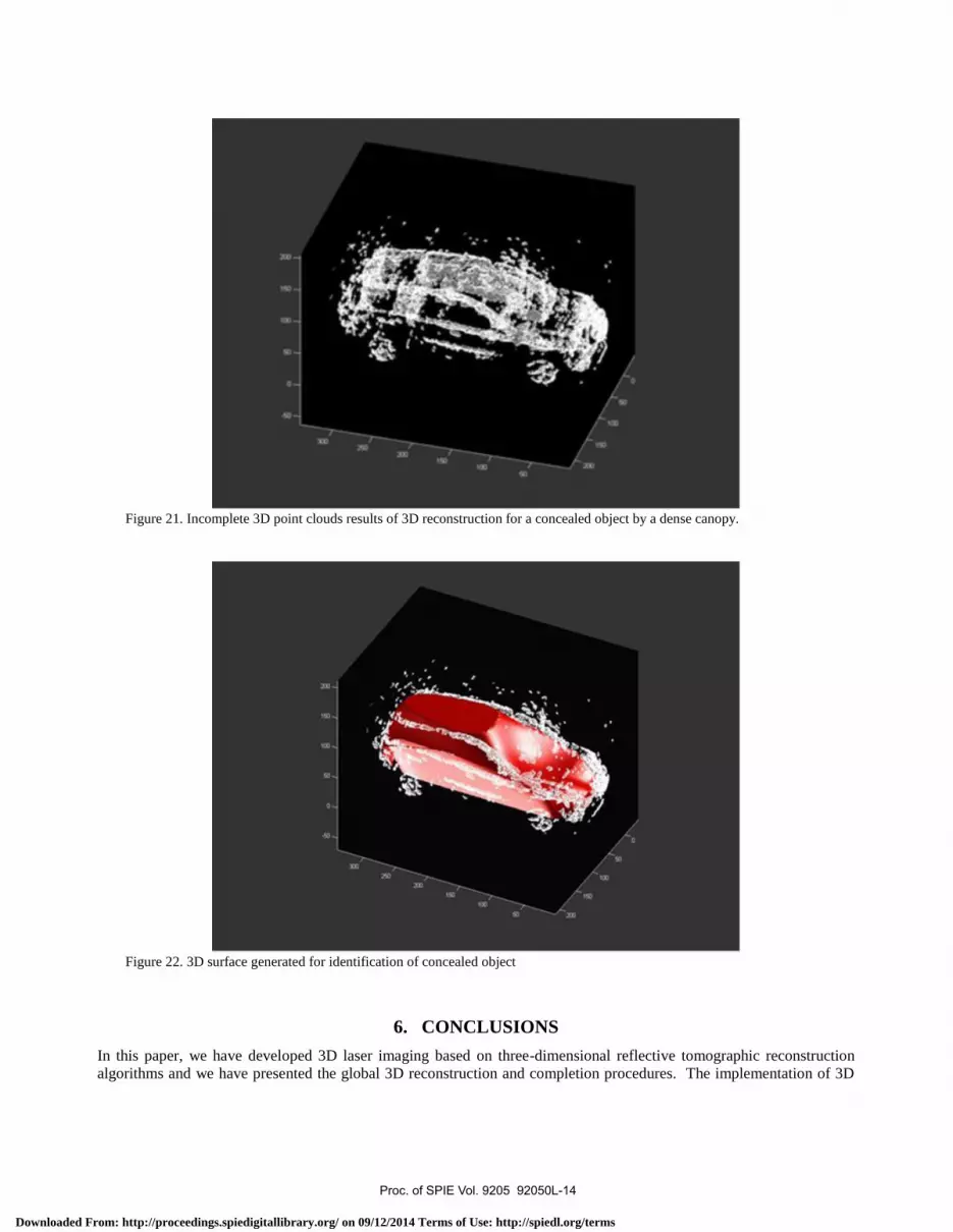
Figure 21. Incomplete 3D point clouds results of 3D reconstruction for a concealed object by a dense canopy.
Figure 22. 3D surface generated for identification of concealed object
6. CONCLUSIONS
In this paper, we have developed 3D laser imaging based on three-dimensional reflective tomographic reconstruction
algorithms and we have presented the global 3D reconstruction and completion procedures. The implementation of 3D
Proc. of SPIE Vol. 9205 92050L-14
Downloaded From: http://proceedings.spiedigitallibrary.org/ on 09/12/2014 Terms of Use: http://spiedl.org/terms
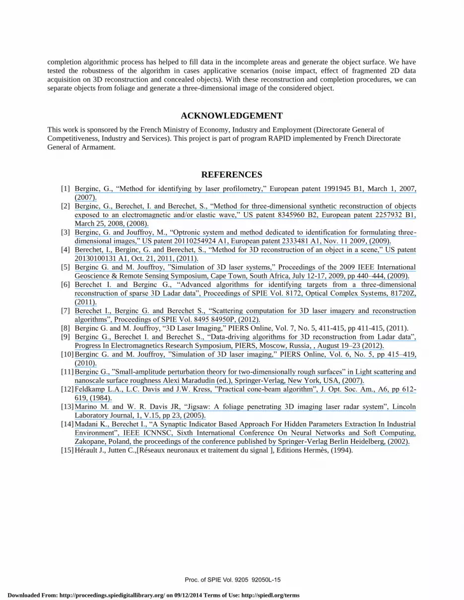
completion algorithmic process has helped to fill data in the incomplete areas and generate the object surface. We have
tested the robustness of the algorithm in cases applicative scenarios (noise impact, effect of fragmented 2D data
acquisition on 3D reconstruction and concealed objects). With these reconstruction and completion procedures, we can
separate objects from foliage and generate a three-dimensional image of the considered object.
ACKNOWLEDGEMENT
This work is sponsored by the French Ministry of Economy, Industry and Employment (Directorate General of
Competitiveness, Industry and Services). This project is part of program RAPID implemented by French Directorate
General of Armament.
REFERENCES
[1] Berginc, G., “Method for identifying by laser profilometry,” European patent 1991945 B1, March 1, 2007,
(2007).
[2] Berginc, G., Berechet, I. and Berechet, S., “Method for three-dimensional synthetic reconstruction of objects
exposed to an electromagnetic and/or elastic wave,” US patent 8345960 B2, European patent 2257932 B1,
March 25, 2008, (2008).
[3] Berginc, G. and Jouffroy, M., “Optronic system and method dedicated to identification for formulating three-
dimensional images,” US patent 20110254924 A1, European patent 2333481 A1, Nov. 11 2009, (2009).
[4] Berechet, I., Berginc, G. and Berechet, S., “Method for 3D reconstruction of an object in a scene,” US patent
20130100131 A1, Oct. 21, 2011, (2011).
[5] Berginc G. and M. Jouffroy, ”Simulation of 3D laser systems,” Proceedings of the 2009 IEEE International
Geoscience & Remote Sensing Symposium, Cape Town, South Africa, July 12-17, 2009, pp 440–444, (2009).
[6] Berechet I. and Berginc G., “Advanced algorithms for identifying targets from a three-dimensional
reconstruction of sparse 3D Ladar data”, Proceedings of SPIE Vol. 8172, Optical Complex Systems, 81720Z,
(2011).
[7] Berechet I., Berginc G. and Berechet S., “Scattering computation for 3D laser imagery and reconstruction
algorithms”, Proceedings of SPIE Vol. 8495 84950P, (2012).
[8] Berginc G. and M. Jouffroy, “3D Laser Imaging,” PIERS Online, Vol. 7, No. 5, 411-415, pp 411-415, (2011).
[9] Berginc G., Berechet I. and Berechet S., “Data-driving algorithms for 3D reconstruction from Ladar data”,
Progress In Electromagnetics Research Symposium, PIERS, Moscow, Russia, , August 19–23 (2012).
[10] Berginc G. and M. Jouffroy, ”Simulation of 3D laser imaging,” PIERS Online, Vol. 6, No. 5, pp 415–419,
(2010).
[11] Berginc G., ”Small-amplitude perturbation theory for two-dimensionally rough surfaces” in Light scattering and
nanoscale surface roughness Alexi Maradudin (ed.), Springer-Verlag, New York, USA, (2007).
[12] Feldkamp L.A., L.C. Davis and J.W. Kress, ”Practical cone-beam algorithm”, J. Opt. Soc. Am., A6, pp 612-
619, (1984).
[13] Marino M. and W. R. Davis JR, “Jigsaw: A foliage penetrating 3D imaging laser radar system”, Lincoln
Laboratory Journal, 1, V.15, pp 23, (2005).
[14] Madani K., Berechet I., “A Synaptic Indicator Based Approach For Hidden Parameters Extraction In Industrial
Environment”, IEEE ICNNSC, Sixth International Conference On Neural Networks and Soft Computing,
Zakopane, Poland, the proceedings of the conference published by Springer-Verlag Berlin Heidelberg, (2002).
[15] Hérault J., Jutten C.,[Réseaux neuronaux et traitement du signal ], Editions Hermès, (1994).
Proc. of SPIE Vol. 9205 92050L-15
Downloaded From: http://proceedings.spiedigitallibrary.org/ on 09/12/2014 Terms of Use: http://spiedl.org/terms