3. quartus ii design flow for max+plus ii users
TRANSCRIPT
© November 2009 Altera Corporation Quartus II Handbook Version 9.1 Volume 1: Design and Synthesis
3. Quartus II Design Flow forMAX+PLUS II Users
This chapter describes how to convert MAX+PLUS® II designs to Quartus II projects, as well as the similarities and differences between the MAX+PLUS II and Quartus II design flows. This discussion includes supported device families, GUI comparisons, and the advantages of the Quartus II software.
IntroductionThe feature-rich Quartus® II software helps you shorten your design cycles and reduce time-to-market. With support for MAX® device families, as well as all of Altera’s newest devices, the Quartus II software is the most widely accepted Altera® design software tool today.
1 The Quartus® II software versions 9.0 or earlier also support FLEX® and ACEX® device families.
Chapter OverviewThis chapter covers the following topics:
■ “MAX+PLUS II Support” on page 3–1
■ “Typical Design Flow” on page 3–2
■ “Device Support” on page 3–2
■ “Quartus II GUI Overview” on page 3–3
■ “Setting Up MAX+PLUS II Look and Feel in the Quartus II Software” on page 3–4
■ “Compiler Tool” on page 3–6
■ “MAX+PLUS II Design Conversion” on page 3–9
■ “Quartus II Design Flow” on page 3–12
MAX+PLUS II SupportThe Quartus II software retains a MAX+PLUS II GUI to help users transition to the Quartus II software design environment.
QII51002-9.1.0
3–2 Chapter 3: Quartus II Design Flow for MAX+PLUS II UsersTypical Design Flow
Quartus II Handbook Version 9.1 Volume 1: Design and Synthesis © November 2009 Altera Corporation
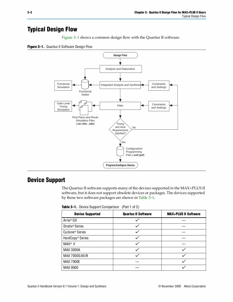
Typical Design FlowFigure 3–1 shows a common design flow with the Quartus II software.
Device SupportThe Quartus II software supports many of the devices supported in the MAX+PLUS II software, but it does not support obsolete devices or packages. The devices supported by these two software packages are shown in Table 3–1.
Figure 3–1. Quartus II Software Design Flow
Analysis and Elaboration
Integrated Analysis and Synthesis
Fitter
Configuration/ProgrammingFiles (.sof/.pof)
FunctionalNetlist
Constraintsand Settings
Constraintsand Settings
FunctionalSimulation
Timingand Area
RequirementsSatisfied?
Yes
No
Post Place-and-RouteSimulation Files(.vo/.vho, .sdo)
Gate-LevelTiming
Simulation
Program/Configure Device
Design Files
Table 3–1. Device Support Comparison (Part 1 of 2)
Device Supported Quartus II Software MAX+PLUS II Software
Arria® GX v —
Stratix® Series v —
Cyclone® Series v —
HardCopy® Series v —
MAX® II v —
MAX 3000A v v
MAX 7000S/AE/B v v
MAX 7000E — v
MAX 9000 — v

Chapter 3: Quartus II Design Flow for MAX+PLUS II Users 3–3Quartus II GUI Overview
© November 2009 Altera Corporation Quartus II Handbook Version 9.1 Volume 1: Design and Synthesis
Quartus II GUI OverviewThe Quartus II software provides utility windows to assist in the development of your designs, as described in the following paragraphs.
Task WindowThe Task window feature in the Quartus II software provides a guided design compilation flow. This type of feature is not available in the MAX+PLUS II software.
Project NavigatorThe Hierarchy tab of the Project Navigator window is similar to the MAX+PLUS II Hierarchy Display and provides additional information such as logic cell, register, and memory bit resource utilization. The Files and Design Units tabs of the Project Navigator window provide a list of project files and design units.
Node FinderThe Node Finder window provides the equivalent functionality of the MAX+PLUS II Search Node Database dialog box and allows you to find and use any node name stored in the project database.
Tcl ConsoleThe Tcl Console window allows access to the Quartus II Tcl shell from within the GUI. You can use the Tcl Console window to enter Tcl commands and source Tcl scripts to make assignments, perform customized timing analysis, view information about devices, or fully automate and customize the way you run all components of the Quartus II software. There is no equivalent functionality in the MAX+PLUS II software.
f For more information about using Tcl with the Quartus II software, refer to the Tcl Scripting chapter in volume 2 of the Quartus II Handbook.
MessagesThe Messages window is similar to the Message Processor window in the MAX+PLUS II software, providing detailed information, warnings, and error messages.You also can use it to locate a node from a message to various windows in the Quartus II software.
FLEX 8000 — v
Classic™ — v
Note to Table 3–1:
(1) Some packages are supported in the Quartus II software 9.0 and earlier.
Table 3–1. Device Support Comparison (Part 2 of 2)
Device Supported Quartus II Software MAX+PLUS II Software
3–4 Chapter 3: Quartus II Design Flow for MAX+PLUS II UsersSetting Up MAX+PLUS II Look and Feel in the Quartus II Software
Quartus II Handbook Version 9.1 Volume 1: Design and Synthesis © November 2009 Altera Corporation
StatusThe Status window displays information similar to the MAX+PLUS II Compiler window. Progress and elapsed time are shown for each stage of the compilation.
Change ManagerThe Change Manager provides detailed tracking information about all design changes made with the Chip Planner. This feature is not available in the MAX+PLUS II software.
f For more information about the Engineering Change Manager and the Chip Planner, refer to the Engineering Change Management with the Chip Planner chapter in volume 2 of the Quartus II Handbook.
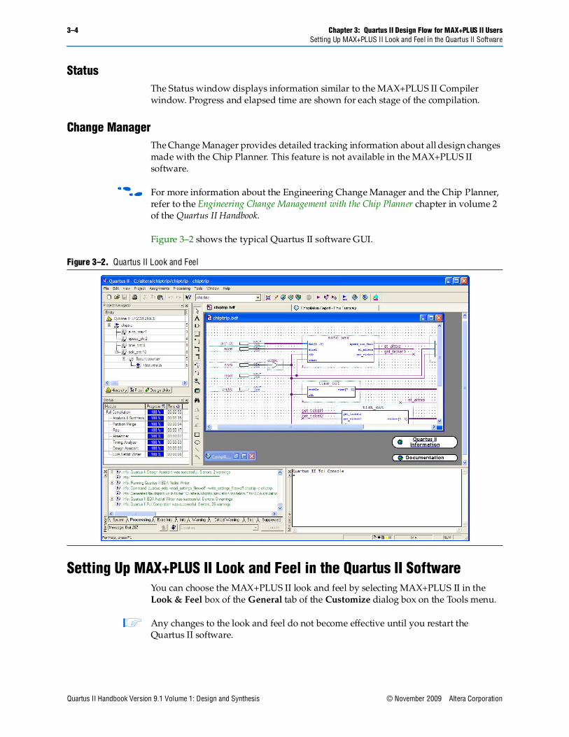
Figure 3–2 shows the typical Quartus II software GUI.
Setting Up MAX+PLUS II Look and Feel in the Quartus II SoftwareYou can choose the MAX+PLUS II look and feel by selecting MAX+PLUS II in the Look & Feel box of the General tab of the Customize dialog box on the Tools menu.
1 Any changes to the look and feel do not become effective until you restart the Quartus II software.
Figure 3–2. Quartus II Look and Feel
Chapter 3: Quartus II Design Flow for MAX+PLUS II Users 3–5MAX+PLUS II Look and Feel
© November 2009 Altera Corporation Quartus II Handbook Version 9.1 Volume 1: Design and Synthesis
By default, when you select the MAX+PLUS II look and feel, the MAX+PLUS II quick menu appears on the left side of the menu bar. You can turn the Quartus II and MAX+PLUS II quick menus on or off. You also can change the preferred positions of the two quick menus. To change these options, perform the following steps:
1. On the Tools menu, click Customize. The Customize dialog box appears.
2. Click the General tab.
3. Under Quick menus, select your preferred options.
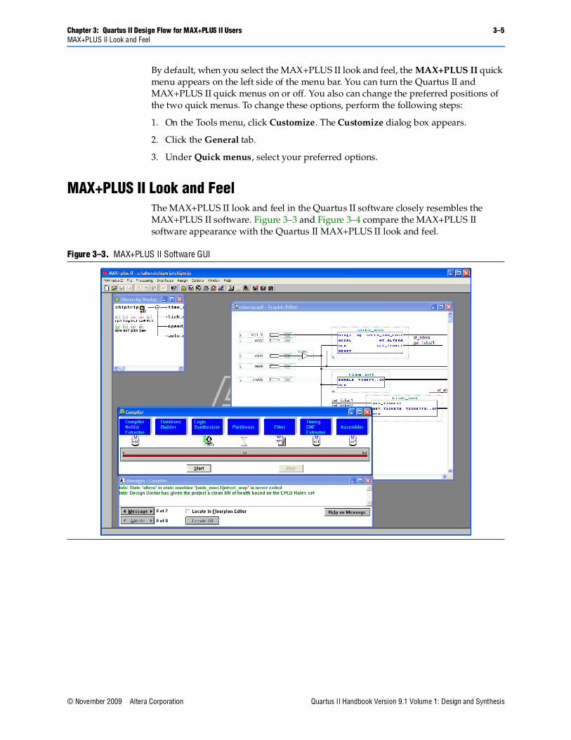
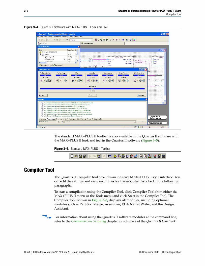
MAX+PLUS II Look and FeelThe MAX+PLUS II look and feel in the Quartus II software closely resembles the MAX+PLUS II software. Figure 3–3 and Figure 3–4 compare the MAX+PLUS II software appearance with the Quartus II MAX+PLUS II look and feel.
Figure 3–3. MAX+PLUS II Software GUI
3–6 Chapter 3: Quartus II Design Flow for MAX+PLUS II UsersCompiler Tool
Quartus II Handbook Version 9.1 Volume 1: Design and Synthesis © November 2009 Altera Corporation
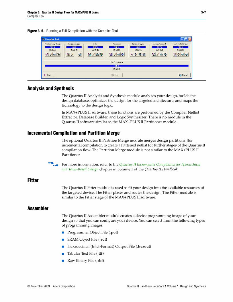
The standard MAX+PLUS II toolbar is also available in the Quartus II software with the MAX+PLUS II look and feel in the Quartus II software (Figure 3–5).
Compiler ToolThe Quartus II Compiler Tool provides an intuitive MAX+PLUS II style interface. You can edit the settings and view result files for the modules described in the following paragraphs.
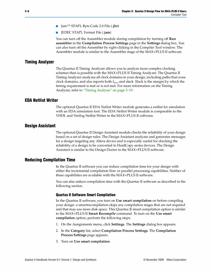
To start a compilation using the Compiler Tool, click Compiler Tool from either the MAX+PLUS II menu or the Tools menu and click Start in the Compiler Tool. The Compiler Tool, shown in Figure 3–6, displays all modules, including optional modules such as Partition Merge, Assembler, EDA Netlist Writer, and the Design Assistant.
f For information about using the Quartus II software modules at the command line, refer to the Command-Line Scripting chapter in volume 2 of the Quartus II Handbook.
Figure 3–4. Quartus II Software with MAX+PLUS II Look and Feel
Figure 3–5. Standard MAX+PLUS II Toolbar
Chapter 3: Quartus II Design Flow for MAX+PLUS II Users 3–7Compiler Tool
© November 2009 Altera Corporation Quartus II Handbook Version 9.1 Volume 1: Design and Synthesis
Analysis and Synthesis The Quartus II Analysis and Synthesis module analyzes your design, builds the design database, optimizes the design for the targeted architecture, and maps the technology to the design logic.
In MAX+PLUS II software, these functions are performed by the Compiler Netlist Extractor, Database Builder, and Logic Synthesizer. There is no module in the Quartus II software similar to the MAX+PLUS II Partitioner module.
Incremental Compilation and Partition MergeThe optional Quartus II Partition Merge module merges design partitions ]for incremental compilation to create a flattened netlist for further stages of the Quartus II compilation flow. The Partition Merge module is not similar to the MAX+PLUS II Partitioner.
f For more information, refer to the Quartus II Incremental Compilation for Hierarchical and Team-Based Design chapter in volume 1 of the Quartus II Handbook.
FitterThe Quartus II Fitter module is used to fit your design into the available resources of the targeted device. The Fitter places and routes the design. The Fitter module is similar to the Fitter stage of the MAX+PLUS II software.
AssemblerThe Quartus II Assembler module creates a device programming image of your design so that you can configure your device. You can select from the following types of programming images:
■ Programmer Object File (.pof)
■ SRAM Object File (.sof)
■ Hexadecimal (Intel-Format) Output File (.hexout)
■ Tabular Text File (.ttf)
■ Raw Binary File (.rbf)
Figure 3–6. Running a Full Compilation with the Compiler Tool
3–8 Chapter 3: Quartus II Design Flow for MAX+PLUS II UsersCompiler Tool
Quartus II Handbook Version 9.1 Volume 1: Design and Synthesis © November 2009 Altera Corporation
■ Jam™ STAPL Byte Code 2.0 File (.jbc)
■ JEDEC STAPL Format File (.jam)
You can turn off the Assembler module during compilation by turning off Run assembler in the Compilation Process Settings page in the Settings dialog box. You can also turn off the Assembler by right-clicking in the Compiler Tool window. The Assembler module is similar to the Assembler stage of the MAX+PLUS II software.
Timing AnalyzerThe Quartus II Timing Analyzer allows you to analyze more complex clocking schemes than is possible with the MAX+PLUS II Timing Analyzer. The Quartus II Timing Analyzer analyzes all clock domains in your design, including paths that cross clock domains, and also reports both fMAX and slack. Slack is the margin by which the timing requirement is met or is not met. For more information on the Timing Analyzer, refer to “Timing Analysis” on page 3–19.
EDA Netlist WriterThe optional Quartus II EDA Netlist Writer module generates a netlist for simulation with an EDA simulation tool. The EDA Netlist Writer module is comparable to the VHDL and Verilog Netlist Writer in the MAX+PLUS II software.
Design AssistantThe optional Quartus II Design Assistant module checks the reliability of your design based on a set of design rules. The Design Assistant analyzes and generates messages for a design targeting any Altera device and is especially useful for checking the reliability of a design to be converted to HardCopy series devices. The Design Assistant is similar to the Design Doctor in the MAX+PLUS II software.
Reducing Compilation TimeIn the Quartus II software you can reduce compilation time for your design with either the incremental compilation flow or parallel processing capabilities. Neither of these capabilities are available with the MAX+PLUS II software.
You can also reduce compilation time with the Quartus II software as described in the following section.
Quartus II Software Smart CompilationIn the Quartus II software, you turn on Use smart compilation on before compiling your design. a smartrecompilation skips any compilation stages that are not required and that may use more disk space. This Quartus II smart compilation option is similar to the MAX+PLUS II Smart Recompile command. To turn on the Use smart compilation option, perform the following steps:
1. On the Assignments menu, click Settings. The Settings dialog box appears.
2. In the Category list, select Compilation Process Settings. The Compilation Process Settings page appears.
3. Turn on Use smart compilation.
Chapter 3: Quartus II Design Flow for MAX+PLUS II Users 3–9MAX+PLUS II Design Conversion
© November 2009 Altera Corporation Quartus II Handbook Version 9.1 Volume 1: Design and Synthesis
Power AnalyzerThe Quartus II software provides power analysis tools that the MAX+PLUS software does not. The PowerPlay suite of power analysis and optimization tools allows you to estimate device power consumption and heat dissipation from early design concepts through design implementation. Because the quality of the resulting power estimation depends on the quality of input data provided, you must provide the most accurate data possible.
The PowerPlay suite of tools supports most of the new devices introduced in the Quartus II software.
f For more information, refer to the PowerPlay Power Analysis chapter in volume 3 of the Quartus II Handbook.
MAX+PLUS II Design ConversionWith the Quartus II software, you can open MAX+PLUS II designs and convert MAX+PLUS II assignments and files.
The Quartus II software is project based. All the files for your design (HDL input, simulation vectors, assignments, and other relevant files) are associated with a project file. For more information about creating a new project, refer to “Creating a New Project” on page 3–12.
Converting an Existing MAX+PLUS II DesignYou can easily convert an existing MAX+PLUS II design for use with the Quartus II software with the Convert MAX+PLUS II Project command in the Quartus II software or the Open Project command. You can find these commands on the File menu.
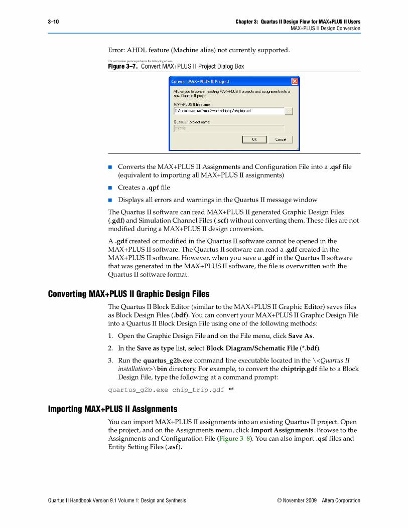
If you use the Convert MAX+PLUS II Project command, browse to the MAX+PLUS II Assignments and Configuration File (.acf) or top-level design file (Figure 3–7) and click Open. The Convert MAX+PLUS II Project command generates a Quartus II Project File (.qpf) and a Quartus II Settings File (.qsf). The Quartus II software stores project and design assignments in the .qsf file, which is equivalent to the Assignments and Configuration File in the MAX+PLUS II software.
You can open and convert a MAX+PLUS II design with the Open Project command. In the Open Project dialog box, browse to the Assignments and Configuration File or the top-level design file. Click Open to display the Convert MAX+PLUS II Project dialog box.
1 The Quartus II software can import all MAX+PLUS II-generated files, but it cannot save files in the MAX+PLUS II format. You cannot open a Quartus II project in the MAX+PLUS II software, nor can you convert a Quartus II project to a MAX+PLUS II project.
The Quartus II software does not support the machine alias AHDL feature. To use the Quartus II software, you must change the AHDL code to avoid use of this feature. The following error message may occur when you convert a project from the legacy MAX+PLUS® II software to the Quartus® II software if you use the machine alias AHDL feature:
3–10 Chapter 3: Quartus II Design Flow for MAX+PLUS II UsersMAX+PLUS II Design Conversion
Quartus II Handbook Version 9.1 Volume 1: Design and Synthesis © November 2009 Altera Corporation
Error: AHDL feature (Machine alias) not currently supported.The conversion process performs the following actions:
■ Converts the MAX+PLUS II Assignments and Configuration File into a .qsf file (equivalent to importing all MAX+PLUS II assignments)
■ Creates a .qpf file
■ Displays all errors and warnings in the Quartus II message window
The Quartus II software can read MAX+PLUS II generated Graphic Design Files (.gdf) and Simulation Channel Files (.scf) without converting them. These files are not modified during a MAX+PLUS II design conversion.
A .gdf created or modified in the Quartus II software cannot be opened in the MAX+PLUS II software. The Quartus II software can read a .gdf created in the MAX+PLUS II software. However, when you save a .gdf in the Quartus II software that was generated in the MAX+PLUS II software, the file is overwritten with the Quartus II software format.
Converting MAX+PLUS II Graphic Design FilesThe Quartus II Block Editor (similar to the MAX+PLUS II Graphic Editor) saves files as Block Design Files (.bdf). You can convert your MAX+PLUS II Graphic Design File into a Quartus II Block Design File using one of the following methods:
1. Open the Graphic Design File and on the File menu, click Save As.
2. In the Save as type list, select Block Diagram/Schematic File (*.bdf).
3. Run the quartus_g2b.exe command line executable located in the \<Quartus II installation>\bin directory. For example, to convert the chiptrip.gdf file to a Block Design File, type the following at a command prompt:
quartus_g2b.exe chip_trip.gdf r
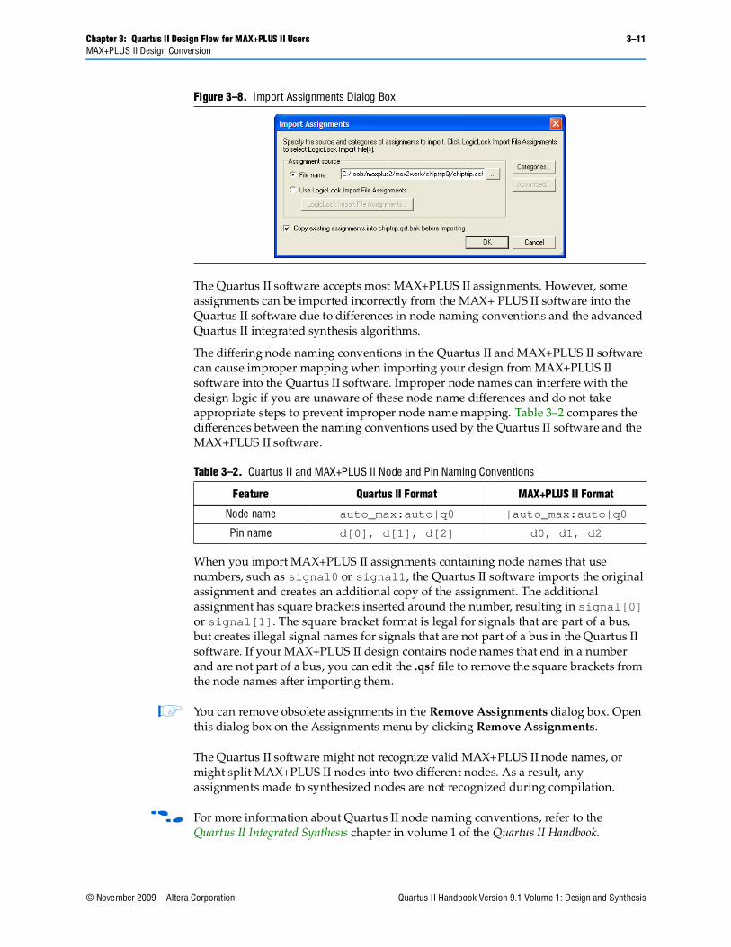
Importing MAX+PLUS II AssignmentsYou can import MAX+PLUS II assignments into an existing Quartus II project. Open the project, and on the Assignments menu, click Import Assignments. Browse to the Assignments and Configuration File (Figure 3–8). You can also import .qsf files and Entity Setting Files (.esf).
Figure 3–7. Convert MAX+PLUS II Project Dialog Box
Chapter 3: Quartus II Design Flow for MAX+PLUS II Users 3–11MAX+PLUS II Design Conversion
© November 2009 Altera Corporation Quartus II Handbook Version 9.1 Volume 1: Design and Synthesis
The Quartus II software accepts most MAX+PLUS II assignments. However, some assignments can be imported incorrectly from the MAX+ PLUS II software into the Quartus II software due to differences in node naming conventions and the advanced Quartus II integrated synthesis algorithms.
The differing node naming conventions in the Quartus II and MAX+PLUS II software can cause improper mapping when importing your design from MAX+PLUS II software into the Quartus II software. Improper node names can interfere with the design logic if you are unaware of these node name differences and do not take appropriate steps to prevent improper node name mapping. Table 3–2 compares the differences between the naming conventions used by the Quartus II software and the MAX+PLUS II software.
When you import MAX+PLUS II assignments containing node names that use numbers, such as signal0 or signal1, the Quartus II software imports the original assignment and creates an additional copy of the assignment. The additional assignment has square brackets inserted around the number, resulting in signal[0] or signal[1]. The square bracket format is legal for signals that are part of a bus, but creates illegal signal names for signals that are not part of a bus in the Quartus II software. If your MAX+PLUS II design contains node names that end in a number and are not part of a bus, you can edit the .qsf file to remove the square brackets from the node names after importing them.
1 You can remove obsolete assignments in the Remove Assignments dialog box. Open this dialog box on the Assignments menu by clicking Remove Assignments.
The Quartus II software might not recognize valid MAX+PLUS II node names, or might split MAX+PLUS II nodes into two different nodes. As a result, any assignments made to synthesized nodes are not recognized during compilation.
f For more information about Quartus II node naming conventions, refer to the Quartus II Integrated Synthesis chapter in volume 1 of the Quartus II Handbook.
Figure 3–8. Import Assignments Dialog Box
Table 3–2. Quartus II and MAX+PLUS II Node and Pin Naming Conventions
Feature Quartus II Format MAX+PLUS II Format
Node name auto_max:auto|q0 |auto_max:auto|q0
Pin name d[0], d[1], d[2] d0, d1, d2
3–12 Chapter 3: Quartus II Design Flow for MAX+PLUS II UsersQuartus II Design Flow
Quartus II Handbook Version 9.1 Volume 1: Design and Synthesis © November 2009 Altera Corporation
Quartus II Design FlowThe following sections include information to help you get started using the Quartus II software. They describe the similarities and differences between the Quartus II software and the MAX+PLUS II software. The following sections highlight improvements and benefits in the Quartus II software:
■ “Creating a New Project” on page 3–12
■ “Design Entry” on page 3–12
■ “Making Assignments” on page 3–14
■ “Synthesis” on page 3–17
■ “Functional Simulation” on page 3–17
■ “Place and Route” on page 3–18
■ “Timing Analysis” on page 3–19
■ “Viewing Chip Resources” on page 3–20
■ “Timing Simulation” on page 3–21
■ “Power Estimation” on page 3–22
■ “Programming” on page 3–23
f For an overview of the Quartus II software features and design flow, refer to the Introduction to the Quartus II Software manual.
Creating a New ProjectThe Quartus II software provides a wizard to help you create new projects. On the File menu, click New Project Wizard to create a new project. The New Project Wizard generates the .qpf file and .qsf file for your project.
Design EntryThe Quartus II software supports the following design entry methods:
■ Altera HDL (AHDL) Text Design File (.tdf)
■ Block Diagram File (.bdf)
■ EDIF Netlist File (.edf)
■ VHDL (.vhd)
■ Verilog HDL (.v) and System Verilog (.sv)
The Quartus II software has an advanced integrated synthesis engine that fully supports the Verilog HDL and VHDL languages and provides options to control the synthesis process.
f For more information, refer to the Quartus II Integrated Synthesis chapter in volume 1 of the Quartus II Handbook.
Chapter 3: Quartus II Design Flow for MAX+PLUS II Users 3–13Quartus II Design Flow
© November 2009 Altera Corporation Quartus II Handbook Version 9.1 Volume 1: Design and Synthesis
To create a new design file, perform the following steps:
1. On the File menu, click New. The New dialog box appears.
2. Click the Device Design Files tab.
3. Select a design entry type.
4. Click OK.
1 You can create other files from the New dialog box on the File menu.
To analyze a netlist file created by an EDA tool, perform the following steps:
1. On the Assignments menu, click EDA Tool Settings. The Settings dialog box appears.
2. In the Category list, select Design Entry & Synthesis. The Design Entry & Synthesis page appears.
3. In the Tool name list, select the synthesis tool used to generate the netlist.
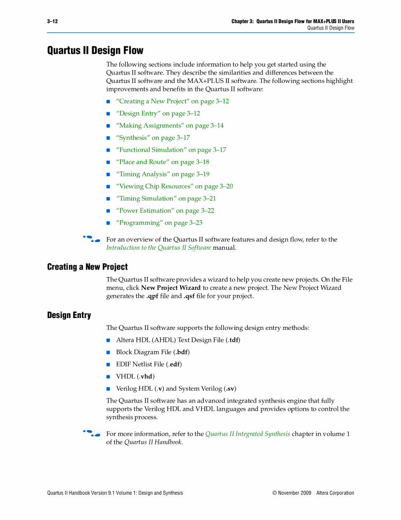
The Symbol Editor allows you to change the positions of the ports in a symbol (refer to Figure 3–9). You can reduce wire congestion around a symbol by changing the positions of the ports.
To make changes to a symbol in a Block Design File, right-click a symbol in the Block Editor and click Properties to display the Symbol Properties dialog box. The Symbol Properties dialog box allows you to change the instance name, add parameters, and specify the line and text color.
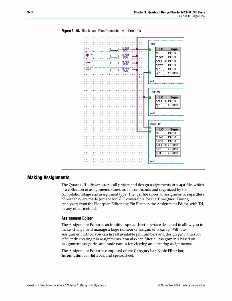
You can use conduits to connect blocks (including pins) in the Block Editor. Conduits contain signals for the connected objects (see Figure 3–10). You can determine the connections between various blocks in the Conduit Properties dialog box by right-clicking a conduit and clicking Properties.
Figure 3–9. Various Port Positions for a Symbol
3–14 Chapter 3: Quartus II Design Flow for MAX+PLUS II UsersQuartus II Design Flow
Quartus II Handbook Version 9.1 Volume 1: Design and Synthesis © November 2009 Altera Corporation
Making AssignmentsThe Quartus II software stores all project and design assignments in a .qsf file, which is a collection of assignments stored as Tcl commands and organized by the compilation stage and assignment type. The .qsf file stores all assignments, regardless of how they are made (except for SDC constraints for the TimeQuest Timing Analyzer) from the Floorplan Editor, the Pin Planner, the Assignment Editor, with Tcl, or any other method.
Assignment EditorThe Assignment Editor is an intuitive spreadsheet interface designed to allow you to make, change, and manage a large number of assignments easily. With the Assignment Editor, you can list all available pin numbers and design pin names for efficiently creating pin assignments. You also can filter all assignments based on assignment categories and node names for viewing and creating assignments.
The Assignment Editor is composed of the Category bar, Node Filter bar, Information bar, Edit bar, and spreadsheet.
Figure 3–10. Blocks and Pins Connected with Conduits
Chapter 3: Quartus II Design Flow for MAX+PLUS II Users 3–15Quartus II Design Flow
© November 2009 Altera Corporation Quartus II Handbook Version 9.1 Volume 1: Design and Synthesis
To make an assignment, perform the following steps:
1. On the Assignments menu, click Assignment Editor. The Assignment Editor window appears.
2. Select an assignment category in the Category bar.
3. Select a node name using the Node Finder or type a node name filter into the Node Filter bar. (This step is optional; it excludes all assignments unrelated to the node name.)
4. Type the required values into the spreadsheet.
5. On the File menu, click Save.
If you are unsure about the purpose of a cell in the spreadsheet, select the cell and read the description displayed in the Information bar.
You can use the Edit bar to change the contents of multiple selected cells simultaneously. Select cells in the spreadsheet and type the value in the Edit box.
Other advantages of the Assignment Editor include clipboard support in the spreadsheet and automatic font coloring to identify the status of assignments.
f For more information, refer to the Assignment Editor chapter in volume 2 of the Quartus II Handbook.
Timing AssignmentsThe Quartus II timing analyzers provide a method of analyzing, debugging, and validating the performance of a design. Timing analysis measures the delay along the various timing paths and verifies the performance and operation of the design. You can specify constraints and assignments that help the design meet timing requirements. If you specify constraints or assignments, the Fitter optimizes the placement of logic in the device to meet those constraints.
The Quartus II software provides two independent timing analyzers: the Classic Timing Analyzer and the TimeQuest Timing Analyzer. You can choose between these two timing analysis tools prior to running a compilation or timing analysis. The timing analysis tool you choose determines the available user interface, constraint entry, reporting, and debugging options. The TimeQuest Timing Analyzer is more powerful than the Classic Timing Analyzer, conforms to the latest industry standards, and supports newer Altera device families.
Classic Timing Analyzer
You can use the timing wizard to help set your timing requirements. On the Assignments menu, click Timing Wizard to create global clock and timing settings. The settings include fMAX, setup times, hold times, clock to output delay times, and individual absolute or derived clocks.
You can also set timing settings manually by performing the following steps:
1. On the Assignments menu, click Settings. The Settings dialog box appears.
2. In the Category list, select Timing Requirements & Options. The Timing Requirements & Options page appears.
3. Set your timing settings.
3–16 Chapter 3: Quartus II Design Flow for MAX+PLUS II UsersQuartus II Design Flow
Quartus II Handbook Version 9.1 Volume 1: Design and Synthesis © November 2009 Altera Corporation
You can make more complex timing assignments with the Quartus II software than allowed by the MAX+PLUS II software, including multicycle and point-to-point assignments using wildcards and time groups.
1 A time group is a collection of design nodes grouped together and represented as a single unit for the purpose of making timing assignments to the collection.
Multicycle timing assignments allow you to identify register-to-register paths in the design where you expect a delayed latch edge. This assignment enables accurate timing analysis of your design.
Point-to-point timing assignments allow you to specify the required delay between two pins, two registers, or a pin and a register. This assignment helps you optimize and verify your design timing requirements.
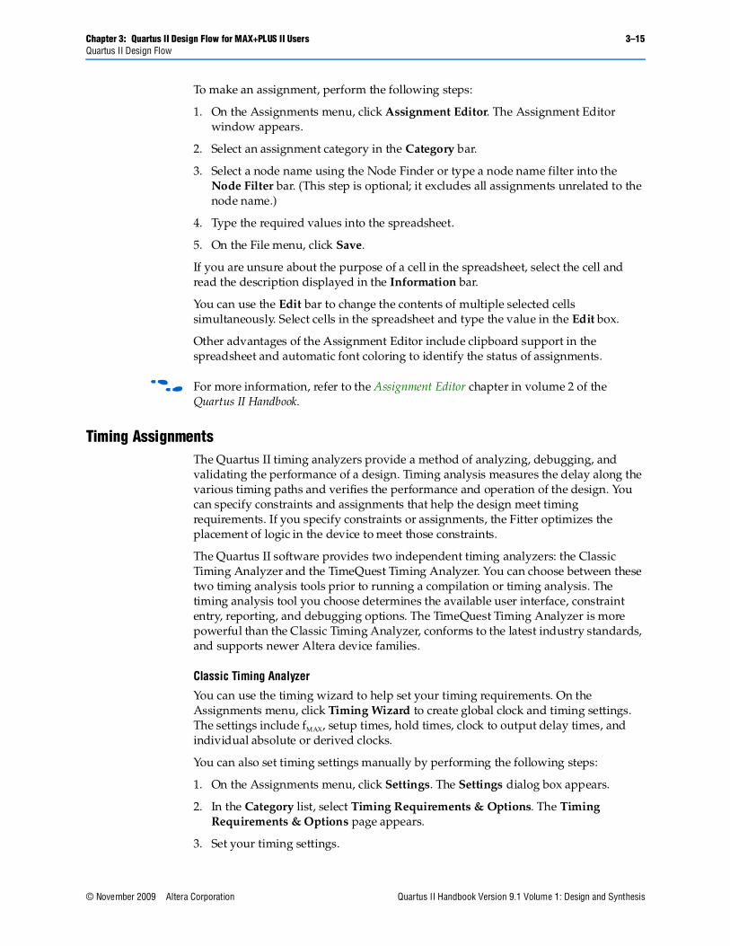
Wildcard characters “?” and “ * “ allow you to apply an assignment to a large number of nodes with just a few assignments. For example, Figure 3–11 shows a 4 ns tSU requirement assignment to all paths from any node to the “d” bus in the Assignment Editor.
TimeQuest Timing Analyzer
The TimeQuest Timing Analyzer is a powerful ASIC-style timing analysis tool that validates the timing performance of all logic in the design using industry standard constraint, analysis, and reporting methodologies. You can use the TimeQuest Timing Analyzer's graphical user interface (GUI) or command-line interface to constrain, run, and view results for all timing paths in the design.
Before running the TimeQuest Timing Analyzer, you must specify initial timing constraints that describe the clock characteristics, timing exceptions, and external signal arrival and required times. You can specify all timing constraints in the Synopsys Design Constraints (SDC) format using the GUI, the Quartus II Text Editor, or the command-line interface. The Quartus II Fitter optimizes the placement of logic in the device to meet your specified constraints.
Early in the design process, before final device fitting is completed, you can check preliminary timing data by running an early timing estimate with the Start Early Timing Estimate command. When your design is complete, you can run a full timing analysis following compilation.
Figure 3–11. Single tSU Timing Assignment Applied to All Nodes of a Bus
Chapter 3: Quartus II Design Flow for MAX+PLUS II Users 3–17Quartus II Design Flow
© November 2009 Altera Corporation Quartus II Handbook Version 9.1 Volume 1: Design and Synthesis
During timing analysis, the TimeQuest Timing Analyzer analyzes the timing paths in the design, calculates the propagation delay along each path, checks for timing constraint violations, and reports timing results as slack in the Report pane and in the console. If the TimeQuest Timing Analyzer reports any timing violations, you can customize the reports to view precise timing information about specific paths. You can then determine whether the design requires additional timing constraints or exceptions, or if the design requires logic changes or place-and-route constraints.
For more information, refer to the Quartus II Classic Timing Analyzer or the Quartus II TimeQuest Timing Analyzer chapter in volume 3 of the Quartus II Handbook.
SynthesisThe Quartus II advanced integrated synthesis software fully supports the industry standard hardware description languages and provides a complete, easy-to-use, stand-alone solution for today’s designs.
You can specify synthesis options in the Analysis & Synthesis Settings page of the Settings dialog box. Similar to MAX+PLUS II synthesis options, you select one of these optimization techniques: Speed, Area, or Balanced.
To achieve higher design performance, you can turn on synthesis netlist optimizations that are available when targeting certain devices. You can unmap a netlist created by an EDA tool and remap the components in the netlist back to Altera primitives by turning on Perform WYSIWYG primitive resynthesis.
f For more information, refer to the Quartus II Integrated Synthesis chapter in volume 1 of the Quartus II Handbook.
Functional SimulationSimilar to the MAX+PLUS II Simulator, the Quartus II Simulator Tool performs both functional and timing simulations. The Quartus II Simulator Tool does not, however, support the latest device families.
Altera recommends that you perform a functional and or a timing simulation of a Quartus II-generated design, or both, with the Mentor Graphics software that was provided with the Quartus II software, or the PE or SE software from Mentor Graphics . The software is a dual-language simulator; you can simulate designs containing either Verilog HDL, VHDL, or both. You can use designs in which a Verilog HDL module instantiates VHDL entities or a VHDL module instantiates Verilog HDL entities.
To open the Simulator Tool, on the MAX+PLUS II menu, click Simulator, or on the Tools menu, click Simulator Tool. Before you perform a functional simulation, an internal functional simulation netlist is required. Click Generate Functional Simulation Netlist in the Simulator Tool dialog box, or on the Processing menu, click Generate Functional Simulation Netlist.
1 Generating a functional simulation netlist creates a separate database that improves the performance of the simulation significantly.
3–18 Chapter 3: Quartus II Design Flow for MAX+PLUS II UsersQuartus II Design Flow
Quartus II Handbook Version 9.1 Volume 1: Design and Synthesis © November 2009 Altera Corporation
You can view and modify the simulator options on the Simulator Settings page of the Settings dialog box or in the Simulator Tool dialog box. You can set the simulation period and turn on or off the Check outputs option. You can choose to display the simulation outputs in the simulation report or in the Vector Waveform File (.vwf). To display the simulation results in the simulation input .vfw, which is the MAX+PLUS II behavior, turn on Overwrite simulation input file with simulation results.
When using either the MAX+PLUS II or Quartus II software, you may need to compile additional behavioral models to perform a simulation with an EDA simulation tool. In the Quartus II software, behavioral models for library of parameterized modules (LPM) functions and Altera-specific megafunctions are available in the altera_mf and 220model library files, respectively. The 220model and altera_mf files can be found in the \<Quartus II Installation>\eda\sim_lib directory.
The Quartus II schematic design files (Block Design File (.bdf) are not compatible with EDA simulation tools. To perform a register transfer level (RTL) functional simulation of a Block Design File using an EDA tool, convert your schematic designs to a VHDL or Verilog HDL design file. Open the schematic design file and on the File menu, point to Create/Update and then click Create HDL Design File for Current File to create an HDL design file that corresponds to your Block Design File.
1 Altera offers a ModelSim starter edition.
You can export a .vwf file or Simulator Channel File (.scf) as a Verilog HDL or VHDL testbench file for simulation with an EDA tool. Open your Vector Waveform File or .scf file and on the File menu, click Export. Select Verilog or VHDL Test Bench File (*.vt) from the Save as type list. Turn on Add self-checking code to file to add additional self-checking code to the testbench.
f For more information, refer to the Quartus II Simulator and the Mentor Graphics ModelSim Support chapters in volume 3 of the Quartus II Handbook.
Place and RouteThe Quartus II Fitter performs place-and-route to fit your design into the targeted device. You can control the Fitter behavior with options in the Fitter Settings page of the Settings dialog box on the Assignments menu.
High-density device families supported in the Quartus II software, such as the Stratix series, sometimes require significant fitter effort to achieve an optimal fit. The Quartus II software offers several options to reduce the time required to fit a design. You can control the effort the Quartus II Fitter expends to achieve your timing requirements with options. If minimizing compilation time is more important than achieving specific timing results, you can turn off the optimization options.
You can decrease the processing time and effort the Fitter expends to fit your design when you select options in the Fitter Settings page of the Settings dialog box on the Assignments menu. Altera recommends the Auto setting, which is available for select device families
To further reduce compilation times, turn on Limit to one fitting attempt in the Fitter Settings page in the Settings dialog box on the Assignments menu.
Chapter 3: Quartus II Design Flow for MAX+PLUS II Users 3–19Quartus II Design Flow
© November 2009 Altera Corporation Quartus II Handbook Version 9.1 Volume 1: Design and Synthesis
If your design is very close to meeting your timing requirements, you can control the seed number used in the fitting algorithm by changing the value in the Seed box of the Fitter Settings page of the Settings dialog box on the Assignments menu. The default seed value is 1. You can specify any non-negative integer value. Changing the value of the seed only repositions the starting location of the Fitter, and does not affect compilation time or the Fitter effort level. However, if your design is difficult to fit optimally or takes a long time to fit, sometimes you can improve results or processing time by changing the seed value.
f For more information, refer to the Area and Timing Optimization chapter in volume 2 of the Quartus II Handbook. This chapter provides Altera recommendations for selecting Fitter options and further instructions for reducing compilation time.
Timing AnalysisTiming analysis measures the delay along the various timing paths and verifies the performance and operation of the design. You can specify constraints and assignments that help the design meet timing requirements. If you specify constraints or assignments, the Fitter optimizes the placement of logic in the device to meet those constraints.
The TimeQuest Timing Analyzer uses the industry-standard Synopsys Design Constraint (SDC) methodology for constraining designs and reporting results.
The TimeQuest Timing Analyzer is a powerful ASIC-style timing analysis tool that validates the timing performance of all logic in the design with industry standard constraint, analysis, and reporting methodologies. You can use the TimeQuest Timing Analyzer’s graphical user interface (GUI) or command-line interface to constrain, run, and view results for all timing paths in the design.
Before running the TimeQuest Timing Analyzer, you must specify initial timing constraints that describe the clock characteristics, timing exceptions, and external signal arrival and required times. You can specify all timing constraints in the Synopsys Design Constraints (SDC) format using the GUI, the Quartus II Text Editor, or the command-line interface. The Quartus II Fitter optimizes the placement of logic in the device to meet your specified constraints.
Early in the design process, before final device fitting is completed, you can check preliminary timing data by running an early timing estimate with the Start Early Timing Estimate command. When your design is complete, you can run a full timing analysis following compilation.
During timing analysis, the TimeQuest Timing Analyzer analyzes the timing paths in the design, calculates the propagation delay along each path, checks for timing constraint violations, and reports timing results as slack in the Report pane and in the console. If the TimeQuest Timing Analyzer reports any timing violations, you can customize the reports to view precise timing information about specific paths. You can then determine whether the design requires additional timing constraints or exceptions, or if the design requires logic changes or place-and-route constraints.
f For more information, refer to the Quartus II TimeQuest Timing Analyzer chapter in volume 3 of the Quartus II Handbook.
3–20 Chapter 3: Quartus II Design Flow for MAX+PLUS II UsersQuartus II Design Flow
Quartus II Handbook Version 9.1 Volume 1: Design and Synthesis © November 2009 Altera Corporation
Viewing Chip ResourcesThe Quartus II software provides two tools for viewing chip resources, Chip Planner and Timing Closure Floorplan, as decribed in the following sections:
Chip PlannerThe Chip Planner provides a visual display of chip resources. It can show logic placement, LogicLock regions, relative resource usage, detailed routing information, fan-ins and fan-outs, paths between registers, and timing delay estimates for paths. You can view critical path information, physical timing estimates, routing congestion, and clock regions. The Chip Planner supports the most recent device families introduced in the Quartus II software. Also, the Chip Planner has more features than the Timing Closure Floorplan found in the MAX+PLUS II software.
The Chip Planner can perform assignment changes, such as creating and deleting resource assignments, as well as post-compilation changes, such as creating, moving, and deleting logic cells and I/O atoms. You can use the Chip Planner in conjunction with the Resource Property Editor to change connections between resources and make post-compilation changes to the properties of logic cells, I/O elements, and PLLs.
f For more information, refer to the Analyzing and Optimizing the Design Floorplan chapter and the Engineering Change Management with the Chip Planner chapter in volume 2 of the Quartus II Handbook.
Timing Closure FloorplanThe Quartus II Timing Closure Floorplan is similar to the MAX+PLUS II Floorplan Editor but has many improvements to help you more effectively view and debug your design. With its ability to display logic cell usage, routing congestion, critical paths, and LogicLockTM regions, the Timing Closure Floorplan also makes the task of improving your design performance much easier.
The Timing Closure Floorplan supports the MAX 3000 and MAX 7000 device families.
To view the Timing Closure Floorplan, on the MAX+PLUS II menu, click Floorplan Editor or Timing Closure Floorplan.
The Timing Closure Floorplan Editor provides Interior Cell views equivalent to the MAX+PLUS II logic array block (LAB) views. In addition to these views, available from the View menu, you can also select from the Interior MegaLABs (where applicable), Interior LABs, and Field views.
1 The Pin Planner is equivalent to the MAX+PLUS II Device view. The Pin Planner can be launched from the View menu or on the Assignments menu by clicking Pin
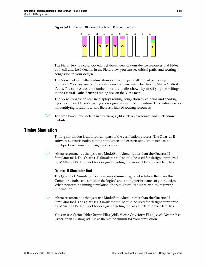
The Interior LABs view hides cell details for logic cells, Adaptive Logic Modules (ALM), and macrocells, and shows LAB information (see Figure 3–12). You can display the number of cells used in each LAB on the View menu by clicking Show Usage Numbers.
Chapter 3: Quartus II Design Flow for MAX+PLUS II Users 3–21Quartus II Design Flow
© November 2009 Altera Corporation Quartus II Handbook Version 9.1 Volume 1: Design and Synthesis
The Field view is a color-coded, high-level view of your device resources that hides both cell and LAB details. In the Field view, you can see critical paths and routing congestion in your design.
The View Critical Paths feature shows a percentage of all critical paths in your floorplan. You can turn on this feature on the View menu by clicking Show Critical Paths. You can control the number of critical paths shown by modifying the settings in the Critical Paths Settings dialog box on the View menu.
The View Congestion feature displays routing congestion by coloring and shading logic resources. Darker shading shows greater resource utilization. This feature assists in identifying locations where there is a lack of routing resources.
1 To show lower-level details in any view, right-click on a resource and click Show Details.
Timing SimulationTiming simulation is an important part of the verification process. The Quartus II software supports native timing simulation and exports simulation netlists to third-party software for design verification.
1 Altera recommends that you use ModelSim-Altera, rather than the Quartus II Simulator tool. The Quartus II Simulator tool should be used for designs supported by MAX+PLUS II, but not for designs targeting the lastest Altera device families.
Quartus II Simulator ToolThe Quartus II Simulator tool is an easy-to-use integrated solution that uses the Compiler database to simulate the logical and timing performance of your design. When performing timing simulation, the Simulator uses place-and-route timing information.
1 Altera recommends that you use ModelSim-Altera, rather than the Quartus II Simulator tool. The Quartus II Simulator tool should be used for designs supported by MAX+PLUS II, but not for designs targeting the lastest Altera device families.
You can use Vector Table Output Files (.tbl), Vector Waveform Files (.vwf), Vector Files (.vec), or an existing .scf file as the vector stimuli for your simulation.
Figure 3–12. Interior LAB View of the Timing Closure Floorplan
3–22 Chapter 3: Quartus II Design Flow for MAX+PLUS II UsersQuartus II Design Flow
Quartus II Handbook Version 9.1 Volume 1: Design and Synthesis © November 2009 Altera Corporation
The simulation options available are similar to the options available in the MAX+PLUS II Simulator. You can control the length of the simulation and the type of checks performed by the Simulator. When the MAX+PLUS II look and feel is selected, the Overwrite simulation input file with simulation results option is on by default. If you turn it off, the simulation results are written to the report file. To view the report file, click Report in the Simulator Tool window.
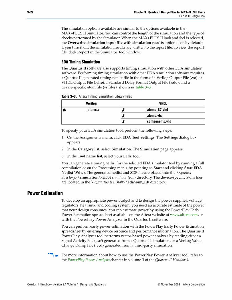
EDA Timing SimulationThe Quartus II software also supports timing simulation with other EDA simulation software. Performing timing simulation with other EDA simulation software requires a Quartus II generated timing netlist file in the form of a Verilog Output File (.vo) or VHDL Output File (.vho), a Standard Delay Format Output File (.sdo), and a device-specific atom file (or files), shown in Table 3–3.
To specify your EDA simulation tool, perform the following steps:
1. On the Assignments menu, click EDA Tool Settings. The Settings dialog box appears.
2. In the Category list, select Simulation. The Simulation page appears.
3. In the Tool name list, select your EDA Tool.
You can generate a timing netlist for the selected EDA simulator tool by running a full compilation or on the Processing menu, by pointing to Start and clicking Start EDA Netlist Writer. The generated netlist and SDF file are placed into the \<project directory>\simulation\<EDA simulator tool> directory. The device-specific atom files are located in the \<Quartus II Install>\eda\sim_lib directory.
Power EstimationTo develop an appropriate power budget and to design the power supplies, voltage regulators, heat sink, and cooling system, you need an accurate estimate of the power that your design consumes. You can estimate power by using the PowerPlay Early Power Estimation spreadsheet available on the Altera website at www.altera.com, or with the PowerPlay Power Analyzer in the Quartus II software.
You can perform early power estimation with the PowerPlay Early Power Estimation spreadsheet by entering device resource and performance information. The Quartus II PowerPlay Analyzer tool performs vector-based power analysis by reading either a Signal Activity File (.saf) generated from a Quartus II simulation, or a Verilog Value Change Dump File (.vcd) generated from a third-party simulation.
f For more information about how to use the PowerPlay Power Analyzer tool, refer to the PowerPlay Power Analysis chapter in volume 3 of the Quartus II Handbook.
Table 3–3. Altera Timing Simulation Library Files
Verilog VHDL
<device_family>_atoms.v <device_family>_atoms_87.vhd
<device_family>_atoms.vhd
<device_family>_components.vhd
Chapter 3: Quartus II Design Flow for MAX+PLUS II Users 3–23Conclusion
© November 2009 Altera Corporation Quartus II Handbook Version 9.1 Volume 1: Design and Synthesis
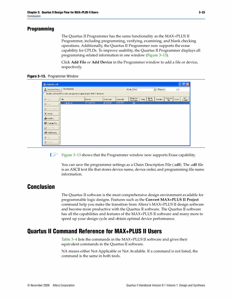
ProgrammingThe Quartus II Programmer has the same functionality as the MAX+PLUS II Programmer, including programming, verifying, examining, and blank checking operations. Additionally, the Quartus II Programmer now supports the erase capability for CPLDs. To improve usability, the Quartus II Programmer displays all programming-related information in one window (Figure 3–13).
Click Add File or Add Device in the Programmer window to add a file or device, respectively.
1 Figure 3–13 shows that the Programmer window now supports Erase capability.
You can save the programmer settings as a Chain Description File (.cdf). The .cdf file is an ASCII text file that stores device name, device order, and programming file name information.
ConclusionThe Quartus II software is the most comprehensive design environment available for programmable logic designs. Features such as the Convert MAX+PLUS II Project command help you make the transition from Altera’s MAX+PLUS II design software and become more productive with the Quartus II software. The Quartus II software has all the capabilities and features of the MAX+PLUS II software and many more to speed up your design cycle and obtain optimal device performance.
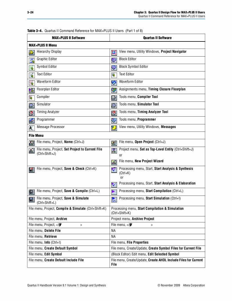
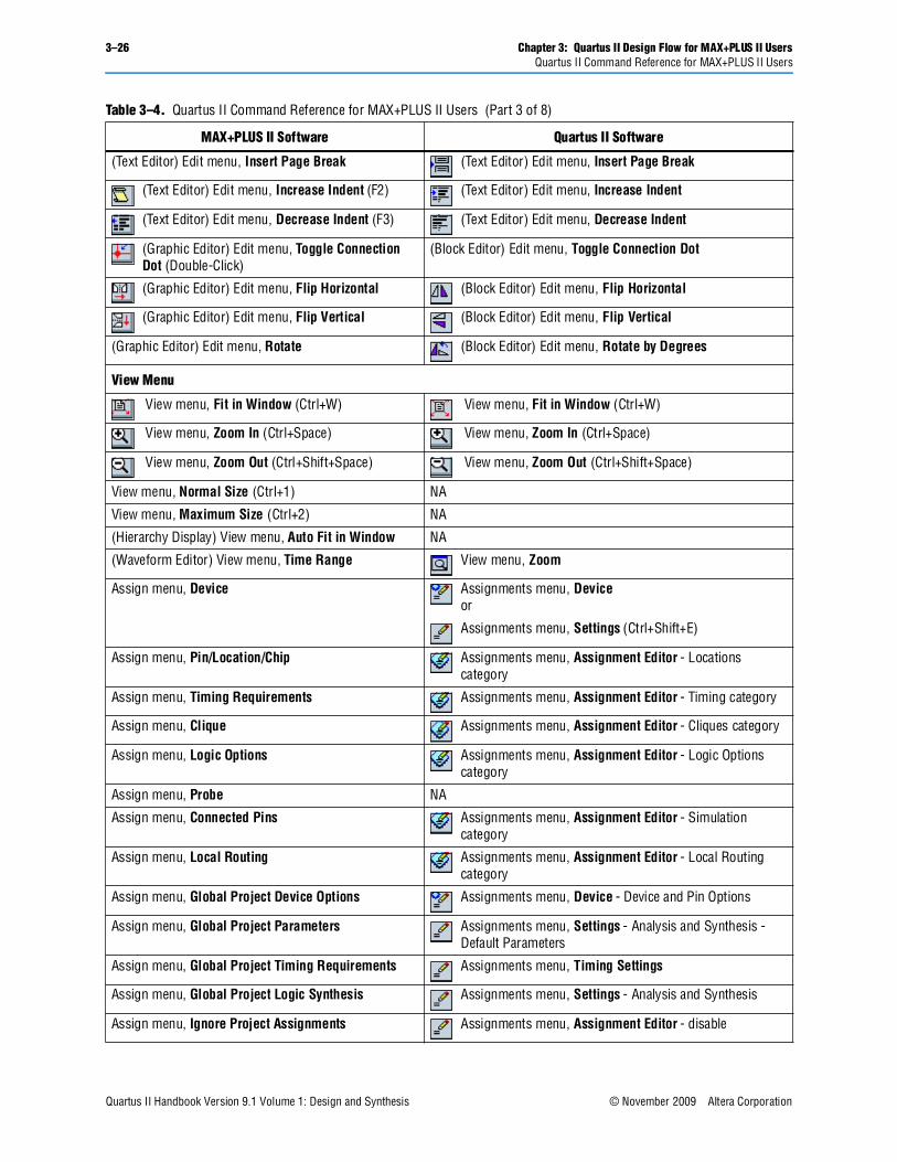
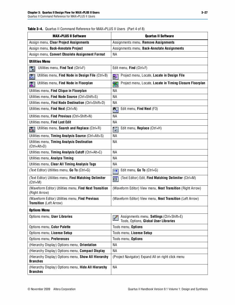
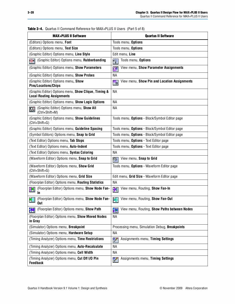
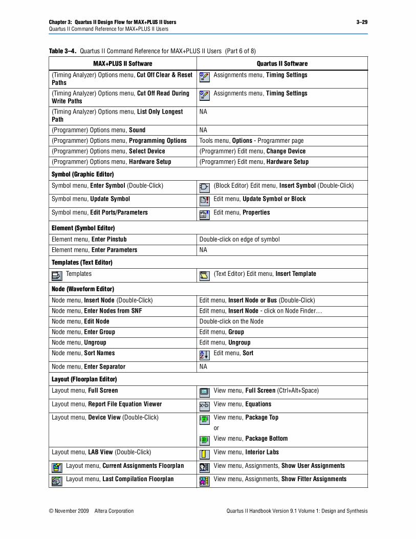
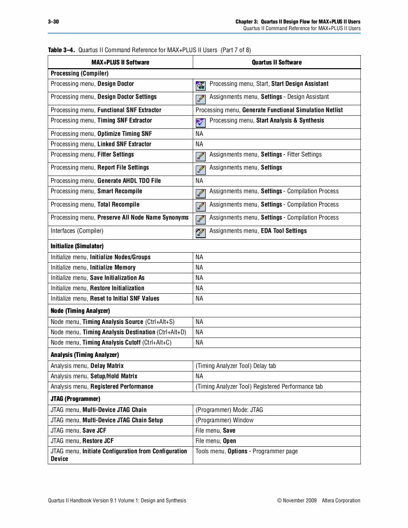
Quartus II Command Reference for MAX+PLUS II UsersTable 3–4 lists the commands in the MAX+PLUS II software and gives their equivalent commands in the Quartus II software.
NA means either Not Applicable or Not Available. If a command is not listed, the command is the same in both tools.
Figure 3–13. Programmer Window
3–24 Chapter 3: Quartus II Design Flow for MAX+PLUS II UsersQuartus II Command Reference for MAX+PLUS II Users
Quartus II Handbook Version 9.1 Volume 1: Design and Synthesis © November 2009 Altera Corporation
Table 3–4. Quartus II Command Reference for MAX+PLUS II Users (Part 1 of 8)
MAX+PLUS II Software Quartus II Software
MAX+PLUS II Menu
Hierarchy Display View menu, Utility Windows, Project Navigator
Graphic Editor Block Editor
Symbol Editor Block Symbol Editor
Text Editor Text Editor
Waveform Editor Waveform Editor
Floorplan Editor Assignments menu, Timing Closure Floorplan
Compiler Tools menu, Compiler Tool
Simulator Tools menu, Simulator Tool
Timing Analyzer Tools menu, Timing Analyzer Tool
Programmer Tools menu, Programmer
Message Processor View menu, Utility Windows, Messages
File Menu
File menu, Project, Name (Ctrl+J) File menu, Open Project (Ctrl+J)
File menu, Project, Set Project to Current File (Ctrl+Shift+J)
Project menu, Set as Top-Level Entity (Ctrl+Shift+J)
or
File menu, New Project Wizard
File menu, Project, Save & Check (Ctrl+K) Processing menu, Start, Start Analysis & Synthesis (Ctrl+K) or
Processing menu, Start, Start Analysis & Elaboration
File menu, Project, Save & Compile (Ctrl+L) Processing menu, Start Compilation (Ctrl+L)
File menu, Project, Save & Simulate (Ctrl+Shift+L)
Processing menu, Start Simulation (Ctrl+I)
File menu, Project, Compile & Simulate (Ctrl+Shift+K) Processing menu, Start Compilation & Simulation (Ctrl+Shift+K)
File menu, Project, Archive Project menu, Archive Project
File menu, Project, <Recent Projects> File menu, <Recent Projects>
File menu, Delete File NA
File menu, Retrieve NA
File menu, Info (Ctrl+I) File menu, File Properties
File menu, Create Default Symbol File menu, Create/Update, Create Symbol Files for Current File
File menu, Edit Symbol (Block Editor) Edit menu, Edit Selected Symbol
File menu, Create Default Include File File menu, Create/Update, Create AHDL Include Files for Current File
Chapter 3: Quartus II Design Flow for MAX+PLUS II Users 3–25Quartus II Command Reference for MAX+PLUS II Users
© November 2009 Altera Corporation Quartus II Handbook Version 9.1 Volume 1: Design and Synthesis
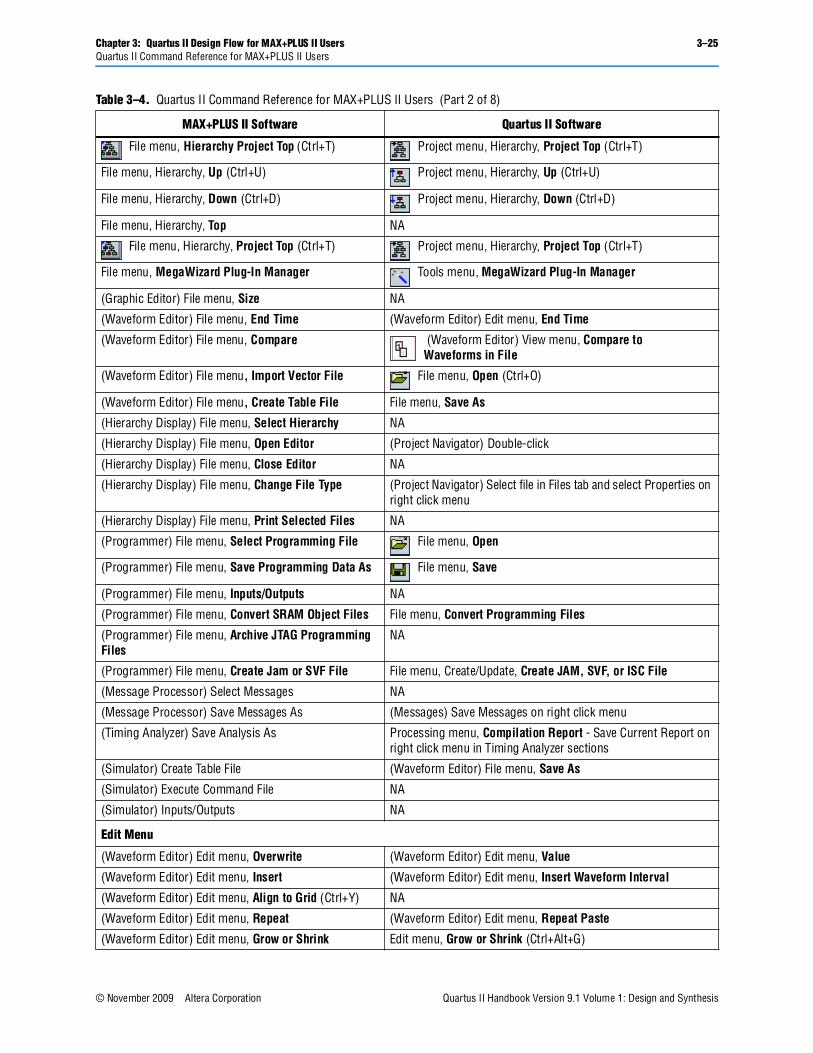
File menu, Hierarchy Project Top (Ctrl+T) Project menu, Hierarchy, Project Top (Ctrl+T)
File menu, Hierarchy, Up (Ctrl+U) Project menu, Hierarchy, Up (Ctrl+U)
File menu, Hierarchy, Down (Ctrl+D) Project menu, Hierarchy, Down (Ctrl+D)
File menu, Hierarchy, Top NA
File menu, Hierarchy, Project Top (Ctrl+T) Project menu, Hierarchy, Project Top (Ctrl+T)
File menu, MegaWizard Plug-In Manager Tools menu, MegaWizard Plug-In Manager
(Graphic Editor) File menu, Size NA
(Waveform Editor) File menu, End Time (Waveform Editor) Edit menu, End Time
(Waveform Editor) File menu, Compare (Waveform Editor) View menu, Compare toWaveforms in File
(Waveform Editor) File menu, Import Vector File File menu, Open (Ctrl+O)
(Waveform Editor) File menu, Create Table File File menu, Save As
(Hierarchy Display) File menu, Select Hierarchy NA
(Hierarchy Display) File menu, Open Editor (Project Navigator) Double-click
(Hierarchy Display) File menu, Close Editor NA
(Hierarchy Display) File menu, Change File Type (Project Navigator) Select file in Files tab and select Properties on right click menu
(Hierarchy Display) File menu, Print Selected Files NA
(Programmer) File menu, Select Programming File File menu, Open
(Programmer) File menu, Save Programming Data As File menu, Save
(Programmer) File menu, Inputs/Outputs NA
(Programmer) File menu, Convert SRAM Object Files File menu, Convert Programming Files
(Programmer) File menu, Archive JTAG Programming Files
NA
(Programmer) File menu, Create Jam or SVF File File menu, Create/Update, Create JAM, SVF, or ISC File
(Message Processor) Select Messages NA
(Message Processor) Save Messages As (Messages) Save Messages on right click menu
(Timing Analyzer) Save Analysis As Processing menu, Compilation Report - Save Current Report on right click menu in Timing Analyzer sections
(Simulator) Create Table File (Waveform Editor) File menu, Save As
(Simulator) Execute Command File NA
(Simulator) Inputs/Outputs NA
Edit Menu
(Waveform Editor) Edit menu, Overwrite (Waveform Editor) Edit menu, Value
(Waveform Editor) Edit menu, Insert (Waveform Editor) Edit menu, Insert Waveform Interval
(Waveform Editor) Edit menu, Align to Grid (Ctrl+Y) NA
(Waveform Editor) Edit menu, Repeat (Waveform Editor) Edit menu, Repeat Paste
(Waveform Editor) Edit menu, Grow or Shrink Edit menu, Grow or Shrink (Ctrl+Alt+G)
Table 3–4. Quartus II Command Reference for MAX+PLUS II Users (Part 2 of 8)
MAX+PLUS II Software Quartus II Software
3–26 Chapter 3: Quartus II Design Flow for MAX+PLUS II UsersQuartus II Command Reference for MAX+PLUS II Users
Quartus II Handbook Version 9.1 Volume 1: Design and Synthesis © November 2009 Altera Corporation
(Text Editor) Edit menu, Insert Page Break (Text Editor) Edit menu, Insert Page Break
(Text Editor) Edit menu, Increase Indent (F2) (Text Editor) Edit menu, Increase Indent
(Text Editor) Edit menu, Decrease Indent (F3) (Text Editor) Edit menu, Decrease Indent
(Graphic Editor) Edit menu, Toggle Connection Dot (Double-Click)
(Block Editor) Edit menu, Toggle Connection Dot
(Graphic Editor) Edit menu, Flip Horizontal (Block Editor) Edit menu, Flip Horizontal
(Graphic Editor) Edit menu, Flip Vertical (Block Editor) Edit menu, Flip Vertical
(Graphic Editor) Edit menu, Rotate (Block Editor) Edit menu, Rotate by Degrees
View Menu
View menu, Fit in Window (Ctrl+W) View menu, Fit in Window (Ctrl+W)
View menu, Zoom In (Ctrl+Space) View menu, Zoom In (Ctrl+Space)
View menu, Zoom Out (Ctrl+Shift+Space) View menu, Zoom Out (Ctrl+Shift+Space)
View menu, Normal Size (Ctrl+1) NA
View menu, Maximum Size (Ctrl+2) NA
(Hierarchy Display) View menu, Auto Fit in Window NA
(Waveform Editor) View menu, Time Range View menu, Zoom
Assign menu, Device Assignments menu, Deviceor
Assignments menu, Settings (Ctrl+Shift+E)
Assign menu, Pin/Location/Chip Assignments menu, Assignment Editor - Locations category
Assign menu, Timing Requirements Assignments menu, Assignment Editor - Timing category
Assign menu, Clique Assignments menu, Assignment Editor - Cliques category
Assign menu, Logic Options Assignments menu, Assignment Editor - Logic Options category
Assign menu, Probe NA
Assign menu, Connected Pins Assignments menu, Assignment Editor - Simulation category
Assign menu, Local Routing Assignments menu, Assignment Editor - Local Routing category
Assign menu, Global Project Device Options Assignments menu, Device - Device and Pin Options
Assign menu, Global Project Parameters Assignments menu, Settings - Analysis and Synthesis - Default Parameters
Assign menu, Global Project Timing Requirements Assignments menu, Timing Settings
Assign menu, Global Project Logic Synthesis Assignments menu, Settings - Analysis and Synthesis
Assign menu, Ignore Project Assignments Assignments menu, Assignment Editor - disable
Table 3–4. Quartus II Command Reference for MAX+PLUS II Users (Part 3 of 8)
MAX+PLUS II Software Quartus II Software
Chapter 3: Quartus II Design Flow for MAX+PLUS II Users 3–27Quartus II Command Reference for MAX+PLUS II Users
© November 2009 Altera Corporation Quartus II Handbook Version 9.1 Volume 1: Design and Synthesis
Assign menu, Clear Project Assignments Assignments menu, Remove Assignments
Assign menu, Back-Annotate Project Assignments menu, Back-Annotate Assignments
Assign menu, Convert Obsolete Assignment Format NA
Utilities Menu
Utilities menu, Find Text (Ctrl+F) Edit menu, Find (Ctrl+F)
Utilities menu, Find Node in Design File (Ctrl+B) Project menu, Locate, Locate in Design File
Utilities menu, Find Node in Floorplan Project menu, Locate, Locate in Timing Closure Floorplan
Utilities menu, Find Clique in Floorplan NA
Utilities menu, Find Node Source (Ctrl+Shift+S) NA
Utilities menu, Find Node Destination (Ctrl+Shift+D) NA
Utilities menu, Find Next (Ctrl+N) Edit menu, Find Next (F3)
Utilities menu, Find Previous (Ctrl+Shift+N) NA
Utilities menu, Find Last Edit NA
Utilities menu, Search and Replace (Ctrl+R) Edit menu, Replace (Ctrl+H)
Utilities menu, Timing Analysis Source (Ctrl+Alt+S) NA
Utilities menu, Timing Analysis Destination (Ctrl+Alt+D)
NA
Utilities menu, Timing Analysis Cutoff (Ctrl+Alt+C) NA
Utilities menu, Analyze Timing NA
Utilities menu, Clear All Timing Analysis Tags NA
(Text Editor) Utilities menu, Go To (Ctrl+G) Edit menu, Go To (Ctrl+G)
(Text Editor) Utilities menu, Find Matching Delimiter (Ctrl+M)
(Text Editor) Edit, Find Matching Delimiter (Ctrl+M)
(Waveform Editor) Utilities menu, Find Next Transition (Right Arrow)
(Waveform Editor) View menu, Next Transition (Right Arrow)
(Waveform Editor) Utilities menu, Find Previous Transition (Left Arrow)
(Waveform Editor) View menu, Next Transition (Left Arrow)
Options Menu
Options menu, User Libraries Assignments menu, Settings (Ctrl+Shift+E)Tools, Options, Global User LIbraries
Options menu, Color Palette Tools menu, Options
Options menu, License Setup Tools menu, License Setup
Options menu, Preferences Tools menu, Options
(Hierarchy Display) Options menu, Orientation NA
(Hierarchy Display) Options menu, Compact Display NA
(Hierarchy Display) Options menu, Show All Hierarchy Branches
(Project Navigator) Expand All on right click menu
(Hierarchy Display) Options menu, Hide All Hierarchy Branches
NA
Table 3–4. Quartus II Command Reference for MAX+PLUS II Users (Part 4 of 8)
MAX+PLUS II Software Quartus II Software
3–28 Chapter 3: Quartus II Design Flow for MAX+PLUS II UsersQuartus II Command Reference for MAX+PLUS II Users
Quartus II Handbook Version 9.1 Volume 1: Design and Synthesis © November 2009 Altera Corporation
(Editors) Options menu, Font Tools menu, Options
(Editors) Options menu, Text Size Tools menu, Options
(Graphic Editor) Options menu, Line Style Edit menu, Line
(Graphic Editor) Options menu, Rubberbanding Tools menu, Options
(Graphic Editor) Options menu, Show Parameters View menu, Show Parameter Assignments
(Graphic Editor) Options menu, Show Probes NA
(Graphic Editor) Options menu, Show Pins/Locations/Chips
View menu, Show Pin and Location Assignments
(Graphic Editor) Options menu, Show Clique, Timing & Local Routing Assignments
NA
(Graphic Editor) Options menu, Show Logic Options NA
(Graphic Editor) Options menu, Show All (Ctrl+Shift+M)
NA
(Graphic Editor) Options menu, Show Guidelines (Ctrl+Shift+G)
Tools menu, Options - Block/Symbol Editor page
(Graphic Editor) Options menu, Guideline Spacing Tools menu, Options - Block/Symbol Editor page
(Symbol Editors) Options menu, Snap to Grid Tools menu, Options - Block/Symbol Editor page
(Text Editor) Options menu, Tab Stops Tools menu, Options - Text Editor page
(Text Editor) Options menu, Auto-Indent Tools menu, Options - Text Editor page
(Text Editor) Options menu, Syntax Coloring NA
(Waveform Editor) Options menu, Snap to Grid View menu, Snap to Grid
(Waveform Editor) Options menu, Show Grid (Ctrl+Shift+G)
Tools menu, Options - Waveform Editor page
(Waveform Editor) Options menu, Grid Size Edit menu, Grid Size - Waveform Editor page
(Floorplan Editor) Options menu, Routing Statistics NA
(Floorplan Editor) Options menu, Show Node Fan-In
View menu, Routing, Show Fan-In
(Floorplan Editor) Options menu, Show Node Fan-Out
View menu, Routing, Show Fan-Out
(Floorplan Editor) Options menu, Show Path View menu, Routing, Show Paths between Nodes
(Floorplan Editor) Options menu, Show Moved Nodes in Gray
NA
(Simulator) Options menu, Breakpoint Processing menu, Simulation Debug, Breakpoints
(Simulator) Options menu, Hardware Setup NA
(Timing Analyzer) Options menu, Time Restrictions Assignments menu, Timing Settings
(Timing Analyzer) Options menu, Auto-Recalculate NA
(Timing Analyzer) Options menu, Cell Width NA
(Timing Analyzer) Options menu, Cut Off I/O Pin Feedback
Assignments menu, Timing Settings
Table 3–4. Quartus II Command Reference for MAX+PLUS II Users (Part 5 of 8)
MAX+PLUS II Software Quartus II Software
Chapter 3: Quartus II Design Flow for MAX+PLUS II Users 3–29Quartus II Command Reference for MAX+PLUS II Users
© November 2009 Altera Corporation Quartus II Handbook Version 9.1 Volume 1: Design and Synthesis
(Timing Analyzer) Options menu, Cut Off Clear & Reset Paths
Assignments menu, Timing Settings
(Timing Analyzer) Options menu, Cut Off Read During Write Paths
Assignments menu, Timing Settings
(Timing Analyzer) Options menu, List Only Longest Path
NA
(Programmer) Options menu, Sound NA
(Programmer) Options menu, Programming Options Tools menu, Options - Programmer page
(Programmer) Options menu, Select Device (Programmer) Edit menu, Change Device
(Programmer) Options menu, Hardware Setup (Programmer) Edit menu, Hardware Setup
Symbol (Graphic Editor)
Symbol menu, Enter Symbol (Double-Click) (Block Editor) Edit menu, Insert Symbol (Double-Click)
Symbol menu, Update Symbol Edit menu, Update Symbol or Block
Symbol menu, Edit Ports/Parameters Edit menu, Properties
Element (Symbol Editor)
Element menu, Enter Pinstub Double-click on edge of symbol
Element menu, Enter Parameters NA
Templates (Text Editor)
Templates (Text Editor) Edit menu, Insert Template
Node (Waveform Editor)
Node menu, Insert Node (Double-Click) Edit menu, Insert Node or Bus (Double-Click)
Node menu, Enter Nodes from SNF Edit menu, Insert Node - click on Node Finder…
Node menu, Edit Node Double-click on the Node
Node menu, Enter Group Edit menu, Group
Node menu, Ungroup Edit menu, Ungroup
Node menu, Sort Names Edit menu, Sort
Node menu, Enter Separator NA
Layout (Floorplan Editor)
Layout menu, Full Screen View menu, Full Screen (Ctrl+Alt+Space)
Layout menu, Report File Equation Viewer View menu, Equations
Layout menu, Device View (Double-Click) View menu, Package Top
or
View menu, Package Bottom
Layout menu, LAB View (Double-Click) View menu, Interior Labs
Layout menu, Current Assignments Floorplan View menu, Assignments, Show User Assignments
Layout menu, Last Compilation Floorplan View menu, Assignments, Show Fitter Assignments
Table 3–4. Quartus II Command Reference for MAX+PLUS II Users (Part 6 of 8)
MAX+PLUS II Software Quartus II Software
3–30 Chapter 3: Quartus II Design Flow for MAX+PLUS II UsersQuartus II Command Reference for MAX+PLUS II Users
Quartus II Handbook Version 9.1 Volume 1: Design and Synthesis © November 2009 Altera Corporation
Processing (Compiler)
Processing menu, Design Doctor Processing menu, Start, Start Design Assistant
Processing menu, Design Doctor Settings Assignments menu, Settings - Design Assistant
Processing menu, Functional SNF Extractor Processing menu, Generate Functional Simulation Netlist
Processing menu, Timing SNF Extractor Processing menu, Start Analysis & Synthesis
Processing menu, Optimize Timing SNF NA
Processing menu, Linked SNF Extractor NA
Processing menu, Fitter Settings Assignments menu, Settings - Fitter Settings
Processing menu, Report File Settings Assignments menu, Settings
Processing menu, Generate AHDL TDO File NA
Processing menu, Smart Recompile Assignments menu, Settings - Compilation Process
Processing menu, Total Recompile Assignments menu, Settings - Compilation Process
Processing menu, Preserve All Node Name Synonyms Assignments menu, Settings - Compilation Process
Interfaces (Compiler) Assignments menu, EDA Tool Settings
Initialize (Simulator)
Initialize menu, Initialize Nodes/Groups NA
Initialize menu, Initialize Memory NA
Initialize menu, Save Initialization As NA
Initialize menu, Restore Initialization NA
Initialize menu, Reset to Initial SNF Values NA
Node (Timing Analyzer)
Node menu, Timing Analysis Source (Ctrl+Alt+S) NA
Node menu, Timing Analysis Destination (Ctrl+Alt+D) NA
Node menu, Timing Analysis Cutoff (Ctrl+Alt+C) NA
Analysis (Timing Analyzer)
Analysis menu, Delay Matrix (Timing Analyzer Tool) Delay tab
Analysis menu, Setup/Hold Matrix NA
Analysis menu, Registered Performance (Timing Analyzer Tool) Registered Performance tab
JTAG (Programmer)
JTAG menu, Multi-Device JTAG Chain (Programmer) Mode: JTAG
JTAG menu, Multi-Device JTAG Chain Setup (Programmer) Window
JTAG menu, Save JCF File menu, Save
JTAG menu, Restore JCF File menu, Open
JTAG menu, Initiate Configuration from Configuration Device
Tools menu, Options - Programmer page
Table 3–4. Quartus II Command Reference for MAX+PLUS II Users (Part 7 of 8)
MAX+PLUS II Software Quartus II Software
Chapter 3: Quartus II Design Flow for MAX+PLUS II Users 3–31Referenced Documents
© November 2009 Altera Corporation Quartus II Handbook Version 9.1 Volume 1: Design and Synthesis
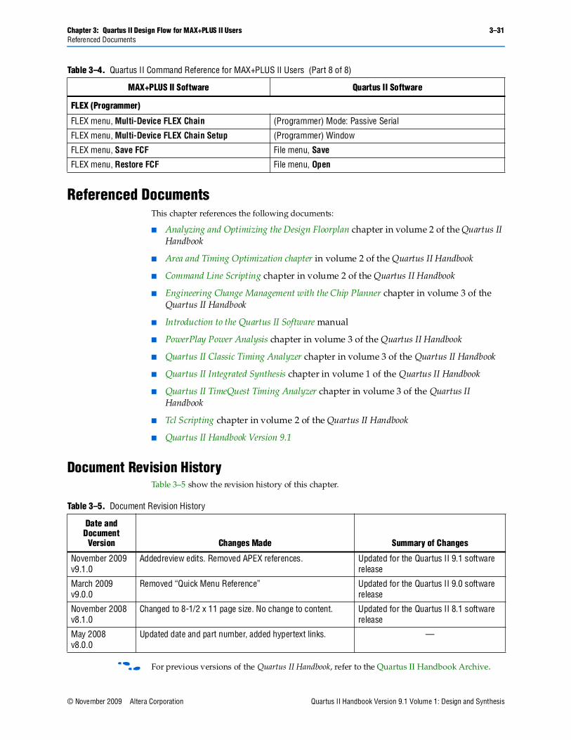
Referenced DocumentsThis chapter references the following documents:
■ Analyzing and Optimizing the Design Floorplan chapter in volume 2 of the Quartus II Handbook
■ Area and Timing Optimization chapter in volume 2 of the Quartus II Handbook
■ Command Line Scripting chapter in volume 2 of the Quartus II Handbook
■ Engineering Change Management with the Chip Planner chapter in volume 3 of the Quartus II Handbook
■ Introduction to the Quartus II Software manual
■ PowerPlay Power Analysis chapter in volume 3 of the Quartus II Handbook
■ Quartus II Classic Timing Analyzer chapter in volume 3 of the Quartus II Handbook
■ Quartus II Integrated Synthesis chapter in volume 1 of the Quartus II Handbook
■ Quartus II TimeQuest Timing Analyzer chapter in volume 3 of the Quartus II Handbook
■ Tcl Scripting chapter in volume 2 of the Quartus II Handbook
■ Quartus II Handbook Version 9.1
Document Revision HistoryTable 3–5 show the revision history of this chapter.
f For previous versions of the Quartus II Handbook, refer to the Quartus II Handbook Archive.
FLEX (Programmer)
FLEX menu, Multi-Device FLEX Chain (Programmer) Mode: Passive Serial
FLEX menu, Multi-Device FLEX Chain Setup (Programmer) Window
FLEX menu, Save FCF File menu, Save
FLEX menu, Restore FCF File menu, Open
Table 3–4. Quartus II Command Reference for MAX+PLUS II Users (Part 8 of 8)
MAX+PLUS II Software Quartus II Software
Table 3–5. Document Revision History
Date and Document
Version Changes Made Summary of Changes
November 2009 v9.1.0
Addedreview edits. Removed APEX references. Updated for the Quartus II 9.1 software release
March 2009v9.0.0
Removed “Quick Menu Reference” Updated for the Quartus II 9.0 software release
November 2008v8.1.0
Changed to 8-1/2 x 11 page size. No change to content. Updated for the Quartus II 8.1 software release
May 2008v8.0.0
Updated date and part number, added hypertext links. —

3–32 Chapter 3: Quartus II Design Flow for MAX+PLUS II UsersDocument Revision History
Quartus II Handbook Version 9.1 Volume 1: Design and Synthesis © November 2009 Altera Corporation