2015 emc test & design guide | interference technology
TRANSCRIPT

interferencetechnology.com
2O15EMC TEST & DESIGN GUIDE
FEATURED TOPICS
8 MILITARY 12 ANTENNAS 16 STANDARDS 48 FILTERS 54 TESTING
DIRECTORIES20 2015 EMC TEST LAB DIRECTORY 46 SUPPLIERS
A Solution to EnhAncE REpRoducibility with RAdiAtEd RF EmiSSion And immunity mEASuREmEntS
ALSO INSIDE: CISPR 32 – What is it, Why was it Written and Where is it Going?
BACK COVER


CONTENTS
2 2015 EMC TEST & DESIGN GUIDEINTERFERENCE TECHNOLOGY
6 EDITORIAL LIVE LEARNING Belinda Stasiukiewicz Editor, Interference Technology
8 MILITARY SPECTRUM SUPPORTABILITY RISK ASSESSMENTS: AN OVERVIEW Brian Farmer Owner, EMC Management Concepts
SPECIAL FEATURE:
2015 EMC TEST LAB DIRECTORY
20
54
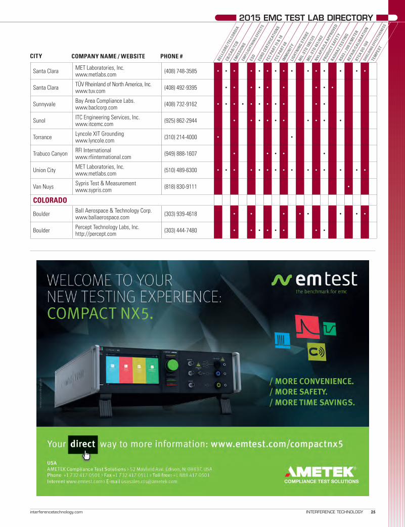
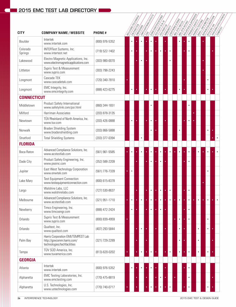
Check out our updated 2015 EMC Test Laboratory Directory, featuring more than 500 test labs around the world. The listings are arranged geographically, with details of services offered, website addresses and contact phone numbers, to provide a quick and easy reference guide to EMC testing services nearby, no matter where you are located.
TESTING - A SOLUTION TO ENHANCE REPRODUCIBILITY WITH RADIATED RF EMISSION AND IMMUNITY MEASUREMENTS?Photo credit: Austest Laboratories, Castle Hill, Australia


CONTENTS
4 2015 EMC TEST & DESIGN GUIDEINTERFERENCE TECHNOLOGY
13
1559
58
12 ANTENNAS HOW DO YOU MEASURE 5G? Lars Jacob Foged Scientific Director, Microwave Vision
16 STANDARDS CISPR 32 – WHAT IS IT, WHY WAS IT WRITTEN AND WHERE IS IT GOING? Ghery S. Pettit President, Pettit EMC Consulting LLC
48 FILTERS MAINS INPUT FILTERS – WHAT IS INSIDE THE BOX AND WHY? John Woodgate Consultant, J M Woodgate and Associates
54 TESTING A SOLUTION TO ENHANCE REPRODUCIBILITY WITH RADIATED RF EMISSION AND IMMUNITY MEASUREMENTS? Mart Coenen Owner, EMCMCC
46 SUPPLIERS GUIDE
64 INDEX OF ADVERTISERS
51


6 2015 EMC TEST & DESIGN GUIDEINTERFERENCE TECHNOLOGY
EDITORIAL
HERE AT INTERFERENCE TECHNOLOGY, we put an emphasis on learning. We strive to publish only the most current, valuable ar-ticles to allow our readers access to important news on advances in EMC, as well as archive materials that are useful for reference. After
more than 40 years as a magazine, we now offer many different ways to dig deeper into this ever-expanding industry. Our most current option is our successful EMC Live series.
EMC Live started as a thought in our minds: “How can we quickly provide important information to our audience in the most efficient way in our fact-paced world?” We believe that no matter where you are in your career, continued education is always essential, and free online learning is a valuable tool that anyone can use. With this thought, we began a series of online webinars, which proved to be popular with view-ers, and then we decided to go even bigger. We needed to create an event that engineers could attend at their convenience, while offering multiple opportunities to learn about different topics – from EMC basics for the young engineer, to in-depth advanced topics for seasoned pros. EMC Live 2014 premiered in October 2014, with more than 5,000 at-tendees. The entire event took place online, allowing engineers to forgo traditional tradeshows and get the information they need conveniently. We received a lot of feedback after the event: the majority of attendees were pleased with the content and wanted more! We then hosted EMC Live 2015 this past April, which also drew many return attendees, and new ones as well. We had a one-day design bootcamp in February 2015, and we will host a one day test bootcamp Nov. 12 of this year. In addi-tion, we have scheduled EMC Live 2016 for April 26-28, 2016. These are all free events that you can attend live the day of, or watch later at your leisure. We encourage you to check it out – you never know what you will learn! We hope that EMC Live will continue to grow in our constantly chang-ing digital world. We are proud to offer our content across multiple plat-forms, so we can reach you wherever you are. Whether you are attending a webinar, browsing our print magazine, clicking through our website, reading our digital edition or keeping up with our enewsletter, we want to assist you and keep you company as you move throughout your EMC career. Please visit www.emclive2015.com for information on our past and upcoming events, and to view our archived webinars. As always, you can also visit www.interferencetechnology.com or email us at [email protected] with any comments or questions.
USA1000 Germantown Pike, F-2
Plymouth Meeting, PA 19462Phone: (484) 688-0300
Fax: (484) 688-0303Email:
CHINA, TAIWAN, HONG KONGACT International
Mainland China - Linda Li, +86-21-62511200Email: [email protected]
Hong Kong - Mark Mak, +85-22-8386298Email: [email protected]
JAPANe-OHTAMA, LTD.
Midori Hamano, +81-44-980-2092E-mail: [email protected]
ITEM Media endeavors to offer accurate information, but assumes no liability for errors or omissions. Information published herein is based on the latest information available at the time of publication. Furthermore, the opinions contained herein do not necessarily reflect those of the publisher.
Copyright © 2015 • ITEM Media • ISSN 0190-0943
EditorBelinda Stasiukiewicz
Editorial AssistantAllison Titus
Production AssistantEvan Barr
Marketing ManagerDawn Hoffman
Marketing SpecialistErica Osting
Sr. Business Development ExecutiveJan Ward
Business Development ExecutivesBlake Maclean
Katie Tolton
Administrative ManagerEileen M. Ambler
Circulation AssistantMary Ann Flocco
Accounting AssistantSusan Kavetski
PresidentGraham S. Kilshaw
Publisher EmeritusRobert D. Goldblum
2015 E MC T E S T & DE S IGN GU IDE
Live Learning
S u b s c r i p t i o n sITEM, InterferenceTechnology—The EMC Directory & Design Guide, EMC Symposium Guide, Europe EMC Guide and EMC Test & Design Guide are distributed annually at no charge to engineers and managers engaged in the application, selection, design, test, specification or procurement of electronic components, systems, materials, equipment, facilities or related fabrication services. Subscriptions are available through interferencetechnology.com.
Belinda StasiukiewiczEditor, Interference Technology


8 2015 EMC TEST & DESIGN GUIDEINTERFERENCE TECHNOLOGY
MILITARY
INTRODUCTION
As we ride on the cusp of a new age of electronic warfare, management and use of the electro-magnetic spectrum are becoming increasingly important. In fact, the Department of Defense (DoD) has deemed the electromagnetic spectrum a critical resource and has established DoD In-
struction 4650.01, which defines policy and procedures for administrating and employing this resource.
One of the key tenants of this document is the performance of a Spectrum Supportability Risk Assessment (SSRA). The SSRA is becoming increasingly important as the spectrum be-comes increasingly more congested, and industry practitioners should be cognizant of recent rule changes when developing new material requirements for new equipment and systems. In addition to addressing the spectrum certification and fre-quency assignment processes, the SSRA is required for the procurement of all spectrum-dependent systems, including commercial-off-the-shelf (COTS) systems.
The purpose of the SSRA is to identify and assess regulatory, technical, and operational spectrum issues with the potential to affect the required operational performance of a candidate system. For example, in addition to determining that a system’s bandwidth requirement complies with an individual nation’s frequency allocation scheme, a new or modified system must also be evaluated with respect to the following: • The system’s potential to cause interference to, or suffer
from, other military and civilian radio frequency (RF) systems currently in use or planned for operational envi-ronments.
• The effect of the system’s proposed spectrum use on the ability of the extant force structure to access the RF spec-trum without interference.
• How the system’s spectrum use conforms to the tables of frequency allocation of intended host nations, ensuring
Spectrum Supportability Risk Assessments: An Overview
BRIAN FARMERConsultant EMC Management Concepts

9interferencetechnology.com INTERFERENCE TECHNOLOGY
Farmer MILITARY
Figure 1: SSRA Requirements in DoDI 5000.02.
regulatory protection from other national co-band spec-trum users.
• Whether or not individual host-nation frequency allo-cations include enough bandwidth to fully support the system’s operational mission—for example, the required data rate. Assessing these topics of concern early in the design of
equipment will save money in the long run. SSRAs will be required of programs at milestone reviews A, B, and C as part of the overall balance of program success against fu-ture risks. Figure 1 identifies a part of Table 2 in the DoDI 5000.02, Milestone and Phase Information Requirements, and it indicates that an SSRA must be developed early for any spectrum-dependent system program and that it must be updated at every major acquisition milestone. A Program Manager’s (PM) failure to obtain spectrum supportability for components in its systems could have direct consequences to the program in meeting performance, schedule, and cost objectives established by its Acquisition Review Board and to the Combatant Commander in meeting Joint Mission Area requirements.
SPECTRUM MANAGEMENT AND REQUIREMENTSTo better understand SSRAs, a little background is pro-
vided. In the DoD acquisition process, spectrum management usually begins with equipment spectrum certification, a pro-cess whereby a system is approved to operate in a particular spectral band. To actually operate the system, spectrum certi-

10 2015 EMC TEST & DESIGN GUIDEINTERFERENCE TECHNOLOGY
MILITARY
fication must be followed by obtaining a frequency assignment.Obtaining frequencies to operate equipment in the United
States is a two-step process, which is managed by the submit-tal of a properly filled out DD Form 1494. The first step is Equipment Spectrum Certification. The certification process assesses equipment transmit and receive characteristics to determine if the system complies with existing RF spectrum regulations. The second step, Frequency Assignment, coor-dinates operational use of specific frequencies within specific bands among current users so that they do not interfere with each other. The Manual of Regulations and Procedures for Radio Frequency Management, issued by the Department of Commerce’s National Telecommunications and Information Administration (NTIA), is the standard for both steps. The NTIA is the regulatory authority over all Federal equipment and spectrum in the United States and Possessions (US&P). The Federal Communications Commission (FCC) regulates non-Federal spectrum in the US&P.
It is important to remember that the SSRA is about as-sessing risk. The Risk Management Guide (RMG) for DoD acquisition defines risk as a measure of the potential inability to achieve overall program objectives within defined cost, schedule, and performance/technical constraints; it has two components: (1) the probability/likelihood of failing to achieve a particular outcome, and (2) the consequences/impacts of failing to achieve that outcome.
Accordingly, an SSRA should include the following com-ponents:
• Regulatory Component: Addressing the compliance of the RF system with U.S. national and international tables of frequency allocation as well as with regulatory agreements reached at the International Telecommunication Union.
• Technical Component: Quantifying the mutual interac-tions between a candidate system and other co-band, adja-cent band, and harmonically related RF systems, including the identification of suggested methods to mitigate the effects of possible mutual interference.
• Operational Component: Identifying and quantifying the mutual interactions among the candidate system and other U.S. military RF systems in the operational environment and identifying suggested methods to mitigate for possible instances of interference. The objective is to quantify any risk that systems won’t meet their performance require-ments due to spectrum supportability issues.
• Electromagnetic Environmental Effects (E3) Assess-ment: At a minimum, electromagnetic compatibility (EMC) and electromagnetic interference (EMI) are to be addressed to determine the potential for interactions be-tween the proposed system and its anticipated operational electromagnetic emissions (EME).
Ideally, an initial SSRA is generated in the early stages of the DoD acquisition process. Early identification of major regula-tory and technical issues allows program office personnel to
focus attention and resources on critical spectrum issues in the later acquisition phases. The owner of the SSRA compiles input from several sources. These sources include the following:
• Technical and regulatory information obtained from DoD databases—specifically, the:
◊ Spectrum Certification System (SCS) database, which is used to generate lists of co-band and adjacent band DoD emitters, providing an overview of other systems sharing expected electromagnetic environments.
◊ Host Nation Spectrum Worldwide Database Online (HNSWDO) database, which is used to identify host nation comments on previous systems in the same fre-quency band and with similar technical parameters as the system being acquired.
• U.S. and non-U.S. tables of allocation, which can be ob-tained in many cases directly from the internet.
• The latest pertinent Host Nation supportability comments are obtained by the Program Management Office (PMO) from the Combatant Command (COCOM) spectrum man-agers. The COCOM spectrum managers will forward any resulting comments to the authors of the SSRA.
• The PMO defines the system’s technical parameters and intended operational deployment required for spectrum support (e.g., the frequency bands of in-tere s t a nd t he i ntende d worldw ide de ve lop -ment, test and operational areas, and host nations).
The major result of the SSRA may be that the PMO consid-ers options such as changing the system’s spectrum use or other technical parameters or beginning consultations with the cognizant Spectrum Management Office (SMO) regard-ing possible courses of action. Typical courses of action can include coordinating bilateral negotiations with individual host-nations or briefing the spectrum requirements of the system to groups such as the NATO Frequency Management Sub-Committee (FMSC), the DoD Spectrum Summit, or various COCOM spectrum conferences. All PMO involve-ment with these groups must be closely coordinated with the cognizant service SMO and DoD representatives.
CONCLUSIONSpectrum supportability is not something that can be as-
sumed; spectrum demands are increasing, and the amount of available spectrum is decreasing. The requirement to perform and submit SSRAs is part of the DoD effort to ensure that the military does not continue to field systems with spectrum and/or interference problems. From the list of items specified in DoDI 4650.01, one also must recognize that producing a meaningful SSRA is a significant engineering undertaking that must be thoughtfully planned and executed. An understand-ing of the entire gamut of required information and the sources and availability of that information, as well as the technical ability to collate, analyze, and present the data, require spe-cialized expertise. And because the SSRA is a relatively new

11interferencetechnology.com INTERFERENCE TECHNOLOGY
Farmer MILITARY
requirement, identifying knowledgeable and experienced help to produce and review an SSRA can prove to be challenging. Accordingly, good sources for additional guidance in this area include the “Joint Services Guide for Development of a SSRA” (available at acc.dau.mil/library) [1] and the Services’ SMOs.
Finally, for those individuals tasked with spectrum sup-portability and related tasks and considerations, the following reminders are given:• Considering spectrum supportability is a critical tenet for
program success.• Spectrum supportability requires application of resources
and knowledgeable people.• Spectrum supportability resources should be applied early
in a program life cycle and should be coordinated with the SMO.
• Thoughtful planning and risk management regarding spectrum supportability will return big savings in terms of unanticipated rework.
REFERENCES [1] The U.S. Defense Information Systems Agency and the Defense Spectrum Organization. “Joint Services Guide for Development of a Spectrum Sup-portability Risk Assessment (SSRA).” https://acc.dau.mil/, September 2011.

12 INTERFERENCE TECHNOLOGY 2015 EMC TEST & DESIGN GUIDE
ANTENNAS
INTRODUCTION
The development of 5G cellular networks is well underway and requires a new approach to ensure accurate measurement of the antenna components. With f lexible radiation patterns which are capable of adapting to the chang-ing situations in mobile networks, the full
characterisation of the Active Antenna System (AAS) in 3D space has been the focus of attention as a component for these new 5G networks. Lars Jacob Foged from MVG (Microwave Vision Group), explains the new approach to measurement and how fast and accurate AAS characteri-sation can be delivered.
THE DEFINITION OF ‘MASSIVE’A key part in 5G development, for both the user and
network segments is Multiple-Input-Multiple-Output (MIMO) antenna arrays or “Massive MIMO”. “Massive” can vary in definition from AAS arrays with relatively few elements, through to more conceptual designs involving hundreds of antennas. Distributed amplification is a com-mon denominator for both beam steering and full integra-tion of the densely packed antenna elements. In order to characterize the AAS the collective performance must be determined in a calibrated Over-the Air (OTA) setup in which the spatial-directional power and sensitivity profile are measured. Consequently, the tests for much smaller mobile devices and the associated performance parameters in relation to these new tests are very similar.
AAS PERFORMANCEThe parameters of interest for AAS performance are the
directional dependent power and sensitivity performances in Far Field (FF) condition [1]:
• Effective Isotropic Radiated Power, EIRP(θ,φ) • Total Radiated Power, TRP• Effective Isotropic Sensitivity, EIS(θ,φ)• Total Isotropic Sensitivity (TIS) or
Total Radiated Sensitivity (TRS)
How do you Measure 5G?LARS JACOB FOGED Scientific Director Microwave Vision Group

13interferencetechnology.com INTERFERENCE TECHNOLOGY
Foged ANTENNAS
The EIRP(θ,φ) and EIS are directional performance parameters that can be measured for a given direction of the antenna device in a calibrated Over-the-Air (OTA) measurement setup. The directional EIRP is the radi-ated power weighted by the directional gain G of the antenna. The TRP can be determined from a full sphere integration of EIRP and associating isotropic gain to the antenna. Likewise, directional EIS is TIS/TRS weighted by the directional gain G of the antenna. TIS/TRS can be determined by integrating the EIS over the full sphere and associating isotropic gain to the antenna.
A further parameter of interest is the polarisation characetristics of the AAS [2] as a mean to obtain polarisa-tion diversity. Directional parameters such as EIRP(θ,φ), EIS are often resolved in orthogonally polarized field vectors. Cross-polarization (X-pol) stands for "per-pendicular" over intended polarization, which is called co-polarization (Co-pol).
ANTENNA FAR-FIELD CONDITIONA generally accepted criteria is to define the FF dis-
tance of an antenna as 2D2/λ, where D is the diameter of the antenna and λ is the free-space wavelength [2]. For electrically small antennas, such as antennas for mobile communication devices, measurement in FF condition is generally satisfied for convenient short measurement distances. However, even for moderate size AAS antennas, the measurement in FF condition puts unrealistic require-ments on the measurement distance. Fig. 1 illustrates the elevation pattern of an 8-element array antenna at 2GHz (BTS1940 from MVG) for different Near Field (NF) distances and the reference FF distance. The elevation pattern is not fully formed for any realistic measurement distance, as you can see in the images.
The FF pattern of a given antenna can be measured di-rectly in a Compact Antenna Test Range (CATR) [1, 2] or determined from NF to FF transformation using standard NF techniques [3]. NF measurements are often preferable for 3D performance scenarios, since they require physi-
Figure 2: Co-pol, NF of 8-element array antenna. Reference measurement (left) and active measurement (right) LTE protocol, using PRU. Magnitude (top), Phase (bottom)
Figure 1: Measured elevation pattern at 2GHz of an 8-element array antenna for different NF distances and FF.

14 INTERFERENCE TECHNOLOGY 2015 EMC TEST & DESIGN GUIDE
ANTENNAS
cally smaller, less expensive, measurement setups and are generally considered faster and more accurate.
Due to power conservation, AAS performance param-eters can be determined at any distance from the device in a calibrated OTA setup. The difference in NF to FF gain of the antenna can be determined and compensated by standard NFFF transformation techniques [3].
PHASE RECOVERYAs the AAS antenna is an active device with highly
modulated signals depending on the communication pro-tocol, it does not provide a fixed phase reference, essential for NF to FF transformation. The recovery of the phase information requires a dedicated measurement setup. A common method is the holographic technique, which uses different combinations of the measured unknown signal with a stable reference signal. The preferred method here is an evolution of this approach based on the simultane-ous reception of the reference and measured signals. A Phase Recovery Unit (PRU) has been designed to perform all the necessary amplification, filtering and signal com-bination for the accurate determination of the phase of the modulated signal.
PHASE RECOVERY MEASUREMENTThe actual AAS antenna is emulated using a mobile
phone with LTE protocol connected to an 8-element passive array (See Fig. 1), as external antenna and Fig. 2 illustrates the comparison of the measured amplitude and phase of the co-polar NF using phase recovery compared to passive measurement on the same antenna. You can see that the amplitude and phase correlation between the measurements works well.
When the measurement with phase recovery in LTE modulation was performed with the PRU unit in a 10MHz bandwidth around the 1940MHz centre frequency of the BTS antenna, the error introduced by the phase recovery technique was determined to be equivalent to a -45dB noise level.
NF VALIDATIONValidating the NF approach, a validation device with
known EIS and EIRP is needed. Since the 8-ele-ment antenna and LTE device in this example are sepa-rable, the reference EIS and EIRP performance of the combined device can be determined from the antenna gain and the sensitivity/radiated power of the LTE device from a conducted measurement.
USING NF TECHNIQUES FOR MEASUREMENT OF EIS OF 8-ELEMENT ARRAY ANTENNA FOR LTE PROTOCOL
The EIS of the 8-element array antenna at 1940MHz using the LTE protocol has been measured in NF and compared to the reference scenario to validate the
approach. The EIS elevation and azimuth pattern of the reference and NF measurement, using the PRU unit in a 10MHz bandwidth around the 1940MHz centre frequency, are compared in Fig. 3. As expected, the pattern shapes are very similar in both azimuth and elevation. The ~1dB offset in measured sensitivity by the two methods is justi-fied by the uncertainties relative to the NF measurements and the determination of the reference scenario. Range calibration and the sensitivity search accuracy for EIS measurement are considered the main uncertainty con-tributor for the near field measurements. Range calibration and sensitivity search accuracy for conducted sensitivity are considered the main uncertainty contributors for a reference scenario of this type. (Figure 3).
USING NF TECHNIQUES FOR MEASUREMENT OF EIRP OF 8-ELEMENT ARRAY ANTENNA FOR LTE PROTOCOL
In addition to measuring the receive EIS , the transmit EIRP of the 8-element array antenna has been measured using the LTE protocol at 1940MHz. The EIRP elevation and azimuth pattern of the reference scenario and the NF measurement, using the PRU unit in a 10MHz bandwidth around the 1940MHz centre fre-quency, are compared in Fig. 4. As expected, the pattern shapes are very similar in both azimuth and elevation. The ~0.5dB offset in EIRP of the two measurements are justified by the uncertainties relative to the NF mea-surements and the determination of a reference scenario of this type. (Figure 4).
ADVANTAGESThe NF measurement technique has been demonstrated
effectively in the measurement of performance parameters such as EIRP and EIS for active antennas such as AAS. It has been confirmed experimentally that the implemented PRU technique can reliably measure the phase in NF for modulated signal with large BW; such as, LTE and allow for accurate NFFF transformation. NF measurement technique makes this, in our opinion, for the accurate measurement and testing of 5G devices, the most advantageous way to measure.
REFERENCES[1] Ericsson contribution, “On radiated testing of AAS BS”, 3GPP R4-132211, May 2013[2] ANSI/IEEE Std 149-1979 Standard Test Procedures for Antennas.[3] IEEE Recommended Practice for Near-Field Antenna Measurements, IEEE Std, 1720-2012[4] L. J. Foged, A. Scannavini, N. Gross, F. Cano-Facila “Accurate Measurement of Transmit and Receive Performance of AAS Antennas in a Multi-Probe Spherical NF System”, IEEE International Symposium on Antennas and Propagation, Vancouver, British Columbia, Canada, July 19-25, 2015

15interferencetechnology.com INTERFERENCE TECHNOLOGY
Foged ANTENNAS
Figure 3: Sensitivity pattern, EIS of 8-element array antenna using LTE protocol. Comparison of direct measurement “Pattern with modulation” with reference “Conducted sensitivity”. Both orthogonal polarisation components are shown. Cross-polarization “Xpol” is perpendicular to the intended polarization “Copol” of the antenna.
Figure 4: Radiated power pattern, EIRP of 8-element array antenna using LTE protocol. Comparison of direct measurement, “Pattern with modulation + NF EIRP” with reference “Conducted Power + Gain”. Both orthogonal polarisation components are shown. Cross-polarization “Xpol” is perpendicular to the intended polarization “Copol” of the antenna.

16 INTERFERENCE TECHNOLOGY 2015 EMC TEST & DESIGN GUIDE
STANDARDS
INTRODUCTION
CISPR 32, “Electromagnetic compatibility of multime-dia equipment – Emission requirements” was first published in 2012. This standard came about due to a major development in consumer electronics, the digital television receiver.
The CISPR is a special committee of the IEC. CISPR stands for the French words for the Special Committee on Radio Interference. CISPR publishes a number of EMC standards used for a variety of product families. This article will discuss only a very small portion of the standards published by CISPR.
The purpose of the SSRA is to identify and assess regulatory, technical, and operational spectrum issues with the potential to affect the required operational performance of a candidate system. For example, in addition to determining that a system’s bandwidth requirement complies with an individual nation’s frequency allocation scheme, a new or modified system must also be evaluated with respect to the following:
From a CISPR perspective, prior to the development and wide scale use of digital TV receivers, television receiver manufac-turers had a single emissions standard to deal with. CISPR 13 provides limits and methods of measurement for emissions from broadcast receivers. Likewise, computer manufacturers had a single emissions standard to deal with. CISPR 22 provides limits and methods of measurement for emissions from information technology equipment (ITE), also known as computers and their peripheral devices. These two standards are independent of each other and provide different limits and methods of measurement, as well as different configurations for the equipment under test. A significant difference noted by television manufacturers in the configuration area was the requirement in CISPR 22 to in-vestigate the impact of cables connected to multiple I/O ports, something not required in CISPR 13.
CISPR 32 – What is it, Why was it Written and Where is it Going?
GHERY S. PETTITPresident Pettit EMC Consulting LLC

17interferencetechnology.com INTERFERENCE TECHNOLOGY
Pett it EDUCATION

18 INTERFERENCE TECHNOLOGY 2015 EMC TEST & DESIGN GUIDE
When digital television receivers were developed the manu-facturers found that they now had two standards to deal with for emissions. A digital television receiver has both a broadcast receiver and a computer in the same box. Hence, both CISPR 13 and CISPR 22 applied to the product. As the limits and test methods differed between the two standards each had to be addressed separately. Needless to say, this added time and cost to the qualification process. Managers don’t tend to look kindly on things that add time and cost to the development process, especially when they see no benefit. As a result, efforts began in CISPR to address this matter.
Addressing the matter of emissions standards for digital television receivers was complicated by the fact that CISPR 13 was maintained in CISPR Subcommittee E (Broadcast receivers) and CISPR 22 was maintained in CISPR Subcommittee G (ITE). If you need to either find a way to coordinate two standards, or write a new one, having two separate subcommittees is not the most efficient way to go about the task. In the end, CISPR/E and CISPR/G were merged in 2001, forming the new CISPR Subcommittee I (Electromagnetic compatibility of information technology equipment, multimedia equipment and receivers). CISPR/E and CISPR/G ceased to exist with the creation of CISPR/I. CISPR/I initially had 4 working groups. WG1 was tasked with the maintenance and updating of CISPR 13 (emis-sions) and CISPR 20 (immunity) for broadcast receivers. WG3 was tasked with the maintenance and updating of CISPR 22 (emissions) and CISPR 24 (immunity) for ITE. WG2 was tasked with the creation of the new multimedia equipment emissions standard, CISPR 32 and WG4 was tasked with the creation of the new multimedia equipment immunity standard, CISPR 35. WG1 and WG3 were dissolved at the end of 2012 and any continuing work on the old standards was folded into WG2 for emissions and WG4 for immunity.
Writing the new standards was not simply a matter of merg-ing two existing documents. Over the years of work on creating CISPR 32 various ideas were proposed and discussed, both within WG2 and by the national committees. Several Committee Drafts (CD) were circulated to the national committees for comments before the final form of the standard emerged. A Committee Draft for Vote (CDV) was circulated and voted in 2010. A large number of comments were received with the national commit-tee votes. These were considered in WG2 and the Final Draft International Standard (FDIS) was circulated and voted in the 4th quarter of 2011. This FDIS was successful and CISPR 32, Edition 1.0 was published in January 2012.
CISPR 32:2012 (1ST EDITION)While its structure is different, CISPR 32 more closely
resembles CISPR 22 (ITE) than it does CISPR 13 (Broadcast receivers). The limits, for the most part, are those contained in CISPR 22. Power line and telecommunications port conducted emissions limits are specified over the same 150 kHz to 30 MHz range, measured using the same techniques and equipment as in CISPR 22 and using the same limits. Likewise, radiated emissions limits are specified over the same frequency range of 30 MHz to as high as 6 GHz, with the same measurement techniques as in CISPR 22 and, again, using the same limits. CISPR 32 also adds
radiated emissions limits from FM receivers at the fundamental and harmonics of the local oscillator frequency. The first edition further changed from calling out specific conducted emissions requirements on telecommunications ports as called out in CISPR 22 to, instead, providing limits for “asymmetric mode conducted emissions” which are applicable to wired network ports, optical fiber ports with metallic shield or tension members and antenna ports. Additional limits are provided for “conducted differential voltage emissions” for TV broadcast receiver tuner ports with an accessible connector, RF modulator output ports and FM broadcast receiver tuner ports with an accessible con-nector. This final set of limits is only provided at class B levels.
Under the rules of the IEC, a standard may only be amended twice before a new edition must be published. And, corrigenda issued to correct errors in published standards count as amend-ments. Members of CISPR/I were quick to note that the IEC Central office had made some seemingly harmless changes be-tween the FDIS that was voted by the national committees and the published form for CISPR 32:2012 that weren’t so harmless. In fact, they had the effect of rendering three critical tables in the standard unusable due to changes to or deletion of notes.
The first corrigenda issued for CISPR 32 made an editorial correction to the French version of the standard. The second corrigenda corrected the errors that had been introduced by the IEC Central Office when they created the published form of CISPR 32:2012. As a result, CISPR 32 had been amended twice by August 2012. When further additions were proposed for CISPR 32 they resulted in the 2nd Edition of the standard, rather than an amendment.
CISPR 32, 1st Edition, provided for performing radiated emissions testing at an Open Area Test Site (OATS), either with or without a weather protection cover, an RF semi-anechoic chamber or a Free Space OATS (FSOATS). Unlike CISPR 22, which provide guidance on testing of radiated emissions below 1000 MHz at distances other than 10 meters for certain class B devices, CISPR 32 explicitly provides limits at 3 meters, as well as limitations on the suitability of test sites chosen for these different measurement distances. It also limits the use of an FSOATS to testing at frequencies above 1 GHz.
CISPR 32:2015 (2ND EDITION)What was changed with the publication of CISPR 32, 2nd
Edition, with it came out in March 2015? The 2nd Edition of CISPR 32 provides a number of clarifications, new test methods and guidance on testing additional product types.
CISPR 32, 2nd Edition, adds limits and other guidance for testing radiated emissions below 1 GHz in a Fully Anechoic Room (FAR). Limitations and clarifications for the use of a FAR for radiated emissions testing below 1 GHz are provided in Table A1.4 and include the limitation that this facility may only be used for testing table-top EUTs. The tables providing limits for radi-ated emissions were all amended to cover the different types of measurement facilities. Limits are now provided for an OATS/SAC at 10 or 3 meters and for a FAR at 10 or 3 meters, both for class A and class B equipment.
A new table, A.7, was added to provide requirements for outdoor units of home satellite receiving equipment. This table
STANDARDS

19interferencetechnology.com INTERFERENCE TECHNOLOGY
Pett it STANDARDS
includes limits for radiated emissions over the frequency range of 30 MHz to 18 GHz, the only limits above 6 GHz in CISPR 32. A whole new annex, Annex H, was added as an informative annex to provide supporting information on the measurement of outdoor units of home satellite receiving systems.
Annex I was added as an informative annex to provide in-formation on other test methods, such as the Gigahertz Trans-verse ElectroMagnetic (GTEM) chamber and a ReVerberation Chamber (RVC). Annex I points out that information on these two test facilities is provided for information purposes and that meeting the limits in Annex I does not constitute compliance with CISPR 32.
In addition, when CISPR 32, 2nd Edition, was published a number of the dated references in section 2 of the standard were updated, as well. New figures were added, definitions were up-dated and other changes made throughout the standard. These changes are far too numerous to detail in this article.
HOW DO I KNOW WHAT HAS CHANGED?The IEC makes it easy to see what has changed when a new
edition of a standard is published. For additional cost you can purchase the Redline Version of the standard which shows all the changes and additions in red ink. There is a disclaimer in the forward stating that the Redline version is not an official IEC standard and is intended only to show you what has changed. The disclaimer states that “Only the current version of the standard is to be considered the official document.” A cynic would note that this disclaimer also has the effect, if taken to heart, of increasing sales of the standard. For a company needing multiple copies of the standard the author would recommend that a small number of Redline versions be purchased and that the version of the standard needed be purchased in quantity. And, the IEC does facilitate multiple copy purchases by giving quantity discounts on the electronic versions. A 20 copy license, for example, may be purchased for the price of 4 individual copies. Plan your purchases accordingly.
WHAT IS COMING IN THE FUTURE?CISPR/I WG2 is looking at a number of potential updates and
changes to CISPR 32 over the next number of years. CISPR/I/510/DC was published on June 26, 2015 based on issues discussed in the May 2015 meeting of CISPR/I WG2 and includes a number of items to be considered for future work on CISPR 32. National committee comments on this DC were due by August 28, 2015 and work was begun at the CISPR/I WG2 meeting in Stresa, Italy on October 1, 2015. This article was written before the August 28 deadline, so it can’t be said here how any of these items will be handled. A description of some of the items is provided to give the reader an idea of what may or may not happen in the future.
The first part is a list of 8 items to be considered for inclusion in a corrigendum to make editorial changes to the standard. None of the proposals would change the meaning of the standard and would serve to clarify some points that have caused questions.
The second part of the Document for Comment (DC) details a list of 10 issues to be discussed and considered for short term work. Any or all of these items could appear in a future amend-ment to CISPR 32:2015. Some of these items include the possibil-
ity of modifying the wired network port requirements to only require current measurements when a telecom interface has a defined spectral mask; considering the use of the RMS Average detector as an option or as an informative annex; clarification on the need, or lack thereof, for additional insulation on top of the ground plane when interconnecting cables are already insulated; considering improving the termination of cables leaving a FAR; considering modification of the measurement methodology and limits above 1 GHz; and considering clarifying how to assess the coupling of a wanted radio signal (and its harmonics) to the line under test during conducted emissions measurements
The third part of this DC provides 11 items to be considered for long term work. While not all the items are listed here, key items that may be of interest include the termination of cables leaving the measurement area; consideration of using the Am-plitude Probability Distribution (APD) method as an alternative above 1 GHz; consider what exercising image is appropriate for new display technologies; to consider if Annex I (RVC and GTEM) should be moved to the main body of the document; and consider the inclusion of the full approach of CISPR 16-4-2 on measurement instrument uncertainty.
Please note that none of these items noted in CISPR/I/510/DC constitute firm changes to CISPR 32. They are only items for consideration and discussion, initially in CISPR/I WG2 and then CISPR/I as a whole. Simple items could show up in CISPR 32 in a few years, more significant and/or controversial items could take even more time. Consider that it took 11 years from the formation of CISPR/I until CISPR 32 was first published. Change in CISPR documents can take a long time. For a really bad example, consider that work started on the creation of CISPR 35 (the immunity complement to CISPR 32) at the same time and that standard has not yet been agreed. There is hope that CISPR 35 will ultimately be published in the first half of 2016, but it remains to be seen how that will turn out.
SUMMARYI’ve discussed, at a high level, what is in CISPR 32, both 1st
and 2nd Editions. Keep in mind that like all CISPR (for that matter, all IEC) documents, CISPR 32 is only so many words on paper. Unless and until a regulator adopts it into their national regulations it means nothing. For example, CISPR 32:2012 has been adopted in the EU as EN 55032:2012 and must be used in place of EN 55013 and/or EN 55022 for all products placed on the market in the EU (regardless of when first declared compli-ant with the EMC Directive) by March 5, 2017. As of the time of the writing of this article, nothing has been said in the list of harmonized standards about EN 55032:2015, so we must wait and see about the new edition.
CISPR 32 is an important standard for manufacturers of multimedia equipment (including digital television receivers) and provides a unified approach for demonstrating a reasonable level of control of emissions from these products to product other users of the radio spectrum. Products already compliant with the requirements in CISPR 22 should see no impact on their design due to the switchover to CISPR 32 in the near future.

2015 EMC TEST LAB DIRECTORY
20 INTERFERENCE TECHNOLOGY 2015 EMC TEST & DESIGN GUIDE
USAALABAMA
Huntsville EMC Compliancewww.emccompliance.com (256) 650-5261 • • •
Huntsville National Technical Systemswww.nts.com (256) 837-4411 • • • • • • • • • • • • • •
ARIZONA
Chandler DNB Engineering, Inc.www.dnbenginc.com (480) 405-6160 • • • • • • • • • •
Gilbert Orbital Scienceswww.orbital.com (480) 892-8200 • • • • •
MesaCompliance Testing, LLC, aka Flom Test Lab www.compliancetesting.com
(480) 926-3100 • • • • • • • • • •
Phoenix Sypris Test & Measurementwww.sypris.com (602) 997-8378 •
Scottsdale General Dynamics C4 Systemswww.gdc4s.com (480) 441-3033 • • • •
Tempe Lab-Tech, Inc.www.advancedtechnologieslab.com (480) 317-0700 •
Tempe National Technical Systemswww.nts.com (480) 966-5517 • • • • • • • • • • • • • • •
Tempe TUV Rheinland of North America, Inc.www.tuv.com (480) 966-1700 •
Tucson RMS EMI Laboratorywww.raytheon.com (520) 665-5990 • •
CALIFORNIA
Agoura Compatible Electronics, Inc. www.celectronics.com (818) 597-0600 • • • • • • • • •
Anaheim EMC TEMPEST Engineeringhttp://emctempest.com (714) 778-1726 • • • • • • •
BELL
CORE
/TEL
CORD
IA
CB/C
AB/T
CBEM
ISSI
ONS
EMP/
LIGH
TNIN
G EF
FECT
S
ESD
EURO
CER
TIFI
CATI
ONS
FCC
PART
15 &
18FC
C PA
RT 6
8IM
MUN
ITY
LIGH
TNIN
G ST
RIKE
MIL
-STD
188/
125
MIL
-STD
461
/462
NVL
AP/A
2LA
APPR
OVED
PROD
UCT S
AFET
Y
RADH
AZ TES
TING
RS03
> 20
0 V/M
ETER
REPA
IR/C
ALIB
RATI
ON
RTCA
DO-
160
SHIE
LDIN
G EF
FECT
IVEN
ESS
TEM
PEST
CITY COMPANY NAME / WEBSITE PHONE #
2015 EMC TEST LAB DIRECTORY
WHEREVER YOU ARE IN THE WORLD you now have access to local testing facilities. We have created an easy-to-use directory of global labs and their services grouped alphabetically by country, state and city, so that our readers can identify labs closest to them. We have strived to make this directory as accurate as possible; our goal is to have the most concise, informative and up-to-date information. E-mail any additions, revisions and suggestions to [email protected].


2015 EMC TEST LAB DIRECTORY
22 INTERFERENCE TECHNOLOGY 2015 EMC TEST & DESIGN GUIDE
Brea CKC Laboratories, Inc.www.ckc.com (714) 993-6112 • • • • • • • •
Brea Compatible Electronics, Inc.www.celectronics.com (714) 579-0500 • • • • • • • • • • •
Carlsbad NEMKOwww.nemko.com (760) 444-3500 • • • • • • • • • • • • • • • • • •
Chino Robinson’s Enterprisewww.robinsonsenterprises.com (909) 591-3648 • •
Costa Mesa Independent Testing Laboratories, Inc.www.itltesting.net (714) 662-1011 • • • • •
E. Rancho Dominguez
Liberty Bel EMC/EMI Serviceswww.libertybelemc.net (310) 537-4235 • • • • • • •
El Dorado Hills Sanesi Associates (916) 496-1760 • • • • • • •
El Segundo Wyle Laboratorieswww.wyle.com (310) 322-1763 •
Fremont CKC Laboratories, Inc.www.ckc.com (510) 249-1170 • • • • • • • • • •
Fremont Underwriters Laboratories, Inc.www.ul.com (510) 771-1000 • • • • • • • • • •
Fremont Elma Electronics, Inc.www.elma.com (510) 656-3400 • • •
Fremont EMCE Engineering, Inc.www.universalcompliance.com (510) 490-4307 • • • • • • • • • • •
Fremont HCT Americahttp://hctamerica.com (510) 933-8848 • • • • • • • •
Fullerton DNB Engineering, Inc. www.dnbenginc.com (714) 870-7781 • • • • • • • • • •
Fullerton National Technical Systems (NTS) www.nts.com (714) 879-6110 • • • • • • • • • •
Gardena Parker EMC Engineering (310) 323-4188 • • • • • • • • • •
Gilroy Scientific Hardware Systemswww.scientifichardware.com (408) 848-8868 •
Irvine 7Layers, Inc.www.7layers.com (949) 716-6512 •
Irvine Northwest EMCwww.nwemc.com (888) 364-2378 • • • • • •
Irvine TUV Rheinland of North Americawww.tuv.com (949) 336-1138
Lake Forest Compatible Electronics, Inc.www.celectronics.com (949) 587-0400 • • • • • • • • • •
Lake Forest Intertek www.intertek.com (800) 976-5352 • • • • • • • • •
Los Angeles Field Management Serviceswww.fms-corp.com (323) 937-1562 •
Los Gatos Pulver Laboratories, Inc.www.pulverlabs.com (408) 399-7000 • • • • • • • • •
Mariposa CKC Laboratories, Inc.www.ckc.com (209) 966-5240 • • • • • • •
Menlo Park Intertekwww.intertek.com (800) 976-5352 • • • • • • • • • • •
Milpitas CETECOM Inc.www.cetecom.com (408) 586-6200 • • • • • • • •
BELL
CORE
/TEL
CORD
IA
CB/C
AB/T
CBEM
ISSI
ONS
EMP/
LIGH
TNIN
G EF
FECT
S
ESD
EURO
CER
TIFI
CATI
ONS
FCC
PART
15 &
18FC
C PA
RT 6
8IM
MUN
ITY
LIGH
TNIN
G ST
RIKE
MIL
-STD
188/
125
MIL
-STD
461
/462
NVL
AP/A
2LA
APPR
OVED
PROD
UCT S
AFET
Y
RADH
AZ TES
TING
RS03
> 20
0 V/M
ETER
REPA
IR/C
ALIB
RATI
ON
RTCA
DO-
160
SHIE
LDIN
G EF
FECT
IVEN
ESS
TEM
PEST
CITY COMPANY NAME / WEBSITE PHONE #


2015 EMC TEST LAB DIRECTORY
24 INTERFERENCE TECHNOLOGY 2015 EMC TEST & DESIGN GUIDE
BELL
CORE
/TEL
CORD
IA
CB/C
AB/T
CBEM
ISSI
ONS
EMP/
LIGH
TNIN
G EF
FECT
S
ESD
EURO
CER
TIFI
CATI
ONS
FCC
PART
15 &
18FC
C PA
RT 6
8IM
MUN
ITY
LIGH
TNIN
G ST
RIKE
MIL
-STD
188/
125
MIL
-STD
461
/462
NVL
AP/A
2LA
APPR
OVED
PROD
UCT S
AFET
Y
RADH
AZ TES
TING
RS03
> 20
0 V/M
ETER
REPA
IR/C
ALIB
RATI
ON
RTCA
DO-
160
SHIE
LDIN
G EF
FECT
IVEN
ESS
TEM
PEST
MilpitasSIEMIC Testing and Certification Serviceswww.siemic.com
(408) 526-1188 • • • • • • • • • • • • • •
Moffett FieldRMV Technology Group LLC - NASA Ames Research Centerwww.esdrmv.com
(650) 964-4792 • • •
Mountain View Electro Magnetic Test, Inc.www.emtlabs.com (650) 965-4000 • • • • • • • • • •
North Highlands Northrop Grumman ESLwww.northropgrumman.com (916) 570-4340 • • • • • • • •
Oakland ITW Richmond Technology (510) 655-1263 •
Orange G & M Compliance, Inc.www.gmcompliance.com (714) 628-1020 • • • • • • • • • • • • • • • • • • •
Pleasanton MiCOM Labswww.micomlabs.com (925) 462-0304 • • • • • •
Pleasanton TÜV Rheinland of North America, Inc.www.tuv.com (925) 249-9123 • • • • • • • • •
Poway APW Electronic Solutionswww2.eem.com (858) 679-4550 • • •
Rancho St. Margarita
Aegis Labs, Inc.http://aegislabsinc.com (949) 751-8089 • • • • • • •
Redondo Beach Northrop Grumman Space Tech. Sectorwww.northropgrumman.com (310) 812-3162 • • • • • • • • • • •
Riverside DNB Engineering, Inc.www.dnbenginc.com (951) 637-2630 • • • • • • • •
Riverside Global Testingwww.global-testing.com (951) 781-4540 • • • • • • •
Sacramento Northrop-Grumman EM Systems Labwww.northropgrumman.com (916) 570-4340 • • • • • • • •
San Clemente Stork Garwood Laboratories, Inc.www.garwoodlabs.com (949) 361-9189 • • • • • • • • • •
San Diego Lambda Electronicswww.lambda.com (619) 575-4400 • • •
San Diego NEMKOwww.nemko.com (858) 755-5525 • • • • • • • • • • • • • • • • • •
San Diego TÜV SÜD America, Inc.www.tuvamerica.com (858) 678-1400 • • • • • • • • • •
Santa ClaraMontrose Compliance Services, Inc.www.montrosecompliance.com
(408) 247-5715 • • • • •
Santa Clara MET Laboratories, Inc.www.metlabs.com (855) 638-5337 • • • • • • • • • • • • • • • • •
San Jose Arc Technical Resources, Inc.www.arctechnical.com (408) 263-6486 • • • • • • • • • • •
San Jose ATLAS Compliance & Engineering Inc.www.atlasce.com (866) 573-9742 • • • • • • • • •
San Jose Safety Engineering Laboratorywww.seldirect.com (408) 544-1890 • •
San Jose Underwriters Laboratories, Inc.www.ul.com (408) 754-6500 • • • • • • • • • •
San Marcos RF Exposure Lab, LLCwww.rfexposurelab.com (760) 471-2100 • •
San Ramon Electro-Test, Inc.www.etmi.com (925) 485-3400 • • • •
CITY COMPANY NAME / WEBSITE PHONE #
2015 EMC TEST LAB DIRECTORY
25interferencetechnology.com INTERFERENCE TECHNOLOGY
Santa Clara MET Laboratories, Inc.www.metlabs.com (408) 748-3585 • • • • • • • • • • • • • • •
Santa Clara TÜV Rheinland of North America, Inc.www.tuv.com (408) 492-9395 • • • • • • • • •
Sunnyvale Bay Area Compliance Labs.www.baclcorp.com (408) 732-9162 • • • • • • • • • • •
Sunol ITC Engineering Services, Inc.www.itcemc.com (925) 862-2944 • • • • • • • • • •
Torrance Lyncole XIT Groundingwww.lyncole.com (310) 214-4000 • •
Trabuco Canyon RFI Internationalwww.rfiinternational.com (949) 888-1607 • • • • •
Union City MET Laboratories, Inc.www.metlabs.com (510) 489-6300 • • • • • • • • • • • • • • •
Van Nuys Sypris Test & Measurementwww.sypris.com (818) 830-9111 •
COLORADO
Boulder Ball Aerospace & Technology Corp.www.ballaerospace.com (303) 939-4618 • • • • • • • •
Boulder Percept Technology Labs, Inc.http://percept.com (303) 444-7480 • • • • • • • •
BELL
CORE
/TEL
CORD
IA
CB/C
AB/T
CBEM
ISSI
ONS
EMP/
LIGH
TNIN
G EF
FECT
S
ESD
EURO
CER
TIFI
CATI
ONS
FCC
PART
15 &
18FC
C PA
RT 6
8IM
MUN
ITY
LIGH
TNIN
G ST
RIKE
MIL
-STD
188/
125
MIL
-STD
461
/462
NVLAP
/A2L
A AP
PROV
ED
PROD
UCT S
AFET
Y
RADH
AZ TES
TING
RS03
> 20
0 V/M
ETER
REPA
IR/C
ALIB
RATI
ON
RTCA
DO-
160
SHIE
LDIN
G EF
FECT
IVEN
ESS
TEM
PEST
CITY COMPANY NAME / WEBSITE PHONE #
2015 EMC TEST LAB DIRECTORY
26 INTERFERENCE TECHNOLOGY 2015 EMC TEST & DESIGN GUIDE
BELL
CORE
/TEL
CORD
IA
CB/C
AB/T
CBEM
ISSI
ONS
EMP/
LIGH
TNIN
G EF
FECT
S
ESD
EURO
CER
TIFI
CATI
ONS
FCC
PART
15 &
18FC
C PA
RT 6
8IM
MUN
ITY
LIGH
TNIN
G ST
RIKE
MIL
-STD
188/
125
MIL
-STD
461
/462
NVL
AP/A
2LA
APPR
OVED
PROD
UCT S
AFET
Y
RADH
AZ TES
TING
RS03
> 20
0 V/M
ETER
REPA
IR/C
ALIB
RATI
ON
RTCA
DO-
160
SHIE
LDIN
G EF
FECT
IVEN
ESS
TEM
PEST
PHONE #
Boulder Intertek www.intertek.com (800) 976-5352 • • • • • • • • • • •
Colorado Springs
INTERTest Systems, Inc.www.intertest.net (719) 522-1402 • • • • • • • • • • •
Lakewood Electro Magnetic Applications, Inc.www.electromagneticapplications.com (303) 980-0070 • • • • •
Littleton Sypris Test & Measurementwww.sypris.com (303) 798-2243 •
Longmont Cascade TEKwww.cascadetek.com (720) 340-7810 • • •
Longmont EMC Integrity, Inc.www.emcintegrity.com (888) 423-6275 • • • • • • • • • •
CONNECTICUT
Middletown Product Safety Internationalwww.safetylink.com/psi.html (860) 344-1651 • •
Milford Harriman Associates (203) 878-3135 •
Newtown TÜV Rheinland of North America, Inc.www.tuv.com (203) 426-0888 • • • • • • • • •
Norwalk Braden Shielding Systemwww.bradenshielding.com (203) 866-5888 • • • • •
Stratford Total Shielding Systems (203) 377-0394 • • •
FLORIDA
Boca Raton Advanced Compliance Solutions, Inc.www.acstestlab.com (561) 961-5585 • • • • • • • • • • • • • • • • • • • •
Dade City Product Safety Engineering, Inc.www.pseinc.com (352) 588-2209 • • • • • • • •
Jupiter East West Technology Corporationwww.enwtek.com (561) 776-7339 • • •
Lake Mary Test Equipment Connectionwww.testequipmentconnection.com (800) 615-8378
•
Largo Walshire Labs, LLCwww.walshirelabs.com (727) 530-8637 • • • • • • • • •
Melbourne Advanced Compliance Solutions, Inc. www.acstestlab.com (321) 951-1710 • • • • • • • • • • • • • • • • • • • •
Newberry Timco Engineering, Inc.www.timcoengr.com (888) 472-2424 • • • • • • • • •
Orlando Sypris Test & Measurementwww.sypris.com (800) 839-4959 • • • • • •
Orlando Qualtest, Inc.www.qualtest.com (407) 293-5844 • • • • • • • • • •
Palm BayHarris Corporation EMI/TEMPEST Labhttp://govcomm.harris.com/ technologies/techfacilities
(321) 729-2289 • • • • • •
Tampa TÜV SÜD America, Inc.www.tuvamerica.com (813)-620-0202 • • • • • • • • • • • • • •
GEORGIA
Atlanta Intertek www.intertek.com (800) 976-5352 • • • • • • • • •
Alpharetta EMC Testing Laboratories, Inc.www.emctesting.com (770) 475-8819 • • • • • • • •
Alpharetta U.S. Technologies, Inc.www.ustechnologies.com (770) 740-0717 • • • • • • • • • • • •
CITY COMPANY NAME / WEBSITE


2015 EMC TEST LAB DIRECTORY
28 INTERFERENCE TECHNOLOGY 2015 EMC TEST & DESIGN GUIDE
BELL
CORE
/TEL
CORD
IA
CB/C
AB/T
CBEM
ISSI
ONS
EMP/
LIGH
TNIN
G EF
FECT
S
ESD
EURO
CER
TIFI
CATI
ONS
FCC
PART
15 &
18FC
C PA
RT 6
8IM
MUN
ITY
LIGH
TNIN
G ST
RIKE
MIL
-STD
188/
125
MIL
-STD
461
/462
NVL
AP/A
2LA
APPR
OVED
PROD
UCT S
AFET
Y
RADH
AZ TES
TING
RS03
> 20
0 V/M
ETER
REPA
IR/C
ALIB
RATI
ON
RTCA
DO-
160
SHIE
LDIN
G EF
FECT
IVEN
ESS
TEM
PEST
PHONE #
Buford (Atlanta) Advanced Compliance Solutions, Inc.www.acstestlab.com (770) 831-8048 • • • • • • • • • • • • • • • • • • • •
Lawrenceville Motorola Product Testing Serviceswww.motorola.com/testservices (770) 487-3356 • • • • • • • •
PeachtreePanasonic Automotivewww.panasonic.com/business/auto-motive
(770) 515-1443 • • • •
Suwanee SGS North Americawww.sgsgroup.us.com (770) 570-1800 • • • • • • • •
IDAHO
Hayden Protection Technology Groupwww.protectiongroup.com (800) 882-9110 • •
Plummer Acme Testing Companywww.acmetesting.com (208) 686-9219 • • • • • • • • • • •
ILLINOIS
Addison Sypris Test & Measurementwww.sypris.com (630) 620-5800 •
Chicago TUV Rheinland of North America, Inc. www.tuv.com (847) 346-0500 •
Downers Grove Elite Electronic Engineering, Inc.www.elitetest.com (630) 495-9770 • • • • • • • • • • • • • • • • • • •
Mundelein Midwest EMI Associates, Inc.www.midemi.com (847) 918-9886 • • • • • • • • •
Northbrook Underwriters Laboratories, LLC.www.ul.com (847) 664-6963 • • • • • • • • • • •
Palatine National Technical Systems NTSwww.nts.com (847) 934-5300 • • • • • • • • • • • • •
Poplar GroveLF Research EMC Design & Test Facilitywww.lfresearch.com
(815) 566-5655 • • • • • • • • • • • • •
Rockford National Technical Systems NTSwww.nts.com (815) 315-9250
Romeoville Radiometrics Midwest Corp.www.radiomet.com (815) 293-0772 • • • • • • • • • • • • •
Roselle Electri-Flex Companywww.electriflex.com (800) 323-6174 •
Wheeling D.L.S. Electronic Systems, Inc.www.dlsemc.com (847) 537-6400 • • • • • • • • • • • • • • •
Wonder Lake Midwest EMI Associates, Inc.www.midemi.com (312) 303-4910 • •
INDIANA
Fort Wayne Raytheonwww.raytheon.com (260) 429-4335 • • • •
IndianapolisRaytheon Technical Services Co., EMI Labwww.raytheon.com
(317) 306-8471 • • • • •
Kokomo Delphi Delco Electronic Systemsdelphi.com (765) 451-5011 • • • •
IOWA
Kimballton Liberty Labs, Inc.www.liberty-labs.com (712) 773-2199 • •
Elk Horn World Cal, Inc.www.world-cal.com (712) 764-2197 • •
CITY COMPANY NAME / WEBSITE


2015 EMC TEST LAB DIRECTORY
30 INTERFERENCE TECHNOLOGY 2015 EMC TEST & DESIGN GUIDE
BELL
CORE
/TEL
CORD
IA
CB/C
AB/T
CBEM
ISSI
ONS
EMP/
LIGH
TNIN
G EF
FECT
S
ESD
EURO
CER
TIFI
CATI
ONS
FCC
PART
15 &
18FC
C PA
RT 6
8IM
MUN
ITY
LIGH
TNIN
G ST
RIKE
MIL
-STD
188/
125
MIL
-STD
461
/462
NVL
AP/A
2LA
APPR
OVED
PROD
UCT S
AFET
Y
RADH
AZ TES
TING
RS03
> 20
0 V/M
ETER
REPA
IR/C
ALIB
RATI
ON
RTCA
DO-
160
SHIE
LDIN
G EF
FECT
IVEN
ESS
TEM
PEST
PHONE #
KANSAS
Louisburg Rogers Labs, Inc.www.rogerslabs.com (913) 837-3214 • • • • • • •
KENTUCKY
Knoxville Global Testing Laboratorieswww.globaltestinglabs.com (865) 523-9972 • • • • • • • • • •
Lexington Lexmark International EMC Lab (606) 232-7650 •
Lexington Intertek www.intertek.com (800) 976-5352 • • • • • • • • •
MAINE
Portland Enerdoorwww.enerdoor.com (207) 210-6511 • • • •
MARYLAND
Baltimore MET Laboratories, Inc.www.metlabs.com (855) 638-5337 • • • • • • • • • • • • • • • • •
Beltsville Antenna Research Associateswww.ara-inc.com (301) 937-8888 •
ColumbiaAdvanced Programs Inc., Cyber Assurance Services Labwww.advprograms.com
(410) 312-5859 • • • • • • • • •
Columbia DRS Advanced Programswww.advprograms.com (410) 312-5800 • • •
Columbia PCTest Engineering Labwww.pctestlab.com (410) 290-6652 • • • • • • • • • • •
Damascus F-Squared Laboratories, Inc.http://f2labs.com (301) 253-4500 • • • • • • • • • • •
Elkridge ATEC Industries, Ltd.www.atecindustries.com (443) 459-5080 • • • • • • •
Frederick The American Association for Lab Accreditation; www.a2la.org (301) 644-3217 •
Gaithersburg Washington Laboratories, Ltd.www.wll.com (301) 216-1500 • • • • • • • • • • • • • •
Hunt Valley National Technical Systemswww.nts.com (410) 584-9099 • • •
New Windsor Electrical Test Instruments, Inc.www.electricaltestinstruments.com (410) 857-1880 • •
Rockville P.J. Mondin, P.E. Consultants (301) 460-5864 • • • •
MASSACHUSETTS
Billerica Quest Engineering Solutionswww.qes.com (978) 667-7000 •
Billerica Sypris Test & Measurementwww.sypris.com (978) 663-2137 • •
Boxborough Intertek www.intertek.com (800) 976-5352 • • • • • • • • • • • • • •
Boxborough National Technical Systemswww.nts.com (978) 266-1001 • • • • • • • • • • • • • • • •
Boxborough TUV Rheinland of North America, Inc.www.tuv.com (978) 266-9500 •
Gloucester Euroconsult, Inc.euroconsult-inc.com (978) 282-8890 • • • •
Lexington Design Automation, Inc. (781) 862-8998 • • • • • • • •
CITY COMPANY NAME / WEBSITE


2015 EMC TEST LAB DIRECTORY
32 INTERFERENCE TECHNOLOGY 2015 EMC TEST & DESIGN GUIDE
BELL
CORE
/TEL
CORD
IA
CB/C
AB/T
CBEM
ISSI
ONS
EMP/
LIGH
TNIN
G EF
FECT
S
ESD
EURO
CER
TIFI
CATI
ONS
FCC
PART
15 &
18FC
C PA
RT 6
8IM
MUN
ITY
LIGH
TNIN
G ST
RIKE
MIL
-STD
188/
125
MIL
-STD
461
/462
NVL
AP/A
2LA
APPR
OVED
PROD
UCT S
AFET
Y
RADH
AZ TES
TING
RS03
> 20
0 V/M
ETER
REPA
IR/C
ALIB
RATI
ON
RTCA
DO-
160
SHIE
LDIN
G EF
FECT
IVEN
ESS
TEM
PEST
PHONE #
LittletonCurtis-Straus LLC, subsidiary of Bureau Veritaswww.curtis-straus.com
(978) 486-8880 • • • • • • • • • • • • •
Littleton Compliance Management Group www.cmgcorp.net (508) 460-1400 • • • • • • • • •
Milford Test Site Services, Inc.www.testsiteservices.com (508) 634-3444 • • • • • • • • • • • • • • •
Newton EMC Test Design, LLCwww.emctd.com (508) 292-1833 •
Peabody TUV SUD America Inc.www.tuvamerica.com (800) TUV-0123 • • • • • • • • • • • • • •
Pittsfield National Technical Systemswww.nts.com (413) 499-2135 • • • • •
Wilmington Thermo Fisher Scientificwww.thermofisher.com (978) 275-0800 • • • • • • • • • •
WoburnChomerics, Div. of Parker Hannifin Corp.www.chomerics.com
(781) 935-4850 • • • • • • • • • • • • • • •
Woburn NELCOwww.nelcoworldwide.com (781) 933-1940 •
MICHIGAN
Auburn Hills TÜV SÜD America, Inc.www.tuvamerica.com (248) 393-6984 •
Belleville Willow Run Test Labs, LLCwww.wrtest.com (734) 252-9785 • • • •
Burton Trialon Corporationwww.trialon.com (810) 341-7901 • • • •
Detroit National Technical Systemswww.nts.com (313) 835-0044 • •
Detroit TUV Rheinland of North America, Inc.www.tuv.com (734) 207-9852 •
Grand Rapids Intertek www.intertek.com (800) 976-5352 • • • • • • • • • • •
Holland TÜV SÜD America, Inc.www.tuvamerica.com (616) 546-3902 •
Novi Sypris Test & Measurementwww.sypris.com (248) 305-5200 •
Novi Underwriters Laboratories, Inc.www.ul.com (248) 427-5300 • • • • • • • • •
Plymouth TÜV SÜD America, Inc.www.tuvamerica.com (734) 455-4841 • • • • • • • • • • • • •
Saginaw Delphi Steering EMC Labwww.delphi.com (989) 797-0318 • • •
Sister Lakes AHD EMC Labwww.ahde.com (269) 313-2433 • • • • • • • •
Warren Detroit Testing Laboratory, Inc. (586) 754-9000 • • •
MINNESOTA
Brooklyn Park Northwest EMC, Inc.www.nwemc.com (612) 638-5136 • • • • • •
Glencoe International Certification Services, Inc.www.icsi-us.com (320) 864-4444 • • • • • • • • • • •
CITY COMPANY NAME / WEBSITE

2015 EMC TEST LAB DIRECTORY
33interferencetechnology.com INTERFERENCE TECHNOLOGY
BELL
CORE
/TEL
CORD
IA
CB/C
AB/T
CBEM
ISSI
ONS
EMP/
LIGH
TNIN
G EF
FECT
S
ESD
EURO
CER
TIFI
CATI
ONS
FCC
PART
15 &
18FC
C PA
RT 6
8IM
MUN
ITY
LIGH
TNIN
G ST
RIKE
MIL
-STD
188/
125
MIL
-STD
461
/462
NVLAP
/A2L
A AP
PROV
ED
PROD
UCT S
AFET
Y
RADH
AZ TES
TING
RS03
> 20
0 V/M
ETER
REPA
IR/C
ALIB
RATI
ON
RTCA
DO-
160
SHIE
LDIN
G EF
FECT
IVEN
ESS
TEM
PEST
PHONE #
Maple Grove TUV Rheinland of North America, Inc.www.tuv.com (763) 315-5012 • • • • • • •
Millville TÜV SÜD America, Inc.www.tuvamerica.com (651) 604-3490 • • •
Minneapolis Environ Laboratories, LLCwww.environlab.com (800) 826-3710 • • • • • • • • • • • • •
Minneapolis Honeywell (612) 951-5773 •
New Brighton TÜV SÜD America, Inc.www.tuvamerica.com (651) 631-2487 • • • • • • • • • • •
Oakdale Intertek www.intertek.com (800) 976-5352 • • • • • • • • •
St. Paul 3Mhttp://solutions.3m.com (651) 778-4577 • • • • • • • •
Taylor Falls TÜV SÜD America, Inc.www.tuvamerica.com (888) 364-3577 • • • • • • • • • • • • • • •
MISSOURI
St. Louis Boeing-St. Louis EMC Labwww.boeing.com (314) 233-7798 • • • •
NEBRASKA
Lincoln NCEE Labswww.nceelabs.com (402) 323-6233 • • • • • • • • •
NEW HAMPSHIRE
Goffstown Retlif Testing Laboratorieswww.retlif.com (603) 497-4600 • • • • • • • • • • • • • • • •
Hudson Core Compliance Testing Serviceswww.corecompliancetesting.com (603) 889-5545 • • • • • •
Sandown Compliance Worldwide, Inc.www.cw-inc.com (603) 887-3903 • • • • • • •
NEW JERSEY
Annandale NU Laboratories, Inc.www.nulabs.com (908) 713-9300 • • • •
Bridgeport Analab, LLCwww.analab1.com (800) 262-5229 • • • •
Bridgewater Lichtig EMC Consultingwww.lichtigemc.com (908) 541-0213 •
Camden L-3 Communication Systems-Eastwww.l-3com.com/cs-east (856) 338-3000
Clifton NJ-METwww.njmetmtl.com (973) 546-5393 • • •
Edison Metex Corporationwww.metexcorp.com (732) 287-0800 •
Edison TESEQ, Inc.www.teseq.com (732) 417-0501 • •
Fairfield SGS U.S. Testing Co., Inc.www.sgsgroup.us.com (800) 777-8378 • • • • •
FarmingdaleEMC Technologists A Div. of I2R Corp.www.emctech.com
(732) 919-1100 • • • • • • • •
Hillsborough Advanced Compliance Laboratory, Inc.http://ac-lab.com (908) 927-9288 • • • • • • •
CITY COMPANY NAME / WEBSITE

2015 EMC TEST LAB DIRECTORY
34 INTERFERENCE TECHNOLOGY 2015 EMC TEST & DESIGN GUIDE
BELL
CORE
/TEL
CORD
IA
CB/C
AB/T
CBEM
ISSI
ONS
EMP/
LIGH
TNIN
G EF
FECT
S
ESD
EURO
CER
TIFI
CATI
ONS
FCC
PART
15 &
18FC
C PA
RT 6
8IM
MUN
ITY
LIGH
TNIN
G ST
RIKE
MIL
-STD
188/
125
MIL
-STD
461
/462
NVL
AP/A
2LA
APPR
OVED
PROD
UCT S
AFET
Y
RADH
AZ TES
TING
RS03
> 20
0 V/M
ETER
REPA
IR/C
ALIB
RATI
ON
RTCA
DO-
160
SHIE
LDIN
G EF
FECT
IVEN
ESS
TEM
PEST
PHONE #
Murray HillAlcatel-Lucent Global Product Compli-ance Laboratory (GPCL)www.gpcl.com
(908) 582-5444 • • • • • • • • • ••
Lakehurst Naval Air Warfare Ctr., Aircraft Div.www.navair.navy.mil/nawcad (732) 323-2085 • • •
Lincroft Don HEIRMAN Consultantswww.donheirman.com (732) 741-7723 • • •
Rutherford SGS International Certification Ser-vices, Inc.; www.sgs.com (800) 747-9047 •
Sayreville Sypris Test & Measurementwww.sypris.com (732) 721-6116 •
Thorofare NDI Engineering Companywww.ndieng.com (856) 848-0033 •
Tinton Falls National Technical Systems (NTS)www.nts.com (732) 936-0800 • • • • • • • • • • • • • • • • •
Wayne Sypris Test & Measurementwww.sypris.com (973) 628-1363 • • • • • • •
NEW MEXICO
Albuquerque Advanced Testing Services, Inc.www.advanced-testing.com (505) 292-2032 • • •
White SandsUSA WSMR, Survivability Directoratewww.wsmr.army.mil
(575) 678-6107 • • • • • • • • •
NEW YORK
Bohemia Dayton T. Brown, Inc.www.daytontbrown.com (800) TEST-456 • • • • • • • • • • • • • • • • • •
College Point Aero Nav Laboratories, Inc.www.aeronavlabs.com (718) 939-4422 • • • • • • • • • • •
Deer Park MCG Surge Protection, Inc.www.mcgsurge.com (800) 851-1508 •
Deer Park Universal Shielding Corp.www.universalshielding.com (631) 667-7900 •
Johnson City BAE Systems Controls, Inc.www.baesystems.com (607) 770-3771 • • • • • • •
Johnstown Electro-Metrics Corp.www.electro-metrics.com (518) 762-2600 •
Liverpool Diversified Technologieswww.dttlab.com (315) 457-0245 • • • • • • • •
Liverpool Source1 Solutions www.source1compliance.com (315) 730-5667 • • • • • • • •
Medford American Environments Co.www.aeco.com (631) 736-5883 • • • • • • • • • • • •
Medina TREK, Inc.www.trekinc.com (716) 438-7555 •
Melville Underwriters Laboratories, LLC.www.ul.com (631) 546-4346 • • • • • • • • • • •
Northport Mohr, R.J., Assoc., Inc.www.rjm.li (631) 754-1142 • • • • • • • • •
Palmyra Source1 Solutionswww.source1compliance.com (315) 730-5667 • • • • • •
Poughkeepsie IBM Corp. Poughkeepsie EMC Labwww.ibm.com (607) 752-2225 • •
CITY COMPANY NAME / WEBSITE

2015 EMC TEST LAB DIRECTORY
35interferencetechnology.com INTERFERENCE TECHNOLOGY
BELL
CORE
/TEL
CORD
IA
CB/C
AB/T
CBEM
ISSI
ONS
EMP/
LIGH
TNIN
G EF
FECT
S
ESD
EURO
CER
TIFI
CATI
ONS
FCC
PART
15 &
18FC
C PA
RT 6
8IM
MUN
ITY
LIGH
TNIN
G ST
RIKE
MIL
-STD
188/
125
MIL
-STD
461
/462
NVLAP
/A2L
A AP
PROV
ED
PROD
UCT S
AFET
Y
RADH
AZ TES
TING
RS03
> 20
0 V/M
ETER
REPA
IR/C
ALIB
RATI
ON
RTCA
DO-
160
SHIE
LDIN
G EF
FECT
IVEN
ESS
TEM
PEST
PHONE #
Rochester Chomerics, Div. of Parker Hannifinwww.chomerics.com (781) 939-4158 • • • • • • • • • • •
Rochester Spec-Hardened Systems (585) 225-2857 • • • • • • • • • •
Webster TUV Rheinland Of North Americawww.tuv.com (315) 569-7524 • • • • • • • • •
Ronkonkoma Retlif Testing Laboratorieswww.retlif.com (631) 737-1500 • • • • • • • • • • • • • • • •
NORTH CAROLINA
Cary CertifiGroupwww.certifigroup.com (800) 422-1651 • • • •
Cary MET Laboratories, Inc.www.metlabs.com (919) 481-9319 • • • • • • • • • • • • • • •
Concord F-Squared Laboratories, Inc.http://f2labs.com (704) 918-4609 • • • • • • • • • • • •
Concord Retlif Testing Laboratorieswww.retlif.com (704) 787-8474 • • • • • • • • • • • • • • • •
Fayetteville Partnership for Defense Innovation R&D Lab; www.ncpdi.org (910) 307-3000 • • • •
Greensboro Electrical South, LPwww.schneiderelectricrepair.com (800) 950-9550 •
Greenville Lawrence Behr Associates (LBA)www.lbagroup.com (252) 757-0279 •
CITY COMPANY NAME / WEBSITE

2015 EMC TEST LAB DIRECTORY
36 INTERFERENCE TECHNOLOGY 2015 EMC TEST & DESIGN GUIDE
BELL
CORE
/TEL
CORD
IA
CB/C
AB/T
CBEM
ISSI
ONS
EMP/
LIGH
TNIN
G EF
FECT
S
ESD
EURO
CER
TIFI
CATI
ONS
FCC
PART
15 &
18FC
C PA
RT 6
8IM
MUN
ITY
LIGH
TNIN
G ST
RIKE
MIL
-STD
188/
125
MIL
-STD
461
/462
NVL
AP/A
2LA
APPR
OVED
PROD
UCT S
AFET
Y
RADH
AZ TES
TING
RS03
> 20
0 V/M
ETER
REPA
IR/C
ALIB
RATI
ON
RTCA
DO-
160
SHIE
LDIN
G EF
FECT
IVEN
ESS
TEM
PEST
PHONE #
Raleigh MicroCraft Corporation (919) 872-2272 • • • • • • • •
Res. Triangle Pk. Advanced Compliance Solutionshttp://acstestlab.com 404 915-8445 • • • •
Res. Triangle Pk. Educated Design & Dev., Inc. (ED&D)www.productsafet.com (919) 469-9434 • • • • •
Res. Triangle Pk. IBM RTP EMC Test Labswww.ibm.com (919) 543-0837 • • •
Res. Triangle Pk. Underwriters Laboratories, LLC.www.ul.com (919) 549-0957 • • • • • • • • • • •
Youngsville TÜV Rheinland Of North America Inc.www.tuv.com (919) 554-3668 • • • • • • • • •
OHIO
Brooklyn Heights Sypris Test & Measurementwww.sypris.com (216) 741-7040 •
Middlefield F-Squared Laboratories, Inc.http://f2labs.com (877) 405-1580 • • • • • • • • • • • •
Cleveland CSA Internationalwww.csa-international.org (216) 524-4990 • •
Cleveland NASA GRC EMI Labfacilities.grc.nasa.gov/emi/index.html (216) 433-2533 • •
Cleveland Smith Electronics (440) 526-4386 • • • • •
Fairborn Sypris Test & Measurementwww.sypris.com (937) 427-3444 •
Mason L-3 Cincinnati Electronicswww.cinele.com (513) 573-6100 • • • • • •
Mentor EU Compliance Services, Inc.www.eucs.com (440) 918-1425 • • • • • •
Middlefield F-Squared Laboratories, Inc.http://f2labs.com (877) 405-1580 • • • • • • • • • • • •
Springboro Pioneer Automotive Technologies (937) 746-6600 • • • • • •
OKLAHOMATulsa Integrated Sciences, Inc. (918) 493-3399 •
OREGON
Beaverton Tektronixwww.tek.com (407) 551-2738 • • •
Hillsboro Cascade TEKwww.cascadetek.com (503) 648-1818 • • •
Hillsboro ElectroMagnetic Investigations, LLC (503) 466-1160 • • • • • • • •
Hillsboro Northwest EMC, Inc.www.nwemc.com (888) 364-2378 • • • • • • • •
Portland TÜV SÜD America, Inc.www.tuvamerica.com (503) 598-7580 • • • •
PENNSYLVANIA
Boalsburg Seven Mountains Scientific, Inc.www.7ms.com (814) 466-6559 • • •
Chambersburg Cuming Lehman Chambershttp://cuminglehman.com (717) 263-4101 • • • •
Glenside Electro-Tech Systems, Inc.www.electrotechsystems.com (215) 887-2196 • • •
Harleysville Retlif Testing Laboratorieswww.retlif.com (215) 256-4133 • • • • • • • • • • • • • • • •
CITY COMPANY NAME / WEBSITE

2015 EMC TEST LAB DIRECTORY
37interferencetechnology.com INTERFERENCE TECHNOLOGY
BELL
CORE
/TEL
CORD
IA
CB/C
AB/T
CBEM
ISSI
ONS
EMP/
LIGH
TNIN
G EF
FECT
S
ESD
EURO
CER
TIFI
CATI
ONS
FCC
PART
15 &
18FC
C PA
RT 6
8IM
MUN
ITY
LIGH
TNIN
G ST
RIKE
MIL
-STD
188/
125
MIL
-STD
461
/462
NVLAP
/A2L
A AP
PROV
ED
PROD
UCT S
AFET
Y
RADH
AZ TES
TING
RS03
> 20
0 V/M
ETER
REPA
IR/C
ALIB
RATI
ON
RTCA
DO-
160
SHIE
LDIN
G EF
FECT
IVEN
ESS
TEM
PEST
PHONE #CITY COMPANY NAME / WEBSITE
Hatfield Laboratory Testing Inc.www.labtesting.com (800) 219-9095 • •
New Castle Keystone Compliance LLCwww.keystonecompliance.com (724) 657-9940 • • • • • • • • • • • • • • • •
Pottstown BEC Inc.www.bec-ccl.com (610) 970-6880 • • • • • •
State College Videon Central, Inc.www.videon-central.com (814) 235-1111 • • • • •
WestConshohocken
Alion Science & Technology - Veritas Capitalwww.alionscience.com (610) 825-1960 • • • • • • • • • •
Willow Grove Nelson Design Serviceswww.nelson-design.com (215) 784-9600 • •
TENNESSEE
Knoxville Global Testing Labs LLCwww.globaltestinglabs.com (865) 523-9972 • • • •
Knoxville Southern Testing Services, Inc. (865) 966-5330 •
Knoxville AMS Corporationwww.ams-corp.com (865) 691-1756 • • • •
TEXAS
Austin Austin EMCwww.austinemc.com (512) 219-6650

2015 EMC TEST LAB DIRECTORY
38 INTERFERENCE TECHNOLOGY 2015 EMC TEST & DESIGN GUIDE
Austin BAE Systems IDS Test Serviceswww.baesystems.com (512) 929-2410 • •
Austin MET Laboratories, Inc.www.metlabs.com (855) 638-5337 • • • • • • • • • • • • • • • • •
Austin TUV Rheinland of North America, Inc.www.tuv.com (512) 927-0070 •
Cedar Park TDK RF Solutions, Inc.www.tdkrfsolutions.com (512) 258-9478 • • • • • • •
Euless Ronald G. Jones, P.E. (817) 267-1476 • •
Houston DNV Certification (281) 721-6600 •
Lewisville Nemko USAwww.nemko.com (972) 436-9600 • • • • • • • • • • • • • •
Plano National Technical Systemswww.nts.com (972) 509-2566 • • • • • • • • • • • • • • •
Plano Northwest EMC, Inc.www.nwemc.com (469) 304-5255 • • • • • •
Plano Intertekwww.intertek.com (800) 976-5352 • • • • • • • •
Richardson Sypris Test & Measurementwww.sypris.com (972) 231-4443 •
Round Rock Professional Testing (EMI), Inc.www.ptitest.com (512) 244-3371 • • • • • • • • • • •
San Antonio Southwest Research Institutewww.swri.org (210) 684-5111 • • • • • • • • • • • • • • • •
UTAH
Coalville DNB Engineering, Inc.www.dnbenginc.com (435) 336-4433 • • • • • • • •
Ogden Little Mountain Test Facility (LMTF) (801) 315-2320 • • • • • • • • •
Salt Lake CityCommunication Certification Laboratory - Nemkowww.cclab.com
(801) 972-6146 • • • • • • • • •
Salt Lake City L3 Communication Systems–Westwww2.l-3com.com/csw (801) 594-2560 • • • • •
VERMONT
Essex Junction Huber & Suhnerwww.hubersuhner.com (802) 878-0555 • •
MiddleburyGreen Mountain Electromagnetics, Inc.www.gmelectro.com
(802) 388-3390 • • • • •
VIRGINIA
ArlingtonRetlif Testing Laboratories - Washington Regulatory Officewww.retlif.com
(703) 528-2737 • • • • • • • • • • • • • • • •
Dulles Orbital Sciences Corp.www.orbital.com (703) 406-5000 • • • • •
Falls Church Raytheon Prototype Serviceswww.raytheon.com (703) 849-1562 • • •
Fredericksburg E-LABS INC.www.e-labsinc.com (540) 834-0372 • • • • • • • •
Fredericksburg Vitatech Engineering, LLChttp://vitatech.net (540) 286-1984 • • • • • • • •
CITY COMPANY NAME / WEBSITE
BELL
CORE
/TEL
CORD
IA
CB/C
AB/T
CBEM
ISSI
ONS
EMP/
LIGH
TNIN
G EF
FECT
S
ESD
EURO
CER
TIFI
CATI
ONS
FCC
PART
15 &
18FC
C PA
RT 6
8IM
MUN
ITY
LIGH
TNIN
G ST
RIKE
MIL
-STD
188/
125
MIL
-STD
461
/462
NVL
AP/A
2LA
APPR
OVED
PROD
UCT S
AFET
Y
RADH
AZ TES
TING
RS03
> 20
0 V/M
ETER
REPA
IR/C
ALIB
RATI
ON
RTCA
DO-
160
SHIE
LDIN
G EF
FECT
IVEN
ESS
TEM
PEST
PHONE #

2015 EMC TEST LAB DIRECTORY
39interferencetechnology.com INTERFERENCE TECHNOLOGY
Herndon Rhein Tech Laboratories, Inc.www.rheintech.com (703) 689-0368 • • • • • • • • • •
McLean American TCB (703) 847-4700 • • • • • • •
Reston TEMPEST, Inc. (VA)www.tempest-inc.com (703) 836-7378 • • • • • • • • • •
Richmond Technology International, Inc.www.techintl.com (804) 794-4144 • • • • • • •
WASHINGTONBothell CKC Laboratories, Inc (425) 402-1717 • • • • • • • • • • • •
Bothell Northwest EMC, Inc.www.nwemc.com (425) 984-6600 • • • • • •
WISCONSIN
Butler Emission Control, Ltd.www.emissioncontrol.com (262) 790-0092 •
Cedarburg L.S. Researchwww.lsr.com (262) 375-4400 • • • • • •
Genoa City D.L.S. Electronic Systems, Inc.www.dlsemc.com (847) 537-6400 • • • •
NeenahInternational Compliance Laboratorieswww.icl-us.com
(920) 720-5555 • • • • •
CITY COMPANY NAME / WEBSITE
BELL
CORE
/TEL
CORD
IA
CB/C
AB/T
CBEM
ISSI
ONS
EMP/
LIGH
TNIN
G EF
FECT
S
ESD
EURO
CER
TIFI
CATI
ONS
FCC
PART
15 &
18FC
C PA
RT 6
8IM
MUN
ITY
LIGH
TNIN
G ST
RIKE
MIL
-STD
188/
125
MIL
-STD
461
/462
NVLAP
/A2L
A AP
PROV
ED
PROD
UCT S
AFET
Y
RADH
AZ TES
TING
RS03
> 20
0 V/M
ETER
REPA
IR/C
ALIB
RATI
ON
RTCA
DO-
160
SHIE
LDIN
G EF
FECT
IVEN
ESS
TEM
PEST
PHONE #

2015 EMC TEST LAB DIRECTORY
40 INTERFERENCE TECHNOLOGY 2015 EMC TEST & DESIGN GUIDE
BELL
CORE
/TEL
CORD
IA
CB/C
AB/T
CBEM
ISSI
ONS
EMP/
LIGH
TNIN
G EF
FECT
S
ESD
EURO
CER
TIFI
CATI
ONS
FCC
PART
15 &
18FC
C PA
RT 6
8IM
MUN
ITY
LIGH
TNIN
G ST
RIKE
MIL
-STD
188/
125
MIL
-STD
461
/462
NVL
AP/A
2LA
APPR
OVED
PROD
UCT S
AFET
Y
RADH
AZ TES
TING
RS03
> 20
0 V/M
ETER
REPA
IR/C
ALIB
RATI
ON
RTCA
DO-
160
SHIE
LDIN
G EF
FECT
IVEN
ESS
TEM
PEST
PHONE #
CANADAALBERTA
Airdrie Electronics Test Centre - Airdriewww.etc-mpb.com (403) 912-0037 • • • • • • • • •
Calgary EMSCAN Corporationwww.emscan.com (403) 291-0313 • • •
Medley Aerospace Engrg. Test Establishment (DND)www.armedforces-int.com (780) 840-8000 • •
BRITISH COLUMBIA
Abbotsford Protocol EMCwww.protocol-emc.com (604) 218-1762 • • • • • • • • • • •
Kelowna Celltech Labs, Inc.www.celltechlabs.com (250) 765-7650 • • • • • • • • • •
Pitt Meadows QAI Laboratorieswww.qai.org (877) 461-8378 • • • • •
Richmond LabTest Certification, Inc.www.labtestcert.com (604) 247-0444 • • • • • • • • • • •
ONTARIO
Kanata Electronics Test Centre www.etc-mpb.com (613) 599-6800 • • • • • • • • • • • • • • • •
Merrickville EMC Consulting, Inc.www.emcconsultinginc.com (613) 269-4247 • • • • • • • • • •
Nepean Multilek Inc.www.multilek.ca (613) 226-2365 • • • • •
Oakville Ultratech Group of Labswww.ultratech-labs.com (905) 829-1570 • • • • • • • • • • • • • •
Ottawa ASR Technologieswww.asrtechnologiesinc.com (613) 737-2026 • • • • • • • •
Ottawa Nemkowww.nemko.com (613) 737-9680 • • • • • • • • • • • • • • • • • • •
Ottawa Power & Controls Engineering Ltd.www.pcel.ca (613) 829-0820 • • • • • •
Ottawa Raymond EMC Enclosures Limitedhttp://raymondemc.ca (800) EMC-1495 •
Scarborough Vican Electronicshttp://vican.ca (416) 412-2111 • • • • • • • • • • •
Toronto CSA Internationalwww.csa-international.org (866) 797-4272 • • • • • • •
Toronto Global EMC Inc.www.globalemclabs.com (905) 883-8189 • • • • • • • • • • • • • • • • • • • •
Toronto TUV Rheinland of North America, Inc.www.tuv.com (416) 733-3677 •
QUEBEC
Lavale Les Enterprises EMC Monde Inc.www.globalemclabs.com (450) 687 4976 • • • • • • • • • • • • • • • • • • •
Montreal Centre de Recherche Industrielle du Quebecwww.criq.qc.ca (514) 383-1550 • • • • •
Quebec Comlab, Inc.www.comlab.com (418) 682-3380 • • • •
Quebec FISO Technologieswww.fiso.com (418) 688-8065 • • • • • •
CITY COMPANY NAME / WEBSITE

2015 EMC TEST LAB DIRECTORY
41interferencetechnology.com INTERFERENCE TECHNOLOGY
BELL
CORE
/TEL
CORD
IA
CB/C
AB/T
CBEM
ISSI
ONS
EMP/
LIGH
TNIN
G EF
FECT
S
ESD
EURO
CER
TIFI
CATI
ONS
FCC
PART
15 &
18FC
C PA
RT 6
8IM
MUN
ITY
LIGH
TNIN
G ST
RIKE
MIL
-STD
188/
125
MIL
-STD
461
/462
NVLAP
/A2L
A AP
PROV
ED
PROD
UCT S
AFET
Y
RADH
AZ TES
TING
RS03
> 20
0 V/M
ETER
REPA
IR/C
ALIB
RATI
ON
RTCA
DO-
160
SHIE
LDIN
G EF
FECT
IVEN
ESS
TEM
PEST
PHONE #
ASIACHINA
Beijing SIEMIC Beijing (China) Laboratorieswww.siemic.com.cn +86 1068049809 • • • • • • • • • • •
Beijing TÜV Rheinland (China) Ltd.www.tuv.com +86 1065666660 • • • • • •
Guangzhou TÜV Rheinland (GuangDong) Ltd.www.tuv.com +86 2028391888 • • • • • • •
Hong Kong TÜV Rheinland Hong Kong Ltd.www.tuv.com +85 221921000 • • • • • • •
Nanjing SIEMIC (Nanjing) China Laboratorieswww.siemic.com.cn +86 2586730128 • • • • • • • • • •
Shanghai CETECOM Shanghiwww.cetecom.com +86 2168795890 • • • • • • • •
Shanghai SIEMIC Shanghai (China) Laboratories +86 2164812901 • • • • • • • • • • •
Shanghai TÜV Rheinland (Shanghai) Co., Ltd.www.tuv.com +86 2161081188 • • • • • • •
Shenzhen SIEMIC (Shenzhen) China Laboratories www.siemic.com +75 52601462 • • • • • • • • • • •
Taipei TÜV Rheinland Taiwan Ltd.www.tuv.com +88 6221727000 • • • • • • •
CITY COMPANY NAME / WEBSITE

2015 EMC TEST LAB DIRECTORY
42 INTERFERENCE TECHNOLOGY 2015 EMC TEST & DESIGN GUIDE
BELL
CORE
/TEL
CORD
IA
CB/C
AB/T
CBEM
ISSI
ONS
EMP/
LIGH
TNIN
G EF
FECT
S
ESD
EURO
CER
TIFI
CATI
ONS
FCC
PART
15 &
18FC
C PA
RT 6
8IM
MUN
ITY
LIGH
TNIN
G ST
RIKE
MIL
-STD
188/
125
MIL
-STD
461
/462
NVL
AP/A
2LA
APPR
OVED
PROD
UCT S
AFET
Y
RADH
AZ TES
TING
RS03
> 20
0 V/M
ETER
REPA
IR/C
ALIB
RATI
ON
RTCA
DO-
160
SHIE
LDIN
G EF
FECT
IVEN
ESS
TEM
PEST
PHONE #
JAPAN
Tokyo CETECOM Japanwww.cetecom.com +81 045 594 9990 • • • • • • • •
Tokyo e-Ohtama, Ltd.www.tuv-ohtama.co.jp +81 044 980 2050 • • • •
Yokohama TUV Rheinland Japan Ltd.www.tuv.com +81 045 470 1850 • • • • • • • •
KOREA
Gyeonggi-do CETECOM MOVON Ltd.www.cetecom.com +82 031 321 2988 • • • • • • • •
Sunae-dong MET Laboratories, Inc.www.metlabs.com +82 31 697 8202 • • • •
TAIWAN
New Taipei City MET Laboratories, Inc.www.metlabs.com +886 2 8227 8887 • • • •
Taoyuan SIEMIC Certification Servceswww.siemic.com +886 3 212 1075 • •
Taipei City CETECOM Taiwanwww.cetecom.com +886 9 722 02380 • •
EUROPEBELGIUM
Erpe-Mere Blue Guide EMC Labwww.bgemc.com +32 (0) 53 60 16 01 • • • • • • • •
GERMANY
Bloomberg Phoenix Testlab GmbHwww.phoenix-testlab.de +49 5235 9500 0 • •
Dortmund EMC Test NRW GmbHwww.emc-test.de +49 231 974 2750 • • • • • •
Egling MOOSER Consulting GmbHwww.mooser-consulting.de +49 817 692250 • • • • • • •
Erlangen Siemens AGwww.siemens.com +49 91 317 32977 • • •
Essen CETECOM GmbH (Germany)www.cetecom.com +49 205 495 190 • • • • • • • •
Karlsruhe Siemens AGwww.siemens.com +49 721 595 2039 • • • • • • •
Ludwigsburg Mooser EMC Technik GmbHwww.mooser-consulting.de +49 714 164 8260 • • • • • •
Moggast EMCCons Dr. Rasek GmbH & Cowww.emcc.de +49 919 49016 • • • • • • • • • • • • • • • •
Nürnberg TUV Rheinland www.tuv.com +49 911 655 5995 • • • • • • •
Ratingen 7Layerswww.7layers.com +49 210 27490 • • • • • •
Wismar CEcert GmbHwww.cecert.com +49 3841 2242 906 • • •
Saarbruecken CETECOM ICT Services GmbHwww.cetecom.com +49 681 598 8438 • • • • • • • • • • •
Siegen EMC Testhaus Dr. Schreiber GmbHwww.emc-testhaus.de +49 271 382702 • • • • • • • • • • •
CITY COMPANY NAME / WEBSITE

2015 EMC TEST LAB DIRECTORY
43interferencetechnology.com INTERFERENCE TECHNOLOGY
BELL
CORE
/TEL
CORD
IA
CB/C
AB/T
CBEM
ISSI
ONS
EMP/
LIGH
TNIN
G EF
FECT
S
ESD
EURO
CER
TIFI
CATI
ONS
FCC
PART
15 &
18FC
C PA
RT 6
8IM
MUN
ITY
LIGH
TNIN
G ST
RIKE
MIL
-STD
188/
125
MIL
-STD
461
/462
NVLAP
/A2L
A AP
PROV
ED
PROD
UCT S
AFET
Y
RADH
AZ TES
TING
RS03
> 20
0 V/M
ETER
REPA
IR/C
ALIB
RATI
ON
RTCA
DO-
160
SHIE
LDIN
G EF
FECT
IVEN
ESS
TEM
PEST
PHONE #
Straubing TÜV SÜD SENTON GmbHwww.tuev-sued.de +49 942 155220 • • • • • • •
Unterleinleiter EMCCons Dr. Rasek GmbH & Cowww.emcc.de +49 919 47227901 • • • • • • • • • • • • • • • • • • •
Verden Block Elektronik GmbHhttp://www.block.eu/en_US/home +49 4231 6780 •
HUNGARY
Budapest TÜV Rheinland InterCert Kft.www.tuv.com +36 146 11100 • • • • • • • • • •
IRELAND
Dunshaughlin Compliance Engineering Ireland Ltdwww.cei.ie +353 1 80170000 • • • • • • • • • • • • •
THE NETHERLANDS
Dordrecht Holland Shielding Systems BVwww.hollandshielding.com +31 78 613 1366 • • • • • •
Eindhoven EMCMCCwww.emcmcc.nl +31 653 81 1267 • • • • • • •
Eindhoven Philips Innovation Serviceswww.innovationservices.philips.com +31 402 74 6762 • • • • • •
Woerden DARE!! Measurements www.dare.nl +31 348 430 979 • • • • • • • • • • •
POLAND
Poznan ILiM - Laboratory of Electronic Devices www.ilim.poznan.pl/LA +48 618 504 989 • • • • • •
SERBIA
Belgrade Idvorsky Laboratorieswww.idvorsky.com + 38 111 677 6329 • • •
SPAIN
Barcelona GCEM-UPCwww.upc.edu/web/gcem +34 93 401 1021 • • • • •
SWEDEN
Kista Intertekwww.intertek.com +44 20 7396 3400 • • • • • • •
SWITZERLAND
Berikon Euro EMC Service (EES) www.euro-emc-service.de +41 566 33 7381 • • •
Geneva SGS International Certification Ser. www.sgs.com +41 44 445 16 80 • • • • • • • •
UNITED KINGDOM
Aberdeen SGSwww.sgs.co.uk +44 (0) 191 377 2000 • • • • • • • •
Blackwood Kiwa Blackwood Compliance Labwww.kiwa.co.uk +44 (0) 1495 229219 • • • •
Bicaster RFI Global Services Ltd. (UL)www.ul.com +44 (0) 1256 312112 • • • • • • • • • • •
Bideford ETC Ltd.www.etcal.co.uk +44 (0) 1237 423388 • •
Brentwood RN Electronicswww.rnelectronics.com +44 (0) 1277 352219 • • • • • • • • • •
CITY COMPANY NAME / WEBSITE

2015 EMC TEST LAB DIRECTORY
44 INTERFERENCE TECHNOLOGY 2015 EMC TEST & DESIGN GUIDE
BELL
CORE
/TEL
CORD
IA
CB/C
AB/T
CBEM
ISSI
ONS
EMP/
LIGH
TNIN
G EF
FECT
S
ESD
EURO
CER
TIFI
CATI
ONS
FCC
PART
15 &
18FC
C PA
RT 6
8IM
MUN
ITY
LIGH
TNIN
G ST
RIKE
MIL
-STD
188/
125
MIL
-STD
461
/462
NVL
AP/A
2LA
APPR
OVED
PROD
UCT S
AFET
Y
RADH
AZ TES
TING
RS03
> 20
0 V/M
ETER
REPA
IR/C
ALIB
RATI
ON
RTCA
DO-
160
SHIE
LDIN
G EF
FECT
IVEN
ESS
TEM
PEST
PHONE #
Burgess Hill METECCwww.metecc.eu +44 (0) 7725 079956 • • • • • • • •
Cambridge dB Technology Cambridge Ltd.www.dbtechnology.co.uk +44 (0) 195 4351974 • • • • •
Dorset TRAC Globalwww.tracglobal.com +44 (0) 168 4571700 • •
Eastleigh Hursley EMC Serviceshttp://www.emctesting.co.uk +44 (0) 2380 271111 • • •
Fareham TUV Product Service/BABTwww.tuvps.co.uk +44 (0) 1489 558100
Guildford Underwriters Laboratorieswww.ul.com +44 (0) 1256 312112 • • • • • • • • • • •
Leicestershire Cre8 Associates Ltdwww.cre8-associates.com +44 (0) 1162 479787 •
Malvern TRaC Global (EMC Projects Ltd)www.tracglobal.com +44 (0) 1684 571700 •
Merseyside SGS International Certification Ser.www.sgs.com +44 (0) 1513 506666 • • • • • • • •
Northampton-shire
3C Test Limitedwww.3ctest.co.uk +44 (0) 1327 857500 • • • • • • •
Renfrew EMC Centrewww.emc-centre.com +44 (0) 1418 886730 • •
Sheffield Frequensys Limitedwww.frequensys.co.uk +44 (0) 114 2353507 • • • •
Solihull TRW Conektwww.conekt.co.uk +44 (0) 121 6274242 • • • • •
Stebbing Electromagnetic Testing Services Ltdwww.etsemc.co.uk +44 (03) 9365 1000 • • •
St. Helens MVG EMCwww.mvg-emc.com +44 (0) 1942 296190 • • • • • • • •
Stropshire Cranage EMC & Safetywww.cranage.co.uk +44 (0) 1630 658 568 •
Towcester 3C Test Ltdwww.3ctest.co.uk +44 (0) 1327 857500 • • • • • • •
Wimborne AQL EMC Limitedwww.aqlemc.co.uk +44 (0) 1202 861175 •
OCEANIAAUSTRALIA
Knoxfield Compliance Engineering Pty Ltdwww.compeng.com.au + 61 (3) 9763 3079 • • • • • • • • • • •
Melbourne EMC Technologies Pty Ltdwww.emctech.com.au +61 (3) 9365 1000 • • • • • • • • • • • • • • • • • •
Sydney EMC Technologies Pty Ltdwww.emctech.com.au +61 (3) 9365 1000 • • • • • • • • • • • • • • • •
Sydney Austest Laboratorieswww.austest.com.au +61 (2) 9680 9990 • • • •
Victoria EMC Technologies www.emctech.com.au +61 (3) 9365 1000 • • •
NEW ZEALAND
Auckland EMC Technologieswww.emctech.com.au +61 (3) 9365 1000 • •
Christchurch Braco Compliance Ltdwww.bracocompliance.com +64 (2) 1208 4303 •
CITY COMPANY NAME / WEBSITE
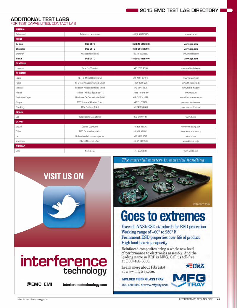
2015 EMC TEST LAB DIRECTORY
45interferencetechnology.com INTERFERENCE TECHNOLOGY
AUSTRIA
Seibersdorf Seibersdorf Laboratories +43 (0) 50550 2805 www.ait.ac.at
CHINA
Beijing SGS-CSTC +86 (0) 10 6845 6699 www.sgs.com
Shanghai SGS-CSTC +86 (0) 21 6140 2666 www.sgs.com
Shenzhen MET Laboratories Inc. +86 755 82911867 www.metlabs.com
Tianjin SGS-CSTC +86 (0) 22 6528 8000 www.sgs.com
DENMARK
Horsholm Delta EMC Services +45 72 19 45 00 www.madebydelta.com
GERMANY
Essen CETECOM GmbH (Germany) +49 20 54 95 19 0 www.cetecom.com
Hagen HF-SHIELDING Joachim Broede GmbH +49 54 05-99 99 04 www.hf-shielding.de
Iserlohn H+H High Voltage Technology GmbH +49 2371 18530 www.hundh-mk.com
Munich National Technical Systems (NTS) +49 89 787475 160 www.nts.com
Neckartenzlingen Hirschmann Car Communication GmbH +49 7127 14 1437 www.hirschmann-car.com
Siegen EMC Testhaus Schreiber GmbH +49 271 382702 www.emc-testhaus.de
Straubing EMV Testhaus GmbH +49 9421 568680 www.emv-testhaus.com
ISRAEL
Lod Israel Testing Laboratories 972 8 9797799 www.itl.co.il
JAPAN
Watari Cosmos Corporation +81 596 63 0707 www.cosmoscorp.com
Chiba EMC Kashima Corporation +81 478 82 0963 www.emc-kashima.co.jp
Ise Underwriters Laboratories Japan Inc. +81 596 2 6717 www.ul.com
Yokohama Kikusui Electronics Corp. +81 45 593 7570 www.kikusui.co.jp
NORWAY
Oslo Nemko, Inc. +47 229 60330 www.nemko.com
ADDITIONAL TEST LABS FOR TEST CAPABILITIES, CONTACT LAB
VISIT US ON
interferencetechnology.com@EMC_EMI

46 INTERFERENCE TECHNOLOGY 2015 EMC TEST & DESIGN GUIDE
2015 EMC TEST LAB DIRECTORY
THIS SUPPLIERS PAGE lists products and services offered by advertisers in this publication to help you find the EMC equipment, com-ponents and services you are looking for. For your convenience, we have also supplied each company's website, where contact information is located. In our digital edition, (www.interferencetechnology.com/category/digital-magazines) these pages are interactive and clickable. More suppliers can be found at http://buyersguide.interferencetechnology.com.
AMPLIFIERS
AR RF / Microwave Instrumentation
www.arworld.us
Empower RF Systems, Inc.www.empowerrf.com
a TESEQ CompanyInstruments for Industryhttp://ifi.com
Milmega www.milmega.co.uk
Pranawww.prana-rd.com
CABLES & CONNECTORS
Schurter
CONSULTANTS
Cherry Clough Consultants, Ltd.Interference TechnologyLionheart SouthwestMontrose Compliance ServicesWyatt Technical Services
FILTERS / FERRITES
Delta Electronics www.delta-emi.com
Fair-Rite Products Corp.www.fair-rite.com
Schurterwww.schurter.com
LIGHTNING AND SURGE TEST EQUIPMENT
Advanced Test Equipment RentalsAR RF / Microwave InstrumentationEM TEST USAHV Technologies Inc.TESEQ, Inc.
AMPLIFIERS (CONT.)
R&K Company Limitedwww.rk-microwave.com
Vectawave www.vectawave.com
Advanced Test Equipment Rentals HV Technologies Inc.
Rohde & Schwarz TESEQ
ANTENNAS
A.H. Systems, Inc.www.ahsystems.com
Advanced Test Equipment RentalsAR RF / Microwave InstrumentationHV Technologies Inc.Rohde & Schwarz TESEQ, Inc.
MEDIA
Interference Technologywww.interferencetechnology.com

47interferencetechnology.com INTERFERENCE TECHNOLOGY
2015 EMC TEST LAB DIRECTORY
SHIELDING
Orbelwww.orbel.com
Parker Chomericswww.chomerics.com
Spira Manufacturing Companywww.spira-emi.com
ETS-Lindgren
SOFTWARE
CST – Computer Simulation Technologywww.cst.com
AR RF / Microwave InstrumentationKeysight TechnologiesRohde & Schwarz, Inc.
TEST EQUIPMENT
Advanced Test Equipment RentalsAR RF / Microwave Instrumentation
A.H. Systems, Inc. EM Test
Empower RF Systems, Inc.HV Technologies Inc.Keysight TechnologiesOphirR&K Company LimitedRohde & Schwarz TESEQVectawave
TEST SYSTEMS
Advanced Test Equipment Rentals
www.atecorp.com
AMETEK CTSwww.ametek-cts.com
EM TEST www.emtest.com
HV Technologies Inc.www.hvtechnologies.com
Keysight Technologieswww.keysight.com
TEST SYSTEMS (CONT.)
Nardawww.narda-sts.it
Rohde & Schwarz www.rohde-schwarz.com
TESEQ, Inc.www.teseq.us
AR RF / Microwave Instrumentation
TESTING LABORATORIES
Retlif Testing Laboratorieswww.retlif.com
Washington Laboratories, Ltd.www.wll.com

48 2015 EMC TEST & DESIGN GUIDEINTERFERENCE TECHNOLOGY
FILTERS
INTRODUCTION
These days, it's common practice to buy-in mains input filters in the shape of metal boxes with four or five terminals. The supplier's lists may be consulted, and advice sought, but often the same filter as was used for a previous product is called up, without too much deliberation. A
filter is a filter is a filter, after all.Well, no, they are not all the same. Let's consider what
we are asking the filter to do. It's quite important at this time, because EMC requirements are being extended both upwards from the 40th harmonic of the power frequency and downwards from the historic 150 kHz lower limit of 'high frequency emissions'. For some products, require-ments already exist down to 9 kHz and there is no low-frequency limit now in the standard, CISPR 11/EN 55011, for 'industrial, scientific and medical' equipment, or in the new Radio Equipment Directive.
Whiter we want it or not (but we mostly do want it), the filter acts both on energy incoming from the power system (an immunity issue) and energy leaving the product and entering the power system (an emission issue). For both flows, we have two modes: differential mode, in which a voltage appears between the two power conductors, and common mode, in which both conductors have the same voltage relative to local ground. In the case of three-phase, three-wire supplies, the filter configuration is more compli-cated, but for three-phase, four wire supplies, each phase is treated as if it were a single phase. Examples can be seen at: http://www.filterconcepts.com/three_phase/3f_series.html
How we can attenuate these flows depends on their source impedances. Clearly, it's not much use connecting a capacitor across a low-impedance source to shunt cur-rent away, because plenty of current is still available, and it's equally futile to connect an inductor in series with a high-impedance source. This is, in fact, an example of a far more general concept.
Mains Input Filters – What is Inside The Box and Why?
J M WOODGATE Consultant J M Woodgate and Associates


50 2015 EMC TEST & DESIGN GUIDEINTERFERENCE TECHNOLOGY
FILTERS
It's useful to think in terms of energy, rather than voltage or current. Energy is the product of power and time and is the 'electricity' we pay for. There are two ways a filter could work; it could absorb unwanted incoming energy or it could refuse to accept it. Absorbing or dissipating filters do exist (those using iron-dust cored inductors, for example), but the energy appears as heat and the amount is often too much to accept. So most filters are 'reflecting'; they refuse to accept incoming energy and push it back to the source.
They do that by having an input impedance very different from the impedance of the source. The 'Maximum Power Theorem' says that the optimum energy transfer occurs when the resistances of source and load (input resistance of the filter) are equal and their reactances are equal and opposite (i.e. one inductive, one capacitive). But our reflect-ing filter wants the worst power transfer we can get, so the resistances need to be very different and, if possible, both reactances have the same sign.
So what is the impedance of the power network? EMC standards committees have put a lot of work into this dif-ficult subject. We know that, at the power frequency, for ordinary wall-sockets it must be in the region of 0.1 Ω to 1 Ω from voltage-drop considerations, but that takes ac-count only of conductor resistance. The network also has what can be represented as a lossy inductor in series, and this model works reasonably well up to about 9 kHz. In Europe, the 'average' value is close to 800 µH, although that approaches the average of zero and infinity if we take in all the outliers including long rural overhead transmission. The 'average' values for other power systems can be found in IEC TR 60725.
A network representing the impedance of 230 V 50 Hz 16 A circuits in Europe from 2 kHz to 9 kHz is given in IEC 61000-4-7 and is shown below in Figure 1, but a new and more accurate network is under development.
For frequencies above 9 kHz, we have the information on 'line impedance stabilizing networks' (LISN) or 'artificial mains networks' (AMN) in CISPR 16-1-2/EN 55016-1-2. For 9 kHz to 150 kHz, an impedance of 5 Ω in series with 50 µH is given, with a parallel 50 Ω resistance, while for the range 150 kHz to 30 MHz an impedance of 50 Ω in parallel with 50 µH is given. There is now a third network, for 150 kHz to 100 MHz, which is 50 Ω in parallel with 5 µH in series with 1 Ω. However, some of these values are 'traditional', and again tend to be the average of zero and infinity. Neverthe-less, their use doesn't result in any proposal to change them on the grounds that something else is demonstrably better.
However, the impedance at any particular wall-socket is undetermined and may even vary, according to what other loads are on the same circuit and how the supply network is configured at that time of day. So we want our filter to be very tolerant of source impedance and not, for example, show any resonant behaviour in conjunction with any likely supply reactance.
The impedance of the load can be very problematical. It is very often a full-wave rectifier, so extremely non-linear. We know from experience of EMC problems in the field that the circuit is transparent from the filter capacitor to the mains filter 'output', because if the capacitor dries out so that its capacitance drops to a much lower value, the high-frequency emissions coming from processes inside the product circuits considerably increase in amplitude, typically by more than 20 dB.
Note to designers: Consider using a high-temperature (105°C or even 135°C) part, with a generous ripple-cur-rent rating, to combat this effect. A 100 nF capacitor in parallel may help, too.
There are two sources of high-frequency energy that propagate from the product to the power system; com-mutation spikes from the rectifier diodes and whatever
high frequencies that circuits in the product generate that can be modelled as a voltage in series with the effective load resistance of the rectifier. There may well also be an active power-factor correction circuit preceding the AC side of the rectifier.
For the 'traditional' frequency range from 150 kHz upwards, the sources (power net-work and rectifier or whatever in the product) are assumed to have high impedances, so should be faced in the filter by capacitors, between the live conductors to present a low impedance to differential mode energy , and equal values from each conductor to ground to do that for common-mode energy.
Simple filters for low-power products therefore have a modified π configuration, (strictly an O-configuration, because it has inductors in both 'legs') as shown in Figure 2. The inductors are rather special and are called a 'common-mode choke'. The two
Figure 1: Artificial mains network for 16 A current and below (from IEC 61000-4-7).

51interferencetechnology.com INTERFERENCE TECHNOLOGY
Woodgate FILTERS
at the input, when differential-mode lower-frequency energy needs to be controlled and the source impedance is lower.
The solution is to add individual induc-tors in each 'leg' of the filter, upstream of the parallel capacitor. Now the low source impedance of the mains supply meets the high impedance of the inductors and energy flow is restricted. This solution is likely to be needed more in the future, as requirements for low-frequency immunity, which are al-ready in EMC Basic standards but not widely called up in product standards, and future standards on emissions, become regulatory requirements.
The same series inductor solution is likely to be necessary at the output end of the filter if the load is something, such as an inverter, that produces emissions in the 2 kHz to 150 kHz range, as many do. So the small metal boxes we use at present may well need to grow in size (and, of course, cost) in the next few years.
It is necessary to be very cautious about published speci-fications of filter attenuation. These are often measured with 50 Ω resistive source and load, which is easy to do but far
windings, as shown are on a single core, usually ferrite, and the windings are in the same direction, as shown by the 'phasing dots'. So for common-mode currents, that flow in the same direction in the two windings, the inductance is high, but for differential mode currents, including the sup-ply current, the inductance is low, but it is designed not to be very small, so that, in conjunction with the capacitors, it attenuates high-frequency differential-mode currents as well. The capacitor at the input serves to further attenu-ate differential-mode currents, whichever direction they are flowing. The parallel resistor is there to discharge the capacitor, so as not to leave the plug pins live if the mains lead is disconnected at the wall-socket. As shown in the three-phase filter circuits accessible via the above link, the earth/ground conductor may be carried through the filter by a separate inductor.
Common-mode currents (unwanted emissions or incom-ing disturbances) flow in the same direction in the two windings, so the effective impedance is much higher. The capacitors at the output attempt to attenuate common-mode voltages while preserving an impedance-balance for the differential mode. 'Attempt', because their values have to be restricted so as not to cause an unacceptable amount of current into the ground connection. This is quite a serious issue when large numbers of products, all contributing only a milliamp or so, are connected to the same ground network. In the Americas, products connected to 240 V pass equal and opposite ground currents from the two live conductors, so contribute no net ground current. (This is because the distribution system is 120 V-0-120 V, with the voltage in one live conductor inverted with respect to the other, so that between the live conductors the voltage is 240 V.)
This configuration is indeed suited to frequencies where the mains and load impedances are relatively high, because the capacitors tend to short-circuit the sources, but that doesn't work well for low-impedance sources, and at fre-quencies well below 150 kHz, just now coming under the EMC spotlight, the mains supply and the load impedances are not high at all. So something more is necessary, at least
Figure 2: Simple mains input filter.

52 2015 EMC TEST & DESIGN GUIDEINTERFERENCE TECHNOLOGY
FILTERS
Figure 3: Measuring differential-mode attenuation in a balanced configuration.
Figure 4: Measuring common-mode attenuation.
from realistic. Many manufacturers also publish results under other conditions, such as a 0.1 Ω source and a 100 Ω load and vice versa, as described in Annex C of the Inter-national Standard CISPR 17/EN 55017 (which includes test set-ups not only for complete filters but also for individual components), but that is not necessarily much more realis-tic. And it doesn't fully explain how to test. It does specify that the filter characteristics are likely to vary with the mains-frequency current flowing, but it does not elaborate that the differential-mode attenuation (the voltage between L and N at the output divided by the corresponding voltage at the input) should really be measured with balanced radio-frequency signals, while the common-mode attenuation should be measured with unbalanced (i.e. one side earthed/grounded) signals. But the standard LISNs only have L and N outputs, whose output is the common-mode voltage plus or minus half the differential-mode voltage.
Figure 3 shows a set-up for measuring differential-mode attenuation in a balanced configuration. Arrangements for applying mains voltage and a load are not shown.
Using this configuration correctly shows the effects of parasitic capacitances inside the filter assembly.
Figure 4 shows a set-up for measuring common-mode attenuation. Again, the arrangements for applying mains voltage and a load are not shown.
Neither of these set-ups show the transformers necessary to do the 0.1 Ω/100 Ω tests.
It is really necessary to measure filter performance in the product it is to be used in, even if it takes some ingenuity to make realistic measurements. A decision has to be made whether to include a standard Line Impedance Stabilizing Network (LISN), which assumes that the mains supply 'looks like' 50 Ω at high frequencies, or to use a hopefully representative supply without a network.


54 INTERFERENCE TECHNOLOGY 2015 EMC TEST & DESIGN GUIDE
TESTING
Most, if not all electrical and electronic ap-pliances have to be tested on their radiated RF emission and their immunity against RF radiated fields. This radiated testing occurs either on an open area test site (OATS) or in an anechoic or semi-anechoic room (SAR). The
electrical and electronic appliance to be measured will be put on a turntable with a 0,8 to 1,0 m high table (table-top equipment) or floor (floor-standing equipment). Cables to be connected to operate the appliance as intended are an everlasting point of discussion w.r.t. their functional and common-mode termination against the metal reference plane/floor of the OATS or SAR, in particular for the mains lead connection.
In the different EMC norms and standards, the RF emission requirements are set w.r.t. the maximum field strength, mostly defined by E-field values, to be measured or the equivalent radiated power (ERP). These measurements then need to be carried out at 3, 10 or 30 meter distance from the appliance to be tested. These measurement sites all need to comply with the normalized site-attenuation (NSA) by using normalized antenna factors, this to ensure that the radiation measurements as taken at one place agree, with tight tolerances to the results taken from another test site. To determine the test site’s NSA, 2 or 3 (free-field) calibrated antennas shall be used.
The appliance, floor-standing or table-top, to be tested on its radiated RF emission has to be placed at the location where the transmission antenna was set before i.e. above the center of the turntable, while the receiving antenna stays in place. The appliance then needs to be connected with all cables to be able to it operate as intended. However, the appliance with all cables connected behaves as a non-predicable undefined antenna to-pology of which the cable orientation and their functional and common-mode termination determine the antenna efficiency as function of frequency.
While measuring on an OATS or in a SAR with a metal ground plane on the floor, all cables connected to the appliance
A Solution to Enhance Reproducibility With Radiated RF Emission and Immunity
Measurements?MART COENENOwner EMCMCC


56 INTERFERENCE TECHNOLOGY 2015 EMC TEST & DESIGN GUIDE
TESTING
will be connected to it or routed on it. The cable lengths, their routing and their termination determine the resulting cable current distributions which determine the antenna efficiency i.e. the radiated power as function of frequency from the appliance as a whole. Optimal impedance mismatch is nice to achieve easy compliance. Trying to achieve the worst-case RF emission by altering the cable topology: routing and length, as function of frequency is near to impossible to do.
For the connection of the mains cables, the Artificial Mains Network (AMN, IEC CISPR-16-1-2) is prescribed, see IEC CISPR 11 and 32, where the AMN has a series impedance of 50 Ω // (50 µH + 5 Ω) for the phase and neutral wires against the metal ground plane being the protective earth (PE) but an impedance of zero (= RF short-circuit) for the PE-wire itself. The impedance definition of the AMN is typically limited to 30 MHz, just where the radiated emission measurement start. An alternative termination network would be a coupling and decoupling network (CDN) or asymmetric artificial network (AAN) which represents in common-mode an impedance of ~150 Ω for all wires to the metal ground plane, typically up to 230 or 300 MHz.
With the construction of EMC measurement facilities, often heavy, multi-section mains filters are used at the control area of an OATS or at the outer wall of the Faraday cage with a SAR, typically far away from the mains wall outlet mounted in or
beneath the turntable location i.e. there where the appliance to be connected to and will be located. As most, if not all, mains filters have a π-filter (CLC) structure, their output impedances against PE i.e. the metal reference plane at their mounting posi-tions can be seen as an RF short-circuit. As the mains supply distribution at an EMC test facility is not built RF-wise (other than being shielded), the impedances at the far-end, being the wall outlet will be undefined for the phase and neutral wires, this under the assumption that the PE-wire of the wall outlet is directly connected to the metal plane of the turntable (which is not true in many cases either). In either case, the common-mode as well as the asymmetric mode impedances at the wall outlet are undefined. The use of an additional AMN or CDN with such an impedance undefined mains outlet then seems the only way out.
If the appliance is provided with multiple ports, screened or non-screened, it will be common that the outer screens of the shielded cables are directly connected to the metal reference plane of the turntable underneath the appliance under test. With non-shielded signal and supply lines all options are open again, from infinite impedance e.g. using a battery operated load or source or an electrical-to-optical interface towards the control area. The common-mode impedance will be undefined and vary between an open-end to an RF short-circuit. Simple examples are: nautical equipment, being insulated from the ship’s body
Figure 1 - Asymmetric impedance measured following a 1,5 meter long mains lead with open, short-circuit and 50 Ω termination at the near-end of the cable 3 x 0,75 mm2

57interferencetechnology.com INTERFERENCE TECHNOLOGY
Coenen TESTING
or hard grounding as it occurs in a combustion engine environ-ment of a vehicle. These options deliver the 2 or 3 extremes with RF emission measurements: a node, an anti-node or an ideally damped/ terminated condition at the far-end of a cable, leading to varying test results with over +/- 20 dB per frequency when that cable termination is dominant for the total RF emission performance.
Figure 1 shows the asymmetrical (neutral/ phase) imped-ance, in dBΩ, as function of frequency, in the range 1 to 300 MHz, when a 1,5 meter long mains lead is used. Here the near-end is left open, short-circuited or terminated with 50 Ω against the reference, which is again hard grounded to the metal reference plane.
The frequency scale runs logarithmically from 1 to 300 MHz and the absolute impedance is running from -10 dBΩ (= 0,3 Ω) to 90 dBΩ (= 30 kΩ). The RF radiated emission measure-ments start (according standards) from 30 MHz, there where impedance-resonances for a 1,5 meter long mains lead start. If there is hidden mains cable length at the test facility, in-between the wall outlet and the OATS or SAR mains entry filter of the test facility, impedance resonances will already start at much lower frequencies.
INCONSISTENCY IN NORMS AND STANDARDThe various EMC norms and standards sometimes require
an AMN, a CDN or a MDS, EM or ferrite clamp and sometimes nothing w.r.t. the impedance definition at the mains wall outlet or mains lead with a radiated RF emission or RF immunity test. As indicated, this could lead to 40 dB of difference in test results at a specific frequency. This won’t show with up with an envelope of a broadband interference source, as there always will be one or many spectral lines which coincide with the maximum antenna efficiency of the cables connected, in particular the mains cable.
Unfortunately in the last version of IEC CISPR 32 reference is made to an AMN i.s.o. a CDN. In the update proposal of IEC CISPR 11, the two networks are even in series: AMN and CDN. The single use of an AMN results in nodes for the PE-wire and a relative impedance definition for the neutral and phase wires against PE, though as earlier indicated just defined up to 30 MHz. By application of an ideal AMN following an RF imped-ance undefined wall outlet, the impedance at the AMN between neutral/ phase and PE becomes 34 dBΩ (= 50 Ω) with a close to ideal minimal impedance variation in the frequency range 1 – 300 MHz, see figure 2, which then still results in impedance variations at the appliance following a mains lead of 1,5 meter equal to figure 1, 50 Ω case.
Figure 2 shows, in contradiction with the requirements of IEC CISPR 16-1-2 that a compact dummy AMN can be made, see figure 3, by which a fair impedance of 50 Ω can be realized till far above 30 MHz. This is something which cannot be achieved
Figure 2 - Asymmetric impedance at the EUT side of an AMN with open, short-circuit and 50 Ω at the supply side.

58 INTERFERENCE TECHNOLOGY 2015 EMC TEST & DESIGN GUIDE
TESTING
by commercially of the shelf (COTS) AMNs.One remaining constraint is that the wall outlet to which the
dummy AMN is applied has its PE terminal directly connected to the metal reference plane of the turntable. An alternative will be to have an additional PE terminal on the dummy AMN which shall make contact to the metal reference plane of the turntable. Another approach which has attempted in the several revisions of IEC CISPR 22 is to define a ferrite clamp e.g. the MDS-clamp on the mains cable as well as other cables to control the common-mode impedance. Common-mode impedance values between 50 and 500 Ω (= 34 – 54 dBΩ) were set as target.
For mains and other 2 and 3-wire unshielded signal and supply lines an appropriate CDN which is terminated with 50 Ω can be used. E.g. a terminated CDN M2 or M3 (conform IEC 61000-4-6) can be used. Also here a dummy CDN can be created which is not intended for measurement purposes but just to represent the 150 Ω (= 44 dBΩ) common-mode imped-ance to either a 2 or 3 wire mains connection. The network has been realized in the same housing as the dummy AMN, see figure 3. The common-mode impedance shall be similar to the requirements of IEC 61000-4-6, see figure 4. Similar to the dummy AMN, the dummy CDN supply port is terminated by an open, a short-circuit and a 50 Ω termination while the EUT port impedance is observed as function of frequency. The values
of the absolute impedance may vary, for frequencies beyond 26 MHz, between 106 and 212 Ω, or 44 dBΩ ± 3 dB = 41 to 47 dBΩ, which is well within the range as defined by IEC CISPR 22 where 34 – 54 dBΩ were given as lower and upper bound.
Without these impedance stabilizing measures with a
Figure 4 - Common-mode impedance at the EUT side of the dummy CDN where the supply side is left open, short-circuited or terminated by 50 Ω
Figure 3 - Photo of a dummy AMN and dummy CDN together with a calibration network with an open, short-circuited and 50 Ω terminated wall outlet box.

59interferencetechnology.com INTERFERENCE TECHNOLOGY
Coenen TESTING
Figure 5 - Common-mode impedance at the end of a 3-terminal mains plug when connected to the open, short-circuited and 50 Ω terminated wall outlet box.
dummy CDN, the wall outlet impedance could vary between extreme values as given in figure 5, being the output of the wall outlet calibration box but taken the class I mains plug (= with PE) length and its stray capacitance is taken into account. The common-mode impedance is measured following 1,5 meter extension lead and is given in figure 6.
CONCLUSIONSIf an electric or electronic appliance fails with a radiated RF
emission or RF immunity test one could ask one selves whether the functional and common-mode cable termination applied agree to what one has expected. Even if one passes the tests, one should ask one selves whether these terminations have been correctly applied. Meeting these impedance constraints will enhance measurement reproducibility and minimize the variations with compliance uncertainty in an easy way.
With a great number of EMC test houses and test facilities the impedances behind the mains wall outlets at the OATS or in the SAR at the turntable are fully undefined leading to large variations of the radiated measurement results even though the NSA requirements are met. A similar constraint applies for all other non-shielded signal/ control/ communication and supply lines. This lack of impedance definition also occurs with the wall
outlets at compact EMC cages, TEM-cells and mode-stirred chambers (MSC). The lack of impedance definition mainly shows in the frequency range up to 300 MHz. Above 300 MHz the enclosure radiation will typically dominate i.e. become an effective antenna
The various EMC norms and standards are not unambigu-ous about the way that the impedance termination at the mains cable has to be provide with the radiated tests. As a result, this is done by the ‘own interpretation’ of the test house i.e. engineer who is performing the tests, leading to large deviations in test results, mostly too negative.
By using one or two simple dummy networks: AMN and CDN one can verify the influence of the mains cable termina-tion. A prescribed choice will enhance the reproducibility and inter-laboratory comparison of the test results.
N.B. Applying a dummy AMN and CDN network in series will be useless as only the ‘last’ network connected to the mains cable towards appliance will dictate the termination impedances (as it was the intention of these dummy networks to eliminate whatever impedance there was at the supply side of the network concerned).

60 INTERFERENCE TECHNOLOGY 2015 EMC TEST & DESIGN GUIDE
TESTING
Figure 6 - Common-mode impedance at the EUT side of a CDN after 1,5 meter mains extension lead with open, short-circuit and 50 Ω termination at the supply side.
Bonus Figure - An example of radiated emissions testing.Photo credit: Austest Laboratories, Castle Hill, Australia


63interferencetechnology.com INTERFERENCE TECHNOLOGY
VISIT US ON
interferencetechnology.com
http://www.youtube.com/user/InterferenceTech1

INDEX OF ADVERTISERS
64 2015 EMC TEST & DESIGN GUIDEINTERFERENCE TECHNOLOGY
Advanced Test Equipment Rentals ............................................................................................................................................................63AH Systems, Inc. ..............................................................................................................................................................Inside Front CoverAR RF/Microwave Instrumentation .....................................................................................................................................21, Back CoverAstrodyne ...................................................................................................................................................................................................... 9CST - Computer Simulation Technologies .................................................................................................................................................. 5Curtis Industries ..........................................................................................................................................................................................51Delta Electronics .........................................................................................................................................................................................49EMC/China ...................................................................................................................................................................................................53EMC LIVE ....................................................................................................................................................................................................... 3EM Test USA ...............................................................................................................................................................................................25Fair-Rite Products .......................................................................................................................................................................................35Fotofab Corp ................................................................................................................................................................................................39HAEFELY HIPOTRONICS ..............................................................................................................................................................................60HV TECHNOLOGIES, Inc. .............................................................................................................................................................................55Interference Technology ...................................................................................................................................................................... 45, 63Keysight ......................................................................................................................................................................................................... 1Mesago ........................................................................................................................................................................................................61Molded Fiber Glass Tray Company ............................................................................................................................................................45Montrose Compliance Services, Inc. ................................................................................................................................................. 47, 62Narda Safety Test Solutions ......................................................................................................................................................................11OPHIR RF .....................................................................................................................................................................................................11Orbel Corporation ........................................................................................................................................................................................17PRANA .........................................................................................................................................................................................................29R & K Company Limited .............................................................................................................................................................................31Retlif Testing Laboratories .........................................................................................................................................................................37Rohde & Schwarz .............................................................................................................................................................. Inside Back CoverSchurter Inc. .................................................................................................................................................................................................. 7Spira Manufacturing Corporation ..............................................................................................................................................................27TESEQ...........................................................................................................................................................................................................41THERMAL LIVE 2015 .................................................................................................................................................................................63Vectawave ...................................................................................................................................................................................................23

