2014 genesis owners manual
TRANSCRIPT
OOWWNNEERR''SS MMAANNUUAALL
OperationMaintenanceSpecifications
All information in this Owner's Manual is current at the time of publication.However, Hyundai reserves the right to make changes at any time so thatour policy of continual product improvement may be carried out.
This manual applies to all models of this vehicle and includes descriptionsand explanations of optional as well as standard equipment. As a result,you may find material in this manual that does not apply to your specificvehicle.
F2
Your Hyundai should not be modified in any way. Such modifications may adversely affect the per-formance, safety or durability of your Hyundai and may, in addition, violate conditions of the limitedwarranties covering the vehicle. Certain modifications may also be in violation of regulations estab-lished by the U.S. Department of Transportation and other federal or state agencies.
Your vehicle is equipped with electronic fuel injection and other electronic components. It is possiblefor an improperly installed/adjusted two-way radio or cellular telephone to adversely affect electronicsystems. For this reason, we recommend that you carefully follow the radio manufacturer's instruc-tions or consult your Hyundai dealer for precautionary measures or special instructions if you chooseto install one of these devices.
CAUTION: MODIFICATIONS TO YOUR HYUNDAI
TWO-WAY RADIO OR CELLULAR TELEPHONE INSTALLATION
F3
This manual includes information titled as WARNING, CAUTION and NOTICE.
These titles indicate the following:
✽✽ NOTICEThis indicates that interesting or helpful information is being provided.
SAFETY AND VEHICLE DAMAGE WARNING
WARNING This indicates that a situation may result in harm, serious injury or death to you or otherpersons if the warning is not heeded. Follow the advice provided with the warning.
CAUTIONThis indicates that a situation may result in damage to your vehicle or its equipment if thecaution is not heeded. Follow the advice provided with the caution.
F4
FOREWORD
Thank you for choosing Hyundai. We are pleased to welcome you to the growing number of discriminating people who driveHyundais. The advanced engineering and high-quality construction of each Hyundai we build is something of which we're veryproud.
Your Owner's Manual will introduce you to the features and operation of your new Hyundai. It is suggested that you read it care-fully because the information it contains can contribute greatly to the satisfaction you receive from your new car.
The manufacturer also recommends that all service and maintenance on your car be performed by an authorized Hyundai deal-er. Hyundai dealers are prepared to provide high-quality service, maintenance and any other assistance that may be required.
HYUNDAI MOTOR AMERICA
Note : Because future owners will also need the information included in this manual, if you sell this Hyundai, please leave the man-ual in the vehicle for their use. Thank you.
Copyright 2013 Hyundai Motor America. All rights reserved. No part of this publication may be reproduced, stored in any retrievalsystem or transmitted in any form or by any means without the prior written permission of Hyundai Motor America.
CAUTIONSevere engine and transmission damage may result from the use of poor quality fuels and lubricants that do not meetHyundai specifications.You must always use high quality fuels and lubricants that meet the specifications listed on Page8-4 in the Vehicle Specifications and consumer information section of the Owner's Manual.
F5
Guide to Hyundai Genuine Parts1. What are Hyundai Genuine Parts?
Hyundai Genuine Parts are the sameparts used by Hyundai MotorCompany to manufacture vehicles.They are designed and tested for theoptimum safety, performance, and reli-ability to our customers.
2.Why should you use genuine parts?Hyundai Genuine Parts are engi-neered and built to meet rigid manu-facturing requirements. Using imita-tion, counterfeit or used salvage partsis not covered under the Hyundai NewVehicle Limited Warranty or any otherHyundai warranty.
In addition, any damage to or failure ofHyundai Genuine Parts caused by theinstallation or failure of an imitation,counterfeit or used salvage part is notcovered by any Hyundai Warranty.
3. How can you tell if you are purchas-ing Hyundai Genuine Parts? Look for the Hyundai Genuine PartsLogo on the package (see below).
Hyundai Genuine Parts exported toare packaged with labels written onlyin English.
Hyundai Genuine Parts are only soldthrough authorized Hyundai Dealerships.
A100A01L A100A02L A100A04L
A100A03L

1
2
3
4
5
6
7
8
I
Introduction
Your vehicle at a glance
Safety features of your vehicle
Features of your vehicle
Driving your vehicle
What to do in an emergency
Maintenance
Specifications, Consumer information, Reporting safety defects
Index
table of contents
1How to use this manual / 1-2Fuel requirements / 1-3Vehicle break-in process / 1-5Vehicle data collection and event data
recorders / 1-6Indicator symbols on the instrument cluster / 1-7
Introduction
Introduction
21
A010000AHM
We want to help you get the greatestpossible driving pleasure from your vehi-cle. Your Owner’s Manual can assist youin many ways. We strongly recommendthat you read the entire manual. In orderto minimize the chance of death or injury,you must read the WARNING and CAU-TION sections in the manual.Illustrations complement the words in thismanual to best explain how to enjoy yourvehicle. By reading your manual, you willlearn about features, important safetyinformation, and driving tips under vari-ous road conditions.
The general layout of the manual is pro-vided in the Table of Contents. A goodplace to start is the index; it has an alpha-betical listing of all information in yourmanual.Sections: This manual has eight sectionsplus an index. Each section begins with abrief list of contents so you can tell at aglance if that section has the informationyou want.
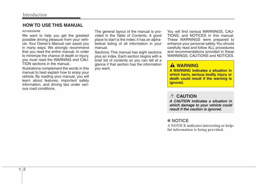
You will find various WARNINGS, CAU-TIONS, and NOTICES in this manual.These WARNINGS were prepared toenhance your personal safety.You shouldcarefully read and follow ALL proceduresand recommendations provided in theseWARNINGS, CAUTIONS and NOTICES.
✽✽ NOTICEA NOTICE indicates interesting or help-ful information is being provided.
HOW TO USE THIS MANUAL
WARNING A WARNING indicates a situation inwhich harm, serious bodily injury ordeath could result if the warning isignored.
CAUTIONA CAUTION indicates a situation inwhich damage to your vehicle couldresult if the caution is ignored.
1 3
Introduction
A020101ABH-EU
Your new vehicle is designed to obtainmaximum performance with UNLEADEDFUEL, as well as minimize exhaust emis-sions and spark plug fouling.
3.8 engineYour new vehicle is designed to use onlyunleaded fuel having an octane number((R+M)/2) of 87 (Research OctaneNumber 91) or higher.
5.0 engineYour new vehicle is designed to use onlyunleaded fuel having an octane number((R+M)/2) of 87 or higher.
For improved vehicle performance, pre-mium unleaded fuel with a Pump OctaneRating of 91 (Research Octane Number95) or higher is recommended.
A020103AUN-EU
Gasoline containing alcohol andmethanolGasohol, a mixture of gasoline andethanol (also known as grain alcohol),and gasoline or gasohol containingmethanol (also known as wood alcohol)are being marketed along with or insteadof leaded or unleaded gasoline.Do not use gasohol containing more than10% ethanol, and do not use gasoline orgasohol containing any methanol. Eitherof these fuels may cause drivability prob-lems, check malfunction indicator light ordamage and damage to the fuel system.Discontinue using gasohol of any kind ifdrivability problems occur.Vehicle damage or drivability problemsmay not be covered by the manufactur-er’s warranty if they result from the useof:1. Gasohol containing more than 10%
ethanol.2. Gasoline or gasohol containing
methanol.3. Leaded fuel or leaded gasohol.
FUEL REQUIREMENTS
CAUTIONNever add any fuel system cleaningagents to the fuel tank other thanwhat has been specified. (Consultan authorized HYUNDAI dealer fordetails.)
WARNING• Do not "top off" after the nozzle
automatically shuts off whenrefueling.
• Tighten the cap until it clicks onetime, otherwise the MalfunctionIndicator Light “ ” will illumi-nate.
• Always check that the fuel cap isinstalled securely to prevent fuelspillage in the event of an acci-dent.
Introduction
41
"E85" fuel is an alternative fuel com-prised of 85 percent ethanol and 15 per-cent gasoline, and is manufacturedexclusively for use in Flexible FuelVehicles. “E85” is not compatible withyour vehicle. Use of “E85” may result inpoor engine performance and damage toyour vehicle's engine and fuel system.HYUNDAI recommends that customersdo not use fuel with an ethanol contentexceeding 10 percent.
Gasoline containing MMTSome gasoline contains harmful man-ganese-based fuel additives such asMMT (Methylcyclopentadienyl ManganeseTricarbonyl).HYUNDAI does not recommend the useof gasoline containing MMT.This type of fuel can reduce vehicle per-formance and affect your emission con-trol system.The malfunction indicator lamp on thecluster may come on.
A020105AUN
Do not use methanolFuels containing methanol (wood alco-hol) should not be used in your vehicle.This type of fuel can reduce vehicle per-formance and damage components ofthe fuel system.
Fuel AdditivesHYUNDAI recommends that you use goodquality gasolines treated with detergentadditives such as TOP TIER DetergentGasoline, which help prevent deposit for-mation in the engine. These gasolines willhelp the engine run cleaner and enhanceperformance of the Emission ControlSystem. For more information on TOPTIER Detergent Gasoline, please go to thewebsite (www.toptiergas.com).For customers who do not use TOP TierDetergent Gasoline regularly, and haveproblems starting or the engine does notrun smoothly, additives that you can buyseparately may be added to the gasoline.If TOP TIER Detergent Gasoline is notavailable, one bottle of additive added tothe fuel tank at every 7,500 miles or 12months is recommended. Additives areavailable from your authorized HYUNDAIdealer along with information on how touse them. Do not mix other additives.
A020107AUN
Operation in foreign countriesIf you are going to drive your vehicle inanother country, be sure to:• Observe all regulations regarding reg-
istration and insurance.• Determine that acceptable fuel is avail-
able.
CAUTIONYour New Vehicle Limited Warrantymay not cover damage to the fuelsystem and any performance prob-lems that are caused by the use offuels containing methanol.
CAUTIONNever use gasohol which containsmethanol. Discontinue use of anygasohol product which impairs dri-vability.
CAUTIONYour New Vehicle Limited Warrantydoes not cover damage to the fuelsystem or any performance prob-lems caused by the use of “E85” fuel.
1 5
Introduction
A030000BUN
No special break-in period is needed. Byfollowing a few simple precautions for thefirst 600 miles (1,000 km) you may add tothe performance, economy and life ofyour vehicle.• Do not race the engine.• While driving, keep your engine speed
(rpm, or revolutions per minute)between 2,000 rpm and 4,000 rpm.
• Do not maintain a single speed for longperiods of time, either fast or slow.Varying engine speed is needed toproperly break-in the engine.
• Avoid hard stops, except in emergen-cies, to allow the brakes to seat prop-erly.
• Don't let the engine idle longer than 3minutes at one time.
• Don't tow a trailer during the first 1,200miles (2,000 km) of operation.
VEHICLE BREAK-IN PROCESS
CALIFORNIA PROPOSI-TION 65 WARNING
Items contained in motor vehiclesor emitted from them are known tothe State of California to cause can-cer and birth defects or reproduc-tive harm. These include:• Gasoline and its vapors• Engine exhaust• Used engine oil• Interior passenger compartment
components and materials• Component parts which are sub-
ject to heat and wearIn addition, battery posts, terminalsand related accessories containlead, lead compounds and otherchemicals known to the State ofCalifornia to cause cancer andreproductive harm.
Introduction
61
This vehicle is equipped with an eventdata recorder (EDR). The main pur-pose of an EDR is to record, in certaincrash or near crash-like situations,such as an air bag deployment or hit-ting a road obstacle, data that willassist in understanding how a vehi-cle's systems performed. The EDR isdesigned to record data related tovehicle dynamics and safety systemsfor a short period of time, typically 30seconds or less. The EDR in this vehi-cle is designed to record such data as:• How various systems in your vehicle
were operating;• Whether or not the driver and pas-
senger safety belts were buckled/fastened;
• How far (if at all) the driver wasdepressing the accelerator and/orbrake pedal; and,
• How fast the vehicle was traveling.
These data can help provide a betterunderstanding of the circumstancesin which crashes and injuries occur.NOTE: EDR data are recorded by yourvehicle only if a non-trivial crash situ-ation occurs; no data are recorded bythe EDR under normal driving condi-tions and no personal data (e.g.,name, gender, age, and crash loca-tion) are recorded. However, otherparties, such as law enforcement,could combine the EDR data with thetype of personally identifying dataroutinely acquired during a crashinvestigation.
To read data recorded by an EDR, spe-cial equipment is required, andaccess to the vehicle or the EDR isneeded. In addition to the vehiclemanufacturer, other parties, such aslaw enforcement, that have the specialequipment, can read the information ifthey have access to the vehicle or theEDR.
VEHICLE DATA COLLECTION AND EVENT DATA RECORDERS
1 7
Introduction
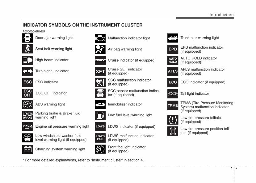
INDICATOR SYMBOLS ON THE INSTRUMENT CLUSTER
Seat belt warning light
High beam indicator
Turn signal indicator
ABS warning light
Parking brake & Brake fluidwarning light
Engine oil pressure warning light
ESC indicator
ESC OFF indicator
Malfunction indicator light
Air bag warning light
Cruise indicator (if equipped)
Cruise SET indicator (if equipped)
Immobilizer indicator
Low fuel level warning light
* For more detailed explanations, refer to “Instrument cluster” in section 4.
Charging system warning light
Low windshield washer fluidlevel warning light (if equipped)
A050000ABH-EU
Door ajar warning light
AFLS malfunction indicator (if equipped)
Tail light indicator
Trunk ajar warning light
Front fog light indicator (if equipped)
ESC
ESCOFF
AFLS
ECO
TPMS (Tire Pressure MonitoringSystem) malfunction indicator(if equipped)
Low tire pressure telltale(if equipped)
Low tire pressure position tell-tale (if equipped)
SCC malfunction indicator (if equipped)
SCC sensor malfunction indica-tor (if equipped)
EPB malfunction indicator (if equipped)
AUTO HOLD indicator (if equipped)
EPB
AUTOHOLD
LDWS indicator (if equipped)LDWS
LDWS malfunction indicator (if equipped)
LDWSFAIL
ECO indicator (if equipped)
2Interior overview / 2-2
Instrument panel overview / 2-3
Engine compartment / 2-4
Your vehicle at a glance
Your vehicle at a glance
22
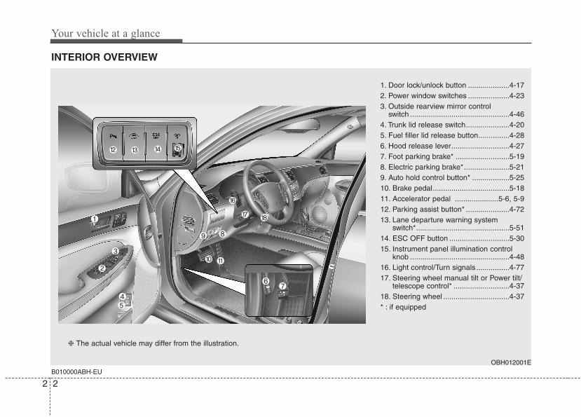
INTERIOR OVERVIEW
B010000ABH-EUOBH012001E
1. Door lock/unlock button ....................4-172. Power window switches ....................4-233. Outside rearview mirror control
switch ................................................4-464. Trunk lid release switch.....................4-205. Fuel filler lid release button...............4-286. Hood release lever............................4-277. Foot parking brake* ..........................5-198. Electric parking brake*......................5-219. Auto hold control button* ..................5-2510. Brake pedal.....................................5-1811. Accelerator pedal .....................5-6, 5-912. Parking assist button* .....................4-7213. Lane departure warning system
switch*.............................................5-5114. ESC OFF button .............................5-3015. Instrument panel illumination control
knob ................................................4-4816. Light control/Turn signals................4-7717. Steering wheel manual tilt or Power tilt/
telescope control* ...........................4-3718. Steering wheel ................................4-37* : if equipped
❈ The actual vehicle may differ from the illustration.
2 3
Your vehicle at a glance
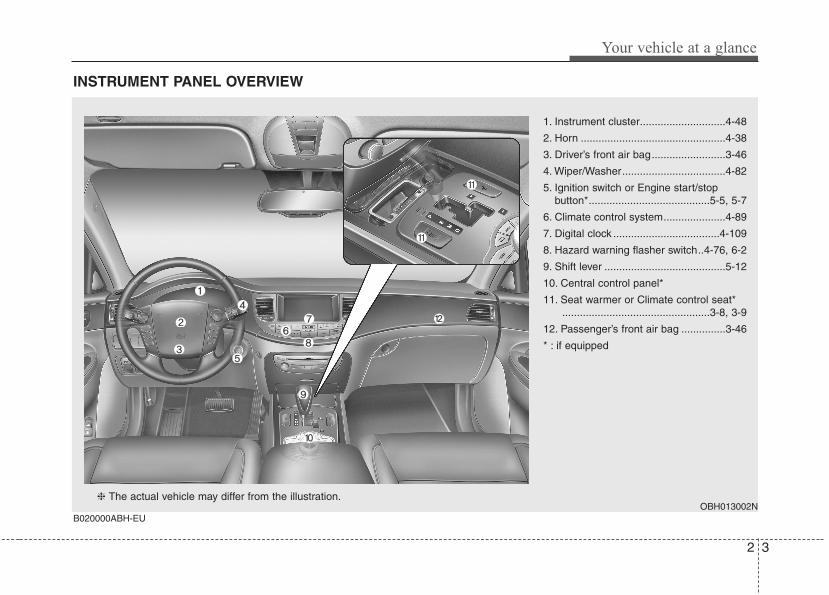
INSTRUMENT PANEL OVERVIEW
OBH013002NB020000ABH-EU
1. Instrument cluster.............................4-48
2. Horn .................................................4-38
3. Driver’s front air bag.........................3-46
4. Wiper/Washer...................................4-82
5. Ignition switch or Engine start/stop button*.........................................5-5, 5-7
6. Climate control system.....................4-89
7. Digital clock ....................................4-109
8. Hazard warning flasher switch..4-76, 6-2
9. Shift lever .........................................5-12
10. Central control panel*
11. Seat warmer or Climate control seat*..................................................3-8, 3-9
12. Passenger’s front air bag ...............3-46
* : if equipped
❈ The actual vehicle may differ from the illustration.
Your vehicle at a glance
42
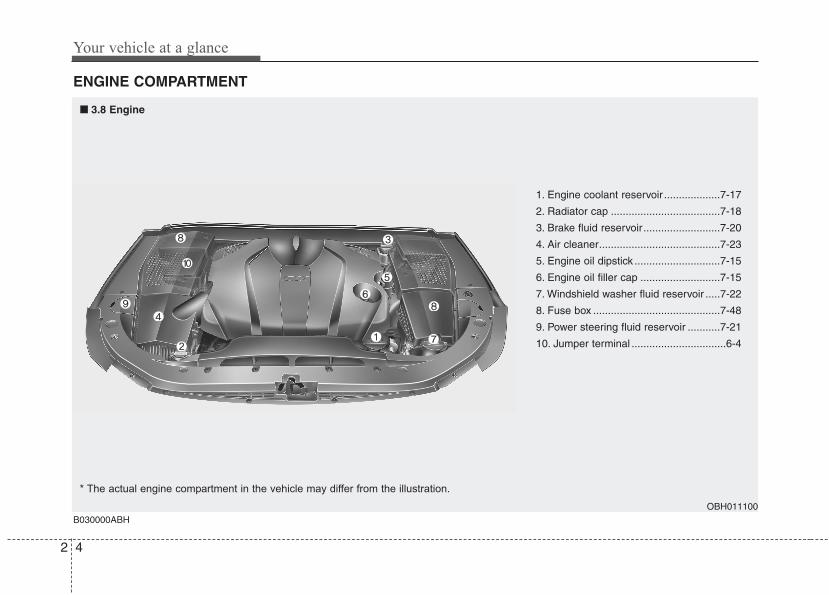
ENGINE COMPARTMENT
OBH011100B030000ABH
* The actual engine compartment in the vehicle may differ from the illustration.
1. Engine coolant reservoir ...................7-17
2. Radiator cap .....................................7-18
3. Brake fluid reservoir..........................7-20
4. Air cleaner.........................................7-23
5. Engine oil dipstick .............................7-15
6. Engine oil filler cap ...........................7-15
7. Windshield washer fluid reservoir .....7-22
8. Fuse box ...........................................7-48
9. Power steering fluid reservoir ...........7-21
10. Jumper terminal ................................6-4
■■ 3.8 Engine
2 5
Your vehicle at a glance
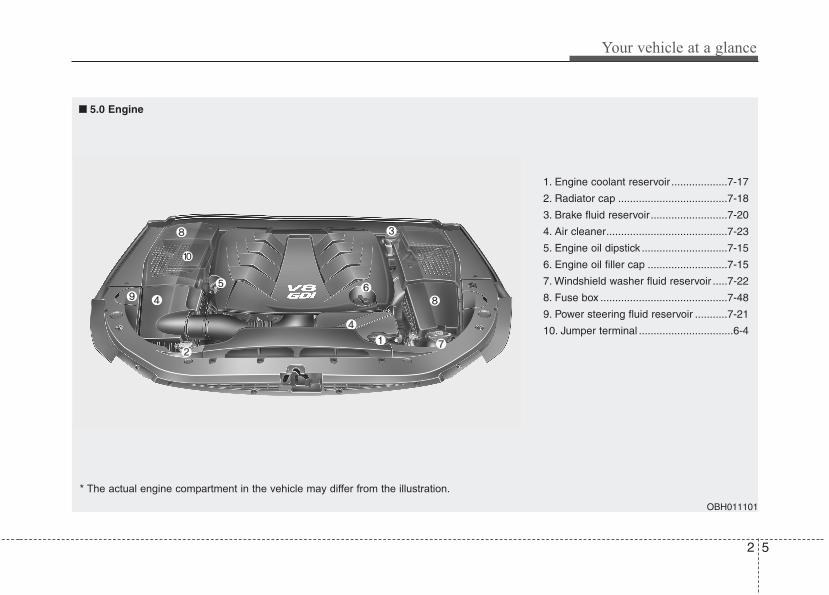
OBH011101
1. Engine coolant reservoir ...................7-17
2. Radiator cap .....................................7-18
3. Brake fluid reservoir..........................7-20
4. Air cleaner.........................................7-23
5. Engine oil dipstick .............................7-15
6. Engine oil filler cap ...........................7-15
7. Windshield washer fluid reservoir .....7-22
8. Fuse box ...........................................7-48
9. Power steering fluid reservoir ...........7-21
10. Jumper terminal ................................6-4
■■ 5.0 Engine
* The actual engine compartment in the vehicle may differ from the illustration.
3
Seats / 3-2
Seat belts / 3-16
Child restraint system / 3-27
Air bag - advanced supplemental restraint system / 3-35
Safety features of your vehicle
Safety features of your vehicle
23
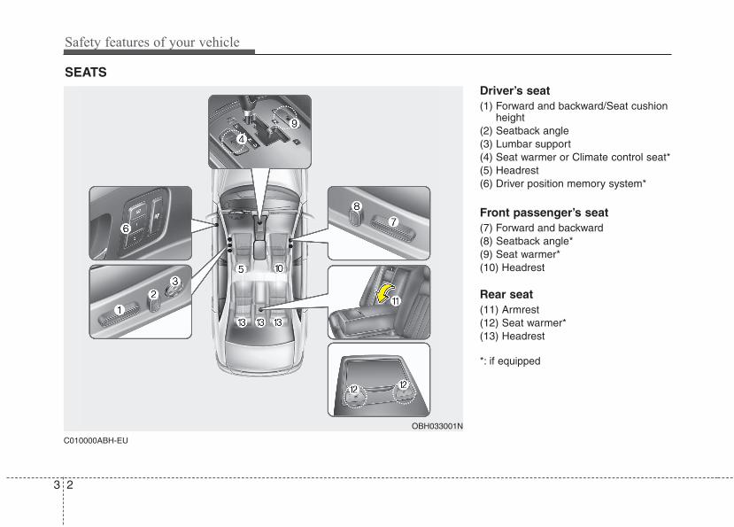
C010000ABH-EU
Driver’s seat(1) Forward and backward/Seat cushion
height(2) Seatback angle(3) Lumbar support(4) Seat warmer or Climate control seat*(5) Headrest(6) Driver position memory system*
Front passenger’s seat(7) Forward and backward(8) Seatback angle*(9) Seat warmer*(10) Headrest
Rear seat(11) Armrest(12) Seat warmer*(13) Headrest
*: if equipped
SEATS
OBH033001N
3 3
Safety features of your vehicle
WARNING - Driver’s seat• Never attempt to adjust the seat
while the vehicle is moving. Thiscould result in loss of control, andan accident causing death, seri-ous injury, or property damage.
• Do not allow anything to interferewith the normal position of theseatback. Storing items against aseatback or in any other wayinterfering with proper locking ofa seatback could result in seriousor fatal injury in a sudden stop orcollision.
(Continued)
(Continued)• Always drive and ride with your
seatback upright and the lap por-tion of the seat belt snug and lowacross the hips. This is the bestposition to protect you in case ofan accident.
• In order to avoid unnecessaryand perhaps severe air baginjuries, always sit as far back aspossible from the steering wheelwhile maintaining comfortablecontrol of the vehicle. We recom-mend that your chest be at least10 inches (250 mm) away fromthe steering wheel.
WARNING - Loose objectsLoose objects in the driver’s footarea could interfere with the opera-tion of the foot pedals, possiblycausing an accident. Do not placeanything under the front seats.
WARNING - Driver respon-sibility for passengers
Riding in a vehicle with the seatbackreclined could lead to serious orfatal injury in an accident. If a seat isreclined during an accident, theoccupant’s hips may slide under thelap portion of the seat belt applyinggreat force to the unprotectedabdomen. Serious or fatal internalinjuries could result.The driver mustadvise the passenger to keep theseatback in an upright positionwhenever the vehicle is in motion.
WARNINGDo not use a sitting cushion thatreduces friction between the seatand passenger. The passenger'ships may slide under the lap portionof the seat belt during an accident ora sudden stop. Serious or fatal inter-nal injuries could result because theseat belt can't operate normally.
WARNING• Do not adjust the seat while wear-
ing seat belts. Moving the seatcushion forward may causestrong pressure on the abdomen.
• Use extreme caution so thathands or other objects are notcaught in the seat mechanismswhile the seat is moving.
• Do not put a cigarette lighter onthe floor or seat. When you oper-ate the seat, gas may gush out ofthe lighter and cause fire.
Safety features of your vehicle
43
C010200AEN
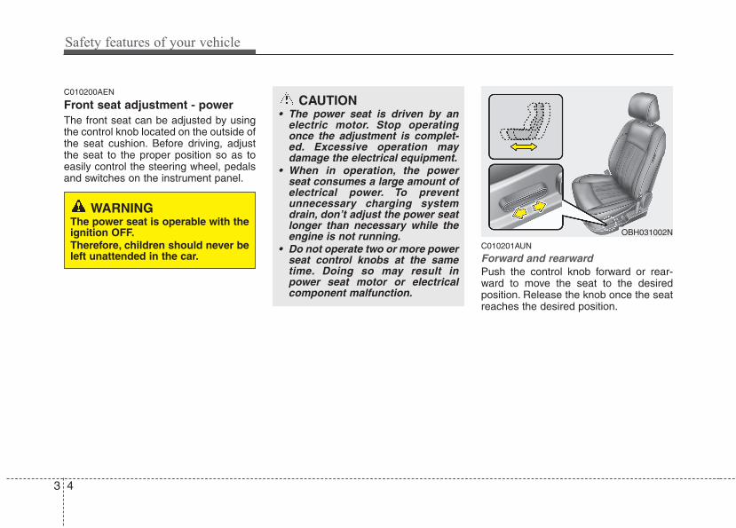
Front seat adjustment - power The front seat can be adjusted by usingthe control knob located on the outside ofthe seat cushion. Before driving, adjustthe seat to the proper position so as toeasily control the steering wheel, pedalsand switches on the instrument panel.
C010201AUN
Forward and rearwardPush the control knob forward or rear-ward to move the seat to the desiredposition. Release the knob once the seatreaches the desired position.
CAUTION• The power seat is driven by an
electric motor. Stop operatingonce the adjustment is complet-ed. Excessive operation maydamage the electrical equipment.
• When in operation, the powerseat consumes a large amount ofelectrical power. To preventunnecessary charging systemdrain, don’t adjust the power seatlonger than necessary while theengine is not running.
• Do not operate two or more powerseat control knobs at the sametime. Doing so may result inpower seat motor or electricalcomponent malfunction.
OBH031002N
WARNINGThe power seat is operable with theignition OFF.Therefore, children should never beleft unattended in the car.
3 5
Safety features of your vehicle
C010202ABH
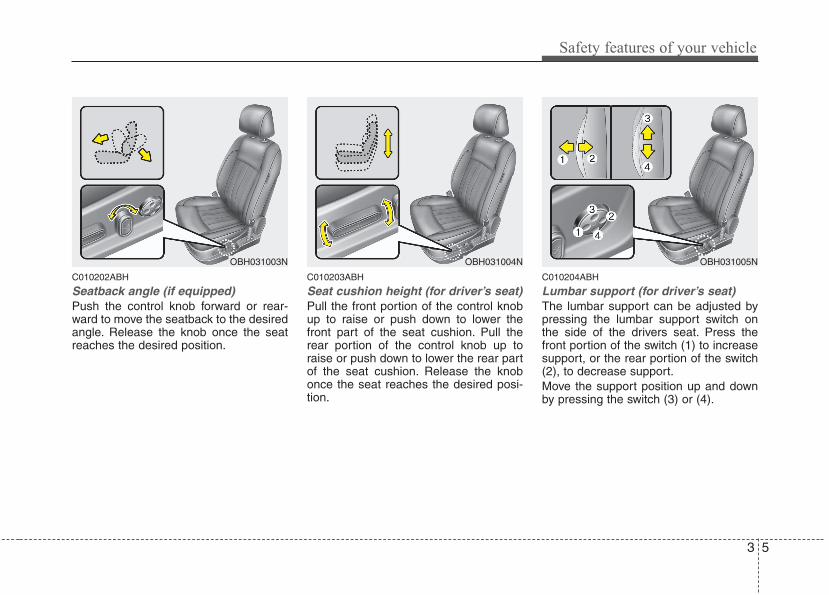
Seatback angle (if equipped)Push the control knob forward or rear-ward to move the seatback to the desiredangle. Release the knob once the seatreaches the desired position.
C010203ABH
Seat cushion height (for driver’s seat)Pull the front portion of the control knobup to raise or push down to lower thefront part of the seat cushion. Pull therear portion of the control knob up toraise or push down to lower the rear partof the seat cushion. Release the knobonce the seat reaches the desired posi-tion.
C010204ABH
Lumbar support (for driver’s seat)The lumbar support can be adjusted bypressing the lumbar support switch onthe side of the drivers seat. Press thefront portion of the switch (1) to increasesupport, or the rear portion of the switch(2), to decrease support.Move the support position up and downby pressing the switch (3) or (4).
OBH031004NOBH031003N OBH031005N
Safety features of your vehicle
63
C010104ABH-EU
HeadrestThe driver's and front passenger's seatsare equipped with a headrest for theoccupant's safety and comfort.The headrest not only provides comfortfor the driver and front passenger, butalso helps to protect the head and neckin the event of a collision.
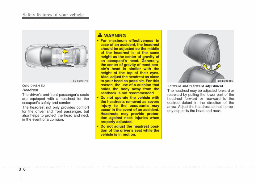
Forward and rearward adjustment
The headrest may be adjusted forward orrearward by pulling the lower part of theheadrest forward or rearward to thedesired detent in the direction of thearrow. Adjust the headrest so that it prop-erly supports the head and neck.
OBH038006L
WARNING • For maximum effectiveness in
case of an accident, the headrestshould be adjusted so the middleof the headrest is at the sameheight as the center of gravity ofan occupant's head. Generally,the center of gravity of most peo-ple's head is similar with theheight of the top of their eyes.Also, adjust the headrest as closeto your head as possible. For thisreason, the use of a cushion thatholds the body away from theseatback is not recommended.
• Do not operate the vehicle withthe headrests removed as severeinjury to the occupants mayoccur in the event of an accident.Headrests may provide protec-tion against neck injuries whenproperly adjusted.
• Do not adjust the headrest posi-tion of the driver's seat while thevehicle is in motion.
OBH038075L
3 7
Safety features of your vehicle
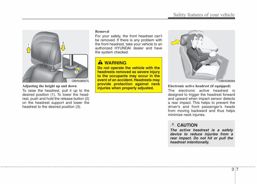
Adjusting the height up and down
To raise the headrest, pull it up to thedesired position (1). To lower the head-rest, push and hold the release button (2)on the headrest support and lower theheadrest to the desired position (3).
Removal
For your safety, the front headrest can’tbe removed. If there is any problem withthe front headrest, take your vehicle to anauthorized HYUNDAI dealer and havethe system checked.
Electronic active headrest (if equipped)
The electronic active headrest isdesigned to trigger the headrest forwardand upward when impact sensor detectsa rear impact. This helps to prevent thedriver's and front passenger’s headsfrom moving backward and thus helpsminimize neck injuries.
WARNING Do not operate the vehicle with theheadrests removed as severe injuryto the occupants may occur in theevent of an accident. Headrests mayprovide protection against neckinjuries when properly adjusted.
OBH038007L OBH038069
CAUTIONThe active headrest is a safetydevice to reduce injuries from arear impact. Do not hit or pull theheadrest intentionally.
Safety features of your vehicle
83
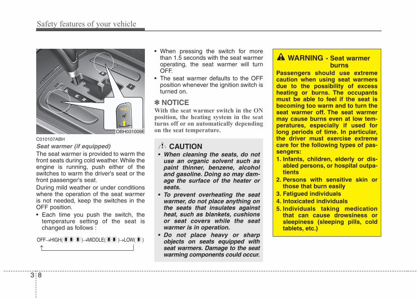
C010107ABH
Seat warmer (if equipped)The seat warmer is provided to warm thefront seats during cold weather. While theengine is running, push either of theswitches to warm the driver's seat or thefront passenger's seat.During mild weather or under conditionswhere the operation of the seat warmeris not needed, keep the switches in theOFF position.• Each time you push the switch, the
temperature setting of the seat ischanged as follows :
• When pressing the switch for morethan 1.5 seconds with the seat warmeroperating, the seat warmer will turnOFF.
• The seat warmer defaults to the OFFposition whenever the ignition switch isturned on.
✽✽ NOTICEWith the seat warmer switch in the ONposition, the heating system in the seatturns off or on automatically dependingon the seat temperature.
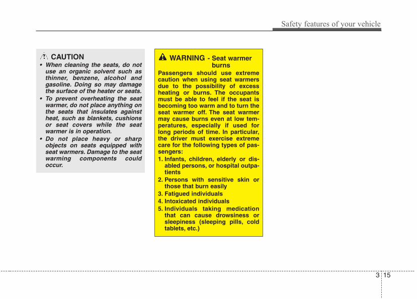
CAUTION• When cleaning the seats, do not
use an organic solvent such aspaint thinner, benzene, alcoholand gasoline. Doing so may dam-age the surface of the heater orseats.
• To prevent overheating the seatwarmer, do not place anything onthe seats that insulates againstheat, such as blankets, cushionsor seat covers while the seatwarmer is in operation.
• Do not place heavy or sharpobjects on seats equipped withseat warmers. Damage to the seatwarming components could occur.
WARNING - Seat warmerburns
Passengers should use extremecaution when using seat warmersdue to the possibility of excessheating or burns. The occupantsmust be able to feel if the seat isbecoming too warm and to turn theseat warmer off. The seat warmermay cause burns even at low tem-peratures, especially if used forlong periods of time. In particular,the driver must exercise extremecare for the following types of pas-sengers:1. Infants, children, elderly or dis-
abled persons, or hospital outpa-tients
2. Persons with sensitive skin orthose that burn easily
3. Fatigued individuals4. Intoxicated individuals5. Individuals taking medication
that can cause drowsiness orsleepiness (sleeping pills, coldtablets, etc.)
OBH031009E
OFF→HIGH( )→MIDDLE( )→LOW( )
→
3 9
Safety features of your vehicle
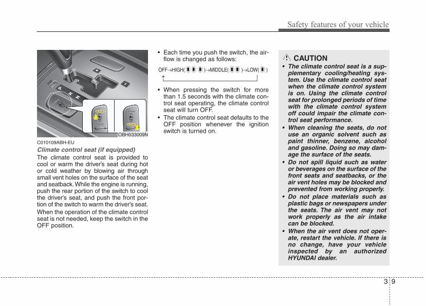
C010109ABH-EU
Climate control seat (if equipped)The climate control seat is provided tocool or warm the driver’s seat during hotor cold weather by blowing air throughsmall vent holes on the surface of the seatand seatback.While the engine is running,push the rear portion of the switch to coolthe driver's seat, and push the front por-tion of the switch to warm the driver’s seat.When the operation of the climate controlseat is not needed, keep the switch in theOFF position.
• Each time you push the switch, the air-flow is changed as follows:
• When pressing the switch for morethan 1.5 seconds with the climate con-trol seat operating, the climate controlseat will turn OFF.
• The climate control seat defaults to theOFF position whenever the ignitionswitch is turned on.
CAUTION• The climate control seat is a sup-
plementary cooling/heating sys-tem. Use the climate control seatwhen the climate control systemis on. Using the climate controlseat for prolonged periods of timewith the climate control systemoff could impair the climate con-trol seat performance.
• When cleaning the seats, do notuse an organic solvent such aspaint thinner, benzene, alcoholand gasoline. Doing so may dam-age the surface of the seats.
• Do not spill liquid such as wateror beverages on the surface of thefront seats and seatbacks, or theair vent holes may be blocked andprevented from working properly.
• Do not place materials such asplastic bags or newspapers underthe seats. The air vent may notwork properly as the air intakecan be blocked.
• When the air vent does not oper-ate, restart the vehicle. If there isno change, have your vehicleinspected by an authorizedHYUNDAI dealer.
OBH033009N
OFF→HIGH( )→MIDDLE( )→LOW( )
→
Safety features of your vehicle
103
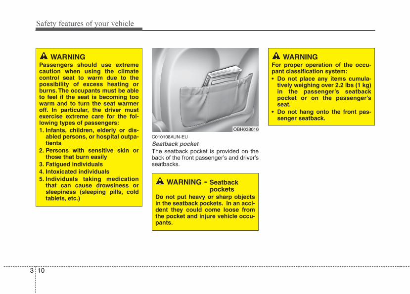
C010108AUN-EU
Seatback pocketThe seatback pocket is provided on theback of the front passenger’s and driver’sseatbacks.
WARNING - Seatbackpockets
Do not put heavy or sharp objectsin the seatback pockets. In an acci-dent they could come loose fromthe pocket and injure vehicle occu-pants.
OBH038010
WARNINGFor proper operation of the occu-pant classification system:• Do not place any items cumula-
tively weighing over 2.2 lbs (1 kg)in the passenger’s seatbackpocket or on the passenger’sseat.
• Do not hang onto the front pas-senger seatback.
WARNINGPassengers should use extremecaution when using the climatecontrol seat to warm due to thepossibility of excess heating orburns. The occupants must be ableto feel if the seat is becoming toowarm and to turn the seat warmeroff. In particular, the driver mustexercise extreme care for the fol-lowing types of passengers:1. Infants, children, elderly or dis-
abled persons, or hospital outpa-tients
2. Persons with sensitive skin orthose that burn easily
3. Fatigued individuals4. Intoxicated individuals5. Individuals taking medication
that can cause drowsiness orsleepiness (sleeping pills, coldtablets, etc.)
3 11
Safety features of your vehicle
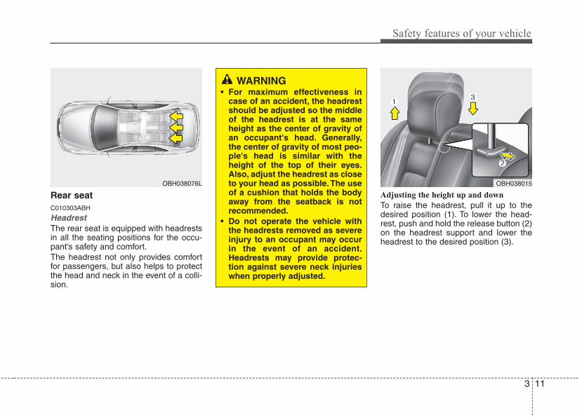
Rear seat C010303ABH
HeadrestThe rear seat is equipped with headrestsin all the seating positions for the occu-pant's safety and comfort.The headrest not only provides comfortfor passengers, but also helps to protectthe head and neck in the event of a colli-sion.
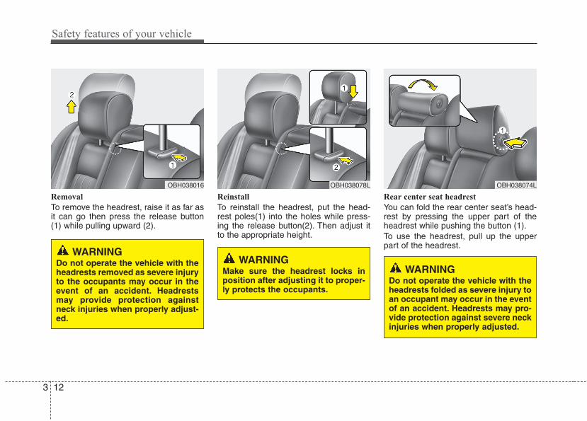
Adjusting the height up and down
To raise the headrest, pull it up to thedesired position (1). To lower the head-rest, push and hold the release button (2)on the headrest support and lower theheadrest to the desired position (3).
OBH038076L
WARNING• For maximum effectiveness in
case of an accident, the headrestshould be adjusted so the middleof the headrest is at the sameheight as the center of gravity ofan occupant's head. Generally,the center of gravity of most peo-ple's head is similar with theheight of the top of their eyes.Also, adjust the headrest as closeto your head as possible.The useof a cushion that holds the bodyaway from the seatback is notrecommended.
• Do not operate the vehicle withthe headrests removed as severeinjury to an occupant may occurin the event of an accident.Headrests may provide protec-tion against severe neck injurieswhen properly adjusted.
OBH038015
Safety features of your vehicle
123
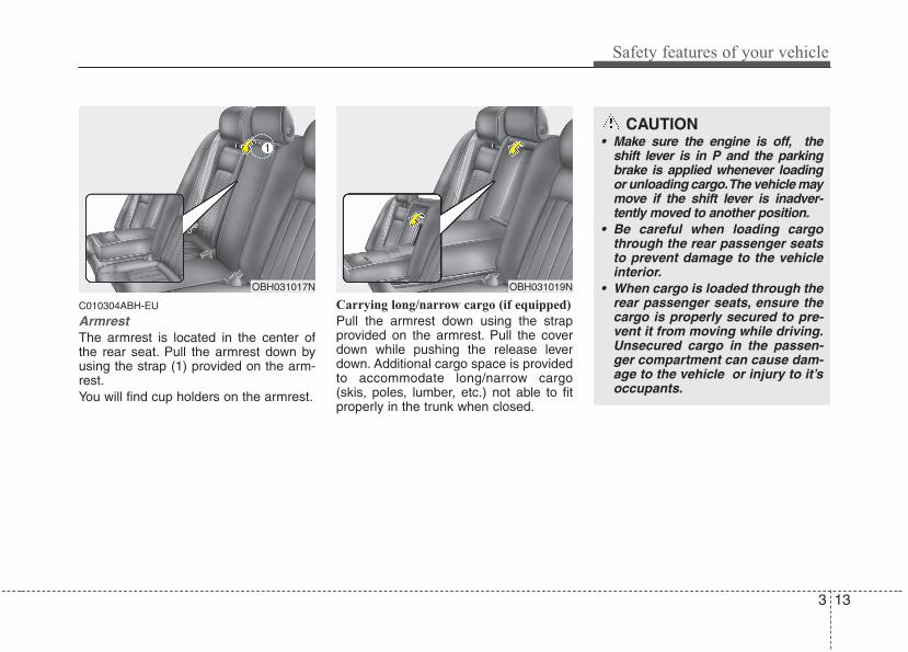
Removal
To remove the headrest, raise it as far asit can go then press the release button(1) while pulling upward (2).
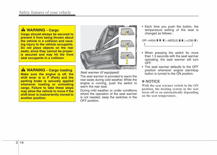
Reinstall
To reinstall the headrest, put the head-rest poles(1) into the holes while press-ing the release button(2). Then adjust itto the appropriate height.
Rear center seat headrest
You can fold the rear center seat’s head-rest by pressing the upper part of theheadrest while pushing the button (1).To use the headrest, pull up the upperpart of the headrest.
WARNINGMake sure the headrest locks inposition after adjusting it to proper-ly protects the occupants.
WARNINGDo not operate the vehicle with theheadrests folded as severe injury toan occupant may occur in the eventof an accident. Headrests may pro-vide protection against severe neckinjuries when properly adjusted.
OBH038074LOBH038078LOBH038016
WARNING Do not operate the vehicle with theheadrests removed as severe injuryto the occupants may occur in theevent of an accident. Headrestsmay provide protection againstneck injuries when properly adjust-ed.
3 13
Safety features of your vehicle
C010304ABH-EU
ArmrestThe armrest is located in the center ofthe rear seat. Pull the armrest down byusing the strap (1) provided on the arm-rest.You will find cup holders on the armrest.
Carrying long/narrow cargo (if equipped)
Pull the armrest down using the strapprovided on the armrest. Pull the coverdown while pushing the release leverdown. Additional cargo space is providedto accommodate long/narrow cargo(skis, poles, lumber, etc.) not able to fitproperly in the trunk when closed.
OBH031019NOBH031017N
CAUTION• Make sure the engine is off, the
shift lever is in P and the parkingbrake is applied whenever loadingor unloading cargo.The vehicle maymove if the shift lever is inadver-tently moved to another position.
• Be careful when loading cargothrough the rear passenger seatsto prevent damage to the vehicleinterior.
• When cargo is loaded through therear passenger seats, ensure thecargo is properly secured to pre-vent it from moving while driving.Unsecured cargo in the passen-ger compartment can cause dam-age to the vehicle or injury to it’soccupants.
Safety features of your vehicle
143
Seat warmer (if equipped)The seat warmer is provided to warm therear seats during cold weather. While theengine is running, push the switch towarm the rear seat.During mild weather or under conditionswhere the operation of the seat warmeris not needed, keep the switches in theOFF position.
• Each time you push the button, thetemperature setting of the seat ischanged as follows :
• When pressing the switch for morethan 1.5 seconds with the seat warmeroperating, the seat warmer will turnOFF.
• The seat warmer defaults to the OFFposition whenever engine start/stopbutton is turned to the ON position.
✽✽ NOTICEWith the seat warmer switch in the ONposition, the heating system in the seatturns off or on automatically dependingon the seat temperature.
WARNING - CargoCargo should always be secured toprevent it from being thrown aboutthe vehicle in a collision and caus-ing injury to the vehicle occupants.Do not place objects on the rearseats, since they cannot be proper-ly secured and may hit the frontseat occupants in a collision.
WARNING - Cargo loadingMake sure the engine is off, theshift lever is in P (Park) and theparking brake is securely appliedwhenever loading or unloadingcargo. Failure to take these stepsmay allow the vehicle to move if theshift lever is inadvertently moved toanother position.
OFF→HIGH( )→MIDDLE( )→LOW( )
→
OBH032021L
3 15
Safety features of your vehicle
WARNING - Seat warmerburns
Passengers should use extremecaution when using seat warmersdue to the possibility of excessheating or burns. The occupantsmust be able to feel if the seat isbecoming too warm and to turn theseat warmer off. The seat warmermay cause burns even at low tem-peratures, especially if used forlong periods of time. In particular,the driver must exercise extremecare for the following types of pas-sengers:1. Infants, children, elderly or dis-
abled persons, or hospital outpa-tients
2. Persons with sensitive skin orthose that burn easily
3. Fatigued individuals4. Intoxicated individuals5. Individuals taking medication
that can cause drowsiness orsleepiness (sleeping pills, coldtablets, etc.)
CAUTION• When cleaning the seats, do not
use an organic solvent such asthinner, benzene, alcohol andgasoline. Doing so may damagethe surface of the heater or seats.
• To prevent overheating the seatwarmer, do not place anything onthe seats that insulates againstheat, such as blankets, cushionsor seat covers while the seatwarmer is in operation.
• Do not place heavy or sharpobjects on seats equipped withseat warmers. Damage to the seatwarming components couldoccur.
Safety features of your vehicle
163
(Continued)Care should be taken to avoid con-tamination of the webbing with pol-ishes, oils and chemicals and par-ticularly battery acid. Cleaning maysafely be carried out using mildsoap and water. The belt should bereplaced if webbing becomesfrayed, contaminated or damaged.It is essential to replace the entireassembly after it has been worn ina severe impact even if damage tothe assembly is not obvious. Beltsshould not be worn with strapstwisted. Each seat belt assemblymust only be used by one occu-pant; it is dangerous to put a beltaround a child being carried on theoccupant's lap.
C020100AUN
Seat belt restraint system
WARNINGSeat belts are designed to bearupon the bony structure of thebody, and should be worn lowacross the front of the pelvis, or thepelvis, chest and shoulders, asapplicable; wearing the lap sectionof the belt across the abdominalarea must be avoided.Seat belts should be adjusted asfirmly as possible, consistent withcomfort, to provide the protectionfor which they have been designed.A slack belt will greatly reduce theprotection afforded to the occu-pant.
(Continued)
(Continued)• Avoid wearing twisted seat belts.
A twisted belt can't do its job aswell. In a collision, it could evencut into you. Be sure the beltwebbing is straight and not twist-ed.
• Be careful not to damage the beltwebbing or hardware. If the beltwebbing or hardware is dam-aged, replace it.
WARNING• For maximum restraint system
protection, the seat belts mustalways be used whenever the caris moving.
• Seat belts are most effectivewhen seatbacks are in theupright position.
• Children age 12 and under mustalways be properly restrained inthe rear seat. Never allow chil-dren to ride in the front passen-ger seat. If a child over 12 mustbe seated in the front seat, he/shemust be properly belted and theseat should be moved as far backas possible.
• Never wear the shoulder beltunder your arm or behind yourback. An improperly positionedshoulder belt can cause seriousinjuries in a crash. The shoulderbelt should be positioned midwayover your shoulder across yourcollarbone.
(Continued)
SEAT BELTS
3 17
Safety features of your vehicle
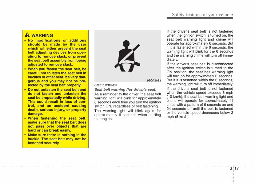
C020101CBH-EU
Seat belt warning (for driver’s seat)As a reminder to the driver, the seat beltwarning light will blink for approximately6 seconds each time you turn the ignitionswitch ON, regardless of belt fastening.The warning light will blink again forapproximately 6 seconds when startingthe engine.
If the driver's seat belt is not fastenedwhen the ignition switch is turned on, theseat belt warning light and chime willoperate for approximately 6 seconds. Butif it is fastened within the 6 seconds, thewarning light will blink for the 6 secondsand the warning chime will turn off imme-diately.If the driver's seat belt is disconnectedafter the ignition switch is turned to theON position, the seat belt warning lightwill turn on for approximately 6 seconds.But if it is fastened within the 6 seconds,the warning light will turn off immediately.If the driver's seat belt is not fastenedwhen the vehicle speed exceeds 6 mph(10 km/h), the seat belt warning light andchime will operate for approximately 11times with a pattern of 6 seconds on and24 seconds off until the belt is fastenedor the vehicle speed decreases below 3mph (5 km/h).
1GQA2083
WARNING• No modifications or additions
should be made by the userwhich will either prevent the seatbelt adjusting devices from oper-ating to remove slack, or preventthe seat belt assembly from beingadjusted to remove slack.
• When you fasten the seat belt, becareful not to latch the seat belt inbuckles of other seat. It's very dan-gerous and you may not be pro-tected by the seat belt properly.
• Do not unfasten the seat belt anddo not fasten and unfasten theseat belt repeatedly while driving.This could result in loss of con-trol, and an accident causingdeath, serious injury, or propertydamage.
• When fastening the seat belt,make sure that the seat belt doesnot pass over objects that arehard or can break easily.
• Make sure there is nothing in thebuckle. The seat belt may not befastened securely.
Safety features of your vehicle
183
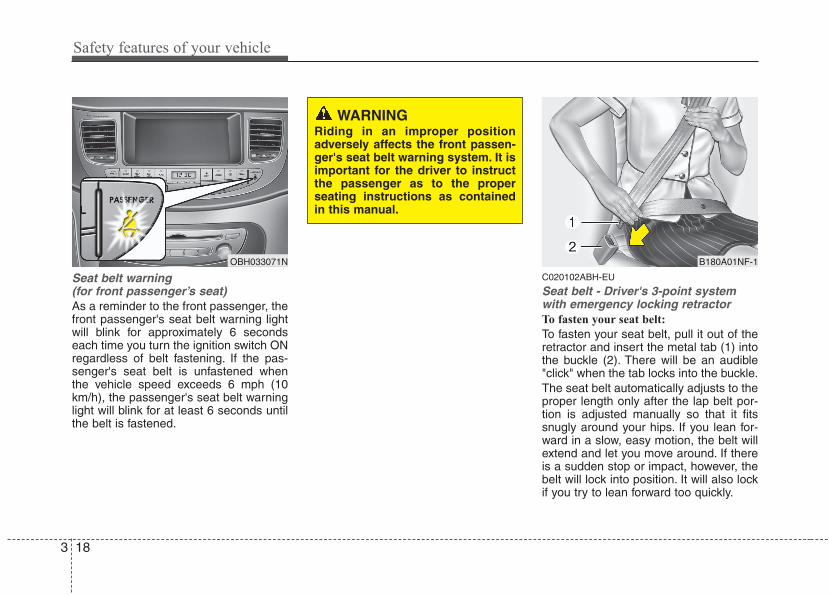
Seat belt warning (for front passenger’s seat)As a reminder to the front passenger, thefront passenger's seat belt warning lightwill blink for approximately 6 secondseach time you turn the ignition switch ONregardless of belt fastening. If the pas-senger's seat belt is unfastened whenthe vehicle speed exceeds 6 mph (10km/h), the passenger's seat belt warninglight will blink for at least 6 seconds untilthe belt is fastened.
C020102ABH-EU
Seat belt - Driver's 3-point systemwith emergency locking retractorTo fasten your seat belt:
To fasten your seat belt, pull it out of theretractor and insert the metal tab (1) intothe buckle (2). There will be an audible"click" when the tab locks into the buckle.The seat belt automatically adjusts to theproper length only after the lap belt por-tion is adjusted manually so that it fitssnugly around your hips. If you lean for-ward in a slow, easy motion, the belt willextend and let you move around. If thereis a sudden stop or impact, however, thebelt will lock into position. It will also lockif you try to lean forward too quickly.
B180A01NF-1OBH033071N
WARNINGRiding in an improper positionadversely affects the front passen-ger's seat belt warning system. It isimportant for the driver to instructthe passenger as to the properseating instructions as containedin this manual.
3 19
Safety features of your vehicle
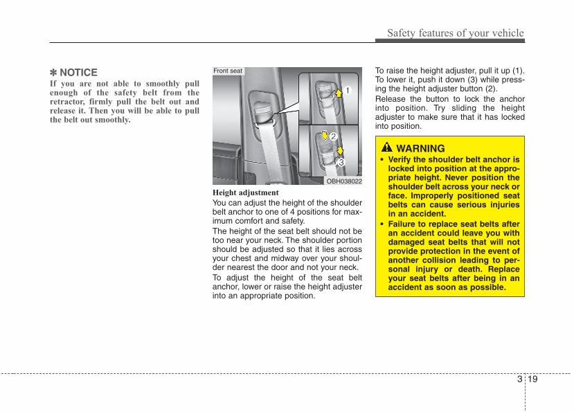
✽✽ NOTICEIf you are not able to smoothly pullenough of the safety belt from theretractor, firmly pull the belt out andrelease it. Then you will be able to pullthe belt out smoothly.
Height adjustment
You can adjust the height of the shoulderbelt anchor to one of 4 positions for max-imum comfort and safety.The height of the seat belt should not betoo near your neck. The shoulder portionshould be adjusted so that it lies acrossyour chest and midway over your shoul-der nearest the door and not your neck.To adjust the height of the seat beltanchor, lower or raise the height adjusterinto an appropriate position.
To raise the height adjuster, pull it up (1).To lower it, push it down (3) while press-ing the height adjuster button (2).Release the button to lock the anchorinto position. Try sliding the heightadjuster to make sure that it has lockedinto position.
OBH038022
Front seat
WARNING• Verify the shoulder belt anchor is
locked into position at the appro-priate height. Never position theshoulder belt across your neck orface. Improperly positioned seatbelts can cause serious injuriesin an accident.
• Failure to replace seat belts afteran accident could leave you withdamaged seat belts that will notprovide protection in the event ofanother collision leading to per-sonal injury or death. Replaceyour seat belts after being in anaccident as soon as possible.
Safety features of your vehicle
203
C020106ABH
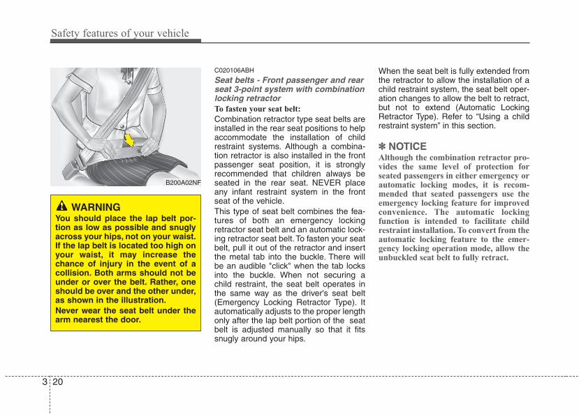
Seat belts - Front passenger and rearseat 3-point system with combinationlocking retractorTo fasten your seat belt:
Combination retractor type seat belts areinstalled in the rear seat positions to helpaccommodate the installation of childrestraint systems. Although a combina-tion retractor is also installed in the frontpassenger seat position, it is stronglyrecommended that children always beseated in the rear seat. NEVER placeany infant restraint system in the frontseat of the vehicle.This type of seat belt combines the fea-tures of both an emergency lockingretractor seat belt and an automatic lock-ing retractor seat belt. To fasten your seatbelt, pull it out of the retractor and insertthe metal tab into the buckle. There willbe an audible "click" when the tab locksinto the buckle. When not securing achild restraint, the seat belt operates inthe same way as the driver's seat belt(Emergency Locking Retractor Type). Itautomatically adjusts to the proper lengthonly after the lap belt portion of the seatbelt is adjusted manually so that it fitssnugly around your hips.
When the seat belt is fully extended fromthe retractor to allow the installation of achild restraint system, the seat belt oper-ation changes to allow the belt to retract,but not to extend (Automatic LockingRetractor Type). Refer to “Using a childrestraint system” in this section.
✽✽ NOTICEAlthough the combination retractor pro-vides the same level of protection forseated passengers in either emergency orautomatic locking modes, it is recom-mended that seated passengers use theemergency locking feature for improvedconvenience. The automatic lockingfunction is intended to facilitate childrestraint installation. To convert from theautomatic locking feature to the emer-gency locking operation mode, allow theunbuckled seat belt to fully retract.
B200A02NF
WARNINGYou should place the lap belt por-tion as low as possible and snuglyacross your hips, not on your waist.If the lap belt is located too high onyour waist, it may increase thechance of injury in the event of acollision. Both arms should not beunder or over the belt. Rather, oneshould be over and the other under,as shown in the illustration.Never wear the seat belt under thearm nearest the door.
3 21
Safety features of your vehicle
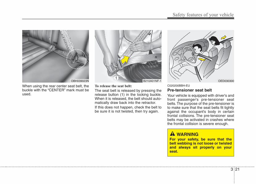
When using the rear center seat belt, thebuckle with the “CENTER” mark must beused.
To release the seat belt:
The seat belt is released by pressing therelease button (1) in the locking buckle.When it is released, the belt should auto-matically draw back into the retractor.If this does not happen, check the belt tobe sure it is not twisted, then try again.
C020200BBH-EU
Pre-tensioner seat belt Your vehicle is equipped with driver's andfront passenger's pre-tensioner seatbelts. The purpose of the pre-tensioner isto make sure that the seat belts fit tightlyagainst the occupant's body in certainfrontal collisions. The pre-tensioner seatbelts may be activated in crashes wherethe frontal collision is severe enough.
B210A01NF-1 OED030300
WARNINGFor your safety, be sure that thebelt webbing is not loose or twistedand always sit properly on yourseat.
OBH039023N
Safety features of your vehicle
223
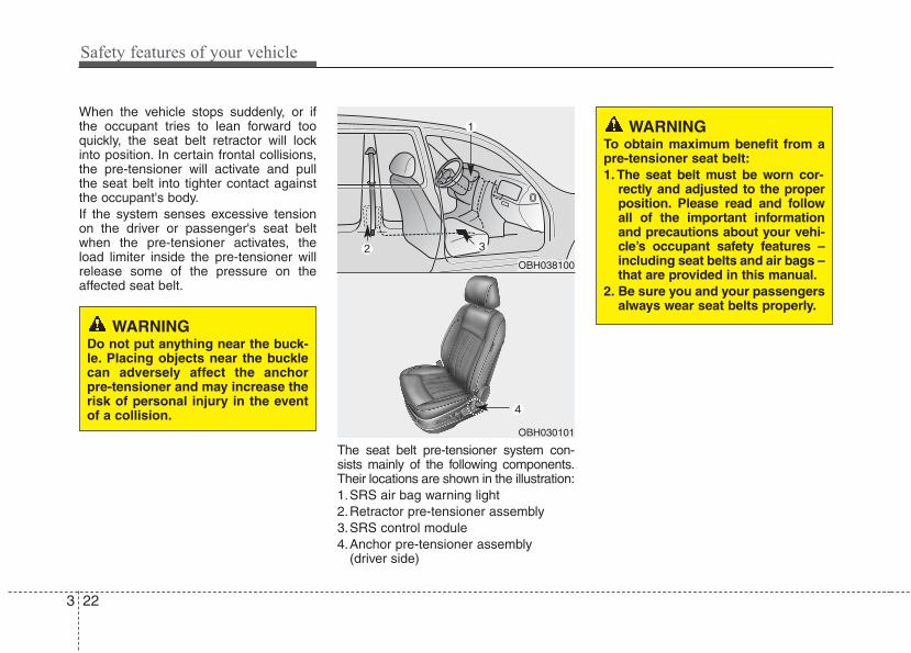
When the vehicle stops suddenly, or ifthe occupant tries to lean forward tooquickly, the seat belt retractor will lockinto position. In certain frontal collisions,the pre-tensioner will activate and pullthe seat belt into tighter contact againstthe occupant's body.If the system senses excessive tensionon the driver or passenger's seat beltwhen the pre-tensioner activates, theload limiter inside the pre-tensioner willrelease some of the pressure on theaffected seat belt.
The seat belt pre-tensioner system con-sists mainly of the following components.Their locations are shown in the illustration:1.SRS air bag warning light2.Retractor pre-tensioner assembly3.SRS control module4.Anchor pre-tensioner assembly
(driver side)
WARNINGTo obtain maximum benefit from apre-tensioner seat belt:1. The seat belt must be worn cor-
rectly and adjusted to the properposition. Please read and followall of the important informationand precautions about your vehi-cle’s occupant safety features –including seat belts and air bags –that are provided in this manual.
2. Be sure you and your passengersalways wear seat belts properly.
OBH038100
OBH030101
WARNINGDo not put anything near the buck-le. Placing objects near the bucklecan adversely affect the anchorpre-tensioner and may increase therisk of personal injury in the eventof a collision.
3 23
Safety features of your vehicle
✽✽ NOTICE• The driver's and front passenger's
pre-tensioner seat belts may be acti-vated in certain frontal collisions.The pre-tensioner seat belts can beactivated where the frontal collision issevere enough, together with the airbags.
• When the pre-tensioner seat belts areactivated, a loud noise may be heardand fine dust, which may appear to besmoke, may be visible in the passengercompartment. These are normal oper-ating conditions and are not haz-ardous.
• Although it is harmless, the fine dustmay cause skin irritation and shouldnot be breathed for prolonged periods.Wash all exposed skin areas thorough-ly after an accident in which the pre-tensioner seat belts were activated.
✽✽ NOTICEThe sensor that activates the SRS airbag is connected with the pre-tensionerseat belt, and the SRS air bag warninglight on the instrument panel willilluminate for approximately 6 secondsafter the ignition switch has been turnedto the ON position, and then it shouldturn off.
CAUTIONIf the pre-tensioner seat belt is notworking properly, the warning lightwill illuminate even if there is nomalfunction of the SRS air bag. Ifthe SRS air bag warning light doesnot illuminate when the ignitionswitch is turned ON, or if it remainsilluminated after illuminating forapproximately 6 seconds, or if itilluminates while the vehicle isbeing driven, have an authorizedHYUNDAI dealer inspect the pre-tensioner seat belt and SRS air bagsystem as soon as possible.
WARNING• Pre-tensioners are designed to
operate only one time. After acti-vation, pre-tensioner seat beltsmust be replaced. All seat belts,of any type, should always bereplaced after they have beenworn during a collision.
• The pre-tensioner seat beltassembly mechanisms becomehot during activation. Do nottouch the pre-tensioner seat beltassemblies for several minutesafter they have been activated.
• Do not attempt to inspect orreplace the pre-tensioner seatbelts yourself. This must be doneby an authorized HYUNDAI dealer.
• Do not strike the pre-tensionerseat belt assemblies.
• Do not attempt to service orrepair the pre-tensioner seat beltsystem in any manner.
(Continued)
Safety features of your vehicle
243
C020300AUN-EU
Seat belt precautionsC020306AUN-EU
Infant or small childAll 50 states have child restraint laws.Youshould be aware of the specific require-ments in your state. Child and/or infantseats must be properly placed andinstalled in the rear seat. For more infor-mation about the use of these restraints,refer to “Child restraint system” in thissection.
WARNINGEvery person in your vehicle needsto be properly restrained at alltimes, including infants and chil-dren. Never hold a child in yourarms or lap when riding in a vehi-cle. The violent forces created dur-ing a crash will tear the child fromyour arms and throw the childagainst the interior. Always use achild restraint appropriate for yourchild's height and weight.
WARNINGAll occupants of the vehicle mustwear their seat belts at all times.Seat belts and child restraintsreduce the risk of serious or fatalinjuries for all occupants in theevent of a collision or sudden stop.Without a seat belt, occupantscould be shifted too close to adeploying air bag, strike the interiorstructure or be thrown from thevehicle. Properly worn seat beltsgreatly reduce these hazards.Even with advanced air bags,unbelted occupants can be severe-ly injured by a deploying air bag.Always follow the precautionsabout seat belts, air bags and occu-pant safety contained in this manu-al.
(Continued)• Improper handling of the pre-ten-
sioner seat belt assemblies, andfailure to heed the warnings notto strike, modify, inspect, replace,service or repair the pre-tension-er seat belt assemblies may leadto improper operation or inadver-tent activation and serious injury.
• Always wear the seat belts whendriving or riding in a motor vehi-cle.
• If the vehicle or pre-tensioner seatbelt must be discarded, contactan authorized HYUNDAI dealer.
3 25
Safety features of your vehicle
✽✽ NOTICESmall children are best protected frominjury in an accident when properlyrestrained in the rear seat by a childrestraint system that meets the require-ments of the Federal Motor VehicleSafety Standards. Before buying anychild restraint system, make sure that ithas a label certifying that it meetsFederal Motor Vehicle Safety Standard213. The restraint must be appropriatefor your child's height and weight.Check the label on the child restraint forthis information. Refer to “Childrestraint system” in this section.
C020301AUN
Larger childrenChildren who are too large for childrestraint systems should always occupythe rear seat and use the availablelap/shoulder belts. The lap portion shouldbe fastened snug on the hips and as lowas possible. Check belt fit periodically. Achild's squirming could put the belt out ofposition. Children are afforded the mostsafety in the event of an accident whenthey are restrained by a proper restraintsystem in the rear seat. If a larger child(over age 12) must be seated in the frontseat, the child should be securelyrestrained by the available lap/shoulderbelt and the seat should be placed in therearmost position. Children age 12 andunder should be restrained securely inthe rear seat. NEVER place a child age12 and under in the front seat. NEVERplace a rear facing child seat in the frontseat of a vehicle.If the shoulder belt portion slightly touch-es the child’s neck or face, try placing thechild closer to the center of the vehicle. Ifthe shoulder belt still touches their faceor neck they need to be returned to achild restraint system.
C020302AKM
Restraint of pregnant women Pregnant women should wear lap/shoul-der belt assemblies whenever possibleaccording to specific recommendationsby their doctors. The lap portion of thebelt should be worn AS SNUGLY ANDLOW AS POSSIBLE on the hips, notcross the abdomen.
WARNING - Shoulder beltson small children
• Never allow a shoulder belt to bein contact with a child’s neck orface while the vehicle is inmotion.
• If seat belts are not properly wornand adjusted on children, there isa risk of death or serious injury.
WARNING - Pregnantwomen
Pregnant women must never placethe lap portion of the safety beltover the area of the abdomenwhere the fetus is located or abovethe abdomen where the belt couldcrush the fetus during an impact.
Safety features of your vehicle
263
C020303AUN
Injured personA seat belt should be used when aninjured person is being transported.When this is necessary, you should con-sult a physician for recommendations.
C020304AUN
One person per beltTwo people (including children) shouldnever attempt to use a single seat belt.This could increase the severity ofinjuries in case of an accident.
C020305ABH
Do not lie downTo reduce the chance of injuries in theevent of an accident and to achieve max-imum effectiveness of the restraint sys-tem, all passengers should be sitting upand the front and rear seats should be inan upright position when the car is mov-ing. A seat belt cannot provide properprotection if the person is lying down inthe rear seat or if the front and rear seatsare in a reclined position.
C020400ABH
Care of seat beltsSeat belt systems should never be disas-sembled or modified. In addition, careshould be taken to assure that seat beltsand belt hardware are not damaged byseat hinges, doors or other abuse.
C020401AEN
Periodic inspectionAll seat belts should be inspected peri-odically for wear or damage of any kind.Any damaged parts should be replacedas soon as possible.
C020402AUN
Keep belts clean and drySeat belts should be kept clean and dry. Ifbelts become dirty, they can be cleanedby using a mild soap solution and warmwater. Bleach, dye, strong detergents orabrasives should not be used becausethey may damage and weaken the fabric.
C020403AEN
When to replace seat beltsEntire in-use seat belt assembly orassemblies should be replaced if thevehicle has been involved in an accident.This should be done even if no damageis visible. Additional questions concern-ing seat belt operation should be directedto an authorized HYUNDAI dealer.
WARNINGRiding with a reclined seatbackincreases your chance of serious orfatal injuries in the event of a colli-sion or sudden stop. The protectionof your restraint system (seat beltsand air bags) is greatly reduced byreclining your seat. Seat belts mustbe snug against your hips andchest to work properly. The morethe seatback is reclined, the greaterthe chance that an occupant's hipswill slide under the lap belt causingserious internal injuries or theoccupant's neck could strike theshoulder belt. Drivers and passen-gers should always sit well back intheir seats, properly belted, andwith the seatbacks upright.
3 27
Safety features of your vehicle
WARNINGTo reduce the chance of serious orfatal injuries:• Children of all ages are safer
when restrained in the rear seat.A child riding in the front passen-ger seat can be forcefully struckby an inflating air bag resulting inserious or fatal injuries.
• Always follow the child restraintsystem manufacturer’s instruc-tions for installation and use ofthe child restraint.
• Always make sure the child seatis secured properly in the car andyour child is securely restrainedin the child seat.
• Never hold a child in your arms orlap when riding in a vehicle. Theviolent forces created during acrash will tear the child from yourarms and throw the child againstthe car’s interior.
• Never put a seat belt over your-self and a child. During a crash,the belt could press deep into thechild causing serious internalinjuries.
(Continued)
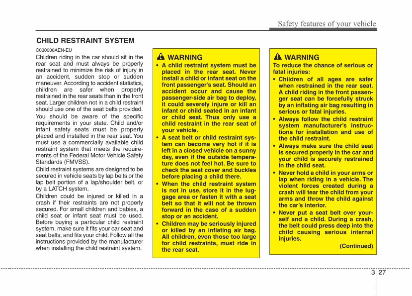
CHILD RESTRAINT SYSTEMC030000AEN-EU
Children riding in the car should sit in therear seat and must always be properlyrestrained to minimize the risk of injury inan accident, sudden stop or suddenmaneuver. According to accident statistics,children are safer when properlyrestrained in the rear seats than in the frontseat. Larger children not in a child restraintshould use one of the seat belts provided.You should be aware of the specificrequirements in your state. Child and/orinfant safety seats must be properlyplaced and installed in the rear seat. Youmust use a commercially available childrestraint system that meets the require-ments of the Federal Motor Vehicle SafetyStandards (FMVSS).Child restraint systems are designed to besecured in vehicle seats by lap belts or thelap belt portion of a lap/shoulder belt, orby a LATCH system.Children could be injured or killed in acrash if their restraints are not properlysecured. For small children and babies, achild seat or infant seat must be used.Before buying a particular child restraintsystem, make sure it fits your car seat andseat belts, and fits your child. Follow all theinstructions provided by the manufacturerwhen installing the child restraint system.
WARNING• A child restraint system must be
placed in the rear seat. Neverinstall a child or infant seat on thefront passenger's seat. Should anaccident occur and cause thepassenger-side air bag to deploy,it could severely injure or kill aninfant or child seated in an infantor child seat. Thus only use achild restraint in the rear seat ofyour vehicle.
• A seat belt or child restraint sys-tem can become very hot if it isleft in a closed vehicle on a sunnyday, even if the outside tempera-ture does not feel hot. Be sure tocheck the seat cover and bucklesbefore placing a child there.
• When the child restraint systemis not in use, store it in the lug-gage area or fasten it with a seatbelt so that it will not be thrownforward in the case of a suddenstop or an accident.
• Children may be seriously injuredor killed by an inflating air bag.All children, even those too largefor child restraints, must ride inthe rear seat.
Safety features of your vehicle
283
C030100AEN-EU
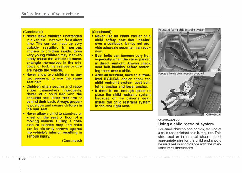
Using a child restraint systemFor small children and babies, the use ofa child seat or infant seat is required.Thischild seat or infant seat should be ofappropriate size for the child and shouldbe installed in accordance with the man-ufacturer's instructions.
(Continued)• Never leave children unattended
in a vehicle – not even for a shorttime. The car can heat up veryquickly, resulting in seriousinjuries to children inside. Evenvery young children may inadver-tently cause the vehicle to move,entangle themselves in the win-dows, or lock themselves or oth-ers inside the vehicle.
• Never allow two children, or anytwo persons, to use the sameseat belt.
• Children often squirm and repo-sition themselves improperly.Never let a child ride with theshoulder belt under their arm orbehind their back. Always proper-ly position and secure children inthe rear seat.
• Never allow a child to stand-up orkneel on the seat or floor of amoving vehicle. During a colli-sion or sudden stop, the childcan be violently thrown againstthe vehicle’s interior, resulting inserious injury.
(Continued)
(Continued)• Never use an infant carrier or a
child safety seat that "hooks"over a seatback, it may not pro-vide adequate security in an acci-dent.
• Seat belts can become very hot,especially when the car is parkedin direct sunlight. Always checkseat belt buckles before fasten-ing them over a child.
• After an accident, have an author-ized HYUNDAI dealer check thechild restraint system, seat belt,tether anchor and lower anchor.
• If there is not enough space toplace the child restraint systembecause of the driver's seat,install the child restraint systemin the rear right seat.
CRS09
OBH038024
Forward-facing child restraint system
Rearward-facing child restraint system
3 29
Safety features of your vehicle
For safety reasons, we recommend thatthe child restraint system be used in therear seats.
Since all passenger seat belts movefreely under normal conditions and onlylock under extreme or emergency condi-tions (emergency locking mode), youmust manually change these seat beltsto the automatic locking mode to securea child restraint.
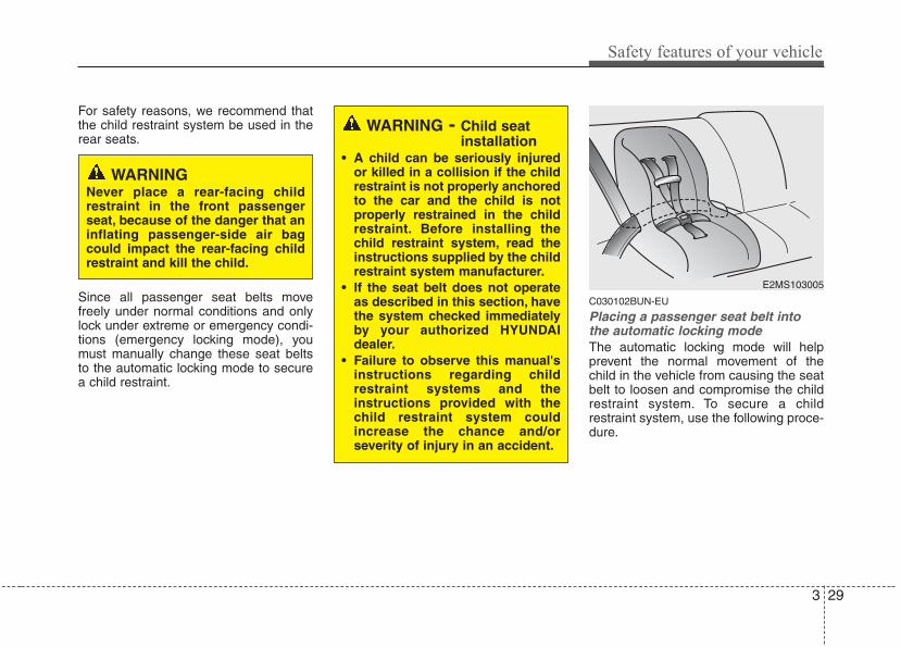
C030102BUN-EU
Placing a passenger seat belt intothe automatic locking mode The automatic locking mode will helpprevent the normal movement of thechild in the vehicle from causing the seatbelt to loosen and compromise the childrestraint system. To secure a childrestraint system, use the following proce-dure.
WARNING - Child seatinstallation
• A child can be seriously injuredor killed in a collision if the childrestraint is not properly anchoredto the car and the child is notproperly restrained in the childrestraint. Before installing thechild restraint system, read theinstructions supplied by the childrestraint system manufacturer.
• If the seat belt does not operateas described in this section, havethe system checked immediatelyby your authorized HYUNDAIdealer.
• Failure to observe this manual'sinstructions regarding childrestraint systems and theinstructions provided with thechild restraint system couldincrease the chance and/orseverity of injury in an accident.
WARNINGNever place a rear-facing childrestraint in the front passengerseat, because of the danger that aninflating passenger-side air bagcould impact the rear-facing childrestraint and kill the child.
E2MS103005
Safety features of your vehicle
303
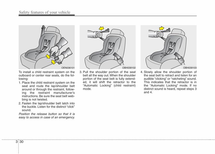
To install a child restraint system on theoutboard or center rear seats, do the fol-lowing:1. Place the child restraint system on the
seat and route the lap/shoulder beltaround or through the restraint, follow-ing the restraint manufacturer’sinstructions. Be sure the seat belt web-bing is not twisted.
2. Fasten the lap/shoulder belt latch intothe buckle. Listen for the distinct “click”sound.
Position the release button so that it iseasy to access in case of an emergency.
3. Pull the shoulder portion of the seatbelt all the way out. When the shoulderportion of the seat belt is fully extend-ed, it will shift the retractor to the“Automatic Locking” (child restraint)mode.
4. Slowly allow the shoulder portion ofthe seat belt to retract and listen for anaudible “clicking” or “ratcheting” sound.This indicates that the retractor is inthe “Automatic Locking” mode. If nodistinct sound is heard, repeat steps 3and 4.
OBH039102OEN036101 OBH039103
3 31
Safety features of your vehicle
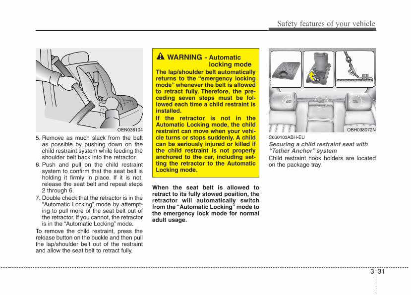
5. Remove as much slack from the beltas possible by pushing down on thechild restraint system while feeding theshoulder belt back into the retractor.
6. Push and pull on the child restraintsystem to confirm that the seat belt isholding it firmly in place. If it is not,release the seat belt and repeat steps2 through 6.
7. Double check that the retractor is in the“Automatic Locking” mode by attempt-ing to pull more of the seat belt out ofthe retractor. If you cannot, the retractoris in the “Automatic Locking” mode.
To remove the child restraint, press therelease button on the buckle and then pullthe lap/shoulder belt out of the restraintand allow the seat belt to retract fully.
When the seat belt is allowed toretract to its fully stowed position, theretractor will automatically switchfrom the “Automatic Locking” mode tothe emergency lock mode for normaladult usage.
C030103ABH-EU
Securing a child restraint seat with“Tether Anchor” system Child restraint hook holders are locatedon the package tray.
OEN036104
WARNING - Automaticlocking mode
The lap/shoulder belt automaticallyreturns to the “emergency lockingmode” whenever the belt is allowedto retract fully. Therefore, the pre-ceding seven steps must be fol-lowed each time a child restraint isinstalled.If the retractor is not in theAutomatic Locking mode, the childrestraint can move when your vehi-cle turns or stops suddenly. A childcan be seriously injured or killed ifthe child restraint is not properlyanchored to the car, including set-ting the retractor to the AutomaticLocking mode.
OBH038072N
Safety features of your vehicle
323
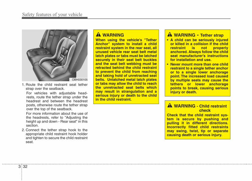
1. Route the child restraint seat tetherstrap over the seatback.For vehicles with adjustable head-rests, route the tether strap under theheadrest and between the headrestposts, otherwise route the tether strapover the top of the seatback.For more information about the use ofthe headrests, refer to "Adjusting theheight up and down - Rear seat" in thissection.
2. Connect the tether strap hook to theappropriate child restraint hook holderand tighten to secure the child restraintseat.
OBH030105
WARNINGWhen using the vehicle's "TetherAnchor" system to install a childrestraint system in the rear seat, allunused vehicle rear seat belt metallatch plates or tabs must be latchedsecurely in their seat belt bucklesand the seat belt webbing must beretracted behind the child restraintto prevent the child from reachingand taking hold of unretracted seatbelts. Unlatched metal latch platesor tabs may allow the child to reachthe unretracted seat belts whichmay result in strangulation and aserious injury or death to the childin the child restraint.
WARNING - Child restraintcheck
Check that the child restraint sys-tem is secure by pushing andpulling it in different directions.Incorrectly fitted child restraintsmay swing, twist, tip or separatecausing death or serious injury.
WARNING - Tether strap• A child can be seriously injured
or killed in a collision if the childrestraint is not properlyanchored. Always follow the childseat manufacturer’s instructionsfor installation and use.
• Never mount more than one childrestraint to a single tether anchoror to a single lower anchoragepoint. The increased load causedby multiple seats may cause thetethers or lower anchoragepoints to break, causing seriousinjury or death.
3 33
Safety features of your vehicle
C030104AEN-EU
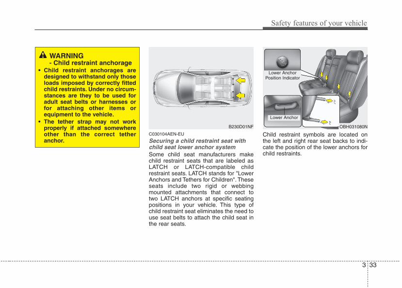
Securing a child restraint seat withchild seat lower anchor systemSome child seat manufacturers makechild restraint seats that are labeled asLATCH or LATCH-compatible childrestraint seats. LATCH stands for "LowerAnchors and Tethers for Children". Theseseats include two rigid or webbingmounted attachments that connect totwo LATCH anchors at specific seatingpositions in your vehicle. This type ofchild restraint seat eliminates the need touse seat belts to attach the child seat inthe rear seats.
Child restraint symbols are located onthe left and right rear seat backs to indi-cate the position of the lower anchors forchild restraints.
B230D01NF OBH031080N
WARNING - Child restraint anchorage
• Child restraint anchorages aredesigned to withstand only thoseloads imposed by correctly fittedchild restraints. Under no circum-stances are they to be used foradult seat belts or harnesses orfor attaching other items orequipment to the vehicle.
• The tether strap may not workproperly if attached somewhereother than the correct tetheranchor.
Lower AnchorPosition Indicator
Lower Anchor
Safety features of your vehicle
343
LATCH anchors have been provided inyour vehicle. The LATCH anchors arelocated in the left and right outboard rearseating positions. Their locations areshown in the illustration. There is noLATCH anchor provided for the centerrear seating position.The LATCH anchors are located betweenthe seatback and the seat cushion of therear seat left and right outboard seatingpositions.Follow the child seat manufacturer’sinstructions to properly install childrestraint seats with LATCH or LATCH-compatible attachments.Once you have installed the LATCH childrestraint, assure that the seat is properlyattached to the LATCH and tetheranchors.Also, test the child restraint seat beforeyou place the child in it. Tilt the seat fromside to side. Also try to tug the seat for-ward. Check to see if the anchors holdthe seat in place.
WARNINGIf the child restraint is not anchoredproperly, the risk of a child beingseriously injured or killed in a colli-sion greatly increases.
WARNING - LATCH loweranchors
LATCH lower anchors are only tobe used with the left and right rearoutboard seating positions. Neverattempt to attach a LATCHequipped seat in the center seatingposition. You may damage theanchors or the anchors may failand break in a collision.
WARNING • When using the vehicle's
"LATCH" system to install a childrestraint system in the rear seat,all unused vehicle rear seat beltmetal latch plates or tabs must belatched securely in their seat beltbuckles and the seat belt web-bing must be retracted behindthe child restraint to prevent thechild from reaching and takinghold of unretracted seat belts.Unlatched metal latch plates ortabs may allow the child to reachthe unretracted seat belts whichmay result in strangulation and aserious injury or death to thechild in the child restraint.
• Do not place anything around thelower anchors. Also make surethat the seat belt is not caught inthe lower anchors.
CAUTIONDo not allow the rear seat belt web-bing to get scratched or pinched bythe child-seat latch and LATCHanchor during the installation.
3 35
Safety features of your vehicle
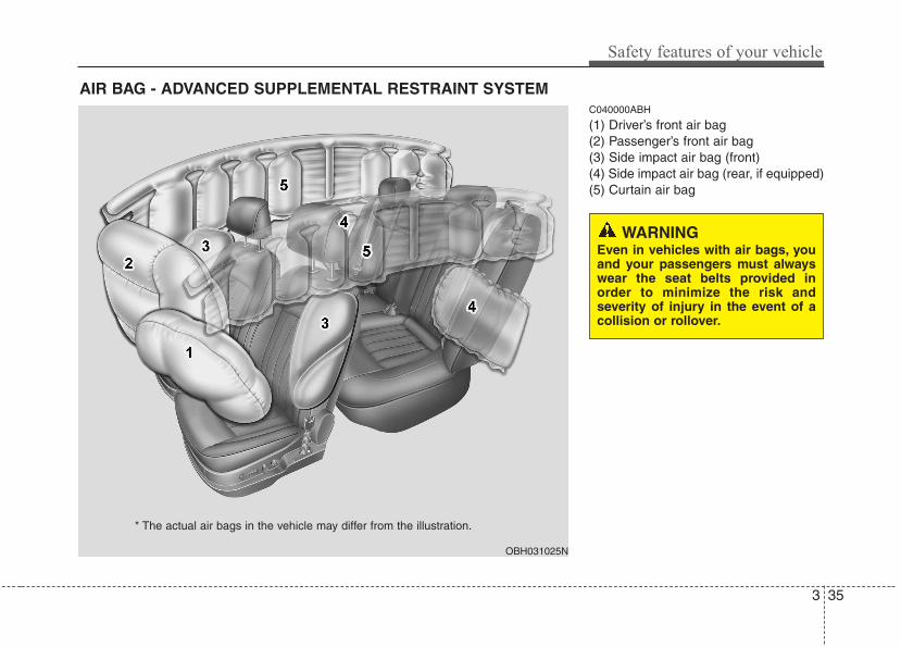
C040000ABH
(1) Driver’s front air bag(2) Passenger’s front air bag(3) Side impact air bag (front)(4) Side impact air bag (rear, if equipped)(5) Curtain air bag
AIR BAG - ADVANCED SUPPLEMENTAL RESTRAINT SYSTEM
OBH031025N
* The actual air bags in the vehicle may differ from the illustration.
WARNINGEven in vehicles with air bags, youand your passengers must alwayswear the seat belts provided inorder to minimize the risk andseverity of injury in the event of acollision or rollover.
Safety features of your vehicle
363
C040900AEN-EU
How does the air bag systemoperate • Air bags are activated (able to inflate if
necessary) only when the ignitionswitch is turned to the ON or STARTposition.
• Air bags inflate in the event of a seri-ous frontal or side collision in order tohelp protect the occupants from seri-ous physical injury.
• There is no single speed at which theair bags will inflate.Generally, air bags are designed toinflate based upon the severity of a col-lision and its direction. These two fac-tors determine whether the sensorsproduce an electronic deployment/inflation signal.
• Air bag deployment depends on anumber of factors including vehiclespeed, angles of impact and the densi-ty and stiffness of the vehicles orobjects which your vehicle hits in thecollision. The determining factors arenot limited to those mentioned above.
• The front air bags will completelyinflate and deflate in an instant.It is virtually impossible for you to seethe air bags inflate during an accident.
It is much more likely that you will sim-ply see the deflated air bags hangingout of their storage compartments afterthe collision.
• In order to help provide protection in asevere collision, the air bags mustinflate rapidly. The speed of air baginflation is a consequence of theextremely short time in which a collisionoccurs and the need to inflate the airbag between the occupant and thevehicle structures before the occupantimpacts those structures. This speed ofinflation reduces the risk of serious orlife-threatening injuries in a severe col-lision and is thus a necessary part of airbag design.However, air bag inflation can alsocause injuries which can include facialabrasions, bruises and broken bonesbecause the inflation speed also caus-es the air bags to expand with a greatdeal of force.
• There are even circumstancesunder which contact with the air bagcan cause fatal injuries, especially ifthe occupant is positioned exces-sively close to the air bag.
WARNING• To avoid severe personal injury
or death caused by deploying airbags in a collision, the drivershould sit as far back from thesteering wheel air bag as possi-ble (at least 10 inches (250 mm)away). The front passengersshould always move their seatsas far back as possible and sitback in their seat.
• Air bags inflate instantly in theevent of collision, and passen-gers may be injured by the air bagexpansion force if they are not inproper position.
• Air bag inflation may causeinjuries including facial or bodilyabrasions, injuries from brokenglasses or burns.
3 37
Safety features of your vehicle
C040902AEN
Noise and smokeWhen the air bags inflate, they make a loudnoise and they leave smoke and powder inthe air inside of the vehicle. This is normaland is a result of the ignition of the air baginflator. After the air bag inflates, you mayfeel substantial discomfort in breathing dueto the contact of your chest with both theseat belt and the air bag, as well as frombreathing the smoke and powder. Openyour doors and/or windows as soon aspossible after impact in order to reducediscomfort and prevent prolongedexposure to the smoke and powder.Though the smoke and powder are non-toxic, they may cause irritation to the skin(eyes, nose and throat, etc). If this is thecase, wash and rinse with cold waterimmediately and consult a doctor if thesymptom persists.
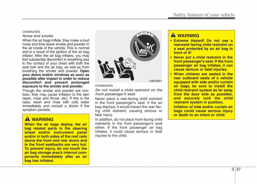
C040903AEN
Do not install a child restraint on thefront passenger’s seat.Never place a rear-facing child restraintin the front passenger’s seat. If the airbag deploys, it would impact the rear-fac-ing child restraint, causing serious orfatal injury.In addition, do not place front-facing childrestraints in the front passenger’s seateither. If the front passenger air baginflates, it could cause serious or fatalinjuries to the child.
1JBH3051
WARNINGWhen the air bags deploy, the airbag related parts in the steeringwheel and/or instrument paneland/or in both sides of the roof railsabove the front and rear doors andin the front seatbacks are very hot.To prevent injury, do not touch theair bag storage area’s internal com-ponents immediately after an airbag has inflated.
WARNING• Extreme Hazard! Do not use a
rearward facing child restraint ona seat protected by an air bag infront of it!
• Never put a child restraint in thefront passenger’s seat. If the frontpassenger air bag inflates, it cancause serious or fatal injuries.
• When children are seated in therear outboard seats of a vehicleequipped with side and/or curtainair bags, be sure to install thechild restraint system as far awayfrom the door side as possible,and securely lock the childrestraint system in position.Inflation of side and/or curtain airbags could cause serious injuryor death to an infant or child.
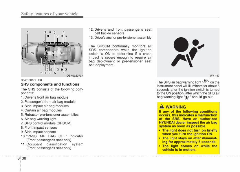
Safety features of your vehicle
383
C040100ABH-EU
SRS components and functionsThe SRS consists of the following com-ponents:1. Driver's front air bag module2. Passenger's front air bag module3. Side impact air bag modules4. Curtain air bag modules5. Retractor pre-tensioner assemblies6. Air bag warning light7. SRS control module (SRSCM)8. Front impact sensors9. Side impact sensors10. “PASS AIR BAG OFF” indicator
(Front passenger’s seat only)11. Occupant classification system
(Front passenger’s seat only)
12. Driver’s and front passenger’s seatbelt buckle sensors
13. Driver’s anchor pre-tensioner assembly
The SRSCM continually monitors allSRS components while the ignitionswitch is ON to determine if a crashimpact is severe enough to require airbag deployment or pre-tensioner seatbelt deployment.
The SRS air bag warning light " " on theinstrument panel will illuminate for about 6seconds after the ignition switch is turnedto the ON position, after which the SRS airbag warning light " " should go out.
W7-147OBH032079N
WARNING If any of the following conditionsoccurs, this indicates a malfunctionof the SRS. Have an authorizedHYUNDAI dealer inspect the air bagsystem as soon as possible.• The light does not turn on briefly
when you turn the ignition ON.• The light stays on after illuminat-
ing for approximately 6 seconds.• The light comes on while the
vehicle is in motion.
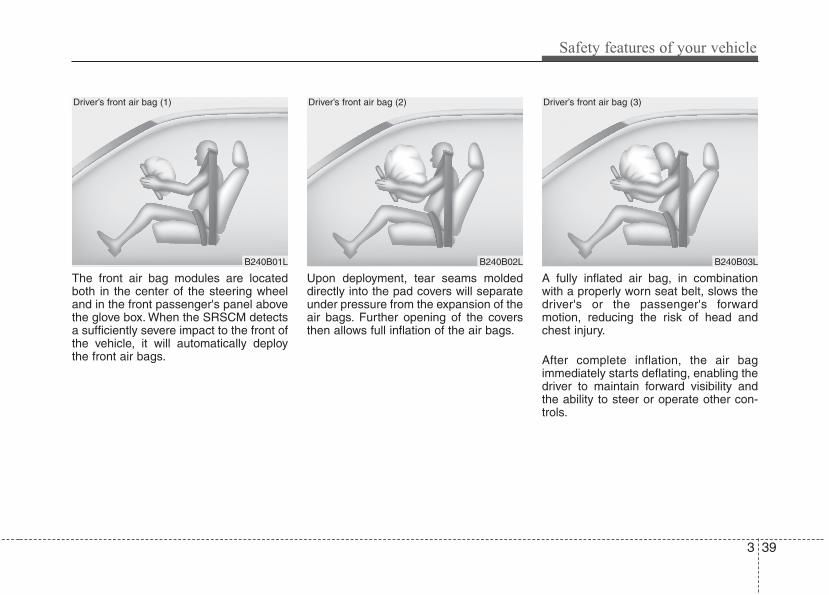
3 39
Safety features of your vehicle
The front air bag modules are locatedboth in the center of the steering wheeland in the front passenger's panel abovethe glove box. When the SRSCM detectsa sufficiently severe impact to the front ofthe vehicle, it will automatically deploythe front air bags.
Upon deployment, tear seams moldeddirectly into the pad covers will separateunder pressure from the expansion of theair bags. Further opening of the coversthen allows full inflation of the air bags.
A fully inflated air bag, in combinationwith a properly worn seat belt, slows thedriver's or the passenger's forwardmotion, reducing the risk of head andchest injury.
After complete inflation, the air bagimmediately starts deflating, enabling thedriver to maintain forward visibility andthe ability to steer or operate other con-trols.
B240B01L
Driver’s front air bag (1)
B240B02L B240B03L
Driver’s front air bag (2) Driver’s front air bag (3)
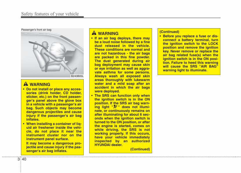
Safety features of your vehicle
403
WARNING • Do not install or place any acces-
sories (drink holder, CD holder,sticker, etc.) on the front passen-ger's panel above the glove boxin a vehicle with a passenger's airbag. Such objects may becomedangerous projectiles and causeinjury if the passenger's air baginflates.
• When installing a container of liq-uid air freshener inside the vehi-cle, do not place it near theinstrument cluster nor on theinstrument panel surface.It may become a dangerous pro-jectile and cause injury if the pas-senger's air bag inflates.
B240B05L
Passenger’s front air bag
WARNING• If an air bag deploys, there may
be a loud noise followed by a finedust released in the vehicle.These conditions are normal andare not hazardous - the air bagsare packed in this fine powder.The dust generated during airbag deployment may cause skinor eye irritation as well as aggra-vate asthma for some persons.Always wash all exposed skinareas thoroughly with lukewarmwater and a mild soap after anaccident in which the air bagswere deployed.
• The SRS can function only whenthe ignition switch is in the ONposition. If the SRS air bag warn-ing light " " does not illumi-nate, or continuously remains onafter illuminating for about 6 sec-onds when the ignition switch isturned to the ON position, or afterthe engine is started, comes onwhile driving, the SRS is notworking properly. If this occurs,have your vehicle immediatelyinspected by an authorizedHYUNDAI dealer.
(Continued)
(Continued)• Before you replace a fuse or dis-
connect a battery terminal, turnthe ignition switch to the LOCKposition and remove the ignitionkey. Never remove or replace theair bag related fuse(s) when theignition switch is in the ON posi-tion. Failure to heed this warningwill cause the SRS “AIR BAG”warning light to illuminate.
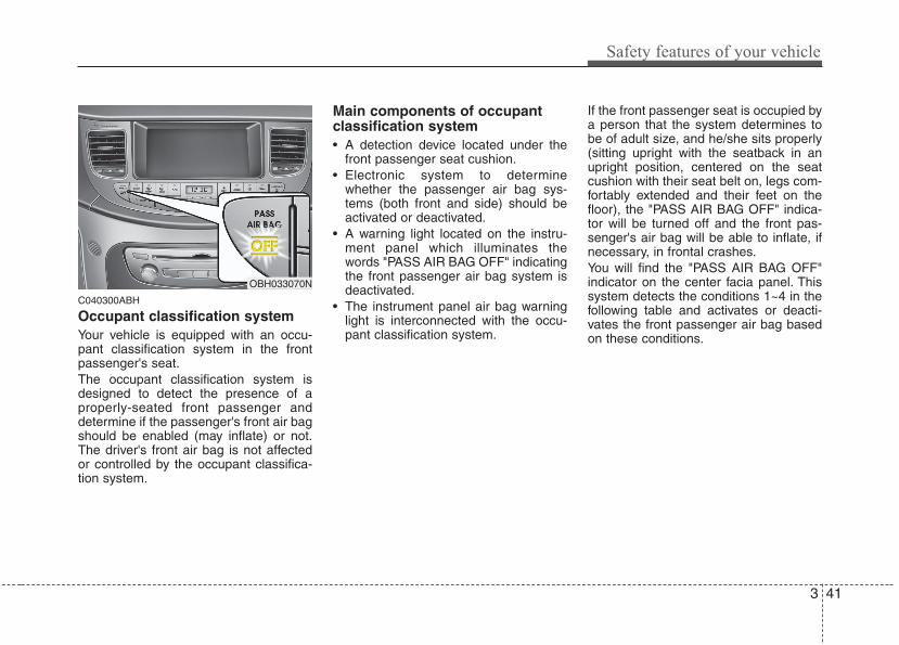
3 41
Safety features of your vehicle
C040300ABH
Occupant classification systemYour vehicle is equipped with an occu-pant classification system in the frontpassenger's seat.The occupant classification system isdesigned to detect the presence of aproperly-seated front passenger anddetermine if the passenger's front air bagshould be enabled (may inflate) or not.The driver's front air bag is not affectedor controlled by the occupant classifica-tion system.
Main components of occupantclassification system• A detection device located under the
front passenger seat cushion.• Electronic system to determine
whether the passenger air bag sys-tems (both front and side) should beactivated or deactivated.
• A warning light located on the instru-ment panel which illuminates thewords "PASS AIR BAG OFF" indicatingthe front passenger air bag system isdeactivated.
• The instrument panel air bag warninglight is interconnected with the occu-pant classification system.
If the front passenger seat is occupied bya person that the system determines tobe of adult size, and he/she sits properly(sitting upright with the seatback in anupright position, centered on the seatcushion with their seat belt on, legs com-fortably extended and their feet on thefloor), the "PASS AIR BAG OFF" indica-tor will be turned off and the front pas-senger's air bag will be able to inflate, ifnecessary, in frontal crashes.You will find the "PASS AIR BAG OFF"indicator on the center facia panel. Thissystem detects the conditions 1~4 in thefollowing table and activates or deacti-vates the front passenger air bag basedon these conditions.
OBH033070N
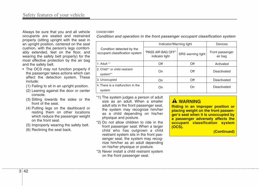
Safety features of your vehicle
423
Always be sure that you and all vehicleoccupants are seated and restrainedproperly (sitting upright with the seat inan upright position, centered on the seatcushion, with the person's legs comfort-ably extended, feet on the floor, andwearing the safety belt properly) for themost effective protection by the air bagand the safety belt.• The OCS may not function properly if
the passenger takes actions which canaffect the detection system. Theseinclude:(1) Failing to sit in an upright position.(2) Leaning against the door or center
console.(3) Sitting towards the sides or the
front of the seat.(4) Putting legs on the dashboard or
resting them on other locationswhich reduce the passenger weighton the front seat.
(5) Improperly wearing the safety belt.(6) Reclining the seat back.
C040301ABH
Condition and operation in the front passenger occupant classification system
*1) The system judges a person of adultsize as an adult. When a smalleradult sits in the front passenger seat,the system may recognize him/heras a child depending on his/herphysique and posture.
*2) Do not allow children to ride in thefront passenger seat. When a largerchild who has outgrown a childrestraint system sits in the front pas-senger seat, the system may recog-nize him/her as an adult dependingon his/her physique or posture.
*3) Never install a child restraint systemon the front passenger seat.
WARNINGRiding in an improper position orplacing weight on the front passen-ger's seat when it is unoccupied bya passenger adversely affects theoccupant classification system(OCS).
(Continued)
Condition detected by theoccupant classification system
1. Adult *1
2. Child*2 or child restraint
system*3
3. Unoccupied
4. There is a malfunction in the
system
Off
On
On
On
Off
Off
Off
On
Activated
Deactivated
Deactivated
Deactivated
"PASS AIR BAG OFF"indicator light
SRS warning lightFront passenger
air bag
Indicator/Warning light Devices
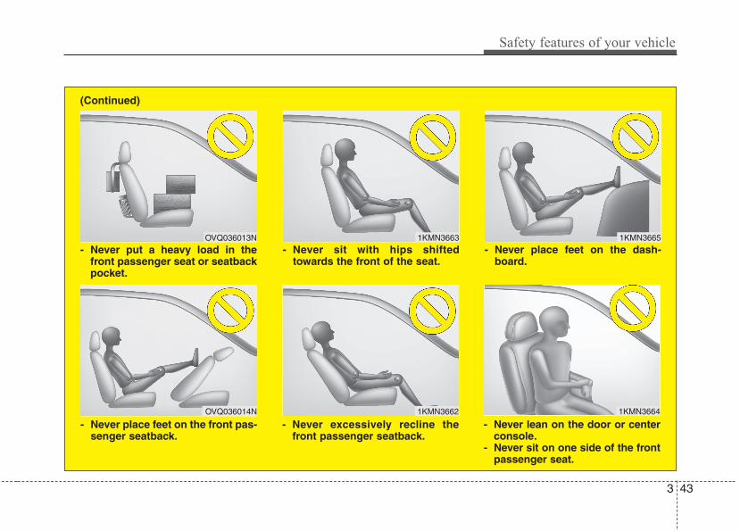
3 43
Safety features of your vehicle
1KMN3663
1KMN3664
1KMN3665
- Never sit with hips shiftedtowards the front of the seat.
- Never lean on the door or centerconsole.
- Never sit on one side of the frontpassenger seat.
- Never place feet on the dash-board.
OVQ036013N
1KMN3662
- Never put a heavy load in thefront passenger seat or seatbackpocket.
- Never excessively recline thefront passenger seatback.
OVQ036014N
- Never place feet on the front pas-senger seatback.
(Continued)
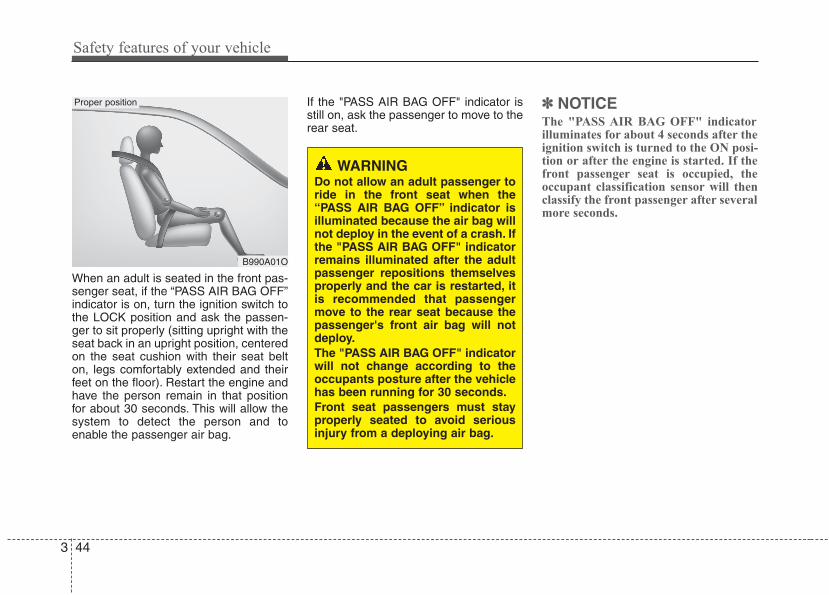
Safety features of your vehicle
443
When an adult is seated in the front pas-senger seat, if the “PASS AIR BAG OFF”indicator is on, turn the ignition switch tothe LOCK position and ask the passen-ger to sit properly (sitting upright with theseat back in an upright position, centeredon the seat cushion with their seat belton, legs comfortably extended and theirfeet on the floor). Restart the engine andhave the person remain in that positionfor about 30 seconds. This will allow thesystem to detect the person and toenable the passenger air bag.
If the "PASS AIR BAG OFF" indicator isstill on, ask the passenger to move to therear seat.
✽✽ NOTICEThe "PASS AIR BAG OFF" indicatorilluminates for about 4 seconds after theignition switch is turned to the ON posi-tion or after the engine is started. If thefront passenger seat is occupied, theoccupant classification sensor will thenclassify the front passenger after severalmore seconds.
B990A01O
WARNINGDo not allow an adult passenger toride in the front seat when the“PASS AIR BAG OFF” indicator isilluminated because the air bag willnot deploy in the event of a crash. Ifthe "PASS AIR BAG OFF" indicatorremains illuminated after the adultpassenger repositions themselvesproperly and the car is restarted, itis recommended that passengermove to the rear seat because thepassenger's front air bag will notdeploy.The "PASS AIR BAG OFF" indicatorwill not change according to theoccupants posture after the vehiclehas been running for 30 seconds.Front seat passengers must stayproperly seated to avoid seriousinjury from a deploying air bag.
Proper position
3 45
Safety features of your vehicle
(Continued)• Air bags can only be used once –
have an authorized HYUNDAIdealer replace the air bag imme-diately after deployment.
• A smaller-stature adult who is notseated correctly (for example:seat excessively reclined, leaningon the door or center console, orhips shifted forward in the seat)can cause a condition where theadvanced frontal air bag systemsenses less weight than if theoccupant were seated properly(sitting upright with the seatbackin an upright position, centeredon the seat cushion with theirseat belt on, legs comfortablyextended and their feet on thefloor).This condition can result in anadult potentially being misclassi-fied and illumination of the"PASS AIR BAG OFF" indicator.
(Continued)• Do not modify or replace the front
passenger seat. Don't place any-thing on or attach anything suchas a blanket or seat heater to thefront passenger seat. This canadversely affect the occupantclassification system.
• Do not sit on sharp objects suchas tools when occupying thefront passenger seat. This canadversely affect the occupantclassification system.
• Do not use accessory seat cov-ers on the front seats.
• Accident statistics show thatchildren are safer if they arerestrained in the rear, as opposedto the front seat. It is recom-mended that child restraints besecured in a rear seat, includingan infant riding in a rear-facinginfant seat, a child riding in a for-ward-facing child seat and anolder child riding in a boosterseat.
(Continued)
WARNING• Even though your vehicle is
equipped with the occupant clas-sification system, never install achild restraint system in the frontpassenger's seat. A deploying airbag can forcefully strike a childresulting in serious injuries ordeath. Any child age 12 andunder should ride in the rear seat.Children too large for childrestraints should use the avail-able lap/shoulder belts. No mat-ter what type of crash, children ofall ages are safer when restrainedin the rear seat.
• If the "PASS AIR BAG OFF" indi-cator is illuminated when thefront passenger's seat is occu-pied by an adult and he/she sitsproperly (sitting upright with theseatback in an upright position,centered on the seat cushionwith their seat belt on, legs com-fortably extended and their feeton the floor), have that person sitin the rear seat.
(Continued)
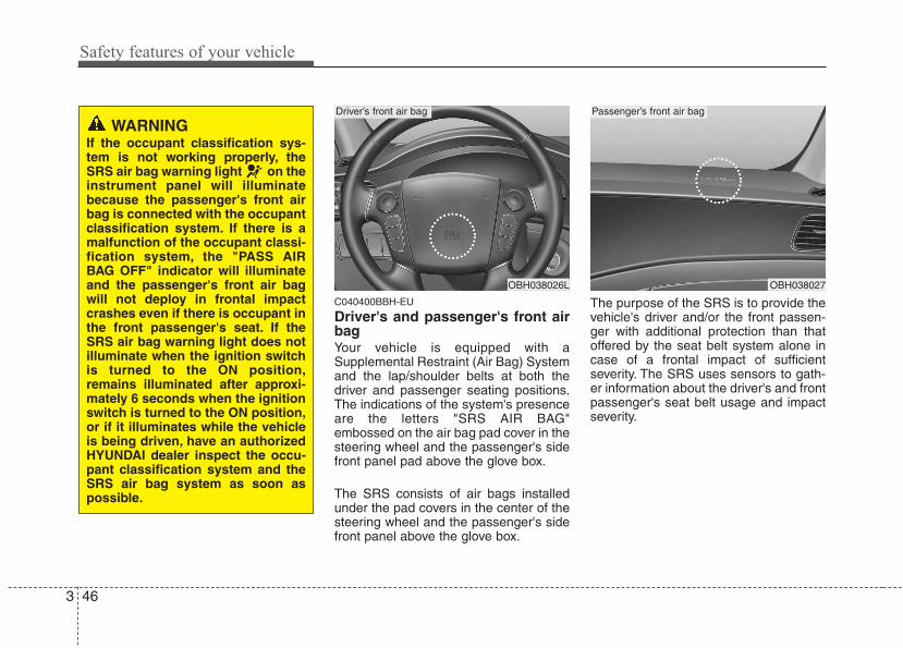
Safety features of your vehicle
463
C040400BBH-EU
Driver's and passenger's front airbagYour vehicle is equipped with aSupplemental Restraint (Air Bag) Systemand the lap/shoulder belts at both thedriver and passenger seating positions.The indications of the system's presenceare the letters "SRS AIR BAG"embossed on the air bag pad cover in thesteering wheel and the passenger's sidefront panel pad above the glove box.
The SRS consists of air bags installedunder the pad covers in the center of thesteering wheel and the passenger's sidefront panel above the glove box.
The purpose of the SRS is to provide thevehicle's driver and/or the front passen-ger with additional protection than thatoffered by the seat belt system alone incase of a frontal impact of sufficientseverity. The SRS uses sensors to gath-er information about the driver's and frontpassenger's seat belt usage and impactseverity.
OBH038026L
Driver’s front air bag
WARNINGIf the occupant classification sys-tem is not working properly, theSRS air bag warning light on theinstrument panel will illuminatebecause the passenger's front airbag is connected with the occupantclassification system. If there is amalfunction of the occupant classi-fication system, the "PASS AIRBAG OFF" indicator will illuminateand the passenger's front air bagwill not deploy in frontal impactcrashes even if there is occupant inthe front passenger's seat. If theSRS air bag warning light does notilluminate when the ignition switchis turned to the ON position,remains illuminated after approxi-mately 6 seconds when the ignitionswitch is turned to the ON position,or if it illuminates while the vehicleis being driven, have an authorizedHYUNDAI dealer inspect the occu-pant classification system and theSRS air bag system as soon aspossible.
OBH038027
Passenger’s front air bag
3 47
Safety features of your vehicle
The seat belt buckle sensors determine ifthe driver and front passenger's seatbelts are fastened. These sensors pro-vide the ability to control the SRS deploy-ment based on whether or not the seatbelts are fastened, and how severe theimpact is.
The advanced SRS offers the ability tocontrol the air bag inflation within two lev-els. A first stage level is provided for mod-erate-severity impacts. A second stagelevel is provided for more severe impacts.
According to the impact severity, andseat belt usage, the SRSCM (SRSControl Module) controls the air baginflation. Failure to properly wear seatbelts can increase the risk or severity ofinjury in an accident.
Additionally, your vehicle is equippedwith an occupant classification system inthe front passenger's seat. The occupantclassification system detects the pres-ence of a passenger in the front passen-ger's seat and will turn off the front pas-senger's air bag under certain condi-tions. For more detail, see "Occupantclassification system" in this section.
WARNINGIf the occupant classification sys-tem is not working properly, theSRS air bag warning light on theinstrument panel will illuminatebecause the SRS air bag warninglight is connected with the occu-pant classification system. If theSRS air bag warning light does notilluminate when the ignition switchis turned to the ON position,remains illuminated after approxi-mately 6 seconds when the ignitionswitch is turned to the ON position,or if it illuminates while the vehicleis being driven, have an authorizedHYUNDAI dealer inspect theadvanced SRS air bag system assoon as possible.
WARNINGDo not place any objects under-neath the front seats as they couldinterfere with the occupant classifi-cation system.
Safety features of your vehicle
483
✽✽ NOTICE• Be sure to read information about the
SRS on the labels provided on the sunvisor.
• Advanced air bags are combined withpre-tensioner seat belts to help pro-vide enhanced occupant protection infrontal crashes. Front air bags are notintended to deploy in collisions inwhich protection can be provided bythe pre-tensioner seat belt.
(Continued)• Move your seat as far back as
practical from the front air bags,while still maintaining control ofthe vehicle.
• You and your passengers shouldnever sit or lean unnecessarilyclose to the air bags. Improperlypositioned driver and passengerscan be severely injured by inflat-ing air bags.
• Never lean against the door orcenter console – always sit in anupright position.
• Do not allow an adult passengerto ride in the front seat when the“PASS AIR BAG OFF” indicator isilluminated, because the air bagwill not deploy in the event of amoderate or severe frontal crash.
(Continued)
WARNINGAlways use seat belts and childrestraints – every trip, every time,everyone! Air bags inflate with con-siderable force and in the blink ofan eye. Seat belts help keep occu-pants in proper position to obtainmaximum benefit from the air bag.Even with advanced air bags,improperly belted and unbeltedoccupants can be severely injuredwhen the air bag inflates. Alwaysfollow the precautions about seatbelts, air bags and occupant safetycontained in this manual.To reduce the chance of serious orfatal injuries and receive the maxi-mum safety benefit from yourrestraint system:• Never place a child in any child or
booster seat in the front seat.• ABC – Always Buckle Children in
the back seat. It is the safestplace for children of any age toride.
• Front and side air bags can injureoccupants improperly positionedin the front seats.
(Continued)
WARNINGIf you are considering modificationof your vehicle due to a disability,please contact the HyundaiCustomer Assistance Center at 1-800-633-5151.
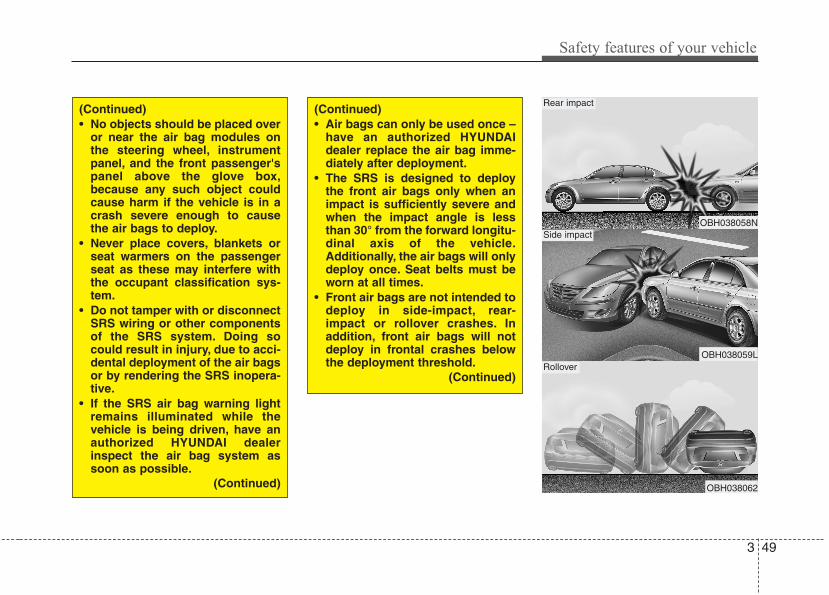
3 49
Safety features of your vehicle
OBH038058N
OBH038059L
OBH038062
Rear impact
Side impact
Rollover
(Continued)• No objects should be placed over
or near the air bag modules onthe steering wheel, instrumentpanel, and the front passenger'spanel above the glove box,because any such object couldcause harm if the vehicle is in acrash severe enough to causethe air bags to deploy.
• Never place covers, blankets orseat warmers on the passengerseat as these may interfere withthe occupant classification sys-tem.
• Do not tamper with or disconnectSRS wiring or other componentsof the SRS system. Doing socould result in injury, due to acci-dental deployment of the air bagsor by rendering the SRS inopera-tive.
• If the SRS air bag warning lightremains illuminated while thevehicle is being driven, have anauthorized HYUNDAI dealerinspect the air bag system assoon as possible.
(Continued)
(Continued)• Air bags can only be used once –
have an authorized HYUNDAIdealer replace the air bag imme-diately after deployment.
• The SRS is designed to deploythe front air bags only when animpact is sufficiently severe andwhen the impact angle is lessthan 30° from the forward longitu-dinal axis of the vehicle.Additionally, the air bags will onlydeploy once. Seat belts must beworn at all times.
• Front air bags are not intended todeploy in side-impact, rear-impact or rollover crashes. Inaddition, front air bags will notdeploy in frontal crashes belowthe deployment threshold.
(Continued)
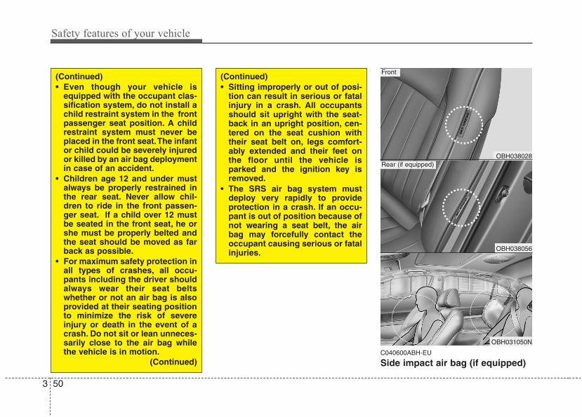
Safety features of your vehicle
503
C040600ABH-EU
Side impact air bag (if equipped)
(Continued)• Sitting improperly or out of posi-
tion can result in serious or fatalinjury in a crash. All occupantsshould sit upright with the seat-back in an upright position, cen-tered on the seat cushion withtheir seat belt on, legs comfort-ably extended and their feet onthe floor until the vehicle isparked and the ignition key isremoved.
• The SRS air bag system mustdeploy very rapidly to provideprotection in a crash. If an occu-pant is out of position because ofnot wearing a seat belt, the airbag may forcefully contact theoccupant causing serious or fatalinjuries.
(Continued)• Even though your vehicle is
equipped with the occupant clas-sification system, do not install achild restraint system in the frontpassenger seat position. A childrestraint system must never beplaced in the front seat.The infantor child could be severely injuredor killed by an air bag deploymentin case of an accident.
• Children age 12 and under mustalways be properly restrained inthe rear seat. Never allow chil-dren to ride in the front passen-ger seat. If a child over 12 mustbe seated in the front seat, he orshe must be properly belted andthe seat should be moved as farback as possible.
• For maximum safety protection inall types of crashes, all occu-pants including the driver shouldalways wear their seat beltswhether or not an air bag is alsoprovided at their seating positionto minimize the risk of severeinjury or death in the event of acrash. Do not sit or lean unneces-sarily close to the air bag whilethe vehicle is in motion.
(Continued)
OBH038028
OBH038056
OBH031050N
Front
Rear (if equipped)
3 51
Safety features of your vehicle
Your vehicle is equipped with a sideimpact air bag in each front and outboardrear seat. The purpose of the air bag is toprovide the vehicle's driver and/or thefront and outboard rear passenger withadditional protection than that offered bythe seat belt alone.The side impact air bags are designed todeploy only during certain side-impactcollisions, depending on the crash sever-ity, angle, speed and point of impact. Theside impact air bags are not designed todeploy in all side impact situations.
(Continued)• Do not install any accessories on
the side or near the side impactair bag.
• Do not place any objects over theair bag or between the air bagand yourself.
• Do not place any objects (anumbrella, bag, etc.) between thedoor and the seat. Such objectsmay become dangerous projec-tiles and cause injury if the sup-plemental side impact air baginflates.
• To prevent unexpected deploy-ment of the side impact air bagthat may result in personal injury,avoid impact to the side impactsensor when the ignition switchis on.
• If the seat or seat cover is dam-aged, have the vehicle checkedand repaired by an authorizedHYUNDAI dealer because yourvehicle is equipped with sideimpact air bags and an occupantclassification system.
WARNING• The side impact air bag is sup-
plemental to the seat belt sys-tems and is not a substitute forthem. Therefore your seat beltsmust be worn at all times whilethe vehicle is in motion. The airbags deploy only in certain sideimpact conditions severe enoughto cause significant injury to thevehicle occupants.
• For best protection from the sideimpact air bag system and toavoid being injured by thedeploying side impact air bag, allseat occupants should sit in anupright position with the seat beltproperly fastened. The driver'shands should be placed on thesteering wheel at the 9:00 and3:00 positions. The passengers'arms and hands should beplaced on their laps.
• Do not use any accessory seatcovers.
• Use of seat covers could reduceor prevent the effectiveness ofthe system.
(Continued)
WARNINGDo not allow the passengers to leantheir heads or bodies onto doors,put their arms on the doors, stretchtheir arms out of the window, orplace objects between the doorsand passengers when they areseated on seats equipped with sideand/or curtain air bags.
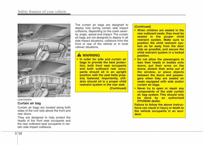
Safety features of your vehicle
523
C040700AEN
Curtain air bag Curtain air bags are located along bothsides of the roof rails above the front andrear doors.They are designed to help protect theheads of the front seat occupants andthe rear outboard seat occupants in cer-tain side impact collisions.
The curtain air bags are designed todeploy only during certain side impactcollisions, depending on the crash sever-ity, angle, speed and impact. The curtainair bags are not designed to deploy in allside impact situations, collisions from thefront or rear of the vehicle or in mostrollover situations.
WARNING• In order for side and curtain air
bags to provide the best protec-tion, both front seat occupantsand both outboard rear occu-pants should sit in an uprightposition with the seat belts prop-erly fastened. Importantly, chil-dren should sit in a proper childrestraint system in the rear seat.
(Continued)
(Continued)• When children are seated in the
rear outboard seats, they must beseated in the proper childrestraint system. Make sure toposition the child restraint sys-tem as far away from the doorside as possible, and secure thechild restraint system in a lockedposition.
• Do not allow the passengers tolean their heads or bodies ontodoors, put their arms on thedoors, stretch their arms out ofthe window, or place objectsbetween the doors and passen-gers when they are seated onseats equipped with side and/orcurtain air bags.
• Never try to open or repair anycomponents of the side curtainair bag system. This should onlybe done by an authorizedHYUNDAI dealer.
Failure to follow the above instruc-tions can result in injury or death tothe vehicle occupants in an acci-dent.
OBH038051N
OBH031052N
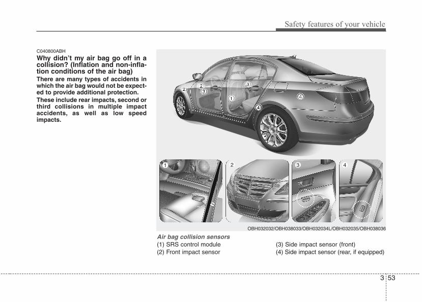
3 53
Safety features of your vehicle
C040800ABH
Why didn’t my air bag go off in acollision? (Inflation and non-infla-tion conditions of the air bag)There are many types of accidents inwhich the air bag would not be expect-ed to provide additional protection.These include rear impacts, second orthird collisions in multiple impactaccidents, as well as low speedimpacts.
Air bag collision sensors(1) SRS control module(2) Front impact sensor
(3) Side impact sensor (front)(4) Side impact sensor (rear, if equipped)
OBH032032/OBH038033/OBH032034L/OBH032035/OBH038036
1 2 3 4
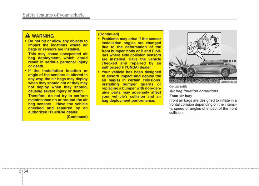
Safety features of your vehicle
543
C040801AEN
Air bag inflation conditionsFront air bags
Front air bags are designed to inflate in afrontal collision depending on the intensi-ty, speed or angles of impact of the frontcollision.
OBH038053
WARNING• Do not hit or allow any objects to
impact the locations where airbags or sensors are installed.This may cause unexpected airbag deployment, which couldresult in serious personal injuryor death.
• If the installation location orangle of the sensors is altered inany way, the air bags may deploywhen they should not or they maynot deploy when they should,causing severe injury or death.Therefore, do not try to performmaintenance on or around the airbag sensors. Have the vehiclechecked and repaired by anauthorized HYUNDAI dealer.
(Continued)
(Continued)• Problems may arise if the sensor
installation angles are changeddue to the deformation of thefront bumper, body or B and C pil-lars where side collision sensorsare installed. Have the vehiclechecked and repaired by anauthorized HYUNDAI dealer.
• Your vehicle has been designedto absorb impact and deploy theair bag(s) in certain collisions.Installing bumper guards orreplacing a bumper with non-gen-uine parts may adversely affectyour vehicle’s collision and airbag deployment performance.
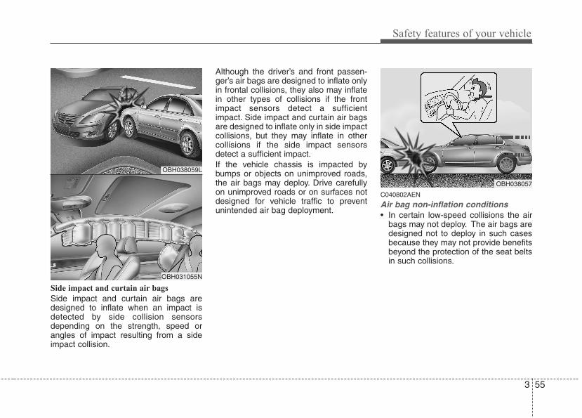
3 55
Safety features of your vehicle
Side impact and curtain air bags
Side impact and curtain air bags aredesigned to inflate when an impact isdetected by side collision sensorsdepending on the strength, speed orangles of impact resulting from a sideimpact collision.
Although the driver’s and front passen-ger’s air bags are designed to inflate onlyin frontal collisions, they also may inflatein other types of collisions if the frontimpact sensors detect a sufficientimpact. Side impact and curtain air bagsare designed to inflate only in side impactcollisions, but they may inflate in othercollisions if the side impact sensorsdetect a sufficient impact.If the vehicle chassis is impacted bybumps or objects on unimproved roads,the air bags may deploy. Drive carefullyon unimproved roads or on surfaces notdesigned for vehicle traffic to preventunintended air bag deployment.
C040802AEN
Air bag non-inflation conditions• In certain low-speed collisions the air
bags may not deploy. The air bags aredesigned not to deploy in such casesbecause they may not provide benefitsbeyond the protection of the seat beltsin such collisions.
OBH038057
OBH038059L
OBH031055N
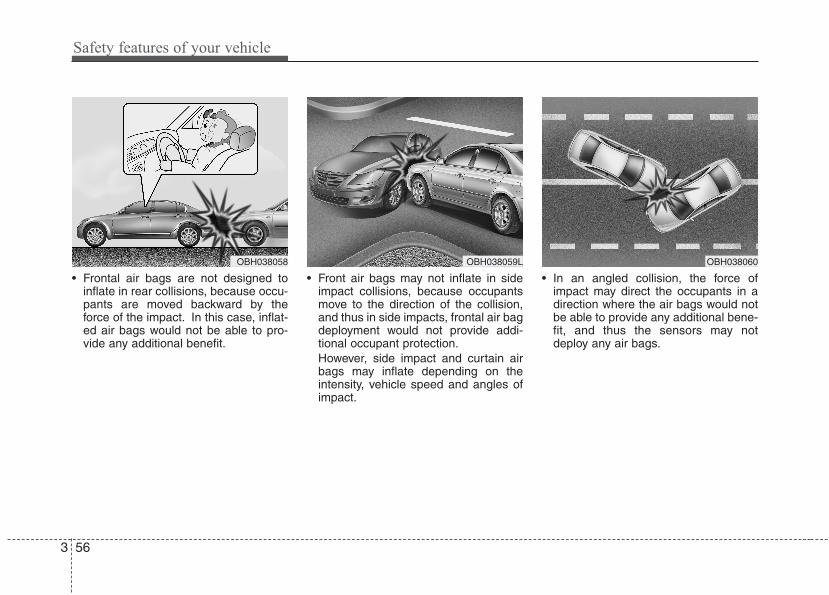
Safety features of your vehicle
563
• Frontal air bags are not designed toinflate in rear collisions, because occu-pants are moved backward by theforce of the impact. In this case, inflat-ed air bags would not be able to pro-vide any additional benefit.
• Front air bags may not inflate in sideimpact collisions, because occupantsmove to the direction of the collision,and thus in side impacts, frontal air bagdeployment would not provide addi-tional occupant protection.However, side impact and curtain airbags may inflate depending on theintensity, vehicle speed and angles ofimpact.
• In an angled collision, the force ofimpact may direct the occupants in adirection where the air bags would notbe able to provide any additional bene-fit, and thus the sensors may notdeploy any air bags.
OBH038060OBH038059LOBH038058
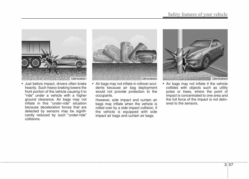
3 57
Safety features of your vehicle
• Just before impact, drivers often brakeheavily. Such heavy braking lowers thefront portion of the vehicle causing it to“ride” under a vehicle with a higherground clearance. Air bags may notinflate in this "under-ride" situationbecause deceleration forces that aredetected by sensors may be signifi-cantly reduced by such “under-ride”collisions.
• Air bags may not inflate in rollover acci-dents because air bag deploymentwould not provide protection to theoccupants.However, side impact and curtain airbags may inflate when the vehicle isrolled over by a side impact collision, ifthe vehicle is equipped with sideimpact air bags and curtain air bags.
• Air bags may not inflate if the vehiclecollides with objects such as utilitypoles or trees, where the point ofimpact is concentrated to one area andthe full force of the impact is not deliv-ered to the sensors.
OBH038061 OBH038062 OBH038063
Safety features of your vehicle
583
C041100BBH
SRS CareThe SRS is virtually maintenance-freeand there are no parts you can safelyservice by yourself. If the SRS air bagwarning light " " does not illuminate,when you turn the ignition on, or continu-ously remains on, have your vehicleimmediately inspected by an authorizedHYUNDAI dealer.
Any work on the SRS system, such asremoving, installing, repairing, or anywork on the steering wheel, the frontpassenger's panel, front seats and roofrails must be performed by an authorizedHYUNDAI dealer. Improper handling ofthe SRS system may result in seriouspersonal injury.
WARNING• Modification to SRS components
or wiring, including the additionof any kind of badges to the padcovers or modifications to thebody structure, can adverselyaffect SRS performance and leadto possible injury.
• For cleaning the air bag pad cov-ers, use only a soft, dry cloth orone which has been moistenedwith plain water. Solvents orcleaners could adversely affectthe air bag covers and properdeployment of the system.
• No objects should be placed overor near the air bag modules on thesteering wheel, instrument panel,and the front passenger's panelabove the glove box, because anysuch object could cause harm if thevehicle is in a crash severe enoughto cause the air bags to inflate.
(Continued)
(Continued)• If the air bags inflate, they must
be replaced by an authorizedHYUNDAI dealer.
• Do not tamper with or disconnectSRS wiring, or other componentsof the SRS system. Doing socould result in injury, due to acci-dental inflation of the air bags orby rendering the SRS inopera-tive.
• If components of the air bag sys-tem must be discarded, or if thevehicle must be scrapped, certainsafety precautions must beobserved. An authorizedHYUNDAI dealer knows theseprecautions and can give you thenecessary information. Failure tofollow these precautions and pro-cedures could increase the riskof personal injury.
• If your car was flooded and hassoaked carpeting or water on theflooring, you shouldn't try to startthe engine; have the car towed toan authorized HYUNDAI dealer.
3 59
Safety features of your vehicle
C041300ABH
Additional safety precautions• All occupants should sit upright, fully
back in their seats with their seat beltson and their feet on the floor.
• Passengers should not move out ofor change seats while the vehicle ismoving. A passenger who is not wear-ing a seat belt during a crash or emer-gency stop can be thrown against theinside of the vehicle, against otheroccupants, or out of the vehicle.
• Each seat belt is designed torestrain one occupant. If more thanone person uses the same seat belt,they could be seriously injured or killedin a collision.
• Do not use any accessories on seatbelts. Devices claiming to improveoccupant comfort or reposition the seatbelt can reduce the protection providedby the seat belt and increase thechance of serious injury in a crash.
• Passengers should not place hardor sharp objects between them-selves and the air bags. Carryinghard or sharp objects on your lap or inyour mouth can result in injuries if anair bag inflates.
• Keep occupants away from the airbag covers. All occupants should situpright, fully back in their seats withtheir seat belts on and their feet on thefloor. If occupants are too close to theair bag covers, they could be injured ifthe air bags inflate.
• Do not attach or place objects on ornear the air bag covers. Any objectattached to or placed on the front orside air bag covers could interfere withthe proper operation of the air bags.
• Do not modify the front seats.Modification of the front seats couldinterfere with the operation of the sup-plemental restraint system sensingcomponents or side air bags.
• Do not place items under the frontseats. Placing items under the frontseats could interfere with the operationof the supplemental restraint systemsensing components and wiring har-nesses.
• Never hold an infant or child on yourlap. The infant or child could be seri-ously injured or killed in the event of acrash. All infants and children shouldbe properly restrained in appropriatechild safety seats or seat belts in therear seat.
C041400AUN
Adding equipment to or modifyingyour air bag-equipped vehicleIf you modify your vehicle by changingyour vehicle's frame, bumper system,front end or side sheet metal or rideheight, this may affect the operation ofyour vehicle's air bag system.
WARNING• Sitting improperly or out of posi-
tion can cause occupants to beshifted too close to a deployingair bag, strike the interior struc-ture or be thrown from the vehicleresulting in serious injury ordeath.
• Always sit upright with the seat-back in an upright position, cen-tered on the seat cushion withyour seat belt on, legs comfort-ably extended and your feet onthe floor.
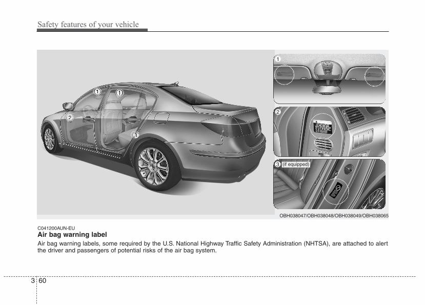
C041200AUN-EU
Air bag warning labelAir bag warning labels, some required by the U.S. National Highway Traffic Safety Administration (NHTSA), are attached to alertthe driver and passengers of potential risks of the air bag system.
OBH038047/OBH038048/OBH038049/OBH038065
2
1
3 (if equipped)
3 60
Safety features of your vehicle
4
Keys / 4-3
Smart key / 4-7
Remote keyless entry / 4-11
Theft-alarm system / 4-14
Door locks / 4-16
Trunk / 4-20
Windows / 4-23
Hood / 4-27
Fuel filler lid / 4-28
Sunroof / 4-31
Driver position memory system / 4-34
Steering wheel / 4-37
Mirrors / 4-39
Instrument cluster / 4-48
Parking assist system / 4-72
Rear view camera / 4-76
Hazard warning flasher / 4-76
Lighting / 4-77
Wipers and washers / 4-82
Interior light / 4-85
Defroster / 4-88
Automatic climate control system / 4-89
Features of your vehicle
Windshield defrosting and defogging / 4-101
Storage compartments / 4-104
Interior features / 4-106
Audio system / 4-115
Features of your vehicle4
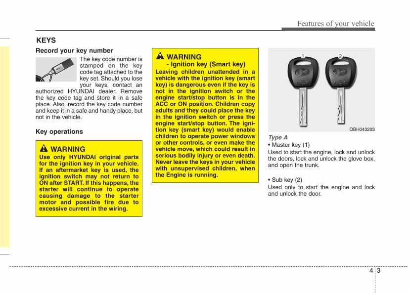
4 3
Features of your vehicle
Record your key numberThe key code number isstamped on the keycode tag attached to thekey set. Should you loseyour keys, contact an
authorized HYUNDAI dealer. Removethe key code tag and store it in a safeplace. Also, record the key code numberand keep it in a safe and handy place, butnot in the vehicle.
Key operationsType A• Master key (1)Used to start the engine, lock and unlockthe doors, lock and unlock the glove box,and open the trunk.
• Sub key (2)Used only to start the engine and lockand unlock the door.
KEYS
WARNING- Ignition key (Smart key)
Leaving children unattended in avehicle with the ignition key (smartkey) is dangerous even if the key isnot in the ignition switch or theengine start/stop button is in theACC or ON position. Children copyadults and they could place the keyin the ignition switch or press theengine start/stop button. The igni-tion key (smart key) would enablechildren to operate power windowsor other controls, or even make thevehicle move, which could result inserious bodily injury or even death.Never leave the keys in your vehiclewith unsupervised children, whenthe Engine is running.
WARNINGUse only HYUNDAI original partsfor the ignition key in your vehicle.If an aftermarket key is used, theignition switch may not return toON after START. If this happens, thestarter will continue to operatecausing damage to the startermotor and possible fire due toexcessive current in the wiring.
OBH043203
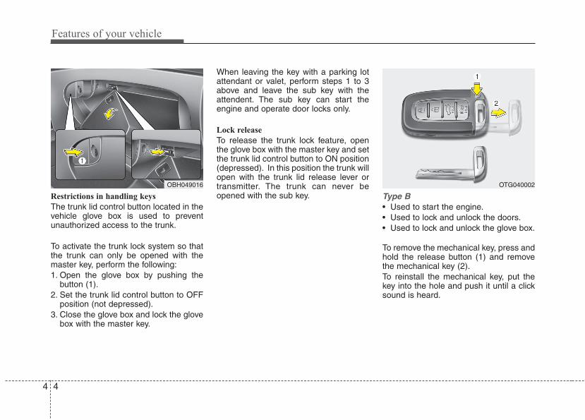
Features of your vehicle
44
Restrictions in handling keys
The trunk lid control button located in thevehicle glove box is used to preventunauthorized access to the trunk.
To activate the trunk lock system so thatthe trunk can only be opened with themaster key, perform the following:1. Open the glove box by pushing the
button (1).2. Set the trunk lid control button to OFF
position (not depressed).3. Close the glove box and lock the glove
box with the master key.
When leaving the key with a parking lotattendant or valet, perform steps 1 to 3above and leave the sub key with theattendent. The sub key can start theengine and operate door locks only.
Lock release
To release the trunk lock feature, openthe glove box with the master key and setthe trunk lid control button to ON position(depressed). In this position the trunk willopen with the trunk lid release lever ortransmitter. The trunk can never beopened with the sub key. Type B
• Used to start the engine.• Used to lock and unlock the doors.• Used to lock and unlock the glove box.
To remove the mechanical key, press andhold the release button (1) and removethe mechanical key (2).To reinstall the mechanical key, put thekey into the hole and push it until a clicksound is heard.
OBH049016 OTG040002
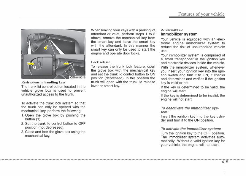
4 5
Features of your vehicle
Restrictions in handling keys
The trunk lid control button located in thevehicle glove box is used to preventunauthorized access to the trunk.
To activate the trunk lock system so thatthe trunk can only be opened with themechanical key, perform the following:1. Open the glove box by pushing the
button (1).2. Set the trunk lid control button to OFF
position (not depressed).3. Close and lock the glove box using the
mechanical key.
When leaving your keys with a parking lotattendant or valet, perform steps 1 to 3above, remove the mechanical key fromthe smart key and leave the smart keywith the attendant. In this manner thesmart key can only be used to start theengine and operate door locks.
Lock release
To release the trunk lock feature, openthe glove box with the mechanical keyand set the trunk lid control button to ONposition (depressed). In this position thetrunk will open with the trunk lid releaselever or smart key.
D010300CBH-EU
Immobilizer systemYour vehicle is equipped with an elec-tronic engine immobilizer system toreduce the risk of unauthorized vehicleuse.Your immobilizer system is comprised ofa small transponder in the ignition keyand electronic devices inside the vehicle.With the immobilizer system, wheneveryou insert your ignition key into the igni-tion switch and turn it to ON, it checksand determines and verifies if the ignitionkey is valid or not.If the key is determined to be valid, theengine will start.If the key is determined to be invalid, theengine will not start.
To deactivate the immobilizer sys-tem:Insert the ignition key into the key cylin-der and turn it to the ON position.
To activate the immobilizer system:Turn the ignition key to the OFF position.The immobilizer system activates auto-matically. Without a valid ignition key foryour vehicle, the engine will not start.
OBH049016
Features of your vehicle
64
✽✽ NOTICEWhen starting the engine, do not use thekey with other immobilizer keys around.Otherwise the engine may not start ormay stop soon after it starts. Keep eachkey separate in order to avoid a startingmalfunction.
✽✽ NOTICEIf you need additional keys or lose yourkeys, consult an authorized HYUNDAIdealer.
This device complies with Part 15 ofthe FCC rules.Operation is subject to the following twoconditions:1. This device may not cause harmful
interference, and 2. This device must accept any interfer-
ence received, including interferencethat may cause undesired operation.
CAUTIONThe transponder in your ignitionkey is an important part of theimmobilizer system. It is designedto give years of trouble-free service,however you should avoid expo-sure to moisture, static electricityand rough handling. Immobilizersystem malfunction could occur.
CAUTIONDo not put metal accessories nearthe ignition switch.The engine may not start becausethe metal accessories may interruptthe transponder signal from trans-mitting normally.
WARNINGIn order to prevent theft of yourvehicle, do not leave spare keysanywhere in your vehicle. YourImmobilizer password is a cus-tomer unique password and shouldbe kept confidential. Do not leavethis number anywhere in your vehi-cle.
CAUTIONDo not change, alter or adjust theimmobilizer system because itcould cause the immobilizer sys-tem to malfunction and should onlybe serviced by an authorizedHYUNDAI dealer.Malfunctions caused by improperalterations, adjustments or modifi-cations to the immobilizer systemare not covered by your vehiclemanufacturer warranty.
WARNINGChanges or modifications notexpressly approved by the partyresponsible for compliance couldvoid the user’s authority to operatethe equipment.
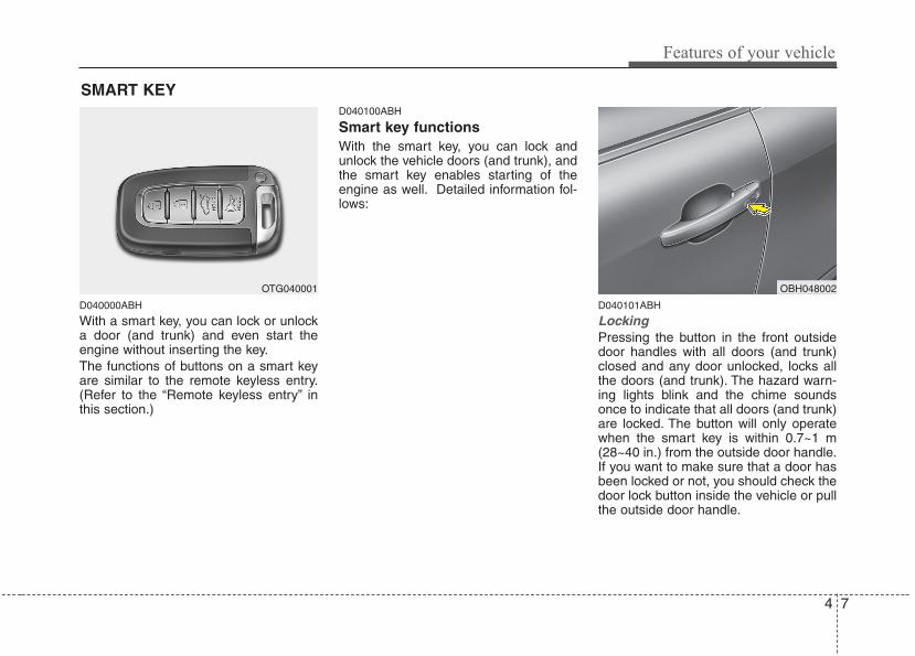
4 7
Features of your vehicle
D040000ABH
With a smart key, you can lock or unlocka door (and trunk) and even start theengine without inserting the key.The functions of buttons on a smart keyare similar to the remote keyless entry.(Refer to the “Remote keyless entry” inthis section.)
D040100ABH
Smart key functionsWith the smart key, you can lock andunlock the vehicle doors (and trunk), andthe smart key enables starting of theengine as well. Detailed information fol-lows:
D040101ABH
Locking Pressing the button in the front outsidedoor handles with all doors (and trunk)closed and any door unlocked, locks allthe doors (and trunk). The hazard warn-ing lights blink and the chime soundsonce to indicate that all doors (and trunk)are locked. The button will only operatewhen the smart key is within 0.7~1 m(28~40 in.) from the outside door handle.If you want to make sure that a door hasbeen locked or not, you should check thedoor lock button inside the vehicle or pullthe outside door handle.
OTG040001
SMART KEY
OBH048002
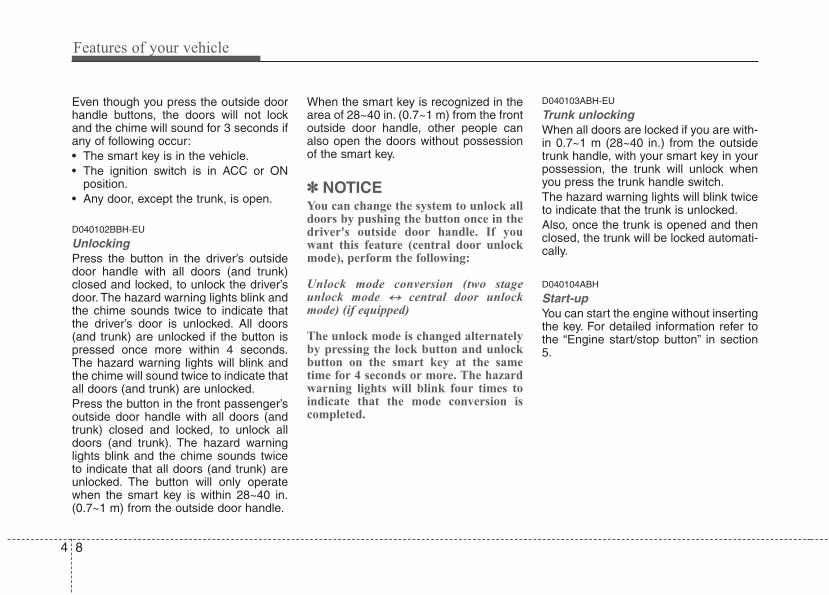
Features of your vehicle
84
Even though you press the outside doorhandle buttons, the doors will not lockand the chime will sound for 3 seconds ifany of following occur:• The smart key is in the vehicle.• The ignition switch is in ACC or ON
position.• Any door, except the trunk, is open.
D040102BBH-EU
Unlocking Press the button in the driver’s outsidedoor handle with all doors (and trunk)closed and locked, to unlock the driver’sdoor. The hazard warning lights blink andthe chime sounds twice to indicate thatthe driver’s door is unlocked. All doors(and trunk) are unlocked if the button ispressed once more within 4 seconds.The hazard warning lights will blink andthe chime will sound twice to indicate thatall doors (and trunk) are unlocked.Press the button in the front passenger’soutside door handle with all doors (andtrunk) closed and locked, to unlock alldoors (and trunk). The hazard warninglights blink and the chime sounds twiceto indicate that all doors (and trunk) areunlocked. The button will only operatewhen the smart key is within 28~40 in.(0.7~1 m) from the outside door handle.
When the smart key is recognized in thearea of 28~40 in. (0.7~1 m) from the frontoutside door handle, other people canalso open the doors without possessionof the smart key.
✽✽ NOTICEYou can change the system to unlock alldoors by pushing the button once in thedriver's outside door handle. If youwant this feature (central door unlockmode), perform the following:
Unlock mode conversion (two stageunlock mode ↔↔ central door unlockmode) (if equipped)
The unlock mode is changed alternatelyby pressing the lock button and unlockbutton on the smart key at the sametime for 4 seconds or more. The hazardwarning lights will blink four times toindicate that the mode conversion iscompleted.
D040103ABH-EU
Trunk unlocking When all doors are locked if you are with-in 0.7~1 m (28~40 in.) from the outsidetrunk handle, with your smart key in yourpossession, the trunk will unlock whenyou press the trunk handle switch.The hazard warning lights will blink twiceto indicate that the trunk is unlocked.Also, once the trunk is opened and thenclosed, the trunk will be locked automati-cally.
D040104ABH
Start-upYou can start the engine without insertingthe key. For detailed information refer tothe “Engine start/stop button” in section5.
4 9
Features of your vehicle
D040300AEN-EU
Smart key precautions✽✽ NOTICE• If, for some reason, you happen to lose
your smart key, you will not be able tostart the engine. Tow the vehicle, ifnecessary, and contact an authorizedHYUNDAI dealer.
• A maximum of 2 smart keys can beregistered to a single vehicle. If youlose a smart key, you should immedi-ately take the vehicle and key to yourauthorized HYUNDAI dealer to pro-tect it from potential theft.
• The smart key will not work if any offollowing occur:- The smart key is close to a radio
transmitter such as a radio station oran airport which can interfere withnormal operation of the smart key.
- You keep the smart key near amobile two-way radio system or acellular phone.
- Another vehicle’s smart key is beingoperated close to your vehicle.
When the smart key does not workcorrectly, open and close the door withthe mechanical key. If you have aproblem with the smart key, contactan authorized HYUNDAI dealer.
(Continued)
(Continued)• If the smart key is in close proximity
to your cell phone or smart phone, thesignal from the smart key could beblocked by normal operation of yourcell phone or smart phone. This isespecially important when the phoneis active such as making call, receivingcalls, text messaging, and/or send-ing/receiving emails. Avoid placingthe smart key and your cell phone orsmart phone in the same pants orjacket pocket and maintain adequatedistance between the two devices.
This device complies with Part 15 ofthe FCC rules.Operation is subject to the following twoconditions:1. This device may not cause harmful
interference, and 2. This device must accept any interfer-
ence received, including interferencethat may cause undesired operation.
CAUTIONKeep the smart key away fromwater or any liquid. If the keylessentry system is inoperative due toexposure to water or other liquids,it will not be covered by your manu-facturer’s vehicle warranty.
WARNINGChanges or modifications notexpressly approved by the partyresponsible for compliance couldvoid the user’s authority to operatethe equipment. If the keyless entrysystem is inoperative due tochanges or modifications notexpressly approved by the partyresponsible for compliance, it willnot be covered by your manufactur-er’s vehicle warranty.
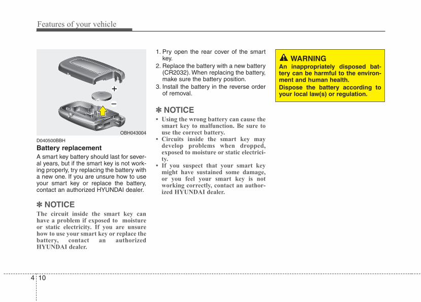
Features of your vehicle
104
D040500BBH
Battery replacementA smart key battery should last for sever-al years, but if the smart key is not work-ing properly, try replacing the battery witha new one. If you are unsure how to useyour smart key or replace the battery,contact an authorized HYUNDAI dealer.
✽✽ NOTICEThe circuit inside the smart key canhave a problem if exposed to moistureor static electricity. If you are unsurehow to use your smart key or replace thebattery, contact an authorizedHYUNDAI dealer.
1. Pry open the rear cover of the smartkey.
2. Replace the battery with a new battery(CR2032). When replacing the battery,make sure the battery position.
3. Install the battery in the reverse orderof removal.
✽✽ NOTICE• Using the wrong battery can cause the
smart key to malfunction. Be sure touse the correct battery.
• Circuits inside the smart key maydevelop problems when dropped,exposed to moisture or static electrici-ty.
• If you suspect that your smart keymight have sustained some damage,or you feel your smart key is notworking correctly, contact an author-ized HYUNDAI dealer.
OBH043004
WARNINGAn inappropriately disposed bat-tery can be harmful to the environ-ment and human health.Dispose the battery according toyour local law(s) or regulation.
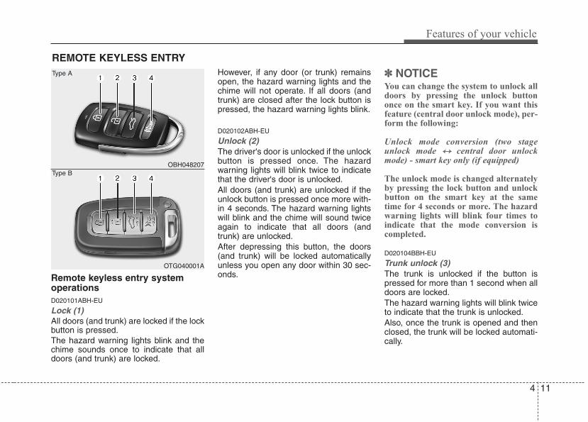
4 11
Features of your vehicle
Remote keyless entry systemoperationsD020101ABH-EU
Lock (1)All doors (and trunk) are locked if the lockbutton is pressed.The hazard warning lights blink and thechime sounds once to indicate that alldoors (and trunk) are locked.
However, if any door (or trunk) remainsopen, the hazard warning lights and thechime will not operate. If all doors (andtrunk) are closed after the lock button ispressed, the hazard warning lights blink.
D020102ABH-EU
Unlock (2) The driver's door is unlocked if the unlockbutton is pressed once. The hazardwarning lights will blink twice to indicatethat the driver's door is unlocked.All doors (and trunk) are unlocked if theunlock button is pressed once more with-in 4 seconds. The hazard warning lightswill blink and the chime will sound twiceagain to indicate that all doors (andtrunk) are unlocked.After depressing this button, the doors(and trunk) will be locked automaticallyunless you open any door within 30 sec-onds.
✽✽ NOTICEYou can change the system to unlock alldoors by pressing the unlock buttononce on the smart key. If you want thisfeature (central door unlock mode), per-form the following:
Unlock mode conversion (two stageunlock mode ↔↔ central door unlockmode) - smart key only (if equipped)
The unlock mode is changed alternatelyby pressing the lock button and unlockbutton on the smart key at the sametime for 4 seconds or more. The hazardwarning lights will blink four times toindicate that the mode conversion iscompleted.
D020104BBH-EU
Trunk unlock (3)The trunk is unlocked if the button ispressed for more than 1 second when alldoors are locked.The hazard warning lights will blink twiceto indicate that the trunk is unlocked.Also, once the trunk is opened and thenclosed, the trunk will be locked automati-cally.
REMOTE KEYLESS ENTRY
OBH048207
OTG040001A
Type A
Type B
Features of your vehicle
124
D020105ABH
Alarm (4)The horn sounds and hazard warninglights flash for about 30 seconds if thisbutton is pressed for more than 0.5 sec-ond. To stop the horn and lights, pressany button on the transmitter (or thesmart key).
D020200AEN-EU
Transmitter precautions✽✽ NOTICE• The transmitter will not work if any of
following occur:- The ignition key is in ignition switch.- You exceed the operating distance
limit (about 90 feet [30 m]).- The battery in the transmitter is weak.- Other vehicles or objects may be
blocking the signal.- The weather is extremely cold.- The transmitter is close to a radio
transmitter such as a radio station oran airport which can interfere withnormal operation of the transmitter.
When the transmitter does not workcorrectly, open and close the door withthe ignition key. If you have a problemwith the transmitter, contact an author-ized HYUNDAI dealer.
(Continued)
(Continued)• If the transmitter is in close proximity
to your cell phone or smart phone, thesignal from the transmitter could beblocked by normal operation of yourcell phone or smart phone. This isespecially important when the phoneis active such as making call, receivingcalls, text messaging, and/or send-ing/receiving emails. Avoid placing thetransmitter and your cell phone orsmart phone in the same pants orjacket pocket and maintain adequatedistance between the two devices.
CAUTIONKeep the transmitter away fromwater or any liquid. If the keylessentry system is inoperative due toexposure to water or liquids, it willnot be covered by your manufactur-er’s vehicle warranty.
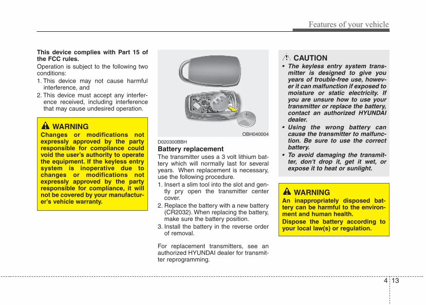
4 13
Features of your vehicle
This device complies with Part 15 ofthe FCC rules.Operation is subject to the following twoconditions:1. This device may not cause harmful
interference, and 2. This device must accept any interfer-
ence received, including interferencethat may cause undesired operation.
D020300BBH
Battery replacementThe transmitter uses a 3 volt lithium bat-tery which will normally last for severalyears. When replacement is necessary,use the following procedure.1. Insert a slim tool into the slot and gen-
tly pry open the transmitter centercover.
2. Replace the battery with a new battery(CR2032). When replacing the battery,make sure the battery position.
3. Install the battery in the reverse orderof removal.
For replacement transmitters, see anauthorized HYUNDAI dealer for transmit-ter reprogramming.
CAUTION• The keyless entry system trans-
mitter is designed to give youyears of trouble-free use, howev-er it can malfunction if exposed tomoisture or static electricity. Ifyou are unsure how to use yourtransmitter or replace the battery,contact an authorized HYUNDAIdealer.
• Using the wrong battery cancause the transmitter to malfunc-tion. Be sure to use the correctbattery.
• To avoid damaging the transmit-ter, don't drop it, get it wet, orexpose it to heat or sunlight.
OBH040004
WARNINGAn inappropriately disposed bat-tery can be harmful to the environ-ment and human health.Dispose the battery according toyour local law(s) or regulation.
WARNINGChanges or modifications notexpressly approved by the partyresponsible for compliance couldvoid the user’s authority to operatethe equipment. If the keyless entrysystem is inoperative due tochanges or modifications notexpressly approved by the partyresponsible for compliance, it willnot be covered by your manufactur-er’s vehicle warranty.
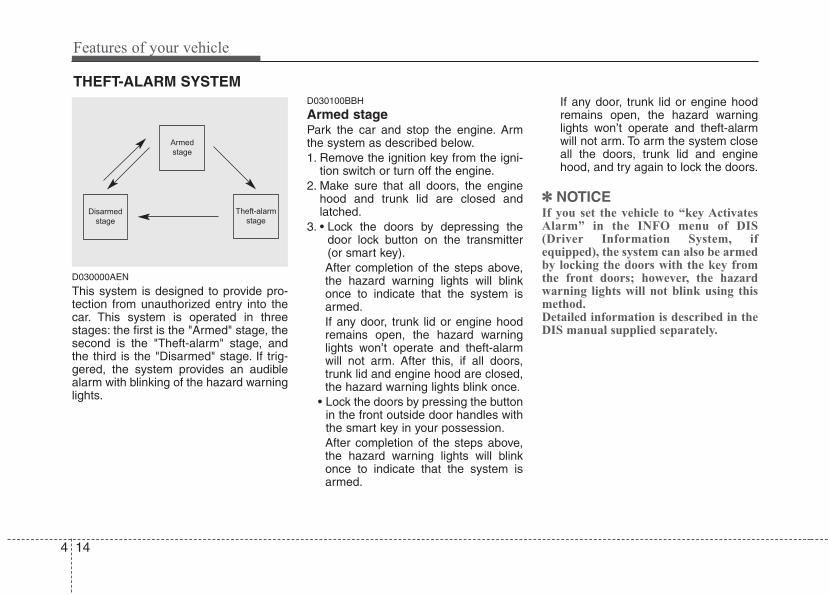
Features of your vehicle
144
D030000AEN
This system is designed to provide pro-tection from unauthorized entry into thecar. This system is operated in threestages: the first is the "Armed" stage, thesecond is the "Theft-alarm" stage, andthe third is the "Disarmed" stage. If trig-gered, the system provides an audiblealarm with blinking of the hazard warninglights.
D030100BBH
Armed stagePark the car and stop the engine. Armthe system as described below.1. Remove the ignition key from the igni-
tion switch or turn off the engine.2. Make sure that all doors, the engine
hood and trunk lid are closed andlatched.
3. • Lock the doors by depressing thedoor lock button on the transmitter(or smart key).After completion of the steps above,the hazard warning lights will blinkonce to indicate that the system isarmed.If any door, trunk lid or engine hoodremains open, the hazard warninglights won’t operate and theft-alarmwill not arm. After this, if all doors,trunk lid and engine hood are closed,the hazard warning lights blink once.
• Lock the doors by pressing the buttonin the front outside door handles withthe smart key in your possession.After completion of the steps above,the hazard warning lights will blinkonce to indicate that the system isarmed.
If any door, trunk lid or engine hoodremains open, the hazard warninglights won’t operate and theft-alarmwill not arm. To arm the system closeall the doors, trunk lid and enginehood, and try again to lock the doors.
✽✽ NOTICEIf you set the vehicle to “key ActivatesAlarm” in the INFO menu of DIS(Driver Information System, ifequipped), the system can also be armedby locking the doors with the key fromthe front doors; however, the hazardwarning lights will not blink using thismethod. Detailed information is described in theDIS manual supplied separately.
THEFT-ALARM SYSTEM
Armed
stage
Theft-alarm
stageDisarmed
stage
4 15
Features of your vehicle
Do not arm the system until all pas-sengers have left the vehicle. If thesystem is armed while a passenger(s)remains in the vehicle, the alarm maybe activated when the remaining pas-senger(s) leave the vehicle. If anydoor (or trunk) or engine hood isopened within 30 seconds after thesystem enters the armed stage, thesystem is disarmed to prevent anunnecessary alarm.
D030200ABH-EU
Theft-alarm stageThe alarm will be activated if any of thefollowing occurs while the system isarmed.• A door is opened without using the
transmitter (or smart key).• The trunk is opened without using the
transmitter (or smart key).• The engine hood is opened.The horn will sound and the hazardwarning lights will blink continuously forapproximately 30 seconds, and the alarmwill repeat once more unless the systemis disarmed. To turn off the system,unlock the doors with the ignition key ortransmitter.
D020106ABH
Opening the trunk with the alarmarmed (if equipped)When the alarm is armed, the alarm willnot sound if the trunk lid is opened withthe transmitter (or the smart key).Once the trunk is opened and thenclosed, the trunk will be locked automati-cally and the system will be armed again.Also, if any of the doors or hood isopened while the trunk lid open and thealarm armed, the alarm will sound.
D030400ABH-EE
Disarmed stageThe system will be disarmed when thedoors are unlocked with the transmitter(or smart key).After depressing the unlock button, thehazard warning lights will blink and thechime will sound twice to indicate that thesystem is disarmed.After depressing the unlock button, if anydoor (or trunk) is not opened within 30seconds, the system will be rearmed.
✽✽ NOTICE• Avoid trying to start the engine while
the alarm is activated. The vehiclestarter motor is disabled during thetheft-alarm stage.If the system is not disarmed with thetransmitter, insert the key into theignition switch, turn the ignitionswitch to the ON position and wait for30 seconds. Then the system will bedisarmed. (for Canada)
• If you lose your keys, consult yourauthorized HYUNDAI dealer.
CAUTIONDo not change, alter or adjust thetheft-alarm system because it couldcause the theft-alarm system tomalfunction. The system shouldonly be serviced by an authorizedHYUNDAI dealer.Malfunctions caused by improperalterations, adjustments or modifi-cations to the theft-alarm systemare not covered by your vehiclemanufacturer warranty.
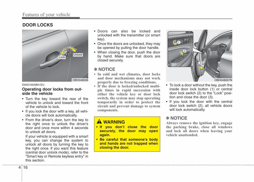
Features of your vehicle
164
D050100ABH-EU
Operating door locks from out-side the vehicle • Turn the key toward the rear of the
vehicle to unlock and toward the frontof the vehicle to lock.
• If you lock the door with a key, all vehi-cle doors will lock automatically.
• From the driver’s door, turn the key tothe right once to unlock the driver’sdoor and once more within 4 secondsto unlock all doors.If your vehicle is equipped with a smartkey, you can change the system tounlock all doors by turning the key tothe right once. If you want this feature(central door unlock mode), refer to the"Smart key or Remote keyless entry" inthis section.
• Doors can also be locked andunlocked with the transmitter (or smartkey).
• Once the doors are unlocked, they maybe opened by pulling the door handle.
• When closing the door, push the doorby hand. Make sure that doors areclosed securely.
✽✽ NOTICE• In cold and wet climates, door locks
and door mechanisms may not workproperly due to freezing conditions.
• If the door is locked/unlocked multi-ple times in rapid succession witheither the vehicle key or door lockswitch, the system may stop operatingtemporarily in order to protect thecircuit and prevent damage to systemcomponents.
• To lock a door without the key, push theinside door lock button (1) or centraldoor lock switch (2) to the “Lock” posi-tion and close the door (3).
• If you lock the door with the centraldoor lock switch (2), all vehicle doorswill lock automatically.
✽✽ NOTICEAlways remove the ignition key, engagethe parking brake, close all windowsand lock all doors when leaving yourvehicle unattended.
DOOR LOCKS
OBH048006
LockUnlock
OBH048007N
WARNING• If you don't close the door
securely, the door may openagain.
• Be careful that someone's bodyand hands are not trapped whenclosing the door.
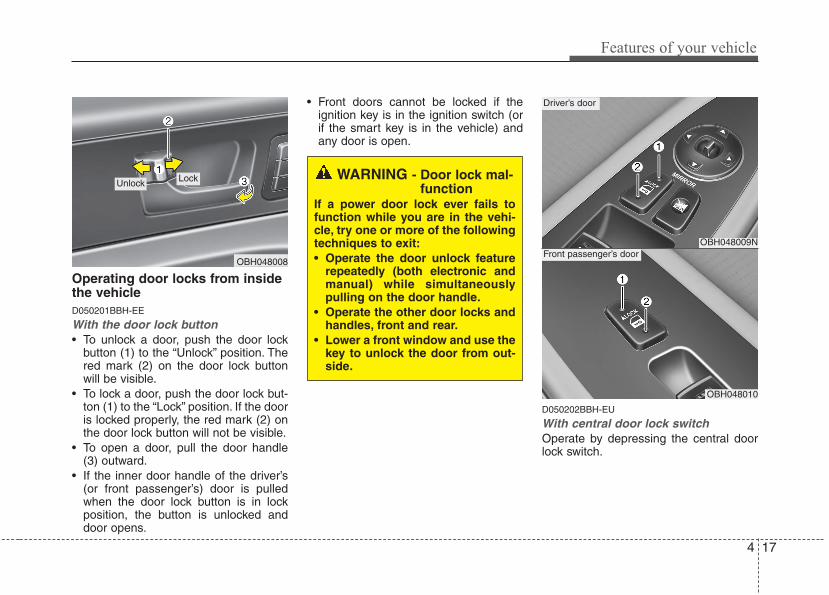
4 17
Features of your vehicle
Operating door locks from insidethe vehicleD050201BBH-EE
With the door lock button• To unlock a door, push the door lock
button (1) to the “Unlock” position. Thered mark (2) on the door lock buttonwill be visible.
• To lock a door, push the door lock but-ton (1) to the “Lock” position. If the dooris locked properly, the red mark (2) onthe door lock button will not be visible.
• To open a door, pull the door handle(3) outward.
• If the inner door handle of the driver’s(or front passenger’s) door is pulledwhen the door lock button is in lockposition, the button is unlocked anddoor opens.
• Front doors cannot be locked if theignition key is in the ignition switch (orif the smart key is in the vehicle) andany door is open.
D050202BBH-EU
With central door lock switchOperate by depressing the central doorlock switch.
OBH048008
Lock UnlockWARNING - Door lock mal-
functionIf a power door lock ever fails tofunction while you are in the vehi-cle, try one or more of the followingtechniques to exit:• Operate the door unlock feature
repeatedly (both electronic andmanual) while simultaneouslypulling on the door handle.
• Operate the other door locks andhandles, front and rear.
• Lower a front window and use thekey to unlock the door from out-side.
OBH048009N
Driver’s door
OBH048010
Front passenger’s door
Features of your vehicle
184
• When pushing down on the front por-tion (1) of the switch, all vehicle doorswill lock.
• When pushing down on the rear por-tion (2) of the switch, all vehicle doorswill unlock.
• If the key is in the ignition switch or thesmart key is in the vehicle, and anydoor is open, the doors will not lockeven though the front portion (1) ofcentral door lock switch is pressed.
D050300AAM-EE
Impact sensing door unlock system(if equipped)In the event of air bag deployment result-ing from a vehicle impact, all doors willautomatically unlock.
D050400ABH-EU
Speed sensing door lock system(if equipped)All doors will be automatically lockedwhen the vehicle speed exceeds 9 mph(15 km/h). And all doors will be automat-ically unlocked after you turn the engineoff or when you remove the ignition key.(if equipped)
WARNING - Unlockedvehicles
Leaving your vehicle unlocked caninvite theft or possible harm to youor others from someone hiding inyour vehicle while you are gone.Always remove the ignition key,engage the parking brake, close allwindows and lock all doors whenleaving your vehicle unattended.
WARNING - Unattendedchildren
An enclosed vehicle can becomeextremely hot, causing death orsevere injury to unattended chil-dren or animals who cannot escapethe vehicle. Furthermore, childrenmight operate features of the vehi-cle that could injure them, or theycould encounter other harm, possi-bly from someone gaining entry tothe vehicle. Never leave children oranimals unattended in your vehicle.
WARNING - Doors• The doors should always be fully
closed and locked while the vehi-cle is in motion to prevent acci-dental opening of the door.Locked doors will also discour-age potential intruders when thevehicle stops or traveling slowly.
• Be careful when opening doorsand watch for vehicles, motorcy-cles, bicycles or pedestriansapproaching the vehicle in thepath of the door. Opening a doorwhen something is approachingcan cause damage or injury.
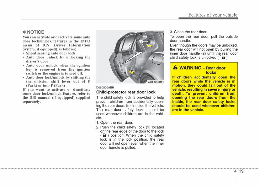
4 19
Features of your vehicle
✽✽ NOTICEYou can activate or deactivate some autodoor lock/unlock features in the INFOmenu of DIS (Driver InformationSystem, if equipped) as follows;• Speed sensing auto door lock• Auto door unlock by unlocking the
driver's door• Auto door unlock when the ignition
key is removed from the ignitionswitch or the engine is turned off.
• Auto door lock/unlock by shifting thetransmission shift lever out of P(Park) or into P (Park)
If you want to activate or deactivatesome door lock/unlock feature, refer tothe DIS manual (if equipped) suppliedseparately.
D050500ABH
Child-protector rear door lockThe child safety lock is provided to helpprevent children from accidentally open-ing the rear doors from inside the vehicle.The rear door safety locks should beused whenever children are in the vehi-cle.1. Open the rear door.2. Push the child safety lock (1) located
on the rear edge of the door to the lock( ) position. When the child safetylock is in the lock position, the reardoor will not open even when the innerdoor handle is pulled.
3. Close the rear door.To open the rear door, pull the outsidedoor handle.Even though the doors may be unlocked,the rear door will not open by pulling theinner door handle (2) until the rear doorchild safety lock is unlocked ( ).
OBH043011
WARNING - Rear doorlocks
If children accidentally open therear doors while the vehicle is inmotion, they could fall out of thevehicle, resulting in severe injury ordeath. To prevent children fromopening the rear doors from theinside, the rear door safety locksshould be used whenever childrenare in the vehicle.
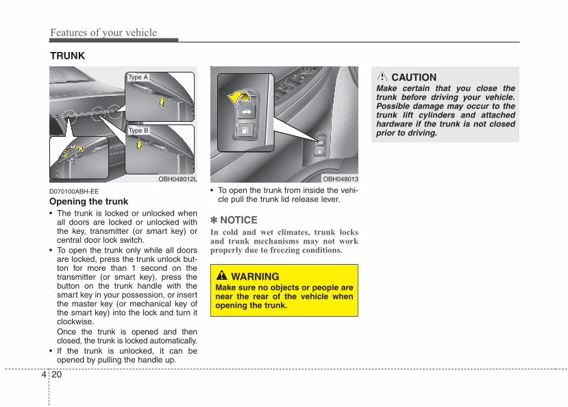
Features of your vehicle
204
D070100ABH-EE
Opening the trunk• The trunk is locked or unlocked when
all doors are locked or unlocked withthe key, transmitter (or smart key) orcentral door lock switch.
• To open the trunk only while all doorsare locked, press the trunk unlock but-ton for more than 1 second on thetransmitter (or smart key), press thebutton on the trunk handle with thesmart key in your possession, or insertthe master key (or mechanical key ofthe smart key) into the lock and turn itclockwise.Once the trunk is opened and thenclosed, the trunk is locked automatically.
• If the trunk is unlocked, it can beopened by pulling the handle up.
• To open the trunk from inside the vehi-cle pull the trunk lid release lever.
✽✽ NOTICEIn cold and wet climates, trunk locksand trunk mechanisms may not workproperly due to freezing conditions.
TRUNK
OBH048012L OBH048013
Type A
Type B
CAUTIONMake certain that you close thetrunk before driving your vehicle.Possible damage may occur to thetrunk lift cylinders and attachedhardware if the trunk is not closedprior to driving.
WARNINGMake sure no objects or people arenear the rear of the vehicle whenopening the trunk.
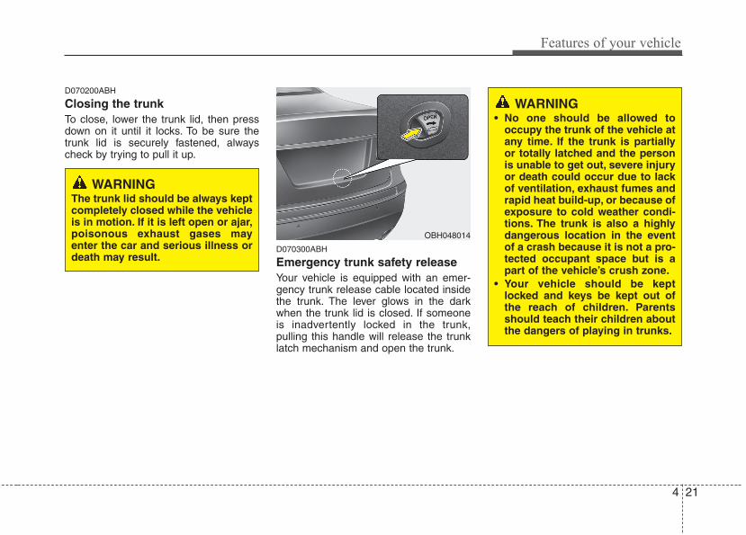
4 21
Features of your vehicle
D070200ABH
Closing the trunkTo close, lower the trunk lid, then pressdown on it until it locks. To be sure thetrunk lid is securely fastened, alwayscheck by trying to pull it up.
D070300ABH
Emergency trunk safety releaseYour vehicle is equipped with an emer-gency trunk release cable located insidethe trunk. The lever glows in the darkwhen the trunk lid is closed. If someoneis inadvertently locked in the trunk,pulling this handle will release the trunklatch mechanism and open the trunk.
OBH048014
WARNINGThe trunk lid should be always keptcompletely closed while the vehicleis in motion. If it is left open or ajar,poisonous exhaust gases mayenter the car and serious illness ordeath may result.
WARNING• No one should be allowed to
occupy the trunk of the vehicle atany time. If the trunk is partiallyor totally latched and the personis unable to get out, severe injuryor death could occur due to lackof ventilation, exhaust fumes andrapid heat build-up, or because ofexposure to cold weather condi-tions. The trunk is also a highlydangerous location in the eventof a crash because it is not a pro-tected occupant space but is apart of the vehicle’s crush zone.
• Your vehicle should be keptlocked and keys be kept out ofthe reach of children. Parentsshould teach their children aboutthe dangers of playing in trunks.
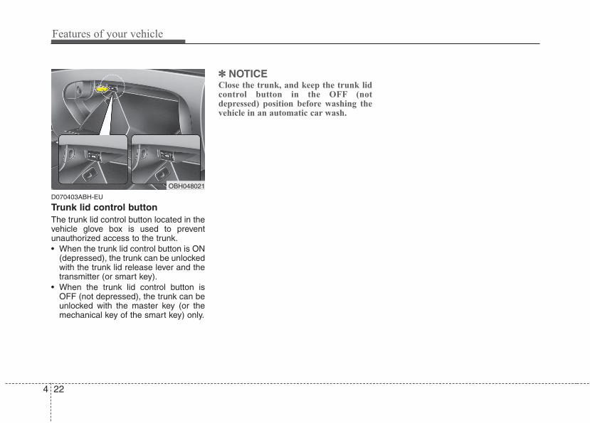
Features of your vehicle
224
D070403ABH-EU
Trunk lid control buttonThe trunk lid control button located in thevehicle glove box is used to preventunauthorized access to the trunk.• When the trunk lid control button is ON
(depressed), the trunk can be unlockedwith the trunk lid release lever and thetransmitter (or smart key).
• When the trunk lid control button isOFF (not depressed), the trunk can beunlocked with the master key (or themechanical key of the smart key) only.
✽✽ NOTICEClose the trunk, and keep the trunk lidcontrol button in the OFF (notdepressed) position before washing thevehicle in an automatic car wash.
OBH048021
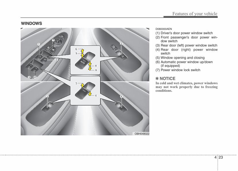
4 23
Features of your vehicle
D080000AEN
(1) Driver’s door power window switch(2) Front passenger’s door power win-
dow switch(3) Rear door (left) power window switch(4) Rear door (right) power window
switch(5) Window opening and closing(6) Automatic power window up/down
(if equipped)(7) Power window lock switch
✽✽ NOTICEIn cold and wet climates, power windowsmay not work properly due to freezingconditions.
WINDOWS
OBH048022
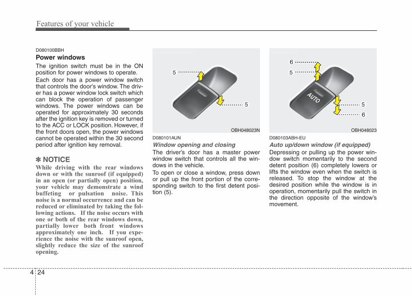
Features of your vehicle
244
D080100BBH
Power windowsThe ignition switch must be in the ONposition for power windows to operate.Each door has a power window switchthat controls the door's window. The driv-er has a power window lock switch whichcan block the operation of passengerwindows. The power windows can beoperated for approximately 30 secondsafter the ignition key is removed or turnedto the ACC or LOCK position. However, ifthe front doors open, the power windowscannot be operated within the 30 secondperiod after ignition key removal.
✽✽ NOTICEWhile driving with the rear windowsdown or with the sunroof (if equipped)in an open (or partially open) position,your vehicle may demonstrate a windbuffeting or pulsation noise. Thisnoise is a normal occurrence and can bereduced or eliminated by taking the fol-lowing actions. If the noise occurs withone or both of the rear windows down,partially lower both front windowsapproximately one inch. If you expe-rience the noise with the sunroof open,slightly reduce the size of the sunroofopening.
D080101AUN
Window opening and closingThe driver’s door has a master powerwindow switch that controls all the win-dows in the vehicle.To open or close a window, press downor pull up the front portion of the corre-sponding switch to the first detent posi-tion (5).
D080103ABH-EU
Auto up/down window (if equipped)Depressing or pulling up the power win-dow switch momentarily to the seconddetent position (6) completely lowers orlifts the window even when the switch isreleased. To stop the window at thedesired position while the window is inoperation, momentarily pull the switch inthe direction opposite of the window’smovement.
OBH048023N OBH048023
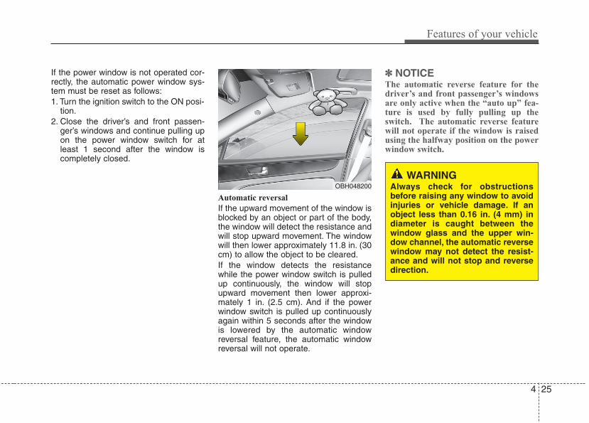
4 25
Features of your vehicle
If the power window is not operated cor-rectly, the automatic power window sys-tem must be reset as follows:1. Turn the ignition switch to the ON posi-
tion.2. Close the driver’s and front passen-
ger’s windows and continue pulling upon the power window switch for atleast 1 second after the window iscompletely closed.
Automatic reversal
If the upward movement of the window isblocked by an object or part of the body,the window will detect the resistance andwill stop upward movement. The windowwill then lower approximately 11.8 in. (30cm) to allow the object to be cleared.If the window detects the resistancewhile the power window switch is pulledup continuously, the window will stopupward movement then lower approxi-mately 1 in. (2.5 cm). And if the powerwindow switch is pulled up continuouslyagain within 5 seconds after the windowis lowered by the automatic windowreversal feature, the automatic windowreversal will not operate.
✽✽ NOTICEThe automatic reverse feature for thedriver’s and front passenger’s windowsare only active when the “auto up” fea-ture is used by fully pulling up theswitch. The automatic reverse featurewill not operate if the window is raisedusing the halfway position on the powerwindow switch.
WARNING Always check for obstructionsbefore raising any window to avoidinjuries or vehicle damage. If anobject less than 0.16 in. (4 mm) indiameter is caught between thewindow glass and the upper win-dow channel, the automatic reversewindow may not detect the resist-ance and will not stop and reversedirection.
OBH048200
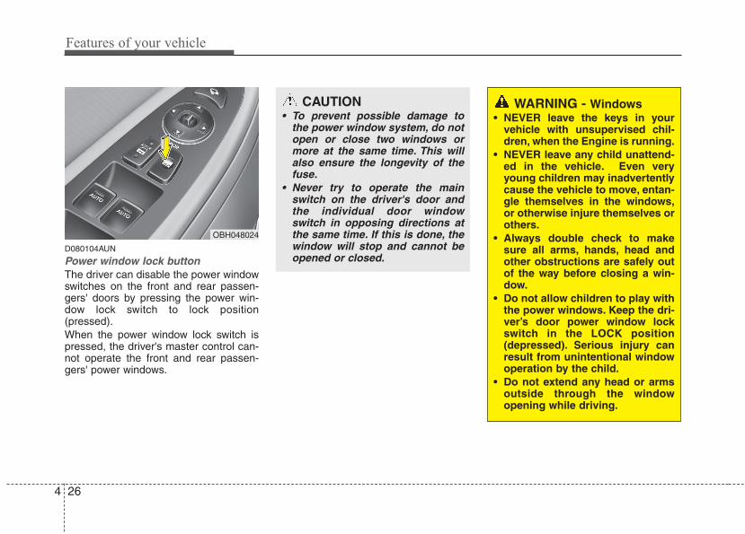
Features of your vehicle
264
D080104AUN
Power window lock buttonThe driver can disable the power windowswitches on the front and rear passen-gers' doors by pressing the power win-dow lock switch to lock position(pressed).When the power window lock switch ispressed, the driver's master control can-not operate the front and rear passen-gers' power windows.
OBH048024
CAUTION• To prevent possible damage to
the power window system, do notopen or close two windows ormore at the same time. This willalso ensure the longevity of thefuse.
• Never try to operate the mainswitch on the driver's door andthe individual door windowswitch in opposing directions atthe same time. If this is done, thewindow will stop and cannot beopened or closed.
WARNING - Windows• NEVER leave the keys in your
vehicle with unsupervised chil-dren, when the Engine is running.
• NEVER leave any child unattend-ed in the vehicle. Even veryyoung children may inadvertentlycause the vehicle to move, entan-gle themselves in the windows,or otherwise injure themselves orothers.
• Always double check to makesure all arms, hands, head andother obstructions are safely outof the way before closing a win-dow.
• Do not allow children to play withthe power windows. Keep the dri-ver’s door power window lockswitch in the LOCK position(depressed). Serious injury canresult from unintentional windowoperation by the child.
• Do not extend any head or armsoutside through the windowopening while driving.
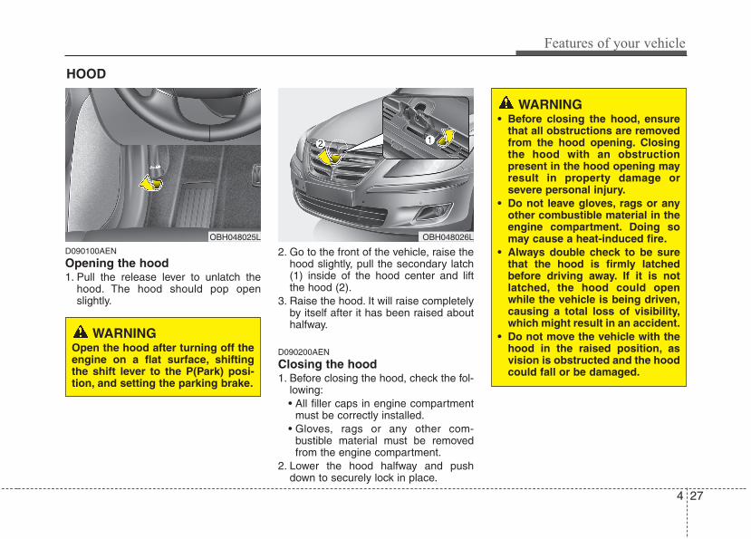
4 27
Features of your vehicle
D090100AEN
Opening the hood 1. Pull the release lever to unlatch the
hood. The hood should pop openslightly.
2. Go to the front of the vehicle, raise thehood slightly, pull the secondary latch(1) inside of the hood center and liftthe hood (2).
3. Raise the hood. It will raise completelyby itself after it has been raised abouthalfway.
D090200AEN
Closing the hood1. Before closing the hood, check the fol-
lowing:• All filler caps in engine compartment
must be correctly installed.• Gloves, rags or any other com-
bustible material must be removedfrom the engine compartment.
2. Lower the hood halfway and pushdown to securely lock in place.
HOOD
OBH048025L OBH048026L
WARNING• Before closing the hood, ensure
that all obstructions are removedfrom the hood opening. Closingthe hood with an obstructionpresent in the hood opening mayresult in property damage orsevere personal injury.
• Do not leave gloves, rags or anyother combustible material in theengine compartment. Doing somay cause a heat-induced fire.
• Always double check to be surethat the hood is firmly latchedbefore driving away. If it is notlatched, the hood could openwhile the vehicle is being driven,causing a total loss of visibility,which might result in an accident.
• Do not move the vehicle with thehood in the raised position, asvision is obstructed and the hoodcould fall or be damaged.
WARNINGOpen the hood after turning off theengine on a flat surface, shiftingthe shift lever to the P(Park) posi-tion, and setting the parking brake.
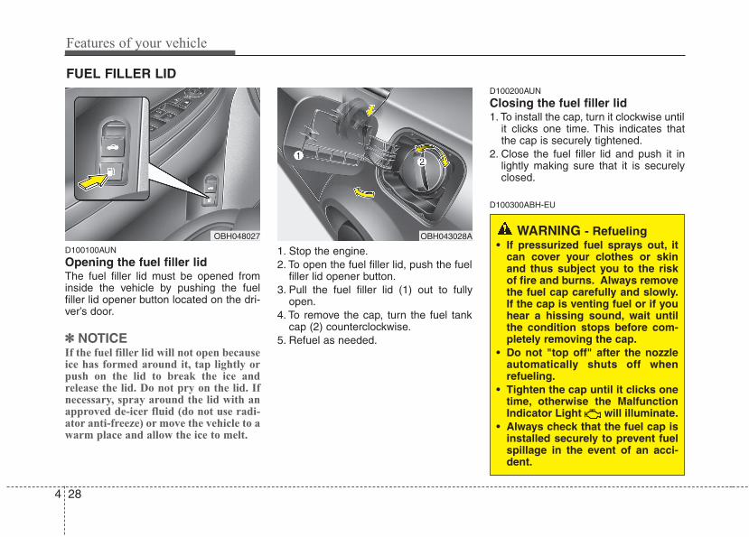
Features of your vehicle
284
D100100AUN
Opening the fuel filler lidThe fuel filler lid must be opened frominside the vehicle by pushing the fuelfiller lid opener button located on the dri-ver’s door.
✽✽ NOTICEIf the fuel filler lid will not open becauseice has formed around it, tap lightly orpush on the lid to break the ice andrelease the lid. Do not pry on the lid. Ifnecessary, spray around the lid with anapproved de-icer fluid (do not use radi-ator anti-freeze) or move the vehicle to awarm place and allow the ice to melt.
1. Stop the engine.2. To open the fuel filler lid, push the fuel
filler lid opener button.3. Pull the fuel filler lid (1) out to fully
open.4. To remove the cap, turn the fuel tank
cap (2) counterclockwise.5. Refuel as needed.
D100200AUN
Closing the fuel filler lid1. To install the cap, turn it clockwise until
it clicks one time. This indicates thatthe cap is securely tightened.
2. Close the fuel filler lid and push it inlightly making sure that it is securelyclosed.
D100300ABH-EU
FUEL FILLER LID
OBH048027 OBH043028A WARNING - Refueling• If pressurized fuel sprays out, it
can cover your clothes or skinand thus subject you to the riskof fire and burns. Always removethe fuel cap carefully and slowly.If the cap is venting fuel or if youhear a hissing sound, wait untilthe condition stops before com-pletely removing the cap.
• Do not "top off" after the nozzleautomatically shuts off whenrefueling.
• Tighten the cap until it clicks onetime, otherwise the MalfunctionIndicator Light will illuminate.
• Always check that the fuel cap isinstalled securely to prevent fuelspillage in the event of an acci-dent.
4 29
Features of your vehicle
(Continued)• Do not use cellular phones while
refueling. Electric current and/orelectronic interference from cel-lular phones can potentiallyignite fuel vapors causing a fire.
• When refueling, always shut theengine off. Sparks produced byelectrical components related tothe engine can ignite fuel vaporscausing a fire. Once refueling iscomplete, check to make sure thefiller cap and filler door aresecurely closed, before startingthe engine.
• DO NOT use matches or a lighterand DO NOT SMOKE or leave a litcigarette in your vehicle while ata gas station especially duringrefueling. Automotive fuel ishighly flammable and can, whenignited, result in fire.
• If a fire breaks out during refuel-ing, leave the vicinity of the vehi-cle, and immediately contact themanager of the gas station andthen contact the local fire depart-ment or 911. Follow any safetyinstructions they provide.
(Continued)• Do not get back into a vehicle once
you have begun refueling sinceyou can generate static electricityby touching, rubbing or slidingagainst any item or fabric (poly-ester, satin, nylon, etc.) capable ofproducing static electricity. Staticelectricity discharge can ignitefuel vapors resulting in rapid burn-ing. If you must re-enter the vehi-cle, you should once again elimi-nate potentially dangerous staticelectricity discharge by touching ametal part of the vehicle, awayfrom the fuel filler neck, nozzle orother gasoline source.
• When using an approved portablefuel container, be sure to place thecontainer on the ground prior torefueling. Static electricity dis-charge from the container canignite fuel vapors causing a fire.Once refueling has begun, contactwith the vehicle should be main-tained until the filling is complete.Use only approved portable plas-tic fuel containers designed tocarry and store gasoline.
(Continued)
WARNING - Refueling dan-gers
Automotive fuels are flammablematerials. When refueling, pleasenote the following guidelines care-fully. Failure to follow these guide-lines may result in severe personalinjury, severe burns or death by fireor explosion.• Read and follow all warnings
posted at the gas station facility.• Before refueling, note the loca-
tion of the Emergency GasolineShut-Off, if available, at the gasstation facility.
• Before touching the fuel nozzle,you should eliminate potentiallydangerous static electricity dis-charge by touching another metalpart of the vehicle, a safe dis-tance away from the fuel fillerneck, nozzle, or other gas source.
(Continued)
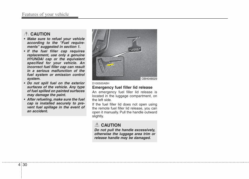
Features of your vehicle
304
D100500ABH
Emergency fuel filler lid releaseAn emergency fuel filler lid release islocated in the luggage compartment, onthe left side.If the fuel filler lid does not open usingthe remote fuel filler lid release, you canopen it manually. Pull the handle outwardslightly.
CAUTION• Make sure to refuel your vehicle
according to the "Fuel require-ments" suggested in section 1.
• If the fuel filler cap requiresreplacement, use only a genuineHYUNDAI cap or the equivalentspecified for your vehicle. Anincorrect fuel filler cap can resultin a serious malfunction of thefuel system or emission controlsystem.
• Do not spill fuel on the exteriorsurfaces of the vehicle. Any typeof fuel spilled on painted surfacesmay damage the paint.
• After refueling, make sure the fuelcap is installed securely to pre-vent fuel spillage in the event ofan accident.
CAUTIONDo not pull the handle excessively,otherwise the luggage area trim orrelease handle may be damaged.
OBH048029
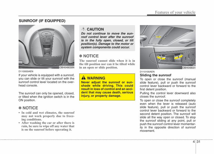
4 31
Features of your vehicle
D110000AEN
If your vehicle is equipped with a sunroof,you can slide or tilt your sunroof with thesunroof control lever located on the over-head console.
The sunroof can only be opened, closed,or tilted when the ignition switch is in theON position.
✽✽ NOTICE• In cold and wet climates, the sunroof
may not work properly due to freez-ing conditions.
• After washing the car or after there israin, be sure to wipe off any water thatis on the sunroof before operating it.
✽✽ NOTICEThe sunroof cannot slide when it is inthe tilt position nor can it be tilted whilein an open or slide position.
D110100AEN
Sliding the sunroof To open or close the sunroof (manualslide feature), pull or push the sunroofcontrol lever backward or forward to thefirst detent position.Pulling the control lever downward alsocloses the sunroof.To open or close the sunroof completelyeven when the lever is released (autoslide feature), pull or push the sunroofcontrol lever backward or forward to thesecond detent position. The sunroof willslide all the way open or closed. To stopthe sunroof sliding at any point, pull orpush the sunroof control lever momentar-ily in the opposite direction of sunroofmovement.
CAUTIONDo not continue to move the sun-roof control lever after the sunroofis in the fully open, closed, or tiltposition(s). Damage to the motor orsystem components could occur.
WARNING Never adjust the sunroof or sun-shade while driving. This couldresult in loss of control and an acci-dent that may cause death, seriousinjury, or property damage.
OBH048031
SUNROOF (IF EQUIPPED)
OBH048030N
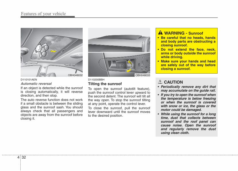
Features of your vehicle
324
D110101AEN
Automatic reversalIf an object is detected while the sunroofis closing automatically, it will reversedirection, and then stop.The auto reverse function does not workif a small obstacle is between the slidingglass and the sunroof sash. You shouldalways check that all passengers andobjects are away from the sunroof beforeclosing it.
D110200BBH
Tilting the sunroof To open the sunroof (autotilt feature),push the sunroof control lever upward tothe second detent. The sunroof will tilt allthe way open. To stop the sunroof tiltingat any point, operate the control lever.To close the sunroof, pull the sunrooflever downward until the sunroof movesto the desired position.
OBH048033
WARNING - Sunroof• Be careful that no heads, hands
and body parts are obstructing aclosing sunroof.
• Do not extend the face, neck,arms or body outside the sunroofwhile driving.
• Make sure your hands and headare safely out of the way beforeclosing a sunroof.
CAUTION• Periodically remove any dirt that
may accumulate on the guide rail.• If you try to open the sunroof when
the temperature is below freezingor when the sunroof is coveredwith snow or ice, the glass or themotor could be damaged.
• While using the sunroof for a longtime, dust that collects betweensunroof and the roof panel cancause noise. Open the sunroofand regularly remove the dustusing clean cloth.
OBH048032
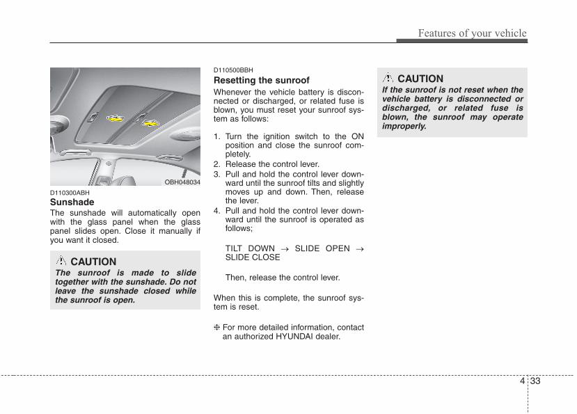
4 33
Features of your vehicle
D110300ABH
Sunshade The sunshade will automatically openwith the glass panel when the glasspanel slides open. Close it manually ifyou want it closed.
D110500BBH
Resetting the sunroofWhenever the vehicle battery is discon-nected or discharged, or related fuse isblown, you must reset your sunroof sys-tem as follows:
1. Turn the ignition switch to the ONposition and close the sunroof com-pletely.
2. Release the control lever.3. Pull and hold the control lever down-
ward until the sunroof tilts and slightlymoves up and down. Then, releasethe lever.
4. Pull and hold the control lever down-ward until the sunroof is operated asfollows;
TILT DOWN → SLIDE OPEN →SLIDE CLOSE
Then, release the control lever.
When this is complete, the sunroof sys-tem is reset.
❈ For more detailed information, contactan authorized HYUNDAI dealer.
CAUTIONThe sunroof is made to slidetogether with the sunshade. Do notleave the sunshade closed whilethe sunroof is open.
OBH048034
CAUTIONIf the sunroof is not reset when thevehicle battery is disconnected ordischarged, or related fuse isblown, the sunroof may operateimproperly.
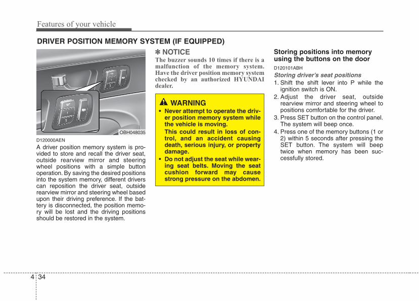
Features of your vehicle
344
DRIVER POSITION MEMORY SYSTEM (IF EQUIPPED)
D120000AEN
A driver position memory system is pro-vided to store and recall the driver seat,outside rearview mirror and steeringwheel positions with a simple buttonoperation. By saving the desired positionsinto the system memory, different driverscan reposition the driver seat, outsiderearview mirror and steering wheel basedupon their driving preference. If the bat-tery is disconnected, the position memo-ry will be lost and the driving positionsshould be restored in the system.
✽✽ NOTICEThe buzzer sounds 10 times if there is amalfunction of the memory system.Have the driver position memory systemchecked by an authorized HYUNDAIdealer.
Storing positions into memoryusing the buttons on the doorD120101ABH
Storing driver’s seat positions1. Shift the shift lever into P while the
ignition switch is ON.2. Adjust the driver seat, outside
rearview mirror and steering wheel topositions comfortable for the driver.
3. Press SET button on the control panel.The system will beep once.
4. Press one of the memory buttons (1 or2) within 5 seconds after pressing theSET button. The system will beeptwice when memory has been suc-cessfully stored.
WARNING • Never attempt to operate the driv-
er position memory system whilethe vehicle is moving.This could result in loss of con-trol, and an accident causingdeath, serious injury, or propertydamage.
• Do not adjust the seat while wear-ing seat belts. Moving the seatcushion forward may causestrong pressure on the abdomen.
OBH048035
4 35
Features of your vehicle
D120102ABH
Recalling positions from memory1. Shift the shift lever into P while the
ignition switch is ON.2. To recall the position in memory, press
the desired memory button (1 or 2).The system will beep once, then thedriver seat, outside rearview mirrorand steering wheel will automaticallyadjust to the stored positions.
Adjusting one of the control knobs for thedriver seat, outside rearview mirror andsteering wheel while the system is recall-ing the stored positions will cause themovement for that component to stopand move in the direction that the controlknob is moved. Other components willcontinue to the recalled position.
D120300BBH
Easy access function (if equipped)With the shift lever in the P position, thesystem will move the steering wheelupward and driver’s seat rearward auto-matically so you can comfortably enterand exit the vehicle.• Without smart key system
- It will move the steering wheel awayfrom the driver and the driver’s seatrearward when the ignition key isremoved.
- It will move the steering wheel towardthe driver and the driver’s seat for-ward when the ignition key is inserted.
• With smart key system- It will move the steering wheel away
from the driver and the driver’s seatrearward when the engine start/stopbutton is turned to the OFF position.
- It will move the steering wheel towardthe driver and the driver’s seat for-ward when the engine start/stop but-ton is turned to the ACC position.
✽✽ NOTICEYou can activate or deactivate the easyaccess function in the INFO menu ofDIS (Driver Information System, ifequipped) as follows;• Seat easy access• Steering easy accessIf you want detailed informations, referto the DIS manual supplied separately.
WARNING Use caution when recalling adjust-ment memory while sitting in thevehicle. Push the seat position con-trol knob to the desired positionimmediately if the seat moves toofar in any direction.
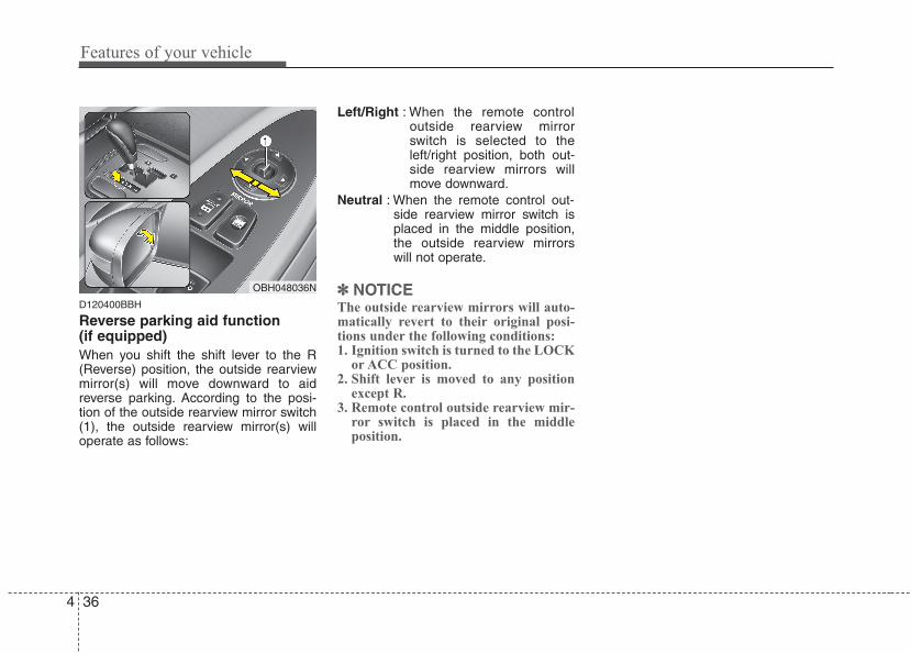
Features of your vehicle
364
D120400BBH
Reverse parking aid function (if equipped)When you shift the shift lever to the R(Reverse) position, the outside rearviewmirror(s) will move downward to aidreverse parking. According to the posi-tion of the outside rearview mirror switch(1), the outside rearview mirror(s) willoperate as follows:
Left/Right : When the remote controloutside rearview mirrorswitch is selected to theleft/right position, both out-side rearview mirrors willmove downward.
Neutral : When the remote control out-side rearview mirror switch isplaced in the middle position,the outside rearview mirrorswill not operate.
✽✽ NOTICEThe outside rearview mirrors will auto-matically revert to their original posi-tions under the following conditions:1. Ignition switch is turned to the LOCK
or ACC position.2. Shift lever is moved to any position
except R.3. Remote control outside rearview mir-
ror switch is placed in the middleposition.
OBH048036N
4 37
Features of your vehicle
D130100ABH
Electronic Hydraulic PowerSteering (EHPS) EHPS uses an electromotor to assist youin steering the vehicle. It senses the vehi-cle speed and road condition.If the engine is off or if the power steer-ing system becomes inoperative, thevehicle may still be steered, but it willrequire increased steering effort.Should you notice any change in theeffort required to steer during normalvehicle operation, have the power steer-ing checked by an authorized HYUNDAIdealer.
✽✽ NOTICEIf the power steering drive belt breaksor if the power steering pump malfunc-tions, the steering effort will greatlyincrease.
✽✽ NOTICEIf the vehicle is parked for extendedperiods outside in cold weather (below14°F/-10°C), the power steering mayrequire increased effort when the engineis first started. This is caused byincreased fluid viscosity due to the coldweather and does not indicate a mal-function.When this happens, increase the engineRPM by depressing accelerator until theRPM reaches 1,500 rpm then release orlet the engine idle for two or three min-utes to warm up the fluid.
D130300AEN
Tilt steering/Telescope steering(if equipped)Tilt steering allows you to adjust thesteering wheel before you drive. You canalso raise the steering wheel to give yourlegs more room when you exit and enterthe vehicle.
The steering wheel should be positionedso that it is comfortable for you to drive,while permitting you to see the instru-ment panel warning lights and gauges.
STEERING WHEEL
CAUTIONNever hold the steering wheelagainst a stop (extreme right or leftturn) for more than 5 seconds withthe engine running. Holding thesteering wheel for more than 5 sec-onds in either position may causedamage to the power steeringpump.
WARNING• Never adjust the angle of the
steering wheel while driving. Youmay lose steering control andcause severe personal injury,death or accidents.
• After adjusting, push the steeringwheel both up and down to becertain it is locked in position.
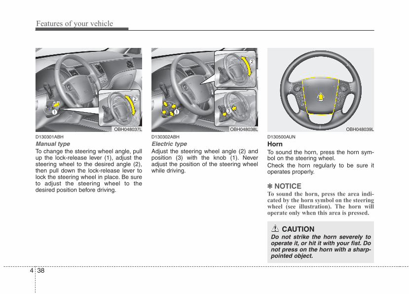
Features of your vehicle
384
D130301ABH
Manual typeTo change the steering wheel angle, pullup the lock-release lever (1), adjust thesteering wheel to the desired angle (2),then pull down the lock-release lever tolock the steering wheel in place. Be sureto adjust the steering wheel to thedesired position before driving.
D130302ABH
Electric typeAdjust the steering wheel angle (2) andposition (3) with the knob (1). Neveradjust the position of the steering wheelwhile driving.
D130500AUN
HornTo sound the horn, press the horn sym-bol on the steering wheel.Check the horn regularly to be sure itoperates properly.
✽✽ NOTICETo sound the horn, press the area indi-cated by the horn symbol on the steeringwheel (see illustration). The horn willoperate only when this area is pressed.
OBH048037L OBH048038L OBH048039L
CAUTIONDo not strike the horn severely tooperate it, or hit it with your fist. Donot press on the horn with a sharp-pointed object.
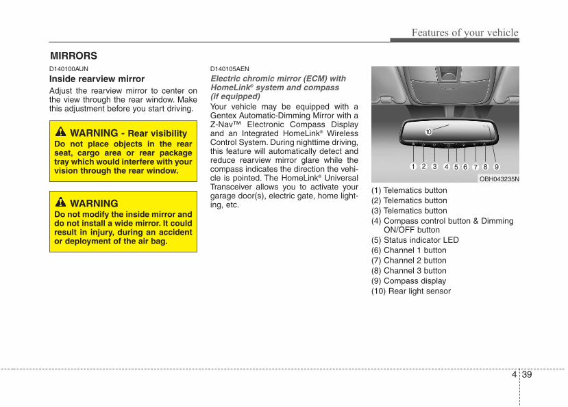
4 39
Features of your vehicle
D140100AUN
Inside rearview mirrorAdjust the rearview mirror to center onthe view through the rear window. Makethis adjustment before you start driving.
D140105AEN
Electric chromic mirror (ECM) withHomeLink® system and compass (if equipped)Your vehicle may be equipped with aGentex Automatic-Dimming Mirror with aZ-Nav™ Electronic Compass Displayand an Integrated HomeLink® WirelessControl System. During nighttime driving,this feature will automatically detect andreduce rearview mirror glare while thecompass indicates the direction the vehi-cle is pointed. The HomeLink® UniversalTransceiver allows you to activate yourgarage door(s), electric gate, home light-ing, etc.
(1) Telematics button(2) Telematics button(3) Telematics button(4) Compass control button & Dimming
ON/OFF button(5) Status indicator LED(6) Channel 1 button(7) Channel 2 button(8) Channel 3 button(9) Compass display(10) Rear light sensor
MIRRORS
WARNING Do not modify the inside mirror anddo not install a wide mirror. It couldresult in injury, during an accidentor deployment of the air bag.
WARNING - Rear visibilityDo not place objects in the rearseat, cargo area or rear packagetray which would interfere with yourvision through the rear window.
OBH043235N
Features of your vehicle
404
Automatic-Dimming Night VisionSafety™ (NVS®) Mirror
The NVS® Mirror in your vehicle is themost advanced way to reduce annoyingglare in the rearview mirror during anydriving situation. For more informationregarding NVS® mirrors and other appli-cations, please refer to the Gentex web-site:www.gentex.com
✽✽ NOTICEThe NVS® Mirror automatically reducesglare during driving conditions basedupon light levels monitored in front ofthe vehicle and from the rear of the vehi-cle. These light sensors are visiblethrough openings in the front and rearof the mirror case. Any object thatobstructs either light sensor willdegrade the automatic dimming controlfeature.
Automatic-dimming functionYour mirror will automatically dim upondetecting glare from the vehicles travel-ing behind you. The auto-dimming func-tion can be controlled by the DimmingON/OFF Button:
1. Pressing and hold the button for 3seconds turns the autodimming func-tion OFF which is indicated by thegreen Status Indicator LED turning off.
2. Pressing and hold the button for 3seconds again turns the auto-dimmingfunction ON which is indicated by thegreen Status Indicator LED turning on.
The mirror defaults to the ON positioneach time the vehicle is started.
Z-Nav™ Compass Display
The NVS™ Mirror in your vehicle is alsoequipped with a Z-Nav™ Compass thatshows the vehicle Compass heading inthe Display Window using the 8 basiccardinal headings (N, NE, E, SE, etc.).
Compass functionThe Compass can be turned ON andOFF and will remember the last statewhen the ignition is cycled. To turn thedisplay feature ON/OFF:1. Press and release the button within
1 second to turn the display featureOFF.
2. Press and release the button againwithin 1 second to turn the displayback ON.
Additional options can be set with pressand hold sequences of the button andare detailed below.
There is a difference between magneticnorth and true north. The compass in themirror can compensate for this differencewhen it knows the Magnetic Zone inwhich it is operating. This is set either bythe dealer or by the user. The operatingZone Numbers for North America areshown in the figure on the following sec-tion.
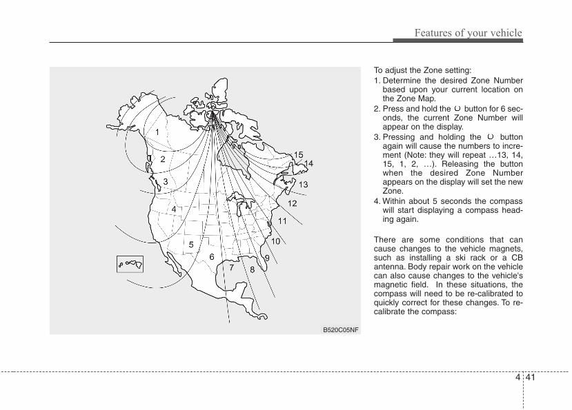
4 41
Features of your vehicle
To adjust the Zone setting:1. Determine the desired Zone Number
based upon your current location onthe Zone Map.
2. Press and hold the button for 6 sec-onds, the current Zone Number willappear on the display.
3. Pressing and holding the buttonagain will cause the numbers to incre-ment (Note: they will repeat …13, 14,15, 1, 2, …). Releasing the buttonwhen the desired Zone Numberappears on the display will set the newZone.
4. Within about 5 seconds the compasswill start displaying a compass head-ing again.
There are some conditions that cancause changes to the vehicle magnets,such as installing a ski rack or a CBantenna. Body repair work on the vehiclecan also cause changes to the vehicle'smagnetic field. In these situations, thecompass will need to be re-calibrated toquickly correct for these changes. To re-calibrate the compass:
B520C05NF
Features of your vehicle
424
1. Press and hold the button for morethan 9 seconds. When the compassmemory is cleared a "C" will appear inthe display.
2. To calibrate the compass, drive thevehicle in 2 complete circles at lessthan 5 mph (8 km/h).
Integrated HomeLink® Wireless ControlSystem
The HomeLink® Wireless Control Systemprovides a convenient way to replace upto three hand-held radio-frequency (RF)transmitters with a single built-in device.This innovative feature will learn theradio frequency codes of most currenttransmitters to operate devices such asgate operators, garage door openers,entry door locks, security systems, evenhome lighting. Both standard and rollingcode-equipped transmitters can be pro-grammed by following the outlined proce-dures. Additional HomeLink® informationcan be found at: www.homelink.com orby calling 1-800-355-3515.
Retain the original transmitter of the RFdevice you are programming for use inother vehicles as well as for futureHomeLink® programming. It is also sug-gested that upon the sale of the vehicle,the programmed HomeLink® buttons beerased for security purposes.
Programming HomeLink®
✽✽ NOTICE• When programming a garage door
opener, it is advised to park the vehi-cle outside of the garage.
• It is recommended that a new batterybe placed in the hand-held transmit-ter of the device being programmed toHomeLink® for quicker training andaccurate transmission of the radio-frequency signal.
• Some vehicles may require the igni-tion switch to be turned to the second(or "accessories") position for pro-gramming and/or operation ofHomeLink.
• In the event that there are still pro-gramming difficulties or questionsafter following the programming stepslisted below, contact HomeLink® at:www.homelink.com or 1-800-355-3515.
WARNINGBefore programming HomeLink® toa garage door opener or gate oper-ator, make sure that people andobjects are out of the way of thedevice to prevent potential harm ordamage. Do not use HomeLink®
with any garage door opener thatlacks the safety stop and reversefeatures required by U.S. federalsafety standards (this includes anygarage door opener model manu-factured before April 1, 1982). Agarage door that cannot detect anobject - signaling the door to stopand reverse - does not meet currentU.S. federal safety standards. Usinga garage door opener without thesefeatures increases the risk of seri-ous injury or death.
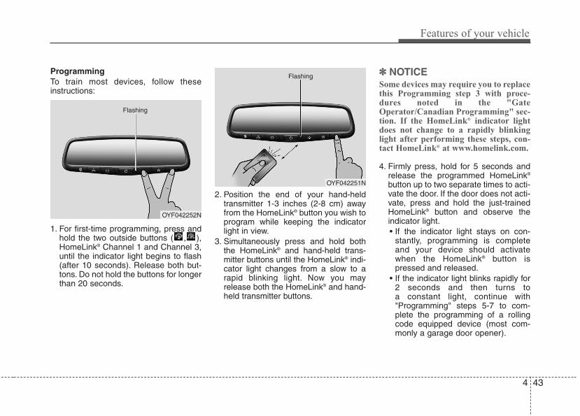
4 43
Features of your vehicle
ProgrammingTo train most devices, follow theseinstructions:
1. For first-time programming, press andhold the two outside buttons ( , ),HomeLink® Channel 1 and Channel 3,until the indicator light begins to flash(after 10 seconds). Release both but-tons. Do not hold the buttons for longerthan 20 seconds.
2. Position the end of your hand-heldtransmitter 1-3 inches (2-8 cm) awayfrom the HomeLink® button you wish toprogram while keeping the indicatorlight in view.
3. Simultaneously press and hold boththe HomeLink® and hand-held trans-mitter buttons until the HomeLink® indi-cator light changes from a slow to arapid blinking light. Now you mayrelease both the HomeLink® and hand-held transmitter buttons.
✽✽ NOTICESome devices may require you to replacethis Programming step 3 with proce-dures noted in the "GateOperator/Canadian Programming" sec-tion. If the HomeLink® indicator lightdoes not change to a rapidly blinkinglight after performing these steps, con-tact HomeLink® at www.homelink.com.
4. Firmly press, hold for 5 seconds andrelease the programmed HomeLink®
button up to two separate times to acti-vate the door. If the door does not acti-vate, press and hold the just-trainedHomeLink® button and observe theindicator light.• If the indicator light stays on con-
stantly, programming is completeand your device should activatewhen the HomeLink® button ispressed and released.
• If the indicator light blinks rapidly for2 seconds and then turns to a constant light, continue with"Programming" steps 5-7 to com-plete the programming of a rollingcode equipped device (most com-monly a garage door opener).
OYF042252N
Flashing
OYF042251N
Flashing
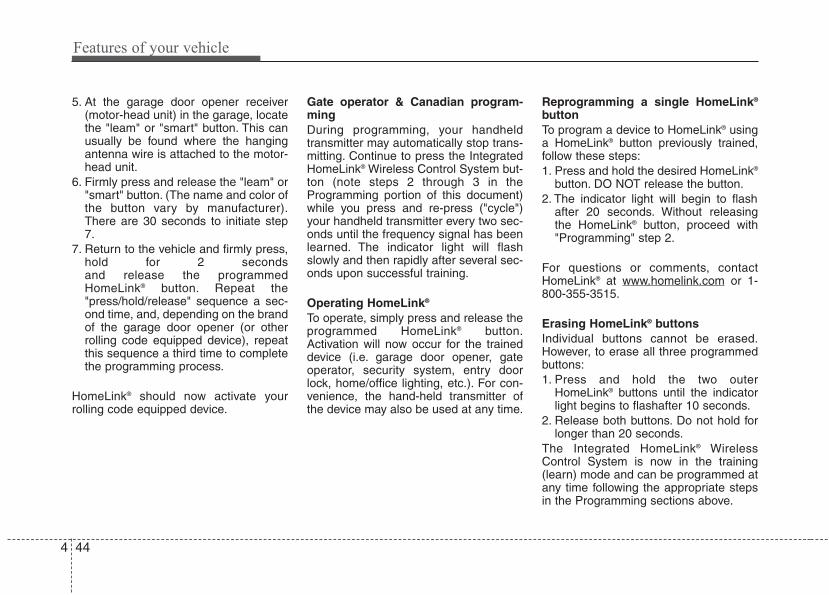
Features of your vehicle
444
5. At the garage door opener receiver(motor-head unit) in the garage, locatethe "leam" or "smart" button. This canusually be found where the hangingantenna wire is attached to the motor-head unit.
6. Firmly press and release the "leam" or"smart" button. (The name and color ofthe button vary by manufacturer).There are 30 seconds to initiate step7.
7. Return to the vehicle and firmly press,hold for 2 seconds and release the programmedHomeLink® button. Repeat the"press/hold/release" sequence a sec-ond time, and, depending on the brandof the garage door opener (or otherrolling code equipped device), repeatthis sequence a third time to completethe programming process.
HomeLink® should now activate yourrolling code equipped device.
Gate operator & Canadian program-mingDuring programming, your handheldtransmitter may automatically stop trans-mitting. Continue to press the IntegratedHomeLink® Wireless Control System but-ton (note steps 2 through 3 in theProgramming portion of this document)while you press and re-press ("cycle")your handheld transmitter every two sec-onds until the frequency signal has beenlearned. The indicator light will flashslowly and then rapidly after several sec-onds upon successful training.
Operating HomeLink®
To operate, simply press and release theprogrammed HomeLink® button.Activation will now occur for the traineddevice (i.e. garage door opener, gateoperator, security system, entry doorlock, home/office lighting, etc.). For con-venience, the hand-held transmitter ofthe device may also be used at any time.
Reprogramming a single HomeLink®
buttonTo program a device to HomeLink® usinga HomeLink® button previously trained,follow these steps:1. Press and hold the desired HomeLink®
button. DO NOT release the button.2. The indicator light will begin to flash
after 20 seconds. Without releasingthe HomeLink® button, proceed with"Programming" step 2.
For questions or comments, contactHomeLink® at www.homelink.com or 1-800-355-3515.
Erasing HomeLink® buttonsIndividual buttons cannot be erased.However, to erase all three programmedbuttons:1. Press and hold the two outer
HomeLink® buttons until the indicatorlight begins to flashafter 10 seconds.
2. Release both buttons. Do not hold forlonger than 20 seconds.
The Integrated HomeLink® WirelessControl System is now in the training(learn) mode and can be programmed atany time following the appropriate stepsin the Programming sections above.
4 45
Features of your vehicle
FCC ID: NZLTLMHL4IC: 4112A-TLMHL4
This device complies with Part 15 ofthe FCC Rules.Operation is subject to the following twoconditions:1. this device may not cause harmful
interference, and 2. This device must accept any interfer-
ence received, including interferencethat may cause undesired operation.
NVS® is a registered trademark and Z-Nav™ is a trademark of the GentexCorporation, Zeeland, Michigan.HomeLink® is a registered trademarkowned by Johnson Controls, Incorporated,Milwaukee, Wisconsin.
D140200AUN-EU
Outside rearview mirror Be sure to adjust mirror angles beforedriving.Your vehicle is equipped with both left-hand and right-hand outside rearviewmirrors. The mirrors can be adjustedremotely with the remote switch. The mir-ror heads can be folded back to preventdamage during an automatic car wash orwhen passing in a narrow street.
WARNING - Rearview mir-rors
• The right outside rearview mirroris convex. Objects seen in themirror are closer than theyappear.
• Use your interior rearview mirroror direct observation to deter-mine the actual distance of fol-lowing vehicles when changinglanes.
CAUTIONDo not scrape ice off the mirrorface; this may damage the surfaceof the glass. If ice should restrictmovement of the mirror, do notforce the mirror for adjustment. Toremove ice, use a deicer spray, or asponge or soft cloth with warmwater.
CAUTIONIf the mirror is jammed with ice, donot adjust the mirror by force. Usean approved spray de-icer (not radi-ator antifreeze) to release thefrozen mechanism or move thevehicle to a warm place and allowthe ice to melt.
WARNING Do not adjust or fold the outsiderearview mirrors while the vehicleis moving. This could result in lossof control, and an accident whichcould cause death, serious injuryor property damage.
WARNING The transceiver has been testedand complies with FCC andIndustry Canada rules. Changes ormodifications not expresslyapproved by the party responsiblefor compliance could void theuser's authority to operate thedevice.
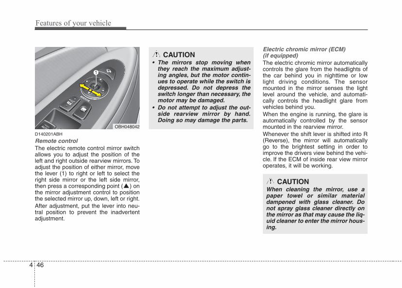
Features of your vehicle
464
D140201ABH
Remote controlThe electric remote control mirror switchallows you to adjust the position of theleft and right outside rearview mirrors. Toadjust the position of either mirror, movethe lever (1) to right or left to select theright side mirror or the left side mirror,then press a corresponding point ( ) onthe mirror adjustment control to positionthe selected mirror up, down, left or right.After adjustment, put the lever into neu-tral position to prevent the inadvertentadjustment.
Electric chromic mirror (ECM) (if equipped)The electric chromic mirror automaticallycontrols the glare from the headlights ofthe car behind you in nighttime or lowlight driving conditions. The sensormounted in the mirror senses the lightlevel around the vehicle, and automati-cally controls the headlight glare fromvehicles behind you.When the engine is running, the glare isautomatically controlled by the sensormounted in the rearview mirror.Whenever the shift lever is shifted into R(Reverse), the mirror will automaticallygo to the brightest setting in order toimprove the drivers view behind the vehi-cle. If the ECM of inside rear view mirroroperates, it will be working.
OBH048042
CAUTION• The mirrors stop moving when
they reach the maximum adjust-ing angles, but the motor contin-ues to operate while the switch isdepressed. Do not depress theswitch longer than necessary, themotor may be damaged.
• Do not attempt to adjust the out-side rearview mirror by hand.Doing so may damage the parts.
CAUTIONWhen cleaning the mirror, use apaper towel or similar materialdampened with glass cleaner. Donot spray glass cleaner directly onthe mirror as that may cause the liq-uid cleaner to enter the mirror hous-ing.
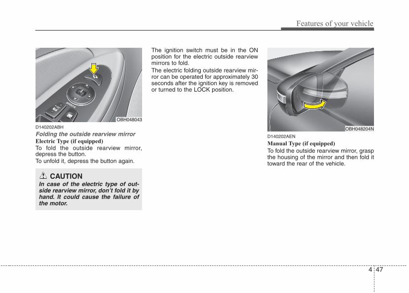
4 47
Features of your vehicle
D140202ABH
Folding the outside rearview mirrorElectric Type (if equipped)
To fold the outside rearview mirror,depress the button.To unfold it, depress the button again.
The ignition switch must be in the ONposition for the electric outside rearviewmirrors to fold.The electric folding outside rearview mir-ror can be operated for approximately 30seconds after the ignition key is removedor turned to the LOCK position.
D140202AEN
Manual Type (if equipped)
To fold the outside rearview mirror, graspthe housing of the mirror and then fold ittoward the rear of the vehicle.
OBH048204N
OBH048043
CAUTIONIn case of the electric type of out-side rearview mirror, don’t fold it byhand. It could cause the failure ofthe motor.
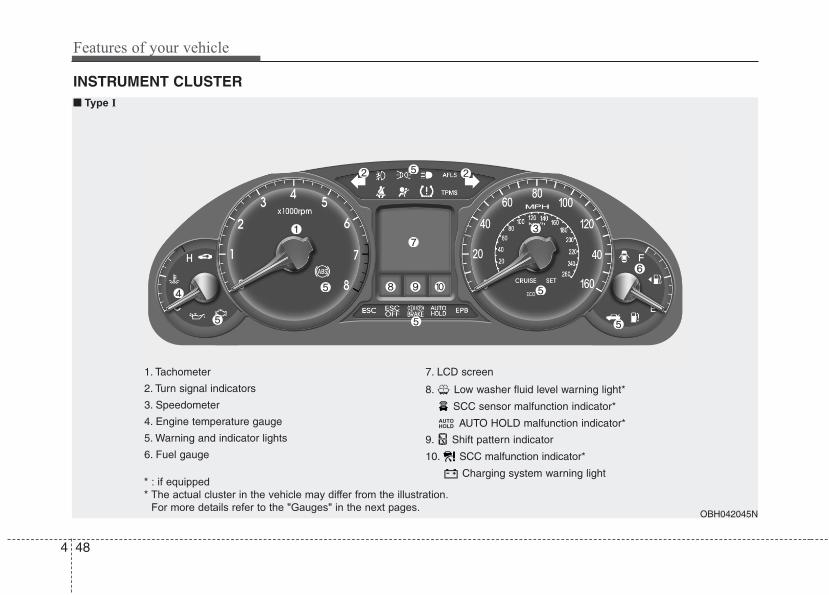
Features of your vehicle
484
INSTRUMENT CLUSTER
1. Tachometer
2. Turn signal indicators
3. Speedometer
4. Engine temperature gauge
5. Warning and indicator lights
6. Fuel gauge
7. LCD screen
8. Low washer fluid level warning light*
SCC sensor malfunction indicator*
AUTO HOLD malfunction indicator*
9. Shift pattern indicator
10. SCC malfunction indicator*
Charging system warning light
AUTOHOLD
OBH042045N
■■ Type I
* : if equipped
* The actual cluster in the vehicle may differ from the illustration.
For more details refer to the "Gauges" in the next pages.
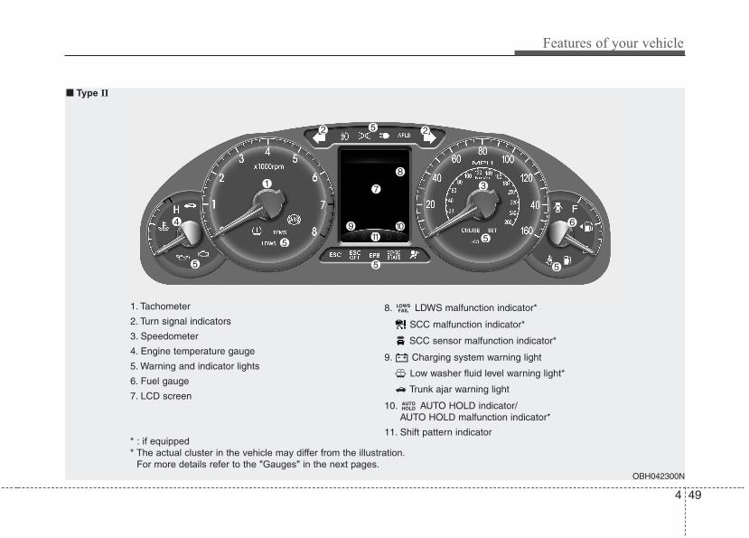
4 49
Features of your vehicle
1. Tachometer
2. Turn signal indicators
3. Speedometer
4. Engine temperature gauge
5. Warning and indicator lights
6. Fuel gauge
7. LCD screen
8. LDWS malfunction indicator*
SCC malfunction indicator*
SCC sensor malfunction indicator*
9. Charging system warning light
Low washer fluid level warning light*
Trunk ajar warning light
10. AUTO HOLD indicator/AUTO HOLD malfunction indicator*
11. Shift pattern indicator
AUTOHOLD
LDWSFAIL
OBH042300N
■■ Type II
* : if equipped
* The actual cluster in the vehicle may differ from the illustration.
For more details refer to the "Gauges" in the next pages.
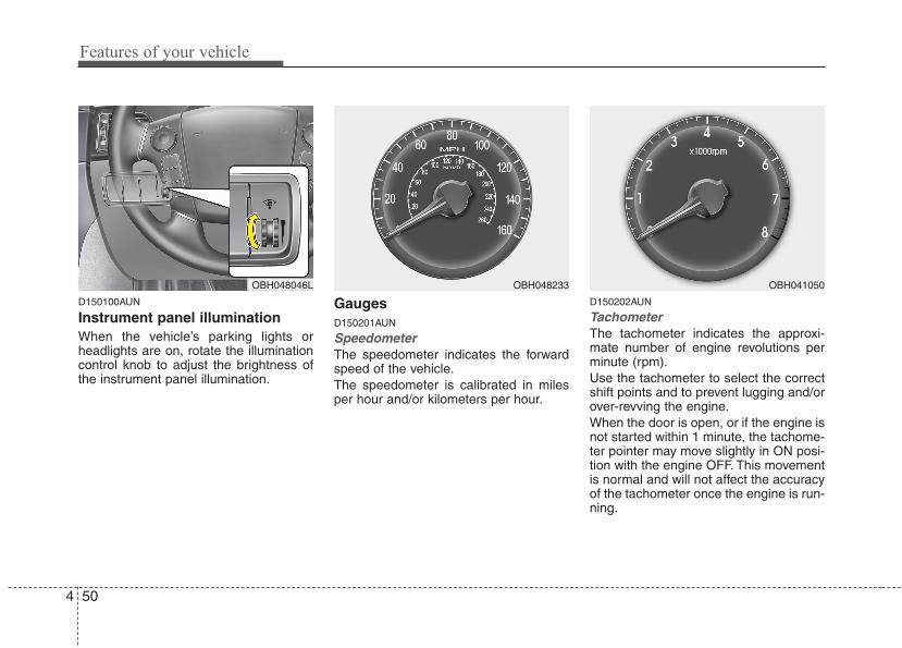
Features of your vehicle
504
D150100AUN
Instrument panel illumination When the vehicle’s parking lights orheadlights are on, rotate the illuminationcontrol knob to adjust the brightness ofthe instrument panel illumination.
GaugesD150201AUN
Speedometer The speedometer indicates the forwardspeed of the vehicle.The speedometer is calibrated in milesper hour and/or kilometers per hour.
D150202AUN
Tachometer The tachometer indicates the approxi-mate number of engine revolutions perminute (rpm).Use the tachometer to select the correctshift points and to prevent lugging and/orover-revving the engine.When the door is open, or if the engine isnot started within 1 minute, the tachome-ter pointer may move slightly in ON posi-tion with the engine OFF. This movementis normal and will not affect the accuracyof the tachometer once the engine is run-ning.
OBH048046L OBH048233 OBH041050
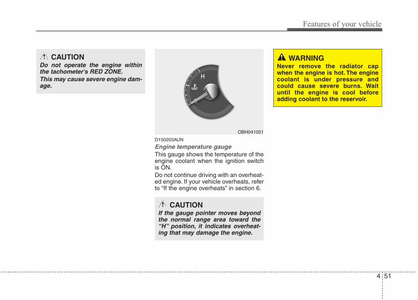
4 51
Features of your vehicle
D150203AUN
Engine temperature gauge This gauge shows the temperature of theengine coolant when the ignition switchis ON.Do not continue driving with an overheat-ed engine. If your vehicle overheats, referto “If the engine overheats” in section 6.
OBH041051
CAUTIONIf the gauge pointer moves beyondthe normal range area toward the“H” position, it indicates overheat-ing that may damage the engine.
CAUTIONDo not operate the engine withinthe tachometer's RED ZONE.This may cause severe engine dam-age.
WARNINGNever remove the radiator capwhen the engine is hot. The enginecoolant is under pressure andcould cause severe burns. Waituntil the engine is cool beforeadding coolant to the reservoir.
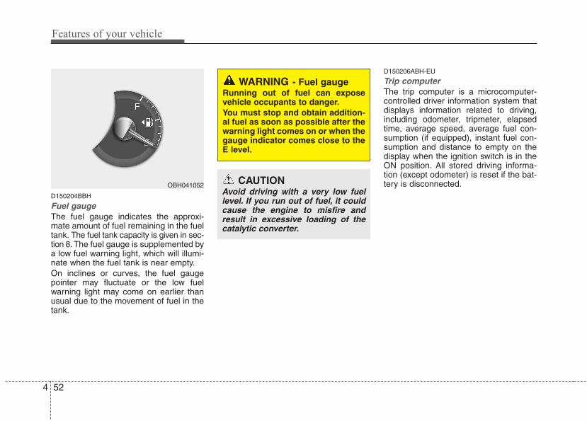
Features of your vehicle
524
D150204BBH
Fuel gaugeThe fuel gauge indicates the approxi-mate amount of fuel remaining in the fueltank. The fuel tank capacity is given in sec-tion 8. The fuel gauge is supplemented bya low fuel warning light, which will illumi-nate when the fuel tank is near empty.On inclines or curves, the fuel gaugepointer may fluctuate or the low fuelwarning light may come on earlier thanusual due to the movement of fuel in thetank.
D150206ABH-EU
Trip computerThe trip computer is a microcomputer-controlled driver information system thatdisplays information related to driving,including odometer, tripmeter, elapsedtime, average speed, average fuel con-sumption (if equipped), instant fuel con-sumption and distance to empty on thedisplay when the ignition switch is in theON position. All stored driving informa-tion (except odometer) is reset if the bat-tery is disconnected.
WARNING - Fuel gaugeRunning out of fuel can exposevehicle occupants to danger.You must stop and obtain addition-al fuel as soon as possible after thewarning light comes on or when thegauge indicator comes close to theE level.
CAUTIONAvoid driving with a very low fuellevel. If you run out of fuel, it couldcause the engine to misfire andresult in excessive loading of thecatalytic converter.
OBH041052
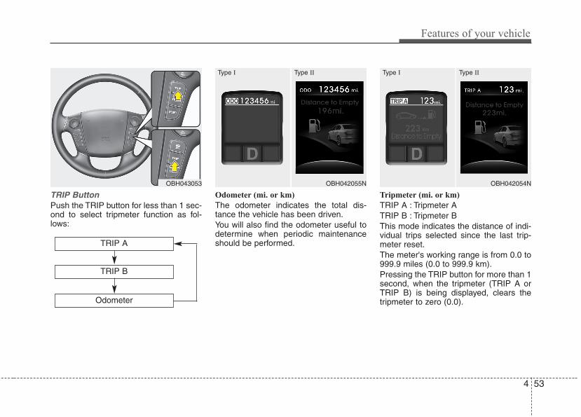
4 53
Features of your vehicle
TRIP ButtonPush the TRIP button for less than 1 sec-ond to select tripmeter function as fol-lows:
Odometer (mi. or km)
The odometer indicates the total dis-tance the vehicle has been driven.You will also find the odometer useful todetermine when periodic maintenanceshould be performed.
Tripmeter (mi. or km)
TRIP A : Tripmeter ATRIP B : Tripmeter BThis mode indicates the distance of indi-vidual trips selected since the last trip-meter reset.The meter's working range is from 0.0 to999.9 miles (0.0 to 999.9 km).Pressing the TRIP button for more than 1second, when the tripmeter (TRIP A orTRIP B) is being displayed, clears thetripmeter to zero (0.0).
OBH043053
TRIP A
Odometer
TRIP B
OBH042055N
Type I Type II
OBH042054N
Type I Type II
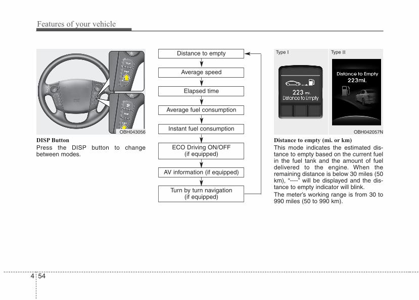
Features of your vehicle
544
DISP Button
Press the DISP button to changebetween modes.
Distance to empty (mi. or km)
This mode indicates the estimated dis-tance to empty based on the current fuelin the fuel tank and the amount of fueldelivered to the engine. When theremaining distance is below 30 miles (50km), “----” will be displayed and the dis-tance to empty indicator will blink.The meter’s working range is from 30 to990 miles (50 to 990 km).
OBH043056 OBH042057N
Type I Type IIDistance to empty
Elapsed time
Average speed
Instant fuel consumption
ECO Driving ON/OFF (if equipped)
Average fuel consumption
AV information (if equipped)
Turn by turn navigation (if equipped)
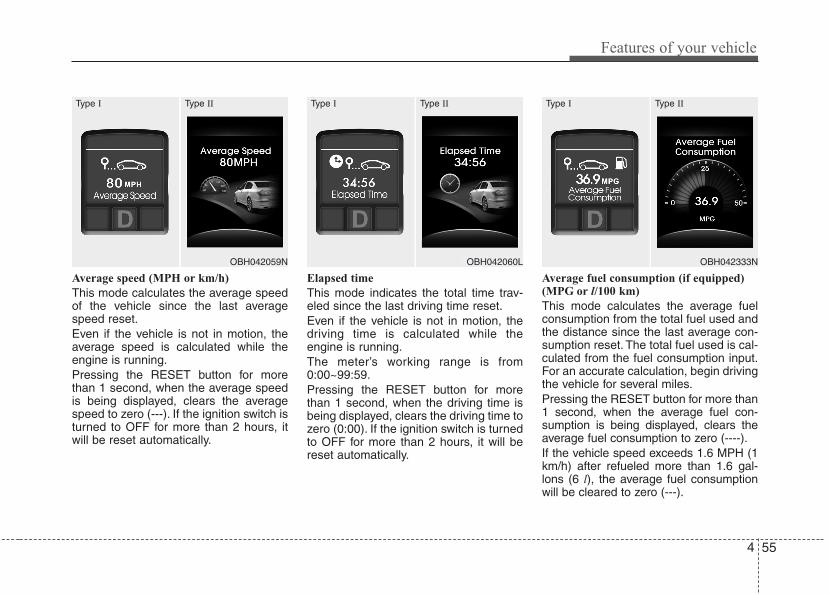
4 55
Features of your vehicle
Average speed (MPH or km/h)
This mode calculates the average speedof the vehicle since the last averagespeed reset.Even if the vehicle is not in motion, theaverage speed is calculated while theengine is running.Pressing the RESET button for morethan 1 second, when the average speedis being displayed, clears the averagespeed to zero (---). If the ignition switch isturned to OFF for more than 2 hours, itwill be reset automatically.
Elapsed time
This mode indicates the total time trav-eled since the last driving time reset.Even if the vehicle is not in motion, thedriving time is calculated while theengine is running.The meter’s working range is from0:00~99:59.Pressing the RESET button for morethan 1 second, when the driving time isbeing displayed, clears the driving time tozero (0:00). If the ignition switch is turnedto OFF for more than 2 hours, it will bereset automatically.
Average fuel consumption (if equipped)(MPG or l/100 km)
This mode calculates the average fuelconsumption from the total fuel used andthe distance since the last average con-sumption reset. The total fuel used is cal-culated from the fuel consumption input.For an accurate calculation, begin drivingthe vehicle for several miles.Pressing the RESET button for more than1 second, when the average fuel con-sumption is being displayed, clears theaverage fuel consumption to zero (----).If the vehicle speed exceeds 1.6 MPH (1km/h) after refueled more than 1.6 gal-lons (6 l), the average fuel consumptionwill be cleared to zero (---).
OBH042059N
Type I Type II
OBH042060L
Type I Type II
OBH042333N
Type I Type II
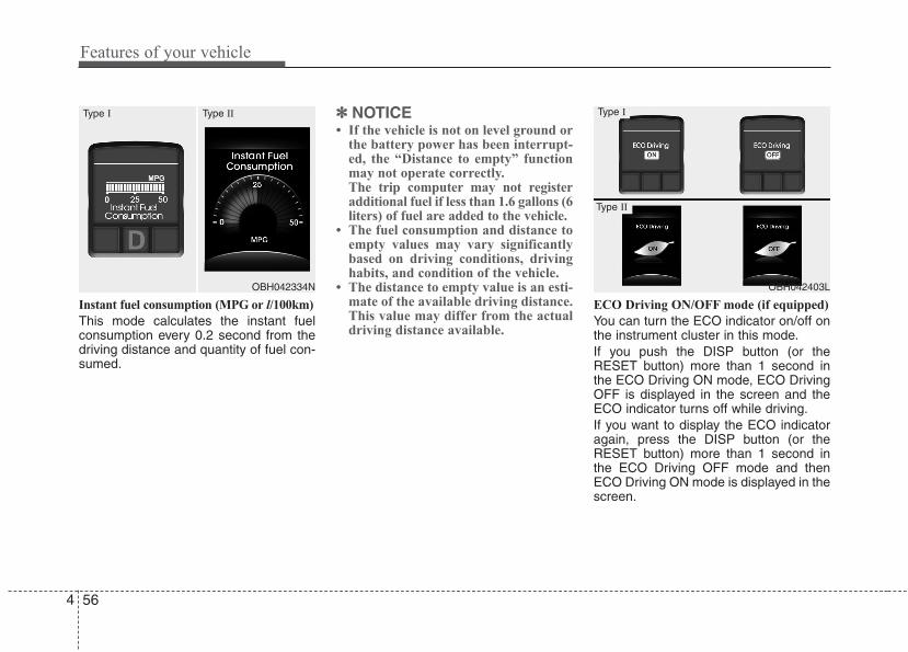
Features of your vehicle
564
Instant fuel consumption (MPG or l/100km)
This mode calculates the instant fuelconsumption every 0.2 second from thedriving distance and quantity of fuel con-sumed.
✽✽ NOTICE• If the vehicle is not on level ground or
the battery power has been interrupt-ed, the “Distance to empty” functionmay not operate correctly.The trip computer may not registeradditional fuel if less than 1.6 gallons (6liters) of fuel are added to the vehicle.
• The fuel consumption and distance toempty values may vary significantlybased on driving conditions, drivinghabits, and condition of the vehicle.
• The distance to empty value is an esti-mate of the available driving distance.This value may differ from the actualdriving distance available.
ECO Driving ON/OFF mode (if equipped)
You can turn the ECO indicator on/off onthe instrument cluster in this mode.If you push the DISP button (or theRESET button) more than 1 second inthe ECO Driving ON mode, ECO DrivingOFF is displayed in the screen and theECO indicator turns off while driving.If you want to display the ECO indicatoragain, press the DISP button (or theRESET button) more than 1 second inthe ECO Driving OFF mode and thenECO Driving ON mode is displayed in thescreen.
OBH042334N
Type I Type II
OBH042403L
Type I
Type II
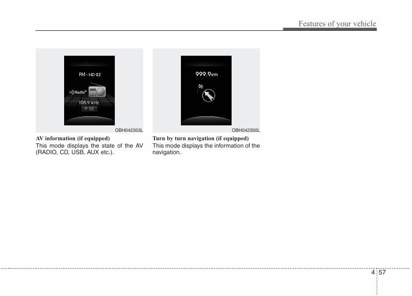
4 57
Features of your vehicle
AV information (if equipped)
This mode displays the state of the AV(RADIO, CD, USB, AUX etc.).
Turn by turn navigation (if equipped)
This mode displays the information of thenavigation.
OBH042353L OBH042350L
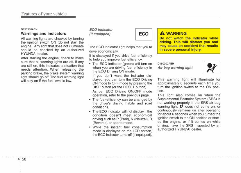
Features of your vehicle
584
D150300AEN
Warnings and indicatorsAll warning lights are checked by turningthe ignition switch ON (do not start theengine). Any light that does not illuminateshould be checked by an authorizedHYUNDAI dealer.After starting the engine, check to makesure that all warning lights are off. If anyare still on, this indicates a situation thatneeds attention. When releasing theparking brake, the brake system warninglight should go off. The fuel warning lightwill stay on if the fuel level is low.
ECO indicator(if equipped)
The ECO indicator light helps that you todrive economically.It is displayed if you drive fuel efficientlyto help you improve fuel efficiency.• The ECO indicator (green) will turn on
when you are driving fuel efficiently inthe ECO Driving ON mode.If you don't want the indicator dis-played, you can turn the ECO DrivingON mode to OFF mode by pressing theDISP button (or the RESET button).As per ECO Driving ON/OFF modeoperation, refer to the previous page.
• The fuel-efficiency can be changed bythe driver's driving habits and roadconditions.
• The ECO indicator will not display if thecondition doesn't meet economicaldriving such as P (Park), N (Neutral), R(Reverse) or sports mode.
• While the instant fuel consumptionmode is displayed on the LCD screen,the ECO indicator turns off (if equipped).
D150302ABH
Air bag warning light
This warning light will illuminate forapproximately 6 seconds each time youturn the ignition switch to the ON posi-tion.This light also comes on when the Supplemental Restraint System (SRS) isnot working properly. If the SRS air bagwarning light does not come on, orcontinuously remains on after operatingfor about 6 seconds when you turned theignition switch to the ON position or start-ed the engine, or if it comes on whiledriving, have the SRS inspected by anauthorized HYUNDAI dealer.
ECO WARNINGDo not watch the indicator whiledriving. This will distract you andmay cause an accident that resultsin severe personal injury.
4 59
Features of your vehicle
D150303AEN
Anti-lock brake system(ABS) warning light
This light illuminates if the ignition switchis turned ON and goes off in approxi-mately 3 seconds if the system is operat-ing normally.If the ABS warning light remains on,comes on while driving, or does notcome on when the ignition switch isturned to the ON position, this indicatesthat there may be a malfunction with theABS.If this occurs, have your vehicle checkedby an authorized HYUNDAI dealer assoon as possible. The normal brakingsystem will still be operational, but with-out the assistance of the anti-lock brakesystem.
Electronic brake force distri-bution (EBD) system warninglight
If these two warning lightsilluminate at the same timewhile driving, your vehiclemay have a malfunction withthe ABS and EBD system.In this case, your ABS and regular brakesystem may not work normally. Have thevehicle checked by an authorizedHYUNDAI dealer as soon as possible.
✽✽ NOTICEIf the ABS warning light or EBD warn-ing light is on and stays on, thespeedometer or odometer/tripmetermay not work. In this case, have yourvehicle checked by an authorizedHYUNDAI dealer as soon as possible.
WARNINGIf the both ABS and brake warninglights are on and stay on, your vehi-cle’s brake system will not work nor-mally during sudden braking. In thiscase, avoid high speed driving andabrupt braking. Have your vehiclechecked by an authorized HYUNDAIdealer as soon as possible.
Features of your vehicle
604
D150304CBH-EU
Seat belt warning
As a reminder to the driver, the seat beltwarning light will blink for approximately6 seconds each time you turn the ignitionswitch ON, regardless of belt fastening.The warning light will blink again forapproximately 6 seconds when startingthe engine.If the driver's seat belt is not fastenedwhen the ignition switch is turned on, theseat belt warning light and chime will oper-ate for approximately 6 seconds. But if it isfastened within the 6 seconds, the warninglight will blink for the 6 seconds and thewarning chime will turn off immediately.If the driver's seat belt is disconnectedafter the ignition switch is turned to theON position, the seat belt warning lightwill turn on for approximately 6 seconds.But if it is fastened within the 6 seconds,the warning light will turn off immediately.If the driver's seat belt is not fastenedwhen the vehicle speed exceeds 6 mph(10 km/h), the seat belt warning light andchime will operate for approximately 11times with a pattern of 6 seconds on and24 seconds off until the belt is fastenedor the vehicle speed decreases below 3mph (5 km/h).
D150305AUN
Turn signal indicator
The blinking green arrows on the instru-ment panel show the direction indicatedby the turn signals. If the arrow comes onbut does not blink, blinks more rapidlythan normal, or does not illuminate at all,a malfunction in the turn signal system isindicated. Your dealer should be consult-ed for repairs.
D150306AUN
High beam indicator
This indicator illuminates when the head-lights are on and in the high beam posi-tion or when the turn signal lever is pulledinto the Flash-to-Pass position.
D150331ABH
Tail light indicator
This indicator illuminates when the taillights are on.
D150307AEN
Engine oil pressure warning light
This warning light indicates the engine oilpressure is low.If the warning light illuminates while driv-ing:1. Drive safely to the side of the road and
stop.2. With the engine off, check the engine
oil level. If the level is low, add oil asrequired.
If the warning light remains on afteradding oil or if oil is not available, call anauthorized HYUNDAI dealer.
CAUTIONIf the engine is not stopped imme-diately after the engine oil pressurewarning light is illuminated, severedamage could result.
4 61
Features of your vehicle
D150308ABH-EU
Parking brake & brake fluidwarning light
Parking brake warning
This light is illuminated when the parkingbrake is applied with the ignition switch inthe START or ON position. The warninglight should go off when the parkingbrake is released while an engine is run-ning.The parking brake warning chime willsound to remind you that the parkingbrake is applied when you are drivingabove 6 mph (10 km/h). Always releasethe parking brake before you drive.
Low brake fluid level warning
If the warning light remains on, it mayindicate that the brake fluid level in thereservoir is low.If the warning light remains on:1.Drive carefully to the nearest safe loca-
tion and stop your vehicle.2.With the engine stopped, check the
brake fluid level immediately and addfluid as required. Then check all brakecomponents for fluid leaks.
3.Do not drive the vehicle if leaks arefound, the warning light remains on orthe brakes do not operate properly.Have the vehicle towed to any author-ized HYUNDAI dealer for a brake sys-tem inspection and necessary repairs.
Your vehicle is equipped with a dual-diagonal braking system.This means youstill have braking on two wheels even ifone of the brake circuits is damaged ormalfunctions. With only one of the circuitsworking, more than normal pedal traveland greater pedal pressure are requiredto stop the car. Also, the car will not stopin as short a distance with only a portionof the brake system working. If thebrakes fail while you are driving, shift to alower gear for additional engine brakingand stop the car as soon as it is safe todo so.
CAUTIONIf the oil pressure warning lightstays on while the engine is run-ning, serious engine damage mayresult. The oil pressure warninglight comes on whenever there isinsufficient oil pressure. In normaloperation, it should come on whenthe ignition switch is turned on,then go out when the engine isstarted. If the oil pressure warninglight stays on while the engine isrunning, there is a serious malfunc-tion.If this happens, stop the car assoon as it is safe to do so, turn offthe engine and check the oil level. Ifthe oil level is low, fill the engine oilto the proper level and start theengine again. If the light stays onwith the engine running, turn theengine off immediately. In anyinstance where the oil light stays onwhen the engine is running, theengine should be checked by anauthorized HYUNDAI dealer beforethe car is driven again.
Features of your vehicle
624
To check bulb operation, check whetherthe parking brake and brake fluid warninglight illuminates when the ignition switchis in the ON position.
D150331ABH
Low tire pressure telltale (if equipped)
Low tire pressure positiontelltale (if equipped)
The low tire pressure telltale comes onfor 3 seconds after the ignition switch isturned to the ON position.If the warning light does not come on, orcontinuously remains on after coming onfor about 3 seconds when you turned theignition switch to the ON position, theTire Pressure Monitoring System is notworking properly. If this occurs, have yourvehicle checked by an authorizedHYUNDAI dealer as soon as possible.The warning lights will also illuminate ifone or more of your tires is significantlyunder-inflated. The low tire pressure posi-tion telltale (supplemental) indicates whichtire is significantly under-inflated by illumi-nating the corresponding position light.Youshould stop and check your tires as soonas possible. If the warning lights illumi-nate while driving, reduce vehicle speedimmediately and stop the vehicle. Avoidhard braking and overcorrecting at thesteering wheel. Inflate the tires to theproper pressure as indicated on the vehi-cle’s tire information placard.
WARNING - Low tire pres-sure
Significantly low tire pressuremakes the vehicle unstable and cancontribute to loss of vehicle controland increased braking distances.Continued driving on tires with lowpressure will cause the tires tooverheat and fail.
WARNING Driving the vehicle with a warninglight on is dangerous. If the brakewarning light remains on, have thebrakes checked and repaired imme-diately by an authorized HYUNDAIdealer.
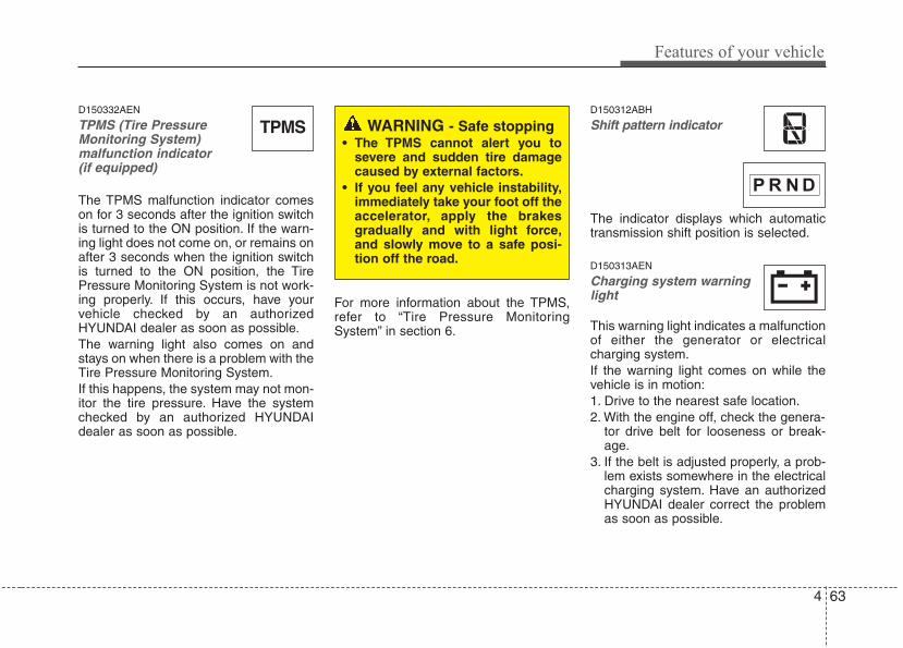
4 63
Features of your vehicle
D150332AEN
TPMS (Tire PressureMonitoring System) malfunction indicator (if equipped)
The TPMS malfunction indicator comeson for 3 seconds after the ignition switchis turned to the ON position. If the warn-ing light does not come on, or remains onafter 3 seconds when the ignition switchis turned to the ON position, the TirePressure Monitoring System is not work-ing properly. If this occurs, have yourvehicle checked by an authorizedHYUNDAI dealer as soon as possible.The warning light also comes on andstays on when there is a problem with theTire Pressure Monitoring System.If this happens, the system may not mon-itor the tire pressure. Have the systemchecked by an authorized HYUNDAIdealer as soon as possible.
For more information about the TPMS,refer to “Tire Pressure MonitoringSystem” in section 6.
D150312ABH
Shift pattern indicator
The indicator displays which automatictransmission shift position is selected.
D150313AEN
Charging system warninglight
This warning light indicates a malfunctionof either the generator or electricalcharging system.If the warning light comes on while thevehicle is in motion:1. Drive to the nearest safe location.2. With the engine off, check the genera-
tor drive belt for looseness or break-age.
3. If the belt is adjusted properly, a prob-lem exists somewhere in the electricalcharging system. Have an authorizedHYUNDAI dealer correct the problemas soon as possible.
TPMS WARNING - Safe stopping• The TPMS cannot alert you to
severe and sudden tire damagecaused by external factors.
• If you feel any vehicle instability,immediately take your foot off theaccelerator, apply the brakesgradually and with light force,and slowly move to a safe posi-tion off the road.
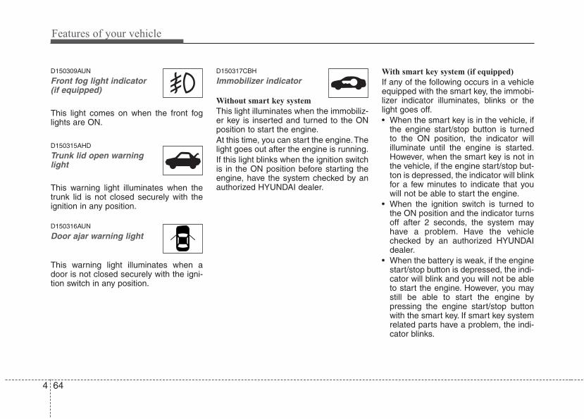
Features of your vehicle
644
D150309AUN
Front fog light indicator (if equipped)
This light comes on when the front foglights are ON.
D150315AHD
Trunk lid open warninglight
This warning light illuminates when thetrunk lid is not closed securely with theignition in any position.
D150316AUN
Door ajar warning light
This warning light illuminates when adoor is not closed securely with the igni-tion switch in any position.
D150317CBH
Immobilizer indicator
Without smart key system
This light illuminates when the immobiliz-er key is inserted and turned to the ONposition to start the engine.At this time, you can start the engine.Thelight goes out after the engine is running.If this light blinks when the ignition switchis in the ON position before starting theengine, have the system checked by anauthorized HYUNDAI dealer.
With smart key system (if equipped)
If any of the following occurs in a vehicleequipped with the smart key, the immobi-lizer indicator illuminates, blinks or thelight goes off.• When the smart key is in the vehicle, if
the engine start/stop button is turnedto the ON position, the indicator willilluminate until the engine is started.However, when the smart key is not inthe vehicle, if the engine start/stop but-ton is depressed, the indicator will blinkfor a few minutes to indicate that youwill not be able to start the engine.
• When the ignition switch is turned tothe ON position and the indicator turnsoff after 2 seconds, the system mayhave a problem. Have the vehiclechecked by an authorized HYUNDAIdealer.
• When the battery is weak, if the enginestart/stop button is depressed, the indi-cator will blink and you will not be ableto start the engine. However, you maystill be able to start the engine bypressing the engine start/stop buttonwith the smart key. If smart key systemrelated parts have a problem, the indi-cator blinks.
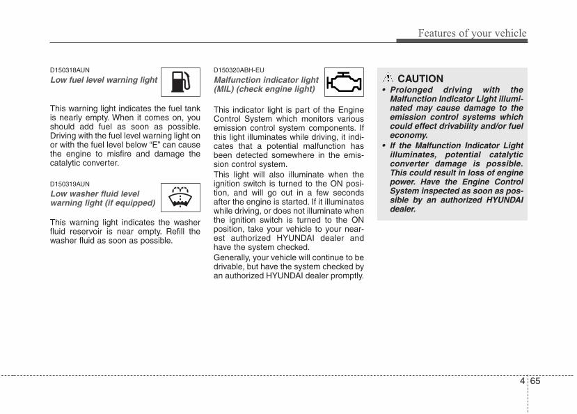
4 65
Features of your vehicle
D150318AUN
Low fuel level warning light
This warning light indicates the fuel tankis nearly empty. When it comes on, youshould add fuel as soon as possible.Driving with the fuel level warning light onor with the fuel level below “E” can causethe engine to misfire and damage thecatalytic converter.
D150319AUN
Low washer fluid levelwarning light (if equipped)
This warning light indicates the washerfluid reservoir is near empty. Refill thewasher fluid as soon as possible.
D150320ABH-EU
Malfunction indicator light(MIL) (check engine light)
This indicator light is part of the EngineControl System which monitors variousemission control system components. Ifthis light illuminates while driving, it indi-cates that a potential malfunction hasbeen detected somewhere in the emis-sion control system.This light will also illuminate when theignition switch is turned to the ON posi-tion, and will go out in a few secondsafter the engine is started. If it illuminateswhile driving, or does not illuminate whenthe ignition switch is turned to the ONposition, take your vehicle to your near-est authorized HYUNDAI dealer andhave the system checked.Generally, your vehicle will continue to bedrivable, but have the system checked byan authorized HYUNDAI dealer promptly.
CAUTION• Prolonged driving with the
Malfunction Indicator Light illumi-nated may cause damage to theemission control systems whichcould effect drivability and/or fueleconomy.
• If the Malfunction Indicator Lightilluminates, potential catalyticconverter damage is possible.This could result in loss of enginepower. Have the Engine ControlSystem inspected as soon as pos-sible by an authorized HYUNDAIdealer.
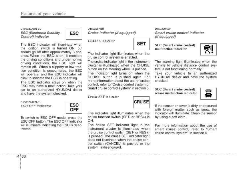
Features of your vehicle
664
D150323AUN-EU
ESC (Electronic StabilityControl) indicator
The ESC indicator will illuminate whenthe ignition switch is turned ON, butshould go off after approximately 3 sec-onds. When the ESC is on, it monitorsthe driving conditions and under normaldriving conditions, the ESC light willremain off. When a slippery or low trac-tion condition is encountered, the ESCwill operate, and the ESC indicator willblink to indicate the ESC is operating.The ESC indicator stays on when theESC may have a malfunction. Take yourcar to an authorized HYUNDAI dealerand have the system checked.
D150324AEN-EU
ESC OFF indicator
To switch to ESC OFF mode, press theESC OFF button. The ESC OFF indicatorwill illuminate indicating the ESC is deac-tivated.
D150325ABH
Cruise indicator (if equipped)
CRUISE indicator
The indicator light illuminates when thecruise control system is enabled.The cruise indicator light in the instrumentcluster is illuminated when the CRUISEbutton on the steering wheel is pushed.The indicator light turns off when theCRUISE button is pushed again. Formore information about the use of cruisecontrol, refer to “Cruise control system orSmart cruise control system” in section 5.
Cruise SET indicator
The indicator light illuminates when thecruise function switch (SET- or RES+) isON.The cruise SET indicator light in theinstrument cluster is illuminated whenthe cruise control switch (SET- or RES+)is pushed. The cruise SET indicator lightdoes not illuminate when the cruise con-trol switch (CANCEL) is pushed or thesystem is disengaged.
D150320ABH
Smart cruise control indicator (if equipped)
SCC (Smart cruise control)malfunction indicator
The warning light illuminates when thevehicle to vehicle distance control sys-tem is not functioning normally.Take your vehicle to an authorizedHYUNDAI dealer and have the systemchecked.
SCC (Smart cruise control)sensor malfunction indicator
If the sensor or cover is dirty or obscuredwith foreign matter such as snow, theindicator will illuminate. Clean the sensorby using a soft cloth.
For more information about the use ofsmart cruise control, refer to "Smartcruise control system" in section 5.
SET
CRUISE
ESC
ESCOFF
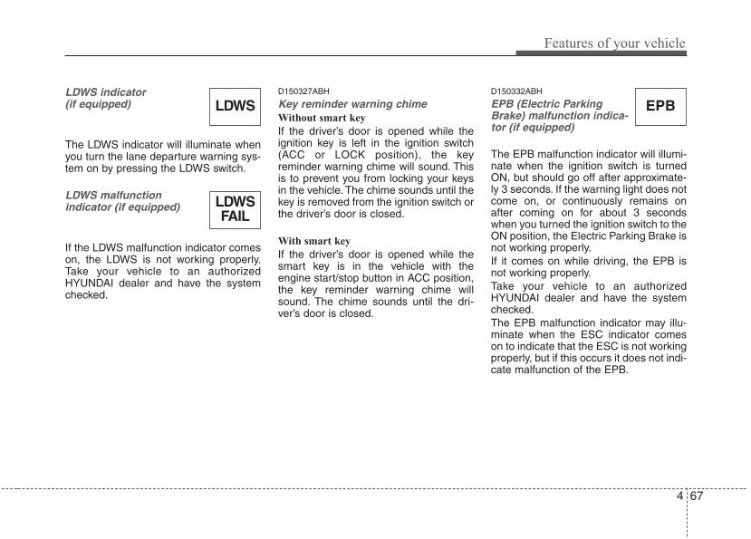
4 67
Features of your vehicle
LDWS indicator (if equipped)
The LDWS indicator will illuminate whenyou turn the lane departure warning sys-tem on by pressing the LDWS switch.
LDWS malfunction indicator (if equipped)
If the LDWS malfunction indicator comeson, the LDWS is not working properly.Take your vehicle to an authorizedHYUNDAI dealer and have the systemchecked.
D150327ABH
Key reminder warning chime Without smart key
If the driver’s door is opened while theignition key is left in the ignition switch(ACC or LOCK position), the keyreminder warning chime will sound. Thisis to prevent you from locking your keysin the vehicle. The chime sounds until thekey is removed from the ignition switch orthe driver’s door is closed.
With smart key
If the driver’s door is opened while thesmart key is in the vehicle with theengine start/stop button in ACC position,the key reminder warning chime willsound. The chime sounds until the dri-ver’s door is closed.
D150332ABH
EPB (Electric ParkingBrake) malfunction indica-tor (if equipped)
The EPB malfunction indicator will illumi-nate when the ignition switch is turnedON, but should go off after approximate-ly 3 seconds. If the warning light does notcome on, or continuously remains onafter coming on for about 3 secondswhen you turned the ignition switch to theON position, the Electric Parking Brake isnot working properly.If it comes on while driving, the EPB isnot working properly.Take your vehicle to an authorizedHYUNDAI dealer and have the systemchecked.The EPB malfunction indicator may illu-minate when the ESC indicator comeson to indicate that the ESC is not workingproperly, but if this occurs it does not indi-cate malfunction of the EPB.
EPBLDWS
LDWSFAIL
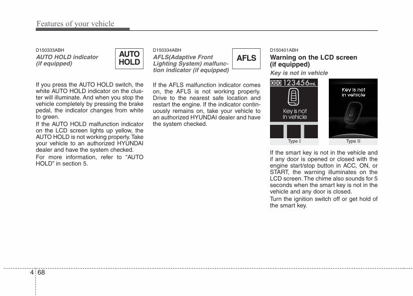
Features of your vehicle
684
D150333ABH
AUTO HOLD indicator (if equipped)
If you press the AUTO HOLD switch, thewhite AUTO HOLD indicator on the clus-ter will illuminate. And when you stop thevehicle completely by pressing the brakepedal, the indicator changes from whiteto green.If the AUTO HOLD malfunction indicatoron the LCD screen lights up yellow, theAUTO HOLD is not working properly.Takeyour vehicle to an authorized HYUNDAIdealer and have the system checked.For more information, refer to “AUTOHOLD” in section 5.
D150334ABH
AFLS(Adaptive FrontLighting System) malfunc-tion indicator (if equipped)
If the AFLS malfunction indicator comeson, the AFLS is not working properly.Drive to the nearest safe location andrestart the engine. If the indicator contin-uously remains on, take your vehicle toan authorized HYUNDAI dealer and havethe system checked.
D150401ABH
Warning on the LCD screen(if equipped)Key is not in vehicle
If the smart key is not in the vehicle andif any door is opened or closed with theengine start/stop button in ACC, ON, orSTART, the warning illuminates on theLCD screen. The chime also sounds for 5seconds when the smart key is not in thevehicle and any door is closed.Turn the ignition switch off or get hold ofthe smart key.
Type I Type II
AUTOHOLD AFLS
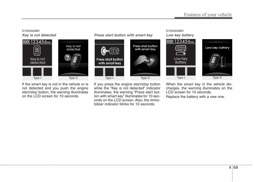
4 69
Features of your vehicle
D150402ABH
Key is not detected
If the smart key is not in the vehicle or isnot detected and you push the enginestart/stop button, the warning illuminateson the LCD screen for 10 seconds.
Press start button with smart key
If you press the engine start/stop buttonwhile the “Key is not detected” indicatorilluminates, the warning “Press start but-ton with smart key” illuminates for 10 sec-onds on the LCD screen. Also, the immo-bilizer indicator blinks for 10 seconds.
D150403ABH
Low key battery
When the smart key in the vehicle dis-charges, the warning illuminates on theLCD screen for 10 seconds.Replace the battery with a new one.
Type I Type IIType I Type II Type I Type II

Features of your vehicle
704
D150404ABH
Press brake pedal to start engine
If the engine start/stop button turns to theACC position twice by pushing theengine start/stop button repeatedly with-out pressing the brake pedal, the warn-ing illuminates on the LCD screen for 10seconds to indicate that you shouldpress the brake pedal to start the engine.
D150405ABH
Shift to "P" position
If you push the engine start/stop buttonwith the engine start/stop button ON andthe shift lever not in P(Park), the warningilluminates on the LCD screen for 10 sec-onds to indicate that you should pressthe engine start/stop button with the shiftlever in P(Park) to turn off the engine.
D150408ABH
Press start button again
If there is a problem with the enginestart/stop button system, the warning illu-minates for 10 seconds to indicate thatyou could start the engine by pressingthe engine start/stop button while press-ing the brake pedal.If the warning illuminates each time youpush the engine start/stop button, takeyour vehicle to an authorized HYUNDAIdealer and have the system checked.
Type I Type IIType I Type IIType I Type II
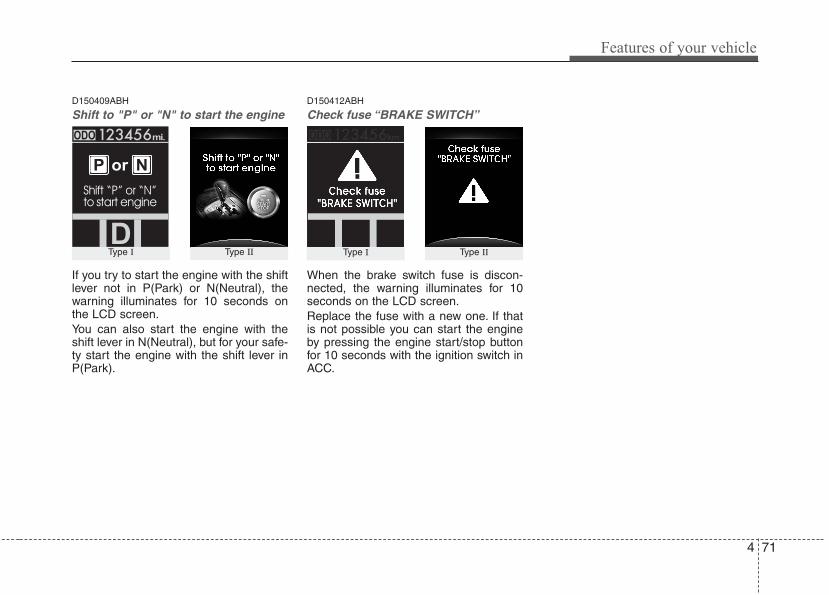
4 71
Features of your vehicle
D150409ABH
Shift to "P" or "N" to start the engine
If you try to start the engine with the shiftlever not in P(Park) or N(Neutral), thewarning illuminates for 10 seconds onthe LCD screen.You can also start the engine with theshift lever in N(Neutral), but for your safe-ty start the engine with the shift lever inP(Park).
D150412ABH
Check fuse “BRAKE SWITCH”
When the brake switch fuse is discon-nected, the warning illuminates for 10seconds on the LCD screen.Replace the fuse with a new one. If thatis not possible you can start the engineby pressing the engine start/stop buttonfor 10 seconds with the ignition switch inACC.
Type I Type IIType I Type II
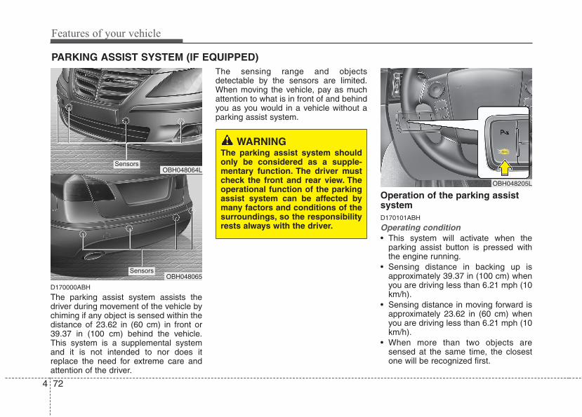
Features of your vehicle
724
D170000ABH
The parking assist system assists thedriver during movement of the vehicle bychiming if any object is sensed within thedistance of 23.62 in (60 cm) in front or39.37 in (100 cm) behind the vehicle.This system is a supplemental systemand it is not intended to nor does itreplace the need for extreme care andattention of the driver.
The sensing range and objectsdetectable by the sensors are limited.When moving the vehicle, pay as muchattention to what is in front of and behindyou as you would in a vehicle without aparking assist system.
Operation of the parking assistsystemD170101ABH
Operating condition• This system will activate when the
parking assist button is pressed withthe engine running.
• Sensing distance in backing up isapproximately 39.37 in (100 cm) whenyou are driving less than 6.21 mph (10km/h).
• Sensing distance in moving forward isapproximately 23.62 in (60 cm) whenyou are driving less than 6.21 mph (10km/h).
• When more than two objects aresensed at the same time, the closestone will be recognized first.
PARKING ASSIST SYSTEM (IF EQUIPPED)
OBH048064L
OBH048065
WARNINGThe parking assist system shouldonly be considered as a supple-mentary function. The driver mustcheck the front and rear view. Theoperational function of the parkingassist system can be affected bymany factors and conditions of thesurroundings, so the responsibilityrests always with the driver.
OBH048205L
Sensors
Sensors
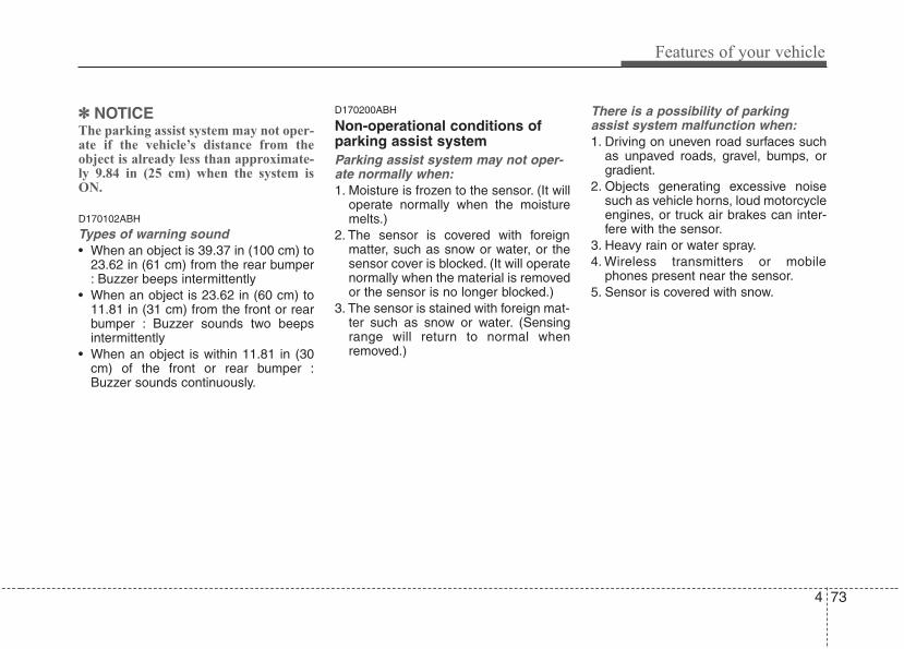
4 73
Features of your vehicle
✽✽ NOTICEThe parking assist system may not oper-ate if the vehicle’s distance from theobject is already less than approximate-ly 9.84 in (25 cm) when the system isON.
D170102ABH
Types of warning sound• When an object is 39.37 in (100 cm) to
23.62 in (61 cm) from the rear bumper: Buzzer beeps intermittently
• When an object is 23.62 in (60 cm) to11.81 in (31 cm) from the front or rearbumper : Buzzer sounds two beepsintermittently
• When an object is within 11.81 in (30cm) of the front or rear bumper :Buzzer sounds continuously.
D170200ABH
Non-operational conditions ofparking assist systemParking assist system may not oper-ate normally when:1. Moisture is frozen to the sensor. (It will
operate normally when the moisturemelts.)
2. The sensor is covered with foreignmatter, such as snow or water, or thesensor cover is blocked. (It will operatenormally when the material is removedor the sensor is no longer blocked.)
3. The sensor is stained with foreign mat-ter such as snow or water. (Sensingrange will return to normal whenremoved.)
There is a possibility of parkingassist system malfunction when:1. Driving on uneven road surfaces such
as unpaved roads, gravel, bumps, orgradient.
2. Objects generating excessive noisesuch as vehicle horns, loud motorcycleengines, or truck air brakes can inter-fere with the sensor.
3. Heavy rain or water spray.4. Wireless transmitters or mobile
phones present near the sensor.5. Sensor is covered with snow.
Features of your vehicle
744
WARNINGPay close attention when the vehi-cle is driven close to objects on theroad, particularly pedestrians, andespecially children. Be aware thatsome objects may not be detectedby the sensors, due to the objectsdistance, size or material, all ofwhich can limit the effectiveness ofthe sensor. Always perform a visualinspection to make sure the vehicleis clear of all obstructions beforemoving the vehicle in any direction.
Detecting range may decrease when:1. Outside air temperature is extremely
hot or cold.2. Undetectable objects smaller than
39.37 in (1 m) and narrower than 5.51in (14 cm) in diameter.
The following objects may not be rec-ognized by the sensor:1. Sharp or slim objects such as ropes,
chains or small poles.2. Objects, which tend to absorb sensor
frequency such as clothes, spongymaterial or snow.
✽✽ NOTICE1. The warning may not sound sequen-
tially depending on the speed andshapes of the objects detected.
2. The parking assist system may mal-function if the vehicle bumper heightor sensor installation has been modi-fied. Any non-factory installed equip-ment or accessories may also interferewith the sensor performance.
3. Sensor may not recognize objects lessthan 11.81 in (30 cm) from the sensor,or it may sense an incorrect distance.Use with caution.
4. When the sensor is frozen or stainedwith snow or water, the sensor may beinoperative until the stains areremoved using a soft cloth.
5. Do not push, scratch or strike the sen-sor with any hard objects that coulddamage the surface of the sensor.Sensor damage could occur.
✽✽ NOTICEThis system can only sense objects with-in the range and location of the sensors,it can not detect objects in other areaswhere sensors are not installed. Also,small or slim objects, or objects locatedbetween sensors may not be detected. Always visually check in front andbehind the vehicle when driving.Be sure to inform any drivers in thevehicle that may be unfamiliar with thesystem regarding the system’s capabili-ties and limitations.
4 75
Features of your vehicle
D170400ABH
Self-diagnosisIf you don’t hear an audible warningsound or if the buzzer sounds intermit-tently when shifting the gear to the R(Reverse) position, this may indicate amalfunction in the rear parking assist sys-tem. If this occurs, have your vehiclechecked by an authorized HYUNDAIdealer as soon as possible.
WARNINGYour new vehicle warranty does notcover any accidents or damage tothe vehicle or injuries to its occu-pants related to a parking assistsystem. Always drive safely andcautiously.
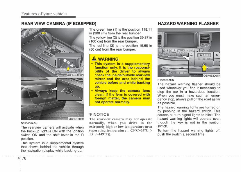
Features of your vehicle
764
REAR VIEW CAMERA (IF EQUIPPED)
D330000ABH
The rearview camera will activate whenthe back-up light is ON with the ignitionswitch ON and the shift lever in the Rposition.This system is a supplemental systemthat shows behind the vehicle throughthe navigation display while backing-up.
The green line (1) is the position 118.11in (300 cm) from the rear bumper.The yellow line (2) is the position 39.37 in(100 cm) from the rear bumper.The red line (3) is the position 19.68 in(50 cm) from the rear bumper.
✽✽ NOTICEThe rearview camera may not operatenormally, when you drive in theextremely high or low temperature area(operating temperature : -20°C~65°C (-13°F~149°F)).
D180000AUN
The hazard warning flasher should beused whenever you find it necessary tostop the car in a hazardous location.When you must make such an emer-gency stop, always pull off the road as faras possible.The hazard warning lights are turned onby pushing in the hazard switch. Thiscauses all turn signal lights to blink. Thehazard warning lights will operate eventhough the key is not in the ignitionswitch.To turn the hazard warning lights off,push the switch a second time.
HAZARD WARNING FLASHER
OBH063001N
WARNING• This system is a supplementary
function only. It is the responsi-bility of the driver to alwayscheck the inside/outside rearviewmirror and the area behind thevehicle before and while backingup.
• Always keep the camera lensclean. If the lens is covered withforeign matter, the camera maynot operate normally.
OBH043068N
OBH048069
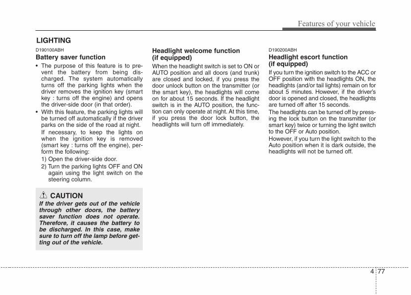
4 77
Features of your vehicle
D190100ABH
Battery saver function • The purpose of this feature is to pre-
vent the battery from being dis-charged. The system automaticallyturns off the parking lights when thedriver removes the ignition key (smartkey : turns off the engine) and opensthe driver-side door (in that order).
• With this feature, the parking lights willbe turned off automatically if the driverparks on the side of the road at night.If necessary, to keep the lights onwhen the ignition key is removed(smart key : turns off the engine), per-form the following:1) Open the driver-side door.2) Turn the parking lights OFF and ON
again using the light switch on thesteering column.
Headlight welcome function (if equipped)When the headlight switch is set to ON orAUTO position and all doors (and trunk)are closed and locked, if you press thedoor unlock button on the transmitter (orthe smart key), the headlights will comeon for about 15 seconds. If the headlightswitch is in the AUTO position, the func-tion can only operate at night. At this time,if you press the door lock button, theheadlights will turn off immediately.
D190200ABH
Headlight escort function (if equipped)If you turn the ignition switch to the ACC orOFF position with the headlights ON, theheadlights (and/or tail lights) remain on forabout 5 minutes. However, if the driver’sdoor is opened and closed, the headlightsare turned off after 15 seconds.The headlights can be turned off by press-ing the lock button on the transmitter (orsmart key) twice or turning the light switchto the OFF or Auto position.However, if you turn the light switch to theAuto position when it is dark outside, theheadlights will not be turned off.
LIGHTING
CAUTIONIf the driver gets out of the vehiclethrough other doors, the batterysaver function does not operate.Therefore, it causes the battery tobe discharged. In this case, makesure to turn off the lamp before get-ting out of the vehicle.
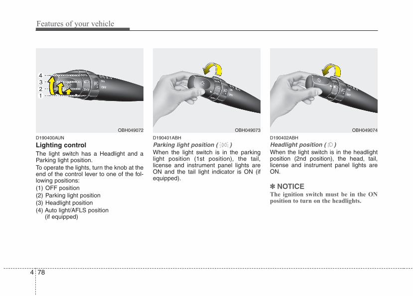
Features of your vehicle
784
D190400AUN
Lighting controlThe light switch has a Headlight and aParking light position.To operate the lights, turn the knob at theend of the control lever to one of the fol-lowing positions:(1) OFF position(2) Parking light position(3) Headlight position(4) Auto light/AFLS position
(if equipped)
D190401ABH
Parking light position ( )When the light switch is in the parkinglight position (1st position), the tail,license and instrument panel lights areON and the tail light indicator is ON (ifequipped).
D190402ABH
Headlight position ( )When the light switch is in the headlightposition (2nd position), the head, tail,license and instrument panel lights areON.
✽✽ NOTICEThe ignition switch must be in the ONposition to turn on the headlights.
OBH049074OBH049073OBH049072
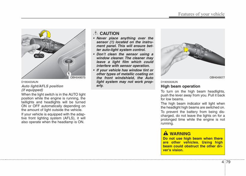
4 79
Features of your vehicle
D190403AUN
Auto light/AFLS position (if equipped)When the light switch is in the AUTO lightposition while the engine is running, thetaillights and headlights will be turnedON or OFF automatically depending onthe amount of light outside the vehicle.If your vehicle is equipped with the adap-tive front lighting system (AFLS), it willalso operate when the headlamp is ON.
D190500AUN
High beam operation To turn on the high beam headlights,push the lever away from you. Pull it backfor low beams.The high beam indicator will light whenthe headlight high beams are switched on.To prevent the battery from being dis-charged, do not leave the lights on for aprolonged time while the engine is notrunning.
OBH049077
CAUTION• Never place anything over the
sensor (1) located on the instru-ment panel. This will ensure bet-ter auto-light system control.
• Don’t clean the sensor using awindow cleaner. The cleaner mayleave a light film which couldinterfere with sensor operation.
• If your vehicle has window tint orother types of metallic coating onthe front windshield, the Autolight system may not work prop-erly.
WARNINGDo not use high beam when thereare other vehicles. Using highbeam could obstruct the other dri-ver's vision.
OBH049075
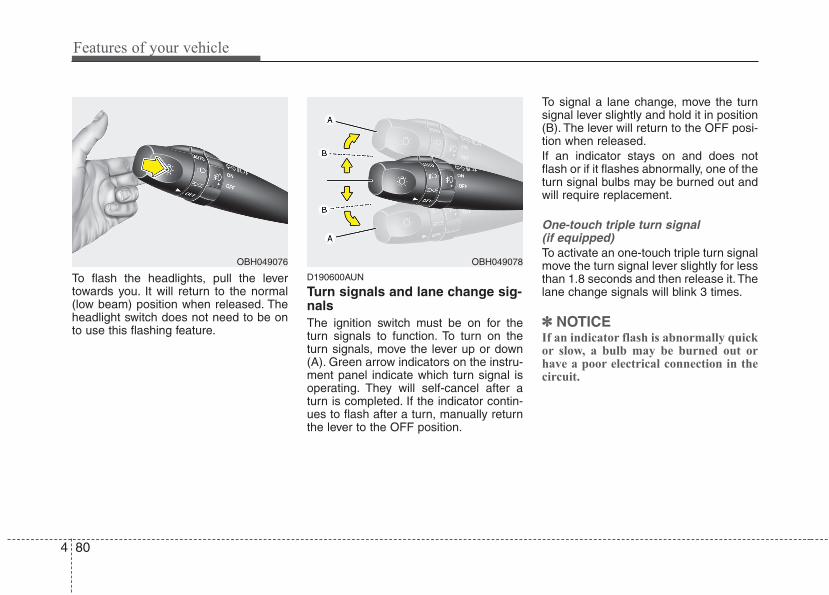
Features of your vehicle
804
To flash the headlights, pull the levertowards you. It will return to the normal(low beam) position when released. Theheadlight switch does not need to be onto use this flashing feature.
D190600AUN
Turn signals and lane change sig-nalsThe ignition switch must be on for theturn signals to function. To turn on theturn signals, move the lever up or down(A). Green arrow indicators on the instru-ment panel indicate which turn signal isoperating. They will self-cancel after aturn is completed. If the indicator contin-ues to flash after a turn, manually returnthe lever to the OFF position.
To signal a lane change, move the turnsignal lever slightly and hold it in position(B). The lever will return to the OFF posi-tion when released.If an indicator stays on and does notflash or if it flashes abnormally, one of theturn signal bulbs may be burned out andwill require replacement.
One-touch triple turn signal (if equipped)To activate an one-touch triple turn signalmove the turn signal lever slightly for lessthan 1.8 seconds and then release it. Thelane change signals will blink 3 times.
✽✽ NOTICEIf an indicator flash is abnormally quickor slow, a bulb may be burned out orhave a poor electrical connection in thecircuit.
OBH049078OBH049076
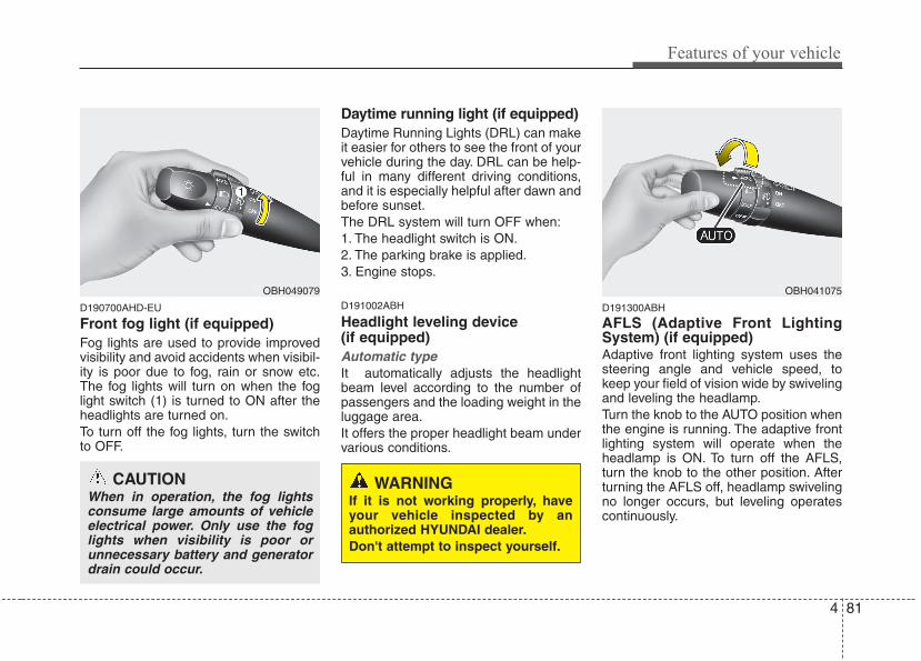
4 81
Features of your vehicle
D190700AHD-EU
Front fog light (if equipped) Fog lights are used to provide improvedvisibility and avoid accidents when visibil-ity is poor due to fog, rain or snow etc.The fog lights will turn on when the foglight switch (1) is turned to ON after theheadlights are turned on.To turn off the fog lights, turn the switchto OFF.
Daytime running light (if equipped)Daytime Running Lights (DRL) can makeit easier for others to see the front of yourvehicle during the day. DRL can be help-ful in many different driving conditions,and it is especially helpful after dawn andbefore sunset.The DRL system will turn OFF when:1. The headlight switch is ON.2. The parking brake is applied.3. Engine stops.
D191002ABH
Headlight leveling device (if equipped)Automatic typeIt automatically adjusts the headlightbeam level according to the number ofpassengers and the loading weight in theluggage area.It offers the proper headlight beam undervarious conditions.
D191300ABH
AFLS (Adaptive Front LightingSystem) (if equipped)Adaptive front lighting system uses thesteering angle and vehicle speed, tokeep your field of vision wide by swivelingand leveling the headlamp.Turn the knob to the AUTO position whenthe engine is running. The adaptive frontlighting system will operate when theheadlamp is ON. To turn off the AFLS,turn the knob to the other position. Afterturning the AFLS off, headlamp swivelingno longer occurs, but leveling operatescontinuously.
OBH041075
WARNINGIf it is not working properly, haveyour vehicle inspected by anauthorized HYUNDAI dealer.Don't attempt to inspect yourself.
OBH049079
CAUTIONWhen in operation, the fog lightsconsume large amounts of vehicleelectrical power. Only use the foglights when visibility is poor orunnecessary battery and generatordrain could occur.
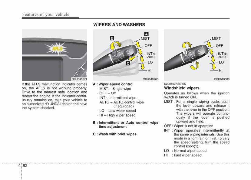
Features of your vehicle
824
If the AFLS malfunction indicator comeson, the AFLS is not working properly.Drive to the nearest safe location andrestart the engine. If the indicator contin-uously remains on, take your vehicle toan authorized HYUNDAI dealer and havethe system checked.
A : Wiper speed control· MIST – Single wipe· OFF – Off· INT – Intermittent wipe
AUTO – AUTO control wipe (if equipped)
· LO – Low wiper speed· HI – High wiper speed
B : Intermittent or Auto control wipetime adjustment
C : Wash with brief wipes
D200100AEN-EU
Windshield wipers Operates as follows when the ignitionswitch is turned ON.MIST : For a single wiping cycle, push
the lever upward and release itwith the lever in the OFF position.The wipers will operate continu-ously if the lever is pushedupward and held.
OFF : Wiper is not in operationINT : Wiper operates intermittently at
the same wiping intervals. Use thismode in a light rain or mist. To varythe speed setting, turn the speedcontrol knob(1).
LO : Normal wiper speedHI : Fast wiper speed
OBH049900 OBH049080OBH041071
WIPERS AND WASHERS
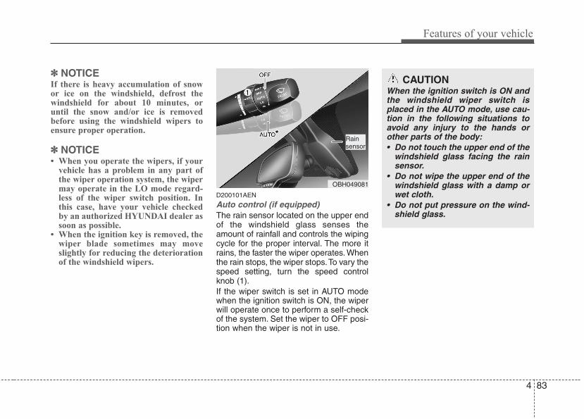
4 83
Features of your vehicle
✽✽ NOTICEIf there is heavy accumulation of snowor ice on the windshield, defrost thewindshield for about 10 minutes, oruntil the snow and/or ice is removedbefore using the windshield wipers toensure proper operation.
✽✽ NOTICE• When you operate the wipers, if your
vehicle has a problem in any part ofthe wiper operation system, the wipermay operate in the LO mode regard-less of the wiper switch position. Inthis case, have your vehicle checkedby an authorized HYUNDAI dealer assoon as possible.
• When the ignition key is removed, thewiper blade sometimes may moveslightly for reducing the deteriorationof the windshield wipers.
D200101AEN
Auto control (if equipped)The rain sensor located on the upper endof the windshield glass senses theamount of rainfall and controls the wipingcycle for the proper interval. The more itrains, the faster the wiper operates. Whenthe rain stops, the wiper stops.To vary thespeed setting, turn the speed controlknob (1).If the wiper switch is set in AUTO modewhen the ignition switch is ON, the wiperwill operate once to perform a self-checkof the system. Set the wiper to OFF posi-tion when the wiper is not in use.
CAUTIONWhen the ignition switch is ON andthe windshield wiper switch isplaced in the AUTO mode, use cau-tion in the following situations toavoid any injury to the hands orother parts of the body:• Do not touch the upper end of the
windshield glass facing the rainsensor.
• Do not wipe the upper end of thewindshield glass with a damp orwet cloth.
• Do not put pressure on the wind-shield glass.
OBH049081
Rainsensor
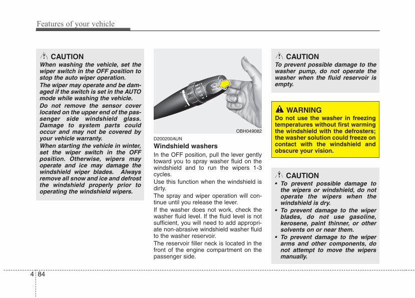
Features of your vehicle
844
D200200AUN
Windshield washers In the OFF position, pull the lever gentlytoward you to spray washer fluid on thewindshield and to run the wipers 1-3cycles.Use this function when the windshield isdirty.The spray and wiper operation will con-tinue until you release the lever.If the washer does not work, check thewasher fluid level. If the fluid level is notsufficient, you will need to add appropri-ate non-abrasive windshield washer fluidto the washer reservoir.The reservoir filler neck is located in thefront of the engine compartment on thepassenger side.
CAUTIONTo prevent possible damage to thewasher pump, do not operate thewasher when the fluid reservoir isempty.
WARNINGDo not use the washer in freezingtemperatures without first warmingthe windshield with the defrosters;the washer solution could freeze oncontact with the windshield andobscure your vision.
CAUTION• To prevent possible damage to
the wipers or windshield, do notoperate the wipers when thewindshield is dry.
• To prevent damage to the wiperblades, do not use gasoline,kerosene, paint thinner, or othersolvents on or near them.
• To prevent damage to the wiperarms and other components, donot attempt to move the wipersmanually.
OBH049082
CAUTIONWhen washing the vehicle, set thewiper switch in the OFF position tostop the auto wiper operation.The wiper may operate and be dam-aged if the switch is set in the AUTOmode while washing the vehicle.Do not remove the sensor coverlocated on the upper end of the pas-senger side windshield glass.Damage to system parts couldoccur and may not be covered byyour vehicle warranty.When starting the vehicle in winter,set the wiper switch in the OFFposition. Otherwise, wipers mayoperate and ice may damage thewindshield wiper blades. Alwaysremove all snow and ice and defrostthe windshield properly prior tooperating the windshield wipers.
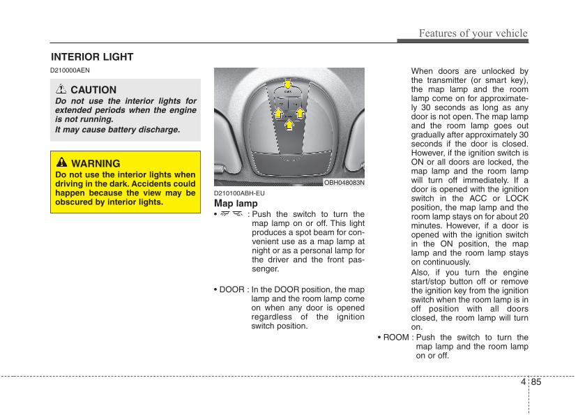
4 85
Features of your vehicle
D210000AEN
D210100ABH-EU
Map lamp • : Push the switch to turn the
map lamp on or off. This lightproduces a spot beam for con-venient use as a map lamp atnight or as a personal lamp forthe driver and the front pas-senger.
• DOOR : In the DOOR position, the maplamp and the room lamp comeon when any door is openedregardless of the ignitionswitch position.
When doors are unlocked bythe transmitter (or smart key),the map lamp and the roomlamp come on for approximate-ly 30 seconds as long as anydoor is not open. The map lampand the room lamp goes outgradually after approximately 30seconds if the door is closed.However, if the ignition switch isON or all doors are locked, themap lamp and the room lampwill turn off immediately. If adoor is opened with the ignitionswitch in the ACC or LOCKposition, the map lamp and theroom lamp stays on for about 20minutes. However, if a door isopened with the ignition switchin the ON position, the maplamp and the room lamp stayson continuously.Also, if you turn the enginestart/stop button off or removethe ignition key from the ignitionswitch when the room lamp is inoff position with all doorsclosed, the room lamp will turnon.
• ROOM : Push the switch to turn themap lamp and the room lampon or off.
OBH048083N
INTERIOR LIGHT
CAUTIONDo not use the interior lights forextended periods when the engineis not running.It may cause battery discharge.
WARNINGDo not use the interior lights whendriving in the dark. Accidents couldhappen because the view may beobscured by interior lights.
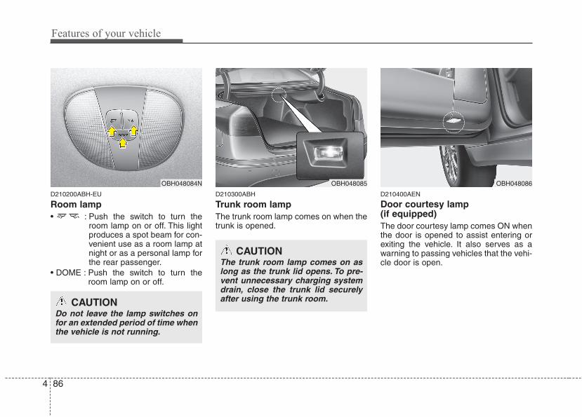
Features of your vehicle
864
D210200ABH-EU
Room lamp• : Push the switch to turn the
room lamp on or off. This lightproduces a spot beam for con-venient use as a room lamp atnight or as a personal lamp forthe rear passenger.
• DOME : Push the switch to turn theroom lamp on or off.
D210300ABH
Trunk room lampThe trunk room lamp comes on when thetrunk is opened.
D210400AEN
Door courtesy lamp (if equipped)The door courtesy lamp comes ON whenthe door is opened to assist entering orexiting the vehicle. It also serves as awarning to passing vehicles that the vehi-cle door is open.
OBH048085 OBH048086OBH048084N
CAUTIONDo not leave the lamp switches onfor an extended period of time whenthe vehicle is not running.
CAUTIONThe trunk room lamp comes on aslong as the trunk lid opens. To pre-vent unnecessary charging systemdrain, close the trunk lid securelyafter using the trunk room.

4 87
Features of your vehicle
D210500ABH
Glove box lampThe glove box lamp comes on when theglove box is opened.
D210600AUN
Vanity mirror lampOpening the lid of the vanity mirror willautomatically turn on the mirror light.
Welcome light (if equipped)When all the doors (and trunk) are lockedand closed, the puddle lamp will come onfor about 15 seconds if any of the below isperformed.- When the door unlock button is pressed
on the transmitter.- When the door unlock button is pressed
on the smart key.- When the button of the outside door han-
dle is pressed.- When the vehicle is approached with the
smart key in possession.But, if you don't lock or unlock the doors for14 days after you lock the doors, the lightdoes not come on. Press the door unlockbutton on the transmitter/smart key orpress the button of the front outside doorhandle. The welcome light will illuminate.
OEN046081OBH048087
CAUTIONTo prevent unnecessary chargingsystem drain, close the glove boxsecurely after using the glove box.
CAUTIONTo prevent unnecessary chargingsystem drain, close the vanity mir-ror cover after using the mirror.
OBH041401
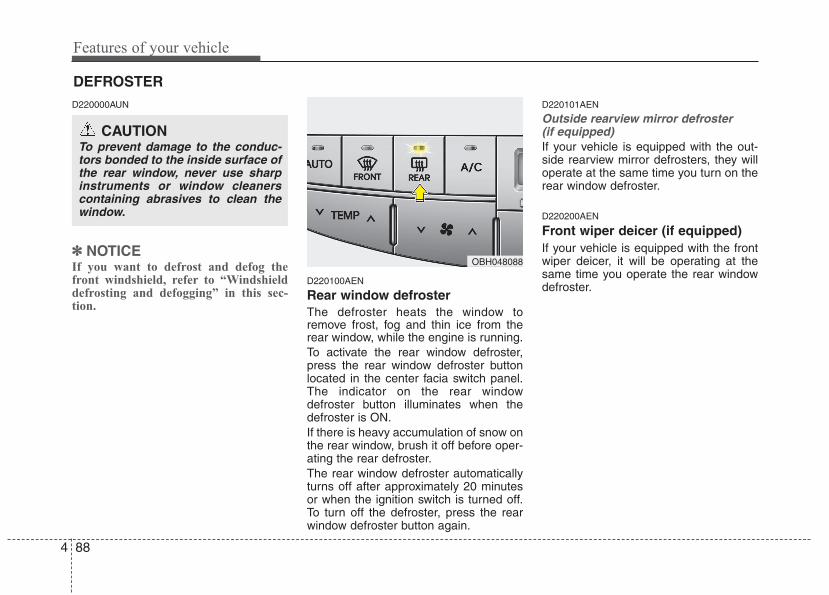
Features of your vehicle
884
D220000AUN
✽✽ NOTICEIf you want to defrost and defog thefront windshield, refer to “Windshielddefrosting and defogging” in this sec-tion.
D220100AEN
Rear window defrosterThe defroster heats the window toremove frost, fog and thin ice from therear window, while the engine is running.To activate the rear window defroster,press the rear window defroster buttonlocated in the center facia switch panel.The indicator on the rear windowdefroster button illuminates when thedefroster is ON.If there is heavy accumulation of snow onthe rear window, brush it off before oper-ating the rear defroster.The rear window defroster automaticallyturns off after approximately 20 minutesor when the ignition switch is turned off.To turn off the defroster, press the rearwindow defroster button again.
D220101AEN
Outside rearview mirror defroster (if equipped)If your vehicle is equipped with the out-side rearview mirror defrosters, they willoperate at the same time you turn on therear window defroster.
D220200AEN
Front wiper deicer (if equipped)If your vehicle is equipped with the frontwiper deicer, it will be operating at thesame time you operate the rear windowdefroster.
CAUTIONTo prevent damage to the conduc-tors bonded to the inside surface ofthe rear window, never use sharpinstruments or window cleanerscontaining abrasives to clean thewindow.
DEFROSTER
OBH048088
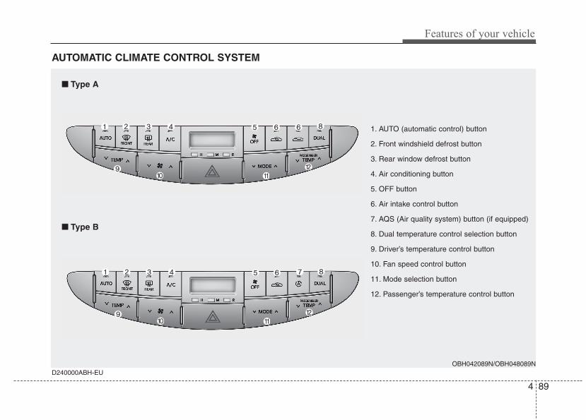
4 89
Features of your vehicle
AUTOMATIC CLIMATE CONTROL SYSTEM
D240000ABH-EUOBH042089N/OBH048089N
1. AUTO (automatic control) button
2. Front windshield defrost button
3. Rear window defrost button
4. Air conditioning button
5. OFF button
6. Air intake control button
7. AQS (Air quality system) button (if equipped)
8. Dual temperature control selection button
9. Driver’s temperature control button
10. Fan speed control button
11. Mode selection button
12. Passenger’s temperature control button
■■ Type A
■■ Type B
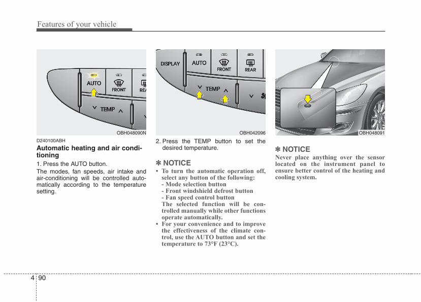
Features of your vehicle
904
D240100ABH
Automatic heating and air condi-tioning1. Press the AUTO button.The modes, fan speeds, air intake andair-conditioning will be controlled auto-matically according to the temperaturesetting.
2. Press the TEMP button to set thedesired temperature.
✽✽ NOTICE• To turn the automatic operation off,
select any button of the following:- Mode selection button- Front windshield defrost button- Fan speed control buttonThe selected function will be con-trolled manually while other functionsoperate automatically.
• For your convenience and to improvethe effectiveness of the climate con-trol, use the AUTO button and set thetemperature to 73°F (23°C).
✽✽ NOTICENever place anything over the sensorlocated on the instrument panel toensure better control of the heating andcooling system.
OBH048091OBH048090N OBH042096
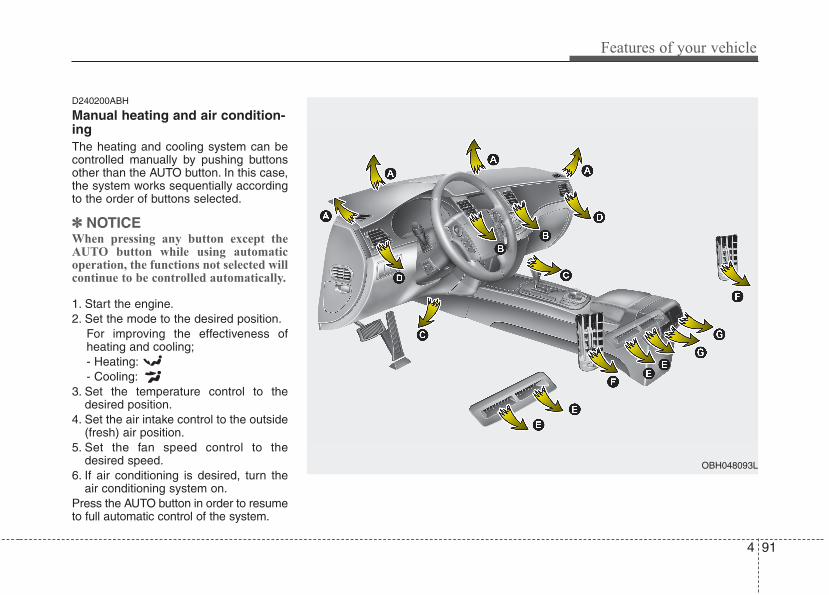
4 91
Features of your vehicle
D240200ABH
Manual heating and air condition-ingThe heating and cooling system can becontrolled manually by pushing buttonsother than the AUTO button. In this case,the system works sequentially accordingto the order of buttons selected.
✽✽ NOTICEWhen pressing any button except theAUTO button while using automaticoperation, the functions not selected willcontinue to be controlled automatically.
1. Start the engine.2. Set the mode to the desired position.
For improving the effectiveness ofheating and cooling;- Heating:- Cooling:
3. Set the temperature control to thedesired position.
4. Set the air intake control to the outside(fresh) air position.
5. Set the fan speed control to thedesired speed.
6. If air conditioning is desired, turn theair conditioning system on.
Press the AUTO button in order to resumeto full automatic control of the system.
OBH048093L
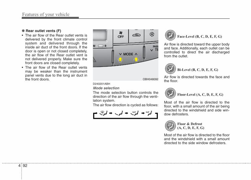
Features of your vehicle
924
❈❈ Rear outlet vents (F)• The air flow of the Rear outlet vents is
delivered by the front climate controlsystem and delivered through theinside air duct of the front doors. If thedoor is open or not closed completely,the air flow of the Rear outlet vent isnot delivered properly. Make sure thefront doors are closed completely.
• The air flow of the Rear outlet ventsmay be weaker than the instrumentpanel vents due to the long air duct inthe front doors.
D240201ABH
Mode selectionThe mode selection button controls thedirection of the air flow through the venti-lation system.The air flow direction is cycled as follows:
Face-Level (B, C, D, E, F, G)
Air flow is directed toward the upper bodyand face. Additionally, each outlet can becontrolled to direct the air dischargedfrom the outlet.
Bi-Level (B, C, D, E, F, G)
Air flow is directed towards the face andthe floor.
Floor-Level (A, C, D, E, F, G)
Most of the air flow is directed to thefloor, with a small amount of the air beingdirected to the windshield and side win-dow defrosters.
Floor & Defrost(A, C, D, E, F, G)
Most of the air flow is directed to the floorand the windshield with a small amountdirected to the side window defrosters.
OBH048092
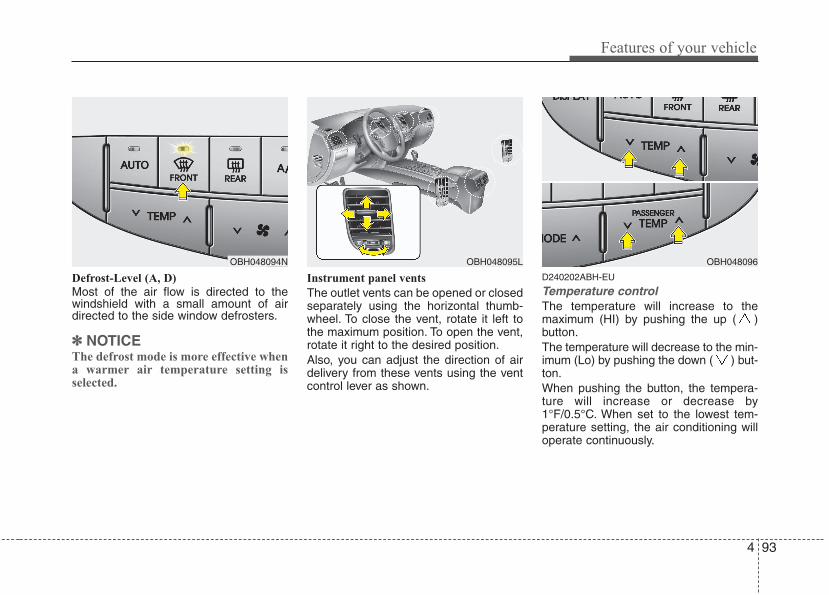
4 93
Features of your vehicle
Defrost-Level (A, D)
Most of the air flow is directed to thewindshield with a small amount of airdirected to the side window defrosters.
✽✽ NOTICEThe defrost mode is more effective whena warmer air temperature setting isselected.
Instrument panel vents
The outlet vents can be opened or closedseparately using the horizontal thumb-wheel. To close the vent, rotate it left tothe maximum position. To open the vent,rotate it right to the desired position.Also, you can adjust the direction of airdelivery from these vents using the ventcontrol lever as shown.
D240202ABH-EU
Temperature controlThe temperature will increase to themaximum (HI) by pushing the up ( )button.The temperature will decrease to the min-imum (Lo) by pushing the down ( ) but-ton.When pushing the button, the tempera-ture will increase or decrease by1°F/0.5°C. When set to the lowest tem-perature setting, the air conditioning willoperate continuously.
OBH048094N OBH048095L OBH048096
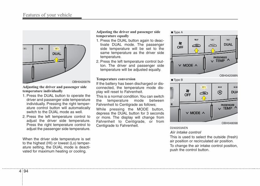
Features of your vehicle
944
Adjusting the driver and passenger sidetemperature individually
1. Press the DUAL button to operate thedriver and passenger side temperatureindividually. Pressing the right temper-ature control button will automaticallyswitch to the DUAL mode as well.
2. Press the left temperature control toadjust the driver side temperature.Press the right temperature control toadjust the passenger side temperature.
When the driver side temperature is setto the highest (HI) or lowest (Lo) temper-ature setting, the DUAL mode is deacti-vated for maximum heating or cooling.
Adjusting the driver and passenger sidetemperature equally
1. Press the DUAL button again to deac-tivate DUAL mode. The passengerside temperature will be set to thesame temperature as the driver sidetemperature.
2. Press the left temperature control but-ton. The driver and passenger sidetemperature will be adjusted equally.
Temperature conversion
If the battery has been discharged or dis-connected, the temperature mode dis-play will reset to Fahrenheit.This is a normal condition.You can switchthe temperature mode betweenFahrenheit to Centigrade as follows;While pressing the MODE button,depress the DUAL button for 3 secondsor more. The display will change fromFahrenheit to Centigrade, or fromCentigrade to Fahrenheit.
D240203AEN
Air intake controlThis is used to select the outside (fresh)air position or recirculated air position.To change the air intake control position,push the control button.
OBH042097N
OBH042098N
OBH048098
■ Type A
■ Type B
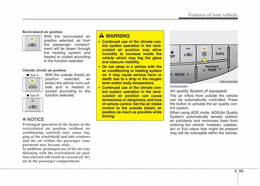
4 95
Features of your vehicle
Recirculated air position
With the recirculated airposition selected, air fromthe passenger compart-ment will be drawn throughthe heating system andheated or cooled accordingto the function selected.
Outside (fresh) air position
With the outside (fresh) airposition selected, airenters the vehicle from out-side and is heated orcooled according to thefunction selected.
✽✽ NOTICEProlonged operation of the heater in therecirculated air position (without airconditioning selected) may cause fog-ging of the windshield and side windowsand the air within the passenger com-partment may become stale.In addition, prolonged use of the air con-ditioning with the recirculated air posi-tion selected will result in excessively dryair in the passenger compartment.
D240204ABH
Air quality System (if equipped)The air inflow from outside the vehiclecan be automatically controlled. Pressthe button to activate the air quality con-trol system.When using AQS mode, AQS(Air QualitySystem) automatically senses outdoorair pollutants and minimizes them fromentering the vehicle, however, unpleas-ant or foul odors that might be presentmay still be noticeable within the vehicle.
WARNING• Continued use of the climate con-
trol system operation in the recir-culated air position may allowhumidity to increase inside thevehicle which may fog the glassand obscure visibility.
• Do not sleep in a vehicle with theair conditioning or heating systemon. It may cause serious harm ordeath due to a drop in the oxygenlevel and/or body temperature.
• Continued use of the climate con-trol system operation in the recir-culated air position can causedrowsiness or sleepiness, and lossof vehicle control. Set the air intakecontrol to the outside (fresh) airposition as much as possible whiledriving.
OBH048099N
■ Type A
■ Type B
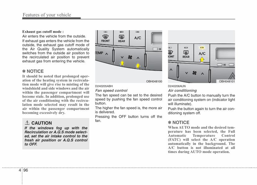
Features of your vehicle
964
Exhaust gas cutoff mode :
Air enters the vehicle from the outside.If exhaust gas enters the vehicle from theoutside, the exhaust gas cutoff mode ofthe Air Quality System automaticallyswitches from the outside air position tothe recirculated air position to preventexhaust gas from entering the vehicle.
✽✽ NOTICEIt should be noted that prolonged oper-ation of the heating system in recircula-tion mode will give rise to misting of thewindshield and side windows and the airwithin the passenger compartment willbecome stale. In addition, prolonged useof the air conditioning with the recircu-lation mode selected may result in theair within the passenger compartmentbecoming excessively dry.
D240205ABH
Fan speed controlThe fan speed can be set to the desiredspeed by pushing the fan speed controlbutton.The higher the fan speed is, the more airis delivered.Pressing the OFF button turns off thefan.
D240206AUN
Air conditioningPush the A/C button to manually turn theair conditioning system on (indicator lightwill illuminate).Push the button again to turn the air con-ditioning system off.
✽✽ NOTICEWhen AUTO mode and the desired tem-perature has been selected, the FullAutomatic Temperature Control(FATC) will select the A/C operationautomatically in the background. TheA/C button is not illuminated at alltimes during AUTO mode operation.
OBH048100
CAUTIONIf the windows fog up with theRecirculation or A.Q.S mode select-ed, set the air intake control to thefresh air position or A.Q.S controlto OFF.
OBH048101
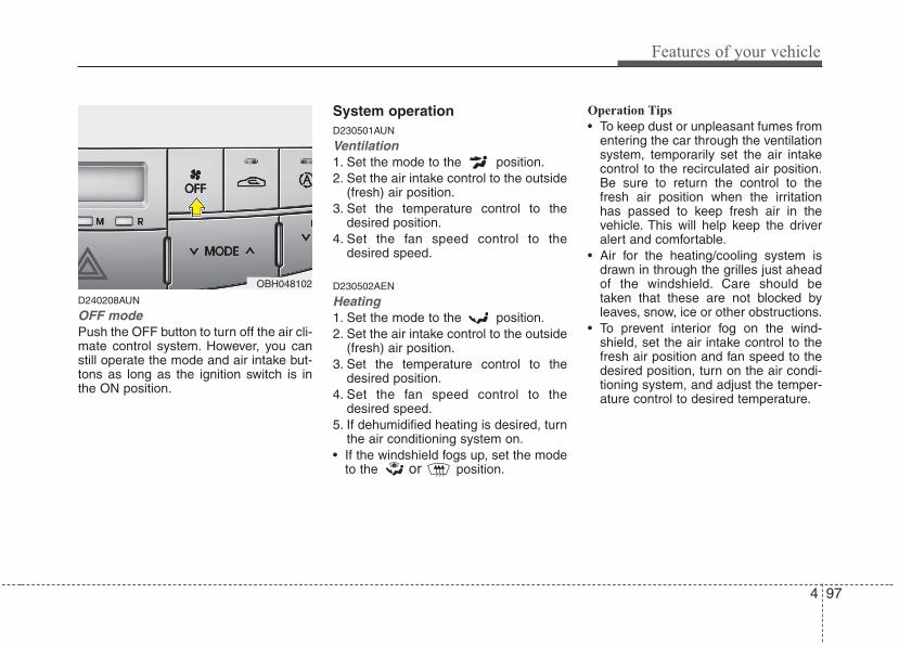
4 97
Features of your vehicle
D240208AUN
OFF modePush the OFF button to turn off the air cli-mate control system. However, you canstill operate the mode and air intake but-tons as long as the ignition switch is inthe ON position.
System operationD230501AUN
Ventilation1. Set the mode to the position.2. Set the air intake control to the outside
(fresh) air position.3. Set the temperature control to the
desired position.4. Set the fan speed control to the
desired speed.
D230502AEN
Heating1. Set the mode to the position.2. Set the air intake control to the outside
(fresh) air position.3. Set the temperature control to the
desired position.4. Set the fan speed control to the
desired speed.5. If dehumidified heating is desired, turn
the air conditioning system on.• If the windshield fogs up, set the mode
to the or position.
Operation Tips
• To keep dust or unpleasant fumes fromentering the car through the ventilationsystem, temporarily set the air intakecontrol to the recirculated air position.Be sure to return the control to thefresh air position when the irritationhas passed to keep fresh air in thevehicle. This will help keep the driveralert and comfortable.
• Air for the heating/cooling system isdrawn in through the grilles just aheadof the windshield. Care should betaken that these are not blocked byleaves, snow, ice or other obstructions.
• To prevent interior fog on the wind-shield, set the air intake control to thefresh air position and fan speed to thedesired position, turn on the air condi-tioning system, and adjust the temper-ature control to desired temperature.
OBH048102
Features of your vehicle
984
D230503AEN
Air conditioning HYUNDAI Air Conditioning Systems arefilled with environmentally friendly R-134a refrigerant.1. Start the engine. Push the air condi-
tioning button.2. Set the mode to the position.3. Set the air intake control to the outside
air or recirculated air position.4. Adjust the fan speed control and tem-
perature control to maintain maximumcomfort.
✽✽ NOTICE• When using the air conditioning sys-
tem, monitor the engine temperaturegauge closely while driving up hills orin heavy traffic when outside temper-atures are high. Air conditioning sys-tem operation may cause engine over-heating. Continue to use the blowerfan but turn the air conditioning sys-tem off if the engine temperaturegauge indicates engine overheating.
• When opening the windows in humidweather air conditioning may createwater droplets inside the vehicle.Since excessive water droplets maycause damage to electrical equipment,air conditioning should only be oper-ated with the windows closed.
Air conditioning system operation tips
• If the vehicle has been parked in directsunlight during hot weather, open thewindows for a short time to let the hotair inside the vehicle escape.
• To help reduce moisture inside of thewindows on rainy or humid days,decrease the humidity inside the vehi-cle by operating the air conditioningsystem.
• During air conditioning system opera-tion, you may occasionally notice aslight change in engine speed as theair conditioning compressor cycles.This is a normal system operationcharacteristic.
• Use the air conditioning system everymonth only for a few minutes to ensuremaximum system performance.
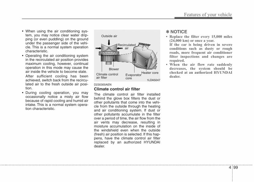
4 99
Features of your vehicle
• When using the air conditioning sys-tem, you may notice clear water drip-ping (or even puddling) on the groundunder the passenger side of the vehi-cle. This is a normal system operationcharacteristic.
• Operating the air conditioning systemin the recirculated air position providesmaximum cooling, however, continualoperation in this mode may cause theair inside the vehicle to become stale.After sufficient cooling has beenachieved, switch back from the recircu-lated air to the fresh outside air posi-tion.
• During cooling operation, you mayoccasionally notice a misty air flowbecause of rapid cooling and humid airintake. This is a normal system opera-tion characteristic.
D230300AEN
Climate control air filter The climate control air filter installedbehind the glove box filters the dust orother pollutants that come into the vehi-cle from the outside through the heatingand air conditioning system. If dust orother pollutants accumulate in the filterover a period of time, the air flow from theair vents may decrease, resulting inmoisture accumulation on the inside ofthe windshield even when the outside(fresh) air position is selected. If this hap-pens, have the climate control air filterreplaced by an authorized HYUNDAIdealer.
✽✽ NOTICE• Replace the filter every 15,000 miles
(24,000 km) or once a year.If the car is being driven in severeconditions such as dusty or roughroads, more frequent air conditionerfilter inspections and changes arerequired.
• When the air flow rate suddenlydecreases, the system should bechecked at an authorized HYUNDAIdealer.
1LDA5047
Outside air
Recirculatedair
Climate controlair filter
Blower
Evaporatorcore
Heater core
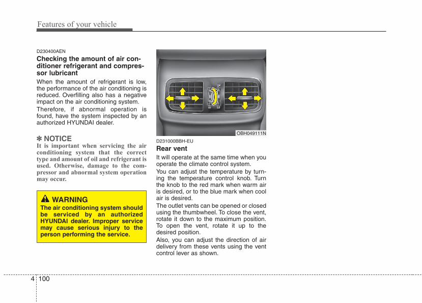
Features of your vehicle
1004
D230400AEN
Checking the amount of air con-ditioner refrigerant and compres-sor lubricantWhen the amount of refrigerant is low,the performance of the air conditioning isreduced. Overfilling also has a negativeimpact on the air conditioning system.Therefore, if abnormal operation isfound, have the system inspected by anauthorized HYUNDAI dealer.
✽✽ NOTICEIt is important when servicing the airconditioning system that the correcttype and amount of oil and refrigerant isused. Otherwise, damage to the com-pressor and abnormal system operationmay occur.
D231000BBH-EU
Rear ventIt will operate at the same time when youoperate the climate control system.You can adjust the temperature by turn-ing the temperature control knob. Turnthe knob to the red mark when warm airis desired, or to the blue mark when coolair is desired.The outlet vents can be opened or closedusing the thumbwheel. To close the vent,rotate it down to the maximum position.To open the vent, rotate it up to thedesired position.Also, you can adjust the direction of airdelivery from these vents using the ventcontrol lever as shown.
OBH049111N
WARNINGThe air conditioning system shouldbe serviced by an authorizedHYUNDAI dealer. Improper servicemay cause serious injury to theperson performing the service.
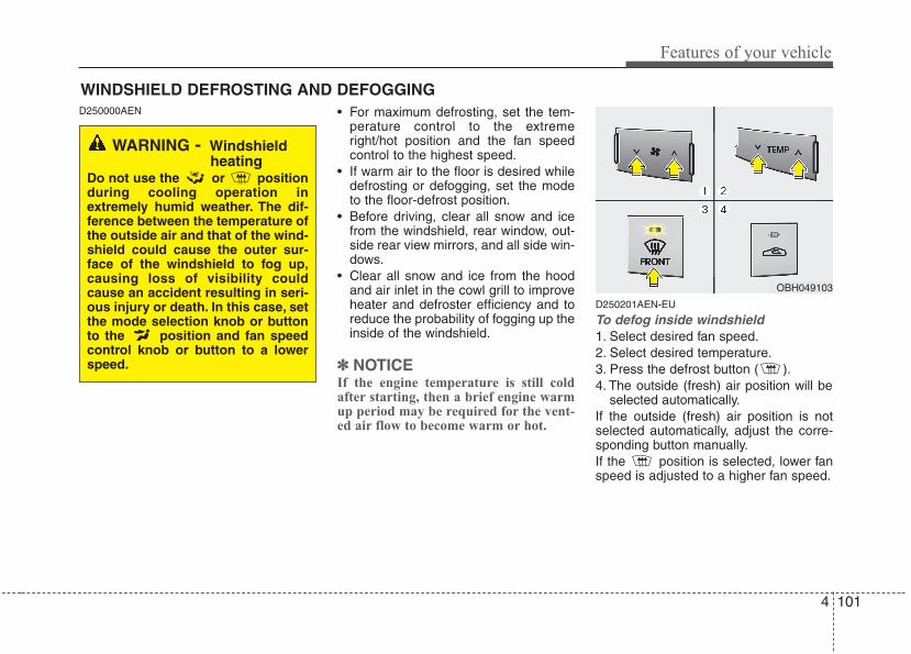
4 101
Features of your vehicle
D250000AEN • For maximum defrosting, set the tem-perature control to the extremeright/hot position and the fan speedcontrol to the highest speed.
• If warm air to the floor is desired whiledefrosting or defogging, set the modeto the floor-defrost position.
• Before driving, clear all snow and icefrom the windshield, rear window, out-side rear view mirrors, and all side win-dows.
• Clear all snow and ice from the hoodand air inlet in the cowl grill to improveheater and defroster efficiency and toreduce the probability of fogging up theinside of the windshield.
✽✽ NOTICEIf the engine temperature is still coldafter starting, then a brief engine warmup period may be required for the vent-ed air flow to become warm or hot.
D250201AEN-EU
To defog inside windshield 1. Select desired fan speed.2. Select desired temperature.3. Press the defrost button ( ).4. The outside (fresh) air position will be
selected automatically.If the outside (fresh) air position is notselected automatically, adjust the corre-sponding button manually.If the position is selected, lower fanspeed is adjusted to a higher fan speed.
WINDSHIELD DEFROSTING AND DEFOGGING
OBH049103
WARNING - Windshieldheating
Do not use the or positionduring cooling operation inextremely humid weather. The dif-ference between the temperature ofthe outside air and that of the wind-shield could cause the outer sur-face of the windshield to fog up,causing loss of visibility couldcause an accident resulting in seri-ous injury or death. In this case, setthe mode selection knob or buttonto the position and fan speedcontrol knob or button to a lowerspeed.
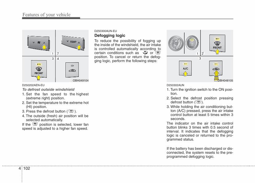
Features of your vehicle
1024
D250202AEN-EU
To defrost outside windshield 1. Set the fan speed to the highest
(extreme right) position.2. Set the temperature to the extreme hot
(HI) position.3. Press the defrost button ( ).4. The outside (fresh) air position will be
selected automatically.If the position is selected, lower fanspeed is adjusted to a higher fan speed.
D250300AUN-EU
Defogging logicTo reduce the possibility of fogging upthe inside of the windshield, the air intakeis controlled automatically according tocertain conditions such as or position. To cancel or return the defog-ging logic, perform the following steps:
D250302AUN
1. Turn the ignition switch to the ON posi-tion.
2. Select the defrost position pressingdefrost button ( ).
3. While holding the air conditioning but-ton (A/C) pressed, press the air intakecontrol button at least 5 times within 3seconds.
The indicator on the air intake controlbutton blinks 3 times with 0.5 second ofinterval. It indicates that the defogginglogic is canceled or returned to the pro-grammed status.
If the battery has been discharged or dis-connected, the system resets to the pre-programmed defogging logic.
OBH049104 OBH048105
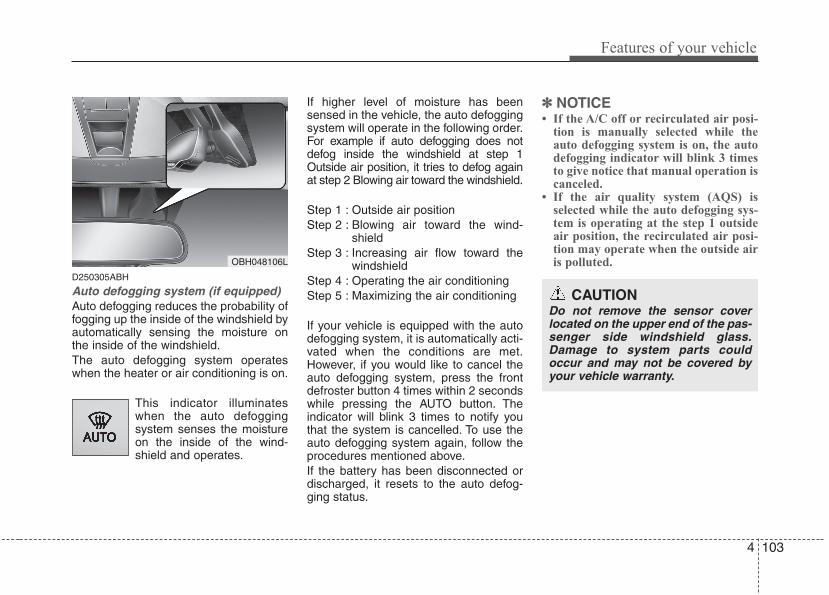
4 103
Features of your vehicle
D250305ABH
Auto defogging system (if equipped)Auto defogging reduces the probability offogging up the inside of the windshield byautomatically sensing the moisture onthe inside of the windshield.The auto defogging system operateswhen the heater or air conditioning is on.
This indicator illuminateswhen the auto defoggingsystem senses the moistureon the inside of the wind-shield and operates.
If higher level of moisture has beensensed in the vehicle, the auto defoggingsystem will operate in the following order.For example if auto defogging does notdefog inside the windshield at step 1Outside air position, it tries to defog againat step 2 Blowing air toward the windshield.
Step 1 : Outside air positionStep 2 : Blowing air toward the wind-
shieldStep 3 : Increasing air flow toward the
windshieldStep 4 : Operating the air conditioning Step 5 : Maximizing the air conditioning
If your vehicle is equipped with the autodefogging system, it is automatically acti-vated when the conditions are met.However, if you would like to cancel theauto defogging system, press the frontdefroster button 4 times within 2 secondswhile pressing the AUTO button. Theindicator will blink 3 times to notify youthat the system is cancelled. To use theauto defogging system again, follow theprocedures mentioned above.If the battery has been disconnected ordischarged, it resets to the auto defog-ging status.
✽✽ NOTICE• If the A/C off or recirculated air posi-
tion is manually selected while theauto defogging system is on, the autodefogging indicator will blink 3 timesto give notice that manual operation iscanceled.
• If the air quality system (AQS) isselected while the auto defogging sys-tem is operating at the step 1 outsideair position, the recirculated air posi-tion may operate when the outside airis polluted.OBH048106L
CAUTIONDo not remove the sensor coverlocated on the upper end of the pas-senger side windshield glass.Damage to system parts couldoccur and may not be covered byyour vehicle warranty.
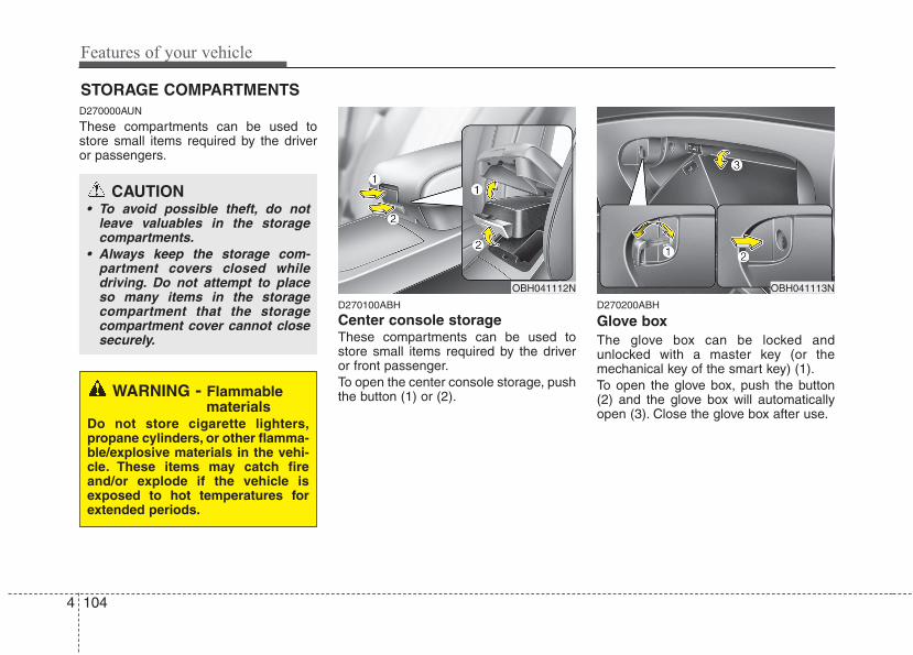
Features of your vehicle
1044
D270000AUN
These compartments can be used tostore small items required by the driveror passengers.
D270100ABH
Center console storage These compartments can be used tostore small items required by the driveror front passenger.To open the center console storage, pushthe button (1) or (2).
D270200ABH
Glove boxThe glove box can be locked andunlocked with a master key (or themechanical key of the smart key) (1).To open the glove box, push the button(2) and the glove box will automaticallyopen (3). Close the glove box after use.
STORAGE COMPARTMENTS
WARNING - Flammablematerials
Do not store cigarette lighters,propane cylinders, or other flamma-ble/explosive materials in the vehi-cle. These items may catch fireand/or explode if the vehicle isexposed to hot temperatures forextended periods.
CAUTION• To avoid possible theft, do not
leave valuables in the storagecompartments.
• Always keep the storage com-partment covers closed whiledriving. Do not attempt to placeso many items in the storagecompartment that the storagecompartment cover cannot closesecurely.
OBH041113NOBH041112N
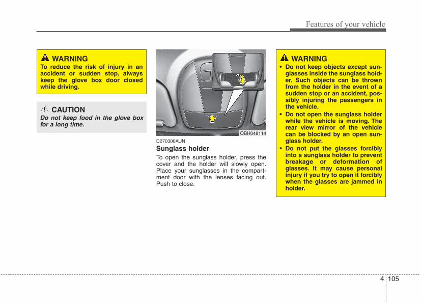
4 105
Features of your vehicle
D270300AUN
Sunglass holder To open the sunglass holder, press thecover and the holder will slowly open.Place your sunglasses in the compart-ment door with the lenses facing out.Push to close.
WARNING To reduce the risk of injury in anaccident or sudden stop, alwayskeep the glove box door closedwhile driving.
CAUTIONDo not keep food in the glove boxfor a long time.
OBH048114
WARNING• Do not keep objects except sun-
glasses inside the sunglass hold-er. Such objects can be thrownfrom the holder in the event of asudden stop or an accident, pos-sibly injuring the passengers inthe vehicle.
• Do not open the sunglass holderwhile the vehicle is moving. Therear view mirror of the vehiclecan be blocked by an open sun-glass holder.
• Do not put the glasses forciblyinto a sunglass holder to preventbreakage or deformation ofglasses. It may cause personalinjury if you try to open it forciblywhen the glasses are jammed inholder.
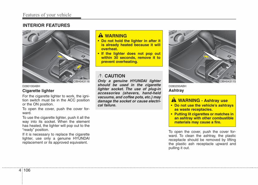
Features of your vehicle
1064
D280100ABH
Cigarette lighterFor the cigarette lighter to work, the igni-tion switch must be in the ACC positionor the ON position.To open the cover, push the cover for-ward.To use the cigarette lighter, push it all theway into its socket. When the elementhas heated, the lighter will pop out to the“ready” position.If it is necessary to replace the cigarettelighter, use only a genuine HYUNDAIreplacement or its approved equivalent.
D280200ABH
Ashtray
To open the cover, push the cover for-ward. To clean the ashtray, the plasticreceptacle should be removed by liftingthe plastic ash receptacle upward andpulling it out.
INTERIOR FEATURES
OBH043116
CAUTIONOnly a genuine HYUNDAI lightershould be used in the cigarettelighter socket. The use of plug-inaccessories (shavers, hand-heldvacuums, and coffee pots, etc.) maydamage the socket or cause electri-cal failure.
WARNING• Do not hold the lighter in after it
is already heated because it willoverheat.
• If the lighter does not pop outwithin 30 seconds, remove it toprevent overheating.
WARNING - Ashtray use• Do not use the vehicle’s ashtrays
as waste receptacles.• Putting lit cigarettes or matches in
an ashtray with other combustiblematerials may cause a fire.
OBH043115
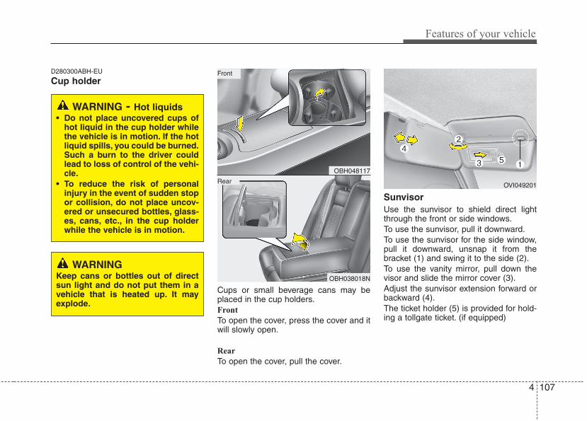
4 107
Features of your vehicle
D280300ABH-EU
Cup holder
Cups or small beverage cans may beplaced in the cup holders.Front
To open the cover, press the cover and itwill slowly open.
Rear
To open the cover, pull the cover.
SunvisorUse the sunvisor to shield direct lightthrough the front or side windows.To use the sunvisor, pull it downward.To use the sunvisor for the side window,pull it downward, unsnap it from thebracket (1) and swing it to the side (2).To use the vanity mirror, pull down thevisor and slide the mirror cover (3).Adjust the sunvisor extension forward orbackward (4).The ticket holder (5) is provided for hold-ing a tollgate ticket. (if equipped)
WARNINGKeep cans or bottles out of directsun light and do not put them in avehicle that is heated up. It mayexplode.
WARNING - Hot liquids• Do not place uncovered cups of
hot liquid in the cup holder whilethe vehicle is in motion. If the hotliquid spills, you could be burned.Such a burn to the driver couldlead to loss of control of the vehi-cle.
• To reduce the risk of personalinjury in the event of sudden stopor collision, do not place uncov-ered or unsecured bottles, glass-es, cans, etc., in the cup holderwhile the vehicle is in motion.
OBH048117
OBH038018N
Rear
Front
OVI049201
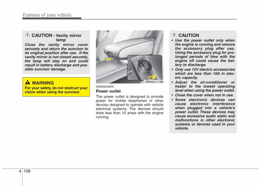
Features of your vehicle
1084
D280500AEN
Power outletThe power outlet is designed to providepower for mobile telephones or otherdevices designed to operate with vehicleelectrical systems. The devices shoulddraw less than 10 amps with the enginerunning.
CAUTION - Vanity mirrorlamp
Close the vanity mirror coversecurely and return the sunvisor toits original position after use. If thevanity mirror is not closed securely,the lamp will stay on and couldresult in battery discharge and pos-sible sunvisor damage.
WARNINGFor your safety, do not obstruct yourvision when using the sunvisor.
OBH041119N
CAUTION• Use the power outlet only when
the engine is running and removethe accessory plug after use.Using the accessory plug for pro-longed periods of time with theengine off could cause the bat-tery to discharge.
• Only use 12V electric accessorieswhich are less than 10A in elec-tric capacity.
• Adjust the air-conditioner orheater to the lowest operatinglevel when using the power outlet.
• Close the cover when not in use.• Some electronic devices can
cause electronic interferencewhen plugged into a vehicle’spower outlet. These devices maycause excessive audio static andmalfunctions in other electronicsystems or devices used in yourvehicle.
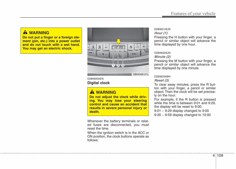
4 109
Features of your vehicle
D280600AEN
Digital clock
Whenever the battery terminals or relat-ed fuses are disconnected, you mustreset the time.When the ignition switch is in the ACC orON position, the clock buttons operate asfollows:
D280601AUN
Hour (1)Pressing the H button with your finger, apencil or similar object will advance thetime displayed by one hour.
D280602AUN
Minute (2)Pressing the M button with your finger, apencil or similar object will advance thetime displayed by one minute.
D280603ABH
Reset (3)To clear away minutes, press the R but-ton with your finger, a pencil or similarobject. Then the clock will be set precise-ly on the hour.For example, if the R button is pressedwhile the time is between 9:01 and 9:29,the display will be reset to 9:00.9:01 ~ 9:29 display changed to 9:009:30 ~ 9:59 display changed to 10:00
WARNINGDo not put a finger or a foreign ele-ment (pin, etc.) into a power outletand do not touch with a wet hand.You may get an electric shock.
OBH048121L
WARNINGDo not adjust the clock while driv-ing. You may lose your steeringcontrol and cause an accident thatresults in severe personal injury ordeath.
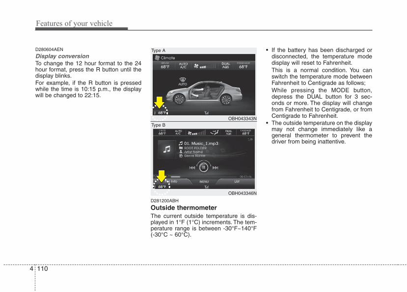
Features of your vehicle
1104
D280604AEN
Display conversionTo change the 12 hour format to the 24hour format, press the R button until thedisplay blinks.For example, if the R button is pressedwhile the time is 10:15 p.m., the displaywill be changed to 22:15.
D281200ABH
Outside thermometerThe current outside temperature is dis-played in 1°F (1°C) increments. The tem-perature range is between -30°F~140°F(-30°C ~ 60°C).
• If the battery has been discharged ordisconnected, the temperature modedisplay will reset to Fahrenheit.This is a normal condition. You canswitch the temperature mode betweenFahrenheit to Centigrade as follows;While pressing the MODE button,depress the DUAL button for 3 sec-onds or more. The display will changefrom Fahrenheit to Centigrade, or fromCentigrade to Fahrenheit.
• The outside temperature on the displaymay not change immediately like ageneral thermometer to prevent thedriver from being inattentive.
OBH043343N
OBH043346N
Type A
Type B
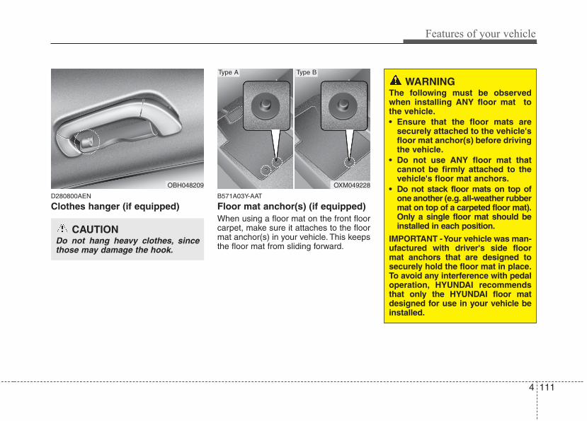
4 111
Features of your vehicle
D280800AEN
Clothes hanger (if equipped)B571A03Y-AAT
Floor mat anchor(s) (if equipped)When using a floor mat on the front floorcarpet, make sure it attaches to the floormat anchor(s) in your vehicle. This keepsthe floor mat from sliding forward.
OBH048209
CAUTIONDo not hang heavy clothes, sincethose may damage the hook.
OXM049228
Type A Type B
WARNINGThe following must be observedwhen installing ANY floor mat tothe vehicle.• Ensure that the floor mats are
securely attached to the vehicle'sfloor mat anchor(s) before drivingthe vehicle.
• Do not use ANY floor mat thatcannot be firmly attached to thevehicle's floor mat anchors.
• Do not stack floor mats on top ofone another (e.g. all-weather rubbermat on top of a carpeted floor mat).Only a single floor mat should beinstalled in each position.
IMPORTANT - Your vehicle was man-ufactured with driver's side floormat anchors that are designed tosecurely hold the floor mat in place.To avoid any interference with pedaloperation, HYUNDAI recommendsthat only the HYUNDAI floor matdesigned for use in your vehicle beinstalled.
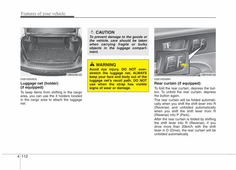
Features of your vehicle
1124
D281000AEN
Luggage net (holder) (if equipped)To keep items from shifting in the cargoarea, you can use the 4 holders locatedin the cargo area to attach the luggagenet.
D281500ABH
Rear curtain (if equipped)To fold the rear curtain, depress the but-ton. To unfold the rear curtain, depressthe button again.The rear curtain will be folded automati-cally when you shift the shift lever into R(Reverse) and unfolded automaticallywhen you shift the shift lever from R(Reverse) into P (Park).After the rear curtain is folded by shiftingthe shift lever into R (Reverse), if youdrive more than 20km/h with the shiftlever in D (Drive), the rear curtain will beunfolded automatically.
OBH048126
CAUTIONTo prevent damage to the goods orthe vehicle, care should be takenwhen carrying fragile or bulkyobjects in the luggage compart-ment.
WARNINGAvoid eye injury. DO NOT over-stretch the luggage net, ALWAYSkeep your face and body out of theluggage net’s recoil path. DO NOTuse when the strap has visiblesigns of wear or damage.
OBH048125
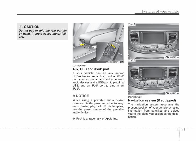
4 113
Features of your vehicle
D281400AFD
Aux, USB and iPod® portIf your vehicle has an aux and/orUSB(universal serial bus) port or iPod®
port, you can use an aux port to connectaudio devices and a USB port to plug in aUSB, and an iPod® port to plug in aniPod®.
✽✽ NOTICEWhen using a portable audio deviceconnected to the power outlet, noise mayoccur during playback. If this happens,use the power source of the portableaudio device.
❈ iPod® is a trademark of Apple Inc.
D281800ABH
Navigation system (if equipped)The navigation system ascertains thepresent position of your vehicle by usinginformation from satellites and guidesyou to the place you assign as the desti-nation.
CAUTIONDo not pull or fold the rear curtainby hand. It could cause motor fail-ure.
OBH041141N
OBH048139N
OBH049139N
Type A
Type B
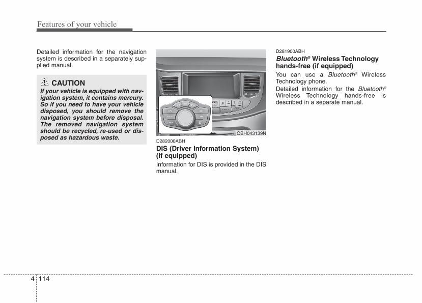
Features of your vehicle
1144
Detailed information for the navigationsystem is described in a separately sup-plied manual.
D282000ABH
DIS (Driver Information System)(if equipped)Information for DIS is provided in the DISmanual.
D281900ABH
Bluetooth® Wireless Technologyhands-free (if equipped)You can use a Bluetooth® WirelessTechnology phone.Detailed information for the Bluetooth®
Wireless Technology hands-free isdescribed in a separate manual.
CAUTIONIf your vehicle is equipped with nav-igation system, it contains mercury.So if you need to have your vehicledisposed, you should remove thenavigation system before disposal.The removed navigation systemshould be recycled, re-used or dis-posed as hazardous waste.
OBH043139N
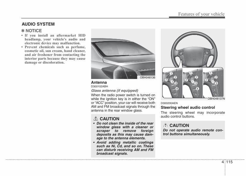
4 115
Features of your vehicle
✽✽ NOTICE• If you install an aftermarket HID
headlamp, your vehicle's audio andelectronic device may malfunction.
• Prevent chemicals such as perfume,cosmetic oil, sun cream, hand cleaner,and air freshener from contacting theinterior parts because they may causedamage or discoloration.
AntennaD300102ABH
Glass antenna (if equipped)When the radio power switch is turned onwhile the ignition key is in either the “ON”or “ACC” position, your car will receive bothAM and FM broadcast signals through theantenna in the rear window glass.
D300200AEN
Steering wheel audio controlThe steering wheel may incorporateaudio control buttons.
AUDIO SYSTEM
OBH048136
CAUTION• Do not clean the inside of the rear
window glass with a cleaner orscraper to remove foreigndeposits as this may cause dam-age to the antenna elements.
• Avoid adding metallic coatingssuch as Ni, Cd, and so on. Thesecan disturb receiving AM and FMbroadcast signals.
OBH048137N
CAUTIONDo not operate audio remote con-trol buttons simultaneously.
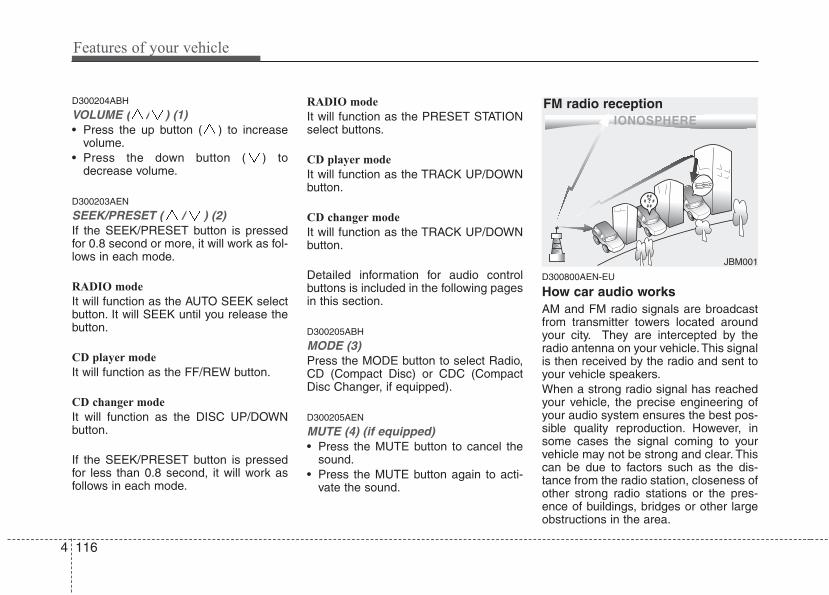
Features of your vehicle
1164
D300204ABH
VOLUME ( / ) (1)• Press the up button ( ) to increase
volume.• Press the down button ( ) to
decrease volume.
D300203AEN
SEEK/PRESET ( / ) (2)If the SEEK/PRESET button is pressedfor 0.8 second or more, it will work as fol-lows in each mode.
RADIO mode
It will function as the AUTO SEEK selectbutton. It will SEEK until you release thebutton.
CD player mode
It will function as the FF/REW button.
CD changer mode
It will function as the DISC UP/DOWNbutton.
If the SEEK/PRESET button is pressedfor less than 0.8 second, it will work asfollows in each mode.
RADIO mode
It will function as the PRESET STATIONselect buttons.
CD player mode
It will function as the TRACK UP/DOWNbutton.
CD changer mode
It will function as the TRACK UP/DOWNbutton.
Detailed information for audio controlbuttons is included in the following pagesin this section.
D300205ABH
MODE (3)Press the MODE button to select Radio,CD (Compact Disc) or CDC (CompactDisc Changer, if equipped).
D300205AEN
MUTE (4) (if equipped)• Press the MUTE button to cancel the
sound.• Press the MUTE button again to acti-
vate the sound.
D300800AEN-EU
How car audio worksAM and FM radio signals are broadcastfrom transmitter towers located aroundyour city. They are intercepted by theradio antenna on your vehicle.This signalis then received by the radio and sent toyour vehicle speakers.When a strong radio signal has reachedyour vehicle, the precise engineering ofyour audio system ensures the best pos-sible quality reproduction. However, insome cases the signal coming to yourvehicle may not be strong and clear. Thiscan be due to factors such as the dis-tance from the radio station, closeness ofother strong radio stations or the pres-ence of buildings, bridges or other largeobstructions in the area.
¢ ¢ ¢
JBM001
FM radio reception
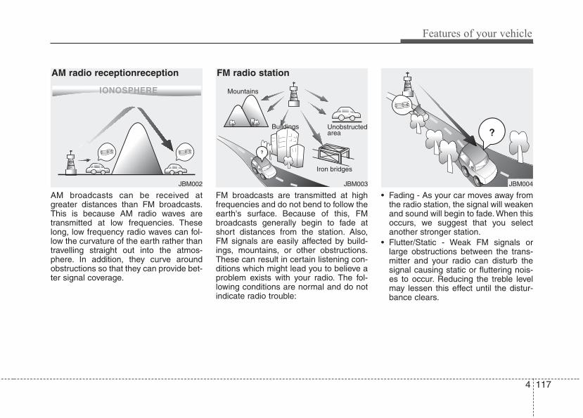
4 117
Features of your vehicle
AM broadcasts can be received atgreater distances than FM broadcasts.This is because AM radio waves aretransmitted at low frequencies. Theselong, low frequency radio waves can fol-low the curvature of the earth rather thantravelling straight out into the atmos-phere. In addition, they curve aroundobstructions so that they can provide bet-ter signal coverage.
FM broadcasts are transmitted at highfrequencies and do not bend to follow theearth's surface. Because of this, FMbroadcasts generally begin to fade atshort distances from the station. Also,FM signals are easily affected by build-ings, mountains, or other obstructions.These can result in certain listening con-ditions which might lead you to believe aproblem exists with your radio. The fol-lowing conditions are normal and do notindicate radio trouble:
• Fading - As your car moves away fromthe radio station, the signal will weakenand sound will begin to fade. When thisoccurs, we suggest that you selectanother stronger station.
• Flutter/Static - Weak FM signals orlarge obstructions between the trans-mitter and your radio can disturb thesignal causing static or fluttering nois-es to occur. Reducing the treble levelmay lessen this effect until the distur-bance clears.
¢ ¢ ¢ ¢ ¢ ¢
JBM002 JBM003
AM radio receptionreception FM radio station
¢ ¢ ¢
JBM004
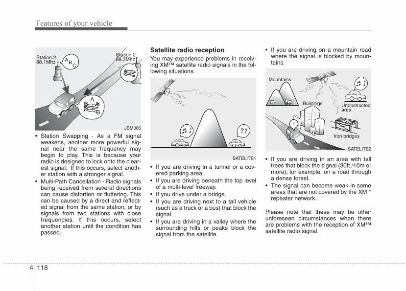
Features of your vehicle
1184
• Station Swapping - As a FM signalweakens, another more powerful sig-nal near the same frequency maybegin to play. This is because yourradio is designed to lock onto the clear-est signal. If this occurs, select anoth-er station with a stronger signal.
• Multi-Path Cancellation - Radio signalsbeing received from several directionscan cause distortion or fluttering. Thiscan be caused by a direct and reflect-ed signal from the same station, or bysignals from two stations with closefrequencies. If this occurs, selectanother station until the condition haspassed.
Satellite radio receptionYou may experience problems in receiv-ing XM™ satellite radio signals in the fol-lowing situations.
• If you are driving in a tunnel or a cov-ered parking area.
• If you are driving beneath the top levelof a multi-level freeway.
• If you drive under a bridge.• If you are driving next to a tall vehicle
(such as a truck or a bus) that block thesignal.
• If you are driving in a valley where thesurrounding hills or peaks block thesignal from the satellite.
• If you are driving on a mountain roadwhere the signal is blocked by moun-tains.
• If you are driving in an area with talltrees that block the signal (30ft./10m ormore); for example, on a road througha dense forest.
• The signal can become weak in someareas that are not covered by the XMTM
repeater network.
Please note that these may be otherunforeseen circumstances when thereare problems with the reception of XM™satellite radio signal.
JBM005
SATELITE1
SATELITE2
4 119
Features of your vehicle
Using a cellular phone or a two-wayradio When a cellular phone is used inside thevehicle, noise may be produced from theaudio equipment. This does not meanthat something is wrong with the audioequipment. In such a case, use the cellu-lar phone at a place as far as possiblefrom the audio equipment.
Care of discs• If the temperature inside the car is too
high, open the car windows for ventila-tion before using your car audio.
• It is illegal to copy and use MP3/WMAfiles without permission. Use CDs thatare created only by lawful means.
• Do not apply volatile agents such asbenzene and thinner, normal cleanersand magnetic sprays made for ana-logue discs onto CDs.
• To prevent the disc surface from get-ting damaged, hold and carry CDs bythe edges or the edges of the centerhole only.
• Clean the disc surface with a piece ofsoft cloth before playback (wipe it fromthe center to the outside edge).
• Do not damage the disc surface orattach pieces of sticky tape or paperonto it.
• Make sure nothing other than CDs areinserted into the CD player (Do notinsert more than one CD at a time).
• Keep CDs in their cases after use toprotect them from scratches or dirt.
• Depending on the type of CD-R/CD-RW CDs, certain CDs may not operatenormally depending upon manufactur-ing companies or processes andrecording methods. In such circum-stances, if you still continue to usethose CDs, they may cause the mal-function of your car audio system.
✽✽ NOTICE - Playing anIncompatible CopyProtected Audio CD
Some copy protected CDs, which do notcomply with the international audio CDstandards (Red Book), may not play onyour car audio. Please note that if youtry to play copy protected CDs and theCD player does not perform correctly,the CDs maybe defective, not the CDplayer.
CAUTIONWhen using a communication sys-tem such a cellular phone or a radioset inside the vehicle, a separateexternal antenna must be fitted.When a cellular phone or a radio setis used with an internal antennaalone, it may interfere with the vehi-cle's electrical system and adverse-ly affect safe operation of the vehi-cle.
WARNINGDon't use a cellular phone whenyou are driving. You should stop ata safe place to use a cellular phone.

Features of your vehicle
1204
BH_PA710BH_RADIO
1. FM/AM Button
2. POWER Button & VOLUME Knob
3. SEEK Button
4. PRESET Buttons
5. DISPLAY (Screen ON/OFF) Button
6. TUNE Knob & SETUP Button
7. SCAN Button
RADIO, SET UP, VOLUME CONTROL (CD Player : PA710BH)
4 121
Features of your vehicle
Using RADIO, SET UP, VOLUMEControl
1. FM/AM ButtonTurns to FM or AM mode, and toggles inthe order of FM1➟FM2➟AM➟FM1...when the button is pressed each time.
2. POWER Button & VOLUMEKnob
Turns the set on/off when the IGNITIONSWITCH is on ACC or ON. If the buttonis turned to the right, it increases the vol-ume and left, decreases the volume.
3. SEEK Button• When the [SEEK ] button is pressed,
it reduces the band frequency to auto-matically select a channel. Stops at theprevious frequency if no channel isfound.
• When the [SEEK ] button is pressed,it increases the band frequency to auto-matically select a channel. Stops at theprevious frequency if no channel isfound.
4. PRESET ButtonsPress [1]~[6] buttons less than 0.8 secondto play the channel saved in each button.Press preset button for 0.8 second orlonger to save current channel to therespective button with a beep.
5. DISPLAY (Screen ON/OFF)Button
Turns the displayed data and light on/offon the LCD.
6. TUNE Knob & SETUP ButtonWhen you rotate to clockwise or counter-clockwise, the frequency increases ordecreases by each step.General(AM 9kHz, FM 100kHz), USA(AM 10kHz, FM 200kHz)When you press this button, enter theSETUP mode. If no action is taken for 5seconds after pressing the button, it willreturn to the play mode. (After enteringSETUP mode, move between itemsusing the left, right and push functions ofthe TUNE/SETUP button.)
7. SCAN ButtonPress to hear a brief sampling of all sta-tions on the frequency band. When youpress this button again at this moment, youcan receive the broadcasting that youchoose.
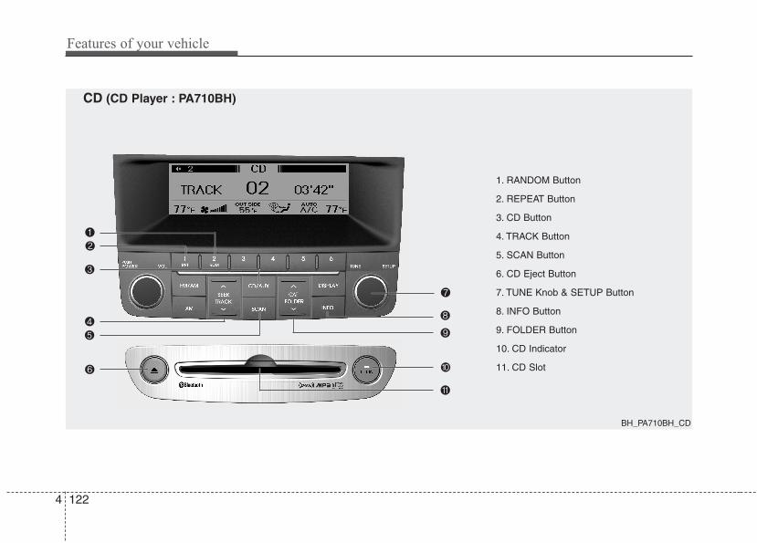
Features of your vehicle
1224
1. RANDOM Button
2. REPEAT Button
3. CD Button
4. TRACK Button
5. SCAN Button
6. CD Eject Button
7. TUNE Knob & SETUP Button
8. INFO Button
9. FOLDER Button
10. CD Indicator
11. CD Slot
BH_PA710BH_CD
CD (CD Player : PA710BH)
4 123
Features of your vehicle
Using CD Player
1. RANDOM ButtonTurns on/off the randomization of theplay list of files in the currently playedDISC. To cancel the mode, press the but-ton once again.
2. REPEAT ButtonRepeats current song when the button ispressed for less than 0.8 second.Repeats the entire DISC when the buttonis pressed for 0.8 second or longer.
3. CD ButtonTurns to CD mode.
4. TRACK Button• Press [TRACK ] button for less than
0.8 second to play from the beginningof current song.
• Press [TRACK ] button for less than0.8 second and press again within 1second to play the previous song.
• Press [TRACK ] button for 0.8 sec-ond or longer to initiate reverse direc-tion high speed sound search of cur-rent song.
• Press [TRACK ] button for less than0.8 second to play the next song.
• Press [TRACK ] button for 0.8 sec-ond or longer to initiate high speedsound search of current song.
5. SCAN ButtonPlay first 10 seconds of each song in theDISC. To cancel the mode, press the but-ton once again.
6. CD Eject ButtonPress button to eject the CD duringCD playback. This button is enabledwhen ignition switch is off.
7. TUNE Knob & SETUP ButtonTurn this button clockwise to displaysongs after current song.Also, turn this button counterclockwise todisplay songs before current song.To listen to the displayed song, press thebutton to skip to the song and play.
8. INFO ButtonDisplays the information of the currentCD TRACK (or FILE) in the order of DISCTITLE➟DISC ARTIST➟TRACK TITLE➟
TRACK ARTIST➟TOTAL➟Play Screen➟
DISC TITLE... when the button is pressedeach time.
9. FOLDER Button• Press [FOLDER ] button child folder
of the current folder and display the firstsong in the folder. Press TUNE/SETUPbutton to move to the folder displayed. Itwill play the first song in the folder.
• Press [FOLDER ] button parent fold-er and displays the first song in the fold-er. Press TUNE/SETUP button to moveto the folder displayed. It will play thefirst song in the folder. (MP3 only)
Features of your vehicle
1244
10. CD IndicatorWhen the ignition switch is in ACC or ONand if the CD is loaded, this indicatoricon is on. If the CD is ejected the icon isoff.
11. CD SlotInsert CD with printed side upward andgently push in. When the ignition switchis on ACC or ON and power is off, poweris automatically turned on if the CD isloaded. This CDP supports 12 cm CDs.But if a VCD, Data CD, or DVD areloaded, "Media Error" message willappear.
CAUTION IN USING USB DEVICE
• To use an external USB device,make sure the device is not con-nected when starting up the vehi-cle. Connect the device afterstarting up.
• If you start the engine when theUSB device is connected, it maydamage the USB device. (USBflashdrives are very sensitive toelectric shock.)
• If the engine is started up orturned off while the external USBdevice is connected, the externalUSB device may not work.
• It may not play inauthentic MP3 orWMA files.1) It can only play MP3 files with
the compression rate between8Kbps~320Kbps.
2) It can only play WMA musicfiles with the compression ratebetween 8Kbps~320Kbps.
• Take precautions for static electrici-ty when connecting or disconnect-ing the external USB device.
(Continued)
(Continued)• An encrypted MP3 PLAYER is not
recognizable.• Depending on the condition of
the external USB device, the con-nected external USB device canbe unrecognizable.
• When the formatted byte/sectorsetting of External USB device isnot either 512BYTE or 2048BYTE,then the device will not be recog-nized.
• Use only a USB device formattedto FAT 12/16/32.
• USB devices without USB I/Fauthentication may not be recog-nizable.
• Make sure the USB connectionterminal does not come in contactwith the human body or otherobjects.
• If you repeatedly connect or dis-connect the USB device in a shortperiod of time, it may break thedevice.
• You may hear a strange noisewhen connecting or disconnect-ing a USB device.
(Continued)
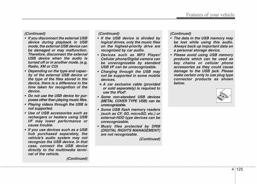
4 125
Features of your vehicle
(Continued)• If you disconnect the external USB
device during playback in USBmode, the external USB device canbe damaged or may malfunction.Therefore, disconnect the externalUSB device when the audio isturned off or in another mode. (e.g,Radio, XM or CD)
• Depending on the type and capac-ity of the external USB device orthe type of the files stored in thedevice, there is a difference in thetime taken for recognition of thedevice.
• Do not use the USB device for pur-poses other than playing music files.
• Playing videos through the USB isnot supported.
• Use of USB accessories such asrechargers or heaters using USBI/F may lower performance orcause trouble.
• If you use devices such as a USBhub purchased separately, thevehicle’s audio system may notrecognize the USB device. In thatcase, connect the USB devicedirectly to the multimedia termi-nal of the vehicle.
(Continued)
(Continued)• The data in the USB memory may
be lost while using this audio.Always back up important data ona personal storage device.
• Please avoid using USB memoryproducts which can be used askey chains or cellular phoneaccessories as they could causedamage to the USB jack. Pleasemake certain only to use plug typeconnector products as shownbelow.
(Continued)• If the USB device is divided by
logical drives, only the music fileson the highest-priority drive arerecognized by car audio.
• Devices such as MP3 Player/Cellular phone/Digital camera canbe unrecognizable by standardUSB I/F can be unrecognizable.
• Charging through the USB maynot be supported in some mobiledevices.
❋ A car exclusive cable (providedor sold separately) is required touse the iPod®.
• Some non-standard USB devices(METAL COVER TYPE USB) can beunrecognizable.
• Some USB flash memory readers(such as CF, SD, microSD, etc.) orexternal-HDD type devices can beunrecognizable.
• Music files protected by DRM(DIGITAL RIGHTS MANAGEMENT)are not recognizable.
(Continued)

Features of your vehicle
1264
1. RANDOM Button
2. REPEAT Button
3. USB Button
4. TRACK Button
5. SCAN Button
6. TUNE Knob & SETUP Button
7. INFO Button
8. FOLDER Button
BH_PA710BH_USB
USB (CD Player : PA710BH)
4 127
Features of your vehicle
Using USB deviceUsing a USB that is connected to themultiple terminal inside the console onthe right hand side of the driver's seat.
1. RANDOM ButtonTurns on/off the randomization of theplay list of files in the currently playedfolder. Press the button for more than 0.8second to randomly play the entire songsin the USB device. To cancel the mode,press the button once again.
2. REPEAT ButtonRepeats current song when the button ispressed for less than 0.8 second.Repeats the entire folder when the buttonis pressed for 0.8 second or longer.
3. USB ButtonIf USB device is connected, it switches tothe USB mode from CD mode to play thesong files stored in the USB.If the auxiliary device is connected, itturns to AUX mode to play the soundfrom the auxiliary player.
4. TRACK Button• Press [TRACK ] button for less than
0.8 second to play from the beginningof current song.
• Press [TRACK ] button for less than0.8 second and press again within 1seconds to play the previous song.
• Press [TRACK ] button for 0.8 sec-ond or longer to initiate reverse direc-tion high speed sound search of cur-rent song.
• Press [TRACK ] button for less than0.8 second to play the next song.
• Press [TRACK ] button for 0.8 sec-ond or longer to initiate high speedsound search of current song.
5. SCAN ButtonPlay first 10 seconds of each song in thefolder. To cancel the mode, press the but-ton once again.
6. TUNE Knob & SETUP ButtonTurn this button clockwise to displaysongs after the current song.Also, turn this button counterclockwise todisplay songs before the current song.To listen to the displayed song, press thebutton to skip to the song and play.
7. INFO ButtonDisplays the information of the file cur-rently played in order of FILE➟TITLE➟ARTIST➟ALBUM➟FOLDER➟TOTAL➟
Play Screen➟FILE... when the button ispressed each time.
8. FOLDER Button• Press [FOLDER ] button sub folder of
the current folder and display the firstsong in the folder. Press TUNE/SETUPbutton to move to the folder displayed. Itwill play the first song in the folder.
• Press [FOLDER ] button main folderand displays the first song in the folder.Press TUNE/SETUP button to move tothe folder displayed. It will play the firstsong in the folder. (MP3 only)

Features of your vehicle
1284
1. RANDOM Button
2. REPEAT Button
3. iPod® Button
4. TRACK Button
5. CATEGORY Button
6. TUNE Knob & SETUP Button
7. INFO Button
BH_PA710BH_iPod®
iPod®® (CD Player : PA710BH)
❈ iPod® is a trademark of Apple Inc.
4 129
Features of your vehicle
Using iPod®®
Using an iPod® when the exclusive cableis connected to the multiple terminalinside the console on the right hand sideof the driver's seat.
1. RANDOM ButtonPress the button for less than 0.8 secondto activate or deactivate the random play-back of the songs within the current cat-egory. Press the button for longer than0.8 second to randomly play all songs inthe entire album of the iPod®. Press thebutton once again to cancel the mode.
2. REPEAT ButtonRepeats the song currently played.
3. iPod® ButtonIf an iPod® is connected, the systemswitches to the iPod® mode to play thesong files stored in the iPod®.
4. TRACK Button• Press the [TRACK ] button for less
than 0.8 second to play from the begin-ning of the current song.
• Press the [TRACK ] button for lessthan 0.8 second and press again with-in 1 seconds to play the previous song.
• Press the [TRACK ] button for 0.8second or longer to initiate reversedirection high speed sound search ofcurrent song.
• Press the [TRACK ] button for lessthan 0.8 second to play the next song.
• Press the [TRACK ] button for 0.8second or longer to initiate high speedsound search of current song.
5. CATEGORY ButtonPress [CAT FOLDER / ] button tomove the category and display the firstsong in the category. Press [TUNE/SETUP] button to move to the categorydisplayed. It will play the first song in thefolder.(PLAYLISTS ➟ ARTISTS ➟ ALBUMS ➟
GENRES ➟ SONGS ➟ COMPOSERS ➟PLAYLISTS ➟...)
6. TUNE Knob & SETUP ButtonTurn this button clockwise or counter-clockwise, it will display the categorymenu. To select the displayed menu,press the button.
7. INFO ButtonDisplays the information of the file cur-rently played in order of TITLE➟ARTIST➟ALBUM➟Play Screen➟TITLE...
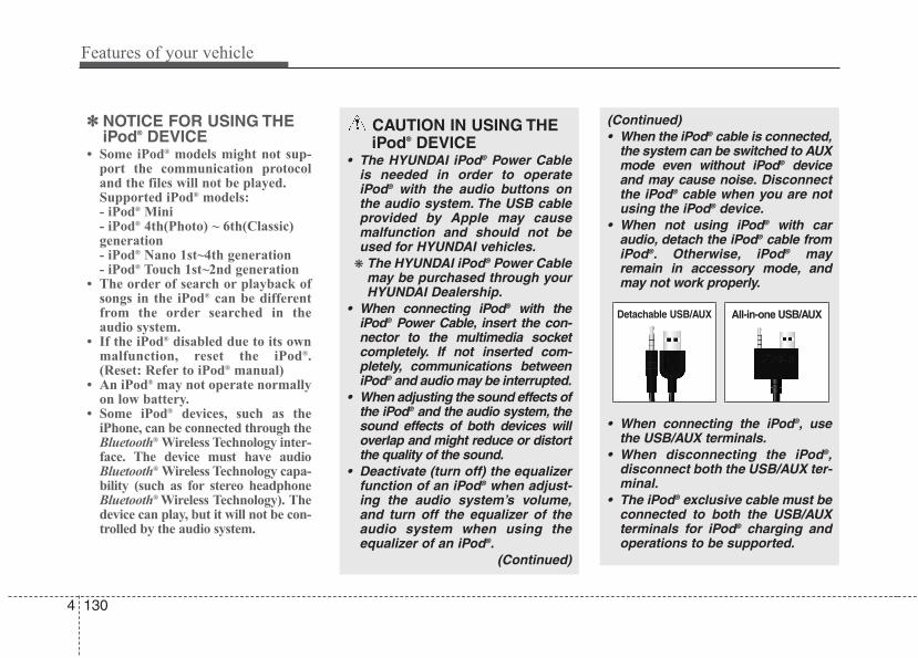
Features of your vehicle
1304
✽✽ NOTICE FOR USING THEiPod® DEVICE
• Some iPod® models might not sup-port the communication protocoland the files will not be played. Supported iPod® models: - iPod® Mini- iPod® 4th(Photo) ~ 6th(Classic)generation- iPod® Nano 1st~4th generation- iPod® Touch 1st~2nd generation
• The order of search or playback ofsongs in the iPod® can be differentfrom the order searched in theaudio system.
• If the iPod® disabled due to its ownmalfunction, reset the iPod®.(Reset: Refer to iPod® manual)
• An iPod® may not operate normallyon low battery.
• Some iPod® devices, such as theiPhone, can be connected through theBluetooth® Wireless Technology inter-face. The device must have audioBluetooth® Wireless Technology capa-bility (such as for stereo headphoneBluetooth® Wireless Technology). Thedevice can play, but it will not be con-trolled by the audio system.
CAUTION IN USING THE iPod® DEVICE
• The HYUNDAI iPod® Power Cableis needed in order to operateiPod® with the audio buttons onthe audio system. The USB cableprovided by Apple may causemalfunction and should not beused for HYUNDAI vehicles.
❋ The HYUNDAI iPod® Power Cablemay be purchased through yourHYUNDAI Dealership.
• When connecting iPod® with theiPod® Power Cable, insert the con-nector to the multimedia socketcompletely. If not inserted com-pletely, communications betweeniPod® and audio may be interrupted.
• When adjusting the sound effects ofthe iPod® and the audio system, thesound effects of both devices willoverlap and might reduce or distortthe quality of the sound.
• Deactivate (turn off) the equalizerfunction of an iPod® when adjust-ing the audio system’s volume,and turn off the equalizer of theaudio system when using theequalizer of an iPod®.
(Continued)
(Continued)• When the iPod® cable is connected,
the system can be switched to AUXmode even without iPod® deviceand may cause noise. Disconnectthe iPod® cable when you are notusing the iPod® device.
• When not using iPod® with caraudio, detach the iPod® cable fromiPod®. Otherwise, iPod® mayremain in accessory mode, andmay not work properly.
• When connecting the iPod®, usethe USB/AUX terminals.
• When disconnecting the iPod®,disconnect both the USB/AUX ter-minal.
• The iPod® exclusive cable must beconnected to both the USB/AUXterminals for iPod® charging andoperations to be supported.
Detachable USB/AUX All-in-one USB/AUX

4 131
Features of your vehicle
1. XM Button
2. SEEK Button
3. SCAN Button
4. PRESET Buttons
5. TUNE Knob & SETUP Button
6. INFO Button
7. CAT/FOLDER Button
BH_PA710BH_XM RADIO
XM Satellite Radio (CD Player : PA710BH)
Features of your vehicle
1324
Using XM Satellite Radio
1. XM ButtonTurns to XM Satellite Radio Mode.XM mode toggles in order to XM1➟XM2➟XM3➟XM1... when the button is pressedeach time.
2. SEEK Button• Press the [SEEK ] button for less
than 0.8 second to select previouschannel.
• Press the [SEEK ] button for 0.8 sec-ond or longer to continuously move toprevious channel.
• Press the [SEEK ] button for lessthan 0.8 second to select next channel.
• Press the [SEEK ] button for 0.8 sec-ond or longer to continuously move tonext channel.
• Radio ID : Seek or Tune to XM channel0 to display the Radio ID.
3. SCAN ButtonPress to hear a brief sampling of allchannels. To cancel the scan mode,press the button once again.
4. PRESET ButtonsPush [1]~[6] buttons less than 0.8 sec-ond to play the channel saved in eachbutton. Push pre-set button for 0.8 sec-ond or longer to save the current channelto the respective button with a beep.
5. TUNE Knob & SETUP ButtonTurn this button clockwise to displaychannels after.Also, turn this button counterclockwise todisplay channels before current channel.XM setup mode : It will be able to changethe XM display. (ex, Display by category/channel or artist/song title.)
6. INFO ButtonDisplays the information of the currentchannel in the order of Artist/Song title➟
Category/Channel name➟Current PlayChannel➟Artist/Song title➟Category/Cha-nnel name... when the button is pressedeach time.If the complete text information is not dis-played, rotate the tune button to see thenext page.
7. CAT/FOLDER Button• Press [CAT ] button to search previ-
ous category.• Press [CAT ] button to search next
category.To listen to the displayed category, pressthe TUNE/SETUP button.To scan channel in displayed category,press the scan button.To search channel in displayed category,press seek buttons or turn the tune but-ton clockwise/counterclockwise.(CATEGORY icon will be turned on inCategory mode)

4 133
Features of your vehicle
BH_PA760BH_RADIO
1. FM/AM Button
2. POWER Button & VOLUME Knob
3. SEEK Button
4. PRESET Buttons
5. DISPLAY(Screen ON/OFF) Button
6. TUNE Knob & SETUP Button
7. SCAN Button
RADIO, SET UP, VOLUME CONTROL (CD Changer : PA760BH)
❈ Lexicon mark is optional
Features of your vehicle
1344
Using RADIO, SET UP, VOLUMEControl
1. FM/AM ButtonTurns to FM or AM mode, and toggles inthe order of FM1➟FM2➟AM➟FM1...when the button is pressed each time.
2. POWER Button & VOLUMEKnob
Turns the set on/off when the IGNITIONSWITCH is on ACC or ON. If the buttonis turned to the right, it increases the vol-ume and left, decreases the volume.
3. SEEK Button• When the [SEEK ] button is pressed,
it reduces the band frequency to auto-matically select a channel. Stops at theprevious frequency if no channel isfound.
• When the [SEEK ] button is pressed,it increases the band frequency to auto-matically select a channel. Stops at theprevious frequency if no channel isfound.
4. PRESET ButtonsPush [1]~[6] buttons less than 0.8 secondto play the channel saved in each button.Push pre-set button for 0.8 second orlonger to save the current channel to therespective button with a beep.
5. DISPLAY(Screen ON/OFF)Button
Turns on/off the displayed data and lighton the LCD.
6. TUNE Knob & SETUP ButtonWhen you rotate to clockwise or counter-clockwise, the frequency increases ordecreases by each step.General(AM 9kHz, FM 100kHz), USA(AM 10kHz, FM 200kHz)When you press this button, enter theSETUP mode. If no action is taken for 5seconds after pressing the button, it willreturn to the play mode. (After enteringSETUP mode, move between itemsusing the left, right and push functions ofthe TUNE/SETUP button.)
❇ SURROUND is only Lexicon model.
7. SCAN ButtonPress to hear a brief sampling of all sta-tions on the frequency band. When youpress this button again at this moment, youcan receive the broadcasting that youchoose.

4 135
Features of your vehicle
1. RANDOM Button
2. REPEAT Button
3. CD Button
4. TRACK Button
5. SCAN Button
6. CD Eject Button
7. TUNE Knob & SETUP Button
8. INFO Button
9. FOLDER Button
10. LOAD Button
11. CD Slot
BH_PA760BH_CDC
CD (CD Changer : PA760BH)
Features of your vehicle
1364
Using CD Player
1. RANDOM ButtonTurns on/off the randomization of theplay list of files in the currently playedDISC. To cancel the mode, press the but-ton once again.
2. REPEAT ButtonRepeats the current song when the but-ton is pressed for less than 0.8 second.Repeats the entire DISC when the buttonis pressed for 0.8 second or longer.
3. CD ButtonTurns to CD mode.
4. TRACK Button• Press [SEEK ] button for less than
0.8 second to play from the beginningof current song.
• Press [SEEK ] button for less than0.8 second and press again within 1seconds to play the previous song.
• Press [SEEK ] button for 0.8 secondor longer to initiate reverse directionhigh speed sound search of currentsong.
• Press [SEEK ] button for less than0.8 second to play the next song.
• Press [SEEK ] button for 0.8 secondor longer to initiate high speed soundsearch of current song.
5. SCAN ButtonPlay first 10 seconds of each song in theDISC. To cancel the mode, press the but-ton once again.
6. CD Eject ButtonPress button for less than 0.8 secondto eject the CD during CD playback. Alldisc in the slot eject when the button ispressed for 0.8 second or longer. Thisbutton is enabled when the ignitionswitch is off.
7. TUNE Knob & SETUP ButtonTurn this button clockwise to displaysongs after the current song.Also, turn this button counterclockwise todisplay songs before the current song.To listen to the displayed song, press thebutton to skip to the song and play.
4 137
Features of your vehicle
8. INFO ButtonDisplays the information of the currentCD TRACK (or FILE) in the order of DISCTITLE➟DISC ARTIST➟TRACK TITLE➟
TRACK ARTIST➟TOTAL➟Play Screen➟
DISC TITLE... when the button is pressedeach time.
9. FOLDER Button• Press the [FOLDER ] button child
folder of the current folder and displaythe first song in the folder. PressTUNE/SETUP button to move to thefolder displayed. It will play the firstsong in the folder.
• Press the [FOLDER ] button parentfolder and displays the first song in thefolder. Press TUNE/SETUP button tomove to the folder displayed. It will playthe first song in the folder. (MP3 only)
10. LOAD ButtonPress the [LOAD] button to load CDs toavailable 6-Disc deck (from 1~6). Push[LOAD] button for more than 0.8 secondto load into all available decks.The last CD will play.
11. CD SlotInsert CD with printed side upward andgently push in. When the ignition switchis on ACC or ON and power is off, poweris automatically turned on if the CD isloaded. This CDP supports 12 cm CDs.But if VCD, Data CD, or DVD discs areloaded, "Media Error" message willappear.
Features of your vehicle
1384
CAUTION IN USING USB DEVICE
• To use an external USB device,make sure the device is not con-nected when starting up the vehi-cle. Connect the device afterstarting up.
• If you start the engine when theUSB device is connected, it maydamage the USB device. (USBflashdrives are very sensitive toelectric shock.)
• If the engine is started up orturned off while the external USBdevice is connected, the externalUSB device may not work.
• It may not play inauthentic MP3 orWMA files.1) It can only play MP3 files with
the compression rate between8Kbps~320Kbps.
2) It can only play WMA musicfiles with the compression ratebetween 8Kbps~320Kbps.
• Take precautions for static electrici-ty when connecting or disconnect-ing the external USB device.
(Continued)
(Continued)• An encrypted MP3 PLAYER is not
recognizable.• Depending on the condition of
the external USB device, the con-nected external USB device canbe unrecognizable.
• When the formatted byte/sectorsetting of External USB device isnot either 512BYTE or 2048BYTE,then the device will not be recog-nized.
• Use only a USB device formattedto FAT 12/16/32.
• USB devices without USB I/Fauthentication may not be recog-nizable.
• Make sure the USB connectionterminal does not come in contactwith the human body or otherobjects.
• If you repeatedly connect or dis-connect the USB device in a shortperiod of time, it may break thedevice.
• You may hear a strange noisewhen connecting or disconnect-ing a USB device.
(Continued)
(Continued)• If you disconnect the external USB
device during playback in USBmode, the external USB device canbe damaged or may malfunction.Therefore, disconnect the externalUSB device when the audio isturned off or in another mode. (e.g,Radio, XM or CD)
• Depending on the type and capaci-ty of the external USB device or thetype of the files stored in the device,there is a difference in the timetaken for recognition of the device.
• Do not use the USB device for pur-poses other than playing musicfiles.
• Playing videos through the USB isnot supported.
• Use of USB accessories such asrechargers or heaters using USBI/F may lower performance orcause trouble.
• If you use devices such as a USBhub purchased separately, thevehicle’s audio system may notrecognize the USB device. In thatcase, connect the USB devicedirectly to the multimedia termi-nal of the vehicle.
(Continued)
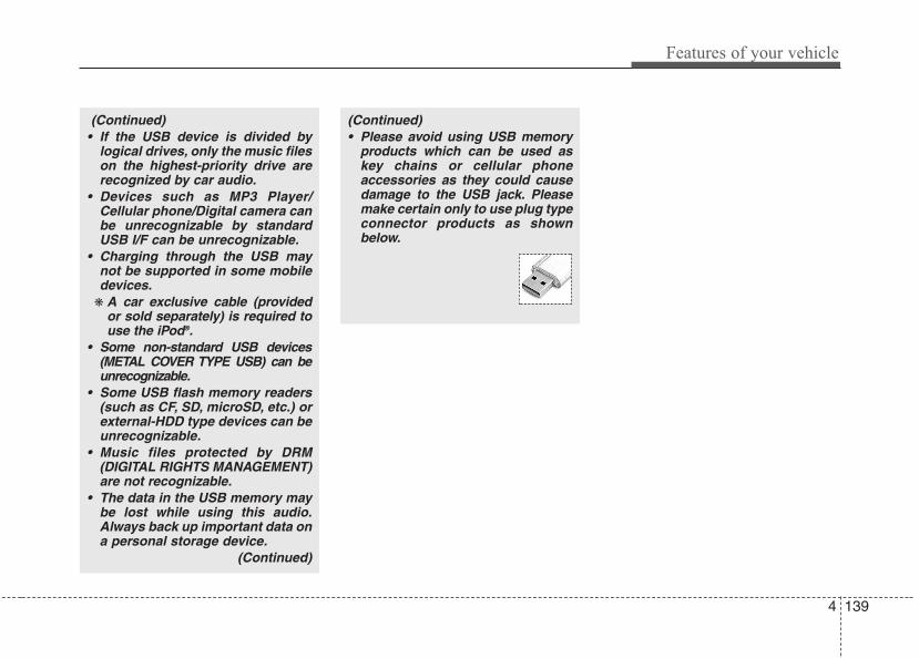
4 139
Features of your vehicle
(Continued)• Please avoid using USB memory
products which can be used askey chains or cellular phoneaccessories as they could causedamage to the USB jack. Pleasemake certain only to use plug typeconnector products as shownbelow.
(Continued)• If the USB device is divided by
logical drives, only the music fileson the highest-priority drive arerecognized by car audio.
• Devices such as MP3 Player/Cellular phone/Digital camera canbe unrecognizable by standardUSB I/F can be unrecognizable.
• Charging through the USB maynot be supported in some mobiledevices.
❋ A car exclusive cable (providedor sold separately) is required touse the iPod®.
• Some non-standard USB devices(METAL COVER TYPE USB) can beunrecognizable.
• Some USB flash memory readers(such as CF, SD, microSD, etc.) orexternal-HDD type devices can beunrecognizable.
• Music files protected by DRM(DIGITAL RIGHTS MANAGEMENT)are not recognizable.
• The data in the USB memory maybe lost while using this audio.Always back up important data ona personal storage device.
(Continued)
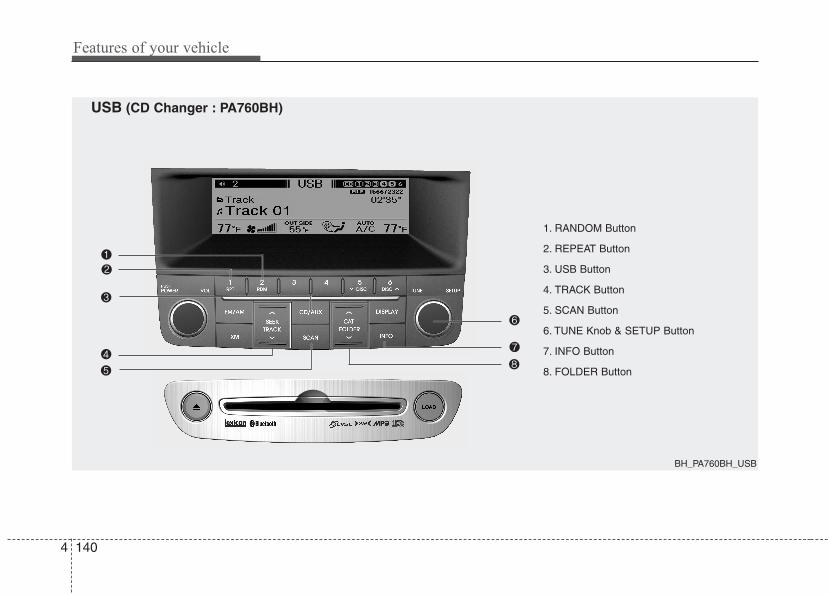
Features of your vehicle
1404
1. RANDOM Button
2. REPEAT Button
3. USB Button
4. TRACK Button
5. SCAN Button
6. TUNE Knob & SETUP Button
7. INFO Button
8. FOLDER Button
BH_PA760BH_USB
USB (CD Changer : PA760BH)
4 141
Features of your vehicle
Using USB deviceUsing a USB that is connected to themultiple terminal inside the console onthe right hand side of the driver's seat.
1. RANDOM ButtonTurns on/off the randomization of theplay list of files in the currently playedfolder. Press the button for more than 0.8second to randomly play the entire songsin the USB device. To cancel the mode,press the button once again.
2. REPEAT ButtonRepeats current song when the button ispressed for less than 0.8 second.Repeats the entire folder when the buttonis pressed for 0.8 second or longer.
3. USB ButtonIf USB device is connected, it switches tothe USB mode from CD mode to play thesong files stored in the USB.If the auxiliary device is connected, itturns to AUX mode to play the soundfrom the auxiliary player.
4. TRACK Button• Press the [TRACK ] button for less
than 0.8 second to play from the begin-ning of current song.
• Press the [TRACK ] button for lessthan 0.8 second and press again with-in 1 seconds to play the previous song.
• Press the [TRACK ] button for 0.8second or longer to initiate reversedirection high speed sound search ofcurrent song.
• Press the [TRACK ] button for lessthan 0.8 second to play the next song.
• Press the [TRACK ] button for 0.8second or longer to initiate high speedsound search of current song.
5. SCAN ButtonPlay first 10 seconds of each song in thefolder. To cancel the mode, press the but-ton once again.
6. TUNE Knob & SETUP ButtonTurn this button clockwise to displaysongs after the current song.Also, turn this button counterclockwise todisplay songs before the current song.To listen to the displayed song, press thebutton to skip to the song and play.
7. INFO ButtonDisplays the information of the file cur-rently played in order of FILE➟TITLE➟ARTIST➟ALBUM➟FOLDER➟TOTAL➟
Play Screen➟FILE... when the button ispressed each time.
8. FOLDER Button• Press the [FOLDER ] button sub fold-
er of the current folder and display thefirst song in the folder. PressTUNE/SETUP button to move to thefolder displayed. It will play the first songin the folder.
• Press the [FOLDER ] button mainfolder and displays the first song in thefolder. Press TUNE/SETUP button tomove to the folder displayed. It will playthe first song in the folder. (MP3 only)
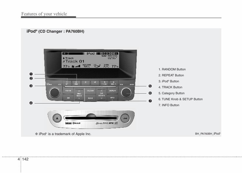
Features of your vehicle
1424
1. RANDOM Button
2. REPEAT Button
3. iPod® Button
4. TRACK Button
5. Category Button
6. TUNE Knob & SETUP Button
7. INFO Button
BH_PA760BH_iPod®
iPod® (CD Changer : PA760BH)
❈ iPod® is a trademark of Apple Inc.
4 143
Features of your vehicle
Using iPod®
Using an iPod® when the exclusive cableis connected to the multiple terminalinside the console on the right hand sideof the driver's seat.
1. RANDOM ButtonPress the button for less than 0.8 secondto activate or deactivate the random play-back of the songs within the current cat-egory. Press the button for longer than0.8 second to randomly play all songs inthe entire album of the iPod®. Press thebutton once again to cancel the mode.
2. REPEAT ButtonRepeats the song currently played.
3. iPod® ButtonIf an iPod® is connected, the systemswitches to the iPod® mode to play thesong files stored in the iPod®.
4. TRACK Button• Press the [TRACK ] button for less
than 0.8 second to play from the begin-ning of the current song.
• Press the [TRACK ] button for lessthan 0.8 second and press again with-in 1 seconds to play the previous song.
• Press the [TRACK ] button for 0.8second or longer to initiate reversedirection high speed sound search ofcurrent song.
• Press the [TRACK ] button for lessthan 0.8 second to play the next song.
• Press the [TRACK ] button for 0.8second or longer to initiate high speedsound search of current song.
5. Category ButtonPress [CAT FOLDER / ] button tomove the category and display the firstsong in the category. Press [TUNE/SETUP] button to move to the categorydisplayed. It will play the first song in thefolder.(PLAYLISTS ➟ ARTISTS ➟ ALBUMS ➟
GENRES ➟ SONGS ➟ COMPOSERS ➟
PLAYLISTS ➟...)
6. TUNE Knob & SETUP ButtonTurn this button clockwise or counter-clockwise, it will display the categorymenu. To select the displayed menu,press the button.
7. INFO ButtonDisplays the information of the file cur-rently played in order of TITLE➟ARTIST➟ALBUM➟Play Screen➟TITLE...

Features of your vehicle
1444
✽✽ NOTICE FOR USING THEiPod® DEVICE
• Some iPod® models might not sup-port the communication protocoland the files will not be played. Supported iPod® models: - iPod® Mini- iPod® 4th(Photo) ~ 6th(Classic)generation- iPod® Nano 1st~4th generation- iPod® Touch 1st~2nd generation
• The order of search or playback ofsongs in the iPod® can be differentfrom the order searched in theaudio system.
• If the iPod® disabled due to its ownmalfunction, reset the iPod®.(Reset: Refer to iPod® manual)
• An iPod® may not operate normallyon low battery.
• Some iPod® devices, such as theiPhone, can be connected through theBluetooth® Wireless Technology inter-face. The device must have audioBluetooth® Wireless Technology capa-bility (such as for stereo headphoneBluetooth® Wireless Technology). Thedevice can play, but it will not be con-trolled by the audio system.
CAUTION IN USING THE iPod® DEVICE
• The HYUNDAI iPod® Power Cableis needed in order to operateiPod® with the audio buttons onthe audio system. The USB cableprovided by Apple may causemalfunction and should not beused for HYUNDAI vehicles.
❋ The HYUNDAI iPod® Power Cablemay be purchased through yourHYUNDAI Dealership.
• When connecting iPod® with theiPod® Power Cable, insert the con-nector to the multimedia socketcompletely. If not inserted com-pletely, communications betweeniPod and audio may be interrupted.
• When adjusting the sound effects ofthe iPod® and the audio system, thesound effects of both devices willoverlap and might reduce or distortthe quality of the sound.
• Deactivate (turn off) the equalizerfunction of an iPod® when adjust-ing the audio system’s volume,and turn off the equalizer of theaudio system when using theequalizer of an iPod®.
(Continued)
(Continued)• When the iPod® cable is connected,
the system can be switched to AUXmode even without iPod® deviceand may cause noise. Disconnectthe iPod® cable when you are notusing the iPod® device.
• When not using iPod® with caraudio, detach the iPod® cable fromiPod®. Otherwise, iPod® mayremain in accessory mode, andmay not work properly.
• When connecting the iPod®, usethe USB/AUX terminals.
• When disconnecting the iPod®,disconnect both the USB/AUX ter-minal.
• The iPod® exclusive cable must beconnected to both the USB/AUXterminals for iPod® charging andoperations to be supported.
Detachable USB/AUX All-in-one USB/AUX
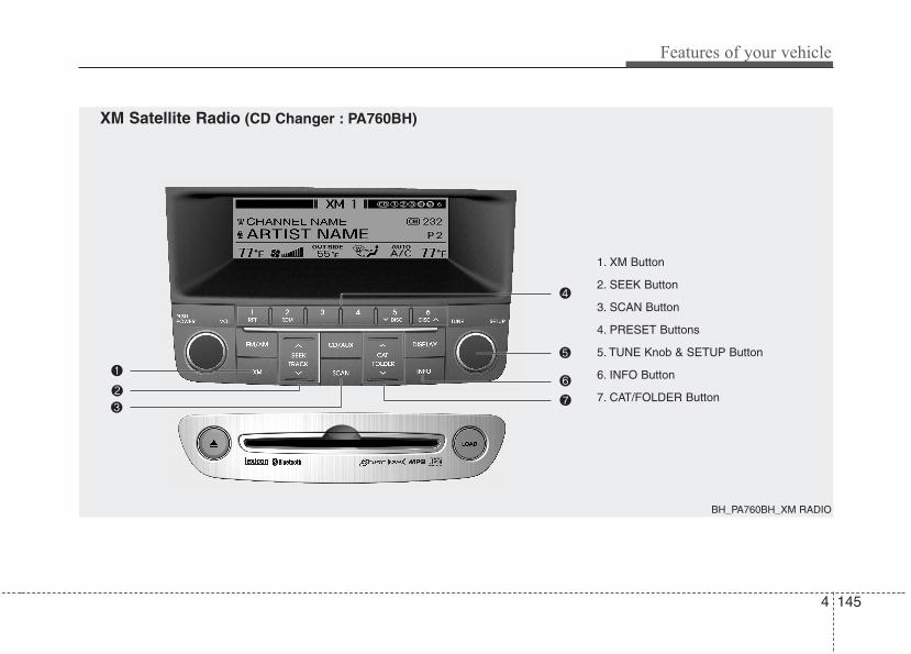
4 145
Features of your vehicle
1. XM Button
2. SEEK Button
3. SCAN Button
4. PRESET Buttons
5. TUNE Knob & SETUP Button
6. INFO Button
7. CAT/FOLDER Button
BH_PA760BH_XM RADIO
XM Satellite Radio (CD Changer : PA760BH)

Features of your vehicle
1464
Using XM Satellite Radio
1. XM ButtonTurns to XM Satellite Radio Mode.XM mode toggles in order to XM1➟XM2➟XM3➟XM1... when the button is pressedeach time.
2. SEEK Button• Press the [SEEK ] button for less
than 0.8 second to select previouschannel.
• Press the [SEEK ] button for 0.8 sec-ond or longer to continuously move toprevious channel.
• Press the [SEEK ] button for lessthan 0.8 second to select next channel.
• Press the [SEEK ] button for 0.8 sec-ond or longer to continuously move tonext channel.
• Radio ID : Seek or Tune to XM channel0 to display the Radio ID.
3. SCAN ButtonPress to hear a brief sampling of allchannels. To cancel the scan mode,press the button once again.
4. PRESET ButtonsPush [1]~[6] buttons less than 0.8 sec-ond to play the channel saved in eachbutton. Push pre-set button for 0.8 sec-ond or longer to save the current channelto the respective button with a beep.
5. TUNE Knob & SETUP ButtonTurn this button clockwise to displaychannels after.Also, turn this button counterclockwise todisplay channels before current channel.XM setup mode : It will be able to changethe XM display. (ex, Display by category/channel or artist/song title.)
6. INFO ButtonDisplays the information of the currentchannel in the order of Artist/Song title➟
Category/Channel name➟Current PlayChannel➟Artist/Song title➟Category/Cha-nnel name... when the button is pressedeach time.If the complete text information is not dis-played, rotate the tune button to see thenext page.
7. CAT/FOLDER Button• Press [CAT ] button to search previ-
ous category.• Press [CAT ] button to search next
category.To listen to the displayed category, pressthe TUNE/SETUP button.To scan channel in displayed category,press the scan button.To search channel in displayed category,press seek buttons or turn the tune but-ton clockwise/counterclockwise.(CATEGORY icon will be turned on inCategory mode)

4 147
Features of your vehicle
BH_PA760BH_HD_RADIO
1. SEEK UP/DOWN Button
2. SCAN Button
3. INFO Button
4. PRESET Buttons
5. TUNE Knob & SETUP Button
HD RADIOTM RECEPTION (CD Changer : PA760BH)
Features of your vehicle
1484
HD RADIOTM INFORMATION
Licensing information
HD RadioTM Technology is ManufacturedUnder License From iBiquity DigitalCorporation. U.S. and Foreign Patents.HD RadioTM and the HD and HD Radiologos are proprietary trademarks ofiBiquity Digital Corporation.
Availability informationHD RadioTM reception is available in theUnited States, including Alaska andHawaii.
What is HD RadioTM technology?The vehicle audio system (if equipped) isable to receive standard analog FM/AMradio broadcasting as well as digital HDRadioTM FM/AM broadcasting.HD RadioTM technology provides digitaland analog reception using existing FMand AM broadcasting frequencies.Currently, radio stations broadcasting anHD RadioTM signal are operating in ahybrid mode of both, analog and digital, inorder to reach both receivers. In bothmodes, analog and digital, the broadcast-ed program contents are the same(exceptduring multicasting, see below).
Eventually, as analog receivers arereplaced by digital ones, radio stationsmay be able to turn off their analogbroadcasting and use only the digitalbroadcasting.
MulticastingHD RadioTM FM stations are able to broad-cast multiple digital programstreams(channels) over a single FM fre-quency. For example, a HD RadioTM FMstation can run a main channel of musicand a sub channel of news(or even two dif-ferent music channels) at one frequency.
Only the program content of the mainchannel is in broadcasted analog.
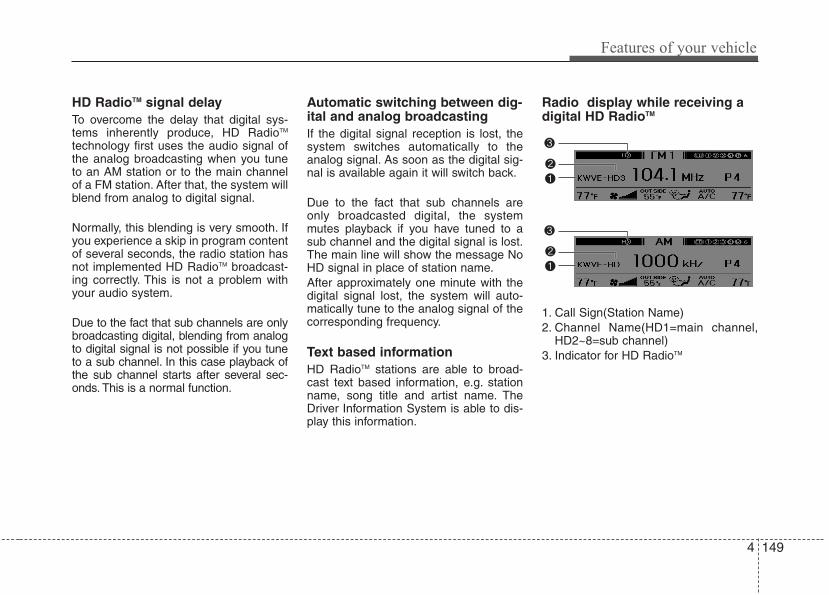
4 149
Features of your vehicle
HD RadioTM signal delayTo overcome the delay that digital sys-tems inherently produce, HD RadioTM
technology first uses the audio signal ofthe analog broadcasting when you tuneto an AM station or to the main channelof a FM station. After that, the system willblend from analog to digital signal.
Normally, this blending is very smooth. Ifyou experience a skip in program contentof several seconds, the radio station hasnot implemented HD RadioTM broadcast-ing correctly. This is not a problem withyour audio system.
Due to the fact that sub channels are onlybroadcasting digital, blending from analogto digital signal is not possible if you tuneto a sub channel. In this case playback ofthe sub channel starts after several sec-onds. This is a normal function.
Automatic switching between dig-ital and analog broadcastingIf the digital signal reception is lost, thesystem switches automatically to theanalog signal. As soon as the digital sig-nal is available again it will switch back.
Due to the fact that sub channels areonly broadcasted digital, the systemmutes playback if you have tuned to asub channel and the digital signal is lost.The main line will show the message NoHD signal in place of station name.After approximately one minute with thedigital signal lost, the system will auto-matically tune to the analog signal of thecorresponding frequency.
Text based informationHD RadioTM stations are able to broad-cast text based information, e.g. stationname, song title and artist name. TheDriver Information System is able to dis-play this information.
Radio display while receiving adigital HD RadioTM
1. Call Sign(Station Name)2. Channel Name(HD1=main channel,
HD2~8=sub channel)3. Indicator for HD RadioTM
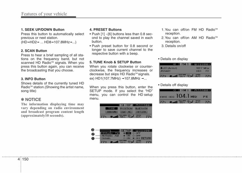
Features of your vehicle
1504
1. SEEK UP/DOWN ButtonPress this button to automatically selectprevious or next station.(HD➟HD2➟ ... HD8➟107.8MHz➟...)
2. SCAN ButtonPress to hear a brief sampling of all sta-tions on the frequency band, but notscanned HD RadioTM signals. When youpress this button again, you can receivethe broadcasting that you choose.
3. INFO ButtonShows details of the currently tuned HDRadioTM station.(Showing the artist name,song title)
✽✽ NOTICEThe information displaying time mayvary depending on radio environmentand broadcast program content length(approximately10 seconds).
4. PRESET Buttons• Push [1] ~[6] buttons less than 0.8 sec-
ond to play the channel saved in eachbutton.
• Push preset button for 0.8 second orlonger to save current channel to therespective button with a beep.
5. TUNE Knob & SETUP ButtonWhen you rotate clockwise or counter-clockwise, the frequency increases ordecrease but skips HD RadioTM signals.ex) HD1(107.7MHz) ➟107.8MHz ➟...
When you press this button, enter theSETUP mode. If you select the “HD”menu, you can control the HD setupmenu.
1. You can off/on FM HD RadioTM
reception.2. You can off/on AM HD RadioTM
reception.3. Details on/off
• Details on display
• Details off display
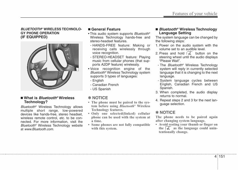
4 151
Features of your vehicle
BLUETOOTH® WIRELESS TECHNOLO-GY PHONE OPERATION(IF EQUIPPED)
■ What is Bluetooth® WirelessTechnology?
Bluetooth® Wireless Technology allowsmultiple short range, low-powereddevices like hands-free, stereo headset,wireless remote control, etc. to be con-nected. For more information, visit theBluetooth® Wireless Technology websiteat www.Bluetooth.com.
■ General Feature• This audio system supports Bluetooth®
Wireless Technology hands-free andstereo-headset features.- HANDS-FREE feature: Making or
receiving calls wirelessly throughvoice recognition.
- STEREO-HEADSET feature: Playingmusic from cellular phones (that sup-ports A2DP feature) wirelessly.
• Voice recognition engine of theBluetooth® Wireless Technology systemsupports 3 types of languages:- English- Canadian French- US Spanish
✽✽ NOTICE• The phone must be paired to the sys-
tem before using Bluetooth® WirelessTechnology features.
• Only one selected(linked) cellularphone can be used with the system ata time.
• Some phones are not fully compatiblewith this system.
■ Bluetooth® Wireless TechnologyLanguage Setting
The system language can be changed bythe following steps:1. Power on the audio system with the
volume set to an audible level.2. Press and hold button on the
steering wheel until the audio displays“Please Wait”.
- The Bluetooth® Wireless Technologysystem will reply in currently selectedlanguage that it is changing to the nextlanguage.
- System language cycles betweenEnglish, Canadian French and USSpanish.
3. When completed, the audio displayreturns to normal.
4. Repeat steps 2 and 3 for the next lan-guage selection.
✽✽ NOTICEThe phone needs to be paired againafter changing system language.• Avoid resting your thumb or finger on
the as the language could unin-tentionally change.
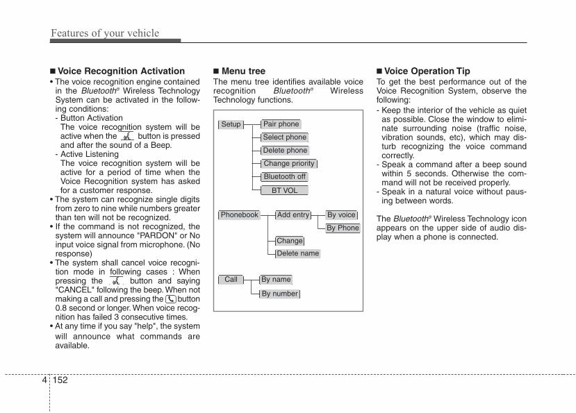
Features of your vehicle
1524
■ Voice Recognition Activation• The voice recognition engine contained
in the Bluetooth® Wireless TechnologySystem can be activated in the follow-ing conditions:- Button Activation
The voice recognition system will beactive when the button is pressedand after the sound of a Beep.
- Active ListeningThe voice recognition system will beactive for a period of time when theVoice Recognition system has askedfor a customer response.
• The system can recognize single digitsfrom zero to nine while numbers greaterthan ten will not be recognized.
• If the command is not recognized, thesystem will announce "PARDON" or Noinput voice signal from microphone. (Noresponse)
• The system shall cancel voice recogni-tion mode in following cases : Whenpressing the button and saying"CANCEL" following the beep. When notmaking a call and pressing the button0.8 second or longer. When voice recog-nition has failed 3 consecutive times.
• At any time if you say "help", the system will announce what commands areavailable.
■ Menu treeThe menu tree identifies available voicerecognition Bluetooth® WirelessTechnology functions.
■ Voice Operation TipTo get the best performance out of theVoice Recognition System, observe thefollowing:- Keep the interior of the vehicle as quiet
as possible. Close the window to elimi-nate surrounding noise (traffic noise,vibration sounds, etc), which may dis-turb recognizing the voice commandcorrectly.
- Speak a command after a beep soundwithin 5 seconds. Otherwise the com-mand will not be received properly.
- Speak in a natural voice without paus-ing between words.
The Bluetooth® Wireless Technology iconappears on the upper side of audio dis-play when a phone is connected.
Pair phone
Select phone
Change priority
Delete phone
Bluetooth off
BT VOL
Setup
Add entryPhonebook
Change
Delete name
By Phone
By voice
Call By name
By number
4 153
Features of your vehicle
■ Phone SetupAll Bluetooth® Wireless Technology relat-ed operations can be performed by voicecommand or by manual operation.
• By Voice Command:Press button on the steeringwheel to activate voice recognition.
• By manual operationPush the TUNE/SETUP knob to enterSETUP mode. Select “BLUETOOTH”item by rotating the TUNE/SETUPknob, then push the knob.
• Pairing phoneBefore using Bluetooth® WirelessTechnology features, the phone must bepaired (registered) to the audio system.Up to 5 phones can be paired in the sys-tem.
✽✽ NOTICE• The pairing procedure of the phone
varies according to each phone model.Before attempting to pair phone,please see your phone’s User’s Guidefor instructions.
• Once pairing with the phone is com-pleted, there is no need to pair withthat phone again unless the phone isdeleted manually from the audio sys-tem (refer “Deleting Phone” section)or the vehicle’s information isremoved from the phone.
• Need to confirm if pairing can be doneby voice. Need to confirm which sys-tem can paired by voice, CDC, CDP.
1. Press button.2. Say “Set Up”.
- The system replies with availablecommands.
- To skip the information message,press again and then a beep isheard.
3. Say “Pair Phone”4. Say “Yes” to proceed.5. Say the name of your phone when
prompted.- Use any name to uniquely describe
your phone.- Use Full name to voice tag.- Do not use a short name or similar
name to voice command.6. Bluetooth® Wireless Technology sys-
tem will repeat the name you stated.7. Say "Yes" to confirm.8. The audio displays “searching ----
passkey: 0000” and asks you to initiatepairing procedure from the phone.
9. Search the Bluetooth® WirelessTechnology system on your phone.Your phone should display your [vehi-cle model name] on the Bluetooth®
Wireless Technology device list. Thenattempt pairing on your phone.
10. After Pairing is completed, your phonewill start to transfer phone/contact listto the audio system.
Features of your vehicle
1544
- This process may take from a fewminutes to over 10 minutes depend-ing on the phone model and numberof entries in the phone/contact list.
11. By manual operation:- Select “PAIR” in PHONE menu, then
proceed from step 5.
✽✽ NOTICEDepending on the phone make andmodel, the phone book contact list maynot transfer to the audio system.
✽✽ NOTICE• Until the audio displays “Transfer
Complete”, Bluetooth® WirelessTechnology hands-free feature maynot be fully operational.
• If the phone is paired to two or morevehicles of the same model, i.e. bothvehicles are HYUNDAI GENESIS,some phones may not handleBluetooth® Wireless Technologydevices of that name correctly. In thiscase, you may need to change thename displayed on your phone fromGENESIS.
• Refer to your phone’s User’s Guide,or contact your cellular carrier orphone manufacturer for instructions.
• Connecting phoneWhen the Bluetooth® WirelessTechnology system is enabled, thephone previously used is automaticallyselected and re-connected. If you want toselect a different phone previouslypaired, the phone can be selectedthrough “Select Phone” menu.Only a selected phone can be used withthe hands-free system.1. Press button.2. Say "Set Up".3. Say "Select Phone" after prompt
- The system lists all the registeredphone names.
4. Say the name or number of desiredphone from the list.
5. Say "Yes" to confirm.6. By manual operation:
- Select “SELECT” in PHONE menu,then select desired phone from thelist.
• Deleting PhoneThe paired phone can be deleted.- When the phone is deleted, all the infor-
mation associated with that phone isalso be deleted (including phonebook).
- If you want to use the deleted phonewith the audio system again, pairingprocedure must be completed oncemore.
1. Press button.2. Say “Set Up”.3. Say “Delete Phone” after prompt.
- The system lists all the registeredphone names.
4. Say the name or number of desiredphone from the list.
5. Say “Yes” to confirm.6. By manual operation:
- Select “DELETE” in PHONE menu,then select desired phone from the list.
4 155
Features of your vehicle
• Changing PriorityWhen several phones are paired to theaudio system, the system attempts to con-nect following order when the Bluetooth®
Wireless Technology is enabled:1) “Priority” checked phone.2) Previously connected phone3) Gives up auto connection.
1. Press button.2. Say “Set Up”.3. Say “Change Priority” after prompt.
- The system lists all the registeredphone names.
4. Say the name or number of desiredphone from the list.
5. Say “Yes” to confirm.6. By manual operation:
- Select “PRIORITY” in PHONE menu,then select desired phone from thelist.
• Adjusting Bluetooth® WirelessTechnology Volume
Bluetooth® Wireless Technology systemvolume can be adjusted separately frommain volume of the audio system.Volume control is available by manualoperation only.Select “BT Volume” in BLUETOOTHmenu, adjust volume to desired level byrotating the TUNE/SETUP knob, thenpress the knob to confirm.
• Turning Bluetooth® WirelessTechnology ON/OFF
Bluetooth® Wireless Technology systemcan be enabled (ON) or disabled (OFF)by this menu.- If Bluetooth® Wireless Technology is dis-
abled, all the commands related toBluetooth® Wireless Technology systemprompts whether you wish to turnBluetooth® Wireless Technology ON or not.
1. Press button.2. Say “Set Up”3. Say “Bluetooth Off” after prompt.4. Say “Yes” to confirm.5. By manual operation:
- Select “BT Off” in PHONE menu, thenafter announcement, say “YES” toconfirm.
■ Phone Book (In-Vehicle)• Adding EntryPhone numbers and voice tags can beregistered. Entries registered in thephone can also be transferred.
• Adding Entry by Voice1. Press button.2. Say "Phonebook".
- The system replies with all availablecommands.
- To skip the information message, pressagain and then a beep is heard.
3. Say "Add Entry".4. Say "By Voice" to proceed.5. Say the name of the entry when
prompted.6. Say “Yes”to confirm.7. Say the phone number of that entry
when prompted.8. Say “Store” if phone number input is
finished.9. Say a phone number type. “Home”,
“Work”, “Mobile”, “Other” or “Default” isavailable.
10. Say “Yes” to complete adding entry.11. Say “Yes” to store additional location
for this contact, or say “Cancel” to fin-ish the process.
Features of your vehicle
1564
✽✽ NOTICE• The system can recognize single digits
from zero to nine. Numbers that areten or greater cannot be recognized.
• You can enter each digit individuallyor group digits together in preferredstring lengths.
• To speed up input, it is a good idea togroup all digits into a continuousstring.
• Recommend to enter the numbers con-stituted an grouping within all digitnumbers to dial 995 / 734 / 0000
• The display corresponding to eachoperation appears on the screen as fol-lows:
• Input operation example:1. Say: “Nine, nine, five”
➟ Display: “995”2. And say: “Seven, three, four”
➟ Display: “995734”
• Adding Entry by Phone1. Press button.2. Say "Phonebook".3. Say "Add Entry" after prompt.4. Say "By Phone" to proceed.5. Say “Yes” to confirm.6. Your phone will start to transfer
phone/contact list to the audio system.This process may take over 10 minutesdepending on the phone model andnumber of entries
7. Wait till the audio displays “TransferComplete” message.
• Changing NameThe registered names can be modified.1.Press button.2.Say “Phonebook”3.Say “Change Name” after prompt.4.Say the name of the entry (voice tag).5.Say “Yes” to confirm.6.Say new desired name.
• Deleting NameThe registered names can be deleted.1.Press button.2.Say “Phonebook”3.Say “Delete Name” after prompt.4.Say the name of the entry (voice tag)5.Say “Yes” to confirm.
4 157
Features of your vehicle
■ Making a Phone Call• Calling by NameA phone call can be made by speakingnames registered in the audio system.1. Press button.2. Say "Call".3. Say “Name” when prompted.4. Say desired name (voice tag).5. Say desired location (phone number
type). Only stored locations can beselected.
6. Say “Yes” to confirm and make a call.
✽✽ TipA shortcut to each of the following func-tions is available:1. Say “Call Name”2. Say “Call <john>”3. Say “Call <john> at <home>”
• Dialing by NumberA phone call can be made by dialing thespoken numbers. The system can recog-nize single digits from zero to nine.1.Press button.2.Say “Call”.3.Say “Number” when prompted.4.Say desired phone numbers.5.Say “Dial” to complete the number and
make a call.
✽✽ TipA shortcut to each of the following func-tions is available:1. Say “Dial Number”2. Say “Dial <digit>”
■ Receiving a Phone CallWhen receiving a phone call, a ringtoneis audible from speakers and the audiosystem changes into telephone mode.When receiving a phone call, “Incoming”message and incoming phone number (if available) are displayed on the audio.• To Answer a Call:
- Press button on the steering wheel.• To Reject a Call:
- Press button for 0.8 second orlonger on the steering wheel.
• To Adjust Ring Volume:- Use VOLUME buttons on the steering
wheel.• To Transfer a Call to the Phone (Secret Call):
- Press button on the steeringwheel.
Features of your vehicle
1584
■ Talking on the PhoneWhen talking on the phone, “Active Calls”message and the other party’s phonenumber (if available) are displayed on theaudio.• To Finish a Call
- Press button for 0.8 second or longeron the steering wheel.
✽✽ NOTICEIn the following situations, you or theother party may have difficulty hearing each other:1. Speaking at the same time, your voice
may not reach the other parties. (Thisis not a malfunction.) Speak alter-nately with the other party on thephone.
2. Keep the Bluetooth® WirelessTechnology volume to a low level.High-level volume may result in dis-tortion and echo.
3. When driving on a rough road.4. When driving at high speeds.5. When the window is open.6. When the air conditioning vents are
facing the microphone.7. When the sound of the air condition-
ing fan is loud.
■ Using the head unit asBluetooth® Wireless Technologymusic
The head unit supports A2DP (AudioAdvanced Distribution Profile) andAVRCP(Audio Video Remote ControlProfile).Both profiles are available for listening toMP3 music via Bluetooth® WirelessTechnology cellular phone supportingabove Bluetooth® Wireless Technologyprofiles.To play MP3 music from the Bluetooth®
Wireless Technology cellular phone,press the [CD/AUX] button until “MP3Play” is displayed on the LCD.Then try playing music by phone.When playing music from the Bluetooth®
Wireless Technology cellular phone, thehead unit displays MP3 MODE.
✽✽ NOTICE• Not only MP3 files, but all the sounds
that the phone supports can be heardby the audio system.
• Bluetooth® Wireless Technology cellu-lar phones must feature A2DP andAVRCP functions.
• Some A2DP and AVRCP Bluetooth®
Wireless Technology cellular phonesmay not play music through the headunit on the first try. Please try thebelow; i.e : Menu➟➟Filemanager➟➟Music➟➟
Option➟➟Play via Bluetooth • Please refer to User's Guide of your
phone for more detailed information.• To stop music, try stop music by the
phone or change audio mode toAM/FM/XM, CD, iPod®, etc.
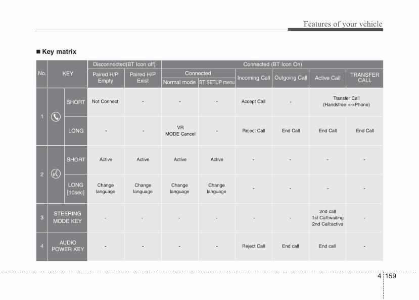
4 159
Features of your vehicle
■ Key matrix
No.
Disconnected(BT Icon off) Connected (BT Icon On)
Paired H/PEmpty
Paired H/PExist
1
SHORT
LONG
STEERINGMODE KEY
SHORT
LONG[10sec]
AUDIOPOWER KEY
Normal mode BT SETUP menuIncoming Call Outgoing Call Active Call TRANSFER
CALL
Not Connect - - - Accept Call
Connected
-Transfer Call
(Handsfree <->Phone)
KEY
- -VR
MODE Cancel- Reject Call End Call End CallEnd Call
-Active Active Active Active - - -
Change language
-
-
Change language
-
Change language
-
-
-
-
-Change
language
-
-
-
Reject Call
-
End call
-
2nd call1st Call:waiting2nd Call:active
-
-
End call -
2
3
4
Features of your vehicle
1604
✽✽ NOTICEBluetooth® Wireless Technology phonecompatibility can be checked by visitingwww.hyundaiusa.com and under theSERVICE & PARTS - BLUETOOTHCOMPATIBILITY menu.• Areas that can be checked - 9 areas,
such as Pairing, Connection,Handsfree Calling, Streaming, etc.
(Continued)• If the cellular phone signal is poor
or the vehicles interior noise is tooloud, it may be difficult to hear theother person’s voice during a call.
• Do not place the phone near orinside metallic objects, otherwise communications with Bluetooth®
Wireless Technology system orcellular service stations can bedisrupted.
• While a phone is connectedthrough Bluetooth® WirelessTechnology your phone may dis-charge quicker than usual as aresult of additional Bluetooth®
Wireless Technology-relatedoperations.
• Some cellular phones or otherdevices may cause interferencenoise or malfunction to audiosystem. In this case, storing thedevice in a different location mayresolve the situation.
• Please save your phone name inEnglish, or your phone name maynot be displayed correctly.
CAUTION IN USINGBLUETOOTH® WIRELESSTECHNOLOGY CELLU-LAR PHONE
• Do not use a cellular phone orperform Bluetooth® WirelessTechnology settings (e.g. pairinga phone) while driving.
• Some Bluetooth® WirelessTechnology-enabled phones maynot be recognized by the systemor fully compatible with the sys-tem.
• Before using Bluetooth® WirelessTechnology related features ofthe audio system, refer to yourphone’s User’s Manual for phone-side Bluetooth® WirelessTechnology operations.
• The phone must be paired to theaudio system to use Bluetooth®
Wireless Technology related fea-tures.
• You will not be able to use thehands-free feature when yourphone (in the car) is outside ofthe cellular service area (e.g. in atunnel, in a underground, in amountainous area, etc.).
(Continued)
5
Before driving / 5-3
Key / 5-5
Engine start/stop button / 5-7
Automatic transmission / 5-12
Brake system / 5-18
Cruise control system / 5-36
Smart cruise control system / 5-40
Lane departure warning system (LDWS) / 5-51
Economical operation / 5-54
Special driving conditions / 5-56
Winter driving / 5-60
Vehicle load limit / 5-64
Vehicle weight / 5-69
Trailer towing / 5-70
Driving your vehicle
Driving your vehicle
25
E010000ABH-EU
WARNING - ENGINE EXHAUST CAN BE DANGEROUS!Engine exhaust fumes can be extremely dangerous. If, at any time, you smell exhaust fumes inside the vehicle, open the win-dows immediately.
• Do not inhale exhaust fumes.Exhaust fumes contain carbon monoxide, a colorless, odorless gas that can cause unconsciousness and death by asphyxia-tion.
• Be sure the exhaust system does not leak.The exhaust system should be checked whenever the vehicle is raised to change the oil or for any other purpose. If you heara change in the sound of the exhaust or if you drive over something that strikes the underneath side of the car, have theexhaust system checked as soon as possible by an authorized HYUNDAI dealer.
• Do not run the engine in an enclosed area.Letting the engine idle in your garage, even with the garage door open, is a hazardous practice. Never run the engine in yourgarage any longer than it takes to start the engine and back the car out.
• Avoid idling the engine for prolonged periods with people inside the car.If it is necessary to idle the engine for a prolonged period with people inside the car, be sure to do so only in an open areawith the air intake set at "Fresh" and fan operating at one of the higher speeds so fresh air is drawn into the interior.
If you must drive with the trunk lid open because you are carrying objects that make this necessary:1. Close all windows.2. Open side vents.3. Set the air intake control at "Fresh", the air flow control at "Floor" or "Face" and the fan at one of the higher speeds.
To assure proper operation of the ventilation system, be sure the ventilation air intakes located just in front of the windshield arekept clear of snow, ice, leaves or other obstructions.
5 3
Driving your vehicle
E020100AUN
Before entering vehicle• Be sure that all windows, outside mir-
ror(s), and outside lights are clean.• Check the condition of the tires.• Check under the vehicle for any sign of
leaks.• Be sure there are no obstacles behind
you if you intend to back up.
E020200AUN
Necessary inspections Fluid levels, such as engine oil, enginecoolant, brake fluid, and washer fluidshould be checked on a regular basis,with the exact interval depending on thefluid. Further details are provided in sec-tion 7, “Maintenance”.
BEFORE DRIVING
WARNINGDriving while distracted can result ina loss of vehicle control, that maylead to an accident, severe personalinjury, and death.The driver’s primaryresponsibility is in the safe and legaloperation of a vehicle, and use of anyhandheld devices, other equipment,or vehicle systems which take thedriver’s eyes, attention and focusaway from the safe operation of avehicle or which are not permissibleby law should never be used duringoperation of the vehicle.
CALIFORNIA PROPOSI-TION 65 WARNING
Engine exhaust and a wide varietyof automobile components andparts, including components foundin the interior furnishings in a vehi-cle, contain or emit chemicalsknown to the State of California tocause cancer and birth defects andreproductive harm. In addition, cer-tain fluids contained in vehiclesand certain products of componentwear contain or emit chemicalsknown to the State of California tocause cancer and birth defects orother reproductive harm.
Driving your vehicle
45
E020300AUN
Before starting • Close and lock all doors.• Position the seat so that all controls are
easily reached.• Adjust the inside and outside rearview
mirrors.• Be sure that all lights work.• Check all gauges.• Check the operation of warning lights
when the ignition switch is turned tothe ON position.
• Release the parking brake and makesure the brake warning light goes out.
For safe operation, be sure you are famil-iar with your vehicle and its equipment.
WARNINGAlways check the surroundingareas near your vehicle for people,especially children, before putting acar into D (Drive) or R (Reverse).
WARNING• When you intend to park or stop
the vehicle with the engine on, becareful not to depress the accel-erator pedal for a long period oftime. It may overheat the engineor exhaust system and cause fire.
• When you make a sudden stop orturn the steering wheel rapidly,loose objects may drop on thefloor and it could interfere withthe operation of the foot pedals,possibly causing an accident.Keep all things in the vehiclesafely stored.
• If you do not focus on driving, itmay cause an accident. Be care-ful when operating controls suchas the audio or heater. It is theresponsibility of the driver toalways be attentive to the task ofdriving and drive safely.
WARNING - Driving underthe influence of alcohol ordrugs
Drinking and driving is dangerous.Drunk driving is the number onecontributor to the highway deathtoll each year. Even a small amountof alcohol will affect your reflexes,perceptions and judgment. Drivingwhile under the influence of drugsis as dangerous or more dangerousthan driving drunk.You are much more likely to have aserious accident if you drink ortake drugs and drive.If you are drinking or taking drugs,don’t drive. Do not ride with a driv-er who has been drinking or takingdrugs. Choose a designated driveror call a cab.
WARNINGAll passengers must be properlybelted whenever the vehicle is mov-ing. Refer to “Seat belts” in section3 for more information on theirproper use.
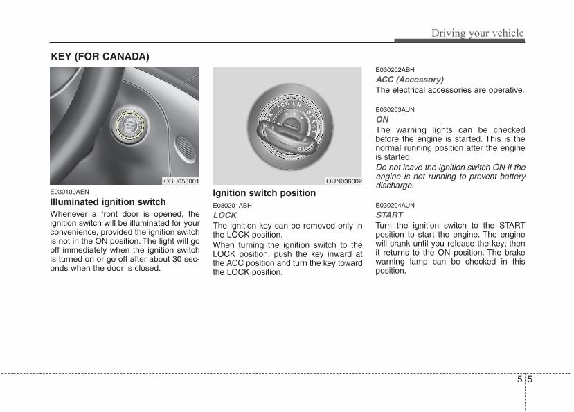
5 5
Driving your vehicle
E030100AEN
Illuminated ignition switch Whenever a front door is opened, theignition switch will be illuminated for yourconvenience, provided the ignition switchis not in the ON position. The light will gooff immediately when the ignition switchis turned on or go off after about 30 sec-onds when the door is closed.
Ignition switch positionE030201ABH
LOCKThe ignition key can be removed only inthe LOCK position.When turning the ignition switch to theLOCK position, push the key inward atthe ACC position and turn the key towardthe LOCK position.
E030202ABH
ACC (Accessory)The electrical accessories are operative.
E030203AUN
ONThe warning lights can be checkedbefore the engine is started. This is thenormal running position after the engineis started.Do not leave the ignition switch ON if theengine is not running to prevent batterydischarge.
E030204AUN
STARTTurn the ignition switch to the STARTposition to start the engine. The enginewill crank until you release the key; thenit returns to the ON position. The brakewarning lamp can be checked in thisposition.
OBH058001 OUN036002
KEY (FOR CANADA)
Driving your vehicle
65
E030205ABH Starting the engineE040000AUN-EU
E040100ABH-EU
1. Make sure the parking brake is applied.2. Place the shift lever in P (Park).
Depress the brake pedal fully.You can also start the engine when theshift lever is in the N (Neutral) position.
3. Turn the ignition switch to START andhold it there until the engine starts (amaximum of 10 seconds), thenrelease the key.
4. In extremely cold weather (below -18°C / 0°F) or after the vehicle hasnot been operated for several days, letthe engine warm up without depress-ing the accelerator.
Whether the engine is cold or warm, itshould be started without depressingthe accelerator.
WARNINGAlways wear appropriate shoes whenoperating your vehicle. Unsuitableshoes (high heels, slippers, skiboots,etc.) may interfere with yourability to use the brake and accelera-tor pedal.
CAUTIONIf the engine stalls while you are inmotion, do not attempt to move theshift lever to the P (Park) position. Iftraffic and road conditions permit,you may put the shift lever in the N(Neutral) position while the vehicleis still moving and turn the ignitionswitch to the START position in anattempt to restart the engine.
CAUTIONDo not engage the starter for morethan 10 seconds. If the engine stallsor fails to start, wait 5 to 10 secondsbefore re-engaging the starter.Improper use of the starter maydamage it.
WARNING - Ignitionswitch
• Never turn the ignition switch toLOCK or ACC while the vehicle ismoving. This would result in lossof directional control and brakingfunction, which could cause anaccident.
• Before leaving the driver’s seat,always make sure the shift lever isengaged in P (Park), set the park-ing brake fully, and shut the engineoff. Unexpected and sudden vehi-cle movement may occur if theseprecautions are not taken.
• Never reach for the ignition switch,or any other controls through thesteering wheel while the vehicle isin motion. The presence of yourhand or arm in this area couldcause a loss of vehicle control, anaccident and serious bodily injuryor death.
• Do not place any movable objectsaround the driver’s seat as theymay move while driving, interferewith the driver and lead to an acci-dent.
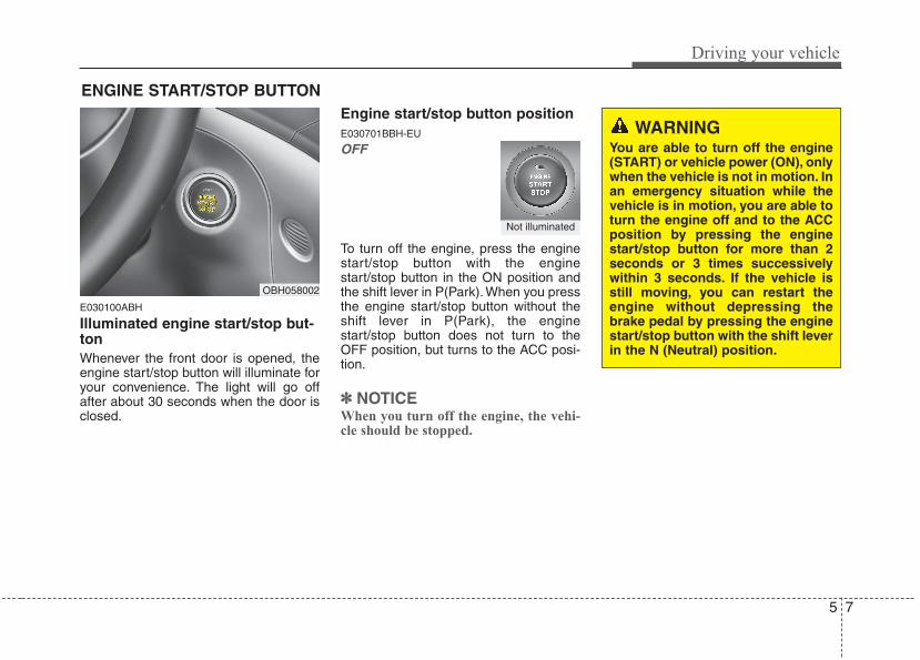
5 7
Driving your vehicle
E030100ABH
Illuminated engine start/stop but-tonWhenever the front door is opened, theengine start/stop button will illuminate foryour convenience. The light will go offafter about 30 seconds when the door isclosed.
Engine start/stop button positionE030701BBH-EU
OFF
To turn off the engine, press the enginestart/stop button with the enginestart/stop button in the ON position andthe shift lever in P(Park). When you pressthe engine start/stop button without theshift lever in P(Park), the enginestart/stop button does not turn to theOFF position, but turns to the ACC posi-tion.
✽✽ NOTICEWhen you turn off the engine, the vehi-cle should be stopped.
ENGINE START/STOP BUTTON
OBH058002
WARNINGYou are able to turn off the engine(START) or vehicle power (ON), onlywhen the vehicle is not in motion. Inan emergency situation while thevehicle is in motion, you are able toturn the engine off and to the ACCposition by pressing the enginestart/stop button for more than 2seconds or 3 times successivelywithin 3 seconds. If the vehicle isstill moving, you can restart theengine without depressing thebrake pedal by pressing the enginestart/stop button with the shift leverin the N (Neutral) position.
Not illuminated
Driving your vehicle
85
E030202ABH-EU
ACC(Accessory)
Press the engine start/stop button whenthe button is in the OFF position withoutdepressing the brake pedal.The electrical accessories are operative.If you leave the engine start/stop button inthe ACC position for more than 1 hour, thebattery power will turn off automatically toprevent the battery from discharging.
E030203AHM
ON
Press the engine start/stop button whenthe button is in the ACC position withoutdepressing the brake pedal.The warning lights can be checkedbefore the engine is started. Do not leavethe ON position if the engine is not run-ning to prevent battery discharge.
E030704ABH
START
To start the engine, press the brakepedal and press the engine start/stopbutton with the shift lever in the P(Park)or the N(Neutral) position.For your safety, start the engine with theshift lever in the P(Park) position.
✽✽ NOTICE• If you press the engine start/stop but-
ton without depressing the brakepedal, the engine does not start andthe engine start/stop button changesas follows :OFF →→ ACC →→ ON →→ OFF
• If you leave the engine start/stop but-ton in the ACC or the ON position fora long time, the battery will be dis-charged.
Orange Blue Not illuminated
5 9
Driving your vehicle
E030205ABH-EU Starting the engineE040000ABH
E040100ABH
1. Carry the smart key or leave it insidethe vehicle.
2. Make sure the parking brake is firmlyapplied.
3. Place the shift lever in the P(Park)position.
4. Depress the brake pedal.5. Press the engine start/stop button.6. In extremely cold weather (below -
18°C / 0°F) or after the vehicle has notbeen operated for several days, let theengine warm up without depressingthe accelerator.Whether the engine is cold or warm, itshould be started without depressingthe accelerator.
WARNINGAlways wear appropriate shoeswhen operating your vehicle.Unsuitable shoes (high heels, slip-pers, ski boots, etc.) may interferewith your ability to use the brakeand accelerator pedal.
CAUTIONIf the engine stalls while you are inmotion, do not attempt to move theshift lever to the P (Park) position. Iftraffic and road conditions permit,you may put the shift lever in the N(Neutral) position while the vehicleis still moving and press the enginestart/stop button in an attempt torestart the engine.
WARNING• Never press the engine start/stop
button while the vehicle is inmotion. This would result in theengine turning off and loss ofpower assist for the steering andbrakes, which may lead to loss ofdirectional control and brakingfunction, which could cause anaccident.
• Before leaving the driver’s seat,always make sure the shift lever isengaged in P (Park), set the park-ing brake fully and shut the engineoff. Unexpected and sudden vehi-cle movement may occur if theseprecautions are not taken.
• Never reach for the enginestart/stop button, or any other con-trols through the steering wheelwhile the vehicle is in motion. Thepresence of your hand or arm inthis area could cause a loss ofvehicle control, an accident andserious bodily injury or death.
• Do not place any movable objectsaround the driver’s seat as theymay move while driving, interferewith the driver and lead to an acci-dent.
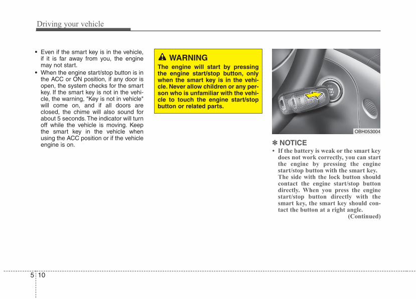
Driving your vehicle
105
• Even if the smart key is in the vehicle,if it is far away from you, the enginemay not start.
• When the engine start/stop button is inthe ACC or ON position, if any door isopen, the system checks for the smartkey. If the smart key is not in the vehi-cle, the warning, "Key is not in vehicle"will come on, and if all doors areclosed, the chime will also sound forabout 5 seconds. The indicator will turnoff while the vehicle is moving. Keepthe smart key in the vehicle whenusing the ACC position or if the vehicleengine is on.
OBH053004
WARNINGThe engine will start by pressingthe engine start/stop button, onlywhen the smart key is in the vehi-cle. Never allow children or any per-son who is unfamiliar with the vehi-cle to touch the engine start/stopbutton or related parts.
✽✽ NOTICE• If the battery is weak or the smart key
does not work correctly, you can startthe engine by pressing the enginestart/stop button with the smart key.The side with the lock button shouldcontact the engine start/stop buttondirectly. When you press the enginestart/stop button directly with thesmart key, the smart key should con-tact the button at a right angle.
(Continued)
5 11
Driving your vehicle
(Continued)• When the stop lamp fuse is blown, you
can't start the engine normally.Replace the fuse with a new one. Ifyou are not able to replace the fuse,you can start the engine by pressingthe engine start/stop button for 10 sec-onds with the engine start/stop buttonin ACC. The engine can start withoutdepressing the brake pedal. But foryour safety always depress the brakepedal before starting the engine.
CAUTIONDo not press the engine start/stopbutton for more than 10 secondsexcept when the stop lamp fuse isdisconnected.
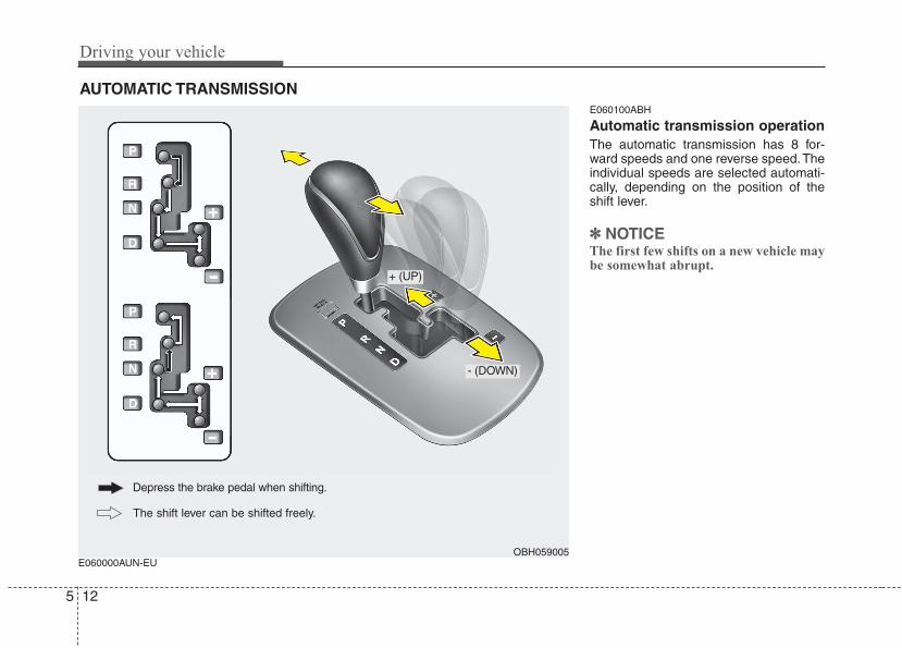
Driving your vehicle
125
E060000AUN-EU
E060100ABH
Automatic transmission operationThe automatic transmission has 8 for-ward speeds and one reverse speed.Theindividual speeds are selected automati-cally, depending on the position of theshift lever.
✽✽ NOTICEThe first few shifts on a new vehicle maybe somewhat abrupt.
AUTOMATIC TRANSMISSION
OBH059005
+ (UP)
- (DOWN)
Depress the brake pedal when shifting.
The shift lever can be shifted freely.
5 13
Driving your vehicle
Always depress the brake pedal whenshifting from N (Neutral) to a forward orreverse gear.
E060101ABH
Transmission rangesThe indicator in the instrument clusterdisplays the shift lever position when theignition switch is in the ON position.
P (Park)
Always come to a complete stop beforeshifting into P (Park). This position locksthe transmission and prevents the drivewheels from rotating.
WARNING - Automatictransmission
• Always check the surroundingareas near your vehicle for peo-ple, especially children, beforeshifting a car into D (Drive) or R(Reverse).
• Before leaving the driver’s seat,always make sure the shift leveris in the P (Park) position; thenset the parking brake fully andshut the engine off. Unexpectedand sudden vehicle movementcan occur if these precautionsare not followed in the order iden-tified.
CAUTION• To avoid damage to your trans-
mission, do not accelerate theengine in R (Reverse) or any for-ward gear position with thebrakes on.
• When stopped on an incline, donot hold the vehicle stationarywith engine power. Use the serv-ice brake or the parking brake.
• Do not shift from N (Neutral) or P(Park) into D (Drive), or R(Reverse) when the engine isabove idle speed.
WARNING• Shifting into P (Park) while the
vehicle is in motion will cause thedrive wheels to lock which willcause you to lose control of thevehicle.
• Do not use the P (Park) positionin place of the parking brake.Always make sure the shift leveris latched in the P (Park) positionand set the parking brake fully.
• Never leave a child unattended ina vehicle.
CAUTIONThe transmission may be damagedif you shift into P (Park) while thevehicle is in motion.
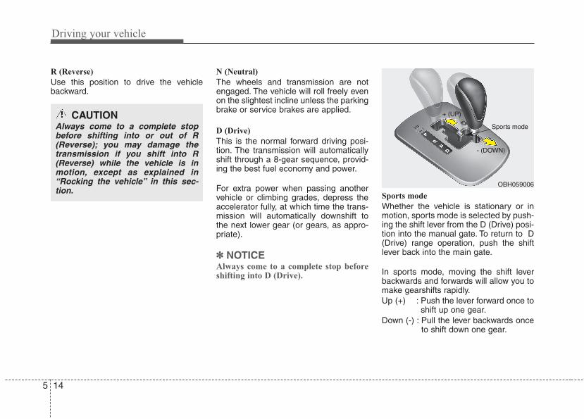
Driving your vehicle
145
R (Reverse)
Use this position to drive the vehiclebackward.
N (Neutral)
The wheels and transmission are notengaged. The vehicle will roll freely evenon the slightest incline unless the parkingbrake or service brakes are applied.
D (Drive)
This is the normal forward driving posi-tion. The transmission will automaticallyshift through a 8-gear sequence, provid-ing the best fuel economy and power.
For extra power when passing anothervehicle or climbing grades, depress theaccelerator fully, at which time the trans-mission will automatically downshift tothe next lower gear (or gears, as appro-priate).
✽✽ NOTICEAlways come to a complete stop beforeshifting into D (Drive).
Sports mode
Whether the vehicle is stationary or inmotion, sports mode is selected by push-ing the shift lever from the D (Drive) posi-tion into the manual gate. To return to D(Drive) range operation, push the shiftlever back into the main gate.
In sports mode, moving the shift leverbackwards and forwards will allow you tomake gearshifts rapidly.Up (+) : Push the lever forward once to
shift up one gear.Down (-) : Pull the lever backwards once
to shift down one gear.
CAUTIONAlways come to a complete stopbefore shifting into or out of R(Reverse); you may damage thetransmission if you shift into R(Reverse) while the vehicle is inmotion, except as explained in“Rocking the vehicle” in this sec-tion.
OBH059006
+ (UP)
- (DOWN)
Sports mode
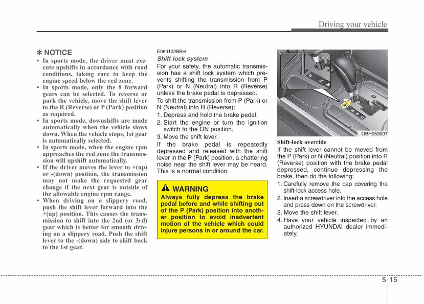
5 15
Driving your vehicle
✽✽ NOTICE• In sports mode, the driver must exe-
cute upshifts in accordance with roadconditions, taking care to keep theengine speed below the red zone.
• In sports mode, only the 8 forwardgears can be selected. To reverse orpark the vehicle, move the shift leverto the R (Reverse) or P (Park) positionas required.
• In sports mode, downshifts are madeautomatically when the vehicle slowsdown. When the vehicle stops, 1st gearis automatically selected.
• In sports mode, when the engine rpmapproaches the red zone the transmis-sion will upshift automatically.
• If the driver moves the lever to +(up)or -(down) position, the transmissionmay not make the requested gearchange if the next gear is outside ofthe allowable engine rpm range.
• When driving on a slippery road,push the shift lever forward into the+(up) position. This causes the trans-mission to shift into the 2nd (or 3rd)gear which is better for smooth driv-ing on a slippery road. Push the shiftlever to the -(down) side to shift backto the 1st gear.
E060102BBH
Shift lock system For your safety, the automatic transmis-sion has a shift lock system which pre-vents shifting the transmission from P(Park) or N (Neutral) into R (Reverse)unless the brake pedal is depressed.To shift the transmission from P (Park) orN (Neutral) into R (Reverse):1. Depress and hold the brake pedal.2. Start the engine or turn the ignition
switch to the ON position.3. Move the shift lever.If the brake pedal is repeatedlydepressed and released with the shiftlever in the P (Park) position, a chatteringnoise near the shift lever may be heard.This is a normal condition.
Shift-lock override
If the shift lever cannot be moved fromthe P (Park) or N (Neutral) position into R(Reverse) position with the brake pedaldepressed, continue depressing thebrake, then do the following:1. Carefully remove the cap covering the
shift-lock access hole.2. Insert a screwdriver into the access hole
and press down on the screwdriver.3. Move the shift lever.4. Have your vehicle inspected by an
authorized HYUNDAI dealer immedi-ately.
WARNINGAlways fully depress the brakepedal before and while shifting outof the P (Park) position into anoth-er position to avoid inadvertentmotion of the vehicle which couldinjure persons in or around the car.
OBH053007
Driving your vehicle
165
Ignition key interlock system The ignition key cannot be removedunless the shift lever is in the P (Park)position. Even if the ignition switch is inthe LOCK position, the key also cannotbe removed.If your vehicle is equipped with enginestart/stop button, the button will notchange to the OFF position unless theshift lever is in the P (Park) position.
E060200AEN
Good driving practices• Never move the gear shift lever from P
(Park) or N (Neutral) to any other posi-tion with the accelerator pedaldepressed.
• Never move the gear shift lever into P(Park) when the vehicle is in motion.
• Be sure the car is completely stoppedbefore you attempt to shift into R(Reverse) or D (Drive).
• Never take the car out of gear andcoast down a hill. This may beextremely hazardous. Always leave thecar in gear when moving.
• Do not "ride" the brakes. This cancause them to overheat and malfunc-tion. Instead, when you are drivingdown a long hill, slow down, shift intoSports Mode and shift to a lower gear.When you do this, engine braking willhelp slow the car.
• Slow down before shifting to a lowergear. Otherwise, the lower gear maynot be engaged.
• Always use the parking brake. Do notdepend on placing the transmission inP (Park) to keep the car from moving.
• Exercise extreme caution when drivingon a slippery surface. Be especiallycareful when braking, accelerating orshifting gears. On a slippery surface,an abrupt change in vehicle speed cancause the drive wheels to lose tractionand the vehicle to go out of control.
• Optimum vehicle performance andeconomy is obtained by smoothlydepressing and releasing the accelera-tor pedal.
5 17
Driving your vehicle
E060203AUN
Moving up a steep grade from a stand-ing startTo move up a steep grade from a stand-ing start, depress the brake pedal, shiftthe shift lever to D (Drive) and releasethe parking brake. Depress the accelera-tor gradually while releasing the servicebrakes.When accelerating from a stop on asteep hill, the vehicle may have a ten-dency to roll backwards. Shifting theshift lever into 2 (Second Gear) willhelp prevent the vehicle from rollingbackwards.
WARNING• Always buckle-up! In a collision,
an unbelted occupant is signifi-cantly more likely to be seriouslyinjured or killed than a properlybelted occupant.
• Avoid high speeds when corner-ing or turning.
• Do not make quick steeringwheel movements, such as sharplane changes or fast, sharp turns.
• The risk of rollover is greatlyincreased if you lose control ofyour vehicle at highway speeds.
• Loss of control often occurs iftwo or more wheels drop off theroadway and the driver over-steers to reenter the roadway.
• In the event your vehicle leavesthe roadway, do not steer sharply.Instead, slow down before pullingback into the travel lanes.
• Never exceed posted speed lim-its.
WARNINGIf your vehicle becomes stuck insnow, mud, sand, etc., then youmay attempt to rock the vehicle freeby moving it forward and backward.Do not attempt this procedure ifpeople or objects are anywherenear the vehicle. During the rockingoperation the vehicle may suddenlymove forward or backward as itbecomes unstuck, causing injuryor damage to nearby people orobjects.
Driving your vehicle
185
E070100ABH
Power brakes Your vehicle has power-assisted brakesthat adjust automatically through normalusage.In the event that the power-assistedbrakes lose power because of a stalledengine or some other reason, you canstill stop your vehicle by applying greaterforce to the brake pedal than you nor-mally would. The stopping distance, how-ever, will be longer.When the engine is not running, thereserve brake power is partially depletedeach time the brake pedal is applied. Donot pump the brake pedal when thepower assist has been interrupted.Pump the brake pedal only when neces-sary to maintain steering control on slip-pery surfaces.
E070101AUN
In the event of brake failure If service brakes fail to operate while thevehicle is in motion, you can make anemergency stop with the parking brake.The stopping distance, however, will bemuch greater than normal.
BRAKE SYSTEM
WARNING - Brakes• Do not drive with your foot rest-
ing on the brake pedal. This willcreate abnormal high brake tem-peratures, excessive brake liningand pad wear, and increasedstopping distances.
(Continued)
(Continued)• When descending a long or steep
hill, shift to a lower gear andavoid continuous application ofthe brakes. Continuous brakeapplication will cause the brakesto overheat and could result in atemporary loss of braking per-formance.
• Wet brakes may impair the vehi-cle’s ability to safely slow down;the vehicle may also pull to oneside when the brakes are applied.Applying the brakes lightly willindicate whether they have beenaffected in this way. Always testyour brakes in this fashion afterdriving through deep water. Todry the brakes, apply them lightlywhile maintaining a safe forwardspeed until brake performancereturns to normal.
• Always confirm the position ofthe brake and accelerator pedalbefore driving. If you do notcheck the position of the acceler-ator and brake pedal before driv-ing, you may depress the acceler-ator instead of the brake pedal. Itmay cause a serious accident.
WARNING - Parking brakeApplying the parking brake whilethe vehicle is moving at normalspeeds can cause a sudden loss ofcontrol of the vehicle. If you mustuse the parking brake to stop thevehicle, use great caution in apply-ing the brake.
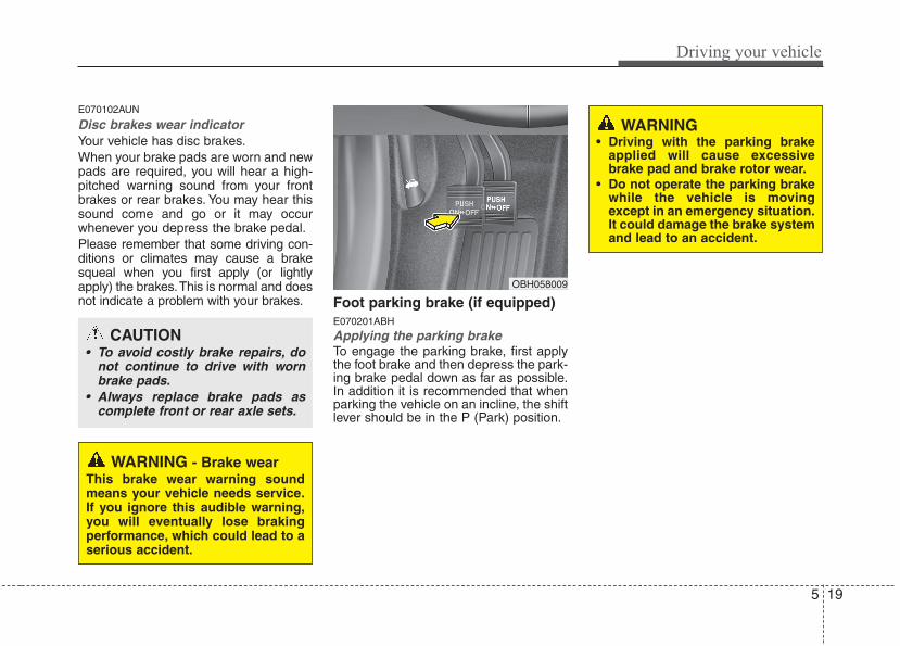
5 19
Driving your vehicle
E070102AUN
Disc brakes wear indicator Your vehicle has disc brakes.When your brake pads are worn and newpads are required, you will hear a high-pitched warning sound from your frontbrakes or rear brakes. You may hear thissound come and go or it may occurwhenever you depress the brake pedal.Please remember that some driving con-ditions or climates may cause a brakesqueal when you first apply (or lightlyapply) the brakes.This is normal and doesnot indicate a problem with your brakes. Foot parking brake (if equipped)
E070201ABH
Applying the parking brakeTo engage the parking brake, first applythe foot brake and then depress the park-ing brake pedal down as far as possible.In addition it is recommended that whenparking the vehicle on an incline, the shiftlever should be in the P (Park) position.
WARNING - Brake wearThis brake wear warning soundmeans your vehicle needs service.If you ignore this audible warning,you will eventually lose brakingperformance, which could lead to aserious accident.
CAUTION• To avoid costly brake repairs, do
not continue to drive with wornbrake pads.
• Always replace brake pads ascomplete front or rear axle sets.
OBH058009
WARNING• Driving with the parking brake
applied will cause excessivebrake pad and brake rotor wear.
• Do not operate the parking brakewhile the vehicle is movingexcept in an emergency situation.It could damage the brake systemand lead to an accident.
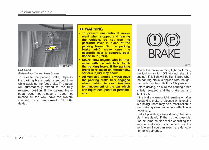
Driving your vehicle
205
E070202ABH
Releasing the parking brakeTo release the parking brake, depressthe parking brake pedal a second timewhile applying the foot brake. The pedalwill automatically extend to the fullyreleased position. If the parking brakepedal does not release or does notrelease all the way, have the systemchecked by an authorized HYUNDAIdealer.
Check the brake warning light by turningthe ignition switch ON (do not start theengine). This light will be illuminated whenthe parking brake is applied with the igni-tion switch in the START or ON position.Before driving, be sure the parking brakeis fully released and the brake warninglight is off.If the brake warning light remains on afterthe parking brake is released while engineis running, there may be a malfunction inthe brake system. Immediate attention isnecessary.If at all possible, cease driving the vehi-cle immediately. If that is not possible,use extreme caution while operating thevehicle and only continue to drive thevehicle until you can reach a safe loca-tion or repair shop.
WARNING• To prevent unintentional move-
ment when stopped and leavingthe vehicle, do not use thegearshift lever in place of theparking brake. Set the parkingbrake AND make sure thegearshift lever is securely posi-tioned in P (Park).
• Never allow anyone who is unfa-miliar with the vehicle to touchthe parking brake. If the parkingbrake is released unintentionally,serious injury may occur.
• All vehicles should always havethe parking brake fully engagedwhen parking to avoid inadver-tent movement of the car whichcan injure occupants or pedestri-ans.
W-75OBH058011
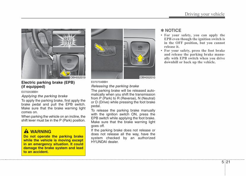
5 21
Driving your vehicle
Electric parking brake (EPB) (if equipped)E070203BBH
Applying the parking brakeTo apply the parking brake, first apply thebrake pedal and pull the EPB switch.Make sure that the brake warning lightcomes on.When parking the vehicle on an incline, theshift lever must be in the P (Park) position.
E070704BBH
Releasing the parking brakeThe parking brake will be released auto-matically when you shift the transmissionfrom P (Park) to R (Reverse), N (Neutral)or D (Drive) while pressing the foot brakepedal.To release the parking brake manuallywith the ignition switch ON, press theEPB switch while applying the foot brake.Make sure that the brake warning lightgoes off.If the parking brake does not release ordoes not release all the way, have thesystem checked by an authorizedHYUNDAI dealer.
✽✽ NOTICE• For your safety, you can apply the
EPB even though the ignition switch isin the OFF position, but you cannotrelease it.
• For your safety, press the foot brakeand release the parking brake manu-ally with EPB switch when you drivedownhill or back up the vehicle.
WARNINGDo not operate the parking brakewhile the vehicle is moving exceptin an emergency situation. It coulddamage the brake system and leadto an accident.
OBH052010OBH052019
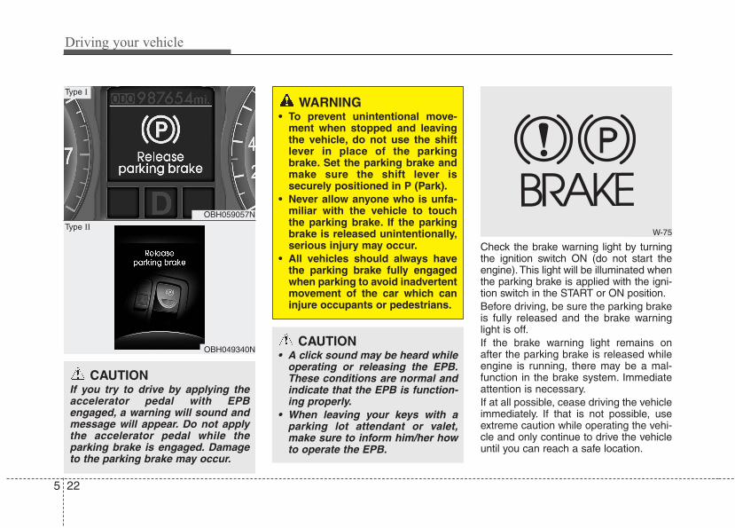
Driving your vehicle
225
Check the brake warning light by turningthe ignition switch ON (do not start theengine). This light will be illuminated whenthe parking brake is applied with the igni-tion switch in the START or ON position.Before driving, be sure the parking brakeis fully released and the brake warninglight is off.If the brake warning light remains onafter the parking brake is released whileengine is running, there may be a mal-function in the brake system. Immediateattention is necessary.If at all possible, cease driving the vehicleimmediately. If that is not possible, useextreme caution while operating the vehi-cle and only continue to drive the vehicleuntil you can reach a safe location.
WARNING• To prevent unintentional move-
ment when stopped and leavingthe vehicle, do not use the shiftlever in place of the parkingbrake. Set the parking brake andmake sure the shift lever issecurely positioned in P (Park).
• Never allow anyone who is unfa-miliar with the vehicle to touchthe parking brake. If the parkingbrake is released unintentionally,serious injury may occur.
• All vehicles should always havethe parking brake fully engagedwhen parking to avoid inadvertentmovement of the car which caninjure occupants or pedestrians.
W-75
CAUTION• A click sound may be heard while
operating or releasing the EPB.These conditions are normal andindicate that the EPB is function-ing properly.
• When leaving your keys with aparking lot attendant or valet,make sure to inform him/her howto operate the EPB.
OBH059057N
OBH049340N
Type I
Type II
CAUTIONIf you try to drive by applying theaccelerator pedal with EPBengaged, a warning will sound andmessage will appear. Do not applythe accelerator pedal while theparking brake is engaged. Damageto the parking brake may occur.
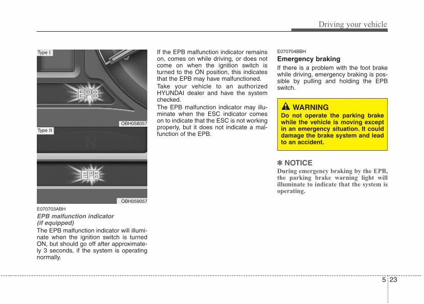
5 23
Driving your vehicle
E070703ABH
EPB malfunction indicator (if equipped)The EPB malfunction indicator will illumi-nate when the ignition switch is turnedON, but should go off after approximate-ly 3 seconds, if the system is operatingnormally.
If the EPB malfunction indicator remainson, comes on while driving, or does notcome on when the ignition switch isturned to the ON position, this indicatesthat the EPB may have malfunctioned.Take your vehicle to an authorizedHYUNDAI dealer and have the systemchecked.The EPB malfunction indicator may illu-minate when the ESC indicator comeson to indicate that the ESC is not workingproperly, but it does not indicate a mal-function of the EPB.
E070704BBH
Emergency brakingIf there is a problem with the foot brakewhile driving, emergency braking is pos-sible by pulling and holding the EPBswitch.
✽✽ NOTICEDuring emergency braking by the EPB,the parking brake warning light willilluminate to indicate that the system isoperating.
WARNINGDo not operate the parking brakewhile the vehicle is moving exceptin an emergency situation. It coulddamage the brake system and leadto an accident.
OBH058057
OBH059057
Type I
Type II
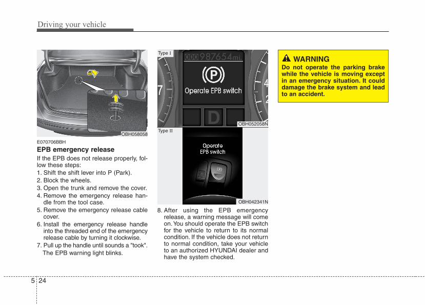
Driving your vehicle
245
E070706BBH
EPB emergency releaseIf the EPB does not release properly, fol-low these steps:1. Shift the shift lever into P (Park).2. Block the wheels.3. Open the trunk and remove the cover.4. Remove the emergency release han-
dle from the tool case.5. Remove the emergency release cable
cover.6. Install the emergency release handle
into the threaded end of the emergencyrelease cable by turning it clockwise.
7. Pull up the handle until sounds a "took".The EPB warning light blinks.
8. After using the EPB emergencyrelease, a warning message will comeon.You should operate the EPB switchfor the vehicle to return to its normalcondition. If the vehicle does not returnto normal condition, take your vehicleto an authorized HYUNDAI dealer andhave the system checked.
OBH058058
OBH052058N
OBH042341N
Type I
Type II
WARNINGDo not operate the parking brakewhile the vehicle is moving exceptin an emergency situation. It coulddamage the brake system and leadto an accident.
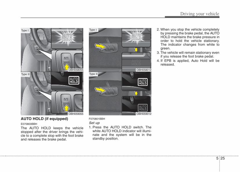
5 25
Driving your vehicle
AUTO HOLD (if equipped)E070800BBH
The AUTO HOLD keeps the vehiclestopped after the driver brings the vehi-cle to a complete stop with the foot brakeand releases the brake pedal.
F070801BBH
Set up1. Press the AUTO HOLD switch. The
white AUTO HOLD indicator will illumi-nate and the system will be in thestandby position.
2. When you stop the vehicle completelyby pressing the brake pedal, the AUTOHOLD maintains the brake pressure inorder to hold the vehicle stationary.The indicator changes from white togreen.
3. The vehicle will remain stationary evenif you release the foot brake pedal.
4. If EPB is applied, Auto Hold will bereleased.
OBH058055
OBH059055
Type I
Type II
OBH058012
OBH059012
Type I
Type II
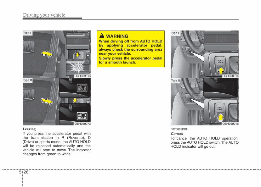
Driving your vehicle
265
Leaving
If you press the accelerator pedal withthe transmission in R (Reverse), D(Drive) or sports mode, the AUTO HOLDwill be released automatically and thevehicle will start to move. The indicatorchanges from green to white.
F070802BBH
CancelTo cancel the AUTO HOLD operation,press the AUTO HOLD switch.The AUTOHOLD indicator will go out.
WARNINGWhen driving off from AUTO HOLDby applying accelerator pedal,always check the surrounding areanear your vehicle.Slowly press the accelerator pedalfor a smooth launch.
OBH059013
OBH059073
Type I
Type IIOBH058014
OBH059016
Type I
Type II
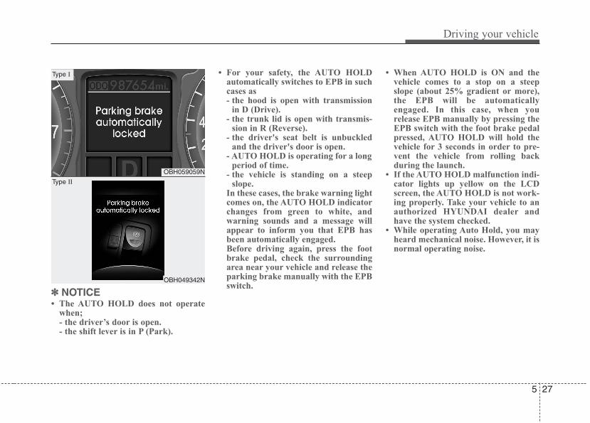
5 27
Driving your vehicle
✽✽ NOTICE• The AUTO HOLD does not operate
when;- the driver’s door is open.- the shift lever is in P (Park).
• For your safety, the AUTO HOLDautomatically switches to EPB in suchcases as- the hood is open with transmission
in D (Drive).- the trunk lid is open with transmis-
sion in R (Reverse).- the driver's seat belt is unbuckled
and the driver's door is open.- AUTO HOLD is operating for a long
period of time.- the vehicle is standing on a steep
slope.In these cases, the brake warning lightcomes on, the AUTO HOLD indicatorchanges from green to white, andwarning sounds and a message willappear to inform you that EPB hasbeen automatically engaged.Before driving again, press the footbrake pedal, check the surroundingarea near your vehicle and release theparking brake manually with the EPBswitch.
• When AUTO HOLD is ON and thevehicle comes to a stop on a steepslope (about 25% gradient or more),the EPB will be automaticallyengaged. In this case, when yourelease EPB manually by pressing theEPB switch with the foot brake pedalpressed, AUTO HOLD will hold thevehicle for 3 seconds in order to pre-vent the vehicle from rolling backduring the launch.
• If the AUTO HOLD malfunction indi-cator lights up yellow on the LCDscreen, the AUTO HOLD is not work-ing properly. Take your vehicle to anauthorized HYUNDAI dealer andhave the system checked.
• While operating Auto Hold, you mayheard mechanical noise. However, it isnormal operating noise.
OBH059059N
OBH049342N
Type I
Type II
Driving your vehicle
285
E070300AEN-EE
Anti-lock brake system (ABS)
WARNINGABS (or ESC) will not prevent acci-dents due to improper or danger-ous driving maneuvers. Eventhough vehicle control is improvedduring emergency braking, alwaysmaintain a safe distance betweenyou and objects ahead. Vehiclespeeds should always be reducedduring extreme road conditions.The braking distance for carsequipped with an anti-lock brakingsystem (or Electronic StabilityControl system) may be longer thanfor those without it in the followingroad conditions.During these conditions the vehicleshould be driven at reducedspeeds:• Rough, gravel or snow-covered
roads.• With tire chains installed.
(Continued)
WARNING• Press the accelerator pedal slow-
ly when you start the vehicle.• For your safety, cancel the AUTO
HOLD when you drive downhill orback up the vehicle or park thevehicle.
CAUTIONIf there is a malfunction with the dri-ver’s door, hood or trunk opendetection system, the AUTO HOLDmay not work properly.Take your vehicle to an authorizedHYUNDAI dealer and have the sys-tem checked.
(Continued)• On roads where the road surface
is pitted or has different surfaceheight.
The safety features of an ABS (orESC) equipped vehicle should notbe tested by high speed driving orcornering. This could endanger thesafety of yourself or others.
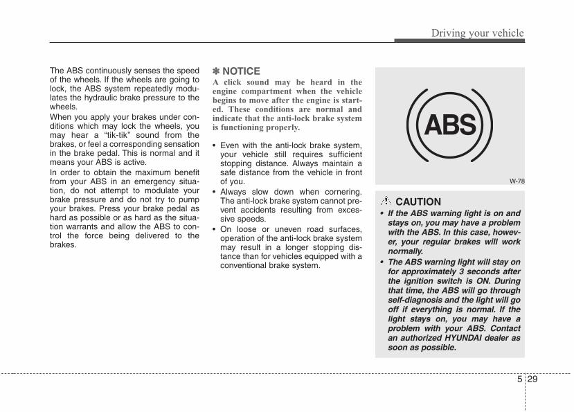
5 29
Driving your vehicle
The ABS continuously senses the speedof the wheels. If the wheels are going tolock, the ABS system repeatedly modu-lates the hydraulic brake pressure to thewheels.When you apply your brakes under con-ditions which may lock the wheels, youmay hear a “tik-tik’’ sound from thebrakes, or feel a corresponding sensationin the brake pedal. This is normal and itmeans your ABS is active.In order to obtain the maximum benefitfrom your ABS in an emergency situa-tion, do not attempt to modulate yourbrake pressure and do not try to pumpyour brakes. Press your brake pedal ashard as possible or as hard as the situa-tion warrants and allow the ABS to con-trol the force being delivered to thebrakes.
✽✽ NOTICEA click sound may be heard in theengine compartment when the vehiclebegins to move after the engine is start-ed. These conditions are normal andindicate that the anti-lock brake systemis functioning properly.
• Even with the anti-lock brake system,your vehicle still requires sufficientstopping distance. Always maintain asafe distance from the vehicle in frontof you.
• Always slow down when cornering.The anti-lock brake system cannot pre-vent accidents resulting from exces-sive speeds.
• On loose or uneven road surfaces,operation of the anti-lock brake systemmay result in a longer stopping dis-tance than for vehicles equipped with aconventional brake system.
W-78
CAUTION• If the ABS warning light is on and
stays on, you may have a problemwith the ABS. In this case, howev-er, your regular brakes will worknormally.
• The ABS warning light will stay onfor approximately 3 seconds afterthe ignition switch is ON. Duringthat time, the ABS will go throughself-diagnosis and the light will gooff if everything is normal. If thelight stays on, you may have aproblem with your ABS. Contactan authorized HYUNDAI dealer assoon as possible.
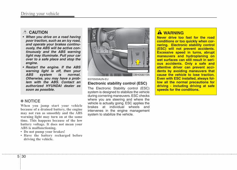
Driving your vehicle
305
✽✽ NOTICEWhen you jump start your vehiclebecause of a drained battery, the enginemay not run as smoothly and the ABSwarning light may turn on at the sametime. This happens because of the lowbattery voltage. It does not mean yourABS is malfunctioning.• Do not pump your brakes!• Have the battery recharged before
driving the vehicle.
E070500AUN-EU
Electronic stability control (ESC)The Electronic Stability control (ESC)system is designed to stabilize the vehicleduring cornering maneuvers. ESC checkswhere you are steering and where thevehicle is actually going. ESC applies thebrakes at individual wheels andintervenes in the engine managementsystem to stabilize the vehicle.
OBH058015N
WARNINGNever drive too fast for the roadconditions or too quickly when cor-nering. Electronic stability control(ESC) will not prevent accidents.Excessive speed in turns, abruptmaneuvers and hydroplaning onwet surfaces can still result in seri-ous accidents. Only a safe andattentive driver can prevent acci-dents by avoiding maneuvers thatcause the vehicle to lose traction.Even with ESC installed, always fol-low all the normal precautions fordriving - including driving at safespeeds for the conditions.
CAUTION• When you drive on a road having
poor traction, such as an icy road,and operate your brakes continu-ously, the ABS will be active con-tinuously and the ABS warninglight may illuminate. Pull your carover to a safe place and stop theengine.
• Restart the engine. If the ABSwarning light is off, then yourABS system is normal.Otherwise, you may have a prob-lem with the ABS. Contact anauthorized HYUNDAI dealer assoon as possible.
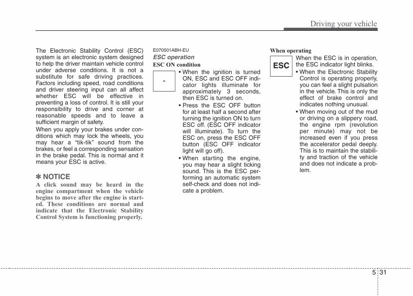
5 31
Driving your vehicle
The Electronic Stability Control (ESC)system is an electronic system designedto help the driver maintain vehicle controlunder adverse conditions. It is not asubstitute for safe driving practices.Factors including speed, road conditionsand driver steering input can all affectwhether ESC will be effective inpreventing a loss of control. It is still yourresponsibility to drive and corner atreasonable speeds and to leave asufficient margin of safety.When you apply your brakes under con-ditions which may lock the wheels, youmay hear a “tik-tik’’ sound from thebrakes, or feel a corresponding sensationin the brake pedal. This is normal and itmeans your ESC is active.
✽✽ NOTICEA click sound may be heard in theengine compartment when the vehiclebegins to move after the engine is start-ed. These conditions are normal andindicate that the Electronic StabilityControl System is functioning properly.
E070501ABH-EU
ESC operationESC ON condition
• When the ignition is turnedON, ESC and ESC OFF indi-cator lights illuminate forapproximately 3 seconds,then ESC is turned on.
• Press the ESC OFF buttonfor at least half a second afterturning the ignition ON to turnESC off. (ESC OFF indicatorwill illuminate). To turn theESC on, press the ESC OFFbutton (ESC OFF indicatorlight will go off).
• When starting the engine,you may hear a slight tickingsound. This is the ESC per-forming an automatic systemself-check and does not indi-cate a problem.
When operating
When the ESC is in operation,the ESC indicator light blinks.• When the Electronic Stability
Control is operating properly,you can feel a slight pulsationin the vehicle. This is only theeffect of brake control andindicates nothing unusual.
• When moving out of the mudor driving on a slippery road,the engine rpm (revolutionper minute) may not beincreased even if you pressthe accelerator pedal deeply.This is to maintain the stabili-ty and traction of the vehicleand does not indicate a prob-lem.
-
ESC
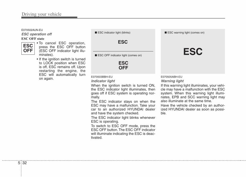
Driving your vehicle
325
E070502AUN-EU
ESC operation offESC OFF state
• To cancel ESC operation,press the ESC OFF button(ESC OFF indicator light illu-minates).
• If the ignition switch is turnedto LOCK position when ESCis off, ESC remains off. Uponrestarting the engine, theESC will automatically turnon again. E070503BBH-EU
Indicator lightWhen the ignition switch is turned ON,the ESC indicator light illuminates, thengoes off if ESC system is operating nor-mally.The ESC indicator stays on when theESC may have a malfunction. Take yourcar to an authorized HYUNDAI dealerand have the system checked.The ESC indicator light blinks wheneverESC is operating.To switch to ESC OFF mode, press theESC OFF button. The ESC OFF indicatorwill illuminate indicating the ESC is deac-tivated.
E070505ABH-EU
Warning lightIf this warning light illuminates, your vehi-cle may have a malfunction with the ESCsystem. When this warning light illumi-nates, EPB and SCC warning light mayalso illuminate at the same time.Have the vehicle checked by an author-ized HYUNDAI dealer as soon as possi-ble.
ESCOFF
ESC
ESCOFF
■ ESC indicator light (blinks)
■ ESC OFF indicator light (comes on) ESC
■ ESC warning light (comes on)
5 33
Driving your vehicle
E070504ABH-EU
ESC OFF usageWhen driving
• ESC should be turned on for daily driv-ing whenever possible.
• To turn ESC off while driving, press theESC OFF button while driving on a flatroad surface.
Never press the ESC OFF button whileESC is operating (ESC indicator lightblinks).If ESC is turned off while ESC is operat-ing, the vehicle may slip out of control.
✽✽ NOTICE• When operating the vehicle on a
dynamometer, ensure that the ESC isturned off (ESC OFF light illuminat-ed).
• Turning the ESC off does not affectABS or brake system operation.
CAUTIONDriving with varying tire or wheelsizes may cause the ESC system tomalfunction. When replacing tires,make sure they are the same size asyour original tires.Never operate the vehicle with dif-ferent diameter tires installed at thesame time.
WARNINGThe Electronic Stability Control sys-tem is only a driving aid; use pre-cautions for safe driving by slowingdown on curved, snowy, or icyroads. Drive slowly and don’tattempt to accelerate whenever theESC indicator light is blinking, orwhen the road surface is slippery.
WARNINGNever press the ESC OFF buttonwhile ESC is operating.If the ESC is turned off while ESC isoperating, the vehicle may go out ofcontrol.To turn ESC off while driving, pressthe ESC OFF button while drivingon a flat road surface.
Driving your vehicle
345
E070600BFD
Good braking practices• After parking the vehicle, check to be
sure the parking brake is not engagedand that the parking brake indicatorlight is out before driving away.
• Driving through water may get thebrakes wet. They can also get wetwhen the car is washed. Wet brakescan be dangerous! Your car will notstop as quickly if the brakes are wet.Wet brakes may cause the car to pullto one side.To dry the brakes, apply the brakeslightly until the braking action returns tonormal, taking care to keep the carunder control at all times. If the brakingaction does not return to normal, stopas soon as it is safe to do so and callan authorized HYUNDAI dealer forassistance.
• Do not coast down hills with the car outof gear. This is extremely hazardous.Keep the car in gear at all times, usethe brakes to slow down, then shift to alower gear so that engine braking willhelp you maintain a safe speed.
• Do not "ride" the brake pedal. Restingyour foot on the brake pedal while driv-ing can be dangerous because it canresult in the brakes overheating andlosing their effectiveness. It alsoincreases the wear of the brake com-ponents.
• If a tire goes flat while you are driving,apply the brakes gently and keep thecar pointed straight ahead while youslow down. When you are movingslowly enough for it to be safe to do so,pull off the road and stop in a safeplace.
• If your car is equipped with an auto-matic transmission, do not let your carcreep forward. To avoid creeping for-ward, keep your foot firmly on thebrake pedal when the car is stopped.
WARNING• Whenever leaving vehicle or
parking, always set the parkingbrake as far as possible and fullyengage the vehicle's transmis-sion into the park position.Vehicles not fully engaged in parkwith the parking brake set are atrisk for moving inadvertently andinjuring yourself or others.
• All vehicles should always havethe parking brake fully engagedwhen parking to avoid inadver-tent movement of the car whichcan injure occupants or pedestri-ans.
5 35
Driving your vehicle
• Be careful when parking on a hill.Firmly engage the parking brake andplace the gear selector lever in P. Ifyour car is facing downhill, turn thefront wheels into the curb to help keepthe car from rolling. If your car is facinguphill, turn the front wheels away fromthe curb to help keep the car fromrolling. If there is no curb or if it isrequired by other conditions to keepthe car from rolling, block the wheels.
• Under some conditions your parkingbrake can freeze in the engaged posi-tion. This is most likely to happen whenthere is an accumulation of snow or icearound or near the rear brakes or if thebrakes are wet. If there is a risk that theparking brake may freeze, apply it onlytemporarily while you put the gearselector lever in P (automatic transmis-sion) and block the rear wheels so thecar cannot roll. Then release the park-ing brake.
• Do not hold the vehicle on an inclinewith the accelerator pedal. This cancause the transmission to overheat.Always use the brake pedal or parkingbrake.
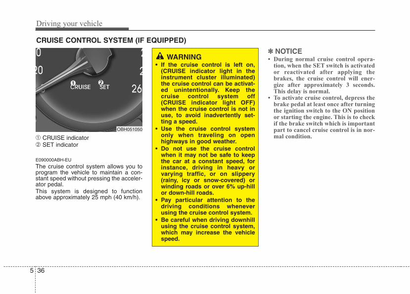
Driving your vehicle
365
➀ CRUISE indicator➁ SET indicator
E090000ABH-EU
The cruise control system allows you toprogram the vehicle to maintain a con-stant speed without pressing the acceler-ator pedal.This system is designed to functionabove approximately 25 mph (40 km/h).
✽✽ NOTICE• During normal cruise control opera-
tion, when the SET switch is activatedor reactivated after applying thebrakes, the cruise control will ener-gize after approximately 3 seconds.This delay is normal.
• To activate cruise control, depress thebrake pedal at least once after turningthe ignition switch to the ON positionor starting the engine. This is to checkif the brake switch which is importantpart to cancel cruise control is in nor-mal condition.
CRUISE CONTROL SYSTEM (IF EQUIPPED)
WARNING• If the cruise control is left on,
(CRUISE indicator light in theinstrument cluster illuminated)the cruise control can be activat-ed unintentionally. Keep thecruise control system off(CRUISE indicator light OFF)when the cruise control is not inuse, to avoid inadvertently set-ting a speed.
• Use the cruise control systemonly when traveling on openhighways in good weather.
• Do not use the cruise controlwhen it may not be safe to keepthe car at a constant speed, forinstance, driving in heavy orvarying traffic, or on slippery(rainy, icy or snow-covered) orwinding roads or over 6% up-hillor down-hill roads.
• Pay particular attention to thedriving conditions wheneverusing the cruise control system.
• Be careful when driving downhillusing the cruise control system,which may increase the vehiclespeed.
OBH051050
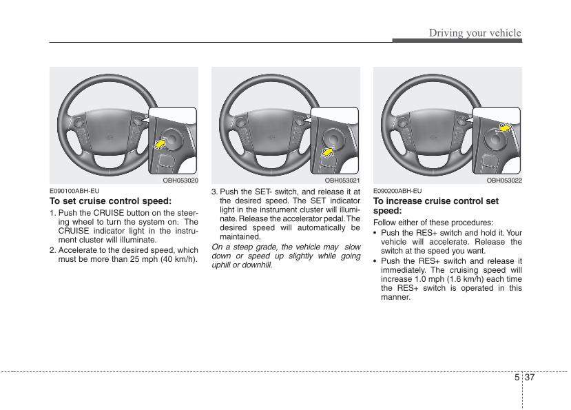
5 37
Driving your vehicle
E090100ABH-EU
To set cruise control speed:1. Push the CRUISE button on the steer-
ing wheel to turn the system on. TheCRUISE indicator light in the instru-ment cluster will illuminate.
2. Accelerate to the desired speed, whichmust be more than 25 mph (40 km/h).
3. Push the SET- switch, and release it atthe desired speed. The SET indicatorlight in the instrument cluster will illumi-nate. Release the accelerator pedal.Thedesired speed will automatically bemaintained.
On a steep grade, the vehicle may slowdown or speed up slightly while goinguphill or downhill.
E090200ABH-EU
To increase cruise control setspeed:Follow either of these procedures:• Push the RES+ switch and hold it. Your
vehicle will accelerate. Release theswitch at the speed you want.
• Push the RES+ switch and release itimmediately. The cruising speed willincrease 1.0 mph (1.6 km/h) each timethe RES+ switch is operated in thismanner.
OBH053021 OBH053022OBH053020
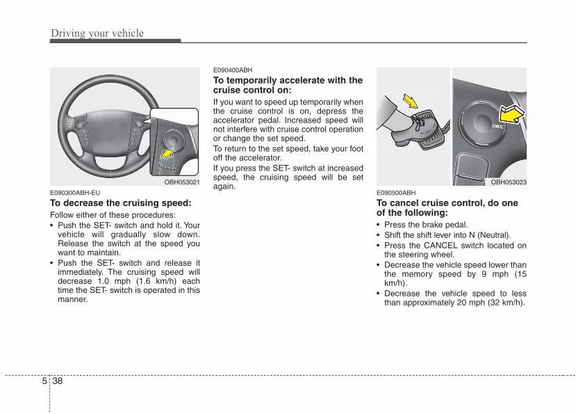
Driving your vehicle
385
E090300ABH-EU
To decrease the cruising speed:Follow either of these procedures:• Push the SET- switch and hold it. Your
vehicle will gradually slow down.Release the switch at the speed youwant to maintain.
• Push the SET- switch and release itimmediately. The cruising speed willdecrease 1.0 mph (1.6 km/h) eachtime the SET- switch is operated in thismanner.
E090400ABH
To temporarily accelerate with thecruise control on:If you want to speed up temporarily whenthe cruise control is on, depress theaccelerator pedal. Increased speed willnot interfere with cruise control operationor change the set speed.To return to the set speed, take your footoff the accelerator.If you press the SET- switch at increasedspeed, the cruising speed will be setagain.
E090500ABH
To cancel cruise control, do oneof the following:• Press the brake pedal.• Shift the shift lever into N (Neutral).• Press the CANCEL switch located on
the steering wheel.• Decrease the vehicle speed lower than
the memory speed by 9 mph (15km/h).
• Decrease the vehicle speed to lessthan approximately 20 mph (32 km/h).
OBH053023OBH053021
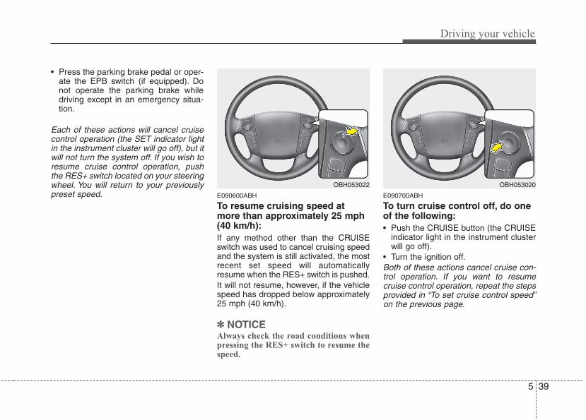
5 39
Driving your vehicle
• Press the parking brake pedal or oper-ate the EPB switch (if equipped). Donot operate the parking brake whiledriving except in an emergency situa-tion.
Each of these actions will cancel cruisecontrol operation (the SET indicator lightin the instrument cluster will go off), but itwill not turn the system off. If you wish toresume cruise control operation, pushthe RES+ switch located on your steeringwheel. You will return to your previouslypreset speed. E090600ABH
To resume cruising speed atmore than approximately 25 mph(40 km/h):If any method other than the CRUISEswitch was used to cancel cruising speedand the system is still activated, the mostrecent set speed will automaticallyresume when the RES+ switch is pushed.It will not resume, however, if the vehiclespeed has dropped below approximately25 mph (40 km/h).
✽✽ NOTICEAlways check the road conditions whenpressing the RES+ switch to resume thespeed.
E090700ABH
To turn cruise control off, do oneof the following:• Push the CRUISE button (the CRUISE
indicator light in the instrument clusterwill go off).
• Turn the ignition off.Both of these actions cancel cruise con-trol operation. If you want to resumecruise control operation, repeat the stepsprovided in “To set cruise control speed”on the previous page.
OBH053022 OBH053020
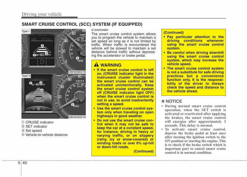
Driving your vehicle
405
➀ CRUISE indicator➁ SET indicator➂ Set speed➃ Vehicle-to-vehicle distance
E150000ABH
The smart cruise control system allowsyou to program the vehicle to maintain aset speed so long as it is not limited bytraffic. When traffic is encountered thevehicle will be slowed to maintain a setdistance behind traffic without depress-ing the accelerator or brake pedal.
✽✽ NOTICE• During normal smart cruise control
operation, when the SET switch isactivated or reactivated after applyingthe brakes, the smart cruise controlwill energize after approximately 3seconds. This delay is normal.
• To activate smart cruise control,depress the brake pedal at least onceafter turning the ignition switch to theON position or starting the engine. Thisis to check if the brake switch which isimportant part to cancel smart cruisecontrol is in normal condition.
SMART CRUISE CONTROL (SCC) SYSTEM (IF EQUIPPED)
WARNING• If the smart cruise control is left
on, (CRUISE indicator light in theinstrument cluster illuminated)the smart cruise control can beactivated unintentionally. Keepthe smart cruise control systemoff (CRUISE indicator light OFF)when the smart cruise control isnot in use, to avoid inadvertentlysetting a speed.
• Use the smart cruise control sys-tem only when traveling on openhighways in good weather.
• Do not use the smart cruise con-trol when it may not be safe tokeep the car at a constant speed,for instance, driving in heavy orvarying traffic, or on slippery(rainy, icy or snow-covered) orwinding roads or over 6% up-hillor down-hill roads.
(Continued)
(Continued)• Pay particular attention to the
driving conditions wheneverusing the smart cruise controlsystem.
• Be careful when driving downhillusing the smart cruise controlsystem, which may increase thevehicle speed.
• The smart cruise control systemis not a substitute for safe drivingpractices but a conveniencefunction only. It is the responsi-bility of the driver to alwayscheck the speed and distance tothe vehicle ahead.
OBH059051N
OBH052051N
Type I
Type II
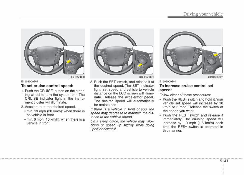
5 41
Driving your vehicle
E150100ABH
To set cruise control speed:1. Push the CRUISE button on the steer-
ing wheel to turn the system on. TheCRUISE indicator light in the instru-ment cluster will illuminate.
2. Accelerate to the desired speed.• min. 19 mph (30 km/h): when there is
no vehicle in front• min. 6 mph (10 km/h): when there is a
vehicle in front
3. Push the SET- switch, and release it atthe desired speed. The SET indicatorlight, set speed and vehicle to vehicledistance on the LCD screen will illumi-nate. Release the accelerator pedal.The desired speed will automaticallybe maintained.
If there is a vehicle in front of you, thespeed may decrease to maintain the dis-tance to the vehicle ahead.On a steep grade, the vehicle may slowdown or speed up slightly while goinguphill or downhill.
E150200ABH
To increase cruise control setspeed:Follow either of these procedures:• Push the RES+ switch and hold it.Your
vehicle set speed will increase by 10km/h or 5 mph. Release the switch atthe speed you want.
• Push the RES+ switch and release itimmediately. The cruising speed willincrease by 1.0 mph (1.6 km/h) eachtime the RES+ switch is operated inthis manner.
OBH053021 OBH053022OBH053020
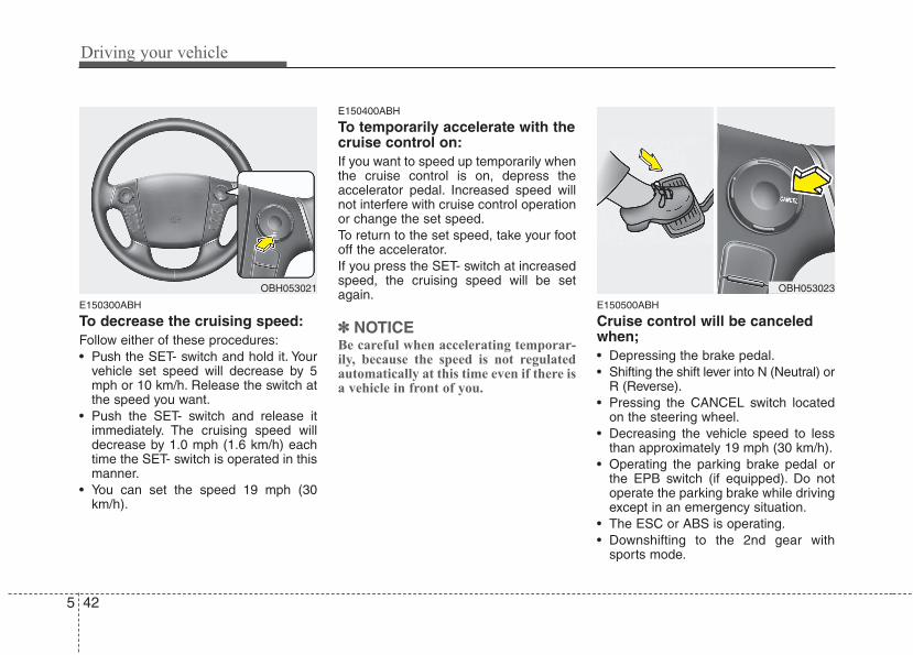
Driving your vehicle
425
E150300ABH
To decrease the cruising speed:Follow either of these procedures:• Push the SET- switch and hold it. Your
vehicle set speed will decrease by 5mph or 10 km/h. Release the switch atthe speed you want.
• Push the SET- switch and release itimmediately. The cruising speed willdecrease by 1.0 mph (1.6 km/h) eachtime the SET- switch is operated in thismanner.
• You can set the speed 19 mph (30km/h).
E150400ABH
To temporarily accelerate with thecruise control on:If you want to speed up temporarily whenthe cruise control is on, depress theaccelerator pedal. Increased speed willnot interfere with cruise control operationor change the set speed.To return to the set speed, take your footoff the accelerator.If you press the SET- switch at increasedspeed, the cruising speed will be setagain.
✽✽ NOTICEBe careful when accelerating temporar-ily, because the speed is not regulatedautomatically at this time even if there isa vehicle in front of you.
E150500ABH
Cruise control will be canceledwhen;• Depressing the brake pedal.• Shifting the shift lever into N (Neutral) or
R (Reverse).• Pressing the CANCEL switch located
on the steering wheel.• Decreasing the vehicle speed to less
than approximately 19 mph (30 km/h).• Operating the parking brake pedal or
the EPB switch (if equipped). Do notoperate the parking brake while drivingexcept in an emergency situation.
• The ESC or ABS is operating.• Downshifting to the 2nd gear with
sports mode.
OBH053021 OBH053023
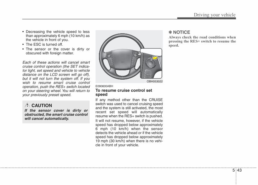
5 43
Driving your vehicle
• Decreasing the vehicle speed to lessthan approximately 6 mph (10 km/h) asthe vehicle in front of you.
• The ESC is turned off.• The sensor or the cover is dirty or
obscured with foreign matter.
Each of these actions will cancel smartcruise control operation (the SET indica-tor light, set speed and vehicle to vehicledistance on the LCD screen will go off),but it will not turn the system off. If youwish to resume smart cruise controloperation, push the RES+ switch locatedon your steering wheel. You will return toyour previously preset speed.
E090600ABH
To resume cruise control setspeedIf any method other than the CRUISEswitch was used to cancel cruising speedand the system is still activated, the mostrecent set speed will automaticallyresume when the RES+ switch is pushed.It will not resume, however, if the vehiclespeed has dropped below approximately6 mph (10 km/h) when the sensordetects the vehicle ahead or if the vehiclespeed has dropped below approximately19 mph (30 km/h) when there is no vehi-cle in front of your vehicle.
✽✽ NOTICEAlways check the road conditions whenpressing the RES+ switch to resume thespeed.
OBH053022
CAUTIONIf the sensor cover is dirty orobstructed, the smart cruise controlwill cancel automatically.
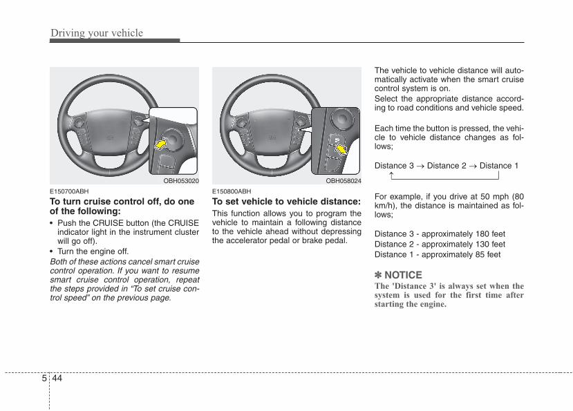
Driving your vehicle
445
E150700ABH
To turn cruise control off, do oneof the following:• Push the CRUISE button (the CRUISE
indicator light in the instrument clusterwill go off).
• Turn the engine off.Both of these actions cancel smart cruisecontrol operation. If you want to resumesmart cruise control operation, repeatthe steps provided in “To set cruise con-trol speed” on the previous page.
E150800ABH
To set vehicle to vehicle distance:This function allows you to program thevehicle to maintain a following distanceto the vehicle ahead without depressingthe accelerator pedal or brake pedal.
The vehicle to vehicle distance will auto-matically activate when the smart cruisecontrol system is on.Select the appropriate distance accord-ing to road conditions and vehicle speed.
Each time the button is pressed, the vehi-cle to vehicle distance changes as fol-lows;
Distance 3 → Distance 2 → Distance 1
For example, if you drive at 50 mph (80km/h), the distance is maintained as fol-lows;
Distance 3 - approximately 180 feetDistance 2 - approximately 130 feetDistance 1 - approximately 85 feet
✽✽ NOTICEThe 'Distance 3' is always set when thesystem is used for the first time afterstarting the engine.
OBH058024OBH053020 →
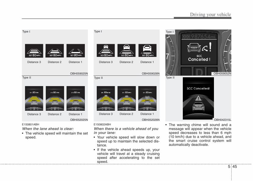
5 45
Driving your vehicle
E150801ABH
When the lane ahead is clear:• The vehicle speed will maintain the set
speed.
E150802ABH
When there is a vehicle ahead of youin your lane:• Your vehicle speed will slow down or
speed up to maintain the selected dis-tance.
• If the vehicle ahead speeds up, yourvehicle will travel at a steady cruisingspeed after accelerating to the setspeed.
• The warning chime will sound and amessage will appear when the vehiclespeed decreases to less than 6 mph(10 km/h) due to a vehicle ahead, andthe smart cruise control system willautomatically deactivate.
OBH059025N
OBH052025N
Type I
Type II
Distance 3 Distance 2 Distance 1
Distance 3 Distance 2 Distance 1
OBH059026N
OBH052026N
Type I
Type II
Distance 3 Distance 2 Distance 1
Distance 3 Distance 2 Distance 1
OBH059052N
OBH042315L
Type I
Type II
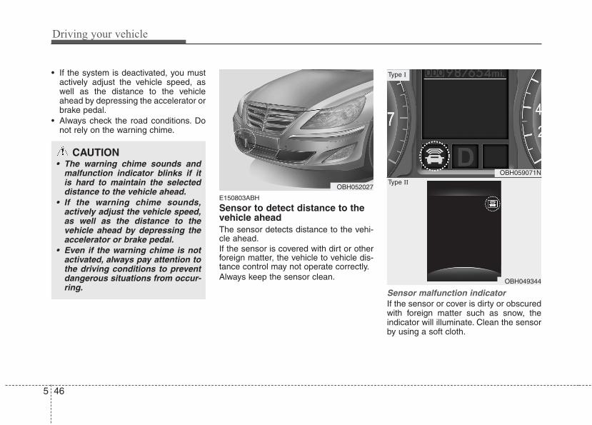
Driving your vehicle
465
• If the system is deactivated, you mustactively adjust the vehicle speed, aswell as the distance to the vehicleahead by depressing the accelerator orbrake pedal.
• Always check the road conditions. Donot rely on the warning chime.
E150803ABH
Sensor to detect distance to thevehicle aheadThe sensor detects distance to the vehi-cle ahead.If the sensor is covered with dirt or otherforeign matter, the vehicle to vehicle dis-tance control may not operate correctly.Always keep the sensor clean.
Sensor malfunction indicator If the sensor or cover is dirty or obscuredwith foreign matter such as snow, theindicator will illuminate. Clean the sensorby using a soft cloth.
OBH059071N
OBH049344
Type I
Type II
CAUTION• The warning chime sounds and
malfunction indicator blinks if itis hard to maintain the selecteddistance to the vehicle ahead.
• If the warning chime sounds,actively adjust the vehicle speed,as well as the distance to thevehicle ahead by depressing theaccelerator or brake pedal.
• Even if the warning chime is notactivated, always pay attention tothe driving conditions to preventdangerous situations from occur-ring.
OBH052027
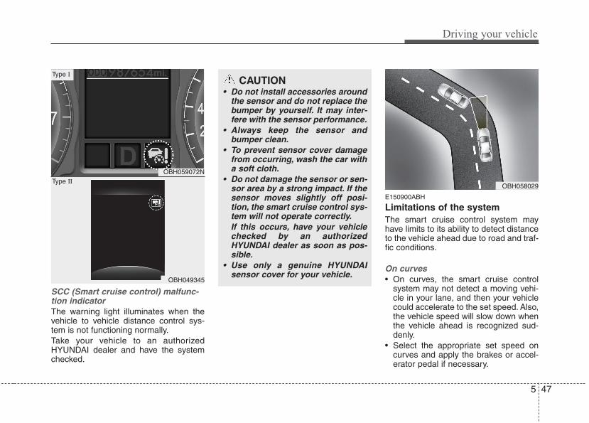
5 47
Driving your vehicle
SCC (Smart cruise control) malfunc-tion indicatorThe warning light illuminates when thevehicle to vehicle distance control sys-tem is not functioning normally.Take your vehicle to an authorizedHYUNDAI dealer and have the systemchecked.
E150900ABH
Limitations of the systemThe smart cruise control system mayhave limits to its ability to detect distanceto the vehicle ahead due to road and traf-fic conditions.
On curves• On curves, the smart cruise control
system may not detect a moving vehi-cle in your lane, and then your vehiclecould accelerate to the set speed. Also,the vehicle speed will slow down whenthe vehicle ahead is recognized sud-denly.
• Select the appropriate set speed oncurves and apply the brakes or accel-erator pedal if necessary.
OBH059072N
OBH049345
Type I
Type II
CAUTION• Do not install accessories around
the sensor and do not replace thebumper by yourself. It may inter-fere with the sensor performance.
• Always keep the sensor andbumper clean.
• To prevent sensor cover damagefrom occurring, wash the car witha soft cloth.
• Do not damage the sensor or sen-sor area by a strong impact. If thesensor moves slightly off posi-tion, the smart cruise control sys-tem will not operate correctly.If this occurs, have your vehiclechecked by an authorizedHYUNDAI dealer as soon as pos-sible.
• Use only a genuine HYUNDAIsensor cover for your vehicle.
OBH058029
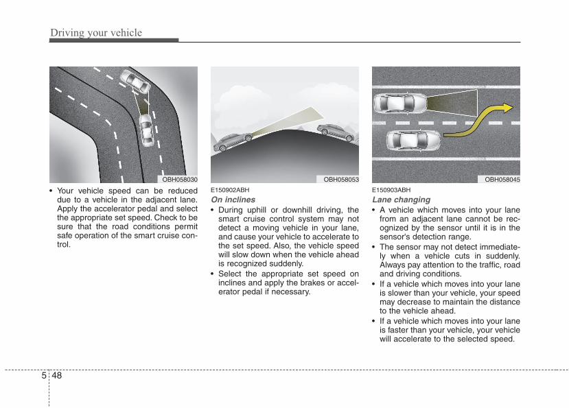
Driving your vehicle
485
• Your vehicle speed can be reduceddue to a vehicle in the adjacent lane.Apply the accelerator pedal and selectthe appropriate set speed. Check to besure that the road conditions permitsafe operation of the smart cruise con-trol.
E150902ABH
On inclines• During uphill or downhill driving, the
smart cruise control system may notdetect a moving vehicle in your lane,and cause your vehicle to accelerate tothe set speed. Also, the vehicle speedwill slow down when the vehicle aheadis recognized suddenly.
• Select the appropriate set speed oninclines and apply the brakes or accel-erator pedal if necessary.
E150903ABH
Lane changing• A vehicle which moves into your lane
from an adjacent lane cannot be rec-ognized by the sensor until it is in thesensor's detection range.
• The sensor may not detect immediate-ly when a vehicle cuts in suddenly.Always pay attention to the traffic, roadand driving conditions.
• If a vehicle which moves into your laneis slower than your vehicle, your speedmay decrease to maintain the distanceto the vehicle ahead.
• If a vehicle which moves into your laneis faster than your vehicle, your vehiclewill accelerate to the selected speed.
OBH058030 OBH058053 OBH058045
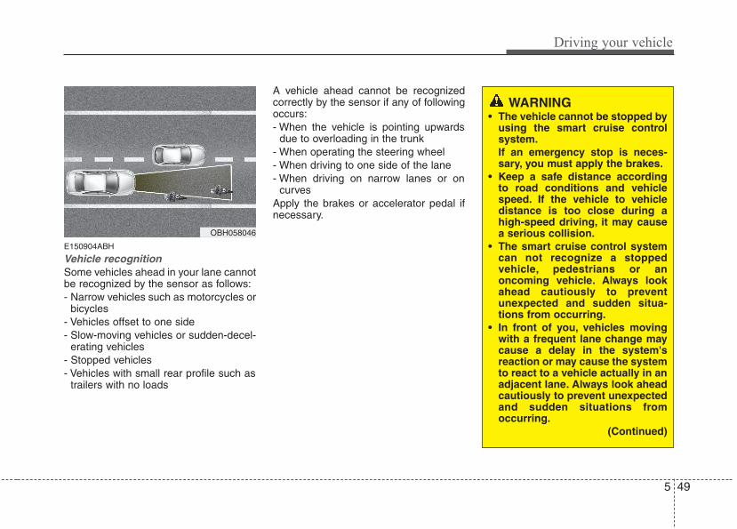
5 49
Driving your vehicle
E150904ABH
Vehicle recognitionSome vehicles ahead in your lane cannotbe recognized by the sensor as follows:- Narrow vehicles such as motorcycles or
bicycles- Vehicles offset to one side- Slow-moving vehicles or sudden-decel-
erating vehicles - Stopped vehicles- Vehicles with small rear profile such as
trailers with no loads
A vehicle ahead cannot be recognizedcorrectly by the sensor if any of followingoccurs:- When the vehicle is pointing upwards
due to overloading in the trunk- When operating the steering wheel- When driving to one side of the lane- When driving on narrow lanes or on
curvesApply the brakes or accelerator pedal ifnecessary.
OBH058046
WARNING• The vehicle cannot be stopped by
using the smart cruise controlsystem.If an emergency stop is neces-sary, you must apply the brakes.
• Keep a safe distance accordingto road conditions and vehiclespeed. If the vehicle to vehicledistance is too close during ahigh-speed driving, it may causea serious collision.
• The smart cruise control systemcan not recognize a stoppedvehicle, pedestrians or anoncoming vehicle. Always lookahead cautiously to preventunexpected and sudden situa-tions from occurring.
• In front of you, vehicles movingwith a frequent lane change maycause a delay in the system'sreaction or may cause the systemto react to a vehicle actually in anadjacent lane. Always look aheadcautiously to prevent unexpectedand sudden situations fromoccurring.
(Continued)
Driving your vehicle
505
(Continued)• The smart cruise control system
is not a substitute for safe drivingpractices but a conveniencefunction only. It is the responsi-bility of the driver to alwayscheck the speed and the distanceto the vehicle ahead.
• Always be aware of the selectedspeed and vehicle to vehicle dis-tance.
• Always maintain sufficient brak-ing distance and decelerate yourvehicle by applying the brakes ifnecessary.
• As the smart cruise control sys-tem may not recognize complexdriving situations, always payattention to driving conditionsand control your vehicle speed.
• For safe operation, carefully readand follow the instructions in thismanual before use.
CAUTIONThe smart cruise control systemmay not operate temporarily due toelectrical interference.
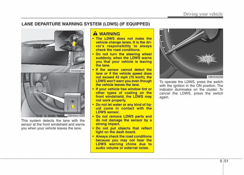
5 51
Driving your vehicle
This system detects the lane with thesensor at the front windshield and warnsyou when your vehicle leaves the lane.
To operate the LDWS, press the switchwith the ignition in the ON position. Theindicator illuminates on the cluster. Tocancel the LDWS, press the switchagain.
LANE DEPARTURE WARNING SYSTEM (LDWS) (IF EQUIPPED)
OVI059012
WARNING• The LDWS does not make the
vehicle change lanes. It is the dri-ver's responsibility to alwayscheck the road conditions.
• Do not turn the steering wheelsuddenly, when the LDWS warnsyou that your vehicle is leavingthe lane.
• If the sensor cannot detect thelane or if the vehicle speed doesnot exceed 43 mph (70 km/h), theLDWS won't warn you even thoughthe vehicle leaves the lane.
• If your vehicle has window tint orother types of coating on thefront windshield, the LDWS maynot work properly.
• Do not let water or any kind of liq-uid come in contact with theLDWS sensor.
• Do not remove LDWS parts anddo not damage the sensor by astrong impact.
• Do not put objects that reflectlight on the dash board.
• Always check the road conditionsbecause you may not hear theLDWS warning chime due toaudio volume or external noise.
OBH049338
OBH052100N
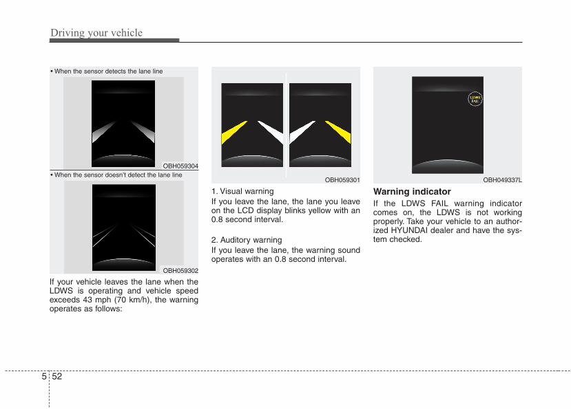
Driving your vehicle
525
If your vehicle leaves the lane when theLDWS is operating and vehicle speedexceeds 43 mph (70 km/h), the warningoperates as follows:
1. Visual warningIf you leave the lane, the lane you leaveon the LCD display blinks yellow with an0.8 second interval.
2. Auditory warningIf you leave the lane, the warning soundoperates with an 0.8 second interval.
Warning indicator If the LDWS FAIL warning indicatorcomes on, the LDWS is not workingproperly. Take your vehicle to an author-ized HYUNDAI dealer and have the sys-tem checked.
OBH059304
OBH059302
OBH059301
• When the sensor detects the lane line
• When the sensor doesn’t detect the lane lineOBH049337L
5 53
Driving your vehicle
The LDWS does not operatewhen:• The driver turns on the turn signal to
change lane.However, when the hazard warningflasher is operating, the LDWS oper-ates normally.
• Operating the wiper switch with HImode due to heavy rain.
• Driving on the lane line.
✽✽ NOTICETo change lane, operate the turn signalswitch then change the lane.
The LDWS may not warn you evenif the vehicle leaves the lane, ormay warn you even if the vehicledoes not leave the lane when:• The lane can't be visible due to snow,
rain, stain, a puddle or many otherthings.
• The brightness outside changes sud-denly.
• Not turning on the headlights at nightor in a tunnel.
• Difficult to distinguish the color of thelane marking from the road.
• Driving on a steep grade or a curve.• Light reflects from the water on the
road.• The lens or windshield is stained with
foreign matter.• The sensor cannot detect the lane
because of fog, heavy rain or heavysnow.
• The surrounding of the inside rear viewmirror temperature is high due to adirect sun light.
• The lane is very wide or narrow.• The lane line is damaged or indistinct.• A shadow is on the lane line by a medi-
an strip.• There is a mark that looks like lane line.• There is a boundary structure.
• The distance from vehicle ahead isvery short or the vehicle ahead driveshiding the lane line.
• The vehicle shakes heavily.• The lane number increases or
decreases or the lane lines are cross-ing.
• Putting something on the dashboard.• Driving with the sun in front of you.• Driving in areas under construction.• The lane line is more than two.
Driving your vehicle
545
E100000AEN
Your vehicle's fuel economy dependsmainly on your style of driving, where youdrive and when you drive.Each of these factors affects how manymiles (kilometers) you can get from a gal-lon (liter) of fuel. To operate your vehicleas economically as possible, use the fol-lowing driving suggestions to help savemoney in both fuel and repairs:• Drive smoothly. Accelerate at a moder-
ate rate. Don't make "jack-rabbit" startsor full-throttle shifts and maintain asteady cruising speed. Don't racebetween stoplights. Try to adjust yourspeed to that of the other traffic so youdon't have to change speeds unneces-sarily. Avoid heavy traffic wheneverpossible. Always maintain a safe dis-tance from other vehicles so you canavoid unnecessary braking. This alsoreduces brake wear.
• Drive at a moderate speed. The fasteryou drive the more fuel your vehicleuses. Driving at a moderate speed, inthe highest gear appropriate for theconditions, especially on the highway,is one of the most effective ways toreduce fuel consumption.
• Don't "ride" the brake pedal. This canincrease fuel consumption and alsoincrease wear on these components.In addition, driving with your foot rest-ing on the brake pedal may cause thebrakes to overheat, which reducestheir effectiveness and may lead tomore serious consequences.
• Take care of your tires. Keep theminflated to the recommended pressure.Incorrect inflation, either too much ortoo little, results in unnecessary tirewear. Check the tire pressures at leastonce a month.
• Be sure that the wheels are alignedcorrectly. Improper alignment canresult from hitting curbs or driving toofast over irregular surfaces. Poor align-ment causes faster tire wear and mayalso result in other problems as well asgreater fuel consumption.
• Keep your car in good condition. Forbetter fuel economy and reducedmaintenance costs, maintain your carin accordance with the maintenanceschedule in section 7. If you drive yourcar in severe conditions, more frequentmaintenance is required (see section 7for details).
• Keep your car clean. For maximumservice, your vehicle should be keptclean and free of corrosive materials. Itis especially important that mud, dirt,ice, etc. not be allowed to accumulateon the underside of the car. This extraweight can result in increased fuel con-sumption and also contribute to corro-sion.
• Travel lightly. Don't carry unnecessaryweight in your car. Weight reduces fueleconomy.
• Don't let the engine idle longer thannecessary. If you are waiting (and notin traffic), turn off your engine andrestart only when you're ready to go.
ECONOMICAL OPERATION
5 55
Driving your vehicle
• Remember, your vehicle does notrequire extended warm-up. After theengine has started, allow the engine torun for 10 to 20 seconds prior to plac-ing the vehicle in gear. In very coldweather, however, give your engine aslightly longer warm-up period.
• Don't "lug" or "over-rev" the engine.Lugging is driving too slowly in too higha gear resulting in the engine bucking.If this happens, shift to a lower gear.Over-revving is racing the enginebeyond its safe limit. This can be avoid-ed by shifting at the recommendedspeeds.
• Use your air conditioning sparingly.The air conditioning system is operat-ed by engine power so your fuel econ-omy is reduced when you use it.
• Open windows at high speeds canreduce fuel economy.
• Fuel economy is less in crosswindsand headwinds. To help offset some ofthis loss, slow down when driving inthese conditions.
Keeping a vehicle in good operating con-dition is important both for economy andsafety. Therefore, have an authorizedHYUNDAI dealer perform scheduledinspections and maintenance.
WARNING - Engine off dur-ing motion
Never turn the engine off to coastdown hills or anytime the vehicle isin motion. The power steering andpower brakes will not functionproperly without the engine run-ning. Instead, keep the engine onand downshift to an appropriategear for engine braking effect. Inaddition, turning off the ignitionwhile driving could engage thesteering wheel lock resulting inloss of vehicle steering whichcould cause serious injury ordeath.
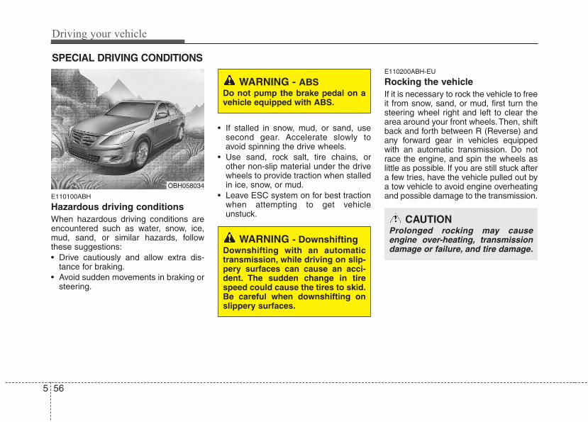
Driving your vehicle
565
E110100ABH
Hazardous driving conditions When hazardous driving conditions areencountered such as water, snow, ice,mud, sand, or similar hazards, followthese suggestions:• Drive cautiously and allow extra dis-
tance for braking.• Avoid sudden movements in braking or
steering.
• If stalled in snow, mud, or sand, usesecond gear. Accelerate slowly toavoid spinning the drive wheels.
• Use sand, rock salt, tire chains, orother non-slip material under the drivewheels to provide traction when stalledin ice, snow, or mud.
• Leave ESC system on for best tractionwhen attempting to get vehicleunstuck.
E110200ABH-EU
Rocking the vehicle If it is necessary to rock the vehicle to freeit from snow, sand, or mud, first turn thesteering wheel right and left to clear thearea around your front wheels. Then, shiftback and forth between R (Reverse) andany forward gear in vehicles equippedwith an automatic transmission. Do notrace the engine, and spin the wheels aslittle as possible. If you are still stuck aftera few tries, have the vehicle pulled out bya tow vehicle to avoid engine overheatingand possible damage to the transmission.
SPECIAL DRIVING CONDITIONS
OBH058034
WARNING - ABSDo not pump the brake pedal on avehicle equipped with ABS.
WARNING - DownshiftingDownshifting with an automatictransmission, while driving on slip-pery surfaces can cause an acci-dent. The sudden change in tirespeed could cause the tires to skid.Be careful when downshifting onslippery surfaces.
CAUTIONProlonged rocking may causeengine over-heating, transmissiondamage or failure, and tire damage.
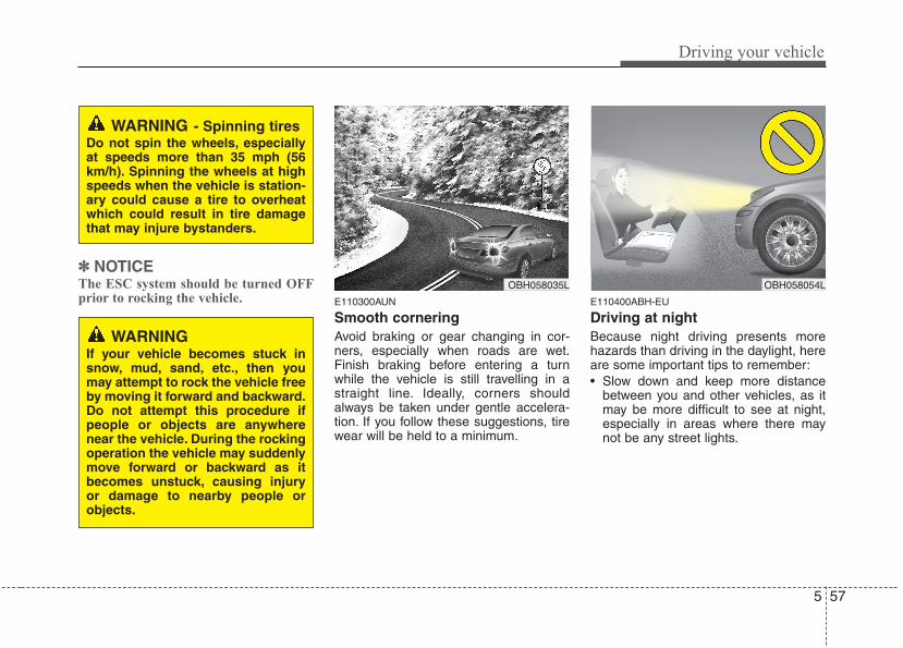
5 57
Driving your vehicle
✽✽ NOTICEThe ESC system should be turned OFFprior to rocking the vehicle. E110300AUN
Smooth corneringAvoid braking or gear changing in cor-ners, especially when roads are wet.Finish braking before entering a turnwhile the vehicle is still travelling in astraight line. Ideally, corners shouldalways be taken under gentle accelera-tion. If you follow these suggestions, tirewear will be held to a minimum.
E110400ABH-EU
Driving at night Because night driving presents morehazards than driving in the daylight, hereare some important tips to remember:• Slow down and keep more distance
between you and other vehicles, as itmay be more difficult to see at night,especially in areas where there maynot be any street lights.
WARNING - Spinning tiresDo not spin the wheels, especiallyat speeds more than 35 mph (56km/h). Spinning the wheels at highspeeds when the vehicle is station-ary could cause a tire to overheatwhich could result in tire damagethat may injure bystanders.
OBH058035L OBH058054L
WARNINGIf your vehicle becomes stuck insnow, mud, sand, etc., then youmay attempt to rock the vehicle freeby moving it forward and backward.Do not attempt this procedure ifpeople or objects are anywherenear the vehicle. During the rockingoperation the vehicle may suddenlymove forward or backward as itbecomes unstuck, causing injuryor damage to nearby people orobjects.
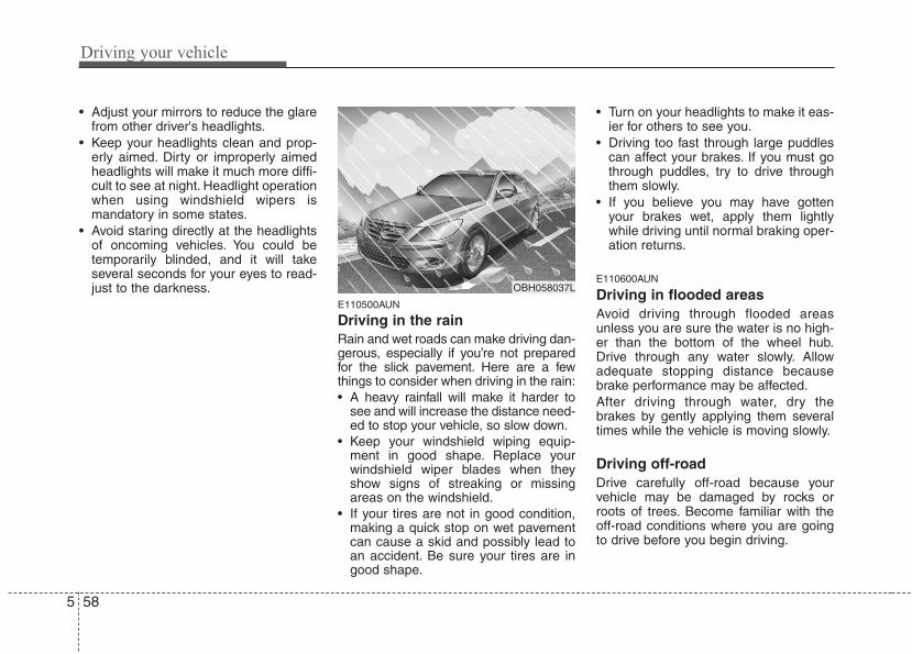
Driving your vehicle
585
• Adjust your mirrors to reduce the glarefrom other driver's headlights.
• Keep your headlights clean and prop-erly aimed. Dirty or improperly aimedheadlights will make it much more diffi-cult to see at night. Headlight operationwhen using windshield wipers ismandatory in some states.
• Avoid staring directly at the headlightsof oncoming vehicles. You could betemporarily blinded, and it will takeseveral seconds for your eyes to read-just to the darkness.
E110500AUN
Driving in the rain Rain and wet roads can make driving dan-gerous, especially if you’re not preparedfor the slick pavement. Here are a fewthings to consider when driving in the rain:• A heavy rainfall will make it harder to
see and will increase the distance need-ed to stop your vehicle, so slow down.
• Keep your windshield wiping equip-ment in good shape. Replace yourwindshield wiper blades when theyshow signs of streaking or missingareas on the windshield.
• If your tires are not in good condition,making a quick stop on wet pavementcan cause a skid and possibly lead toan accident. Be sure your tires are ingood shape.
• Turn on your headlights to make it eas-ier for others to see you.
• Driving too fast through large puddlescan affect your brakes. If you must gothrough puddles, try to drive throughthem slowly.
• If you believe you may have gottenyour brakes wet, apply them lightlywhile driving until normal braking oper-ation returns.
E110600AUN
Driving in flooded areas Avoid driving through flooded areasunless you are sure the water is no high-er than the bottom of the wheel hub.Drive through any water slowly. Allowadequate stopping distance becausebrake performance may be affected.After driving through water, dry thebrakes by gently applying them severaltimes while the vehicle is moving slowly.
Driving off-roadDrive carefully off-road because yourvehicle may be damaged by rocks orroots of trees. Become familiar with theoff-road conditions where you are goingto drive before you begin driving.
OBH058037L
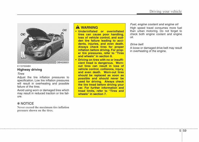
5 59
Driving your vehicle
E110700ABH
Highway drivingTiresAdjust the tire inflation pressures tospecification. Low tire inflation pressureswill result in overheating and possiblefailure of the tires.Avoid using worn or damaged tires whichmay result in reduced traction or tire fail-ure.
✽✽ NOTICENever exceed the maximum tire inflationpressure shown on the tires.
Fuel, engine coolant and engine oilHigh speed travel consumes more fuelthan urban motoring. Do not forget tocheck both engine coolant and engineoil.
Drive beltA loose or damaged drive belt may resultin overheating of the engine.
WARNING• Underinflated or overinflated
tires can cause poor handling,loss of vehicle control, and sud-den tire failure leading to acci-dents, injuries, and even death.Always check tires for properinflation before driving. For prop-er tire pressures, refer to “Tiresand wheels” in section 8.
• Driving on tires with no or insuffi-cient tread is dangerous. Worn-out tires can result in loss ofvehicle control, collisions, injury,and even death. Worn-out tiresshould be replaced as soon aspossible and should never beused for driving. Always checkthe tire tread before driving yourcar. For further information andtread limits, refer to “Tires andwheels” in section 7.
OBH028001
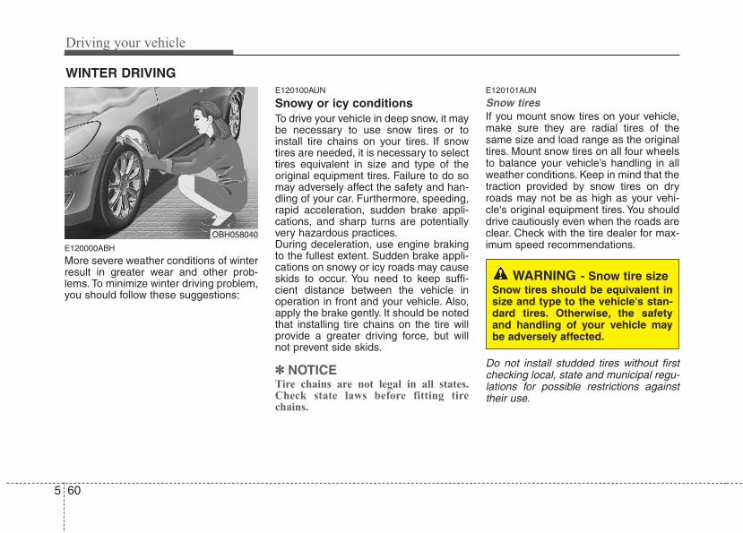
Driving your vehicle
605
E120000ABH
More severe weather conditions of winterresult in greater wear and other prob-lems. To minimize winter driving problem,you should follow these suggestions:
E120100AUN
Snowy or icy conditionsTo drive your vehicle in deep snow, it maybe necessary to use snow tires or toinstall tire chains on your tires. If snowtires are needed, it is necessary to selecttires equivalent in size and type of theoriginal equipment tires. Failure to do somay adversely affect the safety and han-dling of your car. Furthermore, speeding,rapid acceleration, sudden brake appli-cations, and sharp turns are potentiallyvery hazardous practices.During deceleration, use engine brakingto the fullest extent. Sudden brake appli-cations on snowy or icy roads may causeskids to occur. You need to keep suffi-cient distance between the vehicle inoperation in front and your vehicle. Also,apply the brake gently. It should be notedthat installing tire chains on the tire willprovide a greater driving force, but willnot prevent side skids.
✽✽ NOTICETire chains are not legal in all states.Check state laws before fitting tirechains.
E120101AUN
Snow tires If you mount snow tires on your vehicle,make sure they are radial tires of thesame size and load range as the originaltires. Mount snow tires on all four wheelsto balance your vehicle’s handling in allweather conditions. Keep in mind that thetraction provided by snow tires on dryroads may not be as high as your vehi-cle's original equipment tires. You shoulddrive cautiously even when the roads areclear. Check with the tire dealer for max-imum speed recommendations.
Do not install studded tires without firstchecking local, state and municipal regu-lations for possible restrictions againsttheir use.
WINTER DRIVING
WARNING - Snow tire sizeSnow tires should be equivalent insize and type to the vehicle's stan-dard tires. Otherwise, the safetyand handling of your vehicle maybe adversely affected.
OBH058040
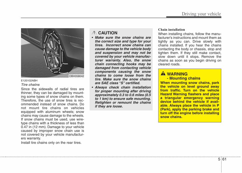
5 61
Driving your vehicle
E120102ABH
Tire chains Since the sidewalls of radial tires arethinner, they can be damaged by mount-ing some types of snow chains on them.Therefore, the use of snow tires is rec-ommended instead of snow chains. Donot mount tire chains on vehiclesequipped with aluminum wheels; snowchains may cause damage to the wheels.If snow chains must be used, use wire-type chains with a thickness of less than0.47 in (12 mm). Damage to your vehiclecaused by improper snow chain use isnot covered by your vehicle manufactur-ers warranty.Install tire chains only on the rear tires.
Chain installation
When installing chains, follow the manu-facturer's instructions and mount them astightly as you can. Drive slowly withchains installed. If you hear the chainscontacting the body or chassis, stop andtighten them. If they still make contact,slow down until it stops. Remove thechains as soon as you begin driving oncleared roads.
CAUTION• Make sure the snow chains are
the correct size and type for yourtires. Incorrect snow chains cancause damage to the vehicle bodyand suspension and may not becovered by your vehicle manufac-turer warranty. Also, the snowchain connecting hooks may bedamaged from contacting vehiclecomponents causing the snowchains to come loose from thetire. Make sure the snow chainsare SAE class “S” certified.
• Always check chain installationfor proper mounting after drivingapproximately 0.3 to 0.6 miles (0.5to 1 km) to ensure safe mounting.Retighten or remount the chainsif they are loose.
WARNING - Mounting chains
When mounting snow chains, parkthe vehicle on level ground awayfrom traffic. Turn on the vehicleHazard Warning flashers and placea triangular emergency warningdevice behind the vehicle if avail-able. Always place the vehicle in P(Park), apply the parking brake andturn off the engine before installingsnow chains.
OBH058042
Driving your vehicle
625
E120200AUN
Use high quality ethylene glycolcoolantYour vehicle is delivered with high qualityethylene glycol coolant in the coolingsystem. It is the only type of coolant thatshould be used because it helps preventcorrosion in the cooling system, lubri-cates the water pump and preventsfreezing. Be sure to replace or replenishyour coolant in accordance with themaintenance schedule in section 7.Before winter, have your coolant tested toassure that its freezing point is sufficientfor the temperatures anticipated duringthe winter.
E120300AEN
Check battery and cablesWinter puts additional burdens on thebattery system. Visually inspect the bat-tery and cables as described in section7. The level of charge in your battery canbe checked by an authorized HYUNDAIdealer or a service station.
E120400ABH
Change to "winter weight" oil ifnecessaryIn some climates it is recommended thata lower viscosity "winter weight" oil beused during cold weather. See section 8for recommendations. If you aren't surewhat weight oil you should use, consultan authorized HYUNDAI dealer.
E120500AUN
Check spark plugs and ignitionsystemInspect your spark plugs as described insection 7 and replace them if necessary.Also check all ignition wiring and compo-nents to be sure they are not cracked,worn or damaged in any way.
WARNING - Tire chains• The use of chains may adversely
affect vehicle handling.• Do not exceed 20 mph (30 km/h)
or the chain manufacturer’s rec-ommended speed limit, whichev-er is lower.
• Drive carefully and avoid bumps,holes, sharp turns, and otherroad hazards, which may causethe vehicle to bounce.
• Avoid sharp turns or locked-wheel braking.
CAUTION• Chains that are the wrong size or
improperly installed can damageyour vehicle's brake lines, sus-pension, body and wheels.
• Stop driving and retighten thechains any time you hear themhitting the vehicle.
5 63
Driving your vehicle
E120600AUN
To keep locks from freezingTo keep the locks from freezing, squirt anapproved de-icer fluid or glycerine intothe key opening. If a lock is covered withice, squirt it with an approved de-icingfluid to remove the ice. If the lock isfrozen internally, you may be able to thawit out by using a heated key. Handle theheated key with care to avoid injury.
E120700AEN
Use approved window washeranti-freeze in systemTo keep the water in the window washersystem from freezing, add an approvedwindow washer anti-freeze solution inaccordance with instructions on the con-tainer. Window washer anti-freeze isavailable from an authorized HYUNDAIdealer and most auto parts outlets. Donot use engine coolant or other types ofanti-freeze as these may damage thepaint finish.
E120800ABH
Do not let your parking brakefreezeUnder some conditions your parkingbrake can freeze in the engaged position.This is most likely to happen when thereis an accumulation of snow or ice aroundor near the rear brakes or if the brakesare wet. If there is a risk the parkingbrake may freeze, apply it only temporar-ily while you put the gear selector lever inP and block the rear wheels so the carcannot roll. Then release the parkingbrake.
E120900AUN
Do not let ice and snow accumu-late underneathUnder some conditions, snow and icecan build up under the fenders and inter-fere with the steering. When driving insevere winter conditions where this mayhappen, you should periodically checkunderneath the car to be sure the move-ment of the front wheels and the steeringcomponents is not obstructed.
E121000AUN
Carry emergency equipmentDepending on the severity of the weath-er where you drive your car, you shouldcarry appropriate emergency equipment.Some of the items you may want to carryinclude tire chains, tow straps or chains,flashlight, emergency flares, sand, ashovel, jumper cables, a window scraper,gloves, ground cloth, coveralls, a blanket,etc.
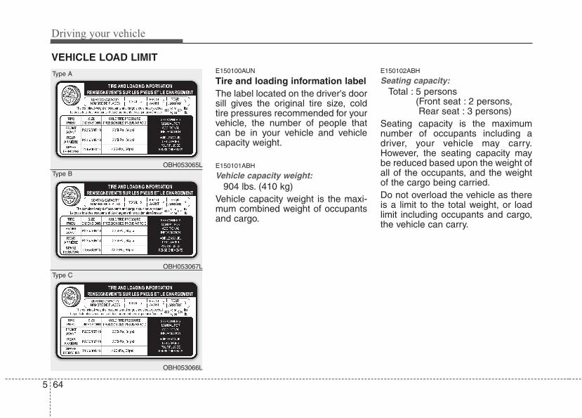
Driving your vehicle
645
E150100AUN
Tire and loading information labelThe label located on the driver's doorsill gives the original tire size, coldtire pressures recommended for yourvehicle, the number of people thatcan be in your vehicle and vehiclecapacity weight.
E150101ABH
Vehicle capacity weight:904 lbs. (410 kg)
Vehicle capacity weight is the maxi-mum combined weight of occupantsand cargo.
E150102ABH
Seating capacity:Total : 5 persons
(Front seat : 2 persons, Rear seat : 3 persons)
Seating capacity is the maximumnumber of occupants including adriver, your vehicle may carry.However, the seating capacity maybe reduced based upon the weight ofall of the occupants, and the weightof the cargo being carried.Do not overload the vehicle as thereis a limit to the total weight, or loadlimit including occupants and cargo,the vehicle can carry.
VEHICLE LOAD LIMIT
OBH053065L
OBH053066L
OBH053067L
Type A
Type C
Type B
5 65
Driving your vehicle
Towing capacity:We do not recommend using thisvehicle for trailer towing.
Cargo capacity:The cargo capacity of your vehiclewill increase or decrease dependingon the weight and the number ofoccupants.
R1-090003
Steps For Determining Correct LoadLimit -1. Locate the statement "The com-
bined weight of occupants andcargo should never exceed XXXkg or XXX lbs.'' on your vehicle'splacard.
2. Determine the combined weight ofthe driver and passengers that willbe riding in your vehicle.
3. Subtract the combined weight ofthe driver and passengers fromXXX kg or XXX lbs.
4. The resulting figure equals theavailable amount of cargo and lug-gage load capacity. For example, ifthe "XXX" amount equals 1400lbs. and there will be five 150 lbpassengers in your vehicle, theamount of available cargo and lug-gage load capacity is 650 lbs.(1400-750 (5 x 150) = 650 lbs.)
5. Determine the combined weight ofluggage and cargo being loadedon the vehicle. That weight maynot safely exceed the availablecargo and luggage load capacitycalculated in Step 4.
6. If your vehicle will be towing a trail-er, load from your trailer will betransferred to your vehicle. Consultthis manual to determine how thisreduces the available cargo andluggage load capacity of yourvehicle.
✽✽ NOTICEWe do not recommend using thisvehicle for trailer towing.
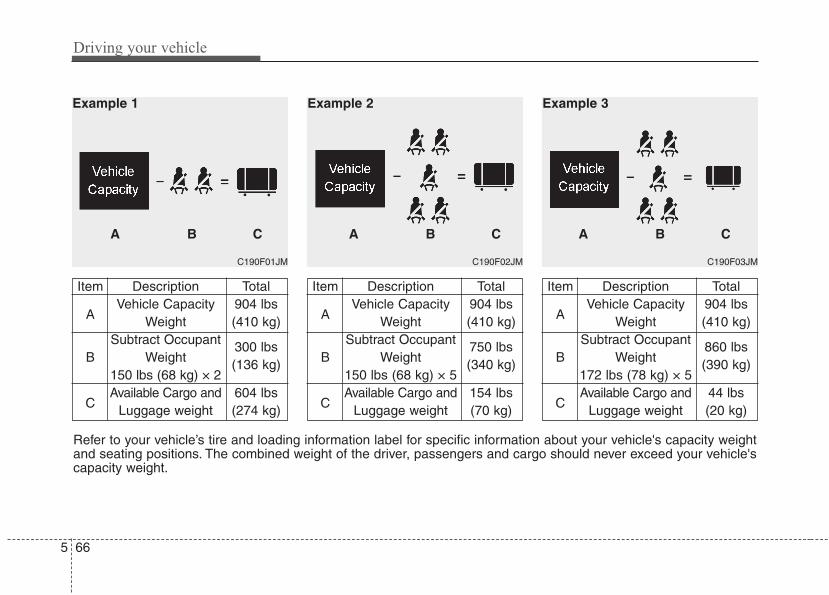
Driving your vehicle
665
Refer to your vehicle’s tire and loading information label for specific information about your vehicle's capacity weightand seating positions. The combined weight of the driver, passengers and cargo should never exceed your vehicle'scapacity weight.
C190F01JM
Item Description Total
AVehicle Capacity 904 lbs
Weight (410 kg)Subtract Occupant
B Weight 300 lbs
150 lbs (68 kg) × 2(136 kg)
CAvailable Cargo and 604 lbs
Luggage weight (274 kg)
Example 1
A B C
C190F02JM
Item Description Total
AVehicle Capacity 904 lbs
Weight (410 kg)Subtract Occupant
B Weight 750 lbs
150 lbs (68 kg) × 5(340 kg)
CAvailable Cargo and 154 lbs
Luggage weight (70 kg)
A B C
Example 2
C190F03JM
Item Description Total
AVehicle Capacity 904 lbs
Weight (410 kg)Subtract Occupant
B Weight 860 lbs
172 lbs (78 kg) × 5(390 kg)
CAvailable Cargo and 44 lbs
Luggage weight (20 kg)
A B C
Example 3
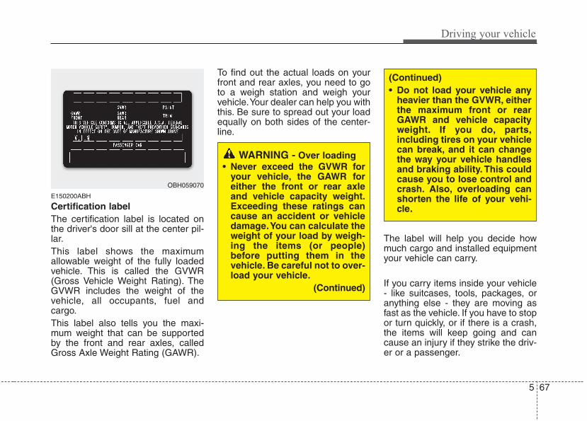
5 67
Driving your vehicle
E150200ABH
Certification labelThe certification label is located onthe driver's door sill at the center pil-lar.This label shows the maximumallowable weight of the fully loadedvehicle. This is called the GVWR(Gross Vehicle Weight Rating). TheGVWR includes the weight of thevehicle, all occupants, fuel andcargo.This label also tells you the maxi-mum weight that can be supportedby the front and rear axles, calledGross Axle Weight Rating (GAWR).
To find out the actual loads on yourfront and rear axles, you need to goto a weigh station and weigh yourvehicle.Your dealer can help you withthis. Be sure to spread out your loadequally on both sides of the center-line.
The label will help you decide howmuch cargo and installed equipmentyour vehicle can carry.
If you carry items inside your vehicle- like suitcases, tools, packages, oranything else - they are moving asfast as the vehicle. If you have to stopor turn quickly, or if there is a crash,the items will keep going and cancause an injury if they strike the driv-er or a passenger.
OBH059070
WARNING - Over loading• Never exceed the GVWR for
your vehicle, the GAWR foreither the front or rear axleand vehicle capacity weight.Exceeding these ratings cancause an accident or vehicledamage.You can calculate theweight of your load by weigh-ing the items (or people)before putting them in thevehicle. Be careful not to over-load your vehicle.
(Continued)
(Continued)• Do not load your vehicle any
heavier than the GVWR, eitherthe maximum front or rearGAWR and vehicle capacityweight. If you do, parts,including tires on your vehiclecan break, and it can changethe way your vehicle handlesand braking ability. This couldcause you to lose control andcrash. Also, overloading canshorten the life of your vehi-cle.
Driving your vehicle
685
WARNING• Overloading your vehicle can
cause heat buildup in yourvehicle's tires and possibletire failure that could lead to acrash.
• Overloading your vehicle cancause increased stopping dis-tances that could lead to acrash.
• A crash resulting from poorhandling, vehicle damage, tirefailure, or increased stoppingdistances could result in seri-ous injury or death.
WARNING - Loose cargoItems you carry inside yourvehicle can strike and injureoccupants in a sudden stop orturn, or in a crash.• Put items in the cargo area of
your vehicle. Try to spread theweight evenly.
• Never stack items, like suit-cases, inside the vehicleabove the tops of the seats.
• Do not leave an unsecuredchild restraint in your vehicle.
• When you carry somethinginside the vehicle, secure it.
CAUTION• Overloading your vehicle may
cause damage. Repairs wouldnot be covered by your warran-ty. Do not overload your vehicle.
• Using heavier suspension com-ponents to get added durabilitymight not change your weightratings. Ask your dealer to helpyou load your vehicle the rightway.
5 69
Driving your vehicle
E160000ABH
This section will guide you in the properloading of your vehicle, to keep yourloaded vehicle weight within its designrating capability. Properly loading yourvehicle will provide maximum return ofthe vehicle design performance. Beforeloading your vehicle, familiarize yourselfwith the following terms for determiningyour vehicle's weight ratings, from thevehicle's specifications and the certifica-tion label:
E160100AUN
Base curb weight This is the weight of the vehicle includinga full tank of fuel and all standard equip-ment. It does not include passengers,cargo, or optional equipment.
E160200AUN
Vehicle curb weightThis is the weight of your new vehiclewhen you picked it up from your dealerplus any aftermarket equipment.
E160300AUN
Cargo weightThis figure includes all weight added tothe Base Curb Weight, including cargoand optional equipment.
E160400AUN
GAW (Gross axle weight)This is the total weight placed on eachaxle (front and rear) - including vehiclecurb weight and all payload.
E160500AUN
GAWR (Gross axle weight rating)This is the maximum allowable weightthat can be carried by a single axle (frontor rear). These numbers are shown onthe certification label.The total load on each axle must neverexceed its GAWR.
E160600AUN
GVW (Gross vehicle weight)This is the Base Curb Weight plus actualCargo Weight plus passengers.
E160700AUN-EU
GVWR (Gross vehicle weight rating)This is the maximum allowable weight ofthe fully loaded vehicle (including alloptions, equipment, passengers andcargo). The GVWR is shown on the cer-tification label located on the driver’sdoor sill.
VEHICLE WEIGHT
Driving your vehicle
705
E140000ABH
We do not recommend using thisvehicle for trailer towing.
TRAILER TOWING
6
Road warning / 6-2
In case of an emergency while driving / 6-2
If the engine will not start / 6-3
Emergency starting / 6-4
If the engine overheats / 6-6
Tire pressure monitoring system (TPMS) / 6-7
If you have a flat tire / 6-13
Towing / 6-21
What to do in an emergency
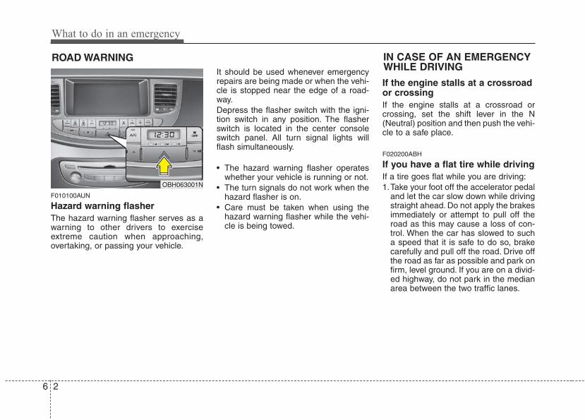
What to do in an emergency
26
ROAD WARNING
F010100AUN
Hazard warning flasher The hazard warning flasher serves as awarning to other drivers to exerciseextreme caution when approaching,overtaking, or passing your vehicle.
It should be used whenever emergencyrepairs are being made or when the vehi-cle is stopped near the edge of a road-way.Depress the flasher switch with the igni-tion switch in any position. The flasherswitch is located in the center consoleswitch panel. All turn signal lights willflash simultaneously.
• The hazard warning flasher operateswhether your vehicle is running or not.
• The turn signals do not work when thehazard flasher is on.
• Care must be taken when using thehazard warning flasher while the vehi-cle is being towed.
If the engine stalls at a crossroador crossingIf the engine stalls at a crossroad orcrossing, set the shift lever in the N(Neutral) position and then push the vehi-cle to a safe place.
F020200ABH
If you have a flat tire while drivingIf a tire goes flat while you are driving:1.Take your foot off the accelerator pedal
and let the car slow down while drivingstraight ahead. Do not apply the brakesimmediately or attempt to pull off theroad as this may cause a loss of con-trol. When the car has slowed to sucha speed that it is safe to do so, brakecarefully and pull off the road. Drive offthe road as far as possible and park onfirm, level ground. If you are on a divid-ed highway, do not park in the medianarea between the two traffic lanes.
IN CASE OF AN EMERGENCYWHILE DRIVING
OBH063001N
6 3
What to do in an emergency
2.When the car is stopped, turn on youremergency hazard flashers, set theparking brake and put the shift lever inP.
3.Have all passengers get out of the car.Be sure they all get out on the side ofthe car that is away from traffic.
4.When changing a flat tire, follow theinstruction provided later in this sec-tion.
F020300AEN
If engine stalls while driving1. Reduce your speed gradually, keeping
a straight line. Move cautiously off theroad to a safe place.
2. Turn on your emergency flashers.3. Try to start the engine again. If your
vehicle will not start, contact anauthorized HYUNDAI dealer or seekother qualified assistance.
F030100BBH
If engine doesn't turn over orturns over slowly1. Be sure the shift lever is in N (Neutral)
or P (Park) and the emergency brakeis set.
2. Check the battery connections to besure they are clean and tight.
3. Turn on the interior light. If the lightdims or goes out when you operate thestarter, the battery is discharged.
4. Check the starter connections to besure they are securely tightened.
5. Do not push or pull the vehicle to startit. See instructions for "Jump starting".
F030200ABH
If engine turns over normally butdoes not start1. Check fuel level.2. With the ignition switch in the LOCK
position, check all connectors at igni-tion coils and spark plugs. Reconnectany that may be disconnected orloose.
3. If the engine still does not start, call anauthorized HYUNDAI dealer or seekother qualified assistance.
IF THE ENGINE WILL NOT START
WARNINGIf the engine will not start, do notpush or pull the car to start it. Thiscould result in a collision or causeother damage.
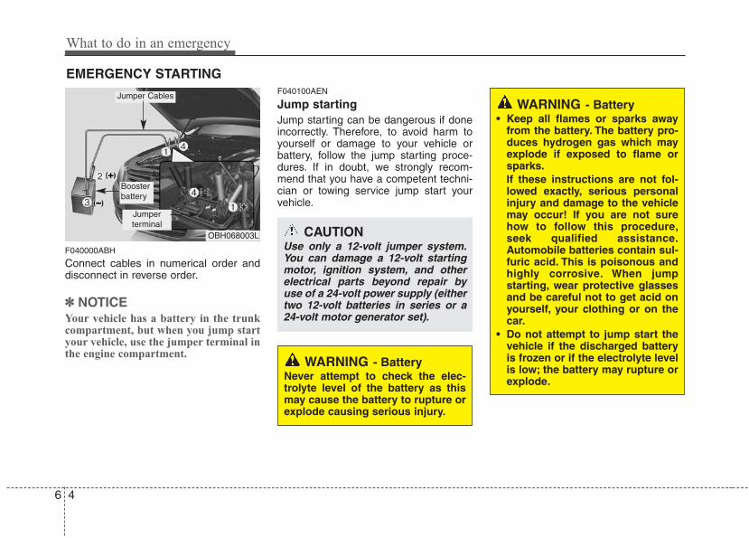
What to do in an emergency
46
EMERGENCY STARTING
F040000ABH
Connect cables in numerical order anddisconnect in reverse order.
✽✽ NOTICEYour vehicle has a battery in the trunkcompartment, but when you jump startyour vehicle, use the jumper terminal inthe engine compartment.
F040100AEN
Jump starting Jump starting can be dangerous if doneincorrectly. Therefore, to avoid harm toyourself or damage to your vehicle orbattery, follow the jump starting proce-dures. If in doubt, we strongly recom-mend that you have a competent techni-cian or towing service jump start yourvehicle.
CAUTIONUse only a 12-volt jumper system.You can damage a 12-volt startingmotor, ignition system, and otherelectrical parts beyond repair byuse of a 24-volt power supply (eithertwo 12-volt batteries in series or a24-volt motor generator set).
WARNING - Battery• Keep all flames or sparks away
from the battery. The battery pro-duces hydrogen gas which mayexplode if exposed to flame orsparks.If these instructions are not fol-lowed exactly, serious personalinjury and damage to the vehiclemay occur! If you are not surehow to follow this procedure,seek qualified assistance.Automobile batteries contain sul-furic acid. This is poisonous andhighly corrosive. When jumpstarting, wear protective glassesand be careful not to get acid onyourself, your clothing or on thecar.
• Do not attempt to jump start thevehicle if the discharged batteryis frozen or if the electrolyte levelis low; the battery may rupture orexplode.
WARNING - BatteryNever attempt to check the elec-trolyte level of the battery as thismay cause the battery to rupture orexplode causing serious injury.
OBH068003L
Jumper terminal
Jumper Cables
Boosterbattery
6 5
What to do in an emergency
F040101ABH-EU
Jump starting procedure ✽✽ NOTICEYour vehicle has a battery in the trunkcompartment, but when you jump startyour vehicle, use the jumper terminal inthe engine compartment.
1. Make sure the booster battery is 12-volt and that its negative terminal isgrounded.
2. If the booster battery is in anothervehicle, do not allow the vehicles totouch.
3. Turn off all unnecessary electricalloads.
4. Connect the jumper cables in the exactsequence shown in the illustration.First connect one end of a jumpercable to the positive terminal of thejumper terminal (1), then connect theother end to the positive terminal onthe booster battery (2).Proceed to connect one end of theother jumper cable to the negative ter-minal of the booster battery (3), thenthe other end to the negative terminalof the jumper terminal (4). Do not con-nect it to or near any part that moveswhen the engine is cranked.
Do not allow the jumper cables to con-tact anything except the correct batteryterminals or the correct ground. Do notlean over the battery when makingconnections.
5. Start the engine of the vehicle with thebooster battery and let it run at 2,000rpm, then start the engine of the vehi-cle with the discharged battery.
6. Let the discharged battery run for atleast 20 minutes either by engineidling or by driving before you turn it offelse the discharged battery may not berecharged enough to restart the car.
If the cause of your battery discharging isnot apparent, you should have your vehi-cle checked by an authorized HYUNDAIdealer.
F040200BBH-EU
Push-starting Vehicles equipped with automatic trans-mission cannot be push-started.Follow the directions in this section forjump-starting.
CAUTION - Battery cablesIf you jump start the dischargedbattery in the trunk compartment,do not connect the jumper cablefrom the negative terminal of thebooster battery to the negative ter-minal of the discharged battery.This can cause the discharged bat-tery to overheat and crack, releas-ing battery acid.Connect the jumper cable from thenegative terminal of the boosterbattery to a solid, stationary ormetallic point away from the dis-charged battery.
What to do in an emergency
66
IF THE ENGINE OVERHEATSF050000ABH
If your temperature gauge indicates over-heating, you experience a loss of power,or hear loud pinging or knocking, theengine is probably too hot. If this hap-pens, you should:
1. Pull off the road and stop as soon as itis safe to do so.
2. Place the shift lever in P and set theparking brake. If the air conditioning ison, turn it off.
3. If engine coolant is running out underthe car or steam is coming out fromthe hood, stop the engine. Do not openthe hood until the coolant has stoppedrunning or the steaming has stopped.If there is no visible loss of enginecoolant and no steam, leave theengine running and check to be surethe engine cooling fan is operating. Ifthe fan is not running, turn the engineoff.
4. Check to see if the water pump drivebelt is missing. If it is not missing,check to see that it is tight. If the drivebelt seems to be satisfactory, check forcoolant leaking from the radiator,hoses or under the car. (If the air con-ditioning had been in use, it is normalfor cold water to be draining from itwhen you stop.)
5. If the water pump drive belt is brokenor engine coolant is leaking out, stopthe engine immediately and call thenearest authorized HYUNDAI dealerfor assistance.
6. If you cannot find the cause of theoverheating, wait until the engine tem-perature has returned to normal. Then,if coolant has been lost, carefully addcoolant to the reservoir to bring thefluid level in the reservoir up to thehalfway mark.
7.Proceed with caution, keeping alert forfurther signs of overheating. If over-heating happens again, call an author-ized HYUNDAI dealer for assistance.WARNING
While the engine is running, keephair, hands and clothing away frommoving parts such as the fan anddrive belts to prevent injury.
CAUTIONSerious loss of coolant indicatesthere is a leak in the cooling systemand this should be checked as soonas possible by an authorizedHYUNDAI dealer.
WARNINGDo not remove the radi-ator cap when theengine is hot. This mayresult in coolant beingblown out of the open-
ing and cause serious burns.
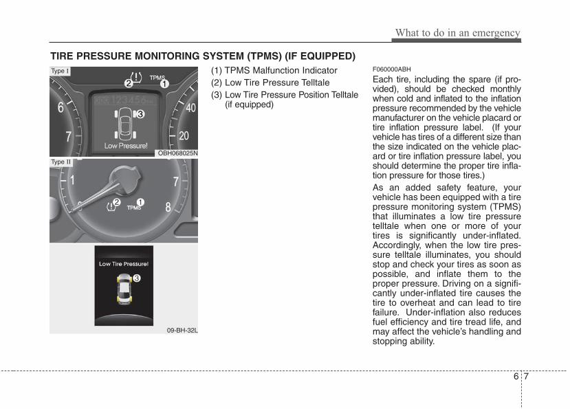
6 7
What to do in an emergency
TIRE PRESSURE MONITORING SYSTEM (TPMS) (IF EQUIPPED)(1) TPMS Malfunction Indicator(2) Low Tire Pressure Telltale(3) Low Tire Pressure Position Telltale
(if equipped)
F060000ABH
Each tire, including the spare (if pro-vided), should be checked monthlywhen cold and inflated to the inflationpressure recommended by the vehiclemanufacturer on the vehicle placard ortire inflation pressure label. (If yourvehicle has tires of a different size thanthe size indicated on the vehicle plac-ard or tire inflation pressure label, youshould determine the proper tire infla-tion pressure for those tires.)As an added safety feature, yourvehicle has been equipped with a tirepressure monitoring system (TPMS)that illuminates a low tire pressuretelltale when one or more of yourtires is significantly under-inflated.Accordingly, when the low tire pres-sure telltale illuminates, you shouldstop and check your tires as soon aspossible, and inflate them to theproper pressure. Driving on a signifi-cantly under-inflated tire causes thetire to overheat and can lead to tirefailure. Under-inflation also reducesfuel efficiency and tire tread life, andmay affect the vehicle’s handling andstopping ability.
OBH068025N
09-BH-32L
Type II
Type I
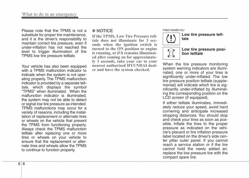
What to do in an emergency
86
Please note that the TPMS is not asubstitute for proper tire maintenance,and it is the driver’s responsibility tomaintain correct tire pressure, even ifunder-inflation has not reached thelevel to trigger illumination of theTPMS low tire pressure telltale.
Your vehicle has also been equippedwith a TPMS malfunction indicator toindicate when the system is not oper-ating properly. The TPMS malfunctionindicator is provided by a separate tell-tale, which displays the symbol"TPMS" when illuminated. When themalfunction indicator is illuminated,the system may not be able to detector signal low tire pressure as intended.TPMS malfunctions may occur for avariety of reasons, including the instal-lation of replacement or alternate tiresor wheels on the vehicle that preventthe TPMS from functioning properly.Always check the TPMS malfunctiontelltale after replacing one or moretires or wheels on your vehicle toensure that the replacement or alter-nate tires and wheels allow the TPMSto continue to function properly.
✽✽ NOTICEIf the TPMS, Low Tire Pressure tell-tale does not illuminate for 3 sec-onds when the ignition switch isturned to the ON position or engineis running, or if it remains illuminat-ed after coming on for approximate-ly 3 seconds, take your car to yournearest authorized HYUNDAI deal-er and have the system checked.
F060100ABH-EU
Low tire pressure tell-tale
Low tire pressure posi-tion telltale
When the tire pressure monitoringsystem warning indicators are illumi-nated, one or more of your tires issignificantly under-inflated. The lowtire pressure position telltale (supple-mental) will indicate which tire is sig-nificantly under-inflated by illuminat-ing the corresponding position on theLCD screen (if equipped).If either telltale illuminates, immedi-ately reduce your speed, avoid hardcornering and anticipate increasedstopping distances. You should stopand check your tires as soon as pos-sible. Inflate the tires to the properpressure as indicated on the vehi-cle’s placard or tire inflation pressurelabel located on the driver’s side cen-ter pillar outer panel. If you cannotreach a service station or if the tirecannot hold the newly added air,replace the low pressure tire with thecompact spare tire.
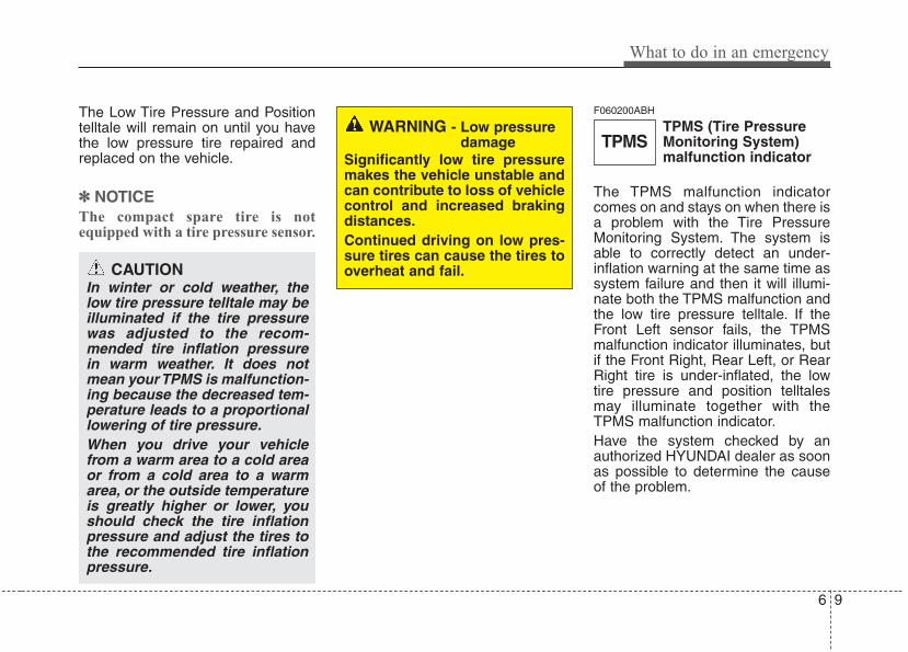
6 9
What to do in an emergency
The Low Tire Pressure and Positiontelltale will remain on until you havethe low pressure tire repaired andreplaced on the vehicle.
✽✽ NOTICEThe compact spare tire is notequipped with a tire pressure sensor.
F060200ABH
TPMS (Tire PressureMonitoring System)malfunction indicator
The TPMS malfunction indicatorcomes on and stays on when there isa problem with the Tire PressureMonitoring System. The system isable to correctly detect an under-inflation warning at the same time assystem failure and then it will illumi-nate both the TPMS malfunction andthe low tire pressure telltale. If theFront Left sensor fails, the TPMSmalfunction indicator illuminates, butif the Front Right, Rear Left, or RearRight tire is under-inflated, the lowtire pressure and position telltalesmay illuminate together with theTPMS malfunction indicator.Have the system checked by anauthorized HYUNDAI dealer as soonas possible to determine the causeof the problem.
WARNING - Low pressuredamage
Significantly low tire pressuremakes the vehicle unstable andcan contribute to loss of vehiclecontrol and increased brakingdistances.Continued driving on low pres-sure tires can cause the tires tooverheat and fail.CAUTION
In winter or cold weather, thelow tire pressure telltale may beilluminated if the tire pressurewas adjusted to the recom-mended tire inflation pressurein warm weather. It does notmean your TPMS is malfunction-ing because the decreased tem-perature leads to a proportionallowering of tire pressure.When you drive your vehiclefrom a warm area to a cold areaor from a cold area to a warmarea, or the outside temperatureis greatly higher or lower, youshould check the tire inflationpressure and adjust the tires tothe recommended tire inflationpressure.
TPMS
What to do in an emergency
106
F060300BBH-EU
Changing a tire with TPMSIf you have a flat tire, the Low TirePressure and Position telltales willcome on. Have the flat tire repairedby an authorized HYUNDAI dealeras soon as possible or replace theflat tire with the compact spare tire.
CAUTIONNEVER use a puncture-repair-ing agent to repair and/or inflatea low pressure tire. The tiresealant can damage the tirepressure sensor. If used, youwill have to replace the tire pres-sure sensor.
(Continued)• If there is a failed tire sensor, it
is possible for TPMS to tem-porarily learn a replacementsensor when you drive closelyto another vehicle equippedwith TPMS too. In rare cases,this may temporarily delay theTPMS malfunction turning on.
CAUTION• The TPMS malfunction indica-
tor may be illuminated if thevehicle is moving around elec-tric power supply cables orradio transmitter such as atpolice stations, governmentand public offices, broadcast-ing stations, military installa-tions, airports, or transmittingtowers, etc. This can interferewith normal operation of theTire Pressure MonitoringSystem (TPMS).
• The TPMS malfunction indica-tor may be illuminated if snowchains are used or some sep-arate electronic devices suchas notebook computer, mobilecharger, remote starter or nav-igation etc., are used in thevehicle.This can interfere withnormal operation of the TirePressure Monitoring System(TPMS).
(Continued)
6 11
What to do in an emergency
Each wheel is equipped with a tirepressure sensor mounted inside thetire behind the valve stem. You mustuse TPMS specific wheels. It is rec-ommended that you always have yourtires serviced by an authorizedHYUNDAI dealer as soon as possible.The spare tire is not equipped with atire pressure monitoring sensor.When the low pressure tire isreplaced with the spare tire, the lowtire pressure and the low tire pres-sure position telltales may extinguishand the TPMS malfunction indicatormay illuminate after restarting andwithin 20 minutes continuous driving.The TPMS malfunction indicator mayremain on until the original tireequipped with a tire pressure moni-toring sensor is reinflated to the rec-ommended pressure and reinstalledon the vehicle until the vehicle hasbeen driven for a few minutes.
Once the low pressure tire is re-inflated to the recommended pres-sure and installed on the vehicle, theTPMS malfunction indicator and thelow tire pressure and position tell-tales will extinguish within a few min-utes of driving.If the indicators do not extinguishafter a few minutes, please visit anauthorized HYUNDAI dealer.You may not be able identify a low tireby simply looking at it. Always use agood quality tire pressure gauge tomeasure the tire's inflation pressure.Please note that a tire that is hot (frombeing driven) will have a higher pres-sure measurement than a tire that iscold (from sitting stationary for at least3 hours and driven less than 1 mile(1.6km) during that 3 hour period).Allow the tire to cool before measur-ing the inflation pressure. Always besure the tire is cold before inflating tothe recommended pressure.A cold tire means the vehicle hasbeen sitting for 3 hours and driven forless than 1 mile (1.6km) in that 3hour period.
CAUTION• Do not use any tire sealant if
your vehicle is equipped witha Tire Pressure MonitoringSystem.The liquid sealant candamage the tire pressure sen-sors.
• In order to correctly monitortire inflation, the 4 tire pres-sure monitoring sensorsshould be exactly fitted toeach of the 4 driven wheels.There should not be any othersensors in the vehicle (includ-ing in the spare tire), as thismay cause the system toincorrectly monitor tire infla-tion.
What to do in an emergency
126
WARNING Changes or modifications notexpressly approved by the partyresponsible for compliancecould void the user's authorityto operate the equipment.
This device complies with Part 15of the FCC rules.Operation is subject to the followingtwo conditions:1. This device may not cause harm-
ful interference, and 2. This device must accept any inter-
ference received, including inter-ference that may cause undesiredoperation.
WARNING - ProtectingTPMS
Tampering with, modifying, ordisabling the Tire PressureMonitoring System (TPMS)components may interfere withthe system's ability to warn thedriver of low tire pressure con-ditions and/or TPMS malfunc-tions. Tampering with, modify-ing, or disabling the TirePressure Monitoring System(TPMS) components may voidthe warranty for that portion ofthe vehicle.
WARNING - TPMS• The TPMS cannot alert you to
severe and sudden tire dam-age caused by external fac-tors such as nails or roaddebris.
• If you feel any vehicle instabil-ity, immediately take your footoff the accelerator, apply thebrakes gradually and withlight force, and slowly move toa safe position off the road.
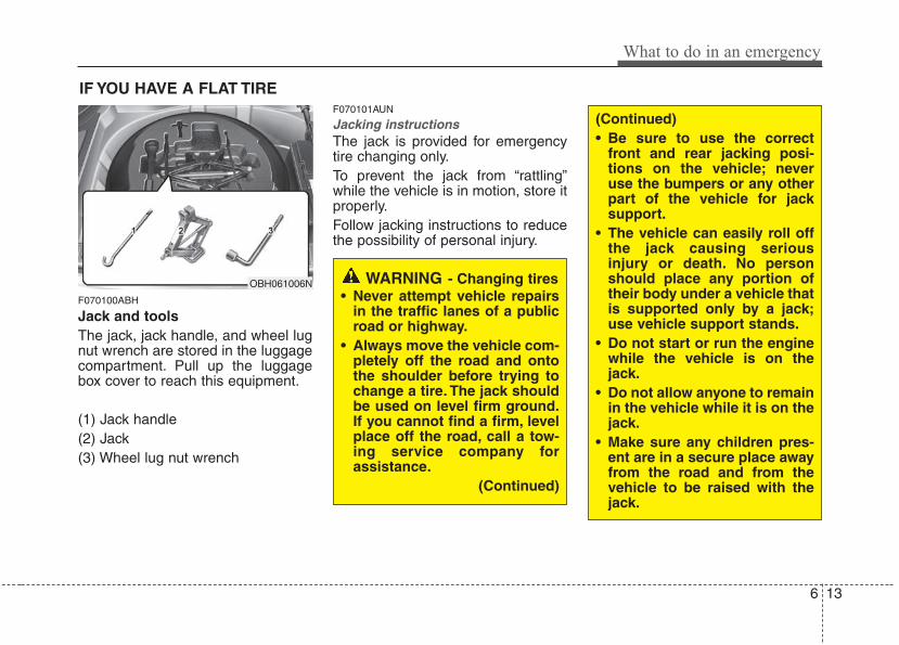
6 13
What to do in an emergency
IF YOU HAVE A FLAT TIRE
F070100ABH
Jack and toolsThe jack, jack handle, and wheel lugnut wrench are stored in the luggagecompartment. Pull up the luggagebox cover to reach this equipment.
(1) Jack handle(2) Jack(3) Wheel lug nut wrench
F070101AUN
Jacking instructions The jack is provided for emergencytire changing only.To prevent the jack from “rattling”while the vehicle is in motion, store itproperly.Follow jacking instructions to reducethe possibility of personal injury.
WARNING - Changing tires• Never attempt vehicle repairs
in the traffic lanes of a publicroad or highway.
• Always move the vehicle com-pletely off the road and ontothe shoulder before trying tochange a tire. The jack shouldbe used on level firm ground.If you cannot find a firm, levelplace off the road, call a tow-ing service company forassistance.
(Continued)
OBH061006N
(Continued)• Be sure to use the correct
front and rear jacking posi-tions on the vehicle; neveruse the bumpers or any otherpart of the vehicle for jacksupport.
• The vehicle can easily roll offthe jack causing seriousinjury or death. No personshould place any portion oftheir body under a vehicle thatis supported only by a jack;use vehicle support stands.
• Do not start or run the enginewhile the vehicle is on thejack.
• Do not allow anyone to remainin the vehicle while it is on thejack.
• Make sure any children pres-ent are in a secure place awayfrom the road and from thevehicle to be raised with thejack.
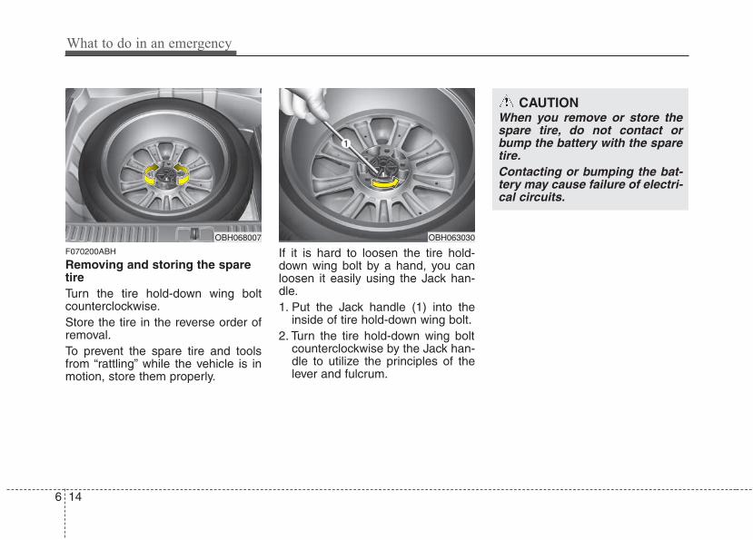
What to do in an emergency
146
F070200ABH
Removing and storing the sparetire Turn the tire hold-down wing boltcounterclockwise.Store the tire in the reverse order ofremoval.To prevent the spare tire and toolsfrom “rattling” while the vehicle is inmotion, store them properly.
If it is hard to loosen the tire hold-down wing bolt by a hand, you canloosen it easily using the Jack han-dle.1. Put the Jack handle (1) into the
inside of tire hold-down wing bolt.2. Turn the tire hold-down wing bolt
counterclockwise by the Jack han-dle to utilize the principles of thelever and fulcrum.
OBH068007
CAUTIONWhen you remove or store thespare tire, do not contact orbump the battery with the sparetire.Contacting or bumping the bat-tery may cause failure of electri-cal circuits.
OBH063030
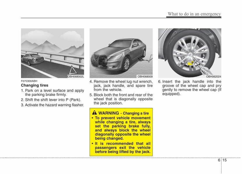
6 15
What to do in an emergency
F070300ABH
Changing tires 1. Park on a level surface and apply
the parking brake firmly.2. Shift the shift lever into P (Park).3. Activate the hazard warning flasher.
4. Remove the wheel lug nut wrench,jack, jack handle, and spare tirefrom the vehicle.
5. Block both the front and rear of thewheel that is diagonally oppositethe jack position.
6. Insert the jack handle into thegroove of the wheel cap and prygently to remove the wheel cap (Ifequipped).
OBH068009 OBH062024
WARNING - Changing a tire• To prevent vehicle movement
while changing a tire, alwaysset the parking brake fully,and always block the wheeldiagonally opposite the wheelbeing changed.
• It is recommended that allpassengers exit the vehiclebefore being lifted by the jack.
OBH068002L
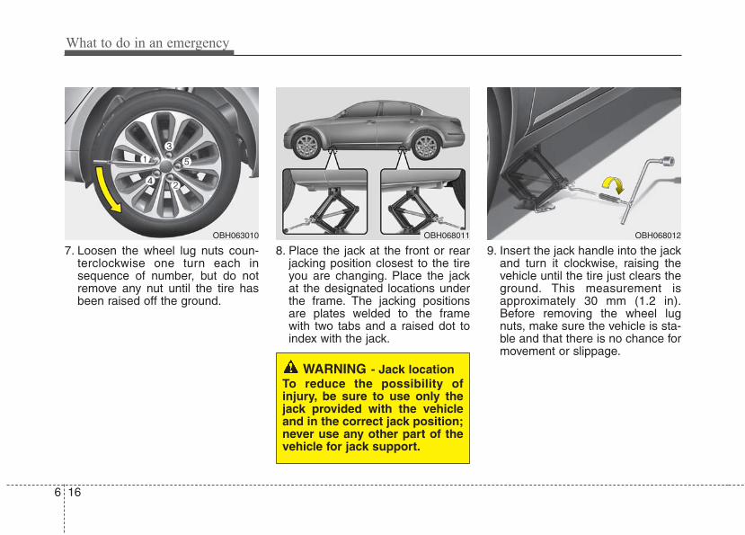
What to do in an emergency
166
7. Loosen the wheel lug nuts coun-terclockwise one turn each insequence of number, but do notremove any nut until the tire hasbeen raised off the ground.
8. Place the jack at the front or rearjacking position closest to the tireyou are changing. Place the jackat the designated locations underthe frame. The jacking positionsare plates welded to the framewith two tabs and a raised dot toindex with the jack.
9. Insert the jack handle into the jackand turn it clockwise, raising thevehicle until the tire just clears theground. This measurement isapproximately 30 mm (1.2 in).Before removing the wheel lugnuts, make sure the vehicle is sta-ble and that there is no chance formovement or slippage.
WARNING - Jack locationTo reduce the possibility ofinjury, be sure to use only thejack provided with the vehicleand in the correct jack position;never use any other part of thevehicle for jack support.
OBH068011 OBH068012OBH063010
6 17
What to do in an emergency
10. Loosen the wheel nuts andremove them with your fingers.Slide the wheel off the studs andlay it flat so it cannot roll away. Toput the wheel on the hub, pick upthe spare tire, line up the holeswith the studs and slide thewheel onto them. If this is diffi-cult, tip the wheel slightly and getthe top hole in the wheel lined upwith the top stud. Then jiggle thewheel back and forth until thewheel can be slid over the otherstuds.
11. To reinstall the wheel, hold it onthe studs, put the wheel nuts onthe studs and tighten them fingertight.The nuts should be installedwith their tapered small diameterends directed inward. Jiggle thetire to be sure it is completelyseated, then tighten the nuts asmuch as possible with your fin-gers again.
12. Lower the car to the ground byturning the wheel nut wrenchcounterclockwise.
WARNINGWheels may have sharp edges.Handle them carefully to avoidpossible severe injury. Beforeputting the wheel into place, besure that there is nothing on thehub or wheel (such as mud, tar,gravel, etc.) that prevents thewheel from fitting solidlyagainst the hub.If there is, remove it. If there isnot good contact on the mount-ing surface between the wheeland hub, the wheel nuts couldcome loose and cause the lossof a wheel. Loss of a wheel mayresult in loss of control of thevehicle. This may cause seriousinjury or death.
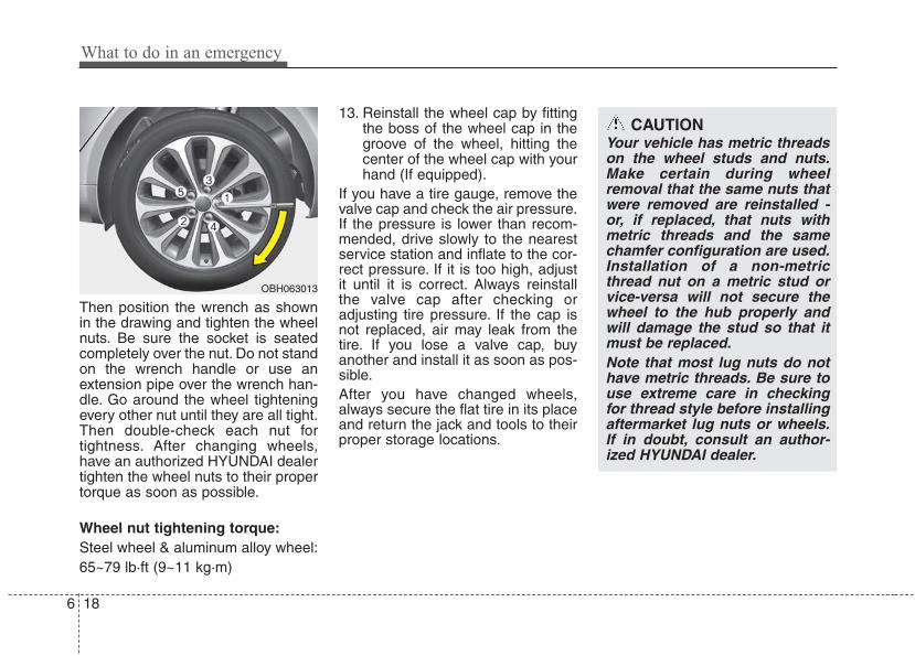
What to do in an emergency
186
Then position the wrench as shownin the drawing and tighten the wheelnuts. Be sure the socket is seatedcompletely over the nut. Do not standon the wrench handle or use anextension pipe over the wrench han-dle. Go around the wheel tighteningevery other nut until they are all tight.Then double-check each nut fortightness. After changing wheels,have an authorized HYUNDAI dealertighten the wheel nuts to their propertorque as soon as possible.
Wheel nut tightening torque:Steel wheel & aluminum alloy wheel:65~79 lb·ft (9~11 kg·m)
13. Reinstall the wheel cap by fittingthe boss of the wheel cap in thegroove of the wheel, hitting thecenter of the wheel cap with yourhand (If equipped).
If you have a tire gauge, remove thevalve cap and check the air pressure.If the pressure is lower than recom-mended, drive slowly to the nearestservice station and inflate to the cor-rect pressure. If it is too high, adjustit until it is correct. Always reinstallthe valve cap after checking oradjusting tire pressure. If the cap isnot replaced, air may leak from thetire. If you lose a valve cap, buyanother and install it as soon as pos-sible.After you have changed wheels,always secure the flat tire in its placeand return the jack and tools to theirproper storage locations.
CAUTIONYour vehicle has metric threadson the wheel studs and nuts.Make certain during wheelremoval that the same nuts thatwere removed are reinstalled -or, if replaced, that nuts withmetric threads and the samechamfer configuration are used.Installation of a non-metricthread nut on a metric stud orvice-versa will not secure thewheel to the hub properly andwill damage the stud so that itmust be replaced.Note that most lug nuts do nothave metric threads. Be sure touse extreme care in checkingfor thread style before installingaftermarket lug nuts or wheels.If in doubt, consult an author-ized HYUNDAI dealer.
OBH063013
6 19
What to do in an emergency
To prevent the jack, jack handle,wheel lug nut wrench and spare tirefrom rattling while the vehicle is inmotion, store them properly.
F070301BBH
Important - use of compact spare tireYour vehicle is equipped with a com-pact spare tire. This compact sparetire takes up less space than a regu-lar-size tire. This tire is smaller than aconventional tire and is designed fortemporary use only.
The compact spare should be inflat-ed to 60 psi (420 kPa).
✽✽ NOTICECheck the inflation pressure afterinstalling the spare tire. Adjust it tothe specified pressure, as necessary.
WARNING - Inadequatespare tire pressure
Check the inflation pressures assoon as possible after installingthe spare tire. Adjust it to thespecified pressure, if necessary.Refer to “Tires and wheels” sec-tion 8.
WARNINGThe compact spare tire is foremergency use only. Do notoperate your vehicle on thiscompact spare at speeds over50 mph (80 km/h). The originaltire should be repaired orreplaced as soon as is possibleto avoid failure of the sparepossibly leading to personalinjury or death.
WARNING - Wheel studsIf the studs are damaged, theymay lose their ability to retainthe wheel.This could lead to theloss of the wheel and a collisionresulting in serious injuries.
CAUTION• You should drive carefully
when the compact spare is inuse. The compact spareshould be replaced by theproper conventional tire andrim at the first opportunity.
• The operation of this vehicleis not recommended withmore than one compact sparetire in use at the same time.
What to do in an emergency
206
When using a compact spare tire,observe the following precautions:• Under no circumstances should
you exceed 50 mph (80 km/h); ahigher speed could damage thetire.
• Ensure that you drive slowlyenough for the road conditions toavoid all hazards. Any road hazard,such as a pothole or debris, couldseriously damage the compactspare.
• Any continuous road use of this tirecould result in tire failure, loss ofvehicle control, and possible per-sonal injury.
• Do not exceed the vehicle’s maxi-mum load rating or the load-carry-ing capacity shown on the sidewallof the compact spare tire.
• Avoid driving over obstacles. Thecompact spare tire diameter issmaller than the diameter of a con-ventional tire and reduces theground clearance approximately 1inch (25 mm), which could result indamage to the vehicle.
• Do not take this vehicle through anautomatic car wash while the com-pact spare tire is installed.
• Do not use tire chains on the com-pact spare tire. Because of thesmaller size, a tire chain will not fitproperly. This could damage thevehicle and result in loss of thechain.
• Do not use the compact spare tireon any other vehicle because thistire has been designed especiallyfor your vehicle.
• The compact spare tire’s tread lifeis shorter than a regular tire.Inspect your compact spare tireregularly and replace worn com-pact spare tires with the same sizeand design, mounted on the samewheel.
• The compact spare tire should notbe used on any other wheels, norshould standard tires, snow tires,wheel covers or trim rings be usedwith the compact spare wheel. Ifsuch use is attempted, damage tothese items or other car compo-nents may occur.
• Do not use more than one compactspare tire at a time.
• Do not tow a trailer while the com-pact spare tire is installed.
CAUTIONWhen the original tire and wheelare repaired and reinstalled onthe vehicle, the wheel nut torquemust be set correctly to preventwheel vibration. The correctwheel nut tightening torque is65~79lb-ft (9~11kg.m).
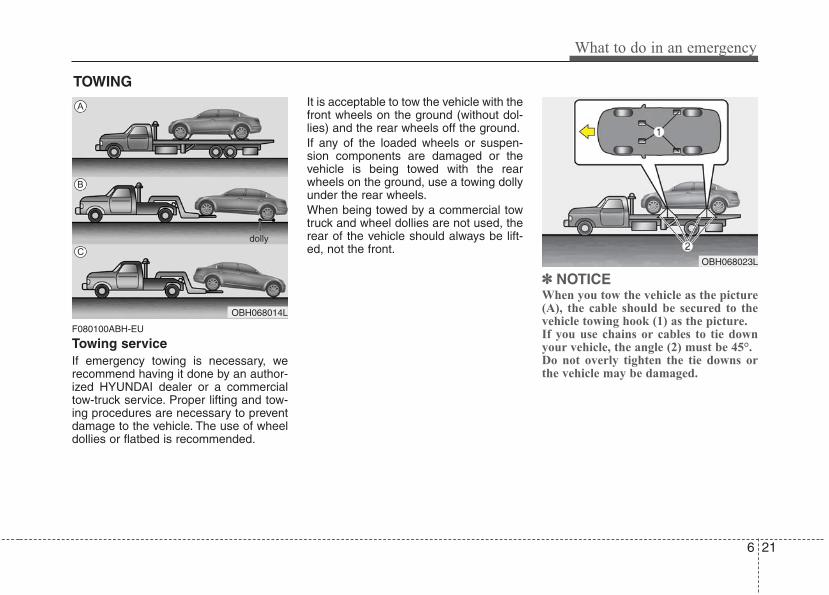
6 21
What to do in an emergency
TOWING
F080100ABH-EU
Towing serviceIf emergency towing is necessary, werecommend having it done by an author-ized HYUNDAI dealer or a commercialtow-truck service. Proper lifting and tow-ing procedures are necessary to preventdamage to the vehicle. The use of wheeldollies or flatbed is recommended.
It is acceptable to tow the vehicle with thefront wheels on the ground (without dol-lies) and the rear wheels off the ground.If any of the loaded wheels or suspen-sion components are damaged or thevehicle is being towed with the rearwheels on the ground, use a towing dollyunder the rear wheels.When being towed by a commercial towtruck and wheel dollies are not used, therear of the vehicle should always be lift-ed, not the front.
✽✽ NOTICEWhen you tow the vehicle as the picture(A), the cable should be secured to thevehicle towing hook (1) as the picture.If you use chains or cables to tie downyour vehicle, the angle (2) must be 45°.Do not overly tighten the tie downs orthe vehicle may be damaged.
OBH068014L
dolly
OBH068023L
A
B
C
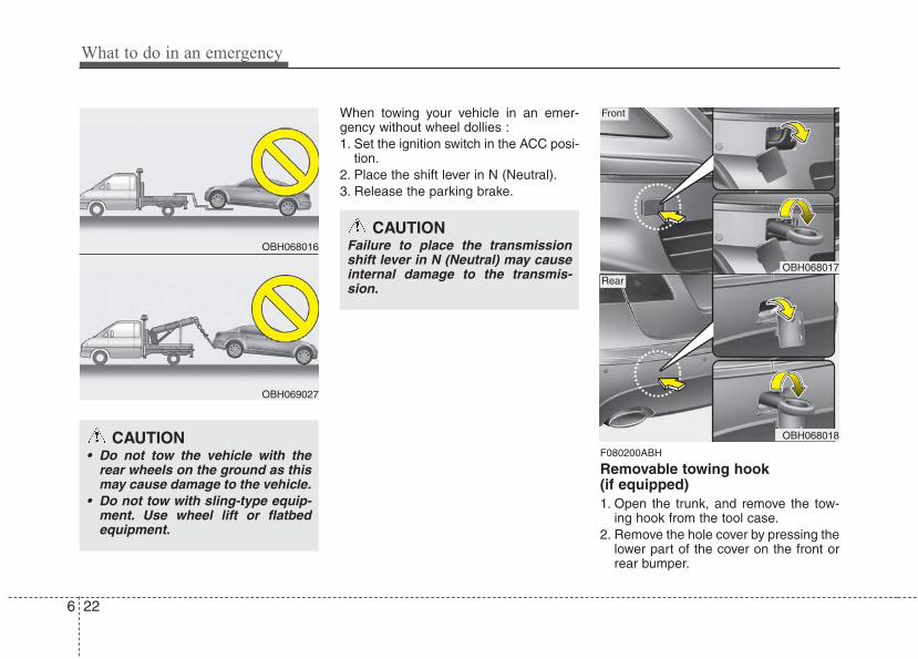
What to do in an emergency
226
When towing your vehicle in an emer-gency without wheel dollies :1. Set the ignition switch in the ACC posi-
tion.2. Place the shift lever in N (Neutral).3. Release the parking brake.
F080200ABH
Removable towing hook (if equipped)1. Open the trunk, and remove the tow-
ing hook from the tool case.2. Remove the hole cover by pressing the
lower part of the cover on the front orrear bumper.
OBH068016
OBH069027
CAUTION• Do not tow the vehicle with the
rear wheels on the ground as thismay cause damage to the vehicle.
• Do not tow with sling-type equip-ment. Use wheel lift or flatbedequipment.
CAUTIONFailure to place the transmissionshift lever in N (Neutral) may causeinternal damage to the transmis-sion.
OBH068017
OBH068018
Front
Rear
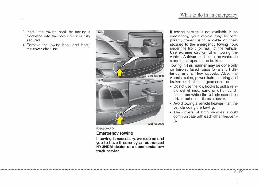
6 23
What to do in an emergency
3. Install the towing hook by turning itclockwise into the hole until it is fullysecured.
4. Remove the towing hook and installthe cover after use.
F080300AFD
Emergency towingIf towing is necessary, we recommendyou to have it done by an authorizedHYUNDAI dealer or a commercial towtruck service.
If towing service is not available in anemergency, your vehicle may be tem-porarily towed using a cable or chainsecured to the emergency towing hookunder the front (or rear) of the vehicle.Use extreme caution when towing thevehicle. A driver must be in the vehicle tosteer it and operate the brakes.Towing in this manner may be done onlyon hard-surfaced roads for a short dis-tance and at low speeds. Also, thewheels, axles, power train, steering andbrakes must all be in good condition.• Do not use the tow hooks to pull a vehi-
cle out of mud, sand or other condi-tions from which the vehicle cannot bedriven out under its own power.
• Avoid towing a vehicle heavier than thevehicle doing the towing.
• The drivers of both vehicles shouldcommunicate with each other frequent-ly.
OBH068019
OBH068020
Front
Rear
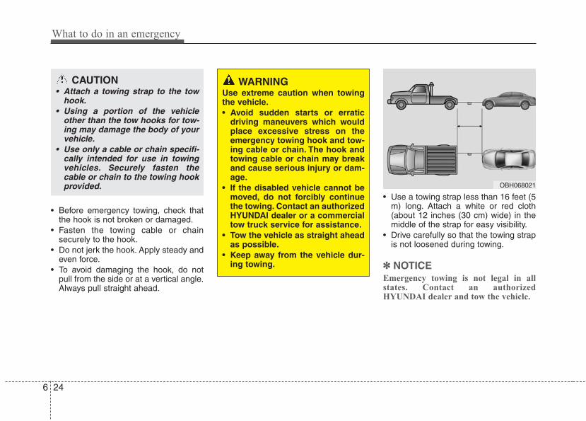
What to do in an emergency
246
• Before emergency towing, check thatthe hook is not broken or damaged.
• Fasten the towing cable or chainsecurely to the hook.
• Do not jerk the hook. Apply steady andeven force.
• To avoid damaging the hook, do notpull from the side or at a vertical angle.Always pull straight ahead.
• Use a towing strap less than 16 feet (5m) long. Attach a white or red cloth(about 12 inches (30 cm) wide) in themiddle of the strap for easy visibility.
• Drive carefully so that the towing strapis not loosened during towing.
✽✽ NOTICEEmergency towing is not legal in allstates. Contact an authorizedHYUNDAI dealer and tow the vehicle.
CAUTION• Attach a towing strap to the tow
hook.• Using a portion of the vehicle
other than the tow hooks for tow-ing may damage the body of yourvehicle.
• Use only a cable or chain specifi-cally intended for use in towingvehicles. Securely fasten thecable or chain to the towing hookprovided.
WARNING Use extreme caution when towingthe vehicle.• Avoid sudden starts or erratic
driving maneuvers which wouldplace excessive stress on theemergency towing hook and tow-ing cable or chain. The hook andtowing cable or chain may breakand cause serious injury or dam-age.
• If the disabled vehicle cannot bemoved, do not forcibly continuethe towing. Contact an authorizedHYUNDAI dealer or a commercialtow truck service for assistance.
• Tow the vehicle as straight aheadas possible.
• Keep away from the vehicle dur-ing towing.
OBH068021
6 25
What to do in an emergency
F080301ABH
Emergency towing precautions• Place the transmission shift lever in N
(Neutral).• Release the parking brake.• Press the brake pedal with more force
than normal since you will havereduced brake performance.
• More steering effort will be requiredbecause the power steering systemwill be disabled.
• If you are driving down a long hill, thebrakes may overheat and brake per-formance will be reduced. Stop oftenand let the brakes cool off.
CAUTION - Automatictransmission
• If the car is being towed with allfour wheels on the ground, it canbe towed only from the front. Besure that the transmission is inneutral. Be sure the steering isunlocked by placing the ignitionswitch in the ACC position. Adriver must be in the towed vehi-cle to operate the steering andbrakes.
• To avoid serious damage to theautomatic transmission, limit thevehicle speed to 10 mph (15 km/h)and drive less than 1 mile (1.5km) when towing.
• Before towing, check the auto-matic transmission for fluid leaksunder your vehicle. If the auto-matic transmission fluid is leak-ing, flatbed equipment or a tow-ing dolly must be used.
7
Engine compartment / 7-2
Maintenance services / 7-4
Owner maintenance / 7-5
Scheduled maintenance service / 7-7
Explanation of scheduled maintenance items / 7-12
Engine oil / 7-15
Engine coolant / 7-17
Brake fluid / 7-20
Power steering fluid / 7-21
Washer fluid / 7-22
Parking brake / 7-23
Air cleaner / 7-23
Climate control air filter / 7-26
Wiper blades / 7-28
Battery / 7-31
Tires and wheels / 7-34
Fuses / 7-48
Light bulbs / 7-62
Appearance care / 7-71
Emission control system / 7-77
California perchlorate notice / 7-80
Maintenance
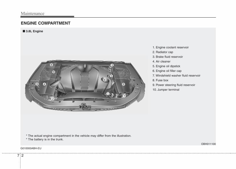
Maintenance
27
ENGINE COMPARTMENT
G010000ABH-EU
■■ 3.8L Engine
OBH011100
* The actual engine compartment in the vehicle may differ from the illustration.
* The battery is in the trunk.
1. Engine coolant reservoir
2. Radiator cap
3. Brake fluid reservoir
4. Air cleaner
5. Engine oil dipstick
6. Engine oil filler cap
7. Windshield washer fluid reservoir
8. Fuse box
9. Power steering fluid reservoir
10. Jumper terminal
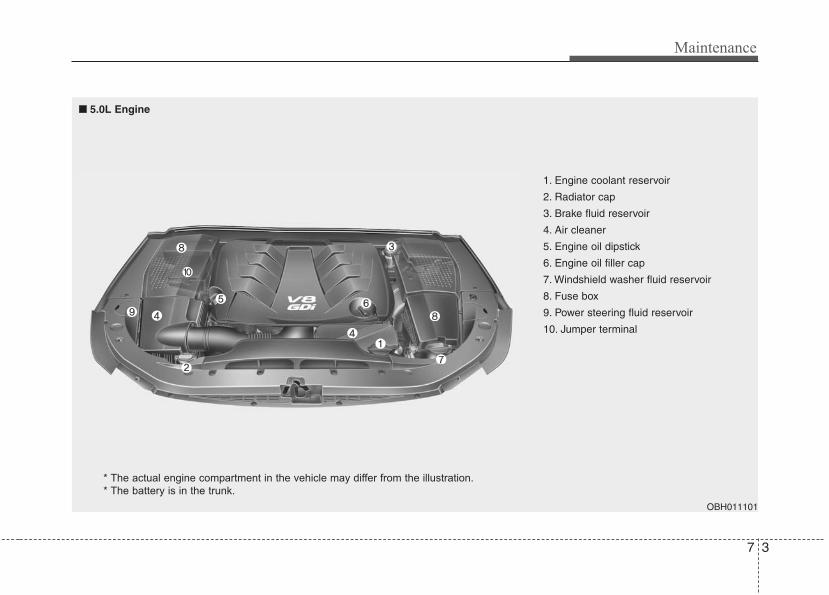
7 3
Maintenance
OBH011101
1. Engine coolant reservoir
2. Radiator cap
3. Brake fluid reservoir
4. Air cleaner
5. Engine oil dipstick
6. Engine oil filler cap
7. Windshield washer fluid reservoir
8. Fuse box
9. Power steering fluid reservoir
10. Jumper terminal
■■ 5.0L Engine
* The actual engine compartment in the vehicle may differ from the illustration.
* The battery is in the trunk.
Maintenance
47
MAINTENANCE SERVICESG020000AEN
You should exercise the utmost care toprevent damage to your vehicle andinjury to yourself whenever performingany maintenance or inspection proce-dures.Should you have any doubts concerningthe inspection or servicing of your vehi-cle, we strongly recommend that youhave an authorized HYUNDAI dealerperform this work.An authorized HYUNDAI dealer has fac-tory-trained technicians and genuineHYUNDAI parts to service your vehicleproperly. For expert advice and qualityservice, see an authorized HYUNDAIdealer.Inadequate, incomplete or insufficientservicing may result in operational prob-lems with your vehicle that could lead tovehicle damage, an accident, or person-al injury.
G020100AEN-EU
Owner’s responsibility
✽✽ NOTICEMaintenance Service and RecordRetention are the owner's responsibility.
You should retain documents that showproper maintenance has been performedon your vehicle in accordance with thescheduled maintenance service chartsshown on the following pages. You needthis information to establish your compli-ance with the servicing and maintenancerequirements of your vehicle warranties.Detailed warranty information is providedin your Owner’s Handbook & WarrantyInformation booklet.Repairs and adjustments required as aresult of improper maintenance or a lackof required maintenance are not covered.We recommend you have your vehiclemaintained and repaired by an author-ized HYUNDAI dealer. An authorizedHYUNDAI dealer meets HYUNDAI’s highservice quality standards and receivestechnical support from HYUNDAI inorder to provide you with a high level ofservice satisfaction.
G020200AEN-EU
Owner maintenance precautions Improper or incomplete service mayresult in problems. This section givesinstructions only for the maintenanceitems that are easy to perform.As explained earlier in this section, sev-eral procedures can be done only by anauthorized HYUNDAI dealer with specialtools.
✽✽ NOTICEImproper owner maintenance duringthe warranty period may affect warran-ty coverage. For details, read the sepa-rate Owner’s Handbook & WarrantyInformation booklet provided with thevehicle. If you're unsure about any serv-icing or maintenance procedure, have itdone by an authorized HYUNDAI deal-er.
7 5
Maintenance
WARNING Be careful when checking yourengine coolant level when theengine is hot. Scalding hot coolantand steam may blow out underpressure. This could cause burnsor other serious injury.
G030000AEN
The following lists are vehicle checks andinspections that should be performed bythe owner or an authorized HYUNDAIdealer at the frequencies indicated tohelp ensure safe, dependable operationof your vehicle.Any adverse conditions should bebrought to the attention of your dealer assoon as possible.These Owner Maintenance Checks aregenerally not covered by warranties andyou may be charged for labor, parts andlubricants used.
Owner maintenance schedule G030101AUN
When you stop for fuel:• Check the engine oil level.• Check coolant level in coolant reser-
voir.• Check the windshield washer fluid
level.• Look for low or under-inflated tires.
WARNING - Maintenancework
• Performing maintenance work ona vehicle can be dangerous. Youcan be seriously injured whileperforming some maintenanceprocedures. If you lack sufficientknowledge and experience or theproper tools and equipment to dothe work, have it done by anauthorized HYUNDAI dealer.
• Working under the hood with theengine running is dangerous. Itbecomes even more dangerouswhen you wear jewelry or looseclothing. These can becomeentangled in moving parts andresult in injury. Therefore, if youmust run the engine while work-ing under the hood, make certainthat you remove all jewelry (espe-cially rings, bracelets, watches,and necklaces) and all neckties,scarves, and similar loose cloth-ing before getting near theengine or cooling fans.
OWNER MAINTENANCE
Maintenance
67
G030102ABH
While operating your vehicle:• Note any changes in the sound of the
exhaust or any smell of exhaust fumesin the vehicle.
• Check for vibrations in the steeringwheel. Notice any increased steeringeffort or looseness in the steeringwheel, or change in its straight-aheadposition.
• Notice if your vehicle constantly turnsslightly or “pulls” to one side when trav-eling on smooth, level road.
• When stopping, listen and check forunusual sounds, pulling to one side,increased brake pedal travel or “hard-to-push” brake pedal.
• If any slipping or changes in the oper-ation of your transmission occurs,check the transmission fluid level.
• Check automatic transmission P (Park)function.
• Check parking brake.• Check for fluid leaks under your vehicle
(water dripping from the air condition-ing system during or after use is nor-mal).
G030103AUN
At least monthly:• Check coolant level in the engine
coolant reservoir.• Check the operation of all exterior
lights, including the stoplights, turn sig-nals and hazard warning flashers.
• Check the inflation pressures of alltires including the spare.
G030104AUN
At least twice a year (i.e., every Spring and Fall):• Check radiator, heater and air condi-
tioning hoses for leaks or damage.• Check windshield washer spray and
wiper operation. Clean wiper bladeswith clean cloth dampened with wash-er fluid.
• Check headlight alignment.• Check muffler, exhaust pipes, shields
and clamps.• Check the lap/shoulder belts for wear
and function.• Check for worn tires and loose wheel
lug nuts.
G030105AUN-EU
At least once a year:• Clean body and door drain holes.• Lubricate door hinges and checks, and
hood hinges.• Lubricate door and hood locks and
latches.• Lubricate door rubber weatherstrips.• Check the air conditioning system.• Check the power steering fluid level.• Inspect and lubricate automatic trans-
mission linkage and controls.• Clean battery and terminals.• Check the brake fluid level.
7 7
Maintenance
SCHEDULED MAINTENANCE SERVICE G040000AUN-EU
Follow Normal Maintenance Schedule ifthe vehicle is usually operated wherenone of the following conditions apply. Ifany of the following conditions apply, fol-low Maintenance Under Severe UsageConditions.• Repeated short distance driving.• Driving in dusty conditions or sandy
areas.• Extensive use of brakes.• Driving in areas where salt or other
corrosive materials are being used.• Driving on rough or muddy roads.• Driving in mountainous areas.• Extended periods of idling or low
speed operation.• Driving for a prolonged period in cold
temperatures and/or extremely humidclimates.
• More than 50% driving in heavy citytraffic during hot weather above 90°F(32°C).
If your vehicle is operated under theabove conditions, you should inspect,replace or refill more frequently than thefollowing Normal Maintenance Schedule.After 120 months or 150,000 miles(240,000 km) continue to follow the pre-scribed maintenance intervals.
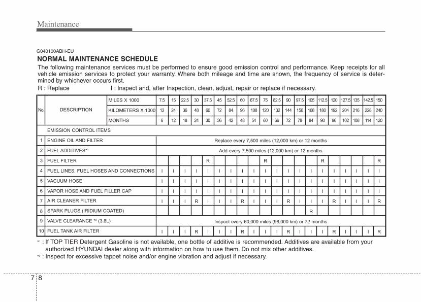
Maintenance
87
G040100ABH-EU
The following maintenance services must be performed to ensure good emission control and performance. Keep receipts for allvehicle emission services to protect your warranty. Where both mileage and time are shown, the frequency of service is deter-mined by whichever occurs first.R : Replace I : Inspect and, after Inspection, clean, adjust, repair or replace if necessary.
NORMAL MAINTENANCE SCHEDULE
*1 : If TOP TIER Detergent Gasoline is not available, one bottle of additive is recommended. Additives are available from yourauthorized HYUNDAI dealer along with information on how to use them. Do not mix other additives.
*2 : Inspect for excessive tappet noise and/or engine vibration and adjust if necessary.
DESCRIPTION
7.5 15 22.5 30 37.5 45 52.5 60 67.5 75 82.5 90 97.5 105 112.5 120 127.5 135 142.5 150
12 24 36 48 60 72 84 96 108 120 132 144 156 168 180 192 204 216 228 240
6 12 18 24 30 36 42 48 54 60 66 72 78 84 90 96 102 108 114 120
Replace every 7,500 miles (12,000 km) or 12 months
Add every 7,500 miles (12,000 km) or 12 months
R R R R
I I I I I I I I I I I I I I I I I I I I
I I I I I I I I I I I I I I I I I I I I
I I I I I I I I I I I I I I I I I I I I
I I I R I I I R I I I R I I I R I I I R
R
Inspect every 60,000 miles (96,000 km) or 72 months
I I I R I I I R I I I R I I I R I I I R
EMISSION CONTROL ITEMS
ENGINE OIL AND FILTER
FUEL ADDITIVES*1
FUEL FILTER
FUEL LINES, FUEL HOSES AND CONNECTIONS
VACUUM HOSE
VAPOR HOSE AND FUEL FILLER CAP
AIR CLEANER FILTER
SPARK PLUGS (IRIDIUM COATED)
VALVE CLEARANCE *2 (3.8L)
FUEL TANK AIR FILTER
No.
1
2
3
4
5
6
7
8
9
10
MILES X 1000
KILOMETERS X 1000
MONTHS
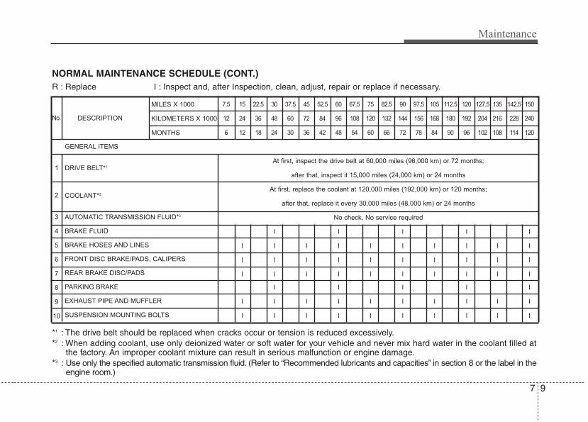
7 9
Maintenance
NORMAL MAINTENANCE SCHEDULE (CONT.)
DESCRIPTION
7.5 15 22.5 30 37.5 45 52.5 60 67.5 75 82.5 90 97.5 105 112.5 120 127.5 135 142.5 150
12 24 36 48 60 72 84 96 108 120 132 144 156 168 180 192 204 216 228 240
6 12 18 24 30 36 42 48 54 60 66 72 78 84 90 96 102 108 114 120
At first, inspect the drive belt at 60,000 miles (96,000 km) or 72 months;
after that, inspect it 15,000 miles (24,000 km) or 24 months
At first, replace the coolant at 120,000 miles (192,000 km) or 120 months;
after that, replace it every 30,000 miles (48,000 km) or 24 months
No check, No service required
I I I I I
I I I I I I I I I I
I I I I I I I I I I
I I I I I I I I I I
I I I I I
I I I I I I I I I I
I I I I I I I I I I
GENERAL ITEMS
DRIVE BELT*1
COOLANT*2
AUTOMATIC TRANSMISSION FLUID*3
BRAKE FLUID
BRAKE HOSES AND LINES
FRONT DISC BRAKE/PADS, CALIPERS
REAR BRAKE DISC/PADS
PARKING BRAKE
EXHAUST PIPE AND MUFFLER
SUSPENSION MOUNTING BOLTS
MILES X 1000
KILOMETERS X 1000
MONTHS
R : Replace I : Inspect and, after Inspection, clean, adjust, repair or replace if necessary.
No.
1
2
3
4
5
6
7
8
9
10
*1 : The drive belt should be replaced when cracks occur or tension is reduced excessively.*2 : When adding coolant, use only deionized water or soft water for your vehicle and never mix hard water in the coolant filled at
the factory. An improper coolant mixture can result in serious malfunction or engine damage.*3 : Use only the specified automatic transmission fluid. (Refer to “Recommended lubricants and capacities” in section 8 or the label in the
engine room.)
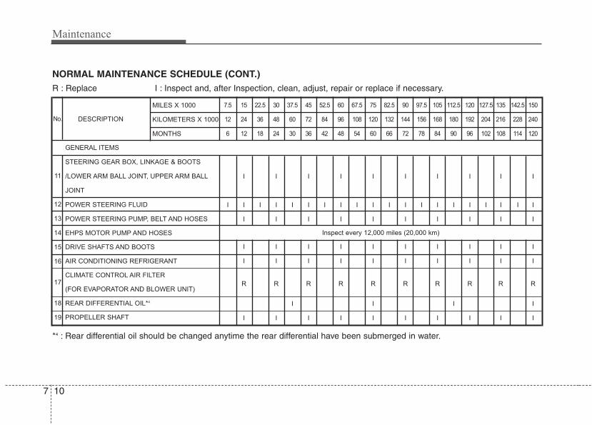
Maintenance
107
NORMAL MAINTENANCE SCHEDULE (CONT.)R : Replace I : Inspect and, after Inspection, clean, adjust, repair or replace if necessary.
*4 : Rear differential oil should be changed anytime the rear differential have been submerged in water.
DESCRIPTION
7.5 15 22.5 30 37.5 45 52.5 60 67.5 75 82.5 90 97.5 105 112.5 120 127.5 135 142.5 150
12 24 36 48 60 72 84 96 108 120 132 144 156 168 180 192 204 216 228 240
6 12 18 24 30 36 42 48 54 60 66 72 78 84 90 96 102 108 114 120
I I I I I I I I I I
I I I I I I I I I I I I I I I I I I I I
I I I I I I I I I I
I I I I I I I I I I
I I I I I I I I I I
R R R R R R R R R R
I I I I
I I I I I I I I I I
GENERAL ITEMS
STEERING GEAR BOX, LINKAGE & BOOTS
/LOWER ARM BALL JOINT, UPPER ARM BALL
JOINT
POWER STEERING FLUID
POWER STEERING PUMP, BELT AND HOSES
EHPS MOTOR PUMP AND HOSES
DRIVE SHAFTS AND BOOTS
AIR CONDITIONING REFRIGERANT
CLIMATE CONTROL AIR FILTER
(FOR EVAPORATOR AND BLOWER UNIT)
REAR DIFFERENTIAL OIL*4
PROPELLER SHAFT
MILES X 1000
KILOMETERS X 1000
MONTHS
No.
11
12
13
14
15
16
17
18
19
Inspect every 12,000 miles (20,000 km)
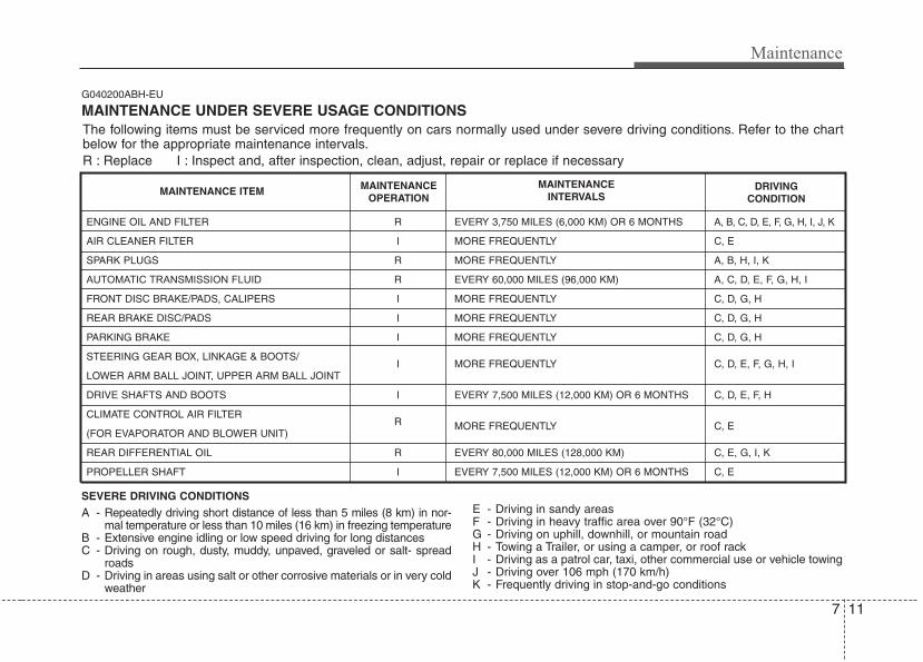
7 11
Maintenance
G040200ABH-EU
MAINTENANCE UNDER SEVERE USAGE CONDITIONS
SEVERE DRIVING CONDITIONS
A - Repeatedly driving short distance of less than 5 miles (8 km) in nor-mal temperature or less than 10 miles (16 km) in freezing temperature
B - Extensive engine idling or low speed driving for long distancesC - Driving on rough, dusty, muddy, unpaved, graveled or salt- spread
roadsD - Driving in areas using salt or other corrosive materials or in very cold
weather
E - Driving in sandy areasF - Driving in heavy traffic area over 90°F (32°C)G - Driving on uphill, downhill, or mountain roadH - Towing a Trailer, or using a camper, or roof rackI - Driving as a patrol car, taxi, other commercial use or vehicle towingJ - Driving over 106 mph (170 km/h)K - Frequently driving in stop-and-go conditions
ENGINE OIL AND FILTER
AIR CLEANER FILTER
SPARK PLUGS
AUTOMATIC TRANSMISSION FLUID
FRONT DISC BRAKE/PADS, CALIPERS
REAR BRAKE DISC/PADS
PARKING BRAKE
STEERING GEAR BOX, LINKAGE & BOOTS/
LOWER ARM BALL JOINT, UPPER ARM BALL JOINT
DRIVE SHAFTS AND BOOTS
CLIMATE CONTROL AIR FILTER
(FOR EVAPORATOR AND BLOWER UNIT)
REAR DIFFERENTIAL OIL
PROPELLER SHAFT
R
I
R
R
I
I
I
I
I
R
R
I
EVERY 3,750 MILES (6,000 KM) OR 6 MONTHS
MORE FREQUENTLY
MORE FREQUENTLY
EVERY 60,000 MILES (96,000 KM)
MORE FREQUENTLY
MORE FREQUENTLY
MORE FREQUENTLY
MORE FREQUENTLY
EVERY 7,500 MILES (12,000 KM) OR 6 MONTHS
MORE FREQUENTLY
EVERY 80,000 MILES (128,000 KM)
EVERY 7,500 MILES (12,000 KM) OR 6 MONTHS
A, B, C, D, E, F, G, H, I, J, K
C, E
A, B, H, I, K
A, C, D, E, F, G, H, I
C, D, G, H
C, D, G, H
C, D, G, H
C, D, E, F, G, H, I
C, D, E, F, H
C, E
C, E, G, I, K
C, E
MAINTENANCE ITEM MAINTENANCEOPERATION
MAINTENANCEINTERVALS
DRIVINGCONDITION
The following items must be serviced more frequently on cars normally used under severe driving conditions. Refer to the chartbelow for the appropriate maintenance intervals.R : Replace I : Inspect and, after inspection, clean, adjust, repair or replace if necessary
Maintenance
127
EXPLANATION OF SCHEDULED MAINTENANCE ITEMSG050100AUN
Engine oil and filterThe engine oil and filter should bechanged at the intervals specified in themaintenance schedule. If the car is beingdriven in severe conditions, more fre-quent oil and filter changes are required.
G050200AUN
Drive beltsInspect all drive belts for evidence of cuts,cracks, excessive wear or oil saturationand replace if necessary.
G050300ABH
Fuel filterA clogged filter can limit the speed atwhich the vehicle may be driven, damagethe emission system and cause multipleissues such as hard starting. If an exces-sive amount of foreign matter accumu-lates in the fuel tank, the filter mayrequire replacement more frequently.After installing a new filter, run the engine forseveral minutes, and check for leaks at theconnections. Fuel filters should be installedby an authorized HYUNDAI dealer.
G050400AEN-EU
Fuel lines, fuel hoses and con-nectionsCheck the fuel lines, fuel hoses and con-nections for leakage and damage. Have anauthorized HYUNDAI dealer replace anydamaged or leaking parts immediately.
G050600AUN
Vapor hose and fuel filler capThe vapor hose and fuel filler cap shouldbe inspected at those intervals specifiedin the maintenance schedule. Make surethat a new vapor hose or fuel filler cap iscorrectly replaced.
G050700AUN
Vacuum hoseInspect the surface of hoses for evidenceof heat and/or mechanical damage. Hardand brittle rubber, cracking, tears, cuts,abrasions, and excessive swelling indi-cate deterioration. Particular attentionshould be paid to examine those hosesurfaces nearest to high heat sources,such as the exhaust manifold.Inspect the hose routing to assure thatthe hoses do not come in contact withany heat source, sharp edges or movingcomponent which might cause heat dam-age or mechanical wear.Inspect all hose connections, such asclamps and couplings, to make sure theyare secure, and that no leaks are pres-ent. Hoses should be replaced immedi-ately if there is any evidence of deterio-ration or damage.
G050800AEN
Air cleaner filterA Genuine HYUNDAI air cleaner filter isrecommended when the filter is replaced.
7 13
Maintenance
G050900AUN
Spark plugsMake sure to install new spark plugs ofthe correct heat range.
G051000AEN
Valve clearance (3.8L)Inspect excessive valve noise and/orengine vibration and adjust if necessary.An authorized HYUNDAI dealer shouldperform the operation.
G051100AUN
Cooling systemCheck cooling system components, suchas radiator, coolant reservoir, hoses andconnections for leakage and damage.Replace any damaged parts.
G051200AUN
CoolantThe coolant should be changed at theintervals specified in the maintenanceschedule.
Automatic transmission fluid Automatic transmission fluid should not bechecked under normal usage conditions.But in severe conditions, the fluid shouldbe changed at an authorized HYUNDAIdealer in accordance to the scheduledmaintenance at the beginning of thischapter.
✽✽ NOTICEAutomatic transmission fluid color isbasically red.As the vehicle is driven, the automatictransmission fluid will begin to lookdarker.This is normal condition and you shouldnot judge the need to replace the fluidbased upon the changed color.
G051500AUN
Brake hoses and linesVisually check for proper installation,chafing, cracks, deterioration and anyleakage. Replace any deteriorated ordamaged parts immediately.
G051600AUN
Brake fluidCheck brake fluid level in the brake fluidreservoir. The level should be between“MIN” and “MAX” marks on the side ofthe reservoir. Use only hydraulic brakefluid conforming to DOT 3 or DOT 4specification.Never mix different types of fluid.
G051700AUN
Parking brakeInspect the parking brake system includ-ing the parking brake pedal and cables.
CAUTIONThe use of a non-specified fluidcould result in transmission mal-function and failure.Use only specified automatic trans-mission fluid. (Refer to“Recommended lubricants andcapacities” in section 8.)
Maintenance
147
G051900AUN
Brake discs, pads, calipers androtorsCheck the pads for excessive wear, discsfor run out and wear, and calipers for fluidleakage.
G052000AUN
Exhaust pipe and mufflerVisually inspect the exhaust pipes, mufflerand hangers for cracks, deterioration, ordamage. Start the engine and listen care-fully for any exhaust gas leakage. Tightenconnections or replace parts as necessary.
G052100AUN
Suspension mounting boltsCheck the suspension connections forlooseness or damage. Retighten to thespecified torque.
G052200AUN
Steering gear box, linkage &boots/lower arm ball jointWith the vehicle stopped and engine off,check for excessive free-play in thesteering wheel.Check the linkage for bends or damage.Check the dust boots and ball joints fordeterioration, cracks, or damage.Replace any damaged parts.
G052300AEN
Power steering pump, belt andhosesCheck the power steering pump andhoses for leakage and damage. Replaceany damaged or leaking parts immedi-ately. Inspect the power steering belt (ordrive belt) for evidence of cuts, cracks,excessive wear, oiliness and proper ten-sion. Replace or adjust it if necessary.
G052400AUN
Drive shafts and bootsCheck the drive shafts, boots and clampsfor cracks, deterioration, or damage.Replace any damaged parts and, if nec-essary, repack the grease.
G052500AUN
Air conditioning refrigerant Check the air conditioning lines and con-nections for leakage and damage.
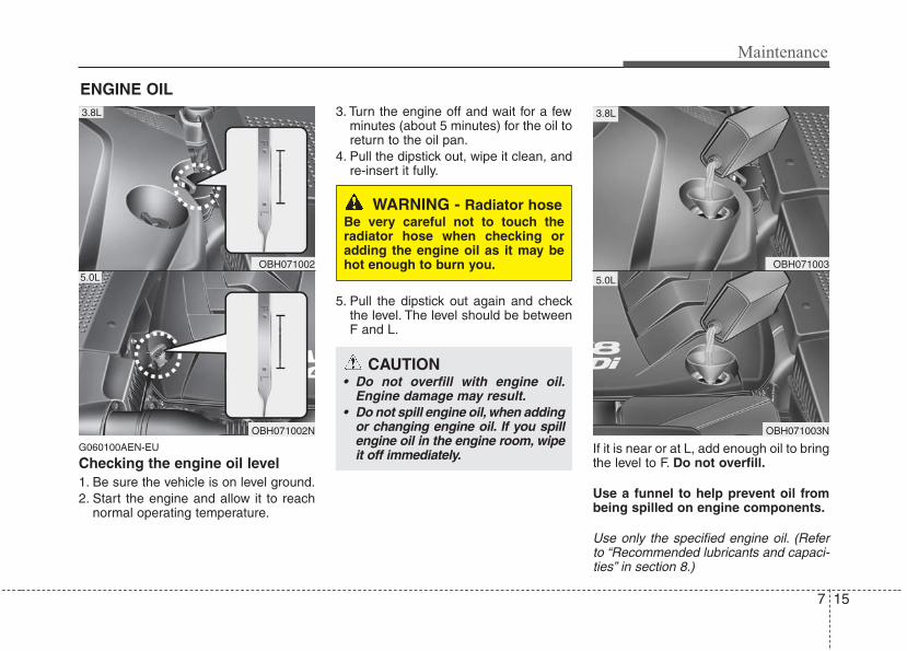
7 15
Maintenance
ENGINE OIL
G060100AEN-EU
Checking the engine oil level 1. Be sure the vehicle is on level ground.2. Start the engine and allow it to reach
normal operating temperature.
3. Turn the engine off and wait for a fewminutes (about 5 minutes) for the oil toreturn to the oil pan.
4. Pull the dipstick out, wipe it clean, andre-insert it fully.
5. Pull the dipstick out again and checkthe level. The level should be betweenF and L.
If it is near or at L, add enough oil to bringthe level to F. Do not overfill.
Use a funnel to help prevent oil frombeing spilled on engine components.
Use only the specified engine oil. (Referto “Recommended lubricants and capaci-ties” in section 8.)
OBH071002
OBH071002N
5.0L
3.8L
OBH071003
OBH071003N
5.0L
3.8L
WARNING - Radiator hoseBe very careful not to touch theradiator hose when checking oradding the engine oil as it may behot enough to burn you.
CAUTION• Do not overfill with engine oil.
Engine damage may result.• Do not spill engine oil, when adding
or changing engine oil. If you spillengine oil in the engine room, wipeit off immediately.
Maintenance
167
G060200AEN-EU
Changing the engine oil and filterHave engine oil and filter changed by anauthorized HYUNDAI dealer according tothe Maintenance Schedule at the begin-ning of this section.
CALIFORNIA PROPOSI-TION 65 WARNING
Engine oil contains chemicalsknown to the State of California tocause cancer, birth defects andreproductive harm. Used engine oilmay cause irritation or cancer ofthe skin if left in contact with theskin for prolonged periods of time.Always protect your skin by wash-ing your hands thoroughly withsoap and warm water as soon aspossible after handling used oil.
7 17
Maintenance
G070000AUN
The high-pressure cooling system has areservoir filled with year-round antifreezecoolant. The reservoir is filled at the fac-tory.Check the antifreeze protection andcoolant level at least once a year, at thebeginning of the winter season, andbefore traveling to a colder climate.
G070100AEN
Checking the coolant level
ENGINE COOLANT
WARNINGRemoving radiatorcap
• Never attempt to remove the radi-ator cap while the engine is oper-ating or hot. Doing so might leadto cooling system and enginedamage and could result in seri-ous personal injury from escap-ing hot coolant or steam.
• Turn the engine off and wait until itcools down. Use extreme carewhen removing the radiator cap.Wrap a thick towel around it, andturn it counterclockwise slowly tothe first stop. Step back while thepressure is released from the cool-ing system. When you are sure allthe pressure has been released,press down on the cap, using athick towel, and continue turningcounterclockwise to remove it.
(Continued)
(Continued)• Even if the engine is not operat-
ing, do not remove the radiatorcap or the drain plug while theengine and radiator are hot. Hotcoolant and steam may still blowout under pressure, causing seri-ous injury.
WARNING The electric motor(cooling fan) is con-trolled by enginecoolant temperature,refrigerant pressure
and vehicle speed. It may some-times operate even when theengine is not running. Use extremecaution when working near theblades of the cooling fan so thatyou are not injured by a rotating fanblades. As the engine coolant tem-perature decreases, the electricmotor will automatically shut off.This is a normal condition. If yourvehicle is equipped with GDI, theelectric motor (cooling fan) mayoperate until you disconnect thenegative battery cable.
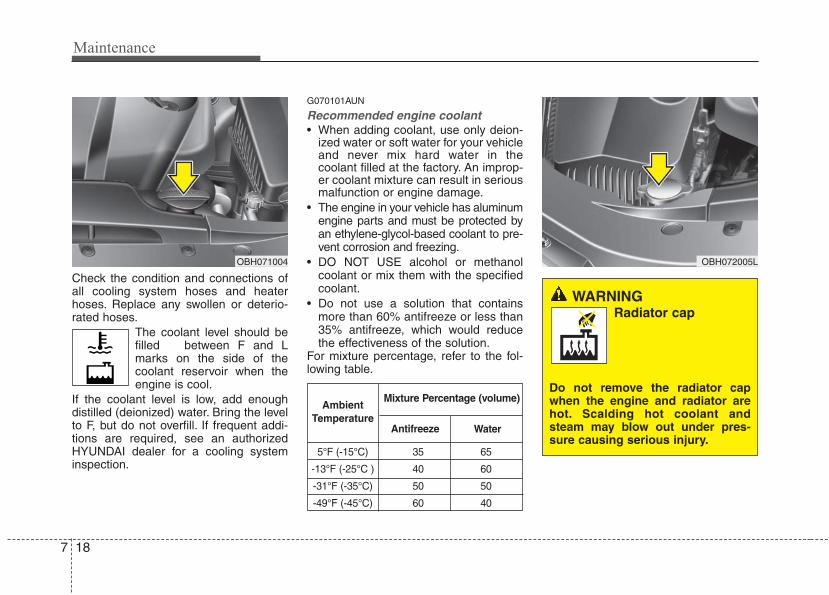
Maintenance
187
Check the condition and connections ofall cooling system hoses and heaterhoses. Replace any swollen or deterio-rated hoses.
The coolant level should befilled between F and Lmarks on the side of thecoolant reservoir when theengine is cool.
If the coolant level is low, add enoughdistilled (deionized) water. Bring the levelto F, but do not overfill. If frequent addi-tions are required, see an authorizedHYUNDAI dealer for a cooling systeminspection.
G070101AUN
Recommended engine coolant• When adding coolant, use only deion-
ized water or soft water for your vehicleand never mix hard water in thecoolant filled at the factory. An improp-er coolant mixture can result in seriousmalfunction or engine damage.
• The engine in your vehicle has aluminumengine parts and must be protected byan ethylene-glycol-based coolant to pre-vent corrosion and freezing.
• DO NOT USE alcohol or methanolcoolant or mix them with the specifiedcoolant.
• Do not use a solution that containsmore than 60% antifreeze or less than35% antifreeze, which would reducethe effectiveness of the solution.
For mixture percentage, refer to the fol-lowing table.
5°F (-15°C) 35 65
-13°F (-25°C ) 40 60
-31°F (-35°C) 50 50
-49°F (-45°C) 60 40
AmbientTemperature
Mixture Percentage (volume)
Antifreeze Water
OBH071004
WARNINGRadiator cap
Do not remove the radiator capwhen the engine and radiator arehot. Scalding hot coolant andsteam may blow out under pres-sure causing serious injury.
OBH072005L
7 19
Maintenance
G070200AEN
Changing the coolantHave coolant changed by an authorizedHYUNDAI dealer according to theMaintenance Schedule at the beginningof this section.
CAUTIONPut a thick cloth around the radiatorcap before refilling the coolant inorder to prevent the coolant fromoverflowing into engine parts suchas the generator.
WARNING - Coolant• Do not use radiator coolant or
antifreeze in the washer fluidreservoir.
• Radiator coolant can severelyobscure visibility when sprayedon the windshield and may causeloss of vehicle control or damageto paint and body trim.
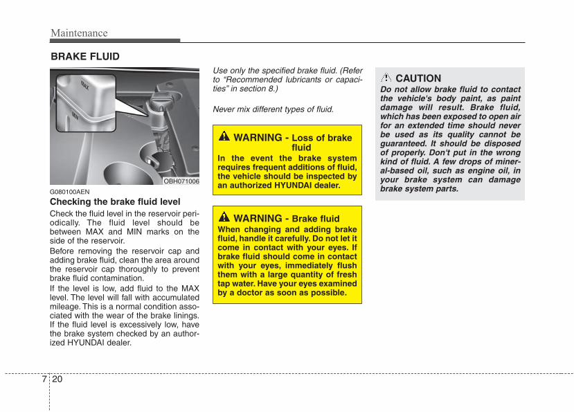
Maintenance
207
BRAKE FLUID
G080100AEN
Checking the brake fluid level Check the fluid level in the reservoir peri-odically. The fluid level should bebetween MAX and MIN marks on theside of the reservoir.Before removing the reservoir cap andadding brake fluid, clean the area aroundthe reservoir cap thoroughly to preventbrake fluid contamination.If the level is low, add fluid to the MAXlevel. The level will fall with accumulatedmileage. This is a normal condition asso-ciated with the wear of the brake linings.If the fluid level is excessively low, havethe brake system checked by an author-ized HYUNDAI dealer.
Use only the specified brake fluid. (Referto “Recommended lubricants or capaci-ties” in section 8.)
Never mix different types of fluid.
WARNING - Brake fluidWhen changing and adding brakefluid, handle it carefully. Do not let itcome in contact with your eyes. Ifbrake fluid should come in contactwith your eyes, immediately flushthem with a large quantity of freshtap water. Have your eyes examinedby a doctor as soon as possible.
WARNING - Loss of brakefluid
In the event the brake systemrequires frequent additions of fluid,the vehicle should be inspected byan authorized HYUNDAI dealer.
CAUTIONDo not allow brake fluid to contactthe vehicle's body paint, as paintdamage will result. Brake fluid,which has been exposed to open airfor an extended time should neverbe used as its quality cannot beguaranteed. It should be disposedof properly. Don't put in the wrongkind of fluid. A few drops of miner-al-based oil, such as engine oil, inyour brake system can damagebrake system parts.
OBH071006
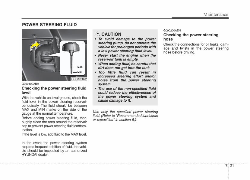
7 21
Maintenance
POWER STEERING FLUID
G090100ABH
Checking the power steering fluidlevel With the vehicle on level ground, check thefluid level in the power steering reservoirperiodically. The fluid should be betweenMAX and MIN marks on the side of thegauge at the normal temperature.Before adding power steering fluid, thor-oughly clean the area around the reservoircap to prevent power steering fluid contam-ination.If the level is low, add fluid to the MAX level.
In the event the power steering systemrequires frequent addition of fluid, the vehi-cle should be inspected by an authorizedHYUNDAI dealer.
Use only the specified power steeringfluid. (Refer to "Recommended lubricantsor capacities" in section 8.)
G090200AEN
Checking the power steeringhoseCheck the connections for oil leaks, dam-age and twists in the power steeringhose before driving.
CAUTION• To avoid damage to the power
steering pump, do not operate thevehicle for prolonged periods witha low power steering fluid level.
• Never start the engine when thereservoir tank is empty.
• When adding fluid, be careful thatdirt does not get into the tank.
• Too little fluid can result inincreased steering effort and/ornoise from the power steeringsystem.
• The use of the non-specified fluidcould reduce the effectiveness ofthe power steering system andcause damage to it.
OBH078022
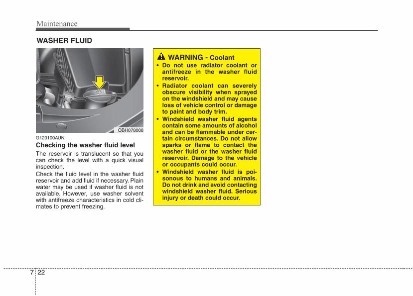
Maintenance
227
WASHER FLUID
G120100AUN
Checking the washer fluid level The reservoir is translucent so that youcan check the level with a quick visualinspection.Check the fluid level in the washer fluidreservoir and add fluid if necessary. Plainwater may be used if washer fluid is notavailable. However, use washer solventwith antifreeze characteristics in cold cli-mates to prevent freezing.
WARNING - Coolant• Do not use radiator coolant or
antifreeze in the washer fluidreservoir.
• Radiator coolant can severelyobscure visibility when sprayedon the windshield and may causeloss of vehicle control or damageto paint and body trim.
• Windshield washer fluid agentscontain some amounts of alcoholand can be flammable under cer-tain circumstances. Do not allowsparks or flame to contact thewasher fluid or the washer fluidreservoir. Damage to the vehicleor occupants could occur.
• Windshield washer fluid is poi-sonous to humans and animals.Do not drink and avoid contactingwindshield washer fluid. Seriousinjury or death could occur.
OBH078008
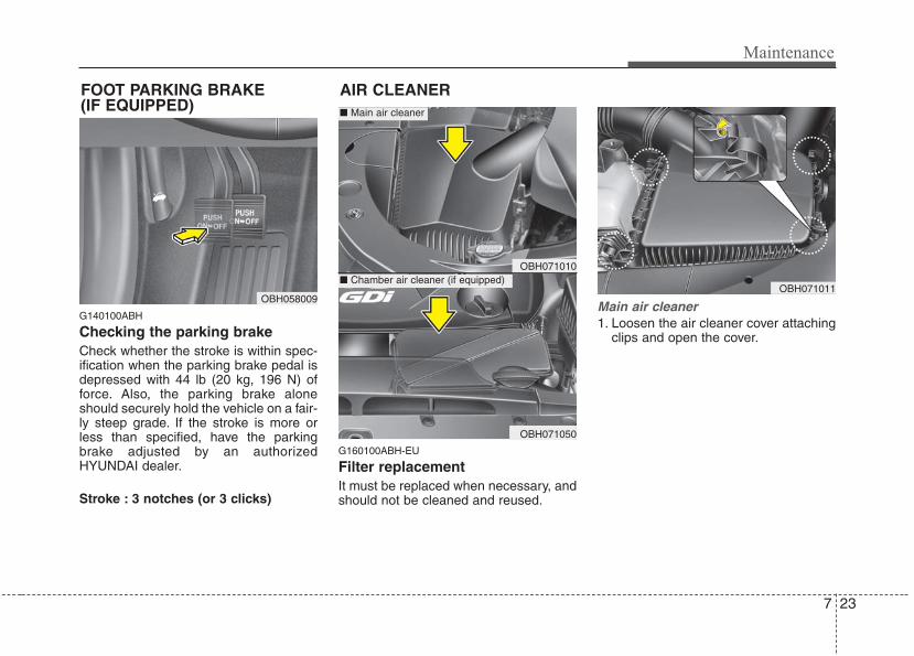
7 23
Maintenance
G140100ABH
Checking the parking brake Check whether the stroke is within spec-ification when the parking brake pedal isdepressed with 44 lb (20 kg, 196 N) offorce. Also, the parking brake aloneshould securely hold the vehicle on a fair-ly steep grade. If the stroke is more orless than specified, have the parkingbrake adjusted by an authorizedHYUNDAI dealer.
Stroke : 3 notches (or 3 clicks)
G160100ABH-EU
Filter replacementIt must be replaced when necessary, andshould not be cleaned and reused.
Main air cleaner1. Loosen the air cleaner cover attaching
clips and open the cover.
OBH071010
OBH071050
OBH058009
FOOT PARKING BRAKE (IF EQUIPPED)
AIR CLEANER
OBH071011
■ Main air cleaner
■ Chamber air cleaner (if equipped)

Maintenance
247
2. Replace the air cleaner filter.3. Lock the cover with the cover attaching
clips.
Chamber air cleaner (if equipped)1. Loosen the air cleaner cover attaching
clips and open the cover.
2. Replace the air cleaner filter afterpulling up the locking tab (1).
3. Lock the cover with the cover attachingclips.
OBH078013 OBH071051 OVI072052
7 25
Maintenance
Replace the filter according to theMaintenance Schedule.If the vehicle is operated in extremelydusty or sandy areas, replace the ele-ment more often than the usual recom-mended intervals. (Refer to“Maintenance under severe usage condi-tions” in this section.)
CAUTION• Do not drive with the air cleaner
removed; this will result in exces-sive engine wear.
• When removing the air cleaner fil-ter, be careful that dust or dirtdoes not enter the air intake, ordamage may result.
• Use a HYUNDAI genuine part. Useof non-genuine parts could dam-age the air flow sensor.
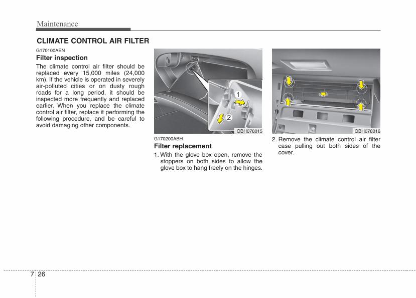
Maintenance
267
CLIMATE CONTROL AIR FILTERG170100AEN
Filter inspectionThe climate control air filter should bereplaced every 15,000 miles (24,000km). If the vehicle is operated in severelyair-polluted cities or on dusty roughroads for a long period, it should beinspected more frequently and replacedearlier. When you replace the climatecontrol air filter, replace it performing thefollowing procedure, and be careful toavoid damaging other components.
G170200ABH
Filter replacement1. With the glove box open, remove the
stoppers on both sides to allow theglove box to hang freely on the hinges.
2. Remove the climate control air filtercase pulling out both sides of thecover.
OBH078016OBH078015
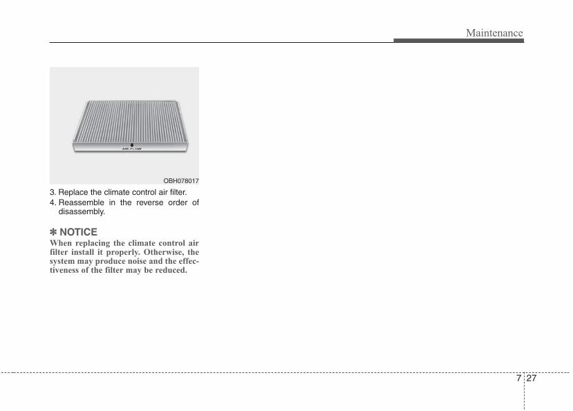
7 27
Maintenance
3. Replace the climate control air filter.4. Reassemble in the reverse order of
disassembly.
✽✽ NOTICEWhen replacing the climate control airfilter install it properly. Otherwise, thesystem may produce noise and the effec-tiveness of the filter may be reduced.
OBH078017
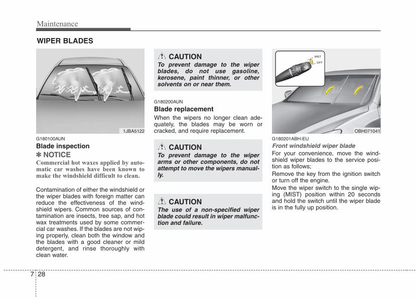
Maintenance
287
WIPER BLADES
G180100AUN
Blade inspection✽✽ NOTICECommercial hot waxes applied by auto-matic car washes have been known tomake the windshield difficult to clean.
Contamination of either the windshield orthe wiper blades with foreign matter canreduce the effectiveness of the wind-shield wipers. Common sources of con-tamination are insects, tree sap, and hotwax treatments used by some commer-cial car washes. If the blades are not wip-ing properly, clean both the window andthe blades with a good cleaner or milddetergent, and rinse thoroughly withclean water.
G180200AUN
Blade replacement When the wipers no longer clean ade-quately, the blades may be worn orcracked, and require replacement.
G180201ABH-EU
Front windshield wiper bladeFor your convenience, move the wind-shield wiper blades to the service posi-tion as follows;Remove the key from the ignition switchor turn off the engine.Move the wiper switch to the single wip-ing (MIST) position within 20 secondsand hold the switch until the wiper bladeis in the fully up position.
1JBA5122
CAUTIONTo prevent damage to the wiperblades, do not use gasoline,kerosene, paint thinner, or othersolvents on or near them.
CAUTIONTo prevent damage to the wiperarms or other components, do notattempt to move the wipers manual-ly.
CAUTIONThe use of a non-specified wiperblade could result in wiper malfunc-tion and failure.
OBH071041
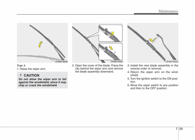
7 29
Maintenance
Type A
1. Raise the wiper arm.2. Open the cover of the blade. Press the
clip behind the wiper arm and removethe blade assembly downward.
3. Install the new blade assembly in thereverse order of removal.
4. Return the wiper arm on the wind-shield.
5. Turn the ignition switch to the ON posi-tion.
6. Move the wiper switch to any positionand then to the OFF position.
OHM078059 OHM078060
CAUTIONDo not allow the wiper arm to fallagainst the windshield, since it maychip or crack the windshield.
OHG070043
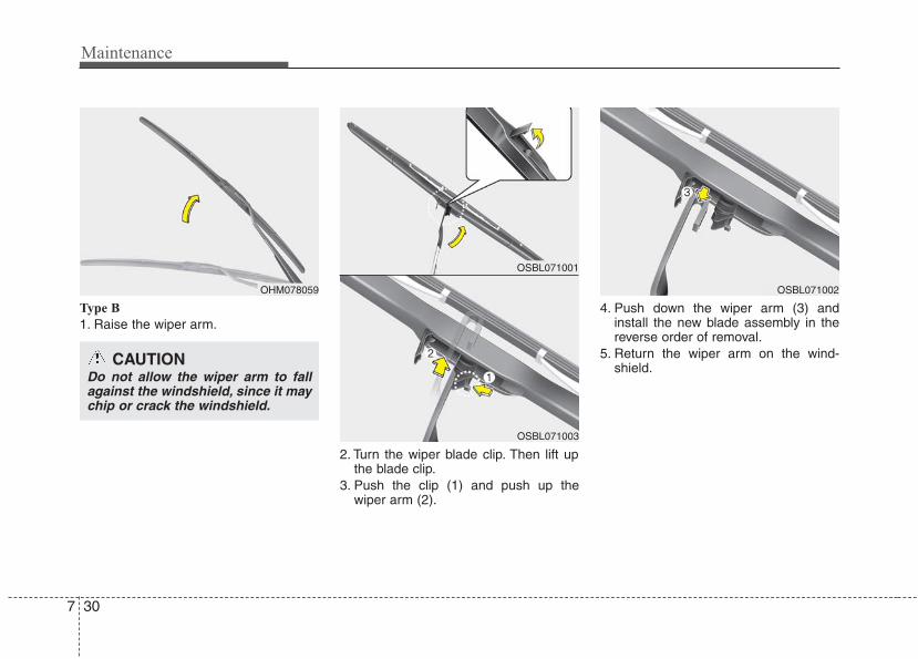
Maintenance
307
Type B
1. Raise the wiper arm.
2. Turn the wiper blade clip. Then lift upthe blade clip.
3. Push the clip (1) and push up thewiper arm (2).
4. Push down the wiper arm (3) andinstall the new blade assembly in thereverse order of removal.
5. Return the wiper arm on the wind-shield.
OHM078059
OSBL071001
OSBL071003
OSBL071002
CAUTIONDo not allow the wiper arm to fallagainst the windshield, since it maychip or crack the windshield.
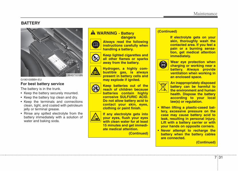
7 31
Maintenance
G190100BBH-EU
For best battery serviceThe battery is in the trunk.• Keep the battery securely mounted.• Keep the battery top clean and dry.• Keep the terminals and connections
clean, tight, and coated with petroleumjelly or terminal grease.
• Rinse any spilled electrolyte from thebattery immediately with a solution ofwater and baking soda.
BATTERY
OBH071018N
WARNING - Battery dangers
Always read the followinginstructions carefully whenhandling a battery.
Keep lighted cigarettes andall other flames or sparksaway from the battery.
Hydrogen, a highly com-bustible gas, is alwayspresent in battery cells andmay explode if ignited.
Keep batteries out of thereach of children becausebatteries contain highlycorrosive SULFURIC ACID.Do not allow battery acid tocontact your skin, eyes,clothing or paint finish.
If any electrolyte gets intoyour eyes, flush your eyeswith clean water for at least15 minutes and get immedi-ate medical attention.
(Continued)
(Continued)
If electrolyte gets on yourskin, thoroughly wash thecontacted area. If you feel apain or a burning sensa-tion, get medical attentionimmediately.
Wear eye protection whencharging or working near abattery. Always provideventilation when working inan enclosed space.
An inappropriately disposedbattery can be harmful tothe environment and humanhealth. Dispose the batteryaccording to your locallaw(s) or regulation.
• When lifting a plastic-cased bat-tery, excessive pressure on thecase may cause battery acid toleak, resulting in personal injury.Lift with a battery carrier or withyour hands on opposite corners.
• Never attempt to recharge thebattery when the battery cablesare connected.
(Continued)
Maintenance
327
G190200ABH
Battery recharging by batterycharger Your vehicle has a maintenance-free,calcium-based battery.• If the battery becomes discharged in a
short time (because, for example, theheadlights or interior lights were left onwhile the vehicle was not in use),recharge it by slow charging (trickle)for 10 hours.
• If the battery gradually dischargesbecause of high electric load while thevehicle is being used, recharge it at 20-30A for two hours.
Battery recharging by vehicleAfter a jump start from a good battery,run the engine for 20-30 minutes at idleor driving the vehicle before it is shutoff.Vehicle may not restart if you shut it offbefore the battery had chance to ade-quately recharge.
CALIFORNIA PROPOSI-TION 65 WARNING
Battery posts, terminals, and relat-ed accessories contain lead andlead compounds, chemicals knownto the State of California to causecancer, birth defects and reproduc-tive harm. Batteries also containother chemicals known to the Stateof California to cause cancer. Washhands after handling.
CAUTION• When you don’t use the vehicle
for a long time in a low tempera-ture area, disconnect the batteryand keep it indoors.
• Always charge the battery fully toprevent the battery case frombeing damaged in a low tempera-ture area.
• If you connect unauthorized elec-tronic devices to the battery, thebattery may be discharged. Neveruse unauthorized devices.
(Continued)
• The electrical ignition systemworks with high voltage. Nevertouch these components with theengine running or the ignitionswitched on.
Failure to follow the above warn-ings can result in serious bodilyinjury or death.
7 33
Maintenance
G190300ABH
Reset itemsItems should be reset after the batteryhas been discharged or the battery hasbeen disconnected.• Auto up/down window (See section 4)• Sunroof (See section 4)• Driver position memory system
(See section 4)• Trip computer (See section 4)• Climate control system
(See section 4)• Clock (See section 4)• Audio (See section 4)
WARNING• Before performing maintenance
or recharging the battery, turn offall accessories and stop theengine.
• The negative battery cable mustbe removed first and installedlast when the battery is discon-nected.
• Operation related to the batteryshould be done at an authorizedHYUNDAI dealer.
CAUTION• Keep the battery away from water
or any liquid.• The battery is in the trunk, so you
should be careful when you loada container filled with liquid intothe trunk.
• For your safety, use a genuineHYUNDAI approved battery whenyou replace the battery.
WARNING - Rechargingbattery
When recharging the battery,observe the following precautions:• The battery must be removed
from the vehicle and placed in anarea with good ventilation.
• Do not allow cigarettes, sparks,or flame near the battery.
• Watch the battery during charg-ing, and stop or reduce the charg-ing rate if the battery cells begingassing (boiling) violently or ifthe temperature of the electrolyteof any cell exceeds 120°F (49°C).
• Wear eye protection when check-ing the battery during charging.
• Disconnect the battery charger inthe following order.
1. Turn off the battery charger mainswitch.
2. Unhook the negative clamp fromthe negative battery terminal.
3. Unhook the positive clamp fromthe positive battery terminal.
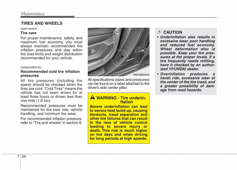
Maintenance
347
CAUTION• Underinflation also results in
excessive wear, poor handlingand reduced fuel economy.Wheel deformation also ispossible. Keep your tire pres-sures at the proper levels. If atire frequently needs refilling,have it checked by an author-ized HYUNDAI dealer.
• Overinflation produces aharsh ride, excessive wear atthe center of the tire tread, anda greater possibility of dam-age from road hazards.
TIRES AND WHEELS G200100AUN
Tire care For proper maintenance, safety, andmaximum fuel economy, you mustalways maintain recommended tireinflation pressures and stay withinthe load limits and weight distributionrecommended for your vehicle.
G200200AEN-EU
Recommended cold tire inflationpressures All tire pressures (including thespare) should be checked when thetires are cold. “Cold Tires” means thevehicle has not been driven for atleast three hours or driven less thanone mile (1.6 km).Recommended pressures must bemaintained for the best ride, vehiclehandling, and minimum tire wear.For recommended inflation pressure,refer to “Tire and wheels” in section 8.
All specifications (sizes and pressures)can be found on a label attached to thedriver’s side center pillar.
WARNING - Tire underin-flation
Severe underinflation can leadto severe heat build-up, causingblowouts, tread separation andother tire failures that can resultin the loss of vehicle controlleading to severe injury ordeath. This risk is much higheron hot days and when drivingfor long periods at high speeds.
OBH088004N
7 35
Maintenance
G200300AUN
Checking tire inflation pressureCheck your tires once a month ormore.Also, check the tire pressure of thespare tire.
G200301AEN
How to checkUse a good quality gage to check tirepressure.You can not tell if your tiresare properly inflated simply by look-ing at them. Radial tires may lookproperly inflated even when they'reunderinflated.Check the tire's inflation pressurewhen the tires are cold. - "Cold"means your vehicle has been sittingfor at least three hours or driven nomore than 1 mile (1.6 km).
WARNING - Tire InflationOverinflation or underinflationcan reduce tire life, adverselyaffect vehicle handling, andlead to sudden tire failure. Thiscould result in loss of vehiclecontrol and potential injury.
CAUTION - Tire pressureAlways observe the following:• Check tire pressure when the
tires are cold. (After vehiclehas been parked for at leastthree hours or hasn't beendriven more than one mile (1.6km) since startup.)
• Check the pressure of yourspare tire each time you checkthe pressure of other tires.
• Never overload your vehicle.Be careful not to overload avehicle luggage rack if yourvehicle is equipped with one.
• Worn, old tires can cause acci-dents. If your tread is badlyworn, or if your tires havebeen damaged, replace them.
CAUTION• Warm tires normally exceed
recommended cold tire pres-sures by 4 to 6 psi (28 to 41kPa). Do not release air fromwarm tires to adjust the pres-sure or the tires will be under-inflated.
• Be sure to reinstall the tireinflation valve caps. Withoutthe valve cap, dirt or moisturecould get into the valve coreand cause air leakage. If avalve cap is missing, install anew one as soon as possible.
Maintenance
367
Remove the valve cap from the tirevalve stem. Press the tire gage firm-ly onto the valve to get a pressuremeasurement. If the cold tire inflationpressure matches the recommendedpressure on the tire and loadinginformation label, no further adjust-ment is necessary. If the pressure islow, add air until you reach the rec-ommended amount.If you overfill the tire, release air bypushing on the metal stem in the cen-ter of the tire valve. Recheck the tirepressure with the tire gage. Be sureto put the valve caps back on thevalve stems. They help prevent leaksby keeping out dirt and moisture.
G200400ABH
Tire rotation To equalize tread wear, it is recom-mended that the tires be rotatedevery 7,500 miles (12,000 km) orsooner if irregular wear develops.During rotation, check the tires forcorrect balance.When rotating tires, check for unevenwear and damage. Abnormal wear isusually caused by incorrect tire pres-sure, improper wheel alignment, out-of-balance wheels, severe braking orsevere cornering. Look for bumps orbulges in the tread or side of tire.Replace the tire if you find either ofthese conditions. Replace the tire iffabric or cord is visible. After rotation,be sure to bring the front and rear tirepressures to specification and checklug nut tightness.
WARNING• Inspect your tires frequently
for proper inflation as well aswear and damage. Always usea tire pressure gauge.
• Tires with too much or too littlepressure wear unevenly caus-ing poor handling, loss of vehi-cle control, and sudden tirefailure leading to accidents,injuries, and even death. Therecommended cold tire pres-sure for your vehicle can befound in this manual and onthe tire label located on the dri-ver's side center pillar.
• Worn tires can cause acci-dents. Replace tires that areworn, show uneven wear, orare damaged.
• Remember to check the pres-sure of your spare tire.HYUNDAI recommends thatyou check the spare every timeyou check the pressure of theother tires on your vehicle.
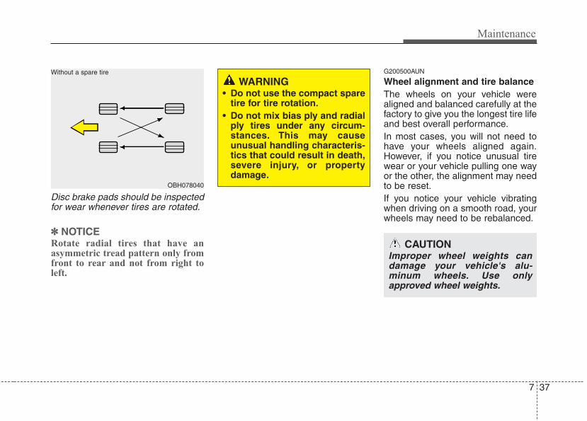
7 37
Maintenance
Disc brake pads should be inspectedfor wear whenever tires are rotated.
✽✽ NOTICERotate radial tires that have anasymmetric tread pattern only fromfront to rear and not from right toleft.
G200500AUN
Wheel alignment and tire balance The wheels on your vehicle werealigned and balanced carefully at thefactory to give you the longest tire lifeand best overall performance.In most cases, you will not need tohave your wheels aligned again.However, if you notice unusual tirewear or your vehicle pulling one wayor the other, the alignment may needto be reset.If you notice your vehicle vibratingwhen driving on a smooth road, yourwheels may need to be rebalanced.
OBH078040
Without a spare tire
WARNING• Do not use the compact spare
tire for tire rotation.• Do not mix bias ply and radial
ply tires under any circum-stances. This may causeunusual handling characteris-tics that could result in death,severe injury, or propertydamage.
CAUTIONImproper wheel weights candamage your vehicle's alu-minum wheels. Use onlyapproved wheel weights.
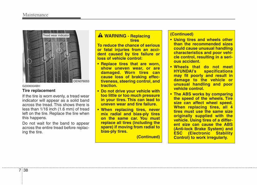
Maintenance
387
G200600ABH
Tire replacementIf the tire is worn evenly, a tread wearindicator will appear as a solid bandacross the tread. This shows there isless than 1/16 inch (1.6 mm) of treadleft on the tire. Replace the tire whenthis happens.Do not wait for the band to appearacross the entire tread before replac-ing the tire.
OEN076053
Tread wear indicator WARNING - Replacingtires
To reduce the chance of seriousor fatal injuries from an acci-dent caused by tire failure orloss of vehicle control:• Replace tires that are worn,
show uneven wear, or aredamaged. Worn tires cancause loss of braking effec-tiveness, steering control, andtraction.
• Do not drive your vehicle withtoo little or too much pressurein your tires. This can lead touneven wear and tire failure.
• When replacing tires, nevermix radial and bias-ply tireson the same car. You mustreplace all tires (including thespare) if moving from radial tobias-ply tires.
(Continued)
(Continued)• Using tires and wheels other
than the recommended sizescould cause unusual handlingcharacteristics and poor vehi-cle control, resulting in a seri-ous accident.
• Wheels that do not meetHYUNDAI’s specificationsmay fit poorly and result indamage to the vehicle orunusual handling and poorvehicle control.
• The ABS works by comparingthe speed of the wheels. Tiresize can affect wheel speed.When replacing tires, all 4tires must use the same sizeoriginally supplied with thevehicle. Using tires of a differ-ent size can cause the ABS(Anti-lock Brake System) andESC (Electronic Stability Control) to work irregularly.
7 39
Maintenance
G200601AUN
Compact spare tire replacement A compact spare tire has a shortertread life than a regular size tire.Replace it when you can see thetread wear indicator bars on the tire.The replacement compact spare tireshould be the same size and designtire as the one provided with yournew vehicle and should be mountedon the same compact spare tirewheel. The compact spare tire is notdesigned to be mounted on a regularsize wheel, and the compact sparetire wheel is not designed for mount-ing a regular size tire.
G200700ABH
Wheel replacement When replacing the metal wheels forany reason, make sure the newwheels are equivalent to the originalfactory units in diameter, rim widthand offset.
G200800AUN
Tire tractionTire traction can be reduced if youdrive on worn tires, tires that areimproperly inflated or on slipperyroad surfaces. Tires should bereplaced when tread wear indicatorsappear. To reduce the possibility oflosing control, slow down wheneverthere is rain, snow or ice on the road.
G200900AUN
Tire maintenance In addition to proper inflation, correctwheel alignment helps to decreasetire wear. If you find a tire is wornunevenly, have your dealer check thewheel alignment.When you have new tires installed,make sure they are balanced. Thiswill increase vehicle ride comfort andtire life. Additionally, a tire shouldalways be rebalanced if it is removedfrom the wheel.
WARNINGA wheel that is not the correctsize may adversely affect wheeland bearing life, braking andstopping abilities, handlingcharacteristics, ground clear-ance, body-to-tire clearance,snow chain clearance,speedometer and odometer cal-ibration, headlight aim andbumper height.
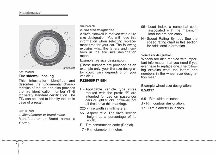
Maintenance
407
G201000AUN
Tire sidewall labelingThis information identifies anddescribes the fundamental charac-teristics of the tire and also providesthe tire identification number (TIN)for safety standard certification. TheTIN can be used to identify the tire incase of a recall.
G201001AUN
1. Manufacturer or brand nameManufacturer or Brand name isshown.
G201002AEN
2. Tire size designation A tire’s sidewall is marked with a tiresize designation. You will need thisinformation when selecting replace-ment tires for your car. The followingexplains what the letters and num-bers in the tire size designationmean.Example tire size designation:(These numbers are provided as anexample only; your tire size designa-tor could vary depending on yourvehicle.)P225/55R17 95H
P - Applicable vehicle type (tiresmarked with the prefix “P’’ areintended for use on passengercars or light trucks; however, notall tires have this marking).
225 - Tire width in millimeters.55 - Aspect ratio. The tire’s section
height as a percentage of itswidth.
R - Tire construction code (Radial).17 - Rim diameter in inches.
95 - Load Index, a numerical codeassociated with the maximumload the tire can carry.
H - Speed Rating Symbol. See thespeed rating chart in this sectionfor additional information.
Wheel size designation
Wheels are also marked with impor-tant information that you need if youever have to replace one. The follow-ing explains what the letters andnumbers in the wheel size designa-tion mean.
Example wheel size designation:6.5JX17
6.5 - Rim width in inches.J - Rim contour designation.17 - Rim diameter in inches.
I030B04JM
1
1
23
4
5,6
7
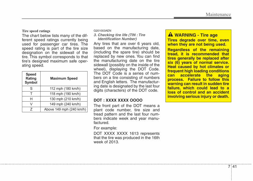
7 41
Maintenance
Tire speed ratings
The chart below lists many of the dif-ferent speed ratings currently beingused for passenger car tires. Thespeed rating is part of the tire sizedesignation on the sidewall of thetire. This symbol corresponds to thattire's designed maximum safe oper-ating speed.
G201003AEN
3. Checking tire life (TIN : TireIdentification Number)
Any tires that are over 6 years old,based on the manufacturing date,(including the spare tire) should bereplaced by new ones. You can findthe manufacturing date on the tiresidewall (possibly on the inside of thewheel), displaying the DOT Code.The DOT Code is a series of num-bers on a tire consisting of numbersand English letters. The manufactur-ing date is designated by the last fourdigits (characters) of the DOT code.
DOT : XXXX XXXX OOOOThe front part of the DOT means aplant code number, tire size andtread pattern and the last four num-bers indicate week and year manu-factured.For example:DOT XXXX XXXX 1613 representsthat the tire was produced in the 16thweek of 2013.
S 112 mph (180 km/h)
T 118 mph (190 km/h)
H 130 mph (210 km/h)
V 149 mph (240 km/h)
Z Above 149 mph (240 km/h)
Maximum SpeedSpeedRatingSymbol
WARNING - Tire ageTires degrade over time, evenwhen they are not being used.Regardless of the remainingtread, it is recommended thattires generally be replaced aftersix (6) years of normal service.Heat caused by hot climates orfrequent high loading conditionscan accelerate the agingprocess. Failure to follow thiswarning can result in sudden tirefailure, which could lead to aloss of control and an accidentinvolving serious injury or death.
Maintenance
427
G201004AEN
4. Tire ply composition and materialThe number of layers or plies of rub-ber-coated fabric in the tire. Tiremanufacturers also must indicate thematerials in the tire, which includesteel, nylon, polyester, and others.The letter "R" means radial ply con-struction; the letter "D" means diago-nal or bias ply construction; and theletter "B" means belted-bias ply con-struction.
G201005AUN
5. Maximum permissible inflationpressure
This number is the greatest amountof air pressure that should be put inthe tire. Do not exceed the maximumpermissible inflation pressure. Referto the Tire and Loading Informationlabel for recommended inflationpressure.
G201006AUN
6. Maximum load ratingThis number indicates the maximumload in kilograms and pounds thatcan be carried by the tire. Whenreplacing the tires on the vehicle,always use a tire that has the sameload rating as the factory installedtire.
G2010007AEN-EU
7. Uniform tire quality grading Quality grades can be found whereapplicable on the tire sidewallbetween tread shoulder and maxi-mum section width.For example: TREAD wear 200 TRACTION AA TEMPERATURE A
Tread wear
The tread wear grade is a compara-tive rating based on the wear rate ofthe tire when tested under controlledconditions on a specified govern-ment test course. For example, a tiregraded 150 would wear one-and-a-half times (1½) as well on the gov-ernment course as a tire graded 100.The relative performance of tiresdepends upon the actual conditionsof their use, however, and maydepart significantly from the normdue to variations in driving habits,service practices and differences inroad characteristics and climate.These grades are molded on theside-walls of passenger vehicle tires.The tires available as standard oroptional equipment on your vehiclemay vary with respect to grade.
7 43
Maintenance
Traction - AA, A, B & C
The traction grades, from highest tolowest, are AA, A, B and C. Thosegrades represent the tire’s ability tostop on wet pavement as measuredunder controlled conditions on spec-ified government test surfaces ofasphalt and concrete. A tire markedC may have poor traction perform-ance.
Temperature -A, B & C
The temperature grades are A (thehighest), B and C representing thetire’s resistance to the generation ofheat and its ability to dissipate heatwhen tested under controlled condi-tions on a specified indoor laboratorytest wheel.Sustained high temperature cancause the material of the tire todegenerate and reduce tire life, andexcessive temperature can lead tosudden tire failure. The grade C cor-responds to a level of performancewhich all passenger car tires mustmeet under the Federal MotorVehicle Safety Standard No. 109.Grades B and A represent higherlevels of performance on the labora-tory test wheel than the minimumrequired by law.
WARNING The traction grade assigned tothis tire is based on straight-ahead braking traction tests,and does not include accelera-tion, cornering, hydroplaning,or peak traction characteristics.
WARNING - Tire temperature
The temperature grade for thistire is established for a tire thatis properly inflated and notoverloaded. Excessive speed,underinflation, or excessiveloading, either separately or incombination, can cause heatbuild-up and possible suddentire failure. This can cause lossof vehicle control and seriousinjury or death.
Maintenance
447
Low aspect ratio tire (if equipped) Low aspect ratio tires, whose aspectratio is lower than 50, are providedfor sporty looks.Because the low aspect ratio tiresare optimized for handling and brak-ing, it may be more uncomfortable toride in and there is more noise com-pare with normal tires.
G201100ABH
Tire terminology and definitionsAir Pressure: The amount of airinside the tire pressing outward onthe tire. Air pressure is expressed inpounds per square inch (psi) or kilo-pascal (kPa).Accessory Weight: This means thecombined weight of optional acces-sories. Some examples of optionalaccessories are, automatic transmis-sion, power seats, and air condition-ing.Aspect Ratio: The relationship of atire's height to its width.Belt: A rubber coated layer of cordsthat is located between the plies andthe tread. Cords may be made fromsteel or other reinforcing materials.Bead: The tire bead contains steelwires wrapped by steel cords thathold the tire onto the rim.Bias Ply Tire: A pneumatic tire inwhich the plies are laid at alternateangles less than 90 degrees to thecenterline of the tread.
(Continued)• If the tire is impacted, inspect
the tire condition or contact anauthorized HYUNDAI dealer.
• To prevent damage to the tire,inspect the tire condition andpressure every 1,800miles(3,000km).
CAUTION• It is not easy to recognize the
tire damage with your owneyes. But if there is the slight-est hint of tire damage, eventhough you cannot see the tiredamage with your own eyes,have the tire checked orreplaced because the tiredamage may cause air leak-age from the tire.
• If the tire is damaged by driv-ing on a rough road, off road,pothole, manhole, or curbstone, it will not be covered bythe warranty.
• You can find out the tire infor-mation on the tire sidewall.
CAUTIONBecause the sidewall of the lowaspect ratio tire is shorter thanthe normal, the wheel and tire ofthe low aspect ratio tire is easi-er to be damaged. So, follow theinstructions below.• When driving on a rough road
or off road, drive cautiouslybecause tires and wheels maybe damaged. And after driving,inspect tires and wheels.
• When passing over a pothole,speed bump, manhole, or curbstone, drive slowly so that thetires and wheels are not dam-aged.
(Continued)
7 45
Maintenance
Cold Tire Pressure: The amount ofair pressure in a tire, measured inpounds per square inch (psi) or kilo-pascals (kPa) before a tire has builtup heat from driving.Curb Weight: This means the weightof a motor vehicle with standard andoptional equipment including themaximum capacity of fuel, oil andcoolant, but without passengers andcargo.DOT Markings: A code molded intothe sidewall of a tire signifying thatthe tire is in compliance with the U.S.Department of Transportation motorvehicle safety standards. The DOTcode includes the Tire IdentificationNumber (TIN), an alphanumeric des-ignator which can also identify thetire manufacturer, production plant,brand and date of production.GVWR: Gross Vehicle Weight RatingGAWR FRT: Gross Axle WeightRating for the Front Axle.GAWR RR: Gross Axle WeightRating for the Rear axle.
Intended Outboard Sidewall: Theside of an asymmetrical tire, thatmust always face outward whenmounted on a vehicle.Kilopascal (kPa): The metric unit forair pressure.Load Index: An assigned numberranging from 1 to 279 that corre-sponds to the load carrying capacityof a tire.Maximum Inflation Pressure: Themaximum air pressure to which acold tire may be inflated. The maxi-mum air pressure is molded onto thesidewall.Maximum Load Rating: The loadrating for a tire at the maximum per-missible inflation pressure for thattire.Maximum Loaded Vehicle Weight:The sum of curb weight; accessoryweight; vehicle capacity weight; andproduction options weight.Normal Occupant Weight: Thenumber of occupants a vehicle isdesigned to seat multiplied by 150pounds (68 kg).
Occupant Distribution: Designatedseating positions.Outward Facing Sidewall: The sideof a asymmetrical tire that has a par-ticular side that faces outward whenmounted on a vehicle. The outwardfacing sidewall bears white letteringor bears manufacturer, brand, and/ormodel name molding that is higher ordeeper than the same moldings onthe inner facing sidewall.Passenger (P-Metric) Tire: A tireused on passenger cars and somelight duty trucks and multipurposevehicles.Recommended Inflation Pressure:Vehicle manufacturer's recommend-ed tire inflation pressure and shownon the tire placard.Radial Ply Tire: A pneumatic tire inwhich the ply cords that extend to thebeads are laid at 90 degrees to thecenterline of the tread.Rim: A metal support for a tire andupon which the tire beads are seated.Sidewall: The portion of a tirebetween the tread and the bead.
Maintenance
467
Speed Rating: An alphanumericcode assigned to a tire indicating themaximum speed at which a tire canoperate.Traction: The friction between thetire and the road surface. Theamount of grip provided.Tread: The portion of a tire thatcomes into contact with the road.Treadwear Indicators: Narrowbands, sometimes called "wearbars," that show across the tread of atire when only 2/32 inch of treadremains.UTQGS: Uniform Tire QualityGrading Standards, a tire informationsystem that provides consumers withratings for a tire's traction, tempera-ture and treadwear. Ratings aredetermined by tire manufacturersusing government testing proce-dures. The ratings are molded intothe sidewall of the tire.Vehicle Capacity Weight: The num-ber of designated seating positionsmultiplied by 150 lbs. (68 kg) plus therated cargo and luggage load.
Vehicle Maximum Load on theTire: Load on an individual tire due tocurb and accessory weight plusmaximum occupant and cargoweight.Vehicle Normal Load on the Tire:Load on an individual tire that isdetermined by distributing to eachaxle its share of the curb weight,accessory weight, and normal occu-pant weight and dividing by 2.Vehicle Placard: A label permanent-ly attached to a vehicle showing theoriginal equipment tire size and rec-ommended inflation pressure.
All season tires HYUNDAI specifies all season tireson some models to provide goodperformance for use all year round,including snowy and icy road condi-tions. All season tires are identifiedby ALL SEASON and/or M+S (Mudand Snow) on the tire sidewall. Snowtires have better snow traction thanall season tires and may be moreappropriate in some areas.
Summer tires HYUNDAI specifies summer tires onsome models to provide superiorperformance on dry roads. Summertire performance is substantiallyreduced in snow and ice. Summertires do not have the tire traction rat-ing M+S (Mud and Snow) on the tireside wall. If you plan to operate yourvehicle in snowy or icy conditions,HYUNDAI recommends the use ofsnow tires or all season tires on allfour wheels.
7 47
Maintenance
Snow tiresIf you equip your car with snow tires,they should be the same size andhave the same load capacity as theoriginal tires. Snow tires should beinstalled on all four wheels; other-wise, poor handling may result.Snow tires should carry 4 psi (28kPa) more air pressure than thepressure recommended for the stan-dard tires on the tire label on the dri-ver's side of the center pillar, or up tothe maximum pressure shown on thetire sidewall, whichever is less.Do not drive faster than 75 mph (120km/h) when your car is equipped withsnow tires.
Tire chainsTire chains, if necessary, should beinstalled on the drive wheels (rearwheels).Be sure that the chains are installedin accordance with the manufactur-er's instructions.To minimize tire and chain wear, donot continue to use tire chains whenthey are no longer needed.
Radial-ply tiresRadial-ply tires provide improved treadlife, road hazard resistance andsmoother high speed ride. The radial-ply tires used on this vehicle are ofbelted construction, and are selectedto complement the ride and handlingcharacteristics of your vehicle. Radial-ply tires have the same load carryingcapacity, as bias-ply or bias belted tiresof the same size, and use the samerecommended inflation pressure.Mixing of radial-ply tires with bias-ply orbias belted tires is not recommended.Any combinations of radial-ply andbias-ply or bias belted tires when usedon the same vehicle will seriously dete-riorate vehicle handling. The best ruleto follow is: Identical radial-ply tiresshould always be used as a set of four.Longer wearing tires can be moresusceptible to irregular tread wear. Itis very important to follow the tirerotation interval shown in this sectionto achieve the tread life potential ofthese tires. Cuts and punctures inradial-ply tires are repairable only inthe tread area, because of sidewallflexing. Consult your tire dealer forradial-ply tire repairs.
WARNING - Snow or ice • When driving on roads cov-
ered with snow or ice, drive atless than 20 mph (30 km/h).
• Use the SAE “S” class or wirechains.
• If you hear noise caused bychains contacting the body,retighten the chain to avoidcontact with the vehicle body.
• To prevent body damage,retighten the chains after driv-ing 0.3~0.6 miles (0.5~1.0 km).
• Do not use tire chains onvehicles equipped with alu-minum wheels. In unavoid-able circumstance, use a wiretype chain.
• Use wire chains less than 0.47inches (12 mm) to preventdamage to the chain’s con-nection.
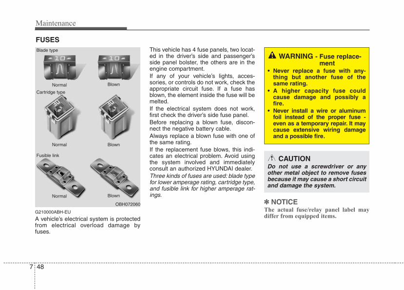
Maintenance
487
FUSES
G210000ABH-EU
A vehicle’s electrical system is protectedfrom electrical overload damage byfuses.
This vehicle has 4 fuse panels, two locat-ed in the driver’s side and passenger’sside panel bolster, the others are in theengine compartment.If any of your vehicle’s lights, acces-sories, or controls do not work, check theappropriate circuit fuse. If a fuse hasblown, the element inside the fuse will bemelted.If the electrical system does not work,first check the driver’s side fuse panel.Before replacing a blown fuse, discon-nect the negative battery cable.Always replace a blown fuse with one ofthe same rating.If the replacement fuse blows, this indi-cates an electrical problem. Avoid usingthe system involved and immediatelyconsult an authorized HYUNDAI dealer.Three kinds of fuses are used: blade typefor lower amperage rating, cartridge type,and fusible link for higher amperage rat-ings.
✽✽ NOTICEThe actual fuse/relay panel label maydiffer from equipped items.
OBH072060
Normal
Normal
Blade type
Cartridge type
Fusible link
Blown
Blown
Normal Blown
WARNING - Fuse replace-ment
• Never replace a fuse with any-thing but another fuse of thesame rating.
• A higher capacity fuse couldcause damage and possibly afire.
• Never install a wire or aluminumfoil instead of the proper fuse -even as a temporary repair. It maycause extensive wiring damageand a possible fire.
CAUTIONDo not use a screwdriver or anyother metal object to remove fusesbecause it may cause a short circuitand damage the system.
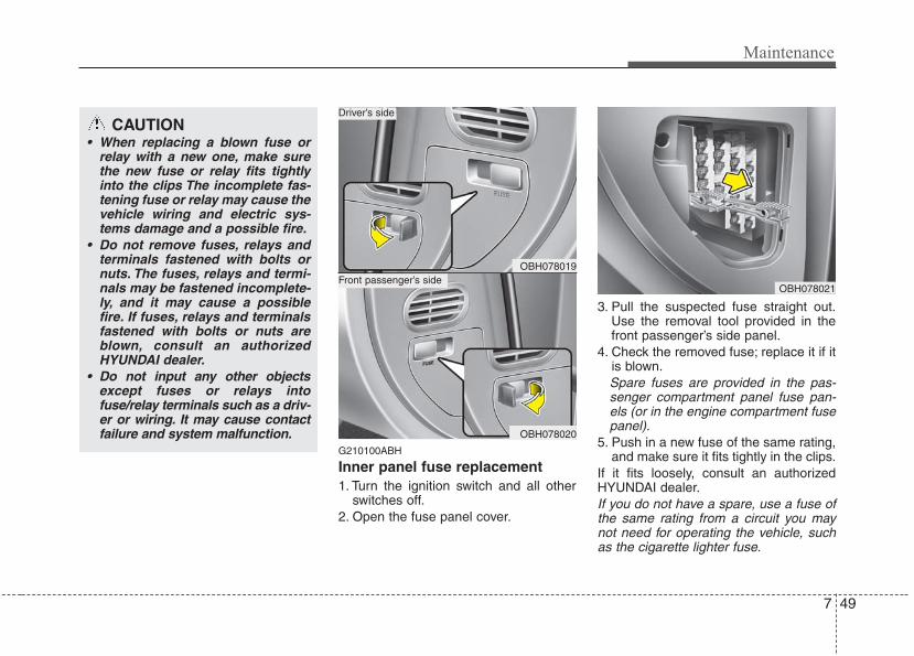
7 49
Maintenance
G210100ABH
Inner panel fuse replacement1. Turn the ignition switch and all other
switches off.2. Open the fuse panel cover.
3. Pull the suspected fuse straight out.Use the removal tool provided in thefront passenger’s side panel.
4. Check the removed fuse; replace it if itis blown.Spare fuses are provided in the pas-senger compartment panel fuse pan-els (or in the engine compartment fusepanel).
5. Push in a new fuse of the same rating,and make sure it fits tightly in the clips.
If it fits loosely, consult an authorizedHYUNDAI dealer.If you do not have a spare, use a fuse ofthe same rating from a circuit you maynot need for operating the vehicle, suchas the cigarette lighter fuse.
OBH078021
OBH078019
OBH078020
Front passenger’s side
Driver’s sideCAUTION
• When replacing a blown fuse orrelay with a new one, make surethe new fuse or relay fits tightlyinto the clips The incomplete fas-tening fuse or relay may cause thevehicle wiring and electric sys-tems damage and a possible fire.
• Do not remove fuses, relays andterminals fastened with bolts ornuts. The fuses, relays and termi-nals may be fastened incomplete-ly, and it may cause a possiblefire. If fuses, relays and terminalsfastened with bolts or nuts areblown, consult an authorizedHYUNDAI dealer.
• Do not input any other objectsexcept fuses or relays intofuse/relay terminals such as a driv-er or wiring. It may cause contactfailure and system malfunction.
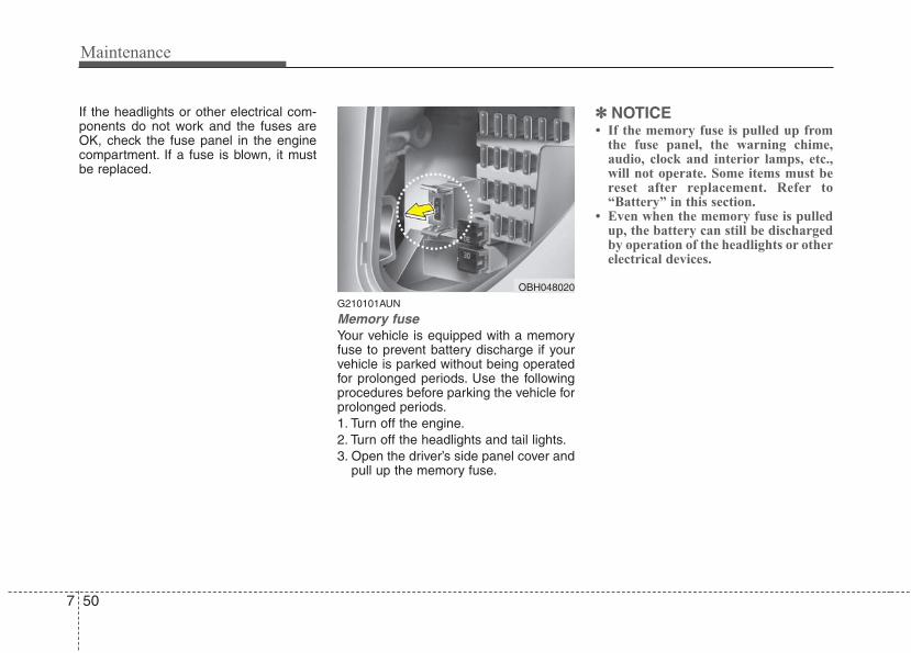
Maintenance
507
If the headlights or other electrical com-ponents do not work and the fuses areOK, check the fuse panel in the enginecompartment. If a fuse is blown, it mustbe replaced.
G210101AUN
Memory fuseYour vehicle is equipped with a memoryfuse to prevent battery discharge if yourvehicle is parked without being operatedfor prolonged periods. Use the followingprocedures before parking the vehicle forprolonged periods.1. Turn off the engine.2. Turn off the headlights and tail lights.3. Open the driver’s side panel cover and
pull up the memory fuse.
✽✽ NOTICE• If the memory fuse is pulled up from
the fuse panel, the warning chime,audio, clock and interior lamps, etc.,will not operate. Some items must bereset after replacement. Refer to“Battery” in this section.
• Even when the memory fuse is pulledup, the battery can still be dischargedby operation of the headlights or otherelectrical devices.
OBH048020
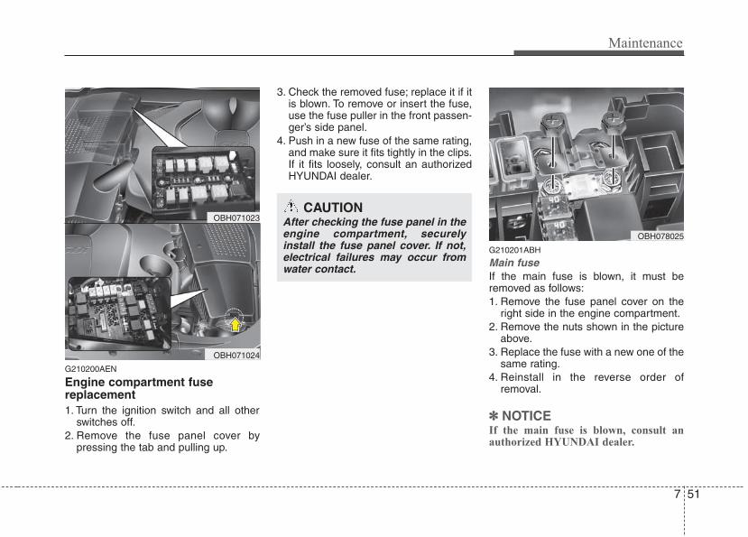
7 51
Maintenance
G210200AEN
Engine compartment fusereplacement1. Turn the ignition switch and all other
switches off.2. Remove the fuse panel cover by
pressing the tab and pulling up.
3. Check the removed fuse; replace it if itis blown. To remove or insert the fuse,use the fuse puller in the front passen-ger’s side panel.
4. Push in a new fuse of the same rating,and make sure it fits tightly in the clips.If it fits loosely, consult an authorizedHYUNDAI dealer.
G210201ABH
Main fuseIf the main fuse is blown, it must beremoved as follows:1. Remove the fuse panel cover on the
right side in the engine compartment.2. Remove the nuts shown in the picture
above.3. Replace the fuse with a new one of the
same rating.4. Reinstall in the reverse order of
removal.
✽✽ NOTICEIf the main fuse is blown, consult anauthorized HYUNDAI dealer.
CAUTIONAfter checking the fuse panel in theengine compartment, securelyinstall the fuse panel cover. If not,electrical failures may occur fromwater contact.
OBH078025
OBH071023
OBH071024
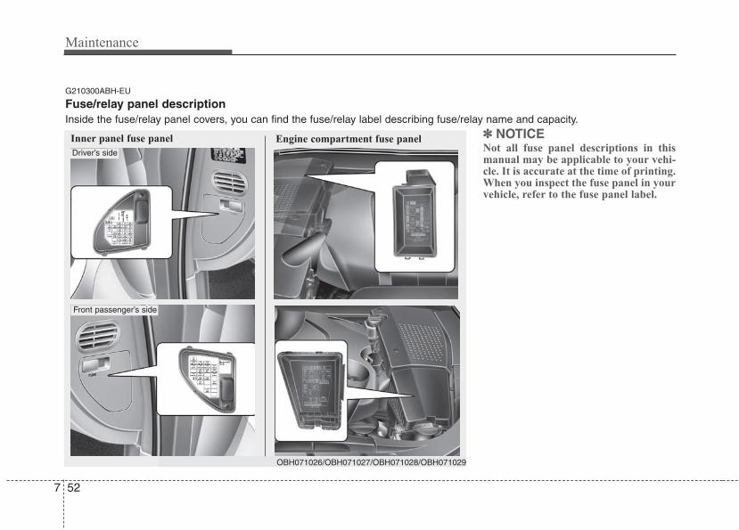
Maintenance
527
✽✽ NOTICENot all fuse panel descriptions in thismanual may be applicable to your vehi-cle. It is accurate at the time of printing.When you inspect the fuse panel in yourvehicle, refer to the fuse panel label.
Inner panel fuse panel Engine compartment fuse panel
G210300ABH-EU
Fuse/relay panel descriptionInside the fuse/relay panel covers, you can find the fuse/relay label describing fuse/relay name and capacity.
OBH071026/OBH071027/OBH071028/OBH071029
Driver’s side
Front passenger’s side
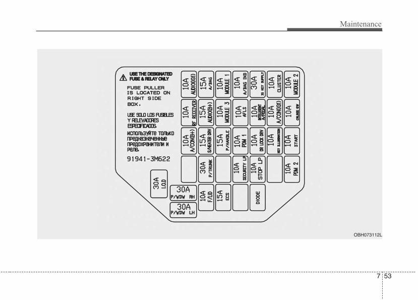
7 53
Maintenance
OBH073112L
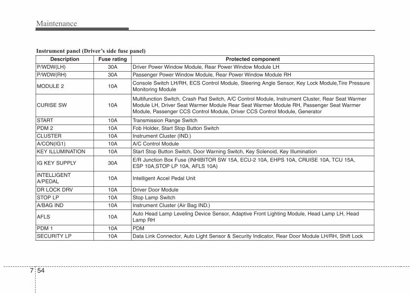
Maintenance
547
Instrument panel (Driver’s side fuse panel)
Description Fuse rating Protected componentP/WDW(LH) 30A Driver Power Window Module, Rear Power Window Module LH
P/WDW(RH) 30A Passenger Power Window Module, Rear Power Window Module RH
MODULE 2 10AConsole Switch LH/RH, ECS Control Module, Steering Angle Sensor, Key Lock Module,Tire PressureMonitoring Module
CURISE SW 10AMultifunction Switch, Crash Pad Switch, A/C Control Module, Instrument Cluster, Rear Seat WarmerModule LH, Driver Seat Warmer Module Rear Seat Warmer Module RH, Passenger Seat WarmerModule, Passenger CCS Control Module, Driver CCS Control Module, Generator
START 10A Transmission Range Switch
PDM 2 10A Fob Holder, Start Stop Button Switch
CLUSTER 10A Instrument Cluster (IND.)
A/CON(IG1) 10A A/C Control Module
KEY ILLUMINATION 10A Start Stop Button Switch, Door Warning Switch, Key Solenoid, Key Illumination
IG KEY SUPPLY 30AE/R Junction Box Fuse (INHIBITOR SW 15A, ECU-2 10A, EHPS 10A, CRUISE 10A, TCU 15A,ESP 10A,STOP LP 10A, AFLS 10A)
INTELLIGENTA/PEDAL
10A Intelligent Accel Pedal Unit
DR LOCK DRV 10A Driver Door Module
STOP LP 10A Stop Lamp Switch
A/BAG IND 10A Instrument Cluster (Air Bag IND.)
AFLS 10AAuto Head Lamp Leveling Device Sensor, Adaptive Front Lighting Module, Head Lamp LH, HeadLamp RH
PDM 1 10A PDM
SECURITY LP 10A Data Link Connector, Auto Light Sensor & Security Indicator, Rear Door Module LH/RH, Shift Lock
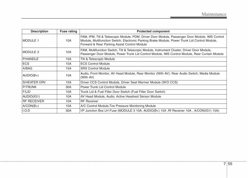
7 55
Maintenance
Description Fuse rating Protected component
MODULE 1 10AFAM, IPM, Tilt & Telescopic Module, PDM, Driver Door Module, Passenger Door Module, IMS ControlModule, Multifunction Switch, Electronic Parking Brake Module, Power Trunk Lid Control Module,Forward & Rear Parking Assist Control Module
MODULE 3 10AFAM, Multifunction Switch, Tilt & Telescopic Module, Instrument Cluster, Driver Door Module,Passenger Door Module, Power Trunk Lid Control Module, IMS Control Module, Rear Curtain Module
P/HANDLE 15A Tilt & Telescopic Module
ECS 15A ECS Control Module
A/BAG 15A SRS Control Module
AUDIO(B+) 15AAudio, Front Monitor, AV Head Module, Rear Monitor (With AV), Rear Audio Switch, Media Module(With AV)
S/HEATER DRV 15A Driver CCS Control Module, Driver Seat Warmer Module (W/O CCS)
P/TRUNK 30A Power Trunk Lid Control Module
F/LID 10A Trunk Lid & Fuel Filler Door Switch (Fuel Filler Door Switch)
AUDIO(IG1) 10A AV Head Module, Audio, Active Headrest Sensor Module
RF RECEIVER 10A RF Receiver
A/CON(B+) 10A A/C Control Module,Tire Pressure Monitoring Module
I.O.D 30A I/P Junction Box LH Fuse (MODULE 3 10A, AUDIO(B+) 15A ,Rf Receiver 10A , A/CON(IG1) 15A)
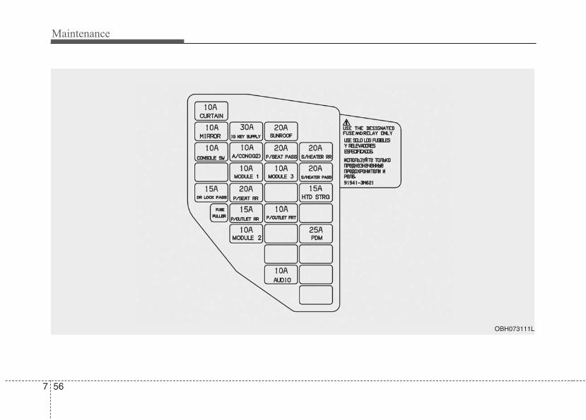
Maintenance
567
OBH073111L
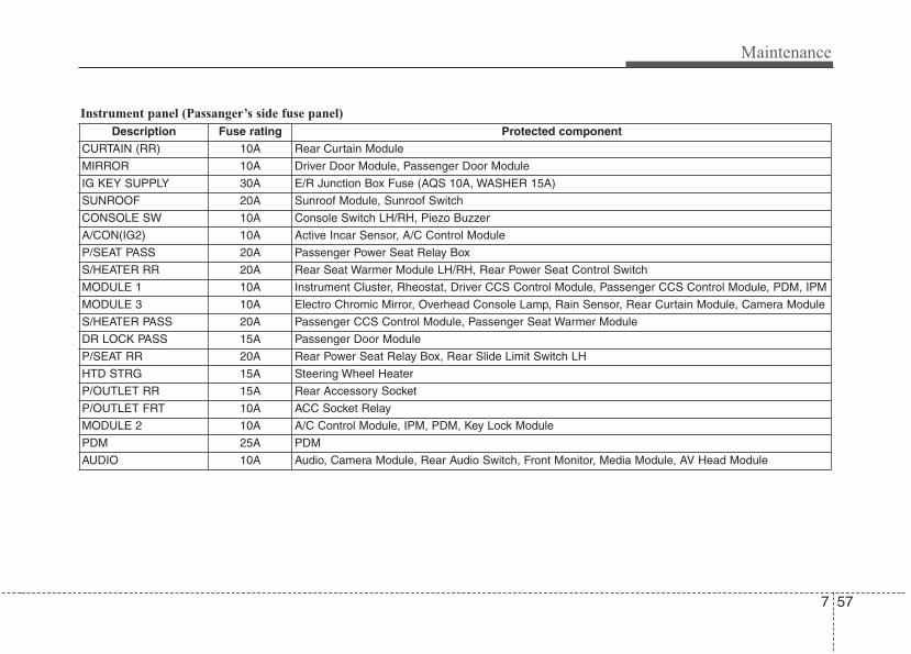
7 57
Maintenance
Description Fuse rating Protected componentCURTAIN (RR) 10A Rear Curtain Module
MIRROR 10A Driver Door Module, Passenger Door Module
IG KEY SUPPLY 30A E/R Junction Box Fuse (AQS 10A, WASHER 15A)
SUNROOF 20A Sunroof Module, Sunroof Switch
CONSOLE SW 10A Console Switch LH/RH, Piezo Buzzer
A/CON(IG2) 10A Active Incar Sensor, A/C Control Module
P/SEAT PASS 20A Passenger Power Seat Relay Box
S/HEATER RR 20A Rear Seat Warmer Module LH/RH, Rear Power Seat Control Switch
MODULE 1 10A Instrument Cluster, Rheostat, Driver CCS Control Module, Passenger CCS Control Module, PDM, IPM
MODULE 3 10A Electro Chromic Mirror, Overhead Console Lamp, Rain Sensor, Rear Curtain Module, Camera Module
S/HEATER PASS 20A Passenger CCS Control Module, Passenger Seat Warmer Module
DR LOCK PASS 15A Passenger Door Module
P/SEAT RR 20A Rear Power Seat Relay Box, Rear Slide Limit Switch LH
HTD STRG 15A Steering Wheel Heater
P/OUTLET RR 15A Rear Accessory Socket
P/OUTLET FRT 10A ACC Socket Relay
MODULE 2 10A A/C Control Module, IPM, PDM, Key Lock Module
PDM 25A PDM
AUDIO 10A Audio, Camera Module, Rear Audio Switch, Front Monitor, Media Module, AV Head Module
Instrument panel (Passanger’s side fuse panel)
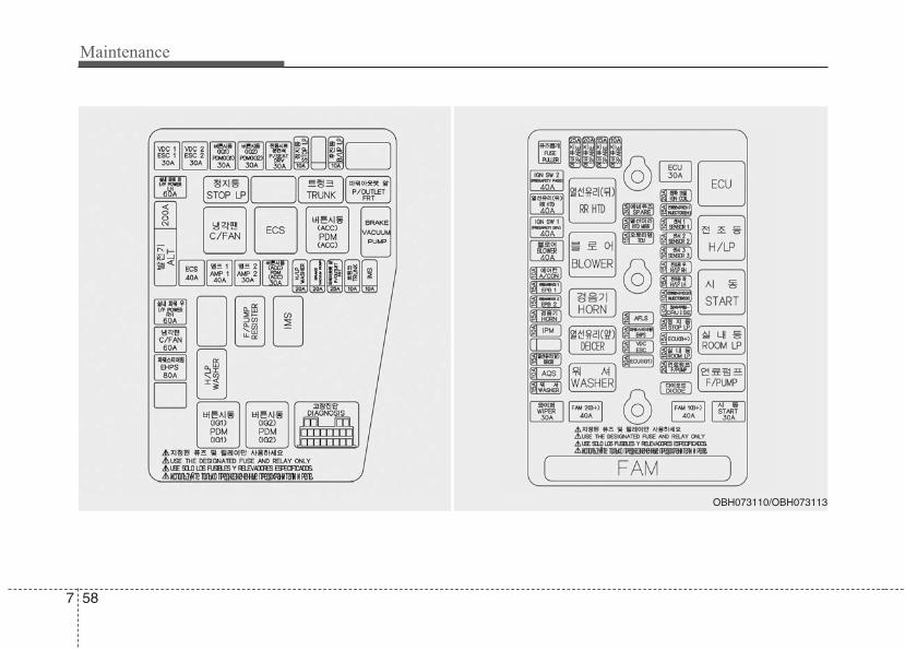
Maintenance
587
OBH073110/OBH073113
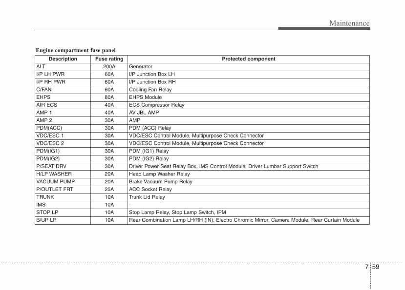
7 59
Maintenance
Description Fuse rating Protected componentALT 200A Generator
I/P LH PWR 60A I/P Junction Box LH
I/P RH PWR 60A I/P Junction Box RH
C/FAN 60A Cooling Fan Relay
EHPS 80A EHPS Module
AIR ECS 40A ECS Compressor Relay
AMP 1 40A AV JBL AMP
AMP 2 30A AMP
PDM(ACC) 30A PDM (ACC) Relay
VDC/ESC 1 30A VDC/ESC Control Module, Multipurpose Check Connector
VDC/ESC 2 30A VDC/ESC Control Module, Multipurpose Check Connector
PDM(IG1) 30A PDM (IG1) Relay
PDM(IG2) 30A PDM (IG2) Relay
P/SEAT DRV 30A Driver Power Seat Relay Box, IMS Control Module, Driver Lumbar Support Switch
H/LP WASHER 20A Head Lamp Washer Relay
VACUUM PUMP 20A Brake Vacuum Pump Relay
P/OUTLET FRT 25A ACC Socket Relay
TRUNK 10A Trunk Lid Relay
IMS 10A -
STOP LP 10A Stop Lamp Relay, Stop Lamp Switch, IPM
B/UP LP 10A Rear Combination Lamp LH/RH (IN), Electro Chromic Mirror, Camera Module, Rear Curtain Module
Engine compartment fuse panel
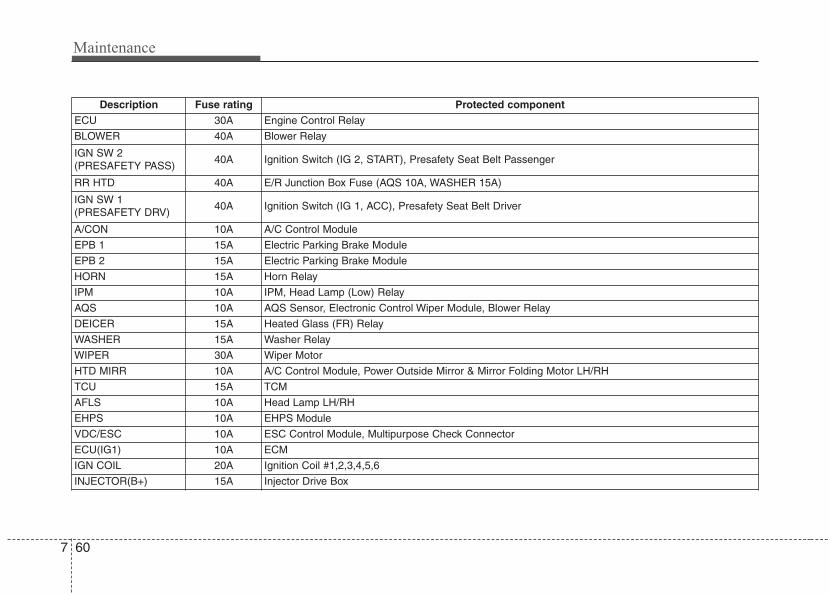
Maintenance
607
Description Fuse rating Protected componentECU 30A Engine Control Relay
BLOWER 40A Blower Relay
IGN SW 2 (PRESAFETY PASS)
40A Ignition Switch (IG 2, START), Presafety Seat Belt Passenger
RR HTD 40A E/R Junction Box Fuse (AQS 10A, WASHER 15A)
IGN SW 1 (PRESAFETY DRV)
40A Ignition Switch (IG 1, ACC), Presafety Seat Belt Driver
A/CON 10A A/C Control Module
EPB 1 15A Electric Parking Brake Module
EPB 2 15A Electric Parking Brake Module
HORN 15A Horn Relay
IPM 10A IPM, Head Lamp (Low) Relay
AQS 10A AQS Sensor, Electronic Control Wiper Module, Blower Relay
DEICER 15A Heated Glass (FR) Relay
WASHER 15A Washer Relay
WIPER 30A Wiper Motor
HTD MIRR 10A A/C Control Module, Power Outside Mirror & Mirror Folding Motor LH/RH
TCU 15A TCM
AFLS 10A Head Lamp LH/RH
EHPS 10A EHPS Module
VDC/ESC 10A ESC Control Module, Multipurpose Check Connector
ECU(IG1) 10A ECM
IGN COIL 20A Ignition Coil #1,2,3,4,5,6
INJECTOR(B+) 15A Injector Drive Box
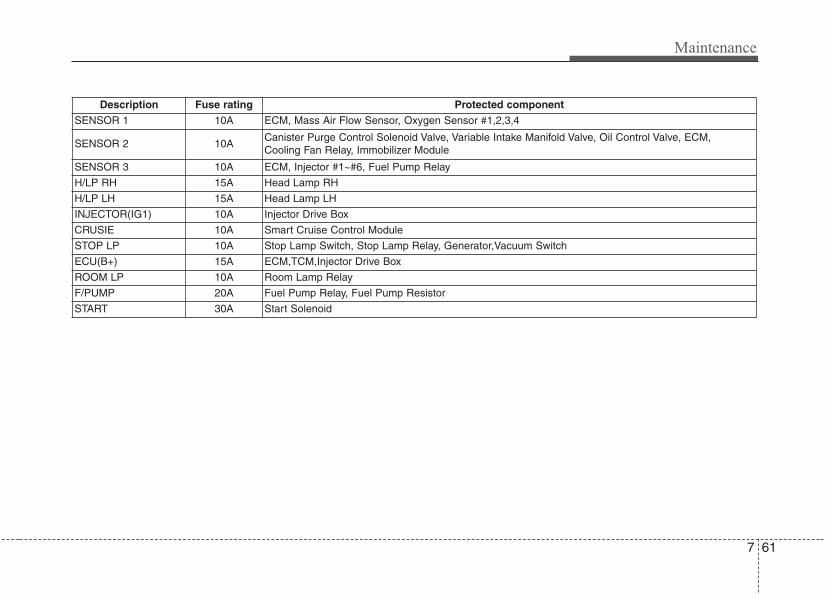
7 61
Maintenance
Description Fuse rating Protected componentSENSOR 1 10A ECM, Mass Air Flow Sensor, Oxygen Sensor #1,2,3,4
SENSOR 2 10ACanister Purge Control Solenoid Valve, Variable Intake Manifold Valve, Oil Control Valve, ECM,Cooling Fan Relay, Immobilizer Module
SENSOR 3 10A ECM, Injector #1~#6, Fuel Pump Relay
H/LP RH 15A Head Lamp RH
H/LP LH 15A Head Lamp LH
INJECTOR(IG1) 10A Injector Drive Box
CRUSIE 10A Smart Cruise Control Module
STOP LP 10A Stop Lamp Switch, Stop Lamp Relay, Generator,Vacuum Switch
ECU(B+) 15A ECM,TCM,Injector Drive Box
ROOM LP 10A Room Lamp Relay
F/PUMP 20A Fuel Pump Relay, Fuel Pump Resistor
START 30A Start Solenoid
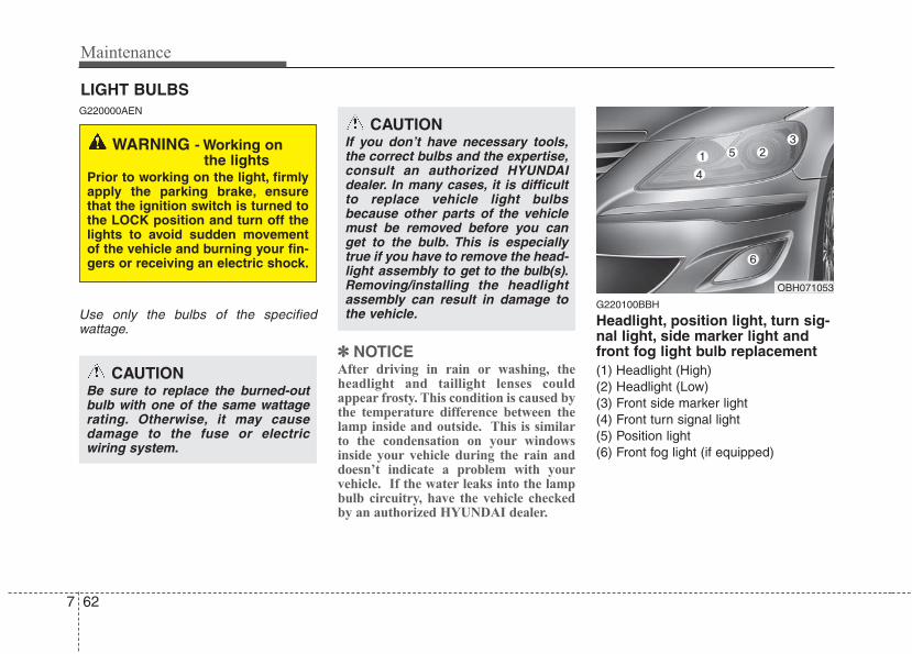
Maintenance
627
LIGHT BULBSG220000AEN
Use only the bulbs of the specifiedwattage.
✽✽ NOTICEAfter driving in rain or washing, theheadlight and taillight lenses couldappear frosty. This condition is caused bythe temperature difference between thelamp inside and outside. This is similarto the condensation on your windowsinside your vehicle during the rain anddoesn’t indicate a problem with yourvehicle. If the water leaks into the lampbulb circuitry, have the vehicle checkedby an authorized HYUNDAI dealer.
G220100BBH
Headlight, position light, turn sig-nal light, side marker light andfront fog light bulb replacement(1) Headlight (High)(2) Headlight (Low)(3) Front side marker light(4) Front turn signal light(5) Position light(6) Front fog light (if equipped)
WARNING - Working onthe lights
Prior to working on the light, firmlyapply the parking brake, ensurethat the ignition switch is turned tothe LOCK position and turn off thelights to avoid sudden movementof the vehicle and burning your fin-gers or receiving an electric shock.
CAUTIONBe sure to replace the burned-outbulb with one of the same wattagerating. Otherwise, it may causedamage to the fuse or electricwiring system.
CAUTIONIf you don’t have necessary tools,the correct bulbs and the expertise,consult an authorized HYUNDAIdealer. In many cases, it is difficultto replace vehicle light bulbsbecause other parts of the vehiclemust be removed before you canget to the bulb. This is especiallytrue if you have to remove the head-light assembly to get to the bulb(s).Removing/installing the headlightassembly can result in damage tothe vehicle.
OBH071053
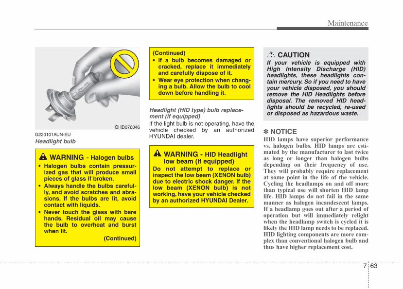
7 63
Maintenance
G220101AUN-EU
Headlight bulb
Headlight (HID type) bulb replace-ment (if equipped)If the light bulb is not operating, have thevehicle checked by an authorizedHYUNDAI dealer.
✽✽ NOTICEHID lamps have superior performancevs. halogen bulbs. HID lamps are esti-mated by the manufacturer to last twiceas long or longer than halogen bulbsdepending on their frequency of use.They will probably require replacementat some point in the life of the vehicle.Cycling the headlamps on and off morethan typical use will shorten HID lamplife. HID lamps do not fail in the samemanner as halogen incandescent lamps.If a headlamp goes out after a period ofoperation but will immediately relightwhen the headlamp switch is cycled it islikely the HID lamp needs to be replaced.HID lighting components are more com-plex than conventional halogen bulb andthus have higher replacement cost.
OHD076046
WARNING - Halogen bulbs• Halogen bulbs contain pressur-
ized gas that will produce smallpieces of glass if broken.
• Always handle the bulbs careful-ly, and avoid scratches and abra-sions. If the bulbs are lit, avoidcontact with liquids.
• Never touch the glass with barehands. Residual oil may causethe bulb to overheat and burstwhen lit.
(Continued)
(Continued)• If a bulb becomes damaged or
cracked, replace it immediatelyand carefully dispose of it.
• Wear eye protection when chang-ing a bulb. Allow the bulb to cooldown before handling it.
WARNING - HID Headlightlow beam (if equipped)
Do not attempt to replace orinspect the low beam (XENON bulb)due to electric shock danger. If thelow beam (XENON bulb) is notworking, have your vehicle checkedby an authorized HYUNDAI Dealer.
CAUTIONIf your vehicle is equipped withHigh Intensity Discharge (HID)headlights, these headlights con-tain mercury. So if you need to haveyour vehicle disposed, you shouldremove the HID Headlights beforedisposal. The removed HID head-lights should be recycled, re-usedor disposed as hazardous waste.
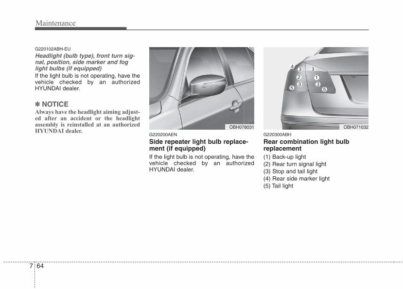
Maintenance
647
G220102ABH-EU
Headlight (bulb type), front turn sig-nal, position, side marker and foglight bulbs (if equipped)If the light bulb is not operating, have thevehicle checked by an authorizedHYUNDAI dealer.
✽✽ NOTICEAlways have the headlight aiming adjust-ed after an accident or the headlightassembly is reinstalled at an authorizedHYUNDAI dealer.
G220200AEN
Side repeater light bulb replace-ment (if equipped)If the light bulb is not operating, have thevehicle checked by an authorizedHYUNDAI dealer.
G220300ABH
Rear combination light bulbreplacement(1) Back-up light(2) Rear turn signal light(3) Stop and tail light(4) Rear side marker light(5) Tail light
OBH078031 OBH071032
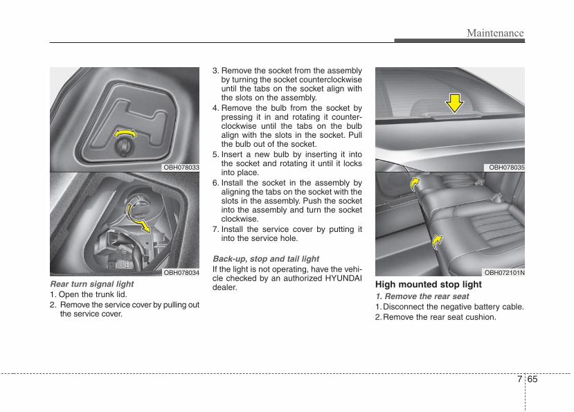
7 65
Maintenance
Rear turn signal light1. Open the trunk lid.2. Remove the service cover by pulling out
the service cover.
3. Remove the socket from the assemblyby turning the socket counterclockwiseuntil the tabs on the socket align withthe slots on the assembly.
4. Remove the bulb from the socket bypressing it in and rotating it counter-clockwise until the tabs on the bulbalign with the slots in the socket. Pullthe bulb out of the socket.
5. Insert a new bulb by inserting it intothe socket and rotating it until it locksinto place.
6. Install the socket in the assembly byaligning the tabs on the socket with theslots in the assembly. Push the socketinto the assembly and turn the socketclockwise.
7. Install the service cover by putting itinto the service hole.
Back-up, stop and tail lightIf the light is not operating, have the vehi-cle checked by an authorized HYUNDAIdealer. High mounted stop light
1. Remove the rear seat1.Disconnect the negative battery cable.2.Remove the rear seat cushion.
OBH078033
OBH078034
OBH078035
OBH072101N
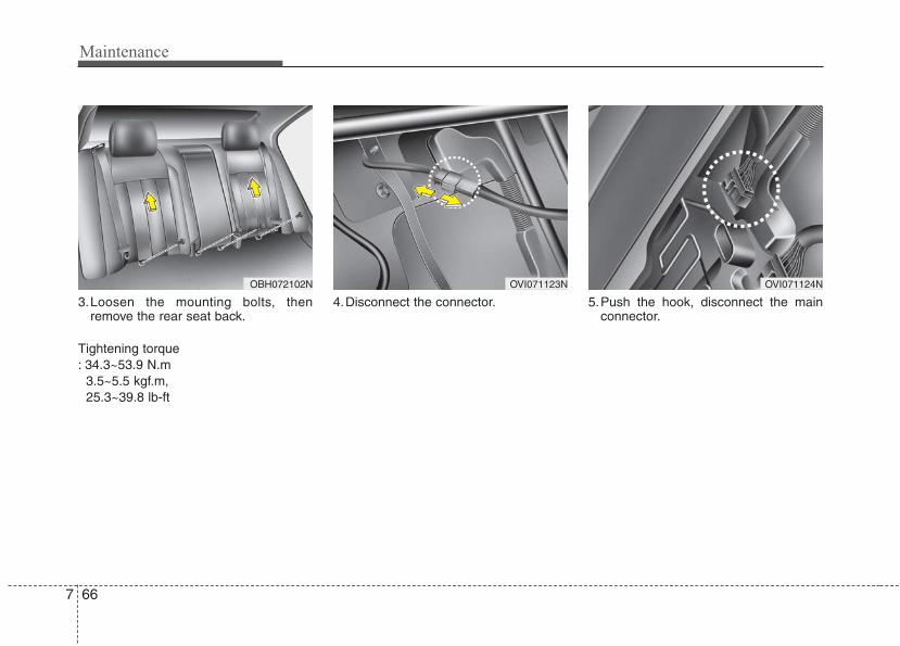
Maintenance
667
3.Loosen the mounting bolts, thenremove the rear seat back.
Tightening torque : 34.3~53.9 N.m
3.5~5.5 kgf.m, 25.3~39.8 lb-ft
4.Disconnect the connector. 5.Push the hook, disconnect the mainconnector.
OBH072102N OVI071123N OVI071124N
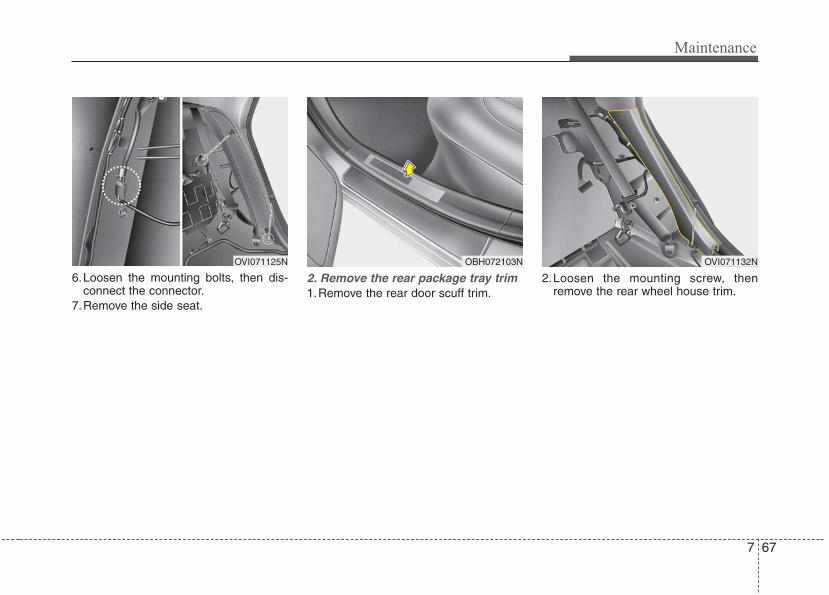
7 67
Maintenance
6.Loosen the mounting bolts, then dis-connect the connector.
7.Remove the side seat.
2. Remove the rear package tray trim 1.Remove the rear door scuff trim.
2.Loosen the mounting screw, thenremove the rear wheel house trim.
OVI071125N OBH072103N OVI071132N
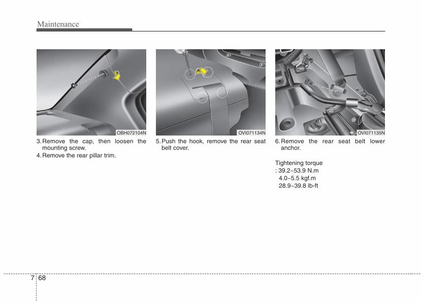
Maintenance
687
3.Remove the cap, then loosen themounting screw.
4.Remove the rear pillar trim.
5.Push the hook, remove the rear seatbelt cover.
6.Remove the rear seat belt loweranchor.
Tightening torque : 39.2~53.9 N.m
4.0~5.5 kgf.m 28.9~39.8 lb-ft
OBH072104N OVI071134N OVI071135N
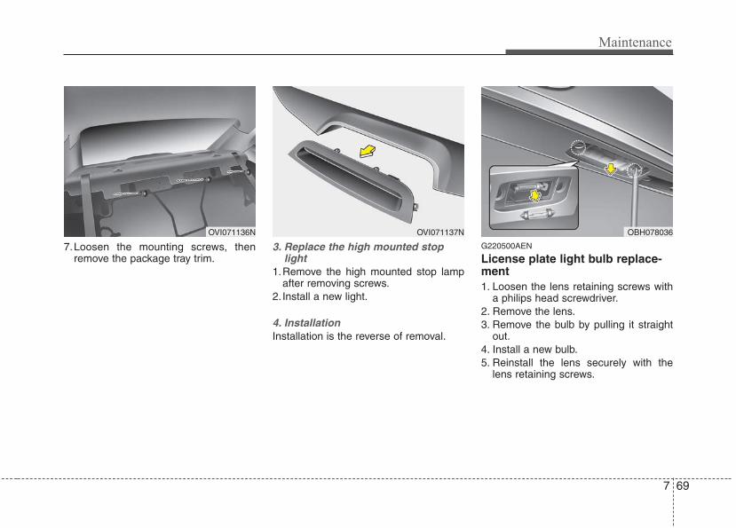
7 69
Maintenance
7.Loosen the mounting screws, thenremove the package tray trim.
3. Replace the high mounted stoplight
1.Remove the high mounted stop lampafter removing screws.
2. Install a new light.
4. InstallationInstallation is the reverse of removal.
G220500AEN
License plate light bulb replace-ment 1. Loosen the lens retaining screws with
a philips head screwdriver.2. Remove the lens.3. Remove the bulb by pulling it straight
out.4. Install a new bulb.5. Reinstall the lens securely with the
lens retaining screws.
OVI071136N OBH078036OVI071137N
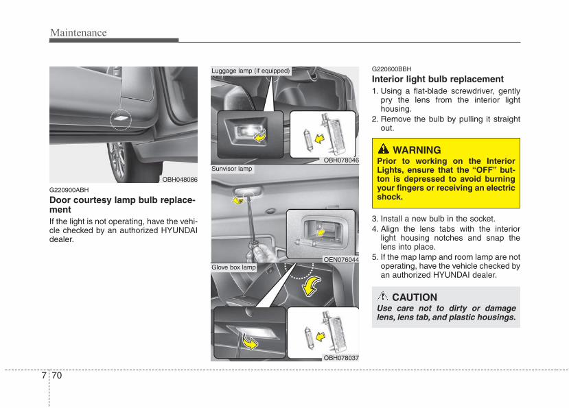
Maintenance
707
G220900ABH
Door courtesy lamp bulb replace-ment If the light is not operating, have the vehi-cle checked by an authorized HYUNDAIdealer.
G220600BBH
Interior light bulb replacement1. Using a flat-blade screwdriver, gently
pry the lens from the interior lighthousing.
2. Remove the bulb by pulling it straightout.
3. Install a new bulb in the socket.4. Align the lens tabs with the interior
light housing notches and snap thelens into place.
5. If the map lamp and room lamp are notoperating, have the vehicle checked byan authorized HYUNDAI dealer.
OBH048086
OBH078046
Luggage lamp (if equipped)
OBH078037
OEN076044
Sunvisor lamp
Glove box lamp
WARNING Prior to working on the InteriorLights, ensure that the “OFF” but-ton is depressed to avoid burningyour fingers or receiving an electricshock.
CAUTIONUse care not to dirty or damagelens, lens tab, and plastic housings.
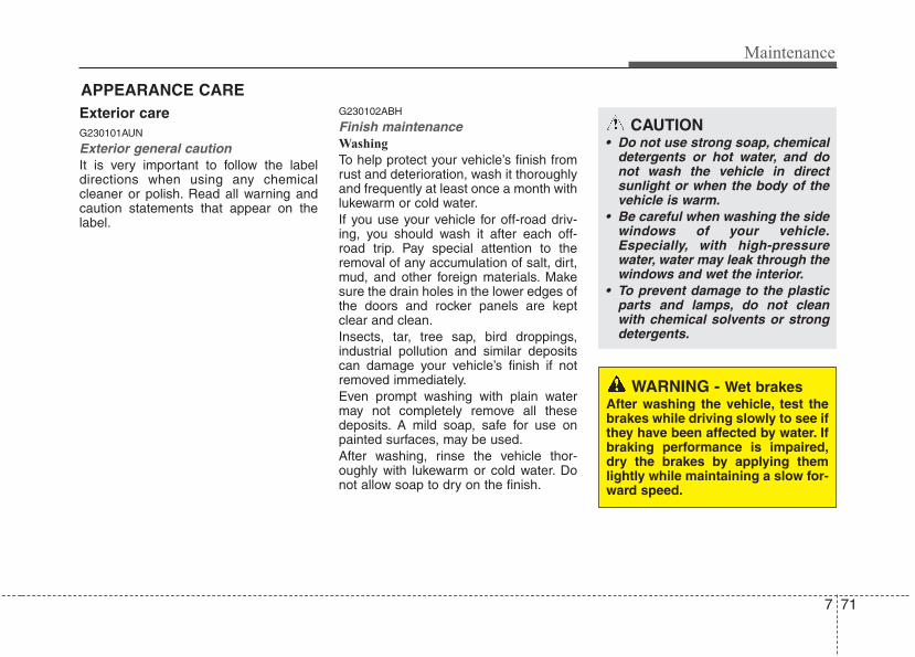
7 71
Maintenance
APPEARANCE CAREExterior careG230101AUN
Exterior general caution It is very important to follow the labeldirections when using any chemicalcleaner or polish. Read all warning andcaution statements that appear on thelabel.
G230102ABH
Finish maintenanceWashing
To help protect your vehicle’s finish fromrust and deterioration, wash it thoroughlyand frequently at least once a month withlukewarm or cold water.If you use your vehicle for off-road driv-ing, you should wash it after each off-road trip. Pay special attention to theremoval of any accumulation of salt, dirt,mud, and other foreign materials. Makesure the drain holes in the lower edges ofthe doors and rocker panels are keptclear and clean.Insects, tar, tree sap, bird droppings,industrial pollution and similar depositscan damage your vehicle’s finish if notremoved immediately.Even prompt washing with plain watermay not completely remove all thesedeposits. A mild soap, safe for use onpainted surfaces, may be used.After washing, rinse the vehicle thor-oughly with lukewarm or cold water. Donot allow soap to dry on the finish.
CAUTION• Do not use strong soap, chemical
detergents or hot water, and donot wash the vehicle in directsunlight or when the body of thevehicle is warm.
• Be careful when washing the sidewindows of your vehicle.Especially, with high-pressurewater, water may leak through thewindows and wet the interior.
• To prevent damage to the plasticparts and lamps, do not cleanwith chemical solvents or strongdetergents.
WARNING - Wet brakesAfter washing the vehicle, test thebrakes while driving slowly to see ifthey have been affected by water. Ifbraking performance is impaired,dry the brakes by applying themlightly while maintaining a slow for-ward speed.
Maintenance
727
Waxing
A good coat of wax is a barrier betweenyour paint and contaminate. Keeping agood coat of wax on your vehicle will helpprotect it.Wax the vehicle when water will nolonger bead on the paint.Always wash and dry the vehicle beforewaxing. Use a good quality liquid orpaste wax, and follow the manufacturer’sinstructions. Wax all metal trim to protectit and to maintain its luster.Removing oil, tar, and similar materialswith a spot remover will usually strip thewax from the finish. Be sure to re-waxthese areas even if the rest of the vehicledoes not yet need waxing.
G230103AUN
Finish damage repair Deep scratches or stone chips in thepainted surface must be repairedpromptly. Exposed metal will quickly rustand may develop into a major repairexpense.
✽✽ NOTICEIf your vehicle is damaged and requiresany metal repair or replacement, be surethe body shop applies anti-corrosionmaterials to the parts repaired orreplaced.
CAUTION• Wiping dust or dirt off the body
with a dry cloth will scratch thefinish.
• Do not use steel wool, abrasivecleaners, or strong detergentscontaining highly alkaline orcaustic agents on chrome-platedor anodized aluminum parts. Thismay result in damage to the pro-tective coating and cause discol-oration or paint deterioration.
CAUTION• Water washing in the engine com-
partment including high pressurewater washing is not recommend-ed. It may cause the failure ofelectrical circuits or engine andrelated part located in the enginecompartment.
• Never allow water or other liquidsto come in contact with electri-cal/electronic components andthe air duct inside the vehicle asthis may damage them.
OJB037800
7 73
Maintenance
G230104AUN
Bright-metal maintenance• To remove road tar and insects, use a
tar remover, not a scraper or othersharp object.
• To protect the surfaces of bright-metalparts from corrosion, apply a coating ofwax or chrome preservative and rub toa high luster.
• During winter weather or in coastalareas, cover the bright metal parts witha heavier coating of wax or preserva-tive. If necessary, coat the parts withnon-corrosive petroleum jelly or otherprotective compound.
G230105AUN
Underbody maintenanceCorrosive materials used for ice andsnow removal and dust control may col-lect on the underbody. If these materialsare not removed, accelerated rusting canoccur on underbody parts such as thefuel lines, frame, floor pan and exhaustsystem, even though they have beentreated with rust protection.Thoroughly flush the vehicle underbodyand wheel openings with lukewarm orcold water once a month, after off-roaddriving and at the end of each winter. Payspecial attention to these areas because itis difficult to see all the mud and dirt. It willdo more harm than good to wet down theroad grime without removing it. The loweredges of doors, rocker panels, and framemembers have drain holes that should notbe allowed to clog with dirt; trapped waterin these areas can cause rusting.
G230106AUN
Aluminum or chrome wheel mainte-nance The aluminum or chrome wheels arecoated with a clear protective finish.• Do not use any abrasive cleaner, pol-
ishing compound, solvent, or wirebrushes on aluminum or chromewheels. They may scratch or damagethe finish.
• Clean the wheel when it has cooled.• Use only a mild soap or neutral deter-
gent, and rinse thoroughly with water.Also, be sure to clean the wheels afterdriving on salted roads. This helps pre-vent corrosion.
• Avoid washing the wheels with high-speed car wash brushes.
• Do not use any alkaline or acid deter-gent. It may damage and corrode thealuminum or chrome wheels coatedwith a clear protective finish.
WARNINGAfter washing the vehicle, test thebrakes while driving slowly to see ifthey have been affected by water. Ifbraking performance is impaired,dry the brakes by applying themlightly while maintaining a slow for-ward speed.
Maintenance
747
G230107AUN
Corrosion protectionProtecting your vehicle from corrosion
By using the most advanced design andconstruction practices to combat corro-sion, we produces cars of the highest qual-ity. However, this is only part of the job. Toachieve the long-term corrosion resistanceyour vehicle can deliver, the owner's coop-eration and assistance is also required.
Common causes of corrosion
The most common causes of corrosionon your car are:• Road salt, dirt and moisture that is
allowed to accumulate underneath thecar.
• Removal of paint or protective coatingsby stones, gravel, abrasion or minorscrapes and dents which leave unpro-tected metal exposed to corrosion.
High-corrosion areas
If you live in an area where your car isregularly exposed to corrosive materials,corrosion protection is particularly impor-tant. Some of the common causes ofaccelerated corrosion are road salts,dust control chemicals, ocean air andindustrial pollution.
Moisture breeds corrosion
Moisture creates the conditions in whichcorrosion is most likely to occur. Forexample, corrosion is accelerated byhigh humidity, particularly when tempera-tures are just above freezing. In suchconditions, the corrosive material is keptin contact with the car surfaces by mois-ture that is slow to evaporate.Mud is particularly corrosive because it isslow to dry and holds moisture in contactwith the vehicle. Although the mudappears to be dry, it can still retain themoisture and promote corrosion.High temperatures can also acceleratecorrosion of parts that are not properlyventilated so the moisture can be dis-persed. For all these reasons, it is par-ticularly important to keep your car cleanand free of mud or accumulations ofother materials. This applies not only tothe visible surfaces but particularly to theunderside of the car.
To help prevent corrosion
You can help prevent corrosion from get-ting started by observing the following:
Keep your car cleanThe best way to prevent corrosion is tokeep your car clean and free of corrosivematerials. Attention to the underside ofthe car is particularly important.
• If you live in a high-corrosion area —where road salts are used, near theocean, areas with industrial pollution,acid rain, etc.—, you should take extracare to prevent corrosion. In winter,hose off the underside of your car atleast once a month and be sure toclean the underside thoroughly whenwinter is over.
• When cleaning underneath the car,give particular attention to the compo-nents under the fenders and otherareas that are hidden from view. Do athorough job; just dampening the accu-mulated mud rather than washing itaway will accelerate corrosion ratherthan prevent it. Water under high pres-sure and steam are particularly effec-tive in removing accumulated mud andcorrosive materials.
• When cleaning lower door panels,rocker panels and frame members, besure that drain holes are kept open sothat moisture can escape and not betrapped inside to accelerate corrosion.
7 75
Maintenance
Keep your garage dryDon't park your car in a damp, poorlyventilated garage. This creates a favor-able environment for corrosion. This isparticularly true if you wash your car inthe garage or drive it into the garagewhen it is still wet or covered with snow,ice or mud. Even a heated garage cancontribute to corrosion unless it is wellventilated so moisture is dispersed.
Keep paint and trim in good conditionScratches or chips in the finish should becovered with "touch-up" paint as soon aspossible to reduce the possibility of cor-rosion. If bare metal is showing through,the attention of a qualified body and paintshop is recommended.
Bird droppings : Bird droppings are high-ly corrosive and may damage paintedsurfaces in just a few hours. Alwaysremove bird droppings as soon as possi-ble.
Don't neglect the interiorMoisture can collect under the floor matsand carpeting to cause corrosion. Checkunder the mats periodically to be surethe carpeting is dry. Use particular care ifyou carry fertilizers, cleaning materials orchemicals in the car.These should be carried only in propercontainers and any spills or leaks shouldbe cleaned up, flushed with clean waterand thoroughly dried.
Interior careG230201AUN
Interior general precautions Prevent chemicals such as perfume, cos-metic oil, sun cream, hand cleaner, andair freshener from contacting the interiorparts because they may cause damageor discoloration. If they do contact theinterior parts, wipe them off immediately.See the instructions for the proper way toclean vinyl.
CAUTION• Never allow water or other liquids
to come in contact with electri-cal/electronic components insidethe vehicle as this may damagethem.
• When cleaning leather products(steering wheel, seats etc.), useneutral detergents or low alcoholcontent solutions. If you use highalcohol content solutions oracid/alkaline detergents, the colorof the leather may fade or the sur-face may get stripped off.
Maintenance
767
G230202AUN
Cleaning the upholstery and interiortrim Vinyl
Remove dust and loose dirt from vinylwith a whisk broom or vacuum cleaner.Clean vinyl surfaces with a vinyl cleaner.
Fabric
Remove dust and loose dirt from fabricwith a whisk broom or vacuum cleaner.Clean with a mild soap solution recom-mended for upholstery or carpets.Remove fresh spots immediately with afabric spot cleaner. If fresh spots do notreceive immediate attention, the fabriccan be stained and its color can beaffected. Also, its fire-resistant propertiescan be reduced if the material is notproperly maintained.
G230203AUN
Cleaning the lap/shoulder belt web-bing Clean the belt webbing with any mildsoap solution recommended for cleaningupholstery or carpet. Follow the instruc-tions provided with the soap. Do notbleach or re-dye the webbing becausethis may weaken it.
G230204AUN
Cleaning the interior window glass If the interior glass surfaces of the vehi-cle become fogged (that is, covered withan oily, greasy or waxy film), they shouldbe cleaned with glass cleaner. Follow thedirections on the glass cleaner container.
CAUTIONUsing anything but recommendedcleaners and procedures may affectthe fabric’s appearance and fire-resistant properties.
CAUTIONDo not scrape or scratch the insideof the rear window. This may resultin damage to the rear windowdefroster grid.
7 77
Maintenance
EMISSION CONTROL SYSTEMG270000AEN-EU
The emission control system of yourvehicle is covered by a written limitedwarranty. Please see the warranty infor-mation contained in the Owner’sHandbook & Warranty Information book-let in your vehicle.Your vehicle is equipped with an emis-sion control system to meet all applicableemission regulations.There are three emission control sys-tems, as follows.
(1) Crankcase emission control system(2) Evaporative emission control system(3) Exhaust emission control system
In order to assure the proper function ofthe emission control systems, it is rec-ommended that you have your carinspected and maintained by an author-ized HYUNDAI dealer in accordance withthe maintenance schedule in this manu-al.
Caution for the Inspection andMaintenance Test (With ElectronicStability Control (ESC) system)• To prevent the vehicle from misfir-
ing during dynamometer testing,turn the Electronic Stability Control(ESC) system off by pressing theESC switch.
• After dynamometer testing is com-pleted, turn the ESC system back onby pressing the ESC switch again.
G270100AUN
1. Crankcase emission controlsystem
The positive crankcase ventilation sys-tem is employed to prevent air pollutioncaused by blow-by gases being emittedfrom the crankcase. This system suppliesfresh filtered air to the crankcase throughthe air intake hose. Inside the crankcase,the fresh air mixes with blow-by gases,which then pass through the PCV valveinto the induction system.
G270200AUN
2. Evaporative emission control(including ORVR: OnboardRefueling Vapor Recovery) system
The Evaporative Emission ControlSystem is designed to prevent fuelvapors from escaping into the atmos-phere.(The ORVR system is designed to allowthe vapors from the fuel tank to beloaded into a canister while refueling atthe gas station, preventing the escape offuel vapors into the atmosphere.)
Maintenance
787
G270201AUN
CanisterFuel vapors generated inside the fueltank are absorbed and stored in theonboard canister. When the engine isrunning, the fuel vapors absorbed in thecanister are drawn into the engine intakemanifold through the purge control sole-noid valve.
G270202AUN
Purge Control Solenoid Valve (PCSV)The purge control solenoid valve is con-trolled by the Engine Control Module(ECM); when the engine coolant temper-ature is low during idling, the PCSV clos-es so that evaporated fuel is not takeninto the engine. After the engine warms-up during ordinary driving, the PCSVopens to introduce evaporated fuel to theengine.
G270300AUN
3. Exhaust emission control system
The Exhaust Emission Control System isa highly effective system which controlsexhaust emissions while maintaininggood vehicle performance.
G270301AUN
Vehicle modifications • This vehicle should not be modified.
Modification of your vehicle couldaffect its performance, safety or dura-bility and may even violate governmen-tal safety and emissions regulations.In addition, damage or performanceproblems resulting from any modificationmay not be covered under warranty.
• Use of unauthorized electric devicesmay cause: Abnormal vehicle operation,Wire damage, Battery discharge, Fire.Be careful not to damage your vehicleby use of unauthorized electric devices.
G270302AUN-EU
Engine exhaust gas precautions (carbon monoxide) • Carbon monoxide can be present with
other exhaust fumes. Therefore, if yousmell exhaust fumes of any kind insideyour vehicle, have it inspected andrepaired immediately. If you ever sus-pect exhaust fumes are coming intoyour vehicle, drive it only with all thewindows fully open. Have your vehiclechecked and repaired immediately.
WARNING - ExhaustEngine exhaust gases contain car-bon monoxide (CO). Though color-less and odorless, it is dangerousand could be lethal if inhaled.Follow the instructions on thispage to avoid CO poisoning.
CALIFORNIA PROPOSI-TION 65 WARNING
Engine exhaust and a wide varietyof automobile components andparts, including components foundin the interior furnishings in a vehi-cle, contain or emit chemicalsknown to the State of California tocause cancer and birth defects andreproductive harm. In addition, cer-tain fluids contained in vehiclesand certain products of componentwear contain or emit chemicalsknown to the State of California tocause cancer and birth defects orother reproductive harm.
7 79
Maintenance
• Do not operate the engine in confinedor closed areas (such as garages) anymore than what is necessary to movethe vehicle in or out of the area.
• When the vehicle is stopped in anopen area for more than a short timewith the engine running, adjust theventilation system (as needed) to drawoutside air into the vehicle.
• Never sit in a parked or stopped vehi-cle for any extended time with theengine running.
• When the engine stalls or fails to start,excessive attempts to restart theengine may cause damage to theemission control system.
G270303AEN
Operating precautions for catalyticconverters (if equipped)
Your vehicle is equipped with a catalyticconverter emission control device.Therefore, the following precautionsmust be observed:• Use only UNLEADED FUEL for gaso-
line engines.• Do not operate the vehicle when there
are signs of engine malfunction, suchas misfire or a noticeable loss of per-formance.
• Do not misuse or abuse the engine.Examples of misuse are coasting withthe ignition off and descending steepgrades in gear with the ignition off.
• Do not operate the engine at high idlespeed for extended periods (5 minutesor more).
• Do not modify or tamper with any partof the engine or emission control sys-tem. All inspections and adjustmentsmust be made by an authorizedHYUNDAI dealer.
• Avoid driving with a very low fuel level. Ifyou run out of gasoline, it could causethe engine to misfire and result in exces-sive loading of the catalytic converter.
Failure to observe these precautionscould result in damage to the catalyticconverter and to your vehicle. Additionally,such actions could void your warranties.
WARNING - Fire• A hot exhaust system can ignite
flammable items under your vehi-cle. Do not park, idle, or drive thevehicle over or near flammableobjects, such as grass, vegeta-tion, paper, leaves, etc.
• The exhaust system and catalyticsystem are very hot while theengine is running or immediatelyafter the engine is turned off.Keep away from the exhaust sys-tem and catalytic, you may getburned.Also, do not remove the heat sinkaround the exhaust system, donot seal the bottom of the vehicleor do not coat the vehicle for cor-rosion control. It may present afire risk under certain conditions.
Maintenance
807
CALIFORNIA PERCHLORATE NOTICEG280000AEN
Perchlorate Material-special handlingmay apply, See www.dtsc.ca.gov/haz-ardouswaste/perchlorate.
Notice to California Vehicle Dismantlers:Perchlorate containing materials, such asair bag inflators, seatbelt pretensionersand keyless remote entry batteries, mustbe disposed of according to Title 22California Code of Regulations Section67384.10 (a).

Maintenance
87
G040100ABH-EU
The following maintenance services must be performed to ensure good emission control and performance. Keep receipts for allvehicle emission services to protect your warranty. Where both mileage and time are shown, the frequency of service is deter-mined by whichever occurs first.R : Replace I : Inspect and, after Inspection, clean, adjust, repair or replace if necessary.
NORMAL MAINTENANCE SCHEDULE
*1 : If TOP TIER Detergent Gasoline is not available, one bottle of additive is recommended. Additives are available from yourauthorized HYUNDAI dealer along with information on how to use them. Do not mix other additives.
*2 : Inspect for excessive tappet noise and/or engine vibration and adjust if necessary.
DESCRIPTION
7.5 15 22.5 30 37.5 45 52.5 60 67.5 75 82.5 90 97.5 105 112.5 120 127.5 135 142.5 150
12 24 36 48 60 72 84 96 108 120 132 144 156 168 180 192 204 216 228 240
6 12 18 24 30 36 42 48 54 60 66 72 78 84 90 96 102 108 114 120
Replace every 7,500 miles (12,000 km) or 12 months
Add every 7,500 miles (12,000 km) or 12 months
R R R R
I I I I I I I I I I I I I I I I I I I I
I I I I I I I I I I I I I I I I I I I I
I I I I I I I I I I I I I I I I I I I I
I I I R I I I R I I I R I I I R I I I R
R
Inspect every 60,000 miles (96,000 km) or 72 months
I I I R I I I R I I I R I I I R I I I R
EMISSION CONTROL ITEMS
ENGINE OIL AND FILTER
FUEL ADDITIVES*1
FUEL FILTER
FUEL LINES, FUEL HOSES AND CONNECTIONS
VACUUM HOSE
VAPOR HOSE AND FUEL FILLER CAP
AIR CLEANER FILTER
SPARK PLUGS (IRIDIUM COATED)
VALVE CLEARANCE *2 (3.8L)
FUEL TANK AIR FILTER
No.
1
2
3
4
5
6
7
8
9
10
MILES X 1000
KILOMETERS X 1000
MONTHS
8
Dimensions / 8-2
Bulb wattage / 8-2
Tires and wheels / 8-3
Recommended lubricants and capacities / 8-4
Vehicle identification number (VIN) / 8-7
Vehicle certification label / 8-7
Tire specification and pressure label / 8-8
Engine number / 8-8
Refrigerant label / 8-8
Consumer information / 8-9
Reporting safety defects / 8-10
Specifications, Consumer information, Reporting safety defects
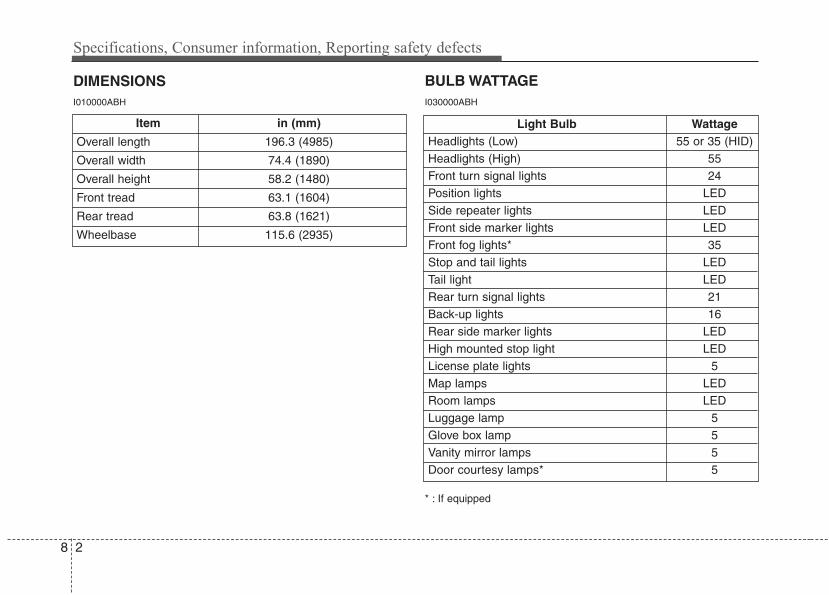
Specifications, Consumer information, Reporting safety defects
28
DIMENSIONS
Light Bulb WattageHeadlights (Low) 55 or 35 (HID)Headlights (High) 55Front turn signal lights 24Position lights LEDSide repeater lights LEDFront side marker lights LEDFront fog lights* 35Stop and tail lights LEDTail light LEDRear turn signal lights 21Back-up lights 16Rear side marker lights LEDHigh mounted stop light LEDLicense plate lights 5Map lamps LEDRoom lamps LEDLuggage lamp 5Glove box lamp 5Vanity mirror lamps 5Door courtesy lamps* 5
BULB WATTAGE
* : If equipped
I010000ABH I030000ABH
Item in (mm)
Overall length 196.3 (4985)
Overall width 74.4 (1890)
Overall height 58.2 (1480)
Front tread 63.1 (1604)
Rear tread 63.8 (1621)
Wheelbase 115.6 (2935)
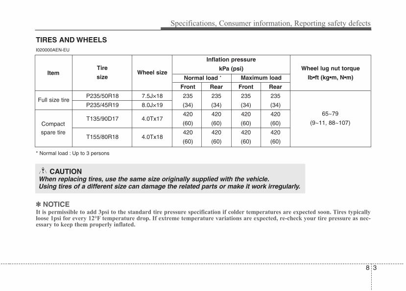
8 3
Specifications, Consumer information, Reporting safety defects
TIRES AND WHEELSI020000AEN-EU
* Normal load : Up to 3 persons
✽✽ NOTICEIt is permissible to add 3psi to the standard tire pressure specification if colder temperatures are expected soon. Tires typicallyloose 1psi for every 12°F temperature drop. If extreme temperature variations are expected, re-check your tire pressure as nec-essary to keep them properly inflated.
Inflation pressure
kPa (psi)
Front Rear Front Rear
P235/50R18 7.5J×18 235 235 235 235
P235/45R19 8.0J×19 (34) (34) (34) (34)
T135/90D17 4.0Tx17420 420 420 420
(60) (60) (60) (60)
T155/80R18 4.0Tx18420 420 420 420
(60) (60) (60) (60)
Full size tire
Compactspare tire
Wheel lug nut torque
lb•ft (kg•m, N•m)
65~79
(9~11, 88~107)
ItemTire
sizeWheel size
Normal load * Maximum load
CAUTIONWhen replacing tires, use the same size originally supplied with the vehicle.Using tires of a different size can damage the related parts or make it work irregularly.

Specifications, Consumer information, Reporting safety defects
48
RECOMMENDED LUBRICANTS AND CAPACITIES I040000BBH-EU
To help achieve proper engine and powertrain performance and durability, use only lubricants of the proper quality. The correctlubricants also help promote engine efficiency that results in improved fuel economy.
These lubricants and fluids are recommended for use in your vehicle.
*1 Refer to the recommended SAE viscosity numbers on the next page.*2 Engine oils labeled Energy Conserving Oil are now available. Along with other additional benefits, they contribute to fuel economy by reducing
the amount of fuel necessary to overcome engine friction. Often, these improvements are difficult to measure in everyday driving, but in a year’stime, they can offer significant cost and energy savings.
*3 If the API service SM engine oil is not available in your country, you are able to use API service SL.
Lubricant Volume Classification
Engine oil *1 *2
(drain and refill)Recommends
3.8L 6.02 US qt. (5.7 l)
API Service SM*3,
ILSAC GF-4 or above
5.0L 7.61 US qt. (7.2 l)
Automatic transmission fluid 10.67 US qt. (10.1 l)GS ATF SP-IV-RR, HYUNDAI genuine
ATF SP-IV-RR or other brands meeting the abovespecification approved by HYUNDAI Motor Co.,
Power steering fluid 0.95 US qt. (0.9 l) Pentosin CHF 202
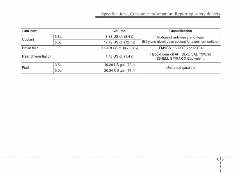
8 5
Specifications, Consumer information, Reporting safety defects
Lubricant Volume Classification
Coolant 3.8L 8.88 US qt. (8.4 l) Mixture of antifreeze and water
(Ethylene glycol base coolant for aluminum radiator)5.0L 12.79 US qt. (12.1 l)
Brake fluid 0.7~0.8 US qt. (0.7~0.8 l) FMVSS116 DOT-3 or DOT-4
Rear differential oil 1.48 US qt. (1.4 l)Hypoid gear oil API GL-5, SAE 75W/90
(SHELL SPIRAX X Equivalent)
Fuel3.8L 19.28 US gal. (73 l)
Unleaded gasoline5.0L 20.34 US gal. (77 l)
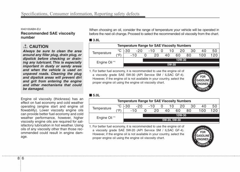
Specifications, Consumer information, Reporting safety defects
68
I040100ABH-EU
Recommended SAE viscositynumber
Engine oil viscosity (thickness) has aneffect on fuel economy and cold weatheroperating (engine start and engine oilflowability). Lower viscosity engine oilscan provide better fuel economy and coldweather performance, however, higherviscosity engine oils are required for sat-isfactory lubrication in hot weather. Usingoils of any viscosity other than those rec-ommended could result in engine dam-age.
CAUTIONAlways be sure to clean the areaaround any filler plug, drain plug, ordipstick before checking or drain-ing any lubricant. This is especiallyimportant in dusty or sandy areasand when the vehicle is used onunpaved roads. Cleaning the plugand dipstick areas will prevent dirtand grit from entering the engineand other mechanisms that couldbe damaged.
Temperature Range for SAE Viscosity Numbers
Temperature
Engine Oil *1
°C(°F)
-30 -20 -10 0 10 20 30 40 50-10 0 20 40 60 80 100 120
1. For better fuel economy, it is recommended to use the engine oil ofa viscosity grade SAE 5W-30 (API Service SM / ILSAC GF-4).However, if the engine oil is not available in your country, select theproper engine oil using the engine oil viscosity chart.
10W-30
5W-30
Temperature Range for SAE Viscosity Numbers
Temperature
Engine Oil *1
°C(°F)
-30 -20 -10 0 10 20 30 40 50-10 0 20 40 60 80 100 120
1. For better fuel economy, it is recommended to use the engine oil ofa viscosity grade SAE 5W-20 (API Service SM / ILSAC GF-4).However, if the engine oil is not available in your country, select theproper engine oil using the engine oil viscosity chart.
10W-30
5W-20, 5W-30
When choosing an oil, consider the range of temperature your vehicle will be operated inbefore the next oil change. Proceed to select the recommended oil viscosity from the chart.
■■ 3.8L
■■ 5.0L
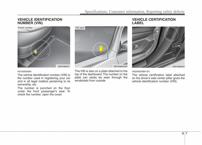
8 7
Specifications, Consumer information, Reporting safety defects
VEHICLE IDENTIFICATIONNUMBER (VIN)
H010000ABH
The vehicle identification number (VIN) isthe number used in registering your carand in all legal matters pertaining to itsownership, etc.The number is punched on the floorunder the front passenger’s seat. Tocheck the number, open the cover.
The VIN is also on a plate attached to thetop of the dashboard. The number on theplate can easily be seen through thewindshield from outside.
VEHICLE CERTIFICATIONLABEL
H020000ABH-EU
The vehicle certification label attachedon the driver’s side center pillar gives thevehicle identification number (VIN).
OBH089002OBH088001 OBH088005N
Frame number VIN label
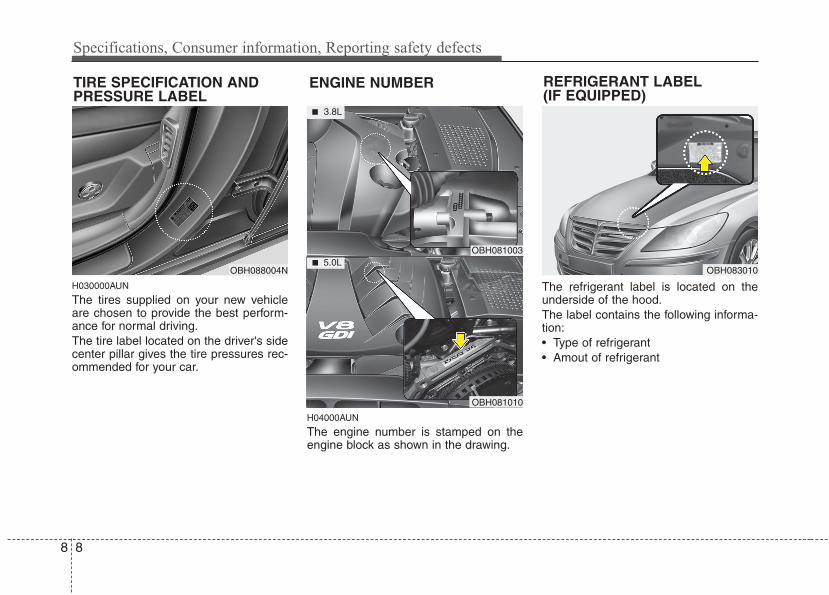
Specifications, Consumer information, Reporting safety defects
88
H030000AUN
The tires supplied on your new vehicleare chosen to provide the best perform-ance for normal driving.The tire label located on the driver's sidecenter pillar gives the tire pressures rec-ommended for your car.
H04000AUN
The engine number is stamped on theengine block as shown in the drawing.
The refrigerant label is located on theunderside of the hood.The label contains the following informa-tion:• Type of refrigerant• Amout of refrigerant
OBH088004N OBH083010
TIRE SPECIFICATION ANDPRESSURE LABEL
ENGINE NUMBER
OBH081003
OBH081010
■ 3.8L
■ 5.0L
REFRIGERANT LABEL(IF EQUIPPED)
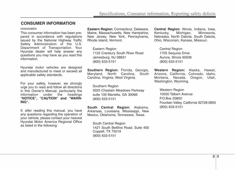
8 9
Specifications, Consumer information, Reporting safety defects
H050000BEN
This consumer information has been pre-pared in accordance with regulationsissued by the National Highway TrafficSafety Administration of the U.S.Department of Transportation. YourHyundai dealer will help answer anyquestions you may have as you read thisinformation.
Hyundai motor vehicles are designedand manufactured to meet or exceed allapplicable safety standards.
For your safety, however, we stronglyurge you to read and follow all directionsin this Owner's Manual, particularly theinformation under the headings"NOTICE", "CAUTION" and "WARN-ING".
If, after reading this manual, you haveany questions regarding the operation ofyour vehicle, please contact your nearestHyundai Motor America Regional Officeas listed in the following:
Eastern Region: Connecticut, Delaware,Maine, Massachusetts, New Hampshire,New Jersey, New York, Pennsylvania,Rhode Island, Vermont.
Eastern Region1122 Cranbury South River RoadJamesburg, NJ 08831(800) 633-5151
Southern Region: Florida, Georgia,Maryland, North Carolina, SouthCarolina, Virginia, West Virginia.
Southern Region3025 Chastain Meadows Parkwaysuite 100 Marietta, GA 30066(800) 633-5151
South Central Region: Alabama,Arkansas, Louisiana, Mississippi, NewMexico, Oklahoma, Tennessee, Texas.
South Central Region1421 South Beltline Road, Suite 400Coppell, TX 75019(800) 633-5151
Central Region: Illinois, Indiana, lowa,Kentucky, Michigan, Minnesota,Nebraska, North Dakota, South Dakota,Ohio, Wisconsin, Kansas, Missouri.
Central Region1705 Sequoia DriveAurora, Illinois 60506(800) 633-5151
Western Region: Alaska, Hawaii,Arizona, California, Colorado, ldaho,Montana, Nevada, Oregon, Utah,Washington, Wyoming.
Western Region10550 Talbert AvenueP.O.Box 20850Fountain Valley, California 92728-0850(800) 633-5151
CONSUMER INFORMATION
H070000AEN
If you believe that your vehicle has adefect which could cause a crash orcould cause injury or death, you shouldimmediately inform the National HighwayTraffic Safety Administration (NHTSA) inaddition to notifying HYUNDAI MOTORAMERICA. If NHTSA receives similarcomplaints, it may open an investigation,and if it finds that a safety defect exists ina group of vehicles, it may order a recalland remedy campaign. However, NHTSAcannot become involved in individualproblems between you, your dealer, orHYUNDAI MOTOR AMERICA.To contact NHTSA, you may call theVehicle Safety Hotline toll-free at 1-888-327-4236 (TTY: 1-800-424-9153); go tohttp://www.safercar.gov; or write to:Administrator, NHTSA, 1200 New JerseyAvenue, SE, West Building, Washington,DC 20590. You can also obtain otherinformation about motor vehicle safetyfrom http://www.safercar.gov.
REPORTING SAFETY DEFECTS
8 10
Specifications, Consumer information, Reporting safety defects
IIndex
Index
2I
Air bag - advanced supplemental restraint system ······ 3-35Air bag warning label ················································ 3-60Curtain air bag ··························································· 3-52Driver's and passenger's front air bag ······················· 3-46Occupant classification system ································· 3-41Side impact air bag ···················································· 3-50SRS components and functions ································· 3-38
Air cleaner ··································································· 7-23Appearance care ·························································· 7-71Audio system ····························································· 4-115
Antenna ··································································· 4-115Bluetooth® Wireless Technology phone operation ····4-151HD RadioTM································································4-147PA710BH ································································· 4-120PA760BH ································································· 4-133Steering wheel audio control ··································· 4-115
Automatic climate control system ······························· 4-89Air conditioning ························································ 4-96Automatic heating and air conditioning ···················· 4-90Manual heating and air conditioning ························ 4-91Rear vent ································································· 4-100
Automatic transmission ··············································· 5-12Ignition key interlock system ···································· 5-16Shift lock system ······················································· 5-15Sports mode ······························································· 5-14
Battery ········································································· 7-31Before driving ································································ 5-3Brake fluid ··································································· 7-20Brake system ······························································· 5-18
Anti-lock brake system (ABS) ·································· 5-28Auto hold ·····································································5-25Electric parking brake (EPB) ······································5-21Electronic stability control (ESC) ····························· 5-30Parking brake ····························································· 5-19Power brakes ····························································· 5-18
Bulb wattage ·································································· 8-2
California perchlorate notice ······································· 7-80Child restraint system ·················································· 3-27
Placing a passenger seat belt into the auto lock mode ········································································ 3-29
Securing a child restraint seat with tether anchor system ······································································ 3-31
Securing a child restraint seat with child seat lower anchor system ·························································· 3-33
Climate control air filter ·············································· 7-26Consumer information ··················································· 8-9Cruise control system ·················································· 5-36
A B
C
I 3
Index
Defroster ······································································ 4-88Dimensions ···································································· 8-2Door locks ··································································· 4-16
Central door lock switch ··········································· 4-17Child-protector rear door lock ··································· 4-19
Driver position memory system ·································· 4-34
Economical operation ·················································· 5-54Emergency starting ························································ 6-4
Jump starting ······························································· 6-4Push starting ································································ 6-5
Emission control system ·············································· 7-77Crankcase emission control system ·························· 7-77Evaporative emission control (including ORVR:
Onboard Refueling Vapor Recovery) System ········· 7-77Exhaust emission control system ······························ 7-78
Engine compartment ·············································· 2-4, 7-2Engine coolant ····························································· 7-17Engine number ······························································· 8-7Engine oil ····································································· 7-15Engine start/stop button ················································· 5-7
Engine start/stop button position ································· 5-7Starting the engine ······················································· 5-9
Explanation of scheduled maintenance items ············· 7-12
Foot parking brake·························································7-24Fuel filler lid ································································ 4-28
Emergency fuel filer lid release ································ 4-30Fuel requirements ·························································· 1-3Fuses ············································································ 7-48
Fuse/relay panel description ······································ 7-52Main fuse ··································································· 7-51Memory fuse ····························································· 7-50
Hazard warning flasher ················································ 4-76Headrest··································································3-6, 3-11Hood ············································································ 4-27How to use this manual ················································· 1-2
If the engine overheats ·················································· 6-6If the engine will not start ············································· 6-3If you have a flat tire ··················································· 6-13
Changing tires ··························································· 6-15Compact spare tire ····················································· 6-19Jack and tools ···························································· 6-13Removing and storing the spare tire ························· 6-14
In case of an emergency while driving ·························· 6-2
D
E
F
H
I
Index
4I
Indicator symbols on the instrument cluster ················· 1-7Instrument cluster ························································ 4-48
Engine temperature gauge ········································· 4-51Fuel gauge ································································· 4-52Instrument panel illumination ··································· 4-50Speedometer ······························································ 4-50Tachometer ································································ 4-50Trip computer ···························································· 4-52Warning and indicators ·············································· 4-58Warning on the LCD screen ······································ 4-68
Instrument panel overview ············································ 2-3Interior features ························································· 4-106
Ashtray ···································································· 4-106AUX, USB and iPod® port ······································ 4-113Bluetooth® Wireless Technology hands-free ··········· 4-114Cigarette lighter ······················································· 4-106Clothes hanger ························································· 4-111Cup holder ······························································· 4-107Digital clock ···························································· 4-109DIS (Driver Information System)······························4-114Floor mat anchor(s) ···················································4-111Luggage net (holder) ··············································· 4-112Navigation system ··················································· 4-113Outside thermometer ··············································· 4-110Power outlet ····························································· 4-108Rear curtain ····························································· 4-112Sunvisor ··································································· 4-107
Interior light ································································· 4-85Interior overview ··························································· 2-2
Key ················································································· 5-5Ignition switch position ··············································· 5-5Starting the engine ······················································· 5-6
Keys ··············································································· 4-3
Lane departure warning system (LDWS)······················5-51Light bulbs ··································································· 7-62
Headlight, position light, turn signal light, side markerlight and front fog light bulb replacement ············· 7-62
High mounted stop light replacement ······················· 7-65Interior light bulb replacement ·································· 7-70License plate light bulb replacement ························ 7-69Door courtesy lamp bulb replacement ······················ 7-70Rear combination light bulb replacement ················· 7-64Side repeater light bulb replacement ························· 7-64
Lighting ······································································· 4-77AFLS(Adaptive Front Lighting System) ·················· 4-81Battery saver function ··············································· 4-77Headlight escort function ············································4-77
L
K
I 5
Index
Maintenance services ····················································· 7-4Mirrors ········································································· 4-39
Electric chromic mirror (ECM) with compass andHomeLink® system ················································ 4-39
Inside rearview mirror ··············································· 4-39Outside rearview mirror ············································ 4-45
Owner maintenance ······················································· 7-5
Parking assist system ··················································· 4-72Power steering fluid ····················································· 7-21
Rear view camera ························································ 4-76Recommended lubricants and capacities ······················· 8-4Remote keyless entry ··················································· 4-11Reporting safety defects ················································ 8-9Road warning ································································· 6-2
Scheduled maintenance service ····································· 7-7Normal maintenance schedule ···································· 7-8Maintenance under severe usage conditions ············· 7-11
Seat belts ······································································ 3-16Pre-tensioner seat belt ··············································· 3-21Seat belt - Driver's 3-point system
with emergency locking retractor ··························· 3-18Seat belts - Front passenger and rear seat
3-point system with combination locking retractor ·· 3-20Seat warmer····························································3-8, 3-14Seats ··············································································· 3-2
Armrest ······································································ 3-13Smart cruise control system···········································5-40Smart key ······································································· 4-7Special driving conditions ··········································· 5-56
Driving at night ························································· 5-57Driving in flooded areas ············································ 5-58Driving in the rain ····················································· 5-58Hazardous driving conditions ···································· 5-56Highway driving ························································ 5-59Rocking the vehicle ··················································· 5-56Smooth cornering ······················································ 5-57
Steering wheel ····························································· 4-37Horn ··········································································· 4-38Power steering ··························································· 4-37Tilt steering ································································ 4-37
M S
O
P
R
Index
6I
Storage compartments ··············································· 4-104Center console storage ············································ 4-104Glove box ································································ 4-104Sunglass holder ······················································· 4-105
Sunroof ········································································ 4-31
Theft-alarm system ······················································ 4-14Tire pressure monitoring system (TPMS) ····················· 6-7
Changing a tire with TPMS ······································ 6-10Low tire pressure position telltale ······························· 6-8Low tire pressure telltale ············································· 6-8TPMS (Tire pressure monitoring system)
malfunction indicator ················································ 6-9Tire specification and pressure label ····························· 8-8Tires and wheels ··················································· 7-34, 8-3
All season tires ·························································· 7-46Checking tire inflation pressure ································ 7-35Compact spare tire replacement ································ 7-39Low aspect ratio tire ····················································7-44Radial-ply tires ·························································· 7-47Recommended cold tire inflation pressures ·············· 7-34Snow tires ·································································· 7-47Summer tires ····························································· 7-46Tire care ····································································· 7-34Tire chains ································································· 7-47Tire maintenance ······················································· 7-39Tire replacement ························································ 7-38
Tire rotation ······························································· 7-36Tire sidewall labeling ················································ 7-40Tire terminology and definitions ······························· 7-44Tire traction ······························································· 7-39Wheel alignment and tire balance ····························· 7-37Wheel replacement ···················································· 7-39
Towing ········································································· 6-21Emergency towing ····················································· 6-23Removable towing hook············································· 6-22
Trailer towing·································································5-70Trunk ············································································ 4-20
Emergency trunk safety release ································ 4-21Trunk lid control button ············································ 4-22
Vehicle break-in process ················································ 1-5Vehicle certification label ·············································· 8-7Vehicle data collection and event data recorders ·········· 1-6Vehicle identification number (VIN) ····························· 8-6Vehicle load limit ························································· 5-64
Cargo capacity ··························································· 5-65Certification label ······················································ 5-67Seating capacity ························································· 5-64Tire and loading information label ···························· 5-64Towing capacity···························································5-65Vehicle capacity weight ············································· 5-64
Vehicle weight ····························································· 5-69Base curb weight ······················································· 5-69
V
T
I 7
Index
Cargo weight ····························································· 5-69GAW (Gross axle weight) ········································· 5-69GAWR (Gross axle weight rating) ···························· 5-69GVW (Gross vehicle weight) ···································· 5-69GVWR (Gross vehicle weight rating) ······················· 5-69
Washer fluid ································································· 7-22Windows ······································································ 4-23
Auto up/down window ·············································· 4-24Power window lock button ········································ 4-26
Windshield defrosting and defogging ······················· 4-101Auto defogging system ··········································· 4-103Defogging logic ······················································· 4-102
Winter driving ······························································ 5-60Snow tires ·································································· 5-60Tire chains ································································· 5-61
Wiper blades ································································ 7-28Wipers and washers ····················································· 4-82
W