2005 edition - lillington, north carolina
TRANSCRIPT
TOWN OF LILLINGTON
DETAILED WATER SPECIFICATIONS General Notes Unless otherwise indicated, all standards apply to the public water system. Described in this section are the general design standards, which are to be followed by all parties in preparing subdivision, utility extension, and utility replacement plans for the Town of Lillington. These design standards will ensure that the citizens of Lillington will continue to have quality water facilities along with an adequate fire protection system. All engineering plans for the public water system must meet the State and/or the Town of Lillington minimum design standards as indicated in the most recent amended Rules Governing Public Water Supplies by the N.C. Department of Health and Human Services or the Town of Lillington Public Works Specifications, whichever is the more stringent. An engineer must certify all projects. The Town of Lillington reserves the right to revise or amend the following specifications as required to insure water quality or facilitate system maintenance. Exceptions may occur without notice on a case by case basis as determined by the Public Works Director and Town Manager or designee. Plans Approval and Requirements. Preliminary water main and hydrant plans shall be submitted with the Zoning Application to the Zoning Administrator. These plans shall be inspected and approved by the Fire Chief, the Public Works Director, and Town Zoning Administrator before review by the Planning Board or any work is done on the project. Plan and profile drawings shall be prepared by a North Carolina registered Professional Engineer signed, sealed, and dated showing the various elements of the utility mains and shall include an overall utility plan layout on a single sheet with scale no smaller than 1 inch = 200 feet. The design of improvements must be based upon the Owners record drawings and actual field verification of existing facilities by the Engineer. The utility drawings shall be on separate sheets, free of landscaping and other details not pertinent to the utility plans. A separate landscaping plan must be submitted with the utility plan showing any proposed landscaping and all water and sewer utilities or easement. All adjacent tracts and topographic information must be shown on the landscaping plan. The water drawings and sewer drawings may be on the same sheets. Landscaping plans shall show all utility engineering drawings and shall be on paper 24 inches by 36 inches. Once installed, certified “as built” plans shall be provided to the Town of Lillington showing the utilities. “As built” drawings for the utilities shall be submitted to the Public Works Department prior to acceptance of the project by the Town of Lillington.
Town of Lillington Page 2 Detailed Water Specifications
1. WATER DESIGN – PUBLIC
a. Location Conditions for Design
1) All mains are to be within dedicated street rights-of-way except major transmission mains not affording direct service connection. Mains within the street right-of-way shall be a minimum of 5 feet from the outside of the pipe to the edge of the right-of-way. Greater separation may be required for greater depth.
2) No person shall place any part of a structure, any permanent equipment, or
impoundment on Town of Lillington Utility Right of Way/Easements or mains. Prohibited structures include, but are not limited to, buildings, houses, air conditioning units /heat pumps, decks, garages, tool or storage sheds, swimming pools, walls, and fences. Fences may be allowed across right of way/easements as long as there is an access gate the full width of the right of way/easement, provided that written approval is first received from the Public Works Department. No fences may be installed longitudinally (lengthwise) within right of way/easements
b. Size
1) Major mains (8" and above) are to be sized according to the Town of
Lillington Water Specifications to meet all fire flow requirements.
2) In residential areas, mains shall be a minimum of 6" in diameter. Eight-inch lines shall be used when the minimum flow requirements cannot be met. Preliminary plans for water lines and hydrants shall be submitted to the Zoning Administrator Public Works Director. The total maximum length of a 6-inch water line, without connecting to a larger main, is 600 feet. The total maximum length of an 8-inch water line, without connecting to a larger main, is 1,000 feet. A copy of the Engineering Report shall accompany the permit application. The Engineer shall supply either by water model or calculations the anticipated water flow and pressure at the furthest hydrant to be installed within the development.
3) Within all residential or commercial cul-de-sacs, a 6-inch water main is
required and must end with a fire hydrant. Water main sizes shall not be reduced except at street intersections or at fire hydrant locations on cul-de-sacs.
4) When the proposed project or subdivisions is confined by natural
topographic features or existing developments, and it is determined that the streets will not be extended to serve adjacent properties, then the mains shall be sized to provide adequate domestic and fire flows. In this case, the minimum main size for single-family residential zoning districts shall be 6 inch and for all other zoning districts shall be 8-inch.
Town of Lillington Page 3 Detailed Water Specifications
5) The Town of Lillington is required to provide a minimum residual pressure
of 20 pounds per square inch (psi) at a minimum flow of 1000 Gallons per Minute. If an individual needs greater pressure, then it is his/her responsibility to incorporate the necessary booster pumping facilities.
6) The developer shall loop water mains to the existing system where feasible.
If streets are extended to the property line for future extension where no service connection is located, the developer shall extend the water main to the property line and terminate the line with a Mechanical Joint plug and appropriate size concrete thrust block. The terminus of the said plug shall be indicated on the “as-built” drawings.
c. Fire Hydrants
1) All fire hydrants shall be installed on a 6-inch branch with a hydrant valve on each branch. All hydrants are to be located at the right-of-way or in a two-foot easement adjacent to the right-of-way. Fire hydrants on private property greater than 10 feet from the public right of way shall be private with the appropriate backflow devices. Fire hydrants on private property less than 10 feet from the public right of way shall be installed in recorded Town of Lillington water easements. The branch valve shall be no greater than one foot from the main and inside the pavement when possible. The valve shall be mechanically restrained to the main. Only one fire hydrant may be installed on a dead end 6-inch line.
2) There shall be a fire hydrant located at each street intersection, and the end
of a cul-de-sacs. The Town of Lillington no longer allows water lines less than 6-inches in diameter nor blow-offs. All dead end water mains shall be terminated at a fire hydrant with gate valve. Any variation to this requirement will require written permission from the Public Works Director, Town Manager or designee.
3) The maximum distance between fire hydrants, measured along street
centerlines, shall be 500 feet, except when residential intersections are not more than 700 feet apart; no hydrant is required between the intersections.
4) In all other districts, the maximum distance between fire hydrants, measured
along street centerline, shall be 300 feet except when business, office and institutional areas are not more than 450 feet apart, no fire hydrant is required between intersections.
5) On major thoroughfares and collector streets with access points only at
street intersections, hydrants shall be located at each street intersection and at 1,000 feet intervals along the street. Where these intersections are less than 1,200 feet apart, no hydrant is required between the intersections. Fire hydrants shall be placed in a staggered arrangement on both sides of any
Town of Lillington Page 4 Detailed Water Specifications
roadway classified as a major or minor thoroughfare with the hydrant spacing as stated above.
6) When the relocation of an existing fire hydrant is approved by the Public
Works Department, the existing hydrant branch will be plugged at the tee or tapping valve with a mechanical plug with no bends. If the existing main/tee is lead joint, the tap or tee will need to be cut out and a new section of pipe (nipple) installed with a ductile iron repair joint.
7) Installation. Hydrants shall be set plumb with a finish grade, which shall
measure 18" from ground to center of the steamer cap. Hydrants shall be properly located so that the pumper nozzle faces the closest curb. The back of the hydrant opposite the pipe connection shall be firmly blocked against the vertical face of the trench with 1/3 cubic yard of concrete. Double bridle rods and collars shall be connected from the tee to the hydrant. Rods shall not be less than 5/8-inch diameter stock and coated with bituminous paint. A minimum of eight (8) cubic feet of stone shall be placed around the drains. The backfill around the hydrants shall be thoroughly compacted. Hydrant installation shall be in accordance with the Ordinances of the Town or as directed by the Public Works Director. All hydrants will have individual controlling valves located no more than fifteen (15) feet from the hydrant. When hydrant extensions are used, they must be manufactured by the same manufacturer as the hydrant on which they are being used and installed in accordance with the manufacturer’s instructions.
8) No services are permitted on any fire hydrant branch.
9) Additional fire hydrants may be required by the Fire Department. 10) There shall be a 3-feet minimum clear distance around all fire hydrants.
This means that nothing shall be within a 3-feet radius of all hydrants including but not limited to trees, shrubs, fencing, guardrail, signs, light and utility poles, etc.
11) Minimum Flows. The minimum acceptable flow is 1,000 gallons per
minute in residential areas, and 1,500 gallons per minute in other districts. These flows will be computed at 20 psi residual. A flow test shall be conducted at hydrant locations deemed necessary by the Public Works Director or his designee. The Owner shall coordinate with the Town of Lillington to schedule these tests and shall be conducted in the presence of a person designated by the Public Works Director.
12) Square Footage and Sprinkler Requirements. When new buildings are
constructed or existing buildings expanded and contain 10,000 total square feet of floor space (all floors of all buildings, new and existing, added together), hydrants shall be installed at 300 foot intervals along all sides of the building that are accessible to Fire Department pumpers. These hydrants shall be within a minimum of twenty (20) feet and a maximum of
Town of Lillington Page 5 Detailed Water Specifications
forty (40) feet away from the building. Existing hydrants along streets can be counted in the 10,000 square foot requirements. Where sprinkler systems are used, a fire department connection shall be provided on the building. The fire department connections shall be located within fifty (50) feet of a fire hydrant. There shall be no obstruction or fencing between the fire department connection and its closest hydrant. Where sprinkler systems or a riser room are required, outside access in accordance with the North Carolina State Building Code shall be provided. Backflow prevention for sprinkler systems shall be as specified in NC Building Code or as directed by the Harnett County Fire Marshal.
d. Valves
1) Each proposed new intersection shall have a main line valve for every leg
i.e., a four-way intersection shall have three main line valves, a TEE intersection shall have two main line valves. All valves shall be rodded to a tee or cross.
2) Each fire hydrant shall have a hydrant branch valve.
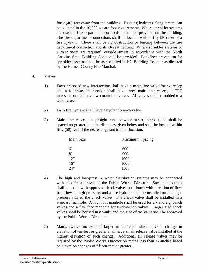
3) Main line valves on straight runs between street intersections shall be
spaced no greater than the distances given below and shall be located within fifty (50) feet of the nearest hydrant to their location.
Main Size Maximum Spacing
6" 600' 8" 900' 12" 1000' 16" 1000' 24" 1500'
4) The high and low-pressure water distribution systems may be connected with specific approval of the Public Works Director. Such connections shall be made with approved check valves positioned with direction of flow from low to high pressure, and a fire hydrant shall be installed on the high-pressure side of the check valve. The check valve shall be installed in a standard manhole. A four foot manhole shall be used for six and eight-inch valves and a five foot manhole for twelve-inch valves. Larger size check valves shall be housed in a vault, and the size of the vault shall be approved by the Public Works Director.
5) Mains twelve inches and larger in diameter which have a change in
elevation of ten-feet or greater shall have an air release valve installed at the highest elevation of such change. Additional air release valves may be required by the Public Works Director on mains less than 12-inches based on elevation changes of fifteen-feet or greater.
Town of Lillington Page 6 Detailed Water Specifications
6) Any water service customer which has a water static pressure greater than eighty (80) psi is required by North Carolina State Building Code to install and maintain a pressure reducing valve. The pressure reducing valve will be installed on the building service line after the meter. Such a device must be installed before the Town of Lillington will allow the actual water connection. This installation is covered by the Plumbing Code and is not maintained by the Public Works Department.
7) Pressure reducing and/or sustaining stations shall be installed when directed
by the Public Works Director to connect high and low pressure systems. The pressure reducing valve shall allow enough flow from the high side to maintain a specified pressure on the low side and will not reduce the high side below a certain amount. This type valve will be a pressure sustaining/ pressure reducing valve.
8) Valves over 4’ in depth must have a valve stem extension to bring operating
nut to a depth of no more than 4’. 9) Insert valves are only to be installed on a case by case basis as approved by
the Public Works Director.
e. Meters
All water services will be metered, and the meter will be located in the rights-of–way or in a 2 foot easement adjacent to the rights-of–way.
Meters sizes shall be 5/8” x 3/4”, 1”, 1 ½”, 2”, 3, 4”, 6”, 8”, or 10” with no exceptions. Any single water service that is to be used for fire service will have a minimum pipe size of 6-inch in diameter, pressure class 350 ductile iron pipe.
All single water services that are used for fire service will be required to have a Fire Service Meter with a by-pass meter. Meters will be the same size in diameter as the service. The only exceptions are a 10-inch Fire Service Meter with a by-pass on a 12-inch water service line and a 5/8” residential meter on a 3/4” water service line.
1) If one common meter is used, it should be located in the right-of-way.
However, when a sidewalk is exists, the meter may be located in a 2-foot easement adjacent to the right-of-way. In no case shall meters be located inside of buildings.
2) The City will maintain all water connections within the street right-of-way at no charge to the property owner. Repairs on private property shall be the responsibility of the property owner or customer.
Town of Lillington Page 7 Detailed Water Specifications
3) The Town’s responsibility will end at the customers side of the meter any and all repairs beyond that point will be the responsibility of the contractor or home owner.
4) All home owners within the Town’s corporate limits and attached to the
Town’s water system will be required to have cutoff (either gate valve or butterfly valve installed within a cast iron or composite meter box for the water service on their side of the meter.. Service lines outside of the Town’s meter box and will be maintained by the home owner. Meter or valve boxes subject to vehicular traffic shall be H-20 traffic rated.
f. Water Backflow/Cross Connection
1) All existing and proposed water services, dedicated fire and irrigation lines
and private distribution systems must be provided with an approved backflow prevention assembly based on a "schedule of compliance" as determined by the Public Works Director. For projects having any combination of these lines, suitable approved assemblies must be provided for containment of each level. Questions concerning the Town of Lillington Backflow/Cross-Connection Prevention Program should be directed to the Public Works Cross Connection Coordinator.
2) On service lines serving a facility that is in operation continuously, the lines
must have parallel backflow prevention assemblies on a single service line or adequate protection on each supply line to that facility. On parallel installations each assembly must be the same type (two double check valve assemblies, two double detector check valve assemblies, two reduced pres-sure zone device assemblies, or two reduced pressure zone detector check assemblies). In some cases, these assemblies must be the same size as the service line. The rule to normally use in this situation is that the assembly must have the square of the diameters equal to the square of the supply service "tap". For example, an 8-inch service line would need at a minimum two 6-inch devices in parallel.
3) The Public Works Department approved backflow prevention assemblies
shall be installed above ground. Assemblies may be installed inside of buildings as long as there are no unprotected taps between the meter and the building. The minimum drain size in an above ground vault for double check assemblies and double detector check valves is 4 inches. An approved dual check valve must be installed at the meter service on single family residential service lines. OS&Y shut-off valves shall be used on all fire line backflow prevention assemblies (2 ½" or larger). All testable backflow prevention assemblies shall have approved test cock.
4) If the fire lines, private distribution systems or domestic service lines are
connected to any "processed water" sources, or booster pump system, backflow protection shall be provided by using the USC approved Reduced Pressure zone assembly (RPZ) type assembly (fire lines require a reduced
Town of Lillington Page 8 Detailed Water Specifications
pressure detector assembly). "Processed water" is water where extra chemicals are added by the user on site to reduce freezing, pipe corrosion, etc. This RPZ assembly shall include the resilient wedge valves and test cocks, and the RPZ unit shall meet the requirements of AWWA standard C-506-78. If the RPZ assembly is 2½" or larger, then it must be supplied with OS&Y shut-off valves. The unit shall be housed in an above ground vault, insulated above ground enclosure, or inside of a building. RPZ’s are required on all mall service connections due to change of use. No RPZ’s may be installed below ground.
5) If the backflow preventer is located on site for fire lines, then it shall be
located outside the structure, which it is serving unless otherwise approved by the Public Works Department. If there are no unprotected taps between the street and building it can be located in the building. All internal or confinement assemblies (isolation assemblies) will have strainers upstream of the device with the exception of devices on fire lines.
6) No person shall fill special use tanks or tankers containing pesticides,
fertilizers, or other toxic chemicals or their residues from a public water system except at a location equipped with an approved air gap (2 X diameter of supply pipe with a minimum gap of 1”) or an approved reduced pressure backflow preventer properly installed on the public water supply. No supplier of water shall permit the filling of such special use containers except at locations so equipped.
7) Backflow prevention assemblies shall be installed at a minimum height of
12 inches and a maximum height of 60 inches above the floor or ground. Assemblies shall also have a clear horizontal distance of 18 inches around the entire diameter of the device.
8) The backflow prevention assembly(s) must be readily accessible at all times.
Readily accessible means that only a one piece cover must be removed for an outside installation to test or perform maintenance on the assembly.
9) Defacing a backflow prevention assembly will not be allowed. Defacing
would include anything that might obscure pertinent information on that assembly (i.e.) nameplate, serial number, etc. Any assembly that is missing a nametag or information stamped in the body will not be considered to be an acceptable assembly installation and must be replaced upon notification by the Town of Lillington (This applies to new assemblies only).
10) Backflow prevention assemblies must be installed, tested and maintained by
persons that have completed the Cross Connection School. It is also required that all assemblies be tested* at the time of installation and annually thereafter. All assemblies must also have the rubber parts changed every five years.
Town of Lillington Page 9 Detailed Water Specifications
The list of approved test equipment follows: Mid-West Model 830, 844, & 845 Watts TK-DP, All assemblies Watts TK-99D Pro-Master RP Test kit * Test equipment shall be calibrated yearly.
All assemblies ¾-inch – 2-inch must have a ball valve that is full port, have a blow-out proof stem, have resilient seats and a 400 psi WOG rating (water, oil or gas). All assemblies 2 ½-inch–10-inch must have fusion bonded, epoxy coated resilient wedge valve. All test cocks must be approved ball valves of the appropriate size.
11) All backflow prevention assemblies installed outside of buildings must be
installed in an approved enclosure with the exception of residential lawn irrigation backflow prevention assemblies. All enclosures shall be insulated and shall meet the requirements of American Society of Sanitary Engineering (ASSE) Standard 1060.
12) Double check valves and double detector check valves may be installed
horizontally or vertically (see approved list). Reduced pressure backflow prevention assemblies shall be installed only horizontally.
13) All fire sprinkler system backflow prevention assembly enclosures shall be
equipped with a heater that is recommended by the enclosure manufacturer.
14) The Owner/Customer shall be responsible to provide adequate power for the operation of the aforementioned heater.
g. Installation Restrictions for Design
1) All water mains, of proper size as determined by the Public Works
Department, shall be installed complete, along all boundaries abutting existing public roadways, from property line to property line regardless of the land use, proposed lot arrangement of the subdivided property or the availability of connection to a main in service. Within all dead-end streets that may be extended, the water main must extend to the property line of the subdivision.
2) All water mains shall be installed with a minimum cover of 3-feet from the
top of finished ground to pipe crown and shall be in accordance with all applicable NCDENR Public Water Supply and Town of Lillington Standards.
3) When mains are to be installed to a dead end or mains are stubbed for future
extension, at least one 18-foot joint of pipe, or more when required. Mains
Town of Lillington Page 10 Detailed Water Specifications
that are determined to be extended in the future must also terminate with a full size main line gate valve prior to the last joint of pipe.
3) All service connections will be made perpendicular to the main. When two
mains exist within the street right-of-way, the main, which provides the best flow and pressure for that parcel, shall be tapped. This determination shall be made by the Public Works Department. No service connections are to be made off of fire hydrant branches.
4) Two (2) 45o bends shall be utilized for 90o turns of the water mains or
branches. 90o bends are not allowed in the water distribution system without prior approval from the Town of Lillington Public Works Director.
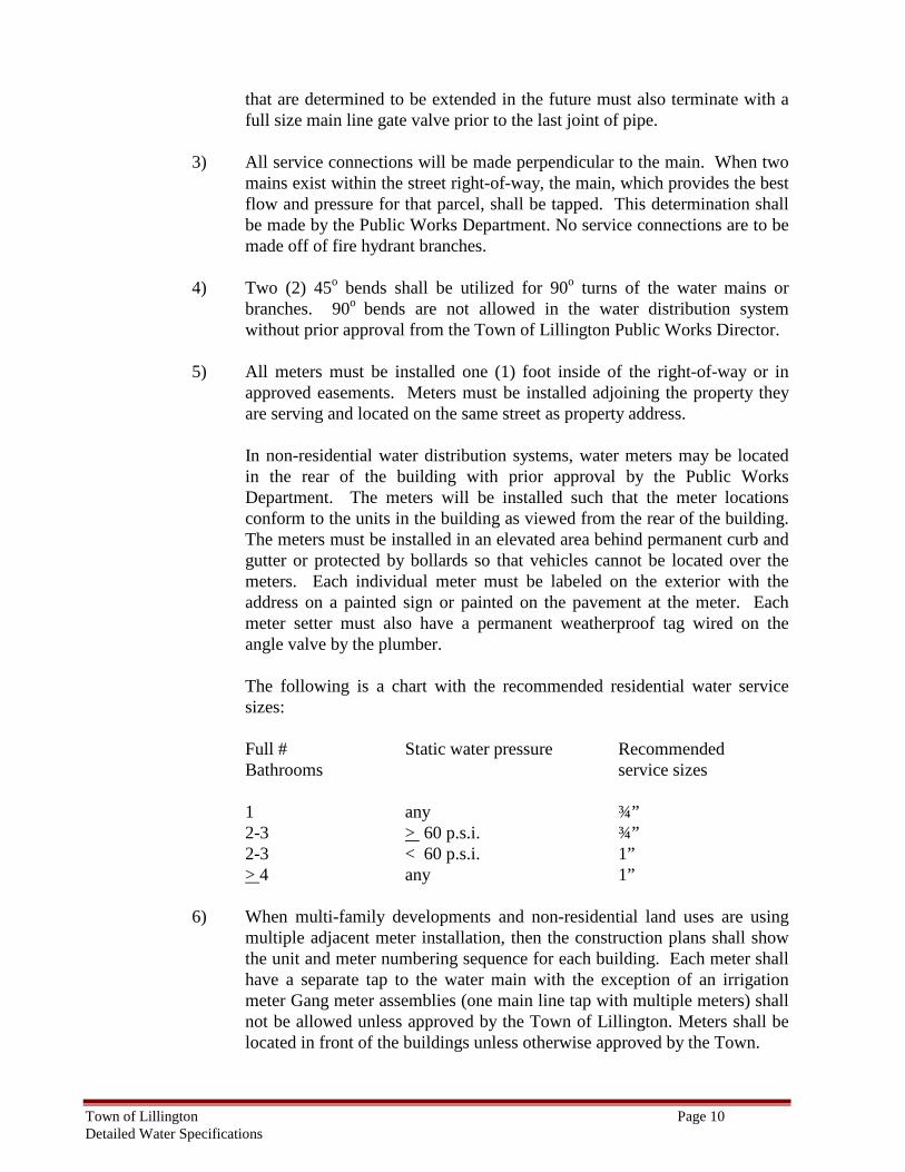
5) All meters must be installed one (1) foot inside of the right-of-way or in
approved easements. Meters must be installed adjoining the property they are serving and located on the same street as property address.
In non-residential water distribution systems, water meters may be located in the rear of the building with prior approval by the Public Works Department. The meters will be installed such that the meter locations conform to the units in the building as viewed from the rear of the building. The meters must be installed in an elevated area behind permanent curb and gutter or protected by bollards so that vehicles cannot be located over the meters. Each individual meter must be labeled on the exterior with the address on a painted sign or painted on the pavement at the meter. Each meter setter must also have a permanent weatherproof tag wired on the angle valve by the plumber. The following is a chart with the recommended residential water service sizes:
Full # Static water pressure Recommended Bathrooms service sizes 1 any ¾” 2-3 > 60 p.s.i. ¾” 2-3 < 60 p.s.i. 1” > 4 any 1”
6) When multi-family developments and non-residential land uses are using
multiple adjacent meter installation, then the construction plans shall show the unit and meter numbering sequence for each building. Each meter shall have a separate tap to the water main with the exception of an irrigation meter Gang meter assemblies (one main line tap with multiple meters) shall not be allowed unless approved by the Town of Lillington. Meters shall be located in front of the buildings unless otherwise approved by the Town.
Town of Lillington Page 11 Detailed Water Specifications
All service lines shall be connected to the correct meter based on sequential number or letter assignment. The unit and meter letter identification must be shown on the construction plans for installation approval. The correction of errors in the proper meter/unit pairing, detected later, will be the responsibility of the original installer or subsequent owners. Upon completion of the installation, tests will be conducted to prove order of connections is correct.
In the case of installation of an adjacent water meters the irrigation meter shall be the last meter in the sequence and clearly marked.
WATER MATERIAL STANDARDS 1. GENERAL MATERIAL REQUIREMENTS
Current specifications of the American Society for Testing Materials (ASTM), American Water Works Association (AWWA), Ductile Iron Pipe Research Association (DIPRA), American Association of State Highway and Transportation Officials (AASHTO), and the American National Standards Institute (ANSI) shall apply in all cases where material is covered by an item in these specifications. All material used shall conform fully to these current standards or be removed from the job at the direction of the Public Works Director.
Pipe specimens shall be subjected to tests by an independent testing laboratory at such time as the Public Works Department may direct or as specified herein. Pipe not meeting these specifications will be ordered removed by the inspector, and such pipe shall be immediately removed from the job site and not transported to any portion of the project being constructed.
Detail or shop drawings of fire hydrants, valves, air release valves, tapping sleeves and tapping saddles or any materials used for construction must be approved by the Public Works Department prior to installation.
These specifications are not to be considered as proprietary in any way. When a particular brand is listed, it is only used as an aid in describing the type of material being requested.
2. MATERIALS – WATER MAIN AND FITTINGS
a. Water Mains
All water mains shall be pressure class or thickness class of either ductile iron, or PVC pipe designed in accordance with AWWA Standard C-150 (ductile iron) or AWWA Standard C-900 & C-905 (PVC). Design shall be done for external and internal pressures separately, using the larger of the two for the design thickness.
Ductile Cast Iron Pipe:
Ductile cast iron pipe shall be centrifugally cast of ductile cast iron (Class 50) having a minimum tensile strength of 60,000 psi, a minimum yield strength of
Town of Lillington Page 12 Detailed Water Specifications
42,000 psi, and a minimum elongation of 10 percent (Grade 60-42-10). It shall be designed, manufactured, and shall conform to the requirements of ANSI A21.50 and ANSI A21.51 (AWWA C151) - Current Standards, for a minimum 150 psi operating pressure plus a minimum allowance of an additional 150 psi for surge. Unless otherwise approved by the Public Works Director.
Nominal laying lengths shall be 18 to 20 feet nominal maximum of 20 percent of each size for each order being as much as 24 inches shorter than the nominal laying length and an additional 10 percent as much as 6 inches shorter than nominal laying length.
Pipe joints shall be bell and spigot, push-on, gasketed type except where flanged ends are specifically required by the Plans.
Dimensions shall conform to the requirements of ANSI A21.6, ANSI A21.8, ANSI A21.11, and WW-P-42 1C, as applicable. Dimensions shall be gauged at sufficiently frequent intervals to assure dimensional control. Insides of sockets and outside of spigot ends shall be tested with circular gages.
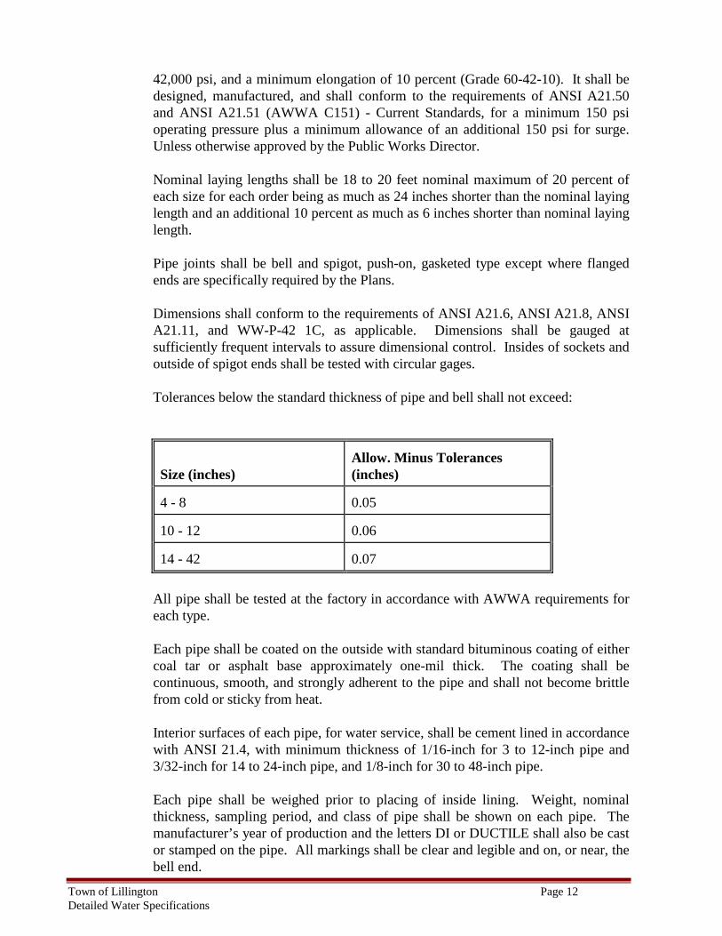
Tolerances below the standard thickness of pipe and bell shall not exceed:
Size (inches)
Allow. Minus Tolerances (inches)
4 - 8
0.05
10 - 12
0.06
14 - 42
0.07
All pipe shall be tested at the factory in accordance with AWWA requirements for each type.
Each pipe shall be coated on the outside with standard bituminous coating of either coal tar or asphalt base approximately one-mil thick. The coating shall be continuous, smooth, and strongly adherent to the pipe and shall not become brittle from cold or sticky from heat. Interior surfaces of each pipe, for water service, shall be cement lined in accordance with ANSI 21.4, with minimum thickness of 1/16-inch for 3 to 12-inch pipe and 3/32-inch for 14 to 24-inch pipe, and 1/8-inch for 30 to 48-inch pipe.
Each pipe shall be weighed prior to placing of inside lining. Weight, nominal thickness, sampling period, and class of pipe shall be shown on each pipe. The manufacturer’s year of production and the letters DI or DUCTILE shall also be cast or stamped on the pipe. All markings shall be clear and legible and on, or near, the bell end.
Town of Lillington Page 13 Detailed Water Specifications
Polyvinyl Chloride Pipe:
PVC pipe shall be rigid polyvinyl chloride with integrally formed, factory fabricated for rubber ring type joints. It shall be suitable for all conditions imposed by Plan locations and for a minimum working pressure of 150-psi, plus an additional 150-psi surge allowance at 73 degrees F. Pipe shall be Type 1, Grade 1, made from clear virgin material and shall conform to all requirements of AWWA Specifications C-900, Class 150. All pipes shall bear the manufacturer’s name, specification, and class pipe. Each length of pipe shall be of 20-feet plus or minus 1-inch, or 38-feet plus or minus 1 inch except that, random lengths may be furnished for special connections and other special uses. Unless otherwise approved by the Public Works Director.
Provisions must be made for expansion and contraction at each joint, through the rubber gasket and pipe bell. Laying lengths shall be 20-feet 11inch, or 38-feet 1-inch except that, random lengths may be furnished for special connections and other special uses.
b. Fittings
All fittings shall be manufactured in accordance with AWWA C-110 or C-153 for ductile iron compact fittings. The fittings shall be tested and the manufacturer shall provide certified test results when requested by the Town of Lillington. This testing shall include hydrostatic proof testing of the fittings.
All fittings shall be mechanical joint with the exception of certain above ground piping which may require flange fittings. Mechanical joints shall be manufactured in accordance with AWWA Standard C-111.
All fittings shall be cast iron or ductile iron and shall have a minimum working pressure rating of 250-psi and minimum iron strength of 30,000-psi.
All fitting interiors shall be cement-mortar lined with a sealcoat in accordance with AWWA Standard C-104, and the outside shall be bituminous coated.
Restrained mechanical glands may be used where restraint is needed except when welded restraining rings are required. Restrained mechanical glands provide additional restraint, but do not take the place of required concrete blocking. Two (2) 45o bends shall be utilized for 90o turns of the water mains or branches. 90o bends are not allowed in the water distribution system without prior approval from the Town of Lillington Public Works Director. All bends shall have concrete thrust blocks appropriately sized in accordance with the Town of Lillington standards.
Town of Lillington Page 14 Detailed Water Specifications
c. Gate Valves
Cast iron or ductile iron resilient wedge style vertical or horizontal gate valves and tapping valves shall be used for all main line and hydrant branch valves in sizes from 6 inches through 24 inches. American, Mueller, Kennedy, AVK, Clow, M&H, and Waterous valves in accordance with AWWA C-509-94, C-515, or the appropriate AWWA standard as applicable, shall be used. All resilient wedge valves shall have internal and external epoxy coating, O-ring seals at the stuffing box and bonnet to body and dual O-rings at the stem seal above the thrust collar.
Tapping valves shall be the same valves as gate valves listed above, subject to the standards, providing that tapping valves shall have the tapping ring.
Gate valves twelve (12) inches in diameter and smaller, shall be mechanical joint. They shall be "O" ring; open-left valves of the non-rising stem type. These valves shall be designed for a minimum of 175-psi working pressure and 300-psi hydrostatic test pressure with a two (2) inch operating nut. Valves shall be cast iron or ductile iron. Gate valves 10-inches and larger shall have a by-pass.
Valves sixteen (16) inches in diameter or greater must be butterfly type.
d. Valve Boxes
Adjustable screw type valve boxes shall be class 35 gray cast iron and manufactured in accordance with ASTM A48. All castings must be domestically cast and so indicated by the manufacturers name and “USA” cast into all sections of the valve box. All castings must meet or exceed AASHTO H-20 load rating.
e. Butterfly Valves
Butterfly valves sixteen greater than (16) inches in diameter shall be Class 150B and shall conform to the latest AWWA Standards C-504, as manufactured by Mueller, Kennedy, Pratt, or American for rubber sealed butterfly valves and valve operating assemblies. “O” ring seals shall also be used exclusively with worm gear.
All valve end connections shall be mechanical joint or Victaulic®, as required by the detail drawings. Valve seats shall be stainless steel, bronze mating or resilient material. Resilient seat shall be mechanically attached to the valve disc, or mechanically retained in the valve body. Resilient seat shall be fully field adjustable by mechanical means. The valve disc shaft shall be stainless steel or either stub or thru-shaft design. Shafts shall be provided with two-way disc thrusters that are fully adjustable from the outside. Valve shaft bearings shall be heavy duty bronze, properly fitted into hubs integrally cast in the body of the valves. All butterfly valve operators shall be worm gear type as manufactured by Philadelphia Gear Works, EPI or approved equal. The valve operator shall be furnished with a two-inch square operating nut, and be so mounted that the valve
Town of Lillington Page 15 Detailed Water Specifications
will open-left (counter-clockwise). The butterfly valve operator shall have AWWA stops, be suitable for submersible service and be sized in accordance with AWWA torque requirements for a full 150B rated valve. The manufacturer of the butterfly valve shall be fully responsible for the satisfactory performance of the assembled valve and operator unit. The specified operators shall be factory mounted by the valve manufacturer and shipped to the job site as an operating unit. External painting, hydrostatic testing, travel stop adjustments and crating for shipment shall be in complete compliance with the latest AWWA specification for butterfly valves.
f. Fire Hydrants
Hydrant Specifications. Hydrants shall be Medallion as manufactured by Clow
Valve Co. or Mueller Centurion a, and conform to the AWWA C502 with a minimum valve opening of 5-1/4-inches. Hydrants shall be furnished with a 4-1/2-inch steamer and double 2-1/2-inch hose connections with caps and chains, National Standard Threads, mechanical joint, 1-1/2-inch pentagonal operating nut, open left, painted fire hydrant red, bronze-to-bronze seating, a minimum 3-V2 foot bury depth with a breakaway ground line flange and breakaway rod coupling.
The hydrant bonnet will be designed with a sealed oil or grease reservoir with O-ring seals and Teflon thrust bearing as furnished by Clow. Fire hydrant caps shall be attached to the body of the fire hydrant with a minimum 2/0 twist link, heavy duty, non-kinking machine chain.
Hydrants shall be open-left type and shall have a six-inch hub-end or mechanical joint elbow. The hydrant barrel shall be of sufficient length to provide a minimum of three and one-half feet of bury and be of the break-away impact type.
g. Air Release Valves
Air release valves shall be two-inch Crispin Pressure Air Valves, Model P 20, with a vacuum check unit, or two-inch Val-Matic, Model VM-45, with a vacuum check unit or equal as approved by the Public Utilities Director. These valves shall be suitable for 150 psi working pressure and designed to allow air to escape auto-matically while the main is in service and under pressure. The valve shall be housed in a Town of Lillington approved eccentric manhole and shall be installed in accordance with standard water details for the Town of Lillington. Air release valve locations shall be approved by the Public Works Department, or as shown on the plans. The Engineer must field stake the air release location.
h. Tapping Sleeves and Tapping Saddles
Tapping sleeves shall be Mueller mechanical joint, Mueller Outlet Seal, American Uniseal, Kennedy Square Seal, or Clow F5205 or F5207. 100% stainless steel sleeves may also be used, as manufactured by Rockwell, Romac, Ford, or JCM
Town of Lillington Page 16 Detailed Water Specifications
provided that all metallic parts of the sleeves shall be 100% stainless steel including bolts. Ductile iron flanges may be included on sleeves or saddles. All sleeves shall have a minimum of 150 psi working pressure. All taps shall be machine drilled--no burned taps will be allowed. The “pipe coupon” shall be tagged with the location and date and turned over to the Town prior to acceptance of the water main.
Tapping Saddles shall be equipped with a standard AWWA C-110-98 flange connection. Sealing gaskets shall be "O" ring type, high quality molded rubber having an approximate seventy durometer hardness, placed into a groove on the curved surface of the tapping saddle. Straps shall be of Stainless steel. Saddles may be used for taps one-half the size of the main or less (i.e. 8-inch tapping saddle for use on a 16-inch main). Unless otherwise approved by the Public Works Director.
i. Water Service Connections
Water service pipe for 3/4 - to 2-inch connections shall be CTS Poly Tubing or type "K" soft copper with no joints or couplings in the right-of-way. On these water services, the fittings shall be NL-brass compression type fittings.
All fittings and valves shall be manufactured in accordance with AWWA Standard C-800, latest revision, and as further specified in these technical specifications..
Exception: Any brass part of the fitting or valve in contact with potable water shall be made of a “No-Lead Brass”, defined for this specification as UNS Copper Alloy No. C89520 or C89833 in accordance with the chemical and mechanical requirements of ASTM B584 and AWWA C-800. This “No-Lead Brass” alloy shall not contain more than nine one hundredths of one percent (0.09% or less) total lead content by weight.
Any Brass part of the fitting or valve not in contact with potable water shall be made of 85-5- 5-5 brass as defined for this specification as UNS Copper Alloy C83600 per ASTM B62, ASTM B584 and AWWA C-800.
All brass fittings and valves shall be certified by an ANSI accredited test lab per ANSI/NSF Standard 61, Drinking Water Components – Health Effects, Section 8. Proof of certification is required. The lead content of the wetted components in contact with potable water, shall also be verified by an ANSI accredited test lab.
Brass fittings and valves shall comply with the United States Of America Safe Drinking Water Act, and the U.S. Environmental Protection Agency.
All brass fittings and valves shall have the manufacturers name or trademark permanently stamped or cast on it. Another marking identifying the “no lead” brass alloy, e.g., ‘NL’, shall be cast or permanently stamped on the fitting or valve. 1 ½-inch and 2-inch taps may be made with use of a double strap saddle.
Town of Lillington Page 17 Detailed Water Specifications
Corporation cocks for direct ¾” and 1” taps may not be used.
Curb stops shall be manufactured by Mueller, or Ford, ball valve. All corporation stops and curb stops shall be bronze ball valves and shall be appropriate material to material corporation and curb stops as manufactured by Mueller, or Ford, and must have a complete ball valve with padlock wings and installed in the meter box Curb stops are required for 1 ½” and 2” meters and shall be located in the meter box on the street side.
Service saddles shall be double strapped and have a neoprene "O" ring gasket attached to the body. The clamp shall have corporation cock threads.
For services greater than 2 inches, the water service pipe shall be 3, 4, 6, 8 or 12 inches in diameter. Cast iron or ductile iron fittings shall be used on these services. All taps will be made by using the appropriate size tapping sleeve and valve. On a "dry line", the connection will be made with a "Mechanical Joint TEE and Valve”.
Coppersetters with dual check valves shall be 3/4 inch and 12 inches in height as manufactured by Ford or approved equal. All coppersetters shall have locking wings on the angle valve and be of the Ford angle check type and will be installed on all residential water services.
j. Meters
All water meters shall be Badger Meters
k. Meter Boxes and Vaults
All meter boxes shall be constructed of cast iron with cast iron lids. Fiberglass or ABS plastic meter boxes may be used with approval of the Public Works Director. Meter boxes shall not be placed within the sidewalk or asphalt unless no other alternatives are available and approval is obtained by the Public Works Director. Meter boxes installed in locations exposed to vehicular traffic shall be H-20 traffic rated.
l. Water Backflow/ Cross Connection The backflow assemblies/devices are made of approved brass, stainless steel, or fusion bond epoxy coated ductile iron.
m. Steel Encasement Pipe
Steel pipe for boring installations shall be high strength steel, welded or smooth-wall seamless manufactured in accordance with ASTM A252 and consisting of grade 2 steel.
Town of Lillington Page 18 Detailed Water Specifications
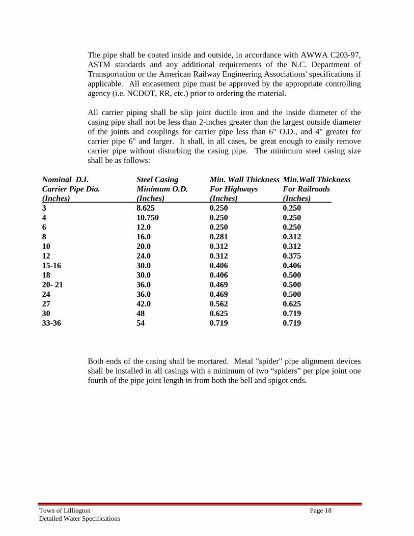
The pipe shall be coated inside and outside, in accordance with AWWA C203-97, ASTM standards and any additional requirements of the N.C. Department of Transportation or the American Railway Engineering Associations' specifications if applicable. All encasement pipe must be approved by the appropriate controlling agency (i.e. NCDOT, RR, etc.) prior to ordering the material. All carrier piping shall be slip joint ductile iron and the inside diameter of the casing pipe shall not be less than 2-inches greater than the largest outside diameter of the joints and couplings for carrier pipe less than 6" O.D., and 4" greater for carrier pipe 6" and larger. It shall, in all cases, be great enough to easily remove carrier pipe without disturbing the casing pipe. The minimum steel casing size shall be as follows:
Nominal D.I. Steel Casing Min. Wall Thickness Min.Wall Thickness Carrier Pipe Dia. Minimum O.D. For Highways For Railroads (Inches) (Inches) (Inches) (Inches) 3 8.625 0.250 0.250 4 10.750 0.250 0.250 6 12.0 0.250 0.250 8 16.0 0.281 0.312 10 20.0 0.312 0.312 12 24.0 0.312 0.375 15-16 30.0 0.406 0.406 18 30.0 0.406 0.500 20- 21 36.0 0.469 0.500 24 36.0 0.469 0.500 27 42.0 0.562 0.625 30 48 0.625 0.719 33-36 54 0.719 0.719
Both ends of the casing shall be mortared. Metal "spider" pipe alignment devices shall be installed in all casings with a minimum of two “spiders” per pipe joint one fourth of the pipe joint length in from both the bell and spigot ends.
Town of Lillington Page 19 Detailed Water Specifications
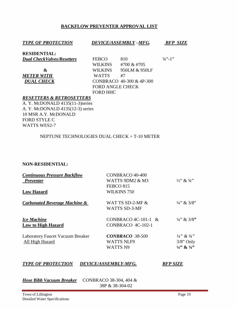
BACKFLOW PREVENTER APPROVAL LIST TYPE OF PROTECTION DEVICE/ASSEMBLY –MFG. BFP SIZE RESIDENTIAL: Dual CheckValves/Resetters FEBCO 810 ¾”-1” WILKINS #700 & #705 & WILKINS 950LM & 950LF METER WITH WATTS #7 DUAL CHECK CONBRACO 40-300 & 4P-300
FORD ANGLE CHECK FORD HHC RESETTERS & RETROSETTERS A. Y. McDONALD 4135(11-3)series A. Y. McDONALD 4135(12-3) series 10 MSR A.Y. McDONALD FORD STYLE C WATTS WES2-7 NEPTUNE TECHNOLOGIES DUAL CHECK + T-10 METER NON-RESIDENTIAL: Continuous Pressure Backflow CONBRACO 40-400 Preventer WATTS 9DM2 & M3 ½” & ¾” FEBCO 815 Low Hazard WILKINS 750 Carbonated Beverage Machine & WAT TS SD-2-MF & ¼” & 3/8” WATTS SD-3-MF Ice Machine CONBRACO 4C-101-1 & ¼” & 3/8” Low to High Hazard CONBRACO 4C-102-1 Laboratory Faucet Vacuum Breaker CONBRACO 38-500 ¼” & ¾” All High Hazard WATTS NLF9 3/8” Only WATTS N9 ¼” & ¾” TYPE OF PROTECTION DEVICE/ASSEMBLY-MFG. BFP SIZE Hose Bibb Vacuum Breaker CONBRACO 38-304, 404 & 38P & 38-304-02
Town of Lillington Page 20 Detailed Water Specifications
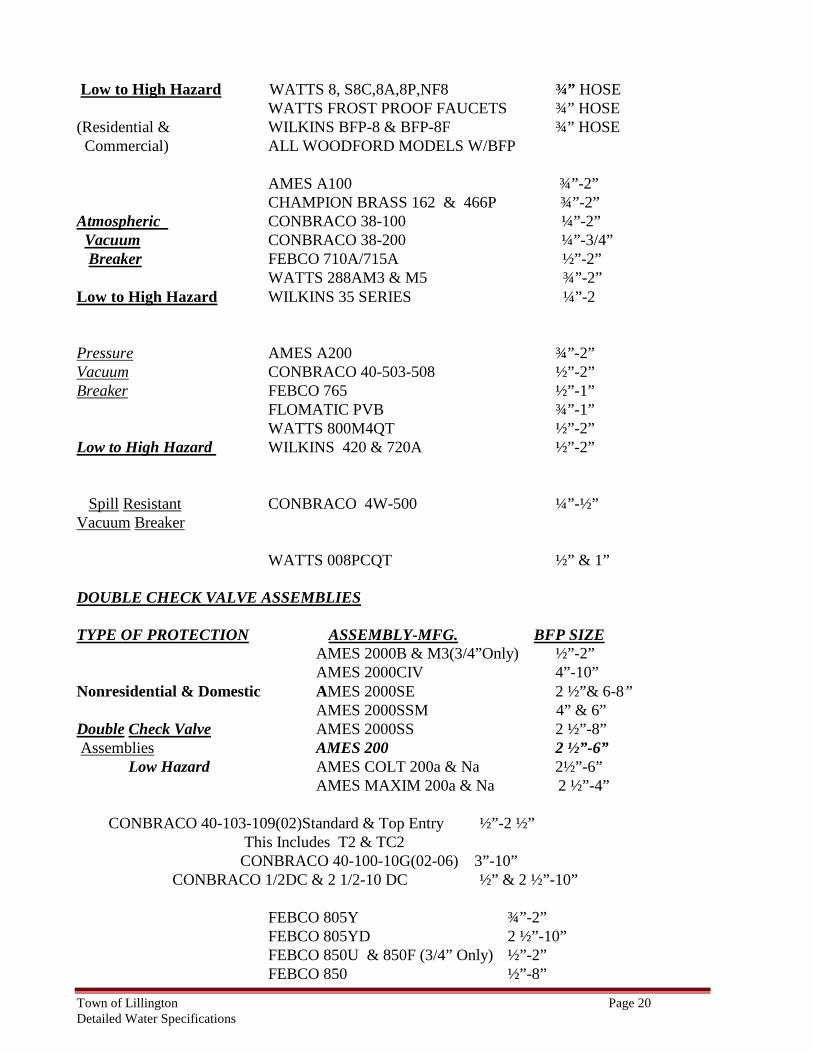
Low to High Hazard WATTS 8, S8C,8A,8P,NF8 ¾” HOSE WATTS FROST PROOF FAUCETS ¾” HOSE (Residential & WILKINS BFP-8 & BFP-8F ¾” HOSE Commercial) ALL WOODFORD MODELS W/BFP AMES A100 ¾”-2” CHAMPION BRASS 162 & 466P ¾”-2” Atmospheric CONBRACO 38-100 ¼”-2” Vacuum CONBRACO 38-200 ¼”-3/4” Breaker FEBCO 710A/715A ½”-2” WATTS 288AM3 & M5 ¾”-2” Low to High Hazard WILKINS 35 SERIES ¼”-2 Pressure AMES A200 ¾”-2” Vacuum CONBRACO 40-503-508 ½”-2” Breaker FEBCO 765 ½”-1” FLOMATIC PVB ¾”-1” WATTS 800M4QT ½”-2” Low to High Hazard WILKINS 420 & 720A ½”-2” Spill Resistant CONBRACO 4W-500 ¼”-½” Vacuum Breaker WATTS 008PCQT ½” & 1” DOUBLE CHECK VALVE ASSEMBLIES TYPE OF PROTECTION ASSEMBLY-MFG. BFP SIZE AMES 2000B & M3(3/4”Only) ½”-2” AMES 2000CIV 4”-10” Nonresidential & Domestic AMES 2000SE 2 ½”& 6-8” AMES 2000SSM 4” & 6” Double Check Valve AMES 2000SS 2 ½”-8” Assemblies AMES 200 2 ½”-6”
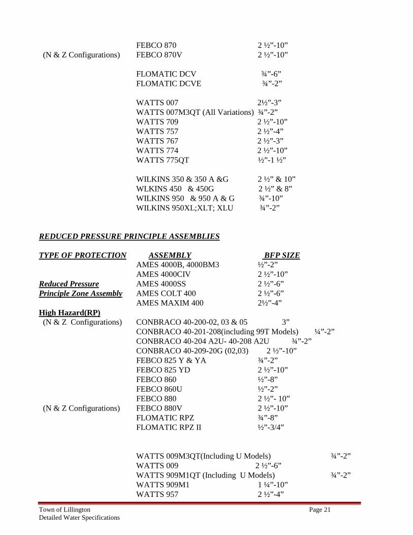
Low Hazard AMES COLT 200a & Na 2½”-6” AMES MAXIM 200a & Na 2 ½”-4” CONBRACO 40-103-109(02)Standard & Top Entry ½”-2 ½” This Includes T2 & TC2 CONBRACO 40-100-10G(02-06) 3”-10” CONBRACO 1/2DC & 2 1/2-10 DC ½” & 2 ½”-10” FEBCO 805Y ¾”-2” FEBCO 805YD 2 ½”-10” FEBCO 850U & 850F (3/4” Only) ½”-2” FEBCO 850 ½”-8”
Town of Lillington Page 21 Detailed Water Specifications
FEBCO 870 2 ½”-10” (N & Z Configurations) FEBCO 870V 2 ½”-10” FLOMATIC DCV ¾”-6” FLOMATIC DCVE ¾”-2” WATTS 007 2½”-3” WATTS 007M3QT (All Variations) ¾”-2” WATTS 709 2 ½”-10” WATTS 757 2 ½”-4” WATTS 767 2 ½”-3” WATTS 774 2 ½”-10” WATTS 775QT ½”-1 ½” WILKINS 350 & 350 A &G 2 ½” & 10” WLKINS 450 & 450G 2 ½” & 8” WILKINS 950 & 950 A & G ¾”-10” WILKINS 950XL;XLT; XLU ¾”-2” REDUCED PRESSURE PRINCIPLE ASSEMBLIES TYPE OF PROTECTION ASSEMBLY BFP SIZE AMES 4000B, 4000BM3 ½”-2” AMES 4000CIV 2 ½”-10” Reduced Pressure AMES 4000SS 2 ½”-6” Principle Zone Assembly AMES COLT 400 2 ½”-6” AMES MAXIM 400 2½”-4” High Hazard(RP) (N & Z Configurations) CONBRACO 40-200-02, 03 & 05 3” CONBRACO 40-201-208(including 99T Models) ¼”-2” CONBRACO 40-204 A2U- 40-208 A2U ¾”-2” CONBRACO 40-209-20G (02,03) 2 ½”-10” FEBCO 825 Y & YA ¾”-2” FEBCO 825 YD 2 ½”-10” FEBCO 860 ½”-8” FEBCO 860U ½”-2” FEBCO 880 2 ½”- 10” (N & Z Configurations) FEBCO 880V 2 ½”-10” FLOMATIC RPZ ¾”-8” FLOMATIC RPZ II ½”-3/4” WATTS 009M3QT(Including U Models) ¾”-2” WATTS 009 2 ½”-6” WATTS 909M1QT (Including U Models) ¾”-2” WATTS 909M1 1 ¼”-10” WATTS 957 2 ½”-4”
Town of Lillington Page 22 Detailed Water Specifications
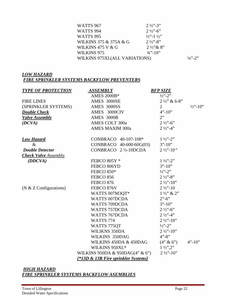
WATTS 967 2 ½”-3” WATTS 994 2 ½”-6” WATTS 995 ½”-1 ½” WILKINS 375 & 375A & G 2 ½”-8” WILKINS 475 V & G 2 ½”& 8” WILKINS 975 ¾”-10” WILKINS 975XL(ALL VARIATIONS) ¼”-2” LOW HAZARD FIRE SPRINKLER SYSTEMS BACKFLOW PREVENTERS TYPE OF PROTECTION ASSEMBLY BFP SIZE AMES 2000B* ½”-2” FIRE LINES AMES 3000SE 2 ½” & 6-8” (SPRINKLER SYSTEMS) AMES 3000SS 2 ½”-10” Double Check AMES 3000CIV 4”-10” Valve Assembly AMES 3000B 2” (DCVA) AMES COLT 300a 2 ½”-6” AMES MAXIM 300a 2 ½”-4” Low Hazard CONBRACO 40-107-108* 1 ½”-2” & CONBRACO 40-600-60G(03) 3”-10” Double Detector CONBRACO 2 ½-10DCDA 2 ½”-10” Check Valve Assembly (DDCVA) FEBCO 805Y * 1 ½”-2” FEBCO 806YD 3”-10” FEBCO 850* ½”-2” FEBCO 856 2 ½”-8” FEBCO 876 2 ½”-10” (N & Z Configurations) FEBCO 876V 2 ½”-10 WATTS 007M3QT* 1 ½” & 2” WATTS 007DCDA 2”-6” WATTS 709DCDA 3”-10” WATTS 757DCDA 2 ½”-6” WATTS 767DCDA 2 ½”-4” WATTS 774 2 ½”-10” WATTS 775QT ½”-2” WILIKNS 350DA 2 ½”-10” WILKINS 350DAG 4”-8” WILKINS 450DA & 450DAG (4” & 6”) 4”-10” WILKINS 950XL* 1 ½”,2” WILKINS 950DA & 950DAG(4” & 6”) 2 ½”-10” {*13D & 13R Fire sprinkler Systems} HIGH HAZARD FIRE SPRINKLER SYSTEMS BACKFLOW ASEMBLIES
Town of Lillington Page 23 Detailed Water Specifications
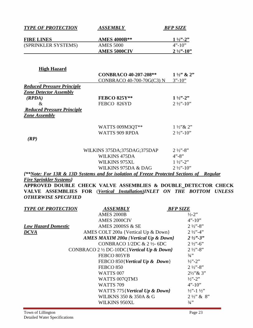
TYPE OF PROTECTION ASSEMBLY BFP SIZE FIRE LINES AMES 4000B** 1 ½”-2” (SPRINKLER SYSTEMS) AMES 5000 4”-10” AMES 5000CIV 2 ½”-10”
High Hazard CONBRACO 40-207-208** 1 ½” & 2”
CONBRACO 40-700-70G(C3) N 3”-10” Reduced Pressure Principle Zone Detector Assembly (RPDA) FEBCO 825Y** 1 ½”-2” & FEBCO 826YD 2 ½”-10” Reduced Pressure Principle Zone Assembly WATTS 009M3QT** 1 ½”& 2” WATTS 909 RPDA 2 ½”-10” (RP) WILKINS 375DA;375DAG;375DAP 2 ½”-8” WILKINS 475DA 4”-8” WILKINS 975XL 1 ½”-2” WILKINS 975DA & DAG 2 ½”-10” {**Note: For 13R & 13D Systems and for isolation of Freeze Protected Sections of Regular Fire Sprinkler Systems} APPROVED DOUBLE CHECK VALVE ASSEMBLIES & DOUBLE DETECTOR CHECK VALVE ASSEMBLIES FOR (Vertical Installation)INLET ON THE BOTTOM UNLESS OTHERWISE SPECIFIED TYPE OF PROTECTION ASSEMBLY BFP SIZE AMES 2000B ½-2” AMES 2000CIV 4”-10” Low Hazard Domestic AMES 2000SS & SE 2 ½”-8” DCVA AMES COLT 200a {Vertical Up & Down} 2 ½”-4” AMES MAXIM 200a {Vertical Up & Down} 2 ½”-3” CONBRACO 1/2DC & 2 ½- 6DC 2 ½”-6” CONBRACO 2 ½ DC-10DC{Vertical Up & Down} 2 ½”-8” FEBCO 805YB ¾” FEBCO 850{Vertical Up & Down} ½”-2” FEBCO 850 2 ½”-8” WATTS 007 2½”& 3” WATTS 007QTM3 ½”-2” WATTS 709 4”-10” WATTS 775{Vertical Up & Down} ½”-1 ½” WILIKNS 350 & 350A & G 2 ½” & 8” WILKINS 950XL ¾”
Town of Lillington Page 24 Detailed Water Specifications
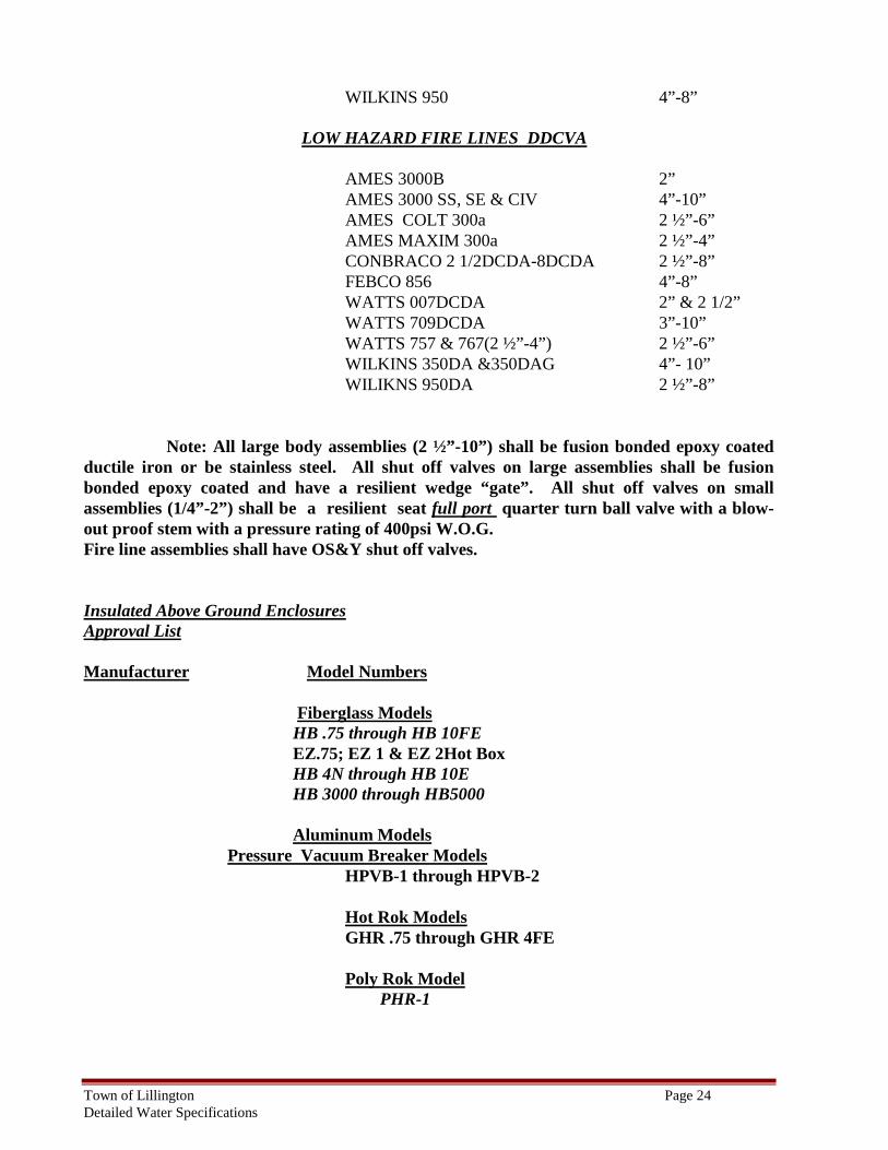
WILKINS 950 4”-8” LOW HAZARD FIRE LINES DDCVA AMES 3000B 2” AMES 3000 SS, SE & CIV 4”-10” AMES COLT 300a 2 ½”-6” AMES MAXIM 300a 2 ½”-4” CONBRACO 2 1/2DCDA-8DCDA 2 ½”-8” FEBCO 856 4”-8” WATTS 007DCDA 2” & 2 1/2” WATTS 709DCDA 3”-10” WATTS 757 & 767(2 ½”-4”) 2 ½”-6” WILKINS 350DA &350DAG 4”- 10” WILIKNS 950DA 2 ½”-8” Note: All large body assemblies (2 ½”-10”) shall be fusion bonded epoxy coated ductile iron or be stainless steel. All shut off valves on large assemblies shall be fusion bonded epoxy coated and have a resilient wedge “gate”. All shut off valves on small assemblies (1/4”-2”) shall be a resilient seat full port quarter turn ball valve with a blow-out proof stem with a pressure rating of 400psi W.O.G. Fire line assemblies shall have OS&Y shut off valves. Insulated Above Ground Enclosures Approval List Manufacturer Model Numbers Fiberglass Models HB .75 through HB 10FE EZ.75; EZ 1 & EZ 2Hot Box HB 4N through HB 10E HB 3000 through HB5000 Aluminum Models Pressure Vacuum Breaker Models
HPVB-1 through HPVB-2 Hot Rok Models
GHR .75 through GHR 4FE Poly Rok Model PHR-1
Town of Lillington Page 25 Detailed Water Specifications
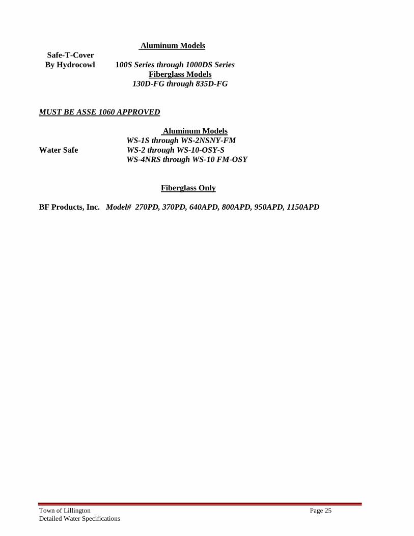
Aluminum Models Safe-T-Cover By Hydrocowl 100S Series through 1000DS Series Fiberglass Models 130D-FG through 835D-FG MUST BE ASSE 1060 APPROVED
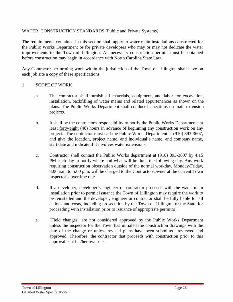
Aluminum Models WS-1S through WS-2NSNY-FM Water Safe WS-2 through WS-10-OSY-S WS-4NRS through WS-10 FM-OSY
Fiberglass Only BF Products, Inc. Model# 270PD, 370PD, 640APD, 800APD, 950APD, 1150APD
Town of Lillington Page 26 Detailed Water Specifications
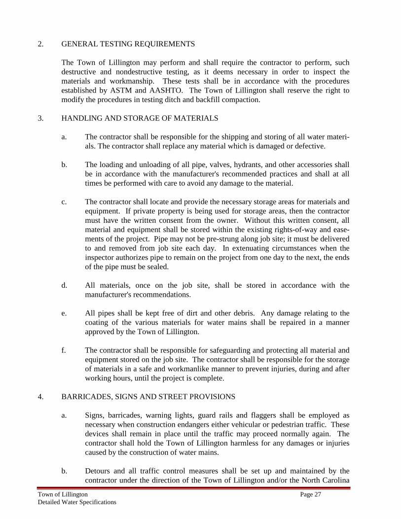
WATER CONSTRUCTION STANDARDS (Public and Private Systems) The requirements contained in this section shall apply to water main installations constructed for the Public Works Department or for private developers who may or may not dedicate the water improvements to the Town of Lillington. All necessary construction permits must be obtained before construction may begin in accordance with North Carolina State Law. Any Contractor performing work within the jurisdiction of the Town of Lillington shall have on each job site a copy of these specifications. 1. SCOPE OF WORK
a. The contractor shall furnish all materials, equipment, and labor for excavation,
installation, backfilling of water mains and related appurtenances as shown on the plans. The Public Works Department shall conduct inspections on main extension projects.
b. It shall be the contractor's responsibility to notify the Public Works Departments at
least forty-eight (48) hours in advance of beginning any construction work on any project. The contractor must call the Public Works Department at (910) 893-3607, and give the location, project name, and individual’s name, and company name, start date and indicate if it involves water extensions.
c. Contractor shall contact the Public Works department at (910) 893-3607 by 4:15
PM each day to notify where and what will be done the following day. Any work requiring construction observation outside of the normal workday, Monday-Friday, 8:00 a.m. to 5:00 p.m. will be charged to the Contractor/Owner at the current Town inspector’s overtime rate.
d. If a developer, developer’s engineer or contractor proceeds with the water main
installation prior to permit issuance the Town of Lillington may require the work to be reinstalled and the developer, engineer or contractor shall be fully liable for all actions and costs, including prosecution by the Town of Lillington or the State for proceeding with installation prior to issuance of appropriate permit(s).
e. "Field changes" are not considered approved by the Public Works Department
unless the inspector for the Town has initialed the construction drawings with the date of the change or unless revised plans have been submitted, reviewed and approved. Therefore, the contractor that proceeds with construction prior to this approval is at his/her own risk.
Town of Lillington Page 27 Detailed Water Specifications
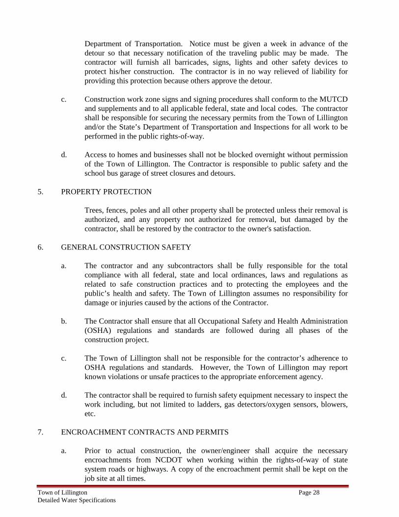
2. GENERAL TESTING REQUIREMENTS
The Town of Lillington may perform and shall require the contractor to perform, such destructive and nondestructive testing, as it deems necessary in order to inspect the materials and workmanship. These tests shall be in accordance with the procedures established by ASTM and AASHTO. The Town of Lillington shall reserve the right to modify the procedures in testing ditch and backfill compaction.
3. HANDLING AND STORAGE OF MATERIALS
a. The contractor shall be responsible for the shipping and storing of all water materi-als. The contractor shall replace any material which is damaged or defective.
b. The loading and unloading of all pipe, valves, hydrants, and other accessories shall
be in accordance with the manufacturer's recommended practices and shall at all times be performed with care to avoid any damage to the material.
c. The contractor shall locate and provide the necessary storage areas for materials and
equipment. If private property is being used for storage areas, then the contractor must have the written consent from the owner. Without this written consent, all material and equipment shall be stored within the existing rights-of-way and ease-ments of the project. Pipe may not be pre-strung along job site; it must be delivered to and removed from job site each day. In extenuating circumstances when the inspector authorizes pipe to remain on the project from one day to the next, the ends of the pipe must be sealed.
d. All materials, once on the job site, shall be stored in accordance with the
manufacturer's recommendations.
e. All pipes shall be kept free of dirt and other debris. Any damage relating to the coating of the various materials for water mains shall be repaired in a manner approved by the Town of Lillington.
f. The contractor shall be responsible for safeguarding and protecting all material and
equipment stored on the job site. The contractor shall be responsible for the storage of materials in a safe and workmanlike manner to prevent injuries, during and after working hours, until the project is complete.
4. BARRICADES, SIGNS AND STREET PROVISIONS
a. Signs, barricades, warning lights, guard rails and flaggers shall be employed as necessary when construction endangers either vehicular or pedestrian traffic. These devices shall remain in place until the traffic may proceed normally again. The contractor shall hold the Town of Lillington harmless for any damages or injuries caused by the construction of water mains.
b. Detours and all traffic control measures shall be set up and maintained by the
contractor under the direction of the Town of Lillington and/or the North Carolina
Town of Lillington Page 28 Detailed Water Specifications
Department of Transportation. Notice must be given a week in advance of the detour so that necessary notification of the traveling public may be made. The contractor will furnish all barricades, signs, lights and other safety devices to protect his/her construction. The contractor is in no way relieved of liability for providing this protection because others approve the detour.
c. Construction work zone signs and signing procedures shall conform to the MUTCD
and supplements and to all applicable federal, state and local codes. The contractor shall be responsible for securing the necessary permits from the Town of Lillington and/or the State’s Department of Transportation and Inspections for all work to be performed in the public rights-of-way.
d. Access to homes and businesses shall not be blocked overnight without permission
of the Town of Lillington. The Contractor is responsible to public safety and the school bus garage of street closures and detours.
5. PROPERTY PROTECTION
Trees, fences, poles and all other property shall be protected unless their removal is authorized, and any property not authorized for removal, but damaged by the contractor, shall be restored by the contractor to the owner's satisfaction.
6. GENERAL CONSTRUCTION SAFETY
a. The contractor and any subcontractors shall be fully responsible for the total compliance with all federal, state and local ordinances, laws and regulations as related to safe construction practices and to protecting the employees and the public’s health and safety. The Town of Lillington assumes no responsibility for damage or injuries caused by the actions of the Contractor.
b. The Contractor shall ensure that all Occupational Safety and Health Administration
(OSHA) regulations and standards are followed during all phases of the construction project.
c. The Town of Lillington shall not be responsible for the contractor’s adherence to
OSHA regulations and standards. However, the Town of Lillington may report known violations or unsafe practices to the appropriate enforcement agency.
d. The contractor shall be required to furnish safety equipment necessary to inspect the
work including, but not limited to ladders, gas detectors/oxygen sensors, blowers, etc.
7. ENCROACHMENT CONTRACTS AND PERMITS
a. Prior to actual construction, the owner/engineer shall acquire the necessary encroachments from NCDOT when working within the rights-of-way of state system roads or highways. A copy of the encroachment permit shall be kept on the job site at all times.
Town of Lillington Page 29 Detailed Water Specifications
b. The Owner/Engineer shall be responsible for securing all other local, state and
federal permits, bonds, and insurance required for the utility construction.
c. The Contractor must have an approved set of permitted construction plans and the Town of Lillington specifications on site at all times.
d. The Contractor shall be properly licensed by the North Carolina Licensing Board for General Contractors. Verification of said license shall be required prior to beginning any work.
8. PAVEMENT REMOVAL AND REPLACEMENT
a. All pavements to be removed shall be cut along straight lines with the appropriate saw cut machine.
b. All cuts of Town of Lillington streets must be patched the same day with a
temporary or permanent patch. Once work has been completed, all temporary patches shall be replaced with permanent ones. All work from patching shall be cleaned up at the same time of patching.
c, Pavement cuts shall be confined to maximum trench bottom width plus six inches
on either side. d. Asphalt compaction shall be done with a gasoline or diesel powered smooth drum
asphalt roller. e. Pavement cuts within NCDOT Right of Way shall not be performed without the proper
encroachment permits on site. All patching of NCDOT pavements shall conform to the approved on site encroachment permit.
f. All repaved areas and new pavement will be proof rolled with a Town of Lillington inspector present during the test.
9. VALVE OPERATIONS
a. No valve in the existing system shall be operated without following the procedure outlined below. Failure to comply with these requirements shall be grounds for suspension of pipe-laying operations until written assurance can be obtained from a company official that such noncompliance will not occur again. The contractor should be aware that the Town of Lillington regards violations of these requirements as justifying punitive measures.
b. Notification procedures are as follows:
1) The contractor shall notify the Public Works Department's Water Distribution Division at (910) 890-3347 in order to request the operation of
Town of Lillington Page 30 Detailed Water Specifications
any valves. At least forty-eight (48) hours notice must be given to the Public Works Department, and at least forty-eight (48) hours notice must be given to each customer affected by a water cut-off. The owner is responsible for notifying the affected customers. All valve operations shall be done by Public Works Department personnel or supervised by the Town of Lillington inspector for a particular project. It is illegal for anyone other than a Town of Lillington employee to operate an existing water main valve, unless accompanied by a Town of Lillington employee.
2) The contractor shall provide the following information when calling the
Water Distribution Division for valve operation: (a) Name of person calling; (b) Name of company; (c) Telephone number of company;
(d) Location of valve (e) Reason for requesting operation and whether to be closed or
open; (f) Time valve to be opened or closed, and
(g) Approximate time water line to be out of service.
c. Each time a contractor needs a valve operated, he/she shall again secure permission, following the steps outlined.
d. System valves shall be defined as any valve, which has main pressure against either
gate face. Newly installed tapping valves and control valves to networks not yet accepted for service are considered as system valves. Valves within a network still under construction are not considered as system valves.
10. CONSTRUCTION WATER
The Town of Lillington does not provide free or otherwise unmetered construction water for any construction project. Contractors are responsible for adequate construction water for their job sites. Contact Town Hall for use of hydrant meter. (910) 893-2654
Note: Individuals caught using water unmetered and/or unauthorized by the Public Works Department will be prosecuted to the fullest extent of the law. 11. EXCAVATION
a. Prior to any excavation or construction, the contractor shall call the North Carolina One-Call Center at 1-800-632-4949 or (811) 48 hours prior to digging, the con-tractor shall be responsible for the location of all existing utilities in the field. If help is needed in locating utilities operated by the Public Works Department, the contractor shall call the Public Works Department at (910) 893-3607.
b. Trench width shall be a minimum of twelve inches plus outside diameter of pipe
and a maximum of twenty-four inches plus outside diameter of pipe, unless OSHA
Town of Lillington Page 31 Detailed Water Specifications
requires additional trench width. Trench width shall be measured between the faces of the cut at the top elevation of the pipe bell.
c. Trench bottom conformation, where no special bedding is required, may be that
referred to herein as flat bottom where the trench bottom is excavated slightly above grade and cut down to pipe grade by hand in the fine-grading operation. Where the trench bottom is inadvertently cut below grade, it shall be filled to grade with an approved material and thoroughly compacted to 95% or use #57 or #67 stone to bring to grade.
d. The maximum length of open trench shall be no more than three hundred feet,
unless approval is obtained from the Public Works Director.
e. The contractor shall, at his/her own expense, keep all trenches free from water during the excavation for construction of foundations, masonry, water mains. The water shall be pumped out of the trench or build check dams to keep it out of the ditch in such a manner as not to cause injury to the public health, private property or the work in progress. Erosion control measures shall be utilized during this pumping.
f. In trenches where water is present or dewatering is required, the trench shall be
stabilized with #57 or #67 stone. When the contractor encounters material during trench excavation, at the opinion of the inspector, or Public Works Director, that is unsuitable (i.e. "muck"), this material shall be replaced with material that is considered suitable prior to the pipe laying operations. In this case, construction fabrics may be required to prevent the migration of side support away from the pipe.
g. Safety and convenience of the public necessitate that all work, including
excavation, be done in such a manner as to cause minimum traffic interruption, both pedestrian and vehicular. Utilities such as fire hydrants, valves, etc., shall be accessible at all times. Gutters and drains shall be left open and clear at all times, and the contractor shall be responsible for all drainage around his work. Provisions shall be made to maintain vehicular traffic on all streets in which work is in progress, and suitable walkways shall be maintained for pedestrian travel.
h. Sheeting or bracing shall be used wherever necessary to prevent failure of the
trench banks. All sheeting shall conform to AASHTO and OSHA safety standards. The decision of the Public Works Director or Engineer relative to bracing for the protection of property of the Town of Lillington shall be binding upon the contractor. The removal of sheeting shall be done in such a manner as to minimize the loss of friction between the backfill and trench walls.
12. ROCK EXCAVATION
a. Rock shall be defined as that solid material that cannot be excavated, in the opinion of the Public Works Director or Engineer, by any means other than drilling and blasting, drilling and wedging, or boulders and broken concrete exceeding ½ cubic
Town of Lillington Page 32 Detailed Water Specifications
yard in volume. Rock shall be excavated to the same limits as earth excavation except that the trench shall be made 6- inches lower than the outer bottom of the pipe, and 6-inches shall be refilled with 6-inches of #57, #67 or select material and thoroughly compacted to the sub-grade level. All blasting shall be done under the supervision of the Town of Lillington Inspector or Engineer and subject to all applicable regulations. The Town of Lillington reserves the right to require the removal of rock by means other than blasting where any pipe or conduit is either too close to or so situated with respect to the blasting as to make blasting hazardous. Rock taken from the ditch shall immediately be hauled away and disposed of by the contractor.
b. Blasting procedures shall conform to all applicable local, state and federal laws and
ordinances. A blasting permit shall be obtained from the Town of Lillington Fire Marshal's Office, prior to any blasting. The application shall be obtained 24-hours before any blasting takes place, and the Fire Marshal may specify the hours of blasting. The contractor shall take all necessary precautions to protect life and property, including the use of an approved blasting mat where there exists the danger of throwing rock or overburden. The contractor shall keep explosive mate-rials that are on the job site in special constructed boxes provided with locks. Failure to comply with this specification shall be grounds for suspension of blasting operations until full compliance is made. No blasting shall be allowed unless a galvanometer is employed to check cap circuits. Where blasting takes place within five-hundred feet of a utility, structure or property which could be damaged by vibration, concussion or falling rock, the contractor shall be required to take seismograph readings and to keep a blasting log containing the following information for each and every shot.
1) Date of shot 2) Time of shot 3) Crew Supervisor 4) Number and depth of holes 5) Approximate depth of overburden 6) Amount and type of explosive used in each hole
7) Type of caps used (instant or delay) 8) The weather 9) Seismograph instrument and readings 10) Pre Blast Surveys
c. This blasting log shall be made available to the Public Works Director or Engineer
upon request and shall be kept in an orderly manner. It shall be the contractor's responsibility to have adequate insurance to cover any damages resulting from blasting so to hold the Town of Lillington harmless from any claims.
13. TRENCH PREPARATION
a. Trench excavation shall conform to the line and depth shown on the plans. The trench shall be properly braced and drained so that workers may work therein safely
Town of Lillington Page 33 Detailed Water Specifications
and efficiently. When water is being pumped from the trench, the pump discharge shall follow natural drainage channels, drains or storm sewers. In discharging trench water, it will be necessary to follow standard erosion control measures so as to minimize erosion and sedimentation. In no case may trench water or groundwater be pumped into or allowed to enter the sanitary sewer system.
b. The width of the trench may vary with the depth of cut and other conditions. The
trench shall be in accordance with the dimensions set forth by OSHA.
c. The foundation for ductile iron shall be a firm and stable flat bottom trench with bell holes so that the pipe rests uniformly on the entire barrel length.
d. Pipe clearance in rock shall be a minimum of six inches below and on each side of
the pipe for sized sixteen inches and less in diameter. For sizes larger than sixteen inches in diameter, the minimum clearance shall be nine inches below and on each side. Engineer to review (remove if rock excavation above is removed)
14. PIPE INSTALLATION
a. All water pipe shall be installed in accordance with the requirements of AWWA Standard C-600-87.
b. Water pipe shall be laid to the line and grade shown on the plans with all valves and
hydrants located as shown on the plans.
c. Protection shall be afforded to all underground and surface structures using methods acceptable to the Public Works Director or Town’s Engineer. This protection shall be furnished by the contractor at the contractors' own expense.
d. Deviation from line and grade may be made only on revised plans upon approval by
Public Works Department and identified on “as-builts” when such deviations arise from grade or line conflicts with existing utilities, structures or other sources of conflict.
e. Subsurface explorations shall be made by the contractor at the direction of the
Public Works Director or Engineer where it is necessary to determine the location of existing pipes, valves or other underground structures.
f. Depth of pipe cover, unless shown otherwise on the plans shall be three feet above
top of pipe. Depth of cover shall be measured from the established street grade or the surface of the permanent improvement to the top of the barrel of the pipe.
g. After the foundation has been properly graded, bedded when applicable, and the
bell holes dug, the pipe and accessories shall be carefully lowered into the trench by approved methods. Under no circumstances shall the pipe or accessories be dropped or dumped into the trench. All damaged pipe and accessories shall be removed from the job.
Town of Lillington Page 34 Detailed Water Specifications
h. Any pipe showing evidence of oil, tar or grease shall be permanently marked and removed from the job.
i. Laying of pipe and jointing of pipe shall be done according to manufacturer's
recommendation with care being taken to provide uniform bearing for the pipe. Bell and spigot of pipe shall be cleaned and properly lubricated where a mechanical joint of a "push on" type joint is employed. No chlorine powder or tablets shall be put in the lines during installation.
j. Open ends of pipe shall be plugged with a standard plug or cap at all times when
pipe laying is not in progress. Trench water shall not be permitted to enter pipe.
k. Pipe cutting for inserting valves, fittings or closure pieces shall be done in a neat and workmanlike manner in accordance with the manufacturer's recommendations and without damage to the pipe.
l. Bell ends will face the direction of laying unless otherwise directed by the Public
Works Director or Engineer. For lines on an appreciable slope, the Public Works Director or Engineer may also require that bell ends face upgrade.
m. Maximum horizontal deflections for ductile iron pipe shall not exceed the
manufactures recommended maximum deflection for an eighteen foot joint of pipe:
n. When installing a water main, the horizontal separation between water and sewer shall be ten-feet. If this separation cannot be maintained due to existing conditions, the only variation allowed is the water main in a separate trench with three feet of separation, and the elevation of the water main at least 24-inches above the top of the sewer and both water and sewer must be Ductile Iron pipe for 10-feet in either direction on both pipes. All distances are measured from outside diameter to outside diameter.
o. When a water main crosses over a sewer main, there must be twenty four inches of
vertical separation. If the water main must go under the sewer main, both these lines must be of ductile iron for a distance of ten-feet on either side of the crossing with a twenty four-inch vertical separation. The crossing of other underground pipe requires a minimum of twenty-four inches of vertical separation. Any changes in these clearances must be approved by the Public Works Director. All crossings within these vertical clearances shall be filled with #67 stone. All distances are measured from outside diameter to outside diameter.
p. When a water line passes over or under a storm sewer, vertical separation of 18-
inches shall be maintained.
q. Railroad crossings shall be made following all precautionary construction measures required by the railroad officials.
r. All water crossings under the state system roads shall be made in accordance with
the requirements of the NC DOT as defined in their encroachment permits.
Town of Lillington Page 35 Detailed Water Specifications
s. Where conditions are, in the opinion of the Town of Lillington Inspector, unsuitable
for laying pipe because of weather or trench conditions, the contractor shall be required to cease work until permission is given by the Town of Lillington Inspector for work to commence again providing such conditions have been corrected.
15. REACTION BLOCKING
a. All fittings or components subject to hydrostatic thrust shall be securely anchored by the use of concrete thrust blocks poured in place, unless otherwise directed by the engineer.
b. Material for reaction blocking shall be transit-mixed concrete. This concrete shall
have a twenty-eight day compressive strength of 2500 psi. Any metal used to resist thrust which is not encased in concrete shall be “hot dipped” galvanized.
16. BACKFILLING PIPE
a. Ductile iron pipe shall be backfilled with suitable native material. No rocks, boulders or stone four inches or larger shall be included in the backfill for at least two feet above the top of the pipe.
b. All backfill shall be compacted in six-inch lifts measured from the pipe foundation
upward. Backfill for roadway shall be compacted to at least 95% of maximum soil density in those areas where the supporting capacity of the soil is of prime consideration. Any tests shall be conducted at the direction of the Town of Lillington Inspector, and the cost of such tests will be borne by the contractor. The contractor shall then be required to submit satisfactory evidence that his ditch compaction meets the specifications.
c. Deficiency of backfill material shall be supplied by the contractor where this
deficiency results from any cause other than rejection of unsuitable backfill material (other than rock) by the Town of Lillington Inspector. In cases where the Town of Lillington Inspector directs, the contractor shall dispose of unsuitable backfill material and provide suitable backfill material. Where excavated material has been rendered unsuitable, either before or after excavation, by inclement weather or type of material, the contractor must correct the moisture or furnish replacement backfill material.
d. Backfilling shall not be allowed, except with permission of the Town of Lillington
Inspector. When a ditch is flooded or the weather is unsuitable, the contractor shall not backfill unless permission is given by the Town of Lillington Inspector. No backfilling with frozen material shall be allowed.
Town of Lillington Page 36 Detailed Water Specifications
17. SETTING VALVES AND VALVE BOXES
a. Valves shall be set at locations shown on the plans with care being taken to support the valve properly and to accurately position the valve box over the operating nut of the valve. Where pavement is existing, the box shall be adjusted to finished street grade and a concrete pad two-feet square and six inches thick shall be poured around the box two inches from the top of finished grade. When valves are located in street rights-of-way, but out of pavement, the boxes shall be adjusted to finished grade and a concrete pad two-feet square and six-inches thick shall be poured around the box one-half inch from the top. When valves are located outside of street rights-of-way, the boxes shall be at finish grade, and a concrete block two-feet square and six-inches thick shall be poured around the box at grade line. Valve locations out of street rights-of-way shall be marked with a concrete valve marker. The exposed portion shall be placed so that a valve-operating tool has free operation.
b. When a tapping sleeve and valve are being used, the valve, sleeve and machine
assembly shall be air tested to hold at 150 psi for a five-minute duration in the presence of the inspector prior to drilling or tapping the main. All tap coupons shall be given to the Town of Lillington inspector. The valve shall be in the closed position during the testing.
18. SETTING FITTINGS
Fittings shall be set at locations shown on the plans with care being taken to properly "bell-up" joints and support the body of the fitting. All dead-end lines shall be plugged with mechanical joint plugs or caps and be restrained.
19. SETTING HYDRANTS
a. Hydrants shall be set plumb with a finish grade, which shall measure 18" from ground to center of the steamer cap. Hydrants shall be properly located on the right side of the road with the pumper nozzle facing the closest curb. The back of the hydrant opposite the pipe connection shall be firmly blocked against the vertical face of the trench with 1/3 cubic yard of concrete. Double bridle rods and collars shall be connected from the tee to the hydrant. Rods shall not be less than 5/8 inch diameter stock and coated with bituminous paint. A minimum of eight (8) cubic feet of stone shall be placed around the drains. The backfill around the hydrants shall be thoroughly compacted. Hydrant installation shall be in accordance with the Ordinances of the Town or as directed by the Public Works Director. All hydrants will have individual controlling valves located no more than fifteen (15) feet from the hydrant.
b. Before a hydrant is set, all dirt and foreign matter shall be removed from the
interior of the hydrant. c. Hydrants shall be bagged, to indicate “out of service”, until all testing is complete
and the mains are placed in service. Bags shall be large enough to cover the entire
Town of Lillington Page 37 Detailed Water Specifications
hydrant and shall be black in color. Bags shall be secured with duct tape at the base of the hydrant and shall be removed immediately after the hydrants are placed in service.
20. SETTING BLOW-OFFS AND RELEASE VALVES
a) Blow-offs and drainage branches shall not be connected to any sewer,
submerged in any stream, or be installed in any other manner that will permit back siphon into the distribution system. • All blow offs to be installed with the effluent end at Valve box finished
grade height will have the threaded portion of the blow off 1” below the final resting height of the cover bottom as to allow the connection of an extender to allow for water to directed away from the blow off point. * Blow-offs shall be permitted only when written permission is received from the Town of Lillington.
b) All air release valves and blow-offs shall be installed such that provisions
can be made by the contractor to get the flow of water to a natural drainage way.
21. SURFACE RESTORATION
a. All disturbed surfaces and property thereon, shall be restored to a condition equal to that existing before construction began, and the contractor shall maintain and be responsible for all ditches in paved streets, curbs, gutters or sidewalks until the contractor repaves the trench cuts. The contractor, with permission of the Inspector, may place temporary or permanent asphaltic material in the cut. Asphalt compaction shall be done with a gasoline or diesel powered smooth drum asphaltic roller.
b. All easements will be seeded with grass and left so they can be mowed by
conventional mowers, unless approved by the Public Works Department for rip-rap or other specified material. The contractor shall guarantee a good uniform stand of grass and shall reseed any bare or thin spots. The contractor will be responsible for a one-year warranty on materials and workmanship.
22. EROSION CONTROL
Erosion control measures shall be performed by the contractor, conforming to the requirements of, and in accordance with plans approved by the State of North Carolina Department of Environment and Natural Resources, North Carolina Sedimentation Control Commission, the Town of Lillington, and as per the erosion control plan portion of the construction drawings and these specifications. The sedimentation and erosion control plan and permit shall remain on site at all times. The contractor shall not allow mud and debris to accumulate in the streets. Should the contractor pump water from trenches during construction, appropriate siltation preventative measures shall be taken prior to the entry into any storm drain or stream. All measures must be taken so that storm water runoff does
Town of Lillington Page 38 Detailed Water Specifications
not go to the pipes or manholes of the utility system. All materials used for erosion control shall be approved by the project Engineer prior to installation by the contractor.
a. Temporary and permanent erosion control measures shall be shown on the plans.
Temporary and permanent erosion control work shall be coordinated throughout the project to provide effective and continuous erosion control throughout construction and post construction, which minimizes siltation of streams, lakes, reservoirs, other water impoundments, ground surface, or other property. Seeding and mulching shall be carried out immediately behind construction.
b. Temporary erosion control measures shall include but not be limited to swaled easements, silt fences, crushed stone check dam devices, silt basins (sedimentation traps), mulching, earth berms, and rip-rap.
c. Permanent erosion control measures shall include but not be limited to swaled
easements, rip rap and seeding of disturbed areas.
d. Erosion and siltation shall be controlled on projects by using swales to control run-off and convey run-off to controlled discharge points, by silt fences, rip-rap, crushed stone, and earth berms to contain silt, with pipe culverts where major access or haul roads cross drainage ditches or streams, silt basins where pipe lines cross drainage ditches or streams, and seeding and mulching will be performed as soon after pipe installation as possible. When temporary measures are removed after completion of the project the disturbed area must be stabilized, if necessary.
23. MAINTAINING SERVICE
When replacing or extending water mains, the contractor shall maintain existing water services.
24. GUARANTEE
The contractor shall guarantee all material, equipment and workmanship for a period of at least one-year after final acceptance by the Town of Lillington. The Public Works Department is responsible for the issuance of final acceptance letters by the Town of Lillington.
25. WETLAND/STREAM BUFFERS
Conditions of 401/404 permits shall be strictly followed to the satisfaction of Corps of Engineers. All Cape Fear Riparian buffers shall be maintained as required by the North Carolina Division of Water Quality.
26. GENERAL WATER MAIN TESTING SEQUENCE
Water mains shall be tested in the following general sequence:
Town of Lillington Page 39 Detailed Water Specifications
a) "Pigging" main (mains with gate valves) b) Flush the main (all flush water shall be de-chlorinated using methods acceptable to
the Town of Lillington Public Works Department);
c) Perform the hydrostatic tests;
d) Introduce the appropriate amount of chlorine by tapping the main;
e) Hold the chlorine solution in the main for at least twenty-four hours and no more than seventy-two hours;
f) Flush the main (all flush water shall be de-chlorinated using methods acceptable to
the Town of Lillington Public Works Department); g) Sample for the bacteriological tests; (contractors expense) and
h) Water mains shall be placed into service within 48 hours of meeting bacteriological analysis requirements and after receipt of the Engineers Certification. If no activity is anticipated on a water main for the first 30 days after it is placed into service, the contractor shall notify the Town of Lillington Public Works Department at 893-3607.
27. PIGGING
All new mains with gate valves must be pigged with a polyethylene "pig", 5#/cubic foot density at the conclusion of installation. The Contractor shall clean all new water mains installed in this project by using a flexible polyurethane swab (“pig”). The pig shall be of 5lb/cf density polyurethane of the proper size for the water mains being cleaned. The pig shall be inserted into the first section of pipe and shall remain there until construction of that line segment is completed. Cleaning shall be accomplished by propelling the pig down the water main by system pressure to the exit point as determined by the Contractor this process shall be observed by the project inspector. After the pig exits the pipe, flushing shall be performed until the water is completely clear and the turbidity level is less than 1.0 NTU. Cleaning of water mains with diameters larger than 12 inches or water mains that utilize butterfly valves shall be performed in the same manner excepting that the Contractor will be required to pig the main from valve to valve or in a manner acceptable to the Engineer and the Owner.
28. HYDROSTATIC TESTS
a. All main installations including private distribution and fire lines to the buildings shall be pressure tested between each main line valve in accordance with AWWA C-600-87. The test shall be performed using a suitable pump and an accurate pres-
Town of Lillington Page 40 Detailed Water Specifications
sure gauge. Immediately upon completion of a section of main, 150 psi (± 5 psi) of pressure shall be applied and held for two hours. The acceptable leakage rate shall not exceed .092 gallons per inch of pipe diameter per 1,000 feet of pipe per hour. Failure of the water main to comply with the above acceptable leakage rate, shall require the contractor to replace any defective materials to insure a watertight installation. If it is deemed that the existing blowoff valve is the cause of failure, the party responsible for the water main extension shall also be responsible for adding a valve at that location and abandoning the existing valve. After any inadequacies have been corrected, the leakage rate will again be tested. This test shall be repeated until that portion of main is brought to compliance with the permissible leakage rate.
b. Prerequisite conditions for inspection prior to testing shall be as follows:
1) Hydrants shall be properly located, operable, plumb and at correct elevation.
2) Valves shall be properly located, operable and at correct elevation. Valve boxes or manholes shall be centered over operating nuts, and the top of the box or manhole shall be at proper elevation.
3) Lines shall be properly vented where entrapped air is a consideration.
29. CHLORINATION
a. All additions or replacements to the water system, including fire lines and backflow prevention devices, shall be chlorinated before being placed in service. Such chlorination must take place under the supervision of an inspector.
b. Pipe subjected to contaminating materials shall be treated as directed by the Public
Works Department or Engineer. Should such treatment fail to cleanse the pipe, replacement shall be required. The Town of Lillington shall bear no portion of any cost sustained by the contractor in meeting this specification.
c. Chlorination of a completed line shall be carried out after completing the pressure
test and in the following manner.
1) Taps will be made at the control valve at the upstream end of the line and at all extremities of the line including valves. These taps shall be located in such a manner as to allow sodium hypochlorite (HTH) solution to be fed into all parts of the line.
2) A solution of water containing high test sodium hypochlorite (70%)
available chlorine or chlorine gas solution shall be introduced into the line by regulated pumping at the control valve tap. The solution shall be of such a concentration that the line shall have a uniform concentration of 50 ppm total chlorine immediately after chlorination. The chart below shows the required quantity of 70% HTH compound to be contained in solution in
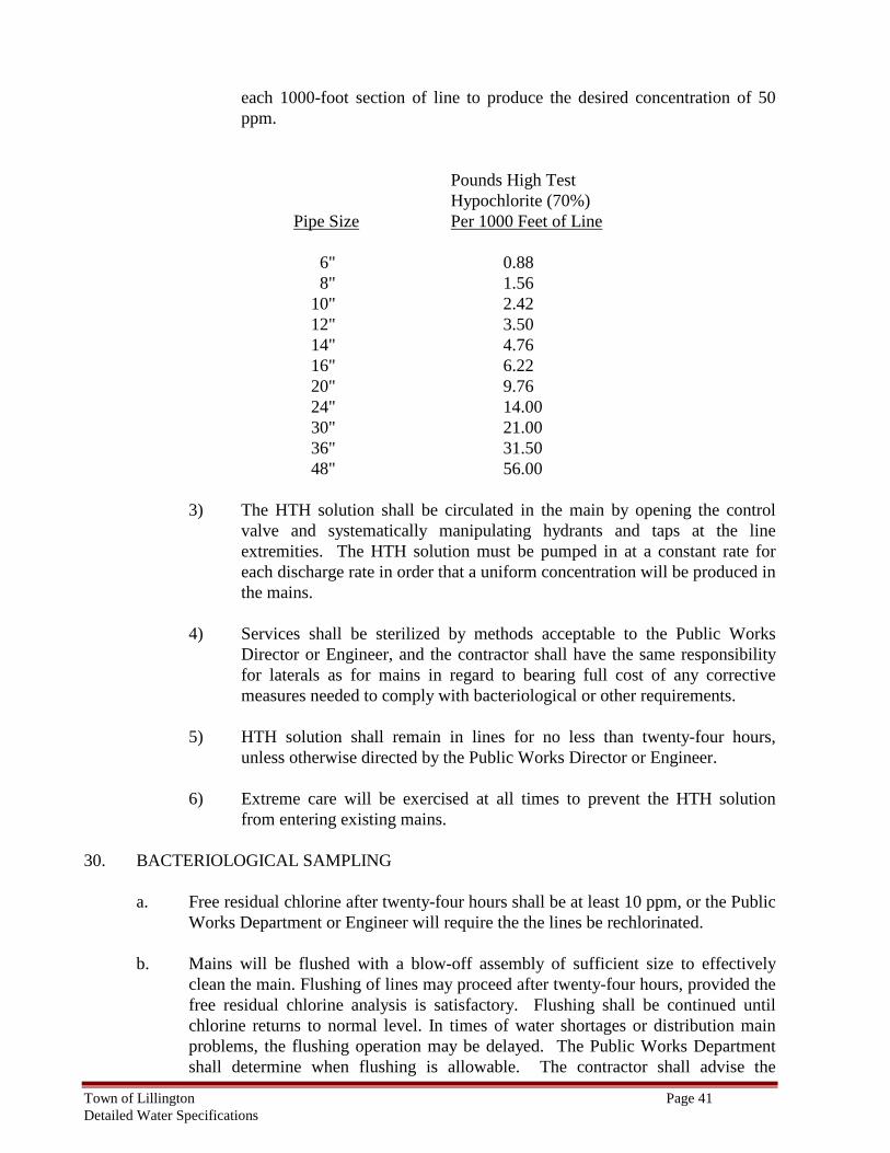
Town of Lillington Page 41 Detailed Water Specifications
each 1000-foot section of line to produce the desired concentration of 50 ppm.
Pounds High Test Hypochlorite (70%) Pipe Size Per 1000 Feet of Line 6" 0.88 8" 1.56 10" 2.42 12" 3.50 14" 4.76 16" 6.22 20" 9.76 24" 14.00 30" 21.00 36" 31.50 48" 56.00
3) The HTH solution shall be circulated in the main by opening the control valve and systematically manipulating hydrants and taps at the line extremities. The HTH solution must be pumped in at a constant rate for each discharge rate in order that a uniform concentration will be produced in the mains.
4) Services shall be sterilized by methods acceptable to the Public Works
Director or Engineer, and the contractor shall have the same responsibility for laterals as for mains in regard to bearing full cost of any corrective measures needed to comply with bacteriological or other requirements.
5) HTH solution shall remain in lines for no less than twenty-four hours,
unless otherwise directed by the Public Works Director or Engineer.
6) Extreme care will be exercised at all times to prevent the HTH solution from entering existing mains.
30. BACTERIOLOGICAL SAMPLING
a. Free residual chlorine after twenty-four hours shall be at least 10 ppm, or the Public Works Department or Engineer will require the the lines be rechlorinated.
b. Mains will be flushed with a blow-off assembly of sufficient size to effectively
clean the main. Flushing of lines may proceed after twenty-four hours, provided the free residual chlorine analysis is satisfactory. Flushing shall be continued until chlorine returns to normal level. In times of water shortages or distribution main problems, the flushing operation may be delayed. The Public Works Department shall determine when flushing is allowable. The contractor shall advise the
Town of Lillington Page 42 Detailed Water Specifications
inspector prior to the chlorination and flushing so that the inspector can advise the Public Works Department of the construction location, size and length of mains. All tests will be done in the presence of an inspector. Flushing will be for short duration. Sufficient precautions must be taken to the satisfaction of the inspector to ensure that the impact of the water is absorbed and the water is conveyed without erosion or property drainage. All flush water shall be de-chlorinated using methods acceptable to the Town of Lillington Public Works Department.
c. After flushing is completed, the Public Works Department (or their designee) shall
collect bacteriological analysis samples for each section of pipe between main line valves. Sample point locations shall be determined by a representative of the engineer or owner.
A custody seal shall be placed on each set of bacteriological bottles. A chain of custody form must be completed for sample set(s) collected and must be delivered along with the sample(s). A certified lab will perform the bacteriological analysis.
d. Samples will be accepted between 8:00 AM and 12 NOON and 1PM and 3:30 PM
Monday through Thursday, excluding holidays. Special arrangements may be made for samples to be accepted outside of this time frame by calling the laboratory in advance.
e. In the event that two successive bacteriologic tests fail, that section of the main shall be re-chlorinated by the contractor and new tests performed prior to moving to the next section of main.
31. SERVICE CONNECTIONS
a. Taps shall be made only on a line under pressure and after the main has been tested and chlorinated. No taps on dry lines shall be allowed, unless specific authorization from the Town of Lillington is obtained.
b. Taps shall be at an angle of forty-five degrees to a perpendicular plane through the
center line of the pipe.
c. The maximum size of a tap shall be ½ the diameter of mains by using a tapping saddle.
d. Larger taps shall be made by using a tapping sleeve and resilient wedge gate valve.
e. No taps or services shall be made on the 24-inch or larger transmission mains.
f. Before any water services are installed, the main shall be thoroughly flushed using a
flow velocity sufficient to scour the pipe interior.
g. Each meter setter shall be flushed before the installation crew proceeds to the next service installation.
Town of Lillington Page 43 Detailed Water Specifications
32. WATER MAIN AND SERVICE ABANDONMENT
a. Contractors abandoning water services shall turn off the corporation cock, and at least one foot of the remaining portion of the service shall be removed from the main toward the right of way line and shall be disposed of properly.
b. Water main abandonment must be performed in accordance with a plan approved by the Public Works Department.
Note: Service and main abandonment require inspection by the Public Works Department at (910) 893-3607.
33. SEALED AS-BUILT PLANS
Certified surveyed "As built" plans and profiles, sealed by a Professional Land Surveyor, and Professional Engineer shall be furnished to the Public Works Department by the Engineer upon completion and prior to acceptance of the public main by the Town of Lillington and completion of private systems. The surveyed "as built" plans shall have North Carolina Geodetic Survey grid coordinates to all meter boxes, valves, manholes, and mains along with the depth information. The water permit number information must also be included. Surveyed "As built" plans of installed utilities shall be furnished to the Town of Lillington prior to issuance of the letter of acceptance. All service stubs shall be shown on the surveyed "as built" plans.
Certified surveyed “As Builts” should be provided in a digital format, and written. The digital file of utilities needs to show the overall water and sewer system layout along with the property or subdivision boundaries and connecting manhole. The water distribution system drawings should show mains sizes, material, hydrants, valves, blow-off assemblies, and any other relevant information (backflow preventers, air release valves, etc.). The digital file should be delivered in DXF format. If this is not possible, then, DWG, DGN, and SHP are also acceptable formats.
34. GENERAL ACCEPTANCE
The developer or his representative must notify the Public Works Departments' Inspector, in writing, before installation and for scheduling inspection. Once the project is complete a punch list and inspection is scheduled noting any deficient items. Once the deficient items are repaired and/or replaced to meet Town of Lillington standards and specifications the developer or his/her representative shall submit the following items to the Town of Lillington Public Works Department.
a. A professional engineer's certified statement of the cost of the public utilities
installed.
b. A professional engineer’s certified statement indicating that the work has been built in accordance with the approved set of construction plans.
c. A release of liens statement from the owner/developer stating that all materials and
workmanship associated with the water main has been paid in full.
Town of Lillington Page 44 Detailed Water Specifications
d. Certified surveyed "As-Built" plans and profile shall be furnished by the engineer
upon completion and prior to acceptance by the Town of Lillington as stated above. e. The developer is responsible for ensuring a one-year written warranty to the Town
of Lillington prior to issuance of the letter of acceptance.
f. The developer and/or engineer shall provide a recorded map to the Town of Lillington showing all public rights-of-way and easements.
h. The engineer shall keep a copy of the “as-built” plans on file indefinitely.
i. A minimum of 2 (1 Paper copy and 1 Digital copy) (two) copies of “as-built” plans
will be supplied to the Owner. j. Prior to acceptance of the water system by the Town, a letter of credit from the
owner will be required of 110% of the value until the one year warranty period expires.
END OF SECTION