19xr (pic ii) hermetic centrifugal liquid chillers 50 hz
TRANSCRIPT
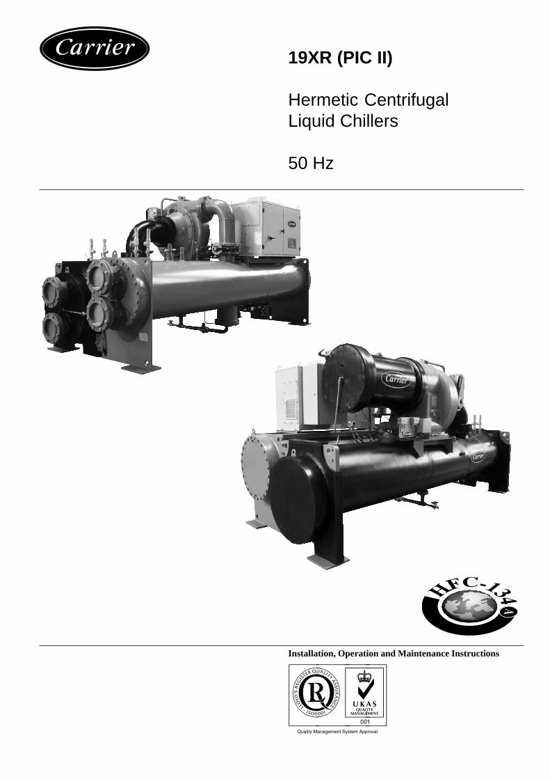
19XR (PIC II)
Hermetic CentrifugalLiquid Chillers
50 Hz
Installation, Operation and Maintenance Instructions
2
The cover illustrations, as well as the diagrams, in this document are for illustrative purposes only and not part of anyoffer for sale or contract.
TABLE OF CONTENTS
INITIAL START-UP CHECKLIST FOR 19XR HERMETIC CENTRIFUGAL LIQUID CHILLERS ................................. 5
1 - SAFETY CONSIDERATIONS ................................................................................................................................................... 91.1 - Installation safety considerations ................................................................................................................................................ 91.2 - Maintenance safety considerations ............................................................................................................................................. 91.3 - Operating checks ......................................................................................................................................................................... 91.4 - Equipment and components under pressure ............................................................................................................................. 101.5 - Repair safety considerations ..................................................................................................................................................... 10
2 - INTRODUCTION AND CHILLER FAMILIARIZATION ................................................................................................... 112.1 - C.E. Mark .................................................................................................................................................................................. 112.2 - Abbreviations and explanations ................................................................................................................................................ 112.3 - Chiller familiarization ............................................................................................................................................................... 12
2.3.1 - Chiller information plate .................................................................................................................................................. 122.3.2 - System components .......................................................................................................................................................... 122.3.3 - Cooler ............................................................................................................................................................................... 122.3.4 - Condenser ......................................................................................................................................................................... 122.3.5 - Motor-compressor ............................................................................................................................................................ 122.3.6 - Control centre ................................................................................................................................................................... 122.3.7 - Factory-mounted starter (optional) ................................................................................................................................... 132.3.8 - Storage vessel (optional) .................................................................................................................................................. 13
2.4 - Refrigeration cycle .................................................................................................................................................................... 132.5 - Motor/oil refrigeration cooling cycle ........................................................................................................................................ 142.6 - Lubrication cycle ....................................................................................................................................................................... 14
2.6.1 - Summary .......................................................................................................................................................................... 142.6.2 - Details ............................................................................................................................................................................... 14
2.7 - Power equipment ....................................................................................................................................................................... 15
3 - INSTALLATION ........................................................................................................................................................................ 173.1 - Introduction ............................................................................................................................................................................... 173.2 - Receiving the machine .............................................................................................................................................................. 17
3.2.1 - Inspect shipment ............................................................................................................................................................... 173.2.2 - Provide machine protection .............................................................................................................................................. 17
3.3 - Rigging the machine ................................................................................................................................................................. 173.3.1 - Rigging the complete machine ......................................................................................................................................... 173.3.2 - Rig machine components ................................................................................................................................................. 183.3.3 - Physical data ..................................................................................................................................................................... 19
3.4 - Install machine supports ............................................................................................................................................................ 253.4.1 - Install standard isolation ................................................................................................................................................... 253.4.2 - Installation of a levelling accessory (if necessary) ........................................................................................................... 253.4.3 - Install spring isolation ...................................................................................................................................................... 26
3.5 - Connection of water piping ....................................................................................................................................................... 263.5.1 - Install water piping to heat exchanger .............................................................................................................................. 263.5.2 - Install vent piping to relief devices .................................................................................................................................. 30
3.6 - Make electrical connections ...................................................................................................................................................... 303.6.1 - Installation standards and precautions .............................................................................................................................. 303.6.2 - Electrical characteristics of the motors ............................................................................................................................ 313.6.3 - Recommended wire section ............................................................................................................................................. 343.6.4 - Communication wiring ..................................................................................................................................................... 363.6.5 - Make the necessary connections for the outgoing control signals ................................................................................... 373.6.6 - Connect the starting cabinet ............................................................................................................................................. 373.6.7 - Connect the starting cabinet to the control box ................................................................................................................ 393.6.8 - Carrier Comfort Network interface (CCN) ...................................................................................................................... 40
3.7 - Special characteristics of the control box (wired) ..................................................................................................................... 403.7.1 - Characteristics .................................................................................................................................................................. 413.7.2 - Factory starter control ...................................................................................................................................................... 41
3.8 - Install field insulation ................................................................................................................................................................ 42
3
TABLE OF CONTENTS (cont'd)
4 - BEFORE INITIAL START-UP ................................................................................................................................................ 434.1 - Necessary checks ...................................................................................................................................................................... 43
4.1.1 - Job data required .............................................................................................................................................................. 434.1.2 - Equipment required .......................................................................................................................................................... 434.1.3 - Using the optional storage tank and pumpout system ...................................................................................................... 434.1.4 - Remove shipping packaging ............................................................................................................................................ 434.1.5 - Open oil circuit valves ...................................................................................................................................................... 434.1.6 - Tighten all gasketed joints and guide vane shaft packing (torque depends on screw diameter) ...................................... 434.1.7 - Inspect water piping ......................................................................................................................................................... 434.1.8 - Check relief devices ......................................................................................................................................................... 44
4.2 - Chiller tightness ........................................................................................................................................................................ 444.2.1 - Check chiller tightness ..................................................................................................................................................... 444.2.2 - Refrigerant tracer .............................................................................................................................................................. 444.2.3 - Leak test chiller ................................................................................................................................................................ 44
4.3 - Standing vacuum test ................................................................................................................................................................ 454.4 - Chiller dehydration ................................................................................................................................................................... 454.5 - Inspect wiring ............................................................................................................................................................................ 474.6 - Carrier Comfort Network interface (see Fig. 22) ...................................................................................................................... 474.7 - Check starter ............................................................................................................................................................................. 474.8 - Oil charge .................................................................................................................................................................................. 484.9 - Power up the controls and check the oil heater ......................................................................................................................... 484.10 - Check optional pumpout system controls and compressor ..................................................................................................... 484.11 - High altitude locations ............................................................................................................................................................ 484.12 - Charge refrigerant into chiller ................................................................................................................................................. 484.13 - Chiller equalization without pumpout unit ............................................................................................................................. 484.14 - Chiller equalization with pumpout unit .................................................................................................................................. 494.15 - Trimming refrigerant charge ................................................................................................................................................... 49
5 - INITIAL START-UP .................................................................................................................................................................. 505.1 - Preparation ................................................................................................................................................................................ 505.2 - Dry run to test start-up sequence .............................................................................................................................................. 505.3 - Check rotation ........................................................................................................................................................................... 505.4 - Check oil pressure and compressor stop ................................................................................................................................... 505.5 - To prevent accidental start-up ................................................................................................................................................... 505.6 - Check chiller operating condition ............................................................................................................................................. 515.7 - Instruct the customer operator .................................................................................................................................................. 51
6 - OPERATING INSTRUCTIONS ............................................................................................................................................... 516.1 - Operator duties .......................................................................................................................................................................... 516.2 - To start the chiller ...................................................................................................................................................................... 516.3 - Check the running system ......................................................................................................................................................... 516.4 - To stop the chiller ...................................................................................................................................................................... 526.5 - After limited shutdown .............................................................................................................................................................. 526.6 - Extended shutdown ................................................................................................................................................................... 526.7 - After extended shutdown........................................................................................................................................................... 526.8 - Cold-weather operation ............................................................................................................................................................. 526.9 - Manual guide vane operation .................................................................................................................................................... 526.10 - Refrigeration log ..................................................................................................................................................................... 52
7 - MAINTENANCE ....................................................................................................................................................................... 547.1 - General maintenance ................................................................................................................................................................. 54
7.1.1 - Soldering and welding ...................................................................................................................................................... 547.1.2 - Refrigerant properties ....................................................................................................................................................... 547.1.3 - Adding refrigerant ............................................................................................................................................................ 547.1.4 - Removing refrigerant ....................................................................................................................................................... 547.1.5 - Adjusting the refrigerant charge ....................................................................................................................................... 547.1.6 - Refrigerant leak testing .................................................................................................................................................... 547.1.7 - Checking guide vane linkage ........................................................................................................................................... 557.1.8 - Trim refrigerant charge ..................................................................................................................................................... 55
4
TABLE OF CONTENTS (cont'd)
7.2 - Weekly maintenance ................................................................................................................................................................. 557.3 - Scheduled maintenance ............................................................................................................................................................. 56
7.3.1 - Service ontime .................................................................................................................................................................. 567.3.2 - Inspect the control centre ................................................................................................................................................. 567.3.3 - Changing oil filter ............................................................................................................................................................ 567.3.4 - Oil specification ................................................................................................................................................................ 567.3.5 - Refrigerant filter ............................................................................................................................................................... 567.3.6 - Oil reclaim filter ............................................................................................................................................................... 577.3.7 - Inspect refrigerant float system ........................................................................................................................................ 577.3.8 - Inspect relief valves and piping (see chapter 'Safety considerations') ............................................................................. 577.3.9 - Verification of the pressure switch calibration ................................................................................................................. 577.3.10 - Compressor bearing and gear maintenance .................................................................................................................... 577.3.11 - Useful compressor maintenance diagrams ..................................................................................................................... 587.3.12 - Inspect the heat exchanger tubes .................................................................................................................................... 597.3.13 - Water leaks ..................................................................................................................................................................... 597.3.14 - Inspect the starting equipment ........................................................................................................................................ 597.3.15 - Check pressure transducers ............................................................................................................................................ 597.3.16 - Corrosion control ............................................................................................................................................................ 59
LIST OF FIGURESFig. 1 - Model number nomenclature ................................................................................................................................................ 12Fig. 2 - 19XR machine components .................................................................................................................................................. 12Fig. 3 - Refrigerant motor cooling and oil cooling cycles ................................................................................................................ 13Fig. 4 - Lubrication system................................................................................................................................................................ 15Fig. 5A - Starter cabinet - internal view with internal door closed ................................................................................................... 16Fig. 5B - Starter cabinet - internal view with internal door open ...................................................................................................... 16Fig. 6 - Machine rigging guide .......................................................................................................................................................... 18Fig. 7 - Dimensional drawing ............................................................................................................................................................ 22Fig. 8 - Dimensional drawing - cooler, side view.............................................................................................................................. 23Fig. 9 - 19XR chiller top view ........................................................................................................................................................... 23Fig. 10 - Compressor detail ............................................................................................................................................................... 24Fig. 11 - Unit rear view ..................................................................................................................................................................... 24Fig. 12 - Chiller footprint .................................................................................................................................................................. 25Fig. 13 - Standard isolation ............................................................................................................................................................... 26Fig. 14 - Accessory isolation ............................................................................................................................................................. 26Fig. 15 - 19XR Accessory spring isolation ........................................................................................................................................ 26Fig. 16 - Typical nozzle piping .......................................................................................................................................................... 27Fig. 17 - Nozzle arrangements - nozzle-in-head waterboxes ............................................................................................................ 28Fig. 18 - Optional pumpout system piping schematic with storage tank .......................................................................................... 29Fig. 19 - Pumpout system piping schematic with storage tank ......................................................................................................... 29Fig. 20 - Relief device locations ........................................................................................................................................................ 30Fig. 21 - COMM1 CCN communication wiring for multiple chillers (typical) ................................................................................ 36Fig. 22 - 19XR with optional unit-mounted starter ........................................................................................................................... 37Fig. 23 - 19XR with freestanding starter ........................................................................................................................................... 38Fig. 24 - Machine isolation ................................................................................................................................................................ 42Fig. 25 - 19XR leak detection procedure .......................................................................................................................................... 46Fig. 26 - Dehydration cold trap ......................................................................................................................................................... 47Fig. 27 - Rotation diagram ................................................................................................................................................................ 50Fig. 28 - Refrigeration log ................................................................................................................................................................. 53Fig. 29 - Guide vane actuator linkage ............................................................................................................................................... 55Fig. 30 - 19XR float valve design ..................................................................................................................................................... 57Fig. 31 - Compressor fits and clearances .......................................................................................................................................... 58
5
INITIAL START-UP CHECKLIST FOR 19XR HERMETIC CENTRIFUGAL LIQUID CHILLERS
Name: _____________________________________________________________________________________________Address: ____________________________________________________________________________________________Town: ______________________________________________________________________________________________Country: ____________________________________________________________________________________________Post code: ___________________________________________________________________________________________Job No.: _____________________________________________________________________________________________Model: ______________________________________________________________________________________________Serial No.: ____________________________________________________________________________________________
Design conditions:
Cooling Brine Flow Temperature Temperature Pressure Pass Suction Condensingcapacity rate in out drop temperature temperature
Evaporator
Condenser
Compressor: Volts _______________________ RLA: _______________________ OLTA: __________________Starter: Mfg ________________________ Type: _______________________Oil pump: Volts _______________________ RLA: _______________________ OLTA: __________________
Control/oil heater: 115 Volts ___________ 230 Volts ___________Refrigerant: Type _______________ Charge (kg) __________
Carrier obligations:Assemble: Yes ________ No ________Leak test: Yes ________ No ________Dehydrate: Yes ________ No ________Charging: Yes ________ No ________Operating instructions: ____________ Hours
START-UP TO BE PERFORMED IN ACCORDANCE WITH APPROPRIATE MACHINE START-UP INSTRUCTIONS
Job data required:1. Machine installation instructions 19XR Yes ________ No ________2. Machine assembly, wiring and piping diagrams Yes ________ No ________3. Starting equipment details and wiring diagrams Yes ________ No ________4. Applicable design data (see above) Yes ________ No ________5. Diagrams and instructions for special controls Yes ________ No ________
Initial machine pressure: __________________
Was machine tight? Yes ________ No ________If not, were leaks corrected? Yes ________ No ________Was machine dehydrated after repairs? Yes ________ No ________
Check oil level and record:Add oil: Yes ________ No ________Amount: ___________________________
_______ 3/4 _______ 3/4_______ 1/2 Top sight glass _______ 1/2 Bottom sight glass_______ 1/4 _______ 1/4
Record pressure drops:Evaporator ________________ Condenser ________________
Refrigerant charge:Initial charge _______________ Final charge after trim ______________
6
INSPECT WIRING AND RECORD ELECTRICAL DATA:
Ratings:Motor voltage: ________ Motor(s) amps: ________ Oil pump voltage: ________ Starter amps: ________Line voltages: Motor: _____________ Oil pump: _____________ Controls/oil heater: ____________
Field-installed starters only:Check continuity T1 to T1, etc (motor to starter power wiring).Megger starter: Do not megger a motor connected to a solid-state starter, unless the leads to the motor are disconnected andmeggered.
Megger motor Phase to phase Phase to ground
T1-T2 T1-T3 T2-T3 T1-G T2-G T3-G
10-second readings
60-second readings
Polarization ratio
Starter:Electro-mechanical __________ Electronic __________
Motor load current transformer ratio _____ : _____ Signal resistor size ________ OhmsTransition timer time __________ seconds
Check magnetic overloads: Add dash pot oil Yes _______ No _______Solid-state overloadsYes _______ No _______
Solid-state starter: Initial voltage __________ Volts Ramp setting __________ seconds
Controls: safety, operating, etcPerform controls test Yes _______ No _______
CAUTION: Compressor motor and control centre must be properly and individually connected back to the earth ground in thestarter (in accordance with certified drawings). Yes _______
Run machine:Do these safeties shut down the machine?Condenser water flow switch: Yes ________ No ________Chilled water flow switch: Yes ________ No ________Pump interlocks: Yes ________ No ________
Initial start:Line up all valves in accordance with instruction manual: _______ Start water pumps and establish water flow: ________Oil level and temperature correct: ________ Check oil pump rotation pressure ________Check compressor motor rotation (motor end sight glass) and record: Clockwise ________Restart compressor. Bring up to speed. Shut down. Any abnormal coastdown noise?: Yes* ________ No ________* If yes, determine cause
Start machine and operate. Complete the following:A. Trim charge and record.B. Complete any remaining control calibration and record.C. Take at least 2 sets of operational log readings and record.D. After machine has been successfully run and set up, shut down and mark shutdown oil and refrigerant levels.E. Give operating instructions to owner's operating personnel. Hours given: ________ hrsF. Call your Carrier factory representative to report chiller start-up.
Signature: ______________________________________ Date: _________(Carrier technician)
Signature: ______________________________________ Date: _________(Customer representative)
7
19XR HERMETIC CENTRIFUGAL LIQUID CHILLER CONFIGURATION SETTINGS LOG(Remove and use for job file)
Controller name: Bus No.:Element No.Table description: Table name: SETPOINT
Setpoint table configuration sheet 19XR
Description Range Units Default Value
Base demand limit 40 to 100 % 100
LCW setpoint 12.2 to 48.9 °C 50
ECW setpoint 12.2 to 48.9 °C 60
Controller name: Bus No.:Element No.Table description: Table name: OCCP01S
Local mode time schedule configuration sheet - 19XR PIC II control - OCCP01S
Day Occupied time Unoccupied time
M T W T F Sa Su H
Period 1
Period 2
Period 3
Period 4
Period 5
Period 6
Period 7
Period 8
Note: Default setting is occupied 24 hours/day
Local mode time schedule configuration sheet - 19XR PIC II control - OCCP01S
Day Occupied time Unoccupied time
M T W T F Sa Su H
Period 1
Period 2
Period 3
Period 4
Period 5
Period 6
Period 7
Period 8
Note: Default setting is occupied 24 hours/day
Controller name: Bus No.:Element No.Table description: Table name: HOLIDEFS
Holiday configuration sheet
Description Range Units Value
Holiday start month 1-12
Holiday start day 1-31
Duration 0-99 Days

8
Table description: Table name: HOLIDEFS
Holiday configuration sheet
Description Range Units Value
Holiday start month 1-12
Holiday start day 1-31
Duration 0-99 Days
Table description: Table name: HOLIDEFS
Holiday configuration sheet
Description Range Units Value
Holiday start month 1-12
Holiday start day 1-31
Duration 0-99 Days
9
1 - SAFETY CONSIDERATIONS
19XR liquid chillers are designed to provide safe and reliableservice when operated within design specifications. Whenoperating this equipment, use good judgment and safetyprecautions to avoid damage to equipment and property orinjury to personnel.
Be sure you understand and follow the procedures and safetyprecautions contained in the machine instructions as well asthose listed in this guide.
1.1 - Installation safety considerations
In certain cases the safety stops are installed on ball valves.These valves are factory-supplied lead-sealed in the openposition. This system permits isolating and removing thesafety stop for checking and replacing. The safety stops aredesigned and installed to ensure protection against fire risk.Removing the safety stops is only permitted if the fire risk isfully controlled and the responsibility of the user.
All factory-installed safety valves are lead-sealed to preventany calibration change. If a safety stop is removed forchecking or replacement please ensure that there is always anactive safety stop on each of the reversing valves installed inthe unit.
The safety valves must be connected to discharge pipes. Thesepipes must be installed in a way that ensures that people andproperty are not exposed to refrigerant leaks. These fluidsmay be diffused in the air, but far away from any building airintake, or they must be discharged in a quantity that isappropriate for a suitably absorbing environment.
Periodic check of the safety valves: See paragraph“Maintenance safety considerations”.
DANGER:DO NOT VENT refrigerant relief valves within a building.Outlet from relief valve must be vented outdoors. The accumu-lation of refrigerant in an enclosed space can displace oxygenand cause asphyxiation.
PROVIDE adequate ventilation, especially for enclosed andlow overhead spaces. Inhalation of high concentrations ofvapour is harmful and may cause heart irregularities, uncon-sciousness, or death. Misuse can be fatal. Vapour is heavierthan air and reduces the amount of oxygen available forbreathing. Product causes eye and skin irritation.Decomposition products are hazardous.
DO NOT USE OXYGEN to purge lines or to pressurize amachine for any purpose. Oxygen gas reacts violently with oil,grease, and other common substances.
NEVER EXCEED specified test pressures, VERIFY the allow-able test pressure by checking the instruction literature andthe design pressures on the equipment nameplate.
DO NOT USE air for leak testing. Use only refrigerant or drynitrogen.
DO NOT VALVE OFF any safety device.
BE SURE that all pressure relief devices are properlyinstalled before operating any machine.
1.2 - Maintenance safety considerations
Engineers working on the electric or refrigeration componentsmust be authorized, trained and fully qualified to do so.
All refrigerant circuit repairs must be carried out by a trainedperson, fully qualified to work on these units. He must havebeen trained and be familiar with the equipment and theinstallation. All welding operations must be carried out byqualified specialists.
Any manipulation (opening or closing) of a shut-off valvemust be carried out by a qualified and authorised engineer.These procedures must be carried out with the unit shut-down.
NOTE: The unit must never be left shut down with the liquidline valve closed.
During any handling, maintenance and service operations theengineers working on the unit must be equipped with safetygloves, glasses, shoes and protective clothing.
WARNING:DO NOT WELD OR FLAMECUT any refrigerant line orvessel until all refrigerant (liquid and vapour) has beenremoved from chiller. Traces of vapour should be displacedwith dry air nitrogen and the work area should be wellventilated. Refrigerant in contact with an open flame producestoxic gases.
DO NOT work on high-voltage equipment unless you are aqualified electrician.
DO NOT WORK ON electrical components, including controlpanels, switches, relays etc, until you are sure ALL POWERIS OFF; residual voltage can leak from capacitors or solidstate components.
LOCK OPEN AND TAG electrical circuits during servicing.
IF WORK IS INTERRUPTED, confirm that all circuits arede-energized before resuming work.
1.3 - Operating checks
During the life-time of the system, inspection and tests mustbe carried out in accordance with national regulations.
The information on operating inspections given in annex C ofstandard EN378-2 can be used if no similar criteria exist inthe national regulations.
Safety device checks (annex C6 – EN378-2): The safetydevices must be checked on site once a year for safety devices(high-pressure switches), and every five years for externaloverpressure devices (safety globe valves).
If the machine operates in a corrosive environment, inspectthe protection devices more frequently.
10
Any use of these chillers with a different refigerant must be inaccordance with applicable national standards.
DO NOT ATTEMPT TO REMOVE connections, componentsetc., while the machine is under pressure or operating. Makesure that the pressure is 0 kPa, before disconnecting therefrigerant connections.
ATTENTION: No part of the unit must use feet, racks orsupports during operation. Periodically monitor and repair orif necessary replace any component or piping that showssigns of damage.
DO NOT climb over a machine. Use platform, or staging.
USE MECHANICAL EQUIPMENT (crane, hoist, etc.) to liftor move heavy components. Even if components are light, usemechanical equipment when there is a risk of slipping or losingyour balance.
DO NOT USE eyelets to lift any part of the machine or thecomplete machine.
BE AWARE that certain automatic start arrangements CANENGAGE COOLING TOWER FAN, OR PUMPS. Open thedisconnect ahead of the tower fans, or pumps.
USE only repair or replacement parts that meet the coderequirements of the original equipment.
DO NOT VENT OR DRAIN water boxes containing industrialbrines, without the permission of your process control group.
DO NOT LOOSEN water box bolts until the water box hasbeen completely drained.
DO NOT LOOSEN a packing gland nut before checking thatthe nut has a positive thread engagement.
PERIODICALLY INSPECT all valves, fittings, and pipingfor corrosion, rust, leaks, or damage.
During refrigerant removal and storage operations follow applic-able regulations. These regulations, permitting conditioning andrecovery of halogenated hydrocarbons under optimum qualityconditions for the products and optimum safety conditions forpeople, property and the environment are described in standardNFE 29795.
Any refrigerant transfer and recovery operations must be carriedout using a transfer unit. A 3/8” SAE connector on the manualliquid line valve is supplied with all units for connection to thetransfer station. The units must never be modified to add refri-gerant and oil charging, removal and purging devices. All thesedevices are provided with the units. Please refer to the certifieddimensional drawings for the units.
DO NOT ATTEMPT TO REPAIR OR RECONDITION anysafety devices when corrosion or build-up of foreign material(rust, dirt, scale, etc.) is found within the valve body ormechanism. If necessary, replace the device.
DO NOT install safety valves in series or backwards.
PROVIDE A DRAIN connection in the vent line near eachpressure relief device to prevent a build-up of condensate orrain water.
1.4 - Equipment and components under pressure
These products incorporate equipment or components underpressure, manufactured by Carrier or other manufacturers. Werecommend that you consult your appropriate national tradeassociation or the owner of the equipment or components underpressure (declaration, re-qualification, retesting, etc.). Thecharacteristics of this equipment/these components are givenon the nameplate or in the required documentation, suppliedwith the products.
1.5 - Repair safety considerations
All installation parts must be maintained by the personnel incharge, in order to avoid material deterioration and injuries topeople. Faults and leaks must be repaired immediately. Theauthorized technician must have the responsibility to repair thefault immediately. Each time repairs have been carried out tothe unit, the operation of the safety devices must be re-checked.
If a leak occurs or if the refrigerant becomes polluted (e.g. by ashort circuit in a motor) remove the complete charge using arecovery unit and store the refrigerant in mobile containers.Repair the leak detected and recharge the circuit with the totalR134a charge, as indicated on the unit name plate.
DO NOT siphon refrigerant.
AVOID SPILLING liquid refrigerant on skin or getting itinto the eyes. USE SAFETY GOGGLES AND SAFETYGLOVES. Wash any spills from the skin with soap and water.If liquid refrigerant enters the eyes, IMMEDIATELY FLUSHEYES with water and consult a physician.
NEVER APPLY an open flame or live steam to refrigerantcylinder. Dangerous overpressure can result. If it is necessaryto heat refrigerant, use only warm water.
DO NOT REUSE disposable (non-returnable) cylinders orattempt to refill them. It is DANGEROUS AND ILLEGAL.When cylinders are emptied, evacuate remaining gas pressure,loosen the collar and unscrew and discard the valve stem. DONOT INCINERATE.
After refrigerant draining operations, CHECK THE REFRI-GERANT TYPE before adding refrigerant to the machine.The introduction of the wrong refrigerant can cause damageor malfunction to this machine.
11
2 - INTRODUCTION AND CHILLER FAMILIARIZATION
Prior to initial start-up of the 19XR unit, those involved in thestart-up, operation, and maintenance should be thoroughlyfamiliar with these instructions and other necessary job data. Thisbook is outlined so that you may become familiar with the con-trol system before performing start-up procedures. Proceduresin this manual are arranged in the sequence required for properchiller start-up and operation.
Maximum outside temperature:For transport and storage of the 19XR units the minimum andmaximum allowable temperatures are –20°C and +48°C.
Unit operating range
Evaporator 19XR Minimum Maximum
Evaporator entering water temperature* °C 6 17Evaporator leaving water temperature* °C 3.3 10
Condenser (water-cooled) 19XR Minimum Maximum
Condenser entering water temperature* °C 16 35Condenser leaving water temperature* °C 13.3 44
* For application requiring brine operation, contact Carrier SA for unit selectionusing the Carrier electronic catalog.
WARNING: This unit uses a microprocessor control system.Do not short or jumper between terminations on circuitboards or modules; control or board failure may result.
Be aware of electrostatic discharge (static electricity) whenhandling or making contact with circuit boards or moduleconnections. Always touch a chassis (grounded) part todissipate body electrostatic charge before working inside controlcentre.
Use extreme care when handling tools near boards and whenconnecting or disconnecting terminal plugs. Circuit boardscan easily be damaged. Always hold boards by the edges andavoid touching components and connections.
This equipment uses, and can radiate, radio frequency energy.If not installed and used in accordance with the instructionmanual, it may cause interference to radio communications. Ithas been tested and found to comply with European Directive89/336/EEC, on Electromagnetic Compatibility. Operation ofthis equipment in a residential area is likely to cause inter-ference, in which case the user, at his own expense, will berequired to take whatever measures may be required to correctthe interference. Always store and transport replacement ordefective boards in anti-static shipping bag.
2.1 - C.E. Marking
The machines that carry the CE mark must comply with thefollowing European directives:- Pressure equipment directive (PED) 97/23/EC- Machinery directive 98/37/EC, modified- Low voltage directive 73/23/EEC, modified- Electromagnetic compatibility 89/336/EEC, modified, and
with the recommendations of the appluicable Europeanstandards:- Machinery safety, electrical equipment for machines,
general regulations: EN 60204-1- Electromagnetic emission: EN 50081-2- Electromagbnetic immunity: EN 50082-2
2.2 - Abbreviations and explanations
Frequently used abbreviations in this manual include:CCM - Chiller Control ModuleCCN - Carrier Comfort NetworkCCW - CounterclockwiseCVC - Chiller Visual ControlCW - ClockwiseECW - Entering Chilled WaterECDW - Entering Condenser WaterEMS - Energy Management SystemHGBP - Hot Gas BypassI/O - Input/OutputISM - Integrated Starter ModuleLCD - Liquid Crystal DisplayLCDW - Leaving Condenser WaterLCW - Leaving Chilled WaterLED - Light-Emitting DiodeOLTA - Overload Trip AmpsPIC II - Product Integrated Control IIRLA - Rated Load AmpsSI - International System of Units of MeasurementTXV - Thermostatic Expansion Valve
The CVC software version number of your 19XR unit will belocated on the CVC module.
Information on the unit control is not included in this manual.Refer to separate control manual.
All information given on unit-mounted starters refers to star-delta connected starters. Electronic starters have separatedocumentation.
12
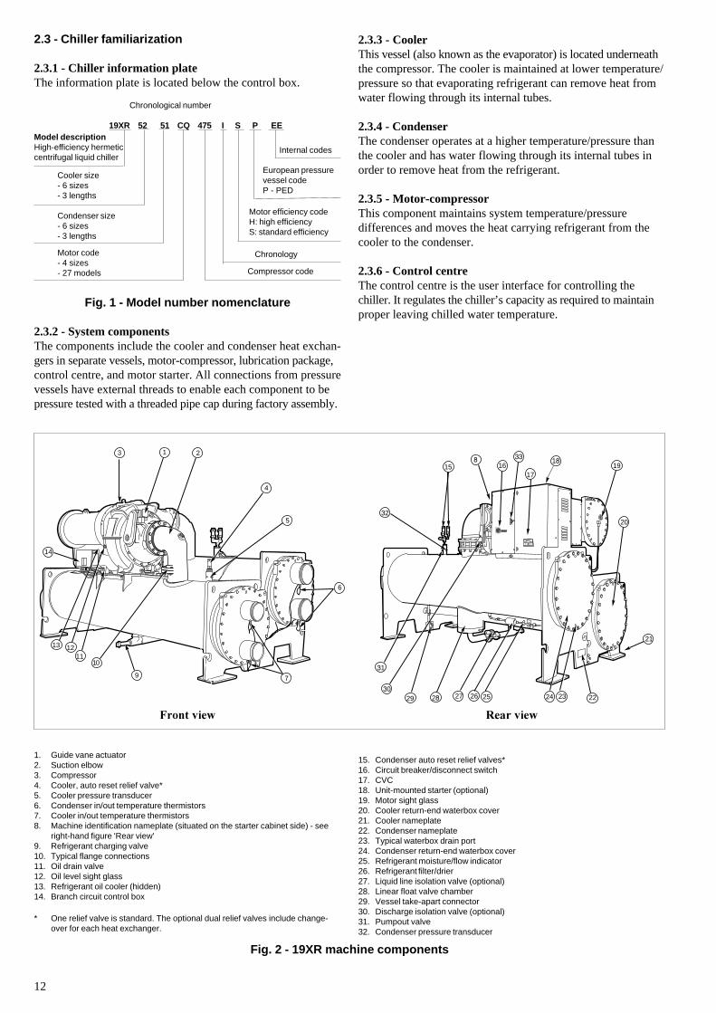
2.3 - Chiller familiarization
2.3.1 - Chiller information plateThe information plate is located below the control box.
Chronological number
19XR 52 51 CQ 475 I S P EE
Fig. 1 - Model number nomenclature
2.3.2 - System componentsThe components include the cooler and condenser heat exchan-gers in separate vessels, motor-compressor, lubrication package,control centre, and motor starter. All connections from pressurevessels have external threads to enable each component to bepressure tested with a threaded pipe cap during factory assembly.
2.3.3 - CoolerThis vessel (also known as the evaporator) is located underneaththe compressor. The cooler is maintained at lower temperature/pressure so that evaporating refrigerant can remove heat fromwater flowing through its internal tubes.
2.3.4 - CondenserThe condenser operates at a higher temperature/pressure thanthe cooler and has water flowing through its internal tubes inorder to remove heat from the refrigerant.
2.3.5 - Motor-compressorThis component maintains system temperature/pressuredifferences and moves the heat carrying refrigerant from thecooler to the condenser.
2.3.6 - Control centreThe control centre is the user interface for controlling thechiller. It regulates the chiller’s capacity as required to maintainproper leaving chilled water temperature.
Fig. 2 - 19XR machine components
1. Guide vane actuator2. Suction elbow3. Compressor4. Cooler, auto reset relief valve*5. Cooler pressure transducer6. Condenser in/out temperature thermistors7. Cooler in/out temperature thermistors8. Machine identification nameplate (situated on the starter cabinet side) - see
right-hand figure 'Rear view'9. Refrigerant charging valve10. Typical flange connections11. Oil drain valve12. Oil level sight glass13. Refrigerant oil cooler (hidden)14. Branch circuit control box
* One relief valve is standard. The optional dual relief valves include change-over for each heat exchanger.
�������� ������
15. Condenser auto reset relief valves*16. Circuit breaker/disconnect switch17. CVC18. Unit-mounted starter (optional)19. Motor sight glass20. Cooler return-end waterbox cover21. Cooler nameplate22. Condenser nameplate23. Typical waterbox drain port24. Condenser return-end waterbox cover25. Refrigerant moisture/flow indicator26. Refrigerant filter/drier27. Liquid line isolation valve (optional)28. Linear float valve chamber29. Vessel take-apart connector30. Discharge isolation valve (optional)31. Pumpout valve32. Condenser pressure transducer
9
1011
14
13 12
7
1 23
4
5
6
32
15
29 28 27 26 25 2230
31
1819
20
21
2324
1617
8 33
Internal codes
Model descriptionHigh-efficiency hermeticcentrifugal liquid chiller
Cooler size- 6 sizes- 3 lengths
Condenser size- 6 sizes- 3 lengths
Compressor code
Motor code- 4 sizes- 27 models
European pressurevessel codeP - PED
Motor efficiency codeH: high efficiencyS: standard efficiency
Chronology
13
The control centre:• registers cooler, condenser, and lubricating system pressures• shows chiller operating condition and alarm shutdown
conditions• records the total chiller operating hours• sequences chiller start, stop, and recycle under micro-
processor control• provides access to other CCN (Carrier Comfort Network)
devices
2.3.7 - Factory-mounted starter (Optional)The starter allows for the proper start and disconnect of elec-trical energy for the compressor-motor, oil pump, oil heater,and control panels.
2.3.8 Storage vessel (optional)There are 2 sizes of storage vessels available. The vessels haverelief valves, a drain valve and a male flare vapour connectionfor the pumpout unit.
NOTE: If a storage vessel is not used at the jobsite, factory-installed isolation valves on the chiller may be used to isolatethe chiller charge in either the cooler or condenser. An optionalpump-out system is used to transfer refrigerant from vessel tovessel.
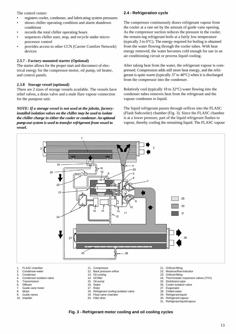
2.4 - Refrigeration cycle
The compressor continuously draws refrigerant vapour fromthe cooler at a rate set by the amount of guide vane opening.As the compressor suction reduces the pressure in the cooler,the remain-ing refrigerant boils at a fairly low temperature(typically 3 to 6°C). The energy required for boiling is obtainedfrom the water flowing through the cooler tubes. With heatenergy removed, the water becomes cold enough for use in anair conditioning circuit or process liquid cooling.
After taking heat from the water, the refrigerant vapour is com-pressed. Compression adds still more heat energy, and the refri-gerant is quite warm (typically 37 to 40°C) when it is dischargedfrom the compressor into the condenser.
Relatively cool (typically 18 to 32°C) water flowing into thecondenser tubes removes heat from the refrigerant and thevapour condenses to liquid.
The liquid refrigerant passes through orifices into the FLASC(Flash Subcooler) chamber (Fig. 3). Since the FLASC chamberis at a lower pressure, part of the liquid refrigerant flashes tovapour, thereby cooling the remaining liquid. The FLASC vapour
Fig. 3 - Refrigerant motor cooling and oil cooling cycles
1. FLASC chamber2. Condenser water3. Condenser4. Condenser isolation valve5. Transmission6. Diffuser7. Guide vane motor8. Motor9. Guide vanes10. Impeller
11. Compressor12. Back pressure orifice13. Oil cooling14. Oil filter15. Oil pump16. Stator17. Rotor18. Refrigerant cooling isolation valve19. Float valve chamber20. Filter drier
21. Orificed fitting22. Moisture/flow indicator23. Orificed fitting24. Thermostatic expansion valves (TXV)25. Distribution pipe26. Cooler isolation valve27. Evaporator28. Chilled water29. Refrigerant liquid30. Refrigerant vapour31. Refrigerant liquid/vapour
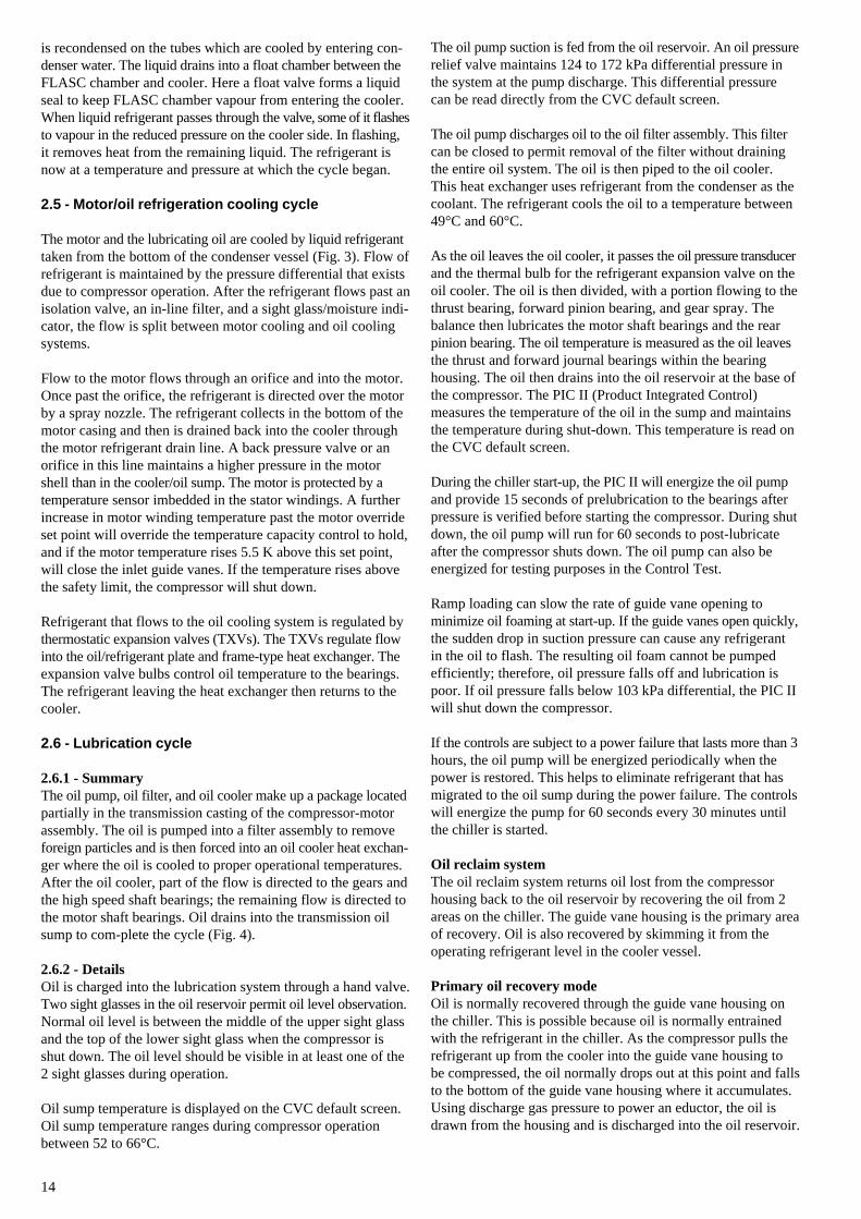
14
is recondensed on the tubes which are cooled by entering con-denser water. The liquid drains into a float chamber between theFLASC chamber and cooler. Here a float valve forms a liquidseal to keep FLASC chamber vapour from entering the cooler.When liquid refrigerant passes through the valve, some of it flashesto vapour in the reduced pressure on the cooler side. In flashing,it removes heat from the remaining liquid. The refrigerant isnow at a temperature and pressure at which the cycle began.
2.5 - Motor/oil refrigeration cooling cycle
The motor and the lubricating oil are cooled by liquid refrigeranttaken from the bottom of the condenser vessel (Fig. 3). Flow ofrefrigerant is maintained by the pressure differential that existsdue to compressor operation. After the refrigerant flows past anisolation valve, an in-line filter, and a sight glass/moisture indi-cator, the flow is split between motor cooling and oil coolingsystems.
Flow to the motor flows through an orifice and into the motor.Once past the orifice, the refrigerant is directed over the motorby a spray nozzle. The refrigerant collects in the bottom of themotor casing and then is drained back into the cooler throughthe motor refrigerant drain line. A back pressure valve or anorifice in this line maintains a higher pressure in the motorshell than in the cooler/oil sump. The motor is protected by atemperature sensor imbedded in the stator windings. A furtherincrease in motor winding temperature past the motor overrideset point will override the temperature capacity control to hold,and if the motor temperature rises 5.5 K above this set point,will close the inlet guide vanes. If the temperature rises abovethe safety limit, the compressor will shut down.
Refrigerant that flows to the oil cooling system is regulated bythermostatic expansion valves (TXVs). The TXVs regulate flowinto the oil/refrigerant plate and frame-type heat exchanger. Theexpansion valve bulbs control oil temperature to the bearings.The refrigerant leaving the heat exchanger then returns to thecooler.
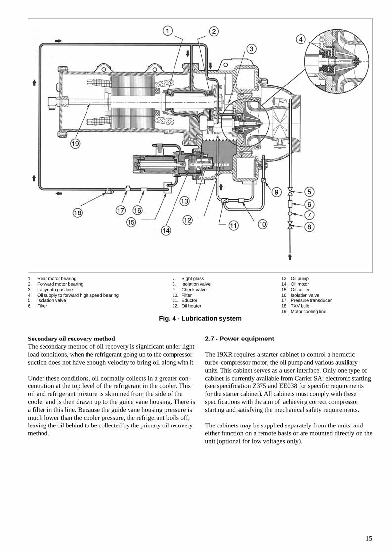
2.6 - Lubrication cycle
2.6.1 - SummaryThe oil pump, oil filter, and oil cooler make up a package locatedpartially in the transmission casting of the compressor-motorassembly. The oil is pumped into a filter assembly to removeforeign particles and is then forced into an oil cooler heat exchan-ger where the oil is cooled to proper operational temperatures.After the oil cooler, part of the flow is directed to the gears andthe high speed shaft bearings; the remaining flow is directed tothe motor shaft bearings. Oil drains into the transmission oilsump to com-plete the cycle (Fig. 4).
2.6.2 - DetailsOil is charged into the lubrication system through a hand valve.Two sight glasses in the oil reservoir permit oil level observation.Normal oil level is between the middle of the upper sight glassand the top of the lower sight glass when the compressor isshut down. The oil level should be visible in at least one of the2 sight glasses during operation.
Oil sump temperature is displayed on the CVC default screen.Oil sump temperature ranges during compressor operationbetween 52 to 66°C.
The oil pump suction is fed from the oil reservoir. An oil pressurerelief valve maintains 124 to 172 kPa differential pressure inthe system at the pump discharge. This differential pressurecan be read directly from the CVC default screen.
The oil pump discharges oil to the oil filter assembly. This filtercan be closed to permit removal of the filter without drainingthe entire oil system. The oil is then piped to the oil cooler.This heat exchanger uses refrigerant from the condenser as thecoolant. The refrigerant cools the oil to a temperature between49°C and 60°C.
As the oil leaves the oil cooler, it passes the oil pressure transducerand the thermal bulb for the refrigerant expansion valve on theoil cooler. The oil is then divided, with a portion flowing to thethrust bearing, forward pinion bearing, and gear spray. Thebalance then lubricates the motor shaft bearings and the rearpinion bearing. The oil temperature is measured as the oil leavesthe thrust and forward journal bearings within the bearinghousing. The oil then drains into the oil reservoir at the base ofthe compressor. The PIC II (Product Integrated Control)measures the temperature of the oil in the sump and maintainsthe temperature during shut-down. This temperature is read onthe CVC default screen.
During the chiller start-up, the PIC II will energize the oil pumpand provide 15 seconds of prelubrication to the bearings afterpressure is verified before starting the compressor. During shutdown, the oil pump will run for 60 seconds to post-lubricateafter the compressor shuts down. The oil pump can also beenergized for testing purposes in the Control Test.
Ramp loading can slow the rate of guide vane opening tominimize oil foaming at start-up. If the guide vanes open quickly,the sudden drop in suction pressure can cause any refrigerantin the oil to flash. The resulting oil foam cannot be pumpedefficiently; therefore, oil pressure falls off and lubrication ispoor. If oil pressure falls below 103 kPa differential, the PIC IIwill shut down the compressor.
If the controls are subject to a power failure that lasts more than 3hours, the oil pump will be energized periodically when thepower is restored. This helps to eliminate refrigerant that hasmigrated to the oil sump during the power failure. The controlswill energize the pump for 60 seconds every 30 minutes untilthe chiller is started.
Oil reclaim systemThe oil reclaim system returns oil lost from the compressorhousing back to the oil reservoir by recovering the oil from 2areas on the chiller. The guide vane housing is the primary areaof recovery. Oil is also recovered by skimming it from theoperating refrigerant level in the cooler vessel.
Primary oil recovery modeOil is normally recovered through the guide vane housing onthe chiller. This is possible because oil is normally entrainedwith the refrigerant in the chiller. As the compressor pulls therefrigerant up from the cooler into the guide vane housing tobe compressed, the oil normally drops out at this point and fallsto the bottom of the guide vane housing where it accumulates.Using discharge gas pressure to power an eductor, the oil isdrawn from the housing and is discharged into the oil reservoir.
15
Secondary oil recovery methodThe secondary method of oil recovery is significant under lightload conditions, when the refrigerant going up to the compressorsuction does not have enough velocity to bring oil along with it.
Under these conditions, oil normally collects in a greater con-centration at the top level of the refrigerant in the cooler. Thisoil and refrigerant mixture is skimmed from the side of thecooler and is then drawn up to the guide vane housing. There isa filter in this line. Because the guide vane housing pressure ismuch lower than the cooler pressure, the refrigerant boils off,leaving the oil behind to be collected by the primary oil recoverymethod.
1. Rear motor bearing2. Forward motor bearing3. Labyrinth gas line4. Oil supply to forward high speed bearing5. Isolation valve6. Filter
13. Oil pump14. Oil motor15. Oil cooler16. Isolation valve17. Pressure transducer18. TXV bulb19. Motor cooling line
Fig. 4 - Lubrication system
2.7 - Power equipment
The 19XR requires a starter cabinet to control a hermeticturbo-compressor motor, the oil pump and various auxiliaryunits. This cabinet serves as a user interface. Only one type ofcabinet is currently available from Carrier SA: electronic starting(see specification Z375 and EE038 for specific requirementsfor the starter cabinet). All cabinets must comply with thesespecifications with the aim of achieving correct compressorstarting and satisfying the mechanical safety requirements.
The cabinets may be supplied separately from the units, andeither function on a remote basis or are mounted directly on theunit (optional for low voltages only).
7. Sight glass8. Isolation valve9. Check valve10. Filter11. Eductor12. Oil heater
16
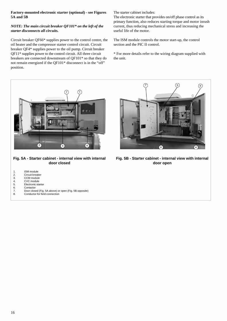
Fig. 5A - Starter cabinet - internal view with internaldoor closed
Fig. 5B - Starter cabinet - internal view with internaldoor open
1. ISM module2. Circuit breaker3. CCM module4. CVC module5. Electronic starter6. Contactor7. Door closed (Fig. 5A above) or open (Fig. 5B opposite)8. Conductor for field connection
Factory-mounted electronic starter (optional) - see Figures5A and 5B
NOTE: The main circuit breaker QF101* on the left of thestarter disconnects all circuits.
Circuit breaker QF66* supplies power to the control centre, theoil heater and the compressor starter control circuit. Circuitbreaker QF4* supplies power to the oil pump. Circuit breakerQF11* supplies power to the control circuit. All three circuitbreakers are connected downstream of QF101* so that they donot remain energized if the QF101* disconnect is in the “off”position.
The starter cabinet includes:The electronic starter that provides on/off phase control as itsprimary function, also reduces starting torque and motor inrushcurrent, thus reducing mechanical stress and increasing theuseful life of the motor.
The ISM module controls the motor start-up, the controlsection and the PIC II control.
* For more details refer to the wiring diagram supplied withthe unit.
17
3 - INSTALLATION
3.1 - Introduction
The 19XR machine is factory assembled, wired, leak testedand electrically tested. Installation (not by Carrier) consistsprimarily of establishing water and electrical services to themachine. The rigging, installation, field wiring, field piping,and insulation of waterbox covers are the responsibilty of thecontractor and/or customer.
3.2 - Receiving the machine
3.2.1 - Inspect shipment
CAUTION: Do not open any valves or loosen any connections.The standard 19XR machine is shipped with a full refrigerantcharge. Some machines may be shipped with a nitrogen holdingcharge as an option.
Inspect for shipping damage while machine is still onshipping conveyance. If machine appears to be damaged or hasbeen torn loose from its anchorage, have it examined bytransportation inspectors before removal. Forward claimpapers directly to transportation company. Manufacturer isnot responsible for any damage incurred in transit.
• Confirm that the unit received is the one ordered. Comparethe name plate data with the order.
• The unit name plate must include the followinginformation:- Version number- Model number- CE marking- Serial number- Year of manufacture and test date- Refrigerant used and refrigerant class- Refrigerant charge per circuit- Containment fluid to be used- PS: Min./max. allowable pressure (high and low
pressure side)- TS: Min./max. allowable temperature (high and low
pressure side)- Globe valve cut-out pressure- Pressure switch cut-out pressure- Unit leak test pressure- Voltage, frequency, number of phases- Maximum current drawn- Maximum power input- Unit net weight
High pressure Low pressureMin. Max. Min. Max.
PS (bar) -0.9 12.5 -0.9 12.5TS (°C) -20 48 -20 48Pressure switch cut-out pressure (bar) 11 -Valve cut-out pressure (bar) 12.5 12.5Test pressure, unit leak test (bar) 10
Check all items against shipping list. Immediately notify thenearest Carrier representative if any item is missing.
To prevent loss or damage (standard EN 378-2 11.22 k, annexA and B), leave all parts in original packages until beginninginstallation. All openings are closed with covers or plugs toprevent dirt and debris from entering machine componentsduring shipping. A full operating oil charge is placed in theoil sump before shipment.
3.2.2 - Provide machine protectionProtect machine and starter from construction dirt and moisture.Keep protective shipping covers in place until machine is readyfor installation.
Do not keep the 19XR units outside where they are exposed tothe weather, as the sensitive control mechanism and theelectronic modules may be damaged.
The unit must be checked periodically during its wholeoperating life to ensure that no shocks (handling accessories,tools etc.) have damaged it. If necessary, the damaged partsmust be repaired or replaced. See also chapter “Maintenance”.
If machine is exposed to freezing temperatures after watercircuits have been installed, open waterbox drains and removeall water from cooler and condenser. Leave drains open untilsystem is filled.
3.3 - Rigging the machine
The 19XR machine can be rigged as an entire assembly. It alsohas flanged connections that allow the compressor, cooler, andcondenser sections to be separated and rigged individually.
3.3.1 - Rigging the complete machineSee rigging instructions on label attached to machine. Also referto physical data and Tables 1 to 7 (chapter 3.3.3). Lift machineonly from the points indicated in the instructions supplied andin the machine rigging drawings. Each lifting cable or chainmust be capable of supporting the entire weight of the machine.
WARNING: Lifting machine from points other than thosespecified may result in serious damage to the unit and personalinjury. Rigging equipment and procedures must be adequatefor machine weight. See Tables 1 to 7 (chapter 3.3.3) formachine weights.
NOTE: These weights are broken down into componentsections for use when installing the unit in sections. For thecomplete machine weight, add all component sections andrefrigerant charge together. See Tables 1 to 7 (chapter 3.3.3)for machine component weights.
IMPORTANT: Make sure that rigging cable is over the riggingbar before lifting.
18
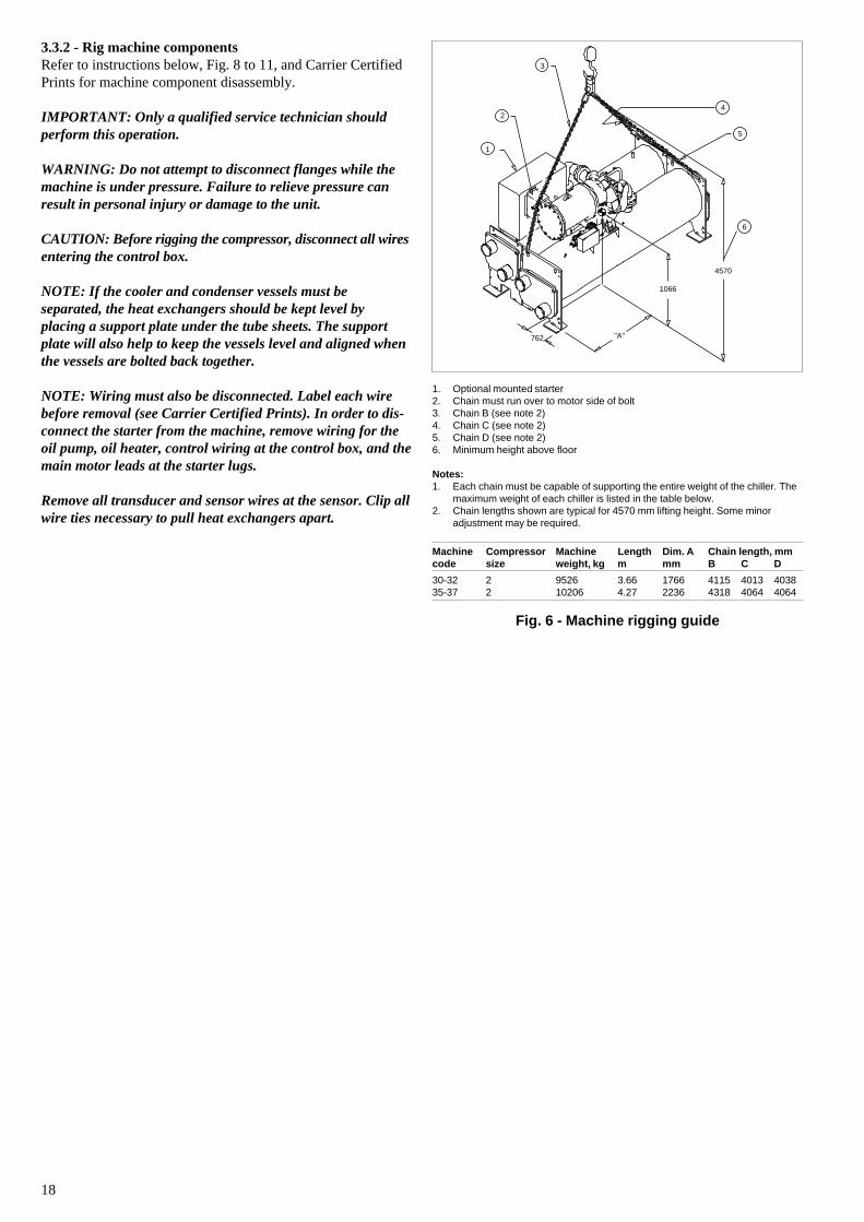
Fig. 6 - Machine rigging guide
1. Optional mounted starter2. Chain must run over to motor side of bolt3. Chain B (see note 2)4. Chain C (see note 2)5. Chain D (see note 2)6. Minimum height above floor
Notes:1. Each chain must be capable of supporting the entire weight of the chiller. The
maximum weight of each chiller is listed in the table below.2. Chain lengths shown are typical for 4570 mm lifting height. Some minor
adjustment may be required.
Machine Compressor Machine Length Dim. A Chain length, mmcode size weight, kg m mm B C D
30-32 2 9526 3.66 1766 4115 4013 403835-37 2 10206 4.27 2236 4318 4064 4064
3.3.2 - Rig machine componentsRefer to instructions below, Fig. 8 to 11, and Carrier CertifiedPrints for machine component disassembly.
IMPORTANT: Only a qualified service technician shouldperform this operation.
WARNING: Do not attempt to disconnect flanges while themachine is under pressure. Failure to relieve pressure canresult in personal injury or damage to the unit.
CAUTION: Before rigging the compressor, disconnect all wiresentering the control box.
NOTE: If the cooler and condenser vessels must beseparated, the heat exchangers should be kept level byplacing a support plate under the tube sheets. The supportplate will also help to keep the vessels level and aligned whenthe vessels are bolted back together.
NOTE: Wiring must also be disconnected. Label each wirebefore removal (see Carrier Certified Prints). In order to dis-connect the starter from the machine, remove wiring for theoil pump, oil heater, control wiring at the control box, and themain motor leads at the starter lugs.
Remove all transducer and sensor wires at the sensor. Clip allwire ties necessary to pull heat exchangers apart.
1
2
3
4
5
6
762 "A"
1066
4570
19
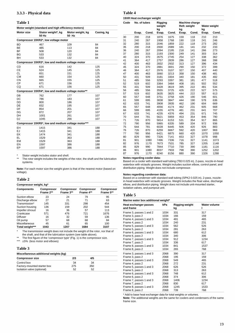
3.3.3 - Physical data
Table 1Motor weight (standard and high efficiency motors)
Motor size Stator weight*, kg Motor weight, kg Casing, kg50 Hz 50 Hz
Compressor 19XR2*, low voltage motor
BD 467 109 84BE 485 113 84BF 508 120 84BG 533 132 84BH 533 132 84
Compressor 19XR3*, low and medium voltage motor
CD 616 142 125CE 624 145 125CL 651 151 125CM 660 154 125CN 665 155 125CP 671 156 125CQ 671 156 125
Compressor 19XR4*, low and medium voltage motor**
DB 762 177 107DC 786 183 107DD 800 186 107DE 832 195 107DF 854 201 107DG 872 207 107DH 1001 261 107DJ 1045 266 107
Compressor 19XR5*, low and medium voltage motor***
EH 1415 341 188EJ 1415 341 188EK 1474 341 188EL 1529 363 188EM 1529 363 188EN 1597 386 188EP 1597 386 188
* Stator weight includes stator and shell.** The rotor weight includes the weights of the rotor, the shaft and the lubrication
systems.
Note: For each motor size the weight given is that of the nearest motor (based onvoltage).
Table 2Compressor weight, kg*
Components Compressor Compressor Compressor CompressorFrame 2** Frame 3** Frame 4** Frame 5**
Suction elbow 23 24 79 95Discharge elbow 27 21 71 63Transmission* 145 331 298 454Suction housing 136 159 202 544Impeller shroud 16 36 57 113Crankcase 571 476 721 1676Diffuser 16 32 59 136Oil pump 57 68 68 84Miscellaneous 45 61 65 100Total weight*** 1043 1207 1684 3107
* The transmission weight does not include the weight of the rotor, nor that ofthe shaft, and that of the lubrication system (see table above).
** The first figure of the 'compressor type' (Fig. 1) is the compressor size.*** ±5% (less motor and elbows)
Table 3Miscellaneous additional weights (kg)
Compressor size 2/3 4/5
Control box 34 34Factory-mounted starter box 275 350Isolation valve (optional) 52 52
Table 419XR Heat exchanger weight
Code No. of tubes Rigging Machine chargeweight Refr. weight Water weightkg kg kg
Evap. Cond. Evap. Cond. Evap. Cond. Evap. Cond.
30 200 218 1876 1675 159 118 210 21031 240 267 1958 1768 190 118 241 24632 280 315 2046 1859 222 118 273 28235 200 218 2000 2089 181 141 232 23336 240 267 2094 2195 218 141 266 27337 280 315 2193 2300 249 141 303 31440 324 370 2675 2745 254 127 338 36241 364 417 2757 2839 286 127 368 39842 400 463 2832 2932 313 127 396 43445 324 370 2881 3001 290 150 372 39946 364 417 2976 3107 327 150 407 44047 400 463 3060 3213 358 150 438 48150 431 509 3181 3304 340 181 435 48251 485 556 3293 3397 381 181 477 51852 519 602 3364 3484 408 181 502 55255 431 509 3428 3619 395 222 481 53456 485 556 3555 3725 426 222 527 57557 519 602 3635 3825 444 222 557 61360 557 648 3751 3758 426 190 546 60161 599 695 3838 3847 444 190 578 63662 633 741 3908 3935 462 190 604 66965 557 648 4056 4174 462 231 605 66866 599 695 4155 4276 481 231 641 70767 633 741 4235 4376 494 231 671 74570 644 781 5621 5959 453 354 846 79071 726 870 5814 6153 531 354 917 86572 790 956 5965 6335 589 334 972 93675 644 781 6028 6445 506 420 926 88376 726 870 6259 6667 592 420 1007 96977 790 956 6421 6875 660 420 1070 105080 829 990 7326 7141 653 327 1078 99881 901 1080 7496 7336 716 327 1141 107382 976 1170 7673 7531 785 327 1205 114885 829 990 7844 7710 730 390 1181 111686 901 1080 8037 7933 798 390 1252 120287 976 1170 8240 8156 880 390 1326 1288
Notes regarding cooler data:Based on a cooler with standard wall tubing (TB3 0.025 in), 2-pass, nozzle-in-headwaterbox with victaulic grooves. Weight includes suction elbow, control panel, anddistribution piping. Weight does not include compressor.
Notes regarding condenser data:Based on a condenser with standard wall tubing (SPK2 0.025 in), 2-pass, nozzle-in-head waterbox with victaulic grooves. Weight includes the float valve, dischargeelbow, and distribution piping. Weight does not include unit-mounted starter,isolation valves, and pumpout unit.
Table 5Marine water box additional weight*
Heat exchanger passes kPa Rigging weight Water volumeand frame kg l
Frame 3, passes 1 and 2 1034 331 317Frame 3, pass 2 1034 166 159Frame 4, passes 1 and 3 1034 481 465Frame 4, pass 2 1034 240 231Frame 5, passes 1 and 3 1034 562 526Frame 5, pass 2 1034 281 263Frame 6, passes 1 and 3 1034 680 612Frame 6, pass 2 1034 340 306Frame 7, passes 1 and 3 1034 912 1234Frame 7, pass 2 1034 336 617Frame 8, passes 1 and 3 1034 841 1537Frame 8, pass 2 1034 265 768
Frame 3, passes 1 and 3 2068 390 317Frame 3, pass 2 2068 195 159Frame 4, passes 1 and 3 2068 549 465Frame 4, pass 2 2068 272 231Frame 5, passes 1 and 3 2068 626 526Frame 5, pass 2 2068 313 263Frame 6, passes 1 and 3 2068 748 612Frame 6, pass 2 2068 374 306Frame 7, passes 1 and 3 2068 1406 1234Frame 7, pass 2 2068 830 617Frame 8, passes 1 and 3 2068 1245 1533Frame 8, pass 2 2068 739 768
* Add to base heat exchanger data for total weights or volumes.Note: The additional weights are the same for coolers and condensers of the sameframe size.
20
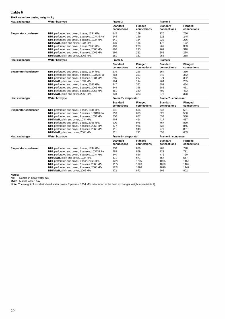
Table 619XR water box casing weights, kg
Heat exchanger Water box type Frame 3 Frame 4
Standard Flanged Standard Flangedconnections connections connectiions connections
Evaporator/condenser NIH, perforated end cover, 1 pass, 1034 kPa 145 159 220 236NIH, perforated end cover, 2 passes, 10343 kPa 145 159 221 245NIH, perforated end cover, 3 passes, 1034 kPa 141 154 229 236NIH/MWB, plain end cover, 1034 kPa 136 136 172 172NIH, perforated end cover, 1 pass, 2068 kPa 186 220 269 303NIH, perforated end cover, 2 passes, 2068 kPa 186 235 269 318NIH, perforated end cover, 3 passes, 2068 kPa 196 212 282 298NIH/MWB, plain end cover, 2068 kPa 181 181 258 258
Heat exchanger Water box type Frame 5 Frame 6
Standard Flanged Standard Flangedconnections connections connectiions connections
Evaporator/condenser NIH, perforated end cover, 1 pass, 1034 kPa 279 296 364 380NIH, perforated end cover, 2 passes, 10343 kPa 268 301 349 382NIH, perforated end cover, 3 passes, 1034 kPa 285 297 371 382NIH/MWB, plain end cover, 1034 kPa 194 194 264 265NIH, perforated end cover, 1 pass, 2068 kPa 347 381 399 434NIH, perforated end cover, 2 passes, 2068 kPa 345 398 383 451NIH, perforated end cover, 3 passes, 2068 kPa 361 380 409 432NIH/MWB, plain end cover, 2068 kPa 323 323 378 378
Heat exchanger Water box type Frame 7 - evaporator Frame 7 - condenser
Standard Flanged Standard Flangedconnections connections connectiions connections
Evaporator/condenser NIH, perforated end cover, 1 pass, 1034 kPa 631 666 547 581NIH, perforated end cover, 2 passes, 10343 kPa 610 663 528 580NIH, perforated end cover, 3 passes, 1034 kPa 650 667 554 580NIH/MWB, plain end cover, 1034 kPa 464 464 417 417NIH, perforated end cover, 1 pass, 2068 kPa 900 975 767 839NIH, perforated end cover, 2 passes, 2068 kPa 877 986 738 845NIH, perforated end cover, 3 passes, 2068 kPa 911 948 777 831NIH/MWB, plain end cover, 2068 kPa 711 711 653 653
Heat exchanger Water box type Frame 8 - evaporator Frame 8 - condenser
Standard Flanged Standard Flangedconnections connections connectiions connections
Evaporator/condenser NIH, perforated end cover, 1 pass, 1034 kPa 830 866 763 798NIH, perforated end cover, 2 passes, 10343 kPa 789 859 721 791NIH, perforated end cover, 3 passes, 1034 kPa 840 866 772 799NIH/MWB, plain end cover, 1034 kPa 671 671 557 557NIH, perforated end cover, 1 pass, 2068 kPa 1220 1295 1085 1156NIH, perforated end cover, 2 passes, 2068 kPa 1177 1326 1029 1169NIH, perforated end cover, 3 passes, 2068 kPa 1224 1298 1096 1147NIH/MWB, plain end cover, 2068 kPa 872 872 802 802
Notes:NIH Nozzle-in-head water boxMWB Marine water boxNote: The weight of nozzle-in-head water boxes, 2 passes, 1034 kPa is included in the heat exchanger weights (see table 4).
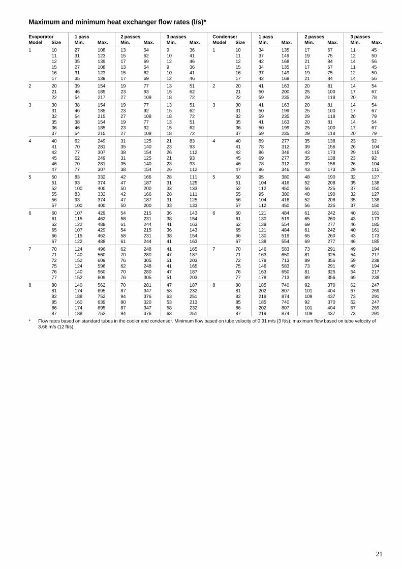
21
Maximum and minimum heat exchanger flow rates (l/s)*
Evaporator 1 pass 2 passes 3 passes Condenser 1 pass 2 passes 3 passesModel Size Min. Max. Min. Max. Min. Max. Model Size Min. Max. Min. Max. Min. Max.
1 10 27 108 13 54 9 36 1 10 34 135 17 67 11 4511 31 123 15 62 10 41 11 37 149 19 75 12 5012 35 139 17 69 12 46 12 42 168 21 84 14 5615 27 108 13 54 9 36 15 34 135 17 67 11 4516 31 123 15 62 10 41 16 37 149 19 75 12 5017 35 139 17 69 12 46 17 42 168 21 84 14 56
2 20 39 154 19 77 13 51 2 20 41 163 20 81 14 5421 46 185 23 93 15 62 21 50 200 25 100 17 6722 54 217 27 109 18 72 22 59 235 29 118 20 78
3 30 38 154 19 77 13 51 3 30 41 163 20 81 14 5431 46 185 23 92 15 62 31 50 199 25 100 17 6732 54 215 27 108 18 72 32 59 235 29 118 20 7935 38 154 19 77 13 51 35 41 163 20 81 14 5436 46 185 23 92 15 62 36 50 199 25 100 17 6737 54 215 27 108 18 72 37 59 235 29 118 20 79
4 40 62 249 31 125 21 83 4 40 69 277 35 138 23 9241 70 281 35 140 23 93 41 78 312 39 156 26 10442 77 307 38 154 26 112 42 86 346 43 173 29 11545 62 249 31 125 21 93 45 69 277 35 138 23 9246 70 281 35 140 23 93 46 78 312 39 156 26 10447 77 307 38 154 26 112 47 86 346 43 173 29 115
5 50 83 332 42 166 28 111 5 50 95 380 48 190 32 12751 93 374 47 187 31 125 51 104 416 52 208 35 13852 100 400 50 200 33 133 52 112 450 56 225 37 15055 83 332 42 166 28 111 55 95 380 48 190 32 12756 93 374 47 187 31 125 56 104 416 52 208 35 13857 100 400 50 200 33 133 57 112 450 56 225 37 150
6 60 107 429 54 215 36 143 6 60 121 484 61 242 40 16161 115 462 58 231 38 154 61 130 519 65 260 43 17362 122 488 61 244 41 163 62 138 554 69 277 46 18565 107 429 54 215 36 143 65 121 484 61 242 40 16166 115 462 58 231 38 154 66 130 519 65 260 43 17367 122 488 61 244 41 163 67 138 554 69 277 46 185
7 70 124 496 62 248 41 165 7 70 146 583 73 291 49 19471 140 560 70 280 47 187 71 163 650 81 325 54 21772 152 609 76 305 51 203 72 178 713 89 356 59 23875 124 596 62 248 41 165 75 146 583 73 291 49 19476 140 560 70 280 47 187 76 163 650 81 325 54 21777 152 609 76 305 51 203 77 178 713 89 356 69 238
8 80 140 562 70 281 47 187 8 80 185 740 92 370 62 24781 174 695 87 347 58 232 81 202 807 101 404 67 26982 188 752 94 376 63 251 82 219 874 109 437 73 29185 160 639 80 320 53 213 85 185 740 92 370 62 24786 174 695 87 347 58 232 86 202 807 101 404 67 26987 188 752 94 376 63 251 87 219 874 109 437 73 291
* Flow rates based on standard tubes in the cooler and condenser. Minimum flow based on tube velocity of 0,91 m/s (3 ft/s); maximum flow based on tube velocity of3.66 m/s (12 ft/s).
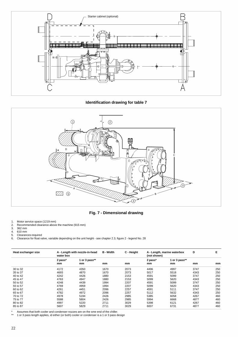
22
Identification drawing for table 7
Fig. 7 - Dimensional drawing
1. Motor service space (1219 mm)2. Recommended clearance above the machine (915 mm)3. 362 mm4. 610 mm5. Clearances required6. Clearance for float valve, variable depending on the unit height - see chapter 2.3, figure 2 - legend No. 28
Starter cabinet (optional)
Heat exchanger size A - Length with nozzle-in-head B - Width C - Height A - Length, marine waterbox D Ewater box (not shown)
2 pass* 1 or 3 pass** 2 pass* 1 or 3 pass**mm mm mm mm mm mm mm mm
30 to 32 4172 4350 1670 2073 4496 4997 3747 25035 to 37 4693 4870 1670 2073 5017 5518 4343 25040 to 42 4242 4426 1880 2153 4591 5099 3747 25045 to 47 4763 4947 1880 2153 5099 5620 4343 25050 to 52 4248 4439 1994 2207 4591 5099 3747 25055 to 57 4769 4959 1994 2207 5099 5620 4343 25060 to 62 4261 4451 2096 2257 4591 5111 3747 25065 to 67 4782 4972 2096 2257 5112 5632 4343 25070 to 72 4978 5194 2426 2985 5385 6058 4267 46075 to 77 5588 5804 2426 2985 5994 6668 4877 46080 to 82 4997 5220 2711 3029 5398 6121 4267 46085 to 87 5607 5829 2711 3029 6007 6731 4877 460
* Assumes that both cooler and condenser nozzes are on the sme end of the chiller.** 1 or 3 pass length applies, id either (or both) cooler or condenser is a 1 or 3 pass design
D
1 2
3
5
4
A
B
C
E
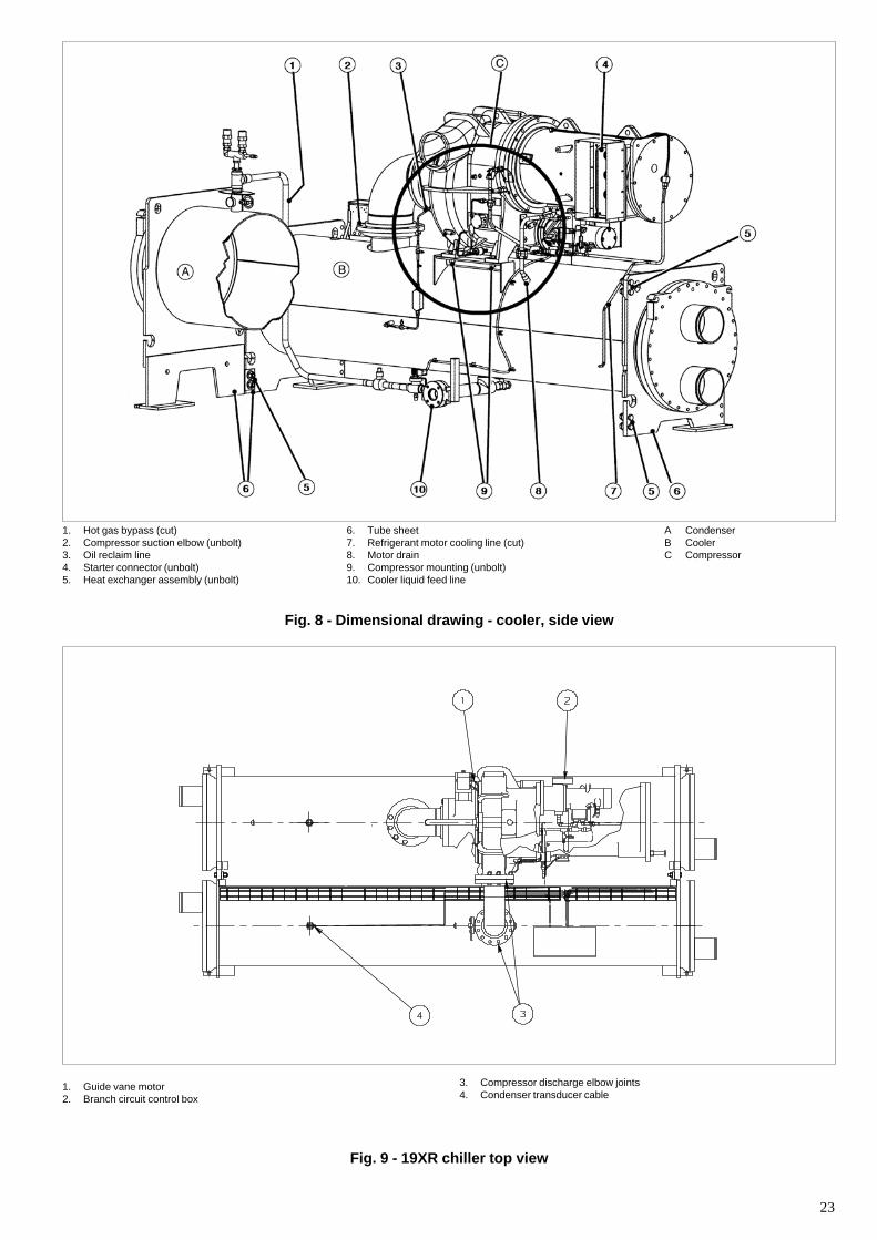
23
1. Hot gas bypass (cut)2. Compressor suction elbow (unbolt)3. Oil reclaim line4. Starter connector (unbolt)5. Heat exchanger assembly (unbolt)
6. Tube sheet7. Refrigerant motor cooling line (cut)8. Motor drain9. Compressor mounting (unbolt)10. Cooler liquid feed line
Fig. 8 - Dimensional drawing - cooler, side view
1. Guide vane motor2. Branch circuit control box
3. Compressor discharge elbow joints4. Condenser transducer cable
Fig. 9 - 19XR chiller top view
A CondenserB CoolerC Compressor
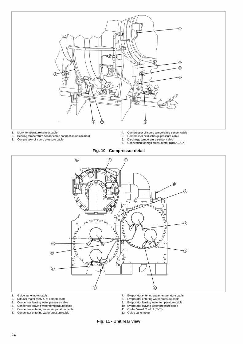
24
1. Motor temperature sensor cable2. Bearing temperature sensor cable connection (inside box)3. Compressor oil sump pressure cable
4. Compressor oil sump temperature sensor cable5. Compressor oil discharge pressure cable6. Discharge temperature sensor cable7. Connection for high pressurestat (DBK/SDBK)
Fig. 10 - Compressor detail
1. Guide vane motor cable2. Diffuser motor (only XR5 compressor)3. Condenser leaving water pressure cable4. Condenser leaving water temperature cable5. Condenser entering water temperature cable6. Condenser entering water pressure cable
12 1 2
10
9
8
7 6
5
4
3
11
Fig. 11 - Unit rear view
7. Evaporator entering water temperature cable8. Evaporator entering water pressure cable9. Evaporator leaving water temperature cable10. Evaporator leaving water pressure cable11. Chiller Visual Control (CVC)12. Guide vane motor
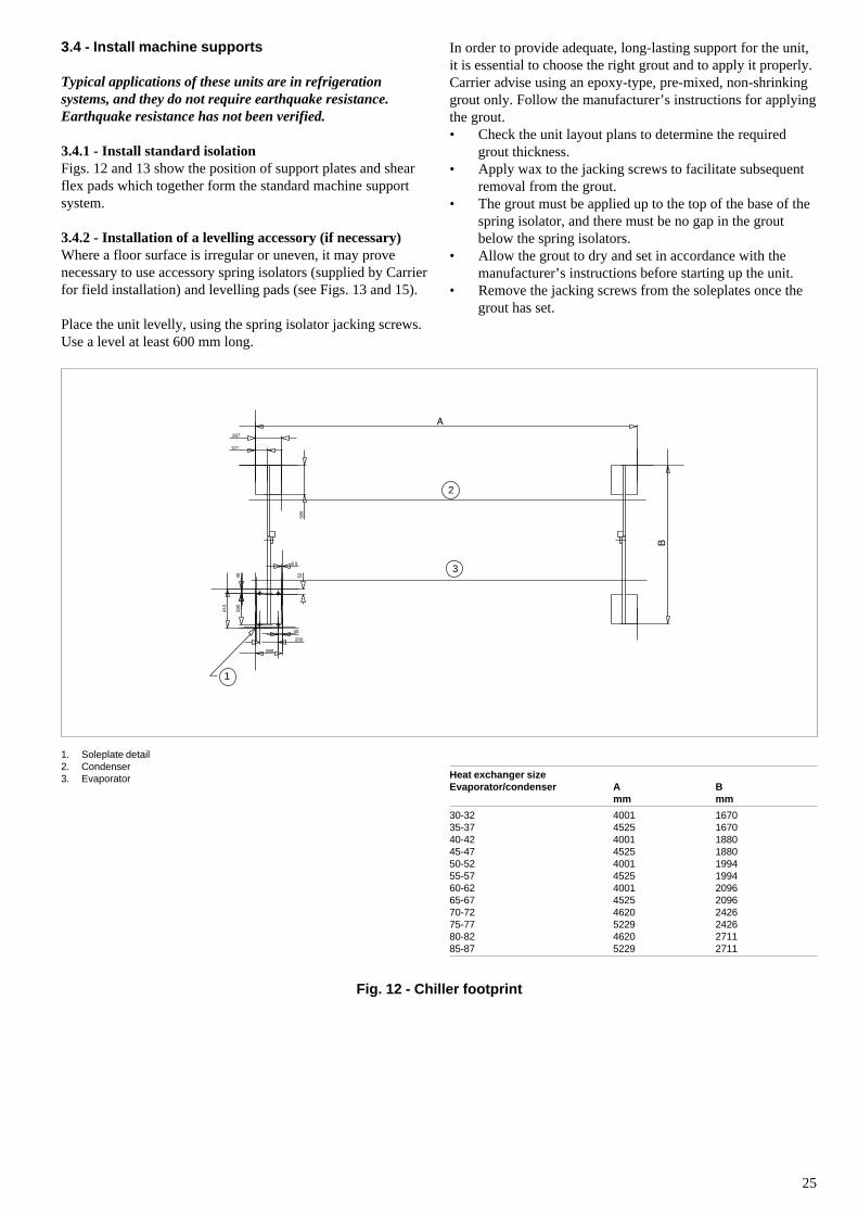
25
3
2
1
3.4 - Install machine supports
Typical applications of these units are in refrigerationsystems, and they do not require earthquake resistance.Earthquake resistance has not been verified.
3.4.1 - Install standard isolationFigs. 12 and 13 show the position of support plates and shearflex pads which together form the standard machine supportsystem.
3.4.2 - Installation of a levelling accessory (if necessary)Where a floor surface is irregular or uneven, it may provenecessary to use accessory spring isolators (supplied by Carrierfor field installation) and levelling pads (see Figs. 13 and 15).
Place the unit levelly, using the spring isolator jacking screws.Use a level at least 600 mm long.
In order to provide adequate, long-lasting support for the unit,it is essential to choose the right grout and to apply it properly.Carrier advise using an epoxy-type, pre-mixed, non-shrinkinggrout only. Follow the manufacturer’s instructions for applyingthe grout.• Check the unit layout plans to determine the required
grout thickness.• Apply wax to the jacking screws to facilitate subsequent
removal from the grout.• The grout must be applied up to the top of the base of the
spring isolator, and there must be no gap in the groutbelow the spring isolators.
• Allow the grout to dry and set in accordance with themanufacturer’s instructions before starting up the unit.
• Remove the jacking screws from the soleplates once thegrout has set.
1. Soleplate detail2. Condenser3. Evaporator Heat exchanger size
Evaporator/condenser A Bmm mm
30-32 4001 167035-37 4525 167040-42 4001 188045-47 4525 188050-52 4001 199455-57 4525 199460-62 4001 209665-67 4525 209670-72 4620 242675-77 5229 242680-82 4620 271185-87 5229 2711
Fig. 12 - Chiller footprint
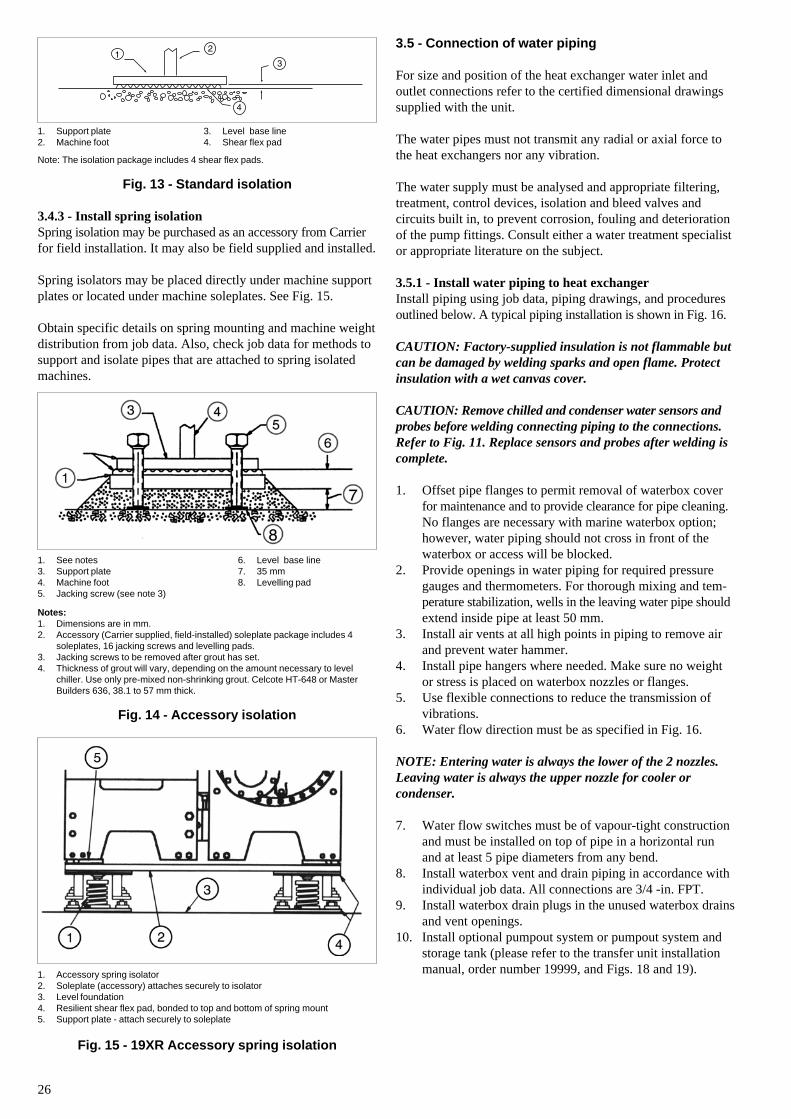
26
Note: The isolation package includes 4 shear flex pads.
Fig. 13 - Standard isolation
3.4.3 - Install spring isolationSpring isolation may be purchased as an accessory from Carrierfor field installation. It may also be field supplied and installed.
Spring isolators may be placed directly under machine supportplates or located under machine soleplates. See Fig. 15.
Obtain specific details on spring mounting and machine weightdistribution from job data. Also, check job data for methods tosupport and isolate pipes that are attached to spring isolatedmachines.
Notes:1. Dimensions are in mm.2. Accessory (Carrier supplied, field-installed) soleplate package includes 4
soleplates, 16 jacking screws and levelling pads.3. Jacking screws to be removed after grout has set.4. Thickness of grout will vary, depending on the amount necessary to level
chiller. Use only pre-mixed non-shrinking grout. Celcote HT-648 or MasterBuilders 636, 38.1 to 57 mm thick.
Fig. 14 - Accessory isolation
3. Level base line4. Shear flex pad
1. Support plate2. Machine foot
1. See notes3. Support plate4. Machine foot5. Jacking screw (see note 3)
6. Level base line7. 35 mm8. Levelling pad
1. Accessory spring isolator2. Soleplate (accessory) attaches securely to isolator3. Level foundation4. Resilient shear flex pad, bonded to top and bottom of spring mount5. Support plate - attach securely to soleplate
Fig. 15 - 19XR Accessory spring isolation
3.5 - Connection of water piping
For size and position of the heat exchanger water inlet andoutlet connections refer to the certified dimensional drawingssupplied with the unit.
The water pipes must not transmit any radial or axial force tothe heat exchangers nor any vibration.
The water supply must be analysed and appropriate filtering,treatment, control devices, isolation and bleed valves andcircuits built in, to prevent corrosion, fouling and deteriorationof the pump fittings. Consult either a water treatment specialistor appropriate literature on the subject.
3.5.1 - Install water piping to heat exchangerInstall piping using job data, piping drawings, and proceduresoutlined below. A typical piping installation is shown in Fig. 16.
CAUTION: Factory-supplied insulation is not flammable butcan be damaged by welding sparks and open flame. Protectinsulation with a wet canvas cover.
CAUTION: Remove chilled and condenser water sensors andprobes before welding connecting piping to the connections.Refer to Fig. 11. Replace sensors and probes after welding iscomplete.
1. Offset pipe flanges to permit removal of waterbox coverfor maintenance and to provide clearance for pipe cleaning.No flanges are necessary with marine waterbox option;however, water piping should not cross in front of thewaterbox or access will be blocked.
2. Provide openings in water piping for required pressuregauges and thermometers. For thorough mixing and tem-perature stabilization, wells in the leaving water pipe shouldextend inside pipe at least 50 mm.
3. Install air vents at all high points in piping to remove airand prevent water hammer.
4. Install pipe hangers where needed. Make sure no weightor stress is placed on waterbox nozzles or flanges.
5. Use flexible connections to reduce the transmission ofvibrations.
6. Water flow direction must be as specified in Fig. 16.
NOTE: Entering water is always the lower of the 2 nozzles.Leaving water is always the upper nozzle for cooler orcondenser.
7. Water flow switches must be of vapour-tight constructionand must be installed on top of pipe in a horizontal runand at least 5 pipe diameters from any bend.
8. Install waterbox vent and drain piping in accordance withindividual job data. All connections are 3/4 -in. FPT.
9. Install waterbox drain plugs in the unused waterbox drainsand vent openings.
10. Install optional pumpout system or pumpout system andstorage tank (please refer to the transfer unit installationmanual, order number 19999, and Figs. 18 and 19).
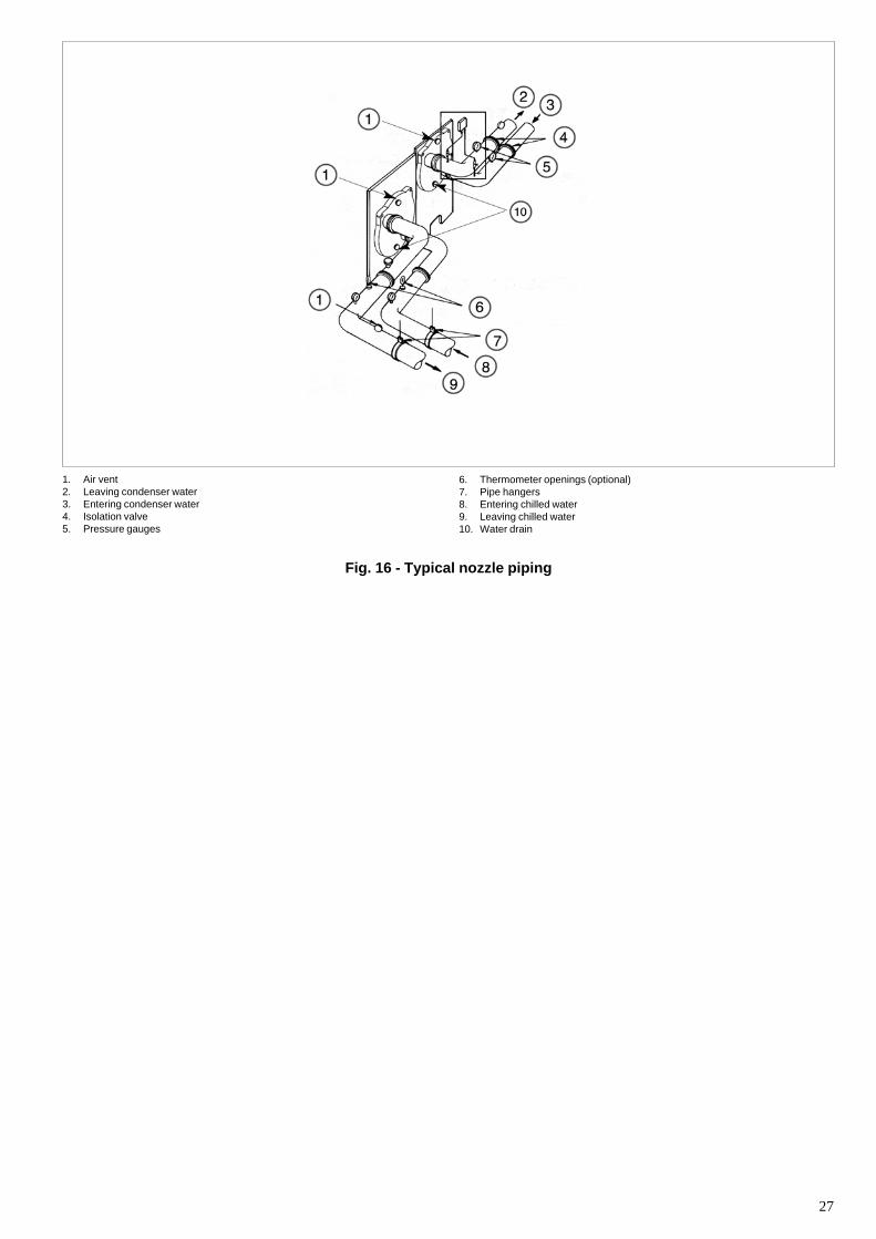
27
1. Air vent2. Leaving condenser water3. Entering condenser water4. Isolation valve5. Pressure gauges
Fig. 16 - Typical nozzle piping
6. Thermometer openings (optional)7. Pipe hangers8. Entering chilled water9. Leaving chilled water10. Water drain
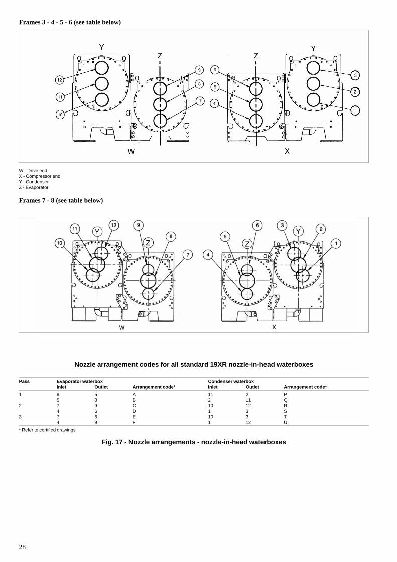
28
Frames 3 - 4 - 5 - 6 (see table below)
W - Drive endX - Compressor endY - CondenserZ - Evaporator
Frames 7 - 8 (see table below)
Nozzle arrangement codes for all standard 19XR nozzle-in-head waterboxes
Pass Evaporator waterbox Condenser waterboxInlet Outlet Arrangement code* Inlet Outlet Arrangement code*
1 8 5 A 11 2 P5 8 B 2 11 Q
2 7 9 C 10 12 R4 6 D 1 3 S
3 7 6 E 10 3 T4 9 F 1 12 U
* Refer to certified drawings
Fig. 17 - Nozzle arrangements - nozzle-in-head waterboxes
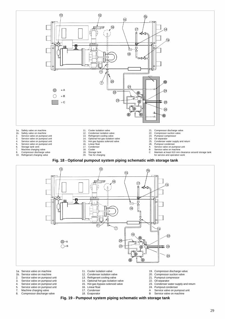
29
1a. Safety valve on machine1b. Safety valve on machine2. Service valve on pumpout unit3. Service valve on pumpout unit4. Service valve on pumpout unit5. Service valve on pumpout unit6. Storage tank vent7. Machine charging valve8. Compressor discharge valve10. Refrigerant charging valve
11. Cooler isolation valve12. Condenser isolation valve13. Refrigerant cooling valve14. Optional hot gas isolation valve15. Hot gas bypass solenoid valve16. Linear float17. Condenser18. Cooler19. Storage tank20. Tee for charging
21. Compressor discharge valve22. Compressor suction valve23. Pumpout compressor24. Oil separator25. Condenser water supply and return26. Pumpout condenserA Service valve on pumpout unitB Service valve on machineC Maintain at least 610 mm clearance around storage tank
for service and operation work
Fig. 18 - Optional pumpout system piping schematic with storage tank
1a. Service valve on machine1b. Service valve on machine2. Service valve on pumpout unit3. Service valve on pumpout unit4. Service valve on pumpout unit5. Service valve on pumpout unit7. Machine charging valve8. Compressor discharge valve
11. Cooler isolation valve12. Condenser isolation valve13. Refrigerant cooling valve14. Optional hot gas isolation valve15. Hot gas bypass solenoid valve16. Linear float17. Condenser18. Evaporator
19. Compressor discharge valve20. Compressor suction valve21. Pumpout compressor22. Oil separator23. Condenser water supply and return24. Pumpout condenserA Service valve on pumpout unitB Service valve on machine
Fig. 19 - Pumpout system piping schematic with storage tank
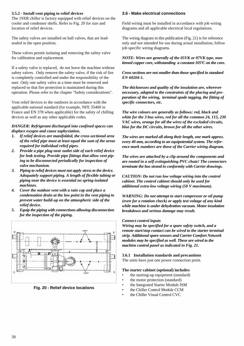
30
3.5.2 - Install vent piping to relief devicesThe 19XR chiller is factory equipped with relief devices on thecooler and condenser shells. Refer to Fig. 20 for size andlocation of relief devices.
The safety valves are installed on ball valves, that are lead-sealed in the open position.
These valves permit isolating and removing the safety valvefor calibration and replacement.
If a safety valve is replaced, do not leave the machine withoutsafety valves. Only remove the safety valve, if the risk of fireis completely controlled and under the responsibility of theuser. Only one safety valve at a time must be removed andreplaced so that fire protection is maintained during thisoperation. Please refer to the chapter "Safety considerations".
Vent relief devices to the outdoors in accordance with theapplicable national standard (for example, NFE 35400 inFrance and EN 378 when applicable) for the safety of chillingdevices as well as any other applicable codes.
DANGER: Refrigerant discharged into confined spaces candisplace oxygen and cause asphyxiation.1. If relief devices are manifolded, the cross-sectional area
of the relief pipe must at least equal the sum of the areasrequired for individual relief pipes.
2. Provide a pipe plug near outlet side of each relief devicefor leak testing. Provide pipe fittings that allow vent pip-ing to be disconnected periodically for inspection ofvalve mechanism.
3. Piping to relief devices must not apply stress to the device.Adequately support piping. A length of flexible tubing orpiping near the device is essential on spring-isolatedmachines.
4. Cover the outdoor vent with a rain cap and place acondensation drain at the low point in the vent piping toprevent water build-up on the atmospheric side of therelief device.
5. Equip the piping with connections allowing disconnectionfor the inspection of the piping.
3.6 - Make electrical connections
Field wiring must be installed in accordance with job wiringdiagrams and all applicable electrical local regulations.
The wiring diagram in this publication (Fig. 21) is for referenceonly and not intended for use during actual installation; followjob specific wiring diagrams.
NOTE: Wires are generally of the 05VK or 07VK type, non-tinned copper core, withstanding a constant 105ºC on the core.
Cross sections are not smaller than those specified in standardEN 60204-1.
The thicknesses and quality of the insulation are, wherevernecessary, adapted to the constraints of the placing and pre-paration of the wiring, terminal spade tagging, the fitting ofspecific connectors, etc.
The wire colours are generally as follows: red, black andwhite for the 3 bus wires, red for all the common 24, 115, 230VAC wires, orange for all the wires of the excluded circuits,blue for the DC circuits, brown for all the other wires.
The wires are marked all along their length, one mark approx.every 40 mm, according to an equipotential system. The refer-ence mark numbers are those of the Carrier wiring diagram.
The wires are attached by a clip around the components andare routed in a self-extinguishing PVC chute! The connectorsterminate the bus strand in conformity with Carrier drawings.
CAUTION: Do not run low voltage wiring into the controlcabinet. The control cabinet should only be used foradditional extra-low voltage wiring (50 V maximum).
WARNING: Do not attempt to start compressor or oil pump(even for a rotation check) or apply test voltage of any kindwhile machine is under dehydration vacuum. Motor insulationbreakdown and serious damage may result.
Connect control inputsWiring may be specified for a spare safety switch, and aremote start/stop contact can be wired to the starter terminalstrip. Additional spare sensors and Carrier Comfort Networkmodules may be specified as well. These are wired to themachine control panel as indicated in Fig. 21.
3.6.1 Installation standards and precautionsThe units have just one power connection point.
The starter cabinet (optional) includes:• the starting-up equipment (standard)• the motor protection (standard)• the Integrated Starter Module ISM• the Chiller Control Module CCM• the Chiller Visual Control CVC
Fig. 20 - Relief device locations
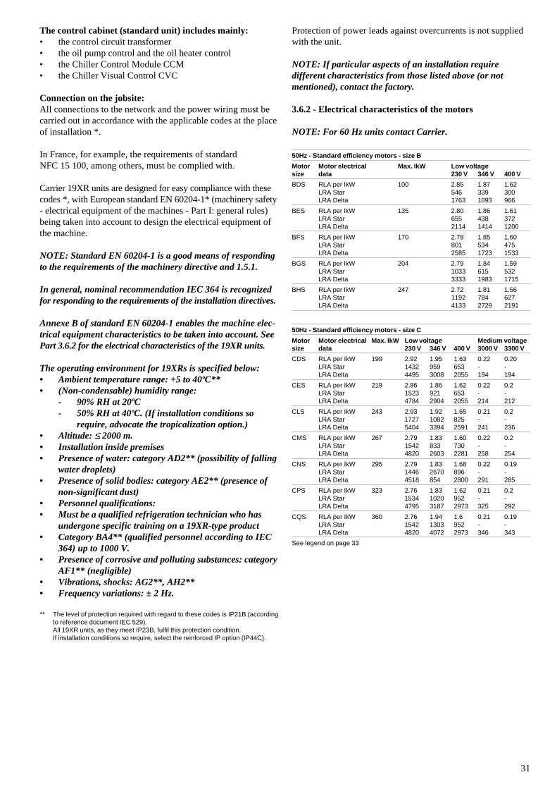
31
The control cabinet (standard unit) includes mainly:• the control circuit transformer• the oil pump control and the oil heater control• the Chiller Control Module CCM• the Chiller Visual Control CVC
Connection on the jobsite:All connections to the network and the power wiring must becarried out in accordance with the applicable codes at the placeof installation *.
In France, for example, the requirements of standardNFC 15 100, among others, must be complied with.
Carrier 19XR units are designed for easy compliance with thesecodes *, with European standard EN 60204-1* (machinery safety- electrical equipment of the machines - Part I: general rules)being taken into account to design the electrical equipment ofthe machine.
NOTE: Standard EN 60204-1 is a good means of respondingto the requirements of the machinery directive and 1.5.1.
In general, nominal recommendation IEC 364 is recognizedfor responding to the requirements of the installation directives.
Annexe B of standard EN 60204-1 enables the machine elec-trical equipment characteristics to be taken into account. SeePart 3.6.2 for the electrical characteristics of the 19XR units.
The operating environment for 19XRs is specified below:• Ambient temperature range: +5 to 40ºC**• (Non-condensable) humidity range:
- 90% RH at 20ºC- 50% RH at 40ºC. (If installation conditions so
require, advocate the tropicalization option.)• Altitude: � 2000 m.• Installation inside premises• Presence of water: category AD2** (possibility of falling
water droplets)• Presence of solid bodies: category AE2** (presence of
non-significant dust)• Personnel qualifications:• Must be a qualified refrigeration technician who has
undergone specific training on a 19XR-type product• Category BA4** (qualified personnel according to IEC
364) up to 1000 V.• Presence of corrosive and polluting substances: category
AF1** (negligible)• Vibrations, shocks: AG2**, AH2**• Frequency variations: ± 2 Hz.
** The level of protection required with regard to these codes is IP21B (accordingto reference document IEC 529).All 19XR units, as they meet IP23B, fulfil this protection condition.If installation conditions so require, select the reinforced IP option (IP44C).
Protection of power leads against overcurrents is not suppliedwith the unit.
NOTE: If particular aspects of an installation requiredifferent characteristics from those listed above (or notmentioned), contact the factory.
3.6.2 - Electrical characteristics of the motors
NOTE: For 60 Hz units contact Carrier.
50Hz - Standard efficiency motors - size B
Motor Motor electrical Max. IkW Low voltagesize data 230 V 346 V 400 V
BDS RLA per IkW 100 2.85 1.87 1.62LRA Star 546 339 300LRA Delta 1763 1093 966
BES RLA per IkW 135 2.80 1.86 1.61LRA Star 655 438 372LRA Delta 2114 1414 1200
BFS RLA per IkW 170 2.78 1.85 1.60LRA Star 801 534 475LRA Delta 2585 1723 1533
BGS RLA per IkW 204 2.79 1.84 1.59LRA Star 1033 615 532LRA Delta 3333 1983 1715
BHS RLA per IkW 247 2.72 1.81 1.56LRA Star 1192 784 627LRA Delta 4133 2729 2191
50Hz - Standard efficiency motors - size C
Motor Motor electrical Max. IkW Low voltage Medium voltagesize data 230 V 346 V 400 V 3000 V 3300 V
CDS RLA per IkW 199 2.92 1.95 1.63 0.22 0.20LRA Star 1432 959 653 - -LRA Delta 4495 3008 2055 194 194
CES RLA per IkW 219 2.86 1.86 1.62 0.22 0.2LRA Star 1523 921 653 - -LRA Delta 4784 2904 2055 214 212
CLS RLA per IkW 243 2.93 1.92 1.65 0.21 0.2LRA Star 1727 1082 825 - -LRA Delta 5404 3394 2591 241 236
CMS RLA per IkW 267 2.79 1.83 1.60 0.22 0.2LRA Star 1542 833 730 - -LRA Delta 4820 2603 2281 258 254
CNS RLA per IkW 295 2.79 1.83 1.68 0.22 0.19LRA Star 1446 2670 896 - -LRA Delta 4518 854 2800 291 285
CPS RLA per IkW 323 2.76 1.83 1.62 0.21 0.2LRA Star 1534 1020 952 - -LRA Delta 4795 3187 2973 325 292
CQS RLA per IkW 360 2.76 1.94 1.6 0.21 0.19LRA Star 1542 1303 952 - -LRA Delta 4820 4072 2973 346 343
See legend on page 33
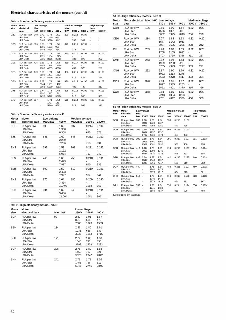
32
Electrical characteristics of the motors (cont'd)
50 Hz - Standard efficiency motors - size D
Motor Motor Low voltage Medium voltage High voltagesize electrical Max. Max. Max.
data IkW 230 V 346 V 400 V IkW 3000 V 3300 V IkW 6300 V
DBS RLA per IkW 340 2.70 1.79 1.55 339 0.218 0.197 - -LRA Star 1679 1160 963 - - - -LRA Delta 5468 3776 3142 332 301 - -
DCS RLA per IkW 366 2.70 1.79 1.55 370 0.216 0.197 - -LRA Star 1681 1163 965 - - - -LRA Delta 5483 3794 3147 373 344 - -
DDS RLA per IkW 394 2.70 1.79 1.55 395 0.217 0.197 391 0.103LRA Star 1821 1184 1025 - - -LRA Delta 5926 3865 2248 439 378 252
DES RLA per IkW 416 2.68 1.78 1.54 419 0.217 0.197 415 0.103LRA Star 2185 1418 1260 - - -LRA Delta 7083 4609 4096 439 378 256
DFS RLA per IkW 449 2.68 1.78 1.54 453 0.216 0.196 447 0.103LRA Star 2189 1421 1262 - - -LRA Delta 7110 4626 4108 419 427 256
DGS RLA per IkW 485 2.68 1.78 1.54 499 0.215 0.196 492 0.103LRA Star 2644 1581 1402 - - -LRA Delta 8593 5150 4563 480 422 312
DHS RLA per IkW 528 2.74 1.78 1.54 525 0.213 0.192 527 0.103LRA Star 2397 1837 1561 - - -LRA Delta 7490 5972 5075 513 563 309
DJS RLA per IkW 597 - 1.78 1.54 565 0.214 0.193 563 0.103LRA Star - 1727 1437 - - -LRA Delta - 5640 4692 513 565 313
50 Hz - Standard efficiency motors - size E
Motor Motor Low voltage Medium voltagesize electrical data Max. IkW 400 V Max. IkW 3000 V 3300 V
EHS RLA per IkW 603 1.62 607 0.214 0.194LRA Star 1.988 - -LRA Delta 6.308 675 578
EJS RLA per IkW 646 1.62 648 0.213 0.192LRA Star 2.289 - -LRA Delta 7.266 753 631
EKS RLA per IkW 692 1.58 701 0.211 0.192LRA Star 2.192 - -LRA Delta 6.984 767 749
ELS RLA per IkW 746 1.60 756 0.210 0.191LRA Star 2.493 - -LRA Delta 7.927 940 838
EMS RLA per IkW 809 1.59 819 0.210 0.191LRA Star 2.493 - -LRA Delta 7.927 937 841
ENS RLA per IkW 876 1.64 886 0.209 0.190LRA Star 3.394 - -LRA Delta 10.498 1058 963
EPS RLA per IkW 931 1.62 943 0.210 0.191LRA Star 3.466 - -LRA Delta 11.004 1061 965
50 Hz - High efficiency motors - size B
Motor Motor Low voltagesize electrical data Max. IkW 230 V 346 V 400 V
BDH RLA per IkW 99 2.87 1.91 1.67LRA Star 801 534 475LRA Delta 2585 1723 1533
BEH RLA per IkW 134 2.87 1.86 1.61LRA Star 1033 615 532LRA Delta 3333 1983 1715
BFH RLA per IkW 171 2.72 1.83 1.58LRA Star 1040 791 656LRA Delta 3598 2739 2282
BGH RLA per IkW 206 2.75 1.80 1.58LRA Star 1455 787 821LRA Delta 5023 2742 2842
BHH RLA per IkW 241 2.73 1.79 1.56LRA Star 1453 786 819LRA Delta 5047 2745 2846
50 Hz - High efficiency motors - size C
Motor Motor electrical Max. IkW Low voltage Medium voltagesize data 230 V 346 V 400 V 3000 V 3300 V
CDH RLA per IkW 196 2.86 1.90 1.64 0.22 0.20LRA Star 1586 1061 902 - -LRA Delta 5002 3345 2848 236 229
CEH RLA per IkW 214 2.77 1.88 1.63 0.22 0.20LRA Star 1577 1142 1013 - -LRA Delta 5087 3685 3266 288 242
CLH RLA per IkW 239 2.76 1.83 1.59 0.22 0.20LRA Star 1768 1165 1032 - -LRA Delta 5703 3758 3328 331 287
CMH RLA per IkW 263 2.92 1.93 1.63 0.22 0.20LRA Star 1959 1253 928 - -LRA Delta 6765 4343 3227 333 291
CNH RLA per IkW 292 2.87 1.90 1.70 0.22 0.20LRA Star 1922 1233 1278 - -LRA Delta 6663 4278 4417 393 364
CPH RLA per IkW 320 2.83 1.91 1.67 0.22 0.20LRA Star 1897 1385 1263 - -LRA Delta 6592 4801 4370 395 369
CQH RLA per IkW 358 2.88 1.89 1.65 0.22 0.20LRA Star 2243 1384 1263 - -LRA Delta 7751 4812 4389 460 389
50 Hz - High efficiency motors - size D
Motor Motor Low voltage Medium voltage High voltagesize electrical Max. Max. Max.
data IkW 230 V 346 V 400 V IkW 3000 V 3300 V IkW 6300 V
DBH RLA per IkW 337 2.68 1.78 1.54 333 0.218 0.197LRA Star 1831 1228 1027 - - - -LRA Delta 5966 4008 3350 440 395
DCH RLA per IkW 361 2.69 1.78 1.54 365 0.216 0.197LRA Star 2064 1297 1097 - - - -LRA Delta 6707 4230 3574 468 423
DDH RLA per IkW 390 2.68 1.78 1.54 391 0.217 0.197 391 0.103LRA Star 2016 1401 1161 - - -LRA Delta 6567 4561 3790 506 450 278
DEH RLA per IkW 413 2.68 1.78 1.55 414 0.216 0.197 414 0.104LRA Star 2017 1399 1240 - - -LRA Delta 6564 4570 4038 546 523 304
DFH RLA per IkW 438 2.69 1.78 1.54 442 0.215 0.195 446 0.103LRA Star 2544 1648 1292 - - -LRA Delta 8288 5366 4217 580 510 302
DGH RLA per IkW 480 - 1.78 1.54 488 0.215 0.197 489 0.102LRA Star - 1740 1478 - - -LRA Delta - 5673 4817 624 615 321
DHH RLA per IkW 513 - 1.78 1.54 516 0.213 0.193 523 0.103LRA Star - 1740 1478 - - -LRA Delta - 5679 4823 894 832 367
DJH RLA per IkW 552 - 1.78 1.54 550 0.21 0.194 556 0.103LRA Star - 1741 1480 - - -LRA Delta - 5689 4837 851 928 403
See legend on page 33
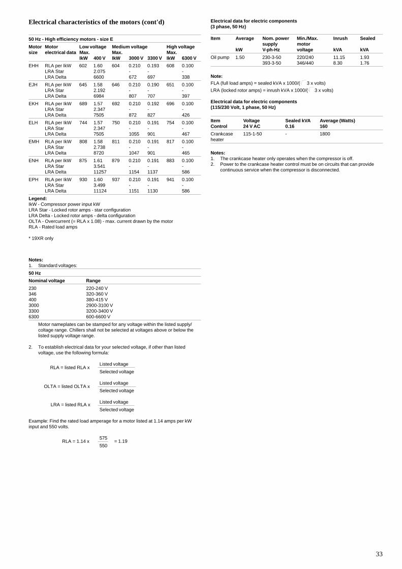
33
Electrical characteristics of the motors (cont'd)
50 Hz - High efficiency motors - size E
Motor Motor Low voltage Medium voltage High voltagesize electrical data Max. Max. Max.
IkW 400 V IkW 3000 V 3300 V IkW 6300 V
EHH RLA per IkW 602 1.60 604 0.210 0.193 608 0.100LRA Star 2.075 - - -LRA Delta 6600 672 697 338
EJH RLA per IkW 645 1.58 646 0.210 0.190 651 0.100LRA Star 2.192 - - -LRA Delta 6984 807 707 397
EKH RLA per IkW 689 1.57 692 0.210 0.192 696 0.100LRA Star 2.347 - - -LRA Delta 7505 872 827 426
ELH RLA per IkW 744 1.57 750 0.210 0.191 754 0.100LRA Star 2.347 - - -LRA Delta 7505 1055 901 467
EMH RLA per IkW 808 1.58 811 0.210 0.191 817 0.100LRA Star 2.738 - - -LRA Delta 8720 1047 901 465
ENH RLA per IkW 875 1.61 879 0.210 0.191 883 0.100LRA Star 3.541 - - -LRA Delta 11257 1154 1137 586
EPH RLA per IkW 930 1.60 937 0.210 0.191 941 0.100LRA Star 3.499 - - -LRA Delta 11124 1151 1130 586
Legend:IkW - Compressor power input kWLRA Star - Locked rotor amps - star configurationLRA Delta - Locked rotor amps - delta configurationOLTA - Overcurrent (= RLA x 1.08) - max. current drawn by the motorRLA - Rated load amps
* 19XR only
Notes:1. Standard voltages:
50 Hz
Nominal voltage Range
230 220-240 V346 320-360 V400 380-415 V3000 2900-3100 V3300 3200-3400 V6300 600-6600 V
Motor nameplates can be stamped for any voltage within the listed supply/coltage range. Chillers shall not be selected at voltages above or below thelisted supply voltage range.
2. To establish electrical data for your selected voltage, if other than listedvoltage, use the following formula:
Listed voltage
Selected voltage
Listed voltage
Selected voltage
Listed voltage
Selected voltage
Example: Find the rated load amperage for a motor listed at 1.14 amps per kWinput and 550 volts.
575
550
RLA = listed RLA x
OLTA = listed OLTA x
LRA = listed RLA x
RLA = 1.14 x = 1.19
Electrical data for electric components(3 phase, 50 Hz)
Item Average Nom. power Min./Max. Inrush Sealedsupply motor
kW V-ph-Hz voltage kVA kVA
Oil pump 1.50 230-3-50 220/240 11.15 1.93393-3-50 346/440 8.30 1.76
Note:FLA (full load amps) = sealed kVA x 1000/( 3 x volts)
LRA (locked rotor amps) = inrush kVA x 1000/( 3 x volts)
Electrical data for electric components(115/230 Volt, 1 phase, 50 Hz)
Item Voltage Sealed kVA Average (Watts)Control 24 V AC 0.16 160
Crankcase 115-1-50 - 1800heater
Notes:1. The crankcase heater only operates when the compressor is off.2. Power to the crankcase heater control must be on circuits that can provide
continuous service when the compressor is disconnected.
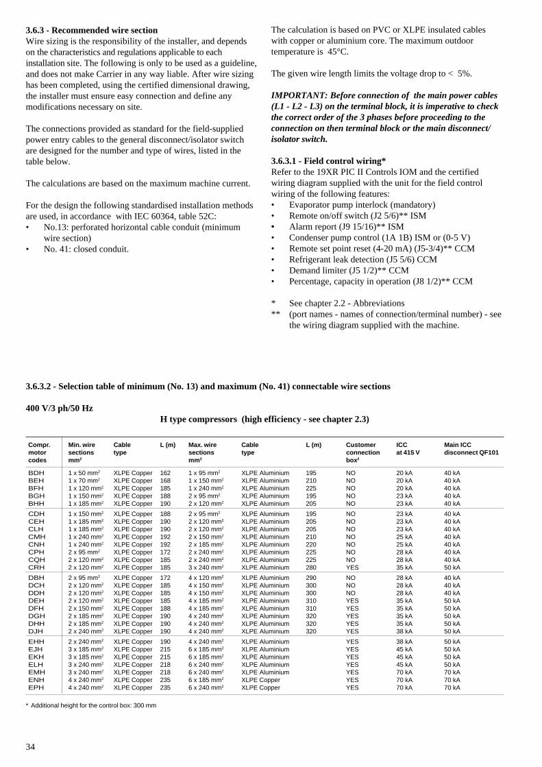
34
3.6.3 - Recommended wire sectionWire sizing is the responsibility of the installer, and dependson the characteristics and regulations applicable to eachinstallation site. The following is only to be used as a guideline,and does not make Carrier in any way liable. After wire sizinghas been completed, using the certified dimensional drawing,the installer must ensure easy connection and define anymodifications necessary on site.
The connections provided as standard for the field-suppliedpower entry cables to the general disconnect/isolator switchare designed for the number and type of wires, listed in thetable below.
The calculations are based on the maximum machine current.
For the design the following standardised installation methodsare used, in accordance with IEC 60364, table 52C:• No.13: perforated horizontal cable conduit (minimum
wire section)• No. 41: closed conduit.
The calculation is based on PVC or XLPE insulated cableswith copper or aluminium core. The maximum outdoortemperature is 45°C.
The given wire length limits the voltage drop to < 5%.
IMPORTANT: Before connection of the main power cables(L1 - L2 - L3) on the terminal block, it is imperative to checkthe correct order of the 3 phases before proceeding to theconnection on then terminal block or the main disconnect/isolator switch.
3.6.3.1 - Field control wiring*Refer to the 19XR PIC II Controls IOM and the certifiedwiring diagram supplied with the unit for the field controlwiring of the following features:• Evaporator pump interlock (mandatory)• Remote on/off switch (J2 5/6)** ISM• Alarm report (J9 15/16)** ISM• Condenser pump control (1A 1B) ISM or (0-5 V)• Remote set point reset (4-20 mA) (J5-3/4)** CCM• Refrigerant leak detection (J5 5/6) CCM• Demand limiter (J5 1/2)** CCM• Percentage, capacity in operation (J8 1/2)** CCM
* See chapter 2.2 - Abbreviations** (port names - names of connection/terminal number) - see
the wiring diagram supplied with the machine.
3.6.3.2 - Selection table of minimum (No. 13) and maximum (No. 41) connectable wire sections
400 V/3 ph/50 HzH type compressors (high efficiency - see chapter 2.3)
Compr. Min. wire Cable L (m) Max. wire Cable L (m) Customer ICC Main ICCmotor sections type sections type connection at 415 V disconnect QF101codes mm2 mm2 box2
BDH 1 x 50 mm2 XLPE Copper 162 1 x 95 mm2 XLPE Aluminium 195 NO 20 kA 40 kABEH 1 x 70 mm2 XLPE Copper 168 1 x 150 mm2 XLPE Aluminium 210 NO 20 kA 40 kABFH 1 x 120 mm2 XLPE Copper 185 1 x 240 mm2 XLPE Aluminium 225 NO 20 kA 40 kABGH 1 x 150 mm2 XLPE Copper 188 2 x 95 mm2 XLPE Aluminium 195 NO 23 kA 40 kABHH 1 x 185 mm2 XLPE Copper 190 2 x 120 mm2 XLPE Aluminium 205 NO 23 kA 40 kA
CDH 1 x 150 mm2 XLPE Copper 188 2 x 95 mm2 XLPE Aluminium 195 NO 23 kA 40 kACEH 1 x 185 mm2 XLPE Copper 190 2 x 120 mm2 XLPE Aluminium 205 NO 23 kA 40 kACLH 1 x 185 mm2 XLPE Copper 190 2 x 120 mm2 XLPE Aluminium 205 NO 23 kA 40 kACMH 1 x 240 mm2 XLPE Copper 192 2 x 150 mm2 XLPE Aluminium 210 NO 25 kA 40 kACNH 1 x 240 mm2 XLPE Copper 192 2 x 185 mm2 XLPE Aluminium 220 NO 25 kA 40 kACPH 2 x 95 mm2 XLPE Copper 172 2 x 240 mm2 XLPE Aluminium 225 NO 28 kA 40 kACQH 2 x 120 mm2 XLPE Copper 185 2 x 240 mm2 XLPE Aluminium 225 NO 28 kA 40 kACRH 2 x 120 mm2 XLPE Copper 185 3 x 240 mm2 XLPE Aluminium 280 YES 35 kA 50 kA
DBH 2 x 95 mm2 XLPE Copper 172 4 x 120 mm2 XLPE Aluminium 290 NO 28 kA 40 kADCH 2 x 120 mm2 XLPE Copper 185 4 x 150 mm2 XLPE Aluminium 300 NO 28 kA 40 kADDH 2 x 120 mm2 XLPE Copper 185 4 x 150 mm2 XLPE Aluminium 300 NO 28 kA 40 kADEH 2 x 120 mm2 XLPE Copper 185 4 x 185 mm2 XLPE Aluminium 310 YES 35 kA 50 kADFH 2 x 150 mm2 XLPE Copper 188 4 x 185 mm2 XLPE Aluminium 310 YES 35 kA 50 kADGH 2 x 185 mm2 XLPE Copper 190 4 x 240 mm2 XLPE Aluminium 320 YES 35 kA 50 kADHH 2 x 185 mm2 XLPE Copper 190 4 x 240 mm2 XLPE Aluminium 320 YES 35 kA 50 kADJH 2 x 240 mm2 XLPE Copper 190 4 x 240 mm2 XLPE Aluminium 320 YES 38 kA 50 kA
EHH 2 x 240 mm2 XLPE Copper 190 4 x 240 mm2 XLPE Aluminium YES 38 kA 50 kAEJH 3 x 185 mm2 XLPE Copper 215 6 x 185 mm2 XLPE Aluminium YES 45 kA 50 kAEKH 3 x 185 mm2 XLPE Copper 215 6 x 185 mm2 XLPE Aluminium YES 45 kA 50 kAELH 3 x 240 mm2 XLPE Copper 218 6 x 240 mm2 XLPE Aluminium YES 45 kA 50 kAEMH 3 x 240 mm2 XLPE Copper 218 6 x 240 mm2 XLPE Aluminium YES 70 kA 70 kAENH 4 x 240 mm2 XLPE Copper 235 6 x 185 mm2 XLPE Copper YES 70 kA 70 kAEPH 4 x 240 mm2 XLPE Copper 235 6 x 240 mm2 XLPE Copper YES 70 kA 70 kA
* Additional height for the control box: 300 mm
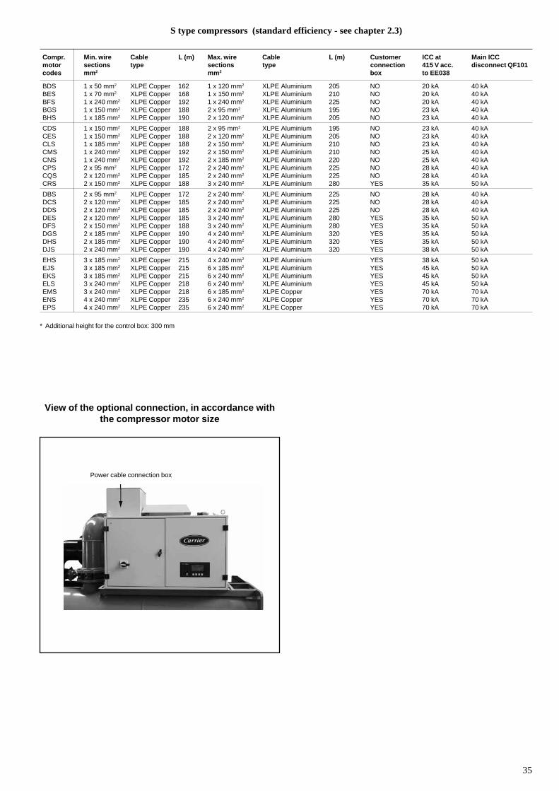
35
S type compressors (standard efficiency - see chapter 2.3)
Compr. Min. wire Cable L (m) Max. wire Cable L (m) Customer ICC at Main ICCmotor sections type sections type connection 415 V acc. disconnect QF101codes mm2 mm2 box to EE038
BDS 1 x 50 mm2 XLPE Copper 162 1 x 120 mm2 XLPE Aluminium 205 NO 20 kA 40 kABES 1 x 70 mm2 XLPE Copper 168 1 x 150 mm2 XLPE Aluminium 210 NO 20 kA 40 kABFS 1 x 240 mm2 XLPE Copper 192 1 x 240 mm2 XLPE Aluminium 225 NO 20 kA 40 kABGS 1 x 150 mm2 XLPE Copper 188 2 x 95 mm2 XLPE Aluminium 195 NO 23 kA 40 kABHS 1 x 185 mm2 XLPE Copper 190 2 x 120 mm2 XLPE Aluminium 205 NO 23 kA 40 kA
CDS 1 x 150 mm2 XLPE Copper 188 2 x 95 mm2 XLPE Aluminium 195 NO 23 kA 40 kACES 1 x 150 mm2 XLPE Copper 188 2 x 120 mm2 XLPE Aluminium 205 NO 23 kA 40 kACLS 1 x 185 mm2 XLPE Copper 188 2 x 150 mm2 XLPE Aluminium 210 NO 23 kA 40 kACMS 1 x 240 mm2 XLPE Copper 192 2 x 150 mm2 XLPE Aluminium 210 NO 25 kA 40 kACNS 1 x 240 mm2 XLPE Copper 192 2 x 185 mm2 XLPE Aluminium 220 NO 25 kA 40 kACPS 2 x 95 mm2 XLPE Copper 172 2 x 240 mm2 XLPE Aluminium 225 NO 28 kA 40 kACQS 2 x 120 mm2 XLPE Copper 185 2 x 240 mm2 XLPE Aluminium 225 NO 28 kA 40 kACRS 2 x 150 mm2 XLPE Copper 188 3 x 240 mm2 XLPE Aluminium 280 YES 35 kA 50 kA
DBS 2 x 95 mm2 XLPE Copper 172 2 x 240 mm2 XLPE Aluminium 225 NO 28 kA 40 kADCS 2 x 120 mm2 XLPE Copper 185 2 x 240 mm2 XLPE Aluminium 225 NO 28 kA 40 kADDS 2 x 120 mm2 XLPE Copper 185 2 x 240 mm2 XLPE Aluminium 225 NO 28 kA 40 kADES 2 x 120 mm2 XLPE Copper 185 3 x 240 mm2 XLPE Aluminium 280 YES 35 kA 50 kADFS 2 x 150 mm2 XLPE Copper 188 3 x 240 mm2 XLPE Aluminium 280 YES 35 kA 50 kADGS 2 x 185 mm2 XLPE Copper 190 4 x 240 mm2 XLPE Aluminium 320 YES 35 kA 50 kADHS 2 x 185 mm2 XLPE Copper 190 4 x 240 mm2 XLPE Aluminium 320 YES 35 kA 50 kADJS 2 x 240 mm2 XLPE Copper 190 4 x 240 mm2 XLPE Aluminium 320 YES 38 kA 50 kA
EHS 3 x 185 mm2 XLPE Copper 215 4 x 240 mm2 XLPE Aluminium YES 38 kA 50 kAEJS 3 x 185 mm2 XLPE Copper 215 6 x 185 mm2 XLPE Aluminium YES 45 kA 50 kAEKS 3 x 185 mm2 XLPE Copper 215 6 x 240 mm2 XLPE Aluminium YES 45 kA 50 kAELS 3 x 240 mm2 XLPE Copper 218 6 x 240 mm2 XLPE Aluminium YES 45 kA 50 kAEMS 3 x 240 mm2 XLPE Copper 218 6 x 185 mm2 XLPE Copper YES 70 kA 70 kAENS 4 x 240 mm2 XLPE Copper 235 6 x 240 mm2 XLPE Copper YES 70 kA 70 kAEPS 4 x 240 mm2 XLPE Copper 235 6 x 240 mm2 XLPE Copper YES 70 kA 70 kA
* Additional height for the control box: 300 mm
View of the optional connection, in accordance withthe compressor motor size
Power cable connection box
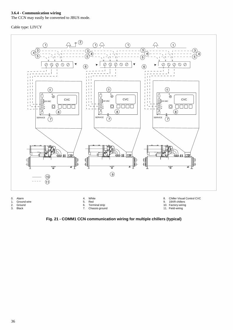
36
3.6.4 - Communication wiringThe CCN may easily be converted to JBUS mode.
Cable type: LIYCY
0. Alarm1. Ground wire2. Ground3. Black
4. White5. Red6. Terminal strip7. Chassis ground
8. Chiller Visual Control CVC9. 19XR chillers10. Factory-wiring11. Field-wiring
Fig. 21 - COMM1 CCN communication wiring for multiple chillers (typical)
G
+
-24 VAC
R
CVC
J6
SERVICE
0J7
J1
J6
}G
+
-24 VAC
R
CVC
J6
SERVICE
0J7
J1
J6
}G
+
-24 VAC
R
CVC
J6
SERVICE
0J7
J1
J6
}
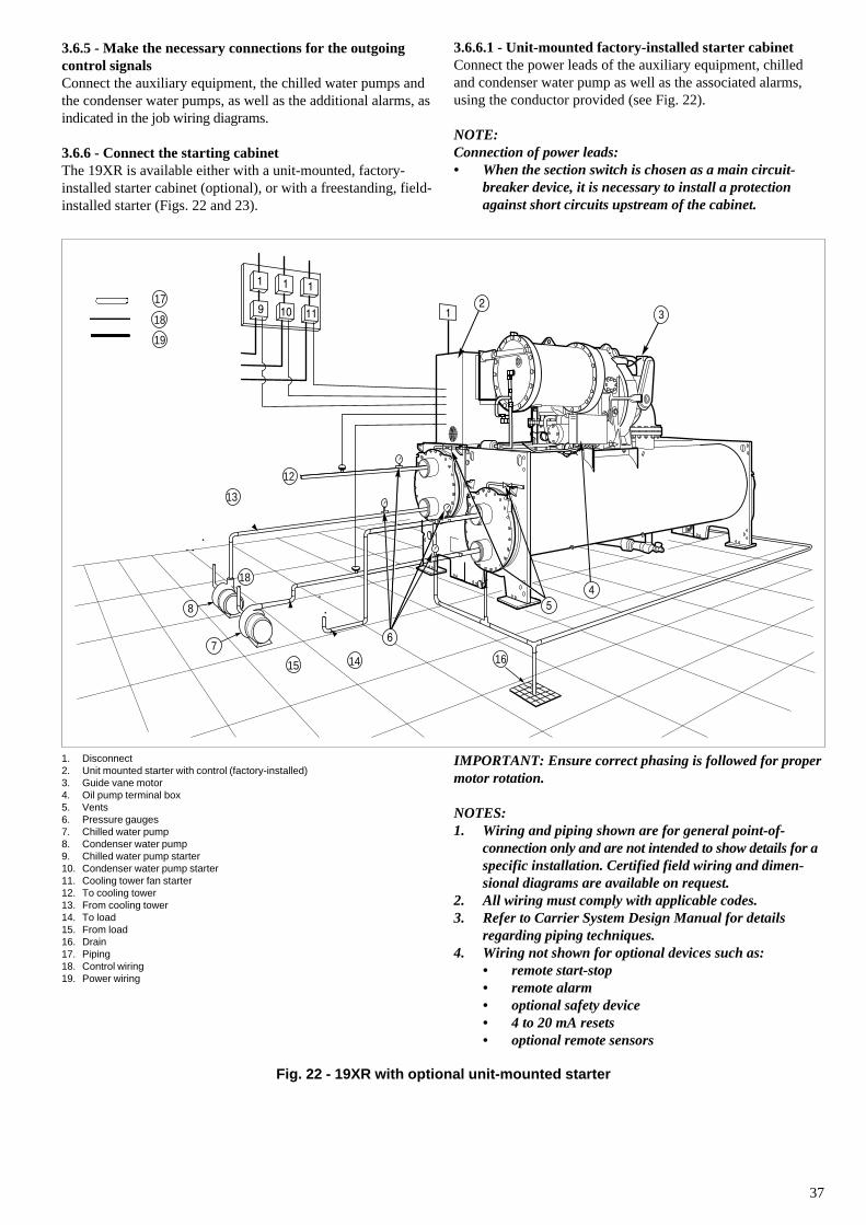
37
3.6.5 - Make the necessary connections for the outgoingcontrol signalsConnect the auxiliary equipment, the chilled water pumps andthe condenser water pumps, as well as the additional alarms, asindicated in the job wiring diagrams.
3.6.6 - Connect the starting cabinetThe 19XR is available either with a unit-mounted, factory-installed starter cabinet (optional), or with a freestanding, field-installed starter (Figs. 22 and 23).
3.6.6.1 - Unit-mounted factory-installed starter cabinetConnect the power leads of the auxiliary equipment, chilledand condenser water pump as well as the associated alarms,using the conductor provided (see Fig. 22).
NOTE:Connection of power leads:• When the section switch is chosen as a main circuit-
breaker device, it is necessary to install a protectionagainst short circuits upstream of the cabinet.
1. Disconnect2. Unit mounted starter with control (factory-installed)3. Guide vane motor4. Oil pump terminal box5. Vents6. Pressure gauges7. Chilled water pump8. Condenser water pump9. Chilled water pump starter10. Condenser water pump starter11. Cooling tower fan starter12. To cooling tower13. From cooling tower14. To load15. From load16. Drain17. Piping18. Control wiring19. Power wiring
Fig. 22 - 19XR with optional unit-mounted starter
IMPORTANT: Ensure correct phasing is followed for propermotor rotation.
NOTES:1. Wiring and piping shown are for general point-of-
connection only and are not intended to show details for aspecific installation. Certified field wiring and dimen-sional diagrams are available on request.
2. All wiring must comply with applicable codes.3. Refer to Carrier System Design Manual for details
regarding piping techniques.4. Wiring not shown for optional devices such as:
• remote start-stop• remote alarm• optional safety device• 4 to 20 mA resets• optional remote sensors
7
8
12
18
16
13
141415
17
18
19
3
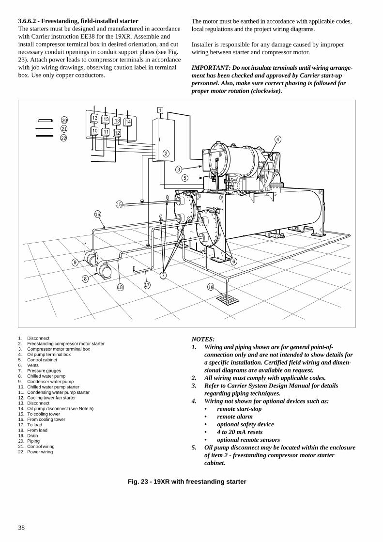
38
3.6.6.2 - Freestanding, field-installed starterThe starters must be designed and manufactured in accordancewith Carrier instruction EE38 for the 19XR. Assemble andinstall compressor terminal box in desired orientation, and cutnecessary conduit openings in conduit support plates (see Fig.23). Attach power leads to compressor terminals in accordancewith job wiring drawings, observing caution label in terminalbox. Use only copper conductors.
The motor must be earthed in accordance with applicable codes,local regulations and the project wiring diagrams.
Installer is responsible for any damage caused by improperwiring between starter and compressor motor.
IMPORTANT: Do not insulate terminals until wiring arrange-ment has been checked and approved by Carrier start-uppersonnel. Also, make sure correct phasing is followed forproper motor rotation (clockwise).
1. Disconnect2. Freestanding compressor motor starter3. Compressor motor terminal box4. Oil pump terminal box5. Control cabinet6. Vents7. Pressure gauges8. Chilled water pump9. Condenser water pump10. Chilled water pump starter11. Condensing water pump starter12. Cooling tower fan starter13. Disconnect14. Oil pump disconnect (see Note 5)15. To cooling tower16. From cooling tower17. To load18. From load19. Drain20. Piping21. Control wiring22. Power wiring
NOTES:1. Wiring and piping shown are for general point-of-
connection only and are not intended to show details fora specific installation. Certified field wiring and dimen-sional diagrams are available on request.
2. All wiring must comply with applicable codes.3. Refer to Carrier System Design Manual for details
regarding piping techniques.4. Wiring not shown for optional devices such as:
• remote start-stop• remote alarm• optional safety device• 4 to 20 mA resets• optional remote sensors
5. Oil pump disconnect may be located within the enclosureof item 2 - freestanding compressor motor startercabinet.
Fig. 23 - 19XR with freestanding starter
1718
15
19
1616
20
21
22
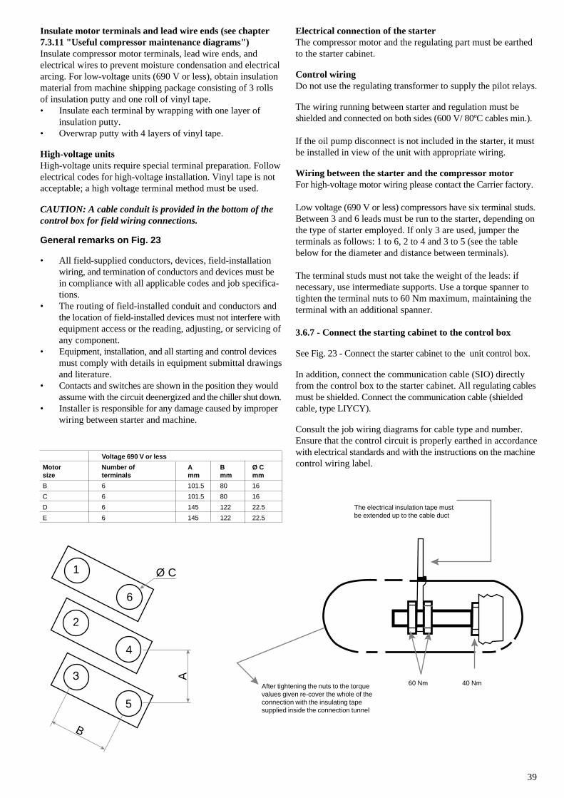
39
Insulate motor terminals and lead wire ends (see chapter7.3.11 "Useful compressor maintenance diagrams")Insulate compressor motor terminals, lead wire ends, andelectrical wires to prevent moisture condensation and electricalarcing. For low-voltage units (690 V or less), obtain insulationmaterial from machine shipping package consisting of 3 rollsof insulation putty and one roll of vinyl tape.• Insulate each terminal by wrapping with one layer of
insulation putty.• Overwrap putty with 4 layers of vinyl tape.
High-voltage unitsHigh-voltage units require special terminal preparation. Followelectrical codes for high-voltage installation. Vinyl tape is notacceptable; a high voltage terminal method must be used.
CAUTION: A cable conduit is provided in the bottom of thecontrol box for field wiring connections.
General remarks on Fig. 23
• All field-supplied conductors, devices, field-installationwiring, and termination of conductors and devices must bein compliance with all applicable codes and job specifica-tions.
• The routing of field-installed conduit and conductors andthe location of field-installed devices must not interfere withequipment access or the reading, adjusting, or servicing ofany component.
• Equipment, installation, and all starting and control devicesmust comply with details in equipment submittal drawingsand literature.
• Contacts and switches are shown in the position they wouldassume with the circuit deenergized and the chiller shut down.
• Installer is responsible for any damage caused by improperwiring between starter and machine.
Electrical connection of the starterThe compressor motor and the regulating part must be earthedto the starter cabinet.
Control wiringDo not use the regulating transformer to supply the pilot relays.
The wiring running between starter and regulation must beshielded and connected on both sides (600 V/ 80ºC cables min.).
If the oil pump disconnect is not included in the starter, it mustbe installed in view of the unit with appropriate wiring.
Wiring between the starter and the compressor motorFor high-voltage motor wiring please contact the Carrier factory.
Low voltage (690 V or less) compressors have six terminal studs.Between 3 and 6 leads must be run to the starter, depending onthe type of starter employed. If only 3 are used, jumper theterminals as follows: 1 to 6, 2 to 4 and 3 to 5 (see the tablebelow for the diameter and distance between terminals).
The terminal studs must not take the weight of the leads: ifnecessary, use intermediate supports. Use a torque spanner totighten the terminal nuts to 60 Nm maximum, maintaining theterminal with an additional spanner.
3.6.7 - Connect the starting cabinet to the control box
See Fig. 23 - Connect the starter cabinet to the unit control box.
In addition, connect the communication cable (SIO) directlyfrom the control box to the starter cabinet. All regulating cablesmust be shielded. Connect the communication cable (shieldedcable, type LIYCY).
Consult the job wiring diagrams for cable type and number.Ensure that the control circuit is properly earthed in accordancewith electrical standards and with the instructions on the machinecontrol wiring label.
Voltage 690 V or less
Motor Number of A B Ø Csize terminals mm mm mm
B 6 101.5 80 16
C 6 101.5 80 16
D 6 145 122 22.5
E 6 145 122 22.5
The electrical insulation tape mustbe extended up to the cable duct
After tightening the nuts to the torquevalues given re-cover the whole of theconnection with the insulating tapesupplied inside the connection tunnel
60 Nm 40 Nm
1
2
3
4
5
6
Ø C
A
B
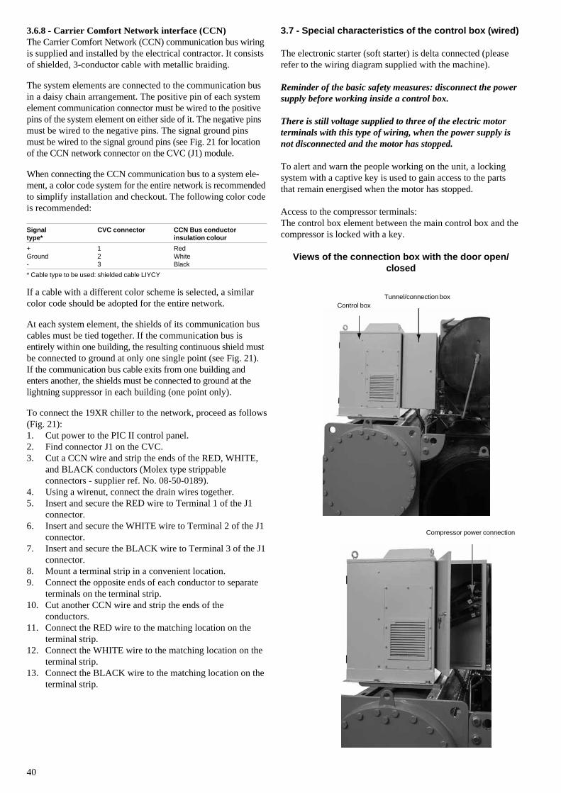
40
3.6.8 - Carrier Comfort Network interface (CCN)The Carrier Comfort Network (CCN) communication bus wiringis supplied and installed by the electrical contractor. It consistsof shielded, 3-conductor cable with metallic braiding.
The system elements are connected to the communication busin a daisy chain arrangement. The positive pin of each systemelement communication connector must be wired to the positivepins of the system element on either side of it. The negative pinsmust be wired to the negative pins. The signal ground pinsmust be wired to the signal ground pins (see Fig. 21 for locationof the CCN network connector on the CVC (J1) module.
When connecting the CCN communication bus to a system ele-ment, a color code system for the entire network is recommendedto simplify installation and checkout. The following color codeis recommended:
Signal CVC connector CCN Bus conductortype* insulation colour
+ 1 RedGround 2 White- 3 Black
* Cable type to be used: shielded cable LIYCY
If a cable with a different color scheme is selected, a similarcolor code should be adopted for the entire network.
At each system element, the shields of its communication buscables must be tied together. If the communication bus isentirely within one building, the resulting continuous shield mustbe connected to ground at only one single point (see Fig. 21).If the communication bus cable exits from one building andenters another, the shields must be connected to ground at thelightning suppressor in each building (one point only).
To connect the 19XR chiller to the network, proceed as follows(Fig. 21):1. Cut power to the PIC II control panel.2. Find connector J1 on the CVC.3. Cut a CCN wire and strip the ends of the RED, WHITE,
and BLACK conductors (Molex type strippableconnectors - supplier ref. No. 08-50-0189).
4. Using a wirenut, connect the drain wires together.5. Insert and secure the RED wire to Terminal 1 of the J1
connector.6. Insert and secure the WHITE wire to Terminal 2 of the J1
connector.7. Insert and secure the BLACK wire to Terminal 3 of the J1
connector.8. Mount a terminal strip in a convenient location.9. Connect the opposite ends of each conductor to separate
terminals on the terminal strip.10. Cut another CCN wire and strip the ends of the
conductors.11. Connect the RED wire to the matching location on the
terminal strip.12. Connect the WHITE wire to the matching location on the
terminal strip.13. Connect the BLACK wire to the matching location on the
terminal strip.
3.7 - Special characteristics of the control box (wired)
The electronic starter (soft starter) is delta connected (pleaserefer to the wiring diagram supplied with the machine).
Reminder of the basic safety measures: disconnect the powersupply before working inside a control box.
There is still voltage supplied to three of the electric motorterminals with this type of wiring, when the power supply isnot disconnected and the motor has stopped.
To alert and warn the people working on the unit, a lockingsystem with a captive key is used to gain access to the partsthat remain energised when the motor has stopped.
Access to the compressor terminals:The control box element between the main control box and thecompressor is locked with a key.
Views of the connection box with the door open/closed
Tunnel/connection boxControl box
Compressor power connection
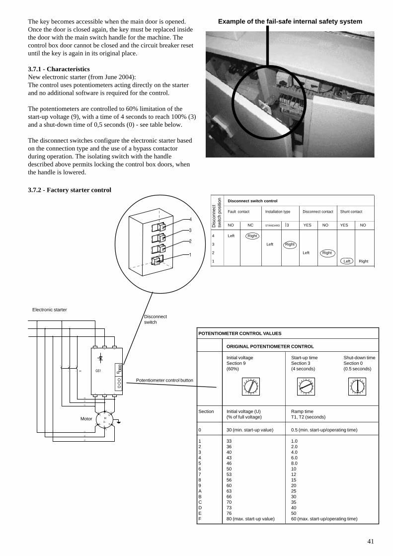
41
The key becomes accessible when the main door is opened.Once the door is closed again, the key must be replaced insidethe door with the main switch handle for the machine. Thecontrol box door cannot be closed and the circuit breaker resetuntil the key is again in its original place.
3.7.1 - CharacteristicsNew electronic starter (from June 2004):The control uses potentiometers acting directly on the starterand no additional software is required for the control.
The potentiometers are controlled to 60% limitation of thestart-up voltage (9), with a time of 4 seconds to reach 100% (3)and a shut-down time of 0,5 seconds (0) - see table below.
The disconnect switches configure the electronic starter basedon the connection type and the use of a bypass contactorduring operation. The isolating switch with the handledescribed above permits locking the control box doors, whenthe handle is lowered.
3.7.2 - Factory starter control
POTENTIOMETER CONTROL VALUES
ORIGINAL POTENTIOMETER CONTROL
Initial voltage Start-up time Shut-down timeSection 9 Section 3 Section 0(60%) (4 seconds) (0.5 seconds)
Section Initial voltage (U) Ramp time(% of full voltage) T1, T2 (seconds)
0 30 (min. start-up value) 0.5 (min. start-up/operating time)
1 33 1.02 36 2.03 40 4.04 43 6.05 46 8.06 50 107 53 128 56 159 60 20A 63 25B 66 30C 70 35D 73 40E 76 50F 80 (max. start-up value) 60 (max. start-up/operating time)
21 0 F
EDCB
A98765
4
32
1 0 FEDCB
A98765
4
32
1 0 FEDCB
A98765
4
3
1
2
3
4
Disconnectswitch
Potentiometer control button
Electronic starter
Disconnect switch control
Fault contact Installation type Disconnect contact Shunt contact
NO NC STANDARD ⎟ 3 YES NO YES NO
4 Left Right
3 Left Right
2 Left Right
1 Left Right
Example of the fail-safe internal safety system
Dis
conn
ect
switc
h po
sitio
n
Motor
T1 T2
GS1
L1 L2
T3
L3
T1
T3
T2
3
4
KM5
6
1
2
L3
L2
L1
12
3
64
5
U WV
X
YZ3~M
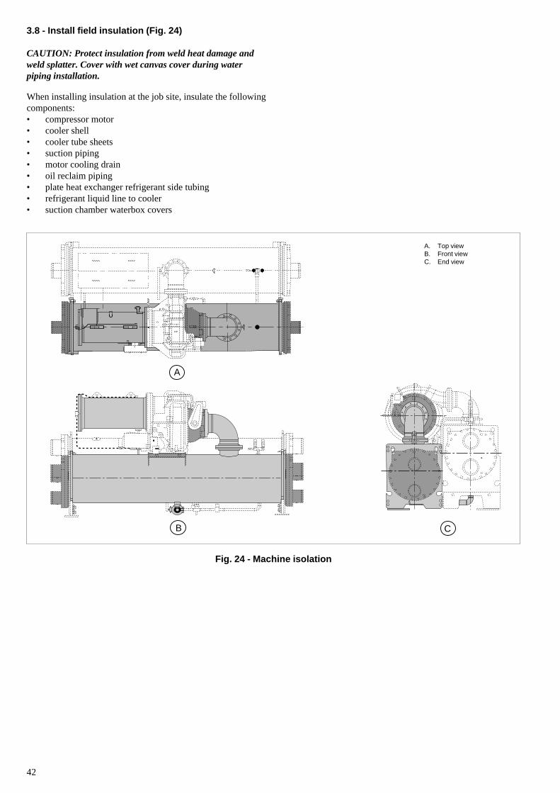
42
A
B C
Fig. 24 - Machine isolation
A. Top viewB. Front viewC. End view
3.8 - Install field insulation (Fig. 24)
CAUTION: Protect insulation from weld heat damage andweld splatter. Cover with wet canvas cover during waterpiping installation.
When installing insulation at the job site, insulate the followingcomponents:• compressor motor• cooler shell• cooler tube sheets• suction piping• motor cooling drain• oil reclaim piping• plate heat exchanger refrigerant side tubing• refrigerant liquid line to cooler• suction chamber waterbox covers
43
4 - BEFORE INITIAL START-UP
4.1 - Necessary checks
4.1.1 - Job data required
Checks before system start-upBefore the start-up of the refrigeration system, the completeinstallation, including the refrigeration system must be verifiedagainst the installation drawings, dimensional drawings, systempiping and instrumentation diagrams and the wiring diagrams.
During the installation test national regulations must befollowed. If no national regulation exists, paragraph 9-5 ofstandard EN 378-2 can be used as a guide.
External visual installation checks:• Compare the complete installation with the refrigeration
system and power circuit diagrams.• Check that all components comply with the design
specifications.• Check that all safety documents and equipments that are
required by current European standards are present.• Verify that all safety and environmental protection
devices and arrangements are in place and comply withthe current European standard.
• Verify that all document for pressure containers,certificates, name plates, files, instruction manuals that arerequired documents required by the current Europeanstandards are present.
• Verify the free passage of access and safety routes.• Check that ventilation in the plant room is adequate.• Check that refrigerant detectors are present.• Verify the instructions and directives to prevent the
deliberate removal of refrigerant gases that are harmful tothe environment.
• Verify the installation of connections.• Verify the supports and fixing elements (materials,
routing and connection).• Verify the quality of welds and other joints.• Check the protection against mechanical damage.• Check the protection against heat.• Check the protection of moving parts.• Verify the accessibility for maintenance or repair and to
check the piping.• Verify the status of the valves.• Verify the quality of the thermal insulation and of the
vapour barriers.
4.1.2 - Equipment required• mechanic’s tools (refrigeration)• digital volt-ohmmeter (DVM)• clamp-on ammeter• electronic leak detector• absolute pressure manometer or wet-bulb vacuum
indicator• 500-V insulation tester (megohmmeter) for compressor
motors with nameplate voltage of 600 V or less, or a 5000-Vinsulation tester for compressor motor rated above 600 V.
4.1.3 - Using the optional storage tank and pumpout systemRefer to the "Pumpout and refrigerant transfer procedures"section for: pumpout system preparation, refrigerant transfer,and chiller evacuation.
4.1.4 - Remove shipping packagingAfter receipt remove any packaging material from the unit.
4.1.5 - Open oil circuit valvesCheck that the oil filter isolation valves (Fig. 4) are open byremoving the valve cap and checking the valve stem.
4.1.6 - Tighten all gasketed joints and guide vane shaftpacking (torque depends on screw diameter)
Gaskets and packing normally relax by the time the chillerarrives at the jobsite. Tighten all gasketed joints and the guidevane shaft packing to ensure a leak tight chiller.
4.1.7 - Inspect water pipingRefer to piping diagrams provided in the certified drawings, andthe piping instructions in the 19XR Installation Instructionsmanual. Inspect the piping to the cooler and condenser. Be surethat flow directions are correct and that all piping specificationshave been met.
Do not introduce any significant static or dynamic pressureinto the heat exchange circuit (with regard to the designoperating pressures).
Before any start-up verify that the heat exchange fluid iscompatible with the materials and the water circuit coating.
In case additives or other fluids than those recommended byCarrier s.a are used, ensure that the fluids are not considered asa gas, and that they belong to class 2, as defined in directive97/23/EC.
Carrier S.A. recommendations on heat exchange fluids:1. No NH4+ ammonium ions in the water, they are very
detrimental for copper. This is one of the most importantfactors for the operating life of copper piping. A contentof several tenths of mg/l will badly corrode the copperover time.
2. Cl- Chloride ions are detrimental for copper with a risk ofperforations by corrosion by puncture. If possible keepbelow 10 mg/l.
3. SO42- sulphate ions can cause perforating corrosion, if
their content is above 30 mg/l.4. No fluoride ions (<0.1 mg/l).5. No Fe2+ and Fe3+ ions with non negligible levels of
dissolved oxygen must be present. Dissolved iron < 5 mg/l with dissolved oxygen < 5 mg/l.
6. Dissolved silicon: silicon is an acid element of water andcan also lead to corrosion risks. Content < 1mg/l.
7. Water hardness: HTM (hydrotimetric strength) >5°F(= French degrees). Values between 10 and 25 can berecommended. This will facilitate scale deposit that canlimit corrosion of copper. HTM values that are too highcan cause piping blockage over time. A carbonate hard-ness (TAC) below 100 is desirable.
44
If the chiller is spring isolated, keep all springs blocked in bothdirections in order to prevent possible piping stress and damageduring the transfer of refrigerant from vessel to vessel during theleak test process, or any time refrigerant is transferred. Adjustthe springs when the refrigerant is in operating condition, andwhen the water circuits are full.
4.2.2 - Refrigerant tracerCarrier recommends the use of an environmentally acceptablerefrigerant tracer for leak testing with an electronic detector.Ultrasonic leak detectors also can be used if the chiller is underpressure.
WARNING: Do not use air or oxygen as a means of pressur-izing the chiller. Mixtures of HFC-134a and air can undergocombustion.
4.2.3 - Leak test chillerDue to regulations regarding refrigerant emissions and the diffi-culties associated with separating contaminants from refrigerant,Carrier recommends the following leak test procedures.1. If the pressure readings are normal for chiller condition:
a. Evacuate the holding charge from the vessels, ifpresent.
b. Raise the chiller pressure, if necessary, by addingrefrigerant until pressure is at equivalent saturatedpressure for the surrounding temperature. Follow thepumpout procedures in sections 4.13 "Chiller equaliza-tion without pumpout unit" and 4.14 "Chiller equaliza-tion with pumpout unit".
WARNING: Never charge liquid refrigerant into thechiller if the pressure in the chiller is less than 241 kPafor HFC-134a. Charge as a gas only, with the cooler andcondenser pumps running, until this pressure is reached,using PUMP-DOWN LOCKOUT and TERMINATELOCKOUT mode on the PIC II. Flashing of liquidrefrigerant at low pressures can cause tube freeze-upand considerable damage.
c. Leak test chiller as outlined in Steps 3 -9.
2. If the pressure readings are abnormal for chillercondition:a. Prepare to leak test chillers shipped with refrigerant
(step 2h).b. Check for large leaks by connecting a nitrogen bottle
and raising the pressure to 207 kPa. Soap test all joints.If the test pressure holds for 30 minutes, prepare thetest for small leaks (steps 2g - h).
c. Plainly mark any leaks which are found.d. Release the pressure in the system.e. Repair all leaks.f. Retest the joints that were repaired.g. After successfully completing the test for large leaks,
remove as much nitrogen, air, and moisture as possible,given the fact that small leaks may be present in thesystem. This can be accomplished by following thedehydration procedure, outlined in the "Chillerdehydration" section below (chapter 4.4).
h. Slowly raise the system pressure to a maximum of1103 kPa but no less than 241 kPa for HFC-134a byadding refrigerant. Proceed with the test for smallleaks (steps 3-9).
8. Dissolved oxygen: Any sudden change in water oxygena-tion conditions must be avoided. It is as detrimental todeoxygenate the water by mixing it with inert gas as it isto over-oxygenate it by mixing it with pure oxygen. Thedisturbance of the oxygenation conditions encouragesdestabilisation of copper hydroxides and enlargement ofparticles.
9. Specific resistance – electric conductivity: the higher thespecific resistance, the slower the corrosion tendency.Values above 3000 Ohm/cm are desirable. A neutralenvironment favours maximum specific resistance values.For electric conductivity values in the order of 200-6000S/cm can be recommended.
10. pH: Ideal case pH neutral at 20-25°C7 < pH < 8
If the water circuit must be emptied for longer than one month,the complete circuit must be placed under nitrogen charge toavoid any risk of corrosion by differential aeration.
Charging and removing heat exchange fluids should be donewith devices that must be included on the water circuit by theinstaller. Never use the unit heat exchangers to add heatexchange fluid.
Piping systems must be properly vented, with no stress onwaterbox nozzles and covers. Use flexible connections toreduce the transmission of vibrations. Water flows through thecooler and condenser must meet job requirements. Measure thepressure drop across cooler and across condenser and comparethis with the nominal values (see selection document).
If the optional pumpout storage tank and/or pumpout systemare installed, check to ensure the pumpout condenser water hasbeen piped in. Check for field-supplied shutoff valves andcontrols as specified in the job data. Check for refrigerant leakson field-installed piping. See Fig. 18 and 19.
4.1.8 Check relief devicesBe sure that relief devices have been piped to the outdoors incompliance with standard EN 378-2. Piping connections mustallow for access to the valve mechanism for periodic inspectionand leak testing. 19XR relief valves are set to relieve at 1250 kPa.
4.2 - Chiller tightness
4.2.1 - Check chiller tightnessFigure 25 outlines the proper sequence and procedures for leaktesting.
19XR chillers are shipped with the refrigerant contained in thecondenser shell and the oil charge shipped in the compressor.The cooler will have a 225 kPa refrigerant charge. Units maybe ordered with the refrigerant shipped separately, along with a225 kPa nitrogen-holding charge in each vessel. To determine ifthere are any leaks, the chiller should be charged with refrigerant.Use an electronic leak detector to check all flanges and solderjoints after the chiller is pressurized. If any leaks are detected,follow the leak test procedure.
45
3. Check the chiller carefully with an electronic leakdetector, or soap bubble solution.
4. Leak Determination - If an electronic leak detector in-dicates a leak, use a soap bubble solution, if possible, toconfirm. Total all leak rates for the entire chiller.Leakage at rates greater than 0.45 kg/year for theentire chiller must be repaired. Note total chiller leakrate on the start-up report.
5. If no leak is found during initial start-up procedures,complete the transfer of refrigerant gas from thepumpout storage tank to the chiller (see section 4.14"Chiller equalization with pumpout unit".
6. If no leak is found after a retest:a. Transfer the refrigerant to the pumpout storage tank
and perform a standing vacuum test as outlined in the"Standing vacuum test" section on this page.
b. If the chiller fails this test, check for large leaks (step2b).
c. Dehydrate the chiller if it passes the standing vacuumtest. Follow the procedure in the "Chiller dehydration"section. Charge chiller with refrigerant (see section4.14 "Chiller equalization with pumpout unit").
7. If a leak is found, pump the refrigerant back into thepumpout storage tank, or if isolation valves are present,pump into the non-leaking vessel (see sections 4.13"Chiller equalization without pumpout unit" and 4.14"Chiller equalization with pumpout unit").
8. Transfer the refrigerant until chiller pressure is at 40kPa absolute.
9. Repair the leak and repeat the procedure, beginningfrom step 2h to ensure a leaktight repair. (If chiller isopened to the atmosphere for an extended period,evacuate it before repeating leak test.)
10. The circuit openings must be plugged during repair, ifthis does not take longer than one day. If it takeslonger, the circuits must be charged with nitrogen.
4.3 - Standing vacuum test
When performing the standing vacuum test or chiller dehydra-tion, use a manometer or a wet bulb indicator. Dial gaugescannot indicate the small amount of acceptable leakage duringa short period of time.1. Attach an absolute pressure manometer or wet bulb
indicator to the chiller.2. Evacuate the vessel to at least 41 kPa, using a vacuum
pump or the pumpout unit (see sections 4.13 "Chillerequalization without pumpout unit" and 4.14 "Chillerequalization with pumpout unit") .
3. Valve off the pump to hold the vacuum and record themanometer or indicator reading.
4. a. If the leakage rate is less than 0.17 kPa in 24 hours,the chiller is sufficiently tight.
b. If the leakage rate exceeds 0.17 kPa in 24 hours,repressurize the vessel and test for leaks. If refrigerantis available in the other vessel, pressurize by followingsteps 2-10 of "Return refrigerant to normal operatingconditions" section. If not, use nitrogen and a refrige-rant tracer. Raise the vessel pressure in increments untilthe leak is detected. If refrigerant is used, the maximumgas pressure is approximately 483 kPa for HFC-134aat normal ambient temperature. If nitrogen is used,limit the leak test pressure to 1103 kPa maximum.
5. Repair leak, retest, and proceed with dehydration.
4.4 - Chiller dehydration
Dehydration is recommended if the chiller has been open for aconsiderable period of time, if the chiller is known to containmoisture, or if there has been a complete loss of chiller holdingcharge or refrigerant pressure.
WARNING: Do not start or megohm-test the compressor motoror oil pump motor, even for a rotation check, if the chiller isunder dehydration vacuum. Insulation breakdown and severedamage may result.
Dehydration is readily accomplished at room temperatures.Use of a cold trap (Fig. 26) may substantially reduce the timerequired to complete the dehydration. The higher the roomtemperature, the faster dehydration takes place. At low roomtemperatures, a very deep vacuum is required for boiling off anymoisture. If low ambient temperatures are involved, contact aqualified service representative for the dehydration techniquesrequired.
Perform dehydration as follows:1. Connect a high capacity vacuum pump (0.002 m3/s or
larger is recommended) to the refrigerant charging valve.Tubing from the pump to the chiller should be as shortand as large a diameter as possible to provide leastresistance to gas flow.
2. Use an absolute pressure manometer or a wet bulbvacuum indicator to measure the vacuum. Open theshutoff valve to the vacuum indicator only when taking areading. Leave the valve open for 3 minutes to allow theindicator vacuum to equalize with the chiller vacuum.
3. Open all isolation valves (if present), if the entire chiller isto be dehydrated.
4. With the chiller ambient temperature at 15.6°C or higher,operate the vacuum pump until the manometer reads -100.61 kPa or a vacuum indicator reads 1.7°C. Operatethe pump an additional 2 hours.
5. Do not apply greater vacuum than 100.97 kPa (757.4 mmHg) or go below 0.56°C on the wet bulb vacuum indica-tor. At this temperature/pressure, isolated pockets ofmoisture can turn into ice. The slow rate of evaporation(sublimination) of ice at these low temperatures/ pressuresgreatly increases dehydration time.
6. Valve off the vacuum pump, stop the pump, and recordthe instrument reading.
7. After a 2-hour wait, take another instrument reading. Ifthe reading has not changed, dehydration is complete. Ifthe reading indicates vacuum loss, repeat steps 4 and 5.
8. If the reading continues to change after several attempts,perform a leak test up to the maximum 1103 kPa pressure.Locate and repair the leak, and repeat dehydration.
46
Fig
. 25
- 19X
R le
ak d
etec
tio
n p
roce
du
re
Leak
test
of 1
9XR
1 - A
ttach
com
poun
d ga
uge
-101
-0-3
000
kPa
to e
ach
vess
el2
- N
ote
ambi
ent t
empe
ratu
re g
auge
rea
ding
s
Mac
hine
s w
ith r
efrig
eran
t cha
rge
Pre
ssur
e on
con
dens
er v
esse
l is
at r
efrig
eran
tsa
tura
ted
cond
ition
s (s
ee r
efrig
eran
t pre
ssur
e-te
mpe
ratu
re t
able
s 5A
and
5D
)
Coo
ler
pres
sure
rea
ding
is 1
03 k
Pa
or h
ighe
r
Rec
ord
pres
sure
s
Pow
er u
p co
ntro
ls to
ens
ure
oil h
eate
ris
on
and
oil i
s ho
t. E
qual
izer
pre
ssur
ebe
twee
n co
oler
and
con
dens
er
Per
form
leak
test
No
leak
s fo
und
Leak
s fo
und
Pre
ssur
e on
con
dens
er v
esse
l is
less
than
satu
rate
d re
frig
eran
t pre
ssur
e (s
ee r
efrig
eran
tpr
essu
re-t
empe
ratu
re ta
bles
5A
and
5D
)
Coo
ler
pres
sure
rea
ding
is b
elow
103
kP
a
Leak
sus
pect
ed
Rec
ord
pres
sure
s
Is e
ither
ves
sel a
t 0 k
Pa?
Pow
er u
p co
ntro
ls to
ens
ure
oil h
eate
ris
on
and
oil i
s ho
t. E
qual
izer
pre
ssur
ebe
twee
n co
oler
and
con
dens
er
Add
ref
riger
ant u
ntil
pres
sure
isab
ove
241
kPa
Per
form
leak
test
Leak
s fo
und
Loca
te a
nd m
ark
all l
eak
sour
ces
Rec
over
refr
iger
ant
from
vess
el
Rep
air
all l
eaks
No
leak
s fo
und
Rec
over
refr
iger
ant
from
vess
el
Per
form
sta
ndin
gva
cuum
test
Pas
sF
ail
Deh
ydra
te v
esse
l if v
esse
l was
at
atm
osph
eric
pre
ssur
e or
low
er
Mac
hine
s w
ith n
itrog
en h
oldi
ng c
harg
e
Pre
ssur
e re
adin
g is
less
than
103
kP
a bu
tgr
eate
r th
an 0
kP
a
Leak
sus
pect
ed
Rai
se p
ress
ure
to 4
83 k
Pa
with
nitr
ogen
(if
usin
g el
ectr
onic
det
ecto
r,ad
d tr
acer
gas
now
)
Per
form
leak
test
usi
ng s
oap
bubb
leso
lutio
n, u
ltras
onic
s or
ele
ctro
nic
dete
ctor
No
leak
sfo
und
Eva
cuat
e ve
ssel
Leak
s fo
und
Loca
te a
nd m
ark
all l
eak
sour
ces
Rel
ease
the
pres
sure
in th
e ve
ssel
Rep
air
all l
eaks
Ret
est o
nly
thos
e jo
ints
that
wer
ere
paire
d
Pre
ssur
e is
at 1
03 k
Pa
(fac
tory
cha
rge)
Rel
ease
nitr
ogen
and
eva
cuat
eho
ldin
g ch
arge
from
ves
sels
Add
ref
riger
ant u
ntil
pres
sure
isab
ove
241
kPa
Per
form
leak
test
Leak
s fo
und
No
leak
sfo
und
Com
plet
e ch
argi
ng m
achi
ne
No
Yes
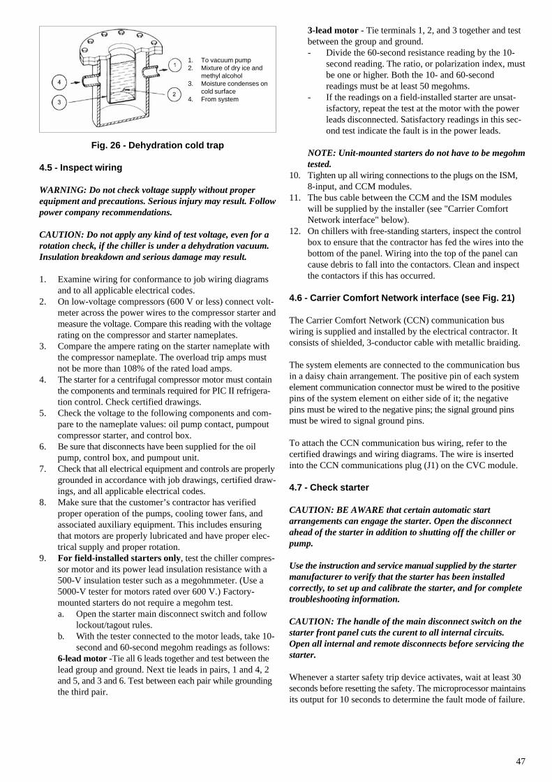
47
3-lead motor - Tie terminals 1, 2, and 3 together and testbetween the group and ground.- Divide the 60-second resistance reading by the 10-
second reading. The ratio, or polarization index, mustbe one or higher. Both the 10- and 60-secondreadings must be at least 50 megohms.
- If the readings on a field-installed starter are unsat-isfactory, repeat the test at the motor with the powerleads disconnected. Satisfactory readings in this sec-ond test indicate the fault is in the power leads.
NOTE: Unit-mounted starters do not have to be megohmtested.
10. Tighten up all wiring connections to the plugs on the ISM,8-input, and CCM modules.
11. The bus cable between the CCM and the ISM moduleswill be supplied by the installer (see "Carrier ComfortNetwork interface" below).
12. On chillers with free-standing starters, inspect the controlbox to ensure that the contractor has fed the wires into thebottom of the panel. Wiring into the top of the panel cancause debris to fall into the contactors. Clean and inspectthe contactors if this has occurred.
4.6 - Carrier Comfort Network interface (see Fig. 21)
The Carrier Comfort Network (CCN) communication buswiring is supplied and installed by the electrical contractor. Itconsists of shielded, 3-conductor cable with metallic braiding.
The system elements are connected to the communication busin a daisy chain arrangement. The positive pin of each systemelement communication connector must be wired to the positivepins of the system element on either side of it; the negativepins must be wired to the negative pins; the signal ground pinsmust be wired to signal ground pins.
To attach the CCN communication bus wiring, refer to thecertified drawings and wiring diagrams. The wire is insertedinto the CCN communications plug (J1) on the CVC module.
4.7 - Check starter
CAUTION: BE AWARE that certain automatic startarrangements can engage the starter. Open the disconnectahead of the starter in addition to shutting off the chiller orpump.
Use the instruction and service manual supplied by the startermanufacturer to verify that the starter has been installedcorrectly, to set up and calibrate the starter, and for completetroubleshooting information.
CAUTION: The handle of the main disconnect switch on thestarter front panel cuts the curent to all internal circuits.Open all internal and remote disconnects before servicing thestarter.
Whenever a starter safety trip device activates, wait at least 30seconds before resetting the safety. The microprocessor maintainsits output for 10 seconds to determine the fault mode of failure.
1. To vacuum pump2. Mixture of dry ice and
methyl alcohol3. Moisture condenses on
cold surface4. From system
Fig. 26 - Dehydration cold trap
4.5 - Inspect wiring
WARNING: Do not check voltage supply without properequipment and precautions. Serious injury may result. Followpower company recommendations.
CAUTION: Do not apply any kind of test voltage, even for arotation check, if the chiller is under a dehydration vacuum.Insulation breakdown and serious damage may result.
1. Examine wiring for conformance to job wiring diagramsand to all applicable electrical codes.
2. On low-voltage compressors (600 V or less) connect volt-meter across the power wires to the compressor starter andmeasure the voltage. Compare this reading with the voltagerating on the compressor and starter nameplates.
3. Compare the ampere rating on the starter nameplate withthe compressor nameplate. The overload trip amps mustnot be more than 108% of the rated load amps.
4. The starter for a centrifugal compressor motor must containthe components and terminals required for PIC II refrigera-tion control. Check certified drawings.
5. Check the voltage to the following components and com-pare to the nameplate values: oil pump contact, pumpoutcompressor starter, and control box.
6. Be sure that disconnects have been supplied for the oilpump, control box, and pumpout unit.
7. Check that all electrical equipment and controls are properlygrounded in accordance with job drawings, certified draw-ings, and all applicable electrical codes.
8. Make sure that the customer’s contractor has verifiedproper operation of the pumps, cooling tower fans, andassociated auxiliary equipment. This includes ensuringthat motors are properly lubricated and have proper elec-trical supply and proper rotation.
9. For field-installed starters only, test the chiller compres-sor motor and its power lead insulation resistance with a500-V insulation tester such as a megohmmeter. (Use a5000-V tester for motors rated over 600 V.) Factory-mounted starters do not require a megohm test.a. Open the starter main disconnect switch and follow
lockout/tagout rules.b. With the tester connected to the motor leads, take 10-
second and 60-second megohm readings as follows:6-lead motor -Tie all 6 leads together and test between thelead group and ground. Next tie leads in pairs, 1 and 4, 2and 5, and 3 and 6. Test between each pair while groundingthe third pair.
48
Electronic startersCheck all field wiring connections for tightness, clearancefrom moving parts, and correct connection.
The starter is factory-programmed and supplied with a noticeSIEMENS 3ZX 1012-ORW34---.
The disconnect is type QF101.
4.8 - Oil charge
The 19XR compressor holds approximately 18.9 l of oil forFrame 2 compressors; 30 l of oil for Frame 3 compressors; 38 l ofoil for Frame 4 compressors and 67.8 l for Frame 5 compressors.The chiller will be shipped with oil in the compressor. Whenthe sump is full, the oil level should be no higher than the middleof the upper sight glass, and minimum level is the bottom of thelower sight glass (Fig. 2). If oil is added, it must meet Carrier’sspecification for centrifugal compressor usage as described in theOil Specification section. Charge the oil through the oil chargingvalve, located near the bottom of the transmission housing(Fig. 2). The oil must be pumped from the oil container throughthe charging valve due to higher refrigerant pressure. Thepumping device must be able to lift from 0 to 1380 kPa orabove unit pressure. Oil should only be charged or removedwhen the chiller is shut down.
The oil cylinder must not be opened until charging begins.Only use new oil cylinders.
4.9 - Power-up the controls and check the oil heater
Ensure that an oil level is visible in the compressor beforeenergizing controls. A circuit breaker in the starter energizes theoil heater and the control circuit. When first powered, the CVCshould display the default screen within a short period of time.
The oil heater is energized by powering the control circuit. Thisshould be done several hours before start-up to minimize oil-refrigerant migration. The oil heater is controlled by the PIC IIand is powered through a contactor in the control box. Starterscontain a separate circuit breaker to power the heater and thecontrol circuit.
This set up allows the heater to energize when the main motorcircuit breaker is off for service work or extended shutdowns.The oil heater relay status can be viewed on the Status02 tableon the CVC. Oil sump temperature can be viewed on the CVCdefault screen.
4.10 - Check optional pumpout system controls andcompressor
Controls include an on/off switch, the compressor overloads, aninternal thermostat, a compressor contactor, and a refrigeranthigh pressure cutout. The high pressure cutout is factory set toopen at a pressure which depends on the approval code. Checkthat the water-cooled condenser has been connected. Loosen thecompressor holddown bolts to allow free spring travel. Openthe compressor suction and discharge service valves. Check thatoil is visible in the compressor sight glass. Add oil if necessary.
See sections 4.13 "Chiller equalization without pumpout unit"and 4.14 "Chiller equalization with pumpout unit".
4.11 - High altitude locations
Recalibration of the pressure transducers will be necessary,because the chiller was initially calibrated at sea level.
4.12 - Charge refrigerant into chiller
CAUTION: The transfer, addition, or removal of refrigerantin spring isolated chillers may place severe stress on externalpiping if springs have not been blocked in both up and downdirections.
The standard 19XR chiller will have the refrigerant alreadycharged in the vessels. The 19XR may be ordered with anitrogen holding charge. Evacuate the entire chiller, and chargechiller from refrigerant cylinders.
4.13 - Chiller equalization without pumpout unit
WARNING: When equalizing refrigerant pressure on the19XR chiller after service work or during the initial chillerstart-up, do not use the discharge isolation valve to equalize.Either the motor cooling isolation valve or charging hose(connected between pumpout valves on top of cooler andcondenser) is to be used as the equalization valve.
For safety reasons this valve is supplied locked from thefactory. To manipulate the other valves a special tool (keytype) is required.
Manipulation of the valves must always be done by aqualified person.
To equalize the pressure differential on a refrigerant isolated19XL chiller, use the TERMINATE LOCKOUT function of theControl Test in the SERVICE menu. This will help to turn onpumps and advise the proper procedure. The following proceduredescribes how to equalize refrigerant pressure on an isolated19XR chiller without a pumpout unit:1. Access TERMINATE LOCKOUT function on the Control
Test.2. Turn on the chilled water and condenser water pumps to
ensure against freezing.3. Slowly open the refrigerant cooling isolation valve. The
chiller cooler and condenser pressures will graduallyequalize. This process will take approximately 15 minutes.
4. Once the pressures have equalized, the cooler isolationvalve, the condenser isolation valve, and the hot gas iso-lation valve may now be opened.
WARNING: Whenever turning the discharge isolation valve,be sure to re-attach the valve locking device. This will preventthe valve from opening or closing during service work orduring chiller operation.
The valve is opened counter-clockwise, and closed clockwise.
49
4.14 - Chiller equalization with pumpout unit
The following procedure describes how to equalize refrigerantpressure on an isolated 19XR chiller using the pumpout unit:1. Access the TERMINATE LOCKOUT mode in the
Control Test.2. Turn on the chilled water and condenser water pumps to
prevent possible freezing.3. Open valve 4 on the pumpout unit and open valves 1a and
1b on the chiller cooler and condenser, Fig. 18 and 19.Slowly open valve 2 on the pumpout unit to equalize thepressure. This process will take approximately 15 minutes.
4. Once the pressures have equalized, the discharge isolationvalve, cooler isolation valve, optional hot gas bypass isola-tion valve, and the refrigerant isolation valve can be opened.Close valves 1a and 1b, and all pumpout unit valves.
The full refrigerant charge on the 19XR will vary with chillercomponents and design conditions, indicated on the job dataspecifications. An approximate charge may be found by addingthe condenser charge to the cooler charge listed in Table 7.
Always operate the condenser and chilled water pumps duringcharging operations to prevent freeze-ups. Use the Control TestTerminate Lockout to monitor conditions and start the pumps.
If the chiller has been shipped with a holding charge, therefrigerant will be added through the refrigerant charging valve(Fig. 18 and 19, valve 7) or to the pumpout charging connection.First evacuate the nitrogen holding charge from the chillervessels. Charge the refrigerant as a gas until the system pressureexceeds 141 kPa for HFC-134a. After the chiller is beyond thispressure the refrigerant should be charged as a liquid until allthe recommended refrigerant charge has been added.
4.15 Trimming refrigerant charge
The 19XR is shipped with the correct charge for the design dutyof the chiller. Trimming the charge can best be accomplishedwhen design load is available. To trim, check the temperaturedifference between leaving chilled water temperature andcooler refrigerant temperature at full load design conditions. Ifnecessary, add or remove refrigerant to bring the temperaturedifference to design conditions or minimum differential. If theunit incorporates a sight glass (option) and has a full charge,bubbling must take place in the upper level of the vessel.
Evaporator size Refrigerant charge (kg)
30 27731 30832 34035 32236 35937 39140 38141 41342 44045 44046 47747 50850 52051 56052 58955 61756 64857 66760 61661 63562 65365 69466 71267 72570 90771 96272 100775 103976 110377 115780 100781 106282 111285 115686 121587 1270
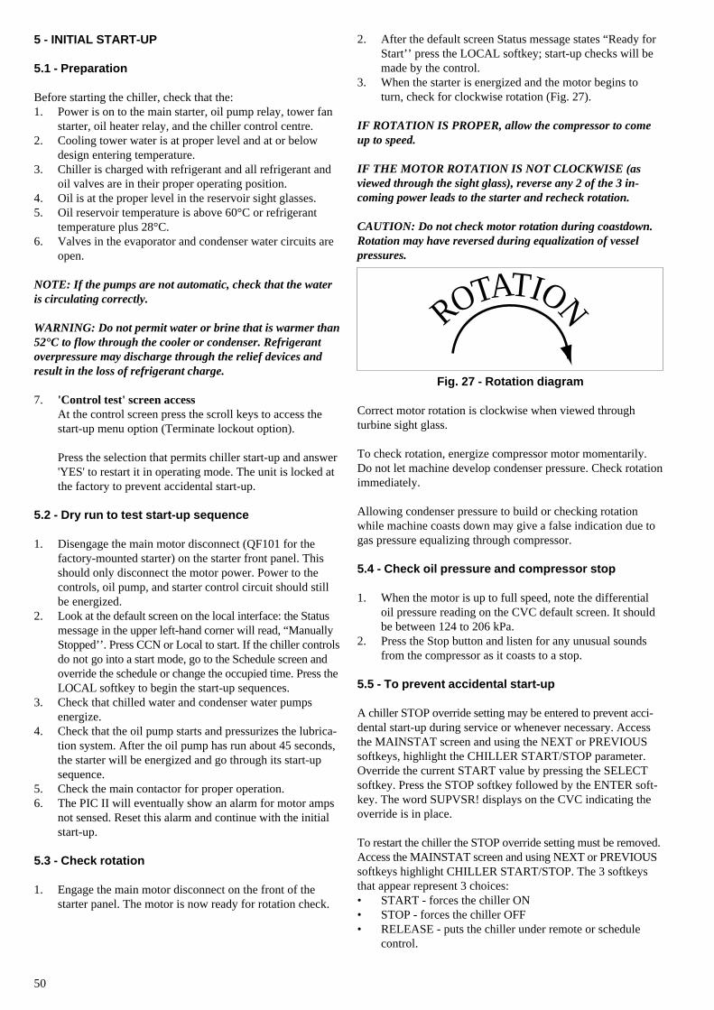
50
ROTATION
5 - INITIAL START-UP
5.1 - Preparation
Before starting the chiller, check that the:1. Power is on to the main starter, oil pump relay, tower fan
starter, oil heater relay, and the chiller control centre.2. Cooling tower water is at proper level and at or below
design entering temperature.3. Chiller is charged with refrigerant and all refrigerant and
oil valves are in their proper operating position.4. Oil is at the proper level in the reservoir sight glasses.5. Oil reservoir temperature is above 60°C or refrigerant
temperature plus 28°C.6. Valves in the evaporator and condenser water circuits are
open.
NOTE: If the pumps are not automatic, check that the wateris circulating correctly.
WARNING: Do not permit water or brine that is warmer than52°C to flow through the cooler or condenser. Refrigerantoverpressure may discharge through the relief devices andresult in the loss of refrigerant charge.
7. 'Control test' screen accessAt the control screen press the scroll keys to access thestart-up menu option (Terminate lockout option).
Press the selection that permits chiller start-up and answer'YES' to restart it in operating mode. The unit is locked atthe factory to prevent accidental start-up.
5.2 - Dry run to test start-up sequence
1. Disengage the main motor disconnect (QF101 for thefactory-mounted starter) on the starter front panel. Thisshould only disconnect the motor power. Power to thecontrols, oil pump, and starter control circuit should stillbe energized.
2. Look at the default screen on the local interface: the Statusmessage in the upper left-hand corner will read, “ManuallyStopped’’. Press CCN or Local to start. If the chiller controlsdo not go into a start mode, go to the Schedule screen andoverride the schedule or change the occupied time. Press theLOCAL softkey to begin the start-up sequences.
3. Check that chilled water and condenser water pumpsenergize.
4. Check that the oil pump starts and pressurizes the lubrica-tion system. After the oil pump has run about 45 seconds,the starter will be energized and go through its start-upsequence.
5. Check the main contactor for proper operation.6. The PIC II will eventually show an alarm for motor amps
not sensed. Reset this alarm and continue with the initialstart-up.
5.3 - Check rotation
1. Engage the main motor disconnect on the front of thestarter panel. The motor is now ready for rotation check.
2. After the default screen Status message states “Ready forStart’’ press the LOCAL softkey; start-up checks will bemade by the control.
3. When the starter is energized and the motor begins toturn, check for clockwise rotation (Fig. 27).
IF ROTATION IS PROPER, allow the compressor to comeup to speed.
IF THE MOTOR ROTATION IS NOT CLOCKWISE (asviewed through the sight glass), reverse any 2 of the 3 in-coming power leads to the starter and recheck rotation.
CAUTION: Do not check motor rotation during coastdown.Rotation may have reversed during equalization of vesselpressures.
Fig. 27 - Rotation diagram
Correct motor rotation is clockwise when viewed throughturbine sight glass.
To check rotation, energize compressor motor momentarily.Do not let machine develop condenser pressure. Check rotationimmediately.
Allowing condenser pressure to build or checking rotationwhile machine coasts down may give a false indication due togas pressure equalizing through compressor.
5.4 - Check oil pressure and compressor stop
1. When the motor is up to full speed, note the differentialoil pressure reading on the CVC default screen. It shouldbe between 124 to 206 kPa.
2. Press the Stop button and listen for any unusual soundsfrom the compressor as it coasts to a stop.
5.5 - To prevent accidental start-up
A chiller STOP override setting may be entered to prevent acci-dental start-up during service or whenever necessary. Accessthe MAINSTAT screen and using the NEXT or PREVIOUSsoftkeys, highlight the CHILLER START/STOP parameter.Override the current START value by pressing the SELECTsoftkey. Press the STOP softkey followed by the ENTER soft-key. The word SUPVSR! displays on the CVC indicating theoverride is in place.
To restart the chiller the STOP override setting must be removed.Access the MAINSTAT screen and using NEXT or PREVIOUSsoftkeys highlight CHILLER START/STOP. The 3 softkeysthat appear represent 3 choices:• START - forces the chiller ON• STOP - forces the chiller OFF• RELEASE - puts the chiller under remote or schedule
control.
51
To return the chiller to normal control, press the RELEASEsoftkey followed by the ENTER softkey. For more information,see the chapters relating to start-up.
The default screen message line indicates which command is ineffect. Open the disconnects or the high-voltage circuit breakers.
5.6 - Check chiller operating condition
Check to be sure that chiller temperatures, pressures, waterflows, and oil and refrigerant levels indicate that the system isfunctioning properly.
5.7 - Instruct the customer operator
Check to be sure that the operator(s) understand all operatingand maintenance procedures. Point out the various chiller partsand explain their function as part of the complete system.
Cooler-condenserFloat chamber, relief devices, refrigerant charging valve,temperature sensor locations, pressure transducer locations,Schrader fittings, waterboxes and tubes, and vents and drains.
Optional pumpout storage tank and pumpout system (referto transfer unit installation manual, document order no. 19999).Transfer valves and pumpout system, refrigerant charging andpumpdown procedure, and relief devices.
Motor compressor assemblyGuide vane actuator, transmission, motor cooling system, oilcooling system, temperature and pressure sensors, oil sightglasses, integral oil pump, isolatable oil filter, extra oil and motortemperature sensors, synthetic oil, and compressor serviceability.
Motor compressor lubrication systemOil pump, cooler filter, oil heater, oil charge and specification,operating and shutdown oil level, temperature and pressure,and oil charging connections.
Control systemCCN and CVC start, reset, menu, softkey functions, localinterface operation, occupancy schedule, set points, safetycontrols, and auxiliary and optional controls.
Auxiliary equipmentStarters and disconnects, separate electrical sources, pumps,and cooling tower.
Describe chiller cyclesRefrigerant, motor cooling, lubrication, and oil reclaim.
Review maintenanceScheduled, routine, and extended shutdowns, importance of alog sheet, importance of water treatment and tube cleaning, andimportance of maintaining a leak-free chiller.
Safety devices and proceduresElectrical disconnects, relief device inspection, and handlingrefrigerant.
Check operator knowledgeStart, stop, and shut-down procedures, safety and operatingcontrols, refrigerant and oil charging, and job safety.
6 - OPERATING INSTRUCTIONS
6.1 - Operator duties
1. Become familiar with refrigeration chiller and relatedequipment before operating the chiller.
2. Prepare the system for start-up, start and stop the chiller,and place the system in a shutdown condition.
3. Maintain a log of operating conditions and document anyabnormal readings.
4. Inspect the equipment, make routine adjustments, andperform a Control Test. Maintain the proper oil andrefrigerant levels.
5. Protect the system from damage during shutdown periods.6. Maintain the set point, time schedules, and other PIC II
functions.
Prepare the chiller for start-upFollow the steps described in the Initial Start-Up section.
6.2 - To start the chiller
1. Start the water pumps, if they are not automatic.2. On the CVC default screen, press the LOCAL or CCN
softkey to start the system. If the chiller is in theOCCUPIED mode and the start timers have expired, thestart sequence will start. Follow the procedure describedin the Start-Up/Shutdown/Recycle section.
6.3 - Check the running system
After the compressor starts, the operator should monitor theCVC display and observe the parameters for normal operatingconditions:1. The oil reservoir temperature should be above 49°C during
shutdown, and above 52°C during compressor operation.2. The bearing oil temperature accessed on the 'COMPRESS'
status screen should be 49 to 74°C. If the bearing tempera-ture reads more than 83°C with the oil pump running, stopthe chiller and determine the cause of the high temperature.Do not restart the chiller until corrected.
3. The oil level should be visible anywhere in one of the twosight glasses. Foaming oil is acceptable as long as the oilpressure and temperature are within limits.
4. The oil pressure should be between 124 to 207 kPa differ-ential, as seen on the CVC default screen. Typically thereading will be 124 to 172 kPa at initial start-up.
5. The moisture indicator sight glass on the refrigerant motorcooling line should indicate refrigerant flow and a drycondition.
6. The condenser pressure and temperature varies with thechiller design conditions. Typically the temperature rangewill be 15 to 41°C. The condenser entering water tempe-rature should be controlled below the specified designentering water temperature to save on compressor kilowattrequirements.
7. Cooler pressure and temperature also will vary with thedesign conditions. Typically the temperature range will be1 to 8°C.
52
8. The compressor may operate at full capacity for a shorttime after the pulldown ramping has ended, even thoughthe building load is small. The active electrical demandsetting can be overridden to limit the compressor IkW, orthe pulldown rate can be decreased to avoid a high demandcharge for the short period of high demand operation. Pull-down rate can be based on power output or temperature rate.It is accessed on the equipment service screen 'RAMP DEM'.
6.4 - To stop the chiller
1. The occupancy schedule will start and stop the chillerautomatically once the time schedule is set up.
2. By pressing the STOP button for one second, the alarmlight will blink once to confirm that the button has beenpressed. Then, the compressor will follow the normal shut-down sequence as described in the Controls section. Thechiller will not restart until the CCN or LOCAL softkey ispressed. The chiller is now in the 'Off control' mode.
Do not attempt to stop the chiller by opening an isolating switch.High-intensity arcing may occur. Do not restart the chilleruntil the problem is diagnosed and corrected.
6.5 - After limited shutdown
No special preparations should be necessary. Follow the regularpreliminary checks and starting procedures.
6.6 - Extended shutdown
The refrigerant should be transferred into the pumpout storagetank (if supplied; see Pumpout and Refrigerant Transfer Proce-dures) in order to reduce chiller pressure and the possibility ofleaks. Maintain a holding charge of 2.27 to 4.5 kg of refrigerantor nitrogen to prevent air from leaking into the chiller.
If freezing temperatures are likely to occur in the chiller area,drain the chilled water, condenser water, and the pumpoutcondenser water circuits to avoid freeze-up. Keep the waterboxdrains open.
Leave the oil charge in the chiller with the oil heater and controlsenergized to maintain the minimum oil reservoir temperature.
6.7 - After extended shutdown
Be sure that the water system drains are closed. It may beadvisable to flush the water circuits to remove any soft rustwhich may have formed. This is a good time to clean the tubevessel and inspect the probe pressure taps and change them, ifnecessary.
Check the cooler pressure on the CVC default screen, and com-pare to the original holding charge that was left in the chiller. If(after adjusting for ambient temperature changes) any loss inpressure is indicated, check for refrigerant leaks. See "Checkchiller tightness" section.
Recharge the chiller by transferring refrigerant from the pumpoutstorage tank (if supplied). Refer to transfer unit installationmanual, document order no. 19999 and sections 4.13 "Chillerequalization without pumpout unit" and 4.14 "Chiller equaliza-tion with pumpout unit". Observe the freeze-up precautions.
Carefully make all regular preliminary and running systemchecks. Perform a Control Test before start-up. If the compressoroil level appears abnormally high, the oil may have absorbedrefrigerant. Make sure that the oil temperature is above 60°C orcooler refrigerant temperature 27°C.
6.8 - Cold-weather operation
When the entering condenser water drops very low, theoperator should automatically cycle the cooling tower fans offto keep the temperature up. The PIC II controls have a towerfan output (terminals 11 and 12 of the ISM).
6.9 - Manual guide vane operation
Manual operation of the guide vanes in order to check controloperation or control of the guide vanes in an emergency opera-tion is possible by overriding the target guide vane position.Access the 'COMPRESS' screen on the interface, and highlightTARGET GUIDE VANE POSITION. To control the position,enter a percentage of guide vane opening that is desired. Zeropercent is fully closed, 100% is fully open. To release the guidevanes to AUTOMATIC mode, press the RELEASE softkey.
NOTE: Manual control will increase the guide vanes andoverride the pulldown rate during start-up. Motor currentabove the electrical demand setting, capacity overrides, andchilled water below control point will override the manualtarget and close the guide vanes. For descriptions of capacityoverrides and set points, see the Capacity Override section(Controls IOM).
6.10 - Refrigeration logA refrigeration log, such as the one shown in Fig. 28, providesa convenient checklist for routine inspection and maintenanceand provides a continuous record of chiller performance. It isan aid in scheduling routine maintenance and in diagnosingchiller problems.
Keep a record of the chiller pressures, temperatures, and liquidlevels on a sheet similar to that shown. Automatic recording ofPIC II data is possible through the use of CCN devices such asthe Data Collection module and a Building Supervisor. Contactyour Carrier representative for more information.
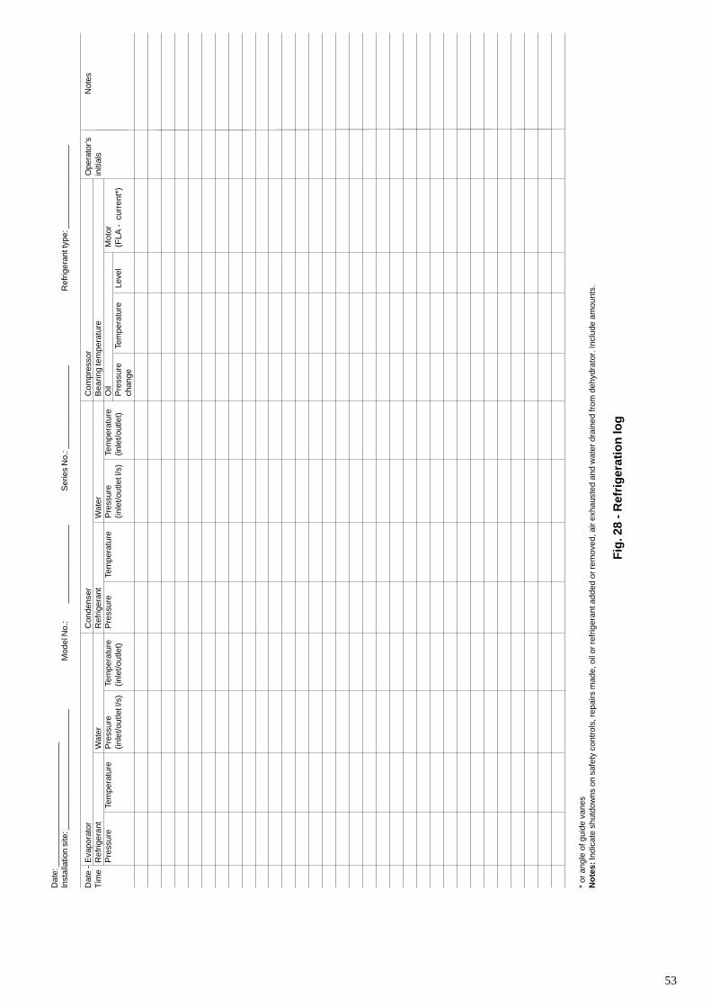
53
Dat
e: _
____
____
____
____
____
____
__In
stal
latio
n si
te: _
____
____
____
____
____
____
_M
odel
No.
:__
____
____
____
___
Ser
ies
No.
: ___
____
____
____
___
Ref
riger
ant t
ype:
___
____
____
____
___
Dat
e -
Eva
pora
tor
Con
dens
erC
ompr
esso
rO
pera
tor’s
Not
esT
ime
Ref
riger
ant
Wat
erR
efrig
eran
tW
ater
Bea
ring
tem
pera
ture
initi
als
Pre
ssur
eTe
mpe
ratu
reP
ress
ure
Tem
pera
ture
Pre
ssur
eTe
mpe
ratu
reP
ress
ure
Tem
pera
ture
Oil
Mot
or(in
let/o
utle
t l/s
)(in
let/o
utle
t)(in
let/o
utle
t l/s
)(in
let/o
utle
t)P
ress
ure
Tem
pera
ture
Leve
l(F
LA -
cur
rent
*)ch
ange
* or
ang
le o
f gui
de v
anes
No
tes:
Indi
cate
shu
tdow
ns o
n sa
fety
con
trol
s, re
pairs
mad
e, o
il or
refr
iger
ant a
dded
or r
emov
ed, a
ir ex
haus
ted
and
wat
er d
rain
ed fr
om d
ehyd
rato
r. In
clud
e am
ount
s.
Fig
. 28
- Ref
rig
erat
ion
log
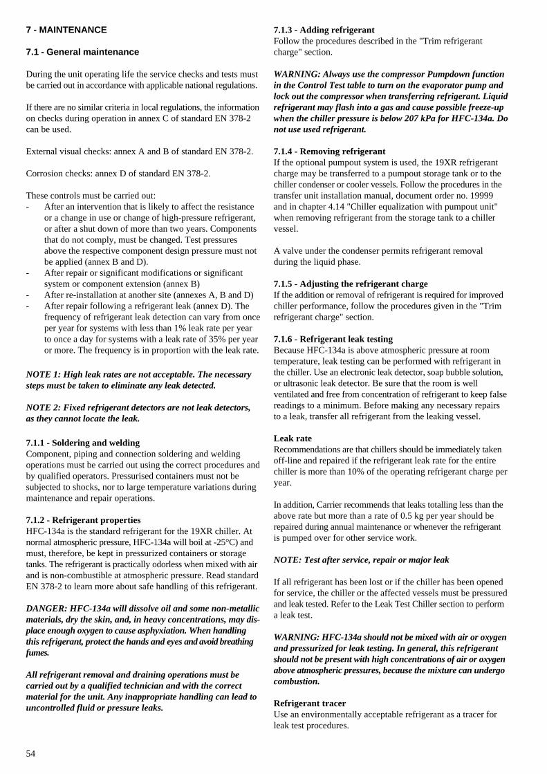
54
7 - MAINTENANCE
7.1 - General maintenance
During the unit operating life the service checks and tests mustbe carried out in accordance with applicable national regulations.
If there are no similar criteria in local regulations, the informationon checks during operation in annex C of standard EN 378-2can be used.
External visual checks: annex A and B of standard EN 378-2.
Corrosion checks: annex D of standard EN 378-2.
These controls must be carried out:- After an intervention that is likely to affect the resistance
or a change in use or change of high-pressure refrigerant,or after a shut down of more than two years. Componentsthat do not comply, must be changed. Test pressuresabove the respective component design pressure must notbe applied (annex B and D).
- After repair or significant modifications or significantsystem or component extension (annex B)
- After re-installation at another site (annexes A, B and D)- After repair following a refrigerant leak (annex D). The
frequency of refrigerant leak detection can vary from onceper year for systems with less than 1% leak rate per yearto once a day for systems with a leak rate of 35% per yearor more. The frequency is in proportion with the leak rate.
NOTE 1: High leak rates are not acceptable. The necessarysteps must be taken to eliminate any leak detected.
NOTE 2: Fixed refrigerant detectors are not leak detectors,as they cannot locate the leak.
7.1.1 - Soldering and weldingComponent, piping and connection soldering and weldingoperations must be carried out using the correct procedures andby qualified operators. Pressurised containers must not besubjected to shocks, nor to large temperature variations duringmaintenance and repair operations.
7.1.2 - Refrigerant propertiesHFC-134a is the standard refrigerant for the 19XR chiller. Atnormal atmospheric pressure, HFC-134a will boil at -25°C) andmust, therefore, be kept in pressurized containers or storagetanks. The refrigerant is practically odorless when mixed with airand is non-combustible at atmospheric pressure. Read standardEN 378-2 to learn more about safe handling of this refrigerant.
DANGER: HFC-134a will dissolve oil and some non-metallicmaterials, dry the skin, and, in heavy concentrations, may dis-place enough oxygen to cause asphyxiation. When handlingthis refrigerant, protect the hands and eyes and avoid breathingfumes.
All refrigerant removal and draining operations must becarried out by a qualified technician and with the correctmaterial for the unit. Any inappropriate handling can lead touncontrolled fluid or pressure leaks.
7.1.3 - Adding refrigerantFollow the procedures described in the "Trim refrigerantcharge" section.
WARNING: Always use the compressor Pumpdown functionin the Control Test table to turn on the evaporator pump andlock out the compressor when transferring refrigerant. Liquidrefrigerant may flash into a gas and cause possible freeze-upwhen the chiller pressure is below 207 kPa for HFC-134a. Donot use used refrigerant.
7.1.4 - Removing refrigerantIf the optional pumpout system is used, the 19XR refrigerantcharge may be transferred to a pumpout storage tank or to thechiller condenser or cooler vessels. Follow the procedures in thetransfer unit installation manual, document order no. 19999and in chapter 4.14 "Chiller equalization with pumpout unit"when removing refrigerant from the storage tank to a chillervessel.
A valve under the condenser permits refrigerant removalduring the liquid phase.
7.1.5 - Adjusting the refrigerant chargeIf the addition or removal of refrigerant is required for improvedchiller performance, follow the procedures given in the "Trimrefrigerant charge" section.
7.1.6 - Refrigerant leak testingBecause HFC-134a is above atmospheric pressure at roomtemperature, leak testing can be performed with refrigerant inthe chiller. Use an electronic leak detector, soap bubble solution,or ultrasonic leak detector. Be sure that the room is wellventilated and free from concentration of refrigerant to keep falsereadings to a minimum. Before making any necessary repairsto a leak, transfer all refrigerant from the leaking vessel.
Leak rateRecommendations are that chillers should be immediately takenoff-line and repaired if the refrigerant leak rate for the entirechiller is more than 10% of the operating refrigerant charge peryear.
In addition, Carrier recommends that leaks totalling less than theabove rate but more than a rate of 0.5 kg per year should berepaired during annual maintenance or whenever the refrigerantis pumped over for other service work.
NOTE: Test after service, repair or major leak
If all refrigerant has been lost or if the chiller has been openedfor service, the chiller or the affected vessels must be pressuredand leak tested. Refer to the Leak Test Chiller section to performa leak test.
WARNING: HFC-134a should not be mixed with air or oxygenand pressurized for leak testing. In general, this refrigerantshould not be present with high concentrations of air or oxygenabove atmospheric pressures, because the mixture can undergocombustion.
Refrigerant tracerUse an environmentally acceptable refrigerant as a tracer forleak test procedures.
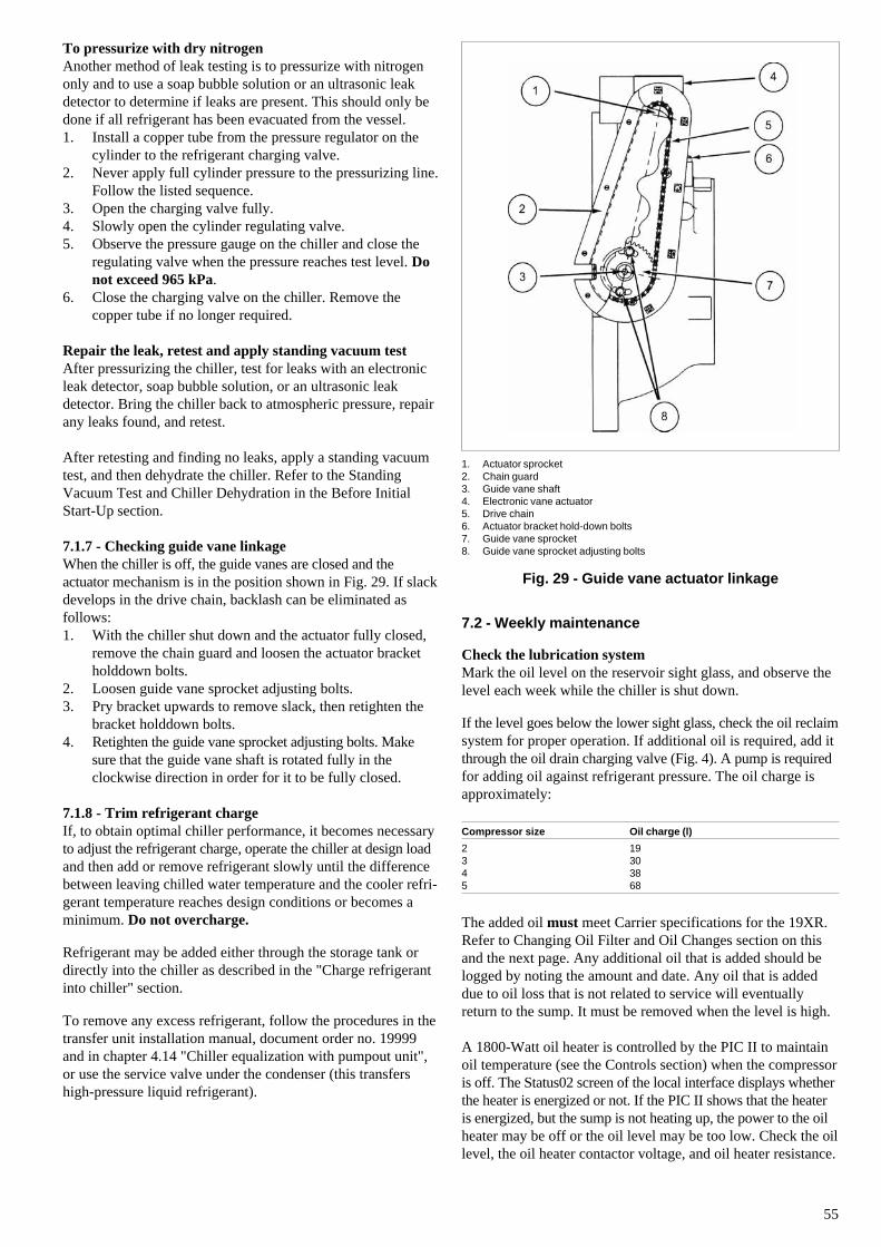
55
To pressurize with dry nitrogenAnother method of leak testing is to pressurize with nitrogenonly and to use a soap bubble solution or an ultrasonic leakdetector to determine if leaks are present. This should only bedone if all refrigerant has been evacuated from the vessel.1. Install a copper tube from the pressure regulator on the
cylinder to the refrigerant charging valve.2. Never apply full cylinder pressure to the pressurizing line.
Follow the listed sequence.3. Open the charging valve fully.4. Slowly open the cylinder regulating valve.5. Observe the pressure gauge on the chiller and close the
regulating valve when the pressure reaches test level. Donot exceed 965 kPa.
6. Close the charging valve on the chiller. Remove thecopper tube if no longer required.
Repair the leak, retest and apply standing vacuum testAfter pressurizing the chiller, test for leaks with an electronicleak detector, soap bubble solution, or an ultrasonic leakdetector. Bring the chiller back to atmospheric pressure, repairany leaks found, and retest.
After retesting and finding no leaks, apply a standing vacuumtest, and then dehydrate the chiller. Refer to the StandingVacuum Test and Chiller Dehydration in the Before InitialStart-Up section.
7.1.7 - Checking guide vane linkageWhen the chiller is off, the guide vanes are closed and theactuator mechanism is in the position shown in Fig. 29. If slackdevelops in the drive chain, backlash can be eliminated asfollows:1. With the chiller shut down and the actuator fully closed,
remove the chain guard and loosen the actuator bracketholddown bolts.
2. Loosen guide vane sprocket adjusting bolts.3. Pry bracket upwards to remove slack, then retighten the
bracket holddown bolts.4. Retighten the guide vane sprocket adjusting bolts. Make
sure that the guide vane shaft is rotated fully in theclockwise direction in order for it to be fully closed.
7.1.8 - Trim refrigerant chargeIf, to obtain optimal chiller performance, it becomes necessaryto adjust the refrigerant charge, operate the chiller at design loadand then add or remove refrigerant slowly until the differencebetween leaving chilled water temperature and the cooler refri-gerant temperature reaches design conditions or becomes aminimum. Do not overcharge.
Refrigerant may be added either through the storage tank ordirectly into the chiller as described in the "Charge refrigerantinto chiller" section.
To remove any excess refrigerant, follow the procedures in thetransfer unit installation manual, document order no. 19999and in chapter 4.14 "Chiller equalization with pumpout unit",or use the service valve under the condenser (this transfershigh-pressure liquid refrigerant).
1. Actuator sprocket2. Chain guard3. Guide vane shaft4. Electronic vane actuator5. Drive chain6. Actuator bracket hold-down bolts7. Guide vane sprocket8. Guide vane sprocket adjusting bolts
Fig. 29 - Guide vane actuator linkage
7.2 - Weekly maintenance
Check the lubrication systemMark the oil level on the reservoir sight glass, and observe thelevel each week while the chiller is shut down.
If the level goes below the lower sight glass, check the oil reclaimsystem for proper operation. If additional oil is required, add itthrough the oil drain charging valve (Fig. 4). A pump is requiredfor adding oil against refrigerant pressure. The oil charge isapproximately:
Compressor size Oil charge (l)
2 193 304 385 68
The added oil must meet Carrier specifications for the 19XR.Refer to Changing Oil Filter and Oil Changes section on thisand the next page. Any additional oil that is added should belogged by noting the amount and date. Any oil that is addeddue to oil loss that is not related to service will eventuallyreturn to the sump. It must be removed when the level is high.
A 1800-Watt oil heater is controlled by the PIC II to maintainoil temperature (see the Controls section) when the compressoris off. The Status02 screen of the local interface displays whetherthe heater is energized or not. If the PIC II shows that the heateris energized, but the sump is not heating up, the power to the oilheater may be off or the oil level may be too low. Check the oillevel, the oil heater contactor voltage, and oil heater resistance.
56
9. Evacuate the filter housing by placing a vacuum pump onthe charging valve. Follow the normal evacuation proce-dures. Shut the charging valve when done and reconnect thevalve so that new oil can be pumped into the filter housing.Fill with the same amount that was removed, then closethe charging valve.
10. Remove the hose from the charging valve, open the isola-tion valves to the filter housing, and turn on the power tothe pump and the motor.
7.3.4 - Oil specificationIf oil is added, it must meet the following Carrier specifications:• Oil type for units using R-134a• Inhibited polyolester-based synthetic compressor oil for-
matted for use with HFC, gear-driven, hermetic compressors• ISO Viscosity Grade 68
The polyolester-based oil (P/N: PP23BZ103) may be orderedfrom your local Carrier representative.
Oil changesCarrier recommends changing the oil after the first year of opera-tion and every three years thereafter in addition to an oil analysis.However, if a continuous oil monitoring system is used and ayearly oil analysis is performed (Periodic Oil Diagnosis), timebetween oil changes can be extended.
To change the oil1. Transfer the refrigerant into the chiller condenser (for iso-
latable vessels) or a pumpout storage tank.2. Mark the existing oil level.3. Open the control and oil heater circuit breaker.4. When the chiller pressure is 34 kPa or less, drain the oil
reservoir by opening the oil charging valve (Fig. 2). Slowlyopen the valve against refrigerant pressure (see chapter'Safety Considerations').
5. Change the oil filter at this time.6. Change the refrigerant filter at this time.7. Charge the chiller with oil. The 19XR uses approximately
30/38 l (compressor size 3/compressor size 4), so that theoil level is visible in the upper sight glass (Fig. 2). Turn onthe power to the oil heater and let the PIC II warm it up toat least 60°C. Operate the oil pump manually, through theControl Test, for 2 minutes. The oil level should be full inthe lower sight glass for shutdown conditions. If the oil levelis above 1/2 full in the upper sight glass, remove theexcess oil.
7.3.5 - Refrigerant filterA refrigerant filter/drier, located on the refrigerant cooling lineto the motor, should be changed once a year or more often iffilter condition indicates a need for more frequent replacement.Change the filter by closing the filter isolation valves (Fig. 3)and slowly opening the flare fittings with a wrench and back-upwrench to relieve the pressure. A moisture indicator sight glassis located beyond this filter to indicate the volume and moisturein the refrigerant. If the moisture indicator indicates moisture,locate the source of water immediately by performing a thoroughleak check.
The PIC II will not permit compressor start-up if the oil tempe-rature is too low. The control will continue with start-up onlyafter the temperature is within limits.
7.3 - Scheduled maintenance
Any work must be done by authorised personnel. Establish aregular maintenance schedule based on the actual chillerrequirements such as chiller load, run hours, and water quality.The time intervals listed in this section are offered as guides toservice only.
7.3.1 - Service ontimeThe CVC will display a SERVICE ONTIME value on the'MAINSTAT' status screen. This value should be reset to zeroby the service person or the operator each time major servicework is completed so that time between service can be viewed.
7.3.2 - Inspect the control centreMaintenance is limited to general cleaning and tightening ofconnections. Vacuum the cabinet to eliminate dust build-up. Ifthe chiller control malfunctions, refer to the TroubleshootingGuide section for control checks and adjustments.
CAUTION: Be sure power to the control centre is off whencleaning and tightening connections inside the control centre.
Check safety and operating controls monthlyTo ensure chiller protection, the "Control test automated test"should be done at least once per month. See Table 3 (ControlsIOM) for safety control settings (see chapter 'Verification ofthe pressure switch calibration').
7.3.3 - Changing oil filterChange the oil filter on a yearly basis or when the chiller isopened for repairs. The 19XR has an isolatable oil filter so thatthe filter may be changed with the refrigerant remaining in thechiller. Use the following procedure:1. Make sure that the compressor is off and the disconnect
for the compressor is open.2. Disconnect the power to the oil pump.3. Close the oil filter isolation valves (Fig. 4).4. Connect an oil charging hose from the oil charging valve
(Fig. 4) and place the other end in a clean container suitablefor used oil. The oil drained from the filter housing shouldbe used as an oil sample and sent to a laboratory for properanalysis. Do not contaminate this sample.
5. Slowly open the charging valve to drain the oil from thehousing.
CAUTION: The oil filter housing is at a high pressure.Relieve this pressure slowly.
6. Once all oil has been drained, place some rags or absorbentmaterial under the oil filter housing to catch any dripsonce the filter is opened. Remove the 4 bolts from the endof the filter housing and remove the filter cover.
7. Remove the filter retainer by unscrewing the retainer nut.The filter may now be removed and disposed of properly.
8. Replace the old filter with a new filter. Install the filterretainer and tighten down the retainer nut. Install the filtercover and tighten the 4 bolts.
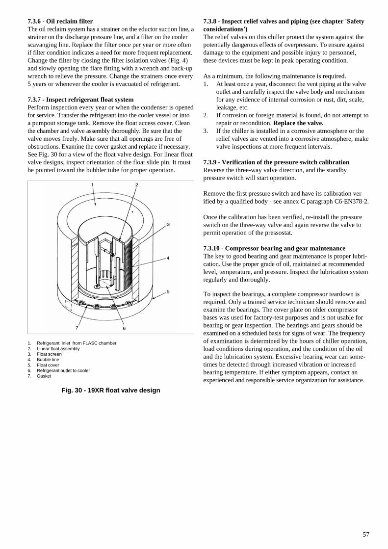
57
7.3.6 - Oil reclaim filterThe oil reclaim system has a strainer on the eductor suction line, astrainer on the discharge pressure line, and a filter on the coolerscavanging line. Replace the filter once per year or more oftenif filter condition indicates a need for more frequent replacement.Change the filter by closing the filter isolation valves (Fig. 4)and slowly opening the flare fitting with a wrench and back-upwrench to relieve the pressure. Change the strainers once every5 years or whenever the cooler is evacuated of refrigerant.
7.3.7 - Inspect refrigerant float systemPerform inspection every year or when the condenser is openedfor service. Transfer the refrigerant into the cooler vessel or intoa pumpout storage tank. Remove the float access cover. Cleanthe chamber and valve assembly thoroughly. Be sure that thevalve moves freely. Make sure that all openings are free ofobstructions. Examine the cover gasket and replace if necessary.See Fig. 30 for a view of the float valve design. For linear floatvalve designs, inspect orientation of the float slide pin. It mustbe pointed toward the bubbler tube for proper operation.
1. Refrigerant inlet from FLASC chamber2. Linear float assembly3. Float screen4. Bubble line5. Float cover6. Refrigerant outlet to cooler7. Gasket
Fig. 30 - 19XR float valve design
7.3.8 - Inspect relief valves and piping (see chapter 'Safetyconsiderations')The relief valves on this chiller protect the system against thepotentially dangerous effects of overpressure. To ensure againstdamage to the equipment and possible injury to personnel,these devices must be kept in peak operating condition.
As a minimum, the following maintenance is required.1. At least once a year, disconnect the vent piping at the valve
outlet and carefully inspect the valve body and mechanismfor any evidence of internal corrosion or rust, dirt, scale,leakage, etc.
2. If corrosion or foreign material is found, do not attempt torepair or recondition. Replace the valve.
3. If the chiller is installed in a corrosive atmosphere or therelief valves are vented into a corrosive atmosphere, makevalve inspections at more frequent intervals.
7.3.9 - Verification of the pressure switch calibrationReverse the three-way valve direction, and the standbypressure switch will start operation.
Remove the first pressure switch and have its calibration ver-ified by a qualified body - see annex C paragraph C6-EN378-2.
Once the calibration has been verified, re-install the pressureswitch on the three-way valve and again reverse the valve topermit operation of the pressostat.
7.3.10 - Compressor bearing and gear maintenanceThe key to good bearing and gear maintenance is proper lubri-cation. Use the proper grade of oil, maintained at recommendedlevel, temperature, and pressure. Inspect the lubrication systemregularly and thoroughly.
To inspect the bearings, a complete compressor teardown isrequired. Only a trained service technician should remove andexamine the bearings. The cover plate on older compressorbases was used for factory-test purposes and is not usable forbearing or gear inspection. The bearings and gears should beexamined on a scheduled basis for signs of wear. The frequencyof examination is determined by the hours of chiller operation,load conditions during operation, and the condition of the oiland the lubrication system. Excessive bearing wear can some-times be detected through increased vibration or increasedbearing temperature. If either symptom appears, contact anexperienced and responsible service organization for assistance.
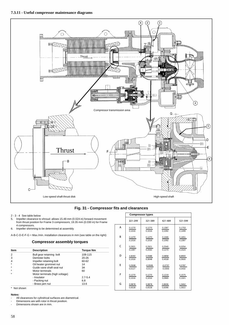
58
2221-299 321-389 421-489 521-599
A 0,1270 0,1270 0,1397 0,1753
0,1016 0,1016 0,1092 0,1499
B 0,1270 0,1270 0,1346 0,1651
0,1016 0,1016 0,1092 0,1397
C 0,2921 0,2921 0,2540 0,0254
0,1397 0,2032 0,1270 0,1524
D 4,8260 0,5588 0,6858 8,8900
0,1016 0,3048 0,4318 6,3500
E 0,0508 -0,0508 -0,0737 0,0787
0,0127 -0,0127 -0,0356 0,0432
F 0,1270 0,1270 0,1219 0,1575
0,1016 0,1016 0,0965 0,1321
G 3,9878 3,9878 0,8636 1,3462
0,6528 0,6528 0,6096 1,0922
Compressor transmission area
2 - 3 - 4 See table below5. Impeller clearance to shroud: allows 15.48 mm (0.024 in) forward movement
from thrust position for Frame 3 compressors; 19.35 mm (0.030 in) for Frame4 compressors.
6. Impeller shimming to be determined at assembly
A-B-C-D-E-F-G = Max./min. installation clearances in mm (see table on the right):
7.3.11 - Useful compressor maintenance diagrams
Low-speed shaft thrust disk
Compressor assembly torques
Item Description Torque Nm
2 Bull gear retaining bolt 108-1153 Demister bolts 20-264 Impeller retaining bolt 60-62* Oil heater grommet nut 14* Guide vane shaft seal nut 34* Motor terminals 60* Motor terminals (high voltage)
- Insulator 2.7-5.4- Packing nut 6.8- Brass jam nut 13.6
* Not shown
Notes:- All clearances for cylindrical surfaces are diametrical.- Dimensions are with rotor in thrust position.- Dimensions shown are in mm.
High-speed shaft
Fig. 31 - Compressor fits and clearances
Thrust
Thrust
Compressor types
59
7.3.12 - Inspect the heat exchanger tubes
CoolerInspect and clean the cooler tubes at the end of the first operatingseason. Because these tubes have internal ridges, a rotary-typetube cleaning system is necessary to fully clean the tubes. Uponinspection, the tube condition will determine the scheduled fre-quency for cleaning and will indicate whether water treatment isadequate in the chilled water/ brine circuit. Inspect the enteringand leaving chilled water temperature sensors for signs of cor-rosion or scale. If a sensor or the probe connections are scaledor the water flow control probes are corroded, they should bechanged.
Verify the flow and speed with the Electronic CATalogueselection program for the unit.
CondenserSince this water circuit is usually an open-type system, the tubesmay be subject to contamination and scale. Clean the condensertubes with a rotary tube cleaning system at least once per year andmore often if the water is contaminated. Inspect the entering andleaving condenser water sensors for signs of corrosion or scale.Replace the sensor if corroded or remove any scale if found.
Verify the flow and speed with the Electronic CATalogueselection program for the unit.
Higher than normal condenser pressures, together with theinability to reach full refrigeration load, usually indicate dirtytubes or air in the chiller. If the refrigeration log indicates a riseabove normal condenser pressures, check the condenser refri-gerant temperature against the leaving condenser water tempera-ture. If this reading is more than what the design difference issupposed to be, then the condenser tubes may be dirty or waterflow may be incorrect. Because HFC134-a is a high-pressurerefrigerant, air usually does not enter the chiller.
In certain cases where a zinc anode (option) is used, regularlycheck its condition.
During the tube cleaning process, use brushes especially designed toavoid scraping and scratching the tube wall. Contact your Carrierrepresentative to obtain these brushes. Do not use wire brushes.
CAUTION: Hard scale may require chemical treatment forits prevention or removal. Consult a water treatment specialistfor proper treatment.
7.3.13 - Water leaksWater is indicated during chiller operation by the refrigerantmoisture indicator (Fig. 2) on the refrigerant motor coolingline. Water leaks should be repaired immediately (see chapter'Water treatment').
CAUTION: Chiller must be dehydrated after repair of waterleaks. See Chiller Dehydration section.
Water treatmentUntreated or improperly treated water may result in corrosion,scaling, erosion, or algae. The services of a qualified watertreatment specialist should be obtained to develop and monitora treatment program.
CAUTION: Water must be within design flow limits, clean, andtreated to ensure proper chiller performance and reduce thepotential of tube damage due to corrosion, scaling, erosion,and algae. Carrier assumes no responsibility for chiller damageresulting from untreated or improperly treated water.
7.3.14 - Inspect the starting equipmentBefore working on any starter, shut off the chiller and open alldisconnects supplying power to the starter.
The disconnect on the starter front panel does not de-energizeall internal circuits. Open all internal and remote disconnectsbefore servicing the starter. Check the cable tightness.
WARNING: Circuit breaker/disconnect switch QF101 mustonly be opened in excpetional circumstances and for a limitedtime, as compressor post-lubrication is not guaranteed underthese conditions.
Inspect starter contact surfaces for wear or pitting onmechanical-type starters. Do not sandpaper or file silverplatedcontacts. Follow the starter manufacturer’s instructions forcontact replacement, lubrication, spare parts ordering, and othermaintenance requirements.
Periodically vacuum or blow off accumulated debris on theinternal parts with a high-velocity, low-pressure blower. Powerconnections on newly installed starters may relax and loosenafter a month of operation. Turn power off and retighten.Recheck annually thereafter.
CAUTION: Loose power connections can cause voltagespikes, overheating, malfunctioning, or failures.
7.3.15 - Check pressure transducersOnce a year, the pressure transducers should be checked against apressure gauge reading. Check all four transducers: the 2 oildifferential pressure transducers, the condenser pressure trans-ducer, and the cooler pressure transducer, and the water-sideevaporation probes (two on the condenser and two on theevaporator).
Note the evaporator and condenser pressure readings on the CVC'HEAT-EX' status screen. Attach an accurate set of refrigera-tion gauges to the cooler and condenser Schrader fittings. Com-pare the two readings. If there is a difference in readings, thetransducer can be calibrated, as described in the TroubleshootingGuide section. Oil differential pressure should be zero wheneverthe compressor is off.
7.3.16 - Corrosion controlAll metallic parts of the unit (chassis, casing panels, controlboxes, heat exchangers etc.) are protected against corrosion bya coating of powder or liquid paint. To prevent the risk ofblistering corrosion that can appear when moisture penetratesunder the protective coatings, it is necessary to carry outperiodic checks of the coating (paint) condition.

Manufactured by Carrier SA, Montluel, France.Order No. 11997-76, 06.2004. Supersedes order No.: 11997-76, 06.2002. Printed on Totally Chlorine-Free Paper.Manufacturer reserves the right to change any product specifications without notice. Printed in the Netherlands