13a announcement system description and operating ... - etler
TRANSCRIPT
AT&T PRACTICES AT&T201-519-101,1ssue4
13A Announcement System Description and Operating Procedures
Common Systems
Contents
1. Overview
2. Description
3. Function
4. Power Requirements
5. Applications
6. Resbictions
March 1991
Copyright C 1990 AT&T AU Rights Reserved
Printed in US.A.
Page
1
3
11
12
12
13
i
AT&T 201-519-101
Contents Page
7. Operation 13
Measuring Power 13
Monitoring Announcements 14
Recording Announcements on UD4 and UD6 14 ,...-....,.
A. Recording with a Handset 14
B. Recording on Any Message Module with a Tape Recorder 15
Recording Announcements on UD7 Circuit Packs 15
Transferring a Series 1 Through 14 Recorded Message Module 15
A. Removing a Series 1 Through 14 Recorded Message Module 16
B. Installing a Series 1 Through 14 Recorded Message Module 16
Transferring a Series 15 or Higher Recorded Message Module or The New UD7 16
A. Removing a Series 15 or Higher Recorded Message Module or a UD7 17
B. Installing a Series 15 or Higher Recorded Message Module or a UD7 Message Module 17
Diagnostic Indications on the UD7 Alphanumeric Display 17
Measuring and Adjusting Channel Output Level 18
8. Maintenance 19
9. Trouble Analysis 19
ii
AT&T 201-519-101, Issue 4
Contents Page
Figures
1. 13A Announcement System 3
2. UD1/UD8 Power Supply Circuit Pack 4
3. UD3B Timing and Control Circuit Pack 5
('· 4. UD4 VML Message Module Circuit Pack (Series 1 Through 14)
With 29A Bubble Memories 6
5. UD4 VML Message Module Circuit Pack (Series 15 or Higher) With
RAM Memories 8
6. UD7 VML Message Module Circuit Pack 10
7. 13A Printed Wiring Backplane 11
8. Blown Fuse 20
9. Current Limit LED 22
10. Field Down LED 24
r-- 11. Digital Voice Alarm LED-Message Modules Series 1 Through 14
Only 25
12. Voice Alarm LED-Message Modules Series 15 or Higher and
UD7 Message Module 27
Tables A. UD1 IUDS Power Supply 4
B. UD3 and UD3B Timing and Control 6
~"""'· c. UD4 and UD6 VML Message Module 7
D. UD7 VML Message Modules 9
E. UD1/UD8 Power Supply Test Point Voltages 13
F. Channel T1 and R1 Pin Numbers 18
G. 13A Common Systems Trouble Clearing 19
. ('
March 1991 iii
('
. r--
AT&T 201-519-101, Issue 4
1. Overview
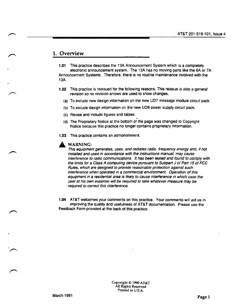
1.01 This practice describes the 13A Announcement System which is a completely electronic announcement system. The 13A has no moving parts like the 6A or 7 A
Announcement Systems. Therefore, there is no routine maintenance involved with the 13A.
1.02
(a)
(b)
(c)
(d)
This practice is reissued for the following reasons. This reissue is also a general revision so no revision arrows are used to show changes.
To include new design information on the new UD7 message module circuit pack.
To include design information on the new UD8 power supply circuit pack.
Revise and include figures and tables. . The Proprietary Notice at the bottom of the page was changed to Copyright Notice because this practice no longer contains proprietary information.
1.03 This practice contains an admonishment.
_A WARNING: This equipment generates, uses. and radiates radio frequency energy and, if not installed and used in accordance with the instructions manual, may cause interference to radio communications. It has been tested and found to comply with the limits for a Class A computing device pursuant to Subpart J of Part 15 of FCC Rules, which are designed to provide reasonable protection against such interference when operated in a commercial environment. Operation of this equipment in a residential area is likely to cause interference in which case the user at his own expense will be required to take whatever measure may be required to correct this interference.
1.04 AT&T welcomes your comments on this practice. Your comments will aid us in improving the quality and usefulness of AT&T documentation. Please use the
Feedback Form provided at the back of this practice .
March 1991
Copyright© 1990 AT&T All Rights Reserved
Printed in U.S.A.
Pagel
AT&T 201-519-101
1.05 Additional copies of this practice and any associated appendixes may be ordered from the AT&T Customer Information Center as follows:
• Call 1-800-432-6600
or
• Complete Form IND1-80.80 and mail to:
AT&T Customer Information Center Attention: Order Entry Department 2855 N. Franklin Road P.O. Box 19901 Indianapolis, IN 46219-1999
1.06 This practice is issued by:
Document Development Organization Network Systems 2400 Reynolda Road Winston-Salem. NC 27106-4696
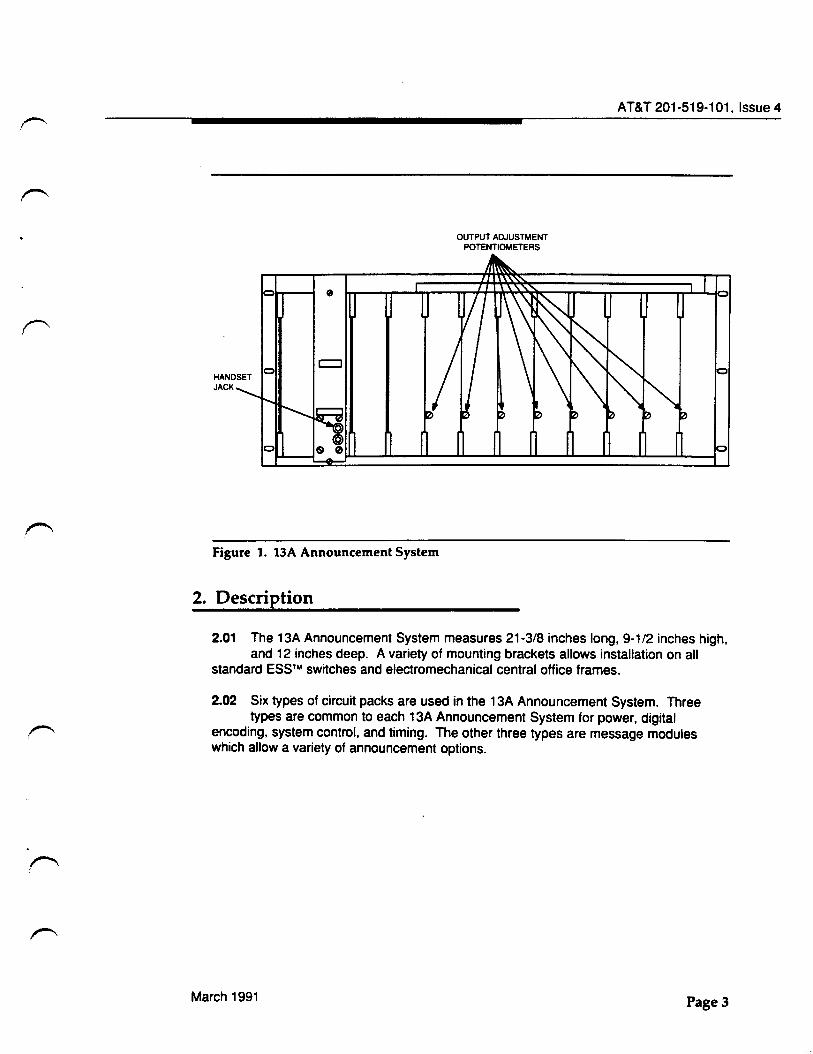
1.07 The 13A is a recorded announcement machine that has the capability of one to eight channels (Figure 1 ). Each channel announces only one recording. The
recording is recorded on a UD4, UD6 or UD7 message module circuit pack. Each announcement can be adjusted in 3-second lengths from 3 to 12 seconds for the UD6, from 3 to 24 seconds for the U04 and from 3 seconds to 2 minutes, 54 seconds for the U07.
Pagel
r'·
Figure 1. 13A Announcement System
2. Description
OUTPUT ADJUSTMENT POTENTIOMETERS
AT&T 201-519-101, Issue 4
2.01 The 13A Announcement System measures 21-3/8 inches long, 9-1/2 inches high, and 12 inches deep. A variety of mounting brackets allows installation on all
standard ESSr"' switches and electromechanical central office frames.
2.02 Six types of circuit packs are used in the 13A Announcement System. Three types are common to each 13A Announcement System for power, digital
encoding, system control, and timing. The other three types are message modules which allow a variety of announcement options.
March 1991 Page3
AT&T 201-519-101
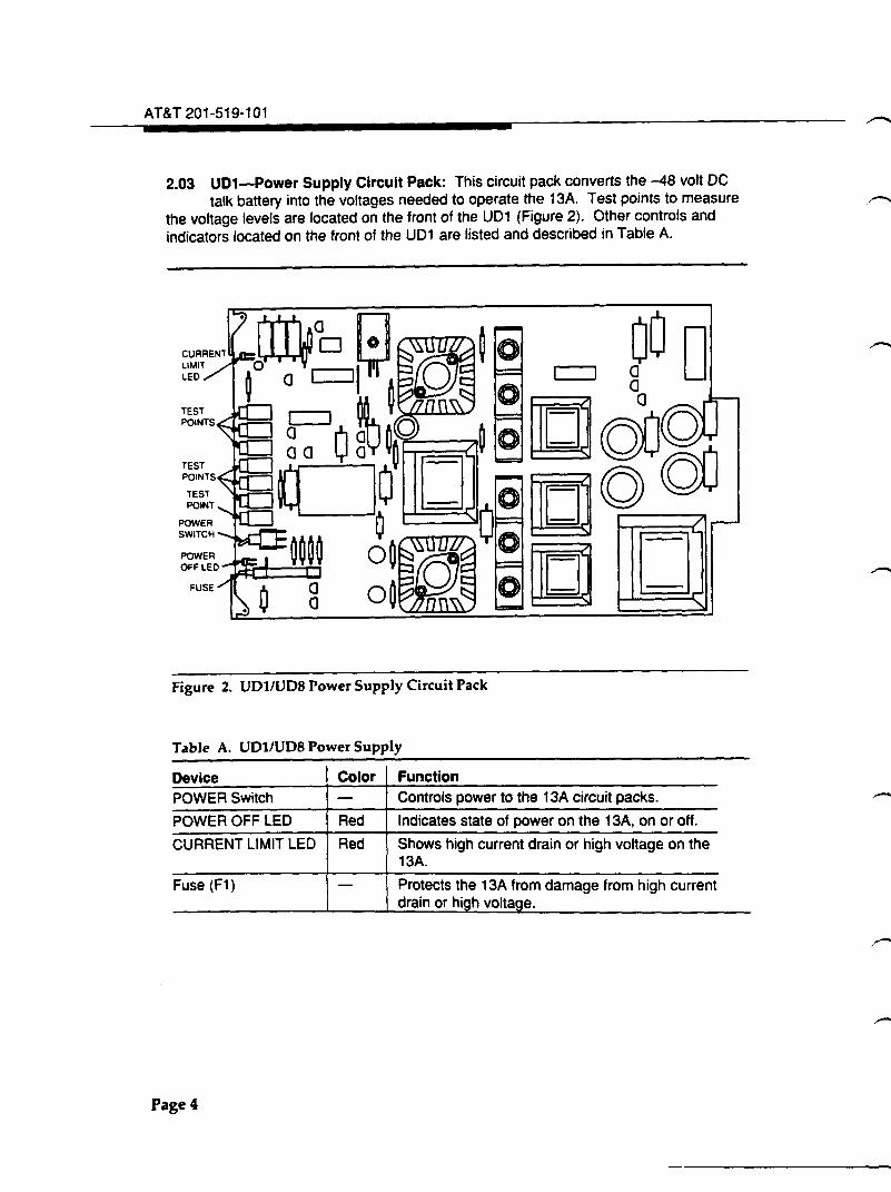
2.03 UD1-Power Supply Circuit Pack: This circuit pack converts the -48 volt DC
talk battery into the voltages needed to operate the 13A. Test points to measure
the voltage levels are located on the front of the U01 (Figure 2). Other controls and
indicators located on the front of the U01 are listed and described in Table A.
Figure 2. UD1/UD8 Power Supply Circuit Pack
Table A. UD1/UD8 Power Supply
Device Color Function POWER Switch - Controls power to the 13A circuit packs.
POWER OFF LED Red Indicates state of power on the 13A, on or off.
CURRENT LIMIT LED Red Shows high current drain or high voltage on the 13A.
Fuse (F1) - Protects the 13A from damage from high current drain or high voltage.
Page4
AT&T 201-519-101, Issue 4
2.04 UD8-Power Supply Circuit Pack: This circuit pack is essentially the same as UD1 except that it operates over a wider input voltage range (-39.5 volt to
-57 volt). It is intended for international applications and meets Conference of European Postal and Telecommunications Administrations (CEPT) requirements.
2.05 UD2-Encoder-Driver Circuit Pack: This circuit pack has two functions. One function is to convert speech from analog to digital format for storage in memory.
The other function is to generate rotating magnetic fields to operate the bubble memory of the UD4 or UD6 message module circuit packs with bubble memories (series 1 through 1 4).
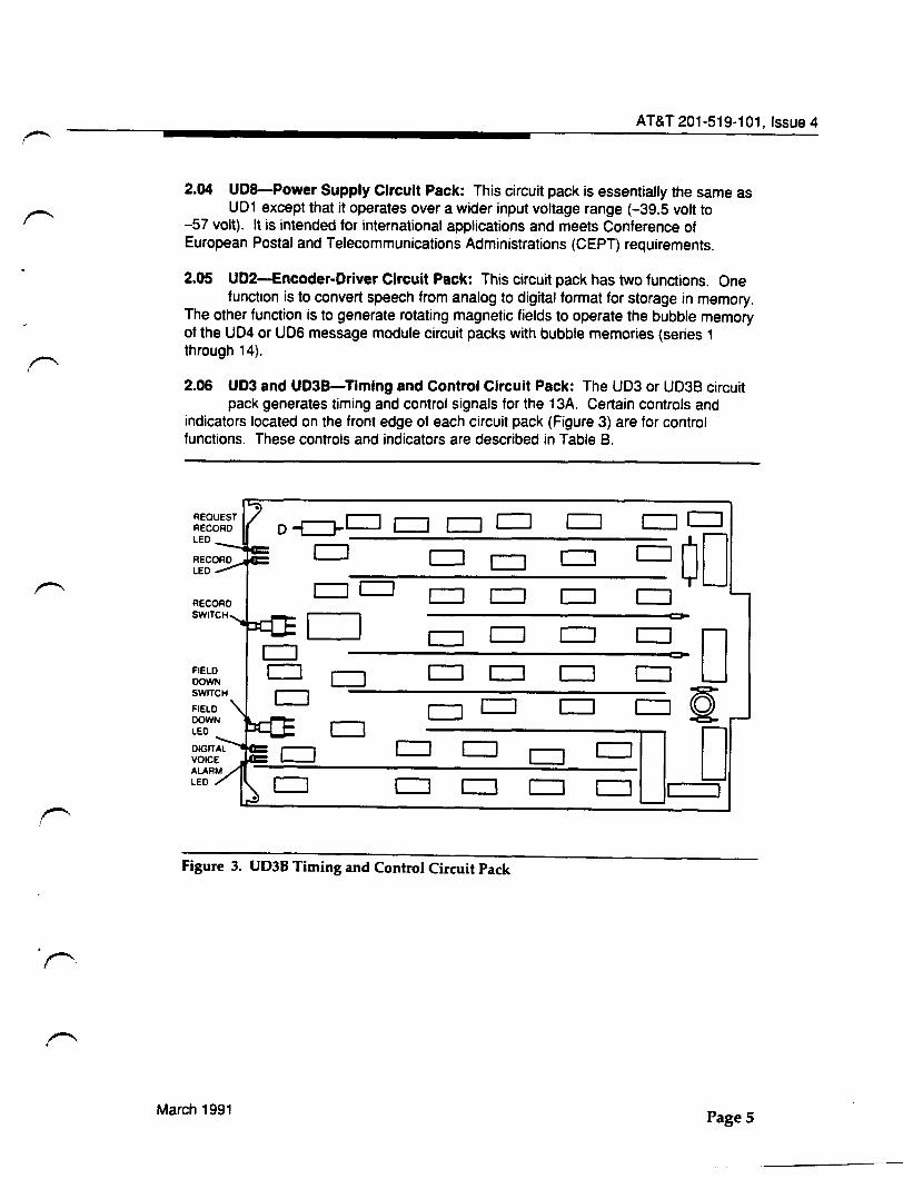
2.06 UD3 and UD3B-Timing and Control Circuit Pack: The UD3 or UD3B circuit pack generates timing and control signals for the 13A. Certain controls and
indicators located on the front edge of each circuit pack (Figure 3) are for control functions. These controls and indicators are described in Table B.
o~CJ CJ CJ CJ CJ CJCJ CJ c:::J OD c:::J CJ CJ CJCJ CJ c:::J c:::J c:::J
c:::J CJ c:::J c:::J
D CJ CJ c::::J c::::J c:::J FIELD CJ c::::J CJ c:::J ~ DOWN
CJ LED
~u D CJ c:::J c::::J c::::J c::J c::J I
Figure 3. UD3B Timing and Control Circuit Pack
March 1991 Page 5
AT&T 201-519-101
Table B. UD3 and UD3B Timing and Control
Device Color Function REQUEST RECORD Switch - This pushbutton switch is used to initiate a request
to record locally. FIELD DOWN Switch - Operating this pushbutton switch stops the
rotating magnetic fields of the 29A memory. CUT-THROUGH LED Green This LED lights for 3 seconds and then is off for
12 seconds to show normal operation of the 13A. REQUEST RECORD LED Red This LED lights to acknowledge a request to
record locally. FIELD DOWN LED Red This LED shows that the rotating magnetic field of
the 29A bubble memory is turned off. DIGITAL VOICE ALARM (OVA) LED Red This LED lights to show there is an error in the
stored digital information on message modules series 1 through 14 (series 15 and higher do not use the OVA).
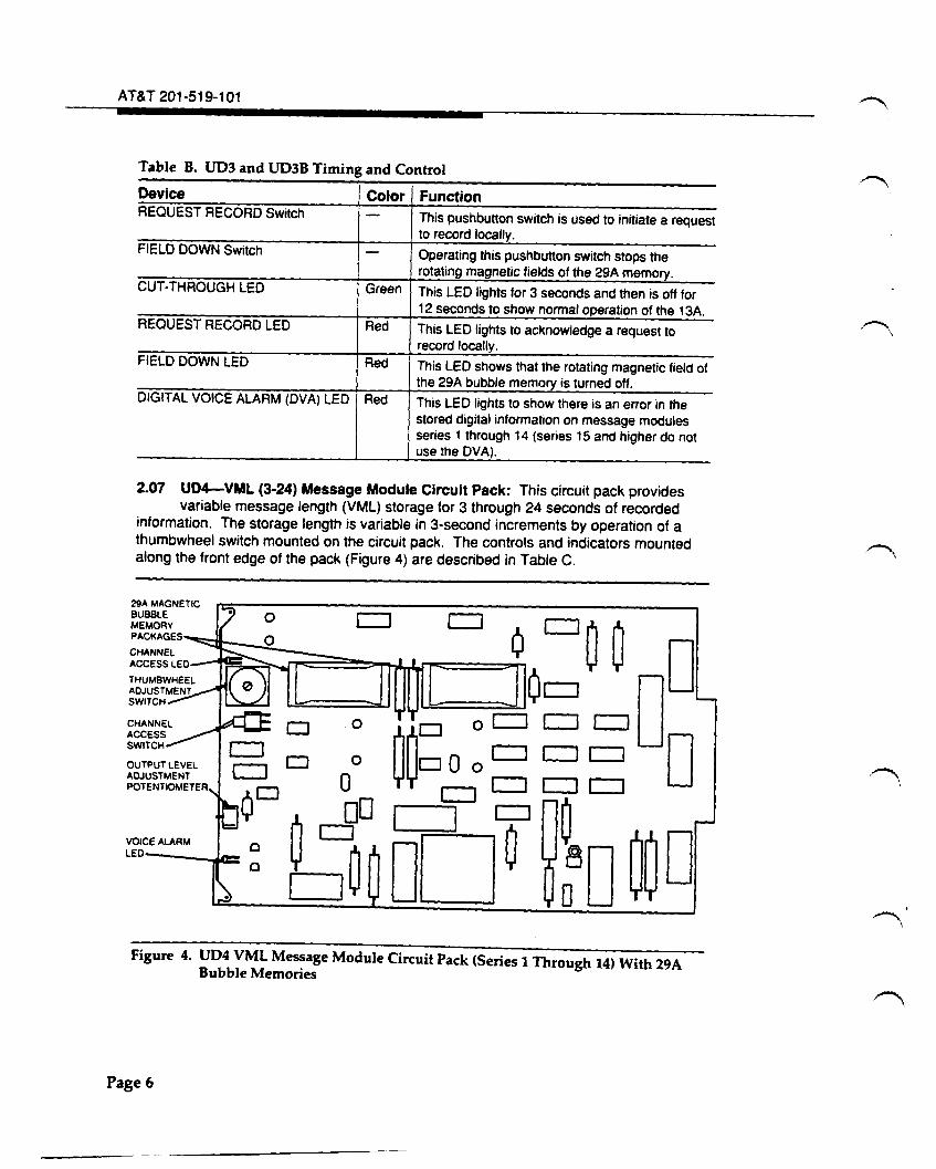
2.07 UD4-VML (3-24) Message Module Circuit Pack: This circuit pack provides variable message length (VML) storage for 3 through 24 seconds of recorded
information. The storage length is variable in 3-second increments by operation of a thumbwheel switch mounted on the circuit pack. The controls and indicators mounted along the front edge of the pack (Figure 4) are described in Table C.
Figure 4. UD4 VML Message Module Circuit Pack (Series 1 Through 14) With 29A Bubble Memories
Page6
AT&T 201-519-101, Issue 4
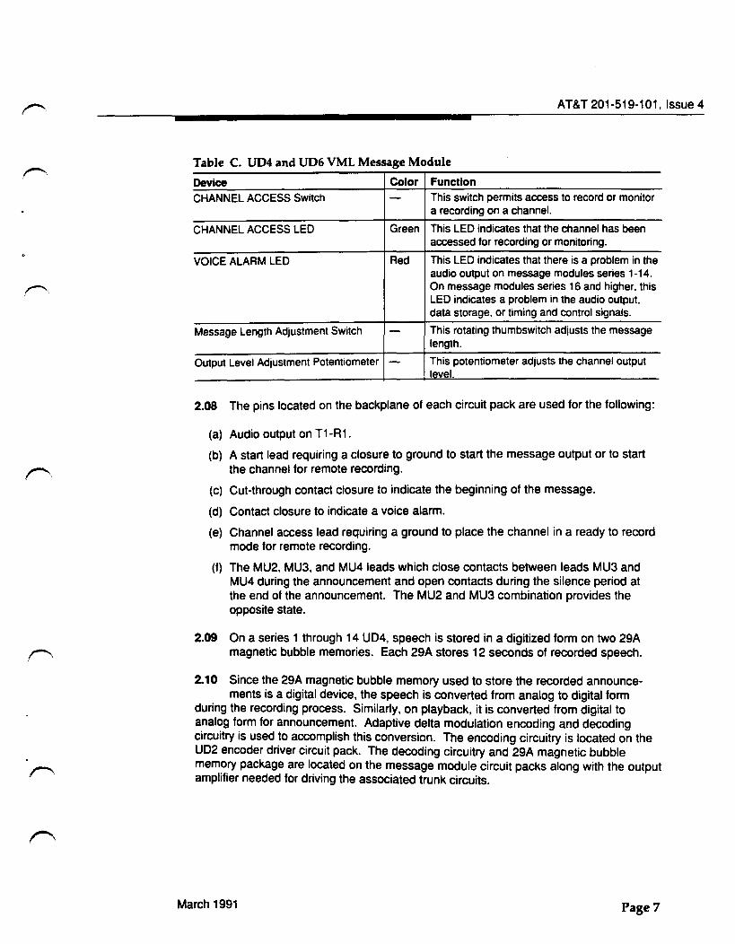
Table C. UD4 and UD6 VML Message Module
Device Color Function
CHANNEL ACCESS Switch - This switch permits access to record or monitor a recording on a channel.
CHANNEL ACCESS LED Green This LED indicates that the channel has been accessed for recording or monitoring.
VOICE ALARM LED Red This LED indicates that there is a problem in the audio output on message modules series 1-14. On message modules series 16 and higher, this LED indicates a problem in the audio output, data storage, or timing and control signals.
Message Length Adjustment Switch - This rotating thumbswitch adjusts the message length.
Output Level Adjustment Potentiometer - This potentiometer adjusts the channel output level.
2.08 The pins located on the backplane of each circuit pack are used for the following:
(a) Audio output on T1-R1.
(b) A start lead requiring a closure to ground to start the message output or to start the channel for remote recording.
(c) Cut-through contact closure to indicate the beginning of the message.
(d) Contact closure to indicate a voice alarm.
(e) Channel access lead requiring a ground to place the channel in a ready to record mode for remote recording.
(f) The MU2. MU3, and MU41eads which close contacts between leads MU3 and MU4 during the announcement and open contacts during the silence period at the end of the announcement. The MU2 and MU3 combination provides the opposite state.
2.09 On a series 1 through 14 UD4, speech is stored in a digitized form on two 29A magnetic bubble memories. Each 29A stores 12 seconds of recorded speech.
2.10 Since the 29A magnetic bubble memory used to store the recorded announce-ments is a digital device, the speech is converted from analog to digital form
during the recording process. Similarly, on playback, it is converted from digital to analog form for announcement. Adaptive delta modulation encoding and decoding circuitry is used to accomplish this conversion. The encoding circuitry is located on the UD2 encoder driver circuit pack. The decoding circuitry and 29A magnetic bubble memory package are located on the message module circuit packs along with the output amplifier needed for driving the associated trunk circuits.
March 1991 Page7
AT&T 201-519-101
2.11 The 29A bubble memory is a nonvolatile memory. It retains the stored information without requiring power. After a recording is made, the message
module can be removed from one 13A Announcement System and installed in another. The nonvolatility feature permits centralized recording of message modules. The prerecorded message module could then be distributed to other 13A Announcement Systems at other locations.
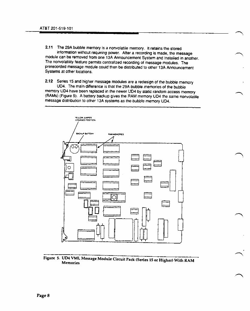
2.12 Series 15 and higher message modules are a redesign of the bubble memory U04. The main difference is that the 29A bubble memories of the bubble
memory U04 have been replaced in the newer U04 by static random access memory (RAMs) (Figure 5). A battery backup gives the RAM memory UD4 the same nonvolatile message distribution to other 13A systems as the bubble memory U04.
YElLOW JUMPER ,ENGAGED POSITI()N1
Figure 5. UD4 VML Message Module Circuit Pack (Series 15 or Higher) With RAM Memories
PageS
AT&T 201-519-101, Issue 4
2.13 To prevent possible damage to the RAM memory, observe precautions for
handling static sensitive devices when handling these RAM memory boards. Use
of a grounding strap and handling these circuit boards by the edge is recommended.
2.14 The RAM memory UD4 is shipped and should be stored with the backup battery
disengaged. To engage the battery in the circuit, the yellow plastic jumper must
be installed on the two upper contacts as shown in Figure 5.
2.15 UD6-VML (3-12) Message Module Circuit Pack: This circuit pack provides
variable message length (VML) storage for 3 to 12 seconds of recorded
information. Except for the length of storage, the circuit pack function, controls and
indicators. and operation is the same as the UD4 (Table C).
2.16 For operation of the backup battery on the UDG RAM memory, the yellow jumper
must be installed on the two upper contacts as in the UD4. (See paragraph 2.14
and Figure 5). ·
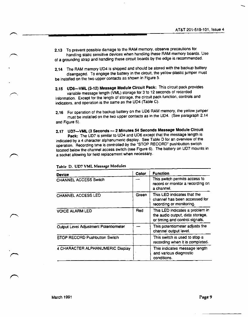
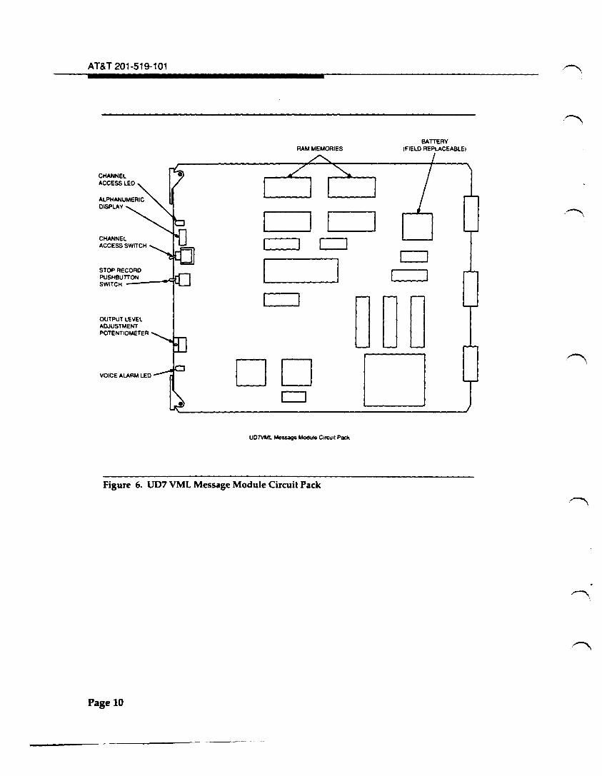
2.17 UD7-VML (3 Seconds- 2 Minutes 54 Seconds Message Module Circuit
Pack: The UD7 is similar to UD4 and UDG except that the message length is
indicated by a 4 character alphanumeric display. See TableD for an overview of the
operation. Recording time is controlled by the "STOP RECORD" pushbutton switch
located below the channel access switch (see Figure 6). The battery on UD7 mounts in
a socket allowing for field replacement when necessary.
Table D. UD7 VML Message Modules
Device Color . Function
CHANNEL ACCESS Switch - This switch permits access to record or monitor a recording on a channel.
CHANNEL ACCESS LED Green This LED indicates that the channel has been accessed for recording or monitoring.
VOICE ALARM LED Red This LED indicates a problem in the audio output, data storage, or timing and control signals.
Output Level Adjustment Potentiometer - This potentiometer adjusts the channel output level.
STOP RECORD Pushbutton Switch This switch is used to stop a recording when it is completed.
4 CHARACTER ALPHANUMERIC Display This indicates message length and various diagnostic conditions.
March 1991 Page9
-
AT&T 201-519-101
CHANNEL ACCESS SWITCH
STOP RECORD PUSHBUTTON SWITCH -----"114 OUTPUT LEIIEL ADJUSTMENT POTENTIOMETER
RAM MEMORIES BATTERY
tFIELO REPLACEABLE!
.._____.I .___I ____. CJ
I
DO c:::J
U0711ML Message Module Corcuot Pack
DOD D
Figure 6. UD7 VML Message Module Circuit Pack
Page 10
AT&T 201-519-101, Issue 4
3. Function
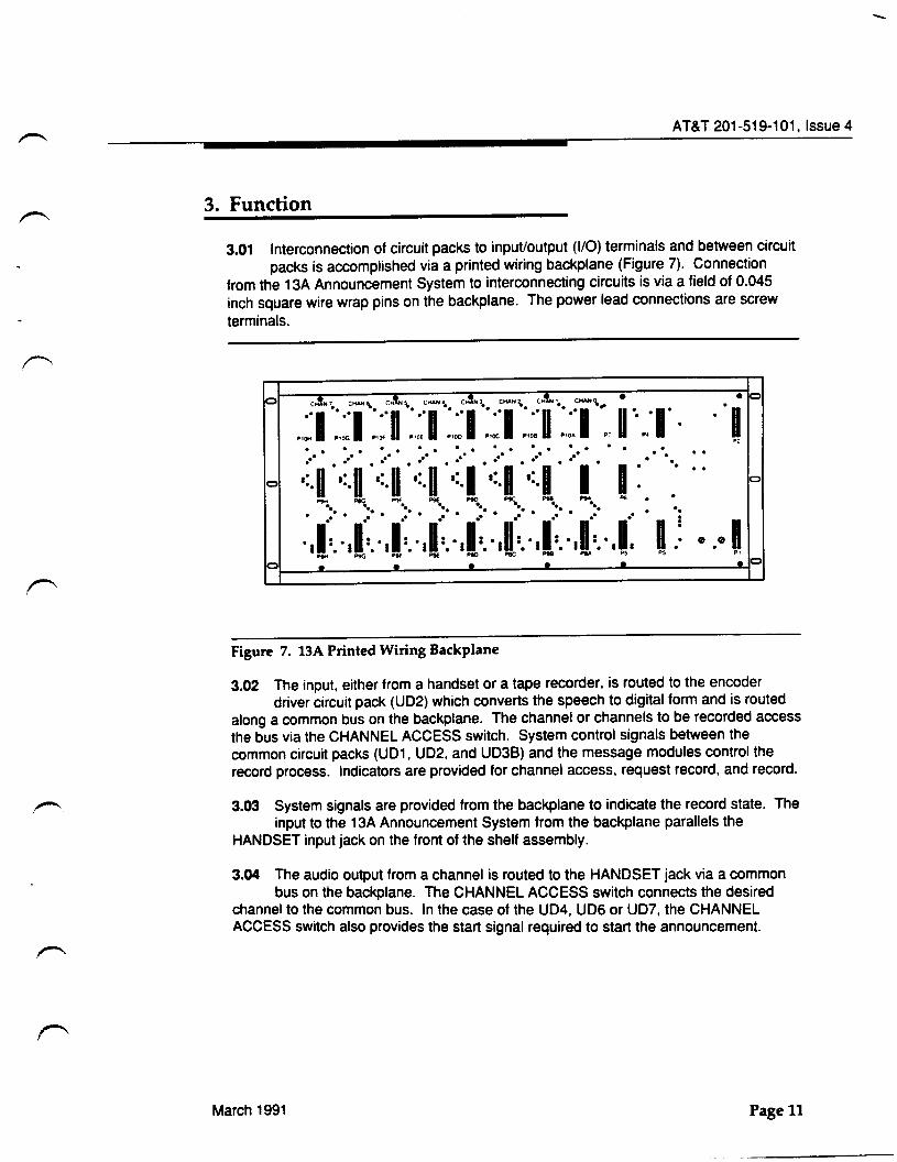
3.01 Interconnection of circuit packs to input/output (1/0) terminals and between circuit
packs is accomplished via a printed wiring backplane (Figure 7). Connection
from the 13A Announcement System to interconnecting circuits is via a field of 0.045
inch square wire wrap pins on the backplane. The power lead connections are screw
terminals.
0 •b
· II ., . . . . . . . . . . . . . . . . . . . . . ~:·a · .~: 1 ·.~:·a· ta · .~: 1 · .~:·1 ·.~:·I. ···I · 1 : - - - ~ ~ ~ - - ~
' ' ' ' ' ' ' ' :.1·:. :.1·:. :.n·:. :.a·:. :.a·:. :.1·:. :.1·:. :.a·: ... u:
0
. . . . . . . . . . 0 . . . .. .
I .
e .e I . . . - ~ - - - ~ - - ~ 0·~--~·------£-·------&-·------&-•------a-•----------~
•• .. • 0
Figure 7. 13A Printed Wiring Backplane
3.02 The input, either from a handset or a tape recorder, is routed to the encoder
driver circuit pack (UD2) which converts the speech to digital form and is routed
along a common bus on the backplane. The channel or channels to be recorded access
the bus via the CHANNEL ACCESS switch. System control signals between the
common circuit packs (UD1, UD2, and UD3B) and the message modules control the
record process. Indicators are provided for channel access, request record, and record.
3.03 System signals are provided from the backplane to indicate the record state. The
input to the 13A Announcement System from the backplane parallels the
HANDSET input jack on the front of the shelf assembly.
3.04 The audio output from a channel is routed to the HANDSET jack via a common
bus on the backplane. The CHANNEL ACCESS switch connects the desired
channel to the common bus. In the case of the UD4, UD6 or UD7, the CHANNEL
ACCESS switch also provides the start signal required to start the announcement.
March 1991 Page 11
-
AT&T 201-519-101
4. Power Requirements
4.01 The power required for the operation of the 13A Announcement System is -48 volt DC. The -48 volt DC must be provided by talk battery through a
separate dedicated filter located in the frame containing the 13A Announcement System.
4.02 The current drain on the -48 volt DC supply is 1 .15 amperes for a 13A Announcement System fully loaded with series 15 or higher message modules
and 1.6 amperes for a 13A Announcement System fully loaded with series 1 through 14 message modules. For a 13A Announcement System fully loaded with UD7s, the current drain is 1.25 amperes.
5. Applications
5.01 Each message module can announce up to 500 trunk circuits simultaneously provided that good distribution design rules are followed. (See SD-97753-01,
Circuit note 1 07.) Each announcement is protected by a dedicated voice alarm circuit. If the announcement level falls below an acceptable level, a voice alarm will be initiated. A voice alarm is also initiated for any power failure.
5.02 The 13A Announcement System has a variety of mounting brackets for installing the unit on all standard frames in electromechanical central offices and ESS
switches.
5.03 The 13A Announcement System is equipment coded and the circuit packs are apparatus coded. The basic equipment code is J1C121A-1. List numbers are
provided to allow equipping the system as desired. List 1 provides the following:
• Shelf assembly
• Backplane
• Front door
• Power supply circuit pack (UD1)
• Encoder driver circuit pack (UD2)
• Timing and control circuit pack (UD3B).
Lists 2 through 4 provide a selection of mounting brackets for mounting the 13A Announcement System on various equipment frames. List 8 deletes UD1 and adds UD~. ~he remaining Lists 40 through 47, 60 through 67, and 70 through 77 provide for eqU1pp1ng the 13A Announcement System Wi. ·the various UD4, UD6 and UD7 VML message module options that are available.
5.04 The 2-digit list number refers to the type of message module and the position it occupies. For example, a List 40 is a UD4 message module in channel o.
Page 12
AT&T 201-519-101, Issue 4
5.05 The options that are available were designed to emulate the features of specific announcement systems. Lists 40 through 47 and 60 through 67 (VML message
modules) were designed to mimic the features provided by the 7A Announcement System. These message modules are compatible with all interconnecting circuits. Lists 50 through 57 (manufacture discontinued) were designed to mimic the features provided by the KS-12068, L6 Recorder/Reproducer.
6. Restrictions
6.01 The following three restrictions apply to the 13A Announcement System:
(a) Keep the loop resistance of the T1 and R1 output cables low (paragraph 5.01 ).
(b) Filter the -48 volt DC power through a dedicated filter located on the frame housing the 13A.
(c) Use twisted pair for all wire connections to the 13A.
More information is found in the circuit notes in SD-97753-01.
7. Operation
Measuring Power
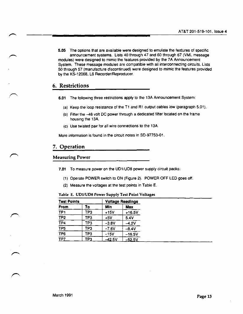
7.01 To measure power on the UD1/UD8 power supply circuit packs:
(1) Operate POWER switch to ON (Figure 2). POWER OFF LED goes off.
(2) Measure the voltages at the test points in Table E.
Table E. UD1/UD8 Power Supply Test Point Voltages
Test Points Voltage Readings From To Min Max TP1 TP3 +15V +16.5V TP2 TP3 +5V 5.4V TP4 TP3 -3.8V -4.2V TP5 TP3 -7.6V -8.4V TP6 TP3 -15V -16.5V TP7 TP3 -42.5V -52.5V
March 1991 Page 13
AT&T 201-519-101
Monitoring Announcements
7.02 To monitor an announcement on a UD4, UD6 or UD7 message module circuit pack:
(1} Connect a handset in the HANDSET jack on the front of the shelf assembly (Figure 1).
(2) Operate CHANNEL ACCESS switch to ACCESS. CHANNEL ACCESS LED lights.
(3) Operate CHANNEL ACCESS switch to NORMAL when through.
Recording Announcements on UD4 and UD6
A. Recording with a Handset
7.03 To record an announcement with a handset:
(1) Operate POWER switch to ON on the UD1 or UD8 circuit pack.
(2) Connect handset in HANDSET jack on the front of the shelf assembly.
(3) Operate CHANNEL ACCESS switch to ON on the channel to be recorded. CHANNEL ACCESS LED lights.
(4) Adjust MESSAGE LENGTH thumbswitch to 24 seconds for UD4 or 12 seconds for UD6.
:E> NOTE: When the RECORD pushbutton switch is operated, the red REQUEST RECORD LED lights. In a few seconds, the green RECORD LED lights. When it lights, begin the recording immediately.
(5) Operate the RECORD pushbutton switch on the UD3 or UD3B circuit pack. Red REQUEST RECORD LED lights.
(6) Record the announcement when the green RECORD LED lights.
(7) Monitor the announcement and rerecord, if necessary.
(8) Adjust MESSAGE LENGTH ADJ thumbswitch to time closest to the length of the recording.
(9} Operate CHANNEL ACCESS switch to NORMAL. CHANNEL ACCESS LED extinguishes.
Page 14
AT&T 201-519-101, Issue 4
B. Recording on Any Message Module with a Tape Recorder
7.04 Tape recorded announcements are generally recorded on the 13A Announcement System using a KS-22566, L2 Interface Unit. General
information on how to use the KS-22566, L2 Interface Unit is found in AT&T 780-200-024 and 780-200-026. Tape recorded announcements may also be made by connecting the earphone output of the tape recorder to the tape jack of the 13A Announcement System.
Recording Announcements on UD7 Circuit Packs
7.05 To record announcements on the UD7 circuit pack with a handset. perform the following procedure.
(1) Operate POWER switch to ON on the UD1 or UDS circuit pack.
(2) Connect handset in HANDSET jack on the front of the shelf assembly.
(3) Operate the CHANNEL ACCESS switch to ON on the channel to be recorded. CHANNEL ACCESS LED lights.
(4) Operate the RECORD pushbutton switch on the UD3 or UD3B circuit pack. Red REQUEST RECORD LED lights. In a few seconds, the green RECORD LED lights. When it lights, begin recording immediately.
(5) As the announcement is being recorded, the elapsed time will be indicated on the alphanumeric display.
(6) When you are done recording the announcement, press the STOP RECORD pushbutton immediately. The alphanumeric display indicates the length of the recording.
(7) Monitor the announcement and rerecord, if necessary.
(8) Operate CHANNEL ACCESS switch to NORMAL. CHANNEL ACCESS LED extinguishes.
Transferring a Series 1 Through 14 Recorded Message Module
7.06 A message module can be transferred from one 13A Announcement System to another one without the Joss of the recorded announcement.
March 1991 Page 15
AT&T 201-519-101
A. Removing a Series 1 Through 14 Recorded Message Module
7.07 To remove a series 1 through 14 recorded message module, perform the following procedure. This procedure is also performed to remove a recorded
message module containing RAMS from a 13A Announcement System equipped with a mixture of series 1 through 14 and RAM message modules.
(1) Depress and hold FIELD DOWN switch on the UD3 or UD38 circuit pack until the FIELD DOWN LED lights.
(2) Release the FIELD DOWN switch.
(3) Operate POWER switch to OFF on the UD1 circuit pack. POWER OFF LED lights.
(4) Remove message module.
(5) Operate POWER switch to ON on the UD1 circuit pack. POWER OFF LED extinguishes.
B. Installing a Series 1 Through 14 Recorded Message Module
7.08 To install a series 1 through 14 recorded message module, perform the following procedure. This procedure is also performed to install a recorded message
module containing RAMs in a 13A Announcement System equipped with a mixture of series 1 through 14 and RAM message modules.
(1) Depress and hold FIELD DOWN switch on the UD3 or UD38 circuit pack until the FIELD DOWN LED lights.
(2) Release FIELD DOWN switch.
(3) Operate POWER switch to OFF on the UD1 circuit pack. POWER OFF LED lights.
(4) Install message module.
(5) Operate POWER switch to ON on the UD1 circuit pack. POWER OFF LED extinguishes.
Transferring a Series 15 or Higher Recorded Message Module or The New UD7
7.09 To transfer a series 15 or higher message module with RAM, leave the yellow plastic jumper in the engaged position (Figure 5). The UD7 does not have a
yellow plastic jumper.
Page 16
A. Removing a Series 15 or Higher Recorded Message Module or a UD7
AT&T 201-519-101, Issue 4
7.10 To remove a recorded message module containing RAMs from a 13A Announcement System equipped with a mixture of series 1 through 14 and RAM
message modules, see paragraph 7.07. To remove a RAM recorded message module from a 13A announcement system equipped with only RAM message modules:
(1) Operate POWER switch to OFF on the UD1 circuit pack. POWER OFF LED lights.
(2) Remove message module.
(3) Operate POWER switch to ON on the UD1 circuit pack. POWER OFF LED extinguishes.
B. Installing a Series 15 or Higher Recorded Message Module or a UD7 Message Module
7.11 To install a series 15 or higher recorded message module or a UD7 in a 13A Announcement System equipped with a mixture of series 1 through 14 and RAM
message modules, see paragraph 7.08. To install a RAM recorded message module in a 13A Announcement System equipped with only RAM message modules:
(1) Operate POWER switch to OFF on the UD1 circuit pack. POWER OFF LED lights.
(2) Install message module.
(3) Operate POWER switch to ON on the UD1 circuit pack. POWER OFF LED extinguishes.
Diagnostic Indications on the UD7 Alphanumeric Display
7.12 Upon applying power to a UD7 circuit pack, the following diagnostic indications may occur:
(1) "DIAG." This indication will appear each time a UD7 has power applied to it. The microcontroller tests its memory and the announcement memory for coherency while this indication is displayed. The duration of this test increases as the announcement length increases.
(2) "RAM FAIL" indicates that the announcement memory has been corrupted. If this indication appears, the announcement must be rerecorded.
(3) "CODE FAIL" indicates a failure in the microcontroller memory. If this indication occurs, the UD7 circuit pack must be replaced.
(4) "BATT FAIL" indicates a battery failure. When this indication occurs, the battery must be replaced in order for the UD7 to maintain nonvolatility.
March 1991 Page 17
AT&T 201-519-101
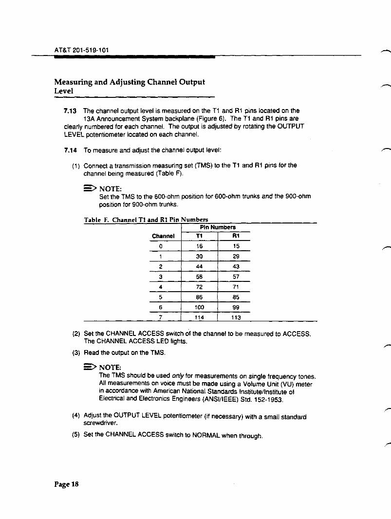
Measuring and Adjusting Channel Output Level
7.13 The channel output level is measured on the T1 and R1 pins located on the 13A Announcement System backplane (Figure 6). The T1 and R1 pins are
clearly numbered for each channel. The output is adjusted by rotating the OUTPUT LEVEL potentiometer located on each channel.
7.14 To measure and adjust the channel output level:
p) Connect a transmission measuring set (TMS) to the T1 and R1 pins for the channel being measured (Table F).
E::>NOTE: Set the TMS to the 600-ohm position for 600-ohm trunks and the 900-ohm position for 900-ohm trunks.
Table F Channel T1 and Rt Pin Numbers Pin Numbers
Channel T1 R1
0 16 15
1 30 29
2 44 43
3 58 57
4 72 71
5 86 85
6 100 99
7 114 113
(2) Set the CHANNEL ACCESS switch of the channel to be measured to ACCESS. The CHANNEL ACCESS LED lights.
(3) Read the output on the TMS.
:>NOTE: The TMS should be used only for measurements on single frequency tones. All measurements on voice must be made using a Volume Unit (VU) meter in accordance with American National Standards Institute/Institute of Electrical and Electronics Engineers (ANSI/IEEE) Std. 152-1953.
(4) Adjust the OUTPUT LEVEL potentiometer (if necessary) with a small standard screwdriver.
(5) Set the CHANNEL ACCESS switch to NORMAL when through.
Page 18
AT&T 201-519-101, Issue 4
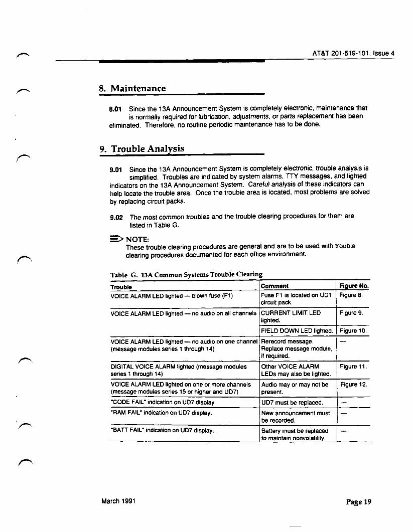
8. Maintenance
8.01 Since the 13A Announcement System is completely electronic, maintenance that
is normally required for lubrication. adjustments, or parts replacement has been
eliminated. Therefore, no routine periodic maintenance has to be done.
9. Trouble Analysis
9.01 Since the 13A Announcement System is completely electronic, trouble analysis is
simplified. Troubles are indicated by system alarms, TTY messages, and lighted
indicators on the 13A Announcement System. Careful analysis of these indicators can
help locate the trouble area. Once the trouble area is located, most problems are solved
by replacing circuit packs.
9.02 The most common troubles and the trouble clearing procedures for them are
listed in Table G.
E:>NOTE: These trouble clearing procedures are general and are to be used with trouble
clearing procedures documented for each office environment.
Table G. 13A Common Systems Trouble Clearing
Trouble Comment Figure No.
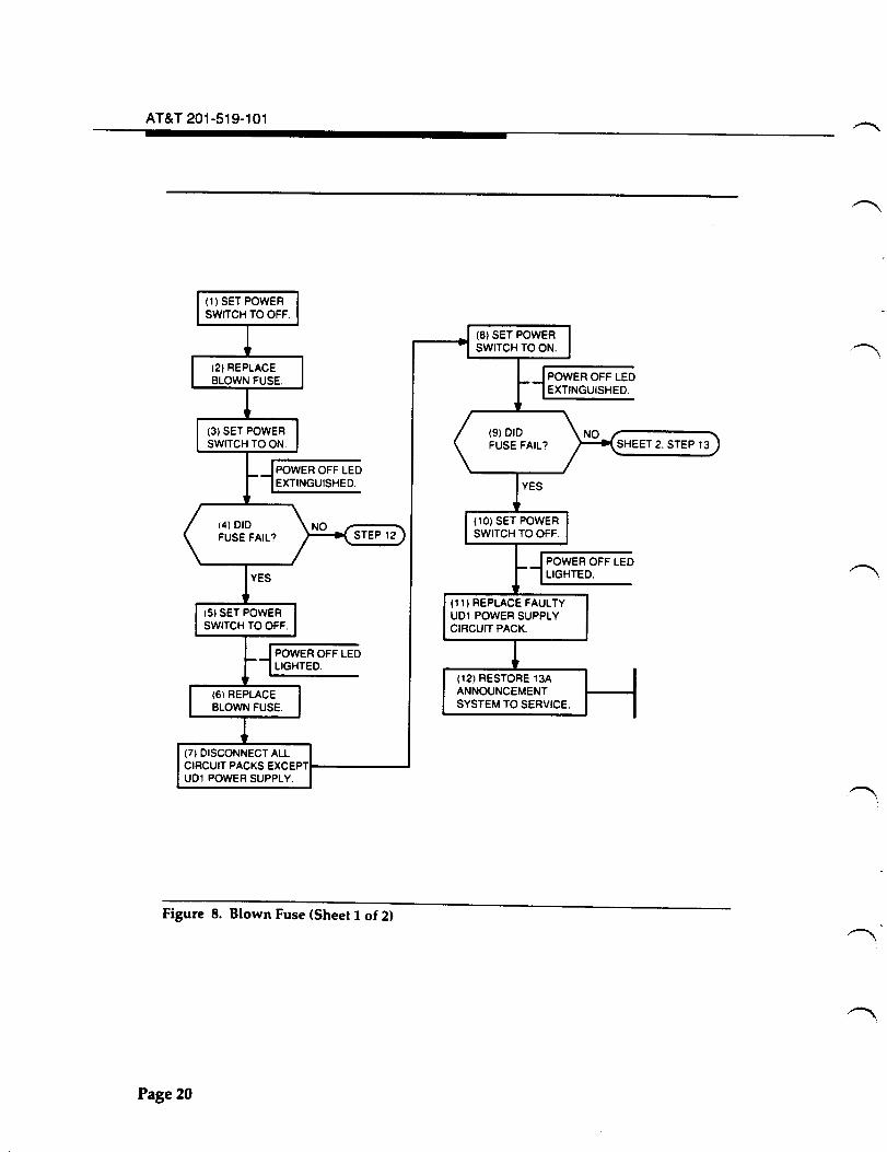
VOICE ALARM LED lighted- blown fuse (F1) Fuse F1 is located on UD1 Figure 8. circuit pack.
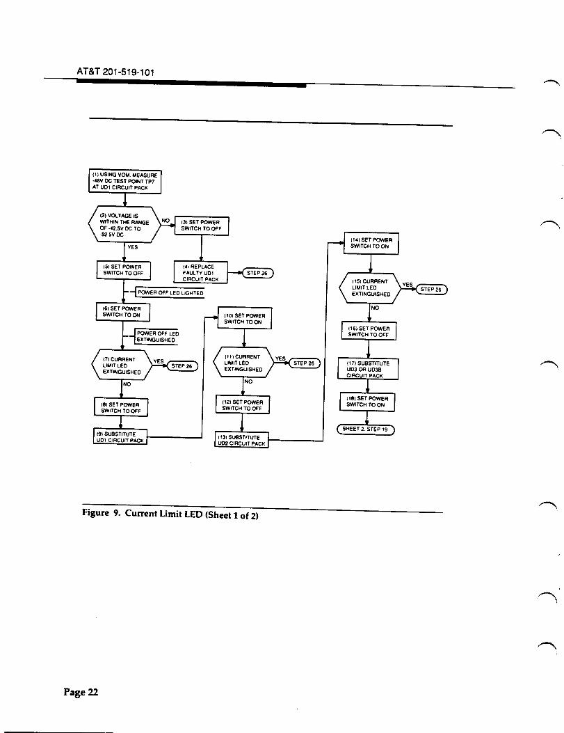
VOICE ALARM LED lighted - no audio on all channels CURRENT LIMIT LED Figure 9. lighted.
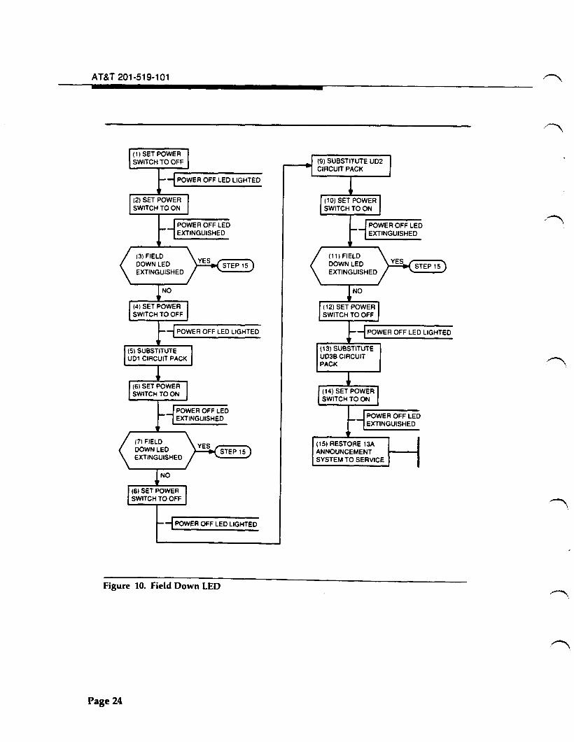
FIELD DOWN LED lighted. Figure 10.
VOICE ALARM LED lighted - no audio on one channel Rerecord message. -(message modules series 1 through 14) Replace message module,
if required.
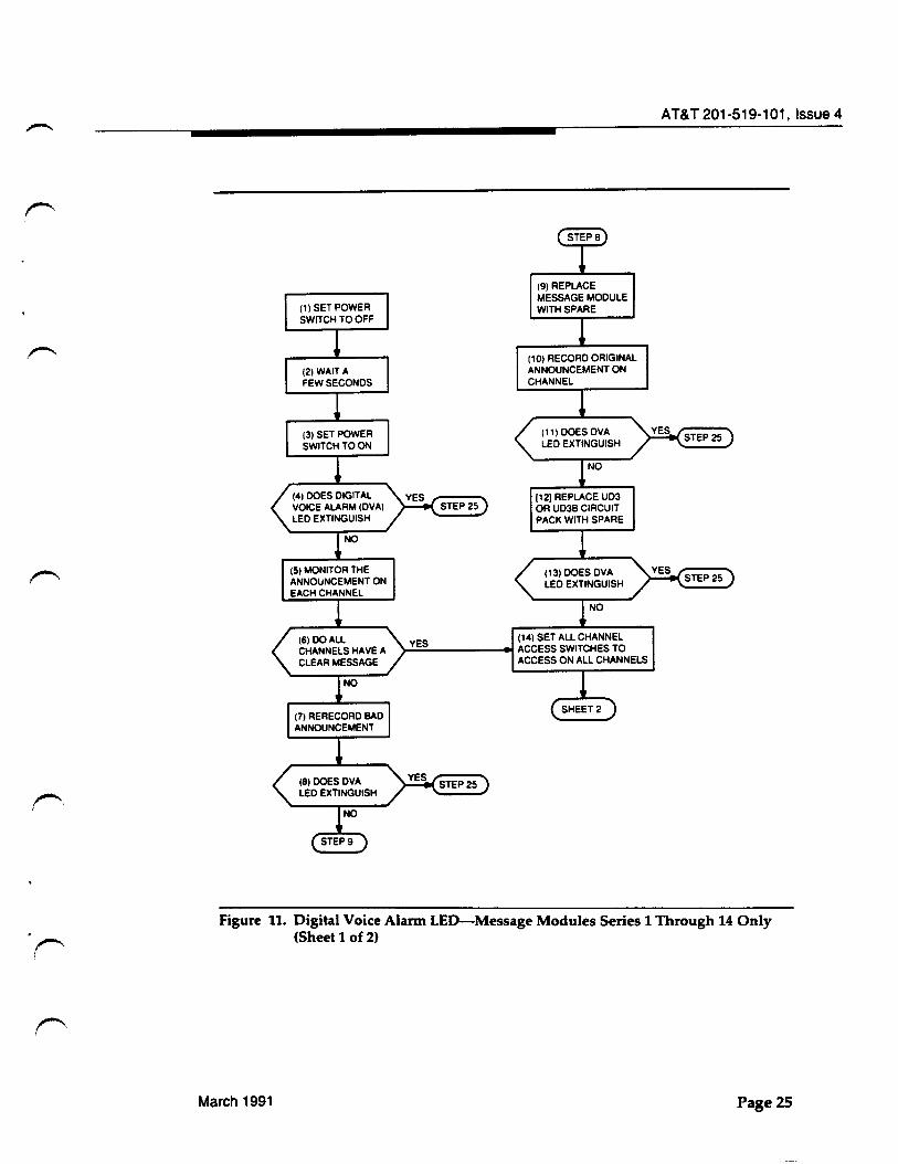
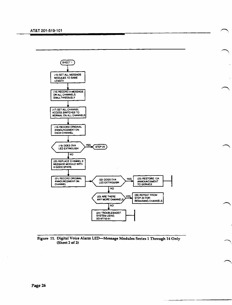
DIGITAL VOICE ALARM lighted (message modules Other VOICE ALARM Figure 11. series 1 through 14) LEOs may also be lighted.
VOICE ALARM LED lighted on one or more channels Audio may or may not be Figure 12. (message modules series 15 or higher and UD7) present.
"CODE FAIL" indication on UD7 display UD7 must be replaced. -"RAM FAIL" indication on UD7 display. New announcement must -
be recorded.
"BATI FAIL" indication on UD7 display. Battery must be replaced -to maintain nonvolatility.
March 1991 Page 19
AT&T 201-519-101
(4) DID FUSE FAIL?
(7) DISCONNECT ALL CIRCUIT PACKS EXCEPT!-------' UD1 POWER SUPPLY
Figure 8. Blown Fuse (Sheet 1 of 2)
Page 20
(9) DID FUSE FAIL?
(1 1) REPLACE FAUL TV UD1 POWER SUPPLY CIRCUIT PACK.
(12) RESTORE 13A ANNOUNCEMENT SYSTEM TO SERVICE.
SHEET 2. STEP 13
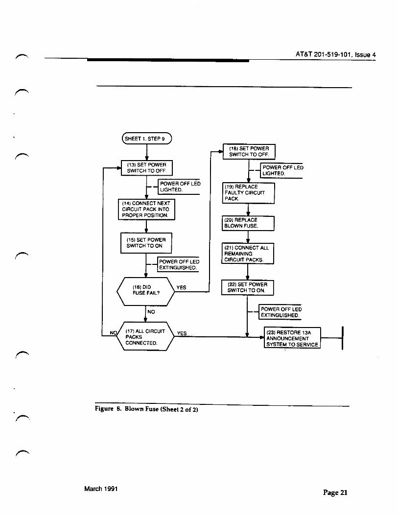
AT&T 201-519-101, Issue 4
(14) CONNECT NEXT CIRCUIT PACK INTO PROPER POSITION.
(15) SET POWER SWITCH TO ON
POWER OFF LED EXTINGUISHED.
(16)DID FUSE FAIL?
YES
(19) REPLACE FAUL TV CIRCUIT PACK.
(21) CONNECT All REMAINING CIRCUIT PACKS.
YES (23) RESTORE 13A ~~--------------~--~ANNOUNCEMENT
SYSTEM TO SERVICE
Figure 8. Blown Fuse (Sheet 2 of 2)
March 1991 Page 21
AT&T 201-519-101
131 SET POWER SWITCH TO OFF
141 REPLACE FAULTY U01 CIRCUIT PACK
Figure 9. Current Limit LED (Sheet 1 of 2)
Page22
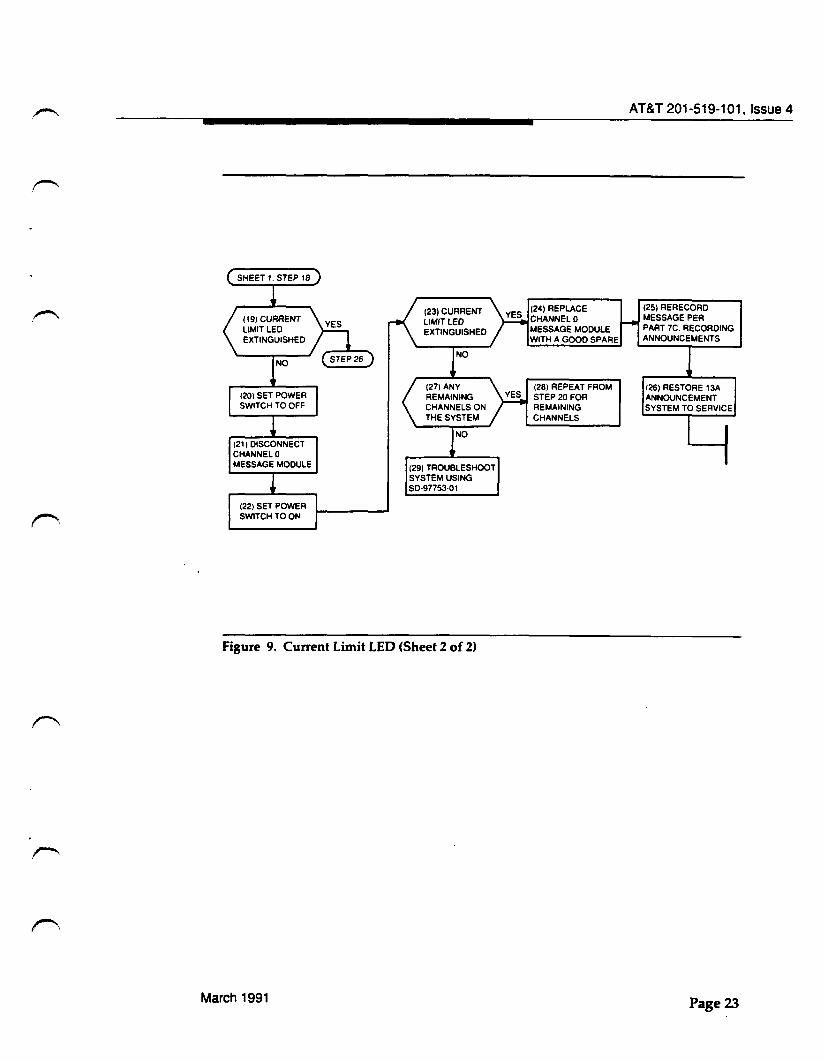
(29) TROUBLESHOOT SYSTEM USING SD-97753-01
Figure 9. Current Limit LED (Sheet 2 of 2)
March 1991
(24) REPLACE CHANNELO MESSAGE MODULE WITH A GOOD SPARE
(28) REPEAT FROM STEP 20 FOR REMAINING CHANNELS
AT&T 201-519-101, Issue 4
(25) RERECORD MESSAGE PER PART 7C. RECORDING ANNOUNCEMENTS
126) RESTORE 13A ANNOUNCEMENT SYSTEM TO SERVICE
Page23
AT&T 201-519-101
(1) SET POWER SWITCH TO OFF
-1 POWER OFF LED LIGHTED
-1 POWER OFF LEO LIGHTED
Figure 10. Field Down LED
Page 24
( 13) SUBSTITUTE U03B CIRCUIT PACK
(15) RESTORE 13A ANNOUNCEMENT SYSTEM TO SERVICE
r--, i
(9) REPLACE MESSAGE MODULE WITH SPARE
(10) RECORD ORIGINAL ANNOUNCEMENT ON CHANNEL
[121 REPLACE UD3 OR U03B CIRCUIT PACK WITH SPARE
(14) SET ALL CHANNEL }-:.:::::..-----t ACCESS SWITCHES TO
ACCESS ON ALL CHANNELS
AT&T 201-519-101, Issue 4
Figure 11. Digital Voice Alarm LED-Message Modules Series 1 Through 14 Only (Sheet 1 of 2)
March 1991 Page25
AT&T 201-519-101
(15) SET ALL MESSAGE MODULES TO SAME LENGTH
(16) RECORD A MESSAGE ON ALL CHANNELS SIMULTANEOUSLY
(17) SET ALL CHANNEL ACCESS SWITCHES TO NORMAL ON ALL CHANNELS
(18) RECORD ORIGINAL ANNOUNCEMENT ON EACH CHANNEL
(20) REPLACE CHANNEL 0 MESSAGE MODULE WITH A GOOD SPARE
(21 1 RECORD ORIGINAL ANNOUNCEMENT ON CHANNEL
(25) RESTORE 13A ANNOUNCEMENT TO SERVICE
(26) REPEAT FROM STEP20FOR REMAINING CHANNELS
Figure 11. Digital Voice Alarm LED-Message Modules Series 1 Through 14 Only (Sheet 2 of 2)
Page26
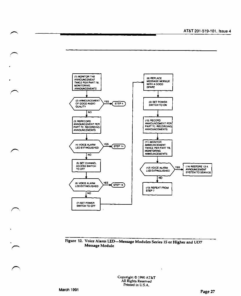
(1) MONITOR THE ANNOUNCEMENT TWICE PER PART 78. MONITORING ANNOUNCEMENTS
(3) RERECORD ANNOUNCEMENT PER PART 7C. RECORDING ANNOUNCEMENTS
15) SET CHANNEL ACCESS SWITCH TO OFF
(7) SET POWER SWITCH TO OFF
(8)REPLACE MESSAGE MODULE WITH A GOOD SPARE
(9) SET POWER SWITCH TO ON
(10) RECORD ANNOUNCEMENT PER PART 7C. RECORDING ANNOUNCEMENTS
(11)MONITOR ANNOUNCEMENT TWIICE PER PART 78, MONITORING ANNOUNCEMENTS
(13) REPEAT FROM STEP7
AT&T 201-519-101, Issue 4
(14) RESTORE 13 A ANNOUNCEMENT SYSTEM TO SERVICE
Figure 12. Voice Alarm LED-Message Modules Series 15 or Higher and UD7 Message Module
March 1991
Copyright© 1990 AT&T AU Rights Reserved
Printed in U.S.A.
Page 27
FEEDBACK FORM
Document Title:
Document Number: Issue Number: Publication Date:
Note to readers:
13A ANNOUNCEMENT SYSTEM DESCRIPTION AND OPERATING PROCEDURES COMMON SYSTEMS AT&T 201-519-101 Issue 4 February 1991
Your feedback on this document is welcome. Your feedback will aid AT&T in improving the quality and usefulness of AT&T customer documentation. When commenting on specific
r-- items within this document, please give the page numbers in question. An AT&T representative will attempt to respond to all written comments.
Comments: ----------------------------------------------------------------------------------------------------------------------
Submitted by (optional):
Name: Company: Address: Telephone Number: Date:
Return to:
Name: Shirley Swearington AT&T Organization: Document Development Organization Address: Dept. 4148, 2400 Reynolda Road, Winston-Salem,NC 271 OS