1 - evolve - karamelion complaint - draft - de - rpx insight
TRANSCRIPT
1
IN THE UNITED STATES DISTRICT COURT FOR THE DISTRICT OF DELAWARE KARAMELION LLC,
Plaintiff, v. EVOLVE GUEST CONTROLS, LLC,
Defendant.
CASE NO. ______________
JURY TRIAL DEMANDED PATENT CASE
ORIGINAL COMPLAINT FOR PATENT INFRINGEMENT
Plaintiff Karamelion LLC, files this Original Complaint for Patent Infringement against
Evolve Guest Controls, LLC, and would respectfully show the Court as follows:
I. THE PARTIES
1. Plaintiff Karamelion LLC (“Karamelion” or “Plaintiff”) is a Texas limited
liability company with its principal place of business at 5570 FM 423, Suite 250 #2022, Frisco,
TX 75034.
2. On information and belief, Defendant Evolve Guest Controls, LLC (“Defendant”)
is a limited liability company organized and existing under the laws of Delaware, with a place of
business at 200 W. Madison St., Ste 750, Chicago, IL 60606. Defendant has a registered agent at
Corporation Service Company, 251 Little Falls Drive Wilmington, DE 19808.
II. JURISDICTION AND VENUE
3. This action arises under the patent laws of the United States, Title 35 of the
United States Code. This Court has subject matter jurisdiction of such action under 28 U.S.C. §§
1331 and 1338(a).
4. On information and belief, Defendant is subject to this Court’s specific and
general personal jurisdiction, pursuant to due process and the Delaware Long-Arm Statute, due
Case 1:19-cv-01202-UNA Document 1 Filed 06/25/19 Page 1 of 26 PageID #: 1
2
at least to its business in this forum, including at least a portion of the infringements alleged
herein. Furthermore, Defendant is subject to this Court’s specific and general personal
jurisdiction because Defendant is a Delaware limited liability company.
5. Without limitation, on information and belief, within this state, Defendant has
used the patented inventions thereby committing, and continuing to commit, acts of patent
infringement alleged herein. In addition, on information and belief, Defendant has derived
revenues from its infringing acts occurring within Delaware. Further, on information and belief,
Defendant is subject to the Court’s general jurisdiction, including from regularly doing or
soliciting business, engaging in other persistent courses of conduct, and deriving substantial
revenue from goods and services provided to persons or entities in Delaware. Further, on
information and belief, Defendant is subject to the Court’s personal jurisdiction at least due to its
sale of products and/or services within Delaware. Defendant has committed such purposeful acts
and/or transactions in Delaware such that it reasonably should know and expect that it could be
haled into this Court as a consequence of such activity.
6. Venue is proper in this district under 28 U.S.C. § 1400(b). On information and
belief, Defendant was formed in Delaware. Under the patent venue analysis, Defendant resides
only in this District. On information and belief, from and within this District Defendant has
committed at least a portion of the infringements at issue in this case.
7. For these reasons, personal jurisdiction exists and venue is proper in this Court
under 28 U.S.C. § 1400(b).
III. COUNT I (PATENT INFRINGEMENT OF UNITED STATES PATENT NO. 6,275,166)
8. Plaintiff incorporates the above paragraphs herein by reference.
Case 1:19-cv-01202-UNA Document 1 Filed 06/25/19 Page 2 of 26 PageID #: 2
3
9. On August 14, 2001, United States Patent No. 6,275,166 (“the ‘166 Patent”) was
duly and legally issued by the United States Patent and Trademark Office. The application
leading to the ‘166 patent was filed on January 19, 1999. (Ex. A at cover). The ‘166 Patent is
titled “RF Remote Appliance Control/Monitoring System.” A true and correct copy of the ‘166
Patent is attached hereto as Exhibit A and incorporated herein by reference.
10. Plaintiff is the assignee of all right, title and interest in the ‘166 patent, including
all rights to enforce and prosecute actions for infringement and to collect damages for all
relevant times against infringers of the ‘166 Patent. Accordingly, Plaintiff possesses the
exclusive right and standing to prosecute the present action for infringement of the ‘166 Patent
by Defendant.
11. The invention in the ‘166 Patent relates to control and monitoring of distributed
systems in buildings such as systems for controlling and monitoring heating, air conditioning,
lighting, security, occupancy, and usage of distributed facilities. (Ex. A at col. 1:5-12). Control
of such distributed systems in the prior art commonly used computer networks and business
software. (Id. at col. 1:11-13). A major difficult with such systems was the expense of wiring
inter-connections between elements of the system, particularly when there are additions or
changes to be made in the system. (Id. at col. 1:14-18). Prior art attempts to reduce the expense
of the systems included using efficient network products such as using a widely known Ethernet
standard, using AC power wiring to transmit RF communications to remove controllers, and
using a combination of wired and wireless communications. (Id. at col. 1:18-27).
12. However, these centralized wireless control systems for building appliances have
not been widely used mainly because systems that have a sufficient communication ranges are
normally subject to regulations and licensing requirements that are prohibitively expensive. (Id.
Case 1:19-cv-01202-UNA Document 1 Filed 06/25/19 Page 3 of 26 PageID #: 3
4
at col. 1:28-32). Also, systems that are powerful enough to be used in widely distributed
installations are unnecessarily expensive to be used in smaller installations. (Id. at col. 1:32-34).
With respect to wireless communication, there is limited availability of RF carrier frequencies,
and potential interference with other nearby systems that might be operating in similar
frequencies. (Id. at col. 1:34-37). Because of the continued deficiencies of the prior art
solutions, there was a need for a wireless appliance control system that overcomes the
disadvantages of the prior art solutions. (Id. at col. 1:38-39).
13. The inventors developed an invention that “meets this need by providing a
wireless configuration that uses a distributed array of low power (short range) wireless
controllers that are also functional as relay units for communicating with a headend control
computer at long range.” (Id. at col. 1:42-46).
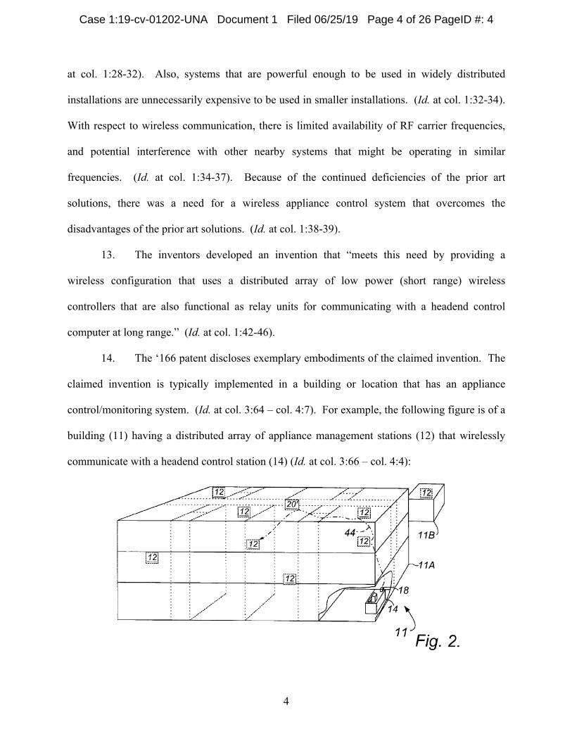
14. The ‘166 patent discloses exemplary embodiments of the claimed invention. The
claimed invention is typically implemented in a building or location that has an appliance
control/monitoring system. (Id. at col. 3:64 – col. 4:7). For example, the following figure is of a
building (11) having a distributed array of appliance management stations (12) that wirelessly
communicate with a headend control station (14) (Id. at col. 3:66 – col. 4:4):
Case 1:19-cv-01202-UNA Document 1 Filed 06/25/19 Page 4 of 26 PageID #: 4
5
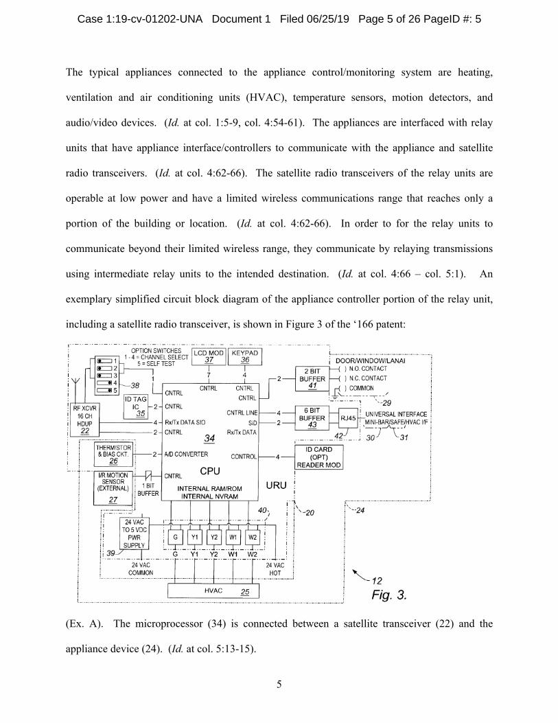
The typical appliances connected to the appliance control/monitoring system are heating,
ventilation and air conditioning units (HVAC), temperature sensors, motion detectors, and
audio/video devices. (Id. at col. 1:5-9, col. 4:54-61). The appliances are interfaced with relay
units that have appliance interface/controllers to communicate with the appliance and satellite
radio transceivers. (Id. at col. 4:62-66). The satellite radio transceivers of the relay units are
operable at low power and have a limited wireless communications range that reaches only a
portion of the building or location. (Id. at col. 4:62-66). In order to for the relay units to
communicate beyond their limited wireless range, they communicate by relaying transmissions
using intermediate relay units to the intended destination. (Id. at col. 4:66 – col. 5:1). An
exemplary simplified circuit block diagram of the appliance controller portion of the relay unit,
including a satellite radio transceiver, is shown in Figure 3 of the ‘166 patent:
(Ex. A). The microprocessor (34) is connected between a satellite transceiver (22) and the
appliance device (24). (Id. at col. 5:13-15).
Case 1:19-cv-01202-UNA Document 1 Filed 06/25/19 Page 5 of 26 PageID #: 5
6
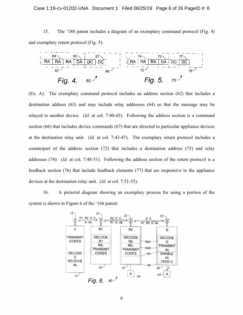
15. The ‘188 patent includes a diagram of an exemplary command protocol (Fig. 4)
and exemplary return protocol (Fig. 5):
(Ex. A). The exemplary command protocol includes an address section (62) that includes a
destination address (63) and may include relay addresses (64) so that the message may be
relayed to another device. (Id. at col. 7:40-43). Following the address section is a command
section (66) that includes device commands (67) that are directed to particular appliance devices
at the destination relay unit. (Id. at col. 7:43-47). The exemplary return protocol includes a
counterpart of the address section (72) that includes a destination address (73) and relay
addresses (74). (Id. at col. 7:48-51). Following the address section of the return protocol is a
feedback section (76) that include feedback elements (77) that are responsive to the appliance
devices at the destination relay unit. (Id. at col. 7:51-55).
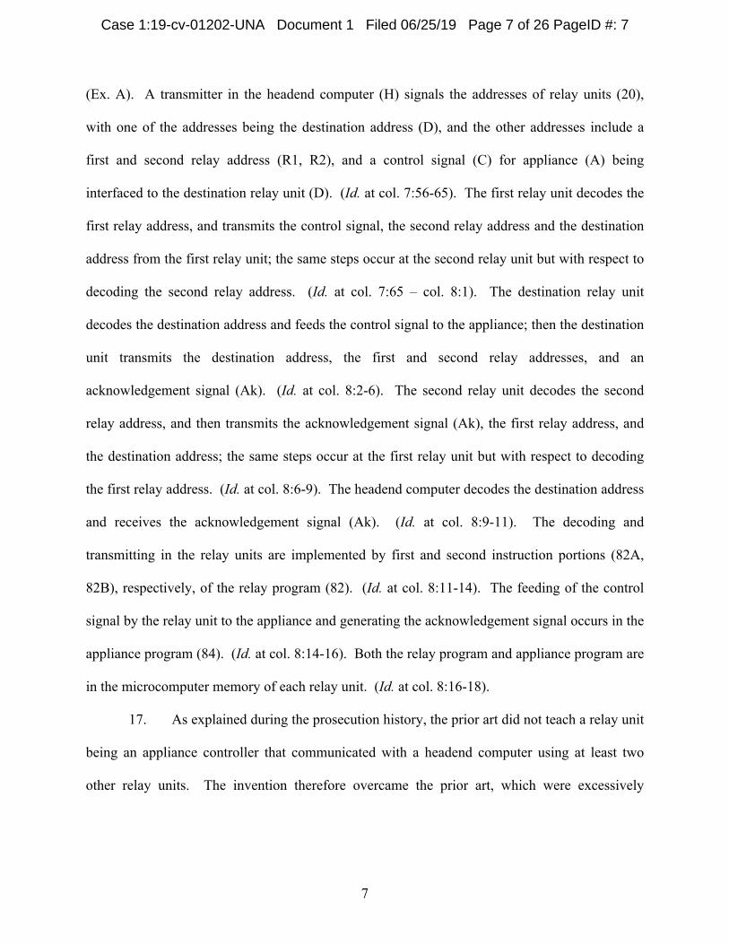
16. A pictorial diagram showing an exemplary process for using a portion of the
system is shown in Figure 6 of the ‘166 patent:
Case 1:19-cv-01202-UNA Document 1 Filed 06/25/19 Page 6 of 26 PageID #: 6
7
(Ex. A). A transmitter in the headend computer (H) signals the addresses of relay units (20),
with one of the addresses being the destination address (D), and the other addresses include a
first and second relay address (R1, R2), and a control signal (C) for appliance (A) being
interfaced to the destination relay unit (D). (Id. at col. 7:56-65). The first relay unit decodes the
first relay address, and transmits the control signal, the second relay address and the destination
address from the first relay unit; the same steps occur at the second relay unit but with respect to
decoding the second relay address. (Id. at col. 7:65 – col. 8:1). The destination relay unit
decodes the destination address and feeds the control signal to the appliance; then the destination
unit transmits the destination address, the first and second relay addresses, and an
acknowledgement signal (Ak). (Id. at col. 8:2-6). The second relay unit decodes the second
relay address, and then transmits the acknowledgement signal (Ak), the first relay address, and
the destination address; the same steps occur at the first relay unit but with respect to decoding
the first relay address. (Id. at col. 8:6-9). The headend computer decodes the destination address
and receives the acknowledgement signal (Ak). (Id. at col. 8:9-11). The decoding and
transmitting in the relay units are implemented by first and second instruction portions (82A,
82B), respectively, of the relay program (82). (Id. at col. 8:11-14). The feeding of the control
signal by the relay unit to the appliance and generating the acknowledgement signal occurs in the
appliance program (84). (Id. at col. 8:14-16). Both the relay program and appliance program are
in the microcomputer memory of each relay unit. (Id. at col. 8:16-18).
17. As explained during the prosecution history, the prior art did not teach a relay unit
being an appliance controller that communicated with a headend computer using at least two
other relay units. The invention therefore overcame the prior art, which were excessively
Case 1:19-cv-01202-UNA Document 1 Filed 06/25/19 Page 7 of 26 PageID #: 7
8
expensive, had insufficient bandwidth, were ineffective in serving multiple devices, were
unreliable, and were difficult to use. (Ex. B at col. 1:43-51).
18. Direct Infringement. Upon information and belief, Defendant has been directly
infringing at least claim 1 of the ‘166 patent in Delaware, and elsewhere in the United States, by
performing actions comprising making, using, selling, and/or offering for sale an appliance
controller for a distributed appliance system having a headend computer, a multiplicity of
appliances, and a plurality of relay units that satisfies the limitations of at least claim 1, including
without limitation the Wireless Digital Thermostat, In-Room Card Reader, 3-Way Accessory
Switch, Plug-In Appliance Module, Plug-In Lamp Module, 5-Button Scene Controller, and
Drapery Control Unit (“Accused Instrumentality”).
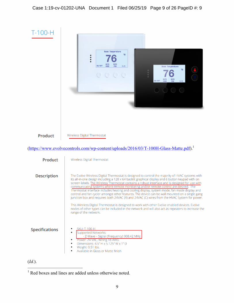
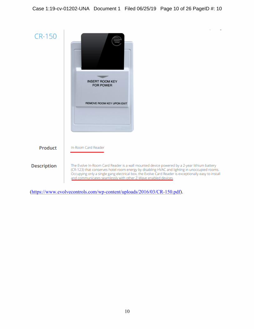
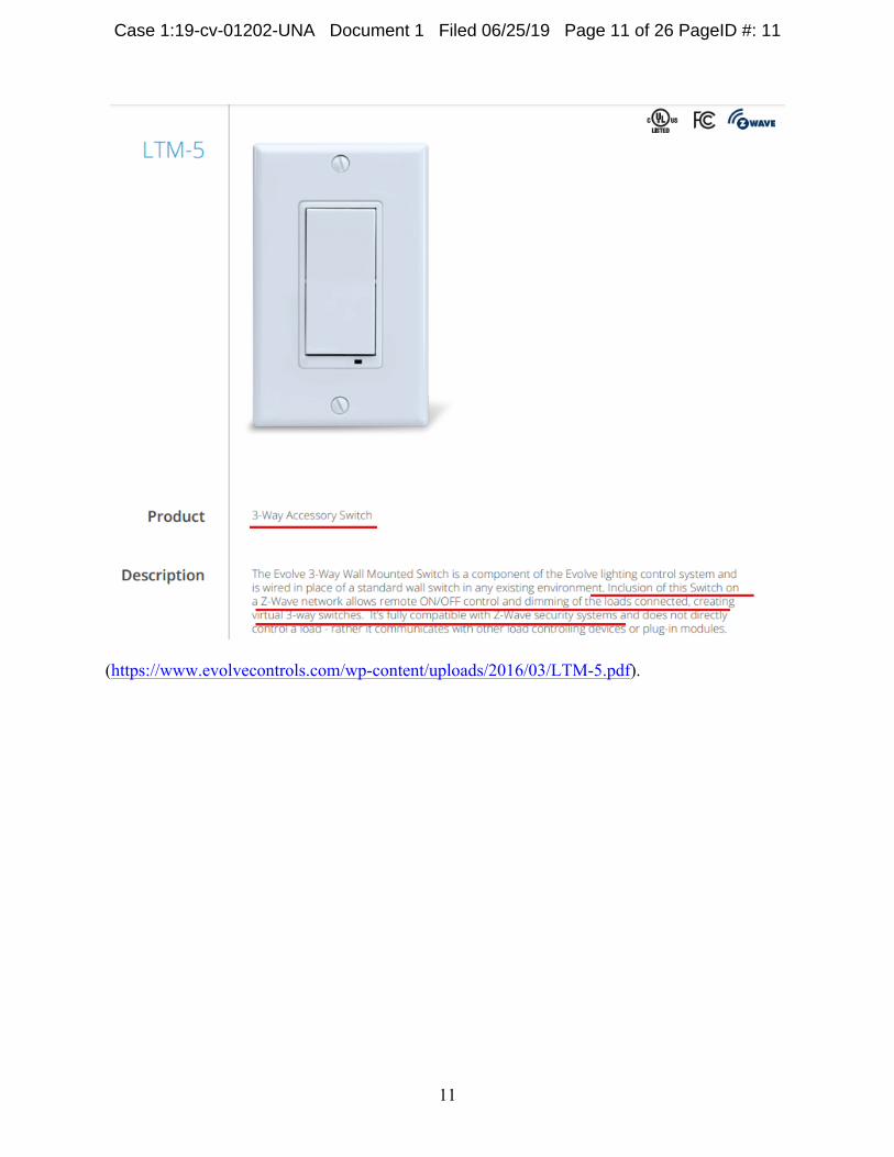
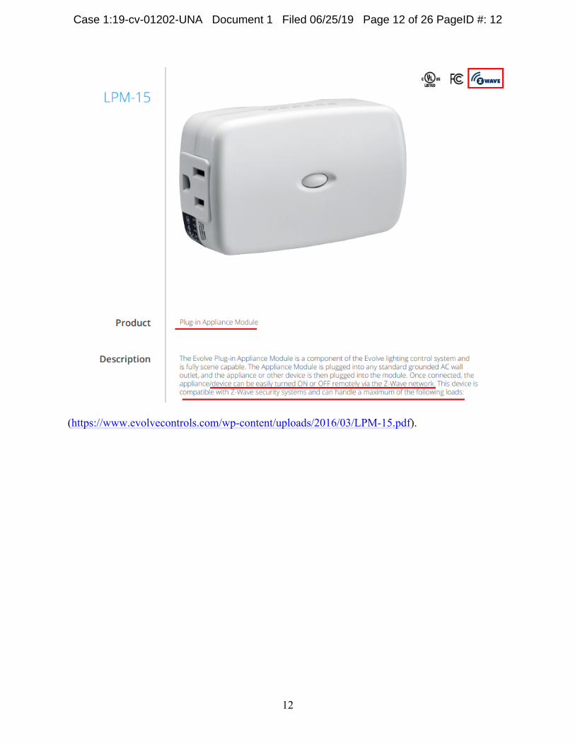
19. Accused Instrumentality provides an appliance controller (e.g., Wireless Digital
Thermostat, In-Room Card Reader, 3-Way Accessory Switch, Plug-In Appliance Module, Plug-
In Lamp Module, 5-Button Scene Controller, and Drapery Control Unit) for a distributed
appliance system (e.g., Z-Wave network) having a headend computer (e.g., primary controller, in
this case a controller (e.g., 5-Button Scene Controller) for the network including the Wireless
Digital Thermostat, In-Room Card Reader, 3-Way Accessory Switch, Plug-In Appliance
Module, Plug-In Lamp Module, 5-Button Scene Controller, and Drapery Control Unit), a
multiplicity of appliances (e.g., appliances such as lights, outlets, etc.), and a plurality of relay
units (e.g., repeaters), one of the relay units being the appliance controller (e.g., Z-Wave node).
20. Each Accused Instrumentality is an appliance controller comprising a low power
satellite radio transceiver (e.g., radio frequency transceivers within the various Z-Wave devices)
having a range being less than a distance to at least some of the appliances.
Case 1:19-cv-01202-UNA Document 1 Filed 06/25/19 Page 8 of 26 PageID #: 8
9
(https://www.evolvecontrols.com/wp-content/uploads/2016/03/T-100H-Glass-Matte.pdf).1
(Id.). 1 Red boxes and lines are added unless otherwise noted.
Case 1:19-cv-01202-UNA Document 1 Filed 06/25/19 Page 9 of 26 PageID #: 9
10
(https://www.evolvecontrols.com/wp-content/uploads/2016/03/CR-150.pdf).
Case 1:19-cv-01202-UNA Document 1 Filed 06/25/19 Page 10 of 26 PageID #: 10
11
(https://www.evolvecontrols.com/wp-content/uploads/2016/03/LTM-5.pdf).
Case 1:19-cv-01202-UNA Document 1 Filed 06/25/19 Page 11 of 26 PageID #: 11
12
(https://www.evolvecontrols.com/wp-content/uploads/2016/03/LPM-15.pdf).
Case 1:19-cv-01202-UNA Document 1 Filed 06/25/19 Page 12 of 26 PageID #: 12
13
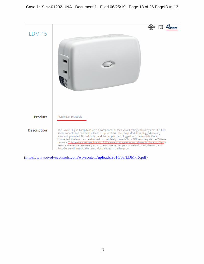
(https://www.evolvecontrols.com/wp-content/uploads/2016/03/LDM-15.pdf).
Case 1:19-cv-01202-UNA Document 1 Filed 06/25/19 Page 13 of 26 PageID #: 13
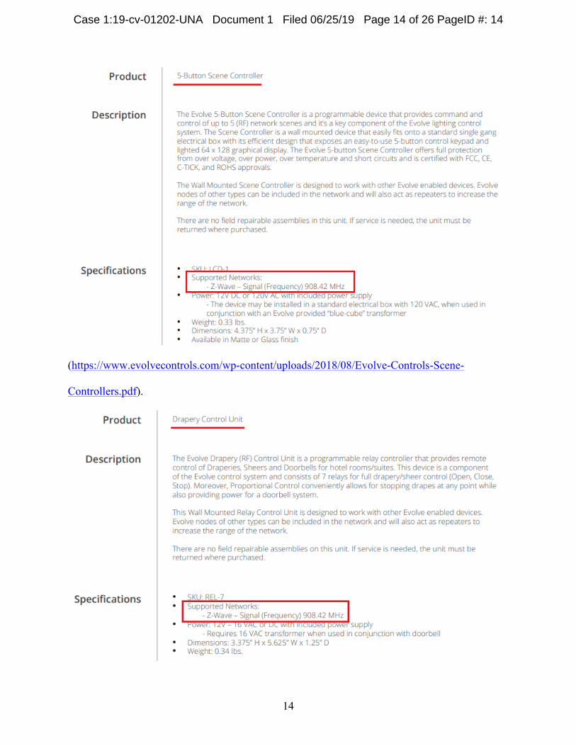
14
(https://www.evolvecontrols.com/wp-content/uploads/2018/08/Evolve-Controls-Scene-
Controllers.pdf).
Case 1:19-cv-01202-UNA Document 1 Filed 06/25/19 Page 14 of 26 PageID #: 14
15
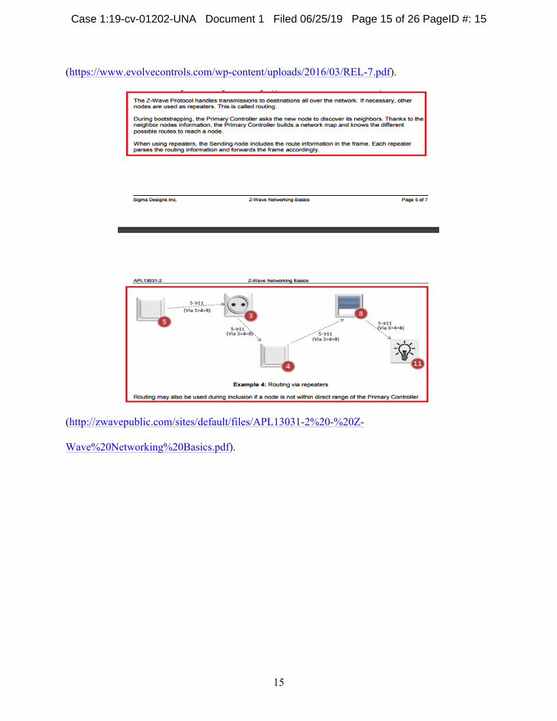
(https://www.evolvecontrols.com/wp-content/uploads/2016/03/REL-7.pdf).
(http://zwavepublic.com/sites/default/files/APL13031-2%20-%20Z-
Wave%20Networking%20Basics.pdf).
Case 1:19-cv-01202-UNA Document 1 Filed 06/25/19 Page 15 of 26 PageID #: 15
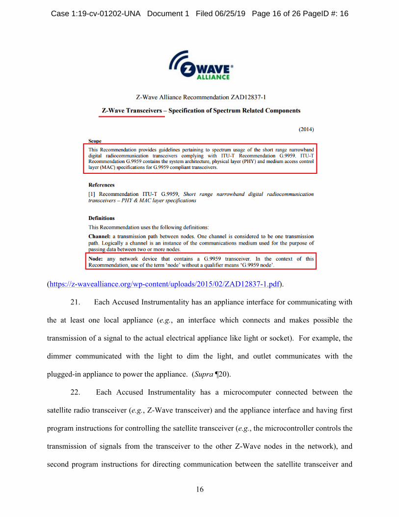
16
(https://z-wavealliance.org/wp-content/uploads/2015/02/ZAD12837-1.pdf).
21. Each Accused Instrumentality has an appliance interface for communicating with
the at least one local appliance (e.g., an interface which connects and makes possible the
transmission of a signal to the actual electrical appliance like light or socket). For example, the
dimmer communicated with the light to dim the light, and outlet communicates with the
plugged-in appliance to power the appliance. (Supra ¶20).
22. Each Accused Instrumentality has a microcomputer connected between the
satellite radio transceiver (e.g., Z-Wave transceiver) and the appliance interface and having first
program instructions for controlling the satellite transceiver (e.g., the microcontroller controls the
transmission of signals from the transceiver to the other Z-Wave nodes in the network), and
second program instructions for directing communication between the satellite transceiver and
Case 1:19-cv-01202-UNA Document 1 Filed 06/25/19 Page 16 of 26 PageID #: 16
17
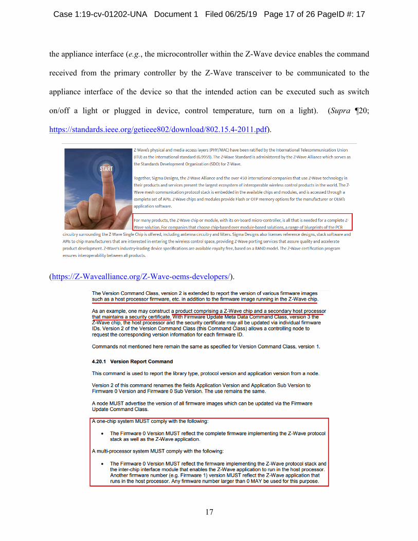
the appliance interface (e.g., the microcontroller within the Z-Wave device enables the command
received from the primary controller by the Z-Wave transceiver to be communicated to the
appliance interface of the device so that the intended action can be executed such as switch
on/off a light or plugged in device, control temperature, turn on a light). (Supra ¶20;
https://standards.ieee.org/getieee802/download/802.15.4-2011.pdf).
(https://Z-Wavealliance.org/Z-Wave-oems-developers/).
Case 1:19-cv-01202-UNA Document 1 Filed 06/25/19 Page 17 of 26 PageID #: 17
18
(http://zwavepublic.com/sites/default/files/command_class_specs_2017A/SDS13782-4%20Z-
Wave%20Management%20Command%20Class%20Specification.pdf).
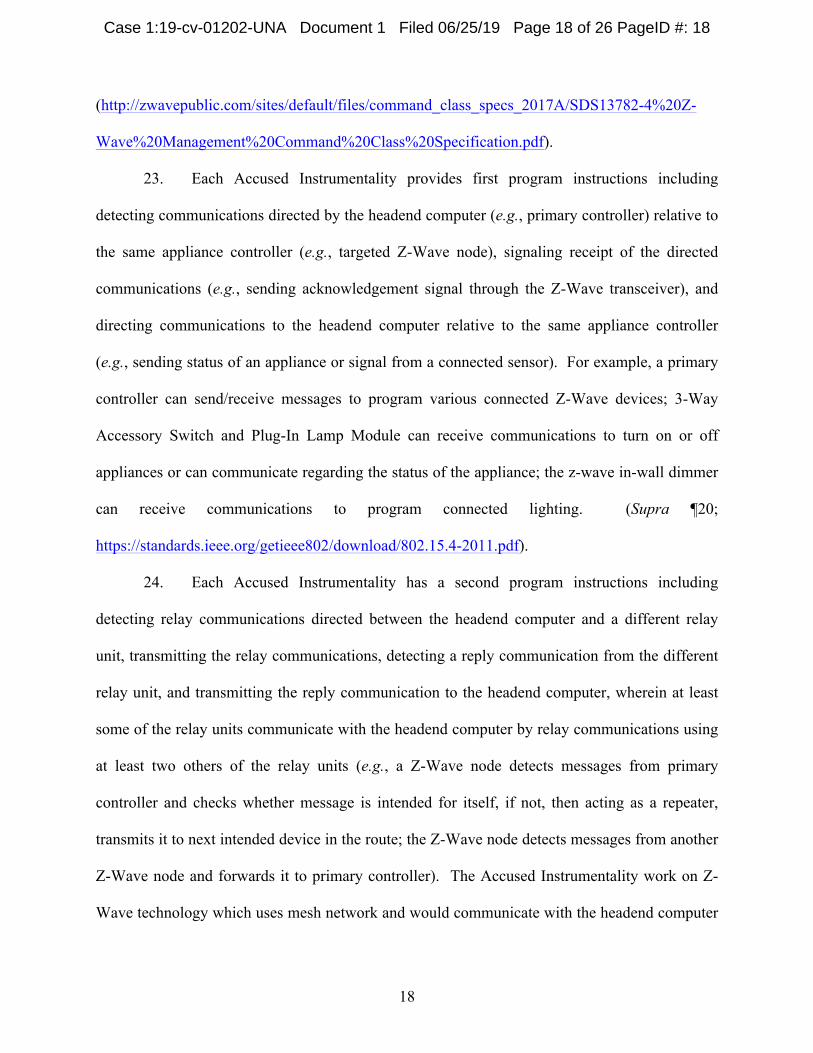
23. Each Accused Instrumentality provides first program instructions including
detecting communications directed by the headend computer (e.g., primary controller) relative to
the same appliance controller (e.g., targeted Z-Wave node), signaling receipt of the directed
communications (e.g., sending acknowledgement signal through the Z-Wave transceiver), and
directing communications to the headend computer relative to the same appliance controller
(e.g., sending status of an appliance or signal from a connected sensor). For example, a primary
controller can send/receive messages to program various connected Z-Wave devices; 3-Way
Accessory Switch and Plug-In Lamp Module can receive communications to turn on or off
appliances or can communicate regarding the status of the appliance; the z-wave in-wall dimmer
can receive communications to program connected lighting. (Supra ¶20;
https://standards.ieee.org/getieee802/download/802.15.4-2011.pdf).
24. Each Accused Instrumentality has a second program instructions including
detecting relay communications directed between the headend computer and a different relay
unit, transmitting the relay communications, detecting a reply communication from the different
relay unit, and transmitting the reply communication to the headend computer, wherein at least
some of the relay units communicate with the headend computer by relay communications using
at least two others of the relay units (e.g., a Z-Wave node detects messages from primary
controller and checks whether message is intended for itself, if not, then acting as a repeater,
transmits it to next intended device in the route; the Z-Wave node detects messages from another
Z-Wave node and forwards it to primary controller). The Accused Instrumentality work on Z-
Wave technology which uses mesh network and would communicate with the headend computer
Case 1:19-cv-01202-UNA Document 1 Filed 06/25/19 Page 18 of 26 PageID #: 18
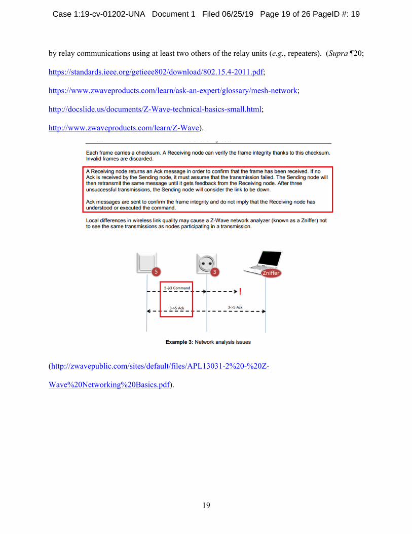
19
by relay communications using at least two others of the relay units (e.g., repeaters). (Supra ¶20;
https://standards.ieee.org/getieee802/download/802.15.4-2011.pdf;
https://www.zwaveproducts.com/learn/ask-an-expert/glossary/mesh-network;
http://docslide.us/documents/Z-Wave-technical-basics-small.html;
http://www.zwaveproducts.com/learn/Z-Wave).
(http://zwavepublic.com/sites/default/files/APL13031-2%20-%20Z-
Wave%20Networking%20Basics.pdf).
Case 1:19-cv-01202-UNA Document 1 Filed 06/25/19 Page 19 of 26 PageID #: 19
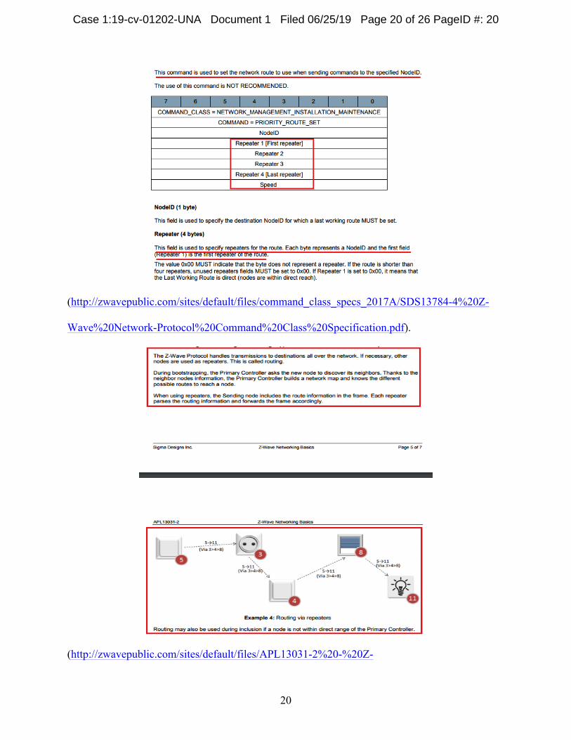
20
(http://zwavepublic.com/sites/default/files/command_class_specs_2017A/SDS13784-4%20Z-
Wave%20Network-Protocol%20Command%20Class%20Specification.pdf).
(http://zwavepublic.com/sites/default/files/APL13031-2%20-%20Z-
Case 1:19-cv-01202-UNA Document 1 Filed 06/25/19 Page 20 of 26 PageID #: 20
21
Wave%20Networking%20Basics.pdf).
III. COUNT II (PATENT INFRINGEMENT OF UNITED STATES PATENT NO. 6,873,245)
25. Plaintiff incorporates the above paragraphs herein by reference.
26. On March 29, 2005, United States Patent No. 6,873,245 (“the ‘245 Patent”) was
duly and legally issued by the United States Patent and Trademark Office. The application
leading to the ‘245 patent was filed on August 14, 2001, and is a continuation-in-part of the
application leading to the ‘166 Patent. (Ex. B at cover). The ‘245 Patent is titled “RF Remote
Appliance Control/Monitoring System.” A true and correct copy of the ‘245 Patent is attached
hereto as Exhibit B and incorporated herein by reference.
27. Plaintiff is the assignee of all right, title and interest in the ‘245 patent, including
all rights to enforce and prosecute actions for infringement and to collect damages for all
relevant times against infringers of the ‘245 Patent. Accordingly, Plaintiff possesses the
exclusive right and standing to prosecute the present action for infringement of the ‘245 Patent
by Defendant.
28. Because the ‘245 patent is a continuation in part of the application leading to the
‘166 patent, the ‘245 patent has a substantially overlapping specification and the background
regarding the ‘166 patent is equally applicable and is incorporated by reference with respect to
the ‘245 patent. (Supra ¶¶11-17).
29. Direct Infringement. Upon information and belief, Defendant has been directly
infringing at least claim 1 of the ‘245 patent in Delaware, and elsewhere in the United States, by
performing actions comprising making, using, selling, and/or offering for sale an appliance
controller for a distributed appliance systems having a multiplicity of appliances, and a plurality
of relay units, that satisfies the limitations of at least claim 1, including without limitation the
Case 1:19-cv-01202-UNA Document 1 Filed 06/25/19 Page 21 of 26 PageID #: 21
22
Wireless Digital Thermostat, In-Room Card Reader, 3-Way Accessory Switch, Plug-In
Appliance Module, Plug-In Lamp Module, 5-Button Scene Controller, and Drapery Control Unit
(“Accused Instrumentality”).
30. Each Accused Instrumentality provides an appliance controller (e.g., Z-wave
thermostat, plug-in fluorescent light and appliance module, in-wall dimmer, and smart switch)
for a distributed appliance system (e.g., Z-Wave network) having a multiplicity of appliances
(e.g., appliances such as lights, appliances, etc.), and a plurality of relay units (e.g., repeaters),
one of the relay units being the appliance controller (e.g., a Z-Wave Controller). (Supra ¶20;
http://zwavepublic.com/sites/default/files/command_class_specs_2017A/SDS13782-4%20Z-
Wave%20Management%20Command%20Class%20Specification.pdf;
http://zwavepublic.com/sites/default/files/APL13031-2%20-%20Z-
Wave%20Networking%20Basics.pdf)
31. Each Accused Instrumentality has a low power satellite radio transceiver (e.g.,
radio frequency transceivers within the various Z-Wave devices) having a range being less than a
distance to at least some of the appliances. (Supra ¶20).
32. Each Accused Instrumentality has an appliance interface for communicating with
the at least one local appliance (e.g., an interface which connects and makes possible the
transmission of signal to the actual electrical appliance like a light and plugged in appliances).
(Supra ¶20).
33. Each Accused Instrumentality has a microcomputer (e.g., microcontroller)
connected between the satellite radio transceiver (e.g., Z-Wave transceiver) and the appliance
interface and having first program instructions for controlling the satellite transceiver (e.g., the
microcontroller controls the transmission of signals from the transceiver to the other Z-Wave
Case 1:19-cv-01202-UNA Document 1 Filed 06/25/19 Page 22 of 26 PageID #: 22
23
nodes in the network) and second program instructions for directing communication between the
satellite transceiver and the appliance interface (e.g., the microcontroller within the Z-Wave
device enables the command received from the appliance interface to be communicated to the
local appliance by the Z-Wave transceiver so that the intended action can be executed such as
switch on/off a light, control temperature, dim a light). (Supra ¶¶20, 22; https://Z-
Wavealliance.org/Z-Wave-oems-developers/;
http://zwavepublic.com/sites/default/files/command_class_specs_2017A/SDS13782-4%20Z-
Wave%20Management%20Command%20Class%20Specification.pdf; http://www.rfwireless-
world.com/Tutorials/Z-Wave-physical-layer.html).
34. Each Accused Instrumentality has a first program instructions including detecting
communications directed by another of the relay units (e.g., another Z-Wave node acting as a
repeater) relative to the same appliance controller (e.g., targeted Z-Wave node), signaling receipt
of the directed communications (sending acknowledgement signal through the Z-Wave
transceiver), and directing communications to the other of the relay units relative to the same
appliance controller (e.g., sending status of an appliance or signal from a connected sensor). For
example, the 5-Button Scene Controller can send/receive messages to program various connected
Z-Wave devices; the Plug-In Lamp Module can receive communications to turn on or off
appliances or can communicate regarding the status of the appliance; the 3-Way Accessory
Switch can receive communications to program connected lighting sources or communicate
regarding the status of the light. (Supra ¶20;
http://zwavepublic.com/sites/default/files/APL13031-2%20-%20Z-
Wave%20Networking%20Basics.pdf;
Case 1:19-cv-01202-UNA Document 1 Filed 06/25/19 Page 23 of 26 PageID #: 23
24
http://zwavepublic.com/sites/default/files/command_class_specs_2017A/SDS13784-4%20Z-
Wave%20Network-Protocol%20Command%20Class%20Specification.pdf).
35. Each Accused Instrumentality has a second program instructions including
detecting relay communications directed between the another of the relay units and a different
relay unit, transmitting the relay communications, detecting a reply communication from the
different relay unit, and transmitting the reply communication to the other of the relay units,
wherein at least some of the relay units communicate with others of the relay units by relay
communications using at least two others of the relay units (e.g., a Z-Wave node detects
messages from primary controller and checks whether message is intended for itself, if not, then
acting as a repeater, transmits it to next intended device in the route. Also, the Z-Wave node
detects messages from another Z-Wave node and forwards it to primary controller. N number of
nodes may be involved in the process acting as repeaters or relay units). The Accused
Instrumentality works on Z-Wave technology which uses mesh network and would communicate
with the other relay units by relay communications using at least two others of the relay units
(e.g., repeaters). (Supra ¶¶20, 24; http://zwavepublic.com/sites/default/files/APL13031-2%20-
%20Z-Wave%20Networking%20Basics.pdf;
http://zwavepublic.com/sites/default/files/command_class_specs_2017A/SDS13784-4%20Z-
Wave%20Network-Protocol%20Command%20Class%20Specification.pdf;
https://www.zwaveproducts.com/learn/ask-an-expert/glossary/mesh-network;
http://docslide.us/documents/Z-Wave-technical-basics-small.html;
http://www.zwaveproducts.com/learn/Z-Wave).
36. Plaintiff has been damaged because of Defendant’s infringing conduct.
Defendant is thus liable to Plaintiff for damages in an amount that adequately compensates
Case 1:19-cv-01202-UNA Document 1 Filed 06/25/19 Page 24 of 26 PageID #: 24
25
Plaintiff for such Defendant’s infringement of the ‘166 Patent and the ‘245 Patent, i.e., in an
amount that by law cannot be less than would constitute a reasonable royalty for the use of the
patented technology, together with interest and costs as fixed by this Court under 35 U.S.C.
§ 284.
37. On information and belief, Defendant had at least constructive notice of the ‘166
Patent and the ‘245 Patent by operation of law, and there are no marking requirements that have
not been complied with.
IV. JURY DEMAND
Plaintiff, under Rule 38 of the Federal Rules of Civil Procedure, requests a trial by jury of
any issues so triable by right.
V. PRAYER FOR RELIEF
WHEREFORE, Plaintiff respectfully requests that the Court find in its favor and against
Defendant, and that the Court grant Plaintiff the following relief:
a. Judgment that one or more claims of United States Patent No. 6,275,166 have been infringed, either literally and/or under the doctrine of equivalents, by Defendant;
b. Judgment that one or more claims of United States Patent No. 6,873,245 have
been infringed, either literally and/or under the doctrine of equivalents, by Defendant;
c. Judgment that Defendant account for and pay to Plaintiff all damages to and costs
incurred by Plaintiff because of Defendant’s infringing activities and other conduct complained of herein, and an accounting of all infringements and damages not presented at trial;
d. That Plaintiff be granted pre-judgment and post-judgment interest on the damages
caused by Defendant’s infringing activities and other conduct complained of herein;
e. That Plaintiff be granted such other and further relief as the Court may deem just
and proper under the circumstances.
Case 1:19-cv-01202-UNA Document 1 Filed 06/25/19 Page 25 of 26 PageID #: 25
26
June 25, 2019 OF COUNSEL: David R. Bennett Direction IP Law P.O. Box 14184 Chicago, IL 60614-0184 (312) 291-1667 [email protected]
STAMOULIS & WEINBLATT LLC /s/ Stamatios Stamoulis Stamatios Stamoulis (No. 4606) 800 N. West Street, Third Floor Wilmington, DE 19809 (302) 999-1540 [email protected] Attorneys for Plaintiff Karamelion LLC
Case 1:19-cv-01202-UNA Document 1 Filed 06/25/19 Page 26 of 26 PageID #: 26