- john f. rider ' - world radio history
TRANSCRIPT
-
,
' -- - - .-....,....r...irC ---''''',,,.,,,....-.72---73.=5,. _47,, :-..4.,..""Ze----- '.:-.. -,..-...--,
- JOHN F. RIDER
---...
e3:',...--- , ...:17:...e',...."---44.24"--'--
'..2"ee -i-''''''*"-,- ..-vnek7se-.,.. -_,.......-- .--.Z.--e-,--.,---:-'1:7--..-----. .. _
'
,
-4-A-,..,...-,e- _--2,,,r...e___ .,.. .
..k'-'.*',4.'"th-_-_,,,,,-....e- - ---....-.-Z..-- -----;-, .1-, - '",..- _,----1,!bn-i....-eb. .--e.ezi,.- - -.,_.., , ...
_..... .
ea, ,,, . .,-'...-, -,. , - ---.-- - , --e, : -2,2- ' -evz.e.._,..".. -
--.!... ...e...,.- -. ;....,.. e._..s,-",-91a-. -
'.--.e... - e -..-,..., --------- ,,,,,.,,,,,e, ......efl;... ',,et'-.. .... "._.....-
- - -.....
- ''',-.: '''-`,--";4e-'-^1.,:.».4.4;
.*M-- -
www.americanradiohistory.com
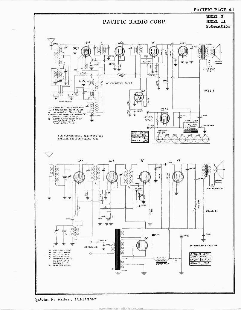
PACIFIC PAGE 9-1
PACIFIC RADIO CORP.
01111.D. 6A7
8
OAnO .54/ITCH
e 4
L/- 304N0 AN7. cO/L 9fSCMOUN_' /g/ J 3 BAND OX CD/L 9.wMO[T/T //A7 O
L,- //YT 'mu fNCY7R9/KI./Y' 302 L1 -DIODE /N7 re -QUENCY 772A/%3112303 1 00047 T, -DYNAMIC SPEAKER N'73/ T0- 2044G TUNING CO/YD AT 620
VOLUME CONI Nt./ls BAND 34/ITCH M.12/
FOR CONVENTIONAL ALIGNMENT SEE SPECIAL SECTION VOLUME VIII
NO VOLTS AC
L ANT. COIL N. 1/e2 L. OX COIL NL1183 L, /0 LE COIL NÁ300 I, 2- LE COIL N. 303 T, TRAMsFORntO n'. 323
VOL CONT 11 2IO
1000(4 M' 711
C, GAM [ONO n' 422
6D6
If -FREQUENCY -965 K. C.
03N1D
75
//OYDL73 AC DC
® xN
LM7E ) /HÌ Or- .B4
ov/r.,.on,_e,
2S -L-6
MODEL 3 MODEL 11 Schematics
LYNAN.0 At A,A
2sz5
UY-23O.mA. el I' /JIn
NOV LIUC4/NG COIL
MODEL 3
/INED
AMNIA -AWLS
2125 2 L6 7 665 6LM 647
O O O
/F-FREOI,FNCy -AlT6 /CC
STUEiC -AC-/V ° // DATE -
DR.Dr- k/L cz AOORorLD: v4"al
©John F. Rider, Publisher
www.americanradiohistory.com
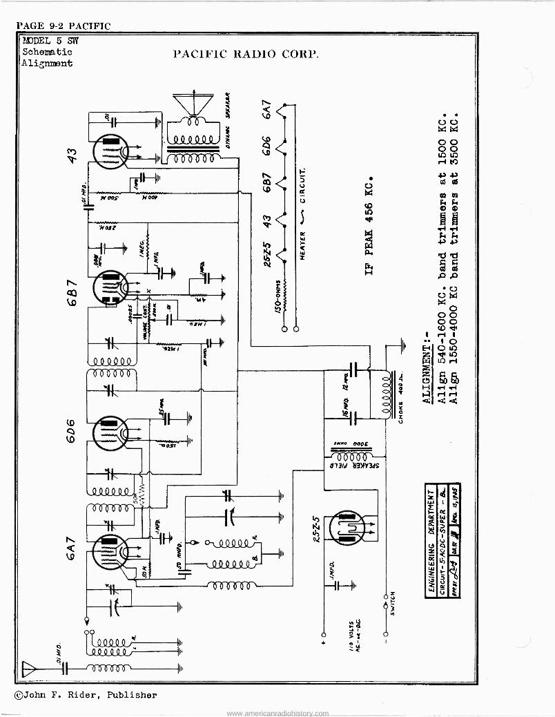
PAGE 9-2 PACIFIC
MODEL 5SIN Schematic Alignment
CO lD
l
o
0.1
yroos oe
7,1i
$á ob
PACIFIC RADIO CORP.
S.1
1H.
ó O
V V
N
4
eJN/
`QQQQQ.4 7-07S1Y6-6-`
.
40.51 ,-0
aSSISUL, 1 MOW
O
00
p,
ò QQ444, N
4 QQ4
nolginf,
h N
!MMO 000E
--t 4 b 0-4 ó 073/d b3NY3dS
©John F. Rider, Publisher
www.americanradiohistory.com
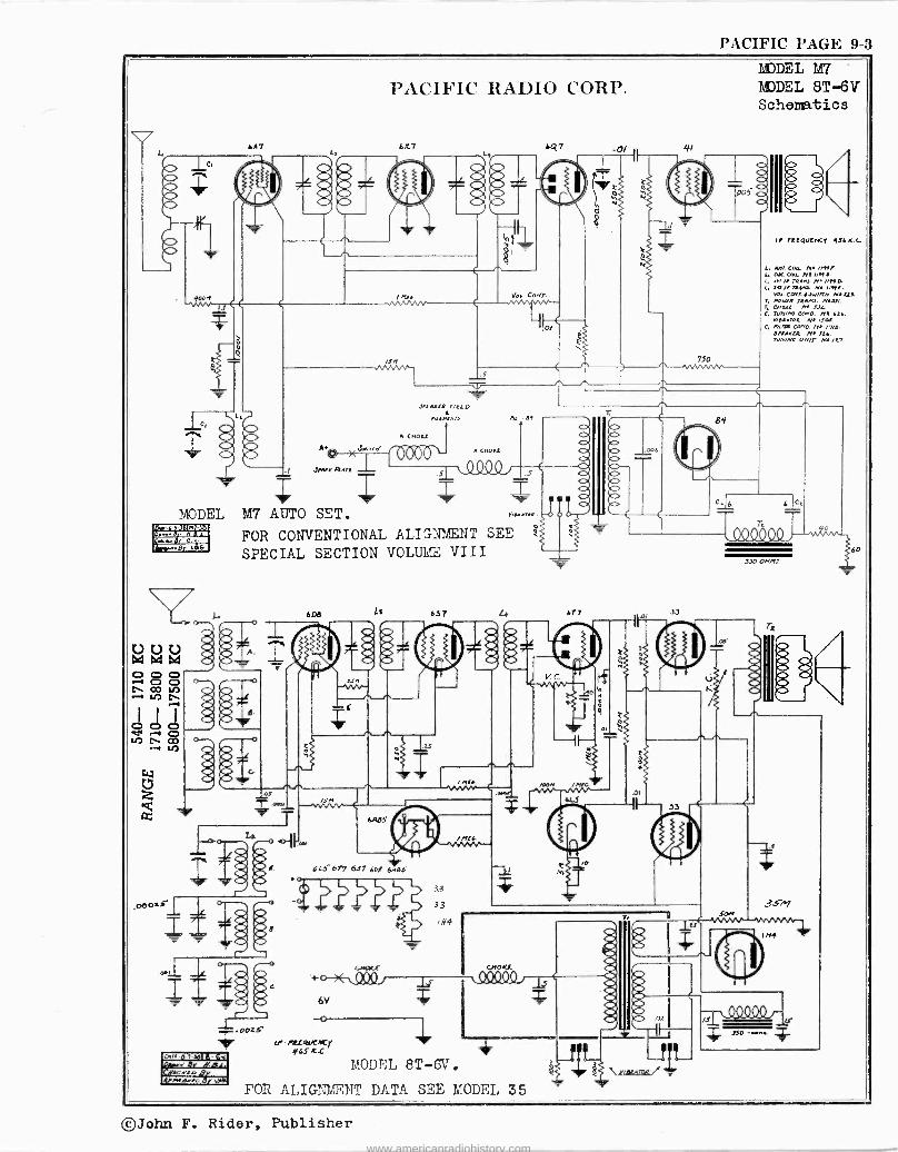
PACIFIC PAGE 9-3
MODEL 1a_'S4p180818 F=L;TMEVVII
MrMEMEM
3:450."
411,
i 40 .44
6A7
JPt.e ßn
M7 AUTO SET.
FOR CONVENTIONAL ALIGNMENT SEE
SPECIAL SECTION VOLUME VIII
PACIFIC RADIO CORP.
6K 7 "17
T ooes
momentum; rrsenvorin;
%
6138 L7 6.57 677
-0/ t 41
V
J3
'V
750
MODEL M7 I DEL 8T -6V Schematics
If fRRQUCIVCY
L. wn/.COu N nNI. L. PIC CWL Ni 2/99 .
/I M.. NI //MP L. av//]RMY- Nt "Ile.
Voa.COrI.J/rzN NaLR T, roUTe M.M. NtJJI. , cno..e L
C, TUN/46 COVO. Ne 626. rmR+Toe N. aruT
C. narn cano. N /716 6Ie21.LR N 7t6. run.. un/T N /LT.
T / QOQQ90
JJO ON4IJ
TE
~T $ ,mN /nec.
OI w_w_. 1 M
7l
61
6.485
6tJ 677 6s7 ba$ 6465
6V
o
/H¢
¡P' rrrmit..0 y q6SKG
CHOKE
1.1.1 kt/
i MODEL 8T -CV.
FOR ALIGNMENT DATA SEE MODEL 35
ó \ V/ER4ft1Q/ 11L --
104
/S
o
©John F. Rider, Publisher
www.americanradiohistory.com
PAGE 9-4 PACIFIC
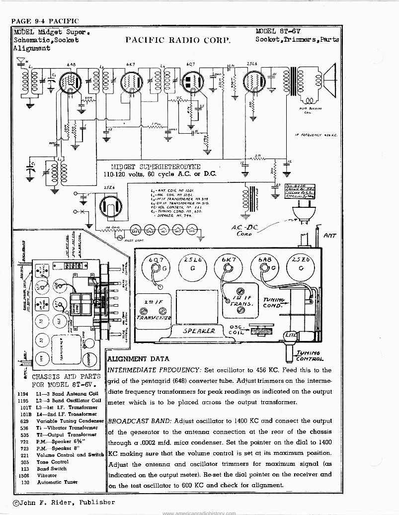
1t )EL Midget Super. Schematio,Sooket Alignment
6 A
CHASSIS AIÎD PARTS FOR MODEL 8T -6V.
1194 L1-3 Band Antenna Coll 1195 L2-3 Band Oscillator Coil
101T L3 -1st I.F. Transformer 101E L4 -2nd I.F. Transformer 629 Variable Tuning Condenser 536 Tl-Vibrator Transformer 535 T2-Output Transformer 722 P.M.-Speaker 61" 723 P.M.-Speaker 8" 221 Volume Control and Switch 305 Tone Control 123 Band Switch
1506 Vibrator 130 Automatic Tuner
PACIFIC RADIO CORP.
6K7 L
MODEL 8T -6V S ocket,Tr iimner s, Parts
6Q7 , , 2516
Ir'IDGET SL'PMETERODYNE 110-120 volts, 60 cycle A.C. or D.C.
2516 L, -ANT. COIL N' /201. li WC. COIL Nº. /202.
TRANJFoa11(4 Jot. IF TRANSFORMER Na JIO.
V.CrVOL CONTROL N° Z2/. C,-TbnING COND. N!. 630.
JPfRKfR Nr.744.
Au on e e e e e ePILOT LIGHT.
: aAdsFC.U:r.
c
L 3PEAkE2
Sr/ 1NVVNti
A.C. -DC CO.ea
ZO
Nun Euc//n/ Cod-.
/f faEQVE/VCY YJ6 KE.
On.- 8.3381 ot. r e IYeE CN/crn B (.L. AFPRCvfJGYV=
A/l'T
2un1ivb ALIGNMENT DATA CONTROL,
INTERMEDIATE FREQUENCY: Set oscillator to 456 KC. Feed this to the
grid of the pentagrid (648) converter tube. Adjust trimmers on the interme-
diate frequency transformers for peak readings as indicated on the output
meter which is to be placed across the output transformer.
BROADCAST BAND: Adjust oscillator to 1400 KC and connect the output
of the generator to the antenna connection at the rear of the chassis
through a .0002 mfd. mica condenser. Set the pointer on the dial to 1400
KC making sure that the volume control is set at its maximum position.
Adjust the antenna and oscillator trimmers for maximum signal (as
indicated on the output meter). Re -set the dial pointer on the receiver and
on the test oscillator to 600 KC and check for alignment.
©John F. Rider, Publisher
www.americanradiohistory.com
PACIFIC PAGE 9-5
er
I -2
#
e'r
PACIFIC RADIO CORP.
.DDOS 6D8
I
- ÿ
657
A]flr8)n-I - BROW. BNIO. AJSIT/OD-2-/AT MAO. pOWTion-3 .3 Id BAnO
r0
LE
ó O C> \
..90025 yg 0003 m2/110
L,
11106
r
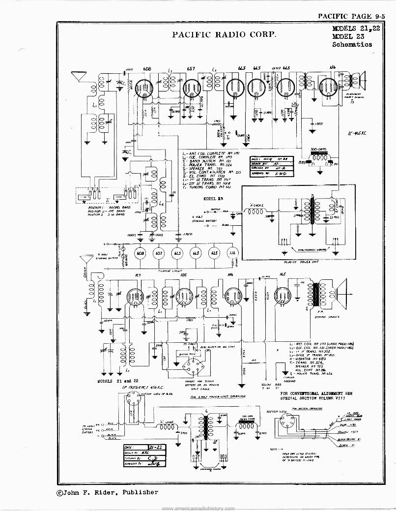
MODELS 21,22 MODEL 23 Schematics
A`
0664S 6LS anrn 6L5
_ ,,,,,
f D
T, e
c
M'
L,- ANT COIL CLN'IPLETE Li- Ox. CONPL£TE /Ke IMO T,- 9AND SWITCH N°. /2) L- POLIER TRANS. N°.5Z0 T, - SPEAKER N'. 722 4- VOL. CONT. OSIITCN M°. 215 &- EL. COND. N° 1720
LE TRANS Al. Mir 2A -t ff. TRANS. N°. l0/e
C, - TUNING COND. N9.62I
MODEL 22
6 VOLT
sTOIAGE D4r7ERY
u4rE: .v,Y.sT NR al APAIVR pr: CA/COCED
AI1a11'ED er. LWG
681,.. 1
Info
300-08115
BA171T VD
I I 1CIl E 10RAAeET
Amer, orwtAA
T
If -465.0
7(Ä7f ñ VCM]OK77E ]( .
6 vo srwARe e.rrur
LI
O
/t 7
b Co
b p
«Soro
657 6L5 6L5
A.twAEn,
/
/J6
Ó Q
/H6
SAID
T MODELS 21 and 22
TP fREQUfNC r 9S6.c.C.
To eVOL,4b to
,ERYZ O rwne
AT
IS E6
.S/?QL
-7F- ))(1
TO T1.411.1 L,- gnT. COIL N°. 170.(1./i74¢ RODLL-lRl2 e1/ALiWKC of, ttx COAI. Lt- OJC. COIL Nº. 13.2412111R NDOLL-/.97)
eortAAVIEV -9e
COAT
L,-/'-' /f TRMY3. N°302. N L,- 0100L /F TRA/Y3. N'JOJ.
on n - V/ 211.1701t n° }go. L-TRAN3. NlJ21
I 3PEARER AT 722 y VOL. ConT. N-LK.
rtir.
7 T -POG/ER MANS. N°-606 CNA.üIs GRO/MO
lr In ow REO C -4Y C -
\ frnCARaw3 vient
PLW-/n WGIER Uvllr
/t,tf
, , 1
]SNID a
b C> Oi b a
L - OrnM/L 3104REK
eerier, VIEW LE ßW
VOL Co-,. i
sOCAET ADA E/TAeA
DATTERI OA DY. POVER
UM,T CACLE
foR 6MILE TbCER-unir OPLDATAOA'
N
DATE : I2/-22 DRAT+ er: ALn.L-
CNECAeo BE
qPMDREo Or:
1 1 1 1 1I 1
3íO-oAD se tAa
FOR CONVENTIONAL ALIGNMENT SEE SPECIAL SECTION VOLUME VIII
/xw 0417E4r DAeA4r1011
bottom vl[V
NOTE - ONLI ODE LEAD l3 D3ED- DEPerrooe 0D VDKM TYRE
CX Á611s08) 11 0.1[0
-E
BE 00
©John F. Rider, Publisher
www.americanradiohistory.com
PAGE 9-6 PACIFIC
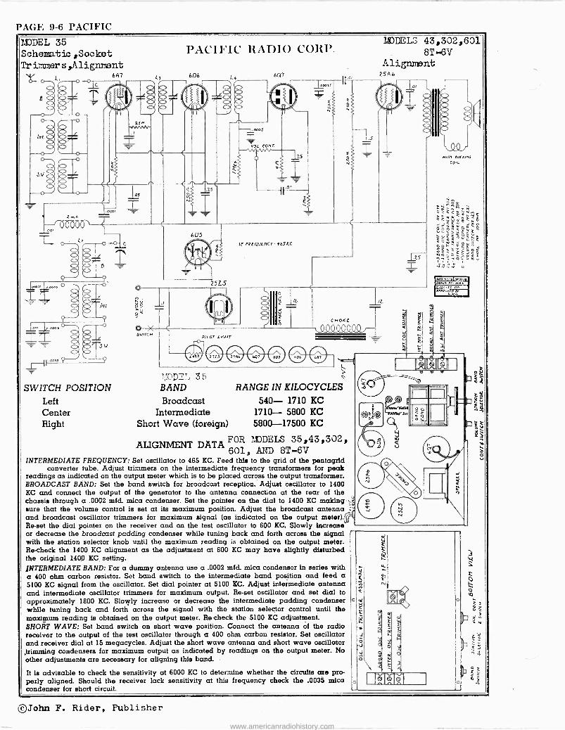
MODEL 35 Schematic ,Socket Trimmer s,Alignment
V/- 6A7 Y- .O
z
(1T.aoo.
Z . Lz .
/nr.
w.
SWITCH POSITION Left Center Right
SNITCH
PACIFIC Rt1DI0 CORP.
L3 606
7I )DE7 35 BAND
Broadcast Intermediate
Short Wave (foreign)
4 6q7
r,BDDELS 43,302,601 8T -6V
Alignment 25A6
RANGE IN KILOCYCLES
540- 1710 KC 1710- 5800 KC 5800-17500 KC
ALIGNMENT DATA FOR MDELS 35,43,302, 601, AND 8T --6V
INTERMEDIATE FREQUENCY: Set oscillator to 465 KC. Feed this to the grid of the pentagrid converter tube. Adjust trimmers on the intermediate frequency transformers for peak
readings as indicated on the output meter which is to be placed across the output transformer. BROADCAST BAND: Set the band switch for broadcast reception. Adjust oscillator to 1400 KC and connect the output of the generator to the antenna connection at the rear of the chassis through a .0002 mfd. mica condenser. Set the pointer on the dial to 1400 KC making sure that the volume control is set at its maximum position. Adjust the broadcast antenna and broadcast oscillator trimmers for maximum signal (as indicated on the output meter) Re -set the dial pointer on the receiver and on the test oscillator to 600 KC. Slowly increase or decrease the broadcast padding condenser while tuning back and forth across the signal with the station selector knob until the maximum reading is obtained on the output meter. Re -check the 1400 KC alignment as the adjustment at 600 KC may have slightly disturbed the original 1400 KC setting. INTERMEDIATE BAND: For a dummy antenna use a .0002 mfd. mica condensor ln series with a 400 ohm carbon resistor. Set band switch to the intermediate band position and feed a 5100 KC signal from the oscillator. Set dial pointer at 5100 KC. Adjust intermediate antenna and intermediate oscillator trimmers for maximum output. Re -set oscillator and set dial to approximately 1800 KC. Slowly increase or decrease the intermediate padding condenser while tuning back and forth across the signal with the station selector control until the maximum reading is obtained on the output meter. Re -check the 5100 KC adjustment. SHORT WAVE: Set band switch on short wave position. Connect the antenna of the radio receiver to the output of the test oscillator through a 400 ohm carbon resistor. Set oscillator and receiver dial at 15 megacycles. Adjust the short wave antenna and short wave oscillator ,trimming condensers for maximum output as indicated by readings on the output meter. No other adjustments are necessary for aligning this band.
It is advisable to check the sensitivity at 6000 KC to determine whether the circuits are pro- perly aligned. Should the receiver lack sensitivity at this frequency check the .0035 mica condenser for short circuit.
o
o
©John F. Rider, Publisher
www.americanradiohistory.com
PACIFIC PAGE 9-7
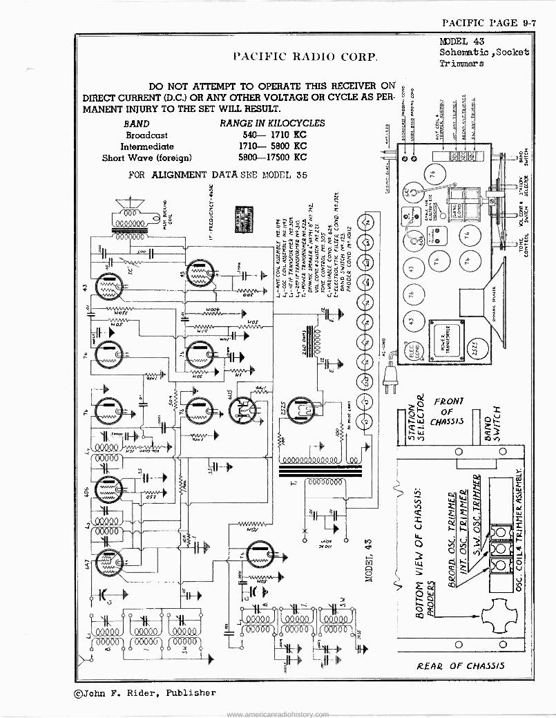
PACIFIC RADIO CORP.
DO NOT ATTEMPT TO OPERATE THIS RECEIVER OIL z
DIRECT CURRENT (D.C.) OR ANY OTHER VOLTAGE OR CYCLE AS PER- º g
MANENT INJURY TO THE SET WILL RESULT. L
BAND Broadcast
Intermediate Short Wave (foreign)
RANGE IN KILOCYCLES 540- 1710 KC 1710- 5800 KC 5800-17500 KC
FOR ALIGNMENT DATA SEE MODEL 35
11 1 11.1.1 x u
- - Il Ih
P c
1-111>
OOC
wOSC -_ IV OS
(},
,.009°°.
4011/
NO/
wOOi
war
NOS
MOs
osr
ó
I1J
15 -0 -6=25 -0Th
v v
o
////
o o ///
J O/C(./ / YYYICY / l // Y -KY i
(fZS°ó°° 0'59,°(r. F7'
-,./VVVNVVv-- NJ/
M ór "rF ' E'">'
11 i--- {
veó >r O//
a
v
º
MDDEL 43 Schematic , Socket Tr inner s
.
r
< <
0® I® ® ®
2
e
ly
G FROM' ú OF
.zz LL? 00523
In
1
ct, o
1
Vi
o o RLAQ OF CHAS5I5
©John F. Rider, Publisher
www.americanradiohistory.com
PAGE 9-8 PACIFIC
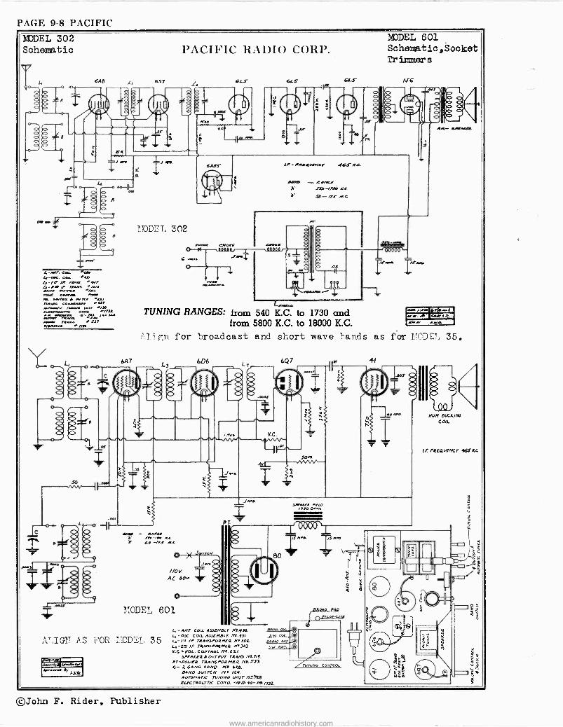
MODEL 302 Schematic
e.
PACIFIC RADIO CORP.
L. 6A8 657 . CLS 615- ! s Q ö f s 11_ ó .
4-.w». CCM. Ou. 4-eC. eeA. OW 4 - /e Yr rtAIR. » AVT !.-to 4» rEAA.i Iw.ssrerc.4 "9.4 TM. GMlY1 'Ser I.. 51)55 t /.eme Nam. < ee5e55AA F111 wvrwwK rm.. ow) /.M
wwrrs irSeT.c ea. &MSt 51r..rµ. 5_ M
NA51 T11Awi
tr
337/ n.RA)55 ,s4)
I
MODEL 302
LI-/11R41AtMCV -ICJ' 4,c.
*WO -- ,[tM-./ .730-Ijte KL
b. /7! II.0
/r o o o
MODEL 601 Schematic, Socket Tr immer s
Iil.ww I6A..
TUNING RANGES: from 540 K.C. to 1730 and from 5800 K.C. to 18000 K.C.
1 f,n for broadcast and short wave bands as f
6A7 6D6
4AM - RAAO. m -a < L -/1f RC
AC 60.
MODEL 601
A' IG2? AS FOR :ODsL 35
4-.-
'P
PT
ti LI -AMT COIL 41.7EHDLr Mf.y.7.. Cl -OSC COI. AssLNeLr Ml. fit. 4-/u IP TRAMSPORMER M1302 L.-2=' IF 75ArIJIOQMER MYJoJ Y.C.FOL. COMrAOL M1.22,
SPEAKER I OUTouT rt4MJ-M7.7/1. 17-Po4/E2 TRr1/KsrORNCR Ml..r7J. G- zGAMO COMO. nt 62e.
04MO S4/17CM /Y4 /21. Au7OHATIC 77/M/4,6 unir M!ee ELECTAOLT7iC COMO. -13/1-ro-MS/7,15,
L
IMO
Rr- 54)A541.
r: rr.N7(S...I rarAß' PoeA5. .
6Aw.w tAIt1
1.»I'D S?, 35.
of
Nun DbGUfle COIL
L/ /4E4[/rcT h66KL
6Q7 41
#730 01.e.
000.-\1, /5Rro
run'''. CON 401.
©John F. Rider, Publisher
www.americanradiohistory.com
PACK. -BELL PAGE 9-1
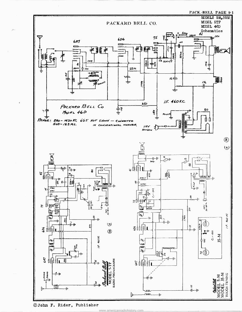
MODELS 5M,35M MODEL 5TP MODEL 46D Schematics s
4-/
RA6E ; 54o - 1+13o 4t 665" Nor 565- i8.31Kc. /K CoWi eAPTiWA& MANNtR
©John F. Rider, Publisher www.americanradiohistory.com
PAGE 9-2 PACK. -BELL
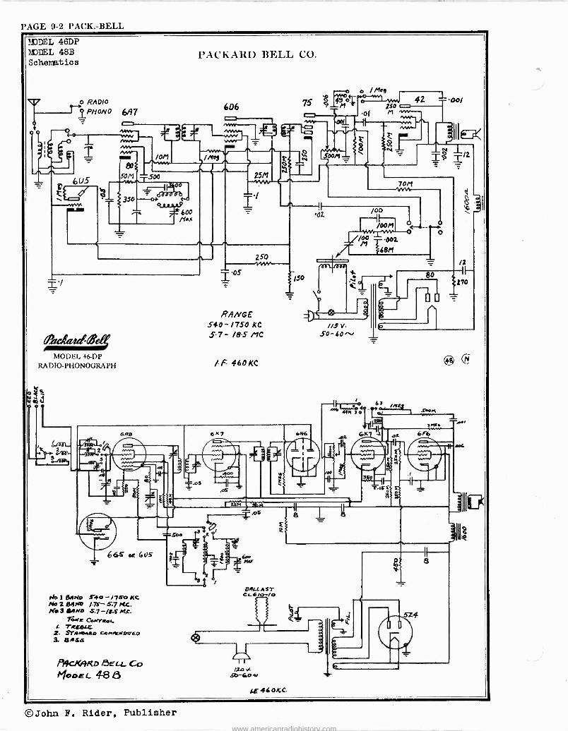
*1DDEL 46DP r.i)DEL 48B S cherat ic s
o RADIO 1"PHONO 637
O o ~° 1 - l =
6U5
aIM
80
50M
11P /0M
PACIír1H1) 13i':I.I. C.O.
606
-,.--1 /Me9
500
350
f 0
600 /HaX
2511
,QCRQdM MODEL 46 -DP
RADIO -PHONOGRAPH
/dal_ 2 3
z50
RANGE 540-1750 KC
.5-7- /8.5 MC
/F 460KC
^o o / ne9 o-wvl ° jso r-+ 42
001
Soon
01 M vw wv 1.00/
70P7
0z. /00
/00/1
M 2 D0
68/1
f '
6 A -Y°# %.
-
ir
II
l. 6K7
D 6
/15 V.
50-60-
,.¿yr 47q10
Al
e
L 664 ox Gas
/Jo 1 BAND 5-40 - i750 Kc NoZB4rm /.7s-5.7rcC. /41.3 8gN0 5.7 -/iS M,c.
TowE CoMTROI /. TREg[E 2 SYAMowRD CetiAUe94rED 3. 6NSS
PACXRRD f3ELL Co I yoDEC. 4-8
ur M = QS
BALL A ST CL6/O-/O
12,3 Sò-bD
8
s
Y-
80
/2 -i F--
%270
é3 ,SboM
1M11
®
J-
-r-os
6i6
5Z4
il 8
Wc
l.f. 460/CC.
©John F. Rider, Publisher www.americanradiohistory.com
PACK. -BELL PAGE 9-3
On0 .- O o-
°
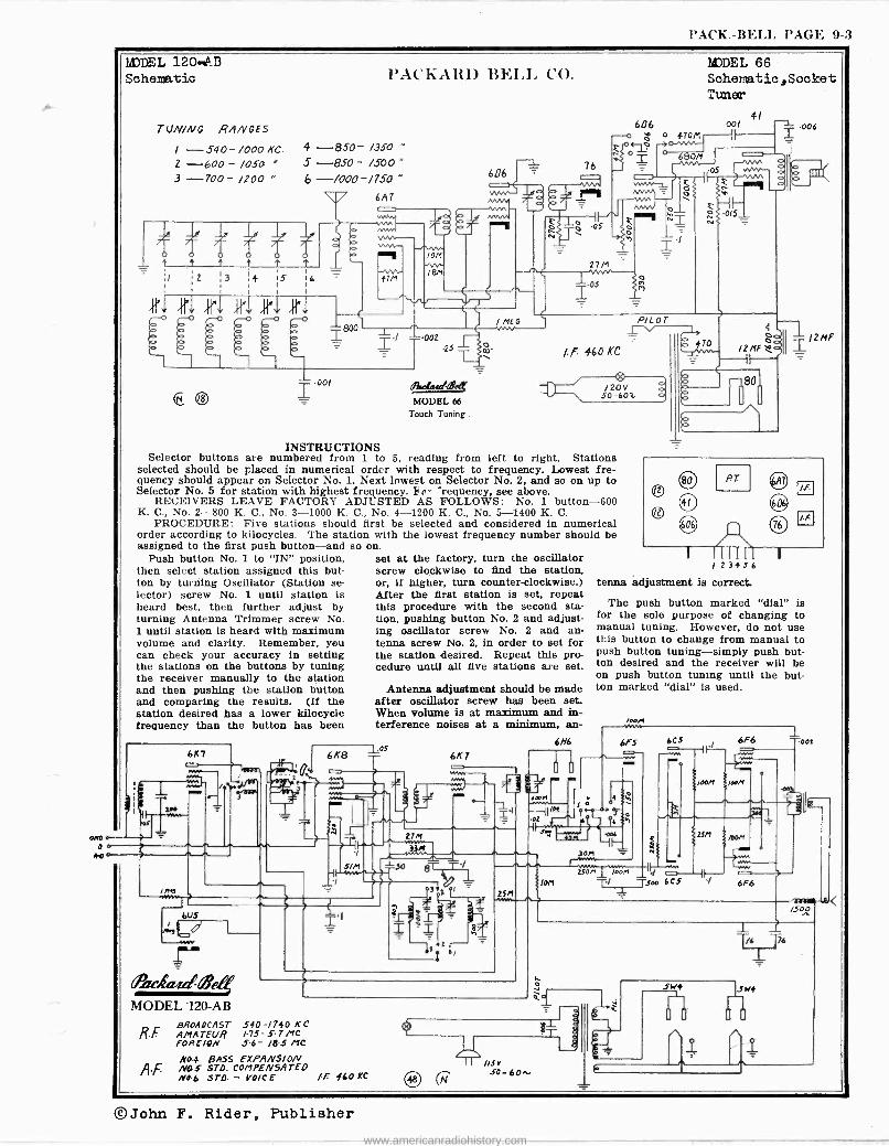
liDDEL 1204B Schematic
TUN/NG RANGES
I -540-/000KC. 2 -600 - /050 3 -700- /Z00 "
o
Ij i4
PACKAH1) ]1h.I,I, CO.
4- -850- /350 "
5 -850 - /500 " 6 -/000 -/750 "
6M
41'1 1,1.1 21. ,i,r1
JE r-0
(o Q 0 0
606 76
`,",1
p OS
2711
05 Ì
M7DEL 66 Sche7aat ic , S ocke t Tuner
606 00/
0(-102.; ó 0 47011
O
y
OM
/ I
f
Ilor
Ñ N
0/5
I MEG P/ L O T -002$p 1 1211F0 470 {lII I /2MF or 460 KC
00/
® I I/oi rds MODEL 66
Touch Tuning.
, /20V SO -601
INSTRUCTIONS Selector buttons are numbered from 1 to 5, reading from left to right. Stations
selected should be placed in numerical order with respect to frequency. Lowest fre- quency should appear on Selector No. 1. Next Lowest on Selector No. 2, and so on up to Selector No. 5 for station with highest frequency. ho- "requency, see above.
RECEIVERS LEAVE FACTORY ADJUSTED AS FOLLOWS: No. 1 button -600 K. C., No. 2-800 K. C., No. 3-1000 K. C., No. 4-1200 K. C., No. 5-1400 K. C.
PROCEDURE: Five stations should first be selected and considered in numerical order according to kilocycles. The station with the lowest frequency number should be assigned to the first push button-and so
Push button No. 1 to "IN" position, then select station assigned this but- ton by turning Oscillator (Station se- lector) screw No. 1 until station is heard best, then further adjust by turning Antenna Trimmer screw No. 1 until station is heard with maximum volume and clarity. Remember, you can check your accuracy in setting the stations on the buttons by tuning the receiver manually to the station and then pushing the station button and comparing the results. (If the station desired has a lower kilocycle frequency than the button has been
1N
/ne
kt.5,
r Achudl'e4 MODEL -120-AB
RF.
6X8
Sin
on. set at the factory, turn the oscillator screw clockwise to find the station, or, if higher, turn counter -clockwise.) After the first station is set, repeat this procedure with the second sta- tion, pushing button No. 2 and adjust- ing oscillator screw No. 2 and an- tenna screw No. 2, in order to set for the station desired. Repeat this pro- cedure until all five stations are set.
Antenna adjustment should be made after oscillator screw has been set. When volume is at maximum and in- terference noises at a minimum, an -
los 6K7
VIM
2711
33!1
SO
eTT.1_
BROADCAST 540-/740 KC AMATEUR 175-5.7 Mc FOREIGN 5-6- 18.5 MC
N04 BASS EXPANSION NOS STD. COMPENSATED /10 6 STD. - VO/C E /F !60 KC ®
6N6
3 t3e
2551
SOD el
111.11 1111.
Fa .05
80
80
41
646
AT
/ 23456 tenna adjustment is correct
The push button marked "dial" is for the sole purpose of changing to manual tuning. However, do not use this button to change from manual to push button tuning-simply push but- ton desired and the receiver will be on push button tuning until the but- ton marked "dial" is used.
6F5
MM.
l
/OM
cae
3011
ti
h
250M /o0M
T/
605 6F6 -005
100M /oaM
S 2SM MOM
6.6 -÷ven
_4 C1'----11--- 1-3-°° 605 / 6,6
/SOO
1 1761 6
©John F. Rider, Publisher www.americanradiohistory.com
PAGE 9-4 PACK. -BELL
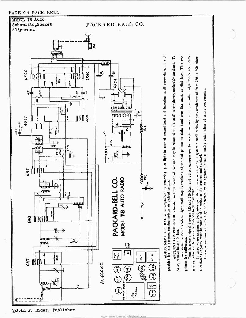
MODEL 78 Auto
Soheme.tic,Sooket Aliment
PACKART) BELL CO.
NÑ+Y
1 o_ e
`Q Pals
os s
K
1
23,Q,H -- II
co
4,)
n
_ _ _ _ 9
h
M
re7151nr
H
u
e
oe 3
K
u, U o Op H w ti. G
.á b o p
e 3 C
c b c°.,
m c to
Ú a " V C'.
° T, a7 d
R N o b
W .a .n > c F .t 6, CJ ó . ` ; .c o c n
E c V ÿ pS ^N °
° o .. u, ctl
H W y
Ñ w
I o
á. ó É Ñ ö '
_
x E m c h ` w :b ü ° a -o
,.. -o a m
m m 6 e..-.<,, ó °. -º s ;ó v
m g. -0c Cp .. o_ Ñ w is b b d ., 0. ° ro a o >
CC ' w G
E W V U G c. c k - c
ó '2''ä -_ .ó cl. 7. b w Ñ .á .... 6, F
M c v a ^'a ,v ^O " - o . ¿
o ia c ro ó . E s.. p>. Ñ a,
00 , C c A m v S
= x ° á ..a
a O A 3 ^e
ep E- c o c ' d
¢ c ° ñ A en .,4 m
zÿ W M o
GT c O
.A N N ` c . r v1 ) C z ó: Ña Á.E E 2
W p. C co' 3.á >
Z m m 3
E" , m á á. ., - W A °J ¡d Ç
ói o ... r. F> c d o ro v ÿ
E E. V U
< ü E-...2 H2 ti W e N. u, m
^C a oa o â g .. ° U
a -p O. pm Q Nd
©John F. Rider, Publisher
www.americanradiohistory.com
PATTERSON PAGE 9-1
1
m
2
S
l'A'1" I'ERSON RAI)IO CO.
s.
or
t5
a
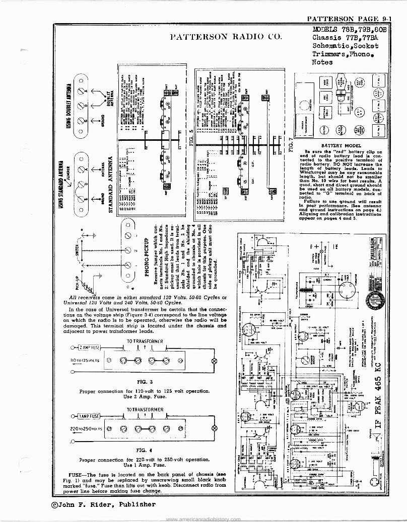
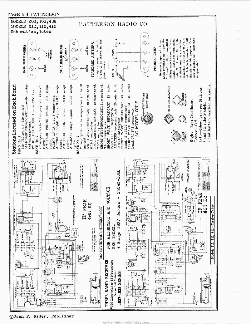
All receivers come in either standard 120 Volts, 50-60 Cycles or Universal 120 Volts and 240 Volts, 50-60 Cycles.
In the case of Universal transformer be certain that the connec- tions on the voltage strip (Figure 3-4) correspond to the line voltage on which the radio is to be operated, otherwise the radio will be damaged. This terminal strip is located under the chassis and adjacent to power transformer leads.
o-P AMP FUSO
110 TOIZSVOLTS
o
TO TRANSFORMER
o C)-Q 9-Q
FIG. 3
Proper connection for 110 -volt to 125 volt operation. Use 2 Amp. Fuse.
TO TRANSFORMER
-[ I AMP FUS[ W A
220To250VOLTS
.0
.. 0)-01 .,
FIG. 4
Proper connection for 220 -volt to 250 -volt operation. Use 1 Amp. Fuse.
FUSE-The fuse is located on the back panel of chassis (see Fig. 1) and may be replaced by unscrewing small black knob marked "fuse." Fuse then lifts out with knob. Disconnect radio from power line before making fuse change.
[r
MODELS 78B,79B,80B Chassis 77B,77BA Schematic,Sooket Trimmer s, Phone Notes
O e BATTERY MODEL
Be sure the "red" battery clip on end of radio battery lead is con- nected to the positive terminal of radio battery. DO NOT increase the length of battery leads. Leads to Winchargei may be any reasonable length, but should not be smaller than No. 10 wire for best results. A good, short and direct ground should be used on all battery models, con- nected to "G" terminal on back of radio.
Failure to use ground will result in poor performance. (See antenna and ground instructions on page 4.) Aligning and calibration instructions appear on pages 4 and 5.
- 500 M,.
030 600 VOLT
r +i, r/'w s º sa; ...i ...I..7,,,.
nn
+ eld ;d$ 3.8
0101388
3 CM 06M
300300 $--";¡+
IF)
1
603 M.
e
30u 0087 6 MM.
iiiLild+ - 7
I U IM 630 VOL
631 0.00
a
8001
S
ins 1= es. Y. ¡G
S: s
006 s0oau .« v«T
0064
ao v«T 50030 01450
1,30.,«.
10
. «, 50o v«+,
k
,00 .«T ..+ $Á a
130 M1+
6854
,30o MM
r*"., `,10003
0.111;
.«. -i
P.
-Y'
e.
e
©John F. Rider, Publisher
www.americanradiohistory.com
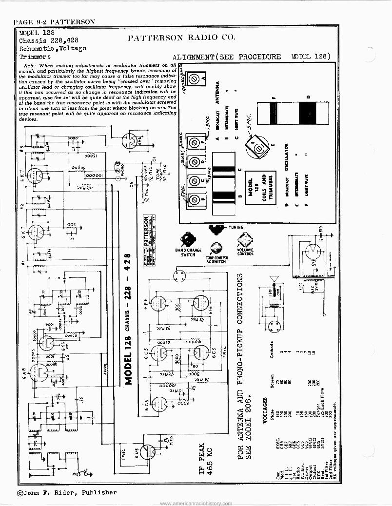
l'AGr: 9-2 l'ATTr,RSO\ MODEL 128 Chassis 228,428 Sohematic,Voltago Tr ismiTer s
l'AT'I'ERSON RAllIO CO.
ALIGNMENT(SEE PROCEDURE Note: When making adjustments of modulator trimmers on all
models and particularly the highest frequency bands, loosening of the modulator trimmer too far may cause a false resonance indica- tion caused by the oscillator curve being "crossed over" removing oscillator lead or changing oscillator frequency, will readily show if this has occurred as no change in resonance indication will be apparent, also the set will be quite dead at the high frequency end of the band the true resonance point is with the modulator screwed in about one turn or less from the point where blocking occurs. The true resonant point will be quite apparent on resonance indicating devices.
I
S
M
00051
f O0ó05 CóW 000 001 a ON
731,12/t W
L 1. _11
co < sr,
-0
- . -
III MI Ili
900'
e 0009 Z
80= 0001 o
x 1C
V VI
)0F:1?
cee
4-1 0-511,-.414
D
N
e
co
.0
BAND CHANGE SWITCH
G TONE CONTROL AC SWITCH
0
I23MIz//
N U
ú
00055 000001 a o
N
3y2/ 000£ 2)y
000001 03d01
0002 N' s
TUNING
o
VOLUME CONTROL
z
MODEL 128)
v O
NRY .+nn07m
O
S .)000 5(000 00 000 N N Ñ
O
d
ú m
Pw ñ S 0000 0.)000 ,nop s O 0 0 0 0 0 0 UN 0O
0. NNN NNFN)l')N
0tCr0,nNin100(0,,t') aedaexpCUUUu.a> WWWWWWWWWW0rd,
©John F. Rider, Publisher
www.americanradiohistory.com
}'ATTERSON PAGE 9-3 Scheratics,Socket Tr iuuner s,Voltage
0 b mb b E
m o my o
C db X áa d a < Lao v
tl ñ 9 U F
cS
N A Ú vv áC ááá
á á d « xb a á aaa ö C
d 35 > >oo > D O E O 10.d (`9N N
N o C7 + o +++ -V ú á
...
Ú
0. 3 0
rn ú Ill e o? ñ ÿ áá á áá+
dó é dx ++ ++. CO
F WÑ» Ì>Ñ Vb 7 w
aaaa ceb Q ó ö 3 .F RD .. 0 Ñ Ñ4 w
c c ? v F- CO
PATTERSON' RADIO CO.
T ú ~ di 0. á CA
''' ó áááá a++áááñ E .â W °' 2aaaa aaaa I 02 A
7
d 2++++ o o++++a a b OC A »» óc»» ,O 0000 ,:,000000 CJ 3t2' ,DcD nD etc] yy*1ÑÑCN7C w
0ó E m:6 .ç N O
N *# e ri
E Ô Ó> O `O f+,OígW ä+7 WP.#I:tl
(f)E1.
> O N a PG.-:Qa 00 FfZ §-2
= E N >o WC : á múi owO A O
g. ] a
«0 VOLT
MOM LOW
,IN
t. a
CT.. .8 = . Rc ºgá -r r' N .u.-J^ X
]
100300
0 a
Hh-0
IN
r4 i :R9 S
N1 Nf19 i I ÿ
ta
/OD VOLT
17º`.a
e
z=- a
-y,L-=.: _Ilt__M-_
wo °..uál'
!41z.-= +.-
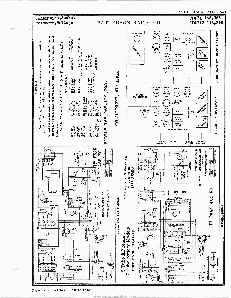
MDDEL 168,268 MODELS 198,298
VIBRATOR
o BEAM
OUTPUT I.
FILTER
OSC -MOD
R.
I. F.
N..2
DETECTOR
FIRST AUDIO AVC
MODU LATOR
OSCIL LATOR
R. F.
; A> o ;
,
44rof
ce,
POWER TRANSFORMER
RECTIFIER
DETECTOR BEAM AUDIO BEAM -AVC OUTPUT OUTPUT
I. F.
N..2
I. F R. F.
I. F.
N.. I
o 8- E'MFD. FILTER
OSC - MOD
o R. F.
OSCII. LATOR
MODU LATOR
: TUNING CONDENSER
O 1
Oy( 40
o
OOJOy°'
LJ
VOLUME CONTROL
TUNING L1 LI
BAND TONE CHANGE CONTROL SWITCH
MOO
-t
u'--
100000 0011
IN
h""t
'MON 5.41M MS. 001M
010111
IN>
rS
Y 3 ']
IM ma 0Ñ=N1*
_fia
: oost u ZOOVOLT
150 01.11 1w
os
10
003 OLT
era ]
STN.
300 var
èí'
©John F. Rider, Publisher
www.americanradiohistory.com
PAGE 9-4 PATTERSON
MODELS 208,308,408 MODELS 212,312,412 Schematic sNotes
PATTERSON RADIO CO.
L.)
(Sp< W<
)W ..2
R C
S -ruz
i o / ÓZ \U o` Q z ace
y
®'D = o
b, .-~.
CS t) o o 'Ó Tf 'LÌ m b Ñ .m d ai 0 Á Á Á E Á MCj ó 2 a a a a W
-. O m d m
:-401 .O-I
Z 2 , m
n ti có m co w n E E N
E >> ri VN W O r ~ O a O
Ú Ú m c Ú v c V- E1 Ñ tFn rñ r-7 v~+ Ó W vb C d^9 C rF/Y v Cl) Ú oi Ñ Ú 4:Ú ÿ. W ñ
Li NF ú e Ó E d ^ d d' 'O Ab A U A.. O I _F-
O E ae m `a v, b a °' U u U < u ú t t, <>. a FY 'b O N
W `i m m w < C < a d C mPC °PC d W D á o z :c z > o0cdvdá;m"a,E`gO
z_.-. ce óá
m w te x b Ri u vP0 ú W u t,W W
y r1 >.O arra > 8 d> > O yaa oa ú w > ö- ñ> ñ<, ? d<d a áz N w uE. ] u
3 ° m m E33ñ
h a :: W p1-. W W 't w d - .. E
W E p. E F .. W F. - F -
O zz 2. m .d.VÚ m ..01.Ú á x m a`y,aaGóa.d-.x.drG.ti ; AóF áA m pá uf >A & mx£óxvx óvx vx ay
rS z,v dax - E4 uaa ud É.0 uzcc Ernr dtrnoiV].A..tn.A Li) .LI
CJ2 m m co
$ e .1.).1 6p
ä ]
PAP
1
i ,
4-1.fN
j5
.11 6:1 ggs, ...J.i..11.,.r
] I'si: Ilfl Ifl Silfr ...t -IL; ü il
551
=º
_ C
o
e
ö Im, YIt
.W qLL
r .11'
: Y ].
o +
e
S
a
.3 3 es
a
..0'..
E
u c á
©John F. Rider, Publisher
www.americanradiohistory.com
PATTERSON PAGE 9-5
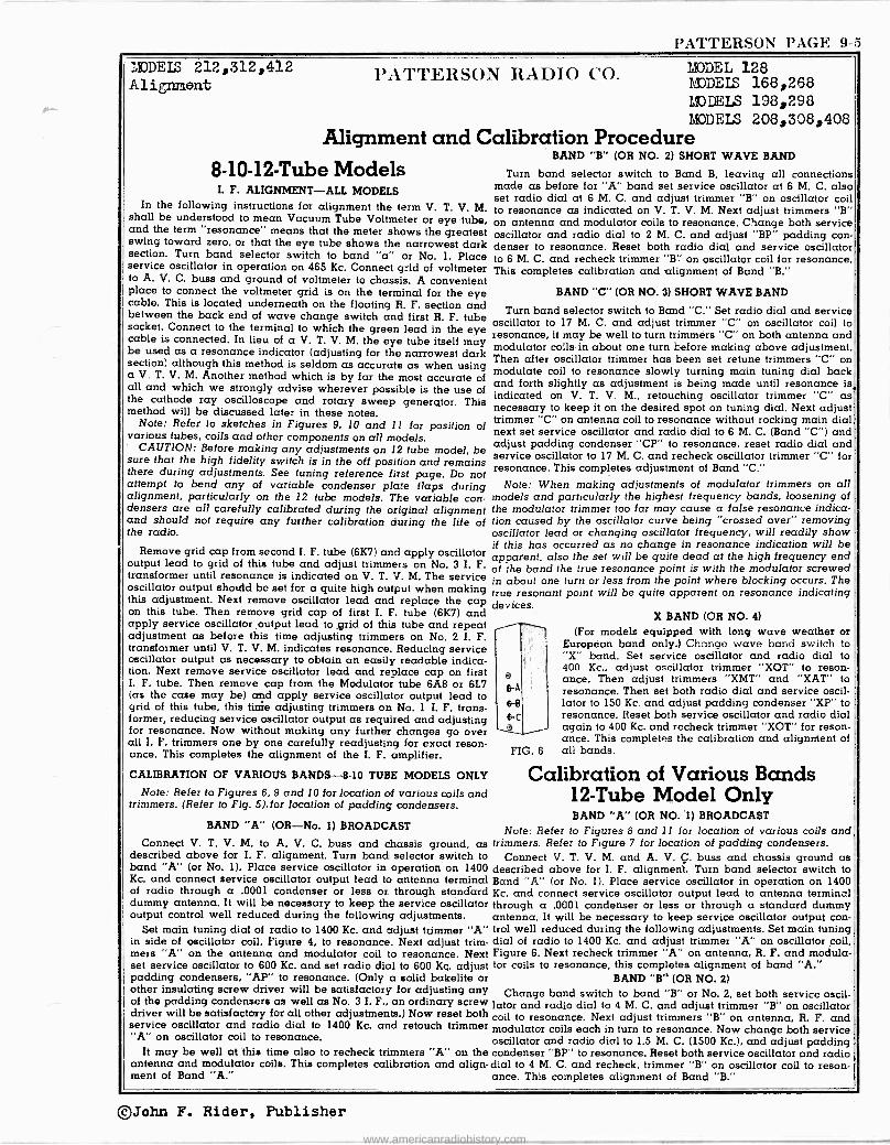
MODELS 212,312,412 Alignment
YA'l'TERSON RADIO CO. MODEL 128 MODELS 168,268 MODELS 198,298 MODELS 208,308,408
Alignment and Calibration Procedure 8 -10 -12 -Tube Models
I. F. ALIGNMENT-ALL MODELS In the following instructions for alignment the term V. T. V. M.
shall be understood to mean Vacuum Tube Voltmeter or eye tube, and the term "resonance" means that the meter shows the greatest swing toward zero, or that the eye tube shows the narrowest dark section. Turn band selector switch to band "a" or No. 1. Place service oscillator in operation on 465 Kc. Connect grid of voltmeter to A. V. C. buss and ground of voltmeter to chassis. A convenient place to connect the voltmeter grid is on the terminal for the eye cable. This is located underneath on the floating R. F. section and between the back end of wave change switch and first R. F. tube socket. Connect to the terminal to which the green lead in the eye cable is connected. In lieu of a V. T. V. M. the eye tube itself may be used as a resonance indicator (adjusting for the narrowest dark section) although this method is seldom as accurate as when using a V. T. V. M. Another method which is by far the most accurate of all and which we strongly advise wherever possible is the use of the cathode ray oscilloscope and rotary sweep generator. This method will be discussed later in these notes.
Note: Refer to sketches in Figures 9, 10 and 11 for position of various tubes, coils and other components on all models.
CAUTION: Before making any adjustments on 12 tube model, be sure that the high fidelity switch is in the off position and remains there during adjustments. See tuning reference first page. Do not attempt to bend any of variable condenser plate flaps during alignment, particularly on the I2 tube models. The variable con- densers are all carefully calibrated during the original alignment and should not require any further calibration during the life of the radio.
Remove grid cap from second I. F. tube (6K7) and apply oscillator output lead to grid of this tube and adjust trimmers on No. 3 I. F. transformer until resonance is indicated on V. T. V. M. The service oscillator output should be set for a quite high output when making this adjustment. Next remove oscillator lead and replace the cap on this tube. Then remove grid cap of first I. F. tube (6K7) and apply service oscillator output lead to grid of this tube and repeat adjustment as before this time adjusting trimmers on No. 2 I. F. transformer until V. T. V. M. indicates resonance. Reducing service oscillator output as necessary to obtain an easily readable indica- tion. Next remove service oscillator lead and replace cap on first I. F. tube. Then remove cap from the Modulator tube 6A8 or 6L7 (as the case may be) and apply service oscillator output lead to grid of this tube, this time adjusting trimmers on No. 1 I. F. trans- former, reducing service oscillator output as required and adjusting for resonance. Now without making any further changes go over all I. F. trimmers one by one carefully readjusting for exact reson- ance. This completes the alignment of the I. F. amplifier.
CALIBRATION OF VARIOUS BANDS -8.10 TUBE MODELS ONLY
Note: Refer to Figures 6, 9 and 10 for location of various coils and trimmers. (Refer to Fig. 5).for location of padding condensers.
BAND "A" (OR-No. 1) BROADCAST
Connect V. T. V. M. to A. V. C. buss and chassis ground, as described above for I. F. alignment. Turn band selector switch to band "A" (or No. 1). Place service oscillator in operation on 1400 Kc. and connect service oscillator output lead to antenna terminal of radio through a .0001 condenser or less or through standard dummy antenna. It will be necessary to keep the service oscillator output control well reduced during the following adjustments.
Set main tuning dial of radio to 1400 Kc. and adjust trimmer "A" in side of oscillator coil, Figure 4, to resonance. Next adjust trim- mers "A" on the antenna and modulator coil to resonance. Next set service oscillator to 600 Kc. and set radio dial to 600 Kç. adjust padding condensers, "AP" to resonance. (Only a solid bakelite or other insulating screw driver will be satisfactory for adjusting any of the padding condensers as well as No. 3 I. F., an ordinary screw driver will be satisfactory for all other adjustments.) Now reset both service oscillator and radio dial to 1400 Kc. and retouch trimmer "A" on oscillator coil to resonance.
It may be well at this time also to recheck trimmers "A" on the antenna and modulator coils. This completes calibration and align- ment of Band "A."
BAND "B" (OR NO. 2) SHORT WAVE BAND
Turn band selector switch to Band B, leaving all connections made as before for "A" band set service oscillator at 6 M. C. also set radio dial at 6 M. C. and adjust trimmer "B" on oscillator coil to resonance as indicated on V. T. V. M. Next adjust trimmers "B" on antenna and modulator coils to resonance. Change both service oscillator and radio dial to 2 M. C. and adjust "BP" padding con- denser to resonance. Reset both radio dial and service oscillator to 6 M. C. and recheck trimmer "B" on oscillator coil for resonance. This completes calibration and alignment of Band "B."
BAND "C" (OR NO. 3) SHORT WAVE BAND
Turn band selector switch to Band "C." Set radio dial and service oscillator to 17 M. C. and adjust trimmer "C" on oscillator coil to resonance, it may be well to turn trimmers "C" on both antenna and modulator coils in about one turn before making above adjustment. Then after oscillator trimmer has been set retune trimmers "C" on modulate coil to resonance slowly turning main tuning dial back and forth slightly as adjustment is being made until resonance is, indicated on V. T. V. M., retouching oscillator trimmer "C" as necessary to keep it on the desired spot on tuning dial. Next adjust trimmer "C" on antenna coil to resonance without rocking main dial next set service oscillator and radio dial to 6 M. C. (Band "C") and adjust padding condenser "CP" to resonance, reset radio dial and service oscillator to 17 M. C. and recheck oscillator trimmer "C" for resonance. This completes adjustment of Band "C."
Note: When making adjustments of modulator trimmers on all models and particularly the highest frequency bands, loosening of the modulator trimmer too far may cause a false resonance indica- tion caused by the oscillator curve being "crossed over" removing oscillator lead or changing oscillator frequency, will readily show if this has occurred as no change in resonance indication will be apparent, also the set will be quite dead at the high frequency end of the band the true resonance point is with the modulator screwed in about one turn or less from the point where blocking occurs. The true resonant point will be quite apparent on resonance indicating devices.
FIG. 6
X BAND (OR NO. 4)
(For models equipped with long wave weather or European band only.) Change wave band switch to "X" band. Set service oscillator and radio dial to 400 Kc., adjust oscillator trimmer "XOT" to reson- ance. Then adjust trimmers "XMT" and "XAT" to resonance. Then set both radio dial and service oscil- lator to 150 Kc. and adjust padding condenser "XP" to resonance. Reset both service oscillator and radio dial again to 400 Kc. and recheck trimmer "XOT" for reson- ance. This completes the calibration and alignment of all bands.
Calibration of Various Bands 12 -Tube Model Only BAND "A" (OR NO. *1) BROADCAST
Note: Refer to Figures 8 and l for location of various coils and trimmers. Refer to Figure 7 for location of padding condensers.
Connect V. T. V. M. and A. V. Ç. buss and chassis ground as described above for I. F. alignment. Turn band selector switch to Band "A" (or No. 1). Place service oscillator in operation on 1400 Kc. and connect service oscillator output lead to antenna terminal through a .0001 condenser or less or through a standard dummy antenna. It will be necessary to keep service oscillator output con- trol well reduced during the following adjustments. Set main tuning dial of radio to 1400 Kc. and adjust trimmer "A" on oscillator poil, Figure 6. Next recheck trimmer "A" on antenna, R. F. and modula- tor coils to resonance, this completes alignment of band "A."
BAND '"B" (OR NO. 2)
Change band switch to band "B" or No. 2, set both service oscil- lator and radio dial to 4 M. C. and adjust trimmer "B" on oscillator coil to resonance. Next adjust trimmers "B" on antenna, R. F. and modulator coils each in turn to resonance. Now change both service oscillator and radio dial to 1.5 M. C. (1500 Kc.), and adjust padding condenser "BP" to resonance. Reset both service oscillator and radio dial to 4 M. C. and recheck, trimmer "B" on oscillator coil to reson- ance. This completes alignment of Band "B."
©John F. Rider, Publisher
www.americanradiohistory.com
PAGE 9-6 PATTERSON MODEL 128 IJIDDELS 168,268 P '1"PERSO. MODELS 198,298 ALIGNMENT BAND "C" OR NO. 3
Change band switch to band "C" or No. 3. Set service oscillator and radio dial to 12 M. C. and adjust trimmer "C" to resonance. Next adjust trimmers "C" on modulator coil rocking radio tuning dial slowly back and forth as adjustment is being made, resetting oscillator trimmer if and as necessary to keep calibration correct at this point after resonance has been reached trimmer "C" on anten- na and R. F. coils may be adjusted to resonance without touching any other controls. Next set both radio dial and service oscillator to 5 M. C. and adjust padding condenser "CP" to resonance. Then reset both radio dial and service oscillator to 12 M. C. and recheck trimmer "C" on oscillator coil to resonance. This completes align- ment of band "C" or No. 3.
BAND "D" OR NO. 4 Change band change switch to Band "D" set service oscillator
and radio dial to 20 M. C. and adjust trimmer "D" on modulate coil slowly rocking main tuning dial to 9 M. C. (Band D or No. 3) and adjust padding condensers "DP" to resonance. Then reset both service oscillator and radio dial to 20 M. C. and recheck to reson- ance, this completes alignment of Band D.
Note: When making adjustments of modulator trimmers on all models and particularly the highest frequency bands, loosening
of the modulator trimmer too far may cause a false resonance indi-
cation caused by the oscillator curve being "crossed over" remov-
ing oscillator lead or Changing oscillator frequency will readily show if this has occurred as no change in resonance indication will
be apparent also the set will be quite dead at the high frequency end of the band, the true resonance point is with the modulator screwed in about one turn or less from the point where blocking occurs. The true resonant point will be quite apparent on resonance indicating devices.
eA
6-8
e -c 6-0 e
"X" BAND OR NO. 5
(For models equipped with long wave weather band only.)
Set band change switch to "X" band. Set both serv- ice oscillator and radio dial to 400 Kc., adjust trimmer "XOT" to resonance. Then adjust trimmers "XAT," "XRT," and "XMT" each in turn to resonance. Then set both service oscillator and radio dial to 150 Kc.
and adjust padding condenser "XP" (very slowly) to resonance. Reset both service oscillator and radio dial to 400 Kc. and recheck trimmer "XOT" to resonance.
F G. 8 This completes all alignment.
Cathode Ray Oscilloscope Alignment
For the service man who is equipped with a cathode ray oscil- loscope and rotary sweep circuit, a very accurate alignment of the intermediate amplifier is possible. Owners of such equipment are usually familiar with the necessary procedure as this point is usually covered thoroughly in the instructions furnished with the equipment. More detailed information than that usually furnished with cathode ray equipment may be found in John Rider's book, "The Cathode Ray Tube at Work." An I. F. output connection in- tended for cathode ray alignment is incorporated in all Patterson 37 models. With chassis upside down and facing back of chassis it will be found in the lower left hand corner of chassis adjacent to the phono terminals and rubber corner rest. In the 8 and 10 tube models the adjustments should be made on the second stage first, then the first stage, then through the modulator and first I. F. trans- former or practically the same procedure as when aligning by any other method. The curve on the 8 and 10 should be round nosed and about 10 Kc. wide at the summit. The high fidelity switch having no effect on the resonant curve in these models. In the 12 tube model the above procedure should be followed out with the exception that the high fidelity switch must be in the "off" position during alignment.
In this model the I. F. curve will be very sharp and not round nosed, after alignment has been completed the high fidelity switch may be turned on for a check, in which position the curve will re- main symetrical but become very broad with possibly a very slight shift in the I. F. frequency in some cases. If this is not the case, a misadjustment has been made in the alignment procedure and the high fidelity switch should be turned off and alignment rechecked as before.
MODELS 208,308,408 T RADIO CO. MODELS 212,312,412
continued: Align.mont,Part 2 Voltage
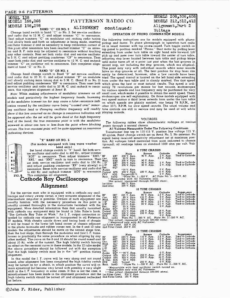
OPERATION OF PHONO COMBINATION MODELS
The following instructions are for models equipped with phono - pickup and motor. To place phonograph in operation turn radio on in usual manner with top coves raised. Turn toggle switch on top panel to position marked "Phono." Start motor by pulling lever extending from under turn table on right hand side forward. Lift pick up and pass over turn table toward the center of turn table, adjusting stop lever located between turn table and pickup hinge until motor turns off at a point just past when the last grooves in record stop, not including the stop grooves, which are elliptical. This point may vary with individual records while some records have no stop grooves at all. The best position for stop lever can easily be determined, however, after a few records have been tried. The speed control is located on the left hand side extending from under the turn table and is clearly marked. Use that speed which gives the best or most natural results. This speed is ordi- narily 78 revolutions per minute for fast records, stroboscopes for various speeds and line frequency may be purchased for very small cost, which make it possible to obtain the exact speed. These stroboscopes are self explanatory. On those models equipped with two speed motors a third lever extends from under the turn table on which speeds are plainly marked, one being 78 R.P.M., the other 331/3 R.P.M. for slow speed records. The usual volume and tone controls are still in service and may be used at will while playing records.
VOLTAGES The following tables show characteristic voltages at various
points through a normal chassis. All Voltages Measurable Under The Following Conditions:
Transformer line tap in 110-115 V. position line voltage 115 V.
60 cycles. Band change switch set on Band No. 2. No antenna. No signal being received sensitivity adjustment set at maximum posi- tion. All voltages listed measured from point indicated to chassis (ground), all readings taken on standard 1000 ohm per volt. Volt- meter.
8 TUBE CHASSIS Screen Cathode Suppressor
90 V. App. 2 V. App. Tied to Cathode 2.5 V. App.
90 V. App. 90 V. App. 2 V. App. Tied to Cathode 90 V. App. 2 V. App. Tied to Cathode
0 V. App. 200 V. App. 15 V. App.
0 V. App. -350 V. AC Plate No. 2--350 V. AC Voltmeter only. through 500,000 ohms).
RF Osc. M1
IFod
2 IF Det. Audio Output EYE
6K7 6A8 6A8 6K7 6K7 6Q7
°50 V. App. 6F6 200 V. App.
6G5 Target -200 V. Rect. 5x3G "Plate No. 1
Measurable with AC 'Not actual, (measured
1st filter 360 V. App. 2nd filter 200 V. App.
Plate 200 V. App. 90 V. App.
200 V. App. 200 V. App. 200 V. App.
10 TUBE CHASSIS Plate Screen Cathode
RF 6K7 235 V. App. 90 V. App. 2.5 V. App. Osc. 6K7 80 V. App. 235 V. App. 0 V. App. Mod. 6L7 235 V. App. 90 V. App. 3 V. App. 1 IF 6K7 235 V. App. 90 V. App. 2.5 V. App. 2 IF 6K7 235 V. App. 90 V. App. 2.5 V. App. Det. 6Q7 55 V. App. 0 V. App. Audio 6Q7 55 V. App. Output 6F6 235 V. App. 235 V. App. 18 V. App. Output 6F6 235 V. App. 235 V. App. 18 V. App. EYE 6G5 235 V. App. 0 V. App. Rect. 5x3G Plate No. 1- -350 V. AC. Plate No. 2-350 V. AC.
`Not actual, (measured through 500,000 ohms). **Measured only with AC Voltmeter.
1st Filter Cond. 325 V. DC 2nd Filter Cond. 250 V. DC
12 TUBE CHASSIS Plate Screen
RF 6K7 250 V. App. 110 V. App. RF 6K7 250 V. App. 110 V. App. Osc. 6K7 250 V. App. 110 V. App. Mod. 6L7 250 V. App. 110 V. App. 1 IF 6K7 250 V. App. 110 V. App. 2 IF 6K7 250 V. App. 110 V. App. Det. 6Q7 Audio 6Q7 ""90 V. App. Output 6F6 325 V. App. 250 V. App. Output 6F6 325 V. App. 250 V. App. B. Osc. 6C5 '50 V. App. EYE 6G5 Target 250 V. App. Rect. 5x4G °"Plate No. 1--330 V. AC.
Suppressor Tied to Cathode Tied to Cathode Tied to Cathode Tied to Cathode Tied to Cathode
Cathode Suppressor 2.5 V. App. Tied to Cathode 2.5 V. App. Tied to Cathode
0 V. App. Tied to Cathode 3 V. App. Tied to Cathode
2.5 V. App. Tied to Cathode 2.5 V. App. Tied to Cathode
0 V. App. 20 V. App. 20 V. App.
0 V. App. 0 V. App.
Plate No. 2-330 V. AC. 'Measurable with beat oscillator switch turned on.
°Measurable only with AC Voltmeter. "'Not actual, (measured through 500,000 ohms).
1st Filter Cond. 350 V. App. 2nd Filter Cond. 235 V. App.
©John F. Rider, Publisher
www.americanradiohistory.com
PIIII.C'O RADIO & TF.I.I+.V. CORP.
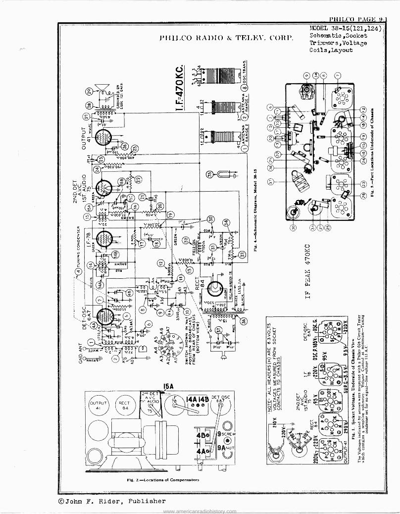
PHILC'O PAGE 9-) MODEL 38-15(121,124) Schematic,8ocket Tr inner s , Voltage Coils,Layout
©John F. Rider, Publisher
www.americanradiohistory.com
PAGE 9-2 PHILCO MDDEL38-15(121,124) Alignment,Specse PIIILCO RADIO & TELEV. CORP. Parts
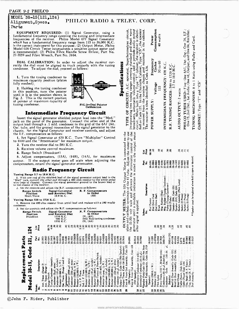
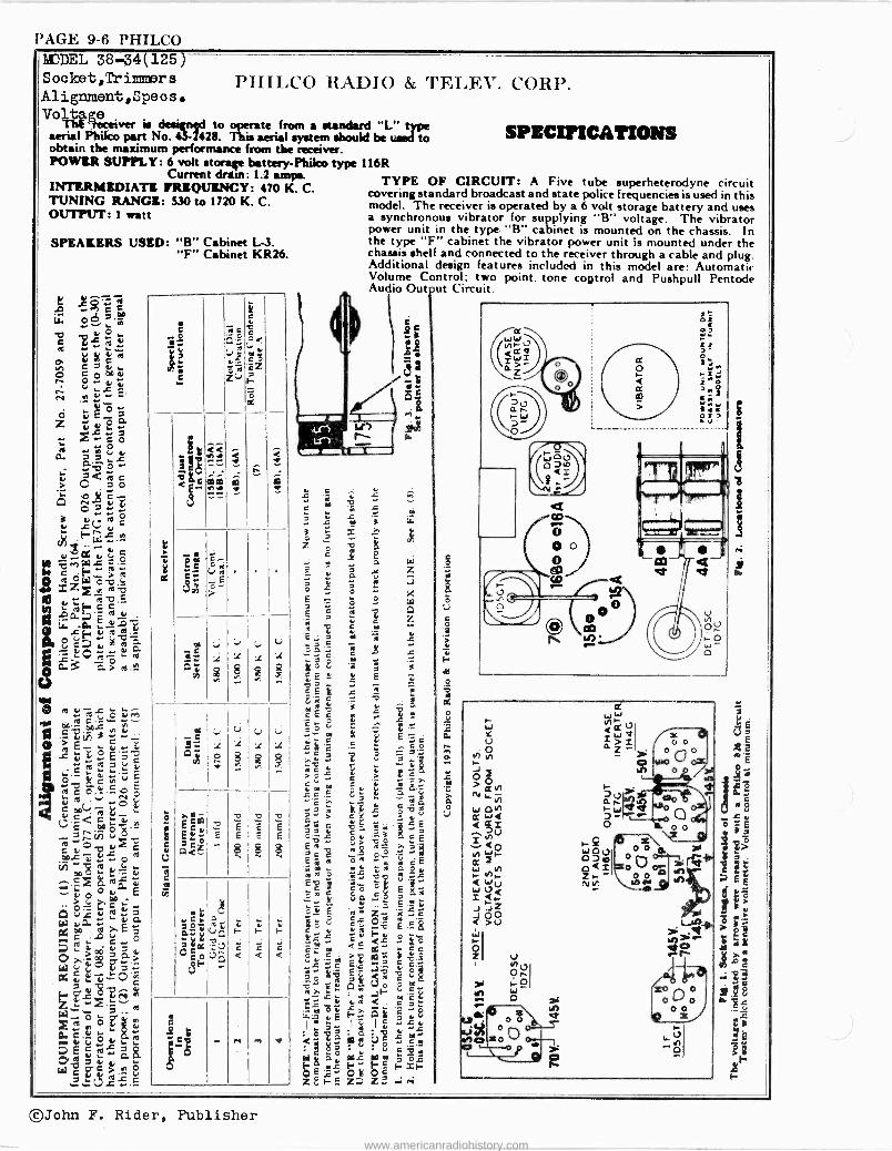
EQUIPMENT REQUIRED: (1) Signal Generator, using a fundamental frequency range covering the tuning and intermediate frequencies of the receiver. Philco Model 077 Signal Generator which has a fundamental frequency range from 115 to 36,000 K.C. is the correct instrument for this purpose; (2) Output Meter, Philco Model 026 Circuit Tester incorporates a sensitive output meter and is recommended; (3) Philco Fibre Handle Screw Driver, Part No. 27-7059 and Fibre Wrench, Part No. 3164.
DIAL CALIBRATION: In order to adjust the receiver cor- rectly the dial must be aligned to track properly with the tuning condenser. To adjust the dial, proceed as follows:
1. Turn the tuning condenser to maximum capacity position (plates fully meshed).
2. Holding the tuning condenser in this position, turn the pointer until it is in the position shown in Fig. 3. This is the correct position of pointer at maximum capacity of tuning condenser. FIG.3-Dial Pointer
Calibration
Intermediate Frequency Circuit Insert the signal generator shielded output lead into the "Med."
jack on the panel of the generator. Connect the other end of the output lead through a .1 mfd. condenser to the grid of the 6A7 Dèt. Osc. tube, and the ground connection of the signal generator to the chassis. Set the Signal Generator and receiver controls, and adjust the I.F. compensators as follows:
1. Set Signal Generator at 470 K.C. Turn "Multiplier" Control to 1000 and the "Attentuator" for maximum output.
2. Turn the receiver dial to 580 K.C. 3. Receiver volume control maximum. 4. Range Switch (Broadcast) 5. Adjust compensators, (15A), (14B), (14A), for maximum
output. If the output meter goes off scale when adjusting the compensators, retard the signal generator attenuator.
Radio Frequency Circuit Tuning Range 5.7 to 18.0 M.C.
1. With one end of the shielded lead of the signal generator output lead in the "Med" jack, connect the other end through a 400 ohm resistor to the white aerial wire (rear of chassis). Connect the signal generator ground to the brown lead or to the chassis of the receiver.
2. Set the controls and adjust the R.F. compensators as follows: Range Switch Signal Generator R. F. Compensators
Position and Receiver Dial in Order Short Wave 18.0 M.C. (4B)
Tuning Range 530 to 1720 K.C. 1. Remove the 400 ohm resistor from aerial lead and replace with a 100 mmfd
condenser. 2. Set the controls and adjust the R.F. compensators as follows:
Range Switch Signal Generator Position and Receiver Dial Broadcast 1550 K.C.
580 K.C. 1550 K.C.
s d az
g. l
R. F. Compensators In Order
(9), (4A) (9A) Roll tuning condenser (9), (4A)
g. p Ñ Ñ Ñ T .? Ñ Ñ g. g. g Ñ N Ñ Ó C Ñ Ñ N g Ñ C .0>
N CV .r ..
c m 0.c -x w 1-2
:4; 'û . oº a m ó,. v u
>y -=,73- o m.>_ ócQJ c U m
OYrb LUaI vv vL.u, ñ.c c i
> ó V3 cimvE >q C2Cy Z 'c m p.9 m
má_p Ów F arroU
Ou NNL U C c..>a,.
,7)
.. -mp ¢.EF.L> V! °ó>00 6Cr
U çtlÿ çaci a E c j 3 0- E " o
irq OQ m r u a 0'-c v;^ L27 > Wo.v CL O ú rn
o ºEr .. u
ar ar ar
c N v ó 2 E 0 vv- v ó
aurEcz C y o O cLuv
oy `iyc Lôco
2 ,i.;5 ° áÿ C é'uO
C e m
Ñ u co C O
a m
F-cc ma C L_y ti
F m
wuuu +p.J O I..m>c'-
V 7 /2,-o,9,1; c
m ó marc;; QL un!
73 ß= óô `?á
a I Agagg TTT e°¢í^aaóne-r,^Rb.b.ócór r -r- M N N N M M M M N N N
ó
o
li
g SSg sOOnÓ"p'mNsz.p, M
3O 1,51
c.=dAMcÑS:dd2hSÑdM2áraMdóc' U
pp Q h Ñ m W ./! N ^-
:á:ga°Y3Ñ . . . . . . . . . . ,; c. . .
-4. . . .
ov z = B G ^^ .:, `N ¿ ; N
,-. Q. . p d Ó ` Ñ ` W .-. .-. .-. J. - ..., C i ̀ Ó Ó
m^ ` 3-- á m33 W _ e é "daa r i 3 t3. 33 5 3 ÿ > > ,0.1Ñ r a, c 6 r L ... . " " .N..cS^ í,e. 8 , 63_ 3« i3 t.',>-.-'' v .,-..e.,, ..:.r 0..v.\ _:,.: e w ß 3 :> ä Vil FF é ...--gCS ' : c+i 5"5ç sdó s ô oóB ` 2q v ei iów m a . ç -. dQ ç$ iç (3
2525 i000 U^ e eU< .. o aa.c.e.eia25á MÑ8 2 25g25 `? ddÑ? c é á mCìÚ.vo ,g,--:- `;ôU á a,
., c-.. cS . é... .no o. r o ...n S.l`. Fÿcÿ.. o L .°. o o a am"`.-, m á .
.. .`.
- ájèU d é `w- ,; vvC: g¿ gg
ld Ff-'>rr_>m a,:.rw 8 «üC7 mc ÉFáaiaci3Fáac,88a:.:33i °gg3ú °$dáó5ól!móºeá °SFcÿ-ifßfC-É-r m._4v,9 rv ..v _ ov v gvv_a_au .,o, wóo m- c c
' e e e ' 9 e o- - .p c e' c'- ' c c c m c g rr ó 3 c a m ` °' g. á c e 2.
o 0 0 o i bl c SS 83 0 8S ó o o$1 o c o" 0 3 a á+ o c o c, i m m__ :- mUUUQODUCGaNClYU>auxxcrc' U W W : Ca;G0.,UU mmm000UA N Ñ Ñ N Ñ Ñ N Ñ N O
M M M M M M M
©John F. Rider, Publisher
www.americanradiohistory.com
PHILCO PAGE 9-3
PIIILC O RADIO & TELEX". CORP.
vg vooa v0..' f wNi sJ J oóiéqáié g WMVOV 'I--1 XX
ri-1r«nre
Ñ $g ra2 cigiig211ä3
©John F. Rider, Publisher www.americanradiohistory.com
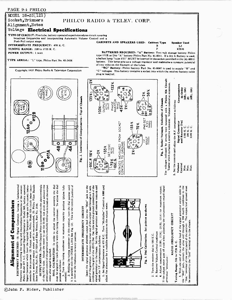
PAGE 9-4 PHILCO 143DEL 38-33(121) Socket,Trilmners Alignment,Ilotes Voltage Electrical Specifications TYPE OF CIRCUIT: Five tube. battery operated superheterodyne circuit covering
broadcast frequencies and incorporating Automatic Volume Control and a Push -Pull output stage. CABINETS AND SPEAKERS USED:
INTERMEISIATE FREQUENCY: 470 K. C.
TUNING RANGE: 530 to 1720 K. C.
POWER OUTPUT: 1 watt
TYPE AERIAL: "L" type, Philco Part No. 45-2428
Copyright 1937 Philco Radio & Television Corporation
N.u.. `° u 0 C Ó- V
0. ú5 g a o M ¿ 3,
,yavQQ,
E1ó tG V` ` 2 ° ` Ñ O
.. .+ O áa° 1Wr=` «e
w . . -3 "
0 ç E 2 w m9 .. 7 C `8°A G
C 3 "N .L+
O a`oEó E
: "F g°z o n 3 V
b ci3.,g eA rä.222 e 82 m2,
rrill.Cc xr1nIO & TEr,r.V. CORP.
Cabinet Type B
F
Speaker Used L3
KR26 BATTERIES REQUIRED: "A" Battery: Two volt storage battery Philco
type 172R or Dry "A" battery Philco Part No. 41-8011. If a dry A Battery is used, a ballast lamp "type 1Y I" MUST be inserted in the socket provided in the (41-8011) battery. This lamp acts as a voltage regulator and maintains a constant potential of two volts on the filament of the tubes.
"BC" Battery: Philco battery Part No. 41-8007 is used to supply "B" and "C" voltages. This battery contains a socket into which the receiver battery cable plug is inserted.
« c _
ú .° > 2,
g r E ooq5 o
ó C ÿ `° O
51
ú Ñ L X
O Ó ea C 6 ,, y 7 á i ÿ ° -a E
ú t . V ö V S7 v ó ú ., 3 JE ° a 4, A = c
.+ L (fl w q
p c û°°'m «m O ÿ mU V
C u F CC m ó v e G l7 «
° « E a 49, V 8
.+ m (r e a « ú,-: A t
w a a
c `o á
C Ó C 7 H=
a 8 1.° m
V
EEKKK
dA A A
©John F. Rider, Publisher
www.americanradiohistory.com
PHILCO PAGE 9-5
MeWIEWE
"9"*"
:
"ej
0
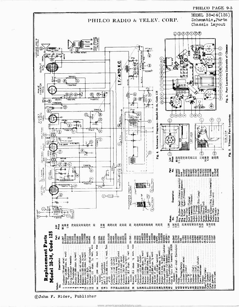
MODEL 38-34(125) Schematio,Parts Chassis Layout
©John F. Rider, Publisher
www.americanradiohistory.com
PAGE 9-6 PHILCO B®DEL 38-34(125) Socket,` i1>11 er8 Alignment,Specse
Tht Vol e
ver is de.ign4d to operate (rom a standard "L" type aerial Phiko part No. 5--12428. This aerial system should be used to obtain the maximum performance (rom the receiver. POWER SUPPLY: 6 volt storage battery-Phiko type 116R
Current driut: 1.2 amps. INTERMEDIATE FREQUENCY: 470 K. C. TUNING RANGE: 530 to 1720 K. C. OUTPUT: 1 watt
SPEAKERS USED: "B" Cabinet L-3. "F" Cabinet KR26.
m U". d' - V N
io L y yy L
1.e)
C 7
Y ._ p CO O CC u v ÿ
,4. u
N e....2: E
, v ó c vE_ oa z tcó 0 á >>ur a ö..
` ZQroc i O z
Q N e 0 O
`+ L (..7,y C r_.-.., cS
iJ . - 3äv`c Mp,."Iilt .
ro °t ,ov>.ro
M S7y ...o b ;'Fcc'E
,c. a- ..ä- '''..1 :i. t i. ro u
º c v ro G L tro w n.3 a>o ro:12
w 0 rovlrcii
AO m OOt ÿ.r a.5iñ3..N.,.. O ,'vE ..i..& rc` C,u
` C ro
V.Ç.O G 0:._; 1, / N
-.c.....!...603.- 73Ecv ` 2 G LX C c v_ text, oro
in v.. C t ... v'4óvaÉ L O 00
úÄúráv W an.«`'a xr ..E_ ..
to. .. e .. o
..7 - ap 7 v tQ >, ó g a.>_
u p.. AG,C,=O
v 8
g2=" i ro
iOOÓ r 1. d ac,_,.
.r Y u L í% 5Eá Oovv á {:iC gCY>»O
'''Z3.2«.2. Ç
s
y
t p
C 0
C ZG
wc Q,º
vL
S
m
i e c o<
C O
cZ
ó - : i
:1g: É --ae
. _
C a;E C, u: .
C Ir. 9S j :i
v 1 ó
i ; < $
U
1
?
E
Vp<Z
ÿ
1 1'. 9
:, 1
L;U u
x 1 $
L.
1
«uo E8; É
^
= E
8
I
= E
ó
=
$É
ry
t $ºtG a2s:'v 0 CF
A
ca< 1;
4 r 1;i <
.
F
Q
c .25
n ry M
PHILCO RADIO & TELEV. CORP.
SPECIFICATIONS
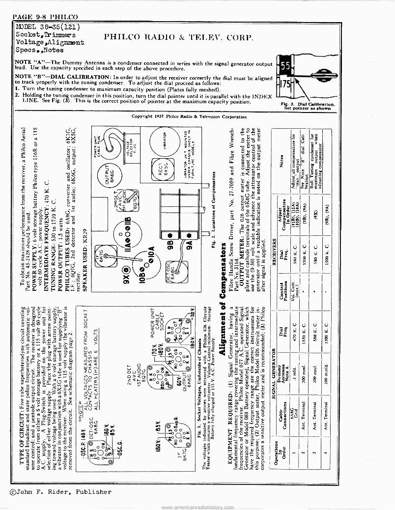
TYPE OF CIRCUIT: A Five tube superheterodyne circuit covering standard broadcast and state police frequencies is used in this model. The receiver is operated by a 6 volt storage battery and uses a synchronous vibrator for supplying "B" voltage. The vibrator power unit in the type "B" cabinet is mounted on the chassis. In the type "F" cabinet the vibrator power unit is mounted under the chassis shelf and connected to the receiver through a cable and plug. Additional design features included in this model are: Automatic Volume Control; two point. tone control and Pushpull Pentode Audio Out ut Circuit.
Y ;L
u C
á
ao
U
©John F. Rider, Publisher
www.americanradiohistory.com
PHILCO PAGE 9-7
Cl
S - w
ñ `-n.nrn.aaimo 0 0 oÑnaom2 gó y : óo
á é c c áñrn...e ÿT. MhNÑÑÑM`bNc~Vc+Jc+JMNÑÑCVcVG%
©John F. Rider, Publisher
www.americanradiohistory.com
PAGE 9-8 PHILCO L DEL 38-35(121) Socket,Trimmers Voltage,A1 ignorent Specs,ZTotes
PHILCO RADIO & CORP.
NOTE "A"-The Dummy Antenna is a condenser connected in series with the signal generator output lead. Use the capacity specified in each step of the above procedure. NOTE "B"-DIAL CALIBRATION: In order to adjust the receiver correctly the dial must be aligned to track properly with the tuning condenser. To adjust the dial proceed as follows: 1. Turn the tuning condenser to maximum capacity position (Plates fully meshed). 2. Holding the tuning condenser in this position, turn the dial pointer until it is parallel with the INDEX LINE. See Fig. (3). This is the correct position of pointer at the maximum capacity position.
I55
Fig. 3 Dial Calibration. Set pointer as shown
U C) «r«.. r y
d :i
r
0.4
cri
.r.>c,`çáb y do U ° a- o
- a o0 ° c
y O
O c y Ç ,O
a d
O T TA E á> 0
> y
cV ..+ a ci..;
ro>á.óN"v L >,
>.3 ceÿ aa y á
ó c E
-3 0
ac,; ó.y> O Á 41 >A,..,
= u,_, a y u Ñ`ú fr -1 dC m É y
.c- ó au)
c ° `E s ; °óáºc U)= 3cñ
y h000 G Hect;o;?cº:3
03 C. y -Ó .0 > = .c0. > c. -u U,m.. ycy Ixvdvv V D E s. 0`
td 0 ÿÔyyE Lr.O2.7,717(3-0',> CL o11ÿYO: W-ó cs;? fl
o C. N O`
Fó ºd.Ero°>v
z 6 au
Ot yU
Copyright 1937 Philco Radio & Television Corporation
o o
o
/ m
.r N Om 12-
W Q
Q
O Ó tJ
>AO0o1 0 O- N 0
'
w O ó 4de0M c- -_
ppL
O Éiñ 3 ÿCt.
1.1
.0 ÿ v O F i iÿ °yy`Ot `` aC ) U y M
7.«
G1.ÇV wr y td s4_
j9"
y °Q o E
C 41ct " yQ L t10..c yy .- VlÁ yó C2 ya
m_ m "óOQ4ptó Q Ou L tE : E `.4. IX 34 ioy + 'CCcEa d>,a oo Qáo W ÿ>> QG
E., Q óy m Z` X cC y Ó 4L1 i 1tl
.°) y0 el.) y. L d 7 4`1
i ap W C O C> y O
t t Z
,ç m
ó
C .o
ïi Eó7.° ú..'
' U
v -
,_`o ii
M3`0 pi só8 oE c °v óu EEmó >=C r-,ZoFEi
, d ; 1!9 QEñc`xEm
r.
$ 2< élC e P á
vl
éÉmoá VQ
._....
á á
icj U ci U
` 11 :L
2 a
ow g $ $ 8
e ô C . . .g.._. oK U a , .
..;'«iE'
V Li U Li
,¿ :é Qw O C
0°0 ó
a
h
F <
z el 9 c c É m Ed.. E E E E
CI ^ 8 8 8 < Z C)
iñ
e G C C
v-9 Ai
2v - È É E
d a O F H. E= E- H. e
S é <
c <
é <
a C
2:2.4' "C, ... eV M .}i
Ó O
©John F. Rider, Publisher
www.americanradiohistory.com
PHILCO PAGE 9-g
PIIILCO RADIO & CORP.
pppp
NMC++JJ pp {pM{pyy
T O CC
O+
O++JJ+
O+ W O+
cMcyy
W
{{yy pp pO ppp yy ccyy Oo mOhO<C'W'OmJOONOÓGÓOOOMJtÿpMO».^-(+jOOAbPOo NínOínq?M^fOn.. NjaMhMMMMNu! a=NN NNv.+NNNFN ^^haaóÑJdaM eacJd -JacS.óbMaacS4cicSmaacSC cSaaacócS2`?2-=ñoaoti AA CSÑ+Mt1ÑÑMdaMMdMM MNJ1pMMM {y MMMMMMMM .....................h'J
tgMMMMMMMMMMMMMMMMM MMMMMVQ MQM NNN NNNNN
.. .m ._.v.?I 4 3 m mvó..-= ád ,ó c- vv d g J a .1 éG 6- c e c c 3-é'- $' a c c. c o eá e o- ' cé e- - g e G ia !a»- °.P e e o 0 ú_ o$$ gq{{ 0 $8 0$ $ o ú_ 0 0$ g o 0 0 0 o opp oPO-t o 0 o e- A
ÚÓUfxUß;..ciP:WUP: Ud.>ppÚdyy.PGUß'.vpp.0.'ÚpUPCWUU0.'P4UUppU
ÚÚFpp¡pp ÚUUpp: 1yy. ppppU0.>GpL' i pZ NIVNRNNNNNNe+JthMMMMMMMMQ VQQQQQQQQypvJyOOqqMf10$UUUUUUAAAP4d4PCî NMQYf.OIo00)OiNMQNfOIOOO) QO wd7 O NMQMlfOlmO NMQ AODO N Q Ama
©John F. Rider, Publisher
www.americanradiohistory.com
l'AGE 9-10 PHILCO MODEL 38-40(121) Sooket,Trimmers Volta ge,Alignment Speos,Tìotes
PHILCO RADIO & TELEV. CORP.
ee
1+ 1--.=) ¢ I x X ,o 0
0 O ÿ
U
7
á ° a ttl ). O ). 0 >
o -yo O .° d L O C.O a tE
v ..i `v,'.-°o
I t 7 E td
y Ö V C y º d o b vG... u
1.5 ecls ;?InUN C.n
Z E º3^"ÿ
O ro o,
L. 7 03 C Ó, ÓÄÓ I tNL'
F3.
° '' a Mn 2 x Y
70y0 di47 2 A E r .Ñ áF V a<aNT
`SAF We2me;wc
Wÿ °3 ~r.F] á~ Ó
á Fa Ai
tr
1ä.° 2 c. Oy v y c oty c cd 0)
0Ó 0) C v' 2:0 E
$ E ao o lv.
7Ñ m 04 .`;
k T Ó u.= =º'ó á= .e c0.NC
7 0 .+ ß. a v GJ 4) td y ÿ a' OA
vÿ°O..Gó .° ...ev'3v....cE d_0Ry7
7t°a+cd 07aN+t°qc
ty7v-ci0.OM 6) U U 00 v 0._ y>' O. 0317a ;p y Ó 0 > ÿ* cc y
"c)-0G,_yN .t_Utl tdC7 /d aEi - tnaé `°0'7 v=c cc,) áL óL 7C1
k. c 0 cd y'Ó1 N U Wvwp -, ?t ºa6 m~E
ce K c u 0. v
rn ó O w v>. Ç -2.22
cc W W
Ora aÚ
ü.C... y .y vC
O a0 p E v .gEo'5'
v y va.. . L.uu y .0v y O 7 ii. cy U ° C Ú :i7 ad
e .¢c O
a h v yy i 9 C
J Lyav+
E
r Eº N O
ç N w.Vi Ccm. Z 7 C Ó
le y O v cart tC -c...) -=> U 0 0. cu.-
! c 9 c
> =vv E' c
ei I£° at M 3 W;`ñv.?: y L Ti, a:
a wöld >
ipil v.°.F '.-- fe .t r' ,ce
é 4i xdA+c ótvo 04
zFms'y E` a
vv _,..,'A
0 A
á. . avo e V w O e«atc $
Id c.V . T .; v( C Ña
E ro L O E ÿ
M -
7a+ C i .0.. '7Z1 v v Ñ u v a º12'Mi.E."ID ro C7((O
<c CfiV - vN 1;,E¢ c t;o v
7.;vo vó'- c.c v v >= ou y
öa° e .°> vus.- .1oóÿoÿ .0)
0... UL ÿ LI ÿ E A
b m ú 52 E 7 á l: CLi02 W y 0 5 co %i ÿ
U c, C tU a+ y
aoiv.v`=O> a 7 0)-0 o0'e aCit O LN G
Wro se;
ÿúÓvá:: ßl.ctaÿ:° 7~
td
e
. C Z
. . o
x« ú ó
Â; . Q .
a á - %
éb
E
U Ú.
2 v
^Ó .om. < C
.~. : N
s vv=
á .
U CJ UJ ( Li
W g :i > s ;i
wAw a áóó 7; C
-8.,.-.. m. s« r bCe ó
UaGr ññ ^ cz tñ
u.- tá
° '3 >Xáa
d é vs .. é é
á
tá
á
CJ U U V U
á ÿ 1 > :L ;L :C
04: O O O ÿ
a
^ ... ' ..
É ,stV 9 9 aE ç b E E E E
W E'e2 E ó E E E
tap . e 8 8 g
.2 <
V é c c c y o0 ? .O.m rn ºv.
mi 00á. °fi ai y L t i
d c.,, b
C C C C` .,_,
I: O
G <
E O
C <
E O
C <
t: O
= <
17
.co d av - " n a v áÓ O
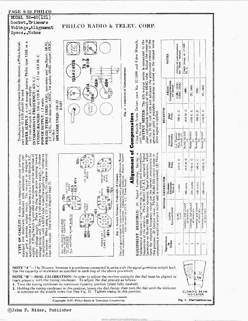
NOTE "A"-The Dummy Antenna is a condenser connected in series with the signal generator output lead. Use the capacity or resistance as specified in each step of the above procedure.
NOTE "B"-DIAL CALIBRATION: In order to adjust the receiver correctly the dial must be aligned to track properly with the tuning condenser. To adjust the dial proceed as follows: L Turn the tuning condenser to maximum capacity position (plate fully meshed). 2. Holding the tuning condenser in this position, loosen the dial clamp; then turn the dial until the indicator
is centered on the middle index line (See Fig. 3). Tighten clamp in this position. GLOWING BEAM INDICATOR
Copyright 1937, Philco Radio & Television Corporation Fie. 3. Dial Calibration
©John F. Rider, Publisher
www.americanradiohistory.com
PHILCO PAGE 9-111.2
C
RED BLc CND
A A3 A4 B B3 B4 A + A5 B
" 85 At.'s
i.,,, b \,A6 B1t1, B8 / . V Al2~7 B12~
1i6B7 A11 A8 Bt1. Be
C12
CI
A10 A9
CIO C9
E E3 E4 E2 f5 F ` F5 t4,,,E8 F14s...FB ;`: A C1144
BIO B9
D D3 D4 . 5 D 4'., .D5 C8 DyV4, 06
7 D12
44t 7 D1j' D8
DIO 09
Ea Fn E10 E9 F10 F9
RF 6U7G
(A)ANT (B)ANT
1,¡
o,S MIXER
loa 6A8G
De o aó 4:
llaJ n , D9
12
I52
ñ
..
D12
1
3 40 0 02
5o
DIRECTION OF ROTATION FROM REAR OF SWITCH
ALL RANGE SWITCHES SHOWN IN
PIIILCO RADIO & TELEV. CORP.
(A)R F (A)O SC (WR F (5)o
TUNING CONDENSER' jY31I.F EXPANDER UNIT
OSC 6A8G
20,000A.
POSIT ON NO I BROADCAST
21 2 n2 2
4 4 4
3 3
GANT RANGEI GANT RANGE 2 GANT RANGE 3
2
0 le RANGE
2
F7 5 4.1AP 5 4 -TAP
4
3
ANT RANGEA
2
3 1
RFRANG( 2 (DR IS RF RANGE A OR 2 2 it 3 i
3
ANT RANGE S
F8 Coss RApGE I 31 oSc RANGE 2 0 0 RANGc
TAP 3 3 3 5
6 5 TAP
4
SC RANGE A IS
10.000A.
WHITE
3
3 WHITE 2A
1 4000n 2 1000n 3
BLUE
c LESS.1n 4 BLUE
b YELLOW
(p 43.n.
YELLOW fiRL4NS,R F p 45n wp
rl YELLOW
REGT 5X4G
C.
LESS .1.11.
N
J > -100n n
=
'IDDOd es.
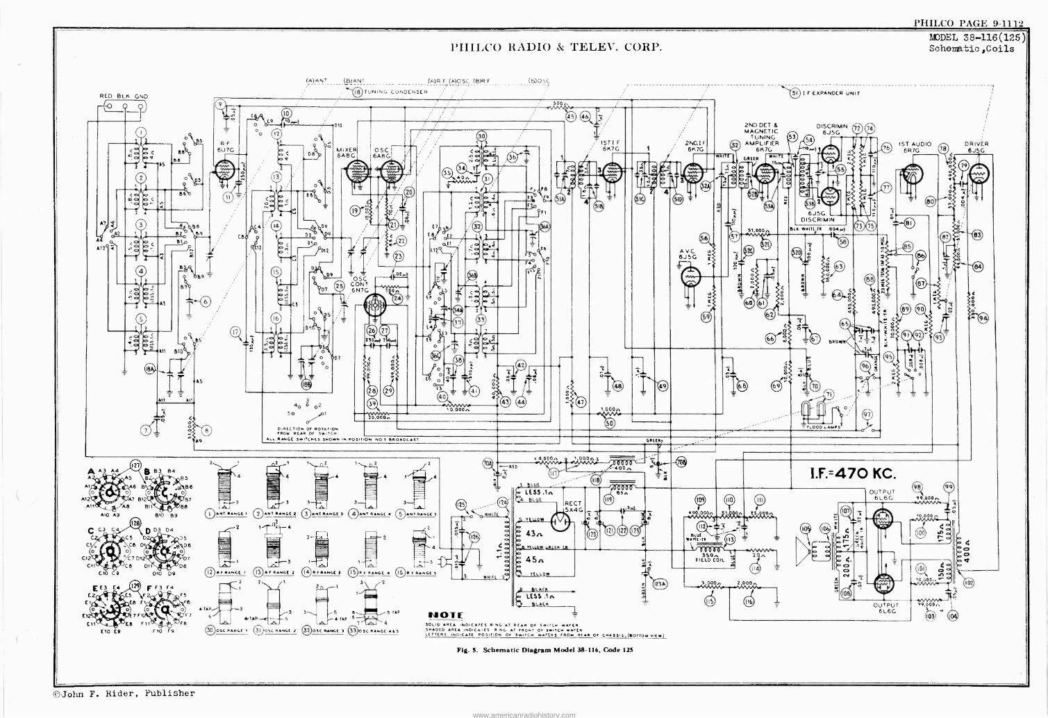
NOTE SOLID RCA INDICATES R NC. AT REAR OF SWITCH WAFER SHADED AREA INDIC AI ES R,NC. AT FRONT OF SWITCH WAFER LETTERS INDICATE POSITION OF SWITCH WAFERS FROM REAR OF CNASSI5,(BOTTOM VIEW)
Fig. 5. Schematic Diagram Model 38-116, Code 125
2ND DET & MAGNETIC
TUNING 2 AMPLIFIER
61c7G
GREEN
~ d b u .O O ; 0 C C. 4r. a
AMC * 6J5G
ótriM , .w,vw. FIELD
350 COIL
21n Ó w.
3,000. 2 OOOn
DISCRIMIN. 72 74 6J5G
6J5G DISCRIMIN.
BIN WHITE TR .004y,í
5. 2D ç
LOOD LAMPS
I.F.=470 KC.
MODEL 38-116(125) Schematic,Coils
1ST AUDIO 6R7G
OUTPUT 6L6G
99.000.
--r
DRIVER 6 J5G
©John F. Rider, Publisher
www.americanradiohistory.com
PHILCO PAGE 9-13 PAGE 9-14 PHIL('O
e e I
e
PIIII,CO RADIO & 'l'I+;I.I+.". CORP.
e e t 00
0 0
GO
0 0
000 o 0
.0't.1: f L- 0/ r
to 4.
ee®e®em 0G
00
o 0 o 000
O
e
O 00 ,O oo
O0
i 1 V
7.0 O 43
o o
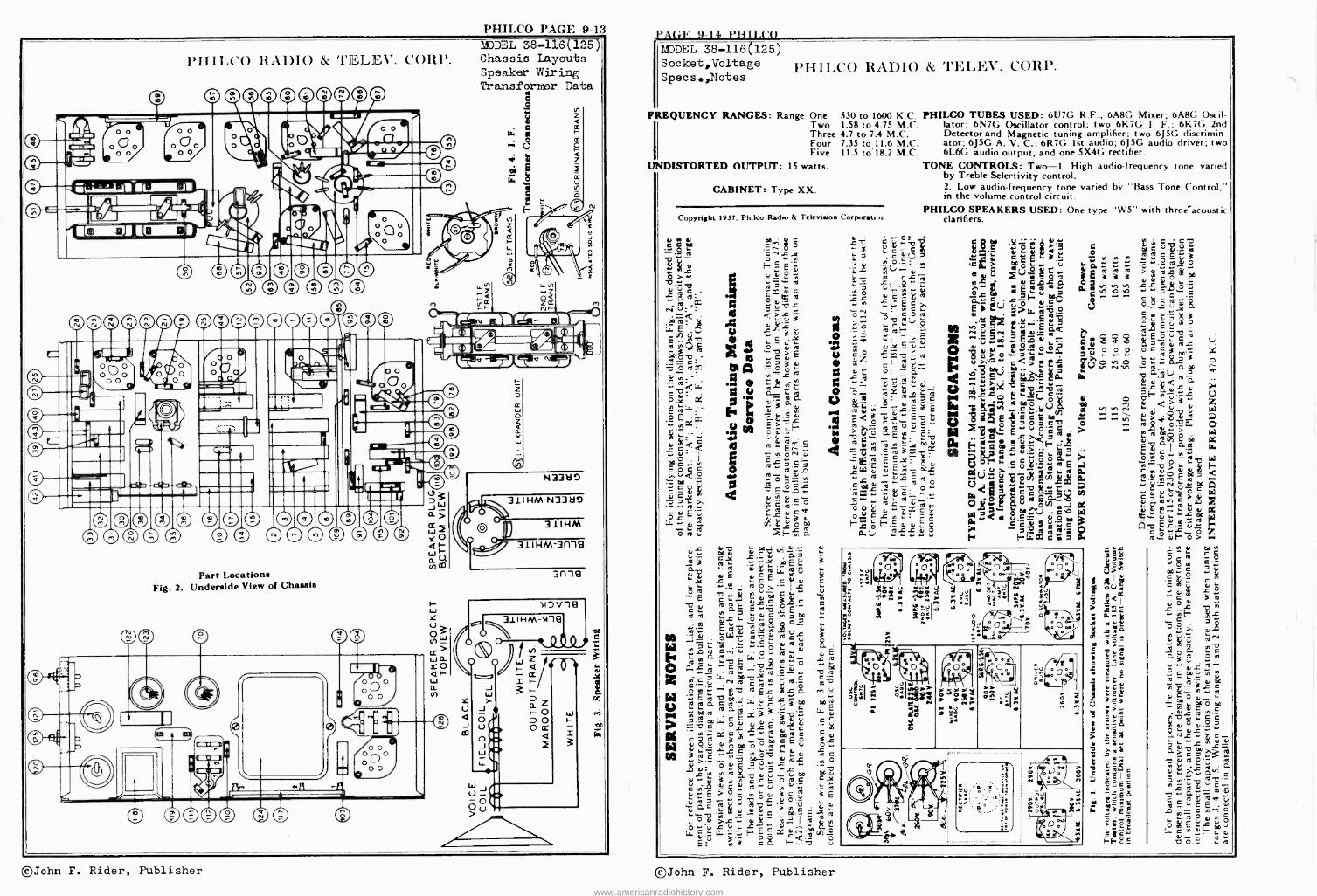
MODEL 38-116(125) Chassis Layouts Speaker Wiring Transformer Data
o
cle
si c.
u
a u o
s 0
An I ma1.' . . .lill
g ó ® M ®®®®
n OCDO ^ G® ®090
® ® .
Part Locations Fig. 2. Underside View of Chassis
e
L4J J
e e a:3m
4
O Q
L o0
-r
® O e
W
N331i0
31I HMN332i
l 31IHM
311HM-3f119
3f119
1J1e 311 HM -N19
" . 1 /
F
MODEL 38-116(125) Socket,Voltage PIIILCO RADIO & TELIX. CORP. Specs.,Notes
REQUENCY RANGES: Range One .530 to 1600 K.C. PHILCO TUBES USED: 6U7G R.F.; 6A8(. Mixer; 6A8G Oscil- Two 1.58 to 4.75 M.C. lator; 6N7G Oscillator control; two 6K7G 1. F.; 6K7G 2nd Three 4.7 to 7.4 M.C. Detector and Magnetic tuning amplifier; two 6J5G discrimin- Four 7.35 to 11.6 M.C. ator; 6J5G A. V. C.; 6R7G 1st audio; 6J5G audio driver; two Five 11.5 to'18.2 M.C. 61.66 audio output, and one 5X46 rectifier.
UNDISTORTED OUTPUT: 15 watts.
CABINET: Type XX.
Copyright 1937. Philco Radio & Television Corporation
C C 00 _ _º _
¿ 0ov 0 3 m G ` ro
: e C,E áóE °r= E
ó ro D o u
c E c C v .30 3g c m
:t2`a áE E L. ta ro 1"t Ç'1'0 a O 00
v
m E 9 c i
7%.G ̀ ...- .,Oc
j3 -r.
ro + .
A ro. vE`` ' .c ro y m
C O N 00. v tC0
ro.- º EL
E á v m ro ro G c 7f.= ..
eoro ro Gro 3 .° eos. c E Y y c OL LL E
yy
., o0 3 tt m O
3 'cri E -w óo-o- >'- p ` 7 0 w ca a Y e
.3 w 71 .. U
c
Eu E >.3ööv
a _Gc v v +
l L `. O a' >.L o+
,1).=` L L c ̀ .L..
F- E.E O
O E ,3n 3 c
L.E ñú 3 . mE.
TONE CONTROLS: Two -1. High audio -frequency tone varied by Treble -Selectivity control. 2. Low audio -frequency tone varied by "Bass Tone Control," in the volume control circuit.
PHILCO SPEAKERS USED: One type "W5" with three -acoustic clarifiers.
>4,-g E8 "Gy C.+ ` ;.ú .E
- é G
Ú` ou rouu
g E ou a_
té 16 V .b e c ú'L- E
.ña y ÿ e O,Dú O
Oo
-v á _Q u<>eó
tb L 7
MlLC CJ yyA
O2uUñ. c;,mN d$«úpé
Ç u ú < 0, 41 ., . G O Y ., ro 4 áV « .E ótñ v:r
pw< ° c ó_ C g" ro ó p.
0 0a >,,`(,) . . C 'O a.. < o é' º m i .. 72 Á ä ;?'i
C . a
7.et
e
Ä 3
g O O
+ O N 'III
0 M 6,1.. N - ^
ñ C c h: C O L O`
ro c c 3'm ó
>A7g-7.
s g.. E o o c
°,2,9
g E E °Eócá óC c v roL m3
L ..s `- ro_ GOiD
v v .f -L ut CF r - _L
4 Q V >4 ro
roa,ó._a ,a0o0ó
ó i áç E '..
m p` Oyy
00 7 .+VLN> ó .ro+ 00
`1,0m'- u0ro^c rt v
E ]- v ¿'-:9 fl Lu-
g°vE-ó> ' N L
o c ro
O H
.3 m.. C E
C a
v OL -C
.5 j,
m _ a ro
ro
G Gÿ ca
c °.oL.7,f. Ñ=a 3r c v r, a, ..
00 t,` O m ..N v c -L .% c c a,,º `öÿ v
ro c _ = L G j c > > ro
ro ó'- a ro
.>. c0
C
a.V 7,o roa- ro i °croro
n ó v w Ó L y . t`:,*
c E
a .. a
177.7 . ro
©John F. Rider, Publisher ©John F. Rider, Publisher
www.americanradiohistory.com
PHILCO PAGE 9-1
PHII,CO RADIO & sal ELEV. CORP.
ryï2o.cL¢C 38-116, C1- 125
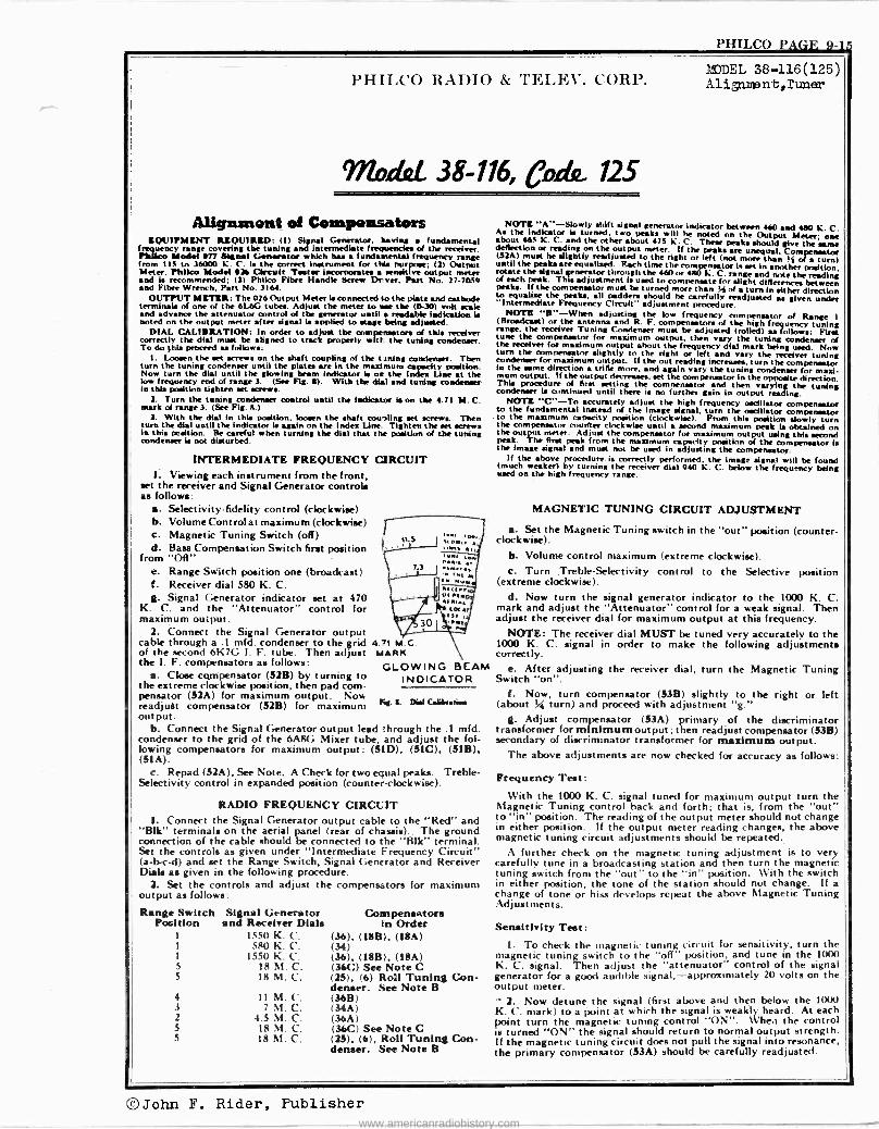
Alignment of Compensators EQUIPMENT REQUIRED: (I) Signal Generator. having fundamental
freeeqquency range covering the tuning and intermediate frequencies of the receiver. Pbl$co Model 017 Signal Generator which has fundamental frequency range from 113 to 36000 K. C. is the correct instrument for this purpose; (2) Output Meter. Phlloo Model 0K Cheult Tenter incorporates sensitive output meter and is recommended; (3) Phlico Fibre Handke Screw Dryer. Part No. 27-70.39 and Fibre Wrench. Part No. 3164.
OUTPUT METER: The 026 Output Meter la connected to the plate and cathode terminals of one of the 6L6G tubes. Adjust the meter to we the (0-30) volt scale and advance the attenuator control of the generator until readable Indication is noted on the output meter after *gnat la applied to stage being adjusted.
DIAL. CALIERATION: In order to adjust the compensator, of this receiver correctly the dial must be aligned to track properly w tl t the tuning condenser. To do this proceed as follows:
I. Loosen the set screws on the shaft coupling of the tuning condenser. Then turn the tuning condenser until the plates are In the maximum cspsdty position. Now turn the dial until the glowing beam Indicator is on the Innddeex Une at the low frequency end of range 3. (See Fig. a). With the dial and tuning condenser in this position tighten set amewe.
2. Turn the tuning condenser control until the indicator is on the 4.71 M. C. mark of range 3. (See Fig. 4.)
3. With the dial in this position, loosen the shaft coupling set screws. Then turn the dial until the indicator is again on the Index Une. Tighten the set screws in this petition. Be careful when turning the dial that the position of the tuning condenser 4 not disturbed.
INTERMEDIATE FREQUENCY 1. Viewing each instrument from the front,
set the receiver and Signal Generator controls as follows:
a. Selectivity -fidelity control (clockwise) b. Volume Control at maximum (clockwise) c. Magnetic Tuning Switch (off) d. Bass Compensation Switch first position
from "Off" e. Range Switch position one (broadcast) f. Receiver dial 580 K. C. g. Signal Generator indicator set at 470
K. C. and the "Attenuator" control for maximum output.
2. Connect the Signal Generator output cable through a .1 mid. condenser to the grid 4 7 M C of the second 61(70 I. F. tube. Then adjust MARK the I. F. compensators as follows:
a. Close cgmpensator (52B) by turning to the extreme clockwise position, then pad com- pensator (S2A) for maximum output. Now readjust compensator (S2B) for maximum out put.
b. Connect the Signal Generator output lead through the .1 mfd. condenser to the grid of the 6A8G Mixer tube, and adjust the fol- lowing compensators for maximum output: (51D), (SIC). (S1B), (S1A).
t. Repad (S2A), See Note. A Check for two equal peaks. Treble - Selectivity control in expanded position (counter -clockwise).
GLOWING BEAM INDICATOR
CIRCUIT
Fy. II. Dial CaBMstiss
RADIO FREQUENCY CIRCUIT 1. Connect the Signal Generator output cable to the "Red" and
"Blk" terminals on the aerial panel (rear of chassis). The ground connection of the cable should be connected to the "51k" terminal. Set the controls as given under "Intermediate Frequency Circuit" (a -b -c -d) and set the Range Switch, Signal Generator and Receiver Dials as given in the following procedure.
2. Set the controls and adjust the compensators for maximum output as follows:
Range Switch Position
1
5
5
4 .3
2
5 5
Signal Generator and Receiver Dials
1550 K. C. 580 K. C.
1550 K. C. 18 M. C. 18 M. C.
11 M. C. 7 M. C.
4.5 M. C. 18M.C. 18 M. C.
Compensators In Order
(36), (18B), (18A) (34) (36), (18B), (ISA) (36C) See Note C (2S), (6) Roll Tuning Con- denser. See Note B (365) (34A) (36A) (36C) See Note C (25), (6), Roll Tuning Con- denser. See Note B
MODEL 38-116(125) Aligmsnt,Tuner
NOTE "A"-Slowly shift signal generator indicator between 460 sad 400 K. C. As the indicator is turned, two peaks will he noted on the Output Meter; one about 463 K. C. and the other about 473 K. C. These peaks should give the same deflection or reading on the output meter. If the peaks are unequal, Compensator (S2A) must he slightly readjusted to the right or left (not more than Sfi of a turn) until the peaks are equalized. Each time the compensator is set In another prsltion, rotate the signal generator through the 460 or 480 K. C. range and note the reading of each peak. This adjustment is used to compensate for alight differences between Peaks If the compensator must be turned more than St of turn in either direction to equalize the peak, all paddere should he carefully readjusted as given under "Intermediate Frequency Circuit" adjustment procedure. NOTE "E"-When adjusting the low frequency compensator of Range I (Broadcast) or the antenna and R. F. compensator of the high frequency tuning range, the receiver Tuning Condenser must be adjusted (rolled) as follows: First tune the compensator for maximum output, then vary the tuning condenser of the receiver for maximum output about the frequency dial mark being used. Now turn the compensator slightly to the right or left and vary the receiver tuning condenser for maximum output. If the out reading increases, turn the compensator in the same direction trille more, and again vary the tuning condenser for maxi- mum output. If the output decrease,, set the compensator in the opposite direction. This procedure of first setting the comnensator and then varying the tuning condenser is continued until there is no further gain in output reading. NOTE "C'-Tr, accurately adjust the high frequency oscillator compensator to the fundamental instead of the image signal, turn the oscillator compensator to the maximum capacity position (clockwise). From this position slowly turn the compensator cnurfter clockwise until a second maximum peak 4 obtained on the output meter. Adjust the compensator for maximum output using this second peak. The first peak from the maximum capacity position of the compensator is the image signal and must not be used in adjusting the compensator. If the above procedure is correctly performed, the image signal will be found (much weaker) by turning the receiver dial 940 K. C. below the frequency being used on the high frequency range.
MAGNETIC TUNING CIRCUIT ADJUSTMENT
a. Set the Magnetic Tuning switch in the "out" position (counter- clockwise).
b. Volume control maximum (extreme clockwise). c. Turn Treble -Selectivity control to the Selective position
(extreme clockwise). d. Now turn the signal generator indicator to the 1000 K. C.
mark and adjust the "Attenuator" control for a weak signal. Then adjust the receiver dial for maximum output at this frequency.
NOTE: The receiver dial MUST be tuned very accurately to the 1000 K. C. signal in order to make the following adjustments correctly.
e. After adjusting the receiver dial, turn the Magnetic Tuning Switch "on".
f. Now, turn compensator (53B) slightly to the right or left (about % turn) and proceed with adjustment "g."
g. Adjust compensator (53A) primary of the discriminator transformer for minimum output; then readjust compensator (53B) secondary of discriminator transformer for maximum output.
The above adjustments are now checked for accuracy as follows:
Frequency Test:
With the 1000 K. C. signal tuned for maximum output turn the Magnetic Tuning control back and forth; that is, from the "out" to "in" position. The reading of the output meter should not change in either position. If the output meter reading changes, the above magnetic tuning circuit adjustments should be repeated.
A further check on the magnetic tuning adjustment is to very carefully tune in a broadcasting station and then turn the magnetic tuning switch front the "out" to the "in" position, With the switch in either position, the tone of the station should not change. If a change of tone or hiss develops repeat the above Magnetic Tuning Adjust men ts.
Sensitivity Test: 1. To check the magnetic tuning circuit for sensitivity, turn the
magnetic tuning switch to the "off" position, and tune in the 1000 K. C. signal. Then adjust the "attenuator" control of the signal generator for a good audible signal,-approximately 20 volts on the output meter.
2. Now detune the signal (first above and then below the 10(K) K. C. mark) to a point at which the signal is weakly heard. At each point turn the magnetic tuning control "ON". When the control la turned "ON" the signal should return to normal output strength. If the magnetic tuning circuit does not pull the signal into resonance, the primary compensator (53A) should be carefully readjusted.
©John F. Rider, Publisher www.americanradiohistory.com
l'AGE 9-16 PHILCO
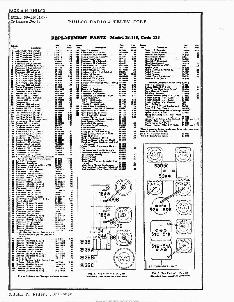
MODEL 38-116(125) Trinmler s,i'arts
$.11.m. Ni. D.rMytt.n
PHILCO RAllIO & TELEV. CORP.
REPLACEMENT PARTS -Model 38-116, Code 125
Pest UM S.1ram. Patt N.. Pete N.. Dmery1Mn No.
1 Ast. Transformer (Rage I) 313615 ! Ant. Tramiormm (Range 2) 32-3616 3 Ant. Transformer (Rage 3) .. 313817 4 Ant. Transformer (Range 4) 32-3616 6 Ant. Trarfamer (Rege 6) 333619 6 Comparator (R. F.) 314064 7 Comitesv (.06 of tubular) 304519 8 R. for (51.000 U..4 watt) . 33461339 S Condenser (.06 of tubular) 30-4133
10 Condenser (10 ouf mien) . 30.1096 11 Condenser (260 pof meal 161032 12 R. F. randomize (Range 1) 33-2630 13 R. F. Tradormer (Range 2) .. . 32-3631 14 R. F. Tramforner (Range 3) 331631 16 R. F. Tradorm« (Range 4) 33-3933 18 R. F. Trendarm., (Range 6) 332634 17 Condemn, (130 rod era) .. . 361036 13 Tuning Condom., Amenably . 31-3066 11 Reamta (15.005 0. ,e watt) .. 33-316339 84 Condenser UM rf tuhuler) 30-4444
33.0703» 33.096335 364315 31470339 31-1084 30-1032 3a1a2 31»4339 33-»9339 319936 313616 32-2627 33-19!6 314100 33.010339 314300 361089 361043 33-370039 33410339 314106 30-4123 33340439 30-4123 31150331 4989PG 333103339 304315
II Remoter (700. y(t watt) 22 Rotten (85 (4 watt) 25 Condenser (.02 of tubules) 14 Rotator(700 0, 4 watt)
I Coadewr (180 rol min) r Condemner (350 rol mica) .
18 Ros.tor (99,00014 Sr watt) .
111 Roaster (941.030 ti, SS watt) 38 Ow. Tnmfoemer (Range 1) 31 Qtr. T,.dorm,. (Range 2) 31 Ow. Trsríormer (Range 3) » (tie. Tndormer (Renee 4 1 5) 34 Cowpen«tor (2 .star) 36 Relater (40 0. 4 wstt) 11 Coommppeewwtor )4 nation) .
37 Co wow (400 rod mow) 38 Condemner (40 ref vin) 38 Remita (20.00014 4 watt) M Rotator (10.000 U. 4 watt) 41 Cordova," (1300 sot .Heal 42 Condene (.06 pf tubular) 43 Resistor (40,C00 0, 1 watt) 44 Condemn, (.06 of tubular) 46 R«ator (5000, 4 watt) .
M Calderon (.1 of Bakelite) 47 Rost.. (1oteo ti, I, osti) M Condenser (.01 of tubular) M Condemn« (.1 of tubular) 304499 M R.wwtor (1.00011, te watt) 33-2)0339 M1 1. F. Espander Unit Areembl (See Note
for let and tad I. F. Traormen) 364912 3M I. F. Transformer 32-2660 Dorman. Tremolo/meet 32-2661 Condemn- (110onfmen)(Part of 63) 361031 Condenser (.5 euef mew) 30-1007 Renstor (1.0 ram.. 4 watt) 33-610339 Condemn, (1 l O oral min) 161031 Condenar (.004 tubular) 304466 Relator (1.0 leg., 4 watt) 33410039 Reeintor (2,000 ti. 't watt) 33.210339 Condemwr (.06 of tutelar) 304444 Remito« (2,00014 43 watt) 33-220339 Remota (160.000 U. t,1 watt) 33-414339 Resistor (490,00014 S, watt) 33-449339 Condemn (.1 --.1 - .7 of) 30.4637 Resistor (6.00011. 1 wan) J3.290439 Condenar (.M of tubular) 30-4444 ('ondemrr (.06 of tubular) 364518 Remote (10.00011, (, watt) 33410139 F2eetolytie ('ondetrer (6--6- 6,1) 362732 Flood Limp Bulla 34-2064 Ra,tar (2.0 met.. 4 watt) 33-620399 Ravine (2.0 mes.. 't watt) 33-120339 Remoto., i 0 men.. ' e watt) 33-310339 Reenter (1.0 mn.. ke watt) 33410339 Condemn (110 ref meal 30-1031 Condenar (110 rol areal 30-1031 Renew (490.00311. Ir watt) 33449339 Condemn (.004 rf lobuter) 30-4436 Rustir (32.00014 't watt) 33-3321139 l'ondenwr (.01 of tubule,) 304169 Condenser (.1 of tubular) 304455 Remain (51,000 (4 St watt) 33461339 Reinstor (99.000U, ,t watt) 33-399339 t oluae (ostral 33.5158 Audio Shorting Swath (Pan of Auto.
Tuner -See part& (6) end (14) Bulks un 273)
Potentiometer 335246 Remote (496000U. Ie watt) 33.449379 Relator (70,0000, 4 watt) 33470339 Rermetor (1.0 rms., 4 watt) 33410339 Condemn (.099,1 tubular) ... 304112 Condemner (.005 of tubular) 30-4112 Condenser (.02 of tubular) 364411 Remeta (330.0000, 4 watt).. 33.433339 Resto, (490.000 0, .4 oett) 33449339 A. F. C. Switch 43-1216 A. F. C. Shortin6 Switch (Pan of Auto.
Tuner- Bulletin 273) 464330 M Remito, (99.000 O. 4 watt).. 33-399339 M Condemn (.M of tubular) .. 304518 IM Remita (10.000)2, 4 watt) 33410339 181 Relator (10,00014 4 watt) . . 33-310339
60.70 143 Input Transformer 337666 .70 143 Ramalor (99,003 fl, 4 watt) 33496338 .70 1M Cosdarer (.06 rf tubular) 304518 .70 199 Cone e Vase Cell AammNy 364647 .70 199 Output Trades., 33-7751 .15 197 Cadman (J3 d tub ulsr) . 30.4491 .30 1N Condom" (.02 rf tubular) 30-4431 .20 1111 Raiser (490,000 ft. 4 watt) 33-449339 .20 III Ramer (51.0000, 4 watt) 33461339 .30 III Relator (36,0004 Si watt) 33436339 .26 11! Cobden/err (.1 of --.1 01 Bokdnte) 495500 .70 113 Field & Pot Ameeably .. $64784
1.00 114 Reactor (30 14 4 watt) .. 33430336 .N 116 Realtor (1,0054 4 watt) . 31230339 J0 113 Relator (3,n
-w0054 el aunt) 1b-324341
.70 117 Relator, wiound (40000-1.0000) 034239
.30 114 Cok .317723
.30 128 & rolytic Couder X10036
.20 Ill Ebaetrolytee Gondar., 367036
.30 112 Cosdesar (.3 st tubular) 304466
.m 113 Neevdyy ua.e Condom: (S - l0 rf) 363201
.20 114 Power Tranefrme,
.30 116 V.-6040 tithe 32-7699
.18 116 V.-3640 cyder 311700
.36 111230 V.-60.60 ryes 32-7701
.16 Is Power ! Bone Tor Notch 43-1196
.30 10 Condenser (.016-.016 rf Bskalnte) 3793DG
.10 117 Wave Switch (Ant. Paean) 43.1394 1.99 143 Wave Switch (R. F. SMion) 411335 1.60 133 Wave Switch (Ow. Section) 42.1334 1.00 Acoustic Clar4a 36-1166 1.60 Automatic Tote Meek. Complete 31.2063 .40 Bevel AwamNy (Cabiset) . . 366333 10 Reso, (Dial Meebnna) 338111 JO Cable and Plug (Floodlfgts) 414263
Gable (Power) 42183 Catie sad Plug (Speaks) 41-3336 Clamp (R. F. Unit Rev Mtn.) 364900 Clamp Ln.kueg Plate (R. F. tint) 263963 .01
(.lamp (1. F. Cad) 343147 01 Coed (I. F. Expander Drive) 27-5411 .04 Coupling
Manias Condemnor and Meg) 36-8603
Complies Meeirm) ng Comdeeoer led Dub 31-1941
Cover (Beadle of Automatie Moab.).. 366012 Dial .
274340 JO Dial Setae and Lem Bolds Am' 31-3063
Rrutcheue Ame,_bly (State. Tabs) 46-3472 Knob (Range Switch) 27-4324 .10 Knob (Tuning) 274330 .10
274331 .10 Knob (Vernier) Knob (Uar. Volume. Ropa.der WM-
se4e 27-4332 .10 Moak de (Tuning Meeka.rm) 264118 .33 Pilot Leap SwketAaNy (3 S&Mats) 366467 Shaft aid Ida Nate (Range Switch) 431303 AO
Price. Subject to Chine. without Notice
.20
.20
.40
.30
.30
.20 70 .38 .so .20
.30
.78
10.00 2.30 4.00 .t0 .20
.78
.20
.20
.20 .20 .20 .20 .70
.30
.20
.20
.20
.20
2.60 .O5
.30
.10
.1D
.20
.20
20
.20
.20
.78
.20
.26
.20 30
1.00
Ile. 6. Top View of R. F. Unit Showing Compementoe Location*
U.S slim.. Pei. No. Dissipt)ns 32.60 Shalt (I. F. Rapsodet)
.30 Shaft (Volume Control)
.20 Shield (Tube. Square) 2.60 Shield (Round 6167G) 2.00 Shield 3rd (I. F.)
.20 Shield (I. F. Rapando,) .
.30 Shield Bow (Square) 20 Shield Item (Round &NMC) J0 Smoker (M6) .20 Snek«t (7 prong. Power tub«) .40 Rork., (7 peoeg) ..
16.00 Socket (Ii .30 Seek« (Powerinnformr) .
.20 Termed Panel (Ant.) >0 .60 MISCELLANEOUS MOUNTING PARTS
1.20 Bolt (Mrs. Smoker) . W-$63 2.20 Bucbiy (Mtg. R. F. Unit) 262257 .01 1.06 Clip (Volume Shaft Front Section) 78.4394 .01 1.04 Crew (Batt of Cahieet) 27.996 .25 Felt (Mts. Speaker) 27-6499 .16
1.75 Rubber Grommet (Mtg. R. F. Unit) 27-4317 .04 Robber Buchan (Nb,. name) 27-4302 .M
7.50 Rubber Bushing (Mtg. Chute) 27.4340 12.00 Rubber Coition (Wtg. Chums) 3656 10.00 Pin (I. I. Shaft) 3014
.76 Sere. (Wng. R. F. Unit Rear Section) W-729 AO Senor (I. F. Coed Clamp). W-132.1-
1.50 Rasp Fulmer (Range SwitebCouNiu) 264279 1.50 Swum (Mtg. R. F. Unit) 27-7307 1.50 Spring (Retaining 1. F. Shaft Front 1.26 Semite) . 268610
Sony Cl,, (I. F. Shaft, Rear Sectors) 28-4117 per C .40 Wuboe-Flat-(l. F. Shaft)
-
W-174 Napkin (him. R. F. )'nit 263927 .01 Woahs-Sprang-(994. I. F. Shalt) 264154 per C .76
.M
.78
.40
Past 4M N.. Prim
766496 110.30 369091 .13 214776 .10 9006 .10 361967 369076 762725 .30 91101 .03 36-1343 27-6067 .11 27-6M7 11 77-6054 .11 77-6062 .11 384744
.,Thee Autocratie Tuning Mokemen Pane differ from tow .03 abown in Service Bulletin 273.
llat I. F. Treedermer Satan 32-2727 tad I. F. Troilism -nee Section 32-2725
(\l DI SCRIM IN
6J5G
(t^1 DISCRIMIN
6J 5G
Pie 7. Top View of I. F. Unit ShowingCompert.ator I.ocwtbas
© John F. Rider, Publisher www.americanradiohistory.com
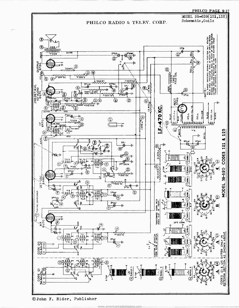
PHILCO PAGE 9-17
PHILCO RADIO & TELEX'. CORP.
^t 4 4 4 7 ^t 0'620 f+
©John F. Rider, Publisher
www.americanradiohistory.com
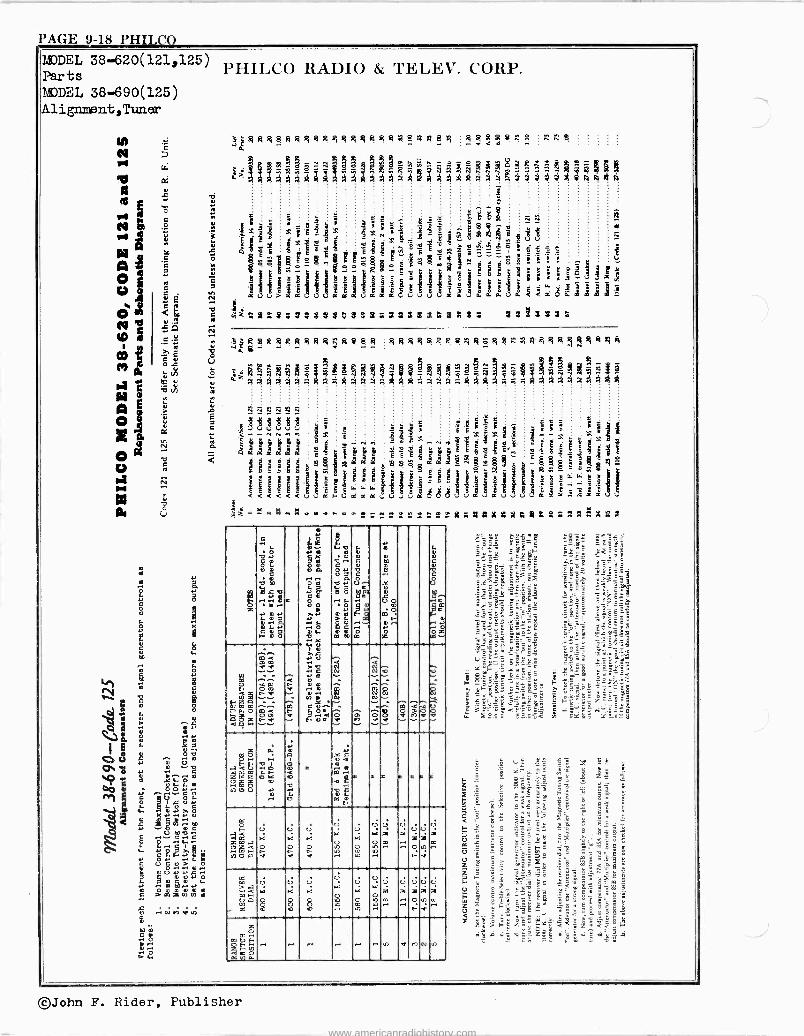
PAGE 9-18 PHILO MODEL 38-620(121,125) PIIIL.CO RADIO & 'FELIX. CORP. Parts MODEL 38-690(125) Alignment,Tuner
ÿ.RRR8ms38qR 3n8n gst8stº.ms a
RSªgRiCe&s- 11 J73ááMá .gee
En .¡ LEp 11 21:4714M "I; `
1 l_!E41Ѫ Y,
7 Y
ttá Vl_b¡}d4lB 9 ^isªri:'É^t
!Qç!
1 §
gp páiódó! 1101/1111111dIlh3,bcd°iL i
kQSR:S6$ZS$$ÇSóS3223.2322223 22!3232
jiÁeRRRR2ßRR9813 RRRM5t.22º1qos;ß3hqiRRi9RÑ5dgR
(M22 2g2 J11! le li i.
CdKd É. l CN`}' .! 2 E ":1 É.d_ d E ¿
2 __ b U dy
3 g¢ Q 9y' ç º+ çº - p{ 5 h Ç 2 Ég4:2áKoi éóggci^i$ E a6g L' 4çQó i tE
y y y g @
. ß
y r
O O O d tT D E ¡ A 6 3 M < <<<<< u r- US K C a u u u V o1 u á Y s Y s
7C
G L O
G ¡lp,.+
O p Gp
{c 04
'i ...c., E
C Y m V . mi 4 tC. dg
0 ) V
{70 ! V
a Ó~ il O .... ......V
... 4 .. .y
9 0
9.- Ú 7
{O. aa+
B Ó ~ V >m m
O Lu
Mu ED
{{.
L C
C Úi
au+
0 ..2 2v
V
H)
B X Ñ
tpOp
í0 0.--,.
.20
e C
C Ú LO}.
aC.0 [ .ú M°-^
ó c.
írimá-.= áz <U..
4 m co e
em o
ó m
;'2 0 >...0 V J >O w C
úa m C
Q1 N ..
E .
ÿ <
Ñ.... NO ......
. <g
CO U é0áé
wJ ; ....
Z
.d6 e z Z Z ÑWO N d U
.
a
.-id Ó O
Ñ
L
0m
Ó v 0
.
e
_
.+
:40 M m
C 911
C. M
Fw
e
w
c e C C
.
t F
M p F M yM.d
mc
U
v
U a
á
U w
á $ io.
U j o
' ÿ +
0 s o0í-Ñm~. e-a
á
m
8-.. -.
áQg
U d
U c 8
U L
8
U ...
U b
U U C
3i m Ñ. U U
y 9 ` óm U U a 9
Z 0 t dz H W 4 C O M.AY
.- - N .-. . .+ .n P7 N u,)
«A li ii pe C lo 22 X23
tm
?g D 'f
3_ .y.aBÉ
FÇ d É'Lsá ^1ç'=
i
©John F. Rider, Publisher
www.americanradiohistory.com
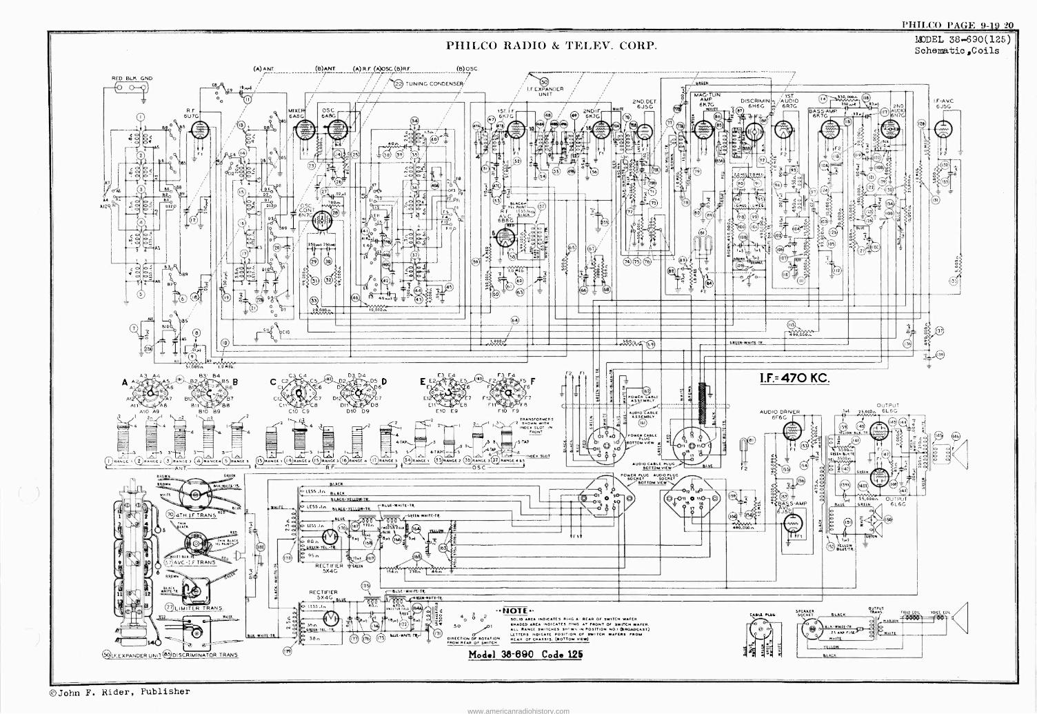
PHILCO PAGE 9-1Q D
A4
Al2
RED BIK.GND.
A3
A A2 A
Al2 A11 A8
A10 A9 2 ¡I
4
ARI
//-)Ifl
R4NGC
RF. 6U7G
Ce
B10 B9
(A)ANT
ír Isy4
(B)ANT. (A) R.F (A)OSC (B)R F
q MIXER/ o \ 6A8G
OSC. CONT 6N7G,
OSC. 6A8G
25094 2 SOR4
C10 C9
fil RANGE 2 RANGES v RANGE4LS)RANGES RANGEI RANGE
ANT. 4
BED DRECK
7094TH IF TRANS R
TRIM LACK
WNIIE-1 BLACK
R
77% LIMITER
TAIN BLAC Il FAIM
TRANS.
RIA -W NRE-TTE -
()IF.EXPANDER UNIT B5 DISCRIMINATOR TRANS.
ID ORO,.
D10 09
PHILCO RADIO & TELEV. CORP.
(B) OSC. 7
TUNING CONDENSER/
04 01 a o
<
' I 2
= 3 3.---3 11111
4-TIA,
RANGE 3 RANGE 4 17 RANGE 3 RANGE I t=
LESS.L. e[uE-wKITE-TR. eIACK'YELLOW-TR. ` - - GREEK -WHIT( -TA.
loaf
RECTIFIER = U -OS
RECTIFIER 5X4G
LESS.In
Sbn GREEK-YEL.-TR.
38n
rpLUE-WNITCTE.
TRILlAR RIS It RED
13>.t w.Y°
ILLLE-WRIT[-TRE J
I.F EXPANDER UNIT
lBLACK-; ILL
R F ES5:
AVG. eLAC
6B8G
F7
FIO F9
TRANSFORMER S
2 SHOWN WITH INDEX SLOT IN
FRONT
RANGE 2 `)RANGE
OSC
NOTE :0 3 4O O 02
50 J01
DIRECTION OF ROTATION FROM REAR OF SWITCH.
2NDIF 6K7G
2ND.DET WMTE 6J5G
POWER CABLE ASSEMBLY
POWER CABLE PLUG
a BOTTOM VIEW t
1
u
ßE7
den I6 tT
AUDIO CABLE PLUG
ARUN
MAG -TUN. AMP 6K7G
row(
BLUE OTTO MVI[ W B
POWER PLUG AUDIOPLUG SOCKET SOCKET \ / BOTTOM VIEW
SOLID AREA INDICATES R."G A REAR OF SWITCH WAFER.
SHADED AREA INDICATES PING AT FRONT OF SWITCH WAFER. ALL RANGE SWITCHES SHI WA IN POSITION NO .1 (BROADCAST) LETTERS INDICATE POSITION OF SWITCH WAFERS PROM REAR OF CHASSIS, (BOTTOM VIEW)
Model 38-890 Code 125
DMIG 1.0 MEB.
NI DRE[K-ITE-TR
400,000n
ëvo;Dóo,
I.F.= 470 KC.
AUDIO DRIVER 6F6G
AS S -AMP
SPEAKER SOCKET
2ND UDO N7G
OUTPUT -Ra1. 25,0002. 6L 6 G
3500.. ER ENpIK-1E
TE 3500n
.1
DLUE
YELLOW BLE-TR.
BLACK
BLK-WNI -TR.
.25 ARP FUS
wNT
FILOw
BLACK
2 S, LOOn GREEN
TGEEEN
OUTPUT TRANS.
OUTPUT 6L6G
MODEL 38-690(125) Schematic ,Coils
I F-AVC 6J5G
FIELD COIL YOKE C IL
o oNKITE
©John F. Rider, Publisher
www.americanradiohistory.com
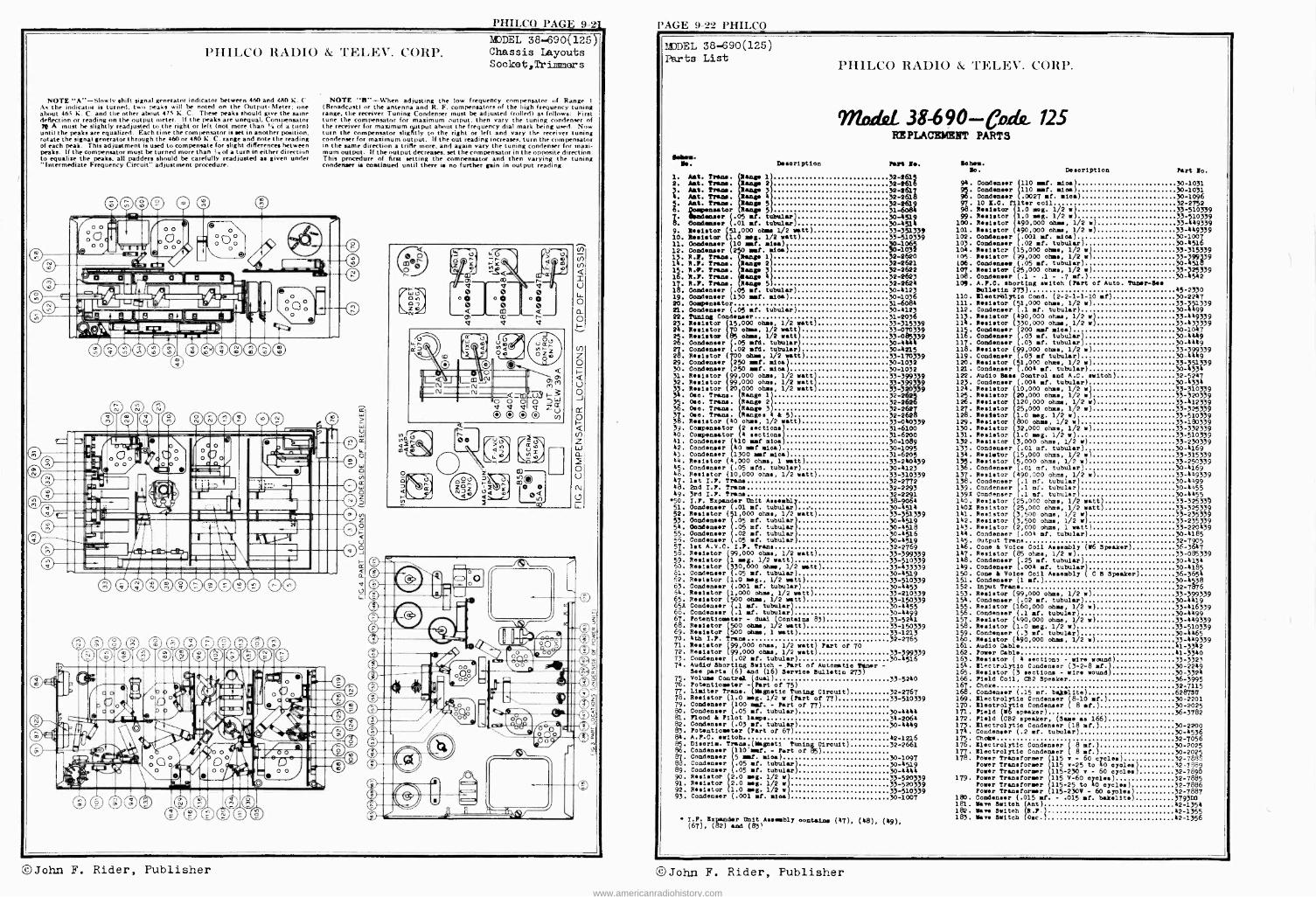
I'IIILCO RAI)IO & TELEV. CORP.
NOTE "A" -Slowly shift signal generator indicator between 460 and 480 K. (' As the indicator is turned, two peaks will be noted on the Output. Meter; one about 465 K. C. and the other about 478 K. C. These peaks should give the same defleçtion or reading nn the output meter. If the peaks are unequal. Compensator 72 A must he slightly readjusted to the right or left (not more than of a turn) until the peaks are equalized. Each time the compensator is set in another position, rotate the signal generator through the 460 or 480 A. C. range and note the reading of each peak. This adjustment is used to compensate for slight differences between peaks. If the compensator must be turned more than is of a turn in either direction to equalize the peaks, all padders should be carefully readjusted as given under "Intermediate Frequency Circuit" adjustment procedure.
090®0 0000 0
e0®®00 00 e000
0068® A® ® 0® 00
PHILCO PAGE 9-21
MODEL 38-690(125) Chassis Layouts Socket,Trinmmers
NOTE "B" -When adjusting the low frequency compensator of Range I
(Broadcast) or the antenna and R. F. compensators of the high frequency tuning range, the receiver Tuning Condenser must be adjusted (rolled) as follows: First tune the compensator for maximum output, then vary the tuning condenser of the receiver for maximum qquutput about the frequency dial mark being used. Now turn the compensator slightly to the right or left and vary the receiver tuning condenser for maximum output. If the out reading increases. turn the compensator in the same direction a trifle more, and again vary the tuning condenser for maxi- mum output. If the output decreases, set the compensator in the opposite direction. This procedure of first setting the compensator and then varying the tuning condenser is continued until there is no further gain in output reading.
PAGE 9-22 PHILCO
MODEL 38-690(125) Parts List
Beliess. Ills. Description
1. Ant. Prans. cap 1 32-2615
3 2. Ant. Trams. ange 2 32-2616
S. pAAnntt..Tra
Tram.
emerge
5 2619
T
4 32-2618
. =air (.05 mit. tubular) 31
8. Oemdaeees (.01 mit. tubular)30.-4514 9. Resistor (5 ms 1 000 oh 1/2 watt) 33-351339 10. Register í1.Ó meg. 1/2 watt) 33-510339 11. (»MAeager (10 nnt. miles)
33:1822
0-1065 12. Condenser (2 mat. Idea) 30-10 3
13. R.!, Trans. Rang, 1 32-2 14. R.1. Traci. Range 2 32-2621 15. R.i. Trine. Reap
4 32-2622
16. 8.1. Trans. any 32-262 17. R.1. Trans. Range 5 32-26Q4 18. Condenser (.05 mt. tubular) 30-4123 19. Oond (130 mat. aloe) 30-10 6 20. Oompeneator 31-6084 21. Condenser (.05 mf. tubular) 30-4123 22. Tuning Condenser 31-2036 2 Resistor 15,000 ohms, 1/2 watt) 33-315339 24. Resistor T0 ohms, 1/2 watt 33-0 339 25.Resistor Bj ohms, 1/2 watt 33-0j85 9 26. Condenser (.05 std. tubular) 30-4444 27.Condenser (.02 std. tubular 30-4215 28 Resistor oh», 1/2 watt) 33-170339 29. Condenser
x(0250 at. aloe 30-1032 30. Condenser (250 caf. aloe) 30-1032 31. Resistor 99,000 ohms, 1/2 watt 33-399339 32. Resistor 99,000 ohms, 1/2 raft 33-3993339 33 Reglstor 20 000 obs., 1/2 watt 33-32033779 3k. Osa. Trans. Range 1 32-262 35.Ose. Trans. Range 27 32-2 36 Ose. Trans. Range 3) 32-2627 37. Ose. Trans. Range. ii & 5). 32-2628 38. Resistor (40 ohm., 1/2 watt) 33-040339 39. Compensator (2 sections) 31-6100 40. Compensator 4 sections )) 31-6200 41. Condenser 410 amt oies 30-1089 42. Condenser 40 mat mina) , 30-1095 43. Condenser 1700 Be! misa) 31-6205 44. Resistor (4,000 ohms, 1 watt) 33-240439 45. Condenser (.05 std. tubular) 30-4123 46. Resistor (10,000 ohms, 1/2 watt) 33-310339 47. let T.P. Tram. 32-2772 48. 2nd I.l. Trans 32-2293 49. 3rd I.r. Trans 32-2291
50. I.?. Expander Unit Assembly 38-4 51. Condenser (.01 elf. tubular) 30-4514 52. Resistor ( 1,000 ohms, 1/2 watt) 33-351339 53. Condenser .05 mt. tubular 30-4519 54. Oondenser .05 mf. tubular 30-4518 55. Condenser .02 t. tubular)) 30-4516 Do. Condenser .05 mt. tubular 30-4519 57. let A.V.C. I.?. Trans 32-2769 5o. Resistor 99,000 ohm, 1/2 watt) 33-399339 59. Resistor 1 mg. 1/2 watt) 33-510339 60. Resistor 330,000 oh», 1/2 watt) 33-433339 61. Condenser (.05 mf. tubular) 30-4519 2. Resistor (1.0 meg., 1/2 watt) 33-510339 63. Condenser (.001 at. tubular) 30-4453 64. Resistor ((1,000 ohm, 1/2 watt) 33-210339 65. Resistor (500 ohms, 1/2 watt) 33-150339 65x Condenser `.1 mt. tubular) 30-4455 66. Condenser ( 1 mit. tubular) 30-5499 67. Potentiometer - dual (Contains 83) 33-5241 68. Resistor 500 ohms, 1/2 watt) 33-150339 69. Resistor 500 ohms, 1 watt) 33-1213 70. 4th I.!. Trans 32-2765 71. Resistor 99,000 ohs., 1/2 watt) Part of TO 72. Resistor 99 000 ohm, 1/2 watt) 33-799339 73. Condenser (.02 f. tubular) 30-4516 74. Audld Shorting Switch - Part of Automatic tenor -
See part. (6) and (16) Service Bulletin 273) 75. Volume Control (dual) 33-5240 76. Potentiometer -((Part of 75) 77.Limiter Trans. Magnetic Tuning Circuit) 32-2767 78. Resistor (1.0 wag. 1/2 w (Part of 77) 33-510339 79. Condenser 100 mat. - Part of 77) 80. Condenser .05 at. tubular) 30-4444 81. Flood i Pilot lamp. 34-2064 82. Condenser (.03 af. tubular) 30-4449 83. Potentiometer (Part of 67) 84. A.T.C. .witch 85. Dise ris. Trans.(Nagneti Tuant 86. Condenser 110 mt. - Part of 87. Condenser 5 amt. sien) 88. Condenser .05 mt. tubular 89. Condenser .05 f. tubular 90. Resistor 2.0 neg. 1/2 w 91. Resistor 2.0 meg. 1/2 w 92. Resistor 1.0 Beg. 1/2 w 93. Condenser (.001 mt. alea
Circuit)
I.P. Expander Unit Assembly eontaine (47), (48), (49), (67), (82) and (83`
PHILCO RADIO & 'FELIX. CORP.
Mode, 38-690 - 125 REPLACEMENT PARTS
Past Be. »hem. lo. Description Part No.
94. Condenser 110 at. mica) 30-1031 95. Condenser 110 mt. mica) 30-1031 96. Condenser .0027 t. mica) 30-1096 9T 10 E.C. lter soil 32-2752 98. Resistor 1.0 msg. 1/2 ml 33-510339 99. Resistor 1.0 wag. 1/2 w) 33-510339
100. Resistor 490,000 ohm , 1/2 w) 73-449339 101. Resistor 490,000 ohms, 1/2 r) 33-449339 102. Condenser .001 mt. mica) 30-1007 103. Condenser 02 sit. tubular) 30-4516 104. Resistor (15,000 ohms, 1/2 r) 33-315339 I05. Resistor (39,000 ohms, 1/2 w) 33-399739 106. Condense! .(.05 mt. tubular) - 30-4518 107. Resister (25,000 ohms, 1/2 w) 33-2255339 108. Condenser (.1 - .1 - .7 mt.) 30-4542 109. A.T.C. shorting switch (Part of Auto. Tuner -gee
Bulletin 273) 45-2330 110. Eleetr'olytio Cond. (2-2-1-1-10 st) 30-2247 111. Resistor (51,000 ohms, 1/2 w) 33-'51339 112. Condenser (.1 mf. tubular) 30-4499 117. Resistor (490,000 oh», 1/2 w) 33-449339 114. Resistor (330,000 oh», 1/2 r) 33-433339 115. Cond 200 of mica) 30-10 7 116. Condenser .03 f. tubular) 30-4449 117. Condenser .03 f. tubular) 30-4449 118. Resistor (99,000 ohm., 1/2 w) 33-9999339 119. Condenser (.03 st tubular) 30-4449 120. Resistor (51,000 ohms, 1/2 w) 33- 51339 121. Condenser (.004 mt. tubular) 30-5331 122. Audio Bass Control and A.C. ewitob) 32-5247 123 Condenser (.00% mt. tubular) 30-4334 124. Resistor 10,000 ohms, 1/2 w) 33-310339 125. Resistor 20,000 ohms, 1/2 w) 33-320379 126. Resistor 120,000 oh», 1/2 w) 33-412339 127. Resistor 25,000 ohms, 1/2 w) 33-325339 128. Resistor 1.0 seg. 1/2 w) 33-510339 129. Resistor 800 oh», 1/2 w) 33-180339 130. Resistor 32,000 ohms, 1/2 w) 33-332339 131. Resistor 1.0 Beg. 1/2 w) 33-510339 1.32. Resistor 3,000 ohms, 1/2 w) 33-230339 133. Condenser (.01 mf. tubular) 30-5169 134. Resister (15,000 ohms, 1/2 w) 33-315339 135. Resistor (5,000 ohms, 1/2 w) 73-250339 136. Condenser (.01 ref. tubular) 30-4169 137. Resistor (490,000 ohms, 1/2 w) 33-449339 138. Condenser .1 mf. tubular 30-4499 139. Condenser (( .1 mf. tubular 30-4455 139x Condenser .1 mf. tubular 30-4455 140. Resistor 25,000 ohm, 1/2 watt) 33-325339 140x Resistor 25,000 ohms, 1/2 watt) 33-325339 141. Resistor 3,500 ohms, 1
m w 33-235339
142. Resistor 3,500 ohms, 1/2 r 33-235339 153. Resistor (2,000 ohms, 1 watt) 33-220439 144. Condenser (.005 mt. tubular) 30-4185 145. Output Trans 32-7905 146. Cone & Volee Coil Assembly (26 Speaker) 36-3647 157. Resistor (85 ohms, 1/2 w) 33-085339 148. Condenser (.25 mt. tubular) 30-4134 149. Condenser (.005 of. tubular) 30-4189 150. Cone & Voice Coil Aneably ( C B Speaker) 36-3654 151. Condenser (1 t.) 30-4538 152. Input Trans 32-7876 153. Resistor (99,000 ohms, 1/2 w) 33-39g99339 154. Condenser (.02 t. tubular) 30-4419 155. Resistor (160,000 ohm, 1/2 w) 33-816339 156. Condenser (.1 st. tubular) 30-4499 157. Resistor (890,000 ohms, 1/2 w) 33-449339 158. Resistor (1.0 Beg. 1/2 w) 33-510339 159. Condenser (.3 st. tubular) 30-4465 160. Resistor (490,000 oh», 1/2 w) 33-419339 161. Audio Cable 1-3342 162. Power Cable 41-3340 1633. Resistor ( 4 sections - wire wound) 33-3323 165. E1e trot yt lo Condenser (3-2-8 af.) 30-2249 165. Resistor (3 section. - wire wound) 30-3321 166. Field Coil, C82 Speaker 36-3995 167. Choke 32-7115 168. Condenser (.15 mit. bajnolite) 628750 169. Electrolytic Condenser (8-10 of.) 30-2201 170. Eleotrolytio Condenser ( 8 st.) 30-2025 171. Field (r6 speaker) 36-3782 172. Field (C82 speaker, (Sus as 166) 173. Electrolytic Condenser (18 st.) 30-2200 174. Condenser (.2 mt. tubular) 30-4536
42-1216 175. Chet* 32-7056 32-2661 176. Electrolytic Condenser ( 8 of.) 30-2025
177. Electrolytic Condenser ` 8 mit.) 30-2025 30-1097 178. Power Transformer 115 - 60 cycles) 32-7898 30-4519Power Transformer 115 -25 to 80 cycles) 32-7889 30-4444Power Transformer 115-230 - 60 cycles) 32-7890 33-520339 179. Power Transformer 115 V-60 cycles) 32-7885 33-520339 Power Transformer (115-25 to 80 cycles) 32-7886 33-510339 Power Transformer 115-230V - 60 cycles 32-7887 30-1007 180. Condenser (.015 at. - .015 .f. bakelite 3793110
181. lave Switch 42-1354 182. lave Switch R.T 42-1355 183. wars Switch Ose. 52-1356
©John F. Rider, Publisher ©John F. Rider, Publisher
www.americanradiohistory.com
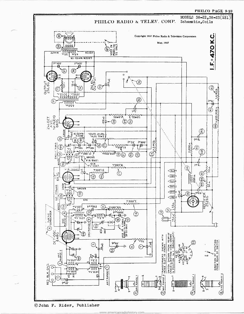
PHILCO PAGE 9-23
r-
MODEIS 38-22,38-23(121) PHIL.CO HAl)IO & 'l'EL,EV. CORP. Schematic,Coils
3111 -IM "OS rVuse N33419
H1-311HM-N332í9
Copyright 1937 Philco Radio & Television Corporation
May, 1937
1N900' '1^900' f
O
e
--J Q9 QSLQQºQt Z
/
-r«Rfr, vOS9
z
e. mw0't i3W01
e 111911HM-
N332f2.., '93140'1 1Y d1/1
11/101'93W 7- } E -9 -1h --219%C)
n v *KOOL i^'OOL
¡º º (,/"000 íS v000.064 Ñ 4 000' 'T'tNM0216
)I l 6 9 N O l
O
1100o't5
V N N) ' d N
>4« ZO' 34900' H =
o
O co Q
W rO,
Z O l7
J CO
4
N119 111OM5+ ..1.2-. ' v0o0'ts
1111 ¡I, o g
\ 0321 vt'SS31 v000'SL /VVWW
N
et.
000 vL
NMOä9
4321 11000'S
't-SS31 4,140SZ 11000'OZL n v
Cri`YwoOSC 0 00á-bl~N-¡- o06
115'9' -I
11t'SS3l
..i).tll'
s't' SS31
-- M Q a a
F£-Z O QQ 1a
000 vl' SS31
Q
'ids 0' 11
1/V Wo/ -a-N
{ (V
3111111111111% r
VL219
98v9
9L)19
<9915Z
791SZ I <192SZ o
3 zei;
05
z rr - W
a Ov
Z W u1 x 4 °
V
4
Ec a o
á 4
N
z 4
o lIIIIIIIIi
©John F. Rider, Publisher
www.americanradiohistory.com
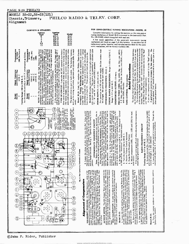
PAGE 9-24 PHILCO MODELS 38-22,38-23(121) Chassis,fimmers, PIIILCO RADIO & TELEV. CORP. Alignment
Speaker Model
HR -2l 38-23 KR -28 38-22 KR -27 38-23 HR -2l 38-23 HR -22 38-22 KR -28 38-22
FOR CONE -CENTRIC TUNING MECHANISM-MODEL, 22
Complete information for setting the stations on the cone -centric tuning mechanism of Model 38-22 is covered in the instruction Part No. (39-5533B) which is supplied with each set.
A few major aaaemblies of the automatic cone -centric tuning mechanism are listed on page 3 of this bulletin. A complete list of replacement parts, however, and detailed service data for the auto- matic mechanism, will be found in bulletin 282.
©John F. Rider, Publisher
www.americanradiohistory.com
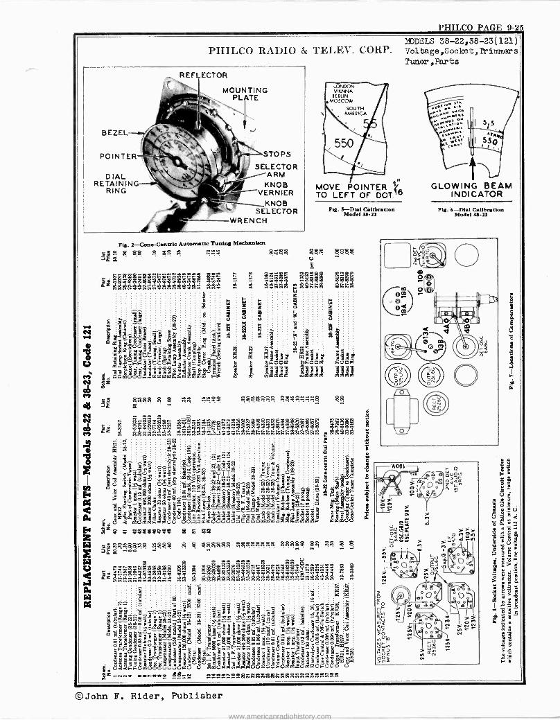
PHILCO PAGE 9-25
23.IDDL'LS 38-22,38-23(121) PHILCO RADIO & TELEV. CORP. Voltage,Socket,Trimmers
Tuner,Parts REFLECTOR
STOPS
SELECTOR ARM
KNOB KNOB VERNIER
KNOB SELECTOR
WRENCH
s$ssses öabo g
ß 3gßßßßß ßßßßßßßß ßgß83 88 ßß S 8
©John F. Rider, Publisher
www.americanradiohistory.com
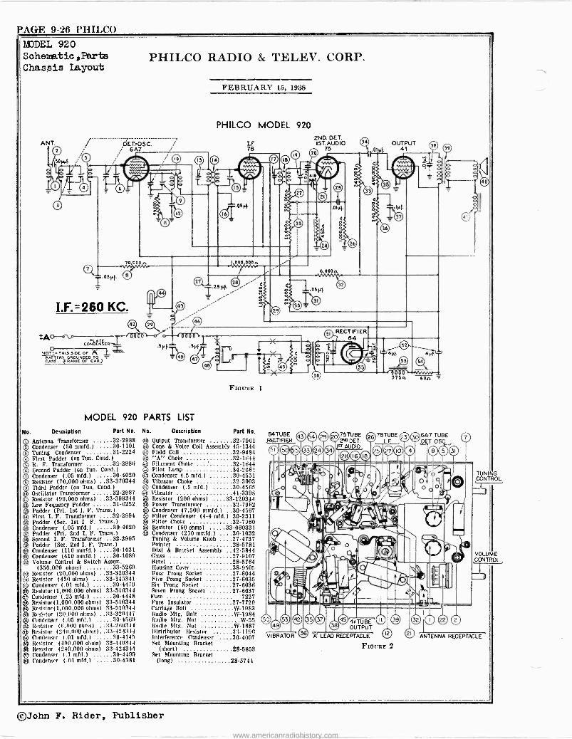
F'AGE 9-26 PHILCO MODEL 920 Sahematio,Parts Chassis Layout
ANT.
PHILCO RADIO & TELEX. CORP.
/ DET-OSC. 6A7
I.F.=260 KC. 42 22
AT- P`ATE
_VVVV VVVVV
CONOENSCR 8µl
NOTE. THIS SIDE Or A 1 1
BATTERY GROUNDED TO CASE. (FRAME OF CAR)
MODEL 920 PARTS LIST
No. Description Part No.
Antenna Transformer 32-2988 Condenser (50 mmfd.) 30-1101 Tuning Condenser 31-2224 First Padder (on l'un. Cond )
R. F. Transformer 32-2986 Second Padder (on Tun. Cond.) Condenser (.05 mfd.) 30-4020 Resistor (70,000 ohms) .33-370344 Third Padder (on Tun. Cond )
Oscillator Transformer 32-2987 Resistor (99,000 ohms) ..33-399344 Low Fequency Padder 31-6252 Padder (Pri. 1st I. F. Trans )
First I. F. Transformer 32-2994 Padder (Sec. 1st I. F. Trans.) Condenser (.05 mfd.) 30-4020 Padder (Pri. 2nd I. F. Trans.) Second I. F. Transformer 32-2995 Padder (Sec. 2nd I. F. Trans.) Condenser (110 mmfd.) 30-1031 Condenser (410 mmfd.) 30-1089 Volume Control & Switch Assem.
(350,000 ohms) 33-5269 Resistor (20,000 ohms) ..33-320344 Resistor (450 ohms) ....33-145341 Condenser (.01 mfd.) 30-4479 Resistor(1,000,000 ohms) 33-510344 Condenser (.25 mfd.) 30-4448 Resistor) 1,000,000 ohms) 33-510344 Resistor) 1,009,000 ohms) 33-51034-1 Resistor (211,000 ohms) ..33-320447
gCondenser 1.05 mfd.) 30-4500 Resistor (0.000 ohms) ..33-260344 Resistor (2411.000 ohms) ..33-424344 Condenser (.01 mfd.) 30-4145 Resistor (490,000 ohms) 33-449344
g Resistor (240,000 ohms) 33-424344 e Condenser (.1 mfd.) 30-4409 Condenser (.01 mfd.) 30-4381
e © o o o o o o o D QI t, z. D
db .T.
D .L
.,
FEBRUARY 15, 1938
PHILCO MODEL 920
Lf. 78
1.000 000n
FIGURE 1
No. Description Part No.
Output Transformer 32-7961 Cone & Voice Coil Assembly 45-1344 Field Coil 32-9484 "A" Choke 32-1644 Filament Choke 32-1644
a Pilot Lamp 34-206! Condenser (.5 mfd.) 30-4551 Vibrator Choke 32-3003 Condenser (.5 mfd.) 30-4565 Vibrator 41-3395 Resistor (200 ohms) ....33-120394 Power Transformer 32-7962 Condenser (7,500 mmfd.) 30-4567
s Filter Condenser (4-4 mfd.) 30-2311 Filter Choke 32-7960 Resistor (60 ohms) 33-060331 Condenser (250 mmfd.) ....30-1032 Tuning & Volume Knob ....27-4737 Pointer 28-5781 Dial & Bracket Assembly 42.5844 Glass 27-9107 Bezel 28-5764 Housing Cocer 38-9505 Four Prong Socket 27-6044 Five Prong Socket 27-6035 Six Prong Socket 27-6036 Seven Prong Socket 27-6037 Fuse 7227 Fuse Insulator 27-7729 Carriage Bolt SV -1983 Radio Mtg. Bolt W-1984 Radio Mtg. Nut W-55 Radio 511g. Nut W-1687 Distributor Resistor 3:1-1190 Interference Condenser 30-4007 Set Mounting Bracket
(short) 28-5853 Set Mounting Bracket
(long) 28-5744
84TUBE RECTIFIER
2ND.DET. 1ST. AUDIO 34
75 .01 1 f 1
OUTPUT 41
IVVVV- 3750. óon
.0 0 © 2"DDET. 2 30 78TFBE DET OS
tsT AUD 0 _o®mo m0m ©® 11 1 ' 41111 -Ì11
'V-I'47-OR. 0 A' LEAD RECEPTACLE
Flaunt 2
TONI G CONTROL
VOLUME CONTROL
ANTENNA RECEPTACLE
©John F. Rider, Publisher
www.americanradiohistory.com
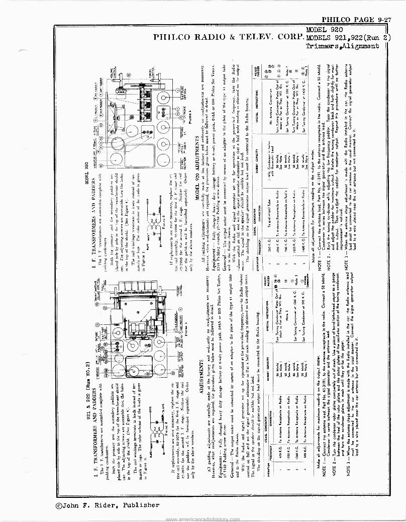
a e 772
v
m G F
ó 4 5 0,7,:¡
qq.c w'6m 5 Ó
# ...°.,. b
2 ` e S e
m
gw w$.g= a ä mx á 1.1..1::...5.4
Co m ^ ó Íh 8Y â ç a:M ä 2 ..°k:
8 m
ú ñ.. C
i,$ ó.o y^ wv-; 8 E.5 S w 6'0
º2. E.s ç 6d.9 F G >. . `>
° .e ÿ t 6'5 ` ...2e 1-2 v s° m s e I v
¡w .« zmrs gör cm>.
°s9Feç =zC^
S
PHILCO PAGE 9-27
PHILCO RADIO & 'rELEV. CORP. moDELS 921,922(Run 2I)
°.. ; s`' g á á
Ji. a
F ó iº
m ° m
w .r «
o
8 8 ê o° ° 3; 8. :
ek e3 g G
bé o « ...9
m .'°c.
m d 5 y º
Ó Ó ^ o q I gK á
'w . q ' a ä °
3 O 3
rá y S# ¿ ¿' . 5Z.: 4 A m 9 5.2.
ó ] 35 ó ó < ^'a 3 " g f° ` é 2.:§
°O.g,a^
9e ¡.,oáog á
` c
m é $ $ Tqyy °
$''8-° ° . °: :; ° O ,..6 "7b °' Sb m /z.,1 1
ó yc v Á P,e` °, 1 qg o
m.: á ç' :F a E' .
"E:.,e 41é
.574 Eÿ
á
E` K°v te -'0". ^ a
o2 á mmmá
m ó_w
é c « 1
6 2:.4-':-. +gp ó TO, _t,.:- ótlow. cq 9 w m S°
é
év W 1
C°p;cPeam '- $ Ê j C86
3 C ásl « 8
ú 2...:.ki ,lis§F_E , ºE 7:, :-'aa és3;g
rr; m w . q >é --
14... ; q ¡ 9
ú F ó c ci p R7 ú" y
p, _o ä
° q
I; .5 á Y
2_, Oa. á wJ
5.3 m, 2-1 ó m
79 é ^.4'9 .8 .
rs ú m 5 ó .°e
li ó .i w ._ o é a
4111111 ° q 15 A =
¿ G g ä á' >. ó &ÿ á
F é «
S ° 3, i
. a mé $ -3.21 qa. 1. 41 sáqqII.
óA 0 öó mo _ú 8 Z ->"§é
$ á.8 y c g E
1 ° F4-8 g m ¡
-5 V. Çm .2°°
I9 rJ q
á 8 .o .
'> s á: 5 1-3 9
é m " ° ° o q o. c
0 d °° :a C .7 é b
1 . 2 á
a s 3c Én = Q q " ó Y
ó..1,''' 4i+
2 3 gPg
v H cÿ v á GF
MODEL 920
Tr immer s,Alignment
2 2 e<
á - 11
E
! '
( < <
4.3 V d ,z
SS S e, §
e
II
C
I Z Ii Ii IZ' 8.x 8J!
ó
E
8
S 8
w a m - ó É? `c á
ï . `c ó o 01.
m
0 - m&
:3 ó o
«
11 Ñ ó
m 4 .VY m `m 0 o m ^
.E,2 m
á ` o` v z E c
-É .7,-2.2f « q
E : ú
«eq¿' « 2-1; mm[
É « ó 'ee5
71.
° v
Y °°éEo_ Eriec5á
m é« « +E
1m_»° °v2
»
2111 o,a 12
y q m
q ° ° E ÚU ai ° - ó É E 3 d-8 .1 1 1 1 m
ó I- ó z z z
T f
É 7,2 8 « m m ó
eo 5 5 ó
ó é o o
ñ« ï m
éj °C á 0 ó. óf
x o.° ° cm °
II D ¡ ó_ Eó
O ÿ ° U ñe 149a; óé 8 as c ó °.
c ó E r v °c
.e m« r á m o: o
ú É » ák 5
1311V-
-2
'3,cri m o é # ; v m. # ac c c
m ó
03' og
`E-
cEá$ ú
s` 11.1 E ñ¿3 á# . 1311,i: 5.3
q
E ó aóú em óa á cs «¿
T m«° `E m m m m o
t55452-'": : o`
m 5 Q` EV °ty m
(.i y
I.JYJ-_.:3É24
á m I I I
2 ó ó 0 Z Z Z
©John F. Rider, Publisher
www.americanradiohistory.com
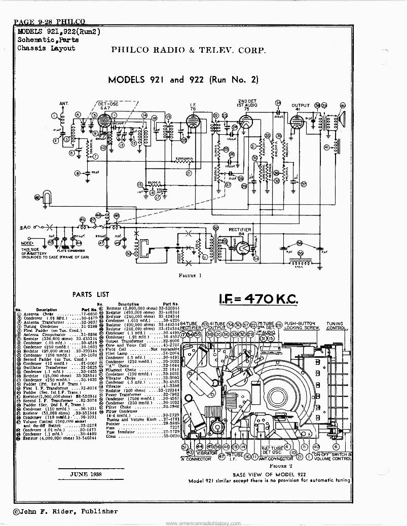
PAGE .9-28 PxILCQ.
O o o o o o o o o D m .s1
o
MODELS 921,922(Run2 Sohenatio,Parts Chassis Layout
ANT.
PIIILCO RADIO & TELEV. CORP.
MODELS 921 and 922 (Run No. 2)
DET-OSC 7 / 6A7
,/(5) fi E //Ipp
gilt OHe tp 2 T cr
rl _Z astir
tAo
O .syfy esouvr
NOTE. 1_gIIT ICJ THIS SIDE PLATE 00N0ENSER OF íA GATTE Rr GROUNDED TO CASE (FRAME OF CAR)
o. Description Antenna Choke Condenser (.01 MN.)
Esovyl .atif
e)-."
PARTS LIST
I.F 78
Ftctrnr; 1
No. Description Part No.
Part No. ® Resistor (2,000,000 ohms) 33-520344 77-0050 6 Resistor (490,000 ohms) 33-449344 30-44ï9 Resistor (240,000 ohms) 33-424344
Tuning Condenser 31-2288 First Fodder (on Tun. Cond )
Antenna Compensator 31-6260 Resistor (330,000 ohms) 33-433344 Condenser (.05 mfd.) 30-4519 Condenser (250 mmfd.) 30-1032 Resistor (99,000 ohms) .33-399344 Condenser (250 mmfd.) 30-1032 Second Padder (on Tun. Cond.) Condenser (12 mmfd.) 61-0007 Oscillator Transformer 32-3025 Condenser (.1 mfd.) 30-4455
G) Resistor (25,000 ohms) 33-325544 gCondenser (250 mmfd.) 30-1032
a Padder (Prl. 1st I.F. Trans )
First I. F. Transformer 32-3074 Padder (Sec. 1st I.F. Trans )
Resistor (2,000,000 ohms) 83-520344 Second I. F. Transformer 32-3076
á) Padder (Sec. 2nd I. F. Trans.) ® Condenser (110 mmfd.) .30-1031
. Resistor (51,000 ohms) ..33-351344 ®® Condenser (110 mrefd.). 30-1031
Volume Control (500,000 ehme) and On -OR Switch 33-5278
e Condenser (.01 mrd.) 30-4479 Condenser (.1 mfd.) 30-4499 Resistor (4,000,000 ohms) 33-540344
Cone and Voice Coil Field Coil Pilot Lamp Condenser (.5 mfd.) 30-4491 Condenser (250 mmfd.) 30-1032 "A" Choke 32-1644 Filament Choke 32-1644 Condenser (250 mmfd.) 30-1032 Vibrator Choke 32-300:1 Condenser (.5 mfd.l 30-4565 Vibrator 41-3398 Resistor (200 ohms) ....33-120344 Power Transformer 32-7962 Condenser (7500 mmfd.) 30-4567 Condenser (250 mmfd.) 30-1032 Filter Choke 32-7960 Filter Condenser (4-4 mmfd.) 30-2329 Tuning and Volume Knob 27-4761 Pointer 28-5969 Fuse 7227 Fuse Insulator 27-7729 Glass 55-0020
Resistor (490,000 ohms) 33-449344 Resistor (240,000 ohms) 33-424344 Condenser (.1 mid.) 30-4499 Condenser (.01 mid.) 30-4501 Output Transformer 32-8000
45-2707 Not replacable
34-20114
JUNE 1938
2ND. DET IST AUDIO
75 OUTPUT 9 4)
oisyr.
4vF 4tiF
d806006k- 175n
I.F = 470 K.C.
84TUBE 53 41TUBE RECTIFIER OUTPUT
ß 7
(D4*, ED ®36©29
VIBRATOR
75TUBE 2M0 DET. I^ DI
ID
6A7 TUB DET.OSC
PUSH-BUTTON TUNING LOCKING SCREW CONTROL,
1 ,
O e Q 0 10 "O H aN-OFF"SWITC ® O VOLUME CONTROL ,NT CONNECTOR
FIGURE 2
BASE VIEW OF MODEL 922
Model 921 similar except there is no provision for automatic tuning
78TUBE I F.
Antenna Transformer 32-3037 Condenser (.015 mad) ....30-4226
©John F. Rider, Publisher
www.americanradiohistory.com
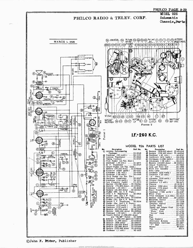
PHILCO PAGE 9-29 MODEL 926
x~41>
V 1
PHILCO RADIO & TELEV. CORP.
MARCH 1, 1938
ids o Hu a
>7N11/I7
a W g7.Q B4TUBE F-0 RECTIFIER
No. ©
Sohema.tio Chassis,Parts
10 ANTENNA RECEPTACLE
4ITUBE &A-7 TUBE
OUTPUT © DET OSC.
FIaoxE 2
K.C.
MODEL 926 PARTS LIST Description Part No.
Antenna Compensating Condenser 31-6248
Condenser (50 mmfd.) 30-1101 Antenna Transformer 32-2945 Tuning Condenser 31-2238 First Padder (on Tun. Cond )
Condenser (.05 mfd.) 30-4444 R. F. Transformer 32-2948 Second Padder (on Tun. Cond.) Resistor (70,000 ohms) ..33-370344 Condenser (6000 mmfd.) :.30-4467 Condenser (.05 mfd.) 30-4020 Condenser (.25 mid.) 30-9448 Third Padder (on Tun. Con )
Oscillator Transformer 32-2947 Condenser (110 mmfd.) 30-1031 Low Frequency Padder 31-6220 Resistor (99,000 ohms) ..33-399344 Resistor (70,000 ohms)..13-370344 Condenser (.05 mfd.) 30-4020 Resistor (25,000 ohms) 33-325344 Padder (Pri. 1st. I. F. Trans.) First I. F. Transformer 32-3013 Padder (Sec. 2nd 1. F. Tans.) Resistor (1,000,000ohms) 33-510344 Padder (Pri. 2nd I. F. Trans.) Second I. F. Transformer 32-3014 Padder (Sec. 2nd 1. F. Trans.) Condenser (110 mmfd.) 30-1031 Condenser (250 mmfd.) 30-1032 Resistor (25,000 ohms) ..33-325344 Resistor (330,000 ohms) 33-433344 Condenser (.01 mid.) 30-4479 Volume Control (1,000,000 ohms)
and "On -OR" Switch 33-5268 Resistor (1,000,000 ohms) 33.510344 Resistor (1,000 ohms) -.33-210344 Resistor (600 ohms) ..33-160331 Resistor (20,000 ohms) ..33-320344 Resistor (32,000 ohms) ..33-332444 Resistor (250,000 ohms) .33-424344 Condenser (.1 mfd.) 30-4122
No. Description Part No. Resistor (250,000 ohms) 33-424344 Resistor (500,000 ohms) 33-449344 Condenser (.01 mid.) 30-4145 Condensers (250 mmfd.) 30-1032 Condensers (4,000 mmfd.) 30-4185 Condensers (.05 mid.) 30-4454 Resistor (10,000 ohms) ..33-310344 Output Transformer 32-7958
íßc Cone and Voice Coll 45-2608 Field Coil Assembly 32-9263 Pilot Lamp 34-2040 Condenser (250 mmfd.) 30-1032 Condenser (.25 mid.) 30-4448
1i
"A" Choke 32-1374 Condenser (250 mmfd.) 30-1032 Vibrator Choke 32-2911 Condenser (.5 mid.) 30-4474 Vibrator 41-3170-3 Resistor (200 ohm) 33-120344 Resistor (150 ohms) 33-115344 Power Transformer 32-7958 Condenser (7500 mmfd.) 30-4587 Filter Choke 32-7959 Filter Condenser (4-4 mfd.) 30-2315 Resistor (120 ohms) ....33-112326 Reception Control 42-5850 Antenna Choke 32-1956 Complete Control 42-5840 Tuning Shaft 28-8871 Tuning and Volume Knob 27-4725 "Carline" Knob 27-4731 "Music" Knob 27-4732 "Speech" Knob 27-4733 Dial 27-5399 Fuse 7227 Fuse Insulator 27-7729 Distributor Resistor 33-1196 Interference Condenser 30-4007 "T" Bolt 28-6161 Washer W-2606 Nut W518
©John F. Ridere Publisher www.americanradiohistory.com
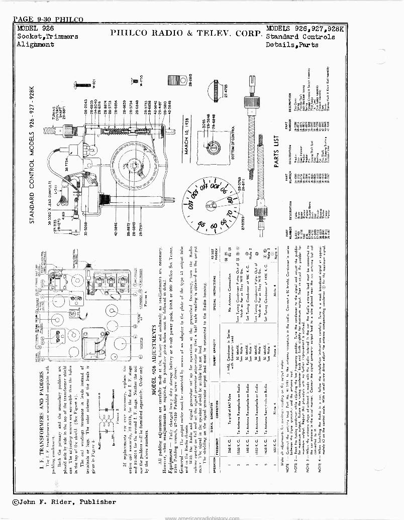
PAGE 9-30 PHILCO MJDEIS 926,927,928K PHILCO RADIO & TELEV. CORP. Standard Controls Details,Parts
©John F. Rider, Publisher
www.americanradiohistory.com
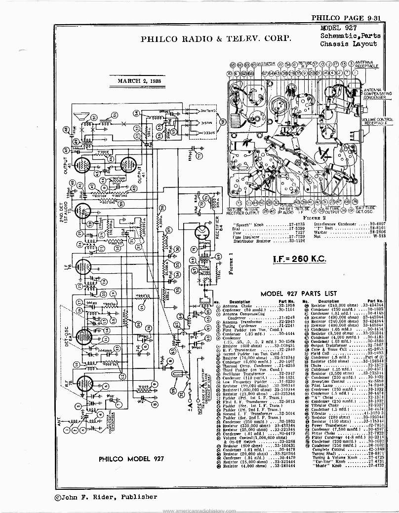
PHILCO PAGE 9-31
Z
v009,CJ
PHILCO RADIO & TELEV. CORP.
MARCH 2, 1988
v000'064 ,r000'ObZ
sr000 SZ
-iH11.44006s c'' HI'
000 OL
PHILCO MODEL 927
0>H 3 33d S
MODEL 927 Sohematic,Parts Chassis Layout
Q ,5 0 SVIBRATOR O78R F9E® 10 12 17 OANTENNA RECEPTACLE
Ir!J i'.rO%O©ou -.
14 41 U: jr
RECTIFIER OUTPUT 2cc DEI 78TUBE 4 TUB ISTAUDIO I.F©OUTPUT®
"Speech" Knob Dial Fuse Fuse Insulator Distributor Resistor
FIGURE 2
27-4733 27-5399
7227 27-7729 33-1196
ANTENNA COMPENSATING CONDENSER
VOLUME CONTROL RECEPTACLE
6-A-7 TUBE DET.OSC.
Interference Condenser 30-4007' "T" Bolt 28-6161 Washer 28-2606 Nut W-518
I.F:= 260 K.C.
MODEL 927 PARTS LIST No. Description Part Ne.
Qr Antenna Choke 32-1956 re Condenser (50 mmfd.) 30-1101
Antenna Compensating Condenser 31-6248
Antenna Transformer 32-2945 Tuning Condenser 31-2241 First Padder (on Tun.' Cond.) Condenser (.05 mid.) 30-4444
® Condenser (.25, .25, .5, .5, 2 mfd.) 30-4568
® Resistor (600 ohms) ....33-160431 Q R. F. Transformer 32-2946 50 Second Padder (on Tun. Cond.)
Resistor (70,000 ohms) ..33-370344 Condenser (6,000 mmfd.) 30-4467 Thermal Comp. Condenser 31-6253 Third Padder (on Tun. Cond.)
gOscillator Transformer 32-2947 Condenser (110 mmfd.) 30-1031 Low Frequency Padder 31-6230
iResistor (09,000 ohms) .33-399344 Resistor(1,000,000 ohms) 33-510344 Resistor (25,000 ohms) .33-325344 Padder (Pri. 1st I. F. Trans.)
CD First I. F. Transformer 32-3013 6 l'adder (See. 1st I. F. Trans.)
Padder (Pri. 2nd I. F. Trans.) Second 1. F. Transformer 32-3014 Padder (See. 2nd I. F. Trans )
Condenser (250 mmfd.) 30-1032 ® Resistor (330,000 ohms) 33-433344 ®® Resistor (25,000 ohms) ..33-325344
Condenser (.01 mfd.) 30-4479 ® Volume Control(1,000,000 ohms)
& On -OR Switch 33-5268 Resistor (600 ohms) ....33-160431 Condenser (.01 mfd.) 30-4479 Resistor (20,000 ohms) ..33-320344 Condenser (.01 mfd.) 30-4479 Resistor (25,000 ohms) ..33-325444 Resistor (4,000 ohms) ..33-240444
No. Description Part No. eResistor (240,000 ohms) .33-424344 Condenser (250 mmfd.) 30-1032 Condenser (.01 mfd.) 30-4145
fe Resistor (490,000 ohms) 33-449344 Resistor (240,000 ohms) 33-424344 Resistor (490,000 ohms) 33-449344 Condenser (.05 mid.) 30-4454 Resistor (3,500 ohms) ...33-235344 Condenser (4,000 mmfd.) 30-4185 Condenser (.03 mfd.) 30-4560 Output Transformer 32-7967 Cone & Voice Coil 45-2653 Field Coil 32-9493 Condenser (.5 mid.) Part of ® Resistor (500 ohms) 33-150344 Choke 32-1372 Condenser (.15 mid.) 30-4571
Q)
Resistor (3,500 ohms) ..33-235344 Condenser (250 mmfd.) 30-1032
e Reception Control 42-5850 ® Pilot Lamp 39-2040 Q Condenser (250 mmid.) 30-1032
ZCondenser (.5 mfd.) 30-4474 "A" Choke 32-1374
(e Condenser (250 tumid.) ... 30-1032 6Vibrator Choke 32-2537
3 Condenser (.5 mid.) 30-4474 ® Vibrator 41-3170-3 Q Resistor (200 ohms) 33-120344 ® Resistor (150 ohms) 33-115344
Power Transformer +
Condenser (7,500 mmfd.) 30-4567 Filter Choke 32-7822 Filter Condenser (4-8 mid.) 30-2316 Condenser (250 mmid.) 30-1032 Condenser (250 mmfd.) 30-1032 Complete Control 42-5840 Tuning Shaft 28-8871 Tuning & Volume Knob 27-4725 "Car -line" Knob 27-4731 "Music" Knob 27-4732
©John F. Rider, Publisher
www.americanradiohistory.com
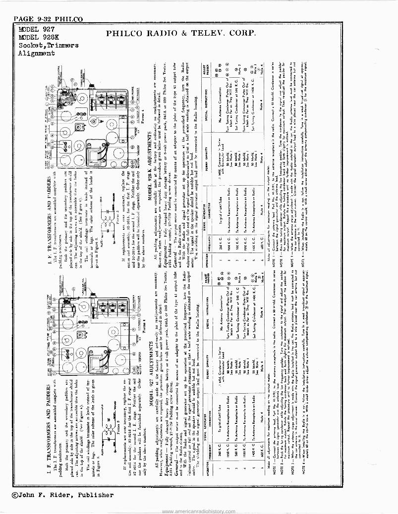
PAGE 9-32 PHILCO
MODEL 927 MODEL 928K Socket ,Trimmers Alignment
;=
PHILCO RADIO & TELEV. CORP.
á O C
á
: X ;á' 3 « . F é
a ,1ÿ 5:3 i g ê E é 3 á
3$ s e 9 3 O1 . gó 1,4
oM 5 á5 g
9 o ó m 3 t
3 $ á ? T" 1 5 P 3 58 ° 3 Aá
5x 8
e 9; : i, a 0
r ó m S eé$ ;4E....2
Ho é: $O1
r9=3é :11
P.
O.$ Aé+ ?« m é 34 :; A :,,e, g
r
O â : 3éo° n ÁAJE ep
. 08
:541 X C .ó épÿ 9ú
ó . m
` ; b 8 75
1'1 1°" 3
i S .i .g-,....;...4"é 6 i L+. 4 ór:0..7..
3 . gC IN . +I,lF . M . .-
xw mg;ÿ~ 5 ºé
3
1
E S
< 4 3 i .0 3 K
3 . g .
3
F F
: Z
d d d d d d Et Et Et Ei Ei
e e e 8 $
g
É
e el ® ® e
Ú
` Z
E
S
®Z ®e. ®j®j
2z jz lZ - . z2¡2,¡
g
g
d
g
d d ai º
i
Z
3
©John F. Rider, Publisher
www.americanradiohistory.com
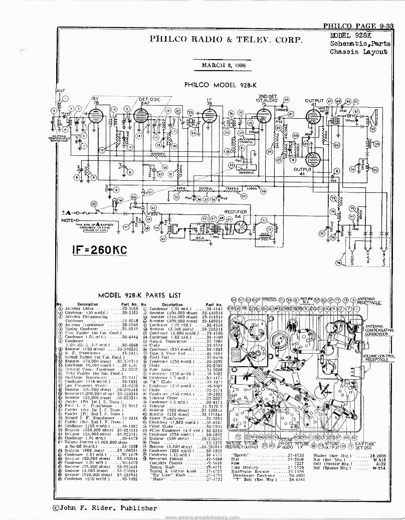
ANTENNA --- IPEMSATING ÿ OONOENSER bA
No. O o o
200000a
TRIS SIDE OEA BATTEAY OR(FRAMOVROED TO CASE.
E OE CAR )
IF=260KC
MODEL 928-K PARTS LIST
Description Part No. Antenna Choke 32-1956 Condenser (50 mmfd.) 30-1101 Antenna Compensating Condenser 31-6248
U Antenna Transformer 32-2945
s Tuning Condenser 31-2242 ® First Padder (on Tun. Cond.)
Condenser (.05 mfd.) 30-4444 ® Condenser
(.25-.25-.5-.5-2 mfd.) 30-4568 Resistor (600 ohms) ....33-160331 R. F. Transformer 32-2946 Second Padder (on Tun. Cond.) Resistor (70,000 ohms) .33-370344
13 Condenser (6,000 mmfd.) 30-4467 ® Thermal Comp. Condenser 32-6232 9 Third Padder (on Tun. Cond )
® Oscillator Transformer 32-2947 ® Condenser (110 mmfd.) 30-1031 Oti Low Frequency Padder 31-6230 O Resistor (99,000 ohms) .33-399344 ®o Resistor(1,000,0011 ohms) 33-510344 ®® Resistor (25,000 ohms) .33-325344
Padder (Pri. 1st I. F. Trans.) First I. F. Transformer 32-3013
® Padder (Sec. 1st I. F. Trans )
e,
Padder (Pri. 2nd I. F. Trans )
Second I. F. Transformer 32-3014 O Padder (Sec. 2nd I. F. Trans )
® Condenser (250 mmfd.) 30-1032 ® Resistor (330,000 ohms) 33-433344
Resistor (25,000 ohms) .33-325344 Condenser (.01 mfd.) 30-4479 Volume Control (1,000,000 ohms & On -0H Switch) 33-5268 Resistor (600 ohms) ....33-160331 Condenser (.01 mfd.) 30-4479 Resistor (20,000 ohms) .33-320344 Condenser (.01 mfd.) 30-4479 Resistor (25,000 ohms) .33-325444 Resistor (4,000 ohms) ..33-240444 Resistor (240,000 ohms) 33-424344
+a Condenser (250 mmfd.) 30-1032
o Ilt
MARCH 3, 1938
PHILCO MODEL 928-K
20000n
No. Description Part No. ® Condenser (.01 mfd.) 30-4145 ® Resistor (490,000 ohms) 33-449344
Resistor (240,000 ohms) 33-424344 Resistor (490,000 ohms) 33-449344 Condenser (.05 mfd.) 30-4454 Resistor (3,500 ohms) .33-235344 Condenser (4,000 mmfd.) 30-4185 Condenser (.03 mfd.) 30-4560 Output Transformer 32-7968 Choke 32-1374 Condenser (250 mmfd.) 30-1032 Cone & Voice Coil 45-2664 Field Coil 32-9493 Condenser (250 mmfd.) 30-1032 Choke 32-2535 Pilot Lamp 34-2040
O Condenser (250 mmfd.) 30-1032 A Condenser (.3 mfd.) 31)-4474 ® "A" Choke 32-1374 Ci Condenser 1250 mmfd.) 30-1032
Choke 32-1374 8 Condenser (350 mmfd.) 30-1032 te Vibrator Choke 32-2537
Condenser (.5 mfd.) 30-4474 Vibrator 41-3170-3 Resistor (200 ohms) 33-120344
t Resistor (150 ohms) 33-115344
O Power Transformer 32-7951 ® Condenser (7,500 mmfd.) 30-4567 O Filter Choke ... 32-7959
Filter Condenser (4-8 mfd.) 30-2316 Condenser (250 mmfd.) 30-1032 Resistor (500 ohms) ....33-150331 Choke 32-1372 Resistor (3,500 ohms) ..33-235344 Condenser (250 mmfd.) 30-1032 Condenser (.15 mfd.) 30-4571 Reception Control 42-5850 Complete Control 42-5810 Tuning Shaft 28-8871 Tuning & Volume Knob 27-4725 "Car Line" Knob 27-4731 "Music" 27-4732
I UB RECTIFIER OUTPUT
2ND.DET. 1ST. AUDIO
7.
ls000n 4000n
RECTIFIER 84)
IBR ' O
(9 3 (2 e Fi' -
pm -111 I
PHILCO PAGE 9-33
OUTPUT 41
78TUBEiel ® R.F
rain t F, ; aeod®Qo 'v'- 0 IÌ* AUDIO
el"-Ser
MODEL 928K Sohematic,Parts Chassis Layout
ov V° 9v
Z V W J J R Ñ ï a
V
00
"Speech" 27-4733 Dial 27-5399 Fuse 7227 Fuse Insulator 27-7729 Distributor Resistor :13-1196 Interference Condenser 30-4007 "T" Bolt (Rec. Mtg.) 28-6161
ANTENNA RECEPTACLE
ANTENNA COMPENSATING CONDENSER
VOWME CONTROL RECEPTACLE
IV
4 TUB 6A-7-11.)8EOUTPUT
19 DET.OSC.
Washer (Rec. 511g.) 28-2606 Nut (Rec. Mtg.) W-518 Bolt (Speaker Mtg.) 6122 Nut (Speaker Mtg.) W -55A
©John F. Rider. Publisher www.americanradiohistory.com
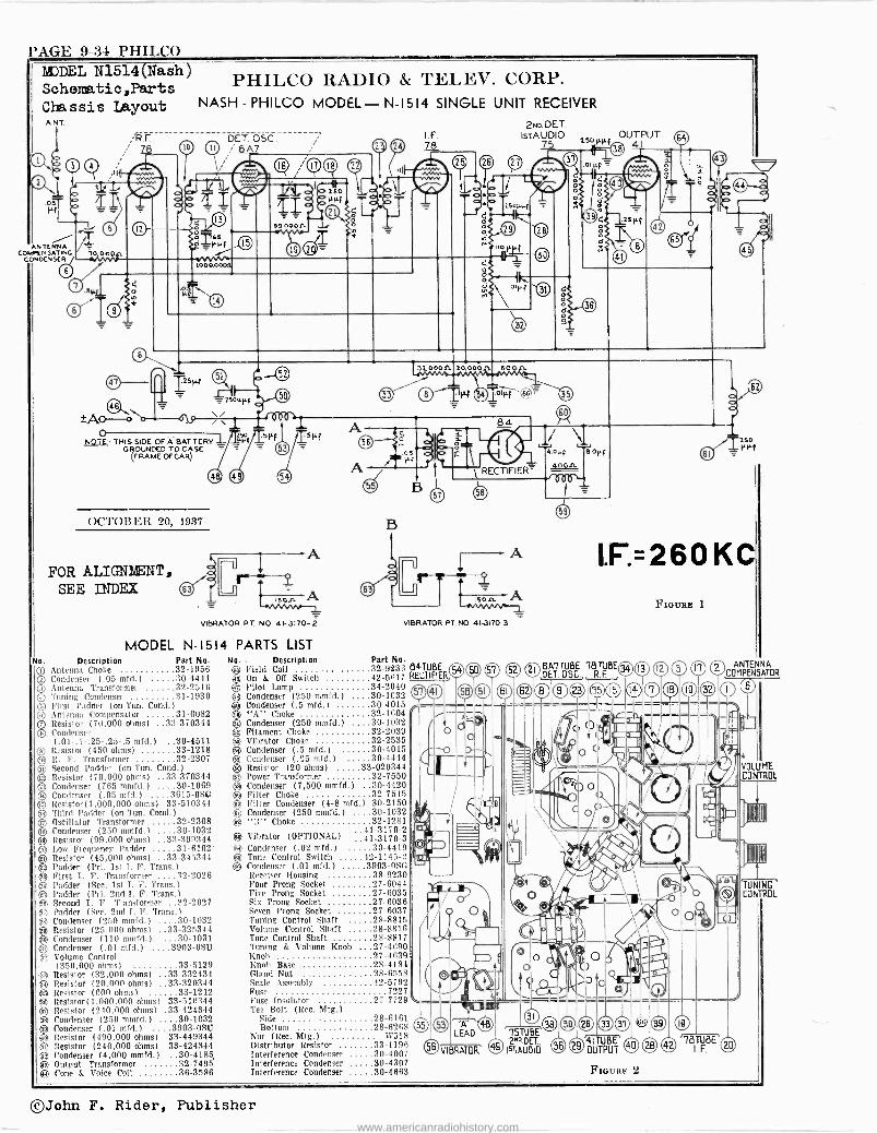
PAGE 9-34 PHILCO MODEL N1514(Nash) Schematic,Parts PHILCO RADIO & TELEV. CORP.
Chassis Layout NASH - PHILCO MODEL- N-1514 SINGLE UNIT RECEIVER
ANT 2No.DET.
ANTENNA COMPENSATING
CONDENSER
DET. OSC. A7
o ¡166 o v
W00,000l1
2501ÄH
±AO=-ò
NOTE:- THIS SIDE OF A BAT TERY GROUNDED TO CASE
FRAME OF CAR)
OCTOBER 20, 1937
FOR ALIGNIENT, SEE INDEX ter
No. Description
99.0001'
51'f
,son -A vwvv+L VIBRATOR PT. NO. 41-3170- 2
MODEL N-1514 PARTS LIST Part No.
0 Antenna Choke 32-1956 ® Condenser (.05 mfd.) 30-4444 ® Antenna Transformer 32-2516 ® Toning Condenser 31-1930 © First Fodder (on Tun. Cond.) ® Antenna Compensator 31-6082 ® Resistor (70,000 ohms) ..33-370344 ® Condenser
(.01-.1-.25-.25-.5 mfd.) 30-4511 ® Resistor (450 ohms) 33-1218
R. F. Transformer 32-2307 u Second Padder (on Tun. Cond.) ® Resistor (70,000 ohms) ..33-370344 © Condenser (765 mmfd.) 30-1069 O Condenser (.05 mfd.) .3615-0SG ® Resistor(1,000,000 ohms) 33-510344 ®Third Padder (on Tun. Cond )
93 Oscillator Transformer 32-2308 ® Condenser (250 mmfd.) 30-1032 93 Resistor (99,000 ohms) ..33-399344
i31-6Low Frequency Padder 102' Resistor (45,000 ohms) ..33-345344 Padder (Pri. 1st I. F. Trans.)
93 First I. F. Transformer 32-2026 e Padder (Sec. 1st T. F. Trans )
g Padder (Pri. 2nd I. Ir. Trans.) g Second I. F. Transformer 32-2027 3 Padder (Sec. 2nd T. F. Trans.) 1g Condenser (250 mmfd.) 30-1032 t3 Resistor (25,000 ohms) ..33-325344 g Condenser (110 mmfd.) 30-1031 e Condenser (.01 mfd.) ....3903 -OSI) g Volume Control
(350,000 ohms) 33-5139 9 Resistor (32,000 ohms) :.33-332434 93 Resistor (20,000 ohms) ..33-320344 93 Resistor (600 ohms) 33-1212 93 Resistor (1.000,000 ohms) 33-510344 g Resistor (240.000 ohms) .33-424344 54 Condenser (210 mmfd.) . 30-1032 ® Condenser (.01 mfd.) ...3903-OSU
Resistor (490,000 ohms) 38-449344 1 Resistor (240,000 ohms) 33-424344 9 Condenser (4.000 mmfd.) 30-4185
ar?j. Output Transformer 32-7495 9i Cone & Voice Colt 36-3586
I . F.
78
32. oson.
B
IsTA U DI O
\ RECTIFIER'
VIBRATOR PT. NO. 413170-3
No. - Description Part No. 93 Field Coil 32-9236 84TUBE ® On & OIT Switch 42-5617 RECTIFIER
© Pilot Lamp 34-2040 r ® Condenser (250 mmfd.) 30-1032 Q Condenser (.5 mfd.) 30-4015 ® "A" Choke 32-1004 ..-- g) Condenser (25Ò mmfd.) 30-1032
Filament Choke 32-2039 O ® Vibrator Choke 32-2535 B Condenser (.5 mfd.) 30-4015 ® Condenser (.05 mfd.) 30-4414 ® Resistor (20 ohms) 33-020344 Q Power Transformer 32-7550
Condenser (7,500 mmfd.) 30-4420 ® Filter Choke 32-7545 eo Filter Condenser (4-8 mfd.) 30-2150 el Condenser (250 mmfd.) 30-1032 ® "B" Choke 32-1281
..41-31770-2
..41-3170-3 ® Condenser (.02 mfd.) 30-4419 (c3,ß Tone Control Switch 42-1145-2 ® Condenser (.01 mfd.) 3903 -USC
Receiver Housing 38-9230 Four Prong Socket 27-6044 Five Prong Socket 27-6035 Six Prong Socket 27-6036 Seven Prong Socket 27-6037 Tuning Control Shaft 28-8815 Volume Control Shaft 28-8816 Tone Control Shaft 28-8817 Tuning & Volume Knob 27-4690 Knob 27-4639 Knob Base 28-4184 Gland Nut 28-6558 Scale Assembly 42-5792 Fuse 7227 Fuse Insulator 27-7729 Tee Bolt (Rec. Mtg.)
Side 28-6161 , Bottom 28-6268 55 53 '71'
Nut (Rec. Mtg.) W518 LEAD 15TUBE
Distributor Resistor 33-1196 58 VIBRATOR 49"o'.DEL. Interference Condenser 30-4007 IsTAUDIO
O
® Vibrator (OPTIONAL)
Interference Condenser 30-4307 Interference Condenser 30-4663
OUTPUT ºso HI. f 41
/ J IJ 4.orf a.orf 400n
1.r=260 KC
® 0 52 21 DÉT0RF BE Ö5C.,
51
36 29 OUTPUT
FIGURE 2
nouas 1
ANTENNA COMPEN5ATOR
I9
® OBTIF, USE'®
VOLUME CONTROL
'TUNING CONTROL
©John F. Rider, Publisher
www.americanradiohistory.com
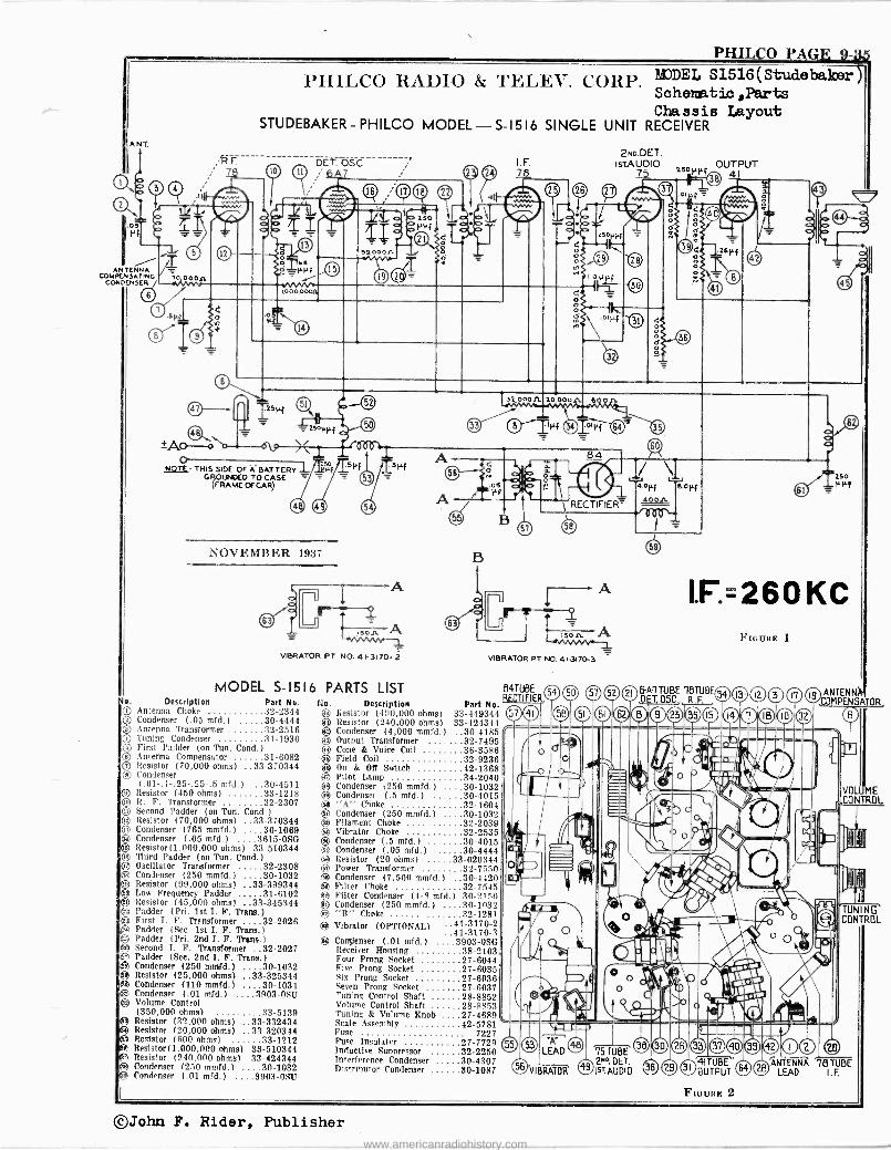
PHILCO PAGE 9-3e
A NT
a 0.
Pf
ANTENNA COMPENSATING
6
47
o NOTE- THIS SIDE OF A. BAT TERV -L
GROUNDED TO CASE (FRAME OF CAR)
PHILCO RAllIO &
STUDEBAKER - PHILCO MODEL-
DET. OSC.
í66 --PVf
~AA/ L000.0000
=2s0pf f \/
NOVEMBER 1937
r-: -- ss -11
i301i -vnn,,w r VIBRATOR PT NO. 41-3170- 2
MODEL S-1516 PARTS LIST No. Description Part No. ® Antenna Choke 32-2344 ® Condenser (.05 mfd.) 30-4444 ® Antenna Transformer 32-2516
Tuning Condenser 31-1930 First Padder (on Tun. Cond.)
® Antenna Compensator 31-6082 O Resistor (70,000 ohms) ..33-370344 ® Condenser
(.01-.1-.25-.25-.5 mfd.) 30=4511 ® Resistor (450 ohms) 33-1218 O R. F. Transformer 32-2307 u Second Padder (on Tun. Cond.) ® Resistor (70,000 ohms) ..33-370344 lI Condenser (765 mmfd.) 30-1069 I+ Condenser (.05 mfd.) 3615-080 Q Resistor(1.000,000 ohms) 33-510344
+o Third Padder (on Tun. Cond )
G Oscillator Transformer 32-2308 A Condenser (250 mmfd.) 30-1032
D Resistor (99,000 ohms) '..33-399344 ® Low Frequency Padder 31-6102 3) Resistor (45,000 ohms) 33-345344
Padder (Pri. 1st I. F. Traie.) } First I. F. Transformer 32-2026
h Padder (Sec. 1st I. F. Tram ) Padder (Pri. 2nd I. F. Trans )
ág Second T. F. Transformer 32-2027 3 Padder (See. 2nd I. F. Trans ) A Condenser (250 mad.) 30-1032
Resistor (25,000 ohms) ..33-325344 Pl Condenser (110 mmfd.) 30-1031 g Condenser (.01 mfd.) ....3903-0311 4 Volume Control
(350,000 ohms) 33-5189 A Resistor (32,000 ohms) ..33-332434 A Resistor (20,000 ohms) ..33-320344 PP Resistor (600 ohms) 33-1212 t Resistor(1.000,000 ohms) 33-510344 (ta Resistor (240.000 ohms) 33-424344 A Condenser (250 mmfd.) 30-1032
+A Condenser (.01 mfd.) ....3903 -Osti
1
rI'ELEV. CORP.
S-1516 SINGLE UNIT
MJDEL S1516(Studebaker) Schematic *Parts Chassis Layout
RECEIVER
2No.DET. I.E. IsTA UDIO 7 7 150PPf
32 00011
B
VIBRATOR PT. ND. 41-3170-3
No. Description Part No. . Resistor (490,000 ohms) 33-449344
Resistor (240,000 ohms) 33-424344 Condenser (4,000 mmfd.) ..30-4185
® Output Transformer ® Cone & Voice Coil ® Field Coil
On & Off Switch Pilot Lamp
32-7495 36-3586 32-9236 42-1368 34-2040
® Condenser t250 mmfd.) . 30-1032 ® Condenser (.5 mfd.) 30-4015
"A" Choke 32-1604 ®i Condenser (250 mmfd.) 30-1032 ® Filament Choke 32-2039 ® Vibrator Choke 32-2535 ® Condenser (.5 mfd.) 30-4015 153 Condenser (.05 mfd.) 30-4444
e Resistor (20 ohms) 33-020344 Power Transformer 32-7550 g Condenser (7,500 mmfd.) 30-4420 p Filter Choke 32-7545
Ed Filter Condenser (4-S mfd.) 30-2150 O Condenser (250 mmfd.) 30-1032 ® "B" Choke 32-1281 ® Vibrator (OPTIONAL) .41-3170-2
..41-3170-3 ® Cortfienser (.01 mfd.) ....3903 -OSO
Receiver Housing 38-2103 Four Prong Socket 27-6044 Five Prong Socket 27-6035 Six Prong Socket 27-6036 Seven Prong Socket 27-6037 "rn'ne Control Shaft 28-8852 Volume Control Shaft 28-8853 Tuning & Volume Knob 27-4689 Scale Assembly 42-5781 - Fuse Fuse Insulator
7227 27-7729 O Inductive Suppressor 32-2250
55 `' LEAD v. 75 TUBE Interference Condenser 30-4307 2ND: DET. Distributor Condenser 30-1087 VIBRATOR 4S
IsT.AUDIO
OUTPUT
250 Pl.`}
IF=260KC FIGURE 1
0 0 31 0 TPUT
FIGURE 2
ANTENNJl1 COMPENSATOR
VOLJME CONTROL
lODJ
TUNING CONTROL
ANTENNA 78 TUBE LEAD I.E.
©John F. Rider, Publisher
www.americanradiohistory.com
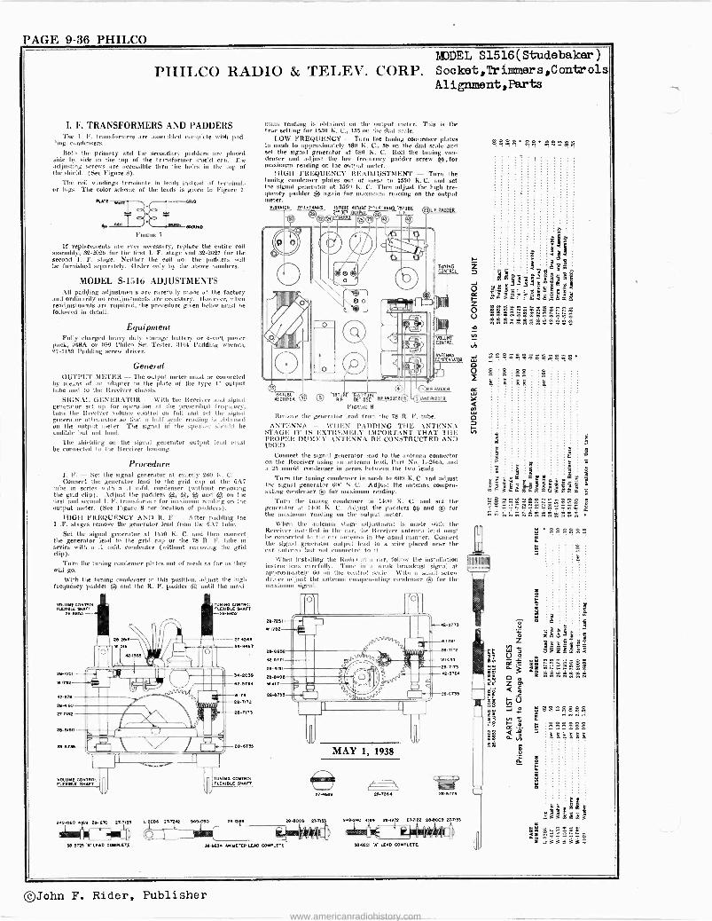
PAGE 9-36 PHILCO TAJDEL S1516(Studebaker)
PHILCO RADIO & TELEV. CORP. Socket,`IYimners,Controls Alignment,Parts
I. F. TRANSFORMERS AND PADDERS The I. F. transformers are assel.a led cmmp'ete with pad -
ling condensers.
Both the primary and the secondary padders are placed side by side in the top of the transformer shied can. l'he adjusting screws are accessible thru the hales in the top of the shied. (See Figure 8).
The coil windings terminate in leads instead of teralinn .:
or lugs. The color scheme of the lends is given in Figure 7.
RAM
M 24:
FIGURE 7
If replacements are ever necessary, replace the entire coil assembly, 82-2026 for the first I. F. stage and 82-2027 for the second 1. F. stage. Neither the coil nor the padders will be furnished separately. Order only by the above numbers.
MODEL S-1516 ADJUSTMENTS All padding adjustments are carefully made at the factory
and ordinarily no readjustments are necessary. However, when readjustments are required, the procedure given below must be followed in detail.
Equipment Fully charged heavy duty storage battery or 6 -volt power
pack, 048A or 099 Philco Set Tester, 3164 Padding wrench, 27-7159 Padding screw driver.
General OUTPUT METER - The output meter must be connected
by means of an adapter to the pinte of the type 41 output tribe and to the Receiver chassis.
SIGNAI, GENERATOR - With the Receiver and signal generator set up for operation at the prescribed frequency, turn the Receiver volume control on full and set the signal generator attenuator so that a half scale reading is obtained on the output meter. The signal idí the speaker shoo id be audible but nut loud.
The shielding on the signal generator output lead must be connected to the Receiver housing.
Procedure I. F. - Set the signal generator at exactly 260 K. C. Connect the generator lend to the grid cap of the 6A7
tube in series with' n .1 mfd, condenser (without removing the grid clip). Adjust the padders ®, ®, .r. and ® on the first and second I. F. transformer fur ua ximuua reading on the output meter. (See Figure 8 for location of padders).
HIGH FREQUENCY AND R. F. - After padding the I .F. stages remove the generator.lend from the 6A7 tube.
Set the signal generator at 1550 K. C. and then connect the generator lead to the grid cap of the 78 R. F. tube in series with n .1 tuft'. condenser (without removing the grid clip).
Turn the tuning condenser plates out of niesh as far as they will go.
With the tuning condenser in this position, adjust the high frequency padder ® and the R. F. padder ád until the maxi -
919 -0E0
`--U
A-3723 'A' tun CCAMETJ
mum reading is obtained on the output meter. This is the true setting for 155(1 K. C., 155 on the dial scale.
LOW FREQUENCY - Turn the tuning condenser plates In mesh to approximately 580 K. C., 58 on the dial scale and set the signal generator at 580 K. C. Roll the tuning con- denser and adjust the low frequency padder screw ®,for maximum reading on the output meter.
HIGH FREQUENCY READJUSTMENT - Turn the tuning condenser plates out of mesh to 1550 K. C. and set the signal generator at 1550 K. C. Then adjust the high fre- quency padder ® again for maximum reading on the output meter.
V10MTOR ir'.I.FTRANs. TSTUBE 41TaaE rAl F TRANS. IsTUBE KT rLF. P.!40.
© ̀ - ©©% rr
J snout TBTUBE 611 TUBE Nf PAODER RECTIFIER RF SET SEC
FuouE 8
Remove the generator lead from the 78 R. F. tube.
ANTENNA -- WHEN PADDING THE ANTENNA STAGE IT IS EXTREMELY IMPORTANT THAT THE PROPER DUMMY ANTENNA BE CONSTRUCTED AND USED.
Connect the signal generator lead to the antenna connector on the Receiver using an antenna lend, Part No. L-2665, and u 25 unnfd. condenser in series between the two leads.
Turn Ume tuning condenser in mesh to 600 K. C. and adjust the signal generator 6181 K. C. Adjust the antenna compen- sating condenser © fur maximum rending.
Turn the tuning condenser tó 14(0 K. C. and set the generator at 14101 K. C. Adjust the padders ® and ® for the maximum reading un the output meter.
When the antenna stage adjustment is made with the Receiver installed in the car, the Receiver antenna lead must be connected tu the car antenna in the usual manner. Connect the signal generator output lend to n wire placed near the car antenna but not connected to it.
When installing the Radio io a car, follow the installation instructions carefully. 'l'une in a weak broadcast signal at approximately 60 on the control scale. With a anull screw driver adjust the antenna compensating con tenser © for the maxi signal.
(1t 0
TUNING Nis
VOLASE METRO_
ANTENNAMPENSATCR
MAY 1, 1938
27+6199
IUD 27 -CC 039-090 assn 9 28.8099 27.7133
38-9234 AMMETER LEAD COMPLETE
m © ] R F RAMER
A PADDER
29-14 Mans
30 .24o 41M 211-IE72 CAME 294009 2T -T133
39ó221 'A' LEAD COMPLETE
sºse. ....
.. 2. . ! . . . ? ? g ?
e 8 88 k $ $g
3
c ä
mF é.d. isx'äSamB E
zd ^
z
8858
888888 fiflxfixB
Mee üie Ñ i S:33;14
©John F. Rider, Publisher
www.americanradiohistory.com
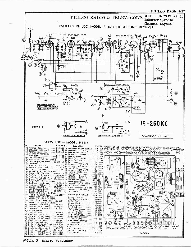
PHIICO PAGE 9-3'7
ANT.
ANTENNA COMPENSATING
CONDENSER
PHILCO RADIO
PACKARD - PHILCO MODEL P
T 78
NOTE-THIS SIDE OF A`BATTERY GROUNDED TO CUE FRAME OF CAR
FIOiJRE I
DET.OSC. 6A7
VIBRATOR PT. NO.41-317O4
7
& TELEX'.
- 1517 SINGLE
CORP. MODEL P1517 ( Pao kar d So helm tic ,Parts Chassis Layout
UNIT RECEIVER
I.F. 2WDET.I9TAUDIO so 's OUTPUT 78 75 1SOrrF 41
32 000.0. 20 000.0. .60 Oft
RECTIFIER
MAIL A VIBRATOR FT. NO. 413170-3
PARTS LIST - MODEL P-1517 O. Description Part No.flo. Description Part No. 841118E QQ Antenna Choke 32-2344 ® Condenser (4,000 mmfd.) ..30-4185 RECTIFIER, C) Condenser (.05 mid.) 30-4444
4
Condenser (.02. mfd.) 30-4419 Antenna Transformer 32-2516 Tone Control Switch 42-1383 ®Antenna Compensating Output Transformer 32-7495 Condenser 31-6082 Cone & Voice Coil 36-3586 © Tuning Condenser 31-1930 Field Coil Assembly 36-3597
e First Padder (on Tun. Cond.) On & Off Switch 42-1368 s Resistor (70.000 ohms) ..33-370344 Pilot Lamp 34-2039
C) Condenser ei Condenser (250 mmfd.) 30-1032 (.1-.25-.25-.5 mid.) 30-4415 ® Condenser (.5 mfd.) 30-4015 iResistor (450 ohms) 33-1218 A" Choke 32-253;1 R. F. Transformer 32-2307 ® Condenser (250 mmfd.) ..30-1032 Second Padder (on Tim. Cond.) ® Filament Choke 32-1604 Resistor (70,000 ohms) ..33-370344 g Vibrator Choke 32-2039 Condenser (765 mmfd.) 30-1069 Condenser (.5 mfd.) 30-4015 Condenser (.05 mfd.) .3815 -OSO Condenser (.05 mfd.) 30-4444 Resistor(1,000,000 ohms) 33-510344 ® Resistor (20 ohms) 33-020344 ® Third Padder (on Tun. Gond.) e3 Power Transformer 32-7550 ® Oscillator Transformer 32-2308 e) Condenser (7.500 mmfd.) ..30-4420 ® Condenser (250 mmfd.) 30-1032 © "B" Filter Choke 32-7545
iResistor (99,000 ohms) ..33-399344 m Filter Condenser (4-8 mfd.) 30-2150 Low Frequency Padder 31-6102 ® Condenser (250 mmfd.) ..30-1032 Resistor (45,000 ohms) 33-345344 ® "B" Choke 32-1281 Padder (Pri. 1st. I. F. Trias.) ..41-3170-2 First I. F. Transformer ...32-2026 ® Vibrator (OPTIONAL) ..41-3170-3 Padder (Sec. 1st I. F. Trans.) Receiver Housing 38-9150 Padder (Pri. 2nd I. F. Trans.) Pilot Lamp Assembly 38-8467
i®' Second I. F. Transformer ..32-2027 Tuning Shaft 28-8783 ä3 Padder (Sec. 2nd I. F. Trans.) Volume Shaft 28-8784
Condenser (250 mmfd.) .30-1032 Scale Assembly 42-5776 ® Resistor (25,000 ohms) ..33-325344 Gland Nut 28-6773 I® Condenser (110 mmfd.) ....30-1031 Four Prong Socket 27-6044 e Volume Control Five Prong Socket 27-6035
(350,000 ohms) 33-5139 Six Prong Socket 27-6036 ® Condenser (.01 mid.) ...3903-OSU Seven Prong Socket 27-6037 O Resistor (32,000 ohms) ..33-332434 Interference Condenser 3 Resistor (20,000 ohms) :.33-320344 (Dome Light) 30-4007 133 Condenser (.01 mfd.) ..3903 -OSO Interference Condenser
Resistor (600 ohms) 33-1212 (Generator) .30-4475 Resistor(1,000,000 ohms) 33-510344 Distributor Resistor 4851 Resistor (250,000 ohms) 33-424344 Fuse 7227 Condenser (250 mmfd.) 30-1032 Fuse Insulator 27-7729 (a Condenser (.01 mfd.) .3903-0SU Tee Bolt (Rec. Mtg.) 28-6268
n Resistor (500,000 ohms) 33-449344 Nut (Rec. Mtg.) W -518A ® Resistor (250,000 ohms) 33-424344
O
VIBRATOR
75 TUBE v 0. DET. Iv: AUDI O
P 7
TONE CONTROL
LE =260KC
OCTOBER 15, 1937
I ' ® 32 U PUT ® FsauRE 2
IS ANTENNA COMPENSATOR
VOLUME CONTROL
'TUNING' CONTROL
ANTENNA 78 TUBE LEAD I.F.
©John F. Rider, Publisher
www.americanradiohistory.com
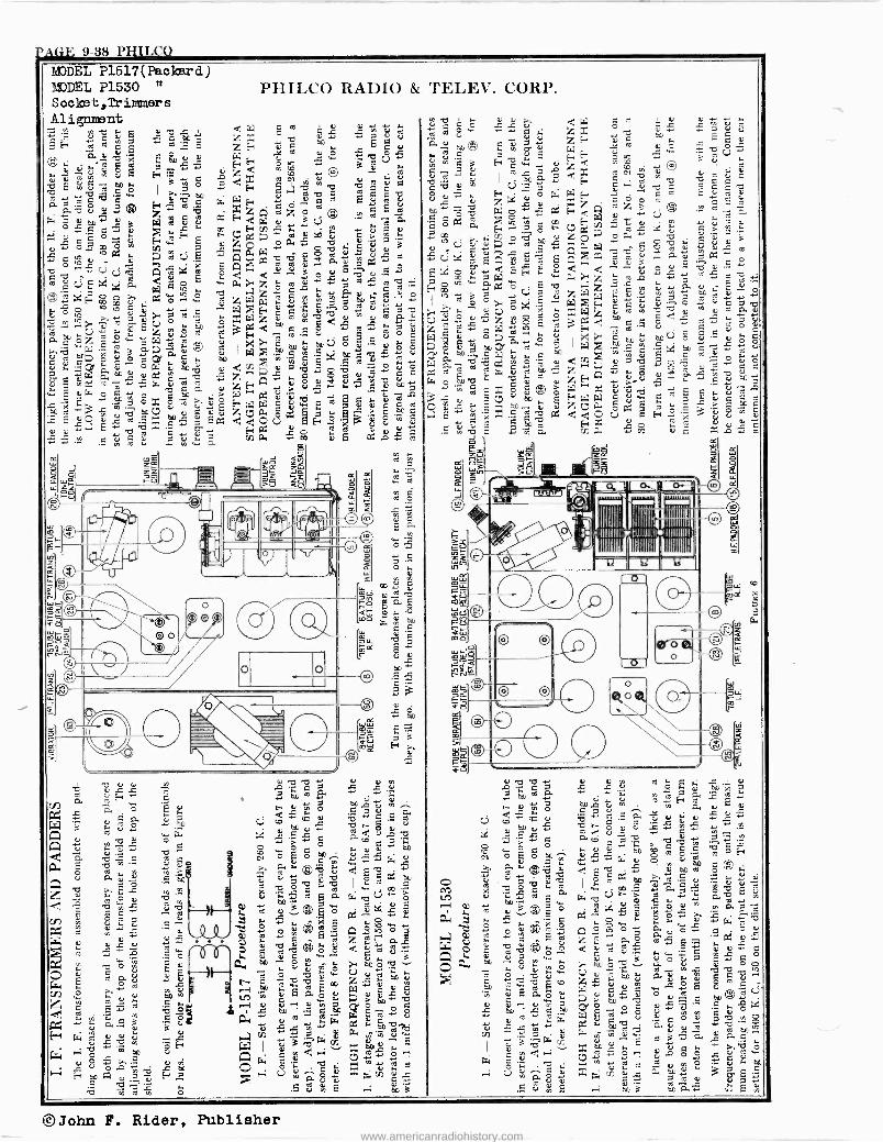
PAGE 9-38 PHIL CO
MODEL P1517(Paokard) MODEL P1530 " Socket,Trimmers Alignment
Ero i.
áE" m m é ? âo k d ÿ .
m c°i 6
'O E w e C w
á á eroe c ßb c V.é.«
Pi V Q ° O.Q+ 00 Q m
ÿ e o o
8 go' c °c
= ~ y 3 t-'
w2¿E F w F E
ÿ Qo 6 ro°2.e U V
m 27',1E1 ú E ád7 E r Q
®.e+ aCF Wg ú 4 w c^ .«o
c ° e, É V O
eön
°"z ów aQ w x .
a °] áG® O O. ([S¡y+
aCi FV. 'ÿQ+ G V O
e,E v..f`'., *+ÿ W úia wEw *w áU e
L E .1:0 V V *
PHILCO RADIO &
C e V V +
° ro cCi ÿ ÿ á? ce,
F a° e wo o QQQ ÿ ai Fd `° y a V 7 d x G Ñ %y ÿ O .d ld
geh G
E ÿ V' zQz3e® aeEá
k-,;4-00>1. Ói U *. m au.
u z 0 $ A+ ÿ ' wm Q g
* EAX : g2 0.E'ES d d 3 p u .
w Ì. z L. e V*+ .+ *'y ÿ e T% í*'r ÿ C, iö
z W re. °, v m eo ÿ -°-' º wZ E. V¿'C E^°+ V Q á ro
$Zrz2Z °° Q Q d ÿ e ÿ F? uc,
E go m c~, N: 0J ós ä y c c
ö.51 7Á C dm roE
Ó t . Ó
2 Q
7 óx ó madó w`"w dtiÿ ~ a.â V ^ eo [ V é ú aE, z ow.
á w p F á> co é
s t e x Q ÿ á E a d d o Ú Ey ' 3' 8 ÿ « Q E
Ñ W"6, . (n P. < E c á ÿ tQé
ZZV`Zf W6po
>S <U
O
o
II
V ro'Cy 5 ÿm4a .L.V+
iei g
c.5 cO Q ,t u e0 u *+
rYi -. > -, C
CO° C ° C ^ N Q V,
>. Q. r. ©E r. V ro aro wro
y `1)" e aq w R, e V ... f l
d O
2 F. ÿ M k Q .°.,
m ® e o ON. v 2á® ó
0. O0 ^
8 w V id Ñ
e wE
L E un w
s'-'.c m'igá á o
Q-,. seÿá. 41 e 2 8 a ;-,->5%.
á. d.v á. 51.1
éG 2"1^0 XrE V
TELEV. CORP.
z E ítö. y Q w u o
.` ó ac+ ave a, 'o W °' 2i e o ç E
9,'"M `'s 9 ET. p e0ro G ú y'y 5 V Vg e0 f. O u,L, v
E , d a
1,11g m º ÿ 'Ó E ÿ 0.
s
O:
/.
á
; 3
ÿÉv .roÚÿ a ^ r
e v 2 ro
E v g Qe E 2
v â >4d
u Ñ 12
ro 01 d o 's 8 L e
y o $ °' E ro u
e
F*' Q e
*' p e*'. w O. V
4' C^ p e *+
ro ° V á.
ó d ÿ Q e ÿ o V
V ú O 2 env ó ÿ
ç u ÿ ó
Ts V,
7 x Q e^ O Ñ Ó
V` t *' ro Q
P .-. E
V
a á d c G A E, L>QeoQ E++ 3-v8ÿ
íO e V V V Q
QYW
g e . o 1112M Q
A i
i I IIIIIrIITIlllll © 17' 11!t/ÌIIIIIIIIIÌÌIIIÌÌ'; I
L L+
U>
*' 'C
c e o
©John F. Rider, Publisher www.americanradiohistory.com
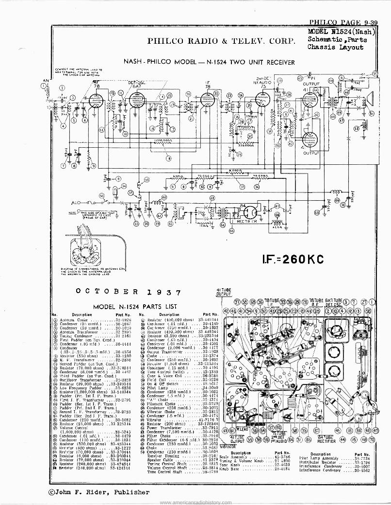
PHILCO PAGE 9-39
AN T
4 8
CONNECT THE ANTENNA ICAO TO NOS TERMINAL rOR USE WITH
TNC UNDER CAR ANTENNA
At
HpiC.OTHIS SIDE 0rA RATTERT ROUNDED TO CASE
(FRAME Or CAR)
,tir 78
PHILCO RADIO &
NASH - PHILCO MODEL - N-1524
S
9
DIAGRAM Or CONNECTIONS TO ANTENNA CO THE GREEN IS THE ANTENNA LEAD. THC BROWN IS THE GROUND LEAD
DETF: OSC. 16A7
OCTOBER 1 9 3 7
s. Description
MODEL N- 1524 PARTS LIST Part No.
r Antenna Choke 32-1926 s Condenser (25 mmfd.) 30-1067
Condenser (50 mmfd.) 30-1029 Antenna Transformer 32-2895 Tuning Condenser 31-2161 First Padder (on Tun. Cond.) Condenser (.05 mfd.) 30-4444 Condenser (.03-.1-.25-.5-.5-.5 mfd.) .30-4554
Os Resistor (550 ohms) 33-1280 o R. F. Transformer 32-2830 íQ Second Padder (on Tun. Cond.)
Resistor (70,000 ohms) .33-370344 O Condenser (6,000 mmfd.) .30-4467 ® Third Padder (on Tun. Cond.) ® Oscillator Transformer 32-2828 ® Resistor (99.000 ohms) ..33-399344 © Low Frequency Padder 31-6230 ® Resistor(1,000,000 ohms) 33-510344 ® Padder (Prl. 1st I. F. Trans.) ® First I. F. Transformer 32-2791 ® Padder (Sec. 1st I. F. Trans )
® Padder (Pri. 2nd I. F. Trans )
® Second I. F. Transformer 32-2793 e Padder (Sec. 2nd I. F. Trans )
Is Condenser (250 mmfd.) 30-1032 clip Resistor (25,000 ohms) ..33-325344 ® Volume Control
(1,000,000 ohms) 33-5245 Condenser (.01 mfd.) 30-4479 Condenser (110 mmfd.) 30-1031
® Resistor (330,000 ohms) 33-433344 ® Resistor (600 ohms) 33-1212 ® Resistor (70,000 ohms) ..33-370444 O Resistor (6,000 ohms) ..33-260344
eResistor (70,000 ohms) .33-370344 Resistor
(240,000 ohms) 33-424344 (240,000 ohms) 33-424344
O O O O o o
I. F. 78
I son
TELEV. CORP.
TWO UNIT RECEIVER
41 TUBE OUST
No. Description Part No.
® Resistor (490,000 ohms) 33-449344 Q Condenser (.01 mfd.) 30-4169 O Condenser (250 mmfd.) 30-1032 ® Resistor (490,000 ohms) 33-449344 Q Resistor (3,500 ohms) ...33-235344 8 Condenser (.05 mfd.) 30-4454
883 Condenser (.01 mfd.) 30-4501 iíß Condenser (2,000 mmfd.) 30-4177 ® Output Transformer 32-7928 Q Choke 32-1374 4'J Condenser (250 mmfd.) 30-1032 ® Resistor (1,500 ohms) ..33-215344
Condenser (.15 mfd.) 30-4191 Tone Control Switch 42-1389
(gi Cone & Voice Coil 36-3586 % Field Coil 32-9236 c. On & Off Switch 42-5617 ® Pilot Lamp ß4-3040 ® Condenser (250 mmfd.) 30-1032 O. Condenser 1.5 mfd.) 30-4474 ® "A" Choke 32-1374 ® Filament Choke ... 32-2729 ® Condenser (250 mmfd.) 30-1032 ® Vibrator Choke 32-2812 ® Condenser (.5 mfd.) 30-4474 ® Vibrator 41-3170-3
Resistor (200 ohms) 33-120344 ® Power Transformer 32-7911 ® Condenser (7,500 mmfd.) 30-4420 ® Filter Choke ® Filter Condenser (4-8 mfd.) ® Condenser (250 mmfd.) ... ® Choke ® Condenser (250 mmfd.) ...
Receiver Housing Speaker Cable 41-3378 Tuning & Volume Knob ....27-4690
28-8813 Tone Knob 27-4639 28-8814 Knob Base 28-4184 28-8798
2No.DET. ISTAUDIO
75
MODEL N1524(Nash) Schematic ,Parts Chassis Layout
OUTPUT
41
I.F=260KC
'18 TUBE I.F.
Tuning Control Shaft Volume Control Shaft Tone Control Shaft .. ,
32-7910 30-2258 30-1032 32-2657 y(B 30-1032 Description Part No. 38-2102 Scale Assembly 42-5786
R
2N4 DET. InAUD10
18TUBE EA') TUBE R.F DET.OSC.,
p3 S01
tP.-q----+
oa
RECTIFIER ® 15 ® Description Part No.
Pilot Lamp Assembly 38-7734 Distributor Resistor 33-1196 Interference Condenser 30-4007 Interference Condenser 30-4562
©John F. Rider, Publisher
www.americanradiohistory.com
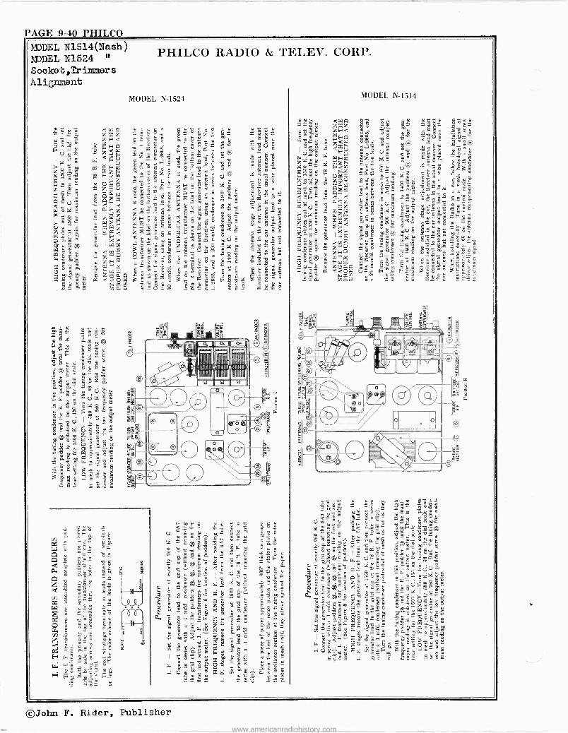
PAGE 9-40 PHILCO
PIIIILCO RADIO & TELEX'. CORP.
©John F. Rider, Publisher
www.americanradiohistory.com
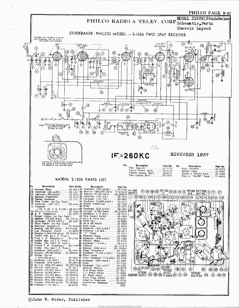
PHILCO PAGE 9-41
A
2
CONNECT THE ANTENNA LEAD TO NO.2 TCRUINAL roe USE WITH
THE UNDER CAR ANTENNA
PHILCO RADIO & TELEV. CORPSohe 51526(Studeba
Schemata Chassis Layout
STUDEBAKER-PHILCO MODEL-S-1526 TWO UNIT RECEIVER
Dff: OSC. /6A7
1,000,00CR
DIAGRAS. OF CONNECTIONS O ANTENNA COIL THE GREEN IS THE ANTENNA LEAD. THE DROWN IS THE GROUND LEAD
MODEL S-1526 PARTS LIST
Description Part Rollo. Antenna Choke 32-2063 Condenser (25 mmfd.) 30-1067 Condenser (50 mmfd.) 30-1029 Antenna Transformer 32-2855 Toning Condenser 31-2161 First Padder (on Tun. Cond.) O Condenser (.05 mfd.) 30-4444 3 Condenser
(.03-.1-.25-.5-.5-.5 mfd.) 30-4554 Resistor (550 ohms) 33-1280 R. F. Transformer 32-2810 e Second Padder (on Tun. Cond.) 0 Resistor (70,000 ohms) .33-370344 0 Condenser (6,000 mmfd.) 30-4467 10 Third Padder (on Tun. Cond )
Oscillator Transformer 32-2828 Resistor (99,000 ohms) ..33-399344 Low Frequency Padder 31-6230 Resistor(1,000,000 ohms) 33-510344 01 Padder (Pri. 1st I. F. Trans.) 01) First I. F. Transformer 32-2791 Padder (Sec. 1st I. F. Trans ) Padder (Prt. 2nd I. F. Trans ) Second I. F. Transformer 32-2793 Padder (Sec. 2nd I. F. Trans.) Condenser (250 mmfd.) 30-1032 Resistor (25,000 ohms) ..33-325344 Volume Control (1,000,000 ohms) 33-5251
Condenser (.01 mfd.) 30-4479 Condenser (110 mmfd.) 30-1031 Resistor (330,000 ohms) 33-433344 Resistor (600 ohms) 33-1212 Resistor (70,000 ohms) ..33-370444 Resistor (6,000 ohms) ..33-260344 Resistor (70.000 ohms) .33-370344 Resistor (240.000 ohms) 33-424344 Resistor (240,000 ohms) 33-424344 Resistor (490,000 ohms) 33-449344 Condenser (.01 mfd.) 30-4514
I. F. 78
.000 000
6.00011.
10, 000.0.
2No.DET. IsT.AUDIO
75
ft
RECTIFIER sou
1F:=260 KC
OUTPUT 41 (aal
p5 0. 20 p
r or
NOVEMBER 1937
No. Description Part No. No. Description Part No. Fuse Insulator 27-7729 Scale Assembly 42-5779 Tuning Control Shaft 28-8790 Speaker Cable 41-3231 Volume Control Shaft 28-8791 Tuning & Volume Knob ....27-4689 Tone Control Shaft 28-8792 Tone & "On -OR" Knob ...27-4618
Description Part No. Condenser (250 mmfd.) .30-1032 41 TUBE Resistor (490,000 ohms) 33-449344
OUTPUT Resistor (3,500 ohms) ...33-235344 Condenser (.05 mfd.) 30-4454 Condenser (.01 mfd.) 30-4501 Condenser (2,000 mmfd.) 30-4177 Output Transformer 32-7928 Choke 32-1374 Condenser (250 mmfd.) .. 30-1032 Resistor (1,500 ohms) ..33-215344 Condenser (.15 mfd.) 30-4101 Tone Control Switch 42-1389 Cone & Voice Coil 36-3526 Field Coil 32-9236 On & Off Switch 42-1369 Pilot Lamp 34-2039 Condenser (250 mmfd.) 30-1032 Condenser (.5 mfd.) 30-4474 "A" Choke 32-1374 Filament Choke 32-2729 Condenser (250 mmfd.) 30-1032 Vibrator Choke 32-2812 Condenser (.5 mfd.) 30-4474 Vibrator 41-3170-3 Resistor (200 ohms) 33-120344 Power Transformer 32-7911 Condenser (7,500 mmfd.) 30-4420 Filter Choke 32-7910 Filter Condenser (4-8 mfd.) 30-2258 Condenser (250 mmfd.) 30-1032 Choke 32-2657 Condenser (250 mmfd.) 30-1032 Receiver Housing 38-2058 Four Prong Socket 27-6044 Five Prong Socket 27-6035 Six Prong Socket 27-6036 VI Seven Prong Socket 27-6037 Inductive Suppressor 32-2250 Interference Condenser 30-4007 Fuse 7227
0, Q 78TUBE ® 9U m ei) 0 Ge r
LTUBE OUTPUT
57U 2"D DET. ISTAUDID RECTIFIERU ®
©John F. Rider, Publisher
www.americanradiohistory.com
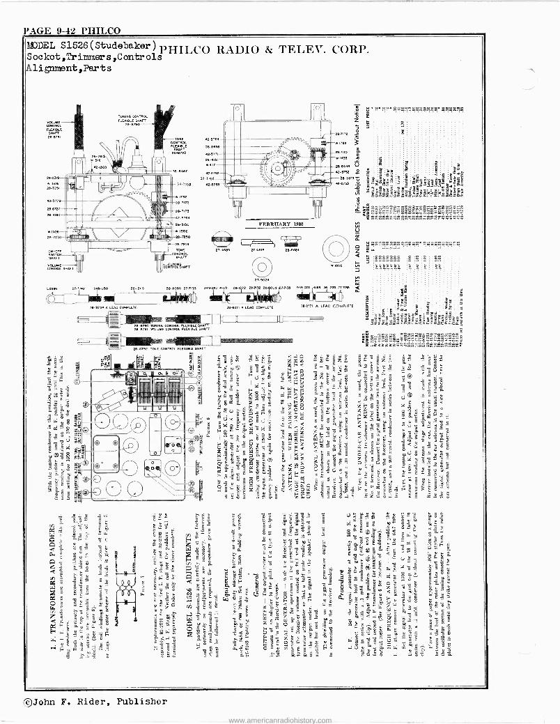
PAGE 9-42 PHILCO MODEL S1526(Studebaker) PHILCO RADIO & TELEV. CORP. Sooket,TrinnneaBs,Controls Alignmant,Parts
MOURNE CONTROL FLEXIBLE
FT Yl-BFBI
265339
w 1506 28-725
42-5779
2845727
284180
W 1508
28-7250
ON-OFF SWITCH SHAFT
VOLUME CONTROL SHAFT
TUNING CONTROL FLEXIBLE SHAFT
2-790
TONE CONTROL FLEXIBLE
SHAFT 28-6792
58-6407
42 5764
268
42-0771
28-4151
W417
423752 2-1407
4-7079 423755
C8º -74n
ºB-7175
42-5764
28-5150
'e?mmimmism _Ìw 1504
28-7250 ,- 28-7248
TONE
UUGNNOSNppiil
CONTROL
mmr c = e.
HV.2
4
27-7742
e
282 7155
- 118Mor
27-4489
28-6790 TUNING GON160L FLEXIBLE4IMFT 26-6791 VOLUME CON160L FLEXIBLE SHAFT
ÌiliIlli>aiE l ,,26-6,92
TONE CONTROL FLEXIBLE SHAFT
diei
5
u
o a
FEBRUARY 1098
7 27-4618 283684
o 27-9024
V; All
59-8ffiI A LEAD COMPLETE
1866
27-7133 1.9 213-1270 27-71501
78-6171 A LEAD COMPLETE
1 a I(
ti o ç a z C
3 é
72 60
ºX75 1455
29.7472
s o
Ó
1782
W T 43
º9-8496 V B75º 2 224407 r,
423755 m
N ffi
á
VI LM
U i
J N F C
. '4a..n 1 s
_Sh8wro8^ar,9e:9Sem_fflo
8888888 a 8 s ñ ä 2222222
g.
t $äa "8 SBe 33ämlm3m"ym3immGF.LIñ.2
, Fm gmro s _:L
_wágáá=:=rowro...ro
'John F. Rider, Publisher
www.americanradiohistory.com
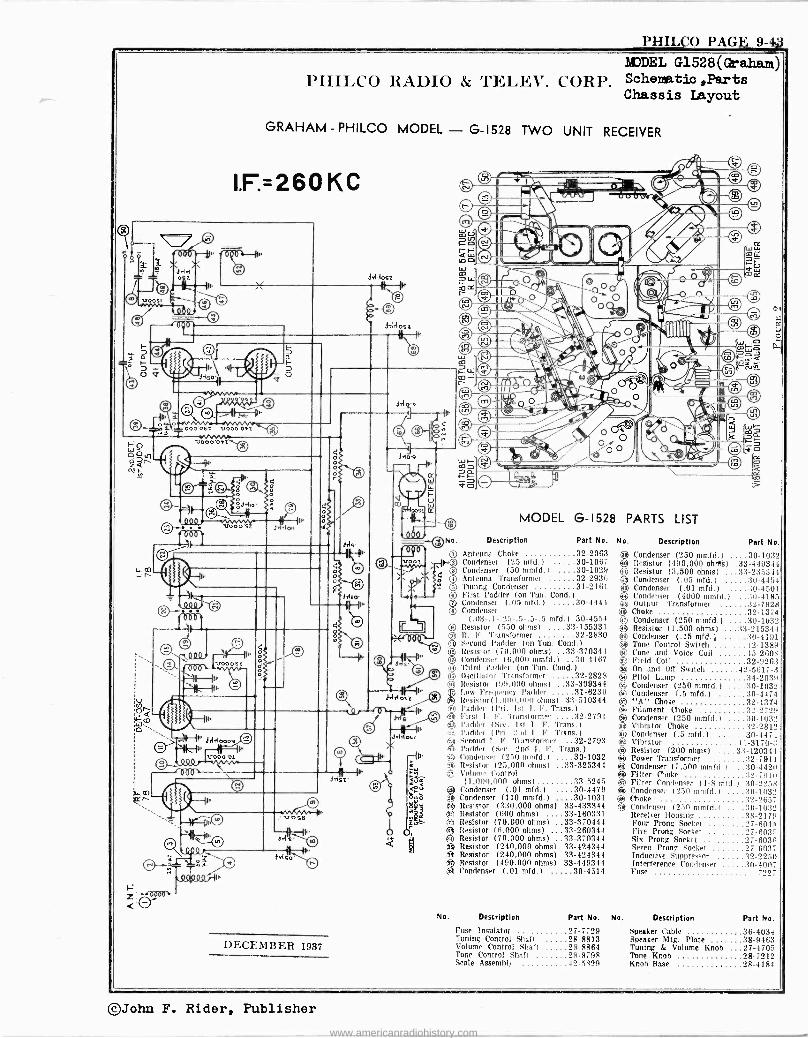
PHILCO PAGE 9-4j3.
D
r<
PHILCO RADIO & TELEV. CORP. MDDEL G1528(Graham) Schematic ,Parts Chassis Layout
GRAHAM .. PHILCO MODEL - G-1528 TWO UNIT RECEIVER
I.F:=26OKC
4
(: H
1.1-'N irre 1 l QQaQQj-114
ECEMBER 1937
3 rn
MODEL G- 152
Description Part No.
Antenna Choke 32-2063 Condenser (25 mfd.) 30-1067 Condenser (50 mmfd.) 30-1029 Antenna 'Transformer 32-2936 Tuning Condenser 31-2161 First )'adder (on Tun. Cond.) Condenser (.05 mfd.) 30-4444 Condenser
(.03-.1-.25-.5-.5-.5 mfd.) 30-4554 Resistor (550 ohms) ....33-155331 R. F. Transformer 32-2830 Second )'adder (on Tun. Cond.) Resistor (70,000 ohms) ..33-370344 Condenser (6,0011 mmfd.) .30-4467 Third )'adder (on 'L'un. Cond )
Oscillator Transformer 32-2828 Resistor (99,000 ohms) ..33-399344 Low Frequency )'adder 31-8230 Resistor( I ,000.000 ohms) 33-510344 )'adder (I'ri. lei I. F. Trans.) First 1. I, . Transformer 32-2791 ladder (See. 1st 1. F. 'Trans.) )'adder (Poi. 2nd I. F. Trans.) Second I. F. Transformer 32-2793 )'odder (See. 2nd 1. F. Trans.) Condenser (25(1 mntfd.) 30-1032 Resistor (25,000 ohms) ..33-325344 Volume Control (1,000,000 ohms) 33-5245
Condenser (.01 mfd.) 30-4479 Condenser (110 mmfd.) 30-1031 Resistor (330,000 ohms) 33-433344 Resistor (600 ohms) ..33-160331 Resistor (70,000 ohms) ..33-370444 Resistor (6.000 ohms) ...33-260344 Resistor (70.000 ohms) .33-370344 Resistor (240,000 ohms) 33-424344 Resistor (240,000 ohms) 33-424344 Resistor (490.000 ohms) 33-449344 Condenser (.01 mfd.) 30-4514
No. Description Part No.
Fuse Insulator 27-7729 Tuning Control Shaft 28-8813 Volume Control Shaft 28-8864 Tone Control Shaft 28-8798 Scale Assembly 42-5829
ta
8 PARTS LIST
No. Description Part No.
89 Condenser (250 mmfd.) ....30-1032 w Resistor (490,000 ohr8s) .33-449344 © Resistor (3,500 ohms) ...33-235344 © Condenser 1.05 mfd.) 30-4454 Ji Condenser (.01 mfdJ >t0-4501
Condenser (4000 mmfd.) a0-4185. 89 Output Transformer 32-7928 ® Choke 32-1374 Q Condenser (250 mmfd.) 30-1032 49 Resistor (1,500 ohms) ...33-215344 e Condenser (.15 mfd.) 30-4191 e Tone Control Switch 42-1389 Q Cone and Voice Coil 43-2608 ON Field Coil 32-9263 ® On and Off Switch 42-5617-:3 ® Pilot Lamp 34-2039 g Condenser (250 mmfd.I 30-1032 ä9 Condenser (.5 mfd.) 30-4474
"A" Choke 32-1374 Filament Choke 32-2_729
e Condenser (250 mmfd.) 3(1-1032 tek Vibrator Choke :32-2812 e Condenser (.5 mfd.) 10-4474 ® Vibrator 41-3170-3 ® Resistor (200 ohms) 33-120344 ® Power Transformer 32-7911 ® Condenser (7,500 mmfd.) :30-4420 e Filter Choke 32-7910 49 Filter Condenser (4-8 mfd.) 30-2258 4 Condenser (250 mmfd.) 30-1032 4. Choke 32-2657 e Condenser (250 mmfd.) 30-1032
Receiver Housing 3S-2179 Four Prong Socket 27-6044 Five Prong Socket 27-6035 Six Prong Socket 27-6030 Seven Prong Socket 27-6037 Inductive Suppressor 32-2250 Interference Condenser 30-4007 Fuse 722,
No. Description Part No.
Speaker Cable 36-4034 Speaker Mtg. Plate 38-9463 Tuning & Volume Knob 27-4705 Tone Knob 28-7212 Knob Base 28-4184
©John F. Rider,. Publisher
www.americanradiohistory.com
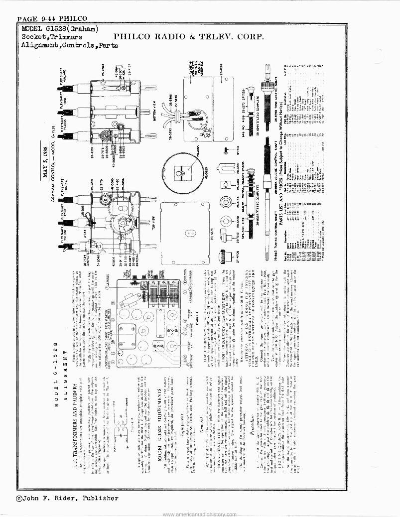
PAGE 9-44 PHILCO MODEL G1528(Graham) SOolflat,Trimmers YHILCO RADIO & TELEV. CORP. Alignment ,Controls ,Parts
ºº 1lt 4-1f11
©John F. Rider, Publisher
www.americanradiohistory.com
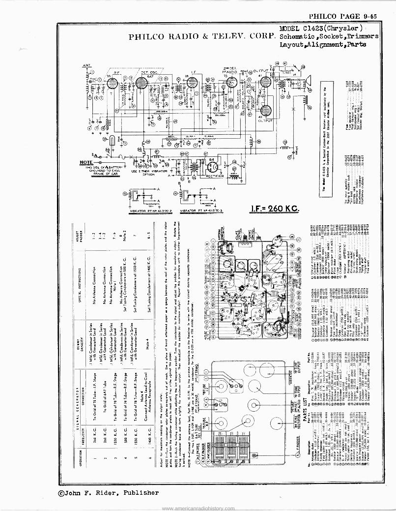
PHILCO PAGE 9-45
ANT
%78
NOTE
F.
THIS SIDE OFABATTERT GROUNDED TO CASE
FRAME OF CAR VIMIUMIMMIE!(
MODEL C1423(Chrysler) PHILCO RADIO & 'l'EI,EV. CORP. Scheme.l:ic,Socket,Trimmers
Layout,Alignment,Parts
4 u _ sx# USE EITHER VIBRATOR
OPTION A
A
I. F. 78
gro DET. xsa..t©OUT PUT I"AUDIO.
75 41
IJ
B
A
ns VIBRATOR PT.N..41-3170.2 VIBRATOR PT. NI, 41-3170.3
U
ö, -
osE 3
v `.c P
00 00 ÚU Ú0 ÚU -13 ,- NJ 4-
s _
Cl Ú Cl Ú Ú ][ Y
3 S 9 e
U
d
1.F.= 260 KC.
é +ii _11x I ©f'\ V% ®'welr)`E.r/' azos.;p,, ,. p
Iz m © UK ., `%,H p 0.. 6í' ee/ II rp ® es: 1111I;i!Ip p :A',l Sr
©Qitai `Q
:i,e`3i
II WU II IJ 0I IIII IIIII I
IIIIII !ÍIII
00©-its_;
22W dA...
=é â Ém z .. 6 .... .. C
bl382 áegitg eryo á - 2 a ssÜ2> ' ae« woe ®
~.$1-6 . .
ón.pó: sne ñ
9"g: . . .
emu= eetetemoemeeees
. ;11! s:B
ñáÑáá==ä m
É6 ..É
.:y..Éóçfi -6 É 2 3e 'É Ne
_ !ónDóóóo_
ÿV
=Nc-B Sº=âyfi: -2 e
^3_8_ óS
y E J °<i=4 g
Q CiEcCÚa>=âaM'cUC 3 J i ®g =met« Ñt N
25 d á e äÁ ÑäS äMälää
E rä - 7 I]Ñ
. ÉB
oB-ris sógá- :-oo " ..ri_mi_ i oN zIg:
s.uS ná é sas 00000044404144
É
0000000
©John F. Rider, Publisher
www.americanradiohistory.com
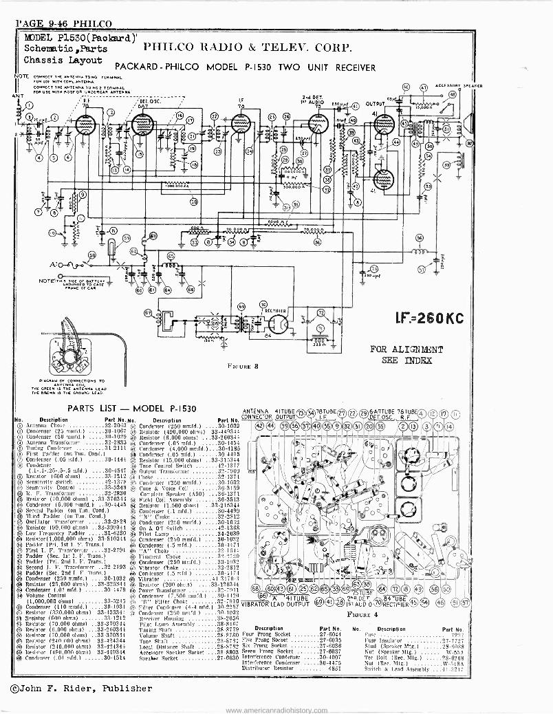
PAGE 9-46 PHILCO
i
MODEL P1530 (Packard )' Schematic ,Parts PIIII,CO RADIO & TELEV. CORP. Chassis Layout
NOTE
ANT
PACKARD - PHILCO MODEL CONNECT THE ANTENNA TO NQI TERMINAL FOR USE WITH COWL ANTENNA
CONNECT THE ANTENNA TO NO2 TERMINAL /OR VOL WITH ROOF OR UNDER CAR ANTENNA
R. E
; 7
b
A'p-6`y
NOTE''. OS SIDE OF BATTERY" GROUNE NDEOETCAD OR CASE
FRA
DIAGRAM OF CONNECTIONS TO NTENNA COIL
THE GREEN IS THE ANTENNA LEAD THE DROWN IS THE GROUND LEAD.
PARTS LIST - No. Description Part No.
QQ Antenna Choke 32-2063 Condenser (25 mmfd.) 30-1067 Cöndenser (50 mmfd.) 30-1029 Antenna Transformer 32-2833 Tuning Condenser 31-2111 First Padder (on Tun. Cond )
Condenser (.05 mfd.) 30-4444 Condenser (.1-.1-.25-.5-.5 mfd.) 30-4547
Resistor (600 ohms) 33-1212 Sensitivity Switch 42-1378 Sensitivity Control 33-5248 It. F. Transformer 32-2830
(70,000 ohms) _.33-370344 Condenser (6,000 mmfd. le. 30-4445 Second Padder (on Tun. Cond.)
I Third Padder (on Tun. Cond )
Oscillator Transformer 32-2828 Resistor (99,000 ohms) ..33-399344
D Low Frequency Padder 31-6230 Resistor(1,000,000 ohms) 33-510344
® Padder (Pri. 1st I. F. Trans.) ® First I. F. Transformer 32-2791 ® Padder (Sec. 1st I. F. Trans )
® Padder (Pri. 2nd I. F. Trans )
Q Second I. F. Transformer 32-2793 e Padder (Sec. 2nd I. F. Trans )
Condenser (250 mmfd.) 30-1032 Resistor (25,000 ohms) ..33-325144 Condenser (.01 mfd.) 30-4479
® Volume Control (1,000,000 ohms) 33-5245
A Condenser (110 mmfd.) 30-1031 Resistor (330,000 ohms) 33-433344
® Resistor (600 ohms) 33-1212 Aj Resistor (70,000 ohms) ..33-370344 3 Resistor (6,000 ohms) ...33-260344
A Resistor (70,000 ohms) ..33-370344 Resistor (240,000 ohms) 33-424344
® Resistor (240,000 ohms) 33-424344 ® Resistor (490.000 ohms) 33-449344 ® Condenser (.01 nifd.) 30-4514
E) O © O O o O
O D 01
DU. 09C. 6 7
MODEL P-1530 ,No. Description Q Condenser (250 mmfd.) .
® Resistor (490,000 ohms) ® Resistor (6,000 ohms)
Condenser (.05 mfd.) +s Condenser (4,000 mmfd.) ® Condenser (.05 mfd.) Q Resistor (15,000 ohms)
Tone Control Switch NJ Output Transformer ® Choke 32-1374 Q Condenser (250 mmfd.) 30-1032 O Cone & Voice Coil 36-3159
Complete Speaker (A50) 36-1371 ® Field Coil Assembly 36-3513 ® Resistor (1,500 ohms) ..33-215344 ® Condenser (.1 mfd.) 30-4499
"B" Choke 32-2812 © Condenser (250 mmfd.) 30-1032 ® On & Off Switch 42-1368 e Pilot Lamp 34-2039 A Condenser (250 mmfd.) 30-1032 s3i Condenser (.5 mfd.) 30-4474 ® "A" Choke 32-1644 ® Filament Choke 32-2729 ® Condenser (250 mmfd.) 30-1032 A Vibrator Choke 32-2312 ® Condenser (.5 mfd.) 30-4474 © Vibrator 41-3170-3 ® Resistor (200 ohms) 33-120344 ee Power Transformer 32-7911 ® Condenser (7,500 mmfd.) 30-4420 n "RI' Filter Choke 32-7910 G3 Filter Condenser (4-4 mfd.) 30-2257 C3 Condenser (250 mmfd.) .--.30-1032
Receiver Housing 38-2056 Pilot Lamp Assembly 38-8467 Tuning Shaft 28-8779 Volume Shaft 28-8780 Tone Shaft 28-8781 Local Distance Shaft 28-8782 Accessory Speaker Socket 38-8803 Speaker Socket 27-6030
P-1530 TWO UNIT RECEIVER
IF 78
70,000 n
FIGURE 3
2,4. GET. YT Ai.3IO tso Pf
000000 01}12
330,000 n_
ANTENNA 4ITUBE
Part No, CONNECTOR OUTPUT,
30-1032 33-449344
.33-260344 30-4454
--.30-4185 30-4495
.33-315344
...42-1377 32-7909
63 61 25 62 65 33 69
UBE 64
Q47 ACCESSORY SPE
o3pt,if LAU/woo OUTPUT
11,000A
4)
®
:DOt'rf
LF'=260 KC
FOR ALIGNIENT SEE INDEX
ErA7TUBE 78TUB D T.OSC. R.F.
wV A R
«D!\ e 18
VIBRATOR EAD OUTPUT 69 41 28 iST.AUDIO 70 RECTIFIER45
Description Part No. Four Prong Socket 27-6044 Five Prong Socket 27-6035 Six Prong Socket 27-6036 Seven Prong Socket 27-6037 Interference Condenser 30-4007 Interference Condenser 30-4475 Distributor Resistor 4851
FIGURE 4
46
No. Description Part No. Fuse 7227 Fuse Insulator 27-7727 Stud (Speaker Mtg.) 28-6088 Nut (Speaker Mtg.) W-554 Tee Bolt (Rec. Mtg.) 28-6268 Nut (Rec. Mtg.) W -518A Switch & Lead Assembly 41-3217
©John F. Rider, Publisher
www.americanradiohistory.com
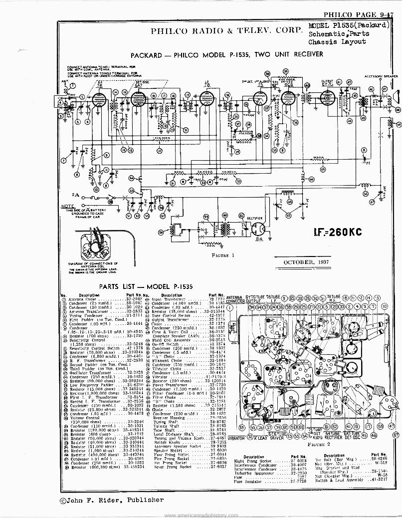
PHILCO PAGE 9-47
PHILCO RADIO & TELEV. CORP. MJDEL P1535(Paclrd) Schematic;Parts Chassis Layout
PACKARD - PHILCO MODEL P-1535, TWO UNIT RECEIVER
CONNECT ANTENNA TO NO.I TERMINAL IOR USE WITH COWL ANTENNA.
COPNECT ANTENNA TO NO2 TERMINAL FOR USE WITH ROOF OR UNDER -CARRIAGE ANTENNA
ANT.
Udo NOTE .
O THIS SIDE OrA BAT TERY
GROUNDED TO CASE FRAME OF CAR
DIAGRAM OF CONNECTIONS OF ANTENNA COIL
TIC GULCH D THE ANrdNA LEAD. THE BROWN IS THE GROUND LEAD.
Don 20.00on
S
FIGURE 1
PARTS LIST - MODEL P-1535 No. Description
IQ Antenna Choke ® Condenser (25 mmfd.) ® Condenser (50 mmfd.)
Antenna Transformer a Tuning Condenser
® First Padder (on Tun. Cond.) ® Condenser (.05 mfd.) 30-4444 ® Condenser
(.05-.12-.15-.25-.5-10 mfd.) 30-4545 ® Resistor (700 ohms) 33-1220 Qa Sensitivity Control
(1,250 ohms) 33-5248 C) Sensitivity Control Switch 42-137.8 # Resistor (70,000 ohms) ..33-370344 laj Condenser (6,000 mmfd.) 30-4467
Ci R. F. Transformer 32-2830 CI Second Padder (on Tun. Cond.) (iA Third Padder (on Tun. Cond )
I Oscillator Transformer 32-2829 s Condenser (250 mmfd.) 30-1032
® Resistor (99,000 ohms) ..33-399344 Low Frequency Padder 31-6230 so
® Resistor (45,000 ohms) ..33-345344 tel
© Resistor(1,000,000 ohms) 33-510344 ® First I. F. Transformer 32-2554 A A Second I. F. Transformer 32-2556 n # Condenser (250 med.)e, 30-1032 ® Resistor (25,000 ohms) ..33-325344 e(dj
j Condenser (.01 mfd.) 30-4479 er
Volume Control (350,000 ohms) 33-5246
g Condenser (110 mmfd.) 30-1031 eü Resistor (190,000 ohms) 33-419344 (gai Resistor (600 ohms). 33-1212 e Resistor (20.000 ohms) ..33-320344
Resistor (40,000 ohms) ..33-340444 # Resistor (51,000 ohms) ..33-351344 # Resistor (1,000 ohms) ..33-210344 SI Resistor (490,000 ohms) 33-449344 e Condenser (.01 mfd.) 30-4501 e Condenser (250 mmfd.t 30-1032
Resistor (600,000 ohms) 33-459334
2' DEI. Ir' AUDIO
o.0 eon
C® 61 r) RECTIFIER
84
Q ACCESSORY SPEAKER
OUTPUT
4i
'KT
I.F=260 KC
OCTOBER, 1937
Part No. No. Description Part No. 32-2063 G Input Transformer 32-7770 ANTENNA 6Y7GTUBE 7BTUBE O 65 30-1067 © Condenser (4,000 mmfd.l 30-4t85 CONNECTOR OUTPUT I.F.
30-1029 ® Condenser (.03 mfd.) 30-4447 .
32-2833 Q Resistor (15,000 ohms) ..33-315344 31-2111 ® Tone Control Switch 42-1377
C) Condenser (250 mmfd.) 30-1032 65 Condenser (.5 mfd.) 30-4474 n "A" Choke 32-1374 ® Filament Choke 32-1604 s© Condenser (250 mmfd.) 30-1032 A Vibrator Choke 32-2537 C5 Condenser (.5 mfd.) 39-4474 se Vibrator 41-3170-3
Resistor (200 ohms) ....33-120344 Power Transformer 32-7720 Condenser (7,500 mmfd.) 30-4420 Filter Condenser (4-8 mfd .1 30-2167 Filter Choke 12-7811 "B" Choke 32-1281 Resistor (1,500 ohms) ...55-21.5341 Choke 32-2657 Condenser (250 mmfd.) 30-1032 Receiver Housing 38-2050 Tuning Shaft 28-8762 Volume Shaft 28-8763 Tone Shaft ... 28-8764 Local Distance Shaft 28-8765 Tuning and Volume Knob 27-4687
rr
GU TUBE VIBRATOR L)A LEAD DRIVER
78RTFBE (FR
29 25 27 32 (B®
60 75TUBE
62 I41 Ce I7 (3i CD
2pDET 'B4TUBE1'6A7TUBE' 55 IJIsT.AUDIO RECTIFIER DET-OSC.45
(ID
Switch Knobs Accessory Speaker Socket Speaker Socket
28-7255 ...38-8805
27-6030 FIGURE 2
Four Prong Socket. Five Prong Socket Six Prong Socket Seven Prong Socket
..27-0044 27-6035 27-6036 27-6037
Description Right Prong Socket Interference Condenser Interference Condenser
Part No. 27-6058 30-4007 30-4475
Description 'fee Bolt (Rec. Mtg.) Nut (Rec. 511g.) Mtg. Bracket and Stud
Inductive Suppressor 32-9359 (Speaker Sltg.l Fuse 7227 Nut (Speaker 511g.) Fuse Insulator 27-7729 Switch & Lead Assembly
Part No. 28-6268
W-518
28-1546 W-55
41-3217
® Output Transformer 32-7778 Choke 32-1374
© Condenser (250 mmfd.) . 31)-1032 ® Cone & Voice Coil 36-3150
Complete Speaker (A49í 36-1370 +P Field Coil Assembly .. 36-3513 # On -Off Switch 42-1374
®John F. Rider, Publisher
www.americanradiohistory.com
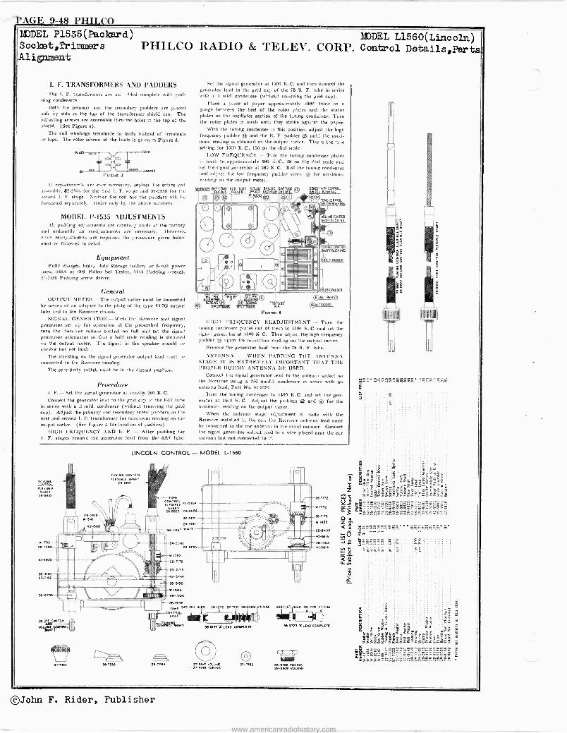
PAGE 9-48 PHILO( ) MODEL P1535(Pack r Socket,Trimmers Alignment
EDEL L1560(Lincoln) PHILCO RADIO & TELEV. CORP. Control Details,Parts
1. F. TRANSFORMERS AND PADDERS The 1. F. transformera are as hied complete with pad-
ding condensers.
Both the primary and the secondary padders are placed side by side in the top of the transformer shield can. The adjusting screws are accessible thru the holes in the top of the shield. (See Figure 4).
The coil windings terminate in leads instead of terminals or lugs. The color scheme of the leads is given in Figure 8.
KA
62 unD Emma 3
If replacements are ever necessary, replace the entire coil sssenlhly, 32-2554 fur the first I. F. stage and 32-2636 for the
econd I. F. stage. Neither the coil nor the padders will be
furnished separately. Order only by the above numbers.
212
MODEL P-1535 ADJUSTMENTS All padding adjustments are carefully made at the factory
and ordinarily no readjustments are necessary. However, when readjustments are required, the procedure given below must be followed in detail.
Equipment Fully charged heavy duty storage battery or 6 -volt power
pack, 048A or 099 l'hilco Set Tester, 3161 Padding wrench, 27-7159 Padding screw driver.
General
OUTPUT METER-The output meter must be connected by means of an adapter to the plate of the type 6Y7G output tube and to the Receiver chassis.
SIGNAL GENERATOR-With the Receiver and signal generator set up for operation at the prescribed frequency, turn the Receiver volume control on full and set the signal generator attenuator so that a half scale reading is obtained un the output meter. The signal in the speaker should be audible but not loud.
The shielding on the signal generator output lead must be
connected to the Receiver housing.
The sensitivity switch must be in the distant position.
Procedure I. F. -Set the signal generator at exactly 260 K. C.
Connect the generator lead to the grid cap of the 6.47 tube in series with a .1 mfd. condenser (without removing the grid cap). Adjust the primary and secondary screw padders un the first and second I. F. transformer for maximum reading on the output meter. (See Figure 4 for location of padders)
HIGH FREQUENCY AND R. F. - After padding the I. F. stages remove the generator lend from the 6A7 tube.
Set the signal generator ut 1500 K. C. and then connect the generator lead to the grid cap of the 78 R. F. tube in series with a .1 mfd. condenser (without removing the grid cap).
Place a piece of paper approximately .008" thick as a
gauge between the heel of the rotor plates and the stator plates on the oscillator section of the tuning condenser. Turn the rotor plates in mesh until they strike against the paper.
With the tuning condenser in this position, adjust the high frequency' padder ® and the R. F. padder ® until the maxi- mum reading is obtained on the output meter. This is the true setting for 1500 K. C., 150 on the dial scale.
1.OW FREQUENCY - Turn the tuning condenser plates in mesh to approximately 580 K. C., 58 nn the dial scale and set the signal generator at 580 K. C. Roll the tuning condenser :md adjust the low frequency padder screw ® for maximum rending on the output meter.
Emma 4
1-11011 FREQUENCY READJUSTMENT - Turn the tuning condenser plates out of mesh to 15011 K.C. and set the sigmd generator at 1500 K. C. Then adjust the high frequency padder ® again for maximum reading on the output meter.
Remove the generator lead from the 78 R. F. tube.
.ANTENNA - WHEN PADDING THE ANTENNA STAGE IT IS EXTREMELY IMPORTANT THAT THE PROPEIt DUMMY ANTENNA BE USED.
Connect the signal generator lead to the antenna socket an the Receiver using a 250 mmfd. condenser in series with an antenna lead, Part No. 41-8191.
Turn the tuning condenser to 1400 K. C. and set the gen- erator at 1400 K. C. Adjust the padder, ® and © for the maximum reading on the output circler.
When the antenna stage adjustment is made with the Receiver installed in the car, the Receiver antenna lead must he connected to the car antenna in the usual manner. Connect the signal generator output lead to a wire placed near the car antenna but not connected to it.
COWYE ONTROL El2n16LE
SHAFT maim
wain - º .7714
a-sso3
tr-4160 2r-ne2
2a-6136
000
27-4821
LINCOLN CONTROL - MODEL L-1560
TYNaN6 Co11TROl KETTLE 31MFT
28-0821
`ONT1ROL
3nAFTE 29l823 2a-2636
4Y-3171
29-.i91
38-9461 w4n
342040 29.6]
w ITeº
ºban º6TIn 42-3nì4
26 siso
W 1306
n -nao
n-7248 TONE 949-190 4108 28.1 72 21-7132 Y 009 1-r,3! 33Y_'16i 167133
CONTROL 3HAFT
COM1110Lt. 3sa16r-s LEA C.028131C.02813172OTE 38-8728 Y Inn CONKETE
287172
2e -n73
w 1433
6n º84 AY -3616
261403614
42-6
27-027-01.0w -9r w.E28-1102- 2,-9146 TONINO 28-1102 anLuWE
27-732 266186 ionisa
55
Og
§§
229. 2222.2222288
if
eg 8 @
t3§ iaC
t : áy
S i Ér .32a ' ] JAMs3eº. -t §6
$$g Egp
.c:MMYFnu'iéEákS- ;`'sç.=.53!c54
rrrn
C888888 8 8
$X5Xkk $
É
88 .
y tÿ
2927 : y 5 63 a i 2 3 were _is` ffi
. ..1. t
'E/EA ÉÉá "s
©John F. Rider, Publisher
www.americanradiohistory.com
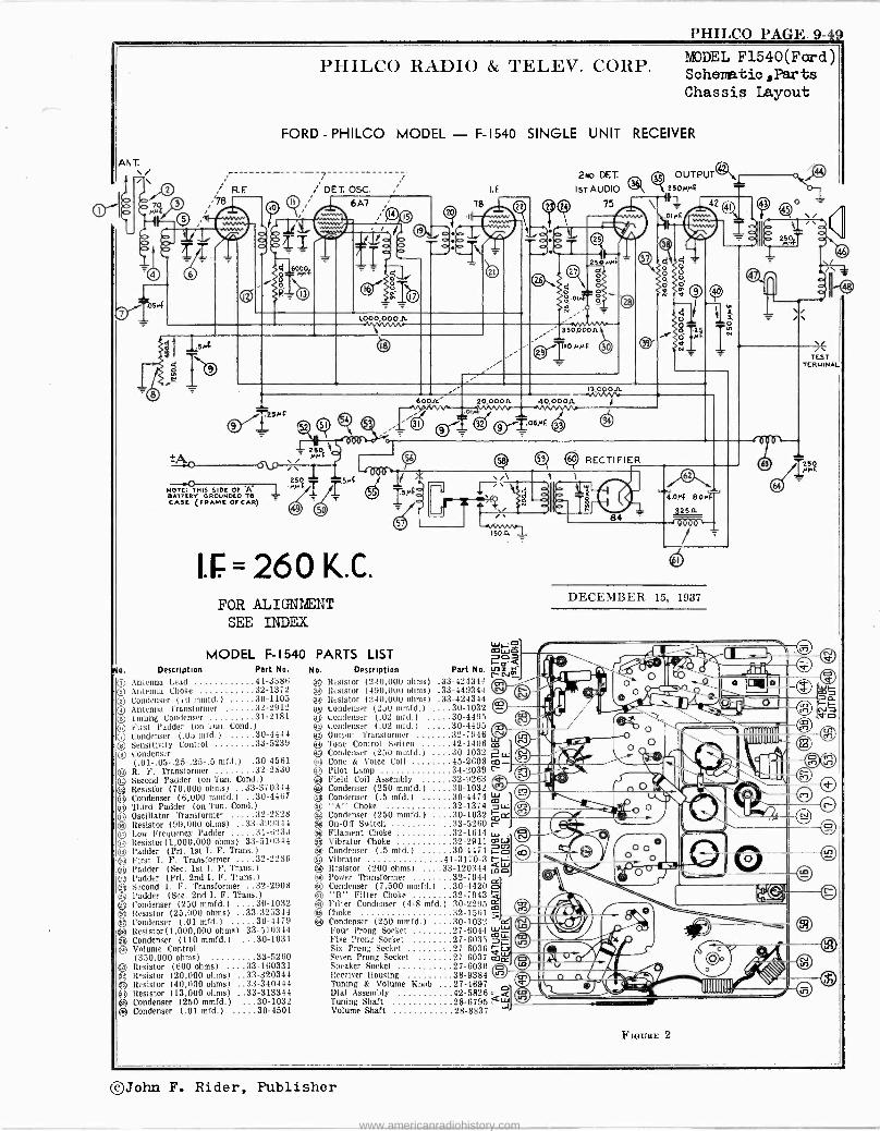
AN T.
1 1\
N OTE: THIS SIDE OF A B ATTER,/ GROUNDED TO CASE FRAME OF CAR)
I,000,000JL
PHILCO RADIO & TELEV. CORP.
l'HILCO PAGE. 9-49
MODEL F1540(Ford) Schematic ,Parts Chassis Layout
FORD-PHILCO MODEL - F-1540 SINGLE UNIT RECEIVER
; DET.OSC. 6A7
-4-
= 260 K.C. FOR ALIGNIENT
SEE INDEX
MODEL F-1540 PARTS LIST lo. Description Part No.
O Antenna Lead 11-3386 ® Antenna Choke 32-1372 ® Condenser (10 tumid.) 30-1105 ® Antenna Translormer 32-2912 ® Tuning Condenser 31-2181 s First Padder (on 'tun. Cond )
(T) Condenser (.0o turd.) 30-4444 ® Sensitivity Control 33-5239 ® Condenser
(.01-.05-.25-.25-.5 mfd.) .30-4561 ® R. F. Transformer 32-2830 ® Second Padder (on 'l'un. Cond.)
Resistor (70,000 ohms) ..33-370344 Oe Condenser (6,000 (mmfd.) .30-4467
13 Third Padder (on Tun. Cond )
Oscillator Transformer 32-2828 ® Resistor (99,000 ohms) ..33-399344 d, Low Frequency Padder 31-0230 (0. Resistor(1,000,000 ohms) 33-510344 e Fodder (Pri. 1st I. F. Trans.) ® First I. F. Transformer 32-2286 QP Padder (Sec. 1st I. F. Trans )
95 Padder (Pri. 2nd I. F. Trans.) Second I. F. Transformer 32-2908 Padder (Sec. 2nd I. F. eons.) Condenser (250 mmfd.) 30-1032 Resistor (25,000 ohms) ..33-325344 Condenser (.01 mfd.) 30-4479 Resistor(1,000,000 ohms) 33-510344
éJ Condenser (110 mmfd.) 30-1031 4i5 Volume Control
(350,000 ohms) 33-5260 al Resistor (600 ohms) ...33-160331 95 R°sistor (20,000 ohms) ..33-320344 39 Resistor (40,000 ohms) ..33-340444
Resistor (13,000 ohms) ..33-313344 ® Condenser (250 mmfd.) 30-1032
95 Condenser (.01 mfd.) 30-4501
m
2No DET.
Ist' AUDIO
350,ODOA
(2) 59 Q RECTIFIER
`\ _ 1
1.I
i_T-Jr-48¡ T i 15
No. Description Part No. rnz t
95 Resistor (240.000 ohms) .33-424344 lsN_
9 Resistor (490,000 ohms) .33-449344 e Resistor (240,000 ohms) .33-424344
9u Condenser ('2DO mmfd.) 30-1032 30-4495 30-4495 32-7946 42-1406 Go 1
30-1032 45-2608 03.- 34-2039 r- 32-9263
....30-1032 30-4474 m 32-1374 3u.
.30-1032 mce 33-5260 r- 32-1644 I 32-2911 lac, 30-4474 r..ó f
41-3170-3 t ab
H1)
®
8 N17
3 ®
Condenser (.02 mtd.) Condenser (.02 rntd.) Output Transformer Tone Control Switch Condenser (250 mmfd.) Cone & Voice Coil Pilot Lamp Field Coil Assembly Condenser (250 mmfd.) Condenser (.5 mfd.) "A" Choke Condenser (250 mmfd.) On -OR Switch Filament Choke Vibrator Choke Condenser (.5 mfd.) Vibrator Resistor (200 ohms) .
® Power Transformer .. . ..32
59 Condenser (7.500 mmfd.) -.30-4420 ß m "B" Filter Choke .. .32-7943 a Filter Condenser (4-8 mid.) 30-2295 m
e5 Choke 32-1561 ® Condenser (250 mmfd.) ....30-1032 Ir
Foúr Prong Socket ........27-6044 ww Five Prong Socket .........27-6035 =9-7. Six Prong Socket ..27-6036 vw Seven Prong Socket 27-6037 mce Speaker Socket 27-6030 Receiver Housing 38-9384 Tuning & Volume Knob 27-4697 Dial Assembly 42-5826 Tuning Shaft 28-6795 Volume Shaft 28-8837
...33-120344 c
K.!
DECE1IBEß, 15, 1937
TEST TERMINAL
©John F. Rider, Publisher
www.americanradiohistory.com
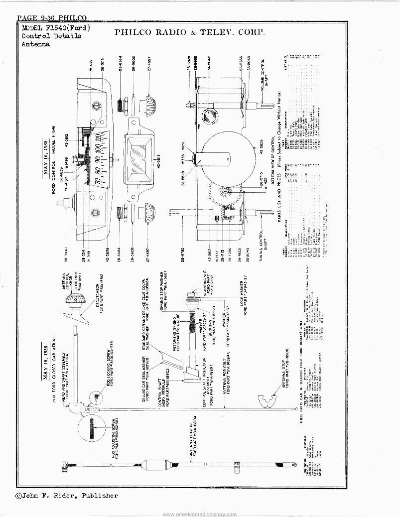
PAGE 9-50 PHILCO MODEL F1540(Ford) Control Details Antenna
PHILCO RADIO & TELEV. CORP.
=&S gm a = ZÑ Ñ wHZZ m ám ¿- Zpár' 2A á00Y Óm Om ám i¢ =m
eieÚF ina
f~/IR ó 3 l4 WF- =O O1 yC xi. gpKp J
LL Jd Nfi.
Ñ Ñ K
0pp o f/1
m W O
rL e Z1 _Zm (7á N Q W Z m Q IA
m Q 2Q 2 UW ore QM =~ 3F- 22 0~
; 7Q . a a; iá á
mo 0 o a 2re z -I 2
Ñ 44 2 ó ;¿M)
mM i50 2m 2 Opi
¡VZW¡I m óg-, Q0 Yá 3á
O v
§ñ m m r& &r xi- o0 2H _ M imm iOg
áa /¢w Wá Ñ tZAÑ 2 o¢ x á &á aLL 2 ~20 ¢
I Z O g LL
io c
©John F. Rider, Publisher
www.americanradiohistory.com
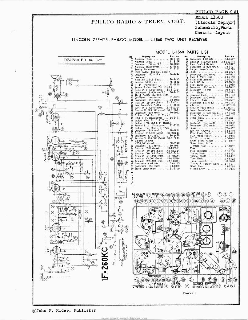
PHILCO PAGE 9-51
PHILCO RADIO & TELEV. CORP. SDDEL L1560 (Lincoln Zephyr) Schematic,Parts Chassis Layout
LINCOLN ZEPHYR - PHILCO MODEL - L-1560 TWO UNIT RECEIVER
DECEMBER 16, 1937
4.
V
MODEL L-1560 PARTS LIST No. Description Part No. C) Antenna Choke 38-8106 Q Antenna Choke 38-8106
Condenser (50 mmfd.) 30-1029 Antenna Transformer 32-2914 Tuning Condenser 31-2161 First Padder (on Tun. Cond )
Condenser (.05 mfd.) 30-4444 Condenser (.01-.05-.25-.5-2 mid.) 30-4493
Q Resistor (600 ohms) 33-1212 R. F. Transformer 32-2830 Second Padder (on Tun. Cond.)
® Resistor (70,000 ohms) .33-370344 Condenser (6,000 mmfd.) .30-4467 Third Padder (on Tun. Cond )
Oscillator Transformer 32-2829 iCondenser (250 mmfd.) 30-1032 Resistor (99,000 ohms) .33-399344 Low Frequency Padder 31-6230
iResistor (45,000 ohms) .33-345344 Resistor(1,000,000 ohms) 33-510344 Condenser (250 mmfd.) . 30-1032
® Padder (Pri. 1st I. F. Trans )
O First I. F. Transformer 32-2791 Q Padder (Sec. 1st I. F. Trans )
§Padder (Pri. 2nd I. F. Trans )
®j Second I. F. Transformer 32-2793 Padder (Sec. 2nd I. F. Trans.) Condenser (250 mmfd.) 30-1032
® Resistor (25,000 ohms) .33-325344 63) Condenser (.01 mfd.) 30-4479 ® Resistor(1,000,000 ohms) 33-510344
cc ® Volume Control (350,000 ohms) 33-5246
I-- g Condenser (110 mmfd.) 30-1031 };
0 Resistor (600 ohms) ..33-160331
1.Nooa LL Resistor (20,000 ohms) .33-320344 6 Resistor (40,000 ohms) .33-340444 I> 2
Resistor (240,000 ohms) 33-424344
di) Resistor (3,000 ohms) ..33-230344
® Resistor (490,000 ohms) 33-449344 -4( Condenser (.01 mfd.) 30-4145
54 Condenser (250 mmfd.) 30-1032 Input Transformer 32-7779
© O O O O O
6Y7G TUBE 78TUBE42 OUTPUT . I.F.
A' 3'.1.--f113 T VIBRATOR LEAD DRIVER
®75TUBE 2"? DET. IST>AUDIO 65
No. Description Part Ne. ® Condenser (.03 mfd.) 30-4447 ® Resistor (15,000 ohms) .33-315344 ® Tone Control Switch 42-1377 4) Condenser (2,000 mmfd.) 30-4177 ® Output Transformer 32-7778 0 -Choke 32-1374
Condenser (250 mmfd.) 30-1032 ® Cone & Voice Coil 36-3159 ® Field Coll Assembly 36-3513 63 On & Oil Switch 42-1369 () Pilot Lamp 34-2039 (s) Condenser (250 mmfd.) 30-1032 (3 Condenser (.5 mfd.) 30-4474 (63 "A" Choke 32-1374 6 Filament Choke 32-2729 ít Je Condenser (250 mmfd.) 30-1032 4o Vibrator Choke 32-2537 ei Condenser (.5 mfd.) 30-4474 U Vibrator 41-3170-3 e)a Resistor (200 ohms) 33-120344 e)i Power Transformer 32-7720 © Condenser (7,500 mmfd.) 30-4420 e Filter Condenser (4-8 mfd.) 30-2167 Q Filter Choke 32-7811 Q "B" Choke 39-1281
e Condenser (250 mmfd.) 30-1032 r Condenser (250 mmfd.) 30-1032 63 Choke 32-2657
Receiver Housing 38-9340 Four Prong Socket 27-6044 Five Prong Socket 27-6035 Six Prong Socket 27-6036 Seven Prong Socket 27-6037 Seven Prong Socket
Octal Base 27-6087 Fuse 7227 Fuse Insulator 27-7729 Tuning Shaft 28-8821 Volume Shaft 28-8822 Tone Shaft 28-8823 Scale Assembly 42-5803 Tuning & Volume Knob 27-4691 Knob Base 28-7284 Switch Lever 28-7255
84TUBE ' 6A7 TUB RECTIFIER DET.05C.
FIGURE. 2
@John F. Rider, Publisher
www.americanradiohistory.com
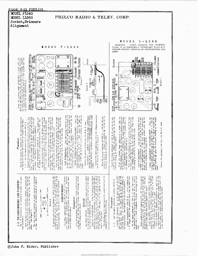
pA('1E 9-52 PHILCO MODEL F1540 mat, L1560 Socket,Triimmers Alignmsnt
PHILCO RADIO & TELEV. CORP.
MODEL L- 1 5 6 0 ANTENNA - WHEN PADDING TILE ANTENNA
STAGE IT IS EXTREMELY IMPORTANT THAT THE PROPER DUMMY ANTENNA RE CONSTRUCTED AND USED.
w1lüiBJ.!MNI
©John F. Rider, Publisher
www.americanradiohistory.com
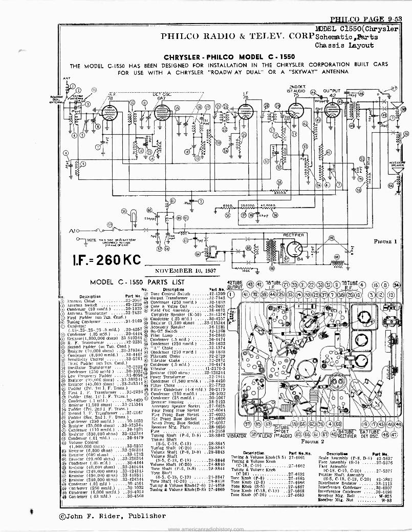
PHILCO PAGE 9-53
ANTE
MODEL C1550(Chrysler PHILCO RADIO & TELEV. CORP Sohematic,Parts
Chassis layout CHRYSLER - PHILCO MODEL C - 1550
THE MODEL C-1550 HAS BEEN DESIGNED FOR INSTALLATION IN THE CHRYSLER CORPORATION BUILT CARS
FOR USE WITH A CHRYSLER "ROADW AY DUAL" OR A "SKYWAY" ANTENNA ANT
No.
No. Description Part No. 1+.7
Antenna Choke 32-2063 C ® Antenna Switch 42-1259 v Condenser (50 mmtd.) 29 Q Antenna Transformer 32-2433 C) First Padder (on Tun. Cond )
O Tuning Condenser 31-2169 () Condenser
(.15-.25-.25-.25-.5 mfd.) .30-4557 Condenser (.05 mfd.) 30-4444
O Resistor(1,000,000 ohms) 33-510344 R. F. Transformer 32-2231
u Second Padder (on Tun. Cond.) Q Resistor (70,000 ohms) .33-370344 0 Condenser (6,000 mmfd.) 30-4467 i+ Sensitivity Control 33-5261 () Third Padder (on Tun. Cond )
3 Oscillator Transformer 32-2232 Condenser (250 mmfd.)
ü Low Frequency Padder 31-6056® ® Resistor (99,000 ohms) ..33-399344® Q Resistor (45,000 ohms) .33-345344
2JPadder (Pri. 1st I. F. Trans.) First I. F. Transformer 32-2286
O Padder (Sec. 1st I. F. Trans.) Q Condenser (.1 mfd.) 30-4499 Q Resistor (1,500 ohms) ..33-215344 St Padder (Pri. 2nd I. F. Trans.) e Second I. F. Transformer 32-2167 e Padder (Sec. 2nd L F. Trans.) ® Condenser (250 mmfd.) 30-1032 91
Condenser (2(151 ,000mmfd.)
.33-325344 30 1031 g Resistor (330,000 ohms) 33-433344 O Condenser (.01 mfd.) 30-4479 O Volume Control
(1,000,000 ohms) 33-5257 g Resistor (6,000 ohms) ...33-260344 ® Resistor (600' ohms) 33-1212 O Resistor (20,000 ohms) ..33-30344 e Condenser (.05 mfd.) 30-4444 O Resistor (40,000 ohms) ..33-340444 e Resistor (240,000 ohms) .33-42434.4 (i'D Resistor (490,000 ohms) .33-449344
Resistor (240,000 ohms) .33-424344 Condenser (.01 mfd.) 30-4501
+ Condenser (250 mmfd.) 30-1032
OO Condenser (6, Condenser (.03
000 30-4024 30-4560
/78 DI`T .bsc.
61A7
01 NOTE THIS SIDE OFA BATTERY 1_ GROUNDED TO C
(i0.AYE O<CAR
I.F.=260 KC NOVEMBER 10, 1937
MODEL C - 1550 PARTS LIST 42TUBE OUTPUT Description Part No.
Tone Control Switch 42-1399 Output Transformer 32-7942 Condenser (250 mmfd.) 30-1032 Cone & Voice Coil 45-2607 Field Coil Assembly 36-4012 Complete Speaker (K-50) 36-1376 Condenser (.25 mfd.) 30-4557 Resistor (1,500 ohms) ...33-215344 Accessory Speaker 36-1281 On -OR Switch 42-1368 Pilot Lamp 34-2040 Condenser (.5 mfd.) 30-4474 Condenser (250 mmfd.) 30-1032 "A" Choke 32-1374 Condenser (250 mmfd.) 30-1032 Filament Choke 32-2729 Vibrator Choke 32-2812 Condenser (.5 mid.) 30-4474 Vibrator 41-3170-3 Resistor (200 ohms) 33-120344 Power Transformer 32-7911 Condenser (7,500 mmfd.) 30-4420 Filter Choke 32-7722 Filter Condenser (4-8 mfd.) 30-2179 Condenser (250 mmfd.) 30-1032 Condenser (25 mmfd.) 30-1067 Receiver Housing 38-2123 Accessory Speaker Socket 27-6025 Four Prong Base Socket 27-6044 Five Prong Base Socket 27-6035 Six Prong Base Socket 27-6036 Seven Prong Base Socket 27-6037 Receiver Mtg. Plate 28-4650 Fuse 45-2559 Tuning Shaft (P-6, D-8) 28-8842 Tuning Shaft
(S-5, C-18, C-19) 28-8845 Tuning Shaft (C-20) 28-8848 Volume Shaft (P-6, D-8) 28-8843 Volume Shaft
(S-5, C-18, C-19) 28-8846 Volume Shaft (C-20) 28-8849 Tone Shaft (P-6, D-8) 28-8844 Tone Shaft
(S-5, C-18, C-19) 28-8847 Tone Shaft (C-20) , 28-8850 Tuning & Volume Knob(P-6) 27-4659 Tuning & Volume Knob(D-8) 27-4660
I.F 78
2ND OCT. iSTAt10iO
75 OUTPUT
42 .03µp 4 D o
i.r..
FIGURE 1
o 78FBE©
® 31 ®e®O7RTFBEO ®(Do O ® 25 9I100©i0
EI! 1c
/ ` v '11
` , 1 O -( --3.19,-...'-::,-1,P,......4,1",*_
,
_ r( ' <Z . d - .. © 65 75TUBE dro o e o
2"° PET. ED'TUa .A7TUBE A LEAD I9?AUDIO (1) CDO ® ®RECTIFIER DEI OSC. ® VIBRATOR
FIGURE 2
Description Part Ns.N.. Tuning & Volume Knob(S-5) 27-4661 Tuning & Volume Knob
(C-18, C-19) 27-4662 Tuning & Volume Knob
(C-20) 27-4692 Tone Knob (P-6) 27-4665 Tone Knob (D-8) 27-4666 Tone Knob (8-5) 27-4667 Tone Knob (C-18, C-19) 27-4668 Tone Knob (C-20) 27-4693
Description Part No. Scale Assembly (P-6, D-8) 42-5637 Face Assembly (S-5) 27-5376 Face Assembly
(C-18, C-19, C-20) 27-5377 Pointer Shaft Assembly
(S-5, C-18, C-19, C-20) 42-5802 Distributor Resistor 33-1113 Interference Condenser 30-4007 Interference Condenser 30-4490 Receiver Mtg. Bolt W-825 Receiver Mt'. Nut W-98
©John F. Rider, Publisher
www.americanradiohistory.com
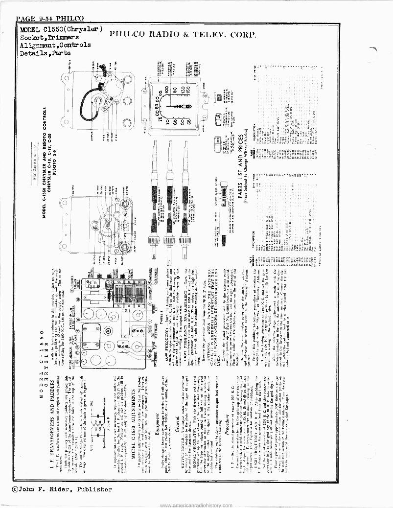
PACTE 9-54 PHILCO
Socket ,Tr iImrier s
Alignment,Controls DetailS,Parts
IMP ' II
. N V
©John F. Rider, Publisher
www.americanradiohistory.com
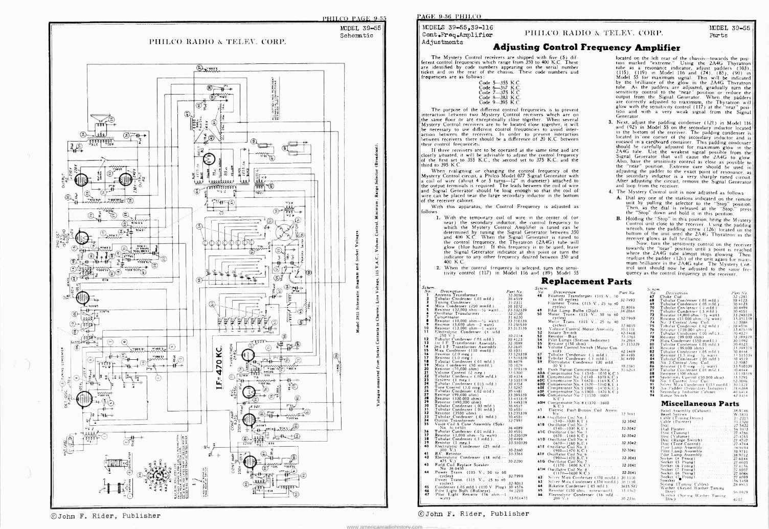
I'HII,CO PAGE 9-55 I/AGI'. 9-56 l'HILC'O
MODEL 39-55 Schematic
I'HILCO RAI)IO & TELEV. CORP.
- 000.--p -- Q. 4,
14 112 41SGE D
4 ßrl.-I
>ti á
0 nie
.00Sí ä.
Mu'
e ti
`101'061 "000.06
N
y,o
a
< 0. 0.; tt, IY 0't
o
e
e0. -t
1 e5
rlurn .11111M. 1
`000 OL
"000'ott s
075
o- o--
u óu
ów
e "000.01 '.000'0
0(00 I vG'0
e-
.. º i: b
a
_
H 19
e
1
00600000001 srS'2
9
-e eso' -e
"01
e
<1 iJ O U m )JtiQLt
se
oóel ^ J -f i
0=o lu e nY0M0 rl 71nM r ¡r 030
r; sofa/
"S7 ) ~ s
: :111:
Ió
8$
¢a
á; Sg
S
i
ii <
o.
u
-0 A SO/
It-
+ s~i 0 'Mstr
rH ", óÓC Ñ_9 rll0!
r+1 / MY Y e
ve,
º Ms als
>l
Fr z O Ñu
o .0a OS
CD-
e
hiCDEIS 39-55,39-116 Cont.Freq.Amplifier PIIII.CO I4À1)IO & 'l'ELEV. CORP. Adjustments Adjusting Frequency F quency Amplifier
The Mystery Control receivers are shipped with five (5) dif- ferent control frequencies which range from 350 to 400 K.C. These are identified by code numbers appearing on the serial number ticket and on the rear of the chassis. These code numbers and frequencies are as follows:
Code 5-355 K.C. Code 6-367 K.C. Code 7-375 K.C. Code 8-383 K.C. Code 9-395 K.C.
The purpose of the different control frequencies is to prevent interaction l;etween two Mystery Control receivers which are on the same floor or are exceptionally close together. When several Mystery Control receivers are to be located close together, it. will be necessary to use different control frequencies to avoid inter- action between the receivers. In order to prevent interaction between' receivers there should be a difference of 20 K.C. between their control frequencies.
If three receivers are to be operated at the same time and are closely situated, it will be advisable to adjust the control frequency of the first set to 355 K.C., the second set to 375 K.C. and the third to 395 K.C.
When realigning or changing the control frequency of the Mystery Control circuit, a Philco Model 077 Signal Generator with a coil of wire (about 4 or 5 turns -12" in diameter) attached to the output terminals is required. The leads between the coil of wire and Signal Generator should be long enough so that the coil of wire can be placed near the large secondary inductor in the bottom of the receiver cabinet.
With this apparatus, the Control Frequency is adjusted as follows:
1. With the temporary coil of wire in the center of (or near) the secondary inductor, the control frequency to which the Mystery Control Amplifier is tuned can be determined by tuning the Signal Generator between 350 and 400 K.C. When the Signal Generator is tuned to the control frequency, the Thyratron (2A4G) tube will glow (blue haze). If this frequency is to be used, leave the Signal Generator indicator at this point or turn the indicator to any other frequency desired between 350 and 400 K C.
2. When the control frequency is selected, turn the sensi- tivity control (117) in Model 116 and (89) Model 55
Schein. No. Description Part No.
1 Antenna Transformer ... 32-3056 2 Tubular -Condenser (.05 mfd.).... 30-4519 3 Tuning Condenser ... .. 31-2311 4 Mica Condenser (250 mmfd.) 301032 S Resistor (32,000 ohm -y, watt) 33-332339 6 Oscillator Transformer 32-2120 7 Compensator 31 6230 8 Resistor (10,000 ohm -1/4 watt) 33-310339 9 Resistor (5.000 ohm -2 watt).. 33-250539
10 Resistor (13,000 ohm -1 watt) 33-313339 11 Electrolytic Condenser (4 mfd.--
250 V.) ........ .... .. 30-2334 12 Tubular Condenser (.05 mfd.) 30-4123 13 1st I.F. Transformer Assembly 32-3089 14 2nd I.F. Transformer Assembly 32.2645 15 Mica Condenser (110 muid.) 30-1031 16 Resistor (2.0 meg.) 33 520339 17 Resistor (1.0 meg.) 11 510339 18 Tubular Condenser ( 01 mfd.) .... 30-4479 19 Mica Condenser (50 mmfd.) 10.1029 20 Resistor (70,000 ohm) 33-370339 21 Volume Control (2 meg.) 33-5300 22 Tubular Condenser (.004 mfd.) 30 4334 23 Resistor (1 meg.) .... 33 510339 24 Tubular Condenser (.015 mfd.) 30-4358 25 - Tone Control (3.0 meg.) 33-5287 26 Tubular Condenser (.02 mid.) 30-4481 27 Resistor (99,000 ohm) . .. . 33-399339 28 Resistor (330,000 ohm) 33-433339 29 Resistor (490,000 ohm) 33.449339 30 Tubular Condenser (.03 mfd.) 30-4517 31 Tubular Condenser (.01 mfd.) .. 30-4501 32 Resistor (3500 ohm) .. 33-235339 33 Tubular Condenser (101 mfd.) 30-4501 34 Output Transformer 32-7997 3S Voice Coil & Cone Assembly (Spkr
No. 36-1450) 36-4089 36 Tubular Condenser (.01 mfd.) 30-4501 37 Resistor (3,000 ohm -1/4 watt) 33-230339 38 Tubular Condenser (.1 mfd.) 30-4499 39 Resistor (1 meg.) 33-510339 40 Electrolytic Condenser (25 mfd.--
300 V.) 30-2360 41 B.C. Resistor 33-3361 42 Electrolytic Condenser (18 mid. -
475 V.) 30-2200 43 Field Coil Replace Speaker
No. 36-1450 44 Power Trans. (115 V., 50 to 60
cycles) 32.7999 Power Trans. (115 V., 25 to 40
cycles) 32-8013 45 Condenser (.05 mfd.) (HO V. Plug) 30-4576 44 Pilot Light Bulb (Bullseye) 34.2210 47 Pilot Light Resistor (16 ohm -1
watt) 33016431
MODEL 39-55 Parts
located on the left rear of the chassis -towards the posi- tion marked "extreme." Using the 2A4G Thyratron tube as a resonance indicator, adjust padders (103), (115), (119) in Model 116 and (74), (85), (90) in Model 55 for maximum signal. This will be indicated by the brilliance of the glow in the 2A4G Thvratron tube. As the padders are adjusted, gradually turn the sensitivity control to the "near ' position or reduce the output from the Signal Generator. When the padders are correctly adjusted to maximum, the Thyratron will glow with the sensitivity control (117) at the "near" posi- tion and with a very weak signal from the Signal Generator.
3. Next, adjust the padding condenser (121) in Model 116 and (92) in Model 55 on the secondary inductor located in the bottom of the receiver. The padding condenser is located in 'one corner of the secondary inductor and is encased in a cardboard container. This padding condenser should be carefully adjusted for maximum glow in the 2A4G tube. Use the weakest signal possible from the Signal Generator that will cause the 2A4G to glow. Also, have the sensitivity control as close as possible to the "near" position. Extreme care should be used in adjusting the padder to the exact point of resonance, as the secondary inductor is a very sharply- tuned circuit. After adjusting the circuit, remove the Signal Generator and loop from the receiver.
4. The Mystery Control unit is now adjusted as follows A. Dial any one of the stations indicated on the remote
unit by pulling the selector to the "Stop" position. Then, as the dial is released at the "Stop," press the "Stop" down and hold it in this position.
B. Holding the "Stop" in this position, bring the Mystery Control unit close to the receiver. Using the padding wrench, tune the padding screw (126) located on the bottom of the unit until the 2A4G Thyratron in the receiver glows at full brilliance.
Now, turn the sensitivity control on the receiver towards the "near" position until a point is reached where the 2A4G tube almost stops glowing. Then readjust the padder (126) of the unit again for maxi- mum brilliance in the 2A4G tube. The Mystery CoA- trol unit should now he adjusted to the same fre- quency as the control frequency ;n the receiver.
Replacement Parts Sc he m.
Vo. Description Part No. 48 Filament Transformer (I15 .V.. 50
to 60 cycles) 32-7993 Filament Trans. (115 V., 25 to 40
cycles) 32.8016 49 Pilot Lamp Bulbs (Dial) 34-2064 50 Motor Trans. (115 V., 50 to 60
cycles) 32-7990 Motor Trans. (115 V.. 25 to 40
cycles) 32.8015 51 Volume Control Motor Assembly 35-1151 S2 Rotary Switch 42-1468 53 Resistor -Bias 13.3363 54 Pilot Lamps (Station Indicator) 34-2064 55 Resistor (150 ohm) 33-115339 56 Volume Control Switch (Motor Con-
trol)
57 Tubular Condenser (.1 mfd.) 42-146930.4499
58 Condenser (.1 mfd.) 30-4499 59 Electrolytic Condenser (30 mid.-
30-2361 60 Push Button Compensator Strip 316264 60A Compensator No. 1 (540-1030 K C.C.) 608 Compensator No.2 (540-1030 K.C.) 60C Compensator No. 3 (670-1160 K.C.) 600 Compensator No. 4 (670-1160 K.U. ) 60E Compensator No.5 (900--1470 K.C.) 60F Compensator No. 6 (900-1470 K.C.) 606 Compensator No.7 (1170-1600
K.C.) 60M Compensator No. 8 (1170-1600
K.C.) 61 Electric Push -Button Coil Assent.
blr 32.3091 61 A t tscillator Coil No. I
(540-1030 K.C.) 32-3042 618 Oscillator Coil No. 2
(540-1030 K.C.1 32.3042 61C Oscillator Coil No. 3
(670--1160 K.C.) 32.3042 61D Oscillator Coil No. 4
(670-1160 K.C.) 32-3042 61E Oscillator Coil No. 5
(900-1470 K.C.) 32.3041 61F Oscillator Coil No. 6
(900-1470 R.C.) 32-3041 61G Oscillator Coil No. 7
(1170-1600 K.C.) 32-3041 61I4 Oscillator Coil No. 8
32-3041 (1170-1600 K.C.) 62 Silver Mica Condenser (370 mmfd ) 30-1110 63 Silver Mica Condenser (370 mmfd ) 30-1110 64 Bakelite Condenser ( 05 mfd.) 3615 -SC. 65 Resistor (150 ohm --wirewnuud) 333,162 66 Electrolytic Condenser (16 mfd.-
200 V.) 30.2356
Schein. No Description Part No. 67 Choke Coil 32 t281 68 Tubular Condenser (.05 mfd.) 30 4123 69 Tubular Condenser (.05 mfd.) 30-4123 70 Tubular Condenser (.1 mfd.) .. 30-4499 71 Tubular Condenser (.5 mfd ) .. 30-4551 72 Resistor (4,000 ohm -'/a watt). . 33.240339 73 Resistor (51 000 ohm -1/4 watt) . . 33.351339 74 No. 3 Control Amp. Coil.... .. . 32-3088 75 Tubular Condenser ( 02 mfd.). 30-4516 76 Resistor (750.00') ohm) 33475339 77 Tubular Condenser (.05 mfd.) 10 412.1 78 Resistor (99.000 ohm) 33 3993.39 79 Mica Condenser (550 mmfd.) 30-1092 80 Tubular Condenser (.05 mfd.)... 30.4123 81 Resistor (99.000 ohm) 3i 3993.39 82 Tubular Condenser (.05 mfd.)... . .10-4444 83 Resistor (1.5 meg.- 1/4 watt) 11.515339 84 Tubular Condenser (.05 mfd.) 304519 85 No 2 Control Amp. Cod.... . . 32-ìO87 86 Resistor (1 0 meg. '1/4 watt) - 33-510339 87 Tubular Condenser (.05 mfd.)..... 304444 88 Resistor (300 ohm) 33-330339 89 Sensitivity Control (50.000 ohm)... 335295 90 No. 1 Control Amp Coil... .. . 32-.3086 91 Silver M:ca Condenser (155 mmfd.) 30-1121 92 Air Padder (Secondary Inductor).. 31.6268 93 Secondary Inductor Cabinet .. . 40-6414 94 Range Switch 42 1454
Miscellaneous Parts Bezel Assembly (Cabinet) 38-9746 Bezel Screws W-1835 ('able (Tuning Drum) ....... .. 31-2315 Cable (Pointer) .......... .... .31-2320 Dial 27.5422 Dial Pointer Sti-1033 Disc (Tuning) 274766 Disc (Volume) 27.4765 Disc (Range Switch) 27-4769 Disc (Tone Control) 27.4764- Pilot Lamp Assembly 389694 Pilot Lamp Assembly 38-9711 Pilot Lamp Assembly 38.9712 Socket (4 Prong) 27-6044 Socket (5 Prong) 27-6035 Socket (6 Prong) 27.60.36 Socket (7 Prong)
ket P Socket (6 Prong)rong) Socket (7
27-6086 27 6099
Speaker 36.1450 Spring (Tuning Cables)... 28-8917 Washer (Keyed Washer Tuning
Diac) 56.1029 W asher (Spring Washer Tuning
Disc) 6717
©John F. Rider, Publisher ©John F. Rider, Publisher www.americanradiohistory.com
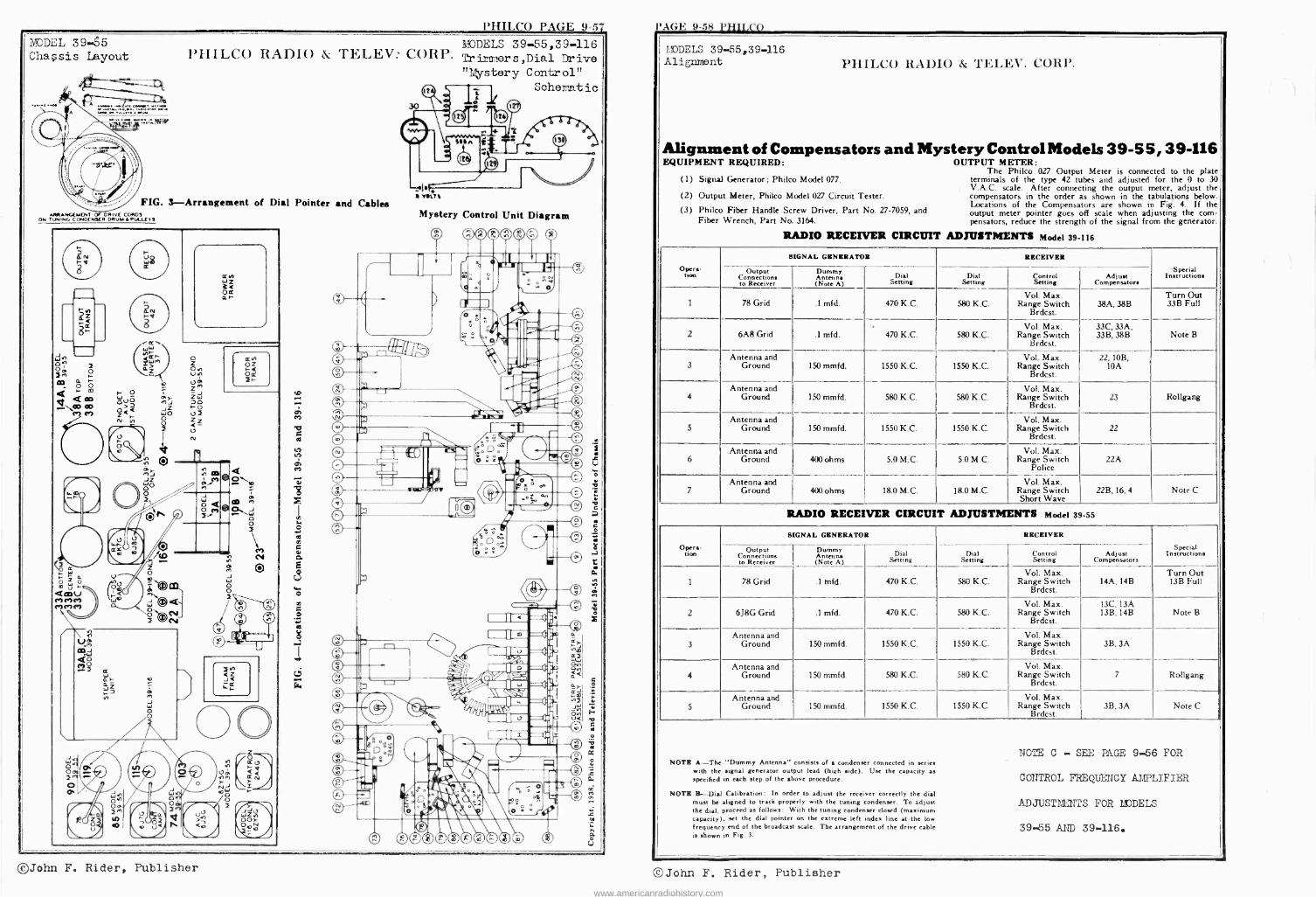
l'HILCO PAGE 9-57 l'AGE 9-58 I'HILCO MODEL 39-55 Chassis Layout
A
»,(.., ..,..
,ti, : NY W
PIIILCO RADIO & TELEV. CORP. Tri rs,Dial Drive "Mystery Control" 1 i Schematic
FIG. 3-Arrangement of Dial Pointer and Cables ARRANGEMENT Or DNIve CORDS
ON TUNING CONDENSER DRUM a PULLIYS
r- O óuo o>< z< N al
r On á A1J
or
W
o
o J W n 0 Oa
O en .t up z zW DO r0 u3 Z <- u N
o
J
o
O
0 O
O
r
L
tl VOL S
MODELS 39-55,39-116
Mystery Control Unit Diagram
C
rJ
e9 ®
á
P,IJDELS 39-55,39-116 Alignment PIIILCO RADIO & TELEV. CORP.
Alignment of Compensators and Mystery Control Models 39-5 5, 39-116 EQUIPMENT REQUIRED: OUTPUT METER:
The Philco 027 Output Meter is connected to the plate (1) Signal Generator; Philco Model 077. terminals of the type 42 tubes and adjusted for the 0 to 30
V.A.C. scale. After connecting the output meter, adjust the (2) Output Meter, Philco Model 027 Circuit Tester. compensators in the order as shown in the tabulations below.
(3) Philco Fiber Handle Screw Driver, Part No. 27-7059, and Locations of the Compensators are shown in Fig. 4. If the output meter pointer goes off scale when adjusting the corn -
Fiber Wrench, Part No. 3164. pensators, reduce the strength of the signal from the generator.
RADIO RECEIVER CIRCUIT ADJUSTMENTS Model 39-116
Opera-
SIGNAL GENERATOR RECEIVER
InInstructions C nnections to Receiver
Antenna (Note A)
Dial Setting
Dial Setting
Control Setting
Adjust Compensators
1 78 Grid .1 mfd. 470 K.C. 580 K.C. Vol. Max.
Range Switch Brdcst.
38A, 38B Turn Out 33B Full
2 6A8 Grid .1 mfd. 470 K.C. 580 K.C. Vol. Max.
Range Switch Brdcst.
33C, 33A, 33B, 38B Note B
3 Antenna and
Ground 150 mmfd. 1550 K.C. 1550 K.C. Vol. Max.
Range Switch Brdcst.
22, 10B, l0A
4 Antenna and
Ground 150 mmfd. 580 K.C. 580 K.C. Vol. Max.
Range Switch Brdcst.
23 Rollgang
5 Antenna and
Ground 150 mmfd. 1550 K.C. 1550 K.C. Vol. Max.
Range Switch Brdcst.
22
6 Antenna and
Ground 400 ohms 5.0 M.C. 5.0 M.C. Vol. Max.
Range Switch Police
22A
7
- Antenna and
Ground 400 ohms 18.0 M.C. 18.0 M.C. Vol. Max.
Range Switch Short Wave
22B, 16, 4 Note C
RADIO RECEIVER CIRCUIT ADJUSTMENTS Model 39-55
Opera- uo^
SIGNAL GENERATOR RECEIVER
Special Instructions Out ut
Connections to Receiver
Dumm Antenna (Note A)
Dial Setting
Dial Setting
Control Setting
Adjust Compensators
1 78 Grid .1 tnfd. 470 K.C. 580 K.C. Vol. Max.
Range Switch Brdcst.
14A, 14B Turn Out 13B Full
2 6J8G Grid .1 mfd. 470 K.C. 580 K.C. Vol. Max.
Range Switch Brdcst.
13C, 13A 13B, 14B Note B
3
Antenna and Ground 150 mmfd. 1550 K.C. 1550 K.C.
Vol. Max. Range Switch
Brdcst. 3B, 3A
4 Antenna and
Ground 150 mmfd. 580 K.C. 580 K.C. Vol. Max.
Range Switch Brdcst.
7 Rollgang
5 Antenna and
Ground 150 mmfd. 1550 K.C. 1550 K.C. Vol. Max.
Range Switch Brdcst.
3B, 3A Note C
NOTE C - SEE PAGE 9-56 FOR NOTE A-The "Dummy Antenna consists of a condenser connected in series
with the signal generator output lead (high .ide). Use the capacity as CONTROL FREQUENCY AMPLIFIER specified inn each step of the above procedure.
NOTE B-Dial Calibration: In order to adjust the receiver correctly the dial must be aligned to track properly with the tuning condenser. To adjust ADJUSTMUZITS FOR /MODELS the dial, proceed as follows: With the tuning condenser closed (maximum capacity), art the dial pointer on the extreme left index line at the low frequency end of the broadcast scale. The arrangement of the drive cable 39x.55 AND 39-116 is shown in Fig. 3.
©John F. Rider, Publisher ©John F. Rider, Publisher
www.americanradiohistory.com
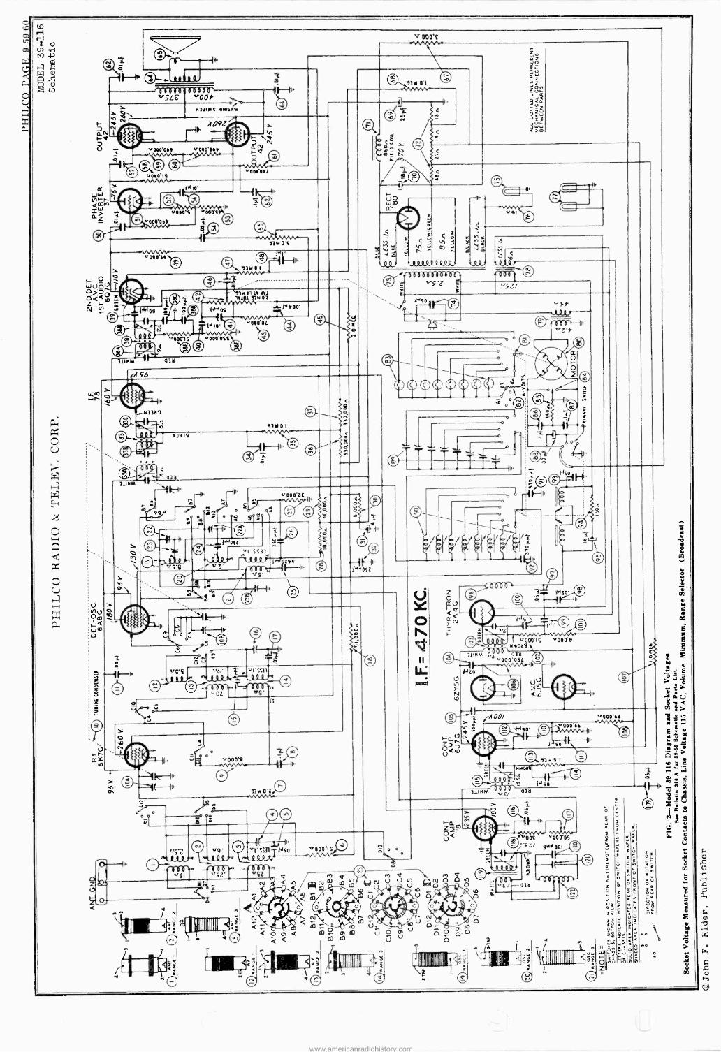
www.americanradiohistory.com
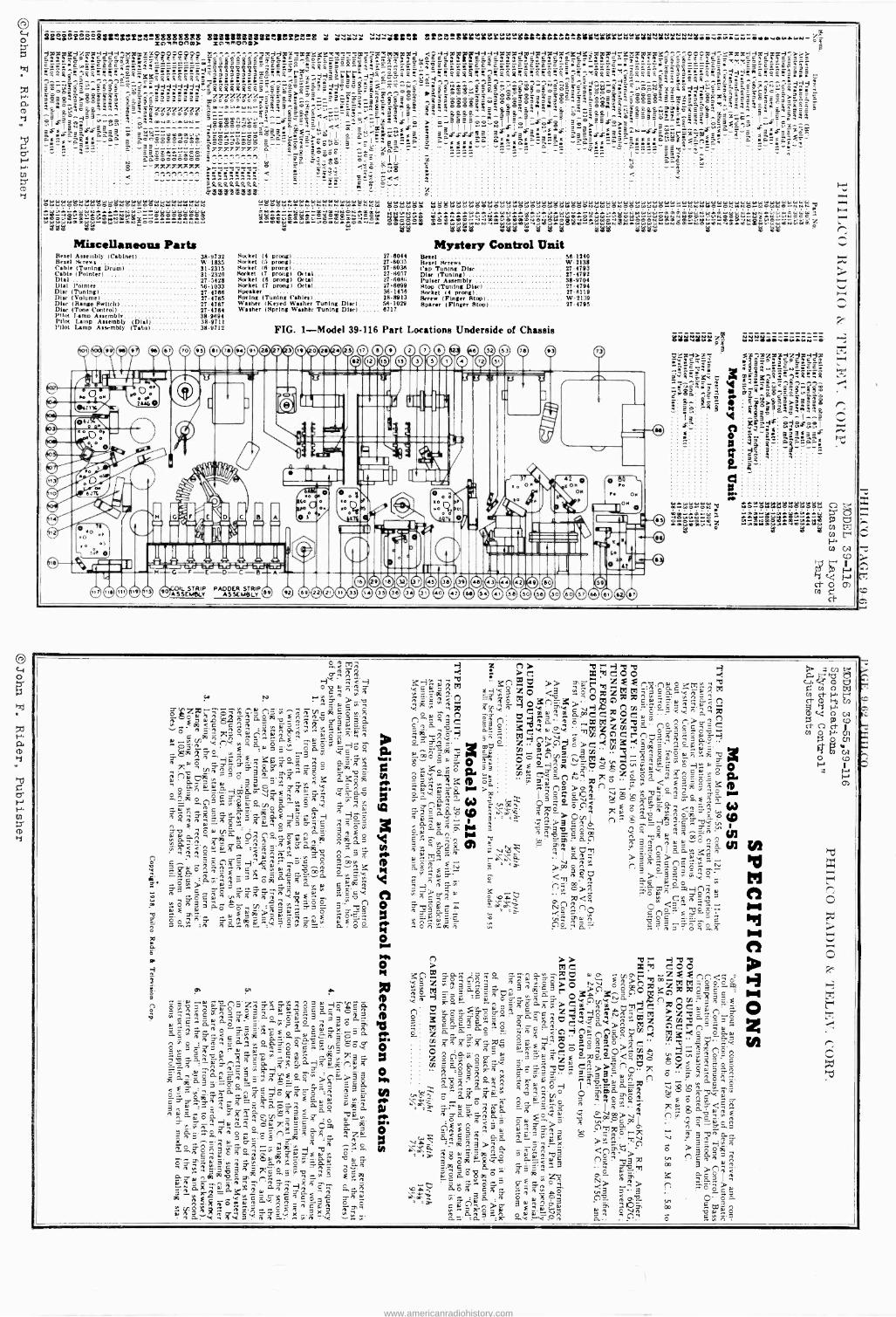
3ieY&lSße-83le;úYnN`óáá88á8á á1aIIS3S31à1áttiSileBlRGI'8 é éáú »jilel Ll,e.Ñ-eSBYYYeY';.Ñ`-"SSLLLLft.Ñ'-SiiL"BL.YwÑ=íC8iv8Lriwi3=8 xwTonm> ZLTOnm>
Fw
a° 8 -7S7CTT.7.7CT.7t >77777577 1.éi.]iÌ1^.11
1 3áééééëé8é ?'' I `4TL - e+ß éeo e
I 1
< .w`a.e
Ó ÌiWiIG:ÓÓÑWiW000ÓebÓ((bCCO+00MttCCKÑ(Ñ(,Ñ
NÓpreG SHOppp9ONOYNm.pO rÓOC2000(..NÓ0(,,,ff
W
Ö NWYWN00a41WrtlW WrQNCOOr-.+rNNNNr
stirttOO,m
aRRRs;º,aº F°a°a$$S°a°.É°éé
Miscellaneous Parts Bezel Assembly (Cabinet) 38-9732 Bezel Screws W.1835 Cable (Tuning Drum) 31-2315 Cable (Pointer) 31-2320 Dial 27-5428 Dial Pointer 38-1033 Dise (Tuning) 27.4768 Disc (Volume) 27-4785 Disc (Range Switch) 37-4767 Dine (Tone Control) 37-4784 Pilot lamo Assembly 38-9894 Pilot Lamp Assembly (Dial) 38-9711 Pilot Lamp Assembly (Tabs) 38-9712
e e
R . . - ë« _ _
é
- - ó WKK ÖÓ 2YuÓÓOÑLÓG OÓWÓWW¡C0WW22KKKIOiOtiÑ KÓfOW4 : e.ÇCLpCimipüg
rOQßÑVOC p+2 ÓelaODOt0ÓWpÿ0=YpOOW00C OG~N4 wO OgCGtRpS .Wa ßr1NNOJQ+WsL WCNGY 5505 0à8 tl d SB 425 $eótl 11
Ó
Rocket (4 prong) 27-6044 Rocket (5 prong) 27.6033 Market (8 prong) 37-8038 Rocket (7 prong) Octal 27-6057 Socket (8 prong) Octal 27-6086 Market (7 prong) Octal 274099 Speaker 38-1450 Storing (Tuning Cables) 28-8913 Washer (Keyed Washer Tuning Disc) 58.1029 Washer (Spring Washer Tuning Dime) 6717
©m mmmm(Do
Mystery Control Unit Bezel 56-1240 Bezel Screws W-2138 Cap Tuning Disc 27-4793 Disc (Tuning) 27-4792 Pulser Assembly 38-9704 Stop (Tuning Disc) ' 27-4794 Rocket 14 prong) 27-8119 Screw (Finger Rion) W-2139 Sparer (Finger Stop) 27-4795
FIG. 1-Model 39-116 Part Locations Underside of Chassis
(D ID ID ID T) O Oe Oe s2 sa e
[ '72
St
ü
a
ß
o Stuv8llï d iiísiiNi
a
déxr7 éñeñééeér
age s y9 rw_gc:Tg wß' X mC3%7i_+^l:i.w..aiR -F_
R r ;ai; º .Sn-nn sá"' w i"=älWg ; - - $ ' Ñ>&>>>a
eg 'i9 6áai;aä:g ae e -e -.1..,.
xá A 3:a 88x831 : 0 s -a_ a2a%a: _ p V a -`_â
4-
2t222222
Yg!Meer rä
1 w eaNNNNNáwéi':eóé'sLWi YOr OY WW
IN..:aYiOiW:J+ tl4uir,Y¡,
8 5;
.
r
rr%Á
tr;^ñ ' o3ª;83^ n w }a rw >y.á
°Ñ... S FHópTOp
z-7 ö'A q:Nc
i é
s e.2 013
Nó w
3g..,,,u)::21 ^$2n
SÓ,Sºn^F oN3ÿ,
QA n ° Q A .SQ
n o 'oow
Cá27;N ô s
ON A 2^ Ec
°.-itazic^_
m.°.,.
oö. 4Eó7
ZArt' ''ño<Ñ
n,,apo C:g»?$ Swn
ñ't
u,no OÓ "°'eñ^i .TSwc caE-2övN'-1 n E w _^ í%w 2 º rSe c Pñ' eáa8'wwawpñosö nas ñ,ww _e-,ñ ëtn ^ ÿ'p.:"-ñ an0
27.`.!' »9 _R g- - óC1-'6¡, ° :.Sa° n^
E n w2 ep
:° C ;,f2 -r." ô Ä.P Á
... ,.,> ws T pcúát.aññ^ñe'rn twEwu
eô^33áô$ö ,(n c^Ns° E v,». a+Eiä)RI>`-°wá:á : no
7..'e. :rt cSs G..^e. ñ w.9 Oi 7 Ñ tSá.N
Fe
c SS» n =o a. w
A ª -,. w n ° aös; öo c ^o, cb+n3<aan N
Sdm ° a rjß is -ni vN 7 ªG A 'O Ñ ñ' S- o o á= ^ s. 3 a Ç sl sc_.or.no . n 5nºn
á^o oñ_.ô ov ñ c-+ Sñr. ?N ".' º ñ ñ ó ñ .w $"?w TÉ w N
Ñ 5:á ó.^ : ó'Ñ'Sñ o3^7CÑ'ºSHo ÿg og w n ep $ Q s (- ñ
T er--;" v
ó W'ñ -' Qw ó° ó^ Tft: 51,4 ç 4 w á ó gç a ¿ w
N ñ º E w ó.o ^,öï ; 3 ° 3 $
w,n- á äñ °'o O .w¡^ íar
w 0 T áº'Ñ,?g,á Ñ'$Eo wákö5a n^o n
Cöç^ ñáw ÿ2 3e Ñoa rtá
s On
.,e ..» 3
?SnCwoo nnSGSn o
N c g"->3 ^ñón-scH° ô-s^'ñ ospS ^wrs8Y=
gc<
Ná.' wá
V p Sn -v
.
.H+r's e5P=n4 :":"45 00 ºN X3
n ª3e º:ñ
9.->;-e 7'7'34 óö's 3
o o O ñ »co JN Ó-wiéñ0 9ar H
pp" W
S Ç 2,8.:11 'a ñ óÿ°o 9ó. _01..). r
Bf n Q O Sn »rs7e8
1º 8 E f.t;;.
2ansN. Ññç°w ô P a n
7w aá.é w .Q.90ñ
.. r c z:eóó He .. Knmt7 » exeR'ná.cOKrN,b
gs<3 zo < ' xo 7," mSm pw01yÓo Ow' N.c,;á.; ö..W1li9xaya-`"n0nn>SaC Ñv £(/2 Le
ÁLx:iCrºnC,ñº3cQáó«3 W
C Á O Cp ^ 30"p -' .n. .^+ n' .
7 w öf'iCtna.v. ÿ...a óis3wñ'::052.-0 á xE ?-ió -dóg0"'wN1cN°cmwñ o w^ adòÑ;' go- xó ôa 3S=^"-° p.
»nS >a :^ Ñ dEläó A N
oot¡cip vn_b. `-r3 S°. '=aZ O cw Enn Rv 0. W o x7o ° P 7C w ô S^ w ñ <`^.s:; w > ^$ º é ^» cOln a-o c » b<,a C a3 b º~ n o
O
n 2-e:
n N N íf c Oo n . .+ Ci=' C._Ci b
ñ w w ° n n ä :147Z-2
'' ç( c ñ N 2.
8 N V re te
?3'8..e> E >poOn^ iG np
C Ó Giale
ñ
CnG áç:.'g'3Ptº n»e>g
O . oÓw
tIanTO Po ^ç ;- g3ñó°ºe
www.americanradiohistory.com
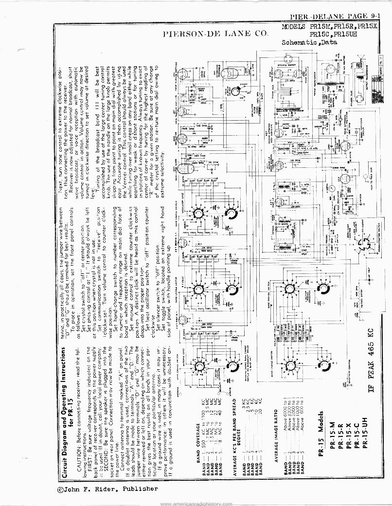
PIER.-DELANE PAGE 9-1
PIERSON-DE LANE CO.
. ód ó; ,áó,P á ¿O3 t£ó'3gaX)c°c ,nEpa, to .;,-,E
w +- s ar .:ó cm ua -o `oóu
.e Ñ p ó T p1L T y >-0
1)7;3 E a 3 C`- °' ° °' ° ó 3 r 3 ó ó _0.0.___ .- _2- 7L U O 3 p y 0) O a c in 0) al C
a)L p c
C> - O E3 O TL 3 0 £ a. O C -Co Tï. ° u, E a, ..- ,0,_z.- a) u W v ú d'0 U¿ c 0 3 a) O X C w E p p a)+' £ Ó.u,
°££inQ.L-.m C
0 0 u 3++ c C C E" T C.'.
~ o O>.0 ° O ó a¿. O W'in W or 'r-, a, a. -o O °°'v Ç u 3 C g. óL
ó c v ó a.T _a óv .1°
C.- J_ >.0 ._ Ó O L O 0) . O O.ti ..'.. C 0) 0 z 6 C O c0óóa °óc_ó3:.w
c v 3 c.3 r a' « ó
d d°c o,On> + -
ó ç ç Ó Ó V a.
N aa,
ÓÓ ,,i ,.. .- O. u, U O O á 3£ Ó U 0i `O Ó `°.íg. 2 Ñ zu °cu £ cw U ^ .- N a, 00 O 01. '1"..- Ú. 0) C r. H .3.?u. CñFOIUCOOa,UO Xú w c cQa, ¿'.. Ea,£
a) a) a) £ a) _ 3 E a > 41 `O .O- L O Z C 2 > 3 C ail- 8 ªÑ )n ç. ..
Q 275 5 úCYOSÿca),a'wX ,. 3> a, o a a) 3 v,. u. o a)
P.
C r C 0) Q, O Ñ "g C
a) p y O O
0 y 3ç c o ï C a) ,n - C U -[ p L ÿ 00 á 0 áw UO U Ú L _o .t._" C>- Ñ ÿ V.0 C Ot
7 á, 0 0 f O C _ 3
C v 0 - ' Ú +O n O
a oa g Ñ.V ú `C c g £ á v C 3 p a) £ 0-2 a C Q EO ° ó.£ up QX3 3 C¿
TD E C a) O
w - O 01 t2 U= C «'-'e-
C.a).Ñ WO O
0) O C C X - C
. Ñ £ Ñ .`.t. á_ d
si, E g 3'ó.Lu. :it a
o N .9 - vi £ }- > O . u ó ó 3 3 c ó_ ú 3 2 a Ç ! - º u ó ó H ... ó s oI T Ñ yLu C L 0 C 0) w C ¿ 0. «O. t b O OO
íLnO 3u3cl- svw`)'Ññ 3i,Ñ i .^(2.g3 C _
p C Ç £ C V O u 3 o U a) O .L C 0) á ó;,; ó' E aN+.,- c v 3°Q Q ó ai aci o)á
5
x a. E- º'- 3 ó Ç O O O a) Ñ a) Ó a) Ñ C ` aVl U V) t101 a) l-.NN v-) _o , C v) p
O P p ó `-' 3 O0 av .2
e
, mi. ism
o,w
r;-1 ,.
Ri11 Sil) Ritt *ire
@1-N-1, ºs oxr
"'1
s
s
feee o,w
LIN Rif-)
1 Q1
y) ) a) T. a) O : O O O I .
C p L ñ C F. Ñ L wu ,E, E ` Q 7
o a 0 w l- > C 0. 0 a, C 3 a0 a0 O ç >v`n, :1
o ó
ó aui 7 v O 0,: ` t >. ç 3 f
0 .O- 3 O . O l7 U +-CO a ..
0 ` a3rn3 'a .1: .LÇc3L v a) o o v 3 ,n ,n a)
Ú) C a C C C Ñ ° ._ Cl > -- a F,__ 3 Ç Ú ú ó o°1
.)L ° C O) O C- C .a. O C , O E ° ç u, O C_ p 3 Q
.05° m ° C C Ei,--c-,z
U C`)n C°£ - U ^ C 0' O' 0 O O C' C,n C cä. -7.O aº,á;, c w' °c aai
o u. °' c oG. yi-C Ej.O--£rÓLO , C O, O ó 0 C0 .O- H O 3 a u) O U
O`F O D U .t-U O j Ñ C ç
E
.- p N
n ó d Ó 7 C C 0 N
in >
Oa,) O C UV 'n 0 C.O. E p.ñ 0.3 C 3 Q1
CO y', `l
. CO a a) a)
ó ° N
C Z`a,ów vcó ÿ>.t..+-cE ú1 " O O- 0 0 Cj.O C O c C vZ c ú) v 3 ó 3 aE, a) ó 6, G, ó _ F - ._F- 0.0 0 c Ñ >- at
3 rn 0.30+- O C-0 Ñ 0) ä 0 0) Q C- O W O a 0 "'I:10 r k..) -12-0-1.."'/U4) _.,t °° E".... 0 0
U O O 9, f. w.2'O'- a - 00000 ZZZZZ <<<<< fC Ca co fö 0a
M DEIS PR15M,PR15R,PR15X PR15C,PR15UH
Schematic ,Data
0000 YYYY m n
NNOQ
ce o0000 ZZZZZ
> 44444 < f0mmmm
00000 00000 SSS pmN a,a)wa)o, > > > > > O O o 2 QQQQQ
i
2ccXUD LA LA IA LA LA
CZ G: G: G: G: O. 0. 0. o. 0.
©John F. Rider, Publisher
www.americanradiohistory.com
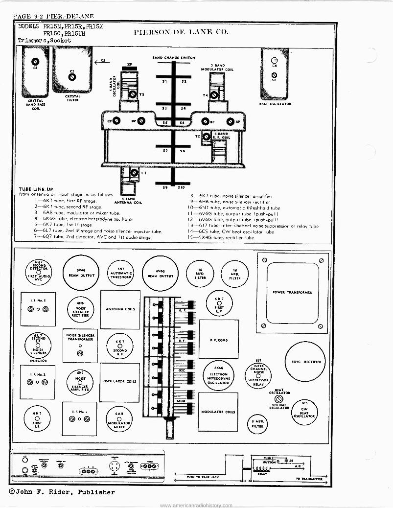
PAGE 9-2 PIER.-DELANE 2.101)E LS PR15M,PR15R,PR15X
PR15C ,PR15UH Tr inner s,Socket
AmsAa`7..
CRYSTAL BAND PASS
COIL
PIERSON-DE LANE CO.
BAND CHANGE SWITCH
CRYSTAL FILTER
TUBE LINE-UP- from antenna or input stage, is as follows:
1-6K7 tube, first RF stage. 5 BAND 9 ANTENNA COIL
2-6K7 tube, second RF stage. 3-6A8 tube, modulator or mixer tube. 4-6K6G tube, electron heterodyne oscillator. 5-6K7 tube, 1st IF stage. 6-6L7 tube, 2nd IF stage and noise silencer injector tube. 7-6Q7 tube, 2nd detector, AVC and 1st audio stage.
6V6G
BEAM OUTPUT
ANTENNA COILS
NOISE SILENCER TRANSFORMER
INJECTOR
I. F. No. 2
OSCILLATOR COILS
®, 000)
5 BAND MODULATOR COIL
8-6K7 tube, noise silencer amplifier. 9-6H6 tube, noise silencer rectifier.
1.0-6N7 tube, automatic threshhold tube 1 1-6V6G tube, output tube (push-pull) 12-6V6G tube, output tube (push-pull) 1 3-6J7 tube, inter -channel noise suppression or relay tube 1 4-6C5 tube, CW beat oscillator tube. 1 5-5X4G tube, rectifier tube.
16 MED.
FILTER
16
MED. FILTER
6 K 7
o FIRST
R. F. COILS
6K6G
ELECTRON HETERODYNE
OSCILLATOR
MODULATOR COILS
PUSH TO TALK JACK
INTER CHANNEL
NOISE
SUPPRESSOR
RELAY
POWER TRANSFORMER
BEAT OSCILLATOR
VOLUME REGULATOR
PSI H SUTTON
TO TRANSMITTER
©John F. Rider, Publisher www.americanradiohistory.com
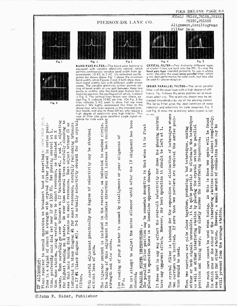
l'rl;H.-I)r.l.AN l: IrAGr. 9-3
Fig
PIN,IIZSO1-1)li. I,ANIi. CO.
1 Fig. 2 Fig 3
BAND PASS FILTER-The band pass feature is equipped with variable selectivity control, which permits continuously variable band width from ap- proximately 10 KC to 2 KC Un -retouched oscillo - grams are shown above. Fig. 1 shows the minimum. band width, while Figures 2 and 3 both show maxi- mum band widths, but with different width screen sweep. The variable selectivity control permits set- ting of band width at any spot between these two points or widths; also the band pass feature has a rejection position, the oscillogram of which, is shown in Fig. 5. The vertical lines drawn over charts, ex- cept Fig. 3, indicate 10 KC per line. IOn Fig. 3 the
Fig. 6 lines indicate 5 KC each to show flat top more plainly.) We highly recommend this filter to the phone man who must operate in the crowded ama- teur bands, and also .to those DX'ers who require o high degree of selectivity plus high-fidelity. This type of filter also gives excellent single signal re- sponse for code work. N
o O
i -1 ( cd s, 4 a cu
0 e e)
O U O N L rI 27 U r-1'
_,' rd?U mm ~ U N f- O 4-t o d o v a)5 0 0
413 °000°' 0
to -P cd golr> N
ti d C)
° r1 O r4 cd 0 +' 0 a) 'Id O d 4-1 0 4 rl >a E m r1 Ord FyN 0000 44 d r-1 P
O n c3 'd 2 'd N c3
O r-1 cd -i
cd i to ri U - o -N +,
'cl)
Ñ O N pi .f CO 4' r-1 O 4r1 cd ri O
'd 1i pt C) 14 E O 1 rya -1 ri -1 a) U 0 r1 rr +' 4' i Di cr)+a.a'
cd +' O.r r
1 U -i O d H)) A O r-1 cd r rl U r-1 N M N N 4F0 U o N cd o a) cd .a cad U N d > 0 r-1 44 4-
+' +a Y O 0 a O N 0 ßt.0 Swo 41
.a m 0 reg
rel r-4 a)H,FI Nr1 N
U r-1
04' N O c0
Fi T, F.l .tro{
E
.á O
w m Nr +' C) 0 .0 A ri P Ñ O o
?S cd 4, U 'd
O F,i
Ñ F -i CO Di r((l r-1 ri ni
U tQ 0d
a3 Ñ .ri 4-i C. Ú Ñ -1 U
c3 N ++ r-1 N ....2
ri 4-2
j a)
0 \D N $4 >. -> 0
4k 0 .-1gl P4 o ON d O C)
r+ 43 cd 0 r
`
7FIo rl E U
ób N4o'Npp
Si
m 5 ó C)
5-1 r3rd 4 o a)r ifl Ña 4 Á r1 q
oo ,4 .4Fip cd
!
Li f/2
44 ..-1 0 40 47 iAU >a
F r
T.' U N -Oi ,04 .d4Oi
O . 44 Di 0 rd com 1 r1 f 1 o e
L4
-i ,C
co Ev
cd 0 0 H a d 0 rt 0 r11 k 1.1
.rpi 4' 4.1 55 N 0) A " 5 W N 4 4. 0 l -i a) O .r1 +a 4 4
(1) 0 O Q) rl 1-1 -P 41 41
0 N 0 0 C) 4-, N 0 'd r l + N C) N g- Ei E4 -i -i to.,, -1 o4i (- fc FEi el j H
a)
a) N 1
O .r1
MODELS PR15Id,PR15R,?R15X
PR15C,PR15U1I Alignment,Oscill.ogams Filter Data
Fig. 5
CRYSTAL FILTER-Two distinctly different types of crystal filters are built into the PR-15-one the band pass type intended primarily for use in phone work; the other the usual series parallel filter, which gives ideal performance for code work, but may also be used for phone reception.
SERIES PARALLEL FILTER-The series parallel filter is of the usual type with a high degree of effi- ciency. Fig. 4 shows the series position set at maxi- mum selectivity. The .selectivity shown may be de- creased considerablyby use of the phasing control. The Series Filter gives the ideal condition of noise
reduction and selectivity for code reception. Fig. 5
and Fig: 6 show the selectivity when crystal is not m use
r1
I* i O O U rl F7 tn a m
m V) +-1 a) O)
ai 4i +a
.c;a r1 . 0 44
o P ó 'd .0 N ie
M MIO
r -I 4-,a) ..-1 O 0 cd 'd .s:
N c3 sa rlp
q a) O +s C) r1 4p q n-1ri /y
a) Aa a a) ri cd
P -P O m -1 U > +I O Ñ -4., Pi
q +' N s~ Fr r ó +a U
d m
Pi m
A COm
o i
e Óo
o > P H
0 n-1,
4-, U a) 4-1 4i
N m > a)
Ó
r-1 d) pr a) rt
}a;2.2 a N Ç N
2 2 .2 ái pi a) ri 41 C) a)
a)3 mc!:: o ,0 Ñ ri ß(I o .
á cd 0 Ri 4-i 'd Qr U N
}y ..i a) + ri a) 4__.,..Fy
U W + w -I
Pi C(1 a)N
0 t1 ,i +3
j5 .r m
S Cr pi H
.r01 .Ó cd gi
Ó ri O rl g 2'":'
Ó ^
DI ri ó4 o
cd sy .d N N m
b' w >a0 N N a)
) r-OI , ,oa
o 1 40.
ó
mm2 2m
U m U
O cd
0 ,s; e HO U
m m -I-) 3
eta)
+ a) 0 m cd pi H
4
r-1
m .A
o U
O o Cd 1~
ri 4i 41 O
o A O rl O
+
F m ry
O
o
©John F. Rider, Publisher
www.americanradiohistory.com
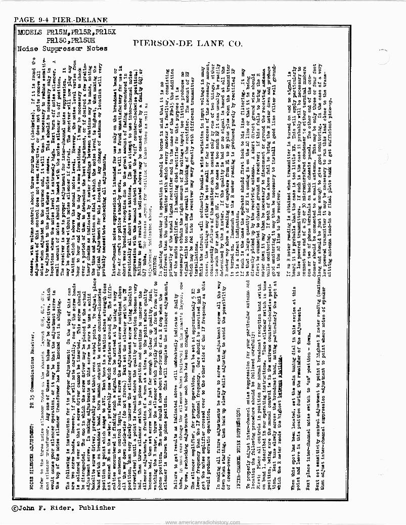
PAGE 9-4 PIER.-DELANE
MODELS PR15M,PR15R,PR15X PR15C,PR15tJE
Noise Suppressor Notes PIERSON-DE LANE CO.
2 m
+wYma
r
..m
m21 r - i 0 Oy
m° c e . jä a 2 dw ó[»>m+w i.. A+. 0.0 ° -M M P .-1 ,qMNOm dmÿ0 Y m .d 0 - pp k
m 10zggya,y> mmYp 8 a. o , V ..22g1 22.0 ° 4,11 mdF a m
.eY UH p2 -¿m e,gF
O m O m .1 00 M0O
m gd y.yU0aE+0mQmda°g7,g H° à.+ 00 H
d I'D
0 y w m. o ç°bA9HovYOYwdr d
ód Fm U0M00Ú+'áViaPbJceC0ae(Ym O Y H m Al V O 0ßPO DÓ2gopOPo g mUrlU0MWFya ji V J
o U Od+mbYywgm O pU7óM
M mm ,meo A mdY mj .PPH ÿmm Úÿ
2 AÓT,mP00m rymgmyá.rD7m 3
497 p OeP Ám,a .r OOmOq
limFinarl.HPQ+ior9FWÚ .°f+F0 1;
.dmo 0mgHO °qAM i. a
i P
g Y 1-4,1U33y 01 gg-.-
F a m W
0 0 0.29d
0p7
2 k,asUtßO.GM
UO.- - ° °riO F 4OHmM0m0aY?C myaYm
Om aRm0 ° 2 .r, ,r.wo r1 r 0 -W 7amm ..-im+wd, ógmm
H
la
mOsM pd ,aw+0maHme°mp0 0. m° gq
VOi. y QQ0
d d+ Ymmym O>I.mD
2." 101 PH y 0 .oU F 12gU0am J m
tiOk mW 1dWm
VppMm
H
,- O0m O{ w F,qm H40ppa'd +.004
m d 4304343440:.qF . Y M.
y V+'s Pm4w.-Çóa A.° 2 , d da2ym ma'
1m CO m Mq
m m
m mFa1 0 p 1 /Y O .m
0 m
p
WMmM m
óF1.+. Ori 000 R 10
MppdOr+fe-1MY0Yea mÿqm UY
9 {,y0$ 8.
0 .4 e .°g
ó3 t mY,2e
m
a L7 +o+
m mnm)Hm.
M,qmm Mgom1Ho4 OO H
°gÓMFdáV f FYi YM yÓm.ppp
dmmg t m
to ,,p0 H O m 0 mMd 2020 0mÚ HOb63 jqVmd0EFmpO.H m a1-4mHÑ
P--mdo .-1mMmMNm e °mM V 2.2 mFeR 0
4 M r M+' YggO,g0 00 N wd 0 00md7mM YFM
:,1.22 m 0Q'
+'r o gä e aemPiPL4s0d 2'2mNP8'p,m Wp,2408'
m b
mA.4i
Ó Ù0F
Md
y
Mm
.
mY
a+
,
..01
{r
.
fY07
. +
P.Wp-V'1i
r l
my
,22 cp'
t7.3y
Mfyy
M0gmd
y
MfmYói
Y r1
{op
mF..
i
{tÑ
r,0l .d
U
M
(LYi
WH2Ñ
MÓ P~AMm ó ó
mqo1 ÿ ipóo Yya eó4mA ÑTOmmrE
P0d
rrW
rboYD OMb OOYÿ 4 r1
dIp,7y1l
O
Quq d.mt Woq1 t+.o_ óHA1W Mm VOWY
aiilleiN MioA mi°mMÓ5d m.g?e mmq . 05'205.0.11'M"mYmdppPM 'mÑY -
JU
212 gYom01Fmm
HY OO yyW .1 r+m Y°VMpdo
Y Wd1: H QQmy 0
MVMpPMN1[l00V
p07yA m 0°y oq M 3m
MFM
.CDqW° R00 Yrl p 4qOtd ,p7 0,...1A, yY Y
bMl Prasq......Ympwha.7 P YpO
l asly Y mri 4,YWgM,Gy. W om aFm mV mYmWM00 .y ót Mm >.no.
m HM Qq O,HkY rp 0
D wáa eMMOH W m P, m MW0 U ,-1p c
Od Os0m MO.. mOL 0N rmY00mW p pYCr]4 M7Yw Wi bRr0Y .mg. Yt OF4. O 07 pF d M
GW Ó Ó q ÓÓHqqmR c 9M MYMM MmcMhDP .-1 ; C Wyy]]4+b0 M d 0.Jm d
m P mom `4
p2220'.,º U1 HÚON.+ Y
M 11+,UP°0a' amo °oYmAApPbM ° CVWY hu 2°ma9YM @m M OYM ami 7m M mO
0 a mV oá O 0 q.140;?w; M0OWy HMFp MYF mG.Y0
p iO+Wpap M
YO o .ed,),.--, " m02 °Hi FmrSY -YP7 Y00OpHb0 ++N qF M P Hm0
M 0 HHyd _û P0 MYWm 0W AA
bO1YMH C000mY.-mUP 0 HU Y Y0
áO OÓYmpppV
R4 ° 7WMpYO,UDMgYUO40
'dF0m0Qq YO MyYM yYY Cmßo0OO FT0
q
koV gpÑqA00ÚHo Mzº0e
Ñ. (w-,4 Ó O9P0MOO WM4pÿFVY, .8.4-20,OORMgp t10 lÚMmA
°GoYp430 ogHg O1 ?u X0o.Y!MO'MWW pare0 Wq2p g0MU.-oUyHm OH,di p :
YM¢ m
0M pA w Oo y YM YmMPGH
@ qAm -g"'091 5:..' óíMpMFA YwoOH J.}HmCq0
mmMom°F. bmu 0 po m
,we, 00 4 MIpq
r4Ap+OPMPm
m gga p msk>>bmm4ÿA ° t'4'
02 M +O W'O HW0pOg02G M 40 m Y rd0.OO
wMO YfO.MmYm8MgUgOWoPAOA0ldY0U
W
yFYp^ÿOq00(O 'pH OW!,,:;:isA").20*.2k
a AO OY02bOYH
Ow vm Y VaOH O0Üg 0 A p O0 0M O ÁCPppy0 YOO rMO Y ,q.Y0YY Uq AYM iY OF m¡ H203Y 0M Y Y.ydULm eOmO O Y YdM Y
p U"-1P3.7 Mpp 4y2MOw;maaqmágaeäm1ma.- k0YZ g0 ÿ pmy q0gÚébFw0
iY0,pp0PqM p"ÓWOMd,m1 ómA maÓ'jrieF BmPo0 ne 0.d G4pM Fo .jPJO7D.
..qm
w ,d g ÿ m r1Ynm5+>0 tO Y YwmUr4wH 7 Y0mO0 Mq, -1 F'dq F
Aapcm YOMVr Omqo Uq F0pmm 02
24:02
O
7AqRyyM WV .1.1,-.2-13.4 qYAdd mm0aMM0R m. pM
04. Y0 AmÓgqd2'M0 tlPUgMY 0'22022 irO YO Ym00OapY 9 °0
A Y w ° o m
ierM U0O4mU:91rl OeO Y'FPM YM
0 0maHOAgÉWSA0 r 0OY00 UY M 2019P4 A
UHk°0Op'U..0A "Hp0gY+iObgQY PM Yy
i*M m0A+ 0 MOYFO0M1z W. U M0M000YQ 4206r4VOP í qOe 1'a-_>9GM HW0MCqa0000AwPMwM2UTFF+rlOw0OOg0OOFF H,pY ° Obr+r+ 6
Ñ m
y0
1 Ymi.Ña1 1
m 0M áe 20
bá
A MM oOP gil.
° J" y a OA 40
0 0Y vYm1 0 +pM y
O 0mq
ó
ÈNp mw
a bm ó4
H 2A,00,1, m,-.
mYe0.
M
.00 m 0o 0WqUaf aH ac. .1Y 21 eP wÓmm0 q 3Z
Y'0
7 q 0 gl Q
0O y Y .00md 52
qp. p , .s H Hj,20 80
.+P.
P ii
0.
á a id>° A' ..40
0 YY Y D Mp
0m m Y
R äl 1" a° PO Yam 0M Nm
a0W .vo §ó, z+
U
q U0
lM
YZMd Y
0 04
r*W9
Y a
m
3 w
á z
©John F. Rider, Publisher
www.americanradiohistory.com
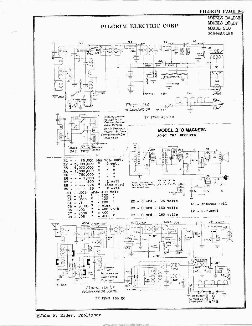
PILGRIM PAGE 9-1
ZOOM
a9
PILGRIM ELECTRIC CORP.
106 /A4
t.77414 - ISM
.00025
JJJ/KNlJ JNONMLO"
Me4rtD41V JjvL POJ/7N/N. Jw/KMIJ JNOWMOMMOOlL - - DA! JN HROAOCAST
PBJrr/ew. ALL D/NEA
CONNicr/OMJ ONDA! JAMJAJDA.
._ 3* /35"
MODEL DA p 460,00/AND UP
185
i I
.013
.36ND=80.320
T5MF0
MODEL - .. 3PLT
DAE T 5 .60025
R1 - - 25,000 R2 - 3,000,000 R3 - 6,000,000 R4 - 1,000,000 R5 - - 750,000 R6 - 1,000 R7 - - - - 800 R8 - - --- 275 R9 - - --- 25
Cl - .005 C2 - .1 C3 - .005 C4 - .1 C5 - .0001 C6 - .02 C7 - .006 C8 - .05
C'-4PLT.
ohm VOL.CONT. " I watt It I n It " " 4
n " C]
n n n
" 1 watt " line cord " 2 watt
mfd- 400 Volt " - 200 "
" - 400 "
" - 200 "
" - mina " - 400 Volt " - 400 " " - 400 "
L,oo
IF PEAK 456 KC
MODELS DA,DAE MODELS DB,DF MODEL 210 Schematics
0j-1 Ó /OOM
000,
A -
MODEL 210 MAGNETIC AC -DC TRF RECEIVER
L. .^^^ ) 6C6 q 38
----- + 4 ,L
1 J
aas 6c6 .$ Ta
un. B. NOTE.- »as., 22 A ..f../x.. .,
.O Bella/ I. fide.
E5-5mfd
E8-8mfd
E8-8mfd
608G 6,17G,./30 J ==r4E o o_-
4aw IME6
b - 6GS n
.0035
_ e N ry
..-/30" .65"
J0M .0/ '5M
Jw TCHEJ /N
SHORT WAVE
POSITION.
F-
25 volts
- 150 volts
- 150 volts
606G 535" ' ` - e1 1,=.
150' II
0005
DOOM _ Stet* son
.oz_ loon
0
A, r Ty
-1 2.2"
s
L1 - Antenna coil
L2 - R.F.Coil
OI 38 .-/Zo"
MooEL De DF 500.001 AND U P. ,P,[[M
r /Oÿ
16o - Z6 VIB.
IF PEAK 456 KC
A
FILr6R CHOKE
I CO"--,.. SO
I BLUE REO- = CRFc i -F.-4' d,rT - I.0;71-
::; --ft a l 1 j
IT,s .5-1- I _ 10
C>
I P P f --fi R 6AV ESISTOR
ON1100ELS-. A L. DF-DFEON. 32. -
©John F. Rider, Publisher
www.americanradiohistory.com
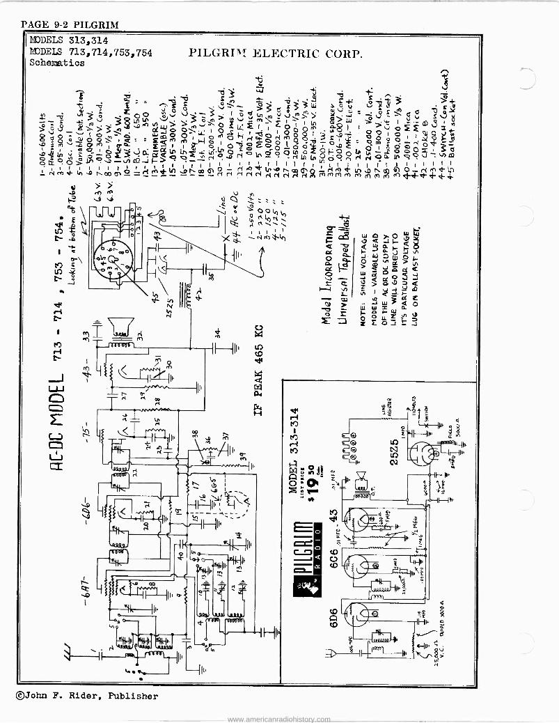
PAGE 9-2 PILGRIM MODELS 313,314 MODELS 713, 714, 753, 754 Schematics
PILGRIM ELECTRIC CORP.
-ci u..: + 4
> d ¿
i I O ts o >3 W dV
u_ .Q N o r
O O '2, v V' _ 1 0 to , J '^ Y _ _ 3v 1.r) Lr' `J , ò m m\ 1 $>p W >°_ áj33`DToCo O\OO f t t ó00'^ w0 , 1 0,0 ' Óó_, Q_ sQM O tHcOópÓ3Si9is
.o re -00 1 a a - 1 I o OC l op p .Ic a3`'dQntngÑu;co zatc,öóótnoZaoaL 0-- O O C _. N . f"1 N In Ut O O rt ólZoÓ>lno-dJ_i> - I I o
N I
t t I I I t I I 1 ' 1 I I 1 I I ln l I I 1 : rV re .h In .D I c0 O- ri V) D h aD 6 ry N Ñ N rV .O OD 0 Q rñ m M m ri ri N cV N (i
V
1.
U i) 'J.;
o '
ó
IQ : 1
X --- N rr) 1r1
HP,
c0
U F Jbo30o ò
E
©John F. Rider, Publisher
www.americanradiohistory.com
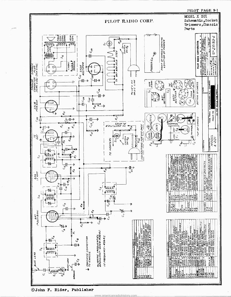
PILOT PAGE 9-1
PILOT RADIO CORP. 1!JDEL X 201 Scheiatic,Socket Irin ners,Chassis Parts
©John F. Rider, Publisher
www.americanradiohistory.com
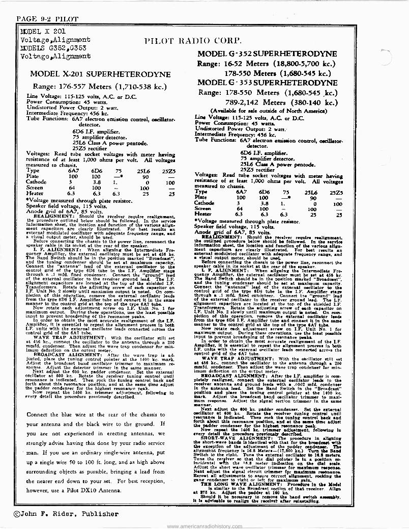
PAGE 9-2 PILOT
MODEL X 201 Voltage,AlignLient MJDELS G352,G353 Voltage,lilignment
PILOT
MODEL X-201 SUPERHETERODYNE
Range: 176-557 Meters (1,710-538 kc.) Line Voltage: 115-125 volts, A.C. or D.C. Power Consumption: 45 watts. Undistorted Power Output: 2 watt. Intermediate Frequency: 456 kc. Tube Functions: 6A7 electron emission control, oscillator.
detector. 6D6 I.F. amplifier. 75 amplifier detector. 25L6 Class A power pentode. 25Z5 rectifier
Voltages: resistance measured
Read tube socket voltages with meter having of at least 1,000 ohms per volt. All voltages to chassis.
Type 6A7 6D6 75 25L6 25Z5 Plate 100 100 -* 90 - Cathode 3 3.8 1. 0 100 Screen 64 100 - 100 Heater 6.3 6.3 6.3 25 25 *Voltage measured through plate resistor. Speaker field voltage, 115 volts. Anode grid of 6A7, 85 volts.
REALIGNMENT: Should the receiver require realignment, the procedure outlined below should be followed. In the service information sheet, the location and function of the various align- ment capacitors are clearly illustrated. For best results an external modulated oscillator with adequate frequency range, and a visual output meter, should be used.
Before connecting the chassis to the power line, reconnect the speaker cable in its socket at the rear of the speaker.
I. F. ALIGNMENT: When aligning the Intermediate Fre- quency Amplifier, the external oscillator must be set at 466 kc. The Band Switch should be in the position marked "Broadcast". and the tuning condenser should be set at maximum capacity. Connect the "antenna" lead of the external oscillator to the control grid of the type 6D6 tube in the I.F. Amplifier stage through a .1 mfd. fixed condenser. Connect the "ground" lead of the external oscillator to the receiver ground lead. The I.F. alignment capacitors are located at the top of the shielded I.F. Transformers. Rotate the adjusting screw of each capacitor on I.F. Unit No. 2 slowly until maximum output is noted. On com- pletion of this operation, remove the external oscillator leads from the type 6D6 I.F. Amplifier tube and connect it in the seal. manner to the control grid at the top of the type 6A7 tube.
Now rotate each adjustment screw on I.F. Unit No. 1 for maximum output. During these operations, use the least possible input to prevent broadening of the resonance peaks.
In order to obtain the most accurate realignment of the I.F. Amplifier, it is essential to repeat the alignment procese in both I.F. units with the external oscillator leads connected across the control grid of the 6A7 tube.
WAVE TRAP ADJUSTMENT: With the oscillator still set at 956 kv., connect the oscillator to the antenna through a 200 mmfd. condenser. Then adjust the wave trap condenser for min- imum deflection on the output meter.
BROADCAST ALIGNMENT: After the wave trap is ad- justed, place the tuning control pointer at the 1400 kc. mark. Adjust the broadcast band oscillator trimmer to maximum re- sponse. Adjust the detector trimmer in the same manner.
Next adjust the 600 kc. padder condenser. Set the external oscillator at 600 kc. Rotate the receiver tuning control until resonance is indicated. Then rock the tuning control back and forth about this resonance position, and at the same time adjust the padder condenser for the highest resonance peak.
Now repeat the 1400 kc. trimmer adjustment, following in every detail the procedure previously described.
Connect the blue wire at the rear of the chassis to
your antenna and the black wire to the ground. If
you are not experienced in erecting antennas, we
strongly advise having this done by your radio service
man. If you use an ordinary single -wire antenna, put
up a single wire 50 to 100 ft. long, and as high above
surrounding objects as possible, bringing a lead from
the nearer end down to your set. For best reception,
however, use a Pilot DX10 Antenna.
RADIO CORP.
MODEL G-352 SUPERHETERODYNE Range: 16-52 Meters (18,800-5,700 kc.)
178-550 Meters (1,680-545 kc.) MODEL G - 353 SUPERHETERODYNE Range: 178-550 Meters (1,680-545 ,kc.)
789-2,142 Meters (380-140 kc.) (Available for sale outside of North America)
Line Voltage: 115-125 volts, A.C. or D.C. Power Consumption: 45 watts. Undistorted Power Output: 2 watt. Intermediate Frequency: 456 kc. Tube Functions: 6A7 electron emission control, oscillator -
detector. 6D6 I.F. amplifier. 75 amplifier detector. 25L6 Class A power pentode. 25Z5 rectifier
Voltages: resistance measured
Read tube socket voltages with meter having of at least 1,000 ohms per volt. All voltiges to chassis.
Type 6A7 6D6 75 25L6 25Z5 Plate 100 100 -* 90 - Cathode 3 3.8 1. 0 100 Screen 64 100 - 100 - Heater 6.3 6.3 6.3 25 25 *Voltage measured through plate resistor. Speaker field voltage, 115 volts. Anode grid of 6A7, 85 volts.
REALIGNMENT: Should the receiver require realignment, the outlined procedure below should be followed. In the service information sheet, the location and function of the various align- ment capacitors are clearly Illustrated. For best results an external modulated oscillator with adequate frequency range, and a visual output meter, should be used.
Before connecting the chassis to the power line, reconnect the speaker cable in its socket at the rear of the speaker.
L F. ALIGNMENT: When aligning the Intermediate Fre- quency Amplifier, the external oscillator must be set at 466 kc. The Band Switch should be in the position marked "Broadcast". and the tuning condenser should be set at maximum capacity. Connect the "antenna" lead of the external oscillator to the control grid of the type 6D6 tube in the I.F. Amplifier stage through a .1 mfd. fixed condenser. Connect tie "ground" lead of the external oscillator to the receiver ground lead. The I.F. alignment capacitors are located at the top of the shielded I.F. Transformers. Rotate the adjusting screw of each capacitor on I.F. Unit No. 2 slowly until maximum output la noted. On com- pletion of this operation, remove the external oscillator leads from the type 6D6 I.F. Amplifier tube and connect it In the same manner to the control grid at the top of the type 6A7 tube.
Now rotate each adjustment screw on I.F. Unit No. 1 for maximum output. During these operations, use the least possible input to. prevent broadening of the resonance peaks.
In order to obtain the most accurate realignment of the LF. Amplifier, it Is essential to repeat the alignment process in both I.F. units with the external oscillator leads connected acro=s the control grid of the 6A7 tube.
WAVE TRAP ADJUSTMENT: With the oscillator still set at 466 kc., connect the oscillator to the antenna through a 200 mmfd. condenser. Then adjust the wave trap condenser for min- imum deflection on the output meter.
BROADCAST ALIGNMENT: After the I.F. amplifier is com- pletely realigned, connect the external oscillator leads to the receiver antenna and ground leads with a .0002 mfd. condenser in the antenna lead. Set the Band Switch in the "Broadcast" position and place the tuning control pointer at the 1400 kc mark. Adjust the broadcast band oscillator trimmer to maxi- mum response. Adjust the signal section trimmer to the same manner.
Next adjust the 600 kc. padder condenser. Set the external oscillator at 600 kc. Rotate the receiver tuning control until resonance is indicated Then rock the tuning control back and forth about this resonance position, and at the same time adjust the padder condenser for the highest resonance peak.
Now repeat the 1400 kc. trimmer adjustment, following in every detail the procedure previously described -
SHORT -WAVE ALIGNMENT: The procedure in aligning the short-wave bands is identical with that for the broadcast with the exception of the adjustment of the Dodder condenser. The alignment frequency Is 16.8 Meters-(17,800 kc.) Turn the Band Switch to the right. Tune the external oscillator to 16.8 meters. Tune the receiver so that the dial pointer is in a position co- incidental with the 16.8 meter indication on the dial scale. Adjust the short wave oscillator trimmer for maximum response. Next adjust the signal circuit trimmer fpr maximum resonance. Repeat all adjustments to assure correct alignment, roeldng the gang condenser to right or left for maximum gain.
THE LONG WAVE ALIGNMENT: Procedure in the Model la similar to the Broadcast section of that receiver. Align
at 876 ke. Adjust the padder at 160 ke. Should it be necessary to remove the band switch amemFy,
it is advisable to realign the receive! alter reinstalling.
©John F. Rider, Publisher
www.americanradiohistory.com
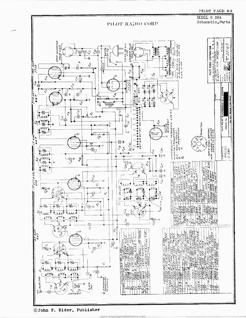
PILOT PAGE 9-3
V
wvvwve
ti
-004 - I. Ito N
--011--At1'
rt . IJ"wv T
-11,411£ -
N b Y
m u \ U
o nod
PILO'!' RADIO CORP.
ÑÓ
o
" N
m N
iss Q h
h M ikeZ
N h
b h h
óti
\
ti O N N ó U
Ú
h O ti
0 L
U
O N
r b Ó
ó O M
e
0 u
0 O O T
ti M
MODEL G 284 Sohematic,Parts
a w
Ó O v ó
01
co
O
+v
O
m
ñ 00
é
3
n
r+
q A Y
e Ct
N
N A Ñ ee
M
N N N.
!-
ti O O
n h
N
Q
ti ti
te e t
J
e
U
I
M \S1
8!
33:
8
©John F. Rider, Publisher www.americanradiohistory.com
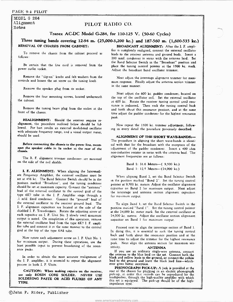
PAGE 9-4 l'ILOT
1BDDEL G 284 Alignment Notes
PILOT RADIO CO.
Tranex AC -DC Model G-284,
Three tuning bands covering 12-94 m. REMOVAL OF CHASSIS FROM CABINET:
To remove the chassis from the cabinet proceed as follows:
Be certain that the line cord is removed from the power outlet socket.
Remove the "slip-on" knobs and felt washers from the controls and loosen the set screw on the tuning knob.
Remove the speaker plug from its socket.
Remove the four mounting screws, located underneath the cabinet.
Remove the tuning beam plug from the socket at the front of the chassis.
REALIGNMENT: Should the receiver require re- alignment, the procedure outlined below should be fol- lowed. For best results an external modulated oscillator with adequate frequency range, and a visual output meter, should be used.
Before connecting the chassis to the power line, recon- nect the speaker cable in its socket at the rear of the chassis.
The R. F. alignment trimmer condensers are mounted on the side of the coil shields.
I. F. ALIGNMENT: When aligning the Intermedi- ate Frequency Amplifier, the external oscillator must be set at 456 kc. The Band Selector Switch should be in the position marked "Broadcast", and the tuning condenser should be set at maximum capacity. Connect the "antenna" lead of the external oscillator to the control grid of the type 6K'7 tube in the I. F. Amplifier stage through a .1 mfd. fixed condenser. Connect the "ground" lead of the external oscillator to the receiver ground lead. The I. F. alignment capacitors are located at the side of the shielded I. F. Transformers. Rotate the adjusting screw of each capacitor on I. F. Unit No. 2 slowly until maximum output is noted. On completion of this operation, remove the external oscillator lead from the type 6K7 I. F. ampli- fier tube and connect it in the same manner to the control grid at the top of the type 6A8 tube.
Now rotate each adjustment screw on I. F. Unit No. 1
for maximum output. During these operations, use the least possible input to prevent broadening of the reson- ance peaks.
In order to obtain the most accurate realignment of the I. F. amplifier, it is essential to repeat the alignment process in both I. F. Units.
CAUTION: When making repairs on the receiver, use only ROSIN CORE SOLDER. NEVER USE SOLDERING PASTE OR ACID FLUXES OF ANY TYPE.
for 110-125 V. (50-60 Cycles)
(25,000-3,200 kc.) and 187-560 m. (1,600-535 kc.)
BROADCAST ALIGNMENT: After the I. F. ampli- fier is completely realigned, connect the external oscillator leads to the receiver antenna and ground leads. Insert a 200 mmf. condenser in series with the antenna lead. Set the Band Selector Switch in the "Broadcast" position and place the tuning control pointer at the 1500 kc. mark. Adjust the broadcast band oscillator trimmer.
Next adjust the interstage alignment trimmer for maxi- mum response. Finally adjust the antenna section trimmer in the same manner.
Next adjust the 600 kc. padder condenser, located on the top of the oscillator coil. Set the external oscillator at 600 kc. Rotate the receiver tuning control until reso- nance is indicated. Then rock the tuning control back and forth about this resonance position, and at the same time adjust the padder condenser for the highest resonance peak.
Now repeat the 1500 kc. trimmer adjustment, follow- ing in every detail the procedure previously described.
ALIGNMENT OF THE SHORT WAVE-BANDS:- The procedure in aligning the short wave -bands is identi- cal with that for the broadcast with the exception of the adjustment of the padder condenser. Insert a 400 ohm non -inductive resistor in series with the antenna lead. The alignment frequencies are as follows:
Band 2: 31.6 Meters-( 9,500 kc.)
Band 1: 12.5 Meters-(24,000 kc.)
When aligning Band 2, set the Band Selector Switch in the position marked "Band 2". Set the tuning control pointer at 9,500 kc. meters. Adjust the oscillator alignment capacitor on Band 2 for maximum output. Next adjust the interstage and antenna section alignment capacitors for maximum output.
To align Band 1, set the Band Selector Switch in the position marked "Band 1". Set the tuning control pointer at the 24,000 kc. meter mark. Set the external oscillator at 24,000 kc. meters. Adjust the oscillator section alignment capacitor on Band 1 for maximum output.
Proceed next to align the interstage section of Band 1.
In doing this, it is essential to rock the tuning control back and forth about the resonance position and at the same time to adjust the trimmer for the highest resonance peak. Next align the antenna section for maximum sen- sitivity. ANTENNA
If you use an ordinary single -wire antenna, connect the antenna to the blue lead on the set. Connect both the black and yellow leads to the ground, or connect the yellow lead to the ground and leave the black lead free-which- ever gives better reception.
PHONOGRAPH PICK-UP: A jack is provided at the rear of the chassis for plugging in an electric phonograph pick-up, in order that records can be reproduced by the loudspeaker, through the high -quality amplifier with which this set is equipped. The pick-up should be of the high - impedance type.
©John F. Rider, Publisher
www.americanradiohistory.com
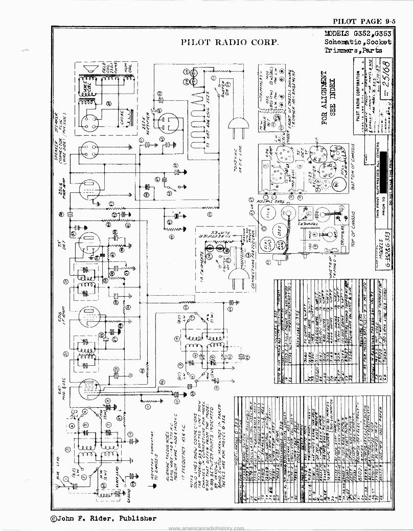
PILOT PAGE 9-5
MJDELS G352,G353 Sohematio, Sooket 9r inºmer s,Part;s
11111 111
1 III i
Ill 1111111111111
IIIIIIMIBINI
`)° Mñ
bYJVhtiVánex4rlvóóa ó~avQWí.nveRRé!óh,`?ti0áp
v
4ÿ fhkkW1h Ñ"Fió;.). `i"Y1°04
3
or4VvWimft?4 4i, mlo.ah
,,,,, gcti
1.1(Ck°ovÁ.k\pp
ÿQ
°ó3ÉA~'2
_
N<, hudl.1whPl`IWoQÑ
>
.`4
N
r;),,), ít.
> wtk c,Cc08 >t10QtÿWpV`
w`dCCó
h o =i =pL
é
k'%\C\4 ;`>Op]p
oóÓ,OÓb'M.4a aa8vs'. \iC`"pv`c\iL áFFkwkONh
. .4i.
10E Wo
Qa2¡'
oa.,
:> ct Q14 YUu)y9X Ve$
E
0 , !
t
Y!V?ºmóhöÓ ;Oññ+.nÁI
! duißvvy v vñé $ÁÁÁ
ón'
Y ~ñ«4ó hñÑMNñ
uii2 tisva,
óó3ó`dóÓ MMÑVN,
" o>ot
wófi¿ MryNk
`
,+iòQqOñNÑñ.¡{.Mbáirfiw
O n g 4
F
q
roh bt, 2 n zt. : .¡hPq^4Fÿé+D
a a
©John F. Rider. Publisher www.americanradiohistory.com
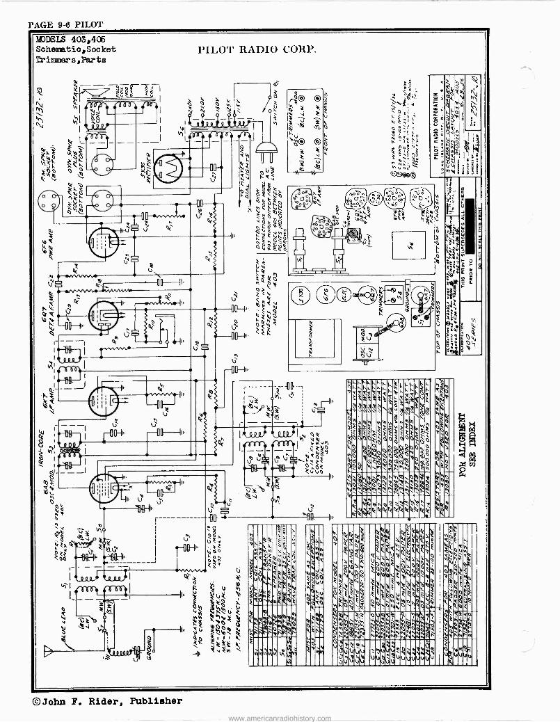
PAGE 9-6 PILOT
MODELS 403,405 Sohematio,Socket Trimmers,Parts
©John F. Rider, Publisher
www.americanradiohistory.com
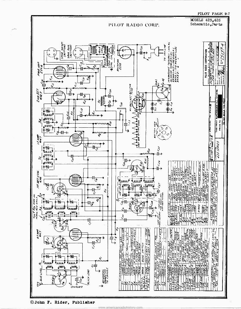
PILOT PAGE 9-7
O O
O 0
? .
äó 1ú$
¡i 3 3
nnVC Q(
IIU--
V\
pa
©
l'II.O'l' RADIO CORP.
N U
. N
Ñ
ti
"e pH',
l n I
ti m , a of N
l,
00-+ N
I RRAiiv 1 ji YJf 1 j 1; 7
0, RAA)fi
'':3,i ow I
. $F F 0 oa - ,;
I l' e É
4 WF h ,ti ,----,;;;;Io
Vv ! K f
n'
4v
3
4
111141 UN \e si á
T'a ét^ NY_f le il. V' áa '''''',',2`;'^ jZQ:
n
.tió le
` ,vví.p
?,,
v
y3
AhÚ% ,`'1/4.
k,'
O ^ Q
V i e "
11 .73 ti
£:
"a it 'e% ,,4' í. 0 0
QQ Ov 2mqpNohryh
Pnññ0'rí0.
v er Nz
`nr: v
i
hhihhhhh v! ów
mKñh
1
vh
-e ú
WEIS 423,425 Schematic,Parts
e
b
3R
I
W O W
R
Z F C C o
IC
s
irN
W
3
oI I-
ik i
OV.`<ti
3oo re
N
OV ,g
nezk
2 d hw
W W4
John F. Rider, Publisher www.americanradiohistory.com
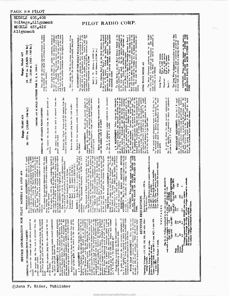
PAGE 9-8 PILOT MODELS 403,405 Voltage,Alignment MODELS 423,425 Alignment
PILOT RADIO CORP.
b1ái1 i a5ór 1ó 598
Oya4 'e ' g< g 9
g81111 ed
9°á N .9& j83 6 ih 89 1
b° g` "si a a zç li `°''Sg 53 ° Ji Ji gJE,meeáy l.E' e$X
. ? rfi8
c e¿. 6 p! a $ pyCq
h a áÇ8$do wó g> SS i i U.I.li' ß` `ä g'9 o s p ~ E9 85ç"a°" Fi" .ÿ.. $ i
S1iiI.1 ás 2a 9á L E$ au._o a hi' ° ° p c e" 9 p 0' 5 e ó 5..5 v55 `° ° g 8 g îi mu ve sñ 8.y ` e y O s S ß" úá a
!;'ÀF
° ao+á 7q08.5 $p JE éô c ñ á.3^ a a if r< 9g ñL^ y $8 $á 7 O .5 " E ,`E$
çé nß b -.g ° wqoÿ N -c3 ̂
00 ° 9 A °°q,oi <y
PdG vi ry < si+-.g 5ó3v`Jó ßñ cs.3 nag ó SY11$e pie
;.m <ä<F. i u e6 r, dS ë
$ C.3$ßu ;gö p' S"SP e+ éicoequ sÓú<ó r > á°.s :
35 ZOO $ád 5 v A, 5°áÿ v v ßH"° c5 ód ,g < Ta 3 .. "
'r:11 ; "_
gg ° ° .." ° ° IN Ñ°ÿ.:? gú Ció.cúác ò3 W {{,,.rp.C.
"9;º¿myugz B ,e
á.'Só m ,ap`q
p1 FZEá 2ggG9 zS 31 <B$G 655º loº"e._Oy . °ö r% i{ (.,°58 .<, qui
ARUM as 3yav
y + t.7 h ..°u.é°.'1 g Emil .98055 Ineá °.15^á. 0, B8 55 le a 5 5 5 i,.ò3` ÿ ï3'S 5"°"5°d -5° °E á3"sa'-i ° $ , S
g a é 5é g.9 oVióe' $ z Ëó 1
O ¿, E 5. S,v _ ` $ ° á H 5$ ó gº:5 7 ée .:M-.11.5
4 e g I2 "
v ?s;- 5$'55-$óe8 wxm 11g.4.g e 1Sq
Ó 6 3 3 .54945 i i 3S°mm:^á°éóg. °w".
+ .s 5 `3 a ^ 5 é °°J c1ça_& $:95 bo.935 e$ ° i <5 Di..
Q é vó rJuys 8 di°viQát çp' jyr
ó ÿ u u g $Qnp ++p
5 c ú d S.S<áLOòc M ¿ á ï a0
Q H Ç c ç u
éo Be 5.,3,10.1.:4i g az.
Q ue ç ° e° 8" 05'g h .5 ÿY 'a soe . 'Ç q $5 Z 1 p
8. c&
1
'c ° Nö3 5'9 E°; .:vg.° bSyá79r.Se PL 5 '2 ág vg
e 5 a" "jig,
a a^al095.3Ó.°R.8$'ttu q9 c'7w óÑs.ù C1 "Y1 ° á ó a0`p ' mu ^ 5 á^O 3 s$á IT.? r 5 ÿg : L Z<Q 9 Se Q éó C.. pig.g a
ó ay i ß5 v88"r°ó8a ?Óº $
É0 5^ 9u5 SÑY t ó IiJu d2$7 °:8g vß eu 8 'c ' o° By ó agw°u 3°,9J Cu,ñ
:7 á" > á ú acE o tt aC v a 0 5 r.i c ' c "5 E 6 e° ..: u
> ó B_ $ .S E á5 3 o: ~ c e 8:v á.s 8 oa'9 O 8$ p 5 c ti w` aº á aßL
eÉç
! 5 awz:'°ieaS ze }{ .° ó Sÿs
3 8 8 5 á?gtl I ó :C9.::Ló55F. ."°'9 5a w_g5á<
Meg 8 9'ô r.ps- 2M:31.414
. . LoC è_ -1...-el
s25yQQ9p 99 ÿgs 9 F" '11.§4d g5éga gEä l" 'O
rs ñi 5 E m55g8? g5a d6ú.wy0a4.a S&3$ 9 `K39 vy 25 wd'v's Q.9 Coÿ
g E
x.9 a s _ d "sn 5$e.EF,eg5p..,.$vÿ mB3vHm3°gp"g5 $
q 9Q$ Eg" $öE é a yyaá 5$,ß-.Esc Cmçb..flHi
u o$uroÿEáu .t g ac9 'vá..Jé3:áuE Iglzi 5á.8 $ 98 ö
i e í v
ßnn5 c'Si1 ë .ÿ S E 9 E .9 .. y '
U'
5:2':'-i 3 < l $ M. F
gás555v L yOa'a58 cgg,óvá -3-0.,§21,4 rm E- ai 0
S óó83 '°ÿ8 r:ÿ= {psS,y,u,SN°¿ pO 1' : d k g r mr$uy "a. $ ycw.n°' 1 sáé 35uYó '9L > $7 v.? O g fl yy 111 .S .9ú uvo ó'ó5oá;,"o8 g5~ SÓp9 1°; Y16
h 5iz
i1Iï1i4!U c u su vu m"" s" ¿ p w cóYYS
0°cB Ci'B3 Yd N a z 1S]i a Ñe $ fiva3 É`.9ra Ze 7u..' Z aH ö D c,,; u t;'-> o Q ß u 5 >?....ti O O ° iLaBm v °. vy uß Q 0°G aa F u . E. v o u 2 3 c. c:ô E á. " o. i - m ° 3° r\ a ep . E5¿' S J" 9 5á á7 .7.c86<0C0..{ $$yE0 ;,;ç Y25 4"9
ops38ao,,, z9 câvw $",c c o sç?aaummv Y-uS{yyqq .:os <ao `' N pp.8. s 3ó uZú`o°aí`4..gsú 9ÿ`H-SçJE ÿ9°t+^v"h oG EV 9 ppFFFFF p7 ~O¡..rñ ñ
.vti..$:ô 5 ó u m egg c, o p ö $ ten.. ñ pú 3 000 ..
ó a-1 .ä39$..<.. if .0 5á5 .9 $8E -gää-g1281-4e .ak9ñ; .. s7sF ÿ.9F é ,`qO `0 °
a ca F ó S
P+ a '°° y r öy àu gñ¿2ó°"mó"aóg. 3 ó,9 3cá` cG a gE"6
O ` °g ÿ ú 859wá 8`J 9 t]o g g ¡j" "8 ú O s` náa W a' v . á °v E.. é$ ö E - $ w ö ïJ
E 9 u E gall! Eó óâá8 g`amF3°a5 9 8.°c° EóuE > E3r T `o5á Z g E ú 5 ó ^e °ywyi ' 8ae.$uó..5`ßc:ws^ cßg o"5 $
q+ °' 5á x S
IjHit á °!i;:!iiki11i ° ú ÿ "
3351 Jvy ° 5 5 á+72ÁS:9
9 . g " g aSE 338 3 cy mn$" r u y ;..25' gee e.".ÿ e ; ñ... E v S{ c çy CJ cTi
'v á e ßi e mi .9 ç ó9E 5" 'oao1O°c"sóÿatlNug9ó< 5S 2óß ..gFó " LiOF . O 5 ` E L aayqâ.a3 3ú '5;a1 -37:e 8 5l;5`gE 9gc "2.1 .'g $ó6óg
°5 5 . Gógua º °ßsa7 5p,ciESáM dg äa9 5bm f+;J > 3 0:,,, c m
mó g - " ó g aE gES.S gmu E°q.e úv e% r .e á g, 5o33$áß.B t:s 9;5 '$5,°eº¿ g. :072 $ j S_ °w9 ..VN9.g9 áo5._..n y a$._ cHE $$ at.iLLi+ v ` E ..ää.-."- 1
5'w? uvs u., ä w- u9.°_ ÿ ó 0 ÿ
hfti ß 5 cm.âe o5 9C4v` gg5 ór8 cßOEe ° uaa ocovuó_' amÁ'Oo oc s "a"3^ds"g5 e° °° °,
I jOó.g .9 7 a oaSSß $. P43 vá3 n^'v° '9 v+ w .9vC cu a.° E5 u _v b g 1aa$ 3r..5 ° a59 aEßé 8ß
s"oJEoéuóyem'S .c7g11.11 gY ' ó5m y X. F cSSA 7`a4., ó m.ör {y ° 8 8 ó8 ó óé vy"ag u 8. a°?E" öóa .o oa:'S >""v
o ° B fiß fip á^" ú e3 w 5.2-0'3:W.712 ` y5' e°: c $<s ° gke'ÓsÁ`goGSóCG.9Kg000iii8éÉ,ráO'.ir,2áraoYy",88eEf+:Báea Éq II o®d 5 ell ú9
666 g
a ó.5 ó 5 SSX.z cß wrSßa r9.5.°...:w5o á 5a8 $5 aaF O
©John F. Rider, Publisher
www.americanradiohistory.com
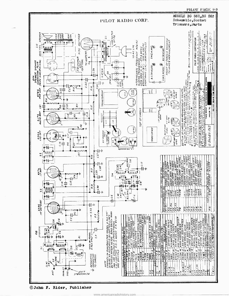
l'íL(P PAGP. 9-9
MODELS BG 562,BG 563 Schematic, Socket Tr immer s ,Part s
. L. W
3v ' ,,,k,
erti, , °`3é3é<'.
ieoti }e ti ",Q.Yt\;.;.aáÿyN%t . ,e
eÿFÿiggó"óhFiFF v\ WaóF'000h$oó áooe ÿF O 00 o, 00 i
O 0OÓ04g6'OCpOOOpg ó0
F N ÑháFóuÑÑOÑvá Fh x
k
p,V.phÁ e\ Ópÿv60wM W VZ- K ZM`2P
`éMÓ1.2N00 hb^`/\)b`f
22 ke
Ó ti
rn
Q e
k- err NNwiMfV ¢ ONnehr\ á
QkYsrerO:kit k.k:eYkk'kk h
bz
,y,Ñ
;`fl^Ñ 4WWN eFFe o`
F WO~~Q eWyJ 4V WF
,+,
k vh
`yy'
NR MJ e.ó0azce,Meeeo
>W< "Ct ZeR1W
Ó ºe ellÓQQ W
WWOUVWWOo@ dk Q0
lW.
v
e
^%pVÿl6i2` myQh,O+:OlO.FOÿ6WYi?h VQukQO;kKWy 14ti6Ó,jNHOrjOVÓÓOOhñpÓñVl4W 2htie;eQe Qhtj FtvetiWu
QI.JZQO`^WON1/4OéFM\,4y COOF º QNwN.c1 Orf4W
F"q¡c°ráhh; éoíWFhFFóóóFccóFFFbFWbFQ Z y M e M c
'h e.NOmOb ÓFéó 1.OVOFNÑlON0.60ófµVO m e eómo2,m4 Foe;oemek e4 e$h4. 4rtó,6pN0Ñm6q.p: u
Mtl Wi.hMbtiÑNhti:tihMmhÿóÚ INnf.t.>MI.t.Af.12Nn
OO\f.. n)NfgO óvM
...mow mqv ^^ ólÑN O`1.NhNt.NNNTaNNN1.NI.tNV^ ON I.h/. N Ó NNNND NN ^ Q N
hÓ .,/1
Ñ mm
`. Ó u Ñ
Gk Á úVNM ùvÚ v `
-Nrn1}N00z Nb -V SúVVu 6MÓÁ, Hnyw°1Mñ 47
yj/Iv)hNyyV1 NVf NN qÚÚVUVImiVVGUVUVUINIVUUV V 4 - -
©John F. Rider, Publisher
www.americanradiohistory.com
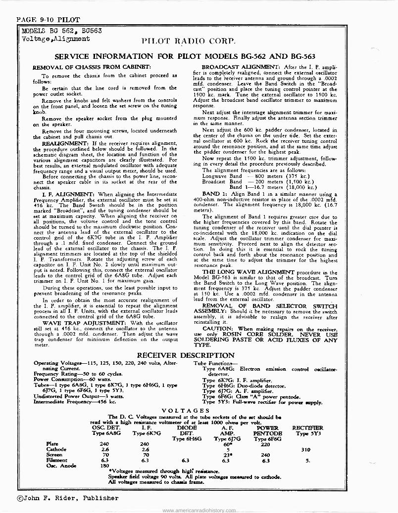
PAGE 9-10 PILOT
MODELS BG 562, BG563 Voltage,Alignment PILOT RADIO CORP.
SERVICE INFORMATION FOR PILOT MODELS BG -562 AND BG -563
REMOVAL OF CHASSIS FROM CABINET:
To remove the chassis from the cabinet proceed as follows:
Be certain that the line cord is removed from the power outlet socket.
Remove the knobs and felt washers from the controls on the front panel, and loosen the set screw on the tuning knob.
Remove the speaker socket from the plug mounted on the speaker.
Remove the four mounting screws, located underneath the cabinet and pull chassis out.
REALIGNMENT: If the receiver requires alignment, the procedure outlined below should be followed. In the schematic diagram sheet, the location and function of the various alignment capacitors are clearly illustrated. For best results, an external modulated oscillator with adequate frequency range and a visual output meter, should be used.
Before connecting the chassis to the power line, recon- nect the speaker cable in its socket at the rear of the chassis.
I. F. ALIGNMENT: When aligning the Intermediate Frequency Amplifier, the external oscillator must be set at 456 kc. The Band Switch should be in the position marked "Broadcast", and the tuning condenser should be set at maximum capacity. When aligning the receiver on all positions, the volume control and the tone control should be turned to the maximum clockwise position. Con- nect the antenna lead of the external oscillator to the control grid of the 6K7G tube in the I. F. Amplifier through a .1 mfd. fixed condenser. Connect the ground lead of the external oscillator to the chassis. The I. F. alignment trimmers are located at the top of the shielded I. P. Transformers. Rotate the adjusting screw of each capacitor on I. F. Unit No. 2 slowly until maximum out- put is noted. Following this, connect the external oscillator leads to the control grid of the 6A8G tube. Adjust each trimmer on I. F. Unit No. 1 for maximum gain.
During these operations, use the least possible input to prevent broadening of the resonance peaks.
In order to obtain the most accurate realignment of the I. F. amplifier, it is essential to repeat the alignment process in all I. F. Units, with the external oscillator leads connected to the control grid of the 6A8G tube.
WAVE TRAP ADJUSTMENT: With the oscillator still set at 456 kc., connect the oscillator to the antenna through a .0002 mfd. condenser. Then adjust the wave trap condenser for minimum deflection on the output meter.
BROADCAST ALIGNMENT: After the I. F. ampli- fier is completely realigned, connect the external oscillator leads to the ieceiver antenna and ground through a .0002 mfd. condenser. Leave the Band Switch in the "Broad- cast" position and place the tuning control pointer at the 1500 kc. mark. Tune the external oscillator to 1500 kc. Adjust the broadcast band oscillator trimmer to maximum response.
Next adjust the interstage alignment trimmer for maxi- mum response. Finally adjust the antenna section trimmer in the same manner.
Next adjust the 600 kc. padder condenser, located in the center of the chassis on the under side. Set the exter- nal oscillator at 600 kc. Rock the receiver tuning control around the resonance position, and at the same time adjust the padder condenser for the highest peak.
Now repeat the 1500 kc. trimmer adjustment, follow- ing in every detail the procedure previously described.
The alignment frequencies are as follows: Longwave Band -800 meters (375 kc.) Broadcast Band - 200 meters (1,500 kc.)
Band 1-16.7 meters (18,000 kc.) BAND 1: Align Band 1 in a similar manner using a
400 -ohm non -inductive resistor in place of the .0002 mfd. condenser. The alignment frequency is 18,000 kc. (16.7 meters).
The alignment of Band 1 requires greater care due to the higher frequencies covered by this band. Rotate the tuning condenser of the receiver until the dial pointer is co -incidental with the 18,000 kc. indication on the dial scale. Adjust the oscillator trimmer condenser for maxi- mum sensitivity. Proceed next to align the detector sec- tion. In doing this it is essential to rock the tuning control back and forth about the resonance position and at the same time to adjust the trimmer for the highest resonance peak.
THE LONG WAVE ALIGNMENT procedure in the Model BG -563 is similar to that of the broadcast. Turn the Band Switch to the Long Wave position. The align- ment frequency is 375 kc. Adjust the padder condenser at 150 kc. Use a .0002 mfd. condenser in the antenna lead from the external oscillator.
REMOVAL OF BAND SELECTOR SWITCH ASSEMBLY: Should it be necessary to remove the switch assembly, it is advisable to realign the receiver after reinstalling it.
CAUTION: When making repairs on the receiver, use only ROSIN CORE SOLDER. NEVER USE SOLDERING PASTE OR ACID FLUXES OF ANY TYPE.
RECEIVER DESCRIPTION Operating Voltages -115, 125, 150, 220, 240 volts, Alter-
nating Current. Frequency Rating-SO to 60 cycles. Power Consumption -60 watts. Tubes -1 type 6A8G, i type 6K7G, 1 type 6H6G, 1 type
6J7G, 1 type 6F6G, 1 type 5Y3. Undistorted Power Output -3 watts. Intermediate Frequency -456 kc.
Tube Functions -- Type 6A8G: Electron emission control oscillator -
detector. Type 6K7G: I. F. amplifier. Type 6H6G: Duo -diode detector. Type 6J7G: A. F. amplifier. Type 6F6G: Class "A" power pentode. Type 5Y3: Full -wave rectifier for power utpply.
VOLTAGES The D. C Voltages measured at the tube sockets of the set should be
read with a high resistance voltmeter of at least 1000 ohms per volt. OSC. DET. I. F. DIODE A. F. POWER Type 6A8G Type 6K7G DET. AMP. PENTODE
Plate 240 240 Cathode 2.6 2.6 Screen 70 70 Filament 6.3 6.3 Osc. Anode 180
Type 6H6G Type 6J7G Type 6F6G
RECTIFIER Type 5Y3
60. 220 5 310
23 240 6.3 6.3 6.3 5.
*Voltages measured through high resistance. Speaker field voltage 90 volta. All plate voltages measured to cathode. All voltages measured to chassis frame.
©John F. Rider, Publisher
www.americanradiohistory.com
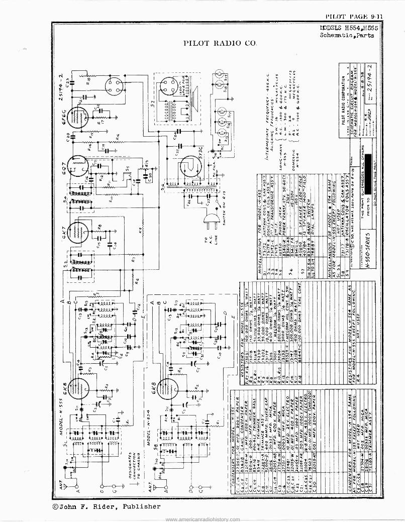
l'II.OT PAGE 9-11
1/49
C9
a
N
wrw Q
à
U
a
PILOT RADIO CO.
M a _
MVNO.
r
NI
c0
l J
Q
U
PR Pi etft
ihd
i
J
Ú
ullJl4n
Q co
i
r
o
J
4
11111
mt`44tnono
11,111
,,
m WI
0- ' O
Mi @III 11 1P. Nit ,
J
J
O
U
J
o a
N
N N W
V U a r
u ºaU uvy
a N N ta
OX
Ó M N
N
LiJDLLS H554,H555 Schematic ,Parts
U
4- 1-13-
n
Y
Z
2
O N
ñ
m
à
m
@
m
O N
N N
N N N
e NI
v
O
O W
J
O
n n
ñ
N m
N N
In
f.11
O
w O
N N w
N
r Z
0
2 u O N a F a
t2,
x
O
H
N
ti N x O
o o
F
Ó
o O o
3
F
o O
o
M
ti
N
F
O
o o
;1m2oNod O O N N O M M M M M M M M
N e ce
d N ot
0 K
V'
O!
O
M N
O N
n 7 M
m O
M
en
d O! o<
N 0!
ò oi
QY
N
m
ú N U
a
i
4 F
O O O
O
O
ñ
V U
41 O
@
e
Q
m
v U
a
N
U U
4 N
O
N
O O
o
o o
F
C W
F
N N
O
e ó
a
F
O
N
00
; V O
N
v u U
e N
N u
U
o O N
N
cele
v N U
o:
Q
á
o o O
M O o
Of i
Ñ o
U
7 O
m
N
< U
M O
m
N U
o U
O
e
Z
a
F
F
N O O
N
2
O V e N N
Ó
3
e
N
e 0
N
4
m N N
V
U
u
b U
N U
en
U
©John F. Rider, Publisher www.americanradiohistory.com
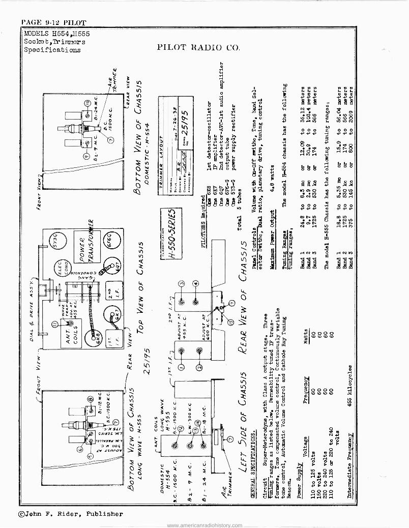
PAGE 942 PILOT MODELS 11554,H555 Socke t, Tr inmier s Specifications
J
o
W ot?
o
3 W
PILOT RADIO CO.
n
r o
In Q
(1-..
W 12(:')
N ;
b
h 0 ,i w ni ri a g 0p0 00 02
R. F t R. Ñ F
0 i3 ++4) cn Á 2i N ä s h 43 CD to
0 OMcOgCO(p0 r1 V v0 e M rO 0 h o O NO U U
le/O d Ñ E-4 el e O O O Z. O O O
( C C i, i, {4 -4-, 43 h h Y.
j.á ,i ñ .2rn -P C.
db o ce ri rH rie- Pi?
ivóh i.e
i ' 43
+ E. ó óód W
Rii $ a >m ó m ß áá óg o g á á ó 0.2 174 CD W0w )OcOU)t0U)S OD O U2 U2 @O
H Ó 43 Y 43 ñ i. +. +.
1 aoauO e DO LO {i N NA 07 N ri U.)ririM
112 H ri Ó O php p Ó Ì h _ E P140 p:1
V
U
N e
ú
e N
@
i
- Of
p\ ~
4-1
kr) 00
il 0 G7
A ]]]
L-1/4
o
©John F. Rider, Publisher
www.americanradiohistory.com
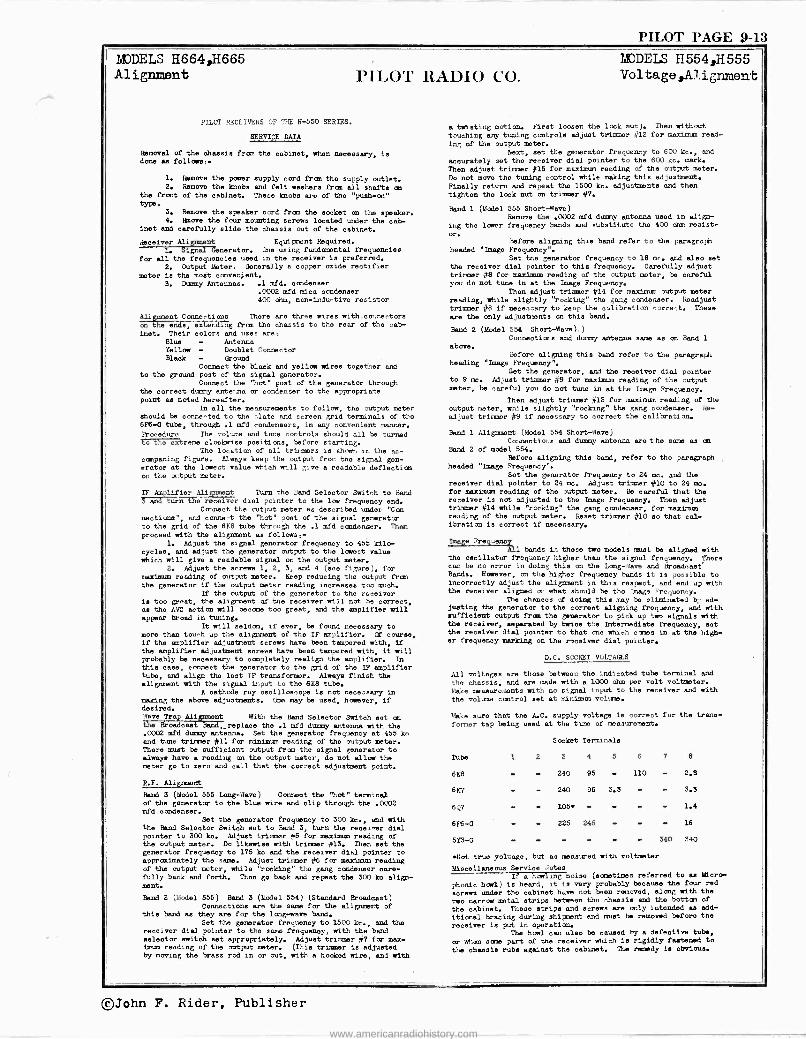
PILOT PAGE 9-13 MODELS H664,H665 Alignment PILOT RADIO CO.
PILOT RECEIVERS OF TILE H-550 SERIES.
SERVICE DATA
Removal of the chassis from the cabinet, when necessary, is done as follows:.
1. Remove the poser supply cord tram the supply outlet. 2. Remove the knobs and felt washers from all shafts on
the front of the cabinet. These ]mobs are of the "push -on" type.
3. Remove the speaker cord from the socket on the speaker. 4. $cove the four mounting screws located under the cab-
inet and carefully slide the chassis out of the cabinet.
deceiver Alignment Equipment Required. 1. Signal denerator. One using fundamental frequencies
for all the frequencies ueed in the receiver is preferred.
2. Output Meter. Generally a copper oxide rectifier
meter is the moat convenient. 3. Dummy Antennas. .1 mfd. condenser
.0002 mfd mica condenser 400 ohm, non -inductive resistor
Aliment Connections There are three wires with.connectora
m the ends, extending from the chassis to the rear of the cab- inet. Their colors and uses are:
Blue Antenna Yellow Doublet Connector Black Ground
Connect the black and yellow wires together and to the ground post of the signal generator.
Connect the "hot" post of the generator through the correct dummy antenna or condenser to the appropriate point se noted hereafter.
In all the measurements to follow, the output meter should be connected to the -.late and screen grid terminals of the 8F6-0 tube, through .1 mfd condensers, in any convenient manner.
Procedure The volume and tone controls Should all be turned to the extreme clockwise positions, before starting.
The location of all trimmers is ahem in the ac- cmpaning figure. Always keep the output fron tho signal gen- erator at the lowest value which will give a readable deflection on the output meter.
IF Amplifier Alignment Turn the Band Selector Switch to Bend S and turn the receiver dial pointer to the low frequency end.
Connect the output meter as described under "Con rections", and connect the "hot" post of the signal generator to the grid of the 6K8 tube through the .1 mfd condenser. Then proceed with the alignment as follows: -
1. Adjust the signal generator frequency to 455 kilo- cycles, and adjust the generator output to the lowest value which will give a readable signal on the output meter.
2. Adjust the screws 1, 2, 3, and 4 (see figure), for maximum reading of output meter. Keep reducing the output fron the generator if the output meter reading increases too much.
If the output of the generator to the receiver is too great, the alignment of the receiver will not be correct, se the AVC action will became too great, and the amplifier will appear broad in tuning.
It will seldom, if ever, be found necessary to more than touch up the alignment of the IF amplifier. Of course, if the amplifier adjustment screws have been tampered with, if the amplifier adjustment serene have been tampered with, it will probably be necessary to completely realign the amplifier. In this case, connect the generator to the grid of the IF amplifier tube, and align the last IF transformer. Always finish the alignment with the signal input to the 6K8 tube.
A cathode ray oscilloscope is not necessary in making the above adjustments. Case may be used, however, if desired. Wave Trap Alignment With the Band Selector Switch set an the Broadcast Bendreplace the .1 mfd dummy antenna with the .0002 mfd dummy antenna. Set the generator frequency at 455 ko and time trimmer #11 for minimum reading of the output meter. There must be sufficient output from the signal generator to always have a reading on the output meter, do not allow the meter go to zero and call that the correct adjustment point.
R.F. Alignment
Band 3 (Model 555 Long -Rave) Connect the "hot" terminal of the generator to the blue wire and clip through the .0002 mfd condenser.
Set the generator frequency to 300 ke., and with the Band Selector Switch set to Band 3, turn the receiver dial pointer to 300 ko. Adjust trimmer #5 for maximum reading of the output meter. Do likewise with trimmer #13. Then set the generator frequency to 175 kc and the receiver dial pointer to approximately the same. Adjust trimmer #6 for maximum reading of the output meter, while "rocking" the gang condenser care- fully back and forth. Then go back and repeat the 300 ko align- ment.
Bead 2 (Model 555) Bend 3 (Model 554) (Standard Broadcast) Connections are the same for the alignment of
thie band as they are for the long -wave band. Set the generator frequency to 1500 kc., and the
receiver dial pointer to the same frequency, with the Land selector switch set appropriately. Adjust trimmer #7 for max- imum reeding of the output meter, (This trimmer is adjusted by moving the brass rod in or out, with a hooked wire, and with
MODELS H55.4H555 Voltage,Al.ignment
a twisting motion. First loosen the lock nut). Then without
touching any tuning controls adjust trimmer #12 for maximum read-
ing of the output meter. Next, set the generator frequency to 600 kc., end
accurately set the receiver dial pointer to the 600 kt. mark. Then adjust trimmer #15 for maximum rending of the output meter. Do not move the tuning control while making this adjustment. Finally return and repeat the 1500 kt. adjustments and then tighten the lock nut on truer #7.
Band 1 (Model 555 Short -Wave) Remove the .0002 mfd dummy antenna used in align-
ing the lower frequency bands and substitute the 400 oies resist-
or. Before aligning this band refer to the paragraph
headed "Image Frequency". Set the generator frequency to 18 mc. and also set
the receiver dial pointer to this frequency. Carefully adjust trimmer #8 for maximum reading of the output meter, be careful you do not tune in at the Image Frequency.
Then adjust trimmer #14 for maximum output meter reading, wile slightly "rocking" the gang condenser. Readjust trimmer #8 if necessary to keep the calibration correct. These
are the only adjustments on this band.
Band 2 (Model 554 Short -Wave).) Connections and dummy antenna same as on Bend 1
above. Before aligning this band refer to the paragraph
heading "Image Frequency". Set the generator, and the receiver dial pointer
to 9 me. Adjust trimmer #9 for maximum reading of the output meter, be careful you do not tune in at the Image Frequency.
Then adjust trimmer #13 for maximum reading of the
output meter, while slightly "rocking" the gang condenser. Re-
adjust trimmer #9 if necessary to correct the calibration.
Band 1 Alignment (Model 554 Short -Wave) Connections and dummy antenna are the same as an
Band 2 of model 554. Before aligning this band, refer to the paragraph
headed "Image Frequency". Set the generator frequency to 24 me. and the
receiver dial pointer to 24 me. Adjust trimmer #10 to 24 me. for maximum reading of the output meter. Be careful that the receiver is not adjusted to the Image Frequency. Then adjust trimmer #14 while "rocking" the gang condenser, for maxim.m
reading of the output meter. Reset trimmer #10 so that cal- ibration is correct if necessary,
/:age Frequency All bands in these tee models muet be aligned with
the oscillator frequency higher than the signal frequency. There can be no error in doing this on the Long -Wave and Broadcast Bands. However, on the higher frequency bande it is possible to incorrectly adjust the alignment in this respect, end end up with the receiver aligned on whet should be tho Image Frequency.
The chances of doing this may be eliminated by ad- justing the generator to the correct aligning frequency, and with sufficient output from the generator to pick up two signala with the receiver, separated by twice the Intermediate frequency, set the receiver dial pointer to that one which comes in at the high- er frequency marking on the receiver dial pointer.
D.C. SOCKET VOLTAGES
All voltages are those between the indicated tube terminal and
the chassis, and are made with a 1000 ohm per volt voltmeter.
Make measurements with no signal input to the receiver and with
the volume control set at minimum volume.
'lake sure that the A.C. supply voltage is correct for the trans-
former tap being used at the time of measurement.
Socket Terminals
1 2 3 4 5 6 7 8
240 95 110 2.8
240 95 3.3 - 3.3
Tube
6K8
6K7
6Q7
6F6 -G
513-0
105e -
225 245
1.4
16
340 340
eliot true voltage, but as measured with voltmeter
Miscellaneous Service Notes If a howling noise (sometimes referred to sa Micro -
phonic howl) is heard, it is very probably because the four red
screws under the cabinet have not been removed, along with the
two narrow metal strips between the chassis and the bottom of
the cabinet. These strips end screws are only intended as add.
itional bracing during shipment and must be removed before the
receiver ie put in operation. The howl can also be caused by a defective tube,
or when some part of the receiver which is rigidly fastened to
the chassis rubs against the cabinet. The remedy is obvious.
®John F. Rider, Publisher
www.americanradiohistory.com
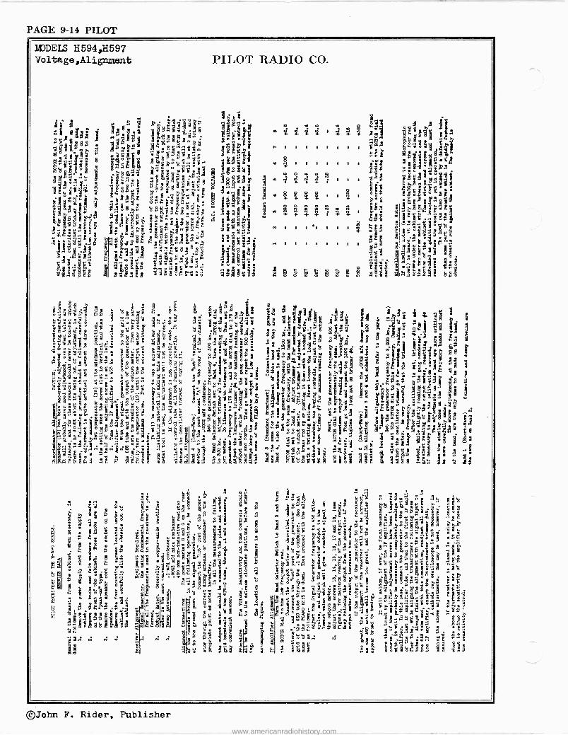
PAGE 9-14 PILOT
NDDELS 11594,11597 Voltage,Alignment PILO'l' RAI)IU CO.
e E
:
m
t
2
8
+
e
R
1 f '
t. Y é
2 n; rH Y B
em
e a®fl
®
m
1$. óT r9 :g 3 á7 5i ° °°
j'''''á" óá'."ó79 t bm °Y ó ó« 5 . r :
^Y 89 ;` .a °á °.`i % .v°s e1é ß F gÿ5$s< se .§311!* «repA
dó MY ° H
°.
plJ
,d.tiAa
p Ó Éa SO
'i2'14 -:
9d 06.n V « okVS yYw ¡sd Ill i e
° .i& . 539 H .¿
e o ° c
e1,0424; E o Y " P H ° H
lis m *6á9: U`«xrisp : Y YoV Yq ® r 7v á`nhY=niie d9bY.sVip
R[i°- 9 o T 3
d u q ó m d H ° SI
ytlq ._ 's ...YMm« il$ws
iw ÿ;óx
iasq"m 9áé>.eó _ ^caYm V«á«e p d m.°C Y Ñ > é rv V -459 tl ..H la. c 9 m G M d« ós ̀s«á aos Ñ.w «u ° m
e!:',1. a v H.Y
VYY py«o«Yré qL'¿°9 9wó j¿
Ó
44
O Y
C
t çç
?. d { V, C O« Y p F
p i
Hi L
ii
Ó
mÓ RúióV 5 áí=.iF9 9ii
470 é "
547 !8 :
9t aY
ad"a
2i"i r'tl 3b
ç
Y á ~ Eß "á
01%ZóL.w 0t1 puq?m"
Y¿ ; °a 99`a
V
i
m Ó Y
y y 0. 4 + Y O d
5tiä,9d á tit89 ÿ
6ó`dS £S Yè"Z°".w Y 6t2Á B7& ág9gu8.`° b
el 1
98 i. .' á 9 11
ób! 13
zo
oas
3om d
S
©John F. Rider, Publisher
www.americanradiohistory.com
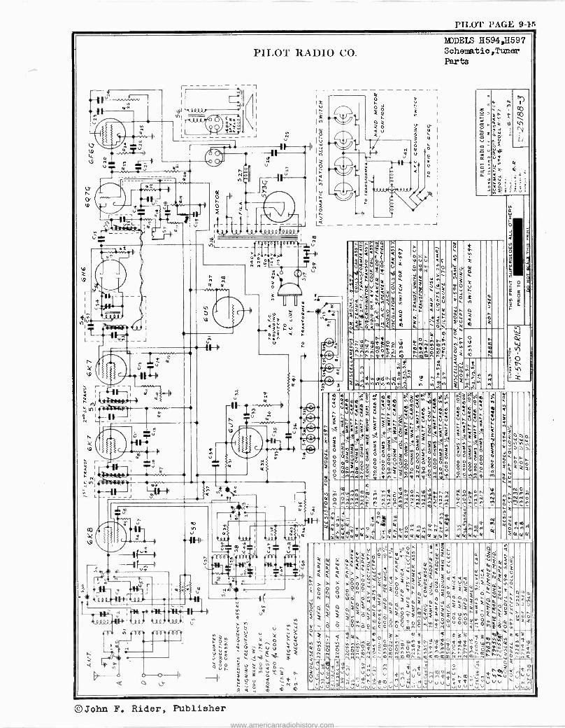
PILOT PAGE 9-15
' I
1.?
á *Ah-. .
u- m- J_-L_
. N
O y A 7 -'---- ---- N
u
PILOT RADIO CO.
I N
/ 2 ç
v u
Of < V ? V L' J N Ç
= i 1/-.I J ó 0 1/4
------ a w.
N ' J
1/49
N
O I
r - lC_A9ri1-IhIeoG
Q lT
a
J {1T1
PA4+IN v Tu T, b.
tl
u
v
Nß NP
at 4.4
H»
: é
MI -
t, a
N
pl VI
N h
va.
ñ
n N
VI
N NN
C
N V
N
N
41
V
h
N
a a
Ó
V N
d O
a
Ñ OO
N
ON
ñ
-_
P o a N
O N a 02
V N
U
N
N
en m
111
RODELS H594,11597 Schematic ,Tuner Parts
ñ
N
Pr)
(co(
1\1^ `1
ce
U
[
O V
m
D.
N ó
I1
vI
vI
N a W I J Q
IV VI
W N a W C 7 N
z ó C a a. º H It
[mOII^ V
3
0.\+3333 N
N 2
Ut0(ovi AUVÚ4v1
QíA.hni
N
íA.wé
tá33N3A3__;rIa \3
er ci e
-4 otee(*) [Qpt
V 1.AUJt['afiVttl í~. i<AeÁV;IQiúFA.ÚV 3 33Ó1[Apt N .1zJIIfd.NN\`
NO`N pQU
NmN` N
4 de
2áO le
ÁíZ3 QìAA ;i3
º ÚNam1A
-
M
Q
\i
'n
[
c ; iF2N1
ÿ
N
W
Z
Nº w;0o NONM
W p 0= Fo=i o 0 o2noEociol e reeZ 0o é= :OÓZiO
000 O ÓÌV
0 O 00200 O O O O V Op 0 0 000 00 0 0ko o 0,00
Z O OaÓñR Ó n128
o 0i1WÒNMIOÑÑÓ ÒOÓóñ O
iW ó
ó;I3:IN7 á a1N?TiNpóNh M+ºÑTn7 m CU
e W N 1fI NNÑpe RI NÑOVNÑNí4u0.NN PIOi.aN^ N1 m11` a 0 OIVNNN, N NN0INNN N 1^N 00, NN N N e^ P.,NN O In A _ 1M1 In 1p M MI ñ 10 M1 M Al 11I IM I11 MI MI
N 11I M1 , N MI T MI I1I T N 1
Ñx ......
o
'4'D- á3 Ñ 1" tlY N W I IV 44-10 O Ota^ qdNO ñ PÑN Ñ r N N Ñ Iù M1 ÁmN AMI
oìañaaa°la aaaamaaaaaaaa aototaot ìaot
Z
O
N
N
N Q
i 0
O Ó
ti [ N IO
0N N N
d
co e.O
V d
O
ee
ON
N 0 N
V Y
O
.
a
V
o
ó N
ú
V
@
u
a
m
aº u o
2. Q Qv
ÌF
ì c
é
F
e
o O O
3 p O Iv ñmN
V nma0 ñnmrv
M
u
V V
u 03 N U V
Q
0 0
u
3
i
ób V' r %
V z
F a
î
ì
é
J
V [
M
F
N
N
W[WF4vQ13
Q QQ a )Fo QIQ'[ J V V V J F` QOJ
o< ÓVNO éyNeçiAq00 N W
a W N N N
FiòfF_Fiºók>> N ONNEOFi`F W OO
99° OO N pp ! Ñ .[ h;$0 33 Q3 Vim
N ohhN a IanP O ap{Fp W ÿ ma -V;
N n 1 N Q N qN N O N N I" N NNp-nN^Nó F N4 N n UNaOÑM1^IuOuu u 7^uuu
uV
N
©John F. Rider, Publisher www.americanradiohistory.com
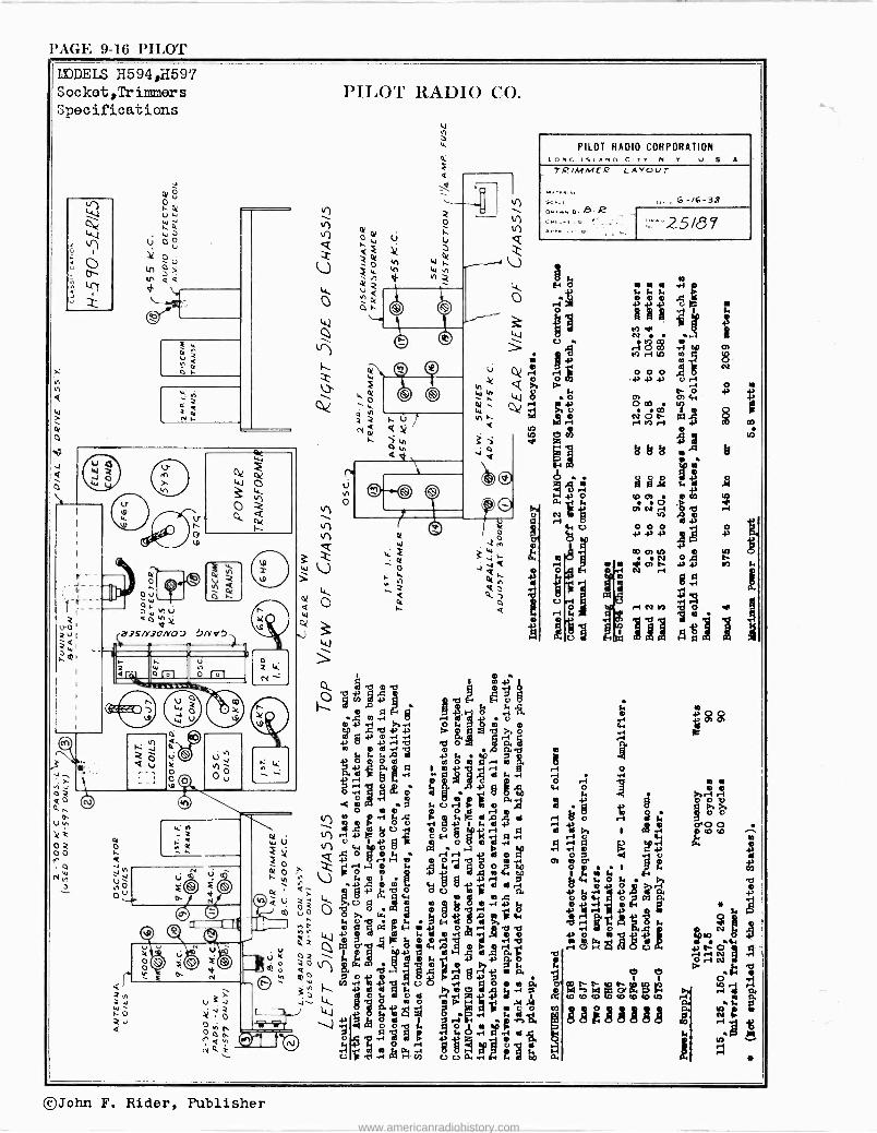
PAGE 9-16 l'II,O'r MODELS H594,H597 Socket,Triruaers
Specifications PILOT' 1-L I)IO CO.
PILOT RADIO CORPORATION I ,N, iSi Awn C irv N Y U S A
TRIMMFT' LAYOUT
J
U
O
ISIw
q ° . 1 Cl aSb °b I 0 o 'CI -P bM A I s
~ . 9° ?JD- " b o d m r. .r1 rb b ó a5 n m d.-1
+03,
t. AD A 04
07 i -I a
b 1. F. L 3
Mi
14:1° rIC. 1 .9 F2 bg
2,
6 r°,
óEll ° á /4>g w ó / ó ó rF m R1 Ab F. -i
tl. Pç, ..4.,
f$D
P 7LD
U ó m b '11 tl {,
C y tl Mg.>. Da i. v) ó m > b Ú P ° t. ¢ d
-2, .O . O OU Irlo S M a
O U
d,` d U G+ 1 L d+ r1 C A + o aoo + d vÉ O eri
grpi
1 á W u
p1qpp
ó ó q O agö
}°3 ed e +
pp .i
o rLq{
++
Q + 0 0 H .,Cç F°i
.i b ó 7m
r1 Of O 1 7 10 . (%} O ' -C o m
gm + ytla
Gd
.G m 4. AD {1.
M F ~ ^ }I'i .0 m m 1: 4a Ö O i ri d d ral 8 ó ó >+, ri ó O( . Q r qq g+' .b O
m, t2 .5°'
m.4 1.a
ó ó¢ri ó ßi Le.
JO p ó T U ó m m 6 ° r°I -1' O V { +i cii
E o d ir 2 4
1 o re. rr}}r.1 {2 p nP fib a m H Orrp fit
di bb r O1tl}p W? F. Ñ ,CQ
02 í7o 7 O'b O gq°a,oo Pr/b r10H LItVUU PO Ipy
i ù O \ ° g y+ 17
L. d---III d a b Ó rI N
'ó ávi $`áia moP. a N
Qº a oy o aá a . o I CO ,-1 m 43 _c r1 q o o o a W h[ ro h In
++ d d M AwcS d,,gq r a m á°4tida dDi. >. r J O L U d ri ri .'A .+ i 1 P'. t0 r0 r0 r0 t0 r0 W ri v 3 J J LL }
o ..%`'
r o m t 1I y
!p op S p! ÿa gJ' L--
7 C C] rÌ 17 dU-' FL v O O O g
R+ 4 +`yNJ 1
F.e {. i tl wó
prpñ M Z Oi f v r a3 .4 °
H 6 g 7º d
F.
rv` cvrlrirn UUar+H 4 tIO a. !
25/87
w w rt
1 8 1
0
k
j . ,
DD
mION
rl AD V1
OOO .{a-1-, -P °r1 O w
O DO °i FWQ
O es
riNO3 O) r F7+ W
ó ó
e .3 8
tri
e
q l9 9 .1°1 /. r r0 O)O.t..4 °y rncv Á ró{
°i° od G
mO,tn APPP
r i IA
tl
3
W Orpi + '
r-1 N M O
i p
r
©John F. Rider, Publisher
www.americanradiohistory.com
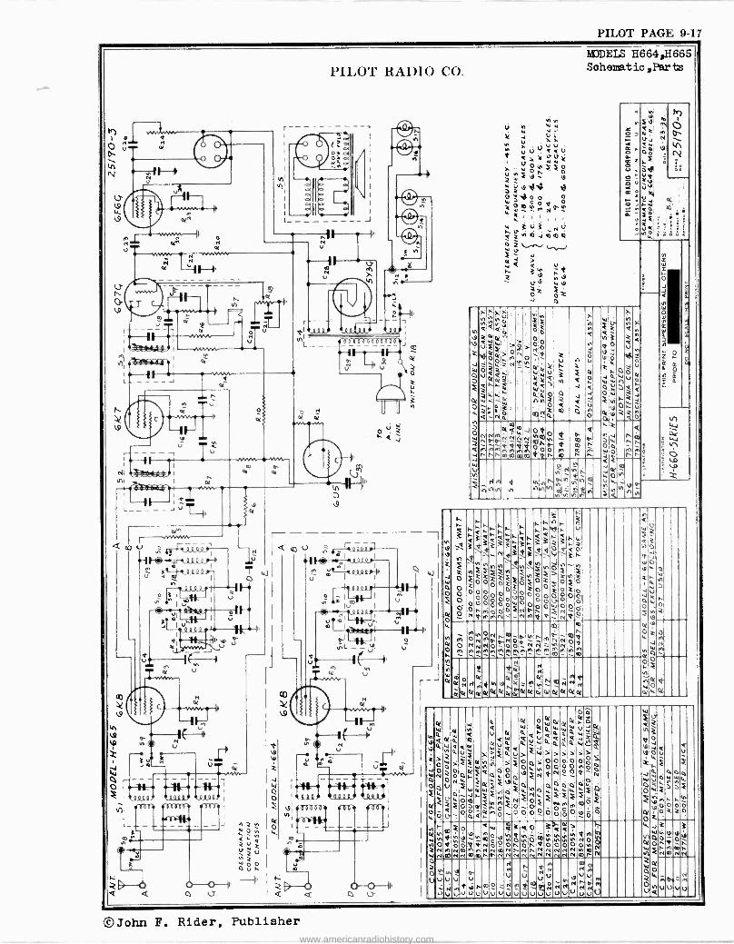
PILOT PAGE 9-17
'7) o c.. .7
L
=4-,1H
t0V
N w ANA/ N
Y
- - U
PILOT RADIO CO.
I
J .- F-- -n
o _
Of a of w-
r
u
H'
`'A < J
íA
tn
Y
MODELS H664,I1665 Soheaatio ,Par ts
';2-* NV
F ox c
x N
úFWNóó mrON JZ_tt Óuá:. r`w
OI tiF..W M=ç3.. a
r -
-Nÿ
r .,, ..
.
.
H
C Ó
éYl 4o hh 4
j( t\
M
C t m
v
<
J i C
Ñ
v Ó
V
u Ú
; 2
ó a úÓ 2 W
vWVWiu
OV,3 NóW
Om3 ri Y1J z t0it00 <2
Y WON Ñ r V.11
.NIU
Q
< u 1d,
00
n n M h
le.
f1
ONNMatt%JÑtO NNµNµ~yye- 4.1
QtryMnttotifdt -nnnmaomao*Qn
O
00 d
"'2
0 co m m n
a p. I è+ r. J
44
U
AAA r1F
tn NynÑ V1
H ,f,
=,nt9 tñtohtñ
N w Ñh H
i
3ti;Qt'~tti`R~;hW V v i z keZZee
W O
ó Ó° F 00000WO
3+3333i ` e0020i O
MM
1MA
-Nt3t Nvttn
Ó O° OVÓ
ryóÑp>
M
\e j O
(.KlSh
vd° `+;1 02
0 0 °Ov m7mHttm
;
NJ O 0 02
tió V1 : pFo
20
V
vf
00 O
tn
Wv ; eo tJ 440
:tn G
W OW i ri `.°
020 -IN
M
.1.."'
--
01 O m
tttNNna,-,,tnn.
N>NjN000P FtmtnMMtOMnMttmmm
N NhN T-n t
nó tn
tn
qo 0(ryNntNxON Of
e N
0! pt p( 0t
tà Ѻ
01 y 0! Ñ K
L^u;-mNNN 0! ot oi !
-Nt Ot Ol pl
O re N wo_. o
óó Q
0.W
0f WWOtWUóOC
V ty4 IL 4it.tÑ WU`t J ao4 W, ;-i0, V> W >> j>>> vNi >FÓO>OOOOt°np0
W QÓtOiOpONpNOOd. Ñ
ró
Ll..:I:
d FwqòF
4 Á M p- 0 0 0 Q Ò p 0 0 v Ó
n ºW i;attO;ii> en
w 000óthnpu.ONttj ÑNNO Q NN
O - O n O n O O O O O N N N N N N N m N
W AONNNN nN N N mn N
N P t M 0 0
U U
V V V N t9 h V M N A f Ñ N N N N N
úùuVUVUVuuuO
u N V
<
O
e
O o o
o
o Ó N
t v
o t to
tí V
N a n
u m V
0 V ù
V i Ç r
OI
O o
; Vt O
N
O W
J
O Z
C
O a
Ó
v 0
N
u u u
N
u
©John F. Rider, Publisher www.americanradiohistory.com
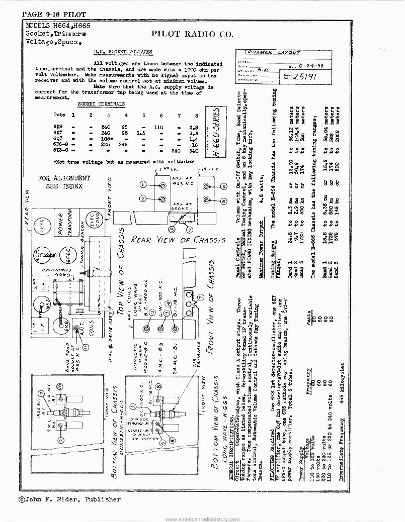
l'AGE 9-18 PILOT
MODELS H664,H665 S ocket, Tr inmiers Voltage,Specs.
PILOT RAllIO CO.
D.C. SOCBET VOLTAGES
All voltages are those between the indicated tube .terminal and the chassis, and are made with a 1000 ohm per volt voltmeter. Make measurements with no signal input to the receiver and with the volume control set at minimum volume.
Make sure that the A.C. supply voltage is correct for the transformer tap being used at the time of measurement.
SOCEET TERMINALS
Tube 1 2 3 4 5 6 7 8
688 - - 240 95 - 110 - 2.8 687 - - 240 95 3.3 - - 3.3 6Q7 - - 105* 1.4 6F6 -G - - 225 245 - - - 16 5t3 -G - - - - - - 340 340
*Not true voltage but as measured with voltmeter
2 "./. F. 1ST' 1.p.
FOR ALIGN- NT e W SEE INDEX
0
ti
o
AD. AT 455 K.0
ADJ. AT 600K .0
VIEW OF CHA55/5
O o
ti
TRIMMER LAYOUT
o...... etv
....oY.o..
0...6 -24 -Tg -
27'2.5/ 9l
o t.
U
X
2 m m m tl o o s. c4 t. t. í. í4
g áám ri o ` ó 0,
x 2 e
4,Y+1}, e
ó Ó ariaD:dgm
go,
g Li,. bgeo
RNA sN.1.441
°' H 10n a 2 .q n o w CDÑ W U)IOr
o
}{¢¢l1
OI t. 10
NOf m ñ
t
w .-INn riNM
Jil e JJJ
o O ri ch O .0 CO i 1 X on .
.¡ Q7
o00 pdmp
T ri -1 O CO m CD
{> Ñ 13 W CL y pp
.W -tlH m vi .O óÚÚ 1
y1 .4 `r1 ri b V h 7 m.i .O,
0r741 m 3 r+ -2 c. >. á A ó e ! 3 a óromm . s
V8 Ó
l9 " p 43 v°$
e
c e LE b A 3
op H P
i md.3 . 2 § N
OO E OP tre W0 .w
.i
i QQ
48.'72 e 03&
m }i N omiä 1 3 O. {
ll HrAw0> Pg eÓ 3 °mu
R Ó
r N ri '49 m Ó ir O F 41 Y4141
T
1 POp Wp OF.p .-pN2 ri .-I N r1 O co W
-I
©John F. Rider, Publisher
www.americanradiohistory.com
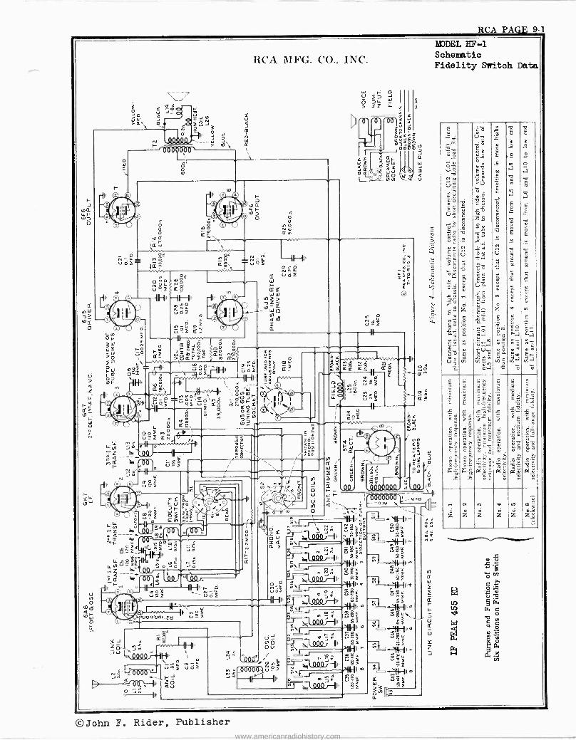
RCA PACE 9 1
ù UI
O
aF 0,
0
Óf i -.-II .ww c G t0 G
111,, úÓ ú ryáó 00 ç U ? rf óZm á ° ò >0 \ /'Q- Yi,ÚP.F.wr
, ÚNÓ -11F.
NLL _ H ún< u òI ,2
M
RCA MFG. CO., INC.
V J_ W III a qq Z ry >6. m Ñp/?uJi
d h
o
,
re15151r ó' Io
aÒ I([ N
X. ó, N -4 M ó VOf- +Q'o
--0,,,,A,-
ZEE ' .p Ñ
O S _ LL
e O N a $HFI
ß\ 4' © O
li O
0o f M N N
Q Ó
MG 4: , m m V
-:z h u f
N
0
4Ñ P G
Ún
40 =<r U
do LLZ
NO > mW P GO> = -
He. ., O
I'--T iW 1 `1 cI(Fm
CpLL,QÔI."G -OW aÌ 4F u ao âNoZó
I
to?. v z
Z ó
22 22
Ñó út01 J O
MNO LL UNi
G
Jm
ó
4 P2 u_î
IILL OÇ e2
I1 ma
Y Ì ru J W ;
N
íQ
a
uRf
11
11
°
toe
d
I, II f1hp, ó
N '-udf
41 -
tu
UY zá
I
of
s) .000-00. za
LL
YJ zöl
^ M yo
ág U J
JU .0^I y jc </ ¡YA , 4
g.\"CLL N- 3
QQJ
Vi Q ZJ
0eI9I ,' 11
(2 ---1'0
Ou
I H
O
II
O°
Ñ au OK
II
E
03W
m
MODEL HF -1 Schematic Fidelity Switch Data
E
.:y cm
W _ E 7
q c".
C uz. ..ü I-,
? T,ÿ
M:5 Um iO wbe
= O V u9 ; C3 >(5
0 °á
.2°
Ó E
.E
m
7 E
ú
u
.. W
12
m >a
C +
m a
E
E
ó 2
i°
ó a b Á
m a
E
Ús úo mo c ` `
>, ó o
ó é
s « u .o ó
g N
v > E
v É
= 9 se. ..- ° y
^ ._
. v
» N ,Q N _
9- ú = Ó =á u
« °° T.
U -
= O o
>2i -.5A=
Ó o
.2.. K
Ñ
Li
-
uQ 0. Ç? ú .. «
= K LAI x 0 tz' ú
vcOOLv.,Ñ u
Ó M
ú ú é d
Z á O..
ò z d N: «2 _ .°c É ó ó =
= E « %,:-.
pM m C.
.+ .
.t..: p ..? Cti a a -5,..:.C ...4°.a
.. m 2 di a N
ó N my de
cM....rVv á é+ uA Ó° íE0 N Ñ Á
' m e, a U q fg VI.. Vl b V.a Ir.
Z. 'a e ö '6
C Ç
Ca,,
.E 5 Ç %p >.
E Ñ R Y,l Ñ Ñ E^
_ E E
.T+
E E E.e
« à
u_ C
c ̀_
O Y
2...
.i O C
.2 S
_ ' n º '2".'=2. ` Ó
2..,
c_ T. O+
>. º %p.
GÄ >, e_ p. N
am 0.m asl; 0.'ú {>~i p4u t ... N F. w q II
Cl M em m'3
z z z z z zó
©John F. Rider, Publisher
www.americanradiohistory.com
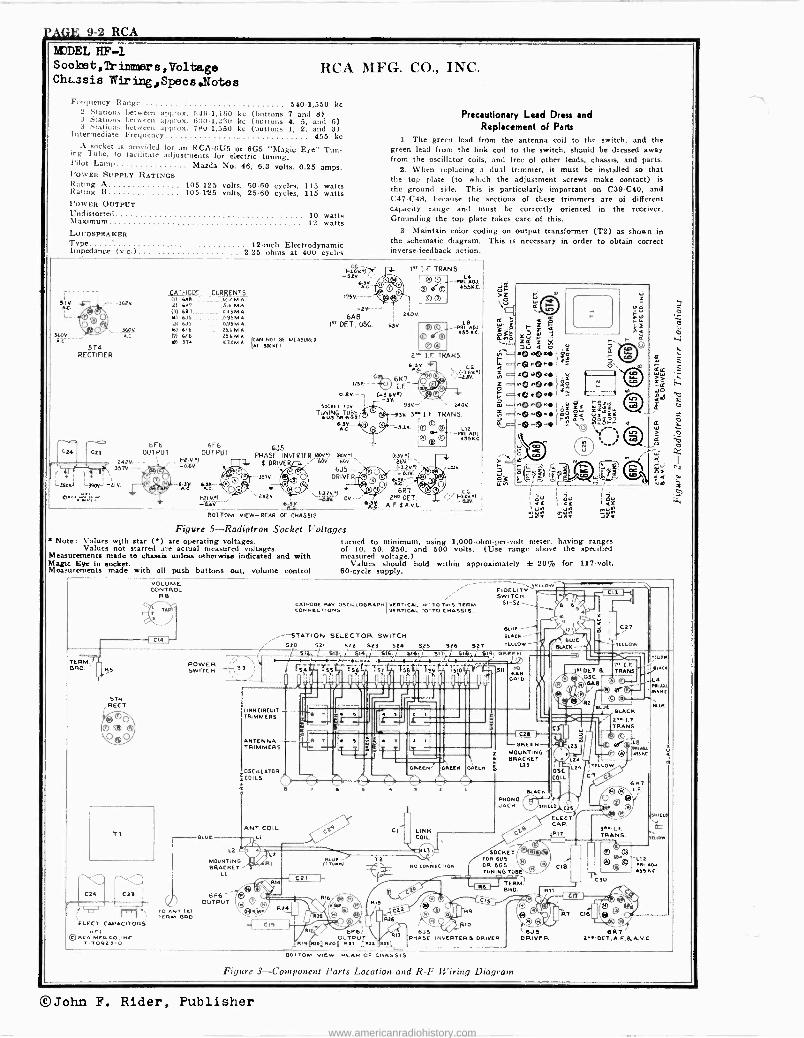
j'AGE 9-2 RCA
IE EL EF-1 Sooket,f imera, Voltage ChL3sis W ring,SpeosNotee
Frequency Range 540-1,550 kc 2 Stations between approx. 540.1,160 kc (buttons 7 and 8) 3 Stations between approx. 630-1,230 kc (buttons 4, 5, and 6) 3 Stations between approx. 780-1,550 kc (buttons 1, 2, and 3) Intermediate Frequency 455 kc A socket is provided for an RCA -605 or 6G5 "Magic Eye" Tun- ing Tube, to lacilitate adjustments for electric tuning.
Pilot Lamp Mazda No. 46, 6.3 volts, 0.25 amps. I 'oWER SUPPLY RATINGS Rating A 105-125 volts, 50-60 cycles, 115 watts Rating B 105-125 volts, 25-60 cycles, 115 watts POWER OUTPUT Undistorted 10 watts Maximum 12 watts LOUDSPEAKER Type 12 -inch Electrodynamic Impedance (v.c.) 2.25 ohms at 400 cycles
360:
514 RECTIFIER
CATHODE CURRENTS (u 6A8..-_. _-._122 M A. 121 6NT..._...
_ _-.5.6 M.A (31 EAT 0.63 MA Si 615 ...... .. _ 0.95M .A. UI 615 ..- 495M A.
360V 161 Ara .. 256MÁ AG 01 6E6 25Á M A
66 ST4 .07.5M f.AN NOT 6E MEASURED ll T SOCKET
6F6 OUTPUT
zazo- ,
35TV ---
L3qpy.J
6E6 OUTPUT
I^nv') 0.6V.
AC ere _ F2f V.1
6.Ae
RCA MFG. CO., INC.
1i6V )1r -say `-
se -
6A8 YT DET, OSC.
Precautionary Lead Dress and Replacement of Parts
1. The green lead from the antenna coil to the switch, and the green lead from the link coil to the switch, should be dressed away from the oscillator coils, and free of other leads, chassis, and parts.
2. When replacing a dual trimmer, it must be installed so that the top plate (to which the adjustment screws make contact) is the ground side. This is particularly important on C39 -C40, and C47 -C48, because the sections of these trimmers are of different capacity range and must be correctly oriented in the receiver. Grounding the top plate takes care of this.
3. Maintain color coding on output transformer (T2) as shown in the schematic diagram. This is necessary in order to obtain correct inverse -feedback action.
1ÁT I. F TRANS.
240 V
ASK
o.av.- SOCKET cot
TUus JINGoRs TUgi
RaV- AC.
6J5 PHASE INVERTER 18001 (60110
DRIVER 766V fibs
6J5 -- 3370 DRIVER
O Ile Go.
F?tV1 OV
BOTTOM VIEW -REAR OF CHASSIS
Figure 5-Radiotron Socket Voltages B Note: Values wjth star (A) are operating voltages.
Values not starred are actual measured voltages. Measurements made to chassis unless otherwise indicated and with Magic Eye in socket. Measurements made with all push buttons out, volume control
VOLUME CONTROL
R 1
RS
STN ,RECT.
T1
'ELECT. CAPACITORS HEI
© RCA MOO. CO.INC. T-TO92J-O
POWER SWITCH
TO ANT (A) TERM. ZERO
BLUE
*2Y
L4 --PM. ADJ.
4551(.C.
--Rtl ADJ. ASS N.C.
1"4 I.F. TRANS.
G.G. ,1 FV9
6K7 1759- -- ).F
-SK 93V_ ` --240V
-838 3M I.F TRANS.
(Ass.)
._EIV.V)
leT 6RT 2 DET.,
A.F. 6 A.V.C.
L12
455K.C.
turned to minimum, using 1,000 -ohm -per -volt meter, having ranges of 10, 50, 250, and 500 volts. (Use range above the specified measured voltage.)
Values should hold within approximately ± 20% for 117 -volt, 60 -cycle supply.
CATHODE RAY OSCILLOGRAPNI VERTICAL - HI - TO THIS TERM. CONNECTIONS VERTICAL 'O -TO CHASSIS.
,--STATION SELECTOR SWITCH - SIO 521 S22 521 S24 SOS 526 SET -T\''1 /1.1s))t{-Af1-,./71=1%-=16,e .s, s1T,
Witt.
519; ORGI . SS I ' rSA -rii t56 ?S7 ni ' as
A6 B 1 i,_1j II' l'li el:l I I- BRIO
LtNNCIRCUIT-- rf- 1
TRIMMERS
111 H E II
r4 M T ANTENNARIMMERS - --
N
8 T I IV - ro- os LILL ATOR
WCOILS äl
ANT. COIL U 4$.
L2
MOUNTING BRACKET -
L1
6F6 --
OUTPUT
Ò-Z7>
1
L2
O,R1
(TúIEuU
LC2I
R24
C19
R26
LINK COIL
®® îr_
6F61 OUTPUT
RI9'R26 R0I R21 Ilse I',ILL._
BOTTOM VIEW- REAR OF CHASSIS
TO
Is
e
GR[CN R
¡On
GREEN
C>
KO COKiLECTIOK
eses R2G
13
YELLOW FIDELITY - SWITCH
SI -S2
SLACK --
6
BLUE mAcs--
CO'
-GREEN- MOUNTING BRACKET
Lt]
aLACK 0+1050. JACK
SOCKET Ieof 1t® FOR SUS ® OR 665 TUNING T
TERM BRO. RI1 -t
® Je © U ® 14 RIO
6J5 ( 9
R6
PHASE INVERTER i DRIVER
C2T
CLLOW
OSC. OIL
ELECT. CAP RIT
Figure 3-Component Parts Location and R -F Wiring Diagram
IATDET. i OSC.
GO 62.8
R
PT I.F TRANS.
ELBE PLACK 2991.F. TRANS.
AJPTe LB
O Q YAM
YELLOW
399 I.F TRANS.
CI.
e© ©4 7 c16
6 KT
CSO
1.F.
Soliti
HAWN
L12 HMII. AO.1
455 KC
6.15 6R7 DRIVER 2RR' OET.A.F,1A.vC.
©John F. Rider, Publisher
www.americanradiohistory.com
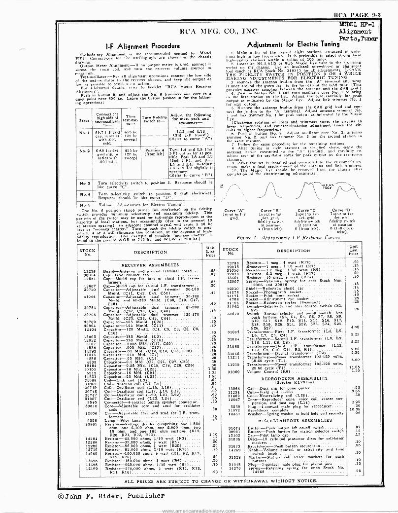
RCA PAGE 9-3
RCA MFG.
l -F Alignment Procedure Cathode-ray Alignment is the recommended method for Model
HF1. Connections for !lie oscillograph are shown in the chassis
drawing. Output Meter Alignment.-If an output meter is used, connect it
across the voice coil, and turn the receiver volume control to maximum.
Teat-oscillator.-For all alignment operations connect the low side of the test -oscillator to the receiver chassis, and keep the output as
low as possible to avoid a -v -c action. For additional details, refer to booklet "RCA Victor Receiver
Alignment". Push in button 8, and adjust the No. 8 trimmers and core to a
quiet point near 600 kc. Leave the button pushed in for the follow- ing operations:
EDEL EF-1 CO., INC. Alignment
Parts, Tuner Adjustments for Electric Tuning
i. Make a list of the desired eight stations, arranged in order from high to low frequencies. It is preferable to select strong local high -quality stations within a radius of 100 miles.
2. Insert an RCA -61J5 or 6G5 Magic Eye tube in the six -prong socket on the chassis. Use an insulated screwdriver or alignment tool (such as RCA Stock No. 31031) for all adjustments. LEAVE THE FIDELITY SWITCH IN POSITION 3 OR 4 WHILE MAKING ADJUSTMENTS FOR ELECTRIC TUNING.
3. Remove the antenna lead-in from the "A" terminal and wrap it once around the green lead to the top cap of the 6A8 tube. (This provides capacity coupling between the antenna and the 6A8 grid.)
4. Push in button No. 1 and turn oscillator core No. 1 to bring in the first station on the list. Adjust the core carefully for peak
output as indicated by the Magic ye. Adjust link trimmer No. 1
for max. output. 5. Remove the antenna lead-in from the 6A8 grid lead and con -
Connect thenect Tune djust
thep followingann the lead-in to the "A" terminal. Adjust antenna trimmer No,
rid link trimmer No. 1 for peak output as indicated by the Magic
Steps high side of
test-osC Turn Fidelity switch to-for e Eye. to the test -oscillator to- to- symmetry- (Clockwise rotation of cores and trimmers tunes circuits
lower frequencies, and counter -clockwise adjustment tunes the cir-
No. 1 6K7 I -F grid cap, in series
with .001 mfd,
455 kc (20 kc sweep)
- - - - L12 and L13 (3rd I -F transf.)
(Refer to curve "A")
cuita to higher frequencies.) 6. Push in button No. 2. Adjust oscillator core No. 2, antenna
trimmer No. 2. and link trimmer No. 2 for the second station in the same manner.
7. Follow the same procedure for the remaining stations.
No. 2 6A8 1st-det. grid cap, in series with
455 kc (20 kc sweep)
Position 4 (from left)
Turn L4 and L5 (1st I -F) out as far as pos- sible. Peak LB and L9
8. After tuning in eight stations as specified above, leave the antenna lead-in connected to the "A" terminal, and carefully re - adjust each of the oscillator cores for peak output on the respective
.001 mid. (2nd I -F), and then L5 and L4. Readjust
stations. 9. After the set is installed and connected to the customer's an -
L8 and L9 slightly if necessary.
teina, make a final readjustment of the antenna and link trimmers. 10. The Magic Eye should be removed from the chassis after
(Refer to curve "B") completion of the electric -tuning adjustments.
No. S Turn selectivity switch to position 5. Response should be like curve t i \v RETURN
RACE
No. 4 Turn selectivity switch to position 6 (full clockwise). Response should be like curve "D".
i \ _A No. 5 Follow "Adjustments for Electric Tuning". The No. 6 position (knob turned full clockwise) on the fidelity Curve "A" Curve "B" Curve "C' Curve "D"
switch provides minimum selectivity and maximum fidelity. This Input to I -F Input to 1st- Input to Ise- Input to 1st - position of the switch may be used tor tun -range reproduction of the grid. det. grid, det. grid, det. grid, majority of local stations, but occasionally (due to the present 10 fidelity switch fidelity switch fidelity switch kc station spacing), an adjacent channel signal will cause a 10 kc at position at position at position beat or "monkey chatter." Turning back the fidelity switch to pad- 4 (from left). 5 (from left). 6 (full clock - ion 5, 4 or 3 will eliminate this condition, at the expense of high- wise).
"monkey is fidelity reproduction. (An example of possible chatter" Figure 1-A rO.ritnnf¢ I -F Res Ons¢ Curvesfound in the case of WOR at 710 kc. and WLW at 700 kc.) 9 pp p
STOCK No. DESCRIPTION
Unit List PricePrice STOCK No.DESCRIPTION
Unit List
RECEIVER ASSEMBLIES 13730 12013
Resistor -1 meg., I watt (R18) Resistor -1 meg., 1'10 watt (R7)
.20
.15
13216 Board-Antenna and ground terminal board... .25 31056 Resistor -1.2 meg., 1,10 watt (R9) .15
30314 Cap-Grid contact cap .09 12679 Resistor -2.2 meg., I watt (R17) .20
12581 Cap cap for first or third I.F. trans- 13601 Resistor -10 meg., * watt (R24) .20 -Shield formers .25 12007 Spring-Retaining spring for core Stock Nos.
12607 Cap-Shield cap for second I.F. transformers .20 12006 :md 30846 .15
30750 Capacitor-Adjustable dual trimmer 30-180 12110 Shield-Radiotron shield cap .14
Mmfd. (C41, C42, C49, C50) .45 14278 Socket-Phonograph socket .25 31066 Capacitor-Adjustable dual trimmer 30-180 14171 Socket-Pilot lamp socket .40
Mmfd. and 65-280 Mmfd. (C39, C40, C47, 4786 Socket-Adjustment eye socket .25 C48) .45 11196 Socket-Radiotron socket (B -contact) .25
30764 Capacitor-Adjustable dual trimmer 65-280 Mmfd. (C37, C38, C45, C48) .45
31(81 S St h-Selectivity and tone control switch (S1, .95
30765 Capacitor-Adjustable dual trimmer 120-470 31070 Switch-Staticn selector and on -off switch-less Mmfd. (C35, C36, C43, C44) .50 push buttons (S3, S4, S5, S6, S7, SB, S9,
30769 Capacitor -105 Mmfd. (C26) .40 510, S11, S12, S13, S14, S15, S16, S17,
30904 Capacitor -105 Mmfd. (C11) .25 S18, S19, S20, S21, S22, S23, S24, S25,
12404 Capacitor -120 Mmfd. (C4, CO, C6. C8, CO, 526, S27) 4.60
C10) .30 31063 Transformer-First I.F. transformer (L4, L5, 13003 Capacitor -180 Mmfd. (C3) .25 L6, L7, C5, C4) 2.25
12952 Capacitor -330 Mmfd. (C16) .25 31064 Transformer-Second T.F. transformer (LB, L9, 5107 Capacitor-.0025 Mfd. (C17, C20) .20 L10, L11, Co, CB) 2.25
4838 Capacitor-.005 Mfd. (C1S) .25 31065 Transformer-Third I.F. transformer (L12, 14393 Capacitor-.01 MEd. (C12, C14, C15, C22) .30 L13, C9, C10, Cll. R3, R4) 2.50
11315 Capacitor-.015 Mfd. (C7) .20 31062 Transformer-Output transformer (T2) 2.30
4886 Capacitor-.05 Mfd. (C1) .20 11211 Transformer-Power transformer 105-120 volts. 4839 Capacitor -0.1 Mfd. (C2, C21, C27, C30) .30 50-60 cycle l T1) 8.00
12484 Capacitor -0.25 Mfd. (C18, C19, C2B, C29).. .30 11212 Transformer-Power transformer 105-120 volts, 30105 Capacitor -16 Mfd. (C25) 1.55 25-60 cycle (T1) 11.65
5212 Capacitor -16 Mfd. (C24) 1.95 31060 Volume Control (R8) 1.50
14531 Capacitor -25 Mfd. (C23) 1.55 31068 Coil-Link coil (LS) .60 REPRODUCER ASSEMBLIES 31069 Coil-Antenna coil (L1, L2) .85 (Speaker RL70E-4) 30749 Coil-Oscillator coil (L15, L16) .80 13866 Cap-Dust cap for center cone3.85 .03 30748 Coil-Oscillator coil (L17, L18, L19) .60 11234 pu Coil-FieldCoil-Neutralizingcoil (L25)coil 30747 Coil-Oscillator coil (L20, L21, L22-) .80 11469 (L26) .85 31067 Coil-Oscillator coil (L23, L24) .80 12667 Cone-Reproducer cone, voice coil, center sus - 5040 Connector -4 -contact female speaker connector .90 pension, and dust cap (L14) 1.95
30846
12006
Core-Adjustable core and stud for oscillatorcoils
Core-Adjustable core and stud for I.F. trans- formers
.30
15
5039 31072 14357
Plug -4 -contact male plug for reproducer Reproducer complete Washer-Spring washer to hold field coil securely
.30 10.35
.06
5226 Lamp-Pilot lamp .17 MISCELLANEOUS ASSEMBLIES 30865 Resistor-Voltage divider comprising one 1,500
ohm, one 2,100 ohm, one 2,900 ohm, two 31074 Button-Push button foe on -off switch .07 15 ohm, and one 165 ohm sections (R19, 30981 Button-Push button for station selector switch .10 R20, R21, R22, R23) 1.10 13103 Cap-Pilot lamp cap.....................i5
14284 Resistor -22,000 ohms, 1/10 watt (RS) .15 31095 Discs -10 celluloid protector discs for call -letter 12266 Resistor -39,000 ohms, } watt (R5) .20 markers . .10 12286 Resistor -56,000 ohms, * watt (R25) .20 31073 Escutcheon-Push button escutcheon .85 12719 Resistor -82,000 ohms, 1/10 watt (RI0) .15 14269 Knob-Volume control or selectivity and tone 14560 Resistor -100,000 ohms, } watt (R1, R2, R13, switch knob....
R15, R26) .20 31028 Marker-Station call letter markers for push 13698 Resistor -180,000 ohms, * watt (R6) .20 buttons .40 11398 Resistor -220,000 ohms, 1/10 watt (R4) .15 31048 Plus -2 -contact male plug for phono jack .15 12199 Resistor -270,000 ohms, } watt (R11, R12,
R14, R16) .20 14270 Spring-Retaining spring for knob Stock No
14269 .05
ALL PRICES ARE SUBJECT TO CHANGE OR WITHDRAWAL WITHOUT NOTICE.
©John F. Rider, Publisher
www.americanradiohistory.com
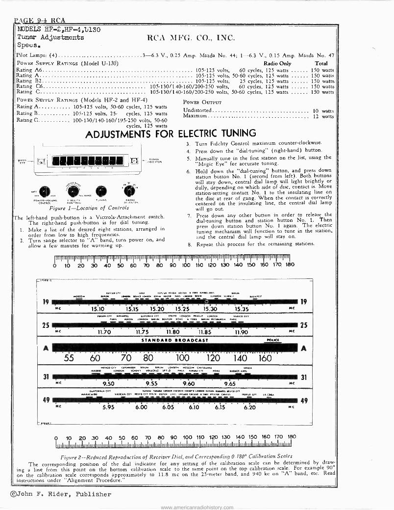
j..WE 9-4 RCA MODELS HF-2,HF-451)130 Tuner Adjustments Specs.
RCA MFG. CO., INC.
Pilot Lamps: (4) 3-6.3 V., 0.25 POWER SUPPLY RATINGS (Model U -13(i) Rating A6 Rating A Rating B2 Rating C6 Rating C POWER SUPPLY RATINGS (Models HF -2 and HF -4) Rating A 105-125 volts, 50-60 cycles, 125 watts Rating B
Rating C
Amp. Mazda No. 44; 1-6.3 V., 0.15 Amp. Mazda No. 47
Radio Only Total 105.125 volts, 60 cycles, 125 watts 150 watts 105-125 volts, 50-60 cycles, 125 watts 150 watts 105-125 volts, 25 cycles, 125 watts 150 watts.
105.130/140.160/200.250 volts, 60 cycles, 125 watts 150 watts 105.130/140.160/200.250 volts, 50.60 cycles, 125 watts 150 watts
105-125 volts, 25- cycles, 125 100.130/140.160/195.250 volts,
cycles, 125
watts 50-60 watts
ADJUSTMENTS FOR ELECTRIC TUNING
POWER OUTPUT
Undistorted Maximum
vEAGIC_ YE
I I 3.
4.
RAnGE 5. 1NDICATOR
6.
IJ ,J
The
. aLOUD
DOW ER -VOLUME
rent. IL A mi
FIDELITY CONTROL CONTROL
Figure 1 -Location of Controls
)I
51T TUNING RANGE
SELECTOR
left-hand push-button is a Victrola-Attachment switch. The right-hand push-button is for dial tuning.
1. Make a list of the desired eight stations, arranged in order from low to high frequencies.
2. Turn range selector to "A" band, turn power on, and allow a few minutes for warming up.
10 watts 12 watts
Turn Fidelity Control maximum counter -clockwise.
Press down the "dial -tuning" (right-hand) button.
Manually tune in the first station on the list, using the "Magic Eye" for accurate tuning.
Hold down the "dial -tuning" button, and press down station button No. 1 (second from left). Both buttons will stay down, central dial lamp will light brightly or dully, depending on which side of disc, contact is. Move station -setting contact No. 1 to the insulating line on the disc at rear of gang. When the contact is correctly centered on the insulating line, the central dial lamp will go out.
'7. Press down any other button in order to release the dial -tuning button and station button No. 1. Then press down station button No. 1 again. The electric tuning mechanism will function to tune in the station, and the central dial lamp will stay on.
8. Repeat this process for the remaining stations.
nnnnmgmrlirnnnmgnnmipmmgnnlnnrnllnnnnlmqnnlnnpminnpminrqmimqmilnnmllnnnnmqmilmqnulnnpml
0 10 20 30 40 50 60 70 80 90 100 110 120 130 140 150 160 170_ 180
err-,
19eee Mc
11(111 OIL LIMA PON 60 11 ACM IMO. M N 41/11111 NMMOSCOW
10180011 YIOC 101100 010111. 1.MI111 Noll 101000E M ON LONDON 1C M1 Y 01010111 - - . .
15.10 15.15 15.20 15.25 15.30 15.35 Mc
_
19
MC
MYNA 011110110. E11111.11 MY 1011° LONDON IN AGO. LONDON 11I11ICO 011 PAINS MAIM 100000 01 0 L01 N 0011011 IOI 1000 0401111 11111.11111.0411104N AM)
11.70 11.75 11.80 11.85 11.90 MC
5
A STANDARD BROADCAST roIKE
A 55 60 70 80 100 120 140 1601
31 MC
MNKO COY (O111110111 011800 MINI 1001°001 NONCOM CONTAGION 11.55A MADRID LONDON SCN0N'1 YNACIUI SIT'LD MALA N.A4 CI?! NOMI 0111001 AIMS - _ -31
9.50 9.55 9.60 9.65 C 4011101611 CITY AOAY 100001 (010.10 1010110 100000 001100 MINO Olt
MARAC AIDO VATICAN COY RNNO OIL 0NÚ1. N1100 OILL 1 10(460 (111(100 0 AMI N111'E t (111/1410 Lo L LA CELLA
49 MC 5.95 6.00 6.05 6.10 6.15 6.20 Mc
0 10 20 30 40 50 60 70 80 90 100 110 120 130 140 150 160 170 180
Il tilüiilii liiiilliüliililülililiililiiliilillüilüI,Ilii,Ii iiIiittIllliIitiii,iiiIlüiIiiiiIiiuhüiIiiliillliIiiuIiIlililiillillltiilliilIliliilii,ililiilliülulilli1iI
Figure 2 -Reduced Reproduction of Receiver Dial, and Corresponding 0-180° Calibration Scales The corresponding position of the dial indicator for any setting Of the calibration scale can be determined by draw-
ing a line from this point on the bottom calibration scale to the same point on the top calibration scale. For example 90° on the calibration scale corresponds approximately to 11.8 me on the 25 -meter band, and 940 kc on "A" band, etc. Read instructions under "Alignment Procedure."
©John F. Rider, Publisher
www.americanradiohistory.com
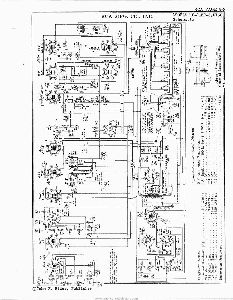
RCA PAGE 9-5
N
O J O i
RCA MFG. CO.. INC.
1V101 93W2 6a
lOa1NOO 31.4f11OA
u8F-
S' vppOl __:OI e000ÓOl`
r-4b...m too x 114 060 p m e2
,^NN y
Ño óf
H14
gá 9,2ó 0
00400 N? J 6000 ¡< $3 93W1
©John F. Rider, Publisher
YODELS HF-2,HF-4,1í130 Schematic
C
Ú F -w
C
V
' ~ I
w3:Zxds ó ó
ºº9a291000m i J
; r od0000000000do; o, ; a á \a1N071
SS
JJ
a .d - ,óó.* óf1 ..(1ü*
es g
o
4
.o. LI. dvMN.-. .' . .
www.americanradiohistory.com
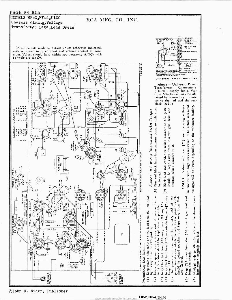
PAGE 9-6 RCA MODELS HF -2,F -F-4,11.30 Chassis Wiring,Voltage Transformar Data,Lead Dross
RCA MFG. CO.. INC.
Measurements made to chassis unless otherwise indicated, with set tuned to quiet point and volume control at mini- mum. Values should hold within approximately ±20% with 117 -volt a -c supply.
VVIYCIA NOVI!
140111).
'JOTS
RED TO POWER SUPPLY -SLACK REO- 10EDTR BLAC1
TOT.L. BLACK
040 RED ELLO
AEO YELLOW BLUE B EN ( TAPED) ELIOW
MOTOR- NOTE INNERT CON YELLOW- TwTER)AÑOD CONTACT BLACK - CORREEPONOINo t0 .LING POWER lUVPIY RATZ NGva
UNIVERSAL TRANS. CONNECTIONS
FGREEN - RECT FIL
GREEN DROWN -
FLEET .PLATE
SLACK BR OWN
BROWN- BLO E - MP GIL
Above - Universal Power Transformer Connections. (110 -volt supply for a Vic - trola Attachment may be ob- tained by connecting the mo- tor to the red and the red - black leads.)
ú Y
N y 12OB 7 ttl C ás
th: E ñ ro ó y ,o v
u. oB ° X:,
d C I.t
LI
N O O C
T! ..C) OC
.4í. N u as C
E C . ..C. . tJ -
es av+ * z o Cd á E ve O
E L O E. V 9 QO
1ui1
..., ~
01 ... b 1-...
ú b O 4 b °
g o a ° , k V u j. Ol
m
Lt. -9 b Oai .G 7 s: O
ro
v
.!E , ; d a .
G e 2 2 -u.; v O a
w ° mtl . ô; e ° w >
T 3
u dx E ° . v b 3>
E-c^ár ,c. D °Á 3ó =ó C C Or O 1d O -p,>.
E ú a OD `T e/ 3 i O ....tvU 2 ,s -a ,3
"t Eá -t2 - ó Or
2:,
°Á C
E~
t a Ve
ya - V
G 17d a ro C
C "L
.1 ni .0
,aE N N0
b0
LLI.,c
ed
Ú O[
u Jw . r u
doI°e -o E ó
23 ó v, 22 -.5 2, OwL,
.b N "V Q-,3 ó b w ro -0 ö E ú ó `' `' 0A._°: Vy`p-.2 .
DDL" a-. H O w .!d ?0 v G a., c cam °a3Ldcç i ÿ tad ° ú -G :n PG ó. L. T7
Q
< é 0...., 4; 'c ea, a E u g ó v
0 u DD Oa T. 0) ea O N E L . F.
y ex
':2: N nn ... .. .. - - ©John F. Rider, Publisher
HF -2, HF -4, U-130 www.americanradiohistory.com
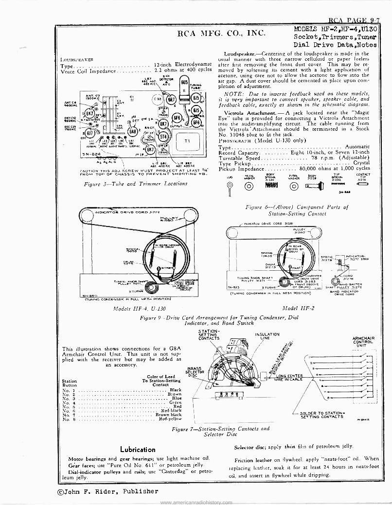
RCA PAGE 9-7
IOU DSPEA KER
Type
RCA MFG. CO., INC.
12 -inch Electrodynamic Voice Coil Impedance 2.2 ohms at 400 cycles :
arc AD,. DETECTOR
488 KC. A'C
ANT. C4 R000KC
OCT CIO Oa08NC
05C. C311 1500110
ANT. C3 ISOON C
ed; CET.
CC.
R.F.AMRSC O
4,«,k
DSE.7 1 ® 6A6
óü.sc! t á% äc I0.E000E 1,0001E NOOK( 1100.2. 6I00KC.
4
6K1
CI C2 0 ANT.
c
ó
5N-824 IIEIF.
lu DET 0 rr s \ _ REV'
6K7
7
ID
TUNING TUE!
s
615 ,
AF
o D!6 IKv 1. EII
OUTFUT`1®
T1
A3 AEAIG I
1,
A07. 488 KC API 45.5KC
CAUT IOW THIS ADJ. SCREW MUST PROJECT AT LEAST 3/4` FROM TOP OF CHASSIS TO PREVENT SHORTING +B.
Figure 3-Tube and Trimmer Locations
, INOICRTOFA oRwC CORO.3aJy PIJLL& V 3I26Ó
SPRING 13036
TUR1LLCvNING K 312'11
JII
3 TUONS
ISN 870 (TUNING CONDENSK IN PILL meeA POSIT
LJNI
MODELS HF-2,HF-4,13130 Socket,Trimmers,Tuner Dial Drive Data,Notes
Loudspeaker.-Centering of the loudspeaker is made in the usual manner with three narrow celluloid or paper feelers after first removing the front dust cover. This may be re- moved by softening its cement with a light application of acetone, using care not to allow the acetone to flow into the air gap. A dust cover should be cemented in place upon corn, pletion of adjustment.
NOTE: Due to inverse feedback used on these models, it is very important to connect speaker, speaker cable, and feedback cable, exactly a3 shown in the schematic diagram.
Victrola Attachment.- A jack located near the "Magic Eye" tube is provided for connecting a Victrola Attachment into the audio -amplifying circuit. The cable running from the Victrola' Attachment should be terminated in a Stock No. 31048 plug to fit the jack. PHONOGRAPH (Model U-130 only) Type Automatic Record Capacity Eight 10 -inch, or Seven 12 -inch Turntable Speed 78 r.p.m. (Adjustable) Type Pickup Crystal Pickup Impedance 80,000 ohms at 1,000 cycles
Lllß IAEIIEII
O 80DY
73P1R 230
ff/NAI
FIERE BODY TIP VAIOLO 31221 31232E
WINI ESN
3N-aaa
Figure 6-(Above) Component Parts of Station -Setting Contact
INDICATOR DRIVE CORD 31201
TUNING kNDe SHAFT PULLEY 31271
3N -sas 3 TURNS
SPRING 31275
ON DENSER DRUM DRIVE
CORD 91283 N FRONT GROOVE
OF DRUM) ,,,,. TUNING CONDENSER IN FULL MESH POSITION)
Models HF -4, U-130 Model HF -2
Figure 9-Drive Cord Arrangement for Tuning Condenser, Dial Indicator, and Band Switch
This illustration shows connections for a G8A Armchair Control Unit. This unit is not sup- plied with the receiver but may be added as
an accessory.
Color of Lead Station To Station -Setting Button Contact No. 1 Black No. 2 Brown No. 3 Blue No. 4 Green No. 5 Red No. 6 Red -black No. 7 Brown -black No. 8 Red -yellow
STATION - SETTING CONTACTS
SBELÉCTÓR `.F,'-`1- ¢,'1 DISC
S
INSULATION LINE
Figure 7-Station-Setting Contacts and Selector Disc
Lubrication
Motor bearings and gear bearings; use light machine oil.
Gar faces; use "Pure Oil No. 611" or petroleum jelly. Dial -indicator pulleys and rails; use "Castordag" or petro-
leum jelly.
CONTACT
31231 0
INDICATOR - 31277 STAID
CORD 31276
BAND -SWITCH SHAFT PULLEY 31272
SAND INDICATOR DRIVE CORD
ARMCHAIR CONTROL
UNIT
SOLDER TO STATION - SETTING CONTACTS
Selector disc; apply thin film of petroleum jelly.
Friction leather on flywheel; apply "neats-foot" oil. When
replacing leather, soak it for at least 24 hours in neats-foot
oil, and insert in flywheel while dripping.
©John F. Rider, Publisher
www.americanradiohistory.com
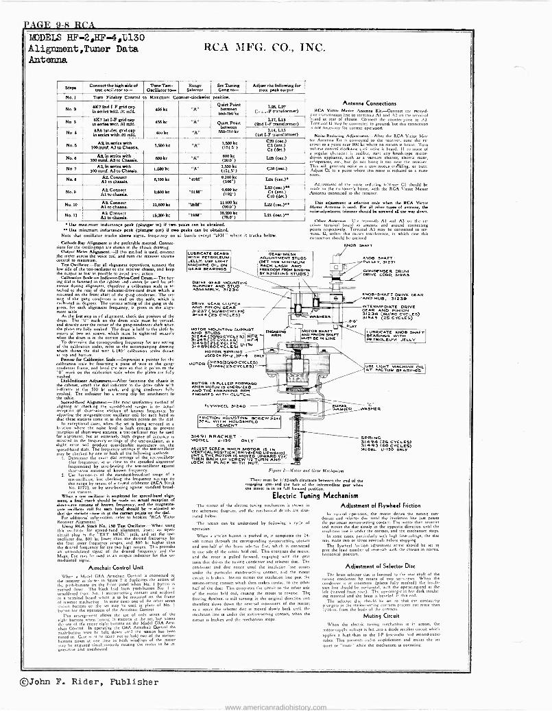
JAGE 9-8 RCA 14)DEIS HF -2,11F-4,0130 Alignment,Tuner Data Antenna
RCA MFG. CO., INC.
Steps Connect the high aide of estoeilhator to- Tune Test-
Oscillator to- Range
Selector Set Tuning Gang to-
AO. the following for mas peak output
TNo. 1 Tern Fidelity Control to Maaimtnm Cometerolockwise position.
No.9 1)R7 2nd I -F grid cap in aeries with .01 mfd 466 lest "A"
Point between L26, L27
(,- a .-F transformer)
Na II 6%7 se
Ut I -F grid cap in rfea with .01 mfd k. 466
"A Quiet Point
660-760 fie
L17, Lis (2nd I -F transformer)
4 Nan SAS he aerie. with p 456 kc "A" (1st I -F itraodorma)
6 AR in series with m 100 qL A3 to Chassis. 1,000 lest "A" 3,600 lee
(1613°) CIIO (me.)(me.)No.
COS (der)
No B AS. in aerie. with
100 mud. AII to Chassis 600 "A" SOO kc (30.0°) L26 Nu.)
No. 7 100 mmL AII to CiRuis 1,600 lee "A" 00 kc
(1616°) CM (ose.)
No. g AlAil
Connect to clsassis 6,100 kc "40M" 6,100 e
(106°) L24 (wc)
Nap Alt 9,600 kc "STY" 9,I00h L2S (osr.)e. ce cm.) C10 (der)
No. 10 AIL Connect Al toeLassis. 11,800k. "ffiY" 11200 kc °) L22 (0..)."
No. 11 Al Connect36,800 k. "1816" kc (7000°) Lai (ono)"
Use maximum inductance peak (plunger be if two peaks can be obtained. e Use tmnimum inductance peak (plunger out) H two peak. can be obtained.
Note that oscillator tracks above signal frequency on al bands except "49M" where it tracks below.
üthod.R.y Alignment is the preferable method. Conn«. sione for the oscdlograph are shown in the chased drawing.
Output Meter Alignment-If this method ie used, connect she meter across the voice coil, and turn the receiver volume control to maximum.
TastOdcillaor.-For all alignment operation, connect the low side of the testodtllator to the receiver thiada, and keep the output as low a possible to avoid avc action.
Calibration Sole on Indiraeae-DtivnCod Drum-The tun. ing dial ú fastened in the cabinet and canna be used for ref erence during alignment therefore a calibration scale is at. tacked to the rear of the indicatordrivecord drum which ill mounted on the front shaft of the gang condenser. The set. tingg of the gang condenser is read on this scale, which e calibrated in degree*. The correct setting of the gang in de. greet for each alignment frequency, is given in ehe align. meet able.
As the first step in rf alignment, check the position of the drum. The 'b" mark on the drum scale must be vertical, and directly over the center of the gangcondeneer shaft when the plates are fully meshed. The drum is held to the shaft by means of two set screws, which must be tightened securely when the drum is in the correct poston.
To determine the corresponding frequency for any Betting of the calibration scales, refer to the accompanying drawing which shows the dial with L 180° calibration dales drawn at top and bottom.
Pointe foe Cah'beatioss Soule.-Improvise a pointer for the calibration dale by fastening a piece of wire to the gang. condenser lame, and bend the wire w that it points to the "0" mark on the calibration dale when the pates are fully meshed.
Dca latte Adjustment ent-Afar fastening the chassis in the cabinet, attach the dial indicator to the drive cable with indicator at the 530 lest mark, and gang condenser fully meshed. The indicator has a spring clip for attachment to the cable.
Spread -Band Alignmee most dtie(actory method of aligning or checking the epreadband rang« ú on actual reception of short-wave nations of known frequency, by adjusting the magnetite -core oscillator coil for each band so that the« stations come in at the correct points on the dial.
In exceptional case., when the set it being divined in a
location where then node level is high enough to prevent reception of short-wave station., a lator may be used for alignment, but an extremely highgh degree of accuracy ie required in the frequency «dings of the temoscillator, as slight error will produce considerable inaccuracy on the spread -band dials. The frequency se of ttings the tesPoecillator
methods: be checked by one or both of the following methods: I. Determine the exact dial semngs of the rest ator
(for frequencies at or clod to the specified alignment frequencies) by serog the test -oscillator against h ve lotions of known frequency.
2. Usese harmonica of the eandard. roadcad range of a
this ranllstor, first checking the frequency tongs on this range by means of a crystal calibrator (RCA Stock No. 9572), or by aermbeating aganet standardstandardbroad,
Whenr stations.
a red oscillator is employed for spread -band align- ment, a final check should be made on actual reception of shortwave nations of known frequency, and the magnetite -
core amillamr coil for each band should be r-djused se
that the Nation. come at the erect point* the disc For additional information, r. fer to booklet "RCA Victor
Receiver Alignment' Using RCA Stock No. 170 Ts Oddl.ter,-When wing
this oscillator for spreadbard alignment, insert an open -
circuit 't plug in the "EXT. MOD. jack, and set the teen oscillator dial 800 kc lower than the desired frequency for the four lower frequency rangea, and 800 kc higher than the desired frequency for the two high ranges. This provides an n oduared signal of the desired frequency and the MagiciEye may be used as an output indicator for thm un modulated signal.
Armchair Control Unit
When a Model GOA Armchair Control is connected to the receiver N shown in figure 7 it duplicates 'the action of the push-button on the front panel when No. 1 button is
pressed down. The black lead from posh.button No. I is
unsoldered from No. I wtion-fitting contact and soldered
to a terminal board which is to be 'mounted on the frame of rejector mechanism. In one
e of the other n
sanon buttons on some
the ate be used place of No.I button for the operation of the Armchair Control.
This arrangement allows the use of only seven of the
eight button. when tuning in wtion at the set, but allows the use of she entire eight buttons on the Model GOA Arm- chair Control. In operating the G8A Armchair Control the
puhbunon must be held down until the station has been
tuned in. Care must be taken not to hold two of the wtion buttons down at one time as both winding. of the motor may be engaged simultaneously causing the motor to be in onentive and overheated.
LUBRICATE GEARS WITH PETROLEUM JELLY. USE LIGHT MACHINE OIL ON GEAR KARINGS
DRIVE GEAR MOUNTING SUPPORT AND STUD ASSEMBLY, 3123G
DRIVE GEAR CLUTCH AND PINION GEAR 91297 Stj/so CYCLES) 51644 25 CYCLES)
Antenna Connections RCA Victor Master Antes KM-Connect the twisted
pair tranemúelon line ro terminals Al and A2 on the terminal hoard at rear of chaule. Connect the caunterpoise to Al. Terminal G may be connected to ground, but this connection is not necessary for correct °pennote.
NodeRduting Adjustment-After the RCA Victor Mae.' ter Antenna Kit is connected to the receiver, tune the re ceiver to a point near 900 kc where no station is heard. Turn volume control clockwise until noise is heard.. If no noise of a regular character ie audible, start any bruhrype motor- driven appliance, such as a vacuum cleaner, electric naor, refrigerator, ex., but do not bring it too near the rer. This will generate noise as communal. tinun caflkling, orbumbu Adjust CI to a poin where this noise in reduced to a mini. MUM.
Adjumment of the noise reducing trimmer CI should be made in the customer's home, with the RCA Victor Mauer
Antenna connected to the receiver.
This adjustment is effective 'only when the RCA Victor Master Antenna is lased. For all other types of antenna, the nurse -adjustment trimmer Mould be Dewed all the may down.
Other Anrennm.-Use terminals Al and A3 on the rc ceiver terminal board as antenna and ground connecung point. respectively. Terminal A3 may be connected to ter- minal G, unless this causes interference, in which cad this connection should be omitted.
GEAR -MESH ADJUSTMENT STUDS (SET FOR MINIMUM B ACK -LASH ANO FREEDOM FROM BINDING BY ROTATING STUDS)
KNOB SHAFT
KNOB SHAFT
--:677 PULLEY. 91271
CONDENSER DRUM ..../DRIVE cono, 91269
.'
MOTOR MOUNTING SUPPORT ANO STUDS 91244 (scrGo evcL 9)I H 91245 2 CYCLES 314139 60 CYC LEB))))) U-'3e
ROTOR SPRING USED OR NF -2, HF -4 ONLY
a MOTOR I31293(SCyIGO CYCLES) Lo 124G(26 CYCLES)
ROTOR la FILLED FORWARD WHEN MOTOR es ENERGIZED AND THE ENGAGING ARM ENGAGES WITH CLUTCH.
FLYWHEEL 31240
NEARING ARM
I "WASHERS
MOTOR SHAFT ANO PINION SHAFT MUST SE IN LINE
KNOB -SHAFT DRIVE GEAR /AND HUB, 31236 INTERMEDIATE DRIVE GEAR AND PINION 31296 50/GO CYCLES) 31545 2 CYCLES)
L.I I LAY
[email protected].:3,4.: !.'1 : f fi gR
.
I/¡ wF
.y 71Kk. ,`".,{
FRICTION ADJUSTING SCREW SEAL WITH HOUSEHOLD
CEMENT.
det
31491 BRACKET MODEL U-130 ONLY
3 VERTICAT L DOSITIOREW f ((ORIV[éND UPWARD UNTIL THE ROTOR
UPT SCREW f5 TURNA UPWARD
DNO3 LOCK I N PLACE WITH NUT.
LUBRICATE KNOB SHAFT KARIPSS WITH PETROLEUM JELLY
USE LIGHT MACHINE OIL AT MOTOR BEARINSS
"C" BYAMMER WASHER
SPRING 31404 (25 CYCLES) 31493 coo CYCLE$) MODEL U-130 ONLY
Figure 8-Motor and Gear Mechanism
There mum be I/32.inch clearance b tty n the end of the engaging arm-and he face
kf the intermediate fear when tho is s fowad position
Electric Tuning Mechanism
The circuit of the electric tuning mechanism is shown in
the schematic diagram, and the mechanical details are illuv tasted bellow.
The action can be understood by following a cycle of operation:
When a station button is pushed in. it completes the 24 volt circuit through the corresponding sationrning contact and one.half of the brass selector dix, which is connected
n
to one side of the motor field coil. This energise. the motor, and the rotor is pulled forward. engaging with the gear
train that drives the tuning condenser and selector disc. The condenser and disc rotate until the insulation line come. under the particular stationuetung contact. and the motor circuit is broken. Inertia
r
s the insulation line peat the
station -setting contact which then makes contact to the other half of she disc: This completes the circuit to the other aide
of the motor field cod, causing the motor to reverse. Thy floating flywheel is still turning in the original direction and
therefore dims down she re venal movement of the motor; as a result the selector did is moved slowly back until the
insulation line is under the sationrtting contact, when the
circuit is broken and the mechanism stops.
Adjustment of Flywheel Friction
In normal operation, the motor driva the tuning con- denser and selector disc und the insulation line fuse pave. the particular sationsetting contact: The motor then recessee and moves the did slowly in the opposite direction until the
eneulamn hoe launder the contact and the mechanism stops.
In some cases, particularly tenth high line -voltage, the did may make two or three reversals before topping.
The flywheel friction adjustment drew should be set to give the
l st number of reversals with the chassis in normal
h
Adjustment of Selector Die
The brass selmior Mac s fastened to the rear shaft of the
n tuning condenser by m ( NM ensscrews. When the condenser is at maximum (plates fully meshed) the insola non line should be honsonW. with the operatingc d at the left (viewed from rear). The pen na -e d has dark insulat- ing matenal and the bau is beveled t this end.
The selector disc should be set x that the conaccnp plungers in the station.dtting contacts project not more than 1/1tren. from the body of the m"tua.
Muting Circuit
When the electric tuning mechanism ie in action, the
motopeupply volage is fed into a diode rectifier circuit which
applies a high "bid to the IF finoaudio and second -audio
tubes. This pre enta audio amplification and makes the set
quiet or mute while ehe mechanism ie operating.
©John F. Rider, Publisher
www.americanradiohistory.com
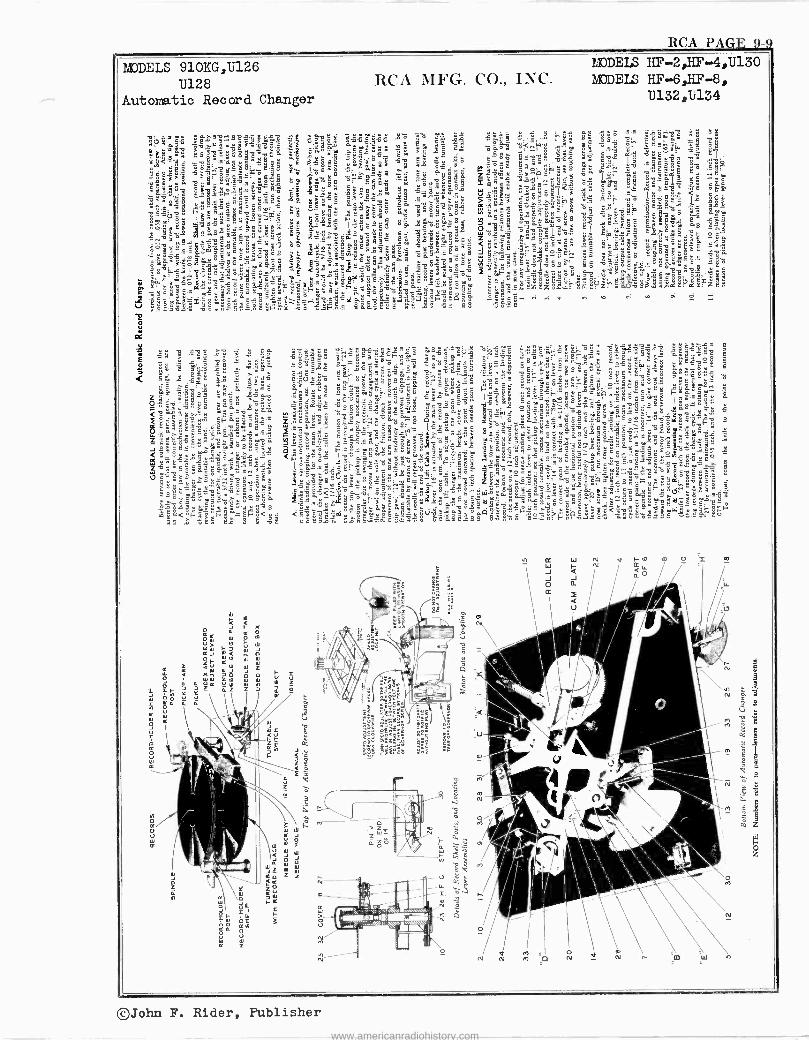
MODELS 910KG,U126 U128
Automatic Record Changer
géñ9lr211. éiE:nlerme=8a: éu 44Aé
5üC2ä$2
RCA PAGE 9-9
ZdODELS HF-2,EF-4,11130
MODELS HF-6,IiF-8, U132,U134
©John F. Rider, Publisher
www.americanradiohistory.com
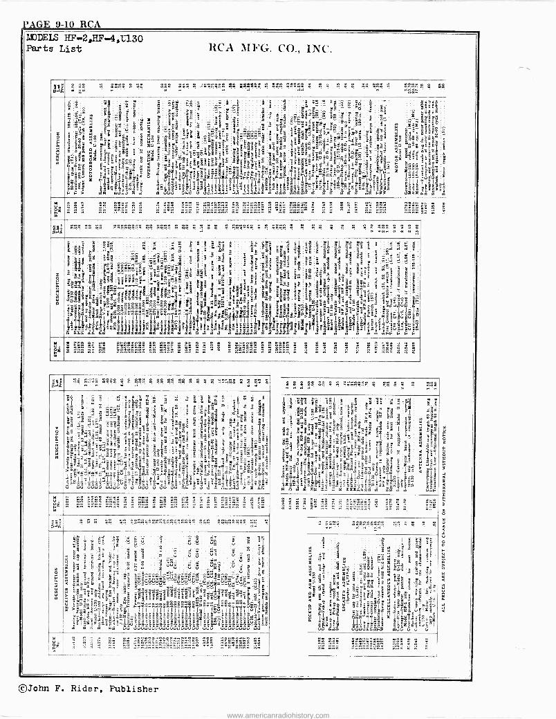
PAGE 9-10 RCA MOnFLS HP -2,11F -4,1;130 Parts List RCA MFG. CO., INC.
o!ä 4 ÿ ! .. e ee e!e eg,g g 4ggr,gge ee ;epee b eee 1.7: .
n rr» 4a
c á$ m
w
g: ^- 31:7°141'11-,y lç
7 iñ:ái A
¢ â
nÑp m
leeqCg
é <5
`- P
dg ti
&u oá 7
F~>
' j
3 52Sce a º_ E2,6°u..-.o
c
a 4 8 mm
`
ga PP» ;.sé 'ÿ3
B -W
l$ äaeez o $l.l=g ÿ;d38
wúao
i
°!
9
!
7 S z1k < e'S- g=e y u5 a- 6 7 r
' z; F7 X'y eLr < a ú 6 o
1
I : 9^.Eä35e4Ét1'4ii>tYyìu>wsPámmm.Ó.y-E.a".ec...ór.cm.y"..ccsEu
m' aÓ
- rggaá
5d á`áá: @@Êg
8" s
Áár 9 c'7°,:zrg
t-14
Y ÿYl úVu
r -g
t ( g
g EÁ
g_;g@äi_-
SÿÁáe7....37ä^Sa.FNacÖS9 g1'l'i1666
úä
e
L
1 ç `g`óó"
O
` ii:
a . ,"i sz_.` r 8 5a
"ÿggseC
t_83 5 _,'ôg
a OSá° a
II II I
uU .+.i.i.i
i "a
áe ._...
to...
_a ttw eë=
ÿÉ.
Y4c'c'c''"qr8xa'
-all g<_ .á.i
...._...ñ5 .
--$wá-
t^'` _-.a
_eg;$E5 e
II {I.I
.i.i.iáäa
g
"a
Sa E i.-
3yÁ l:_`-
eä Y I¡
u www
°11EF gláue^aä_9daEhmáe.
`.t.,
Sa',. y @`nug; e .5_;"
g°- 5='s6^"áads
I I I.:I:I
I
rw`9>
2
^
°gr
Eemeee"e=r1°"
r2
t a
_sci.,._ti
w
" t .t°
ide'
I -I w w
tm
Ig
c áa ól 'Só _e
8522
t.. I"ä9É :
>3
wm F33
á me in m
.:
gvC. lo > .
rm
dri I
á óáEë Uiii
îäÉ.
$áCám ggn..S
ä
grÿ rEeEg
T':
eSoe g
u(r 7 ' l i`y'm 6m wu
úa oz p n .e
..5 -
n 5 5n n 5 n n 5 n 5nn 5 nn5n5n5 n5 5nn5n5 n ..n nnwn .. n n n .. 55 555 5555 15 n w
áe g g g 2.42giA.1 r4 1 2,M e e 4 e g e e r .5. r « r
7 o
á áyÿ m5 -ss te
'lañe
yßg3.Siá 'íyÿ:3
11411311:PialiiIVIZTial S
s;`s
t 11 k - rra
YY
aa
.' --,1= SSS
e
á g
d - i .5
g.°,-"a
da da
4m
1s{ :_S
n C 8
r~ e6,;.b$
7ñ 9
>
Ó `wz-eSeSeäeäa83ail'É
reaiácrñ5 cá.-..ea =s
oÿi........ á
áeeoeSS4 no -
èwáltt5a 3""q_g..aán aaaaaaaa
::oi Ag
5ttvl` Ciéÿ áá ++9gg. Td3t ._..e,¡osòêáEEn
á
zg^°i atlêp..i
ÿ7 e i^5vmá
gg '8'i"uc 7Ig{
7
aa aaaa
:á^ E.
ea
`..a^I
q ^' ftr I
3
Sg g?
8
8
,.0 á `5
.5 i..g
e,° '
I 77
s a aa
n
! I
y ó7pV 5 eÁt8Cánin- ÿ
egr" ye' a.g
1: ! eRe í' k, t:ç
E1 .y 9 9p
s / 3 ..gy
ä $
r
i w e a E5 z: rEuS° i=,^7
I
kf7ÌÁgßa$zceÁe=e w m
á
y
'
Cÿ+ áéS
K58 r.agEfr e 375g5 Ciäa1-R IIIIII
z Mw';9;,
:yk
ÿ
3k
á er
1 é= e
.á TÁó ti a -r
..e
:$g ÁÁÿ
o3k
5(cerr Gé.c j
8
IY.tdlÌl
w w w
s:.Ë;1 .ii- °cÿ -YYS8
3a`' ^.ei oe; . ÉyOerwor=o¢ rl :869 III a"F1-n>
?. 232é7-á
g 2y
xx
fi
yg É` §g.a;ÿ.«tº 9e<ru.5e. S5 g 1
I m
;a
:á
á: ee aa7 etl
§ áuy
S > a
I
8151-118188`2$.Pou $
oL.él 9
i 5g1
.^g8 á
ó 3 K
;°j
B-=5 > >
97 w w
le
j té áywe^ 44Kó
8
5>
8' w
11k1 11
l
áy u
a7=g 7 am
r;198=..`a > a
9a :I:Iw3-Ait" w
v' é
á"^"S ¡Pi
> iiä.I
w
i i g
r < °
5
E a
Ë
°:.1'12'9-'''''
,:á3á '. "
^gv w`1
- egg
y1L1! ; el
t a"R
-gcú:.û`á aN
; t
1 e
uáuEe
r
C
: m g
t
L t tC
ti Ñ
y
7
r
n r 55 15 55555555 55 1515111 5 w 'w . 555555 . 5 115i 5 5 5 n n ñ 5 5 5 55n 5 5 5
°I j,.l q`é w:gee e ..
=44. .. ..44s . .....222; e.:4 n
c S
á
a
i §T ufgE43 l 5 ^lyy $. a á.ia r8ät, 1111
gg áá
1
gaia 7láñS4E ÉB?
r95.áÉ<Z B<leDeo8 - t -Taánáátó5 "ú:é:ëS:;g ;,e. `5a. yd. "yéó2mdug < << .c-
6o1i1i1i: J.Tg=rÿlë;é ú uú 333 ú83ú
i.ër
r5"tl QápQ'$ 3 ú giS °g<gc 8;8;°4
c c t 1 m u usuS
y ÿ° 1i
9
tag $og'--ae-
5
á á253-éj
9<
ak EO .2,°
l
><.<4Y-
u3
g S " e.
káeC .1 E1'$ -:á't
g xË 5Y5.5
2á14u
,:
é,1!_ r
uuecs
: ró ë
a 3 e -twá't
°g i 1"R;1i.eee°e EáT y e á:Yye4Yfr9`e £ ,
b.g185`-.:u73a;a < - 2f.eoá.eóºcä°a
Sa5g510 ><> awem
`
u ú 3 .ság
i = g Ey.gk 6é li
8 t u'é éal
S É .9 T9 n 400 g
[e 5^QÉ
- g"
a Áº=>
lol js>rtiwa g . ëällë
saár
L Hi!¡U..Z w nn n5 MI n 5 515 n 55 55 55 5 5 5 5 55555 n 5 55
aa DI ... ........ .224.2 .. .........gg n..
c E
a uw
á
U> _
;, e .É
s 5,5
é áylg
a11 -x- > .a:355iwzá
EgSéferyEaMr4.n..n w ñi.vgóááñ.e_me5ó5óéé^!.iÓ.óóááe^ÇL,3 a>y-=täy4.1 xg<<
S7 el?`'u'= m° m
i
d d .
s
" sk E
ri'' -.2,54
e:grÿ ÿ_gg ;á
ä1 r.e
1.5 ÿ8y_-ÿ179c-yi.g:.._.5..=-. m m` m0Ó
9 $
C7
I
5
ugnéw
-
1
$
''.ul'úúúVÑuuVúúúVÚVúV¿púúV §s- a. 2é:éfié5
UU
^ ^ w
V d 1
a m
d_dddddd
TTIIII
!4á le5egááT#I5°er 6wo000agg3oa>á6ÿlSúloS6Se.aS3S;$5 ODUUUUVUVUVVUVVOOD
5
a
s
ëllEééáil!èsÿeé`efié
1111III7?7Tii
e` he
i--;
.. E ,¡
..
--I ... d
ir.á
-3:.
.i ú5 .r
ax
ad Sd
II u !e>l;#g$go8>g ..5i'a;'á-Ái_
UÚU VUpODUO
.. ..
u
u.0 ú .. dd
I
g gq
. :
w a
e ó:
Ysel°Á
úú
5 15r1
Mg¡l
Y
Ó°
,_^
. : ! - - nh ü*-:.....5..nnn....n..n_hn_ .. ,. n n..nn 5n
5 M á
w .. . . ....... . .. r
i1 9g; 1r5^t g
t_; 5-99:yz
o " 7 2ÿ j-a-$+g gee á=é=. ',--g ila Fç e ma _ SS
It." 1Sg88 á1=g 8g8 E8- .
I
t- 7 8 a x 7 C=esBil.°g°= 39 zil yl k á _ g rf= 3 c;5a1 "7II_ÿa _a= tyará v :.5o.a ák
e ÿ=ÿyi.y8°[ká;sëy âá S -
. Á Rowqoiák`g.ÿ$ Biegº°O;,.e eOs=511cicóg-""x-ééms,"7v12.fad 15 -J- cá3 IÌ71 GG U°`a 4. 810.'5311 9yE3°gElllÿ.Ìlq ia=° es'-g5e".,-8eéd1kza--^ 6 ó°i ï="_.. m isidamm ww
a g8
7 l$
k ?gM°t .á'a my tS5ó5
272'91.011 s n " "g1Ñfrgt@Ì
á EI 11512a úú S.é uúúúSS =3
I
I.
ig ÿi °E
cr 18E 3"
ÌálïE Sl. äm
55555
©John F. Rider, Publisher
www.americanradiohistory.com
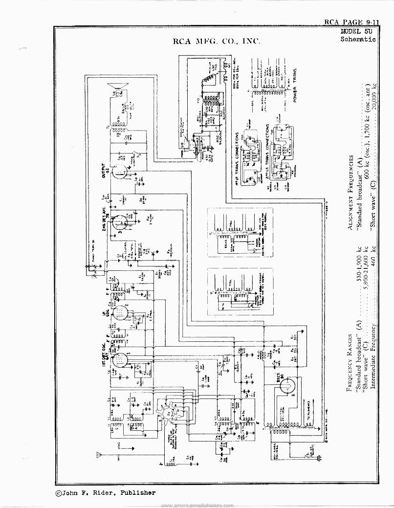
RCA PAGE 9-11
©John F. Rider, Publisher
www.americanradiohistory.com
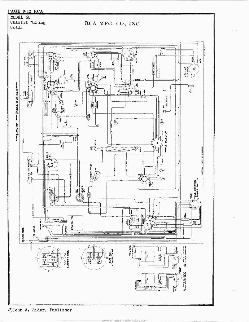
PAGE 9-12 RCA MODEL 5U Chassis wiring Coils
RCA Mh'G. CO., INC.
. Ì ar ° 'r - 11 ..
` n= r 1 ` , , ;
x n. -i ti.
$ "á ,. - ls ( VI g A
` -- ,s tjf, r 2
NF _ Q
ñó Ó ÿ V
0 4
n 3Z
o o , Vj 9
UJUI/l1lL(1.1
-..._ v = xnoa N«á
MiWi a 'r" p fe º F
N le an an'. t; ° ) i V- n
C. -,ele -J
ó-- 1 .
- a WV
2,i-- crea
.-1 t---, ¡
1. -h..i .
é \ Na3No
a 6 s
: r -o ' 4
1 &
1-.___----j Nn tC
/ oy ar iób w O ^ ¡ `l `
fr r u,.
_1 . .
_J 0, «....-
Zr OW x WG
JV W
i 6 F ///
Já WV X
11 Z}Ç ív .
x Fa i ñ` . / +I
1 MIi
º °" 1 n f X
V ` .m.a. - . ----_,Q -
. . :; _ N. - í F
. - 0 ó I
` o ne \ r It.
óº
.
e .
a3n
E___c _
JZ úF VV
N O u
©John F. Rider, Publisher
www.americanradiohistory.com
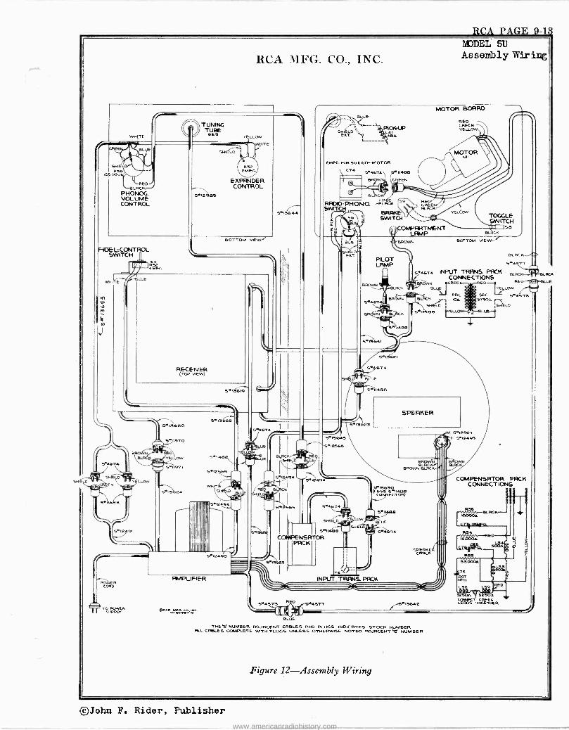
RCA PAGE 9-10 MODEL 513
RCA MFG. CO-., INC.
WHITE
R
SH I LD\ 36
o BLUE
LACK RED
PHONOG. VOLUME CONTROL
FIDEL.CONTROL SWITCH
1RSE
LUE
POJJER CORD
TUNING TUBE
0EB
FiMPLIFIER
ATD GONER I 5' PALM
SKI EL
YELLOW
R32 EMEG
ITE
BLUE
RFDIO-PHONO. SWI
Assembly Wiring
EMEO. FOR 50 ( DO -MOTOR I C74 54614 511488
BR GEEN I B -CK
1 -BLACK
BRAKE SWITCH
PILOT LAMP
MOTOR BOARD
RED REEN ELL.
RE CREE BLACK
OMPLTMENT
BROWN
S 14430
MOTOR MI
YELLOW TOGGLE SWITCH
s8 auk
BOTTOM VIEW
BLACK.
5441? s`46T+ INPUT TRANS. PACK BLACK
CONNECTIONS REEN RED ED Low
GAI. BLACK 104
SHIELD
5..1146e }YEL11T
5.4573 6150n F\\
SIILD HfLUé
SPEAKER
THE` S NUMBER RDJRCENT CABLES AND PLUGS INDICATES STOCK NUMBER nu_ CABLES COMPLETE WITH PLUGS UNLESS OTHERWISE NOTED ADJACENT C NUMBER
Figure 12-Assembly Wiring
COMPENSATOR PACK CONNECT IONS
32504 ` 5250k CCMIECT GREEN LEADS TOGETHER
RCK
©John F. Rider, Publisher
www.americanradiohistory.com
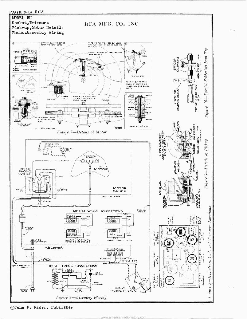
PAGE 9-14 RCA YODEL SU S ooket, Tr immer s
Piok-+up,Motor Details
Phono.Assembly Wiring
- - - - TO REMOVE TURNTABLE UTMO IT- LOOSER NUT, PUBN STOP UP OUT OP SLOT Mq ROTATE eo-
REMOVE BURRS FROM POLES OP STATOR APO ROTOR MYTH PME EMERY ELOTR
261e2,. PEO
IIO VOLTS-5OCYCLES I10VOLTS-25CYCLES
_UE YELLOW L. -SHIELD EXT.
©John F. Rider, Publisher
www.americanradiohistory.com
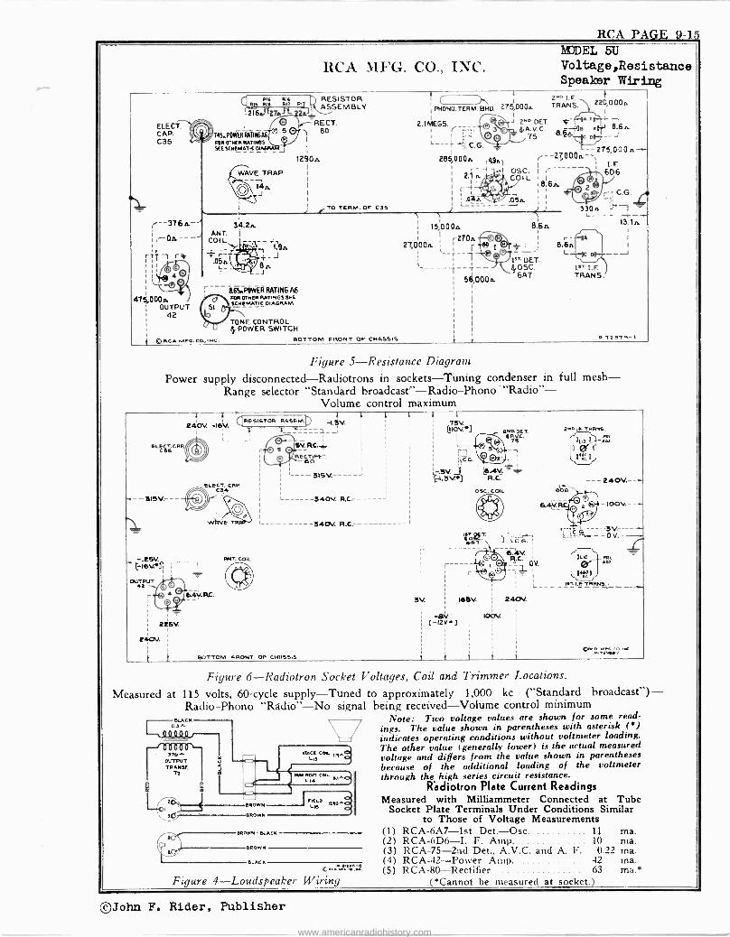
RCA PAG E 9 15 MODEL 5U
RCA MFG. CO., INC. Voltage,Resistance Speaker Wiring
ELECT. CAP. C35
--376iL-
I,' -Oa--- 1
11¡ 1 I ,Ïa 4
l' v-0 474000.
OUTPUT 42
RR: RK RESISTOR "M Rwf R" T ASSEMBLY
-216a276n- L RECT.
14S.PBMRH4RI41466 80 FOR OTRfR MTIII83 3E[5191lMATIC
1290,.
WAVE TRAP
14n J I
TO TERM. OF C35
34.2, ANT.
COIL
.054
r 165RPOWERATINGA6 iill OTNlR RATINSS 3RR fOIÇAMTIÇ OIAORAM
® RCA MIR. co., INC.
TONE CONTROL 4, POWER SWITCH
BOTTOM FRONT OF CHASSIS
2"a I. F.
PHONO.TERM.BRD. 2T5,0002I. TRANS.
2.144EGS. I 2'4°. OCT. r-.- 31 1 I .- 75 8'-6T
'43. C.G.
220,000A
8.6,. J
--275,0006-- 28%00 On. 149A1 r--27,000.--, __`F. -T
.I OSC. Ì
1. r 2.16fyiCOI L 1
r -4n 18.6 I
I Akan 1y .Ó5n I I v; C.G.
L- _ -- J i 3306 '3". -1
15,000. ' I r210.
21,0006 ; I r I
------T 54,000.
' n 8.6. 13.1I
8.6n 1sT DET. LJG 8OSC. 1.* t.r
6A7 TRANS.
a-12919-1
Figure 5-Resistance Diagram
Power supply disconnected-Radiotrons in sockets-Tuning condenser in full mesh- Range selector "Standard broadcast"-Radio--Phono "Radio"
Volume control maximum
114.1-i ii
' CRESISTOR RSSE`NLp 16K T -
8,7_RG
s6K j iau*r II
OUTPUT 45
r
REGSTOIrEr.
'----318V.
---- -340v. R.C.-
ANT. COIL
BOTTOM FRONT OP CHASSIS
1
340V. R.C.
1
3V.
r r
-iV ' A30K [-i2V47
2wO1.11 TRANS.
°L12 II v Oro
101/
1---340V.---
100V.---
-0 V.-
CCi.iawi c.
Figure 6-Radiotron Socket Voltages, Coil and Trimmer Locations.
Measured at 115 volts, 60 -cycle supply-Tuned to approximately 1,000 kc ("Standard broadcast")- Radio-Phono "Radio"-No signal being received-Volume control minimum
Note: Two voltage values are shown for some read- ings. The value shown in parentheses with asterisk (*) indicates operating conditions without voltmeter loading. The other value (generally lower) is the actual measured voltage and differs from the value shown in parentheses because of the additional loading of the voltmeter through the high series circuit resistance.
:I¡ Radiotron Plate Current Readings Measured with Milliammeter Connected at Tube
Socket Plate Terminals Under Conditions Similar to Those of Voltage Measurements
(1) RCA -6A7 -1st Det.-Osc. 11 ma. (2) RCA-6D6-I. F. Amp. 10 ma. (3) RCA -75 -2nd Det., A.V.C. and A. F. 0.22 ma. (4) RCA-42-Power Amp. 42 ma. (5) RCA-80-Rectifier 63 ma.*
Figure 4-Loudspeaker Wiring (*Cannot be measured at socket.) c;:22!.",.1
®John F. Rider, Publisher
www.americanradiohistory.com
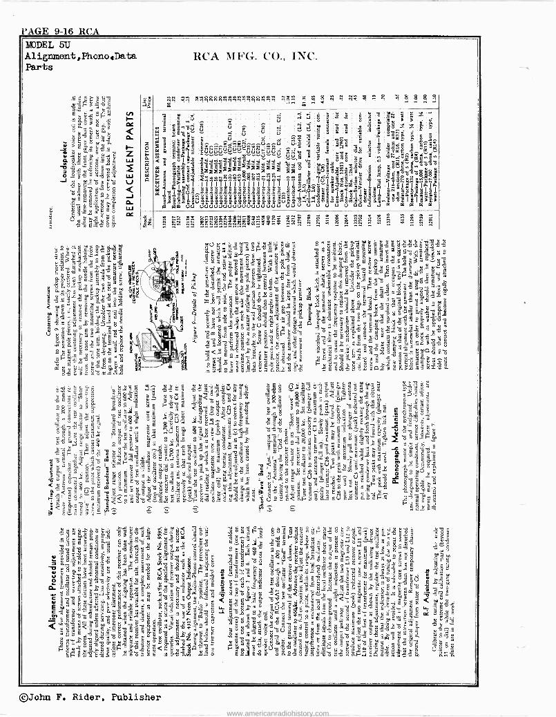
PAGE 9-16 RCA MODEL 5U Alignment,PhonoData Parts
.5
v d >971' v.ó . w u
E s3ñ ó .a ñ ó ' ó «
cw3 ; ú .pé 00u 43°d .*e u-+áw..m 3.r
5.S ú
2e:a a«Qÿ 'S$v6 '"*".. 3ú
O o'3« $ évo é á J .. S w
e ° ó 6° Êá>óuO
é6ó`w3°Jg-á 'v;aq.u."iówE
, é.ñ^uE° rt 6 e
fi ciipmiu8 E_ °
. 3 ú, E m é ú u ä m
c v.fi.S°'wÿ« vS '21331 ° u 3
6 ÿ a E y« v'g 6.ô E.O,a« ná
'ES o u i.a « a 3 u m á u ° « u m..y u «.5dvó,««3ó
m 124.1;2.-55.2 ú E ó
ú ó+^ jv`lme b gÿ E ó
ó.ci
J, er . 0 5 .2 à
Z,1 1 mó m u oÿ "is .91
3 . u ° E a V C..ÿ i
w y w V E c w w ,¡E..LEd«°y°Yu d3ÿÿó 0
3... é ó _ =0s
á¿
RCA MFG. CO., INC.
tr.'r 1-, '..e 2c e R g r H q .. n $ g as gá
s Wd
.. .`°.
.g E4 " ÿ
0 0 § 1E
i ñ ¡1;
.Fak5 á.
b 3wEe ñ=
iXad a:2 e..:c J ÿ"ieq ̂é m..
I " E339E3g <aYáS.°:iyvzN`O4a E454 u3YuEáe8«,,Ê_e 2xYi1äs5 gaE30.aE5ó
a2äi aáaáä,oá.áóáááä aaáäeGroáq°.aaa.Ñöÿ3.aß1t 1sias: 0d uv uuVuuuUuuuuuuuUuu uUU U.0 a a a a
e. ÿz -.n NN NÑRNrIRInÑi~gYtÑi ^Ng n R ñ!i....
...
ñ !g.-.
SV 9.w S_e é 3« sw z 3 wg E x«,,°e.á. 11« 1
s«.`'J d.ó«« u
8
Eúwm3pÿ.. drouä t ú3 gwCâEú.ÊCÊ] 'SósgroCáké.°. p. et .C_Y O S?m.°`rY2 8> 0,.Si s y. úú« L , kéY .5 «a oo 'S.°e°L% 3é vÿ w.o ° E 2,92g> c ui3 $ó w Ya Év ÿv 6 Y ece e. u E.t 6> u u c u o .9y ° w> ú o«,c ov c 3 é c
5 º o.Z E Qy3:.°, u« 3
75-1:g e w v É:? â, e Y óf-' o Sir:° me
u w w
tv Eá, «g 3ÿÿg r3-5.,.-5''''.2.2
h..2_, 3'%.§.:).,X-3. ó vj É.r
ú x ó« 9v3 m
5c. .d-""m.3u..cr u ygÊuw. ° óÿu a Stim°«c ? 3 .5..g d 3 ro3y.E oo -... .3 1474 6« .$ u ...33' R1ó,v«m6a.5 /.ofia>.$oiyt«.muúól-' 3Só
'ó.$$wA'Y, °a5m wy má...é$b u 1.-.º, 'C«- Tsv c;E ro ó u-ó ov :ô v E _ .5 q °« $ o a yE3S 4>3éSy0.°M6«ómw'áóm.o+ oÿug púgE .5ms.` ÿs.Êsá3â.óo Ys E« 3'ó fiÿV é «y á« 3` wai o> ä11:1-4 i`- a
ú5'.0.% w
F .5 w y ó ç a' E E .c o ésv p ° E ú u w
y p [° ÿ C `.a ÿ O 7 ` 1
le + Y ale' v oYY.Saa :2: -E, u.$
.'9y3çSo v C ÿS°,L6>.en.«Y.`°E .9..ÑCVSC4pq$.SLaó ó<23ua$.'uú 2,
>P'có.ú,wwév ú,E%ó.-.95A«4ó c v 6úaúa. «^E u,,,r..á =oÿc s ay;,oú.,r,.. úpiúc'ú5 ñ°ó0u usucv w>sv.x-x_ 6,ä.5 .-9:.54,2... É.s w w 8.áá ñ.5« ÿ E wen« 3 º Ut:-'23`' S>a ó éx': á
0eW .u.3 ó Cg ä.y°.ÿg 4 n Ñ «« C fi «« 3 úÚ T5 3 g
V p-.°« C' á3 ér ú lf
o m. 3 li o.-. - 5 yy v°3b ÿÉóXinu>fi < ú Ê,V é<óáów..°.^ °°°<°'f-wÿ«um óaÿc.°, .....F.-41.1 y
o' oo3w O3 .5 FtipE vO ac. G,úé °wy ;Ñspaw>. ó= méÊ ' ..:abE ögç;
Ô,.fiw gim
u`o <ú&.r°.á.«Crióú má 3eñ'3fi¿,.ó'acmÿss°'ÿ E Ǻd'
wwO °c $a á .« Á=u p <' úu °u O0' ì' T r3 c óo.- =r .c=..EoÓ ó'`Otl uE $.u.V
JÓvuO.].iae ú3..`.á «O« esilç.eips3?áév'= ee O mv«i w..o3^ .. n 8.0 8ºw« ç s...,;: oE E avá'X pa -5:A-.'e Ó° 5 3 Ñ °.a y ;A EI:» Y C ÿ 5 y 3.+ úCppC ° °'- 8 °1 V en M T 5 ° T.3 p ú .° 9 ...°.ó>mñE-ñ yO'ú`c °c0« 3 EF6q'C
3Og"5n"s,. 5' s-$úú wfi_E áSmvum ó°+.°cm ..mw d 3Y«5a fi$ ÿrs5ósi=`ÁÓ.523v SEoss'ÓoEE^ S Ê° Ê wóF' u .T v:
..-..r.1-;..,.=(-.;'.5 bi ...á,3a , 2.3 .ASgwua;,..i$.Eu v=yy °!.>>3>3.ÊeSÊó.«á,xay. ñóÉéúv F.:3F au e ó7a Ou SnúúS5auá0°c.0!-w c. u...u.-ó.5 w,,Eri6wv ` ó'ä-.3.6 v úyùb fiá.: oyvs: Su Yy ' suu$ Ew e E_U.
j 22 F S 3 .o c ` L
> umeE'uú oç$%S°mw cv.ug eá á'>rmdevwSu v; .`ó,'áv
ó °aÉóS«1v.e_...>.s4E=mwÿ.5s =ro <óC "V p°.E«5 VCú3yqó cgúC=c L.v... e.`ao.5.. a °db>^uC3$ÓgO<vu > úuóvór w3°cÉ9mF"'e ccáÑw ¡< eve u«E 3 fiEáóa.`úyu.û_`:+73;Jé ; Êp«.52=cE 7ó.u.'o yE S .-§,, ..... á:o.mEd `'u$vú..<3ñóó<.°.5úLF.u.v.5é«3ÉU38é<áFóó.3.V.SácF'.S eev°''wv.,C
d C i vEcc <.ú E -,Sa a > $ Ê e ÿ u .... ,5a é L É _ ES3. r
ÿ20' Táó '=aúSfeè v°.s Tló .30.ò ..oeöueuo.;,;v^ v uv` 5p3 ó'v" coó5'v3m .ai.`.5$V óo a ewe. äú.fi3óu>cF«°óóáy33$>«g' óc Eu5 3aó$5 eusr; er..véa «u oa.-.. Wóúv óéua áu wo.c >`u ',eE eaa ew ou áÊ., L 63úuyuu ,: >,u,róÓ yr °^"v7u uv
v"E-0.-0. Ê 3 ....-egg...- Z mái« c yu .. Zo
E-9$ ºt+á á« 3. >ÿ 3 gs ác uemá á .m c v ; y ú
`c 36.óv.Si Luc,6s° 3pO3túá- jÊc ó C7dcóLi Éú$.fißm3éó, SÉ. -7, a w 3 u é'é u Y.
ov viv b ñ ú°c. $
Çe Tw e.:1 : e.9 u=
°1 ..` fiSÿ ;,5 é.3cÊo w
c ä =v tt.é.ú . owú a 55",v ÿ ó r ÿw ñ c'-3 ̀ ú 01 w Ê u a...p..
É °eracSs Bú('úuvóá =veywÇ^S.9 uv -TÉ E"$3Ywrow3$6> íer
w Q Ewus8 éwó,S ...003ó_ e oC g.Wá b dv.o pp ....,. dv ,Gv E S^só$a ..«.°ó «3 a° ú «°Ú E s ti m :` á.!'3w>.Vc°é BL ÿo v°v'á3 ; .ô..úti..5 u.r.'%óc aÉdS$.9ce6,ó uò
c ú ó
w 3v é 'p S Ạb 2...-..9. cc
L-35 ÿ$ 3 o m.e á« d ó<:ª ,s,i.. m mó '3`.: múa ö ÿ ÿ ÿ 3
tu Eé°aY..uw.ú00..u w>wE epú c«; .e < vÿp":.óä ó .aÿ,.5.u.3-"e<afiC°Oc'-.ifi< < m u
ew °m.S5¿ w.éuro, .°uveó °Ló >.wo Sÿ.5 eÊ 6°w .v...oÇs e.eu L 'S6«ú E.m.$Uÿcw!+ñ° .3.5 $e -5v:ú tL 6....ao .a ow$.$o3-có5 3 Ê'- vcEfi W uu vf oyr ÉvE ót5.9sÿE ÿ$_.a zua,a -3°á..«_3t=. E_°cu.:m'. .óE. :é3FS8_o3.°. oC ÿ_6 .;"«>,-. úçúCÊcé6v>á3gÉéÓS°'3a,°Ov
roöd_msax«Ê 3ÿ.5ómeöé'x«,ácsóówc ",su, .`
éÇ 6 0.°.0 .-tuw$wó.Co >.. çóE óó L'BóÚ°'ÿcg uw.. EmL,óÿ..v wE u .5
Td9mó$'wg.u.mugr$.3az53 E ....°ww>av m ú'Cu3=áóum $md.Sä. C°.Ca Fs.. $ uv .3-a.ú u 3 ó óó Z d< M u 9 Áú má « á'Ó.3_. Ç 24; t.ä me: Êoo.y Ó°óy ó 6. ° ó a u ó
.0 $ g, ÿ ó t.. w 3 . ó 3.SN w Á ^. ó` L w ór 9; 6.m. -8-a. L'S ó 8 E 6-°0 $3« $ S'á^ê, ó-88..E.4 o áro wÿ « m ó..n ó. t' E n w ú.. ú
©John F. Rider, Publisher
www.americanradiohistory.com
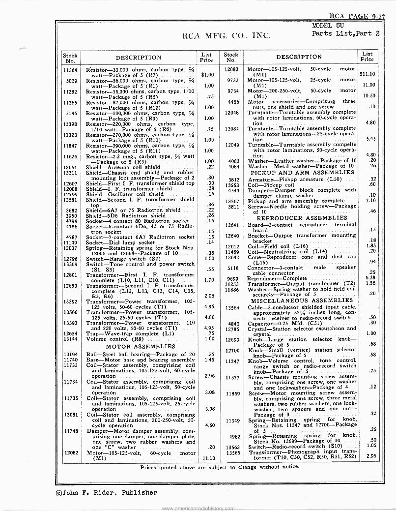
RCA PAGE 9 -
MODEL 5U
RCA MFG. CO., INC. Parts List,Part 2
Stock No. DESCRIPTION List
Price Stock No. DESCRIPTION List
Price
11364 Resistor -33,000 ohms, carbon type, 1/4 12083 Motor -105 -125 -volt, 50 -cycle motor watt -Package of 5 (R7) $1.00 (M1) $11.10
5029 Resistor -56,000 ohms, carbon type, % 9733 Motor -105 -125 -volt, 25 -cycle motor watt -Package of 5 (R1) 1.00 (M1) 11.00
11282 Resistor -56,000 ohms, carbon type, 1/10 9734 Motor -200 -250 -volt, 50 -cycle motor watt -Package of 5 (R5) .75 (M1) 10.50
11365 Resistor -82,000 ohms, carbon type, % 4456 Motor accessories -Comprising three watt -Package of 5 (R12) 1.00 nuts, one shield and one screw .10
5145 Resistor -100,000 ohms, carbon type, 1/4 12048 Turntable -Turntable assembly complete watt -Package of 5 (R9) 1.00 with rotor laminations, 60 -cycle opera -
11398 Resistor -220,000 ohms, carbon type, tion 4.80 1/10 watt -Package of 5 (R6) .75 13084 Turntable -Turntable assembly complete
11323 Resistor -270,000 ohms, carbon 'type, % with rotor laminations -25 -cycle opera - watt -Package of 5 (R10) 1.00 tion 5.45
11847 Resistor -390,000 ohms, carbon type, 1/4 12049 Turntable -Turntable assembly compelte watt -Package of 5 (R11) 1.00 with rotor laminations, 50 -cycle opera -
11626 Resistor -2.2 meg., carbon type, 1/4 watt tion 4.80 -Package of 5 (R3) 1.00 4083 Washer -Leather washer -Package of 10 .20
12651 Shield -Antenna coil shield .22 4084 Washer -Metal washer -Package of 10 .26
13311 Shield -Chassis end shield and rubber PICKUP AND ARM ASSEMBLIES mounting foot assembly -Package of 2 .80 3812 Armature -Pickup armature (L50) .... .32
12607 Shield -First I. F. transformer shield top .30 13568 Coil -Pickup coil .60 12008 Shield -I. F. transformer shield .28 4543 Damper -Damper block complete with 12799 Shield -Oscillator coil shield .15 damper clamp, washer .10 12581 Shield -Second I. F. transformer shield 13567 Pickup and arm assembly complete 7.10
top .36 3811 Screw -Needle holding screw -Package 3682 Shield -6A7 or 75 Radiotron shield .22 of 10 .46 3950 4794
Shield -6D6 Radiotron shield Socket -4 -contact 80 Radiotron socket
.26 .15 REPRODUCER ASSEMBLIES
4786 Socket -6 -contact 6D6, 42 or 75 Radio- 12641 Board -3 -contact reproducer terminal tron socket .15 board .15
4787 Socket -7 -contact 6A7 Radiotron socket .15 12640 Bracket -Output transformer mounting 11199 Socket -Dial lamp socket .14 bracket .18
12007 Spring -Retaining spring for Stock Nos. 12012 Coil -Field coil (L16) 1.85
12006 and 12664 -Package of 10 .36 11469 Coil -Neutralizing coil (L14) .20
12796 Switch -Range switch (S2) 1.00 12642 Cone -Reproducer cone and dust cap 13309 Switch -Tone control and power switch (L15) .94
(SI, S3) .55 5118 Connector -3 -contact male speaker 12801 Transformer -First I. F. transformer cable connector .25
complete (L10, Lii, C10. C11) 1.70 9699 Reproducer -Complete 6.38
12653 Transformer -Second I. F. transformer 11253 Transformer -Output transformer (T2) 1.56
complete (L12, L13, C13, C14, C15, 11886 Washer -Spring washer to hold field coil R5, R6) 2.06 securely -Package of 5 .20
13392 Transformer -Power transformer, 105- MISCELLANEOUS ASSEMBLIES 125 volts, 50-60 cycles (T1) 4.95 13564 Cable -3 -conductor shielded input cable,
13566 Transformer -Power transformer, 105- approximately 321/2 inches long, con - 125 volts, 25-50 cycles (T1) 4.80 nects receiver to radio -record switch .50
13393 Transformer -Power transformer, 110 4840 Capacitor -0.25 Mfd. (C51) .30 and 220 volts, 50-60 cycles (T1) 4.95 12785 Crystal -Station selector escutcheon and
12654 Trap -Wave -trap complete (L1) .75 crystal 1.00 13144 Volume control (R8) 1.00 12699 Knob -Large station selector knob -
MOTOR ASSEMBLIES Package of 5 .68
10194 Ball -Steel ball beari Packa a of 20 fig- g .25 12700 Knob -Small (vernier) station selector
knob -Package of 5 .58 11740 Base -Motor base and bearing assembly 1.45 11347 Knob -Volume control, tone control, 11733 Coil -Stator assembly, comprising coil range switch or radio -record switch
and laminations, 105 -125 -volt, 60 -cycle knob -Package of 5 .75 operation ... 2.96 11377 Screw -Chassis mounting screw assem-
11734 Coil -Stator assembly, comprising coil bly, comprising one screw, one washer and laminations, 105 -125 -volt, 50 -cycle and one lockwasher-Package of 4 .12 operation 3.08 11869 Screw -Motor mounting screw assem-
11735 Coil -Stator assembly, comprising coil and laminations, 105 -125 -volt, 25 -cycle
bly, comprising one screw, three metal washers, two rubber washers, one lock -
operation 3.08 washer, two spacers and one nut - 13081 Coil -Stator coil assembly, comprising Package of 3 .32
coil and laminations, 200 -250 -volt, 50- 11349 Spring -Retaining spring for knob, cycle operation 4.60 Stock Nos. 11347 and 12700 -Package
11748 Damper -Motor damper assembly, corn- of 5 .25
prising one damper, one damper plate, 4982 Spring -Retaining spring for knob, one screw, two rubber washers and Stock No. 12699 -Package of 10 .50
one "C" washer .20 13563 Switch -Radio -record switch (S10) .... 1.05
12082 Motor -105 -125 -volt, 60 -cycle motor 13565 Transformer -Phonograph input trans - (M1) 11.10 former (T10, C50, C52, R50, R51, R52) 2.95
Prices quoted above are subject to change without notice.
©John F. Rider, Publisher
www.americanradiohistory.com
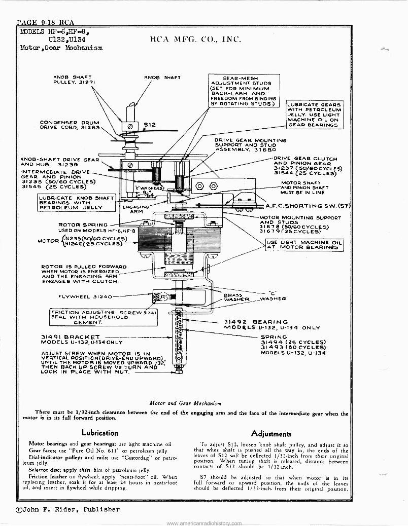
PAGE 9-18 RCA MODELS HF-6,FIF-8,
Ú132,U134 liotor,Gear Mechanism
KNOB SHAFT PULLEY, 31271
CONDENSER DRUM DRIVE CORD, 31283
KNOB -SHAFT DRIVE GEAR ANO HUB. 31239 INTERMEDIATE DRIVE GEAR AND PINION 31238 (50/60 CYCLES) 31545 (25 CYCLES)
LUBRICATE KNOB SHAFT BEARINGS WITH PETROLEUM JELLY
ROTOR SPRING
RCA MFG. C'O., INC.
KNOB SHAFT
S12
C wASNERs
TT -r__944
ENGAGING ARM
USED ON MODELS HF-6,HF B
e3I235(50/60 CYCLES) MOTOR 31246(25CYCLES)
ROTOR IS PULLED FORWARD WHEN MOTOR IS ENERGIZED AND THE ENGAGING ARM ENGAGES WITH CLUTCH.
FLYWHEEL 31240
GEAR -MESH ADJUSTMENT STUDS (SET FOR MINIMUM BACK -LASH ANO FREEDOM FROM BINDING BY ROTATING STUDS)
DRIVE GEAR MOUNTING SUPPORT ANO STUD ASSEMBLY, 31680
O O
FRICTION ADJUSTING SCREW 3124I SEAL WITH HOUSEHOLD
CEMENT.
31491 BRACKET MODELS U-132, U-134 ONLY
ADJUST SCREW WHEN MOTOR 15 IN VERTICAL POSITION(DRIVE-END UPWARD) UNTIL THE ROTOR IS MOVED UPWARD 1/32; THEN BACK UP SCREW 1/2 TURN AND LOCK IN PLACE WITH NUT.
WW
LUBRICATE GEARS WITH PETROLEUM JELLY. USE LIGHT MACHINE OIL ON GEAR BEARINGS
-DRIVE GEAR CLUTCH AND PINION GEAR 31237 50/60 CYCLES) 31544 (25 CYCLES)
MOTOR SHAFT AND PINION SHAFT MUST BE IN LINE
A. F. C. SHORT I NG S W. (S7)
MOTOR MOUNTING SUPPORT AND STUDS 31678 (50/6OCYCLE5) 31 67 9 (25 CYCLES)
USE LIGHT MACHINE OH_ AT MOTOR BEARINGS
BRASS -C-- WASHER _WASHER
31492 BEARING MODELS U-132, U-134 ONLY
SPRING 31494 (25 CYCLES) 31493 (60 CYCLES) MODELS U-132, U-131
Motor and Gear Mechanism
There must be 1/32 -inch clearance between the end of the engaging arm and the face of the intermediate gear when motor is in its full forward position.
Lubrication
Motor bearings and gear bearings; use light machine oil. Gear faces; use "Pure Oil No. 611" or petroleum jelly. Dial -indicator pulleys and rails; use "Castordag" or petro-
leum jelly. Selector disc; apply thin film of petroleum jelly. Friction leather on flywheel; apply "neats-foot" oil. When
replacing leather, soak it for at least 24 hours in neats-foot oil, and insert in flywheel while dripping.
the
Adjustments
To adjust S12, loosen knob shaft pulley, and adjust it so that when shaft is pushed all the way in, the ends of the leaves of S12 will be deflected 1/32 -inch from their original position. When tuning shaft is released, distance between contacts of S12 should be 1/32 -inch.
S7 should be adjusted so that when motor is in its full forward or upward position, the ends of the leaves should be deflected 1/32 -inch. from their original position.
©John F. Rider, Publisher
www.americanradiohistory.com
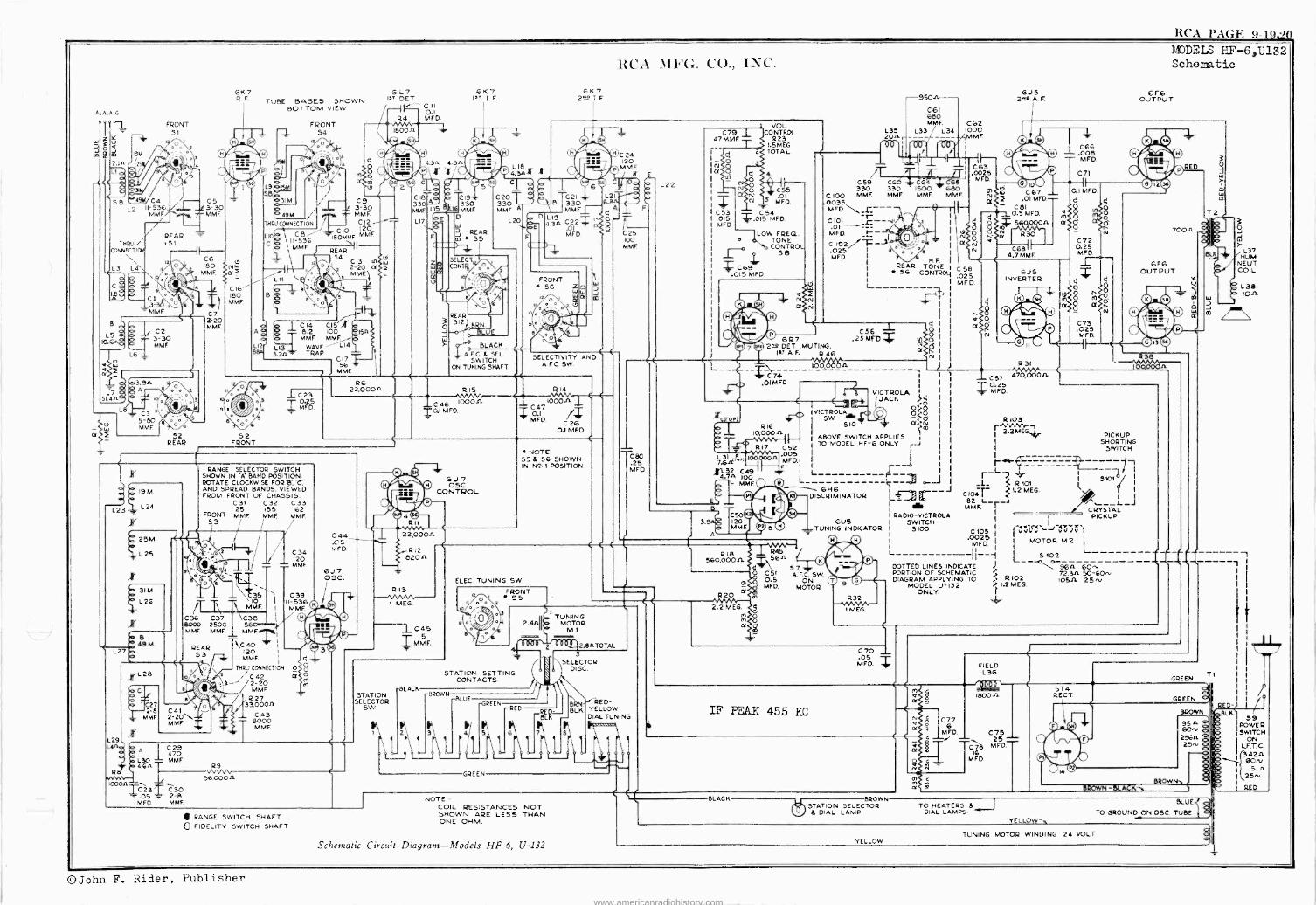
RCA PAGE 9-19;4)
w
2 15M
2.In 2
5B
8
3
ILPiC4 L2 II -536
MMF, i
THRU / CONNECTION
L3 L44
B
L5 10.6
a
FRONT 51
1
/J
REAR ,S1
CI \ 3-3 ì MMF
8\ / 52
REAR
14
4
C5 3-30 MMF.
C6 180
MME
C7 2 20 MME
61(7 R.F
Nw a2
C16 -- 180 MMF.
9\
8
TUBE BASES SHOWN BOTTOM VIEW
OI
L9 25M S
31 M
FRONT 54 o
Y M1
\9a
49M
THRU CONNECT ON
UO C8 II -536
C 11 MMF
B
A
Llzr
L
91a
8
6L7 1s' DET
CII 0.1 MFD.
a O o
a S)
124
18002
6K7 ?T I. F.
0 ©4© ©`©
1 + 4.3n 1.3n .C70 J , 4.3 020 C - / .loir50
C9 3-30 MME C12
C IO 120 18oMMF MMF
\ REAR
54 C13 NSw 1 ° 2-20 a}ì
O MMEI
o 5
L13 3.2A
C 14 CI5 X 8.2 LOO MMF MMj
WAVE L14 TRAP
1
o 1 jö C23
'o9 0.25 {y 4 MFD.
52 FRONT
C17 56
MMF.
ISA
R6 22,000A
C IB 330 MME
LI7
C19+ 33
LIS 8 16 MMF. D
F
2
REAR 5 5 *
C20 330 MME A
L20
SELECT, CONT% j
o
REAR
30 512 BRN
W =LUE
pI BLACK
4. F.0 & SEL. SWITCH
ON TUNING SHAFT
R15
C 46 100011 T0.1 MFD.
RCA MFG. CO.. INC.
6K7 21t2 I F
.r
F
D
C
C 24 120 MMF.
,BY
6 TC21 6, B330
MMFr- L19 n O
4.3n C22 O .OI O MFD.
FRONT * 56
o II o
2:
Lj O
n
q 14
tßJ
m
SELECTIVITY AND A.F.C. SW.
R 14
1000 A C47 z 0.1 MFD.
C
C 26 0.1 MFD.
"gq
é 19M.
L2-3 L 24
"" 25M.
;,-L25
L 2G
- B 49M
L27
L29
cC
RANGE SELECTOR SWITCH SHOWN IN "A' BAND POSITION. ROTATE CLOCKWISE FOR"B."C' AND SPREAD BANDS. VIEWED FROM FRONT OF CHASSIS.
C31 C32 C33 155 62
MME MME FRONT 53
25 MME
e 11 t,
C36 8000 MMF
C37 2500 MME
REAR 53
1.4.2
R8
L28 C
27 2-8
MME
./7,; 9
2 2Ó\ MMF
t35 MME.
C38
MME
\C40 120 MMF.
1
C34 120 MME
C39 II -536 MME
-- THRU CONNECTION O
i \\ C42 q13-'/2-20
MME
R 27 /33,0002
C43 T8000
MMF
o
C44 .05 MFD
6J7 OSC
H OSC. CONTROL
22,000A
R12 820 A
* NOTE 55 5 56 SHOWN IN N4. I POSITION.
0
100 MME
C80 .25 MED.
L22
C79 1 47 MME T
; 2
iá
C53 .015 MED
I -
VOL CONTROL
R23 1.5 MEG TOTAL
e 4
Ó C55 .01
N S MED.
ZC54 .015 MFD.
i
LOW FREGI. ° TONE
CONTROL Se
C6 .015 MFD.
u
a fN
a 2 N
C
C 100 .0035
MFD
950:..
C61 680 MME.
2Ó L33 L34
I
C59 CI"C64 65 330 330 1500 680 MMF. MME MME. MME
C62 1000 MMF.
J
C OI
I - -- MFD. - C 102,-F-3 025 MED. i
1
L * 56R
H. F.
TONE CONTROL'
6 R 7 2w? OET MUTING,
le A. F. R 46
'-- r C 74 .OI M FD
100,0002
C36 .25 MFD
JrCIT°P) R16
I
7.61iRer) XL 32 C49
4.7A 100 C
B C50
3. c' 120 o MM
A
0 d
C63 .0025 MFD
N O O
N
n
6J5 282 A. F.
MODEM' EF-6,U132 Schematic
6F6 OUTPUT
I, C67 î .01 MED.-- CBI 0.5 MED.
a
000A
R30
C68 4.7 MMF.
a m a
C 58 .025 MFD.
a
i 1
VICTROLA JACK
I VICTROLA u SW. " a: ti SIo
O,OOOA ABOVE SWITCH APPLIES¡ R17 C52 1 TO MODEL NE -6 ONLY
I D. F
t_
L_
2
R13 -WM-- 1 MEG.
1 C 45 IS
MMF.
C29 I 470 L30 MME 4.6A
10004. Tc28 C30
.05 -"-* 2-8 MED MMF.
1/VVV).. 56.000A
ELEC. TUNING SW.
FRONT 0.1 * 55 . iio
RIB 560,00011
TUNING 2.4211 - MOTOR
M =. e STATION SETTING
CONTACTS
STATION BLACK
BROWN
SELECTOR SW
1-1
LUE REEN
GREEN
2
\ \
RED
BnTOTAL
-RREDLK -
7
3 SELECTOR
DISC.
BRN. BLK
RED - YELLOW DIAL TUNING
m
VÑh 2.2 MEG.
M
a
a
R45 VGA
C51 0.5
.6°- MED.
m
57 A.F.C.
ON MOTO
6H6 DISCRIMINATOR
GUS .TUNING INDICATOR
sIo 00
1 MEG
alb RADIO-VICTROLA
SWITCH 5100
L
DOTTED LINES INDICATE PORTION OF SCHEMATIC DIAGRAM APPLYING TO
MODEL U-132 ONLY.
6J5 INVERTER
-4r 4
o O Ñ
R31
C57 470,000A 0.25 MFD.
R 103 -WA`, 2.2MEG,4_
r -L I -
_L- Z R
CIO4j 1.2f01MEG82
MME. T ,
.óó25 MFD.
1 I--1
R102 5: L2 MEG
4- C 6 6 .005 MFD.
C71
0.1 MFD.
a O
C72 0.25 MFD.
ó
025 MED.
II
O
N
N
RED
7002
6F6 OUTPUT
R3
PICKUP SHORTING
SWITCH - T
5101/ Tf 1
CRYSTAL PICKUP
(-4 VaF`'JJJV,i I MOTOR M2 1
S102 -\ 96A 60", 72.3A 50-60", 1052 25n,
1-C
C70 .05 MFD.
IF PEAK 455 KC
C
C
RANGE SWITCH SHAFT C FIDELITY SWITCH SHAFT
NOTE COIL RESISTANCES NOT SHOWN ARE LESS THAN ONE OHM.
Schematic Circuit Diagram -Models HF -6, U-132
BLACK BROWN STATION SELECTOR 8 DIAL LAMP
FIELD
ppLpp3GG
18001L
N
1C77 16 a ¡
4 AIM
TB °f 16
á 4 MFD
a R
a a $
ó
T 2 O J w Y
L37 HUM
NEUT. COIL
IW D
GREEN T 1
C75 25 -"--
MFD.
5T4 RECT
GREEN
BROWN - BLACK-.
BROWN
195 A 60"' 256n 25'
BROWN-.
TO HEATERS S DIAL LAMPS.
YELLOW-,
BLUE
TO GROUND ON OSC. TUBE
TUNING MOTOR WINDING 24 VOLT YELLOW
L38 10A
-I
RED- I1 BLK 39
IPOWER !SWITCH
i N
LFO.TC.
60,v I 5 A
1
25,,
¡ RED
©John F. Rider, Publisher
www.americanradiohistory.com
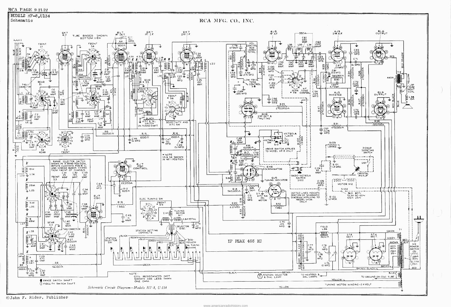
RCA PAGF, 9-21.22
MODELS HF -8,U134 Schematic
4.4.410
m am m 191
2.In 2
n
3
SB C4 L2 II -536
MMF..
THRU / CONNECTION
L3 L4\
B
L5 10.6.
F
/
.i
CI 3- MMF
FRONT 51
Oò
REAR SI
i 7'
o
92 REAR
C5 3-30 MME.
CG 180
NAME 3
C7 2 20 MME
61(7 R. F
A
TUBE BASES SHOWN BOTTOM VIEW
L9 25M 54
FRONT 54
3 o
o
/
6L7 I>t? DET
C II 0.1 MFD. R4
C O O O
3IM C9 3-30
49 MMF. C12
CIO 120 ''ÌBOMMF MME
I
REAR ; 34 C13 LP
o 2-20 a
THRUCONNECT ON
L C8i \
H-536 536 C - 11 MME
8
ó L12 8M
L11 / ii
á 91.. °o
L13 3.24
/5
C14 CIB 8.2 100 en
MME MME>, WAVE' L14 TRAP
C17 56
MMF.
w f
61(7 IsT I. F.
0 ED
© ©© 4.3n 4.34 oxx o
C /! Co 5 2 C18 o ó
MME33O L15
L17
LI 1330 MMF.
D w
REAR CO * 55
RCA MFG. CO., INC.
6K7 2ND I. F.
LIB
©© C24 120
4.3^x x dew M E
® C a ... íAl6Q C Oc o C20L0 o -I ó TC21 L2-
330 B 1330 6 F MMF A MMFr 2L20
0 0 L 19 4.- ,,, 4.34AI2Z MFD. - C25
100 C MME.
SELECT CONTI/
o,
e/r
o
REAR' I
512; BRN. o BLUE
# BLACK
A.F.0&SEL. SWITCH
ON TUNING SHAFT
FRONT Z w 56 w w (.3
/'.//I I` °o
J co
SELECTIVITY AND A EC. SW.
L C23
°,,oí°, rMFD I
e °o
52 FRONT
RG 22,00011 R15
C 46 1000JA TQI MFD.
R14
10004-
0.1 MFD.
ir
E 25M.
L
31M
L26
B 49 M
L27 E
L29
C
RANGE SELECTOR SWITCH SHOWN IN "A' BAND POSITION. ROTATE CLOCKWISE FOR-B;'C; AND SPREAD BANDS. VIEWED FROM FRONT OF CHASSIS.
C31 C32 C33 25 155 62
FRONT MME MME MME 53
o/
C 35 10 MMF.
C36 C37 C38 I
8000 2500 MME MME MMF
REAR \C 40 53 20
iÌL28
27 2-8
MME
8
C41
MME
C 34 120 = MME
C39 II -536 MME
MMF. 1
. o THRU CONNECTION O O O
O
,
o/ ii, o
MME R27
33,00011 C43 - 8000 MME
C44 .05 MFD.
6J7 OSC
T
R
6J7 OSC.
CONTROL
22,000A
R12 82011
1213
1 MEG.
* NOTE 55 & 56 SHOWN IN NP. I POSITION.
L22
C79 1 47 MME
F I
lá I _
C53 .015 MED.
T 2
VOL. CONTROL
R23 I.5MEG TOTAL
4 4
N 5
C55
MFD.
C 54 -e.015 MFD.
N a
LOW FREQ. ° TONE
CONTROL
JQ s
C69. .015 MED.
E
6.15 Pr A.F.
©©© O / O10330 C100 MMF, .0035
N MED _r--- N
-950
L33 20±> r
C61 980 MMF.
L33 L34 C62 1000 MME
n
C60 330 MMF.
C101 OI -"--7-
MFD. - I
C 21-g- .025
-3 I
MFD. H.E. I
REAR TONE * 56 CONTROL'
C64 - 1500
MME.
C6S J 680 MME
o o /6
I
Q25 L I' MFD. t
R 25 1/VVVVM 270,o00n
6H6 289 DET & ' MUTING
C 48
é 120 MMF
p R16 b 10,000 o _v"v1`r-1 ó R17 C52
Ibn e* I0 MFD.
,L32 C49 - 4-7 100
'T
C50 120 MME
C45 15
MMF.
A I C29 1 470
% L30 _ MME 4.64
1000P. CZ8 C30 = .OS - 2-8 MED MME
1/V /V. 56.00011
rBLACK STATION
SELECTOR SW
ELEC. TUNING SW
0 e
o FRONT * 55
2
. o i
560,000/1
R20
L_
Ñ
C 63 .0025 MFD
OO
O
N
GJ 5 2N2 A. F.
BLG OUTPUT
© © 0 0,1
cn``1.0, C67 - 2(j2 .01 MED.-
- C8I et y0.5 MED. m
4 r 560000n a g otoN
R30 r -, a
C6811- 4.7 MME
C 58 .025 MFD
á a
I
1
I
VICTROLA I
JACK j..O w
I VICTROLA+ °<5 SW.
SIO a:.22 I.
I ABOVE SWITCH APPLIES 1 TO MODEL HF -8 ONLY -J
L
6H6 DISCRIMINATOR
61)5 .TUNING INDICATOR
1218 R45 / \564 (
C 51 A7F
0.5 ON m ó MFD. MOTOR a
STATION SETTING CONTACTS
1 TUNING 2.411 MOTOR
M1
BROW LUE
RE EN
GREEN
\
RED ._RED BLK
7
2.8ATOTAL
3 1C74 SELECTOR =.01
DISC. -131", MED.
BRN BLK
RED - YELLOW DIAL TUNING
m
2.2 MEG {o m O
m O a
SW
0.0 ©!
6J5 INVERTER
4
8
r - Cì
m ff
1 C66 .005 - MED.
C7I
0.1 MFD.
O
C72 0.25 MFD.
o
N
{o
ó m a
N
RED
4404
a
R31 - C57 470,00011 -I- 0.25
MFD.
C73 .025
MFD.
R38
0 103
I ,BMEG. PICKUP F SHORTING
I SWITCH r r g r -L-7 :' 3 o---1 _L_ ? R Iot _J 0104 1.2 MEG.
82 L_ _J MME, r
R32
1 MEG
RADIO-VICTROLA SWITCH
5100
L
----- -1 --- I
I
2ïi CRYSTAL PICKUP
.00010255 ¡vVLF'-'JCJVV',
MED 1 MOTOR M2 1
11 1 Ì L-------- S 102 L__ DOTTED LINES INDICATE j %n 60r, PORTION OF SCHEMATIC l R 102
72.34 50 -GO, DIAGRAM APPLYING TO 10511 25-V MODEL U-134 . I.2 MEG.
ONLY. L
C70 .05 MED.
IF PEAK 455 KC
M C
s
á a
RANGE SWITCH SHAFT Q FIDELITY SWITCH SHAFT
NOTE COIL RESISTANCES NOT SHOWN ARE LESS THAN ONE OHM.
BLACK BROWN STATION SELECTOR & DIAL LAMP
FIELD L 36
1800A
T2
BLK
D
O
w
L37 HUM
NEUT. COIL
6 L38 - 10.11
GREEN T1
CÑ77 076 16 10
MFD. MFD.
O T/ T \,..____
8 16
MFD
C 5 m r.1
IO MFD a a
n O co
5T4 574 RECT RECT.
GREEN
BROWN -BLACK-,
BROWN
13211 6O'V 1784- 25, -.
BROWN-. aJ
TO HEATERS bJ BLUE
DIAL LAMPS. TO GROUND ON OSC. TUBE YELLOW-,
TUNING MOTOR WINDING -24 VOLT
4
1
I /^ /r RED-) I / ;BLK.1 59
POWER SWITCH
ON L.F.T. C.
/1.894 0 v
2.774
RED
Schematic Circuit Diagram -Models 11F-8, U-134 YELLOW
©John F. Rider, Publisher
www.americanradiohistory.com
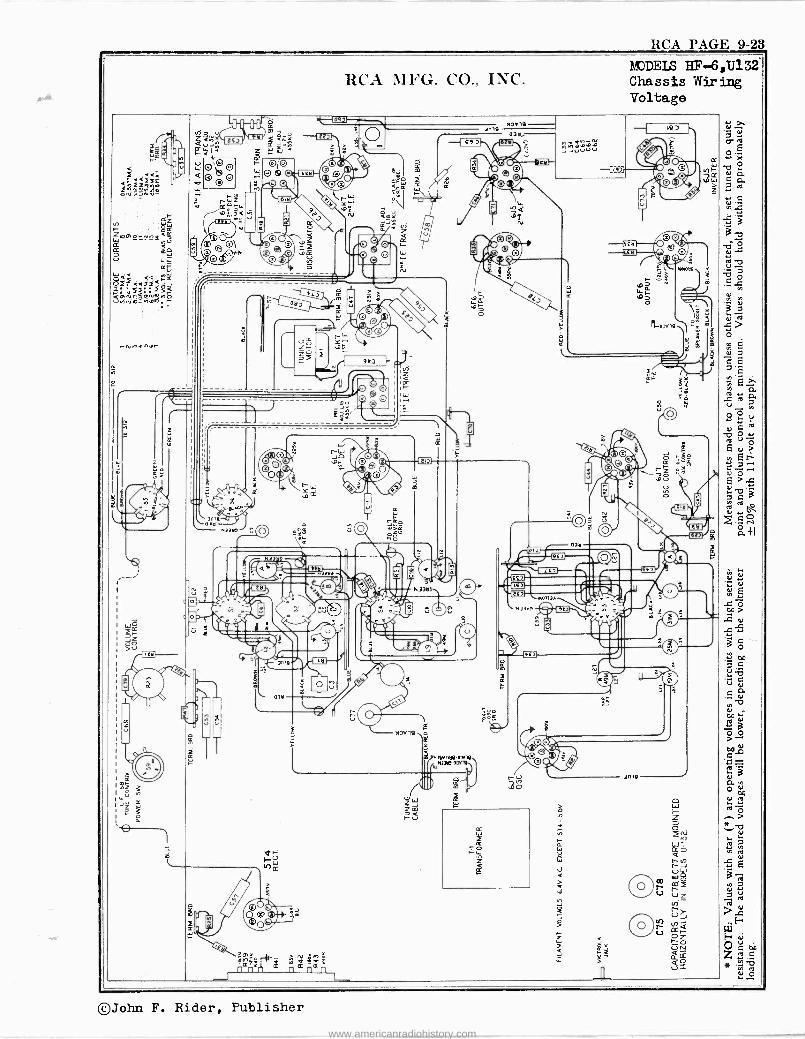
RCA PAGE 9-23
MODEIS IT -6,U132 - RCA MFG. CO., INC'. Chassis wiring
Voltage
c m i
IeOY,Y ` zn,. 19J 3
gg I I. a r,4-;,, áJ: ZS
3 Y i-%
031y ® i.fiJ
^ JJ,osô.o ^, .~.d+ O' Ló
-1 t ~1 g+ " uuuv : O'i9p ott001. .- ®0y g®Ì .<`< p O 990.©p" b
"o ill O o o ® .`..® ,1 .a ú ê ni.7.1.Y- .: + C
gi r , '3°`
: o.,: .-i f?
'
® ; ® a " ® á n, <mx 3 . en
N 3 i ,
w oo.ó_wn= á i W ^ Jrro
[ m O\V :Op °
=oá o °o
` 8© á
® ©' <t 00 , ó
e ®© o M p ff. 4.)-c
ú 1 -
'`p Ñ c t
3
wYow 4
i ^
2511<i __ á E- d r o
la- I- `í`=-
Ii -eYr,.n,pr I5i" Zg ,,: m F!
Y C @
7 .
' .. I : m
I
____ la ; T F. .
h-`; p a
o Ñ lJ b .J-
ff à¡' I I Ó
I
i ,.- ' ---- <- e` i(O I " 2
^ z n - ---- ------ - - C ni
u i
I
:
I
i pó F: ç .y. > , ,.
W
I© m \
"p ó -is: O O,1
í0i ^ c
y
Je
eÿ
aill;":K .,I.
.:
.. z©O
O { ©oF1"
,
Te 0
00 I
W 3 + 7
: V ` oó
ó P
7 ~ Ft) 7'z
ac i 2 *
ON 731110 Y
L
o4 0
. C
ag \ tiu d áiI
0)Y
N]) 9 ® 1 © O . äl \ .. F .
"_... _ 1
/} Ilia u
IM 1
u
6 14 O'`, ®III _.'.I,/ N33tl
,[7 - , O e Q,
0 (
J o i.t " r V ' .
,..* O
í{a
J1/ ~ V
T u
º
.nJ03
.... NJ]Y!(¿;{' ñ" - " Ì
( i = = _
.0 O pp >
N
_ -==s- , ...1Z . W
y D 0 z. a --
o ® ® 3 m m ; 3 G
,II 4 e M O
à
s.® Jv d 0111, ii
3a I 10
R °` .,,,,ai
u
o
I "O 2
NJD4
',Ó;:, C ®
>-- t)(1.0SNMgqiJiy
C ^ V3
Ñú `y ' '
( CI
%
3nK 1 N
O Op
e: 2 ^,
á 3,p r ú
o . h- Z O .". >
2........
ar FW All'
Z S
` M 1.J v IY
+ r- in (J 1
7 Í3 m m
.] 8 FFt-`
V
co be
- O N ;,3 tif:PN it i >raiÑ°y. f12.7.3
{.t aJ Z
® r. Zi e Ú po 4 e <
F u z 3j x ÚN
ó v 3.Ñ - á r+4- n ° n¢n s=
O íva
or ,.0 F ei
Oceó íZ. .0
', __J °:ó
©John F. Rider, Publisher
www.americanradiohistory.com
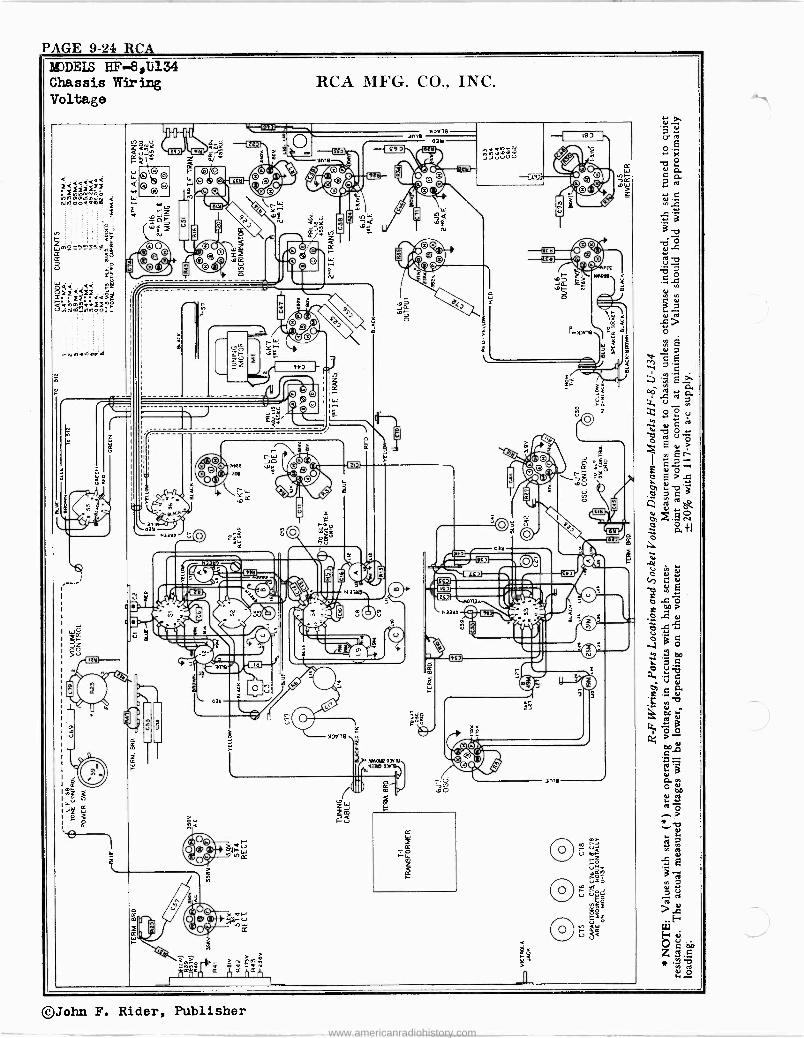
DEIS HF -8,1i134 Chassis Wiring RCA MFG. CO., INC. Voltage
(. T y' "+''/.
7 \ ],. 'Vie 03tl
.J 16J k I
.d.. Ú ,y
Z<Á mod, á rti ¢ú2. Qil [ICI . 9 ' A E C90 ^í°iú
Gt_+
O.
K 1 Y é/ $ ma _
u u Fi C
O 11 Ñ Ole O' QO Ej\u* Z1
F2i u OO iv_ ® n y
i ro ef O O p® ® '
QQ f-.
niA nmwuiuf, à ode am
a
<
ti Y
.e WZ a
ti
+
®r ® ( ti amy
gr" v 7d
e ®
N4 N
,,Q N -
(/ç B " Lee
v Wpo-rvnavi,o 00 ( O Q z rm.): O ©
u ®lo®O O©
e' sr3
Os° mg Bß. ®Q p
1 0' \®O ,i 0(Tf
vcJ I: CF
Qz fl
ü_ ©' N----O ry iY ' ñ y
s.^m,
TM10YB
m ó44 <à r ' .ú h oízààiî S.
3ÑMmna.3í;'r fy iài
nm^rcivfoo i
I
r s
O
S ® s a é o
o -b
a
x <
W m
7 O
-una'n.orm .. .
I
' u ZF-
. r Y .uk
1 .1 0® © m i
R
FMJVN .,.
°0 O
ÿ m a 7 î ® '
1: íy Z
1
&: ; " 1 . m/
0© N a 1 3 a , p0 I.i n V ÿ
gia O O
a.+
u As Z. N
v ó ó ' ta
I' 1' F=
,',
É bb ri d
f,/ J © °o
0 E N ú .y
1 C.~
v
.1.
5
e ,ä
o`1o 00/1`
Y
Awe TOY
° ¡ o°`I(1 F.+ Q
If'
"O
u 0.
1` m
7o Fo
.OV
', ®
d N yl,.
g Ñá Ñ vÓ\
a d
ó O JOJY a.
..> rnl'ir,_ Q > ó u tl 7V
0J 11 m a; / ] 1Oi ,a N3 aI , : I LC
'
Ñ:,m
O
!9_I HFú O I
-e. .0
I ! t -te »., Y
:d L . 1{a g d a Ó1.'ó ó H 2 OO '2ñ ® sdarna .m t 5I. 2
y î P.
, C3( o ® ïp¢
; d .,I;11 f
, : a
7 N 2f,
á >.
Cp
®, .M(>ra Ne.(
aLeC.;L.
o h
I1 ea'
U
r© 3B " - .00 p
Ñ
; 1 ' 6
lk' Ñú
\/.8ec
O h °` I Om
m
ujO u ó 0® Nÿ
q ä
r:-, O, y
°2 4,- ¡on+Ó>T, 0
Oi
ñ`fll
O >el - ®._, OL/W2 U s
R
¢ 7 ñ ¢ , g
Ltl
uro,ó
>1 WH l'"'
Ú OGob w te
1..
1
.Or
©John F. Rider, Publisher
www.americanradiohistory.com
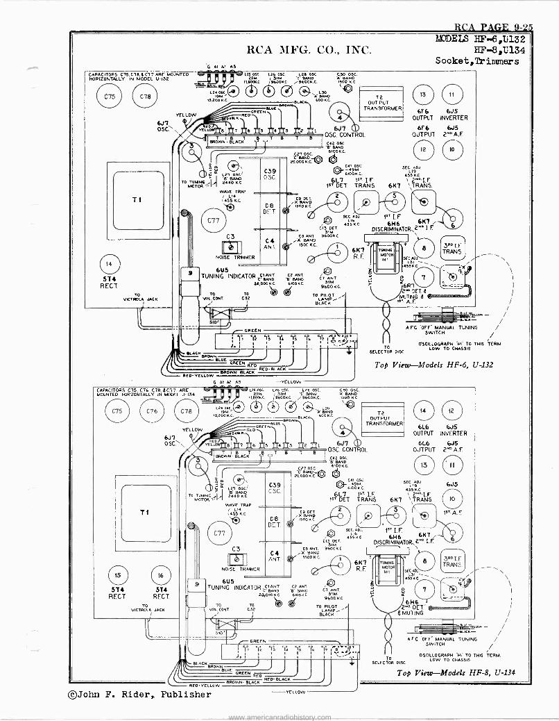
RCA PAGE 9-25
RCA MIFG. CO., INC. G AI A2 A33,ß.
CAPACITORS C75,C7B 4 C77 ARE MOUNTED t. L25 DSC
HORIZONTALLY IN MODEL 1).132 lK
YELLOW
6,17 OSC
TI
514 RECT
TO VICTROLA JACK
25M 11.601:4«.
13.200K.C. (111)
124 OK.
BIBL
DUDELS HF -6,U132 HF -8,1)134
Socket,Trir¡uners
GR[[
L26 05C. 123 05C31M
V ND j9600K.0 /96Ó0K.C.
LOO A BAND
BLACK, 60 KC.
BLUE \BIIOW,1, ¡
C
{7 7 6 3 43 j2 40219 gg T 4L B B
BROWNI - BLACK j `'T T
I
áI 127 05C!
TO TONING/1 I 14Óó MOTOR 'I
WAVE TRAP L1
1455 K.0
C3
NOISE TRIMMER
6U5 TUNING INDICATOR C5'..;22;
20,00 B..CC
TO TO lJ VOL CONT CS2
C27 OSC. 'C BAND 0 20,00 K.C.
C9 OCT .% BAND
1300 K.0
COO 05C. 'A BAND 15000 KC
T2 OUT PUT
TRANSFORMER
6J7 CU OSC CONTROL
C42 05C. B' BAND 61DOK C
V C41
9 4M. 61OOKOSC C.
6L7 1" I.F. 15T DET TRANS.
C13 DET SIM
CS ANT 9600K BAND
1500 K.C.
C2 ANT B' BAND 6100 KC
CT ANT 31M
9600 KC,
TO PILOT LAMP.,'
BLACK
h SEC ADJ.
LIA 435 KC
6K7 R. F.
6F6 6.15 OUTPUT INVERTER
6F 6 6J5 OUTPUT 2"OA-F
12 f0 .) SEC ADJ
1.19 435 K.0
\ 2"I.F 6K7 \TRANS.
b l ` /
16H6 6K7 7 DISCRIMINATOR,2"' i. F
SEC ADJ` LOI -
453K.0
`6R7 2". DET 4
MUTING á IST A. F.
S10x
GREEN G ra S 1at 1 51 °I2 1O 14 55 6 1 0
J. Ì I
I 1 1 1
I 1 Sa c
SLACKER / J I
BLUE GREEN
RED RED -BLACK
BED -YELLOW BROWN BLACK
G Al A2 A3 -YELLOW
KKK / AFC OFF" MANUAL TUNING /
SWITCH / TO
OSCILLOGRAPH -HI TO THIS TERM.
SELECTOR DISC LOW TO CHASSIS
Top View-Models HF -6, U-132
CAPACITORS C75 C76, C78.4 C77 ARE MOUNTED HORIZONTALLY IN MODEL U-134
YELLOW
6J7 OSG>
TI
C31 16
ST4 514 REGT RECT.
TO VICTROLA JACK
L24 OSÇ 1
9M. 13,200 K.C.
125 05C. L26 05C. LOB 05C. 2.504 131M '0 BANA
11,800KC. 19600.0. / 96000.C.
C RE04
BLU GRÉE
CD 1 BR
L30 -A BAND 600.0 BLACK,
7 6 5 4 3 2 I
BROT WN- LACKT
R T OSC
TO TUNING/I 24
1
MOTOR 'I WAVE TRAP
L14 455 K.0
C3
NOISE TRIMMER
T B T B
6U5 TUNING INDICATOR .=
20,000 K C
TO VOL CONI
TO CS2
C27 O5C C BAND
2'000 K C. !7
C9 DET A BAND 500 N.0
C30 OSC. Ä BAND 1500 K.0
T2 OUT PUT
TRANSFORMER
6J7 05C CONTROL
CA2 OSO B' BAND 6100K C.
041 OSC. 4
61009M0 G.
6L7 15? I.F. 1sT DET TRANS. / \
SEC. ADJ. L Ib
455 K.0 C15 DET
310 CS ANT. 9600 K.0 Ä BAND
1500 K.C.
C2 ANT .8' BAND 6100KC
Cl ANT 31M
9600 KC
TO PILOT LAMP--"
BLACK
6L6 6J5 OUTPUT INVERTER
6L6 6.15 OUTPUT 2ND A.F.
SEC ADJ 119
455 K,C
6K7 \\TRANS.
b 16H6 6K7
DISCRIMINATOR,2"°I F
6,15
1" A. E
350 IF TRANS.
SEC. ADJ` \ L51
455K .C.
á
6H6 2N° DET e
$ MUTING
510'
d, i I
I
GREEN
1 Y1 wiz `Is TA 5á 1 1
Y6 rT, 8a eLfa.a
LACK BROWN J BLUE
GREEN RED
TO SELECTOR DISC
A Vf
KKK
AFC OFF MANUAL TUNING
/ OSCILLOGRAPH CHI TO THIS TERM.
LOW TO CHASSIS
SWITCH
Top View-Models HF -8, U-134
RED -YELLOW
©John F. Rider,. Publisher
BROWN- BLOC RED BLACK
YELLOW
www.americanradiohistory.com
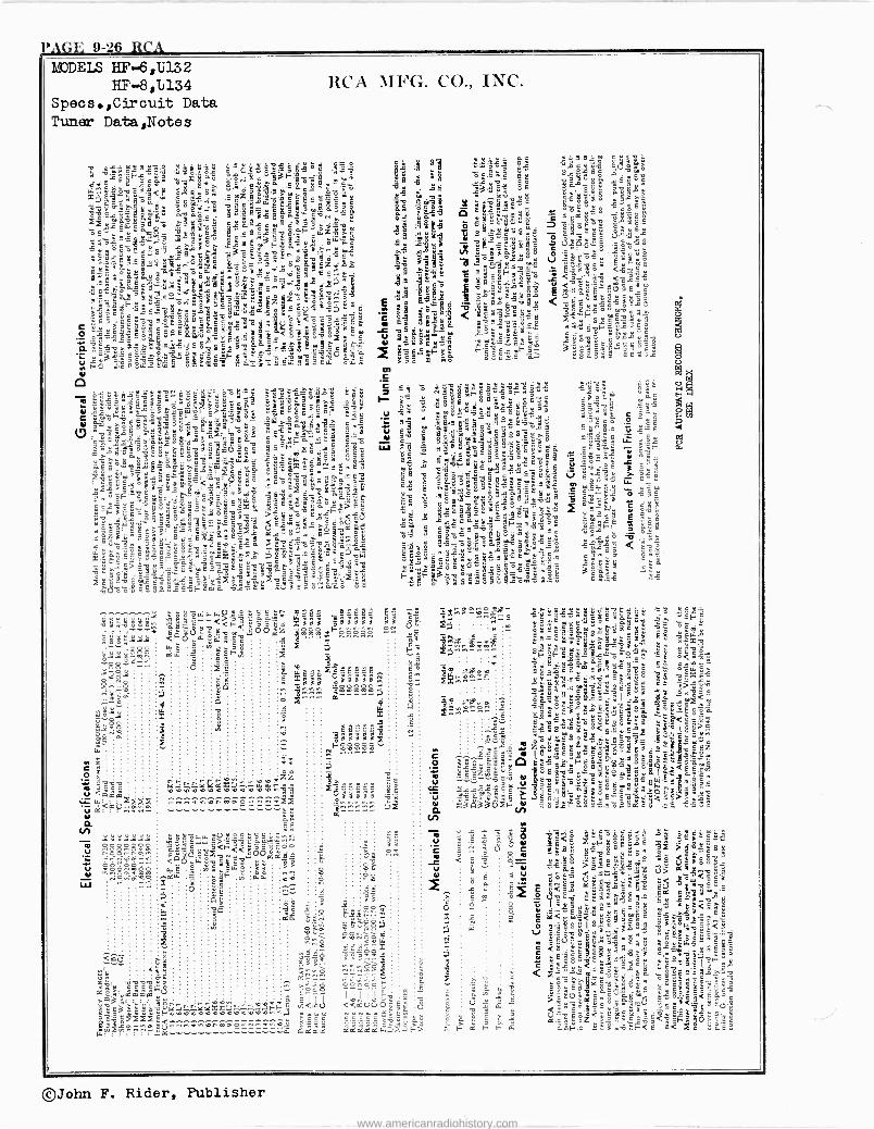
PAGE 9-26 RCA MODELS HF -6,1;132
HF -8,11134 Specs.,Circuit Data Tuner Data,Notes
©John F. Rider, Publisher
www.americanradiohistory.com
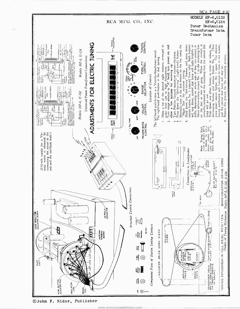
RCA PAGE 9-2J MODELS HF -6,U132
HF -8,1134 Tuner Mechanism Transformer Data Tuner Data
!Ji º ; II,II Z= ó
W4y13 aG I[ ; Wÿjp C VGC Ú^
u QJQJW
tlWt)m W- mmF10T
1Q1 LóQOlopQl lú.J l
o 0 V ZP v ZJ O ti
cc a
a- ,0
a Q m
Zft,
©John F. Rider, Publisher
www.americanradiohistory.com
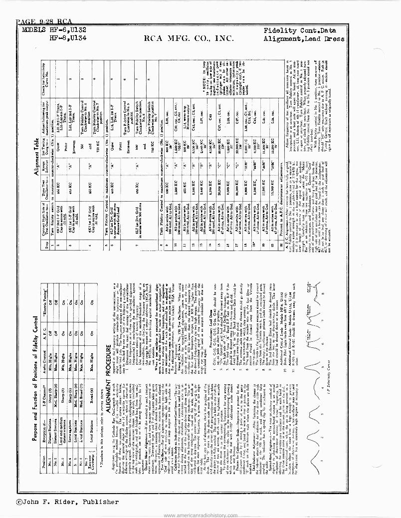
-"AGE 9-28 RCA BEDEW HF -6,U132
HF --8,U134 RCA MFG. CO., INC. Fidelity Cont.Data Alignment,Lead Dress
M'
úd ä u ú
. a m
ira glió*illf Ó
By_-..E 31= L 'y.S2 ó.ÖOkg
Z erg §a rill "°b9nMgöa$ 1
4 ä
x § $ I
00I .5 b
éty cg< m
Fg
ko ¡
G
x o JFMmu
¡y Fs
é 1
1MM
w s m
a
ti 07
. 8.1 w 9V Ep$$,. F
ZS S (i.
2E.° a Bg
FÚ
á s
1D Ó eº
$ ¿ 33pp V
. N` 2 Er
z w (-U FU
$ p .i
.
J
ci, m g
U
B s i 1 aq
ug ÉiguÉúvgJ 9 u d
u
i É
J
e °
ó ó2
2 8
9 m
A
e
1
d U
S $
6 Z° V idi0
.7 e u
idF ` V Ode
3a
u i41. "
u O dSm
u içde
V e $ u DGe á
u pga á
V k á
V
ñ 6 z
g 9 uM ...Q.
tl tt < é t i< 1
a
< é
s
`< _`< ;o NI ú ú Ä as
.i 9 s
% %
7~ 73
p 9 M OVG
e CVgE
7
g lgu0
87 Dd
3
OVG
2§
W
! N OVG
!
Vk
! OÁ
! á
OVG
! DG
p
OV4
F uTC
959
m lI.Q?
uT
5?
m3
F e
.o' mú
g t$ ö o
á! 00 Y
E m .fi
' Q
:ill m9 .5
i 2
si `g`g`M`g`M`M`ä.
id 8
1 S1
E' 2
1 á1
8
l` Si
E
Al
8
Si
2 i 8 g
` 2
1<á si ó+s`:23s`cs
8
< 9 i E
d 5 8
12i 5 g
io 8
< 01
2 i 5
$ q .. m m M e m r m e P. . . °..1 ;$ .. 2 .. .". .m.
b $ p 2
%.,
F.
s Q
te 0
k1 c 0 O
tee O O O 0
V
à 0 0 O O O O O
v c
á
m x
g
x x
xi g
i 14 x x
g g
i x x
g g
1v1v6 :, i; 1 11/ 1
00
41111111 1°2 QI '1! m2
1
á 4
! ]
,á /zz w N »
z ae m nl z;azz
...
<"B"- ..> lie :411 afiJ°`c'1
c`ovy6v W ÿó
ióeqv
ZeC ewe C 9'n73ésv B !. S
"41 Eti "oN' `°gy ' b ` 3= 'o4'=m m S 9a1> L' ° g º:.. c2 151-.M e1.a1
31444
Ii
sa Y$a9p9[9 Spg6"
e"z'r$ ` .a» ia°gánaßkba $z . I"p°m°"o .ó @z1 el 'e415: {,B.5Q
zw'9óa
1..ga 6 o c ÿS $2s << hi tñV3b9óY36ó
.c u9 = ° ó rv 3Hszg9"¡' eai'As3fi°.
, 3-.,m-
e1d "é Ci:§`sLePé
o J ó_' 1á
9 m1. . <
óa°so"a $,
°'i'.-a," sa3>xa - 4 fiL°° áóÉ3gój<y °ygo J 112'2la.°"13r'
d1.fi^",:eñ2 ySxzSa-ÿ i í",ó"5» .6g?`10ÚóÇJ
X éZ1. .03 ó tre e`áB EC"
gSy31a2 äv..jeg.° 33i' .é&ç
óZrga3ea3 É.`e61`g ¿.B övcOi IÇ9`y`rg Jig,
S 1.a9q; 9égá °Se ú g_
Y- -- 112,22i10, ú= -8 08 =v"'6cy
vsò 6°`Fáóÿc
úA9b¿^
»Yo
I'seó y9^er.1.$0p
82v.cfi io= ers` 2145J ÿ J1 -.
° eñóg9II:wÿSc 6q'a1.F.1ggPó Er31a' 'w3fii óiw °..6 5:65
yge1.0gE6r."
"S
$ ïg4.z9_á5
1.g '2gg i^= ar wöSz asa..
TANA sSá XSFèe _gS " JaE g9s9 ñ ̀ ' o-
.. b V o ,º c ö
ÿÿ
C
9 ~$±oäá. `rl'mw $ m1. $ñçç .ä. 3 c -3.E
3X6.eá: s:F':
egte$#00 ró9°ees aaroe6:ÿ Q9x 95-6-5-1.:d-g1.21=<çá^'°:
g 1."gº= mw ere <2 eB _- °
é é q.E9
L ñ 6"áy2'o"ss -.r ób .°w. 3 :nc$yw1.50 263l2çtPóö1 <Z.EYf; röö-.._ I25aas,`' ecS.qó,9,ó
. ` =- , " c a 9Eg
eác(}Éxo=.D93 WWE'e `3c=ç`xi
96ó:móáád43ña
©John F. Rider, Publisher
www.americanradiohistory.com
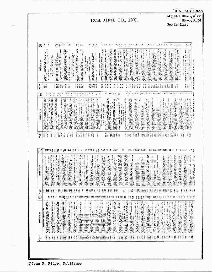
RCA PAGE 9-2 MODELS HF -6,1)132
RCA MFG. CO., INC. HF -6,11134 Parts List
óu 5;1 e
. S 48 4441 444 444 . . . . . .
w " w w . . . . . . . .444414 . . . . . . .
w ; " " «&"
gz
$
1.s
m a
áapgqii3L
$,!
N.
ó
Yäp m9 <
á
s^s ÿ.P3s a3Y 6w
E. e-:á$IÉ 1á
f5 9w
xñ66a<ä aa6
Ó.
0m Yae
Ye <w=
g aä ^
'
ÿ
! ,_ le'
@Ç -le
? sÿ
'
9 mw :3;1
mil. :
6
' ëi
E
Y :ä`S
g
1.ea9I
1.sy:
xe''Sa
al
g 6:°6rE ú+°¿
g
" a-
. 8
s= 'Xs
Ca'"
8i
! ! Y
°
ä
zñ2rP
ñéEl
w zä .ei
mi LS
!"x"
< I El
ñ^
áF <
z
a x
I ñx C
YY
EI °
E
t
sa s
L;w >ossadmy ïmg.p3e.immJJuuxx9s-s
wá I
á
x> "° É 5t
E ° .
x > Çe
31$99'°
J
S
°
,XVF' IwI
ço«sm.w:d7e8Eg8 F 1
J J Yi .F
É.E
,_ :
IBInlolgeBex
F F
F I
.F r
1 Eä
;:.f.. ."s >'cñú',
h F F
éä
r. e°V1ä
m f>a
;i
Sx
F
z O
w .1 .R 2 -x qx"qx e
gRR
8 S
á8 á8
!I y1
E. ; p l' le
;:.m_é..-3éaa11:i weFm
>
n9 9
m
x qPE
6' E
g 8
1
t I"
$: F F>w
<
-- =
Ff.ñ
O r n
"S m-
. >
H8 .os Y
a
A_
tly-
ill u4
; gli á° !line'
FIjs6¢1'1s8'8i Bái9E1 m
=5
12 mt9y98
Ë_- á tlZ
MI `°
i..
4
0Ú0
i ..
s 3d88I
i a1 Z S 2 <= B
y úä,..°'ñ_ôá E 8+"+
á 3 X a
e 9 - mY
s z ó
ti_Y1!egÌ.Ì19ÌlÌlÌÌgÌÌrÌÌÌ1&ÌêIoÌmlmá;Ìi? x^" Y a
.eY,.°é.`ó'.c_Ç ;f
UUu
E.5
2
`ELeoE$$L=
>,Fe
`3+ V4UM
°
Or
c_
L
É-
aX
xx'Sa= nvPv_aeo exdre--ya
a
y
3S
'
I_.EaaEi uY
a t
www
<E
y w www
4 C
ey
3
G
aä=ssäl.-ea t ä:1`I=
m m w m
m
Crá
o r
1 J
w
- Od- Fx - - - - - - - - n. w w w..w n n n n w n w n w n n w n n wn .. ww w w n n w nnn w nnnnnnn wn nnnnn.- n -n nwwn .. n n w
g.7l 9.,-'
n .. r w . .. . . . .. . ..
w 4 . .. . . . 4 444 . . ..414444444444 . . ... ..ñño... .. .
. . . . . --
.O. f.
6 w YO
9 I!
S e ,qj
fi Sam.X
Z9
ewi'eg. .
u.
J.. wa äát
a6 ! vem B3ww
i `
d V E" 3sy Ú
LP 8 u saa" ! y[aacl
.J,
E17:
Y-1b-b2
u
Y :Y ill g./: 9ÉE
óSev"
áEá
Ì I
: A: á>
SS
"Yi
-
8
1> úuu
E
ú
_ v.l
-
30súm
6
á á
°
vtt
0 i
vGCCC
' E
I ia .
o
vé vá
.= .'
Éá 8é
_6
ñ °I ºa
aE mc
o ú°J
E
3
y
EF
! "l
.
2w .>"
c
s
i=I
3 YY
5
i
fi
v`îi
Yi
r.ÉrSEó ° a<"..
I
a ! 3
É
__7a
'r
ÿ g a
`
>_
al
E>E
á9 1 1T e3t.
S
ñ aä
Çpéâ:
É°u'
°- .F.<^
I
s dda
éîç
áot! "rE
ee .a
1
éEéércércz
rc
r
aay "Et
j EO
Ii :II3ñ:;
.
rc9 aaaaaraaa L'..y 3
atttit33 ..
éagÉEEÉ E
t !w n a
TTTiiiTTI1T2gi. rs:::eé:°rc°gÿ:ÿ.222çá2g2á`
á aaa
x
Y
3
°
l
°"
a¿á°mm
á
ssa
î1l'llFll
yy
y __--
yy
IÑËäIl
mwmm
yo
f':°
-
.i_$l
áw -E$ä'
:Sa="-'"'e
w
?
r
- -
áY ól
XEóu
.g.a
1
- -
!y
é>:aiuIi"ú
? <
-Ç:
_
MI áCwm
e,'
=x 222 2 22 EEEEEEESE
"234222223n°wwwww. -- - n"wwnn .. n wn n wnn wnn n n n n nn .,nn n n .. n nn n .. nnwn n
n.. ..-. ...n ....nn..nwn Hw w n n n n nn
ág . ñ ñ : .. w . . 4. .......... 444a41e141aeee
e .. 44 áwóñé 44 44 " -"" . 44444 4444 41 4 A 4 4 . 4 . . . .. 4
0 E x
ÿ
1 s ., Ea
Y é.
114 < .4
> ^Tr
pS
i84 El
A
s
.1=1.:
s^"a1<.'Iäc.Tr,!.66y
:mmm
Y s 4 es
3 É-" S
2.
ii.l fr>.
Ce
X
1.; m6dGS
ie=ura
ZaßÉ
" `F °E d
á ö g
S
E. d!
!
JT1e1111111ä1I°I°°!°iiiTiii"
á
i....2"a-ne Eúúúúúôúú
_-
2hwrmwr°2222e2:2222..
°
g
úeê. Áúú`úuw 1111e111111111,1
_ó uuuuwuuuuuuu
. "
w..:ú+
ú
«
a
é
°e°:9,..,
i
aúe.s
udw
Y
r '
u
á
«gsaÿS
u
^v
u"
ú'yu`m
ÉwÉ7dÉ$g sé-..wae.:....2.2.,
i!'ii?qq¡
uuu
ú
ñuuudFs5
É'9aéÉ
ü9
e5'166wrY
s
7
.
u
ú-
Td .A;
qiiT.ii>«::<
a ' !
:ru9ëI
dux3
w
;.
m I I
`xUX
T.°eC,r90e dEÊPEEEVÉÉEEÉÉÉ
8 É
.111_1;i)â' , uEuuu_33
a_-
m:e.É
2.2
:e
ñ»
ú177aI
a°
a
rc
Et"
EssaXXB
13 <1',
s s
1 1
- .
är.6-wF
I
>^n-`S
_xe-°;.É
VéY-ô_:E°
IÌ ÿ'L=y"¿
Ïaa,ggó,.a9
w3x6
ñiJx.Ìñd6Lg.
E w :Xa 17,
a
ñdÌ:
éw
tE a E-
§`' a
xi
Ìñjl.l.
w$
+
H .. 22 22 2 22: 2 22222 2g22 22222222222:
n n. w w wwnnw w" " w w"w-nw:,--ww :,-n E E. -w w nnw w - " n wwann n- 3= :, E E NNE' "n -n E 3 - :4, w" 3 ' ñw
©John F. Rider, Publisher
www.americanradiohistory.com
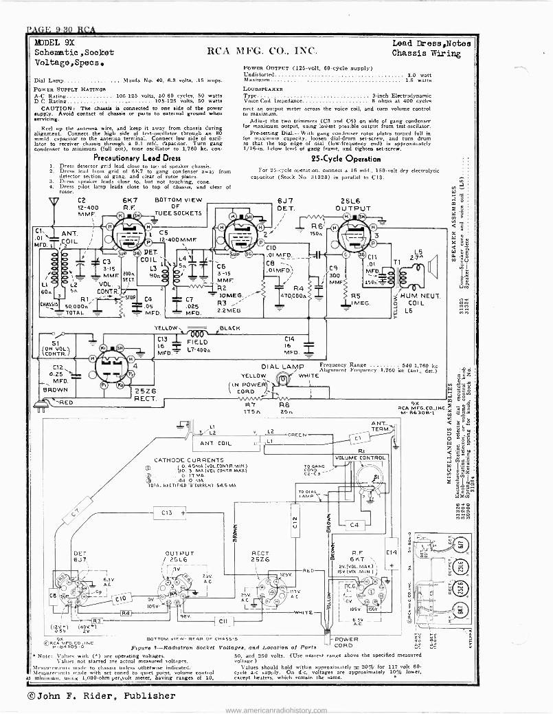
l'AG1'. 9-30 RCA
MODEL 9X Schematic ,Socket Voltage,Specs.
Lead Dress,Notes RCA MFG. CO., INC. Chassis Wiring
Dial Lamp Mazda No. 40, 6.3 volts, .15 amps.
POWER SUPPLY RATINGS A -C Rating 105-125 volts, 50-60 cycles, 50 watts D -C Rating 105-125 volts, 50 watts
CAUTION: The chassis is connected to one side of the power supply. Avoid contact of chassis or parts to external ground when servicing.
Reel up the antenna wire, and keep it away from chassis during alignment. Connect the high side of test -oscillator through an 80 mmfd. capacitor to the antenna terminal. Connect low side of oscil- lator to receiver chassis through a 0.1 mfd. crapacitor. Turn gang condenser to minimum (full out), tune oscillator to 1,760 kc, con -
Precautionary Lead Dress 1. Dress detector grid lead close to top of speaker chassis. 2. Dress lead from grid of 6K7 to gang condenser away from
detector section of gang, and clear of rotor plates. 3. Dress speaker leads close to, but not touching, cone. 4. Dress pilot lamp leads close to top of chassis, and clear of
rotor.
C2 12-400 MME
C1,
MFD.
ANT. COIL
L1
60n 3
CHASSIS
C3 3-15 NAME
L2 VOL. 5n CONTR.
R1'" '2 50.000n TOTAL -
6K7 R. F.
p © © ,e 1 i
CM DET- COIL
L3 90u
BOTTOM VIEW OF
TUEE SOCKETS
POWER OUTPUT (125 -volt, 60 -cycle supply) Undistorted 1.0 watt Maximum 1.5 watts LOUDSPEAKER Type 8 -inch Electrodynamic Voice -Coil Impedance 8 ohms at 400 cycles nett an output meter across the voice coil, and turn volume control to maximum.
Adjust the two trimmers (C3 and C6) on side of gang condenser for maximum output, using lowest possible output from test-oscilator.
Pre-setting Dial.-With gang condenser rotor plates turned full in for maximum capacity, loosen dial -drum set -screw, and turn drum so that the top edge of dial (low -frequency end) is approximately 1/16 -in, below level of gang frame, and tighten set -screw.
25 -Cycle Operation For 25 -cycle operation, connect a 16 mfd., 150 -volt dry electrolytic
capacitor (Stock No. 31323) in parallel to C13.
UP
1
(ON VOL. 1 CONTR. /
C12 0.25
MFD.
BROWN
'`RED
200e.
SECT.
STOP
C5 I2-400 MME.
2
C4 05 = MFD.
L4 Sn
5\UP
C6 I 3-15
MM
R2 10MEG.
025 R3
= MFD. 2.2 MEG.
6J7 DET.
= R 6'
C10 .01 MEO.
Cet 01MFD)
1' R4 1170,000n.
150,
-Al
25L6 OUTPUT
C9 300 MMF.
L5
T1
R5 IMEG.
YELLOWS BLACK
3 HUM NEUT. o COIL d L6 i
C131 FIELD C114 I
® ® _ MFD L7-400 5 16 MFD. _
© / © DIAL LAMP Frequency Range 540-1,760 kc / i Alignment Frequency 1,760 kc (ant., det.)
0
YELLOW WHITE
® (IN POWER.'I 25Z6 \ CORD 1- 1
RECT.
uu
OCT. 6J7, --i
02v >1 (ADV.>) 0.5v 2V.
©RCA 9x
MrG CO. INC. P-84309-á
R7 115n.
LI ,-2/L2
ANT. COIL
CATHODE CURRENTS 8O. 4 5 MA. (VOL.CONTR. M I N.)
1 O. 3 MA.(VOL.CONTR.MAX.) 0. IT MA.
44.0 MA. TOTAL RECTIFIED -B-CUNNENT 54.5 MA.
I05V.'
BOTTOM VIEW- REAR OF CHASSIS
Figure S-Radiotron Socket Note: Values with (") are operating voltages.
Values not starred are actual measured voltages. Measurements made to chassis unless otherwise indicated. Measurements made with set tuned to quiet point, volume control
at minimum, using 1,000-ohm-per,volt meter, having ranges of 10,
©John F. Rider, Publisher
L2
RECT. 25Z6
I- - 25V. A.C.
L_ -
R8 25n
TO GANG CONO. CS -C3"
TO DIAL LAMP
ANT.. TERM.
R. F. 6K7 `
2V. (VOL. MAx) ,1
15V.(VOL.MIN.); / ...
POWER so Voltages, and Location of Parta CORD
50, and 250 volts. (Use nearest range above the specified measured voltage.)
Values should hold within approximately ± 20% for 117 -volt 60 -
cycle a -c supply. On d -c, voltages are approximately 10% lower, except heaters, which remain the same.
O M CAN men Ml.!
www.americanradiohistory.com
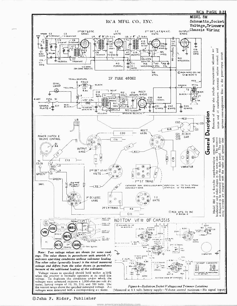
RCA PAGE 9-31 MJDEL 82d
GREEN CZ C3 3-30MMF. / 9-365MMF.
L1 2.n
-4 CI
680 MMF.
C4: O.1 MFD.
RCA MFG. CO., INC.
157.0ET.4O5C. I.F. 6ABG 6K7G
L4.N¡.III' L5 -7.2n "
C AIN._ LL .2Q/
Aá b
'A -HOT
/C5 C6 I 3-I5MMF. 19-365MM4,
1 L2 ` 3.5
g ¡
pp gL3' R1
RQ6A' J
`56,000A 39OMMF.
5.6 MMF (06 SOME MODELS)
DIAL LAMP
FUSE SI FI
SPARK CI7 PLATE -,Z
POWER SWITCH L VOLUME CONTROL
OS, COIL
GREEN
1937,
GREEN
TRANS.
2 F
TO ALL HEATERS FIELD
IsT.I.F.
0r TRAMS.
BLACK
L9 4.8A rC1B--- BLUE
15000A
2MODET,A.F.lyA.V.C. 6QTG
T- 9.6A B
Cl2 470 M MF
VOLU ME CONTR.
R3 CII R4 0.1 500,0004 MFD.
IF PEAK 460KC
0.5 LB J MFD
rL1O-.03n ll
TO - 6X5G I -i: HEATER I YELLOW
OUTPUT 6 N6G
1sT. DET 4 ose.
Note: Two voltage values are shown for some read. ings. The value shown in parentheses with asterisk (') indicates operating conditions without voltmeter loading. The other value (generally lower) is the actual measured voltage and differs from the value shown in parentheses because of the additional loading of the voltmeter.
C23
LÓ V ,E C
ro
.-
ú Ó c O
eI u Ó e V u
u C U GG 'D
É E
b ?
C
e Á
C
d
C -D
o p d ä ro U ri YI
N 1
V d t0 > u ñ 'd a to
0
C Ñ 0
r01 'rF v
V .u.E u u4 CE
ve , E
d x u.t u .oc a
ái .C.,bL u.,aá 211',
Óe[ > `u d O C L6^
u lu. b c
`"gó°ß Ñ V
o ágó
.c -2 .2 eé
© RCA MFG.CO.INC. I t r I I I 225V. m-619TS-G 24SV. (-1.W)
I
OUTPUT I I
-1.2V. I -16V. I C22 6.3V.- 6.3V. r -6.3V. - 6E6 -6 I I I I I r C21,<23,L /t-A..T C23
O© - I 2isv zzavi © Ges-- )®- J J i I
L L -TL// O® -R E
(i(6i]2.oDLT,AF,I 6.3.4V.. I I ©O®ORECT. 6K6-ß
I
I L
24-ß DET.-AF AVC.
647G 0
CREEN
1" DET&OSC. 6A 8G
is -T IF TRANS.
Rit C19 RECT. .0015MFD. GX5G
R13-15,000na BROWN -BLACK
R6 270A
R7 R8 39A 39A
P2 C2O 0.25 MFD.
RECT. 6X5G
0 ® 0
T 2N° I F TRANS.
R14 1200,
Schematic ,Socket Voltage,, Triomiera
OUTPUTChassis Wiring 6KBG
CIS .oI MFD
o o Ci
RIO G 470,00OÁ
C16 .OV5 MFD.
©RCA M FG. CO. I NC M-81929-3
REO
GREEN 45TÁ
T2 I
BLACK -
C2' Z I C22 .L C23 TT6MFD. GUI FO ;IOMFD.
-RED C2z
T VIBRATOR
BLACK
LII
3 EA.
C21
CATHODE RAY OSCILLOGRAPH VERTICAL'HI- TO THIS TERM. CONNECTIONS VERTICAL "O' TO GROUND
N
O Ol i.F o ® 6.06
Búá
© RCA MFG. CO. INC. P-94194-0
-- °c 22 BOTTOM VIEW OF CHASSIS --O c_Kcc5
-ANT 6001w.
-LI - L y SLc ADJ.
FC4MeG.00.,InC 460 KC SN -,793 4A.V.C..
I ----- (-16V.P) 6C1-1-0 6-G il 0.7V.
I 2^P-I.F.TRAN3.
ssv. r , I °RI.
Z CG. I ADJ
L r - 12T.OET., OSC T (-1.TV. ^l; GAB -G -1.7V. ,^^`'^'
--o.rv, f - I F6.3v '' - 6.3V. I ls.. I F TRANS. I ('I.TV,4)
" ; -alv.
Voltage values as specified should hold within ±200 when the receiver is normally operative at its rated line voltage. To duplicate the conditions under which the voltages were measured reqwres a 1,000 -ohm -per -volt d -c
meter, having ranges of 10, 50, 250, and 500 volts. Use the nearest range above the specified measured voltage. A -C
voltages were measured with a corresponding a -c meter. (Measured
c.ß I
F -ow ; .4 PRI O.On. _ I O 1ADJ. L ® -1
...0 RC O.. xtsv (LI) I ' I. F.
I I
)V. 95V. I 6KT-G QV' 1
I I 225v.
BOTTOM VIEW OF CNASEI6I, 1 t )
21
CATHODE CURRENTS
re.1 . 16.361 No, OMNI
N S. 44.591! R. REEANNOT OE
SECRET. MEASURED
ú
ú
7 a C
Ñ
oc.
Figure 4-leadiotron Socket Voltages and Trimmer Locations at 6.3 volts battery supply -Volume control minimum -No signal input)
©John F. Rider, Publisher www.americanradiohistory.com
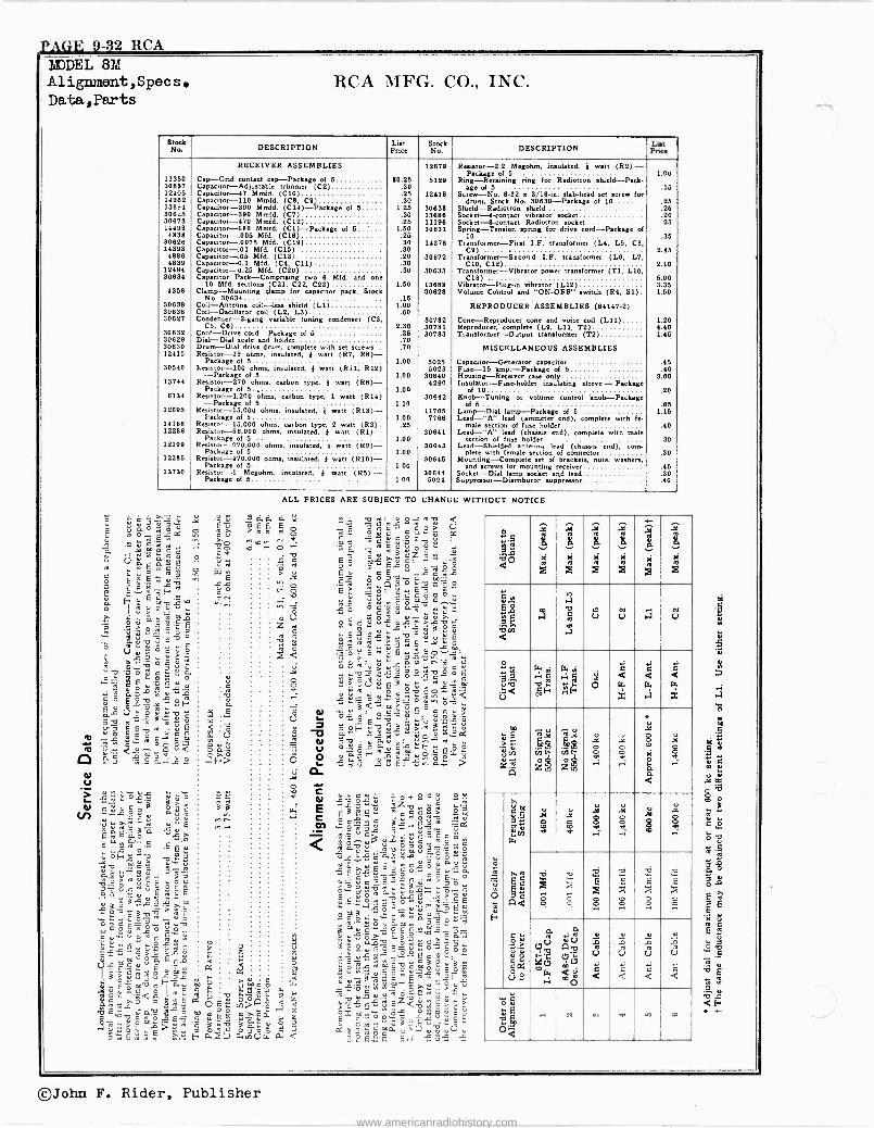
TAGE 9-32 RCA MODEL 8M Alignment,Specs. Data., Parts
RCA MFG. CO., INC.
Stock No. DESCRIPTION List
Price Stock No DESCRIPTION Lin
Price
RECEIVER ASSEMBLIES 12879 Resistor -2.2 Megohm, insulated, 4 watt (RS) - Package of 5 1.00
11360 Cap -Grid contact cap -Package of 5 80.S5 5129 Ring -Retaining nog for Radiotron shield -Pack - 30837 Capacitor -Adjustable trimmer (C2) .90 age of 5 .15 12406 Capacitor -47 timid. (C10) .25 12418 Screw -No. 8-32 a 3/16 -in. slab -head set screw for 14282 Capacitor -110 Mmfd. (C8, C9) .30 drum, Stock No. 30830 -Package of 10 .25 13894 Capacitor -990 Mmfd. (C14) -Package of 6 1.25 30838 Shield-Radiotron shield .25 30625 Capacitor -390 Mond. (C7) .30 13686 Socket -i -contact vibrator socket .20 30673 Capacitor -470 Mmfd. (C12) .25 11196 Socket -8 -contact Radiotron socket .25 14498 Capacitor -680 Mmfd. (C1) -Package of 5 ' 1.50 30631 Spring -Tension spring for drive cord -Package of
4838 Capacitor -.005 Mfd. (C18) .25 10 .96 30828 Capacitor -.0075 Mfd. (C19) .90 14378 Transformer -First I.F. transformer (1...4, L5, CO. 14393 Capacitor -.01 Mfd. (C15) .30 C9) 2.45 4886 Capacitor -.05 Mfd. (C13) .20 90872 Transformer -Second I.F. transformer (Le, L7, 4839 Capacitor -0.1 Mfd. (C4, C11) .30 C10, C12) 2.10
12484 Capacitor -0.25 Mfd. (C20) .30 30833 Transformer -Vibrator power transformer (T1, Lia, 30634 Capacitor Pack -Comprising two 8 Mfd. and one C18) . 5.00
10 Mfd. sections (C21, C22, C23) 1.50 13888 Vibrator -Plug-in vibrator (L12) 3.35 4958 Clamp -Mounting clamp for capacitor pack, Stock 30828 Volume Control and "ON-OFF" switch (R4, S1). 1.50
No. 30634 .15 30639 Coil -Antenna coil -less shield (L1) 1.00 REPRODUCER ASSEMBLIES (84147-2) 30636 Coil -Oscillator coil (L2, LS) .60 30627 Condenser -2 -gang variable tuning condenser (CS, 30782 Cone -Reproducer cone and voice coil (L11) 1.20
CS, CO) 2.30 Reproducer, complete (L9, Lib, T2) 4.40 30632 Cord -Drive cord -Package of 6 .25
,30781 30783 Transformer -Output transformer (T2) 1.45
30629 Dial -Dial scale and holder .70 30630 Drum -Dial drive drum, complete with set screws .70 MISCELLANEOUS ASSEMBLIES 12415 Resistor -39 ohms, insulated, 4 watt (R7, R8) -
Package of 5 1.00 5025 Capacitor -Generator capacitor .45 30540 Resistor -100 ohms, insulated, 4 watt (Ril, R12) 5023 Fuse -15 limp. -Package of 5 .40
-Package of 5 1.00 30640 Housing -Receiver case only 3.80 13744 Resistor -270 ohms, carbon type, 4 watt (R8)- 4290 Insulator-Foseholder insulating sleeve -Package
Package of 5., 1.00 of 10 .20 6134 Resistor -1,200 ohms, carbon type, 1 watt (R14) 30642 Knob -Tuning or volume control knob -Package
-Package of 5 1.10 of 5 .85 12695 Resistor -15,000 ohms, insulated, 4 watt (R13)- 117135 Lamp -Dial lamp -Package of 5 1.15
Package of 5 1.00 7788 Lead -"A" lead (ammeter end), complete with fe - 14168 Resistor -15,000 ohms, carbon type, 2 watt (R3). .25 male section of fuse holder .40 12286 Resistor -56,000 ohms, insulated, 4 watt (R1)- 30841 Lead -"A" lead (chaisis end), complete with male
Package of 5 1.00 section of fuse holder .30 12199 Resistor -270,000 ohms, insulated, 4 watt (R9)- 30643 Lead -Shielded antenna lead (chassis end), corn -
Package of 5 1.00 plete with female section of connector .30 12285 Resistor -470,000 ohms, insulated, 4 watt (R10)- 30846 Mounting -Complete set of bracket., nub, washer.,
Package of 5 1.00 and screws for mounting receiver .45 13730 Resistor -1 Megohm, insulated, 4 watt (R6)- 30644 Socket -Dial lamp sorbet and lead .30
Package of 5 1.00 5024 Suppressor -Distributor suppressor .40
c á ó b ó
v "°^Ema ó .m Ó
.m OK
ro
E - VáEÿvu s
ú ° ro ro A 9
ó Eé+.Eéu;fi v.
á i v u,Emvÿ`o O
9.311 «2.2,74....
m ° C
ó .61 >
E '17eu
rás25 0'3*E -úE -e .Y. P- rt =.11 C.m
t0 - .. .a v á ÿ ó 8<
:4:5
co u > l ú ÿ ó 1 f ó ° d = a ' g% N -511,ô 3 au á v, .,
-,-..'11.-q .- ÿ ÿ E eo.r.' áE'aa a. Eroap¢oE C ' s o' ^Eÿ
"o1 -,s:ú ,,ºP. ao`msY .
°
g..«¡.!;
..2»3 ro p Ei Ñ O Ñ
31uO e E E
Y ;ài ;m ó-o E c.o i> wi
á
w 0 úb
Gú-QOtYá
O
W
j0! 1
2'ú
w Éñ m = N=çF '=a lr'Ì_y
S ró 1E.á w. s>ó3. fECs,2E oú cóEwS ÿÁ>.8<.
e
23 g 8ú j oE Pa á
8` E â m : cá??; z
,-ópánUwdu
9 á c > .Ee Ñ
b
ALL PRICES ARE SUBJECT TO CHANGE WITHOUT NOTICE.
++
!t1IIi ^ C
.BaO
^ g o 'ce.,.
o v E ü E :
ú E c ó 0 ó Y
..14.2 ° O C w Ú 4 p Y Y
_ u ú ... Ñ Y A` w ro ó ú úíY. ro> L ó C ;.a s ro ñ
ú ÿ> y C= ÿ ÿ C C =L .'2 E
n... u >E.roó"p.
32.2-22. O C a i u ro
óY vqó v3< '; ° öó
_ Y> Qó'`; ú_ósù E c u ÿe e.. u ist -g72 3 d wd 'O 41ú . ÿNO.O nf O^
_ a
=L aáF ro L c Cw
zóvs-^,Y, 22 _ -5121 922 °598
º'=°s`ó
Ém ás :á v Ob5¿ o v.o
0..Y+n
.
w pro °da .s.Éó°=áÉ..fy.ó ?
j " 4.;'>5"6-,9, C ro > C 5 O °ÿwñáé,óp: `âpE E= 8».='b,. >=Y
b
' ce m
ú C G..O ` óo .Y. Y a ee n 7 7.°. ` ro
d ,.L T O.. O aro `y
Y C a Ó m E_ `+ ] dYE.2.275.Y° =oo º. º=b d= eva
b ::ú21 Eemcd.p E=°bE° ro
Éx C., Ó s.º .LS O d C ú
2b117.1"(% -d:(3. ro y E 0sO
Qºn9.9:
.°+
1-4.,1'
áó
i $
: is
.11
b
i 8
: x
a
b i,
X á
>é
¡
.N
x >i
le E° ml
rn
m -)
á q
J
U U ,1U N
Ü<
H ' b F
( r-e
',2E -.O u
á <
é < W
.4
C < f?r
x
Y'Z
úÑ A3
Ca
sy ÿ$ ze z .'$YJ
di
"
a u y
i
<
AgÌ
di
-
.o.
w 7$ç Ó b
A pm áZ tY.y
(ar
i, w
sá Q<
q c.
ó., z äa Cs
V
m ai
l..
ro v
JÌ
A.
0 _
Y
8 m
.Ì 8 i. .i
W x r. 8
W ti
S
r 8 x
b E i 8
... E 5
..b.
"c
. ro
(7b CA
o"Ñ VG
w r, m O
Y
U
é
u
Ñ U
á
u
m U
á
u t U
á
óÉ C
Ó6 .t N o'1 dt r° or
©John F. Rider, Publisher
www.americanradiohistory.com
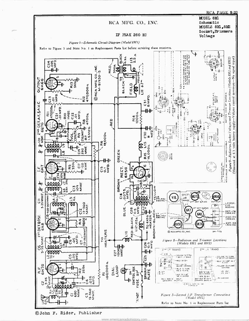
RCA PAGE 9-3ÿ$
RCA MFG. CO., INC.
IF PEAK 260 KC
Figure 1-Schematic Circuit Diagram (Model 8311)
Refer to Figure 3 and Note No. 1 in Replacement Parts list before servicing these receivers
Ñ
A9 00000
Ip
'06ò601,0 ..---1I l ---
m
J.. tO Q O xs-
PO u `'-î 1.1.. J
d Ino' "EI iu
u rn
N 1n oç ç
QE
ó
C.i C if) Li
et co Ili ' II
C2. tD 4
-ne --' `\ á
I LL
- p ' 0 f1 '( ï Y1I` ,gT Vo
r 0 0000
I^'d0000`
LC) óU
LD NJ
b
o o
w o, CC C° /
In
CC
W
I
4 o w o
O
CC en \
N
-J
e o o
cc
z W W
--H I..O
o J
o o
In 0 cc _
gib
ort: m
11111 C)
In -1V
u
7
HI
MODEL 8?LL Schematic MODELS 8ML,8M2 Socket,eimmers Voltage
p1
z
o J J WLa -PRI.ADJ.
260 NC PAS. N2.^ DET.%q.VC
14.r.FTRANS.
lST-OET.$OSC
OUTPUT
3 f 6A8 2 0 SCA MFG. CO., IN C.
L.F. OS C. CIO
L 600 NC
SN-TT3
ANT.-C2 1400 NC
Figure 8-Radiotron and Trimmer Locations (Models 8M1 and 8M2)
Z"O I.E TRANS.
LB,16
L9, 16^
YELLOW TO TERN Y' ON i' II TRANS.
----RED TO OR
"'YELLOW TO VOLUME CONTROL
- -BLUE To TUBE NO.3 PLATE
\BUS TO TUBE N0. 4 DIODES
BM I RUN A ONLY (.3TAMPEO TLaT0-I)
2ND I E TRANS
- YEIIOW TO TERM. ïON 1' I.E TRANS.
Q --BLUE TO TUBE NO.3
0 PLATE
/ 1
_ el
- CONTROL
YELLOW TO WLUME
II oils TO TVBE N0. 6 DIODES
RED TO B 8,11 RUN ONLY Ornino 84096-41 "
R e-, Nee-, co, ere
l8, 29^ C9, 29
_TO CHASSIS
Figure 3-Second I -F Transformer Connections (:Model 8M1)
Refer to Note No. 1 in Replacement Parts list.
©John F. Rider, Publisher www.americanradiohistory.com
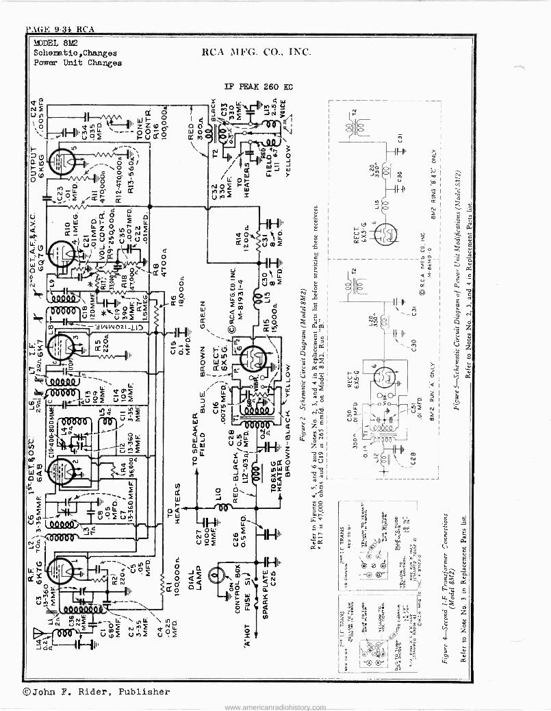
} AGE J-34 RCA
IF PEAK 260 KC
á )hhvOym MF mÇ M
73 ci
Ì
1
!- IM ó
J .-o.., ee 1 \
o t H 1i J T.4 O
/ I li O f Y
NO ~w Úpo M _
II' r o tL F NOS tOip V0f u0
0 J J W Y
O
Cu
3
_J
MODEL 8M2 Schematio,Changes Power Unit Changes
RCA MFG. CO., INC.
Qle el ()in
p I O ItfOZZ1D0 kit. ó --- - ó ó ó
I 4 I. ... - O
11 ` e \OO
II'ó g2 -
te) O O e NóLL
. F Y/ v [L
O
o
0 EiW
oW0 Li. >.
tOO MONt LL d)NpV1ni UUO
d Q0 ° J
'
\W
Cr O r, II, e 2pp _ =$ o N * M aS le 10.000i\ f IR -_N W
'own?. a; HP_ Fdf t -ih. I ̀_'
N * U + -sWW021_LIJ
I(1 O Cr N
N
m _11.r . QV JN uN -lci NLL \ N .0 N C
Hi1.
d o O r v
J pd
N \ O 2
Ñ CC N
d o o o o
J o o
tO o
Hi,.
®John F. Rider, Publisher www.americanradiohistory.com
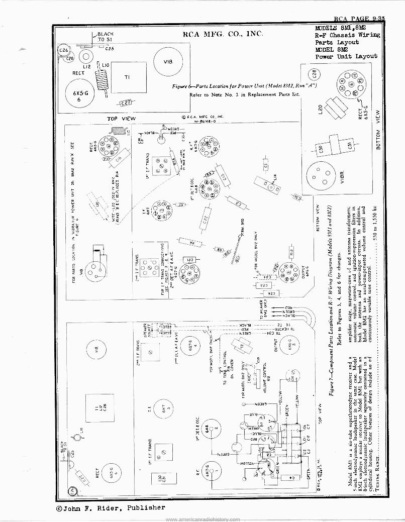
I
Figure 6-Parts Location for Power Unit (Model 8M2, Run "A")
Refer to Note No. 2 in Replacement Parts list.
RCA PAGE 9-3 c
©John F. Rider, Publisher
www.americanradiohistory.com
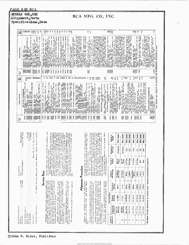
PAGE 9-36 RCA
MJDELS 8Ì,842 Alignment,Parts Specifications ,Data
RCA MFG. CO., INC.
Mß2 «« e_m
-
girl !
z
s rc
á
''''' . Rh. ..
MA2 .22e2 2822222
. d e . '222 8 2..
1 ñ: .. " . '
§ ! ' °`
mäé á"t 6 z a á
, 1 3
3 1q -e 3á
: F t ¡Ç2P i ^ $:
z1 9`,1.
g tin a23..^sgg 1*
E?é 3 ae =fr36 4 1111 á.3A . -A '4 s e ö,1 lo á., "'
= 3: "08 e e dá 5?3`eg;
3 t'5 Ieee« e.esm''e ó A`ä2`áSEe
$$$j <s 'Igs ixi'iiiil?Ii-.i«iiii¿Y tiÿ úlááámlláiáák.A.L.
:E
E S
egg 1J
H . E;i á
é ° :8
1 ápgS¡g
-1 Eä7
é 8m^s :zi2x'á29:897e5S 53:$ iÿ8;53 wxs
u
Emm am 3 smE 3 i5eo ag-?_pp 5'ge` é ae
88 <8 22].. Jr' om1,yigg ,'=g 1. S 9 'a«M3 Saa;281.`c±'çnö. EiDi' iGäS
ú' 2: u u Ç _3 °$ _ SSéY'_9_EY,YEás`s Egém
Eûjúúó ßó °vÉjá$?$XáÌ<Iá-oöá$áÿ `Yq `m lé w vIpáB " bçIg°ajsd<s.Eó ss31 ûn5ÿ-éá 04 55' m
8 F9 b ?i7813$TX5a5e3 ` 3 x »> we d us as uu 444 a aBH > úuûo
.. h..2 ..e.. e .. .... .. .... "tr°........ ...... ne . e. 2 88 282 2 2..nn 2 ..
0ú G 7Ó _ s4- . ; æ Jäo
EP
2 8
y...
:3.2Ñ52ó^ós2á u -drsaooo
1111111 I i íó x g >e i J
ie EJ
qE
vúi á
á
9 u u Ú ú u id u
s. 39 ú<
9 c ä(y :M
o $ o
S
Ó
1
$ o
S F7
il
y z
my Fy i g
0
Ñ
S M.
$ g g
q g
g $ -1
É %
é il X
a
ew .3> e1
u8
Qe
EZ.44,
úe qÚ
ót.7
d C4
tl
©John F. Rider, Publisher
www.americanradiohistory.com
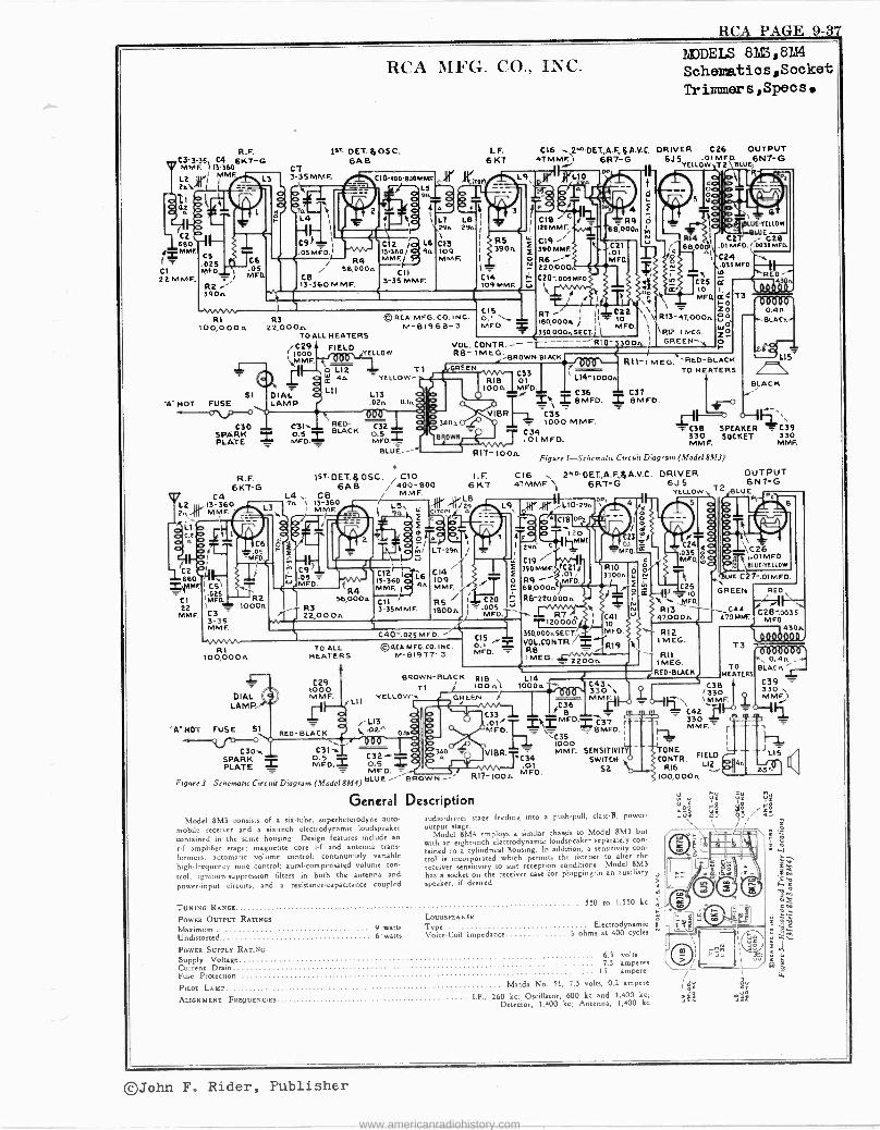
RCA PAGE 9-37
R.F. C3-3-35 C4 6K7 -G MME. ) 13-360 ri 'JAME/ 2A\
úi
I-ó co 0 660
i=.MMF. C5 .025
CI MFD. 22MMF,
R2 390n
R1 R3 100,000n 22,000n
TO ALL HEATERS
RCA MFG. CO., INC.
13T DET.II,OSC. 6A B
CT 3-35 MMF.
C9 _ ¡
.05 MFD.1 R4
56,000n C8 13-360 MMF.
, C29 1000
\MMF.
V! SI DIAL
'A" HOT FUSE LAMP
C30 SPARK PLATE -
R.F. 6K7 -G 6A8 400-800
C4 L4 CB / MMF.
L2 I1r 13-360 Tn 13-360 L , 2..{II MMF L3yI i `r l
Op11Ll O
.:71.-- E
í OrO.x ^ olA' } 2n C6 0 2 k /
I
109
ol os úr L7-2 I
II-p' =MFD. E., H v
Co I i- ós?= C12~jq^aqró C14 É
ÿ11`6IMt'. ; C51 MFD. t MMF.01tx/ 4n MMF. / / ti
CI 'Mil 56,000a Cll R5 / 1 C20 22 = P.3 3-35MMF. I T.005 '-
---,,<,. MMF. C3 22,OOOn 1600. MEE) -35(( MME l C40'.025MFD. /
C11 3-35 MMF.
©RCA MFG.CO.INC M-81968-3
FIELD YELLOW
T1 YELLOW -7-
L13 .02m 0.1.
C31-. RED- C32 0.5 T BLACK o.5 MFO.i__
BLUE --
O
LE. 6 K7
C16 2NoDET.,A.F.,$A.V.C. 4T MME 6R7 -G
L9 n L10
h S OP
II
F í r.
Ir4 CIB0nDLUWËLIOW
F390M 66OOp01MFD..a035MFD o R6 MFD. O I C24 \
1y N 220000 rv \35MFD. C14 I r C20-.00smr°. T 109 MMF. u 4 N C25 a
I úo e a' 10 I
MODELS 821&i,82d4
Schematics,Socket Tr irrmer s, Spec s
DRIVER C26 OUTPUT .01 MFD. 6J5YELLOW\T2`` ewe,
MED. U.
CIS \ ió 0.1 MFD` 1BO,OOOw ) I \t\ RI3-4T,000. ?
350,000nSECT.) I \R12 1MEG,
VOL. CONTR. r R:0-3300n. ¡ GREEN-` RB- MEG.
BROWN-BLACK
GREEN > C33
1 L14' 1000. 1
MED. TT C36 T C37 y; a., mpg). 2 BMFD.
C35 1000 MMF.
R2 1000rt
NWVV. R1
100,000n
DIAL LAMP
'A" MOT FUSE Si
C30` SPARK PLATE
1sT DETßOSC. C70
5, LI' ((TOP/
TO ALL ©RCA MFG. CO. INC. HEATERS M-81977-3
C15 iy 0.1 =_ MFD.
W v0 Z-
O
C34 .01 MED.
13
R11-1 MEG.`--RED- BLACK TO HEATERS
0.4n BLACK
2.5 v LIS
BLACK
rit C3B SPEAKER = C39 330 SOCKET 330 MME. MMF.
R17- 1 Oon Figure 1 -Schematic Circuit Diagram (Model 8M3)
I.F. C16 2N0.DET.,A.F.,6A.V.C. DRIVER OUTPUT 6K7 4T GAME. \ 6R7 -G 6J5 6N7 -G
YELLOW 72 LUE
D-le C
29ñ C
C19 390 MM F$4C
R9 6B000n R6 -22o,000
L10 29. OP 4
16 UPa ji t I o d izo
2 ° r 1MMF. 0.3
! ç C ? MFD. ' 035
a MFRIO
ó ó 33/00n y H t
MFD.
1 C25¢
-. 10 n S. N "N ---
Rt R13 C41 47000.
2j
R7 120,000 I 10
350,000nSECT. MFD
VOL.CONTR /= RB R19 MEG. - 2200.
a
` R12
R I 1 MEG.
C29 BAOWN-BLACK RIB .
1000 Ti 100.1 MME.
íL11 YELLOW,.
REO -BLACK LI3
`.02h OAR
111 C31. 0.5D.= C30.5 'T MF = MFD.
Figure 3 -Schematic Circuit Diagram (Model 8M4). BLUE BROWN
General Description
GRE
Model 8M3 consists of a six -tube, superheterodyne auto,
mobile receiver and a six-inch electrodynamic loudspeaker contained in the same housing. Design features include an
rf amplifier stage; magnetite core i1 and antenna trans-
formers; automatic volume control; continuously variable
highfrequency tone control; aural -compensated volume con trol; ignition -suppression filters in both the antenna and
power -input circuits; and a resistance -capacitance coupled
C33
MFD.
18R.
L14 1000n ---.-067)
fC36
=R B I =MFD.= C37=
\C35 == BMFD.
C34 .01
R17-100Á MF0.
C43 330 \ MMF.
1000 MMF. SENSITIVIT
SWITCH S2
1 r R11 I I1 MEG.
REO -BLACK
audio -driver stage feeding into a push-pull, class -B, power -
output stage. Model 8M4 employs a similar chassis to Model 8M3 but
with an eight -inch electrodynamic loudspeaker separately con-
tained in a cylindrical housing. In addition, a sensitivity con-
trol is incorporated which permits the listener to alter the
receiver sensitivity to suit reception conditions. Model 8M3 has a socket on the receiver case for plugging -in an auxiliary speaker, if desired.
TUNING RANGE
POWER OUTPUT RATINGS LOUDSPEAKER
Maximum 9 watts Type Electrodynamic
Undistorted. 6'watts Voice -Coil Impedance 3 ohms at 400 cycles
POWER SUPPLY RATING
Supply Voltage 6.3 volts
Current Drain 7.5 amperes
Fuse Protection 15 ampere
PILOT LAMP Mazda No. 51, 7.5 volts, 0.2 ampere
ALIGNMENT FREQUENCIES I.F., 260 kc; Oscillator, 600 kc and 1,400 kc; Detector, 1,400 kc; Antenna, 1,400 kc
550 to 1,550 kc
6
IC2- -Ñ 1.01MFD. ' \8 uEYELLOW
RE C27-.01MFD.
GREEN RED
470Ms1F C28-0035
MED. t4030. AY1nLYn T3
TO HEATERS
C38 /330 ' \1 1MME
- C42 330 MMF.
TONE FIELD CONTR.
L1 R16 100,000..
á
000 Q
BLACK - C39 330 MME. I
IL
©John F. Rider, Publisher
www.americanradiohistory.com
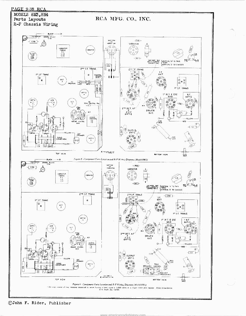
PAGE 9-38 RCA YODELS 8M3,8M4 Parts Layouts R-F Chassis Wiring
-I C29
BLACK 31
SMRC3MTL
AP
iRCCN
;mama HEM CII Ióer CIC
CS CA
VIBRATOR TRANS.
T -t L-13 C -3F
YELLOW
GANG CONOENSER
YELLOW
TOP VIEW
BUCK 31
VIBRATOR TRANS.
T-1 LI, C32
RCA MFG. CO., INC.
BOT TOM or
vURATOq
VOLINK CONTROL R -R
R
-L-11T11--
VIBRATOR
2"" DQT,A.F/
kV G. 6R7 -G
:.I OUTPUT. 6N7 -G
/ RN
GTIIOOE MY .NÍ TO THIS !AZ OSCILLOGMPN [ONNFCTg TERM m3
VERTICAL TO CHASSIS
1^ I.F. TRANS.
'DET. Q 056. 6A8
DRIVER 6J5
Figure 2 -Component Parts Location and R -F Wiring Diagram (Mode! 8M3)
1 I.F. TRANS.
® e
YELLOW
GANG CONDENSER
YELLOW CII C7 -CB Olt GREEN
2°n I.F. TRANS.
e
TERM. IRS
CONTROL R-8
-R7
AUDIO
TO T3
TOP VIEW
OrM VIBRATOR
-/e saw "rc cs ,nc
Cgs
cz C2S
BOTTOM VIEW
YELLOW
RED
A
VIBRATOR l5 CCA 00 \O%
11N7 f
"R 1.E TRANS
7 000
', (ìt
8111
SIM á0
tk4 / RN
2"a D` T, A.F/
A.V.C. 6R7 -G
L OUTPUT
6N7 -G
Go® Q
1
CATHODE RAY {VERTICAL 'in" TO THIS 04,,,,,G,,,,, CCNICCTIDMS TTRM
VERTICAL CrTO CHASSIS /
/ / -{ C40 I.-- / I.F / 6K7 /
O: u3
DRIVER 6J5
CO,'
° p O+ C
x
0 0 ©
1^ LE. TRANS.
1^ OCT. Q OSC. 6A8
? D :
CI l'JY
` R.F. 6K7 -G
C)---
- a
YELLOW
RED CO
TONE SPEAKER CONTROL
RED C4I
Cu C21 C41
SOCKET MOUNTING
Mai
BOTTOM VIEW
Figure 4 --Component Ports Location and R -F Wiring Diagram (Mode! 8M4) Re may consist of two miators connected in aerie having i total valued 1,000 ohms or a single 1,000 ohm resistor. Make replacement.
with Stock No. 14790.
ANT.
©John F. Rider, Publisher
www.americanradiohistory.com
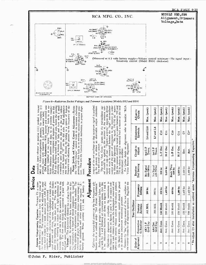
CG, 6V.
2V.(BM3) 6.7V.(BM4)
RCA PAGE 9-39
EDDELS 8B3,8144 Alignment,Trinmmers
Voltage,Data
SKT-G Cri. R.E
(Measured at 6.3 volts battery supply-Volume control minimum-No signal input- Sensitivity control (Model 8M4) clockwise)
2"^ DET. +^, 6RT-G OV
u0 GGc'^ 6.6V. (BM3)
roil BV .1 o )B.SV(SMa)
1260KC OQ
Y"s.¡.F.TRANSE
Figure 6-Radiotron Socket Voltages and Trimmer Locations (Models 8M3 and 8M4)
o ..,.,71
A O rs
áyya
v
Z
âyya
a.
re
Z
á66a11
va.
rti
Z
w ÿ
61
Z
âyye
a
Z
â{ue1
0.
Z
áype
Q
el
Z
âa
v 03
E d
N
O á v
á
00ú ra p
á
o Ú
., U
.oi
U ,~
tj )` U M
U
ó Ñ I. 7
< tTj
Vi
ry Cá v. aH
irY Vi
C¡
, ..
..H
N
rw
.3
Ñ o (_.
x
V,
w .a
w
ú A ¢
as . Ç . ú úN á.
A
íóq . Ç mg
z
ii l' te., n z
. 8
u
8.ag c F.
x`° a
o
e .,
u
o o ; u
o o :'
L. o
4 U N O3 m u El
>, u e V]
. É
tL
GV
u
m N g
.)8C
d ,-1
.Ç
V rl
.Y
2W
r-1
C
W r1
4 [
A Q.
F. ro O
..b..wi F
Ó
bi Fi
2 .y
wi F 22 ..
w
ti
.r, Fi
2 .y
b
2 .ti
b+ Fi
2 1-1
L.
>
R a coo
G4 g Ú Mc.c ¡,
b ca C C a
Ú
<
a
Ú
a
a a
Ú
<
a a V _
a a Ú
¢«
0.( V
2 ..4
N N M W .n <O t` 00
©John F. Rider, Publisher
www.americanradiohistory.com
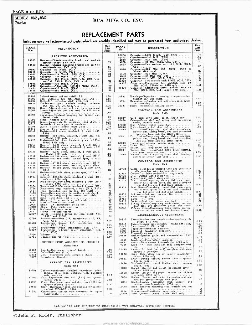
PAGE 9-40 RCA
MODELS 8M3,8M4 Parta RCA MFG CO.. INC.
REPLACEMENT PARTS Insist on genuine Factory -tested parts, which are readily identified and may be purchased From authorized dealers.
STOCK DESCRIPTION Unit List
Price STIOoCK DESCRIPTION
Unit
PriceN
RECEIVER ASSEMBLIES 30800 30303
Capacitor -1,000 Mmfd. (C29, C35) Capacitor -.0035 Mfd. (C28)
.30
.40 13789 Bracket -Chassis mounting bracket and stud as- 4838 Capacitor -.005 Mfd. (C20) .25
sembly-Model 8M4 only .75 4858 Capacitor -.01 Mfd. (C21, C26, C27) .25 13543 Bracket -Chassis mounting bracket and stud as- 13695 Capacitor -Two sections each .01 Mfd. (C33,
sembly-Model 8M3 only .65 C34) .80 30802 Capacitor -22 Mmfd. (Cl) .20 4870 Capacitor -.025 Mfd. (C5, C40) - (C40 in 13141 Capacitor -47 Mmfd. (C16) .25 Model 8M4 only) .20 14262 Capacitor -109 Mmfd. (C13, C14) .30 5196 Capacitor -.035 Mfd. (C24) .20 12404 Capacitor -120 Mmfd. (C17, C18) .30 4886 Capacitor -.05 Mfd. (C6, C9) .20 30832 Capacitor -330 Mmfd. (C38, C39. C42, C43) 4839 Capacitor -0.1 Mfd. (C15, C23) .30
-(C42, C43 in Model 8M4 only) .20 30828 Capacitor -Two sections each 8 Mfd. (C36, C37) 1.60 13894 Capacitor -390 Mmfd. (C19) .25 14902 Capacitor -Comprising two sections, each 10
11978 Capacitor -Adjustable -400-800 Mmfd. (C10) .50 Mfd. (C22, C25)Model 8M3 only 1.10 30433 Capacitor -470 Mmfd. (C44) .30 30829 Capacitor -Comprising three sections, each 10
14498 Capacitor -680 Mmfd. (C2) .30 Mfd. (C22, C25, C41) Model 8M4 only.... 1.30
30793 Coil -Antenna coil and shield (L2) 1.80 30833 Housing -Reproducer housing complete - less 30792 Coil -Oscillator coil -less shield (L5, L6) 1.15 speaker unit and cable 4.00 30794 Coil-R.F. coil -less shield (L3, 1.4) 1.45 9774 Reproducer -Speaker unit only -less case, cable, 30823 Condenser -3 -gang variable tuning condenser and mounting parts 7.65
(C3, C4, C7, C8, C11, C12) 5.25 13797 Screw -Reproducer housing screw .06 12882 Core -Adjustable core and stud for antenna coil .20 12006 Core -Adjustable core and stud for I.F. trans- CONTROL BOX ASSEMBLIES
former .15 Model 8M3 13996 Coupling -Insulated coupling for tuning con-
denser shaft .75 30817 Cord -Dial drive cord -25 ft. length only.... 1.25 13691 Filter -Antenna filter (LI) .75 30820 Cover=Cover shell and spring used on control 30824 Gear -Large gear for condenser rotor shaft 1.25 shafts, beneath knobs .15 30825 Gear -Small worm gear for condenser 1.25 30822 Dial -Oblong etched glass dial .50 13694 Guide -Volume control shaft guide .25 30818 Dial -Round etched glass dial .50 13111 Reactor -Filter reactor (L14) 1.75 30813 Dial Unit -Comprising round dial, escutcheon, 30540 Resistor -100 ohms, insulated, i watt (R17, pointer disc, spring barrel, and cord assembled
R18) .20 -less dial lamp and dial lamp socket 2.50 12281 Resistor -390 ohms, insulated, j watt (R2, R5) 30821 D:al Unit -Comprising oblong dial, escutcheon, -Model 8M3 only .20 pointer disc, spnng barrel, and cord assembled 14720 Resistor -1,000 ohms, insulated, } watt (R2)- -less dial lamp and dial lamp socket 2.50
Model 8M4 only .20 30819 Indicator --Indicator pointer disc .45 12267 Resistor -1,200 ohms, insulated, } watt (R15) .20 11765 Lamp -Dial lamp .23 12194 Resistor -1,800 ohms, insulated, } watt (R5) 30816 Socket -Dial lamp socket and lead .70
-Model 8M4 only .20 30814 Tuning Unit -Comprising knob shaft, bearing, 13716 Resistor -2,200 ohms, insulated, * watt (R19) and gear case -less knob 2.00
-Model 8M4 only. .20 30815 Volume Unit -Comprising knob shaft, bearing, 12312 Resistor -3,300 ohms, insulated, } watt (R10) .20 and on -off switch -less knob 1.30 13669 Resistor -22,000 ohms, carbon type, 2 watt
11646 Resistor -47,000 ohms, insulated, }} watt (R13) .20 CONTROL BOX ASSEMBLIES
12286 Resistor -56,000 ohms, insulated, t watt (R4). .20 Model 8M4 13715 Resistor -88,000 ohms, insulated, * watt (R9,
Rid) .20 13792 Cable -3 -conductor shielded tone and sensitivity 11281 tor -100,000 ohms, carbon type, 1/10 watt Resistor -100,000 30817
cable complete with 4 -prong plug Cord -Dial drive cord -25 ft. length only
1.25 1.25 Rl) .15 30822 Dial -Oblong etched glass dial .50
13734 Resistor -120,000 ohms, insulated, } watt (R7) 30818 Dial -Round etched glass dial .50
13698 -Model only
Resistor -180,000 ohms, insulated, * watt (R7) .20 30821 Dial Unit -Comprising oblong dial, escutcheon,
-Model 8M3 only .20 pointer disc, spring barrel and cord assembled
12264 Resistor -220,000 ohms, insulated, * watt (RO) .20 -less dial lamp and dial lamp socket 2.50
13730 Resistor meg., insulated, j watt (R11, R12) .20 30813 Dial Unit -Comprising round dial, escutcheon,
3584 -1
Ring -Retaining ring for R.F. coil shield .03 pointer disc, spring barrel and cord assembled
13472 Ring -Retaining ring for oscillator coil shield .03 -less dial lamp and dial lamp socket 2.50
13471 Ring -Retaining ring for antenna coil shield... .03 30819 Indicator -Indicator pointer disc .45
6129 Ring -Tube -shield ring .03 30837 Knob -Wing knob .30 3623 Shield-R.F. or oscillator coil shield .20 11765 Lamp -Dial lamp .23
14491 Shield -Antenna roil shield .20 30816 Socket -Dial lamp socket and lead .70
12008 Shield-I.F. transformer shield can .40 30835 Tuning Unit -Comprising knob shafts, bearing, 12218 Shield -Tube shield and ring .20 gear case and sensitivity switch -less knobs 2.95
11196 Socket-Radiotron socket .25 30836 Volume Unit -Comprising knob shafts, bearing,
12241 Socket -Vibrator socket .30 tone control and on -off switch -less knobs.. 3.15
12007 Spring -Retaining spring for core, Stock Nos. 12882 and 12006 .02 MISCELLANEOUS ASSEMBLIES
30796 Transformer -First I.F. transformer (L7, L8, 30839 Case -Receiver case complete -less speaker grille C13, C14) 2.25 -Model 8M3 only 6.25
30483 Transformer -Second I.F. transformer (L9, 30840 Case -Receiver case complete -Model 8M4 only 6.25 L10, C17, C38) 2.25 13109 Capacitor -0.5 Mfd. (C31) 12230 Transformer -Audio transformer (T2, T3)... 5.65 4293 Capacitor -Ammeter capacitor
.70
.60 30827 Transformer -Vibrator power transformer (Tl, 5025 Capacitor -Generator capacitor .45
L13, C32) 3.10 5023 Fuse -15 ampere .08 12236 Vibrator 4.00 30838 Grille -Speaker grille and cloth -Model 8M3 13711 Volume Control (RS) 1.50 only 1.15
4290 Insulator -Fuse holder insulator .02 REPRODUCER ASSEMBLIES (72684-1) 30642 Knob -Tone control knob -Model 8M3 only .13
Model 8M3 7766 Lead -"A" lead (ammeter end) complete with clip .40
12482 12450
Board -Reproducer terminal board Coil -Field coil (L12)
.50 2.00
12445 Lead -"A" lead (set end)_ complete with male section of connector .26
12451 Cone -Reproducer cone complete (L15) 2.00 13806 Ring -Soft rubber ring for speaker mounting - 9687 Reproducer -Complete 5.65
30811 Model 8M4 only
Shaft -Tuning control flexible shaft - approx. .60
25} -in. long 1.20 REPRODUCER ASSEMBLIES 13926 Shaft -Volume control flexible shaft - approx.
Model 8M4 25j -in. long 1.20 12248 Socket -Bracket and socket for speaker cable -
13794 Cable -S -conductor shielded reproducer cable, Model 8M3 only .25 approx. 18 -in. long, complete with 3 -contact 12502 Socket -Bracket and socket for tone control lead male connector 1.10 -Model 8M3 only .30
13795 Coil -Reproducer field coil (L12) for speaker 13804 Socket -Bracket and socket for speaker and con - marked 72947-1 2.25 trol box cables -Model 8M4 only .45
13796 Cone -Reproducer cone and dust cap (L15) for 12254 Stud -Speaker mounting stud, spacer, and speaker marked 72947-1 3.30 washer assembly -Model 8M4 only .45
30834 Cone -Reproducer cone and dust cap for speaker 12448 Stud -Receiver mounting stud, washer, and nut marked 72947-22 (L15) 3.30 assembly .45
11984 Connector -3 -contact male connector for repro- 5024 Suppressor -Distributor suppressor .40 ducer cable .35 12249 Tone Control -(R16) -Model 8M3 only 1.00
ALL PRICES ARE SUBJECT TO CHANGE OR WITHDRAWAL WITHOUT NOTICE.
O John F. Rider. Publisher www.americanradiohistory.com
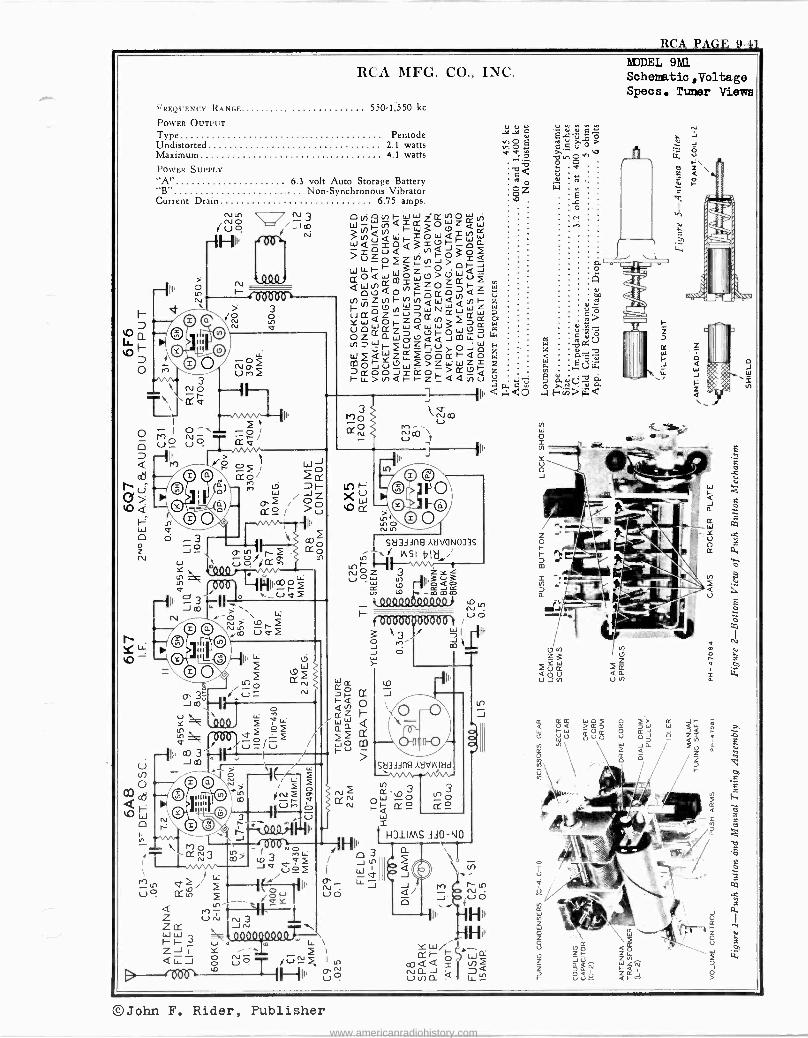
RCA PAGE 9-41
RCA MFG. CO., INC.
FREQUENCY RANGE 5501,550 kc
POWER OUTPUT Type Pentode Undistorted 2.1 watts Maximum 4.1 watts
POWER SUPPLY "A" 6.3 volt Auto Storage Battery "B" NonSynchronous Vibrator Current Drain 6.75 amps.
212 N3 0,/i V H WW Z tY V 0 W V _m LL-yt=CC OWZáWp NQ -H11, Q=ó~iaWw UJFOa
5=2 04 Q=áÚOZViO i .000
W4-F-~WZO OQ iQOQWQf1ViWO>ZWf i
0 CM H If'`~ 0Óv N OOOQCfOÑa
C -zUff- NA upe NH z 4 l_NOWNWw Yz3-iY ¢Wew lÓ ó ÚÓWZWQWjrP >WN
Oz CI- WáUQQtDliu s.
cc
N=L2WJuyOJp Mu-12OJÚOzW
>zWWzxx
r z 10->VOiQÑz~QQV1ú ?é
1 ]---111I, < ...1.<o
oo Wó Mo/ 2(: M
W F- M / Z X O > VCY
o Nto Q,O tn¡., v
N S N tQ \ u 1
1. J
II
0 Ln
Sä34lf19 AWL/014033S
WSI-17121..i
úÓw ,ñ ;ú3 is)
II' o a o L.0 _mmm
i =: 0 ... S CCp 3r, r Jm,ïï-11 , ra
Q
1%;9 f Q ` W
vi rrfr)r î f a tl LO
u: o2 re\ % ÚrPi NMn `, N O .---I i____
L,2 '-'snuvv`^-'-111.
- ÚD Ñ / Ltt
W
.1v11ûç/f / î
II' /< , u u O © a / 4 î
CO -O ^' > / Z ó 2 o
ON d } N e ©"'' e il "M o N
0 © e o .4-00.0 Milli- _ 4a6--~1H11. /
I' 3 vi / u'i Jv/úº
I W t7 e lÓ li Ñ L J u cc in ___ rcr uO
/ Li o
-1 Z Úti N3 Jru W W \ I- F- 3 u < m W Z J i Y ,-- 4L_7_,QIi G úo fCJS 1 in
B --'f 006 `° Hill '23 ó
f 6Ò680906ÖÙ0 ì /u0
J O }
`7 3 rt ®W
1/40O
-á CC 9
H31IMS 330 -NO
MODEL 9M1 Schematic, Volta ge Specs, Timer Views
41>
< H.
Z Q fu
©John F. Rider, Publisher www.americanradiohistory.com
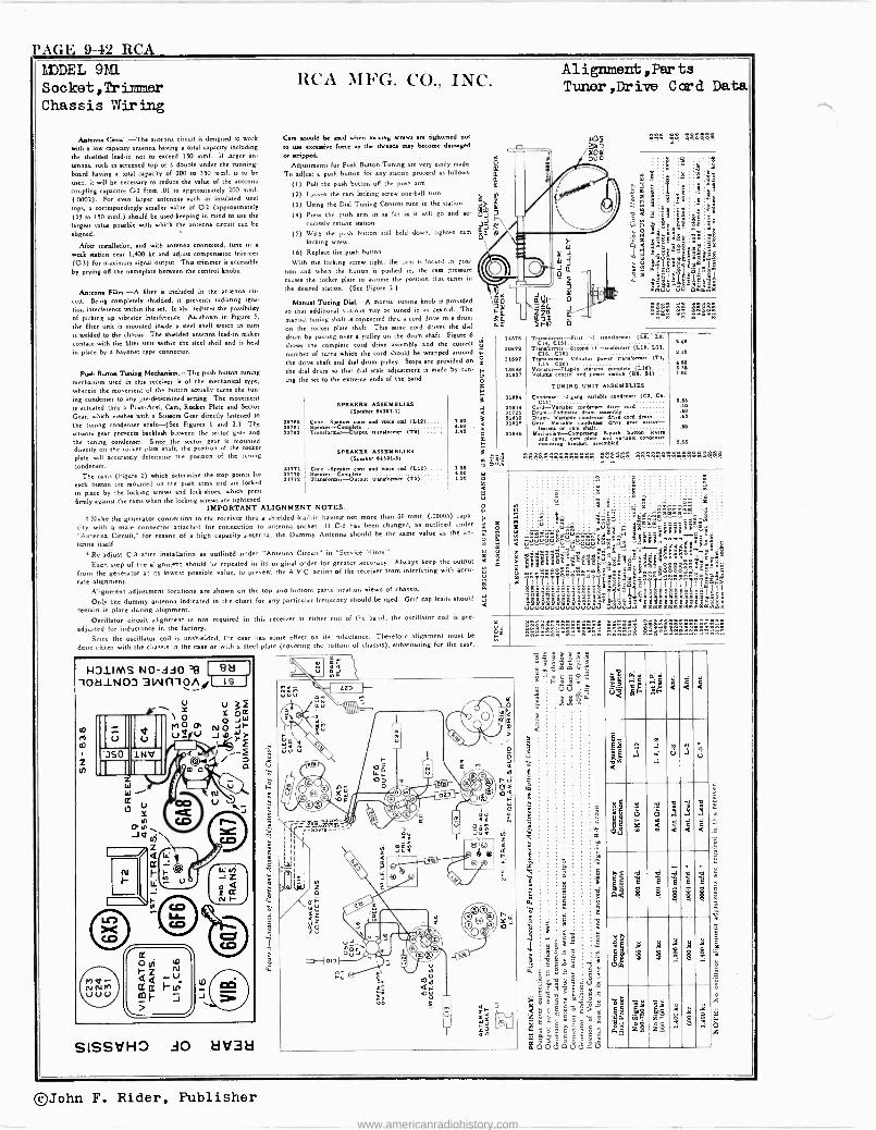
PAGE 9-42 RCA EDDEL 9N1 S oc ket, Tr iin ner Chassis Wiring
Mumma Gres: .-The antenna circuit is designed to work
with a low capacity antenna having a total capacity including
the shielded lead-in not to exceed 150 mmf. 1f larger an teams, such as screened top or a double under the running -
board having a total capacity of 200 to 550 mmf. is to be
wed, it will be necessary to reduce the value of the antenna
coupling capacitor C'2 from .01 to approximately 200 mmf.
(.0002). For even larger antenna such as insulated steel
tops, a correspondingly smaller value of C-2 (approximately
125 to 150 mmf.) should be used keeping in mind to use the
largest value possible with which the antenna circuit can be
aligned.
After Mutilation, and with antenna connected, tune in
weak «ado nur 1,400 kc and adjust compensator trimmer
(C-3) for maximum signal output This trimmer is accessible
by prying off the nameplate between the control knobs.
Arden= Filter.-A filter is included in the antenna ciri
cult. Being completely shielded, is preven radiating igni-
tan interference within the set. It also reduces the possibility
of picking up vibrator interference. As. shown in Figure 5,
the filar unit is mounted inside a steel shell which in turn
is welded to the chassis. The shielded antenna lead-in makes
contact with the filter unit within the steel shell and is held
M place by a bayonet type connector.
Pass, Button Tuning Mecluni.m.-The push button tuning
mechanisme used in this r of the mechanical type,
wherein the movement of the button actually turn. the tun-
ing condenser to any pre -determined setting. The movement
is actuated ehro a Push -Arid, Cam, Rocker Plate and Sector
Gear, which meshes with a Scieson Gear directly fastened to
the tuning condenser .haft-(See Figures 1 and 2.) The
scissors gear preventa backlash between the sector gear and
the tuning condenser. Since the sector, gear is mounted directly on the rocker plate abaft, the position of the rocker
SPEAKER ASSEMBLIES plate will accurately determine the pouuon of the tuning (Speaker 04301.3) condenser. {1,71 Cone-Spmker cone and voice càl (L12) 1.25
The cams (Figure 2) which determine the atop points for ei,vt Speaker-Complete 4.00
each button are mounted on the push arms and are locked 3177º Tr.nsioewnr-Output traulormer (rº) I.»
in place by the locking screws and lockshoe., which press
firmly against the came when the locking screws are tightened. IMPORTANT ALIGNMENT NOTES.
to.
t Stake the generator connection to the receiver thru a shielded lead-in having not more than 50 mmf. (.00005) capa-
city with a male connector attached for connection to antenna socket. If C-2 has been changed, as outlined under ss
"Antenna Circuit," for reason of a high capacity antenna, the Dummy Antenna should be the same value as the an- m
tenna itself.go Re -adjust C-3 after installation as outlined under "Antenna Circuit" in "Service Hints."
Each step of the alignment should be repeated in its original order for greater accuracy. Always keep the output t from the generator at its lowest possible value, to prevent the A.V.C. action of the receiver from interfering with accu-
rate alignment Alignment adjustment locations are shown on the top and bottom parts location views of chassis. o.
Only the dummy antenna indicated in the chart for any particular frequency should be tided. Grid cap leads should
remain in place during alignment. C
Oscillator circuit alignment is not required in this receiver at either end of the band; the oscillator coil is pre -
adjusted for inductance in the factory.
Since the oscillator cod is unshielded, the rase has some effect on its inductance. Therefore alignment must be
done either with the chassis in the case or with a steel plate (covering the bottom of chassis), substituting for the case.
RCA MFG. Co., INC.
-a m
SISSVHO AO 1:1d3a
Care should be used when locking screen are tightened not
to use eccessive force es the threads may become damaged
or stripped Adjustments for Push Button Tuning are very taffy made.
To adjust a push button for any cation proceed as follows:
(I) Pull the push button off the push arm.
(2) Loosen the cam locking screw one-half turn.
(3) Using the Dial Tuning Control tune in the station.
(4) Pees. the push arm in as far as it will go and ac-
curately atone «anon.
(3) With the push button still held down, tighten cam
locking drew.
(6) Replace the push button.
With the locking screw tight, the cam is locked in pou.
lion and when the button is pushed in, the cam pressure
causes the rocker plate to assume the position that tunes in
the desired station. (See Figure 2.)
Manual Turning Dial. A manual tuning knob is provided
so that additional stations may be tuned in as desired. The
manual tuning shaft is connepted ehro a cord drive to a drum
on the rocker plate shaft. This same cord drives the dial
drum by passing over a pulley on the drum shaft Figure 6
shows the complete cord dove assembly and the correct
number of turne which the cord should be wrapped around
the drive shaft and dial drum pulley Stops are provided on
the dial drum so that dial dale adjustment is made by tun- ing the set to the extreme ends of the band.
30762 307.1 30733
SPEAKER ASSEMBLIES (Speaker 8{351-1)
Coone-SpesksrWpkclt e and wire cuit (Lt,º)
v'r.esfarmei-Output transformer (Tx)
1.10 4.60 1.46
Alignment,Parts Tunor,Drive Cord Data
wO4
-!I óÓ
14396
30609
33as,
3143,
31104
31735 31610 31612
33466
sga
Transformer-riot id transformer (L6, Lº.
C16. C15) Traoafonner-Scanne N transformer (LIO, L11.
Transformer Vibrator power tramiormw (Ta, 116. Cº6)
Vibrator-Plug-in P
complete 1 Volume
vibrator srib (ß{ as)
TUNING UNIT ASSEMBLIES
caddied-º.sans .srisble condor.« (C3, Ca, cn)
condenser drive Card-Venablecord ..... Dorm-Indien« drum maemblyns
D Vnsbiu condmaer dun cord drvmt«- Gla .a onbk con
man fié driva gear
r«drams. cam we sait osoable °c date mounting bracket. awembled
con d.»
8.10
{.86 3.24 1.00
s.a0 .30 .a0 .a0
.50
9.55
.eeaee .. gArigAgrIMAMIg
L
Ï
o
z
YB.
...
l^à "AJ :
r úil±
. . .
; e §§gees' aga
.ñSg
IIaIIIITIIgoM> IIlIaarorara3oaa
úúúúúúduút;úúuuú u t§u3.3 L000000000ñ $m
M
Ód :
m S zu e..seseew.. .n.........e esewww$rr weS::em
é g ,win^
E 3 7
U 3 D
80 3 C
Ó
tl
ó ºtl á
0.
JI
i .11Q á
ó3 c.9 :=0.
8Q tÓ$ $ m r 8
©John F. Rider, Publisher
www.americanradiohistory.com
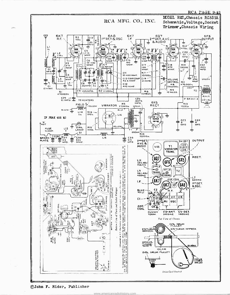
RCA PAGE 9-43
.I
Ó
CZ .01 MED
2R CI
12MMF.
6K7 R. F.
L2 1.256
IC3 , 2-15
MME. ,
R3 1506
SUP
C13
.05 1vIFD,
CS 2-15 MME.
IL56.5n
S
R
C6 10-430 M M F.
RCA MFG. CO., INC.
6A8 6K7 15T DET &OSC. I. F.
2
LB B6
100 MMF.
2' SMMF,
YV L9 { B.
C
R A E15
100 M M F.
A C4
I 8 1 -1 C1,
I SbXZ T`1\ 10-430MMF. 10-430 r
L3 MME l ¡ C12-TEMRCOMP
0.66 J/ L147.SMMF.
e L4 Cg = L6 '.-r___- __,..
_ CIO .05MFD.1 3,. L L7
O / X,= Tn 470 MME.
C9 -.o25 MED. R 2-22,000n R1 470,0006
® C16 100 ^ MME.
C17 100 M M F.
R7 - 33.00061 C19 .01 MED
R6 1.5 MEGS.
MODEL 9bi2,Chassis RC357A Schenatic,Voltage,Socket Tr immeer , Chas s i s Vlf ir irlg
6Q7 2N0 DET., A.V.C., 1 &AUDIO _
LIO di LI1
°6
BA $ OPI O
2 C18 470 MMF.
ggggggVOLUME CONTROL
R6 250,000
R9 IO MECS.
1 R12
470..
C20 .01 MED)\
RIO 330,000
i
1
6F6 OUTPUT
i w
C22 .005 MFD.
C21 1 = 390 GREEN
R11 MME. 470,0006
RED fi 450n
100000
C29 T 0.1 MFD. Z TO HEATERS
FIELD ti -YELLOW
111 BLACK -
L14 56
IF PEAK 455 SC
HOT
FUSE L13 - DIAL ISAMP. + LAMP
SI
RI6 -..- 100 n
R15+ Io On
VIBRATOR R5
27,000A
SPARK 1CZB..L 27 C- 30 PLATE = 2 0.5 820
MED = MMF.
111
LIS
Ti
C25 .007 5 MFG/.
GREEN \1
6656
BROWN I
C26 = 0.5 = MEO
^ r- 15
uÑ
U
111111111 r r , e m
ap U
K. =` o
Wa wU Ñ'i8
w
0 p0
YJn a UUJ
0 a r áBó r Q ó Nti
O
©Ol. O
á~ rç W
tg I
Ec
c 9t °9 74
xt ©^ (I,I o^;o
fj
1(`l e
G R
, °i Wg á E $
(a p _1
ç
g E ,z, . a ,,
-r a tee 4IC
Ño 72 gw
y I9 y
a
J o
'_p c`
O ( © o O a º- 1
&
N fi: O
J ame
U m? 09 s 3 ó- :E
li 1 ó NÑ m
mS
'01.,:,1%
. . a eLL
pp >
-- ó f '
©r - o HI 1'y . , O © > 7
i Liz' í®
r ©" 00 D O (e L m
_
a
. 8P o t co ' 8
. g tS-
, s> N Oa
.0 OU
Jz Q r r 2 0N w 2';,, O \ tñ
u ?el rfy-=}i
-
9Lÿ
5 XE
of f.
òÉ
elk TURN3 APPROX.
MANUAL TUNING SHAFT
IDLER DIAL DRUM PULLEY
6X 5 R ECT.
T 2 -- 0008 BLACKr
P -8436I-3 112'2.86
R13 1200n
RI4 15,0006
2NODET. A.V.C. &. AUDIO
L1I SEC. ADJ 455K
C23 I8 MEO
L9 r SEC. ADJ. 455KC
I. F.
BLUE _r TO Ll
C1 --
6Q7
2M0I F.
TRANS
6K1
CZ
T1 VIBRATOR
TRANS,
CD 15T 1.F.
SN -837
C23 ELECT.
C24
T2
TRANS
3 OSC.COIL
ANT. ---'19r Cg
tI COIL =L
DUMMY Cm -ANT. C5-DET. TERM. 1400 KC 1400 KC
6K1
e l
Cil
OSC.
-i
6A8
Top I'icw of Chassis
DIAL DRUM PULLEY eVE URNS APPROX.
1 I
C24 B MED.
OUTPUT i
RECT.
- L7 600 KC
15T DET. ficosC.
- i
Drier Cord /lookup
DCÓIPGD oleUM
©John F. Rider, Publisher
www.americanradiohistory.com
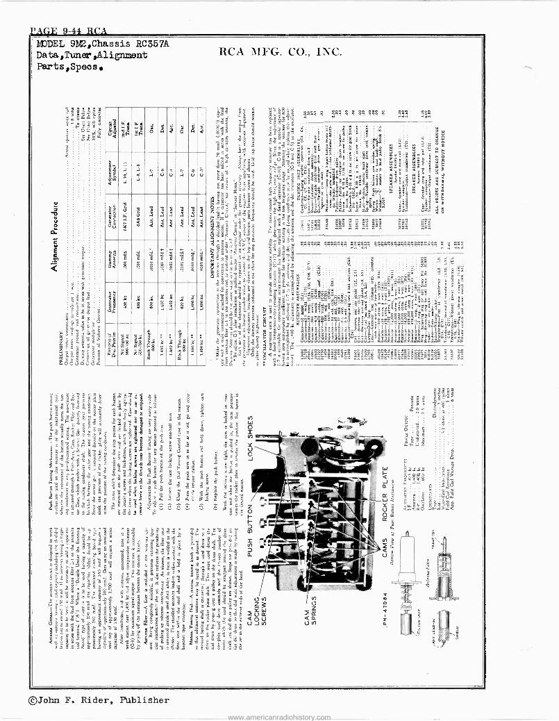
,AG1E 9-44 RCA MODEL 9M2,Chassis RC357A Data,Tuner,Alignment Parts,Speos.
Ill u á h
r ó ó g c
g8
ól <
.1
4 .i
S
á .i
y
o '? ci .i
yu o
o
g go, k m
gg
.3 yg
.3
<
gp
.i q < <
. q <
yp
.1
q <
r77éIé777 "8, i '8, i 's,
..w
á 2 ç 3 $ $ § $ $
b c5
£ p,Q
ÿe- 3
2w
$ inn 0ö 2ñ
m óo syº F3
ó a
: i 8 .,
: i . 030
sy rg
: áç
X
: iç
i
i. 3
á É
a a
g
1. 1-24323 a
i
o m- v ó i: i 00 '
o d .1-4.11 é n
e
i î 3
ñ mo " = a '- _áó édié r$5
ÿ i 24 c3
3 é c i !! g" ó ° m c
/C .
g é Q- Y i F , 5 á 9
p> Kg. "w i5S50i i ó <
3 . rx ámgfa aaa x m;e .,m
é= ás ' i
;Hai 3ää Féx. 9<i- ., ., .. _ é w..S Fv
RCA MFG. CO., INC.
r
ww,3wä t3 ;
st9ó 3óón3 á `
e
:92g.à7'E2éé.. `éeg yD'39ÿá 5wé93w`ga =Zñ_i.2oeä 1 E =":ói '
=iógç7é =3" 9a=. es zsS é9 w=8góë ; =.aé Faá3
., ,e ;c1 .-.-á3 XÿáówXSq'w3 9 E é u i w S.9 v ̀ .3a
2= é é é
- ^ Y. w g Eâ e b.s - â w7 n Fm-_32ers ""s=_1.. Ì236ö1:ó9é un
sÿ33.:.g1`e a1e$°é «g`úE g hi J 1
S " g 8?$ ñg 251-,1 s s:c 8 d =º ú 9 ï ó s 1
Q 09 g gs w "`á ¿ ó Ç ó é ._ 3" w v= U J tn gsä.Êÿ.éw=w . mmF-_i es9fg
' i " a v 9 á ó.s
á g é< E e á é
=
a S3Er1,: 2316 á..i Báó.sS S"69vwg:33
wAeneo n 'w'gww,ááe`e,ááwwg`0,ááéóáá'w, ó é +ÿ
.."$ w"w .,.." ..w wmwH" w..., ..fi.............. ww1 ., " ..w
lée E
©John F. Rider, Publisher
www.americanradiohistory.com
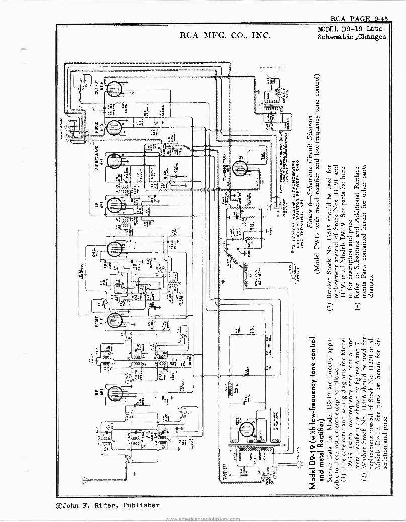
RCA PAGE 9-45
RCA MFG. CO., INC.
';u
ax
J
tl g
xé>r
-------------- ------ .R 4
age
Ñ
%,r -If 4 e s AÌ
re -.t R2
«yp .r. ̂ .ei hi
W ÿ ,s; L7
^p4
e
áz
1oY 9,.w
Ok
I-
L c x FF OOPl Xa
-IF-ó 7.1Ó-11-.7h o m
)11 .W
24
aR;
I
°
R Ai VA
< J
J *
15: Z,
d
T-ter~-1,
8 ì
ef;;;171 M JQß
or
Q
ti
44.
e 0000000
I 10
I
NODEL D9-19 Late Schematic,Changes
ó
o u
o
e ú e2 k.. o, czt)
q w w 3 S i º
v é ed c: ºw i ~i `d d ^ á""W ú. o
ea ^ , y (,) ,, y .. v,
, o C O ed
'CO) o a .2
E -ß s.. `.2 .G . Vi "0".C1 ..C.
O;ar2 u0 oi < íu.
L i/) á
' C b . on v aC
COAÁ
ó zÿ.D"" No°Ñó ..x E >á,u
"1'Z ` > Ñ
73h V)
CO 41 v,
4: . 7 : g C wwd`,a CO w ..5. c4 E ú
o 7i. -12) C r W «1b CO
CO ..eó .b 7) CH U . ,.Fi..i,i ÿ O v.0,
d ú w CO
,0N.N-. C C CJ,... vi u y r-, u N.í.uO C0ó
oó zú 1.4
ty Ri V]
mb .,..c : oQcd1
ó Q.--,
n adòNv x 5 ,c -ó
" -. b Ñ Ó d io C C z° d i+ s _ly E. aa'[o;aU ú
-a Ñ5YvC o
v e ú o,Q cd
rd.[ .a s- i... E C .-titi 4 CO v O O ` .4 u N. i
a .,rd r.
u> '-'4')
., .-. <
C ÿ N .-4N G
O cop ,1,,i
v cd u
©John F. Rider, Publisher
www.americanradiohistory.com
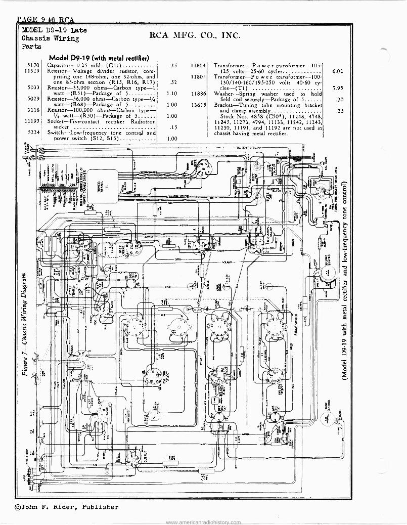
PAGE 9-46 RCA MODEL D9-19 Late Chassis Wiring Parts
5170 11329
5033
5029
3118
11195
5224
>
ö; C'
t a
s3
RCA MFG. CO., INC.
Model D9-19 (with metal rectifier) Capacitor -0.25 mfd. (C51) Resistor-Voltage divider resistor, com-
prising one 148 -ohm, one 32 -ohm, and one 85 -ohm section (R15, R16, R17)
Resistor -33,000 ohms-Carbon type -1 watt-(R51)-Package of 5
Resistor -56,000 ohms-Carbon type -1/4 watt-(R68)-Package of 5
Resistor -100,000 ohms-Carbon type - 1/4 watt-(R50)-Package of 5
Socket-Five-contact rectifier Radiotron socket
Switch-Low-frequency tone contrgl and power switch (S12, SIS)
.25 11804
11805 .52
1.10
1.00
1.00
.15
1.00
11886
13615
Transformer- Power transformer -105- 125 volts -25-60 cycles
Transformer-P o w e r transformer -100- 130/140.160/195.250 volts -40.60 cy- cles-(T1)
Washer-Spring washer used to hold field coil securely-Package of 5
Bracket-Tuning tube mounting bracket and clamp assembly Stock Nos. 48:58 (C505), 11248, 4748,
11245, 11273, 4794, 11133, 11242, 11243, 11230, 11191, and 11192 are not used in chassis. having metal rectifier.
i r
3
9
s
.n
19
il
9
_ANICOM.
4 e
N
M.
M. t2v,a-1L1w
E
l.,0w-5M10
m.
- s-
.o1..
M
CC
ag
ei
L
L -
o
.1 T.
4t
e. cR
yS
1.5
i
e .,.
wan.
s R
AMO
igg
I
;
rdD/
i(
I
1
w
8 I '
MOM
6.02
7.95
.20
.25
i
M
E
©John F. Rider, Publisher
www.americanradiohistory.com
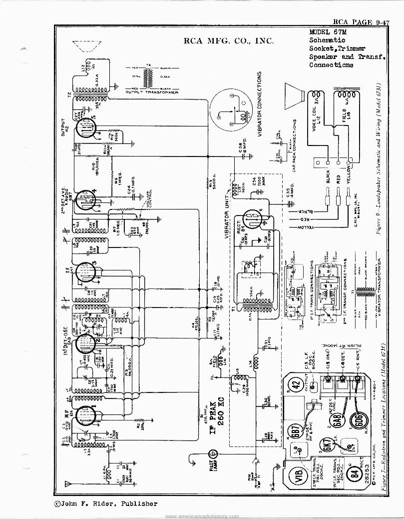
RCA PAGE 9-47
N
7
'000000801)0` ó{ NI,"
P!r Q_
p,
REO
304.
REP .LACK OUTPUT TRANSFORMER
RCA MFG. CO., INC.
q
08 ä° ô m
PW Gf
/ >U
d
li 1www
-L-
[
.0000040000i áo Ale 000Ó8006ò6`
ÑwF Ì V 1.4
'2.e4
.E u_
y ooe
I . I
T N 71y1 OI'
AF TOóF OQ9Q9QQQ9 Iut.E
1,m'006Ò0000 1
\ ffe tä Í
I<
IL
0 o O
11
e es- -0 --..rF -1
({). 93 0.
uro IH"
e
?"1 II
0000Q90Q9
r J °T86ó <
Ó
áÿ
or
f
T
e
MODEL 67M Schematic Socket,Trimmear°
Speaker and Transf. Connections
u
O J ó J W } W
¢
2f-
3 e aE é
É F I
tiñ 4 ó i m
O j ;
W m n
I á
Ou e0
z 2 O u
'77IOOIÓI l L.: ù
N%I1 ki iù F
JÑY el 0 o ¢
OQIn n Ln
u, 0 u u V ,
I- p I
7 O
IIIIIL:A [1 ("11 U'J - /
W
rM VQ N W o
21d. LL NQ
'(I
0
02 U2 Q co
r -
u C (7
N e
2
©John F. Rider, Publisher www.americanradiohistory.com
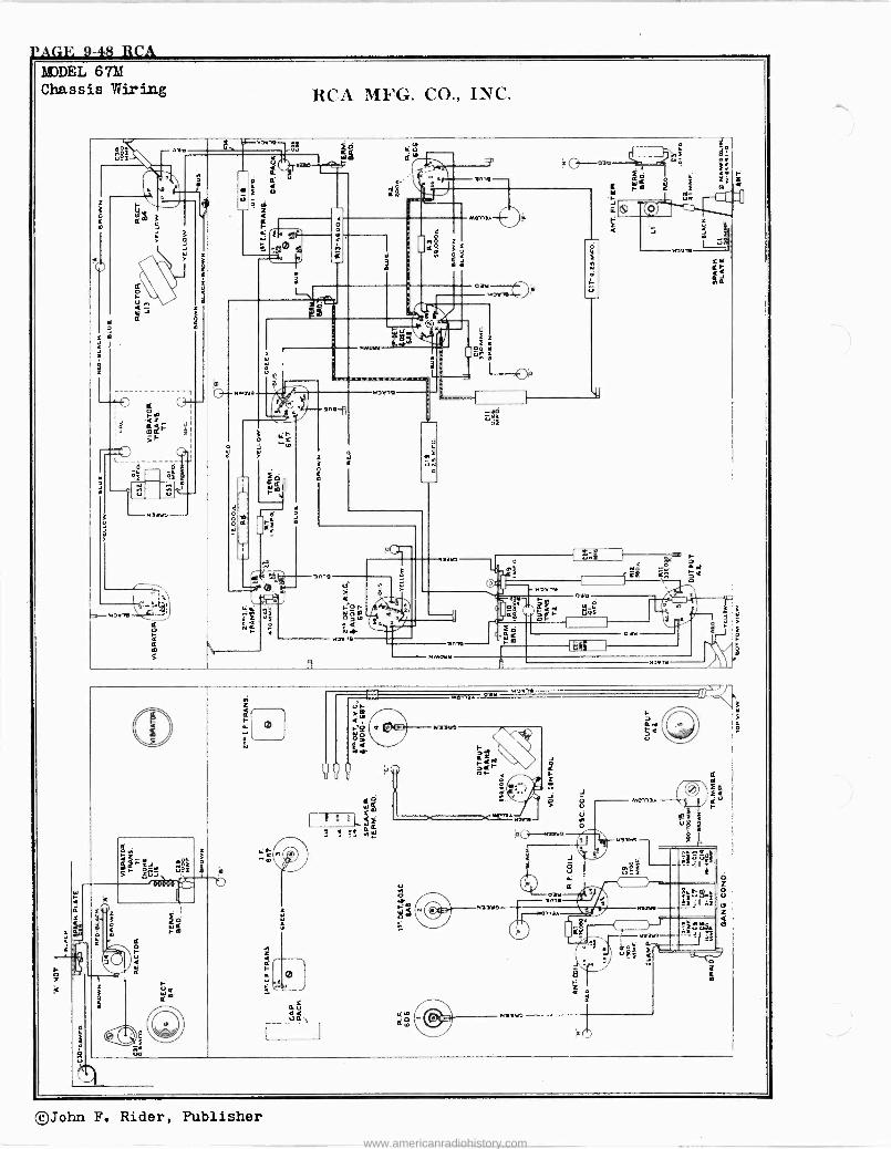
MJDEL 67M Chassis Wiring RCA MFG. CO., INC.
2 . 55, - os r pUgé C 8
- .mm ei lF -< Or u e W
-a, F1.1n
á` s; z '
4Y anna- i ,. ..o
Fo c ú m
iQ
r1;
z< o
j g < 0113/ F
_ tl ; H i v` m
e
A 1° O ` . Sl Q Ñ á F "oe,v -
Q m m i i f
n ° 4 Q O W 02!1,...7---32 ^ -
.`I 7
r
i r ó:'
m .
tl ie i z r S m
á yy
3
" E`R `We -0ó e _
ID
L Q--"MOYm r21,12
¢o ` `Z /
. p
vn. _.-.r
_I -cti i. -.1.i
mm0 L___
o
el^
m¢
.
R
ú
ç
r <
Ó
W
IaY
R Q
tl
o W
Q
I
IL
F
uÑ ó
"aarv á n ó
rÌ _
( úc F
V!4 é
MaaY° 0 wW
F 6á
K$ am. `ñ
-A 0 +-- u " al >rnv i - ,- , , !-
/12V -v .i:p ? Fo1' ñi .
o `.~mb o F g j
¢ °< è` 6 v_ó ut ce a
Fr ¢ r rc oóW
m n lLep
j "M W n 3ne
w D'e-11. , If/ M..naA OiY , ^
¢o
c v: 0 < r
u nt C Y
o
m l f4 p raare - f o'd
º
> ¢
t ,
f' c ry
1 °
r 7M =N 1 OF 4
9 , Li' J g f u
It r O ià
6I ó élrNM n w W f p U 8
? :! 5;:e2 ú eQ
; . e9 3 Yaro I a. P
3M á`_ _f
F li
b
O ÿ b g
y
8Y P FF
u F
n t
_.^I9 Rf
4
,veÓao¿ C ; C z
á I, ' i : i :`sF ªs1B:F
ú
ó z I z W. .: "aaw.w
Q ..nna. .......
Z Y
z W Op
i, ú Ç i súúg4 V á° ó m r.Y
F"u%-:n- F
r F ,\YJJJá
1
=
L I- »
~
0
-t 6 LOQ
..2. F C.:
e u ̀ ..r r
0 °
0 ULL /422.V
N
P úò
©John F. Rider, Publisher
www.americanradiohistory.com
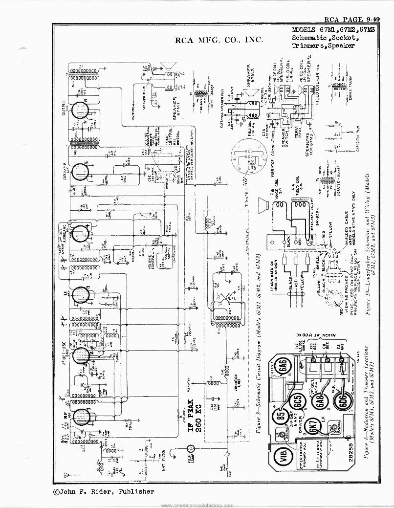
RCA PAGE 9-49
cco
000000
RCA MFG. CO., INC.
y'. ii"3s .,.ni \
12 1
, 1 - á`: y. LL' 1 N Ot
l' ti -- bi fN0
z
i3 it á ú e......1ä....` . W
ú.rOÓ °'F y[ -a 3 L ßr J -t--_ i.4
N f"""-IJ =F I ^ 1 : sr ó
MAN,. 1=
MJDELS 67M1,67BG2,67I13
Schematio,Socket, 7r immYer s, Speaker
g. NF 1 l{ _J
24 V
z <
ó
s
-moue, 6
º1F- -ql /
b o °FIQ `m r IS = O Z
u WJ `..
O á roM < .- N.,
m c ç â^ y
J W N _ e K O O T
WWQQ ;`. tl idi -1 . Ñ \ Z 1
\
JU'Ly d 2. ! ú áÑ 1-;`r--.eo
nT^ 19Uÿ
sg. ó; ówI
ÿ'm\ .. á oacf
\1'hu Z 35 .- L - ; Uá x
cm 7z ¿i1 LLú LL,
3)1001;1 1V N9IIV ú
Nó>< U
N ÿ mÿ O V p V V c
©John F. Rider, Publisher
www.americanradiohistory.com
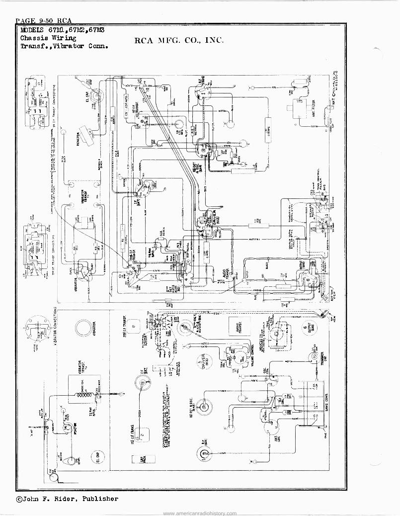
RAGE 9-50 RCA MDDEIS 67M1,67Md2,6711V3
Chassis Wiring Transf.,Vilratar Conn.
©John F. Rider, Publisher
www.americanradiohistory.com
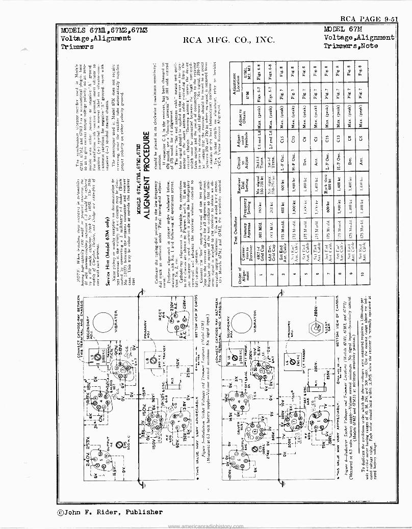
RCA PAGE 9-51
MODELS 671,11,67112,6712 Voltage ,Alignment Tr immer s
RCA MFG. CO., INC.
=ló9*-9,g .v 3 « >'öó. '8-'3 3 ú 3 . '> z ó c_ .ÿ .. o
o ó, a éc c " e ¿, ñ ÿ c- -;:f..9.7312 u ñ. m«e`+
v .2..?: .!7Y^«.t °
'EIS.:<'22.:4: .
C , mR a..
Q ...c 't 6tz ó . mu c1m«'.. v ú.>^'- ° 'ñ_>-.çóó i° E
ÿó Eû^Lozu- ..Ó Óo. ÓO. Ç á F° °:ÿ'sâó.. o -
.G1 Cqóiñ bñto .e. 'Ç Á.L.EçE.3Zmÿe.
ÿ« ó!° ' vá m > ú' n«ññ úòis°= Ci Y O °> Ó.°. '3 YCC .0....r6.;E Ó_Ç
ñ
> ,ñ. A x mÿúu m .cá:._eñ.eá ó >.eñó.eu.Escñ.3ÿca
C._ C ^ Y'Ó ÿÓ.Oy'^Cç -o 21'.m. Eqv o'-' ,_
C ° ÿÿ..Q ç Y,íOi A'ÿ ?e $'-á °uu W .E eiç ó' SLcr.._u oy.. 3ceE e GC m úñ z'E _..
Qw ú' c ÿ' w 2.,..:: . u V ..uo. ¡n
h u m
c^ s C
-5,-. uº .. c_ My = «m= ,Oÿ.iÿ ú- [+ 1 _. ÿ^N L ° O O e.%.1.22+11"3 Lr W 'M.ê eeua-c '^ vvo3= If ro .i ÿ o.E «eco Eue¿"y> uÇ> ,C -ne. N O C.Y^_ñie.ÿÿ°S^3RCÚ swä _
g.:-.. s u d g.--4.-.- FuY'_.u°.°: vC F°,
Er.° áé (".t..,.1 . úá Ó A:'AEÿm x . d
SJ ái V
2 h. - Z
c
.1A2 ÿ« i 9av 7gYm lial Z.^Ñ4G ç.".0ú ÿr¡
D =ÿÿñaTÓoáv f-I5J. OEó"N1 (3 O.Yym0 C.+ mm
ÇóK
3..
. ÿd_^ ^ .c O.(;a`O2 'Y Fe
0.2..o ócs amr :J w ° ç ç -`r °3-«O
OOC
S ^; Oÿ ç t.: _çÿ -l'N r: ^ 51Y9 °>.e,,eñ0
0 e0z ^ -Yÿ!'
ú ñt çiN_ t^O0
iiel -0 a" zrY Yó «iáa > ç p n e Ú.ÿ C. Ñi u c_.; u ñz = Z0
fr o
z m o 5
.ñi.
I t . i ci O .'+a .tOu N
Wm
> Q .d
a ©© fo ñi .>mQJ \
\ T t1 1 N I 7 7 (j r> I w
I f Ú=> O.ÑóP1n T62.
--'''-'''.1
O CO Ú 1 0 C%`
;1 4h O u á
e- ): ; ' NI óerl
ï---1 o O3 A I
D4 1
---1 1°áó .>oi--J . 1ñ.a
t7 1 ,' L>_..n-
.m Q °3 ;;'e.> --°----1' 9 v f- r
1 ©OI
1 L-1 I -----07 1
. -----J
> U M G
Y
.U+-- iQ `lYû w m
p H O ---1 O
© > 1
ho o 1---4 m I
: t
.r--§- `M r --1,0,--
¢ N . o
> af r ,óá ---g- I -- al Imm
m Ó-r1Ot*,(tu -
1 I l:`'
)O 0 I n > I `,rr - .o HQ Á')
a 3 I iJ i
...._"_> -ú1 ¢Ó1 -m > J ml > ----o- Lm----
p,
MODEL 67M Voltage ,Alignment Trimmer s,Note
ç ç E'=
ro Ió 0 .7 a
e rL
'
L*.
ro
W
eb
R.
eó
W
m eó
ÍL
*°. e
GL
m eà
[>.
m m rL
eo
m rL
Z Ñ
m w
,, ,,,
m 'w"
n ro
w eá
k.
n ro
'w
n eó
'r."
e. eó
w
r m
w
n m
ir.
r ei w
gR ' 'ä 9O a
Ñ á
X
X
Á á
X
X
Ñ á
%
X
Ñ á
X
Ñ á M
X
q á x
X
X
á
m
É
Ñ Ia w
X
.Y0
Ñ RI i
Ñ n
k oi i
4 ô .á
m P
..7
á m
á U U u U U U Ú o
'8 j « V a
= Ñ J. F
':-.4..é E
- F
O w
.1
0 cs.
x
i Q
c a w
.7
6 f. x
G c
w m
= m i Q tÁ IY.
TA' C é od, Zr,
^= vc. O V l..;
ooC
O $ ..
ó . ó ..
ÿ o ó Ó b
iX
JC
g ,..
:< º .-.
Y
_=
.-.
Ó
3
O Ñu Zfi..
. äa
ÿm úE
m N
W
$
y Y `4
?I
0 b
p O ..
pY O ..
.1. pY 8 ..
ÿ o 0 v
..
i 8 .-.
i O - .-.
a ES 7 Q a
.,:i
$
,. W
íÉ
..
W
.4
.,
..7.-.:
,é
;
.72
Á
_
72
F
-,
_ A
- l -
Ì =
ú 1;
c c'^ g.g2 U«a,
._u
'OU'
q Gu
úU
C
WV
ÿG a
_- w .J '<
`. Lu VC
u T ̂ f:7Ú
JQ
u
"2 wu f- ¢
....-,%' wu .%- á
-9= _- ';:u V1^ ¢
- wu .%Q
^ E
N ., V v. w . m P tio
CC
O
cl)[á
LG W
m
1.1
Ad
l
I f1. > \ u p
i Teil' %- -«
«>c,0,.',,? rQ pr
y Ñ u`Y ¡ 1:0-
.
\ Y ,oo Z
6 r 4 ó c
r_S__ 4
> i O F,O ----A-i a -j- ó o I
l-+_ -en m L_J
r > O O 5.. i.----
O ''---o- a q
1
ñ mJ --á-ti¿1 --i---J r - r..-1
m © Q I> O uQ Q© i 1O Oi --£---1.--,;.¡'..3.1
-_ó - m ---- ó-----4-J 1 ço mi > 0 0 - - -----ó-- Q
© .' Ff
Ó I
m
L --J
" ¡ rN-.
J¡)\1I~ AJJ > O
rc--- > miL ? -- ,,--,
I Al N6i I
ó:O ©/J 1 0 A
I
; 4m 1 LJ ar¡ o>-
L--> í I t w
II,
©John F. Rider, Publisher
www.americanradiohistory.com
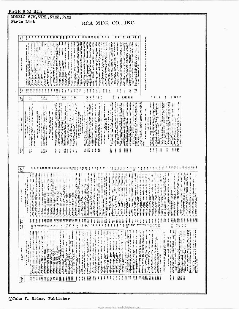
9-52 RCA 1LDELS Pert
6711,67111,67/02,672.8 List RCA MFG. CO., INC.
x -
nE riz
A1111:4444s.s45j544Ut4 4z4s44 44ß 14 g 44 14q i ^
a t : ! ° î t
: ' ' 3 1
! á `"3 " ̀
SsR i Y ' 1 º E É º } , E S 3 E
I'
:
3
i - e L é
S
ga;E t
° ` t
°Eág s
a .7. º ¡ t
É = Y . t'.jr - `
t ÿ `- i, _'
`-
E x @- Y i j
E
3 ái E
º $ á
8 - º
w3E r
EtC_-_ 8
;: =
Y 1
` `=E` ° :Z 3 5.i
É
L <°Y- <at3i9°.
é .
°``gi,' k0 `ti
é - -: '
.RÓ '1
- i° yw
_ Y ,i : á E.ywa il_era-yiYESé ÉYe SYw
á Y É.aâe ; ` - '
it_y
á :
.
t Y-
' ,t9i.Et:lZtLt .
°ec_3 a s1
=r
i
E E
3É
tiieº =C".`0i 4<
L ° teS`SY
.;`?
'î a
;.: r.` `
_E.a_!`gá;a85`9á Fr ,L`:.a^ îi,;:
YR Y ai.
..
E _ e
»
-g9 . jE.s=a'` °IG='º FY -ét3
) ! ' ó get : `.Y, :
.;.`lilxF 4!!u ^4 Y"'7R GY Y <lOÇq6Si,is`1t`!ñ OOCiÑm 1IÍir¡, mi''l._2i! II_1_ l .Yiº' »°i -tF1`IS'é, î mi a t`-T. lY- ! !Sr isákct,îFalg'=L;i1AAE,'a3
E _;eg
'tºé'Yl;i>=:-y $ .. '° itäim 'r
Et ^ S Yî'IL . S:iiiiiy yy8;3S».lm' aá1.i,i.
f:u Ú`41 u 4 H r R W oidi i'; .R. x r .i 4 D. teirY i `d m m m F E
ßg$á s+aßs= _ æ= « « ª
"
;E 3S
4ß ßg49 4 g44 q 9 44 14 g ß:4 1 9; gR1 ! ß .:. .: .. . .: « . « _ 1 1 _ g g nee 1
_ «
: tº :g :: _ _ :t:_ t º 23 i4 `
33 : -
= oe= 11
--= - :
r. 3 Sa É' _: - 6F'%
! é
G . ° E v,ÿ
E_ 1¿; 4i
3 - °
ti .t i` ; ` ` . 'E: m } :
á ië: 3 i e 1 -Eë t 3 : m
3 t
g 2 3,
é ú z é.EpéE' ; 3 c
n
Et É á i a
I x i Eis -: `
s ; M i i
g c,. 'º¡
"33 : .æ .t É 'r o =
i=« : `«' !3 áéÿ F -
a -t . 5:. rx z$
c
m,a
S az m c á
EE EE ° s - 3 ex; YioYs = d É
+ : 3ái« . - é 3
a xm.ri ax'/. v á=® .
- K Z kP rm s
a ".
L_ç
.ßz..' Yÿ
9 S ä-< v . .x . .
"Y m ɺ` °i a f6 : au t
.fa= S-3 L-'
=
a
-:_ `
Z ág ée p._
e EE ée 5.r.
e= ws
z it
Ei YE7.rece'__y iS_ X
` _
mm E ÿd Ir0 .Yz YÉés artx °.°r `E'ET
er.Y: L! - e -é -`ºV 'm m Ei. ..`,s '1":113yna ` ;EC°} -ú >rEtió tir !m º ': ZB[t`I1t;e3 °E .`ai
E
á ÓÓ r .-1`é Cié y_tá.é ºî.pi=L Cÿ ç. Y=9%
ae! i tiSlú_Éi é j! y -`d ºE.. _
i^.t áPP - CSi iáñ OKi áé1? Ca 4 -E =E 4 C Éábs- -- °é 4 r1á1
E r :.. ü n x =%5;= s e x Yz x %'-E x `-`;`-`E. % x Qt:t
%9 xv . a ;' l' li I
al -=b_E111tE_- IÉ!`_e ;i ° `E :"»%n
3 %`s
3 s- ÿiÿ d C le 1 ZZ: ÿ t -
I -,s -
ti Yt!'Iclll_13rs3a g dx a8'
á_
1yET-yiFZ.«i.t i ii
ic3E aE
Lift' xá_ T L_á- ga .fX!i` u - . ffk
i-- -æ. . m °
% ..S°-` ^ k a :'rl-a";
x f
>yº31-Yaalæ°a!` g.ÉmixGe°ipÁ i1.
ir LA _ - ai i:,
i.E=5_3 wi`-i
-E -='E" C ,
5
l1é_ á°__..
-=E_ c, u
s ßg$ 3 æ ææm á ss ' :s
á E á^: ᪺
s 4 1 144«s41 ßa:;::_1=44:,«.s«s ß a22gs4 4 Ñ 4ß 4 41 1 14 4 4 s 4 4 4 g.4 1 g 4 4 1 4 1 s g- s 44:111 1 1«^ss t ' ., .. .a
1 g i S
E É t ` i : t
1
i ié
6 i ` ¡ s
¡ 1
`
ó á i 6
l
.
S _ ^ 'ß
5 ;
r - r' é `
p q °_ I - º- I I
C i I º
i :1 3 Ç
E F
'z I' E º `- $î as 9' s .= i - 3 x X X X 2 xk! R X a ".7.iiÉ i I.i p X y Y x Ë E, 3 L
z "' a f°
` < 3$ E
3 _ic ;, e L- -ß -u , s3 ñ.:t S
L p_ ,fit g 3 Y
=" 3
_ 3 8; - 8 - : z'e` YE. t"' !
x z
-`.i 'î - -É arts
+. ^e iC
3
g g t
---w=_iZá-d¢_ :$° a»,. ß é^ . f:«-.,_ a- ._gE:.r^»$C¢. . ..-.ies -_n
-..vdios Éëvds dd`Eß'
=,_' : : - :.i á - E
_ E
- é : tr i
i _ St
`^
. E'
- : . . pp
` . '!
: et ' , ..
ifiße
: - - . . É
ë
_ . .
É é
B 't
é y_x - :
-º°G-v_ : : "3
Rºxa`z w:' 0
_
Ó a L
x; -is! _ - le. It a 'k
EEEEºEEaat 'ddv. . ir sr S 4ëë i Éi' iä aaFZ. a i ai 'i' E=_ii_ aa
ñ 88 a E
5«îï-`.EºS <ßá
_ ' ' Á^-_éá:æ_- æi- e" 1TÌllIa!!!!i iiiÌ?IÌÌI.;.i,eaw
- º_º .222222222.¡_,. ke; °º r r!
yf`«!f_ f}!?!!$gt=yygÉë1Î1Çl;.all;.IY2_`_t;_e_ æ`7
" r' E _`kLs ié e; `ntózé x
EY Ez..' :_; : s ,.,; e:;l;i;;I
! °. - -
itiF:-E.L:6iLE.E1='liii:__:<=`.
E
..°
_ r x
_
é:ixé e _ _.
$ x#isimá`$`Éz >^,' Ik`e?:yI,IYxx`
- 1F ri2"C r_r_
e-ex.-Ozcz..
c
ß.°`.-1= ` 1 -y -`°11'i äx«tc,...k.:ii;`4,.
.
«iii x3..-'-- :,aa.t., -4;11M:14 .Y
rééS º° ÿ_. _IS î s`YYé xiEE`EE
c. ÉE
.«:."R . E
° "CaS ;e`!pSj _
s-! `=i ii i-i - =t t eE:' 's c.dLLc::.Cui c.uc.4 i, i.=Sßßc ac-YSee g rx %% x r r r ac% x s x x% x r xr m r<=: : m F F l F:.
tr°
gc..-'.c.:.:.:+ gg' m » 8 .iS îî»::3º:3_:RL' % Çi Ç ß x fi Á 3R » S II
R: S : á x ! ? I <l ! 4.H:«l1 á $ á « :I.
3 4 ß 1 1444444114as44$ 22 1:1122 !s =s 441 1ß 4? ñ?e g 4 4 g es e41 4111-4 4 s!494g.
s ß4^ 4 s.
i «
i ' i x ti i,° S S 3éi: s a s s ; ;::.
: !HW L 1
r 11 : FF
a? i é i' É .
i
y C
! î . i¡_Ì j : j X x
= 1 X^ X F3
i z t r t.Ye
xt
ági''i - m o- é
x á.
i G
3 B: ' p
á : E v 2 á
'
,' =k
=
t X
" T
ì X ; Y S- 3¡-' ° e
m ° &^ á Éx t
_
`i - Yá
ddt : YEg .i
îi ° -
3 x
_ i « 3 S'" S ` ^ t 3g
. 5
E
tt
I 7 _ ler L 3 f3r 3 ;` ;í°i C 7"'
.ya r" e ( - P'i-L _ á=ß; ererdáV4_Y . ' " : = _E =3 $ s
`6x . i z:°; á ° óm : " 3i z_ r3a.
x ñ: °
': º
' x É. v= ` ui :% v _ L
Yaº
º @
' .t8ddd' e1 E< Eëë . :dE . iëëë a Ed.i : aaa axïa ¡pat. 3 ë ;Sa r 3 __ '1j tg» ß+E
T- E
! I lxE.=tr á 7
t
t . d
5 =_ ir
'C i"=Etë C=3
^
i =
. - Y
!- £
_ 1
_e
t_ .. ` é !i
-_
i.3 E
e "
y_3 - f Ei °p Y
_» Ixóf :
î: - x
. _
9
E -F $s ' é" !`- -:
.=-ites! x 3 x
i»iea.-E' F F!a _ `T rI ;42.4*-
;_:
°E
e' -ar i.-e xr».` E»°:_`i.. t_.',° Mi_R íiKF
t1444-it
3é ?'
E
w-
t3tr°.' =ît`« i:a.'
LLé:G- 3ºS--`
1 x ! !
§Rx4E'E_EÉ I y. II1
â 'xÿ ! ii; g °_ !x -1.
y,<á á `<S' Y
$ B°M'
r_- TÍ _ Ili; a o ° i_a` ! F K a iR's°FA F
` s.tE aq3
Y
.f ée ºixRi--° ._ °.
ti gX =m iE Y;. x. T .st a yyyy y. zr ëlIi {`_, _ t Yii'ÿ1e°Ré:ë YvÌi1;î é38-_'
lß=-f`.é _ :ji.r_=*IY7E4laaiÿÿ z lEE-: cmz-jj g3 `% Ri= ;4r`3vla`;3:æs Yæ3 assal -
YY a." u c.6:+G.au H et= ¿- _i xx x x %'% x% x r ix mu ix3z-F F FFY S" Ó_a Eº
' á c Ft !!á!a!!8lls?li I ls _ iá 5 á i
; 4 I i 'i ill Mil! i! i 9 i!!! s
®John F. Rider, Publisher
www.americanradiohistory.com
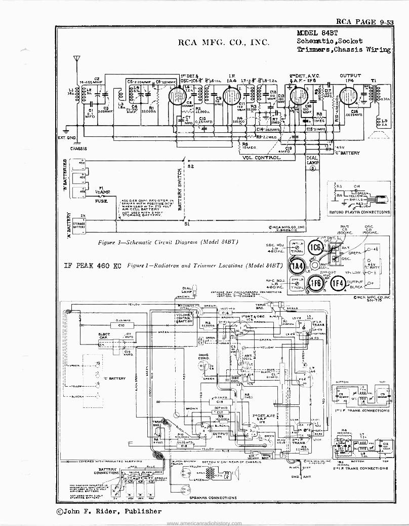
RCA PAGE 9-53
RCA MFG. CO., INC.
C2 14-455 MMF
Le 3BAp 4,51,2
Otx2 co ^
, C3 2-IOMMF.
- B 4
EXT. GND.
/777777
CHASSIS
fA
MFD
45V
45
45 PI
1/2AMP.
2V. +
STORA6F 6ATTEüT
PUSS
C6-2-20MMF M C5'120MMF
1.4I1 5.7n \
1.6,s. 25- i140 RI MMF. 339000.
=/i
A00 0.613 OHM RESISTOR IM 'SERIES WITH POSITIVE (+1-A-
WHEN USED WITH 2n VOLT AIR -CELL BATTERY NOT USED WITH 2 VOLT STORAGE RY.
1>T DET.A I.Fi DEC.ICS-iii' 4r1.6 -IIA 1A4 L7-1/Ar ArL9-7.2n
e CS r T
óC1L I2D
O MMF. 56 MMf.
1 izo R3 MMF.22,100
L6-.. 7.2n1 0
C) r C6
110MM
CT
MFO
Ra 22,000s.
CIO 0.25 MFO
a
R4 220E20 f - MEG
1111 T MUM >óe
C13 ISO M
C14- 0025M
R5'2.2MEG r
MJDEL 84BT Schematio,Socket Tr immers,Chassis Wiring
EM°DET., A.V. C. yA.F.- 1F8
1 MEG. C19 4MF0.
VOL. CONTROL
3
fi
12016 MMF.
S
414$ óói MOO OO
RS
C15 0.1MF0
DIAL LAMP
SL
Figure 3-Schematic Circuit Diagram (Model 84BT)
® RCA M FG. CO., I NC. P -E4061-0
SEC. RDJ. L6
400 KC.
IF PEAK 460 KC Figure 1-Radiotron and Trimmer Locations (Model 84BT)
DIAL LAMP
,BROWN
SEC. RDJ. LB
400 KC. C TvtwICÁ'MITÓ TwÌ TtÁMNNECTIONS vERTeRLro ToeN,uls. _-
Oò
OUTPUT 1F4 l
4; _ CIS
.00MFO
-4.5 V.
C" BATTERY
T1
R3 C14
R4 I-TEL. ow SHIELD
RED
RECORD PLAYER CONNECTI ONS
PINT 0050C
OO KG. 1500KG.
OUTPUT BLOCK
LO
0.E5MFD.
CIO
Ivo I CONTROL I ,BATT.
s i
ELECT GREEN
CAP, IiNFD.
C11'
Y I - 4MFp.
II COVERED WITH INSULATED SLEETING
BATTERY CONNECTIONS
AIRc.e> V ERV.
BRD
RS IO MEES
i REO .SLUE
I T4
0055 MFD CIS
/ 4
VELLO
OUTPUT 104
Tina sna SNILLD
N PET. SWIC. MAC IC BROWN
GREEN
LS LIS -C8 ,ADJ
RI la000A TRANI.
--yyII ,yyYey14-e9 LSSB IFI
2".DET,AV.C. 4yA.F
IF6
y,5*SEu
TOP
lS-C9
-III Iló
I
K 4ROLra
F
Y
t ylLACK-
UE
c 7 Tnu 20MMr. BRD
6LACK-BROWN BOTTOM VIEW- REAR OP.CMASSIS ,SLACK `FELLOW V
a45n0 0 ORE[N-i
0.oln
SPEAKER CONNECTIONS
ú.
.
ó I.F.
JA4
r-5 2 SO
ÌI
II Cß04 LT -C11
,1 \`.aA r S
1 C O 6>.M
i¡I I E^^I.R , LTCH
II TRANa.
R6 11 1.0 mess
DLA05 SLUE
ONO. ANT.
Y
ORCR MN-TFG. ,INC
BOTTOM TOP
Iti.CO.,INC
CS 110114.412
e
I°, LE TRANS. CONNECTIONS
0.4
L,IS BOTTOM 22,000,
E>1.0 TRANS, CONNECTI ONE
TOP
zy 45V
©John F. Rider, Publisher
www.americanradiohistory.com
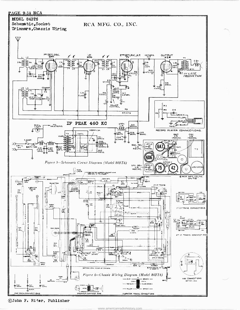
CAGE 9-54 RCA M7DEL 84BT6 Schenatic,Sooket Triammers,Chsssis Wiring
38 C. .-.
P(K-4313MMF >Anne
C3
LE
O
CI --Ih- O.IMF0.. 330
MM .
I.T. Osc. ,NI' ,lá
CC
RI
RCA MFG. CO., INC.
61G T.2n ce
OOaLL E'19
110 T d ¡O Ta.$6 MMF MME
5 L6
C,p TMF
.20 n T.2c T.2n MMEl =1
/IOO CIE
IT db 120 MMF.
L7 LP
2200
180 MME
CIS I I
E^ODET.,RVC.,A F T5
007 MED. C17
DP
3
270,OÓ D/! A
ICK 7 RS MR0. g7
22M- 2.2MEG. MOºO
VOLUME CONTROL
Ziv.
R1
22,000.
IF PEAK 460 KC ~HeATGRS
SAMP Iy-Lo
DRTT. SI - ov. BATT. SW. clvi ceo
0.28 -'.T330 MF0. IiMMF
290. L13
0 Q0l
®ÑFa C24
O.I MFD.T
II
OUTPUT 42* Ç16 120 MME
RIO 70
T as OMFO
TI
RS 660.
CIB Len L9
MF0. soo./+.
4l IN LATE PRODUCT/ON
Ces SEC RUJ. .OIMFO. -
L6 -- 460KC.
RMM20n
Figure 5-Schematic Circuit Diagram (Model 84BT6)
LAMP tah~
SEC ROJ. LB
460 KC.
YELLOW
SMIE D RED
JOI.dILUE TAPI
RECORD PLAYER CONNECTIONS.
RN COIL 2"DDET
RVC
3 O
®61C. r.
i j-- ..taN Me. CNORs
D w [ eM
mCl. I CT SATT
Ill N.s..
I
COIL
1 J
^
Wen,. TRANS.
Tie - 'I !RN
1.wD
Lí0
-- w..a.L[,.ì_ w[ IIFLL d MI." TRANS.
VOLUME , nTa.ar[.s 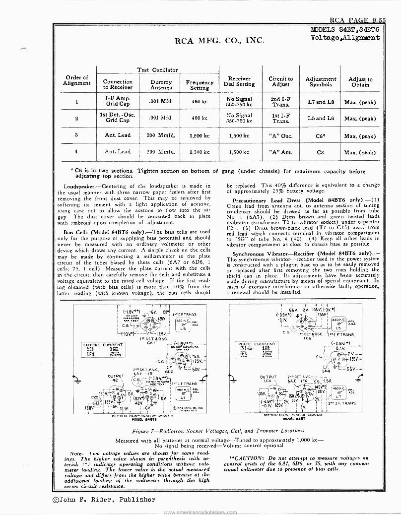
-,r
RCA MFG.
Test Oscillator
CO., INC. MODELS
Voltage,Alignment 84BT,84BT6
Order of Alignment Connection
to Receiver Dummy Antenna
Frequency Setting
Receiver Dial Setting
Circuit to Adjust
Adjustment Symbols
Adjust to Obtain
I -F Amp. Grid Cap550-750 .001 Mfd. 460 k c No Signal
kc 2nd I -F Trans. L7 and L8 Max. (peak)
2 1st Det. -Osc.
Grid Cap .001 Mfd. 460 kc No Signal 550-750 kc
1st I -F Trans. L5 and L6 Max. (peak)
3 Ant. Lead 200 Mmfd. 1,300 kc 1,500 kc "A" Osc. C6* Max. (peak)
4 Ant. Lead 200 Mmfd. 1,500 kc 1,500 kc "A" Ant. C3 Max. (peak)
* C6 is in two sections. Tighten section on bottom of gang (under chassis) for maximum capacity before adjusting top section.
Loudspeaker. -Centering of the loudspeaker is made in be replaced. This 40% difference is equivalent to a change the usual manner with three narrow paper feelers after first of approximately 25% battery voltage.
removing the front dust cover. This may be removed by Precautionary Lead Dress (Model 84BT6 only). -0 ) softening its cement with a light application of acetone, Green lead from antenna coil to antenna section of tuning using care not to allow the acetone to flow into the air condenser should be dressed as far as possible from tube gap. The dust cover should be cemented back in place No. 1 (6A7). (2) Dress brown and green twisted leads with ambroid upon completion of adjustment. (vibrator transformer T2 to vibrator socket) under capacitor
The bias cells are used C21. (3) Dress brown -black lead (T2 to C25) away from
Bias Cells (Model 84BT6 only). -The red lead which connects terminal in vibrator compartment only for the purpose of supplying bias potential and should to "SG" of tube No. 4 (42). (4) Keep all other leads in never be measured with an ordinary voltmeter or other vibrator compartment as close to chassis base as possible. device which draws any current. A simple check on the cells may be made by connecting a milliammeter in the plate Synchronous Vibrator -Rectifier (Model 84BT6 only).- circuit of the tubes biased by these cells (6A7 or 6D6, 2
The synchronous vibrator -rectifier used in the power system cells;is constructed with a plug-in base so as to be easily removed 75, 1 cell). Measure the plate current with the cells or replaced after first removing the two nuts holding the
in the circuit, then carefully remove the cells and substitute a shield can in place. Its adjustments have been accurately voltage equivalent to the rated cell voltage. If the first read- made during manufacture by means of special equipment. In ing obtained (with bias cells) is more than 40% from the cases of excessive interference or otherwise faulty operation, latter reading (with known voltage), the bias cells should a renewal should be installed.
1 t t 1/ f
(-1.BV.**) -6V. 150V.I 00 NOT {1 I I I
1 I.F.TRANS.
I I I t 1 1
¡ 66V. 2V. 1351/.¡(3V..) F0.9V.*)Ì .jam I 135VI
I MEASU RC ^rI 1
SEE TEXT 7 a_.J25V
I 660 H.C1 MI.
I 6P % I LS
f1 I
-Or1V 1 / 0m; J ! ;
L,h.L J
4606.C. PRI
LS
I (IOVB -J t I NV» 1s" OET1j05C.
C.G:' i' Is,. DET. oSC. s..
IC6g 1 I.F.TRAN51.
CATHODE CURRENT
N.'S 510A.1,M4 Warta.
6AT -(-1.8V.'*)---- I
Sae TexxURC
'®( 6V.- - PLATE CURRENT
N LOP S4166. .S013. 32 ma. N.4 ssms.
(-0.9V.*) r--- -0.1V. ~
C.G.;..;
ttl`
2""'DET., A.V.c, 6D6 -50V.-- OUTPUT yA.F -75 - (-O.9V.ss)1 r 42 C'G' oo Nor wusuae -
sEE TEZT 2""'I.F. TRANS.
135V.-
1A4 66V.-- 1 OUTPUT 2we'OET..A.V.C;1--;, -- r 1F A.F - 1FS "e:D. -1.5V.
r-T$ T 1601/. a --+ OV 3 1
C25 1 I 73)f
1 (82 fß.
1p DV :
p,155V.íI e 401/. 4-Q I r 1# I 1
168V. 1 I -6V. 10.3V. I I -6V. I I© e t Ì t t ti t t
4606.0 PRI.
L7
RCA MFG CO.INC. P-14075-0
r-7-4-49-4.14 ÑÓV*)I
135V. 1w ¡(9 3,z I (Su,^© A-- :(4.5. jjjYf"2V !_ OV
-O.1V 1291/.1 I
I 1
1
1/. 1
i t .3 f t t
2NeI.F.TRANS.
6606.0. ADJ.
L7
t DOTTOM VIEW- REAR OF CHASM S BOTTOM VIEW- REAR OF CNASSI3
MODEL 6451$ MODEL 13487
Figure 7-Radiotron Socket Voltages, Coil, and Trimmer Locations
Measured with all batteries at normal voltage -Tuned to approximately 1,000-kc- No signal being received -Volume control optional
Note: Two voltage values are shown for some read- ings. The higher value shown in parenthesis with as- *'CAUTION: Do not attempt to measure voltages on terisk (*) indicates operating conditions without volt- control grids of the 6A7, 6D6, or 75, with any conven- meter loading. The lower value is the actual measured tional voltmeter due to presence of bias cells. voltage and differs from the higher value because of the additional loading of the voltmeter through the high series circuit resistance.
©John F. Rider, Publisher
www.americanradiohistory.com
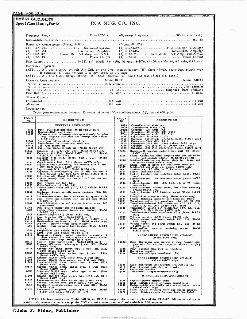
4AGE 9-56 RCA
WJDELS 84BT,84BT6 Specifioations,Parts RCA MFG. CO., INC.
Frequency Range 530-1,720 kc Alignment Frequency 1,500 kc (osc., ant.)
Intermediate Frequency 460 kc
RADIOTRON COMPLEMENT (MODEL 84BT) (MODEL 84BT6) (1) RCA -106 First Detector -Oscillator (1) RCA -6A7 First Detector -Oscillator (2) RCA -1A4 . Intermediate Amplifier (2) RCA -6D6 Intermediate Amplifier (3) RCA -1F6 Second Det., A -F Amp., and A.V.C. (3) RCA -79 Second Det., A -F Amp., and A.V.C. (4) RCA -1F4 Power Output (4) RCA -42 Power Output Pilot Lamp 84BT, (1) Mazda 2.0 volts, .06 amp.; 84BT6, (1) Mazda No. 40, 6.3 volts, 0.15 amp.
BATTERIES REQUIRED
84BT...."A", one plug-in, 21/2 -volt Air Cell, or one 2 -volt storage battery; "B", three 45 -volt, heavy-duty, plug-in type B batteries; "C", one 4% -volt C battery tapped at 1% volts.
84BT6..."A", one 6 -volt storage battery; "B", none required; "C", three bias cells (Stock No. 12681).
CURRENT CONSUMPTION MODEL 84BT MODEL 84BT6 "A" at 2 volts 0.42 ampere. "A" at 6 volts 2.95 amperes "B" at 135 volts 25 ma (Supplied from vibrator) Fuse Rating 1/1 amp. 5 amps.
POWER OUTPUT Undistorted. 0.3 watt 0.5 watt Maximum 0.5 watt 0.8 watt
LOUDSPEAKER
Type: permanent -magnet dynamic Diameter: 6 inches Voice coil impedance: 21/4 ohms at 400 cycles.
STOCK DESCRIPTION STOCKNo DESCRIPTION
RECEIVER ASSEMBLIES 4629 Cap-Radiotron shield cap 12629 Capacitor -58 Mmfd. (C9)
4289 Body -Fuse connector body (Model 84BT6 only) 14262 Capacitor -110 Mmfd. (CB) 14286 Bracket -Dial lamp bracket 12404 Capacitor -120 Mmfd. (C11, C12) 14288 Cable -3 -conductor battery cable approximately 60 inches 12724 Capacitor -120 Mmfd. (C5, C16)
lone complete with fuse and battery clips (Model 12406 Capacitor -180 Mmfd. (C13) 841íT only) 14320 Capacitor -330 Mmfd. (C7, C20) (Model 84BT8 only)
12607 Cap -First I -F transformer shield cap 5107 Capacitor -.0025 Mfd. (C14) 12581 Cap. -Second I -F transformer shield cap 5005 Capacitor -.0035 Mfd. (C18) (Model 84BT only) 12118 Cap -Grid contact cap 5148 Capacitor -.007 Mfd. (C17) (Model 84BT only) 4288 Cap -Fuse connector male cap (Model 84BT6 only) 5196 Capacitor -.007 Mfd. (C17, C18) (Model 84BT8 only)
11654 Capacitor -.O1 Mfd. (C22, C23) (Model 84BT6 only) 13673 Resistor -10 megohms, carbon type, } watt (R8) (Model 4841 Capacitor -0.1 Mfd. (Model 84BT, Cl, C15) (Model 84BT only)
84BT6, Cl, C10, C24) 14315 Shield -Chassis end shield complete with bias cell holder 4840 Capacitor -0.25 Mfd. (Model 84BT, C10) (Model -For end opposite vibrator (Model 84BT6 only)
84BT8, C19) 14318 Shield -Chassis end and bottom shield for vibrator end 12741 Capacitor- 0.5 Mfd. (C21) (Model 84BT8 only) of chassis (Model 84BT6 only) 14287 Capacitor -Pack comprising two sections each 4 Mfd. 12008 Shield -First or second 1-F transformer shield can
(C7, C19) (Model 84BT only) 14317 Shield -Vibrator shield can (Model 84BT6 only) 13046 Capacitor -8 Mfd. (C25) (Model 84BT6 only) 3682 Shield -1A4, 1F8, BDB, or 75 Radiotron shield 14310 Capacitor Pack -Comprising one 10 Mfd. and two 8 14114 Socket -Dial lamp socket
Mfd. section» (C15, C28, C27) (Model 84BT6 only) 4794 Socket -4 -contact 1A4 Radiotron socket (Model 84B'í' 12681 Cell -Bias cell (Model 84BT6 only) only) 14289 Clip -2 battery clips, one marked "+" and one un-
marked 4814 Socket -5 -contact 1F4 Radiotron socket (Model 84BT
only) 14285 Coil -Antenna coil (L1, L2) 4788 Socket -8 -contact 106, 1F8, 6D8, 42, or 75 Radio - 14257 Coil -Oscillator coil (L3, L4) tron socket 12179 Coil -Vibrator choke coil (L10, L11) (Model 84BT6
only) 14312 Socket -B -contact vibrator socket, less rubber mounting
(Model 84BT8 only) 14256 Condenser -2 -gang variable tuning condenser (C2, C3,
C4, C6) 4787 Socket -7 -contact 6A7 Radiotron socket (Model 84BT8
only) 5119 Connector -3 -contact female connector for speaker cable 4284 Spring -Fuse connector spring (Model 84BT8 only)
14314 Cord -Power cord complete with fuse and clips (Model 12007 Spring -Retaining spring for core Stock No. 12008 84BT8 only) 14261 Transformer -First I -F transformer (L5, L8, CB, C9)
12006 Core -Adjustable core and stud for first or second I -F transformers
14283 Transformer -Second I -F transformer (L7, L8, C11, C12, CIS, R3, R4) (Model 84BT only)
14284 4288
Dial -Station selector dial and holder assembly Ferrule -Fuse connector ferrule and bushing (Model
14308 Transformer -Second I -F transformer (L7, L8, C11, C12, C13, R4) (Model 84BT8 only)
84ßT6 only) 14311 Transformer -Vibrator transformer (T2) (Model 84BT8 3748 Fuse -4 ampere (F1) (Model 84BT only) only) 5140 Fuse --5 ampere (F1) (Model 84BT6 only) 14309 Vibrator complete (L12) (Model 84BT8 only)
14318 Holder -Bias cell holder (2 cells) (Model 84ßT8 only) 14282 Volume control and power switch (R7, Si) (Model 14319 Holder -Bias cell holder (1 cell) (Model 84BT8 only) 84BT only) 14263 Indicator -Station selector indicator pointer 14307 Volume control and power switch (R4, Si) (Model
4290 Insulator -Fuse connector body insulator (Model 84BT8 84BT8 only) only) 4285 Washer -Fuse connector insulating washer (Model
4348 Lamp -Dial lamp (Model 84BT only) 84BT8 only) 4340 Lamp -Dial lamp (Model 84BT6 only)
14313 Mounting- Vibrator socket mounting comprising 2 rubber washers, 2 screws, 2 eyelets, 2 washers. 2 lock- washers, and 2 nuts (Model 84BT8 only)
REPRODUCER ASSEMBLIES (78474-3) (Model 84BT only)
12818 Reactor -Filter reactor (L13) (Model 84BT8 only) 14303 Cone -Reproducer cone centered in metal housing corn - 8063 Resistor -330 ohms, carbon type, } watt (R6) (Model plete with dust cap, less output transformer and plug
84BT6 only) (L9) 6031 Resistor -880 ohms, carbon type, } watt (R8, R11, 5118 Plug -3 -contact male plug for reproducer
R12) (Model 84ßT8 only) 9802 Reproducer complete 12330 Resistor -3,300 ohms, carbon type, } watt (R13) 14304 Transformer -Output transformer (TI)
(Model 84BT8 only) 11305 Resistor -22,000 ohms, carbon type, } watt (R2) REPRODUCER ASSEMBLIES (78494-2) 14284 Resistor -22,000 ohms, carbon type, 1/10 watt (R3) (Model 84BT8 only) 11384 Resistor -33,000 ohms, carbon type, } watt (R1)
(Model 84BT only) 14305 Cone -Reproducer cone complete with dust cap (L9) 12333 Resistor -68,000 ohms, carbon type, * watt (R1) 5118 Plug -3 -contact male plug for reproducer
(Model 84BT8 only) 9803 Reproducer complete 6023 Resistor -150,000 ohms, carbon type, } watt (R9) 14308 Transformer -Output transformer (T1)
(Model 84BT only) 11398 Resistor -220,000 ohms, carbon type, 1/10 watt (R4) MISCELLANEOUS ASSEMBLIES
(Model 84BT only) 11323 Resistor -270,000 ohms, carbon type, } watt (R9) 14288 Crystal -Station selector crystal 11172 Resistor -470,000 ohms, carbon type, } watt (R10) 14269 Knob -Station selector or volume control knob
3033 Resistor -1 megohm, carbon type, } watt (R8) (Model 14299 Resistor -0.88 ohm flexible wire wound ballast resistor 84BT only) (Model 84BT only)
11828 Resistor -2.2 megohms, carbon type, } watt (Model 14298 Screw -Chassis mounting screw and washer assembly 84BT, R5) (Model 84BT8, R5, R7) 14270 Spring -Retaining spring for knob Stock No. 14269
NOTE: On later production Model 84BT6, an RCA -41 output tube is used in place of the RCA -42. All circuit and speci- fication data remain the same except the "A" current consumption at 6 volts which is 2.65 amperes.
©John F. Rider, Publisher
www.americanradiohistory.com
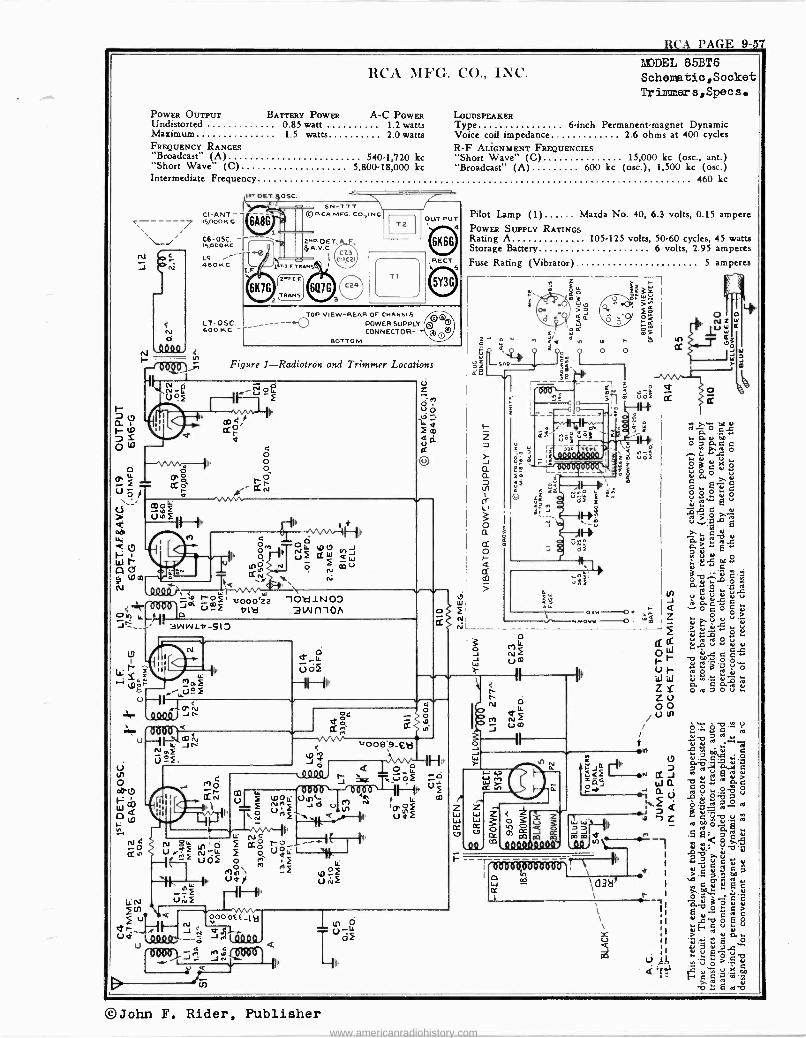
RCA PAGE 9-57
RCA MFG. Co., INC. MODEL 85BT6 Schematio,Socket TriImQers,Specs.
POWER OUTPUT BATTERY POWER A -C POWER LOUDSPEAKER Undistorted 0.85 watt 1.2 watts Type 6 -inch Permanent -magnet Dynamic Maximum 1.5 watts 2.0 watts Voice coil impedance 2.6 ohms at 400 cycles FREQUENCY RANGES R -F ALIGNMENT FREQUENCIES "Broadcast" (A) 5401,720 kc "Short Wave" (C) 15,000 kc (osc., ant.) "Short Wave" (C) 5,800-18,000 kc "Broadcast" (A) 600 kc (osc.), 1,500 kc (ow.) Intermediate Frequency 460 kc
'fee
.1ST DET $OSC. R1
CI -ANT. - 15.0001( c
CS -05C. - IS DDONC
L9 ,--- 400.4C
I.
6A86 r ,
SN --171 © P.CR MFG. CO.,INC
' 2Na DEI
A. V.G.
1 'I. E TRANS'
2^91.F.
TRAMS
C23 C11C2I
LT-O5C. 600 M C
12 OUTPUT
4 r
TI
TOP VIEW -MEAN OF CHASSIS
-----o POWER SUPPLY CONNECTOR
BOTTOM
REC
ó
Pilot Lamp (1) Mazda No. 40, 6.3 volts, 0.15 ampere POWER SUPPLY RATINGS Rating A 105.125 volts, 50-60 cycles, 45 watts Storage Battery 6 volts, 2.95 amperes Fuse Rating (Vibrator) 5 amperes
é-
d
Y1 är I ,, Figure 1-Radiotron and Trimmer Locations s^e S, r- -le I -_- --1
ó Ñ º m úó5 tY
O Io CO 4,r u.
O yr^CLi ^r 4.
Ir c0 1CI.
11 tío î m _ i" "- L < 2 o. D c ú
M Y d Q a0. Z a^ .qï °z .. au û O a
u ri ,,
o a a c a ; Y u- . o
O p I o O J Vnmr'm,,="-, 9m= 04 ÓáuMÓ LL p,O
0 á Fm --- --' ú g
ú C y O u
Ú CLo` -Ñ Ñ á5 .. N-* co
ó,^+, Ô f á Ì I O Iz ` 5 fô W$ ao VWvV [T < uó5 5 Lew
e u
úof
= ú sLL i I <; é
m W ~ W
n s Ka
I
O 0
m V w i 1 < r u ,- `ó Itl o
Q O O W
W >m
COO< >> 53,2
N
I
; ' ___
:
o d I UÑf{
1+ J '
Ñ 1
4 LLHIa >.
Lau ...c 1 ^ Ñ 1,0(j J . z= óï 7.0 É v H I IF
>
F o uF lW !id O D N
' e
mV Yú to - ui a o O N k< 1
unS y^O 'qrm>l v000'zz -102i1N00 w
N a"Ó
:'tú2, ö 2 ..M
cODO&(
\ 0 0OlJf
c% ,...«.. ble 3Wt110/ o 21 - NI
QZ
ÿo G
o ó é ^..oe I 'mI ÿd V U'y 2 d1.,° o
3 IL Q 415ºúd II f _4 Ó VQl
01- d b" O Ow I
l,; : i +IY U O i W A u r L a O or mwf -1--1U }
t I TIN W W ú" ú
m ú Vó t` ZY óro7óu F... --,L4
Ç
N O ZO Q400: J r` óe __
I K 1 u / S^0C s
U --i vw- - 2 v Á " JI ,./008«,9-V21 0 i d ÿ N e,> i M, ÿ eD ú C
ÚºF. `J°2 HI,, W
On W Ou? c o__YdJaJbáwäeC,OMJ
of ¡4w í=oáN uJ Q a c..I OHNUf 0.,n rOy CO O O
Wol> `ii1' Cf ei Ññ Uná N
of m
Z Z , tl U e èu,
ó fl ó 1.` () M 0 J1 v `` Q o v p_. O In Ñ clíy a II Uaï
p h á ó » IM
ti L b ó áe N , M---. - \h/v-1 II
I t ''/C7
al 0113 RS
/S 11---..-..- tn ..- C. Ö 7 ro Y
Ñ Urg Ñ! 0 VOLL`-\ I ..Q!!. m QQYYQ.i[ïID1y
mm Ñ "23 t'
ÿ UOf
Ó. m 4 f- __II' ' 2 ú G C w
tels , F 0 9F I to \ < I >.S ; m
yW m h Ua9 Ulvf ó e3 `l43ä I
"' c ú ú 8 c
_ f F --1u \ t 1 g.m v IiN Utiî ° d à ó 9 ú
\\ II Ed2 I, ñá QV11...-Q
o0'Off_Ib \ II YI c ú p
e J Ñ v,r°°L
0 I
ro Ud lt YY --ó JtQfl TH',--''
o Y >F u 0.,. u 4 41GßD0
a ,-,'1,
i jjo
I J JÑI1 li' Li »Al _' >.
C Q YiI
..C
a± ro ro
V «51
©John F. Rider, Publisher www.americanradiohistory.com
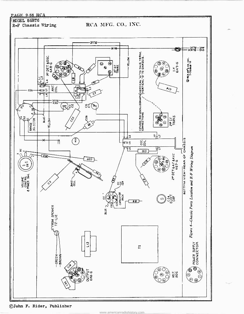
MODEL 85BT6 R -F Chassis Wiring RCA MFG. CO., INC.
3(llâ 1 3m8 -my 3ne- -lteiTi0Ylfl-
F QN9
ÿ Wh_ FN
iiO
°°o 0 w© -7 f C til
¡I
Bh V~
!ii
ó " © LI --= oQO u i
O® e i
2
V o 14.
Á<e
4~ -T L. +tÚ
J J
"r < Q Q O
3 ~_, j w -r f- F ®¢ » 43l- v -43- IrU a J " _
á gmfl
Q U tu h
(138<3H / O N L/
U U Liu Le . ó \ _,
Ñ `\ Q O M
a u u t 1.1
c 3 ú <c Cr F
©O Vi Z
F
CW7 W ZJ a JO
// ÿ óZ rZ
,vr QO -i
a Ñ~
<w CC _ ao uu
n J J11 IJ J O
111 U Q
R d ti OI7
m, ,~
U LL C
® Lk f CÑ
F z 0 0; > 0
b
, \\
02J
h IT s W V V Ú U
ó 1
C -3v
,c O eM® ° p 1 C
.3- ® 0 F-: 4'
Ó
ÑI
NW ¢ Oo
O 0 o,
W *
, .k.-
W
ci L c o f r ó m o
.ÿ d . ) ---7 @ á H U W U
T oc ir., u W V C
¡\ X W Q W J a. cg v) N J N
L._H
, -2
ZZ oc
_
J H
N i *
rz.
CC O ~ h W
cc
3OÓ cgm I I
Re."
©` )-Oo U F 0 0o W> 0 ó©p au p
O o
oIle
©John F. Rider, Publisher
www.americanradiohistory.com
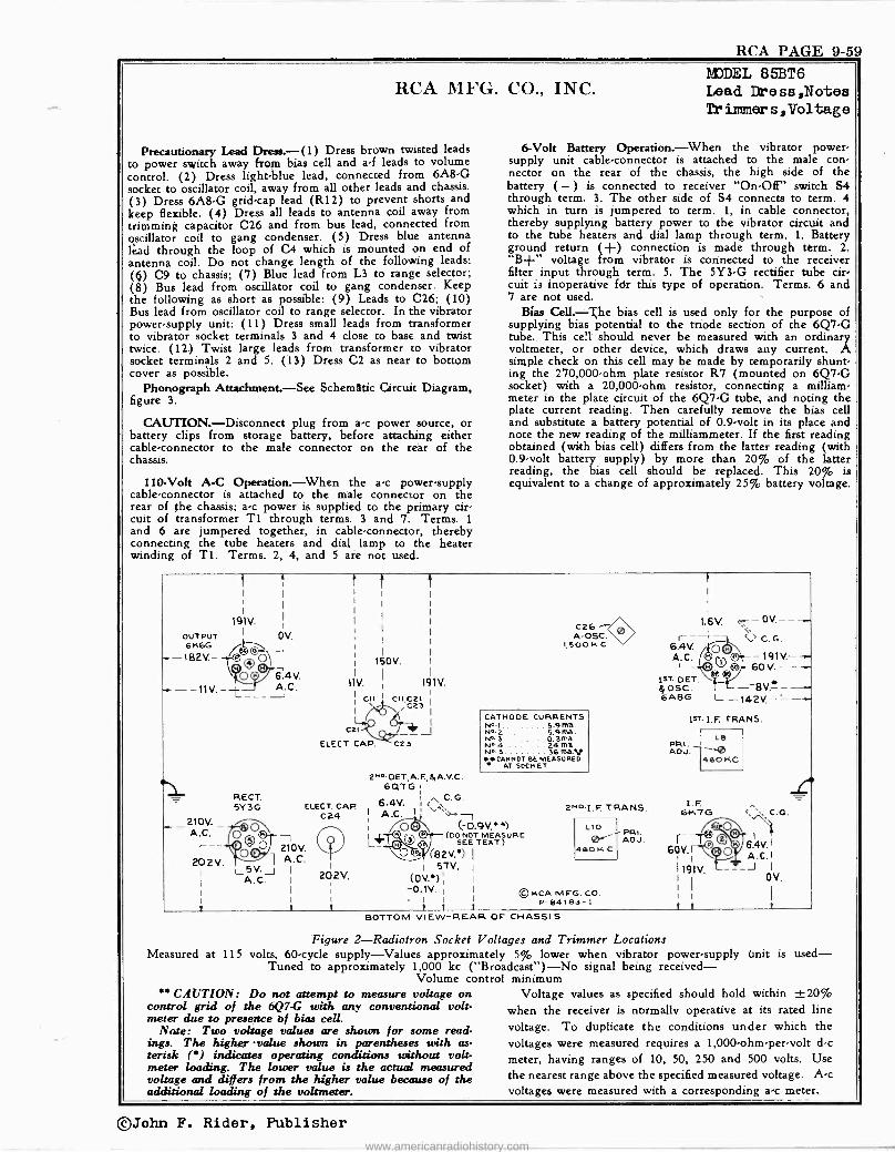
RCA PAGE 9-59
RCA MFG. CO., INC.
Precautionary Lead Dress.-(1) Dress brown twisted leads to power switch away from bias cell and a -f leads to volume control. (2) Dress light -blue lead, connected from 6A8 -G socket to oscillator coil, away from all other leads and chassis. (3) Dress 6A8 -G grid -cap lead (R12) to prevent shorts and keep flexible. (4) Dress all leads to antenna coil away from trimming capacitor C26 and from bus lead, connected from gscillator coil to gang condenser. (5) Dress blue antenna lead through the loop of C4 which is mounted on end of antenna coil. Do not change length of the following leads: (e) C9 to chassis; (7) Blue lead from L3 to range selector; (8) Bus lead from oscillator coil to gang condenser. Keep the following as short as possible: (9) Leads to C26; (10) Bus lead from oscillator coil to range selector. In the vibrator power -supply unit: (11) Dress small leads from transformer to vibrator socket terminals 3 and 4 close to base and twist twice. (12.) Twist large leads from transformer to vibrator socket terminals 2 and 5. (13) Dress C2 as near to bottom cover as possible.
Phonograph Attachment.-See Schematic Circuit Diagram, figure 3.
CAUTION.-Disconnect plug from a -c power source, or battery clips from storage battery, before attaching either cable -connector to the male connector on the rear of the chassis.
110 -Volt A -C Operation.-When the a -c power -supply cable -connector is attached to the male connector on the rear of the chassis; a -c power is supplied to the primary cir- cuit of transformer T1 through terms. 3 and 7. Terms. 1
and 6 are jumpered together, in cable -connector, thereby connecting the tube heaters and dial lamp to the heater winding of Ti. Terms. 2, 4, and 5 are not used.
MODEL 85BT6 Lead Dress,Notes Tr inuner s , Voltage
6 -Volt Battery Operation.-When the vibrator power - supply unit cable -connector is attached to the male con- nector on the rear of the chassis, the high side of the battery (-) is connected to receiver "On -Off" switch S4 through term. 3. The other side of S4 connects to term. 4 which in turn is jumpered to term. 1, in cable connector, thereby supplying battery power to the vibrator circuit and to the tube heaters and dial lamp through term. 1. Battery ground return (+) connection is made through term. 2. "B+" voltage from vibrator is connected to the receiver filter input through term. 5. The 5Y3 -G rectifier tube cir- cuit is inoperative fir this type of operation. Terms. 6 and 7 are not used.
Bias Cell.-The bias cell is used only for the purpose of supplying bias potential to the triode section of the 6Q7 -G tube. This cell should. never be measured with an ordinary voltmeter, or other device, which draws any current. A simple check on this cell may be made by temporarily shunt- ing the 270,000 -ohm plate resistor R7 (mounted on 6Q7 -G socket) with a 20,000 -ohm resistor, connecting a milliam- meter in the plate circuit of the 6Q7 -G tube, and noting the plate current reading. Then carefully remove the bias cell and substitute a battery potential of 0.9 -volt in its place and note the new reading of the milliammeter. If the first reading obtained (with bias cell) differs from the latter reading (with 0.9 -volt battery supply) by more than 20% of the latter reading, the bias cell should be replaced. This 20% is equivalent to a change of approximately 25% battery voltage.
OUTPUT 6K6G 182V. -
O V. J 6.4V. A.C. ----'
RECT. 5Y 3G
210V. A.C.
I ° `/ 210 V.
202V. O 1 A.C. 5V. __I
A.C.
t t
150V.
11V.
L Cal
ELECT. CAP.
ELECT. CAP C24
202V.
191V.
CII 021 C23 J
C23
C26 A-OSC.
1,5OOK C
CATHODE CURRENTS 141111 . 5.9 ma. N11.2 5.9 Re.
3ma. N4 24 ma. N".5 36 mav **CANNOT BE MEASURED
AT SOCKET
2«0. DET,A.F.,S,A.V.C. 6Q7G
6.4V. C.G.
A.C.lI +
(-0.9V.) (0 NOT
i - SEE TEXT)
URE
(82V.') I 51V.
(0V.*) -0.1V. I
. I I
t t
2"mI.F. TRANS.
LIO PRI. ADJ.
460 K C
© RCA MEG. CO. P-84193-1
1
1.6V. c- - OV.- - r - 7 `, ' C. G.
6.4V. A. C. ¡'n0 ©r 191V.- y \O 60V.--+
LST. ()ET. gosc. - 6A8G L--142V.----
LsT I. F. TRANS.
L8 PR1. ADJ. ^'0
460 KC
I.F. 6K7G ``:. C. G G.
N ,
6.4V.1 A.C.I -J I
O V.
Measured at
** CAUTION: Do not attempt to measure voltage on control grid of the 6Q7 -G with any conventional volt- meter due to presence of bias cell.
Note: Two voltage values are shown for some read- ings. The higher -value shown in parentheses with as- terisk (*) indicates operating conditions without volt- meter loading. The lower value is the actual measured voltage and differs from the higher value because of the additional loading of the voltmeter.
BOTTOM VIEW -REAR OF CHASSIS
Figure 2-Radiotron Socket Voltages and Trimmer Locations 115 volts, 60 -cycle supply-Values approximately 5% lower when vibrator power -supply unit is used-
Tuned to approximately 1,000 kc ("Broadcast")-No signal being received- Volume control minimum
Voltage values as specified should hold within ±20% when the receiver is normally operative at its rated line voltage. To duplicate the conditions under which the voltages were measured requires a 1,000 -ohm -per -volt d -c
meter, having ranges of 10, 50, 250 and 500 volts. Use the nearest range above the specified measured voltage. Ac voltages were measured with a corresponding a -c meter.
©John F. Rider, Publisher
www.americanradiohistory.com
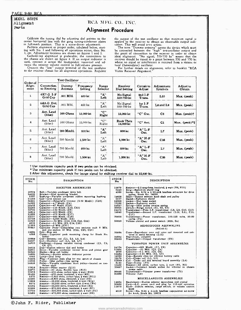
PAGE 9-60 RCA
IS DEL Alignment Parts
85BT6 RCA MFG. CO.. INC.
Alignment Procedure
Calibrate the tuning dial by adjusting dial pointer to the the output of the test oscillator so that minimum signal is center horizontal line with the gang tuning -condenser plates applied to the receiver to obtain an observable output indi - in full -mesh position. This is a screw -driver adjustment. cation. This will avoid a -v -c action.
Perform alignment in proper order, tabulated below, start- The term "Dummy antenna" means the device which must ing with No. 1 and following all operations across, then No. be connected between the "high" test -oscillator output and 2, etc. Adjustment locations are shown on figures 1 and 2. the point of connection to the receiver in order to obtain
Cathode-ray alignment is preferable; the connections to ideal alignment. "No signal, 550.750 kc" means that the the chassis are shown on figure 4. If an output indicator is receiver should be tuned to a point between 550 and 750 kc used, connect it across the loudspeaker voice -coil and ad- where no signal or interference is received from a station or vance the receiver volume control to full -volume position. local (heterodyne) oscillator.
Connect the "low" output terminal of the test oscillator For further details on alignment, refer to booklet "RCA to the receiver chassis for all alignment operations. Regulate Victor Receiver Alignment."
Order of Align- ment
Test Oscillator
Range Selector
Receiver Dial Setting
Circuit to Adjust
Adjustment Symbols
Adjust to Obtain
Connection to Receives
Dummy Antenna
Frequency Setting
6K7 -G I -F Grid CapLeft .001 Mfd. 460 kc
A., No Signal 550-750 kc
2nd I -F Trans. L10 Max. (peak)
2 6A8 -G Det. Grid Cap
00l Mfd. 460 kc "A" Left
No Signal 550-750 kc
1st I -F Trans. L8 and L9 Max. (peak)
3 An
blue)t. ad 300 Ohms 15,000 kc Right 15,000 kc "C" Osc. C8 Max. (peak)t
Ant. Lead (blue) 300 Ohms 15,000 kc
.c, Right
Rock Thrtt 15,000kc "C" Ant. Cl Max. (peak)s$
5 Ant. Lead (blue) 200 Mmfd. 600 kc
"A" Left 600 kc "A" L -F
Ose, L7 Max. (peak)
Ant. Lead (blue) 200 Mmfd. 1;500 kc "A"
Left "A" H -F
Oso. C28 Max. (peak)
Ant. Lead (blue) 200 Mmfd. 600kc "A"
Left 600kc "A" L -F Osc. L7 Max. (peak)
8 Ant. Lead
(blue) 200 Mmfd. 1,500 kc "A" Left 1,500 kc "A" H -F
Osc. C26 Max. (peak)
t Use maximum capacity peak if two peaks can be obtained. * Use minimum capacity peak if two peaks can be obtained. t After this adjustment, check for image signal by shifting receiver dial to 1.5,920 kc.
STOCK DESCRIPTION STOCKNo, DESCRIPTION
14834 14832 5237
11360 30881 14392 12408 14262 12724 12812 13699 12537 12728 14393
4839 11203 30667
12681 4358
30659 14847 14633
14631 14651 30660 14695 4340
14404 14836 14639
12818 14653 13454 30499
5175 12265 13998
8072 12454 12199 13733 12285
RECEIVER ASSEMBLIES
Belt-Variable condenser drive belt Bracket-Dial mounting bracket Bushung-Variable condenser rubber mounting bushing Cap-Grid contact cap Capacitor-Adjustable trimmer (3-30 Mmfd.) (C28) Capacitor -4.7 Mmfd. (C4) Capacitor -47 Mmfd. (C15) Capacitor -110 Mmfd. (C12, C13) Capacitor -120 Mmfd. (C8) Capacitor -450 Mmfd. (C9) Capacitor -470 Mmfd. (C17) Capacitor -560 Mmfd. (C18) Capacitor -4,500 Mmfd. (C3) Capacitor-.01 Mfd. (C10, C19, C20, C22) Capacitor -0.1 Mfd. (C5, C14, C25) Capacitor -8 Mfd. (C11) Capacitor Pack-Comprising two sections each 8 Mfd.
and one section 10 Mfd. (C21, C23, C24) Cell-Bias cell Clamp-Capacitor pack mounting clamp for Stock No.
30657 Coil-Antenna coil (LI, L2, L3, L4) Coil-Oscillator coil (L5, L6, L7) Condenser -2 -gang variable tuning condenser (C1, C2,
C6, C7) Dial-Station selector dial and holder Drive-Variable condenser vernier drive and pinion gear Holder-Bias cell holder Indicator-Station selector indicator pointer Lamp-Dial lamp Plug -7 -contact male plug for rear apron of chassis Pulley-Idler pulley-less spring Pulley-Variable condenser drive pulley-located on con-
denser shaft Reactor-Filter reactor (L13) Resistor -50 ohms, flexible type (R12) Resistor -270 ohms, carbon type, i watt (R13) Resistor -470 ohms, insulated, } watt (R8) Resistor -5,600 ohms, carbon type, } watt (R11) Resistor -6,800 ohms, insulated, i watt (R3) Resistor -22,000 ohms, insulated, I watt (R14) Resistor -33,000 ohms, carbon type, } watt (R4) Resistor -33,000 ohms, insulated, } watt (R2) Resistor -270,000 ohms, insulated, i watt (R7) Resistor -330,000 ohms, carbon type, i watt (R1) Resistor -470,000 ohms, insulated, i watt (R9)
12879 5129 4389
14638 5037
14658 11196 14837 30655 14376 14642
30658
30858
30864
30662 30663
14724 11654 4839
12484 14289 12179 12819 5140
13220 30667
30665 30686
14654 30668 12873
4119
Resistor -2.2 megohms, insulated, i watt (Re, R10) Ring-Radiotron shield ring Screw-No. 6-32 s 3/16 -inch headless set -screw for drive
pulley, Stock No. 14639 Shalt-Station selector knob shaft and pulley Shield-Radiotron shield Socket-Dial lamp socket Socket-Radiotron socket Spring-Idler pulley tension spring Switch-Range switch (Si, S2, S3) Transformer-First I.F. transformer (L8, L9, C12, C13) Transformer-Second I.F. transformer (L10, L11, C15,
C17) Transformer-Power transformer, 105-125 volts, 50-60
cycles (Ti) Volume control and power switch (R25, S4)
REPRODUCER ASSEMBLIES (84140-1)
Cone-Reproducer cone and voice coil mounted and cen- tered in metal housing (L12)
Reproducer, complete Transformer-Output transformer (T2)
VIBRATOR POWER UNIT ASSEMBLIES Capacitor -560 Mmfd. (C7, C8) Capacitor-.01 Mfd. (C3, C4) Capacitor -0.1 Mfd. (C5, Ce) Capacitor -0.25 Mfd. (C1, C2) Clip-Battery clips for vibrator battery cable Coil-Choke coil (L1, L3) Coil-Choke coil and terminal board assembly (L4) Fuse -5 -amp. (F1) Resistor -56 ohms, carbon type, i watt (RI, R2) Socket -7 -contact female socket for vibrator to chassis
power cable Transformer-Vibrator power transformer (T1) Vibrator (L5)
MISCELLANEOUS ASSEMBLIES Escutcheon-Station selector escutcheon and crystal Cord-A.C. power cord and plug for 110 -volt operation Knob-Station selector, range switch, or volume control
knob Screw-No. 8-32 z }-inch headless cup -pointed set -screw
for knob, Stock No. 12673
©John F. Rider, Publisher www.americanradiohistory.com
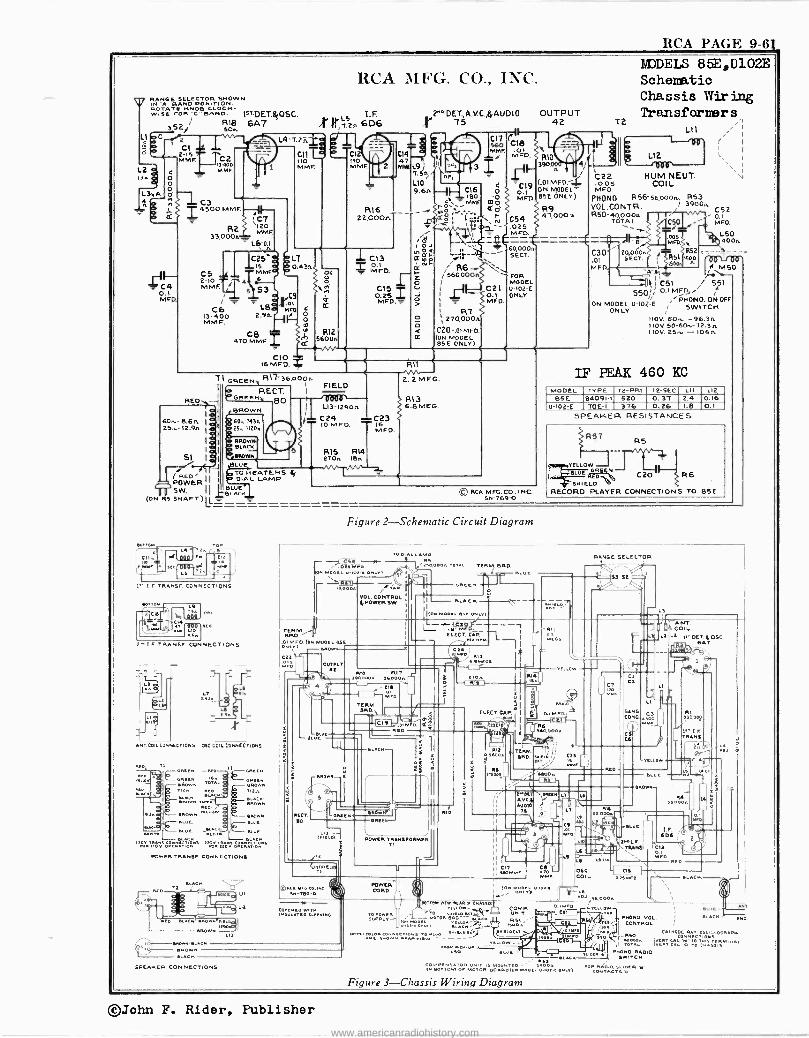
RCA PAGE 9-61
L2 I.2.
RANGE BAND POSITION TSHOWN ON I
ROTATE KNOB CLOCK- WISE FOR "C 'WAND. 1sTDETB¡OSC.
352/ R18 6A7 soA
RCA MFG. CO., INC.
C4 0.1 MF
CI 2 5 MMF
RED
0 MME
C6 13-400 MM F.
6on.-8.6A 05,-12.9A
SI I
T1
J (RE D' I
POWER SW. I
I BLAC BwE N
(ON as SHAFT) L
22,000A
CIO I6 MFO.
GREEN', R17'36.000,
RECT. 1
FIELD DGREENi ÓO
L13-12906 [BROWN
S 60..7436 025,11206
OO BROWN,g BLACK
TO HEATERS DIAL LAMP
C13 0.1 MFO.
R15 RI4 27Dn IBA
DET.,A.V.C.,E,AUDIO OUTPUT 75 42
I0«I NOpp
¢ F SN _
( --- o I - RT
`27O,000Á q
CZO -.OIMFO - (ON MODEL 85E ONLY)
R13 6.8 MEG
CS¿p (CI8 WIMP'. 04 t
MFD. C
© RCA MFG. CO.. I NC. 5N-1690
MODELS 85E,U102E Schematic Chassis Wiring Transformers
41
(.OIMFD. 4 ON MODEL 85E ONLY)
T2
)e0 ( S C22
R9 47,000A
O05 MFO.
PHONO R56- 56,000n. 853 VOL.CONTR. I 3900.
C52 R50-4o0Oon TÓTAL 0.1
C5O A, _ MFD.
851 o 50
HUM NEUT. COIL
L50 400A
FA 50 F1
iCSI 551 550!1
ON MODEL U -102-E /PNONO.ON-OFF
ONLY SWITCH IIOV. 60.,, -96.36 110V. 50-60ro-72.3 A 1IOV.25.,. -105A
IF PEAK 460 KC MODEL B5E
u -102-E
TYPE 84091-1 70E -I
T2 -PRI. 520 376
T2 -SEC 0.37 0.26
LII 2.4 I.8
SPEAKER RESISTANCES
LI2 0.16 0.1
íR57 RS
YELLOW J LDE N C20 R6 SMI ELD
RECORD PLAYER CONNECTIONS TO 85E
1 I f TRANSE CONNECTIONS
SIC
C IF TRANSF CONNECTIONS
ANT COIL CONNECTIONS SSC.COIL CONNECTIONS
NEE TI GREEN -ROO
GREEN I. -111 A NEO
. wOWN HARM NED
oRoom ` ARAM
Tu V-oREEK
BROWN 712n
sñOWw.
BLUE
row 110010.Otiiúnö roA 1600 321424.0.4"'
POWER TRANSE CONNECTION§
SPEAKER CONNECTIONS
'ro _ YNIT -.113).:A TO POWERMorON iéó1ó rCN R51 "" tit n ,IÍ-,F-y¿ 'II'`b U
-2-, Sa,o00. I WPM VEN -REM MOUSES
-JL,61,r COMP Mio
-0'22W-r.= H,-e- - r E,r"LLDW_
ASO HOC.
oN EorioM O[ MOTOR sósñOwN MOoal E -toa-[ oNlTl
Figure 3-Chassis Wiring Diagram
Figure 2-Schematic Circuit Diagram
TO DIAL LPAV * E5 .M- o. THAI.
*mow. U-Iot-[
\ .7 `g0óos r VOL CONTROL 1
Ç PO WER SW. I
ONCEN
TERM. BRD.
I - ELAC
ÌwN MOEHI Esc ONL.)
RANGE SELECTOR
r7 i.79-7
S3 S2
TERM. Kr 1
..0wt.T01 M F O. (ow MODEL Ese
LEGT. He HRH
Cott
...n OUTIIIT J! O 4
CMO
RIO RIT 090000* 5.000.
TEEM. ERE),
CIE 01.
UL
RECT. ED
C 9 .romI Fo. E Rao
SLACK
RIS O.A[c
trog
ELECT. CA P.
Cla
APE
Iñ LW
rx
uxln
0Rc
POWER TRAMSFORMER TI
R12 o 'mow 2
014
R
RM RD.
0.I
TELLO
wlá
000.
IMP
Cl CE
SANO CONE
LI
POWER CORD
'4004
LI
YELLOW
LT
MIKA
LS
AL:
LI Le_ Ose. COIL
ION moo P
IOlS Y I \`^L
ERO
ANT. COIL E I OCT {OEC.
SAT
e900c12
IR LI TRANS r -_
1>00000.
.SLUE
I I 1
C. F.
'DS f`oI.I. .TMNE.T Cl
Nco
D 0. SO
o
ADJ ä
b \\
KACK
SLUE
PHONO. VOL. HACK W0. CONTROL i
MO CATMOO
00v I10CILL00RA00
I rÓ1006 I nNr14t'Ö TO CwwAls '"`"
PHONO- RADIO SWITCH
EOR Aw010 LIOER W CONTACTSA
©John F. Rider, Publisher
www.americanradiohistory.com
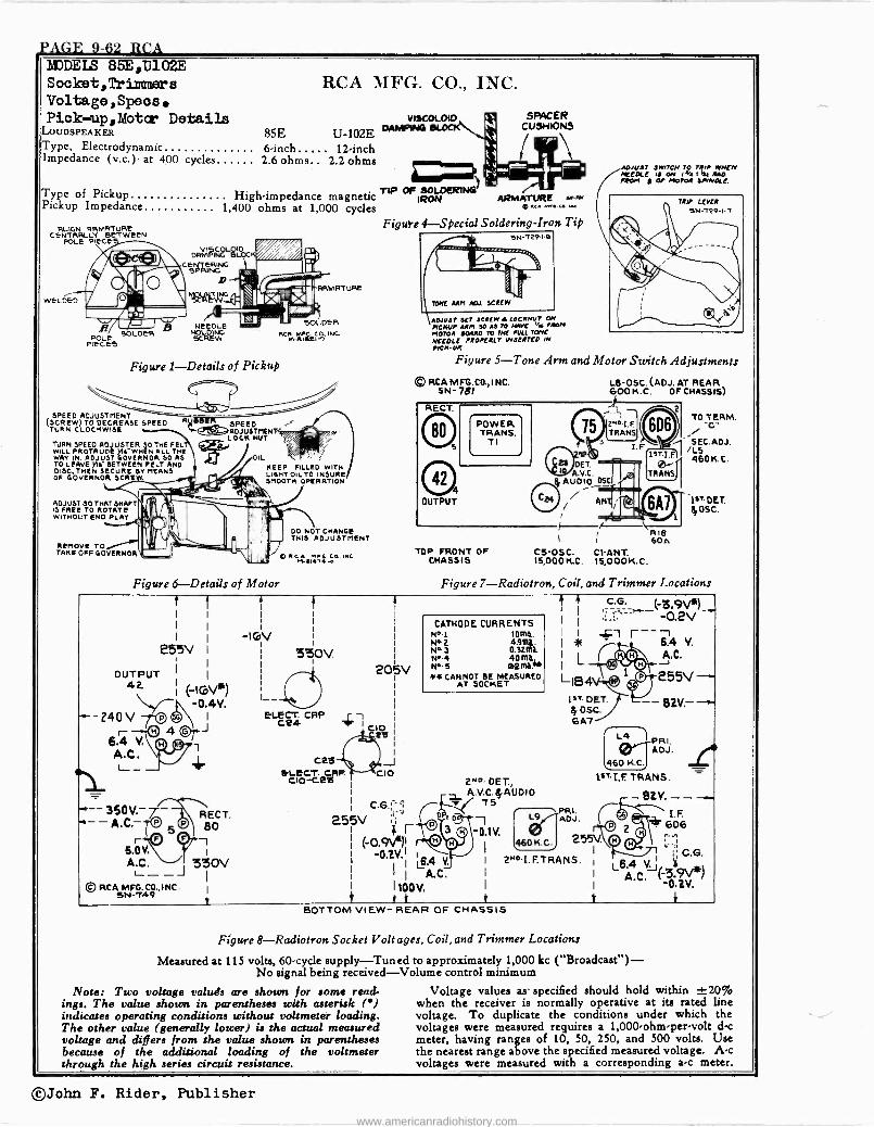
PAGE 9-62 RCA MODELS 85E,TJ102E
255V I
( lGv*) -0.4V.
-Z40V -r©® J Cr - W 4
6.4 Y.
A.G. L__ _
360V.- - - A.C.-
Socket,Triamers Voltage,Speos. Pick up,Motcr Derails
LOUDSPEAKER
Type, Electrodynamic Impedance (v.c.) at 400 cycles
Type of Pickup Pickup Impedance
ALIGN ARMATURE CENTRALLY BETWEEN
POLE PIECE
wELDED
POLE PIECES
SOLDER
RCA MFG. CO., INC.
VISCOLOu7
85E U -102E DAMPING
6 -inch 12 -inch 2.6 ohms.. 2.2 ohms
SPACER CUSHIONS
ADJUST 3TT/rcN r0 MP WHEN NEEDLE It ON I% I t RAD. FROM g or MOTOR SPINDLE.
High -impedance magnetic TIP OR SOLDENG IRO
RI ARMATURE sK
1,400 ohms at 1,000 cycles p ^" "' ̀° ' V ISCOLOID
DRMFING B
C SNPTRÑ G NSRTe
NEEDLE HOLDING SCREW
Figure 1-Details of Pickup
SPEED ADJUSTMENT (SCREW) TO DECREASE SPEED
TURN CLOCKWISE
TURN SPEED ADJUSTER 30 THE FEL WILL PROTRUDE h -WHEN ALL THE WAY IN. ADJUST GOVERNOR SO AS TO LEAVE yl E- BETWEEN FELT AND DISC, THEN SECURE DV MEANS OF GOVERNOR SCRE
ADJUST 30 THAT SHAFT IS FREE TO ROTATE WITHOUT ENO PLAY
REMOVE TO TAKE OFF GOVERNOR
OIL KEEP FILLED WITH LIGHT OIL TO INSURE SMOOTH OPERATION
Figure 6-Details of Motor
DO NOT CMANOE THIS ADJUSTMENT
pSC. MRS CO.IKC M -E1414-°
Figure 4-Special Soldering -Iron Tip 7N -1291G
TONE ARM ADJ. SCREW
`AOJYSr SET 3CREW6 LOCKNUT ON
MCRW' ARM SO AS TO HAYE vI$ PROM
MOTOR JOARO TO THE PULL TON«
NEEDLE PROPERLY INSERTED IN /ICH UP
Figure 5-Tone Arm and Motor Switch Adjustments
© RCA MFG. CO., I NC. SN -7ßi
POWER TRANS.
TI
4 OUTPUT
TOP FRONT OF CHASSIS
L6-0SC (ADJ. AT REAR GOO I.( .0 OF CHASSIS)
ITRANS
IJJJJJF
nI,
DET A.V.C.
AUDIO 05C
Cnp 7 AN /
/
CS-OSC. C1 -ANT. 15,000 K.C. 15,000K.C.
Rie sort.
2 TO TERM.
SEC. ADJ. il5 460K. C.
1ST DET.
Figure 7-Radiofron, Coil, and Trimmer Locations
OUTPUT 42.
RECT. 80
5.0 7
V.
A.C. , 3'50V
L © RCA MFG.CO.,INC.
SN -749
330V.
ELECT. CRP C24
C23
1-
205V
CIQII
J e-LCCT. CRP. } - CIO
CIO -ces
¡ C.G.;..
255V {
(-0.9v91 -0.2IV. i L6.4
V.
I A.C. I 100V. f t`
CATHODE CURRENTS N. 1 toma.
N° 3 0.32011 N° 4 4oma. N°5 mPmago **CANNOT BE MEASURED
AT SOCKET
2"O DET., A.V.C.eAUDIO
75
tI
I r- I * 6.4 V.
I L ( A.C.
cG'_ (_3.9v9 - -0.2V
L164 t ^ -255V -- 1ST DET. $ osc. 6A7
PRI. AOJ.
-0.1V.
I 2"D.I.F.TRANS.
- 82V.-
PRI. ADJ.
t. TRAN S.
-Bay. --- I.F.
606
I
C.G. L6.4 V X
A.c. (-3.9V*)
t BOTTOM VIEW- REAR OF CHASSIS
Figure 8-Radiotron Socket Volt ages, Coil, and Trimmer Locations
Measured at 115 volts, 60 -cycle supply-Tuned to approximately 1,000 kc ("Broadcast")- No signal being received-Volume control minimum
Note: Two voltage vainds are shown for some read- ings. The value shown in parentheses with asterisk (*) indicates operating conditions without voltmeter loading. The other value (generally lower) is the actual measured voltage and differs from the value shown in parentheses because of the additional loading of the voltmeter through the high series circuit resistance.
Voltage values as- specified should hold within ±20% when the receiver is normally operative at its rated line voltage. To duplicate the conditions under which the voltages were measured requires a 1,000 -ohm -per -volt d -c meter, having ranges of 10, 50, 250, and 500 volts. Use the nearest range above the specified measured voltage. A -c voltages were measured with a corresponding a -c meter.
®John F. Rider, Publisher
www.americanradiohistory.com
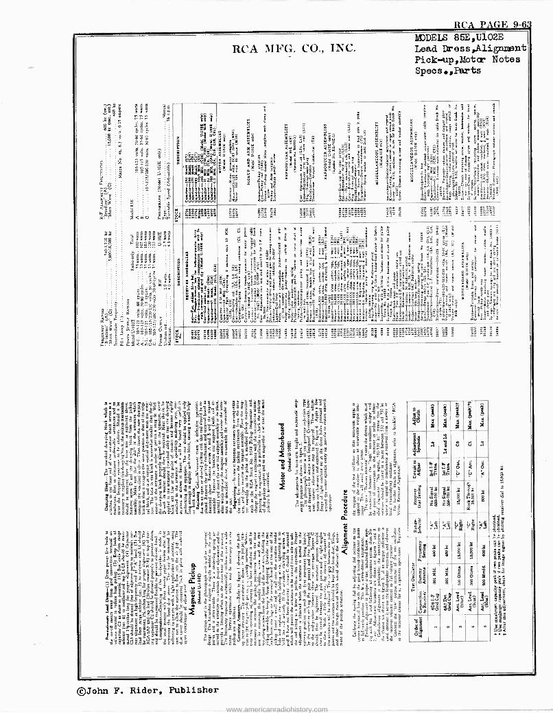
RCA PAGE 9- s
aaaaa m aa a66666g66
8ó'282 r.
RCA MFG. CO., INC. MODELS 85E,í 102E
Lead r ess,Alignment Pick-uup,Motor Notes Specs. ,Parts
E i pg..........0
.. .. Lir;óB= dd d.d.d a:::^ _avYlj4Qi§
fiTB
î$i ár L. ._ DD 7Z
á á".=
.'iSt .,-uw `d
aa : III7¡^'
'S z m z. 7:° 91 Q 1
. i 1 t< E I'Éë3;i°-gg__3 m r a . s
m Y9r á _ Y" 8i POI a
..
m
F : ? ;, d 4: 3 ' a 999 1 i 5,.: ^., .
2¡ ..
.-., `-i" .7 7 7^ 7 7< E t â:e . á$s Ñ»9 IáI ., ú?E t° s"é
Ë i 5 Yi -t- E á- r "<r: 9 5 "<Sr e''''t
? .,á i° L 51 $ 6"9° ! ?; g s-
X r9 e_ S 5 V a . É: m é uS a $ y.e;-; 8
22e ó° <' - g ry: á-$'9v m, y" 3
- -5i ' ¡ff. rt gq n -y ;er i: >E 7 ?5_ 07 7 B9 g pi za ó$^' ái49 éi__ k o4 6" =8 e $ °aq ' 08 .°_= : 4°q .2 ;4 a.` - 'u .2 é F: d : 7.'i °-S $r S "_. 535á;7 ei S S" -
le..."' aE n- > 7.e.=e
m .a.
ú 7 7°^^ °y ,. Y
3@ .. e y as'g
Ìy$
^ ß . S7..ú < Y r .. -' i.^" -
ijJEE
^^ ° ä; á 7".Sa m
lili ¡'i '9s Ç YE
: rz. ß,,xl!7 i.slY s?6BP
Çk
J,
y Ç!á
$éyé LIBI =yáéyp!p !ÿisáag«d°îtö:7
O i3 Ú10gh Nfim Úuu jrOoI á 7 >'
ez L::S... .. .. .... ........ _. . M9 :47.!.: ._. ^ _ .. .. _. ." . . . .."..
:
E ti °
a ß
3ä=a
;6á k77
2 a ä r
e á
a
á áa72 úû 3a41dd ái-11:
K ig Sie G xlq
é1 7g
ñu u3 WWI
i
n S D" a ;I ' 9 : ., c ' . H8
S ° Y _ S .. ^ °i ... I A C 7 uu á `7 S
7 to. : '8
a á 3 ..._ ., â
1
s g !.. a á^ áá mra'r-rmr^ ûû { ,- +
< _
7 rg
B y s Ì
_ a°t cCC ysxc0l:.º E E E $ z°
a .
7 7 s _ e3 â¡ id, 6iCiiiiE'S i_ Y 53 éy 3- a- x s $ ' 28 E_8 ye ++6 ..... - -..+tid
:F E v ia 1
`
` L 3= :7 i é i
s.'g $ä B 8 a ºs_ a > C i'
E ;4ä 5`' . a Ç . i" K°Fg
4 js:g °
. ! Y8°
.
° i i Ill i,l;49Za7 5 r é¿°7 755 i $i aa___ 9 i a3 &-«.
'f 5 Im!5 e9 J. y5 `:3 : 7 y i°°aya..m.,; ál ^
I -1 Ill !!dd
áá ae,=:.e= dyé ' a"-° 7 i s"es
t- s°E % 91E' S,-a`O<$''v4 . 4
S^_ á 4" ïä ;; 8 1° ,. ^rr_ osgw'..: tër g ai_
gt7r á yá#¿ñO oeéééóóéó9eáé.á..eñgÉ !a.ia a ° . a : ^ - t 'o$$vooéééa.ei ég'6.'I I `á`
T fI .a ag ^ T ;'ds'BEs; 2- 5 ?iF
BISYB3°^á'si: '>!3óI^0=I.`ái!_7Í¿mîlî¿Tiîîî ily=º=I=¡° Tiiii 2- l' 19áyá=" 1y11p3.zBá9säeqy_"ss`asá᪪-3isxlsl' ed
3Q uga _. g a sóil-Eii'EeEEib6daiysº 9 .3ááE Qm3a uu 3 Y3 oó.S3á n re maa arr mamrraaaaaam Mg' .5'5 8 FÑ rf> >
1, 5
i .
_ -
°e
7 2=". m - s:é
k `°C3
<e fi "s
ñ 4" È c4
ma 4 ; Ë c "y s º°-
ó é5 EE-sói ,y Sári g°' s I-rygh9
'i'
5s'em 1"It" múii:mm"
rSS g: S 98@7=. ~
3 23222 : 22 2 222 222 áê&:á:ÉöS ñ'«Rn":t:r:: á . ... 'R ...... _ .. . ." ._ R ... ^.."" ... ^ ^.
92i855e,o9 'a45.e ixÉgX
.o5e8V
'g5:º:1o3fl 9.1:'3.á' 7 v.6B54 o:e.-
7.
xoCe8 ¢ .81<gd'ì ºaLx__1' " sa2Ez.ië .yvñ_91e<
5
a5`9-'oZ:ki-e _8bî5Rca$ a"38554 '5 @iä7@':ggó-3 °moC tlç4 é.e=.s. 5a8 Jo"geáqa
12 i '241:11i1 4i-59sa X=B é' -
fa
1E9.yá
ó
: s'"
9
5 -5 0.-13,:d1
Sáóé,i.ggom3ee
3 P-9li a áa°a3elöá.._.,d C £ .7 _ Bpe°
Só C
iS 8.. e - 59- . çY !! § 3 Qi .a s8c
ó3 .vc`°7sZ8°.X$óS.3,ayq p.é: BC 1ªiß.:"2850°áveáe9B
Ce 55eet7w DeoEó'7E"b$ 2 a $9.äá°:a5Ee5o "aC"o..o
``oY:V°?: :aS"-.3 'z ` e 268.eEtl$e..áo $S aeiá wrY
sá- m-5-55:
: :gel. -
el.
. ..s
24141'11
3C" ?r
"P 'sget '3.3e52
F e da5
a ocel8
o ^ _ rº"«é S
eL388sa ` a ,
v = : e,á.e. i .¡§15T.4
-2-56.E-Ja
° =.83 3ó6ce1ÿ6
`s qññ
5ó -' 7c9 7 ï8 a: er! " 'e
.g; ele" g9 ;.aÿ 'axaZ5E5á$<Ee853<o3aö$>i E ï..
á1 <
Hill á
i
J
3*
á
' <
s a a n
8i "A e` a Ó a9 Ó < ;ar
.7 JF ú iV
el 8 5 $ 12 áQ z z " r
5B5
Oi < < g, <ÿ
ç çç
L i i d 8
wa e d 7i
"8,
d i
a
ó = á
ñ H
á9 ,
e8
o.¡ ud$ 8g
$ § é e
§ §
á$
Mi
e e
hi e
8 ., a n e m
o
©John F. Rider, Publisher
www.americanradiohistory.com
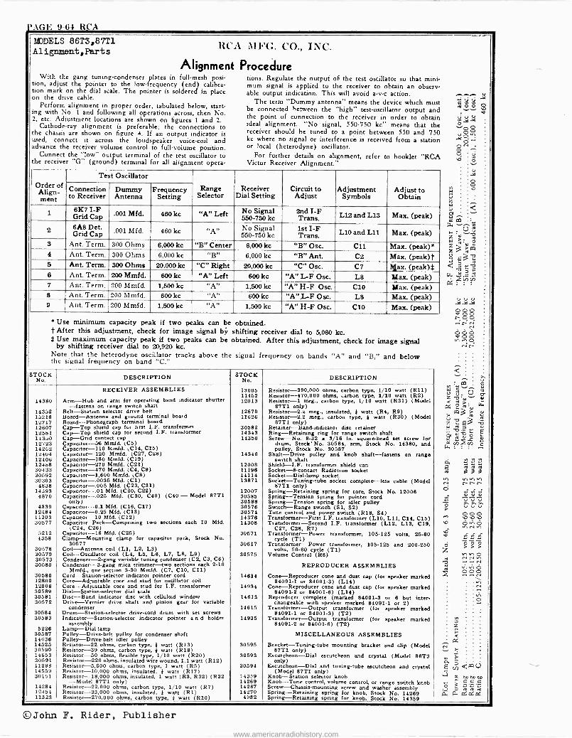
)'AGE 9-64 RCA
MJDELS 86T3,87T1 Alignment,Parts
RCA MFG. CO., INC.
Alignment Procedure With the gang tuning -condenser plates in full -mesh posi-
tion, adjust the pointer to the low -frequency (end) calibra- tion mark on the dial scale. The pointer is soldered in place on the drive cable.
Perform alignment in proper order, tabulated below, start- ing with No. 1 and following all operations across, then No. 2, etc. Adjustment locations are shown on figures 1 and 2.
Cathode-ray alignment is preferable; the connections to the chassis are shown on figure 4. If an output indicator is used, connect it across the loudspeaker voice -coil and advance the receiver volume control to full -volume position.
Connect the low" output terminal of the test oscillator to the receiver "G" (ground) terminal for all alignment opera-
tions. Regulate the output of the test oscillator so that mini- mum signal is applied to the receiver to obtain an observ- able output indication. This will avoid a -v -c action.
The term "Dummy antenna" means the device which must be connected between the "high" test -oscillator output and the point of connection to the receiver in order to obtain ideal alignment. "No signal, 550-750 kc" means that the receiver should be tuned to a point between 550 and 750 kc where no signal or interference is received from a station or local (heterodyne) oscillator.
For further details on alignment, refer to booklet "RCA Victor Receiver Alignment."
Order of Align- ment
Test Oscillator
Range Selector
Receiver Dial Setting
Circuit to Adjust
Adjustment Symbols
Adjust to Obtain
Connection to Receiver
Dummy Antenna
Frequency Setting
l 6K7 I -F Grid Cap550-750 001 Mfd. 460 kc "A" Left No Signal
kc 2nd I -F Trans. L12 and L13 Max (peak)
2 6A8 Det. Grid Cap
.001 Mfd. 460 kc "A No Signal 550-750 kc
1st I -F Trans. L10 and L11 Max. (peak)
3 Ant. Term. 300 Ohms 6,000 kc "B" Center 6,000 kc "B" Osc. C11 Max. (peak)* 4 Ant. Term. 300 Ohms 6,000 kc "B" 6,000 kc "B" Ant. C2 Max. (peak)t 5 Ant. Term. 300 Ohms 20,000 kc "C" Right 20,000 kc "C" Osc. C7 Max. (peak)$ 6 Ant. Term. 200 Mmfd. 600 kc "A" Left 600 kc "A" L -F Osc. L8 Max. (peak) 7 Ant. Term. 200 Mmfd. 1,500 kc "A" 1,500 kc "A" H -F Ose. C10 Max (peak) 8 Ant. Term. 200 Mmfd. 600 kc "A" 600 kc "A" L -F Osc. L8 Max. (peak) 9 Ant. Term. 200 Mmfd. 1,500 kc "A" 1,500 kc "A" H -F Ose. C10 Max. (peak)
* Use minimum capacity peak if two peaks can be obtained. t After this adjustment, check for image signal bÿ shifting receiver dial to 5,080 kc. $ Use maximum capacity peak if two peaks can be obtained. After this adjustment, check for image signal by shifting receiver dial to 20,920 kc. Note that the heterodyne oscillator tracks above the signal frequency on bands "A" and "B," and below the signal frequency on band "C."
STOCK No. DESCRIPTION STOCK
No. DESCRIPTION
14380
14352 13216 12717 12607 12581 11310 12723 14262 12404 12406 12488 30433 30592 30303
4838 14393
4870
4839 12484 11203 30577
5212 4358
30578 30579 30573 30580
30586 12800 12006 30589 30581 30572
30584 30583
5228 30587 14636 14525 30590 14653 30591 11298 14559 30151
14284 12454 11323
RECEIVER ASSEMBLIES
Arm -Hub and arm for operating band indicator shutter -fastens on range switch shaft
Belt -Station selector drive belt Board -Antenna and ground terminal board Board -Phonograph terminal board Cap -Top shield cap for first 1.F. transformer Cap -Top shield cap for second I.F. transformer Cap -Grid contact cap Capautor-58 Mmfd. (C5) Capacitor -110 Mmfd. (C14, C15) Capacitor -120 Mmfd. (C27, C28) Capacitor -180 Mmfd. (C19) Capacitor -270 Mmfd. (C21) Capacitor -470 Mmfd. (C4, C9) Capacitor -1,600 Mmfd. (C8) Capautor-.0035 Mfd. (C1) Capacitor -.005 Mfd. (C23, C31) Capacitor -.01 Mfd. (C20, C22) Capacitor -.025 Mfd. (C30, C40) (C40 - Model 87T1
only) Capacitor -0.1 Mfd. (C16, C17) Capacitor ---0.25 Mfd. (C13) Capacitor -10 Mfd. (C12) Capacitor Pack -Comprising two sections each 10 Mfd.
(C24, C26) Capacitor -16 Mfd. (C25) Clamp -Mounting clamp for capacitor pack, Stock No.
30577 Coil -Antenna coil (L1, L2, L3) Coil -Oscillator coil (L4, L5, Le, L7, L8, L9) Condenser -2 -gang variable tuning condenser (C2, CS, C6) Condenser -S -gang mica trimmer -two sections each 2-10
Mmfd., one section 3-30 Mmfd. (C7, C10, C11) Cord -Station -selector indicator pointer cord Core -Adjustable core and stud for oscillator coil Core -Adjustable core and stud for I.F. transformer Dial -Station -selector dial scale Disc -Band indicator disc with celluloid window Drive -Vernier drive shaft and pinion gear for variable
condenser Drum -Station -selector drive -cord drum with set screws Indicator -Station -selector indicator pointer a n d holder
assembly Lamp -Dial lamp Pulley -Drive -belt pulley for condenser shaft Pulley -Drive -belt idler pulley Resistor -22 ohms, carbon type, } watt (R13) Resistor -39 ohms, carbon type, } watt (R19) Resistor -50 ohms, flexible type, 1/10 watt (R20) Resistor -220 ohms, insulated wire wound, 1.1 watt (R12) Resistor -5,600 ohms, carbon type, 1 watt (R5) Resistor -10,000 ohms, insulated, } watt (R17) Resistor -18,000 ohms, insulated, 1 watt (R3, R32) (R32
-Model 87T1 only) Resistor -22,000 ohms, carbon type, 1/10 watt (R7) Resistor -33,000 ohms, insulated, } watt (Rl) Resistor -270,000 ohms, carbon type, } watt (R10)
13005 11452 12013
12679 11626
30582 14343 14350
14340
12008 11196 14114 13871
12007 30585 30588 30578 30574 14376 14308
30571
30617
30575
14614
14934
14613
14615
14935
30595
30593
30594
14359 14289 14287 14270
4982
Resistor -390,000 ohms, carbon type, 1/10 watt (R11) Resistor -470,000 ohms, carbon type, 1/10 watt (R2) Resistor -1 meg., carbon type, 1/10 watt (R31) (Model
87T1 only) Resistor -2.2 meg., insulated, } watt (R4, R9) Resistor -2.2 meg., carbon type, } watt (R30) (Model
87T1 only) Retainer -Band -indicator disc retainer Ring -Retaining ring for range switch shaft Screw -No. 8-32 x 8/16 in, square -head set screw for
drum, Stock' No. 30584, arm, Stock No. 14380, and pulley, Stock No. 30587
Shaft -Drive pulley and knob shaft -fastens on range switch shaft
Shield-I.F. transformer shield can Socket -8 -contact Radiotron socket Socket -Dial -lamp socket. Socket -Tuning -tube socket complete -lesa cable (Model
6711 only) Spring -Retaining spring for core, Stock No. 12006 Spring -Tension spring for pointer cord Spring -Tension spring for idler pulley Switch -Range switch (SI, S2) Tone control and power switch (R18, S4) Transformer -First I.F. transformer (L10, L11, C14, C15) Transformer -Second I.F. transformer (L12, L13, C19,
C27, C28, R7) Transformer -Power transformer, 105-125 volts, 25-60
cycle (T1) Transformer -Power transformer, 105-125 and 200-250
volts, 50.80 cycle (T1) Volume Control (R8)
REPRODUCER ASSEMBLIES
Cone -Reproducer cone and dust cap (for speaker marked 84091-1 or 84001-3) (Lie)
Cone -Reproducer cone and dust cap (for speaker marked 84091-2 or 84001-8) (L14)
Reproducer complete (marked 84001-S or 6 but inter- changeable with speaker marked 84091-1 or 2)
Transformer -Output transformer (for speaker marked 84091-1 or 84001-3) (T2)
Transformer -Output transformer (for speaker marked 84091-2 or 84001-6) (T2)
MISCELLANEOUS ASSEMBLIES
Bracket -Tuning -tube mounting bracket and clip (Model 87T1 only)
Escutcheon -Dial escutcheon and crystal (Model 86T3 only)
Escutcheon -Dial and tuning -tube escutcheon and crystal (Model 87T1 only)
Knob -Station selector knob Knob -Tone control, volume control, or range switch knob Screw -Chassis -mounting screw and washer assembly Spring -Retaining spring for knob, Stock No. 14269 Spring -Retaining spring for knob. Stock No. 14359
E ro
w
ÿ 5
ááá vthh r-rr
©John F. Rider, Publisher www.americanradiohistory.com
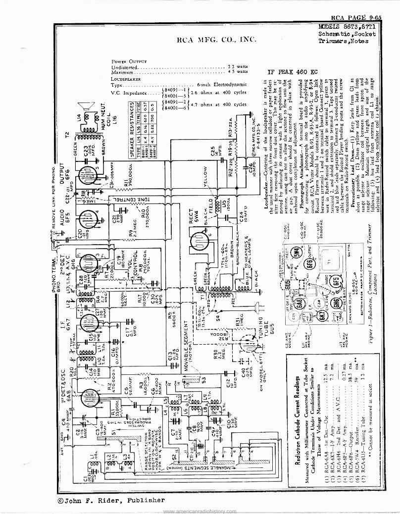
RCA PAGE 9-65
z w
O
RCA MFG. CO., INC.
POWER OUTPUT
Undistorted Maximum LOUDSPEAKER
Type
V.C. Impedance
2.2 watts 4.5 watts
6 -inch Electrodynamic 4 84091-1
2.6 ohms at 400 cycles 84001-3 84091-2
4.7 ohms at 400 cycles 84001-6
r.1
r Ñ Io J
r á
o al
d
h d
N
J IV
N
W 7-
.i ág Ó
Pó ZÓ
ó O II.
q o ....O
i )3Vy I ---J-- IOtilN0J 3N01
'MMA, w v -IHiI `.0g
Cf oLL NP-. O 13 Kt
W Ò Ñ
e
o
J 4
_ido û ó o I- ó á o m i Zm00 7MO
CCÑ ..« 1'I d N r
ú N f
e o
Sa
w
Ú W
g'cc
Ó
W }
W ZZ
HII. r
OE1 1 to;MrvíOi I rl ó t) 0. - f ---r W -/W
I
tn d ctó
lo
NO ce) NU.
5o2 IH
o0 4 et o
CC r- î N ói pî a` c U ú'2f e o o
á o,
111140I 1231310 SINl NI S3SS31i9O\!d
IL HDLIMS U1
> -- f N aQamz °r!ol-m jZooCP,
I ZOe d á 03 rF
1'
I., eel
IÑZOUm N IZOuOfN j ...,V ' 31_m.
'11 .A` \v m I a 1, áu=iál° (tl010a) S1N3W93S - 4 Jo
111
u IN
Ne.\
4 N
IV
MODELS 86T3,87T1 Schomatic,Socket Trimaaers ,Note s
IF PEAK 460 BC m p V er Çúwó váQáSpú,a, aóSC
:Ta ú' Ú e
óÿë
V °'O o E ayáOÿ E°am, c..i!«
«aÿ.5 áÚ1,4ám 1-0E-1".:-2, ^qE, °° m ds 2 ao Ç.A.arlo.
OOUu'CYoIl1yV.w to NV too V «
24 g -g
É c á ä p 3 g C u.a-D $ QQJi ^ ûA ó «? ér ú A'p.. E V 6 o <.cc o ,,- I .° óc V^ ° oc .d3 °
V V` p°° . N.. u° [.Cd.. ú p.i ÿ1 °"'" Q .G V á Ó d 0 N.6
01 A^, C...°, V agá áúú ^ = á v N°
á d c.f i3 ;'ê
ro ?« á m b ÿ b ei p,,.o ¡ c °9 D c ç7 .E ò á-'^' c á °.. L d G, auddroEÑp7úá Ó
ú yyE < VC3 gpï,ó aáwúvá
ciY+a w 7 á 00«
11S:á $d'^á1 a«VVâ3 ?o `"^+' "0000
e+: ó d á. Y. e"i;3 Y Evá E a ó c c : E °'uoGp30 ú: -gC:'Qg
z Iná n aF o = ra
m 3 aJ O WJ
I
w I--
I,_ , rnF Z oM *r_ CO
cC_ W L-_--^^'. -¡^^"` l 2 I v000'91 I _-_1 h tt`___-^.^.^T-o--rJ.J
J m
R cr
2v
1 22 ¢ ;iv:: Hi' 4
lu/1
Oíut
ÓO V ul 5
'I a
Ì ó
=ó l O i or Z1¢ Wm Zr er - p ff :i:r-L!
ÑY Oó
Uñ
Ñ
EEEE r - N v tV
ó
.+ N ee1 Y v, .p 1`
©John F. Rider, Publisher www.americanradiohistory.com
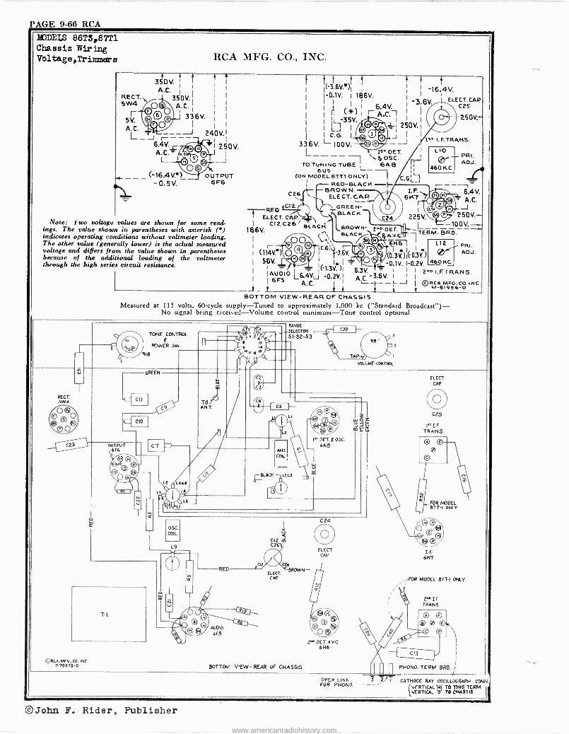
PAGE 9-66 RCA
M)DELS 86T3,87T1 Chassis Wiring Voltage,Trimmers RCA MFG. CO., INC.
" t ? 350V. I
A.C. I
Z1RECT
350V. 5W4A.C. '
5V ©33 A.
IJ
0
I1
V --J r- 6.4V - A.0 L
(-16.411*) - 0.5V.
1 250V.
OUTPUT 6F6
Note: Two voltage values are shown for some read- ings. The value shown in parentheses with asterisk (') indicates operating conditions without voltmeter loading. The other value (generally lower) is the achtal measured voltage and differs from the value shown in parentheses because of the additional loading of the voltmeter through the high series circuit resistance.
©RCA MFG.. CO. INC. T-70875-0
t ''
1 i( -36V.. )1 j ¡ -16.4V.
1 1-0.1V. 1 186V. 1
AA 1 1 6.4V. I
-3'6V ELECT. CAPA7
i IIL 35V. M A.C.1 Ì i / 250V.-
1 I i I¡óa.i25oVl \
I I C.G. © J 1 1sTI.F.TRANS. 336V. L 100V. e O -- ' L----- 1sT.DET I
4, OSC. TO TUNING TUBE L- 6A E3
T -REO ELECT. CA,P 1
C12,C26 BLACK `BROWN - 186V. BLACIc/
G (114Y.') Q ®
r Ol C
-3"6V,
50V.
6U5 (ON MODELEL 8771 ONLY)
¡ ¡--- RED -BLACK -F- C26 F- BROWN
ELECT. CAP 4C12.7GREEN-
BLACK 1
225V.
2^'.-DET. $ A.KC.Ú 7
6H -En
(03)1(>03V.)
PRI. ADJ.
460 KC i
6.4V. A.C. J
250V.- -100V.
TERM- BRO-
I
e 1 - L -0.1V. 1-0.2V.
IAU010 L6.4V.J(!p2y,i 6.3V 6V. 1 j
2"o-IF.TRANS. A.Ç.
I 6F5 A.C. -J ©gCA MPG. CO. INC. M-81956-0
L10
L12. PR, er''''fADJ.
460 KC
BOTTOM VIEW -REAR OF CHASSIS Measured at 115 volts, 60 -cycle supply-Tuned to approximately 1,000 kc ("Standard Broadcast")-
No signal being received-Volume control minimum --Tone control optional
OUTPUT 6F6
TONE CONTROL
POWER 5w.
R18
L8 L4A,B
L4
RED
AUDIO
6F5
RANG
SELECTOR
S1 -S2 -S3
< C12 . C26)
CIL C26
ELECT BROWN -
CAP
BOTTOM VIEW -REAR OF CHASSIS
FOR PHONO. -
1"DET.FOSC. 6A6
ELECT. CRP.
PET AV C 6H6
WLUME-CONTROL
ELECT. CAP
C25
r, LE TRANS.
FOR MODEL 87T -I ONLY
2FOR MODEL 87T -I ONLY
z I
2"11.IF TRANS
PHONO. TERM. BAD.
OPEN LINK 3 z/ 1 CATHODE RAY OSCILLOGRAPH CONN.
{VERTICAL -H( TO THIS TERM. VERTICAL 21- TO CHASSIS II
©John F. Rider, Publisher
www.americanradiohistory.com
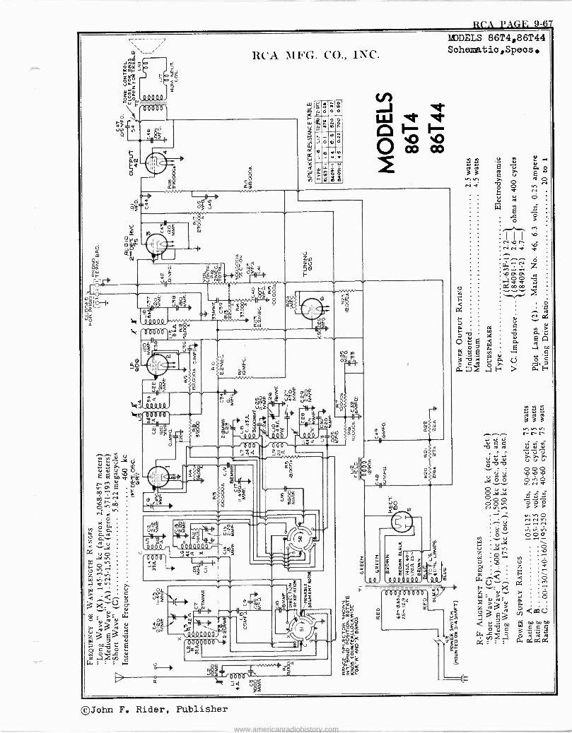
RCA PAGE 9-67
e
RCA MFG. CO.. INC.
F
Q
lM''OiL íf N4
o N ç 3II°
d ö
o
ò
Iti lírvi
o
-7: .7, ó ei
m w f v1 ì
ó J.
á Ç ä
ñDDELS 86T4,86T44 Schematic,Specs
a O
81-, Na <
óplEóogÑ /2114 >U
á r 1ó
-.-rO.L mOu J8£
Y INf IA> 1u Ú M10
rL d 1.->O_
Jd/ n / f T 1ív m in£ .QQ000
N_f2d
6Oö06`J:g Q
IM
Ilpp
J
d1 e a
ÚO N
d a a_o
N Of Q N úxN m
QQQ O O
0006 g ÚNe1 iQ -F f
º Q
F
N
J O£ aNlyUn I -0:140.
£M1 ó - OF VNf
X
1 1 1 1 111
1 111
Jo Prv
ud m-óç
Ó
6 m
NNF MÑF JNF UÑ£
J`N e k M
L04.4 4e.
`Q40000. fmF
U'OnV JYri U -F
Sm -+ Of 5
O,L
011 -21E>
deli...,d "N1 nQ
\111100QJvá x 0006E5'0\4
J m:1
PU Ña RF
of
Z=
ó
u
a
d
N$f 1 . .wv I Q .
u_F
b
N N
z W
v
y
q
Lee'
00
4
o m n Id-` m UlIr,r-
QQ Q9 QQQ °19 1 1 1 i 1 1 1 1 1
° m u m u N te 33 0
.4 o
N
r N -+
:; 4.1
ááá c- r r-
m
©John F. Rider, Publisher
www.americanradiohistory.com
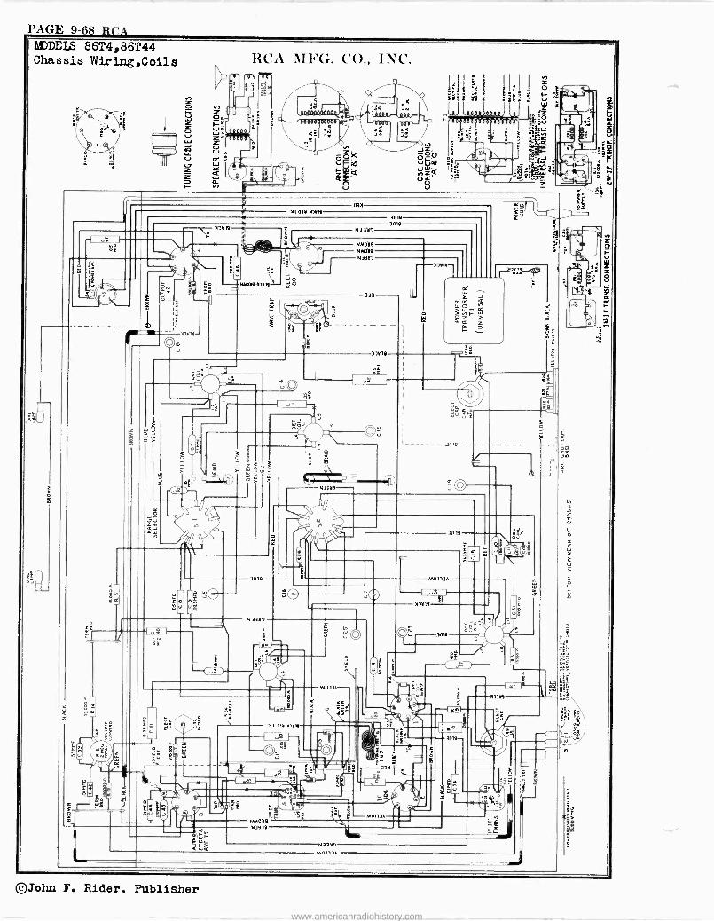
PAGE 9-68 It CA MJDEI: 86T4,86T44 Chassis Wiring,Coils
2
O" ß ì}lB//II
(AP
RCA iIFG. CO., INC.
il H
J
set
ÓO)< uF -"
S'..
Z el I
h º
lsl: I_
y. __.J:ñ 8 261%7,
,- ei
I 0 E1
%e
.44
11103. 10411 an
-{ g
1
{
02
NMM A/1
N33)1
-Onlº
3mº
O O
NM039 NMOaº N33a!
1
UQO l l
3i
aia
óç
.' /
/I
h [ o
o
QJ
K W
-3n19- - -
c 3iUE We e
a yy
2
wee Y ç V
T
.. -ll .1.Yj111
I^
U
MO1l3A-
iSh
á
3n1º
M0113Á
1311111
z
m= Ié
x
0
n
Vit;
O
. le 1.
QJ
r. O
O - Ry jCZ / \ NMU)º J
ytly
z Ѣ
C
Ilh
.E
pge
at 03)
M0113Á
so Lè111
1
-31111111K
J ;' 1 3s
N
N33)! M01 -13A
o
¡g
©John F. Rider, Publisher
www.americanradiohistory.com
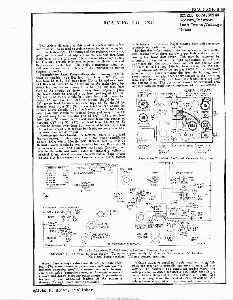
RCA PAGE 9-6v
OUTPUT ' L 6,3v.-.1
42 A. C.
RCAMFG_CO.,INC.
RCA 3111G. CO., INC.
The various diagrams of this booklet contain such infor- mation as will be needed to isolate causes for defective opera- tion if such develops. The ratings of the resistors, capacitors, coils, etc., are indicated adjacent to the symbols' signifying these parts on the diagrams Identification titles such as R1, Ll, Cl, etc., provide reference between the illustrations and Replacement Parts List. The coils, transformer windings, and reactors are rated in terms of d -c resistance to permit continuity checks.
Precautionary Lead Dress.-Keep the following leads as short as possible: (1) Bus lead from C16 to S2, (2) bus lead from L8 to S2, (3) leads from C24 to L8 and to chassis. (4) Bus lead from L5 to S2 should be 21/2 inches long be- tween lugs .and dressed away from S2, (5) bus lead from C17 to S2 should be dressed away from adjacent parts, (6) leads should be dressed away from grid lug of 42 tube, (7) Cll lead to L5 should be 1 inch long and dressed be- tween L5 and C4, C11 lead to ground should be short, (8) green lead between opposite lugs on S2 should be dressed away from S2, (9) excess antenna lead should be dressed above chassis, (10) blue lead from L7 to 6A7 oscil- lator plate lug should be dressed down and away from L8
lug and away from oscillator grid of 6A7, (11) green lead from L6 to S2 should be dressed away from bus connected between C17 and S2, (12) red lead from L6 tap to S2 should be dressed away from bus connected between C17 and S2. When necessary to replace bus leads, use only wire hav- ing same diameter as original.
Phonograph Attachment.-A terminal board is provided for connecting a phonograph into the audio amplifying circuit. RCA Victor Models R-93, R -93-A, R-93-2, or R-94 Record Players should be connected as follows: Remove link between terminals 1 and 2 on terminal board. Connect green wire in Radio -Record switch cable to terminal 1, yellow to terminal 2, and shield extension to terminal 3. Tape unused red and blue leads separately. Connect a 2 -conductor twisted
MODELS 86T4,86T44 Socket,Trimmers Lead Dress,Voltage Notes
cable between the Record Player binding posts and the screw terminals on Radio -Record switch.
Loudspeaker.-Centering of the loudspeaker is made in the usual manner with three narrow paper feelers after first re- moving the front dust cover. This may be removed by softening its cement with a light application of acetone, using care that the acetone does not flow into the air gap.
Speakers RL -63F-1 and $4091.1 have screws for the cen-
tering adjustment, while on speaker 84091-2, it is necessary to separate the glued centering disc from the housing, insert paper feelers in air gap, then apply cement to the centering disc, press down firmly, and leave the feelers in place until the cement dries. The dust cover should be cemented back in place with ambroid after completion of the adjustment.
'C`OSC.C23 20,0001C.C.
OET. p2 TUNING TUBE .6 20,000 H. C.
4 1
AU010 OUTPUT
\\ LI\ \
/ \
RECTIFIER/
)
f RCAMFO.CO 15C. li COIL
151 a K Y - WAVE TRAP \ 'A' 05C LII (TOP REAR OF CHASSIS,' -A-DET. C15 460 KC. LI \\IT5HC. 1350 A.0 .
'A' ANT. C6 VA -05C. C29 35014C. 350 14.C.
/WANT. C4 'A'OSC.L10 i1500H.C. 600H.C. / -A"06C.C2S , 'A DET. C13 1500H.C. /1530H.C.
2DET nu010(6
O5C COIL
L16 601(11
Figure 1-Radiotron, Coil, and Trimmer Locations
CATNODE CO@NTS
(1) tCA-4A9 n.4 NA.
ut RCA -5A 115tt MA
a) ACA-1t O11.501A
(4) RCA -4t 35 MA
(5) RCA -t0 I N IIA.
(5) RCA -645 CAMA.
CA5 NOT AC MAAM1tC0 T AOCNAT
t f I Rao R21 Rn I O5C COILl
L=16V.=1J v f `* x 1 r -1.35V :RES. ASSEMBLY
I
C413
--350V.-A.C. -r-7700V.-A.C. RECT.
80
5V. A.C.
- 330V.-- -
(-t6V.e
EL. CAP.
05C. C01 L
(-3.2V.4) - D.4v (. -
LC. G.
DET.
()ET. COI L
ANT. COIL.
2ASV. > v A e 7C
-235V.- P 4vß\ Q TONE CONTROL
POWER SW.
A.C.
49
EL. CAR.
249V.
1-'(112V.4)__ 100V.
--155 V. - --- 4.05C. L___ _-1-22.4V'I- SAT (-7 V.)
BLACK- BROWN TR BLACK
TUNING UBE CABLE
DET. COIL BLOCK-GREENTR. ... ... BLACK- RED TR.
VOLUME CONTROL
BOTTOM FRONT OF CHASSIS
C.G.
rti (-1.35V.') -0.5V.
v
lAT I.F. TRANS.
PRI. 0.34.) 1 _o I
ADJ.
-0.4K (3.2V.) C.G. - aav. :,
A.G.__ 6.3V .C.
__j I.F. 6D6
(100 V.') 94V.
PRI. ADJ.
BRGM.
ZOO V.-
2"'pET.,A.F r- - eA.V.C. bv. rie
75 `, 6.3V. A.C.
(12SV.") 87V. -
P-T299A-1
Figure 2-Radiotron Socket Voltages, Coil, and Trimmer Locations Measured at 115 volts, 60 -cycle supply-Tuned to approximately 1,000 kc or 300 meters band-
No signal being received-Volume control minimum
Note: Two voltage values are shown for some read- ings. The value shown in parentheses with asterisk (') indicates operating conditions without voltmeter loading. The other value (generally lower) is the actual measured voltage and differs from the value shown in parentheses because of the additional loading of the voltmeter through the high series circuit resistance.
114 60Á.0
Voltage values as specified should hold within ±20% when the receiver is normally operative at its rated line voltage. To duplicate the conditions under which the voltages were measured requires a 1,000 -ohm -per -volt d -c meter, having ranges of 10, 50, 250 and 500 volts. Use the nearest range above the specified measured voltage. A -c voltages were measured with a corresponding a -c meter. -
©John F. Rider, Publisher
www.americanradiohistory.com
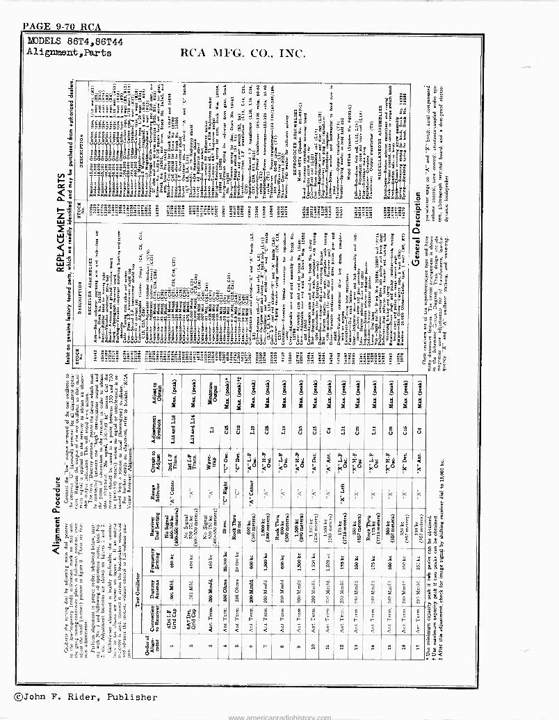
PAGE 9-70 RCA MODELS 86T4,86T44 Alignment ,Parts RCA MFG. CO., INC.
i
1
x
a
`1,13 $.
ó in ZIa^mm '^^ `3
3 .m á
g ' iáárczáke
ñ u ó 0,: á:,éª ^ ]
m w
xzÇ:
Ckt@kDkFk'm«5 9 9
: '
e á m^e r. 2 a a
x r.
5
ai
Ziá'0iney Z
"m4+?vá ó .3',;¿ I ;3! .á : _;ÿ_6m. ---7-----7,1:`i á' á b 1e 5$5Feza3 <°
3gMh:13i-_"Vn«á6Iº
Mg b+
:ÿ<zi ptii ÿ ri
Ñ
iea.
a$aaxÓ-eLDv"dbiL5á= ea
w
h9ú«ûi
$
h
k
'
p SSa lú9< x4z7 ma_é eil I E/" äa: igó,é `w9.5frysor/îy>m?5sááná
.2,....1 5 5p^6 '221g .:11t5,. .ádñ _ x ibSrr ®ú m- ú ` eà.
K^t Qh ñ9E18 éBE ñs é
O a¿=mOOOOÓOÓOOooOá;a
»' `áÉ 9
tli b
e°aE 2mÿ7k Ë ^ "Lé 0000eoeeSg$:°a»zá3 á a» ia '.'4'--gli ddd
mm'
ln yºl
1 YY 4aTlIÌT7lml2 ?@a@ Eblj 1Ì1x17$i
1i 7 1.!PeeaZZáó'Ú<Ó".KF5
hg x Me? e'
Y
1 aEaaaaaaAa!aa HwbHneám wlj Ñi ViV 3 ú>lF k,q
h » »»» »» »a»'eoeo e aaaaa a »» y » » »iOP á a r e » »»»»» »» »» »» »» »»»»
ó a ó,
eVmO
O
ä ̂û x á' Ili t i? 5
V áV 2:5
c c- T
"-
á a- á'tlá
<'"_: :$ra g
Ci è á5S á b z zÿ ;V á
d 8-ak
ú óÂ - z "i _ g' a_
-5 M 33zò ª 5- â ' °º ;- ¡ 3 áÉ. ia ,. xPo m , .. r qL - E.^ . 5
,ú _x ``," : m'4é ` ÿ á
r
ée a ! " ie Ì%; L
a °ë"' x É`'@qá ' E= -Y m r 3
. _ 5ú .. S ° - " -; _ °c=2" s é3`: w$a =c_
< 3 ..9ëé 5b é bbû ^".^r..^.iV . -á 1 °la x d
c :: ..á$ 10045 ótl @ ..ôôa»a e.-úúôuo-..ô.. r..^ a <" 3 ,.,. Ób''E-6 w -@°: .e úúúáúú.... ..,. . `1q ä
5 . ;5 .em.ësÿ fi`rc.. > ^ L 99 2 2úúú.,..-...._ uúu"weú='ú. I' B s:
' '- i $ x_ : '_rá !i .. 5
ú Éoá^s" ák"ñ 'áéÈéÉÉÉÉ9R.7ddeddsdd'2ddqu5 l'd'3<° ' ° E -.`q reL5 m" 7c8ó Edd59
g sszzaaee 5; - " ` °t.E m x3 a ' w33Sai8191O o dnonoà7tSp?I`
e $" " a 8 aY .s a ee e sÓé
<- a 's°. CE
- yaóe
.9 é'c t.,: ui
o eo»»aaee ,Eóà- ,. 'Ea - ̀ L' e`o e%5<8 .-eÉílIbsl<»Ia II
? _aái __ hÉd, ve>5eS d. 8V8 I I I _ 111/ !I 119 E'' 9 z'o9g'g'> ; ó((1I8g_-`aa`1I`1I
ßsß?l8ákl1 -S:4L ú"-.. if°114.1
IL
et àm $ $ 8 _é.'s<'égEm.é 1 le es :" G gg -áec°gä=3ág E X 8l Sm°° S Ge
x5-13iallá,oäáásg .eodeáy¡jäääaae.a 1;,.é1 J, 3 £'"ti°e3 < wgmee úúúui. eJfJÑ4iJuuuUVUVVUue,ÑVVUuuUVÚfVÚ ú V u Vu uáäó ó5á5 :úE'$azdaEmaa mzúá
«4 22222»» »» !HIM .
rea\ .aaaa 7.:11-71:21111.11g!»»» »»» » »» » »» »» »» » » »»a » » "x
dì 3.. c c r o y
lcj.Sáeó
"Ló«.d a3eg.7 gS«
a _g3 e°``g 9:5só9e,boL gel,1-vÿ@öy=y
a` yop5.a r
ë-y8_ém`8a 3-ó5.^ : S
óe $SHq"Sá'Sé c z
5ti3E@= g - o
Y V3.7? 9érv1 N- @ro-éc°ó8sá n3g our"=m89
eg
ë eo d
x
+ 8
d x
xo 8
d x
i
d x
1
d x
x d x
8 d x
1
d x
8I d x dd x
8
x
8
d x
8
d x
8
d x
8
d x
8 d x
Zc.2 a
á59
a
áúvá ú iácác .
u .
o i
Sg
< Ey i
A E.
.t-. f 6
¢ 0
g a.5y ú<0
a w
mg <0
E. .!$ <0
a mg <0 .
g a<.S¢ < i
g
< .
E.
k0 -
E.
mg k0 3
E.
.5¢ K0
E.
mg %0
á k
é k 3
le
á,
e
ú <
< < x i ú
ù é
u <
< < < < < iC
k k k k ìe
Ci 22!
.,
eaQeÿ E
pf
i-...
ro~ o E m.e. 'e zhv-ee 6 »
fi y$
..
b
E }e;
.ML
SE
1y F.S F.ás .E Y
º 3 ..
` Y gE
.-,
` Y $E d
j L ÿ« E m
nn L ÿx ymE
} ,Y3N gE hÉti
ó
3
s
.9
Wm
`çi
7 . w
ai
Ñ
ÿ
e
.Qú ÿº
8
JQñI
.i n.E. ..
ÿ íe..
Qi
o -t
. n
JÌ
e -s
.á
n
.i,
ñ
q La <
il
ó e .
ç ES
ç °`f
i O
4 bf
w E :8
g
E 1 g
W E
31
g
v É
o a
E
w
W E
e a
W E :E o o
4 E
5r e 0
E
0
v
o o
E 51
Ñ e .9X,
ú ax
ciS
ÿ á. aD
Ou é.
aDr
gE.
h
i`
Fá
<
F
<
F
<
F
<
F
<
F
<
F
<
ÉE
<
h
<
h
<
F
<
È
E+
<
É
F
<
É
f^
<`
ó
vá^ O
..a » .a m .e n ee m .o. .. .ai .. .r. .e. .`O. .r»
©John F. Rider, Publisher
www.americanradiohistory.com
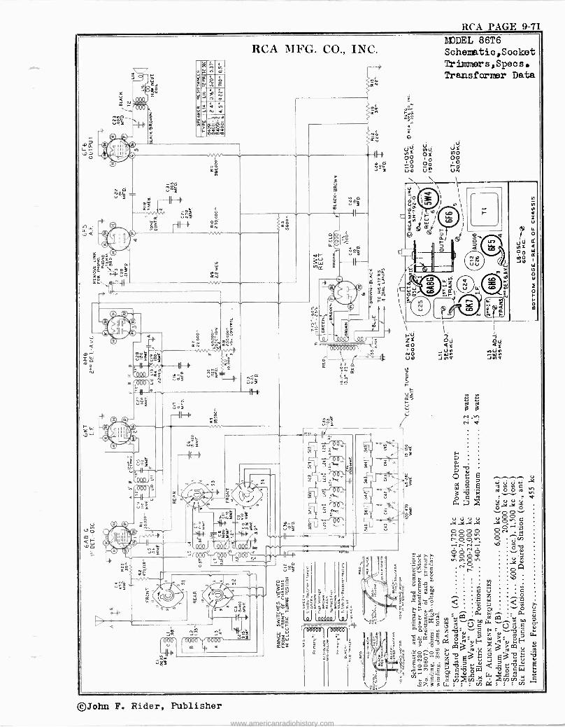
RCA PAGE 9-71
..
p Q
- 1 1
14
N G p u'î I m2
d JtNmli
Fó 11 F ou 1
ó'
:o e
°n IV 4
1
r
RCA MFG. CO., INC.
u j
IDDEL 86T6 Schenatio,Sooket Trieers,Specs. Transfarner Data
o
a ÑoP.8 ó a
ZdiᢠdÚ 3 - II- -, 1
Tóifm 6 eW C uI _ >á \ of 7 h m
Y n ie ell i î¢ ° wa
Pati 5 Qî / a ro Q1. 0 m`J `o = W
6 2= YQ ®®
.1-.fl by
Ó fd 1 w l'
Z
Ia óñ g J 1 / m a Q
e V LN./ W 11 NIP Lf N N S
Z `]i` o W ; n 1 I '
® ] 1 8 cg ó r- 1 I I ó +. " ` ' ' ' SL 044k s Z Y ó i.
> e - éti m áá ti < rbbbbbóóó aó úá uó ~ ÑÑfP li W n , NO WM NWM 2ó _1î_"$"1` q ó P UO JNQ JYIf
.p . m--Ir"1 Qò Q $Ñ c
N ¢ c ¢ Z z "OQQ 3Q df v'aZ*. «2 ^ 2 z 000 3 of -- r-
, 4I - IH, 1-
,,,Z e EA, u e á á G
<
f
W
--11-1, J
cí
^]
N ,..-> N V'2e'
W
4l I110Y
0*". -1(¡©\
` á© - ^yZ 0 A -1E4...1, p4
JrY 7C -E
ñ: E. I Ñ ^, e Ñ` x Ó e ?
}^
. . - tOO 1-- .J.122 ppW
' coO v co
.
. .<4U . . ó . ' Q t. .00 C4 a> j'ti" ......00.....áxç
o ü'' 9 w./0\. -.-/ i- 23 uJuu u a
t.3 c, O T i 0^, Te _ ..4.-4-4.21
Ñ,p pF11I1 3 sri ó00ó vwi .n rÓ0In ui 2^ .-rÑ-p4, Á 2 úñ f ' Irx Ó <
Q. o .. _ óut
b aa o
0Avá
r..3 '
o h V W ä
. so
. Wi u u ' n g úu
Ó 1%5 N. ,u? Z°
O Ó Z e 4:i< W n 7%C
U C O e -,i
el 2 C^ frW r-'- \oJ MNO . PM . á 1
>` ~Z 3
J + y W '00000 ¡
EaFó 5 1^mis+NU `ÁÓ
3 ' il
' o < p , z 7 1
vgW 1717---- G.ó a 2.,s,
-NsÁôaC¿ßi p 'uf' W d.u
2E-.oa3N11 X >OQ
. J E 3 e3b t3
U
">.' W .0: Qd tW R c%y,cg ñ ¿' IñMwihlññ" oi/ ºz 33 G1 . . . ñ . . i
Gt.)
S U
î o F
o
©John F. Rider, Publisher
www.americanradiohistory.com
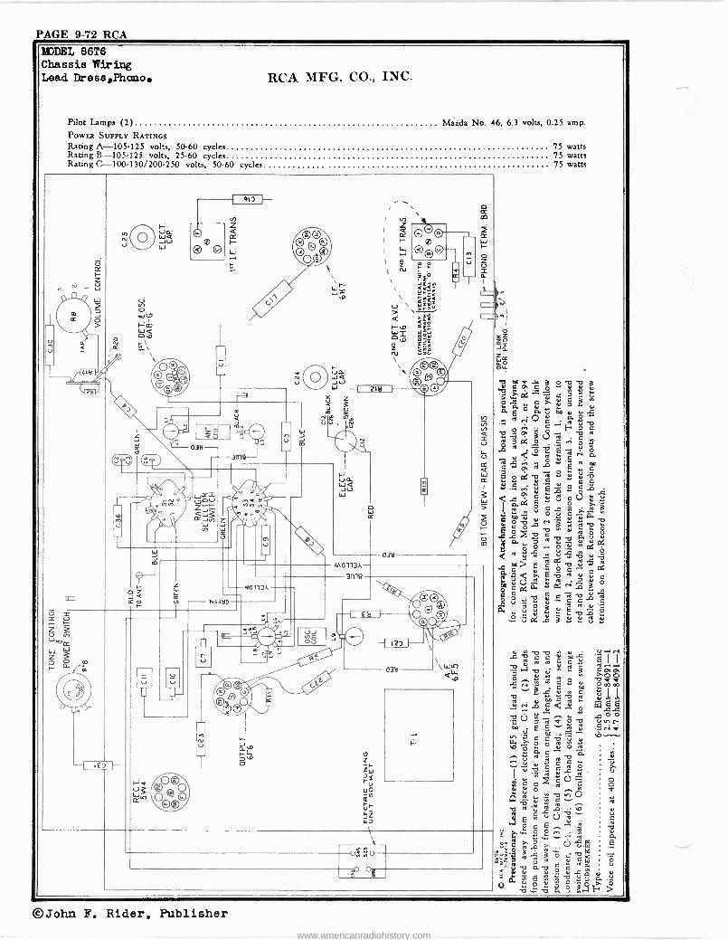
PAGE 9-72 RCA
Pilot Lamps (2) Mazda No. 46, 6.3 volts, I
POWER SUPPLY RATINGS Rating A-105-125 volts, 50-60 cycles Rating B -105-12g volts, 25.60 cycles Rating C--100.130/200.250 volts, 50-60 cycles
©John F. Rider, Publisher www.americanradiohistory.com
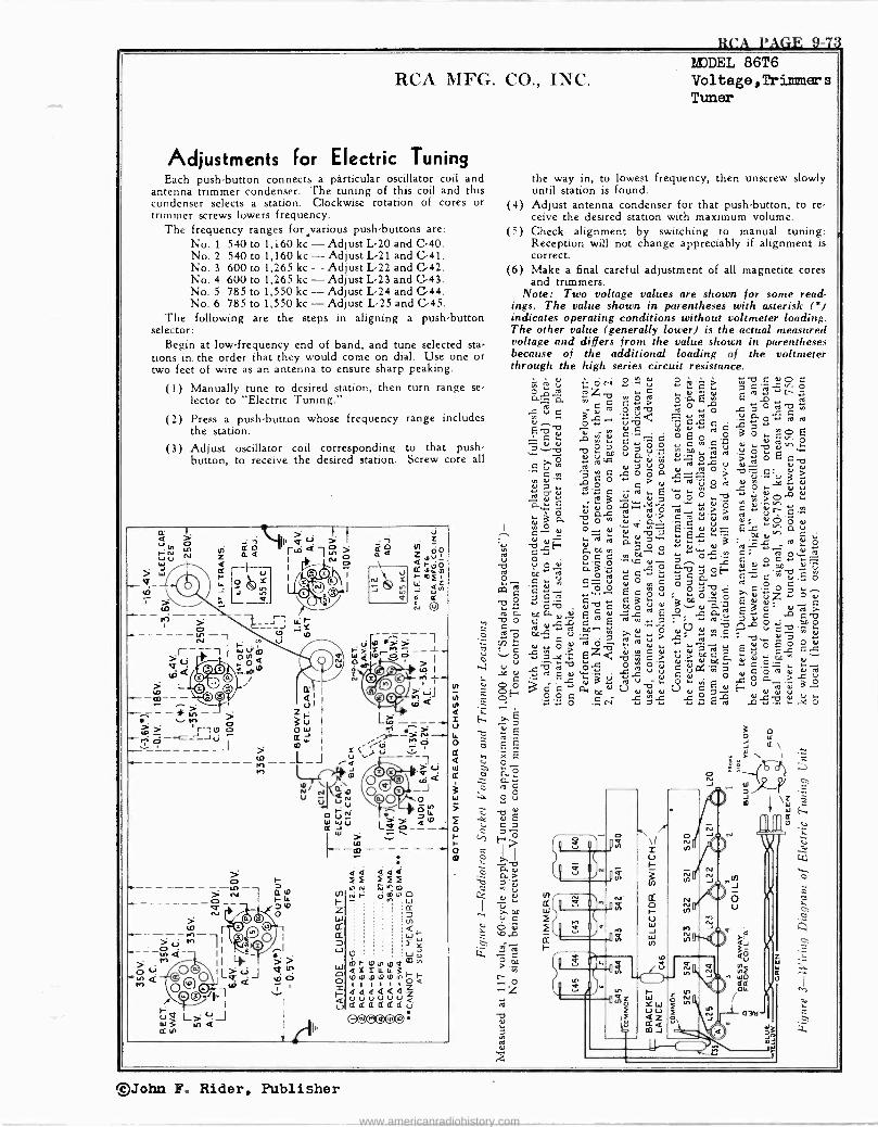
H('A PAGE 9-73
RCA MFG. CO., INC.
Adjustments for Electric Tuning Each pushbutton connects a particular oscillator coil and
antenna trimmer condenser. The tuning of this coil and this condenser selects a station. Clockwise rotation of cores or trimmer screws lowers frequency.
The frequency ranges ford arious push -buttons are: No. 1 540 to 1,160 kc - Adjust L-20 and C-40. No. 2 540 to 1,160 kc - Adjust L-21 and C-41. No. 3 600 to 1,265 kc - Adjust L-22 and C-42. No. 4 600 to 1,265 kc - Adjust L-23 and C-43. No. 5 785 to 1,550 kc - Adjust L-24 and C-44. No. 6 785 to 1,550 kc - Adjust L-25 and C-45.
The following are the steps in aligning a push-button selector:
Begin at low -frequency end of band, and tune selected sta- tions in. the order that they would come on dial. Use one or two feet of wire as an antenna to ensure sharp peaking.
(1) Manually tune to desired station, then turn range se- lector to "Electric Tuning."
(2) Press a push-button whose frequency range includes the station.
(3) Adjust oscillator coil corresponding to that push- button, to receive the desired station. Screw core all
(4)
(5)
MODEL 86T6 Voltage ,Trimmers Tuner
the way in, to lowest frequency, then unscrew slowly until station is found. Adjust antenna condenser for that push-button, to re- ceive the desired station with maximum volume. Check alignment by switching to manual tuning: Reception will not change appreciably if alignment is correct.
(6) Make a final careful adjustment of all magnetite cores and trimmers.
Note: Two voltage values are shown for some read- ings. The value shown in parentheses with asterisk (') indicates operating conditions without voltmeter loading. The other value (generally lower) is the actual measured voltage and differs from the value shown in parentheses because of the additional loading of the voltmeter through the high series circuit resistance.
O í.^. Ú ti 5' Li ( e) u w
O'. Op Ñ ` Y Y Y
ON ú 7
-oc C Y
a a o é 0.0+ O C
Y
2: o " E
v At
O 1r x r3 7 ÿ O
r- a+ Y O m ÿ =
-., .n C o. Y OQ '
8E+You,.- EC`áú E í..
. ... OC Y H C F.
.+ w- Y N .0 .5.. _. `e 22
O
Ow, á^ r. 2Y .O+ pCe u
ú'u aCá auC`°d.EÓ oab C -áoÿ.. c3mo.á 6ddz od ++032 a b E L C' á Y a. Y ^
_. 7 Ó a; OCO Ó A uC-tf y iü
14.
a b Ó E p O á
> Oo C . Y ..-. Y pe O.
.Y.. Ñ m 70 Y
`i Y Ó 7 -Y f". ÿaE
O a++ ro
Ñ
o L)
.>. -e 3
u
©John F. Rider, Publisher
www.americanradiohistory.com
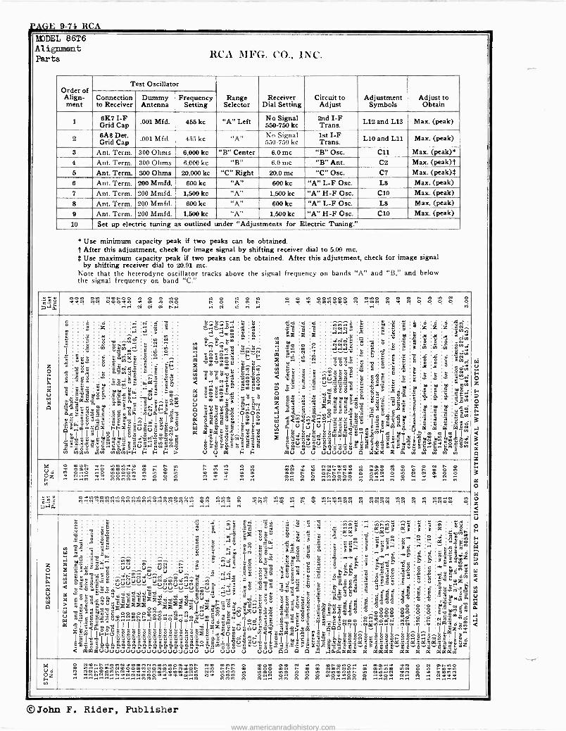
?'AGE 9-74 RCA
LUDEL 86T6 Alignment Parts RCA MFG. CO., INC.
Order of Align- ment
Test Oscillator
Range Selector
Receiver Dial Setting
Circuit to Adjust
Adjustment Symbols
Adjust to Obtain
Connection to Receiver
Dummy Antenna
Frequency Setting
1 6K7 I -F Grid Cap
.001 Mfd. 455 kc "A" Left No Signal 550-750 kc
2nd I -F Trans. L12 and L13 Max. (peak)
2 6A8 Det. Grid Cap
.001 Mfd. 455 kc "A" No Signal 550-750 kc
1st I -F Trans. L10 and L11 Max. (peak)
3 Ant. Term. 300 Ohms 6,000 kc "B" Center 6.0 mc "B" Osc. C11 Max. (peak)* 4 Ant. Term. 300 Ohms 6,000 kc "B" 6.0 mc "B" Ant. C2 Max. (peak)t 5 Ant. Term. 300 Ohms 20,000 kc "C" Right 20.0 mc "C" Osc. C7 Max. (peak)t 6 Ant. Term. 200 Mmfd. 600 kc "A" 600 kc "A" L -F Osc. L8 Max. (peak) 7 Ant. Term. 200 Mmfd. 1,500 kc "A" 1,500 kc "A" H -F Osc. C10 Max. (peak) 8 Ant. Term. 200 Mmfd. 600 kc "A" 600 kc "A" L -F Osc. L8 Max. (peak) 9 Ant. Term. 200 Mmfd. 1,500kc "A" 1,500kc "A" WF Osc. C10 Max. (peak)
10 Set up electric tuning as outlined under "Adjustments for Electric Tuning."
* Use minimum capacity peak if two peaks can be obtained. t After this adjustment, check for image signal by shifting receiver dial to 5.09 mc. $ Use maximum capacity peak if two peaks can be obtained. After this adjustment, check for image signal
by shifting receiver dial to 20.91 mc. Note that the heterodyne oscillator tracks above the signal frequency on bands "A" and "B," and below the signal frequency on band "C."
-- G2 ]..7a
OOm Oto Nm00 0 0 m0 to O mom o o a cotoc00 o eto0 O O O N ,O to N O n ,O 7.wol NN 0007.to a a m NO n o n OW t- .1 r: w ,OmM,O,Om M .!NN N w N 0 0 0 0
M .Ì.Ì ci ci o; c:. .. ci ui .i .. ..o z o É C4
U ÿ
cl
g
s ° Q
C w
d,oá. deal a +s««á
o.r.
>rss wOpásipa
?YÌ11=11m1g@"@uo@u roúúmçúÑeéYYé+e,béóa ya.._
y
Y 'C tá
ñZW u ú rr,
.71
:Q$ .°.
04 wY,°a,aa
2uuYE QQ
úú`ªt¡,
ÿÿtÁ
T.
.r u O
H
ú
... «w yyy C
E w ow ..'C'CQwu2lÿNFe)
ÿm
T7
YmCDá óeäá¡, ° ú 0._
..°.wHw« w ÇTÓ,ti :.aeaoC QaQ._ OOYwW
' éá t¡(¡pç«
mmmFE+
...
.a mp áN.y
en..pp C
Y7 « w -á w t p4
et ;»Iû óomó
.. a
E
.°y
ÿ
R. WaW ..
0G
-o u« 3t33ma c7oFov Vp.W«p Y,..YÿO°
F
> to N
,Ó
.°r
úq
G
c
Y
F
w
to
Ó
_ `F pp
C
Ç>, F u « O mm
o« >e
F>
t..Y« w°.Viwyia.
-1-.1 °' m
.l .vi m é ava .-..-.Óm y ..o.0
W g
.i°? ,..°.ÑwÑ a«óóów PO ya.oao
E .i m ma W m
Tl T7 li rA Q Ó a Ó m w w ä < .. NE Y.r w a Q O Ó O E W 87.2.7,-.2 p "Ili G Ypi3úa= o 7y7yEa
le lese.1-1- 0.pE$pEum p,`.i,,.íriq
a aYYa;.Q u á mq,° ..oxot E II II ú O« YáuacNéywqä C.7Cwa. ÓEÿE
Ú Ú á
Y JI
ñ
'"F`"F °.. enEm w.i oWo Pe.? «m «ó g.,.óN ,;a.,
OtAOm o Im Y @ú
F
Y .w
w
0.,
m
°
qqq
F
`T7 tl , M
W m
ni i7.to. aa Ld, % u.. y z N tl
Y E < û y C `o«
W au z~
< o .i ;;;.-e o .1 a7,oW.4,yOmuuu.,
W 3<7.<<a.r.7C'C'Cwg u a lu y IY e K Qa'ú7.'úaYU «wuwVwuaw a..a..a..aa_._.
0ÓÚ
W
E
Ñ ,ó m
ú E
Ç
YY. á
. ? lu Y° .i«ci«è««WWW
Ú
y 9 C
rá
O !, Ñ
E
E
ázä'ccuöv
lu
V
em._ NNNr aaa ÑNÑ «! rivni
'ó''S..°. Y b
m Ó Ó Ó a ,0 7.« r °'u_w.... V....ú O
p E3'sû Q
`° p O g w
.^.CwwwE
oaaaYuó to0«««ÿ
l ÿúÚ... Q-..Y.^éO.°VSfAF
I .L°tú Q
ÚÚÚÚÚÚ
= ,t Y g O
« u
a
yu II« wEupOañ.a.íwirwC.a.C.a.Co°7-ÓVI
w'C Q
t: 4 o
.Q é Q w° .Q QQy°E
úJQI..a. o >
aO1 a« li ú
QC $.aéw 1°YQwa¿ QAC°Jlÿ7.r
..a}I a- Wkx
U u
w
ÿ
E
Óa á g
Iwv
ÿé
C a
m Q
E ía.
8 Y
° w a
I L
0.
y ä
i.
a
é w
Y
w p
C
° E .9
s Ìrlmlmlmj7w a gq gq
LO
t1
0 , y7 O
N
.w
W
w
w Q
' . t;
m wN
Ya7
0 T.
yy
ÿ °i
ó .,t
W
w Q
é w E
t:
m we7
m
O ÿM ' ,i. N limb .Vy »ciel ÿ N p rn V)+
Lm ` :bei
7. ú Qom O N
..`°. m
,«4`.°' w '261 Q
é C77. w«ym E ,Qá Q ÿÿ
a ú,ó N
7.ít wm .... m m
,,{,
ÓÓ Oz F..
N
o met at- tomtoam e t- to n a M to to ..0 a to C7Nt-mmm to Mm0 m o n o N n 0 7. OWN ..O mmNnn O r O n n M M MN 0 0 Mm7.aaa m Otom N to m n m o M O.. O totoOtoM M to m to m O, m 0 M m0 t- n Onnnnm O toMN to N e) 0 0 0 N OO..Oa
.ai O O 0
iM. ti ti 7. .7..
0.. O O M0000 0aa O r7.. ia.
a ..M .. MMMM.-. M M M .. MM M M M..MMMM M 0.7.... M M M
« ú C
p.7p,
ontoNotototoOOntoono,nOto000to Oto tomo O tonto toto to to o tontomoo o OC70N too o m 00.0e) M M..NNNNNe)MMNNMMaNMNNMM.. mM ..M7. 0 to0.7M .-.m .. t" m.!..e..NN N C7NN°i .!N N e! .!N00 0 .. ...i .,.. t; ,^i
z O p.
<`,vétE..°y...°.w m W A
ú .
q g é w W á .a w [G 3....«,0..9 W r wsT7^«ú
6ÓOYQCEY W O. a gyv W « >
.2x
u qÓQOQ,G.4S1ÿto..Nmnnmóóóóó.INOÄUQMC..Nu W a<ag'óC
8ÿ 1 á1 < oamaauuuuuuuuuuuuuuuuuuu
T 3
a á e«w :W`"
ÿ.^to
ñsúw w
°°ww
i waQóaaaaaaaaaaaaaaaa..a.aÿS'ög-gSvóó°°-"e>2`ss==S90ú8a8úÊ8"LO"0
yÉ «4
.ry°. C
in; w«
O
w
o,o,
w,ov,`zóvmimzztoz.
FF l II II
.-NM uuuuuu
ó
to.'..'...Ny' I 00o2°.oc.coo.o.P.°.°.°.ri°Ióyy< gÓi1ÑÑÓÑÁg4Á°ww.jwwOMEo
s
ú
g
. w
.m^.m . . . ....-. . . .o N..m MN ..ñ . uu .V VN .. :a
+"M.+ V u :..u.-. :w O M. -a
uÚÑamiumÚÑ.9
TitiwtiÓEd Uu..u..iJöNu.9
ó v v E wEÉEÉEz dó... .Úud
.N., Q..a
11 1 I ti
y ó.
«
á 2
^w Ñ
p a
n..- º2 a
.éX
OU
mr .1.e°
m Q
a ú . aé
e'7mé a ni,-t«
IV,Y aa .eS w
áa; ^
u u,¡o wI üÿu,=u«v
1Ó(eYV uuu
ÿ C w
O 3 M
eh
i= 00 Eú E p 5
C úo E
Ti -úú$ wu.^ y}
_Ar...! O,c.--Oww
w
u
^q .ú C
'2'5« ° Ñ _ W '2 r,
qOö °a,^`o`
b7 í°. w
ú w
a C Á
°
Qá
mI«ú 141fi uuu
1«w..
$ s 5.==
eta °«9 =1E4.
2 G G wY
2«
:w óó
-ce«,.., 0
QSY á._agg
ww>>in P9rIe I w;áúßÿÿái.,«iáªwRwwwau.,aamas
nn
..°`. w
á s Y '± w
E 2é ' 7 ó
w ¿
S
>22 gw
Qu'¡.
n n
C
Y q
a
ó q u S .5
Ó
ú w Q g ÿ IgC1C1 orI
. ú
é e
ÿ>.i, gA ,,ag =Cw a,° a._
YY ^(,, »Nm0
Ii
aáaaaa
...« 7m g áá a \
ñ ;1;"' aB ....«d .. pp,
--2 g'IÌ
^
y7c00 ó 00
I..láis
ti,cnoî
Q
g a
Y
'.
i 7
Ç a
0r OM....O N..
a
Ä W..« It
7:4-. 4. q M 3 w 3
a
.«a efe- ««Q w; gO^ S é.5 ú
2 2 ssi oo
o000 Oc00 OC ^1
aaaa
^w á a
,,.,, Á
,g
Cp i] ; r ú
ë tp
s! .° 0o 00 O
°vim ..1..^I
aa
Á a
,0y
..
á
C p A
O 0 Ó m
a
Ä a
ti \ ..
c«ª"Nw° « Q o
o o O
8 a
m a w a, ...
Ylie,z yY ú_i 1",.22z4
«°»ó7
É.b NwC
aaam
+ó . «n á
s p o M tee..
ÓJt M wQ_ Ó
dm `
w« gá ma
wM 0 g Q._mi7. Sp'
ZÌWá a ß.. 5°
.5u z
9 U OZ F..
M
O Nmnt-"OMNammMNMmMmOar7.Mn NO MOM 0 mOm 00 N a M mnmmo.. ,r mW..a 7.M to N mnMo e to....OmtoNmOomMOOMmtonMmOn to nnn co m00 me) n m e e)mMNmn m mtocm toe) O to twee M MNnmtoMnNaaaatoMmM.mmm7.Nto NM toto.0 to moca too to to to Ntomtoton to 040m0 7.M O a mmMM ra . 00404NN..NaNNNOOoaaa7.7.N..o to7. 000 0 zee O.. O O c to0aa00 0..o7. N. M .. N 7.a ....M MMM M M.... MM M M M M..nMM M .-, M.. .7-41.1 .. ..ye...
fal u É o z F
o ac
Ñ
a
*J4
a x F
a o W V z < x U o E F u W 00
w 51
a
áä .u.
0.
a a
©John F. Rider, Publisher www.americanradiohistory.com
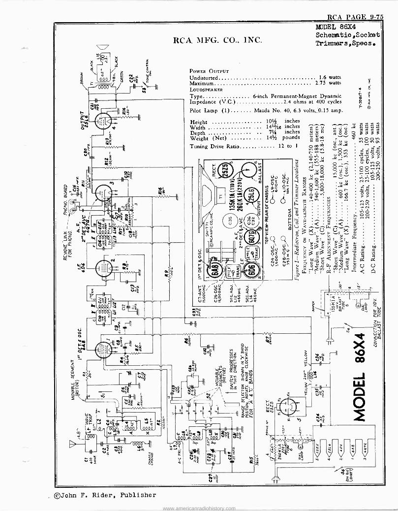
RCA PAGE 9-75
C
Y
0 J
I I ro
N
oz
rti
o
-- VA.4
úñEl t
ú $É L
V * , 664
Q
J i
Q94D X
Lo -e
RCA MFG. CO., INC.
POWER OUTPUT
MDDEL 86X4 Schematio,Socket Trimmer s, Spec s.
Undistorted 1.6 watts Maximum 2.75 watts LOUDSPEAKER <
Type 6 -inch Permanent -Magnet Dynamic m z
Impedance (V.0 ) 2 4 ohms at 400 cycles ñ 2
Pilot Lamp (1) ....... Mazda No. 40, 6.3 volts,, 0.15 amp.
Height 101/2 inches Width . ... 141%g inches ^^ Depth . .. 7% inches E
Weight (Net) ... 141/2 pounds É 4)
00
Tuning Drive Ratio 12 to 1 00 r---.-
f-
U W Q
z o 4. 011
W áo
r- N 4 -J
m
i a
9 N mn o
N W =
cr
el;
-U nte Zh0 d W
v 3 J ~A J .
a Ve VF
^F h
W
r
Hh UN We)
ó
"41
aI
h
YOÑb N
á3 ú
0 33 oo no,o
a
W o
m
©John F. Rider, Publisher
www.americanradiohistory.com
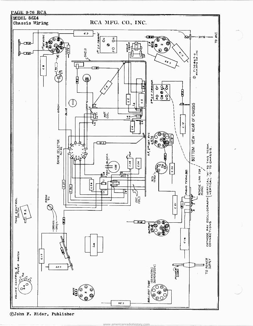
'AGE 9-76 RCA blJDEL 86X4 Chassis Wiring RCA 3ih'G. CO., INC.
62 - z 3 Ó ® RI
'6 ¢
O
- v\ _ 3m9 ]--1 *el- Y 0 R.i. De , ©,. u ® o
a ¢ ;r
ú - ` Ó H® © 0v ~
J U
W ,
1 T - f_ , -11 b0
o , P
Litt
C
^/ /, F
.'..3
eii
©
H
le 2
i- O tu O
^ ti
. u
4
® m
000\\ Z U J U N \ Vi Iii
J
_ I
<-/-3
'I/ l3 J T cf.) _
m F J
rn1I ó a rn U
V JJ I
0 M J' .J
\
N cc
w
O© \
1
,
oc
cO p
eOm d/C\ \ W_ / f 11[y,}
® -r \ > U N _1h
w CD
a
e
,ºN, Y
m' Ñ
ó ® V N
Q ill\\ ©
. \ \
\\\
F.
2 h F yN1
CO r U \- u '0'2 - o0 º v Q
N rr o to+ CO
_ ao o2 F
io z
.1_ Li ,C e z ...1J ~
V N
--c-1-1.-c-1-1.¢F r-1--1-'
W
ÿ
J QQ U U -
V Z T U`, IJ t_ 2 11 2o W W v á » -.-
r F. i Za
ce O ó N
N Q JJJJ!! ñ cc
2= Ou
U Y u
U 3
Wcr) 2
)wf O J -J
U N 0 z Z ry © fl U U) ti
L.-- o Cc Cc
' © e A }Z
QO mce óMO ri F
ï U J
,---- p C.
z
w u 0 W
QO UU
i.).
3 h
Cr y W J 3a
W - zz> >
- ^I c ^
o U 0
et
f °" WÑ©©® In CN
®Q
YY
m N
0 Oo , 000
3ó Q.
-D ro *G
©John F. Rider, Publisher
www.americanradiohistory.com
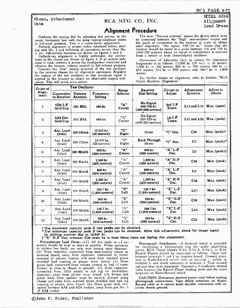
RCA PAGE 9-77
Phono. Attachment MODEL 86X4
RCA MFG. CO., INC. Alignment Data
Lead Dress
Alignment Procedure Calibrate the tuning dial by adjusting dial pointer to the The term "Dummy antenna" means the device which must
center horizontal line with the gang tuning -condenser plates be connected between the "high" test -oscillator output and in full -mesh position. This is a screw -driver adjustment. the point of connection to the receiver in order to obtain
Perform alignment in proper order, tabulated below, start- ideal alignment. "No signal, 550.750 kc" means that the ing with No. 1 and following all operations across, then No. receiver should be tuned to a point between 550 and 750 kc
2, etc. Adjustment locations are shown on figures L and 2. (400-550 meters) where no signal or interference is received Cathode-ray alignment is highly preferable; the connec- from a station or local (heterodyne) oscillator.
tions to the chassis are shown on figure 4. If an output indi- Conversion of kilocycles (kc) to meters for alignment cator is used, connect it across the loudspeaker voice -coil and frequencies is as follows: 15,000 kc (20 mc) = 20 meters; advance the receiver volume control to full -volume position. 1,500 kc = 200 meters; 600 kc - 500 meters; 460 kc =
Connect the "low" output terminal of the test oscillator 652 meters; 353 kc - 850 meters; and 166.7 kc = 1,800 to the receiver chassis for all alignment operations. Regulate meters. the output of the test oscillator so that minimum signal is
applied to the receiver to obtain an observable output indi- For further details on alignment, refer to booklet "RCA This avoid a -v -c action. Victor Receiver Alignment." cation. will
Order of Test Oscillator Receiver Circuit Adjustment Adjust to
Align- meet Connection
to Receiver Dummy Antenna
Frequency Setting
Range Selector Dial Setting
to Adjust Symbols Obtain 1550-750 6D6 I -F
Grid Cap ,001 Mfd. 460 kc
«A»r
Center No Signal
kc (400-5601 meters)
2nd I -F
Trans. L13 and L14 Max. (peak)
2 6A8 Det. Grid Cap .001 Mfd. 460 kc "A"
Center No Signa l 550-750 kc
(400-550 meters) 1st I -F Trans. L11 and L12 Max. (peak)
3 Ant. Lead
(blue) o,., Ohms 15,000 kc
(20 meters) i.c"
Right 16 mc "C" Osc. C25 Max. (peak)t
Ant. Lead (blue) 300 Ohms 15,000 kc
(20 meters) "C"
Right Rock Through
15 mc "C" Ant. C7 Max. (peak)*
5 Ant. Lead
(blue) 200 Mmfd. 600kc (500 meters)
"A" Center
600kc (500 meters)
"A" L -F Ose. L9 Max. (peak)t
6 Ant. Lead
(blue) . 200 Mmfd. 1,500 kc (200 meters)
"A" Center
1,500 kc (200 meters)
"A" H -F Osc. Max. (peak)
7 Ant. Lead (blue) 200 Mmfd. 600kc
(500 meters) "A"
Center 600 kc
(500 meters) "A" L -F
Ose. L9 Max. (peak)
8 Ant. Lead
(blue) 200 Mmfd. 1,500 kc (200 meters)
"A" Center
1,b00 kc (200 meters)
"A" H -F Osc. C24 Max, (peak)
9 Ant. Lead
(blue) 200 Mmfd. 166.7 kc
(1,800 meters) "X" Left
166.7 kc (1,800 meters)
"X" L -F Osc.
L10 Max. (peak)
10 Ant. Lead
(blue) 200 Mmfd. ` kc
(850 meters) "X" Left
353 kc (850 meters)
"X" H -F Osc. C28 Max. (peak)
11 Ant. Lead
(blue) 200 Mmfd. 166.7 kc (1,800 meters)
"X" Left
166.7 kc (1,800 meters)
"X" L -F Osc. L10 Max. (peak)
12 Ant. Lead
(blue) 200 Mmfd. 353 kc (850 meters)
"X" Left
363 kc (850 meters).
r`X" H -F Osc. C28 Max. (peak)
t Use maximum capacity peak if two peaks can be obtained. * Use minimum capacity peak if two peaks can be obtained. After this adjustment, check for image signal
by shifting receiver dial to 15,920 kc. $ "X" H -F Osc. trimmer C28 must be at least three turns out during this adjustment.
Precautionary Lead Dress.-(1) All bus leads in r -f as- sembly should be kept as short as possible. When necessary Phonograph Attachment.-A terminal board is provided
to replace bus leads, use only wire having same diameter. for connecting a phonograph into the audio amplifying
(2) Dress capacitor, connected from tone -control switch to circuit. RCA Victor Models R-93, R -93-A, R-93-2, or R-94
terminal board, away from capacitor, connected to center Record Players should be connected as follows: Open link
terminal of volume control, and away from exposed green between terminals 1 and 2 on terminal board. Connect green
shielded lead running to phono. term. board.- (3) Dress wire in Radio -Record switch cable to terminal 1, yellow to
green lead, connected from volume control -to 2nd i -f trans- terminal 2, and shield extension to terminal 3. Tape unused
former, as close to chassis as possible. (4) Dress capacitor, red and blue leads separately. Connect a 2 -conductor twisted
connected from 25L6 socket to red lug on electrolytic- cable between the Record Player binding posts and the screw
capacitor, away from phono. term. board. (5) Brown and terminals on Radio Record switch.
green leads from speaker must be twisted, dressed along CAUTION: Disconnect receiver power cord before making chassis and away from exposed green shielded lead and lug phonograph connections. Tape shield extension on Radio - running to phono. term. board. (6) Dress green lead, con- Record cable so it cannot make metallic connection with re- nected between 6A8 and 6D6 sockets, away from, pin No. 5 ceiver chassis ground. of 6A8 socket.
©John F. Rider, Publisher
www.americanradiohistory.com
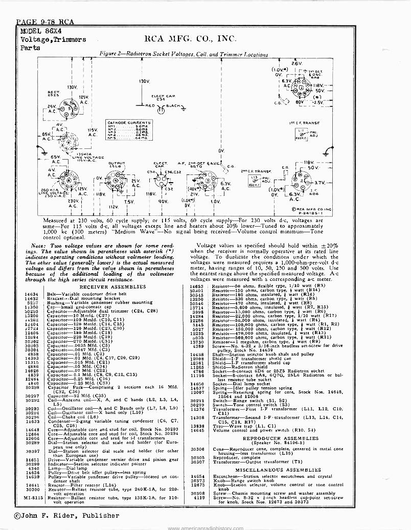
LAGE 9-78 RCA MODEL 86X4 Voltage ,Trimmers Parts
RCA MFG. CO., INC.
Figure 2-Radiotron Socket Voltages. Coil, and Trimmer Locations ?
RECT. 2525
25V.
rA.c A.C.-L° ,
's1*»- 135K1A _ 65d. LINE VOLTAGE
+ A.C. /ISV:A.O.
4V. I
A.C.
125V.
.C.
R
130V,
ELECT. CAP. C35
REO L¡BLACK
115V. A.C.
2601<1A LINE VOLTAGE: A.C. a30 V-A.C.
230V. j A.C.
I
/
CATHODE CURRENTS NL 1 .... 5 0 ma. Net soma. N..3.... 0.2ma. N114 48 ma. N^.5 ...64 ma.
OUTPUT 25L6
®( 25V. Q
I l
#-}'-
I
A.C.
1118V.
1
I J I 7.5V.
I 112V. I tt i i
ELECT. CAP.
C36 C36.C32
OV.
A.F, 244OET. aIA.V.CF 6qT G
r a63V. (40V.a A.C. I 21V.
f a I 2.6V.
(1.oV.*) I r}isTOET.
OV. ¡--t,Z 46Áéc.
16.3V I A.C.
L 1181/4/.--
501/4/. - (+a)
C.G..,\s> 8 V. -2.5V -"
lsr. I. F. TRANS F
1.11 I
ADJ. 4604.[.
C.G. 21.11.t.F. TRANSF. 11
L13 IFDo, rI
. r 4601LC. I 1, (1.OV.*)rI.F
OV. 1_6.3V.606
r -118V. ---.-
- 50V.-
(1.OV.9 1.0V. Ì
A.C. OV. 1 I
I I
t
3.7 V. -
©RCA MFG.CO.INC. P -84185-t
Measured at 230 volts, 60 cycle supply; or 115 volts, 60 cycle supply-For 230 volts d -c, voltages are same-For 115 volts d -c, all voltages except line and heaters about 20% lower-Tuned to approximately 1,000 kc (300 meters) "Medium Wave"-No signal being received-Volume control minimum-Tone control optional.
Note: Two voltage values are shown for some read- ings. The value shown in parentheses with asterisk (6) indicates operating conditions without voltmeter loading. The other value (generally lower) is the actual measured voltage and differs from the value shown in parentheses because of the additional looking of the voltmeter through the high series circuit resistance.
14634 14632 5237
11350 30295 15200 14262 12404 127.24 12406 12694 30302 30303 30304
4858 14393 11315
4886 14626
4839 12484
4840 30298
30297 30292
30293 30294 30296 14633
14648 12864 12006 30289
30397
14651 30290
4340 14638 14639
14641 30300
MI -8115
RECEIVER ASSEMBLIES Belt-Variable condenser drive belt Bracket-Dial mounting bracket Bushing-Variable conoenser rubber mounting Cap-Small grid -contact cap Capacitor-Adjustable dual trimmer (C24, C28) Capacitor -10 Mmfd. (C27) Capacitor -109 Mmfd. (C10, C11) Capacitor -120 Mmfd. (C14, C15) Capacitor -120 Mmfd. (C23, C30) Capacitor -180 Mmfd. (C18) Capacitor -220 Mmfd. (C 19 ) Capacitor -270 Mmfd. (C31) Capacitor-.0035 Mfd. (C5) Capacitor-.0047 Mfd. (C3) Capacitor-.01 Mfd. (C2) Capacitor-.01 Mfd. (C4, C17, C20, C29) Capacitor-.015 Mfd. (C21) Capacitor-.05 Mid. (C34) Capacitor-.07 Mfd. (C22) Capacitor -0.1 Mfd. (C8, C9, C12, C13) Capacitor -0.25 Mfd. (C16) Capacitor -0.25 Mid. (C33) Capacitor Pack-Comprising 2 sections each 18 Mfd.
(C32, C36) Capacitor -32 Mfd. (C35) Coil-Antenna coil-X, A, and C bands (L2, L3, L4,
Coil-Oscillator) coil-A and C Bands only (L7, L8, L9) Coil-Oscillator coil-X band only (L10) Coil-Choke coil (L6) Condenser -2 -gang variable tuning condenser (C6, C7,
C25, C26) Core-Adjustable core and stud for coil, Stock No. 30293 Core-Adjustable core and stud for coil, Stock No. 30294 Core-Adjustable core and stud for i -f transformers Dial-Station selector dial scale and holder (for Euro-
pean use only) Dial-Station selector dial scale and holder (for other
than European use) Drive-Variable condenser vernier drive and pinion gear Indicator-Station selector indicator pointer Lamp-Dial lamp Pulley-Drive belt idler pulley-less spring Pulley-Variable condenser drive pulley-located on con-
denser shaft Reactor-Filter reactor (L16) Resistor-Ballast resistor tube, type 260K -1A, for 220 -
volt operation Resistor-Ballast resistor tube, type 135K -1A, for 110 -
volt operation
Voltage values as specified should hold within ±20% when the receiver is normally operative at its rated line voltage. To duplicate the conditions under which the voltages were measured requires a 1,000 -ohm -per -volt d -c meter, having ranges of 10, 50, 250 and 500 volts. Use the nearest range above the specified measured voltage. A -c voltages were measured with a corresponding a -c meter. 14653 30301 30545 13250 30546 13714 3998
14284 12286 5145 5027
12285 o035
13730 4389
14638 12008 12581 11285
4786 11196
14650 14637 12007
30291 30299 14376
14308
13838 14645
30306
30305 30307
14854 30373 12673
30308 4119
Resistor -50 ohms, 8exiblC type, 1/10 watt (R3) Resistor -150 ohms, carbon type, } watt (R14) Resistor -180 ohms, insulated, } watt (R16) Resistor-S30 ohms, carbon type, } watt (R5) Resistor -470 ohms, insulated, } watt (R8) Resistor -5,600 ohms, insulated, } watt (R7, R15) Resistor -15,000 ohms, carbon type, } watt (R6) Resistor -22,000 ohms, carbon type, 1/10 watt (R17) Resistor -56,000 ohms, insulated, } watt (R4) Resistor -100,000 ohms, carbon type, } watt (Rl, R2) Resistor -150,000 ohms, carbon type, } watt (R12) Resistor -470,000 ohms, insulated, } watt (R1S) Resistor -560,000 ohms, carbon type, } watt (R11) Resistor -1 megohm, carbon type, } watt (R9) Screw-No. 6-32 x 3/16 -inch headless set -screw for drive
pulley, Stock No. 14639 Shaft-Station selector knob shaft and pulley Shield-I-F transformer shield can Shield-I-F transformer shield cap Shield-Radiotron shield Socket -6 -contact 6D6 or 2525 Radiotron socket Socket -8 -contact 6A8, 6Q7G, 25L6 Radiotron or bal-
last resistor tube socket Socket-Dial lamp socket Spring-Idler pulley tension spring Spring-Retaining spring for core, Stock Nos. 14648,
12664 and 12006 Switch-Range switch (S1, S2) Switch-Tone control switch (S3) Transformer-First I -F transformer (L11, L12, C10,
C11) Transformer-Second I -F transformer (L13, L14, C14,
C15, C18, R17) Trap-Wave trap (L1, C1) Volume control and power switch (R10, S4)
REPRODUCER ASSEMBLIES (Speaker No. 84106-1)
Cone-Reproducer cone, complete, centered in metal cone housing-less transformer (L15)
Reproducer, complete Transformer-Output transformer (Ti)
MISCELLANEOUS ASSEMBLIES Escutcheon-Station selector escutcheon and crystal Knob-Range switch knob Knob-Station selector, volume control or tone control
knob Screw-Chassis mounting screw and washer assembly Screw-No. 8-32 x 4 -inch headless cup -point set -screw
for knob, Stock Nos. 12673 and 30373
©John F. Rider, Publisher www.americanradiohistory.com
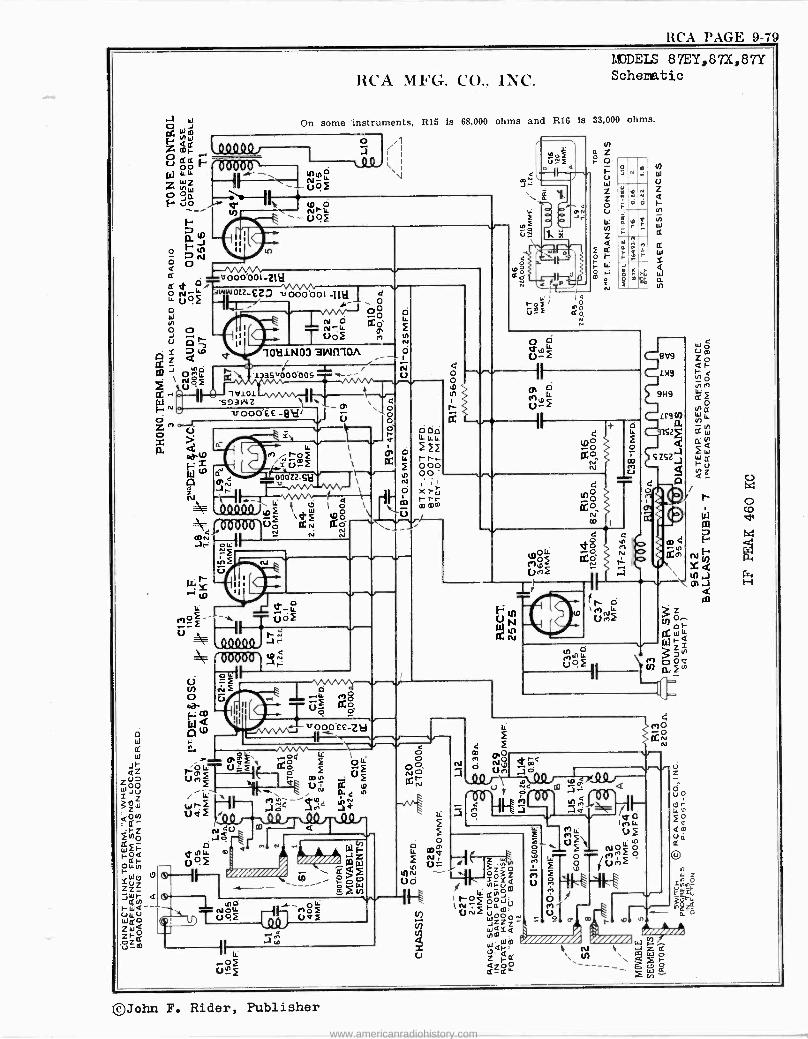
RCA PAGr. 9-79
o o
o
o W
o U Y
F^
a F a o
10 J N N
1.--«A/_vi 000.001-2111
CC :i 0L2-£23 vOÓ 001 d 092 Oo
N ° Md N^LL
T uóF (7
RCA MFG. CO., INC. NADEIS 87EY,87X,87Y Schematic
On some instruments, R15 is 68,000 ohms and R16 Is 33,000 ohms.
NN4 N- 00.2 Ñr-O
-p42
o Ar Q
d e
1011i1403 awn -ion o
133511000'005
1'4101
1. /
v000'fE
elle131131 1
= Nwer to xm2
Á lo
00012-SH ONO 1-v-
k
N 1d ~ 102 \d'2 ó le VÑ N aÑ 1
N N Jr:
N U
Amu
11111
aLL
1 2 V
.î ° ro$ 5 Uf Ito
G
v000ee-Za..-- Cr'\- 0=e x3 eó S2 c mN 2
UN D. N
o r Odd
222 rr- 000 oo ,I
Xrÿ co mm
S' o O 10
N
r
o n¿
; roF ümF
PN Jr
N8 o.
o
wob - r.12
11 11 1/
LL.
ÚQ2
W
N co (V
y CD áW
a ,
' 4 02
002
9
LL
2 2
113 o NLL
092
O \NLL
U r12
W U Z Q
N
W
9V9
1119
9H9
I
cry
v `
o
11
Ñ
O O
Ná l FA, ( -I\
OZ;ó
O Z Uó ,
~om ;Ñ020áó r
Ñ pN2
WZZ°N (Q WQYá
gC1 N m W m F
/////// àr, R Al Z Ñ 4 \ 0 4200 ------ CC -141.' --
11 ce
JCXlQ
[ .îa
11
H
©John F. Rider, Publisher
www.americanradiohistory.com
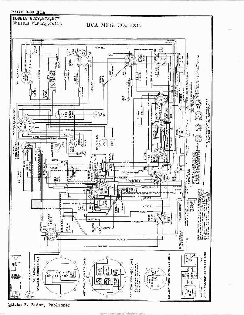
PAGE 9-80 RCA
MODELS 87EY,87X,87Y Chassis Wiring,Coils
r-ane u+
`NMOtlH( ) j}
F
©John F. Rider, Publisher
www.americanradiohistory.com
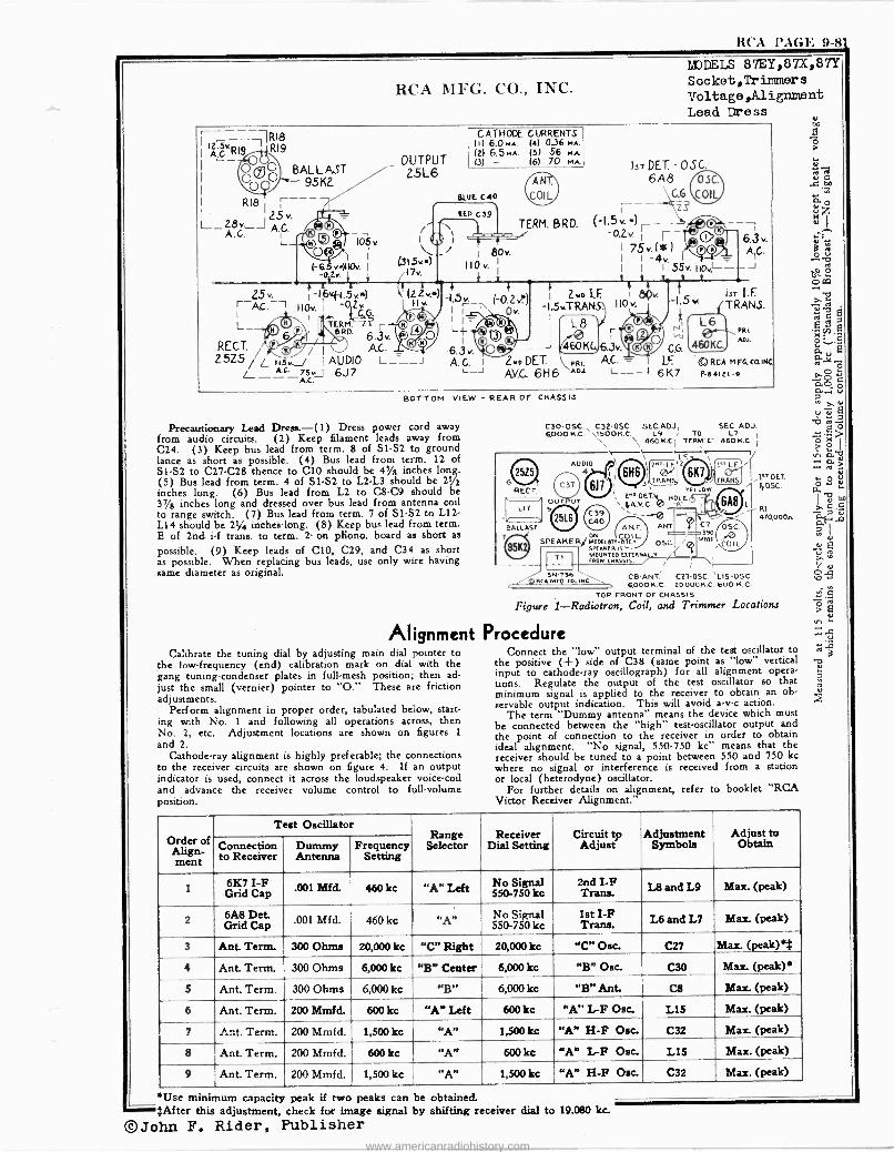
RCA I'A(if'. 9-81
OUTPUT 25L6
41 k
Calibrate the tuning dial by adjusting main dial pointer to the low -frequency (end) calibration mark on dial with the gang tuning -condenser plates in full -mesh position; then ad- just the small (vernier) pointer to "O." These are friction adjustments.
Perform alignment in proper order, tabulated below, start- ing with No. 1 and following all operations across, then No. 2, etc. Adjustment locations are shown on figures 1
and 2. Cathode-ray alignment is highly preferable; the connections
to the receiver circuits are shown on figure 4. If an output indicator is used, connect it across the loudspeaker voice -coil and advance the receiver volume control to full -volume position.
RCA MFG. CO., INC..
MODELS 87EY,87X,87Y Socket, Trimmers Voltage ,Alignment Lead Dress
Iq."R19 R19
BALLAST 95K2
R18 25v.
L_28v._J A.C. A.G. lóv
( 63 vry110v. -D...
}-16v{.1.5"*) 110Iv. I
02v LG.G.
TERM. r eRD. 6.3"
RECT. / I
A.G. 5Z5//L usv.J I AUDIO
AC. 75',1 6J7
I 80v. 110v.
1
r
1.5v. (-abm
CATHODE CURRENTS III 6.0M4. (4) 0.36 MA.
(2) 6.5MA. (5) 56 MA 13) - (6) 70 rA
BLUE C40
TERM. BRD.
Ìr I I = L 6.3v. A. C. J
0 v.
IsT DET - OSC. 6A8
G.G
(-1.5v.*)
I.F.
-1.5. TRANS
d) I
®rd _J 71'60® KC,
0.2v r r- i 75v.(s )
-4v I I
I 55v. t.j t , se 89, 13T IrT I.F. I10 v 1
O 6.3v. AIC.
.--J
6.3v. 2ND DET \RRL ¡+.C. y I IF ©RCA M FG. CQINC
A.V.C. 6H6 ADl 6K7 P-84121-0
(TRANS. (
úIl L6
CG 460KC,
.RI. ADJ.
BOTTOM VIEW - REAR Or CHASSIS
Precautionary Lead Dress.-(1) Dress power cord away from audio circuits. (2) Keep filament leads away from C24. (3) Keep bus lead from term. 8 of S1 -S2 to ground lance as short as possible. (4) Bus lead from term. 12 of S1 -S2 to C27 -C28 thence to C10 should be 4S/s inches long. (5) Bus lead from term. 4 of S1 -S2 to L2 -L3 should be 21/2
inches long. (6) Bus lead from L2 to C8 -C9 should be 37/e inches long and dressed over bus lead from antenna coil to range switch. (7) Bus lead from term. 7 of SI -S2 to L12 - L14 should be 21/4 inches -long. (8) Keep bus lead from term. E of 2nd. i -f trans. to term. 2- on phono. board as short as
possible. (9) Keep leads of C10, C29, and C34 as short as possible. When replacing bus leads, use only wire having same diameter as original.
6 W REGT
BALLAST
C30-OSC.` C32-0SC. SEC.A0J.1 SEC ADJ. $000 K.C. ,1500K.C. L9 TO L7 1 \ 460K.C.I TERM"C- 460K.C. (
AUDIO IF.
o.¡FI2'
]`JRANS,
zne.DET?t0 HOLE s\4AV.0 A -
ANT. \ ANT
SPEAKER/ MODELee é)E SPEAKER IS' MOUNTED EXTERNALLY FROM CHASSIS / Ti
TRANS .PT DET. OSC.
RI 470,000A
/5N-736 CD -ANT C2l-0SC. LIS-OSC CA MFG. CO.. NC. poo K. C. 20.000K .C. 600 NEC
TOP FRONT OF CHASSIS
Figure 1-Radiotron, Coil, and Trimmer Locations
Alignment Procedure Connect the 'low" output terminal of the test oscillator to
the positive (+) side of C38 (same point as "low" vertical input to cathode-ray oscillograph) for all alignment opera- tions. Regulate the output of the test oscillator so that minimum signal is applied to the receiver to obtain an ob- servable output indication. This will avoid a -v -c action.
The term "Dummy antenna" means the device which must be connected between the "high" test -oscillator output and the point of connection to the receiver in order to obtain ideal alignment. "No signal, 550-750 kc" means that the receiver should be tuned to a point between 550 and 750 kc where no signal or interference is received from a station or local (heterodyne) oscillator.
For further details on alignment, refer to booklet "RCA Victor Receiver Alignment."
Order of
ment
Test Oscillator Range
Selector Receiver
Dial Setting Circuit tp Adjust
Adjustment Symbols
Adjust to Obtain Connection
to Receiver Dummy Antenna
Frequency Setting
1 6I{7 I -F Grid Cap
.001 Mfd. 460 kc "A" Left No Signal 550-750 kc
2nd I -F Trans. L8 and L9 Max. (peak)
2 6A8 Det Grid Cap
.001 Mfd. 460 kc "A" No Signal 550-750 kc
1st I -F Trans. L6 and L7 Max. (peak)
3 Ant Term. 300 Ohms 20,000 kc "C" Right 20,000 kc "C" Ose. C27 Max. (peak)'$
4 Ant Term. 300 Ohms 6,000 kc "B" Center 6,000 kc "B" Ose. C30 Max. (peak)*
5 Ant. Term. 300 Ohms 6,000 kc "B" 6,000 kc "B" Ant. C8 Max. (peak)
6 Ant. Term. 200 Mmfd. 600 kc I "A" Left 600 kc "A" L -F One. L15 Max. (peak)
7 Ant. Term. 200 Mmfd. 1,500 kc "A" 1,500 kc "A" H -F Ose. C32 Max. (peak)
8 Ant. Term. 200 Mmfd. 600 kc "A" 600 kc "A" L -F Ose. LIS Max. (Peak)
9 Ant. Term. 200 Mmfd. 1,500 kc "A" 1,500 kc "A" H -F Ose. C32 Max. (peak)
*Use minimum capacity peak if two peaks can be obtained. ..0.»$After this adjustment, check for image signal by shifting receiver dial to 19.080 kc.
©John F. Rider, Publisher www.americanradiohistory.com
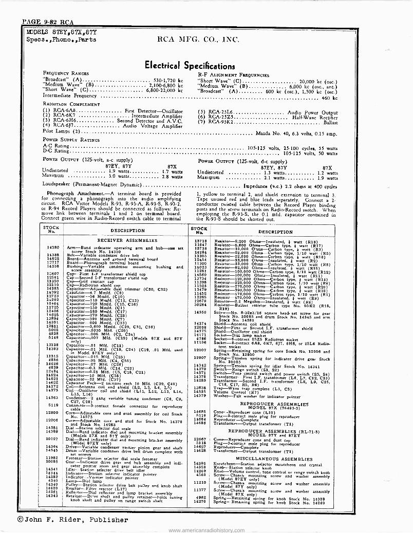
PAGE 9-82
MDDELS
Specs 87EY,87X,87Y
.,Phono.,Parts RCA MFG. CO., INC.
Electrical Specifications FREQUENCY RANGES R -F ALIGNMENT FREQUENCIES "Broadcast" (A) 530.1,720 kc "Short Wave" (C) 20,000 kc (osc.) "Medium Wave" (B) 2,100-6,800 kc "Medium Wave" (B) 6,000 kc (osc., ant.) "Short Wave" (C) 6,800-22,000 kc "Broadcast" (A) 600 kc (osc.), 1,500 kc (osc.) Intermediate Frequency 460 kc RADIOTRON COMPLEMENT (1) RCA -6A8 First Detector-Oscillator
2 RCA -6K7 (5) RCA -25L6 Audio Power Output (2) Intermediate Amplifier (6) RCA -25Z5 Half -Wave Rectifier (3) RCA -6H6 Second Detector and A.V.C. (7) RCA -95K2 Ballast (4) RCA -6J7 Audio Voltage Amplifier
Pilot Lamps (2) Mazda No. 40, 6.3 volts, 0.15 amp. POWER- SUPPLY RATINGS A -C Rating 105.125 volts, 25-100 cycles, 55 watts D -C -Rating 105.125 volts, 50 watts PowER OUTPUT (125 -volt, a -c supply) PowER OUTPUT (125 -volt, d -c supply)
87EY, 87Y 87X 87EY, 87Y 87X Undistorted 1.9 watts 1.7 watts Undistorted 1.3 watts 1.2 watts Maximum 3.0 watts 2.8 watts Maximum 2.1 watts 1.9 watts Loudspeaker (Permanent -Magnet Dynamic) Impedance (v.c.) 2.2 ohms at 400 cycles
Phonograph Attachment.-A terminal board is provided 1, yellow to terminal 2, and shield extension to terminal 3. for connecting a phonograph into the audio amplifying Tape unused red and blue leads separately. Connect a 2 circuit. RCA Victor Models R-93, R -93-A, R -93-S, R-93-2, conductor twisted cable between the Record Player binding or R-94 Record Players should be connected as follows: Re- posts and the screw terminals on Radio -Record switch. When move link between terminals 1 and 2 on terminal board. employing the R -93-S, the 0.1 mfd. capacitor contained in Connect green wire in Radio -Record switch cable to terminal the R 93-S should be shorted out.
-
STOCK No. DESCRIPTION STOCK
No, DESCRIPTION
14380
14388 14623 12717 14338
12607 12581 11350 12110 14383 14392 12723 14282 12404 12725 12406 14625 13894 14391 12811
6005 4838 5148
13138 14393
11315 4886
14626 4839
12484 14624 14621 14622 14372 14373
14363
5119
12800
12006
14381 14389
30127
14364 14345
11982 30085
14341 14344 14382
4340 14340 14620 14361 14343
RECEIVER ASSEMBLIES
Arm-Band indicator operating arm and hub-teas set screw Stock No. 14350
Belt-Variable condenser drive belt Board-Antenna and ground terminal board Board-Phonograph terminal board Bushing-Variable condenser mounting bushing and
screw assembly Cap-First I -F transformer shield top Cap-Second I -F transformer shield top Cap --Grid contact cap Cap-Radiotron shield cap Capacitor-Adjustable dual trimmer (C30, C32) Capacitor -4.7 Mmfd. (C6) Capacitor -56 Mmfd. (C10) Capacitor -110 Mmfd. (C12, C13) Capacitor -120 Mmfd. (C15, C16) Capacitor -150 Mmfd. (Cl) Capacitor -180 Mmfd. (C17) Capacitor -270 Mmfd. (C23) Capacitor -390 Mmfd. (C7) Capacitor -600 Mmfd. (C33) Capacitor -3,600 Mmfd. (C29, C31, C36) Capacitor-.0035 Mfd. (C20) Capacitor-.005 Mid. (C2, C34) Capacitor-.007 MEd. (C19) (Models 87X and 87Y
only) Capacitor-.01 Mfd. (C11) Capacitor-.01 Mfd. (C19, C24) (C19, .01 Mfd. used
in Model 87EY only) Capacitor-.015 Mfd. (C25) Capacitor-.05 Mfd. (C4, C35) Capacitor-.07 Mfd: (C26) Capacitor -0.1 Mfd. (C14, C22) Capacitor -0.25 Mfd. (C5, C18, C21) Capacitor -10 Mfd. (C38) Capacitor -32 Mid. (C37) Capacitor Pack -2 sections each 18 Mfd. (C39, C40) Coil-Antenna coil and shield (L2, L3, L4, L5) Coil-Oscillator coil and shield (Lll, L12, L13, L14, L15, L16) Condenser -2 gang variable tuning condenser (C8, C9, C27, C28) Connector -3 -contact female connector for reproducer
cable Core-Adjustable core and stud assembly for coil Stock No. 14373 Core-Adjustable core and stud for Stock No. 14376
and Stock No. 14283 Dial-Station selector dial scale Dial-Band indicator dial and mounting bracket assembly (Models 8 X and 87Y only) Dial-Bandindicator dial and mounting bracket assembly
(Model 87EY only) Drive-Variable condenser vernier pinion gear and shaft Drum-Variable condenser drive belt drum complete with set screws Fastener-Station selector dial scale fastener Gear-Indicator drive gear and hub assembly and indi-
cator pointer stem and gear assembly complete Idler-Station selector drive belt idler Indicator-Station selector indicator pointer Indicator-Vernier indicator pointer Lamp-Dial lamp Pulley-Station selector drive belt pulley and knob shaft Reactor-Filter reactor (L17) Reflector-Dial reflector and lamp bracket assembly Retainer-Drive shaft and pulley retainer-holds tuning knob shaft and pulley on range switch shaft
13716 11647 13736 14284 11305 12454 11300 14023 11281 14580 13734 11398 11323 13479 11452 12285 12679 30284
14350
14374 12008 14375 14171
4786 11196
12007
12907
14342 14370 14371 14376 14283
13838 14335 14379
14685 5118
14684 14686
12667 5118
14627 14628
14398 14359 14269
4560
11210
11377
4982 14270
Resistor --2,200 Ohms-Insulated, f watt (R13) Resistor -5,600 Ohms-Carbon type, * watt (R17) Resistor -10,000 Ohms-Carbon type, I watt (R3) Resistor -22,000 Ohms-Carbon type, 1/10 watt (R5) Resistor -22,000 Ohms-Carbon type, } watt (R16) Resistor -33,000 Ohms-Insulated, I watt (R2) Resistor -33,000 Ohms-Carbon type, 1/10 watt (R8) Resistor -82,000 Ohms-Insulated, } watt (R15) Resistor -100,000 Ohms-Carbon type, 1/10 watt (R12) Resistor -100,000 Ohms-Insulated, 1 watt (R11) Resistor -120,000 Ohms-Carbon type, } watt (R14) Resistor -220,000 Ohms --Carbon type, 1/10 watt (R6) Resistor -270,000 Ohms-Carbon type, f watt (R20) Resistor -390,000 Ohms-Carbon type, I watt (R10) Resistor -470,000 Ohms-Carbon type, 1/10 watt (R1) Resistor -470,000 Ohms-Insulated, f watt (R9) Resistor -2.2 Megohm-Insulated, I watt (R4) Resistor-Ballast resistor tube type No. 95K2 (R18,
R19) Screw-No. 8-32x3/16 square head. set screw for gear
Stock No. 30085 and drum Stock No. 14345 and arm Stock No. 14380
Shield-Antenna coil shield Shield-First or Second I.F. transformer shield Shield-Oscillator coil shield Socket-Dial lamp socket Socket -6 -contact 25Z5 Radiotron socket Socket -8 -contact 6A8, 6K7, 6J7, 6836, or 25L6 Radio -
tron socket Spring-Retaining spring for core Stock No. 12006 and
Stock No. 12800 Spring-Tension spring for indicator drive gear Stock
No. 30085 Spring-Tension spring for idler Stock No. 14341 Switch-Range switch (S1, S2) Switch-Tone control switch and power switch (S3, S4) Transformer-First I.F. transformer (L6, L7, C12, C13) Transformer-Second I.F. transformer (L8, L9, C15, C16, C17, R5, R6) Trap-Wave trap complete (Ll, C3) Volume Control (R7) Washer-Felt washer for indicator pointer
REPRODUCER ASSEMBLIES MODEL 87X (76493-3)
Cone-Reproducer cone (L10) Plug-I-contact male plug for reproducer Reproducer-Complete Transformer-Output transformer (T1)
REPRODUCER ASSEMBLIES (RL -71-3) MODEL 87Y and 87EY
Cone-Reproducer cone and dust cap Plug -3 -contact male plug for reproducer Reproducer-Complete Transformer-Output transformer (Ti)
MISCELLANEOUS ASSEMBLIES Escutcheon-Station selector escutcheon and crystal Knob-Station selector knob Knob-Volume control, tone control or range switch knob Screw-Chassis mounting screw and washer assembly (Model 87EY only) Screw-Chassis mountingscrew and washer assembly (Model 87Y only) Screw-Chassis mounting screw and washer assembly (Model 87X only) Spring-Retaining spring for knob Stock No. 14359 Spring-Retaining spring for knob Stock No. 14269
©John F. Rider, Publisher www.americanradiohistory.com
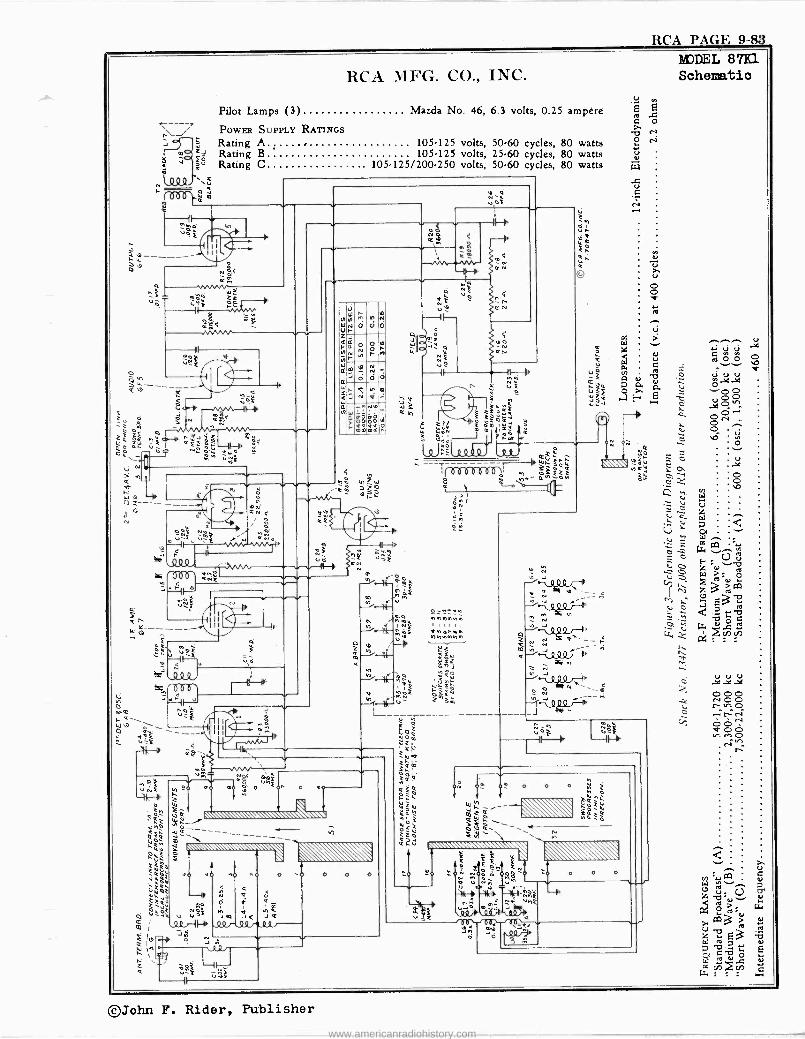
RCA PAGE 9-83
RCA MFG. CO., INC.
Pilot Lamps (3) Mazda No. 46, 6.3 volts, 0.25 ampere
POWER SUPPLY RATINGS
2 Rating A 105425 volts, 50.60 cycles, 80 watts Rating B 105.125 volts, 25.60 cycles, 80 watts Rating C . 105-125/200-250 volts, 50-60 cycles, 80 watts
ti
e2----- om $
Q gi
2 '----WMMh- F -
"o
t£9 Ni ~VW
JN II
V«
J Q
lb Na
a- s
N
OHZ-F
IL)
111
^ O
Ñ v á d f °=
N
m f -Rlt.--ih I 7s
J n
ti IQ
L
en ÚÿF
v
O
M
Ó
n d
N
Ó
r o N
0
m
O
a
-q
S8 mºO
N N - d 10
n lo
br IW éº!O
a
N u3 C h
N q
ON
n K N
JO Co,
ÌF---i 1
c Ei
h17_.IÓ
W WÓM R
Q úyN b -$ YÒ f
rt
/
JUL,C FO
Ú - _
10536D8DO riez; i rf e b
a; óM
MV
0 O O O Ñ C
?.QhÁ GG
wW ÑZÓ w / m2ó W
iy{``
o
O O
é
0 N N
MODEL 87K1 Schematic
///1 ++ ci
úi m 0 ..Gi O ó
..../0 O
0. 0 1...r 0 N
4 p a )0b 0
r ö u
Ó "' 0 c_ .Y e O ti u ` V U :: z
V' d
Z2 W
= c H v.,flO).
- z3 M )/:- E -2
e C 7 10
:: y b Ó G
Lz, k á Ñ
©John F. Rider, Publisher
www.americanradiohistory.com
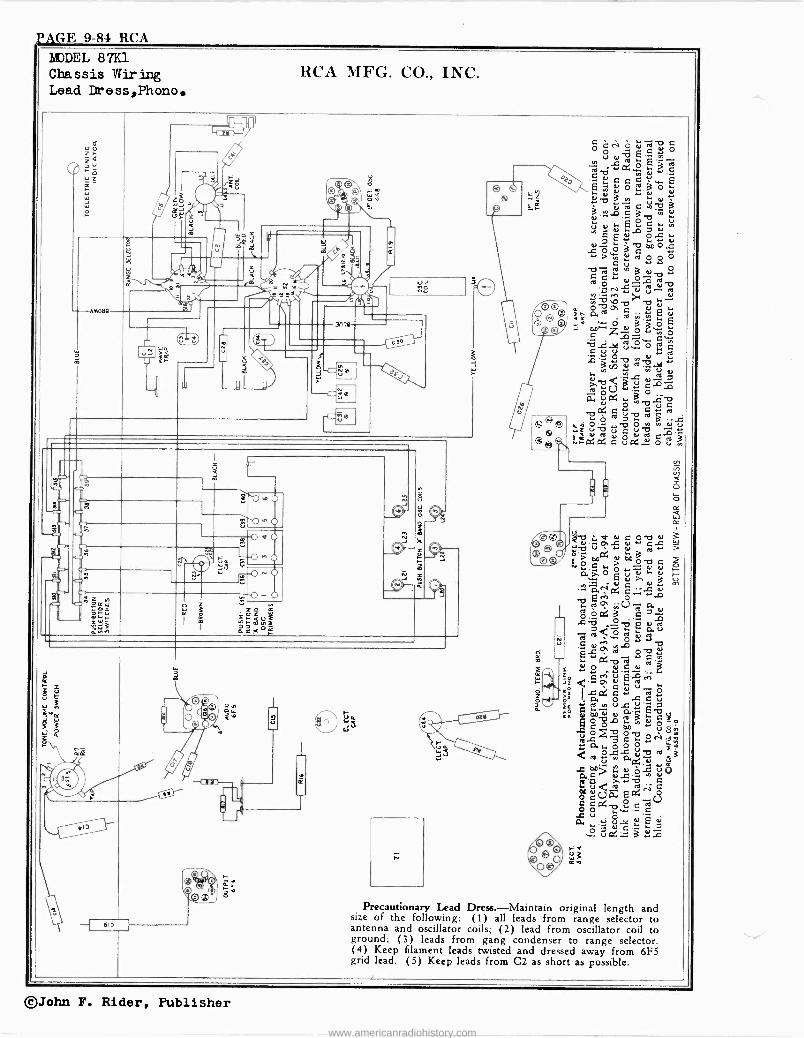
P AGE 9-84 RCA
ó
MODEL 87K1 Chassis Wir inc Lead Dress,Phono.
RCA MFG. CO., INC.
á
-6M6ä9
ós
>
c7 vf
n -2 G 0
yyr VW'jÑ
--I 616 1
0t
úa !l 4.3
o CN er d o d 2b r, ób C b .+
h d R a+ E Eá`d
.-
itjiä
. Gd-p á . wadsZ:ómóyum
o ó
.u Cu .,
mi0M u,sb$ =1
Q v® a^ P. ro Q C ÿ d © .., ro `°h w â q/ o6--z"ó r.[ .ñ
.°e c , o y w+
4.3
i y:a 0 (y u i a` .+C 97 u ó°uQ u.,a"o ..`il8Tfa+g ú.vwd2 lía`eeuipar`uC.. rrP:Pl. C ufy.. o v 3
w Q 1.1 16
I W ó .+ ú e^ u.t y, -' o o o. @v a.
.iyi C 0~0
á a~d+ C o
u sp ® 2
?GÿNg $a,o00 is `e°maui-oa gg[ÿvò-+CÓ o.
6sd dtd 01üá Qo4`V ó ób.á
Al u a,,Yu.eE .º oG 3 :1
F -
e
Precautionary Lead Dress.-Maintain original length and size of the following: (1) all leads from range selector to antenna and oscillator coils; (2) lead from oscillator coil to ground; (3) leads from gang condenser to range selector. (4) Keep filament leads twisted and dressed away from 6F5 grid lead. (5) Keep leads from C2 as short as possible.
©John F. Rider, Publisher
www.americanradiohistory.com
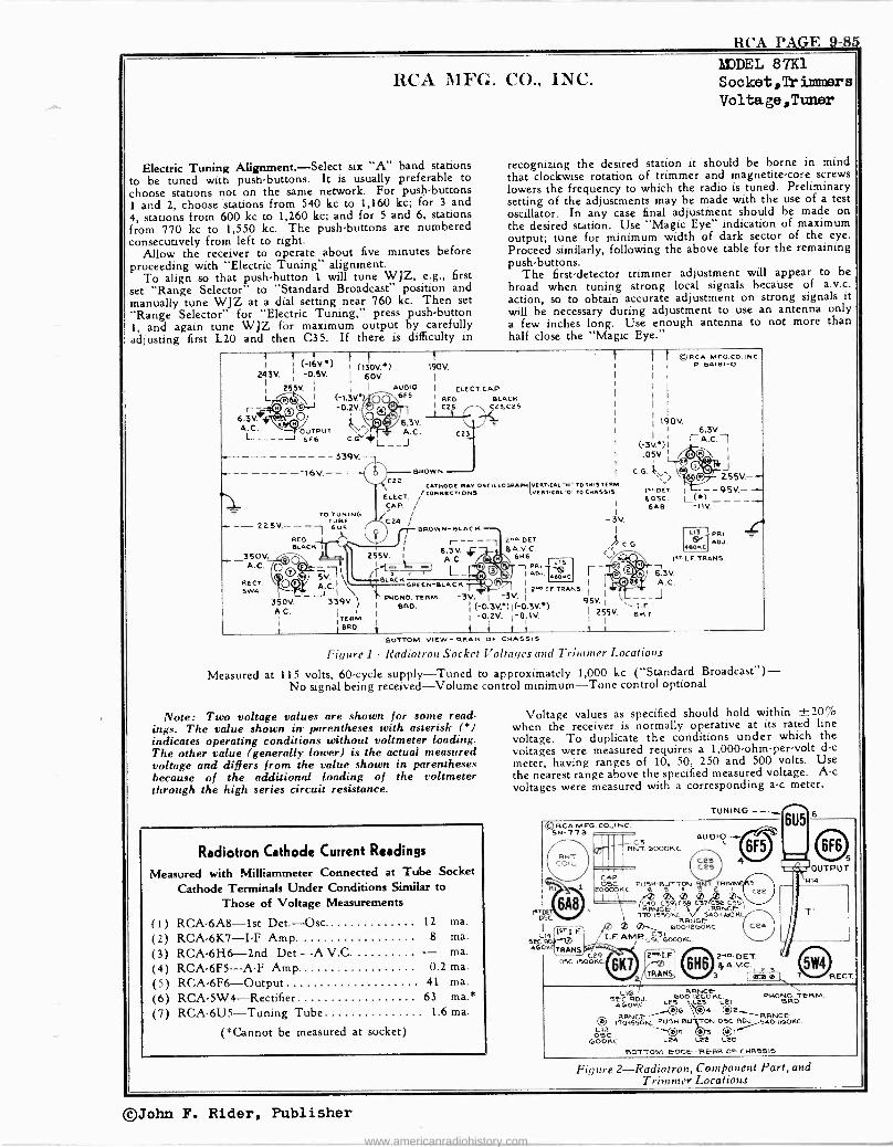
RCA PAGE 9-85
RCA MFG. CO., INC.
Electric Tuning Alignment. -Select six "A" band stations to be tuned with push -buttons. It is usually preferable to choose stations not on the same network. For push -buttons 1 and 2, choose stations from 540 kc to 1,160 kc; for 3 and 4, stations from 600 kc to 1,260 kc; and for 5 and 6, stations from 770 kc to 1,550 kc. The push -buttons are numbered consecutively from left to right.
Allow the receiver to operate about five minutes before proceeding with "Electric Tuning" alignment.
To align so that push-button 1. will tune WJZ, e.g., first set "Range Selector" to "Standard Broadcast" position and manually tune WJZ at a dial setting near 760 kc. Then set "Range Selector" for "Electric Tuning," press push-button 1, and again tune WJZ for maximum output by carefully adjusting first L20 and then C35. If there is difficulty in
MODEL 87K1 Socket, Tr imnsrs Voltage,Tunler
recognizing the desired station it should be borne in mind that clockwise rotation of trimmer and magnetite -core screws lowers the frequency to which the radio is tuned. Preliminary setting of the adjustments may be made with the use of a test oscillator. In any case final adjustment should be made on the desired station. Use "Magic Eye" indication of maximum output; tune for minimum width of dark sector of the eye. Proceed similarly, following the above table for the remaining push -buttons.
The first -detector trimmer adjustment will appear to be broad when tuning strong local signals because of a.v.c. action, so to obtain accurate adjustment on strong signals it will be necessary during adjustment to use an antenna only a few inches long. Use enough antenna to not more than half close the "Magic Eye."
I } (-16V') } (130V.) 190V.
24311 -0.5V. I 60V. I I
1 255V. i 1 I AUDIO L I (-1.3V.)p 6F5 6.3
.7g -0.2V. V.
i,,7,4-- 6.3V. A.C. OUTPUT A.C. L____J 6F6 C.G. # L___J
ELECT.CAP RED BLACK
I C25 C23.C25
C23
I ©RCA MFG.CO.INC. I I
P-64101-0 I II I
190V.
1
6.3V.
1 -339V.- . I Q; C22BaowN ,, Ó 255V.--
CATNODERAYOSCILLO6RAPNVERTICAL"TOTMTERM. _ ELECT. CORNECTIONS
NI' IS VERTICAL`O"TOCIIASSIS t"' OCT. 1 -95V.-
i aost. L(*) ----- 6AB -11V. TO TUNING
225V.- - - TUBE 6'6
350V. A.C.
RECT. SW4
350V A.C.
RED - SLACK
0 05V F
339V. )
'TERM. I BaO.
CAP. ¡ 1C24 l
BROW N-BLAC K I 1\ V ;
255V I 6.3V.
-BLACK
l 3V.)1 A.C. -1
I .O5V. I '
I C.G. F
C.G. 14
LI3 1 PARIDJ.
soKc I"_ I.F. TRANS.
r I
63V. OREEN -/LACK - I I
H A.C. 1
2"1OI.F. TRANS. PHONO. TERM. -3V. I -3V. I 9$V.
1 (-0.3V.)I(-0.3V. )
I 255V. eKi I -0.2V. I -0.1V. V i t i t i
660.
2- DET. 6 A.V. C.
5H6 -1 vRl TI
us ADJ. 460KC
r
BOTTOM VIEW- REAR OF CHASSIS
Figure 1-Radiotron Socket Voltages and Trimmer Locations
Measured at 115 volts, 60 -cycle supply -Tuned to approximately 1,000 kc ("Standard Broadcast") - No signal being received -Volume control minimum -Tone control optional
Note: Two voltage values are shown for some read- ings. The value shown in parentheses with asterisk (8) indicates operating conditions without voltmeter loading. The other value (generally lower) is the actual measured voltage and differs from the value shown in parentheses because of the additional loading of the voltmeter through the high series circuit resistance.
Radiotron Cathode Current Readings
Measured with Milliammeter Connected at Tube Socket Cathode Terminals Under Conditions Similar to
Those of Voltage Measurements
(1) RCA -6A8 -Ist Det.-Osc. 12 ma.
(2) RCA -6K7 -I -F Amp. 8 ma.
(3) RCA -6H6 -2nd Det.-A.V.C. - ma.
(4) RCA -6F5 -A -F Amp. 0.2 ma.
(5) RCA -6F6 -Output 41 ma.
(6) RCA -5W4 --Rectifier 63 ma.*
(7) RCA -6U5 -Tuning Tube 1.6 ma.
(*Cannot be measured at socket)
Voltage values as specified should hold within ±20% when the receiver is normally operative at its rated line voltage. To duplicate the conditions under which the voltages were measured requires a 1,000 -ohm -per -volt d -c
meter, having ranges of 10, 50, 250 and 500 volts. Use the nearest range above the specified measured voltage. A -c
voltages were measured with a corresponding a -c meter.
TUNING -- I RCA MFG. CO..INC SN -77 3
R
IATDE 05C
6A8
u4 1sTI F.
oRa-0 TRANS.
c OSC.1500KC
Pic III
AUDIO C3
RNT.6000KC. C2a C25
S9TT4ON
,R5
RRÑGE / ` '0 I KRNGÉ
/TO 1550KC V 540 1160KC R4NGB
600 126OKC. I
I.F. AMR Oÿ 0000KC
6K7 2
L1ß RRNCE 5EC ROJ. 600-1260KC. PHONO TERM
AGOKC LCS LCS 121 660. B 4 02 RRNGE RRNGé
O 1T01550KC PUSH 6 TON OSC RIM 5401WOKC. E-
1.-12 03C.
2'at.F.
RAMS ca)
6F5
DET $ A.VC.
3 020 B
O 1 1
ßÿC OUTPUT
011
414
'T RECT.
`OOS 3 QI/ GOOKC L24 Le2 L20
BOTTOM BOGE -REAR OF CHRTSI5
Figure 2-Radiotron, Com/onent Part, and Trimmer Locations
©John F. Rider, Publisher
www.americanradiohistory.com
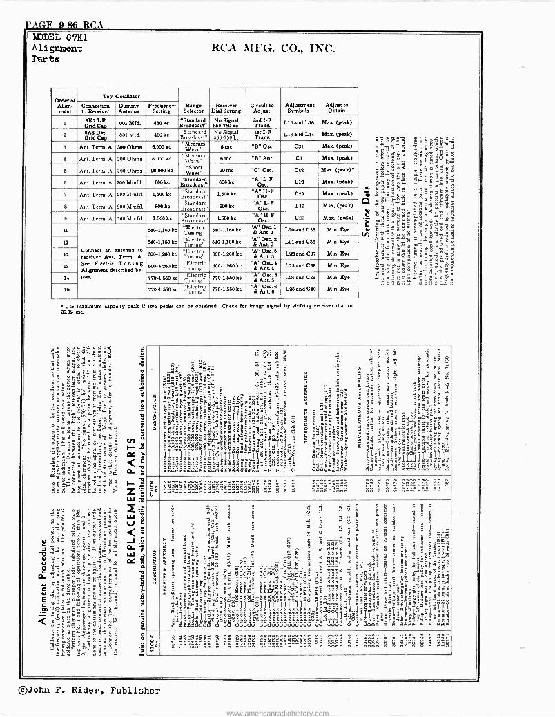
PAGE 9-86 RCA LáVDEL 87K1 Alignment Parts
RCA MFG. CO., INC.
Order of Align- ment
Test Oscillator
Range Selector
Receiver Dial Setting
Circuit to Adjust
Adjustment Symbols
Adjust to Obtain
Connection to Receiver
Dummy Antenna
Frequency. Setting
8%7 I -F Grid Cap
.001 Mfd. 480 kc "Standard Broadcast"
No Signal 550-750 kc
2nd I -F Trans. L15 and 1.18 Max. (peak)
6A8 Det. Grid CapBroadcast" .001 Mfd. 480 kc "Standard No Signal
550-750 kc 1st I -F Trans. 1.13 and 1.14 Max. (peak)
S Ant. Term. A 300 Ohms 8,000 kc "Made" Wave" 8 me "B" One. C31 Max. (peak)
4 Ant. Term. A 300 Ohms 6,000 kc "Medium Wave" 8 me "B" Ant CS Max. (peak)
5 Ant. Term. A 300 Ohms 20,000 kc "Short 20 me "C" Osc. C42 Max. (peak)
6 Ant. Term. A Mmfd. 200 Mm 800 kc "Stan Bro a dcdarast"
d 800 kc Osc. "A" I`F 1.12 Max. (peak)
7 Ant. Term. A 200 Mmfd. 1,500 kc "Standard Broadcast" 1,600 kc "A" H -F
Osc. C28 Max. (peak)
8 Ant. Term. A 200 Mmfd. 800kc "standard Broadcast"
800kc Osc
q, I`F 1.10 Max. (peak)
9 Ant. Term. A 200 Mmfd. 1,600 kc "Standardot1,600 Broadcast" kç "A"
Osc. C29 Max. (peAk)
10
Correct an antenna to receiver Ant. Term. A. See Electric Tuning Alitemettt described be- low.
640-1,180 kc "Electric Tuning' b40-1,160 ke "A"
Ant. 1
1
& 1.20 and C36 Min. Eye
11 540-1,180 kc "TuniElecntrg' 510-1,180 kc "12'se. 2 t 2ic L21 and C98 Min. Eye
12 800.1 980 kc "Electric Tuning" 600-1,260 kc "A" Ow. S
& Ant. 3 1.22 and C37 Min Eye
1S 600-1,260 kc "Electric Tuning' 600-1,280 kc
" Osc. 4 A
&Ant. 4 L23 and C38 Min. Eye
14 770-1,550 kc "Electric Tuning c 770-1,660 ke & Ant 66 L24 and C39 Min. Eye
15 770-1,550ke "Electric Tuning" 770-1,550 kc "A"0cc.6
& Ant. 6 L25 and C40 Min. Eye
Use maximum capacity peak if two peaks can be obtained. Check for image signa by shifting receiver dial to 20.92 inc.
c d Eó áá a1 5°ñv.'cli
E s
17ÿ .ÿ?S Bó_ ° vis, óp ë Q$ Ñvr.:
u 1SS
I; d's,8 o É e É g.>'''., ,..-
1ß2o
Ys "-?wó` Swy1lg...fc Y E .. ; g, ÿñ.=- z
ô u w öEmu+ac uE ï mm a óu c I .i.e .2.9:.
siE Em2ÿ^ g2.-Ñcaú.5i c" e coo6róc fn tl ° >^"P",z d ú.l- e
°'-21,e12 2a !- ' +.áq 3 ä-.1E,-. cc é
w.9 n v... < E
m7:äE°gic°rvCú c d.m.62c9Á.2pó=d f1. m a.,"ca
c E of;F. E - 3 3-"°vw° 3 1-- s á B ó 1 3:? ..i ó1 > 2n ...£
<11J
v G -' m é .vdg °- ",°,o
Béo,`u, 9z!+._ a¿á UA m
c ill o.. a p o V d
`á óñ"á$ú Sú Y Q m g u ÿ g. 0.6 g° E ` ó."3F -, ñ z;^ : ?bm J t vvog _ñ^4 i; r°s_L có' II.n0 -'»óce1
u ayP "3áó0` O 3 ó _A
92d eÉñ'â:ó6 `b;'m°áº^C ;.=ó.e_ "5.
É :en400,.r.g:v e ?$' .>
icéÓ8ÉYó MMc.óáú4$ó r e <"m .et ,,,C, rúárgñL ` 9 .. ú é.B E29v l$ ú> m
Ó":.« Ú9ÓL<OB.:t"i C YY
0 ,". m P. r e C c ti (re -N.': CÚ'cg"">Ú` lä .ºr á ñ 4
cc .", È -F, ó ^'-"
eE a `nu
s é ó ° ay
Y EO
.._`"E u'a.g1o ád
áñ°.y +á Lc.çá85 4 ?éc a ..... 9
Cä 4.°2-g«°-2 óF'ó.a
.E ác. C r momá p 22-1.0-95
eo ",¡ G
* ri V °vócc ó.ón<áñ^á
.0 "t 3 5 ° c s c l d m
Ñ c . m u ti
é.:y8óóóJ °5T0"vE sY ñBp°9`...O BP r21:1;,áv2ù
mm.,> 3 rc o E opPcc ..
2 ñóütuQá r:.'$ci>
.
ot o
t" äú H ° 2 . - .. n I si...A rm ^ - ppp
ei r2 ñ °' a. 0,0.a+á +.t . .J A V1 = ñ ..
-.447'2, a m ttó8-áá . S ; x k M .ii g é r i; 6z 6 ^+laá^0..,.7-. " á ; ,° a o%D 9 t z, z F;á"ss;a g"2? -; it 22 l;
°s
a1A x
is.:~-rt-ma ; .44á e o tF"
ÿr a^N < o3g at= _,
E @ a nj` .E@m a ;Pero r
C,S-a..e°_=..;gl l exgf°c ¡, t= e a il] e =_ ao ó
y -5e x
$ß?"së.3=S.3Sea2+=r II 'Sw'°'r. 2 ? ú 8 5, 42 z °C :hill.aé 9:rY
° ÉÉÉw ì4ZeÿiC3.. am.:,.E1.. o rv 52 < ..9 S,°.,Se y5ec_72S" i 22 ++
E a -1áC O e0=° -t :5 EéC3'. °. : ét2 °éG:á862.ag.. e á a°9=>:$q ` +9.9°ç5800.É'
o i °L aaa=6°wÿ,¿° m
ÿá.éeo`,s ÿ 3'i -e l;.=".
oóg5y :Ejºó io aada 2 -_ oa Ñ+ÑiÑg+ .'g.-" eSóéóó °SNYE _ a ;o Ec-
ñ$ S qeóéC00 e¡Ib [ E._am .. 3._5g Z _b°rlw m I II_:°° YYf.1oro.,..áE'.Im r D F .°eySÿtu < Z+o da aaa Lpqml IÌ
F1771 III J.°+áá.E 3 cäza I ll=2>amFY =ll^I °eZ ° laa>:a YYÿ L7' m S°"..-rse1111111=Y ~ a.x.a.a.e.e.... _ -mäm,l 111 ;ESa :<2:a;?ee d °" 6''66aaaaaaa9xxsxxeo'i'F"SSt'c+e äaE_B° Se <ay5v aaaaaaaaaaaaanmYmmvrNmxN FF F Ñ F dVUUaamF3 m'ú w w úl XkXanmm
M .n. .
m an
u n. ... .. nn u mn n. w
C c
U
W X
5 .g _ . S ú. _ Z E;
5 E. ;
< ú < T x ea
% e
ª 9 0 º°'° " .. u a I : _
°4 m ÿ"' --á 5 ; > ° 2 : ° cá
8 8 y- i' u S ñ V m áááa 2 a9 S á
oe ä S+y""é ' M; o
8 i ,.a .2 ° a` 7 5: yëyajsa« &, .3.13. ;$m e ó - 0u ó 4
u 8 ^ É E a -Sac r é ë e Y dáá .4" V. °ra,`ga£
a _ Y2n ^m 0uu0.. aa.,srdu,.u 2y Via
I
a `° - x ;o= 5 G&, uuuu+ri....^a ^ 1.b_.4,ä>a"ds
°' á gg ee
uuun" . 9á9i .5 e -'á_8g ç .=°=8'á 'u°EE .ä ti.iddè.°"4.2..732g1VvuV 5 «< ó°i' ç ä e`
y y í y . k`' c..= '°"' .
2"um w g o';g3olxe 22 Pig' U - u .. Otleër 0èbñíñ-d_0-9G O^Y és° Ge°":10,1q.
a°"_9!$--..1 éo2óéSS'
a ón .18,9Aééeágwó E,.Sgáó aaSSa Xoyt"'"eeaáí c .. ° ° ° V.. '°E- oeo
a F9Ge o oq'n° áe .: a38 .s yé"" pC° rm 9 °'"
cÉ Y '9 rmFSúIJIuIj171ÍI1Í71^ 3:áM1 ' > oeIeoo,x 71 e
L lo sao ç7l:lYa"ë"ú.3ó:a aaú; y::;g,,aa«; mE
2E17l `é6=3 +g.a.ë"
YäSSaá137S o go3d o$ñ==o=n°== u ááiä°tiä.eg3esr2>29vég-P --Ili < xxxxuuuu u ud uduuu duuuuuuuuuuuu uu uuuu u u uoóo 0 0....ad $ t2 aaa
pZ 5 .ne n n
eä mmmu 25: nn n nn n . .n
©John F. Rider, Publisher
www.americanradiohistory.com
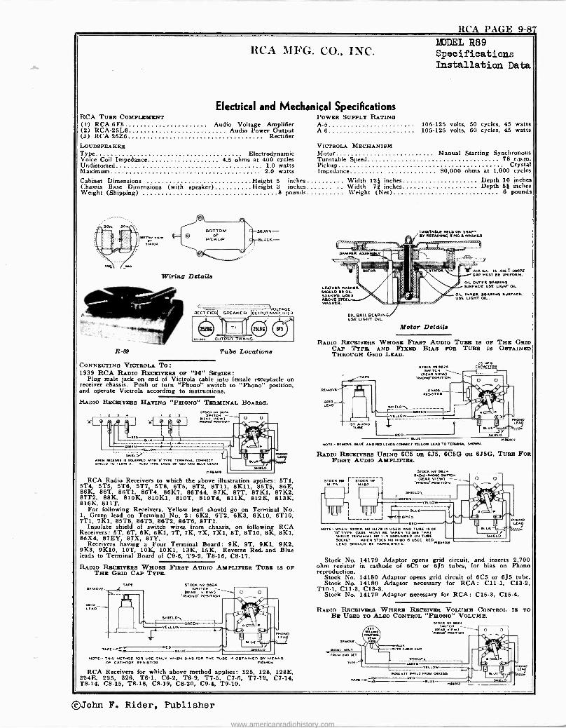
RCA PAGE 9-87
RCA TUBE COMPLEMENT
RCA MFG. CO., INC.
Electrical and Mechanical Specifications POWER SUPPLY RATING
MODEL R89 Specifications Installation Data
(i) RCA -6F5 Audio Voltage Amplifier A-5 105-125 volts, 50 cycles, 45 watts (2) RCA -25L6 Audio Power Output A-6 105-125 volts, 60 cycles, 45 watts (3) RCA -25Z6 Rectifier LOUDSPEAKER VICTROLA MECHANISM Type Electrodynamic Motor Voice Coil Impedance 4.5 ohms at 400 cycles Turntable Speed Undistorted 1.0 watts Pickup Maximum 2.0 watts Impedance 90,000 ohms at 1,000 cycles
Cabinet Dimensions Height 5 inches Width 12} inches Chassis Base Dimensions (with speaker) Height 3 inches Width 7* inches Weight (Shipping) 8 pounds Weight (Net)
R-89
Wiring Details
O LTAGE OUTPUT A MPL IF IE R
Tube Locations
CONNECTING VICTROLA TO: 1939 RCA RADIO RECEIVERS OF "90" SERIES :
Plug male jack on end of Victrola cable into female receptacle on receiver chassis. Push or turn "Phonti " switch to "Phono" position, and operate Victrola according to instructions.
RADIO RECEIVERS HAVING "PHONO" TERMINAL BOARDS.
RED
GREEN
EL
L SHIELD.'
ER IS EQUIPPED «IT e' 'vet TERMINAL COIENECT SHIELD TO TERMS ALSO TAPE END! of RED AND x"E LEADS
LLOVE
'
d 1`, ''11
RCA Radio Receivers to which the above illustration applies 5T1, 5T4, 5T5, 5T6, 5T7, 5T8, 6T5, 8T2, 8T11, 8K11, 85T5 86E, 86K, 86T, 86Th, 86T4, 86K7, 86T44, 87K, 87T, 87K1, 87K2, 87T2, 88K, 810K, 810K1, 810T, 810T4, 811K, 812K, 813K, 816K, 811T.
For following Receivers, Yellow lead should go on Terminal No. 1, Green lead on Terminal No, 2: 6K2, 6T2, 6K3, 6K10, 6T10, 7T1, 7K1, 85T8, 86T3, 86T2, 86T6, 87T1.
Insulate shield of switch wires from chassis, on following RCA Receivers: 5T, 6T, 6K, 6K1, 7T, 7K, 7X, 7X1, 8T, 8T10, 8K, 8K1, 86X4, 87EY, 87X, 87Y.
Receivers having a Four Terminal Board: 9K, 9T, 9K1, 9K2, 9K3, 9K10, SOT, 10K, 10K1, 13K, 15K. Reverse Red, and Blue leads to Terminal Board of C9-6, T9-9, T8-16, C8-17.
RADIO RECEIVERS WHOSE FIRST AUDIO AMPLIFIER TUBE IS OF THE GRID CAP TYPE.
REMOVE
GRID
TAPE
5HIELD GR
LOW
TAPECRED
STOCK NS 5824 SWITCH
.PHONO- (REAR VIEW)
EEN (MI BLU
PHONO LEAD
NOTE - THIS METHOD FOR USE ONLY WHEN BIAS FOR THE TUBE 15 OBTAINED BY MEANS OF CATHODE RESISTOR N8E40!
RCA Receivers for which above method app ies: 125, 128, 128E, 224E, 225, 226, T6-1, C6.2, T6-9, T7-5, C7-6, T7-12, C7-14, T8-14. C8-15, T8-18, C8-19, C8-20, C9-4, T9-10.
LEATHER WASHER SHOULD SE OIL SOAKED. 40E1 ARDOR STEEL WASHER.
OIL BALL BERRI NG USE LIGHT OIL
Depth 10 inches Depth 5* inches
6 pounds
TURNTABLE MELO OM SMART BI RETAINING RINO B WASHER
Motor Details
AIR OA IS.OI42,.00075 GAP MUST BE UNIFORM.
OIL OUTER BEARING SURrACE,USE L14HT on.
OIL INNER BEARING SURFACE. USE LIGHT OIL.
RADIO RECEIVERS WHOSE FIRST AUDIO TUBE IS OF THE GRID CAP TYPE. AND FIXED BIAS FOR TUBE IB OBTAINED THROUGH GRID LEAD.
AP
REMOVE
CAPACIT04 ST.wME
9ez4
fRUrtcK R V1EW\ PHOHC POSITION
GREEN YELL
PLEAD
RED EILUE
NOTE REMOVE BLUE ANC/ SW LEADS Cbsect YELLOW LEAD TO TERMINAL SHOWN.
RADIO RECEIVERS USING 6C5 OR 6J5, 6C5G OR 6J5G, TUBE FOR FIRST AUDIO AMPLIFIER.
STOCK NE r STOCK N9 1 14179 I 14180
Manual Starting Synchronous 78 r.p.m.
Crystal
STOCK NH 5824 RAROAROIE SWITCH
RORER VIEWI POSITION
BHrtLDl EEN , !WI VELLOW J,
L J T[+wnrD. III,RO OPE '11 PHPND
RED ei EJ EAO
NOTE --WHEN STOCK N2 1417915 USED AND TUBE IS OF / G TYPE CARF MUST 8E TAKEN TO SEE THAT -SHIELD TERMINAL Nº 1 15 GROUNDED ON TUBE SOCKET. WHEN STOCK NE 14180 15 USED RE13...
8 LEAD SHOULD BE TAPED,OPIIT C.
Stock No. 14179 Adaptor opens grid circuit, and inserts 2,700 ohm resistor in cathode of 6C5 or 6J5 tubes, for bias on Phono reproduction.
Stock No. 14180 Adaptor opens grid circuit of 6C5 or 6J5 tube, Stock No. 14180 Adaptor necessary for RCA: C1l-1, C13-2,
T10-1, C11-3, C13-3. Stock No. 14179 Adaptor necessary for RCA: C15-3, C15-4.
RADIO RECEIVERS WHERE RECEIVER VOLUME CONTROL IS TO BE USED TO ALSO CONTROL "PHONO" VOLUME.
PIDNO VPOS T OH
TO AUDK)
OMEN GEN YELIOw
TAPE Cm RED 1434/LATE. SHELD FROM DIASSM
RHONO LEAD
©John F. Rider, Publisher
www.americanradiohistory.com
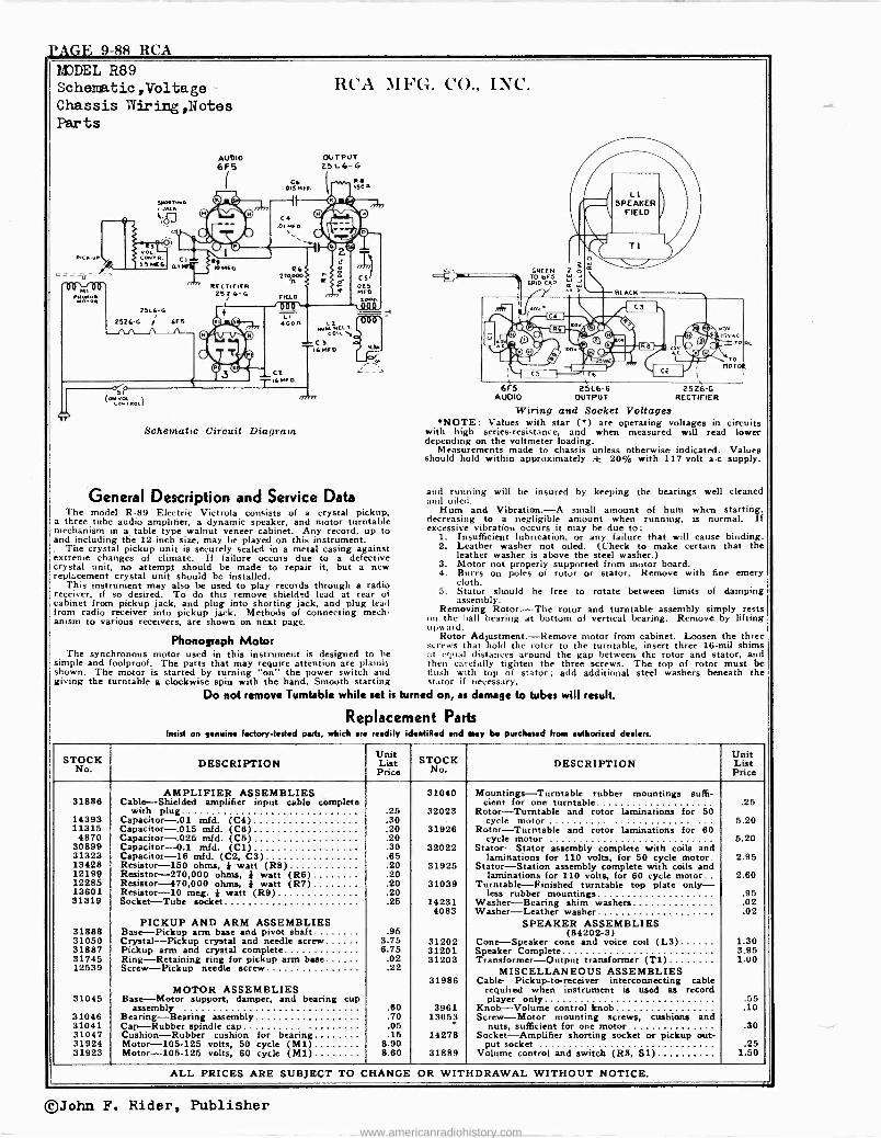
PAGE 9-88 RCA MODEL R89 Schematio,Voltage Chassis Wiring,Notes Parts
AUDIO 6F5
Schematic Circuit Diagram
ILCA M FG. CO., INC.
OUTPUT 251.6-G
General Description and Service Data The model R-89 Electric Victrola consists of a crystal pickup,
a three tube audio amplifier, a dynamic speaker, and motor turntable mechanism in a table type walnut veneer cabinet. Any record, up to and including the 12 -inch size, may be played on this instrument.
The crystal pickup unit is securely sealed in a metal casing against extreme changes of climate. If failure occurs due to a defective crystal unit, no attempt should be made to repair it, but a new replacement crystal unit should be installed.
This instrument may also be used to play records through a radio receiver, if so desired. To do this remove shielded lead at rear of cabinet from pickup jack, and plug into shorting jack, and plug lead from radio receiver into pickup jack. Methods of connecting mech- anism to various receivers, are shown on next page.
Phonograph Motor The synchronous motor used in this instrument is designed to he
simple and foolproof. The parts that may require attention are plainly shown. The motor is started by turning "on" the power switch and giving the turntable a clockwise spin with the hand. Smooth starting
Do not remove Turntable while set is turned on, as damage to tubes will result.
Replacement Parts Insist on genuine Factory -tested parts, which are readily identified and may be purchased hot authorized dealers.
GREEN TO br5
GRID CAP
6F5 251.6-G 25Z6 -G AUDIO OUTPUT RECTIFIER
Wiring and Socket Voltages *NOTE: Values with star (*) are operating voltages in circuits
with high series -resistance, and when measured will read lower depending on the voltmeter loading.
Measurements made to chassis unless otherwise indicated. Values should hold within approximately ± 20% with 117 -volt a -c supply.
and running will be insured by keeping the bearings well cleaned and oiled.
Hum and Vibration. -A small amount of hum when starting, decreasing to a negligible amount when running, is normal. 1f excessive vibration occurs it may he due to:
1. Insufficient lubrication, or any failure that will cause binding. 2. Leather washer not oiled. (Check to make certain that the
leather washer is above the steel washer.) 3. Motor not properly supported from motor board. 4. Burrs on poles of rotor or stator. Remove with fine emery
cloth. 5. Stator should be free to rotate between limits of damping
assembly. Removing Rotor. -The rotor and turntable assembly simply rests
nu the ball bearing at bottom of vertical bearing. Remove by lifting upward.
Rotor Adjustment. -Remove motor from cabinet. Loosen the three screws that hold the rotcr to the turntable, insert three 16 -mil shims at equal distances around the gap between the rotor and stator, and then carefully tighten the three screws. The top of rotor must be Hush with top of stator; add additional steel washers beneath the stator if necessary.
STOCK No. DESCRIPTION
Unit List
Price STOCK
No. DESCRIPTION
Unit List Price
AMPLIFIER ASSEMBLIES 31040 Mountings -Turntable rubber mountings suffi - 31886 Cable -Shielded amplifier input cable complete cient for one turntable .25
with plug .25 32023 Rotor -Turntable and rotor laminations for 50 14393 Capacitor -.01 mfd. (C4) .30 cycle motor 5.20 11315 Capacitor -.015 mid. (C6) .20 31926 Rotor -Turntable and rotor laminations for 60
4870 Capacitor -.025 mfd. (C5) .20 cycle motor 5.20 30899 Capacitor -0.1 mid. (C1) .30 32022 Stator -Stator assembly complete with coils and 31323 Capacitor -16 mid. (C2, C3) .65 laminations for 110 volts, for 50 cycle motor. 2.95 13428 Resistor -150 ohms, } watt (R8) .20 31925 Stator -Station assembly complete with coils and 12199 Resistor -270,000 ohms, } watt (R6) .20 laminations for 110 volts, for 60 cycle motor.. 2.60 12285 Resistor -470,000 ohms, * watt (R7) .20 31039 Turntable -Finished turntable top plate only - 13601 Resistor -10 meg. 4 watt (R9) .20 less rubber mountings .95 31319 Socket -Tube socket .25 14231 Washer -Bearing shim washers .02
4083 Washer -Leather washer .02 PICKUP AND ARM ASSEMBLIES SPEAKER ASSEMBLIES
31888 Base -Pickup arm base and pivot shaft .95 (84202-3) 31050 Crystal -Pickup crystal and needle screw 3.75 31202 Cone -Speaker cone and voice coil (L3) 1.30 31887 Pickup arm and crystal complete 6.75 31201 Speaker Complete 3.95 31745 Ring -Retaining ring for pickup arm base .02 31203 Transformer -Output transformer (T1) 1.00 12539 Screw -Pickup needle screw .22 MISCELLANEOUS ASSEMBLIES
MOTOR ASSEMBLIES 31986 Cable -Pickup -to-receiver interconnecting cable
required when instrument is used as record 31045 Base -Motor support, damper, and bearing cup player only .55
assembly .60 3961 Knob -Volume control knob .10 31046 Bearing -Bearing assembly .70 13053 Screw -Motor mounting screws, cushions and 31041 Cap -Rubber spindle cap .05 nuts, sufficient for one motor .30 31047 Cushion -Rubber cushion for bearing .15 14278 Socket -Amplifier shorting socket or pickup out - 31924 Motor -105-125 volts, 50 cycle (M1) 8.90 put socket .25 31923 Motor -105-125 volts, 60 cycle (M1) 8.60 31889 Volume control and switch (R3, S1) 1.50
ALL PRICES ARE SUBJECT TO CHANGE OR WITHDRAWAL WITHOUT NOTICE.
©John F. Rider, Publisher
www.americanradiohistory.com
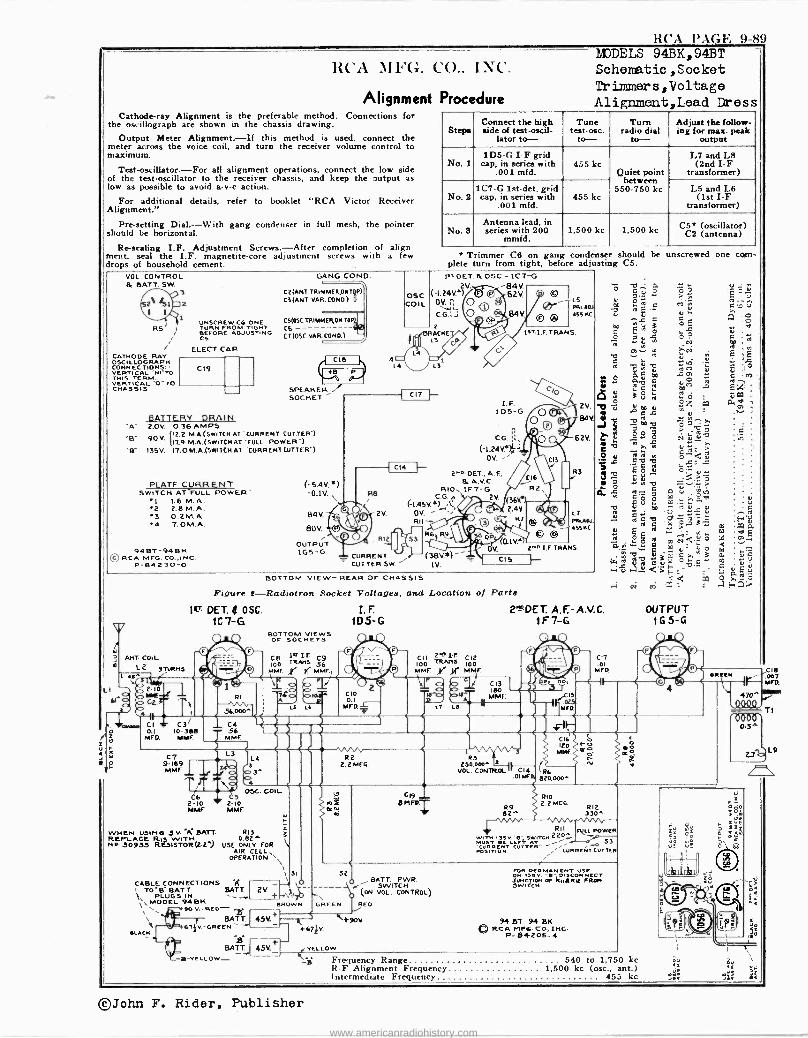
RCA l'AGN, 9-89
1IcA. ath'G. CO.. INC.
Alignment Procedure Cathode-ray Alignment is the preferable method. Connections for
the oscillograph are shown in the chassis drawing.
Output Meter Alignment. -If this method is used, connect the meter across the voice coil, and turn the receiver volume control to maximum.
Test -oscillator. -For all alignment operations, connect the low side of the test -oscillator to the receiver chassis, and keep the output as low as possible to avoid a -v -c action.
For additional details, refer to booklet "RCA Victor Receiver Alignment."
Pre-setting Dial. --With gang condenser in full mesh, the pointer should be horizontal.
Re -sealing I.F. Adjustment Screws. -After completion of align- ment, seal the I.F. magnetite -core adjustment screws with a few drops of household cement.
hTJDELS 94BK,94BT Schematic ,Socket Trim>âlers,Voltage Alignment,Lead Dress
Steps Connect the high side of test-oscil-
lator to- Tune
test-osc. to- Turn
radio dial to- Adjust the follow - ing for mas. peak
output
No. I 1D5 -G I -F grid
cap, in series with .001 mfd.
455 kc Quiet point
between 650-750 kc
L7 and L8 (2nd I -F
transformer)
No. 2 1C7 -G 1st-det. grid cap, in series with
.001 mfd. 455 kc
L5 and L6 (1st I -F
transformer)
No. 3 Antenna lead, in series with 200
mmfd. 1,500 kc 1,500 kc C5* (oscillator)
C2 (antenna)
* Trimmer C6 on gang condenser should be unscrewed one com plete turn from tight, before adjusting C5.
VOL. CONTROL & BATT. 5W.
CATHODE RAY OSC IL LOG RA PH CONNECTIONS.- TERTICAL "'.I'TO
HIS TERM VERTICAL "0 -TO CHASSIS
UNSCREW CG ONE TURN FROM TIGHT BEFORE ADJUSTING C5.
ELECT. CAP
C19
GANG COLAD.
C2(ANT. TRIMMER ON T?) C3 (ANT VAR. COHO.) I
CS(OSC.TRIMMER,ON TO
CE (T(OSC.VAR.CbND.)
SPEAKER .
SOCKET
BATTERY DRAIN "A- 2.0V. 0.36 AMPS 'B- 50V. (12.2 M. A. (SWITCH AT CURRENT CUTTER.)
117.9 M. A. (SWITCH AT "FULL POWER") -B" 135V. 17.0 M.A.(SWITCH Al CURRENT CUTTER')
4
13T-DET &OSC.-1CT-G c (-1.24V*) F G / 62V. COIL OV. i O
v. ti
L4®L3
2 BRACKE
L3
i® I. F.
105-G
C.G.
Ci
0-- 0 9
PRI ODI 45S RC
1ST- I.F. TRANS
O Or
`10
Cjo
Ij 2V.
84v
62V.
REM 2.1.DET..A.F. 16'R3 PLATEC_UßRENT (-5.4v.*) &A.V.0
SWITCH AT FULL POWER' -O.1V. RB 1F7-G R2,\
L L6 M. A. (/ CG. 2V.
*2 2.8 M.A. O [-1.45V*) , ! ú 2;4V. C V '3 0.2M.A. 84V._.7 2V. OY. v RT L7
4 T.OM.A. BDY P 0 a11 1` O ® i 459KC - R12' . R ft, 4. ` ©
OUTPUT 1' '0-IYY 94BT-94BK LGS-G 41-.4_7\1 tj OM 2.1.1.ETRANS.
©RCAMFG.CO.,INC. = CURRENT (38V.*)-1 1
CI 1.-- P-84230-0 CUT TER SW.' IV,
f
3 á
ANT COIL L 9TURN3
BOTTOM VIEW- REAR OF CHASSIS
Figure 2-Radiotron Socket Voltages, and Location of Parts
1LT DET. Q OSC. I. F. 2'RDET. A.F.-A.V.C. OUTPUT 1C 7-G 1D5 -G IF 7-G 1G 5-G
BOTTOM VIEWS OF SOCKETS
D u C N
'-'92
a á _ m E ro N m ci6= yo a+-.
0 wb Ç; °E> >.,- t'ó O V1 S N C u .b,- Q U ..0 =6>_" - ; Q,_
, Q yT O >..- ,-I N Yn Z. : . H !
1 Y LI -Dóot12-10
ao b Gr.,"
w1 +, 7cnrn C I
ó 0.1 MEp.
u r
f
C7 9-189 I
MME Q
T- "\g OSC. COIL C6 6
2-10 2"1D RIME IMF
C8 IsT I.F C9
100 TMAnS' 56 MME MMFI
WHEM us 3V. Ä BATT REPLACE Rt WITH Ha 30933 R13TOR(o2 %
R13 0.82*
USE ONLY FOR AIR CELL,
OPERATION `
CABLE CONNECTIONS 1 TO'B- BATT. BATT ` PLUGS IN
MOOEL 94 BK L\ \ 90 V. -RED- .a \ BATT. 45V. _i__. +9oV 94 DT 94 8R
LACH 6TV-GREEN ` 1- }G]ÌY. ®RCAMFG-CO.,INC.
P -e4203-4 B t
BATT-* 45V. ,vELLow -o-TELLOw- 1ä
BATT. PWR.
2V - --- r SWITCH (ON VOL. CONTROL)
32 I
LM1'F C12 100 TRAM. 100 MME. ir }H* MAW
Gt9 8 MFn.
RII FULL POWER l
sT P w
,TSY. }sw ITCH 220
33 OSITI RTLc ""-
CURRENT CUTTER
!Ii GREEN I REO
SI r
FOR PERMANENT SE OR 131 v. '" D1sCONHECT JUNCTIOH OF AuARM FROK SWITCH
Frequency Range 540 to 1,750 kc R -F Alignment Frequency 1,500 kc (osc., ant.) Intermediate Frequency 455 kc
C18 007
MFA
470^ QQQQ
T1
L9
2-N
©John F. Rider, Publisher
www.americanradiohistory.com
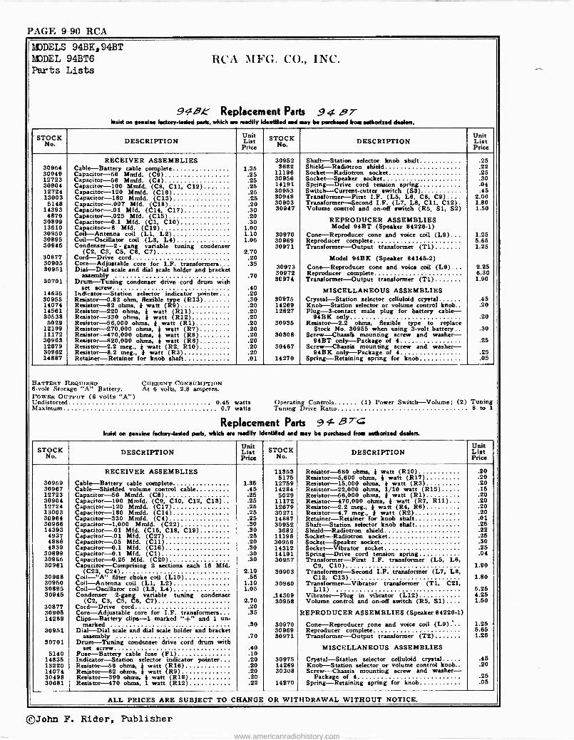
PAGE 9-90 RCA
MODELS MODEL Parts
94BK,94BT 94BT6 RCA Lists
91B,e Replacement Insist factory
\IFG. CO.,
Parts readily identified and
INC.
94 BT be from dealers. on genuine -tasted parts, which are may purchased authorized
Unit Unit STOCK DESCRIPTION List STOCK DESCRIPTION List No. Price No. Price
RECEIVER ASSEMBLIES 30952 Shaft -Station selector knob shaft .25 30954 Cable -Battery cable complete 1.35 3682 Shield-Radiotron shield .22 30949 Capacitor -56 Mmfd. (C9) 11196 Socket-Radiotron socket .25 12723 Capacitor -56 Mmfd. (C4)
.25 30956 Socket -Speaker socket .30 30904 Capacitor -100 Mudd. (C8, C11, C12)
.Y5 14191 Spring -Drive cord tension spring .04
12724 Capacitor -120 Mmfd. (C16) .25
30953 Switch -Current -cutter switch (S3). .45 13003 Capacitor -180 Mmfd. (C13)
.25
.25 30948 Transformer -First I.F. (L5, L6, C8, C9).... 2.00 5148 Capacitor -.007 Mfd. (C18) .20 30903 Transformer -Second I.F. (L7, L8, C11, C12) . 1.80
14393 Capacitor -.01 Mfd. (C14, C17) .30 30947 Volume control and on -off switch (R5, Si, S2) 1.50 4870
30899 Capacitor -.025 MEd. (C15) Capacitor -0.1 Mfd. (C1, C10)
.20
.30 REPRODUCER ASSEMBLIES 13610 Capacitor -8 Mfd. (C19) 1.00 Model 94BT (Speaker 84226-1) 30950 Coil -Antenna coil (Li, L2) 1.10 30970 Cone -Reproducer cone and voice coil (L9) ... 1.25 30895 Coil -Oscillator coil (L3, L4) 1.05 30969 Reproducer complete 5.65 30945 Condenser -2 - gang variable tuning condenser 30971 Transformer -Output transformer (T1) 1.25
(C2, C3, C5, C6, C7) 2.70 30877 Cord -Drive cord .20 Model 94BK (Speaker 84145-2) 30905 Core -Adjustable core for I.F. transformers... .35 30973 Cone -Reproducer cone and voice coil (L9)... 2.25 30951 Dial -Dial scale and dial scale holder and bracket 30972 Reproducer complete 6.30 30701
assembly Drum -Tuning condenser drive cord drum with
.70 3C974 Transformer -Output transformer (T1) 1.90
14635 set screw
Indicator -Station selector indicator pointer... .40 .20 MISCELLANEOUS ASSEMBLIES
30955 Resistor -0.82 ohm, flexible type (R13) .30 30975 Crystal -Station selector celluloid crystal .45 14074 Resistor -82 ohms, I watt (R9) .20 14269 Knob -Station selector or volume control knob.. .20 14581 Resistor -220 ohms, } watt (R11) .20 12827 Plug -3 -contact male plug for battery cable- 30538 Resistor -330 ohms, } watt (R12) .20 94BK only .20
5029 Resistor -56,000 ohms, } watt (R1) .20 30935 Resistor -2.2 ohms, flexible type to replace 12199 Resistor -270,000 ohms, } watt (R7) .20 Stock No. 30955 when using 3 -volt battery.. .30 11172 Resistor -470,000 ohms, } watt (RS) .20 30308 Screw -Chassis mounting screw and washer - 30963 Resistor -820,000 ohms, } watt (R6) .20 94BT only -Package of 4 .25 12679 Resistor -2.2 meg., } watt (R2, R10) .20 30467 Screw --Chassis mounting screw and washer - 30962 Resistor -8.2 meg., } watt (R3) .20 94BK only -Package of 4 .25 14887 Retainer -Retainer for knob shaft .01 14270 Spring -Retaining spring for knob .05
BATTERY REQUIRED CURRENT CONSUMPTION 6 -volt Storage "A" Battery. At 6 volts, 2.8 amperes. POWER OUTPUT (6 volts "A") Undistorted 0.45 watts Operating Controls (1) Power Switch -Volume; (2) Tuning Maximum 0.7 watts Tuning Drive Ratio 8 to 1
Replacement Parts 91- 8 T> Insist on genuine factory -tested parts, which era readily Identified and may be purchased from authorized dealen.
Unit Unit STOCK DESCRIPTION List STOCK DESCRIPTION List
No. Price No. Price
RECEIVER ASSEMBLIES 11353 Resistor -680 ohms, } watt (R10) .20 5175 Resistor -5,600 ohms, I watt (R17) .20
30959 Cable -Battery cable complete Cable
1.35 12759 Resistor -15,000 ohms, } watt (R3) .20 30967 .45 14284 Resistor -22,000 ohms, 1/10 watt (R15) .15 -Shielded volume control cable
Capacitor -56 Mmfd. (C8) 12723 .25 5029 Resistor -56,000 ohms, 3 watt (RI) .20 30904 Capacitor -100 Mmfd. (C9, C10, C12, C13).. .25 11172 Resistor -470,000 ohms, i watt (R7, R11) .20 12724 Capacitor -120 Mmfd. (C17) .25 12679 Resistor -2.2 meg., } watt (R4, R6) .20 13003 Capacitor -180 Mmfd. (C14) .25 30271 Resistor -4.7 meg., } watt (R2) .20 34964 Capacitor -330 Mrnfd. (C4) .25 14887 Retainer -Retainer for knob shaft .01 30966 Capacitor -1,000 Mmfd. (C22) .30 30952 Shaft -Station selector knob shaft .25 14393 Capacitor -.01 Mfd. (C15, C18, C19) .30 3682 Shield-Radiotron shield .22
4937 Capacitor -.01 Mfd. (C27) .25 11196 Socket-Radiotron socket .25 4888 Capacitor -.05 Mfd. (C11) .20 30956 Socket -Speaker socket .30 4839 Capacitor -0.1 Mfd. (C16) .30 14312 Socket -Vibrator socket .25
30899 Capacitor -0.1 Mfd. (C1) .30 14191 Spring -Drive cord tension spring .04 30965 Capacitor -O.25 Mfd. (C20) .30 30957 Transformer -First I.F. transformer (L5, L6, 30961 Capacitor -Comprising 2 sections each 16 Mfd. C9, C10) 1.90
(C23, C24) 2.10 30903 Transformer -Second I.F. transformer (L7, L8, 30968 Coil -"A" filter choke coil (L10) .55 C12, C13) 1.80 30950 Coil -Antenna coil (L1, L2) 1.10 30960 Transformer -Vibrator transformer (T1, C21, 30895 Coil -Oscillator coil (L3, L4) 1.05 L11) 5.25 30945 Condenser -2 -gang variable tuning condenser 14309 Vibrator -Plug in vibrator (L12) 4.25
(C2, C3, C5, C6, C7) 2.70 30958 Volume control and on -off switch (R5, S1).... 1.50 30877 Cord -Drive cord .20 30905 Core -Adjustable core for I.F. transformers .35 REPRODUCER ASSEMBLIES (Speaker 84226-1) 14289 Clips -Battery clips -1 marked "+" and 1 un-
marked .30 30970 Cone -Reproducer tone and voice coil (L9) ... 1.25 30951 Dial -Dial scale and dial scale holder and bracket 30969 Reproducer complete 5.65
assembly .70 30971 Transformer -Output transformer (T2) 1.25 30701 Drum -Tuning condenser drive cord drum with
set screw .40 MISCELLANEOUS ASSEMBLIES 5140 Fuse -Battery cable fuse (F1) .10
14635 Indicator -Station selector indicator pointer .20 30975 Crystal -Station selector celluloid crystal .45 13220 Resistor -56 ohms, * watt (R16) .20 14269 Knob -Station selector or volume control knob.. .20 14074 Resistor -82 ohms 4. watt (R9) .20 30308 Screw -Chassis mounting screw and washer - 30498 Resistor -390 ohms, } watt (R18) .20 Package of 4 .25 30681 Resistor -470 ohms, 1 watt (R12) .22 14270 Spring -Retaining spring for knob .05
ALL PRICES ARE SUBJECT TO CHANGE OR WITHDRAWAL WITHOUT NOTICE.
©John F. Rider, Publisher
www.americanradiohistory.com
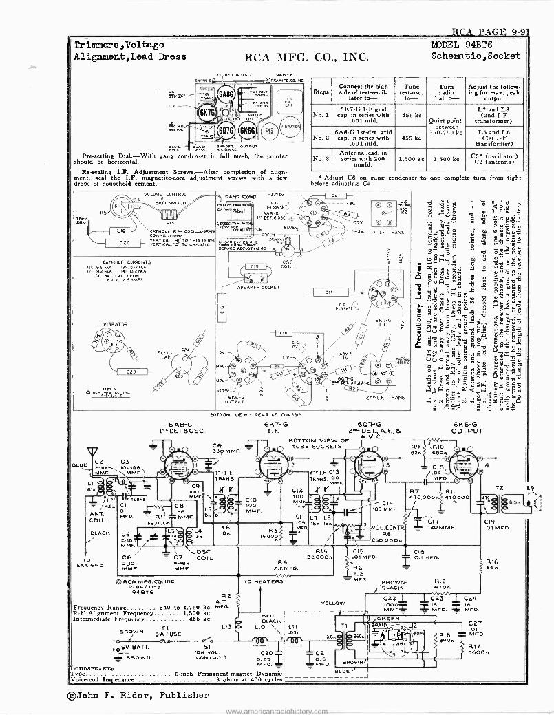
RCA PAGE 9-9' Trimmers,Voltage Alignment,Lead Dress
igc.Ac - ... ",.
RCA MFG. CO., INC. P.00T. Q OBC. 9..T6
-ARCAMFG.CO.INC
AAA! 6A8G
2) )
6K1G ,LI ANT. COIL
TRANS
`FòñT -
éloóñc
SMIELO
6416 6K6G) 3
cE3 CPA
TI C21 LII
BRATS
.DCT. OUTPUT nnT. ÓÑó .FA4Vt.
Pro -setting Dial.-With gang condenser in full mesh, the pointer should be horizontal.
Re -sealing I.F. Adjustment Screws.-After completion of align- ment, seal the I.F. magnetite -core adjustment screws with a few drops of household cement.
EJDEL 94BT6 Schematio,Socket
Steps Connect the high side of test-oscil-
lator to- Tune
test -oser. to- Turn radio
dial to- Adjust the follow - ing for max. peak
output
No. 1 6K7 -G I -F grid
cap, in series with .001 mfd.
455 kc Quiet point
between 550-750 kc
L7 and L8 (2nd I -F
transformer)
No. 2 6A8 -G 1st-det. grid cap, in series with
.001 tnfd. 455 kc
L5 and L6 (1st I -F
transformer)
No. 8 Antenna lead, in series with 200
mmfd. 1,500 kc 1,500 kc CS* (oscillator)
C2 (antenna)
* Adjust C6 on gang condenser to one complete turn from tight, before adjusting C6.
VOLUME á CONTROL am:SWITCH
IIIIIIIIII
CATHODE RAY OSCILLOGRARI CONNECTIONS VERTICAL -H1 TO THIS TERM. VERTICAL -O- TO CHASSIS
_\ GANG COMO.
et ( TRNa e3( MR..n
(-1.339," 6A8 -C. -
CC55((
I DET 4 OSC.
C7(04C ' BLUE
GREEN , UNSCRECGONE B L TVRN 'Rom1144.4r! BEFORE A93WTUtl CS
CATHODE CURRENTS III.. 9.6 MA. 131...0.17 M.A. I21 9.2 M.A. 141 13.2 M.A
Á BATTERY DRAIN 6.0 V., 2.6 AMPS.
VIBRATOR
oA M°4 cD, Inc. v e.2a4-o
SPEAKER SOCKET
43V
U7V-'
-5.15V. (
6K6 -G OUTPUT
oSC. COIL
LS
-143 V.
C.G.
6t3)V) :
VIP I.F. TRANS.
pn
u i ' óóó Â
,0R O
1ú qqqq
{m p
1'1'12 A 1 Ñ 1 O VO Y 1.b
.S.4:1.6
> r 1.+ñF3 íâ «ú:-p
ñ $pÿ ~ b
i «a7
i¡ 9FovG«úu a a-«.a 1. ' .4.e1,--5
o ; ñ'-' W ñ S9. p,y U Ú -O m mE
J g Ñ N .q . ,Li u M
1 Ç m-c.c§a,n i i,ba0ó
u E 6KT-G O m E SAt7 Q gg ó ebD Ó I. F. :: Ea d, « .: íaa Ó b ú ro> = UV... ti
o-r á ' v a od
iiü N R O y V s ä " s" º y_«A ó ÿm 7a léc.n..9ro"c$omóaoa4o
Ó RTJa O á á Gi V aA
4ro,m
.roro a úLT; .,g.,oa« L I.aóAa d 1.,rimF°c
d-g.Y 41 'm R'^ m0 .: 2 c9Á^cim vi ávi fáPO 4Ty oL1 (: v roil y V -Gl g«
BLUE
6 AB- G 1sT DET. ff OSC.
C2 C3 2-1O--, 10-388 MME
L 6115
L2' 4.8,,
ANT. COI L
BLACK
TO EXT. GND.
1 9TURNS
CI 0.1 ee. MFD.
56,000n L3' lA CS
2-10 MME
BOTTOM VIEW - REAR OF CHASSIS
6KT-G I.F.
C4 330 MMF.
1*T I.F TRANS.
00 . r MME, ` Pe"
CB L51 el 56
MME. Bolo
C6' 23.10 MMF.
L4 315
4
L6 8A
BOTTOM VIEW OF TUBE SOCKETS
2nD I.F. C13 TRANS.l00
ÿ MME 1 CI 2 r 1
6QT-G 2MD' DET., A. F., ti
A- V- C.
o
6K6 -G OUTPUT
C10 100 c c MMF
100 J MMF. A
C11 L7 LB -05 IBn len
R3 MED. l
I S,o00 T n
180 MMF.
VOL.CONT RS
250,000n
R9 R1O 82n 68015
CIB /.01
MF
R7 511 4lO,oOo 470,000
- CI4
/:L,_., =Ito tom F.
-= `OSC. CT COIL 9-189 MME.
R4 2.2 MEG.
© RC A MFG. CO. INC. P-84211-3
94 BIG
C9
R2 4.7
Frequency Range 540 to 1,750 kc MEG. R -F Alignment Frequency 1,600 kc Intermediate Frequency 455 kc
F1 L13 BROWN 5'A.FUSE
-O ` el,p o +2..5V. BATT. Si
(ON VOL - BROWN CONTROL)
TO HEATERS
LOUDSPEAKER
BLACK L1O LI1
I .03n 7flrl 11 /7rR-
RIS 22,000n
CI5 .O1MFD.
RE 2.2 = MEG.
YELLOW
RED- r I
O
©
FR13A9¡
4wc.
TRANS.
C16 T 0.1 MED.
BRCWN- 'BLACK
R12 470a.
C22 2 T C23 T C24
IMMOFT¡ 16 ± MED. = MED.
LT1
0.84
GREEN
B60n I
C21 I
MFD. I BROWNrI
Type 5 -inch Permanent -magnet Dynamic BLUET' Voice -coil Impedance 3 ohms at 400 cycles - ------- -- -J
BRAID -2 L12 rfreCIA VIE
T2 L9 2.7a.,
R O.Sn
1
J
C19 .01 MEO
R16 5615
C27 -01
RIB MFD. 39OÁ
R17 5600A
©John F. Rider, Publisher
www.americanradiohistory.com
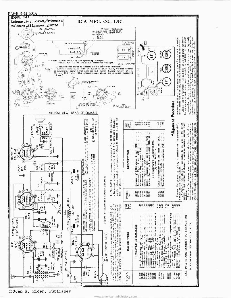
I AGE 9-92 RCA MJDEL 41- Schematic,Socket,Trinaners i
Voltage,Alignmentiyarts I
104V. -- OUTPUT 25L6 -G
ry 2LAu -J
VOL. CONTROL L
POWER SWITCH
BLACK
GREEN
-6.3V. BLUE C7/ ' j ` CAPACITOR
(AC.) -. PACK«
RCA MFG. CO., INC.
7 fCC13
C14
CATHODE CURRENTS
(1) 0.4MÁ OL. CONTR MIN) {11.2M.Á. VOL. CONTR. MAX.)
(21 0.12 M.A. (3) 47M.A. (4) 5BM.A.
C14
RED
Note: Values with (4) are operating voltages. CD Values not starred are actual measured voltages.
GANG CONDENSED /ÒV. Measurements made to chassis unless otherwise indicated.
_-(00V4) \leasurements made with set tuned to quiet point, volume control liv. at minimum, using 1,000 -ohm -per -volt meter, having ranges of 10,
50, and 250 volts. (Use nearest range above the specified measured voltage.)
117V - (AC)
RECT. 2526 -G
-1 25v. e.z.)
J
1
, 0' ^ L4
ÿñ TÑiä sAr-er 110V.--
r R.F.
6K7 R.E
6.3V. COIL 1(44
3V.(VOL.CONTR. MAI L18 V.(VOL. CONTR. MIN
.-- -110V.
C RCA MicxC.. INC. V-e4zo4-o
BOTTOM VIEW - REAR OF CHASSIS
_0 I 01, U1nf
1- r- ul 0 t0
O<
d O
í ' . v m ö H11 u
tC
ó
úóF
- 4 J 2
0 J W
W }
OC I-
Z 0 _i
ó \s.
cc
I)
sÑ>
N ÿ\ _Nk 171 p 7.) R.2
¡ w
I¡
-
Q O3
I ` W
. F A4I r13
f4
00000100 NLVei.ANO
he
OZ
WOmmm..e aie, N F W a' t` Nhmm.rmm ..0..00
..o,..wm
A N ea 000 MMM
¡u Paw
i0000000 1000 00 0000 OV,MN a? NV, O..WN ,ONN
,44,-1 N
W ó r 3 a
é s 5
V F O
w Ç N O Ó ~ 0:
V p
B
dp.-. u.... . ..á . .9 zB
WCN.1sV G..~. i Ó sA. Ur.tvU
oU..11.~i5 uú a..,119 nv"ti_ .dcei" _' >ó.-,X ñr`,Z.QU úá nC1b YaYZ.2)ä o
W W Uv 00 $óóló+ o1,tjéc8º,Úiécñm I' L L 1 1 ¡ 11.4g 2 w o°
I I 6«22,82e2 <ai3 II agióoo ;;..,all_ ññroññññS'Sóvóó I a~iúú vu..... UUU UU .7xM
O H OMa\mNmWm Wmmt'mmme m.7mmmmm
O w 0 0 0 0 0 ..a'..leM.,a,m ñt 000 000 MY,M
NO OM 00 mm
m O W mmvl m0 .°. M .%,
©John F. Rider, Publisher www.americanradiohistory.com
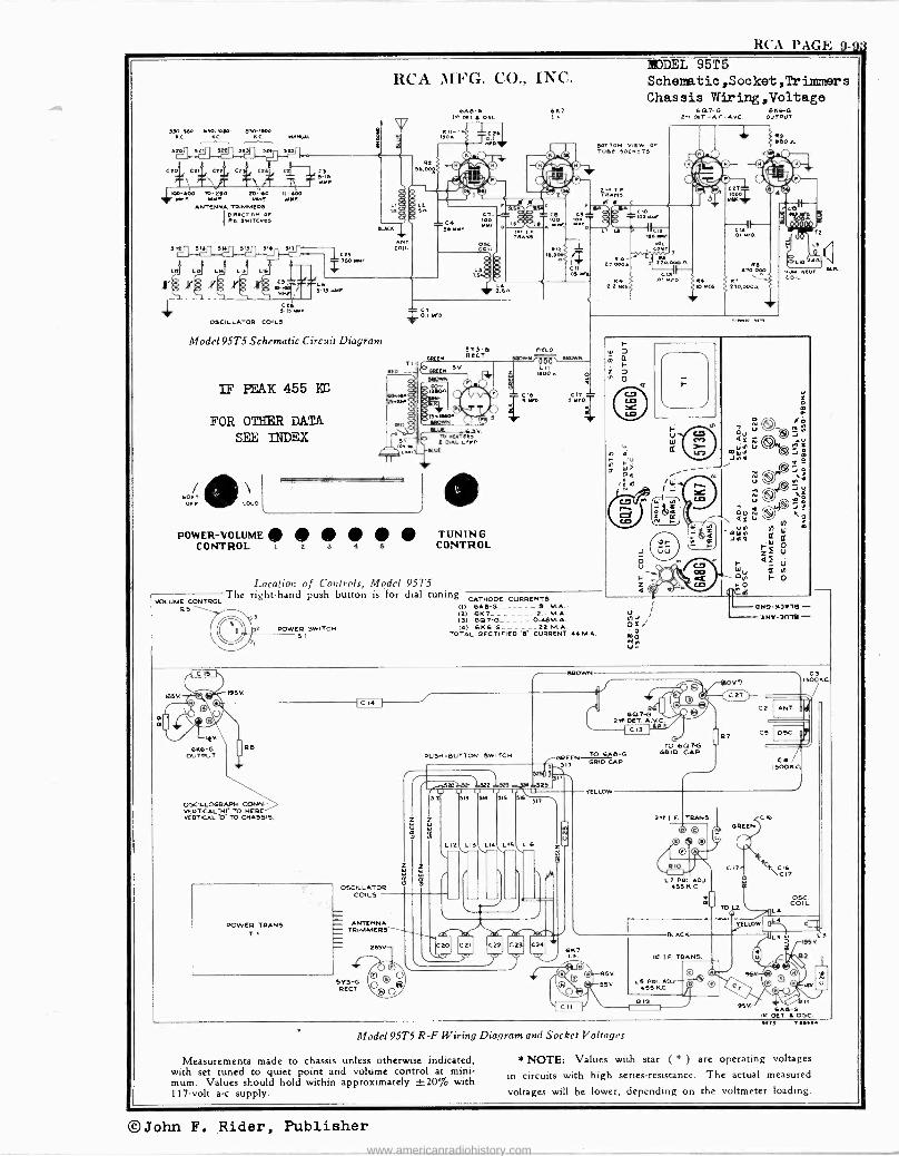
RCA PAGE 9-9% MODEL 95T5
sso-re 6w-R,r aso -rico KC KC. KC. MANLML
Deo 321 ft! ets(Ì
ctO,`c*\\ ctS
1KI0-400 70-243 201140 11. MO MMF M. MMF IMF
ANTENNA TRIMMERS IDIReCTION OF
Pe. OwITCNts
311 112,1E.2.111._2_4. 3 !I{¡, e1T
4 LA
x§ x$ x§ x.§p^ C31` TDL6 ,DMM ÿ.I , F
40.
l/ cei
3-1S NMF
OSCILLATOR COILS
RCA MFG. CO., INC.
BLACK
Model 95T5 Schematic Circuit Diagram
IF PEAK 455 KC
FOR OTHER DATA SEE INDEX
6Ae-6 1sT OeT 4 osc
Rn-- 1e0A
cl 0.1 IIFD.
GREEN
!K
STD -6 RECT.
5.3v. To IKAT1Rl i DAL LAMP
UE
s
5
POWER -VOLUME TUNING CONTROL I 2 3 4 s CONTROL
607 I.F
3RowN(á0á' 00ow
ri00n
r.
Location of Controls, Model 95T5 The right-hand push button is for dial tuning CATHODE CURRENTS
QS VOLUME CONTROL
(I) 6AS-3 (2) 607 -12.1 M.A. (3) GQ7-G_ - _ - - 0.41314A. (4) 6K6-6______22 M.A.
TOTAL RECTIFIED R CURRENT 44 M.A.
s
POWER SWITCH SI
CI, ! MFD.
Schematio,Socket,Trimmers Chassis VPiring,Voltage
BOTTOM WOW OF TUB. eocte7s
/
O2i 'O Me u-
00.7 -G 636-6 2 RRT -A.F-Ave OUTPUT
IRMA
Foe NeuT 1Ln. COIL
ONT)1)511 - 'LNt-anl -
IRS
C 15
5V.
kK 6K6ß
OUTPUT RS
OSCILLO0RAPH COKIN - VERTICAL"H1 TO HERE VERTICAL "0- TO CHASSIS.
POWER TRANS T I
C 14 I
5ROw
OSCILLATOR COILS
PUSH -SUTTON SWITCH
2
6
ó
e320321 182 ól27 u U u
32 sri !M 515
Z
L 12
\.
ANTENNA TRIMMERS
- 2e5V.
5TYG RECT.
O O o O® o
L14
i
LIS
m,32p I`u 517
LIS
r ' J d IO 607H2
DOLT.
GREEN 1.--2L -"ße-* _ 517 GRID CAP
317
l
C20 \Sr-
C21 C2 yy 23 24 "UP
YELLOW
C IS
TO 607G t2RIO CAP
7
V
C3 IS00KC.
C2 AN
C5 OSC
C6/ 1500K
33. 1. F. TRANS.
o
t9 0 n
RIO
L7 PRI. ADJ. 455 K.C.
607
. O O ti O
o yell
V
SK
Model 95T5 R -F Wiring Diagram and Socket Voltages
Measurements made to chassis unless otherwise indicated, with set tuned to quiet point and volume control at mini- mum. Values should hold within approximately ±20% with 117 -volt a -c supply.
BLACK
GREEN
CI
a TO La
TE
CK
\CC17K
COIL L4
Im I.F. TRANS.
LS PRI. AQI 455 K.C. T'
RID
O 0 IRS 6AS-S
la OCT 4 OSC. errs Tws4
NOTE: Values with star ( * ) are operating voltages
in circuits with high series -resistance. The actual measured
voltages will be lower, depending on the voltmeter loading.
©John F. Rider, Publisher
www.americanradiohistory.com
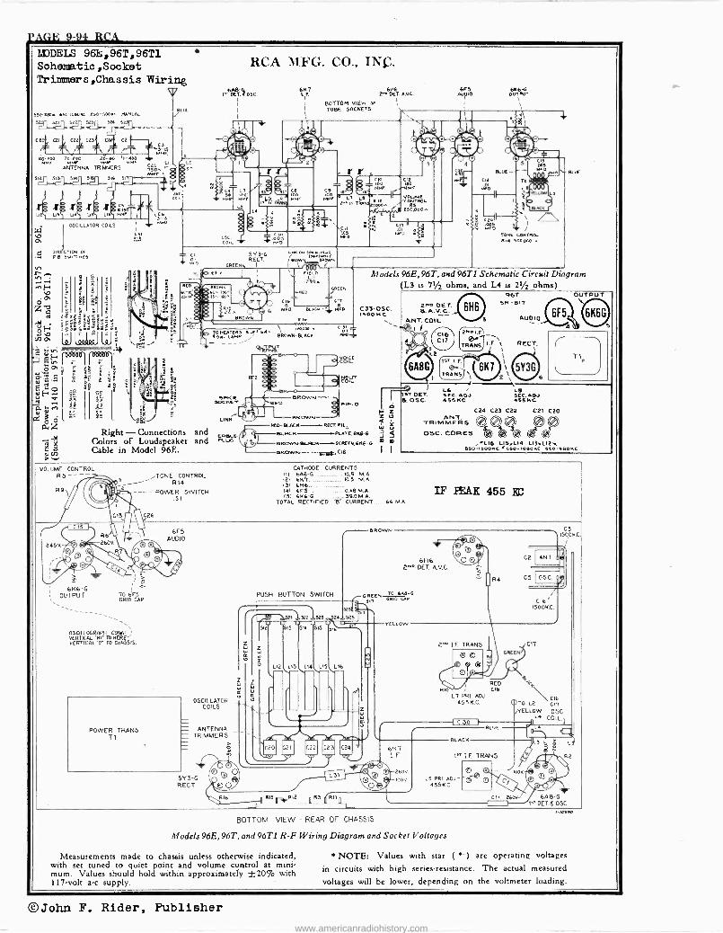
TAGE 9-94 RCA IilDEIS 961;, 96T, 96T1 Schematic ,Socket Trimmer s'Chassis Wiring
550- 1066 630-1080KA A58 .5000C MANUAL
St1 s St5 5D1
Ct CEI ctg ctsi CIDI C2
RD -M00 t .a 111-400
ANTENNA TRINKERS
SK 515 SM 515 516
J J J xóx xoxx Utl Ua Wl Ual LM
OSCILLATOR COILS c7
U II CT10N OF FE SMNCMES
9°
2
2.
. ,K2_2
BL
6
CI
Right - Connections Colors of Loudspeaker Cable in Model 96E.
VOLUME CONTROL
RCA MFG. CO., INC.
l'pilE7. < OSC.
CSC. COIL
Caa
;.003 MFO.
5Y 5-4 REGT
GREEN,
DLSe. ;
6K7 6K6 6FS 6K6 -G L r 2^ BET. ANN. AUDIO OUTPUT
I BOTTOM VIEN aF Ì II 1 TUBE SOCKETS
S 8 C00 CIE
MMF ¡ia1MF
LD AR.O r
C EL L- IF TRAlytlo00 RS (./, t50poDw -$- C -Ift.-
`2 +
L...co" >hoc n.w
L." FIELD
IESOa 1CAKEN
C17
BLACK n6.11R
1Y
LN
TO HEATERS KLEA 1.4 \ Ipoee. 4 DBL LAMP
W4%7 LTpL1
BROWN- BLACK
and and
,TONE CONTROL R14
----POWER SWITCH .51
26
6K6 -G I OUTPUT
I
TO 6FS GRID CAP
05CILLOGRAPH CONN.- VERTICAL 'NI' TO HERE' VERTICAL '0' TO CHASSIS.
6F5 AUDIO
POWER TRANS TI
LINK
CABO> FLLK.
OSCILLATOR COILS
ANTENNA TRIMMERS
5Y 3-G REGT
RED
DR RED BLACK KEW FIL,
Cr)--DLMCK PLRTE,6186-0
la DRc.M.FDLNCn----5WRECK, &K6-0
MOWN C16
CNIN
C'a1 s 8...1188
PIrLD
BLUE
. gaBsl , I iss
TONE CONTRO.. 1414 504000 4
Models 96E, 96T, and 96T1 Schematic Circuit Diagram (L3 is 71/2 ohms, and L4 is 21/2 ohms)
C37-OSC. I BOO KC
CATHODE CURRENTS nl 6A6 -C.... ....... 4.1.4
121 6147 10.5 M.A. 131 6H6 141 6FS 0.48 M. A.
a Z 1=5
35 m m
11
21.0 OET.
ANT. COIL
6A8G 1
We - TRANS
757 0E7I hOSC.
96T SN -D17
AUDI
L6 / L5 BBC. ADJ. SEC. ADJ. 435KC 455 KC
ANT. TRIMMERS OSC. CORES
C24 C23 C22 C'21 C20
fpb®dó L16 LIS1L14 L135U2q
660-IBOOKC 650-IOBOKC BBO-BBOwC
OUTPUT
TOTAL RECTIFIED $ CURRENT 66 M.A.
PUSH BUTTON SWITCH
u 512 1S 5K 5K, 515
u
V Li2 L1S 1.14 LIS L16
A1`R16 QR1SriR12 RS R11S
! 1
BA WN
IF PEAK 455 KC
6H6 2^ "BET. AV.C.
6REEn TO 606-G 517
R-CAP
YELLOW
2" I.F. TRANS
R10
L7 PRI. ADJ 455 K.C.
BOTTOM VIEW - REAR OF CHASSIS
Models 96E, 96T, and 96T1 R -F Wiring Diagram and Socket Voltages
Measurements made to chassis unless otherwise indicated, with set tuned to quiet point and volume control at mini- mum. Values should hold within approximately ±20% with 117 -volt a -c supply.
RED CIA
I" LF TRANS.
GREEN
C 6/ I500KC.
6A8 -G 14 OETd OSC.
C3 I500KC
* NOTE: Values with star (*.) are operating voltages
in circuits with high series -resistance. The actual measured
voltages will be lower, depending on the voltmeter loading.
©John F. Rider, Publisher www.americanradiohistory.com
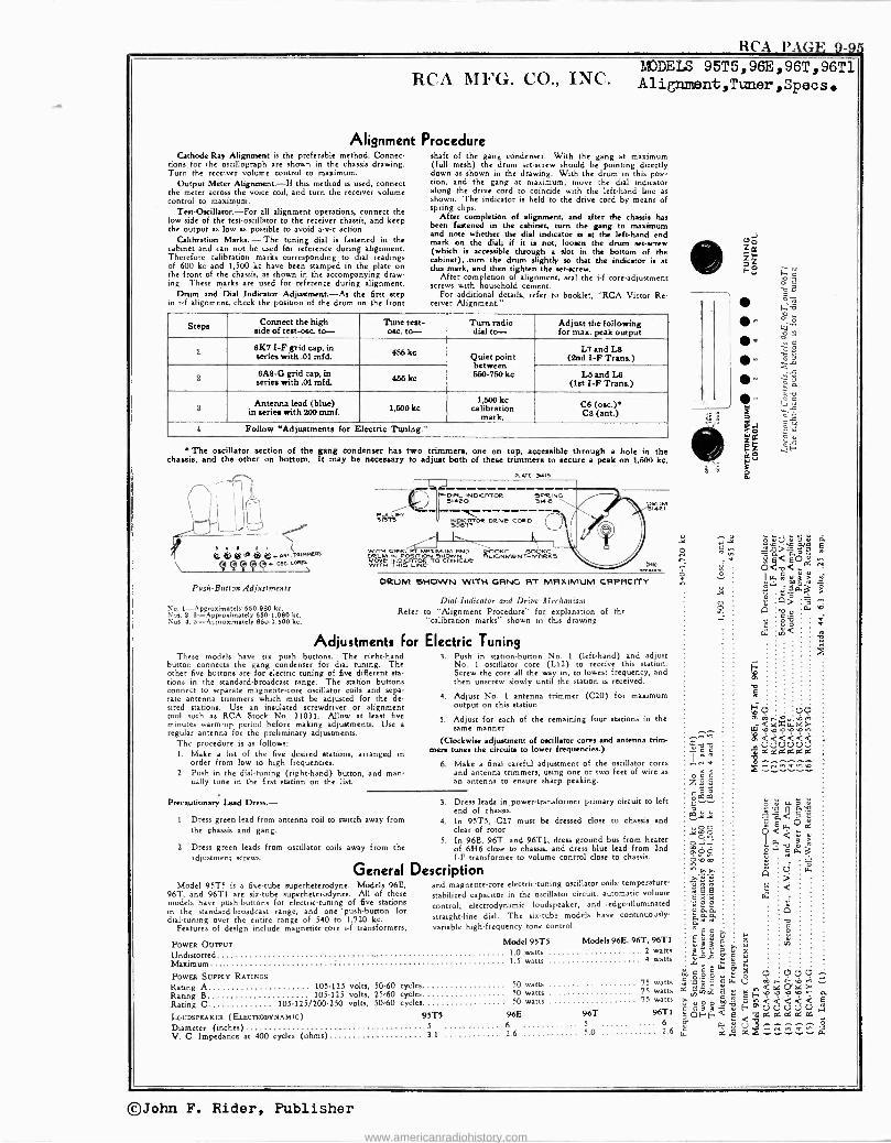
RCA PAGE 9-9 1MJDELS 95T5 96E 96T 96T1
RCA MFG. CO., INC. Alignment,T>mer,Specs
Alignment Procedure Cathode -Ray Alignment is the preferable method. Connec-
tions for the oscillograph are shown in the chassis drawing. Turn the receiver volume control to maximum.
Output Meter Alignment-If this method is used, connect the meter across the voice coil, and turn the receiver volume control to maximum.
Test-Oscillator.-For all alignment operations, connect the low side of the test -oscillator to the receiver chassis, and keep the output as low as possible to avoid a -v -c action.
Calibration Marks.-The tuning dial is fastened in the cabinet and can not be used for reference during alignment. Therefore calibration marks corresponding to dial readings of 600 kc and 1,500 kc have been stamped in the plate on the front of the chassis, u shown in the accompanying draw- ing. These marks are used for reference during alignment.
Drum and Dial Indicator Adjustment-Au the first step in r -f alignment, check the position of the drum on the front
shaft of the gang condenser. With the gang at maximum (full mesh) the drum set -screw should be pointing directly down as shown in the drawing. With the drum in this posi- tion, and the gang at maximum, move the dial indicator along the drive cord to coincide with the left-hand line as shown. The indicator is held to the drive cord by means of spring clips.
After completion of alignment, and after the chassis has been fastened in the cabinet, turn the gang to maximum and note whether the dial indicator is at the left-hand end mark on the dial; if it is not, loosen the drum set -screw (which is accessible through a slot in the bottom of the cabinet), .turn the drum slightly so that the indicator is at this mark, and then tighten the set -screw.
After completion of alignment, seal the i -f core -adjustment screws with household cement.
For additional details, refer to booklet, "RCA Victor Re- ceiver Alignment."
Steps Connect the high side of test-o8G, to-
Tutu test- osa to-
Turn radio dial to-
Adjust the following for max. peak output
6K7 I -F grid cap, in series with .01 mfd. 466 Quiet point
between 550-750 kc
L7 and L8 (ltd I -F Trans.)
8M -G grid cap, p,
in series with .01 mfd. 466 ke L6 and LS
(Ist I -F Trans.)
3 ue) mAte Antenna lf.
1,500 kc 1,500 kc
calibrationseri mark.
C8 (osa) CS (ant.)
4 Follow "Adjustments for Electric Tuning."
* The oscillator section of the gang condenser has two trimmers, one on top, accessible through a hole in the chassis, and the other on bottom. It may be necessary to adjust both of these trimmers to secure a peak on 1,500 kc.
r
® ® ® m ® ® Ng. ralRtstta O r Olc. COxf1 C C C C
Push -Button Adjustments
No. 1-Approximately 650-980 ke. Noe. 2, 3-Approximately 850.1,080 kc. Nos. 4. 5-Approximately 850.1,600 kc.
These models have six push buttons. The right-hand button connects the gang condenser for dial tuning. The other five buttons are for electric tuning of five different sta tions in the standard -broadcast range. The station buttons connect to separate magnetite -core oscillator coils and sepa- rate antenna trimmers which must be adjusted for the de- sired stations. Use an insulated screwdriver or alignment tool such as RCA Stock No. 31031. Allow at least five minutes warm-up period before making adjustment,. Use a regular antenna for the preliminary adjustments.
The procedure is as follows: 1. Make a list of the five desired stations, arranged in
order from low to high frequencies. 2. Push in the dial -tuning (right-hand) button, and man-
ually tune in the first station on the list.
PLAIT 51419
DIRL INDICRTOR D1420
scoot Delve CORO
DRUM 3Me1
pWpqqRUUM
GRNG RT MRxIMM gq U RNO ppppKC YlOOKC MOJ!MM
.1Ó3MÓCNGIOE RLCNMlYNT-MRRK5 WTHITtC qN wrw
DRUM eHOWN WITH GRNG RT MAXIMUM CRPRCITY
Dial -Indicator and Drive Mechanism Refer to "Alignment Procedure" for explanation of the
"calibration marks" shown in this drawing
Adjustments For Electric Tuning 3. Push in station -button No. 1 (left-hand) and adjust
No. 1 oscillator core (L12) to receive this station. Screw the core all the way in, to lowest frequency, and then unscrew slowly until the station is received.
4. Adjust No. 1 antenna trimmer (C20) for maximum output on this station.
5. Adjust for each of the remaining four stations in the same manner.
(Clockwise adjustment of oscillator cores and antenna trim- mers tunes the circuts to lower frequencies.)
6. Make a final careful adjustment of the oscillator cores and antenna trimmers, using one or two feet of wire as an antenna to ensure sharp peaking.
Precautionary Lead Dress. - 1. Dress green lead from antenna coil to switch away from
the chassis and gang.
2. Dress green leads from oscillator coils away from the adjustment screws.
General Model 95T5 is a five -tube superheterodyne. Models 96E,
96T, and 96T1 are sixtube superheterodynes. All of these models have push -buttons for electric -tuning of five stations in the standard -broadcast range, and one 'push-button for dial -tuning over the entire range of 540 to 1,720 kc.
Features of design include magnetite -core i -f transformers,
POWER OuiºuT Undistorted Maximum
3. Dress leads in,powertraneformer primary circuit to left end of chassis.
4. In 95T5, .C27 must be dressed close to chassis and clear of rotor.
5. In 96E, 96T, and 96T1, dress ground bus from heater of 6H6 close to chassis, and dress blue lead from 2nd TF transformer to volume control close to chassis.
Description and magnetite -core electric -tuning oscillator coils; temperature -
stabilized capacitor in the oscillator circuit; automatic volume
control; electrodynamic loudspeaker, and edge -illuminated
straight-line dial. The sixtube models have continuously -
variable high -frequency tone control.
Model 95T5 Models 96E, 96T, 96T1
1.0 watts 2 watts 1.5 watts 4 watts
POWEa SUPPLY RATINGS
Rating A 105.125 volts, 50-60 cycles Rating B 105.125 volts, 25.60 cycles Rating C 105.125/200.250 volts, 50-60 cycles
LOUDSPEAKER (ELECTRODYNAMIC) 951'5 96E 5 6 3.1
Diameter (inches) V. C. Impedance at 400 cycles (ohms)
50 watts 50 watts 50 watts
75 watts 75 watts 75 watts
96T 96T1 5 6
2.6 5 0 2.6
rJ
c N
m o a
2,a22 C11 C5 U
0.000 Ic 8rixá Nhh 8 `J vF,,o,o,o sta K+
ú m;o <U,U<y < ;ó Qá daGddd 0.30F1 -
n, 3 ,., óG .: d de v
©John F. Rider, Publisher
www.americanradiohistory.com
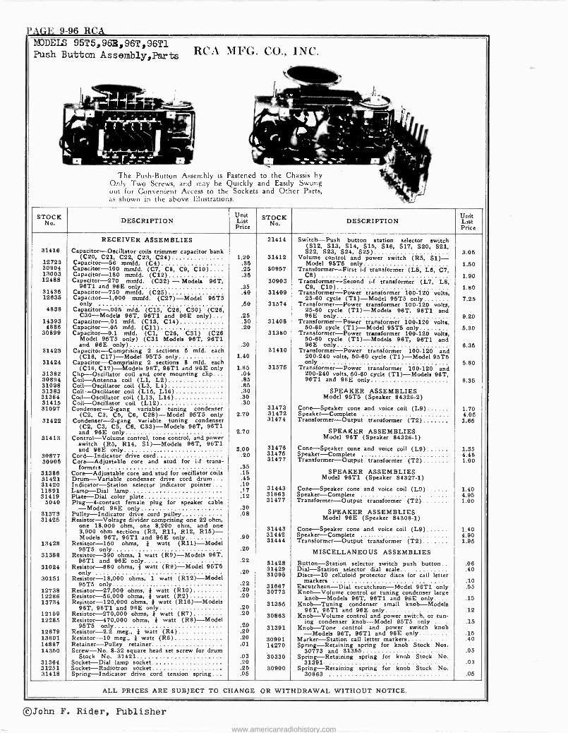
PAGE 9-96 RCA MODELS
Push Button 95T 5, 965, 96T, 96T1
Assembly/Parts RCA MFG. (r.CO., INC .
.,
r Ì ^i il . r1 +: ',....,- A
..,b-34-is..a --"\ ;t EC IN
+The Push -Button Assembly is Fastened to the Chassis by Only Two Screws, and may be Quickly and Easily Swung , out for Convenient Access to the Sockets and Other Parts, .
as shown in the above Illustrations.
STOCK Unit STOCK Unit No DESCRIPTION List No DESCRIPTION List
Price Price
RECEIVER ASSEMBLIES 31414 Switch-Push button station selector switch 31416 Capacitor-Oscillator coils trimmer capacitor bank
(S12, S13, S14, S15, 616, S17, S20, S21, S22, S23, S24, 625) 3.05
(C20, C21, C22, C23, C24) 1.20 31412 Volume control and power switch (R5, 51)- 12723 Capacitor -56 mmfd. (C4) .35 Model 95T5 only 1.50 30904 Capacitor -100 mmfd. (C7, C8, C9, C10).... .25 30957 Transformer-First i -f transformer (L5, L6, C7, 13003 Capacitor -180 mmfd. (C12) .35 C8) 1.90 12488 Capacitor -270 mmfd. (C32) - Models 96T, 30903 Transformer-Second i -f transformer (L7, L8, 98T1 and 96E only .35 C9, C10) 1.80 31435 Capacitor -750 mmfd. (C25) .40 31409 Transformer-Power transformer 100-120 volts,
12835 Capacitor -1,000 mmfd. (C27)-Model 95T5 25-60 cycle (T1)-Model 95T5 only 7.25 only .50 31574 Transformer-Power transformer 100-120 volts,
4838 Capacitor-.005 mfd. (C15, C26, C30) (C28, 25-60 cycle (T1)-Models 96T, 96T1 and C30-Models 96T, 96T1 and 96E only) ... .25 96E only 9.20
14393 Capacitor-.01 mfd. (C13, C14) .30 31408 Transformer-Power transformer 100-120 volts, 4886 Capacitor-.05 mfd. (C11) .20 50-60 cycle (T1)-Model 95T5 only 6.30
30899 Capacitor -0.1 mid. (C1, C26, C31) (C26 Model 95T5 only) (C31 Models 96T, 96T1
31380 Transformer-Power transformer 100-120 volts, 50-80 cycle (T1)-Models 98T, 98T1 and
and 96E only) .30 96E only 6.35 31423 Capacitor-Comprising 2 sections 5 mfd. each 31410 Transformer-Power transformer 100-120 and
(C16, C17)-Model 95T5 only 1.40 200-240 volts, 50-60 cycle (T1)-Model 95T5 31424 Capacitor-Comprising 2 sections 8 mid. each only 5.80
(C16, C17)-Models 96T, 96T1 and 96E only 1.65 31575 Transformer-Power transformer 100-120 and 31382 Clip-Oscillator coil and core mounting clip... .04 200-240 volts, 50-80 cycle (T1)-Models 96T, 30894 Coil-Antenna coil (LI, L2) .85 96T1 and 96E only 8.35 31098 Coil-Oscillator coil (L3, L4) .85 31383 Coil-Oscillator coil (L15, L16) .30 SPEAKER ASSEMBLIES 31384 Coil-Oscillator coil (L13, L14) .30 Model 95T5 (Speaker 84326-2) 31415 Coil-Oscillator coil (L12) .30
Cone-Speaker 31097 Condenser -2 -gang variable tuning condenser 31473 1.70 cone and voice coil (L9) Speaker-Complete (C2, C3, C5, C6, C28)-Model 95T5 only 2.70 31472 4.06
31422 Condenser -2 -gang variable tuning condenser 31474 Transformer-Output transformer (T2) 1.65 (C2, C3, C5, C6, C33)-Models 96T, 96T1 and 96E only 2.70 SPEAKER ASSEMBLIES
31413 Control-Volume control, tone control, and power Model 96T (Speaker 84326-1) switch (R5, R14, S1)-Models 98T, 96T1 and 96E only 3.00 31476 Cone-Speakerr cone and voice coil (L9) 1.35
30877 Cord-Indicator drive cord .20 31475 Speaker-Complete 4.45 30905 Core-Adjustable core and stud for i -f trans- 31477 Transformer-Output transformer (T2) 1.00
formers .35 31386 Core-Adjustable core and stud for oscillator coils .15 SPEAKER ASSEMBLIES 31421 Drum-Variable condenser drive cord drum .45 Model 98T1 (Speaker 84327-1) 31420 Indicator-Station selector indicator pointer .10 11891 Lamp-Dial lamp .17 31443 Cone-Speaker cone and voice coil (L9) 1.40 31419 Plate-Dial color plate .12 31683 Speaker-Complete .... .... 4.95
5040 Plug -4 -contact female plug for speaker cable 31477 Transformer-Output transformer (T2) 1.00
31373 -Model 98E only
Pulley-Indicator drive cord pulley .30 .08 SPEAKERE ASSEMBLIES ASSEMBLIES
31425 Resistor-Voltage divider comprising one 22 ohm, Moel (Speaker 84308-1) one 18,000 ohm, one 8,200 ohm, and one 31443 Cone-Speaker cone and voice coil (L9) 1.40 3,900 ohm sections (R3, R11, R12, R15)- 31442 Speaker-Complete .. 4.90
13426 Models 96T, 96T1 and 96E only
Resistor -150 ohms, } watt (R11)-Model .90 31444 Transformer-Output transformer (T2) 1.95
31388 95T5 only
Resistor -390 ohms, 1 watt (R9)-Models 96T, 20 MISCELLANEOUS ASSEMBLIES
31024 98T1 and 98E only
Resistor -880 ohms, I watt (R9)-Model 95T5 .22 31428 Button-Stationlect selector switchpush button.. .06
only .20 31429 Dial-Station selector dial scale.. .. .. .40
30151 Resistor -18,000 ohms, 1 watt (R12)-Model 31095 Discs -10 celluloid protector discs for call letter markers .10 95T5 only .22 31667 Escutcheon-Dial escutcheon-Model 96T1 only .55 12738 Resistor -27,000 ohms, } watt (R10) .20 30773 Knob-Volume control or tuning condenser large
12286 Resistor -56,000 ohms, I- watt (R2) .20 knob-Models 98V, 98T1 and 98E only. .. .15 13734 Resistor -120,000 ohms, I watt (R16)-Models 31355 Knob-Tuning condenser small knob-Models
96T, 96T1 and 96E only .20 96T, 96T1 and 96E only ........ . . .12 12199 Resistor -270,000 ohms, I watt (R7) .20 30883 Knob-Volume control and power switch, or tun - 12285 Resistor -470,000 ohms, I watt (R8)-Model ing condenser knob-Model 95T5 only .15
95T5 only .20 31391 Knob-Tone control and power switch knob 12679 Resistor -2.2 meg., I. watt (R4) .20 -Models 96T, 96T1 and 96E only ..... .. .15 13601 Resistor -10 meg., } watt (R6) .20 30991 Marker-Station call letter markers .40 14887 Retainer-Pulley retainer .01 14270 Spring-Retaining spring for knob Stock Nos. 14350 Screw-No. 8-32 square head set screw for drum 30773 and 31355 .05
Stock No. 31421 .03 30330 Spring-Retaining spring for knob Stock No. 31384 Socket-Dial lamp socket .20 31391 .03 31251 Socket-Radiotron socket .25 30900 Spring-Retaining spring for knob Stock No. 31418 Spring-Indicator drive cord tension spring .05 30863 .05
ALL PRICES ARE SUBJECT TO CHANGE OR WITHDRAWAL WITHOUT NOTICE.
©John F. Rider, Publisher
www.americanradiohistory.com
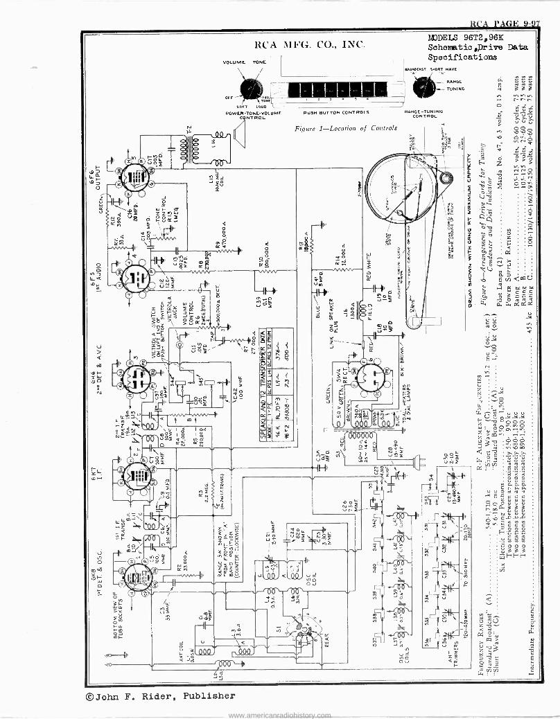
RCA PAGE 9-97
LO j-
o z
L
Or(I ,-I u) O R
N
?
.<
RCA MFG. CO., INC.
VOLUME TONE
OFF 'ITONE SOFT LOUD
POWER TONE -VOLUME NT ROL
PUSH BUTTON CONTROLS
Figure 1-Location of Controls
z
MODELS 96T2,96K Schematic ive Data Specifications
EROMCAST SNORT WAVE
RANGE -TUNING
J I ,? ;- tt= =N ] or
CONTROL
RANGE
TUNING
c4
E 3 e . 3
r r
w a `C E <wU
ó
h e
.ñ..^ GL ä 0, c2 a: a:
©John F. Rider, Publisher
www.americanradiohistory.com
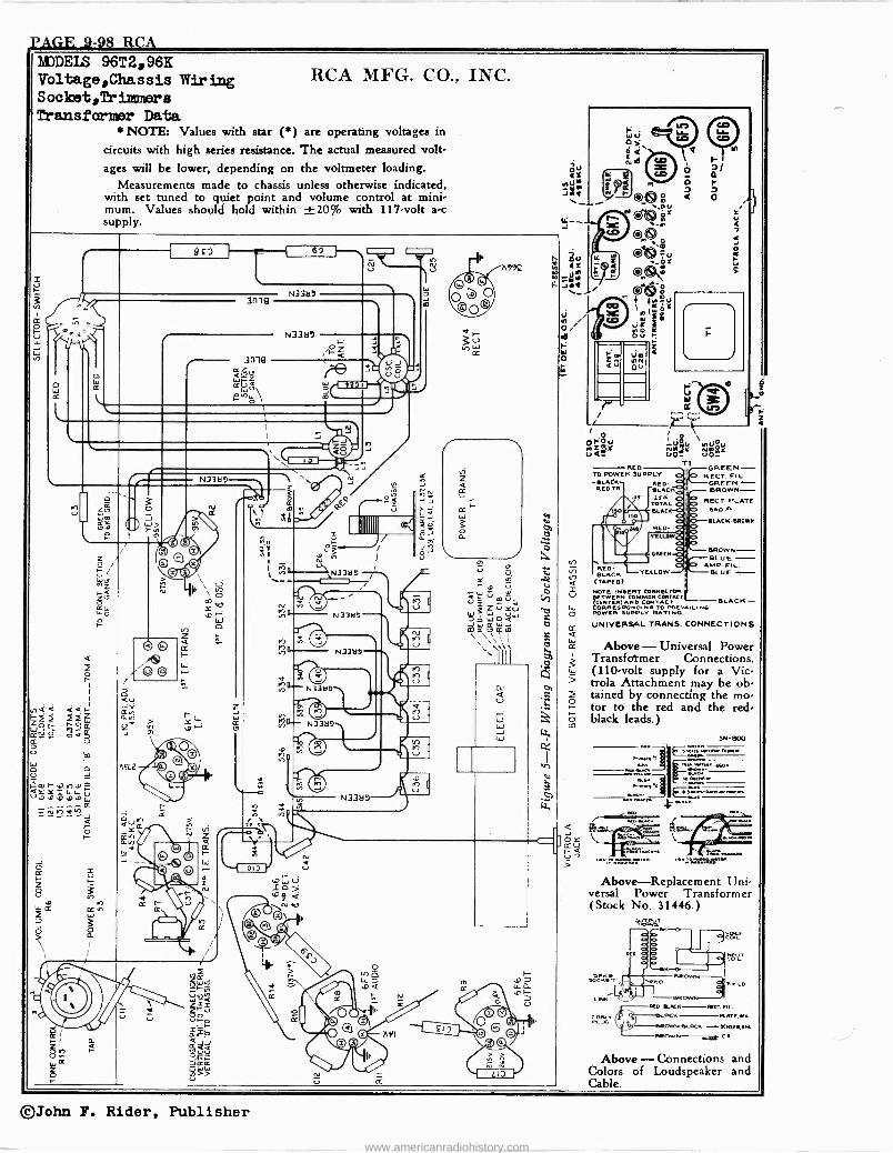
PACO -4-98 RCA NDDEIS 96T2,96K Voltage,Chassis Wiring Sooket,Trimmrars
Transformer Data NOTE: Values with star (*) are operating voltages in
circuits with high series resistance. The actual measured volt' ages will be lower, depending on the voltmeter loading.
Measurements made to chassis unless otherwise indicated, with set tuned to quiet point and volume control at mini- mum. Values should hold within ±20% with 117 -volt a -c supply.
o
w
N
o
¢ z
r
§ Xa
92D
o
á
ame
ame áóu Wr-Z Z W V \
N33M9
N33a7 O~ r<
RCA MFG. CO., INC.
n992
lY
wf
r
W = NOTE INSERT CONNECTOR V BETWEEN COMMON CONTACT
(CENTER) AND CORP ESPOND
CONTACT BL4CK O TO PREVAILING POWER SUPPLY RATING.
CC UNIVERSAL TRANS. CONNECTIONS
Above- Universal Power Transfotmer Connections.
Q 3 (110 -volt supply for a Vic - 5 trola Attachment may be ob - ó) ó tained by connecting the mo- I- tor to the red and the red - CO - black leads.)
tL
, WL! 1. :` eo da Y Nd ri
o Q J > > O®?0 a 0
I Valu \nti0u 40NN-Y NnéY VO
RED TO POWER SUPPLY -SLACK BED -
RED TB BLACK Iss ESA
TOTAL BLAG
RED YELLOW
GR EN
YELLOW
n
GREEN - RECT FIL.
GREEN BROWN-
RECT.PLATE 660
SLACK -BROWN
BROWN - BLUE
AMP. FIL. BLU E - RED.
BLACK (TAPED)
Ireee -I
SN -800 fedoNte;Roc.,Ile..,N_.L
KIE. WN. . Ko.
sa.`".IN- emcee. Mew.
Above-Replacement Uni- versal Power Transformer (Stock No. 31446.)
LNPP KD -KKR FIL,
C Male- S---BL.RC ATL,aLt ...LUG! b GM.M.,CR-.-SCMCR.cLG AR N,Ci,
Above- Connections and Colors of Loudspeaker and Cable.
©John F. Rider, Publisher
www.americanradiohistory.com
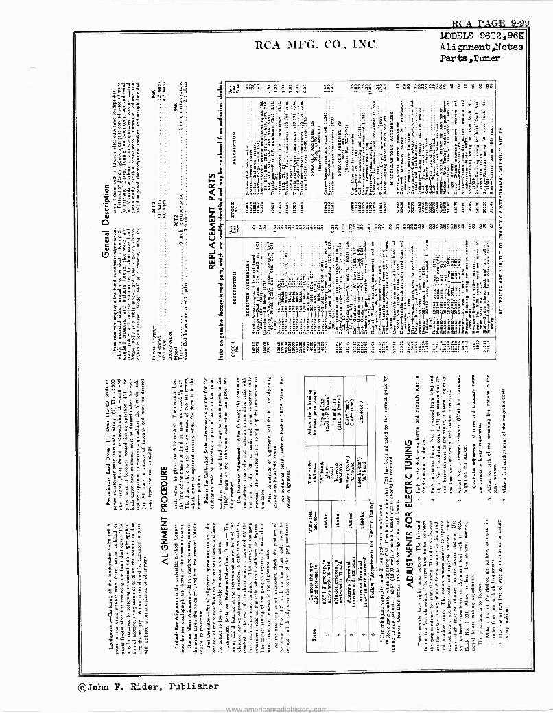
$CA PAGE 9-99
ee S S
AAA
..?Ce
v L .r 3 çç ñ .á $25 F=e' : Y ^ 9 fl4VS
ó g ó á > > : ..`.Ó
a 5 fi
á
All8,--,1! qS
E;73.1 -,,di E e -. b O ° ° C
LF7 ` á L 3 ÿ e v i . Ó
e o - 5
óy y3 9 .t.
3 3 a $
Ezá:8 _º
ó â =á >. ¢..q `
'3 é 0 ó C 19'm a 4 . 3 y ^ s ti
'0,8-2472 3 s
$ 7 w^
^ ó 9 t á é
01 C " a c óv_ 3 .. 1 L
V Ñ .., 5,"s=ö :s mN
¿ q c > ,:,
C É. ÿ
« t S 4
a are, c < $
$ 3 ° I o . á
3 ^
4°` ú.ä s G. 8
G : : ó5 w p e` Ot E ó É ñ `-.;
RCA MFG. CO., INC. MODELS 96T2,96K Al3gnment,Notes Parts,Tuner
m2 .. n . .
He :e2., n
. .. r ....... . . . . . ..
z
á
M1
Y
'z S:m é;T
e7 ,«°.i; ä's ;6
mmmmmq
A á
O T,! -t Meri; gäáldqi@g"s -
¿'ñ
.:
^S
.n6.
3 '
° A
~EF^B
441 hid!
F
t C
Aor =
8 ö; < I Y
aF..
e a -a° ,>o
4 -ill /p.1.1171,1ä
F °° qF
- âr
m'áx
.fr9 «
x -
M«-4Ya
é. Si Sa
Xál
ú6;q
1á ¡f°
oe>.
5 z Id
s$
> ' a m
mj I
C
éG3ÿ
:I..
2
á
5:
;6
3 6 ,`;.- ä"
'
s
$a2ÿ__sYsYs 18...g...4..... xe'
'g"a:C.
Iillt!Yuie!!1 >°i
2q$ :óx éE
$ ' ;p:° 3°g$RaF_9s5Y
:2E
L $.
qm"..e"."m
ei Z
3.4..1 n ° o-
2 '-^-
a2a
x
Y
«
$ e
ú_ rnrno+w. nn neannnrwn nn n nnw
r á m
.. w n
ill.. paa . . »ñ . . . . ..... 2'° . .... . 2A A2 .
.. .. .. w n
aJI.T1 löé3ºe_äää.Éä_xd mu
2
ñúo363S33oS úú
éx u.¡.^6 ú w .:
lII11III011IY1
á1uJxuS° uo uuuuu
F
:
u
: e
ú.
s q
x
u
8wóri
i"
e-aag: v
$
11<1e2. á 3 0 C0
^
á9
iIA áz>QgóI^i7i7iT¿=g
2Caa-L, ú a äSáa
j
ââmâ
'tz1é6iê3- é...
òód
°°s° B8LEçóe aaaaaaa
L"
'"w5
51
anÿw
.0
.
..4 :
Y u¿ = n°..n qw.. w ^
nn nw rn n nw n nwnn n nnn n n ngn 5g515515.. n nn
$CaC'm 5 "ó=äcDm .áS - C . C y F'
ir « 9 .0 C
C ÿ 0 I S
G O> v3
41131" 7 6 ó
S .ó^ mé
° G.s- sY mE aG $y$$°E'É.ñ E 5ó Ce`iwQ.3 g.a .^m` 'o c E!
asF E88eEaám^ áó ° 35= -5
.;57,1 7 V :: . V c
11 1' _w°eñ.'eoeYoq am>. ?m;m _' . G
;1-.92.43,12.:1 S ^ E v
P BL.áö..s ñ 53Fa g2ra ,
;t ¡y
g
és
á la W.. á
áM
5oy o.r á,
5 a $ ää
ó i8 U
°
Idgg b .. Ci
4ieegg 9 $ $- " dág
cd s M5:1'ói
3
$
M3 3 i 2 y
s p
P s ei ÚimY
iU 6 ,1
d
41 m
He l¡ bp, 8
'14 .8
..
m Y q . n
5
ó s s Ú 3 u
,
a .á
S3 95' .E ó C
A
° q Ó O «
O_ .3 : C
_. C $s Y £ :
D . a ó w °x z ` e
ó3
G ^ :y^ á; á 5 d w VÓ 5< Q
cc O 9a "'á Li séIIw6op
ÿ Ó u Y C
ZSS ß L a ° ^ 9
^
: v á c e ó É
s eo n Y. E- y..:rÿ ,Eme
< <ä4°w`w^ 9. t.,
111 c.°' ., E
b vsee c cáygóa34 c
i
Êos^. w5s ` m ^ - ú ;.s ó ek
;9 C É 6 ÿ
c $ s ° 1'19. e"e$2.Gr
á ^ ñ fi a .
= lie a
s v e
b ó
G $
a
©John F. Rider, Publisher
www.americanradiohistory.com
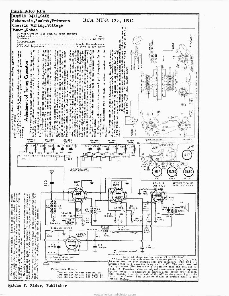
PAGE 9-100 RC A éJDEIS 94X1,94X2 Sohematic,Socket,Tr Ulmer s RCA nIFG. CO., INC. Chas s is Wir i.ng, Volta ge Twier,Notes
ôro POWER OUTPUT (125 -volt, 60 -cycle supply) o Undistorted 1.0 watt Maximum 1.5 watts u ó LOUDSPEAKER
E e Type 5 -inch Electrodynamic ro a m Voice -Coil Impedance 3 ohms at 400 cycles
t7:d ô F
iúY uro Ó e««'S °1".ÿ.+ 3.é.e.u..°nriÑy,, « A .+.Vu"eo
at á_ w '"75.7.1`..e
á E" ""a.w3 MEa"=K> m
á 2 ó ' '.
ro í°i á Ó " p"j Mj ^ a .d ó , p p6 ó 1. 3
.5 b v..~4 -c ó_ ° u b;311_ as u n O á .g° uc - u .u+aVi,muu a. w c rom
:el « c'ù ó 2ñ^ ïE.c« ro$ -4-14ÿ +É g 3 SS ?tóñb o
w d r W° .5 :,2;.5... oc Úa á T b Aú o Y óubó` vº"ii"«ard Yg óa áEacEu tJ u ^u E 3° ro ESceºm E É a. «~ m k« «EEá
?,. u ua«ô g c oF, c r óó ua '3^uRju «,á uea> ti u q áro ro« á ó p,acFE,¡«,?g ro.ÿ M ° 'Fu_
°u V ° ~ «3ó'S eobropo
á rutEbo roÿ«trro
> M$ pq.aâ uo úS u.5teouro'áu ; « a .3oou«E y c^wb uux c w C .ö L6.0.9-9g n«u .L r C ro ú O w «« Ep« E O ÿ ,-.F.,,,1-...,e- r U . U.ti m ÿ «;
9 n -C óo
ä ó' ro °.°óú: á° due'ac^ u u Lea uuo « o á « ° u «cta E
á°ñtbabeo v ¿° $ 'ô Ecyé CO$c bÚ«eÉ° a
E ÉuvEE -. a i 2 . " o E A.« U roW.º.. 't e..0 cc - o c- u E.c ç
u ` á .«. ó E-º ó E roù ú n gó.a. ELG1 Qù $ p m «.5 E
t EMó$ 'á 6I ú.% ú C.ti roúu "íb0
ÓNc 2.3 P Ç
E R..4. aÿ; roro « u U.-.uN..._R7 ro cu
43 et; an .ú»óñ u«óoá "NO0.°N°p °.c E cóc°ti.E Y .~. _ C .3g1,-.,,,, >. ^ .-,E2,9, Ó ~ ro 7
Ó ^ ú .
m ., ÿ " . ' ú Ú n co ,â- _ u... E
5H$ u3;$uFá É,«°,ó ?52L1,-212-2-2.5,.5..u," C Cgcc )r O O -22 ` ...eo s-ñ .2 -g119 -8 -?.x.2 a ij cuu'« ` n úa°zö t.Kû sEù .a á3u"ñ ax«.Eá,ºba 'S ô`Y,
n O> ,4au u _ ouó a F 'e, 'D b 2roc roOF< á ^°úr°-uñrou««ú ó',óíc, ó.ñ °. c ú._ói.. O >
". °.oÌ-, iQ p ñ ro tL c E O,ú ß., ti a_ . r7 c u-... «o a eo..'- u H ro _ u ub Lt,b (4 c ro
A..c..4.2` s . .1-.1311' a °ua taiñ u ac º º ó E.= c« f.. m, -1;N 2.7,.:721q. 'roút
`.du 0 F `t ."i. -bg." ú E v, o m- n (. °=.c
A é 3v º «C) óh. 3b` ó.b0 Á á« ° v . .:2.-G '
M
20-150 75-250 MMF.. MMF. .
C2 C2 1 C23 I% C22í0 C21
T
125-400 M M F.
C2
125-400 MMF.
C26 0 C27I, C2B
'IS- ISO MMF..
/ C29
5
g i, .i
m
o
nsT 17,5191
I `I.1611 eeED
1:
$
2
1bj
-_S
ww R 1
20-150 MMF.
ÓÑT.
C30 C3 /
T 524 - 523 522 521 526 527 528 529 530
525 J o-f-1W20 'r °J J _ «7«. J
o;á Y L
gE" Y«
u b a
e u m m c « Ap
uÉ m°3D
Ó V u v « Y O U
I
H «u« á..+: O p ó tY= a_u4 G
xY pY o c ú" >Y ób
^ A
ro'g v E ú Á
gma ""^ º a 'á u 'R
ó°4; c. w s ,..-9«uv q::;; ¿Ou
Y.°. ro.+u 'ñ:á« fio
Cé".ñ«,X, u
pp « C« a5 ° u R^e C .5.2.,_02 1,11%1, ÿj 10px gx p N c;-ti :4.`j,2,1 -7,1X
ó V .u.
3 u 2 é u«Om ae0.i^..
DIRECTION OF PUSH BUTTONS
CI .OI MFD.
t 2
6K7 R. F.
LIeP b L2 604D p 54
Dg VOLUME CONTROL 3
.J_ R 1 2
C 50,0007/ CHASS IS TOTAL
51 (ON VOL. CONTR.)
53
3
2004 L3 Q L4 SECT. 90a2á 5n
R2
1 IB,000n
STOP I
M0.1 = FD.
6J7 DET.
FI ELD BLACK--,
i 25Z6 -G RED CO O RECT.
041111eK© 4 nee
© O
C12 .05 MVO.
BLACK, 94%1
©RCA MFG. CO. INC. P-84244-2
R
R3 2.2 MEG
I I\\ C8
.01 MFD.
0.4/. w,iG.CC
C tIºIICKET
5 1 ``
: 5J731
524¡ ANTE COI
l L
5 -523
T $ 29
°525 6K7
R,F
25L6 -G OUTPUT
R6 = 1504
R4
C10 .01 MFD.
470,002 I I
L6 YELLOW
4004 GREEN -
RED
522
s21 527
4
RE CT
c.. -TO. -o
DEI
6J1
S26,520
3
OUTPUT
C11 .025 MFD.
BOTTOM VIEW OF TUBE SOCKETS
RED
I RS 1M EG
C9 300 MMF.
I C13 16 MFD.
R-0 (IN POWER CORD) I 904 --/V WN+
WHITE
FREQUENCY RANGE Two stations between 540-900 kc Two stations between 680-1,200 kc Two stationº>between 850-1,500 kc
C14 5 MFD.
504
LS
pBLACK 11 j
(L5 is 3.5 ohms and the sec. of Ti is 0.5 ohms) ** Some sets have a three -section capacitor pack (Cl, C13, C14 -
In other sets, the pack contains only two capacitors (C13, C14) ; a separate 0.25 mfd. capacitor being used as C7. The pack furnished for replacement (No. 30873) is a two -section pack and does not in elude C7. Therefore, when an 'original three -section pack is replaced by No. 30873, it is necessary to connect a No. 30965 200 -volt 0.25 mfd. capacitor from the cathode of the 6J7 to the ground lug at the output transformer. This capacitor should be dressed close to the front of chassis.
©John F. Rider, Publisher
www.americanradiohistory.com
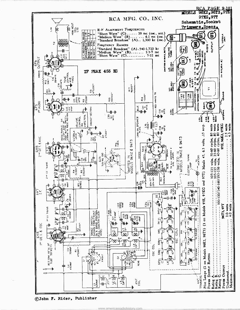
R n
^n
Y
--lN
d J
0áa00
J
l7 ¡ Z Z W O U Ñ p
d _ U O o \O -
d Q Ó
1_ I- TI n ó m ó' 392 ¢ r wv
h-
W Z Jln Ú J i
e
OJP: e
4' No> o -E
r2î
h
J < áú OO ~
aj Ú_- >
0 N
O 0 IY N
a_
J n N N
f d ñ
s a
w
m Ó r K
RCA MFG. CO., INC.
R -F ALIGNMENT FREQUENCIES
"Short Wave" (C) 20 me (osc., ant.) "Medium Wave" (B) ... 6.1 me (osc.) "Standard Broadcast" (A).. 1,500 kc (osc.) FREQUENCY RANGES "Standard Broadcast" (A) . 540-1,720 kc "Medium Wave" (B) ... 2.3-7 me "Short Wave" (C) .... 7-22 me
IF PEAK 455 K6
¢ ó --./vn----
O ró (¿
Q O
4
1
In e. -9i H
,c 01
-© zY ÿ e m<f
-- 1 I WJ o 3_14- .j IQQJ,_ 40
L
o
uoï O b N
Itl 11
N Vo
o Nn ¢n
J f
o
d A I I
J U m
W '00'. 00' i U
Lo N< ^ Q\ hoe J
Y
J q O
V ,
O
L_
J, J ü
ó
RCA PAGE 9-10 IDEIS 96K2,96T3,97E
97KG,97T Sohematio,Soolcet Tr s Seos
IMr
J J J J
z
O
A M.+.1 M a1 R ud uiiL e
eeec ee áááe áá
ó
©John F. Rider, Publisher
www.americanradiohistory.com
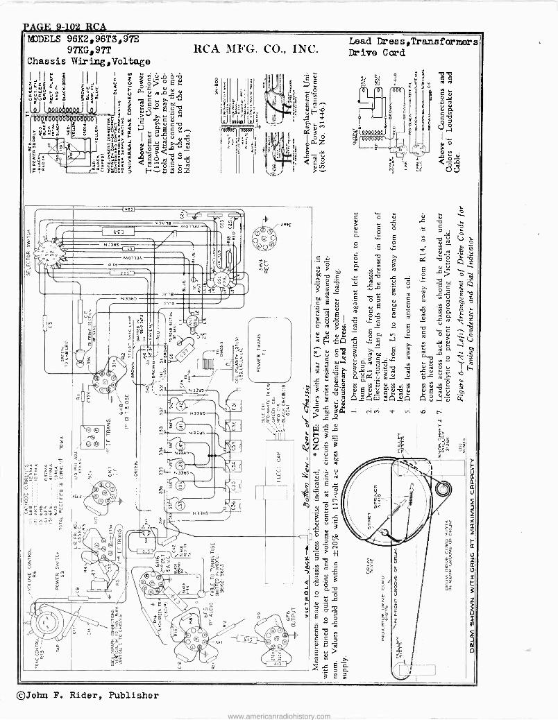
pAGF, 9-102_ RCA IIDDEIS 96K2, 96T3, 97E
97KG,97T Chassis Wiring,Voltage
RCA MFG. CO., INC.
Y ú o>° P. Ñ co -t-.1 o"bao
> úcg"' E á c
ro
14 e<oz a UUF 13.2
z'á t[ Y át O L p-
I fZ E9>ÿro gg@$$ áóôy rl
li&g a $ s> Q;9-2 ä'
s HºesL
N« rF cc K'
Bç)
MOl13A 03tl
2za
ti N
.433199 3019
ame
MOl13A
bo ó
0 W
15G2
mr.o,n,vnIL;
:.
e m :ÿ
h t Ña-='\,. N13tl9 ------
ä
=3 J
s
> Si ¢ .- a Nb ,
T99E
z
COLJ
º ul U 1- L._ sa L_a ,,,i-
v
?
Lead Dr ess 'Transformer s Dr ive Cord
..., . d o
,...
Y O a 2 a
ç _ t.- -o L W
-RI Ñ >
0.0 ro w e.,
a0 .0 C , ÿ -V a ;.G ,r .roC ol
á %
m 4) Y C 0 7 c E ú E ,Ó1
of C 4 E 24/ L ó.ú ° I
w 2 0
01 ft 1.l " coH.n ÿ .1
:.ei e > E o , g oe ó L af ar L1, ro E .0 « .;D, ó..á..,1rb L ç G u 3 '
-.9 .Pla
3y ÿ.j meh ;?:ÚÑ T. ^C1
7 m + ä".2äm eä
%ÓO ó R1 -. N ..; v v1 s S,
-2 .á
Z *
.?..i a0
u ro
dU .0 of
u E o 't1
.. ro
-g."'"
ó ̂ '
O ú 01 ó É b O i
^N O N
C > +1 a c á g ro
'A 04120412o
s .
N
` i
OO.-C v 2 ô IL
ú >
ñ
8 a
É v'3 1 c
r C
yy7 d V \\N
Ñ N T
> ú o d. E .'o
O.
L .°, d o, .13G b I. 7...9
d g VO ó v. ói ga d y ti ÿ ¡¡c b
1 i.' E N,u `
..12 5-: C ö b
â C Q
h d I O
ti á t ÿ v tl
e
c d 4,..-...
z o V r -Zd, 2 a L ro la, O ro
LP..tjÿ.O eI
.c ÿ óA E-
t,' -c `,-4 >, W V)
0
dÉ ú ó, a A ú -ti e: GL
e r ...e
i''
f22" m
John F. Rider, Publisher
www.americanradiohistory.com
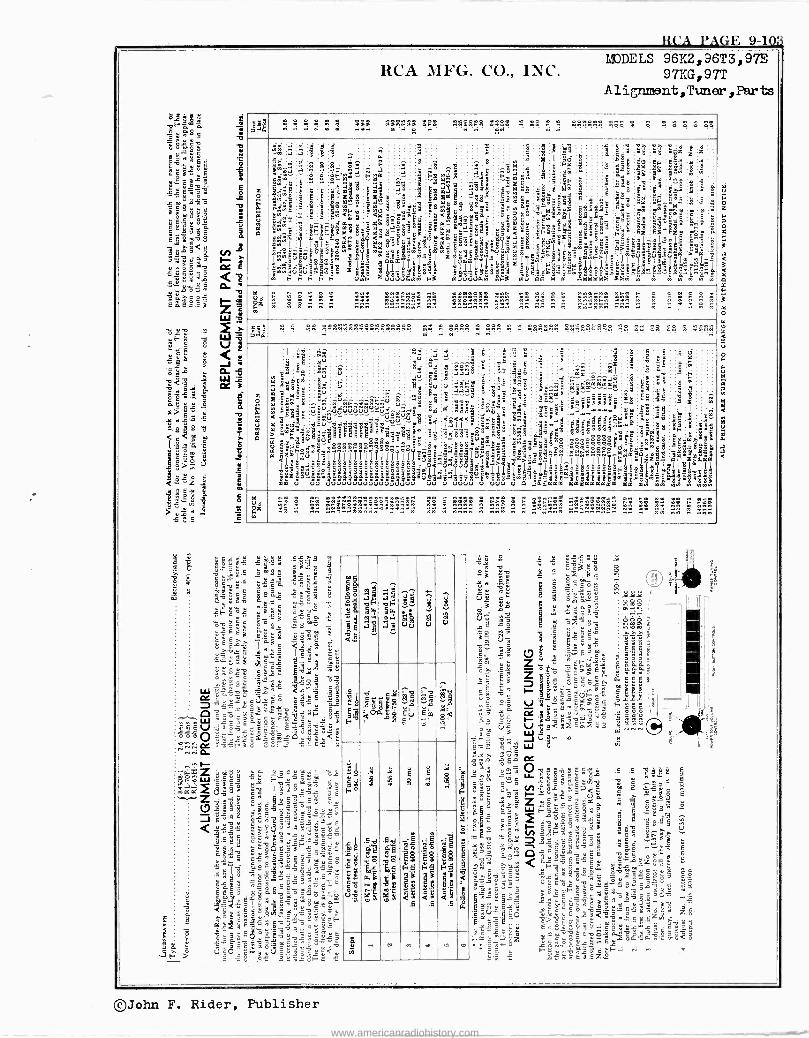
RCA PAGE 9-103
Ó
C
RCA MFG. CO., INC. MODELS 96I:2, 96T3, 97E
97KG, 97T A l ignraent, Tuner , Par ts
;g w . . e Y Y
!s! assm -5 19T, a^ .. 72Y
Cz
ä
C1
w .,;ásil Çwââá°:$
pl
.: iñ'R
°iawEúúóm@ti ll p
wwwCpáén: if
5 x
Y
-z`'Y 1,191 F
t" É
..,.ß14a sÑ .$°O>X IFY á
F F
^ Y^ á h'm-
w_' ja °<;5
5 8° 6< >; Sqÿgg" 18 8 ¿ >: i
F 0wF
á
.S
Ñ..C114
bmj sm89 m
..Xê93 xä â.,b XS- :6ix"1
°''%XStgw'nSd5sé8T5"lm E II'
la. 00004.w
á ^:
á :S ;
Y5 . 3
gaxÈä,m9gs"°gtx
l:
1.. 2
gg 3s ye
°p 89
.
' .: â "OÓ eE m3' Samo
m p5 <a.5.Y9á< Oayxg.
mm XnyyC"
Y<m
I ai°b1.d F3 14000V4.w
.s .:
ell ,;tt. Y
g0 Z"^
áS I IY
p
ao
a
glóm'
^m Fy,min tg'gäs á8 p'sc noi" pm°
3s x= tiá <
bá 7 .5 z6ix F3 IÓV
i! ' 7F 91! _; =?b98 m8
g! Ñ
1»5.'nu " °ÌS'lä,,s;
Em+mmc T.I-.IF"a-amxl l:ÿ
GÓmId
8`a'S
gI hm
.. cm
Wm
m1 9.
1 i'- ' xSlamti.>12`I 3
Zäÿ' m
m
5 1
°
8ÿ8 y.Ee_ 5`a i"
'.4:',0-1.!
° -o IpICkZZ>!m
8 8g
xy
eo
b á:"r`ám : Ë
ÿ3 E
é '-1 g x F8 ¡ ä>:E3`6z
Ì` ät'ltY',n_II
`.g ig tu
It-' " t.o 3 5 xée xm^x°w
.é; 3m '3 .y
8 é s II!
70 6aa a
Y.
.^. --.i'cn`ó
:Bz;z t'`3y
6n $ g` '8' e =c
I
I lÿll
Al w
.Ó
AA c çmç
á 99
w
8 g
8 b
m
y 0 mz " .... . Y..as Ywn
zY n nnw nm. .. nn nn n n HE! nnn . n .
.. n n
Mná . . .. 1444441444;444444 m .. 1444
m 1,41 . . 444444 441444414 14 44 .. 44 4 1411
o'. a á
Ó,>,°'
$
T.]
á 19óg m Lei
e <99ö <1."-i° 14 S, m á,9àp
146aU
S7Ë .Fina
14 mlm Iá 8;t
SYa'a33±?3a3aó33e5uaSaSkigbi=éte°?¿e¡'¿-décbñ2,ib:x5in' mm
a ma15
3°
,u
u
ai "
ia. In "^
V6 ",- ,4«u
d..u" .
6úmo .
1 .°sx -
Vu UV00000000000000
,. ú
ú _ â
â"â :Y n" úú. úljúúúVV-w^rúmd d ddd - aa ñééd LC Éd-ÿn
o c`= á,<3wCÉ m m' nP'mm.. 11 III lgqI
Its65a$8áëe°i>" gggga9 gaa.acad2ggYS°
..
úú`.0
I11Y
q: . d !
~ 8
é^38..3
ut
' `pu
° e °14 t V. '§ `
°A
<áaoq
e.
á:i âs
á ááá"
led 5 gg
m <1s <a«< 4`2141.>..,,,' áú `-ib`i< á33p°'w a-yp
qI ;Tart UVUV
>
9
B i' éria
d$g"
u>p.. 1i..>'<g<
0
;
d- ó' Y` eE8 e"
a t 22e
°7!
, 1 12
1,V
3
e3 p`_ .+ 5ñ á^8 ñ
an_7: a; q.._jnSa iI6
en
5 _ ee
2
@ á4ám
e-ï Épe"s
e,." 117141.111.. á
a 75 °'"II:Ifa,JaIâl 1TI6
G Sd14mm
ñ ê n
d m:ámmmámm
o OpO 914 SoB>° :::;,..;:i-ä4712.
aamaaaaaa
.
áá
oII sss..,.....s ,.,.
6 s§5...-
ô,...m
iiéi.
: :s
IIII
marcd $
óéE`
F-.$.Il.ä
a
é'i S
.. áÿ â I b 7Y t
aé
C s m
a1d zz_.
1414 14m
C
éË
EEO q : C b
iii
I
s I
s ÿ :' F Pr' id 3'mblmaS i: IlilmlIl bsaeEbSlc
t'
ä 8
I
b
a
w
bm
i p qt aa
ppy
¡.Z . n.
Yd
n! ...nln!! ... n nn n nnn! n nnn n! n n. nn n...! ... il. nn nn ..nw
gºéWi Y'°5^ . <3 c
f ° äÿé
mä ` 93 c ñ .11'2
° s
gs8r c>g2 eL ú!V 5E='P5 ; %Iy "c - "` -6 Ó ñ ° y 3 c6é °pu- JEYúE Eá
É,:"m
"wv.m 2àre. Ia; 539$1 Jééwñ.
5434$ ctc? .ÿ` `,11121. rQ `á ñ 3 ` ñ é
o YY á.c v.L.ctjyi cs -^-W ^ é6ñ ÿÿÉ.SaYwY-a
.Co.L ; wvs i 0 0 O "'3 r Y Y v00,_
1.2E-2É1.2E-2 ÿ .v.2.1
á Ñ >.5
"°°n' zc9q3 4' Z 9 ú
(.2851g J éY' <1;g14'
s º' -57º
il
« IA é.É
Sk le á',m,
9 9a
AM
OJ 5
ly
ou
í+
1 u
^ Yá
8 u
a II
gd y p c [8 G 33.5ñ á pp
E'a td0. Eu
g' E°a ' y<
§'
é ÿ
gá
eg F °
$ !g
$ $ m
^
W
d1i 21-3 "§§
1¡
i;é
U!
11
1, ei mn
gs.$ b.
b .2 E
+J
G
E
g$ F$
<VS
.fi a á
L r 01 m V N m Ñ
2 óÿ 3 á "9 = ú" ^
g ñ° óé d
Ú p e ß w Y,iççi 1
c á9 e .. mi i
C 313 'I '62 a-
a! úa -§5 e..1
.. 9 ..m
w s'Ñ (7
úóY
c
0.
¡gó
q 'Ë- B g
"
in 2Yç V
é"Ká1E Y
1
.:4.3 e IIáó ox Vo<iSñPEñ g$II N N 3e ; J Vp ri _ÿ «le, W 'r H
G aY coÉñ
ó äL'ócCé"xc 'E ' wtet ..:. fi
c ú "o .-..i %- `0añ H $ XE C °° VI:
ac H- 'á3w É qa _o¿ fi
" Y Y lee 14 c ú úá ;
C ó 3 4 @ al < .O.óóñ:cE ó E
vÿd o o 14'x$ F YD"evg ñ: ó ' ..° "t=8
ñ3 `mEºx93 °` rs°a c$ °'9 14.0. "`CC<E r'.ÿñOa_ 'E .T.'c m
.^ZY^ÿ . - c G
$ Y.ÿS ^r .0 .Zÿw. 09L^LOpY7 ä0
II II
çE4c^aéáac^$3:°ÿ1 3g F _ GOc ñ3..7 tl¿a 05 "
EY, p rc ó yó:
Emm g0 .Sj.ÿCYcé" Eys¿'ü Emgd`"e:nqr,s'- qq9
. -suet. óYAa6.s... ác v°.`ó --úz Y c! ó a Y F^: r 3p;éázw
©John F. Rider, Publisher
www.americanradiohistory.com
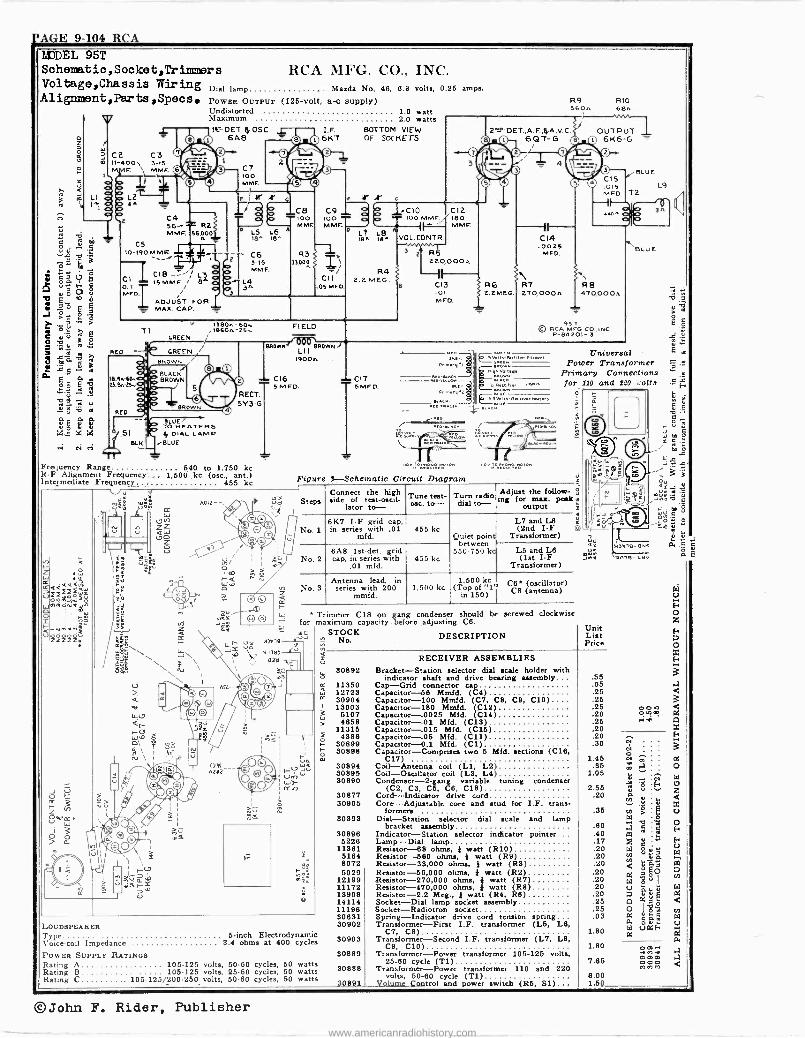
PAGE 9-104 RCA MJDEL 95T Schematic ,Sooket,Tr inner s Voltage,Chassis Wiring Dial lamp Alignment,Parts,Speos POWER OUTPUT (126 -volt, a -c supply)
C2 CS I1 -4O0, 3-15 MM F. 1 m M
)
REO
Undistorted 1.0 watt Maximum 2.0 watts ILT.DET.f)OSC. 4.,
6A8
C4 56-,T R2 MMF. I56,200
10-190 M MF
ADJUST FOR = MAX. CAP. -
CT t00 MMF
a L5 L6 18^ 18^
C6 3-15 MM F.
13804-60.,. T1 ,18604-25-.
GREEN
BLUE TO HEATERS 5 DIAL LAMP
--BLUE
CB
MMF.
J3000
I.F. BOTTOM VIEW 6KT OF SOCKETS
F tl Sr
RCA MhG. CO., INC. Mazda No. 46, 6.9 volts, 0.25 amps.
2"-P DET.,A.FA.A.V.0 p_ 6QT-G
C9 TT p'
_C10 C12 MMF 180
MMF s L,á
A VOL. CONTR.
CII .05 MFD.
FIELD
BaO",/ UCH i, 1900E
r. CI6
RECT. 5V3 -G
Frequency Range 540 to 1.750 kc R -F Alignment Frequency... 1,500 .kc (osc., ant.) Intermediate Frequency_.
Y 455 kc
LOUDSPEAKER Type Voice -coil Impedance
A012 --
earn J -n
5MFD.
2.z MEG.
R5 220000A
CI3 RG .01 S 2.2MEG. MED.
C14 .0025
MED.
R9 R10 560A 68E
OUTPUT 6K6 -G -
BLU E C15 .015 L9 AWE) T2.
II -a. Zf`
R7 R tì 270,000A 4-10.000A
95 T
© RCA MEG co .INC P-134201-3
CI7 SMFD.
$ hernL.,a
I+rmvY i óa -gh 9elta;
. . ö a ,,. ,,.a
Fn. Y 2 u;
eCn)wIn-R.ar.a Irtan
Figure 37 -Schematic Circuit Diagram
Steps
No. 1
No. 2
Connect the high side of test -oscil-
lator to - Tune test- ate. to - Turn radio
dial to -
13Lu E
Universal Power Transformer
Primary Connections for 110 and 220 co is
0
Adjust the follow- S ing for max. peak
output 2
6K7 I -F grid cap, in series with .01
mfd. 455 kc
6A8 1st-det. ¡(rid cap, in series with
.01 mid. 455 kc
Quiet point between
550-750 kc
L7 and L8 (2nd I -F
Transformer)
L5 and LB (1st I -F
Transformer)
No.3 Antenna lead, in series with 200
mmfd. 1,500 kc
1,600 kc (Tmo
150)of 1. C6 (oscillator) C8 (antenna)
* Trimmer C18 on gang condenser should be for maximum capacity before adjusting C6.
- 3D r Úó ;7414
N3345 \ ) 43p \
f
6 -inch Electrodynamic 9.4 ohms at 400 cycles
POWER SUPPLY RATINGS Rating A 105-125 volts, 50-60 cycles, 50 watts Rating B 105-125 volts, 25-60 cycles, 50 watts Rating C . 105-125/200.250 volts, 50-60 cycles, 50 watts
screwed clockwise
STOCK DESCRIPTION No. Unit List Price
RECEIVER ASSEMBLIES 30892 Bracket -Station selector dial scale holder with
indicator shaft and drive bearing assembly 11350 Cap -Grid connector cap 12723 Capacitor -56 Mmfd. (C4) 30904 Capacitor -100 Mmfd. (C7, C8, C9, C10) 13003 Capacitor -180 Mmfd. (C12) 5107 Capacitor -.0025 Mfd. (C14) 4858 Capacitor -.01 Mfd. (C13)
11315 Capacitor -.015 Mfd. (C15) 4886 Capacitor -.05 Mfd. (C11)
30899 Capacitor -O.1 Mfd. (C1) 30898 Capacitor -Comprises two 5 Mfd. sections (C16,
C17) 30894 Coil -Antenna coil (Li, L2) 30895 Coil -Oscillator coil (L3, L4) 30890 Condenser -2 -gang variable tuning condenser
(C2, C3, C5, C8, C18) 30877 Cord -Indicator drive cord 30905 Core -Adjustable core and stud for I.F. trans-
formers 30893 Dial -Station selector dial scale and lamp
bracket assembly 30896 Indicator -Station selector indicator pointer
5226 Lamp -Dial lamp 11361 Resistor- 68 ohms, } watt (R10)
5164 Resistor -560 ohms, } watt (R9) 8072 Resistor -33,000 ohms, } watt (R3) 5029
12199 11172 13998 14114 11198 30631 30902
30903
30889
30888
30891
Resistor -58,000 ohms, } watt (R2) Resistor -270,000 ohms, } watt (R7) Resistor -470,000 ohms, } watt (R8) Resistor -2.2 Meg., } watt (R4, RB) Socket -Dial lamp socket assembly Socket-Radiotron socket Spring -Indicator drive cord tension spring Transformer -First I.F. transformer (L5, 1,13,
C7, C8) Transformer -Second I.F. transformer (L7, L8,
C9, C10) Transformer -Power transformer 105-125 volts,
25-60 cycle (Ti) Transformer -Power transformer 110 and 220
volts, 50-60 cycle (T1) Volume Control and power switch (R5, Si)
.55
.05
.25
.25
.26
.20
.25
.20
.20
.30
1.45 .85
1.05
2.55 .20
.35
.60
.40
.17
.20
.20
.20
.20
.20
.20
.20
.25
.26
.03
1.80
1.80
7.65
6.00 1 50
an-l-.Nv
ómm .ii
oa.-d mmm 000 MWC3
©John F. Rider, Publisher
www.americanradiohistory.com
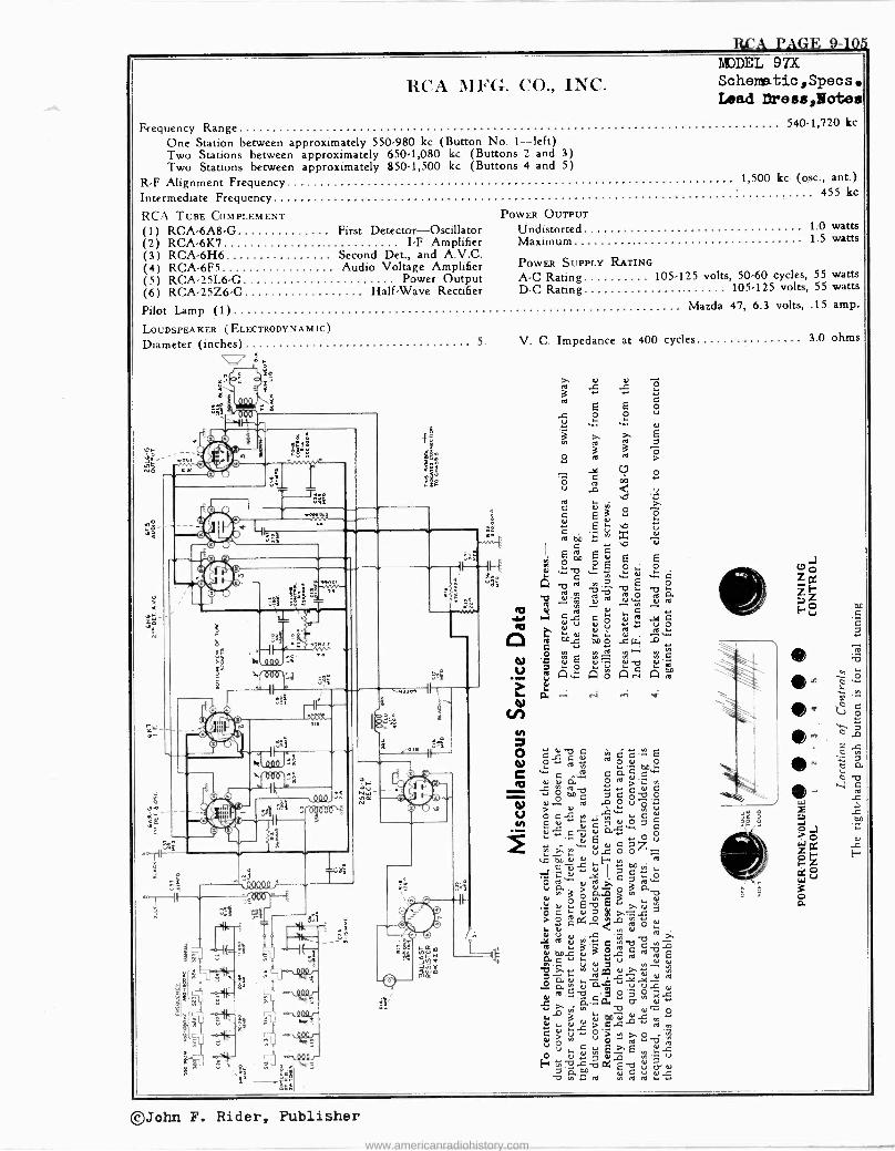
ILCA PAG 1? 9-105
RCA MFG. CO., INC.
Frequency Range One Station between approximately 550.980 kc (Button No. 1-left) Two Stations between approximately 650.1,080 kc (Buttons 2 and 3) Two Stations between approximately 850-1,500 kc (Buttons 4 and 5)
R -F Alignment Frequency 1,500 kc (osc., ant.) 455 kc
11BDDEL 97X Schematic ,Specs Lead Dresa,Hotea
540.1,720 kc
Intermediate Frequency
RCA TUBE COMPLEMENT POWER OUTPUT
(1) RCA -6A8 -G First Detector-Oscillator Undistorted (2) RCA -6K7 I -F Amplifier Maximum (3) RCA -6H6 Second Det., and A.V.C.
POWER SUPPLY RATING (4) RCA -6F5 Audio Voltage Amplifier (5) RCA -25L6 -G Power Output A -C Rating (6) RCA -25Z6 -G Half -Wave Rectifier D -C Rating
Pilot Lamp (1) LOUDSPEAKER (ELECTRODYNAMIC)
Diameter (inches) 5.
is
1.0 watts 1.5 watts
105-125 volts, 50-60 cycles, 55 watts 105-125 volts, 55 watts
Mazda 47, 6.3 volts, .15 amp.
53=
S2,- .t ca
3
o JW
1,1
r
tgi
i fi^¡''^ .
s
ó
bt II
^O 21
'.Yr
0Ò04 cggy cri I i- 81 ,
II
© o 1Lr
0 0
000 «
VVVVV
sóp
zì
h 2 9J`, es -
£
.d, 00J
-., 000 J- '.!
u
o o O O
V. C. Impedance at 400 cycles 3.0 ohms
zQÿl
I.d
tl m .á s . . .. N
E E O a+ÿ .. .
3 T á
ÿ ro N
.sa O C
si Y v5
C d Ó
Ñ
E ,o u GD
'y m b d
C d E m d º ºE O,; o " C ÿ ai N w -o y bb b 2 04 o
ce ú N. -d. á .; N N ..y
III I+ r. Y dú e° ° .,v,,N,
..si u
~ O1 I.i M N N..~. m .+{%I Y
° d d úMq dN 'n E :o ; Á Á ó ÁÑ Á Á
á.. ei ..; ..1'
.{..
ó.;á C « ÿd.º á ú áé0-oo é
E ea d C N 0 7 C ÿ" pp
u E +' ° V v. y or C oz íN.. íy. V.tl O O mvyFr ^ú 0/ ocÿ" ob> c°
Q. ó ó..ó ° 3 -0 ° Ev s D.ei .;
Ó a. d
a0
7 CP+j.0 N O í0. N N N N
rd
g CN
20.°u
d LúN ? 4 8 ° ú
74 .12N 3 v da+ o
:: e, do er or s .,
.. > G.C N v, L OV ^ T 2
O V Oi ..d, " Osl É T E 4).2 E~vsóaúa
áúO tel aÑ Ñ
E N
e s
*- e-
ó
©John F. Rider, Publisher
www.americanradiohistory.com
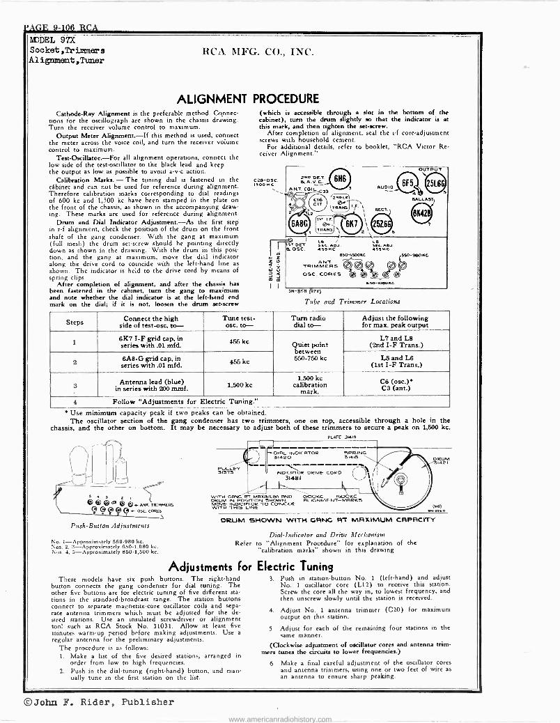
CAGE 9-106 RCA Lä)DEL 97X Socket,Trinuners Alignment,Tlmer
RCA MFG. CO., INC.
ALIGNMENT PROCEDURE Cathode -Ray Alignment is the preferable method. Connec-
tions for the oscillograph are shown in the chassis drawing. Turn the receiver volume control to maximum.
Output Meter Alignment.-If this method is used, connect the meter across the voice coil, and turn the receiver volume control to maximum.
Test-Oscillator.-For all alignment operations, connect the low side of the test -oscillator to the black lead and keep the output as low as possible to avoid a -v -c action.
Calibration Marks. - The tuning dial is fastened in the cabinet and can not be used for reference during alignment. Therefore calibration marks corresponding to dial readings of 600 kc and 1,500 kc have been stamped in the plate on the front of the chassis, as shown in the accompanying draw- ing. These marks are used for reference during alignment.
Drum and Dial Indicator Adjustment-As the first step in r -f alignment, check the position of the drum on the front shaft of the gang condenser. With the gang at maximum (full mesh) the drum set -screw should be pointing directly down as shown in the drawing. 'With the drum in this posi- tion, and the gang at maximum, move the dial indicator along the drive cord to coincide with the left-hand line as
shown. The indicator is held to the drive cord by means of spring clips.
After completion of alignment, and after the chassis has been fastened in the cabinet, turn the gang to maximum and note whether the dial indicator is at the left-hand end mark on the dial; if it is not, loosen the drum set -screw
(which is accessible through a slot in the bottom of the cabinet), turn the drum slightly so that the indicator is at this mark, and then tighten the set -screw.
After completion of alignment, seal the i -f core -adjustment screws with household cement.
For additional details, refer to booklet, "RCA Victor Re. ceiver Alignment."
cas-osc. 150o MC
2.. OCT. e& A. V. C..
ANT. COIL 39
O`s 'Lz
6A8G
tST OCT eL osc.
C16 C17
®3 '211Lrl
TRANS 1r RECT.
IST I.F.
0 TSAR \I 6K1
2\
AUDIO
OUTPUT
6F5 e m BALLAST
ciD
L6 / L8 SSA. ADJ. SEC. ADJ. 4955C 55 bec
850 ,s55 -9608c ANT.
TRIMMERS O ® O \ o9C. CARES bed()
650-KIBOKC
5N-858 (37X)
Tube and Trimmer Locations
Steps Connect the high side of test-osc. to-
Tune test- osc. to-
Turn radio dial to-
Adjust the following for max. peak output
1 6K7 I -F grid cap, in series with .01 mfd. 455 kc Quiet point
between 550-750 kc
L7 and L8 (2nd I -F Trans.)
2 6A8 -G grid cap, in series with .01 mfd. 455 kc L5 and L8
(1st I -F Trans.)
3 Antenna lead (blue)
in series with 200 mmf. 1,500 kc 1,500 kc
calibration mark.
C6 (osa.)* C3 (ant.)
4 Follow "Adjustments for Electric Tuning."
* Use minimum capacity peak if two peaks can be obtained. The oscillator section of the gang condenser has two trimmers, one on top, accessible through a hole in the
chassis, and the other on bottom. It may be necessary to adjust both of these trimmers to secure a peak on 1,500 kc.
®m ®®4 ANT. TRIMMERS - O5C. CORES
Push -Button Adjustments
No. 1-Approximately 550-980 kc. Nos. 2, 3-Approximately 650-1,080 kc. Nus. 4, 5-Approximately 850-1,500 kc.
_L -
PULLEY 31373
DIRL INDICRTOR 31420
PLATE 31419
SPRING 31418
INOICRTOR DRIVE- COCO 31481
\\AA. WITH GANG RT MRUMUM FIND 000KC ISOOKC DRUM IN POSITION SHOWN ALIGNMENT-MARKS MOVE- 1NOICHroix
TO COINCIDI
1\
DRUM 31421
DRUM 6HOWN WITH GANG RT MAXIMUM CAPACITY
Refer
Adjustments For These models have six push buttons. The right-hand
button connects the gang condenser for dial tuning. The other five buttons are for electric tuning of five different sta tions in the standard -broadcast range. The station buttons connect to separate magnetite -core oscillator coils and sepa- rate antenna trimmers which must be adjusted for the de- sired stations. Use an insulated screwdriver or alignment tool such as RCA Stock No. 31031. Allow at least five minutes warm-up period before making adjustments. Use a
regular antenna for the preliminary adjustments. The procedure is as follows: 1. Make a list of the five desired stations, arranged in
order from low to high frequencies. 2. Push in the dial -tuning (right-hand) button, and man
ually tune in the first station on the list.
Dial -Indicator and Drive Mechanism to "Alignment Procedure" for explanation of the "calibration marks" shown in this drawing
Electric Tuning 3. Push in station button No. 1 (left-hand) and adjust
No. 1 oscillator core (L12) to receive this station. Screw the core all the way in, to lowest frequency, and then unscrew slowly until the station is received.
4. Adjust No. 1 antenna trimmer (C20) for maximum output on this station.
5. Adjust for each of the remaining four stations in the same manner.
(Clockwise adjustment of oscillator cores and antenna trim- mers tunes the circuits to lower frequencies.)
6. Make a final careful adjustment of the oscillator cores and antenna trimmers, using one or two feet of wire as
an antenna to ensure sharp peaking.
©John F. Rider, Publisher www.americanradiohistory.com
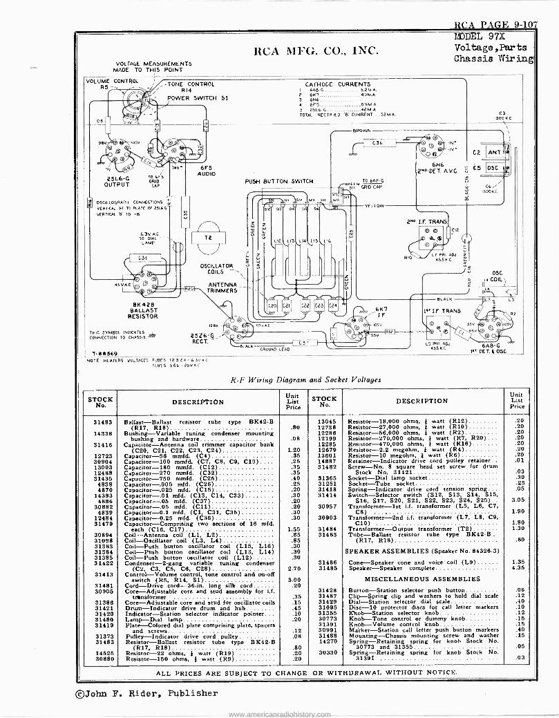
R('A PAGr: 9-107
RCA MFG. CO., INC. VOLTAGE MEASUREMENTS
MADE TO THIS POINT
VOLUME CONTROL RS
CIS
s
9BV.
7v.
25L6 -G OUTPUT
MODEL 97X Voltage ,Parts Chassis Wiring
--TONE CONTROL ' R14 . 2 POWER SWITCH SI
TO 6FS GRID
CAP
74V
OSCILLOGRAPH CONNECTIONS L. VERTICAL )41 TO PLATE OF 2516G
VERTICAL 'O TO B
6.3V. A.C. TO DIAL'
LAMP
C31
45 V A.C.
BK429 BALLAST
RESISTOR
THIS SYMBOL INDICATES CONNECTION TO CHASSIS. l T -B11369
6F5 AUDIO
T2
11, OSCILLATOR
COILS
ANTENNA TRIMMERS
128V
25Z6 -G,- RECT
CATHODE CURRENTS I 648.G 5.2 M.A. 2 647 40M.Á. 3 6H6 4 6F5 0.9M.A. 5 25L6 -G------- ......... 42M.A. TOTAL RECTIFIED $- CURRENT...._52M.A
,.---- BROWN
C3 1500 K.L. \
C36
PUSH BUTTON SWITCH TO 6AP-C GREEN
GRID CAP
' ele 152,1;1323 sza
51 U 5M SIS SK U VLL,
`12 `LIS L14
i
15 L16
1
C20
ter C21 C23
117 V.A.0
BLACK GROUND LEAD
C37
... ,:.
YELLOW
-IV.-
-IV' O ®/
6H6 2NO.DET. A.V.C.
C2 ANT.
05C.
C6 1500K.C.
2"2" I.F. TRANS
RIO
O ® 0.
m
C12
L7 PRI. ADJ. z 455N C.
Já
J
e I
61(7 I. F.
105V.
53V.
BLACK
1" LF TRANS.
n ll
LS PRÌ. ADJ 455 K.C.
OSA.
5
OSC. t.4 COIL)
L3 " L3
1 i
6A 8-G 1sT OCT. 1 OSC.
R2
NOTE HEATERS VOLTAGES TUBES 1.2,3. t 4. 4.3V. A
TUBES 566- 25V.A.0
R -F Wiring Diagram and Socket Voltages
STOCK No. DESCRIPTION
Unit List Price
STOCK O.
DESCRIPTION Unit List Price
31483 Ballast-Ballast resistor tube type BK42-B 13045 Resistor -18,000 ohms, } watt (R12) .20 (R17, R18) .80 12738 Resistor -27,000 ohms, * watt (R10) .20
14338 Bushing-Variable tuning condenser mounting 12286 Resistor -56,000 ohms, } watt (R2) .20 bushing and hardware .08 12199 Resistor -270,000 ohms, } watt (R7, R20) ... .20
31416 Capacitor-Antenna coil trimmer capacitor bank 12285 Resistor -470,000 ohms, } watt (R16) .20 (C20, C21, C22, C23, C24) 1.20 12679 Resistor -2.2 megohm, } watt (R4) .20
12723 Capacitor -56 mmfd. (C4) .35 13601 Resistor -10 megohm, } watt (R6) .20 30904 Capacitor -100 mmfd. (C7, CS, C9, C10).... .25 14887 Retainer-Indicator drive cord pulley retainer .01 13003 Capacitor -180 mmfd. (C12) .36 31482 Screw-No. 8 square head set screw for drum 12488 Capacitor -270 mmfd. (C32) .35 Stock No. 31421 .03 31435 Capacitor -750 mmfd. (C25) .40 31365 Socket-Dial lamp socket .30
4838 Capacitor-.005 mfd. (C26) .25 31251 Socket-Tube socket .25 4870 Capacitor-,025 mfd. (C15) .20 31418 Spring-Indicator drive cord tension spring. . . .05
14393 Capacitor-.01 mfd. (C13, C14, C33) .30 31414 Switch-Selector switch (S12, S13, S14, S15, 4886 Capacitor-.05 mfd. (C37) .20 S16, S17, S20, S21, S22, S23, S24, S25).. 3.05
30882 Capacitor-.05 mfd. (C11) .20 30957 Transformer -1st i.f. transformer (L5, L6, C7, 4839 Capacitor -0.1 mfd. (CI, C31, C35) .30 C8) 1.90
12484 Capacitor -0.25 mfd. (C36) .30 30903 Transformer -2nd i.f. transformer (L7, LB, C9, 31479 Capacitor-Comprising two sections of 18 mfd. C10) 1.80
each (C16, C17) 1.55 31484 Transformer-Output transformer (T2) 1.30 30894 Coil-Antenna coil (L1, L2) .65 31483 Tube-Ballast resistor tube type BK42-B .
31098 Coil-Oscillator coil (L3, L4) .85 (R17, R18) .80 31383 Coil-Push button oscillator coil (L15, L16) .30 31384 Coil-Push button oscillator coil (L13, L14) .30 SPEAKER ASSEMBLIES (Speaker No. 84326-3) 31385 Coil-Push button oscillator coil (L12) .30 31422 Condenser -2 -gang variable tuning condenser 31486 Cone-Speaker cone and voice coil (L9) 1.35
(C2, CS, C5, C6, C28) 2.70 31485 Speaker-Speaker complete 4.35 31413 Control-Volume control, tone control and on -off
switch (R5, R14, S1) 3.00 MISCELLANEOUS ASSEMBLIES 31481 Cord-Drive cord -36 -in. long silk cord .20 30906 Core-Adjustable core and stud assembly for i.f. 31428 Button-Station selector push button .08
transformer .35 31487 Clip-Spring clip and washers to hold dial scale .12 31386 Core-Adjustable core and stud for oscillator coils .15 31429 Dial-Station selector dial scale .40 31421 Drum-Indicator drive drum and hub........ .45 31095 Disc -10 protector discs for call letter markers .10 31420 Indicator-Station selector indicator pointer... .10 31355 Khob-Station selector knob .12 31480 Lamp-Dial lamp .20 30773 Knob-Tone control or dummy knob .15 31419 Plate-Colored dial plate comprising plate, spacers 31391 Knob-Volume control knob .15
and screws .12 30991 Marker-Station call letter push button markers .40 31373 Pulley-Indicator drive cord pulley .08 31488 Mounting-Chassis mounting screw and washer .15 31483 Resistor-Ballast resistor tube type BK42-B 14270 Spring-Retaining spring for knob Stock No.
(R17, R18) .80 30773 and 31355 .05 14525 Resistor -22 ohms. } watt (R19) .20 30330 Spring-Retaining spring for knob Stock No. 30880 Resistor -150 ohms, } watt (R9) .20 31391 .03
C24
ALL PRICES ARE SUBJECT TO CHANGE OR WITHDRAWAL WITHOUT NOTICE.
©John F. Rider, Publisher
www.americanradiohistory.com
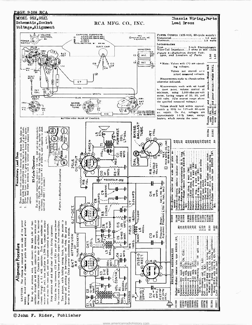
SAGE 9-108 RCA
CATHODE CURRENT6 Q. 6.5 M A.(vOL.MNTR. MiN) ZOMA (VOL fnMTR.MAR.\
..O.ISM.A. T.O M A
DTAL RECTIFIED '!" 59 MA.
.6V ¡
L__zsv.__ A.C. my.)
2.50 VOL. COMTRMAX aov)sii CONTR.MM
NV VOL COITE MIM.
Powae OUTPUT (125 -volt, 60 -cycle supply) Undistorted . 1.0 watt Maximum 1.5 watts LOUDSPEAKER Type 5 -inch Electrodyniunic Voice -Coil Impedance...3 ohms at 400 cycles Figure J--Radiotron Socket Volt-
ages, and Location of Parta
Note: Values with () are operat- ing voltages.
Values not starred a r e
actual measured voltages.
Measurements made to chassis unless otherwise indicated.
Measurements made with set tuned to quiet point, volume control at minimum, using 1,000 -ohm -per -volt meter, having ranges of 10, 50, and 250 volts. (Use nearest range above the specified measured voltage.)
Values should hold within approxi- mately ± 20% foi 117 -volt 00 -cycle a -c supply. On d -c, voltages are approximately 1 0 % lower, except heaters, which remain the same.
0000000olD» e mOiNN02N..O+IN9 m
OIDW Omi-m..m..m m91m Mf-Cimi-DiMOi mON t-aJ .... m.. OMN MN..náI..O.. M.-I.a ....MM....MM
©John F. Rider, Publisher www.americanradiohistory.com
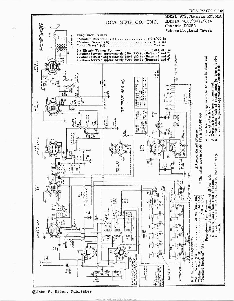
RCA PAGE 9-109
i 06aÓ?)
St 1
E
U,
úó
RCA MFG. CO., INC. MODEL 97Y,Chassis RC352A MODELS 98X, 98EY, 98YG
Chassis RC352 Schematic,Lead Dress
FREQUENCY RANGES "Standard Broadcast'" (A) 5401,720 kc "Medium Wave" (B) 2.3.7 me "Short Wave" (C) 7.22 me
Six Electric Tuning Positions 550.1,500 kc 2 stations between approximately 550 950 kc (Buttons 1 and 2) 2 stations between approximately 680.1,180 kc (Buttons 3 and 4) 2 stations between approximately 890.1,500 kc (Buttons 5 and 6)
ó 2
D Z
_J
OIi LL
..J -a mF Iz- F
----^v-i-
_mf u.,>F
N
z
e
9 X a-
g O
;S
ññ 4
H NQ
W N
E°i
ó
WÑ Zp
LZ
bI
1
L L
<^ _i
s .4 ú
©John F. Rider, Publisher
www.americanradiohistory.com
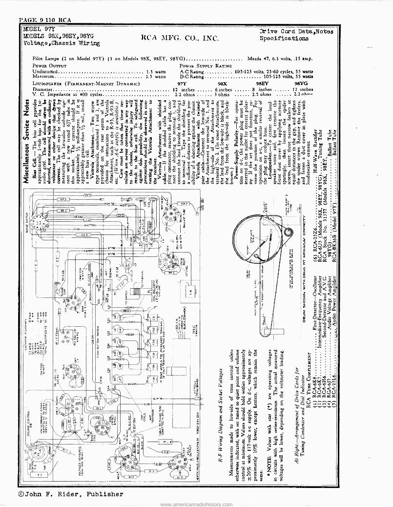
PAGE 9-110 RCA
1dJDEL 97Y DIDDELS 98X,98EY,98YG Voltage,Chassis Wiring
Drive Cord. Data,Notes RCA MFG. CO., INC. Specifications
Pilot Lamps (2 on Model 97Y) (3 on Models 98X, 98EY, 98YG) Mazda 47, 6.3 volts, .15 amp. POWER OUTPUT POWER SUPPLY RATING Undistorted 1.5 watts A -C Rating 105-125 volts, 25.60 cycles, 55 watts Maximum 2.5 watts D -C Rating 105-125 volts, 55 watts
LOUDSPEAKER (PERMANENT -MAGNET DYNAMIC) 97Y 98X 98EY 98YG Diameter 12 inches 6 inches 8 inches 12 inches
Z4 2, u tt .2-0.2.2 u r
o ú a >. y, o C u s ñ
u
.
v ....
2.2 nh m .V. C. Impedance at 400 cycles 2.2 ohms 3 ohms 2.2 ohms M
Ó ecA.ma a Çc w
w
:s,yú.nc;33g3` dtroOeQro.mc,O°m uvG
Oc
ô
%
fÓÓ uuuroÿuiL ºe1wséml5
N ÓQ ÿ w._ o ro ro
rEua_ÿº cúLOzú
.vflÿ3d^^W o,.. c p,w s . Eúó7uruwn
o uu_, uôä ó- À. u f.,-3.-.
ÿ rocÿ F.O Áuÿdu m u.3 ro< IQ ? :
,
c ú .°'
Ivb82s9Fd N 9jPifl1Hij 5 ji1HD1!J]! W^gcroulp7r^L
pC
E-...~°' óa pv. ...ru 1 Y ^ 1>EuccF \a a dgy¿>u ..e. ...9,, a°E
u TeoúQc' .Äuñ Qód°rQu"' E a.cc>.uó.cá": cu
dooH''rodá EoYcccad 2-2 e-.°:>, LoO japro,u,bmroúS ccY 5sauEaa9'2v. 2uEsuo . >3=cuÿ Ec,Sdu z..= .W 2. g pN-E y roWói' 00d
1pv Euy .5 ecyuÿu5Lds.eu
St a 0= 11aVlY
4
M0113Á
ase
03a Mo113A
3nls
eg
anls
« «« ÁF Ng; ºA ág Q
ñ
JY
Ar Q
e
O{-Fpp u> MS
Éá
r
xa I m N33a u
O C
ti
1
O
-:(94,*** fD
R
ag
-i r
1
N
aaa-
3\ .f
ra
\
9
e
IN
V a b a m E ; ro o, E
F. G a ro v w1 a>
Ñ ro
`.3
ro E7 .i
C Ñ aG. m C.é 4^ .á Ou
E C 7575, ô75
L
. b V .- v1ú 2
gO >;á á Ó 4b.ObbN 2, =2 M 2H
v
-le, O C c s ro
u i.20 Oq tlá q.rin+ans C .,3á
3GÓ .2p,
4 a rill c a el º ir é é ú : á d
a w °° 7 u
V xG u % .G .a Ñ Ñ 'C $ K
w > y Ç da, 3 V
:li a:2,2 101 a o -.4 '-R C . AL CA
° ^ l e ' E >. e
ro
ro ôbE z..8.m .c c.o ei * 3 ó º+I á E p>
©John F. Rider, Publisher www.americanradiohistory.com
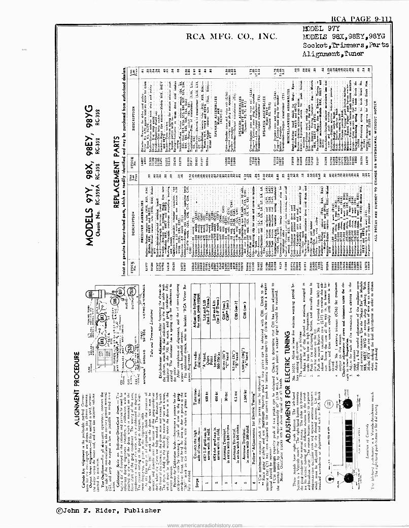
RCA PAGE 9-111
IH z W
W V J W CC
RCA MFG. CO., INC. l'J'JDEL 97Y MODELS 98.X,98EY,98YG Socket,Trïnnners,Farts Al ignment,Timer
mm; . . . . . . . 1
y . ' ß°$ .. .." x . . . . . . s . . .
w+ei
Zp111F.glwu
m
3
e C-
91
I! b!44° Ewnÿ§É4
1xa4!s!°. awäbeelyi
S
ÿ
3oa8sl
ó
sz a
5I
1 k
iS S
x_
1
"s^^:.m
E
é
y +
p.á5.
m
2 22= ú.
Já i!^T.3'
1n,° e
rE< -
:
iw i
á8
1é
ilä
I2
^^ á
: 1tm. ak mo'4 <n
S k- 0 w ill'
! SU41'
" 8
@ a2 ,s1
á;añQ°1S .«,,,
e1 ó 5
7d F
, 4
Ñ îAa8 S
s+
- <g Sa.
e mai °.i
:
8 8461 4m U0.w,m
1
ú á41 m -=
,«;al3;Reeg8B_1 .8am!1S1b;.lá r
ñvl; m$
111'x1 a9e1$káá.
B
m
e
;101
ú0
a1
§
-ard. hv
Um' ^m'
é4s
epyy
9
9 3
Ïng!órc b
t
?gale;'
1qe>.
Ykk°aaa3'ñ2a
41 ag 8aÿ8$ ás3
`u
=
1a
E
`
I' as
+
j
9
I n
:
úá i?z
a2 :a ñR . 2n y 52 y n 22 2 n 2 14! 5155 145 .. 22 122 2 2. ...a ....... y..
7# J g ggg g g gg Eáñ........3?...... w98 0l aaBR ! « !ñ8á : MI! g .....á«9S&R 14;é
z
2
á
m
2
á Káá
m 3y
é':
m ill ill
EI°.ealûas38á98 E
I
^
mI
q;
r m
mu. 4>'
11ai e Si Pill É8.
"ggms ggl Y
a
EL
i
%8
m
gá
b
:
.V;^ó
I
óáá^§_!# > u
ó
d .. : ó
-
gq
°a. uú
^. y . . .
:î.:.: :.,,... ú&:v Á :Owuaó^.óî1, uu u..uuw..u.-ó ?::ê:8:
d "`Núú"S dddd dd éáéèááá@dé JIwTTI IIII 1 é k k° 6S b°SÉ'° á ºOa ! . °. ö"g ° g'u
äaaáº31 úVÚVuuuúVuuuuVuuuu
ä.
u 3ó
ú: w u
olImáa c é llsóá3a"E$áxba9ibl°á1ñ16eSSeaewn úúV
I i !:+ g
S ,g a g a c w 3` ?
V
.::5 dds 3' aue ,
SSS' 993óyJ°>bb. ddd
I I 1.411177114144.4........- uuV
s s á 8
8
S g 3 ,.SSÿy
1 mYt .. g $'s5<"
ILA á8: i>>
uVuu
3
-e
É]
g;Sm3'
8
S
L
$ Y 'á"d 'Q71111 A a¡,.d'aa
^
: .q C 6 é
3d3ú
5
I ., ' : : : ma..ó :,;"rcrc wÿc aa _
°i Ei_epca 9.. F :t_..,,e- ...^..- r^ d
î:itIá4a°31m1
d6Ó l
r a.9.a.e.e:
a aaaaaaaaaaa
á er
"
aa
IA
z
` á 2y -
a ^ 2 y MI5< n2 .w 222 2y 2222 x aaay
y y:î$ : 3
22............ ..
r s
g E r a
,.5$ y 9 L
"`s<ae 5=se S
h'-;092
c9 ám^
yr_ZE>
;O
s y
E
3
e':-,z Pa 42-72;72e°1111.
Éa
213.1 ti r
óÿ9cro- Tÿÿ
MI qwá c.cmóm_
É . ó1g8 N§
IY 9 °°O ö»°. iw.L3x4w02è370
ac2wE y a_ 0.g vc` W_y 3 1..ó 1O
cE v ' vC12h>
n4uwh2EÑc .zá sÉ'.2
óirg» s»é I° aE°v . »13
12e.9
11 °. í 1ëásamuu
<g
:; 2.2.
..
i l I u g u
o
'.d°ud
g
= GS
d Q
.3.59r. 0 O'0.1p
$
' á U EOq
m <
Mg 13
e +i
eRm!). R 0 E g
ti éógE Ú'
9d
65l5Fg'E'FFÿ
m'S
.5d
e 2
é9
ú á.5
fi L<
5
g.. M
Cl m . N O
OIIwL VI il 3 .9 .9 ÿ' 5 av'ö si
,d ó m .9 .Q fl ç 3 ÿ c
y..y áV á É = úñ fi +Jag ó $_9+9$
s9 . : 8 Qgg$ .`g a 4 `KXaó U i Y N . 6 8 .`8 9
9 e
Ú áS e:9 v cm $.x; ° r^ . öi.óe ° = 5
rE » > V áo ` y cuEúé aó .5 aó .. 8 tl á
»>`.3 6 ú,t ó 9 F E i¢ c,
1::
gámm3xE, 5 wE: áwZ>Syr_4Étanó »3fVoÿ
átf.^5c.°.° é8.. ° Cea.ó á ÿd 1 ñés¿ó,'o°COÓ»» ro +>34°'t »>¡ É .. J
ñx v..H ó9 E»?¿w°y óc úcal cáSó V1ÿyQSGzx Zó+ByJáeo Jñ ÿ óÿ..M`es3.éa.3>- yvóúo o.ó ~óó.io`ásáññv,°.< o<7`.Eww3» ° ti V
r. 3 c ; W. :. - ... .., . a; d d - v J e é_.. ^v W z.__ . .2.Y >. .. ú b ca óEa C:
ñ .o,.ñ w4^9Gy ÿ.. scu+aÉX N r y +7<
ÿ 3a,Z óáÇ3y:VVaL
ñ W F c. á ñ CC
' le °o < i 3
.íji ° e2 -.1 -21.X -e.'3
t¡y :2::N .F1GC._ ú 6 n- gKy __.»...°,2,-E8 Y>
» OS G pOñ
'-'4'-q''''' ÿ0.°ÿC
`` et é -ñc =á.é ` (- -"
roTÚSro^n KCña+ÿ4 ñ ï á ñ E s myS ó i K` EN.9
.
I="`ÿ =º_` Üä. ro o
m ñ0 ïç .3, EYó ü $ñ
5 K° » 7.+. ó ,,,e4.. x' E
C ñt úz ñ
ñ Ó r C t w gr FCuw00 "c y.. » .>cñ É 3. -
©John F. Rider, Publisher
www.americanradiohistory.com
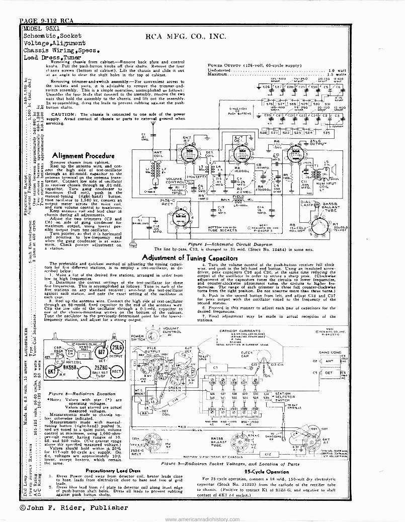
VAGE 9-112 RCA MDDEL 95X1 Schenatic,Sooket Voltage ,Alignment Chassis Wiring,Speos. Lead Dress,Tlmer
Removing chassis from cabinet.-Remove back plate and control knobs. Pull the push-button knobs off their shafts. Remove the four chassis screws (bottom of cabinet). Lift the chassis and slide it out at an angle to clear the shaft holes in the top of cabinet.
Removing trimmer -and -switch assembly.-For convenient access to the sockets and parts, it is advisable to remove the trimmer -and - switch assembly. This is a simple operation, accomplished as follows; Unsolder the four leads that connect to the assembly, remove the two nuts that hold the assembly to the chassis, and lift out the assembly. In re -assembling, dress the leads to prevent rubbing against the push- button shafts.
CAUTION: The chassis is connected to one side of the power supply. Avoid contact of chassis or parts to external ground when
0ÿ o - á $23 lno
"2 Li m 000 b r00
e2a
máá pas eoo P, i.
>Al "0 q q Oo
8,1. Alignment Procedure
servicing.
R -Remove chassis from cabinet. ç Eç ú Reel up the antenna wire, and con-
nect the high side of test -oscillator 3áá through an 80-mmfd. capacitor to the
antenna terminal on the antenna trans- . e former. Connect low aide of oscillator < °
º'«'« C g g to receiver chassis through h an .01-mfd.
ai capacitor. Turn gang condenser to Ä: minimum (full out), push to the
manual -tuning (right-hand) button, m5 c 3 3 tune oscillator to 1,560 kc, connect an n E C(..,f., output meter across the voice coil,
la and turn volume control to maximum. Keep antenna roll and lead clear of
chassis during all adjustments. Adjust the two trimmers (Ca and
C6) on side of gang condenser for maximum output, using lowest pos- sible output from test -oscillator.
Turn pointer, so that it is horizontal and pointing to low -frequency end when the gang condenser is at maxi- mum. Check pointer adjustment on a station.
.ni
"P.
IA V
é v
z4°
C.
-t á
RCA biI+TG. CO., INC.
CI 1
w0.r 0
ANT. COI L
oT
ó
POWER OUTPUT (125 -volt, 40 -cycle supply) Undistorted 1.0 watt Maximum 1.5 watts
125-400 75-250 MMF.
MOMISO 12-400 .'MMF. F MF.
4, C26 C27 Cut C29 C30 C51,16 T
F5126 527 528N129 530 531 DIRECTION 12s-400 T5-250 20-150 12-400
OF .MMF i' M F NORF. MMF. sue. aUTTONs C20 + C2I C22 + C23 / C24 +C2 ' C3
T ; -# 3-ISMMF.
6K7 R.F
VOLUME , CONTROL
RI -110.000. TOTAL
OET. COIL
200.sECT2
2526-G RECT.
-e" si
1.1 Ua.oN10 5O12
S Mrs. V
óai MFO.
R9 IMEO.
Li A
C15 .05 MFO
6U 7 DET,
-L RaIß000A
lC7 0.25 Para; R3,
= 2.2MEG.
CB .O1MFD
1.! R4
410,000.
R6
ISO,
D MCD
C9 300 MMF,
R5
25L6 OUTPUT
SFr
tZ ils.
C11 .035
FD.
5E0
C13 6 2 1MFO.
FIELD4A *ACS
OVV VfL
L6-400.
BOTTOM VIEW OF TUBE SOCKETS
C14 16 MCD
95n1 © AC. MFO. CO., I NC. P-54252-3
L.
as co, HUM NEUT.
COIL LT
DIAL" LAMP BK55B
BALLAST /TUBE
Ì0
RB OA© R7 IsOACOLO
0 170.507
O O S
Figure 1-Schematic Circuit Diagram The line by-pass, C12, is changed to .25 mfd. (Stock No. 12484) in some sets.
Adjustment of Tuning Capacitors The preferable and quickest method of adjusting the tuning capaci-
tors for five different stations, is to employ a test -oscillator, as de- scribed below:
1. Make a list of the desired five stations, arranged in order from low to high frequencies.
2. Determine the correct settings of the test -oscillator for these five frequencies. This is accomplished as follows: Tune in each of the five stations on any standard receiver; zero -beat the test -oscillator against each station, and note the exact setting of the oscillator in each case.
8. Reel up the antenna wire. Connect the high side of test-oaejllator through an 80-mmfd. fixed capacitor to the end of the antenna wire. Clip the low side of the oscillator through a 0.1-mfd. capacitor to. one of the chassis -Mounting screws on the bottom of the cabinet. Tune the oscillator to the previously -determined point for the lowest - frequency station, and adjust for a strong output.
OCT.
25166 BALLAST
TUBE
Figure 2-Radiotron Location Note: Values with star (') are
operating voltages. Values not starred are actual
measured voltages. Measurements made to chassis un-
less otherwise indicated. Measurements made with manual -
tuning button (right-hand) pushed in. and set tuned to a quiet point, volume control at minimum, using 1,000 -ohm - per -volt meter, having ranges of 10. 50, and 250 volts. (Use nearest range above the specified measured voltage.)
Values should hold within t 20% for 117 -volt 60 -cycle a -c supply. On d -c, voltages are approximately 10% lower, except heaters, which remain the same.
-n
Precautionary Lead Dress 1. Dress Power cord away from detector coil, beater leads close
to base, leads from electrolytic close to base and free of grid leads.
2. Dress blue lead from r -f plate to detector coil along front edge of push-button shaft holes. Dress all leads to prevent rubbing against push button shafts.
POWER SWITCH
VOLUME CONTROL
RI
DET. COIL
nEo
Issv_
-IlT V_A_C
25Z6 -G RECT.
21V. Ac.
J
Kc
n S31 STATION S25 -"SELECTOR
< 3W1TCH ,TD 551
ORIDaL2
i
ORc v`nl M cco.,INc.
P -M4 25T-0
GANG COND. C3 sso
C2 ( ANT. INC
OET. ,C KC
CS (
3-ls MMF.
4. Turn the volume control of the push-button receiver full clock- wise, and push in the left-hand end button. Using an insulated screw- driver, peak capacitors C20 and C26, at the same time reducing the output of the oscillator in order to secure a sharp peak. (Clockwise adjustment of the capacitors tunes the circuits to lower frequencies, and counter -clockwise adjustment tuns the circuits to higher fre- quencies. The range of each trimmer is three full counter -clockwise turns from the tight position. Do not unscrew more than three turns.)
S. Push in the second button from left, and adjust C21 and C27 for peak output with the oscillator tuned to the frequency of the second station.
6. Proceed in this manner to adjust each pair of capacitors for the -
desired frequencies. 7. Final adjustment may be made in actual reception of the
stations.
BLUE
CATHODE CURRENTS 0.5 MA.(WA cOloTR 5100
... ,2-0MA (WM .CONTRWA) O.nMA.
) 4T.oMA TOTAL R2CiIF120-5-CUAR2NT 59MA.
ELECT" CAP
C13á 4 C13 -CIA ® W a ,
540-0110 5130 -1200 a50 -I500 NC KC
BKsse BALLAST TUBE.
Figure 3-Radiotron Socket Voltages, and Location of Parts 25 -Cycle Operation
For 25 -cycle operation, connect a 16 mfd., 150 -volt dry electrolytic capacitor (Stock No. 81323) from the cathode of the rectifier tube to chassis. (Positive to contact Kl of 25Z6 -G, and negative to shell contact of 617 r -f socket.)
©John F. Rider, Publisher www.americanradiohistory.com
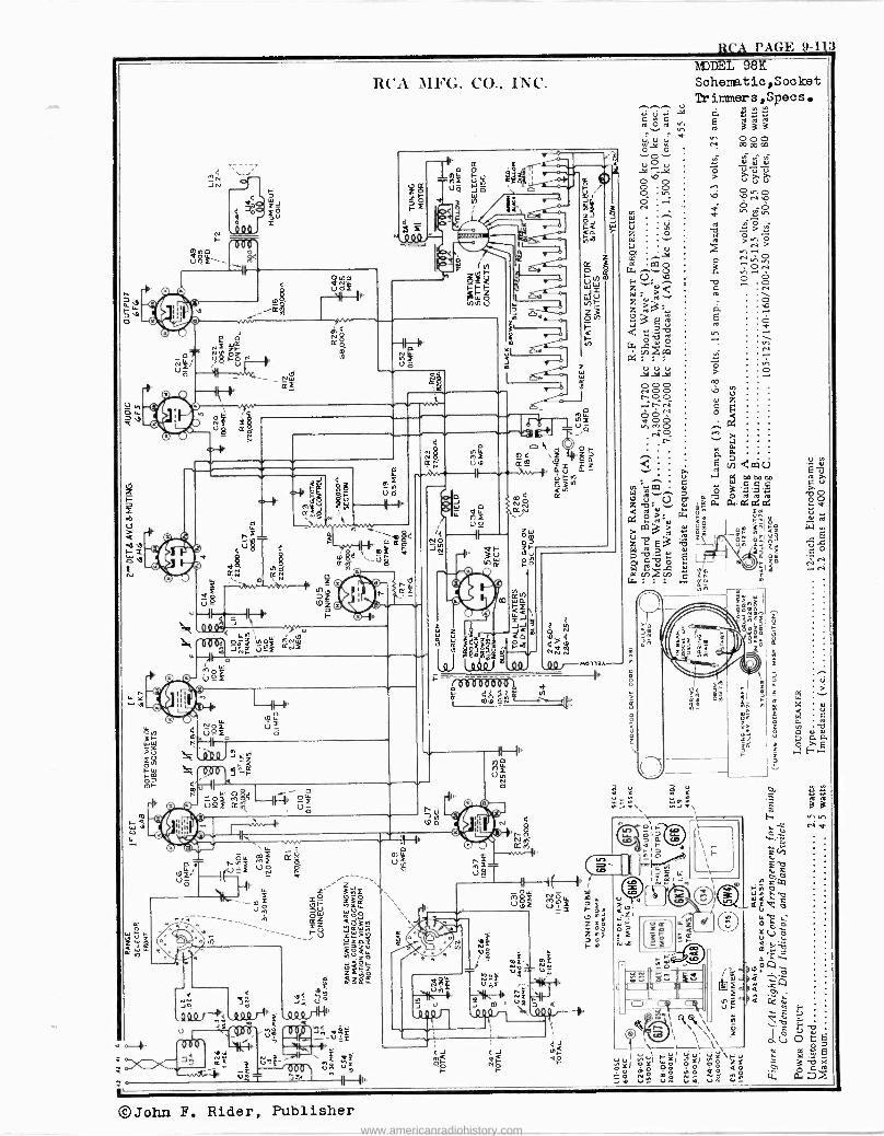
RCA PAGE 9-113
MODEL 8K Saheme.tic,Socket Trimme.rs,Specs.
bob b aaa ci 0 0 0
Ó,d p N co co co ...iO.... ' . . v 0 V i d ÿ Ñ
O b 0 > ú ÿ Ú
bNb .. V
©John F. Rider, Publisher www.americanradiohistory.com
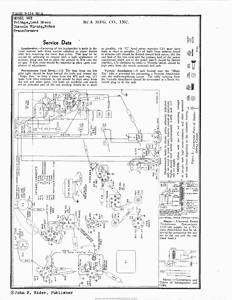
j'AGE 9-114 RCA liDDEL 98B Voltage,Lead Dress Chassis W r ing,Notes Transfarmera
Service Data Loudspeaker.-Centering of the loudspeaker is made in the
usual manner with three narrow celluloid or paper feelers after first removing the front dust cover. This may be re- moved by softening its cement with a light application of acetone, using care not to allow the acetone to flow into the air gap. A dust cover should be cemented jp place upon com- pletion of ádjustment.
Precautionary Lead Dreg.-(1) The lead from the left pilot light should be kept behind the bulb and toward the "Magic Eye," to keep it away from the 6F5 grid cap, (2) leads from mica trimmers to coil should be kept away from the coil and other parta, (3) leads on oscillator coil which are an extended part of the coil winding should be as short
RCA MFG. CO., INC.
M0113A
NA NIDrG
M0113A
M0113A
asa so a.L 03a- 'al D' 1B
o f
s possible, (4) "C" band series capacitor C31 must have leads as short as possible, (5) all leads from antenna board to antenna coils should be dressed toward back apron, (6) the one lead of the line cord and the primary lead of the power transformer which run to the power switch should be twisted together, (7) shielding on leads to Victrola switch should be kept away from the switch terminals and jack.
Victrola Attachment.-A jack located near the "Magic Eye" tube is provided for connecting a Victrola Attachment into the audio -amplifying circuit. The cable running from the Victrola Attachment should be terminated in a Stock No. 31048 plug to fit the jack.
a
F
á i
O
m
bb 13
>
G
d a o
ro
J l
Q
RED - SLACK (TAPED)
ROTC INSERT CONNECTOR
ATEE/TIAN° COMMON
CORRESPONDING SUPPLY RAGT NG IReNe
UNIVERSAL TRANS. CONNECTIONS
ó
S
a
T
I=
GREEN - RECT. F.
GREEN - BROWN-
RECT
B LACK-BRORw
-BROWN -- S LOE -
AMG.FI. B LUE - YELLOW -
MOTO« -.02-L -YELLOW -
BLACK -
YELLOW
Above - Universal Power Transformer Connections. (110 -volt supply for a Vic - trola Attachment may be ob- tained by connecting the mo- tor to the red and the red -
black leads.)
t o RCN
RROWN- Above - Connections and
Colors of Loudspeaker and Cable.
©John F. Rider, Publisher www.americanradiohistory.com
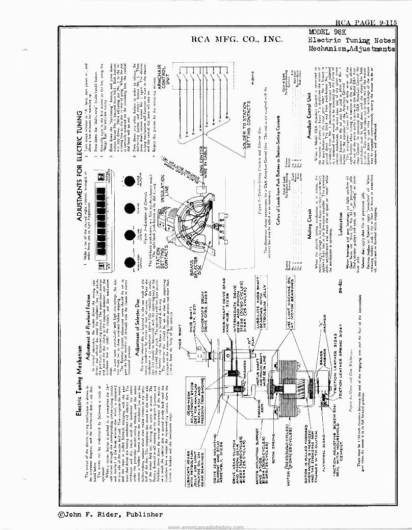
RCA PAGE 9-115 MODEL 98K Electric Tuning Notes Mechanism,Adjustments
©John F. Rider, Publisher
www.americanradiohistory.com
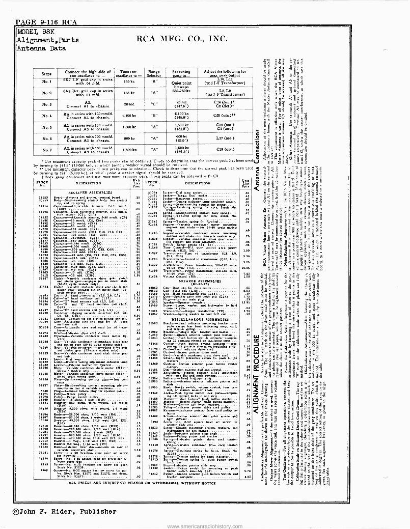
PAGE 9-116 RCA MODEL 98K Alignment ,Parts Antenna Data
RCA MFG. CO., INC.
Steps Connect the high side of test -oscillator to - Tune test-
oscillator to - Range Selector
Set tuning an: to-
Adjust the following for mu. eak ou ut
No. 1 - . gn cal' In serles with .01 mfd. 455 kc "A' Quiet point
between 550-750 kc
10, 11 (2nd I -F Transformer)
No.2 BAS Det. grid cap in series with .01 mfd
456 1. «A« Ls, L9 (1st I -F Transformer)
No.s AS. Connect Al to chassis. 20 me «C., 20 me
(147.5°) C24 (ose.)
CB (det.)t
No. 4 A2, in series with 100 mmfd. Connect AS to chassis.
8,100 kc "g 6,100 kc (1465°) C26 ()me
No. 6 A2 in series with 100 mmfd. Connect AS to chassis.
1,500 kc ^A^ 1,500 kc (151.5°)
CZ9 (nee.) CS (ant)
No. 8 A2, in series with 100 mmfd.
Connect AS to chassis. 800 lee ^A" 800 kc
(29.6°) L17 (osa)
No. 7 AI, in series with 100 mmfd.
Connect AS to chassis. 1,500 kc "A" 1,600 kc (151.6°)
C29 (ose.)
s rg :t.2.4 3 V >11 .21,9,x
ó39rT C 51
1s
PI <á W i
m3 St 9 G
5 " i V.8 v T C
>59 ^ e 1°1 2 GG
n 7'$
111::"2:.3:12
u<E >'^ a
'-. C Sr E.1 L i2 P-U v .2 -61,i VI Cxáá
el c <EáoVY ;3 <q s2(j2
C v eY` úBc Use minimum capacity peak if two peaks can be obtained. Check o determine that the correct peak has been usetly <
E F+'ó,00C
eu 8:-2i
w by turning to 141.5° (19,090 kc), at which point a weaker s gnat should be received. ' ;9: Use minimum capacity peak if two peaks can be obta ned. Check to determine that the correct peak has been used O 4,74 ^ .
« ö É ó ú ^ c É
by turning to 124° (5,190 kc), at which point a weaker signal should be received. C `Ê< 4'2
Y G Cfi 8 t R k d d't peas 'f two pe ks can be obtained with CA C ÿ s c ii
Ell.:
E Y ó.¿c Cós- C 55'ó >?.^, c°>,5m' z G ,. s.. a- c s <`«s o
l' -g.2 á'ó?óÿGÇ^ 1121;
N wC p i sgSS .. .. jn ̀
n v ef.D < y v. D C.c s'1 arGt c s 1 s_ä G 3:18-i
illillee:;111-ie =);:.21 g"
ggM_a9gú "e$1tX=ii.AiláB ;eC(3olc$g..ó.óo ,e
4557 ug ^ÿ1V V G ° ?Êó<óÉ°'" ó O(.5 ^ c Z .> `.=,:c:ô ¿
a,áF' .1 .. > ^ v : F <
oe
STOCK No.
gang condenser an use maximum Capacity
DESCRIPTION Li" prja
+
STOCK No.
a
DESCRIPTION Unit Lit Price
RECEIVER ASSEMBLIES 31364 Socket -Dial lamp Becket .40
31261 Board -Antenna and round teentinal board.... .26 13871 31461
Socket -"Manic Eyre Becket Socket -Toone ton wicket*
A5 .90 91449 to nisei body, Im contact Boer, 91985 dockst. SpckN-Tuning ivditats lamp tip .01
14714
springg voc and tip sprint
Ca(C211) Adiusta ble trimmer, 2-12 mmfd. 18 31293
12007 Spring -R tainngttinricgnt tip wring Spring -Retaining pro[ /or C.O. Stock No.
.01
81º92 Capacitor. -Dual adjuatnble trimmer, 3.50 maid. .60
312302202
512[9 contact body eprStuck Spring-Station-timingensnwring
.02
31º62 each section (C24. C25)
Capacitor -Adjustable trimmer, 5-80 meld. (CO) .40 .25
31º6º 8p 31º60
Temion sprint la ire, Stock No. .03
.01 12496 Capacitor -16 mmfd. (CI, C6{) .35 32142 Spring-Tmoion spring for Bywbm .01 31432 12948
Capacitor -20 mmfd. (C27) / Capacitor -33 meld. (C1)
.40
.35 31244 Support-Vnnable condenser motor mounting
support and etude -for 60-40 cycle mode. 12720 31270
Capacitor -100 meta. (COO) Capacitor -100 mmfd. (C11. C12, C13, C14)
-.36 .35 31246
ovary Support -Variable denser motor mounting
45
12724 14726
Capacitor -12o mmld. (Cl?. C38) Capacitor -150 mild. (C16)
.36
.36 suppoet and studfAdor 2 model. only. .70
31033 91453 Capacitor -600 meld. (Cº1.) .35 91438
unecycle
Support -Nana is denser ¢rin gear mown - ' g and Rub .60
31406 Capacitor -1.500 mad. (C2s) Capacitor --6,00o mmfd. (C31)
.36
.75 31º48 31248
52)asea
-iconintone
Tone Switch -Range twitch (Sl, n Tone Control -H .4. rove contra? n d poem'
.96
0548 6393
Capacitor -.007 m)d. (C18 C91, C{o) Capxnor-.0o7 mud. C)
25 .30 91í1e7
switch 24) Dint W tramtormet (1.8. 1.6, Trcii, 3.60
11395 11918 93ee 4739
Capacitor -.01 mfd. (C6 C21, C39, C59, C63). Capacitor -.016 m1á. Cs)8) cawe;+or-.o6 add. (c9) Capacitor -0.1 ofd. (C10, 018)
.80
.40
.ºo oto
31268 Transformer--Seco¢d H tranalormu (lelo, LIl, C33, C14)
2.20
º.oa 12464 30867
Capacitor -.0.25 mid. (C33, COO) Capacitor -0.5 mkt. (C19)
.8Ó
.80
31899 Tr 225-60 ci-Powu transformer, 106.1!0 .o)o cycle (Ti) 10.56
11403 6219
Capacitor -10 mid. (C34) Capacitor -16 mid. (C16)
1.16 1.86
31493 T 00400aformer-Power
eraWoemu, 106.140 .olts,
((RO) 31537 Clutch -Variable condenser drive gear clutch and pinion tear --engage pin on rooter shalt
31424 Vdume Coñvdle -
SPEAKER( ASSEMBLIES 1.60
(60-80 cycle mode. ode) .36 -F3) S164á Clutch -Variable condemer drive gear dutch and 13935 Cap -Duit cos for cantos .28 pinion gear -en [e pin on motor shaft (28-
cycle models only) n .46Coil-Field 12012 11930
Coil -Field coil (L19) Coil -Hum neutralising coil (L14)
5.90 .30 31593
31296 Coil -"A" band antenna coil (LS. L6, L7).... Coil -"A" band mediator coil (L17)
1.30 1.05
91976 31302
Cone -Souks and voice coü (L13) Plug -a -contact male lug
1.76 .25
91294 37496
Coil -"B" band antenna coil (L3. LO) Coil -"B" and 'C' band emulator coil (L16,
.60 31300 14368
Speaker -Speaker complete crew, washer, and lorkwber to held Screw--SS a
10.95
31297 31290
Coil -"C" band antenna coil (LI, LI) Cmdeme-3-gang variable condenser (C3 CO
C7. C8, C32)
a6 .80
655 14357 14357
ants m yoke t
to Wnndo-Spring co Wubsr-Spring wisher to hold fiert tail field
.70 1.06
.06
31231 Contact -Contact tip for setionyatting contact. .0e MISCELLANEOUS ASSEMBLIES 31280 Cor d(o core and dead for A" baud
oscillator coil 81303 Bracket -Band indicator mounting bracket mm - 31º69 Cor core re and stud for i4 tram- formers.16 Die[ on band indicating strip, cord
pring .40 71273 31440
Drum -Indicator driverot drum heel -Variable coedmser drive motor fly, Flywheel -Variable
heel
.60
.25
31982
91945
Bracket -"Manic Eye" bracket and holder Button -Station selector switch pink button. Carina -Push button meth contacte -comprit
.22
.15
31º36 Gear -Variable condenser intermediate drive gear and pinion near (60-60 cycle model. only)... 60 31344
inn 30 ecte riveted r¢ insulating sMv Contact-Pwh button a tch corium -con .70
31846 Gear --Variable condenser intermediate drive gear d piniongear (46<yde models only) .40 31278
pritinn 39 contact. 'vatw on imulet.g min. Cord -Rani icator drive cord
1.20 .12
31239 Gear --Variable condenser knob shaft drive gearand
hub .as 51º61 31483
Cord -Indicator pointer drive cord Cord -Variable condenser drum drive cord
.60
.20 Lamp -Did Iamb 17 41464 Cover -Eight protective coven for posh butte
r. 11480 Lamp -Electric tuning adjmtnrmt indicator Wrap 2e 31309 Cuakion-Station selector push button rubber .08
31243 JIº93
Leather -Friction leather for flywheel Motor-Variable«4condenare drive motor (MI)- .04
31451 cushion
Dial -Station selector dial and areal ,Ot .95
31º36 Motor-Vemable only
drive motor (M1)- 6.60
31356 Exntchmn-Station e)xerr dcci eerrtehem
31228 60-60 cycle node. only
Platt-Sn r tioneettieg contact plate ern- 4.88
31304 only -)es dial and puck button.
Indicator -Band indicatortrip 3.66
.16
31527 tun
Plate-Stationeettmg contact mounting plate - 46 31306 Indicator -Station selector indicator pointer and wo
6060 mounts on rear of variable condenser
Plug -4 -contact female plug for speaker cable .50 .30
61Jú6 I[nob--Rana .wie«h..pWme control. tree con- trot or station selector knob .12
31271 31272
Paley -rotor Dinky Pulley --Range switch pulley
,pa .40
31346 Lock-Pueh button switch lock plate--compr - leg 10 contact locks in one strip .80
14560 31431
Reimer -18 ohms, } watt (R19) Rejator-220 ohm, wire wound. 1.5 watts
.20 31458 53467
Marker -'D.1 Tuning' e ll button marker... Parker -"Record Player' push button marts..
.01
.Ol
31430 (R26)
R.s,tor-5,200 ohm, wire wood. 1.6 ware .18 91589
91860 Markers -Station call latter markets Pulley -Indictor pointer drivecord Dpol,
.36
.10
14284 Resistor -22,000 - hmm, 1/10 wan (54) ohm, .02 14887 Retainer -Indicator pointer drive cord pulley re
+at^er .O3
14167 Resistor -º7,000o ºBeat. (R53) .15 .10 31306 Screen -Station w m end dial color seed
11300 Reaktor -33,000 oh, 1/10 watt (RO. R117,39º3 Screw -Not N us6-32 moue head wt screw for '4ohm,
12010 Enamor -64000 ohm., 1/10 watt (529) porter slide stop .06 11398 Be.tor-5:40,000 ohm, 1/l0 watt (Rio)....
.16
.16 11210 Screw-Chusv counting acrewd, w.dben, and lot-ledin for one Marie .05 12244
11497 Reistor -440,000 ohms, } watt (Rot) Reidtor-430,000 ohms, 1/10 wan (Rio)
.20
.18 31287 31347
Shaft -Indicator pointer lido shaft Socket --Pickup socket and bracket
.15
.30 11482 14013
Resistor -470,000 ohm, 1/10 watt (Si. R8).. Reistor -1 mug., 1/10 wan (R7, 550)
.16 13038 Spring -Indicator pointer drive cord mason 6131 Resistor 2.2 meg., 1/10 watt (R3)
.16
.16 31418 Sprung -Variable drip .08
91439 Rotor -Selector rotor dime -mounts on rear of sh variable rondenur alt 1.18 16270
modem.. cord tendon
Spring -Retaining Retaining opting for knob, Stock No. 06
31241 Screw -it x 20 needles, cam print set xrew for .02 31213
31366 Spring -Tension wring for band indicator
.06
.03 14350 Screw-No.é 332 square hew sot screw for et 31313 span[-Tmaien spring for push bane twitch 4119
later Cam Screw --No. 8-32 headline sat screw for gear,
.03 31307 Stop-Indicatorlepointer slide stop .30
4866 Stark No. 31239
Screw --No. 8-34 square heat set acrew for peal- .02 31360 Seetcn-Pickup switch for mounting on push
button switch assembly (S3) 2.70 ley, Stock Nog. 31471 and 31272, and drum, 31312 Switch -Station selector push button switch and Stock No. 61273 .03 bracket complete 4.28
ALL PRICES ARE SUBJECT 'TO CHANGE OR WITHDRAWAL WITHOUT NOTICE
14. r2 ^Sea
.rgm2B'S E.2sa .c o c â e v 5 c s ñ <.Ey é5¿Fst"5Y 'c^^ wG óa3 .5 `wE
W °e s5 i ̂ CC y33e512,cª ÿ z.9ä5EY.:A >^^u 9rMñ W gcYE ä5 éú.cQ
r .. ey <.c :O
`,r? .ye °.r..-= _ O`' 5rw°5 ác'v23.ó.6 .n ß.t ve3 2é:E`ä u^ u !- ;..SS es 3ÓÉ -5.ºÉ5 3 Gm " '- 4.2. ' ' - t 1 9 g . t «tee ei eáOy ssncÑa'sÿ él
S r°r5 711 M 15' jY21m5
V. Joc'c YJs . ` a á°5 c
8L; rg °' Y
cÿ p ú 4. °'m
li 11
w
jsgus5
1
S ñV9> 5= ':-f.d^ 1e,33 33355' 3.à
gd
5B a SéoEo e
O ém..,°u.9m `` 5 é á 7y ü Cñ g C i .- O VVVIII
p ;e g"~ m0Gm'3 17.5
g 18..rJ
.$
G Fau mYs8t9 a 53 35 . BEa3me
©John F. Rider, Publisher
www.americanradiohistory.com
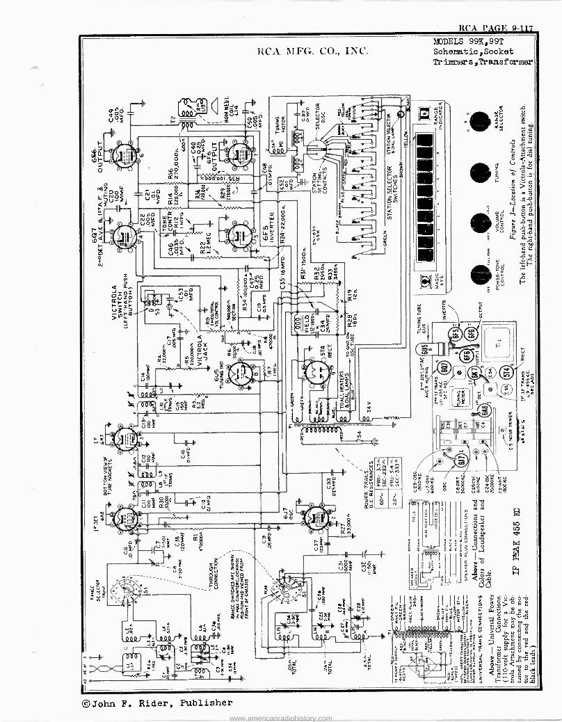
RCA l'AGN. 9- 117
? o
0'O_ UF
RCA MFG. CO., INC.
1= N
\A hl ZJQ QrY`/7". UJ -1- 0
I- ",,,---z ,OC,OIL UOf
§
n_o L uOLL f
-,ci, Ñ R \ .4, k
. m N KN
're. \ -
r-__!z ...._ 4
4u$ 4 ox Cru
2r 91N m ' >O-
sg z3 u- tGZ
'r(-I/! _ q w
'4.<JVN' 0.111 O 94 ¢ÑN
O!
r
Q
,p $4 a
r
M
4
4 O o N N
Ñ
L
4 o o
e q NJ 0
M flN Mn CLÑ ardi
tr,
in
r ! r
c
óoóùóD000l
2
íO9
2
N
W
z
Ñ
MODELS 99K,99T Schematic,Socket Tr immers,Transformer
K wo l7 Q
t a a u
I IsI Ió
¢ui
I,II:. I I
6 ¢
_.*.Ó1
Ei,
é
O_oZ
=1= óN> d LLu3a"!
/'L'a fl , mWm'
pÍL f
ro-N ÿ C ro.09+'
4 á pE «.O
. .ç
ro.TyC cuvro i. E,h"p " ;
1
Lo 0. ^ , i¢ ,9 2 ¢ j1:i1 ¢
%.ó I
©John F. Rider, Publisher www.americanradiohistory.com
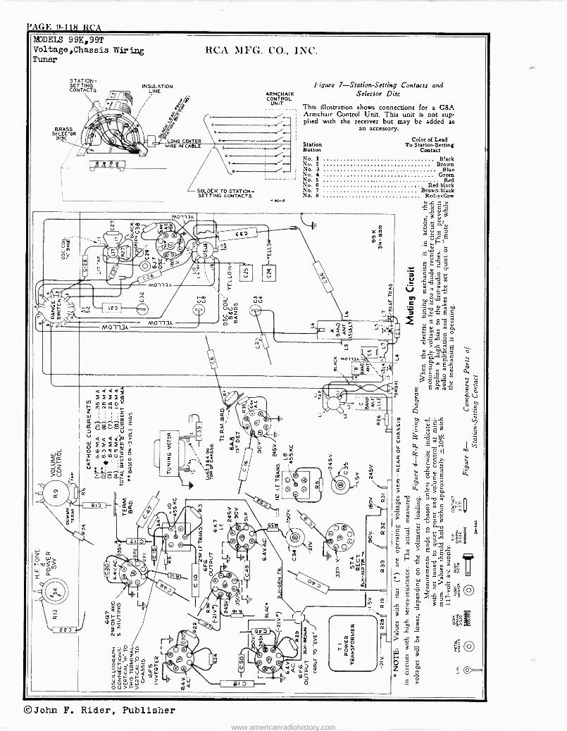
PAGE 9-118 RCA MJDELS 9 9K, 99T Voltage,Chassis Wiring Tuner
STATION- SETTING INSULATION CONTACTS n LINE i
pp F o ~ f J i Q
7yr S RASOR 1',t`1 v~f DISC 1 À\: 7
MO -113A
M0113A
M01131.
z
RCA MFG. CO., INC.
Figure 7-Station-Setting Contacts and ARMCHAIR Selector Disc CONTROL
UNIT This illustration shows connections for a G8A Armchair Control Unit. This unit is not sup- plied with the receiver but may be added as
an accessory.
SOLDER TO STATION - SETTING CONTACTS
it -
1.66416
Color of Lead Station To Station -Setting Button Contact No. 1 Black No. 2 Brown No. 3 Blue No. 4 Green No. 5 Red No. 6 Red -black No. 7 Brown -black No. 8 ..... Red -yellow
r
ú MOl13Ayu
c'V ^ w
^ ú N p v
E g 5 +. v'
2 sv CZf '2.41
P. O üN ro e u
c'^m em
7 u'^ y
m c O
^d Aa ` m C o e ^J0 O,m ê ó'a^
ú E T.4°V7.:º
0. et c we...
ó:--,.o; E Oáa ñ Eag
g
ñ> ó v e d
M-ä1 = Q
c tl
la Ô (7) y
a tl
C G O ^
ú
W t,
O O s
c p cv n a eo d C C :o . b.c fÑ
> é %>
o a Ç íé ú º -º2
8 -7,1
O N > E O - L O O
``3.p ÿ a á >a C
Ú O
u O b m^ e
v C d
Ñoo > >
.. 5> ú 7. LL3
; d äE- >zo
O
> s
t$
O u z *
O
©John F. Rider, Publisher www.americanradiohistory.com
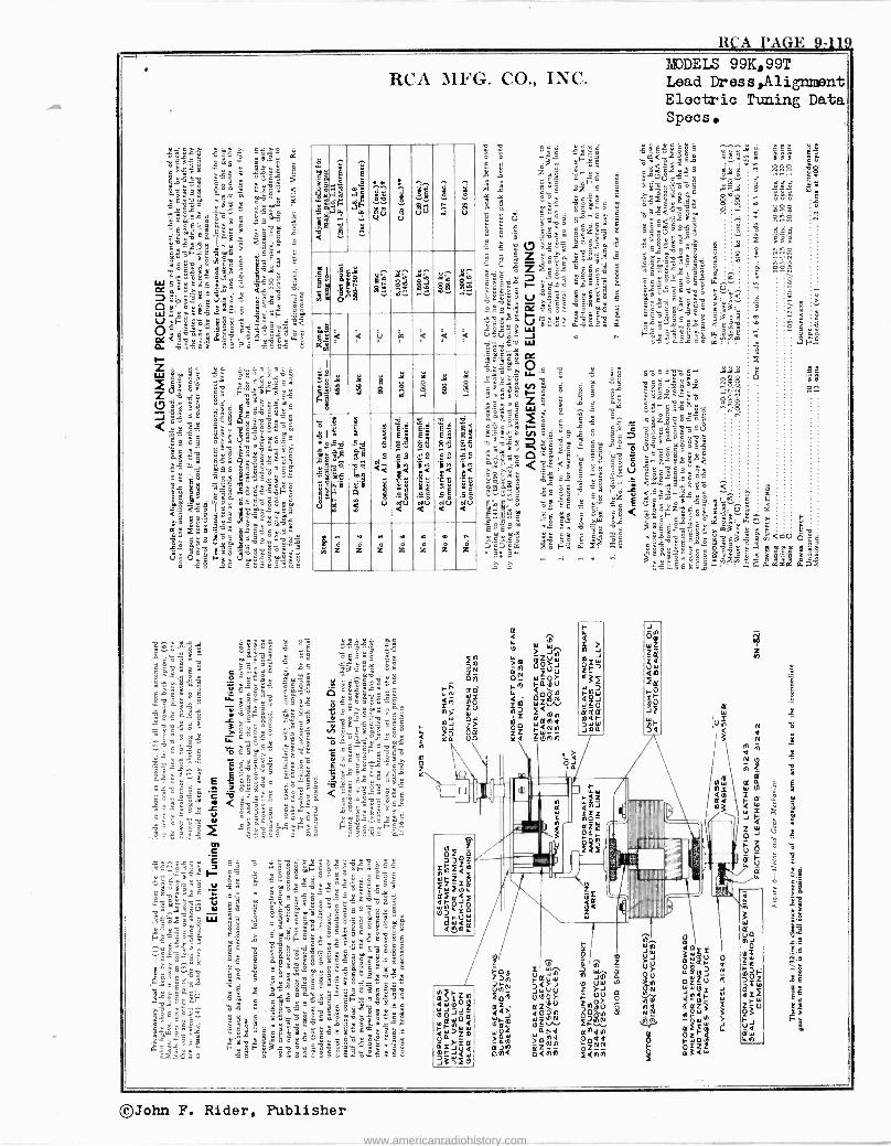
RCA PA GE 9 119
y;tBi: 4: ..-5" 4. 11-7.5
s
â
oiái3 ms x i
D
`11tEE";"c9,t<U_$`3«ñcó.ïE°-ñ.
`s r :::::7:::::77;8i" 'l.i:<e"¡: «`
"cé1II3oFá8C "ma
"o 9äg" $A9gs.ë c °É;ä
ä==éW6É 'Wo vgx Ç ó 1.,,,..i.
ÿaf?ñö $ácy Er3_á"W-
d<9y3ï 3S? «gE"
RCA 1IFG. CO., INC.
mx i ,.áS
<5
1 gq
O Ff
@ o
.1..
C4
Y
.. ',3,-.-. ó gU
E
8
J 9 ÚV
? .7
a
V
§ io m
S ÿ
G8 'Sae U g: C
82 m..
yh v yç a .
el al < < a7
0 < < <
I
0
i 8 8 g s . 8
a11 oBd
«SS i «ow
U
Ge -F
b
1
.E.d
;1 E9 'i O
m
0.E <<
u I UUUUU
d
8" E 3< " 5¿
ä
e9
sO
fit .f., .7'.
.51
d
C 881
JE
Éé
.51
d
E 8 38
:< ri .22
., d z á z n
z z n
z o
z ó z
7.U.'1-14:- £ç óá : é « ° =eEr...sx,ä Uá,a`y"-`3.`sy
fix<x° «*"9 c -..Y.:aá3se °
ß a 5-¡ é D 3 ú3 óó º° e0
_r9r`Ys" +.EEsB:YE 5 `É5= g2
`'8; gé3?'E r:E y
.etCo$céc9ó ,ag
"2>Ly É = BSá"óIIäc.
zsieÿó$a g«ä .21,4-1:1-11:".!:..q "
c ò 0 A ° ß°_ ga3ÿS"$i "s 3«l ºC
DrvEL +
A 3 L . r 9 S Y ' E r ` ` :
A o r -`E
~ys~ó3>:.."31c8rc=y.:
: C ' xr '
c Zra . E.,
"c
9z4$ 5
é:t vcxg
i ." s 'g-eji áp Yo
ú 3 r V4'3 IIy
c Z£Eóa « c : >4:012. c>fi9a g 3 00=v w,°aYs
IIS
u ?gee cFE" 5 éó°y y 1 "óigO
111
5 áv`«: Ú ñU p 3 o r - W
mö
-g;
=1-4 roó3 ñv °;°3E $ ¿o. ` e s ".: ä ï é H á c $e
9 Ó º;2 «a ^yá` V º` V 8 é:r : <'<S 1 v rYr IIII
a ;1 - y "2' !E "'g" s á`" s <
.1 -ése `" w
.b :ó ±ó [2.%'. ä
.m x8
MODELS 99K,99T Lead Dress,Alignint Electric Tuning Data Specs.
y;Ey$a5
"- E é
3' E@ogab" -E5 ay Lo'XC t ó1ó
W Fr u'ñE$tis"" 'L5ú8 Eo : ia°
3ó-9.0Có
u°o"z?fioô> a " Ñógaóâ1,"a } 5 "
ó -C E a rr ® s.E 3r r 3""s s gÿi`
x°.2 o°ââ2 cfAi
c$Yw
úy d.
ó
sç r.
©John F. Rider, Publisher
www.americanradiohistory.com
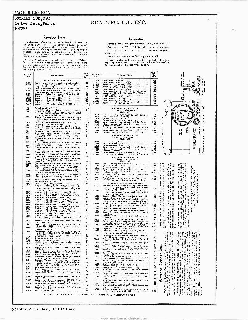
VAGE 9-120 RCA MODELS 99K,99T Drive Data,Parts Notes
Service Data Loudspeaker. -Centering of the loudspeaker is made in
the usual manner with three narrow celluloid or, paper feelers after first removing the front dust cover. This may be removed by softening its cement with a light application of acetone, using care not to allow the acetone to flow into the air gap. A dust cover should be cemented in place upon completion of adjustment.
Victrola Attachment. -A jack located near the "Magic Eye' tube is provided for connecting a Victrola Attachment into the audio -amplifying circuit. The cable running from the Victro a Attachment should be terminated in a Stock No. 31048 plug to fit the jack.
RCA MFG. CO., INC.
Lubrication
Motor beatings and gear bearings; use light machine oil.
Gear faces; use "Pure Oil No. 611" or petroleum jelly.
Dial -indicator pulleys and rails; use "Castordag" or petro- leum jelly.
Selector disc; apply thin film of petroleum jelly.
Friction leather on flywheel; apply "neatsfoot oil. When replacing leather, soak it for at least 24 hours in neatsfoot oil, and insert in flywheel while dripping.
um, CS Ed á v o
c s S j 0
ec
o ú
4.7,/ .._ ñ
miE É< á á y4
É ÿ Tw g V m
m a..rj
° ° C < si Ç C
°q ° =E01- ,ó Ch ó
h ,.c.c Ccío PU wÊx- v. /
có Al i^ z 'x 1:. e5 flL ÿ ó>. 9 tb
° Mc c ro'á c á fL
E 1Ed2á g,v °3 <E.(;r: _ <; - ai c iy"c w <L,-Hax= ö>=E=
_Ss x24 e..2,9
ú 5 T ú $ l c ó,i: E p
-
<c ...,'L uúS E§ E e
iú p c
V,: G wA M .. a>'ñL,^,c' `
° C ú 01'1 .S1:1'7,2.212 c19c s.YU6'c-O.ô `Q{Vc iñóñ ofYOJ5v9.rc
C .: .,éoú tósáÿw`s C
JÌ a á g$r°C 4úC a.83.--5 vc'3
q cú"e útry.u+y>>°uc . c
° C
'j1.32§ C °^ e
< e ÿ.ñ ñ c
os^9v
.rr, >2;7,2 ti,<--0-.:it-">d<CEw .(úú>ovE °6 ro E c i ̂ º X ó > c E' ALL PRICES ARE SUBJECT TO CHANGE OR WITHDRAWAL WITHOUT NOTICE.
,°, áiFá F°cECóE
STOCK No. DESCRIPTION
Unit List Price
STOCK No. DESCRIPTION
Unit List Pries
RECEIVER ASSEMBLIES 12724 Capacitor -120 mmfd. (CS7, C38) .35 31253 Board -Antenna and ground terminal board... .116 12725 Capacitor -150 mmfd. (C36)) .96 31229 Body -Station -setting contact body, lee contact
tip and tip spring .18 53439 31033
Capacitor -560 mmfd. (C28) Capacitor -1,600 mmfd. (C26)
.
.3636
12714 31292
Capacitor-Adjurtable trimmer 2-12 mmfd. (C99) Capacitor -Dual adjustable trimmer 9-90 mmfd.
1.60 91406 30309
Capacitor -8,000 !d. (CSS) Capacitor -.00911 mid. (C46)
.75
.40
each section (C24, C25) .40 4838 14393
Capacitor -.006 m(d. (C37, C22, C49, C50).. (CB C38, C CaCp52, 83, C39,
.25
31252 Capacitor -Adjustable trimmer 6-80 mmfd. (C5) Capacitor -15 mmfd. (CI, C54)
.25
.85 11315
tor -.01 mid.
Capacitor -5Ä1S mid. (C36) AO .20
12948 Capacitor -S3 mmfd. (Cl) .35 30882 Capacitor -.05 mid. (C9) .40 31492 12720
Capacitor -20 mmfd. (C27) Capacitor -100 model. (COO)
.40
.95 4839
30985 Capacitor -0.1 mid. (C10, C18) Capacitor -0.26 nild. (C33, C.0, C47)
.30
.30 31270 Capacitor -100 mmfd. (C11, C12, C13, C14).. .35 30887 Capacitor -0.5 mid. (C39) .30
6212 Capacitor -is mid. (C36) 1.36 SPEAKER ASSEMBLIES 14631 31237
Capacitor -25 mid. (C34) Clutch -Variable condenser drive gear clutch and
1.55 (Speaker RL -83-H4) Model 99T
31544
pinion gar -ngag` pin on motor shalt (50/80 ycle odehes only)
Clutch -Variable condenser drive gear dote!, and .9b 19358
13866 Board -3 -contact reproducer terminal board... Cap -Cone center dust u D
.15
.25 pinion gear -engages pin on motor shaft (26 cycle odeis only) .46
11254 11469
Coil -Field coil (L32) Coil -Hum neutralizing coil (L14)
9.86 .30
53299 31298
Coil -"Am band antenna coil (Lb, L6, L7).... Coil -"A" band mediator coil (L17)
1.90 1.05
31310 6099
Cone -Speaker cone and voice coil (L13) Plug -6 -contact male plug for speaker
1.76 .30
31284 51286
Coil -"B" band antenna coil (L9, L4) Coil -'B" and "C" band oscillator coil (L16,
.36 31309 14369
Speaker -Complete Screw -Screw, washer, mid lockweher to told
in
11.20
31297 Coil- L18'C"
band antenna it (L3, L2) g0 14534 Transforme.85 core
r --Output transformer (T2) 995 31290 Condenser -3 -gang variable condaser (C3, C4, 14357 Washer -Sprint washer to hold field coil .08
C7, CO, C32) 6.60 SPEAKER ASSEMBLIES 91231 31289
Contact -Contact tip forstation-netting contact Core -Adjustable con and stud for -t trans-
.08 (Speaker RL -70-112) Model 99K
31260 Core --Adjustable core and stud for "A" band 16
15886 Cap -Duet capfor a cater .03
31273 oscillator coil
Drum -Indicator drive cord drum .35 11234
11469 Cal -Field 1 (L12) Coil -Neutralizing coil (L14)
9.85 .30
31240 Flywheel -Variable condenser drive motor fly- .80
91275 Cone -Speaker cone and voice coil (LIS) 1.75
31239 wheel
Cur -Variable condenser knob shaft drive gar .25 6039
31590 Plug---4-contact male plug for speaker Speaker -Complete
.30 12.36
91438 and hub
Gear-Variableyy condenser intermediate drive .65 14394
14357 Trasfonoern-Output transformer (T2) Washer -Spring weber to hold field coil securely
9.86 .06
31545 S
GeasaVnrcikl eeonám0:e8r0intérrlmeáiaa árively`ear 60 SPEAKER ASSEMBLIES
11891 and pinion gear (25 cycle models only)
Lamp -Dial lamp .40 .17
(Speaker 5L70 -E2) Model 99K
31480 Lamp -Electric tuning adjustment indicator lamp .20 13868 Cap -Dust cap for cone center .09 31243 31248
Leather -Friction leather for flywheel Motor -Variable condenser drive motor (M1)-
.04 11234 11489
Coil -Field coil (L12) Coil -Neutralizing coil (L14)
3.86 .90
31235 25 cycle models only
Motor -Variable condenser drive motor (Ml)- 6.50 12867 5039
Cone --Speaker cone and voice coil (L1S) Plug -4 -contact male plug for speaker
1.95 .30
31229 50/80 cycle modal only
Plate -Station -setting contact plate -less contact 4.85
.45 14535 14358
Speaker -Complete Screw -Screws, washers, and lockwashen to hold
12.90
31227 Plate. -Station -setting contact mounting plate- mount. on of variable condenser .50 14534
core inyoke TransformerOutput transformer (T2)
.04 3.85
5040 91271
Plug -4 -contact female plug for speaker cable.. Pull pulleya
.30 14357 Washer -Spring washer to hold field coil .08
31274 31250
Pulley -Range Range itch pulley Resistor -Voltage divider comprieing one 1,500
ohm, one 2,950 ohm, one 3,400 ohm, 12
20 31303
MISCELLANEOUS ASSEMBLIES Bracket -Band indicator mounting bracket corn -
pinte less indicator strip, cord, and tension ohm, and one 180 ohm sections (R19, R28, 531, R32, RS3) .90 31276
spring -Model 99K Bracket -Band indicator mounting bracket con.
.40
14284 13998
Resistor -22.000 ohms, 1/10 watt (R24) Resistor -22,000 ohms, } watt (R4)
.15 .20
Pete Ims indicator strip, cord, and tension spring -Model 99T .40 11300
12454 Re.iator-33.000 ohms, 1/10 watt (R27, R30) Resistor -33,000 ohms, } watt (R8)
.15
.20 91282 91958
Bracket -Magic Eye mounting bracket and holder Button -Station selector posh button
.22
.15 11281 14580
Reistor -100.000 ohma Resistor -100.000 ohms
1/10 watt (R34).... } watt (B9ó)
.15
.20 91346 Contact -Push button awrteh cone eta--compris-
ing 10 contact. riveted on insulating strip. .70 11398 14284
Resistor -220,000 ohms Reaistor-220,000 ohms
1/10 watt (R14, R36) } watt (RS)
.15
.20 31344 Contact -Push button switch contact.-oom ris -
ing 19 contacta riveted on insulating strip.. 1.20 11453 11452
Raiator-470,000 ohms Resistor -470.000 ohma
1/10 watt (R16, R29) 1/10 watt (R1)
.15
.15 31278 91281
Cord -Band indicator drive .ord Cord -Indicator pointer drive cord
.12
.60 12485 12019
Resinor--470,000 ohms Resistor -1 meg., 1/10
} watt (Rs) watt (R7, R4s)
.20
.15 31293 31456
Cord -Variable condenser drum drive cord.... Cover -8 protective coven for push button
.20
31056 5191
Resistor-1.2 meg., 1/10 watt (R24) Reistor -2.I meg., 1/10 watt (53)
.15
.15 31359 Cuahion-Station button .08
31233 Rotor -Selector rotor disc -mounts on rear of selector plats rubber
cushion .08 31241
variable denser haft Screw -fl 20 headlea ccne point set screw
1.16 31451 31356
Dial- a Station selector dial scale d crystal... Escutcheon -.-Station selector did tcheon-
.96
4119 for flywheel
Screw -No. 8-32 headless set screw for gear .02
31381 less dial ensile and push buttons -Model 99K
Escutcheon -Station selector dial tcheon- 2.85
14360 Stock No. 31239
Screw -No. 8-32 square head set screw for .02
31304 less dial male and pink buttons -Model 99T
Indicator -Band indicator strip 8.20 .15 selector rotor disc .03 31905 indicator -Station selector indicator pointer... .40 4688 Screw -No. 8-34 square head ecru, r for
pulley Stock Nos. 31271 and 31272, and drum 31355 Knob -Range switch, volume control, tone con -
trot, or station selector knob .12 Stock No. 31273 .03 31348 Lock -Push button twitch lock late-cu u- mpr 31964 19871 31251 91985
Socket -Dial lamp socket Socket-Magipo Eye socket Socket-Radiotron socket Socket -Tuning indicator lamp insulated socket
.20
.46
.25
.30
31589
31457
ing 10 contact locks in one stop Markers -Station call letter markers for push
s .
Markerr"Record Player" for
.80
S6 31232 Spring -Contact tip spring for station. setting
marker push button .01 contact .01 31458 Marker -"Dial Tuning" marker for push button .01 12007 Spring -Retaining spring for core Stock No.
31269 .02 31280 14887
Pulley -Indicator pointer drive cord pulley.... Retainer -Indicator pointer drive cord pulley re -
.10
31262 31230
Spring -Tension spring for core Stock No. 31260 Spring--Station-setting contact body spring
.01
.01 31308 tainer
Screen -Station »lector did color screen end .01
31242 Spring -Tension spring for flywheel .01 light diffuser .45 31236
31244
Support -Variable condenser drive gear mount- supporting studs
Support -Variable condenser assemblyotor
mounting .65
11410
3093
Screw -Chaule mounting screws washers, and
Screw -No. 8- 32 square had set screw for .06
31245 support and studs for 50/80 cycle models only
Support -Variable condenser motor mounting .45
31287 pointer elide stop
Shaft -Indicator pointer elide shaft .05 .15
31291 support and studs -for 25 cycle model.....
Switch -Range switch (Sl, S2) .70 .95
91917 31279
Socket -Pickup socket and bracket Spring -Band indicator tension spring
.30
.03 31249 Tone Control -Hi. tone control and power 13838 Spring -Indicator pointer drive cord tttelon 91287
twitch (R32. 84) Transformer -pint 1-f transformer (Le, Le,
1.50 31418
spring Spring -Variable tenderiser dam drive -cord ten -
.O8
31288 C11, C12)
Transformer -Second i -f transformer (L10, L11, 2.20
14270 Mon spring
Sprint -Retaining spring for knob Stock No .05
91908 C13, C14)
Transformer -Power transformer 105-130, 140- 2.05
31319 31355
Spring -Tension spring for push button twitch .06
81228 180, 200-250 volts, 50-80 cycle (T1)
Transformer -Power transformer 110 volts, On- 13.85
31307 latch bar
Stop -Indicator pointer slide stop 08
.30
31225 80 cycle (Ti(
Transformer -Power transformer 110 volts, 50 13.00 31312 Switch -Station selector push button switch and
bracket complete 4.25 31450
80 cycle (T1) Volume Control (R9)
8.60 1.50
91360 Switch -Pickup switch for mounting on push button switch assembly (89) 2.70
©John F. Rider, Publisher
www.americanradiohistory.com
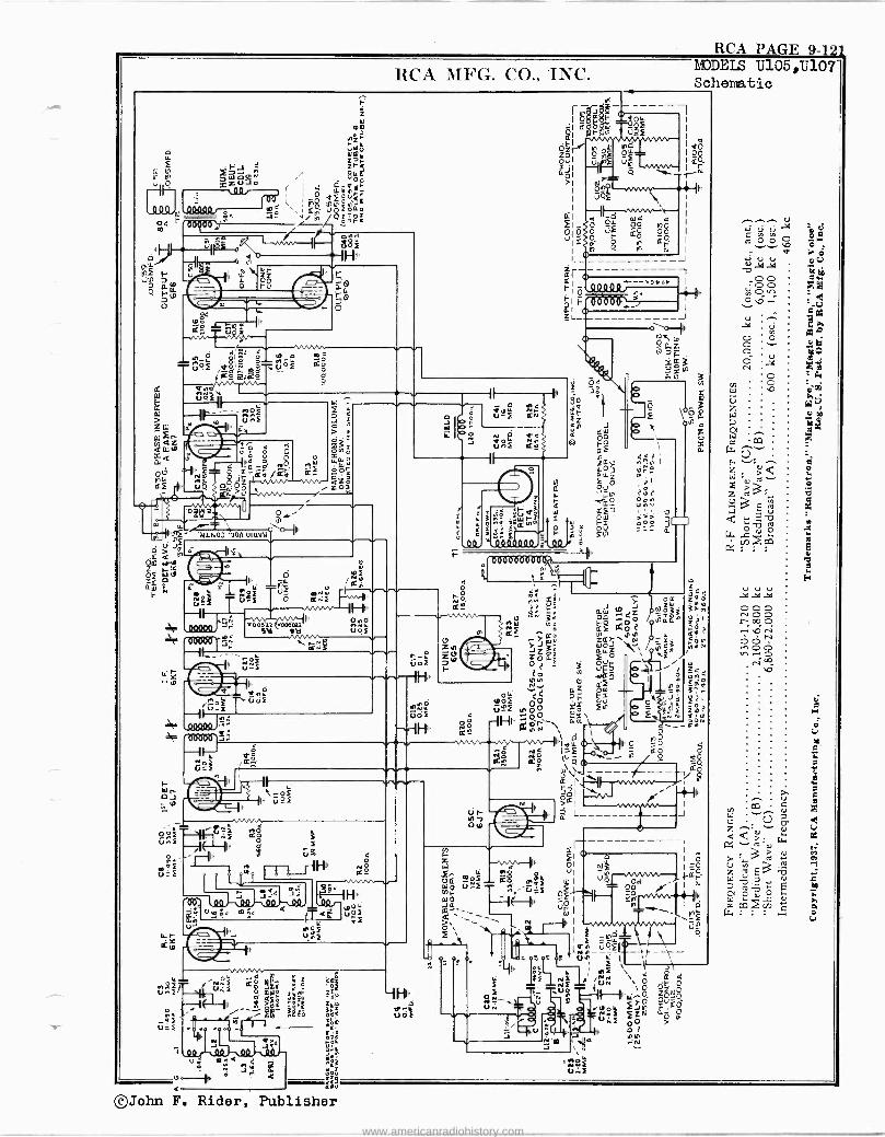
RCA PAGE 9-121
tU
D o
F'J Zgú1ò
d J m{ l 0p6Dy"
22
Ñ 0
. IL "ZZ F8
d'8a a ,n.23i e o 0 co
ó ñ,°....
-
noF --Ir-F
RCA MFG. CO., INC.
r
p UQ
Q
..l Ñ
> á vO { ice) IIQ Ó, OO
W ÿW
pQpQ ¢Qeáá áF owoi
O -i5-2= vv--vN á ó 0 M/`y / 0I,"'
áa o3 '704 otavá II uF
lh /Qº .03 li o
Ú^_É Jo
C..;F I' - I'
/g 000001 'r vooóz ooóou 9tl ftl uof
ooeT J z áe fs- __ W'
of U -F
4 ;C-
.-. N I' r^ó
n°É úóF V=F -II
WOO )37:,
000003. -III
PF
mcF u=E
¢..
ú95
V G
M HI' NO
Q2
O1 W< TúoF ¡F
II., úr:
4r i
:;:i1!T!t
z=° gt'_` OoiÑ°
"¢ ó z rá: úi. h3
: oc. --e, " o
J <s c o
©John F. Rider, Publisher
rQd
u ma< { nr
r- UOF
IHI
o o rf ó _
Z _ ar CI l º 09Il' °
a4 u -F á
0 re úñF 6ó
II
d
cud 000
{ o 0
N\M.
ZIO
F
mç Xál r órc
fLW toJ
L 'm3 3 QÑáñ
ZZ3o fLLZ`J\1ONáÑ o JJJ <m Oza_ 3 OJr
o
MODELS U105,U107 Schematic
I1
www.americanradiohistory.com
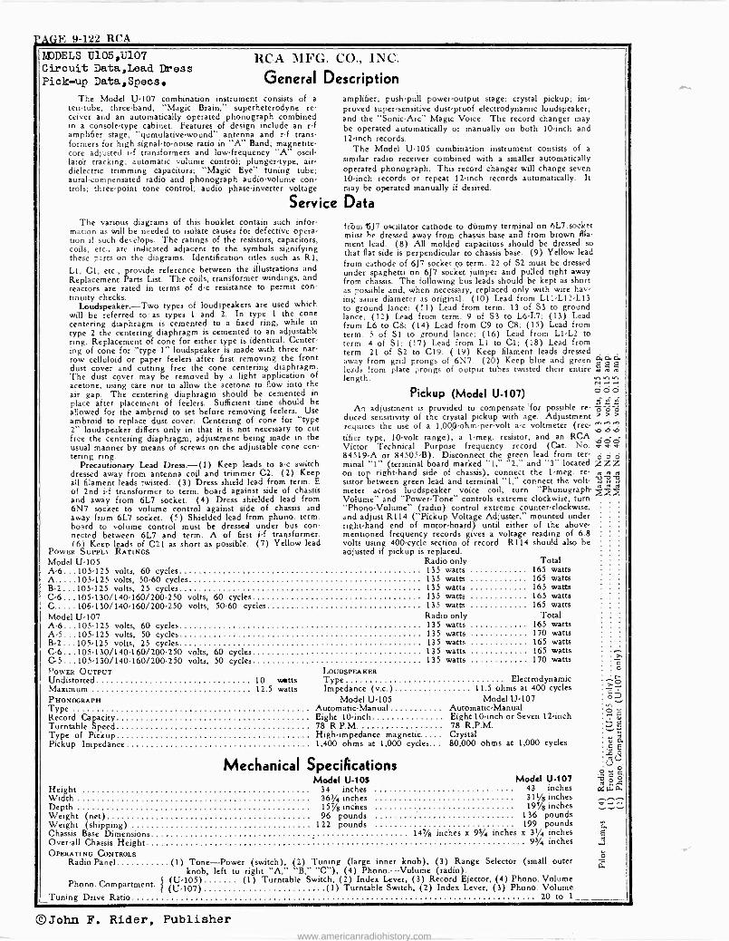
PAGE 9-122 RCA MODELS U105,U107 Circuit Data,Lead Dress Pick-up Data,Speos
RCA MFG. CO., INC.
General Description The Model U-107 combination instrument consists of a
ten -tube, three -band, "Magic Brain," superheterodyne re- ceiver and an automatically operated phonograph combined in a console -type cabinet. Features of design include an r -f amplifier stage, "qumulative-wound" antenna and r -f trans- formers for high signal-to-noise ratio in "A" Band; magnetite - core adjusted i -f transformers and low -frequency "A" oscil- latór tracking; automatic volume control; plunger -type, air - dielectric trimming capacitors; "Magic Eye" tuning tube; aural -compensated radio and phonograph audio -volume con- trols; three-point tone control; audio phase -inverter voltage
amplifier; push-pull power -output stage; crystal pickup; im- proved super -sensitive dust -proof electrodynamic loudspeaker; and the "Sonic -Arc" Magic Voice. The record changer may be operated automatically or manually on both 10 -inch and 12 -inch records.
The Model U-105 combination instrument consists of a
similar radio receiver combined with a smaller automatically operated phonograph. This record changer will change seven 10 -inch records or repeat 12 -inch records automatically. It may be operated manually if desired.
Service Data The various diagrams of this booklet contain such infor-
mation as will be needed to isolate causes for defective opera- tion if such develops. The ratings of the resistors, capacitors, coils, etc., are indicated adjacent to the symbols signifying these parts on the diagrams. Identification titles such as R1,
LI, Cl, etc., provide reference between the illustrations and Replacement Parts List. The coils, transformer windings, and reactors are rated in terms of d -c resistance to permit con tinuity checks.
Loudspeaker.-Two types of loudspeakers are used which will be referred to as types 1 and 2. In type 1 the cone centering diaphragm is cemented to a fixed ring, while in type 2 the centering diaphragm is cemented to an adjustable ring. Replacement of cone for either type is identical. Center- ing of cone for "type 1" loudspeaker is made with three nar- row celluloid or paper feelers after first removing the front dust cover and cutting free the cone centering diaphragm. The dust cover may be removed by a light application of acetone, using care not to allow the acetone to flow into the air gap. The centering diaphragm should be cemented in place after placement of feelers. Sufficient time should be allowed for the ambroid to set before removing feelers. Use ambroid to replace dust cover: Centering of cone for "type 2" loudspeaker differs only in that it is not necessary to cut free the centering diaphragm, adjustment being made in the usual manner by means of screws on the adjustable cone cen- tering ring.
Precautionary Lead Dress.-(1) Keep leads to a -c switch dressed away from antenna coil and trimmer C2. (2) Keep all filament leads twisted. (3) Dress shield lead from term. E of 2nd i -f transformer to term. board against side of chassis and away from 6L7 socket. (4) Dress shielded lead from 6N7 socket to volume control against side of chassis and away from 6L7 socket. (5) Shielded lead from phono. term. board to volume control must be dressed under bus con- nected between 6L7 and term. A of first i -f transformer. (61 Keen leads of C21 as short as possible. (7) Yellow lead
POWER SUPPLY RATINGS Model U-105 A-6...105.125 volts, 60 cycles A.....105.125 volts, 50-60 cycles B-2...105.125 volts, 25 cycles C-6 ...105-130/140-160/200-250 C..... 105-130/140-160/200-250
tróm 15J7 oscillator cathode to dúmmy terminal on 6L7,socket múst be dressed away from chassis base ana from brown fila- ment lead. (8) All molded capacitors should be dressed so that flat side is perpendicular to chassis base. (9) Yellow lead from cathode of 6J7 socket to term. 22 of S2 must be dressed under spaghetti on 6J7 socket jumper and pulled tight away from chassis. The following bus leads should be kept as short as possible and, when necessary, replaced only with wire hav- ing same diameter as original: (10) Lead from L11 -L12 -L13 to ground lance; (11) Lead from term. 13 of S3 to ground lance; (12) Lead from term. 9 of S3 to L6 -L7; (13) Lead from L6 to C&; (14) Lead from C9 to C8; (15) Lead from term. 5 of SI to ground lance; (16) Lead from LI -L2 to term. 4 of S1; (17) Lead from LI to Cl; (18) Lead from term. 21 of S2 to C19. (19) Keep filament leads dressed away from grid prongs of 6N7. (20) Keep blue and green É 2 Q leads from plate prongs of output tubes twisted their entire length.
Pickup (Model U-107) O O
An adjustment is provided to compensate 'for possible re- c c duced sensitivity of the crystal pickup with age. Adjustment requires the use of a 1,000 -ohm -per -volt a -c voltmeter (ree- 222 tifier type, 10 -volt range), a 1-meg. resistor, and an RCA . ó Victor Technical Purpose frequency record (Cat. No. v v 84519-A or 84505-B). Disconnect the green lead from ter- o minal "1" (terminal board marked "1," "2," and "3" located zZZ on top right-hand side of chassis), connect the 1-meg. re- e m e sistor between green lead and terminal "1," connect the volt- U meter across loudspeaker voice coil, turn "Phonograph. Volume" and "Power -Tone" controls extreme clockwise, turn "Phono -Volume" (radio) control extreme counter -clockwise, and adjust R114 ("Pickup Voltage Adjuster," mounted under right-hand end of motor -board) until either of the above - mentioned frequency records gives a voltage reading of 6.8 volts using 400 -cycle section of record. R114 should also be adjusted if pickup is replaced.
Radio only Total 135 watts 165 watts 135 watts 165 watts 135 watts 165 watts
volts, 60 cycles 135 watts 165 watts volts, 50-60 cycles 135 watts 165 watts
Model U-107 A-6...105.125 volts, 60 cycles A-5...105.125 volts, 50 cycles B-2...105.125 volts, 25 cycles C-6 ... 105-130/140-160/200-250 C-5 ... 105-130/140-160/200-250 POWER OUTPUT Undistorted 10 watts Maximum 12.5 watts
Radio only Total 135 watts 165 watts 135 watts 170 watts 135 watts 165 watts
volts, 60 cycles 135 watts 165 watts volts, 50 cycles 135 watts 170 watts
LOUDSPEAKER Type Impedance (v.c.)
PHONOGRAPH Model U-105 Type Automatic -Manual Record Capacity Eight 10 -inch Turntable Speed 78 R.P.M. Type of Pickup High -impedance magnetic.... Pickup Impedance 1,400 ohms at 1,000 cycles..
Electrodynamic 11.5 ohms at 400 cycles
Model U-107 Automatic -Manual Eight 10 -inch or Seven 12 -inch 78 R.P.M. Crystal 80,000 ohms at 1,000 cycles
Mechanical Specifications Model U-105 Model U-107
Height 34 inches 43 inches Width 363/4 inches 3 W inches Depth 15% inches 195/a inches Weight (net) 96 pounds 136 pounds Weight (shipping) 122 pounds 199 pounds Chassis Base Dimensions 14'/8 inches a 93/4 inches x 31/4 inches Over-all Chassis Height 93/4 inches OPERATING CONTROLS
Radio Panel (1) Tone-Power (switch), (2) Tuning (large inner knob), (3) Range Selector (small outer knob, left to right "A," "B," "C"), (4) Phono.-Volume (radio).
(U-105) (1) Turntable Switch, (2) Index Lever, (3) Record Ejector, (4) Phono. Volume (U-107) (1) Turntable Switch, (2) Index Lever, (3) Phono. Volume
20 to 1
Phono. Compartment Tuning Drive Ratio
á E
á Ó
w
©John F. Rider, Publisher www.americanradiohistory.com

RCA PAGE 9-123
RCA MFG. CO., INC.
9nae'vla aMaWVI Yao 11M00a
o
a r ,
ó r_t I` k = Y'
ORIr'V.O 11rNi tl0! 1.7Ma0!
Zai l, W
á u
N4hin- E CE
K
i$
t .p,
col
q c
i
Ñ Vé
É
Mp r
5&E
;g a tl
er
e 3
sW
v
z
C.,4
0=5_
gi
MODEL U105 Chassis Wiring Coils
ú eft dsesao
\g opa O d
J.--úôáC o.r_r
3 ÿ
u
u
o
a'd 0 zuga` 7y u w
u e [.II 9
o
nr
08
ors
ac Llst-
3 2 ç r NW',Vn/
., u
1.051
o
ar ó"
f
a
f
é
aro
YOilnw
!
`Aaarmo n_
!
x
e
a
ó; Yp
qf
B
ó
rc
y
úw
an Nata
w -1
S
e 4 R
mr O '0 3
W
z e-
j V
2 aC
r
pe Z N
3 V i V
ä t
v i
@John F. Rider, Publisher
www.americanradiohistory.com
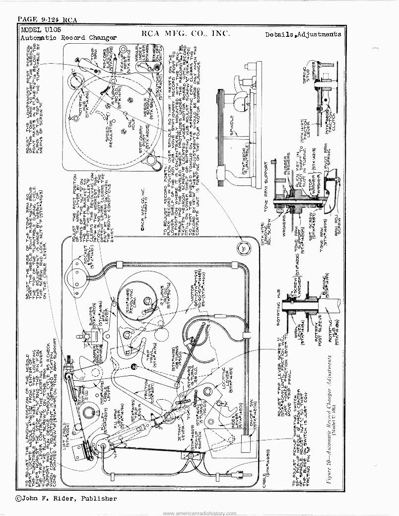
PAGE 9-124 RCA MDDEL U105 Automatic Record Changer
Y p U
ZO, ÚZ7
°pQLLw w aiF UZJ " wd0- ¢J2¢ ZWJau i wZWw¢JOZ x SSF 1-úFt-¢125-212 1 2pÓÓU¢ LZ OpEZJFZmO Ódie¢iZOP
[t-O{CNª "p°¡rxdUuE-
váiÓVQú2:.-' z ZJZZi
S
Ó73 2WÑZZPK JZ F2J3aÚN Z Jt-Wmdt- i -¢¢Z J=Zdt-
fuZOCL
¢ t-adZ No 0- KZ
¢o E- íw-OZW
occ W u7O rut-Jt-r"3
RCA MFG. CO.. INC.
fÓ S,2á óU
iB Qm p Zoj O ,+pmW t-Z a
ei ¢ vw*Y áÓ Fz ~u t3 fm
r dtF x O. t-Q2Z Ñ u i. ' ZpY
raxnv,3rÑ or2 v ° 1-dvóm 0px p3 WutW2Wáw3 d7ÚU¢á k_- p2m0u0 á¢r°óFFmd ó77ó29F ÑQF¢P wÑ,7WmY1"2
°? 7 ó;QóvZó aO-2pZ WW
dZt-¢°LE rtx-
>a¡WupO770 029°23ó U1ztF"miLO¢Z FOO O' OFwF aE-2Nw3 " ápiFWZí
G.
KaFwA""N wt F
Z °uZÓduWdmi rW7¢O¢ Jd- O Wp S w .E-
QJwm2WFdfp 2 KOJFxÓ21D7 WZ2úwzzjv fr áÓZ=JFmW
ID
Fx2LLáwioJJ ¢F 32
fdZOZ¢pFll S t-" OWQ"Ww Z2J
Ñ=1F¡[Za2¢¢ Ó SuwO°t-Jt-O$a$
7rz E-¢SZWw F O¢°3a¢útOdló -7 ¢w¢W= pl-' wN FaJat F""2U osxJr' -w?xx ¢oFt-vtOaFW
o ZO t upx-fz Ñ O" uri. pA)0w_FQd Z adFJ"xW.9
djd Oi¡'s "r}
"
ac -
Debails,Adjustments
0 ídu= m" m¢ m
k- 3 z
a
O
aÑ "
pOd
Ú> 1-1 1.
33 aW
Fd 2 a
-
J" S g k- .111-11-
2ZpW J
2QÓ Z...>
Wilk- ^ IJ2UJ
aZaa á
2.-u a dhalcd
k"pdt- SO 0d f2u OF]Ó uoÓ V a ¢92..-)2 77020-7
F i _
22`2 `+ f --d--
r1 ;, i
lc L--
2i N4W
ó
7tl1 ó
O vZQÓ-l S ; Qáa I
-piáZmi : w ° a
F i CO Oa1iá U k-OOL t-I-
2 YW 3 $ zw3
ÉY FF gZZ
©John F. Rider, Publisher
www.americanradiohistory.com
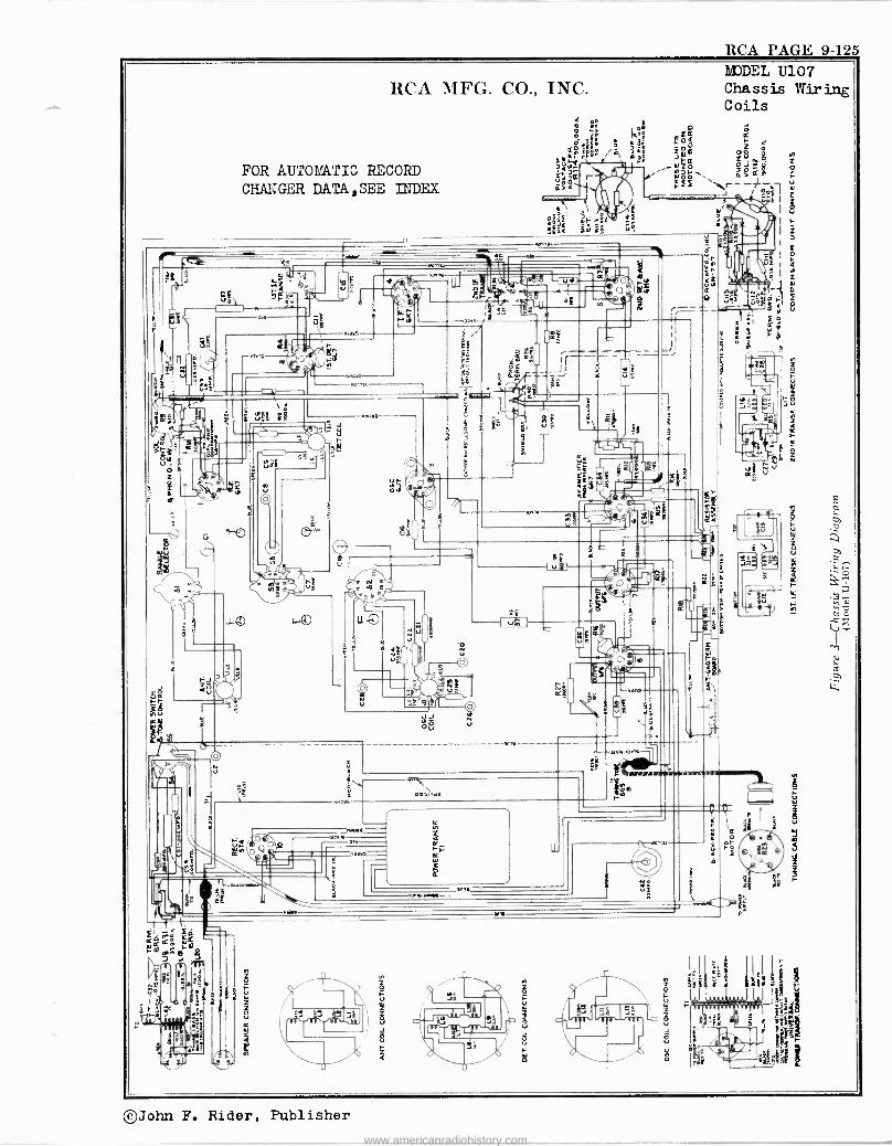
FOR AUTOMATIC RECORD CHANGER DATA,SEE INDEX
rs g I 31
--- ¡
RCA PAGE 9-125
©John F. Rider, Publisher
www.americanradiohistory.com
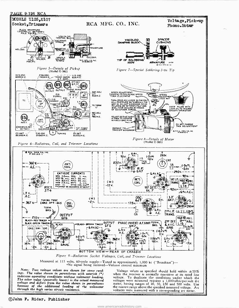
FACE 9-126 RCA_
MODELS U105,U107 S ooket,Tr inner s
HUGH RRMRTURE CENTRRLLY BETWEEN
POLE PIECE
WELDED
E SOLDER PIEPCES
C23-0SC 6000 K.C. \
Ti
1'
0 RECT.
©RtaMFECt,INC I RI 5N-734-1 r ` 660,000A
Figure 5 -Details of Pickup (model i1-105)
C 26-0SC. - - - - L13 -0SC. / ISOOK.C. .- PHASE INVERT. 600 K.C. A. F. AMP..
RCA MFG. CO., INC.
RRMRTURE
2" DET Ì8 ® ® l+A.VCS
6
IOUTPUT OUTPUT "ONO- TERM.
R19
BRO.
46'I.FI
SIE7
0K.C.ADJ. 33,OOOn e eef
.
C18 \ OSC.
20MMF. r. .f ` 41
,
AEI Ti;
`'e`..37 1scDE _ 1Ej\
7L1
efil't7- C3R.F \ ELLOW ITOP tRONT
330MMF. OF <wR»I.
TUNING C9-DET. 20,000 K.C.
CO -ANT, - \C 20.0SC. LO,000 K.C. 20,000K.C.
TO TERM R3
6K TO
C /s.I..-I SEC.ADJ. _I1 LIS TRAN511 460K e
Figure 6-Radiotron, Coil, and Trimmer Locations
VISCOLOIO DAMPING BLOCK
TIP OF SOLDERING IRON
Voltage , Pie k -up Phono. Motta
SPACER CUSHIONS l'
ARMATURE ®,c. MF CO INS
Figure 7 -Special Soldering -Iron Tip
SPEED ADJUSTMENT (SCREW) TO DECREASE SPEED
TURN CLOCKWISE
TURN SPEED ADJUSTER 30 THE FEL WILL PROTRUDE >le WHEN ALL THE WAY N. ADJUST GOVERNOR SO AS TO LEAVE )1a- BETWEEN FELT AND DISC, THEN SECURE DY MEANS OF GOVERNOR SCRE
ADJUST 30 THAT SHAFT! % IS :0Tk.I+j
MOVE TO TAKE OFF GOVERNOR
SPEED ADJUST MEN
LOCK NUT L kf KEEP FILLED WITH LIGHT OIL TO INSURE SMOOTH OPERATION
DO NOT CHANGE THIS ADJUSTMENT
pRCA n6.C.INC r1 -.1414b
Figure 8 -Details of Motor (Model U-105)
RCA MF.. co. me. P-81123-1
-- 360 V.-- -, -- A.C.-, i
I
r- 1
1
L3v_jI AC. I
1
-367v.J
J
RECT. 5T4
CATHODC CURRCNTS N/} 7.8MA. N16- 1 MA. NºfT0. MA. Nº7- 26MA. Nt3- 8.6MA NIB- 2GmA N14Y 7.8 ...A. Nº9- 2. MA NºFr - Nº10-110.MA!N UNNOT 8E MIASURtO AT SOCKET
TUNING TUBE CACLE Nº 9 - 6G5
TERM. BRD.
-4-- 210v. -- BLACK -RED TRKER + BLACA-GREEN TRACER..
;C+2
MCOLOID C r.RING PRIENOBPRI
SCRETW`
NEEDLE HOLDING
OSC
e - COIL
Z1 / --CIO 330 MM.
ANT. COIL
i
S60000n
OUTPUT 6F6
-2
=0i _ <-01v t r---2t0v--- -. 1 r ---90v--+'
11LTI.F 460 ® 1.
TRANS r- LL14 - r r6.4V-A L__ -- I I
(*) -15v.
I 6L 7 90v L----------- --
I I
I
90v.
235 v
4 240v.
C41
6.4K A.C.
r1 GG
-0(1v.
uwJ R.F 6 K7
175v.- - =" >, ®T I
aa 6J705C.
11.F _ Ov. 16K7 p71--)
210v!
C& i___";` TRANS.
I I 367v. I 367v. , 240 v1.j
Y. 6 A -21v. -2v. 1
PHASE INVERT. A -F. AMP 2-- DEL
6N7 6.4v. i ABC
360 v Z40 V. (-El" 1 mow.
-016v. t i i/ BOTTOM VIEW -REAR OF CHASSIS
Figure 9-Radiotron Socket Voltages, Coil, and Trimmer Locations Measured at 115 volts, 60 -cycle supply -Tuned to approximately 1,000 kc ("Broadcast") - No signal being received -Volume control minimum
1rBLACK- MOWN TRACER OUTPUT
Note: Two voltage values are shown for some read- ings. The value shown in parentheses with asterisk (') indicates operating conditions without voltmeter loading. The other value (generally lower) is the actual measured voltage and differs from the value shown in parentheses because of the additional loading of the voltmeter through the high series circuit resistance.
eRO. \I &A V C --Fa3v9 6H6 ov, ^
1 (-0V*) (-3v.`) I 0 v.
o.1v. I 1 r y ó= , 1 (130V!') I 64v. ÿ 3) 1oov. I
A.C._3v. -3y. r- 1_
J
- 1
PRS. ADJ.
t t
Voltage values as specified should hold within ±20% when the receiver is normally operative at its rated line voltage. To duplicate the conditions under which the voltages were measured requires a 1,000 -ohm -per -volt d -c meter, having ranges of 10, 50, 250 and 500 volts. Use the nearest range above the specified measured voltage. A -c voltages were measured with a corresponding a -c meter.
©John F. Rider, Publisher
www.americanradiohistory.com
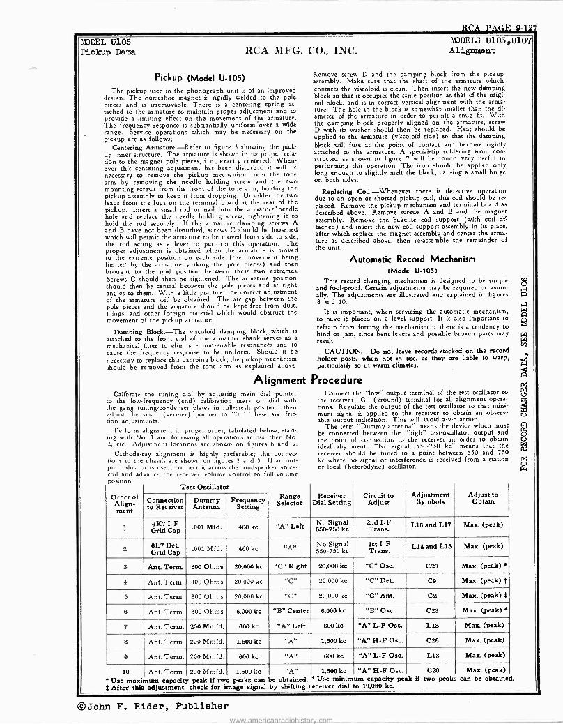
RCA PAGE 9-127
MODEL U105 Pickup Data
MODELS Ú105,U107 RCA MFG. CO., INC. Alignment
Pickup (Model U-105)
The pickup used in the phonograph unit is of an improved design. The horseshoe magnet is rigidly welded to the pole pieces and is irremovable. There is a centering spring at- tached to the armature to maintain proper adjustment and to provide a limiting effect on the movement of the armature. The frequency response is substantially uniform over a s 1de range. Service operations which may be necessary on the pickup are as follows:
Centering Armature.-Refer to figure 5 showing the pick- up inner structure. The armature is shown in its proper rela- tion to the magnet pole pieces, i. e., exactly centered. When- ever this centering adjustment has been disturbed it will be necessary to remove the pickup mechanism from the tone arm by removing the needle holding screw and the two mounting screws from the front of the tone arm, holding the pickup assembly to keep it from dropping. Unsolder the two leads from the lugs on the terminal board at the rear of the pickup. Insert a small rod or nail into the armature' needle hole and replace the needle holding screw, tightening it to hold the rod securely. If the armature clamping screws A and B have not been disturbed, screws C should be loosened which will permit the armature to be moved from side to side, the rod acting as a lever to perform this operation. The proper adjustment is obtained when the armature is moved to the extreme position on each side (the movement being limited by the armature striking the pole pieces) and then brought to the mid position between these two extremes. Screws C should then be tightened. The armature position should then be central between the pole pieces and at right angles to them. With a little practice, the correct adjustment of the armature will be obtained. The air gap between the pole pieces and the armature should be kept free from dust, filings, and other foreign material which would obstruct the movement of the pickup armature.
Damping Block.-The viscoloid damping block which is
attached to the front end of the armature shank serves as a
mechanical filter to eliminate undesirable resonances and to cause the frequency response to be uniform. Should it be
necessary to replace this damping block, the pickup mechanism should be removed from the tone arm as explained above.
Alignment Calibrate the tuning dial by adjusting main dial pointer
to the low -frequency (end) calibration mark on dial with the gang tuning -condenser plates in full -mesh position; then adjust the small (vernier) pointer to "0." These are fric- tion adjustments.
Perform alignment in proper order, tabulated below, start ing with No. I and following all operations across, then No. 2, etc. Adjustment locations are shown on figures 6 and 9.
Cathode-ray alignment is highly preferable; the connec- tions to the chassis are shown on figures 2 and 3. If an out put indicator is used, connect it across the loudspeaker voice - coil and advance the receiver volume control to full -volume position.
Test Oscillator
Remove screw D and the damping block from the pickup assembly. Make sure that the shaft of the armature which contacts- the viscoloid is clean. Then insert the new damping block so that it occupies the same position as that of the origi nal block, and is in correct vertical alignment with the arma- ture. The hole in the block is somewhat smaller than the di ameter of the armature in order to permit a snug fit. With the damping block properly aligned on the armature, screw D with its washer should then be replaced. Heat should be applied to the armature (viscoloid side) so that the damping block will fuse at the point of contact and become rigidly attached to the armature. A specialtip soldering iron, con- structed as shown in figure 7 will be found very useful in performing this operation. The iron should be applied only long enough to slightly melt the block, causing a small bulge on both sides.
Replacing Coil.-Whenever there is defective operation due to an open or shorted pickup coil, this coil should be re placed. Remove the pickup mechanism and terminal board as
described above. Remove screws A and B and the magnet assembly. Remove the Bakelite coil support (with coil at cached) and insert the new coil support assembly in its place, after which replace the magnet assembly and center the arma- ture as described above, then re -assemble the remainder of the unit.
Automatic Record Mechanism (Model U-105)
This record changing mechanism is designed to be simple and fool -proof. Certain adjustments may be required occasion. ally. The adjustments are illustrated and explained in figures 8 and 10.
It is important, when servicing the automatic mechanism, to have it placed on a level support. It is also important to refrain from forcing the mechanism if there is a tendency to bind or jam, since bent levers and possible broken parts may result.
CAUTION.-Do not leave records stacked on the record holder posts, when not in use, as they are liable to warp, particularly so in warm climates.
Procedure Connect the "low" output terminal of the test oscillator to
the receiver "G" (ground) terminal for all alignment opera- tions. Regulate the output of the test oscillator so that mini- mum signal is applied to the receiver to obtain an observ- able output indication. This will avoid a -v -c action.
The term "Dummy antenna" means the device which must he connected between the "high" test -oscillator output and the point of connection to the receiver in order to obtain ideal alignment. "No signal, 550-750 kc" means that the receiver should be tuned. to a point between 550 and 750 kc where no signal or interference is received from a station or local (heterodyne) oscillator.
Order of Align- ment
Connection to Receiver
Dummy Antenna
Frequency Setting
Range Selector
Receiver Dial Setting
Circuit to Adjust
Adjustment Symbols
Adjust to Obtain
1 6K7 I -F Grid Cap .001 Mfd. 460 kc "A" Left No Signal
550-750 kc 2nd I -F Trans. L16 and L17 Max. (peak)
2 6L7 Det. Grid Cap .001 Mfd. 460 kc "A" No Signal
550-750 kc 1st I -F Trans. L14 and L15 Max. (peak)
3 Ant. Term. 300 Ohms 20,000 kc "C" Right 20,000 kc "C" Osc. C20 Max. (peak)
4 Ant. Term. 300 Ohms 20,000 kc 20,000 kc "C" Det. C9 Max. (peak) t
5 Ant. Term. 300 Ohms 20,000 kc 20,000 kc "C" Ant. C2 Max. (peak)
6 Ant. Term. 300 Ohms 6,000 kc "B" Center 6,000 kc "B" Osc. C23 Max. (peak) *
7 Ant. Term. 200 Mmfd. 600 kc "A" Left 600 kc "A" L -F Osc. L13 Max. (peak)
8 Ant. Term. 200 Mmfd. 1,500 kc 1,500 kc "A" H -F Osc. C26 Max (peak)
8 Ant. Term. 200 Mmfd. 600 kc 600 kc "A" L -F Osc. L13 Max. (peak)
10 Ant. Term. 200 Mmfd. 1,500 kc "A" 1.500 kc "A" H -F Osc. C26 Max. (Peak) j' Use maximum capacity peak if two peaks can be obtained. Y Use minimum capacity peak if two peaks can be obtained. $ After this adjustment, check for image signal by shifting receiver dial to 19,080 kc.
©John F. Rider, Publisher www.americanradiohistory.com
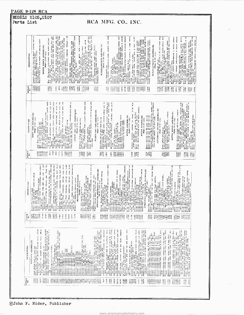
PAGE 9-128 RCA MODELS Parts
U105,U107 List RCA MFG. CO., INC.
m R1
= t á $ §^Z ' S ät ;y [ E 9
en ë-yÉ m t:S - së
m a=
2 iII
I;JIIII <e
iw o c^ Er
g3s6 B id " ik_ "
EE º O É m8 ;. e < rÉyaë 5 u°" "-
gC`=; á
ail _éº, Ó GFäê:iY.4..{e'v : _
äss ä 8jjsûTtj IjFI I
Iß1 . . 85 e;Ë=
6 8= w F3 muÚ Ú Ú IA
I
? -li ó
E y
s " 1 .ci
°EtmÓ=cu
ä
2aÉc$ëZ "
r ih
g E arÉóc6a.0
:g ^ rái ° ; !- wë _
a-oOná= =e }t 3` º It:z491m ti
: ug 'llj :gË
E$I gizë=32 OW Jza ma° wwqq
3sO li
6 ^ .,ee: o .
e ë '
'=,ó: = - = _
. ; - 8 « çóg.rc R ` m t n : 6 dd9 H s Ì g g m°mq -g :a}°}
; t -{{ e;yg pe-
kti á ..8L a .0 --BºXé
y < 1 i'' II! 5 < ^ û8ä'
<b d óÈ SE r e^ .e. n ä ç. º
c; .3t__2w. û?^$3$ ° yy ;2'i?2:B ; .r W7 . UUJYáe w " Er téóE ÿS J .-
EE. r6 4 c <8 8 yd.._. 5 é8 0. óa .j.js a it z dd- . EÉéëca`` < ËdmEóe é ÉÓ óE5 'o̪
5¿ s '`Ea9=;SS; Yg á I EcEá J Sd =" Uhl 'I ' __ m y m se_ "á°4a=á
t ër- c«t m Ç: Eóó.y.-á$5 ó .c4 u 5 io.'.éO
._ óééeáéé1 ;á- ;ÿ _ s - <<ë _, z' ,1 ag°" _
Noo_;._geE 'rcF "ÿ-oä : Sá ëllÍl l ettq`.tg È äl:"tFg g4SE
g = -I,.II amg u IIII.S "glrwnr'e
ÌII 3=11; ë tá= ligl 2 I..ÌÌe Se
Iáäá .l$1=1=æ;esllëtgë aI;1 asslY2 æw Áa >o39ë Y'gm"ëë
lige. in/ S= ë3iI.e,eë6iE F m°V4ÚVÚÚm .. .`. Y mm mm,éwqm' aa qm mmq °
k Uó ME" ...... .. ...... n g ...... n- .. ....y n.. .. .. _^ ...-. -.. .. _1^ ........ .... 5! .. g ..w. .. n n
O
.2
" E ó^ 3 - ó2 é S ég `-C S : 9 - : z 33 8
frt - w $ ó m ¿° 3
8
! B L SSt ao i- ; : m órá" :, m ;
II E < _ , t e -.Ç êêêó' = é
.së a,
K i 1 : 3 m^ >, tel-' ` U
ó .. ë 3á h1 .^,'á ^ " m "
ib : - é t 5 E; u C J . 2 J= aÉi pa t e3 á
Sc"Ea.. .. é á x c8 = a` m - ë< 5 u 8 e éq
aeS = r n i -Xcé r8 ;2 ÿ 9! y 99e,a zo id <g 3 jr ; t.. $ cE s ÿÓ :
c ñ `` -é = Er,o F- ".^. G^ ut t' "::t' - ra < ; _' " < <ÿ E ;32 L gg io Cë i> .. ad 5 .71
_4 n Ci t2 O_ó $ n1ç Gó áméE:á¿
u8 S.:g mé 'ær$e=8
3s <8 -..ñt- É -c, _3ñ'
z9 Éñe" c- zé lu, _ ó"ÿ ó-" m5
ggeos : ñ rEl .4Eoié
O
i
S=óe °- 7a -3'ray "2eëÉ@, = É:áñe i5 .'TTi é Fy"ï ói ná.ón fl!
w43` Mói:, `"'
4
_^ Y v- u'" ....2g.2
e > CA F t ,°$ é-á
Xt ä <-r_ u 3s_agä < ....,. o.oÉt o BóeË E4SE kySbww `.m iËmm" a n6 oèà á " É é>:EóeOgg a
rcS=l'óó" w.11 '21 1$, j11 L61 =zz _a6=jké ä¿Ilj a5se: ge < < Iq.E1 ä
ff
1 1'144111 llº64es I
It{
á gSál1 jjj ¡Al.a I
IºIjs l1c°a aé_-.C: ó ;l - F8 ó IIys`
> y p¿=g=- aw t'"_ ._ 8- °stt'
- acii "ëó.y tmm"`Úw ól°g g qrñqÏ"f <000 4.ñui múÚ Ó a ä4q.ñmmq Ó@S:w aa:ÿ U4ugiwy mmÚ+ Ó44 qqÿ
Y
gz . n _ :
- - a e........
.+ .-..... n.. .. .. n .. >ww...>
.. .. 4 .. .... ...... g!!
....n ..
r
$
á
la: 9 û ú 3
. ] rq.eiJ: $ sú m z " ; 4 Sa . y i `zz¡? 52 t
ó 3
115:122M rä .Ë m
g
ä ó ós mn
á 3
ÿ ; $ n é
g: c sxx=á g 9 ë;$
5.
a
's2""-_
,
`3tá_-SC=vi'i3ñu" _.çt5 ^é-_'t.net'
<c7¡E'E1
t r q
'e m`.
x +- m & '
t
:
gx æ'm S 2 2 ! ! C É 2
15 x
- a
75 3`e é
2! ] i1. SSS ` S$`y cɡu@
ï ë t m
e ë "
t
w9-$- y-5gtt ,3naw+=='t-É! baÿ$"
sOé"
áÌ't
m
é.ó".
wFóó`l
mqF.2s"ewm."_r_t
yS-_r ym _="
n .
ÚEs-t!
F` FV Ñ-
Umrm
y-- 6tt
Oo4O
-t,5.
su'yy9
m"$
7
'S
°8y"n`
d[".y3ISe1Ja0
a ë
é@>t
--t g6er t.5t trEt _
ót
<Ko_waz
'w
2 é â á óI
3r .I " 9>- 6 5
;-O
(] S -z- SF -i U y y-SçclgLj17ñ lgl^.2r.2Eeg_a55 &'11118 ru 11II1 r Ylllló I 1`111igll,llllä:
F +ú FF> Uu má 3 m Vä+ âúyg q 11 11, J J4 wyywmyqó3
FZ..... .. . e =,e r r n r n n .... .... ü .... .... ........... ., .. .. .. ...,.. .. ,. ....-.. .. .. n9. Mg«
O
m m
5:
J a
- 3E E
. < a
r w > `"r
et De 2<`_ _
:t`°<° 2>1^1e11jclu,geeºººt Ilo 9 - -ttä;wa_alllá
mm9 m° mmÚÚ
Ec m eêë j '
L
' m sa2
.-, ê eT ci, 'C.F.
E- -e á ó Ç
E c . "'.g r ti z r "
áme u .'+.iJú" @ 3 3 'g - qÿS ám«m«m-rcá;_ t -NEqEé VU Jú é, i 6 c -E -r«I`««. J.. - . .". = . . .
n ^
e e.:. - .,:i
e± e3éË ÚrÚ J..:- é- 1E -On« é$. ióÿ yC ei á vu_e ^.. ú ú. ?Jócá° -"q -« á ó`i.-i.xa>.a V V- ^-_a`.?Éa:céá Ez D -cc "gaJa
_ =ggpap88` uu 8á8 ñ xë< =S= B$ ó8 44 °:q= - ÉEEBâwá:á ^ûúúú,44ûê^^s`<-"të ^O>>
e Et. ,.s , tS.-53 3i$$<w33` ;$ Sa381rc.`",:
- ' - ,etO t EE S `ä c E "" t .uûú¡û3n-a_ óá-áx- . Ë e. o
d..d....dËeËèdyd - et:S:o i t _ r ase- ` CÉÉ Éá <é 11
aag -tq ' ËËËËËËËË:aza oáe;; áádro
_ ddd -u.,uuuo..E . Ë ó2 á7r a f a
Mil _ 'ËË 5zPdd eë-c $v cr7e t sc 3az5z:za::e ayan=Sae _ $SE" i : afro öx:E- rYEo
_ o< ' .9
- ñLF''sE jS-c75 $CÉë lár. r'cg1111111riîiiïi7iiiigqii`=;jjáj ?_ ?; ;'ll`tjlga la'-E EE.éËÿ;zE
s= °° °=e=e°°=ss<o' "'säwa ë. E g"^frlJwslllllllTl
1,7 T( Illll<Iz -ovou -er3=1'ce_____._. ° ee= = tstt tlyl ïg;: 6áááá äáä a11i;:láji;22E=;ïäi 7a;a q.$s :..:::.;ê:::::"m 8än : , StS
8.c,23 _vég =""- 3OEEEECë'ómëëmEEaIIëëëë=..ÿwm ÚUVÚVVÚÚÚVVÚÚÚÚVVÚUÚÚÚÚVVÚÚÚÚÚÚÚÚ Ú Ú yC O O q mP.U.$.=.JZ ä âm amqmmaiq mm mm mmmma má
1g n_. . MV.. 3.1211;1121i212212121122 3g2111;11 y .. _.. .. .. .. ....n .,... .. _ ....
5.3_112 1 _:1 n.. n..!n.. -- _
©John F. Rider, Publisher
www.americanradiohistory.com
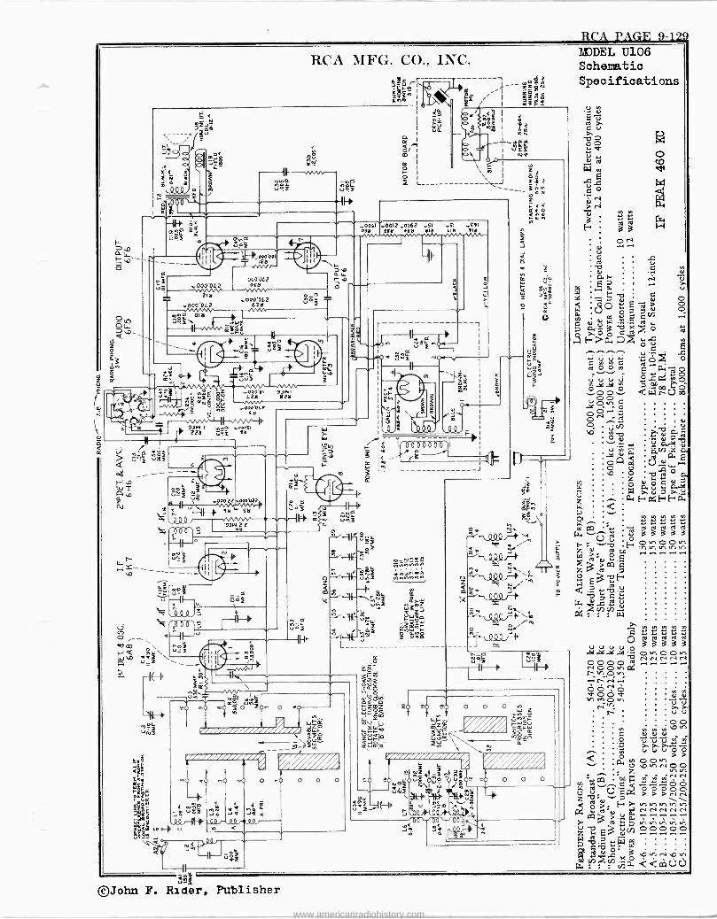
R
RCA MFG. CO., INC.
a g Lñ I
-11--0.22Vv- ú$i $s _yC
i
T '-000001 Ify rr.vr-
000.012 - ....000 '04 OfH
di al ..D00'OL2
.u000 '0(2 62tl
o ar
mnE OItl C.2,1/4_ C.2,1/4_u ̀
W, : II
1 .3. Sg
wrc -%«g -` Ñ .000bt
ctl
c
I u I zi a I S
`__I zSz - - 3i+10
YIN
z
Óooflr.001t,.o062 f1 -iI f11
dY ffil 0ftl Itl LItl - 71
zp WBr 000'YI 93 I iza 2
>
rW Uo ÓII u
`e..ºººº ,3
Li V .V V,7
0.
9714 S ,nó 0211 = 0ftl
O <-11-`) rico . t`o W :1\u-2 Lz,
-1(4 h rc
i7/7/Il///777/%
je J JP G
<
o <
c=;
y^` uT SV OJW
O"ZOe- o i
z
diiizii/iiii OiWlp
I__
Jry
II
©John F. Rider, Publisher
-1
ó J
ii 1 "-z I
E.á;
wy z c 2 ; e ú &
00
'(603Öüb61i i7 [.11
3 `
gel v u. Z1
4
u
I m
y 2. -'000`< ee,.O
N ñ W ro' `c3,Ç
N m w
4 2= .g 3 TF z N,- g
átt é m~ Ell,' O y .an Lbti
F- ç á g 4.
N O) /
'\-W12->':g \q W : . . {
O NY
:11-1/4 090r1 J
>1d'JDEL U106 Schematic Specifications
mJ0o` Z
Ou'....` f."
O O O
z A
an, ae_
,,1
=vW ó
='CZW
hpy.25 4
O O O
IC ú ú 2 2 td td td to Ñ aaaaa Ov 00 tn
www.americanradiohistory.com
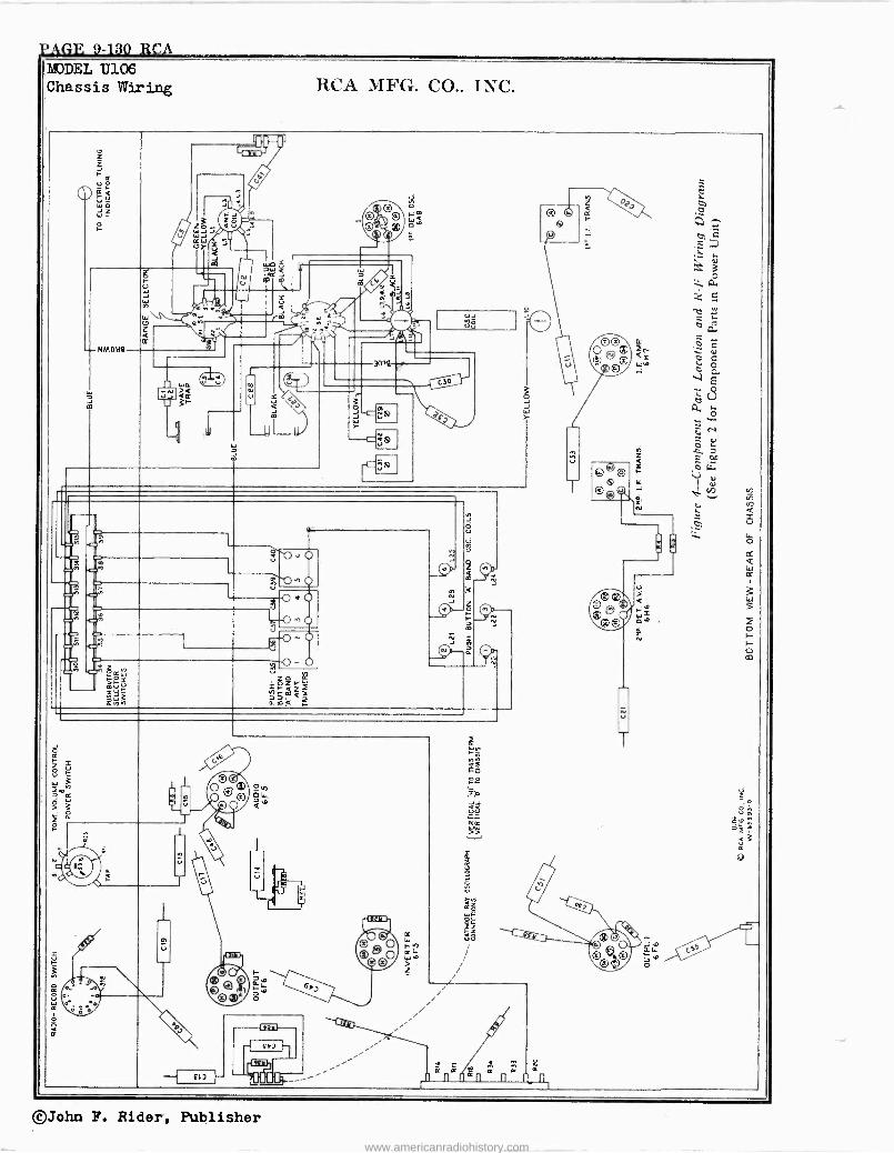
?AGE 9-130 RCA MODEL U106 Chassis Wiring RCA MFG. CO.. TNC.
¡I 1
Z
.?,c
TY
_uF C
ú C
J ci en
v >\
w=
Vy
I
io WO <U
J'nI , W .. -+
JJ
f.t0 ® `Q W
~ i0 ® 11 fl
¡
© c
W ^ + C, C
t¢]} Ú » m
W
Q m
< m
` Y Iy .4e ̀ - r'r'
O \ Q
+
, m
r, J
\ C
J 4..^ ^
,ºNI /\ m Ì J
Ú_J 1.
Z - OO V O-Ì11
Q N .+ . J c NMoaa
OOO ®
ó d
13) ® C
v \
3flla < ©W íC, O
a w J ?i EG, -.1.1g.
V u . 2
O -
CS
W 1
w
- C.m
, º
ÿ N O w
°i C O ñ Z
F. Oq v u ®©O
V 4i.
v T om o .
=
N Q
1 J = V O
I .. .1
-, O
--o `o°o Ñ T
S^ '=' '.D" Q
W
ò 9,O O n C] .o ñ N ®® O<0
© < 1v
® o^4 =-C ., O
____(:)-,4
g
O ®O ®©
o, 2o
Ch. 47'' vh O F
- Ñ h. -- h -
y` O m
¡oÈ 0 { grW >g4 ¡th
MrmZj
0.mQ
c o Q=Q,w
<r
i--
cc
8 f
oc
J. 1 . m L'
ó °® O Q O Ó4.
O á°
L,ll
2 ,2
gv;i
. . ` á
~ : ` 1 ®
® F
e < 3
a ®
® g
a *1:1,.
i tc
O O n O >
i fY i
i0 ' af ®.0.. o `°
G I- ®O F .g i i
° 'A Q,111 W O _ O .t,-,
0 /
CHI ® cr . M r, l f{3 lll 8m m l." ---'' ,nan
©John F. Rider, Publisher www.americanradiohistory.com
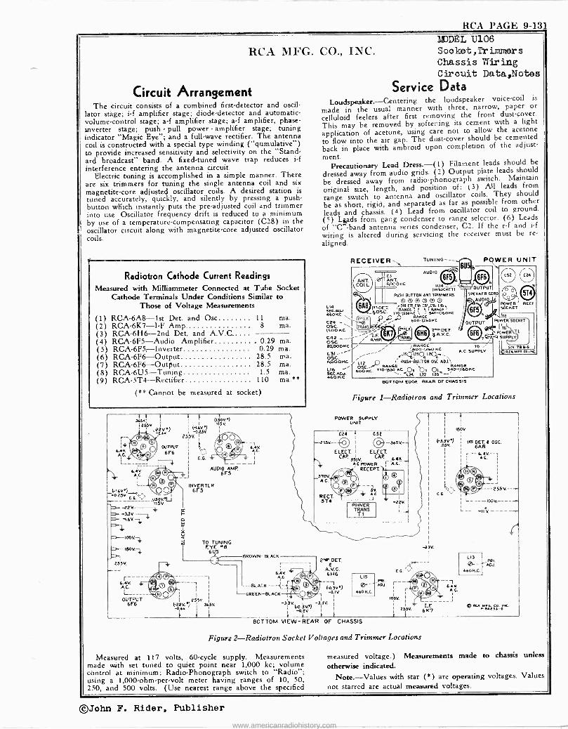
RCA PAGE 9-131
RCA MFG. CO., INC.
Circuit Arrangement The circuit consists 9f a combined first -detector and oscil-
lator stáge; i -f amplifier stage; diode -detector and automatic - volume -control stage; a -f amplifier stage; a -f amplifier, phase - inverter stage; push - pull power - amplifier stage; tuning indicator "Magic Eye"; and a full -wave rectifier. The antenna coil is constructed with a special type winding ("qumulative") to provide increased sensitivity and selectivity on the "Stand- ard broadcast" band. A fixed -tuned wave trap reduces i -f interference entering the antenna circuit.
Electric tuning is accomplished in a simple manner. There are six trimmers for tuning the single antenna coil and six magnetite -core adjusted oscillator coils. A desired station is tuned accurately, quickly, and silently by pressing a push- button which instantly puts the pre -adjusted coil and trimmer into use. Oscillator frequency drift is reduced to a minimum by use of a temperature -compensating capacitor (C28) in the oscillator circuit along with magnetite -core adjusted oscillator coils.
r
Radiotron Cathode Current Readings Measured with Milliammeter Connected at Tube Socket
Cathode Terminals Under Conditions Similar to Those of Voltage Measurements
(1) RCA -6A8 -1st Det. and Osc 11 ma. (2) RCA-6K7-I-F Amp. 8 ma. (3) RCA -6H6 -2nd Det. and A.V.C (4) RCA-6F5-Audio Amplifier _ 0.29 ma. (5) RCA-6F5,-Inverter 0.29 ma. (6) RCA-6F6-Output 28.5 ma. (7) RCA-6F6-Output 28.5 ma. (8) RCA-6U5-Tuning 1.5 ma. (9) RCA-5T4-Rectifier 110 ma.**
(** Cannot be measured at socket)
365K: i 255v
,22V -,16Y
6AV. AC
6.4K A.C.
L_
OU6FP6UT
OUTPUT
6 F6
ác
ú
(150v ) 115K
AUDIO AMR
INVERTER 6F5
TO TUNING EYE ..E
6U5
I R55V. .K 3íSK
1
4.4V.
BROWN- BLACK
6.Ìv A.C.
BLACK
GREEK -BLACK
-3 3v 3V0) -3
-àev.
BOTTOM VIEW -REAR OF CHASSIS
Figure 2-Radiotron Socket Voltages and Trimmer Locations
MODEL U106 Soolflet,Trinlmers
Chassis Wiring Circuit Data,Notes
Service Data Loudspeaker.-Centering the loudspeaker voice -coil is
made in the usual manner with three, narrow, paper or
celluloid feelers after first removing the front dust -cover.
This may he removed by softening its cement with a light
application of acetone, using care not to allow the acetone
to flow into the air gap. The dust -cover should be cemented
back in place with ambroid upon completion of the adjust-
ment. Precautionary Lead Dress.-(1) Filament leads should be
dressed away from audio grids. (2) Output plate leads should
be dressed away from radio -phonograph switch. Maintain
original size, length, and position of: (3) All leads from
range switch to antenna and oscillator coils. They should
be as short, rigid, and separated as far as possible from other
l(e)ds and Ls ds from srfroms. (4) Lead
gang condenserto range selector. (6) Leads of "C" -band antenna series condenser, C2. If the r -f and i -f
wiring is altered during servicing the receiver must be re-
aligned.
RECEIVER` TUNING --- AUDIO
R14- DNloCKCT)
RISIf BUTT 0 N i1NT. TRIM ME RS ! ® oO O O©© POWER RECT. L14 tA8 1sxDET -CG2 09 nB CTI(C% Cry SEC.OJ. OSC. 'RANGE S IUNBES 6F5
socKET 460 RC 4
JD, 510-U60KC ! Y RANGC ITO
C29 .0 600-Q60NC OUTPUT POWC0.50[KET OSC. 12 CF MO T1 SOOKG
K Ólló 2 A.DET.
()TO POWCR
c4a _- ' AMR ! OCY SUPPEN
osc. 24000 Ki % RANOE TO ' 6N-TB4Ó
C31- ____--- 05C.
Ly-'l -1,260 AC A.C. SUPPLY ACA Mn.N.NC (% `6 4 -"`1 \
6POOKC L12 ....1) , P1.1511-U'ITONOSC.ADU.`, RAN6! RANO!
L16 - s°oo'Kc TT41-SSO KG o4 `b, oli 5;e11,1170 KC SEGAW.- --L21 122 L20 - 460 KC
POWER UNIT
BOTTOM CDGE ROAR of CHASSIS
Figure 1-Radiotron and Trimmer Locations
POWER SUPPLY UNIT
27, PET.
A.V.C. 6H6 1
F0.3V) -0.1V
V.
LIS Pn. r-- 0-- Aoa
4601I.0 r I
IOOV.
I ,
253K 6K7
150K
(-3lv .05V.
6.4K A.C.
j
III se T.8 08C.
A.G.
L__
L13
0-- 46OK.C.
.Pat.
ADJ
® AvBi2Jl 0
Measured at 117 volts, 60 -cycle supply. Measurements made with set tuned to quiet point near 1,000 kc; volume control at minimum; Radio -Phonograph switch to "Radio"; using a 1,000 -ohm -per -volt meter having ranges of 10, 50, 250, and 500 volts. (Use nearest range above the specified
measured voltage.) Measurements made to chassis unless
otherwise indicated.
Note.-Values with star (*) are operating voltages. Values
not starred are actual measured voltages.
©John F. Rider, Publisher
www.americanradiohistory.com
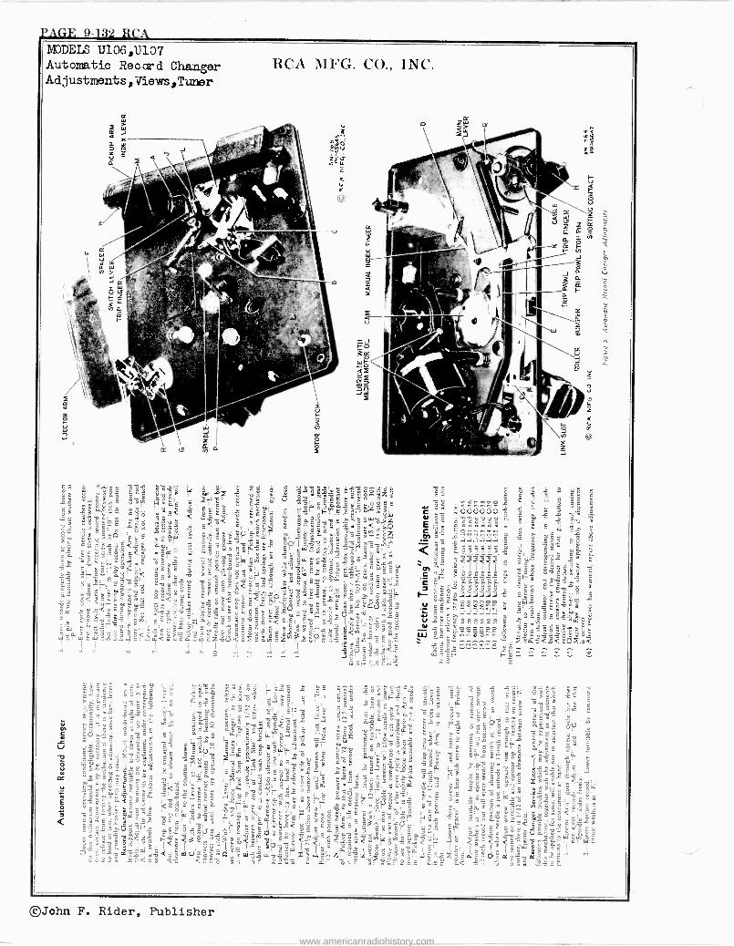
j'AGE 9132 RCA MODELS U106,11107 Automatic Record Changer Adjustments, Views,Turner
©John F. Rider, Publisher
www.americanradiohistory.com
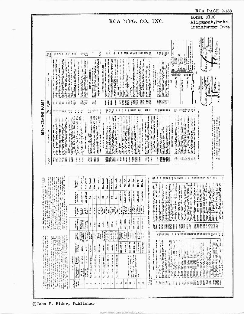
RCA PAGE 9-133 MODEL U106 Aligmx nt,Parts Transformer Data
mu. ...é .... ... . .w . . . . . ... ..^
r ... .gen w
w ¢
6 é
.
9
b
3
l 8 i 7'
.8 0
'P
8
:
; ; ` B
8 ' :
ó
a a
á â
;?
,...
áâ'3g '°
.'3 :r; E
a . ;
m i
5ia5i
Ea - 'i 1 am
ÿ
sé -
p°
x s e
a - s
t g
g
:
Q:
/º 8
%3
1 .
T á ä::.2 ;.bm
Y gsey
z°
x º
;
: c e8
ZO:ZZ9ZY+Z
.
_ Q«rcáçió.
,á °,,m=mmOmgAm o I
^ I
= F
z p- ".GF^ m p31
á 8 E. @ 8 Y eS me E
áeg 6
_ o
á Ú w c
9
8
'I
'SiyL
E4 538 3Qgggq.3
9'CV
:.ª =_5 ª'38.-
E ó S<93F4
YSáC'Ccóá'Oc-. mmw
atr8
b º !
8
I°iÌ
o5i S7 tp
"37
v< of
22äj
x I
t E nñ "<
°F'z,' e. F
ëgws 9
I F g _!
< >blT.0 m3 U4mwm
ïB.m Ñ "gw &e "='
TTg ° <<Slla
<x a ap a
r°,aa.:;á t o ..
g eri :._ 1 < g YY
9 Já 1 1 i! 5a
i;Eá: ggm'
<
gg
< ÿ
o a 8 a ° g F ° g
#a;S$t .6..
13i` zap 5 ªa nY6d6a aáim .+§ u_Ew
'6ïe8~ 5 s""-8""ar 2E SIñal Ewtw-t 9
. °
Lw e
ááxñ_{I u :5;áé_1§yyI?'ai;o2;..w-"E
5 5 . s
$$ J
u Ú
Y é9
yy
á 0
_; _
.,w I: y Hc.e. iIP
uOPI
a .
vo.ç.a_e E .-:
°e Boy,S wn°
°
z @6ár°'
Y11311.ar1: a.1Zaa
á5E ` Sár
3 r@' L fr"$ 6a
IL
m
s l .C e°ti
.
é tg Fáo,;
ILI
h
<.S E
a at °wey.w á ";ézei ó á 5"^"
a aya a OáSY"
lááfr-gt9 ÚtlUU6aE+3
á5g
EÓ= `5-°I eó: ¿T$:gg
S<'1
° s' W ú
¢ E á
y W o
m E ú c"> á< WW m a
r
Q uHeUg FZ.. r
..' .. .. --
aáú : a
i
Hi iáiááás-r wwwan
b 9;;Zár-e Y35 "
9m
¡û
5
"8 iïFi6
EIIJ1
5
%aa4á`f <
i
miÚÚ
Eb w
é>
g3tá=3é;2'ylF
á
é1EE
4
Q. Ys
tala5y
wú
i
u9^g
a Y
< Fá Éc
<e88g.8yp=g Ú Ç áañm ÚU
'_
-EÍyy6 i Gá. y
cw EE
w w 2 e E9E
a E; w..e .e .. w w ww 3.22 . owwww . n .. .. w .. .. w...a. w .. wwwwn .. w w ""
r E
'00 i X M
y
11
s
gg
d M
z - .1 six
ó M
y 8
M It II w S It
m 'S.
W
it
W W
_.
W
.â
m
.é
$ <"
á °
'
á
.i ;
á
" iuuav ~ a ú
á
ú :5 á
ci
á
V
á
U
: á : U
:;K
2.' '9.5,
V<
.. ae e..S
ÂÑ4 r Or
á
J
m
.i
ó Ú<O<O40<O<dl<M<d14d14d14ß1
a.
aÿx2 W W
.i (4 .. ó,;ó,;ó.+p«ó.:ó.:
N N »
e-é-- m m m m
°ggÓ
Y. t
a aQ
1-..1.74i1 $ nv.Y
zgi .-
m m
6 á
y g
çV ffi§. " V §
8
ÿ
m
s . S
c
m
ÿçç
3
g
ÿçç
6
g
"ó e 0.q`É3Ì
7213: Äÿ:u ñDVvÇ.
ä: -
-î
ó.23." ÿ:
óÄ Ñ`-mñzvF.F!F - GrE .y`1' ye:`=u1
Le 'Y -E' '1 -._-= ^_Ei
a
OY « hL
V
'es P § m mg y ÿ V e J
ÿ
$
á 2
iS
r é gg d
ÿ
rnp,
q
o$ ¿5Q,
E]<
;8
e g
:9- " c
.g O ' E
O
É O içç
?a
E i g
E
ñ «4 cá c á gEF er
< A a
gg
El> E ç
CF,
e e 3
ó u y<
c.
ó u..
úzci
m
O
C7
<
<
6 E
F
á
6 E
E-
á
6 E
F
á
6 E
c a
a' E
F
é¢
6 E
É
ó ëe P
.+ m 01 m t` m m . n .. .. .r ..
1b2g3,-, 13 x°
é`
=gx R
III iH, iääs
1 [
xiæ?ñ
1 Ea ?º
; =á°M
Y1 1544113g°ªlªr 07;1m
33äc
1 !l g 5fr ó
6
1 I <
áa 3
13
c o
;3
?"
a.t :';IdLaaaÉaa
' ^ éái
oe1Z11#1$1 g
'71
e. ...
Eiál
it
-.,.«.
Ioeóóé
-r Tó?áYya>"8a óSh
r
$nágEi ai°
i
s.
\ 11w8-Ei
á+"a-Ei. a eeag9e
`r
'
5
ÿ
i g
é
1!
.
ñpé5etts;
rª
° { 1111ë mmamUUUUV"Wv
ri
..e,
öés;ti;C
u+ÉE
É ä
è g 393
+ó_ÉE
rm_éE 1 =
u
9
ë~
fr°°"°°
öSI`säaöáá=^=öäö"g`iglgl u
ugueueu
e,._eúóúóúûûp
-°_dd9
ioeeooa
iiliii!!l
ÚUVUUUUYG°UUUUWISUU
<de
g_°°ssg"...
únê '
gú
u&
9
âJ u
m
l
§s<.
:á
.:.;., -i
ááái E.g
:a
Ii «<1 ó
ó
YSSo uuuu
I Ç
r
is
u
u
n"nwnwwnw w w n nww..wwww.e.ñiw ww wn wwnn
©John F. Rider, Publisher
www.americanradiohistory.com
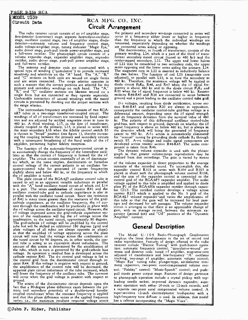
PAGE -9-134 RCA MODEL U109 Cirouit Data RCA MFG. CO., INC.
Circuit Arrangement The radio receiver circuit consists of an r -f amplifier stage,
first -detector (converter) stage, separate heterodyne -oscillator stage, oscillator control stage, two i -f amplifier stages, diode- detector-automatic volume and frequency control stage, audio voltage -amplifier stage, tuning indicator "Magic Eye," audio driver stage, push-pull triode power -amplifier stage, and a full -wave rectifier. The phonograph circuit consists of a volume expander stage, expander amplifier stage, expander rectifier, audio driver stage, push-pull power amplifier stage, and full -wave rectifier.
The antenna and detector coils are constructed with a special type of winding ("qumulative") to provide increased sensitivity and selectivity on the "A" band. The "A," "B," and "C" sections on both coils are wound on single forms and are series connected. The range selector operates in such a manner that the correct portions are selected for the primary and secondary windings on each band. The "A," "B," and "C" oscillator sections are likewise wound on a single form but are connected so they operate separately. Undesirable interaction of unused windings with the tuned circuits is prevented by shorting out the proper sections with the range selector.
The intermediate -frequency amplifier consists of two RCA - 6K7 tubes in a two -stage transformer -coupled circuit. The windings of all i -f transformers are resonated by fixed capaci- tors and are adjusted by molded magnetite cores to tune to 460 kc. A third winding, L17, in the first i -f transformer, closely coupled to the primary, L15, is placed in series with the main secondary L16 when the fidelity control switch S5 is thrown to "broad" position (see figure 1), thereby increas- ing the coupling between the primary and secondary circuits with a consequent broadening of the band width of the i -f amplifier, permitting higher fidelity reception.
The function of the automatic -frequency -control circuit is to automatically change the frequency of the heterodyne oscil- lator so that the correct if frequency is formed for the i -f amplifier. The circuit consists essentially of an i -f discrimina- tor which, as the name implies, discriminates or furnishes control voltage of the correct polarity to an oscillator fre- quency -control tube for generated i -f carrier frequencies slightly above and below 460 kc, or the frequency to which the i -f amplifier is tuned.
The plate circuit of the RCA -6J7 oscillator control tube is caused to act as an apparent variable inductance in parallel with the "A" band oscillator tuned circuit of which coil L14 is a part. The series combination of resistor R41 and the oscillator control -tube grid to cathode capacitance is also in parallel with the oscillator tuned circuit. Since the resistance of R41 is many times greater than the reactance of the grid - cathode capacitance, at the oscillator frequency, the r -f cur- rent through the combination will be practically in phase with the r -f voltage across the oscillator tuned circuit. However, the rf voltage impressed across the grid -cathode capacitance sec- tion of the combination will lag the r -f voltage across the combination, or the tuned circuit, approximately 90 degrees. The grid -cathode r -f voltage will be amplified by the control tube but will be shifted an additional 180 degrees (grid and plate voltages of all tubes are always opposite in phase) so that the amplified r -f voltage appearing across the plate circuit will now lead the voltage across the combination or the tuned circuit by 90 degrees, or, in other words, the con- trol tube is acting as an equivalent shunt inductance. The amount of this action is determined by the amplification of the tube, which in turn is governed by the grid -cathode bias voltage. In operation a residual bias is developed across the cathode resistor R43. The d -c control grid voltage is fed to the control grid from the discriminator circuit through re- sistor R44. If this voltage is negative with respect to ground, the amplification of the control tube will be decreased, the apparent plate circuit inductance of the tube increased, which will lower the frequency of the oscillator tube. The converse will occur when the grid voltage is positive with respect to ground.
The action of the discriminator circuit depends upon the fact that a 90 -degree phase difference exists between the pri- mary and secondary potentials of a double -tuned loosely - coupled transformer when the resonant frequency is applied and that this phase difference varies as the applied frequency varies; i.e., the maximum resultant response voltage across
the primary and secondary windings connected in series will occur at a frequency either lower or higher in frequency than the frequency to which the individual windings are resonated, respectively depending on whether the windings are connected series aiding or opposing.
The discriminator, or fourth if transformer, consists of the primary winding, L24, which is a part of the third i -f trans- former secondary tuned circuit (tuned to 460 kc) and the center -tapped secondary, L22. The upper and lower halves of L22 may be considered as two secondary coils, the upper series opposing and the lower series aiding the primary, L24. The magnetite core in L22 is inserted to inductively balance the two halves. The function of coil L23 (magnetite core adjusted), in parallel with L22, is to tune the secondary to 460 kc. Therefore, the maximum voltage will be applied to diode circuit P2K2, R46, and R45 when the i -f signal fre- quency is above 460 kc and to the diode circuit PiK1 and R20 when the i -f signal frequency is below 460 kc. Resistor sections R46 -R45 and R20 are connected in series between ground and a point leading to the oscillator control tube grid.
D -c voltages, resulting from diode rectification, across sec- tion R46 -R45 and section R20 are always in opposition, consequently the oscillator control -tube grid -bias voltage is a differential amount, depending upon the if signal strength and its frequency deviation from the nominal value of 460 kc. The polarity of this differential oscillator control -tube gridbias, with respect to ground, depends on whether the i -f signal frequency is above or below 460 kc, but is always in the direction which will bring the generated i -f frequency nearer to 460 kc. A -f -c action is automatically eliminated for "manual" tuning by grounding diode cathode K1 through switch S7. A -v -c voltage and audio signal components are developed across resistor section R46 -R45. The audio com- ponent is taken from R46.
The dynamic volume expander is used with the phono- graph so that greater volume -range reproduction may be realized from disc recordings. The gain is varied by means
of the volume expander in direct proportion to the average intensity of the recorded sound. To accomplish this, the expander control R103 in series with R104 and R105 is placed in shunt with the phonograph volume control R108, and the arm of the expander control is connected to the control grid of the RCA -6F5 expander amplifier. The audio voltage applied to this tube is amplified and applied to diode plate P1 of the RCA -6H6 expander rectifier through capaci- tor C215. The rectified current develops a voltage across resistor R215 which is applied to the No. 3 grid of the RCA -6L7 volumd expander 'and varies the amplification of this tube so that the gain will be increased for loud pass- ages and decreased for soft passages. The volume expander circuit is arranged so that there is no appreciable change of gain, with an average record, between the minimum ex- pansion (second dot) and "Off" positions of the "Dynamic Amplifier" control.
General Description The Model U 1 0 9 Radio -Phonograph Combination
employs the latest developments in the art of record and radio reproduction. Features of design effected in the radio receiver include "Electric Tuning"- with push-button opera- tion; automatic frequency control; "qumulative-wound" an- tenna and detector coils; tuned r -f amplifier; magnetite -core adjusted i -f transformers and low -frequency "A" oscillator tracking; two -stage i -f amplifier; automatic volume control; "Magic Eye" tuning tube; plunger -type, air -dielectric trim- ming capacitors, two -point aural -compensated volume con- trol; "Fidelity" control; "Music -Speech" control; and push- pull triode power output stage. Features of design pertinent to phonograph operation include a crystal pickup with top - loading needle socket; improved dynamic expander; auto- matic operation with either 10 -inch or 12 -inch records; and a separate two -point aural compensated volume control. A super -sensitive 12 -inch electrodynamic loudspeaker with a high -frequency tone diffuser is used. In addition, this model has a cabinet incorporating the "Magic Voice".
©John F. Rider, Publisher
www.americanradiohistory.com
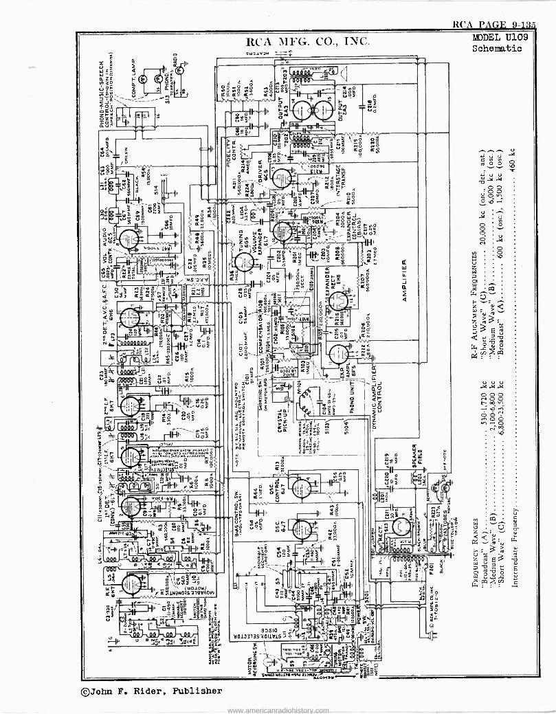
RCA PAGE 9-1.3
Ii `Y i 1°
N
î F utif rf P úo úrF
fi
lu
v0oft-14a,
1]I S" 000052
Ir
p.
In
,e - G . O Y_ ó WN1NmF f.f a
7HI L-IHf .
IZCr IhG. CC)., I1C. 9tl31V3N e MODEL U109
Schematic
n O
¡¡ I
4 ó n Try í0i10 ÿ1ó óó an fg ° '$s1l` a° aº t
mo
,, ¡ i u F
FGj1I l3lSl3Q1./ - ' Jina k10000 ) j e
1644 auvw Isom .waulu a
ññóOu1u0] 11i]Sa] w]NM 8 iaau]Was 11 .u.l,nssr 0 i
a%rñs sew ar.Mçr^Of aOO
%.UUa)33e wmÑò F-iHl ó mg '-' HI,. ,,ág aa
Uòe
c y 941',
PP
u¡F N uoi No 2.C àNIF a 8
..054-ey ,
08 R. a. p_LL O
u
>alri y Ii
e 3 'uFF
o< ̀la°4rL ó W g F 75
(nOlOU) â I; 1W3w03S 219VA0 W
0.:572 !
11 «6;224 y -ti--F7iy ffSsós
¡se n Ee óMu3 1r _ Fg.
,n
a1e.
oo [i 711 ` 41, ON
_fnO ú`4F d
I- el LL_
_ Ñ N VO
LLÑ
II.
`'^-S Qaau íQi8 I' 000Yf, ÑO w
~ rve
rsQtyr , a« Zá e-Hñ ZW z -..41g tii IF %Z m1CPI
u_ . for Zm O.5 -G. ,- aW Ell' 01G -. j 1 Ñs oHIuf O. foú
IÑ af O N
Ill' L C ¢ 4 41
6i «OOF If
8Ú ZÚ=
ro O
e m
û áQ -,I X
I
We .... úof r----7it
IgBF$ E ,1ago- Of"Ice-- o ootz-/(1S ÚN
Q W ' 61 F 5 ó_ póÌN
IL
id Ñ a8
i î Q - 8 ^U
Óó jóá. uN - S
r.
,
xu? r m- 201141'äf
-- u u v J ¢' IZ ÌW
Wui Ii
ó
`.:::k m¿u v.W
-z 17,
riú 004
Hi'.
á ill
x Yu >:^ e3ee n R úñ 'ç°cú o_ o
Y1 N
o o
d
Ó
a
° 0
O° .2 ,- u4f iaÑ
gWl s. áQ d
aGf \x4Q10 W
tF W LL
---" F ' ] J Z aQ vÑ Qr z Z
N 4
ée o UO O -" i U > a
Z
t f
vú di P-
3- E 'Diu, r á- u OZ
Ze -IHI uz N4
-5203 m-
Y NO `F 1 O
1ir 7 0 10
Zo `roí @Fr ti_f FCa---- 1ii2-
N LLnf Y
Higfy
e8 IF [co
O
á 0.
II
u
SaSIa _ Lf a013313S WO11V1S ó
3 I N z I
ar oa ro5[ h of
3 U+ " e Lt e ,. o 1 T Pii -PF Yb , .. á_ u.g {,>
I s"` 6ió =- a° ó :- Ir
M F- -i01"Y =2....,_ '- Ilk-
a Y.mM01111FNfM ]10M7.lOW.Y^ iev .Z_
h o
o ü=î
Za
ÑOj 5 + ád T u `m. ' ^ î rNOóó
V ~ c YrW W
m
fó ¡y ag I
.
á !Q
e
err
©John F. Rider, Publisher
www.americanradiohistory.com
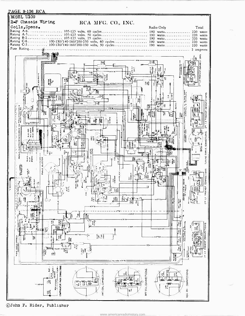
PAGE 9-136 RCA MODEL U109 R-F Chassis Wiring Coils,Specs. Rating A-6 Rating A-5 Rating B-2 Rating C-6 100-130 Rating C-5 100.130 Fuse Rating.
-3nlp N331.19-
gt#
- fl)P1r.
z
L ova
NMaM
1 Rs \
4
RCA MFG. CO., INC. Radio Only Total
105-125 volts, 60 cycles 190 watts 220 watts 105-125 volts, 50 cycles 190 watts 220 watts 105-125 volts, 25 cycles 190 watts 220 watts
/140-160/200-250 volts, 60 cycles 190 watts 220 watts /140-160/200-250 volts, 50 cycles 190 watts 220 watts
3 amperes
.--Ma113A
)I)Ola
Ol :Z
0 l aY-03019
Na3Ye
©John F. Rider, Publisher
www.americanradiohistory.com
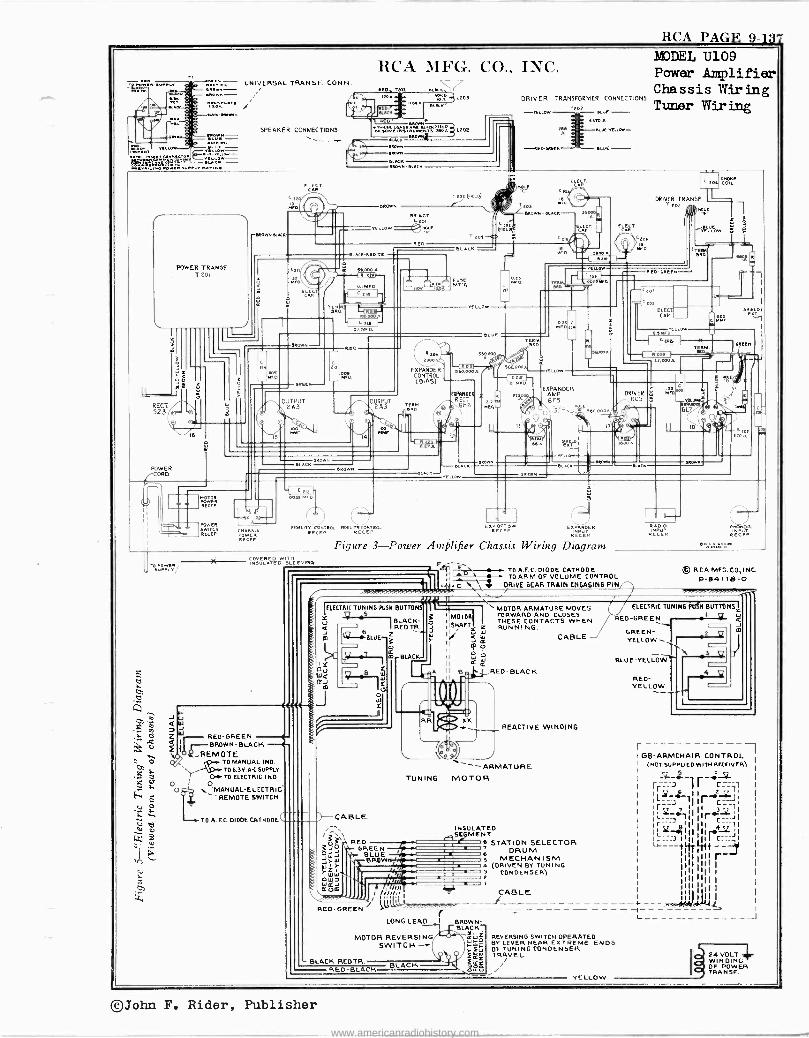
RCA PAGE 9-137
UNIVERSAL TRANSE. CONN.
Run/ ,DA .E
SPEAKER CONNECTIONS
=01 lL40.
tti33 ;.E. -
RCA MFG. CO., INC.
LxOS
EROWN
DNtoMei "++a2D`ñ L202 ER
DR
(KKK DROWN 'LACK
DRIVER TRANSFORMER CONNECTIONS
.ALA rM íZr-EIOEYntOO-
-1LEDRR!!N - EWE-
MODEL U109 Power Amplifier Chassis Wiring Tuner Wiring
POWER TRANSF T 201
1
MOWNDLK
Ct
ROW /Ox (Feat) ! -
REACT. 4, LOW =e3NWE
EL KN REO TR
RED
Ga) 34000 A
D.í®.
TERM. eaD.
ALNC
PUSE MT'..
Cxb 0 YELLOW
POWER CORD
ORElN- w3D
i 1
o U Ire,4
OUTPUT 2A3
I
EXPANDER CONTROL ( BIAS)
OUTPUT 12X3 Aëññ
-i R
ELAC DR
ERown
EAPANM REGT
X6116
LLO
(III
NAE L <ED
eS
BLACK
'UV
O ' RLR
tOE
KD
DRIVER TRANSE. xox
TE
CLOW
1.04 .00[3 10.0
R G1LE
L tos croNe COIL
ñAN
E LLIE
Ev
LL
EXPANDER AMP 6F5
wi éiT1
C[o,
toa ELECT CAR
Kll 0 rv. aW
coot
tE ADDA
DRIVER 6C5
I 13 N__'
3 ND.
6L
10
GR! !n
-EJ
et e EL C
ERO
AOwÉR
vftER
POWER sW TCN RELEP POWER
RECCE
0035 M0.O.
MO[ ONT ROL RpELIW CONTRA, RA ExRECEw
RPeE RCONT R RADiO
RECÉP
Q J Z Q f 1, Yt.FiEMOTE
el* TO MANUAL IND. 1`¢ tYi TO L3 V.A-C SUPPLY
O TO ELECTRIC IND.
0 -MANUAL-ELECTRIC `( - REMOTE SWITCH
BROWN
CIOVERED WITH ULATED SLEEVIRN
Figure 3-Power Amplifier Chassis Wiring Diagram
I- U W
RED -GREEN BLACK
TO A.F.C. DIODE CATHODE
TO A.F.C.-DIODE CATHODE TO ARM OF VOLUME CONTROL riL-DRIVE GEAR TRAIN ENGAGING PIN
© RCA MEG. CO,INC P-84118-0
'ELECTRIC TUNINGPUSH BUTTONS ' MOTOR ARMATURE MOVES Y I MOTOR FORWARD AND CLOSES
BLACK- p 11 THESE CONTACTS WHEN RED TR. IISNAFT_. = RUNNING.
u
Y Wá
Q-:BLue-f l0
` ÿ If ` CABLE O
II C BLACK II w W
II E 2 A II B RED -BLACK W
.0 E 0
CABLE
3;L RED
3039, `E1- OREEN 0ÿJ w).- BLUE Wy; BROW
WW ESA
RED -GREEN
LONG LEAD I BACK
MOTOR REVERSING IYaUWÓ
REVERSING SWITCH OPERATED BY LEVER NEAR EXTREME ENDS SWITCH~
W OF TUNING CONDENSER TRAVEL.
BLACK-REDTR BLACK . tc RED -BLACK LY_ ii
ELECTRIC TUNING }USN BUTTONS
REO GREE 1 O N
_z y
\ 3 Q 4
YELLOW
.i
411. RR ARP
TUNING
xx REACTIVE WINDING
ß)_T1
ARMATURE MOTOR
INSULATED S SE- ME NT . AillMMNBIR
'4111111RW.//-
STATION SELECTOR DRUM
MECHANISM 4 (DRIVEN BY TUNING 3 CONDENSER) 2
GREEN- YELLOW 1
BLUE -YELLOW,
RED - YELLOW
J
I GB -ARMCHAIR CONTROL (NOT SUPPLIED WITH RECEIVER) I
liïliiitl CABLE 1011-- - - ------ - _ L_
24 VOLT WINDING OF POWER TRANSF.
©John F. Rider, Publisher
www.americanradiohistory.com
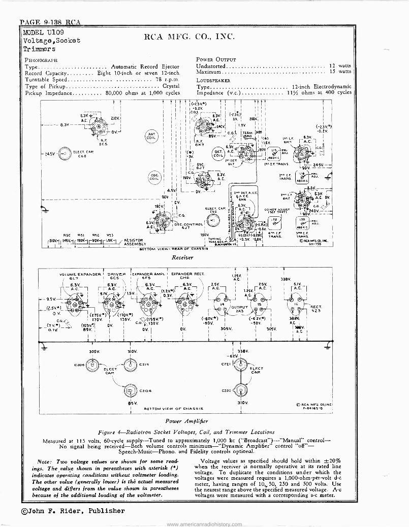
PAGE 9-138 RCA
MODEL U109 Voltage,Sooket Tr immer s
RCA MFG. CO., INC.
PHONOGRAPH
Type Automatic Record Ejector Record Capacity Eight 10 -inch or seven 12 -inch Turntable Speed 78 r.p.m. Type of Pickup Crystal Pickup Impedance 80,000 ohms at 1,000 cycles
POWER OuTPuT Undistorted 12 watts Maximum 15 watts
LOUDSPEAKER
Type 12 -inch Electrodynamic Impedance (v.c.) 11% ohms at 400 cycles
A.C. (-og- - -- - L A.F.
6C5
- 245V. ELECT. CAP
CAB
R50 R51 R52 R53
V. I r190111r90K1 LSV.
r 63V A.C. _J
{ ¡(-t.'3v.) t ' f ! t t t I I -0.2v.
Ì I I I
jCs (-E311N
142? -0°- © © A.C. I
O , 200V. ' -" I I :41 8V I
. Ai. I I >
I 0 I" I
I I
1 G--J I C.G'. ITERM. ¡MN -SSV.-J .,,
I D. 1 I(1 I i R. F.
. I
Il(116)
6NT 6.[V.-- A.C.
r,©` 16SV1
i(+k) Co L L + O ,- J I
I A ',000-1`DET',000-1 -J I ?i OSC. BL7
1 á 647 C.G
190V. L_
© Q© -0
L ---o A
0V.
C.G.
-- 13V. A.C. J
-J Y 2NO DET,A.V.0 4A.F.C.
6N6
6.3V. ELECT. CAP. i I r A.C-1
C50 r I +1j7l
OSC. CONTROL 647
190V.
RESISTOR I TUNING
ASSEMBLY I TUSE66S
Toti 1 , t 60TTOM VIEW- REAR OF CHASSIS
it* [.F. LI.CV. CNT
Receiver
F11I. ADJ.
9sT r.F. TRANS.
2w 1.r TRANS.
2-[.r 6147
DD NOT ADJUST MC TEXT)
r 0/ (-D.tfvJ
E62SV)(O.Itflrt)¡ 4TN.1.r
-0.3V. -016v.1
L 90 V. 245V_
-41 PRI. ADJ.
LSD IRI.
1LG
31m-I.F. TRANS. e SCA MNMK; 6 INE.
1
VOLUME EXPANDER I DRIVER 'EXPANDER AMPL.I EXPANDER RECT. GL7 I 6C5 I 6F5 I 6H6
L6.3V._ I 6.3V. 6.3V. El A.C. 1 I - A.c. r- A.c. ;In } 1
1.SV.1 i( )1 -C4 L 7 d\ I
WO CJ. 1 - 6.3V.
A.C.
}
(275V) 270 V.
(10311 0V. BSV. 1
I I
t i 1
300V.
C206
(1TOV.*) 135V. (151V.)
0.01.z,130 V.
011. I
I I I
t
}
}
310V.
2.6V.
r A.C.
-50V. I
0V. 305V. I I
i 1
BOTTOM VIEW OF CHASSIS
2.5v.
L25V. r A.C. 1 A.C.
J
310V.
I
(-6 2V.9 I
-50V. 1 305V.
I 1
Y i
RECT. 5Z3
368V2 1
AC39SV. I
I A. C. I
I i
® RCA MFG. CO,INC. P-64165-0
Power Amplifier
Figure 4-Radiotron Socket Voltages, Coil, and Trimmer Locations
Measured at 115 volts, 60 -cycle supply -Tuned to approximately 1,000 kc ("Broadcast") -"Manual" control - No signal being received -Both volume controls minimum -"Dynamic Amplifier" control "off" -
Speech -Music --Phono. and Fidelity controls optional.
Note: Two voltage values are shown for some read- ings. The value shown in parentheses with asterisk (*) indicates operating conditions without voltmeter loading. The other value (generally lower) is the actual measured voltage and differs from the value shown in parentheses because of the additional loading of the voltmeter.
Voltage values as specified should hold within ±20% when the receiver is normally operative at its rated line voltage. To duplicate the conditions under which the voltages were measured requires a 1,000 -ohm -per -volt d -c meter, having ranges of 10,, 50, 250 and 500 volts. Use the nearest range above the specified measured voltage. A -c voltages were measured with a corresponding a -c meter.
©John F. Rider, Publisher www.americanradiohistory.com
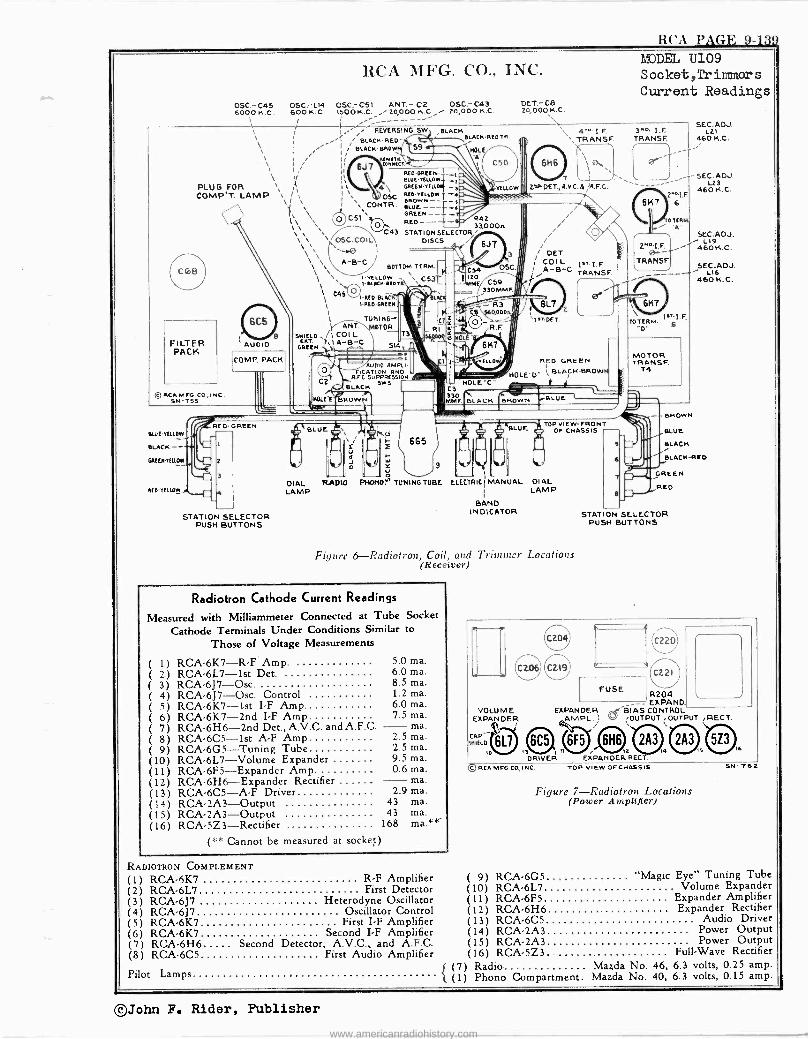
RCA PAGE 9-13f
RCA MFG. CO., INC.
OSC.-C45 OSCrL14 OSCr C51 ANT. -C2 OSC.- C43 6000 K.C. 60OK.C. 1500 K.C. 20,000 K.C.i 20,000 K.C.
DET.- CB 20, 000 K.C.
MODEL U109 S ocket,Tr inner s Current Readings
PLUG FOR COMP'T. LAMP `\ / 11
\1 \
REVERSING. SW.
BLACK.RED- , BLACN-BROwEIS9
MO II RIT[
BLACK .4-ThBI.ACK.RED TR.
II 61CONNECT.
FILTER PACK
()RCA MFO. co., INC. SN-TBS
BLUE -YELLOW
SLACK --
RED' 'nut,
AUDIO
[COMP. PACK
REO- GREEN
STATION SELECTOR PUSH BUTTONS
l'\ '\ \ \\
\\ \ \ \
\\\\ \\\
; C45 vl.A[D"BLAC 1RED-GREEN
TUNI NG- ANTr.-",,mOTOR
5NIE1.0 I COI L EFT j, 1 A -B -C
GREEN
C2
HOLES'
NROWN SLUE D y
4`, I 3v OSC
\ . CONTR. \
CS1`
OSC.COIL
A -B -C
514
5104.5EEN- eLUc'TELLOw GAEEN-VELLO*, RED- YELLOW y BROWN -- BLUE--- f GREEN - RED- -
C43 STATION DIS DI SCS
AUDIO AMPu- FICAT'ION ANO
AFC SUPPRESSION
BLACK Sw S .
Y
DIAL RADIO PHONON TUNING TUBE ELECTRIC
LAMP
-+L
ttLLOw
4".' I. F.
',MANSE
\ I
7 V_-. 2DET.,A.V.0 ß 41.F.C. `
6K7\ 6
R42
SELECTOR
, ' 33,OC10 i i 6J7 I i
3 DE7. I/ I COIL IET.LF.
zó OSC. I Ì /A -B -C
C59 III % \ DAOMMF. 11 i
iC Pr - R3
47'''.--------94 C6 4000n
ú IfT.DET. II
C3 330 MMF
TOP VIEW- FRONT OF CHASSIS
MANUAL DIAL LAMP
BAND INDICATOR
Figure 6-Radiotron, Coil, and Trimmer Locations (Receiver)
Radiotron Cathode Current Readings
Measured with Milliammeter Connected at Tube Socket
Cathode Terminals Under Conditions Similar to
Those of Voltage Measurements
( 1) RCA-6K7-R'F' Amp. ( 2) RCA -6L7 -1st Dct. ( 3) RCA-6J7-Osc. ( 4) RCA-6J7-Osc. Control ( 5) RCA'6K7-1st I -F Amp. ( 6) RCA -6K7 -2nd I -F Amp ( 7) RCA -6H6 -2nd Det.,A.V.C. and A.F.C. -ma. ( 8) RCA -6C5 -1st A -F Amp 2.5 ma. ( 9) RCA-6G5-Tuning Tube 2.5 ma. (10) RCA-6L7-Volume Expander 9.5 ma. (11) RCA-6F5-Expander Amp. 0.6 ma. (12) RCA-6H6-Expander Rectifier - ma. (13) RCA-6C5-A'F Driver 2.9 ma. (14) RCA-2A3-Output 43 ma. (15) RCA-2A3-Output 43 ma. (16) RCA-5Z3-Rectifier . 168 ma.**-
(** Cannot be measured at socket)
5.0 ma. 6.0 ma. 8.5 ma. 1.2 ma. 6.0 ma. 7.5 ma.
RADIOTRON COMPLEMENT
(1) RCA -5K7 R'F Amplifier (2) RCA -6L7 First Detector (3) RCA -6J7 Heterodyne Oscillator (4) RCA -6J7 Oscillator Control (5) RCA -6K7 First I -F Amplifier (6) RCA -6K7 Second I -F Amplifier (7) RCA -6H6 Second Detector, A.V.C., and A.F.C. (8) RCA -6C5 First Audio Amplifier
Pilot Lamps (7) Radio
'l (1) Phono Compartment.
3RD I.F. TRANSF.
' 1 _.
1.
TO TERM.
MOTOR TRANSF.
T4
2"a1.F. 0--' TRANSE
\
SEC. ADJ. L21
460 K.C.
- SEC. ADJ. LZ3
460 K.C.
-- DROWN
BLUE
BLACK
BLACK -RED
SEC.ADJ. L19
460 K.C.
__SEC. AD.! L16
460 K. C.
GREEN
REO
STAT ON SELECTOR PUSH BUTTONS
VOLUME EXPANDER
t ÉL 6L7 10
O
4
FUSE 8204 EXPAND.
EXPANDER ,r -..e -B1 BIAS CONTROL AMPL. ) OUTPUT .OUTPUT ,RECT.
o I313) I11 6F5
12
DRIVER EXPANDER RECT.
RCA MFG. CO., INC. TOP VIEW OF CHASSIS
4
Figure 7-Radiotron Locations (Power Amplifier)
6
SN -T62
( 9) RCA -6G5 "Magic Eye" Tuning Tube (10) RCA -6L7 Volume Expander (11) RCA -6F5 Expander Amplifier (12) RCA -6H6 Expander Rectifier (13) RCA -6C5 Audio Driver (14) RCA -2A3 Power Output (15) RCA -2A3 Power Output (16) RCA -5Z3. Full -Wave Rectifier
Mazda No. 46, 6.3 volts, 0.25 amp. Mazda No. 40, 6.3 volts, 0.15 amp.
©John F. Rider, Publisher
www.americanradiohistory.com
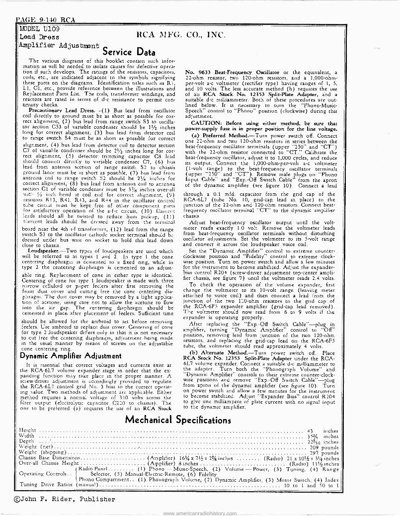
PAGE 9-140 RCA MODEL U109 Lead Dress RCA MFG. CO., Amplifier Adjustment
Service Data The various diagrams of this booklet contain such infor-
mation as will be needed to isolate causes for defective opera- tion if such develops. The ratings of the resistors, capacitors, coils, etc., are indicated adjacent to the symbols signifying these parts on the diagrams. Identification titles such as R1, L1, Cl, etc., provide reference between the illustrations and Replacement Parts List. The coils, transformer windings, and reactors are rated in terms of d -c resistance to permit con- tinuity checks.
Precautionary Lead Dress.-(1) Bus lead from oscillator coil directly to ground must be as short as possible for cor- rect alignment, (2) bus lead from range switch S3 to oscilla- tor section C53 of variable condenser should be 11/2 inches long for correct alignment, (3) bus lead from detector coil to range switch S4 must be as short as possible for correct alignment, (4) bus lead from detector coil to detector section C7 of variable condenser should be 21/2 inches long for cor- rect alignment, (5) detector trimming capacitor C8 lead should connect directly to variable condenser C7, (6) bus lead from antenna section of range switch S2 to chassis ground lance must be as short as possible, (7) bus lead from antenna coil to range switch S2 should be 21/4 inches for correct alignment, (8) bus lead from antenna coil to antenna section Cl of variable condenser must be 37/8 inches over-all with % inch bend at coil end for correct alignment, (9) resistors R13, R41, R43, and R44 in the oscillator control tube circuit must be kept free of other component parts for satisfactory operation of the a -f -c circuit, (10) filament leads should all be twisted to reduce hum pickup, (11) filament leads should be dressed away from the terminal board near the 4th i -f transformer, (12) lead from the range switch S3 to the oscillator cathode socket terminal should be dressed under bus wire on socket to hold this lead down close to chassis.
Loudspeaker.-Two types of loudspeakers are used which will be referred to as types 1 and 2. In type 1 the cone centering diaphragm is cemented to a fixed ring, while in type 2 the centering diaphragm is cemented to an adjust- able ring. Replacement of cone in either type is identical. Centering of cone for type 1 loudspeaker is made with three narrow celluloid or paper feelers after first removing the front dust cover and cutting free the cone centering dia- phragm. The dust cover may be removed by a light applica- tion of acetone, using care not to allow the acetone to flow into the air gap. The centering diaphragm should be cemented in place after placement of feelers. Sufficient time should be allowed for the ambroid to set before removing feelers. Use ambroid to replace dust cover. Centering of cone for type 2 loudspeaker differs only in that it is not necessary to cut free the centering diaphragm, adjustment being made in the usual manner by means of screws on the adjustable cone centering ring.
Dynamic Amplifier Adjustment It is essential that correct voltages and currents exist at
the RCA -6L7 volume expander stage in order that the ex- panding function may take place in the proper manner. A screw -driver adjustment is accordingly provided to regulate the RCA -6L7 control grid No. 3 bias to the correct operat- ing value. Two methods of adjustment are applicable. Either method requires .a normal voltage of 310 volts across the filter output (electrolytic capacitor C220 to chassis). The one to be preferred (a) requires the use of an RCA Stock
INC.
No. 9633 Beat -Frequency Oscillator or the equivalent, a 22 -ohm resistor, two 120 -ohm resistors, and a 1,000 -ohm - per -volt a -c voltmeter (rectifier type) having ranges of 1, 5, and 10 volts. The less accurate method (b) requires the use of an RCA Stock No. 12353 Split -Plate Adapter, and a suitable d -c milliammeter. Both of these procedures are out- lined below. It is necessary to turn the "Phono -Music - Speech" control to "Phono" position (clockwise) during this adjustment.
CAUTION: Before using either method, be sure that power -supply fuse is in proper position for the line voltage.
(a) Preferred Method.-Turn power switch off. Connect one 22 -ohm and two 120 -ohm resistors in series between the beat -frequency oscillator terminals (upper "250" and "CT") with the 22 -ohm resistor connected to "CT." Calibrate the beat -frequency oscillator, adjust it to 1,000 cycles, and reduce its output. Connect the 1,000 -ohm -per -volt a -c voltmeter (1 -volt range) to the beat -frequency oscillator terminals (upper "250" and "CT"). Remove male plugs on "Phono Input Cable" and "Exp.-Off Switch Cable" from the apron of the dynamic amplifier (see figure 10). Connect a lead
through a 0.1 mfd. capacitor from the grid cap of the RCA -6L7 (tube No. 10, grid -cap lead in place) to the junction of the 22 -ohm and 120 -ohm resistors. Connect beat - frequency oscillator terminal "CT" to the dynamic amplifier chassis.
Adjust beat -frequency .oscillator output until the volt- meter reads exactly 1.0 volt. Remove the voltmeter leads from beat -frequency oscillator terminals without disturbing oscillator adjustments. Set the voltmeter to its 5 -volt range and connect it across the loudspeaker voice coil.
Set the "Dynamic Amplifier" control to extreme counter- clockwise position and "Fidelity" control to extreme clock- wise position. Turn on power switch and allow a few minutes for the instrument to become stabilized. Adjust the expander - bias control R204 (screw -driver adjustment top -center ampli- fier chassis, see figure '7) until the voltmeter reads 2.4 volts.
To check the operation of the volume expander, first change the voltmeter to its 10 -volt range (leaving meter attached to voice coil) and then connect a lead from the junction of the two 120 -ohm resistors to the grid cap of the RCA -6F5 expander amplifier (grid -cap lead removed). The voltmeter should now read from 6 to 9 volts if the expander is operating properly.
After replacing the "Exp.-Off Switch Cable"-plug in amplifier, turning "Dynamic Amplifier" control to "Off" position, removing lead from junction of the two 120 -ohm resistors, and replacing the grid -cap lead on the RCA -6F5 tube, the voltmeter should read approximately 4 volts.
(b) Alternate Method.-Turn power switch off. Place RCA Stock No. 12353 Split -Plate Adapter under the RCA - 6L7 volume expander. Connect a suitable d -c milliammeter to the adapter. Turn both the "Phonograph Volume" and "Dynamic Amplifier" controls to their extreme counter -clock- wise positions and remove "Exp.-Off Switch Cable"-plug from apron of the dynamic amplifier (see figure 10). Turn on power switch and allow a few minutes for the instrument to become stabilized. Adjust "Expander Bias" control R204 to give one milliampere of plate current with no signal input to the dynamic amplifier.
Mechanical Specifications Height 43 inches Width 35% inches Depth 227/18 inches Weight (net) 209 pounds Weight (shipping) 297 pounds Chassis Base Dimensions (Amplifier) 16% x 7% x 27/8 inches (Radio) 21 x 10% x 3% inches Over-all Chassis Height (Arllplifier) 8 inches (Radio) 11% inches
Radio Panel (1) Phono-Music-Speech, (2) Volume-Power, (3) Tuning, (4) Range Operating Controls.. Selector, (5) Manual -Electric -Remote, (6) Fidelity
Phono Compartment (1) Phonograph Volume, (2) Dynamic Amplifier, (3) Motor Switch, (4) Index Tuning Drive Ratios (manual) 10 to 1 and 50 to 1
©John F. Rider, Publisher
www.americanradiohistory.com
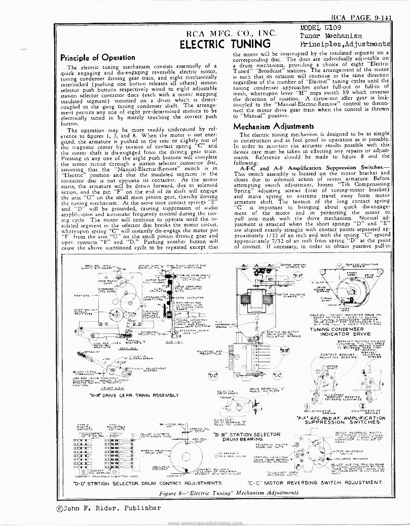
RCA PAGE 9-141
RCA MFG. CO., INC.
ELECTRIC TUNING Principle of Operation
The electric tuning mechanism consists essentially of a
quick engaging and disengaging reversible electric motor, tuning condenser driving gear train, and eight mechanically interlocked (pushing one button releases all others) station selector push buttons respectively wired to eight adjustable station selector contactor discs (each with a motor stopping insulated segment) mounted on a drum which is direct - coupled to the gang tuning condenser shaft. The arrange- ment permits any one of eight pre -determined stations to be electrically tuned in by merely touching the correct push button.
The operation may be more readily understood by ref- erence to figures 1, 5, and 8. When the motor is not ener gized, the armature is pushed to the rear or slightly out of the magnetic center by tension of contact spring "C" and the motor shaft is dis -engaged from the driving gear train. Pressing in any one of the eight push buttons will complete the motor circuit through a station selector contactor disc, assuming that the "Manual -Electric -Remote" switch is in "Electric" position and that the insulated segment in the contactor disc is not opposite its contactor. As the motor starts, the armature will be drawn forward, due to solenoid action, and the pin "F" on the end of its shaft will engage the arm "G" on the small main pinion gear, thereby driving the tuning mechanism. At the same time contact springs "E" and "D" will be grounded, causing suppression of audio amplification and automatic frequency control during the tun- ing cycle. The motor will continue to operate until the in- sulated segment in the selector disc breaks the motor circuit, whereupon spring "C" will instantly dis -engage the motor pin "F" from the arm "G" on the small pinion driving gear and open contacts "E" and "D." Pushing another button will cause the above mentioned cycle to be repeated except that
MODEL U109 Tuner Mechanism Principles,Adjustments
the motor will be interrupted by the insulated segment on a
corresponding disc. The discs are individually adjustable on a drum mechanism, providing a choice of eight "Electric Tuned" "Broadcast" stations. The arrangement of the motor is such that its rotation will continue in the same direction regardless of the number of "Electric" tuning cycles until the tuning condenser approaches either full -out or full -in of mesh, whereupon lever "H" trips switch S9 which reverses the direction of rotation. A throw -out idler gear is link - coupled to the "Manual -Electric -Remote" control to discon- nect the motor drive gear train when the control is thrown to "Manual" position.
Mechanism Adjustments The electric tuning mechanism is designed to be as simple
in construction and as fool proof in operation as is possible. In order to maintain the accurate results possible with this device care must be taken in effecting any repairs or adjust- ments. Reference should be made to figure 8 and the following:
A -F -C and A -F Amplification Suppression Switches.- This switch assembly is located on the motor bracket and closes due to solenoid action of motor armature. Before attempting switch adjustment, loosen "Tilt Compensating Spring" adjusting screws (rear of tuning -motor bracket) and move spring to extreme travel away from motor armature shaft. The tension of the long contact spring "C" is important in bringing about quick disengage- ment of the motor and in permitting the motor to pull into mesh with the drive mechanism. Normal ad- justment is attained when the short springs "D" and "E" are aligned exactly straight with contact points separated ap- proximately 1/32 of an inch and with the spring "C" spaced approximately 7/32 of an inch from spring "D" at the point of contact. If necessary, in order to obtain positive pull -in
4E SH I MOTOR wv FT. . MAIN PINION - RR t' RND ñß K' aTRTIÓNRRY- yIRE [NCAGINC N F RRM'G' SM1{TSa
111
`+ I
`
I
.Mum.` II .NC CONDENSER 1 GRNIM ORNE TILT I1 SNRFT RNID PINIº4Tb COMPENS"TINO
CERR aTH sRRIND
11- -' % ECCENTRIL 111"72&""w GGROJUSTING
SCRGW i:F ` NH RND LEVER STKrSÓ1G N
STHIig j2EAR vlEw SPRING M
iNH
ADJUST TO TNI a. DIMENSION R RND IEVER A9SGMBY
RDJUSTMENT. MRNIJ ELECCTRIC' REMOTE aWITCH IN RGNIOTC POSITION.
FRONT VIEW
'R -Fi DRIVE GERR
STN 1{T{I
SCERR RND SET
ST ÑGij{i 59
ETED ADJUSTABLE CONTACTS CONTACTS
es el,
CONTACT R SELS
CONTACT ASSEMBLIES SEMBMBLIES(BbTTOM VIEW)
"D D' STATION SELECTOR
MOTR UL O RRD
'M CERR
STKI{TSt
LEPw'UG 3G E
M
'lLOT I
CHA5515 RFIroN
DRppUrvUE cenaS5RRM.J
pp
MgT'll{ETUD
STIÚG ázTIÑG
GERB STHNTSS 6GST -BACKLASH
SORS GERB ON TUNIN.GT. COMO SHAFT.
SIDE VIEW
EVEP CREWSMENT SCREWS
TRRIN R55EMBLY
""..g PR SOU
ADJUST CONTACTS TO STRAIGHT EDGE
iT DRUM DISK
TOR
I
SC-GMGÑTD
CONTRCT
ADJUSTING ETE RECEPTACL
e meM DN%FT
SDwvENI B RE RE IN6 'x' ADJU6TING SCREw!
STÖTIq ADJ.
"B -B" STATION SELECTOR KUcr
+' DRUM BEARING. ADJUSTING NUTS
MOTOR BRAce. SCREWS W
OTOR MOUNTING SCREWS "V'
DRUMOCOUPLINGTOR ADJUSTING SCREWS
DRUM BEARING PpJVl TINO PLATE
Tx 6-1 ©RCA MFG L ,INC. STATION SELECTOR
DRUM REAR ELBRING RDJUSTNG BCREwa
TÓ CENTCER OFJINSULRT[D SEGMENT WITH HEY IN SLOT
DRUM CONTRC1 ADJUSTMENTS "C -C"
NKR[WJUETING
CAUTION:- ADJUST INDICATOR DRUM ON SHAFT SO TORT 'C' SLOT IS CLEAR OF TUNING COODDGcé.Gió VERNIER" ÓRT AND
F GPOSITIONSF - D ULL-IN MESH.
TUNING CONDENSER INDICATOR DRIVE
BRACHET ROTATED COUNTER CLOG HYI'yIySE TIMLpL THgI SySPRCE
% Í?ÌTRIÉME RI TINilIFiT RETIGNTEN
BRACKET CONTACT BRACKET RDJUETINR ADJUSTING SCREWS? 5CREW5
Il lORFR / i
ADJUSTME SPRANG
ADJUSTMENTET
"F -F" A.F.C. AND A.F. AMPLIFICATION SUPPRESSION SWITCHES.
OJUOJNT NGT NÚT"
PISOD4CRTOCHTHUL TOUCH
CNDeN Eeee FULZee' MESH.
MOTOR REVERSING SW ITCH
INSULATED SEGMENT
G COR ICAL WHEN TTUN LEVER I17 VERTICAL WH[N TUN Ë gHOND[NSER IB FULL OUT OF
MOTOR REVERSING SWITCH ADJUSTMENT.
Figure 8-"Electric Tuning" Mechanism Adjustments
©John F. Rider, Publisher
www.americanradiohistory.com
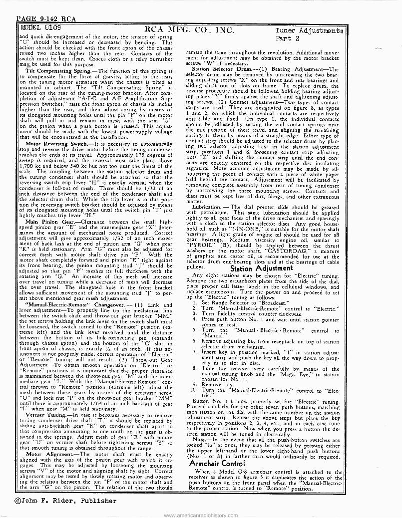
PAGE 9-142 RCA DEL U109 RCA MFG
and quick disengagement of the motor, the tension of spring "C" should be increased or decreased by bending. This action should be checked with the front apron of the chassis raised two inches higher than the rear. Contacts of the switch must be kept clean. Crocus cloth or a relay burnisher ma be used for this purpose.
tilt Compensating Spring.-The function of this spring is to compensate for the force of gravity, acting to the rear, on the tuning motor armature when the chassis is tilted as mounted in cabinet. The "Tilt Compensating Spring" is located on the rear of the tuning -motor bracket. After com pletion of adjustment "A -F -C and A -F Amplification Sup- pression Switches," raise the front apron of chassis six inches higher than the rear, and then adjust spring by means of its elongated mounting holes until the pin "F" on the motor shaft will pull in and remain in mesh with the arm "G" on the pinion when a push button is pressed. This adjust, ment should be made with the lowest power -supply voltage that will be encountered at the installation.
Motor Reversing Switch.-It is necessary to automatically stop and reverse the drive motor before the tuning condenser reaches the ends of its travel. Approximately 175 degrees of sweep is required, and the reversal must take place above 1,700 kc and below 540 kc but not too near the limits of the scale. The coupling between the station selector drum and the tuning condenser shaft should be attached so that the reversing switch trip lever "H" is exactly vertical when the condenser is full -out of mesh. There should be 1/32 of an inch clearance between the end of the condenser shaft and the selector drum shaft. While the trip lever is in this posi- tion the reversing switch bracket should be adjusted by means of its elongated mounting holes until the switch pin "I" just lightly touches trip lever "H."
Main Pinion Gear.-Clearance between the small high- speed pinion gear "E" and the intermediate gear "K" deter mines the amount of mechanical noise produced. Correct adjustment will give approximately 1/32 of an inch move- ment of back lash at the end of pinion arm "G" when gear "K" is held stationary. Arm "G" must also be adjusted for correct mesh with motor shaft drive pin "F." With the motor shaft completely forward and pinion "E" tight against its front bearing, the pinion mounting stud "J" should be adjusted so that pin "F" meshes its full thickness with the rotating arm "G." An increase of this mesh will increase over travel on tuning while a decrease of mesh will decrease the over travel. The elongated hole in the front bracket allows sufficient movement of the mounting stud "J" to per. mit above mentioned gear mesh adjustment.
"Manual -Electric -Remote" Changeover. - (1) Link and lever adjustment-To properly line up the mechanical link between the switch shaft and throw -out gear bracket "MM," the set screws holding the link lever on the switch shaft must be loosened, the switch turned to the "Remote" position (ex treme left) and the link lever revolved until the distance between the bottom of its link -connecting pin (extends through chassis apron) and the bottom of the "C" slot, in front apron of chassis, is exactly 1/4 of an inch. If this ad justment is not properly made, correct operation of "Electric" or "Remote" tuning will not result. (2) Throw -out Gear Adjustment-To obtain smooth operation on "Electric" or "Remote" positions it is important that the proper clearance is maintained between the throw -out gear "M" and the inter- mediate gear "L." With the "Manual -Electric -Remote" con- trol thrown to "Remote" position (extreme left) adjust the mesh between these gears by means of the eccentric screw "0" and lock nut "P" on the throw -out gear bracket "MM" until there is approximately 1/64 of an inch backlash of gear "L" when gear "M" is held stationary.
Vernier Tuning.-In case it becomes necessary to remove tuning condenser drive shaft "T," it should be replaced by sliding anti -backlash gear "R" on condenser shaft apart so that compression amounting to one tooth on the gear is ob. tained in the springs. Adjust mesh of gear "R" with pinion gear "U" on vernier shaft before tightening screws "S" so that smooth tuning is obtained throughout the range.
Motor Alignment.-The motor shaft must be exactly aligned with the axis of the pinion gear with which it en- gages. This may be adjusted by loosening the mounting screws "V" of the motor and aligning shaft by sight. Correct alignment may be tested by slowly rotating motor and observ- ing the relation between the pin "F" of the motor shaft and the arm "G" on the pinion. The relation of the two should
. CO.. INC. Tuner Adjustments Part 2
remain the same throughout the revolution. Additional move- ment for adjustment may be obtained by the motor bracket screws "W" if necessary.
Station Selector Drum.-(1) Bearing Adjustment-The selector drum may be removed by unscrewing the two bear ing adjusting screws "X" on the front and rear bearings and sliding shaft out of slots on frame. To replace drum, the reverse procedure should be followed holding bearing adjust- ing plates "Y" firmly against the shaft and tightening adjust- ing screws. (2) Contact adjustment-Two types of contact strips are used. They are designated on figure 8, as types 1 and 2, on which the individual contacts are respectively adjustable and fixed. On type 1, the individual contacts should be ,adjusted by setting the end contact springs near the mid -position of their travel and aligning the remaining springs to them by means of a straight edge. Either type of contact strip should be adjusted to the selector drum by plac- ing two selector adjusting keys in the station adjustment strip, positions 1 and 8, loosening contact strip adjusting nuts "Z" and shifting the contact strip until the end con tacts are exactly centered on the respective disc insulating segments. More accurate adjustment may be made by sil houetting the point of contact with a piece of white paper held behind the contact. Adjustment will be facilitated by removing complete assembly from rear of tuning condenser by unscrewing the three mounting screws. Contacts and discs must be kept free of dirt, filings, and other extraneous matter.
Lubrication. - The dial pointer slide should be greased with petrolatum. This same lubrication should be applied lightly to all gear faces of the drive mechanism and sparingly with a cloth to the station selector discs. Any good house hold oil, such as "3 -IN -ONE," is suitable for the motor shaft bearings. A light grade of engine oil should be used for all gear bearings. Medium viscosity engine oil, similar to
PYROIL" (B), should be applied between the thrust washers on the motor shaft. "CASTORDAG," a mixture of graphite and castor oil, is recommended for use at the selector drum end -bearing slots and at the bearings of cable pulleys. Station Adjustment
Any eight stations may be chosen for "Electric" tuning. Remove the two escutcheon plates from the side of the dial, place proper call letter labels in the celluloid windows, and replace escutcheons. Turn the power on and proceed to set up the "Electric" tuning as follows:
1. Set Range Selector to "Broadcast." 2. Turn "Manual -Electric -Remote" control to "Electric." 3. Turn Fidelity control counter -clockwise. 4. Press push button No. 1 and wait until station pointer
comes to rest. 5. Turn the "Manual Electric Remote" control to
"Manual." 6. Remove adjusting key from receptacle on top of station
selector drum mechanism. 7. Insert key in position marked, "1" in station adjust
ment strip and push the key all the way down to prop- erly fit in slot in disc.
8. Tune the receiver very carefully by means of the manual tuning knob and the "Magic Eye," to station chosen for No. 1.
9. Remove key. 10. Turn the "Manual -Electric -Remote" control to "Elec.
tric." Button No. 1 is now properly set for "Electric" tuning.
Proceed similarly for the other seven push buttons, matching each station on the dial with the same number on the station adjustment strip. Repeat the above steps but place the key respectively in positions 2, 3, 4, etc., and in each case tune to the proper station. Now when you press a button the de- sired station will be tuned in electrically.
Note.-In the event that all the push-button switches are locked "ia" at once, they may be released by pressing either the upper left-hand or the lower right-hand push buttons (Nos. 1 or 8) in farther than would ordinarily be required. Armchair Control
When a Model G-8 armchair control is attached to the receiver as shown in figure 5 it duplicates the action of the push buttons on the front panel when the 'ManualElectric- Remote" control is turned to "Remote" position.
©John. F. Rider, Publisher
www.americanradiohistory.com
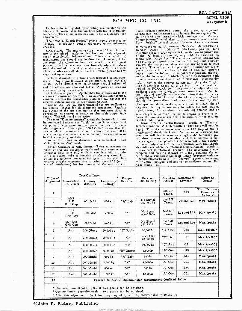
RCA PAGE 9-143
RCA MFG. CO.,
Calibrate the tuning dial by adjusting dial pointer to the left ends of horizontal calibration lines with the gang tuning, condenser plates in full -mesh position. This is a screw -driver adjustment.
The "Manual -Electric -Remote" switch should be turned to "Manual" (clockwise) during alignment unless otherwise specified.
CAUTION.-The magnetite core screw L22 on the bot- tom of the 4th i -f transformer has been accurately adjusted, for an exact electrical balance of coil L22 to center tap, during manufacture and should not be disturbed. However, if for any reason the adjustment has been moved from its original position, it will be necessary to mechanically adjust this screw until the end of the stud protrudes exactly A of an inch (four threads exposed) above the brass bushing prior to any alignment operations.
Perform alignment in proper order, tabulated below, starts ing with No. 1 and following all operations across, then N. 2, etc. A -f -c discriminator adjustments should_ follow, r -f and i -f adjustments tabulated below. Adjustment locations are shown on figures 4 and 6.
Cathode-ray alignment ispreferable; the connections to the chassis are shown on figure 2. If an output indicator is used, connect it across the loudspeaker voice -coil and advance the receiver volume control to full -volume position.
Connect the "love output terminal of the test oscillator to the receiver chassis for all alignment operations. Regulate the output of the test oscillator so that minimum signal is applied to the receiver to obtain an observable output indi- cation. This will avoid a -v -c action.
The term "Dummy antenna" means the device which must be connected between the "high" test -oscillator output and the point of connection to the receiver in order to obtain ideal alignment. "No signal, 550.750 kc" means that the receiver should be tuned to a point between 550 and 750 kc where no signal or interference is received from a station or local (heterodyne) oscillator.
For further details on alignment, refer to booklet "RCA Victor Receiver Alignment."
A -F -C Discriminator Adjustments.-These adjustments are rather critical and should, be performed with extreme care. Improper adjustment mai' result in complete failure of the oscillator control tube to function or else may cause it to detune the oscillator instead of tuning it to the signal. It is assumed that the magnetite core adjusting screw L23 (top of 4th i -f transformer) has been turned all the way out (ex,
INC. MODEL U109 Alignment
treme counter -clockwise) during the preceding tabulated adjustments. Adjustments are as follows: Remove spring "N" on link and arm assembly which connects the "Manual - 'Electric -Remote" switch shaft to the throw -out gear bracket. Turn "Fidelity" control counter -clockwise. Connect antenna
to receiver antenna "A" terminal. With the "Manual -Electric. Remote" switch in "Manual" (clockwise) position, tune in a strong local station near 600 kc or the low -frequency end of the "A" band as accurately as possible by means of the tuning tube "Magic Eye." The most accurate adjustment will
be obtained by adjusting the "vernier" tuning knob mid -way between the two points where the eye just appears to start to open. This will place the generated i -f carrier signal fre- quency exactly in the center of the i -f amplifier response curve (should be 460 kc if i -f amplifier was properly aligned) and is the frequency to which the a -f -c discriminator (4th i -f transformer) should be tuned to resonance. Without dis-
turbing any of the receiver adjustments, place the "high" test -oscillator lead about 3/4 of an inch from- the grid cap lead of the RCA -6K7, 1st i -f amplifier tube, adjust the test - oscillator output to maximum, turn test -oscillator "Modula- tion" off, and carefully zero -beat the test -oscillator frequency (approximately 460 kc) with the i -f carrier signal. Avoid placing the test -oscillator lead nearer to the grid cap lead
than specified above, as doing so will tend to detune the i -f amplifier. It may be necessary to reduce the local station signal, during this operation, by shortening antenna lead or grounding antenna "A" terminal to chassis in order to in, crease the loudness of the beat note sufficiently for accurate zero -beat adjustment.
Throw "Manual -Electric -Remote" switch to "Electric" (center) position. A high whistle or beat note will now be heard. Turn the magnetite core screw L23 (top of 4th if transformer) slowly clockwise. As this screw is turned, the beat note will first increase to a high audio frequency and will then decrease to a zero -beat and then increase in fre- quency again. The point of exact zero -beat is the position for correct adjustment of the discriminator. Zero -beat should also still exist when the "Manual -Electric -Remote" switch is thrown back to "Manual" position. The adjustment is now complete and may be checked by slightly detuning the re- ceiver above and below the local station frequency with the "Manual -Electric -Remoti in "Manual" position, switching to "Electric" position, and noting the oscillator pull -in. Re place spring "N."
Order of Alignment
Test Oscillator Range- Selector
Receiver Dial Setting
Circuit to Adjust
Adjustment Symbols
Adjust to Obtain Connection
to Receiver Dummy Antenna
Frequency Setting
1 4th I -F Trans. L23
Turn Extreme Counter- clockwise
2 6K7 I -F
Grid Cap .001 Mfd. 460 kc "A" Left No Signal
550-750 kc 3rd I -F Trans. L20 and L21 Max. (peak)
3 6K7 I F
Grid Cap .001 Mfd. 460 kc No Signal
550-750 kc 2nd I -F Trans. L18 and L19 Max. (peak)
4 6L7 Det. Grid Cap .001 Mfd. 460 kc "A" No Signal
550-750 kc 1st I -F Trans. L15 and L16 Max. (peak)
5 Ant. 300 Ohms 20,000 kc "C" Right 20,000 kc "C" Osc. C43 Max. (peak)*
6 Ant. 300 Ohms 20,000 kc Rock thru 20,000 kc "C" Det. C8 Max. (peak)[
7 Ant. 300 Ohms 20,000 kc C 20,000 kc "C" Ant. C2 Max. (peak)$
8 Ant. 300 Ohms 6,000 kc "B" Center 6,000 kc "B" Osc. C45 Max. (peak)*
9 Ant. 200 Mmfd. 600 kc "A" Left 600 kc "A" Osc. L14 Max. (peak)
10 Ant. 200 Mmfd. 1,500 kc "A" 1,500 kc "A" Osc. C51 Max. (peak)
11 Ant. 200 Mmfd. 600 kc "A" 600 kc "A" Osc. L14 Max. (peak)
12 Ant. 200 Mmfd. 1,500 kc "A 1,500 kc "A" Osc. C51 Max. (peak)
13 Proceed to A -F -C Discriminator Adjustments Outlined Below
* Use minimum capacity peak if two peaks can be obtained. f Use maximum capacity peak if two peaks can be obtained. $ After this adjustment, check for image signal by shifting receiver dial to 19,080 kc.
©John F. Rider, Publisher
www.americanradiohistory.com
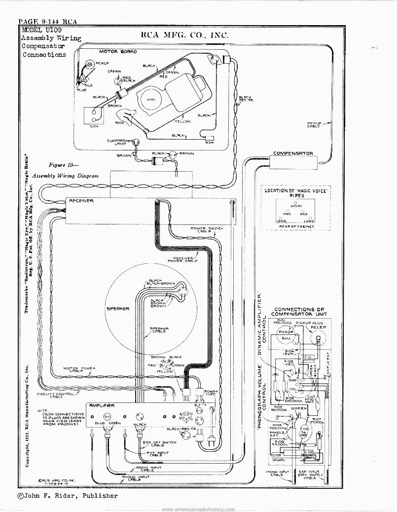
PAGE 9-144 RCA
Figure 10- m
To m Assembly Wiring Diagram
tj :
Ú RECENéR v
< U
it; ,tä,
eó ) : á
1..03 I
p y I
m I
V
8 ro
N`TE COLOR CONNECTIONS TO PLUGS ARESHOWN REAR VIEW (AWAY FROM PRONGS).
`\ !RR ReLEPUT
PHONO INPUT ` CRIßLF
©John F. Rider, Publisher
www.americanradiohistory.com
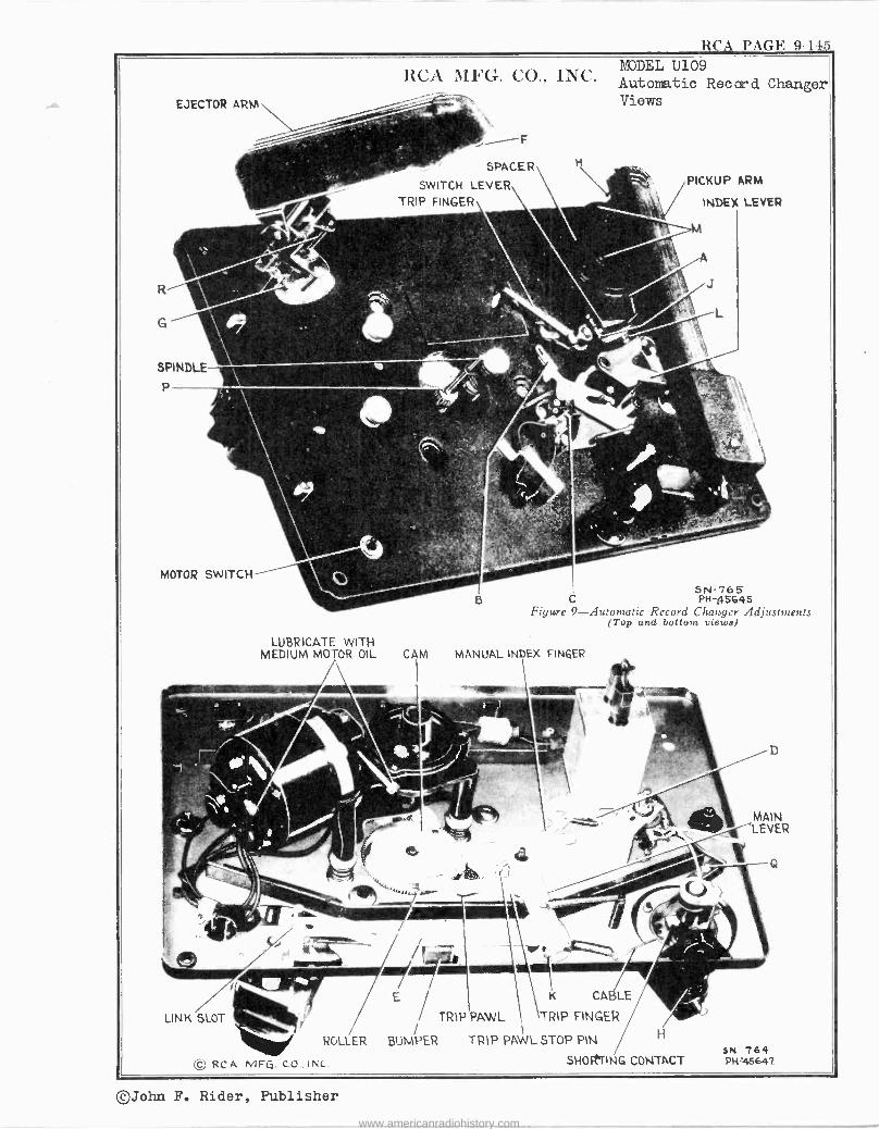
RCA PAGE 9-145 MODEL U109 RCA MFG. CO., INC. Automatic Record Changer Views
3N-765 C PH -45645
Figure 9-Automatic Record Changer Adjustments (Top and bottom views)
K CA1
PAWL TRIP FINGER
TRIP PAWL STOP PIN
©John F. Rider, Publisher
www.americanradiohistory.com
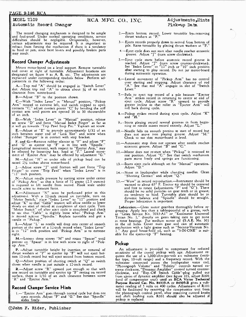
VAGE 9-146 RCA
LUDEL U109 Automatic Record Changer
RCA MFG. CO., INC.
The record changing mechanism is designed to be simple and fool -proof. Under normal operating conditions, service difficulties should be negligible. Occasionally, however, certain adjustments may be required. It is important to refrain from forcing the mechanism if there is a tendency to bind or jam, since bent levers and possibly broken parts may result.
Record Changer Adjustments Mount motor -board on a level support. Remove turntable
and cover at right of turntable. Adjustment locations are designated on figure 9 as A, B, etc. The adjustments are explained under corresponding symbols below Perform ad- justments in the following order:
A.-Trip rod "A" should be engaged in "Switch Lever" slot. Adjust trip rod "A" to obtain about % of an inch clearance from motor -board.
B.-Adjust "B" to the position shown. C.-With "Index Lever" in "Manual" position, "Pickup
Arm" rotated to extreme left, and switch tripped to open contacts "C," adjust contact points "C:' by bending the stiff contact arm until points are opened 10 to 30 thousandths of an inch.
D.-With "Index Lever" in "Manual" position, release set screw "D" and force "Manual Index Finger" as far as it will go towards "Trip Pawl Stop Pin." Tighten set screw.
E.-Adjust at "E" to provide approximately 1/32 of an inch between outer end of "Link Slot" and screw when rubber "Bumper" is in contact with stop bracket.
F. and G.-Remove rubber silencer at "F" and adjust "F" and "G" so ejector tip "F" is in line with "Spindle." Longitudinal movement, with respect to "Ejector Arm," may be effected by loosening hex. head at "F." Lateral move- ment of "Ejector Arm" may be effected by adjustment "G."
H.-Adjust "H" so under side of pickup head can be raised 2% inches above motor -board.
J.-Adjust screw "J" until friction will just force "Trip Finger' to move "Trip Pawl" when "Index Lever" is in "12" inch position.
N.-Adjust needle pressure by turning screw under center of "Pickup Arm" so that a force of 72 grams (2.5 ounces) is required to lift needle from record. Hook scale under needle screw to measure force.
K.-Adjustment "N" must be performed prior to this adjustment. With a 12 -inch record on turntable, turn on "Motor Switch," place "Index Lever" to "12" position and adjust "K" so that "Cable" tension will allow needle to lower slowly on start of record at completion of eject cycle. Turn "Motor Switch" off after eject cycle is completed and check to sec that "Cable" is slightly loose when "Pickup Arm" is moved against "Spindle." Replace turntable and put a needle in "Pickup."
L.-Adjust "L" so needle will drop into center of smooth portion at the start of a 12 -inch record when "Index Lever" is in "12" inch position and "Pickup Arm" is to extreme right.
M.-Loosen three screws "M" and rotate "Spacer" until pointer on "Spacer" is in line with screw to right of "Pick- up Arm."
P.-Adjust turntable height by insertion or removal of thrust washers at "P" so ejector tip "F" will not eject bot tom 12 -inch record but will eject second from bottom record.
Q.-Adjust position of shorting switch at "Q" so switch closes when needle is just outside a 12 -inch record.
R.-Adjust screw "R" upward just enough so that with one record on turntable and ejector tip "F" resting on record surface, there is 1/32 of an inch clearance between screw "R and "Ejector Aim."
Record Changer Service Hints 1.-"Ejector Arm" goes through normal cycle but does not
eject records. Adjust "F" and "G." See that "Spindle" slides freely.
Adjustments ,Hints Pick-up Data
2.-Ejects bottom record. Lower turntable by_ removing thrust washers at "P."
3.-Ejects records properly down to second from bottom of pile. Raise turntable by placing thrust washers at "P."
4.-Eject cycle does not start after needle reaches eccentric groove. Adjust "J" (turn screw clockwise).
5.-Eject cycle starts before eccentric record groove is reached. Adjust "J" (turn screw counter -clockwise). Set "Index Lever" to "12" inch or "10" inch position after starting to play record. Do not jar motor -board during automatic operation.
6.-Lateral movement of "Pickup Arm" has no control over starting and stopping. Adjust clearance of rod "A." See that rod "A" engages in slot of "Switch Lever."
7.-Fails to eject top record of a pile because "Ejector Arm" strikes record in returning to center at end of eject cycle. Adjust screw "R" upward to. provide greater incline so that roller in "Ejector Arm" will roll back during cycle.
8.-Pickup strikes record during eject cycle. Adjust "K" and "H."
9.-Starts playing record several grooves in from begin- ning or needle misses record entirely. Adjust "L.-
10.-Needle falls on smooth portion at start of record but does not move into playing groove. Adjust "M." Check to see that motor -board is level.
11.-Automatic stop does not operate after needle reaches eccentric groove. Adjust "B" and "C."
12.-Motor does not re -start when "Pickup" is returned to rest position. Adjust "C." See that switch mechanism parts move freely and springs are functioning.
13.-Starts eject cycle although set for "Manual" operation. Adjust "D."
14.-Noise in loudspeaker while changing needles. Clean "Shorting Contact" and adjust "Q."
15.-"Wow" in record reproduction.-Instrument should be warmed to about 65° F. Ejector tip should be centered and free to rotate (adjustments "F" and "G"). There should be no solid particles on gear teeth or in grease; no tendency to bind. Turntable plate should be in dynamic balance and "Spindle" should be straight. Proper lubrication is important.
Lubrication.-Clean motor gear -box thoroughly before re - greasing. Apply less than a tablespoonful of a grease, such as "Cities Service No. 7035 -Al" or "Koolmotor Universal Trojan No. 1," directly on gears taking care to get none in rotor bearings. Put medium motor oil (S.A.E. No. 30) in the oil holes. Cover main gear and cam of automatic mechanism with a light grease such as "Socony-Vacuum No. 2." Any good house -hold oil, such as "3 -IN -ONE" is suit- able for the ejector -tip "F" bearing.
Pickup An adjustment is provided to compensate for reduced
sensitivity of the crystal pickup with age. Adjustment re- quires the use of a 1,000 -ohm -per -volt a -c voltmeter (recti- fier type, 10 -volt range) and a frequency record. With the voltmeter connected across the loudspeaker voice coil, "Phonograph Volume" and "Fidelity" controls turned ex, treme clockwise, "Dynamic Amplifier" control turned counter- clockwise, and "Exp.-Off Switch Cable" -plug pulled out from apron of dynamic amplifier (see figure 10), adjust R101 (end of compensator unit) until an RCA Victor Technical Purpose Record Cat. No. 84519-A or 84505-B gives a volt- meter reading of 5 volts on 400 cycles. Adjustment of R101 will be facilitated by removing the compensator unit from the phonograph control panel, after removing control knobs and shaft bushing nuts. R101 should also be adjusted if pickup is replaced.
©John F. Rider, Publisher
www.americanradiohistory.com
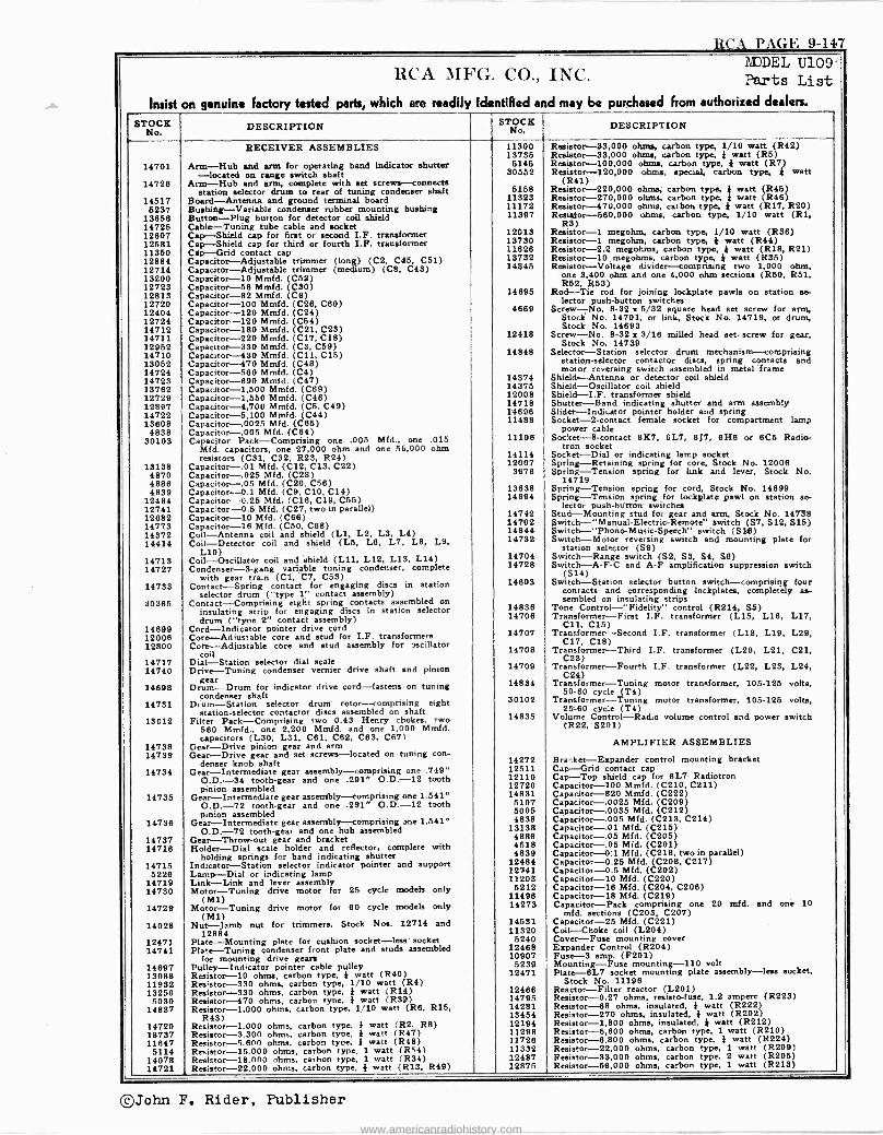
RCA PAGE 9-147
ItCr1 MFG. CO,, INC. IIflODEL U109 - Parts List
Insist on genuine factory tested parts, which ere readily identified and may be purchased horn authorized dealers.
STOCK No. DESCRIPTION O
K STOCK DESCRIPTION
RECEIVER ASSEMBLIES 11300 Resistor -33,000 ohms, carbon type, 1/10 watt (R42) 13735 Resistor -33,000 ohms, carbon type, } watt (R5)
14701 Arm -Hub and arm for operating band indicator shutter 5145 Resistor -100,000 ohms, carbon type, } watt (R7) -located on range switch shaft 30552 Resistor -120,000 ohms, special, carbon type, ! watt
14728 Arm -Hub and arm, complete with set screws --connects (R41) station selector drum to rear of tuning condenser shaft 5158 Resistor -220,000 ohms; carbon type, 4 watt (R45)
14517 Board -Antenna and ground terminal board 11323 Resistor -270,000 ohms, carbon type, 4 watt R46 5237 Bushing -Variable condenser rubber mounting bushing 11172 Resistor -470,000 ohms, carbon type, } watt (R17, R20)
13658 Button -Plug button for detector coil shield 11397 Reaiator-560,000 ohms, carbon type, 1/10 watt (R1, 14725 Cable -Tuning tube cable and socket R3) 12607 Cap -Shield cap for first or second I.F. transformer 12013 Resistor -1 megohm, carbon type, 1/30 watt (R36) 12581 Cap -Shield cap for third or fourth I.F. transformer 13730 Resistor -1 megohm, carbon type, } watt (R44) 11350 Cap -Grid contact cap 11826 Resistor -2.2 megohms, carbon type, } watt (R18, R21) 12884 Capacitor -Adjustable trimmer (long) (C2, C46, C51) 13732 Resistor -10 megohms, carbon type, } watt (R35) 12714 Capacitor -Adjustable trimmer (medium) (C8, C43) 14845 Resistor -Voltage divider -comprising two 1,000 ohm, 13200 Capacitor -10 Mmfd. (C52) one 3,400 ohm and one 4,000 ohm sections (R60, R51, 12723 Capacitor -56 Mmfd. (C30) R52, R53) 12813 Capacitor -82 Mmfd. (C6) 14695 Rod -Tie rod for joining lockplate pawls on station so- 12720 Capacitor -100 Mmfd. (C28, C60) lector push-button switches 12404 Capacitor -120 Mmfd. (C24) 4669 Screw -No. 8-32 x 5/32 square head set screw for arm, 12724 Capacitor -120 Mmfd. (C54) Stock No. 14701, or link, Stock No. 14719, or drum, 14712 Capacitor -180 Mmfd. (C21, C23) Stock No. 14893 14711 Capacitor --220 Mmfd. (C17. C18) 12418 Screw -No. 8-32 x 3/16 milled head set. screw for gear, 12952 Capacitor -330 Mmfd. (C3, C59) Stock No. 14739 14710 Capacitor -430 Mmfd. (C11, C15) 14848 Selector -Station selector drum mechanism -comprising 13052 Capacitor -470 Mmfd. (C48) station -selector contactor discs, spring contacts and 14724 Capacitor -580 Mmfd. (C4) motor reversing switch assembled in metal frame 14723 Capacitor -890 Mmfd. (C47) 14374 Shield -Antenna or detector coil shield 13762 Capacitor -1,500 Mmfd. (C69) 14375 Shield -Oscillator coil shield 12729 Capacitor -1,550 Mmfd. (C48) 12008 Shield-I.F. transformer shield 12897 Capacitor -4,700 Mmfd. (C5, C49) 14718 Shutter -Band indicating shutter and arm assembly 14722 Capacitor -6,100 Mmfd. (C44) 14696 Slider -Indicator pointer holder and spring 13608 Capacitor -.0025 Mfd. (C65) 11488 Socket -2 -contact female socket for compartment lamp
4838 Capacitor -.005 Mfd. (C84) power cable 30103 Capacitor Pack -Comprising one .005 Mfd., one .015
Mfd. capacitors, one 27,000 ohm and one 56,000 ohm 11198 Socket -B -contact 61C7, 6L7, 6.17, 8H6 or 6C5 Radio-
tron socket resistors (C31, C32, R2S, R24) 14114 Socket -Dial or indicating lamp socket
13138 Capacitor -.01 Mfd. (C12, C13. C22) 12007 Spring -Retaining spring for core. Stock No. 12006 4870 Capacitor -.025 Mfd. (C28) 3878 Spring -Tension spring for link and lever, Stock No. 4886 Capacitor -.05 Mfd. (C20, C56) 14719 4839 Capacitor -0.1 Mfd. (C9. C10. C14) 13638 Spring -Tension spring for cord, Stock No. 14899
12484 Capacitor -0.25 Mfd. (C18, C19, C55) 14694 Spring -Tension spring for lockplate pawl on station se - 12741 Capacitor -0.5 MEd. (C27, two in parallel) lector push-btittorr. switches 12682 Capacitor -10 Mid. (C66) 14742 Stud -Mounting stud for gear and arm, Stock No. 14738 14773 Capacitor -16 Mfd. (C50. C68) 14792 Switch -"Manual -Electric -Remote" switch (S7, S12, 515) 14372 Coil -Antenna coil and shield (L1, L2, LS, L4) 14844 Switch -"Phono -Music -Speech" switch (She) 14414 Coil -Detector coil and shield (L6, L8, L7, LB, L9,
L10) 14732 Switch -Motor reversing switch and mounting plate for
station selector (S9) 14713 Coil -Oscillator coil and 'shield (L11, L12, L13, L14) 14704 Switch -Range switch (S2, SS, S4, SB)
14727 Condenser -3 -gang variable tuning condenser, complete with gear train (C1, C7, C53)
14728 Switch -A -F -C and A -F amplification suppression switch (S14)
14733 Contact -Spring contact for engaging discs in station selector drum ("type 1" cóntact assembly)
14693 Switch -Station selector button switch -comprising four contacts and corresponding lockplates, completely as -
10385 Contact -Comprising eight spring contacts assembled on sembled on insulating strips insulating strip for engaging discs in station selector 14836 Tone Control -"Fidelity" control (R214, S5) drum ("type 2" contact assembly) 14708 Transformer -First I.F. transformer (L16, L16, L17,
14899 Cord -Indicator pointer drive cord C11, C15) 12008 Core -Adjustable core and stud for I.F. transformers 14707 Transformer -Second I.F. transformer (L18, L19, L29, 12800 Cote -Adjustable core and stud assembly for oscillator C17, C18)
coil 14708 Transformer -Third I.F. transformer (L20, L21, C21, 14717 Dial -Station selector dial scale C23) 14740 Drive -Tuning condenser vernier drive shaft and pinion
gear 14709 Transformer -Fourth I.F. transformer (L22, L23, L24,
C24) 14698 Drum -Drum for indicator drive cord -fastens on tuning
condenser shaft 14834 Transformer -Tuning motor transformer, 105-125 volts,
50-60 cycle (T4) 14731 Drum -Station selector drum rotor -comprising eight
station -selector contactor discs assembled on shaft 30102 Transformer -Tuning motor transformer, 105-125 volts,
25-60 cycle (T4) 13812 Filter Pack -Comprising two 0.43 Henry chokes, two 14835 Volume Control -Radio volume control and power switch
580 Mmfd., one 2,200 Mmfd. and one 1.000 Mmfd. capacitors (L30, L31, C61. C62, C63, C87)
(R22,- S201)
14738 Gear -Drive pinion gear and arm AMPLIFIER ASSEMBLIES 14739 Gear -Drive gear and set screws -located on tuning con-
denser knob shaft 14272 Bracket -Expander control mounting bracket 14734 Gear -Intermediate gear assembly -comprising one .749" 12511 Cap -Grid contact cap
O.D.-34 tooth -gear and one .291" O.D.-12 tooth 12110 Cap -Top shield cap for 8L7 Radiotron pinion assembled 12720 Capacitor -100 Mmfd. (C210, C211)
14735 Gear -Intermediate gear assembly -comprising one 1.541" 14831 Capacitor -820 Mmfd. (C222) O.D.-72 tooth -gear and one .291" O.D.-12 tooth 5107 Capacitor -.0025 Mfd. (C209) pinion assembled 5005 Capacitor -.0035 Mfd. (C212)
14738 Gear -Intermediate gear assembly -comprising one 1.541" 4838 Capacitor -.006 Mfd. (C21S, C214) O.D.-72 tooth -gear and one hub assembled 13138 Capacitor -.01 Mfd. (C215)
14737 Gear -Throw -out gear and bracket 4888 Capacitor -.O6 Mfd. (C205) 14716 Holder -Dial scale holder and reflector, complete with 4518 Capacitor -.05 Mfd. (C201)
holding springs for band indicating shutter 4839 Capacitor -0:l Mfd. (C218, two in parallel) 14715 Indicator -Station selector indicator pointer and support 12484 Capacitor -0.25 Mfd. (C208, C217) 5228 Lamp -Dial or indicating lamp 12741 Capacitor -0.5 Mfd. (C202)
14719 Link -Link and lever assembly 11203 Capacitor -10 Mfd. (C220) 14730 Motor -Tuning drive motor for 25 cycle models only 5212 Capacitor -18 Mfd. (C204, C208)
(M1) 11496 Capacitor -18 Mfd. (C219) 14729 Motor -Tuning drive motor for 80 cycle models only
(M1) 14273 Capacitor -Pack comprising one 20 mfd. and one 10
mfd. sections (C203. C207) 14028 Nut -Jamb nut for trimmers, Stock Nos. 12714 and 14531 Capacitor -25 Mfd. (C221)
12884 11320 Coil -Choke coil (L204) 12471 Plate -Mounting plate for cushion socket -less' socket 5240 Cover -Fuse mounting cover 14741 Plate -Tuning condenser front plate and studs assembled 12488 Expander Control (R204)
for mounting drive gears 10907 Fuse -3 amp. (F201) 14897 Pulley -Indicator pointer cable pulley 5239 Mounting -Fuse mounting -110 volt 13988 Resistor -10 ohms, carbon type, I watt (R40) 12471 Plate -8L7 socket mounting plate assembly -less socket, 11932 Resistor -330 ohms, carbon type, 1/10 watt (R4) Stock No. 11198 13250 Resistor -S30 ohms, carbon type, I watt (R14) 12486 Reactor -Filter reactor (L201)
5030 Resistor -470 ohms, carbon type, i watt (R391 14795 Resistor -0.27 ohms, resisto -fuse, 1.2 ampere (R22S) Resistor insulated, } watt (R222) 14837 Resistor -1,000 ohms, carbon type, 1/10 watt (RB, R15, 14281 -88 ohms, Resistor -270 ohms, insulated, } watt (R202) R43) 13454
14720 Resistor -1.000 ohms, carbon type, } watt (R2. R8) 12194 Resistor -1,800 ohms, insulated, } watt (R212) 13737 Resistor -3.300 ohms, carbon type, I watt (F.47) 11298 Resistor -5,800 ohms, carbon type, 1 watt (R210) 11647 Resistor -5.800 ohms, carbon type, i watt (R48) 11728 Resistor -6,800 ohms, carbon type, } watt (R224) 5114 Resistor -15.000 ohms, carbon type. 1 watt (Rt4) 11332 Resistor -22,000 ohms, carbon type, 1 watt (R209)
14078 Resistor -18.060 ohms, carbon type, 1 watt (R34) 12487 Resistor -33,000 ohms, carbon type, 2 watt (R205) 14721 Resistor -22,000 ohms, carbon type, I watt (R13, R49) 12875 Resistor -56,000 ohms, carbon type, 1 watt (R213)
©John F. Rider, Publisher
www.americanradiohistory.com
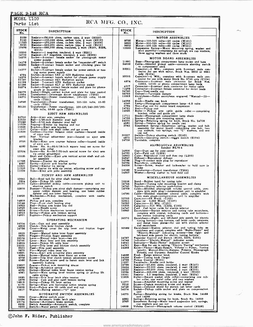
PAGE 9-148 RCA MODEL U109 Parts List RCA MFG. CO., INC.
STNo It DESCRIPTION STNOCK o. DESCRIPTION
5029 Resistor -56,000 ohms, carbon type, I. watt (R220) MOTOR ASSEMBLIES 5145 Resistor -100,000 ohms, carbon type, } watt (R219) 9735 Motor -105-125 volts -25 cycles (M1D1) 11323 Resistor -270,000 ohms, carbon type, } watt (R206) 9651 Motor -105-125 volts -50 cycles (M101) 5035 Resistor -560,000 ohms, carbon type, } watt (R211) 9650 Motor -105-125 volts -60 cycles (M101) 12486 Resistor -580,000 ohms, insulated, * watt (R207, R208,
R215) 12050 Suspension Spring-Motor P P B-Motor mounting spring, washer and
12200 R megohm, insulated, }watt (R201)stud assembly-comprising six springs, six cup washers, three spring washers and three studs
14752 Resistor -2.7 megohms, insulated, I watt (R203) 14275 Socket -2 -contact female socket for phonograph motor MOTOR BOARD ASSEMBLIES 14276
power supply Socket -2 -contact female socket for "expander-off"Base- switch 11881 BPh onora B ph compartment lamp socket and base
14280 Socket -2 -contact n -contact female socket and clinching plate for radio input
14819 Cable-Shielded pickup cable-connects shorting switch to compensator pack
14277 Socket -3 -contact female socket for power switch or tun- ing motor power supply
12051 Capacitor -2 Mfd., complete with 2 -contact male con- nector for use with motor, Stock Nos. 9650 or 9851
4794 Socket -4 -contact 2A3 or 5Z3 Radiotron socket only (0104) 14279 Socket -5 -contact female socket for chassis power supply 13101 Capacitor -4 Mfd., complete with 2 -contact male con - 11197 Socket -6 -contact 6C5 Radiotron socket nector for use with motor Stock No. 9735 only (C104) 11198 Socket -7 -contact 6H6 Radiotron socket 4674 Connector -2 -contact male connector for Stock Nos. 11196 Socket -8 -contact 6L7 or 6F5 Radiotron socket 12051, 13101 or phono compartment lamp leads 14274 Socket-Single contact female socket and plate for phono - 4577 Connector -2 -contact male connector for motor cable
graph or expender input 11488 Connector -2 -contact female connector for motor leads 14278 Socket-Single contact socket and plate for tone control 14760 Cup-Used-needle cup 13964 Transformer-Interstage driver transformer (T202) 14762 Damper-Turntable damper 14271 Transformer-Power transformer, 105-125 volts, 50-60
cycle (T201) 11553 Escutcheon-Index escutcheon engraved "Manual -12-
10" 14846 Transformer-Power transformer, 105-125 volts, 25-60 14688 Knob-Needle rest knob
cycle (T201) 4340 Lamp-Phonograph compartment lamp -6.3 volts 30130 Transformer-Power transformer, 100-130/140-160/195- 3764 Nut-Cap nut for motor board suspension
250 volts, 50-60 cycle (T201) 14761 Rest-Pickup rest
EJECT ARM ASSEMBLIES 14825 Roller - Pickup arm cable guide roller - comprising
bracket, roller and guide pin 14753 Arm-Effect arm, complete
11711 Shade-Phonograph compartment lamp shade 14753 Ball -1/16 -inch diameter steel ball
14758 Spacer-Pickup arm mounting spacer 10129 Ball -1/16 -inch diameter steel ball
14270 4565
Spring-Retaining spring for knob, Stock No. 14758 Spring-Tension spring for needle rest 11529 Bearing-Effector tip bearing and nut 3763 Suspension Spring-Suspension spring, washer and bolt 11538 Bracket-Eject arm bracket assembly for motor board-comprising one bolt, two 11537 Collar-Eject arm shaft collar and set screw cup washers, two springs, two "C" washers, and one 11536 Cushion-Counter balance roller cushion-located inside cap nut of eject arm 30157 Switch-Pickup shorting switch (S105) 4055 Post-Vertical adjustment post-located on eject arm 4671 Switch-Operating switch-toggle switch (S104)
3729 bracket
Roller-Eject arm counter balance roller-located inside of elect arm
14759 Turntable. complete
REPRODUCER ASSEMBLIES 4580 Screw-No. 6 -32 -3/16 -inch square head set screw for eject arm collar Speaker RL78-4
11534 Screw-No. 8 -36 -7/32 -inch special screw for eject arm 14606 Cap-Dust cap for cone center tip center adjustment 14785 Coil-Field coil (L202)
11535 Shaft and Collar-Eject arm vertical action shaft and col- 14602 Cone-Reproducer cone and dust cap (L203) lar assembly 14847 Diffuser-Reproducer diffuser
11528 Silencer-Ejector tip silencer 14786 Plug -6 -contact male plug for reproducer 4067 Spring-Ejector arm bracket spring 14784 Reproducer, complete
11531 Spring-Ejector tip spring 14358 Screw-Screw, washer and lockwasher to hold core in 11530 Tip-Ejector tip with tip center, adjusting screw and cap yoke 11539 Yoke-Eject arm yoke assembly 12568 Transformer-Output transformer (T203)
14357 Washer-Spring washer to hold field coil PICKUP AND ARM ASSEMBLIES
10941 Ball-Steel ball for pivot shaft bearing MISCELLANEOUS ASSEMBLIES 3204 Cable-Pickup lift cable 12038 Band-Rubber band for tuning tube
30101 Cable-Shielded pickup cable-connects pickup unit to 14744 Bracket-Tuning tube mounting bracket and clamp shorting switch 14745 Button-Station selector push-button
Cable-Shielded 12850 Damper-Pickup arm pivot shaft damper-comprising one upper rubber damper and bearing, one lower rubber
14789 phonograph volume control cable, com- plete with male plug-compensation unit to amplifier
damper and one lower bearing 14790 Cable-Shielded expander control cable, complete with 14820 Mechanism-Pickup mechanism, complete with needle two male plugs-compensation unit to amplifier
screw 12723 Capacitor -56 Mmfd. (C105) 14818 Pickup and arm, complete 12951 Capacitor -2,200 Mmfd. (C107) 12546 Plug-Pivot shaft bearing plug 14393 Capacitor-.01 Mfd. (C101) 14823 Rod-Pickup arm brake trip rod 11315 Capacitor-.015 Mfd. (C102, C103) 14822 Screw-Needle screw 14747 Card-Call letter cards for station selector 14824 Screw-Pickup mechanism terminal 14840 Escutcheon-Station selector and tuning tube escutcheon, 14913 Spring-Pickup arm tension spring complete with crystal, indicating cards and buttons - 14821 Support-Pickup mechanism support less station indicating cards
OPERATING MECHANISM 30570 Escutcheon-Right- and left -land side panels for electric
tuning buttons-less buttons, call letter cards, retainers, 14754 Cam-Cam and gear assembly and metal front plates-for use with station selector
6808 Clutch-Trip lever friction clutch dial escutcheon 14756 Cover-Metal cover for trip lever and friction finger
assembly 30569 Escutcheon-Station selector, dial and tuning tube es -
cutcheon and crystal, complete with "Radio -Phono" and 6809 Finger-Manual index lever finger assembly "Electric -Manual" indicating screens-less right- and 3670 Finger-Friction finger assembly left-hand side panels for electric tuning buttons
11554 Lever-Manual index lever-less pin 14787 Expander Control and Switch (R103, 5101, S102) 14755 Lever-Main lever and link assembly 14749 Indicator-"Electric-Manual" indicator screen 14914 Lever-Pickup lift cable lever 14841 Indicator-"Radio-Phonti' indicator screen 11555 Lever-Trip lever and friction clutch assembly 14751 Key-Key for use in setting "Electric Tuning" mechanism 6503 Pawl-Trip pawl assembly 14269 Knob-Phono-Music-Speech, Volume-Power, Tuning 3672 Pin-Manual index lever pin (small), Manual -Electric -Remote, Fidelity, Phonograph
13635 Plate-Eject arm actuating plate assembly Volume, and Dynamic Amplifier Control Knobs 4564 Screw-Manual index lever finger set screw 14688 Knob-Range selector knob 4059 Screw-Trip lever clutch tension adjustment screw 14359 Knob-Tuning knob (large) 4586 Screw-Special screw used to fasten main lever and link 14788 Pickup Control (R101)
assembly bushing 11607 Receptacle-Needle card holder 13637 Spacer-Pickup arm mounting spacer 12738 Resistor -27,000 ohms, insulated, I watt (R107) 13638 Spring-Actuating spring 12454 Resistor -33.000 ohms, insulated, I watt (R106) 4565 Spring-Manual index lever finger tension spring 14023 Resistor -82,000 ohms, insulated, } watt (R102) 4081 Spring-Main spring lever tension spring or pickup lift 12264 Resistor -220,000 ohms, insulated, } watt (R105)
cable spring 12201 Resistor -1.5 megohms, insulated, I watt (R104) 2893 Spring-Trip lever latch plate tension 11829 Roller-Record pocket slide roller-comprising one rub - 3676 Spring-Cam and gear pawl tension spring ber roller, one metal roller and two washers
14916 Spring-Pickup lift lever spring 11377 Screw-Amplifier mounting screw and washer 4125 Spring-Eiect arm horizontal action tension spring 5210 Screw-Chassis mounting screw and washer
13836 Stud-Pickup arm lift cable stud and nut 14746 Shield-Celluloid shield for station call letter cards 2917 Washer-Spring washer-"U" type 14274 Socket-Pickup cable socket and plate on compensation
unit AUTOMATIC SWITCH ASSEMBLIES 14270 Spring-Retaining spring for knobs, Stock Nos. 14688
3994 Cover-Motor switch cover and 14269 10184 Plate-Automatic brake latch plate 4982 Spring-Retaining spring for knob, Stock No. 14359 10174 Springs-Automatic brake springs 3763 Suspension Spring-Motor board suspension bolt, springs, 8805 Switch Assembly-Automatic switch, complete cup washers and cap nut 3522 Switch-Motor switch (S103) 14833 Volume Control-Phonograph volume control (R108)
©John F. Rider, Publisher
www.americanradiohistory.com
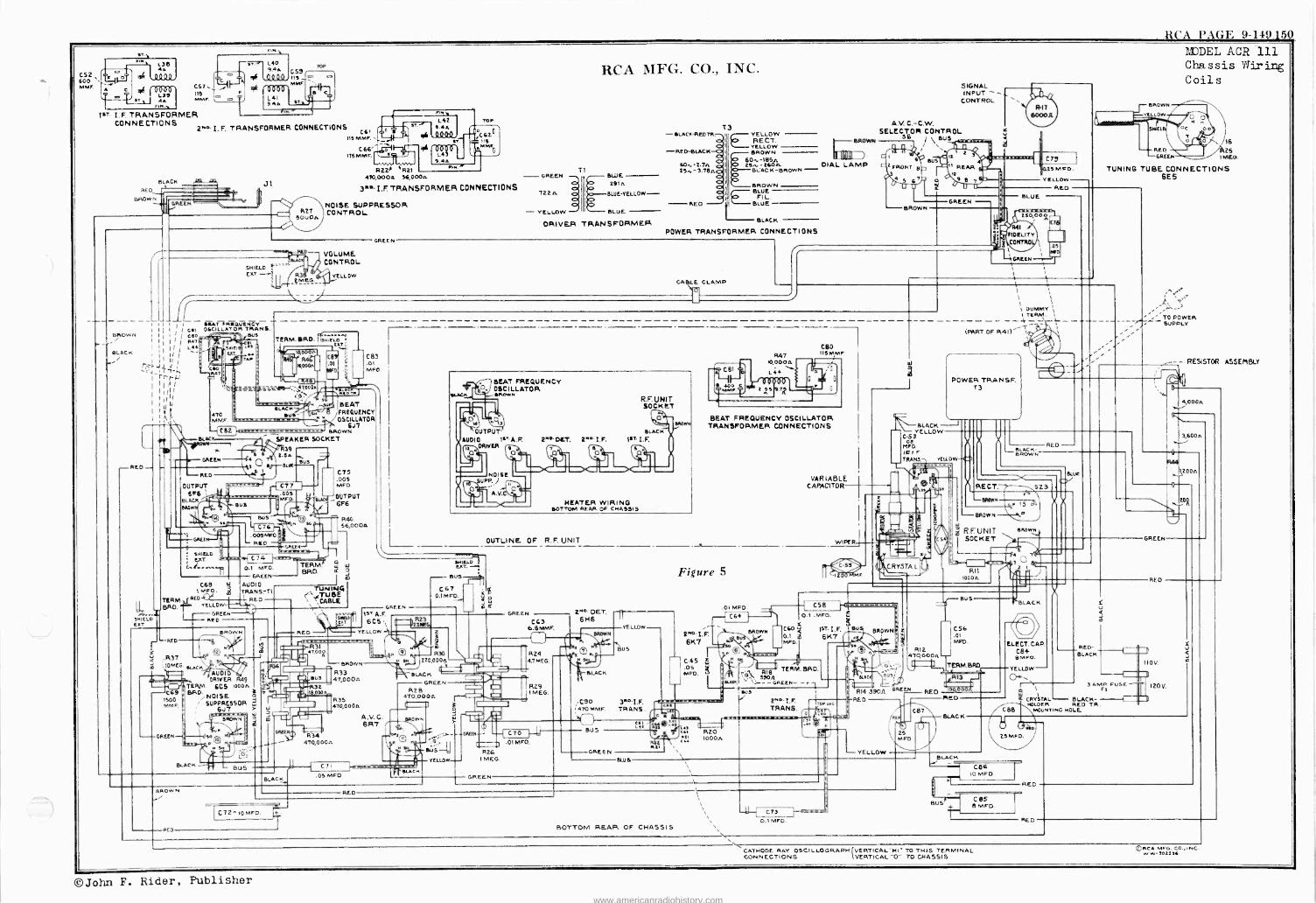
RCA PAGE 9-149150
C52 600 MME
L39 F a
WI' I. F. TRANSFORMER CONNECTIONS
C67. 115 MME
2.0. I. F. TRANSFORMER CONNECTIONS c61
113 MME.
BLACK 47.1.-£4. aED-
BROW GREEN
BROWN
BLACK
-RED
J1
R22Á " R21 470,000W 56,000a - GREEN
3"O I.F TRANSFORMER CONNECTIONS
NOISE. SUPPRESSOR CONTROL
VOLUME.
SHIELD B__j`K ' CONTROL
EST .-1ÿ R31T °r#YELLOW 2MEG.
GREEN
T
1521.
- YELLOW
RCA MFG. CO., INC.
BLUE 291n.
BLUE-YELLOW-
BLUE
ORIVER TRANSFORMER
- BLACK-REDM.
.RED -BLACK
60,1,-2.7W 25,1, - 3.78n
RED
T3 YELLOW RECT.
I YELLOW BROWN
60,-185n. 25,-260n. DIAL LAMP
BLACK -BROWN LACK -BROWN - BROWN SLUE
Fl LIL .
BLUE
BLACK
POWER TRANSFORMER CONNECTIONS
CABLE CLAMP ` o
SIGNAL INPUT -
CONTROL
A.V.. C.-C.W. SELECTOR CONTROL
BROWN 56I \ BUS
RIT 6000A
( Cl,
0.23MFD.
YELLOW- REO
.05
BROWN
Low
?IX)DEL ACR 111 Chassis Wiring Coils
16
REO 2S GREEN IMEO.
TUNING TUBE CONNECTIONS 6E5
I BEAT FREWUENCY
I 061 OSCILLATOR TRANS. ' I coo
( q4T I L44
1 I
li ,
r'ra' AI ll II lu
Lit M ..4 SHIELD
'EAT
TERM. ERD. sAIELO EAT
0
1
Iq000A
S
4T0 MME.
- (C82 BLACK
GREEN
RED
OUTPUT 6F6
BLACK
C 83 .01 MFD
SEAT FREQUENCY OSCILLATOR
6J7 BROWN ' `SPEAKER SOCKET
39
4- L
Is
BUS
SLACK BU
S 2Sa
B, SUE
BUS
C74 0.1 MF).
GREEN
CBS g AUDIO 1 MAO. TRANS -T1
TERMREG RED BRD. YELLOW
--GREEN RED
BROWN
P O á .R37
'.1oMEG. BLACK
`.-RED-r-%
ßC69 1500 MME.
-GREEN
AUDI 0' DRIVER Mg
TERM. 6C5 1000A. BRO.NOISE
SUPPRESSOR 6.17
BLACK
BROW N
RED
So
BROWN
SH
BUS
C77 .005 MED
Fr
GALE
sus
TERM. BRO.
C75 .00S MED.
OUTPUT 6F6
R40 56,000a
O W
J m
TUNIN4 e, 'rule
RED
N
m
BLACK
32 000
a
R34
SEAT FREQUENCY OSCILLATOR
igte4 Pte OUTPUT
r UDIO 1$7 A. F.
DRIVER
L
kr NOISE
.
L n
R. F. UNIT SOCK ET
BLACK 2'41. GILT. 2.1.I.F. 137I.F.
3L'J NEATER WIRING
BOTTOM REAR OF CHASSIS
OUTLINE OF R.F. UNIT
GREEN IST. A.F. 6 CS
YELLOW -` set
C67 0.I MFD.
BROWN
R33 47 000n
R35 410,000A
4/0,000 W
C71
.05 MED.
RED
A. V. C. 6R7
H sH
¢
--j` ¡
2R.2Ky 23
220 000a
SLACK
GREEN R28
4T0,000W
WA
BLACK
SUS
YELLOW.
GREEN
C63 6.BMMF.
l )
2MO DET. 6H6
R24 4.7MEG.
829 I MEG.
BEAT FREQUENCY OSCILLATOR TRANSFORMER CONNECTIONS
O
n
7 BUS
is BLACK
YELLOW -
,C90 3R0I.F. (47016MF. TRANS.
.. cum-- C70 1-' .01MFD.
R26 IMEG.
GREEN
BUS
GREEN
Figure 5
2Ko.I.F. 6K7
.01 MFD. ®
VARIABLE CAPACITOR
WIPER
F
1
I DUMMY I TERM.
'y- L _ (PART OF 841)-K
POWER TRANSE. T3
BLACK YELLOW
MED os IC I F TRANS. VEU.0W
TO POWER SUPPLY
_- RESISTOR ASSEMBLY
_ BLAC K- BROW N
RED
RECT 523
BLUE
-BROWN 5
-BROWN \P
e R.F UN T SROw`
SOCKET I R11
IOOO a
D 4,000n
3,600a
R44
1,200n
GREEN
BROWN Su
P ©K C 65 W " M D. 3 áy -1 TERM. SAD.
^_-GREEN--'i
CS8
0.1 _MFD. 1
cc() 1ST. I.F Bu 0.1 6K7 '7 MED.
BUS
Cat TRANS.
Lot MS/ RZO
R21
BLUE
1000n
1700 Il1G
c b2.Id .cá
BROWN
tEBSSaI Kr R14 39011 BREEN
RED
YELLOW
BUS
CS' .01 MED.
R12. 420,000A 11 TERM.BRD,
RED 1,.,...
CB7
4tS \D. /
RED
LACK
ELECT. CAP. C84 9 MFD.
BLACK
C72-10MED
BOTTOM REAR OF CHASSIS
\ 1
1\
C73 O.1 MED
BLACK i
YELLOW -- r\\ 3 AM` FUSE
RED- BLACK
U 3 m
CRYSTAL BLACK HOLDER RED TR.
CBS MOUNT NG HOLE
B
COG 10 MFD.
CBs B MED.
REO
RED
REO
CATHODE RAY OSCILLOGRAPH VERTICAL"HI" TO THIS TERMINAL CONNECTIONS VERTICAL"O" TO CHASSIS
©PCA MFG. CO.,iNC w W-302234
©John F. Rider, Publisher www.americanradiohistory.com
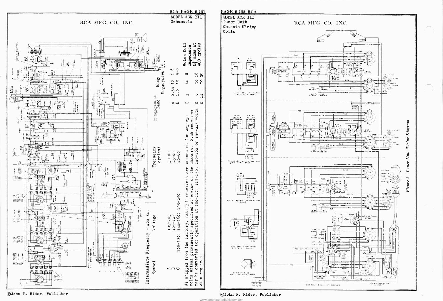
RCA PAGE 9- 151 PAGE 9-152 RCA
I z
Wj 01-
RCA MFG. CO., INC.
FP r YLL
I So ._
-ii-*. n 1 . . ,
E u
F
o0 :N 'WU 10a <
u árt .. . - - e
3: o.
+- .` h 1 _O t IL -'-'--
+}t3 u I
ÿ1 ? Z
K= rt s4
+ - f 1ºa.,,,~ rc.\ i $
ói a,
r"' ,
III
' }OS EO ee
,o^ID ii e
N I_ iE
? _oá fti -43.4%- f 4^
r ..w°°-t1 "'J
ao¡
{ j(
_¡<lT IOG1 1001 Ij11061i .01
«<<<ZCCX
Oe 1,1
LL _ _1Hi_" i ss rÇ-2F E. a1- r - ,c 8
1_2 - -
ñ<C..^Çéw
`.`."
FZZ x
t ,
Z7Z F F
21.2,i- 1, Ipwn _ e
/
1 ' w _ SS // ...e C111212 I
U
r1
O
0
Ñ i 5 ó
R É D o e u " F. F
Yg
I- < E11EeffDil3 11 á
u o
2$
f 5,"
h A
X
re-
d.rs
W
3 rz
D A M \ \ a P73M7#V^ i
\II Ñ7
- óp P R
ti
,vññ^iñ VVVUVUVVVU
MJbEL ACR 111 Schematic
a) ßj
Ú V coo
U 0.re
reio Co. V
04
LO O Ui
r-1 f co `O O M
txo CI ?. O O O O O cd U N N N N N
fY. cd CO e 0
CT40 rI ab .,-4 a) 1.E5
4-'.p.1 .V R1 v-1
400 Ñ In Ñ 4 .1 C7
OH r-I U O Ñ I I Ìy 'H .-I to in o >>RI «-' O O O -H H H
4-'$-.
Q) U .-; a
O cd N O ¡3) 4-1 0
a) 0 O G .1 w
O -
4-
a Ñ O bc. c.
41 U) Cl) a) I--1 +n > é-. O b a) IZI .-1
¢ cn c /á á º ó1 .a a) $..
-= u) .A U) S, (I
v) o - cd .= d P E 3
àL DEL ACR 111 runer Unit Chassis Miring Coils
LS
e IA
l5 t.2 A
ANT. COIL CONNECTIONS
LIS 13.0 25 AA
LIS T. L23
LIN IA L28 IA
R.F AND CET COIL CONNECTIONS
L9 LI9 440 L29 aaII
0 5A L20 511 1.30 SA
ANT, R.F. AND OX. con_ CONNECTONS A DAND
OSc COIL CONNECTIONS
SAND oS ,IECOIL CONNECTIONS
eNo AI A2
eus
^1!S
C1 44A
ga -NT ..ND c' BcmL
NT__Yuo uOU SA 5A
eU5
RCA MFG. CO., INC.
Blue
5R0
CRee
Ls 2.2A
ANT. COIL NCD'E' Le Le La In
eReEN
RED
YELLOW 11
CEO 20oMMf
540 /ca IGo !tO
YELLOW
P Ln E I]
S2n IS1 T
:I E !
5
we- 20113 . eu9 uz
OREEN
LN
NI13 ca3 Cs
O O MNF 520 MMF
YELL W RED
CESEN
Due
SUS
BUS
RED L
25 A il
TA ,r L22
BLUE
RED BUS
L21 3.12
7D
LIE
22
DUS YELLOW
OREE
SUS
u9
BUS C e CK
3ioMMf`JItO MMf
IEO NNc\//iwSMM
Ieo MM`cSI )10 NNF
56 .91N L36 TOP .19.N
\
BUS
Dus
PUS
R1 A I
D o O u OEec.
c 35 ) 1050 2.16/2
t29S Mrnc
So55 MM
osc co.L e"t"
L312
BUS
L35MI5%
L LS
='a"` aa RISA
L NE TAD 00
C SS .01MFD
BLUE O/ YELLOW [MOWN
6JT LI2MMf
0 BLUE
I.12 NMf C 30`
ELLOW
C a 1.o2 NMF
C 3 Ii MMf
e C 12 01.01F
CIa IaMNF
C ee .01 o
YELlOed
á
21Z.; ö ̀ 1
BOT TOM BACK OF CHASSIS Q '..5";057,%,"
©John F. Rider, Publisher ©John F. Rider, Publisher www.americanradiohistory.com
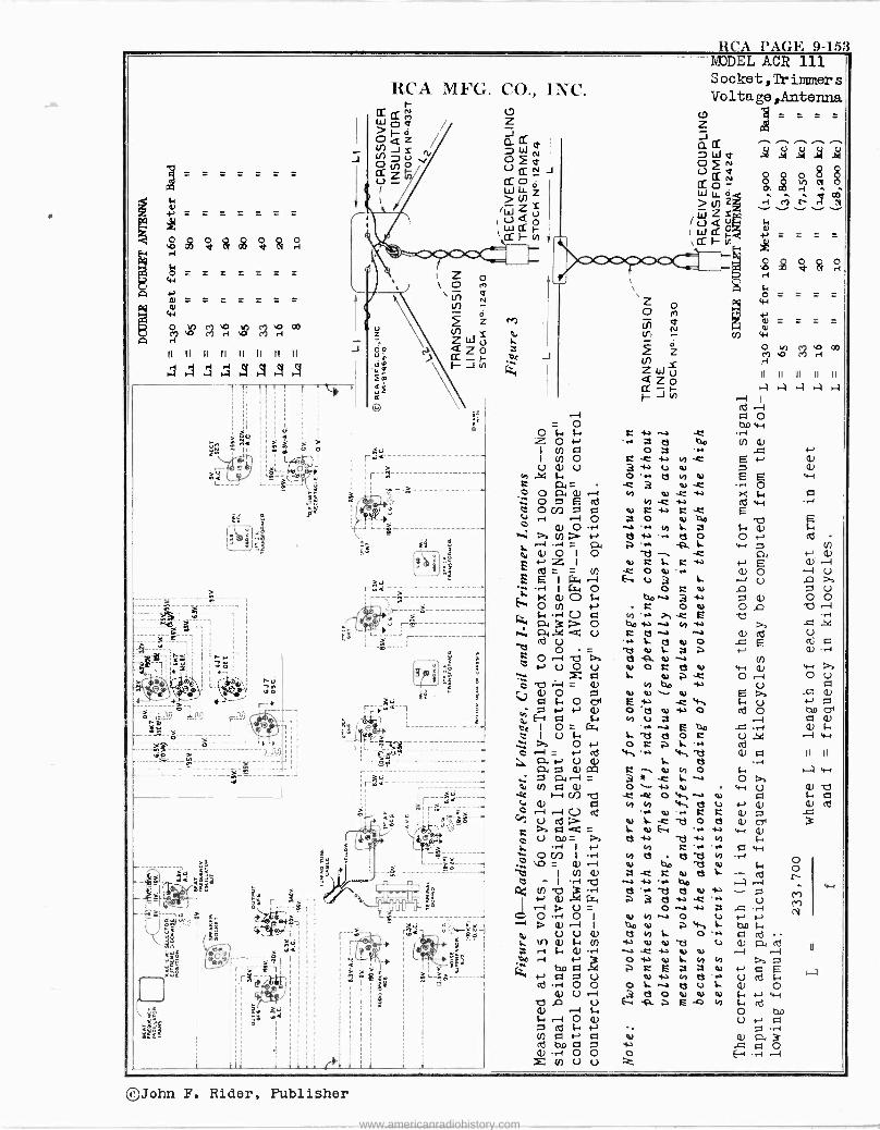
RCA l'AGE 9-153
4) 111
rOi Ç b
'Ó fy r II II II II )I II II II
4 4ááS4
Ñ
<1-`),) f
--!=.1--ó----
C/ Ñ r--
J
4 '
r r x
RCA MFG. CO., INC. r --
r -g
IR
o
'>. - fej, ~40- ir
J
Ó cñ 0
4-J L+ ' U a3> cd
6 U ZS o -
I>f es -)000 (I) O v
R+ O c71
ÿ E Á 4-)O.
ÇI
OV
S. 7a O N
a a1 +-' U Q) P4 aaa m Ñ á Q) te h-1 b p r -I r-1 C.i cd á¢- p V bD = Da
r-1 I f+ ` O V= Q)r] I -.-1
D ) I U) Q)
Ña).ec: Ó Ó -41 I
r--1 I
chJ
. 1n a {. U) " r1 S. (1) .-1 bo r1 1-)
L K1) N C1 O U cd O O o . U
V Ea Q) 1 S.
O Q) cÒ S. N
V) Ca 4) Q N cd Q.) -ÑÓO 0
N
h
MODEL ACR 111 Socket,Trilmners Voltage,Antenna
cD =
-r r +a K -C
aJ 40
o íi S- -e
m 'r+
a o K o) Cov C O O) y'.+ T C E
bp ia N y r:3 N N
+ L C! N O T) o) L .t ? 1y o) ti V O d N
y 40 N N O) O) -C`ti o s o) , o 17 U .1
L. E
o C .+ 4.4 L. d o) v) o
-C O'11ti ey N e+ T'.
L c 2t o e [-r . Itt -44
1n '. di
e N tl 1.1 ' M 40
d o)+ 3 a -c
O +a -N N V) a O U 40 4u ? `ti L t! H L O 'N
1-) O) N '1j U ) -C i.) Oi a) OW V L. 10) y C E z e d N 1)
KV' L. . c) L. t2 O N N N
-o to
c. w
= = _ =
e e o
ao d tt á H
.4 O >C S. c7
Erd
w r+
v -i Q) w ia O --1 O á E
(1) +J A
Ó cd ol a Q)
.0 .-1 Q) S. w
Q) A II II r+ aw O -a v-1 U N
I+ 1-, Q) N cd
á1 w (1) S.
c7 w .Ff
S.
U r -I h+ 1--r
hD i-.
C1J á1 r r--( ^J
S. cd w
O 4D O N Q
..i
a o E-4 . ,-,
o O r () ('r) N
w
©John F. Rider, Publisher
www.americanradiohistory.com
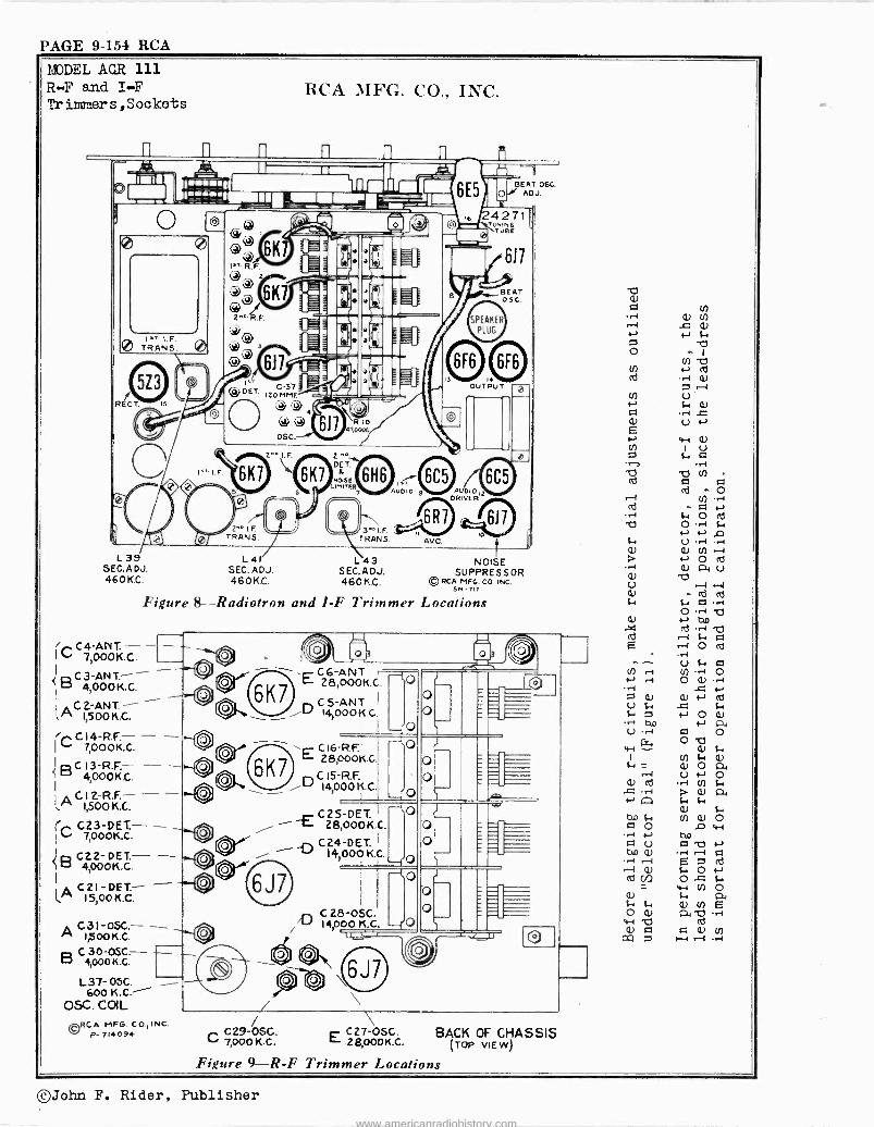
PAGE 9-154 RCA
MODEL AGR 111 R-F and I-F Trinvaers,Sockets
RCA MFG. CO., INC.
n
_.
O O
0
.
I." I.F. TRANS. 0
RECT.
C
j_e
s._ I. F.
Cb® i` eß , 6K1 I= 1111 `- I,.. R.F. - -
0 1 -- - 1-11111: 6K7 óIK 1 =1 ®1
2-°.R.F. 1 -` <o, 11111.
ol 21 Gi
.-^, 611 _ .o
o,1g =1' ODET. C S7 ,(
120M\\M;E.
-.W--- @>
4l U c 617 <,R
osc.
2"° I.F.
6K7 6K7
2"°IF TRANS.
"° DE T.
(NOISE LIMITER
3°° I.F TRANS.
ODI O
_. .r. _- 6E5 ' o
BEAT OSC. ADJ.
G 24271 Ó) \TUNIN6
I TUBE
617
BEAT 05C.
SPEAKER
PLUG
4(11D OUTPUT
S AUDIDI2
DPI VER
6R7 x,617 A.V.C.
L 35 SEC. A DJ. 460 K.C.
L41 SEC. ADJ. 460 K.C.
Figure 8-Radiotron
C4-A00TKIV. - - I C 7,0.C.
< C3 -ANT.-- ó 4,000K.C.
I.`C1500K.C.
ÌCC 14-R.F.- 7,o00K.C.
ó C 4,000 K.C.
G12 -RF.- - I A 1,500
C.12.-R.F.-
-C7000K.C.
1B C22-DET.- -
I
4,000K.C.
G1521-DKE.CT.- ! A ,00. A C31 -05C.- -
1,500 K.C.
B C 4, 3000
K.C. I0-OSC- }-
L37- 05C. 600 K.C!
OSC. COIL
©RCA MFG. CO.,INC. P- 714094
L43 SEC,ADJ. 460 K.C.
t NOISE
SUPPRESSOR © RCA MFG. CO. INC.
SN -717
and 1-F Trimmer Locations \ C6 -ANT 28,000K.C.
C 5 -ANT I
14)000K.C.
o
o
-(o
o o
C 16-R.F.i E 28,0ooK.c.
C15-R.F. E)14,o0 K.C.I
-to
-j0
O
O
C2S-DET.I { 28,000K.C.
C24-DET. -4)14,000 K.C.
C 28-OSC. 'Lj 14000 K
L_(0 -LO
O o
O o
I r I
C 29-OSC. C 7,000 K.C. C27-OSC. E 28,000K.C.
BACK OF CHASSIS TOP VIEW)
w Q)
L+ á .@-I
T7 m F1 p <d - o
(¡) . ri
o o s. 1-, 4..1 p U -1 .4-4
N () Id Q) R1 U b r -I c. a o v «-, an ab . i -I q .--I O cd
(.1) 1-1
N .-1 O Q) 'I ..c n N
(t) a) a cd
iU 1-4 N O Ñ
r+ b4 N a U 4-1 q O
0 wC14 v c.
_ ci) ó á
+ v « o Q) cd '.
Q 40 f. v) Q) ó
O 1] w -c:7-211,12o N an
U a Q) .H-40 Q) f. O
cd C/D
cw.
ti) o c. c. (1) (n e o Q) a, w C cd N a a (1) u)
aa r1
Figure 9-R -F Trimmer Locations
©John F. Rider, Publisher
www.americanradiohistory.com
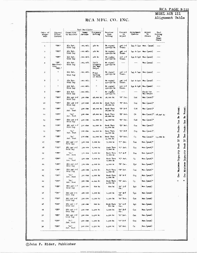
ttl-r1 l'a-1lir 9-15
Order of Align- sent
Crystal Filter Control
RCA MFG.
Test Oscillator
CO..
Receiver Dial
Setting
INC.
Circuit to
Adjust
Adjustment Symbole
Mist Zo
Obtain
MODEL ACR 111 Alignment Table
Dial Setting
For Image Check
Connection to Receiver
Dummy Fr uency Setting .Antenna
i
a
3
4
5
6
7
8
9
io
11
12
13
14
15
16
17
1s
19
a0
21
as
23
at
25
a6
27
a8
29
30
31
36
"OFFS
"OFF"
'CFF"
"ON" Mid -Posi- tion
"MAX."
"
"
"
'CFF"
'CFF"
'CFF"
"OFF"
'CFF"
'CFF"
'CFF"
"OFF"
"OFF"
"OFF"
"OFF"
"CF?"
"Opp"
'CFF"
"Opp"
'OFF n
"CFF"
uppps
"CFF"
"OFF"
'OFF"
"CFF"
"CFF"
"OFF"
"OFF"
617 Det. Grid Cap
6L7 Det. Grid Cap
61.7 Det. Grid Cap
617 Det. Grid Cap
617 Det.
Grid Cap
61n Det. Grid Cap
617 Det. Grid Cap
61.7 Det. Grid Cap
6117 and r -f Gril Cap
6K7 and r -f Grid Cap
"Ai" Ant Post
"Al" Amt. Post
6117 and r -f Grid Cap
6117 and r -f Cap
"Ai" Ant. Post
"Ai" Ant. Post
6117 and r -f Grid Cap
6117 and r -f Grid Cap
"Ai" Ant. Post
"Ai" Ant. Post
6117 and r -f Grid Cap
6117 and r -f Grid Cap
"Ai" Ant. Post
"Ai" Ant. Post
6117 and r -f Grid Cap
6117 and r -f Grid Cap
6117 and ref Grid Cap
6117 and r -f Grid Cap
6117 and r -f Grid Cap
6117 and r -f Grid Cap
"Ai" Amt. Post
"Ain
Ant. Post
.001 mfd.
.001 mfd.
.001 mfd.
.coi mfd.
.001 mfd.
.001 mfd.
.001 mfd.
.001 .fd.
300 ohm
300 ohm
300 ohm
300 ohm
300 ohm
300 ohm
300 ohm
300 ohm
300 ohm
300 ohm
300 ohm
300 ohm
30o ohs
300 ohm
300 ohm
300 ohm
300 ohm
30o ohm
300 ohm
300 ohm
300 ohm
30o ohm
300 ohm
300 ohm
460 kc
460 kc
460 kc
Shift Slightly for Max. Output
Final Setting of Above
"
"
"
a8,000 kc
28,000 kc
a8,000 kc
28,000 kc
14,000 kc
14,000 kc
14,0oo kc
14,000 kc
7,000 kc
7,000 kc
7,000 kc
7,000 kc
4,000 kc
4,000 kc
4,000 kc
4,000 kc
600 kc
1,500 kc
1,500 kc
600 kc
i,5oo kc
i,5oo kc
i,5oo kc
1.500 kc
No signal 550-750 kc
No signal
550-1 o kc
No signal
550-750 he
No signal 550-75o kc
No signal
550-750 kc
No signal
550-75o kc
No signal
550-75o kc
No signal
550-750 kc
a8,000 kc
Rock Thru 28,000 kc
Rock Thru 28,000 kc
Rock Theo 28,000 kc
14,000 kc
Rock Thru i4,000 kc
Rock Thrn 14,000 kc
Rock Thro i4,000 kc
7,000 kc
Rock Thru 7,000 kc
Rock Then 7,000 kc
Rock Thru 7,000 kc
4,00o kc
Rock Thru 4,00o kc
Rock Thru kc
Rock Thin 4,0o0 kc
600 kc
i,5oo kc
1,500 kc
Rock Thru boo kc
i,5oo kc
1,500 kc
1,500 kc
1,500 kc
3rd i -f Trans.
and i -f Trams.
let i -f Trans.
--
3rd i -f Trans.
and i -f Trans.
ist i -f Trans.
- "E" Osc.
"E" Det.
"E" R -F
"E" Ant.
"D" Osc.
"D" Det.
"D" R -F
"D" Ant.
"C" Oec.
"C" Det.
"C" R -F
"C" Ant.
"B" Osc.
"B" Det.
'rB" R -F
"B" Ant.
"A" 1,-F Omo.
"A" 8-F Osc.
"A" Det.
"A" LAP Osc.
"A" 8-F Oso.
"A" Det.
"A" R -F
"A" Ant.
1.43 á Loa
141 & Loo
139 & 138
-
143 A 14a
141 A Loo
139 A L38
- C27
Cas
C16
C6
Cas
Cao
Cis
CS
C29
Ca3
C14
C4
Cao
Can
C13
C3
137
C31
Cal
107
C31
Cal
C1a
Ca
Max. (peak)
Mix.(peak)
Max. (peak)
Max.(peak)
Max.(peak)
Max.(peak)
Max.(peak)
Check for Max.Oltput
Max.(peak)}
Max.(peak)
Max.(peak)'
Max.(peak)'
Max.(peak)'
Max. (peak)+
Max. (peak)+
Mai.(peak)+
Max.(peak)
Max.(peak)+
Max.(peak)+
Max.(peak)+
Max.(peak)*
Max.(peak)+
Max. (peak)+
Nax.(peak)+
.(peak)
Max.(peak)
Max.(peak)
Max.(peak)
Max.(peak)
Max.(peak)
Max.(peak)
Max.(peak)
- - - -
-
- - -
1 1 O O
28,9ao kc 14 P4
y y
1 iiGrid
, w
13,080 kc ., L
W W ~ ~ ,aL
W p,
p., d,
..., ...I
U ee
C
J i
Ó 024,000
} *
©John F. Rider, Publisher
www.americanradiohistory.com
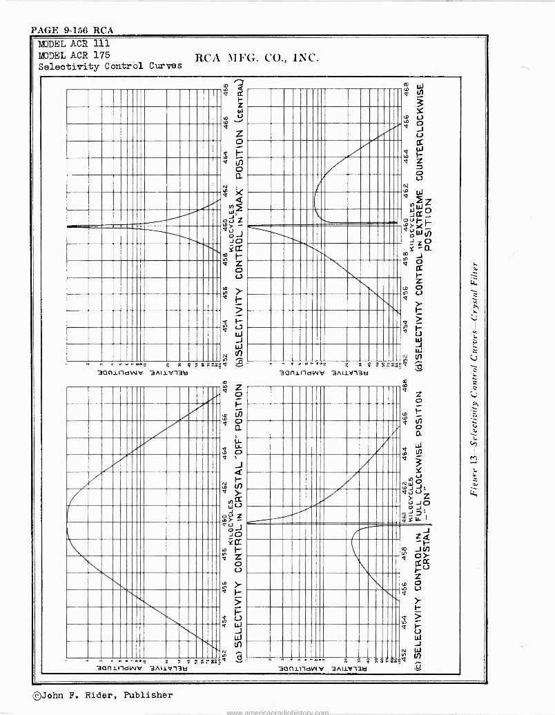
PAGE 9-156 RCA MODEL ACR 111 MODEL ACR 175 Selectivity Control Curves
RCA MFG. CO.. INC.
Al a ut. Of I- m R
30(1111dWV 3A11V132
30f11fdVVo S 2
3/I1V13Lla
.
N 0
a 228'20.
(
.1 t N m m2o
30f1111dWV 3AI1V13ä
3Of1111d01 V N n a ñ S r
3A11V13Fi S
d m v
d V
N
so2
©John F. Rider, Publisher
www.americanradiohistory.com
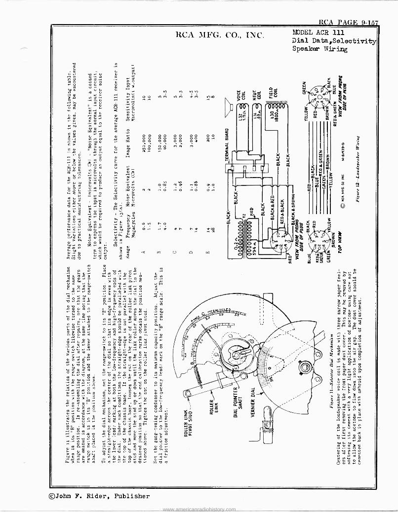
RCA PAGE 9-157
RCA MFG. CO., INC.
O - 4, Ñ 4 7
40 0.' 0 0 04 .-1 e 0 . N > .+ n a e e .a .- a e O
u O Li,.. u. aa U ea 3 e U . 0 .. 40 N V F 4 h V) 0) V)
3 L1 0^~J .>i .-I .) N O 0 Vl M er1 141 Y f) 00 . .' .e.-, -IA b u I -. O> .-, ed = .1.0 a -I
440-4E á .-. C. é
Vi 40. 0 ed 0 a u á Ñ el 1E.. .c) 00 rn N > p0 o1
+ a O 4 e 00 - 4)
~ N W á ..-1e>d O ti 0 ' I, O O O O O O O O 0 0 Ó.. N c oe c ¡y. O O O O O O 0 Y N~ c ed 00 0 v 000 10/1 Ó t0/1 ? co N 1)
0 e 4 0i a o É
Cln G . c a w ^ .) R) I .' .-) .-. .. 4) 0 0 -I 3 V N O pD
P'. 0 Fe O ed .+
U 14 C) N > d î O- Ú
O 0 O U a .~. O- m . 0 00 Ó ' E O . á.,. O CO N, h IT .. 00 0,O > a 1.. I. . 4 0 . U a a U
Cxa'] O Cl e4 .. O .+ O .. o O. w Ó E~ 0 '.. 0 Ó . .' .- O N M
.) 0 1 0.0 CO 14
,.....ew 0o 0. Zx 40 .) Á a - 4.. É. d
0 E 44
O ' N u .I t01 1 In
ead á . Id e- c) v ..
E O at .>-I LI) 4 Ñ 0 a U L. 4) >+ o V1 r, O
w Á v W 40. L
..>i m a U o. ed O.. .+ 7 7 n 7y 7 c0
F... C.) a 40 .-. -.I W
Cl
óre4ele. áiwñ 40iP`
O > a eó03 .
.1a 00 .)0 Z .+ .) 0 S..coo ` E 0an. 3 00 C) . C) 4. N O Q Q G7 U La [z7
G)n 40 .) 3 O N / c 0
E o0) .-u Ñ w t I- s Ni F 0 .1-1.-I c O 0 0.) 1 0 a 0 43 C
c ed 000 r¡
a 3 40
3 a É ` r U N I' 0 a 40 c V H 4) 0 ed to G a L 4) .-I ,C .--I a N E 0 t c a O 0 .-1 -.+ e el O o c .' « of > >. 4) 3 -'. .
Á4, 00
4 .~
0 Ó ,-I .--1
..-1 40 .. C 4)
N N O ed a 4) 4) e4) F b .0 N ¢ b+.,c..a O. 0 4 .-I yc O u V.- .+ a eT ed .-I .--1 .' a . N
á ÿ 4) Oa 0 - 000 10. a 4 Ó N 0 Ó 0 .- e 4) ' W 40 r. 0 1d 4 0 +0 10 .. 00 4 N 0 = 0 1 D a > .+ e .+ a
. Oa) --E W N N 0040 .) c E a N V) 4 N I' c M-.1 -. O.) O
N' V0) .4i y a c O a w 4) . 14
0- O a
PO 1+ -.. 0 E ., O .. 40 c N O.-1 G > I).-... ed 3 O. ed .) . 0a N ..+ .+ o.I .. a.4
10..
N e c.c-. el0 0 4e)I. O. 1¡04
a U s N-.. 0 F U >. 00 to 4) -be X 1d .) a .-I F c 4) .' O u 40 F AC 4a a 0, 4-44>)
3 N 0 Ì) 1 4) Q E.-1 Ú Ó 4 U w V.-1 N.. a.+ .+c.-1 1d .+ Id 0 1 1d am c a F E.x > t0000u O É3 .-I 00 0 /. ... a .-i Á NE.+ a Ìú0O Eá ed ed c .t. FÁ FÓ
EK 40.'4
0 4'0 .. Ñ ~N N 0 -
4 .-1 10e. c w 0 4 e.. N 4) 41,O0 4-, 00 -0 0 00 404,) .) - O 0 00 0
0 a} .) 4.) .+ e
u a . >. c a c .+ b 0 0 U) w 3 40 O O u I- 4.4 .. - .I G N.. c a.-1 a 0 a .+ a
.-pi c á c O N - 4) (1) 0 .. 0tl)
40 0 I. Ó 0.) E.- a a E u v .' O 4 4) e 41.4o. 4 . 4-1 0 . 0
.N .. 0 0 - 0 0 c N
3 ..
0 3= i 0 I' .-. - 4 a I. ac0 N0Ì a 0 PI 4,
d . - .) 0 .) O I U 01 c m 0 0 Id o 3 N .+ 10. ead IN. á L VN)
e e -.Ni P á Ñ Ú .O-1 N 4) .. 0 . E o AC u N a.+ ., a .' N a 4 0 4
1
Fd o 0N O c 00 0 0 la. P. 0 .c+ Id A E
N L Ono 0.. E 0 N- ed M a 40 0 -- 44)
V N v) Ñ Ó
F Ó O a pq a en 40 40 0 10 v .+ .-, - - O a -el I 40
.i -Q 40 e 0 0=.) u> '.+ 0 00 4 ed N u 0 .' O N> e 0 ...... 40 .) u I' w 0 E O O ed a
.~.. N 0 ' 1d . a 4 - O c a .0 00 a 0 O t 3' N 00 0.-1 .- 0 Ñ
M a N N a 0.. -.>ode, 1d n1 a 40 41 Ó .- F 0 É 0.) .d O ... O w 0 0 40 c a M
O a 00 00 w Ñ - 40 + 0 40 ...1a0 ~ .-1 F
00 0 0 0 a 0 N 0 0 0 a e N O .' 10 w c ed F 1d c O e c c O.+ 0. 0-. G. 3 R. 0 4 N H 1d .' .' ' N 40.) co 40 1d
MODEL ACR 111 Dial Data,Selectivity Speaker Wiring
11
; ' 0ó ó \ m °.
ñ !`J Z p Y Y W Z 0 á á 3 I
FIRM i M, CO m
ç W m
rorall ó i JW .-4 aQ
W W U W m ä
F
Q
jz m Q
A jg Ö COm r_
éÓ 3 WW+`Qd
1. O m' C W
W
W j .a+. OC Iti K m K e C7
..:1,14,
Y
W Q
W V W W J J -
pp[ 0 r e u_ >p_ W_O Cd V. .. m . OCOJ
Wg WtJ O 04. J Pn ZIV i.,,,
aWc w6
>. o W 4e
O
- >+.-. D 6) O O 4) e 40 O " N N
4 644 F P. 1) Iq
P0 1' n0 a 0 Ó G N Ó 14 4 7 U 0 e 1d 0 «. ..E. e E
O Ó 0 N N40-. 0 4)
c H A F w c - . F a
0 O a O > O .1 co .+
O U .ó«ua E PH A
Ó
N. 40 a 4) u
Ñ ° ~
C
Ó a1'oa edt e
U a00.a. 0 .+ .-1
b .O+ O A 3
OF
p 4 4 0 p >w>40 tEd
v.á ed óc 4 r -. .-
áá`.03 N ... 7 >O I' 0 10d o E a ~ I0. É á i ú .- N 0 w .. - 0 0 Owc ed .
ap a Ñ ati Ó N
{. ...ce 0. a r .+ aß
py 4N. Ó O Ñ U 0 N . U
©John F. Rider, Publisher
www.americanradiohistory.com
PAGE 9458 RCA
MODEL ACR 111 Notes,Operation
1. General
RCA MFG. CO., INC.
This new, sixteen -tube, RCA Amateur Communications Receiver is built for rack
and for table mounting and covers a frequency range of from 5µo to 30,000 kc.
It embodies the most up-to-date circuits and construction, including RCA metal
tubes, electrical band spread, beat -frequency oscillator, crystal filter,
noise suppressor, noise limiter, sensitivity and automatic -volume controls,
standby switch, loudspeaker, and phone jack. The advanced degree of sensi-
tivity and selectivity of the instrument together with its frequency stability
and reliability open to the operator a field of reception covering all com-
munications in the more important ranges.
This book should be studied carefully to learn how to make full use of the
ACR-Au and keep it in its optimum operating condition.
2. Special Features
An inspection of the schematic circuit diagram and the wiring diagrams make
clear the many developments incorporated in this model. See Fig.µ. 5 and u.
Metal tubes provide effective shielding as well as minimum terminal spacing
and short connecting circuits with their attendant advantages. The eleven
labeled controls, including the phone jack, are all on the front panel, thus
giving complete front panel operation. The two large diameter tuning knobs
with crank handles are comfortable and convenient -to the hand and facilitate
rapidity and ease of tuning. In conjunction with the vernier drive and elec-
trical band spread system, fine tuning adjustments are easily made. An AVC
Switch allows one to dispense with the use of the Automatic -Volume -Control
when desired.
The Crystal Filter in the first i -f stage provides single -signal reception
with an unusually high degree of selectivity, and the adjustable Selectivity
Control is a means of obtaining various degrees of selectivity with or without a rejection dip. The Electron -Ray -Tube Indicator fulfills the dual function
of measuring signal input and aiding in precise tuning.
The Noise Suppressor is a valuable aid in reducing interfering noises and thus
enabling the operator to obtain reception of maximum strength and fidelity and
minimum interference. It is used in conjunction with the Signal Input Control
A Noise Limiter is incorporated in the circuit by means of the second diode of
the second detector (RCA 61161 tube. This device reduces peak noises due to
excessive signals or bursts of static which load the anode beyond a certain
bias value.
The Selector Dial brings each scale separately into the dial opening by a turn
of the Range Selector knob and gives clear vision tuning calibrations for the
range in use only. In addition the vernier scale beneath provides for cali-
bration spread, and the readings of both tuning and calibration spread scales
may be entered in the station log for future reference when it is again de-
sired to receive the same station.
The Beat Oscillator is equipped with two controls, It) an "Oo-0f1" switch and
(a1 a Heterodyne Control with magnetite -core tuning which effectively governs
the pitch. The shield enclosing the entire beat -oscillator circuit enables
the listener to operate the set with freedom from undesirable beat notes due
to harmonics.
The Loudspeaker is a separate unit attached to the chassis by means of a
cable with a seven -prong plug-in connection. It is assembled on a small
wooden mounting in which holes are provided for fastening to a large baffle
when high -quality reproduction is required.
4. Circuit Data and Power Rating
Circuit - Superheterodyne with beat -frequency oscillator for CM reception,
noise suppressor, noise limiter, crystal filter, automatic volume control,
electron -ray tuning indicator, calibrated signal input (sensitivity; control,
electrical band spread, and class A pentode output system.
Power Output - 5 watts (undistorted); 8 watts maximum.
Loudspeaker - (separate unit) - Electro -dynamic 8 -inch (voice -coil impedance
x -i/µ ohms at µo0 cycles].
Tubes -
RCA -6K7 - Radio Frequency Amplifiers
RCA -6J7 - First Detector
RCA -6J7 - Oscillator RCA -6K7 - Intermediate -Frequency Amplifiers
RCA -6116 - Second Detector and Noise Limite?
RCA -6C5 - Audio -Voltage Amplifiers
RCA -6F6 - Power Output Tubes
RCA -523 - Full -Wave Rectifier
RCA -6J7 - Beat -Frequency Oscillator
RCA -6R7 - Automatic Volume Control
RCA -6J7 - Noise Suppressor
RCA -6E5 - Tuning Indicator
the signal frequency are essential antenna requirements for best reception. A three -terminal board with the terminals marked "Ai", "An", and "G" is pro- vided on the rear of the chassis for connections to antenna and ground. The "G" terminal should always be connected to a good external ground.
For maximum performance in any one or two amateur bands, one of the antenna systems illustrated below is recommended. Essential parts, such as cross- over insulators (Stock No. 43e71, transmission lines (Stock Nos. inµaq and 1243o1 and receiver coupling transformers (Stock No. 12420 may be pur- chased from your dealer.
PART III - OPERATION
6. Controls
All controls are located upon the front panel and are identified by adjacent markings.
(al Tuning aad Band Spread - The two large knobs to the right and ).eft of the dial are respectively the "Main" and "Band Spread" tuning knobs. The. latter covers a range of zo percent (7 5%) of the main dial scale reading.
(bl Volume - The Volume Control is the knob to the left below the "Band Spread" tuning knob. It is connected in the audio -frequency circuit, and the receiver output level is increased with clockwise rotation.
(cl Power and Fidelity - The Power Switch is combined with the Fidelity Control, the power being off in the counter -clockwise position.
The Fidelity Control provides attenuation of the higher frequencies. Full -range reproduction is obtained with the knob turned clockwise. Turning counter -clockwise introduces a capacitance in the secondary circuit of the driver transformer, which attenuates the high -frequency response and aids in the reduction of disturbing background noises.
Id) Range - The Range Selector in the center of the panel below the dial selects any one of the five scales of which the frequency limits are tabulated under "Part II Electrical Specifications". Turn the Range Selector knob to bring the required scale into the dial opening.
(el Electron -Ray -Tuning Tube - The green illuminated Electron -Ray -Indi- cator Tube (RCA -6X5) at the left of the dial near the top of the front panel is a visible guide to precise tuning. The deflection of the electron stream by the signal voltage causes a narrowing of the darker sector. Maximum de- flection, (i.e., when the area of the light sector is at á maxinuml indicates that the receiver is tuned to exact resonance.
If) Selectivity Control - This introduces the crystal filter into the i -f circuit for single -signal reception of CW telegraph or telephone trans- mission. Crystal phasing is performed by means of an air -trimmer capacitor. Near the midway position marked "Max." the crystal circuit is balanced and maximum selectivity is obtained. This setting is characterized by minimum background noise. In the extreme clockwise position the crystal is short- circuited by means of the crystal switch. Other positions broaden the crystal selectivity curve on one side of resonance and cause a rejection dip on the other side. They are useful for phone reception through severe interference.
(g) Beat Frequency - The Beat Frequency knob at the extreme lower left is a heterodyne control governing the Beat Oscillator output frequency.. When set at its zero mid -position the Beat Oscillator frequency will approziiine zero beat with the receiver tuned accurately to an i' owing signal. The
calibration figures on either side of the zero position indicate the approxi- mate frequency in kilocycles of the beat produced by the"combination of the
Beat Frequency Oscillator and the received signal tuned to exact resonance.
(h) Signal Input - The Signal Input Control is calibrated from i to
to,000 on a logarithmic scale. It is used in conjunction with the Electron - Ray -Indicator to obtain the approximate value it microvolts of any signal delivered to the receiver. This is accomplished by tuning the receiver to resonance by means of the Electron -Ray -Indicator and then rotating the Signal
Input knob fully counter -clockwise to reduce the voltage on the Electron -Ray tube. -"en by slowly rotating this control clockwise, a point causing only
a slit Reflection 11/64 inch; in the dark sector in the Electron -Ray -Indi- cator, will be obtained. The Signal Input scale reading will then be the ap-
proximate signal input value to the receiver, in microvolts. For code recep tion the correct setting will be at the point where the Electron -Ray -Indica-
tor just begins to flicker.
The absolute accuracy of Signal Input values depends upon the sen-
sitivity of the receiver. This in turn depends on proper alignment, condi-
tion of tubes, value of line voltage and similar factors. Relative readings,
however, between stations of different signal strengths give a correct com-
parison. Signal Input readings are also useful for reporting to the trans-
mission station for making tests on different types of antennas, for discov-
ering improvements in transmitters at distant locations, and for making
charts of signal strength variations.
Note: Naltigly the readings by 5 for obtaining values on band "T" operation.
See diagram label on shield on chassis for locations of tubes and grid leads. Ii) ARC - CM Selector - This is a five position switch on the right of
the dial and by means of this knob the operator may set the receiver for
Modulated or CM reception, either with or without Automatic Volume Control,
Power Consumption - iºo wails. according to requirements. On normal CW reception with the control turned
to "CW AVC ON" the time constants of the AVC circuits will be such that they
5. Antenm) will hold during intervals between characters. For slow -speed CW reception,
however, the time constant will not hold and the switch should be turned to
A most important factor in good reception is the antenna. Both "noise re- "CM AVC OFF" and the Signal Input Control used for adjusting the output
dieing" and "directional" properties as well as definite "length" to suit level. Furthermore the central point is a "Standby" position which keeps
the filaments of all tubes heated ready for immediate reception. This is
indicated by means of the Standby Light at the top right hand side of the
front panel.
Power Supply Ratings - Check with rating symbol on chassis.
;®John F. Rider, Publisher
www.americanradiohistory.com
RCA PAGE 9-159
RCA MFG. CO., INC.
Ij/ Noise Suppressor - The Noise Suppression Control is for reducing peaks of noise to a minimum. When used in conjunction with the Signal Input or Sensitivity Control and the Fidelity Control, the Noise Suppressor be - cones a very important and valuable device for reducing interfering noises that may impair the inteliigibility of radio reception. It is of particular value in minimizing interference caused by the ignition systems of airplanes and automobiles, dial telephones, and similar electrical apparatus. Inter- ference from rotating electrical machinery however is not eliminated by this device.
With a station properly tuned io by. the use of the Electron -Nay - Tuning -Indicator, then if the Noise Suppression knob is slowly rotated in a clockwise direction a point of noticeable distortion of the signal will eventually be reached. (If the signal is too strong it may be necessary to reduce the strength by means of the Signal Input Control in order to obtain a point of noticeable distortion on the Noise Suppression Control./ The knob should then be turned very slowly counter -clockwise' until the signal becomes clear. This point is the correct setting for the Noise Suppression Control for that particular signal.
This control is also effective for inter -carrier Noise Suppression and its use in this capacity requires the following procedure in order to obtain reception with full strength, maximum fidelity and minimum interfer- ence:
(11 Reduce Signal Input Control as low as possible, mean- while keeping receiver output at the desired level by means of the Volume Control.
(al Set receiver at a point where no signal is being re - ceived.
13( Adjust Noise Suppression Control till background noise is just audible.
1µI Tune in desired signal again.
This adjustment of the receiver is of particular value for inter- mittent signals or when it is desired to standby on a certain channel, the background output of the receiver being extremely Low on "no signal" and yet allowing full volume on "signal".
Ik( Phones - The Phone Jack is to the left of the front panel. When a
phone plug is inserted in this jack, it simultaneously connects a resistance load across the secondary of the output transformer in place of the voice coil of the electro -dynamic loudspeaker. It also connects the phones across the plate circuit of the output tube, a blocking_ condenser being used to
isolate the d -c voltage. The loudspeaker field which is employed as a filter
for the rectifier stage, still forms an active part of the circuit when using headphones. By inserting the phone plug part way in the jack both headphone
and loudspeaker signals may be obtained. The loudspeaker is connected to the
chassis by means of a cable and plug.
7. Dial
The Selector Dial provides for each major band a single clearly calibrated
sca'e in the upper dial opening. Each scale is clearly marked in megacycles.
The small lower dial opening gives calibration spread for accurate logging.
The mechanism is illustrated in Figure ii.
8. Tuning
The two r -f amplifiers (6E71, first detector (6,171 and oscillator 16J7) are tuned by two four -gang variable capacitors and controlled from two knobs.
The right hand knob controls the main tuning capacitor and the left hand knob the band spread capacitor. The band spread capacitor is connected in the circuit to cover a uniform percentage of band spread regardless of the fre- quency to which the receiver is tuned. Frequency readings on the dial scale obtained by rotation of the Main Tuning knob arg_gg11.ßccurate when the Band Spread Control is at zero - turned fully to right.
The Tuning limits for each of the five ranges are given under "Part II - Electrical Specifications". To tune the receiver for desired reception of modulated signals proceed as follows:
(a1 Turn Power Switch "On".
(bl Turn Range Selector to bring the desired scale into the Selector Dial opening.
(cl Set AVC - CW Control to "MOD. AVC ON".
Idi Advance Signal Input Control fully clockwise for maximum sensi- tivity.
(el Advance Volume Control clockwise until background noise is heard.
(fl Set Band Spread Control at zero - fully clockwise - and then ro- tate Main Tuning Control to a point just below desired frequency, such as at the low end of an Amateur Band. Now tune in signal with Band Spread Control. Turn slowly counter -clockwise, observe the Calibration Spread scale to obtain station location and then watch the Electron -Ray -Toning -
Indicator for point of resonance.
Igl Decrease volume as necessary and set Fidelity Control for pre,
ferred quality of reproduction. Full tone range reproduction is obtained with the knob set to its extreme clockwise position.
(hl Silent Tuning may be obtained by reducing the volume until no
signal is heard, and then tuning by means of the visual indications of
the Electron -Ray Tube.
(il Weak Modulated Signals - The Beat Oscillator may be used to ad-
vantage io locating weak, modulated signals: For this purpose it should be
MODEL ACR 111 Adjustment Notes
tuned exactly to the intermediate frequency of the receiver by turning the Beat Frequency Control to "o" so that an audio -frequency note of ascending pitch will be obtained on each side of resonance of the ocoming signal when the AVC - CW Selector is turned to "CM AVC OFF". Any carrier will then be tuned to exact resonance when the Frequency Control is adjusted for
"zero beat" and weak signals will be located almost as well as those of
greater strength because of the heterodyne "whistle" produced while passing through resonance. After proper adjustment has been made, turn AVC - CW Se- lector to "MOD. AVC ON".
Ijl CW Signals - For CW (code/ reception, the tuning procedure is the same as for modulated signals except that the Beat Oscillator performs a definite rather than incidental function. The Beat Frequency Control is set
not at zero, but slightly to either side so as to provide an audio -frequency beat note when the receiver is tufted to resonance with any carrier. Adjust the pitch with the Beat Frequency Control knob. Tura AVC - CW Selector to
"CW AVC OFF" when receiving slow speed CW transmission.
Iki If the interference is objectionable during reception, the Noise Suppression Control should be adjusted,as described under "Controls" Sec- tion 6, to its "correct setting" for that signal.
(11 Selectivity - The value of the Crystal Selectivity Control is most
evident on CW reception. Its importance should not be forgotten in phone re.
ception and for identification of weak stations which are normally lost in
the background noise. The curves IFigure13) should be studied carefully be- fore operating the Selectivity Control.
The following suggestions also may be of value:
Locate the desired frequency or station with control at
"Crystal OFF," i.e., in its position of minimum selectivity, then ad,juat to obtain the desired degree of selectivity.
Tuning is extremely critical with control in the "Max." posi- tion and in consequence the movement of the Band Spread knob should be very slow and deliberate.
Heterodyne Control Setting
Connect a source of unmodulated carrier of the i -f frequency from the grid of
the RCA -6J7 first -detector to ground. Turn AVC off, crystal filter to maxi-
mum selectivity, sensitivity control to maximum, audio volume control par-
tially on and beat oscillator on.
Rotate the Heterodyne Control knob to left or right until the heterodyne beat
is heard.
Change the frequency of the unmodulated carrier from the test oscillator
very carefully for maximum deflection on the electron -ray -tube indicator. Re-
duce the signal input if necessary so that the electron -ray -tube does not com-
pletely close. The test oscillator is now adjusted to the same frequency as
the crystal filter.
Set the Heterodyne Control knob at its zero position and note whether the
heterodyne beat is at zero frequency. If not, proceed as follows:
(al Rotate the Heterodyne Control knob to obtain zero beat.
(b/ Loosen the knob set screw and turn loosened knob on shaft to its
"o" or vertical position.
Icl Tighten up set screw.
The Heterodyne Control is now adjusted to zero beat at the frequency of the
crystal filter.
In the event that the frequency drift is such that the zero beat position of
the knob is at or beyond the figure "a" on either side, or outside field of ro-
tation, the following adjustment is necessary:
(al Tura knob until the set -screw -stop on the knob control shaft, behind
the front panel, is approximately vertical, then loosen stop with screw driver.
(bl Tura core stud to obtain zero beat. Use a pair of padded long -nose
pliers to rotate the core stud in order to avoid injuring thread.
(cl Turn set -screw -stop over to left (facing front panel/ to its mid -
position, and adjust knob control shaft to allow 1/3a to i/16 inch clearance
between front panel and adjacent surface of knob.
(di Tighten set -screw -stop with pliers to grip core stud, then swing
stop to vertical and tighten securely with screw driver.
(el Proceed as first described for setting knob accurately to zero posi-
tion at zero beat.
Note: Do not Dull control shaft loose from bearing bracket when adjusting
core stud.
Beat Frequency Oscillator - The frequency generated by the Beat Frequency beat -oscillator (457 to µ63 kcl for CW reception is applied to the No. i diode plate of the RCA -6N6 second -detector through capacitor C63. This frequency mixes with the incoming intermediate frequency to produce an audio -frequency note which can be readily heard in the loudspeaker or phones. The movable magnetite -core, adjusted by the Beat Frequency Control, provides a variable in- ductance which acts as a vernier control for adjustment of the oscillator fre- quency over the required a -f range on either side of the intermediate -frequency signal. The plate and screen -grid voltage supply to this oscillator is turned on and off by means of the AVC - CW selector switch.
AVC - CW Selector - A five -position switch selects the type of reception and controls the Beat Oscillator and AVC circuits. The secondary of the audio transformer T1 is short-circuited in the "Standby" position.
©John F. Rider, Publisher
www.americanradiohistory.com
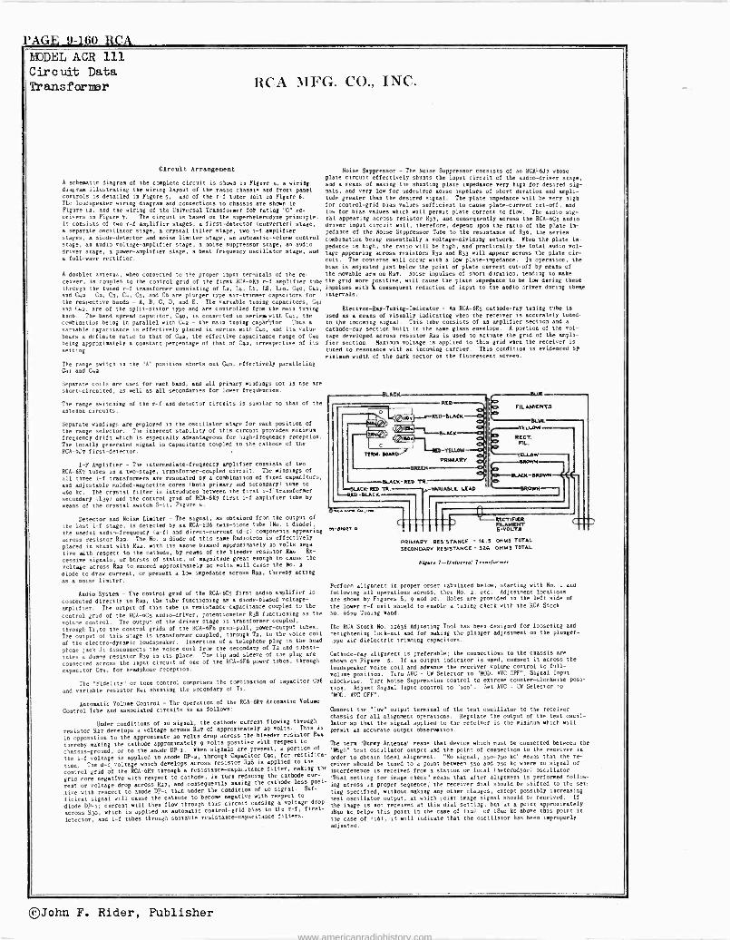
PAGE 9-160 RCA MODEL ACR 111 Circuit Data Transfarnnr HCA MFG. CO., INC.
Circuit Arrangement
A schematic diagram of the complete circuit is shown in Figure µ, a wiring diagram illustrating the wiring Layout of the radio chassis and front panel controls is detailed io Figure 5, and of the r -f tuner unit in Figure 6. The Loudspeaker wiring diagram and connections to chassis are shows in
Figure au, and the wiring of the Universal Transformer Sot rating "C" re-
ceivers in Figure 7. The circuit is based on the superheterodyne principle. It consists of two r -f amplifier stages, a first -detector (converter) stage, a separate oscillator stage, a crystal filter stage, two i -f amplifier stages, a diode -detector and noise limiter stage, an automatic -volume control stage, an audio voltage -amplifier stage, a noise suppressor stage, an audio driver stage, n power -amplifier stage, a beat frequency oscillator stage, and
a full -wave rectifier.
A doublet antenna, when connected to the proper input terminals of the re-
ceiver, is coupled to the control grid of the first RCA -6i7 r -f amplifier tube
through the tuned r -f transformer consisting of La, Lµ, L6, L8, Lao, Cµo, Cµa, and Cµ2. Ca, C3, Co, Cl, and C6 are plunger type air -trimmer capacitors for the respective bands - A, B, C, D, and B. The variable tuning capacitors, Cµl
and Cµa, are of the split -stator type and are controlled from the main tuning
knob. The band spread capacitor, Cµ°, is connected in serigm with Cµa, the
combination being in parallel with Cµa - the main tuning capacitor. Thus a
variable capacitance is effectively placed in series with Coo, and its value bears a definite ratio to that of Cµ2, the effective capacitance rouge of Cµo
being approximately a constant percentage of that of Cµa, irrespective of its
setting.
The range switch io the "A" position shorts out Cµ°, effectively paralleling Cµa and Cµa.
Separate coils are used for each band, and all primary windings not in use are
short-circuited, as well as all secondaries for lower frequencies.
The range switching of the r -f and detector circuits is similar to that of the
antenna circuits.
Separate windings are employed in the oscillator stage for each position of
the range selector. The inherent stability of this circuit provides minimum
frequency drift which is especially advaatageoua for high frequency reception.
The locally generated signal is capacitance coupled to the cathode of the
RCA -6J7 first -detector. ,
I -P Amplifier - The intermediate -frequency amplifier consists of two
RCA -6K7 tubes in a two -stage, transformer -coupled circuit. The windings of
all three i -f transformers are resonated by a combination of fixed capacitors,
and adjustable molded -magnetite cores (both primary and secondary) tune to
µ6o kc. The crystal filter .is introduced between the first i-ftransformer
secondary 1L39) and the control grid of RCA -61/7 first i -f amplifier tube by
means of the crystal switch S -nu, Figure µ.
Detector and Noise Limiter - The signal, as obtained from the output of
the last i -f stage, is detected by an RCA -686 twin -diode tube (No. a diode),
the useful audio -frequency (a -f) and direct -current (d -c) components appearing
across resistor Rau. The No. s diode of this same Radiotron is effectively
plated in shunt with Ran, with its anode biased approximately ao volts nega-
tive with respect to the cathode, by mesas of the bleeder resistor Rae. Ex-
cessive signals, or bursts of.static, of magnitude great enough to cause the
voltage across Ran to. exceed approximately uo volts will cause the No. u
diode to draw current, or present a low impedance across Rua, thereby acting
as a noise limiter.
Noise Suppressor - The Noise Suppressor consists of an RCA -6J7 whose plate circuit effectively shunts the input circuit of the audio -driver stage, and a means of making the shunting plate impedance very high ter desired sig- nals, and very low for undesired noise impulses of short duration and ampli- tude greater than the desired signal. The plate impedance will be very high for control -grid bias values sufficient to cause plate -current cut-off, and low for bias values which will permit plate current to flow. The audio sig- nal appearing across resistor R37, and consequently across the RCA -6C3 audio driver input circuit will, therefore, depend upon the ratio of the plate im- pedance of the Noise Suppressor Tube to the resistance of R36, the series combination being essentially a voltage -dividing network. When the plate im- pedance is high, the ratio will be high, and' practically the total audio vol-
tage appearing across resistors Ria and R33 will appear across the plate cir- cuit. The converse will occur with a low plate -impedance. In operation, the
bias is adjusted just below the point of plate current cut-off by means of
the movable arm on Raz. Noise impulses of short duration, tending to make the grid more positive, will canse the plate impedance to be low during these
impulses with "a consequent reduction of input to the audio driver during theme
intervals.
Electron -Ray -Tuning -Indicator - An RCA -6E5 cathode-ray tuning tube is
used as a means of visually indicating when the receiver is accurately tuned,
to the incoming signal. This tube consists of an amplifier section and a
cathode-ray section built in the same glass envelope. A portion of the vol-
tage developed across resistor Rua is used to actuate the grid of the ampli-
fier section. Maximum voltage is applied to this grid when the receiver is
tuned to resonance with an incasing carrier. This condition is evidenced by
minimum width of the dark sector on the fluorescent screen.
Audio System - The control grid of the RCA -6C5 first audio amplifier is
connected directly to Rau, the tube functioning as a diode -biased voltage -
amplifier. The output of this tube is resistance -capacitance coupled to the
control grid of the RCA -6C5 audio -driver, potentiometer R38 functioning as the volume control. The output of the driver stage is transformer coupled,
through Tito the control grids of the RCA -6F6 push-pull, power -output tubes.
The output of this stage is transformer coupled, through Ta, to the voice coil
of the electro -dynamic loudspeaker. Insertion of a telephone plug in the head-
phone jack Ji disconnects the voice coil from the secondary of Ta and substi-
tutes a dummy resistor Rae in its place. The tip and sleeve of the plug are
connected across the input circuit of one of the RCA -6F6 power tubes, through
capacitor C74, for headphone reception.
The "Fidelity" or tole control comprises the combination of capacitor C78
and variable resistor Ron shunting the secondary of Ti.
Automatic Volume Control - The operation of the RCA -6R7 Automatic Volume
Control Tobe and associated circuits is as follows:
Under conditions of no signal, the cathode current flowing through
resistor Ru7 develops a voltage across R27 of approximately a9 volts. This is
in opposition to the approximate ao volts drop across the bleeder resistor Rea
thereby making the cathode approximately 9 volts positive with respect to
chassis -ground, or to the anode DP -a. When signals are present, a portion of
the i -f voltage is applied to anode DP -a, through Capacitor C9o, for rectifica-
tion. The d -c voltage which develops across resistor Ra8 is applied to the
control grid of the RCA -6R7 through a resistance -capacitance filter, makiag the
grid more negative with respect to cathode, in turn reducing the cathode cur-
rent or voltage drop across Rai, and consequently making the cathode leas posi-
tive with respect to anode DP -1 than under the condition of no signal. Suf-
ficient signal will cause the cathode to become negative with respect to
diode Dp-a; current will then flow through this circuit causing a voltage drop
across Rao, which is applied as automatic control -grid bias to the r -f, first-
letector, and i -f tubes through suitable resistance -capacitance filters.
SLACK
TERM. ROAM)
GEED/
RED
RED -!LACK
LACK
-YELLOW
PRIMARY
BLACK -RED TR. LACK -RED TR. ySRMAIIE LEAD
RED -BLACK
O ac.. ""..
M -alma? -n
FILAMENTS -B' YELLOW
REGT. nL.
Ynu.OW nIlmWN
MACK-BRows
aROWN
RECT1FtER FILAMIDET s -
PRIMARY RESISTANCE -14.5 ONMS TOTAL
SECONDARY RESISTANCE - 326 OHMS TOTAL
F:Rwo 7-Udverd Trawdormor
Perform alignment id proper order tabulated below, starting with No. a and
following all operations across, then No. a, etc. Adjustment location are shows by Figures 8, 9 and io. Notes are provided in the left side of
the lower r -f unit shield to enable a tuning check with the RCA Stock
No. 6679 Tuning nand.
The RCA Stock No. 1a636 Adjusting Tool has been designed for loosening and
-etightening lock -nut and for nuking the plunger adjustment on the plunger-
.ype air -dielectric trimming capacitors.
Cathode-ray alignment is preferable; the connections to the chassis are
shown on Figure 5. If an output indicator is used, codnect it across the
loudspeaker voice coil and adraste the receiver volume control to full -
volume position. Turn AYC - CR Selector to "MOD. AVC OFF"; Signal Input
clockwise. Turn Noise Suppression control to extreme counter -clockwise posi-
tion. Adjust Signal Input control to "moo". Set AVC - CR Selector to
"MOD. AVC OFF".
Connect the "Low" output terminal of the test oscillator to the receiver chassis for all alignment operations. Regulate the output of the test oscil- lator so that the signal applied to the receiver is the minimum which will
permit an accurate output observation.
The term "Dummy Antenna" means that device which must be connected between the
"High" test oscillator output and the point of connection to the receiver in
order to obtain ideal alignment. "No signal, 550-75o kc" means that the re-
ceiver should be tuned to a point between 550 and 750 kc where no signal or
interference is received from a station or local (heterodyne) oscillator.
'Dial setting for image check" means that after alignment is performed follow-
ing across in proper sequence; the receiver dial should be shifted to the set,
ling specified, without making any other changes, except possibly increasing
test oscillator output, at which point image signal should be received. If
the image is not received at this dial setting, but at a point approximately
[8µo kc. below this point i0 the case of (sal or 18µo kc above this point in
the case of 1161, -st will indicate that the oscillator has been improperly
adjusted.
®John F. Rider, Publisher
www.americanradiohistory.com
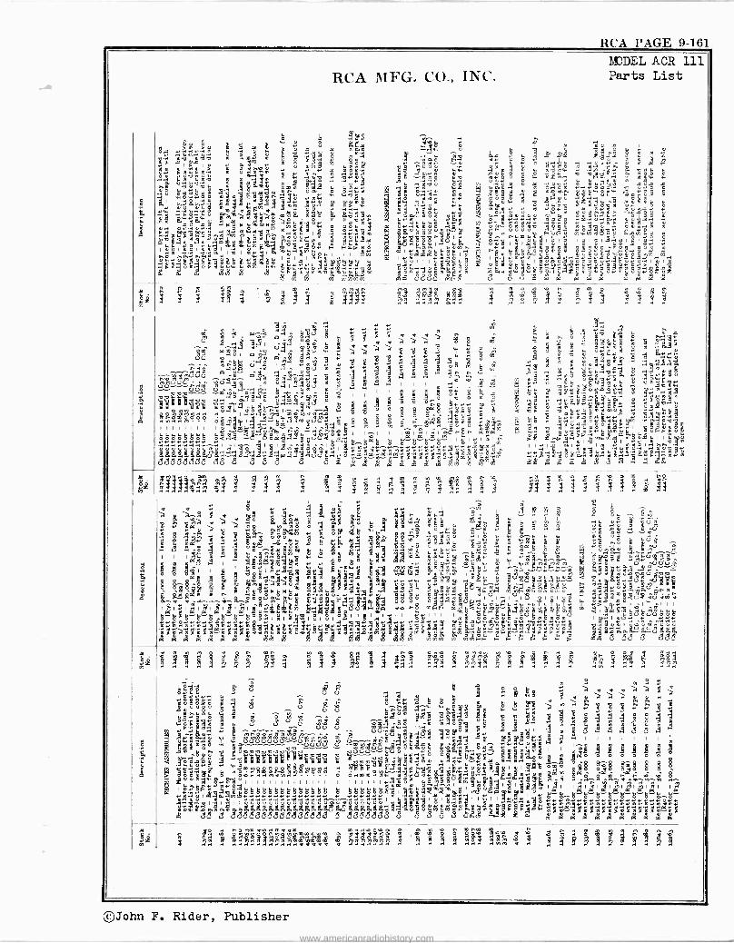
RCA PAGE 9-161
NODE ACR 111 RCA MFG. CO., INC. Parts List
H I
ón
.PÑAnóUwÇIU+
Iw.Vi'áwHmdJÓ .
mrlñél YrWL.ntltlñ7 .ñédI A.¡
uI*!i!jJI
Qn
n
L
.b{..i Ad {{I
8I
YdI
Aa`mW
ÿFpóú mU
!'1
áépÓPyUI}
.WóUGAuUNNN4
wYráNqÚgI
á
m
WÚìpqOUÓ
óó
aáUú
1 A2
bmgá
1525 2.Y4a1 y i
At. 25''4e páqé F2i
M13b
ÚMg yy enwn YO3O qoyg. 4q1Úne0-ggWJI3QKyd
ti 1qÿtll
laVAWñád1'I
I
.Vwdg
41
¡1 VÉfl.MrwYq
r.aO F «
Oayw V gUyt.wipá4 dáAq'1
á1Ór 79ñ nWP1 %
ñ11h1111q1 iq W.yZ WYrÚ m .I O n 1+f
44! V b n m M V1
s s ,Rá p ,
.O 4 «p p
Ip
.-1
m !p
W^4 -0atp óCá r81 «W r T 3 Y d fl ° m O i kill
ti' ó ^V1 U
'a-13 Ñ p á a 1 Q H gl..,
w T a a .i .i b M of C ; á S° 4U a°I 8 ilk 2:Tig..
d+.-1 Uá ñóÚww $E `c. ám
dtl[r ¡ O OU« eq V
ÿ e°4vú mY d1iL« «V ÿ Az 18e W Q m n.7 ÿ d v « O
ggY
V H .i w m ñ EÇ á..°ióñ úq <.y°
tcwc"j`VVñ.ioì ii`'éQ w º áú 8 ó .Y9
d w
rñ :¿ ó,áeáT ú bv.Cog
p ty1 y
{
. (9 Cp
O w a p ó d á u.1 'Pay91yV1.tbbU`.wWU
ymNóyÓHyO ÿ OgPppn
yó
pIE
1p n 8 OtYVr Op .101
.ydw rd1 gUqU«p00a
.1:35 m IÓNNOógpO^p,y(d00edv .1 W A AYOB O
H HaO 06u'U Ñ i .iU MnmG6yUPÿY.«.1 q Y.tiqO
rlvnl.iCKOOÓÓ ótlqc pl.r.lVNrytl4lriHmpypt,Ú PyH P M N m
C.gOtl . ¡i.
V
.eí0+pgwUú CNI N+Úi Cua Y O ÓaOM tl N .°i^d^Va.°i nú ^ 'dC CiV{.UAM..IIV
O F.> I I I I I I I I I U a aa
y 1
HHHHHHHH H..99 ó`ó6á .7úvec°Td{°m« I I-1 I
1l.ml.°II I^ nón ága a w. wm.kw{.ró wwp w
MYY«YY1M^ÑI IOO^IEmIOI p ^10aH HaH H HH..,Hól II«N141 > > ICV úl ÑNOwI114 u
tpggg 5ggfmg{/gg
PYg.y .IqO [I q.Ox000 VIO+L«m, V^r^7«pp1+««m«ñ«dr.A«JUI.IV_ 11161a1«V° I.`1.21wñU..gil.yVVgU« 6lL6Sá0.6i4Ú6 ÓMA. Wri`.lOéUOU°. $'Ma.a.giÁpG..I pó.á¿¿
y°yo¿¿m.wórppv « m? -+ad®°EHiw.iNn
ad38ßa8 ticg c° ci c4 ú 3 oé qi a° á á4Aism7 v%d% aááAó a á~ ^ ag
s41 ; ! ! ! 1s ágx ? fi Al x3s I I «
< a « o « ÿ i^ 0 8 &áñ 5 ° á á a á y aHú..i °S " ú w m me gqw
duqut
émpy yp ç{1. ayMy O
ds pp y w m m . q O ÿ `gGy" Ñ
I .°i M
I M O a ú CilVl « E °i! ii qqP Wú 4. w C
gg Syy 991 á y 8 °-y Á yY le &e 8ó w> á mp "" . t
17 L7 7 Q ó`^ m.r á 2+5 {. {. ° m
yyx .y1 7 5-54 ` w w n mg {. ó a ô o « ñ a
I 1 IM j q V pn Y u% O H % UqO Oq Itch O Cypp w. yql tl w -Wm Wp .qO
tl l .-..Mm pÚ.
e a
q"eicgaM.1H..Oi V W W yÓ y Ó äw PG O ÿJIW [ q rqM°J« «~qq.-.q.q.-. O 0P
¿ ¡ 9 U S 1 '.4 ..i A.M A gd «d
IA O O U hi 7 [] G.-Yp
dyg H IK u O .1 U
AO A ÓI I ' .5;114.223 LÇA twin. d ND Vy mm.ltlá dÑ í . aV .F....H.m ~U mOU, ° a o @ m w ó
Av ow á av 9 m A
mgQ
a «
:me! «., «cis -ryyb
8 pp.8
p
ir F.7.011!!".:
y0g@
9 7 o Ew C
olp ú o w1iQy u yy ii O O Q O I Ó4 00 i , ..°I w
i S ú {. Y ~ O P. hM Ñ v.F Q ú ú 1 FI A ..1 .0 TU n q DZ Aóá°Dóci im Ro w
((!t rn 12' a+ ¡ e C 7 dApA U U
1 n71«1.11 I HI (VI IO..V.11yWMM IQ..Iñárw1ciUm1-l.q
v.o nF m[°iai<{.bHEbcY Ñ pÑC á q I« 11 1 1 I
HH"HHaH"kH°ÓKlúlálúl°lOlllylVlllúlll láló OHONmnSmg 6IaSeciHciAeee,
ág2f"°á§°I'a7Y°e« ll1 #m JA Asaáa "ásu m n m .° g .o n a o o q .+
I R ! á g á á 1 !4 eá ? á 4 !J! g ! j á i
O gy y M e y p
m \s \q pi
O . y
^ m U Ó .1 w 1
~1 x M 3 U°
ú{º. s{ó.
ci
y c.ni R u {O°.
.^wO wç° n.°équ
.l o w
{° ó
O ú ú & ÿ .á
w 1 0y° H e Q O N O C .-1 V E al 9 m ° y `"gtióa 9 ci cº'
` .îw..°l .,, ñwg , g" 48 3'.C « 6 8 d
,Ì«Ym g $ññe m£ . " °g°gw Säm ` á á S d 4 g $8 ' 9ro ao occ ecma$ó0ó3ú° iô óA w w.m gg
A m {, a, C
u v v o o vd a o a c c7 c7-- c7 o Y o Y"'+ m I I I^,g , , , , OyY nevi O á wú.1 U g70 0 0 0 0 0 0 -++~A q Yï``qwwwwv b ati ° -' bö4'
p .aLoró $ h Ìati áYm .=1 ww o a g B^ mº Q «qq«Yyy«.1 6 ñ°°RE&R$íHyyHó'óóó ". pÌiovvB.SYpYp9t°t,gOápé örmo«$ npml°Aóomo $°jR$ o°ó ö ö q1gOú2áqlwóHó ÚÌI.Iin71NlMIII11 0 0.1mmÌqMätó..lUqrPYROÚ..ie$I.y.iW.1MYóH.aY óaó ónat ó .ó
tt,,is PY« mYóu, wwoV«aqA 1 °' q,yqÉóe I O$
I pOáéY t.l Q A M 1.YVf
wáÿyUHHOOHHHHHHHH.Só óYóaapH
óó'óóóóáÌó,l$j:pU"Eé
{áp.Vi1<°.i
ó' iui.7i1; lá l
{I I rll l tl llá{l. l añ
tldááeWWMLLCLL4GMILMWMLLWGLWgKJáIUWMáál.-IpuúUNoÿ"W(siSeÿáá1ao aPr6a+wYYy«qá«p p
Mlá`. s.4P^9aa3T 3ni"ii°`7oi cscs cs cscscscscscscsscscscscscsLcsa 8 cicscscscscscg c4 U U cs V
n m N° ô m4 a $ á
1á y v # 2
®John F. Rider, Publisher
www.americanradiohistory.com
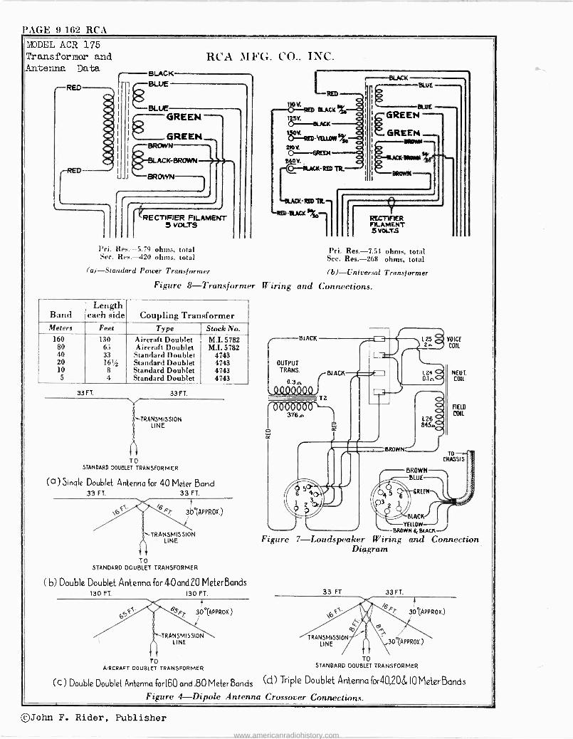
'AGE 9-162 RCA
MODEL ACR 175 Transformer and Antenna Data.
r- RED
L
BLACK
BLUE
BLUE
RCA )I FG. CO., INC.
GREEN
GREEN BROWN
RECTIFIER FILAMENT 5 VOLTS
RED
RECTIFIER FILAMENT 5 VOLTS
l'ri. Res. --5.79 ohms. total Pri. Res. -7.54 ohms, total Sec. Res. -420 ohms, total Sec. Res. -268 ohms, total
(a)-Standard Power Transformer (b)-Universal Transformer
Figure 8-Transformer Wiring and Connections.
Band Length
each side Coupling Transformer Meters Feet Type Stock No.
160 130 Aircraft Doublet M.I. 5782 80 63 Aircraft Doublet M.I. 5782 40 33 Standard Doublet 4743 20 161/2 Standard Doublet 4743 10 8 Standard Doublet 4743
5 4 Standard Doublet 4743
33 FT. 33 FT.
TRANSMISSION LINE
TO STANDARD DOUBLET TRANSFORMER
(a) Single Doublet Antenna for 40 Meter Bond 33 FT. 33 FT.
30°tAPPROX.)
'-TRANSMISSION LINE
TO STANDARD DOUBLET TRANSFORMER
(b) Double Doublet Antenna for 40 and 20 Meter Bands 130 FT. 130 FT.
't s,s 30°(APPROX.)
`TRANSMISSION LINE
TO AIRCRAFT DOUBLET TRANSFORMER
(C) Double Doublet Antenna forl60 and .80 Meter Bands
BLACK
OUTPUT TRANS.
0.3n
376.,
d 50- 6 O 2 Ce p
VOICE COIL
NEUT. COIL
FIELD
COIL
TO
CHASSIS
L. Jl YELLOW BROWN 6&BLACK
Figure 7-Loudspeaker Wiring and Connection Diagram
33 FT.
TRANSMISSION LINE
33 FT.
a / 30'(APPROX)
BLACK
30 (APPROX.)
TO STANDARD DOUBLET TRANSFORMER
(d) Triple Doublet Antenna for40,20& 10 Meter Bands
Figure 4-Dipole Antenna Crossover Connections.
©John F. Rider, Publisher
www.americanradiohistory.com
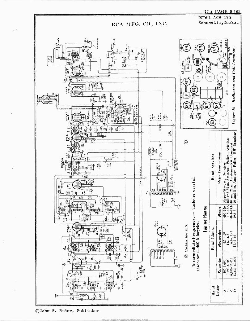
RCA PAGE 9-] ß3
RCA MFG. CO., INC.
u
<< p, Al
r LL
ofo
11 f 1
g<t 32
wr ' sY Ito
Q.00Út.
3-
Ir
=ö < T B H,,,
-o gôi
c
.i.4 úiF w Ni S
11 .F ¡ q
.4 241. wF41 g< <t
Hi'
s7{f üYde<
s o
:wF
1n<
ä8<
CT ó%V
N Ir OF
r tl17 oto
U 1,4f H <
\$ = S§F o
-1 e.`,1 Lp.u .p Y M01409¡71y
Q< .< -Jet< ¡< )
0,3171
D
LIS N
<IÑiI. . o
. zns n..(
° °î
ës
t'i á n1!! t9
uF
e :5,.
o
- °
.7. t t 19 ' < Z§ < °(.222 a
II IH' â8< r.é1 ú E
iHi'
FLe lú-nhe
OW_= xd1 E e ° /sE 11
w rúñE
2} _, --F'l' 7 7 .I A ttt Sf'il
o
LN wtir esf
¡ßF i
tttl,' _
äáóf
; f oQSÓ --1I A
< ca te'!<
II
9
00,
ZZ F tf
>aZ r m O óEFCu
I
e
MODEL ACR 175 Schems.tic,Sockot
0
e
.
M
N
>-,
Ó
d
Á
s
dCOVA
©John F. Rider, Publisher
www.americanradiohistory.com
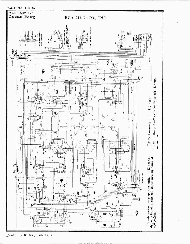
PAGE 9-164 RVA MODEL ACR 175 Chassis Wiring
nw w.0 x Mora.
RCA MFG. CO., INC.
©John F. Rider, Publisher
www.americanradiohistory.com
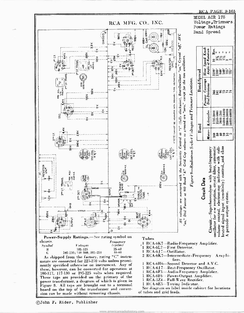
RCA PAGE 9-165
RCA MI+1G. CO., INC.
41 NT r y 1\ L0_
> 5 > A --0--1
r -(4- L-; " -i ¢ r-----------.---ro---- Y N!1 -- O -----5.-0----,--,> --7 ri1 r---- - y i
I n ti -- - ÿ ---- ;
i.+ J á - - -o-----¡ 1
> ' - ~(il gj 142
------J Ç 4---10 Z > e ..:
u:
N
- W
N
nl
O
Ç
.- N9itl9 - ú -- tol
r 2 r,Fa-
1 Ó
O_--- -a
o ---I.
MOl1Lr
-_-p
0 N 0
/Ú m
o e
II
I >
o o o
3 o
a ;t
Z e
a:
J
J
-íONn
.r eau ulz
] a» I -___
íS > ääw--- -aó
> "
Power -Supply Ratings.-See rating symbol on chassis. Frequency
Symbol Voltages (cycles) B 105-125 25-60 C 100-130; 140-160; 195-250 40-60
As shipped from the factory, rating "C" instru- ments are connected for 225-250 volts unless promi- nently specified otherwise on instrument. Any of these, however, can be converted for operation at 100-117, 117-130 or 195.225 volts when required. Three taps are provided on the primary of the power transformer, a diagram of which is given in Figure 8. All taps are brought out to a terminal board on the top of the transformer and conver- sion can be made without removing chassis.
1> F. -is 1 1d W r7tall m0- '
J
Tubes 1 RCA-6K7--Radio-Frequency Amplifier. 1 RCA-6L7-First Detector. 1 RCA -6J 7-Oscillator. 2 RCA-6K7-Intermediate -Frequency Ampli-
fiers. 1 RCA-6H6-Second Detector and A.V.C. 1 RCA -6J 7-Beat-Frequency Oscillator. 1 RCA-6F5-Audio-Frequency Amplifier. 1 RCA-6F6-Power-Output Amplifier. 1 RCA-5Z4-Full-Wave Rectifier. 1 RCA-6E5-Tuning Indicator. See diagram on label inside cabinet for locations
of tubes and grid leads.
MODEL ACR 175 Voltage,Tr immer s
Power Ratings Band Spread
O C K
OMN--I
t; R R F L C
N N - 4p ci2 o
Ó C á000ác`ov 4.) in PtllC- [- N onPM.
GL.
CO
"zii
OD
O C (211 Vi eá?,2c`eC. Mr -1 yÁ
M .s áA
-e O O .943 0 0 Ç1 t- r-1 M i' a veódáo ., o00pp r-u0000 -M C- 00N O
M/ F -V
-1 V
5-, p V
O OD OOO D N .-1 N
X ~
S e
V
©John F. Rider, Publisher
www.americanradiohistory.com
'AGE 9-16(i RCA
LDDEL ACR 175 Alignment,Controls Circuit Data
©John F. Rider, Publisher
www.americanradiohistory.com
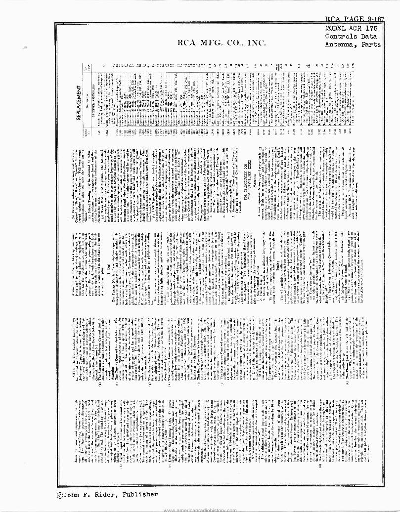
RCA PAGE 9-167
=q4=1Wn4at ryryñg«ñ««:i .vlñétilñMM. 5 , n = .g474 a
©John F. Rider, Publisher
www.americanradiohistory.com
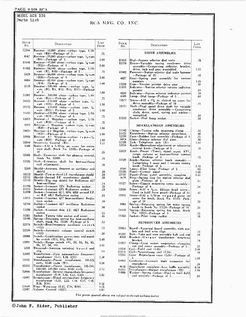
PAGE 9-168 RCA
M)DEL ACR 175 Parts List
RCA MFG. CO., INC.
STOCK No. DESCRIPTION LIST STOCK
PRICE No. DESCRIPTION LIST PRICE
11300 Resistor -33,000 ohms -carbon type, 1/10 - watt (R8) -Package of 5 .75 DRIVE ASSEMBLIES
8067 Resistor -39,000 ohms -carbon type, 1/2 -watt (R9) -Package of 5 1.00 11952 Dial -Station selector dial scale .78
11646 Resistor -47,000 ohms -carbon type, %-watt 12116 Drive -Variable tuning condenser drive (R25) -Package of 5 1.00 assembly -Comprising reflector, bracket,
11282 Resistor -56,000 ohms -carbon type, 1/10. drive, hub and gear assembled 1.35 watt (R7, R18) -Package of 5 .75 11982 Fastener -Station selector dial scale fastener
5029 Resistor -56,000 ohms -carbon type, I/; -watt -Package of 25 (R30) -Package of 5 1.00 4827 Gear -Spring gear assembly for vernier
.42
8064 Resistor -82,000 ohms -carbon type, 1/2 -watt pointers 1.25 (R36) -Package of 5 1.00 11228 Gear -Vernier pointer drive gear .42
3118 Resistor -100,000 ohms -carbon type, I/4 - 11303 Indicator -Station selector vernier indicator
11281
11323
11172
watt (Rl, R4, R12, R13, R17) -Package of 5,
Resistor -100,000 ohms -carbon type, 1/10 - watt (R24) -Package of 5
Resistor -270,000 ohms -carbon type, %- watt (R29) -Package of S
Resistor -470,000 ohms -carbon type, %- watt (R31) -Package of 5
1.00 4520 4340
.75 12577
1.00 12117
1.00
pointer Indicator -Station selector indicator pointer Lamp -Dial lamp -Package of S' Screw -8-32 x 1l/ in. slotted set screw for
drive assembly -Package of 10 Shaft -Dual speed drive shaft for variable
condenser drive assembly -Comprising
.22
.18
.60
.15
11452
12013
Resistor -470,000 ohms -carbon type, 1/10 - watt (R19) -Package of 5
Resistor -1 Megohm - carbon type, 1110 .75
11222
shaft, drive, spool, spring and washer - assembled
Socket -Dial lamp socket .36 .18
watt (R38) -Package of 5 .75 3033 Resistor -1 Megohm-carbon type, I/ -watt MISCELLANEOUS ASSEMBLIES
(R20) -Package of 5 1.00 11626 Resistor -2.2 Megohm-carbon type, I/ -watt 11192 Clamp -Tuning tube mounting clamp .12
(R22) -Package of 5 1.00 12122 Escutcheon -Station selector escutcheon... .60 11936 Resistor -4.7 Megohm-carbon t y p e -t/. 12130 Foot -Rubber foot assembly -Package of 4. .25
watt (R23) -Package of 5 1.00 6614 Glass -Station selector dial glass .30 12090 Sensitivity Control (RS) 122 12128 Jack -Telephone jack (J1) 1.02 4669 Screw -8.32 x 5/32 -in. set screw for exten- 12124 Knob -Heterodyne adjustment or selectivity
sion shaft, Stock No. 12105 -Package of control knob -Package of 5 .70
12103
12105
10 .
Shaft -Extension shaft for phasing control, Stock No. 12089
Shaft -Extension shaft for beat -oscillator coil adjustment
25 12123
.15 12129
15
Knob -Power (Tone), signal input, AVC, range, volume or beat -oscillator control knob -Package of 5
Knob -Station selector knob assembly - Comprising 1 main and 1 vernier tuning knob -Package of 5
.70
2.10 5249 Shield -Antenna, detector or oscillator coil 4340 Lamp -Pilot lamp -Package of 5 .60
shield .20 12120 Panel -Control panel 1.68 12112 Shield -First or third I.F. transformer shield .28 12121 Panel -Front panel assembly, complete 5.45 12111 Shield -Second I.F. transformer shield.... .28 4678 Ring -Spring ring for station selector dial 12110 Shield -Top cap shield for Radiotron 6J7 glass -Package of 5 .34
beat -oscillator .14 12127 Screw -Chassis mounting screw assembly - 11195 Socket -S -contact 5Z4 Radiotron socket... .15 Package of 4 .18 11313 Socket -S -contact 6F5 Radiotron socket.... .18 12126 Screw -6-32 x %-in. fillister head screw - 11198 Socket -7 -contact 6L7, 6F6, 6H6 second I.F. Used to hold front panel -Package of 10. .42
or R.F. 6K7 Radiotron socket .15 12125 Screw -8.32 x 5/16 -in. cupped point set 12113 Socket -7 -contact 6J7 beat -oscillator Radio- screw for knob, Stock No. 12124 -Pack-
tron socket .16 age of 10 .20 12114 Socket -7 -contact 6J7 oscillator Radiotron 4982 Spring -Retaining spring for main tuning
socket .16 knob in Stock No. 12129 -Package of 10. .26 11196 Socket -8 -contact first I.F. 6K7 Radiotron 11349 Spring -Retaining spring for knob, Stock
socket .15 No. 12123 -Package of 5 .15 11381 Socket -Tuning tube socket and cover .45 11222 Socket -Pilot lamp socket .18 12106 Spring -Retaining spring for beat -oscillator
12374 shaft, Stook No. 12105 -Package of 5....
Switch -Beat -frequency oscillator switch .15 REPRODUCER ASSEMBLIES
12109
12088
12091
5238
12095
12101
12331
12096
12097
(S14) Switch -Automatic volume control switch
(S10) Switch -Combination power, tone and stand-
by switch (S13, S15, S16) Switch -Range switch (Si, S2, S3, S4, S5,
S6, S7, S8, S9) Terminal -Antenna terminal board and
clip Transformer -First intermediate frequency
transformer (L17, L18, C33) Transformer -Power transformer, 105.125
volts, 25.60 cycle (T1) Transformer -Power transformer, 105.130,
140-160, 195-250 volts, 50-60 cycle Transformer -Second intermediate frequency
transformer (L19, L20, C41, C42) Transformer -Third intermediate frequency
transformer (L21, L22, C46, C47, C48, R18, R19)
.55 11954
.30 11231 8060
1.00 11257
3.55 11254
.14 11233 11235
1.50 11953
5.20 9658
5.15 11253 11886
1.85
2.52
Board -Terminal board assembly, with eye- lets and lead wire clips
Bolt -Yoke and core assembly bolt and nut Bracket -O u t p u t transformer mounting
bracket Clamp -Cone center suspension clamping
nut and screw assembly -Package of 5 Coil -Field coil (L26) Coil -Neutralizing coil (L24) Cone -Reproducer cone (L25) -Package of
5 Connector -6 -contact male connector for
reproducer .
Reproducer complete -Less baffle assembly Transformer -Output transformer (T2) Washer -Spring washer -Used to hold field
coil securely -Package of 5
.14
.16
.14
.25 2.00
.30
3.50
.28 6.16 1.56
.20
11649 Trap -Wave -trap (L27, C70, R39) 1.15 12087 Volume Control (R27) 1.84
The prices quoted above are subject to change without notice
©John F. Rider, Publisher
www.americanradiohistory.com
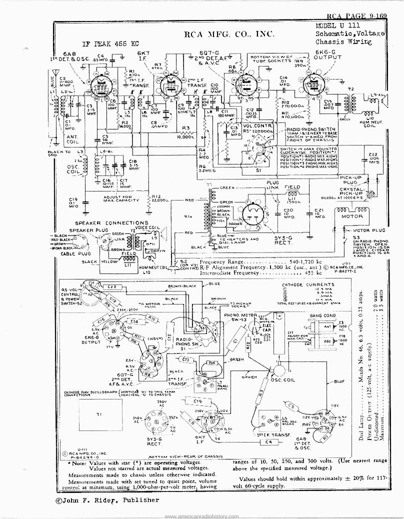
RCA PAGE 9-169
1.
2
Cl 0.1 MFD.
} i
! 1_
BLACK TO L3 ONO. +
2.5ná OS C. g COI ÿa _ 2
19
IF PEAK 455 KC
ANT. COI L
- BLACK RED -BLACK
-BROWN -BROWN-BLACK
CABLE PLUG
RS -VO L.
COUNR & POWER SWITCH -S
BLACK
s
C 0.1 MFD
C6 100 - MME
6K7 I.E.
\\ R7 470n R1 47on 1sT.I.F.
,TRANSE ,r X
LS LIS IB IBA
R2 56,001
OCT LOO MME. TX
Ce .05 M FO.
5G MME
RCA MFG. CO., INC.
6QT-G 1 - Z DET. A.F.= & A.V.C. ' R8
68n 0 2NoI.F. \\0/1"\ TRANSE. CIO
O
C9 T á 100 I--2-, MMF.'L7
Ien
3 VOA.",
IO,000n
óm.L
L8 1 CC~1
180 MME.
B I
L4-Bn
'1 1
160 I 517 MME. I MME
C8 3 15 MME
I
ADJUST FOR MAX. CAPACITY
R12 22,000n
SPEAKER CONNECTIONS SPEAKER PLUG
GREEN -T 2VOICE CO; L
®q LINK
6.3V. A.C.
6K6 -G OUTPUT
C22
HUM NEUT.COIL L10
R4 2 2 MEG.
/ R6 2.2MEG.
DPI
c133 .01 MFD.
DP
BOTTOM VIEW OF -- TUBE SOCKETS (R9
390
©© O'0 0aß
C14 .01 MFD.
I C12 .0035T MFD.
VOL.CONTR. R5- 220,000A
12
11
0 1-
4 5
S1
RIO 270,000n
470,000n
MODEL U 111 Sohematio,Voltage Chassis Wiring
6K6 -G OUTPUT
RADIO-PHONO.SWITCH 1TERM.1&12 NEXT TO BASE
SWITCH VIEWED FROM
1 FRONT OF CHASSIS
S
SWITCH IN MAX. COUNT ER -
CLOCKWISE POSITION.1. POSITION1-RAD10 MIN.HIGHS POSITION2-RADIO MAX.HIGHS PO S ITIO Na3-PHO NO.MIN. HIGHS POSI T ION 44 -PH ONO.MAX.H IGHS
T2
LIO HUM NEUT.
COIL
I C22 .006 MFD.
T1 GREEN
RED --il GREEN
BROWN - -
9.1n BLACK
BROWN
RED BLUE -4 - TO HEATERS AND DIAL LAMP.
BLACK BLUE
PLUG LINK FIELD
6b6`- \ 1300n
CaO 10 MFD.-
\\
5Y3 -G RECT.
PICK-UP PLUG 9
CRYSTAL. PICK-UP Y
BQ000n AT 1000 C.P.S.
- C 21 nVV V LJ Vvv - MFD MOTOR
J 52 voLFrequency Range 540-1,720 kc(oti u111
coNTRtR-F Alignment Frequency. 1,500 kc (osC., ant.) © RCAMFG.CO.,INC.
Intermediate Frequency... 455 kc P-84277-2
s ---MOTOR PLUG
53 ON PHONO. SWITCH. OPEN POSITION 15 ON 1 AND 2. CLOS 40 POSITION IS ON 3 AND 4.
BROWN -BLACK
BL` CK
TO MOTOR PLUG
235V..i250V.
e C14
(l 0, OV.
17V
2.5V.
6.3V.
607-G 2ND. DET.,
AF.& A.V.C. -'
(165V.1 U
BLUE
BROWN
RADIO- PHONO. SW.,
BLACK
2. I.F. TRANSF. -
CATHODE RAY OSCILLOGRAPH VERTICAL 'HI" TO THIS TERM. CONNECTIONS {VERTICAL "0" TO CHASSIS
350V. AC
Ti 350V.
AC O\?52v.
1
5V. AC
5Y3 -G RECT.
O o
BLACK. TO PICKUP SOCKET
PHONO. MOTO SW. -S3
© PRI ADJ. 455KC
C19
250V. 0 112V.
0) LUZ unuv
T ©% © K
6K7 I.E.
SV.
GREEN
5.3V. AC
1 N
C21 - RED -
WHITE TR
],ELEC. CAP.
BLACK
RC2021 C
GREEN
U-111 © RCA MFG. CO., INC P-54594-0 .BOTTOM VIEW -REAR OF CHASSIS
*Note: Values with star (*) are operating voltages. Values not starred are actual measured voltages.
Measurements made to chassis unless otherwise indicated. Measurements made with set tuned to quiet point, volume
control at minimum, using 1,000 -ohm -per -volt meter, having
r 1sTI.F. TRANSF.
, C4 1 -
CATHODE CURRENTS 12.5 MA. 8.9 MA.
.34 MA. 31.5 MA.
TOTAL RECTIFIEDB CURRENT 6SMA.
GANG COND.
C2C
CI7 ADJUST FOR MAX.CAP.--.
OSC. COIL
C3 ANT.' %1500
KC.
CI6 05G
L5 112V.
PRI. ADJ. 455 H 250V.
6A6 Iwo DET. E. OSC.
C18 1500 KC.
- BLUE
112V.
6.3V AC 6V.
ò z N cd
ranges of 10, 50, 250, and 500 volts. (Use nearest range above the specified measured voltage.)
Values should hold within approximately ± 20% for 117 volt 60 -cycle su . ly.
©John F. Rider, Publisher
www.americanradiohistory.com
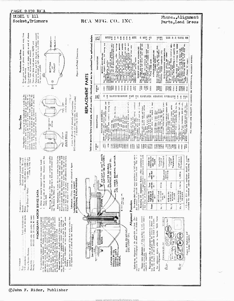
l'AGE 9-170 RCA
páá , , °8 : . . n n .4...1 . ^ . .. ... e,;« . . . . . . 1;9
o
u
o
.5
X
a$
a <C ó t 1}°ñ,a,'gó'a.s
Y
#311...9."..l;a2a m
á e
a T1 pm lyl 3° : °ns p
I I= «aBiivt múweS
$ 2,$a; B,
21'4E.! EÉYE9_r
áEew<DaoE° .
a ëgaeam3e'6É
BHjt'.ÿ:ÿ"L`2I
1 q
; B8`° Pm
`kó__E
9°s
m a.ñ
I g
.5 ,«
@n;mEa ..
i i=+
ä
_
7
i é
t. 33
ánE
á gi? 3t w5.
< y á
< O¿9 : äFB < ä
2
i.ä° us a°'a5aT :lg,
mw CuS
E
si di '@
IV B7á
°
Iui
t ú ..¢ ma
9 i:5 a c Yta a é on o mVBt a öB
LI/.
.á .Éat.
m
m
t m , 1 :etti
:9ÿ° < aB úÉiia
á
.
Bó
3aá tE
ele Éáláll?q un.Stá
é
r `
.g
fi
.411
d.
gYBá 2ád
i i
;8é g.: 3 e.
t7yt
- óñ.5.
gg
aÉ.éaa
gg
3
a ú InI
w
Y
Ó mZ
..
ill n nnn n n n n n n .. n .. n nn n..n n n nnnn n
!, ,óñáei,$ei, 5..1.4 « Aé:rááá ñ . . . . . . . . . .
ti .. .. e.+
e$i
<!- >:° ö i. BNam_uuuauuuuuuu
B 5
!
S
@:ts
ú
'
e
` E6n11de.Éuó=;t$ó =.00S
4014iigt Ytßo_tz-cza<qE"9i?31°"é"a""t.tattt`ea_
,
',:" úrúvi
ÚÚ
;B 4
.
L
;sii ,9;s
"3§"
:
1:ó
1
<
4mSaaaaa
Y.
.
t S $
oe
i
el
mnégw !
;t
já
n
$« ál m`
i1i1iÌ
.
ttE1á« 8@ aáa t
Frtxñg .._
11111 óóBtYB;dg
eéoe«8
_
°`s_ b lx
11 b In gel_ je:4
V1ey8C
III. I 00Jmnt
8 S i
F ó
g
.E92
1 $FS Ì-i,gcö °s
t ti-3
i á tá2
º;jq
ai
qY
ó° áz
. nono . n .3111 ..nnn nnn nn nn nnn n n Mill! n n n
I
Ip
i' A ke\NOM\
Id
eße%%neeMaM. : li`3w-,
b e-4
<lB v ''é
F
e
=n 1-
,. ̂ sé
0E3
Fq ''çç
á ÿ ó
g1r ó s ÿ
Ftd `^
pi &1 311
x t_E
e0s
v a; «ze
Vie'
ÿs _;è
li. °8 -r
a
,m z z z
©John F. Rider, Publisher
www.americanradiohistory.com
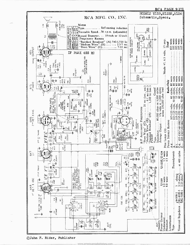
RCA PAGE 9- 17
rá)DELS U119,U122E,U124
J O
\..c,IOi W S l7
( u g ci
Z oZ M W
Q ñ N I F-Ú Ki
ª u O Nr-N
,
\o -
U
o-II'h. K30 O\
e
o--
N p W N U -
ó
W
J 3
z a
Q J
4 h
N d 4
e
4
4
W Y 4 O. Yl
e
N S ó
RCA MFG. CO., INC. Schematio,Specs.
'MOTOR
Type Self-starting induction
Turntable Speed..78 r.p.m. (adjustable)
Record Diameter. .. 10 -inch or 12 -inch FREQUENCY RANGES "Standard Broadcast" (A) 540.1,720 kc "Medium Wave" (B)....... 2.3.7 me "Short Wave" (C) 7-22 me
IF PEAK 455 KC
0 î é I
00 u K Ñ ,nv
Ñ » \ Nl-1 « Ñ O
< 1 O t^1^ o v.Yl, i aó 00. m0 K aro
VQ N
a
, , Z `+ î --1Ip N(
úm --in
2ú Pr
oN
?
0 ó
1`o h 1
Of
/
NÓ o u)2
L1, ^ O +n . u Z
z
v rnQ
4
R
o Q
J°oá
o J
-O
O
î
Ó 20 ú W e m G<
C 2J o 3 ?$ 2 M cc ) ¡ J
O h or \ u .J e° h ^ O lJ`\ O I- O
000006' `- o ..... « g á
g S y,o,WrA Oñ u ï oN
d04 ús
-Il111r
yW U-<
1173 !OW 1
Ñ M W
Ó O'
J p
a _roo Má J
a
Qo V
-J o
ù ó
tn
J
e
N
neee 21 5áááá
v-' E,y Y1 v, Uf V'I rn ^r C 00000
00000 > > > > >
ce N N O r N N Ir. te I!) .1 .1 0000%0%
©John F. Rider, Publisher
www.americanradiohistory.com
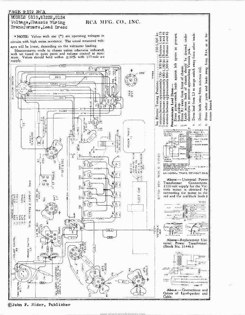
PAGE 9-172 RCA RdJDEIS Ú113,U122E,U124 Voltage,Chassis Wiring Transfarmers,Lead Dress
RCA MFG. CO., INC.
* NOTE: Values with star (*) are operating voltages in
circuits with high series resistance. The actual measured volt-
ages will be lower, depending on the voltmeter loading. Measurements made to chassis unless otherwise indicated,
with set tuned to quiet point and volume control at mini, mum. Values should hold within ±20% with 117 -volt a -c supply.
=1
V
m)
8çß
/ N3389 I II
N7M18 J M0113A
M 113A
038
223
co r .0 N.D .D .v m .D .º
cr
N o
Z
N3387
hSL2
in -18
3116
h
'N33tl7 F-í-
1IIIIIIIII
e 2 II- N3387
ÿ yMjE^- N3367
m
47;
%1 n
\-1 017 1)
N
823
OSS,
Iä
V
.... -.9°N
V'sO G Ol I.
O c á á 0.9.9.9 N a >n .-.e eey .n > é P.
p C q C O d ,noOO ., n d7 a á C aa aaw O
á ém " ÿ 000 N. -C-u. ,/1 00 0 oÿ O! > > CT .-1.11.1
oD
ó CO 0. [ G
m 1a
,ÿ m b DO w'm Á >.>.>. N O ro O v,vú::
m .4o. ap
L. L. ee I Z7 ó u LL 'EE ÿ ...L
is.4O El 4) N aaa .0. º w
a Ré,á .a a 'Eaaa CO O' NpmddvHeee .O'.
.a>, Gdch 3 il
E;dd
JA..a1:10-1 d
871
N ¢
- N eN RED
TO POWER SUPPLY -BLACK RED -
RED TR BLACK SSN I TOTAL A SLAP(
RED- YELLO
RED - BLACK
(TAPED)
NOTE INSERT CONNECTOR BET((CENVERVANOMMON
D CONTACTA[T AC CORRESPONDING TO PREVAILING POWER SUPPLY RATING.
UNIVERSAL TRANS. CONNECTIONS
< n V7
T) GREEN - ERECT FIL.
GREEN - BROWN-
RECT. PLATE 660 -n-
BLACK-MOWN
DROWN - BLUE -
AMP. CIL. BLUE - VELLO
BLACK-
Above - Universal Power Transformer Connections. (110 -volt supply for the Vic - trola motor is obtained by connecting the motor to the red and the red black leads.)
6 41
5N-800
nozr
Above-Replacement Uni- versal Power Transformer. (Stock No. 31446.)
MD-BLACK-ERECT. FIL.
PLUG BLPiCN PLRTE,
9 oiHeOw,rpLtCK SCREENcFC
eR CIE
Above - Connections and Colors of Loudspeaker and Cable.
©John F. Rider, Publisher
www.americanradiohistory.com
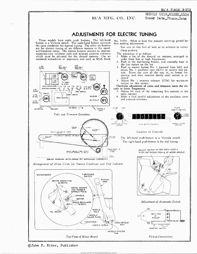
RCA PAGE 9-173 MODELS U119,U122E,U124
RCA MFG. CO., INC. Tuner Data,Phono.Data
ADJUSTMENTS FOR ELECTRIC TUNING These models have eight push buttons. The left-hand
button is a Victrola switch. The right-hand button connects the gang condenser for manual tuning. The other six buttons are for electric tuning of six different stations in the stand- ard -broadcast range. The station buttons connect to separate magnetite -core oscillator coils and separate antenna trimmers which must be adjusted for the desired stations. Use an insulated screwdriver or alignment tool such as RCA Stock
Ctl tOMC\
RECT. czs G.IMC C2s% ISOOKC
cao 20 MC
L11 fRc. ADJ. 69 K;
C29 ANT.
C20 OSC.
US SEC.ADJ. 435 KC
1ST. DET. e, OSC.
OSCILLATORCORR{+O6 OS 04 ANTRNNATRMNRIN
I. F
03 02 01 ZwoDET.
-^6 r &A.V.0 850- 980 KC
I IBO KC AUDIO
OUTPUT
ANTENNA GROUND 5N -819-I U-119,
Tube and Trimmer Locations
DRUM
IND1C05 IVW CORD
DRUM OtlYt CORO 31514 IN ReOR GROWS OFD RUM
NIICTROLA JACK
No. 31031. Allow at least five minutes warm-up period be- fore making adjustments.
Use one or two feet of wire as an antenna to ensure sharp peaking.
The procedure is as follows: 1. Make a list of the desired six stations, arranged in
order from low to high frequencies. 2. Push in the dial -tuning button, and manually tune in
the first station on the list. 3. Push in station button No. 1 (second from left) and
adjust No. 1 oscillator core (L37) to receive this sta- tion. Screw the core all the way in, to lowest fre- quency, and then unscrew slowly until station is re- ceived.
4. Adjust No. 1 antenna trimmer (C36) for maximum output on this station.
Clockwise adjustment of cores and trimmers tunes the cir- cuits to lower frequencies.
5. Adjust for each of the remaining five stations in the same manner.
6. Make a final careful adjustment of the oscillator cores and antenna trimmers.
MEDIUM VOLUME TONE
OFF
BPO.NASI SNORT WAVE
RANGE TUNING
TONE~- I l l . , 6
O,0 POWER RTONE 'VOL UM RANGE -TUNING
CONTROL PUSH BUTTON CONTROLS CONTROL
Location of Controls
PULLEY The left-hand push-button is a Victrola switch.. 31373
-- - The right-hand push-button is for dial tuning.
KNOB ST £ PULLEYURI 3,368
ulsliño
OVUM SHOWN WITH GING FIT MRXIMUM CRPRCITY
Arrangement of Drive Cords for Tuning Condenser and Dial Indicator
MOTOR BOARD
MOTOR MOUNTING SCREw3
METAL WASHER AND RUBBER SPINDLE PIECE
OIL HOLES
TURNTABLE SWITCH
NEEDLE HOLE
NEEDLE GAUGE PLATE
PICKUP ARM
PICKUP
TURNTABLE
NEEDLE SCREW
Top View of Motor Board
USED NEEDLE BOX
NEEDLE EJECTOR TAB
ADJUST SWITCH TO TRIP WHEN NEEDLE
IS ON 134" RADIUS FROM 4 OF MOTOR SP NDLE
Adjustment of Automatic Switch / v ` BRAID
SOT TOM po OF
PICKUP
J L {O r-BLUE
SHORTING SWITCH
Pickup Connections
©John F. Rider, Publisher
www.americanradiohistory.com
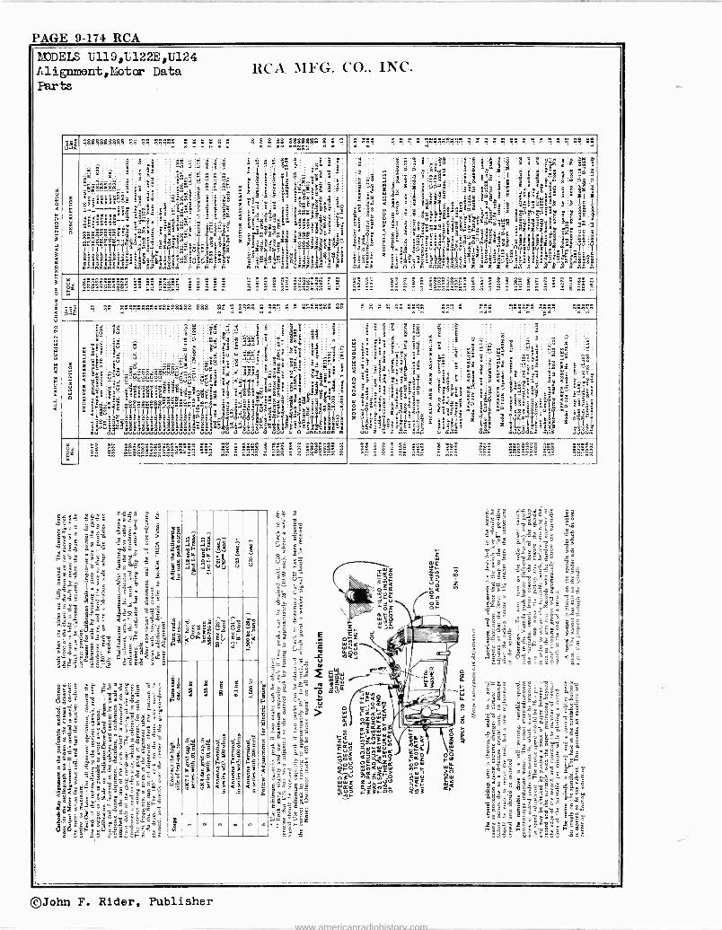
hUDEIS U119,U122E,U124 Alignment,líotor Data RCA MFG. CO., INC. Parts
»j ^ . . . . . . . . . :A C: . . 2 2 g g g n w .«
oS2ß3B$ e « , « . .-
8 :
. . . . . . . . . . . . ?!..5; . . 1 . e e el ß9
ti
h
m z
L. P =
`a
rc
s
z o
ñ rc u m P
1'
ii- 2'; ,"......-.ii 66«8
Ì22222 ÌÌ7ÌÌTsselz«¡ixj
mE- mzmmmmmmm
m.m ..''.22-'
mmfr
+_ ifas@y..: ° <
rr.é
éÉÉ
"áó%º
éËCbfrÓi
^g
:,
i:
.
°:2
9$ SF
G: w2 4224
9ñZYY^é> .
3° mm"
g5
ó
.
mm
i lc $ oÿ.Fw
!n
'8="«d^I..élä
« .s.b'.á
°-°
Ta3 frdmv
' ñ ^é:,';
: tl°
on
.b@tlñ;még;9
âá4:a á
a
! __ - =
ff
:u.u.I.--9EÓSP; E.h
E d
S é
S pg
S
9
$ S a
*22921'.2
i ÿi
3 ^ 2 :
w z
S: m 5 E=
^ ÿ én 9
. <
AA ó g<°eC` é O..mn
z áX$`i=`iaá
éÌÌÌd?EgerhÌÎ(Ì'ál
m
é é
1 S . !
fr:.. a - 'sá.
n
ä a
S 35
.¢ RR I
a Al
gg !
° t "
naa <é_
ä uu
K
^ 5S 1S
l5E3
fi_K!Y raá'
.1'.* .@CB `.ear rn. r' ..ó... `'S $Eg "°.-
Énn«á ó .
loâñsx"SïR`
a.3T31ai uBSFn"n
5
3 .
^
á °I! .0 ó
3
39
,.
çnJ:l ÿEg KA
s 8
8 .. 7
Ny
I S<
3
Si
ó;
Óc eta
"U
; 7 ÿa
w^- < ó!
fr° o m tla
z 3: < j fr-
$
ì .ÌS"rje'Y11111111áás5llÿl är
fr ....3
3, 'II
9! e
T á , °
x
Y
' s
e+ e.1
S&á3 7
Ó3 a a e. a xrr _freiááT°fruF.n.Fáe_ mF
$yyYY'
ce ö m
''r e -fr
PPP+
E i: LL18Fa.°á
á$'6'-e`=`r z3 3
iáé
°°°°.1.1, xxx°.il%k7
$`
;méfr
`.frá°%°Iyó''álI9s
fr $ ó 3
frfr5
Ypi
,d4111
.!w
e e}8 _ai
ÿá5 `á` ée. ìi é 5 $^^ á á33
t,álptx!,§ in.7
a
I
: i i e
t
m
,E" 9
8 8 fig 9f...:3zz Y¿ f Ü >iOS';n osfr fri= °"_m Yñ.«.Y-- g:9 3-``-aE$ 82ó88F-`'
éfiyEyfiçóYr _ "! f! E
Yy`:.Ǻ1.;IYwY
um ]-.2-.2 m
m < 82ÿ F, ==I S9 r r é o
w+r
i9v
w m
rä g,
á
!
8 '
= 99
nm
2 9
I
ä B
3
J
é «
h
3 m o
úr Éz m
nn n n n e
.. .. .. « ..
e"' n n n n n.. nnnnnnn n n n ..- nn n n n..nnnn..nnn ^
n n n n n n.. n n n .. n nn ..
m
z -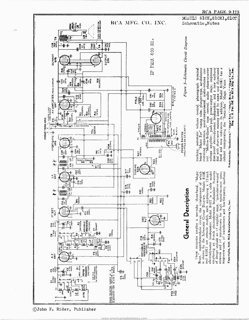
RCA PAGE 9-175
(23:i
! 08ß80 J
MODELS 810K,810K1,810T es RCA1Ih(t. CO.. INC. Schema.tic,nTotes
r :
i
q
4 úó
8f IH' f óó ± $$g 3 F-" o.
o 4
tu 3 f
'A-4 81` s it -é -u91 1de ,pdiu°3 -ó i ss was. ;
. :2V>
-1 ug 2 á. " u
< 0
p.3o1 C QQ ir ub oo. _..
!'Ol OiWz_(e10as,,000'ooc \ z
u
N ry3
U /v s N .;O T ú$f ,i.
2,2 Qm --..ti
II
U-3 sÑ
e 2,121Ñ 3 Rn
II
5;1 ;=11.1H102 U' oR 0 ó
I'd Oki u 9 Ñ jr \N
a°3 u
- ç -s Goa
1111,
O E
Ñ =w[
Z ,p z 7b t-
_2
eä
o
m
au
.4R
rib'm .J
N
a
u a.Qu.flro C y O > ú u y p ro ro
di
Ñ.01 d O a7 E ,.E -e4 - a-2ó
éo e
u ?Oá c vao
,,m c ~ O
úa17 b u O y ro ro
"VO d Ñ sw vacro aooD " c
_ 7 Ó ~ >. p'u `.R .. Laa
C aî á O G o. d"71 ú; u Prp itl ó N bDú
C_. CVJ E 2"-
leb :0 ;Bro%yg C pc ro
.UiN T»
>.o." ro U(Q U W 3 0 V
E u ro W d 0 a3a:.ca r.Ñ ú O C. pi -C 2 p
E y C
d OL., Ñ
..
0o a d .êc7O ..;qvE °ro ÿ Oy ÿ ro
.a >44,-2 u
óóú.i9 d%is p L~ ro
E ro p yyÌa.3H coao:°á'.>"cú
Ó pdcro$ÿ vv ó.E'
ó. bEE.,o ,«
ÿ ro ~
d r O Ñ et .2
Ol . Eev Q C" p ro u . .+ dFr.
ro u 'v ó a p ` >'ú'.u"EvE
o+ ro o d âu ro d. ó h d ... c J
Lmro ^N órñó.%,` V
Ñ ú N u
Ñ-V+-.cOLd vQT Ero^vc "42 cm,
' gd
ÿ C ti"ro N.D V D.N 0
C 0
PO roddOroE
@John F. Rider, Publisher
www.americanradiohistory.com
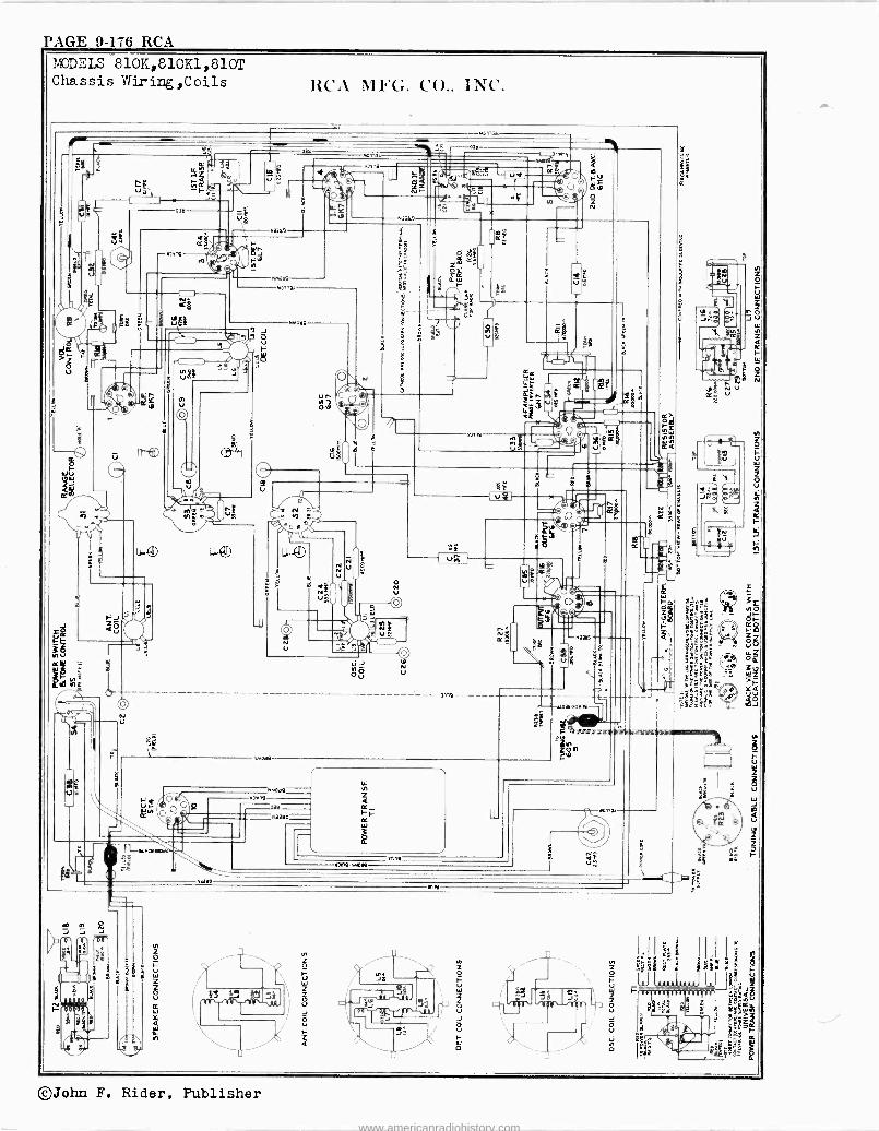
PAGE 9-176 RCA MODELS 810K,810K1,810T Chassis Wiring,Coils
©John F. Rider, Publisher
www.americanradiohistory.com
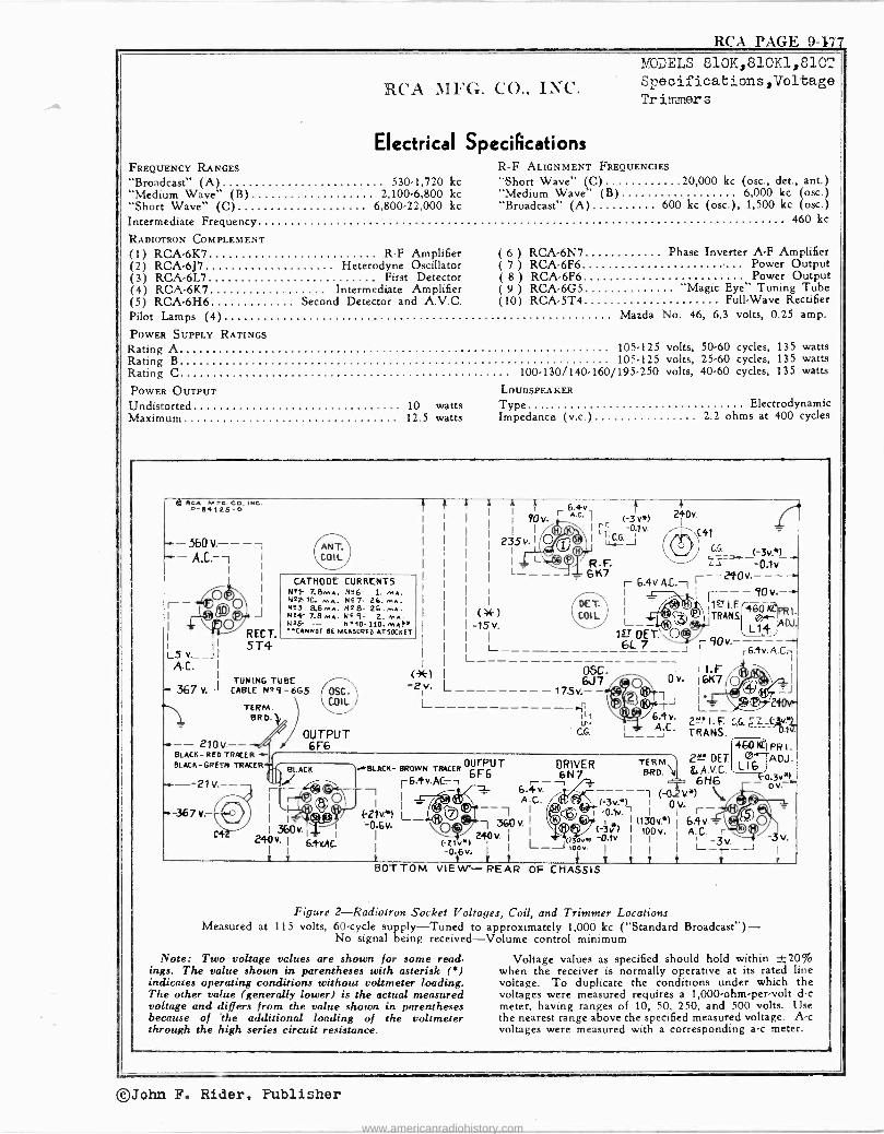
RCA PAGE 9477
RCA MFG. CO., INC.
Electrical Specifications FREQUENCY RANGES
"Broadcast" (A) 530-1,720 kc "Medium Wave" (B) 2,100.6,800 kc "Short Wave" (C) 6,800-22,000 kc Intermediate Frequency 460 kc
RADIOTRON COMPLEMENT (1) RCA -6K7 R -F Amplifier (2) RCA -6J7 Heterodyne Oscillator (3) RCA -6L7 First Detector (4) RCA -6K7 Intermediate Amplifier (5) RCA -6H6 Second Detector and A.V.C. Pilot Lamps (4) Mazda No. 46, 6.3 volts, 0.25 amp.
POWER SUPPLY RATINGS Rating A Rating B Rating C
POWER OUTPUT Undistorted 10 watts Maximum 12.5 watts
MODELS 810K,810K1,810T Specifications,Voltage Tr immer s
R -F ALIGNMENT FREQUENCIES
"Short Wave" (C) 20,000 kc (osc., det., ant.) "Medium Wave" (B) 6,000 kc (osc.) "Broadcast" (A) 600 kc (osc.), 1,500 kc (osc.)
(6 ) RCA -6N7 Phase Inverter A -F Amplifier (7) RCA -6F6 Power Output (8) RCA -6F6 Power Output (9) RCA -6G5 "Magic Eye" Tuning Tube (10) RCA -5T4 Full -Wave Rectifier
105-125 volts, 50-60 cycles, 135 watts 105.125 volts, 25-60 cycles, 135 watts
100.130/140.160/195.250 volts, 40.60 cycles, 135 watts
LOUDSPEAKER
Type. Impedance (v.c.)
Electrodynamic 2.2 ohms at 400 cycles
0 RCA Mrs. CO. INC. t rP-6+12.5-0I
I
I
--36ÚV.---T ANT. - A.C.- COIL I
, 1
l' t A 1 c
. V
j 90 V. r A'c' 1 1 1813r
235v.1 ` w
I
L- L-
4. t (-3v*) 2110v.
I L -0.1v. C41 J 1 uw
G6 w
R.F. / g -7_,....--01v1 ..
6K7 I
r CATHODE CURRCNTS N!t 7.8MA. Nº6- 1. MA. Nº2-10. MA. Nº7- 26. MA.
l.6MA.
i
- r 6.4V. At. -1 r-2¢Ov.--- i i I r --
RO,V,t-- _ .(I C) Ì--- 1 O
RECT.
N?3- Nº8- 26. MA. NºY 7.8 MA. Nº9 Z. MA. N'$- - Nº9-110. MA:. CANNºT RE MEASURED AT SOCKET
I
I
l
I
((
DET.
F 1-
I.F CDIL-- ITRANS Li -15 V. \SY
IL OET.
46O Kl. @i-ADd.
L1'4 11 5T4
L5v.__JI I
A.C. I
J TUNING TUBE (*I
V. I - 367 V. CABLE Nº 9 6G5 OSC. I L
TERM. COIL L BR D.
OUTPUT
-T
6L7 r90v.---- L L------ ---
I
r6.4v.AC.I
O5C. -- 1 I I. ,77-¡,
6J7 0 0,v- 16K7 Q 175v.- -z
-1 1 I j -- Q`t 210vr v' A.C. 2-"2 I. F.
C`G`2= C. t___ TRANS. 1 -- 210v. --
6F6 BLACK -RED TRACER 'N. DU(®+jADJ. OUTPUTTERM BLACK -GREEN TRACER+ BLACK BLACK -BROWN TRACER DRIVER
A 11 L 16Eo.3v*)
+--21 V.--
.-367 v.- ACC JJl
C4 240
>
_ (, g
1 360v.1ï 1
v. I 6. m. i
6 F 6 aRo. \ r6.4v.gC-, 6.4 v.
I j A.G. . l -3v+1 I 0
F2tv...1 L-- ,7 --1
I ®®Ì -o.tv. ' I
0.6v. 0 -I 360v. i # (130v. 1 ;I: I t0pv. l rw) 24ov. t Is.,., -0.1v I I
f -O.6v I
1iV I
t t
ov.. V.
\,.. !
I r 41),37+, 1 64v. I A.C.
-3v_ 3v.
t L t J
r BOTTOM VIEW -REAR OF CHASSIS
Figure 2-Radiotrou Socket Voltages, Coil, and Trimmer Locations Measured at 115 volts, 60 -cycle supply -Tuned to approximately 1,000 kc ("Standard Broadcast") -
No signal being received -Volume control minimum
Note: Two voltage values are shown for some read- Voltage values as specified should hold within ±20% ings. The value shown in parentheses with asterisk (C) when the receiver is normally operative at its rated line indicates operating conditions without voltmeter Loading. voltage. To duplicate the conditions under which the The other value (generally lower) is the actual measured voltages were measured requires a 1,000 -ohm -per -volt d -c voltage and differs from the value shown in parentheses meter, having ranges of 10, 50, 250, and 500 volts. Use because of 'the additional loading of the voltmeter the nearest range above the specified measured voltage. A -c through the high series circuit resistance. voltages were measured with a corresponding a -c meter.
©John F. Rider, Publisher
www.americanradiohistory.com
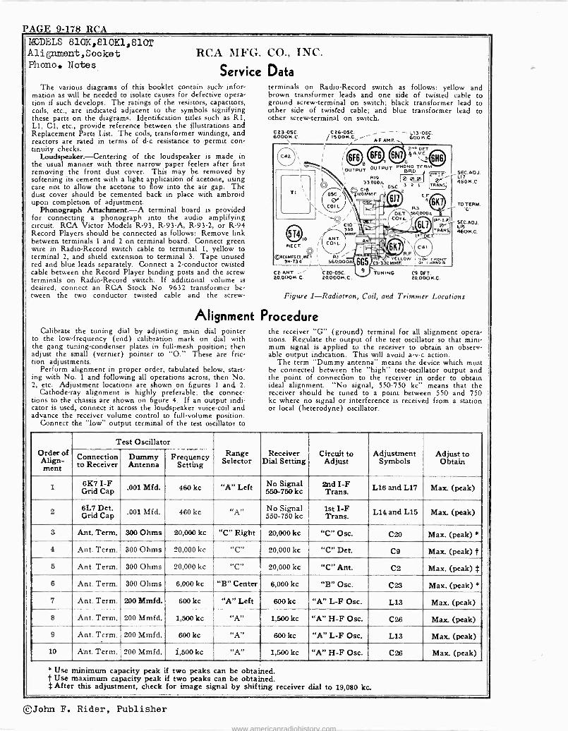
PAGE 9-178 RCA MODELS 810K,810K1,810T Alignment,Sooket RCA TIFG. Phono. Notes
Service The various diagrams of this booklet contain such- infor-
mation as will be needed to isolate causes for defective opera- tion if such develops. The ratings of the resistors, capacitors, coils, etc., are indicated adjacent to the symbols signifying these parts on the diagrams. Identification titles such as R1, L1, Cl, etc., provide reference between the illustrations and Replacement Parts List. The coils, transformer windings, and reactors are rated in terms of d -c resistance to permit con- tinuity checks.
Loudspeaker.-Centering of the loudspeaker is made in the usual manner with three narrow paper feelers after first removing the front dust cover. This may be removed by softening its cement with a light application of acetone, using care not to allow the acetone to flow into the air gap. The dust cover should be cemented back in place with ambroid upon completion of adjustment.
Phonograph Attachment.-A terminal board is provided for connecting a phonograph into the audio amplifying circuit. RCA Victor Models R-93, R -93-A, R-93-2, or R-94 Record Players should be connected as follows: Remove link between terminals 1 and 2 on terminal board. Connect green wire in Radio -Record switch cable to terminal 1, yellow to terminal 2, and shield extension to terminal 3. Tape unused red and blue leads separately. Connect a 2 -conductor twisted cable between the Record Player binding posts and the screw terminals on Radio -Record switch. If additional volume is desired, connect an RCA Stock No. 9632 transformer be- tween the two conductor twisted cable and the screw -
CO., INC.
Data terminals on Radio -Record switch as follows: yellow and brown transformer leads and one side of twisted cable to ground screw -terminal on switch; black transformer lead to other side of twisted cable; and blue transformer lead to other screw -terminal on switch.
C23-0SC. S00014 .C.
1
I
T1 ,
\T
@0 / RECT.
ol ©0.CAMF6.0L,I2
lN-734
C26OSC. - --- L13-OSC. /ISOOK.Ci A-FAMP. 6001S.C.
or
COIL
ANT. COIL
33,000n C19
120MMF.
2...06T !}A.v.c5` ̀
- OUTPUT OUTPUT BRO. SI7 RI9 L
3 2 1 TRAN 46oK.C.
T. "M OE COI L
CIO_
330 MF Il\=IrlAl
RI 560.000
L ' c
6K R3
TO TERM.
1sn,1 K TRAM
e- LIS r 460 N.C.
R.F YELLOW I TOP rNON-r
3 330MMF. or <ww»ie.
C2 -ANT. - Cto-OSC. TUNING C9-0ET. 20,000K.C. 20,00014.C. 2000014.C.
Figure 1-Radiotron, Coil, and Trimmer Locations
Alignment Procedure Calibrate the tuning dial by adjusting main dial pointer
to the low -frequency (end) calibration mark on dial with the gang tuning -condenser plates in full -mesh position; then adjust the small (vernier) pointer to "O." These are fric- tion adjustments.
Perform alignment in proper order, tabulated below, start- ing with No. 1 and following all operations across, then No. 2, etc. Adjustment locations are shown on figures 1 and 2.
Cathode-ray alignment is highly preferable; the connec- tions to the chassis are shown on figure 4. If an output indi- cator is used, connect it across the loudspeaker voice -coil and advance the receiver volume control to full -volume position.
Connect the "low" output terminal of the test oscillator to
the receiver "G" (ground) terminal for all alignment opera- tions. Regulate the output of the test oscillator so that mini- mum signal is applied to the receiver to obtain an observ- able output indication. This will avoid a -v -c action.
The term "Dummy antenna" means the device which must be connected between the "high" test -oscillator output and the point of connection to the receiver in order to obtain ideal alignment. "No signal, 550.750 kc" means that the receiver should be tuned to a point between 550 and 750 kc where no signal or interference is received from a station or local (heterodyne) oscillator.
Order of Align- ment
Test Oscillator Range
Selector Receiver
Dial Setting Circuit to Adjust
Adjustment Symbols
Adjust to Obtain Connection
to Receiver Dummy Antenna
Frequency Setting
1 6K7 I -F Grid Cap .001 Mfd. 460 kc "A" Left No Signal
550-750 kc 2nd I -F Trans. L16 and L17 Max. (peak)
2 6L7 Det. Grid Cap
.001 Mfd. 460 kc «A" No Signal 550-750 kc
1st I -F Trans. L14 and L15 Max. (peak)
3 Ant. Term. 300 Ohms 20,000 kc "C" Right 20,000 kc "C" Osc. C20 Max. (peak) *
4 Ant. Term. 300 Ohms 20,000 kc "C" 20,000 kc "C" Det. C9 Max. (peak) t 5 Ant. Term. 300 Ohms 20,000 kc "C" 20,000 kc "C" Ant. C2 Max. (peak) $
8 Ant. Term. 300 Ohms 6,000 kc "B" Center 6,000 kc "B" Osc. C23 Max. (peak) *
7 Ant. Term. 200 Mmfd. 600 kc "A" Left 600kc "A" L -F Osc. L13 Max. (peak)
8 Ant. Term. 200 Mmfd. 1,500 kc "A" 1,500 kc "A" H -F Osc. C26 Max. (peak)
9 Ant. Term. 200 Mmfd. 600 kc "A" 600 kc "A" L -F Osc. L13 Max. (peak)
10 Ant. Term. 200 Mmfd. i,500kc "A" 1,500 kc "A" H -F Osc. C26 Max. (peak)
* Use minimum capacity peak if two peaks can be obtained. Use maximum capacity peak if two peaks can be obtained.
t After this adjustment, check for image signal by shifting receiver dial to 19,080 kc.
©John F. Rider, Publisher
www.americanradiohistory.com
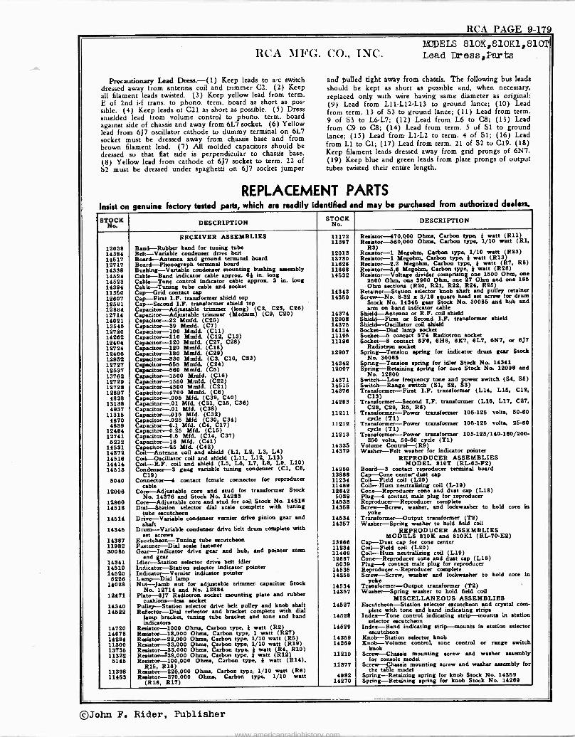
RCA PAGE 9-179 P.VDELS 810K,810K1,810TI
RCA MFG. CO., INC. Load Dress,Parts
Precautionary Lead Dress.-( 1) Keep leads to ac switch dressed away from antenna coil and trimmer C2. (2) Keep all filament leads twisted. (3) Keep yellow lead from term. E of 2nd i -f trans. to phono. term. board as short as pos. sible. (4) Keep leads of C21 as short as possible. (5) Dress shielded lead from volume control to phono. term. board against side of chassis and away from 6L7 socket. (6) Yellow lead from 6J7 oscillator cathode to dummy terminal on 6L7 socket must be dressed away from chassis base and from brown filament lead. (7) All molded capacitors should be
dressed so that flat side is perpendicular to chassis base.
(8) Yellow lead from cathode of 6J7 socket to term. 22 of S2 must be dressed under spaghetti on 6J7 socket jumper
and pulled tight away from chassis. The following bus leads should be kept as short as possible and, when necessary, replaced only with wire having same diameter as original: (9) Lead from L11,L12-L13 to ground lance; (10) Lead from term. 13 of S3 to ground lance; (11) Lead from term. 9 of S3 to L6 -L7; (12) Lead from L6 to C8; (13) Lead from C9 to C8; (14) Lead from term. 5 of Si to ground lance; (15) Lead from L11.2 to term. 4 of Si; (16) Lead from L1 to Cl; (17) Lead from term. 21 of S2 to C19. (18) Keep filament leads dressed away from grid prongs of 6N7. (19) Keep blue and green leads from plate prongs of output tubes twisted their entire length.
REPLACEMENT PARTS enuine factory tested parts, which are readily identified and may be purchased from authorized dealers.
STOCK No.
DESCRIPTION SOCK
o. DESCRIPTION
RECEIVER ASSEMBLIES 11172 Resistor ---470,000 Ohms, Carbon type, } watt (R11) 11397 Resistor -580,000 Ohms, Carbon type, 1/10 watt (Rl,
12038 Band -Rubber band for tuning tube R3) 14354 Belt -Variable condenser drive belt 12013 Resistor -1 Megohm, Carbon type, 1/10 watt (R23) 14517 Board -Antenna and ground terminal board 13730 Resistor -1 Megohm, Carbon type, j watt (R13) 12717 Board -Phonograph terminal board 11626 Resistor -2.2 Megohm, Carbon type, } watt (R7, RS) 14338 Bushing -Variable condenser mounting bushing assembly 11668 Resistor -5.8 Megohm, Carbon type, } watt (R26) 14524 Cable -Band indicator cable approx. 8} in. long 14532 Resistor -Voltage divider comprising one 1500 Ohm, one 14123 Cable -Tone control indicator cable approx. 3 in. long 2600 Ohm, one 3900 Ohm, one 27 Ohm and one 165 14394 Cable -Tuning tube cable and socket Ohm sections (R20, R21, R22 R24, R25) 11350 Cap -Grid contact cap 14343 Retainer -Station selector knob shaft and pulley retainer 12607 Cap -First I.F. transformer shield top 14350 Screw -No. 8-32 x 3/18 square head set screw for drum 12581 Cap -Second I.F. transformer shield top Stock No. 14345 gear Stock No. 30085 and hub and 12884 Capacitor -Adjustable trimmer (long) (C2, C23, C26) arm on band indicator cable 12724 Capacitor -Adjustable trimmer (Medium) (C9, C20) 14374 Shield -Antenna or R.F. coil shield 14021 Capacitor -22 Mmfd. (C25) 12008 Shield -First or Second I.F. transformer shield 13545 Capacitor -39 Mmfd. (C7) 14375 Shield -Oscillator coil shield 12720 Capacitor -100 Mmfd. (C11) 14114 Socket -Dial lamp socket 14262 Capacitor -110 Mmfd. (C12, C13) 11195 Socket -6 contact 5T4 Radiotron socket 12404 Capacitor -120 Mmfd. (C27, C28) 11196 Socket -8 contact 13F8, 6H6, 6K7, 6L7, 6N7, or 8J7 12724 Capacitor -120 Mmfd. (C18) Radiotron socket 12406 Capacitor -180 Mmfd. (C29) 12907 Spring -Tension spring for indicator drum gear Stock 12952 Capacitor -330 Mmfd. (C3, C10, C33) No. 30085 12727 Capacitor -656 Mmfd. (C24) 14342 Spring -Tension spring for idler Stock No. 14341 12537 Capacitor -560 Minfd. (C5) 12007 Spring -Retaining spring for core Stock No. 12006 and
13762 Capacitor -1500 Mmfd. (C16) No. 12800 12729 Capacitor -1550 Mmfd. (C22) 14371 Switch -Low frequency tone and power switch (S4, S5) 12728 Capacitor -4600 Mmfd. (C21) 14515 Switch -Range switch (SI, S2, S3) 12897 Capacitor --'4700 Mmfd. (CS) 14378 Transformer -First I.F. transformer (L14, L15, C12, 4838 Capacitor -.00S Mfd. (C39, C40) CIS)
13138 Capacitor -.01 Mfd. (C31, C36, C38) 14283 Transformer -Second I,F. transformer (L16, L17, C27, 4937 Capacitor -.01 Mfd. (C38) C28, C29, R5, RS)
11315 Capacitor -.016 Mfd. (C32) 11211 Transformer -Power transformer 105-125 volts, 50-60 4870 Capacitor -.025 Mfd (C30, C34) cycle (T1) 4839 Capacitor -0.1 Mfd. (C4, C17) 11212 Transformer -Power transformer 106-125 volts, 25-60
12484 Capacitor -0.25 Mfd. (C15) cycle (T1) 12741 Capacitor -0.5 Mfd. (C14, C37) 11213 Transformer -Power transformer 105-125/140-160/200- 521.2 Capacitor -18 Mfd. (C41) 250 volts, 50-60 cycle (T1)
14531 Capacitor -25 Mfd. (C42) 14335 Volume Control -(R9) 14372 Coil -Antenna coil and shield (L1, L2, L3, L4) 14379 Washer -Felt washer for indicator pointer 1451.8 Coil -Oscillator coil and shield (L11, L12, L13) REPRODUCER ASSEMBLIES 14414 Coil-R.F. coil and shield (L5, L8, L7, L8, L9, L10) MODEL 810T (RL -83-F2) 14513 Condenser -3 gang variable tuning condenser (C1, C8, 14356 Board -3 contact reproducer terminal board
C19) 13888 Cap -Cone center dust cap 5040 Connector -4 contact female connector for reproducer 11234 Coil -Field coil (L20)
cable 11469 Coil -Hum neutralizing coil (L-19) Cone dust (L18) 12006 Core -Adjustable core and stud for transformer Stock 12642 -Reproducer cone and cap Plug -4 contact male plug for reproducer No. 14378 and Stock No. 14283 5039
12800 Core -Adjustable core and stud for coil Stock No. 14518 14533 Reproducer -Reproducer complete 14518 Dial -Station selector dial scale complete with tuning
tube escutcheon 14358 Screw -Screw, washer, and lockwasher to hold core in
yoke 14514 Drive -Variable condenser vernier drive pinion gear and 14534 Transformer -Output transformer (T2)
shaft 14357 Washer -Spring washer to hold field coil 14345 Drum -Variable condenser drive belt drum complete with
net screws REPRODUCER ASSEMBLIES
MODELS 810K and 810K1 (RL -70,-E2) 14387 Escutcheon -Tuning tube escutcheon 13888 Cap -Dust cap for cone center 11982 Fastener -Dial scale fastener 11234 Coil -Field coil (L20) 30085 Gear -Indicator drive gear and hub, and pointer stein 11489 Coil -Hum neutralizing coil (L19)
and gear 12687 Cone -Reproducer cone and dust cap (L18) 14341 Idler -Station belt idler 5039 Plug -4 contact male plug for reproducer 14519 Indicator-Stationselector selector indicatorry pointer 14535 Reproducer -Reproducer complete 14520 Indicator -Vernier indicator pointer 14358 Screw -Screw, washer and lockwasher to hold core in
5228 Lamp -Dial lamp yoke 14028 Nut -Jamb nut for adjustable trimmer capacitor Stock 14534 Transformer -Output transformer (T2)
No. 12714 and No. 12884 14357 Washer -Spring washer to hold field coil 12471 Plate -6J7 Radiotron socket mounting plate and rubber
cushions -less socket MISCELLANEOUS ASSEMBLIES 14340 Pulley -Station selector drive belt pulley and knob shaft 14527 Escutcheon -Station selector escutcheon and crystal corn - 14522 Reflector -Dial reflector and bracket complete with dial plete with tone and band indicating strips
lamp bracket, tuning tube bracket and tone and band indicators
14528 Index -Tone control indicating strip --mounts in station selector escutcheon
14720 Resistor -1000 Ohms, Carbon type, j watt (R2) 14529 Index -Band indicating strip -mounts in station selector 14078 Resistor -18,000 Ohms, Carbon type, 1 watt (R27) escutcheon 14284 Resistor -22,000 Ohms, Carbon type, 1/10 watt (R5) 14359 Knob -Station selector knob 11300 Resistor -33,000 Ohma, Carbon type, 1/10 watt (R19) 14289 Knob -Volume control, tone control or range switch 13735 Resistor -33,000 Ohms, Carbon type, } watt (R4, R10) knob 11322 Resistor -39,000 Ohms, Carbon type, } watt (R12) 11210 Screw -Chassis mounting screw and washer assembly 5145 Resistor -100,000 Ohms, Carbon type, } watt (R14), for console model
R16, R18) 11377 Screw -Chassis mounting screw and washer assembly for 11398 Resistor -220,000 Ohms, Carbon type, 1/10 watt (R8) the table model 11453 Resistor -270,000 Ohms, Carbon type, 1/10 watt 4982 Spring -Retaining spring for knob Stock No. 14359
(R16, R17) 14270 Spring -Retaining spring for knob Stock No. 14289
©John F. Rider, Publisher
www.americanradiohistory.com
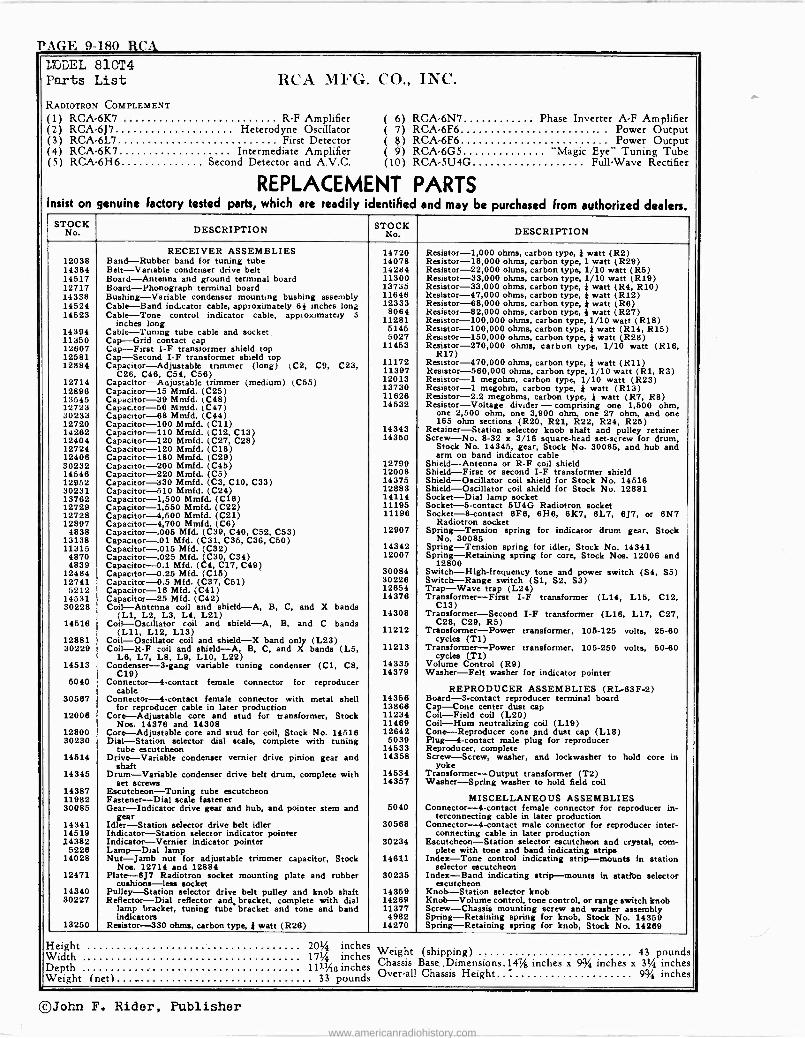
PAGE 9-180 RCA MODEL 810T4 Parts List
KADIOTRON COMPLEMENT
RCA MFG. CO., INC.
(1) RCA -6K7 R -F Amplifier ( 6) RCA -6N7 Phase Inverter A -F Amplifier (2) RCA -6J7 Heterodyne Oscillator ( 7) RCA -6F6 - - Power Output (3) RCA -6L7 First Detector ( e) RCA -6F6 Power Output (4) RCA -6K7 Intermediate Amplifier ( 9) RCA -6G5 "Magic Eye" Tuning Tube (5) RCA -6H6 Second Detector and A.V.C. (10) RCA-5U4G Full -Wave Rectifier
REPLACEMENT PARTS Insist on genuine factory tested parts, which are readily identified and may be purchased from authorized dealers.
S No K DESCRIPTION STOCK No. DESCRIPTION
RECEIVER ASSEMBLIES 14720 Resistor -1,000 ohms, carbon type, } watt (R2) 12038 Band -Rubber band for tuning tube 14078 Resistor -18,000 ohms, carbon type, 1 watt (R29) 14384 Belt-Vanable condenser drive belt 14284 Resistor -22,000 ohms, carbon type, 1/10 watt (R5) 14517 Board -Antenna and ground terminal board 11300 Resistor -33,000 ohms, carbon type, 1/10 watt (R19) 12717 Board -Phonograph terminal board 13735 Resistor -33,000 ohms, carbon type, } watt (R4, R10) 14338 Bushing -Variable condenser mounting bushing assembly 11646 Resistor -47,000 ohms, carbon type, } watt (R12) 14524 Cable -Band indicator cable, approximately 6¡ inches long 12333 Resistor -68,000 ohms, carbon type, }watt (R6) 14523 Cable -Tone control indicator cable, appiox,mately 3 8064 Resistor -82,000 ohms, carbon type, }watt (R27)
inches long 11281 Resistor -100,000 ohms, carbon type, 1/10 watt (R18) 14394 Cable -'-Tuning tube cable and socket 5145 Resistor -100,000 ohms, carbon type, } watt (R14, R15) 11350 Cap -Grid contact cap 5027 Resistor -150,000 ohms, carbon type, } watt (R28) 12607 Cap -First 1-F transformer shield top 11453 Resistor -270,000 ohms, carbon type, 1/10 watt (R16, 12581 Cap -Second I -F transformer shield top R17) 12884 Capacitor -Adjustable trimmer (long) (C2, C9, C23, 11172 Resistor -470,000 ohms, carbon type, }watt (R11)
C26, C46, C54, C56) 11397 Resistor -560,000 ohms, carbon type, 1/10 watt (R1, R3) 12714 Capacitor -Adjustable trimmer (medium) (C55) 12013 Resistor -1 megohm, carbon type, 1/10 watt (R23) 12896 Capacitor -15 Mmfd. (C25) 13730 Resistor -1 megohm, carbon type, } watt (R13) 13545 Capacitor -39 Mmfd. (C48) 11626 Resistor -2.2 megohms, carbon type, * watt (R7, R8) 12723 Capac.tor-56 Mmfd. (C47) 14532 Resistor -Voltage divider - comprising one 1,500 ohm, 30233 Capacitor -68 Mmfd. (C44) one 2,500 ohm, one 3,900 ohm, one 27 ohm, and one 12720 Capacitor -100 Mmfd. (CU) 165 ohm sections (R20, R21, R22, R24, R25) 14262 Capacitor -110 Mmfd. (C12, C13) 14343 Retainer -Station selector knob shaft and pulley retainer 12404 Capacitor -120 Mmfd. (C27, C28) 14350 Screw -No. 8-32 x 3/16 square -head set -screw for drum, 12724 Capacitor -120 Mmfd. (C18) Stock No. 14345, gear, Stock No. 30085, and hub and 12406 Capacitor -180 Mmfd. (C29) arm on band indicator cable 30232 Capacitor -200 Mmfd. (C45) 12799 Shield -Antenna or R -F coil shield 14546 Capacitor -220 Mmfd. (C5) 12008 Shield -First or second I -F transformer shield 12952 Capacitor -330 Mmfd. (C3, C10, C33) 14375 Shield -Oscillator coil shield for Stock No. 14516 30231 Capacitor -510 Mmfd. (C24) 12883 Shield -Oscillator coil shield for Stock No. 12881 13762 Capacitor -1,500 Mmfd. (C16) 14114 Socket -Dial lamp socket 12729 Capacitor -1,550 Mmfd. (C22) 11195 Socket -5 -contact 5U4G Radiotron socket 12728 Capacitor -4,500 Mmfd. (C21) 11196 Socket -8 -contact 6F6, 6H6, 6K7, 6L7, 6J7, or 6N7 12897 Capacitor -4,700 Mmfd. (C6) Radiotron socket
4838 Capacitor -.005 Mfd. (C39, C40, C52, C53) 12907 Spring -Tension spring for indicator drum gear, Stock 13138 Capacitor -.01 Mfd. (C31, C35, C36, C50) No. 30085 11315 Capacitor -.015 Mfd. (C32) 14342 Spring -Tension spring for idler, Stock No. 14341
4870 Capacitor -.025 Mfd. (C30, C34) 12007 Spring -Retaining spring for core, Stock Nos. 12006 and 4839 Capacitor -0.1 Mfd. (C4, C17, C49) 12800
12484 Capacitor -0.25 Mfd. (C15) 30084 Switch -High -frequency tone and power switch (S4, S5) 12741 Capacitor -0.5 Mfd. (C37, C51) 30226 Switch -Range switch (S1, S2, 83)
5212 Capacitor -16 Mfd. (C41) 12654 Trap -Wave trap (L24) 14531 Capacitor -25 Mfd. (C42) 14376 Transformer -First I -F transformer (L14, L15, C12, 30228 Coil -Antenna coil and shield -A, B, C, and X bands C13)
(L1, L2, L3, L4, L21) 14308 Transformer -Second I -F transformer (L16, L17, C27, 14516 Coil -Oscillator coil and shield -A, B, and C bands C28, C29, R5)
(L11, L12, L13) 11212 Transformer -Power transformer, 105-125 volts, 25-60 12881 Coil -Oscillator coil and shield -X band only (L23) cycles (T1) 30229 Coil -R -F coil and shield -A, B, C, and X bands (L5,
L6, L7, L8, L9, L10, L22) 11213 Transformer -Power transformer, 105-250 volts, 50-60
cycles CT1) 14513 Condenser -3 -gang variable tuning condenser (C1, C8, 14335 Volume Control (R9)
C19) 14379 Washer -Felt washer for indicator pointer 5040 Connector -4 -contact female connector for reproducer
cable REPRODUCER ASSEMBLIES (RL -83F-2) 30567 Connector -4 -contact female connector with metal shell 14356 Board -3 -contact reproducer terminal board
for reproducer cable in later production 13866 Cap -Cone center dust cap 12008 Core -Adjustable core and stud for transformer, Stock 11234 Coil -Field coil (L20)
Nos. 14376 and 14308 11469 Coil -Hum neutralizing coil (L19) 12800 Core -Adjustable core and stud for coil, Stock No. 14516 12642 Cone -Reproducer cone and dust cap (L18) 30230 Dial -Station selector dial scale, complete with tuning 5039 Plug -4 -contact male plug for reproducer
tube escutcheon 14533 Reproducer, complete 14514 Drive -Variable condenser vernier drive pinion gear and
shaft 14358 Screw -Screw, washer, and lockwasher to hold core in
yoke 14345 Drum -Variable condenser drive belt drum, complete with 14534 Transformer -Output transformer (T2)
set screws 14357 Washer -Spring washer to hold field coil 14387 Escutcheon -Tuning tube escutcheon 11982 Fastener -Dial scale fastener MISCELLANEOUS ASSEMBLIES 30085 Gear -Indicator drive gear and hub, and pointer stem and
gear 5040 Connector -4 -contact female connector for reproducer in -
terconnecting cable in later production 14341 Idler -Station selector drive belt idler 30568 Connector -4 -contact male connector for reproducer inter - 14519 Indicator -Station selector indicator pointer connecting cable in later production 14382 Indicator --Vernier indicator pointer 30234 Escutcheon -Station selector escutcheon and crystal, corn -
5226 Lamp -Dial lamp plete with tone and band indicating strips 14028 Nut -Jamb nut for adjustable trimmer capacitor, Stock
Nos. 12714 and 12884 14611 Index -Tone control indicating strip -mounts in station
selector escutcheon 12471 Plate -6J7 Radiotron socket mounting plate and rubber
cushions -less socket 30235 Index -Band indicating strip -mounts in atatton selector
escutcheon 14340 Pulley -Station selector drive belt pulley and knob shaft 14359 Knob -Station selector knob 30227 Reflector -Dial reflector and bracket, complete with dial 14269 Knob -Volume control, tone control, or range switch knob
lamp bracket, tuning tube bracket and tone and band 11377 Screw -Chassis mounting screw and washer assembly indicators 4982 Spring -Retaining spring for knob, Stock No. 14359
13250 Resistor -330 ohms, carbon type, } watt (R26) 14270 Spring -Retaining spring for knob, Stock No. 14289
Height 20/4 inches Weight (shipping) 43 pounds Width 17% inches Chassis Base ,Dimensions.147/8 inches x e4 inches x 3% inches Depth 111:M6 inches
Weight (net)... _... 33 pounds Over-all Chassis Height 9 4 inches
®John F. Rider, Publisher
www.americanradiohistory.com
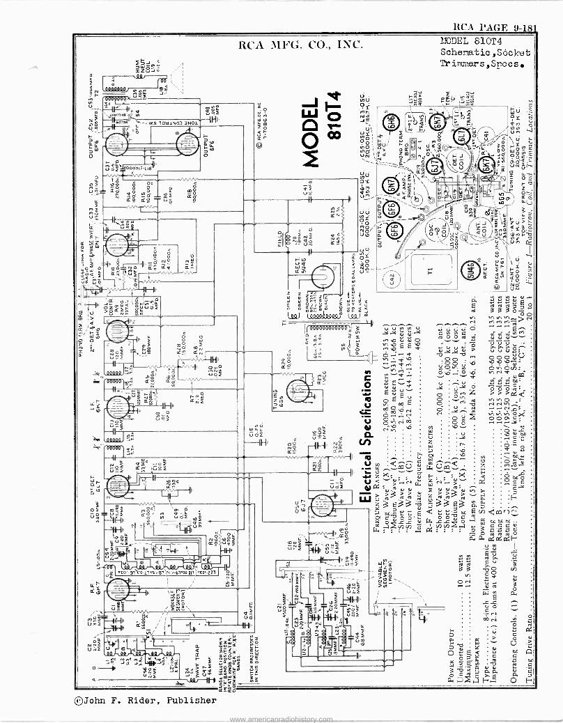
RCA PAGE 9-111
5J C
SZúG d 4 i
0000000 ) O. p 0] m F úó J=
r1 oao0fö,y < ./
c O 7 1. -.YI,1M N
N =M5101i1NO3 3N01 N o tt.. U ? yq . ÿ r °o
RCA 1b1FG. CO., INC.
d ú ¿F OOOóu-Lltl
m
Ú
7 <
o f é Op 004
ue= S,S G o Ñ QO teG
LL Sº dÓ Vó
ó
Lr reY
o
Y O Ó e O W o sQ äF ñ , ú i -/l-
Hrv
Já W Q 1ÓfIN4 >SdÑ ÑWUoF
< LL O O
O W a * ' OF m0
N O N N Ñ2 Um cc ¢rv
u -f ` ' Hp. J7l 2-vv µ oÓ 00001 ó! /
Np Ó óf dp d m,n.vw
< <.
to.oF wU^'
A e ' U
u m. Qi
W
Qf u
a NÓ 1pf ¢º u
Xd
al .co -yl%'D.LlPr1.Bl\N.>-6100-011ie a221 Ru N ú E
O UZi /1""\ 2ÑQ\
/ I úF Hk sv / ° pl A N
Ñ /
04 . . n
Úl.i £ U m Q
O
Ud
II IM
V N
= Ño a rVm N_ Q N1-CCt úW
4 GGYQNC pQ6 F r o
Wim NmY; zxa aná
á=aC
II
d_
z z
3nç3 =wwWY a a Qó ' á3:2. u
l90) lnóooóooºQ, '69) J m
'- ---a mo ; U z 1`n' os ® fw 1,,aN 1 ,
V= W 2
/(1)DEL 810T4 Schematic aSöcket Trimners,Specs
10-áV IJúú . .
am. m v
Ñ d..r ., E
<I rd
v, h v1 v,.-- > N ./-.i. N .-r .--i ... b - ¡ áó0òoooaó0oo ; 3 ' .bd ú ci E^
'W ma d it
D1 M0 N Ol0 N OvN ÿ OJ N v `
^v ^ V V ^
Ñ\ 30 ''" b E E 0l ..y su Ol .7 V Ú 0:79' ̂ ,ODri
a 11 O^' . O M pO,p.-V.0 Il ..y 000 V. ... VOv, m
n w N N..I v,0 .--I O ,O <V 94-
áF c ÿ w...< u î.0 íN,
Or 04
pp. o ÉÿVv w:z >>>°=
E u o ÿv, c=
O Eo0 E O "' co ,v,0 U
CO u . .Nr1v. ` p°1N., ON .C ú ^+ v,v,v, Ó F OOP C - ÿ 0v N00 O Ó - +.dC'
CO X) 0 /)
14 O v \
:/i N
u ...NONO bd C
r 'e)..9ó v; V a ,Ci N \ Ian ..-
° á ~ z 1ho'::' ...All cÛ d Ûcôd e Iry v/ 1 a.`. z ,': ..-.7-- ,°, F.. >ti J`t" ò mâ :% <'-';'....-.5 a. Ñ.r ../
W O Ç C °'a;3bd zA>2; T el (A W
W 3 e 3 3 d á 33 E3 á, : H
D pC L: E d:. i.:á OC E V7
N W0 ',IV ..ON -C Ir..2 O I alnrn .°,C
S V
á 1na ö w
úr N Ouc,
O,0
m `=
LL n Û-î Úlúí O
@ P TOf
u_F Za -. o _
_
t7
O
ci. E td
li
20 ,:.,
~4 NOF u . ú \u
< r)e-4
3xIX E a ¡a
vK C] ál ál
N a á F "1 O
°John F. Rider, Publisher
www.americanradiohistory.com
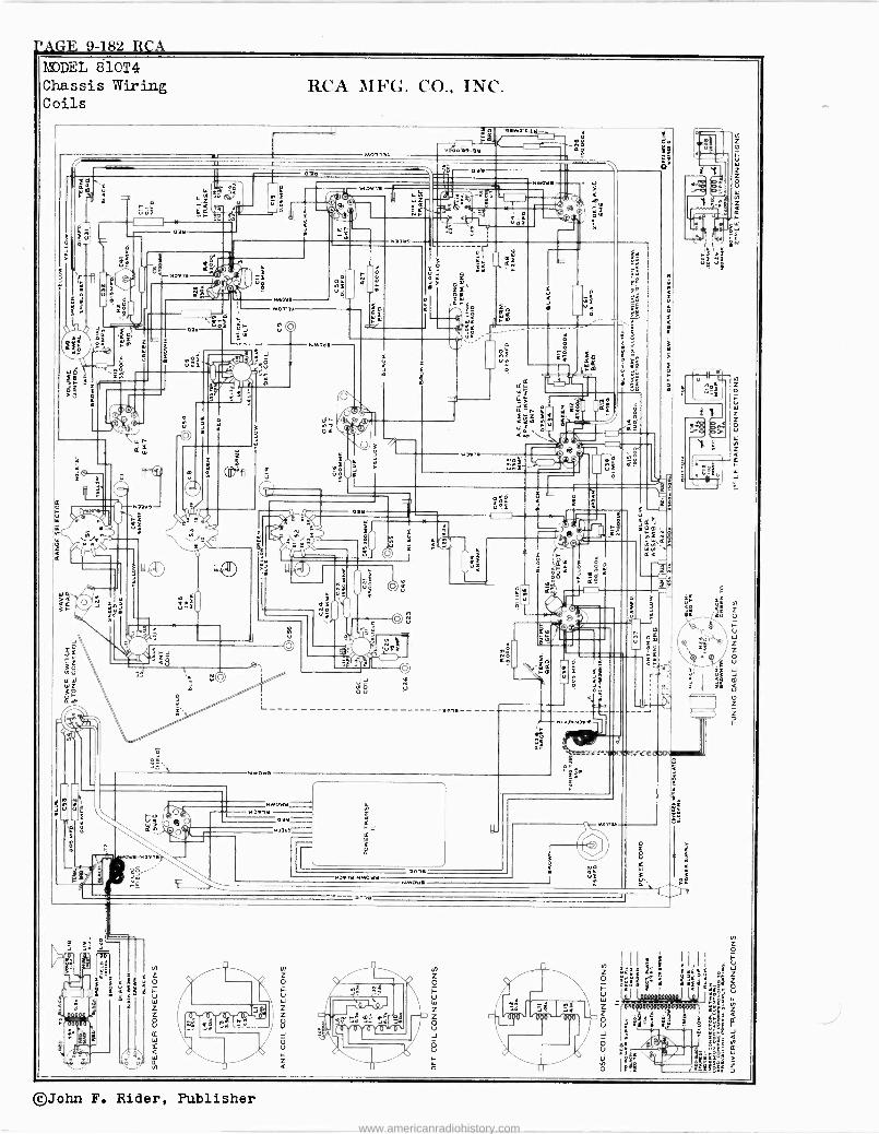
TAGE 9-182 RCA 1I DEL 810T4 Chassis Wiring Coils
z
8 O
W
RCA MFG. CO., INC.
$ï
[
B
z o u t, IN
t2
ú z z o u LL N z
r
©John F. Rider, Publisher
www.americanradiohistory.com
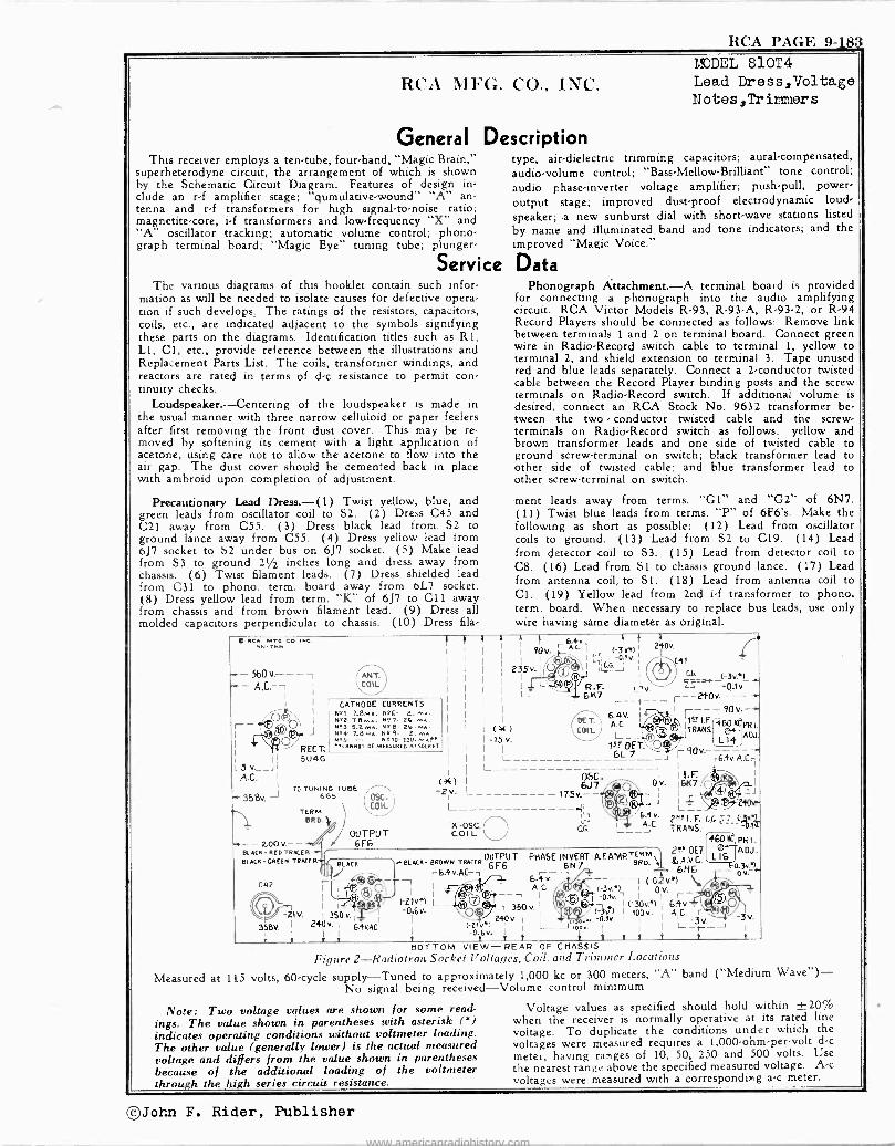
RCA PAGE 9183
RCA MFG. CO., INC.
General This receiver employs a ten -tube, four -band, "Magic Brain,"
superheterodyne circuit, the arrangement of which is shown by the Schematic Circuit Diagram. Features of design in- clude an r -f amplifier stage; "qumulative-wound" "A" an- tenna and r -f transformers for high signal-to-noise ratio; magnetite -core, i -f transformers and low -frequency "X" and "A" oscillator tracking; automatic volume control; phono- graph terminal board; "Magic Eye" tuning tube; plunger -
Servi The various diagrams of this booklet contain such infor-
mation as will be needed to isolate causes for defective opera- tion if such develops; The ratings of the resistors, capacitors, coils, etc., are indicated adjacent to the symbols signifying these parts on the diagrams. Identification titles such as RI, L1, Cl, etc., provide reference between the illustrations and Replacement Parts List. The coils, transformer windings, and reactors are rated in terms of d -c resistance to permit con- tinuity checks.
Loudspeaker. ---Centering of the loudspeaker is made in the usual manner with three narrow celluloid or paper feelers after first removing the front dust cover. This may be re- moved by softening its cement with a light application of acetone, using care not to allow the acetone to flow into the air gap. The dust cover should be cemented back in place with ambroid upon completion of adjustment.
Precautionary Lead Dress. -(1) Twist yellow, blue, and green leads from oscillator coil to S2. (2) Dress C45 and C21 away from C55. (3) Dress black lead from. S2 to ground lance away from C55. (4) Dress yellow lead from 6J7 socket to S2 under bus on 6J7 socket. (5) Make lead from S3 to ground 21/2 inches long and dress away from chassis. (6) Twist filament leads. (7) Dress shielded lead from C31 to phono. term. board away from 6L7 socket. (8) Dress yellow lead from term. "K" of 6J7 to CI1 away from chassis and from brown filament lead. (9) Dress all molded capacitors perpendicular to chassis. (10) Dress fila -
Measured at
MODEL 810T4 Lead Dress,Voltage Notes,Trir>xer s
Description type, air -dielectric trimming capacitors; aural -compensated, audio -volume control; "Bass -Mellow -Brilliant" tone control; audio phase -inverter voltage amplifier; push-pull, power -
output stage; improved dust -proof electrodynamic loud- speaker; -a new sunburst dial with short-wave stations listed by name and illuminated band and tone indicators; and the improved "Magic Voice."
ce Data Phonograph Attachment. -A terminal board is provided
for connecting a phonograph into the audio amplifying circuit. RCA Victor Models R-93, R93 -A, R-93-2, or R-94 Record Players should be connected as follows: Remove link between terminals 1 and 2 on terminal board. Connect green wire in Radio -Record switch cable to terminal 1, yellow to terminal 2, and shield extension to terminal 3. Tape unused red and blue leads separately. Connect a 2 -conductor twisted cable between the Record Player binding posts and the screw terminals on Radio -Record switch. If additional volume is desired, connect an RCA Stock No. 9632 transformer be- tween the two conductor twisted cable and the screw - terminals on Radio -Record switch as follows: yellow and brown transformer leads and one side of twisted cable to ground screw -terminal on switch; black transformer lead to other side of twisted cable; and blue transformer lead to other screw -terminal on switch.
ment leads away from terms. "Gl" and "G2" of 6N7. (11) Twist blue leads from terms. "P" of 6F6's. Make the following as short as possible: (12) Lead from oscillator coils to ground. (13) Lead from S2 to C19. (14) Lead from detector coil to S3. (15) Lead from detector coil to C8. (16) Lead from S 1 to chassis ground lance. (17) Lead from antenna coil, to S1. (18) Lead from antenna coil to Cl. (19) Yellow lead from 2nd i -f transformer to phono. term. board. When necessary to replace bus leads, use only wire having same diameter as original.
Ru Mec co, me.SN-768
-560v.---, A.L.-1
I I
I
I CATHODE CURRENTS Nºt i.e., 526- Nº2- TBw.A. Nº 7- 26. mA. Nt3-S.LMA. NºB- Nºr 7.8 so. Nº g- 2. mA.
I RECT.' .N25- - Nº10-110.A.eR
CANNOT OE MEASUREO AT SOCKET
5U4G L5 v._ I
AC. i
TO TUNING TUBE - 358v. J 6G5
TERM. BRD.
OSC COIL
OUTPUT - zoo v---' « / 6F6 +BLACK-02oTRACER OUTPUT PHASE INVERT -A.F.
2-'DET. BLACK -G0010 TRACER
6 BLACK I....,BLACK- BROWN TRACER 6F6 6N7 BR0. 6hV
tel{ I
Lr 64v.Ac-,
C42 16. v. IC.Ql QY6lw Ac / 1-3v.á) I
-I 350v I ®-o.N. I
OIV-. r 1Q 350v. I
. a30s') 1 6Av. I.6v \ (ttelg` l W 3 E 3v) fop v. A.C. r
3V. \(-Clvv)240v.Ì L_____,(2::: 1.1v i i
I L-3r I -0tó v. y
1 t t t 1 i t o
BOTTOM VIEW- REAP OF CHASSIS
Figure 2-Radiotron Socket Voltages, Coil, and Trimmer Locations
115 volts, 60 -cycle supply -Tuned to approximately 1,000 kc or 300 meters, "A" band ("Medium Wave") - No signal being received -Volume control minimum
L
t+ I I
t t 90V. r
6A1.
t-3vR) 240v.
I I IB 1.1 I -0.1v. ¡ C41
235 v.1 0 1 JJ
I J J
i G6. <-3v.) I LI- R.F. 1.1V.
t -- Div- 6 K ,240
90v + A.C. ETI.F.r4601t4'PR). L__l.j TRANS LAOJ. lot -
r6.4v.A.c.l
OSC. ' 1 n Ov. 16K7 Q
6.4V.I
I
\y'J I
-21V. I 350 v.14:
358V. Ì 240v. 6.4vAC.
i º 2 2
"K -05C. COIL
Note: Two voltage values are shown for some read- ings. The value shown in parentheses with asterisk (0) indicates operating conditions without voltmeter loading. The other value (generally lower) is the actual measured
voltage and differs from the value shown in parentheses because of the additional loading of the voltmeter through the high series circuit resistance.
E1
C.G.
6J7 * J L__\®,,. 6I. A.C.
2.R I. F. CA 2z -el -_ TRANS. PR I. ADJ.
-ov.^ Yr0.3v_9
Voltage values as specified should hold within ±20`'/0 when the receiver is normally operative at its rated line voltage. To duplicate the conditions under which the voltages were measured requires a 1,000.-ohmper-volt d -c
meter, having ranges of 10, 50, 250 and 500 volts. Use the nearest range above the specified measured voltage. Ac voltages were measured with a corresponding a -c meter.
I-(ThJohn F. Rider, Publisher
www.americanradiohistory.com
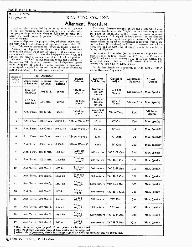
PAGE 9-184 RCA MODEL 810T4 Alignment RCA MFG.
Alignment Calibrate the tuning dial by adjusting main dial pointer
to the low -frequency (end) calibration mark on dial with the gang tuning -condenser plates in full -mesh position; then adjust the small (vernier) pointer to "O." These are fric- tion adjustments.
Perform alignment in proper order, tabulated below, start- ing with No. 1 and following all operations across, then No. 2, etc. Adjustment locations are shown on figures 1 and 2.
Cathode-ray alignment is highly preferable; the connec- tions to the chassis are shown on figure 4. If an output indi- cator is used, connect it across the loudspeaker voice -coil and advance the receiver volume control to full -volume position.
Connect the "low" output terminal of the test oscillator to the receiver "G" (ground) terminal for all alignment opera- tions. Regulate the output of the test oscillator so that mini- mum signal is applied to the rec to obtain an observable output indication. This will avo. a-v-c action.
CO., INC.
Procedure The term "Dummy antenna" means the device which must
be connected between the "high" test -oscillator output and the point of connection to the receiver in order to obtain ideal alignment. "No signal, 545-400 meters" means that the receiver should be tuned to a point between 545 and 400 meters where no signal or interference is received from a sta- tion or local (heterodyne) oscillator. In extreme noisy loca- tions, one end of C10 (top of gang) should be unsoldered during i -f alignment.
Conversion of kilocycles (kc) to meters for alignment fre- quencies is as follows: 20,000 kc (20 mc) = 15 meters; 6,000 kc (6 mc) = 50 meters; 1,500 kc = 200 meters; 600 kc = 500 meters; 460 kc = 652 meters; 353 kc = 850 meters; and 166.7 kc = 1,800 meters.
For further details on alignment, refer to booklet "RCA Victor Receiver Alignment."
Order of Align- ment
Test Oscillator Range
Selector Receiver
Dial Setting Circuit to
Adjust Adjustment
Symbols Adjust to
Obtain Connection to Receiver
Dummy Antenna
Frequency Setting
1 6K7 I -F Grid Cap .001 Mfd. 460 kc "Medium
Wave" No Signal
545-400 meters
2nd I -F Trans. L16 and L17 Max (peak)
2 6L7 Det. Grid Cap.001 Mfd. 460 kc "Medium,
Wave" ' No Signal
545-400 meters
1st I -F Trans. L14 and L15 Max. (peak)
3 Ant. Term. 200 Mmfd. 460 kc "Medium Wave"
No signal 545-400 meters
Wave Trap L24 Minimum Output
4 Ant. Term. 300 Ohms 20,000 kc "Short Wave 2" 20 me "C" Osc. C55 Max. (peak)*
5 Ant. Term. 300 Ohms 20,000 kc "Short Wave 2" 20 mc "C" Det. C9 Max. (peak) j'
6 Ant. Term. 300 Ohms 20,000 kc "Short Wave 2" 20 mc "C" Ant. C2 Max. (peak)$
7 Ant. Term. 300 Ohms 6,000 kc "Short Wave 1" 6 mc "B" Osc. C23 Max. (peak)*
8 Ant. Term. 200 Mmfd. 600 kc "Medium Wave" 500 meters "A" L -F Osc. L13 Max. (peak)
9 Ant. Term. 200 Mmfd. 1,500 kc "Medium Wave" 200 meters "A" H -F Ose. C26 Max. (peak)
10 Ant. Term. 200 Mmfd. 600 kc "Medium Wave" 500 meters "A" L -F Osc. L13 Max. (peak)
11 Ant. Term. 200 Mmfd. 1,500 kc "Medium Wave" 200 meters "A" H -F Ose. C26 Max. (peak)
12 Ant. Term. 200 Mmfd. 166.7 kc "Long 1,800 meters "X" L -F Osc. L23 Max. (peak)
Ant. Term. 200 Mmfd. 353 kc "Lone Wave 850 meters "X" H -F Osc. C46 Max. (peak)
14 Ant. Term. 200 Mmfd. 353 kc Wav g 850 meters "X" Det. CM Max. (peak)
15 Ant. Term. 200 Mmfd. 353 kc Wave 850 meters "X" Ant. C56 Max. (peak)
16 Ant. Term. 200 Mmfd. 166.7 kc g Wave" 1,800 meters "X" L -F Ose. L23 Max. (peak)
17 Ant. Term. 200 Mmfd. 353 kc Wave" 850 meters "X" H -F Osc. C46 Max. (peak)
* Use minimum capacity peak if two peaks can be obtained. t Use m>< ximum capacity peak if two peaks can be obtained. $ After this adjustment, check for image signal by shifting receiver dial to 19,080 mc.
©John F. Rider, Publisher
www.americanradiohistory.com
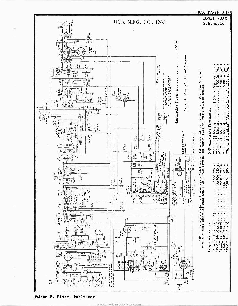
RCA PAGE 9-185
o
00 A $
606öö
e á
ì2 nhQC9Ñi 11 p061 m Jú_
t
5ñb
; mw
RCA MFG. CO., INC.
111/000
Ñ¢
d
Y cc
LC u
3j:
, b
cc
áÉ áf
r' Illr i5 iii kúrá
N
F I.\J3irv W Q éF Qm -OP
b---°- nó 22,
F fro- ÁVI - -_{ o°Cr ulo Q8 > II111 .
'.ó Qí
IY Ú m£
Y s uñ
m £
NIm
>- S.á
(8010120-''''
g_ó 1N3W935 318VAON1
f
cc
,Y y a
cç
NS J ..i11111 ,1,1,1,1C:NYl1Y1001 p 1).
10 1.13100W 01 117-,4 p£
a^4,744:9 Ab W01aa0Y10ItIYWl6iftiY00W:W]11M :m
e m
h f
iha t F I _F ¡ nt tn n
J J O
z
I
woa JI"' ow
-..wú
z
m
mÚCáJ//Q4YV -r. (_ (___ {/ f 6Ö06öÒ00O6ÒQD0 Wt=J W
g,s ó r v Ó3WZU W
3Ñ ¢
m
ce _ E - w
z ó
Q
F lá
.` 7.0 m
1,
7 g4
:
m
I
ec
3 8
e ol` úe
m
!!r
0
áS
MODEL 813K Schematic
A O O O O
:1 a .. Vy vl V' M (,1..-.1
^p ..w CU.
g>>>> V)eenN
®John F. Rider, Publisher
www.americanradiohistory.com
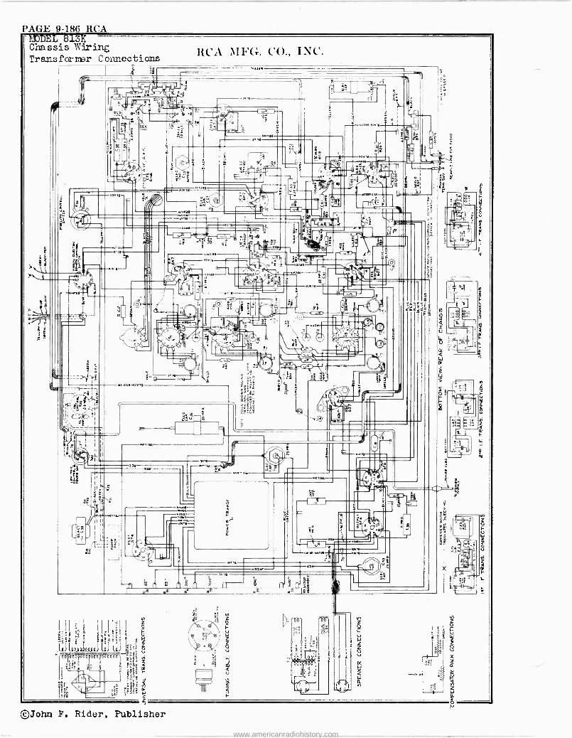
PAGE 9-186 RCA MODEL 813K Chassis Wiring Transformer Connections
Lg
v rw £ ,
.0 aaa-H:rn
IIII
r -i
II 3î`1! I§`: Is
1g . w,w-----
RCA MFG. CO., INC.
l
©John F. Rider, Publisher
www.americanradiohistory.com
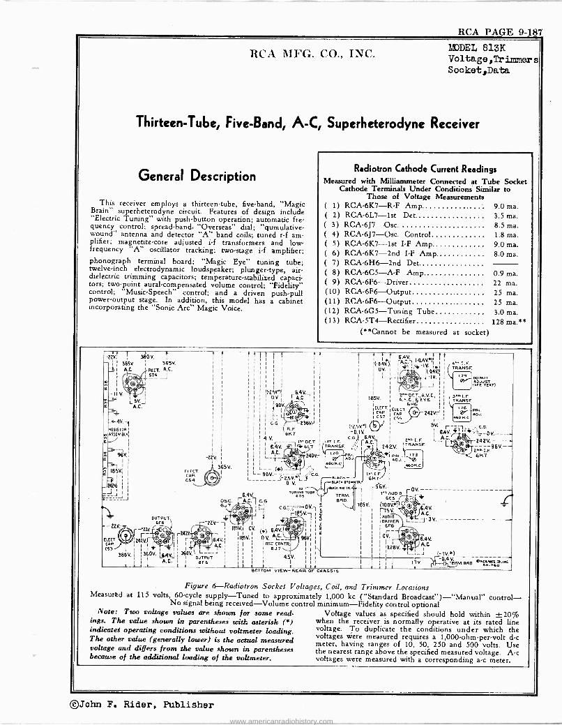
RCA PAGE 9-187
RCA MFG. CO., INC. MODEL 813K Voltage,Tr imr.ler s Socket,Data
Thirteen -Tube, Five -Band, A -C, Superheterodyne Receiver
General Description
This receiver employs a thirteen -tube, five -band, "Magic Brain" superheterodyne circuit. Features of design include "Electric Tuning" with push-button operation; automatic fre- quency control; spread -band, "Overseas" dial; "qumulative- wound" antenna and detector "A" band coils; tuned r -f am- plifier; magnetite -core adjusted i -f transformers and low - frequency "A" oscillator tracking; two -stage i -f amplifier; phonograph terminal board; "Magic Eye" tuning tube; twelve -inch electrodynamic loudspeaker; plunger -type, air - dielectric trimming capacitors; temperature -stabilized capaci- tors; two -point aural -compensated volume control; "Fidelity" control; "Music -Speech" control; and a driven push-pull power -output stage. In addition, this model has a cabinet incorporating the "Sonic Arc" Magic Voice.
Radiotron Cathode Current Readings Measured with Milliammeter Connected at Tube Socket
Cathode Terminals Under Conditions Similar to Those of Voltage Measurements
( 1) RCA -6K7 -R -F Amp. 9.0 ma. ( 2) RCA -6L7 -1st Det. 3.5 ma. ( 3) RCA-6J7-Osc. 8.5 ma. ( 4) RCA-6J7-Osc. Control 1.8 ma. ( 5) RCA-6K7--lst I -F Amp. 9.0 ma. ( 6) RCA -6K7 -2nd I -F Amp. 8.0 ma. ( 7) RCA -6H6 -2nd Det. ( 8) RCA -6C5 -A -F Amp. 0.9 ma. ( 9) RCA -6F6 -Driver 22 ma. (10) RCA -6F6 -Output 25 ma. (11) RCA -6F6 --Output 25 ma. (12) RCA -6G5 -Tuning Tube 3.0 ma. (13) RCA -5T4 -Rectifier 128 ma.**
(**Cannot be measured at socket)
ß2V.
1
2 - II
r°2 R
RESISTORS III ASSEMBLY:
380 V.
A Cy 'EEC'. A.C.
365v.
1£0 5T4 J
\U©T V. F- ` i
LSVJ A.C.
4V.-1 I
I
I
{ f T r
1
I
I
-25VI(.')1 (iv.r
C.G.
454 I
I 6.4V.6L7
1 Ì
I
6.4V. I
A.C. 1 I
11 90V. I
I l K" ,
236Vr R.F
6K7 __
OCT1sT. ,"3..,. S©
!
I
I
I
18554. :
:
(-2.SV.") 'U.IV
LsT i. F. GG.,trÁ
C54, TRANSF. ,__,
I ' (-0.454. ):
OL_
L
:ELECT
I
CCyST/ V 242V.
1 6.454 1 /
¡ iC.- 1 1
fi 4V*) I.: I ' 11.0.454): I
r_ -154.1 1
.. __J
27°13E7 A. A.V.C. I
A.F.C, R.. EYE I
616 i l
ELECT. I
C55 242 V:_ J
354.
1 6A V.
2.c. I. F I_A.,C.I TRANSE L.
4T,. I.E. TRANSF
L29 00140T
(SEE TEAT)
3m- LE TRANSE
L26 PEI.
4601<. C. ADJ.
C.G. / }f _0 V,___ Ql ia
6 I ----96V.-- -_T 96V.í GI
185V. R
I
42541 I
I
---___J
-
- V'
ELECT. CAP.
C53
380V.
I
1
I
OUTPUT 6F6
2254. mOA r-O 242Vr 1 F- I
: + I 1
; 560V. L6AV.
'2254.
I
365V. ELECT CAP
C54 a OSC. 6JT (y(K-
O
t--2254--1 Éé V \ 18554.1
r242V:¡0" A 7
r 1
A...' A.C.I ? L___J
i 36054.
L
6.4V. A.C.1rC.G.
©
OV 1 1
I
IBSV. 1
,
1
I
I A.C. l._Z T ti 24054.
I \T1 j I L_- (JO __
I' L-9654._____) -'C.G. %2.5 V..) y -' 0 V. ToRaA,o
TU ADS
.
1
r185V7 I i vim^ I
6.454. 1 I (*) AR. 1
1 V. 9654. I OSC. CONTR.I I
6.37
I 4.554. i I
eo RI ADJ.
460 N.0
et.AcK BLA.-BROWN
TA.II
TERM. TERM, BEM
[
r
°
1sT.I.F 6K7
TR
I
185V.
i
: I
1
I
I
1
it I-23 PRI 0S ADJ.
a -I 460K .0
1
I
I
96V.J 1,T AUDIO /- rrCV 6C(4J0 r -i'
(:0054.6) O
©© 6.4
rAUDIO A.C.
:DRIVER I-.-- ---h3 i 6F6
OV. [ . 6.454.
I Q r iï A.C. 122854
L_I_J ¡
2"''7F ÓK7
_
V.
V.
X )
1 I A.C. ourauT `_o1'V.
I 6F 6 I 11 I I I I I I
Hr ß¡y4 V' ORu66A.,PIC. I 1754 I.T-ERM.BRD. 6...co -_t_ , 1 I 1 t 1 1, 1 i i i 1 _I
BOTTOM VIEW -REAR OF CHASSIS
Figure 6-Radiotron Socket Voltages, Coil, and Trimmer Locations Measurad at 115 volts, 60 -cycle supply -Tuned to approximately 1,000 kc ("Standard Broadcast") -"Manual" control -
No signal being received -Volume control minimum -Fidelity control optional Note: Two voltage values are shown for some read- Voltage values as specified should hold within ±20%
ings. The value shown in parentheses with asterisk (') when the receiver is normally operative at its rated line indicateg operating conditions without voltmeter loading. voltage. To duplicate the conditions under which the The other value (generally lower) is the actual measured
voltages were measured requires a 1,000 -ohm -per -volt d -c meter, having ranges of 10, 50, 250 and 500 volts. Use voltage and differs from the value shown in parentheses the nearest range above the specified measured voltage. A -c because of the additional loading of the voltmeter. voltages were measured with a corresponding a -c meter.
©John F. Rider, Publisher
www.americanradiohistory.com
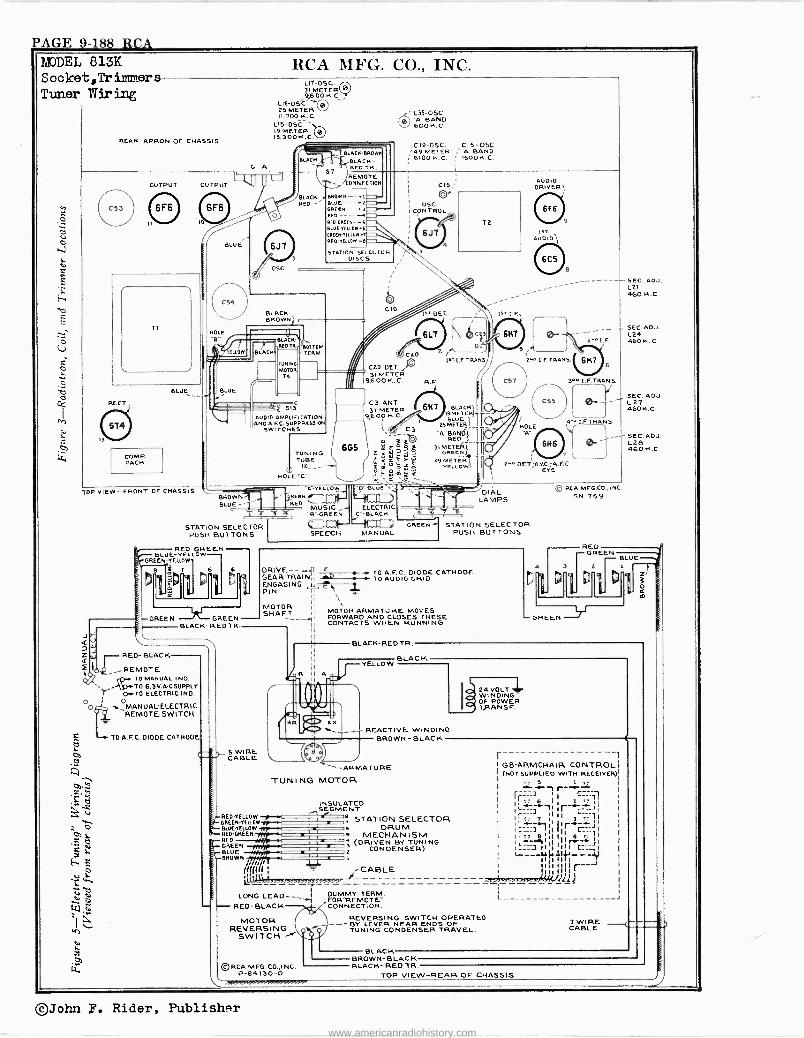
PAGE 9-188 RCA ADEL 813K Socket,Trimmers Tuner Wiring
RCA MFG. CO., INC.
REAR APRON OF CHASSIS
OUTPUT
G A
OUTPUT L1
TI
BLUE
RECT.
COMP PACK
BLU E
HOLE
LIT-OSC. 31 METER 0 9,600 H.C.
LI6-OSC. 25 METER 11,700 K.C.
LIS-OSC. 19 METER Eql IS 300 INC..
6J7
OSC
LACK
BLACK RED -
5T
I BLAC -BAD
BLACK, - RED TR
L3S-OSC 0 A'BAND
600K.C.
C10-OSC. C15-OSC. 149 METER ¡"A"BAND 6100 K.C. ; 1500K.C:
REMOTE ONNECTION
BROWN --.1
RED-GAEEN-.S BLUEYELLOW-6 6REEN-TFLLOW- REO YELLOW -HI
GIB;
V O5C.
CONTROL
STATION SELECTOR DISCS
BLACK - BROWN
LLO BLACK
BLACK. REOTR.
TUNING MOTOR
T4
BOTTOM TERM.
AUDIO AMPLIFICATION AND A.F.C. SUPPRESSION
SWITCHES
TOP VIEW- FRONT OF CHASSIS BROWN BLUE -
I TUNING (I' TUBE
6G5
CIO
UC20 C2O-DET 31 METER
9,600 K.C.
C3 -ANT 31 METER
9,600 K.C.
C3
ò'-gób W X íW! ÿ E -I
Y ïe 0
HOLE"C"
I =YELLOW++1EE1 I"D=B-LUI- 'TGßElN /J Lq-'I7 1
RED MUSIC ELECTRIC
`B --GREEN `C" -BLACK I
GREEN STATION SELECTOR SPEECH MANUAL PUSH BUTTONS STATION SELECTOR
PUSH BUTTONS
RED -GREEN BLUE-YELLOW-
t)
GREEN
s.
or -REMOTE 1 TO MANUAL IND. \ ...WA,. 6.3V. A-CSUPPLY Y O -'TO ELECTRIC IND.
oMANUAL-ELECTRIC REMOTE SWITCH
6
GREEN BLACK- RED TR
RED -BLACK
TO A.F C. DIODE CATHODE
6J7 4
ls' DET
6L7
2 /
Is
R.F.
6H7
T2
01,
BLACK'
BLUE- 2.5 METERI
.ABANOr_fi
31 METER) GREEN,
49 METER YELLOW,
AUDIO DRIVER
L+= AUDIO"
HOLE
9
4 N. E.F. TRANS.
7 L
2^^.DET;A VJ41A -C. EYE
SEC. ADJ. L21 460 K.0
SEC.ADJ. L24 460 K. C
SEC. ADJ. L 27 460 K.C.
ISEC. ADJ. 6> r LOB
46014.0
DRIVE --+.'{1 E . TOA.F.C. DIODE CATHODE
GEAR TRAIN11 - TO AUDIO GRID ENGAGING CIL, £O, t PIN EÌ LL T MOTOR SHAFT
RED -YELLOW GREEN -YELLOW BLUE -YELLOW REO -GREEN RED
gGREEN BLUE BROWN
MOTOR ARMATURE. MOVES FORWARD AND CLOSES THESE CONTACTS WHEN RUNNING.
BLACK -RED TR.
YELLOW
DIAL LAMPS
© RCA MFG.CO., INC SN -759
O
BLAC K
REACTIVE WINDING BROWN -BLACK
ARMATURE
TUNING MOTOR
/I// am
((((((i CABLE L.--- - --------
LONG LEAD -- "--1i FMMY TTM .
RED -BLACK
INSULATED SEGMENT
STATION SELECTOR DRUM
N MECHANISM (DRIVEN BY TUNING
CONDENSER)
24 VOIT WINDING OF POWER TJA ANS F.
MOTOR REVERSING
SWITCH
RCA MFG.CO.,I NC. P-84130-0
REVERSING SWITCH OPERATED --- BY LEVER NEAR ENDS OF TUNING CONDENSER TRAVEL.
BLACK
r-- GB -ARMCHAIR CONTROL (HOT SUPPLIED WITH RECEIVER)
w 217.'1.
T1 IE I
I Ì11r
LC
C=:-J1 I i. 7 3
I¡ I I¿-1111 I I I r.-- I
I11
IILI II I
s
I IIII1111 r I I l u
l i i i I
L - J
7 WIRE _( CABLE
BROWN- BLACK BLACK- RED TR.
TOP VIEW -REAR OF CHASSIS
©John P. Rider, Publisher www.americanradiohistory.com
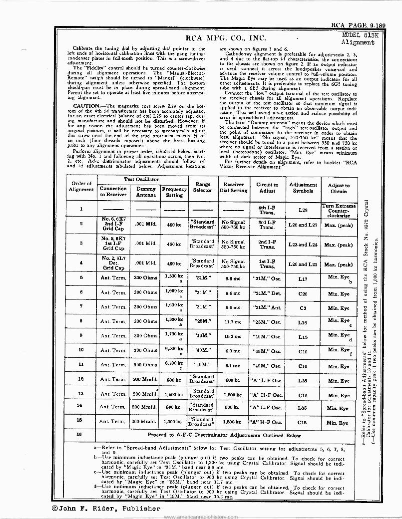
RCA PAGE. 9-189
RCA MFG. CO., INC. Calibrate the tuning dial by adjusting dial dia1 pointer to the
left ends of horizontal calibration lines with the gang tuning - condenser plates in full -mesh position. This is a screw -driver adjustment.
The "Fidelity" control should be turned counter -clockwise during all alignment operations. The -Manual-Electric- Remote- switch should be turned to "Manual" (clockwise) during alignment unless otherwise specified. The bottom shield -pan must be in place during spread -band alignment. Permit the set to operate at least five minutes before attempt- ing alignment.
CAUTION.-The magnetite core screw L29 on the bot- tom of the 4th i -f transformer has been accurately adjusted, for an exact electrical balance of coil L29 to center tap, dur- ing manufacture and should not be disturbed. However, if for any reason the adjustment has been moved from its original position, it will be necessary to mechanically adjust this screw until the end of the stud protrudes exactly % of an inch (four threads exposed) above the brass bushing prior to any alignment operations.
Perform alignment in proper order, tabulated below, start- ing with No. 1 and following all operations across, then No. 2, etc. A -f -c disriminator adjustments should follow r -f and i -f adjustments tabulated below. Adjustment locations
MODEL 813K Alignment
are shown on figures 3 and 6. Cathode-ray alignment is preferable for adjustments 2, 3,
and 4 due to the flat -top i -f characteristics; the connections to the chassis are shown on figure 2. If an output indicator is used, connect it across the loudspeaker voice -coil and advance the receiver volume control to full -volume position. The Magic Eye may be used as an output indicator for all other adjustments. It is preferable to replace the 605 tuning tube with a 6E5 during alignment.
Connect the "low" output terminal of the test oscillator to the receiver chassis for all alignment operations. Regulate the output of the test oscillator so that minimum signal is applied to the receiver to obtain an observable output indi- cation. This will avoid a -v -c action and reduce possibility of error in spread -band adjustments.
The term "Dummy antenna" means the device which must be connected between the "high" test -oscillator output and the point of connection to the receiver in order to obtain ideal alignment. "No signal, 550-750 kc" means that the receiver should be tuned to a point between 550 and 750 kc where no signal or interference is received from a station or local (heterodyne) oscillator. "Min. Eye" means minimum width of dark sector of Magic Eye.
For further details on alignment, refer to booklet "RCA Victor Receiver Alignment."
Order of Alignment
Test Oscillator Range
Selector Receiver
Dial Setting Circuit to
Adjust Adjustment
Symbols Adjust to Obtain Connection
to Receiver Dummy Antenna
Frequency Setting
1 4th I -F Trans.L28 Turn Extreme
Counter- clockwise
2 No. 6, 6K7
2nd I -F Grid Cap
.001 Mfd. 460 kc "Standard Broadcast"
No Signal 550-750 kc
3rd I -F Trans. L26 and L27 Max. (peak)
3 No. 5, 6K7
lat I -F Grid Cap
.001 Mfd. 460 kc "Standard Broadcast"
No Signal 550-750 kc
2nd I -F Trans L23 and L24 Max. (peak)
4 No. 2, 6L7
Det. Grid Cap
.001 Mfd. 460 kc "Standard Broadcast"
No Signal 550-750,1(c
1st I -F Trans. L20 and L21 Max. (peak)
5 Ant. Term. 300 Ohms 1,800 kc ab "31M." 9.6 mc "31M." Osc. L17 Min. Eye
6 Ant. Term. 300 Ohms 1,600 kc a
"31M." 9.6 me "31M." Det. C20 Min. Eye
7 Ant. Term. 300 Ohms 1,600 kac "31M." 9.6 ntc "31M." Ant. C3 Min. Eye
8 Ant. Term. 300 Ohms 1,300 kc a "25m." 11.7 mc "2.5M." Osc. L16 Min. Eye
c
9 Ant. Term. 300 Ohms 1,700 ac "19M." 15.3 mc "19M." Osc. L15 Min. Eye d
10 Ant. Term. 300 Ohms 6,00 kc e
"49M." 6.0 mc "49M." Osc. C10 Min. Eye f
11 Ant. Term. 300 Ohms 6,100 kec 49M.., 6.1 mc "49M." Osc. C10 Min. Eye
12 Ant. Term. 200 Mmfd. 600 kc "Standard Broadcast" 600 kc "A" L -F Osc. L35 Min. Eye Y
13 Ant. Term. 200 Mmfd. 1,500 kc "Standardoct1,500 Broadcast" kc "A" H -F Osc. C15 Min Eye Y
14 Ant. Term. 200 Mmfd. 600 kc "Standard Broadcast" 600 kc "A" L -F Osc. L35 Min. Eye
15 Ant. Term. 200 Mmfd. 1,500 kc "Standard Broadcast" 1,500 kc "A" H -F Osc. C15 Min. Eye
16 Proceed to A -F -C Discriminator Adjustments Outlined Below
a-Refer to "Spread -band Adjustments" below for Test Oscillator setting for adjustments 5, 6, 7, 8, and 9.
b-1 ise minimum inductance peak (plunger out) if two peaks can be obtained. To check for correct harmonic, carefully set Test Oscillator to 1,200 kc using Crystal Calibrator. Signal should be indi- cated by "Magic Eye" in "31M." band near 9.6 rrtc.
c-Use minimum inductance peak (plunger out) if two peaks can be obtained. To check for correct harmonic, carefully set Test Oscillator to 900 kc using Crystal Calibrator. Signal should be indi- cated by "Magic Eye" in "25M." band near 11.7 mc.
d-Use minimum inductance peak (plunger out) if two peaks can be obtained. To check for correct harmonic, carefully set Test Oscillator to 900 kc using Crystal Calibrator. Signal should be indi- cated by "Magic Eye" in "19M." band near 15.3 mc.
©John F. Rider, Publisher www.americanradiohistory.com
PAGE 9-19 O RCA EDDEL 813K Circuit Data Adjustrents,Lead Dress
Spread -bend Adjustment .-Bottom shield -pan must be in
place before attempting . read-band alignment. Alignment of the spread ("Overseas") bands requires special procedure
since test oscillators used alone are not ordinarily sufficiently
accurate for this purpose. The RCA Stock No. 9572 Crystal
Calibrator affords a convenient and accurate alignment stand-
ard. Wrap a few turns of wire around the crystal alibrator and connect one free end to the antenna terminal of the
receiver. Using the crystal calibrator to obtain the necessary
accuracy, follow the tabulated alignment procedure for the.
"31M.', "25M.", and "19M." bands. The "31M." band alignment, for example, is done as
follows: Tune the receiver ("Standard broadcast" band) to
the 1,000 kc crystal calibrator output with the crystal tali- brator "Hi -Lo" switch in "Hi" position. Snap "Hi -Le" switch
to "Lo" and carefully tune receiver to 1,600 kc (the sixth
100 kc harmonic above 1,000 ht) for minimum "Magic Eye" opening (Min. Eye). Move crystal calibrator away from an,
tenna wire, connect test oscillator, and carefully adjust test
oscillator for minimum "Magic Eye" opening at a netting
of approximately 1,600 kc. (If Stock No. 150 Test Oscillator is used, refer to second paragraph below.) Raise test -oscillator output to give sufficient harmonic output and use 6th harmonic (9,600 kc) for aligning in "31M." band at 9.6
mc. Align in the "25M." band at 11.7 mc (11,700 kc), the
9th harmonic of the testosallator 1,300 kc output. Align in the "19M." band at 15.3 mc (15,300 kc), the 9th harmonic of the teat -oscillator 1,700 kc output. In each case
select the peak giving minimum "Magic Eye" opening. For the "49M." band, snap crystal calibrator "lino':
switch to "Hi", turn the range selector to "49M." band, and
set receiver dial pointer to 6.0 mc. Adjust oscillator trimming n capacitor CIO for minimum "Magic Eye" opening. Use
peak indicated by the alignment table. Snap "HiLo" switch to "Lo" and locate 6,100 kc (the first 100 kc harmonic above 6,000 kc) by slightly readjusting CIO with the dial pointer set at 6.1 mc. This method insures nelection of correct crystal -calibrator harmonic.
When aligning with the RCA Stock No. 150 Teat Oscil lator use the variable (unmodulated) oscillator(' and "Magic Eye" indication of receiver output. Set test -oscillator dial 800 kc lower than the desired signal for the four lower ire quency ranges and 800 kc higher than the desired signal for the two high range. and use in ame manner as TMV97-C. Insert an open -circuit telephone plug in the test oscillator "Eat. Mod.' jack, no the modulated fiscal -frequency oscillator will be cat off, and align on the unmodulated variable oscil-
lator signal, which will clot. the "Magic Eye" and evidence
itself by a rushing noise in the speaker. If the crystal calibrator signals are weak, disconnect test
oscillator while using the crystal calibrator. More accurate alignment in the apreadbands can be
accomplished by making final slight adjustments using American, English, or German shortwave -b oadasting ate tions of known frequency for frequency standards.
A -F.0 Direiminator Adjistmenta-These adjustments are
rather critical and should be performed with extreme care.
Improper adjustment may result in complete failure of the oscillator control tube to function or else may cause it to detune the oscillator instead of tuning it to the signal. It is
assumed that the magnetite core adjusting screw L28 (top of 4th 1f transformer) has been turned all the way out (extreme counterclockwise) during the preceding tabulated adjoin - menu. Adjustments are a. follows: Remove spring "N' on
link and arm assembly which connects the "Manual -Electric. Remote" switch shaft to the throw -out" gear bracket. Turn "Fidelity" control counter -clockwise. Connect antenna to re ceiver antenna terminal. With the "Manual -Electric -Re, mote" switch in "Manual" (right) position, tune in a
strong local station near 600 kc or the low -frequency end of the "A" band as accurately as potable by meant of the tun- ing tube "Magic Eye." The most accurate adjustment will be obtained by adjusting the "vernier" tuning knob mid -way between the two points where the eye just appears to start to open. This will place the generated i -f carrier signal fee quency exactly in the center of the i -f amplifier response curve (should be 460 kc if i -f amplifier was properly aligned) and is the frequency to which the afc discriminator (4th if transformer) should be tuned to resonance. Without din torhing any of the receiver adjustments, place the "high" test -oscillator lead about 5h of an inch from the grid cap lead of the RCA -6K7, 1st i -f amplifier tobe, adjust the wt oscillator output to maximum, turn testosàllator "Module tion" off, and carefully zero -beat the test'oecillator frequency (approximately 460 kc) with the if carrier signal. Avoid placing the test -oscillator lead nearer to the grid -cap lead than specified above, as doing so will tend to detune the if amplifier. It may be necessary to reduce the local station signal, during this operation, by shortening antenna lead or grounding antenna "A" terminal to chassis in order to in- crease the loudness of the beat note sufficiently for accurate zero -beat adjustment.
Throw "Manual -Electric -Remote" switch to "Electric" (center) position. A high whistle or beat note will now be heard. Turn the magnetite core screw L28 (top of 4th s -f transformer) slowly clockwise. As this screw is turned, the beat note will first increase to a high audio frequency and will then decrease to a reeobeat and then increase in fre- quency again. The point of exact zero -beat is the position
t The No.in 110 Test Oscillator employsy axed-frequency
oscillato100 r. The heuscale
is oscillator
alibated to the frequencyunm for the two higher frequency anges and to the difference ere. quency for the four lower frequency rangea.
RCA MFG. CO., INC.
for correct adjustment of the diectiminator. Zero -beat should ceiver above and below the local station frequency with the
also still exist when the "Manual -Electric -Remote" switch is " anualElectricRemoti" io "Manual" position, switching
thrown back to "Manual" position. The adjustment is now to "Electric" position, and noting the oscillator pull -in. Re -
complete and may be checked by slightly detuning the re place spring "N."
Circuit Arrangement The circuit consists of an rd amplifier sage; firshdetector
(converter) sage; separate heterodyne -oscillator sage; oscil-
latorcontrol stage; two i -f amplifier stages; diode detector,
automatic -frequency and volume -control stage; audio voltage amplifier stage; audio -driver stage; push-pull powerampli er
sage: tuning indicator "Magic Eye"; and a full -wave
rectifier. The antenna and first -detector code are constructed with a
special type cif winding ("qumulative") to provide increased sensitivity and selectivity on the "Standard Broadcast" band. Special capacitors shunting the spread -band oscillator coils change in capacity with temperature variations to reduce oscillator frequency drift.
Spread -band tuning is accomplished electrically by shunting the low -capacity section of the oscillator variable capacitor with relatively large temperature -stabilized fixed capacitors for tuning the oscillator coil on the "19M," "25M," ' 31M," and "49M" bands. Antenna and first -detector coils are designed to be sufficiently broad -tuned to require no variable tuning over the narrow frequency range of the spread -bands.
The spread -band oscillator coils and the "Standard Broad- cast" band mediator, first -detector, and antenna cods arc all wound on separate forms. The antenna and first -detector spread -band coils are tapped. Undesirable interaction between coils is avoided by shorting proper unused sections by means of the range lector.
The intermediate frequency amplifier consists of two RCA - 6R7 tubes in a two -stage transformer -coupled circuit. The windings of all if transformers are resonated by fixed cape citors and are adjusted by molded magnetite cores to tune to 460 kc. A third winding, L22, in the first if transformer, closely coupled to the, primary, L20, is placed in series with the main secondary, L21, when the fidelity control switch SII is thrown to "broad" position (see figure 1), thereby incraa ing the coupling between the primary and secondary circuits with a consequent broadening of the band width of the id amplifier, permitting higher fidelity reception.
The function of the automatic -frequency -control circuit is to automatically change the frequency of the heterodyne oscillator so that the correct i -f frequency u formed for the ie amplifier. The circuit consists essentially of an if dui cnmmator which, as the name implies, discriminates or fur - rushes control voltage of the correct polarity to an oscillator frequency -control tube for generated 1.4 carrier frequencies slightly above and below 450 kc, or the frequency to which the le amplifier is tuned.
The plate circuit of the RCA -6j7 oscillator -control tube is
caused to act as an apparent variable inductance in' parallel with the "A" band oscillator tuned circuit of which coil L35 is a part. The settee combination of resistor R5 and the capacitor Cl6 is also in parallel with the oscillator tuned cit.-
cwt. Since the resistance of 145 is many times greater than the reactance of C16, at the oscillator frequency, the rf cur- rent through the combination will be pracnally in phase with the el voltage across the oscillator tuned circuit. However, the r -f volage impressed across the C16 capacitance section of the combination, or from grid to cathode, will lag the rf volage acros the combination, or the tuned circuit, approximately 90 degrees. The grid -cathode r -f voltage will be amplified by the control tube but will be shifted an addi- clonal 180 degrees (grid and plate voltages of all tubes are always opposite in phase) so that the amplified ef voltage appearing across the plate circuit will now lead the volage across the combination or the tuned circuit by 90 degrees, or, in other word., the control tube is acting as an equivalent shunt inductance. The amount of this action is determined by the amplification of the tube which, in turn, ù governed by the grid -cathode bias voltage. In operation, a residual bias is developed across the cathode resistor R6. The de control -
grid voltage u fed to the control grid from the discriminator circuit through resistor R7. If Shin voltage is negative with respect to ground, the amplification of the control tube will be decreased, the apparent plate -circuit inductance of the tube increased, which will lower the frequency of the oscil- lator tube. The converse will occur when the grid volage is positive with respect ect to ground.
The action of discriminator circuit depends upon the fact that a 90 -degree phase difference exists between the pri mary and secondary potentials of a double -tuned loosely - coupled transformer when the resonant frequency is applied, and that this phase difference varies as the applied frequency varies, i.e., the maximum resultant response voltage across
the primary and secondary winding. connected in series will occur at a frequency either lower or higher in frequency than the frequency to which the individual windings are resonated, respectively, depending on whether the windings are connected series aiding or opposing.
The discriminator, or fourth i'f transformer, consists of the primary winding, L30, which is a part of the third if trans- former secondary tuned circuit (tuned to 460 kc) and the centereapped secondary, L29. The upper and lower halves of L29 may be considered as two secondary coils, the upper series aiding and the lower series opposing the primary, L30. The magnetite core in L29 in inserted to inductively balance the two halves. The function of coil 128 (magnetite core adjusted), in parallel with 129, is to tune the secondary to
460 kc. Therefore, the maximum volage will be applied to
diode circuit PtKt and R18 when the if signal frequency u below 460 he and to the diode circuit PºKa and RI7 when
the if signal frequency is above 460 kc. Resistors RI7 and
R18 are connected in series between ground and a point leading to the oscillator controltube grid.
Dc volages, resulting from diode rectification, across RI7
and R18 are always in opposition, consequently the oscillator
control -tube grid -bias voltage is a differential amount, de
pending upon the i -f signal strength and its frequency devu tion from the nominal value of 460 kc. The polarity of this
differential oscillator control tube grid -bias, with respect to
ground, depends on whether the if signal frequency is above or below 460 kc, but u always in the direction which vnll
bring the generated if frequency nearer to 460 kc. A.fc action is automatically eliminated for "manual" tuning by grounding diode cathode Ki through switch 59.
Service Data
The various diagrams of this booklet contain such infor mation as will be needed to isolate causes for defective opera, tion if such develops. The ratings of the resistors, capacitors,
coils, etc., arc indicated adjacent to the symbols signifying these part. on the diagrams. Identification titles such a Rl, LI, CI, etc., provide reference between the illusations and
Replacement Para List. The coils, transformer windings, and
reactors arc rated in terms of d -c resistance to permit con tinuity checks.
Precautionary Lead Davos.-(1) Green bun leads from CI ne
from nearIby
and Gro(2)C59 Green
S2 bu
¡Mould lead from C113 y to S3 should
be 2)inchee long and dressed away from nearby parts. (3) Bus leads from C12 to L18 and from L18 to 53 should be as
short as possible. (4) Red and blue leads from tube No. 3
to 19M. oscillator coil should be dressed away from coil.
(5) Tube No. 3 grid lead should be 6 -inches long and
dressed away from grounded metal parta. (6) All leads
behind oscillator coils should be dressed close to chassis. (7) "Magic Eye" cable should be clamped to dial bracket. (8) Filament leads should all be twisted. (9) Leads from C44
and C48 should be dressed close to chassis. (10) A.c leads
near R22 should be dressed away from R22. (I1) Leads
from SI1 to the first id transformer should be twisted and
dressed away from chassis. (12) Capacitors C7, C8, and C9
should be dressed perpendicular to chassis and away from each other and grounded metal parts. (13) Motor -cable
leads should be dressed away from pinion gear. (14) Blue
bus lead from "A" detector coil to "P" of tube No. 1
should be dressed centrally between band -witch shield and air trimmer C20. The following should be dressed away from the chassis: (IS) Yellow bus lead from "K" of tube No. 3
to S3. (16) Yellow btu lead from "OG" of tube No. 2.
(17) Blue bus lead from C47 to R26. Phonograph Attachment.-A terminal board is provided
for connecting a phonograph into the audio-amplifing cir- cuit. RCA Victor Models R-93, R -93-A, R-93.2, or R-94 Record Players should be connected as follows: Remove the link from the phonograph terminal board. Connect green wire in Radio -Record switch cable to terminal I; yellow to terminal 2; shield to terminal 3; and tape up the red and blue. Connect a 2conductor twisted cable between the Record Player binding posts and the screwterminals on Radio -Record switch. If additional volume is desired, con nett an RCA Stock No. 9632 transformer between the 2 conductor twisted cable and the screwterminals on Radio - Record switch as follows: Yellow and brown transformer leads and on side of twisted cable to ground screwterminal on switch; black transformer lead to other side 'of twisted cable; and blue transformer lead to other ...terminal on twitch.
Lotdapeaker.-Two types of loudspeakers are used which will be referred to as types 1 and 2. In type 1 the cone centering diaphragm is cemented to a fixed ring, while in type t.2 the centering diaphragm is cemented to an adjustable ring. Replacement of cone for either type is identical. Center, ing of cone for type I loudspeaker is made with three narrow celluloid or paper feelers after first removing the front dust
cover and cutting free the cone centering diaphragm. The dun cover may be removed by a light application of acetone, ruing care not to allow the acetone to Sow into the air gap. The centering diaphragm should be cemented in place after placement of feelers. Sufficient time should be allowed for
the ambroid to set before removing feelers. Use ambroid to replace dust cover. Centering of cone for type 2 loudspeaker differ. only in that it ú not necessary to cut free the center, ing-diaphragm, adjustment being made in the usual manner by means of screws en the djuaable cone centering ring.
©John F. Rider, Publisher
www.americanradiohistory.com
RCA PAGE 9-191
Main Pinion Gear. --Clearance between the small high. speed pinion gear "E" and the intermediate gear "K" deter. mines the amount of mechanical noise produced. Correct adjustment will give approximately 1/32 of an inch move. ment of hack lash at the end of pinion arm "G" when gear "K" is held stationary. Arm "G" must also be adjusted for correct mesh with motor shaft drive pin "F." With the motor shaft completely forward and pinion "E" tight against its front bearing, the pinion mounting stud "J" should he adjusted so that pin "F" meshes full thickness with the rotating arm "G." An increase of this mesh will increase over travel on tuning while a decrease of mesh will decrease the over travel. The elongated hole in the front bracket allows sußciént movement of the mounting stud "J" to per. mit above mentioned gear mesh adjustment.
"ManualElectric-Remote" Changeover.- (1) Link and arm adjustment-To properly line up the mechanical link between the switch shaft and throwout gear bracket "MM," the set screws holding the link arm on the switch shaft must be loosened, the switch turned to the "Manual" position (ex- treme right) and the link lever revolved until the distance between the linkconnecting pin (extends through chassis apron) and the right-hand (viewed from front) side of the slot, in front apron of chassis, is exactly 5/16 of an inch. If this adjustment is not properly made, correct operation of
sulated segment in the selector disc breaks the motor circuit, whereupon spring "C" will instantly disengage the motor pin "F" from the arm "G" on the small pinion driving gear and open contacts "E" and "D." Pushing another button will cause the above mentioned cycle to be repeated except that the motor will be interrupted by the insulated segment on a corresponding disc. The discs are individually adjustable on a drum mechanism, providing a choice of eight "Electric Tuned" "Broadcast" stations. The arrangement of the motor is such that its rotation will continue in the same direction regardless of the number of "Electric" tuning cycles until the tuning condenser approaches either fulbout or full -in of mesh, whereupon lever "H" trips switch S7 which reverses the direction of rotation. A throwout idler gear is link - coupled to the "ManualElectricRemote" control to dixon- nect the motor drive gear train when the control is thrown to "Manual" position.
Mechanism Adjustments The electric tuning mechanism is designed to be as simple
in construction and as fool proof in operation as is possible.. In order to maintain the accurate results possible with this device care must be taken in effecting any repairs or adjust, mests. Reference should be made to figure 4 and the following:
A -F -C and A -F Amplification Suppres iota Switches.- This switch assembly is located on the motor bracket and closes due to solenoid action of motor armature. The tension of the long contact spring "C" is importanein bringing about quick disengagement of the motor and in permitting the motor to pull into mesh with the drive mechanism. Normal adjustment is attained when the short springs "D" and "E" are aligned exactly straight with contact points separated ap- proximately 1/32 of an inch and with the spring "C" spaced approximately 7/32 of an inch from spring "D" at the puint of contact. If necessary, in order to obtain positive pull -in and quick disengagement of the motor, the tension of spring "C" should be increased or decreased by bending. This action should be checked with the front apron of the thaw. raised two inches higher than the rear. Contacts of the switch must be kept clean. Crocus cloth or a relay burnisher may be used for this purpose.
RCA MFG. CO., INC.
Principle of Operation ELECTRIC TUNING The electric tuning mechanism consists essentially of a "Electric" or "Remote" tuning will not result. (2) Throw quick engaging and disengaging reversible electric motor, out Gear Adjustment-To obtain smooth operation on "Elec tuning condenser driving gear train, and eight mechanically the" or "Remote" positions it is important that the proper interlocked (pushing one button releases all others) station clearance is maintained between the throwout gear "M" and selector push buttons respectively wired to eight adjustable the intermediate gear "L." With the "Manual-ElectricRe station selector contactor discs (each with a motor stopping mote control thrown to "Remote" position (extreme left) insulated segment) mounted on a drum which is direct adjust the mesh between these gears by meant of the eccen coupled to the gang tuning condenser shaft. The arrange- enc screw "O" and lock nut "P," contacting the throwout ment permits any one of eight pre -determined stations to be gear bracket "MM," until there is approximately 1/64 of an electrically tuned in by merely touching the correct push inch backlash of gear "L" when gear "M" is held stationary. button. If all eight buttons are inadvertently locked in, firmly Vernier Tuning.-In case it becomes necessary to remove pushing the right-hand button will release them. tuning condenser drive shaft "T," it should be replaced by The operation may be more readily understood by ref- sliding anti -backlash gear "R" on condenser shaft apart so erence to figures I, 4, and 5. When the motor ú not ener that compression amounting to one tooth on the gear is ob gized, the armature is pushed to the rear or slightly out of tamed in the springs. Adjust mesh of gear "R" with pinion the magnetic center by tension of contact spring "C" and gear "U" on vernier shaft before tightening screws "S" so the motor shaft is disengaged from the driving gear train. that smooth tuning is obtained throughout the range. Pressing in any one of the eight push buttons will complete Motor Alignment.-The motor shaft must be exactly the motor circuit through a station selector contactor disc, aligned with the axis of the pinion gear with which it en assuming that the ManualElectricRemote" switch is in gages. This may be adjusted by loosening the mounting "Electric" position and that the insulated segment in the
contactor disc is not opposite its contactor. As the motor screws "V" of the motor and aligning shaft by sight. Correct alignment may be tested by slowly rotating motor and obsery starts, the armature will be drawn forward, due to solenoid ing the relation between the pin "F" of the motor .shaft and action, and the pin "F" on the end of its shaft will engage, the arm "G" on the pinion. The relation of the two should the arm "G" on the small main pinion gear, thereby driving remain the same throughout the revolution. Additional move the tuning mechanism. At the same time contact springs "E" ment for adjustment may be obtained by the motor bracket and "D" will be grounded, causing suppression of audio screws "W" if necessary. amplification and automatic frequency control during the tun Station Selector Drum. (1) Bearing Adjustment-The ing cycle. The motor will continue to operate until the in, selector drum may be removed by unscrewing the two bear ing adjusting screws "X" on the front and rear bearings and sliding shaft out of slots on frame. To replace drum, the reverse procedure should be followed holding bearing adjust- ing plates "Y" firmly against the shaft and tightening adjust, ing screws. (2) Contact adjustment-Two types of contact strips are used. They are designated on figure 4, as types l and 2, on which the individual contacts are respectively adjustable and fixed. On type 1, the individual contacts should be adjusted by setting the end contact springs near the mid -position of their travel and aligning the remaining springs to them by means of a straight edge. Either type of contact strip should be adjusted to the selector drum by firmly placing two selector adjusting keys in the station adjustment strip, positions I and 8 (locking respective discs), loosening contact strip adjusting nuts "Z" and shift. ing the contact strip until the end contacts are exactly centered on the respective disc insulating segments. More accurate adjustment may be made by silhouetting the point of contact with a piece of white paper held behind the con, tact. Adjustment will be facilitated by removing complete assembly from rear of tuning condenser by unscrewing the three mounting screws. Contacts and discs must be kept free of dirt, filings, and other extraneous matter.
Lubrication.-The dial pointer slide should be greased with petrolatum. This same lubrication should be applied lightly to all gear faces of the drive mechanism and sparingly with a cloth to the station selector discs. Any good house, hold oil, such au "3INONE," is suitable for the motor shaft bearings. A light grade of engine oil should be used for all gear bearings. Medium viscosity engine oil, similar to "PYROIL" (B), should be applied between the thrust washers on the motor shaft. "CASTORDAG," a mixture of graphite and castor oil, is recommended for ,use at the selector drum endbearing slog and at the borings of cable pulleys.
Station Adjustment Any eight stations may be chosen for "Electric" tuning.
Remove the two escutcheon plates from the side of the dial, place proper call letter labels in the celluloid windows, and replace escutcheons. Turn the power on and proceed to set up the "Electric" tuning as follows:
1. Set Range Selector to "Standard Broadcast." Motor Reversing Switch.-It is necessary to automatically 2. Turn "ManualElectricRemote" control to "Electric." stop and reverse the drive motor before the tuning condenser 3. Turn Fidelity control counterclockwise. reaches the ends of its travel. Approximately 175 degrees of 4. Press push button N. 1 (left) and wait until station sweep is required, and the reversal must take place above pointer comes to rest. 1,700 kc and below 540 kc but not too near the limits of the 5. Turn the " Manual Electric Remote " control to scale. The coupling between the station selector drum and "Manual." the tuning condenser shaft should be attached so that the 6. Remove adjusting key from receptacle on top of sta reversing switch trip lever "H" is exactly vertical when the tion selector drum mechanism. condenser is fullout of mesh. There should be 1/32 of an 7. Insert key in position marked "1" in station adjust - inch clearance between the end of the condenser shaft and ment strip and push the key all the way down to prop - the selector drum shaft. While the trip lever is in this post- erly fit in slot in disc. tion the reversing switch bracket should be adjusted by means 8. Tune the receiver very carefully by means of the of its elongated mounting holes until the switch pin "I" just manual tuning knob and the "Magic Eye." to station lightly touches trip lever "H." chosen for N. L.
9. Remove key. IO. Turn the 'Manual-ElectricRemote" control to "Elec-
tric " Button No. 1 is now properly set for "Electric" tuning.
Proceed similarly for the other seven push buttons, matching each station on the dal with the same number on the station adjustment strip. 3epeat the above steps but place the key respectively in pontions 2, 3, 4, etc., and in each case tune to the proper station. Pressing the proper button will now cause the desired station to be tuned in electrically.
Armchair Control When a Model G8 armchair control is attached to the
receiver as shown in figure 5 it duplicates the action of the push buttons on the front panel when the "Manual -Electric. Remote" control is turned to "Remote" position.
Service Hints a. Capacitor CI8 should be carefully checked for leakage
or short circuit in cases of intermittent operation or no operation. R9 should be shorted out and CI8 replaced by Stock No. 4839, as shown by the Schematic Circuit Diagram figureuit. I,Capacitor
CS should be checked d for in he event e in
s cleakage or short circuit.
MODEL 813K Tuner Data Specifications
e. Resistor R5 was 33,000 ohms in some instruments. Replace with Stock No. 12333.
d. Capacitor C16 was 82 mmfd. in some instruments. Replace with Stock No. 14021.
e. Capacitor C38 was two 0.5 mfd. in parallel on some instruments. Replace with Stock No. 30623.
<ñ<<ñ<<ñ<eev<,<r<., UüüUüü aaaaaocc iaoao-
z
X -r..v-.,o
N
ti
©John F. Rider, Publisher
www.americanradiohistory.com
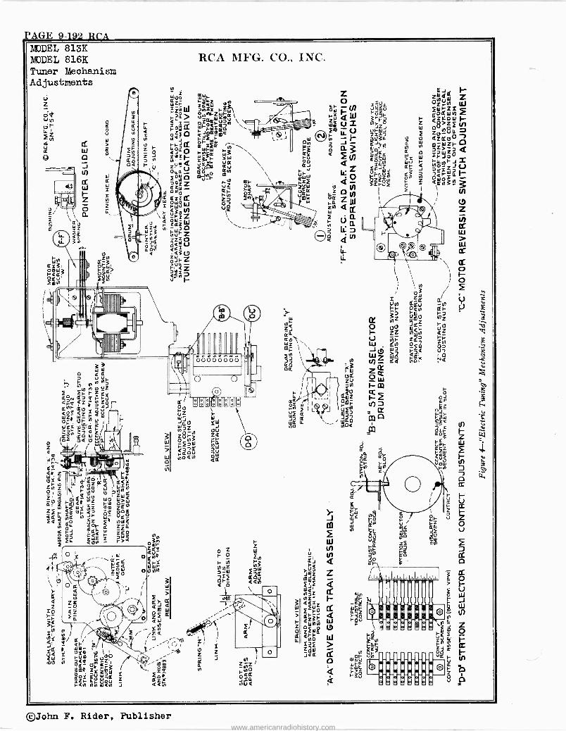
PAGE 9-192 RCA MODEL 813K MODEL 816K Tuner Mechanism Adjustments
©John F. Rider, Publisher www.americanradiohistory.com
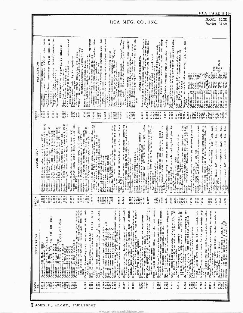
aa i 1VLi O'1.7
MODEL 813K RCA MFG. CO., INC. Parts List
Z 0
H W.4,íw. A«1
0 0 , r C CO 2 w ú ú w
ç^ ; ÿ á a Ñ« $ C Ó ti
to 2 g
°p G Î C Fx E e á:W Tó9 ÿ V O
p, 3 4 .°
.i si .mi 0Ó
ú ú Y V ê - ' R -4.;¡ N 0 V 7 A Ñ n c o c "m.. 55 E4 m c a 04, a a v á °>W ` e w é E° t¿ ,°`$ .44 cß úE
Ú á
ó g2 a `O,ea ú ó ac ôm yS ó_ 4ú xv v .N. .40. rn $
Y u4 Po ««` u ú
wY.F _-- BE.+iz fy»à r°e 1 ú; ó m !' U
Ññ w ó W ú e vi° W e«7ó ú g .'4"..«.o
.ó o«ó a mGv x
ává E:g ñ: ¡, F..o. .o -I .oI .7 u ó H.022 e: ' mó sE c4 1A« PA
Th« w ° ú S t
m ~ a
vcdw°c x iE E ° .. U
P9 s ú Qe°a«uó gee= uY wE rn Mx' .. x o c x Y W.w ga cxx . v x Nm Oi i M O u v Ñ« 7 Ç,u a' 3 .'24 0 W y ó t.a p y w w " melee
«Y C vl 5 Ot 1. e> VV.() ^ W M u v Vj « Y C « Ó yC .3e -7.. v .a Y .°., ô 5 « r Y:_a ç+ v' mbx ww a ui ` >, x ÿ °C
a V ÿ.. atiwâw.v 1iCo Zv S w..e.ìm °iâî º .°. 8F wt"!+ ,ros0._.., 1°+acá m:So.J
:7.2g CC C C a'> 7 « W 3WÚÇyú C YCO m0`
... a O wCxE gq 7 NmOm..OIÑVroMMNO1N..m ¡ a,«7e C xm 0 CO..41mN. (i .4.=^a e G a « z o wÿ^m°2 1c, cx,o,-.Yi^ ewmm W pE«g9mM äY
.o x W;' C, VUUUU"v)V"u VUUUUU ««N W OC .Y.ú . Yÿ E wÿwm``0v0 úGe YE^ mw x ° 7 +"" g 7
?Y ` Yoau Eaa4a.^Ye"í"4.uweuwóm 'EC9ew O'.x'1wm W ÿv..1.0. V a« vÁÁ v°vv9l..b.d`9WSJvvbv
ó ó ó`9`"q ú- Ee$ W ..ome°u..,«.. '«.=,°, o E mm uax5SÁ°.2m A°ó moó2 B2ÉÉME ö w1,y.9. e x
g30.4 -2i ..ï. m am a aoôOaúcMúoOmV c2ceomúgig .u.c'mmF' t2 2-.,15...462.4 v?ooOiooO00000 eaY° w mY °_._._ 98S'C e yG"m w Ce.ß O a 3 a40 40 .. M .N ° !!!I wc°.7,wU eotu«uu g g c ,á.='bee av«v eg«xE C óvre%d
'''2"'"22:1222'"' ú«0 vavGlúa«^ I é I° Ô I^ I Y I IFáoE1cu" x0^i oEs.lâF> T°O
o F"E: w a"Y p > uus«v ÌIÌÌIII IIIIIIITI EE-E.,uacóa,w, E ÌouóI6 °t..1.Y. u.aa crEEQaI I I -I^ C ooYOYó Y gaI 71 vIò «u^ ¡,Y^oo
1 1
I Im ealY .ef
Çxa;a nto...cCÿ 00000000000000Eo
CCÁC>OCIpó IIL;IEé .°..beYCÓ«p?áÓV.I+o3ICC4CO0 ~J,.3ILXJIúp7qÿl IYwNÑRYw.ÓÁwwYÑaOwYWÁÑ 1i1e. w. Yw"`N^ R.°U O F w OwÓO"0T. Y.-q. ee COx ßß~ 4q Ó NOíw. ÿ íw. w N Ñ Ñ wwawdw Á V Ñ wßÁ Ñ Á Áwaw Ñ R Á wßÁ e FF é.1 F.> uUu âa"F3 wu. U ca W PEQCD4JE vmvvi ara wPaWPam a VU VUUU .UUU..UUUUUVUu..0
ad
0zV O
rn
m40 O CNN TO..n .O..O m mM a CN..40m40 OCNO C CO nnmalm n 40m N..041 N.IM400mCOn4041N..NONaI mN m m C ONO MNNm 41COW m NN N NNmmmC .ame- N m.-I..CmN M .. OCmm 40NNN..00N000....m..ION mC m m C COCO 0400040 N000 m 4000 40 4040NMCCV NN40N N C mNCCm N m01 Cm40 m 40ONm404040n4040a.NN40nON ..p
a a N .r ..... V.M M r. .. .y ..
z 0 F
á
W q
á mN áá a '" '° º EL á w° z« g
..,,,,wo W " ` 2 M
m « ' C a a u a N.... -.M.. v. -.v vÿ rn 'C Ó w «n
.. ... lù.-.át~+INaa.-.ai« á Ñ á Ná...F B . 6E a ox o ym o ú ~ 9 °_Ñ .O..avdt«avá«Pm..ág --á «nM«.W Oc»
wm Óp
ÓE x. °.° .ON.íO. ; To 6 oYJN a e0
Ca N N Cl N «añ wa -- «o Wa .X 0..x 3 Y9
E um ue y a° z m - a a a a «O .. e-- 3
C .CO `or pa w Jey. E ú _O a 3««g
"....e. «« 33«mm B 10.0_.« sa'p ,",íN- E ^ ó m.. ° p`, á ó`-" ¿ á ó.ú ..0 1 1ò m. « «.0. Á 3.Ï .O.« YOMwr . á éí4. Ñ mt CN z w x3 7 O' G. CON
.-N7
N.N7 3ti3....3y., -3.« 3 O0aZ P. L.aw E 1ö óói .11.° g' v yFCC_ É é c
a .a
..... ááYGY>«ß. «>a.« ~"G M2 .°' "m Ú áÁ ÓCO a 2g r
ú ^Ú G Sx e " Nv ` 1. ÿ
GááaS >ß. áG;? °Ya^ úz w 982 cv 1ö áÓ mY ó; v. '.re ñ 11)44 ñé á0 É É Saÿ $« c cg ÿa c c x . cc ez ae 1n3 a.- E
e c emcó° °ÿ «ee á°aaC°,aß-ç' a° EéE c4Oro º.a Cú « T ú ÁóJ ú eif úa ó° ^ ó º
« ma «aI ó14e m m óóóááágámro Á ú óóáá óEó4ów«á««;ÿ á.Eo ';ö óó Á 4.3 Ea 4iúúEú . . - wúí4i2 óvi m¡,gâroó :. -. Ñ«q il ó,.0`,,,`o.
..~°. :, a00a 3 .:m io u« « « «
:._2-1,.,- uú .. ÉÉ ÉE pp vcá.CvvvvONñ
z úmÉ vòw. aY áém m
m mvóCv é Nw ° `>'w I.W'. W
R
._.-ssss.Ecóó óó Éx.26>o v..4,.4..4,40M .,yï.uEu .° k n Yi.e e -:d.YOr'.': ñNxQ 4,-1-e"-
.. ., ¿z=s00°°° .exmmó'Ehem1.^:°w9m1i2 kó,áEú°.Fi,m ma á«aó. á 4°'w.Eé `NE v x p00°00 00 OOYum YYaúmmmm km w OwO. Ot6«« «m 6944 e4at«WO >`...° .YnYSÿ
g q
OooOóóógóóó óg óbúÿ .áóvúúúúúó.. v°1i óúrE°tl1 1w 44óE°Oa e2'2'97,1"..»¡. 1Y.ó3w x.u°_w' " s ó 00000000000 00,-,F.NN
,,SSeÓ m c._..Y°ee ee^Ye,O Oxws .ÁCÇ V Q W 07 F W OONMCO..m.NMm..O..nj.
aNOmN.-...NN.O. 0.3° EE EE' Óm M«ú.30.C.c .O.YúúYÚÓ§ÿ.4+C .re0«ß°'Ó ÿm« wÓ Ó" '.«q.° I ^ I^ I
IIIIIIIIIIIIIIIIIII61.2M.aXIsÇIIII"II4IaIIllmiúme4WFI..IÓII,IuóÓ;u;mp O
I I I rrr r .m-0 íO.ÓEe111113°030«YvVmvL YC«iNtmmmmmY66I I txiOxii.xx..xew"wN'ñmwNÿm ñtt'3'3'ñ'ñ.a!ñ'av.'m'áÓEwwwww V17-'1.7.m>VY °JCJP.YÓdICëCra.pí4.ñ'i.'i.0;^«yñí4.«í".m,í".62eñU`Um.2. Ptaaaaäáa(KY.P4P: a"a áaaáá a aÿÿÿÿÿÿ ÿ ÿ tititilñm«ÿr ÿIÁfÁÑ ti ÿ ÿÿÿmAÿ fÁ4ÿmvrñ E°+F E É F
w u0
ÑZi
N
.N.OM+.41m404040mN NN .40.M....M m NNm4140N40 .m,. C Nmm.INmCO N ..á..mNm a. 40 40.-.mNpM N 41m 41 MC N m 40 MmM..NmmM40m 40 MmMN n m40404040. -.m O m4000404040 N MON 40 m 40400.40NC 40 CON O 00 0 O 0 ..00:IO..ONaOM..aI ...M. 00... -Im m mmmmmOCO d m mN040m.-... m ..mOm CO m mmmNmm N N 40 Nn n n n .0,7.1,.z.,-,7:M M aN N .I .. .N-0 M il't^ ... .~i a VI 40 w ..N. .d0. .N N N aI a0.-... a.
.a. M.N. M ..e. .a. .e...e.I.-e0..e.I ..e...e. ..e.0 .-a...a0. dI a0 Ñ .a.
e .p.
. . .
Z
c) /
mo,¡ ú a¡
".Yrc
r
«c
+ I Ié
N
mu
- Y °i
.7_ ._ ._ ._ .y_II
C:3
ú
10c
A=1 Ó Ó d i4oá
a .
C ÿ r C V - Ce Ó Ó O 4b° ñ G YA COO mú 4 4ú^ aN M E6áa ú O E xRmC ÓO .5.e:a .5..e Y. -a
u uU E ciá m E'E oc ° rámm « C..S rE B B ro
W° á0
ô 2
E Eá ásÚ .oaO' . r E« c $««
4uE« c 2é Nar
ÿ40 wó . .a . áTé ÿ aw i CV 0 ó 49 9 2 Tt.:ßuU
e a^ ,- 9wé
.
ú I aCI° sO ú úC Ó 4mu N 2á ` =7E ááááá^« ÓmY«.e PS a Y xÓG w E1 o 'ò we 3
w O °
G
IwYO
>>
.
N 2 " m.... Vu úbi4wú CYky
Yi el el a m Ñ Y w I w -s0 . . Áwñ °.5. V,«a^^lemeGÓRT wOmÓ 06x w gt« w «
ááñ4 Nm aégg á .aúá úúc.0p uaC«u_?âE bYóq ml má px° 3 ß
aá GT> .a rU U m .wp ÿi é âG E u-
uwAé=múv_úñroroá .2.7d8..2.7d8.=.." 421 > óE:m 4 1t.ó- ó ó 2'3''Qá 1°i.ñcUu'-- vO
l -N.ó° E 9 3 p..arTCw9rY Yb
ww Óx x1O Ó Ó -4,9.. ah°á U.UU.UUa.22ObMmYo Q ç9 « °óóóùmUE -' «y45úúwv97pYE8;múé«rmm« EE
E Et. >.ti« ,.tee' w .te ..o 2óóm. mxo NN`>Y Y Y° 1Äau
ó
wwjjS`V_°°0 0 rnS0éUám` óuOá v yqv v dáxxaé ú0b.°¿óióEú2 wwúcúm«Eo ú `róóo
xÓÓ.N
.I u Jg 12
°Ó 0 , m awgáÑúé1Cg°óáMpEAFA«aá bép_"n0rÓÓ
22023m° 322% 274 wtttt40 72íY n 1%38..0, óOäO.ó IIlIIIlmv aÚ-ú 'a'EEEELú ivim,9Añ8á1wwQ'EgéFl4F Fá g5-7 .53r417 e«O$NdEáa (a Qmm.Mm:mokpE I vvFLmóÁÓtcO«. wqI+I F ^tIxi ...p"2
wOÿwJó
11ùwVùw"ú7"üw j(:I1_ ÿ.IIII ; CVú«7>eLi Omww«dNwO ätO Ó,túY1411: NRúÁ ßa UUwVUVUUUVU..uUV . ca au UUUUUV U vw UwpUU¡ qmAq ü ü 0 ü 011x x Is: is: aa
V Ó Oz .. 0M
..NmnmmOmmpp40Nn.-I..N N mC nm 40MN Om O n 40 m nCOm N C.. CO 40 m o ..0000 O m .. C anOm
.'.40MM40..nm1ñFN..n.-IM.. 0 mm mCO mNnNNm dI m 40 m mOmm m mM MM M 40 m mONN M m m m41m. mm,040..Mmmm..mN4000m0 40 mm mm mmmmmm O m n M mOmm m mN Nn N N m m40NN n m w 4m.COO`.. 1N.M_.4I.My..414041m010d10410 .M. a4. .4.-0i41-. ..41..aI-.dlía....d..al. m O ..d1. O .V0 -..N...40...41.. .a.
a...M.. a1.41-. a0 a0 .40-0 a0..ma. .N v N MMO .... .. m ...... M r-0 .. .. M M .'. .. .'. .'. .'. M 7:22'2'..""52';12Z2
©John F. Rider, Publisher
www.americanradiohistory.com
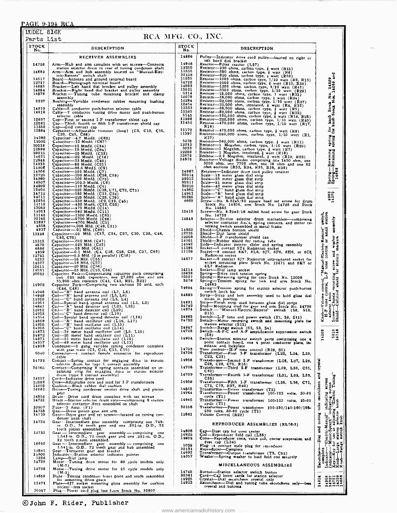
PAGE 9-194 RCA MODEL 816K Parts List RCA MFG. Co., INC.
ST DESCRIPTION S No. K DESCRIPTION
RECEIVER ASSEMBLIES 14886 Pulley -Indicator drive cord pulley -located on right or left hand dial bracket
14726 Arm -Hub and arm complete with set screws -Connects 14946 Reactor -Filter reactor (L37) station selector drum to rear of tuning condenser shaft 13250 Resistor -330 ohms, carbon type, } watt (R15)
14883 Arm -Arm and hub assembly located on "Manual-Elec- 11355 Resistor --390 ohms, carbon type, } watt (R6) 0
14517 tric-Remote' switch shaft
Board-Antennang 30158 11935
Resistor -820 ohms, carbon type, } watt (R30) Resistor -1000 S
12717 and ground terminaloadboard
Board -Phonograph terminal board 14720 ohms, carbon type,01
Resistor -1000 ohms, carbon 1/10
watt 2, R13)ña
type, } (R10, R36) ,o 14885 Bracket -Left hand dial bracket and pulley assembly 14993 Resistor -1200 ohms, carbon type, 1/10 watt (R41) .~.,N 14884 Bracket -Right hand dial bracket and pulley assembly 13031 Resistor -3300 ohms, carbon type, 1/10 watt (R29) 14878 Bracket -Tuning tube mounting bracket and clamp 5114 Resistor -15,000 ohms, carbon type, 1 watt (R31)
,.~. o
assembly 14078 Resistor -18,000 ohms, carbon type, 1 watt (R24) Z ó 5237 Bushing -Variable condenser rubber mounting bushing 14284 Resistcr-22,000 ohms, carbon type, 1/10 watt (R37) 4 x
assembly 12454 Resistcr-33,000 ohm, insulated, } watt (R4, R12) e 14919 14918
Cable -5 conductor push-button selector cable Cable -7 conductor tuning drive motor and push-button
selector cable
12333 11365 5145
Resistor -68,000 ohms, carbon type, Resistor -82,000 ohms, carbon
yp, } watt (R3) type, } watt (R32)
Resistor -100,000 ohms, carbon type, } watt (R14, R28) co
éco 12607 12581 11350
Cap -First or second I -F transformer shield cap Cap -Third, fourth or fifth I -F transformer shield cap Cap -Grid contact cap
11398 11452
Resistor -220,000 ohms, carbon type, 1/10 watt (R40) Resistor -470,000 ohms, carbon type, 1/10 watt (R17, ÿ é AI
e.
12884 Capacitor -Adjustable Adjustable trimmer (long) (C3, C10, C15, C20, C65, C68)
11172 11397
Resistor -470,000 ohms, carbon type, } watt(R8)° Resistor -560,000 ohms, carbon type, 1/10 at (R1,
g be 14392
13002 Capacitor -4.7 Mmfd. (C62) Capacitor -12 Mmfd. (C87( 5036
R27) Resistor -560,000 ohms, carbon type, } watt (R11)
C./ oc
30016 Capacitor -12 Mmfd. (C34) 12013 Resistor -1 Megohm, carbon type, 1/10 watt (R26) 12896 Capacitor -15 Mmfd. (C64) 3033 Resistor -1 Megohm, carbon type, I watt (R7) mm 30015 Capacitor -15 Mmfd. (C33) 12200 Resistor -1 Megohm, insulated, } watt (R16) E.5 14021 Capacitor -22 Mmfd. (C16) 12679 Resistor -2.2 Me oh gm,insulated, watt (R19, R20) 9 12948 Capacitor -33 Mmfd. (C40) 14876 Resistor -Voltage divider comprising one 1450 ohm, one
comp} 5200 ZB 14910 Capacitor -90 Mmfd. (C21) ohm, one 7700 ohm, one 18 ohm and one 82 XX 14906 Capacitor -96.5 Mmfd. (C9) ohm sections (R33, R34, R35, R38, R39)
I
I m 14906 Capacitor -100 Mmfd. (C7) 14887 Retainer -Indicator drive cord pulley retainer betao 12720 14960
Capacitor -100 Mmfd. (C36, C58) Capacitor -100 Mmfd. (C73)
30014 30013
Scale -19 meter glass dial strip Scale -25 meter glass dial strip 'CT.. ~ as 14907 Capacitor -103.5 Mmfd. (C8) 30011 Scale -31 meter glass dial strip Scale
corn 14909 Capacitor -110 Mmfd. (C6) 30010 _. -49 meter glass dial strip
Scale -"C" band glass dial strip 12404 Capacitor -120 Mmfd. (C35, C71, C72, C75) 14962 14712 Capacitor -180 Mmfd. (C31, C32) 14961 -- Scale - band glass dial strip ben 14711 Capacitor -220 Mmfd. (C28, C29) 30286 Scale -"A" band glass dial strip MN 12952 Capacitor -330 Mmfd. (C2, C19, C45) 4669 Screw -No. 8-32x5/32 square head set screw for drum '.-, 14710 Capacitor -430 Mmfd. (C22, C23) Stock No. 14856, arm Stock No. 14726 and Stock 13052 Capacitor -470 Mmfd. (C14) No. 14883 14911 Capacitor -580 Mmfd. (C11) 12418 Screw -No. 8-32x3/16 milled head screw for gear Stock 13140 30160
Capacitor -1500 Mmfd. (C83) Capacitor -2700 Mmfd. (C66) 14848
No. 14739 Selector -Station selector drum mechanism -comprising
e tw
12897 Capacitor -4700 Mmfd. (C5) selector contactor disc's, spring contacts, and motor re- ¡ i q 4838 Capacitor -.005 Mfd. (C49, C51) versing switch assembled in metal frame 6 4937 Capacitor -.01 Mfd. (C50) 14882 Shield -Chassis bottom shield
_
oe 3 -q5
13138 Capacitor -.01 Mfd. (C17, C24, C27, C30, C39, C46, 12735 Shield -Dial lamp shield C69, C70 12008 Shield -I -F transformer shield can O r 11315 Capacitor -.015 Mfd. (C47) 14901 Shield -Rubber shield for tuning tube a ó y
4870 Capacitor -.025 Mfd. (C42) 14892 Slide -Indicator pointer slider and spring assembly J B 4886 Capacitor -.05 Mfd. (C61) 11195 Socket -5 contact 5T4 Radiotron socket .E E
4839 12741
Capacitor- 0.1 Mfd. (C4, C18, C25, C26, C37, C60) Capacitor -0.5 Mfd. (2 in parallel) (C38)
11196 Socket -8 contact 6K7, 6L6, 6J7, 6F8, 6H8, or 6C5 Radiotron socket
" 0 a i o
5212 14377
Capacitor -16 Mfd. (C55) Capacitor -16 Mfd. (C57)
14877 Socket -8 contact 6J7 Radiotron impregnated socket for socket mounting plate Stock No. 12471 and 6K7 or s e
E 13611 Capacitor -20 Mfd. (C56) 6L7 Radiotron
S g
é 14531 30053
Capacitor -25 Mfd. (C53, C54) Capacitor Pack -Compensating capacitor pack comprising
14114 13638
Socket -Dial lamp socket Spring -Drive cord tension spring Cr. ma
two .015 add. capacitors, one 27,000 ohm and one 12007 Spring -Retaining spring for core Stock No. 12006 .,- 1v 33,000 ohm resistors (C41, C43, R21, R23) 3676 Spring -Tension spring for link and arm Stock No. n
14902 Capacitor Pack -Comprising two sections 10 mfd. each 14883 ë Q ó. (C44, C48) 14694 Spring -Tension spring for station selector push-button 2« Ea
14948 Coil -"A" band antenna coil (L7, L8) switch latch bar 14949 Coil -"B" band antenna coil (L5, L6) 14889 Strap -Strap and bolt assembly used to hold glass dial a ó.9'
E 14950 Coil -"C" band antenna coil (L3, L4) strips in position oÿ = 14951 Coil -Special band spread antenna coil (L1, L2) 14891 Strip -Finish strip used between glass dial strips ó t 14867 Coil -"A" band detector coil (L21, L22) 14742 Stud -Mounting stud for gear and arm Stock No. 14738 > « -.C.)(.1
14952 Coil -"B" band detector coil (L20) 14874 Switch - "Manual -Electric -Remote" switch (S6. S10, ,n, g I J, 14953 Coil -"C" band detector coil (L19) S13) ox if g.a
14954 Coil -Special band spread detector coil (L18) 14863 Switch -L -F tone and power switch (S7, S9, S11) o 2 14869 Coil -"A" band oscillator coil (L16, L17) 14732 Switch -Motor reversing switch and mounting plate for 14 ins 14955 Coil -"B" band oscillator coil (L15) station selector (S12) 14956 Coil -"C" band oscillator coil (L14) 14947 Switch -Range switch (S2, S3, S4) 14873 Coil -19 meter band oscillator coil (L9, L10) 14728 Switch -A -F -C and A -F amplification suppression switch m ..em . ,
14872 14871
Coil -25 meter band oscillator coil (L11) Coil -31 meter band oscillator coil (L12) 14904
(S8) Switch -Station selector switch parts comprising one 4 Nr.
mi" . 14957 Coil -49 meter band oscillator coil (L13) point contact board, one 4 point conductor plate, ín- 14858 Condenser -3 gang variable tuning condenser complete sulator and lockplate
with gear train (C1, C12, C13, C59) 14703 Tone control -H -F tone control (R26, S5) 5040 Connector -4 contact female connector for reproducer
cable 14706 Transformer -First I -F transformer (L23, L24, L26,
C22, C23) 14733 Contact -Spring contact for engaging discs in station
selector drum for type 1 contact assembly 14968 Transformer -Second I -F transformer (L26, L27, L28,
C28, C29, C76, R18) 30365 Contact -Comprising 8 spring contacts assembled on in-
sulating strip for engaging discs in station selector 14708 Transformer -Third I -F transformer (L29, L30, C31,
C32)
14857 drum (type 2 contact assembly)
Cord -Indicator drive cord 14709 Transformer -Fourth I -F transformer (131, L32, L33,
C35) 5 12006 Core -Adjustable core and stud for I -F transformers 14969 Transformer -Fifth I -F transformer (L35, L36, C71,
°0 3 ey
14890 Cushion -Black rubber dial cushion C72, C73, R37, R40) a 14862 Drive -Tuning condenser vernier drive shaft and pinion 14855 Transformer -Driver transformer (T2)
14856 gear
Drum -Drive cord drum complete with set screws 14944 Transformer -Power transformer 105-125 volts, 50-60
cycle (T1) é ee u
- m 14731 Drum -Station selector drum rotor -comprising B station 14945 Transformer -Power transformer 106-125 volts, 26-60 a
5 9d 10907
selector contactor discs assembled on shaft Fuse --3 Amp. (F1) 30156
- cycle (Ti) Transformer -Power transformer 100-130/140-180/195- á 76e 0
2 a-- '5 14738 14739
Gear -Drive pinion gear and arm Gear -Drive gear and set screws -located on tuning con-
de er knob shaft 12861
250 volts, 50-60 cycle (Ti) Volume Control (R22)
é.5 s °mil « Ti
14734 Gear -Intermediate In ermed ate gear assembly -comprising one .749- é út1 ir 14735
in. O.D., 34 tooth gear and one .291 -in. O.D., 12 tooth pinion assembled.
Gear -Intermediategear assembly14606 -comprising one 14922
REPRODUCER ASSEMBLIES (RL76-3) Ca Dust cap for cone center Coll -Reproducer field coil (L38)'.53..
m $ a
1 eÿ.5 ç 5 ¡ w : 1.541 -in. O.D., 72 tooth gear and one .291 -in. O.D.,
12 tooth pinion assembled. 14602 Cone -Reproducer cone, voice col, center suspension and .3 n a . e G 14860 Gear - Intermediate gear assembly - comprising one 5039
dust cap (L34)P Plug -4 contact ale for I
i-- toe 1.541-ín. O.D., 72 tooth gear and hub assembled 30131 plug reproducer
Reproducer -Complete g u I I a,w r 14861 Gear-Throwout gear and bracket 14992 Transformer ú vas 14900 Indicator -Station selector indicator pointer 14357
-Output transformer (T3, C52) Washer
. o o« «x 5226 Lamp -Dial lamp -Spring washer to hold field coil securely p ú s 1.
14729 Motor -Tuning drive motor for 60 cycle models only (M-1) MISCELLANEOUS ASSEMBLIES c roc
hS ,...XXX 14730 Motor -Tuning drive motor for 25 cycle models only (M-1) 14745 Button -Station selector switch button
a bet-. .eam 14859 Plate -Tuning condenser front plate and studs assembled 30381 Card -Call letter cards for station selector
12471 for mounting drive gears
Platt -6J7 socket mounting plate assembly for cushion 14925 14929
Crystal -Dial escutcheon crystal only Escutcheon -Dial and tuningat tube escutcheon only -less
N NNn nom m e n a0
m
socket -less socket crystal and buttons 30557 Plug -Power cord plug less fuses Stock No. 10907
©John F. Rider, Publisher www.americanradiohistory.com
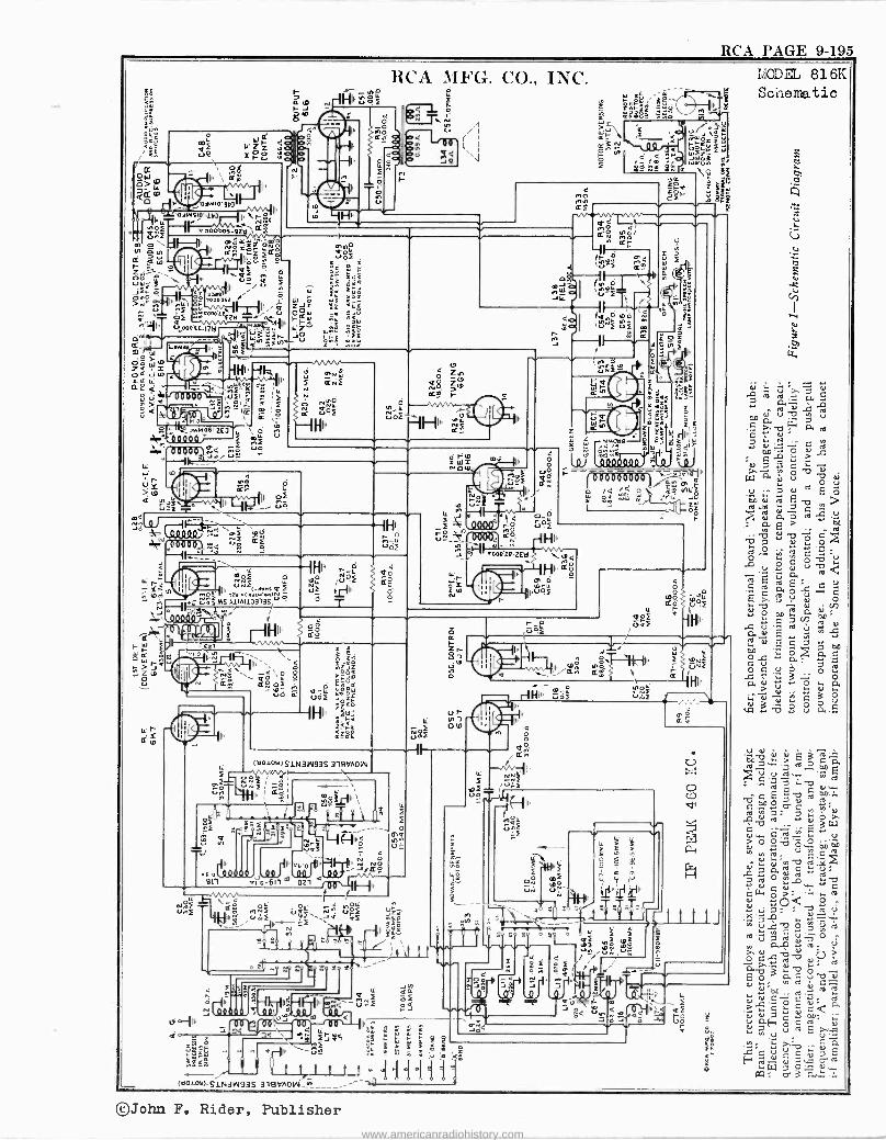
RCA 3IFG. CO., INC.
4 ú -- 4, IU `32ï ;
p rig, T ÑnG) 1-- `\\
A" ,0eoaocn,5.,1 ,,,; IH
NºV.LVan{ riz as ..
u0
HIl _ó 4
1 0Ñf LL 4
^l04 Q0
i IYoéi Ìil Iu..oaú.aw.luc uf y'
00 ' : ºfMSAlIAII]3135 ' 6
Ñ
FIt F,
0 .>113 ' '. Z t.
S
RCA PAGE 9-195
,á .; a T á [ ,s,a.. b
t+o ry 7 V c r -b w a ,,.
L .r .. c
Q 0 : T ? y o b u
W d
V Oti .
,V. i.. O N E
on u ro E -o > td d o [ ,y V Á. >
co
ro
Y
º N ó b ( . 12.
ád Ó
u ú r -Ci C
E % v Y v o ú A V 0 1 V N 00 . p
-C V O ?; Ê .N - d E.c c o0
8 w . V N G-. V-.
C7 0 ó 1+
o u u ..
Ñ Vÿz
n ó ó O
S V L1..G..
©John F. Rider, Publisher
www.americanradiohistory.com
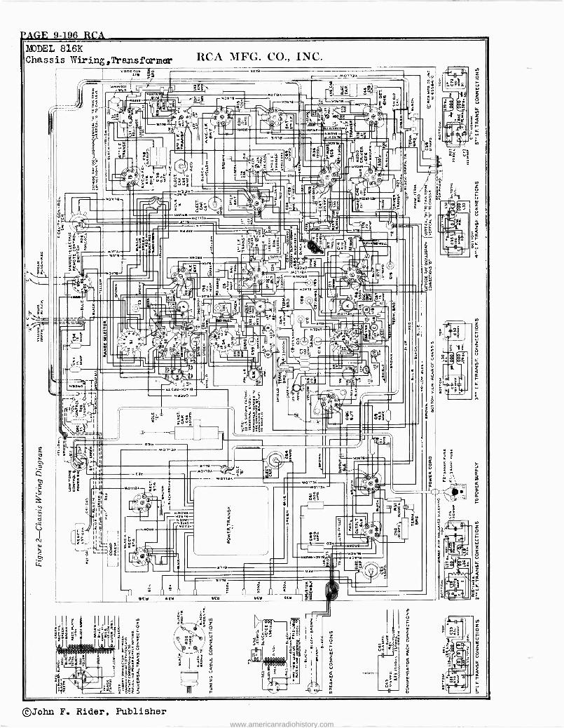
-'AGE 9-196 RCA
©John F. Rider, Publisher
www.americanradiohistory.com
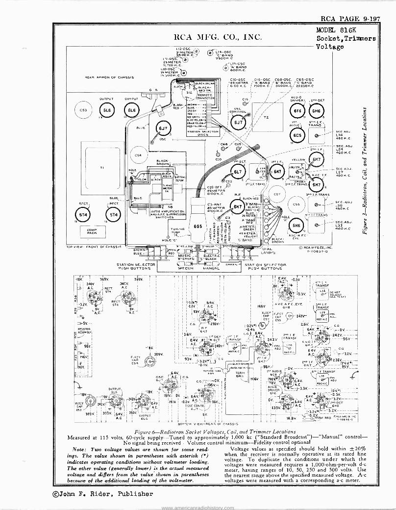
RCA PAGE 9-197
RCA MFG. CO., INC.
REAR APRON OF CHASSIS
G
L12-OSC. 31 METER 9,60014.C.
L11-OSC. 25 METER 11,700 K.C.
L10-OSC. ' I6, 300 19 METER
K. C.
L14-OSC. 'IC 'BAND 9500K.C.
BLAC
OUTPUT OUTPUT
TI
RECT.,
COMP. PACK
BLUE
r RECT.
m BLUE
'I I
o POLE
6J 7
O5C.
BLACK- RED
512
BLACK'BRO
BLACK- RED TR
óeL17-OSC. 7)." BAND 600K.C.
REMOTE ONNECTION
BROWN --I BLUE ----t GREEN ----3 REO.6141E9--6 BLUE'YEUD-O
6REEM1'ELLOS- REO -YELLOW -O
STATION SELECTOR DISCS
BLACK- BROWN
ELLO
¡BUCK I MO TK.
BLACK
TONINO MOTOR
74
D
BOTTOM TERM.
AUDIO AMPLIFICATION AND AEC. SUPPRESSION
SWITCHES
TUBE 14_
HDLE"C"
MODEL 816K Socket,Trimners Voltage
CIO-OSC. C15-OSC. C68-OSC. C65-OSC. ;49 METER ¡"A"BANO ,"B" BAND /-C 'BANC
610OK.C. 150014.C./ 600014.C.i 2gODOK.C. I- /"
' , AUDIO " CIA; ¡ DRIVER ¡ , 2no0ET a " OSC. ' ""
CONTROL / "
/ i TO 11 B
C68 ¡ Cy"
CIO
UC^UO
COO-DET. N 49 METER 6100 K.C.
C3 -ANT. 49 METER 6100 K.C.
6G5
6J7
4/4/ r/
C6S
DET . IF', I
6LT
2
L24
D:
leLLF. TRANS
BLACK -BE -0- "B" BAND
6K7 BLACK I9METER SLOE
26 METER_ `A"BAND-UT
RED 11
31 METEAl T GREEN)
49 ME1 IRW_ YELLO
'C"BAND
R. F.
SOLE
IeT. S.r.I.F. AUD10 TRA NS.
SEC.ADJ. ® L36 460 K. C.
0- ------- SEC. ADJ. - 2^' LE, 124
46014.C.
LEB, CTS=,T.,
RIS.C75-;,
5/ GREEN' nO.I. F.TRANS.
6147
7
A.VC. I.F.
6 K7
oj 9 A.V.0C.-
BLACK- EYE BROWN
6
TOP VIEW- FRONT OF CHASSIS A=YELLOW
BROWN GREEN
BLUE -- R e° MUSIC- ELECTRIC B' -CREEN 'C" -BLACK
STATION SELECTOR PUSH BUTTONS SPEECH MANUAL
OREEN
DIAL LAMPS
STATION SELECTOR PUSH BUTTONS
© RCA MFG.Cv., INC T-70837-0
SEC.ADJ. L27 460 K. C.
SEC. ADJ. L30 460 K.C.
SEC. ADJ. L33 46014.C.
- i i 340V. t I A.
m ( R
I
-3.2V
369V.
RECT. 5T4
340V. A.C.
RECT. 574 ñ
LSV.
i LSV. j A.C.
ssv.-1 RESISTOR'
w ASSEMBLY' I
96v., I
'-"VI
-áa
3B9V.
6
ELECT. CAR C54
-18V.
359V.
OSC 6,17
r-1BV.- -1
r242Y4- r 6/{V.
Ì I
I 1
I I
r64V., A.C.
I 1
R. F.
6147 13.6V.
I I _ t*T-DET. ' 6.4V. ri 6l7
240V)
L_- ({I6)__ L_ 93v.
L------!3.2V.4Ly OK
-0.1V. eLACK4RowNm. LLII
"RI,GReOTR. TO TUNING TUBE 6.4V..C.6G9
I
TERM. I-A.C., C G I BRO.
ings. The value shown in parentheses with asterisk (6) indicates operating conditions without voltmeter loading. The other value (generally lower) is the actual measured voltage and differs from the value shown in parentheses because of the additional loading of the voltmeter.
--18V
ELECT CAP C53
OUTPUT 6L6
--311v _® M2V.r©v
I
A.C. i 369V. i ; 350V. 6,qV ; 360V
OUTPUT Ì I
A.L. 1 6L6 1 1 1 1 1
}
196V.
ELECT I CAP. I C57
(-32V.) `b -0.4V.
C.G j 6.4V. F. .
TRANSF.
RI. I
ADJ.
iX r196V, e
191V.I OV. (i) 6.4V III A.Ç_` 1 I
191V.I -0.2V. 96VI. , I OSC. CONTRI
I 6J7 I
I I I Ill
I I 5V. I I I
I I I I I I
1 1 i 1 I t t BOTTOM VIEW -REAR OF CHASSIS
1eT.I.F. 6147
1
2Q6V. 1
I
I L _J (-3.2V4)1- BRO. ORCAMis.m..lNC.
-TOB3B-0
1 6.4V. -0.3V.
OVd iT l ß i 1J -OJV,
A.V C., A.F C . EYE 6H6
ELECT. CAP C55
2n. I. F.
242V TRANSF
~J PRI. L26 ADJ. 1 460 K.C.
2421/
us/. 64V.
iT1 . C.G.
AL r DV.---- _l^{zazv.----- --96V.--
A.V.C.[.F. 6147
6.4V. ALC.
, C.G.
ç- 7.2V.--
236V.---- (114V..)- 114V4)- - 95V.
_
TRANSF.
RI. ADJ.
gro I 96VJ 6KT
(96V.) nev.
AUDIO I DRIVER
5E6
¡OV. p_ I i ®é Ix33V
I,- AUDIO ¡-OV 6csri
O Á e 6 V.
A.C.
6.4V. A
64V. [A.C.
A.C.
(OU..) --_- -0.3V. --3.2V.----- 2re DET.
6146
Figure 6-Radiotrolt Socket Voltages, Coil, and Trimmer Locations Measured at 115 volts, 60 -cycle supply --Tuned to approximately 1,000 kc ("Standard Broadcast") -"Manual" control -
No signal being received -Volume control minimum -Fidelity control optional Note: Two voltage values are shown for some read- Voltage values as specified should hold within ±20%
when the receiver is normally operative at its rated line voltage. To duplicate the conditions under which the voltages were measured requires a 1,000 -ohm -per -volt d -c meter, having ranges of 10, 50, 250 and 500 volts. Use the nearest range above the specified measured voltage. A -c voltages were measured with a corresponding a -c meter.
©John F. Rider, Publisher
www.americanradiohistory.com
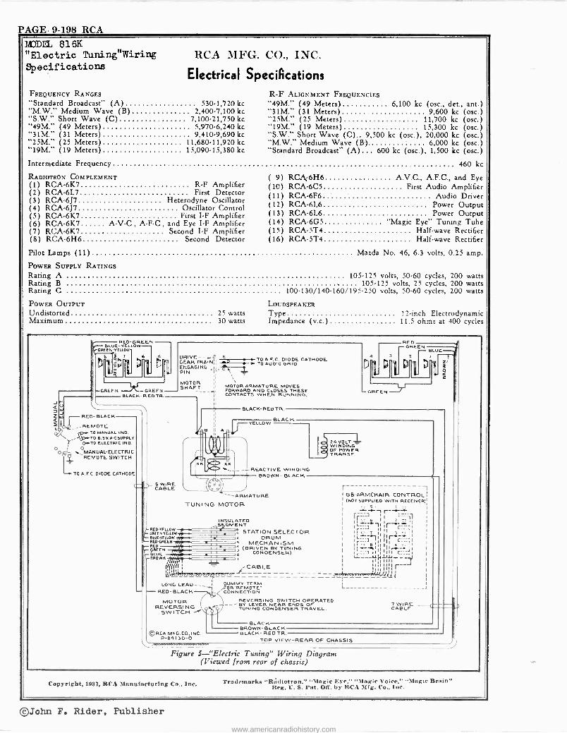
PAGE. 9-198 RCA
MODEL 816K "Electric Tuning"Wiring Specifications
RCA MFG. CO., INC.
Electrical Specifications FREQUENCY RANGES
"Standard Broadcast" (A) 530-1,720 kc "M.W." Medium Wave (B) 2,400.7,100 kc "S.W." Short Wave (C) 7,100-21,750 kc "49M." (49 Meters) 5 970-6,240 kc "31M." (31 Meters) 9,410.9,690 kc "25M." (25 Meters) 11,680-11,920 kc "19M." (19 Meters) 15,090.15,380 kc
Intermediate Frequency
RADIOTRON COMPLEMENT (1) RCA -6K7 R -F Amplifier (2) RCA -6L7 First Detector (3) RCA -6J7 Heterodyne Oscillator (4) RCA -6J7 Oscillator Control (5) RCA -6K7 First I -F Amplifier (6) RCA -6K7 A -V -C, A -F -C, and Eye I -F Amplifier (7) RCA -6K7 Second I -F Amplifier (8) RCA -6H6 Second Detector
Pilot Lamps (11)
POWER SUPPLY RATINGS
Rating A
R -F ALIGNMENT FREQUENCIES "49M." (49 Meters) 6,100 kc (osc., det., ant.) "31M." (31 Meters) 9,600 kc (osc.) "25M." (25 Meters) 11,700 kc (osc.) "19M." (19 Meters) 15,300 kc (osc.) "S.W." Short Wave (C).. 9,500 kc (osc ), 20,000 kc (osc.) "M.W." Medium Wave (B). 6,000 kc (osc.) "Standard Broadcast" (A)... 600 kc (osc.), 1,500 kc (osc.)
460 kc
( 9) RCA, -6H6 A.V.C., A.F.C., and Eye (10) RCA -6C5 First Audio Amplifier (11) RCA -6F6 Audio Driver (12) RCA -6L6 Power Output (13) RCA -6L6 Power Output (14) RCA -6G5 "Magic Eye" Tuning Tube (15) RCA -5T4 Half -wave Rectifier (16) RCA -5T4 .... Half -wave Rectifier
.. Mazda No. 46, 6.3 volts, 0.25 amp.
105-125 volts, 50-60 cycles, 200 watts Rating B . 105-125 volts, 25 cycles, 200 watts Rating C 100.130/140.160/195.250 volts, 50.60 cycles, 200 watts
POWER OUTPUT Undistorted 25 watts Maximum 30 watts
LOUDSPEAKER
Type 12 -inch Electrodynamic Impedance (v.c.) 11.5 ohms at 400 cycles
RED-GLOWREEN - BLUE-YEL OREEN-VELLOW
Ìi17i-
6 D
GREEN GREEN BLACK -RED TR
J V QW 7 Z W RED -BLACK
ZppIO4 REMOTE rJ/ TO MANUAL IND.
` TO 6.5 V.A-C SUPPLY
O.TO ELECTRIC IND.
ooh MANUAL-ELECTRIC Y V REMOTE SWITCH
TO A.F C. DIODE CATHODE
S WIRE CABLE
BRED -YELLOW - GREEN -YELLOW
BLUE -YELLOW -RED GREEN -RED
GREEN -BLUE
BROWN ..... rÌlff 1 ¡ - -CABLE
LONG LEAD--- DUMMY TERM. 1 FOR"REMOTE` -RED- BLACK ,( CONNECTION.
1
-ß:lÌ E TO A.F.C. DIODE CATHODE
GEAR TRAIN,¡ O TO AUDIO GRID ENGAGING 11,- PIN `rr T
SHMOAFRT l' MOTOR ARMATURE MOVES SHAFT FORWARD AND CLOSES THESE II CONTACTS WHEN RUNNING,
B II A .l, lin .
BLACK -RED TR.
YELLOW
GREEN
REO GREEN
BLUE
Z o
BLAC K
REACTIVE WINDING BROWN- BLACK
'..--ARMATURE TUNING MOTOR
INSULATED SEGMENT
STATION SELECTOR DRUM
MECHANISM j (DRIVEN BY TUNING CONDENSER)
24VOLT WINDING OF POWER TRANSF.
r- ---, G8 -ARMCHAIR CONTROL (NOT SUPPLIED WITH RECEIVER)
5 .. . l r'-.a f== 11 r i ¡,¡1 I ___] l i C T 1 I y' I I
1 I
Ir___711'j111 C_UI I Lr__-41,J.111_- 1 11 I 1111 r_J
11111I1ÌÌ1 asai'+fsisnsashY,_V=i
REVERSING MOTOR SWITCH -OPERATED REVERSING -7 BY LEVER NEAR ENDS OF
SWITCH BY
CONDENSER TRAVEL.
©RCA MFG.CO.,INC. P-84130-0
BLACK
L -J
7 WIRE CABLE
BROWN -BLACK BLACK- RED TR.
TOP VIEW -REAR OF CHASSIS
Figure 5-"Electric Tuning" Wiring Diagram (Viewed from rear of chassis)
Copyright, 1957, RCA Manufacturing Co., Inc. Trademarks "R, diotron," "Magic Eye," "Magic Voice," "Magic Brain" Reg. U. S. Pat. Olf. by RCA Mfg. Co., Inc.
©John F. Rider, Publisher
www.americanradiohistory.com
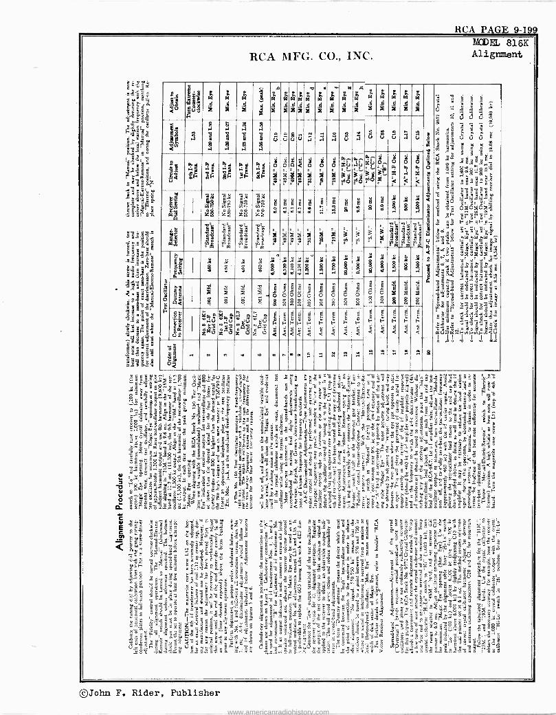
RCA PAGE 9-199
25
á° 4Ix gum
z
T W
a
5
á
Yy $
86 MA
.°M
S
Led
i1 é
z8
¡9 , , Ñ'O w Ñó a A
v
kl
X
á
ai
a4 ;F
ñÿ $ á Ñ
od z TA
8
RCA MFG. CO., INC.
á
5
Ji
9 ¡, K
N Ñ N :4,
O :
uA
r
ci
E
111
3
gki
í
U
E
8
6d
ñ
8 U
Á
.
fA
d °re
ú
°r8
w
E
.`é
8
p19
ce
á
o
m o;
pl
.
á
E
a
i3
pw
á
o
m1 i
8
8
r p1
Ú
a xù
NQ
eÉ N
MODEL 816K Alignment
r
A g X X
á
an .Ú
8
Ó
W
rñ
W W 5
W
:3
Ú Ú
xú
a g vio
Ó,.
3e.
0 w x
w 0 a x
6
E á
311 i 2
y
q
á : 01
b
S ¡,
Z2 C v 9 w
S¡,
w r.erk,
T1.G
Et Q 8
.
ó+ o
É
0 É
o Ë E fi
o É L
o
E L o
é
ó É
V ^ E
8
é í 8
eu gQ
e
u$
eY o
kM n m Ú
z
!°
ma O.
.i9
z21
N
á m
v 'Joe z0
v
1 qq0 `O Jv
00Qº
2 U
b
<
m
fi
á
É
F É
M
F
E
Ñ
.ma M
H
á
E
<
F
6 <
Ñ A
Eÿ."
O d ti O ñ>
322-8-2.5 C C g
á V O C w
é a
w w Lñ w Y = ' a 03JOJ07J á w:'"w"'á EF<ÉSE+c-
úu u o u mÿ éuw:ñÉ'm
C >.. C > C T oaoL°sú6 EvEv6vó wrw..w..u° L ÿL t
9 r Q C m .Sú.EÉw
9bq T9E YñíyiñúáLW
,-. .,."oE 6$ <Ewm E9 'á ` ' "U a 2 `` : c... ^; E (5. w7 º= -> u Q y'^ Tw`X' S"ó' vó`ce .óEñ?:á:ó,°.ám rwE v~:T. cf L'yy h
Y s .:.° ÿ é c ó.2 ç 2: 8 - á. o a" u ó á E u Eÿ"u`ñE.°.ñám a -d
.ÓmELa.. "
G C GmóC` C9Ew^ ,iSnjúln-Eñv
ú á E$uoYvwy.=°E- cE`y Z.Ésº 3cX»c-' v>
o_ 4 I»B5s `>.rvEBóé oäu°sEiB"" óLñóEá' .y.^IumcóSvm.Ci e_Yó uo ó.Ec wi,
Sy - ^s ms
°. zE« ë
E QQ^ °`s ó C C J
gó..3 sggm
Ó -ÿ é
" 1;. 5 "..L..o: a. °9 .13:
°."°° C' g.Áz_rEu - u u É E é .oe ill L.
:17:
é 9
1_421_5 .:;111111
wuTi y x .
ó. a C"`; F ú ¡Ina EwÿqurúEuö-wd9 w
7s .s 0 5 ag . e ¿
gc:"c9E c lie.' Ys..' cE°D .=v^°L
cT,S g e É.rj áv TE p? mwa E ' E ` ` p ? w wÇqÉóQós.."av >.
"2-..3 C2ÉyÉ2 oLEu ó a3 -oi ó o..y E ;wá a^u óvñ
sq.,'°np`ugané<çs_ ác., yod...ó =ó"E9u ä- ó '<a CEóvw$E`oG"'u
i .._c
"2,4-6f., " &O Ö
<0-5.4Euu aL --c3uñs .
w
._"E EEátió =T EuE ^ 9çñód'ÿée ire--. w = 'é...
-_,uo&'mc .^w..00E ¿
<.
t, s.a :r' Ofi-e?móÿ `Ñ.-16.
Lau`É; e woî- ,o w<É . _ w o5- .-. " ei.. ó=ü ú.o>.ú
u ° óu v y .
é
-w° C: :.w:-.E.
«=
á, -e- ="a ri o-. w° Cá` ú° Í^ w
w...SÿóEcuw:EE-"óñ-.ññ'm.u.l ó
zT,F-` 35
$L ^ E» ó ú 5' . ó r ò é ^ ò è º w.: L E E_. o ., v e u ÿ ó E ó w ñ° o u s u s c ö E ' E u 3 S äz cÑ E9U5 yá.V
8 ..> Z.. Ew uóm. u?d>ó" o úó" 3 w.. °.ug?3c öYóo-p Eux .. Tiw ó .-.y. a ap
a:25.2 ao .. c fi E C riEfJ- YYy^ q t> fiuf,çó vBSú=C ó9v á .xfioñ ó»Eóg ao..`c°ww`c ° `ucT'Og q$ ^Sp ` 2
ólu" c- 9ºE u¿»`c óE_ ;ó?Ehó" L ó`._ ó8?Cwxs$ér IIuw `" . . u .. w ... .,
41..ò< é$°^y :á":i$`..m" _s°w ú ó 0° .. Ç TE=o ó:óoö¡. L u E 4cué c ..û u .
m òqß o y u ágá_¿ C`w
3 u` c°- `ÚcQ . Ecy° .Es ..W u -.lei:.yE ZEsáwóÿ;âFEa 7,,°Cx c
r-''..5 yú ÿ :. .
: w o C :' _r "a °o..=u -'ós`Euc$c COEia9"7óñ a3w2Euu° vcóu E5óY8:
9 °e-o C' .Tmse..E uu °`_.. yy
eta ' .il
..Lñ.vmE$°, Qñxó'oT7ò"c Cs^'.ÿ;5éóEóásYi é?º'óvcóY.°ò«g.óCG óñuóx C`cü7wsc[[:: `.3vx<^á .ö"óuoácCé.¿EF,Ecé._cÿ._°G $Cáe`ó7mE_Ev.p°'C. Lv' . o.m Dy ÇusE.°.. . góñ`-cS7ú
c .. yp`3" EE`=°
mómv <°^é = äú ...?5g áe roo._ `u-
`o S> "7ó3C2i;séô9gá.é°rÿ é3FE'_ mVE " ó°k Úñ3v $ñ,Ú agóFu vú. `n0o .._ eea X Á ° Ç" ` c `+L -uw vEév:áS E°ow ._.+ww ;rEó9: ....wuu .'..1_83°3 > ..o° wóE-2.°0áEsówo . oEE
21,142
`rZ°ö ,..t3 w°á> > ° ._E E vu " cEh óó.,t . u,E! vºy'u ^_ ».o.Eú oäEós2'^»9O'7 :u$c,g=9 Tóo, OáELv'a ugc ú.oa d.é .2E y a
° E $.-. $v É eu ó " ñ o e U :I wE
E`o
...o.0 °' .9"s?,° c=3 EmEE ;1,22 -ócúñu m..- 'sonóvI^ñ t`.2 -31 w='2.-22 ÿ á éc>; uC79 c ó`g ó ¿ë ó ñ r á Ea ó E 0 0_ F, e E w o,^ u0 3 u
©John F. Rider, Publisher
www.americanradiohistory.com
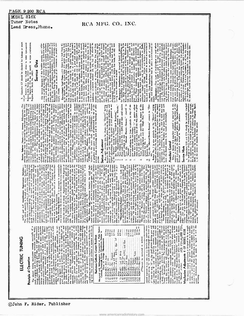
PAGE 9-200 RCA
g yg e " ° L H a @,: O pp u$. :8`á3°a°1çmY"3" e1YaEïméE uY cY3 a g E
E86 Lc a c3
MODEL 816K Tuner Notes Lead Dress,Phono.
RCA MFG. CO., INC.
.P. ¿ewwg ÚE13y1e1=.o1Ñg yÿ E? ó6E^. $.' coyua, 1c sucuyó 'si`óg+bt8 sEác2cmy E90VÑ9LEÿudya`C3 E°á"zc s>mg9y,$s:@@ M á"F`1QX.°ye
suás.aç@ aL$.. 3 áyc ó2O Éfi^1.Oá¿ó_Eyó cOB,a..`u.Ecc1 o-1 1.e11 -.(3'g 6m-,a,g° "ó$L3úg S^gq ~g1.c`wwá-y.<"3>.ÚE1E°Co3
98d"Oc3ÿyó,ó Ó^1-03C59woá. " -3` - e , u e 9ñóo' YeY m. ¿3E00 E^w., L3a m-3g(7..n waiÚ7au3.9spdv aS Evm+iaSúsO ú
83 a ES óE,-,cS:'^ =^é .o.,0-0.;. óbC ocEu.. Ee ... v lc S v u c5`= E.^_-9 v3 o3wÑvw?vU La¿`?9 SY6é'g áú .úE9u' c.óóú8.8á o
ca ..ro3.-ac aL 1.. L ,1.u, 3 L D 3°ó..31m °,.§
5 128'cw°ms3o3 .°. "5°==.- =.am° -1 .-.°5m., áu u....au1 c R
âSó3iñE p2_s^ó3ásSóú.ó3:u3s f.9w-Eçö>-@ÿS3 s° 9gegE Ó38"-...á fi á s s 21-c au E o= ,°°us.geomsp mé=3`º ,-,:i.--...1.-7,.2-5!2,,z v>: á-â 3$..C._wéSó..uoâ ^1.9ú selasuuc3 9 ._ a c 1 9. 91.. 8.fi y c"33Oó8_.^ ' yâo o fi c<"?c,S.:C1 aá D
;s(( 5.ÿ'9á1 ó yzÿs. Ec^E3 úó9éo3.E Em ádc"s r81P1>1 `^ oOÉCSB$Yéec3 ó33wE.`:pu.6 3ó .. ,3-1@^:Eáy áwÿÿFá,.o g'ö Cÿy@aç59$:°S.gg.Eç éä Ócusu-3e3eE'c°ccs
'iiF1m s s3.ô g c z,53` .7ó°ú.,á.. @3"u.. Ew = 3,-3....uiâYÿ>fi S.R.,q. e è'S ó$LCKES°@a-, L- o
y>
Cú Sv .7 3°w s.. S9C..L3,..... IrX11C«. o,_ á oBs -l. gÿ$ Cd -3° . ' s Ea7 Ú^ '11-g .r..5'ä 3c. ô+s^ o .qcou3 E y- o Ls ó3 së^c,'c_ Y c oo8y"z,yióuu.° p.gp,c2`-"cu...-ö§ SE; ];;2--128-;j22'81
s"EEáyz IIáya .....2., .'.e <":'2. ÿa-á 1,61$.aBiYóS"ÿ L c0 -C 232 r Ç-3 ou óC s a c3óg m`8u1E 3- y p a E 3" c E Ó 1 z " S o 3° C ú" Ó" ú < 6 O . ? ° ; u .13`YlEÚ e¿3s` W ú Cuc ó.. e,_..1,,ä> $1..S:EULFgqi ó'ââ 9"1: Z a. ó1PC °
iX3áE ÿ ' ;ymE-ógyá12,..L. 3Czufi.->.c3ficC°. p.8d..gça1 m.áá=O1aCs1Elas c.. c.:3C, gÛE-- R3
a
g3.óQzmmóo ppóávÉ.EóSvw b5 .S..áGsóS8Súfi",°+,v
1...SeúUe33 `nu°',ów1>,Lv`5ôp>óÿ
8E..>u0-gá> S'OyE OöY.éti Ózq c2 °3` cu"u.ÿu E
Eö85.iCgá EÚ.`_1:=3s`.¡Cs..ó.Áóóc:ar:á3s" .°..sLSEâdoicSd_ di SL'.C°--uuóóFEèii
.u..g m aY9 agm s ÿ$cc9uÿ maásáL:a <S1 $ oac Lo á33fi oa e ÿ.. §§ ïg
jau" LY,
mCcoácÿe.5múuÿ"é8c=38D1-ue3:usmy°Lg s°a1 á1 E d .°fi s s°c6-f. eY.. g1-01:2"5.au F
g .á.ñs=3ggE.éÿóú maá9B!Zqz .°^'11Y v gyo 8 ü _g 9.á e.°ÿ ä .$yEmq 'aSasd2fiy :s ºÿa yu3t8
. Y&ó ° ó. 8 ¿pa
mms2°c6 vu 535y' <°rRoy1.E5^ yé s s 9u $ ua10° s.6Er wálmcmC á31 EÓ ° 3m - uL c° u1 5ói c cN e.eâ- c fi`11 w ,j c
wF, o wF 3 O .t .. á- w 8fi p o ° ? g u u ÿ'3a1 $- c " = .= ó á . w é4X
q`
áÓÿs 3 è ' é "° á Cu"°3 a1_w9u ó¿,iysa..L.cu.9= S.`: i ° bóm c eyc S.$ d o.aa á5
-13 u._ o W " 8
3á3 4"a .9á' c
Ós ga ó ad
cg ^1î ó'^`. B^.._ ucus tiu. .90 5 y el suw u o3su 3-.á IO 3"c. e@gE 1"[email protected] 522-cZ , -7 es ayZY fi°"äL w áóáÓg 222'7, .g..°.:
Ì111 ,g13 3 ep
Ao. g Ó $6r gw
$s / á w6
9 Ó1a8^.-OY.ac Sá8°ñ>.°3a S11'oa0°83 p00 "3;c3 0= = ye3e_S- g.ác w3ECoÿá `K73^s>.5 >.s33ascó.9Óg óG1us-nX1"a<$ .L e 93 wu$si .áEcc ,yó °cakgè.á - ._ ,°'IIY1 g=3ss61Egg . F1-' ° y 1u 'd CSu ó. C a aax 3s 3.cc°uéF ' o . ' s el") > EÚFyo>.3g u .. wYmF <s :.°X -05.6 °.Y.g-2 1se > .s'..udañ b Uo 0 :gss°édmD3g"cEm.ES am m"u= Dsé.L3 ÿc.saói ÇF$1;. $B=^g aCósCo cc su c- 3 :, s1u $. 1 33 Ysu. 5"a.. ^ o o e g o ioó
:3.ç.wá.su.:83á'1óú?óDÿr- S:Ss3m°'Bd ^ `BSc@^.s.w a7x 9 ij
Ó 4 6 E ! VNl
6c"v9gSó5.éÿY8gMi3Egti. óÑsá<é' _ 2 Z `Óus' k.cÿcéC`A O=Iócs zfic,.>.c'.ó -1E _ °CsL
E x ó. ;.ao o, pE cE,yec c>,ccyE o - 1Óáeáw,.;z3ò.^eufigul a.°9 oII .3- sy á"ai..Óa9'80.2uocu3owsuoJ@'aa11,u e"' dó39 3ñcLâY-1s1'gm a.Y^áECçâeó >"¿c°O,C, riá ráFFó..°F-. da..EuFfidF$áE$u5 vv uús o cc33E8 slsyca>e msE °uS5 . s9$ C
sÉ SgSM= 3a m PÓ
á81w28S < Cá@i
al5á+:`-24.''FS.M dÓ °ác331p'g.? sÿCómsáç39ÿÿk /3r Ói.8 .5..o6y'`8`,cdé¿St'o$'Yo$Y á:8Cé3> aw ay ce- LeEw W
2: ' 3Y"o° moSy-u°'.c ú ÿ.gó -..Só.. Es vfi1$á" sC`C y.2..au`ijos E."._Ó3óófiyCy y g
1 LsE yYc.°XS3' ó3 c sn 9s.-' o °p'á,.e,ös3 e: o ='aF'e E aCäá..p°yggmgaoÚosp" s óFéÊE: iV..ñcváÿL 9m1EógB=ó_ç Ei4 áá9 m5 a .7s7yÿaáce"2"cá..W Is ÿ--sÓ.ÿm
d G c r fi "2" G ó B .c:''cQYm.w.açcOD o's.p. S^. o. :'a: dQ s2 g....'o o.." Bum pp co
3`a°séoc.oq$Jó Ú 8á .á$L83 .93s 1lU a;::"css .. ÿSS :asaoa'a2°"°1 ó5 C.g`: Ó sa3b3afi P
> Sÿy ámÉo 3::,°1uaa3a 6aG3-Pu3Ó..,' @ÿc`"9g1Çdc 6Ë°c°á.8u`9 o3._euC._ . E s ç fi-aEo$L5sw'ó 3 aa.8- Ê ú1c«e7ä°a6fic gSacañ .a9 aYo...ag 'a`m9 5É^'Y^4°`á1 " F69á3C5E35 a6oq3áä3Yuó_ >'ó3úºwi°có$.sc.2g4e3$tc:m8'D°w''$ o88á8 6só 2 "= Ea o3 63c Ls°6ñ 3 5C S"6 e.§us. Cuwa sá`c-.ÓE6uEc gfi os &o8eÿ+uá3 _3 ñ¡,Óu'3.93óá1 5,-u.q-d ó3° AP' c - ,8w: -.9m aá C..s? 96..3á=º315=...,--1 <tt á°' F1 s Su oV"fia OsS s"sú'a. 2Pm°.9..: ogw a'0030 oaimgg>c{..H s so..,,.rs" C sxpluia CsÁ.E1 cE 6 1 w` u >.-yyy S S: ú 3 B E°
áfibc:. É2u21=dl.sic o .ac. E..._ . F: eo. 3oÿ'n>"Ó1 cÿc"m-gs8 '1 .7111 8c ót .. ti3á a .1 ó ` ..'çço os9o3Gocyp á"Fs.ó°se ms ..c.ì:ms c " 9 cC u sy' E yEmEB c °'m..UZ 6áp .`Sóu E á..!:s sá ÿ1a "3scuEe
3 .- ^.w ° 33 u oii ÿc!3 -ás3 1 S E c3 a s ° á
Qs
o Y o c o y. ÿ máoo.9."'=.: 163 13L°:°,fi`SvEñ w3
IÉsSC.. c>e }e3' w-.áwe aEé.9 "^'eí.gg°- aq 9.. et 60._ s 1$ 18.v Y1G °°um.9e
á ig y. °g'óé ÿut¿1a9pOd Eÿ90:aCFvga3gsiá.° 1 Sö á a"- yóQa 5`S CaEcX a aB-ES3Yw e"3á 1?`u' "e = ,2. 8s: 9^ w
Sgë3 °sED °536 .9 s YS °s 5 s.-1 >a: 1
c1 uÿ E e.-" F3` á¿: Ct.ÿyu 60°E 5 3 E
yFg'5513 -t° c r°.9a guc5 $55 Y ^c E`o á C 7p Al 6q
'4" V.-2 2..':gyáaw sag . .osásáBaaé go`.ga °é i- $ ._w3+3: ÿssK 31' maçç=Cag~S < o. é a. 3 e s Co o.,a et Ii -g5 9 s>ma c mç ° .. Eáá- FJ ç 3 8 2E; éC8 n o=63a u Ó ¡flit 205.
1--J..51,.fiww ow. YCÿ9 » 9L5C .55$óá fi 9: EAT. :á$3'3:`aá: o5 -í-+s 91i.bm9 aáBmS âmY.9..E9Y w>Cmú L1 -'T ¡J-21141'4111.31-1,1:: ° SLE9E-o:gw y.Ç
ó0asáEéá `1- 5aóo1m>: ip} C.S >.6:39 ,C`° óóÚBa. 61o°° 5 z.-.9 é3sorré'á$á3z °gq°
ÿu-f.ra.,fiáW1..c3áYS9óé>6: Y .1e3II3_e éESe:éaS1E'séágç,2;5
8"E11ÓZgE>5`SáLYdgL@óam s
=ESV"óJEq/P3áóºÓñSs°iñfi 13 2mh=oegÉ''a..ºeE3sCvmßm5yÇ.97ss Kg
e é°Ó¿.73 33.E.ÿ9scmo^.a CT -.1 p emL 3cfi.ÿu1 s".g°seocáó,ágq..g'wp Bumu- 1 ,g °i òSóEE6aOc c T.99ÓLi21ó B%s' Q C?¿ $ a 9éócs..Ñg=,s-.,93ö.c`ue°EC'2u
a^ 2º9meY.msgaaPÿsá.saagÿyye O mó°JÓseása., cC,°eméuIIiS$°b'vÚÉ cÉ. . u9c$áY85,9áó8 `mSßms .g° ó: º_
G. y 12 m á °mo_'38 -@ G..
E Fy ',a $' =9fiEe ái: é 6 ,, 2
et r 5. 5 ésn' a .E.'mÿ5a5 ñ°1 3 S5 :.
.:
w :
:
: -6.1"e e w ce;ÿ< < <:> é a-e cci<a5pp,ppë",
ui
._ óu.á > eel!! °cc>.a.c351L
óYiïqº` ibáll TpCpvo'Yo ,y<oñxog,°'º,op?uF,.F<.,'r
C áááfiáááeá
SE ES S ES
7
..........., . ..,.......,.,.........,
gs"°ógÑ g a ó 5 11su e 9-5 Ó99 W M a á3 ñ1 e °°ieg 1@ E9no a 5a1
m .. y +? Ç á ö g m Ê a a s c+á 1 2 154-§=-u ggc=3g8chlÿ$`.ó äm`cäÿc3s'38W ß3^s .ó'Se3'^doEu: B48°aÓ1o3m
.1$e3g9$ á33QriáwV:'9sç3ú: 1C ÿwC1424 wÿwc^9.ÿ° é 1á'c3 V2"5Á
¢ S49L-1' <8 . s-oy Y °y=@3áacúE°3m Eg13 £ÚÚ1$3F ±gc8 Sc á
m ó7 E= Ç.. II é E.c
e @ 3 3a ÿ&o 1a< awarä $ c mgy á i$.- º- 1ç3g E Óg$E g$ ec `óɺ'53É3'is63 :áa`ed ° a o° Çg"ys'z'za `°E"ag 3 cFuO"igº aÓilÿSwF.sEafi58as` S=vE?
©John F. Rider, Publisher
www.americanradiohistory.com
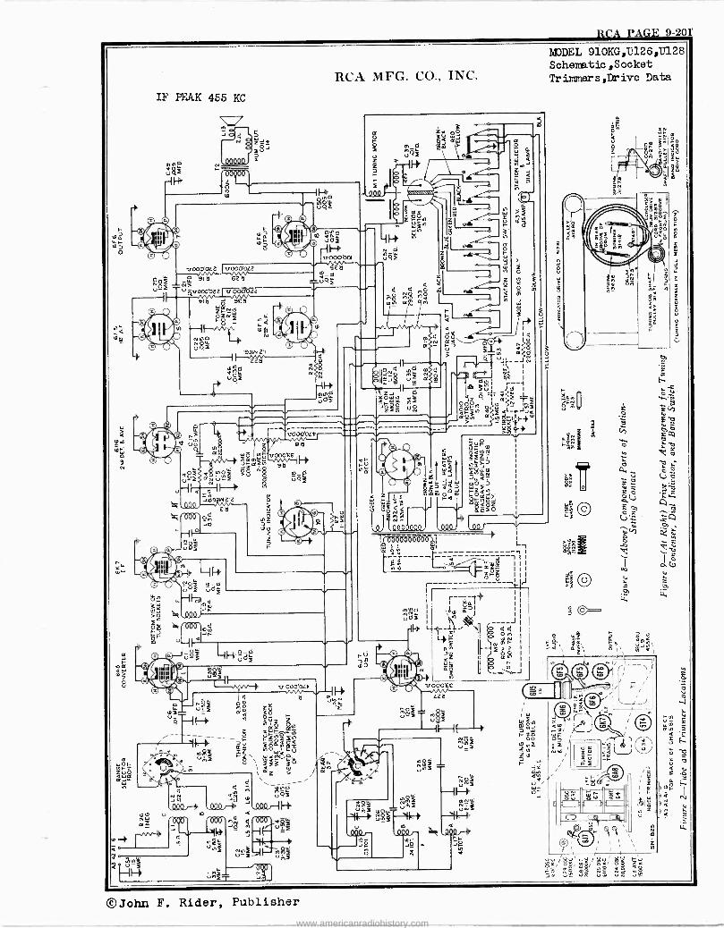
RCA PAGE 9-20r
rADDEL 910KG,U126,17128
Schematic ,Socket Tr inners ,Drive Data
©John F. Rider, Publisher
www.americanradiohistory.com
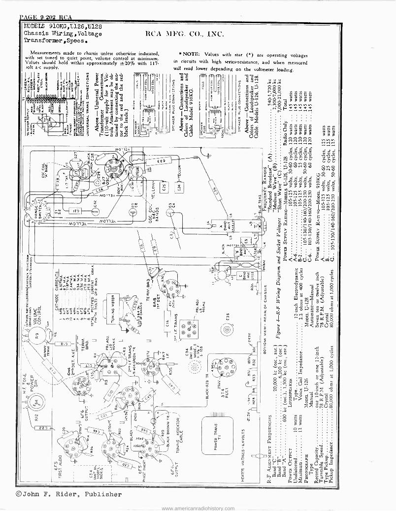
?'AGE 9-202 RCA MODELS 910KG,t126,U128 Chassis Wiring,Voltage Tr ansformer,Speas.
RCA MFG. CO., INC.
Measurements made to chassis unless otherwise indicated. with set tuned to quiet point, volume control at minimum. Values should hold within approximately ±20% with 117 Jolt a -c supply.
Ó á ® N . +r ú
e iiii O o
J b ® T
\ M0113A
hh --I 140 I
MO'113A
M0113A
M0113J.
$
gá 5
>
*NOTE: Values with star (5) are operating voltages in circuits with high series -resistance, and when measured will read lower depending on the voltmeter loading.
C C y, e.a tel N Ñ Ñ.Ni V V V = o $ .6a .st .ee
O
It ' .<3.It- ÑpOpO( tw0o.n+> "rNt;Lt;9 f = áááu
z óò u p 7 a C?7 vl en 0 O en en vl vl en ' V.S%
{ pp'p ; i
c3.371 e,ï o f. v v < v r
3. I.-oe IsIsS n a`
I W . O Fi b.. W
'g'52 O F. >.
IIIII
Y > Y < ` ?4 y q .S ó V
.j
. a 0/ C ú2 L L L 2 N a
2.3 ÚÚ "_'
n O Oaááaá Am ;- aÚÚ o á a a OOÑOO rhv,
x u
á
0
Er
aa
m
z W
u
o s I -
u
i
u
A
ó
oz_/
a 1 U' [ n -,-Coo -- uO2m
A05t
e ©
z
IIIU
A
rLL Y eo-
M1M
R
0
á m
V V V V u m 4 q 4
II :z n V >.
V V V V>.A>.>.
-rOen00 'O.00NO.O ette_ Q ú nó
ól e ..2g: 8
a >to3b y>>>>> U
W`a 2E>'. 3 p.N. .N.. 1a.. O.nvlvlo0
1- W J ei- OÑÑ ;w n 1 ~$c
z 'o J J - , li á g o : . °' á P :<má5: ,--0....g, ñ r ç >' 00 0 V 0.
È :2 :: J f m óó
Ú M0113AW J < o F\ O M m mmi\\te eN ; l wa<càtid
,d : eii -g 7."' uiQJ e ÁV
ñi. V.
J G
N
Ud1i O m < c4Ñ d t¡
G%e^17+ O u e tll ^' ^1 p0 ú P.e O
-'<tñiW 3 e W
> j h ¡ ' 1 f -L,_ O ....
4,1 L d ,Am ú C ,
c _
N V
óñ iuei W Ooÿov
04 Ó 0- J= n
Ili r e. . N 06 iI.
a Ó 8.08
eO
O te á V .0 ....
@ l V
g Wi V í7 º ó lñrô dáóaflo
u>i Q ._O. ]
F % C
C C p .2 otiUoo
r= > n
b 3 ä
W o Irl
: V FE. ú ÿ C
o p d X. . to ben aa Úíod 5$ a
f:4 6
dG C0.0 61;12..p..0 a ro es ea . ádá E-Eäe
na H U In ¢
©John F. Rider, Publisher
www.americanradiohistory.com

RCA PAGE 9-20$
MODELS 910KG,U126,U128 RCA MFG. CO., INC.
General The RCA Victor Model 910KG Receiver employs a ten -
tube, three -band, "Magic Brain" superheterodyne circuit, the arrangement of which is shown in the schematic circuit dia- gram. Features of design include: "Electric Tuning" for eight broadcast stations; a link -coupled antenna circuit; magnetite -core i -f transformers and. "A" -band oscillator coil; full automatic volume control; Victrola jack and switch; "Magic Eye" tuning tube; improved 12 -inch dust -proof elec- trodynamic loudspeaker; aurally compensated audio volume control; continuously variable high -frequency tone control; provision for armchair control attachment; illuminated band indicator; noise -reducing antenna adjustment on "A" band; temperature -stabilized capacitors; phase inverter audio ampli- fier; and push-pull power output stage.
The Model U-126 combination instrument consists of a
Service Data Victrola Attachment. -A jack located near the "Magic
Eye" tube is provided for connecting a Victrola Attachment into the audio -amplifying circuit on Model 910KG. The cable running from the Victrola attachment should be terminated in a Stock No. 31048 plug to fit the jack.
Loudspeaker.-Centering of the loudspeaker is made in the usual manner with three narrow celluloid or paper feelers after first removing the front dust cover. This may be re- moved by softening its cement with a light application of acetone, using care not to allow the acetone to flow into the air gap. A dust cover should be cemented in place upon com- pletion of adjustment.
Precautionary Lead Dress. - (1) The lead from the left pilot light should be kept behind the bulb and toward the "Magic Eye," to keep it away from the 6F5 grid cap, (2) leads from mica trimmers to coil should be kept away from the coil and other parts, (3) leads on oscillator coil which are an extended part of the coil winding should be as short as possible, (4) "C" band series capacitor C31 must have leads as short as possible, (5) all leads from antenna board to antenna coils should be dressed toward back apron, (6) the one lead of the, line cord and the primary lead of the power transformer which run to the power switch should be twisted together, (7) shielding on leads to Victrola switch should be kept away from the switch terminals and jack.
Circuit Data,Antenna Lead Dress,Tuninn Dial
Description radio receiver similar to the Model 910KG, and in addition, a phonograph turntable with a self-starting electric motor, and crystal pickup. The phonograph will play ten- or twelve - inch records; and automatically shuts "off" at the end of record play. The output of the pickup is "shorted" out when the pickup is on the pickup rest.
The Model U-128 combination instrument consists of a
radio receiver similar to the Model 910KG, with an automatic phonograph methanism. The phonograph has a self-starting motor, crystal pickup, and may be set to play ten -inch and twelve -inch records singly, or automatically. In the automatic position, seven twelve -inch; eight ten -inch; or a mixed group of seven, ten- and twelve -inch records, may be played in succession. The output of the pickup is "shorted" out when the pickup is on the pickup rest.
Antenna Connections RCA Victor Master Antenna Kit.-Connect the twisted -
pair transmission line to terminals Al and A2 on the terminal board at rear of chassis. Connect the counter -poise to A3. Terminal G may be connected to ground, but this connection is nod necessary for correct operation.
Noise -Reducing Adjustment.-After the RCA Victor Mas- ter Antenna Kit is connected to the receiver, tune the re- ceiver to a point near 900 kc where no station is heard. Turn volume control clockwise until noise is heard. If no noise of a regular character is audible, start any brush -type motor - driven appliance, such as a vacuum cleaner, electric razor, refrigerator, etc., but do not bring it too near the receiver. This will generate noise as a continuous'crackling, or buzz. Adjust C5, which is mounted behind the antenna terminal board, to a point where this noise is reduced to a minimum.
Adjustment of the noise reducing trimmer C5 should be made in the customer's home, with the RCA Victor Master Antenna connected to the receiver.
This adjustment is effective only when the RCA Victor Master Antenna is used. For all other types of antenna, the noise -adjustment trimmer C5 should be screwed all the way down.
Other Antennas.-Use terminals Al and A3 on the re- ceiver terminal board as antenna and ground connecting points respectively. Terminal A3 may be connected to- ter- minal G, unless this causes interference, in which case this connection should be omitted.
0 IO ZO 30 40 510 60 701 80 90 100 IIO 120 130 140 150 160 170 180
SNORT WAVE
t0NO0,i-SONM7-NMA-ROAM MIN -TOLTO -NTTSRVII maw -MARRON-WINOS. MIN-LOMDO0 HAVANA-ONO-MNIS-SYOMSY-MAORD 10.000M - ROAN - PAINS CONDOM-IARM-,Oat MEW TORI( u0- Ma1ROURME - SRNIOIINA - 31 M KAHN á3M MDsCOW MOOS 19 M 16 M
NEW YORK LONDON-MTTSMROM 13M
8 9 10 12 14 16 18 20 22 MC
STANDARD BROADCAST
. , ,. , .
2.3 2:5 3.0
POLICE
MEDIUM WAVE
AIRCRAFT
4.0
AMATEUR
POUCE
A R R
120 R R
140 R R. ., .
160 5.0 6.0 7.0 MC
B 6]M AIRCRAFT
cotoMMA If. AMERICA)
49M - ANUNMAO - SITTLOROM 10001A -MUM - CIKA00 - NEW YORK MIX. OTT- -TORONTO-CARACAS
0 IO 20 30 40 50 60 70 80 90 100 110 IzO 130 140 150 160 370 180
1111111111111111111111111111111111111111111111111
Figure 1-Tuning Dial, and Corresponding 0-180° Calibration Scale
The corresponding dial setting for any reading of the calibration scale can be determined by drawing a line straight up from this point; for example, 151.5° on the calibration scale corresponds to a dial reading of 1,500 kc on "A" band. Read instructions under "Alignment Procedure."
55 60 70 80 100
©John F. Rider, Publisher
www.americanradiohistory.com
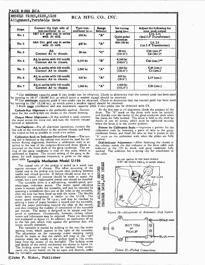
PAGE 9-2041 RCA MODELS 910KG,U126,1128 Alignment ,Turntable Data
RCA MFG. CO., INC.
Steps Connect the high side of test -oscillator to - Tune test-
oscillator to - Range Selector
Set tuning gang to-
Adjust the following for maxeak output
No. 1 6K7 I -F grid cap m series
with .01 mfd. 455 kc «A" Quiet point
between 550-750 kc
(2nd I-F1Transformer)
No. 2 6A8 Det. grid cap in series with .01 mfd.(1st , kc "A" L8, L9
I -F Transformer)
No. 3 AZ Connect Al to chassis. 20 me "C" 20 me
(147.5°) C24 (osc.)*
C8 (det.)t
No. 4 A2, in series with 100 mmfd. Connect A3 to chassis. 6,100 kc "g'. 6,100 kc
(145.5°) C25
No. 5 AZ in series with 100 mmfd. Connect A3 to chassis. 1,500 kc "A" 1,500 kc
(15L5°) C29 (osc.) C3 (ant.)
No. 6 A2, in series with 100 mmfd. Connect A3 to chassis. 600 kc ..A., 600 kc
(29.5°) L17 (osc.)
No. 7 A2, in series with 100 mmfd. Connect A3 to chassis.
1,500 kc "A,. 1,500 kc (151.5°) C29 (osc.)
* Use minimum capacity peak if two peaks can be obtained. Check to determine that the correct peak has been used by turning to 141.5° (19,090 kc), at which point a weaker signal should be received.
** Use minimum capacity peak if two peaks can be obtained. Check to determine that the correct peak has been used by turning to 124° (5,190 kc), at which point a weaker signal shauld be received.
f Rock gaºg condenser and use maximum capacity peak if two peaks can be obtained with C8.
Cathode -Ray Alignment is the preferable method. Connec- tions for the oscillograph are shown in the chassis drawing.
Output Meter Alignment.-If this method is used, connect the meter across the voice coil, and turn the receiver volume control to maximum.
Test-Oscillator.-For all alignment operations, connect the low side of the test -oscillator to the receiver chassis, and keep the output as low as possible to avoid a -v -c action.
Calibration Scale on Indicator -Drive -Cord Drum.-The tun- ing dial is fastened in the cabinet and cannot be used for ref- erence during alignment, therefore a calibration scale is at- tached to the rear of the indicator -drive -cord drum which is
mounted on the front shaft of the gang condenser. The set- ting of the gang condenser is read on this scale, which is
calibrated in degrees. The correct setting of the gang in de- grees, for each alignment frequency, is given in the align- ment table.
Turntetble Mechanism Model U-126 The crystal unit of the pickup is sealed in a metal case
against extremes of climate. The offset mounting of the crystal unit in the pickup arm insures ideal tracking between needle and record grooves. If failure should occur due to a defective crystal, no attempt should be made to repair the crystal, but a new replacement crystal unit should be installed.
The turntable drive is a self-starting, variable -speed, gov- ernor -type, induction motor. The motor speed adjusting screw is located under the turntable, and may be adjusted by inserting a screwdriver thru one of the holes in the turntable, after the hole has been lined up with the screw. The flexible motor drive arrangement is similar to the U-128. The motor speed should be '78 r.p.m., and may be checked by placing a piece of paper between a record and the turntable, with the paper protruding beyond the edge of the record, and then counting the number of revolutions of the turntable per minute. The motor is designed to be simple and fool- proof in operation. Occasionally, however, certain adjust- ments and lubrication may be required. These are illustrated and explained in figure 12. In addition, an application of oil to the felt pad, which rubs against the governor disc, will insure smooth operation.
The turntable is started by pushing to the rear. the motor starting lever, which appears to the right of the turntable. The adjustment on the automatjc motor stopping switch should be made so that the switch will snap to the "off" position when the needle in the pickup head is 13/4 inches away from the center of the turntable. The locking screw and details of the switch mechanism are shown in figure 14. The locking screw and nut may be reached, from under- neath the motor board, or, by an open end wrench, under the turntable.
As the first step in r -f alignment, check the position of the drum. The "0" mark on the drum scale must be vertical, and directly over the center of the gang -condenser shaft when the plates are fully meshed. The drum is held to the shaft by means of two set screws, which must be tightened securely when the drum is in the correct position.
Pointer for Calibration Scale.-Improvise a pointer for the calibration scale by fastening a piece of wire to the gang - condenser frame, and bend the wire so that it points to the "0" mark on the calibration scale when the plates are fully meshed.
Dial -Indicator Adjustment.-After fastening the chassis in the cabinet, attach the dial indicator to the drive cable with indicator at the 530 kc mark, and gang condenser fully meshed. The indicator has a spring clip for attachment to the cable.
ADJUST SWITCH TO TRIP WHEN NEEDLE IS ON I-3/4 RADIUS FROM Q, OF MOTOR SPINDLE
Figure 14-Adjustment of Automatic Stop Switch
o BOT TOM
OF PICKUP
Figure 15-Pickup Connections
BLUE
©John F. Rider, Publisher
www.americanradiohistory.com
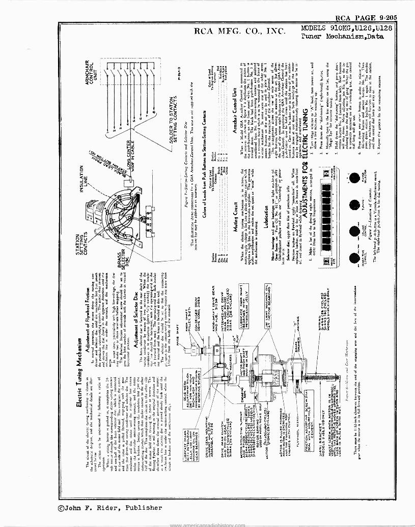
RCA PAGE 9-205
MODELS 910KG,U126,U128 Tuner Mechanisri,Data
©John F. Rider, Publisher
www.americanradiohistory.com
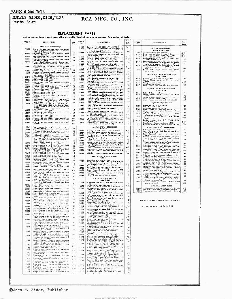
PAGE 9-206 RCA EDDELS 910KG,U126,U128 Parts List
RCA MFG. CO., INC.
REPLACEMENT PARTS wig 00 gamine factory-btWd pub, which we readily identified and may be purchased from eudlodfed dealers
6TNá6 DESCRIPTION Lbt Prio
STOCKUnit No. DESCRIPTION List
Price
RECEIVER ASSEMBLIES 11611 Cagdwr-25 old. (C34) (Model 91060). 1.66 Beane[-Varinple denser mat rotor diet- rent baring -los bracket and cup assembly
31237 Clutch -Venable condoner drive gear clutch and r.onl pin on motor ahYt-60.
31963 (Yoh. U-184 and U-198) .10
Bard -Antenna d terminal board 11844
80
Clutch --Variable em done [eat clutch and .56
[round (Model 910KG) .25 Diyyncci, {earngs{e Din on maw shaft -º6
42 71531 Board -Antenna d ground lemons) board (Modal U-126 and 111118) .25
31 13 11414
Coe...0 and .túen3 ail (L5, Le, L7). .. Coil -"A" band wcilleor coil (LI7)
1.30 1.06 11949 Bally-9tnion.seltieg contact body, lee cooact
and 31494 Coil -"B" band antenna coil c L3. LA) '1
.80 31978 Bracket-B a dap echoer mounting bracket corn-
.38 31286 Coil -"B.. ab "C" hand mediator (Lib. .t6
31451
plue -.n indicator strip, cord, and tewion
Bracket -Bracket and bearing cup for variable condemner
tU-oIIs rotor adjustment (Models
s a
motor
31217 31180
31281
Call -"C" bend antenna coil (LI, LI) Conde -3-4 nser
C7, Cl, C32) { r`,,able condenser (CO. Cl.
Conlin -Contact tip for rt .ettica ccetacl. itcht`co
.90
4.50 .04
31!44 1º714
Br5-111 .45 E Caprite-Adjusúkk trimmer
bracket (CM)) L6ó
Ca Dual adjustable trimmer 3-30 nodal I
31316
3131[
Conan -Polo buttons omprir m{ 10 contacts sÁ on insulate{ nnpria
Conran -cosh button switch contMega strip..- in{ I9 riveted on inrulat.{ ,,rip...
.70
1.90
11894 each b aec-on (1b, 125). A. (mer 6.80 rmfd. (Cb) .Q5 Gpwtor-15 .em 31171
31º51
,odic Cord -Banc indicator
pointer mod
Cord -I cord 10 .60
11948 d.
Capacitor -33 reed. (Cl,C1 161). .35 311184 sciable de,,dove
Core-Adjsla acornter drum mirs coed.... .QO 11441 11057
CGenerator-36 mid. (C1) .10 Capaeitor-4l amid. (C57) .10
81º14 core and mud (oc 1-1 tour C Moors 15 13067 *pal C -!t ment*. (167) (YodW U146 and 31910 Core-.ccp ck. arc and stud ter "A" band
cod 19720 31170
Cap to, 100 ale. (CYO) .35 Capacitor -100 amid. (C11, C19 Cll. C14) .35
31273 31240
Drum-R`Indicator driva cord drum Fl0,1cr« Variable condoner drive meter 91-
.BO
12724 19746
Cm..., of -110 mord. (CIA Cot) .36 Capacitor -150 meld. (C15) .84' 13!39 Gear-`tVandle condenser knob..baft drive gear
.46
310033 31406
Capacitor-060 eppaaimr-1 S00mneed.( ((C28) .35 Cagmor-6,000
need. (C31) .75
71646 Ger -Variable hub
condenser .se mod.. dyer gene and > eel -9á cycle nodeia only
.48
.40 5107 C -.00Yb mid, (114) (Modes U-114,
pacitor-.0896 33151 inyclNiod dora {ear Gear -pinion
gear -60-110 Modal na pinion tar--cator .50 34828 4828
C red. (174) .16 Capacitor -.515 mad. 177, 149, 15.25 .15
31531 31639
101..) Indicator -Band Indicator step (Model 5.12) Indicator -Band tndlanr strip (Node. U -lß4
.18
4858 c tadaor mid. cdº1. cu) (Yohb D-I9s d U-1221 .25 11491
U-1Band
Lendp-acne lust seep. 4.7 V. .16
14393 Capacitor-Al 1065) (C9Ì, CC48, CC6t C39, i. Model 71410
or oemDartmant
Lamp -Electric Electric tuning adjustment indicator lamp, .I7
810K0 only) (C65 m Mods. U.124 and 8.9 V. 0.18 amp .24
11315 5.118only)15 .10
Capacitor -.016 ((1)6) .10 31344 33344
Leather bast lather fer kywhel Lock -Pugh button ...itch lock vv.te-camprb-
.04
1483º 4839 30947
Capacitor old. .20 Cape -do -0.1 ami.d. CIO, C) .90 Capacitor --1.98 (4317 .30
31241 oto 10 contact leks m one Api
mnlyr drive motor (YI) Motor -Variable eyrie -25 >d< rndeb only
.80
4.60 30847 Capacitor -0.2e ofd. (C19) .30 11£36 c dk drive motor (MI) N-50.40 30147 5239
Capacitor -0.5 mid. (319) .30 -18 id. (Ceo) (Model 8U.124)e 1.36
cycle cycle
contact late
Plate-]<Intar cortan p lee e
7.66 6
31886 01,0, Car -Viz -In idd. (136) (4184 U -1H and
U -troc 1.25 91017 Plate -Selector mounting pinte-mDuna ce rear
r2.cctt .50 31785 Ca 90 old, 11947 (Mode. U.IQI and
U-149) 1.78 30181
c kneer Plcabl. 0-336 plue loi phew. motor
cable (Mode. U-148 and U-194) .36
5040 Plu{-4coneact lesede plat for speaker cabin MOTORBOARD ASSEMBLIES
12493 (Yodel 81060)
Pluge-5-contact fem. plug weaker .30 Model U-194
91210 Pulley -Indicator Uneb pointer U.128)ocord
paney ue1e 'A0 .10 31530 9848
Coupling -Flexible motor coupling complete.. Cup -Used ncdle cup and lid complete
2.18 .76
31271 31272
Pulley -Motor 00547 Pulley --Rage evich pulley
.25
.20 31485 31695
Mounting-Ptckur nove bun rubber ,counting.. Pin -Dove pm e luten fleible coupling . .10
91250 Resritor-Vohage divider comprising one L600 turntable 'haft .03 Ohm, one 2,960 ohm, one 9,, 00 hm, one 12 ohm, d one 140 ohm ructions (RI., R118.
30370 Plug-Acontect male plu[ for autematle swatch .16
14117 R31, R92, R33).
Rancor -º2,000 ohms, 1 10 watt (844) .90 n1á
14196 30100
Screw --Set screw for flexible ceuplieib S0tieg3--1 A miring. for automatic sait
.05 .08
13991 Rutor-99000 ohms, 1 watt (R4) a .20 31156 Sprier[-Ued needle cup cornon .D tton ring .04 11300 12804
Resistor -99,000 ohms, 1'I watt (R97, 8304 Renter -39,000 ohm, I watt (R8)
.15
.90 31177 Strip--CempMe set el rubber eri. ter 8.x,0
>> ggrn 10 17040 12281
Rektor -omit 0 o050544. I watt (11554 R ohm., I watt (R5, RSV 849)
.90 31594 31187
So ire. utwrnc ...Mob and leva complete.. Sriteh-Swneh only ter automatic switch (271"
9.76 .36
11913
0 1220.000 ¡0491 Models U-116 and U.128 only)
Reuter -110.000 ohm, 1,10 watt (R11) .20 .15
31633 Turntable -Turntable with rpindie .haft and sana complete 3.96
11489 11459
Resistor -170,000 ohm, 1/10 watt (818. R99) Reuter -470,000 ohm, 1,/10 watt (R1)
.16
.16 31837 Webers -Tamable bearing end .him washers. A.
122116 12013
Ra.ar-179000 ohms. I wartt (R4) Rouer -1 me 1/10 watt (R7, R26)
.10 .16
MOTO R B OAR ASSEMBLIES Yodel U-1111
30208 T.,
Reenter -1.9a., 4 w (522. R41) (1141 111149 Ber -Tone arm mounting base .36 11981
Model. U-196 and U-1111 only) Reinter --1.5 et., 1/10 watt (Rd Ó) (Models
`
.90 3116º Board -Record changer bane ' h all welded and riveted men and bearings -Ira
5131 U-129 and U-128 only)
Reimer -2.1 reg, w (R3 `drive
.16
.15 14209 elf or-Malg parts
Bumper -Mate lever rubber bumper (I) 7.00
14847
31933
Re sett -Indicator pointer lord pulleyretainer
Rot r-Sakater rotor din -mount on rear d .01 14{1 Cup-Ued efts cup, r and lid cwvpka..
Bacuechwn-index real,
.06
.75 40
variable condenser Wet L48 31161 Guide -Pickup lift cable (coil .Doe[. cor gin. tarie) (9) .30 31141 Seatfor
ñee10 beadle., cone pint eat screw
yr 0º x1150 Mounting -Pickup arm bane rubber. mounting omplete .45 4119 Screw -Ne 8-34 beadles et screw fou gem
Stock No. 91239 .04 31106 Sprtn{ Needle cap lid tension rprioa .01
14960 Screw -No. 8-32 square head set *crew for elector roof disc .03 0PERATI NO MECHANISM
4849 Sc . 8-3 w fo more head set nerer pulley Stock Nos. 311 271 and 31479 and drum Stock 31134
Mode U-191
Bracket -Pickup locating Mae mounting bracket
31364 Nn. 31273
Socket -Dial lamp neck« .03 .40 31144 Cam-CamS and [ear aeembls (4) 9.66
13471 31347
Socket -Magic Eye socket Socket -Pickup socket and bracket
.45
.30 6801
91148 Clutch -Trip lever friction clutch namely (5) Coupling -Motor coupleº complete with tune
.16
31151 31345
Socket -Tube socket Socket -Tuning indicator lamp in.ulated seem
.20
.30 table drive gear, rubber ripe. ,ewer coupling, .rid drive (6) 1.80
91979 31232
Spring -Band indicator tension ap,,ea Spring -Contact rip spring for.tatemaetiea
.03 í1)ße alll9
Corerap for rip of retord pat Finger -Trap lever friction Niger by (7)
.16
.45 come .01 91119 G recd arm d rick gear for front Idt-
rd taud)rack 1513f Spring-Indoeer pointer drive cord tension
.08 31120
Gar arm gear for rear right -
hand record pot (9) .66 31411 Spring --Variable condenser drive cord tension
pru,t . .06 31121 31123
Ger -Record poet gear (10) Guide--Main Piing guide (11)
.99
.40 11007 Spring -Retaining non. tor core Steak Ne.
91989 . .02 31114 31197
Lever -Index lever ably (12) Lever -Index lever tension spring lever (lf)
.76
.30 31190 31282
Spring-gmion-caning cota°, body wring. Spring -Toulon .prinº for core Stock No.31080
At .01
31190 93113
Lever -Locating lever and pawl elembly (14) Lever -Main aaumblY (16)
lever Lumbl
.70 1.36
31941 Sprang -Tension spring for Byrheel .01 91310 yylever R(16)
alt cable and .Driet LL .55
31319 Sp` barns
ion spring for push button switch lamb
31135 31190
Lever -Pickup locating lever pt (I7).. Lever -Record sepeear elevating Mae monk.
.96
31494 Spring-Vanablv condemner meter rotor adjunt. ment bearing wring for 26 mode. only 31131
with adjustment screen (18) Laver -Trip detaining lever (I8
.10
.30
31109
cycle (Models U-128 and U-120 nly)
Spring -Variable dour motor rotor adjust- .01 31116
31131 Lever -Trip lever ably (10 Leer -Trip regulator lever (41
1.66 .16
Dearing npring fou 60.80 cycle model. only (Mode. U-146 and U-111 only) .02
31133 31144
Pawl -Trip pawl auembly (19) Pin -Record pot drive pi (83)
.80
.04 91º38 Support -Variable co dorer drive tear mount-
mg supin,, and stnm esembTo .66 14407 Roller-Pickuplift cable roller and bracket »-
one .aa
91245 Support -Variable denser e mounting rid um ter
05 on y VV ender I
91114
4503
Screw -Cone Cbly pointed moo rnr.tep lever se hub o record pa Mel
Se Pickup lilt ctabl a5044. .04 .04
31490
decycle (tlod 1 B)OKG ly)
Support -Variable condenser motmounting for moel.
.70 14105 9110
Screw -Setscrew lot flexible coupling Screw-Spec scree to edit friction dutch
r`
.06
25 cycle oly support e vet (Mode. U.I26 d U-124 only) .00 81124 Separator -Record anteater knife O.)
.09
.75 31.4 Support -Variable c ,,denser motor mounting pied and mum lus 50-99 cyme modela Drily
91129 91115
Shaft -Record separator pot eel (46) Shelf -Record post .held eembly (17)
.40 1.46
91488 (Model eIOKG only)
Support -Variable c dorer Dr mounting .45 31141
9676 Spindle --Turntable spindle .haft and spring Spring -Cam Owl t i or4n/ n ' goer
1.40
support end studs .r 50-80 cycle mode. only (Models U-118 and U-129 only) .35 14190
(DI turns, .190 -in. O.D., 4]/44Án..-) Spring -Pickup locating lever short gyring or
.04
91980
31291
Switch -Pickup twit. fer mounting on push button switch
(Sr,(33)
un
Switch -Range switch ( 32) 2.70 .95 31145
locating lever pawl tension spring (98) (16 sic. 14.) s, 160 -in. O.D.,
tension Springs -Main lever e on Drin[ (99) (18 .08
91312 Switch -Station selector push Mimi. switch and bracket complete 9.25 31136
turns, 9/16 -in. O.D,n 3 -in. 1[.) Spring -Pickup locating lever ton[ nPrioli or
.05
91278 Tone Control -N .f. tone control and power witch (R12, .1) 1.50
,rima lev« acne n *Drin{ (JO) (ßb turne, .190 -in. O.D., 15/18 -in. Igo.,, .06
91187 Transformer -Fire i-1 transformer (Lx, Le, Cil. 132) 1.11
9088 Spring -Pickup lift cable tm goring (31) (20 , 115 -in. ó.D., lm. 4-), .04
01281 Transformer -Second i -f transformer (L10, L11, 319, 114) 1.01
31117 Sprint -Record operator mesure pine{ (14) turn., 1-h,. O.D., kin. Ig) .02
31300 Translormer-Power t anafermer 105'190.140/ 180-100 200 volts. 50.50 cycle (TI)... 13.86
Spring -Trip t et(33){ 15vturns er or butin. .ver i
44
t [ (33) (16 .190-.. O.D
91226
91125
Transformer -newer tran.former 110 volts. 25-
Transfo,,tat cle
TPower transformer 110 volt, 60- 19.00
91332 91147
Spring-lfurntable .pindle spring........ fleaib Se
cou --Complete set o1 rubber ecriq flexible
.09
.40
91450 60 eyrie (Tl)
Volume Control (R9) I Model 910KG only) 9.00 1.50
31139 91124
Turntableg A.aembly-le. .pindle Washer -"C" washer for top of record pent
3.35 .04
3124e Volume Control ( R9) (Mode. U-126 and 0.125 en.) 1.60 31149 Wehen-TumaW thrust washers (1 sleek 1
bronze. 1 felt) .15
STOCK No. DESCRIPTION
Unit List Price
1170] 31448 31383 31157 30889
30870 31447
31168
14204
91489 31155
31448 91150 81141
91161 31166
31159 91]40 91161
19884 11294 114693127576
5099
31539
31530
31691
14594 14357
31358 13103
314e.
31640
31541
91151 91356
91361
30898
31305
31542
91365
31468 91457 51589 31760
aloe. 11010
14270
31470
11131
31426 11428 9916
MOTOR ASSEMBLIES Mode. U -l28, 0.198
Geeemor-Maton *peed Soeemor Motor -106125 vol. 25 cycle (Yº) Moor -1061º5 velu 50-50 cycle (M1) Motor -106-185 volt, 40 cycle (Mº) Plug -2 -contact female plug lot motor Wade
Pluzcs n 98l, açroeplug ter meter poor cable Screw -Complete of or {
e sod spacer -for 05 cycle mounting
Sc weer,
i t { weber., a pacers -for 60-50 cycle models
Sweob-MDAr toggle twitch (S7) (Model 1.1-141 only)
PICKUP AND ARM ASSEMBLIES Model U-146
Base -Pickup arm bee and IMAM et
pivot u Crysl-Pickup crystal ea ridge and needle
meow Pickup and arm complete Screw -Pickup need sorer Shalt-Pkkup pivot arm and shalt e.mnbly
PICKUP AND ARM ASSEMBLIES Model U-123
Cable --Pickup arm lift able and clip Crystal -Pickup emu) cartridge needled ndle Pickup And arm complete Screw --Pickup needle
me Shot -Pickup pivot arm and shaft aesebiP
SPEAKER ASSEMBLIES Cap -Duet cop for a center Coil -Fiert coil (L12) Coil -Neutralising coil (L14) Cone -Speaker cane and vain coil (L13) Plug-4connn male plug fbr apege (Model
91 -KG only Plug -6 -twat plug for apeker (Mdek
U.128 and only) Speaker complete RL70H.4) (Yodel 91045
only)
Speaker complete (RL70H-4) (Modek U-126 and U.1011
Tracdermer only)
-Output put tr analormer (T9) Weher -Sprier[ weber hold field coil more,
MISCELLANEOUS ASSEMBLIES Button -Station selector push button Cap -Pakt Imp cap (Bulb Eye) (Modele U-124
d U-199 only), Cover--8-protective coven for poll button
CushiOT Cbasnia mounting combo and bl,ce-auBùimtcomboter ono clime. (Md.
U-125 and U-126 only) Cushion -Mohr plate mounting cushion and
elm. assembly -sufficient U.mt ion instrument
Dial Stati nModel. lselector ái.14 scale and crptal. Escutcheon -Tuning dial escutcheon -kris dial
and button (Model 910KG only) Eecutchedn-Tuning dial eche es on-1 dial
and button (Models U.12648and U.125 only) Hinge --Cabinet (Mod. hinge (Mod U-126 d
U1211 ceºo
only) katet tndicat0r potnt.e
Indicator -Station nnnlelector
Indicator pointer (ModelsU-lú6 and U ---m 1ºS Iy)
Knob-StationKnob-Stati lector, la control, too con tr I, errrang* ewitch knob
Yorker -"D.1 Tuning.. Dash button marker M -"Record P.1er
ps button rker.me. button
Marker -Station call Serean -Compartmentlamp m re (ºdeb
U.126 d U-165 only) Screen--Dial calm urea &` (4 required) d) (ModelClousta
mounting mrew. and "weber ,010KG
only) - Spun[-Retaining spring' for knob Stock No
31356 .
Supension-Nwor bard suspension apringa, and 1wher (4 required) (Mod.ú8 e and U-125 only)
ºePee-C net lid support (Med. U-1411 and U -124g only)
ANTENNA ASSEMBLIES Counterpoise Line -Additional length CO It. long Insulator -Strain and countermine insulator. Tranemwim Line -Additional Moog. 00 It. 9019
3.06 99.70 14.50 17.75
.36 .35
.40
.95
4.11) 7.60
.1º
.41
.06
4.95 7.45
.19
.46
.03 3.85 .30
1.75
.30
.25
11.96
10.45 3.96 .08
.16
.15
.08
.50
.60
.95
1.85
2.90
.96
.40
.35
.11
.01
.0l
.95
.20
.45
.06
.05
.10
1.85
1.36 .05
1.60
ALL PRICES ARE SUBJECT TO CHANGE OR
WITHDRAWAL WITHOUT NOTICE..
©John F. Rider, Publisher
www.americanradiohistory.com
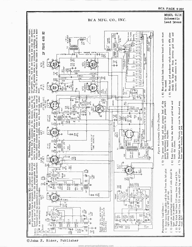
RCA PAGE 9-207
N O 01
ON -O : ? GC
Ó
Ç Ol
ú . c m
.....Oe°_ .^i
íY.. H ` /v/ e
Ñ w O [7ó + O .x0-- 2 eo
Q.=z
<
n
cu
C-)c?.c 3'-Z «: a
] Ne ~_ Y
I 2.e á VO
OC :;ÿ áer 7OY1. Y. ÓQ
-O V Y
<
ttÇ., u
.p
p7 Ó OY N
C a C u au°gY N
C 04;1 z`deeo .2 2 r^
«c°2 Q N
.. .Y..`i'a unj ú ° c
Y a
Y O
a.,9 o .. u ryz CN C c< 7 r,
d -o 8.4 ú? g.ä1
o
q'^ ¢ ... C Ñ ,, c
Y p V V
At, C se).
C O N
2'5 A e p W '
Vie
yóz
uOzti o00001
3
RCA MFG I NC .
NM089-NOVB >1V19 IÑ0ó
0 =
. Z
H
93121 0000L2
918 00022
pItl
in cc
ó
,e --e
a
Le r
e
W 4
11
531 -/ .000zz Ñuoz
r ta ° 521
O
3w2a J .OÓ
Wp -' 2 OC G
Nm`
z i N o u y
rI() z 4._
9
ola
m 33
N T
z
m .. ... .
o+ z z1
0 JVVVY la h
n
11'1 11 )/1 IIF 111
-IP m /l
0- anis
g M ry \-M0ll3A
200
9
$i F
W_Y > ï 12W H j
mI-
s
93W 1 rÑ r .. IP.J nnz za
-
'000
Oy,O no V z
0462 .0042
618 028 1 i
W J.?
n
42
F te N
4
Q- u)
0r
Ñ 1
_
(199
4
0C
ne
4 1)
i
M
¡.n'vái u\j z
Lie
Áh
t úg
s
aG+
p
Ee .3
.az
0
co
`2; 9.2 2;N9 JnN ,4Ilr11,# 991i
X
Ur'
3ç
MODEL 911K Schematic Lead Dress
Y T 3 a d Ñ N
7 r-1 r
ú ^ ^ N
á -- - I
©John F. Rider, Publisher
www.americanradiohistory.com
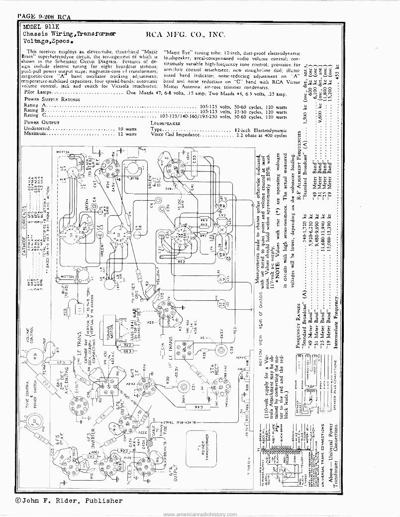
PAGE 9-208 RCA
M0113A .,r
II
RCA MFG. CO., INC.
"Magic Eye" tuning tube; 12 -inch, dust -proof electrodynamic loudspeaker; aural -compensated audio volume control; con- tinuously variable high -frequency tone control; provision for armchair control attachment; new straight-line dial; illumi- nated band indicator; noise -reducing adjustment on "A" band and noise reduction on "C" band with RCA Victor Master Antenna; air -core trimmer condensers.
One Mazda 47, 6.8 volts, .15 amp; Two Mazda 44, 6.3 volts, .25 amp.
`3ms
AIS
S£3
u
443 053
91 Ña Jf
volts, 50.60 cycles, 120 watts volts, 25.30 cycles, 120 watts volts, 50.60 cycles, 120 watts
£43
12 -inch Electrodynamic 2.2 ohms at 400 cycles
Pier
mo
f2 F
MODEL 911K Chassie Wiring,Thansformer Voltage, Specs.
This receiver employs an eleven -tube, three -band "Magic Brain" superheterodyne circuit, the arrangement of which is shown in the Schematic Circuit Diagram. Features of de- sign include electric tuning for eight broadcast stations; push-pull power outut stage; magnetite -core i -f transformers; magnetite -core "A band oscillator tracking adjustment; temperature -stabilized capacitors; four spreád-bands; automatic volume control; jack and switch for Victrola attachment;
Pilot Lamps
POWER SUPPLY RATINGS Rating A 105.125 Rating B 105-125 Rating C 105.125/140.160/195.250 POWER OUTPUT LOUDSPEAKER Undistorted .. 10 watts Type Maximum 12 watts Voice Coil Impedance
F- z W m D cc
2 F-
V
m
C2 a CM
I- ~ Ñ W Di d F,PZ V M>l
z 3`u>.' ha e
©a®
,Ï.
r
uK Z°
0 o2
á
z Lit
Y `
7\£42
r
m
5222
3
- Ú
943
a33V211 0321-713'-18
,u<
CD
z
4
ú 71f P2..
AIS'
> ª
á l'II e n_ 4Z2 áry
f W 0 f óQúm á m
1;4
S
ÿ o o v,
Áz-[12;21-4 55_pO O
T' á.
ó
ú
Z
ág
Sá I w
©John F. Rider, Publisher www.americanradiohistory.com
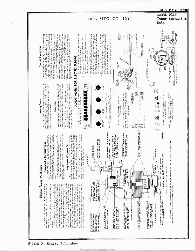
RCA PAGE 9-209
©John F. Rider, Publisher
www.americanradiohistory.com
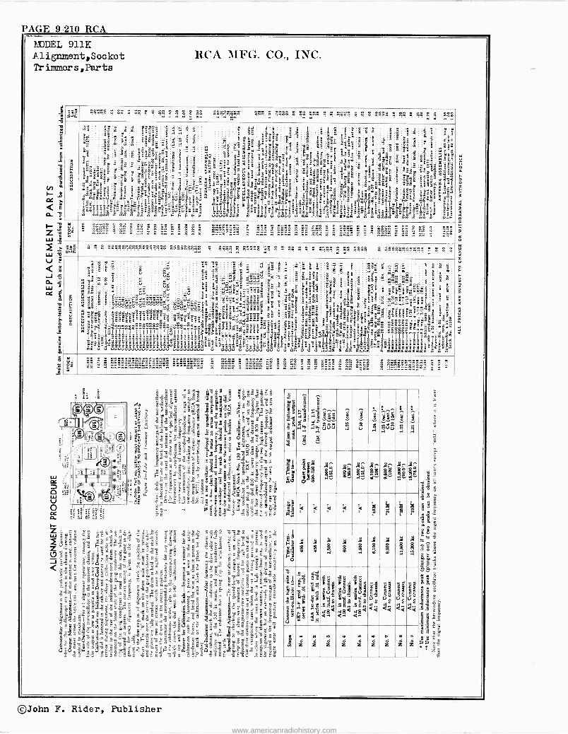
PAGE 9-210 RCA =EL 911K Alignment,Socket Trimmers,Parts
eps aG
!:o gg$:. g me a F s séS . . . . . . . . . . . . . .
w w w w . w
. . . . . . . . . . . . . .
p . n
u
ó
s9
ÿ&
é
IT .zi á '1ë: "xó'E
z hózrct=ú IIII:I$ÌI
e,;tt; 1xyx<âe.o:ó>=Po=';e@sá
i Bs nC
w`
i 'Z
1
yy
ó Eö
. _- ÿr
° -- ç2 .,. m
i
1
d
" ° .'w
e
.I elcc
mil figé8e .E"Er " -"
éeOfrB
eie g. ñS .- é'2e ` zlâlâlê t=>>S>,.w
I I I =oñz ,"":
9
att
`°8
x
; á
e .á +
t
y S_^r_
á "
1413175':
á S
w
jS '
8^ F_ F3
!
I
ç -
j-. a Z a
^ `pSr aq i_ a w
o,rge ' 39, 34
ill
ô:
=z
3 _.t
á@
3t"
lT"$I 3
É AÉ
: m .- H má
5 m é
tm s @<
m °.e;18"çye 3 <' 6`
" á . ú3'
'i z.e .WzSeJI a r áºEr
.1 <a"' xo > m g7".e ` wm3-;a6"a Yi I
8
-idle!, xx,, ,.
:.:.'
t$Y°Y=iYYç
ell; eñ--3 S=E°2óEx
ziS`S .. CgiEiotB -cfrzxzt>r
e`äa "gézs..
I Iioms> I
:r
' g3
1r t
!c' pp
á Y es.x
'
o.
T.fr$""'-;
i;@3z_
2
73
w C 8: b.e
a _
k
1xr-z-,^ä frS. g.; ; -
5 Ì° l"3ä;-"
:$ 1 .' b;
'zE $! áae
=e: i "-
-"y t S;S""
frip "" deg SLe^: IÌS"!m t: _o : t` !
°tt
"°t
É: aáa >r3
@q ty. - t35t
`rea ..a$t
é"x: _ +E >ó_ " t ! IIrq='
_
e 3
x 1
: ÿ 1.3"
º e.g
S ES°
.`º`''G "33"oatl Yrl
g'x`lya= _
e
'í
3
S8$ : d
z t=..
:
# "521 2
Szg j.
qe yEx< _"
`t -Flea x tx;i
1s_ 1
II
'a
1 ji
! /S
E:."i3
k t.
§ 8:.7: pp á.º.3=. ÿa'iz
> I ,Iey_j
z
m
sw
a g
"
S
`<éé 2.S" 8.3s" x;fr
i;
t
L_g"x
$d c e.3a
-Sg " Ze1 l
É.I.- S
! ,
=
wZ ..
m áéá n_n.n nn n n. n n nn n n w n n n..... n..n w gig n nnnn n wn nww n n nww.. n .. nnng n nn .. nn . w..
?aw . . ................. .....
wn . .:Sß w .... !I . 1 14 S ! .... . .......... . .
ó
5 át
Y
c M
`
a N-
°- 1
< 3 a1a á
° '@
m .1,:.
6 . a <41!
II
8i _
g m"ú
é é
é g b
S 9
<ê{ !vlll11íílIIIÌIII"Illql,>
5Eê r;r Ya "
u
3;
e
w :â E áo Sdd_dd
ee e "fi` 3 e
r
x x ç._e-e.S....ä.a4t:-;-ócö'' rääáaä
ú3uúúúd3ú
n' ú
oe
ê
u
^ÚÚ
'...d ëxaaeè'. e
$$naeoo
e
.
.
uuuuu:
eLEB
tt-syxttx
'º uúúuúúu
: ú ua
'.r
VÚ
.nin
a;
^â {..V..yyVTgE
. .1d
1 m
..mn
a ^ê udGuúuuuó
.
eú .;..â..' san
É-dd3r, 3 e'.E .
E'
aäïssë11191&11
9;
11
46 .1
cover..an^5á11..
e ^ e>Ga'" 9
3ó
.t ! 'g :E
.tfY
II
ú
aâ. d=aeätS
Ê3ßá+ °z9.i16ë35
o g3 1 S áñáá..t`MiImg: siè-
33335ä uuuu
: 3 a ó :táâ8
= .a";;:"
Jn 3`=
8ee e
.
u -'saug
^ è .0 .i.i .i,....-
_a7___
$SSr ' °^X
tt.-9,
~I
:u<'g'<<ti'íy"
Ig1 uuuuu
"' $i
5.
F 5 . é 9" Ex
äá9
's-
äe uu
t
_
_ .r, 2 Bágt < Sz o "3ó3
_ -E` "
225 ."3
z- 1 í1.; _
u V°qC
y.g. `-G ut i! gó
eg:i
'Éfi .
Tÿ -=-" Or' óaoe9 $ SB`, sCy:.
> g= ñ 2. cg.;:=.5.
Ñ>'éi=QaÌ>ç>^ ! !1l11 [,r!'S.gl.;g`-$Ì u ú u
3 ;
g -
"É cz. É-0 t
sÉge°r ._
i.".g3g
= B."° "g_ -z=aeñ4áx"F 'e tl "á
a:
á É -$8 ? Sfr i 91ó
_
fr F
`x'á-i efr-ó.:meo
J_-S"b" E.=fr .
ll Ì` ery 7 s6
eßá S:È 3
°
Ea ç3óä
Ca smrc 8ogrie
xS 5>° :alrc!^nliÌnÌ11111
11íe . '$ä
sdia
á :ê
a a^
; -â?-añê. ;:° - "
-d1111211 äoeeo
eéoóEErmÉm
ewfrtxá;gtxtgpÌ'.I=
''$'ádá'$é¡¡x! a aaaaaaaaaaa
.; á
zrc-- " ....
- !b'F .
i@ re;` c^
e
a k
4
E1
9 =x
t É
t'r _""
zz°xz`z
t e .:
s' Z
. g
5
"r é n
mtw w .8.6
g w w
r
. m m ..m.,SSr. .. . .w . n nnw. . nn.nn nn n. ,4 w w...w.n n nn nww . nn0n_.n_._..®z
IIÉ
9 ái á
1
aw
á
59 guu
á
m
d ui g Ég1 i" ¡ i i y? y $ e 8; . b- : cs ó
p P. $.3f:g óg ek §'g
jztq é é é `< é i
3a
f á
Fi ji¡ O
7 g i 3 ó ei i d
'
Ji-IJiIJiPi1i 8EE 11 aE
1 O
11 -E
O
, m g2gégée .5
e
e". ew w eg b O F m ?
m z z z z z z z z z
©John F. Rider, Publisher
www.americanradiohistory.com
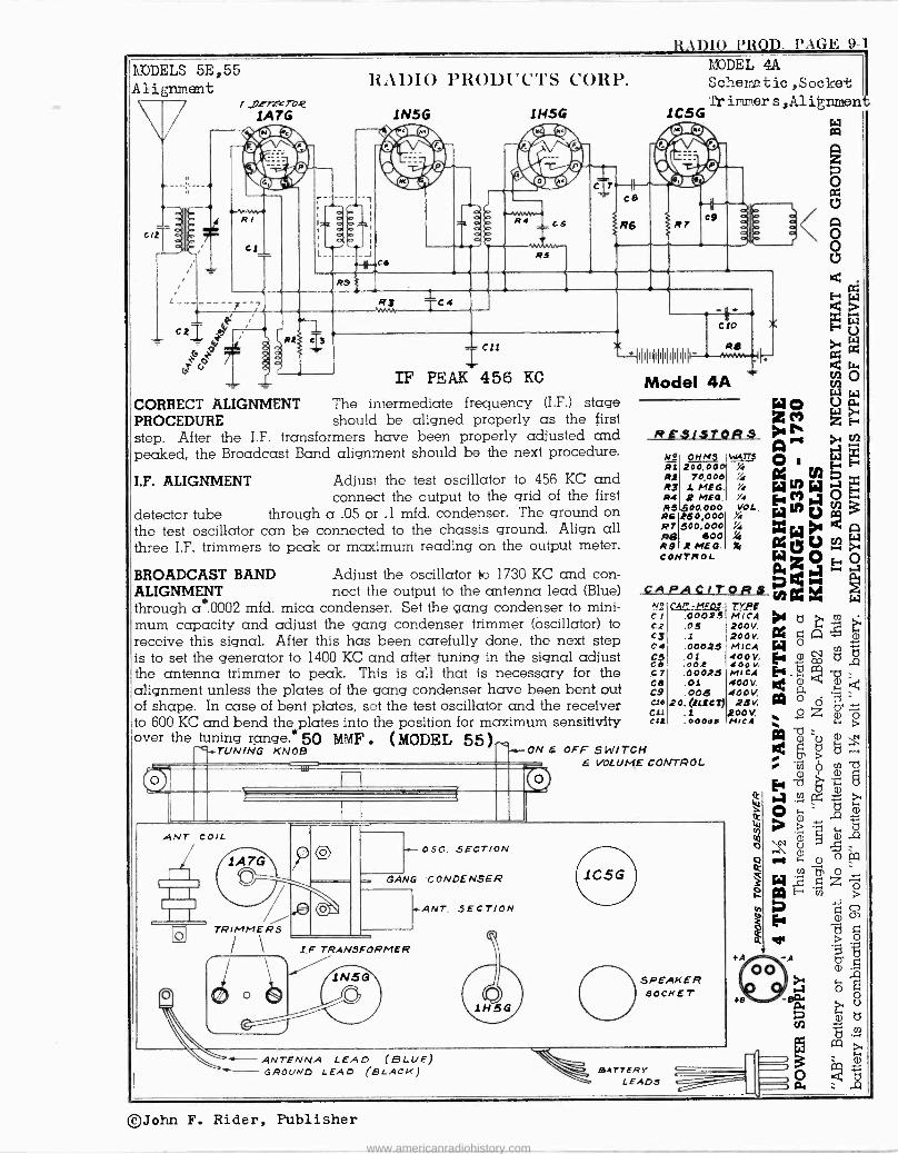
RAI)IO PROD. I'A(i>E: 9-1
r
YODELS 5E,55 Alignment
1 "jJITKTO.Q IA TG
7 ' /
t
L
11A1)IO PRODUCTS CORP.
J
R9
1N5G
Rs Tc4
1 H5G
RS
Cll
IF PEAK 456 KC
CORRECT ALIGNMENT The intermediate frequency (I.F.) stage PROCEDURE should be aligned properly as the first step. After the I.F. transformers have been properly adjusted and peaked, the Broadcast Band alignment should be the next procedure.
I.F. ALIGNMENT Adjust the test oscillator to 456 KC and connect the output to the grid of the first
detector tube through a .05 or .1 mfd. condenser. The ground on the test oscillator can be connected to the chassis ground. Align all three I.F. trimmers to peak or maximum reading on the output meter.
BROADCAST BAND Adjust the oscillator to 1730 KC and con - ALIGNMENT nect the output to the antenna lead (Blue) through a".0002 mfd. mica condenser. Set the gang condenser to mini- mum capacity and adjust the gang condenser trimmer (oscillator) to receive this signal. After this has been carefully done, the next step is to set the generator to 1400 KC and after tuning in the signal adjust the antenna trimmer to peak. This is all that is necessary for the alignment unless the plates of the gang condenser have been bent out of shape. In case of bent plates, set the test oscillator and the receiver to 600 KC and bend the plates into the position for maximum sensitivity over the tuning range.` MF 50 M . (MODEL 551
SWITCH VOLUME CONTROL
MODEL 4A Schematic ,Socket ir immer s,Alignmen
1C5G
clo a
111111#111#11.--44,-
Model 4A WO Z M
RESISTORS Q N° ONMI WATT3 e RS 200,00 % Ri 70,00o Y4 a ry7
R4 2 Mf0. %i WM~ R5.600.000 VOL.
ÌE { ¡?
Ri 160,000 l V 127 600,000 %4 w RI600 4
MEG. X1 aeÓ CONTROL W x
CcAPAC/TORS ÿá1~1 N,s CAp _ MF03. T1'. CI .00025 MICA C2 .05 200V. C3 .1 .200V. C 4 .00025 MICA
cÓ .0012 440000 Vv
C7 .00025 MICA CA .01 400V. C9 .005 400V. C10 20, (lLtC¡j 23V. Cu .1 200V. CJt .00001 MICA
ANT COIL
1 7A G TR/MMER5
/
1--- 056. .SECTION
GANG CONDENSER
+ANT. SECTION
TRANSFORMER
ANTENNA LEAD (BLUE GROVND LEAD (BLACK)
SPEAKER SOCKET
BATTERY LEADS
©John F. Rider, Publisher
www.americanradiohistory.com
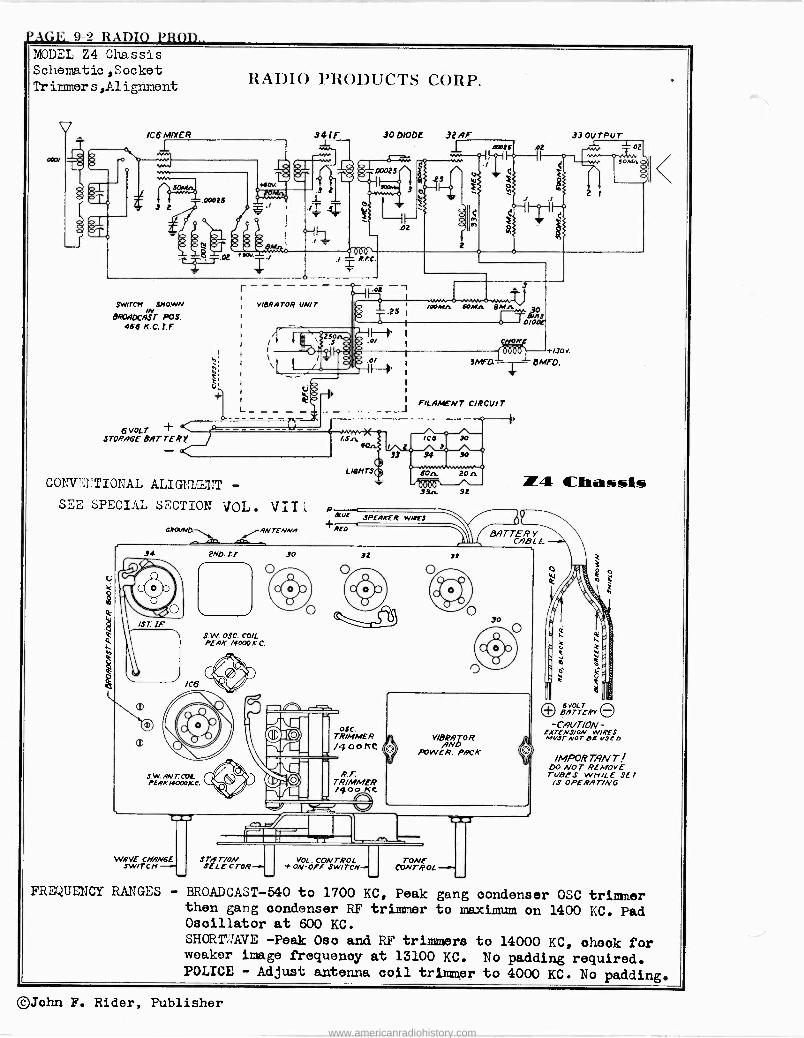
PAGE 9-2 RADIO PROD.. MODEL Z4 Chassis Schematic,Socket Tr immer s ,A1 ignment
/C6 MIXER
1
SWITCH SHOWN
BROADCAST POS. 456 KC 1.F
6VOLT + STORAGE BRT TER Y
RADIO PRODUCTS CORP.
VleRATOR UNIT
CONY'.?'TIONAL ALIGMENT -
SEE SPECIAL SECTION VOL. VII
6ROVNQ rAN rENNA
'04
300100E 32 Ar 33 OUTPUT
rgrl D0029
Y 3
LIGHTS
1ÓL SPEAKER
+RID
y -1-- ̀°°is i / F l h g
i,,,
i
KF t/30V
mea -- aMFo.
FILAMENT cIRCUIT
0-0 ICI 30
/ 9
93 34 !0 o-w.,wwwn,vwN-0
SOn 20n
!9n 92
WIRES
34 2N0. !E 30 32 ds
WRVS CNRNGE SWITCH -+ STAT/oN
SE LE CTOR-.. VOL. CONTROL t ON-OFF SWITCN- CVNTROL -..
J-
-n 2
74 Chassis
BATTERY CABLE
6VOLT + BATTERY O -CAl/FION - rxrrivs/av Awes
N(,3TN07-EV$E0
IMPORTi9NT DO NOT REMOVE TVBES WHILE SET IS OPERAT/NG
FREQUENCY RANGES - BROADCAST -540 to 1700 KC, Peak gang oondenser OSC trimmer then gang condenser RF trimmer to maximum on 1400 KC. Pad Oscillator at 600 KC. SHORTIÍ;AVE -Peak Osc and RF trimmers to 14000 KC, oh©ok for weaker image frequency at 13100 KC. No padding required. POLICE - Adjust antenna coil trimmer to 4000 KC. No padding.
©John F. Rider, Publisher
www.americanradiohistory.com
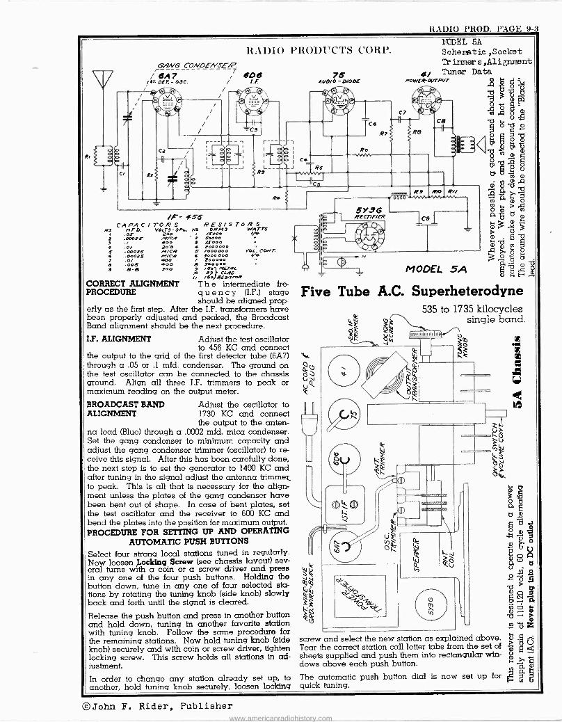
xAI)Io I'ROD. l'AG1'. 9-3
o P
HAllIO PH011I'C'l'S C'OHY.
6A/VG' CONOENSE/P.
i 6A7 ---- /7 606 DET.-OSC. / LF.
,i©+ /
®f'l s,
Ca
-II
R27
/
Ca
r--- /
/l
a
L_ R8
Ai/0/0- /OOE
Ce
Re YdW
R
MEL 5A Scheme tic ,Socket Tr innner s ,Alignment
4/ Tuner Data POWER -OUTPUT Q
tg .61b g UU á`q_m
c7 `a Ia x ó ce v~" ~-IF--' Re
/F= ¢5.6 CAPACITORS RESIS
Nd n O. VOlrs"SPL. N! OHMS / .05 2 .00025 4 .0/ 5 .00025 6 .00025 7 .0/ d .005 3 8-8
/y/CA #00 20-0 M/Cq /!/CA 400 400 900
CORRECT ALIGNMENT PROCEDURE
/5000 2 57.000 ! /5000 4 2000000 S /000000 i 9000 000 7 200000 e Soo 000
TOWS ATTS
vox. CwVT.
9 /60 METAL p 33 CLAD ¿I /60 REarrse2
T h e intermediate fre- q u e n c y (I.F.) stage should be aligned prop-
erly as the first step. After the I.F. transformers have been properly adjusted and peaked, the Broadcast Band alignment should be the next procedure. I.F. ALIGNMENT Adjust the test oscillator
to 456 KC and connect the output to the grid of the first detector tube (6A7) through a .05 or .1 mfd. condenser. The ground on the test oscillator can be connected to the chassis ground. Align all three I.F. trimmers to peak or maximum reading on the output meter.
BROADCAST BAND Adjust the oscillator to ALIGNMENT 1730 KC and connect
the output to the anten- na lead (Blue) through a .0002 mfd. mica condenser. Set the gang condenser to minimum capacity and adjust the gang condenser trimmer (oscillator) to re- ceive this signal. After this has been carefully done, the next step is to set the generator to 1400 KC and after tuning in the signal adjust the antenna trimmer to peak. This is all that is necessary for the align- ment unless the plates of the gang condenser have been bent out of shape. In case of bent plates, set the test oscillator and the receiver to 600 KC and bend the plates into the position for maximum output. PROCEDURE FOR SETTING UP AND OPERATING
AUTOMATIC PUSH BUTTONS
Select four strong local stations tuned in regularly. Now loosen Locking Screw (see chassis layout) sev- eral turns with a coin or a screw driver and press in any one of the four push buttons. Holding the button down, tune in any one of four selected sta- tions by rotating the tuning knob (side knob) slowly back and forth until the signal is cleared.
Release the push button and press in another button and hold down, tuning in another favorite station with tuning knob. Follow the same procedure for the remaining stations. Now hold tuning knob (side knob) securely and with coin or screw driver, tighten locking screw. This screw holds all stations in ad- justment. In order to change any station already set up, to another, hold tuning knob securely, loosen locking
5Y3G RECT/f/ER
R.V 0000
9
Rro R//
MODEL 5A
Five Tube A.C. Superheterodyne 535 to 1735 kilocycles
`ie single band.
Ir lam. 1111111111111
screw and select the new station as explained above. Tear the correct station call letter tabs from the set of sheets supplied and push them into rectangular win- dows above each push button.
The automatic push button dial is now set up for quick tuning.
m >
©John F. Rider, Publisher www.americanradiohistory.com
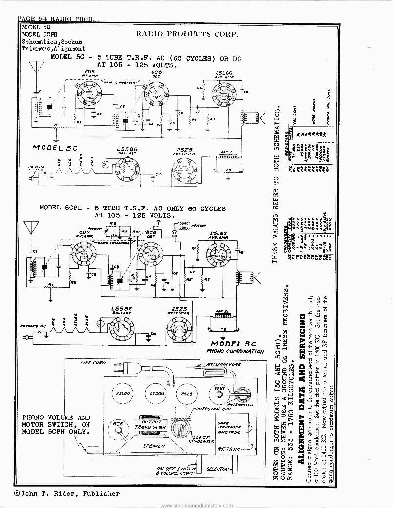
l'AGE 9-4 RADIO PROD. L3DDEL 5C LEDDEL 5CPH Schematics,Socket Trimmer s ,A1 ignment
RADIO PRODUCTS CORP.
MODEL 5C - 5 TUBE T.R.F. AC (60 CYCLES) OR DC AT 105 - 125 VOLTS.
6D6 6C6 25L6G R.F. AMP DET AUD. AMP
MODEL 5C
IO VOLTS AC O.[
e e vi
ú Ç Ñ ñ b e N ^1
''`GA IR CONDE MI
L558G BALLAST
25Z5 RECTIF/ER
C!
MODEL 5CPH - 5 TUBE T.R.F. AC ONLY 60 CYCLES AT 105 - 125 VOLTS.
PrOTOr AtRVP60 6
, T' L 66 !teAM! i R p Agio. AMR
Rl vn Ri
e b r Ñ AO WLT! AC
C.w.iEnJp r/
L558G BALLAST
Ca
25Z5 RECTIgitR
CO
MODEL 5C PHONO COMB/NAT/ON
UNE CORD
PHONO VOLUME AND MOTOR SWITCH, ON MODEL 5CPH ONLY.
,SWTENNA WIRE
25L6G
6C6 imanwe'l DUTPuur
T/PANSFORNER
SPEAKER
O a TAGE COIL
ELECT. CONDENSER
FNNgCO/L
GAwG 3`J CONDENBER / qNr. T]P/M.
/2E754//1.
ON-OFF SWITCH e VOi[ LryE CONT. SSELECTQ
efe2teltte
8000 N00Ó i§g Ni
aeI zltrrteZtrZk
W Cf)
vla{rY4triúl°iÿ{Oi<rG E-1
o A 2 ö á x d
ooc á
c ... c5 á 24ö ö áQmÑó ITI 14 Q ° b 5
OíUi ocñ ö
Z r E+ ö 'x x W ;z E 11 Ó I Ii tr m (j °
ii X d b u V Z
2 e Ú Ó M mb` V NG
O tJ]W Oil d 1~^ WHpCS ro ó
ZÚá G O ö
U t7 g
©John F. Rider, Publisher www.americanradiohistory.com
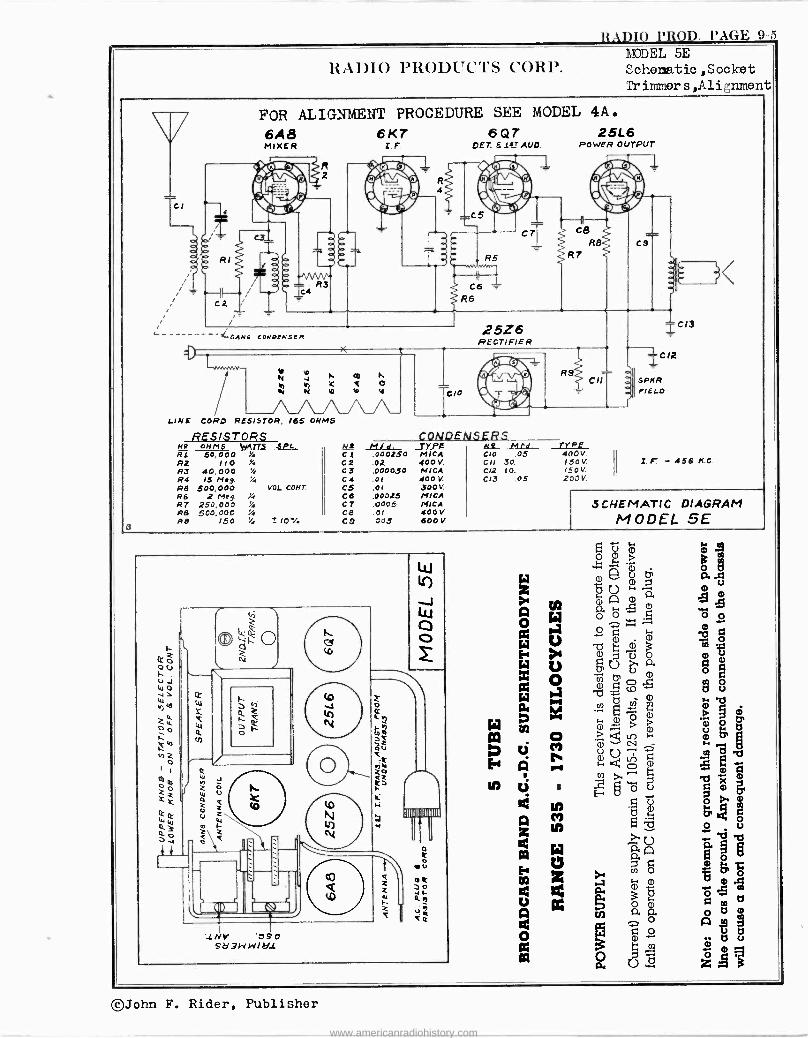
RADIO PROD. PAGE 9-5
RAI)IO PRODUCTS CORP. 1eDDEL 5E Schematic ,Socket Tr immer s ,Alignment
Cl
FOR ALIGNMENT PROCEDURE SEE MODEL 4A. 6A8 6KT 6 Q T 25L6 MIXER I.F. DET. .ter MID. POWER OUTPUT
RI
C2
%
{ GANC CONDENSER 25Z6 RECTIFIER
LINE
-./VWWV-.
CORO RESISTOR,
RESISTORS
Y v N
á
I 01)
Y n v
t\ CI
165 OHMS
RO OHMS WATTS SPL. RI 60,000 Y. C 1 .000250 R2 110 Y. 02 .02 R3 40.000 C3 .000030 R4 15 Meg. Y. C4 .01 PS 500,000 VOL. COHT. CS .01 RS R7
2 Meg. Z 250,000
C6 C 7
.00025
.0005 R8 500,000 C8 .01
3 Re 150 '4 * 10X CO 005
9
CONDENSERS TYPE .3_ 14 td. TYPE MICA C'0 .05 400V. 400V. cif 30. 150V. MICA Cl2 00. 150V. 400V. 013 .05 200V. 500v. MICA MICA 400V 600V.
CIl
=-- C9
-C 1,
SPKR. FIELD
2. F - 456 K.0
SCHEMATIC DIAGRAM MODEL 5E
'1NV 'DSO S213WW/211
gai > m
2 á a .23 ú '~^. m
Q0 m e A
O. ó 5 c o m Qm3
mga
g, CD C P. fi m -2
-.9 (Do ä 8
d m
m b ó M m
F.. m > m °N,b 7 K4l.T) {-' M § atlIi
?, ~ G°:'
m
Ñg°6 omg U , a A a ó
o
Óá Ó i o.m
m
d eáe
á aC n p m
CZ 21 1 a i --
m ts u
01
º d zAá
©John F. Rider, Publisher
www.americanradiohistory.com
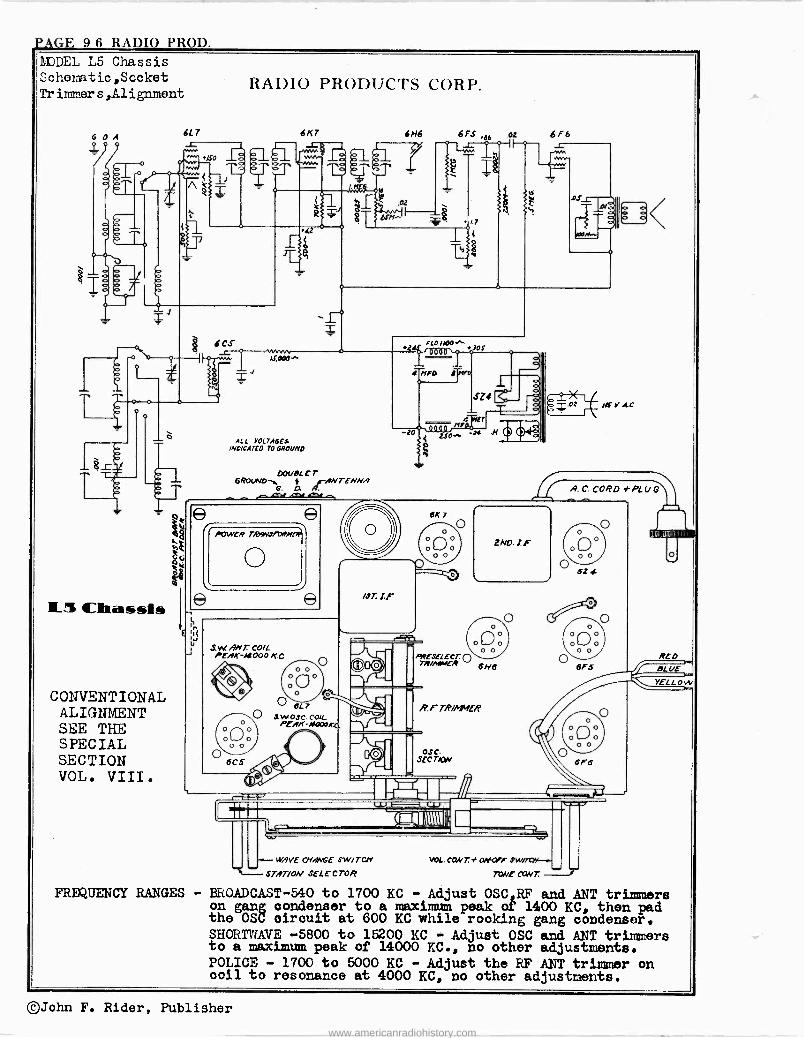
PAGE 9-6 RADIO PROD. !DDEL L5 Chassis Cchonatic,Sccket Tr inmier s,A1 ignorent
G D A
11..3 Chassis
CONVENTIONAL ALIGNMENT SEE THE SPECIAL SECTION VOL. VIII.
6L 7
E
1
RADIO PRODUCTS CORP.
6K7
6 Cs Lf^
ALL VOLTAGES INDICATED TO GROUND
O04./DL C T GROVNDti jr-MITE/Mw
G. D. A. ct .m. m
POWER TRAYJft7WM174
S.W. ANT. COIL . PEAK -1R000 KC
, O 6L7 O SWOSC COIL
o \ PEAK-4000KL'
J
6 N6 6 FS e6 ±1
/.7
FLD//00 .z A +lOS
ó i nFa f?fro
02
sZs - T
nrá ET
LUjSOw -34 .H
/ST. l.f
- - WAVE CNAbVGE SW/TCLi
STAT/0N SELECTOR
OSC. SECT/ON
2NO. I F
6 F6
/dA.0
A. C. CORO fPLV G
WL. CONT. t OAF0ir Sw/7riF...
TOME NNT
SZ 4
-1)
YELLow
FREQUENCY RANGES - BROADCAST -540 to 1700 KC - Adjust OSC RF and ANT trimmers on gang condenser to a maximum peak of 1400 KC, then pad the OSC circuit at 600 KC while rocking gang condenser. SHORTWAVE -5800 to 15200 KC - Adjust OSC and ANT trimmers to a maximum peak of 14000 KC., no other adjustments. POLICE - 1700 to 5000 KC - Adjust the RF ANT trimmer on coil to resonance at 4000 KC, no other adjustments.
©John F. Rider, Publisher
www.americanradiohistory.com
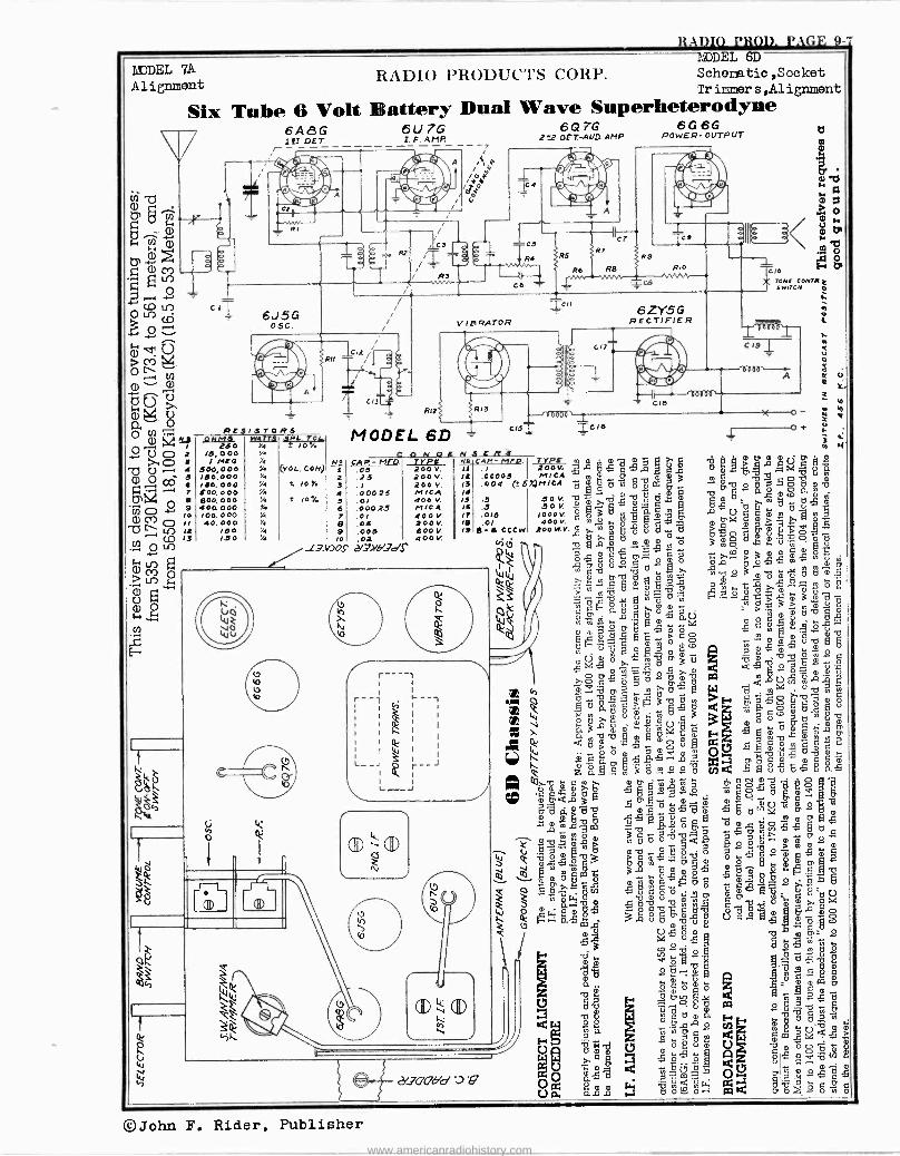
RADIO PROD. PAGE 9-7 /JODEL 6D
DEL 7A RADIO PRODUC'T'S CORP. Schematic ,Socket Alignment Tr inner s,Alignorent
Battery Dual Wave Superheterodyne 6U7G 6QTG 6 G 6 6 I. F. AMP 2 22D£T-AUD AMP POWER- OUTPUT
Six Tube 6 Volt 6AI G 1!T !DST V
i
1 C I 6J5G
OSC.
A
C
C4
-05 R4 .WM
C6 'r-
Cf
R5 >RT
R6 R9 RIO
SCB
RE9/9T0RS
RII
ONMS W4TT5 BPI-. V46 250 %4 a 104
15,000 r / MEO /4
500,000 'A VOL, CON) 150,000 Y 110,000 Yo t 10Y. 500, 000 1/4
600, 000 Y. ! 10 % 400 00o Y 100.000 A 40, 000 Y4
/50 %4
/ó0 %
h o
J. L
C
R1II
MODEL 6D
VIBRATOR
R13
=C I I
6ZY5G RECTIFIER
z úe 10000P-,
TONE CONTI( Z LWITCN p
O
o+
ti b 8
w
CQNOLNSERa b
No CAP,-MFC? TYPE n.1P.- TYPE mmmÿ tly >a2C%pm s 5 200 V. 11 .l 2oov, ga 1] C m u ,a 3.5 ióév. iá :óöá5(:SX,ñici m G d m óroa 3 . m ° RA mv 4 :0.01025 MICA /4 m tl q 01
yt, m 5 400 v. 15 .7 O O V. 1y 1 U
qCq
,¡ m p m . pl
6 :0.0,025 MICA /6 .5 OOV. o- P. g m ,pU tl tl tla m
7 40o V. l7 .015 /ooOV. G O 3 Ñ m a m m m
B .05 ZOO V. IB .O/ 400 v. m O
O
og m bAL m7`. m^^ 9 .005 B00V. /98-i000W Poow.V.mmm A >ry,Vÿ9747 l0..00.105 02 400 V. ? C r t -, m C] 1
Vi( .Cl m mm o3 mp...ú m13.VOSd/Xb'dS
i)t ap .cp m mma O p C O m 0 p p p rj ^
x mtlmU mÑur ? mo3ómú .5romg°ax ..A xdóóro oi*ñm 'vmom óxrc3wñd
C k c c á ó a> -`6"°Z. " á > m m m e
0 ° m ñS áe > °co m
m ów ro a O o m m U , Ñ 1°,ou,2xá.ód,mlo a'matl
.1>4-.5. ° >` ` tl tl .,5,.. -.2,g419 -8.
' o a ú m O ` b m
gp . Ú m m ú G O t7 m CQ 11 U - .Ô db O. a a.t.70-0 d .CN Ó a
r l ~--1 .r, pÓ ñ -O ÿ > ro d Fyyy. , ó úO ó m
Ii \ .00m tl ly mOmO I % m U ' m .; a 7atl ......0 I Ii V tit tl Á
aOm. ^ U. m O t 0 G
m m K ma m,uMâ rJ gm-1-152..,°mA I
a ro ro m tl m m F O
1
á tl m X -, m o u R. I. .!~ d m m C G" U
> mo O(J ,y... m
m c ó. e, PsJ^.? x tl, d é m m G ó'm Q
O O tl a 'O O x ` G t
MM p
2 a F m 3 o N°° tl y gC
9 u o . 2 Wmbd° JÓ1qqmm 0 m 0O«O 32z.0 f
tlamÚ'tl wm.C°O'?Om rJtläum2m 1 1
á
O ó g
x x m o
Mo O 5mlTqX COÁm; S°óoro m>ma°^wmep
mtivE510 E'arcSXmm W dÿJ.. pd g m dmx m14PC ámÿouOtlo
W wOm ÇEib vi roJaÁoQ.Ibb xº ó ° mm8 tó:
UYJR.Ke° mCÚ oJ m C
m úOm° .tlm : e G Ó 12 Jä ii" ádv
ó
Óro º =m_mtlE
tlPglg i o gd al ..9..v.9 --q--.
Q roñdm Fa i mÿa módroZu
"-"'"""r"'"22 Ua [ °CD cmOód« m= £
Óml ` m á2vT7úgóó
0 o oC OO °amo1rÓo áro oo-
Up. á. .ñ 4; l .w a a ctis°Á
h
%
® -®
® ®
21_700dd :DV
©John F. Rider, Publisher www.americanradiohistory.com
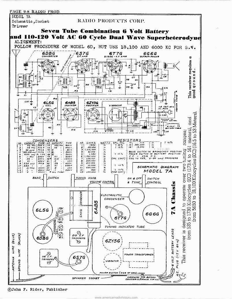
l'AGE 9-8 RADIO PROD. MODEL 7A Schei.tic,Socket RADIO PR011i'C'I'S CORP. Trimmer
Seven Tube Combination 6 Volt Battery and 110-120 Volt AC 60 Cycle Dual Wave Superheterodyne
ALIGNMENT: FOLLOW PROCEDURE OF MODEL 6D,
6066 763TG 6T 7G 6G6G CONVERTER p / Z.F. AMP. 0100E -A. F. AMP. OUT PVT -POWER
A off, , a jT,
/ R
U/ 1/ BC,
ASH
r
CA
R 1 c2
Cl
C25
C3
cs
6L5G / 05C.
62
í -=i..T'¡--' C. I
R3 / \\.
R14
CONDENSERS
6A85 INDICATOR
RIS
CAPAC/TV TYPE N_ CAPACITY TYPE 05 Mid. 200 V. 14 .005 MM. 400 V
2 .05 Mid. 200 V. 15 ,05 400 V.
3 50 +..moi. MICA 16 5 25v. 4 300-600...../ MICA /7 8. 200 v. 5 4000 ¡. M. S 5 . 18 6. 200V.
.1 Mid. 200V 19 .01 600V. 7 .05 200v 20 .015 10 00V. ó .01 . 400V 21 ,S 10V. 9 250 4...f MICA 22 .05 400V.
!O 250 n .. 23 0l 000V, 11 .01 Mid. 400V. 24 .5 10v. 12 .1 - 200V. AS . / .. 200v 13 .S . 200V. i 011. TYPE
BAND SWITCH
R4 i_L
BUT USE 18.100 AND 6000 KC FOR S.W.
i:'w,
N?
2 3 4 5 6 7 a 3 10 11 22 13
r6ZY.5G RECTIFIER
CO'
C/3
o
e JO
C9
VIBRATOR
Cll Re R11
IC/2
20.
9 R/2
C19
OHM5 2500
40,000 /, 000.000
30.000 1,500
/, 000,000 500.000 500,000 200,000
10, 000 500,000
3.25 100.000
C14
R41
C2/ - - - -- - RES/STORS
5,22. TOL.. 14 / 10 ï4 ! IOY. 151 250,000 74
!0 Y> I6 /S. OOo 1/4
ro :
(VOL. CONT)
2 /0 % TONY CONT)
TUNING KNOB
TVOLUME CONTROL
ON S OFF
B TONE
6 VOLT »ATT16V COILS
3 j 24 2 to Y
SAND SWITCH IN BROADCAST POSITION' POWER SWITCH IN BATTERY POSITION. I F. - 456 H. C. O C26 TO C29, 2-20 ,,.f TRIMMERS.
SCHEMATIC DIAGRAM MODEL TA
SWITCH CONTROL
6L5G
¿ES S. F. TRIMMERS
ti SW
oli
v e v
ELECTROLYTIC CONDENSER
zM4 Z. F. TRIMMERS
TUNING INDICATOR TUBE
6G 6G
SPEAKER SOCKET
; `
\ 6ZY5G i \ i i \ r----------
1
POWER¡ TRANSFORMER \ 1
VIBRATOR L_-_ -_ _ - - _T -- I 1
1
POWER SWITCH (S/06 OF CAN)
CAOCKW/SE POR BATTERY COVNTER.CIECITw/JE FOR A.0
©John F. Rider, Publisher
www.americanradiohistory.com
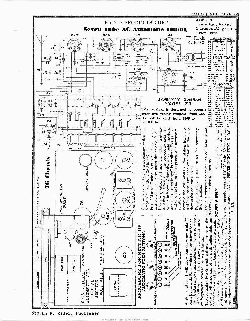
RADI0 PROD. P.1G1. 9-9
CIO
Al5
RADIO PRODUCTS CORP.
Seven Tube AC Automatic Tuning 6A 7 6D6 75 41
N IF PEAK
/. r\ SW. AC.
$ ú
3
z
1MEL 7G Schematic ,Socket Tr ir.nner s,A1 ignat ent Tuner Data
C/, 1I/1 456 KC
cll f 80 1000A SNtP.
114 RS RO RT 1313 R9 RIO RII Ris
fLO. R13 RI4
.RIS
RES f STORd y; /./ M S W1 T1 RL /0, 000 9, R2 /0,000 133 /0, 000 s
350 Yj 2 MEO
/5 /050. Yj .500,000 VOL.CONT 500,000 TONI CON.
I M!0 ) 250,000 500,000 400!5 e /
5,000 50,000 Y,
POWjR TRANI r-2379 AN7 CO/L I-2337 OaC. COIL P-2560 dWITON P-,tj01
CAPAC I TOR At Mf09 7___X/24_
a/5 .005 ssou R/3 Cl .0001 MICA ClC22
Cl .O I 400 V. C4 .05 LOOV. Cl .OS 400V.
SCHEMATIC DIAGRAM Cl :ó° (sÓ`TGR)i óv.
MODEL 7G Cl .0022 400 C9 .00025 MICA
GO .Ol 400 y. 013 /0.0 (ELLCT) 350V This receiver is designed to operate C12 10 (ELICT) 350V.
r :IH over two tuning ranges: from 545 CK 00045 75%600
to 1720 kc and from 5800 to C/S 0015 MICA CI6 .0001 MICA
f 1,f 1,6 It 003 ! 5 MICA
18,10U kc CO 00067"I%MICA 0/9 .00063 ! / % Cl .00065 = I Y.
Z Z 4` - m b si rg a tr m I tr m d) 5 Ú 7--7--7--`J---7- ;It ' a Ñ 2 - ,b Á y a) vl []y
N C7
N a T Lr ea' P °' V1 U º - Fì Ñ °' °'
c ` 0 "-. /-. e'-'s 7. . J e 9 a) >,- : E-1
E a " " , Oy 5 : A ION$ . Ç"., ó m y c:, Éió >m.3 ty á °cDiG.M-i ,x b
3 V aió áÑó ,5v m ó i-. .7,
v 0 0 g ty " E .-5, N° b 3 0 H NN tnlnA m0o 0CJ d ~
1. j O .-,(1)
U O ~ v ul F a)
-u .Q Z'O U Ó Ñ,C. Cr a 0
CP w0 - Z
6 O IQ , r, w _Ç a) Ü óZHd ó 0 d--` o; gÙ
ö 0 t1 0 g aU) ö U
a) z7 Ó p N q 2 d m o
O'--5 m 0 ö C1 á S..-.
o.Q y N N V) .s Ñ CS t7 P. a Oó 0 _>"> °'º ,N a
cr. N-N OU 0-E p O CP -^" O N O g e ,, O Vi to ° a`) 3°'" 2 --3 aa) a) ú)
U d 0.- Z ö O 3 OU 1Y. FW-,
d 30
á
ci ri v ri -Ç ß d G O Q. F, m m m CP G b ÿ y bi 2 3 ú Ñ ap, S 8 CO e g O
a. 0 OOAE Y OóO, .ti. -.0; CPUO
Uz á 3. co
5:~30Ñ 0 Z] ^ ;_ b 2 ó°° áoU,
á éus ,r, o-5 aen oº o , W
W t. a 1 2 a) Vl O tn ..1:12
: a) x om 2ag 51)- 14i
to
]ei C®> h 3°A ö
-1 LLL/7 - c-" L- E- r
U
r r
Oa ` ,Y
O U á O m/ y ö ö m v ai 5 á OÁ I N
O
O ® c, a U d m º ® U1
07 CT
W o ®6 tñ CP q .p
> Ñ -3 U 0°°a
U Á E 0 , p' C_) eT7 1.0. O U N d OÑ.ñ tOti
dááóÑONö-5.ñ
©John F. Rider, Publisher www.americanradiohistory.com
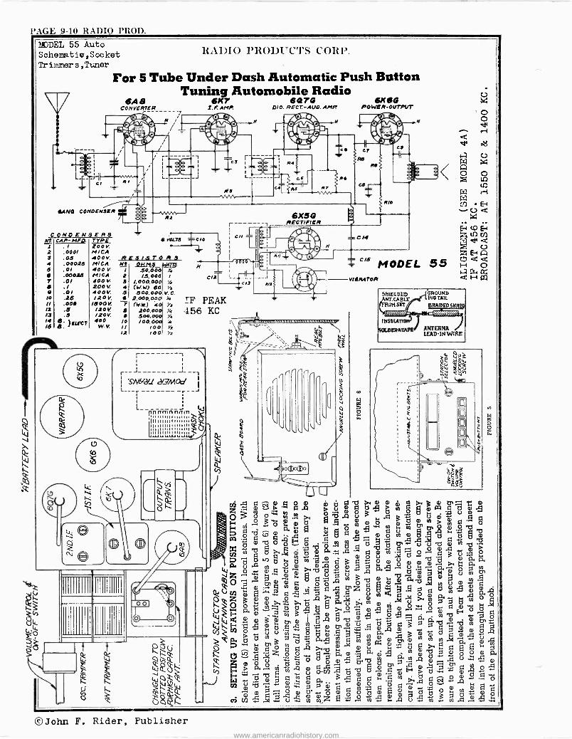
'AGE 9-10 RADIO PROD.
MODEL 55 Auto Sehematiu,Socket Tr immer s , Tuner
RA1DIO PR011i'C'I'S CORP.
For 5 Tube Under Dash Automatic Push Button Tuning Automobile Radio
6K7 6076 I.F. AMP. DIO. RECT-AUD. AMP.
6A a CONVERTER
AN CONDENSER -^nnrm.J R1
.
I
1 Ei
2 . ZOON T1t/0o i
Pi! CAP- TPE VOLTS ,o--
2 .0001 MICA 3 .0.5 400v RE3I3TO R3 I
4 .00025 MICA NI OHMS 5 .01 400 V I 50,000 X. N ' y'
.00025 MICA 2 /3.000 i 7 .01 400V 3 /,000.00 V.
.1 200 V. 4 (YN) 60 i2
.O/ 400V. 3 300.00 V.C. 10 .25 120 V. 6 2,000,00 14
/I .00 /600V. 7 (ww) t0 72 12 .5 120V 200,000 '/, /3 .3 120V. 9 500.000 '/. 14 ó . }ELECT 400 IO /00,000 X /B e. W.V. II /00 l'2
12 10 0 '/2
C ONO EN$ER8
C/2T ~ II cl3
IF PEAK .156 KC
L. Lop
ó
i
r\
i
r-- - - -i i
S/1IV2LI 21.,7MAd
, -- riririm- ññrtm ÚuuIllilllly n unnnnu" nnniZu^ lulul'uW lu Jly
7 -
q J
IIIIIIIIII
o 0 ï
b
J
It
6K66 POWER -OUTPUT
C15 MODEL 55
VIBRATOR
pi
v
4 Á >
ì
N
Zm d ú
I
ó9mdqri
O" Ú Ub dN
O Nÿdpd N°5 3 vgl O
CD ii3 2.
.5 áaoOmÿó
A °o- Ç ö CN.aº^ di
qFÓZJEuFda) º:b d .A öW m d b+ Ñ'Cq y aÑdÓ.Ma
.4 ...0 C a Ó Ó w q Q. 1á a -2.... a
A1
-p á 2
a1 ß .
Q. N .4 ú0ÚO br b y a .-
U wa >wU
O
p O- -[ ¿ t .5 ÿ F d 0 ÿÓ,'N1:1 Oöo .. a o -6.á NoÑ A. NA
Ú ZC'ó2_,Ñ... 5 2 A U . Ñ ÿö d 4 Ñ.1,1 .i Ñ;
© John F. Rider, Publisher www.americanradiohistory.com
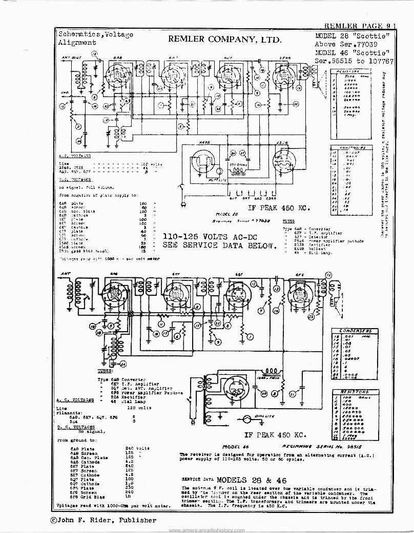
REMLER PAGE 9-1
Schematic s,tioltage Alignment
ANT 8[uF 1, 640
Line 25A6. 2ntt 813, 6\7, 6.7?
1cf Volts E4 D-
22.2s.-317.14,;£5_
:w signal, full volume.
From nogativ_ of p'ato supply to
ems ploLe 100 5Ag szroc:: 60 C.19 oS,i. plate SAC .etheùe 6}, riele 61'7 snree:. 6S', cm.^ne i.T7 plite ....? aCrlie:.
C77 cnt::cde E5AC .1..h6 seinen 25.1t erid btas ecppl
AMT
100 3
100 100
3
40 1 3
93 100 15
,''d lit` 1000 c..:, p.r voli meter
A. C. VOLTAGES
Line Filament.:
6A8, 6X7. 60. 5.64
D. C. VOLTAGES No signal,
From ground to:
6A8 Plate BA8 Screen 648 Osc. Plate 6A8 Cathode 6X7 Plate 6X7 Screen 6K7 Cathode 6.7? Plate 6Q? Cathode 675 Plate 67'8 Screen 6F6 Grid Biqa
REMLER COMPANY, LTD.
24'48
MODEL 28 "Scottie" Above Ser.77039 l'/rDEL 46 "Scottie" Sere98515 to 107767
4 S 6
/e
rood 0.", 000 25000 £ 5000 100.-00 /teO.n 2£e... S 00000 $00000 / roa,.
hr, o,. , rN.7, eJ );!
.0,00'2,'
{I
DO I, . / , O,
0,
/e Io
27 t:
27
t. LY tJ 27
MCOEL 28
.77044 TU1E5
777e LAB - Sonverter ' 67.7 - L.Y. A:.plltter 110-125 VOLTS AC -DC WS - 'etector ' 25A6 Nobler simplifier pentode
SEE SERVICE DATA BELOW. 2 v3 1"".ter 46 - Dill lanp.
ser eel 6Fi
TUBES:
Type 6A8 Converter 6K7 I.F. Amplifier 60 Dei. AVC. Atn,:llfie. 676 Power Amplifier Pentane
" 524 Rectifier " 46 Jlal Lamp
120 volts
676 6 5
240 volt. 125 125 4.2 E40 125 4.2 100 1.8 230 140 18
Vintages reed with 1000 -Ohm per volt meter.
,2422/ Tr
IF PEAK 450 KC. MODEL 46
a a 4 ! 7 e 0 /0 =3
C O/rDE71'SERS ,001 II/Gf.
.0r
.0d .o/
.O1 .03
./
4 4 .000$O
4
REs/J rpQs /00 0A..£ f.t0 400 /.400 /00000 t.s00e0
.10 000 JOo0e0 J00 000 JO0 OOO /,.. 2.1000'
wCc//YN7/Yt 5E,i4t W.. 985/S The receiver Le designed for operation froc an alternating current (A.C.) power supply of 110-125 volta. 50 or 60 cycle..
SERVICE DATA MODELS 28 & 46 The anten..a R.F. coil is located over the variable condenser and is trim- med by ':he 'a, -ter on the rear section of the variable condenser. The oncilletcr rc,7i is mounted under the chacdle and i trimmed by the front trimmer lactic... The I.F. transformers and trimmers are mounted under the ohaul,. The I.F. frequency ta 450 K.C.
©John F. Rider, Publisher www.americanradiohistory.com
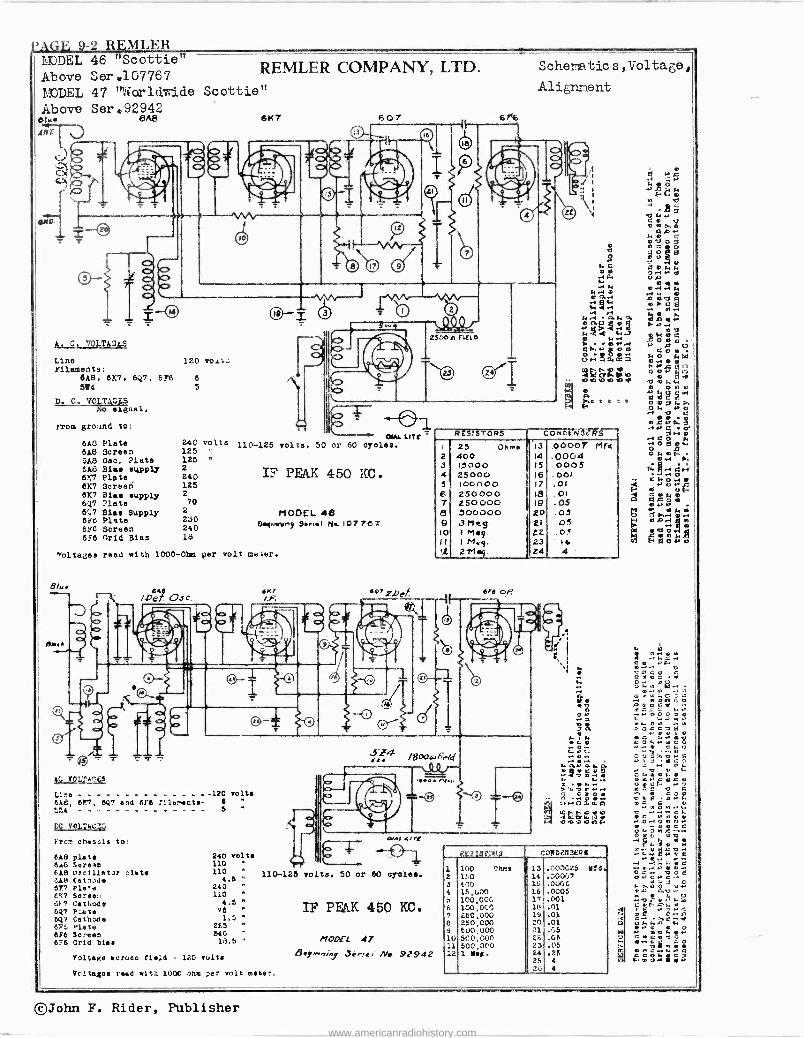
PAGE 9-2 REMLER IuDDEL 46 "Sc ottie tt
Above Sere1G7767 MODEL 47 '1iV'arldvdde
Above Ser.92942 Olw. 6A8
AMFr t r
'
c, a . ̀ /
U ri
A. C. 'JOLTAGr;S
Line Filaments:
648, 6K7, 524
p. C. VCLTAGSS No signel,
rom ground to:
120 oO1l.J
50, 6F6 6
5
648 Plate 6A8 Screen GAS Oac. Plate 6A8 Biaa supply 6K7 Plate 627 3creeri 6K7 Bias supply 2 60.7 ?late 270
6Ç7 Biae Supply 616 Plate 230 6Y6 Screen 240 6F6 Grid Blas 18
240 volts 125 125 "
2 240 125
REMLER COMPANY, LTD. Scherratics,4oltage,
Scottie"
6147 507 , 6r6
-4" OIAi. UTe 110-125 volts, 50 or 60 oyolea.
IF PEAK 450 KC.
MODEL 48 64.imei.e, 5..41 Na 107 767
7olta;les reed with 1000-01mm per volt aw.er.
640 /De>~ Osc.
r2"
Ac TOLMa0t5
Line -120 volts 6A8, 607, 647 and 616 fller,sat.- 6
.,2 - - - - - - - - - - - - - 5 "
DC V01.:&.:3v
I'rcn ohrseis Lo:
6A8 plate 240 volts 6.0 Soreaa 110 618 Oscillet3r .1at 110 6.48 Cetnol. 4.5 617 Pla,.e 240 EX7 torse., 110 61. Cathode 4.5 647 Piet. 76
647 Cathode 1.5 "
6F5 Plate 2E5 6f6 Soreaa 540 -
6?6 Grid Olas 15.5
110-126 volta.
Voltage somas field 120 volts
Voltegoe reed with 1000 onm per volt meter.
O/Al 4/Ye
50 or 60 oralea.
IF PEAK 450 KC.
IfOD£L 47 B ey/nni 3er,e, No 92942
Alignnent
e 1 e:a V t.'.3e O aQ
.q ÿ va.» CO OP.' NO a eue
e a C O
$ e
NC .701.0 MC.
0,44.0 eww
A.40 044.4N wo... .owe e 'w esc a. .4
q1 .4 r, {.
4.-1 O.hO4 wÁwi enbo s.+.. wMth-' ióó[ Cá.Y j o m . pOV Co JNác+.Keá hCoOÑ:,É 04400 .'Gi3d UU 0 0.' t,.h .o o w) .o e T7 0 1. .y
O
e oro
RESISTORS COn0ENefR`r- I 25 Ohm& '13 .00007 M1d 2 400 14 .0004 3 I,3000 IS .0005 4 25000 16 .001 5 IOonOo 17 ,01 6 2SOoo0 18 .01 7 250000 19 .05 e 300000 20 .05 9 3r7cg. 21 .05 10 I M.y. 22 .0.' 11 1 May. 23 14 11 2 -TI .y. e4 4
bra o/?
N.
.- 1
e. e ó w Y
. 4 4 . t . ... O -.
... i + N 0.6. G h P Ñ9at-..
.
i...,. ..ot«", ñ .ói.r.
n
m4uá10.. zsi 4000014
jtC318Y01?8 Co]IDî.NiF:Rf
1 150 Cho' 113 .000C25 ed. 2 110 , 14 .00057 3 cri 16 .0506 4 15,000 ' 16 .0005 á 100,00O3 r
17 .001 6 100,000 18 .01
7 150,000 19 .01 8 250,000 20 .01
9 500,000 ' M. .05
10 5t'0,000 22. .05
11 500,0('0 23 .0e 12 1 Y.R. 14 .26
25 4
0 2". 4
a w.. o
.-Oio041,0 C : ,] omé4n ., O ª
. . t: L 4 V . O
..a o
ó r o a. V v
.O.ne o.o.c-.
: c Y T O O
©John F. Rider, Publisher
www.americanradiohistory.com
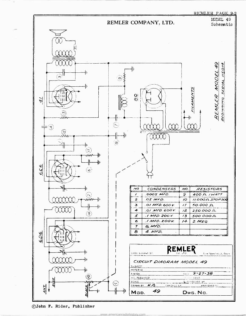
REIII.RR PAGE 9-3
REMLER COMPANY, LTD.
off
( Y m cz)
r-r'Jc5cv
z e
E
,000000 1 +''
IE
aa
J
---{H"
o
.A.A0 kt
MODEL 49 Schematic
! NO. CONDENSERS NO. RES/570,45 / .0005 MFO. 9 400 .f!- / WATT 2 .0S MFO. /0 //.0001-1.57-0#7200 .3 .0/ Miro. 600 V // 5-0.000 SL 4 .0/ MFD. 600 V. /2 250.000 SZ
S . / MFD. 200 V. /3 500. 00011 6 . / /NF -0. 200i! /4 2 /Y/EG 7 B.MFO. 6 4. /1lFD.
2101 BRTANT ST.
R ^EMLER 1 -Tu 5.NE,AN7.5..2,C.In
C/PCU/T O/AGRAM 41040E L. 49 StIi3JE0T MATERIAL
FINISH (.All 9-27-38 >in. 4EquIREo . , .. .t nir SCALE :-..uv, ,SL 11E0 BY
CRANN BY M./3. ,^,HFCrIG Br AVPkOVEn H.
MOD. 49 DWG. No.
©John F. Rider, Publisher
www.americanradiohistory.com
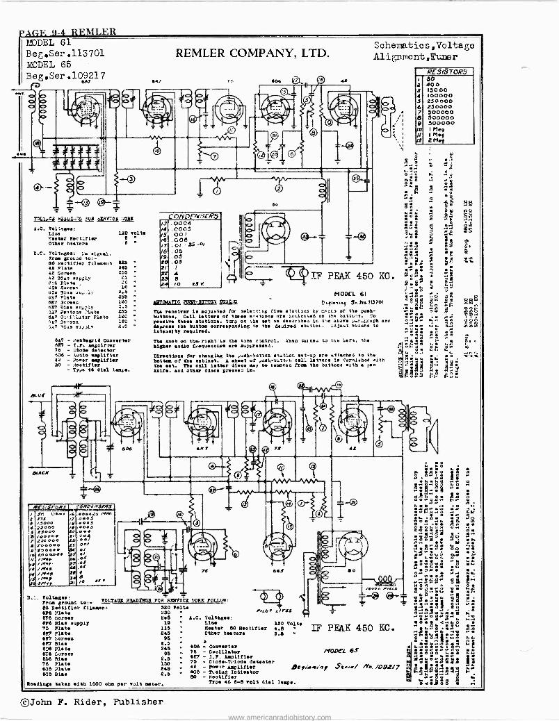
AGE 9-4 REMLER /JODEL 61
Beg.Ser.113701 MODEL 65 Beg.Ser.109217
6A7
= 3
VDL1..C2 h4AI;..s E92 sERrct won
A.C. Vol:agea: Line +'.eeter Rectifier Other hanter
120 volts 6
6
D.C. 7oltage,: signal. From ground ío:- 80 Rectifier filament 225 42 Plate 245 42 Screen 255 42 91ae supply 21
C.:6 Plate .:0
ó 5uree''. IC 41.o 91ns rn;,1. 2.5 oK7 Pinte 255 027 3r.reu 120 627 etas eu,,,.ly 1.5 3.17 2entota ?late 255 617 0.:i'.ìatar Plate 121 '.5,7 Se, -sen 1,2C
:A7 114e el,J)1' 2.5
667 - Pentsgrtd Converter 627 - T.F. Amplifier 76 - JSode detector . Da - Audio amplifier 42 - Toner amplifier 30 - teotltter
- Tp o 48 d181 lane.
SCUP
s,roR /
2 3'3 7 '3noo
25000 C0000 /40000 r 2,44300C
e t4,,0000 p 500000
O 1,Ooqo0. / inl.
Yrl' M.16
/ /r.l /yF.
JNrr
5 a
4 S tr
D.:. Voltage
ar
.003 003 f 02 .n0/
onY 0/ O/
.oS
.oS ,oS
asV
60/
REMLER COMPANY, LTD.
I.- 606 1//J- ._ L l 2 f -
C nNnF/v t Rs 00C4 0005 00! 006 .01 .
25 . 0!
05 05 .05
4 8 I O ZS Y
417f0nLtTIC 268R-BOTTON TOUI:!F
00
Scherlatics,Vol+age
Al ignment,Tuter
TF PEAK 450 KO.
MODEL 61
E.14,,.^1 5. ho.113 701
The receiver is adjusted for eels" rt ng fire ata'iona ty c^ar.s of the push- buttons. Call letters of these e., a cne nTe lccicoted on OF.. button's. To
receive these station., tut,. on ;he set se de.:ribeu jr. the above i..r_Gruph ano
depress the button oorrespondlnb to the desired etutiot. .,4Iuat volura to
intenslty required.
The knob on th.. right io the tone contrcl. ¿hen tut neo to ton left, 51,4
higher audio frequencies are upprssaed.
Directions for ehenglug the push-hutton station set-up are attached to the
bottom of the eabloet. A ah.et of ,,a.¿-bcttnn call lettera is furnished with the set. The call letter dleca may be removed from the buttons with a pen knife. sod other diane presses ln.
76
From growl to:- VOLTA6g P2ADTWG5 FOR eavICE itORT FOLLOW,
60 R.otifiel fllaaene 520 Volts 676 Plate 250 6F8 Screen 6F6 Bias supply 75 plate 627 Plate 627 ,.preen 621 Bias 676 Plate 67.6 Coreen 606 Ries 76 Plat. 605 Plate 615 81..
245 1D
ils 245 95
2.5 245 95
2.5 150 245 2.5
Readings taken with 1000 ohm per volt meter.
PILOT' LYr2s A.C. Voltages:
Line Rester 60 Rectifier Other heaters
6D6 - Converter 76 - Oscillator 6F7 - I.F. Amplifier 75 - L'iode -Triode detector 42 - ponr Amplifier 635 - Tu414/ Indicator 80 - Rectifier
'Me 46 6-8 volt dial lampa.
120 Volta 4.6 s.s
TTiC.+en
, y ns
IF PEAK 450 RC.
t/ODC1 6S
deFr'ww:or ase.:/ /Yo. /092/7
RESISTORS
2 a 4 s 6 7 d 9
JO J1
/2
30 400 15000 100000 250000 250000 500000 500000 500000 I Meg IMy 2M.y
.O O
O P OGwv s q.+Mÿ
:tieoq
Ñ A V 8
ó ó.+M
i2'".1."2 n+á..m.. ~ é
ti ó 44 q a
O O ., 4 q . O O e el. s. c e O i y
ti FAO
l G
o -. ~.:e s e..t~0', éóçóeñ
q N O
O..On . e cce
M or a
tl pp p~O~ e et..
4 E: OO
..:
ti
0 O O H
A o
a O
, d M
ó a%
M C a F+ O . N Ó
©John F. Rider, Publisher
www.americanradiohistory.com
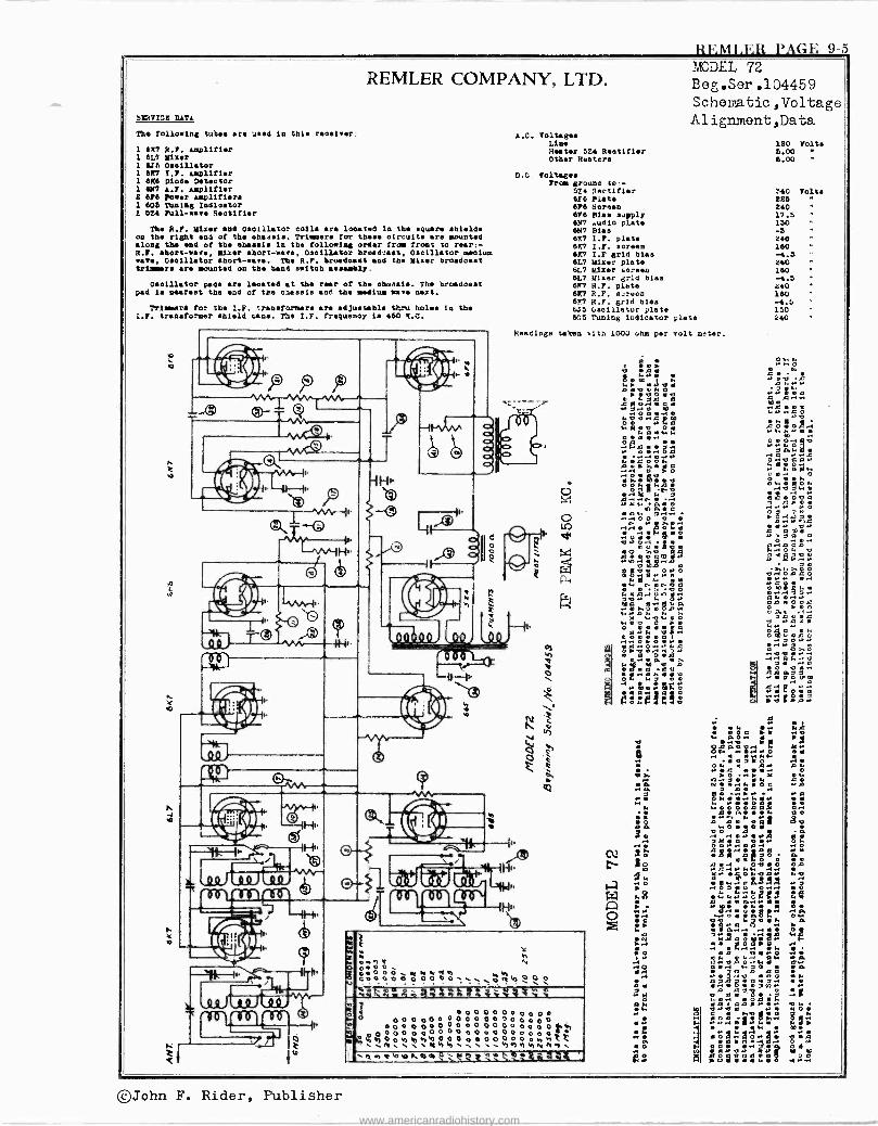
}ZF.M1.E13 PAGE 9-5
REFILER COMPANY, LTD.
SKRPI02 DATA
The following tubes are iced In this reoaiver.
1 6X7 A.P. amplifier 1 6L1 Miler 1 6i6 Oaoillator 1 6157 I.P. amplifier 1 6X6 Diode Detector 1 IN7 .P. amplifier 2 6,6 Power amplifiers 1 602 Tuning Indloator 1 624 Pull -wave R.otlfler
The A.F. Kiser and Oscillator coil, are located in the square shieldn on the right end of the chassie. Trimmer. for theca circuit. are mounted along the end of the sballi. In the following order from front to rear:- R.P. abort -wave, Mixer abort -ware, Oscillator broadcast, Oscillator medium wave, Oscillator abort -ware. The R.F. brodoaat and the Miser broadcast trimmer are mounted on the band nei tob meetly.
Oscillator pads ere Iodated at the rear of the chnaale. The broadcast pad le Oeareet the end of tee chassis and the medium cave next.
Trim -are for the I.F. transformers ere adjustable that holes in the L.P. transformer shield cane. The L.P. frequesoy 1. 460 S.C.
ñ
p
L .o
4 p --(;)1
1 T
b
4
fi N
T
ö
-1f 1b
Ä.C. Voltages Line Heater 5Z4 Rootifier Other Heaters
MODEL 72
Beg.Ser.104459 Schematic ,Voltage Alignment,Data
D.C. foliage. Prom ground to. -
574 Aactifier 6F6 Piste 6P6 toreen 6F6 Alee supply 6N7 ,.udlo plate 6N7 Plea 6X7 I.F. plate e1C7 I.P. screen 6X7 I.F grid bias 6L7 Kiser plate 6L7 Mixer careen 6L7 Mixer grid bias 6X7 H.F. plate 6X7 R.F. screen 6X7 R.P. grid bias tJ5 Oscillator plate 6^,5 Tuning ludicator plate
Readings taken with 1002 clam per volt meter.
Li
f1
t.4
ti
66 r sm1
L 3 V
tf f
n
t
a d
e
Fa in rii HI
1
r a
4
ñ
0 4.,4 teoo O 0 0 0 0 M N N N < 0 0 0 0 0 0 0 0 0 0,
titi«amm%,,4wx,$x% ;Ter e4?..
1 O o 0 0 0 0 0 0 0 0 O 0 00000000000000 O O O D o O o 0 0 0 0 0 0 0 0 o t a O 0 t °bbonbÿ0)oo 0 0o6 00ó0 ó a ya,°,Li
M1 , q41h, . v,., Y1 ÿNn1, qn ti0 eieeth:"4 z
.qne n ó i 0
O M 4 ° O 2 ..
t2.7;271::"0 «
on
tmá~A de-e o
ór 40 00 .aa
0
2A ó
8GA v ¡
.10 F
O . . ,r . ° 4 N e 4 O C .11;
24 :.o3 óó1 `áAeesen
mó 12:« 0
óX aÁ.°.« 2t
e 92¡'t
0 o
t o'
O A
120 Volt. 5.00 6.00
:40 226 240 17.5 130 -S 240 160 -4.5 240 160 -4.5 i40 160 -4.5 150 240
Volta
°, ó _ ° .e
P4i «
qVá.°i.Q. mo .e e 4 t .225.2.4 .
L
`%é c éó : é
ito. t
a.3.0ö ,
O
.00. C ó°«
O.
H< O Ñ n v
000º ms.. o.. .:; a4
4 G
« « O
G m O e o
O e
4 . i c 9 so : A X90.
O- ~ ev «Ñgo: e ro a«
e
'3 :0Bar..+
co 4M«xr..1
s
CO
_:w;SL
O
Ó Ó« p 0 0 4 . A.. ,«.:
MO 02°9
A
r~
w
0400m. ó«o.°. .qé.° Gd. 49. -.
©John F. Rider, Publisher
www.americanradiohistory.com
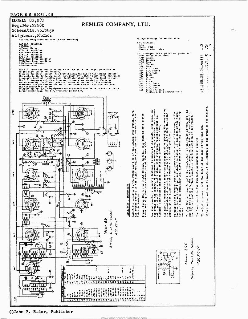
PAGE 9-6 REbILER MODELS 89,89C Beg,Ser,92582 Scheme.tic , ií oltage Alignment,Fhono.
The following tube are need 1n Chia receiver:
607-R.F. Amplifier L7-ASrer
6C5-Cecillctor 6X7 -t.7. Amplifier 6116.Diode Detector 6F6-a.P. Arplifier 6P6 -A.F. Aerlifler SV6G-Beata lower Amplifier 6Y6C.Beem Fewer amplifier bit -Tuning !mitigator 5140 -Rectifier
REMLER COMPANY, LTD.
The 7.F.,liirer and c eolllater rode ere located 1n the large equere Melee en the right end of the chasela. Trimmore for thee, circuit ere mounted alms the end of tee ehaeete,heneath the coil. 1r. the following Order; 0.P. abort.,.., Weer short W974, Occil:ato: broadcast, Oectllatcr medium wave, Oecillstor short wave. From front to rear. The R.F. breadeaet end Mirer broadcast trltmere are mountud or. t'ta range switch arse.-.bly, eeclllator pade ere located It the beet of the variable eondeneer. The pad nearest the end of the chaeele te for the broadcast band end the medium way. le next..
?Ader. for the I.E. transformers are ed)uetable thru holle In the S.F. trar.s-
forrer shield cans. Tho I.F. freeueney te 460 I,C.
=-p
H1
--4F-'{t'
4 i \J
nN
VLSiJ IXX.I º
h
IIT41111
[ r
If21) ,u,
11.
00Ó0 0
Valtsge resdlcge for serrlec wert:
A.C. Feitaee- Line Ranter 1X442 beaters ether tubes
120 Volts 48 '
6
D.1. Voltages: Ino signal) Err ground to;
5i41 ñecttfler Filament 2h0 Volta 6'{65 Plate 224,,
60(2 Screens 260 -
sveC Pies 16.C.' t°1 Plated 60
6FE Pine 1.1
bd7 i.i. Plate 210
60 1,1. Screen 100 "
't7 T.F. 51ee 3 "
607 Flote 260
6L7 ernen 100
61.7 Flet 3 61! Plate 1E0
057 A.F. Plate 260
657 . Screen 10h 607 R.F. Et am 3
EEO Target Voltage 260 Voltage series eoeaksr field 7E
u a L Ó
m M
e M JS l ó m O a t H.0o o.
0 ad r .d O ' G 4.1 4 O ó o M a
0 L w
A 1. o O S 04 O M n O
.0r M J
O go 4 O 0
-.00 A a0
o Vow G A 0 o b 6 Y 0,4
c z F Ñ O. lMí...+ *--5-;
tl V ñó .ÿ SL o.,
r ó t or j, O .y WD aO O é 7 nV m a. mp M ó
w wA a á
O e d Masan o
m1 7,1 D K Cl a Ñ ̂ G A Y. ó CA 000 0., A. o.. M ` O 4 .. O Y
L ry .-
L O L' t0 ,.-% O 1] 0 ..
OP Ç P = a% mg -:a, 1a1 C1 2 O a!
M'`1 p L M P, .00 v A o
o O ea ~ C B O O ^ G
ço
- . .+ a A..' a ed `'ó mb otiasa ,:n m c
ói 1,.... ce... 0.....4 : é `. ... rv sar44UO Oa40 o -o o .óOUO flM 0 M
-.. r 4+,1, C mdO O O. .5 CO
MO Ot F M O w - F C-+ ..m .a ea na 5m OOa 0q a
n 2g.:, L bQ A.: f.~
aM 1 A a FFO Aa«' e-. m
0A ri te MÉt ..Ab Oa w m0 N2Me.00 s.+ CO Ì.7
W.. .Ó C .. M F:O n P. I. 60o Cw00.4 m mo r o
O O r.4 o ro a n :d -- 0.00 AO b] O .. ?u m Hi 0 A Ì. .a a 0, WO ñ
tri O ra O a T. . O O a 1) 0 0 U O w)
OM V r' A H F r U C e. l ' 0-00 O ro
a0
00 .-1m0 O.0 010 O .. .O.r m.o ^n
ó ó ..G mC.. V i M1-1.~+ ~ eea
O[O.o 0 0 1. A~Ñ .0 i m
r. tOJ 4
nµi c C t. Groi,C : M 2ti 4.
C m O M A. Y A 4 w more mM ,:
Oct a: b. óm {7 - OV ^ ~ el M a M[:
p 0
N0 .4 t0. A
Si F á.0 i i.
w A O .+o 061.+M.UiU ..o H
P,4.e Ó P.
P O n 00.4 n U+" 0 1.
NíAa o.a; one, ...0. 4tO FÑiO. i-O.ti
} > >e ' c o s .. , ó ^
ów .n ó8aSoooaäas,_aöys...,;;á;h U
ñ .f R$ ñ . e\. . w\ w b`1 M 'f ÿ ti Ñ i< 7 ; O t ¢
s o 0 o a¿ ó' ó ú ' ó ó oº Oo, ó ó ó c ó ó w
ú .3,32,%,N2.:2.... -..,t ó ó C e wrypheñ+iNhy2i2. yMMh-htiyti,. n
-N^awtt Oe.yR ? CO ze es01.wO.,mw,:,~ÿ w.wi ..aiY Mn1,l'f
o ,1
©John F. Rider, Publisher
www.americanradiohistory.com