© copyright statement - fuel performance catalyst
TRANSCRIPT
© Copyright Statement All rights reserved. All material in this document is, unless otherwise stated, the property of FPC International, Inc. Copyright and other intellectual property laws protect these materials. Reproduction or retransmission of the materials, in whole or in part, in any manner, without the prior written consent of the copyright holder, is a violation of copyright law.
FPC FUEL CATALYST LOADBOX TESTOF NORMALLY ASPIRATED LOCOMOTIVE ENGINESUSING THE CARBON MASS BALANCE METHOD FOR
DETERMINING FUEL CONSUMPTIONBY
WISCONSIN CENTRAL TRANSPORTATION
Report preparedby
UHI Corporation, Provo, UtahLakeside Oil Company, Milwaukee, WI
FPC Great Lakes, Manitowoc, WI
August 19, 1996
CONTENTS
2.1.7 The Effects of Operating Conditions on Combustion
Page
(ii)
(iii)
4
5
5
5
5
6
6
6
7
7
7
Contents
Abstract
1.0 INTRODUCTION
2.0 BACKGROUND
2.1 Diesel Engine Combustion Theory
2.1.1 The Combustion Process
2.1.2 The Delay Period
2.1.3 The Period of Rapid Combustion
2.1.4 The Third Phase of Combustion
2.1.5 The Final Phase of Combustion
2.1.6 The Ideal Combustion Process
2.2 Possible Mode of Action of the FPC CombustionCatalyst
2.2.1 Flame Propagation 7
3.0 TESTING 8
3.1 The AAR RP-503 8
3.2 The WAIT Study 9
3.2.1 Conclusions of the WAIT Study 12
3.3 Specific Fuel Consumption Trials of Diesel Generators 12
3.3.1 Diesel Generator Test Method 12
3.3.2 Conclusions for the Specific Fuel Consumption
Generator Trials 133.4 The Wisconsin Central Multiple Engine Loadbox Test 13
3.4.1 Test Methodology 143.4.2 Correction for Fuel Density 143.4.3 Correction for Barometric Pressure 153.4.4 Discussion of Smoke Density 153.4.5 Discussion of Anomalies
4.0 CONCLUSIONS 16
5.0 RECOMMENDATIONS 17
6.0 REFERENCES 18
7.0 APPENDIX 1 The WAIT Study 19
8.0 APPENDIX 2 Varimax Variable Compression Test 20& Research Rig
9.0 APPENDIX 3 Computer Printouts of Engine Data 21
10.0 APPENDIX 4 Carbon Mass Balance Formulae 2211.0 APPENDIX 5 Dr. G. J. Germane's Resume' 23
12.0 APPENDIX 6 Barometric Pressure Readings
13.0 APPENDIX 7 Fuel Consumption Comparisons 25Smoke Spot Number Comparisons
ii
Abstract
This report documents the effect of Fuel Performance Catalyst (FPC), a combustion catalyst, uponengine efficiency, exhaust smoke, exhaust sparking and carbon buildup when used in normallyaspirated (roots blown), EMD engines. The subject of this paper is a loadbox test conducted byWisconsin Central Transportation on four locomotive engines (2 x SW 1500, and 2 x GP35) with andwithout FPC. Test engines were run under full load at throttle settings 2, 4, 6, and 8. The resultswere as follows:
(1) Fuel consumption was reduced 4 % to 8%, depending upon throttle setting. The switcher testfleet averaged a 7.53 % reduction in fuel consumed with FPC treatment. The GP35 test fleet averageda 5.55% reduction in fuel consumption.
(2) Exhaust smoke density was reduced 6% to 50%. Smoke density reductions averaged24.8% in the switcher test fleet, and 17.8% in the GP35 test fleet. Exhaust gases were visiblycleaner.
(3) Exhaust "sparking" and carbon buildup in spark arresters were greatly reduced, evidence ofcleaner, more complete combustion, and even greater cost savings through reduced maintenance andincreased engine life. Further cost reductions and improved public image through reduced tracks idefires and visible pollution reduction are another benefit of FPC fuel treatment.
These benefits are supported by dozens of laboratory tests, including the Southwest ResearchInstitute's (SwRI) test using the Association of American Railroads, Recommended Practice 503 (RP-503). Test results reviewed in this report are those from SwRI, the Western Australia Institute ofTechnology (WAIT) and several genset operations where specific fuel consumption tests have beenpossible. These studies verify FPC is most effective when used in engines operating in fieldapplications under transient conditions.
The findings of the Wisconsin Central test of the FPC catalyst agree with the above studies, and withothers conducted by several railroads. The Wisconsin Central test is the fourth field study withlocomotive engines comparing engine performance and emissions from several identical engines withand without FPC catalyst treated fuel.
iii
1.0 INTRODUCTION
During the period of May 1992 to June 1992 an extensive test program was successfully completed atSouthwest Research Institute (SwRI), San Antonio, Texas. The test program determined the effect ofa fuel combustion catalyst (designated FPC-1®)upon fuel properties, engine wear, deposit formation,and engine performance. The test procedure conducted by SwRI was the Recommended Practice 503(RP-503), a procedure authored and recognized by the Association of American Railroads (AAR).
The final phase of the RP-503 is a engine performance test on a full-sized, twelve cylinder, 645E3BEMD locomotive engine. The test engine was operated under steady-state conditions and at maximumhorsepower output per unit of fuel consumed (optimum brake specific fuel consumption). Brakespecific fuel consumption (bsfc) was reduced 1.74% over baseline diesel fuel when consuming dieselfuel treated with FPC catalyst under these engine conditions [ Ref 1 ].
Combustion experts concluded that the 1.74% improvement in bsfc (improved fuel economy) wouldtranslate to improvements several times greater in engines operated in the field due to thetransient nature of field operating conditions [ Ref 6 ].
Other independent laboratory studies, such as the Varimax engine test conducted by the WesternAustralia Institute of Technology (WAIT) confirm this conclusion. Tests at varying engine speeds,loads, and injection timing agree with expert opinion. The WAIT test revealed FPC catalyst treatedfuel produced greater improvements in bsfc as engine operating conditions deviated from best powerand bsfc. Although the WAIT engine was tested under steady-state conditions at each rpm, load, andinjection timing, the test conditions more closely reproduced field conditions than do steady-stateengine testing [ Ref 2 ].
Further, test data from over a dozen specific fuel consumption (sfc) trials of diesel power generatingequipment, agree with the WAIT study. Diesel generators, although not subjected to as severe ofconditions as engines in mobile equipment, can be tested in the field at specific loads and rpm. It isalso reasonably simple to accurately measure fuel consumption and power output in kilowatts [ Ref 3].
The results of the RP-503, WAIT, and stationary genset tests have verified the addition of FPCcatalyst to diesel fuel, creates significant fuel savings in high horsepower, medium-speed dieselengines. These also verify greater benefit with catalyst treatment of engines used in more transientapplications.
The principle subject of this paper is a loadbox test conducted by Wisconsin Central Transportation(WCRR) undertook to determine the effect of FPC catalyst (FPC-2 1110,000 ratio was used) uponfuel economy and emissions in a fleet of four EMD powered locomotives (2 x SW1500 and 2 xGP35). Several throttle notch positions were selected for the test, and the engine fully loaded in anattempt to create engine conditions most like those experienced under actual operation. The resultsagree with those obtained in previous field tests, the SwRI study, and support expert opinion aboutFPC catalyst.
4
2.0 BACKGROUND2.1 Diesel Combustion Theory
2.1.1 The Combustion Process
The four-cycle compression-ignition engine employs the conventional four strokes per power cycle ofintake, compression, power, and exhaust. The two-cycle engine shortens the number of strokes of thepiston by combining the power and exhaust stroke, and the intake and compression stroke.
The air inducted on the intake is either normally aspirated or forced in by the supercharger, while thefuel is injected into the cylinder near the end of the compression stroke. In most diesel engines, thecombustion chamber temperature at the end of the compression stroke is approximately 600 degrees C(Celsius). This temperature is dependent upon the compression ratio and the initial air temperature.
Near the end of the compression stroke, fuel is sprayed into the combustion chamber at pressuresvarying from about 1,200 psi to over 30,000 psi. The injection pressure is governed by engine speedand size, and by the type of combustion chamber and injection system used [ Ref 4 ].
With the commencement of fuel injection, the combustion process is initiated. Each charge ofinjected fuel experiences several phases in the reaction as follows:
(1) An ignition delay period
(2) A period of rapid combustion
(3) A period of combustion where the remainder of the fuel charge is burned as it isinjected.
(4) An after burning period in which the unburned fuel may find oxygen and burn, oftentimes referred to as the tail of combustion.
In following the combustion process and the path of fuel particles, it should be understood that afterignition has occurred, many of these steps will be proceeding at the same time, since the mixture ishomogeneous [ Ref 5 ].
2.1.2 The Delay Period
The delay consists of a physical and a chemical delay. The physical delay is required to atomize thefuel, mix it with air, vaporize it, and produce a mixture of fuel vapor and air.
During the chemical delay, prefiame oxidation reactions occur in localized regions with temperatureincreases of 540 to 1100 degrees C. These prefiame reactions are initiated by the catalytic effect ofwall surfaces, high temperatures, and miscellaneous particles that form the active chain carriers priorto rapid combustion. As the local temperature increases, the fuel vapors begin to crack at anaccelerating rate and produce material with high percentages of carbon which become heated toincandescence as local ignition is initiated.
5
Inflammation develops quickly either by rapid and complete oxidation of the fuel and air or theoxidation of the intermediate products of the chain reactions of the fuel [ Ref 5].
2.1.3 The Period of Rapid Combustion
Combustion during the period of rapid combustion is due chiefly to the burning of fuel that has hadtime to vaporize and mix with air during the delay period. The rate and extent of the burning duringthis period are closely associated with the length of the delay period and its relation to the injectionprocess.
The relation of the delay on both the rate and extent of pressure rise during this phase, is especiallystrong when the delay period is shorter than the injection period [ Ref 5 ].
2.1.4 The Third Phase of Combustion
The third phase is the period from maximum pressure to the point where combustion is measurablycomplete.
When the delay period is longer than the injection period, the third period of combustion will involveonly the fuel which has not found the necessary oxygen during the period of rapid combustion. Inthis case, the combustion rate is limited only by the mixing process. However, even when all the fuelis injected before the end of the delay period, poor injection characteristics can extend the third periodwell into the power or expansion stroke, causing low output and poor efficiency.
When injection timing is such that the second phase of combustion is complete before the end ofinjection, some portion of the fuel is injected during the third phase, and the rate of burning will beinfluenced by the rate of injection, as well as by the mixing rate [ Ref 4 ].
2.1.5 The Final Phase of Combustion
The final phase or tail of combustion continues after the third phase at a diminishing rate as anyremaining fuel and oxygen are each consumed. This last stage, and the previous one arecharacterized by diffusion combustion, with production and combustion of carbon particles and a highrate of heat transfer radiation. This phase occurs well down the expansion stroke, when much of theoxygen has been consumed and combustion temperatures are lower. It is at this stage that smoke andcarbon monoxide emissions are formed [ Ref 4 ].
2.1.6 The Ideal Combustion Process
The thermal efficiency of an internal combustion engine, whether spark or compression-ignition, willincrease if the combustion time is reduced. Mean effective pressure will be higher, and thus morework can be extracted from the same energy input from combustion. The rate of pressure rise duringthe period of rapid combustion corresponding to constant volume combustion, should be as rapid aspossible without exceeding a certain value.
The fuel remaining after the period of rapid pressure rise should be burned at a rate such as to holdthe cylinder pressure constant, at the maximum allowable value, until all the fuel is burned.
6
2.1.7 The Effects of Operating Conditions on Combustion
With respect to the diesel engine, the combustion rate as well as the rate and extent of pressure rise,depends greatly on the design of the combustion chamber and the injection system. However,injection timing, engine speed, turbulence, compression ratio, fuel-air ratio, spray characteristics, fuelcetane number, and inlet temperature and pressure all effect the combustion rate or flame speed.
A detailed discussion of the impact of these operating conditions on combustion is found in Reference4.
2.2 Possible Mode of Action of the FPC Combustion Catalyst
2.2.1 Flame Propagation
As previously mentioned, the speed with which the combustion process takes place influences theefficiency of the heat released by the chemical reaction. With greater rates of heat release, it is oftenpossible to transfer more of the heat into useful energy.
The combustion catalyst manufactured by UHI Corporation and distributed by FPC Technology, Inc.,is a burn rate modifier dissolved in a solvent carrier. When the combustion catalyst is introduced intoa liquid hydrocarbon fuel and combustion begins, the catalyst appears to form propagating centers thatinitiate multiple flame fronts. These propagating centers in effect increase the thermal conductivity ofthe fuel-air mixture, since heat transmission through it is more rapid with their presence.
Once combustion has been initiated, it is likely that the iron salt thermally decomposes into ions. Theiron ions will promote the formation of free hydrocarbon radicals for the combustion process, due totheir electron configuration. Other portions of the molecular aggregate, also form ions providingadditional free radicals for the combustion process, as well as, providing kinetic energy to local fuelmolecules in excess of their normal activation energy.
If the activation energy of the fuel-air mixture can be decreased, the reaction rate will tend toincrease. Similarly, if the concentration of reacting substances and the collision frequency of themolecules can be increased, the reaction rate will increase.
Therefore, the thermal efficiency of an internal combustion engine will increase, if the combustiontime is decreased. A shorter combustion time implies greater flame speed. Thus, if a proposedcombustion catalyst is to be of any benefit in terms of improving horsepower output and/or decreasingfuel consumption, it must increase flame speed or assist in maintaining flame speed through the thirdand last phases of combustion.
The completeness of combustion may also be positively affected. If combustion is more complete,more energy is liberated while the flame front traverses through the fuel-air mixture. Controlledengine tests with FPC catalyst reveal not onJy increased horsepower output and reduced fuelconsumption, but typically reduced unwanted gas and particulate exhaust emissions.
Further, when engine operating conditions are such that flame speed is slowed, creating greatercombustion time losses, the FPC fuel catalyst will recover a greater percentage of those losses. Thus,
7
the catalyst will have a more profound effect upon engines operating in the field, than enginesoperating in the laboratory.
3.0 TESTING
3.1 The AAR RP-503
In early 1992, UHI Corporation was encouraged by several major railroads to conduct tests with FPCcatalyst (FPC-1® 115000ratio was used) at Southwest Research Institute (SwRI) using the Associationof American Railroads (AAR), the Recommended Practice 503 (RP-503).
The RP-503 constitutes two screening tests and an engine performance trial. The screening testsinclude the determination of an additives effect upon fuel properties, engine deposit formation, andengine wear. The final procedure is an engine performance trial conducted in a 12 cylinder, 645E3BEMD locomotive engine.
These studies concluded that FPC catalyst had no measurable effect on the chemical properties of thefuel, nor did it detrimentally impact engine life and deposit formation. The EMD engine also showeda 1.74% improvement in bsfc at a 95% confidence level with FPC catalyst treated fuel [Ref 1 ].
This is a remarkable improvement given the existing efficiency of this particular engine (37.2 % brakethermal efficiency and 0.354 bsfc) and the fact the test engine was run under optimum engineconditions (steady-state, notch 8, 900 rpm). Under these conditions, injection timing is the bestmatch for maximum horsepower and lowest bsfc, and therefore, combustion time losses areminimized. Further, the engine was in like-new condition, and smoke emissions were nil.
These engine test conditions are specified by the AAR since a typical locomotive engine operates 50to 60% of the time at notch 8. However, the steady-state, maximum horsepower operating conditionstend to minimize the potential for horsepower and bsfc gains [ Ref 6 ].
3.2 The WAIT Study
Studies by the Western Australian Institute of Technology (WAIT) have collected considerable datademonstrating the effect of the FPC catalyst on engine efficiency while operating at varying rpm,load, and injection timing. The test was designed to best illustrate the effects of the combustioncatalyst. In addition, the test conditions were meant to relate the effect of the catalyst, to the mostcommonly altered settings and conditions encountered, during normal field operation of a heavy-dutycompression-ignition engine.
The objective of the WAIT study was to analyze the effect of the combustion catalyst on engine brakepower and brake specific fuel consumption. In order to considerably broaden the scope of the testprogram in terms of relevance to simulating true commercial and industrial operating conditions, thefollowing parameters were introduced to be varied accordingly:
(1) Engine speed
(2) Throttle setting
8
(3) Fuel Injection Timing
(4) The concentration of the catalyst in the diesel fuel
The manner in which each parameter was altered is described below:
* Engine speed in all tests was varied from 1600 rpm to 2400 rpm by increments of 200 rpm.
* Throttle settings were altered alternatively from half throttle to full throttle in the majority of thetests.
* Fuel injection timing was varied from 18 degrees before top dead center (BTDC) to 42 degreesBTDC, in increments of 6 degrees, in specific tests. The standard injection timing was 30 degreesBTDC.
* The concentration of the catalyst in the diesel fuel was altered by employing three different mixingratios.
* Engine base parameters which were held constant during the entire test program were compressionratio, and valve timing. The compression ratio was 18:1. Valve timing was set to the enginemanufacturers' recommended values for diesel as is listed below:
INTAKE VALVE OPENS 10.8 degrees BTDC
CLOSES 42.6 degrees ABDC
EXHAUST VALVE OPENS 7.6 degrees BBDC
CLOSES 21.6 degrees ATDC
VALVE OVERLAP = 32.4 degrees
Baseline tests using untreated fuel were conducted at the beginning, middle, and end of the testprogram to check whether any drift in the engine performance had occurred, due to the introductionof the combustion catalyst [ Ref 2 ].
For all tests conducted in the Varimax engine test program at WAIT, full details of which parameterswere altered in each particular test are given on each page of tabulated results in APPENDIX 1.0(The WAIT Study).
3.2.1 Conclusions for the WAIT Study
The Varimax engine test program has shown quite convincingly the benefits of FPC catalyst in dieselfuel. At the highest catalyst concentration in the fuel, bsfc improvements ranged from 1.71% to4.99%, with an average improvement of4.19% at half throttle and low torque, 3.04% at full throttleand high torque, and 2.61 % at full throttle and 2400 rpm while varying injection timing from 42degrees BTDC to 18 degrees BTDC.
9
3.3 SPECIFIC FUEL CONSUMPTION TRIALS OF DIESEL GENERA TORS
For over ten years, the FPC combustion catalyst has been subjected to field trials by dozens ofprofessional engineers representing the interest of the company by whom they are employed. Thesetrials have involved all types of engines under virtually every operating condition imaginable.Generally speaking, these field trials reveal FPC catalyst has greater effect upon engines in mobileequipment than stationary equipment, and high speed engines than medium or low speed engines.These data support the laboratory data mentioned above, and the theory that the catalyst affects flamespeed [Ref 3 ].
For the purposes of this paper, although still much like laboratory engines, only the details of specificfuel consumption studies in diesel generators (gensets) will be given. These tend to be the bestcontrolled field tests available, and the only tests where the measurement of specific fuel consumption(kilowattslliter) are practical.
3.3.1 Diesel Generator Test Method
Typically, the genset is operated under steady-state conditions and fixed load on baseline fuel whilethe rate of fuel consumption (liters or gallons) and the power output (kilowatts) are measured. Once areliable database has been accumulated, the fuel for the gensets is treated with FPC catalyst and thegensets operated as normal from three to five hundred hours. This is known as the preconditioningperiod, and is allowed due to the considerable data that indicates the catalyst first functions to removeexisting engine carbon residue, therefore delaying the achievement of maximum catalyst effectiveness.
Once the engine preconditioning period is completed, the gensets are again tested. The procedure,engine speed, and load are reproduced, with the only deviation being the baseline fuel is now treatedwith FPC catalyst.
All parameters affecting engine efficiency (intake air temperature, intake pressure, fuel density) aremeasured and corrections to power output and fuel consumption made.
Some fourteen stationary diesel gensets have been tested in this manner. Engines tested include thefollowing makes:
(1) Blackstone EL8
(2) Caterpillar 3412
(3) Cummins VTA28G3
(4) Detroit 12V and 16V149
(5) EMD L20/645F4B
(6) Mirrlee K8 Major
10
(7) Ruston
(8) English Electric
3.3.2 Conclusions for the Specific Fuel Consumption Trials of the DieselGenerators
Improvements in specific fuel consumption range from 3.1 to 4.8 %, with an average for the entiresample of 3.7 % . Reductions in smoke density average 23 % for all gensets tested [ Ref 3 ].
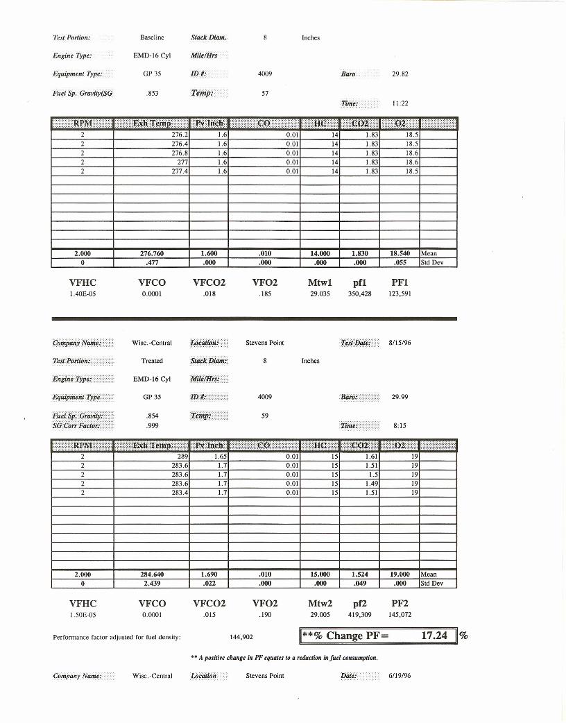
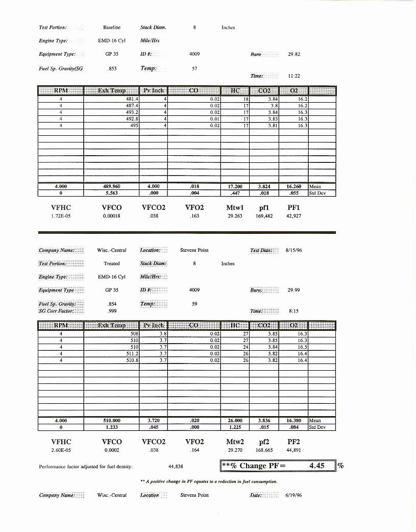
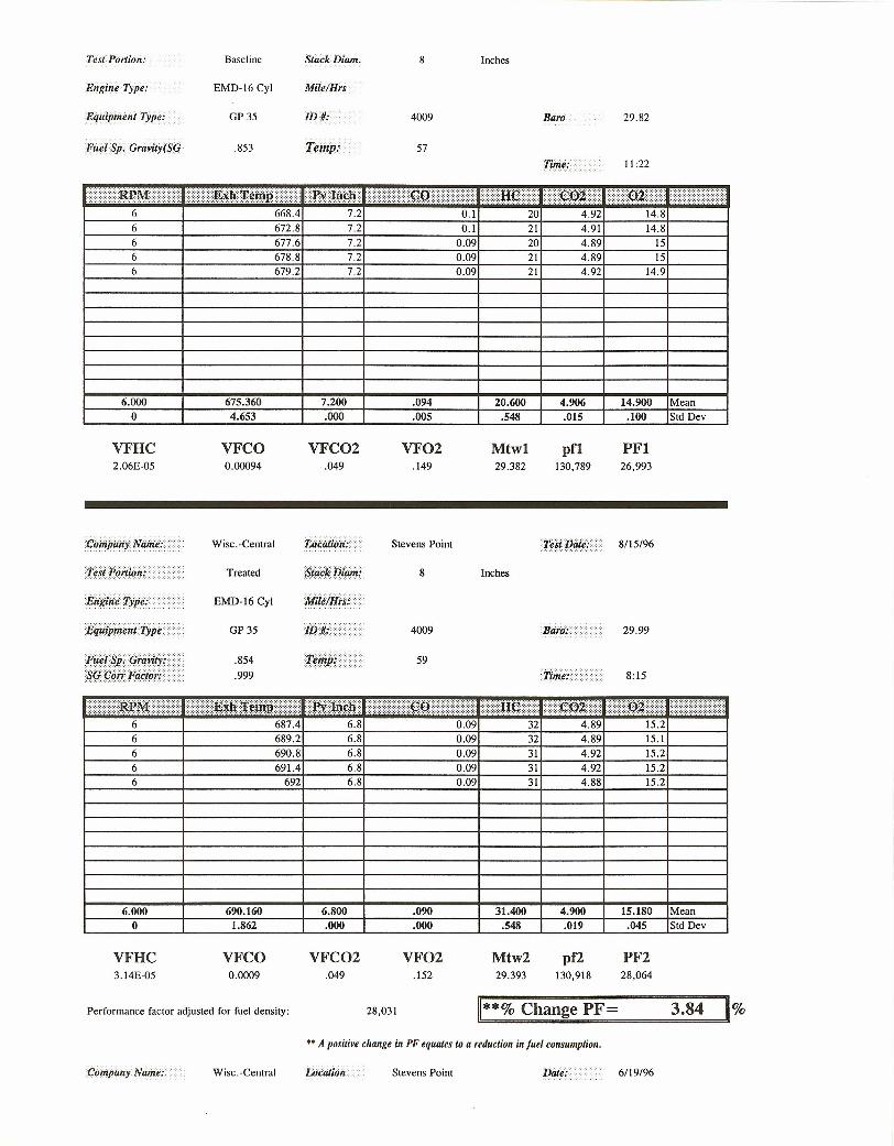
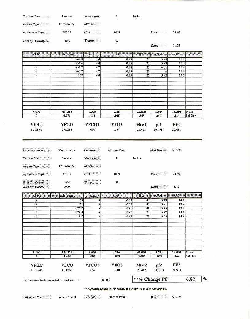
3.4 The Wisconsin Central Loadbox Test of Four Roots Blown Engines
Wisconsin Central Transportation conducted studies to determine the effect of FPC-2 on fuel economyand smoke emissions in a fleet of SWI500 and GP35 locomotives. The test also involved long termobservation of the claimed "cleaning up" ability of the catalyst. The four test locomotives arepowered by either 12 cylinder or 16 cylinder EMD engines. All four engines are normally aspirated(roots blown).
A loadbox was employed to load (full load) the engines. Fuel consumption was measured using botha weigh scale method and an exhaust gas analysis method also utilized by the US-EPA, known as thecarbon mass balance (cmb). A Bacharach Smokespot Method was used to determine changes inexhaust smoke density.
All locomotives were tested for fuel consumption using the cmb method. The GP35s were tested atnotch settings 2, 4, 6, and 8. The SW1500s were tested at notches 2, 4, and 6. All engines wererun at full load at each notch setting.
Also, smoke density readings were taken at idle, 2, 4, 6, and 8 (GP35s) or idle, 2, 4, and 6(SWI500s), also while at full load.
Units 4009 (GP35) and 1550 (SWI500) were tested using a second method which employed a weighscale. This procedure was developed by Wisconsin Central to determine the fuel consumption of theirengines. The weigh scale method and results will be treated in a separate report.
The locomotives were first tested while using untreated (baseline) number 2 diesel fuel. After thebaseline tests, the fuel for the four test locomotives were treated with FPC-2 for approximately eightweeks. At the end of the eight week engine preconditioning period, the cmb and weigh scale testswere repeated at identical load and notch settings. Engine rpm and rack length were also reproduced.
3.4.1 Test Methodology
The test methodology for determining changes in fuel consumption was the "Carbon Mass Balance"(cmb). The cmb method measures the carbon containing products of the combustion process (C02,CO, HC) found in the exhaust, rather than directly measuring fuel flow into the engine. The CMBalso makes possible the determination of FPC catalyst's effect upon regulated emissions, specificallysmoke for the diesel engine.
11
The cmb uses state-of-the-art, non-dispersive infrared analysis (NDIR) and the measurement of carboncontaining exhaust gases to determine fuel consumption indirectly. The method has been central tothe EPA Federal Test Procedures (FTP) and Highway Fuel Economy Test (HFET) since 1974, and isinternationally recognized. This method has proven to be at least as accurate as more conventionalflowmeter or weigh scale methods [ Ref 8 ].
The test was supervised by technical representatives for Wisconsin Central. The exhaust gas datacollected during the baseline and treated fuel carbon balance tests are summarized on the attachedcomputer printouts (Appendix 3). From these data, the volume fraction (VF) of each gas isdetermined and the average molecular weight (Mwt) of the exhaust gases computed. Next, the engineperformance factor (pf) or the carbon mass in the exhaust is computed. The pf is finally corrected forexhaust temperature and pressure velocity (exhaust density), intake air pressure (barometric) and fueldensity, yielding an engine performance factor (PF) or carbon mass flow rate corrected for totalexhaust mass flow and fuel energy content.
The PFs are shown on the bottom of the computer printouts found in Appendix 3. The PF relates tothe length of time required to consume a given volume of fuel, therefore a positive change in PFequates to a reduction in fuel consumption (longer time to consume same amount of fuel at the sameload). The cmb formula and legend are found on Figure 1 under Appendix 4. A sample calculationis found on Figure 2, also under Appendix 4 (CMB Formulae).
These formulae were provided for UHI by Dr. Geoffrey J. Germane, Ph.D. Mechanical Engineering,and former Department Chair at Brigham Young University, as the technical approach for the cmb.Dr. Germane's resume is also included in Appendix 5 (Dr. G. J. Germane's Resume' ).
3.4.2 Correction for Fuel Density
Dr. Germane's formulae assume a fuel density of 0.82 (reference specific gravity for diesel). UHIengineers measure fuel specific gravity (density) by taking samples from the rolling tank on eachlocomotive. Only the treated fuel rate of fuel consumption or PF (PF2) is corrected for changes infuel density (energy content). The baseline fuel density is used as the reference. The correctionfactor (if applicable) for fuel density is made to the treated fuel and shown on the treated fuelcomputer printouts (Appendix 3 Raw Data Computer Printouts).
3.4.3 Correction for Barometric Pressure.
The barometric pressure is used in the calculation of both the baseline and treated fuel PFs. Thesepressure readings were obtained from the National Weather Service for the Stevens Point area. Thebarometric pressures are shown on the computer printouts.
3.4.4 Discussion of Smoke Density
Smoke is a product of incomplete combustion, and as such, is a measure of engine efficiency. Smokeis simply unburned fuel droplets that are exhaust from the engine. Generally speaking, these particlesare formed during the late stages of combustion when temperatures have fallen off and oxygenavailability is limited. The FPC catalyst improves the oxidation of these fuel droplets, speeding flamefront development and extracting more useful energy before the exhaust valve or port opens. More
12
power is generated and smoke emissions are reduced.
Smoke measurements from the engines tested during the baseline and treated fuel tests were collectedusing the Bacharach Smokespot Method. The Bacharach method draws a specific volume of exhaustgas through a standard 5 micron filter medium. The particulate in the exhaust gas sample collects onthe surface of the filter medium. The surface is darkened by the particulate according to the densityof the particulate in the exhaust sample. The greater the particulate density, the darker the color.The Bacharach smoke scale ranges from 0 to 9, with 0 being a white, particulate free filter, and 9being a completely black filter.
The smoke spot numbers are relative smoke density numbers for each engine tested and can be usedto determine any change in smoke emissions when compared to FPC catalyst treated fuel. Acomparison of the baseline and treated Smoke Numbers (shown on Table 2, Appendix 7) indicate theuse of FPC catalyst in the Wisconsin Central locomotives created as much as a 50% reduction insmoke density. Smoke reductions were greater at lower notch settings.
The reduced engine smoking leads to less carbon or soot accumulation on stacks, spark arresters,turbochargers (were applicable), and other critical engine components. Less engine smoke alsoequates to fewer and smaller soot particles exhausting from the engine. The smaller particles haveless mass and therefore, carry less heat, burning out before reaching combustion materials near thetracks. Engine component life and efficiency is also maintained much longer.
3.4.5 Discussion of Anomalies
The results of the cmb test are consistent, and agree with other tests from previous railroad tests.The pattern of change also agrees with tests done by Southwest Research Institute on a MP15locomotive. These tests show the 645 EMD is most efficient in the middle notch settings (4-7), withefficiency declining at the terminal notch settings.
There were two anomalies in the fourteen tests of the four locomotives. The first appeared at notch 2on the 4009. Here a 17% change in fuel consumption was observed. This is an obvious anomaly,being over three times greater than the average of the remaining three tests conducted on the 4009.
The second anomaly appears in the test results for the 4006. At notch 8, the 4006 saw a 10.9%reduction in fuel consumption. In this case, the problem appears to be the result of a erroneousexhaust pressure velocity reading. Apparently the actual reading was 9.3 inches of water during thetreated test, and not the 9.0 that was recorded. If correct, the change in pressure from 9.0 to 9.3would correct the PF downward to approximately 7.3 %, a percentage change that is more in line withthe other test results on the 4006.
The anomalies have been removed from the test sample and are not used in the conclusions for thisreport.
13
4.0 CONCLUSIONS
(1) As concluded by Southwest Research, under ideal engine conditions, (best power timing,engine speed, load, and at steady-state) the use of FPC catalyst in a locomotive and/or any othermedium speed diesel engine will generate a significant fuel economy improvement of no less than1.74%.
(2) Tests conducted by another independent laboratory, the Western Australia Institute ofTechnology (WAIT), on a Varimax engine operated at varying rpm, injection timing, and load verifythat 1.74% is a minimum, and that average fuel economy improvements under more transientconditions typically experienced in the field will be several times greater.
(3) The same WAIT study determined that fuel economy gain is increased with increasingcatalyst concentration and with engine operation deviating from best power parameters, supporting thetheory of the catalyst mode of action.
(4) Although engine operating conditions are less severe for stationary engines than formobile equipment, specific fuel consumption tests in over a dozen stationary heavy duty dieselgenerator sets operating in the field confirm the WAIT findings. The addition of FPC catalyst tostandard diesel fuel improved fuel economy approximately 3.7% in these studies.
(5) Actual field trials in Wisconsin Central's fleet of four roots blown 645E EMD poweredlocomotives agree with the above conclusions. Fuel consumption was reduced 4% to 8% with FPCcatalyst fuel treatment. Additional benefits include reduced engine smoking, exhaust sparks, andcarbon or soot buildup.
(6) These data agree with the conclusions rendered by Dr. Geoffrey J. Germane, Ph.D. ,Mechanical Engineering and Chairman of the Department of Mechanical Engineering, BrighamYoung University, in a letter to Mr. Vernon Markworth, Principal Engineer, Design andDevelopment, Department of Engine Research, Southwest Research Institute, 6 August 1992[ Ref 6 ].
Other combustion experts, such as Dr. G. K. Sharma, Senior Research Manager, Indian OilCorporation, with whom the writer of this paper has discussed FPC catalyst benefits, also agree[ Ref 7 ].
5.0 RECOMMENDATIONS
Given the considerable independent laboratory and field data collected verifying the potential for fuelsavings by treating diesel fuel with FPC-2, a large fuel consumer can realize a significant net fuel costsavings with FPC-2 fuel treatment. The data document actual fuel savings, after FPC-2 fuel treatmentunder transient engine operating conditions, will be two to three times or more than the RP-503results. Combustion experts agree with the comparison between the results of the RP-503 and resultsseen in engines operated in the field.
Wisconsin Central Transportation can expect to experience fuel savings of approximately 6.5% to 7%with FPC-2 fuel treatment. Exact dollar savings will depend upon the cost and volume of fuel used
14
by Wisconsin Central, and the work regime of the engines. Therefore, URI and Lakeside Oilrecommend Wisconsin Central commence fuel treatment with FPC-2 as soon as possible, and beginnow to recover the losses being sustained from consuming untreated fuel.
It is also recommended that, upon system wide fuel treatment, a program be initiated to determine theimpact of FPC-2 upon long term engine maintenance and engine life. DRI recommends analysis ofoil to determine the impact of FPC-2 upon oil viscosity and wear metals. Oil analysis and engineexamination have proven the use of FPC catalyst improves lubricant life, reduces engine wear metals(iron and copper), and reduces carbon residue related maintenance and engine failures, particularlypertaining to valves, injectors, ring zone areas, and bearings. Field studies have also documentedengine smoking and stack fires are reduced after FPC catalyst fuel treatment.
15
6.0 REFERENCES
1. Evaluation of a Fuel Additive, Final Report, Volume I, SwRI Project No. 03-4810 byMarkworth
2. Performance Evaluation of a Ferrous Salt Combustion Catalyst Applied to Diesel Fuel byGuld
3. Ten Years of Testing by Platt
4. The Internal-Combustion Engine in Theory and Practice, Volume I by Taylor
5. The Internal-Combustion Engine in Theory and Practice, Volume II by Taylor
6. Letter to Mr. Vernon Markworth, Principal Engineer, Design and Development, Departmentof Engine Research, SwRI, from Dr. Geoffrey J. Germane, Chairman, Department MechanicalEngineering, Brigham Young University
7. Meeting with Dr. G. K. Sharma, Senior Research Manager, Indian Oil Co. and Mr. S. CraigFlinders, VP, Tech Services, URI Corporation, 2 June 1994.
8. SAE PAPER, 75302; by Bruce Simpson, Ford Motor Company.
16

7.0 APPENDIX 1
THE "WAIT" STUDY
18
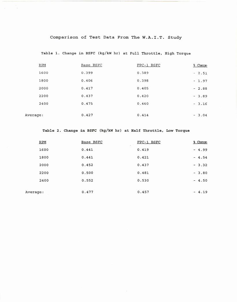
Comparison of Test Data From The W.A.I.T. Study
Table 1. Change in BSFC (kg/kW hr) at Full Throttle, High Torque
RPM Base BSFC FPC-1 BSFC % Chlrr:g
1600 0.399 0.389 - 2.51
1800 0.406 0.398 - 1.97
2000 0.417 0.405 - 2.88
2200 0.437 0.420 - 3.89
2400 0.475 0.460 - 3.16
Average: 0.427 0.414 - 3.04
Table 2. Change in BSFC (kg/kW hr) at Half Throttle, Low Torque
RPM Base BSFC FPC-1 BSFC % ClEn::e
1600 0.441 0.419 - 4.99
1800 0.441 0.421 - 4.54
2000 0.452 0.437 - 3.32
2200 0.500 0.481 - 3.80
2400 0.552 0.530 - 4.50
Average: 0.477 0.457 - 4.19
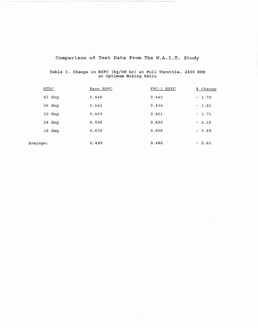
Comparison of Test Data From The W.A.I.T. Study
Table 3. Change in BSFC (kg/kW hr) at Full Throttle, 2400 RPMat Optimum Mixing Ratio
BTDC Base BSFC FPC-l BSFC % Change
42 deg 0.448 0.440 - 1.79
36 deg 0.442 0.434 - 1.81
30 deg 0.469 0.461 - 1.71
24 deg 0.506 0.490 - 3.16
18 deg 0.630 0.608 - 3.49
Average: 0.499 0.486 - 2.61
8.0 APPENDIX 2
VARIMAX VARIABLE COMPARISON TEST & RESEARCH RIG
19
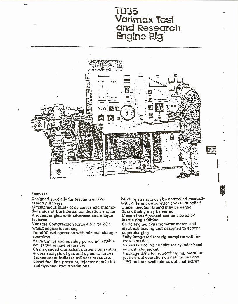
1035Vcrimcix Testand ResearchEngine Rig.
••• CJ.CL -:
19 "'-. .. ~.~.~...i .· '· ....· :
FeaturesDesigned specially for teaching and re·search purposasSimultaneous 5tudy of dynamics and thermo-dynamIcs of the Internal combustion engineA robust engine with advanced and uniquefeaturesVariable Compre~ion Ratio 4,5:1 to 20:1whilst engine Is runningPetrel/diesel operation with minimal change--overtime .Valve timing and opening period adjustablewhilst the engine i:l runningStrain gauged crankshaft suspension svsternallows analysts of gas and dynamic forcesTransducers Jndicate cylind.,( pre ssure,diesel fuel line pressure, injector needle lift.and flywheel cyclic variations
Mixture strength can be controlled manuallywith different carburettor chokes suppliedDiesel injection timing may be v~~edSpark timing may be variedMass of tho flywheel can be altered byInertia rin~ additionBasic engine, dynamometer motor, andelectrical loading unit designed to acceptsuperchargingFully integrated test rig complete with in-stru mentationSeparate cooling circuits for cylinder headand cylinder jacketPackage UMS for supercharging, petrol ln-[ection and operation on natural gas andLPG fuel are available as optional extras
II\1I"
I
.,.
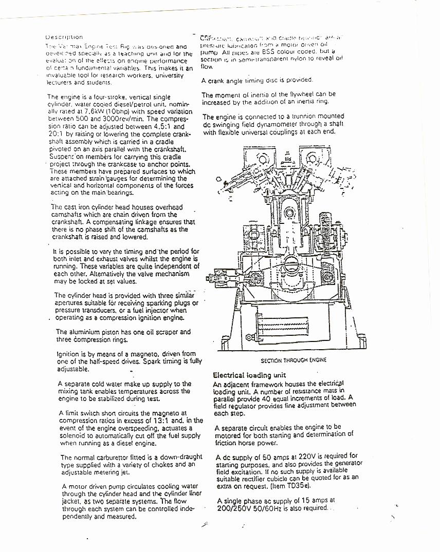
UeSClIpilOf1
1:1e 'v'c' ,la' ::'<'(:J'fj '(:r.: h'e; ':.0> :.)(,:;·0<11:(; anaocvc.cr-e o soec;al1y as a H:~ctllna U"" dlld tOI llit\:'valuG: ,)'101 tht ei:e:!~ on or.ql;;(": ueriorrnanceat ce':;' :-.Iundiin'er\\a! v(ir,ahl(;!~.ThiS makes it an,nvalu<:~le \001 tor re sear cn workers. universitylecturers and stuoeois.
The engine is a fOUI-SHOk~. vertical singlecylinder. water cooieo oiesei/cetrot unit. nomin-ally rated at 7 .6kW (1Obhp) with speed varleuonbel ween 500 and 3000rev/min. The cornpres-sico ratio can be adjusted between 4.5:1 and20:1 by raising or lowering the complete crank-snah assembly which is carried in a cradlepivoted on an axis paralle.! with the crankshaft.Su:me~::'on members lor carrying this cradle
. project ~hfou9h thE: crankcas~ to anchor points.These members have precareo surfaces to whichare anached strain 'Qauges for determining thevertical and horizontal components of the forcesacting on the main bearings.
The cast iron Cylinder Mad houses overheadcamshafts which are chain driven from thecrankshaft. A compensating linkage ensures thatthere is no phase shift of the camshafts as thecranksl".aft is raised and lowered.
It is possible to vary the timing and 'the period forboth inlet and exhaust valves whilst the engioe isrunning. These variables are Quite independent ofeach other. Alternatively the valve mechanismmay be locked at set values.
The cylinder head is provided with three simllar-aoenures suitable for receiving sparking plugs orpressure transducers. or a {uel injector whenoperating as a compression ignition engine.
The aluminium piston has one oil scracer andthree compression rings.
Ignition is by means of a rna9neto. driven fromone of the halt-speed drives. Spark timing is fullyadjustable.
A separate cotd water make up SlJpply to themixing tank. enables temperatures across theengine to be S\abilized during lest.
A limit switch shon circuits the magneto atcompression ratios \n excess of 13:1 and. in theevent of the engine overspeedinq, actuates asolenoid to automatically cut off the fuel supplywhen running as a diesel engine.
The normal carburettor fitted is a down-draughttype supplied with a variety of chokes and anadjustable metering jet.
A motor driven punjp circulates cooling waterthrough the cylinder head and the cylinder liner[acket, as two seoarate systems. The flowthrough each system can be controlled inde-pendently and measured.
C::i~·.v:.~t~-::.C..••I.I~.:·,~I·:~1·\\lC:~~~\·:, r,I.::,',:,C· (!t/, ;I~'
1.l!l!~.:.\If<:tuiJ";:I!\on i~JJ":'"1 " mOIO' Or,vC" 0':P\I('I'\!J All rlltlC~ alV ess coto,» Coded. OUI dsocuoo I:" 1f1 :.eml-tldf1sf)arent nylon 10 reveal allIlov,
A crank angle timing o.sc is provided.
The moment 01 inertia 01 the flywheel can beincreased by the addilion 01 an inerua ring.
The engine is coooeciec to a uunnio« mountedde swinging lield dynamometer through a shaftwith flexible univerSQIcouplings at each end.
SECTION THROUGH ENGINE
Electrical IQading unitM ~diacen, framework houses the electri~1loading unit. A number of resistance mats inparallel provide 40 equal increments at load. Afield regulator provides fine adjustment betweeneach Step.
A separate circuit enables the engine to bemotored for both starting and determination offriction horse power.
A de supply of 50 amps at 220V is required forstarting purposes. and also provides the generatorfield excitation. If no such supply is availablesuitable rectifier cubicle can be quoted for as anextra on request. (hem T035e).
A single phase 8C supply of 15 amps at200!250V 50/60Hz is also required ... .•..
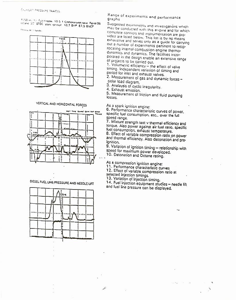
\ '. so "'. ".'. r U~I "~a:lk, 1 (J !J 1 C/l{lll),(r<.~ '111.0 Pe"oI9/;(,~:.(o(' ~:: sroc ~:~I,:'\I",lIot. 10,7 ellP e r.s BI.1(P
I 'r?C:
I :lI \. '" .... ..... .. ... ..., .... ....
,. I " . t\.I I I)(l~I -- ~
VEATICAt. AND HORl2:0NT AI..FORCES
DIESELFUEL LINE,PfI£SSURE AND NEEO~ UFi
I I\~oc • III I ~:;J I f I
\ . J.... ....I... ..... ... . f' .•. ••••. ) . .~ ~, ~
. ~
Range of experiments and p e rtormao cegraphs
SU9gesl(?d eXIJ(!fII'IC01:' (jnd Im'(1Sllgalions whlc"
m.:l\, be conduClec1 Wllt\ Ihis ell~\ne and for whicr.comDlele COntrols ario In:;\rurnentalion are pro-vided are lisled below. Ihi:; li!'t is by no meanseXhaustive and serves only as a guide for carryingOUI a number 01 expenrnerus oenioent to recip-roealing internal combustion engil'le thermo-dynamics and dynamics, The facilities iocor-pOrated in the design ef"l(lble an extensive rangeof projecis to be carried OUI." VOlumetric ellicieney":' the effect of valvetiming. tndependent varia lion of timing andperiod for inlet and exhauSl valves.2, Measuremom 01 gas and dynamic forces-polar load di~grarn.
3, AnataYSisof cyclic irregularity.4. Exhaust emission.5. Measurement 01 friction and fluid pumpinglosses,
As a sPQrk iQnilion engine:6. Periormance characteristic curves of power.speciiic fuel consumption. etc .. over the fullspeed ra(lge.7. Mixture strength test v thermal efficiency andtorque. Also power against air fuel ratio, specificfuel consumption, exhaust temperature.8. Effect of variable compression ratio .on POwerand thermal efficiency. Also detonation and pre-ignition.9. Variation of ignition timing - relationship withspeed for maximum power developed., O. Detonation and Octane rating.
As a.compression ignition engine:, 1. Periormance Characteristic curves12. Effect of variable compression ratio atselected injection timings.13. Variation of Injection timing. .14. Fuel injection equipment studies - needle 11ftand fuel Una preSSure can be displayed.
.•..
\
••ao ~.. ..1:t . . . 0( i I<10 I · ...~~l
'f~'
'" I~
~.a, •...::9. "'M~"~·f .(,.
rVU !v:(!'t,.,f
,
£.II/P\Q. IIototV), .
•
I
\
~:L-...------ -1&OO--~.---.~--_---..i.o• Uotto - ••••, ••••
ttwt.,. !<At: ~~::st ffff_""-6 ~
••
- ~ - - WQO ~.-.oq aoc)O
¥Up - -'=
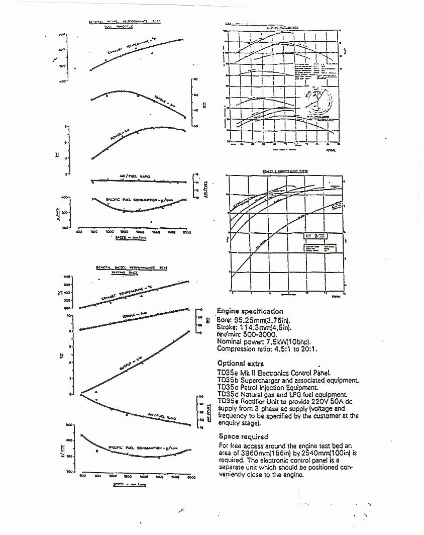
.-- •-Engine specificationBore: 95.2Srnm(3.75in).Stroke: 114.3mm{4.5in) •rev/min: 500-3000.Nominal power: 7.5 kW(' Obhp).Compression ratio: 4.5:1 to 20: 1.
Optionalexua •T035a Mk II Electronics Control Pal'\elT035b Suceccharger and associated equipment.TD35e Petrol Injection Equipment.TD35d Natural gas and LPG fuel eoulpmeot,T035$ Rectiflef Unit to provide 220V SOA deSlJPCly from 3 phase ae supply (voltage andfrequency to be specified by the customer at theenQuiry stage).
Space requiredFor free access around the engine test bed anarea of 3960mm(156in) by 2540mm(100in) isrequired. The electronic control panel is 8separate unit which should be positioned con-ve0iently close to tM engine.
.•..'\
t n s t att a u o r,
l',e: '.c '~ irt:~ SI,H\(j'f"lQ on d(\\l-v1br.11110n Ollds.c.nci 1."" redd11y be moved 10 any other suitableSll;- rI oss.reo
A 2~0{ol1I1englh oll1exible exhauSt pipe isprovided logelhe( wilh a suitable silencer.
Services requiredde supply. 220V 50A short term r<l\ing (startin9onl'A Single phase ac supply 15A at 200/250V.50/60Hl.
Mains or lank water supply' for coolin~ watermake-co.
Exhaust extension.
tt is essential that the engine basep~ti ismounted on a weU supported concrete foundation.
Dimensions and weIghtsNett 2740mm(108inj X 1295mm(51in) x1850mm(73in): 1620kg(3584Ib)Gross: Iaoorox - packed tor export)8.43m~(300ftl): 2444kg(5376Ib)
Tender speclficatlcnTo ccrnortsa a fully integrated test rig completewith instrumentation to allow a slmultaneousstudy of dynamics and thermodynamics of in-ternat combustion engines. The unit shOUld navea variab!e compression ratio. variable between4.5:1 and 20:1 Whilst the engine is ruMing.~ -Valve timing and opening period should beadjustable whilst engiM is running and theengine should capable of petrOl or dtesel opera-tion. The time of diesel injection spark should bevariable aod tha crank shan suspension systemshould be strain ~auged to allow the analys1sofgas dyl\amic forces. Transducers should be flUedto allow imprlCation of cylindit pressure. dteselfuel line pressure, injector needle lift. 1lywhee1cyclic variations. In addition.the mass of theflyvvheel should be variable by an inertia ringaddition. A separate cooling circuit for cylinderhead' and cy{inder jacket should be lnco.rporatedand P<Jckageunit should be eValtable for $upercharging. petrol injection and operation on naturalgas. and LPG.
.,.

9.0 APPENDIX 3
RAW DATA COMPUTER PRINTOUTS
20
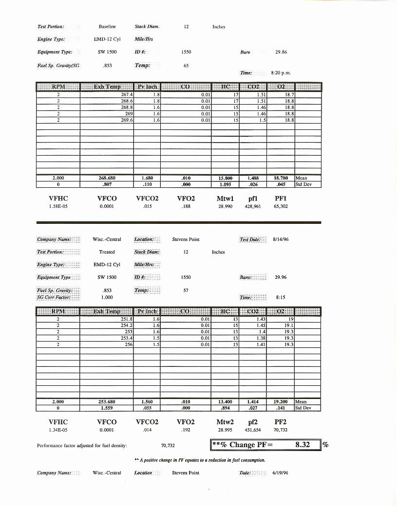
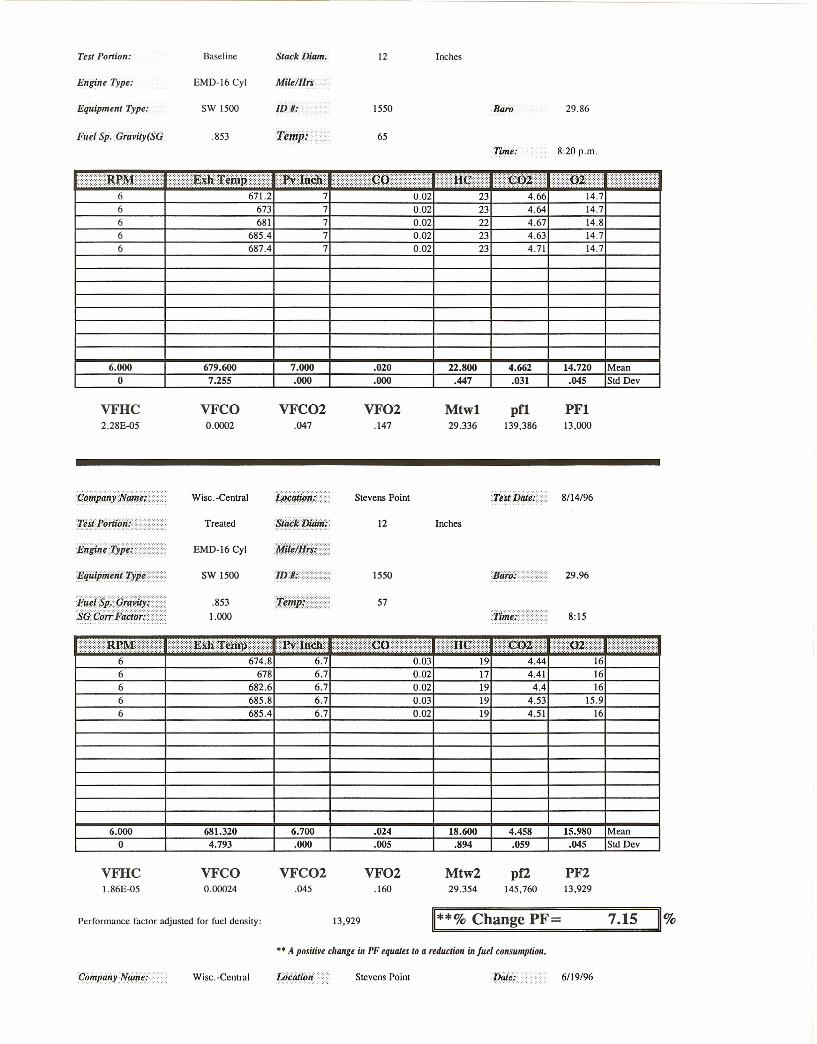
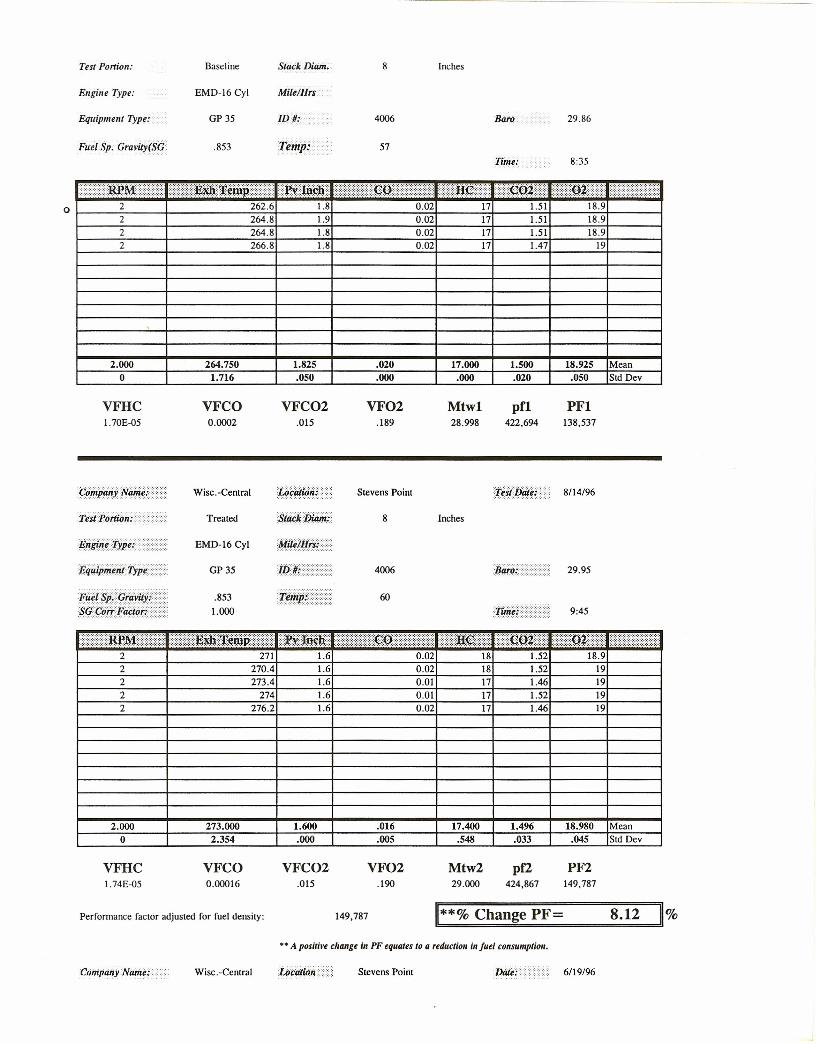
Test Portion: Baseline Stack Diam.
Engine Type: EMD-J2 Cyl Mile/Hrs
Equipment Type: SW 1500 IDII:
Friel Sp, Gravily(SG .853 Temp:
12 Inches
1550
65
Baro 29.86
~p~/ •••t::::.lti.l#r~mp.f..~J®'W2 267.4 1.8
Time: 8:20 p.m.
.045 Std Dev
2 268.6 1.8
f:f.H¢./.::~. :••f::::Q~••)0.01 17 1.51 18.70.01 17 1.51 18.8
2 268.8 1.6 0.01 15 1.46 18.82 269 1.6 0.01 15 1.46 18.82 269.6 1.6 0.01 15 1.5 18.8
2.000o
268.680.807
1.680.110
.010 15.800 1.488 18.780 Mean
VFHC1.58E-05
&HJJji/!Je@1.)p¥»·.i;'¥i:§P'q;~YitYP:.·§Qf/i,&ifit,i¥±:·:··{)·
VFCO0.0001
Wisc. -Central
Treated
EMD-12 Cy\
SW 1500
.8531.000
VFC02.015
.000 1.095
VF02.188
Mtwl28.990
Stevens Point
12 Inches
1550
57
.026
pf1428,961
PFI65,302
29.96
8:15
0.01fRrM< .......}.•.••J$m.OO~ffl.lf·<••'JWm~w
2 251.8 1.615 1.45 19.12 254.2 1.6 0.01
2 253 1.6 0.01 13 1.4 19.32 253.4 1.5 0.01 13 1.38 19.32 256 1.5 0.01 13 19.31.41
2.000 253.680 1.560 .010 13.400 1.414 19.200 Mean0 1.559 .055 .000 .894 .027 .141 Std Dev
VFHC VFCO VFC02 VF02 Mtw2 pf2 PF21.34E-05 0.0001 .014 .192 28.995 451,654 70,732
Performance factor adjusted for fuel density: 70,732 Change PF= 8.32 %
C(Jmpany Name: Wise. -Central
•• A positive change ill PF equaus /(J a reduction in fuel consumption.
Stevens Point 6119/96
Test Portion:
Engine Type:
EquipmentType:
Fuel Sp. Gravity(SG
Baseline
EMD-12 Cyl
SW 1500
.853
12 Inches
MilelHrs
ID/(: 1550 29.86
65
4 0.02 16.4·Jt#i<W~mtF) (lWtnd{
477.6 4.6
8:20 p.m.
4 481.2 4.6 0.0218 3.4818 3.48 16.4
4 486.6 4.6 0.02 18 3.51 16.34 489.2 4.6 0.02 18 3.5 16.34 491.8 4.6 0.02 18 3.49 16.3
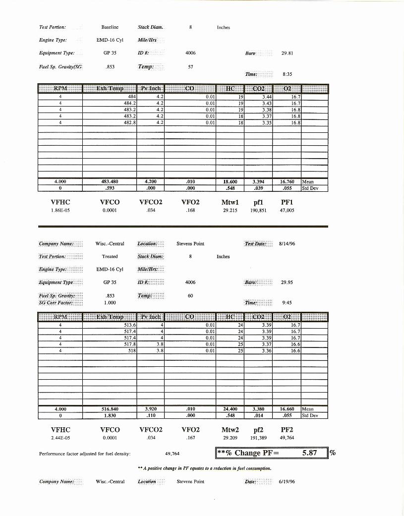
4.000o
485.2805.815
4.600 .020 18.000 3.492 16.340 Mean
VFHC1.80E-D5
VFCO0.0002
Wisc.-Central
Treated
EMD-12 Cyl
SW 1500
.8531.000
.000 .000 .000
VFC02.035
VF02.163
Mtwl29.213
UcatiO":(.............. - .... Stevens Point
siiilkijf/i,Ji....... ,"', . 12 Inches
1550
57
.013 .055 Std Dev
pfl185,015
PFI19,387
29.96
8:15
13
~l~M.){\:?:~~J.Wmit ))J.Wm.~K4 480.6 4.4
13 17.20.01
4 483.4 4.4 0.01 3.384 487 4.4 0.01 17 3.34 17.34 485 4.3 0.01 17 3.31 17.34 486.6 4.3 0.01 17 3.33 17.3
4.000 484.520 4.360 .010 15.400 3.352 17.280 Mean0 2.614 .055 .000 2.191 .037 .045 Std Dev
VFHC VFCO VFC02 VF02 Mtw2 pf2 PF21.54E-D5 0.0001 .034 .173 29.228 193,436 20,846
Performance factor adjusted for fuel density: 20,846 11**% Change PF= 7.53 11%
Wisc.-Central
•• A positive change in PF equates to a reduction in [uel consumption.
Stevens Point 6/19/96
Test Portion:
Engine Type:
Equipment Type:
Fuel Sp. Grllvily(SG
Baseline
EMD-16 Cyl
SW 1500
.853
12 Inches
Mile/Hrs-:':
1550
65
Baro
Time: 8:20 p.m.
0.02 23 4.666 671.2 7
29.86
14.76 673 7 0.02 23 4.64 14.76 681 7 0.02 22 4.67 14.86 685.4 7 0.02 23 4.63 14.76 687.4 7 0.02 23 4.71 14.7
6.000o
679.6007.255
7.000 .020 22.800 4.662.031
14.720 Mean.045 Sid Dev
VFHC2.28E-05
·iiii.P(jrliQitf......).···>·...................
!¥fo{[email protected].???·····
F@t§i"9r1rif>'~·$(!@itl!#.tijf(>
VFCO0.0002
Wisc.-Central
Treated
EMD-16 Cyl
SW 1500
.8531.000
.000 .000 .447
VFC02.047
VF02.147
Mtwl29.336
Stevens Point
12 Inches
1550
57
pfl139,386
tl#ii@M? 8/14/96
PFI13,000
29.96
674.8 6.7
8:15
678 6.7
Wise. -Central
•• A positive change in PF equates to a reduction in fuel consumption.
0.03 19 4.44 1666 0.02 17 4.41 166 682.6 6.7 0.02 19 4.4 166 685.8 6.7 0.03 19 4.53 15.96 685.4 6.7 0.02 19 4.51 16
6.000 681.320 6.700 .024 18.600 4.458 15.980 Mean0 4.793 .000 .005 .894 .059 .045 Sid Dev
VFHC VFCO VFC02 VF02 Mtw2 pf2 PF21.86E-05 0.00024 .045 .160 29.354 145,760 13,929
Performance factor adjusted for fuel density: 13,929 11**% Change PF= 7.15 11%
C()rnparlY·./'fiffifll:··· Stevens Point 6/19/96
Company Name;
Test Portion:
Engine Type:
Equipment Type: """,
Fuel$p; Gra®($G
Wise. -Central
Baseline
EMD-12 Cyl
SW 1500
.853
Stevens Point Date:
StackDiam; 12 Inches
Mili!11M, ..·..,··"
1554
59
2
1.064
6/18/96
29.83
8:30 p.rn.
1.5114247.6 1.8 0.012 247.8 1.8 0.01 14 1.5 192 1.8248.6 0.01 14 1.5 192
2249.6 1.8 am 14 1.49 19
1.46 19
VFHCI.40E-05
2 248.720
250 1.8 0.01 14
19.000 Mean.000 Sid Devo
VFCO0.0001
1.800 .010 14.000 1.492
PFI62,089
$Hjiij~D.lm<','}
:g#.Witt#MltiiNJ<
Wisc.-Central
Treated
EMD-12Cyl
SW 1500
.8531.000
.000 .000 .000 .019
VFC02.015
VF02.190
Mtwl29.000
pO428,290
siiikiJiJiffd..................... Inches
Stevens Point
12
1554
80
1.442
5.581
29.91
2:30 p.m.
151.4 19
238 1.7 0.0122
235.8 1.7 0.01 15228 0.011.7 15 1.38 19.1
VFHC1.50E-05
1.680 .010 15.000 1.408 19.020 Mean.045 .000 .000 .023 .045 Sid Dev
VFC02 VF02 Mtw2 pf2 PF2.014 .190 28.987 453,102 67,222
67,222 ~**% Change PF= 8.27 ~%
•• A positive change in PF equates 10 a reduction in fuel consumption.
22
2.000 230.920o
VFCO0.0001
Performance factor adjusted for fuel density:
227.2 1.7 0.01 151.6225.6 0.01 15
1.4 19191.42
Company Name:
Test Portion:
Engine Type:
Equipment Type:
Wisc.-Central
Baseline
EMD-12 Cyl
SW 1500
.853
Locaiion: -. Stevens Point
StackDiam. 12 Inches
Mile/Hrs
li>#: 1554
59
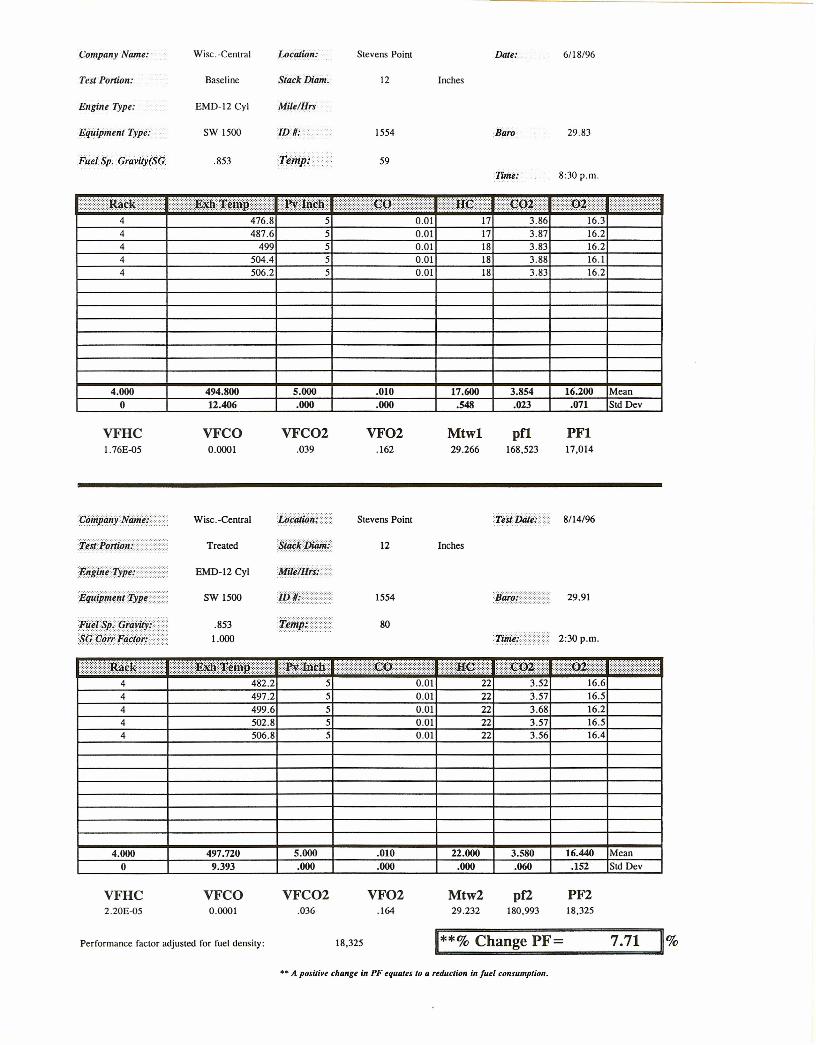
Date: 6118/96
Baro 29.83
ilhi~k:: ::::J{~1Wfuiit ::)::mf:m~M4 476.8 5
Tint.e: 8:30 p.m.
::n.e.P:Q$.:: ::::::J)~)0.01 17 3.86 16.3
4 487.6 54 ffl 5
0.01 17 3.87 16.20.01 18 3.83 16.2
4 504.4 5 0.01 18 3.88 16.14 506.2 5 O.oI 18 3.83 16.2
4.000o
494.80012.406
5.000 .010 17.600 3.854 16.200 MeanStd Dev
VFHC1.76E-05
VFCO0.0001
Wisc.-Central
Treated
EMD-12 Cyl
SW 1500
.8531.000
.000 .000 .548
VFC02.039
VF02.162
Mtwl29.266
tkWffMi·::.:::·:: Stevens Point
12 Inches
1554
80
.023 .071
pfl.168,523
PFI17,014
29.91
2:30 p.m.
O.oI
::::: :IDi¢l{:::::(:::::::::::::£@fm~mir:: :JWffli.i.f.#4 482.2 5
22 3.57 16.54 497.2 5 0.014 499.6 5 0.01 22 3.68 16.24 502.8 5 0.01 22 3.57 16.54 506.8 5 0.01 22 16.43.56
4.000 5.000 .010 22.000 3.580 16.440 Mean.000 .000 .000 .060 .152 Std Dev
VFC02 VF02 Mtw2 pf2 PF2.036 .164 29.232 180,993 18.325
18,325 11**% Change PF= 7.71 ~%•• A positive change in PF equates to a reduction in fuel consumption.
497.720o 9.393
VFHC2.20E-05
VFCO0.0001
Performance factor adjusted for fuel density:
Stevens Point
12 Inches
1554
59
Company Name: Wisc. -Central Location:
Test Portion: Baseline StackDiam.
Engine Type: EMD-12 Cyl Milt/Hrs
Equipment Type: SW 1500 ID#:
Fuel Sp. Gravity(SG .853 reitJp:
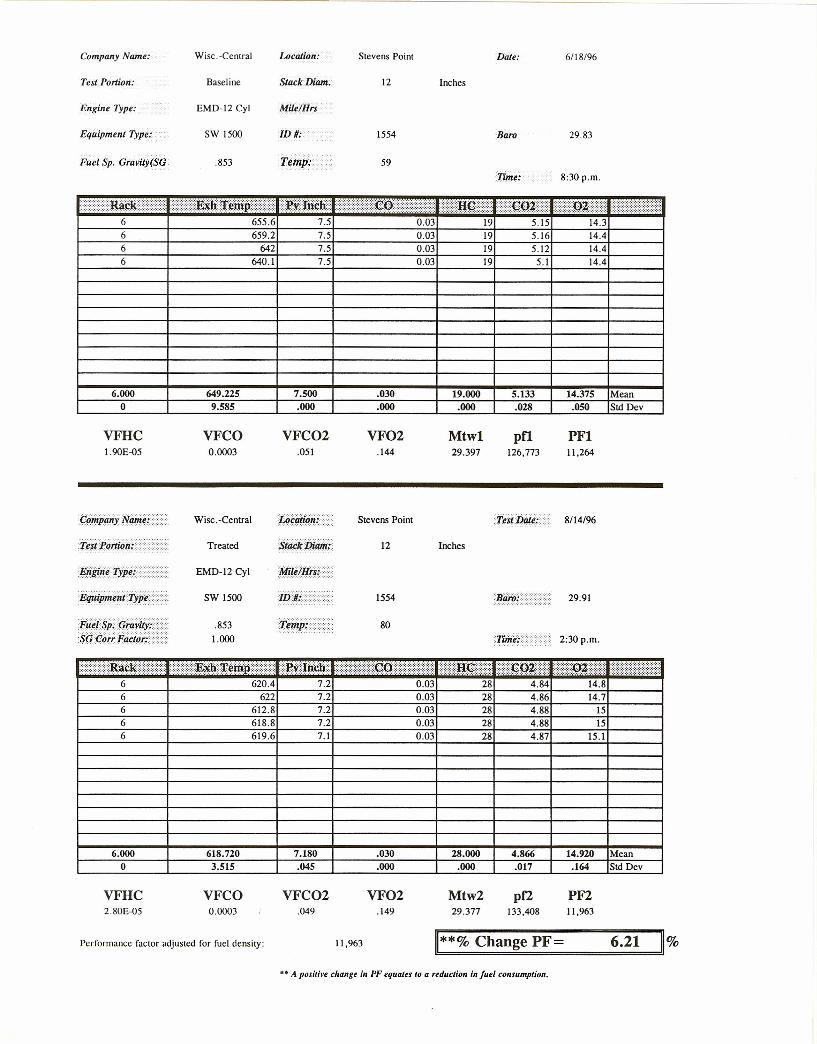
Date: 6/18/96
Baro 29.83
0.Q3
8:30 p.m.
6 655.6 7.56 659.2 7.56 642 7.56 640.1 7.5
6.000o
VFHC1.90E-{)5
649.2259.585
0.Q3 190.Q3 190.03 19
7.500 .030 19.000
5.16 14.4
VFCO0.0003
.000 .000 .000
5.12 14.4
VFC02.051
VF02.144
Mtwl29.397
5.1 14.4
1£.1IiiHfTyj;i'.\·}······............... .
F1~1.§f·.gmr&~)iSO.CoHFiiCtor:.}·.··............ .
Wisc.-Centra1
Treated
EMD-12Cyl
SW 1500
.8531.000
Stevens Point
SiJlitJikWi:....................... 12 Inches
MtiHfifii(...................
1554
80
5.133 14.375 Mean.028 .050 Std Dev
pO126,773
PFI11,264
TesitWh 8/14/96
29.91
2:30 p.m .
28 4.846 620.4 7.2 0.036 622 7.26 612.8 7.26 618.8 7.26 619.6 7.1
6.000o
VFHC2.80E-05
7.180 .030 28.000 4.866 14.920 Mean.045 .000 .000 .017 .164 Std Dev
VFC02 VF02 Mtw2 pf2 PF2.049 .149 29.377 133,408 11,963
11,963 11**% Change PF= 6.21 ~%•• A positive change in PF equates to a reduction in fuel consumption.
618.7203.515
VFCO0.0003
Performance factor adjusted for fuel density:
0.Q3 280.Q3 280.Q3 280.03 28
4.86 14.74.88 154.88 154.87 15.1
Test Portion:
Engine Type:
Equipment Type:
Fuel Sp. GraviJy(SG
Baseline
EMD-16 Cyl
GP 35
.853
Mile/Hrs
8
4009
57
Inches
Baro 29.82
0.01
11:22
2 276.2 1.6 14 1.83 18.52 276.4 1.6 0.01 14 1.83 18.52 276.8 1.6 0.01 14 1.83 18.62 277 1.6 om 14 1.83 18.62 277.4 1.6 0.01 14 1.83 18.5
2.000o
276.760-477
1.600.000 .000
14.000.000
1.830.000
18.540 Mean.055 Std Dev
VFHC1.40E-05
pi@i/#N1.SiWii
w~g§gig(@iig::$l,l@fiE4"4ijfD{
VFCO0.0001
Wisc.-Central
Treated
EMD-16 Cyl
GP35
.854
.999
VFC02.018
VF02.185
Stevens Point
8
4009
59
Mtwl29.035
Inches
pfl350,428
PFI123,591
29.99
:::ltm.\ i\\::::::mE~mMhH:(i:J.:Wm~!f2 289 1.65
8:15
2 283.6 1.72 283.6 1.7
0.01 15 1.61 19om 15 1.51 190.01 15 1.5 190.01 15 1.49 190.01 15 1.51 19
2 283.6 1.72 283.4 1.7
284.6402-439
2.000 1.690 .010 15.000 1.524 19.000 Mean.022 .000 .000 .049 .000 Std Dev
VFC02 VF02 Mtw2 pf2 PF2.015 .190 29.005 419,309 145,072
144,902 ~**% Change PF= 17.24 11%
o
VFHC1.50E-05
VFCO0.0001
Performance factor adjusted for fuel density:
Company Names: Wisc.-Central
•• A positive change in PF equates to a reduction in fuel consumption.
Stevens Point 6/19/96
Test Portion: Baseline StackDiam.
Engine Type: EMD-16 Cyl Mile/Hts
Equipment Type: GP 35 ID #:
Fuel Sp. Gravity(SG. .853 Temp:
8 Inches
4009
57
BaTT'" 29.82
18
1'U7!e:. . II :22
fRPM···()··...::::~~X~ffipf)f~tiR!l4 481.4 4 0.024 487.4 4 0.D2 17 3.8 16.24 493.2 4 0.D2 17 3.84 16.34 492.8 4 0.01 17 3.83 16.34 4~ 4 0.02 17 3.81 16.3
4.000o
489.9605.563
4.000 .018 17.200 3.824 16.260 Mean
VFHCI. 72E-05
fil~t$j;9@1M/.:sfJ¢¥iil¥¥,...:)·.·····
VFCO0.00018
Wise. -Central
Treated
EMD-16Cyl
GP35
.854
.999
.000 .004 .447
VFC02.038
VF02.163
Mtwl29.263
ilkfifii/ii:····............... -. Stevens Point
8 Inches
4009
59
.055 Std Dev.018
pfl169,482
PFI42,927
29.99
8:15
27
\\r.ReMr.)::e~Xi.ffiP.:·)·)~JMb. •.·4 508 3.8 0.024 510 3.7 0.02 27 3.85 16.34 510 3.7 0.D2 24 3.84 16.54 511.2 3.7 0.D2 26 3.82 16.44 510.8 3.7 0.02 26 16.43.82
4.000 510.000 3.720 .020 26.000 3.836 16.380 Mean.045 .000 1.225 .015 .084 Std Dev
VFC02 VF02 Mtw2 pf2 PF2.038 .164 29.270 168,665 44,891
44,838 11**% Change PF= 4.45 ~%•• A positive change in PF equates to a reduction in fuel consumption.
o 1.233
VFHC2.60E-05
VFCO0.0002
Performance factor adjusted for fuel density:
Wisc.-Central Stevens Point 6/19/96
Test Portion:
Engine Type:
Equipment Type:
Filtil$p .. Graiiity(SG·
Baseline
EMD-16 Cyl
GP 35
.853
Stack Diam.
MilelHrs
[DUo'
8
4009
57
6.0004.653
Inches
Baro 29.82
0.1
11:22
.015
6 668.4 7.26 672.8 7.2 0.16 677.6 7.26 678.8 7.26 679.2 7.2
VFHC2.06E-05
675.360o
VFCO0.00094
7.200.000
0.090.090.09
.094
.005
20 4.92 14.821 4.91 14.820 4.89 1521 4.89 1521 4.92 14.9
20.600 4.906 14.900 Mean.100 Sid Dev
VFC02.049
VF02.149
.548
Mtwl29.382
pn130,789
PFI26,993
Jiff4ip/#fntfyiN>
fJ@§J1 •••G$I'it)I.·./ ••••X(;.¢M£FtlC[oii····.··
Wise. -Central
Treated
EMD-16Cyl
GP35
.854
.999
WciiiWiti>................. Stevens Point
8
4009
59
6.0001.862
Inches
29.99
6 687.4 6.8
8:15
0.09 32 4.89 15.26 689.2 6.8 0.09 32 4.89 15.16 690.8 6.8 0.09 31 4.92 15.26 691.4 6.8 0.09 31 4.92 15.26 692 6.8
VFHC3.14E-05
690.160o
VFCO0.0009
Performance factor adjusted for fuel density:
Wise. -Central
0.09 31 4.88 15.2
Stevens Point 6/19/96
6.800 .090 31.400 4.900 15.180 Mean.000 .000 .548 .019 .045 Sid Dev
VFC02 VF02 Mtw2 pf2 PF2.049 .152 29.393 130,918 28,064
28,031 11**% Change PF= 3.84 11%•• A positive change ill PF equates to a reduction in fuel consumption.
Test Portion: Baseline Stack Dillin,
Engine Type: EMD-16 Cyl MilelHrs
Equipment Type.' GP 35 ID #:
Fuel Sp. Gravity(SG .853 Tempi-»:
8 848.8 9.48 852.6 9.48 853.2 9.28 860.2 9.28 857 9.4
8.000o
VFHC2.26E-05
854.3604_371
9_320.110
8 Inches
4009
57
Baro 29.82
Tun~,: 11:22
0.29 13.2
5_968.114 Std Dev
23 5.9823 5.9323 6.0122 622 5.92
22.600.548
Mtwl29.491
pfl104,984
VFCO0.00286
VFC02.060
0.280.280.290.29
.286
.005
13.313.413.413.5
13.360 Mean.041
PFI20,491
VF02.134
f#~t§f·9fBqM ••••iS/l@ff·lfii/tiif; •••·.·"
Wisc.-Central
Treated
EMD-16Cyl
GP35
.854
.999
$##41@##Mili/iiiM)
8 868 98 871 98 875.2 98 877.4 98 882 9
8.000o
VFHC4.lOE-05
874.7205.464
VFCO0.00256
Performance factor adjusted for fuel density:
Company NiJ.it{e.'/
Stevens Point
8
4009
59
Inches
tis{D4I:} 8/15/96
29.99
8:15
0.25 14.10.250.260.250.27
4444413937
5.795.81 13.95.75 13.8
9.000 .256 41.000 5.744 14.020 Mean.000 .009 3.082 .063 .164 Std Dev
VFC02 VF02 Mtw2 pf2 PF2.057 .140 29.482 109,173 21,913
21,888 **% Change PF= 6.82 %
5.72 14.15.65 14.2
Wisc.-Central
•• A positive change in PF equates to a reduction in fuel consumption.
6/19/96Stevens Point
Test Portion:
Engine Type:
Equipment Type:
Fuel Sp. Gravi!y($({
Baseline
EMD-16 Cyl
GP 35
.853
Stack Diam. 8 Inches
MildHrs
ID 1/: 4006
Temp.' . 57Time: 8:35
29.86
~~Mi\:~~T~fup\rfJiM:(:B¢}Uq~: .:Q~)o r- ~2~----+_----------~2672~.6~----~1.~8t_----------~0~.~02~----~1~7t_--~1~·751~ ~1~8.~9t_------;
2 264.8 1.9 0.02 17 1.51 18.92 264.8 1.8 0.02 17 1.51 18.92 266.8 1.8 0.02 17 1.47 19
2.000o
264.7501.716
1.825 .020 17.000 1.500 18.925 Mean.050 Sid Dev
VFHCl.70E-05
VFCO0.0002
.050 .000 .020
PFI138,537
E44ipn@{tyM»)·:·:
&~@~~i:l~!:
Wisc.-Central
Treated
EMD-16 Cyl
GP35
.8531.000
.000
VFC02.015
VF02.189
Mtwl28.998
pfl422,694
${#kiif$it,:
M@/iJf#i
Inches
Stevens Point
8
4006
609:45
29.95
2 271 1.6::UB.¢::i\:¢.mU ::U·?P7\?
0.Q2 18 1.52 18.92 270.4 1.62 273.4 1.62 V4 1.6
0.Q2 18 1.52 190.01 17 1.46 19
2 2M2 I~0.01 17 1.52 19
Wisc.-Central
0.02 17 1.46 19
•• A positive change in PF equates to a reduction in fuel consumption.
Stevens Point
2.000 273.000 1.600 .016 17.400 1.496 18.980 Mean0 2.354 .000 .005 .548 .033 .045 Std Dev
VFHC VFCO VFC02 VF02 Mtw2 pf2 PF21.74E-05 0.00016 .015 .190 29.000 424,867 149,787
Performance factor adjusted for fuel density: 149,787 **% Change PF= 8.12 %
6/19/96
8 Inches
4006
57
Test Portion: Baseline Stack Dillin.
Engine Type: EMD-16 Cyl Mile/Hrt
Equipment Type: GP 35 1D1i:
Fuel Sp. GraviLy(SG. .853 Tempt:',
4
.593 .
29.81
8:35
19 3.44 16.7484 0.014.24 484.2 4.2 0.01 19 3.43 16.74 483.2 4.2 0.01 19 3.38 16.84 483.2 4.2 0.01 18 3.37 16.84 482.8 4.2 0.Ql 18 3.35 16.8
4.000 483.480o
VFCO0.0001
4.200 .010 18.600 3.394 16.760 Mean
VFHCI. 86E-05
ie.st.foitWn:·.·.··}>······
ii:"irii~..Type: )}.·}........... , .
rArt*i;<;rari#i ..·..?saCorrFtit:J66 ••••?·.·...................
Wise. -Central
Treated
EMD-16Cyl
GP 35
.8531.000
.000 .000 .548
VFC02.034
VF02.168
Mtwl29.215
Stevens Point
8 Inches
4006
60
.039 .055 Std Dev
pO190,851
PFI47,005
29.95
9:45
~eM. .·.·.\E~jM#p).\\@mM(4 513.6 4
·.\H¢)···)¢'W:/·)):~~\ ••0.Ql 24 3.39 16.7
4 517.4 44 517.4 4
0.Ql 24 3.39 16.70.01 24 3.39 16.7
4 517.8 3.8 0.01 25 3.37 16.64 518 3.8 0.01 25 3.36 16.6
4.000 516.840 3.920 .010 24.400 3.380 16.660 Mean0 1.830 .110 .000 .548 .014 .055 Std Dev
VFHC VFCO VFC02 VF02 Mtw2 pf2 PF22.44E-05 0.0001 .034 .167 29.209 191,389 49,764
Performance factor adjusted for fuel density: 49,764 11**% Change PF= 5.87 11%
Company Name:>· Wise. -Central
•• A positive change in I'F equates to a reduction in fuel consumption.
Stevens Point 6/19/96
Test Portion:
Engine Type:
Equipment Type:
FuelSp, Oravity(Sp
Baseline
EMD-16 Cyl
GP 35
.853
Sllick[)jilin. 8
Mile/Hrs
IV #: 4006
'Temp:··.··< 57
Inches
Baro 29.81
Time.'. 8:35
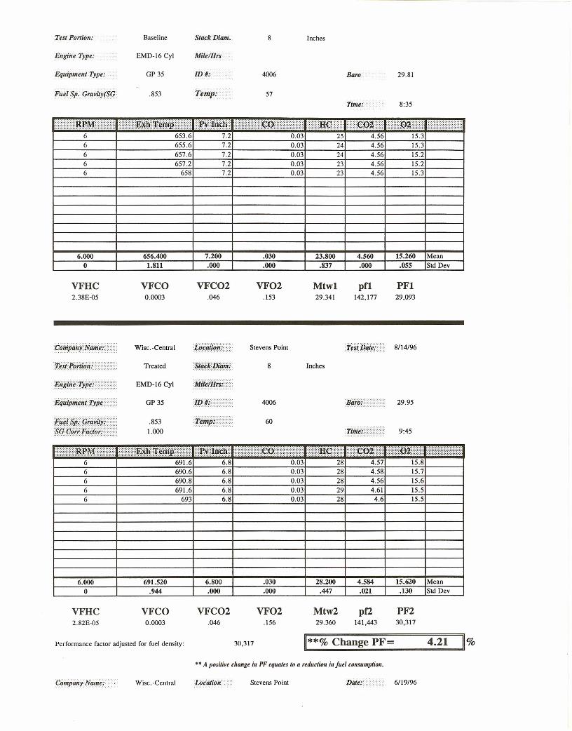
0.03iRgMr:ft~m~mp.(( (~tij~lii
6 653.6 7.2 256 655.6 7.2 0.03 24 4.56 15.36 657.6 7.2 0.03 24 4.56 15.26 657.2 7.2 0.03 23 4.56 15.26 658 7.2 0.03 23 4.56 15.3
6.000 656.400 7.200 .030 23.800 4.560 15.260 Mean0 1.811 .000 .000 .837 .000 .055 Sid Dev
VFHC VFCO VFC02 VF02 Mtwl pO PFI2.38E-05 0.0003 .046 .153 29.341 142,177 29,093
tistJ>.~itfM;.:.•·.·.·:·:::·::·:···
§#~MDMH····){·ij#fi.fu~@tJiN)·::
j.;if:~t:~e·9rer@·'S.Of}liif.F/icfifi,'{
Wisc.-Central
Treated
EMD-16 Cyl
GP 35
.8531.000
Stevens Point
8
4006
60
Inches
29.95
9:45
0.03 15.86 691.6 6.8 28 4.576 690.6 6.8 0.03 28 4.58 15.76 690.8 6.8 0.03 28 4.56 15.66 691.6 6.8 0.03 29 4.61 15.56 693 6.8 0.03 28 4.6 15.5
6.000 691.520 6.800 .030 28.200 4.584 15.620 Mean0 .944 .000 .000 .447 .021 .130 Sid Dev
VFHC VFCO VFC02 VF02 Mtw2 pf2 PF22.82E-05 0.0003 .046 .156 29.360 141,443 30,317
Performance factor adjusted for fuel density: 30,317 **% Change PF= 4.21 %
CiHnpanYName: Wise-Central
•• A positive change in PF equates to a reduction in fuel consumption.
6/19/96Stevens Point
Test Portion:
Engine Type:
E4uipmCI1/ Type:
Fuel Sp: Oravity(SG
Baseline
EMD-16 Cyl
GP 35
.853
Stack Dlam. 8 Inches
MilelHrs
/DHo' 4006 Baro
57
29.81
Time: 8:35
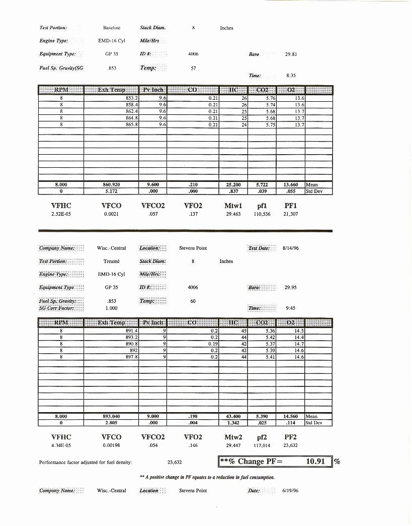
0.210.21
8 853.2 9.6 26 5.76 13.68 858.4 9.6 26 5.74 13.68 862.4 9.68 864.8 9.68 865.8 9.6
25 5.68 13.725 5.68 13.7
0.21
24 5.75 13.70.210.21
8.000o
860.9205.172
9.600 .210 25.200 5.722 13.660 Mean.055 Sid Dev
VFHC2. 52E-05
VFCO0.0021
.000 .000 .837 .039
PFI21,307
Wisc.-Central
Treated
EMD-16 Cyl
GP35
.8531.000
VFC02.057
VF02.137
Mtwl29.463
pfl110,536
Inches
Stevens Point
8
4006
t~&RD•••n.· ...· 60
5.36
29.95
9:45
4514.4
)....i~ ·...~gijlWmpi....i.W:)'jMf8 891.4 9 0.28 893.2 9 0.2 44 5.428 890.8 9 0.19 42 5.37 14.78 8~ 98 897.8 9
8.000 9.000 .198 43.400 5.390 14.560 Mean.000 .004 1.342 .025 .114 Sid Dev
VFC02 VF02 Mtw2 pf2 PF2.054 .146 29.447 117,014 23,632
23,632 1**% Change PF= 10.91 11%
893.040
0.2 420.2 44
o 2.805
VFHC4.34E-05
VFCO0.00198
Performance factor adjusted for fuel density:
Wisc.-Central
•• A positive change in PF equiues to a reduction in fuel consumption.
Stevens Point
5.39 14.614.65.41
6/19/96

10.0 APPENDIX 4
CARBON MASS BALANCE FORMULAE
21
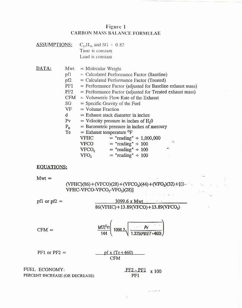
Figure ICARBON MASS BALANCE FORMULAE
ASSUMPTIONS: CI211)(1 and SG = 0.82Time is constantLoad is constant
DATA: Mwtpflpf2PFIPF2CFMSGVFdPvPBTe
EQUATIONS:
Mwt=
= Molecular Weight= Calculated Performance Factor (Baseline)= Calculated Performance Factor (Treated)= Performance Factor (adjusted for Baseline exhaust mass)= Performance Factor (adjusted for Treated exhaust mass)= Volumetric Flow Rate of the Exhaust= Specific Gravity of the Fuel= Volume Fraction= Exhaust stack diameter in inches= Velocity pressure in inches of H20= Barometric pressure in inches of mercury= Exhaust temperature ofVFHC = "reading" 7 1,000,000VFCO = "reading" 7 100VFC02 = "reading" 7 100VF02 = "reading" 7 100
(VFHC)(86)+(VFCO)(28)+(VFCO~(44)+(VFO:D(32)+[(1-· .VFHC- VFCO-VFC02- VF02)(28)]
pfl or pf2 =
CFM =
PFI or PF2 =
3099.6 x Mwt86(VFHC) + 13.89(VFCO) +13.89(VFCO~
pf x (Te+460)CFM
FUEL ECONOMY:PERCENT INCREASE (OR DECREASE)
PF2 - PFI x 100PFI
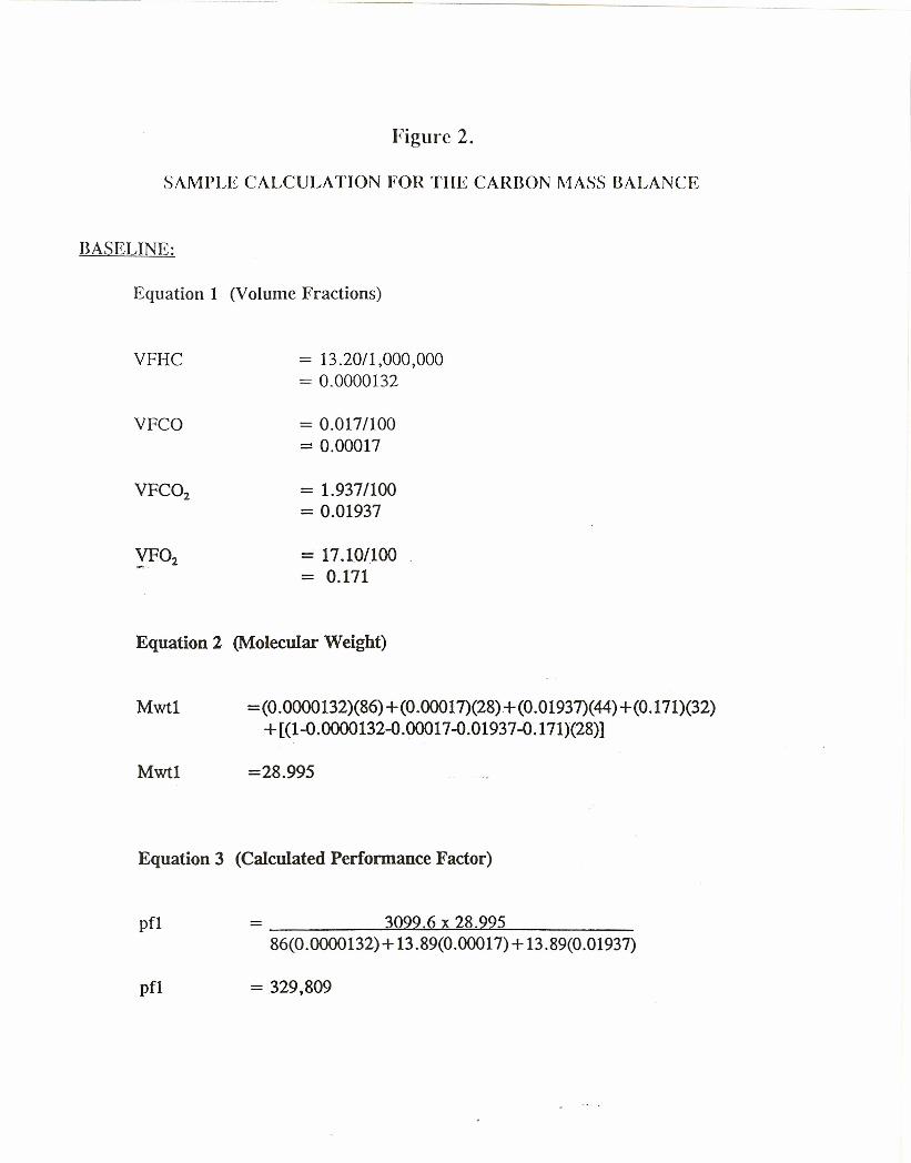
Figure 2.
SAMPLE CALCULATION FOR THE CARBON MASS BALANCE
BASELINE:
Equation 1 (Volume Fractions)
VFHC = 13.20/1,000,000= 0.0000132
VFCO = 0.017/100= 0.00017
= 1.937/100= 0.01937
-.: 17.10/100= 0.171
Equation 2 (Molecular Weight)
Mwtl =(0.0000132)(86)+(0.00017)(28)+(0.01937)(44)+(0.171)(32)+ [(28)(00132-0.00017-0.01937-0.171סס.1-0)]
Mwtl =28.995
Equation 3 (Calculated Performance Factor)
pfl - ---=<:3~09c....!.9~.6.L...x~28~.9~9'""'5 _86(0.0000132)+ 13.89(0.00017)+ 13.89(0.01937)
pfl = 329,809
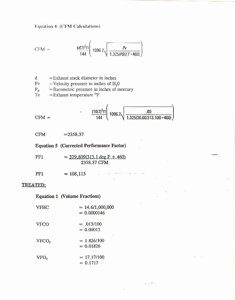
Equation 4 (CFM Calculations)
CFM = (d/2)2n( 1096.2144
Pv 11.325(PBIET +460)
d =Exhaust stack diameter in inchesPv =Velocity pressure in inches of H20PB == Barometric pressure in inches of mercuryTe =Exhaust temperature of
CFM =(10/2)2rr 1096.
144 1.325(30.00{313.1 00 +460).60 1
CFM =2358.37
Equation 5 (Corrected Performance Factor)
PFI = 329.809(313.1 deg F + 460)2358.37 CFM
PFI = 108,115
TREATED:
Equation 1 (Volume Fractions)
VFHC = 14.6/1,000,000== 00146סס.0
VFCO = .0131100= 0.00013
= 1.826/100= 0.01826
= 17.17/100= 0.1717
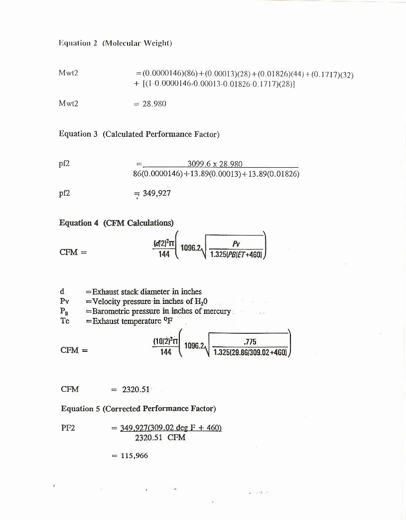
Equation 2 (Molecular Weight)
Mwl2 = (0.0000146)(86) + (0.00013)(28) + (0.01826)(44) + (0.1717)(32)+ [(1-0.0000146-0.00013-0.01826-0.17 17)(28)J
Mwl2 = 28.980
Equation 3 (Calculated Performance Factor)
pf2 3099.6 x 28.98086(0.0000146) +13.89(0.00013) +13.89(0.01826)
pf2 , 349,927.Equation 4 (CFM Calculations)
!d1211rr( 1096. Pv)CFM = 144 1.325(PB{ET +4601
d = Exhaust stack diameter in inches .Pv = Velocity pressure -in inches of H20PB =Barometric pressure in inches of mercury .Te = Exhaust temperature of
.775 )CFM=
(10{212iT 1096.144 1.325(29.86{309.02 +4601
CFM = 2320.51-
Equation 5 (Corrected Performance Factor)
PF2 = 349.927(309.02 deg F + 460)2320.51 CFM
= 115,966
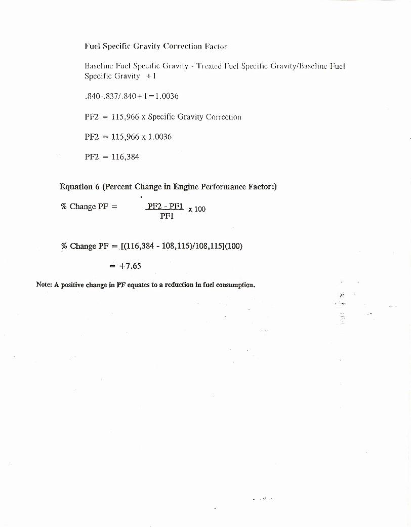
Fuel Specific Cravity Correction Factor
Baseline fuel Specific Gravity - Treated Fuel Specific Gravity/Baseline FuelSpecific Gravity + 1
.840-.837/ .840 + 1= 1.0036
PF2 = 115,966 x Specific Gravity Correction
PF2 = 115,966 x 1.0036
PF2 = 116,384
Equation 6 (percent Change in Engine Performance Factor:)
% Change PF = PF2 - PFI x 100PFI
% Change PF = [(116,384 - 108,115)/108,115](100)
= +7.65
Note: A positive change in PF equates to a reduction in fuel consumption.

11.0 APPENDIX 5
DR. G. 1. GERMANE'S RESUME'
22
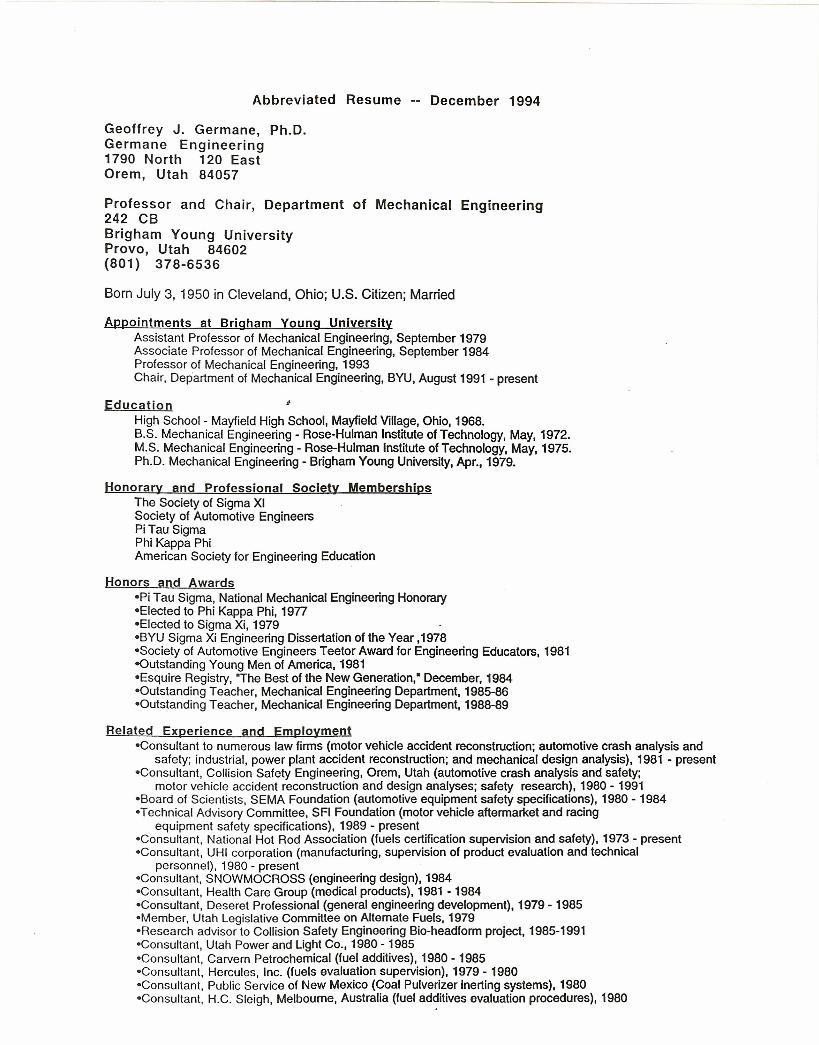
Abbreviated Resume -- December 1994
Geoffrey J. Germane, Ph.D.Germane Engineering1790 North 120 EastOrem, Utah 84057
Professor and Chair, Department of Mechanical Engineering242 CBBrigham Young UniversityProvo, Utah 84602(801) 378-6536
Born July 3, 1950 in Cleveland, Ohio; U.S. Citizen; Married
Appointments at Brigham Young UniversityAssistant Professor of Mechanical Engineering, September 1979Associate Professor of Mechanical Engineering, September 1984Professor of Mechanical Engineering, 1993Chair, Department of Mechanical Engineering, BYU, August 1991 - present
Education ~High School - Mayfield High School, Mayfield Village, Ohio, 1968.B.S. Mechanical Engineering - Rose-Hulman Institute of Technology, May, 1972.M.S. Mechanical Engineering - Rose-Hulman Institute ofTechnology, May, 1975.Ph.D. Mechanical Engineering - Brigham Young University, Apr., 1979.
Honorary and Professional Society MembershipsThe Society of Sigma XISociety of Automotive EngineersPi Tau SigmaPhi Kappa PhiAmerican Society for Engineering Education
Honors and Awards-Pl Tau Sigma, National Mechanical Engineering Honorary-Electsd to Phi Kappa Phi, 1977-Elected to Sigma Xi, 1979-BYU Sigma Xi Engineering Dissertation of the Year ,1978-Society of Automotive Engineers Teetor Award for Engineering Educators, 1981-Outstanding Young Men of America, 1981=Esqulre Registry, "The Best of the New Generation,· December, 1984-Outstandinq Teacher, Mechanical Engineering Department, 1985-86-Outstandinq Teacher, Mechanical Engineering Department, 1988-89
Related Experience and Employment-Consultant to numerous law firms (motor vehicle accident reconstruction; automotive crash analysis and
safety; industrial, power plant accident reconstruction; and mechanical design analysis), 1981 - present-Consuttant, Collision Safety Engineering, Orem, Utah (automotive crash analysis and safety;
motor vehicle accident reconstruction and design analyses; safety research), 1980 - 1991-Board of Scientists, SEMA Foundation (automotive equipment safety specifications), 1980 - 1984-Technical Advisory Committee, SFI Foundation (motor vehicle aftermarket and racing
equipment safety specifications), 1989 - present-Consultant, National Hot Rod Association (fuels certification supervision and safety), 1973 - present-Consultant, UHI corporation (manufacturing, supervision of product evaluation and technical
personnel), 1980 - present-Consultant, SNOWMOCROSS (engineering design), 1984-Consuttant, Health Care Group (medical products), 1981 - 1984-Consultant, Deseret Professional (general engineering development), 1979 - 1985-Mernber, Utah Legislative Committee on Altemate Fuels, 1979-Research advisor to Collision Safety Engineering Bio-headform project, 1985-1991-Consultant, Utah Power and Light Co., 1980 - 1985-Consultant, Carvern Petrochemical (fuel additives), 1980 - 1985-Consultant, Hercules, Inc. (fuels evaluation supervision), 1979 - 1980-Consuttant, Public Service of New Mexico (Coal Pulverizer inerting systems), 1980-Consultant, H.C. Sleigh, Melbourne, Australia (fuel additives evaluation procedures), 1980
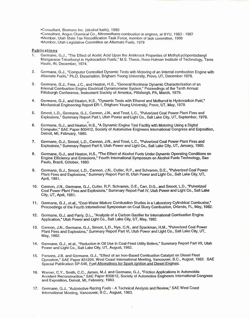
-Consultant, Biomass Inc. (alcohol fuels), 1980-Consultant, Angus Chemical Co., Nitromethane combustion in engines, at BYU, 1983 - 1987-Mernber, Utah State Tax Recodification Task Force, member of task committee, 1988-Mernber, Utah Legislative Committee on Alternate Fuels, 1979
Publications1. Germane, G.J., "The Effect of Acetic Acid Upon the Antiknock Properties of Methylcyclopentadienyl
Manganese Tricarbonyl in Hydrocarbon Fuels," M.S. Thesis, Rose-Hulman Institute of Technology, TerreHaute, IN, December, 1974.
2. Germane, G.J., "Computer Controlled Dynamic Tests with Motoring of an Internal combustion Engine withAlternate Fuels," Ph.D. Dissertation, Brigham Young University, Provo, UT, December 1978.
3. Germane, G.J., Free, J.C., and Heaton, H.S., "General Nonlinear Dynamic Characterization of anInternal Combustion Engine Electrical Dynamometer System," Proceedings of the Tenth AnnualPittsburgh Conference, Instrument Society of America, Pittsburgh, PA, March, 1979.
4. Germane, G.J., and Heaton, H.S., "Dynamic Tests with Ethanol and Methanol in Hydrocarbon Fuel,"Mechanical Engineering Report ER-1, Brigham Young University, Provo, UT, May, 1979.
5. Smoot, L.D., Germane, G.J., Cannon, J.N., and Trost, L.C., "Pulverized Coal Power Plant Fires andExplosions," Summary Report Part I, Utah Power and Ught Co., Salt Lake City, UT, September, 1979..,
6. Germane, G.J., and Heaton, H.S., "A Dynamic Engine Test Facility with Motoring Using a DigitalComputer," SAE Paper 800412, Society of Automotive Engineers Intemational Congress and Exposition,Detroit, MI, February, 1980.
7. Germane, G.J., Smoot, L.D., Cannon, J.N., and Trost, L.C., "Pulverized Coal Power Plant Fires andExplosions," Summary Report Part II, Utah Power and Ught Co., Salt Lake City, UT, January, 1980.
8. Germane, G.J., and Heaton, H.S., "The Effect of Alcohol Fuels Under Dynamic Operating Conditions onEngine Efficiency and Emissions," Fourth Intemational Symposium on Alcohol Fuels Technology, SaoPaulo, Brazil, October, 1980.
9. Germane, G.J., Smoot, L.D., Cannon, J.N., Cutler, R.P., and Schramm, DE, "Pulverized Coal PowerPlant Fires and Explosions," Summary Report Part III, Utah Power and Ught Co., Salt Lake City, UT,April, 1981.
10. Cannon, J.N., Germane, G.J., Cutler, R.P. Schramm, DE, Carr, D.G., and Smoot, L.D., "PulverizedCoal Power Plant Fires and Explosions," Summary Report Part IV, Utah Power and Ught Co., Salt LakeCity, UT, April, 1981.
11. Germane, G.J., et.al., "Coal-Water Mixture Combustion Studies in a Laboratory Cylindrical Combustor,"Proceedings of the Fourth International Symposium on Coal Slurry Combustion, Orlando, FL, May, 1982.
12. Germane, G.J. and Parry, D.L., "Analysis of a Carbon Gasifierfor Intemational Combustion EngineApplication," Utah Power and Ught Co., Salt Lake City, UT, May, 1982.
13. Cannon, J.N., Germane, G.J., Smoot, L.D., Nye, C.N., and Spackman, H.M., "Pulverized Coal PowerPlant Fires and Explosions." Summary Report Part VI, Utah Power and Ught Co., Salt Lake City, UT,May, 1982.
14. Germane, G.J., et.al., "Reduction in Oil Use in Coal-Fired Utility Boilers," Summary Report Part VII, UtahPower and Ught Co., Salt Lake City, UT, August, 1982.
15. Parsons, J.B. and Germane, G.J., "Effect of an Iron-Based Combustion Catalyst on Diesel FleetOperation," SAE Paper 831204, West Coast International Meeting, Vancouver, B.C., August, 1982. SAESpecial Publication SP-548, Fuel Alternatives for Spark Ignition and Diesel Engines.
16. Warner, C.Y., Smith, C.C., James, M.J. and Germane, G.J., "Friction Applications in AutomobileAccident Reconstruction," SAE Paper 830612, Society of Automotive Engineers International Congressand Exposition, Detroit, MI, February, 1983.
17. Germane, G.J., "Automotive Racing Fuels - A Technical Analysis and Review,· SAE West CoastInternational Meeting, Vancouver, B.C., August, 1983.
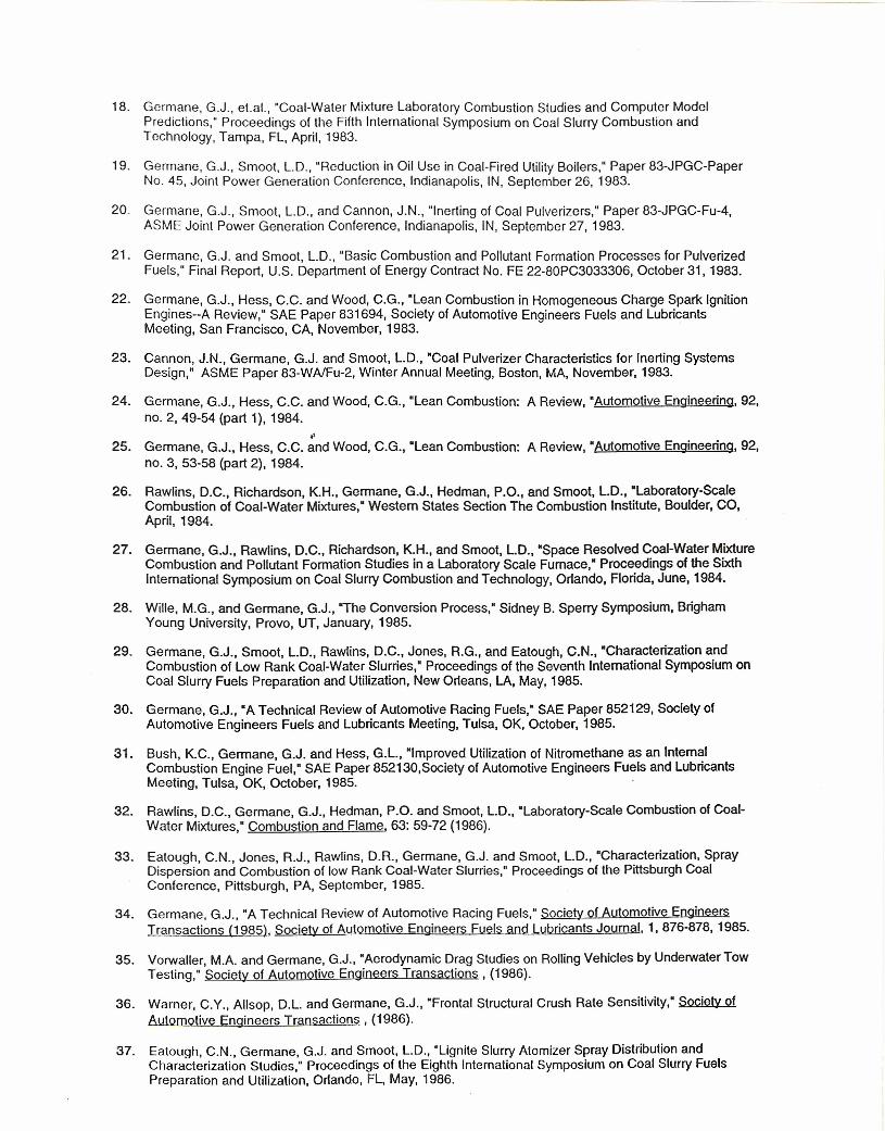
18. Germane, G.J., et.al., "Coal-Water Mixture Laboratory Combustion Studies and Computer ModelPredictions," Proceedings of the Fifth International Symposium on Coal Slurry Combustion andTechnology, Tampa, FL, April,1983.
19. Germane, G.J., Smoot, L.D., "Reduction in Oil Use in Coal-Fired Utility Boilers," Paper 83-JPGC-PaperNo. 45, Joint Power Generation Conference, Indianapolis, IN, September 26, 1983.
20. Germane, G.J., Smoot, L.D., and Cannon, J.N., "Inerting of Coal Pulverizers," Paper 83-JPGC-Fu-4,ASME Joint Power Generation Conference, Indianapolis, IN, September 27,1983.
21. Germane, G.J. and Smoot, L.D., "Basic Combustion and Pollutant Formation Processes for PulverizedFuels," Final Report, U.S. Department of Energy Contract No. FE 22-80PC3033306, October 31, 1983.
22. Germane, G.J., Hess, C.C. and Wood, C.G., "Lean Combustion in Homogeneous Charge Spark IgnitionEngines--A Review," SAE Paper 831694, Society of Automotive Engineers Fuels and LubricantsMeeting, San Francisco, CA, November, 1983.
23. Cannon, J.N., Germane, G.J. and Smoot, L.D., "Coal Pulverizer Characteristics for Inerting SystemsDesign," ASME Paper 83-WAlFu-2, Winter Annual Meeting, Boston, MA, November, 1983.
24. Germane, G.J., Hess, C.C. and Wood, C.G., "Lean Combustion: A Review, "Automotive Engineering, 92,no. 2, 49-54 (part 1), 1984 . .'
25. Germane, G.J., Hess, C.C. and Wood, C.G., "Lean Combustion: A Review, "Automotive Engineering, 92,no. 3, 53-58 (part 2), 1984.
26. Rawlins, D.C., Richardson, K.H., Germane, G.J., Hedman, P.O., and Smoot, L.D., 'Laboratory-ScaleCombustion of Coal-Water Mixtures,' Western States Section The Combustion Institute, Boulder, CO,April,1984.
27. Germane, G.J., Rawlins, D.C., Richardson, K.H., and Smoot, L.D., "Space Resolved Coal-Water MixtureCombustion and Pollutant Formation Studies in a Laboratory Scale Fumace," Proceedings of the SixthInternational Symposium on Coal Slurry Combustion and Technology, Orlando, Florida, June, 1984.
28. Wille, M.G., and Germane, G.J., "The Conversion Process," Sidney B. Sperry Symposium, BrighamYoung University, Provo, UT, January, 1985.
29. Germane, G.J., Smoot, L.D., Rawlins, D.C., Jones, R.G., and Eatough, C.N., "Characterization andCombustion of Low Rank Coal-Water Slurries," Proceedings of the Seventh International Symposium onCoal Slurry Fuels Preparation and Utilization, New Orleans, LA, May, 1985.
30. Germane, G.J., "A Technical Review of Automotive Racing Fuels," SAE Paper 852129, Society ofAutomotive Engineers Fuels and Lubricants Meeting, Tulsa, OK, October, 1985.
31. Bush, K.C., Germane, G.J. and Hess, G.L., "Improved Utilization of Nitromethane as an IntemalCombustion Engine Fuel," SAE Paper 852130,Society of Automotive Engineers Fuels and LubricantsMeeting, Tulsa, OK, October, 1985.
32. Rawlins, D.C., Germane, G.J., Hedman, P.O. and Smoot, L.D., "Laboratory-Scale Combustion of Coal-Water Mixtures," Combustion and Flame, 63: 59-72 (1986).
33. Eatough, C.N., Jones, R.J., Rawlins, D.R., Germane, G.J. and Smoot, L.D., "Characterization, SprayDispersion and Combustion of low Rank Coal-Water Slurries," Proceedings of the Pittsburgh CoalConference, Pittsburgh, PA, September, 1985.
34. Germane, G.J., "A Technical Review of Automotive Racing Fuels," Society of Automotive EngineersTransactions (1985), Society of Automotive Engineers Fuels and Lubricants Journal, 1,876-878,1985.
35. Vorwaller, M.A. and Germane, G.J., "Aerodynamic Drag Studies on Rolling Vehicles by Underwater TowTesting," Society of Automotive Engineers Transactions, (1986).
36. Warner, C.Y., Allsop, D.L. and Germane, G.J., "Frontal Structural Crush Rate Sensitivity," Society ofAutomotive Engineers Transactions, (1986).
37. Eatough, C.N., Germane, G.J. and Smoot, L.D., "Lignite Slurry Atomizer Spray Distribution andCharacterization Studies," Proceedings of the Eighth International Symposium on Coal Slurry FuelsPreparation and Utilization, Orlando, FL, May, 1986.
38. Rawlins, D.C., Jones, R.G., Germane, G.J., Smoot, L.D., and Paulson, L.E., "Lignite Coal Water SlurryCombustion Characteristics in a Laboratory-Scale Furnace," Proceedings of the Eighth InternationalSymposium on coal Slurry Fuels Preparation and Utilization, Orlando, FL, May, 1986.
39. Rawlins, D.C., Germane, G.J. and Smoot, L.D., "Low Rank Coal-Water Fuel Combustion in a LaboratoryScale Furnace," Combustion and Flame, 74(3):255-266 (1988).
40. Rawlins, D.C., Smoot, L.D. and Germane, G.J., "Comparison of Combustion Characteristics BetweenLignite-Water Slurry and Pulverized Lignite," Western States Section of the Combustion Institute, SaltLake City, UT, April, 1988.
41. Eatough, C.N., Rawlins, D.C., Germane, G.J., and Smoot, L.D., "Lignite Slurry Spray Characterizationand Combustion Studies," Western States Section, The Combustion Institute, Dana Point, CA, October,1988.
42. Eatough, C.N., Boardman, RD., Germane, G.J., and Smoot, L.D., "Comparison of CombustionMeasurements and Model Predictions of Thermal NOx, Temperatures, Velocities and Major Species in aSwirling Natural Gas Diffusion Flame," First Intemational Confemece on Combustion Technologies for aClean Environment, Vilamoura - Portugal, 3-6 September 1991.
43. Cope, R.F., Monson, C.R, Hecker, W.C., and Germane, G.J., "Improved Temperature, Velocity andDiameter Measurements forlChar Particles in Drop-Tube Reactors," Westem States Section of theCombustion Institute, Los Angeles, CA, October, 1991.
44. Boardman, R.D., Eatough, C.N., Germane, G.J., and Smoot, L.D., "Comparison of Measurements andPredictions of Flame Structure and Thermal NOx in a Swirling, Natural Gas Diffusion Flame", Combust.Sci. and Tech. 93,1-6,1992.
45. Monson, C. R, Germane, G. J., Blackham, A. U., and Smoot, L. D., "Experimental Char Oxidation atAtmospheric and Elevated Pressures," Western States SectionlThe Combustion Institute, Berkeley, CA,12 October 1992.
46. Pyper, D., Blackham, S., Warren, D., Hansen, L., Christensen, J., Haslam, J., Germane, G.J., andHedman, P.O., "CARS Temperature Measurements in the BYU Controlled Profile Reactor in Natural Gasand Natural Gas-Assisted Coal Flames," Western States SectionlThe Combustion Institute, Berkeley,CA, 12 October 1992.
47. Germane, G. J., "Thrust Area 6: Model Evaluation Data and Process Strategies," Energy & Fuels,7(6):906-909, November/December 1993.
48. Monson, C. R, and Germane, G. J., "A High Pressure Drop-Tube Facility for Coal Combustion Studies,"Energy & Fuels, 7(6):928-936, NovemberlDecember 1993.
49. Sanderson, D. K., and Germane, G. J., "Composition of Combustion Gases and Particles in a PulverizedCoal-Fired Reactor," Energy & Fuels, 7(6):910-918, NovemberlDecember 1993.
50. Monson, C.R., Germane, G. J., Blackham, A. U., and Smoot, L. D., "Char Oxidation at ElevatedPressures, K accepted for publication in Combustion and Flame.
51. Cope, RF., Monson, C.R., Hecker, W.C., and Germane, G.J., "Improved Temperature, Velocity andDiameter Measurements for Char Particles in Drop-Tube Reactors," Energy & Fuels, 8(4):925-931, 1994.
52. Bateman, K.J., Germane, G.J., Smoot, L.D., and Eatough, C.N., "A Facility for High PressureMeasurement of Reaction Rates of Mm-Sized Coal," accepted for publication in Energy & Fuels, 1994.
53. Bateman, K.J., Smoot, L.D., Germane, G.J., Blackham, A.U., and Eatough, C.N., "Effect of Pressure onOxidation Rates of Mm-Sized Char," accepted for publication in Fuel, 1994.
54. Germane, G.J., "Some Considerations Relating to Side Impact Occupant Protection and ComplianceWith FMVSS 214," American Bar Association, Chicago, Illinois, March, 1995.
Patents1. "Nitromethane Fuel Compositions," U. S. Patent 4,583,991 granted to Geoff J. Germane and Gary L.
Hess, 1986.
2. "Dispenser for Slender Objects, " U. S. Patent granted to Geoff J. Germane, Richard D. Ulrich and David8. Anderson, 1982.

12.0 APPENDIX 6
BAROMETRIC PRESSURE READINGS
22
* WEATHERBANK NOW PUBLISHES A QUARTERLY NEWSLETTER! Subscribe to ** the RainMaker now for just $10 a year! Spring issues will be ** mailed this month! Call Customer Service for more info. ** ** THE POLLEN INDEX MAP HAS BEEN REPLACED BY A NEW ULTRAVIOLET ** INDEX MAP! Choose Custom Industrial Graphics from the menu, & ** enter code #1, product GOal to select the new map. ** ---------------------------------------------------------------- ** ** ISO-GRAPHIC menu has been upgraded for version 5.0! ** ** See the HELP NEWS file for details on downloading upgrades. ** WEATHERBANK MOVES! See the HELP MOVE file for our new info. ** CUSTOMER SERVICE: (M-F, 8:30 am - 6:00 pm. CT) .. 405-359-0773 ** INTERNET E-Mail Address:[email protected] ** INTERNET Home Page: http://www.thor.net/-wxbank *********************************************************************ONLINE ....+STATION FILE: WI 06-18-16 GMTDY-HR TOWN TMP DEW HUM FLK WIND GST PRSSR VSBLY-WX CLOUD COVER====== ============ --- --- ======== ===== ======== ===============18-04P Eau Claire 94 62 35 103 /0 6 BKN 10 OVC18-04P*Eau Claire EAU SP 1608 5 SCT E10 OVC 21/2L-F/0608/98118-04P*Eau Claire EAU SP 1620 8 SCT E10 OVC 7/0605/98118-05P Eau Claire 63 60 90 64 E 10 29.81 10 10 OVC18-06P Eau Claire 64 62 93 69 E 7 29.81 15 10 OVC18-07P Eau Claire 67 60 78 70 E 9G16 29.80 15 14 OVC18-08P Eau Claire 65 60 84 69 E 7G17 29.81 15 14 OVC18-09P Eau Claire 66 61 84 71 NE 7 29.81 15 14 OVC18-10P Eau Claire 66 61 84 70 E 8 29.81 15 14 OVC18-11P Eau Claire 66 61 84 70 NE 8 29.81 15 16 OVC
DY-HR TOWN TMP DEW HUM FLK WIND GST PRSSR VSBLY-WX CLOUD COVER====== ============ ======== ===== ======== ===============18-04P Rhinelander 58 47 E 14G21 29.87 3R-F 6 OVC18-05P Rhinelander 58 47 E 14 29.88 3L-F 6 OVC18-06P Rhinelander 58 50 E 10 29.88 3F 4 OVC18-07P Rhinelander 59 52 E 10 29.88 21/2R-F 4 BKN 8 OVC18-08P*Rhinelander18-09P*Rhinelander18-09P*Rhinelander RHI SP 2107 E7 BKN 10 OVC 5R-F 60/M/0807/98718-10P Rhinelander 61 53 NE 11 29.86 6R-F 7 OVC18-11P Rhinelander 61 54 E 10 29.86 7 6 BKN 10 OVCDY-HR TOWN TMP DEW HUM FLK WIND GST PRSSR VSBLY-WX CLOUD COVER====== ============ --- ======== ===== ======== ===============18-04P Wausau 60 57 90 59 E 10 29.83 7R- 7 OVC18-05P Wausau 61 58 90 63 E 7 29.84 7 7 OVC18-06P Wausau 61 58 90 61 NE 9 29.84 7 7 OVC18-07P Wausau 61 59 93 66 E 5 29.84 7R- 7 OVC18-07P*Wausau AUW SP 1920 E7 OVC 10 0703/984/RE1818-08P Wausau 61 58 90 62 E 8 29.84 10 7 OVC18-08P*Wausau AUW SP 2024 E8 OVC 10 0705/98318-09P Wausau 62 58 87 60 E 11 29.84 10 8 OVC18-10P Wausau 62 58 87 65 NE 6 29.83 10 8 OVC18-11P Wausau 62 58 87 64 E 7 29.82 10 8 OVCDY-HR TOWN TMP DEW HUM FLK WIND GST PRSSR VSBLY-WX CLOUD COVER====== ============ --- ======== ===== ======== ===============18-04P Mosinee 57 56 96 53 E 11 29.82 10R- 7 OVC18-05P Mosinee 57 56 96 53 E 11 29.83 7 7 OVC
18-06P Mosinee 58 56 93 55 NE 10 29.82 10R- 7 OVC18-07P Mosinee 58 56 93 52 E 15G18 29.83 10 9 OVC18-08P Mosinee 59 57 93 55 NE 13 29.83 10 9 OVC18-09P Mosinee 59 57 93 55 E 14G20 29.83 10 7 OVC18-10P Mosinee 59 57 93 55 NE 13 29.82 10 7 OVC18-11P Mosinee 59 57 93 55 E 14 29.81 10 7 OVC
DY-HR TOWN TMP DEW HUM FLK WIND GST PRSSR VSBLY-WX CLOUD COVER====== ============ --- ======== ===== ======== ===============18-04P Green Bay 60 60 100 60 NE 11 29.82 11/4R-L- 3 OVC18-05P Green Bay 61 60 97 60 NE 13 29.81 2R-L-F 3 OVC18-06P Green Bay 61 60 97 59 NE 14 29.81 21/4F 3 OVC18-07P Green Bay 60 60 100 60 NE 11 29.82 2F 3 OVC18-08P Green Bay 61 60 97 61 NE 11 29.81 2F 3 OVC18-09P Green Bay 61 60 97 62 NE 10 29.80 21/2F 5 OVC18-10P Green Bay 61 60 97 62 NE 10 29.79 2L-F 5 OVC18-11P Green Bay 62 60 93 61 NE 13 29.79 2L-F 5 OVC
DY-HR TOWN TMP DEW HUM FLK WIND GST PRSSR VSBLY-WX CLOUD COVER====== ============ ======== ===== ======== ===============18-04P Appleton 59 59 100 54 E 17 29.80 1/4R-F 1 X18-05P Appleton 60 60 100 54 NE 23 29.80 3/8R-F 1 X18-06P Appleton 60 60 100 56 NE 17 29.79 1/8F 1 X18-07P Appleton 60 60 100 56 NE 17 29.80 3/8F 1 X18-08P Appleton 60 59 97 55 NE 17 29.80 1/4F 1 X18-09P Appleton 60 59 97 55 NE 17 29.79 1/4F 1 X18-09P*Appleton ATW SP 2125 W1 X 1/2L-F 0516/97818-10P Appleton 60 59 97 55 NE 17 29.78 3/4L-F 2 X18-11P Appleton 60 60 100 57 NE 16 29.78 1L-F 2 X
DY-HR TOWN TMP DEW HUM FLK WIND GST PRSSR VSBLY-WX CLOUD COVER====== ============ --- ======== ===== ======== ===============18-04P Oshkosh 62 61 97 62 E 11 29.77 1/2F 0 3 OVC18-05P Oshkosh 62 61 97 63 E 10 29.78 1/2F 3 OVC18-06P Oshkosh 62 61 97 63 E 10 29.77 3/4F 3 OVC18-07P Oshkosh 62 62 100 65 E 9 29.78 1/2F 3 OVC18-08P Oshkosh 62 62 100 62 NE 13 29.78 1R-F 1 OVC18-09P Oshkosh 63 62 97 66 E 9 29.77 1R-F 0 3 OVC18-10P Oshkosh 63 62 97 65 NE 11 29.76 3/4R-F 0 3 OVC18-11P Oshkosh 62 61 97 61 NE 14 29.76 1/4F 0 3 OVC
DY-HR TOWN TMP DEW HUM FLK WIND GST PRSSR VSBLY-WX CLOUD COVER====== ============ ======== ===== ======== ===============18-04P Manitowoc 56 54 93 53 NE 9 29.78 1/2 X 2 OVC18-05P Manitowoc 56 54 93 53 NE 9 29.77 1/2 2 OVC18-06P Manitowoc 57 55 93 56 NE 8 29.77 5 2 OVC18-07P Manitowoc 57 54 90 54 NE 9 29.77 5 2 OVC18-08P Manitowoc 56 54 93 54 NE 8 29.77 4 2 BKN 44 OVC18-09P Manitowoc 57 54 90 58 N 6 29.76 5 2 BKN 40 OVC18-10P Manitowoc 56 53 90 55 N 7 29.75 4 4 BKN 46 OVC18-11P Manitowoc 55 52 90 53 NE 7 29.75 1/2 4 OVC
DY-HR TOWN TMP DEW HUM FLK WIND GST PRSSR VSBLY-WX CLOUD COVER====== ============ ======== ===== ======== ===============18-04P La Crosse 64 61 90 68 NE 7 29.77 21/2F 5 OVC18-05P La Crosse 65 61 87 69 N 7 29.78 3F 7 OVC18-06P La Crosse 65 61 87 68 NE 9 29.78 6F 7 OVC18-07P La Crosse 65 61 87 69 NE 8 29.78 SF 9 OVC18-08P La Crosse 66 62 87 71 E 8 29.78 5F 7 OVC18-09P La Crosse 67 62 84 71 NE 9 29.77 6H 13 OVC
18-10P La Crosse 67 62 84 72 NE 8 29.78 10 10 OVC18-11P La Crosse 66 61 84 72 NE 6 29.78 8 10 OVCDY-HR TOWN TMP DEW HUM FLK WIND GST PRSSR VSBLY-WX CLOUD COVER====== ============ --- --- --- ======== ===== ======== ===============18-04P Camp Douglas 62 60 93 64 E 9 29.77 5L-F 5 OVC18-05P Camp Douglas 62 60 93 64 E 9 29.78 5L-F 5 BKN 13 OVC18-06P Camp Douglas 63 61 93 64 NE 10 29.78 3L-F 5 BKN 11 OVC18-07P Camp Douglas 63 60 90 66 NE 8 29.78 7R- 5 SCT 12 OVC18-08P Camp Douglas 62 60 93 63 NE 10 29.78 6R- 7 SCT 12 OVC18-09P Camp Douglas 63 59 87 63 NE 10 29.79 7 12 OVC18-10P*Camp Douglas18-11P*Camp Douglas
DY-HR TOWN TMP DEW HUM FLK WIND GST PRSSR VSBLY-WX CLOUD COVER====== ============ --- ======== ===== ======== ===============18-04P Madison 66 65 97 75 E 6 29.73 2F 3 OVC18-05P Madison 66 66 100 74 NE 8 29.72 2F 3 OVC18-06P Madison 66 66 100 75 NE 7 29.73 1/2F 3 OVC18-07P Madison 67 66 97 75 N 8 29.73 1/2F 5 OVC18-08P Madison 66 65 97 69 N 14 29.74 1/2F 7 OVC18-09P Madison 66 65 97 69 NE 13 29.73 5F OVC18-10P Madison 67 65 93 72 NE 10 29.73 10+ 9 OVC18-11P Madison 67 65 93 73 NE 9 29.72 10+ OVC
DY-HR TOWN TMP DEW HUM FLK WIND GST PRSSR VSBLY-WX CLOUD COVER====== ============ --- --- ======== ===== ======== ===============18-04P Janesville S 7 29.71 7 47 BKN 100 OVC18-05P Janesville SW 7 29.71 7 47 BKN 100 OVC18-06P*Janesville18-07P Janesville N 8 29.71 4F 12 BKN 40 OVC18-08P Janesville E 11 29.71 5RF 13 BKN 40 OVC18-09P*Janesville18-09P*Janesville JVL SP 2124 M7 BKN 20 OVC 2RW-F 0112/97118-10P Janesville N 11 29.71 11/2RW-F 7 BKN 27 OVC18-11P Janesville N 9 29.71 11/2RW-F 4 OVC
DY-HR TOWN TMP DEW HUM FLK WIND GST PRSSR VSBLY-WX CLOUD COVER====== ============ --- ======== ===== ======== ===============18-04P Milwke Mitch 59 58 97 62 E 6 29.73 1/4R-F 0 1 X18-05P Milwke Mitch 59 59 100 64 NE 5 29.73 1/2F 0 1 OVC18-06P Milwke Mitch 60 59 97 63 N 7 29.72 1/4F 0 1 OVC18-07P Milwke Mitch 57 56 96 52 N 13 29.73 1/2R-F 0 1 OVC18-08P Milwke Mitch 58 56 93 57 N 8 29.73 1/2F 0 1 OVC18-09P Milwke Mitch 60 57 90 62 NE 7 29.73 1/2F 1 OVC18-10P Milwke Mitch 58 56 93 59 N 7 29.72 1/2F 3 OVC18-11P Milwke Mitch 56 55 96 56 N 7 29.72 1/4F 1 OVC
DY-HR TOWN TMP DEW HUM FLK WIND GST PRSSR VSBLY-WX CLOUD COVER====== ============ ======== ===== ======== ===============18-04P Milwke Timme E 6 29.75 1/4F 0 X18-05P Milwke Timme E 9 29.75 1/4F 0 X18-06P Milwke Timme E 9 29.75 1/2R-F 1 X18-06P*Milwke Timme MWC SA 1745 W1 X 1/2R-F M/M/0908/97518-07P Milwke Timme NE 11 29.76 3/4R-F X 3 OVC18-08P Milwke Timme NE 11 29.75 1F X 3 OVC18-09P Milwke Timme NE 11 29.74 5/8F 1 X18-10P Milwke Timme NE 11 29.74 3/8F 1 X18-11P Milwke Timme NE 9 29.74 5/16F 0 X
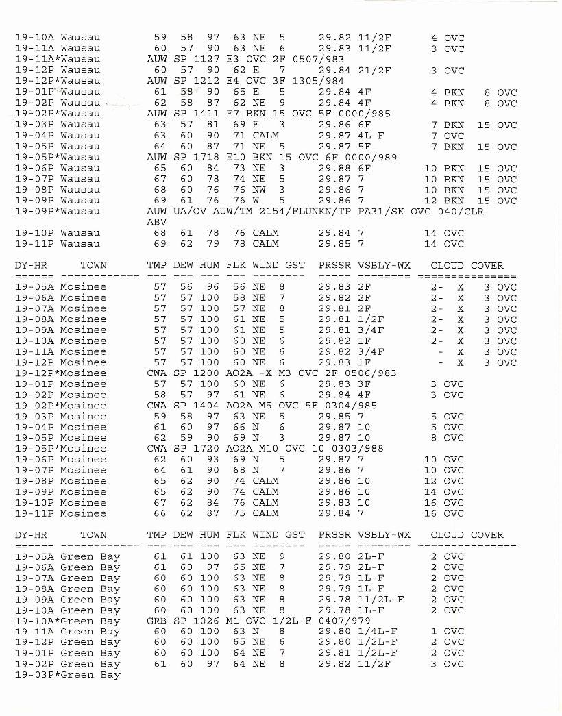
19-10A Wausau 59 58 97 63 NE 5 29.82 11/2F 4 OVC19-11A Wausau 60 57 90 63 NE 6 29.83 11/2F 3 OVC19-11A*Wausau AUW SP 1127 E3 OVC 2F 0507/98319-12P Wausau 60 57 90 62 E 7 29.84 21/2F 3 OVC19-12P*Wausau AUW SP 1212 E4 OVC 3F 1305/98419-01P'Wausau 61 5'8 90 65 E 5 29.84 4F 4 BKN 8 OVC19-02-PWausau, 62 58 87 62 NE 9 29.84 4F 4 BKN 8 OVC19==02P*Wausau AUW SP 1411 E7 BKN 15 OVC 5F 0000/98519-03P Wausau 63 57 81 69 E 3 29.86 6F 7 BKN 15 OVC19-04P Wausau 63 60 90 71 CALM 29.87 4L-F 7 OVC19-05P Wausau 64 60 87 71 NE 5 29.87 5F 7 BKN 15 OVC19-05P*Wausau AUW SP 1718 E10 BKN 15 OVC 6F 0000/98919-06P Wausau 65 60 84 73 NE 3 29.88 6F 10 BKN 15 OVC19-07P Wausau 67 60 78 74 NE 5 29.87 7 10 BKN 15 OVC19-08P Wausau 68 60 76 76 NW 3 29.86 7 10 BKN 15 OVC19-09P Wausau 69 61 76 76 W 5 29.86 7 12 BKN 15 OVC19-09P*Wausau AUW UA/OV AUW/TM 2154/FLUNKN/TP PA31/SK OVC 040/CLR
ABV19-10P Wausau 68 61 78 76 CALM 29.84 7 14 OVC19-11P Wausau 69 62 79 78 CALM 29.85 7 14 OVCDY-HR TOWN TMP DEW HUM FLK WIND GST PRSSR VSBLY-WX CLOUD COVER====== ============ ======== ===== ======== ===============19-05A Mosinee 57 56 96 56 NE 8 29.83 2F 2- X 3 OVC19-06A Mosinee 57 57 100 58 NE 7 29.82 2F 2- X 3 OVC19-07A Mosinee 57 57 100 57 NE 8 29.81 2F 2- X 3 OVC19-08A Mosinee 57 57 100 61 NE 5 29.81 1/2F 2- X 3 OVC19-09A Mosinee 57 57 100 61 NE 5 29.81 3/4F 2- X 3 OVC19-10A Mosinee 57 57 100 60 NE 6 29.82 1F 2- X 3 OVC19-11A Mosinee 57 57 100 60 NE 6 29.82 3/4F X 3 OVC19-12P Mosinee 57 57 100 60 NE 6 29.83 1F X 3 OVC19-12P*Mosinee CWA SP 1200 A02A -X M3 OVC 2F 0506/98319-01P Mosinee 57 57 100 60 NE 6 29.83 3F 3 OVC19-02P Mosinee 58 57 97 61 NE 6 29.84 4F 3 OVC19-02P*Mosinee CWA SP 1404 A02A M5 OVC 5F 0304/98519-03P Mosinee 59 58 97 63 NE 5 29.85 7 5 OVC19-04P Mosinee 61 60 97 66 N 6 29.87 10 5 OVC19-05P Mosinee 62 59 90 69 N 3 29.87 10 8 OVC19-05P*Mosinee CWA SP 1720 A02A M10 OVC 10 0303/98819-06P Mosinee 62 60 93 69 N 5 29.87 7 10 OVC19-07P Mosinee 64 61 90 68 N 7 29.86 7 10 OVC19-08P Mosinee 65 62 90 74 CALM 29.86 10 12 OVC19-09P Mosinee 65 62 90 74 CALM 29.86 10 14 OVC19-10P Mosinee 67 62 84 76 CALM 29.83 10 16 OVC19-11P Mosinee 66 62 87 75 CALM 29.84 7 16 OVC
DY-HR TOWN TMP DEW HUM FLK WIND GST PRSSR VSBLY-WX CLOUD COVER====== ============ ======== ===== ======== ===============19-05A Green Bay 61 61 100 63 NE 9 29.80 2L-F 2 OVC19-06A Green Bay 61 60 97 65 NE 7 29.79 2L-F 2 OVC19-07A Green Bay 60 60 100 63 NE 8 29.79 1L-F 2 OVC19-08A Green Bay 60 60 100 63 NE 8 29.79 1L-F 2 OVC19-09A Green Bay 60 60 100 63 NE 8 29.78 11/2L-F 2 OVC19-10A Green Bay 60 60 100 63 NE 8 29.78 1L-F 2 OVC19-10A*Green Bay GRB SP 1026 M1 OVC 1/2L-F 0407/97919-11A Green Bay 60 60 100 63 N 8 29.80 1/4L-F 1 OVC19-12P Green Bay 60 60 100 65 NE 6 29.80 1/2L-F 2 OVC19-01P Green Bay 60 60 100 64 NE 7 29.81 1/2L-F 2 OVC19-02P Green Bay 61 60 97 64 NE 8 29.82 11/2F 3 OVC19-03P*Green Bay
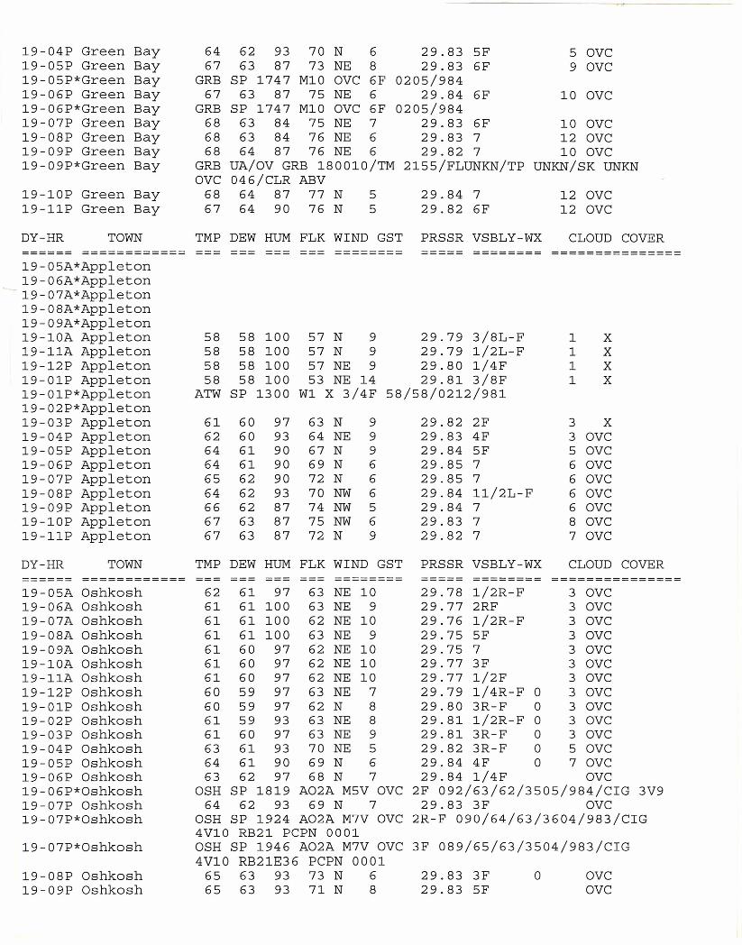
19-04P Green Bay 64 62 93 70 N 6 29.83 5F 5 OVC19-05P Green Bay 67 63 87 73 NE 8 29.83 6F 9 OVC19-05P*Green Bay GRB SP 1747 M10 OVC 6F 0205/98419-06P Green Bay 67 63 87 75 NE 6 29.84 6F 10 OVC19-06P*Green Bay GRB SP 1747 M10 OVC 6F 0205/98419-07P Green Bay 68 63 84 75 NE 7 29.83 6F 10 OVC19-08P Green Bay 68 63 84 76 NE 6 29.83 7 12 OVC19-09P Green Bay 68 64 87 76 NE 6 29.82 7 10 OVC19-09P*Green Bay GRB UA/OV GRB 180010/TM 2155/FLUNKN/TP UNKN/SK UNKN
OVC 046/CLR ABV19-10P Green Bay 68 64 87 77 N 5 29.84 7 12 OVC19-11P Green Bay 67 64 90 76 N 5 29.82 6F 12 OVC
DY-HR TOWN TMP DEW HUM FLK WIND GST PRSSR VSBLY-WX CLOUD COVER====== ============ ======== ===== ======== ===============19-05A*Appleton19-06A*Appleton
-19-07A*Appleton19-08A*Appleton19-09A*Appleton19-10A Appleton 58 58 100 57 N 9 29.79 3/8L-F 1 X19-11A Appleton 58 58 100 57 N 9 29.79 1/2L-F 1 X19-12P Appleton 58 58 100 57 NE 9 29.80 1/4F 1 X19-01P Appleton 58 58 100 53 NE 14 29.81 3/8F 1 X19-01P*Appleton ATW SP 1300 W1 X 3/4F 58/58/0212/98119-02P*Appleton19-03P Appleton 61 60 97 63 N 9 29.82 2F 3 X19-04P Appleton 62 60 93 64 NE 9 29.83 4F 3 OVC19-05P Appleton 64 61 90 67 N 9 29.84 5F 5 OVC19-06P Appleton 64 61 90 69 N 6 29.85 7 6 OVC19-07P Appleton 65 62 90 72 N 6 29.85 7 6 OVC19-08P Appleton 64 62 93 70 NW 6 29.84 11/2L-F 6 OVC19-09P Appleton 66 62 87 74 NW 5 29.84 7 6 OVC19-10P Appleton 67 63 87 75 NW 6 29.83 7 8 OVC19-11P Appleton 67 63 87 72 N 9 29.82 7 7 OVC
DY-HR TOWN TMP DEW HUM FLK WIND GST PRSSR VSBLY-WX CLOUD COVER====== ============ ======== ===== ======== ===============19-05A Oshkosh 62 61 97 63 NE 10 29.78 1/2R-F 3 OVC19-06A Oshkosh 61 61 100 63 NE 9 29.77 2RF 3 OVC19-07A Oshkosh 61 61 100 62 NE 10 29.76 1/2R-F 3 OVC19-08A Oshkosh 61 61 100 63 NE 9 29.75 5F 3 OVC19-09A Oshkosh 61 60 97 62 NE 10 29.75 7 3 OVC19-10A Oshkosh 61 60 97 62 NE 10 29.77 3F 3 OVC19-11A Oshkosh 61 60 97 62 NE 10 29.77 1/2F 3 OVC19-12P Oshkosh 60 59 97 63 NE 7 29.79 1/4R-F 0 3 OVC19-01P Oshkosh 60 59 97 62 N 8 29.80 3R-F 0 3 OVC19-02P Oshkosh 61 59 93 63 NE 8 29.81 1/2R-F 0 3 OVC19-03P Oshkosh 61 60 97 63 NE 9 29.81 3R-F 0 3 OVC19-04P Oshkosh 63 61 93 70 NE 5 29.82 3R-F 0 5 OVC19-05P Oshkosh 64 61 90 69 N 6 29.84 4F 0 7 OVC19-06P Oshkosh 63 62 97 68 N 7 29.84 1/4F OVC19-06P*Oshkosh OSH SP 1819 A02A M5V OVC 2F 092/63/62/3505/984/CIG 3V919-07P Oshkosh 64 62 93 69 N 7 29.83 3F OVC19-07P*Oshkosh OSH SP 1924 A02A M7V OVC 2R-F 090/64/63/3604/983/CIG
4V10 RB21 PCPN 000119-07P*Oshkosh OSH SP 1946 A02A M7V OVC 3F 089/65/63/3504/983/CIG
4V10 RB21E36 PCPN 000119-08P Oshkosh 65 63 93 73 N 6 29.83 3F 0 OVC19-09P Oshkosh 65 63 93 71 N 8 29.83 5F OVC
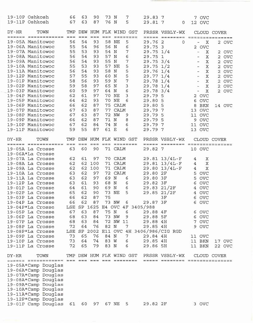
19-10P Oshkosh 66 63 90 73 N 7 29.83 7 7 OVC19-11P Oshkosh 67 63 87 76 N 5 29.81 7 0 12 OVCDY-HR TOWN TMP DEW HUM FLK WIND GST PRSSR VSBLY-WX CLOUD COVER====== ============ --- ======== ===== ======== ===============19-05A Manitowoc 56 54 93 58 NE 5 29.76 2 0 X 2 OVC19-06A Manitowoc 55 54 96 56 N 6 29.75 3 2 OVC19-07A Manitowoc 55 53 93 54 N 7 29.75 1/4 X 2 OVC19-08A Manitowoc 56 54 93 57 N 6 29.75 1 X 2 OVC19-09A Manitowoc 56 54 93 55 N 7 29.75 3/4 X 2 OVC19-10A Manitowoc 55 53 93 57 NE 5 29.75 1/2 X 2 OVC19-11A Manitowoc 56 54 93 58 N 5 29.76 1/4 X 2 OVC19-12P Manitowoc 57 55 93 60 N 5 29.77 1/4 X 2 OVC19-01P Manitowoc 58 56 93 59 N 7 29.78 1/4 X 2 OVC19-02P Manitowoc 59 58 97 65 N 3 29.78 1/4 X 2 OVC19-03P Manitowoc 60 59 97 64 N 6 29.78 3/4 X 2 OVC19-04P Manitowoc 62 61 97 70 NE 3 29.79 5 2 OVC19-05P Manitowoc 64 62 93 70 NE 6 29.80 5 6 OVC19-06P Manitowoc 66 62 87 75 CALM 29.80 5 8 BKN 14 OVC19-07P Manitowoc 67 63 87 77 CALM 29.79 7 13 OVC19-08P Manitowoc 67 63 87 72 NW 9 29.79 5 11 OVC19-09P Manitowoc 66 62 87 71 N 8 29.79 5 9 OVC19-10P Manitowoc 67 62 84 74 N 6 29.79 7 11 OVC19-11P Manitowoc 59 55 87 61 E 6 29.79 7 13 OVC
DY-HR TOWN TMP DEW HUM FLK WIND GST PRSSR VSBLY-WX CLOUD COVER====== ============ ======== ===== ======== ===============19-05A La Crosse 63 60 90 71 CALM 29.82 7 10 OVC19-06A*La Crosse19-07A La Crosse 62 61 97 70 CALM 29.81 13/4L-F 4 X19-08A La Crosse 62 62 100 71 CALM 29.81 13/4L-F 4 X19-09A La Crosse 62 62 100 71 CALM 29.80 13/4L-F 4 X19-10A La Crosse 63 62 97 72 CALM 29.80 2F 5 OVC19-11A La Crosse 63 62 97 69 N 6 29.80 3F 5 OVC19-12P La Crosse 63 61 93 68 N 6 29.82 3F 6 OVC19-01P La Crosse 64 61 90 69 N 6 29.83 21/2F 4 OVC19-02P La Crosse 65 62 90 73 NE 5 29.85 21/2F 4 OVC19-03P La Crosse 66 62 87 75 3F 6 OVC19-04P La Crosse 66 62 87 73 NW 6 29.87 3F 6 OVC19-04P*La Crosse LSE SP 1625 E4 OVC 4F 3405/98819-05P La Crosse 67 63 87 75 N 6 29.88 4F 6 OVC19-06P La Crosse 68 63 84 73 NW 9 29.88 5F 6 OVC19-07P La Crosse 68 63 84 72 NW 11 29.88 4H 7 OVC19-08P La Crosse 72 64 76 82 N 7 29.85 4H 9 OVC19-08P*La Crosse LSE SP 2002 Ell OVC 4H 3406/986/CIG RGD19-09P La Crosse 73 65 76 84 N 7 29.84 4H 11 OVC19-10P La Crosse 73 64 74 83 W 6 29.85 4H 11 BKN 17 OVC19-11P La Crosse 72 65 79 83 N 6 29.86 5H 11 BKN 22 OVC
DY-HR TOWN TMP DEW HUM FLK WIND GST PRSSR VSBLY-WX CLOUD COVER====== ============ ======== ===== ======== ===============19-05A*Camp Douglas19-06A*Camp Douglas19-07A*Camp Douglas19-08A*Camp Douglas19-09A*Camp Douglas19-10A*Camp Douglas19-11A*Camp Douglas19-12P*Camp Douglas19-01P Camp Douglas 61 60 97 67 NE 5 29.82 2F 3 OVC
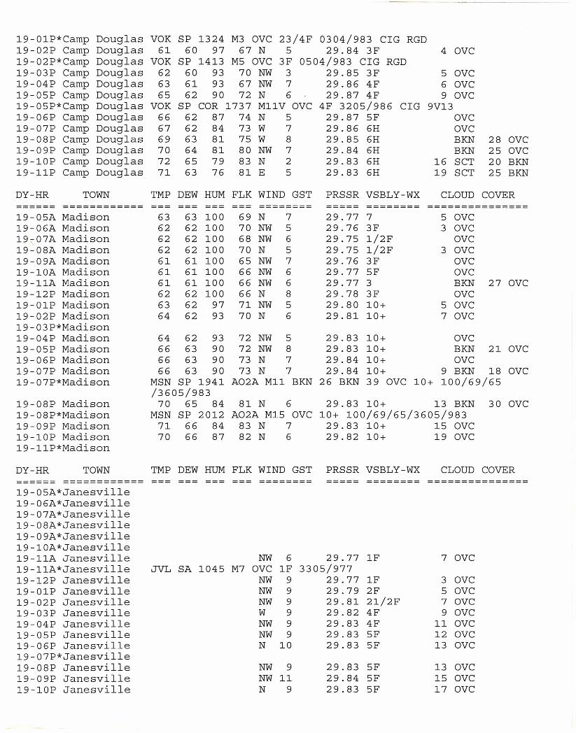
19-01P*Camp Douglas VOK SP 1324 M3 OVC 23/4F 0304/983 CIG RGD19-02P Camp Douglas 61 60 97 67 N 5 29.84 3F 4 OVC19-02P*Camp Douglas VOK SP 1413 M5 OVC 3F 0504/983 CIG RGD19-03P Camp Douglas 62 60 93 70 NW 3 29.85 3F 5 OVC19-04P Camp Douglas 63 61 93 67 NW 7 29.86 4F 6 OVC19-05P Camp Douglas 65 62 90 72 N 6 29.87 4F 9 OVC19-05P*Camp Douglas VOK SP COR 1737 M11V OVC 4F 3205/986 CIG 9V1319-06P Camp Douglas 66 62 87 74 N 5 29.87 5F OVC19-07P Camp Douglas 67 62 84 73 W 7 29.86 6H OVC19-08P Camp Douglas 69 63 81 75 W 8 29.85 6H BKN 28 OVC19-09P Camp Douglas 70 64 81 80 NW 7 29.84 6H BKN 25 OVC19-10P Camp Douglas 72 65 79 83 N 2 29.83 6H 16 SCT 20 BKN19-11P Camp Douglas 71 63 76 81 E 5 29.83 6H 19 SCT 25 BKN
DY-HR TOWN TMP DEW HUM FLK WIND GST PRSSR VSBLY-WX CLOUD COVER====== ============ --- --- ======== ===== ======== ===============19-05A Madison 63 63 100 69 N 7 29.77 7 5 OVC19-06A Madison 62 62 100 70 NW 5 29.76 3F 3 OVC19\07A Madison 62 62 100 68 NW 6 29.75 1/2F OVC19-08A Madison 62 62 100 70 N 5 29.75 1/2F 3 OVC19-09A Madison 61 61 100 65 NW 7 29.76 3F OVC19-10A Madison 61 61 100 66 NW 6 29.77 5F OVC19-11A Madison 61 61 100 66 NW 6 29.77 3 BKN 27 OVC19-12P Madison 62 62 100 66 N 8 29.78 3F OVC19-01P Madison 63 62 97 71 NW 5 29.80 10+ 5 OVC19-02P Madison 64 62 93 70 N 6 29.81 10+ 7 OVC19-03P*Madison19-04P Madison 64 62 93 72 NW 5 29.83 10+ OVC19-05P Madison 66 63 90 72 NW 8 29.83 10+ BKN 21 OVC19-06P Madison 66 63 90 73 N 7 29.84 10+ OVC19-07P Madison 66 63 90 73 N 7 29.84 10+ 9 BKN 18 OVC19-07P*Madison MSN SP 1941 A02A M11 BKN 26 BKN 39 OVC 10+ 100/69/65
/3605/98319-08P Madison 70 65 84 81 N 6 29.83 10+ 13 BKN 30 OVC19-08P*Madison MSN SP 2012 A02A M15 OVC 10+ 100/69/65/3605/98319-09P Madison 71 66 84 83 N 7 29.83 10+ 15 OVC19-10P Madison 70 66 87 82 N 6 29.82 10+ 19 OVC19-11P*Madison
DY-HR TOWN TMP DEW HUM FLK WIND GST PRSSR VSBLY-WX CLOUD COVER====== ============ ======== ===== ======== ===============19-05A*Janesville19-06A*Janesville19-07A*Janesville19-08A*Janesville19-09A*Janesville19-10A*Janesville19-11A Janesville NW 6 29.77 1F 7 OVC19-11A*Janesville JVL SA 1045 M7 OVC 1F 3305/97719-12P Janesville NW 9 29.77 1F 3 OVC19-01P Janesville NW 9 29.79 2F 5 OVC19-02P Janesville NW 9 29.81 21/2F 7 OVC19-03P Janesville W 9 29.82 4F 9 OVC19-04P Janesville NW 9 29.83 4F 11 OVC19-05P Janesville NW 9 29.83 5F 12 OVC19-06P Janesville N 10 29.83 5F 13 OVC19-07P*Janesville19-08P Janesville NW 9 29.83 5F 13 OVC19-09P Janesville NW 11 29.84 5F 15 OVC19-10P Janesville N 9 29.83 5F 17 OVC
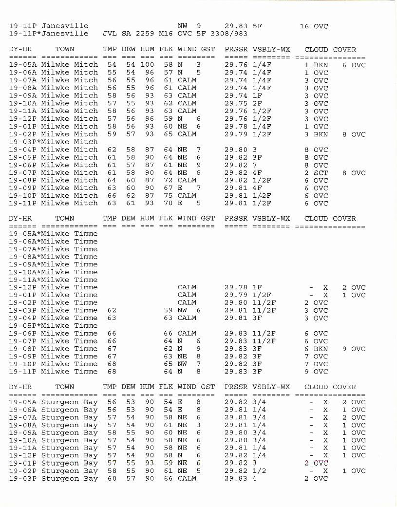
19-11P Janesville19-11P*Janesville
NW 9 29.83 5FJVL SA 2259 M16 OVC 5F 3308/983
DY-HR TOWN TMP DEW HUM FLK WIND GST PRSSR VSBLY-WX============== ============
19-05A Milwke Mitch 5419-06A Milwke Mitch 5519-07A Milwke Mitch 5619-08A Milwke Mitch 5619-09A Milwke Mitch 5819-10A Milwke Mitch 5719-11A Milwke Mitch 5819-12P Milwke Mitch 5719-01P Milwke Mitch 5819-02P Milwke Mitch 5919-03P*Milwke Mitch19-04P Milwke Mitch 6219-05P Milwke Mitch 6119-06P Milwke Mitch 6119-07P Milwke Mitch 6119-08P Milwke Mitch 6419-09P Milwke Mitch 6319-10P Milwke Mitch 6619-11P Milwke Mitch 63
54 10054 9655 9655 9656 9355 9356 9356 9656 9357 93
58 8758 9057 8758 9060 8760 9062 8761 93
58 N 357 N 561 CALM61 CALM63 CALM62 CALM63 CALM59 N 660 NE 665 CALM
64 NE 764 NE 661 NE 964 NE 672 CALM67 E 775 CALM70 E 5
=====29.76 1/4F29.74 1/4F29.74 1/4F29.74 1/4F29.74 1F29.75 2F29.76 1/2F29.76 1/2F29.78 1/4F29.79 1/2F
29.80 329.82 3F29.82 729.82 4F29.82 1/2F29.81 4F29.81 1/-2F29.81 1/2F
DY-HR TOWN TMP DEW HUM FLK WIND GST PRSSR VSBLY-WX
19-05A*Milwke Timme19-06A*Milwke Timme19-07A*Milwke Timme19-08A*Milwke Timme19-09A*Milwke Timme19-10A*Milwke Timme19-11A*Milwke Timme19-12P Milwke Timme19-01P Milwke Timme19-02P Milwke Timme19-03P Milwke Timme 6219-04P Milwke Timme 6319-05P*Milwke Timme19-06P Milwke Timme 6619-07P Milwke Timme 6619-08P Milwke Timme 6719-09P Milwke Timme 6719-10P Milwke Timme 6819-11P Milwke Timme 68
CALMCALMCALM
59 NW 663 CALM
66 CALM64 N 662 N 963 NE 865 NW 764 N 8
29.78 1F29.79 1/2F29.80 11/2F29.81 11/2F29.81 3F
29.83 11/2F29.83 11/2F29.83 3F29.82 3F29.82 3F29.83 3F
DY-HR TOWN TMP DEW HUM FLK WIND GST PRSSR VSBLY-WX====== ============19-05A Sturgeon Bay 56 5319-06A Sturgeon Bay 56 5319-07A Sturgeon Bay 57 5419-08A Sturgeon Bay 57 5419-09A Sturgeon Bay 58 5519-10A Sturgeon Bay 57 5419-11A Sturgeon Bay 57 5419-12P Sturgeon Bay 57 5419-01P Sturgeon Bay 57 5519-02P Sturgeon Bay 58 5519-03P Sturgeon Bay 60 57
16 OVC
CLOUD COVER===============
1BKN1 OVC3 OVC3 OVC3 OVC3 OVC3 OVC3 OVC1 OVC3 BKN
8 OVC8 OVC8 OVC2 SCT6 OVC6 OVC6 OVC6 OVC
6 OVC
8 OVC
8 OVC
CLOUD COVER===============
xX
2 OVC3 OVC3 OVC
6 OVC6 OVC6 BKN7 OVC7 OVC9 OVC
2 OVC1 OVC
9 OVC
CLOUD COVER======== ===== ======== ===============
90 54 E 890 54 E 890 58 NE 690 61 NE 390 60 NE 690 58 NE 690 58 NE 690 58 N 693 59 NE 690 61 NE 590 66 CALM
29.82 3/429.81 1/429.81 3/429.81 1/429.80 3/429.80 3/429.81 1/429.82 1/429.82 329.82 1/229.83 4
XXXXXXXX
2 oveX
2 OVC
2 OVC1 OVC2 OVC1 OVC1 OVC1 OVC1 OVC1 OVC
1 OVC
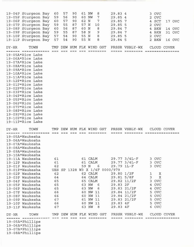
19-04P Sturgeon Bay 60 57 90 61 NW 8 29.83 4 3 OVC19-05P Sturgeon Bay 59 56 90 60 NW 7 29.85 4 2 OVC19-06P Sturgeon Bay 60 57 90 62 N 7 29.85 7 4 SCT 17 OVC19-07P Sturgeon Bay 59 55 87 57 N 10 29.85 5 2 OVC19-08P Sturgeon Bay 60 56 87 60 N 8 29.84 7 4 BKN 14 OVC19-09P Sturgeon Bay 59 55 87 58 N 9 29.84 7 4 BKN 31 OVC19-10P Sturgeon Bay 57 54 90 55 N 8 29.85 5 2 OVC19-11P Sturgeon Bay 57 54 90 55 N 8 29.84 5 2 BKN 16 OVC
DY-HR TOWN TMP DEW HUM FLK WIND GST PRSSR VSBLY-WX CLOUD COVER====== ============ --- ======== ===== ======== ===============19-05A*Rice Lake19-06A*Rice Lake19-07A*Rice Lake19-08A*Rice Lake19-09A*Rice Lake19-10A*Rice Lake19-11A*Rice Lake19-12P*Rice Lake19-01P*Rice Lake19-02P*Rice Lake19-03P*Rice Lake19-04P*Rice Lake19-05P*Rice Lake19-06P*Rice Lake19-07P*Rice Lake19-08P*Rice Lake19-09P*Rice Lake19-10P*Rice Lake19-11P*Rice Lake
DY-HR TOWN TMP DEW HUM FLK WIND GST PRSSR VSBLY-WX CLOUD COVER====== ============ --- ======== ===== ======== ===============19-05A*Waukesha19-06A*Waukesha19-07A*Waukesha19-08A*Waukesha19-09A*Waukesha19-10A*Waukesha19-11A Waukesha 61 61 CALM 29.77 3/4L-F 3 OVC19-12P Waukesha 61 61 CALM 29.77 3/4L-F 3 OVC19-01P Waukesha 62 59 N 6 29.79 lL-F 3 OVC19-01P*Waukesha UES SP 1328 W3 X 1/4F 0000/97919-02P Waukesha 62 62 CALM 29.80 1/2F 1 X19-03P Waukesha 64 64 CALM 29.81 5/8F 3 X19-04P Waukesha 65 65 CALM 29.82 11/2F 3 OVC19-05P Waukesha 65 63 NW 6 29.83 2F 4 OVC19-06P Waukesha 65 63 NW 6 29.83 21/2F 4 OVC19-07P Waukesha 66 60 NW 11 29.84 11/2F 5 OVC19-08P Waukesha 66 60 NW 11 29.84 21/2F 5 OVC19-09P Waukesha 67 61 NW 11 29.83 21/2F 5 OVC19-10P Waukesha 66 60 NW 11 29.83 4F 5 OVC19-11P Waukesha 67 63 NW 8 29.83 4F 6 OVC
DY-HR TOWN TMP DEW HUM FLK WIND GST PRSSR VSBLY-WX CLOUD COVER====== ============ ======== ===== ======== ===============19-05A*Phillips19-06A*Phillips19-07A*Phillips19-08A*Phillips
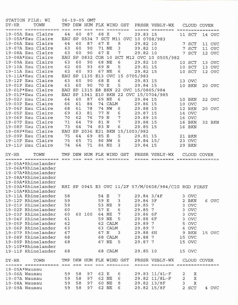
STATION FILE: WI 06-19-05 GMTDY-HR TOWN TMP DEW HUM FLK WIND GST PRSSR VSBLY-WX CLOUD COVER====== ============ --- --- ======== ===== ======== ===============19-05A Eau Claire 64 60 87 68 E 7 29.83 15 11 SCT 14 OVC19-05A*Eau Claire EAU SP 0534 7 SCT M11 OVC 10 0708/98319-06A Eau Claire 64 60 87 67 E 8 29.82 10 7 SCT 11 OVC19-07A Eau Claire 63 60 90 71 NE 3 29.82 10 7 SCT 11 OVC19-08A Eau Claire 63 60 90 67 E 7 29.82 10 7 SCT 12 OVC19-08A*Eau Claire EAU SP 0832 COR 10 SCT M12 OVC 10 0505/98219-09A Eau Claire 63 60 90 68 NE 6 29.82 10 10 SCT 13 OVC19-10A Eau Claire 62 60 93 69 N 5 29.81 15 10 SCT 13 OVC19-11A Eau Claire 62 60 93 67 NE 6 29.82 15 10 SCT 12 OVC19-11A*Eau Claire EAU SP 1135 E13 OVC 15 0705/98319-12P Eau Claire 63 60 90 68 E 6 29.83 15 13 OVC19-01P Eau Claire 63 60 90 70 E 5 29.84 15 10 BKN 20 OVC19-01P*Eau Claire EAU SP 1315 E8 BKN 22 OVC 15/0805/98419-01P*Eau Claire EAU SP 1341 E10 BKN 22 OVC 15/0704/98519-02P Eau Claire 64 60 87 69 NE 6 29.84 15 10 BKN 22 OVC19-03P Eau Claire 66 61 84 74 CALM 29.86 15 10 OVC19-04P Eau Claire 68 61 78 74 NW 6 29.88 15 12 BKN 20 OVC19-05P Eau Claire 69 63 81 77 N 6 29.87 15 14 OVC19-06P Eau Claire 70 62 76 79 N 7 29.89 15 16 OVC19-07P Eau Claire 71 64 79 81 N 7 29.88 15 16 BKN 32 BKN19-08P Eau Claire 73 64 74 83 N 6 29.85 15 16 BKN19-08P*Eau Claire EAU SP 2036 E21 BKN 15/1003/98219-09P Eau Claire 75 64 69 85 E 5 29.81 15 21 BKN19-10P Eau Claire 75 65 71 86 NW 6 29.84 15/ 23 OVC19-11P Eau Claire 74 64 71 84 NE 3 29.84 15 29 BKN
DY-HR TOWN TMP DEW HUM FLK WIND GST PRSSR VSBLY-WX CLOUD COVER====== ============ ======== ===== ======== ===============19-05A*Rhinelander19-06A*Rhinelander19-07A*Rhinelander19-08A*Rhinelander19-09A*Rhinelander19-09A*Rhinelander RHI SP 0945 E3 OVC 11/2F 57/M/0608/984/CIG RGD FIRST19-10A*Rhinelander19-11A Rhinelander 58 54 E 7 29.84 3/4F 3 OVC19-12P Rhinelander 59 59 E 3 29.84 3F 2 BKN 6 OVC19-01P Rhinelander 59 53 NE 9 29.85 7 3 OVC19-02P Rhinelander 60 57 E 6 29.85 7 3 OVC19-03P Rhinelander 60 60 100 64 NE 7 29.86 6F 3 OVC19-04P Rhinelander 61 59 NE 5 29.88 6F 3 OVC19-05P Rhinelander 62 62 CALM 29.89 7 5 OVC19-06P Rhinelander 63 63 CALM 29.89 7 6 OVC19-07P Rhinelander 67 67 N 3 29.88 6H 9 BKN 15 OVC19-08P Rhinelander 68 68 CALM 29.88 7 15 OVC19-09P Rhinelander 68 67 NE 5 29.87 7 15 OVC19-10P*Rhinelander19-11P Rhinelander 68 68 CALM 29.85 10 15 OVC
DY-HR TOWN TMP DEW HUM FLK WIND GST PRSSR VSBLY-WX CLOUD COVER======= ======:;:;:===== ======== ===== ======== ===============19-05A*Wausau19-06A Wausau 59 58 97 62 E 6 29.83 11/4L-F 2 X19-07A Wausau 59 58 97 62 NE 6 29.82 11/8L-F 2 X19-08A Wausau 59 58 97 60 NE 8 29.82 13/8F 3 X19-09A Wausau 59 58 97 62 NE 6 29.82 15/8F 2 SCT 4 OVC
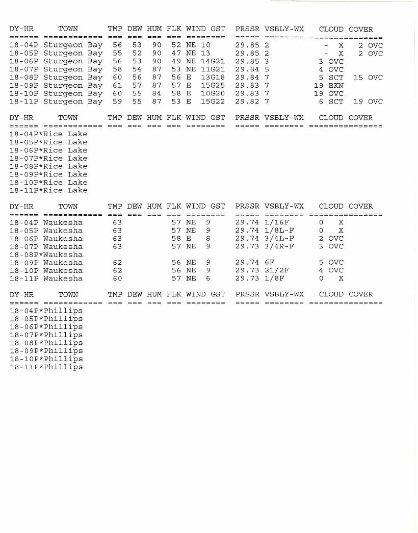
DY-HR TOWN TMP DEW HUM FLK WIND GST PRSSR VSBLY-WX CLOUD COVER====== ============ --- --- --- ======== ===== ======== ===============18-04P Sturgeon Bay 56 53 90 52 NE 10 29.85 2 X 2 OVC18-05P Sturgeon Bay 55 52 90 47 NE 13 29.85 2 X 2 OVC18-06P Sturgeon Bay 56 53 90 49 NE 14G21 29.85 3 3 OVC18-07P Sturgeon Bay 58 54 87 53 NE 11G21 29.84 5 4 OVC18-08P Sturgeon Bay 60 56 87 56 E 13G18 29.84 7 5 SCT 15 OVC18-09P Sturgeon Bay 61 57 87 57 E 15G25 29.83 7 19 BKN18-10P Sturgeon Bay 60 55 84 58 E 10G20 29.83 7 19 OVC18-11P Sturgeon Bay 59 55 87 53 E 15G22 29.82 7 6 SCT 19 OVC
DY-HR TOWN TMP DEW HUM FLK WIND GST PRSSR VSBLY-WX CLOUD COVER====== ============ --- ======== ===== ======== ===============18-04P*Rice Lake18-05P*Rice Lake18-06P*Rice Lake18-07P*Rice Lake18-08P*Rice Lake18-09P*Rice Lake18-10P*Rice Lake18-11P*Rice Lake
DY-HR TOWN TMP DEW HUM FLK WIND GST PRSSR VSBLY-WX CLOUD COVER====== ============ --- ======== ===== ======== ===============18-04P Waukesha 63 57 NE 9 29.74 1/16F 0 X18-05P Waukesha 63 57 NE 9 29.74 1/8L-F 0 X18-06P Waukesha 63 58 E 8 29.74 3/4L-F 2 OVC18-07P Waukesha 63 57 NE 9 29.73 3/4R-F 3 OVC18-08P*Waukesha18-09P Waukesha 62 56 NE 9 29.74 6F 5 OVC18-10P Waukesha 62 56 NE 9 29.73 21/2F 4 OVC18-11P Waukesha 60 57 NE 6 29.73 1/8F 0 X
DY-HR TOWN TMP DEW HUM FLK WIND GST PRSSR VSBLY-WX CLOUD COVER====== ============ --- ======== ===== ======== ===============18-04P*Phillips18-05P*Phillips18-06P*Phillips18-07P*Phillips18-08P*Phillips18-09P*Phillips18-10P*Phillips18-11P*Phillips
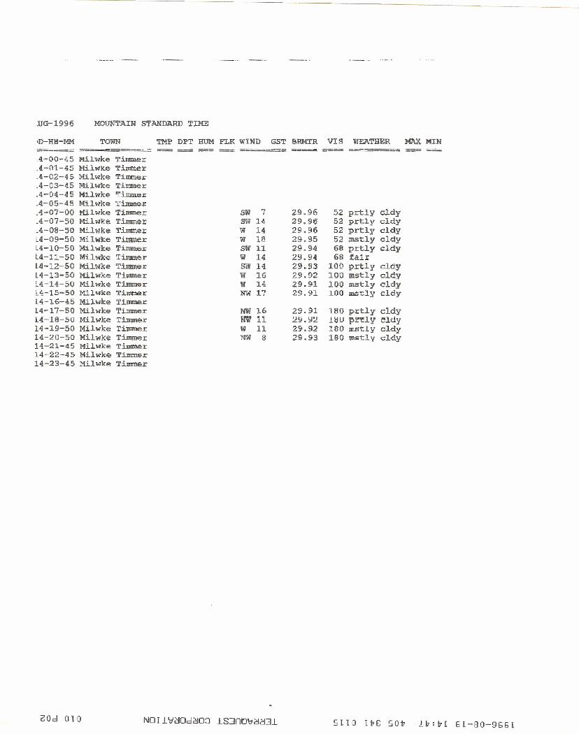
UG-1996 MOU"NTAIN STANDARD TIME
'D-HH-MM TOWN TMI:' DPT HUM FLK w:tND G5T SRMTR VIS WEATHER MAXMIN;;;;;;;====~ ::===----==~=.:......:.=: ===;:;;: -- -_ . -.====~ =-== ~!=.::::;::;:==~ =-;;;= ====.4-00-45 Mi.lwke 'J'.immer.4-0l-45 Mil~ke T i:tnttI.e r.4-02-45 Milwke TiIIIner;;.4-03-45 Milwke Timmer.4-04-45 Milwke TinnneLA-05-45 Milwke Timn'te:x:A-O")-OO !tilwke Timmer SW 7 2.9.96 52 prtly cldyA-07-50 Milwke Timmer sw H. 29.96 52 prtly cldyA-08-50 Milwke Till'l\Tl.er W 14 29.96 52 prtly cldyL4-09-50 Milwke Tirmter w 18 29.95 52 mstly cldyL4-10-50 Milwke Timmer SW 11 29.94 68 prt.Ly c1dyL4.-11-50 Milwke Timmer W 14 29.94 68 fairl4~12-S0 Milwke Timmer SW 14 29.93 100 prtly cldyl4-13-50 Milwke Timmer W 16 29.92 100 mstly cldyL4.-14-50 Milwke Timmer W 14 29.91 100 mstly cldyl4-15~50Milwke T:i~r NW 17 29.91 lOa mstly cldyL4-16-45 M.i.l.wke T.i.mmerl4-17-50 Milwke Timmer NW J.6 29.91 180 prtly cldyl4-16-S0 Milwke Timmer W 11 LY.Y:l HlU ~rny eldy14-19-50 MHwke '.I:' il!Il'lle I W 11 29.92 180 m5tly cldy14-20-50 Milwke 'r~r lIlW 8 29.93 180 It[stl y cldy14.-21-45 Milwke Tinuoer14-22-4.5 Mi.lwkE!: Timmer14-23-45 Mi.lwke Timmer
GOd 010 SLIO Iv8 SOV Lv:vL 5L-80-955L

13.0 APPENDIX 7
CARBON BALANCE TEST DATA
24
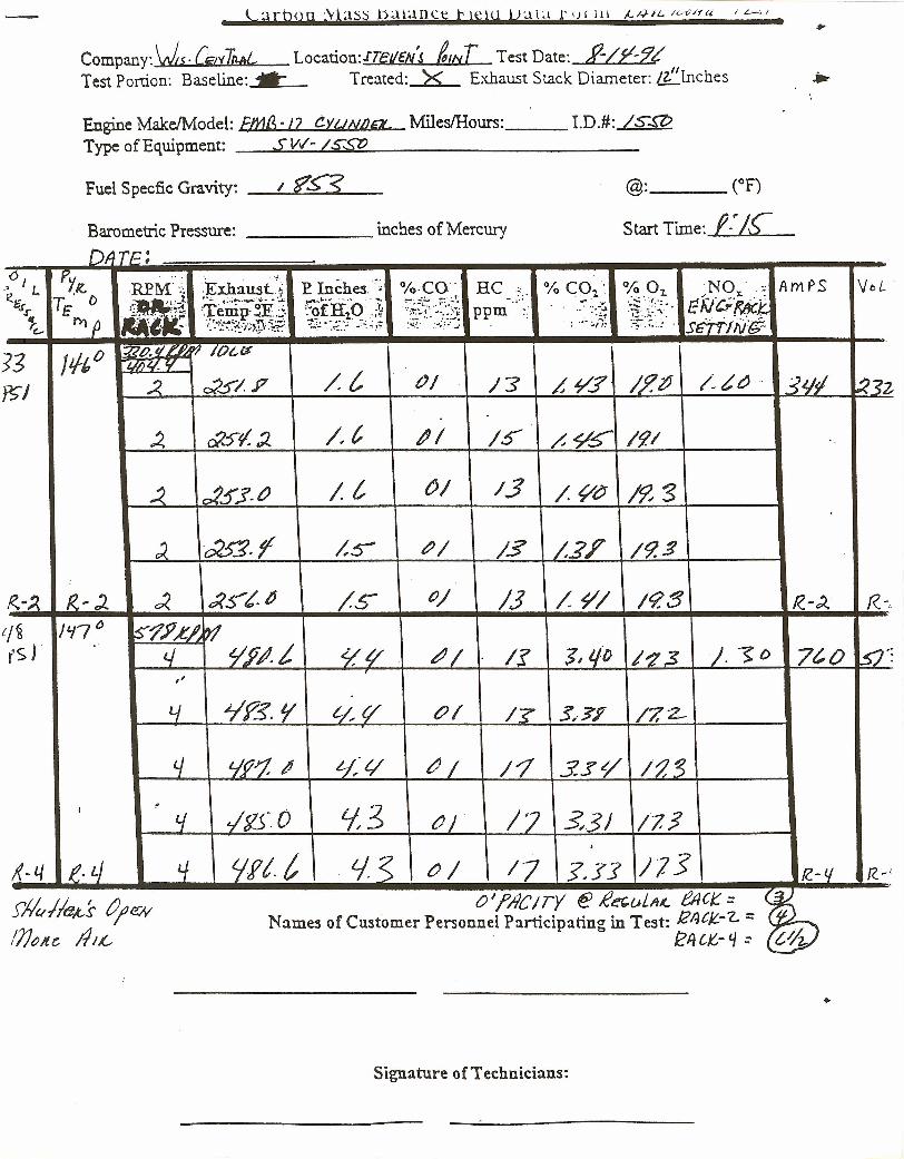
\ arboq ;vpss b;1i;1ilCtT t le19 VaLl r u[ 111 jj.;-n 16-c/ft< IL-:.I.
Company:Ws.[i;/,fTtLltL Location:JTellcNS twr Test Date:~Test Portion: Baseline: .•.. Treated: >< Exhaust Stack Diameter: &"lnches .••
Engine MakeIModel: Wg'/2 CWN/2a< MilesIHours: __ LD.#: IS.!??Type of Equipment: _......lS~VIl':......-..L./.:..Ls::w:s1?!::.- _
Fuel Specfic Gravity: _.!-/..:.:::?;~~:........£S__
Barometric Pressure: inches of Mercury
@: (oF)
Start Time: f·"/£
{
DfT!=. ;0 PYK.RPM···;;
.~.0 I L .Exhaust.·t. EInches.·~~ %·CO· HC % CO2' 0/0 02, NO ':; Am~S VoL'R6
t. °mJ :'-st{:~:':~;0~ 1: .'''- .•..•.... -~.......•• !lif'HO'1 "
•......, ,;::: ......::.:-;. E~C;f#:t:t"J"£~ fJ Ii'.,~::~Te·nip·~E.;. ppm _.' "--..1 "!r.:"."'.
'=~~.:~:;:~}.-::~:~~.~
.. .~;.,..,~~:;,.n -....... : ..-:'i!~ smJl\ilt-c- I." •••••.••••~~~; ••"}_~.' ~'-~" ,.•:.: .
:5 Ji/. o-:aP,1/ ~ ? /ac«" -I./i)q V
I..2. c2s/ J7 /.t OJ 1"3 ~¥.? /.?~ /~~~ .. .?I/i l2sz
..4 cX'st/. :J.. /, c ~I /5' /, 95"" 19./
~ c:l5Y·~ It ()/ /3 /~CJ /9! 3
d ~,f /,~ /PI /3 /,21'" 19.~
fl..-~ 1<.')' 0< .;(st. " /s: P/ 1.3 /~/ /9.:3 R.-~ R.-,
/~ /'17 o ~?j1.,e~'t1fSr 4 .!/,P#. i <1/,// ~/ If 1,t/o 1'2 ;3 ). .~ o 7t,O 5'):
"L/ ~Y5.¥ t./.,f/ &>1 /? 5,·?? /7,2-
4 t.jP'1 ~ '--/;t/ ~/ /"1 3.s~ /~.~
I~
~f~-·O L(3tf tiJ 17 ~3J /7,3.j(~tJ e. I.} tf Iffl t t.JS tJl /7 s.r: J7S f(. - i.f f( ~i
j41!tM:-s tJ;e;y O'j?IlC/TY @ £a,uLA~ tAc~ = 7~Names of Customer Personnel Participating in Test: !ZtIt/L-,- = @
//JOItC ,1U.- eI1CK.- 4:: t~
•
Signature of Technicians:
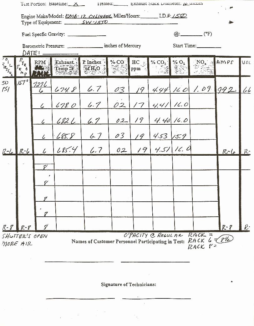
T 1.51 Portion: baseune: X t reateu: __ t.xnaust :JlaCK Lrameter: ~UlI.,;UC:)
Engine Make/Model: EIrl/;- 12. CyLINRl9l. Miles/Hours: LD.#: ISWType of Equipment: .$W ';.s:rt2
Fuel Specfic Gravity: _
Barometric Pressure: inches of Mercury Start Time: _
DAn~!) (') p. .. .. . '.: '.. ..'t . ~·IncheS.·~;i( I r Yfl. REM':; ·.ExhalL5t.~ %,CO' HC -; % C01~ % Oz. NOx' .:.; ArY\P,r VOL~L •
, .•.;.... i;··; •••.·_··v···-."..A: ~fJ:fo··:t .~~rf-:·~~~:':·~~-~!.- .•.. ~\:·f- 'o~~<{~~;~0;'~~E 6 r ",0':::· :Temp-~E.5 ppm "
.. -' -. ~.:.:J.Sq -~~~~~~;J-.-::~':~:';:~''''''..:.~;'.~.:.~:'
"'. '-.:.,.~p ~::~~:~!/~,~::~. : ...- :;i!~
«-
5D J~1t 121t(51 ~
(,,?~ .F ~, 7 tJ3 /9 ~9f' IL- L) I b C;.. 992-. tl..
c t'Jf. () £. 1 02- /7 L/.~/ I~. 0
c tf'c2 L t.1 ~.L. /9 L/ L/d It. CJ
c tfS:Y &. 7 £)3 I~ t/.S3 /$:9
R-ID /C -/, c tfJ~i {" 7 0:2- I 9 'ISI /«. t ((,...I» R-
.' f/',
p-
i'
~r
((-1 R.-r 1 /?.-S' e-Si/~rrelL'.s Of'ENtrJ~!2E"J[L
OJfllCITy e. i2e,uL J1~ R.I4CK-::;_~Names of Customer Personnel Participating in Test: /GA CJ( (, ~
rZ,ItCK.. r~
Signature of Technicians: •
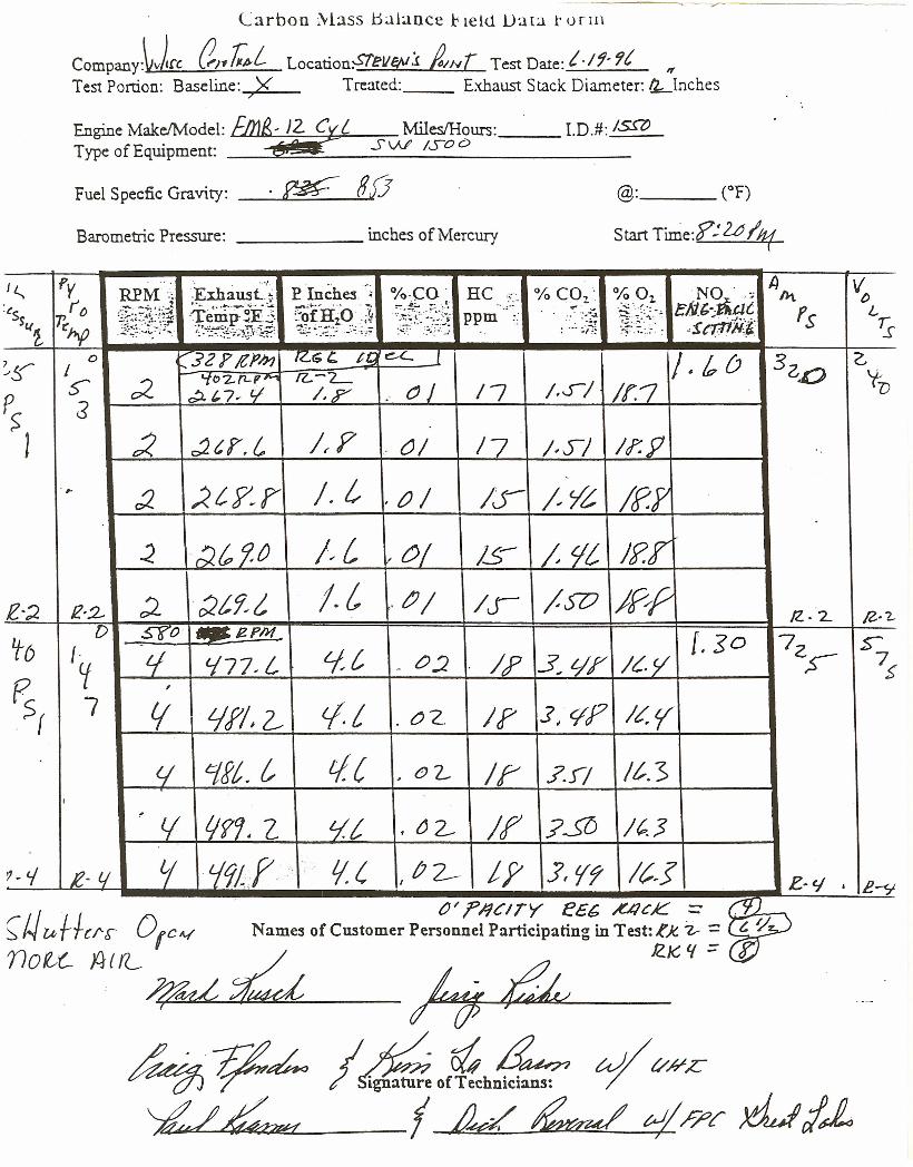
Carbon Mass b;liance t< ield Data r o r m
Company:~Jfc al.,~L Location:STell§Vj !IN[ Test Date: t-/j· 9t "Test Portion: Baseline: X Treated: Exhaust Stack Diameter: ~lnches
/
Engine Make/Model: lDJe, 12. eXt: MilesIHours: __ I.D.#: 15mType of Equipment: e:£ I S VJl ISO c>
Fuel Specfic Gravity: . ~ 8[J
Barometric Pressure: inches of Mercury
@: (OF)
Start Time:?: 2.iJ lit(
J~ fy REM-:; ;~~:~~:iE Inches -- %-_CO- HCIi
~• %CO' % Oz. e;;'~dt n.t:"s r~ :1.~~:~~~!~
...,.....:1-&..... . "'- ~it!:~~~~t;. _ 2
-re-nip- ~E.::' :~ofHiO-;¥ ""•... '., -~-:\~~ fs L
"!'rAp ppm .. ' ".-.l.Sq -- :':.:~;~! "icrr(iij" 15
~~~,~::~~~,~~.,~;\-.~~~..:~.~;;.;:",-::':'. ~~./:; :":.:.' :.~~.~'"':...' .:'I·.l •..•..
~!5' 0 32 F It'Jn IZ~C t, ~ 1 /. l6 3z.o GI '102fL!;""M fl. L 'tV
p>S" c2 ~'7r' - I,Y OJ /7 /,01 1r.1:$
J :< r:J. tr.c I~F ()/ /7 1·,)/ Ir.P
t,
-#- :2 ;< tY.,r /. ()/ IS- /7'Z /f:Y,
~ :2& tj,O /~(,I' 0/ IS- I 1/, JPr
e·;;. £,2- ;2 ()t~1, j.i, tJ/ /..r ISD J~P /Z.2 /2.. ?-
1f6D S?o Mae-PM [.$0 72t t! tft, 5""'
~'177, L - 0.1 IF 3..tJf I~V ~ 7~
Fe ,
Sf 7 t( Lff'l ~ 1.t oz. If' .1, 'IF It'.r(j t:j~t.t tI{ . eL If" .?J/ /t.>
I .l( Ljf9 • l/t IfZ f
£12.- ?SO 1("3
'f -mr ,- Lie 02- iF .f,l(f /?~J'1 - c.f R-li ' .
I f:..c; p.-s',
;:-t/Utfl-(/ ..s: °rc""
0" ;?I9CITY eec ~cK z: r:v~Names of Customer Personnel Participating in Test:~)(. ~ := U~.;.)
IZ. K- l( z: (JJ
(I
/~Of~h~ uj/t/#£f IkL ~ ~/?c >!LI/~
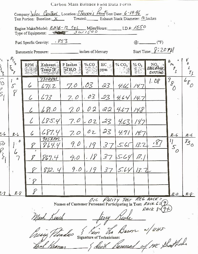
Carbon Mass Bulance 1<ie ld Data t o r m
Company: \bsc &/VTtiK Location: SA..-vc,,/S IZNtTest Date: t, -/9 -9£ If
Test Portion: Baseline: X Treated: Exhaust Stack Diameter: /z- Inches, -Engine Make!Model: £/)14,-/7... (.yL MilesIHours: __ LD.#: /srOType of Equipment: @ 7 $ .5 u..J / S-"O 0
Fuel Specfic Gravity: _. _?S_3 _ @: (OF)
Start Time: r;Z;;-I'j;fBarometric Pressure: inches of Mercury
1(
I 6
S"'
7
/lot"
6
J&7
e-s- fl-y
%Co·_.1,..,..": ..,.. ' ".-..t
. '.-:.,: ..-~;!~
t, 73otePM_ IF /. Df '1s~ __~t7~/~.Z~~7.~'_~-r{_~~+-~~]~~~~-~~~/~~~7~__~ 0
{, /'7.? 7. 0 I ()J -?3 'I. t. t.j /LJ, 7
c /'fJ·O ')0 , 0;),{, LP,:r: cf 7.0 ~()L
C. ini ?r°r02-
'l6SK.P/YL
f -9 t lj, r; 1. () ,/9,
Y sPt7.L/ 9/0 . If
P g'J2, Lf 9·0 ,,19~ 7Y
V6Lr;
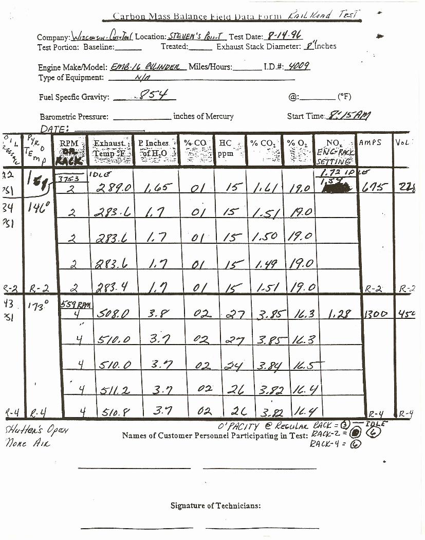
Carbon ~bss B:lbnse beW U:lU torIll ~d I~/f-d r&r7~
Company: 'v.hscClolSJH- (lrqwhz.f Location: Snllgtt 's &lIu[ Test Date: 1-1{9('Test Portion: Baseline: Treated: Exhaust Stack Diameter: Lfnches
Engine Make/Model: &11&-1' tItfiAlPE?l MilesIHours: __ LD.#: we?Type of Equipment: __ .:.I«.,u./dL- _
Barometric Pressure: inches of Mercury Start Time:R::' /.S'll/J!DATt= ;
0 Pyl(,. RPM'·:· .., 'L ·;~~..a~~i E Inches • %·CO· HC % COl' 0/0 o, NO ':; AmPS VoL ,:Rli TE'O "~
~~ ...... " '''":' ~~f~:~:~\;0.. ~ :L ... .",.,": '" ..::;: ""::":.;. EA/c.,;!:tit:t.r Te·mp· ~F..::. :"ofHlO .;¥ ppm ".' "-~..1
1: ~p 1_" ··t·:.; .. .=., s:··~··c- ·/:t.~":~~~!./})~y.~. ~~.:~~~~:.;....•:.'~~:,~ : .#- ..•",,: '-~'.'.:.: SGt"'lING-
'-, 1,1;2 ..~~ J7~3
I oce: IP r-d'a:?~\ .:< :< ytJ.t) 1,~5 01 1:;- I, {,/ l~tJ t1~ ~
~4 J '-ItfI~ »rs.c ~1 0/ IS /.,_~I /9.0
PSI: .:2 »rs.c /. 7 til IS- /.s» /?o
). ees. ~ /, ? ~I 15'" /. '/1/ /9.0
~-:{ 1<.,). ~ 2f1- 'I 1,1 PI IS' ;',s/ 19.0 R.-')" f(-<2
~3 0 ~S'i2PAf/1"3~I
<./ 51J2.tJ 3.£7 t?:L 'C:;7 <, }'S- /t:,3 f,:If J?Ol> I.IS"'~
"
L/ ~/tJ~ (/ 3.? t?.;< o?7 :5.?.s- /L..5
4 0/(). tJ $,'1 112 ~(../ $,J'q /~S- l-
I
I ~tf .A)/l a. 3.7 t?:J. .2t $,?:l I~- tj
I
{-L/ e- LJ L/ Sib. f/ 3.1 ~~ ,2(, 3..E2. J?~ fC-(/ f(-~, OJ,PACITY ~ £e(,uiltL.. f!ACJ: = Q).-r LCr4!ItM:-s t';eIY
'JJI?ItC ,4/~ Names of Customer Personnel Participating in Test: 124C/C..-"L :: (j) ~k?11CK,- 4 : @
•
Signature of Technicians:
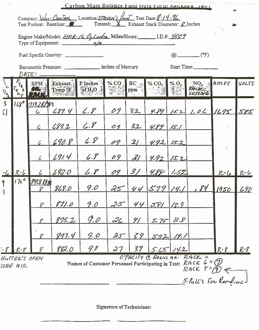
Carbop tylass Balance ~ para t OEm AM' f,S'l a t ts~""Company: 'vJJ - r;ENTtd.. Location:SUNEN 'J' guT Test Date: (11- rt,Test Portion: Baseline:J- Treated: X Exhaust Stack Diameter: LInches
Engine MakeIModel: &nti-It, t7",&/r", Miles/Hours:__ LD.#: We?Type of Equipment: I .!.!,~U!/""~ _
Fuel Specfic Gravity: _
Barometric Pressure: inches of Mercury Start Time: _
DAfE':, p. r •• _', '.: ',. .•. ··of· .."
J REM'~ ·.ExhaU5t.~ P ··IncheS.·"~ %·CO· He %CO '. % Oz.' 'NO' Amp.!' VOLTSt: YR. .~ . .... x.:i 'i.:
L ,•• ·.d·Ti<;;~~;jf~ ·~flf'o·t '~¥-~':~~{0.' 1....~.::." "",,'"; .,' :~"f~:~~E~;:Jt~.Ss £ 6 ppm . .'. .~.' " ..-..11&1" emp-.:.c'..:,. .0, 2. ..• .,. .. ....:::~~'2~~
'I•. hip . ~~~:~~!/':JJY'~.'t~~~:;;.:;~._7~~:;~ -;. .-~.. \;':.:." ~
'3 I(,~D rJ192U 'fy)
~J (p ti'? '/ t~? t)'j ?:2- ~.P9 1.5:"2.- /" "L /c os: S-R'~
c t99-:t i~Y 09 3:L «rr /.5:1
c tCJt1. r t.9 d9 ~I ~92... /502
c /, 91 t./ s.r Py J'/ C£tJ~ /S:L
'-In rt. - /, c t9c2.0 b.? tJ9 3/ ~n /-ss: IC-~ n-c, 17t,0 1?l~.VtlA~ ,,/P ft.? o 9~O t:?S- .«« 6:79 /v.r JqSD· cs». , ,y; 1'1/,a 9.0 ~s- 9l/' ~J /f'.9
17 S'/}S', :2 tl,() r2{' 7"/ S; 71>- /.1.P.
9//7. t/e 9- 0 tJ.s- ~9 6-:'''12- /1",/
'-1 R.-1 Y ~K2,O 9,! ~7 '$7 s:t.s- /t/.J- [(-f e-ro'rncir» e, !2e,uL J'J/I...r R.4CK- =:
Names of Customer Personnel Participating in Test: /2A C J( t :::(j) .tzec« ~:{fJ ~
________ ......:;.5lu U 's J-o~ .e.e~o"cJ•
l/urrelL'S ore»]~RE ft/{L
Signature of Technicians:
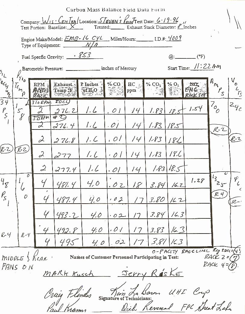
Carbon Mass Balance r ietd Data t o r m \
Company: \J,r . em 1ff (Location: STI!3I1/iJ:i ~ gJrest Date: G../9· 'It /1 \\.
Test Portion: Baseline: _ Treated: Exhaust Stack Diameter: LJnches 1\
Engine Make/Model: £!J1(]- If, CYL MilesIHours: __ LD.#: i~~9Type of Equipment: __ -----:.~~Z/}~'"""'""'----------
Fuel Specfic Gravity: 6 f£"3 @: (OF)
//:Z2J}h1Iv Barometric Pressure: ---- inches of Mercury
yStart Time:
)\ ,
~Jb -, '-. '. . '.--/.
EInches.c~ °i~.co. flntV
k RPM'" .Exhaust, ~. HC % CO2' 0/0 01 ~ ., 0
Jf./jff,J..-I • .:.... .I.·.;•••..__ ··v·•• '..A:; !:'"CH''o '1 ~¥[:~~~0 ."., .. ., .~. ~:':-- W -. ,'-: LYv}p +~.~p-;.~.:;. .. 's\ ppm . .. ' .••.-..l. 15' ~ ..r..'
'!l};;'-':~ .~. 2 .,;,~. :":,: ~;~~!l:-~. . ".' -,J~'.--:~ rs:...,;tli~ I:.'-~~~~!i)tl}<~i?~=~ '"::~~:.; .-~~.~:;~ .-~..\ ..:.: . 17Mi/r-tft
3LJJ i si» er» 1?Oc.9 70 2'fcr s: :J. c27L.z.. /. L 0/ ltf /. rs I P. .<:1.-- J.s1 0,
? f I s7S"£Pj/\ #'9I ;;2. oI7t, 'f I~L .0/ Icf l~f3 /f,S- -:-:---.,
~-1-)~ /. L oj ILl //P3
~~~ 7!"f I j?~
~~D(@ ;2 d77 I~ L ~ / 1<1 l/fJ I?:((
;J. )~i /~3 Its- -cJ-;7, cf • 0/ /4o 's I.:
~f Ie i • LzY ft,.tfF! « '-//0 • 0 z: IP s.f1 /e.z: 2.)', (ii!i)
L
~ 0 Lf t.Jf7 r Lio tJ). /7 .1~?O It. 7.- ~(
(J I IG~'~
t( lff] .7___ «0 ·o~ /7 J'.?y /s.s~
&4 Lj C/92. r ..00 ,{).j 17 3~f] /c,·3/lJV tt Lf9s It 0 . O~ /7 ?-?/ /(3
,-
~ ~/J~C) - f ActTY {tPrJ<.I..IN.L K~ tl1:'i
TnIDOL.t; J Names of Customer Personnel Participating in Test: /Z;;jC~ 2 = rzf/JN~ D 1'..£ - EI1C1G t.(::: p .
/;::s~vr'f IS.,,~;:IE'
~;i.!l~ (/1/£Signature of Technicians:
!Pd ;(~
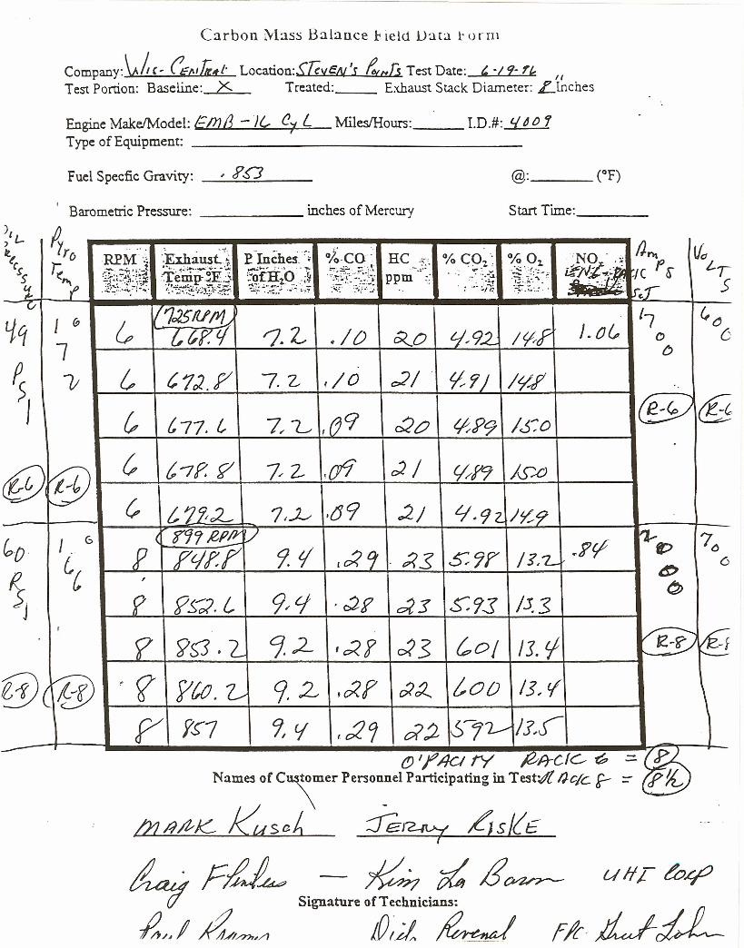
Carbon Mass Balance 1<ie ld l)au t o r m
Company:\t.!t c, (1£/111«,. Location:SJ{vcN'S 4,Jj Test Date: ,0/9- ,? 1/
Test Portion: Baseline: X Treated: Exhaust Stack Diameter: Llnches
Engine MakeJModel: Gm/3 - JG, (l7 L MilesfHours: __ LD.#: '-Id () '1Type of Equipment: _
Fuel Specfic Gravity: ' ?D
I Barometric Pressure: inches of Mercury Start Time: _
0/0 Oz...~ .../:.;.-;:..~.~ ..~'. -.
.-~"'.:.: ~
[ &7{;
I / 1JSflj!Y/~lp {,sr Zf ~. L ./ 0
~ C.7J.P 7. Z .r o
0(0 tJ~92 /0F
07/ ~7J /I/~
@tfPt--&~~t,-'7-f'.-f/__t_-.-.:.7-/ _2---r-::-\rfi'_-+-;2_/-+-..L...:..0...:::......!f9~/~.:::...A:J-+-_-I
{, (,1r2- 7,Y- .69 .2; If. 9 2. J~9-
'7l.ot;. D
6
fo-o·
~.J
,
lJ.s
7()6
t---7K......-f-_y_S'5_.-.;;;;;.L+-----9.;......-. 2..------'1--' ;(~r_I__~...::....3__+_~-O..:..../-4-/-J..-!..lj_l__-_1~ ~
§@ t-'_?-+-~_'to_.---+-~---.;..9_.2---+-,_;{ f-t-c:<_~__4_(,_O-0-l-/_3~_tf+----I~ f~1 c;, V I c21 d;2 0'-;L-- /J,.J
(!) I~ ACI tY ~R-CfG- ~ .=. ~Namesof c\mer PersonnelParticipatingin Test;/{ l)cole f- :=- e...V
l21/?foK- Kusch :Jer2i'-'j £]sL(E
4 FM~ Signature1:zici~ /J~~/AI Ana?7,/1 ,0;;1 ~ {"If, JiJ-di-
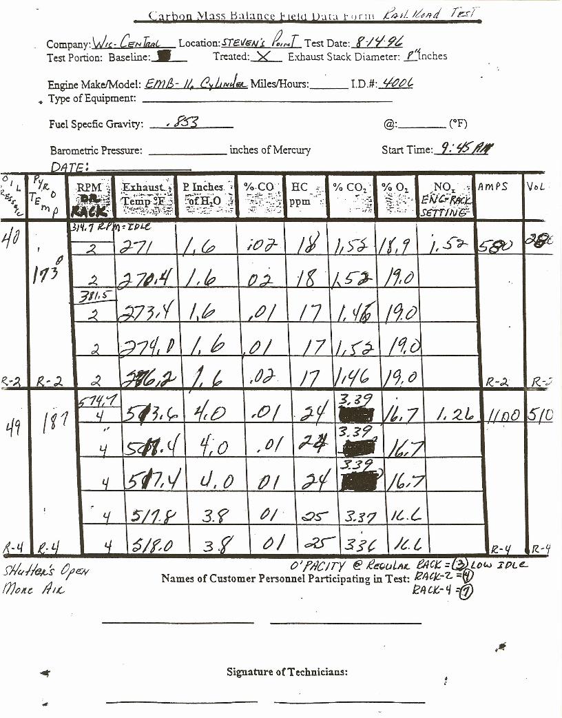
CarboQ \\'bss B~lance t tel<1 U'.lLl t (HIlI ~JL J~Rd rg:s7~
Company:YI~- CEfNlizoL. Location:srell~Ni ;2,,...[ Test Date: fIr- p~Test Portion: Baseline:___ Treated: X Exhaust Stack Diameter: f'inches
Engine MakeJModel: Em/!;- J(, <JyLlflfJf1& MilesIHours: __ LD.#: '/tJtJ(".• Type of Equipment: _
Fuel Specfic Gravity: ~ FE
Barometric Pressure: inches of Mercury
@: (OF)
Start Time: 9:9.> ,1/4'
Amf>S VoL·
itJ (J-
R.-~ f(-eJ
3.jh0I!tJA:,s tJle;vrJJoJ(~flu"
O'j?AC/TY ~ £e(;OiAt... tAc~ =' Lcw IPLLNames of Customer Personnel Participating in Test: 124tj{..-Z. ::"&)
. ERCj(,- q =(j)
Signature of Technicians:
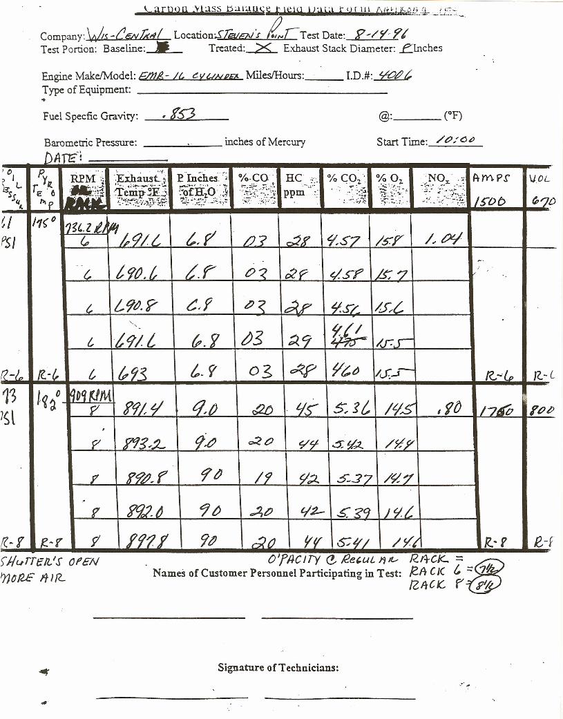
- \x,UbOn ,Vl:.lSS balausu Ie \51 vau t (FIll AIJ'Ui;&!'c~_:a-_LE_S:
Company:\v~.s -C6YUd( LocationSJEvGj7l/f £C Test Date: f'~/r:?( .'-.Test Portion: Baseline:_>>_. Treated: X Exhaust Stack Diameter: .finches
Engine Make/Model: E.IJl£- It, t:.V?lNJ?p Miles/Hours: __ LD.#: ¥t?t??Type of Equipment: _..Fuel Specfic Gravity: ' 152Barometric Pressure: __ ~ __ inches of Mercury Start Time: /t?;"(j~
DAn:':'() P. .. '-. '.. . ..-/ .
PIncheS.c;) I
r.~(·R.PM"··; ·.Exhaust..~" %-CO He ..- %~Ol" % Oz. NOx' ,:.: Arn.P,r IJOL, L
•'''.;.." i:··j •••• ·_··v····,'...: ~flfo 't ~+~\~.~~;(~.- •.a"
"." ".-r-: " ·~.i\~~_.-(..... . ,,:,",. .".;~:
~S :Temp-~F.j ppm . ..' .... -..1_~.::-.:~~~-:;'~6~~·E 6 -~. 1 .. ;~ " .. ... ",-;',
/5"Dbflip....
~:':~~~~!,.}}~y.~~; -'~::'~;:'..-:.~.~:.~ . : ..-~ii: "'JD4«. ."
~/ /1(C 11~'.ltl ~PSI ~ ttj/i t,p' /J? r2,f ~S7 /5'17 /.. IX!
~.F~
" ". ltj~;£ c><. C:CP ~s-f? LS;'7c ,"
t, L9t'.Y C~f ~< i~? ~.u &{,<. ffl-
c t91t (P.f t/3 ~9 /J7r~
((-/~ /C-/' c ?9~ t.r OS o'<p ~&" /c.f....J- n-t, J(.-L
13 l~~() qDq~M :
1st p f9/'~ tj,1J ao tj~ s.s; ILjS' I ftJ /7~ I'PZI,
P ?1g,~ 9~ C:<t:J ~rf .:5:'£2.. /71Y
Y j'@,r '1~ 19 Y'.;l. 5-.:57 /~'/,
S'92.~e 9tJ ~t' t!2-- s s» Jq/..
,1(-1 f?-y 9' f'f? JI 9~ ~() r~ 0;,// /Vt 1<: r e-,. OlfltCJTy e £e,ut.. J1~ R.I4CK-.:::tB
Names of Customer Personnel Participating in Test: 12ft CJ( t :::7"/ZiteK.. f" R~
fJ/urrell/s OPEN'ncRE ITJ{L
Signature of Technicians:
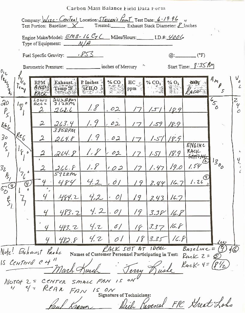
Carbon Mass Balance 1<ie ld Data t o r rn
Company: \at$' c. - GNT,A I Location:SlEuIiN:r t,Nr Test Date: t. -19· 9/' If
Test Portion: Baseline: >( Treated: Exhaust Stack Diameter: Llnches
Engine Make/Model: Em!!- It ezL MilesIHours: __ I.D.#: $0t?{,Type of Equipment: __ ~~~/.L.J.d~ _
Fuel Specfic Gravity: I FS-3 @: (OF)
f.'1SJffr}Start Time:
\J~L
zif()
/7 /.S9 /P.9
/7 /.s/ 19:9£NGJ}( c
/7 j.Sj /79 ltA-qL. ...r~~ LI.(
J9.,tJ"'-V/. 'l:!; '3 ~-
17 /. 1f7 I. rf" ()o I
c
/9 .1. (j If? /t..7 .CD/.Z(,>
19 .J. «s It.. '7
/7 3-JP «r
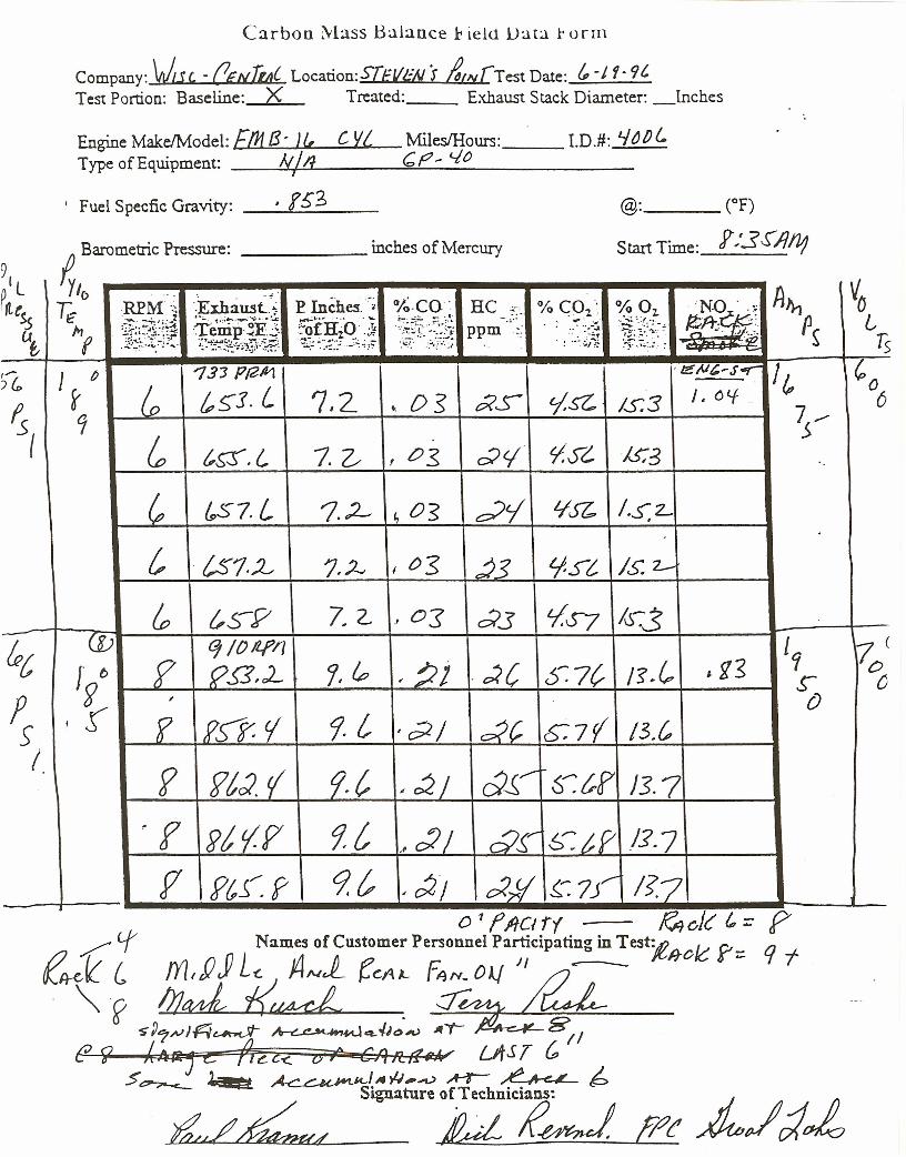
Carbon Mass Balance 1<ield Data l' o r m
Company: \J.H. - (lgNWC Locarion:S[EVl:"N J &/lv[Test Date: &, -J f· 9t.Test Portion: Baseline: X Treated: Exhaust Stack Diameter: Inches
Engine MakeJModel: [IJt B· J(, C Vi MilesIHours: __ LD.#: J..jtJ/)~Type of Equipment: kIll 6f?- <./0
I
I Fuel Specfic Gravity: __ ' .!::...,;f5~3__ @: (OF)
Start Time: Y:.3S'1l1l?Iv Barometric Pressure: ---- inches of Mercury
L Y/o VortL~.. '-.
';!:~:~(iP Inche5.c; °/~,CO' AmT;; REM':; HC ,.c % C01~ % Oz- 'NO ',~s.s :1;}1~~~. ~l-." -., ..•. ;?[:~~~q ~ft'?;.j:: 0~f :Tbrip'~F.j :~ofH10.;.¥ .. c. .,- ..," ":~;\~:~"~~. P~ppm .•• " .••.••...l
ut, ~~'.~~~~.~;"~;~~y.~~:.:~.~:;~:.;... .:..~.;:;~.. . : ":#:. ,~~~!:.;..r-.-;-•.:.: .. ~
'r; ....J~~ Ts••......
.>:
1 r 0 'l3J PJ21Z1 '~;..t~-s~ It, "0)&,(0 LIs t5"J· 1,2 Ds t5<S tj,~ 1..5:3 J. otf 6..
7S"1{
~ t&r.t, 1. Z. 0.$ ~c.( Y:S'i Js:3,
~ &.51. L 7..2- ~ 0"5 ~'i '1~ 1.S:2-
c i51.:L 7.~ I os 23 'i-S't Is: 2.-
& {'S-9 7, 2.. .. Os d3 L/.s=7 10":3- (J)(PC q IO/if11 '1 i70(
r () ? 9S5,cL 7, ~ :;;j ;<(, S7? 15~~ ,g~~ s: oF ~
, o, f PIT. 1 9- {, ,~/ dc, 6:7r(' 13.&sI f ftJ.tf 9.{, d~/"
" ~/ S".tf Js·7r f 2;; {.r 91, c:I/ Ct.?
" d~ /:1·7
f PtJ~f 9? ' ~/ c:l)! s: rs: 1?7
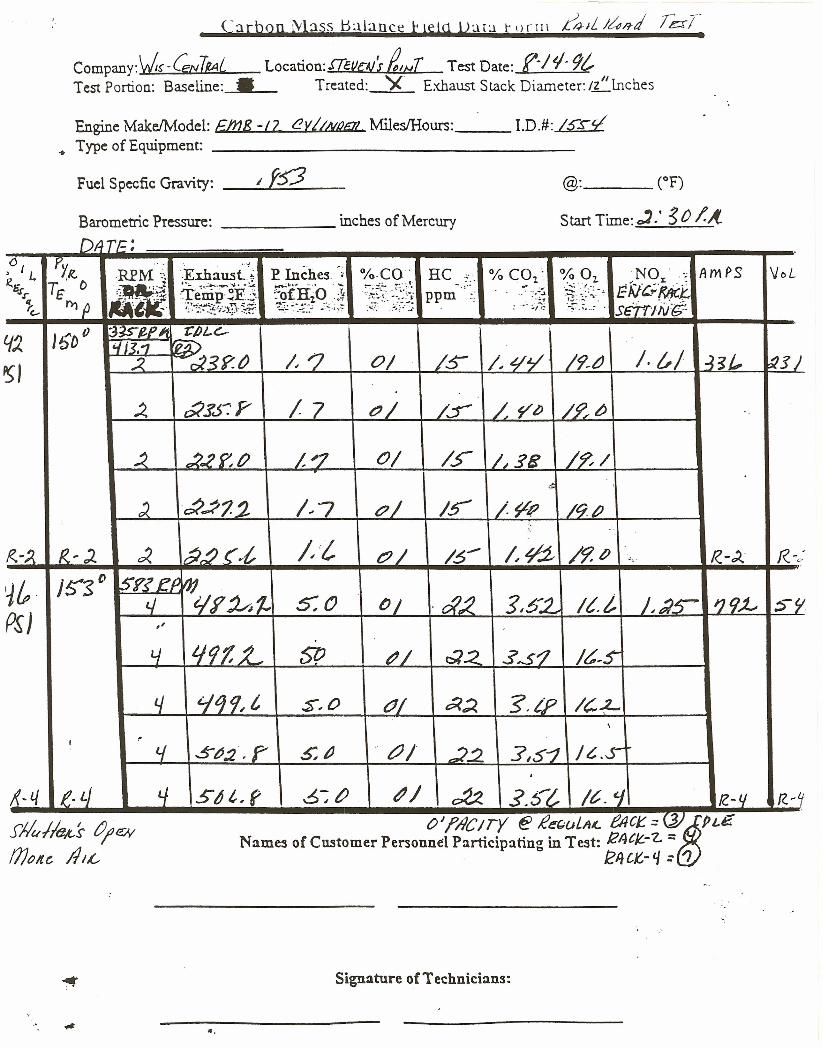
Carbon ~l:1sS t);}lanqi k lelq Vau r ()rlll 4-IL J~ffd TcrT.
Company:V!-(ENTIAL Location:£Tetle-~tS tINT Test Date: f-/'l9?Test Portion: Baseline:___ Treated: ')( Exhaust Stack Diameter: Ill/Inches
Engine Make/Model: £InB -/7 eVI/Nl2lil1 MilesIHours: __ LD.#: Isrr/• Type of Equipment: _
Fuel Specfic Gravity: _....;,/.....jt.:...;;;~~__
Barometric Pressure: inches of Mercury
@: (OF)
Start Time: ~.' ~ 0 /.A..t» TE;
0 Py ""
;~~:'~(i' I L RPM'" E Inches -- %·CO" HC % COl' % 02, NO " .r; flmf>S VoL.f?R15 T£ o
.~!l)fHO "1 ~~f!:~~~0
/ x ... •. ". ......:. :(., lE ';/Ci-{?;fc£~.r +e"~p' ~~.::. ppm .. ' ..~-..1 ~ .. :--.:,
II Y'Y}{J .'/··t·:~ .~-:~~.~:}-.,,~.:~~.~"-;, '}:~~'.~"'C.- ,:T.~~~~!.h·~~·:2 : .~.:'/-;: S£Trlll/{t-
/) 15D" :3isee« 'C/)I-<:-tI.. i4H.'1 rP1t~, :2. ~3f'.ti /. r; 0/ /S- /. L/¥' /9-tJ /. ~/ ~s/' 'till
~ O(sJ:P 17 C'/ /f /. yt; /~tJ
~ 2.2 f': t? /,"7 0/ /s: /,,58 /?-/.~
) ~.;P71. /..7 (?/ Is-' /~R /qp.\-
r<,,-J. 1<.,). ~ a~(.l" /: CJ/ 16- /,~ /9.D R.-J. f(-,,:
~& }S--S 0 srr e» IJ14 'i/?~f., 5:0 lJj .~.2 3;52- It.I, J.;?S- IJtjJ- Sf!
P~J "Lj LJ9f,L 51? t:'/ c::l2 $,$'1 /s.s:
4 '1i)9~c $,0 Cli t5?;;l. -g.iP IC,L\
I ~t.f .5~:2.f' 5;ti tJ/ ,22. :1,5-1 I~.S-.
~~L/ e· LJ tJ s s c.r 6:~ t?/ otz .5.St. /~. '1 I? -l/ R. ~~/ oj ~ IT ~ ~e(;oL/t~ eea: =<J. PL£jM-I!tJ.t.s tJ;eN'
moltc ItIL
f?,'C Y ~Names of Customer Personnel Participating in Test: 124CjC.-"l.. ::
" ~4CK,- q :: 'J "
Signature of Technicians:
«.
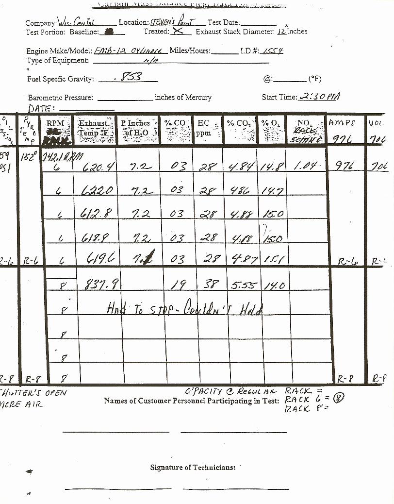
Company:\Js. Cbt Te' Location:JlCVEtir BatL Test Date: If
Test Portion: Baseline: • Treated: X Exhaust Stack Diameter: Rlnches
Engine Make!Model: &113-Ii{ (J rIM/prt MilesIHours: __ LD .#: IS-SfType of Equipment: .-£.••••••.~.o~/l--_-------Fuel Specfic Gravity: _"':"-!~:""':~:::"::::::__
Barometric Pressure: inches of Mercury Start Time: .;2 : 30 fM
97/
R..-f'
')t>«a: /~O
t, t.12. F
JG- L
-Jlurre/l./s Of EN
r)N2£ ITIIL
o 'fIJC I ry <! !2e,uL It IV R.I4CI<-:::Names of Customer Personnel Participating in Test: /2.A C J( t :::@
[Z,It C K, F"~
Signature of Technicians: '
e-f
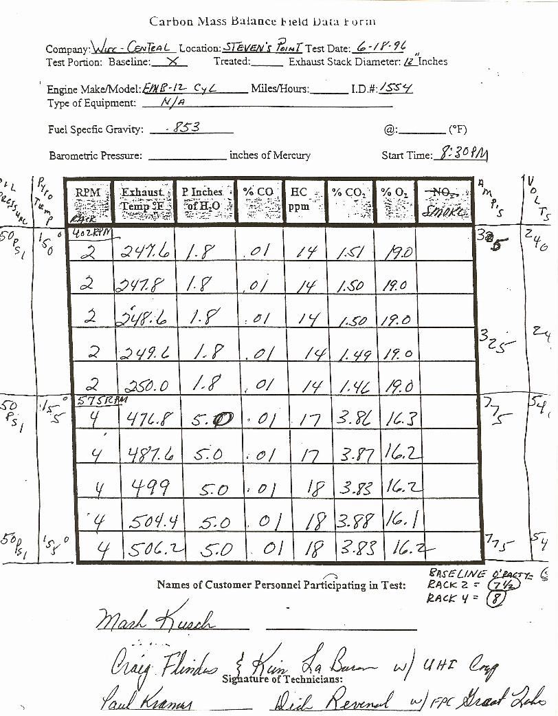
Carbon Mass Balance l' ield Data t o r rn
Company:Vu., - (J;Nk~L Location:..5ieVSV·S t:1"4 T Test Date: ~ ~/ y. 9'"Test Portion: Baseline: X Treated: Exhaust Stack Diameter: L,Llnches
I Engine MakeIModel:E!NLi'-/Z- CyLType of Equipment: _..!...:./V+/..:....:..A _
Miles/Hours: __ LD.#: ISS7'
Fuel Specfic Gravity: . ?53 @: (OF)
Start Time: t $0 f41Barometric Pressure: inches of Mercury
J 6
~ I·r ,0/
1f7 ()/
/.p ~ ~/
/~f . tJ /
/~f ,0/,
S-. to ~ tJ )
Jl~.',: ht
k?R.~· r,s
,
C( LJ?l & 0:{) i (!) /
l.f +19 5.0 .' 0/~t; 5tJ 1. t.J sO D)
Sb~ 'S' 0 tr 5"tJC. L SO OJ~I r
/1 ;.~I 19.0
/£/ ;,So /f.~
Ie( /.S~ / f'. CJ
/</ /, t/9 If. 0
17 .:? Pi / C.r /7 ~:r- (
/7 ]·1'7 J~,L
/9 ssr IC" IIf ?·PS It.2~
~Names of Customer Personnel Participating in Test:
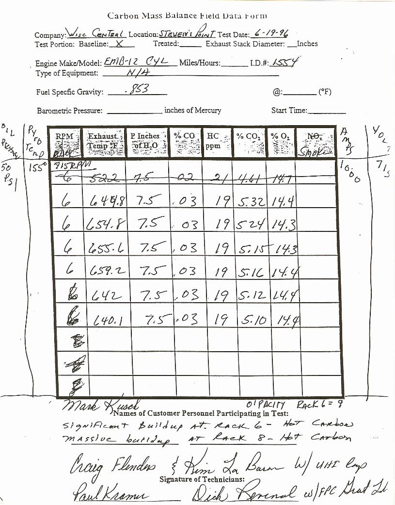
Carbon Mass Balance 1<ie ld Da t a r 0 r rn
Companyv,.rc. C:N 7iZl~t Location:Sll;Vc:w't ~T Test Date: ~ - 19- 9(,Test Portion: Baseline: X Treated: Exhaust Stack Diameter: _lnches
I Engine Make/Model: {J1l/J-1 2 (!Y L MilesIHours: __ LD.#: IzY'Type of Equipment: __ .L-NL..;/c...;;H--'---- _
Fuel Specfic Gravity: _----I' g,-~~3~_Barometric Pressure: inches of Mercury Start Time: _
r>l Py -, ". '. . ..-t. A- , VoL RPM-·; ··Exhaust.. ~. E Inches.c; °lo-co' RC %C01' % 01. N.e:- .
P~ rb ~ _';"1"_1. ,~;..... 4~·';""""""·"';'···· '...A: ..,.......; •... '" :-.. \ ..... ~~r:~~:;~~~0..- x ...'.
1 L:l~ T'-' of' :"ofH1O.;.¥ -- •...: .,., :~ft~~"1£%fii1TCh,fJ
ppm _.' ..~-...l
~h itJ. '-.:" ;.~ :···,~~P-n~·d: ... :' .,;..~.;~~ 7-- ';..·...:..··~~·~//~~1~<~ ~..:~~~r;:.._:.'~.~:~~
'-~" ,.,:.:. :
5'0 I5'S~ '1J~~f M~ 16. 7,f-.s I
~/' -')') 1"1;-- /'I"') 'J I / I / I, 66
.5~ .u ,••..... , .."I -/ y: /
& & fE/.f 7.5 I" 0 3 Ie; S' 3 'Z.. / tj, if
? /sv.r 7~ c)'? 1 r; ~~{ /lj. ~
? tS-S: t, ~c-/ o ~ /9 s: J.J' --!'13
c {, 5"'/. '1.- 7,S- 03 /fj SIC, I<-f.lfo'
I t &L{l--- 7.S- 0$ /9 s: /2- If/,rj/
~ ("lf~. J 7,:;- ~o:s /9 S:/D /,/~
$~~
P 1
/ lJ7tJd 1({~~j: 01 fAclrr ~t:.'= ?j
"... .••.... . .Names of Customer Personnel Participating in Test .S;7N)A~"'" l>u;lj~l' ~ ~c¥- ~ - ~T"" ~~().u
?nA>~)V~ h~II.J¥ A-r ~ ~- Abr ~c»,
fLJJ!~!f)dJ oJ/fIe
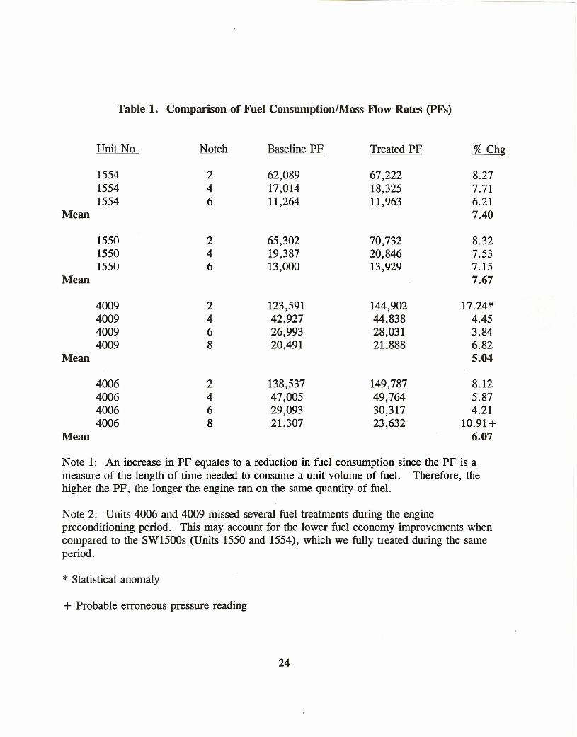
Table 1. Comparison of Fuel Consumption/Mass Flow Rates (PFs)
Unit No. Baseline PF Treated PF % Chg
155415541554
246
62,08917,01411,264
67,22218,32511,963
8.277.716.217.40Mean
155015501550
246
65,30219,38713,000
70,73220,84613,929
8.327.537.157.67Mean
4009400940094009
Mean
2468
123,59142,92726,99320,491
144,90244,83828,03121,888
17.24*4.453.846.825.04
4006400640064006
2468
138,53747,00529,09321,307
149,78749,76430,31723,632
8.125.874.21
10.91+6.07Mean
Note 1: An increase in PF equates to a reduction in fuel consumption since the PF is ameasure of the length of time needed to consume a unit volume of fuel. Therefore, thehigher the PF, the longer the engine ran on the same quantity of fuel.
Note 2: Units 4006 and 4009 missed several fuel treatments during the enginepreconditioning period. This may account for the lower fuel economy improvements whencompared to the SW1500s (Units 1550 and 1554), which we fully treated during the sameperiod.
* Statistical anomaly
+ Probable erroneous pressure reading
24
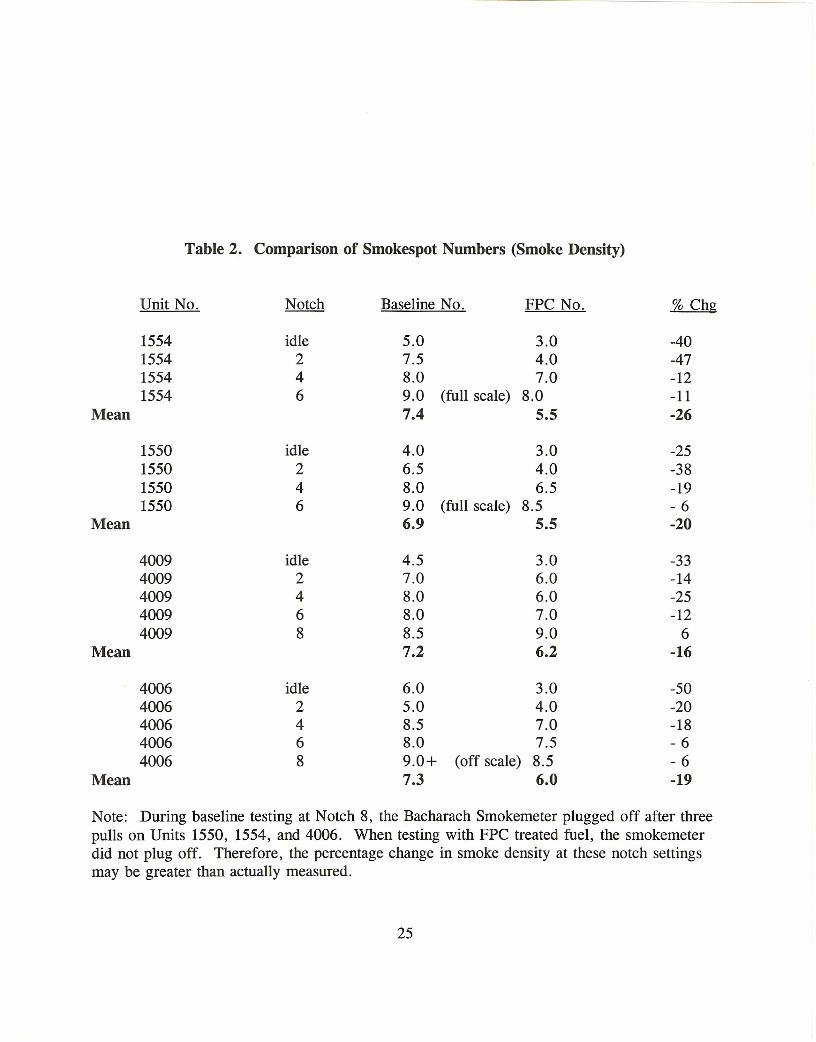
Table 2. Comparison of Smokespot Numbers (Smoke Density)
Unit No. Notch Baseline No. FPC No. % Chg
1554 idle 5.0 3.0 -401554 2 7.5 4.0 -471554 4 8.0 7.0 -121554 6 9.0 (full scale) 8.0 -11
Mean 7.4 5.5 -26
1550 idle 4.0 3.0 -251550 2 6.5 4.0 -381550 4 8.0 6.5 -191550 6 9.0 (full scale) 8.5 - 6
Mean 6.9 5.5 -20
4009 idle 4.5 3.0 -334009 2 7.0 6.0 -144009 4 8.0 6.0 -254009 6 8.0 7.0 -124009 8 8.5 9.0 6
Mean 7.2 6.2 -16
4006 idle 6.0 3.0 -504006 2 5.0 4.0 -204006 4 8.5 7.0 -184006 6 8.0 7.5 - 64006 8 9.0+ (off scale) 8.5 - 6
Mean 7.3 6.0 -19
Note: During baseline testing at Notch 8, the Bacharach Smokemeter plugged off after threepulls on Units 1550, 1554, and 4006. When testing with FPC treated fuel, the smokemeterdid not plug off. Therefore, the percentage change in smoke density at these notch settingsmay be greater than actually measured.
25
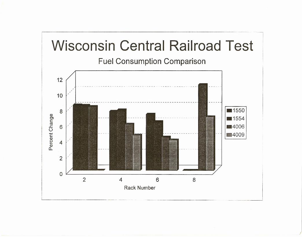
Wisconsin Central Railroad Test
(l)0)cro.c 6U.•...•c(l)
~ 4 '(l)0..
Fuel Consumption Comparison
12
8
,,,10 '
2 '
o ~----------------------------~2 4 6 8
Rack Number
L---- . . _
.1550
.1554
.4006
11I4009
/