document resume title module one: electrical current
TRANSCRIPT
DOCUMENT RESUME
ED 099 498 CE 002 575
TITLE Module One: Electrical Current; Basic Electricity andElectronics Individualized Learning System.
INSTITUTION Bureau of Naval Personnel, Washington, D.C.REPORT NO NATPERS-94558-1aPUB DATE Jan 72NOTE 127p.; For other modules in the series, see CE 002
573-589
EDRS PRICE MF-S0.75 MC-86.60 PLUS POSTAGEDESCRIPTORS Course Content; *Electricity; *Electronics;
Individualized Instruction; Individualized Programs;Industrial Education; Military Training; PostSecondary Education; *Programed Instruction;*Programed Materials; Study Guides; Trade andIndustrial education; Units of Study (SubjectFields)
ABSTRACTThe student is introduced in this module to some
fundamental concepts of electricity. The module is divided into fivelessons: electricity and the electron, electron movement, currentflow, measurement of current, and the ammeter. Each lesson consistsof an overview, a list of study resources, lesson narratives,programed materials, and lesson summaries. (Author/BP)
NAVPERS 94558-la
BASIC ELECTRICITY AND ELECTRONICS
INDIVIDUALIZED LEARNING SYSTEM
MODULE ONE
ELECTRICAL CURRENT
riQ Study Booklet
tii0 BUREAU OF NAVAL PERSONNEL
thuluary 1972
OVERVIEW
MODULE ONE
ELECTRICAL CURRENT
In this module you will be introduced to some fundamental concepts
of electricity. You will learn what electrical current is and does,
how to build a simple circuit, and how to measure current in that
circuit.
For you to more easily learn the above, this module has been di-
vided into the following five lessons:
Lesson I. Electricity and the Electron
Lesson II. Electron Movement
Lesson III. Current Flow
Lesson IV. Measurement of Current
Lesson V. The Ammeter
Do not be concerned at this time with names or terms unfamiliar to
you. Each will become clear as you proceed. However, if you have
any questions, do not hesitate to call your instructor. Turn to
the following page and begin Lesson I.
BASIC ELECTRICITY AND ELECTRONICS
INDIVIDUALIZED LEARNING SYSTEM
MODULE ONE
LESSON I
Electricity and the Electron
Study Booklet
Overview One-1
OVERVIEW
LESSON I
Electricit,r and the Electron
In addition to the Module Overview, as you start each lesson, you
will find a lesson overview like this one. it is merely an outline of
what you will study and learn to do in each lesson. In this lesson you
will study and learn about thA following:
-what electricity does
-what electricity is
- movement inside a solid wire
-a word on theory
- the electron and two other particles
- the atom
- wire and other materials
-composition of matter
-space between atomic particles
Each of the above topics will be discussed in the order listed. AS
you proceed through this lesson, observe and follow directions
carefully.
BEFORE YOU START THIS LESSON, PREVIEW THE LIST OF STUDY RESOURCES ON
THE NEXT PAGE.
3
Study Resources One-I
LIST OF STUDY RESOURCES
LESSON I
Electricity and the Electron
To learn the material in this lesson, you have the option of choosing,
according to your experience and preferences, any or all of the following:
STUDY BOOKLET:
Lesson Narrative
Programmed Instruction
Lesson Summary
ENRICHMENT MATERIAL:
Boeke, K. Cosmic View: The Universe in 40 Jumps.
New York: The John Day Company, 1957.
NAVPERS 93400A-la "Basic Electricity, Direct Current."
Fundamentals of Electronics. Bureau of Naval Personnel.
Washington, D.C.; U.S. Government Printing Office, 1965.
Remember, you may study all or any of these that you feel are necessary
to answer all Progress Check questions correctly. Do not forget that
in one sense of the word your instructor is a living resource; perhaps
the best. Call him if you have any kind of a problem.
YOU MAY NOW STUDY ANY OR ALL OF THE RESOURCES LISTED ABOVE. YOU MAY
TAKE THE PROGRESS CHECK AT ANY TIME.
4
Narrative One-I
NARRATIVELESSON I
Electricity and the Electron
What Electricity Does
Most of us know what electricity does. It makes telephones,radios, televisions, toasters, and washing machines work, to namea few. Without electricity, cars, trains, and ships will notmove. Electricity makes the lamp on your power supply and thelight in your classroom glow. We know what electricity does, butwhat is electricity itself? Let's see if we can find the answer.
Findin9 Out What Electricity, 1
To first find out what electricity is, think of it as comingthrough wires. Whether it be your television set, or your toaster,or the light in your classroom or on your power supply, the elec-tricity is carried through wires. Without wires carrying energy,none of these would work. Remember when you plugged your powersupply into the outlet in the wall? Not only are there wires onyour power supply, but there are wires inside the wall leadingto the outlet. There are also wires inside the wall that leadto the on-off switch that turns on the light in your classroom.Therefore, to learn what electricity is, let's first considerthe wires that carry this electricity.
At this time, disconnect any wire from your power supply.Look at the end of it. Does it seem solid or hollow?
The answer is: "The wire seems solid."
Movement Inside a Solid Wire
It is perhaps much easier to see what electricity is by visualizingit inside a wire. Although this wire is not hollow like a waterhose through which water flows, scientists tell us there ismovement within this solid wire. The question is, "How can thisbe?" You can't see anything moving; you can't feel anythingmoving. When we say something is moving, we mean something Isflowing like a current of water. For the moment, then, let'sassume the truth of what the scientists say, that there is move-ment or flow within a wire.
S
Narrative One-I
A Word on Theory
We refer to this movement or flow within a wire as a theory be-cause it cannot be directly observed by seeing, hearing, smelling,or feeling. The movement cannot be verified by your senses. Yetthis scientific theory explains how electricity works, and isverifiable by indirect measurement and observation.
The Electron
In their theory of explaining what electricitythe scientists use the concept of the electron.scientists see this electron as a part717-1611submicroscopic particle, that is, it is too smathe most powerful microscope made.
is and how it works,in their theorizing,
can move. It is a11 to see even with
The Electron and Two Other Particles
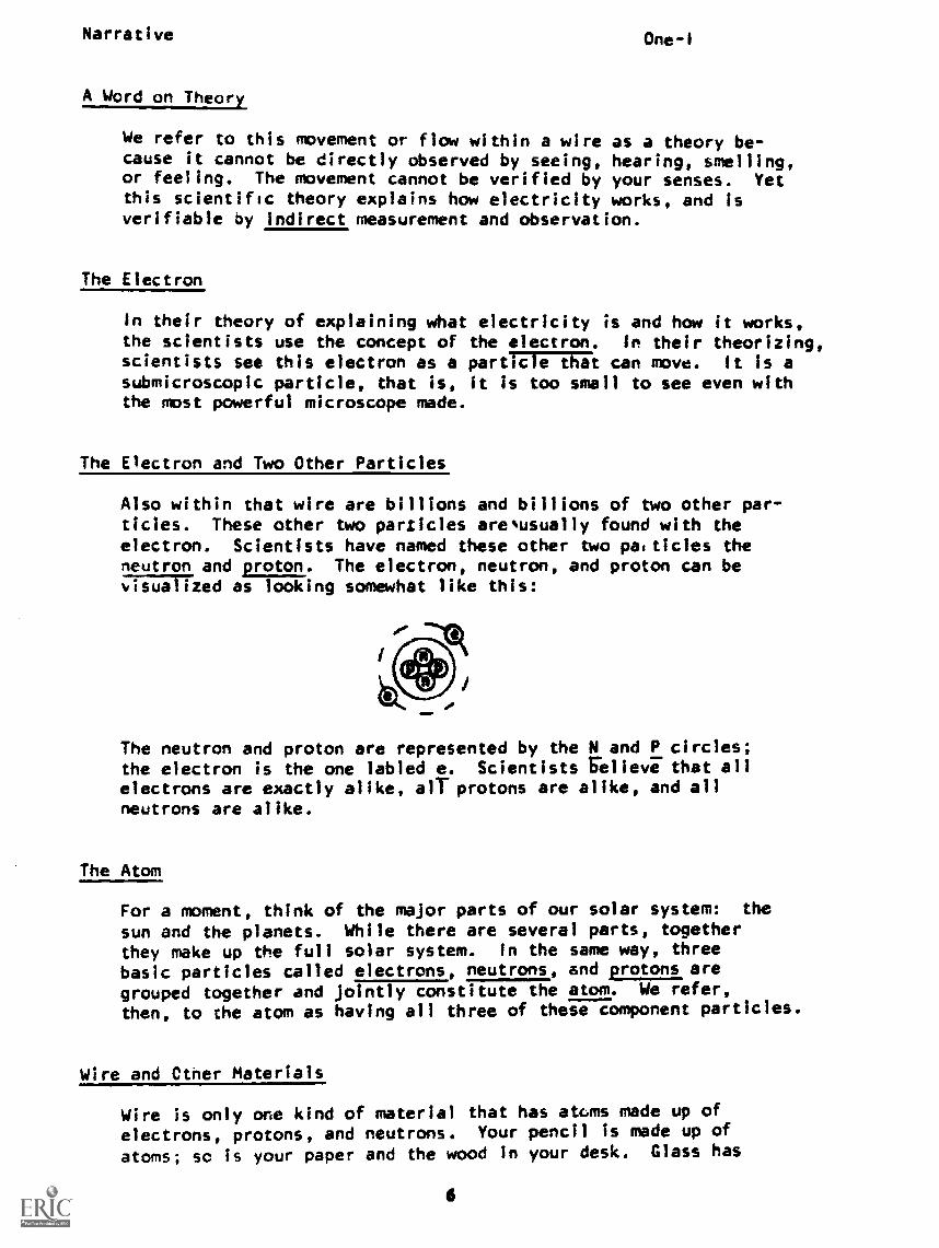
Also within that wire are billions and billions of two other par-ticles. These other two particles are usually found with theelectron. Scientists have named these other two particles theneutron and proton. The electron, neutron, and proton can be;TilliTTzed as looking somewhat like this:
The neutron and proton are represented by the N and P circles;the electron is the one labled e. Scientists relieve that allelectrons are exactly alike, ail-protons are alike, and allneutrons are alike.
The Atom
For a moment, think of the major parts of our solar system: the
sun and the planets. While there are several parts, togetherthey make up the full solar system. in the same way, threebasic particles called electrons, neutrons, and protons aregrouped together and jointly constitute the atom. We refer,
then, to the atom as having all three of these component particles.
Wire and Ctner Materials
Wire is only one kind of material that has atoms made up of
electrons, protons, and neutrons. Your pencil Is made up of
atoms; so is your paper and the wood in your desk. Glass has
6
Narrative One-I
atoms, air has atoms, clothes have atoms, water has atoms, brickshave atoms; the fenders on your car, your steering wheel, all aremade up of atoms. In other words, all matter has atoms. Asstated, all electrons are alike, all protons are alike, and allneutrons are alike. However, you can't use a piece of glass tocarry electricity as you can a piece of wire. The difference inmaterials lies in the number and arrangement of these subatomicparticles within the individual atoms.
Composition of Matter
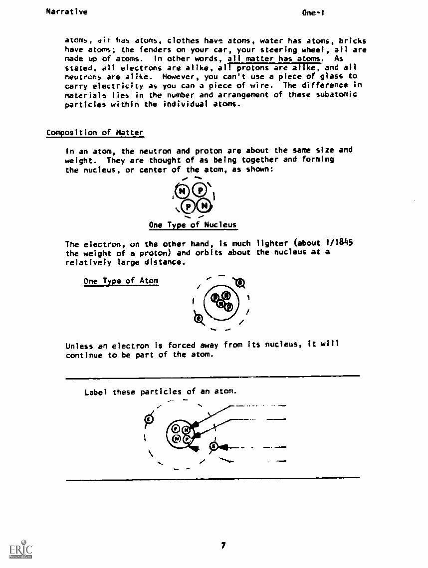
In an atom, the neutron and proton are about the same size andweight. They are thought of as being together and formingthe nucleus, or center of the atom, as shown:
.One Type of Nucleus
The electron, on the other hand, is much lighter (about 1/1845
the weight of a proton) and orbits about the nucleus at arelatively large distance.
One Type of Atom
Unless an electron is forced away from its nucleus, it will
continue to be part of the atom.
Label these particles of an atom.
7
Narrative One1
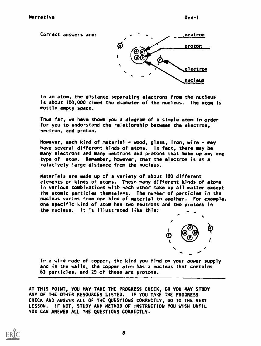
Correct answers are: neu ron
electron
nucleus
In an atom, the distance separating electrons from the nucleusis about 100,000 times the diameter of the nucleus. The atom ismostly empty space.
Thus far, we have shown you a diagram of a simple atom in orderfor you to understand the relationship between the electron,neutron, and proton.
However, each kind of matarial wood, glass, iron, wire - mayhave several different kinds of atoms. In fact, there may bemany electrons and many neutrons and protons that make up any onetype of atom. Remember, however, that the electron is at arelatively large distance from the nucleus.
Materials are made up of a variety of about 100 differentelements or kinds of atoms. These many different kinds of atomsin various combinations with sach other make up all matter exceptthe atomic particles themselves. The number of particles in thenucleus varies from one kind of material to another. For example,one specific kind of atom has two neutrons and two protons inthe nucleus. It is illustrated like this: Yo
In a wire made of copper, the kind you find on your power supplyand in the walls, the copper atom has a nucleus that contains63 particles, and 29 of these are protons.
AT THIS POINT, YOU MAY TAKE THE PROGRESS CHECK, OR YOU MAY STUDYANY OF THE OTHER RESOURCES LISTED. IF YOU TAKE THE PROGRESSCHECK AND ANSWER ALL OF THE QUESTIONS CORRECTLY, GO TO THE NEXTLESSON. IF NOT, STUDY ANY METHOD OF INSTRUCTION YOU WISH UNTILYOU CAN ANSWER ALL THE QUESTIONS CORRECTLY.
8
P.I. One-I
PROGRAMMED INSTRUCTIONLESSON I
Electricity and the Electron
YOU MAY ALREADY KNOW THE INSTRUCTIONAL MATERIAL IN FRAMES 1 to 7.TO FIND OUT, GO TO FRAME 8, WHICH IS A TEST FRAME, AND SEE IF YOUCAN ANSWER ALL THE QUESTIONS THERE. FOLLOW THE DIRECTIONS GIVENAFTER THE TEST FRAME.
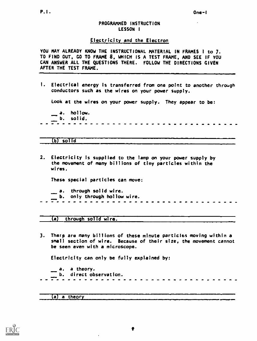
1. Electrical energy is transferred from one point to another throughconductors such as the wires on your power supply.
Look at the wires on your power supply. They appear to be:
a. hollow.b. solid.
(bT sol
2. Electricity is supplied to the lamp on your power supply bythe movement of many billions of tiny particles within thewires.
These special particles can move:
a. through solid wire.b. only through hollow wire.
(a) through solid wire.
3. Tharp are many billions of these minute particles moving within asmall section of wire. Because of their size, the movement cannotbe seen even with a microscope.
Electricity can only be fully explained by:
a. a theory.b. direct observation.
(a) a theory
P. I. One-I
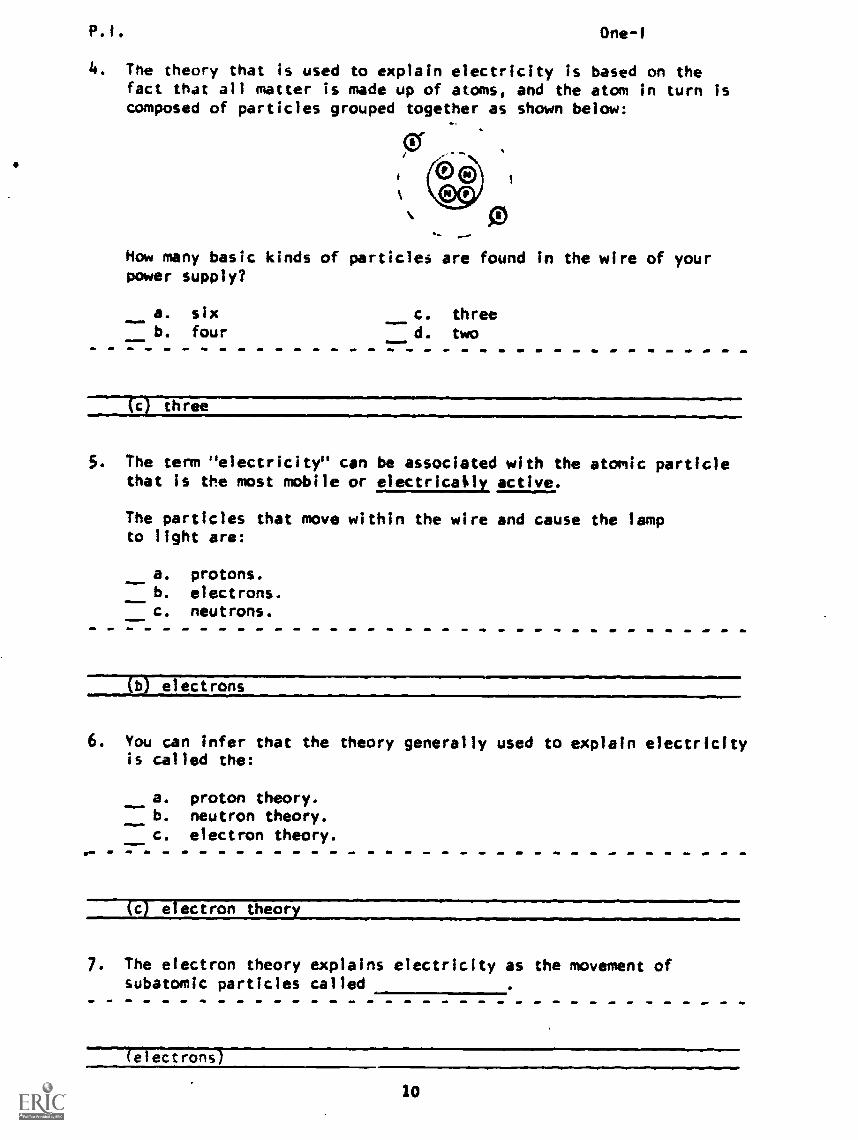
4. The theory that is used to explain electricity is based on thefact that all matter is made up of atoms, and the atom in turn iscomposed of particles grouped together as shown below:
How many basic kinds of particles are found in the wire of yourpower supply?
a. sixb. four
c. threed. two
three
5. The term "electricity" can be associated with the atomic particlethat is the most mobile or electrically. active.
The particles that move within the wire and cause the lampto light are:
a. protons.b. electrons.c. neutrons.
electrons
6. You can infer that the theory generally used to explain electricityis called the:
a. proton theory.b. neutron theory.c. electron theory.
(c) electron theor
7. The electron theory explains electricity as the movement ofsubatomic particles called
le)ectrons)
10
One-I
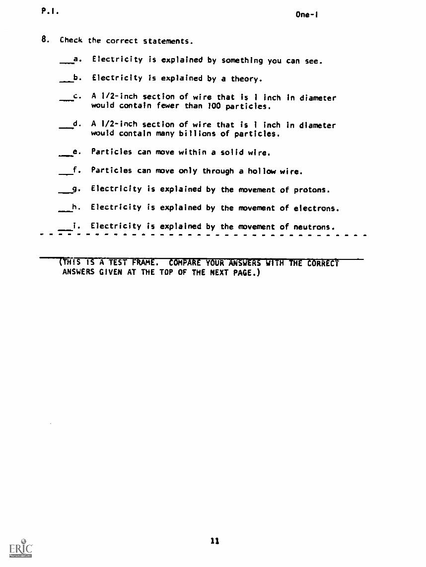
8. Check the correct statements.
a. Electricity is explained by something you can see.
b. Electricity is explained by a theory.
c. A 1/2-inch section of wire that is 1 Inch in diameterwould contain fewer than 100 particles.
d. A 1/2-inch section of wire that is 1 inch in diameterwould contain many billions of particles.
e. Particles can move within a solid wire.
f. Particles can move only through a hollow wire.
___9. Electricity is explained by the movement of protons.
h. Electricity is explained by the movement of electrons.
i. Electricity is explained by the movement of neutrons.
(THIS IS A TEST FRAME. COMPARE YOUR ANSWERS 'WITH TH1 CORRECTANSWERS GIVEN AT THE TOP OF THE NEXT PAGE.)
P.I. One-I
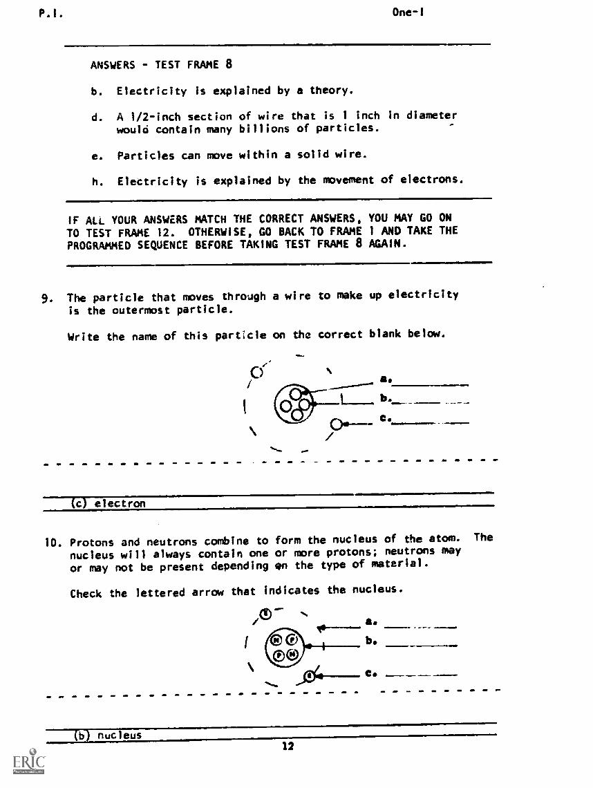
ANSWERS - TEST FRAME 8
b. Electricity is explained by a theory.
d. A 1/2-inch section of wire that is 1 inch in diameterwould contain many billions of particles.
e. Particles can move within a solid wire.
h. Electricity is explained by the movement of electrons.
IF ALL YOUR ANSWERS MATCH THE CORRECT ANSWERS, YOU MAY GO ON
TO TEST FRAME 12. OTHERWISE, GO BACK TO FRAME 1 AND TAKE THEPROGRAMMED SEQUENCE BEFORE TAKING TEST FRAME 8 AGAIN.
9. The particle that moves through a wire to make up electricity
is the outermost particle.
Write the name of this particle on the correct blank below.
(c) electron
10. Protons and neutrons combine to form the nucleus of the atom. The
nucleus will always contain one or more protons; neutrons may
or may not be present depending en the type of material.
Check the lettered arrow that indicates the nucleus.
a.
b.
C.
..m11.-
/1-e-
nucleus12

P.1. One-I
11. In a solid material, the nucleus, for all practical purposes,remains stationary while the electrons are the active particles.
Check the particles which are not very mobile.
a. neutronsb. electronsc. protons
(a) neutronsz and ic) protons
12. Label the three particles.
trim is A TEST FRAME. COMPARE YOUR ANSWERS WITH THE CORRECTANSWERS GIVEN AT THE TOP OF THE NEXT PAGE.)
13
P.1. One-I
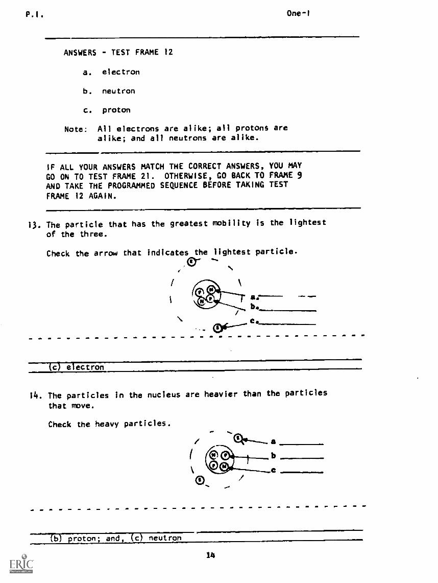
ANSWERS - TEST FRAME 12
a. electron
b. neutron
c. proton
Note: All electrons are alike; all protons arealike; and all neutrons are alike.
IF ALL YOUR ANSWERS MATCH THE CORRECT ANSWERS, YOU MAYGO ON TO TEST FRAME 21. OTHERWISE, GO BACK TO FRAME 9AND TAKE THE PROGRAMMED SEQUENCE BEFORE TAKING TESTFRAME 12 AGAIN.
13. The particle that has the greatest mobility is the lightest
of the three.
Check the arrow that indicates the lightest particle.
AD- --
a.b.
(c) electron
14. The particles in the nucleus are heavier than the particles
that move.
Check the heavy particles.
a
CO proton; and, (C) neutron
14
P. I . One-1
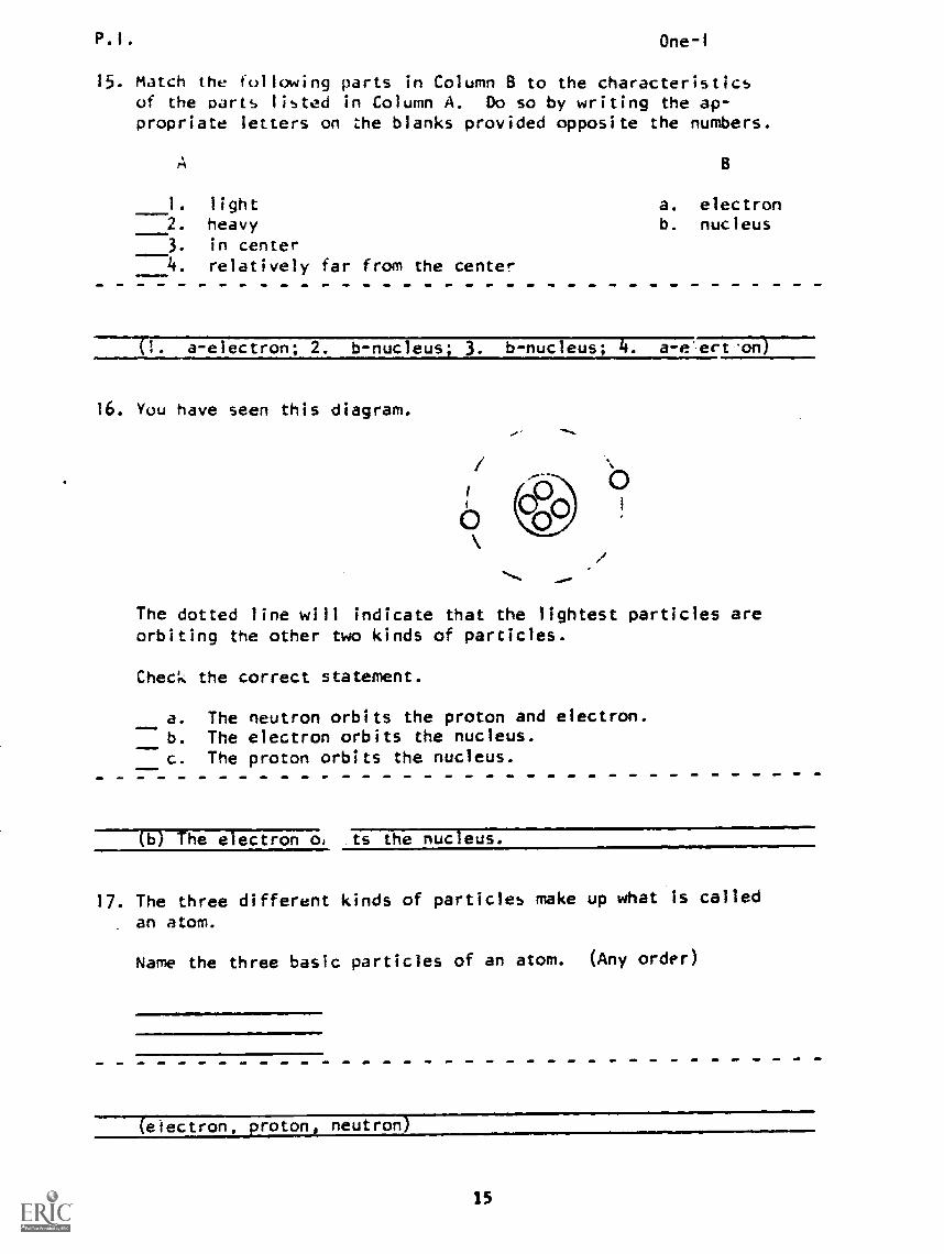
15. Match the following parts in Column B to the characteristicsof the parts listed in Column A. Do so by writing the ap-propriate letters on the blanks provided opposite the numbers.
1. light---2. heavy
3. in center4. relatively far from the center
B
a. electronb. nucleus
a-electron; 2. -nucleus. 3. b- nucleus; 4. a-e-ect-on)
16. You have seen this diagram.
The dotted line will indicate that the lightest particles areorbiting the other two kinds of particles.
Check the correct statement.
a. The neutron orbits the proton and electron.b. The electron orbits the nucleus.c. The proton orbits the nucleus.
(b) The electron o, is the nucleus.
17. The three different kinds of particles make up what Is called
an atom.
Name the three basic particles of an atom. (Any order)
(electron, proton, neutron)
15
0.1. One-1
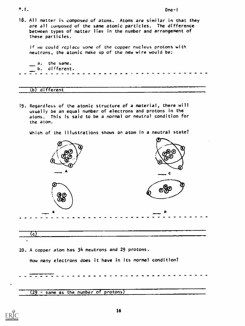
18. All matter is composed of atoms. Atoms are similar in that theyare all ',Jolposed of the same atomic particles. The differencebetween types of matter lies in the number and arrangement ofthese particles.
If we could replace some of the copper nucleus protons withneutrons, the atomic make up of the new wire would be:
a. the same.
b. different.
(b) different
19. Regardless of the atomic structure of a material, there willusually be an equal number of electrons and protons in theatoms. This is said to be a normal or neutral condition forthe atom.
Which of the illustrations shows an atom in a neutral state?
A
a
(c)
20. A copper atom has 34 neutrons and 29 protons.
How many electrons does it have in its normal condition?
(29 - same as the number of protons)
16
P. I .
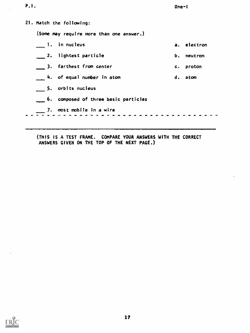
21. Match the following:
(Some may require more than one answer.)
1. in nucleus
2. lightest particle
3. farthest from center
4. of equal number in atom
5. orbits nucleus
6. composed of three basic particlesINOMMIO
7. most mobile in a wire
One - I
a. electron
b. neutron
c. proton
d. atom
(THIS IS A TEST FRAME. COMPARE YOUR ANSWERS WITH THE CORRECTANSWERS GIVEN ON THE TOP OF THE NEXT PAGE.)
P.I. One-I
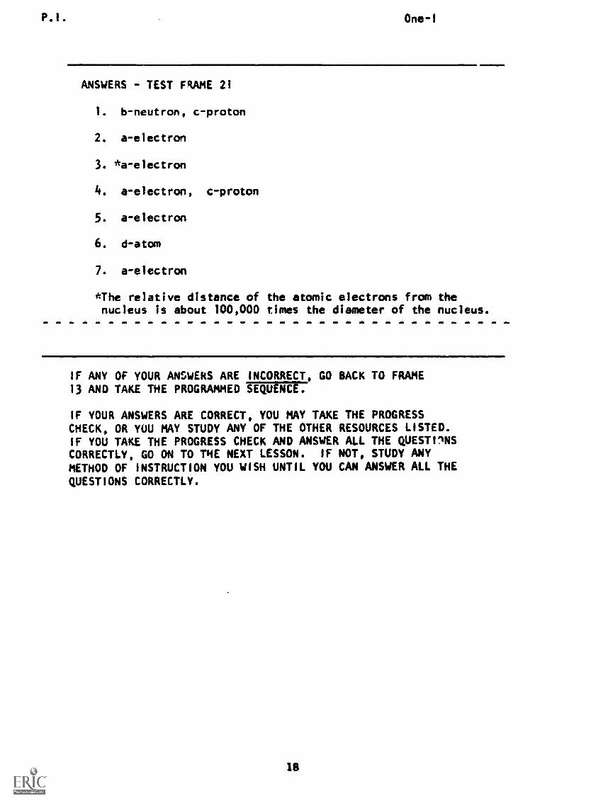
ANSWERS - TEST FRAME 21
1. b-neutron, c-proton
2. a-electron
3. *a-electron
4. a-electron, c-proton
5. a-electron
6. d-atom
7. a-electron
*The relative distance of the atomic electrons from thenucleus is about 100,000 times the diameter of the nucleus.
IF ANY OF YOUR ANSWERS ARE INCORRECT, GO BACK TO FRAME13 AND TAKE THE PROGRAMMED SEQUENCE.
IF YOUR ANSWERS ARE CORRECT, YOU MAY TAKE THE PROGRESSCHECK, OR YOU MAY STUDY ANY OF THE OTHER RESOURCES LISTED.IF YOU TAKE THE PROGRESS CHECK AND ANSWER ALL THE QUESTONSCORRECTLY, GO ON TO THE NEXT LESSON. IF NOT, STUDY ANYMETHOD OF INSTRUCTION YOU WISH UNTIL YOU CAN ANSWER ALL THE
QUESTIONS CORRECTLY.
Summary One -i
SUMMARYLESSON I
Electricitt and the Electrcn
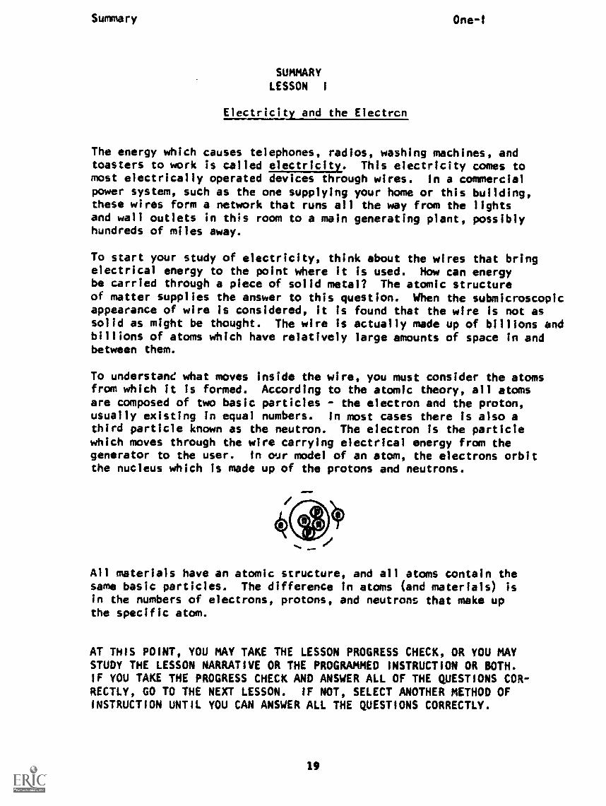
The energy which causes telephones, radios, washing machines, andtoasters to work is called electricity. This electricity comes tomost electrically operated devices through wires. In a commercialpower system, such as the one supplying your home or this building,these wires form a network that runs all the way from the lightsand wall outlets in this room to a main generating plant, possiblyhundreds of miles away.
To start your study of electricity, think about the wires that bringelectrical energy to the point where it is used. How can energybe carried through a piece of solid metal? The atomic structureof matter supplies the answer to this question. When the submicroscopicappearance of wire is considered, it is found that the wire is not assolid as might be thought. The wire is actually made up of billions andbillions of atoms which have relatively large amounts of space in andbetween them.
To understand what moves inside the wire, you must consider the atomsfrom which it is formed. According to the atomic theory, all atomsare composed of two basic particles - the electron and the proton,usually existing in equal numbers. In most cases there is also athird particle known as the neutron. The electron is the particlewhich moves through the wire carrying electrical energy from thegenerator to the user. In our model of an atom, the electrons orbitthe nucleus which is made up of the protons and neutrons.
!MP
All materials have an atomic structure, and all atoms contain thesame basic particles. The difference in atoms (and materials) isin the numbers of electrons, protons, and neutrons that make upthe specific atom.
AT THIS POINT, YOU MAY TAKE THE LESSON PROGRESS CHECK, OR YOU MAYSTUDY THE LESSON NARRATIVE OR THE PROGRAMMED INSTRUCTION OR BOTH.IF YOU TAKE THE PROGRESS CHECK AND ANSWER ALL OF THE QUESTIONS COR-RECTLY, GO TO THE NEXT LESSON. IF NOT, SELECT ANOTHER METHOD OFINSTRUCTION UNTIL YOU CAN ANSWER ALL THE QUESTIONS CORRECTLY.
19
BASIC ELECTRICITY AND ELECTRONICS
INDIVIDUALIZED LEARNING SYSTEM
MODULE ONE
LESSON II
Electron Movement
Study Booklet
21
Overview One-11
OVERVIEW
LESSON II
Electron Movement
We have seen that electrons are usually bound to an atom. We have
also inferred that a flowing stream of electrons constitutes
electricity. This lesson will make clear the difference between
these two possible states of electrons. in this lesson you will
study and learn about the following:
- movement of particles
- negative and positive charges
-neutral particles
-law of charged bodies
- random drift
Each of the above topics will be discussed in the order listed. As
you proceed through this lesson, observe and follow directions carefully.
BEFORE YOU START THIS LESSON, PREVIEW THE LIST OF STUDY RESOURCES
ON THE NEXT PAGE.
22
Study Resources One-I,
LIST OF STUDY RESOURCES
LESSON II
Electron Movement
To learn the material in this lesson, you have the option of choosing,
according to your experience and preferences, any or all of the
following:
STUDY BOOKLET:
Lesson Narrative
Programmed Instruction
Lesson Summary
ENRICHMENT MATERIAL:
NAVPERS 99400A-la "Basic Electricity, Direct Current."
Fundamentals of Electronics. Bureau of Naval Personnel.
Washington, D.C.: U. S. Government Printing Office, 1965.
You may study whatever learning materials you feel are necessary to
answer the questions in the Lesson Progress Check. All your answers
must be correct before you can go to Lesson III. Remember your in-
structor is available at all times for any assistance you may need.
YOU MAY NOW STUDY ANY OR ALL OF THE RESOURCES LISTED ABOVE. YOU MAY
TAKE THE PROGRESS CHECK AT ANY TIME.
23

Narrative One-II
NARRATIVE
LESSON II
Electron Movement
Movement of Particles
Think about the title of this lesson, "Electron Movement." Weare speaking here of the movement of the electrons within solidmaterial such as a wire. The other two principle atomic particles,the neutron and proton, are too heavy and too tightly boundtogether to move around in the wire as freely as the electronsdo.
Charges
To understand the movement of electrons, you must understandthe term charge. A charge can be defined as "a store or accumulationof force." Two of the three basic atomic particles, the electronand the proton, have a charge and are called charged. articles.Some charged particles attract each other and some reps Let'ssee which attract and which repel.
Negative and Positive Charges
Recall that the electrons orbit the neutrons and the protons of theatomic nucleus. The electrons do this because their tendency tofly away due to centrifugal force is balanced by an attractionto the protons in the nucleus. The attraction is strong enoughto keep the electron within the atom, but not strong enough todraw it to the nucleus. The part to remember here is that thee1octron is attracted to the proton. Knowing this, let'ssuppose that we refer to the electron as a negative (-) chargeane a proton as a positive (+) charge. They are unlike charges.
Answer this question.
1. Do unlike charges attract repel?
The answer is that unlike charges attract. The negativelycharged electron Is attracted to the positively charged proton.
Neutral Particles
As we commonly use the term, anything that Is neutral is neither
24
Narrative One-11
one way nor the other. A neutral article is neither attractednor repelled by other charge or unc arged) particles. You canobserve that word neutral resembles neutron.
Name the atomic particle that is neither attractednor repelled by other charged particles.
The answer, of course, is neutron. It is neither attracted norrepelled by either the electron or proton. The neutron playsno noticeable role in electric current.
Like Charges,
We said that the electron has a negative charge and that theproton has a positive charge. Because they are unlike charges,they attract each other. But what about two electrons, bothnegatively charged, or two protons, both positively charged?The answer is that "like charges repel."
Answer this question.
Which two repel each other?
r. two electronst, two protonsc. an electron and proton
The two electrons will repel. They do so because they are"like charges." The same goes for two protons. They areboth alike in that they are both positively charged. Theanswer is "a" and "b".
Law of Charged Bodies
The Law of Charged Bodies states exactly what you have just learned:"Like charges repel, unlike charges attract." This law of chargedbodies is part of Coulomb's Law. (The balance of this law tells us"how much" the charges repel or attract.)
We can state this law of Charged Bodies in a number of ways, allmeaning the same thing.
25
Narrative
Repulsion
One -11
-Like charges repel.-Two electrons repel.-Two protons repel.-A negative and a negative repel.- A positive and a positive repel.
- A (+) and a (+) repel.
- A (-) and a (-) repel.
Attraction
-Unlike charges attract.-A proton and an electron attract.- A positive and a negative attract.-A (+) and a (-) attract.
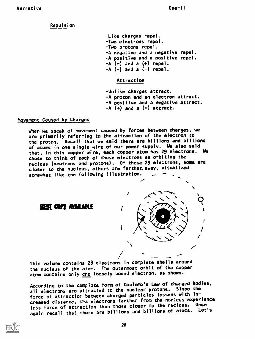
Movement Caused by Charjes
When we speak of movement caused by forces between charges, weare primarily referring to the attraction of the electron to
the proton. Recall that we said there are billions and billionsof atoms In one single wire of our power supply. We also said
that, in this copper wire, each copper atom has 29 electrons. We
chose to think of each of these electrons as orbiting the
nucleus (neutrons and protons). Of those 29 electrons, some are
closer to the nucleus, others are farther_ away, visualized
somewhat like the following illustration.
MST WI AWAKE
This volume contains 28 electrons in complete shells around
the nucleus of the atom. The outermost orbit of the copper
atom contains only one loosely bound electron, as shown.
According to the complete form of Coulomb's Law of charged bodies,
all electrons are attracted to the nuclear protons. Since the
force of attractior between charged particles lessens with in-
creased distance, the electrons farther from the nucleus experience
less force of attraction than those closer to the nucleus. Once
again recall that there are billions and billions of atoms. Let's
26

Narrative One-11
take just two of these atoms and look at the electrons farthestfrom the nucleus in each atom. #
'Pr
1
In observing the two illustrations, remember two points:
1. The outer electrons, although attracted to their respec-tive nuclei, have the weakest force of attraction becausethey are farthest away.
2. As the outer electrons of each atom approach each other,they will repel each other.
You know this because: (check one)
a. like charges repel.b. unlike charges repel.
IM
The answer Is "like charges repel."
This force of repulsion between outer electrons of one atom andouter electrons of another atom may become stronger than theattraction of electrons to the protons. Therefore, as the outerelectrons approach each other, they repel and may be forced outof their atomic orbits.
When this occurs, the atom is left with more positive charge (protons)than negative charge (electrons) leaving the atom with a net posi-tive charge. This positively charged atom is called a sitive ton.If an electron joins an atom that already has a full comp ement Unrelectrons 1,a neutral atom), the atom assumes a net negative chargeand becomes a negative ion. An ion, then, is simply a chargedatom. The process whereby an atom becomes an ion is calledionization. The amount of energy (outside force, such as heatenergy, light energy, etc.) necessary to cause ionization for anyparticular atom is known as the ionization potential.
Random Drift of Electrons
Once an electron has been driven from its atomic orbit it becomesa free electron, drifting here and there seeking a new orbit. Thisfree electron, no linger attracted to its home atom, is now free todrift at random. This movement of free electrons is referred toas random drift. Note that special cases exist at the surface of
27
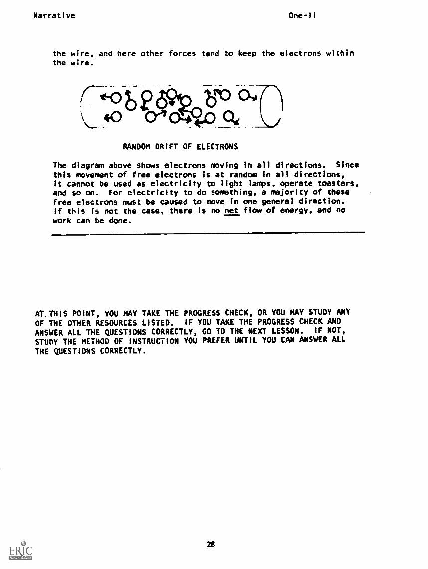
Narrative One-II
the wire, and here other forces tend to keep the electrons withinthe wire.
RANDOM DRIFT OF ELECTRONS
The diagram above shows electrons moving in all directions. Sincethis movement of free electrons is at random in all directions,it cannot be used as electricity to light lamps, operate toasters,and so on. For electricity to do something, a majority of thesefree electrons must be caused to move in one general direction.If this is not the case, there is no net flow of energy, and nowork can be done.
AT. THIS POINT, YOU MAY TAKE THE PROGRESS CHECK, OR YOU MAY STUDY ANY
OF THE OTHER RESOURCES LISTED. IF YOU TAKE THE PROGRESS CHECK ANDANSWER ALL THE QUESTIONS CORRECTLY, GO TO THE NEXT LESSON. IF NOT,
STUDY THE METHOD OF INSTRUCTION YOU PREFER UNTIL YOU CAN ANSWER ALL
THE QUESTIONS CORRECTLY.
28
P. I.
PROGRAMMED INSTRUCTIONLESSON II
One-II
Electron Movement
TEST FRAMES ARE 18, 29, and 35. AS BEFORE, GO FIRST TO TEST FRAME18 AND SEE IF YOU CAN ANSWER ALL THE QUESTIONS THERE. FOLLOWTHE DIRECTIONS GIVEN AFTER THE TEST FRAME.
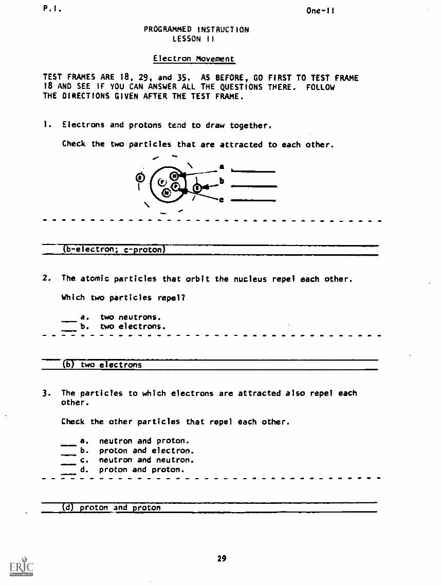
Electrons and protons tend to draw together.
Check the two particles that are attracted to each other.
(b- electron; c-proton)
2. The atomic particles that orbit the nucleus repel each other.
Which two particles repel?
a. two neutrons.b. two electrons.
----(0&o electrons
3. The particles to which electrons are attracted also repel eachother.
Check the other particles that repel each other.
a. neutron and proton.b. proton and electron.c. neutron and neutron.d. proton and proton.
(d) proton and proton
P.I.
4. Match the two columns.
a. two electronsb. two protonsc. protons and electrons
One -I I
1. attract2. repel
(a. 2-repel; b. 2-repel; c. 1-attract)
5. The atomic particles that are not in the nucleus are said tohave a negative charge. (Charge means an ac:umulation or storeof force.)
Which particle has a negative charge?
a. protonb. electronc. neutron
) electron
6. The other kind of particle that attracts and repels is said to have apositive charge.
Which particle has a positive charge?
a. protonb. neutronc. electron_
(a) proton
7. As its name implies, the third particle is neutral and could besymbolized this way: (-)
A neutron:
a. has a net positive charge.b. neither attracts or repels.c. has a net negative charge.
--T6TneitPattrctrc77grr-e s.
30
P.I. One-II
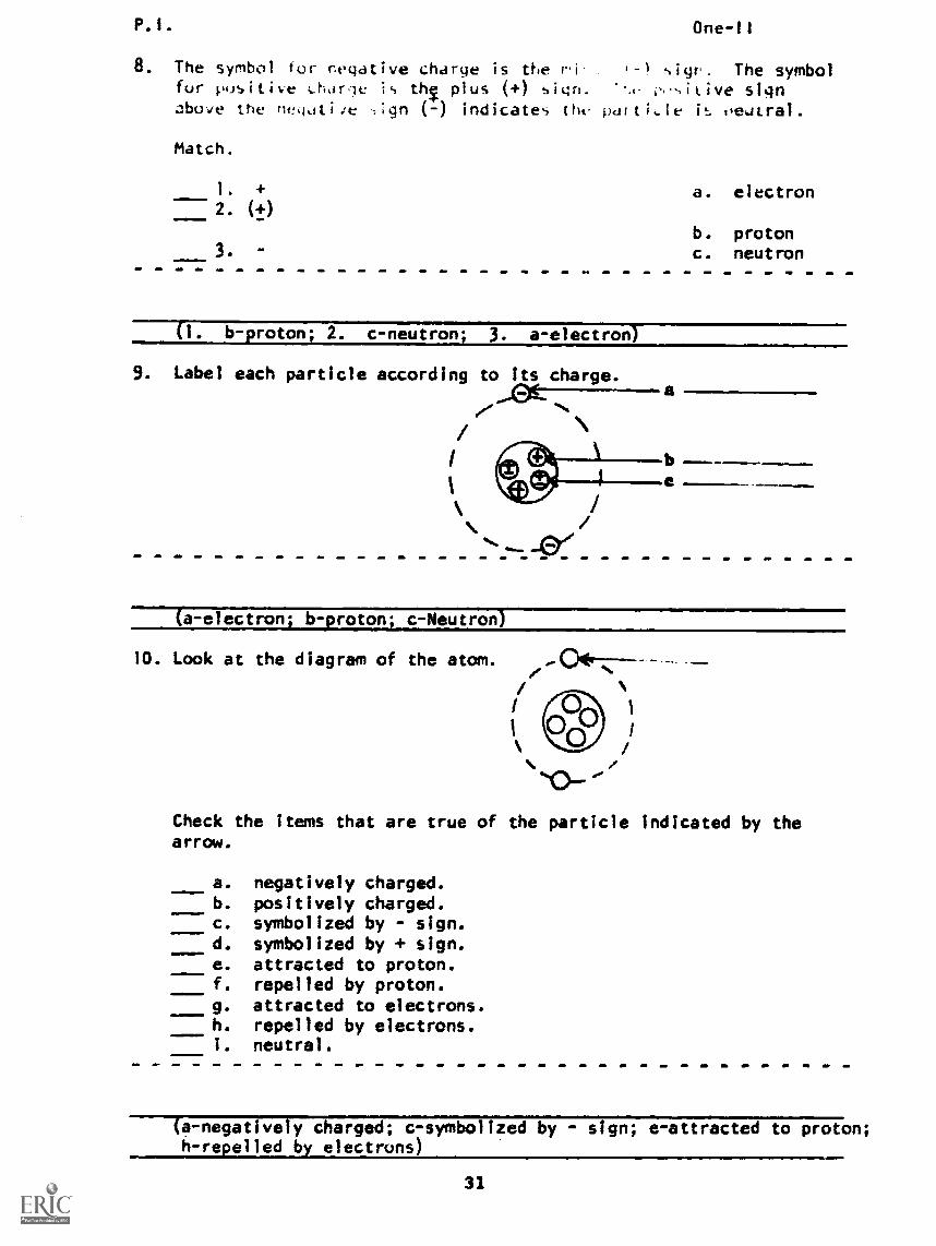
8. The symbol for negative charge is the '-) The symbolfur pusitive i..harle is thT plus (+) sign. signabove the ne!qotiie -.;gn (-) indicate-, the' pditi,ie is oeatral.
Match.
1. + a. electron2. (+)
b. proton3. c. neutron
(i. b-proton; 2. c-neutron; 3. a-electron)
9. Label each particle according to its charge.a
(a-electron; b-proton; c-Neutron)
10. Look at the diagram of the atom.
Check the items that are true ofarrow.
a. negatively charged.b. positively charged.c. symbolized by - sign.d. symbolized by + sign.e. attracted to proton.f. repelled by proton.g. attracted to electrons.h. repelled by electrons.1. neutral.
the particle indicated by the
(a-negatively charged; c-symbolized by - sign; e-attracted to proton;h-repelled by electrons)
31
P.1.
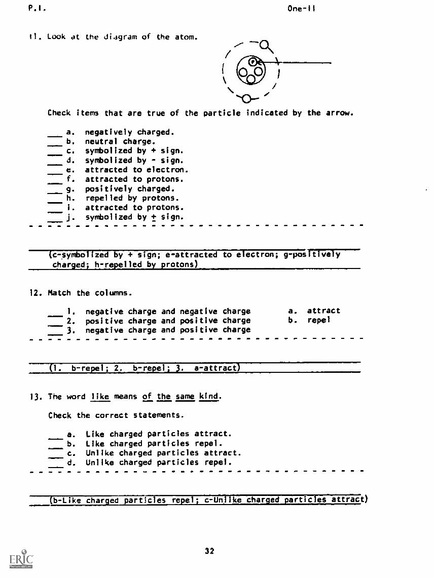
II. look at the diagram of the atom.
One-11
Check items that are true of the particle indicated by the arrow.
a. negatively charged.b. neutral charge.c. symbolized by + sign.d. symbolized by - sign.e. attracted to electron.f. attracted to protons.g. positively charged.h. repelled by protons.i. attracted to protons.j. symbolized by + sign.
(c- symbolized by + sign; e-attracted to electron; g-positivelycharged; h-repelled by protons)
12. Match the columns.
1. negative charge and negative charge2. positive charge and positive charge3. negative charge and positive charge
a. attractb. repel
(1. b-repel; 2. b-repel; 3. a-attract)
13. The word like means of the same kind.
Check the correct statements.
a. Like charged particles attract.b. Like charged particles repel.c. Unlike charged particles attract.d. Unlike charged particles repel.
(b-Like charai particles repel; c-Unlike charged particles attract)
32
P.1. One-II
14. what true of the charged particles is also true ofgroups of charges.
Check the correct statements.
a. Groups of like charges repel.b. Groups of unlike charges attract.c. Groups of unlike charges repel.d. Groups of like charges attract.
(a-Groups of like charges repel; b-Groups of unlike charges attract)
15. in electrical theory:
a. unlike charges attract.b. like charges repel.
(a-unlike charges attract b-like charges repel)
16. That unlike charges attract and like charges repel is referredto as the "Law of Charged Bodies." According to the Law ofCharged Bodies:
.10.111.P
a. two electrons repel.b. two protons repel.c. protons and electrons attract.
(a-two electrons repel; b-two protons repel; c-protons and electronsattract)
17. You can infer that the Law of Charged Bodies does not referto the particle that is neutral.
Write the name of the neutral particle.
(neutron)
33
P.I. One-II
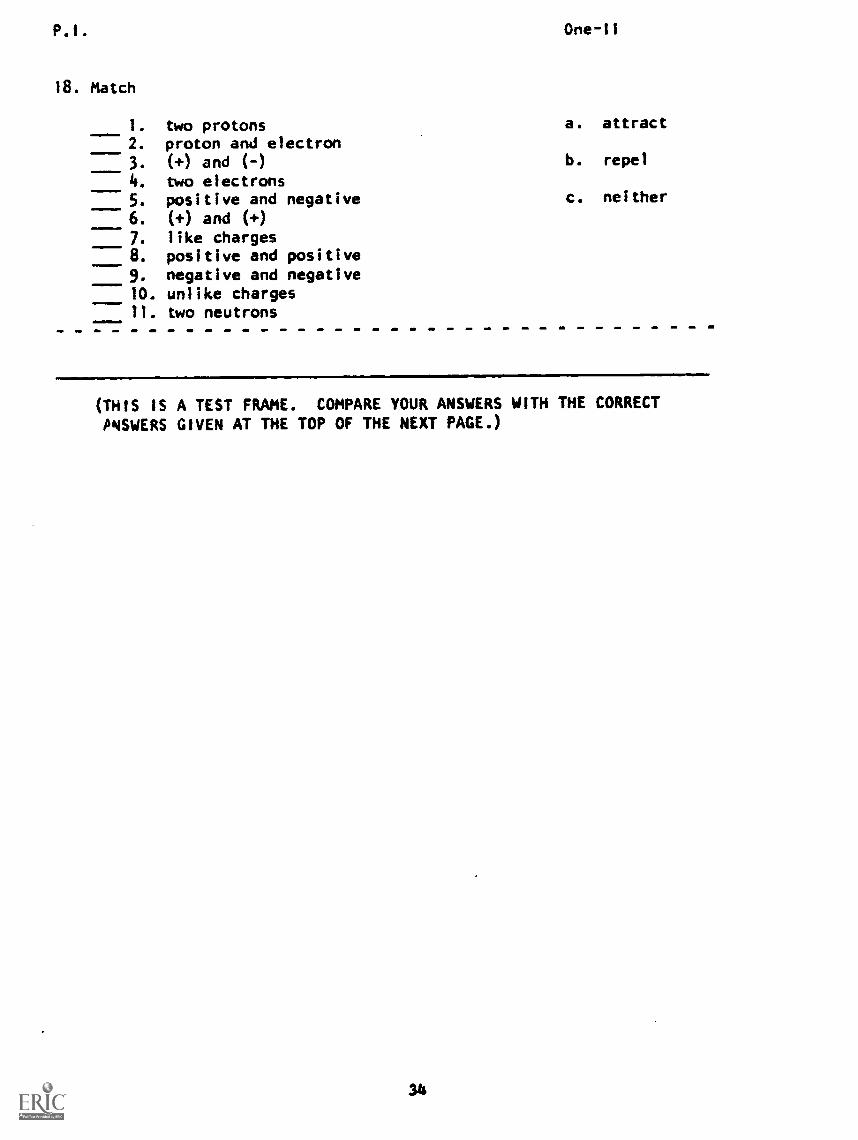
18. Match
1. two protons2. proton and electron3. (+) and (-)
4. two electrons5. positive and negative6. (+) and (+)7. like charges8. positive and positive9. negative and negative10. unlike charges11. two neutrons
a. attract
b. repel
c. neither
(THIS IS A TEST FRAME. COMPARE YOUR ANSWERS WITH THE CORRECTPNSWERS GIVEN AT THE TOP OF THE NEXT PAGE.)
P.1. One-11
ANSWERS - TEST FRAME 18
1. b 7. b2. a 8. b3. a 9. b4. b 10. a5. a 11. c6. b
IF ALL YOUR ANSWERS MATCH THE CORRECT ANSWERS, YOU MAY GO ONTO TEST FRAME 29. OTHERWISE, GO BACK TO FRAME 1 AND TAKE THEPROGRAMMED SEQUENCE BEFORE TAKING TEST FRAME 18 AGAIN.
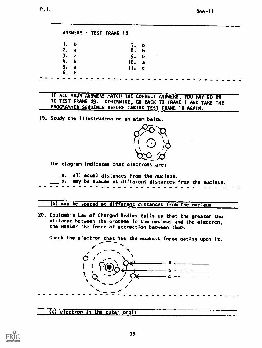
19. Study the Illustration of an atom below.
The diagram indicates that electrons are:
a. all equal distances from the nucleus.b. may be spaced at different distances from the nucleus.
(b) may be spaced at different distances from the nucleus
20. Coulomb's Law of Charged Bodies tells us that the greater thedistance between the protons in the nucleus and the electron,the weaker the force of attraction between them.
Check the electron that has the weakest force acting upon it.
/(1)
b
a
cbk %A.
Se'
(c) electron In the outer orbit
35
P.1. One-11
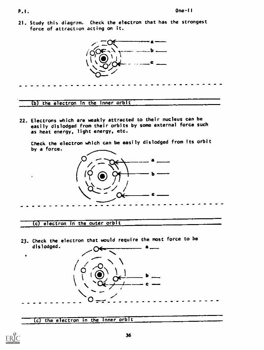
21. Study this diagram. Check the electron that has the strongest
force of attraction acting on it.
:DO( a .---
0t-ip_;\ "'
(b) the electron in the inner orbit
22. Electrons which are weakly attracted to their nucleus can be
easily dislodged from their orbits by some external force such
as heat energy, light energy, etc.
Check the electron which can be easily dislodged from its orbit
by a force.
a
I 1
Ic) electron in the outer orbit
23. Check the electron that would require the most force to be
dislodged. a
0 ) I
N'a-dedt I c ---
(c) the electron in the inner orbit
36
One-li
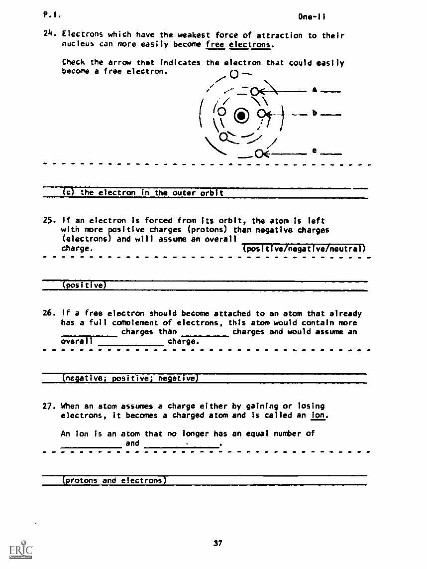
24. Electrons which have the weakest force of attraction to theirnucleus can more easily become free electrons.
Check the arrow that indicates the electron that could easilybecome a free electron.
TO the electron in the outer orbitammulmar
25. If an electron is forced from its orbit, the atom is leftwith more positive charges (protons) than negative charges(electrons) and will assume an overallcharge. (positiveihegative/neutral)
(positive)
26. if a free electron should become attached to an atom that alreadyhas a full complement of electrons, this atom would contain more
charges than charges and would assume anoverall charge.
(negative; positive; negative)
27. When an atom assumes a charge eitherelectrons, it becomes a charged atom
An ion is an atom that no longer hasand
by gaining or losingand Is called an ion.
an equal number of
protons and electrons
37
P.I. One-II
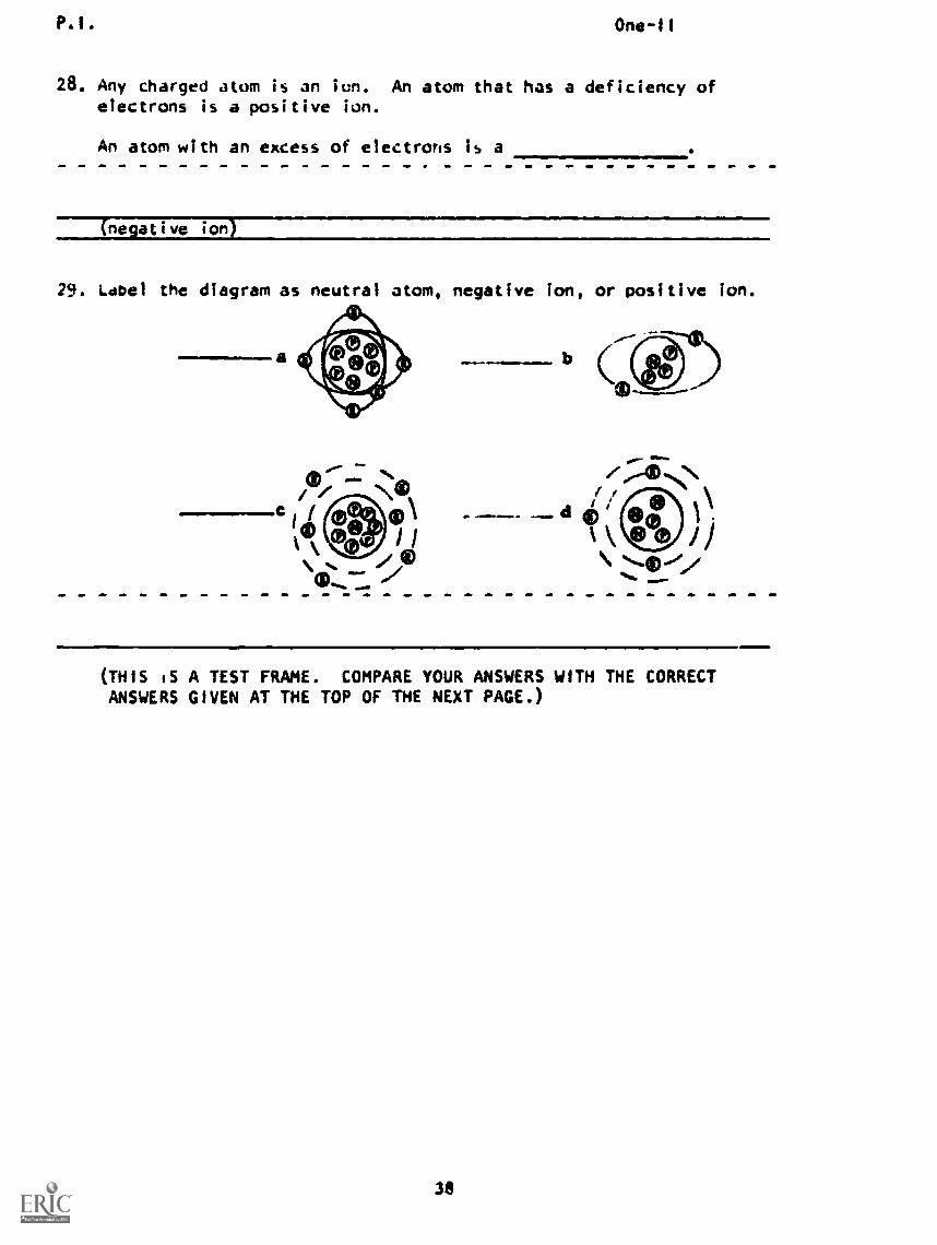
28. Any charged atom is an ion. An atom that has a deficiency ofelectrons is a positive ion.
An atom with an excess of electrons is a
(negative ion)
29. Label the diagram as neutral atom, negative ion, or positive ion.
..1111/0=ela
(THIS IS A TEST FRAME. COMPARE YOUR ANSWERS WITH THE CORRECTANSWERS GIVEN AT THE TOP OF THE NEXT PAGE.)
38
P.I. One-II
ANSWERS - TEST FRAME 29
a. Neutral; b. Positive; c. Positive: d. Negative
IF ALL YOUR ANSWERS MATCH THE CORRECT ANSWERS, YOU MAY GOON TO TEST FRAME 35. OTHERWISE, GO BACK TO FRAME 19 AND TAKETHE PROGRAMMED SEQUENCE BEFORE TAKING TEST FRAME 22 AGAIN.
30. The process whereby an atom becomes an ion is known as ionization.The amount of energy (outside force such as heat energy, lightenergy, etc.) required to cause ionization is called ionizationLotential.
In order for an electron to become free of the parent atom,energy equal to or greater than the must beapplied to the atom.
on zatson tentidi
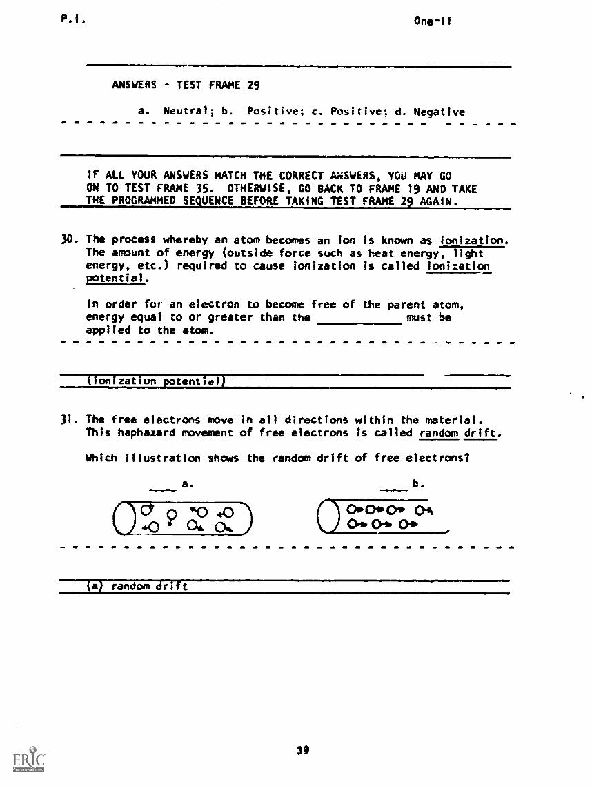
31. The free electrons move in all directions within the material.This haphazard movement of free electrons is called random drift.
Which illustration shows the random drift of free electrons?
a. b.
(ICY 0 sO 4.0 0 °Poway ()Ac>. 0-0.0 OA oft
(a) random edit
39
P.1. One-11
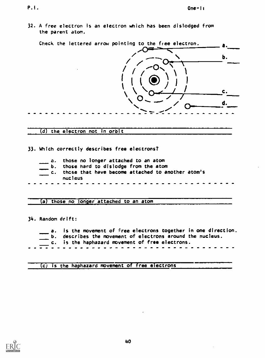
32. A free electron is an electron which has been dislodged fromthe parent atom.
Check the lettered arrow pointing to the free electron.
/-0°-ON
t */C.
a.
b.
(d) the electron not in orbit
33. Which correctly describes free electrons?
a. those no longer attached to an atomb. those hard to dislodge from the atomc. these that have become attached to another atom's
nucleus
(al those no longer attached to an atom
34. Random drift:
a. Is the movement of free electrons together in one direction.b. describes the movement of electrons around the nucleus.c. is the haphazard movement of free electrons.
(c) is the haphazard movement of free electrons

35. Check the correct statements.
III1
!!
One -I I
a. Within an atom having several shells of electrons, theelectrons are all at equal distances from the nucleus.
b. The greater the distance between the nucleus and theelectron, the weaker the force of attraction betweenthem.
c. Electrons weakly attracted to the nucleus are difficultto dislodge from that nucleus.
d. Free electrons are those that have the greatest potentialof being free when an outside force is applied.
e. Random drift is the haphazard movement of atoms in a wire.
f. Within an atom having several shells of electrons, theelectrons are spaced at different distances from thenucleus.
g. Electrons dislodged from their atoms after an externalforce has been applied are called free electrons.
h. The greater the distance between the nucleus and theelectron, the greater the force of attraction betweenthem.
i. Random drift is the haphazard movement of protons in awire.
j. Electrons weakly attracted to their nucleus are the easiestto dislodge from their orbits.
(THIS IS A TEST FRAME. COMPARE YOUR ANSWERS WITH THE CORRECTANSWERS GIVEN AT THE TOP OF THE NEXT PAGE.)
41
P.I. One-11
ANSWERS - TEST FRAME 35
b The greater the distance between the nucleus and theelectron, the weaker the force of attraction betweenthem.
f - Within an atom having several shel.s of electrons,the electrons are spaced at diff,-,lnt distances fromthe nucleus.
g Electrons dislodged from their atoms after an externalforce has been applied are called free electrons.
j Electrons weakly attracted to their nucleus are theeasiest to dislodge from their orbits.
IF ANY OF YOUR ANSWERS IS INCORRECT, GO BACK TO FRAME 19 AND TAKETHE PROGRAMMED SEQUENCE.
IF YOUR ANSWERS ARE CORRECT, YOU MAY TAKE THE PROGRESS CHECK,OR YOU MAY STUDY ANY OF THE OTHER RESOURCES LISTED. IF YOU
TAKE THE PROGRESS CHECK AND ANSWER ALL THE QUESTIONS CORRECTLYGO ON TO THE NEXT LESSON. IF NOT, STUDY ANY METHOD OF INSTRUC-TION YOU WISH UNTIL YOU CAN ANSWER ALL THE QUESTIONS CORRECTLY.
42
Summary One-II
SUMMARYLESSON II
Electron Movement
The electron may constitute electricity because it has an electriccharge. The proton also has an electric charge, but it is oppositein character to the electron's charge. By common agreement, wecall the proton's charge sitive and that of the electron negative.The neutron is neutral, that Is, it has no net charge.
In the last lesson, you learned that electrons are believed tocarry the electrical energy. Protons and neutrons are too heavy andtoo tightly bound together to move around in the wire as freely asthe electrons do.
Complex forces hold the electrons in their more stable positions inthe atom. It is experimentally found that positive and negativecharges attract each other. Another electrical force is the mutualrepulsion which exists between electrons. Similar mutual repulsionexists between protons. These forces are stated in Coulomb's Lawof Charged Bodies as "like charges repel and unlike charges attract."The protons in the nucleus of an atom are held together by verystrong nuclear binding forces; so the protons cannot be separated bythe force of repulsion between them. But the orbiting electrons aremore delicately balanced. There is a force of attraction betweenthe electrons and the nuclear protons. This force tends to pull theelectrons toward the nucleus while the energy of their motion(centrifugal force) tends to move them outward. Normally the twoforces will balance and the electrons will remain in orbit aboutthe nucleus, and the atom will maintain its electrical neutral state.
The greater the distance between two unlike charges, such as anorbiting electron and the positive charge of the nucleus, thesmaller the force of attraction between the two particles. Becauseof this, the electrons that orbit farthest from the nucleus maylose this balance of force quite easily and move away from the atomto become free electrons. This will occur when some outside force(heat energy, light energy, etc.) is applied to the atom. Sincethe electron with its negative charge has left the atom, the atomnow contains more positive charges (protons) than negative charges(electrons) and has become a positively charged particle called apositive ion.
If a free electron becomes attached to an atom that already has afull complement of electrons the atom assumes an overall negativecharge and is called a negative ion. As you may have gathered,ion is a term used to refer to an atom that has assumed a netnegative or positive charge. The process whereby an atom becomesan ion is known as ionization and the amount of energy (outsideforce) necessary torierelectron from its atom is known as theionization potential for that atom.
Summary One-II
Once an electron leaves its orbit and becomes a free electron, itdrifts at random through the material until some other force (apositive charge, repulsion from another electron, attraction toan atom which has lost an electron, etc.) acts upon it. This move-ment of free electrons is called random drift, and because thismovement within a material takes FITZrirrin directions, theaverage net effect is zero; nothing can be measured and no electricalwork is done.
AT THIS POINT, YOU MAY TAKE THE PROGRESS CHECK OR YOU MAY STUDY THELESSON NARRATIVE OR THE PROGRAMMED LESSON. IF YOU TAKE THE PROGRESSCHECK AND ANSWER ALL OF THE QUESTIONS CORRECTLY, GO TO THE NEXT LES-SON. IF NOT, STUDY THE METHOD OF INSTRUCTION YOU PREFER UNTIL YOUCAN ANSWER ALL THE QUESTIONS CORRECTLY.
44
BASIC ELECTRICITY AND ELECTRONICS
INDIVIDUALIZED LEARNING SYSTEM
MODULE ONE
LESSON III
Current Flow
Study Booklet
Overview One-III
OVERVIEW
LESSON III
Current flow
In this lesson you will study and learn about the following:
- random drift vs. directed drift
- directing electron movement
- current path
- simple circuits
- introduction to schematics
- direction of current flow
- building a simple circuit
Each of the above topics will be discussed in the order listed.
As you proceed through this lesson, observe and follow directions
carefully.
BEFORE YOU START THIS LESSON, PREVIEW THE LIST OF STUDY RE-
SOURCES ON THE NEXT PAGE.
Study Resources One -lit
LIST OF STUDY RESOURCES
LESSON III
Current Flow
To learn the material in this lesson, you have the option of choos-
ing, according to your experience and your preferences, any or all
of the following:
STUDY BOOKLET:
Lesson Narrative
Programmed Instruction
Lesson Summary
ENRICHMENT MATERIAL:
Boeke, K. Cosmic View: The Universe in 40 Jumps.
New York: The John Day Company, 1957.
NAVPERS 93400A-1a "Basic Electricity, Direct Current."
Fundamentals of Electronics. Bureau of Naval Personnel.
Washington, D.C.: U. S. Government Printing Office, 1965.
AUDIO-VISUAL:
Sound/Slide Presentation: "Constructing a Simple Circuit."
You may study whatever learning materials you feel are necessary
to answer the questions in the Lesson Progress Check. All your
answers must be correct before you can go to Lesson IV. Remember,
your instructor is available at all times for any assistance you
may need.
YOU MAY NOW STUDY ANY OR ALL OF THE RESOURCES LISTED ABOVE. YOU
MAY TAKE THE PROGRESS CHECK AT ANY TIME.
47
Narrative One-Ill
NARRATIVELESSON III
Current Flow
Random Drift vs. Directed Drift
In the previous lesson we spoke of random drift, which yourecall was the movement of the outermost electron away fromits atomic nucleus. Disconnect a wire from your power sup-ply, pick it up, and look at it. Inside that wire there isa random drift of billions of free electrons. In this state,these free electrons are not capable of doing anything useful,meaning they cannot make lamps light or machines operate orhousehold appliances work. This is true if all the wires areconnected but your power supply cord is not plugged in, orif the switch is open. To obtain electrical current, thefree electrons drifting at random must be moved in one generaldirection. Directing and controlling this movement is referredto as directed drift.
Directing Electron Movement
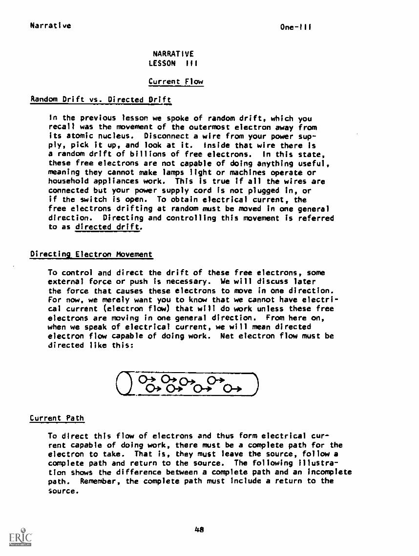
To control and direct the drift of these free electrons, someexternal force or push is necessary. We will discuss laterthe force that causes these electrons to move in one direction.For now, we merely want you to know that we cannot have electri-cal current (electron flow) that will do work unless these freeelectrons are moving in one general direction. From here on,when we speak of electrical current, we will mean directedelectron flow capable of doing work. Net electron flow must bedirected like this:
Current Path
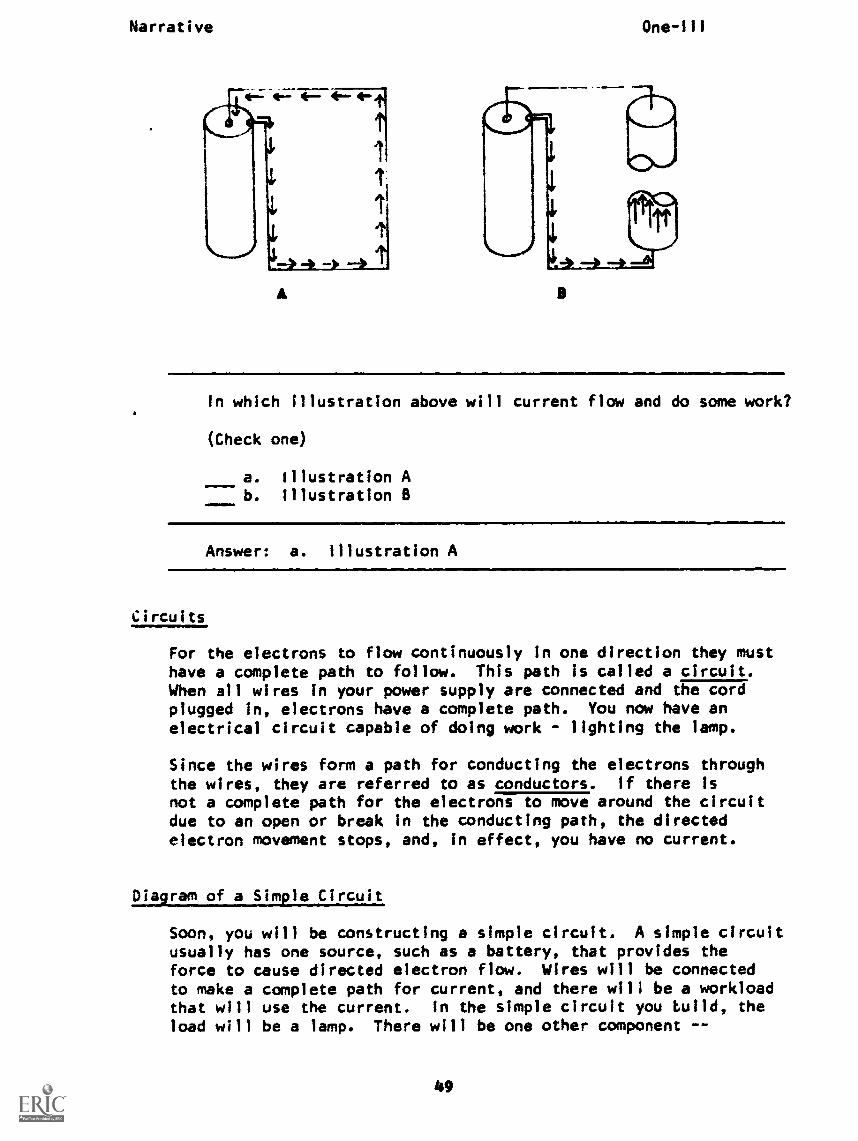
To direct this flow of electrons and thus form electrical cur-rent capable of doing work, there must be a complete path for theelectron to take. That is, they must leave the source, follow acomplete path and return to the source. The following illustra-tion shows the difference between a complete path and an incompletepath. Remember, the complete path must include a return to the
source.
Narrative One-III
a
In which illustration above will current flow and do some work?
(Check one)
a. Illustration Ab. Illustration B
Answer: a. Illustration A
Circuits
For the electrons to flow continuously in one direction they musthave a complete path to follow. This path is called a circuit.When all wires in your power supply are connected and the cordplugged in, electrons have a complete path. You now have anelectrical circuit capable of doing work - lighting the lamp.
Since the wires form a path for conducting the electrons throughthe wires, they are referred to as conductors. If there isnot a complete path for the electrons to move around the circuitdue to an open or break in the conducting path, the directedelectron movement stops, and, in effect, you have no current.
Diagram of a Simple Circuit
Soon, you will be constructing a simple circuit. A simple circuitusually has one source, such as a battery, that provides theforce to cause directed electron flow. Wires will be connectedto make a complete path for current, and there will be a workloadthat will use the current. In the simple circuit you Wild, theload will be a lamp. There will be one other component --
49
Narrative One-ill
a knife switch, that can be used to break or complete the path ofcurrent flow.
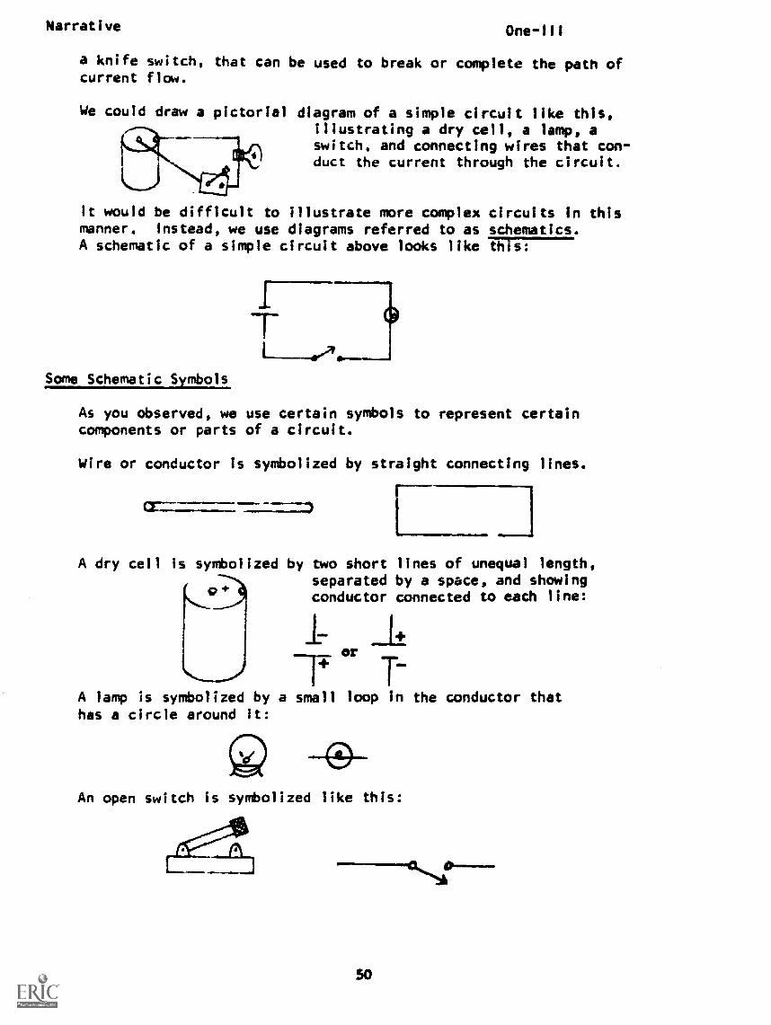
We could draw a pictorial diagram of a simple circuit like this,illustrating a dry cell, a lamp, aswitch, and connecting wires that con-duct the current through the circuit.
It would be difficult to illustrate more complex circuits in thismanner. Instead, we use diagrams referred to as schematics.A schematic of a simple circuit above looks like iTirir
Some Schematic Symbols
As you observed, we use certain symbols to represent certaincomponents or parts of a circuit.
Wire or conductor is symbolized by straight connecting lines.
cr--
A dry cell is symbolized by two short lines of unequal length,separated by a space, and showing
cro conductor connected to each line:
or
1--A lamp is symbolized by a small loop in the conductor thathas a circle around it:
An open switch Is symbolized like this:
50
Narrative One-111
This open switch bymbol---/.--indicates that the circuit isbroken or open and no current can flow because the blade of theswitch is not touching the metal contact.
A closed switch is symkolized like this:
You can see that when the switch is closed, there is a completepath for current.
Open switch ..--. open circuit - no current
Closed switch closed circuit - current flow
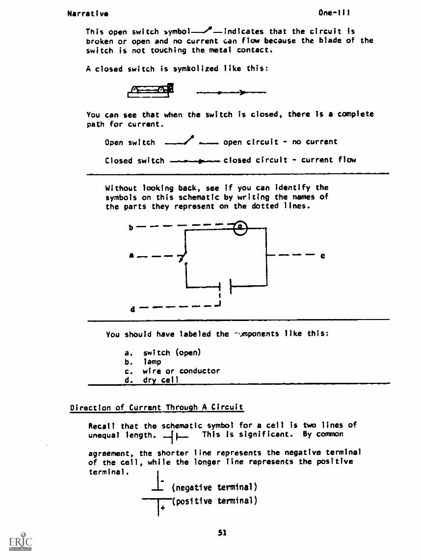
Without looking back, see if you can identify thesymbols on this schematic by writing the names ofthe parts they represent on the dotted lines.
d -S -J
- .11=1=1. =MM.
You should have labeled the -Jmponents like this:
a. switch (open)b. lamp
c. wire or conductord. dry cell
Direction of Current Through A Circuit
Recall that the schematic symbol for a cell Is two lines ofunequal length. This is significant. By common
agreement, the shorter line represents the negative terminalof the cell, while the longer line represents the positive
terminal.
(negative terminal)
(positive terminal)
51
Narrative One-III
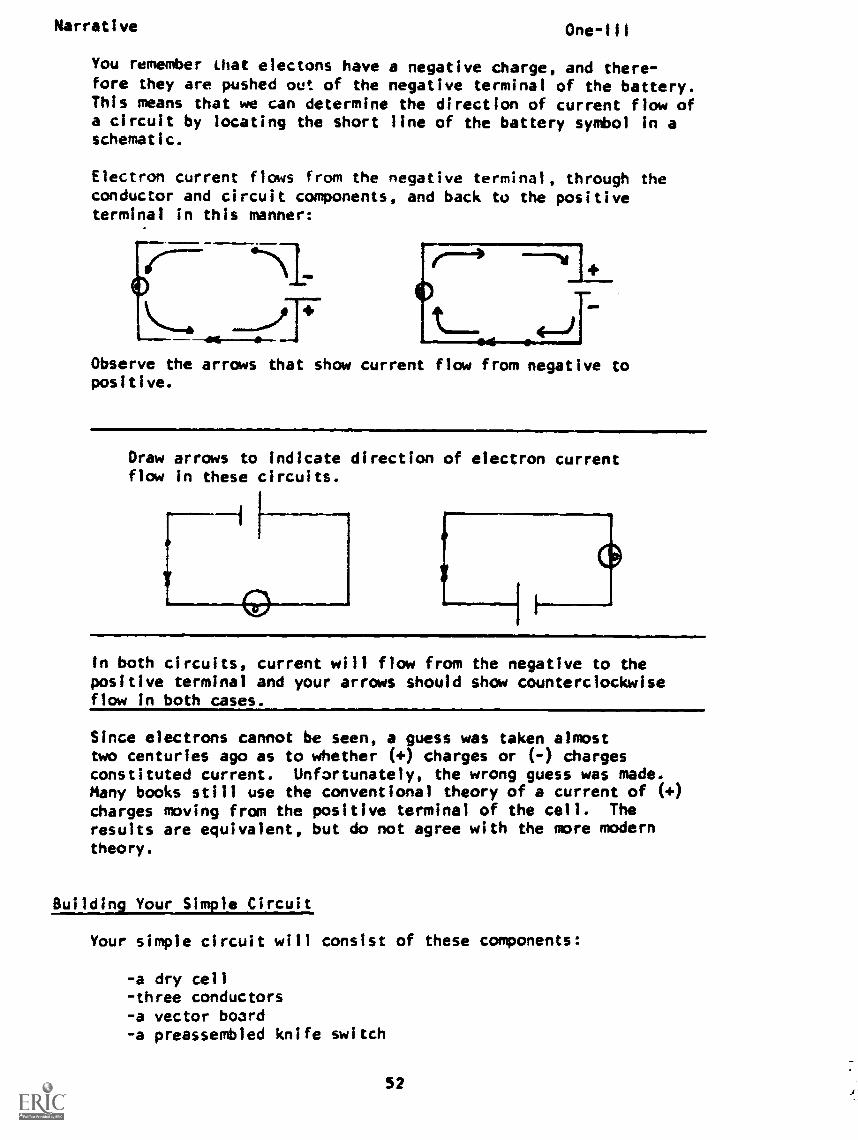
You remember that electons have a negative charge, and there-fore they are pushed out of the negative terminal of the battery.This means that we can determine the direction of current flow ofa circuit by locating the short line of the battery symbol in aschematic.
Electron current flows from the negative terminal, through theconductor and circuit components, and back to the positiveterminal in this manner:
Observe the arrows that show current flow from negative topositive.
Draw arrows to indicate direction of electron currentflow in these circuits.
In both circuits, current will flow from the negative to thepositive terminal and your arrows should show counterclockwiseflow in both cases.
Since electrons cannot be seen, a guess was taken almosttwo centuries ago as to whether (+) charges or (-) chargesconstituted current. Unfortunately, the wrong guess was made.Many books still use the conventional theory of a current of (+)charges moving from the positive terminal of the cell. Theresults are equivalent, but do not agree with the more moderntheory.
Building Your Simple Circuit
Your simple circuit will consist of these components:
a dry cellthree conductorsa vector board- a preassembled knife switch
52
Narrative One-Ill
IF YOU DO NOT ALREADY HAVE THESE ITEMS AT YOUR CARREL, GO NOWTO THE MATERIALS CENTER AND ASK FOR YOUR "SIMPLE oncurr"PACKAGE FOR IODULE ONE.
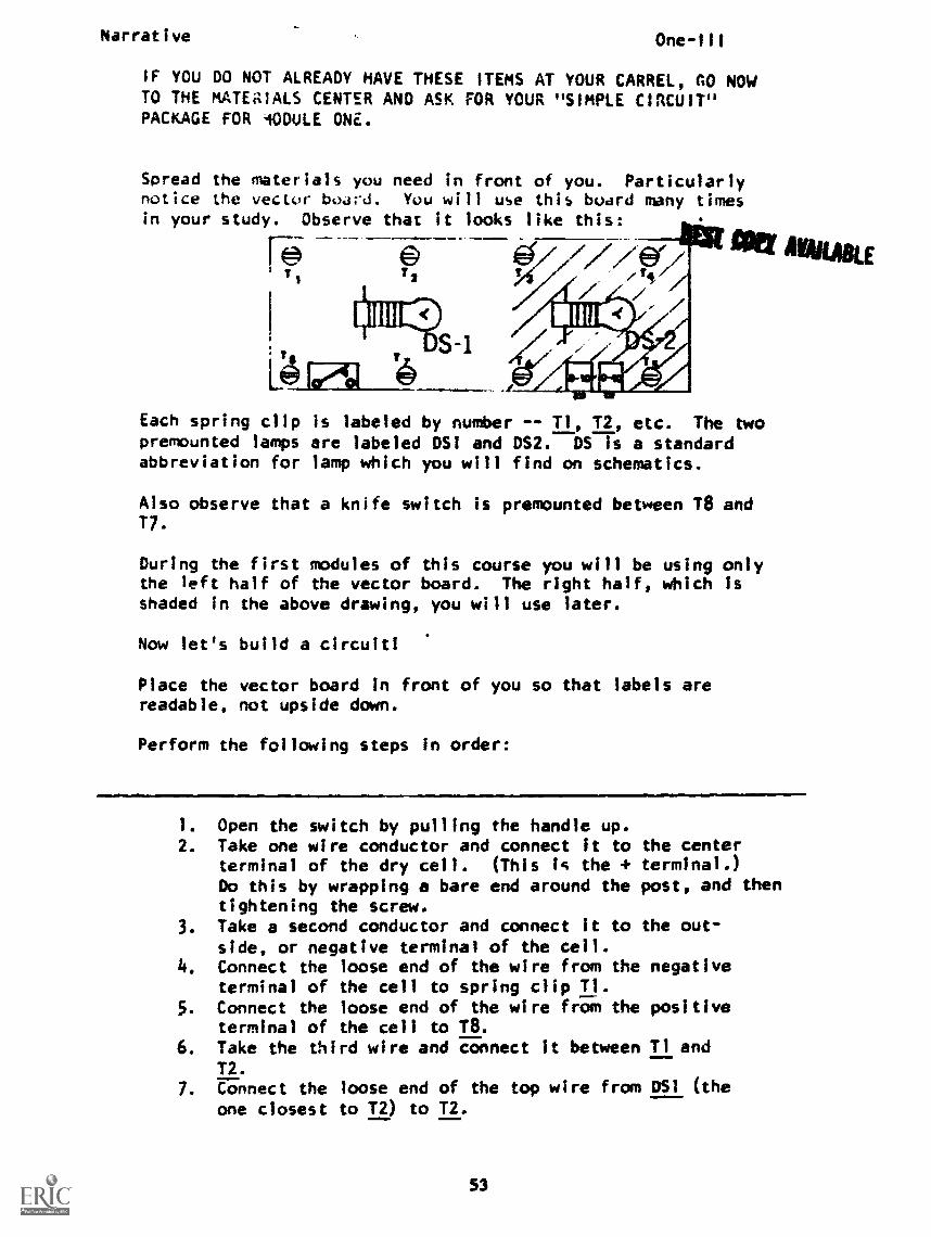
Spread the materials you need in front of you. Particularlynotice the vector board. You will use this board many timesin your study. Observe that it looks like this:
rs -1
Each spring clip is labeled by number -- T1, T2, etc. The twopremounted lamps are labeled DS! and DS2. DS is a standardabbreviation for lamp which you will find on schematics.
Also observe that a knife switch is premounted between 18 and17.
During the first modules of this course you will be using onlythe left half of the vector board. The right half, which isshaded in the above drawing, you will use later.
Now let's build a circuit!
Place the vector board in front of you so that labels arereadable, not upside down.
Perform the following steps in order:
1. Open the switch by pulling the handle up.2. Take one wire conductor and connect it to
terminal of the dry cell. (This is the +Do this by wrapping a bare end around thetightening the screw.
3. Take a second conductor and connect it toside, or negative terminal of the cell.
4. Connect the loose end of the wire from theterminal of the cell to spring clip
5. Connect the loose end of the wire from theterminal of the cell to 11
6. Take the third wire and connect it betweenT2.
7. Connect the loose end of the top wire from
the centerterminal.)post, and then
the out-
negative
positive
Tl and
DSI (the
one closest to 17) to T2.
53
Narrative One-111
8. Connect the loose end of the bottom wire from DS1 to
17.
9. Connect the wires from each end of the switch toT7 and T8.
Now you tavf constructed a simple circuit. Look at it to seethatsytkeigawk 'made all connections and provided a complete path
for current.
10. Now close the switch to complete the path.
YOUR LAMP SHOULD LIGHT.
11. Close and open the switch several times. Observe that
as the metal part of the switch touches the metal con-
tact, the circuit is closed, and the lamp lights. As
contact is broken, the circuit is open, no current can
flow, and the lamp does not work.12. Finally, open the switch and leave the circuit as it
is. (You will use it again in the next lesson.)13. Draw a schematic to represent the simple circuit you
have constructed. Include the symbols for:
1. the cell2. the conductor3. switch4. lamp
Then draw arrows on your schematic to indicate the
direction that current would flow if the switch were
closed.
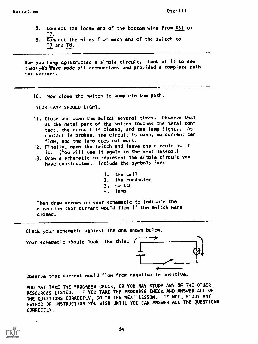
Check your schematic against the one shown below.
Your schematic should look like this: (-I'
T44......
Observe that current would flow from negative to positive.
YOU MAY TAKE THE PROGRESS CHECK, OR YOU MAY STUDY ANY OF THE OTHER
RESOURCES LISTED. IF YOU TAKE THE PROGRESS CHECK AND ANSWER ALL OF
THE QUESTIONS CORRECTLY, GO TO THE NEXT LESSON. IF NOT, STUDY ANY
METHOD OF INSTRUCTION YOU WISH UNTIL YOU CAN ANSWER ALL THE QUESTIONS
CORRECTLY.
54
P. 1.
PROGRAMMED INSTRUCTIONLESSON III
Current Flow
TEST FRAMES ARE 7, 10, 21, 25, and 29. ASTEST FRAME 7 AND SEE IF YOU CAN ANSWER ALLFOLLOW THE DIRECTIONS GIVEN AFTER THE TEST
One-III
BEFORE, GO FIRST TOTHE QUESTIONS THERE.FRAME.
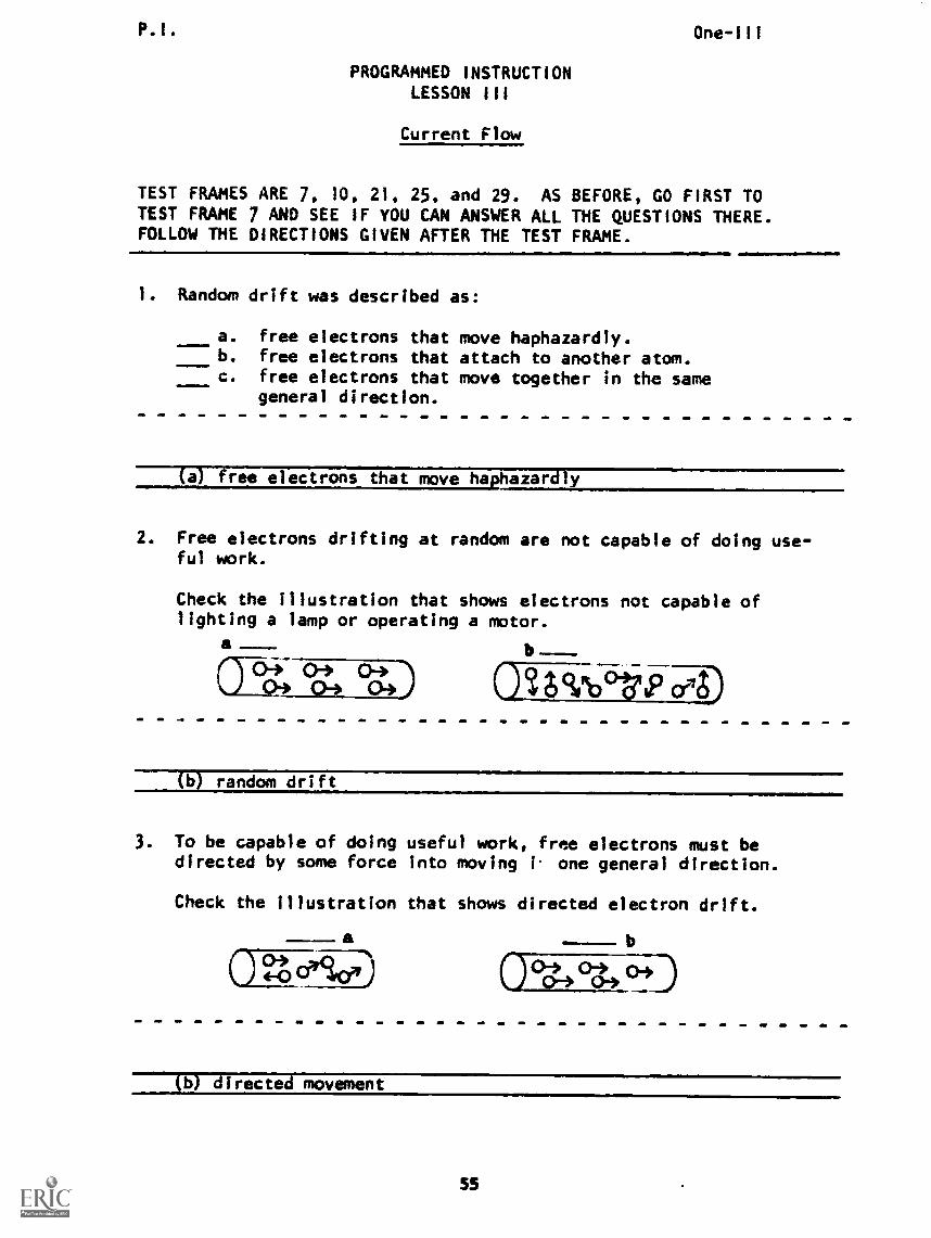
1. Random drift was described as:
a. free electrons that move haphazardly.b. free electrons that attach to another atom.c. free electrons that move together in the same
general direction.
(a) free electrons that move haphazardly
2. Free electrons drifting at random are not capable of doing use-ful work.
Check the illustration that shows electrons not capable oflighting a lamp or operating a motor.
a
075-0,..) 04 0404)04
-)
(b) random drift
3. To be capable of doing useful work, free electrons must bedirected by some force into moving 1 one general direction.
Check the illustration that shows directed electron drift.
a a
°4 °4)04
(b) directed movement
55
P.I. One-Ill
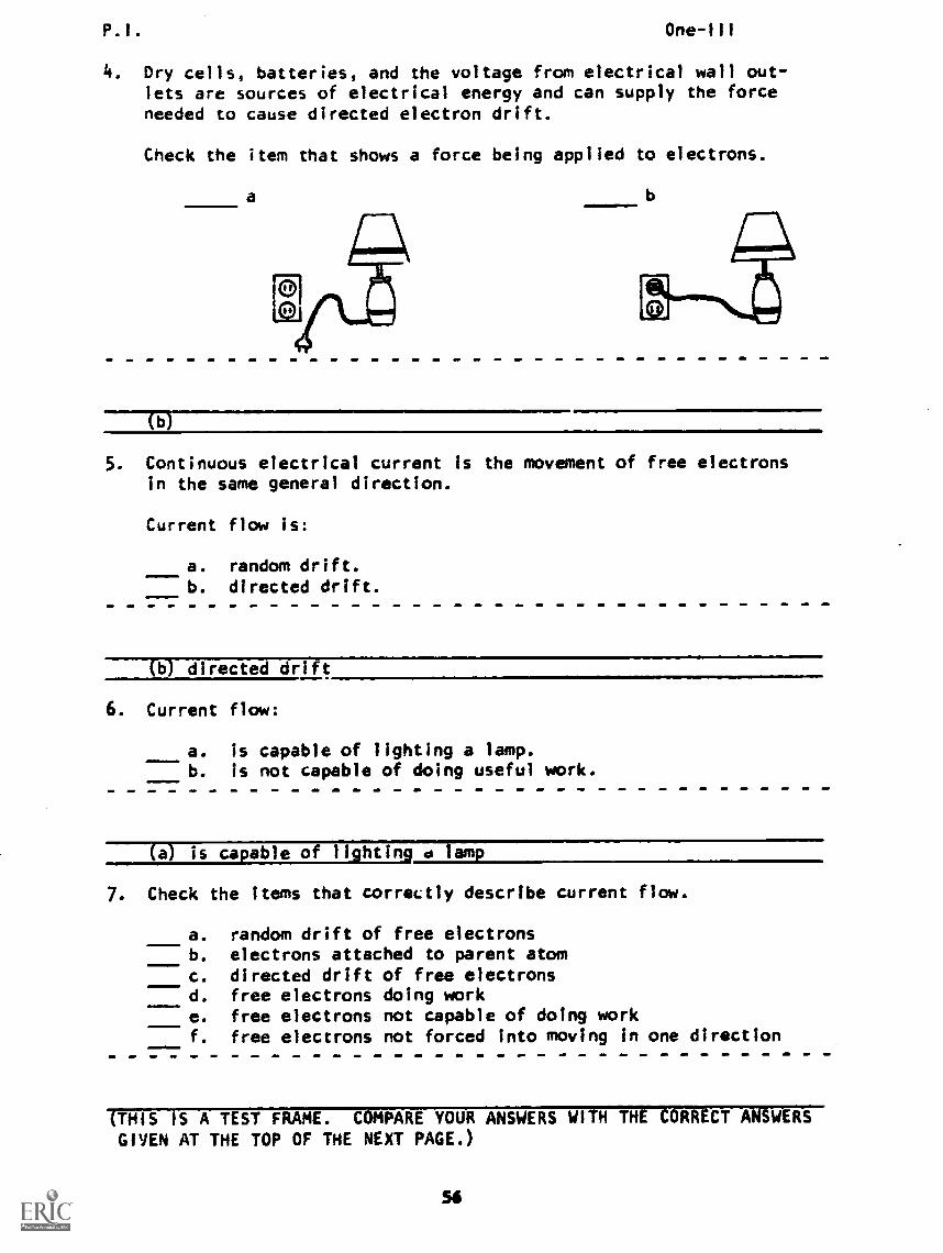
4. Dry cells, batteries, and the voltage from electrical wall out-lets are sources of electrical energy and can supply the forceneeded to cause directed electron drift.
Check the item that shows a force being applied to electrons.
a b
b
5. Continuous electrical current is the movement of free electronsin the same general direction.
Current flow is:
a. random drift.b. directed drift.
(6) directed drift
6. Current flow:
a. is capable of lighting a lamp.b. is not capable of doing useful work.
(a) is capable of lighting d lamp
7. Check the items that correctly describe current flow.
a. random drift of free electronsb. electrons attached to parent atom
c. directed drift of free electronsd. free electrons doing worke. free electrons not capable of doing workf. free electrons not forced into moving in one direction
(THIS IS A TEST FRAME. COMPARE YOUR ANSWERS WITH THE CORRECT ANSWERSGIVEN AT THE TOP OF THE NEXT PAGE.)
So
P.I. One -Ill
ANSWERS - TEST FRAME 7
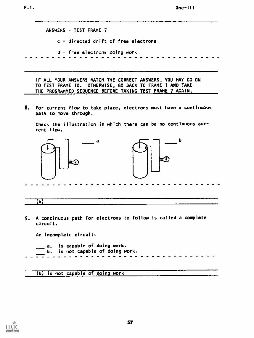
c - directed drift of free electrons
d - free electrons doing work
IF ALL YOUR ANSWERS MATCH THE CORRECT ANSWERS, YOU MAY GO ONTO TEST FRAME 10. OTHERWISE, GO BACK TO FRAME 1 AND TAKETHE PROGRAMMED SEQUENCE BEFORE TAKING TEST FRAME 7 AGAIN.
8. For current flow to take place, electrons must have a continuouspath to move through.
Check the illustration in which there can be no continuous cur-rent flow.
(b)
9. A continuous path for electrons to follow is called a completecircuit.
An incomplete circuit:
a. is capable of doing work.b. is not capable of doing work.
(b) is not capable of doin work
P.I. One-III
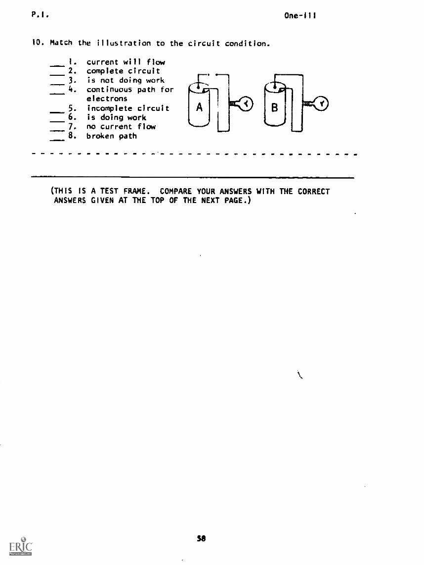
10. Match the illustration to the circuit condition.
1. current will flow2. complete circuit3. is not doing work4. continuous path for
electrons5. incomplete circuit6. is doing work7. no current flow8. broken path
(THIS IS A TEST FRAME. COMPARE YOUR ANSWERS WITH THE CORRECTANSWERS GIVEN AT THE TOP OF THE NEXT PAGE.)
P.I. One-III
ANSWERS - TEST FRAME 10
I. b 5. a
2. b 6. b
3. a 7. a
4. b 8. a
IF ALL YOUR ANSWERS MATCH THE CORRECT ANSWERS, YOU MAY GOON TO TEST FRAME 21. OTHERWISE, GO BACK TO FRAME 8 ANDTAKE THE PROGRAMMED SEQUENCE BEFORE TAKING TEST FRAME 10AGAIN.
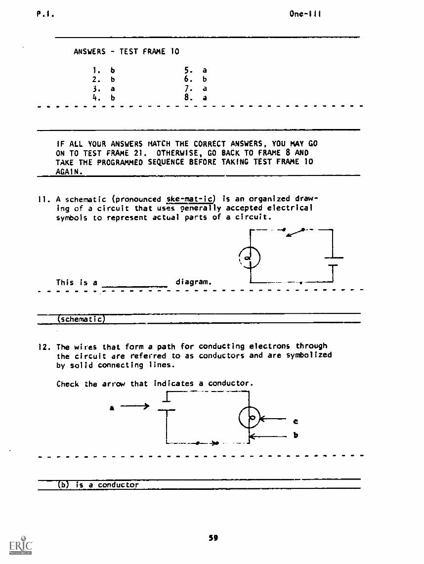
11. A schematic (pronounced ske-mat-ic) is an organized draw-ing of a circuit that uses sienerally accepted electricalsymbols to represent actual parts of a circuit.
This is a diagram.
sTTcer7Zrc-r--
12. The wires that form a path for conducting electrons throughthe circuit are referred to as conductors and are symbolizedby solid connecting lines.
Check the arrow that indicates a conductor.
(b) is a conductor
p. l. One-111
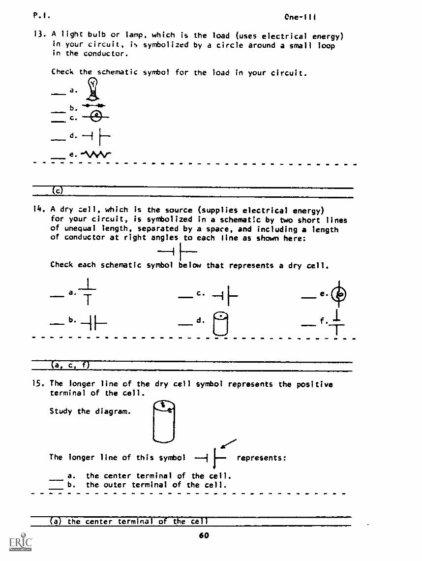
13. A light bulb or lamp, which is the load (uses electrical energy)in your circuit, is symbolized by a circle around a small loopin the conductor.
Check the schematic symbol for the load in your circuit.
(c)
14. A dry cell, which is the sourcefor your circuit, is symbolizedof unequal length, separated byof conductor at right angles to
(supplies electrical energy)in a schematic by two short linesa space, and including a lengtheach line as shown here:
Check each schematic symbol below that represents a dry cell.
Tb. H
(a c f)
15. The longer line of the dry cell symbol represents the positiveterminal of the cell.
te-rNStudy the diagram. \--Jr8
*,........? .VThe longer line of this symbol --A represents:
a. the center terminal of the cell.b. the outer terminal of the cell.
(a) the center terminal of the cell
60
P.I. One-111
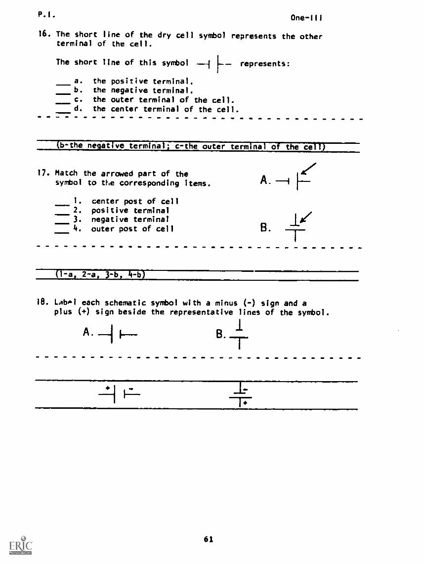
16. The short line of the dry cell symbol represents the otherterminal of the cell.
The short line of this symbol represents:
a. the positive terminal.b. the negative terminal.c. the outer terminal of the cell.d. the center terminal of the cell.
(b-the negative terminal; c-the outer terminal of the cell)
17. Match the arrowed part of thesymbol to the corresponding items.
1. center post of cell2. positive terminal3. negative terminal4. outer post of cell
B'
(1-a, 2-a, 3-b, 4-1!)
18. LAbP1 each schematic symbol with a minus (-) sign and aplus (+) sign beside the representative lines of the symbol.
B .
P.I. One-111
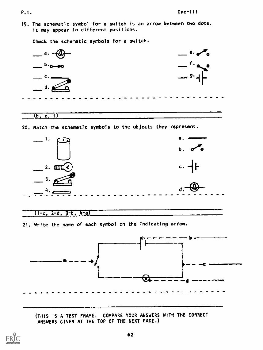
19. The schematic symbol for a switch is an arrow between two dots.It may appear in different positions.
Check the schematic symbols for a switch.
_a. e oho
4%.16.0
9 IF
20. Match the schematic symbols to the objects they represent.
2.
3.=
a.
b. creAre
(1 c 2 -d 4 -a)
21. Write the name of each symbol on the indicating arrow.
). & -a,
m1. b
(THIS IS A TEST FRAME. COMPARE YOUR ANSWERS WITH THE CORRECT
ANSWERS GIVEN AT THE TOP OF THE NEXT PAGE.)
62
P.I. One-Ill
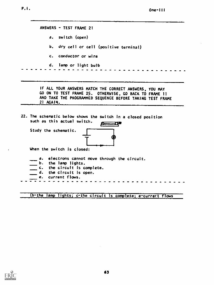
ANSWERS - TEST FRAME 21
a. switch (open)
b. dry cell or cell (positive terminal)
c. conductor or wire
d. lamp or light bulb
IF ALL YOUR ANSWERS MATCH THE CORRECT ANSWERS, YOU MAYGO ON TO TEST FRAME 25. OTHERWISE, GO BACK TO FRAME 11AND TAKE THE PROGRAMMED SEQUENCE BEFORE TAKING TEST FRAME21 AGAIN.
22. The schematic below shows the switch in a closed positionsuch as this actual switch.
Study the schematic.
When the switch is closed:
.11=1.
a. electrons cannot move through the circuit.b. the lamp lights.c. the circuit is complete.d. the circuit is open.e. current flows.
b-the la a. lights. c-the circuit I late e-currert flows
P. I . One-111
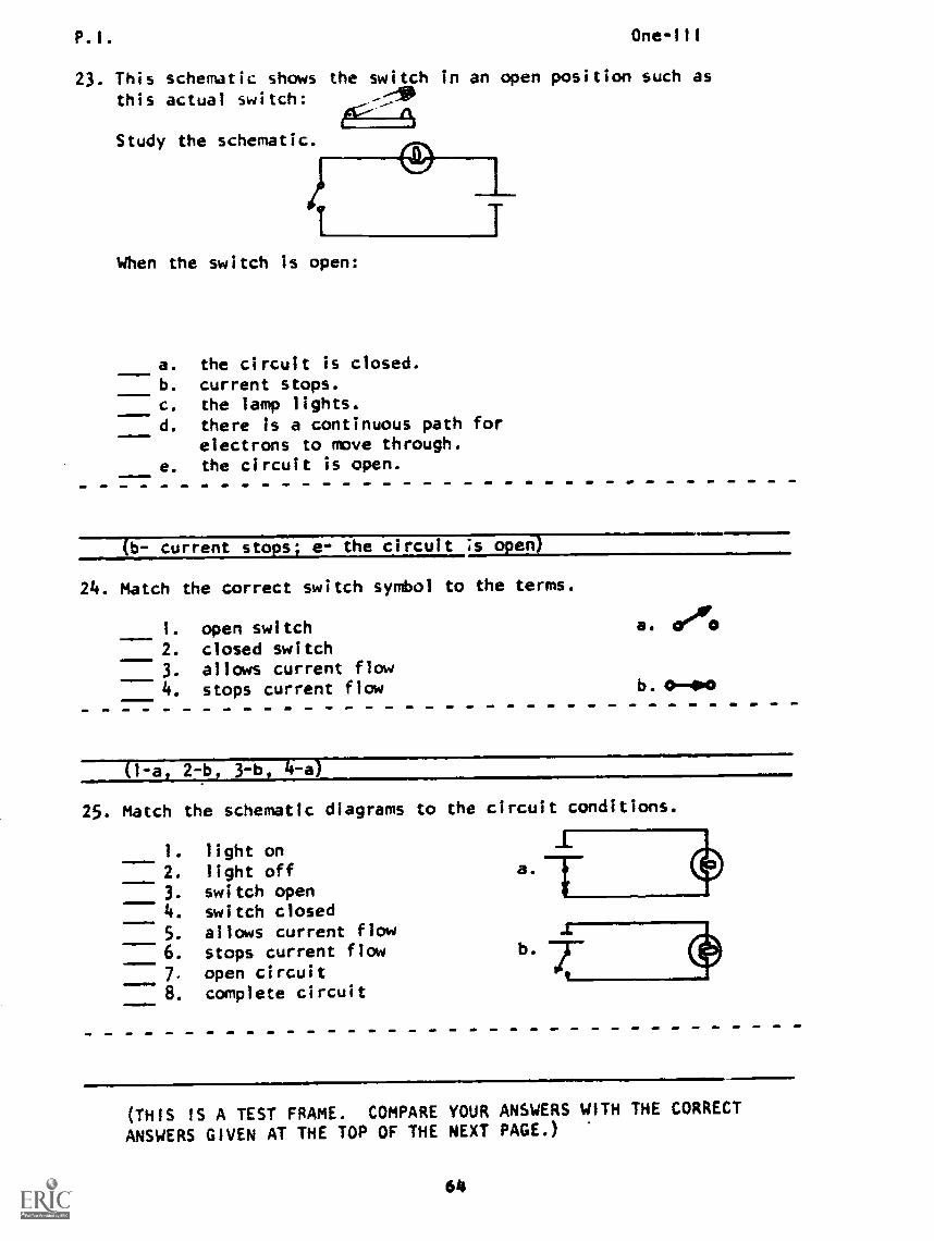
23. This schematic shows the switch in an open position such as
this actual switch: n
Study the schematic.
When the switch is open:
a. the circuit is closed.b. current stops.c. the lamp lights.d. there is a continuous path for
electrons to move through.e. the circuit is open.
(b- current stops; e- the circuit is open)
24. Match the correct switch symbol to the terms.
=1=411161. open switch2. closed switch3. allows current flow4. stops current flow
a. 17"
b. 0-00
(1-a, 2-b, 3-b, 4-a)
25. Match the schematic diagrams to the circuit conditions.
1411.
NNIImbwm
1. light on
2. light off3. switch open4. switch closed
5. allows current flow6. stops current flow7. open circuit8. complete circuit
a.
b.
(THIS IS A TEST FRAME. COMPARE YOUR ANSWERS WITH THE CORRECT
ANSWERS GIVEN AT THE TOP OF THE NEXT PAGE.)
64
P.I. One-III
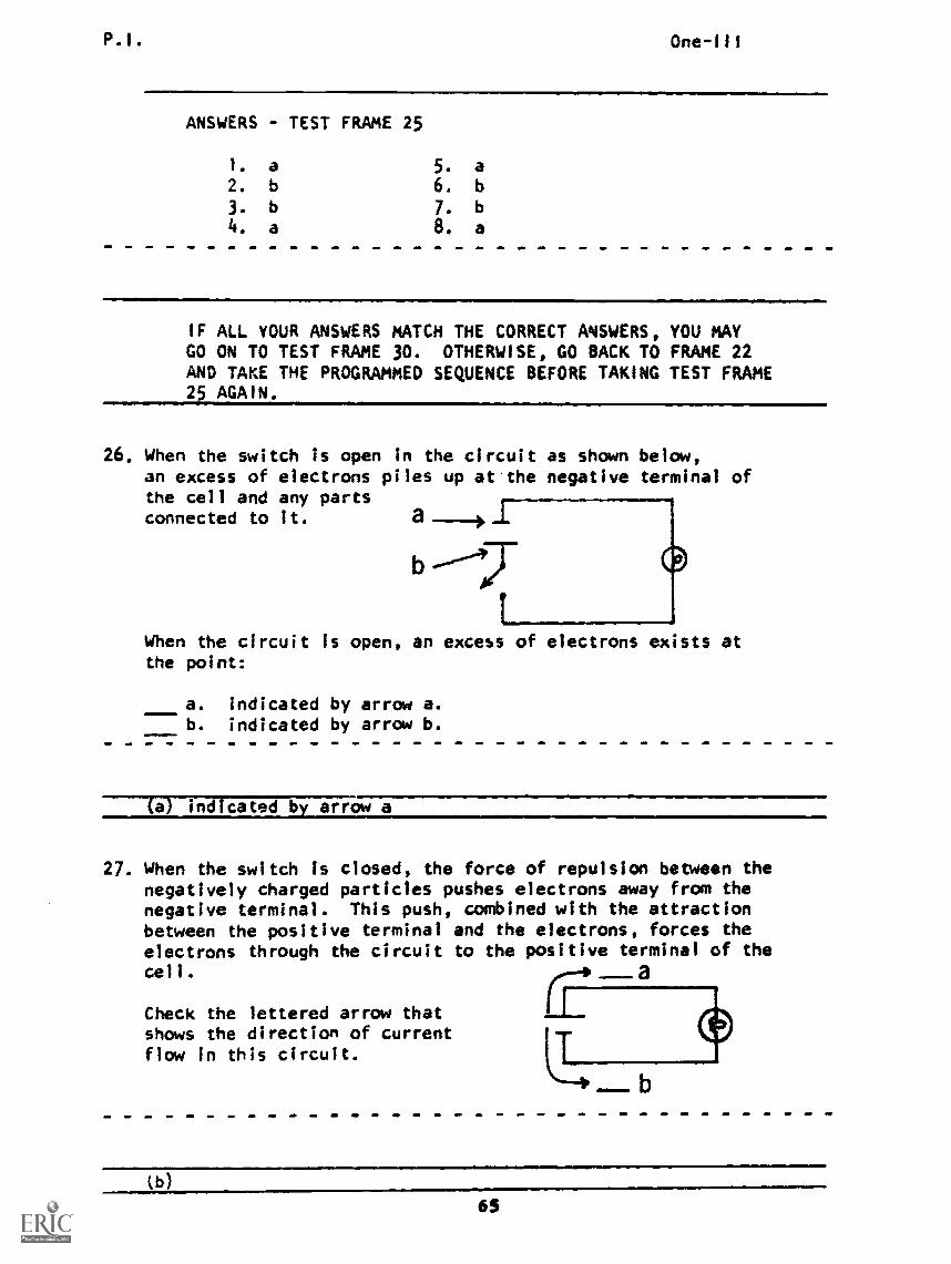
ANSWERS - TEST FRAME 25
1. a 5. a2. b 6. b
3. b 7. b
4. a 8. a
IF ALL YOUR ANSWERS MATCH THE CORRECT ANSWERS, YOU MAYGO ON TO TEST FRAME 30. OTHERWISE, GO BACK TO FRAME 22AND TAKE THE PROGRAMMED SEQUENCE BEFORE TAKING TEST FRAME25 AGAIN.
26. When the switch is open in the circuit as shown below,an excess of electrons piles up at'the negative terminal ofthe cell and any partsconnected to it. a
b
When the circuit is open, an excess of electrons exists atthe point:
a. indicated by arrow a.b. indicated by arrow b.
(a) indicated by arrow a
27. When the switch is closed, the force of repulsion between thenegatively charged particles pushes electrons away from thenegative terminal. This push, combined with the attractionbetween the positive terminal and the electrons, forces theelectrons through the circuit to the positive terminal of thecell.
Check the lettered arrow thatshows the direction of currentflow in this circuit.
(b)
65
P.1.
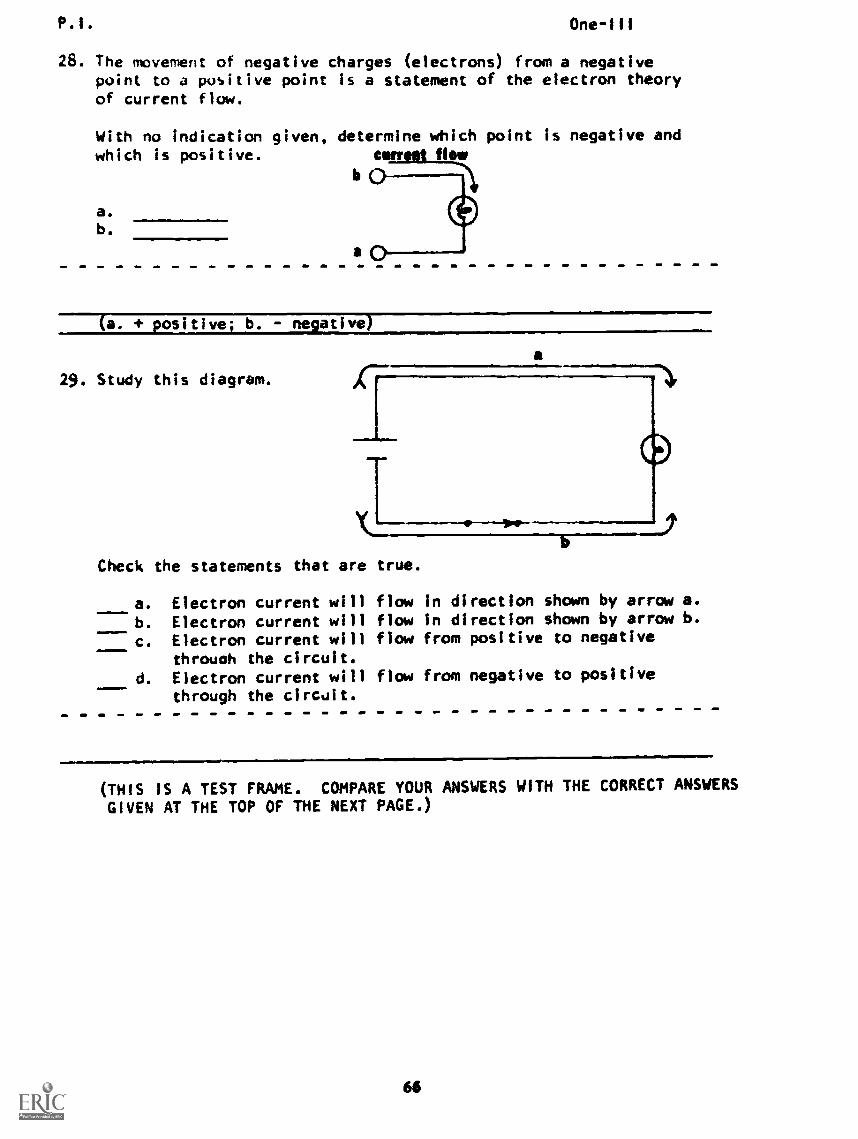
28. The movement of negative charges (electrons)point to a positive point is a statement ofof current flow.
One -Ill
from a negativethe electron theory
With no indication given, determine which point is negative andwhich is positive. canmit fit
a.
b.
(a. 4. positive; b. - nelative
29. Study this diagram.
a
Check the statements that are true.
a.
b.
c.
d.emomMno.
Electron current will flowElectron current will flowElectron current will flowthrough the circuit.Electron current will flowthrough the circuit.
100
in directin directfrom posi
from nega
ion shown by arrow a.ion shown by arrow b.tive to negative
tive to positive
(THIS IS A TEST FRAME. COMPARE YOUR ANSWERS WITH THE CORRECT ANSWERS
GIVEN AT THE TOP OF THE NEXT PAGE.)
66
P.I. One-111
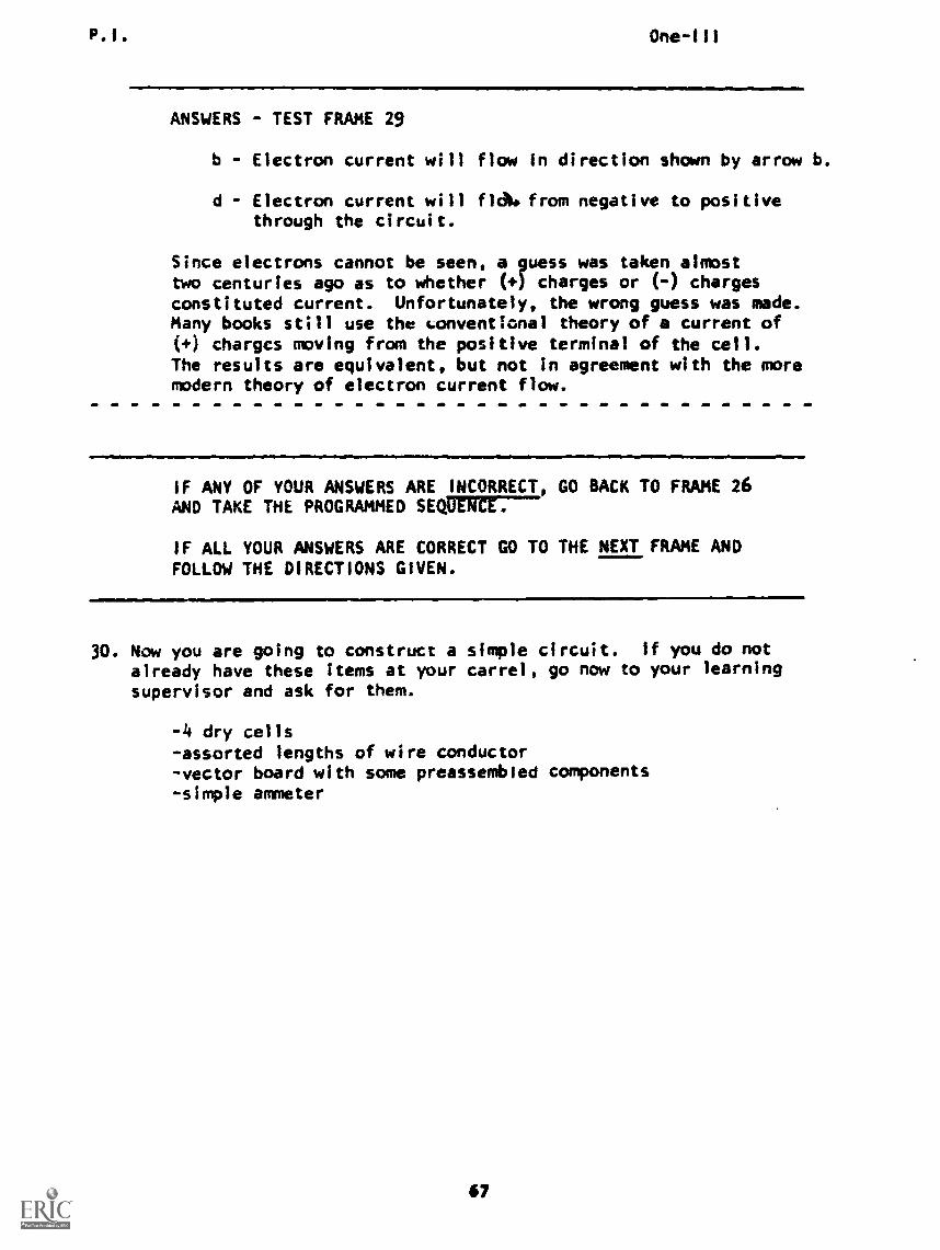
ANSWERS - TEST FRAME 29
b - Electron current will flow In direction shown by arrow b.
d Electron current will floN from negative to positivethrough the circuit.
Since electrons cannot be seen, a guess was taken almosttwo centuries ago as to whether (+) charges or (-) chargesconstituted current. Unfortunately, the wrong guess was made.Many books still use the uonventlonal theory of a current of(+) chargcs moving from the positive terminal of the cell.The results are equivalent, but not in agreement with the moremodern theory of electron current flow.
IF ANY OF YOUR ANSWERS ARE INCORRECT, GO BACK TO FRAME 26AND TAKE THE PROGRAMMED SEQUENCE.
IF ALL YOUR ANSWERS ARE CORRECT GO TO THE NEXT FRAME ANDFOLLOW THE DIRECTIONS GIVEN.
30. Now you are going to construct a simple circuit. If you do notalready have these items at your carrel, go now to your learningsupervisor and ask for them.
-4 dry cells-assorted lengths of wire conductor-vector board with some preassembied components-simple ammeter
67
P.E.
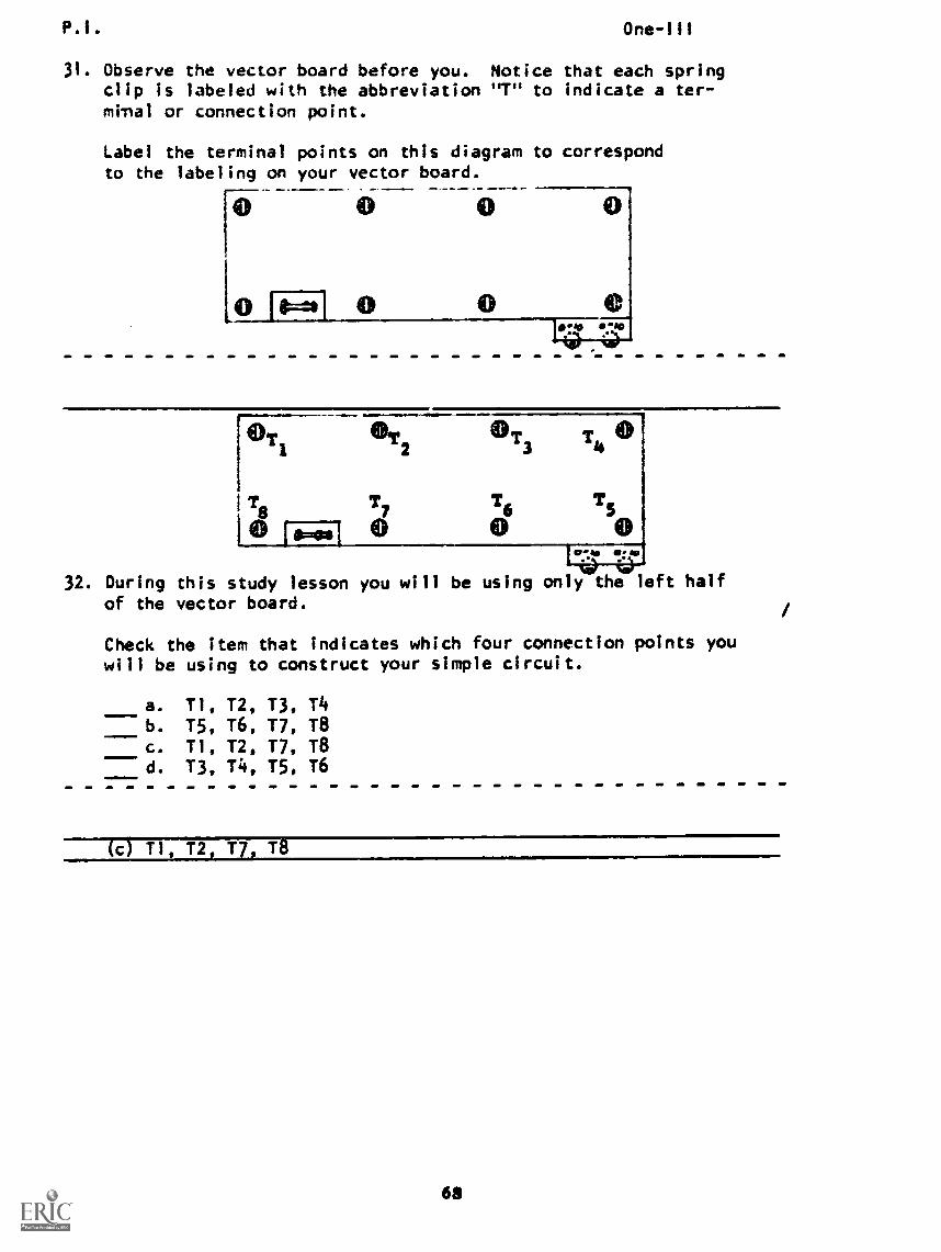
31. Observe the vector board before you. Noticeclip is labeled with the abbreviation "T" tomi.nal or connection point.
One -Ill
that each springindicate a ter-
Label the terminal points on this diagram to correspondto the labeling on your vector board.
32. During this study lesson you will be using only the left halfof the vector board.
Check the item that indicates which four connection points youwill be using to construct your simple circuit.
a. TI, 12, T3, T4b. T5, T6, 17, T8c. T1, T2, T7, T8d. T3, T4, T5, T6
(c) T1, T2, 17, T8
6$
P. I. One-Ill
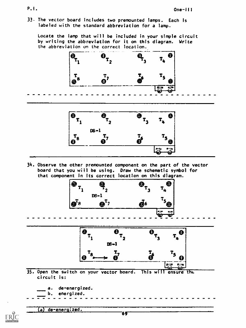
33- The vector board includes two premounted lamps. Each islabeled with the standard abbreviation for a lamp.
Locate the lamp that will be included in your simple circuitby writing the abbreviation for it on this diagram. Writethe abbreviation on the correct location.
OT2
7
Or
34. Observe the other premounted component on the part of the vectorboard that you will be using. Draw the schematic symbol forthat component in Its correct location on this diagram.
0T1 2
DS-1
4)77
073T401
44650
0T2
1331
35. Open the switch on your vector board. This will ensure thtcircuit is:
a. de-energized.b. energized.
la) de-energized.69
P.I. One-111
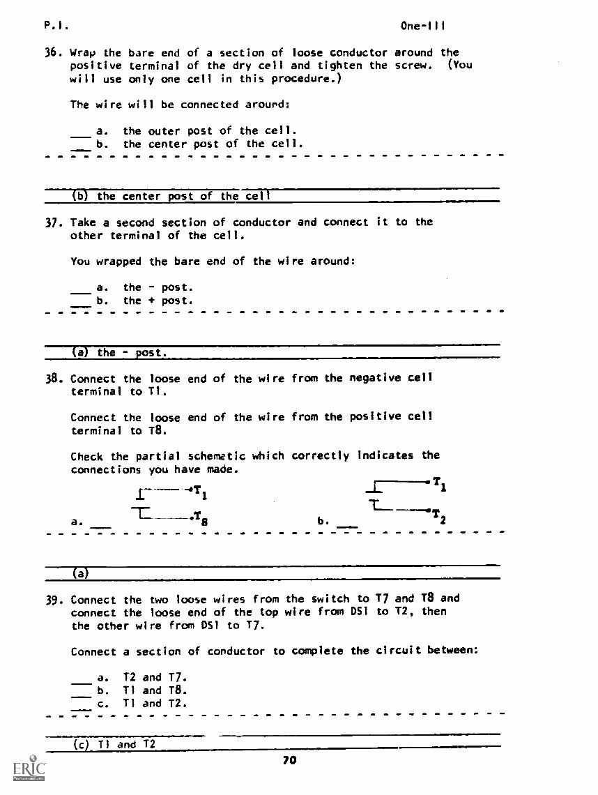
36. Wrap the bare end of a section of loose conductorpositive terminal of the dry cell and tighten thewill use only one cell in this procedure.)
The wire will be connected around:
a. the outer post of the cell.b. the center post of the cell.
around thescrew. (You
(b) the center post of the cell
37. Take a second section of conductor and connect it to theother terminal of the cell.
You wrapped the bare end of the wire around:
I a. the post.
b. the + post.
(a) the - post.
38. Connect the loose end of the witerminal to T1.
Connect the loose end of the witerminal to T8.
Check the partial schemetic whiconnections you have made.
-4111
a.:rg
re from the negative cell
re from the positive cell
ch correctly Indicates the
b. 2
(a)
39. Connect the two loose wires from the switch to T7 and T8 andconnect the loose end of the top wire from D51 to T2, thenthe other wire from D51 to 17.
Connect a section of conductor to complete the circuit between:
=I= I
a. 12 and T7.b. T1 and 18.c. Ti and T2.
(c) T1 and 12
70
P.1. One-111
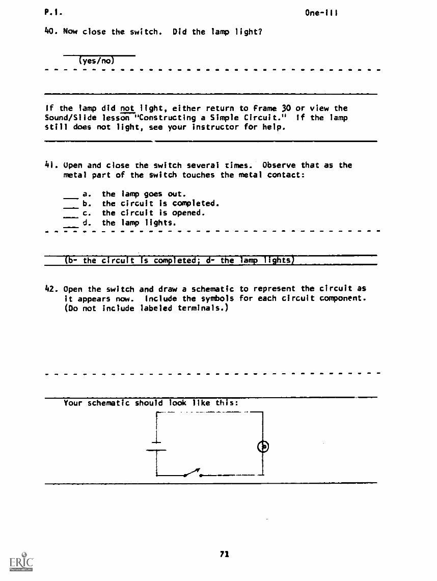
40. Now close the switch. Did the lamp light?
(yes /no)
If the lamp did not light, either return to Frame 30 or view theSound/Slide lesson "Constructing a Simple Circuit." If the lampstill does not light, see your instructor for help.
41. Open and close the switch several times. Observe that as themetal part of the switch touches the metal contact:
a. the lamp goes out.b. the circuit is completed.c. the circuit is opened.d. the lamp lights.
(l- the circuit Is completed; d- the lamp lights)
42. Open the switch and draw a schematic to represent the circuit asit appears now. Include the symbols for each circuit component.(Do not include labeled terminals.)
Your schematic should look like this:
r
71
P.I. One-III
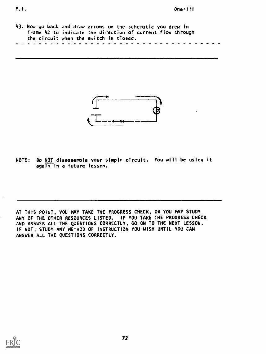
43. Now go back and draw arrows on the schematic you drew inframe 42 to indicate the direction of current flow throughthe circuit when the switch is closed.
NOTE: Do Do NOT disassemble your simple circuit. You will be using itagain in a future lesson.
AT THIS POINT, YOU MAY TAKE THE PROGRESS CHECK, OR YOU MAY STUDYANY OF THE OTHER RESOURCES LISTED. IF YOU TAKE THE PROGRESS CHECKAND ANSWER ALL THE QUESTIONS CORRECTLY, GO ON TO THE NEXT LESSON.IF NOT, STUDY ANY METHOD OF INSTRUCTION YOU WISH UNTIL YOU CANANSWER ALL THE QUESTIONS CORRECTLY.
72
Summary One-Ill
SUMMARYLESSON III
Current Fluky
in the previous lesson you studied random drift and movement ofelectrons. In this lesson you will learn about the directed driftof electrons, which is the general movement of electrons in one di-rection through a wire. This directed drift of electrons results ina change in the location of some of the charges in the wire. Workis done when this takes place. Directed drift of electrons is calledcurrent flow. In later lessons, we will learn about the forces thatproduce a current flow.
For continuing current flow to take place, there must be a completepath for electrons to take. It there were only a straight pieceof wire, free electrons would soon be forced to one end of the wireand no more current would flow. When a complete path exists, electronsmove from the point where force is applied to them, then through thewires and back to the force through the closed loop, or circuit.
Consider a single circuit using one cell to provide force, a lamp t.show when work is being done, a switch to control electron movementin the circuit, and wires to form a complete path for current flow.
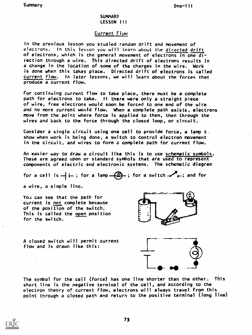
An easier way to draw a circuit like this is to use schematic symbols.These are agreed upon or standard symbols that are used to representcomponents of electric and electronic systems. The schematic diagram
for a cell is .J 1--; for a lamp ; for a switch-440-; and for
a wire, a simple line.
YOJ can see that the path forcurrent is not complete becauseof the position of the switch.This is called the open positionfor the switch.
A closed switch will permit currentflow and is drawn like this:
The symbol for the cell (force) has one line shorter than the other. This
short line is the negative terminal of the cell, and according to theelectron theory of current flow, electrons will always travel from thispoint through a closed path and return to the positive terminal (long line)
73
Summary One-Ill
where the force pushes them to the negative terminal again.
Electron Current Flow:
Since electrons cannot be seen, a guess was taken almost twocenturies ago as to whether (+) charges or (-) charges constitutecurrent. Unfortunately, the wrong guess was made and the positivecharges were assumed to be the mobile particles. Many books stilluse the conventional theory of a current consisting of (+) chargesmoving from the positive terminal of the cell. The results areequivalent, but do not agree with the modern electron theory.
AT THIS POINT, YOU MAY TAKE THE LESSON PROGRESS CHECK, OR YOU MAYSTUDY THE LESSON NARRATIVE OR THE PROGRAMMED INSTRUCTION OR BOTH.IF YOU TAKE THE PROGRESS CHECK AND ANSWER ALL OF THE QUESTIONS COR-RECTLY, GO TO THE NEXT LESSON. IF NOT, SELECT ANOTHER METHOD OFINSTRUCTION UNTIL YOU CAN ANSWER ALL THE QUESTIONS CORRECTLY.
(Note: Remember there is a sound/slide presentation in this lesson.)
NOTE: ALL STUDENTS SHOULD DO THE EXERCISE INDICATED IN THE PROGRAMMEDINSTRUCTION, FRAMES 30 THROUGH 43, OR THE AUDIO-VISUAL PRESENTATION,"Constructing A Simple Circuit."
74
BASIC ELECTRICITY AND ELECTRONICS
INDIVIDUALIZED LEARNING SYSTEM
MODULE ONE
LESSON IV
Measurement of Current
Study Bookl ®r
Overview
OVERVIEW
LESSON IV
Measurement of Current
One-IV
In this lesson you will study and learn about the following:
-why we measure current
-measuring is counting
- counting electrons
- electrons that do work
- the coulomb
- measurement and time
- the ampere
- standard abbreviations
- powers of ten and scientific
notation
- the prefixes and micro-
Each of the above topics will be discussed in the order listed.
As you proceed through this lesson, observe and follow directions
carefully.
BEFORE YOU START THIS LESSON, PREVIEW THE LIST OF STUDY RESOURCES
ON THE NEXT PAGE.
Study Resources One-IV
LIST OF STUDY RESOURCES
LESSON IV
Measurement of Current.
To learn the material in this lesson, you have the option of choosing,
according to your experience and preferences, any or all of the following:
STUDY BOOKLET:
Lesson Narrative
Programmed Instruction
Lesson Summary
ENRICHMEIT MATERIAL:
"Powers of Ten." Programmed Instruction Booklet (BE/E).
"Scientific Notation and Powers of Ten." Programmed
Instruction Boc'let A-1/b-lb.
Backe, K. Cosmic View: The Universe in 40 Jumps
New York: The John Day Company, 1957.
Remember, you may study any or all of these that you feel are necessary
to answer all Progress Check questions correctly. All your answers must
be correct before you can go to lesson V. Remember, your instructor
is available at all times for any assistance you may need.
YOU MAY NOW STUDY ANY OR ALL OF THE RESOURCES LISTED ABOVE. YOU MAY
TAKE THE PROGRESS CHECK AT ANY TIME.
77
Narrative One-IV
NARRATIVE
LESSON IV
Measurement of Current
Why We Measure Current
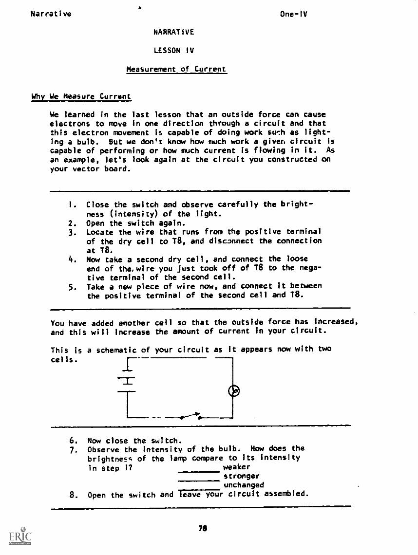
We learned in the last lesson that an outside force can causeelectrons to move in one direction through a circuit and thatthis electron movement is capable of doing work swil as light-ing a bulb. But we don't know how much work a given circuit iscapable of performing or how much current is flowing in it. As
an example, let's look again at the circuit you constructed onyour vector board.
1. Close the switch and observe carefully the bright-ness (intensity) of the light.
2. Open the switch again.3. Locate the wire that runs from the positive to
of the dry cell to T8, and disconnect the connectionat T8.
4. Now take a second dry cell, and connect the looseend of the, wire you just took off of T8 to the nega-tive terminal of the second cell.
5. Take a new piece of wire now, and connect it betweenthe positive terminal of the second cell and 18.
You have added another cell so that the outside force has increased,
and this will increase the amount of current in your circuit.
This is a schematic of your circuit as it appears now with two
cells.
es.a.M10.
6. Now close the switch.7. Observe the intensity of the bulb. How does the
brightness of the lamp compare to its intensity
In step 1? weakerstrongerunchanged
8. Open the switch and rei;;717ir circuit assembled.
71
Narrative One-1V
You should have observed that thc bulb glowed with greater in-tensity with two cells as the source. We can assume from thisexperiment that a greater amount of current was flowing in thecircuit; however, we do not know how much. We have still notmeasured the amount of current in our circuit.
It is frequently important to determine the amount of currentin a given piece of equipment to know if it is properly func-tioning and for troubleshooting.
Measuring Is Countinv
To measure or quantify current, we must count electrons. Recall
that current flow is the movement of electrons through a circuit.Therefore, the electrons we count must be the ones pushed throughthe circuit by electrical force. Electrons in a disconnectedwire cannot be counted as current. In other words, the onlyelectrons we want to count are the ones that contribute tothe current flow, not the ones moving at random. Therefore, tomeasure current, we must count the number of electrons movingin one direction through a circuit.
Counting Electrons
At all times, there is random drift of billions and billions offree electrons within all conductors in the circuit. When anoutside force is applied, it causes a general directed movementof electrons in the direction the force is pushing. This
does not mean that all the free electrons instantaneously rushoff in the direction they are being pushed, but that theirmovements will carry them along the circuit in that direction.In general, in a fraction of a second, a net average flow is
set up.
Electrons That Do Work
The problem now is to find out the rate of electron movementaround the circuit. Put the point of your pencil on a wirein your simple circuit. When the circuit is turned on and the pushbegins, billions of electrons start moving past that locationin one direction. This does not mean, however, that allelectrons start moving in that direction; others still move atrandom, and may produce no detectable change in the location of
any charges. in counting current, we count the net number of
electrons that move in one direction and do work.
To do any work in the circuit, charges must move through it. In
order to have current in a wire, electrons must continuously move
around the circuit. The only electron movements that causework to be done are the movements that are not cancelled by some
movement in the opposite direction, so it is the difference,
or net effect of the movements that we must measure.
79
Uacrat:ve One-IV
The Coulomb
The number of electrons moving through the circuit is astronomical;there are so many of them they are hard to count. To make thecounting easier, we count by groups instead of by single electrons.Suppose 14e could nut electrons in containers like we do jellybeans. We could then count the number of full containers insteadof the individual beans. In electricity, we refer to each containergroup as a coulomb (note that both container and coulomb have a
Each coulomb consists of approximately 6,250,000,000,000,000,000eectrons. Therefore, when about 6,250,000,000,000,000,000 elec-trons pass a point on the wire, one coulomb passes that point.If twice that many electrons go past a point, two coulombs havepassed.
Suppose about "6,250,000,000,000,000,000 x 3"electrons pass a point. How many coulombs pass?
Answer: 3 coulombs
Measurement and Time
Current flow, like the flow of water, must be measured withrespect to time. A river flowing at the rate of 1,000 gallonsper day is not carrying much water; a river which carries 1,000gallons per minute is obviously carrying much more water. In
the same way, a circuit conducting 10,000,000,000 electrons aroundit each hour has much less current flow than one which carries10,000,000,000 electrons past a location each second.
The simple circuit you built conducts about 1,000,000,000,000,000,000electrons (approximately 15/100 of one coulomb) per second. Tohelp make this clear, if you place your pencil on some part ofthe simple circuit, when the switch is closed about1,000,000,000,000,000,000 electrons will go past your pencilpoint in the time it takes to snap your fingers! So not onlymust we know how many coulombs go past the point, we must knowhow fast they go past a certain location. When we talk ofhow many, we talk of coulombs. When we talk of how many coulombsRE: second, we talk of amperes.
The Ampere
An ampere is an electron movement of one coulomb (about6,250,000,000,000,000,000 electrons) per second past a certainlocation in a circuit. In other words, If one coulomb, or group
80
Narrative One-1V
of electrons passes a point in a circuit in one second, one ampereof current is flowing. Two coulombs flowing through a wire inone second, then, would be two amperes.
How many amperes are flowing if one coulomb moves pasta point in half a second?
Answer: 2 amperes
Standard Abbreviations
There are several ways to make writing and talking about currentflow easier. One way is to use standard abbreviations for thethings we work with; for example, the letter "1" is usedto represent current flow. Current flow = I. If
you want to write "the current flow in that circuit Is threeamperes," you may use "1 = 3 amperes" and say the same thing.Another abbreviation is the letter "A" (either upper or lowercase) which stands for amperes. This allows you to write thesame statement even more briefly as "1 = 3a." These symbolssimplify writing and are used in almost every country that usesour alphabet.
Using standard symbols, write "the current flow isequal to two amperes."
Answer: 1 = 2a
The relationship betweAn current, charge and time can be statedmathematically as I = where 1 represents current in amperes,2, is charge in coulombs1. , and T is time In seconds.
One convenient way of dealing with very large (or very small)numbers such as the number of electrons in a coulomb of chargeis to employ powers of ten. This system is based on the ideathat by moving the decimal point one place to the right or !eftwe change a number's value by a factor of ten. For example, ifwe start with a number such 1235. and move the decimal point one
place to the left (123.5), we have effectively divided theoriginal number by ten. If, on the other hand, the decimal weremoved to the right (12350.), we have effectively multiplied by ten.
Powers of Ten and Scientific Notation
Let's see how we use this "powers of ten" idea to count electrons.
81
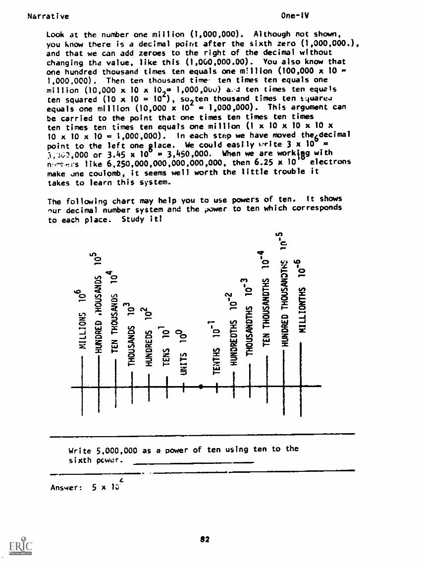
Narrative One-1V
Look at the number one million (1,000,000). Although not shown,you know there is a decimal point after the sixth zero (1,000,000.),and that we can add zeroes to the right of the decimal withoutchanging tha value, like this (1,000,000.00). You also know thatone hundred thousand times ten equals one m!ilion (100,000 x 101,000,000). Then ten thousand time ten times ten equals one
million (10,000 x 10 x 102= 1,000,00u) a. J ten times ten equals
ten squared (10 x 10 = 10 ), so2ten thousand times ten t4uared
equals one million (10,000 x 10 = 1,000,000). This argument can
be carried to the point that one times ten times ten times
ten times ten times ten equals one million (1 x 10 x 10 x 10 x
10 x 10 x 10 = 1,000,000). In each step we have moved the6decimal
point to the left one glace. We could easily trite 3 x 10 =
:4,;0,000 or 3.45 x 10 = 3,450,000. When we are workigg with
n.e.t..Irs like 6,250,000,000,000,000,000, then 6.25 x 10 electrons
make .me coulomb, it seems well worth the little trouble it
takes to learn this system.
The following chart may help you to use powers of ten. It shows
'ur decimal number system and the ,power to ten which corresponds
to each place. Study it!
InI
Write 5,000,000 as a power of ten using ten to the
sixth power.
c)0 =
I =a 4 1-1-- Amw 3 w =
N2 2 E-
71-LAJ
E =1 g,.._ . ., ,. ii.x a 0.1= = I- 8,- VI r-- 0c) CI CD
I"
I CX 1, Ca 2 c) ci_..1 ca = La
- 0fX S uJ 411= 1 8 CZ2 2= =1 2 1 Oealt 1
Write 5,000,000 as a power of ten using ten to the
sixth power.
c)0 =
I =a 4 1-1-- Amw 3 w =
N2 2 E-
71-LAJ
Answer: 5 x
..mImmammsEm ,!. amIl11M
82
Narrative One-IV
You can use this method to express very small numbers also.In this case, you must move the decimal point to the right anduse a negative power of ten. Cne one - thousandth (.001) becomes
one times ten to the minus third (1 x 10 ).
Write (.0000C28) as a number t nies ten to negativesixth power.
Answer: 2.8 x 10⁻⁶
Scientific Notation makes use of powers of ten to write numbersin a standard way. In scientific notation, the decimal pointis always placed behind the first digit of a number and the appro-priate power of ten is used. For exampis, the number of elec-trons in a c9Hlomb is written 6.25 x 10 rather than 62.5 x 10or .625 x 10'J.
Milli- and Micro-amperes
A useful way of working with current (and other) measurementswhen the values are fractions of an ampere is to use the metricprefixes milli- and micro-. Milli- means thousandths (.001),and micro- means millionths (.000001). You san see this fitsright in with the powers of ten (milli = 10 J and micro10 ). One milliampere is, thsrefore, equal to one one-thousandth of an ampere or 10 J amperes.
Writing these in the short way, the small letter "tn" is used forand the Greek letter mu ",," is used for micro-. To write
"the current_tlow is 30 microamperes," you coulT747-Tre either"I = 30 x 10 a" or "I = 30 .,a." If the current were 4 milli-amperes, you could write "I = 4 ma" or "1 = 4 x 10 a."
Express:
a. 0.006 a in mab. 0.00005 a inc. 0.002 ma in .a
Answer: a. 6 mab. 50c. 2
AT THIS POINT, YIU MAY TAKE THE PROGRESS CHECK, OR YOU MAY STUDY ANY OFTHE OTHER RESOURCES LISTED. IF YOU TAKE THE PROGRESS CHECK AND ANSWERALL OF THE QUESTIONS CORRECTLY, GO TO THE NEXT LESSON. IF NOT, STUDY ANY
METHOD OF INSTRUCTION YOU WISH UNTIL YOU CAN ANSWER ALL THE QUESTIONS
CORRECTLY.
83
P.I. One-IV
PROGRAMMED INSTRUCTION
LESSON IV
Measurement of Current
TEST FRAMES ARE 12, 22, 42, and 53. AS BEFORE, GO FIRST TO TESTFRAME 12 AND SEE IF YOU CAN ANSWER ALL THE QUESTIONS THERE. FOL-LOW THE DIRECTIONS GIVEN AFTER THE TEST FRAME.
1. Current was described as the:
a. directed drift of protons.b. random drift of neutrons.c. directed drift of electrons.d. random drift of electrons.
(c) directed drift of electrons
2. Current flow results from the directed movement of chargescaused by the application of a:
a. force inside the atom.b. force external to the atom.
(b) force external to the atom
3. The amount of external force is one factor which determinesthe amount of current flow. If the force being applied isincreased, there will be a corresponding increase in current.
What will happen if the amount of force is decreased?
a. Current will remain the same.b. Current will decrease.c. Current will increase.
(b) Current will decrease
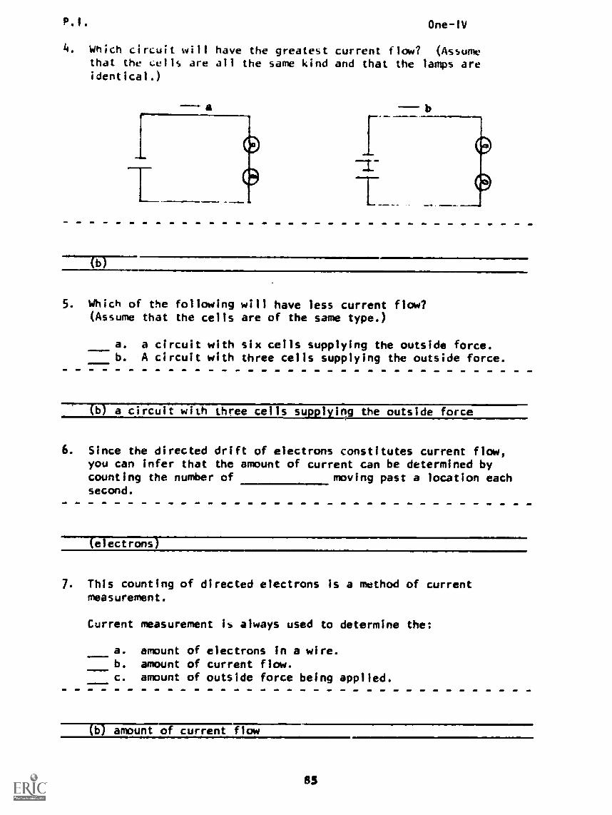
p. I. One-1V
4. Which circuit will have the greatest current flow? (Assumethat the ells are all the same kind and that the lamps areidentical.)
a
(b)
5. Which of the following will have less current flow?(Assume that the cells are of the same type.)
a. a circuit with six cells supplying the outside force.b. A circuit with three cells supplying the outside force.
a circuit with three cells supplyilg the outside force
6. Since the directed drift of electrons constitutes current flow,you can infer that the amount of current can be determined bycounting the number of moving past a location eachsecond.
(electrons)
7. This counting of directed electrons is a method of currentmeasurement.
Current measurement is always used to determine the:
a. amount of electrons in a wire.b. amount of current flow.c. amount of outside force being applied.
(b) amount of current flow
85
P.1. One-1V
8. When measuring current flow, time (t) must also be taken Intoconsideration.
Which would be the highest current flow?
a. 36 electrons passing per hour.b. 60 electrons passing per minute.c. 10 electrons passing per second.
(c) 10 electrons passing per second
9. Since electrons are moving throughout the circuit, electrons canonly be measured as they pass a given in the conductor.
(point or location)
10. When measuring current, both the number of electrons passing agiven location and must be considered.
( t i mei
11. Which correctly describes current measurement?
a. determining the number of electrons passing a givenlocation in a conductor within a specified time
b. counting the total number of electrons moving throughouta circuit
c. measuring the number of electrons between two or morepoints in a conductor
d. determining the magnitude of the random drift
(a) determining the number of electrons passing 3 givenlocation .n a conductor within a specified tine
86
P. I.
12. Check each true statement.
One-IV
a. Current flow in a disconnected wire cannot be measured.b. Measurement of current is a measure of the number of
electrons in a wire.c. Measurement of current is a measure of the number of
electrons passing a given point per unit time.
(THIS IS A TEST FRAME. COMPARE YOUR ANSWERS WITH THE CORRECTANSWERS GIVEN AT THE TOP OF THE NEXT PAGE.)
87
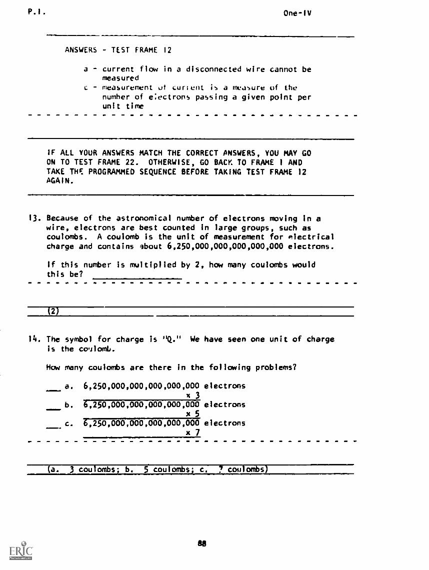
P. I . One-IV
ANSWERS TEST FRAME 12
a - current flow in a disconnected wire cannot bemeasuredmeasurement ut curl ent is a measure of thenumber of e:ectrons passing a given point perunit time
IF ALL YOUR ANSWERS MATCH THE CORRECT ANSWERS, YOU MAY GOON TO TEST FRAME 22. OTHERWISE, GO BACK TO FRAME 1 ANDTAKE THE PROGRAMMED SEQUENCE BEFORE TAKING TEST FRAME 12AGAIN.
13. Because of the astronomical number of electrons moving in awire, electrons are best counted in large groups, such ascoulombs. A coulomb is the unit of measurement for electricalcharge and contains about 6,250,000,000,000,000,000 electrons.
If this number is multiplied by 2, how many coulombs wouldthis be?
U
14. The symbol for charge is "Q." We have seen one unit of chargeis the co.ilomb.
How many coulombs are there in the following problems?
a. 6,250,000,000,000,000,000 electronsx3
b. 6,250,000,000,000,000,000 electronsx5
c. 6,250,000,000,000,000,000 electronsx7
3 coulombs coulomb c. coulombs)
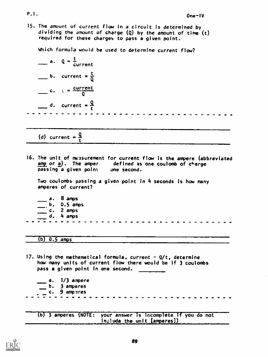
P.I. One-IV
15. The amount of current flow in a circuit is determined bydividing the amount of charge (Q) by the amount of time (t)required for these charges to pass a given point.
Which formula would be used to determine current flow?
a. Q =t
current41111m
b. current = tQ
- current
d. current = SI
c.
(d) current =
16. The unit of measurementand or 2). The angepassing a given point
for current flow is the ampere (abbreviateddefined as one coulomb of charge
one second.
Two coulombs passing a given point in 4 seconds is how manyamperes of current?
a. 8 ampsb. 0.5 ampsc. 2 ampsd. 4 amps
----111 0.5 amps...,111!MII111M.
17. Using the mathematical formula, current - Q/t, determinehow many units of current flow there would be if 3 coulombspass a given point in one second.
a. 1/3 ampereb. 3 amperesc. 9 amperes
N) 3 amperes (NOTE: your answer is incomplete if you do notinzlude the unit (amperes] )
89
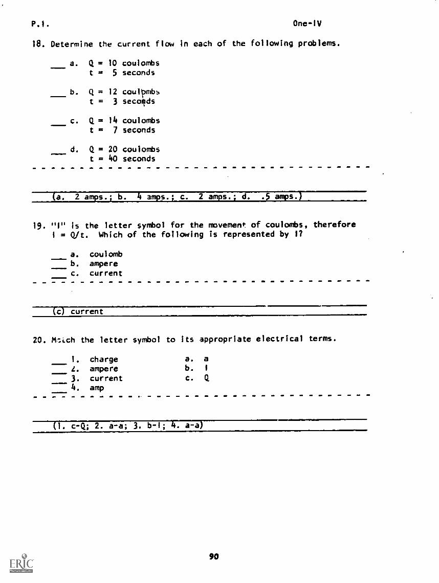
P.1. One -IV
18. Determine the current flow in each of the following problems.
a. Q = 10 coulombst = 5 seconds
b. Q = 12 coull:Imb
t = 3 seconds
c. Q = 14 coulombst = 7 seconds
d. Q = 20 coulombst = 40 seconds
(a. 2 amps.; b. 4 amps.; c. 2 amps.; d. .5 amps.)
19. "1" is the letter symbol for the movement. of coulombs, therefore1 = Qit. Which of the following is represented by 1?
a. coulombb. amperec. current
c current
20. ttli.ch the letter symbol to its appropriate electrical terms.
1. chargeL. ampere3. current4. amp
a. ab. 1
c. Q
c -(1; 2. a-a; 3. b-1; . a-a

P.I. One -IV
21. Match the statements to their equivalent mathematical expression.
1. I = 6 a a. The current flow is 6 amperes.2. I = 5 a b. Four amps of current are3. I = 4 a
c.
flowing.
Current flow in the circuitis 5 amperes.
(1. a-the current flow is 6 amperes; 2. c-current flow in the cir-cuit is _5 amperes; 3. b-four amps of current are flowinj)
22. Convert the following statements to their equivalentmathematical expressions.
a. The current flow is equal to 10 amperes.b. Eight amperes of current are flowing.c. The current is 3 amps.d. The curre (in any unit) is charge per unit time.
(THIS IS A TEST FRAME. COMPARE YOUR ANSWERS WITH THE CORRECTANSWERS GIVEN AT THE TOP OF THE NEXT PAGE.)
91
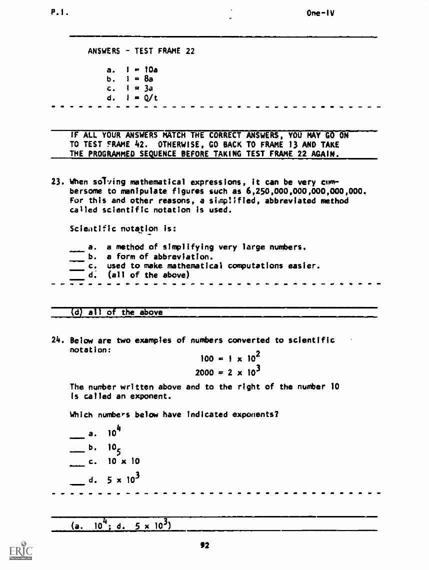
P.I. One-IV
ANSWERS TEST FRAME 22
a. I = 10ab. I = 8ac. I =3ad. I = Qit
IF ALL YOUR ANSWERS MATCH THE CORRECT ANSWERS, YOU MAY GO ONTO TEST FRAME 42. OTHERWISE, GO BACK TO FRAME 13 AND TAKETHE PROGRAMMED SEQUENCE BEFORE TAKING TEST FRAME 22 AGAIN.
23. When solving mathematical expressions, it can be very cum-bersome to manipulate figures such as 6,250,000,000,000,000,000.For this and other reasons, a simp!Ified, abbreviated methodcalled scientific notation is used.
Scientific notation is:
a. a method of simplifying very large numbers.b. a form of abbreviation.c. used to make mathematical computations easier.d. (all of the above)
(d) all of the above
24. Below are two examples of numbers converted to scientificnotation:
100 - 1 x 10²
2000 = 2 x 10³
The number written above and to the right of the number 10Is called an exponent.
Which numbers below have indicated exponents?
a. 104
Mall b. 105
C. 10 x 10
d. 5 x 10³
(a. 10 -d. 5x10³
92
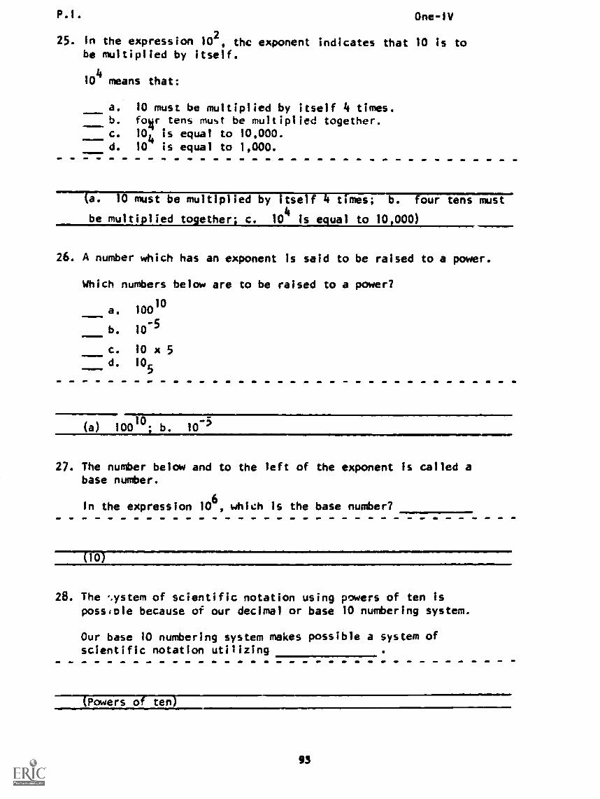
P1. One-IV
25. In the expression 10 2, the exponent indicates that 10 is to
be multiplied by itself.
104
means that:
a. 10 must be multiplied by itself 4 times.b. for tens must be multiplied together.c. 10
4is equal to 10,000.
d. 10 is equal to 1,000.
(a. 10 must be multiplied by itself 4 times; -b. four tens must
be multiplied together; c. 104
is equal to 10,000)
26. A number which has an exponent is said to be raised to a power.
Which numbers below are to be raised to a power?
a. 10010
b. 10-5
MIII=
C. i0 x 5d. 10
5
(a) 1001°- b. 10-5
27. The number below and to the left of the exponent is called abase number.
In the expression 106
, which Is the base number?
(10)
28. The 'system of scientific notation using powers of ten Ispossible because of our decimal or base 10 numbering system.
Our base 10 numbering system makes possible a system ofscientific notation utilizing
(Powers of ten)
93
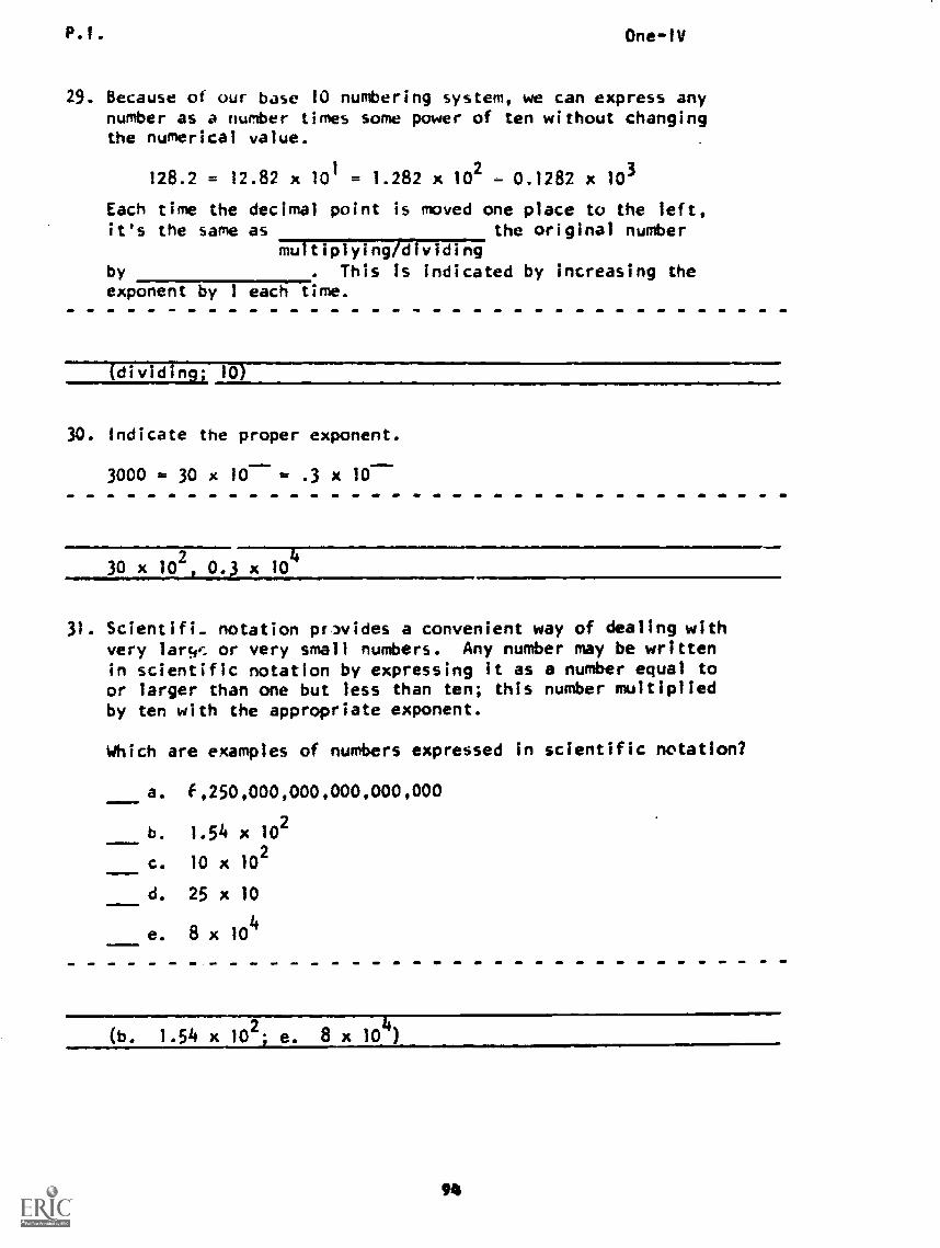
p.,. One-IV
29. Because of our base 10 numbering system, we can express anynumber as a number times some power of ten without changingthe numerical value.
128.2 = 12.82 x 101= 1.282 x 10
2- 0.1282 x 10³
Each time the decimal point is moved one place to the left,it's the same as the original number
multiplying/dividingby . This is indicated by increasing theexponent by 1 each time.
(dividing; 10)
30. Indicate the proper exponent.
3000 = 30 x 10 ... .3 x 10-
30 x i02, 0.3 x 10
31. Scientifi_ notation prIvides a convenient way of dealing withvery 'arse, or very small numbers. Any number may be writtenin scientific notation by expressing it as a number equal toor larger than one but less than ten; this number multipliedby ten with the appropriate exponent.
Which are examples of numbers expressed in scientific notation?
a. f,250,000,000,000,000,000
b. 1.54 x 10²
c. 10 x 102
d. 25 x 10
e. 8 x 10⁴
(b. 1.54 x 10² e. 8 x 10 )
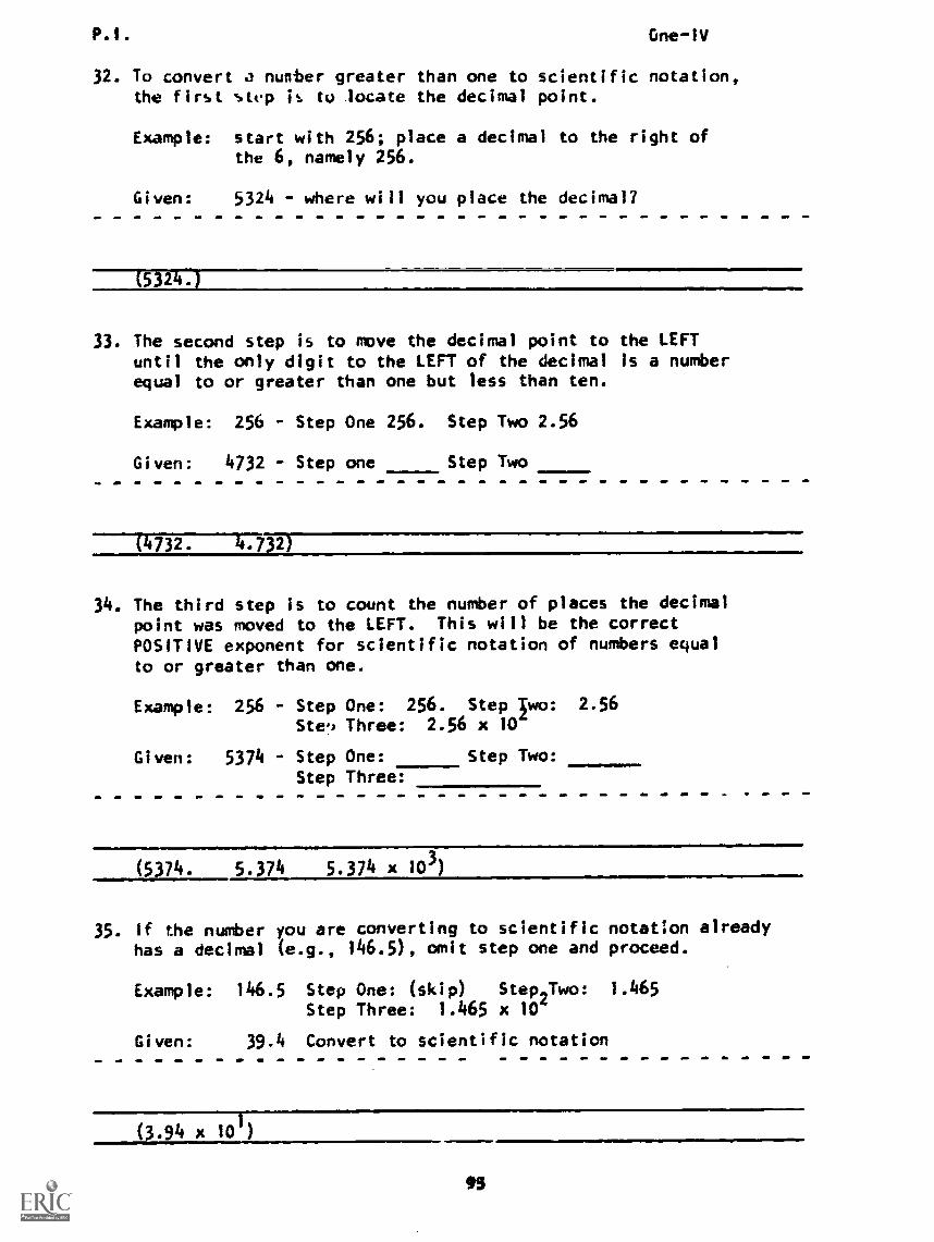
P.1. One-1V
32. To convert a number greater than one to scientific notation,the first step it to locate the decimal point.
Example: start with 256; place a decimal to the right ofthe 6, namely 256.
Given: 5324 - where will you place the decimal?
5 2
33. The second step is to move the decimal point to the LEFTuntil the only digit to the LEFT of the decimal is a numberequal to or greater than one but less than ten.
Example: 256 Step One 256. Step Two 2.56
Given: 4732 - Step one Step Two
(4732. 4.732)
34. The third step is to count the number of places the decimalpoint was moved to the LEFT. This will be the correctPOSITIVE exponent for scientific notation of numbers equalto or greater than one.
Example: 256 - StepSte.,
Given: 5374 - StepStep
One: 256. Step Iwo: 2.56
Three: 2.56 x 10
One: Step Two:Three:
(5374. 5.374 5.374 x 10³)
35. If the number you are converting to scientifichas a decimal (e.g., 146.5), omit step one and
Example: 146.5
Given:
Step One: (skip) Step2Two:Step Three: 1.465 x
39.4 Convert to scientific notation
notation alreadyproceed.
1.465
(5.94 x 101)
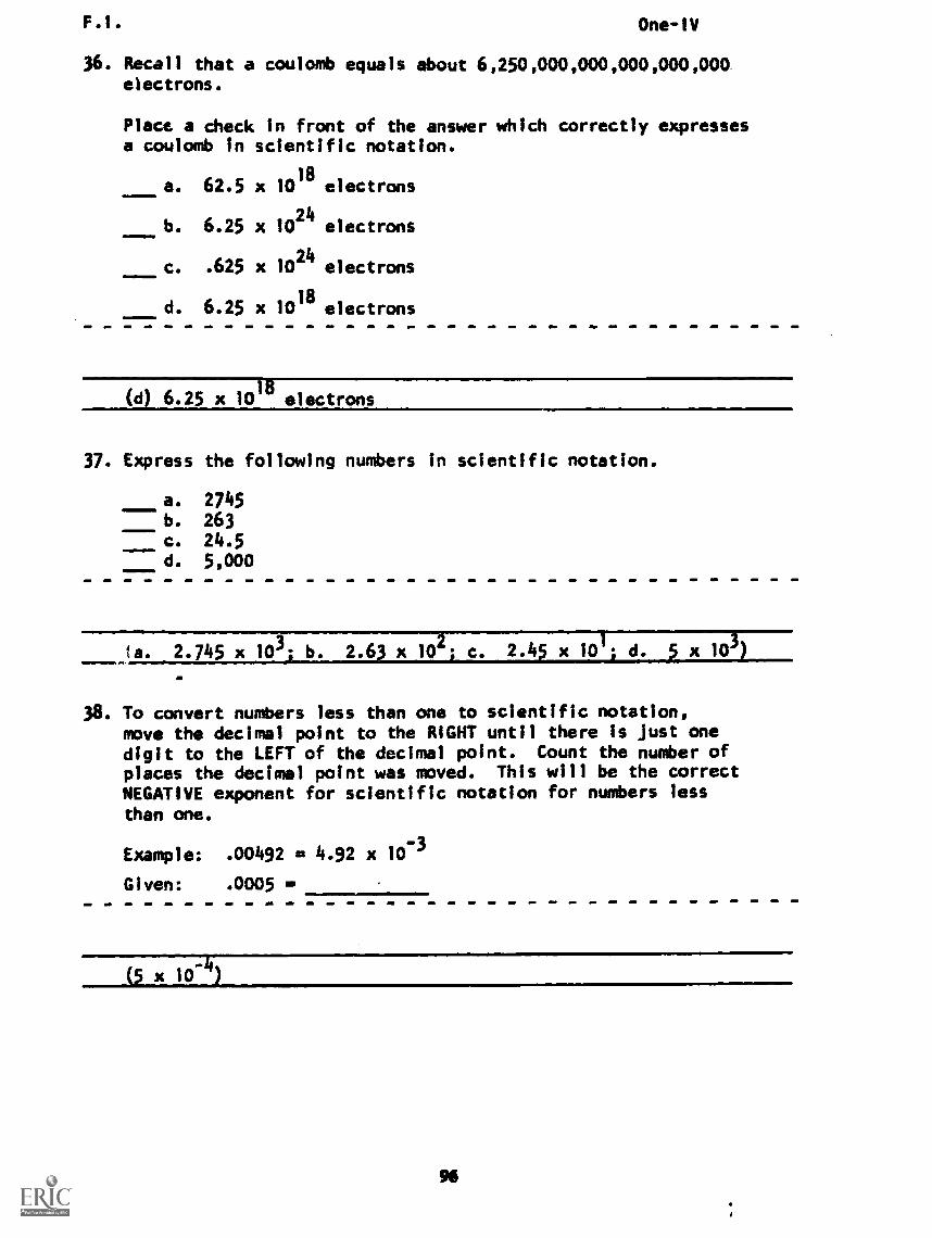
F.I. One-IV
36. Recall that a coulomb equals about 6,250,000,000,000,000,000electrons.
Place a check in front of the answer which correctly expressesa coulomb in scientific notation.
a. 62.5 x 10¹⁸
electrons
b. 6.25 x 1024
electrons
c. .625 x 1024
electrons
41111=IMINd. 6.25 x 10
18electrons
(d) 6.25 x 10¹⁸ electrons
37. Express the following numbers in scientific notation.
a. 2745b. 263c. 24.5d. 5,000
ta. 2.745 x 10³) b. 2.63 x 10² c. 2.45 x 101; d. 3 x 10³)
38. To convert numbers less than one to scientific notation,move the decimal point to the RIGHT until there Is just onedigit to the LEFT of the decimal point. Count the number ofplaces the decimal point was moved. This will be the correctNEGATIVE exponent for scientific notation for numbers lessthan one.
Example: .00492 m 4.92 x 10⁻³
Given: .0005 m
(5 x i0-4)
96
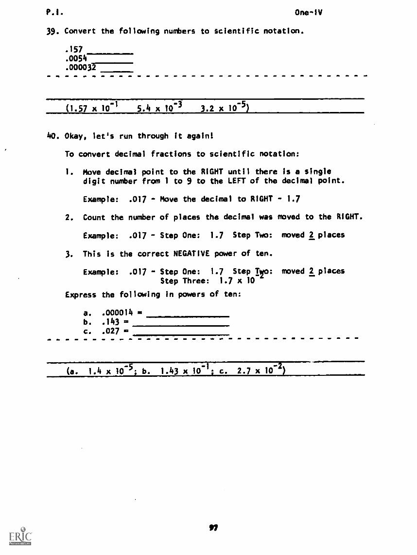
One-1V
39. Convert the following numbers to scientific notation.
.157
.0054
.0000337
(1.57 x 10⁻¹ 5.4 x 10⁻³ 3.2 x 10⁻⁵)
40. Okay, let's run through it again!
To convert decimal fractions to scientific notation:
1. Move decimal point to the RIGHT until there is a singledigit number from 1 to 9 to the LEFT of the decimal point.
Example: .017 - Move the decimal to RIGHT - 1.7
2. Count the number of places the decimal was moved to the RIGHT.
Example: .017 - Step One: 1.7 Step Two: moved 2 places
3. This Is the correct NEGATIVE power of ten.
Example: .017 - Step One: 1.7 Step T/o: moved 2 placesStep Three: 1.7 x 10
Express the following in powers of ten:
a. .000014b. .143 =c. .027 =
(a. 1.4 x 10⁻⁵; b. 1.43 x 10⁻¹; c. 2.7 x 10⁻²)
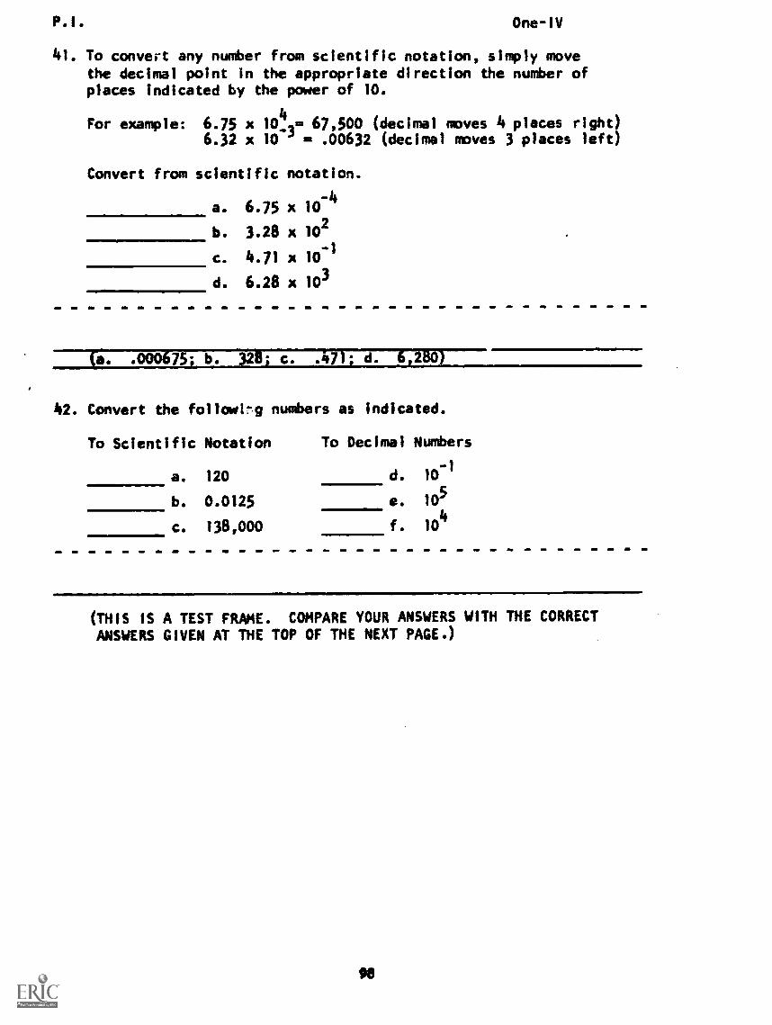
P.I. One-IV
41. To convert any number from scientific notation, simply movethe decimal point in the appropriate direction the number ofplaces indicated by the power of 10.
For example: 6.75 x 10_42= 67,500 (decimal moves 4 places right)6.32 x 10 ' = .00632 (decimal moves 3 places left)
Convert from scientific notation.
a. 6.75 x 10⁻⁴
b. 3.28 x 10²
c. 4.71 x 10⁻¹
d. 6.28 x 10³
cc .000675; b. 32k; c. .471; d. 6,280)
42. Convert the followi!-1 numbers as indicated.
To Scientific Notation To Decimal Numbers
a. 120 d. 10
0.0125 105
b.
1,11Me.
c. 138,000 f. 104
MIN1111
(THIS IS A TEST FRAME. COMPARE YOUR ANSWERS WITH THE CORRECTANSWERS GIVEN AT THE TOP OF THE NEXT PAGE.)
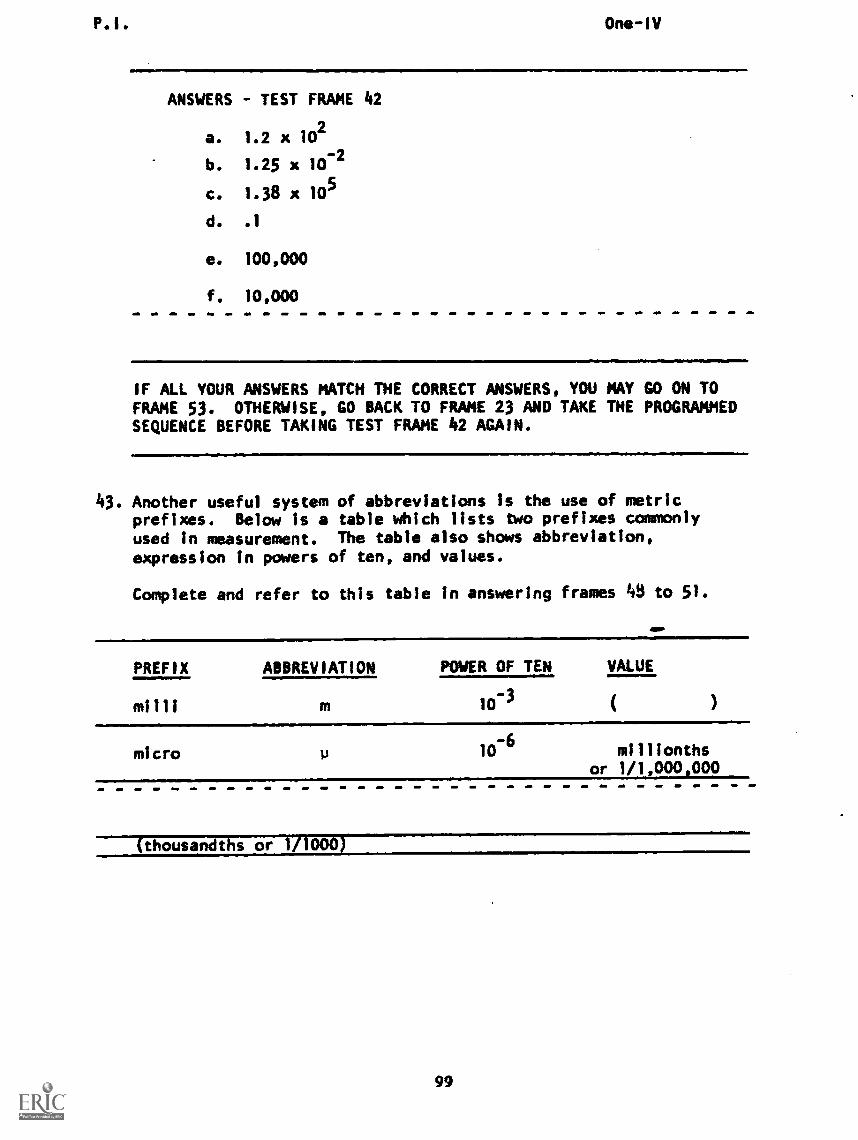
P. I . One-IV
ANSWERS - TEST FRAME 42
a. 1.2 x 10²
b. 1.25 x 10⁻²
c. 1.38 x 10⁵
d. .1
e. 100,000
f. 10,000
IF ALL YOUR ANSWERS MATCH THE CORRECT ANSWERS, YOU MAY GO ON TOFRAME 53. OTHERWISE, GO BACK TO FRAME 23 AND TAKE THE PROGRAMMEDSEQUENCE BEFORE TAKING TEST FRAME 42 AGAIN.
43. Another useful system of abbreviations is the use of metricprefixes. Below is a table which lists two prefixes commonlyused In measurement. The table also shows abbreviation,expression in powers of ten, and values.
Complete and refer to this table in answering frames 0 to 51.
PREFIX ABBREVIATION POWER OF TEN VALUE
milli m 10-3
micro a 10-6
millionthsor 1/1,000,000
(thousandths or 1/1000)
99
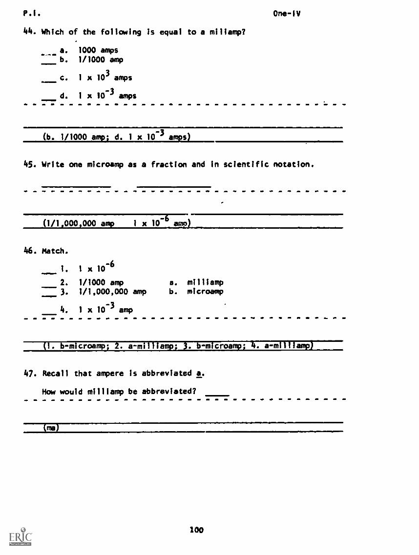
P.I. One-IV
44. Which of the following is equal to a millamp?
a. 1000 ampsb. 1/1000 amp
c. 1 x 10³ amps
d. 1 x 10⁻³ amps
(b. 1/1000 amp) d. 1 x 10⁻³ amps)
45. Write one microamp as a fraction and in scientific notation.
(1/1,000,000 amp 1 x 10⁻⁶
amp)
46. Match.
1 x 10⁻⁶
1/1000 amp1/1,000,000 amp
4. 1 x 10⁻³ amp
a. milliampb. microamp
(1. b-microamp; 2. a-milliamp; 3. b-microamp; 4. a-milliamp)
47. Recall that ampere is abbreviated a.
Mow would milliamp be abbreviated?
(ma)
100
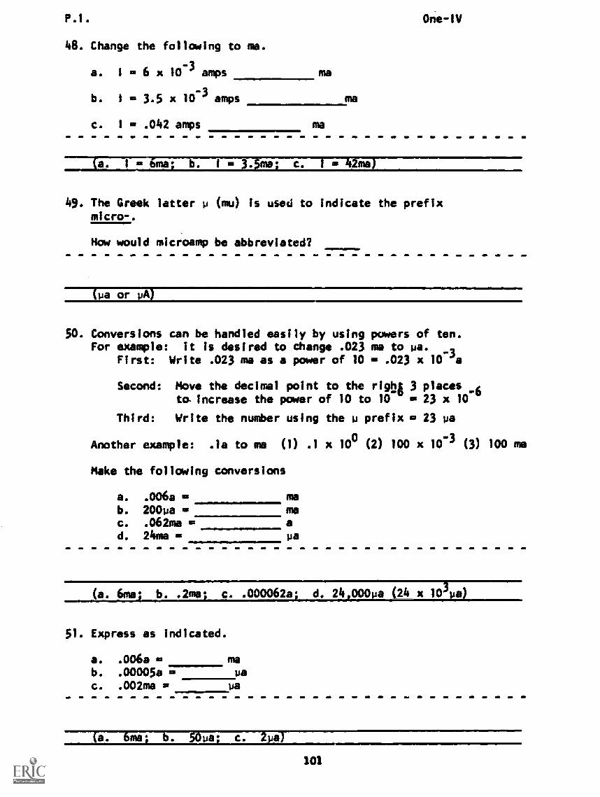
P.1.
48. Change the following to ma.
= 6 x 10⁻³ amps
= 3.5 x 10⁻³ amps
= .042 amps
a. 1
b. 1
c. 1
ma
One-1V
(a. 1 a 6ma; b. 1 = 3.5mo; c. 1 = 42ma)
49. The Greek letter p (mu) Is used to indicate the prefixmicro-.
How would microamp be abbreviated?
(pa or NA)
50. Conversions can be handled easily by using powers of ten.For example: it is desired to change .023 ma to pa.
First: Write .023 ma as a power of 10 - .023 x 10 'a
Second: Move the decimal point to the right 3 places _6to increase the power of 10 to 10 = 23 x 10
Third: Write the number using the p prefix = 23 pa
Another example: .1a to ma (1) .1 x 100 (2) 100 x 10-3 (3) 100 ma
Make the following conversions
a. .006a = mab. 200pa = mac. .062ma = ad. 24ma Pa
(a. 6ma; b. .2ma; c. .000062a; d. 24,000pa (24 x 103pa)
51. Express as indicated.
a. .006a d ma
b. .00005a - ua
c. .002ma - pa
6ma; b. 50pa; c. 2_pai
101
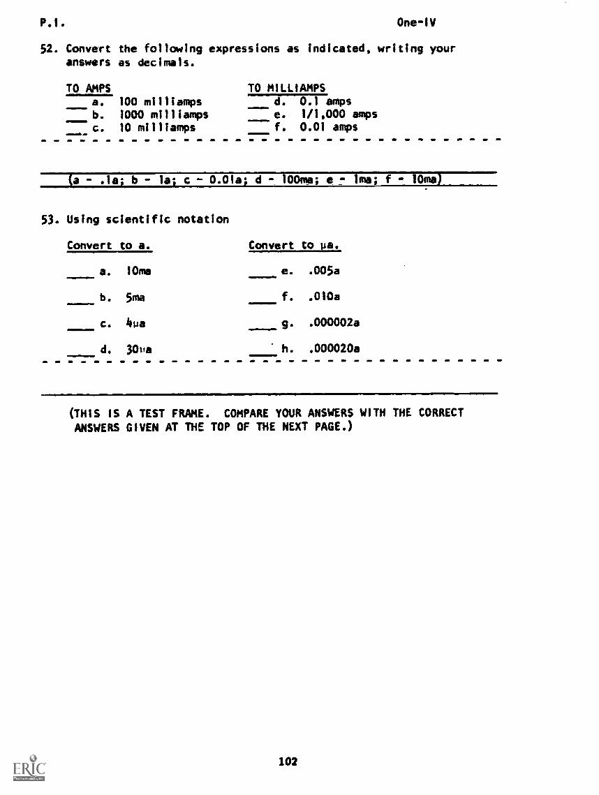
P.1. One-IV
52. Convert the following expressions as indicated, writing youranswers as decimals.
TO AMPS100 milliamps1000 milliamps10 milliamps
TO MILLIAMPSa. d.
----e.0.1 amps1/1,000 amps0.01 amps
b.
c. f.
(a - .1gq b - la; c 0.0Ia; d 100ma- e lma; f --10ma)
53. Using scientific notation
Convert to a. Convert to pa.
a. 10ma e. .005a
b. 5ma f. .010a
c. 4ua g. .000002a
d. 1011a h. .000020a=,
(THIS IS A TEST FRAME. COMPARE YOUR ANSWERS WITH THE CORRECTANSWERS GIVEN AT THE TOP OF THE NEXT PAGE.)
102
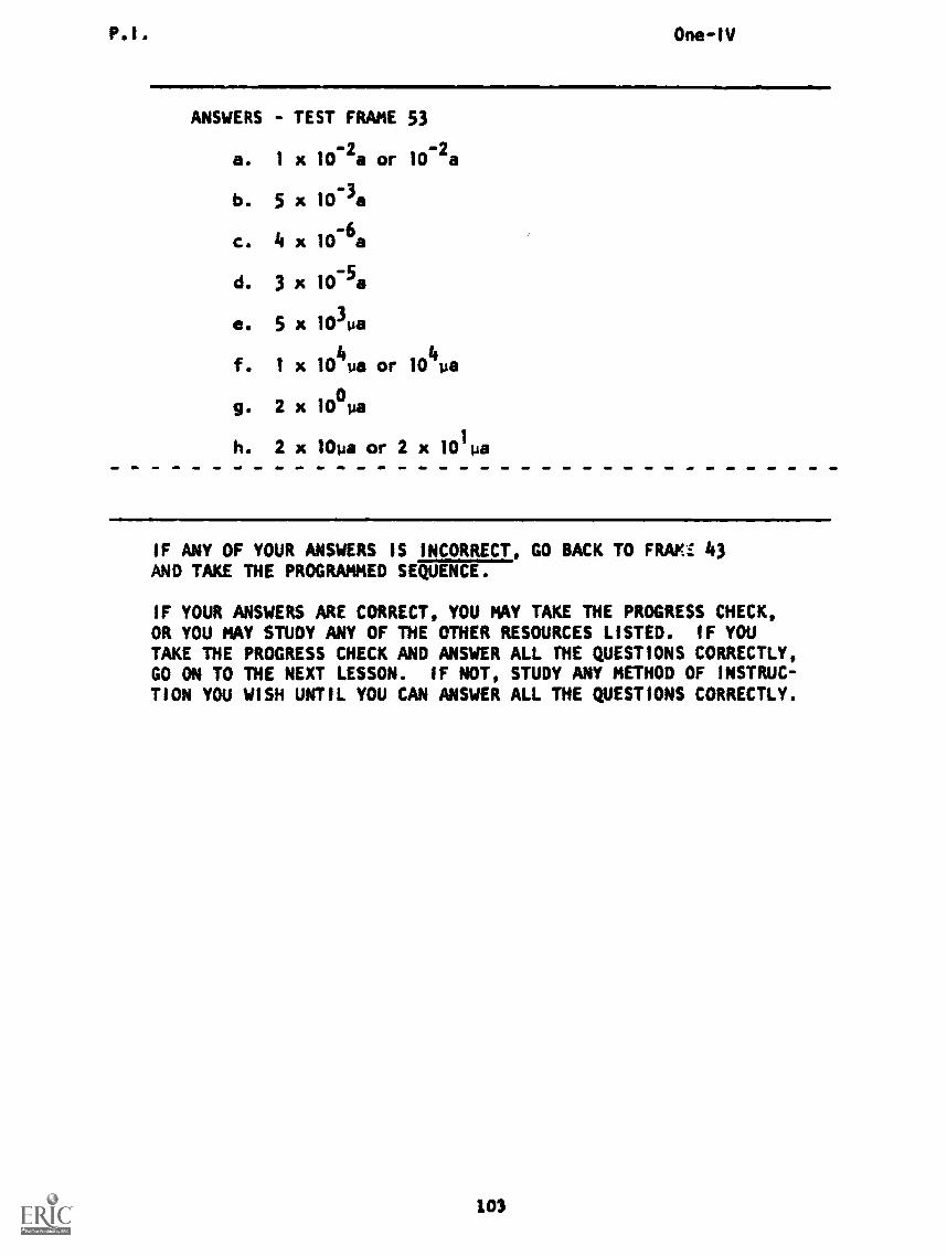
P.I. One-IV
ANSWERS - TEST FRAME 53
a. 1 x 10⁻²
a or 10-2
a
b. 5 x 10⁻³a
c. 4 x 10⁻⁶a
d. 3 x 10⁻⁵a
e. 5 x 10³ua
f. 1 x 10⁴ua or 10
4ua
g. 2 x 10 'la
h. 2 x 10ua or 2 x 10 pa
IF ANY OF YOUR ANSWERS IS INCORRECT, GO BACK TO FRAM:: 43AND TAKE THE PROGRAMMED SEQUENCE.
IF YOUR ANSWERS ARE CORRECT, YOU MAY TAKE THE PROGRESS CHECK,OR YOU MAY STUDY ANY OF THE OTHER RESOURCES LISTED. IF YOUTAKE THE PROGRESS CHECK AND ANSWER ALL THE QUESTIONS CORRECTLY,GO ON TO THE NEXT LESSON. IF NOT, STUDY ANY METHOD OF INSTRUC-TION YOU WISH UNTIL YOU CAN ANSWER ALL THE QUESTIONS CORRECTLY.
103
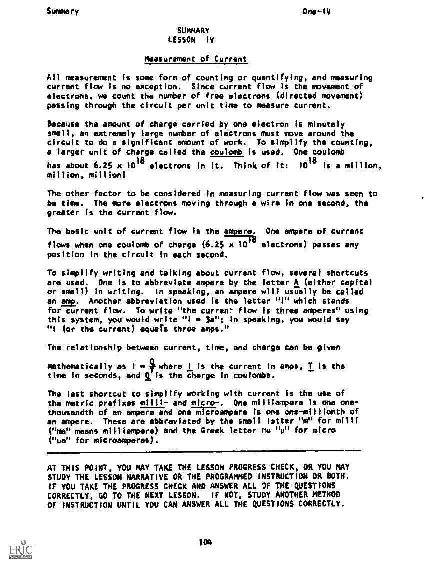
Summary One-1V
SUMMARYLESSON IV
Measurement of Current
All measurement is some form of counting or quantifying, and measuringcurrent flow is no exception. Since current flow is the movement ofelectrons, we count the number of free electrons (directed movement)passing through the circuit per unit time to measure current.
Because the amount of charge carried by one electron is minutelysmall, an extremely large number of electrons must move around thecircuit to do a significant amount of work. To simplify the counting,a larger unit of charge called the coulomb is used. One coulomb
has about 6.25 x 10¹⁸
electrons in it. Think of it: 1018
is a million,million, million!
The other factor to be considered in measuring current flow was seen tobe time. The more electrons moving through a wire In one second, thegreater is the current flow.
The basic unit of current flow is the re. One ampere of current
flows when one coulomb of charge (6.25 x 10 electrons) passes anyposition in the circuit in each second.
To simplify writing and talking about current flow, several shortcutsare used. One is to abbreviate ampere by the letter A (either capitalor small) in writing. in speaking, an ampere will usually be calledan E. Another abbreviation used is the letter "I" which standsfor current flow. To write "the current- flow is three amperes" usingthis system, you would write "I is 3a"; In speaking, you would say"I (or the current) squats three amps."
The relationship between current, time, and charge can be given
mathematically as 1 - where I is the current in amps, T is thetime in seconds, and g Is the charge in coulombs.
The last shortcut to simplify working with current is the use ofthe metric prefixes milli- and micro-. One milliampere Is one one-thousandth of an ampere and one71776empere is one one-millionth ofan ampere. These are abbreviated by the small latter 'gym" for milli("me" means milliampere) ane the Greek letter mu "p" for micro( "na" for microamperes).
AT THIS POINT, YOU MAY TAKE THE LESSON PROGRESS CHECK, OR YOU MAYSTUDY THE LESSON NARRATIVE OR THE PROGRAMMED INSTRUCTION OR BOTH.IF YOU TAKE THE PROGRESS CHECK AND ANSWER ALL OF THE QUESTIONSCORRECTLY, GO TO THE NEXT LESSON. IF NOT, STUDY ANOTHER METHODOF INSTRUCTION UNTIL YOU CAN ANSWER ALL THE QUESTIONS CORRECTLY.
1014
BASIC ELECTRICITY AND ELECTRONICS
INDIVIDUALIZED LEARNING SYSTEM
MODULE ONE
LESSON V
The Ammeter
Study Booklet
Overview One -V
OVERVIEW
LESSON V
The Ammeter
In this lesson you will study and learn about the following:
-why the ammeter
-how an ammeter works
-meter tolerances
-the practical use of the ammeter
Each of the above topics will be discussed in the order listed.
As you proceed through this lesson, observe and follow directions
carefully.
BEFORE YOU START THIS LESSON, PREVIEW THE LIST OF STUDY RESOURCES
ON THE NEXT PAGE.
Study Resources One-V
LIST OF STUDY RESOURCES
LESSON V
The Ammeter
To learn the material in this lesson, you have the option of choosing,
according to your experience and your preferences, any or all of the
following:
STUDY BOOKLET:
Lesson Narrative
Programmed Instruction
Lesson Summary
ENRICHMENT MATERIAL:
NAVPERS 93400A-la "Basic Electricity, Direct Current."
Fundamentals of Electronics. Bureau of Naval Personnel.
Washington, D.C.: U.S. Government Printing Office, 1965.
AUDIO-VISUAL:
Sound/slide presentation, "The Ammeter."
YOU MAY NOW STUDY ANY OR ALL OF THE RESOURCES LISTED ABOVE. YOU
MAY TAKE THE PROGRESS CHECK AT ANY TIME. UPON COMPLETION OF THIS
LESSON, YOU SHOULD ASK YOUR INSTRUCTOR FOR THE MODULE TEST COVERING
ALL THE LESSONS IN THIS BOOKLET. YOU MAY REVIEW PREVIOUS LESSONS
IF YOU WISH.
. tI
107
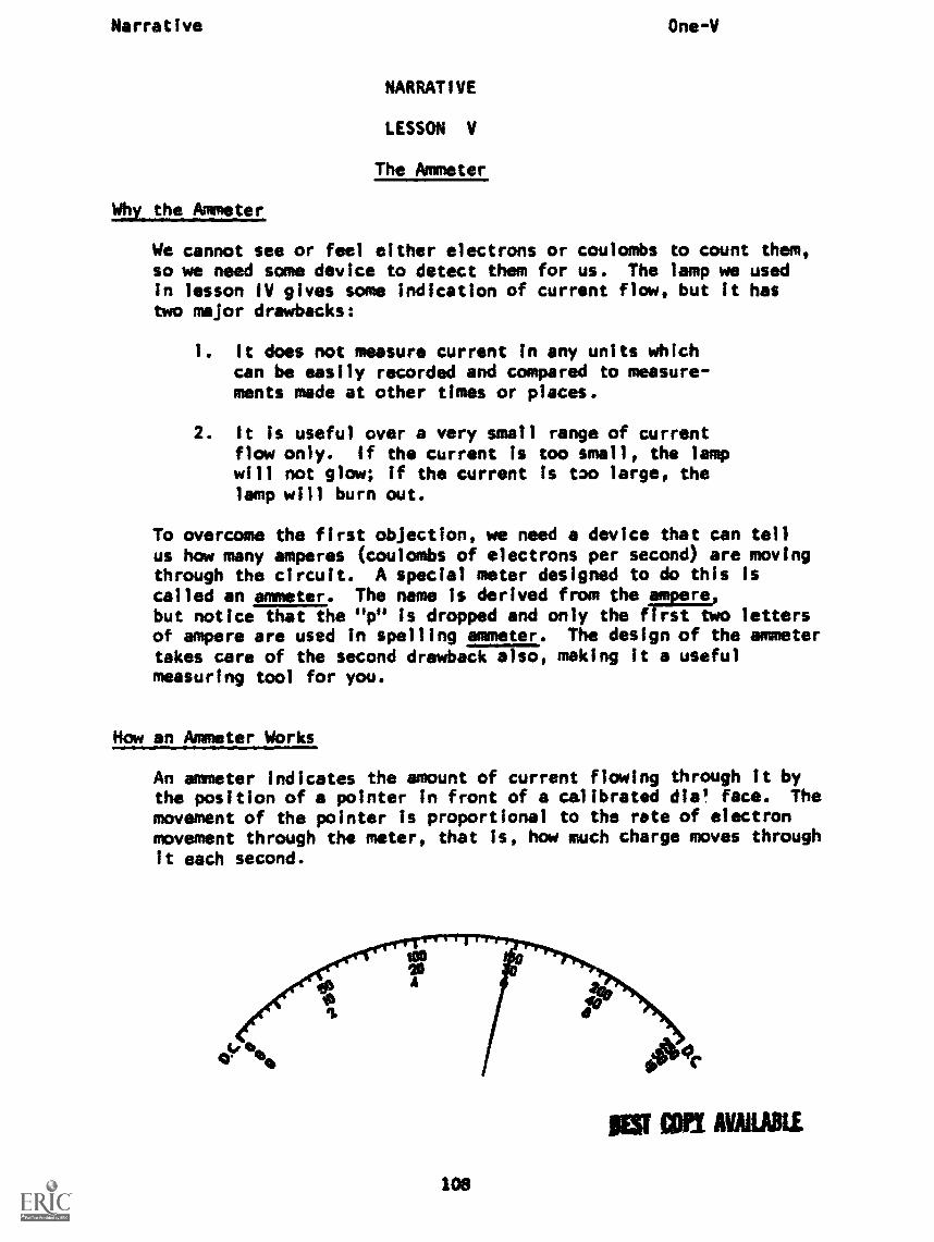
Narrative One-V
NARRATIVE
LESSON V
The Ammeter
Why the Ammeter
We cannot see or feel either electrons or coulombs to count them,so we need some device to detect them for us. The lamp we usedin lesson IV gives some indication of current flow, but it hastwo major drawbacks:
1. It does not measure current in any units whichcan be easily recorded and compared to measure-ments made at other times or places.
2. It is useful over a very small range of currentflow only. If the current is too small, the lampwill not glow; if the current is too large, thelamp will burn out.
To overcome the first objection, we need a device that can
tclaalhl:
(coulters
fdeeirel:::eefsro:e:h:e::::)
through the circuit. A special meter designed to do thismany amperes
but notice that the "p" is dropped and only the first twoof ampere are used in spelling ammeter. The design of thetakes care of the second drawback also, making it a usefulmeasuring tool for you.
tell
movingis
lettersammeter
How an Ammeter Works
An ammeter indicates the amount of current flowing through it bythe position of a pointer in front of a calibrated die' face. Themovement of the pointer is proportional to the rate of electronmovement through the meter, that is, how much charge moves throughit each second.
108
fr4c.
as CM AMAMI
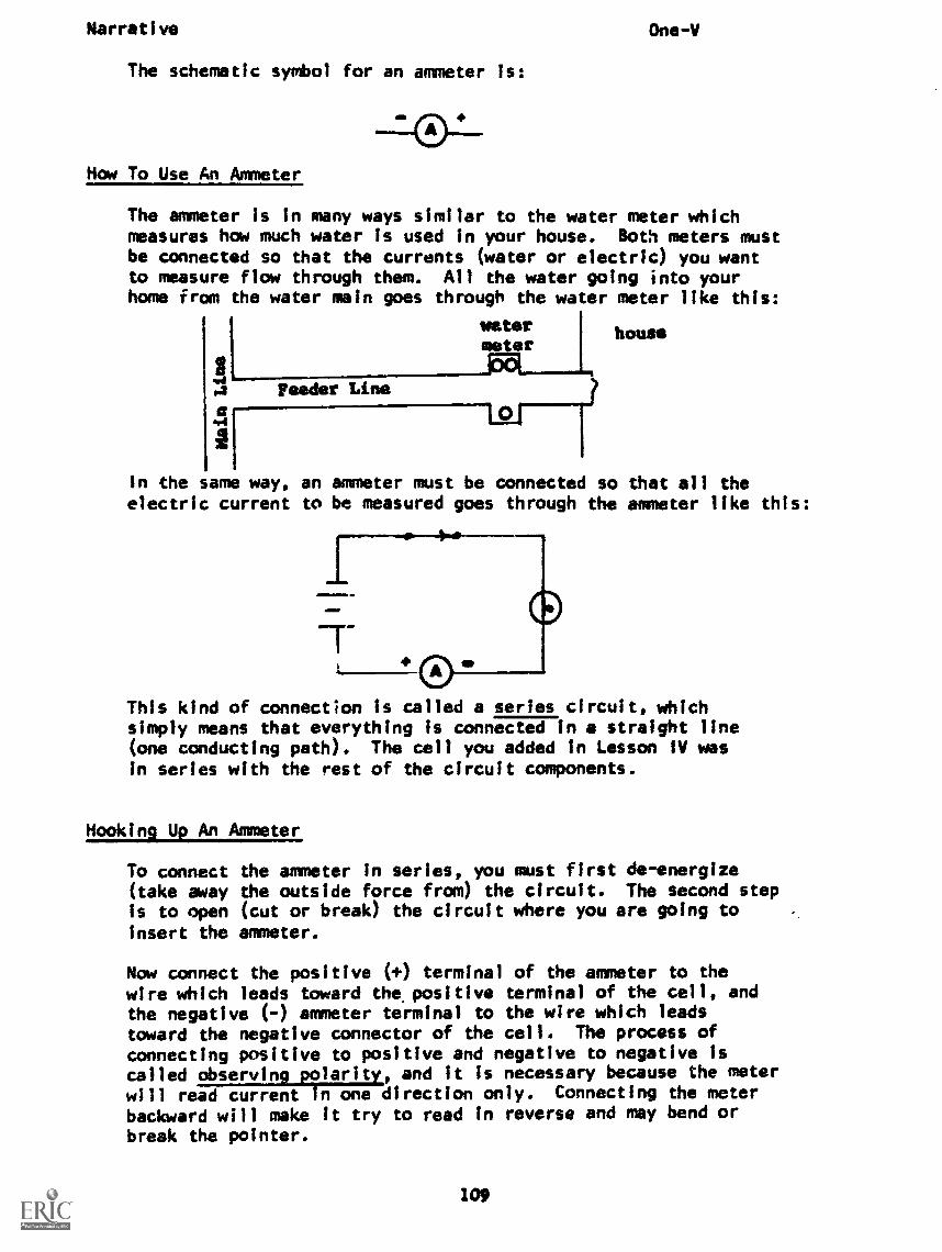
Narrative One -V
The schematic symbol for an ammeter is:
How To Use An Ammeter
The ammeter is in many ways similar to the water meter whichmeasures how much water is used in your house. Both meters mustbe connected so that the currents (water or electric) you wantto measure flow through them. All the water going into yourhome from the water main goes through the water meter like this:
meter
aara
11
Feuer Line
pfl
In the same way, an ammeter must be connected so that all theelectric current to be measured goes through the ammeter like this:
house
This kind of connection Is called a series circuit, whichsimply means that everything is connected in a straight line(one conducting path). The cell you added in Lesson IV wasin series with the rest of the circuit components.
Hooking Up An Ammeter
To connect(take awayIs to openinsert the
the ammeter in series, you must first de- energizethe outside force from) the circuit. The second step(cut or break) the circuit where you are going toammeter.
Now connect the positive ( +) terminal of the ammeter to thewire which leads toward the positive terminal of the cell, andthe negative (-) ammeter terminal to the wire which leadstoward the negative connector of the cell. The process ofconnecting positive to positive and negative to negative iscalled observing polarity, and it is necessary because the meterwill read current In one direction only. Connecting the meterbackward will make it try to read in reverse and may bend orbreak the pointer.
109
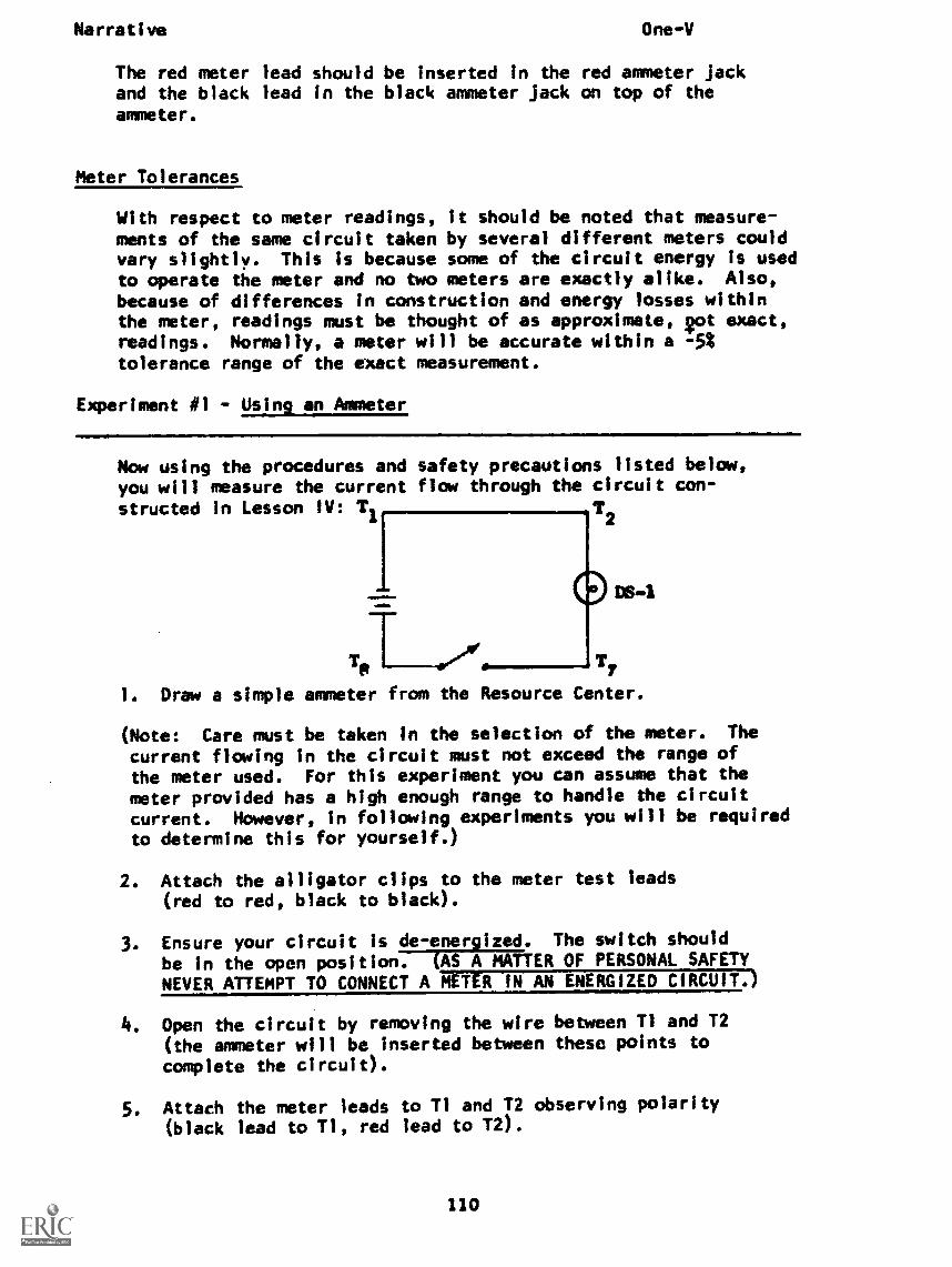
Narrative One -V
The red meter lead should be inserted in the red ammeter Jackand the black lead in the black ammeter Jack on top of theammeter.
Meter Tolerances
With respect to meter readings, it should be noted that measure-ments of the same circuit taken by several different meters couldvary slightly. This is because some of the circuit energy is usedto operate the meter and no two meters are exactly alike. Also,
because of differences in construction and energy losses withinthe meter, readings must be thought of as approximate, got exact,readings. Normally, a meter will be accurate within a -5%tolerance range of the exact measurement.
Experiment #1 - Using an Ammeter
Now using the procedures and safety precautions listed below,you will measure the current flow through the circuit con-
structed in Lesson IV: Ti T
DS..1
T71
1. Draw a simple ammeter from the Resource Center.
(Note: Care must be taken in the selection of the meter. The
current flowing in the circuit must not exceed the range of
the meter used. For this experiment you can assume that themeter provided has a high enough range to handle the circuit
current. However, in following experiments you will be requiredto determine this for yourself.)
2. Attach the alligator clips to the meter test leads(red to red, black to black).
3. Ensure your circuit is de- energized. The switch should
be in the open position. (AS A MATTER OF PERSONAL SAFETYNEVER ATTEMPT TO CONNECT A METER IN AN ENERGIZED CIRCUIT.)
4. Open the circuit by removing the wire between T1 and T2
(the ammeter will be inserted between these points tocomplete the circuit).
5. Attach the meter leads to Tl and T2 observing polarity
(black lead to Ti, red lead to T2).
110
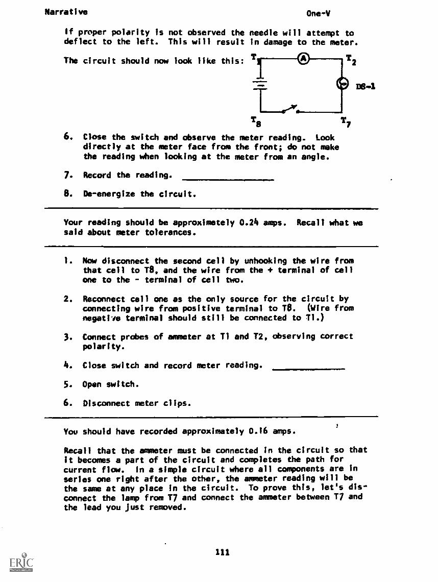
Narrative One -V
If proper polarity is not observed the needle will attempt todeflect to the left. This will result in damage to the meter.
The circuit should now look like this: T
IMAM.
1111!
Ti
6. Close the switch and observe the meter reading. Lookdirectly at the meter face from the front; do not makethe reading when looking at the meter from an angle.
7. Record the reading.
De-energize the circuit.
T7
Your reading should be approximetely 0.24 amps. Recall what wesaid about meter tolerances.
1. Now disconnect the second cell by unhooking the wire fromthat cell to T8, and the wire from the + terminal of cellone to the terminal of cell two.
2. Reconnect cell one as the only source for the circuit byconnecting wire from positive terminal to TO. (Wire fromnegative terminal should still be connected to T1.)
3. Connect probes of ammeter at T1 and T2, observing correctpolarity.
4. Close switch and record meter reading.
5. Open switch.
6. Disconnect meter clips.
You should have recorded approximately 0.16 amps.3
Recall that the ammeter must be connected in the circuit so thatit becomes a part of the circuit and completes the path forcurrent flow. In a simple circuit where all components are Inseries one right after the other, the ammeter reading will bethe same at any place in the circuit. To prove this, let's dis-connect the lamp from T7 and connect the ammeter between T7 and
the lead you just removed.
111
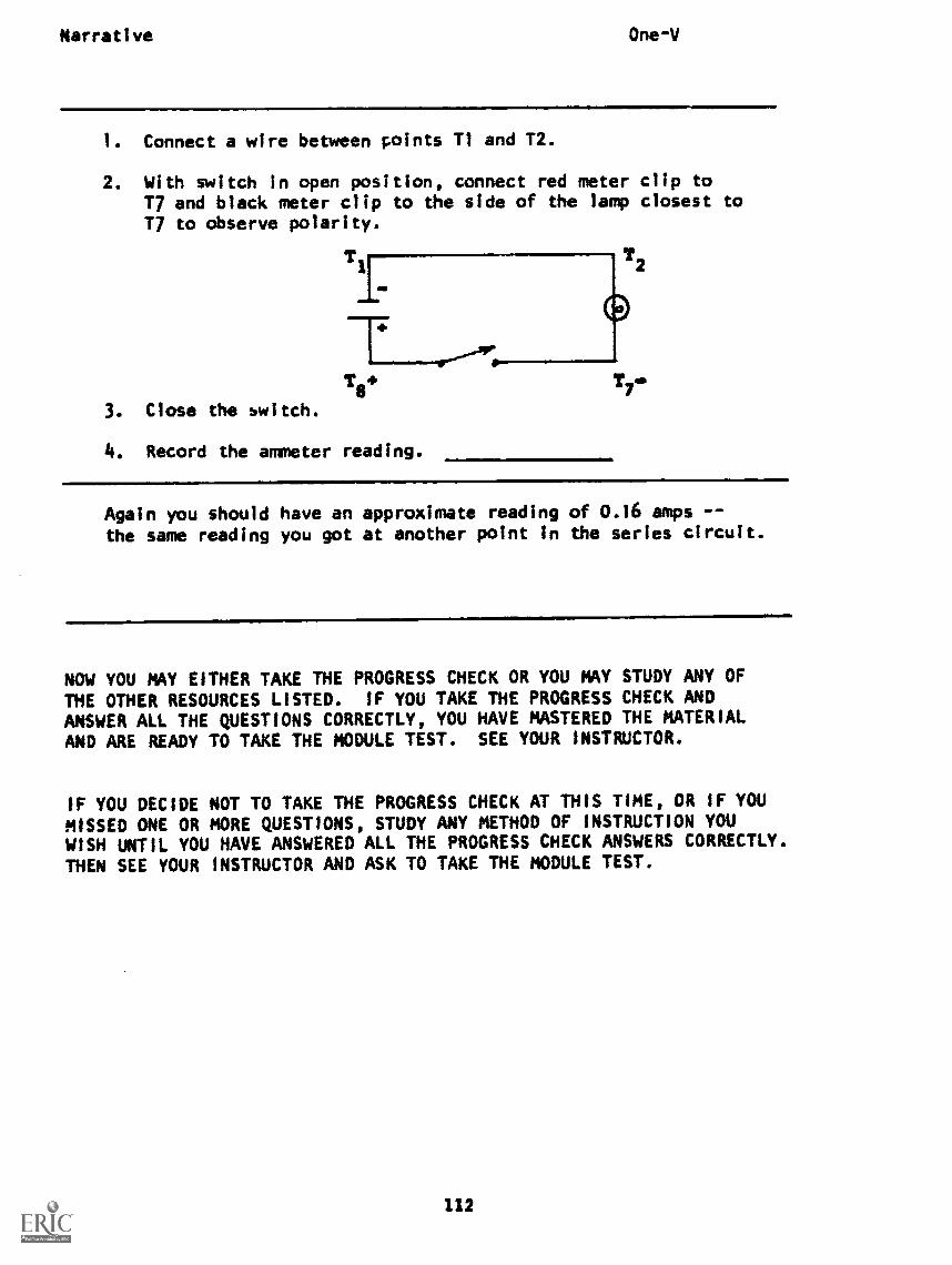
Narrative One-V
1. Connect a wire between points Ti and T2.
2. With switch in open position, connect red meter clip toT7 and black meter clip to the side of the lamp closest to17 to observe polarity.
T8.3. Close the switch.
4. Record the ammeter reading.
T7
Again you should have an approximate reading of 0.16 amps --the same reading you got at another point In the series circuit.
NOW YOU MAY EITHER TAKE THE PROGRESS CHECK OR YOU MAY STUDY ANY OF
THE OTHER RESOURCES LISTED. IF YOU TAKE THE PROGRESS CHECK ANDANSWER ALL THE QUESTIONS CORRECTLY, YOU HAVE MASTERED THE MATERIAL
AND ARE READY TO TAKE THE MODULE TEST. SEE YOUR INSTRUCTOR.
IF YOU DECIDE NOT TO TAKE THE PROGRESS CHECK AT THIS TIME, OR IF YOU
MISSED ONE OR MORE QUESTIONS, STUDY ANY METHOD OF INSTRUCTION YOU
WISH UNTIL YOU HAVE ANSWERED ALL THE PROGRESS CHECK ANSWERS CORRECTLY.
THEN SEE YOUR INSTRUCTOR AND ASK TO TAKE THE MODULE TEST.
112
P.I. One -V
PROGRAMMF INSTRUCTION
LESSON V
The Ammeter
TEST FRAMES ARE 13, 21, 27, and 28. AS BEFORE, GO FIRST TO TESTFRAME 13 AND SEE IF YOU CAN ANSWER ALL THE QUESTIONS THERE. FOLLOWTHE DIRECTIONS GIVEN AFTER THE TEST FRAME.
1. Recall that current flow in a wire is the movement of sub-microscopic particles called:
a.
b.
c.
protons.neutrons.electrons.
---TET7le-ons
2. Amperage or the amount of current is partly determined by:
=111.MIMa. counting the number of electrons passing a given
point per second.b. measuring the velocity of electrons.c. measuring the distance a coulomb travels In one second.
(i) counting the number of electrons passing a given point persecond
3. Since electrons cannot be seen, a special measuring device mustbe used to determine amperage.
The name of a device used to measure current is an ammeter, ormeter.
a. voltageb. amperagec. resistance
[b) amperaje
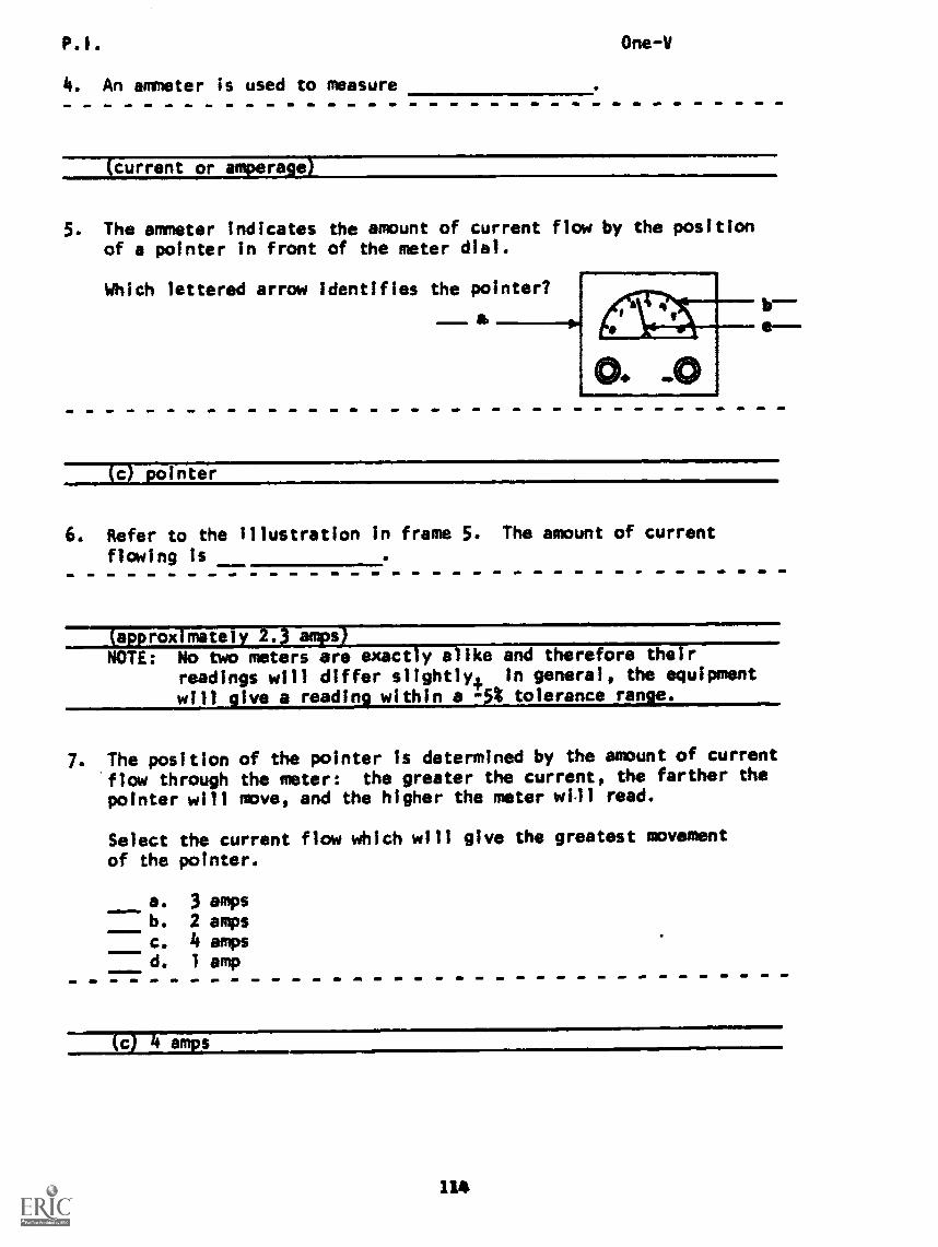
P.I.
4. An ammeter is used to measure
One -V
(current or amperage)
5. The ammeter indicates the amount of current flow by the positionof a pointer in front of the meter dial.
Which lettered arrow identifies the pointer?
1.m.mlwrot &
(c) pointer
6. Refer to the illustration in frame 5. The amount of current
flowing is
approx mately amps
NOTE: No two meters are exactly alike and therefore their
readings will differ slightly4 in general, the equipmentwill give a reading within a -5$ tolerance range.
7. The position of the pointer Is determined by the amount of current
flow through the meter: the greater the current, the farther thepointer will move, and the higher the meter will read.
Select the current flow which will give the greatest movement
of the pointer.
a.
c.
d.
3 amps2 amps4 amps1 amp
114
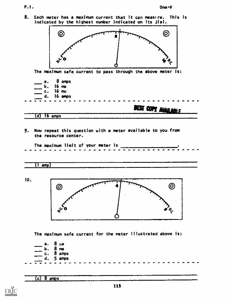
P.1. One -V
8. Each meter has a maximum current that it can measr,re. This isindicated by the highest number indicated on its Mal.
The maximum safe current to pass through the above meter is:
a. 8 ampsb. 16 mac. 16 mu
d. 16 amps
BESr COPT Alum
9. Now repeat this question with a meter available to you fromthe resource center.
The maximum limit of your meter Is
10.
(1 amp
The maximum safe current for the meter illustrated above is:
a. 8 pab. 8 mac. 8 ampsd. 5 amps
(c) 8 amps
115
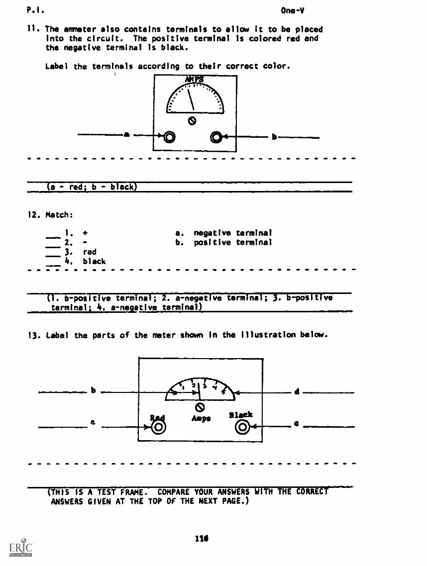
P.I. One -V
11. The ammeter also contains terminals to allow it to be placedinto the circuit. The positive terminal is colored red andthe negative terminal is black.
Label the terminals according to their correct color.
(a - red; b black)
12. Match:
1. +2. -
red
4. black
a. negative terminalb. positive terminal
. b -posit ve term na . a-negat ve term -pos t
terminal; 4. a-negative terminal
13. Label the parts of the meter shown in the illustration below.
(THIS IS A TEST FRAME. COMPARE YOUR ANSWERS iiITH THE CORRECTr
ANSWERS GIVEN AT THE TOP OF THE NEXT PAGE.)
P.I. One -V
ANSWERS - TEST FRAME 13
a. positive terminal
b. pointer
c. negative terminal
d. meter dial
IF ALL YOUR ANSWERS MATCH THE CORRECT ANSWERS, YOU MAY GO ON TOTEST FRAME 21. OTHERWISE, GO BACK TO FRAME 1 AND TAKE THEPROGRAMMED SEQUENCE BEFORE TAKING TEST FRAME 13 AGAIN.
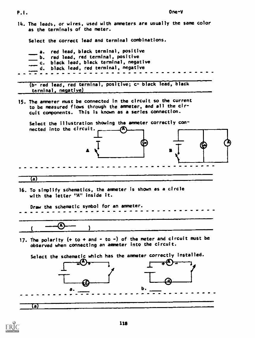
P.1. One -V
14. The leads, or wires, used with ammeters are usually the same coloras the terminals of the meter.
Select the correct lead and terminal combinations.
a. red lead, black terminal, positiveb. red lead, red terminal, positivec. black lead, black terminal, negatived. black lead, red terminal, negative
red lead, red terminal, positive; c- black lead, black
terminal native
15. The ammeter must be connected in the circuit so the currentto be measured flows through the ammeter, and all the cir-
cuit components. This is known as a series connection.
Select the illustration showing the ammeter correctly con-
nected into the circuit.
A
(a)
16. To simplify schematics, the ammeter is shown as a circle
with the letter "A" inside it.
Draw the schematic symbol for an ammeter.
17. The polarity (+ to and - to -) of the meter and circuit must be
observed when connecting an ammeter into the circuit.
Select the schematic which has the ammeter correctly installed.
1 4
Ta. b.
(a)
118
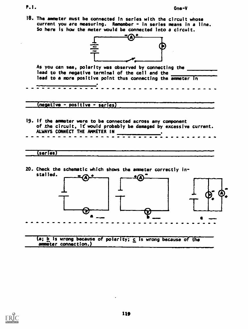
P.1. One -V
18. The ammeter must be connected in series with the circuit whosecurrent you are measuring. Remember - in series means in a line.So here is how the meter would be connected into a circuit.
As you can see, polarity was observed by connecting thelead to the negative to of the cell and thelead to a more positive point thus connecting the meter
(negative - positive - series)
19. If the ammeter were to be connected across any componentof the circuit, le would probably be damaged by excessive current.ALWAYS CONNECT THE AMMETER IN
(series)
20. Check the schematic which shows the ammeter correctly in-stalled. I..
a; b is wrong because of polarity; c is wrong because of theammeter connection.)
11
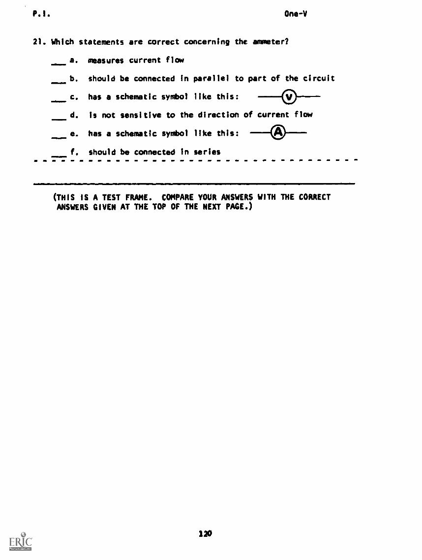
P.1. One -V
21. Which statements are correct concerning the ammeter?
a. measures current flow
b. should be connected In parallel to part of the circuit
c. has a schematic symbol like this:
d. is not sensitive to the direction of current flow
e. has a schematic symbol like this:
f. should be connected in series
(THIS IS A TEST FRAME. COMPARE YOUR ANSWERS WITH THE CORRECTANSWERS GIVEN AT THE TOP OF THE NEXT PAGE.)
120
One-V
ANSWERS - TEST FRAME 21
a - measures current flow
e - has a schematic symbol like this:
f - should be connected in series
IF ALL YOUR ANSWERS MATCH THE CORRECT ANSWERS, YOU MAY GO ON TOTEST FRAME 27. OTHERWISE, GO BACK TO FRAME 14 AND TAKE THEPROGRAMMED SEQUENCE BEFORE TAKING TEST FRAME 21 AGAIN.
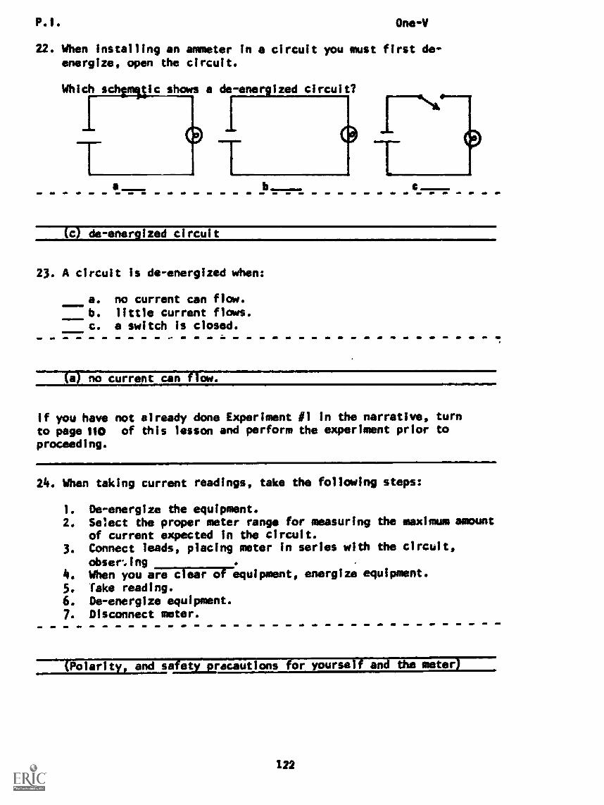
P.I. One-V
22. When installing an ammeter in a circuit you must first de-energize, open the circuit.
Which schanettic shows a de- energized circuit?
a C
(c) de-energized circuit
23. A circuit is de-energized when:
a. no current can flow.b. little current flows.c. a switch is closed.
(a) no current can flow.
If you have not already done Experiment 11 in the narrative, turnto page itD of this lesson and perform the experiment prior toproceeding.
24. When taking current readings, take the following steps:
1. De-energize the equipment.2. Select the proper meter range for measuring the maximum amount
of current expected in the circuit.3. Connect leads, placing meter in series with the circuit,
obseming4. When you aiVETZul7-Trequipment, energize equipment.5. Take reading.6. De-energize equipment.7. Disconnect meter.
(Polarity, and safety_precautions for yourself and the meter)
122
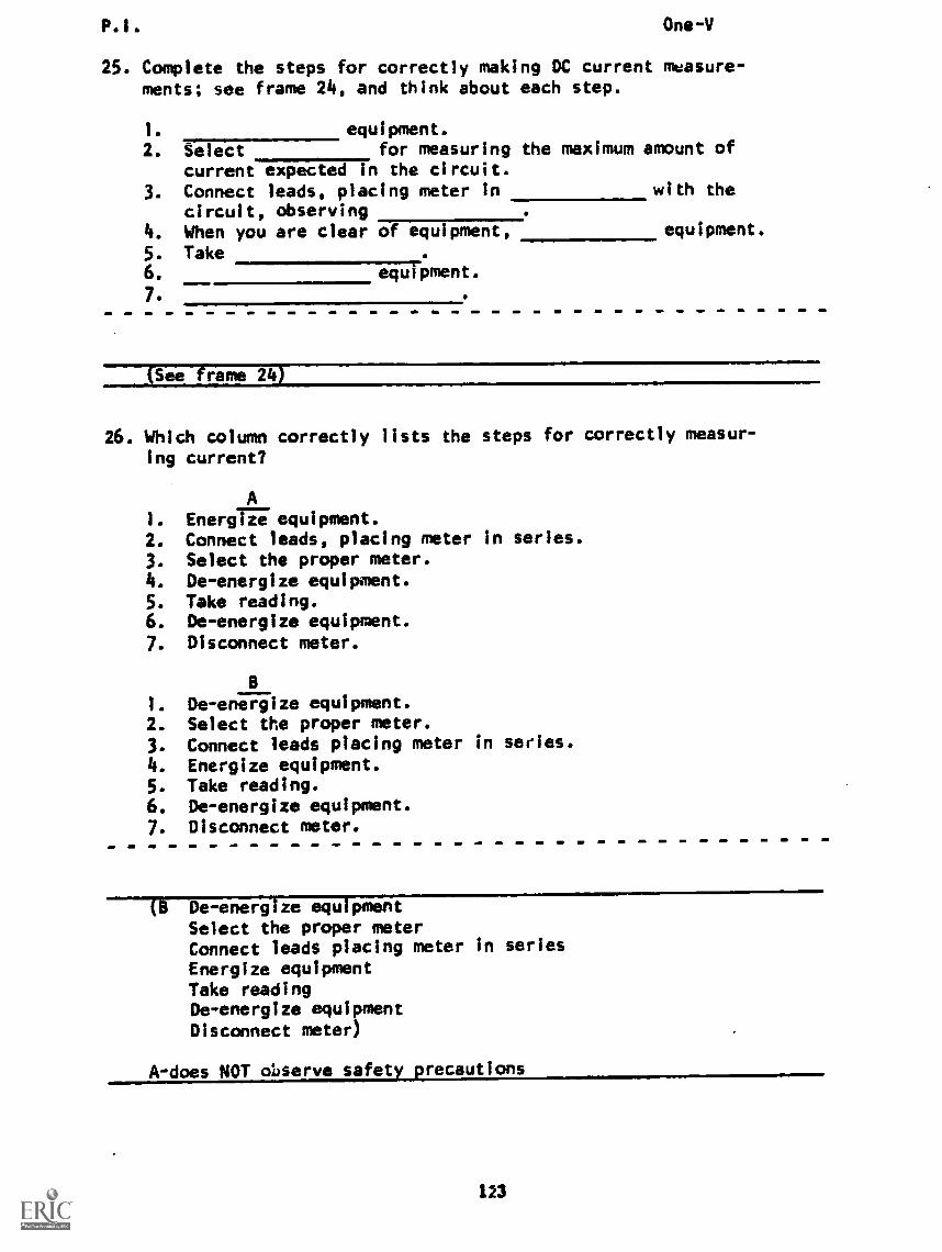
One-V
25. Complete the steps for correctly making DC current measure-ments; see frame 24, and think about each step.
1. equipment.2. Select for measuring the maximum amount of
current expected in the circuit.3. Connect leads, placing meter in with the
circuit, observing4. When you are clear of equipment, equipment.
5. Take6.
7.
equipment.
ee f rams 24
26. Which column correctly lists the steps for correctly measur-ing current?
A1. Energig equipment.2. Connect leads, placing meter in series.3. Select the proper meter.4. De-energize equipment.
5. Take reading.6. De-energize equipment.7. Disconnect meter.
B
I. De-energize equipment.2. Select the proper meter.3. Connect leads placing meter in series.
4. Energize equipment.
5. Take reading.6. De-energize equipment.7. Disconnect meter.
De -energ ze equ peent
Select the proper meterConnect leads placing meter in seriesEnergize equipmentTake readingDe-energize equipmentDisconnect meter)
A-does NOT observe safety precautions
123
P.1. One-V
27. Write out the steps required to properly connect an ammeter.
1.
2.
3.
4.
5.
6.
7.
(rHis is A TEST FRAME. COMPARE YOUR ANSWERS WITH THE CORRECTANSWERS GIVEN AT THE TOP OF THE NEXT PAGE.)
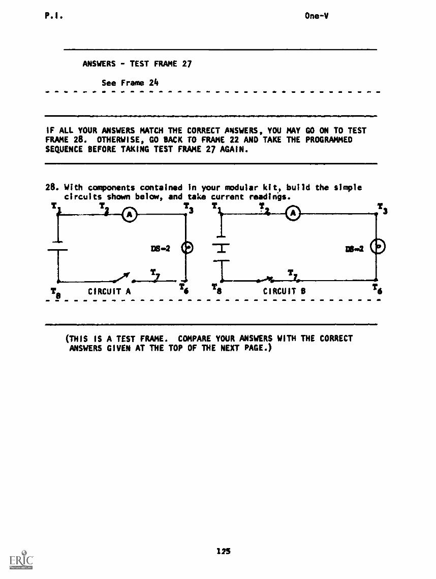
P.I. One-V
ANSWERS - TEST FRAME 27
See Frame 24
IF ALL YOUR ANSWERS MATCH THE CORRECT ANSWERS, YOU MAY GO ON TO TESTFRAME 28. OTHERWISE, GO BACK TO FRAME 22 AND TAKE THE PROGRAMMEDSEQUENCE BEFORE TAKING TEST FRAME 27 AGAIN.
28. With components contained in your modular kit, build the simplecircuits shown below, and take current readings.
T3
T
DS-2
Ts CIRCUIT AT6
T
T6
(THIS IS A TEST FRAME. COMPARE YOUR ANSWERS WITH THE CORRECTANSWERS GIVEN AT THE TOP OF THE NEXT PAGE.)
123
P.I. One-V
ANSWERS - TEST FRAME 28
The current in Circuit B should be greater than that ofcircuit A. If not, check with your instructor.
IF YOUR ANSWERS ARE CORRECT, YOU MAY TAKE THE PROGRESS CHECK, ORYOU MAY STUDY ANY OF THE OTHER RESOURCES LISTED. IF YOU TAKE THEPROGRESS CHECK AND ANSWER ALL THE QUESTIONS CORRECTLY, YOU HAVEMASTERED THE MATERIAL AND ARE READY TO TAKE THE MODULE TEST. SEE
YOUR INSTRUCTOR.
IF YOU DECIDE NOT TO TAKE THE PROGRESS CHECK AT THIS TIME, OR IF YOUMISSED ONE OR MORE QUESTIONS, STUDY ANY METHOD OF INSTRUCTION YOUWISH UNTIL YOU HAVE ANSWERED ALL THE PROGRESS CHECK QUESTIONS CORRECTLY.THEN SEE YOUR INSTRUCTOR AND ASK TO TAKE THE MODULE TEST.
126

SUMMARY
LESSON V
The Ammeter
Because we can neither see nor feel electrons, we must determine cur-rent by measuring some effect of the movement of charges. We coulduse the brightness of a lamp to do this, but the light bulbindicator has three major drawbacks:
1. We cannot easily record or compare readings.2. It is useful over a very limited range of currents only.3. The lamp takes too much of the electrons' energy
away from the work we want done in the circuit, therebydisturbing the circuit.
A device called an ammeter overcomes all three difficulties and isthe normal method for measuring current flow. The ammeter indicatesthe current flow through it by the position of a pointer in front ofits calibrated dial. The schematic symbol for an ammeter is:
An ammeter must be connected in series so that all the currentto irigalred flows through ft. The schematic diagram for acircuit with an ammeter connected is:
If you are satisfied with your understanding of the ammeter, read',Hooking Up an Ammeter" in the Narrative for this lesson, thenperform the experiment "Using an Ammeter" which follows it; if not,continue your study of Lesson V.
NOW YOU MY EITHER TAKE THE PROGRESS CHECK OR STUDY ANY OTHER OF THERESOURCES LISTED. IF YOU TAKE THE PROGRESS CHECK AND ANSWER ALLQUESTIONS CORRECTLY, YOU HAVE MASTERED THE MATERIAL AND ARE READYTO TAKE THE MODULE TEST. SEE YOUR INSTRUCTOR.
IF YOU DECIDE NOT TO TAKE THE PROGRESS CHECK AT THIS TIME, OR IF YOUMISSED ONE OR MORE QUESTIONS, STUDY ANY METHOD OF INSTRUCTION YOU WISHUNTIL YOU HAVE ANSWERED ALL THE PROGRESS CHECK ANSWERS CORRECTLY. THENSEE YOUR INSTRUCTOR AHD ASK TO TAKE THE MODULE TEST.
127