document resume ce 004 654 - eric · 2014-01-27 · document resume. ce 004 654. boatswain's...
TRANSCRIPT

ED 110 830
TITLE
INSTITUTION
REPORT NOPUB DATENOTEAVAILABLE FROM
DOCUMENT RESUME
CE 004 654
Boatswain's Mate F1 and C: Naval Rate TrainingManual.Naval Education and Training Command, Pensacola,Fla.NAVEDTRA-10304-C75347p.; Answer sheets not reproducibleSuperintendent of Documents, U.S. Government PrintingOffice, Washington, D.C. 20402 (Stock Number (manual)0502-LP-051-5210, (answer sheets)0502-LP-051-5211)
EDRS PRICE MF-$0.76 HC-$17.13 Plus PostageDESCRIPTORS Assignments; *Aviation Technology; Course Content;
Equipment Maintenance; *Fuels; IndividualInstruction; *Instructional Materials; *Job Training;*Manuals; Military Training; Post SecondaryEducation; Technical Education
IDENTIFIERS *Boatswain Mate F 1 and C; Navy
ABSTRACTThe Rate Training Manual and Nonresident Career
Course (RTM/NRCC) form a self-study package that enables AviationBoatswain's Mate F to fulfill the requirements for advancement toABF1 and the ABF1 for advancement to the rank of ABFC. In preparingfor advancement examinations, the manual should be studied inconjunction with Military Requirements for Petty Officers 1 and C,NavPers 10057 (series). Chapter one discusses the enlisted ratingstructure, the requirements for advancement, responsibilitiesinvolved in advancement, and various advancement opportunities.Chapters two through ten cover the following topics: aviation fuelsdivision afloat, JP-5 systems afloat, operation of the JP-5 system,gasoline systems afloat, aviation lube oil system, fuels divisionashore, quality assurance and surveillance, maintenance and repair,and administration. The document concludes with a subject index and a61-page course assignment booklet. (BP)
***************************************************************************
Documents acquired by ERIC include many informal unpublishedmaterials not available from other sources. ERIC makes every effortto obtain the best copy available. nevertheless, items of marginalreproducibility are often encountered and this affects the quality
****
* of the microfiche and hardcopy reproductions ERIC makes available *
* via the ERIC Document Reproduction Service (EDRS). EDRS is not *
* responsible for the quality of the original document. Reproductions *
* supplied by EDRS are the best that can be made from the original. *******************************************************1*****************

AVIATION
U.S DEPARTMENT OF HEALTH,EDUCATION & WELFARENATIONAL. INSTITUTE OF
EDUCATION
THIS DOCUMENT HAS BEEN REPRO-JOUCE0 EXACTLY AS RECEIVED FROMTHE PERSON OR ORGANIZATION ORIGIN-ATING IT POINTS OF VIEW OR OPINIONSSTATED DO NOT NECESSARILY REPRE-SENT OFFICIAL NATIONAL INSTITUTE OFEOUCATION POSITION OR POLICY
p BOATSWAIN'S MATE F 1 & C
RATE TRAINING MANUALAND NONRESIDENT CAREER COURSE
NO
NAVEDTRA 10304-C

NAVAL EDUCATION AND TRAINING PROGRAM DEVELOPMENT CENTERPENSACOLA, FLORIDA 32559
May 1975
Specific Instruction and Errata forRate Training Manual and Nonresident Career Course
AVIATION BOATSWAIN'S MATE F 1 &C, NAVEDTRA 10304-C
No attempt has been made to issue corrections for errors in typing,punctuation, etc., which are obvious to the enrollee and do notaffect the student's ability to answer the item.
Textbook, NAVEDTRA 10304-CMake the following change:
Preface, page i
75
Delete the last sentence of the thirdparagraph: "The NRCC is designated...successfully." Reason: This statementis in error as it conflicts with the"points" statement in the Naval ReserveRetirement box in the NRCC.
T-: r
003

PREFACE
The ultimate purpose of training Naval personnel is to produce acombatant Navy which can ensure victory at sea. A consequence of thequality of training given them is their superior state of readiness. Its result isa victorious Navy.
This Rate Training Manual and Nonresident Career Course (RTM/NRCC)form a self-study package that will enable ambitious Aviation Boatswain'sMate F to help themselves fulfill the requirements of their rating.
Designed for individual study and not formal classroom instruction, theRTM provides subject matter that relates directly to the occupationalqualifications of the Aviation Boatswain's Mate F rating. The NRCC providesthe usual way of satisfying the requirements for completing the RTM. Theset of assignments in the NRCC includes learning objectives and supportingitems designed to lead students through the RTM. The NRCC is designated amajor revision, and retirement point credit will be granted to NavalReservists who complete (or retake) it successfully.
This training Manual and nonresident career course was prepared by theNaval Education and Training Program Development Center, Pensacola,Florida, for the Chief of Naval Education and Training. Technical assistancewas provided by the Aviation Boatswain's Mate School, Lakehurst, NewJersey and the Naval Sea Systems Command.
1975 Edition
Published byNAVAL EDUCATION AND TRAINING SUPPORT COMMAND
Stock Ordering No.0502-LP-051-5210
UNITED STATESGOVERNMENT PRINTING OFFICE
WASHINGTON, D.C.: 1975

THE UNITED STATES NAVY
GUARDIAN OF OUR COUNTRYThe United States Navy is responsible for maintaining control of the seaand is a ready force on watch at home and overseas, capable of strongaction to preserve the peace or of instant offensive action to win in war.
It is upon the maintenance of this control that our country's gloriousfuture depends; the United States Navy exists to make it so.
WE SERVE WITH HONOR
Tradition, valor, and victory are the Navy's herifage from the past. Tothese may be added dedication, discipline, and vigilance as the watchwordsof the present and the future.
At home or on distant stations we serve with pride, confident in the respectof our country, our shipmates, and our families.
Our responsibilities sober us; our adversities strengthen us.
Service to God and Country is our special privilege. We serve with honor.
THE FUTURE OF THE NAVY
The Navy will always employ new weapons, new tecnniques, andgreater power to protect and defend the United States on the sea, underthe sea, and in the air.
Now and in the future, control of the sea gives the United States hergreatest advantage for the maintenance of peace and for victory in war.
Mobility, surprise, dispersal, and offensive power are the keynotes ofthe new Navy. The roots of the Navy lie in a strong belief in thefuture, in continued dedication to our tasks, and in reflection on ourheritage from the past.
Never have our opportunities and our responsibilities been greater.
ii005

CONTENTS
CHAPTER Page
1. Aviation Boatswain's Mate F Rating 1
2. Aviation fuels division afloat 11
3. JP-5 systems afloat 16
4. Operation of the JP-5 system 69
5. Gasoline systems afloat 94
6. Aviation lube oil system 134
7. Fuels division ashore 141
8. Quality assurance and surveillance 156
9. Maintenance and repair 208
10. Administration 252
INDEX 270
Qualifications for Advancement 276
Nonresident Career Course follows Qualifications for Advancement
CHAPTER 1
AVIATION BOATSWAIN'S MATE F RATING
This training manual is designed to aid theABF2 in preparing for advancement to ABI-1and the ABF1 in preparing for advancement toABFC. It is based primarily on the professionalrequirements or qualifications for ABFI andABFC, as specified in the Manual ofQualifications for Advancement, NavPers 18068(Series). In preparing for advancementexaminations, this manual should be studied inconjunction with Military Requirements forPetty Officers 1 & C, NavPers 10057 (Series).The latter covers the military requirements forall first class and chief petty officers.
ENLISTED RATING STRUCTURE
The present enlisted rating structure includestwo types of ratingsgeneral ratings and serviceratings.
GENERAL RATINGS are designed toprovide paths of advancement and careerdevelopment. A general rating identifies a broadoccupational field of related duties andfunctions requiring similar aptitudes andqualifications. General ratings provide theprimary means used to identify billetrequirements and personnel qualifications. Somegeneral ratings include service ratings; others donot. Both Regular Navy and Naval Reservepersonnel may hold general ratings.
Subdivisions of certain general ratings areidentified as SERVICE RATINGS. These serviceratings identify areas of specialization within thescope of a general rating. Service ratings areestablished in those general ratings in whichspecialization is essential for efficient utilizationof personnel. Although service ratings can existat any petty officer level, they are mostcommon at the P03 and P02 levels. Both
1
Regular Navy and Naval Reserve personnel mayhold service ratings.
ABF RATING
The ABF rating is a service rating and isincluded in Navy Occupational Group IX(Aviation). The general rating, AB, applies at theE-8 and E-9 levels.
Figure 1-1 illustrates all paths ofadvancement for an Airman Recruit to MasterChief Aviation Boatswain's Mate, WarrantOfficer (W-4), and Limited Duty Officer. Shadedareas indicate career stages where qualifiedenlisted personnel may advance to WarrantOfficer (W-1), and selected Warrant Officers mayadvance to Limited Duty Officer. Personnel inenlisted rates and ratings and warrant ranks notin a shaded area may advance only as indicatedby the arrows.
The Manual of Qualifications forAdvancement, NavPers 18068 (Series), statesthat ABF's operate, maintain, and repairaviation fueling and lubricating oil systems onaircraft carriers, including aviation fuel andlubricating oil service stations and pumprooms,piping, valves, pumps, tanks, and portableequipment related to the fuel system; operate,maintain, and repair the valves and pipingsystems within the Air Department spacesaboard carriers; supervise the operation andservicing of fuel pits, fuel farms, and equipmentassociated with the fueling and defueling ofaircraft ashore and afloat; operate and servicemotorized fueling equipment; maintain fuelquality assurance and surveillance in aviationfuel systems ashore and afloat; train, direct, andsupervise firefighting crews, fire rescue teams,
007

AVIATION BOATSWAIN'S MATE F I & C
WARRANTOFFICER
W-I
LDO
p// 0/ ///A cwo 4 cwo /
ASCM
ABCS
AlECE- T
ABE2E-5
ABE3E-4
WARRANT OFFICER INPUT ZONE
LDO INPUT ZONE
AIRMANE-3
APPRENTICEE-2
RECRUITE- I
Figure 1-1.Paths of advancement.
and damage control parties in assigned fuel andlubricating oil spaces; and observe and enforcefuel-handling safety precautions.
The aviation fuels chief supervises thepersonnel assigned to the aviation fuels division.ABF 1's are normally assigned to supervise flight
2(10R
195.1
deck and hangar deck fueling crews, theoperation and maintenance of equipmentassigned to the aviation fuels division, andoperational procedures. They also enforce safetyprecautions and assist the chief in theadministration of the division.

Chapter 1AVIATION BOATSWAIN'S MATE F RATING
On shore stations, senior ABF's may beassigned to supervise the operation of the mobilerefuelers.
A wide variety of assignments ashore isavailable to the ABF1 and ABFC. In addition tothe routine billets to which lower rated ABF'sare assigned, the ABF1 and ABFC are eligiblefor assignment to instructor duty as well as anumber of other desirable billets. Most of thesebillets are directly associated with training.Some of the more desirable billets to which theABF1 and ABFC may be assigned are describedin the following paragraphs.
1. Instructor duty is available to both theABF1 and ABFC in the ABF Schools atNATTC, Lakehurst, N. J. Another possibility forinstructor duty is at NATTC, Memphis,Millington, Tenn.
Instructor billets are normally tilled on avoluntary basis. Detailed information concerningassignment to instructor duty is contained in theEnlisted Transfer Manual, NavPers 15909(Series).
2. ABFC's are also eligible for assignment toduty with the Naval Education and TrainingProgram Development Center headquartered atPensacola, Florida, as a Technical Writer to assistin the preparation of Rate Training Manuals andNonresident Career Courses (formerly calledEnlisted Correspondence Courses) for the ABratings, and as an item writer in the preparationof Navy-wide advancement examinations forenlisted personnel.
For a listing of other special programs andprojects, reference should be made to theEnlisted Transfer Manual. Others are alsoannounced from time to time in BuPers Notices.
Personnel may indicate their desire forassignment to a specific program or project byindicating it in the "remarks" block of theirRotation Data Card.
In today's modern Navy there is an awesomearray of weapons and ships. Who can say whichone is the most important? It is a known factthat our modern carrier force, whether it be ourCVA's, CVS's, or CV's is one of the bigdeterrents to any world power thinking ofarmed conflict. The striking power and the
maneuverability of our carriers are what makethem so important in the defense of the freeworld.
This is why you as a senior petty officer inthe ABF rating should realize the importance ofyour position. You, as ABF's, play a veryimportant part in keeping your ship a fightingship.
As a rewlt of the Naval Leadership Programa considc table amount of material related tonaval leadership for the senior petty officer isavailable. Studying this material will make youaware of your many leadership responsibilities asa senior petty officer; and will also be of greathelp in developing leadership qualities. It willncc in itself, however, make you a good leader.Leadership principles can be taught, but a goodleader acquires that quality only through hardwork and practice.
As you study this material containingleadership traits, keep in mind that probablynone of our most successful leaders possessed allof these traits to a maximum degree, but aweakness in some traits was more thancompensated for by strength in others. Criticalself-evaluation will enable you to realize thetraits in which you are strong, and to capitalizeon them. At the same time you must constantlystrive to improve on the traits in which you areweak.
Your success as a leader will be decided, forthe most part, by your achievements in inspiringothers to learn and perform. This is bestaccomplished by personal example.
ADVANCEMENT
By this time, you are probably well aware ofthe personal advantages of advancementhigherpay, greater prestige, more interesting andchallenging work, and the satisfaction of gettingahead in your chosen career. By this time, also,you have probably discovered that one of themost enduring rewards of advancement is thetraining you acquire in the process of preparingfor advancement.
The Navy also profits by your advancement.Highly trained personnel are essential to thefunctioning of the Navy. By advancement, youincrease your value to the Navy in two ways:
3
k 009

AVIATION BOATSWAIN'S MATE F 1 & C
First, you become more valuable as a personwho can supervise, lead, and train others andsecond, you become more valuable as a technicalspecialist and thus make far-reachingcontributions to the entire Navy.
Since you are studying for advancement toP01 or CPO, you are probably already familiarwith the requirements and procedures foradvancement. However, you may find it helpfulto read the following sections. The Navy doesnot stand still. Things change all the time, and itis possible that some of the requirements havechanged since the last time you went up foradvancement. Furthermore, you will beresponsible for training others for advancement;therefore, you will need to know therequirements in some detail.
HOW TO QUALIFY FOR ADVANCEMENT
To qualify for advancement, a person must:
1. Have a certain amount of time in grade.2. Complete the required military and
professional training manuals.3. Demonstrate the ability to perform all
the PRACTICAL requirements for advancementby completing applicable portions of the Recordof Practical Factors, NavEdTra 1414/1(formerly NavPers 760).
4. Be recommended by his commandingofficer.
5. Demonstrate his KNOWLEDGE bypassing a written examination on (a) militaryrequirements, and (b) professionalqualifications.
Remember that the requirements foradvancement can change. Check with youreducational services office to be sure that youknow the most recent requirements.
When you are training lower rated personnel,it is a good idea to point out that advancementis not automatic. Meeting all the requirementsmakes a person ELIGIBLE for advancement.Such factors as the score made on the written
examination, length of time in service,performance marks, and quotas enter into thefinal determination of who will actually beadvanced.
HOW TO PREPARE FOR ADVANCEMENT
Preparation for advancement includesstudying the qualifications, working on thepractical factors, studying the required RateTraining Manuals, and studying any othermaterial that may be specified. To preparey ourself for advancement or to help othersprepare for advancement, you will need to befamiliar with (1) the "Quals" Manual, (2) theRecord of Practical Factors, NavEdTra1 4 1 4/1, (3) a NavEdTra publication calledBibliography for Advancement Study, NavEdTra10052 (Series) and (4) Rate Training Manuals.The following sections describe these materialsand give some information on how to use themto the best advantage.
"Quals" Manual
The Manual of Qualifications forAdvancement, NavPers 18068 (Series), gives theminimum requirements for advancement to eachrate within each rating. This manual is usuallycalled the "Quals" Manual, and thequalifications are of two general types: (1)military requirements, and (2) professional ortechnical qualifications. Military requirementsapply to all ratings rather than to any one ratingalone. Professional qualifications are technical orprofessional requirements that are directlyrelated to the work of each rating.
Both the military requirements and theprofessional qualifications are divided intosubject matter groups. Then, within each subjectmatter group, they are divided intoPRACTICAL FACTORS and KNOWLEDGEFACTORS.
The qualifications for advancement and abibliography of study materials are available inyour educational services office. The "Quals"Manual is changed more frequently than Rate
4010

Chapter 1AVIATION BOATSWAIN'S MATE F RATING
ing Manuals are revised. By the time you`ire studying this training manual, the "quals"may have been changed. Never trust any set of"quals" until' you have checked the changenumber against an UP-TO-DATE copy of the"Qua ls" Manual.
In training others for advancement,emphasize these three points about the "quals":
1. The "quals" are the MINIMUMrequirements for advancement. Personnel whostudy MORE than the required minimum willhave a great advantage when they take thewritten examinations for advancement.
2. Each "qua]" has a designated ratelevelchief, first class, second class, or thirdclass. You are responsible for meeting all"quals" specified for the rate level to which youare seeking advancement AND all "quals"specified for lower rate levels.
3. The written examinations foradvancement will contain questions relating tothe practical factors AND to the knowledgefactors of BOTH the military requirements andthe professional qualifications.
Record of Practical Factors
A special form known as the Record ofPractical Factors, NavEdTra 1414/1 for theappropriate rating, is used to record thesatisfactory performance of the practical factors.This form lists all military and all professionalpractical factors. Whenever a persondemonstrates his ability to perform a practicalfactor, appropriate entries must be made in theDATE and INITIAL columns. As a P01 or CPO,you will often be required to check the practicalfactor performance of lower rated personnel andto report the results to your supervising officer.
As changes are made periodically to the"Qua ls" Manual, new NavEdTra 1414/1 formsare provided when necessary. Extra space isallowed on the Record of Practical Factors forentering additional practical factors as they arepublished in changes to the "Qua ls" Manual.The Record of Practical Factors also providesspace for recording demonstrated proficiency inskills which are within the general scope of therate but which are not identified as minimum
qualifications for advancement. Keep this inmind when you are training and supervisingother personnel. If a person demonstratesproficiency in some skill which is not listed inthe "quals" but which is within the generalscope of the rate, report this fact to thesupervising officer so that an appropriate entrycan be made in that person's Record of PracticalFactors.
When you are transferred, the Record ofPractical Factors should be forwarded with yourservice record to your next duty station. It is agood idea to check and be sure that this form isactually inserted in your service record beforeyou are transferred. If the form is not in yourrecord, you may be required to start all overagain and requalify in practical factors that havealready been checked off. You should also takesome responsibility for helping lower ratedpersonnel keep track of their practical factorrecords when they are transferred.
A second copy of the Record of PracticalFactors should be made available to each man inpay grades E-3 through E-8 for his personalrecord and guidance.
NavEdTra 10052
Bibliography for Advancement Study,NavEdTra 10052 (Series) is a very importantpublication for anyone preparing foradvancement. This publication lists required andrecommended Rate Training Manuals and otherreference material to be used by personnelworking for advancement. NavEdTra 10052(Series) is revised and issued once each year bythe Naval Education and Training SupportCommand. Each revised edition is identified bya letter following the NavEdira number. Whenusing this publication, be SURE you have themost recent edition.
The required and recommended referencesare listed by rate level in NavEdTra 10052(Series). It is important to remember that youare responsible for all references at lower ratelevels, as well as those listed for the rate towhich you are seeking advancement.
Rate Training Manuals that are marked withan asterisk (*) in NavEdTra 10052 areMANDATORY at the indicated rate levels. Thecompletion requirements of a mandatory
5
nl1.2,1

AVIATION BOATSWAIN'S MATE F 1 & C
training manual may be satisfied by (1) passingthe appropriate Nonresident Career Course thatis based on the mandatory training manual, (2)passing locally prepared tests based on theinformation given in the mandatory trainingmanual, or (3) in some cases, successfullycompleting an appropriate Navy school.
When training personnel for advancement,do not overlook the section of NavEdTra 10052which lists the required and recommendedreferences relating to the military requirementsfor advancement. All personnel must completethe mandatory military requirements trainingmanual for the appropriate rate level before theycan be eligible to advance. Also, make sure thatpersonnel working for advancement study thereferences which are listed as recommended butnot mandatory in NavEdTra 10052. It isimportant to remember that ALL referenceslisted in NavEdTra 10052 may be used as sourcematerial for the written examinations, at theappropriate levels.
Rate Training Manuals
There are two general types of Rate TrainingManuals. Manuals (such as this one) are preparedfor most enlisted rates and ratings, givinginformation that is directly related to theprofessional qualifications for advancement.Basic manuals give information that applies tomore than one rate and rating.
Rate Training Manuals are revised from timeto time to bring them up to date. Thepublication, List of Training Manuals andCorrespondence Courses, NavEdTra 10061(Series), which is revised annually, contains alisting of current Rate Training Manuals andtheir identifying numbers. The letter followingthe number identifies the latest revision; forexample, -A indicates first revision, -B indicatessecond revision, etc.
Rate Training Manuals are designed for thespecial purpose of helping naval personnelprepare for advancement. By this time, you haveprobably developed your own way of studyingthese manuals. Some of the personnel you train,however, may need guidance in the use of RateTraining Manuals. Although there is no single"best" way to study a training manual, thefollowing suggestions have proved useful formany people:
1. Study the military requirements and theprofessional qualifications for your rate beforeyou study the training manual, and refer to the"quals" frequently as you study. Remember,you are studying the training manual primarilyto meet these "quals."
2. Before you begin to study any part of thetraining manual intensively, get acquainted withthe entire manual. Read the preface and thetable of contents. Check through the index.Thumb through the manual without anyparticular plan, looking at the illustrations andreading bits here and there as you see things thatinterest you.
3. Look at the training manual in moredetail, to see how it is organized. Look at thetable of contents again. Then, chapter bychapter, read the introduction, the he f, .gs, andthe subheadings. This will give you a pretty clearpicture of the scope and content of the manual.
4. When you have a general idea of what isin the training manual and how it is organized,fill in the details by intensive study. In eachstudy period, try to cover a complete unititmay be a chapter, a section of a chapter, or asubsection. The amount of material you cancover at one time will vary. If you know thesubject well, or if the material is easy, you cancover quite a lot at one time. Difficult orunfamiliar material will require more study time.
5. In studying each unit, write downquestions as they occur to you. Many peoplefind it helpful to make a written outline of theunit as they study, or at least to write down themost important ideas.
6. As you study, relate the information inthe training manual to the knowledge youalready have. When you read about a process, askill, or a situation, ask yourself some questions.Does this information tie in with pastexperience? Is this something new and different?How does this information relate to thequalifications for advancement?
7. When you have finished studying a unit,take time out to see what you have learned.Look back over your notes and questions.Without looking at the training manual, writedown the main ideas you have learned fromstudying this unit. Do not just quote themanual. If you cannot give these ideas in your
6
n12

Chapter 1AVIATION BOATSWAIN'S MATE F RATING
own words, the chances are that you have notreally mastered the information.
8. Use Nonresident Career Courseswhenever you can. These courses are based onRate Training Manuals or other appropriatetexts. As mentioned before, completionrequirements of a mandatory Rate TrainingManual can be satisfied by passing theNonresident Career Course based on the trainingmanual. You will probably find it helpful totake other courses, as well as those based onmandatory training manuals. Taking additionalcourses helps you to master the informationgiven in the training manuals, and also gives youan idea of how much you have learned.
INCREASED RESPONSIBILITIES
When you assumed the duties of a P03, youbegan to accept a certain amount ofresponsibility for the work of others. With eachadvancement, you accept an increasingresponsibility in military matters and in mattersrelating to the professional work of your rate.When you advance to P01 or CPO, you will finda noticeable increase in your responsibilities forleadership, supervision, training, working withothers, and keeping up with new developments.
As your responsibilities increase, your abilityto communicate clearly and effectively mustalso increase. The simplest and most directmeans of communication is a common language.The basic requirement for effectivecommunication is therefore a knowledge of yourown language. Use correct language in speakingand in writing. Remember that the basic purposeof all communication is understanding. To lead,supervise, and train others, you must be able trspeak and write in such a way that others canunderstand exactly what you mean.
Leadership and Supervision
As a P01 or CPO, you will be regarded as aleader and supervisor. Both officers and enlistedpersonnel will expect you to translate thegeneral orders given by officers into detailed,practical, on-the-job language that can beunderstood and followed by relativelyinexperienced personnel. In dealing with yourjuniors, it is up to you to see that they performtheir jobs correctly. At the same time, you mustbe able to explain to officers any important
problems or needs of enlisted personnel. In allmilitary and professional matters, yourresponsibilities will extend both upward anddownward.
Along with your increased responsibilities,you will also have increased authority. Officersand petty officers have POSITIONALauthority that is, their authority over otherslies in their positions. If your CO is relieved, forexample, he no longer has the degree ofauthority over you that he had while he wasyour CO, although he still retains the militaryauthority that all seniors have over subordinates.As a P01, you will have some degree ofpositional authority; as a CPO, you will haveeven more. When exercising your authority,remember that it is positionalit is the rate youhave, rather than the person you are, that givesyou this authority.
A Petty Officer conscientiously and proudlyexercises his authority to carry out theresponsibilities he is given. He takes a personalinterest in the success of both sides of the chainof command .. . authority and responsibility.The Petty Officer who does not seek out andaccept responsibility, loses his authority andthen the responsibility he thinks he deserves. Hemust be sure, by his example and by hisinstruction, that the Petty Officers under himalso accept responsibility. In short, he must bethe leader his titlePetty Officersays he is.Training
As a P01 or CPO, you will have regular andcontinuing responsibilities for training others.Even if you are lucky enough to have a group ofsubordinates who are all highly skilled and welltrained, you will still find that training isnecessary. For example, you will always beresponsible for training lower rated personnelfor advancement. Also, some of your bestworkers may be transferred, and inexperiencedor poorly trained personnel may be assigned toyou. A particular job may call for skills thatnone of your personnel have. These and similarproblems require that you be a trainingspecialistone who can conduct formal andinformal training programs to qualify personnelfor advancement, and one who can train.individuals and groups in the effective execution'of assigned tasks.

AVIATION BOATSWAIN'S MATE F 1 & C
In using this training manual, study theinformation from two points of view. First,what do you yourself need to learn from it? Andsecond, how would you go about teaching thisinformation to others?
Training goes on all the time. Every time aperson does a particular piece of work, somelearning is taking place. As a supervisor and as atraining expert, one of your biggest jobs is to seethat your personnel learn the RIGHT thingsabout each job so that they will not form badwork habits. An error that is repeated a fewtimes is well on its way to becoming a bad habit.You will have to learn the difference betweenoversupervising and not supervising enough. Noone can do his best work with a supervisorconstantly supervising. On the other hand, youcannot turn an entire job over to aninexperienced person and expect that person todo it correctly without any help or supervision.
In training lower rated personnel, emphasizethe importance of learning and using correctterminology. A command of the technicallanguage of your occupational field enables youto receive and convey information accuratelyand to exchange ideas with others. A personwho does not understand the precise meaning ofterms used in connection with his work isdefinitely at a disadvantage when he tries to readofficial publications relating to his work. He isalso at a great disadvantage when he takesexaminations for advancement. To train othersin the correct use of technical terms, you willneed to be very careful in your own use ofwords. Use correct terminology and insist thatpersonnel you are supervising use it too.
You will find the Record of PracticalFactors, NavEdTra 1414/1, a useful guide inplanning and carrying out training programs.From this record, you can tell which practicalfactors have been checked off for each personand which ones have not yet been done. Use thisinformation to plan a training program that willfit the needs of the personnel you are training.
0 n - t h e-j ob training is usually controlledthrough daily and weekly work assignments.When you are working on a tight schedule, youwill generally want to assign each person to thepart of the job that you know he can do best. Inthe long run, however, you will gain more byassigning personnel to a variety of jobs so that
8
(11 4
each person can acquire broad experience. Bygiving people a chance to do carefully supervisedwork in areas in which they are relativelyinexperienced, you will increase the range ofskills of each person and thus improve theflexibility of your working group.
Working with Others
As you advance to P01 or CPO, you willfind that many of your plans and decisionsaffect a large number of people, some of whomare not even in your own occupational field. Itbecomes increasingly important, therefore, foryou to understand the duties and theresponsibilities of personnel in other ratings.Every petty officer in the Navy is a technicalspecialist in his own field. Learn as much as youcan about the work of others, and plan yourown work so that it will fit into the overallmission of the organization.
Keeping Up WithNew Developments
Practically everything in the Navy p olicies,procedures, publications, equipment systemsissubject to change and development. As a P01 orCPO, you must keep yourself informed aboutchanges and new developments that affect youor your work in any way.
Some changes will be called directly to yourattention, but others will be harder to and. Tryto develop a special kind of alertness for newinformation. When you hear about anything newin the Navy, find out whether there is any wayin which it might affect your work. If so, findout more about it.
SOURCES OF INFORMATION
As a P01 or CPO, you must have anextensive knowledge of the references to consultfor accurate, authoritative, up-to-dateinformation on all subjects related to themilitary and professional requirements foradvancement.
Publications mentioned in this chapter aresubject to change or revision from time totimesome at regular intervals, others as the

Chapter 1AVIATION BOATSWAIN'S MATE F RATING
need arises. When using any publication that issubject to revision, make sure that you have thelatest edition. When using any publication that iskept current by means of changes, be sure youhave a copy in which all official changes havebeen made.
A list of training manuals and publicationsthat will be helpful as references and foradditional study in preparing for advancement isincluded in the reading list at the beginning ofthe text. Additional training manuals that areapplicable are available through youreducational services officer.
In addition to training manuals andpublications, training films furnish a valuablemurce of supplementary information. Films thatmay be helpful are listed in the U. S. Navy FilmCatalog, Nav Air 10-1-777.
ADVANCEMENT OPPORTUNITIES FORPETTY OFFICERS
Making chief is not the end of the line as faras advancement is concerned. Advancement toSenior (E-8) and Master (E-9) Chief, WarrantOfficer, and Commissioned Officer are amongthe opportunities that are available to qualifiedpetty officers. These special paths ofadvancement are open to personnel who havedemonstrated outstanding professional ability,the highest order of leadership and militaryresponsibility, and unquestionable moralintegrity.
PROFICIENCY PAY
The determination as to which Navy ratings,NEC's, and Special Duty Assignments areauthorized proficiency pay is accomplishedthrough an annual review, within the Bureau ofNaval Personnel. Those ratings, NEC's, or specialduty assignments which fulfill the Departmentof Defense criteria for an award of proficiencypay are included in a proposed fiscal yearProficiency Pay Program submitted to theSecretary of Defense for approval.
The Secretary of Defense has authorized twocategories of Proficiency Pay for Navypersonnel:
1. Shortage Specialty (Proficiency Pay). Amonthly amount of pay in addition any payand allowances to which otherwise entitled thatmay be awarded to an eligible enlisted memberwho possesses a critical rating or NEC. ShortageSpecialty pay is designed to assist in attainingand sustaining adequate career manning levels incritical ratings and NEC's.
2. Special Duty Assignment (ProficiencyPay). A monthly amount of pay in addition toany pay and allowances to which otherwiseentitled that may be awarded to an eligibleenlisted member who is assigned to certainspecial duties. Special Duty Assignment pay isdesigned to assist in attaining and sustaining anadequate volunteer manning level in the criticalspecial duty assignments.
ADVANCEMENT TO SENIORAND MASTER CHIEF
Chief petty officers may qualify for theadvanced grades of Senior and Master Chief.These advanced grades provide for substantialincreases in pay, together with increasedresponsibilities and additional prestige. Therequirements for advancement to Senior andMaster Chief are subject to change but, ingeneral, include a certain length of time in grade,a certain length of time in the naval service, arecommendation by the commanding officer,and a sufficiently high mark on the Navy-wideexamination. The final selection for Senior andMaster Chief is made by a regularly convenedselection board.
Examination Subjects
Qualifications for advancement to SeniorChief Petty Officer and Master Chief PettyOfficer have been developed and published inthe Manual of Qualifications for Advancement,NavPers 18068 (Series). They officially establishminimum military and professionalqualifications for Senior and Master Chief PettyOfficers.
The Bibliography for Advancement Study,NavEdTra 10052 (Series), contains a list ofstudy references which may be used to study forboth military and professional requirements.
V9 ni 5
AVIATION BOATSWAIN'S MATE F 1 & C
Satisfactory completion of the NonresidentCareer Course titled Military Requirements forSenior and Master Chief Petty Officer,NavEdTra 91209, is mandatory for advancementto E-8 and E-9.
When preparing for advancement to Senior(ABCS) or Master (ABCM) Chief, it is suggestedthat you study the additional material listed inStudy Guide for Aviation Boatswain's Mate E-8and E-9, NavPers 10114.
ADVANCEMENT TO WARRANTAND COMMISSIONED OFFICER
The Warrant Officer program providesopportunity for advancement to warrant rank
01 6 10
for E-6 and above enlisted personnel. E-6's, tobe eligible, must have passed an E-7 rating examprior to selection.
The LDO program provides a path ofadvancement from warrant officer tocommissioned officer. LDO's are limited, as arewarrants, in their duty, to the broad technicalfields associated with their former rating.
If interested in becoming a warrant orcommissioned officer, ask your educationalservices officer for the latest requirements thatapply to your particular case.

CHAPTER 2
AVIATION FUELS DIVISION AFLOAT
This chapter covers the organization, duties,and responsibilities of the aviation fuels divisionaboard aircraft carriers, amphibious assault(LPH), and amphibious transport dock (LPD)type ships.
TYPICAL V-4 DIVISIONORGANIZATION
It must be emphaszied that you willencounter many variations of AvFuels Divisonsafloat. This has been brought about by thedifferent types of ships employed by the Navythat must have the capability of fueling anddefueling aircraft. Regardless of the type of ship,keep in mind that the basic mission of thedivision remains the same: therefore, the basicdivision structure does not change. Some of thevariations you will be confronted with whenorganizing a division will be the number of menassigned to the division, the number and typesof aircraft embarked, and the tacticalemployment of your ship. The number of jobsand responsibilities of an AvFuels Division on anLPD remains the same as on a CVA. Thedifference is the number of personnel availableto perform the division's mission. (See fig. 2-1.)
AVIATION FUELS OFFICER
The basic function of the AvFuels Officer isto direct and supervise the fueling and defuelingof aircraft in accordance with instructions fromthe aircraft handling officer. Other equallyimportant duties and responsibilities are to:
1. Supervise and maintain records of theexpenditures of all aviation fuels and lubricating
oil and keep the aircraft handling officerinformed as to the amount of aviation fuelsrequired for replenishment.
2. Supervise aviation fuel replenishment,ensuring the proper connction of the fuelinghose and bonding wire and the proper operationof the fueling system. Also inform theofficer-of-the-deck and the supply officer on thequantity of fuel received at the completion ofthe operation.
3. Maintain an active quality assuranceprogram to ensure quality of the deliveredaviation fuels and lubricants.
4. Ensure compliance with all safetyregulations in the handling of aviation fuels andlubricating oil.
5. Supervise training of the V-4 divisionpersonnel.
6. A c t as division officer in theadministration of the V-4 division.
7. Supervise the maintenance and repair ofthe AvFuels systems.
8. Obtain the services of other thanAvFuels division personnel if assistance isrequired to repair certain equipment.
9. Direct the AvFuels division in handlingmalfunctions of the AvFuels and lube oilsystems.
10. Submit required reports.11. Initiate requisitions for general supplies,
repair parts, and equipment.12. Determine and report to the Aviation
Supply Officer the quantity and quality ofaviation fuels and aviation lube oil.
LEADING CHIEF PETTY OFFICER
The leading CPO is the senior CPO of thedivision, and all other CPO's of the division are

AVIATION BOATSWAIN'S MATE F 1 & C
Div SION
L CPO
DOTI ION
LPO
SUPPLY
0
DAMAGECONTROL
0
TRAINING
0QUALITY
ASSONANCEPO
REPAIRTEAM
PO
POLICE
0YEOMAN
REPAIR
CREW
COMPARTMENT
CLEANERS
FL OHTDEC(0
FUEL
CROWS
PHONE
TALKERS
FUEL
CHECKER
POMPROOMCREW
LUSOIL
CRC HOWDEL(PO
FILTERNOONCREW
FILTERROOMCREW
mum NOON CREWS ELIMINATED ON LP. A10Lro TYPE SNIPS THE FILTERS ON THESE SRNS MELOCATED AT FuELINIG STATICO4 OR IN PlINIPROOMS
11,LUSO& CREW WN.L OPERATE AND MANTAS,CLEANS,* SOLVENT STUDIO OM SNIPS SO [MAPPED
ON SNIPS NAVING SMALL DIVISIONS SONEOf THE MOVE JOSS MUST SE CONSINED
FUEL
OURS
Figure 2-1.Typical AvFuels Division Organization.
subordinate to him. He has authority over allenlisted personnel of the V-4 division andensures that the material upkeep andmaintenance of the aviation fuels systems areproperly performed. He is also responsible forensuring that the cleanliness of the spacesassigned to the division conform with the highstandards established for the ship. His specificduties are to:
1. Pursue a vigorous training program inaccordance with departmental and divisionalpolicies.
12
PooNE
TALKERS
FUEL
CNECNER
198.1
2. Maintain logs and submit reports asrequired.
3. Control the personal appearance of allpersonnel of the division.
4. Muster the division daily and make areport of this muster to the division officer.
5. Maintain an up-to-date watch, quarter,and station bill for the division.
6. Supervise the upkeep, repair, andcleaning of all assigned spaces and machinery.
7. Recommend to the division officer theassignment of men to billet numbers.

Chapter 2AVIATION FUELS DIVISION AFLOAT
8. Screen special requests, indicaterecommended or not recommended, andforward for approval or disapproval in theprescribed form.
9. Assist the division officer in thepreparation of Reports of Enlisted PerformanceEvaluation (NavPers 1616/18W for E-6 andbelow and NavPers 1616/8W for E-7 and above).
10. Advise the division officer when there isa need for an extension of the normal workingday to maintain material upkeep and cleanlinessof spaces to conform to division standards.
11. Disable vital machinery only afterpermission has been obtained from the divisionofficer.
12. Perform such other duties as directed byproper authority. An assistant leading CPO maybe assigned to the V-4 division, depending uponthe total number of ABFC's assigned to the airdepartment. The assistant leading CPO aids theleading CPO in all of the above duties and acts asthe leading CPO in his absence.
LEADING PETTY OFFICER
The aviation fuels leading petty officer isprimarily responsible for the administrativefunctioning of the division. During operationsinvolving the handling of aviation fuels, he actsas a roving supervisor to coordinate the activitiesof the entire division. The leading petty officeris the senior petty officer (other than CPO's)assigned to the division. All other petty officersare subordinate to him.
The specific duties and responsibilities of theleading petty officer correspond closely withthose of the leading CPO. These duties may beconsidered to be performed on a more personalbasis, in that the leading petty officer dealsdirectly with the junior petty officers and menin the division, and serves as liaison betweenthem and the leading CPO.
Some of the more important responsibilitiesof the leading petty officer are the maintenanceof the training program; enforcement of safetyregulations; and the upkeep of the divisionwatch, quarter, and station bill. The leadingpetty officer also prepares the division dailywatch list and ensures that all personnel standingthe aviation fuels security watch are properlyqualified.
(111 913
AVIATION FUELS BELOWDECKS PETTY OFFICER
The below decks petty officer supervises alloperations of related equipment located belowthe main deck. Specific duties andresponsibilities are as follows:
1. Supervise pumproom petty officers inoperations of JP-5, aviation gasoline, lube oil,contaminated lube oil, and auxiliary systems.
2. Supervise pumproom petty officers inoperation of filter rooms.
3. Supervise pumproom petty officers instripping of JP-5 tanks.
4. Act as aviation fuels control supervisorduring the receipt, transfer, and discharge of allaviation fuels.
5. Supervise all repairs and tests to aviationfuels equipment and spaces below the maindeck.
6. Supervise usage sequence so that JP-5 isused in accordance with tank cleaning schedule.
7. Ensure that damage control settings areproperly maintained at all times.
8. Ensure strict adherence to all safetyprecautions.
9. Supervise the cleaning of all assignedspaces.
10. Supervise and monitor sound poweredphone circuit.
11. Perform such other duties as may beassigned.
AVIATION FUELS FLIGHT ANDHANGAR DECK PETTY OFFICER
The aviation fuels flight and hangar deckpetty officers supervise the operation andmaintenance of the aviation fueling stations ontheir respective decks. His specific duties andresponsibilities are to:
1. Maintain a log on the fueling stations andsupervise the taking of fuel samples at fuelingstations as required by applicable instructions.
2. Ensure that all applicable safetyprecautions are observed.
3. Supervise the upkeep, repair, andcleaning of all fueling stations and other spacesassigned.

AVIATION BOATSWAIN'S MATE F 1 & C
4. Ensure that all men assigned arethoroughly instructed in their duties.
5. Obtain permission from the divisionofficer prior to performing any fueling ordefueling operations.
6. Ask the officer-of-the-deck to have the"smoking lamp" put out prior to performingany operation involving the handling of aviationfuel or making repairs.
7. Ensure that all men assigned are in properuniform.
8. Muster the fueling crews and any otherpersonnel assigned flight quarters stations inconnection with the fueling and defueling ofaircraft on the flight or hangar deck.
AVGAS AND JP-5 PETTY OFFICERS
The AvG as and JP-5 petty officers areresponsible for the operation and maintenanceof all below decks machinery and equipment oftheir respective systems. Specific dutiesperformed in their respective systems are to:
1. Maintain all logs and reports andsupervise the taking of fuel samples as required.
2. Ensure that all safety precautions andorders are strictly complied with, including thechecking of safety shields on flange joints inmachinery spaces.
3. Supervise the upkeep, repair, andcleaning of all machinery and spaces assigned.
4. Supervise and instruct all assignedpersonnel in the proper operation and repair ofmachinery and equipment.
5. Obtain permission from the divisionofficer before undertaking any major repairs.
6. Ensure proper ventilation in fuelpumprooms and filter rooms.
7. Ensure that only authorized personnelare permitted in aviation fuel spaces.
8. Ensure that all damage control settingsare correct at all times.
9. Perform such other duties as may beassigned.
AVIATION FUELS REPAIRTEAM PETTY OFFICER
The repair team petty officer supervises themaintenance of the aviation fuels systems on the
14020
main deck and above. Specific duties andresponsibilities include the following:
1. Maintain a master maintenance log ofthe aviation fuels systems.
2. Ensure the proper handling and stowageof tools and spare parts and aviation fuel testingand emergency equipment under the custody ofthe V-4 division.
3. Supervise the upkeep and cleanliness ofrepair team shop and stowage spaces.
4. Ensure that all men assigned arethoroughly instructed in their duties.
5. Ensure that all safety, testing, andemergency equipment is in proper workingcondition.
6. Ensure that all safety precautions areobserved.
7. Conduct maintenance and repair of allaviation fueling equipment above the main deck.
8. Supervise the stowage and issue ofdivision cleaning gear.
9. Assume the duties of the divisiondamage control petty officer during his absence.
10. Conduct periodic checks on sparesound-powered telephone sets.
11. Perform such other duties as may beassigned.
LUBE OIL PETTY OFFICER
The lube oil petty officer supervises alloperations and maintenance of the aviation lubeoil system. His specific duties andresponsibilities are to:
1. Supervise the operation of the aviationlube oil system and the distribution of lube oil.
2. Supervise replenishment of the aviationlube oil system.
3. Train assigned personnel in safe workhabits and in the proper operation of the lubeoil system.
4. Supervise the maintenance, repair, andcleaning of all assigned machinery and spaces.
5. Obtain permission from the divisionofficer prior to making any major repairs.

Chapter 2AVIATION FUELS DIVISION AFLOAT
6. Perform such other duties as may beassigned.
OTHER ADMINISTRATIVEPERSONNEL
Other key billets of an aviation fuels divisioninclude the education and training petty officer,the safety petty officer, the damage controlpetty officer, quality assurance petty officer,and the police petty officer. These billets aregenerally filled by ABF2's and ABF3's and maybe assigned as a collateral duty. When assigningpersonnel to these billets, the senior ABF shouldchoose the most qualified personnel availableand ensure that they are properly trained andchecked out in their assigned duties. This assuresa smooth running division and relieves the seniorpetty officers of many small details in order thattheir attention may be directed to the moreimportant duties.
AVIATION FUELSSECURITY WATCH
One of the most important functions of theAv Fuels division is the proper standing of theaviation fuels security watch. This watch isstood 24 hours a day when the ship is not at
15
flight quarters. Only qualified personnel fromthe Av Fuels division will stand this watch andevery effort should be put forth by the divisionpolice petty officer to ensure that thewatch-standers understand the importance oftheir watch. The Av Fuels security watch isresponsible for the security of the Av Fuelssystem. To ensure that the system is secure, hemust:
1. Make hourly inspections of alldesignated spaces and piping.
2. Immediately notify the Av Fuels Officer,Air Department Integrity Watch Officer, andOOD if discrepancies are noted.
3. Make hourly reports to the OOD (AirDepartment Integrity Watch Officer if squadronsare embarked).
4. Insert entries in appropriate logbooks oneach inspection tour.
5. Safeguard against any welding or burningnear the Av Fuels system unless the system hasbeen properly freed of fuel and vapors.
6. Ensure compliance with all safetyprecautions.
7. Perform such other duties as may beassigned.
NOTE: If manning levels permit, thesecurity watch should be a two-man watch toensure the safety of personnel involved.
(121
CHAPTER 3
JP-5 SYSTEMS AFLOAT
The majority of JP-5 fueling systemsinstalled aboard carriers today were convertedfrom the original high capacity aviation gasolinesystem. This is true for the CVA's constructedprior to the USS KITTY HAWK (CVA-63), allCVS's, and even some of the older LPH's. Eventhe newer systems on our most modern carrierswere designed along the same lines as theseconversions.
In order to give the broadest possiblecoverage of all the different types of systems (asto size, scope, and capacities) with a minimumof repetition, it will first be necessary to brieflyreview the history of the aviation fuel systems.
The CV-33 type system (commonly referredto as the low capacity system), capable ofdispensing aviation gasoline at a maximum rateof only 1,000 gpm (500 gpm forward and 500gpm aft), was adequate for World War II typeaircraft. (See fig. 3-1.) However, as aircraftincreased in size and speed, thereby requiring alarger quantity of fuel, it became necessary toincrease the stowage capacity of the aviationfuel system and the rate at which aircraft couldbe refueled.
The original high capacity aviation gasolinesystem was designed for this increased capacity.(See fig. 3-2.) The stowage tanks for this systemwere basically the same as the low capacitysystem tanks, though larger, and arranged in thesame manner. They were located below the firstplatform decktwo sets forward and two setsaft (one set on either side of the centerline).
Sea water for this system was provided byfour 600 gpm sea water pumps in eachpumproom. The pumps were fed directly from asea chest located in the bottom of the ship. Thedischarge from these pumps was directed to theouter tank sea water supply risers and the
16
A22
overboard discharge. An elevated loop in theoverboard discharge established the requiredhead of pressure to force the gasoline out of thetanks to the AvGas pumps. The loop also limitsthe amount of pressure that could be applied tothe tank structure. This makes it independent ofthe ship's fire main system and eliminates theuse of the sea water gravity tank. Additionallines are provided for flushing, draining, andsteaming the tanks.
The gasoline side of the system was alsoenlarged. Four 675 gpm aviation gasolinebooster pumps were installed in eachpumproomtwo pumps for each distributionriser. The distribution risers (that section ofpiping from the pumproom to the flight andhangar decks) were increased to 6 inches indiameter. Each distribution riser contained anautomatic pressure-regulating system, a forwardand reverse flowmeter, and a high-capacity filter,plus several aircraft service stations designed tofuel and defuel aircraft simultaneously.
The distribution risers were divided into fourquadrants: quadrant 1 forward, starboard;quadrant 2 forward, port; quadrant 3 a ft ,starboard; and quadrant 4 a f t , port. All fourquadrants were cross-connected to enable anyaircraft service station to be supplied from anystowage tank. This system had a maximumdelivery rate of aviation gasoline (115/145) of1,200 gpm per quadrant.
The aviation fueling systems originallyinstalled on the first four super carriers (CVA59, 60, 61 and 62) were identical to the onepreviously described except for their stowageand distribution capabilities. These carriersemployed six sets of saddle-type stowage tanks,four sets forward and two sets aft. The aviationgasoline booster pumps had a rated capacity of

Chapter 3JP-5 SYSTEMS AFLOAT
OVERBOARDDISCHARGE
DOUBLE-WALLEDPIPING
WATER TURBINEPUMP
FIRE MAIN
ELECTRICALLYDRIVEN PUMP
-GLOBE VALVE3>II GATE VALVE
4.=---P ONE WAY CHECK VALVE
PRESSURE REDUCINGNALVE
:c1cr STOP LIFT CHECK VALVE
>T<r DIAPHRAGM VALVE(PRESSURE REGULATOR)
I= SALT WATER IMO GAS
1:kr AUTOMATIC VALVE
3)` :r STOP CHECK VALVE
FLOAT VALVE
RELIEF VALVE
PLUG VALVE
EDUCTOR
Co
r SPECTACLE FLANGE
r ORIFICE
THERMOMETER
SIGHT GLASS GAGE
o.
oA COMPOUND GAGETyr (VACUUM AND PRESSURE)
PRESSURE GAGE
Figure 3-1.Low capacity aviation gasoline system.
17 023
198.2

AVIATION BOATSWAIN'S MATE F 1 & C
(B)
FORWARD LEG
OUTBOARDDISTRIBUTIONMAINS
DOUBLE-WALLEDPIPING
CROSS-OVERVA VES
AFTER LEGTHIRD DECK
SEA WATERPUMPS
SEACHEST
FOURTH DECK
OUTER TANKSEA WATERSUPPLY RISERS
Figure 3-2.High ccity aviation gasoline system.
(124¶4
18
FIRST PLATFORM
AVGAS
IIIII SEA WATER
198.3

Chapter 3JP-5 SYSTEMS AFLOAT
1,100 gpm and the sea water pumps 1,000 gpm.The distribution risers were also enlarged to 8inches in diameter. These systems had amaximum delivery rate of aviation gasoline(115/145) of 2,000 gpm per quadrant.
The first major change to the aviation highcapacity gasoline system was the introduction ofjet mix. (See fig. 3-3.)
When jet aircraft first became operational inthe fleet, they burned 115/145 aviation gasoline.The "original" high capacity system was capableof effectively refueling this new high-speedaircraft but the stowage capacity for Av Gas wasfound to be insufficient for jet aircraft operatingon an around- the -clock schedule during theKorean War. Since an increase in the protectedfuel storage space was not practical, a fuel whichcould be stored in unprotected tanks wasdeveloped. This fuel was JP-5, a special, highflashpoint (140 degrees F) kerosene. As aninterim measure until all jet engines could betested and approved for operation on JP-5 fuel,a system was devised for blending one part ofAvGas with two parts of JP-5 to make a fuelcalled "Jetmix" which had volatilitycharacteristics similar to the JP-3 and JP-4 fuelsused at shore stations.
A number of ship's black oil tanks wereconverted to JP-5 stowage tanks. These tankswere arranged in two groups, one group forwardand one group aft. Each group had an equalnumber of port and starboard tanks. Althoughthe normal stowage capacity of ship's black oilfuel was decreased somewhat, the ship's rangewas not affected, as JP-5 could, in anemergency, be used as boiler fuel. Consequently,some means had to be provided to deliver JP-5to the engineers in the event of this emergency.Eight amidship wing tanks (4 port and 4
198.4Figure 3-3.--Jet mix aviation gasoline (tank arrangement/.
starboard, 2 per boilerroom), which arenormally empty voids, were designated asEMERGENCY SERVICE TANKS for thispurpose. A transfer main running fore and aftinterconnected the forward and after group ofJP-5 stowage tanks and the emergency servicetanks. A number of filling connections installedon the port and starboard side of the hangardeck were interconnected with the transfer mainby downcomers.
Four JP-5 transfer pumps Were installed onthe seventh deck level, two forward and two aft.These pumps were of the 1,000 gpm at 100 psicentrifugal type. (See Worthington JP-5 pump,fig. 3-4.) A blender was installed in eachaviation gasoline pumproom (first platform).The suction header of the transfer pumps wasconnected to the fore and aft transfer main. Thedischarge header was connected to one side ofthe blender. The piping in the aviation gasolinepumproom was modified to enable the starboardAvGas pumps to discharge into the other side ofthe blender.
JP-5 was received aboard through the hangardeck filling connections and directed via thetransfer main to the forward and after group ofstowage tanks. An equal number of port andstarboard tanks were filled as a unit. After theJP-5 was allowed to settle for a prescribed lengthof time, it was stripped of all water and solids.The existing black oil stripping system wasutilized for this purpose.
The transfer pumps then took suction froman equal number of port and starboard stowagetanks and discharged into one side of theblender. Only one pump in each pumproom wasused for this operation. The other wasdesignated as a standby. Simultaneously, one ofthe starboard AvGas pumps was used to transferaviation gasoline from the starboard set ofAvGas tanks to the other side of the blender.The end result, JET MIX, was then stowed inthe port AvGas tanks both forward and aft. Asthe JP-5 stowage tanks were emptied, they couldbe ballasted with sea water if necessary.
The port AvGas pumps and the portquadrants 2 and 4 were used to dispense jet mixto jet aircraft on the port side only. Allcross-connecting piping between the port andstarboard quadrants were blanked off. With theaddition of the wing stowage tanks, the jet mix

AVIATION BOATSWAIN'S MATE F 1 & C
6-INCHDISCHARGE
0-INCHSUCTION
NASH VACUUMPRIMING
PUMP PRIMING VALVE
SEAL TANK(FRESH WATER)
VENT
LEVEL GAGE
Figure 3-4.Worthington JP-5 transfer pump.
system resulted in a substantial increase in theoverall aircraft fuel capacity of the carrier.
The conversion of all jet engines to operateefficiently on JP-5 alone caused the jet mixsystem to become obsolete. However, theconversion from the jet mix system to theinterim aviation fuel system was comparativelysimple. (See fig. 3-5.) Four of the existing wingstowage tanks, two forward (I port and I
starboard) and two aft (1 port and I starboard),were converted to and designated as JP-5 servicetanks. A separate filling and a separate suctionline and a hand-operated stripping pump wereinstalled in these tanks. The sea water ballastconnections were removed.
NOTE: JP-5 service tanks are never ballastedwith sea water.
Stripping JP-5 stowage tanks with the blackoil stripping system proved time-consuming andwasteful and an independent JP-5 strippingsystem was installed. This system had fourstripping pumpstwo forward and two aft.These pumps served to strip the JP-5 stowageand service tanks of water and solids. Theblenders were removed from the aviationgasoline pumprooms. The existing JP-5 pumpdischarge header was connected directly to theport distribution risers in the aviation gasolinepumproom. The port saddle tanks were returned
20
026
198.5
198.6Figure 3-5.Interim JP-5 system (tank arrangement/.
for storage of aviation gasoline. The two aviationgasoline pumps that were used for delivery of jetmix were returned as standby aviation gasolinepumps in the starboard quadrant. One of theJP-5 pumps in each pumproom was designatedas a transfer pump and the other as a servicepump. A first-stage filter (fig. 3-6) was installedbetween the transfer pumps and the servicetanks. The piping to the inlet side of the filterwas orificed to limit the flow to 200 gpm.
JP-5 was received aboard in the same manneras in the jet mix system. After it had beenallowed to settle for a prescribed period of time,it was stripped of all water and solids andtransferred via the transfer filter to the servicetanks. After the JP-5 in the service tanks hadsettled for a second prescribed period of time, itwas again stripped of any water or solids

Chapter 3JP-5 SYSTEMS AFLOAT
198.7Figure 3-6.Transfer filters.
remaining. The clean, water-free JP-5 was thenpumped from the service tanks through servicefilters on the 3rd deck to jet aircraft on theflight and hangar decks, via the port quadrant.The piping and valves were so arranged thateither of the two existing pumps in eachpumproom could be used for transfer or servicein an emergency, but one pump in eachpumproom was designated as a transfer pumpand the other as a service pump.
When attack and fighter aircraft becamepredominantly jet-engined aircraft in the fleet, itwas obvious that the CVA-class carriers requireda maximum stowage and distribution of JP-5and a limited stowage and distribution ofaviation gasoline. The ultimate JP-5 System(CVA) conversion from the "interim" was acomplex one. (See fig. 3-7.) The forwardaviation gasoline pumproom was eliminated. The
21
198.8Figure 17.Ultimate fuel system (tank arrangement).
forward aviation gasoline stowage tanks wereconverted to JP-5 stowage and/or service tanks.The forward starboard aviation gasolinequadrant became a JP-5 quadrant. The after portaviation gasoline storage tanks were converted toJP-5 service tanks. The after starboard aviationgasoline quadrant remained the same, except forthe removal of two aviation gasoline and two seawater pumps which were not required. Thisconversion gave a three-quadrant delivery ofJP-5 and one of aviation gasoline.
The USS KITTY HAWK (CVA-63) was thefirst carrier constructed from the keel up withan original high capacity JP-5 fueling system.The type JP-5 system installed on this, and allnewly constructed CVAs thereafter, has a fourquadrant delivery of JP-5 and limited stowageand distribution of Av Gas for servicingpiston-type aircraft on the starboard side only.Except for the additional quadrant and minorchanges to the distribution piping to incorporatea newly developed service station (Cla-Val),these systems are practically identical to andpatterned after the CVA-59 conversions. Nofurther information is given for this system here,as it is discussed in detail later in the chapter.
Not all "interim" systems were converted tothe CVA system. The operational demand of ourcarrier fleet required low-speed, long-range,antisubmarine, hunter-killer type aircraft. At thepresent time, only reciprocatingengined
027
AVIATION BOATSWAIN'S MATE F 1 & C
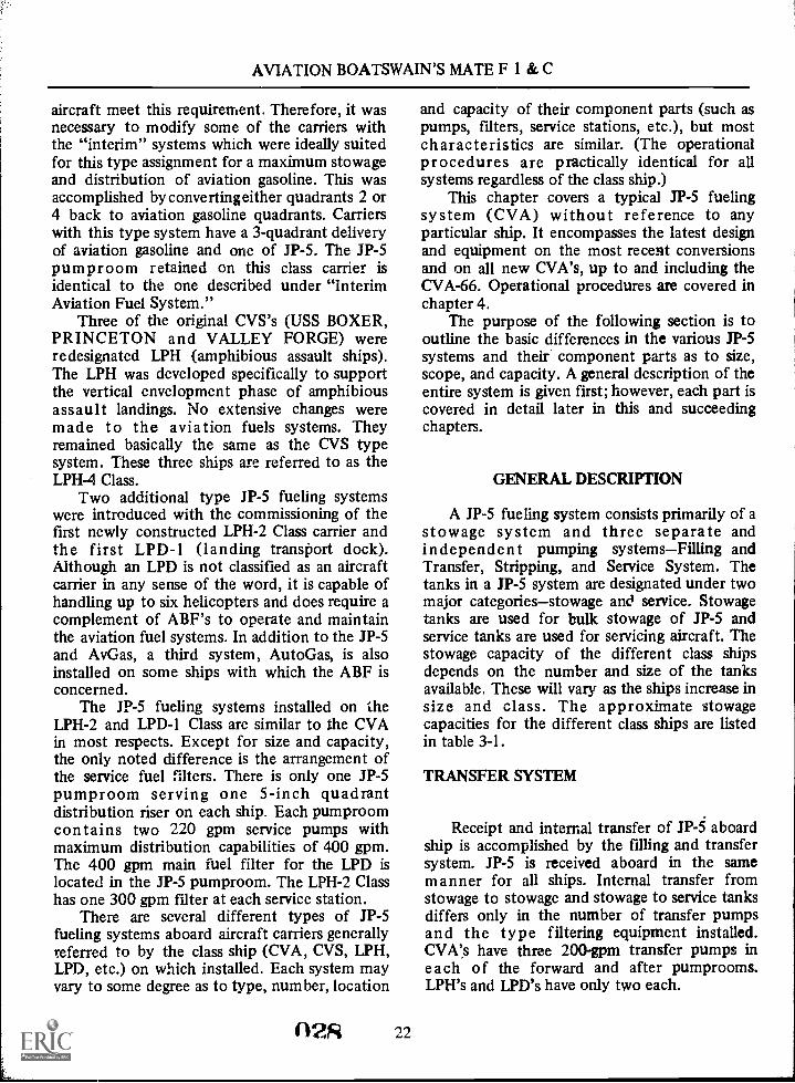
aircraft meet this requirement. Therefore, it wasnecessary to modify some of the carriers withthe "interim" systems which were ideally suitedfor this type assignment for a maximum stowageand distribution of aviation gasoline. This wasaccomplished byconvertingeither quadrants 2 or4 back to aviation gasoline quadrants. Carrierswith this type system have a 3-quadrant deliveryof aviation gasoline and one of JP-5. The JP-5pumproom retained on this class carrier isidentical to the one described under "InterimAviation Fuel System."
Three of the original CVS's (USS BOXER,PRINCETON and VALLEY FORGE) wereredesignated LPH (amphibious assault ships).The LPH was developed specifically to supportthe vertical envelopment phase of amphibiousassault landings. No extensive changes weremade to the aviation fuels systems. Theyremained basically the same as the CVS typesystem. These three ships are referred to as theLPH-4 Class.
Two additional type JP-5 fueling systemswere introduced with the commissioning of thefirst newly constructed LPH-2 Class carrier andthe first LPD-1 (landing transport dock).Although an LPD is not classified as an aircraftcarrier in any sense of the word, it is capable ofhandling up to six helicopters and does require acomplement of ABF's to operate and maintainthe aviation fuel systems. In addition to the JP-5and AvGas, a third system, AutoGas, is alsoinstalled on some ships with which the ABF isconcerned.
The JP-5 fueling systems installed on theLPH-2 and LPD-I Class are similar to the CVAin most respects. Except for size and capacity,the only noted difference is the arrangement ofthe service fuel filters. There is only one JP-5pumproom serving one 5-inch quadrantdistribution riser on each ship. Each pumproomcontains two 220 gpm service pumps withmaximum distribution capabilities of 400 gpm.The 400 gpm main fuel filter for the LPD islocated in the JP-5 pumproom. The LPH-2 Classhas one 300 gpm filter at each service station.
There are several different types of JP-5fueling systems aboard aircraft carriers generallyreferred to by the class ship (CVA, CVS, LPH,LPD, etc.) on which installed. Each system mayvary to some degree as to type, number, location
02R 22
and capacity of their component parts (such aspumps, filters, service stations, etc.), but mostcharacteristics are similar. (The operationalprocedures are practically identical for allsystems regardless of the class ship.)
This chapter covers a typical JP-5 fuelingsystem (CVA) without reference to anyparticular ship. It encompasses the latest designand equipment on the most recent conversionsand on all new CVA's, up to and including theCVA-66. Operational procedures are covered inchapter 4.
The purpose of the following section is tooutline the basic differences in the various JP-5systems and their component parts as to size,scope, and capacity. A general description of theentire system is given first; however, each part iscovered in detail later in this and succeedingchapters.
GENERAL DESCRIPTION
A JP-5 fueling system consists primarily of astowage system and three separate andindependent pumping systemsFilling andTransfer, Stripping, and Service System. Thetanks in a JP-5 system are designated under twomajor categoriesstowage and service. Stowagetanks are used for bulk stowage of JP-5 andservice tanks are used for servicing aircraft. Thestowage capacity of the different class shipsdepends on the number and size of the tanksavailable. These will vary as the ships increase insize and class. The approximate stowagecapacities for the different class ships are listedin table 3-1.
TRANSFER SYSTEM
Receipt and internal transfer of aboardship is accomplished by the filling and transfersystem. JP-5 is received aboard in the samemanner for all ships. Internal transfer fromstowage to stowage and stowage to service tanksdiffers only in the number of transfer pumpsand the type filtering equipment installed.CVA's have three 200-gpm transfer pumps ineach of the forward and after pumprooms.LPH's and LPD's have only two each.

Chapter 3-1P-5 SYSTEMS AFLOAT
Table 3-1.Stowage capacities.
Class ship Approximate capacity
LPD-3 (LA SALLE) 1/4 million gallons
LPH-2 (IWO JIMA) % million gallons
CVA-19 and 34(HANCOCK &ORISKANY) '/2 million gallons
CVA-41 (MIDWAY) 1 million gallons
CVA-59(FORRESTAL) 1 '/2 million gallons
CVA-63 (KITTYHAWK) 1 3/4 million gallons
CVA (N)-65(ENTERPRISE) 2 1/4 million gallons
CVA-66 (AMERICA) 21/4 million gallons
CVA-67 (JOHN F.KENNEDY) 2'h million gallons
190.103
The two types of filtering equipment(located between the transfer pumps and servicetanks) presently being used in the transfersystem are the 300 gpm transfer filters and the200 gpm centrifugal purifiers. The transferfilters were the first to be used in the system.They are of the same type referred to in theinterim system. Filters are rated at 300 gpm bythe manufacturer, but were reduced to 200 gpmby the Navy to ensure a more efficient operationand longer life of the elements. The LPD-3 classhas two filters of this type installed in theirtransfer system. The centrifugal purifier isreplacing the transfer filters. They are designedto remove water and solids by centrifugal force.CVA's and LPH-2 Class carriers have twopurifiers in each JP-5 pumproom. Regardless ofthe type filtering equipment installed, themaximum pumping rate from stowage to servicetanks is 400 gpm per pumproom for all systems.
23
STRIPPING SYSTEM
The motor-driven stripping system is used toremove water and sludge and to completelyempty the tanks. The arrangement of thissystem is basically the same for all ships. CVA'sand the LPH-2 Class carriers have two strippingpumps in each JP-5 pumproom. The LPD-3 Classhas only one stripping pump.
SERVICE SYSTEM
Of the three different pumping systems thatmake up a JP-5 fueling system, the most noteddifferences will be found in the service system.The arrangement of this system not only differsfor the different class ships but also within eachclass, depending on the type service stationinstalled. The service system encompasses allpiping, valves, and related equipment (such aspressure regulator, service fuel filter, and servicestations necessary to safely deliver the cleanestpossible fuel from the service tanks to theaircraft). The number and size of the quadrantdistribution risers and the distributioncapabilities of the different class ships are shownin table 3-2.
PUMPS
Pumps in the JP-5 pumprooms are dividedinto three major categoriesservice, transfer,and stripping. The most common service pumpused in the fleet is the centrifugal type. Thereare three different capacities:
1,100 gpm (on CVA-59 Class and up)675 gpm (on CVA-43 and below)
220 gpm (on LPH's and LPD's)
The most common transfer pumps used in thevarious systems are the rotary-vane and rotarygear with a rated capacity of 200 gpm at 50 psi.
There are two types of stripping pumps inuse in the JP-5 systemthe rotary-vane typewith a capacity of 50 gpm at 50 psi, and theinternal rotary gear with a capacity of 46 gpm at50 psi.
029

AVIATION BOATSWAIN'S MATE F 1 & C
Table 3-2.JP-5 distribution capabilities.
Class Number Size quad. No. pumps Capacity Capacitycarrier quadrants dist. riser per quadrant ea. pump ea. quadrant
LPD-3 1 5 in. 2 220 gpm 400 gpm
LPH-2 1 5 in. 2 220 gpm 400 gpm
CVA-19 3 6 in. 2 675 gpm 1,200 gpm
CVA-34 3 6 in. 1 1,000 gpm 900 gpm
CVA-41 and 42 3 6 in. 2 675 gpm 1,200 gpm
CVA-43 4 6 in. 2 675 gpm 1,200 gpm
CVA-59, 60, 61and 62 3 8 in. 2 1,100 gpm 2,000 gpm
CVA-63-67 4 Bin. 2 1,100 gpm 2,000 gpm
PRESSURE REGULATOR
There is an automatic pressure-regulatingsystem installed in each JP-5 quadrantdistribution riser except on carriers equippedwith the Cla-Val fuel/defuel valve type servicestations. The pressure regulator maintains aconstant regulated pressure in the quadrant at allrates of flow. The regulating systems areidentical for all class carriers except for theirphysical size and pressure setting. The size of thedistribution riser determines the size of theregulating system required, either 6-inch or8-inch. The pressure setting will vary for theindividual ship. This will depend on the size andlength of the piping in each quadrant and thetype service station installed; i.e., Blackmer, orWheeler.
SPARLING FLOWMETERS
Originally, there was one Sparling flowmeterinstalled in each quadrant distribution riser. Thismeter is no longer installed in the JP-5 system.However, they are still used in the AvGassystem, and are discussed in chapter 5 of thismanual.
n `fin 24
198.104
SERVICE FUEL FILTERS
All CVA's have one service fuel filterinstalled in each quadrant distribution riserlocated outboard at the third deck level. Thereare two different capacities of filters in the JP-5system on CVA's, 1,200 gpm on ships with6-inch distribution piping, and 2,000 gpm onships with 8-inch piping. The LPH-2 Class hasone 300 gpm filter installed at each JP-5 servicestation. LPD's have only one 400 gpm filterlocated in the JP-5 pumproom. Regardless of thenumber, capacity, and location, all main fuelfilters are designed for the same purposetoremove water and solids from the JP-5 just priorto entering the aircraft. Except for their physicalsize and shape, all filters are basically the same.
SERVICE STATIONS
In the past, there were four fueling stationsused in the fleet; Wayne, Wheeler, Blackmer, andCla-Val fuel/defuel valve.
At the time the Cla-Val station is the mostwidely used and is being installed on all newconstruction; the Blackmer and Wheeler are theonly other stations that are still in use. The

Chapter 3JP-5 SYSTEMS AFLOAT
Cla-Val and Blackmer stations are the only onesdiscussed in this manual. NOTE: The USSMidway, CVA-41, is the only ship withWheeler-type fueling stations.
SYSTEM COMPONENTS
TANKS
Stowage of aviation fuel aboard carriers hasalways presented a serious fire and explosionhazard. With the introduction of JP-5 as theprimary jet fuel, hazards in handling werelessened and, because of the high flashpoint ofJP-5 (minimum 140 degrees F), protectivestowage is not required.
Basically, there are four types of JP-5tankswing, deep centerline, double-bottom,and peak tanks. See figure 3-8 for the types andlocations of JP-5 tanks.
Tank names generally relate to the relativelocation of the tanks in respect to the hull of theship. Shield tanks are located around thereactors on nuclear-powered carriers.
Wing tanks are deep tanks which are locatedin a fore and aft row along the contour of thehull on the port and starboard sides of the ship.There are normally two rows of wing tanks oneach side. These tanks are located between voidsand are an integral part of the ship's underwaterprotective system. The top of the tank is at thefourth deck level and the bottom is the shell of
Co VImmmmmmmmm mmmmmmmmmmmmmmmmm__INIEMM11111M1....... 0010........ innIUMENMENEB.......
the ship. There is an equal number of port andstarboard wing tanks in the forward group andin the after group. Each port tank has anidentical twin of the same shape and capacitylocated directly opposite on the starboard side.These twins are operated as a unit; that is, theyare filled and emptied as if they were one tankto preserve the list and trim of the ship.
Deep centerline tanks referred to here werethe original 'AvGa, tanks on CVA's that wereconverted to JP-5 tanks. Normally, all forwardtanks and the after port tanks were converted.The cofferdams for the converted tanks areeither filled with fresh water or utilized asservice or stowage tanks.
Seagoing vessels have two bottoms; a bottomand an inner bottom. The space between doublebottoms is divided into many watertightcompartments which are used for stowage offuel, water, or ballast. These are calleddouble-bottom tanks. The bottom of these tanksis the bottom or outer shell of the ship. The topof these tanks is the inner bottom which is alsothe deck of the bilge. Double-bottom tanks are,by necessity, shallow tanks.
Peak tanks are deep tanks which are locatedin the extreme bow and stem of the ship belowthe waterline. Only the bow tanks are used forJP-5 stowage at the present time. The shell ofthe ship forms two sides and the bottom of eachpeak tank.
JP-5 tanks are designed and constructed tofulfill specific purposes and are classified under
1. JP-5 wing tanks (forward group).2. JP-5 wing tanks (after group).3. Amidships emergency tanks (wing tanks).4. Peak tanks.5. Deep centerline tanks.6. Shield tanks (nuclear-powered carriers.only).7. AvGas saddle tanks.
8. Double-bottom tanks.9. Cofferdam (filled with fresh water).
10. Bilge keel.A. Air.L. Liquid.R. Reactor.
Figure 3-8.Types of JP-5 tanks.
25
198.9

AVIATION BOATSWAIN'S MATE F I & C
two major categoriesSTOWAGE andSERVICE. A stowage tank is any tank used forthe bulk stowage of JP-5. Any wing, deepcenterline, double-bottom, or peak tank can beused for bulk stowage. A service tank is any tankused for stowage of JP-5 suitable for issue toaircraft. The JP-5 in a service tank has beenpassed through either a filter or a centrifugalpurifier prior to being pumped into the servicetank. Generally, only wing or deep centerlinetanks are used for this purpose. Service tankshave but one purpose, servicing aircraft, butstowage tanks can be used for several purposes.The designation of each tank indicates all thefunctions performed by that tank. Table 3-3 liststhe normal designations and utilizations ofstowage tanks.
JP-5 Stowage Tanks
A typical JP-5 stowage tank with associatedpiping is shown figure 3-9. Each JP-5 stowagetank and the piping within the tank are coatedwith DEVRAN or its equivalent (a special typepaint applied to the interior of each tank) tominimize rust formations.
An air escape riser which vents the tank tothe atmosphere extends from the top of thetank to an air escape main that runs fore and aftjust below the main deck. The air escape riser(vent line) prevents a buildup of pressure whenthe tanks are being filled, and prevents a vacuumfrom forming when the tanks are being emptied.
There are usually four air escape mainsserving the forward and after groups oftankstwo forward (one port and onestarboard) and two aft (one port and onestarboard). A cane-shaped vent line extends upfrom each main to just below the 02 level and
Tank designations
loops back down to just below the 01 levelwhere it terminates in a can. One end of the can,which contains a flame arrester, penetrates theskin of the ship and is open to atmosphere. Theoutboard end is covered with a ratproof screenand the inboard end is closed by an inspectionplate. The flame arrester is cleaned quarterly.CAUTION: The ship's side cleaners should becautioned about spray painting in the immediatevicinity of these vents. Sprayed paint can stopthe flow of air through the vents by clogging theflame arrester.
An overflow line extends from near the topof the stowage tank to an overflow tank. Thisline is considerably larger than the tank fill lineto prevent rupture of the stowage tank in theevent of overfilling at high pressure. A one-waycheck valve in the overflow line ensures thatwhen the tank is full it will overflow into anoverflow tank and not into another stowagetank.
A bolted manhole cover provides access tothe tank for inspection, cleaning, andmaintenance.
A sounding tube extends from the extremebottom of the tank to the second or third deck.The lower end is secured to a striker plate andthe upper end is closed by a threaded access cap.That section of the sounding tube within thetank has evenly spaced holes to ensure that thelevel of the fuel in the tube is the same as that inthe tank. Sounding tubes are provided formeasuring the quantity of JP-5 in the tank,detecting water, and thiefing a sample.
Each JP-5 tank is provided with aremote-reading liquid level indicator. The gageswhich measure the amount of JP-5 in gallons arelocated near the tank manifold valves.
Table 3-3.Tank designations and utilizations
Utilizations
JP-5 Bulk stowage of JP-5 only.JP-5 or overflow Bulk stowage of JP-5, and receives the overflow from tanks desig-
nated JP-5.JP-5 or ballast Bulk stowage of JP-5, and is ballasted (filled with sea water) when
the tank is emptied of JP-5.JP-5 overflow or ballast Bulk stowage of JP-5, ballasted when empty of JP-5, and receives
the overflow from tanks designated JP-5 or ballast.
26

Chapter 3JP-5 SYSTEMS AFLOAT
The suction and fill tailpipe extends fromthe manifold to a minimum of 24 inches off thebottom at the lowest end of the tank. Anonvortex bellmouthed fitting and a splash plateare installed on the end of the tailpipe. Thisfitting reduces turbulence when filling, preventsa vortex from forming when emptying the tank,and also prevents taking a suction directly offthe bottom. Stowage tanks are filled andemptied through this line.
The stripping tailpipe is similar in design tothe suction and fill tailpipe except that it issmaller in size and has no splash plate. This lineextends from the stripping manifold to amaximum of 11/2 inches off the bottom at the
lowest end of the tank. The stripping tailpipe isused to remove water and sludge from thebottom of the tank, and to completely emptythe tank by removing the last 24 inches ofusable JP-5 when consolidating the fuel load.The stripping tailpipe is also used whenballasting and deballasting the stowage tanks.
NOTE: JP-5 stowage tanks have a filling rateof 500 gpm per tank, with the requiredminimum of six tanks on the line.
JP-5 Overflow Tanks
Overflow tanks (fig. 3-10) have basically thesame fittings previously described for the
02
01
n
2nd
3rd
4th
Nonvortex bellmouthed fitt ng
Splash plate
Nonvortex IstIlmouthsd Fittingand splash plat.
1. Tank.L Fill and suction tailpipe.3. Nonvortex bellmouthed fitting
and splash plate.4. Stripping tailpipe.5. Nonvortex bellmouthed fitting.S. Air bell.7. Tank downpipe.S. Tank top plug and box assembly.
9. Manhole (tank access).10. Sounding tube.11. Striker plate.12. Sounding tube cap.13. Air escape riser.14. Air escape main.15. Air vent.16. Flame arrester.17. Overflow line.
18. One-way check valve.19. Suction and fill manifold.20. Stripping manifold.21. Gage panel (liquid level indicator).22. Connection to other tank air escape risers.23. Connection to other tank valves.24. Connection to transfer main branch header.25. Connection to flood and drain manifold.
Figure 3-9.Typical JP-5 stowage tank. 197.40.1
27033

AVIATION BOATSWAIN'S MATE F 1 & C
stowage tanks, except for the large overflow lineand the arrangement of the vent line. In additionto serving as a regular stowage tank, they arealso designed to receive the overflow from theother stowage tanks in their respective nest.
NOTE: A nest of tanks is that small unit oftanks within a group of tanks that is serviced byone overflow tank. The forward and after groupsof stowage tanks consist of several nests oftanks.
The overflow tanks are actually a safetyfeature to prevent rupturing stowage tanks inthe event they are overtaxed (pressurizedexcessively) during a filling operation. Theoverflow tanks overflow overboard when theyare full. The large overflow line extends up fromthe top of the tank to just below the seconddeck. Here it loops back down and dischargesinto an overflow box on the third deck. Theoverflow box contains a flapper check valve thatallows JP-5 to be discharged overboard butprevents sea water from entering the tanks. Aninspection plate located directly over the valveallows access for cleaning and maintenance. Inthe past, flapper check valves have frozen opendue to corrosion, and sea water contaminationof JP -5 has resulted. These valves must thereforebe inspected at least every 6 months (more oftenif necessary).
The overflow tanks are vented via an airescape riser from the top of the loop in theoverflow line to one of the common air escapemains. Overflow tanks are the last tanks to befilled when receiving JP-5 aboard and are thefirst tanks to be emptied when transferringinternally.
Amidship EmergencyService Tanks
There are eight wing tanks (4 port and 4starboard) located amidships which are used foremergency issue of JP-5 to the engineers for useas boiler fuel. These tanks are so located thatthere is one port and one starboard tankoutboard of each of the four main enginerooms.The amidship tanks are primarily voids and arean integral part of the Damage ControlUnderwater Protective System. JP-5 for aviationuse is NEVER stowed in these tanks. Once JP-5is pumped into these tanks, it becomes the
p34 28
A. Overflow box.B. Overflow line.C. Dividing bulkhead.D. Flapper check valve.E. Hinge.F. Access cover.G. Hole trough dividing bulkhead.H. Hole through ship's skin.1. Overflow from stowage tanks in nest.2. Overflow line.3. Air escape riser.4. Air escape main.5. Overflow box.6. Overflow tank.7. One-way check valves.8. Fill and suction tailpipe with nonvortex fitting.9. Stripping tailpipe.
10. Sounding tube.11. Tank downpipe with air bell (liquid level indicator).
197.41.1Figure 3-10.Typical JP-5 overflow tank.
property of the Engineering Department and isno longer considered as being aviation fuel andWILL NOT be used as such.
On newer carriers, emergency service tanksare not required. If JP-5 is needed for emergencyboiler fuel it is pumped directly to the fuel oilservice tanks.
JP-5 Service Tanks
Although much of the equipment in theservice tanks (fig. 3-11) is similar to thatdescribed in the stowage and overflow tanks, the

Chapter 3JP-5 SYSTEMS AFLOAT
1. Service tank.2. Filling tailpipe with nonvortex fitting.3. Hand pump stripping tailpipe.4. Motor-driven stripping pump tailpipe.5. Horizontal recirculating line.6. Tank downpipe (liquid level indicator).7. Air bell.9. Sounding tube.9. Suction tailpipe with nonvortex fitting.
10. Tank access manhole.11. Overflow line.12. Overflow box.13. Air escape riser.14. Air escape main.
197.42.1Figure 3-11.Typical JP-5 Service Tank.
piping arrangement is different and additionalequipment is required.
Service tanks have an independent fillingtailpipe and an independent suction tailpipe.The filling tailpipe extends from the commondischarge header of the transfer filtering mediain the JP-5 pumproom to a minimum of 24inches off the tank bottom. Service tanks are
29
NEVER filled directly from a tanker, barge orpier. They are always filled from settled stowagetanks only via the transfer filtering media. Thesuction tailpipe extends from the service pumpscommon suction header to a minimum of 24inches off the tank bottom in the opposite endfrom the fill line. A shut-off valve is installed inthis line between the service pump commonsuction header and the service tank. Twoindependent stripping systems, one handoperated and the other motor-driven, areinstalled in each service tank. The tailpipe forthe hand operated stripping pump extends froma maximum of three-fourths inch off the servicetank bottom to the hand operated pump in thepumproom. The tailpipe for the motor-drivenstripping pump extends from a maximum of 1%inches off the tank bottom to the commonsuction header of the motor-driven strippingpumps. This line is equipped with a shutoff valveand a one-way check valve. Service tanks areNEVER ballasted with sea water; therefore, noprovisions are made for this purpose. Themotor-driven stripping system for service tanksis primarily used to completely empty the tanksand to remove the wash water after a cleaningoperation. (Use of detergents in wash water isforbidden.) A recirculating line is installedhorizontally 18 inches off the tank bottom inthe opposite end from the suction tailpipe. Thisline provides a leans of returning to the servicetank the recirculated fuel from the dischargeside of the service pump and the pressureregulator (when installed). A number of 1-inchholes, equally spaced along the top of therecirculating line allow JP-5 to be returned tothe tank without disturbing the contents of thetank. Foaming is minimized since therecirculating line is always covered with JP-5.
Tank Inspection and Cleaning
Each JP-5 stowage and service tank must beemptied, opened, and inspected at least onceevery 6 months.
CAUTION: No person is to enter any JP-5tank for inspection or cleaning until theconditions for safe entry specified by theGas-Free Engineer (or his authorizedrepresentative) have been strictly complied with.
(1'

AVIATION BOATSWAIN'S MATE F 1 & C
If the inspection reveals that bulkheads,stiffeners, and flat surfaces have collected solidsto the extent that they are readily visible, thetanks are washed with sea water from a firehose.Wash water is removed from stowage tanksdesignated JP-5 or ballast by the main drainageeductor, and from service tanks and stowagetanks (designated JP-5 only) by the JP-5motor-driven stripping pumps.
The above procedures are followed if theoperation is conducted at sea. If conducted inport, assistance by a shore activity and changesin the wash water removal procedure arerequired to prevent harbor pollution.
Due to the ease with which deposits can bewashed out of JP-5 tanks with a firehose,steaming is not required nor should it beemployed since the tank coatings may bedamaged.
JP-5 tanks are never cleaned by the chemicalcleaning processes using solvent-emulsifier typecompounds. Small quantities of the chemicaltype cleaners remaining in the tanks willcontaminate the coalescer elements in thefilter/separator and destroy their coalescingability.
When conducting the inspection andcleaning of JP-5 tanks, refer to applicableMaintenance Requirements Cards for correctprocedures and safety precautions to befollowed.
LIQUID LEVEL INDICATORS
Each JP-5 tank is provided with aremote-reading liquid level indicator, regardlessof the type of tank. These indicators are knownby various names; such as, King Gages, MeriamGages, Static Head Liquid Level Gages, etc.Three types presently being used aboard shipare:
1. Hand pump model (three tube system).2. Compressed air model (two tube system).3. Compressed air model (one tube system).
The theory of operation of all three modelsis basically the samethey weigh the JP-5 in thetank and indicate the amount in gallons. Theyare, in reality, a frictionless-balance which ishydrostatic in operation and is based on the "U"tube principle. There are no floats, gears,diaphragms, springs, electrical components, or
n116 30
other moving parts; therefore, there is no loss ofaccuracy over years of use.
The "U" tube is more nearly perfect thanany other pressure-measuring device, being freefrom all moving mechanical parts which canwear or lose their adjustments. The hydrostatichead of JP-5 being measured is exactly balancedby the rise of gage liquid. Accuracy of one-halfof one percent can be obtained with the liquidlevel indicators. The accuracy of the readingdepends on four factors:
1. Proper engineering of gage installation.2. The accuracy with which the gage scale is
graduated.3. The specific gravity used to calibrate the
scale.4. The degree of care with which the
operator takes readings.
To understand the operation of the liquidlevel indicators, one must understand thefollowing two principles:
1. Volume changes due to rise or drop intemperature.
2. Weight does NOT change withtemperature variations.
EXAMPLE: At 60°F 1 gallon of JP-5 withan API of 40 weighs 6.870 pounds, and occupies231 cubic inches. If the JP-5 temperature risesto 90° F, it will expand and occupy 234 cubicinches but the weight of the fuel remains thesame.
The scales are calibrated in feet and inchesof height of the tank and in gallons for each footincrease of tank height.
The scale graduated in feet and inches isbased on the mean specific gravity of JP-5 at6CP F. JP-5 specific gravity varies from 0.788 to0.845. The mean is 0.8165. The error ofreadings resulting from the fluid in the tankhaving a specific gravity of 0.788 or 0.845 willbe +3.5 percent.
The pressure created by the height of theliquid in the tank (the hydrostatic head), actingagainst the air trapped in the tank downpipe, istransmitted through the pressure line to theindicating liquid in the liquid well. This pressure,being applied to the top of the indicating liquid,forces the liquid down in the liquid well

Chapter 3-3P-5 SYSTEMS AFLOAT
(reservoir) and up into the gage glass where thereading is taken. The result is, in effect, africtionless-balanced scale; where the unknownweight of the liquid (the hydrostatic head) inthe tank is exactly balanced against the knownweight of the liquid in the "U" tube.
Hand Pump Model (Three Tube System)
The Hand Pump Model (three tube system)(fig. 3-12) was the first type to be installed inJP-5 tanks and will be found only in the JP-5systems on some of the older carriers. However,it is used on all ships for measuring the quantityof liquid in the cofferdams surrounding theaviation gasoline tanks. This system consists ofthree main parts: gage, tank downpipe, andconnecting tubing.
The gage, located near the tank manifoldvalves, houses the pump, "U" tube (gage glassand liquid reservoir), and gage scales. The pump,mounted in the base of the gage, serves atwo-fold purpose; it is used to blow the JP-5 outof the downpipe and provides the workingmedium (air) between the JP-5 in the tank andthe indicating liquid in the reservoir. It consistsof a spring-loaded plunger with a self-lubricatedleather seal. A spring-loaded check valveassembly, installed in the discharge line, preventsthe loss of air back through the hand pump. Thecheck valve contains a compression spring,sliding piston, and a silicone rabber seat. Thegage glass, which forms one side of the "U"tube, is mounted at the front of the gage andprovides a visible means of determining theheight of the indicating liquid. Two scales, oneon each side of the gage glass, are set at a15°angle to the front cover in a plane passingthrough the gage glass. The angle mountingeliminates glare and parallax. The scales arewhite enamel with black graduations. One scaleis calibrated in gallons and the other in inches ofindicating liquid. The scales are exactlycalibrated for each individual tank uponinstallation and are not interchangeable. Gagesare identified on the gage panel by a label plateinstalled directly above each gage, giving thetank number and tank contents.
The reservoir, which holds the indicatingliquid, forms the bottom and the other side of
31
the "U" tube. There are three types ofindicating liquid used:
1. Mercury is used for tanks which have adepth of over 10 or 12 feet. The mercury usedhas a specific gravity of 13.546 and isapproximately 13.6 times as heavy as water. Thescale used with mercury will measure depths ofwater 14 times its own length.
2. No. 294 Red Liquid (acetylenetetrabromide) is used for tanks which have a
13
* Pump discharge pressure
Hydrostatic head pressure
JP-5
Equalized vacuum or pressure
Indicating liquid
1. Hand pump.2. Spring-loaded air-check
valve assembly.3. Spring.4. Piston and silicone
rubber seat.5. Gap glass.6. Scale.7. Liquid well (reservoir).
8. JP-5 tank air bell.9. Tank top plug and box
assembly.10. JP-5 tank air bell.11. Pump line.12. Pressure line.13. Equalizer line.14. JP-5 tank.15. JP-5 tank vent.
198.10Figure 3-12.Hand pump model (three-tube system).
037

AVIATION BOATSWAIN'S MATE F 1 & C
depth of up to 10 or 12 feet. This indicatingliquid has a specific gravity of 2.940 and isapproximately 3.0 times as heavy as water. Thescale used with the No. 294 Red Liquid willmeasure depths of water three times its ownlength.
3. No. 120 Green Liquid (alphachlornapthalene) is used for tanks which have adepth of up to 5 feet It has a specific gravity of1.200 and is approximately 1.2 times as heavy aswater. The scale used with the No. 120 GreenLiquid will measure depths of water P/4 times itsown length.
The tank downpipe is a 3/4-inch pipe thatextends from the tank top plug and boxassembly to the air bell located 2 inches off thetank bottom. This line transmits the hydrostatichead pressure of the JP-5 in .the tank to thepressure line attached to the gage. The tank topplug and box assembly provides a compactmeans of attaching the air lines from the gage tothe tank and tank downpipe. The indicator gageand tank are interconnected by three airlinespump line, pressure line, and equalizerline. The pump line connects the discharge ofthe hand pump to the tank downpipe. Thepressure line connects 'the top of the liquidreservoir to the top of the tank downpipe. Thisline transmits static head pressure of the JP-5 inthe tank downpipe to the indicating liquid. Theequalizer line connects the top of the tank tothe top of the gage glass. This line equalizes anypressure or vacuum between the two points. Thevolume of air required to operate the three tubesystems is kept to a minimum by using smallbore (0.050 inch ID) capillary tubes. All threetubes are encased in a 3/8-inch diameterflame-resistant, waterproof, flexible armoredcable. All extension joints between the gage andtank are silver-soldered and tested at 100 psi.Tank and gage connections are made tight withthe application of litharge and glycerin on thethreaded fittings.
OPERATION OF THE HAND PUMPMODEL.Operate the hand pump four or fivetimes SLOWLY to expel any liquid from thetank downpipe that may have entered due tocontraction of air in the system. If liquid is inthe downpipe, the indicating liquid will riserapidly in the gage glass. Stop pumping
32
immediately, as there is danger in blowing theindicating liquid out the top of the gage. Thisrapid rise of liquid in the gage glass is caused bythe back pressure developing since a cold orheavy liquid cannot be immediately expelledfrom the downpipe with the first few strokes ofthe pump. Wait a few seconds until the liquidsettles and then pump again until the liquid riseshalf way up the gage. If the liquid drops sharplyafter the second pimping, repeat the pumpingoperation until the liquid no longer rises rapidlyand two consecutive equal readings are obtained.These are then the correct reading.
The excess air pumped into the tank afterthe liquid has been removed from the tankdownpipe will bubble up through the JP-5 andescape to atmosphere via the tank vent line. Thesystem will remain full of air due to the closingof the air check valve in the pump discharge line.The pressure of the trapped air in the system isincreased by the weight (hydrostatic head) ofthe JP-5 in the tank. This increased pressure istransmitted to the tor of the reservoir via thepressure line forcing the indicating liquid up intothe gage glass in proportion to the hydrostatichead of JP-5.
MAINTENANCE ANDTROUBLESHOOTING (HAND PUMPMODEL).If the indicating liquid in the gageglass does not drop to the bottom line on thescale when the tank is known to be empty, theprobable cause maybe:
1. Foreign matter blocking the air line tube:2. Too much indicating liquid in the
reservoir.
The cause may be determined bydisconnecting the three air line tubes at the topof the gage. If the indicating liquid drops in thegage glass, it is an indication that the tubes areblocked and must be blown out with dry air.When using the ship's low-pressure air system,use a calcium chloride dryer to dry the air. If theindicating liquid does not drop or remains abovethe first mark on the scale, it is an indication oftoo much liquid in the reservoir. Remove theexcess liquid by the drain plug at the bottom ofthe gage. If the indicating liquid falls below thefirst mark on the scale, add additional liquidthrough the center connection. Use an eye

Chapter 3JP-5 SYSTEMS AFLOAT
dropper when adding red or green liquid and apaper funnel for mercury.
When filling the gage with mercury neverallow the mercury to come in contact with anymetal except iron and steel, as it immediatelymixes with other metals; thus spoiling themercury for other use. If the mercury is left incontact with other metals for a sufficient lengthof time the latter will disintegrate. Whenmercury is not in use it must be kept in astoppered glass, iron, or earthen container.Never use commercial or dirty mercury. Mercurycan be cleaned by forcing it through a cleanchamois skin.
If the indicating liquid does not stay up inthe gage glass after operating the hand pump,and JP-5 is known to be in the tank, the cause isprobably an air leak. There are normally threeplaces to look for an air leak: a loose nut at theair line connections, a soldered joint, or aleaking air check valve assembly. Use a soapsolution when testing for leaks and operate thehand pump to supply the necessary air. Checkgage connections first and then the tank.
If the indicating liquid fails to rise slightlywhen the gage is pumped, after it has stood idlefor at least 12 hours, and it is known that thereis more JP-5 in the tank than the gage indicates,the cause is probably:
1. The hand pump is not delivering air.2. The air check valve assembly is clogged.3. One of the air lines is clogged.Check the pump first by disconnecting the
pump line (the right-hand connection at the topof the gage). If air fails to discharge through thisconnection after operating the pump, replacethe pump leather and/or the check valveassembly.
Cautions to be taken when performingmaintenance on the gage:
1. Never disconnect the air line tubes (eitherat the tank or at the gage) if there is anypressure on the tank.
2. Never permit dirt or moisture to enterthe gage or gage line during maintenance work.
3. Use only DRY air when blowing out gagelines. Calcium chloride dryers can beconstructed onboard. They consist basically of apiece of 1% inch copper tubing approximately15 inches long filled with calcium chloride. Thedischarge end is packed with cotton to prevent
L
33
blowing the calcium chloride out of the tubing.Each end is closed by threaded caps fitted withtubing connections.
4. Always use a soap solution when testingfor leaks.
Compressed Air Model(Two Tube System)
The compressed air models operate on thesame theory as the hand pump model. Many ofthe component parts are basically the same. Themajor difference is the method used in supplyingair for its operation. These systems utilize theship's low-pressure air system, eliminating theneed for the hand pump and pump line. Withthe utilization of the ship's low-pressure airsystem for the air supply, additional equipmentis required to clean, dry, and control the airflowto the gages. (See fig. 3-13.)
The air supply line leading off the ship'slow-pressure air system to the gage panel boardcontains an air filter and separator , an airreducing valve, and a pressure gage. This line alsosupplies air to other gage panels in the system.
The air filter and separator filters out dirtand separates moisture from the incoming air. Itcontains a renewable filter element that isreplaced semiannually. The separator is draineddaily through the petcock installed in thebottom of the air filter and separator.
The air reducing valve is a spring-loaded,diaphragm-operated valve. It is set to reduce theship's low-pressure air to 45 psi.
The pressure gage provides a means ofaccurately setting the reducing valve andindicates the air pressure being supplied.
Each gage on the panel board contains thefollowing additional equipment: a duo-snubbermanifold assembly, an air check valve assembly,two rotometers, a duo-purge valve, and avent-check valve. The duo-snubber manifoldassembly provides a compact means ofinterconnecting the iow-pressure air supply,rotometers, equalizer line, pressure line, and theduo-purge valve. Two duo-snubber plugs areincorporated in the manifold to further reducethe air pressure to the rotometers from 45 psi to5 psi.
The air check valve assembly, located at theinlet to each rotometer, is a spring-loaded,sliding piston type valve with a silicone rubberseat. The valves are spring-loaded to close. They

AVIATION BOATSWAIN'S MATE F 1 & C
ME LOW PRESSURE AIR SUPPLY
anni AIR AT 45 PSI= AIR AT 5 PSI
5 PSI AIR AT 1 CFH
MI HYDROSTATIC HEAD PRESSURE
IBM EQUALIZED PRESSURE OR VACUUM
29
IN PURGEPOSITION
Tr Tin';'//
tyvkv1,/, 444_0...A..Afaue' 4 -.4 4
1. Air filter and separator. 9. Vent check valve. 20. Fill plug. 28. Air bell.2. Air reducing valve. 10. Duo-snubber plugs. 21. Drain plug. 29. Tank vent.3. Pressure gage. 11. Needle valve. 22. Gage glass. 30. JP-5.4. Drain cock. 12. Nylon bell. 23. Scale. 31. Level of JP-5 in tank at5. Duo-snubber manifold 13. Scale. 24. Indicating liquid. 90% full.
assembly. 14. Pistons (two). 25. Level of indicating 32. Tank top plug and box6. Air cheek valve. 15. Knob assembly. liquid corresponding assembly.7. Rotometers. 16. Spring. to 90% full. 33. Connection to other8. Duo-purge valve. 17. Pressure line. 26. Tank. liquid level indicator on
18. Equalizer line. 27. Tank downpipe. the panel board.19. Liquid well.
Figure 3-13.-Compressed air model (two-tube system).
allow air under pressure to flow from theduo-snubber manifold up through therotometers during normal operation, but preventa loss of air out of the system in the event thelow-pressure air supply is cut off. They alsoprevent a backtlow through the system duringthe purging operation.
(14034
198.11
The two rotometers (one in the pressure lineand the other in the equalizer line) serve tometer the flow of air to 1 cfh (cubic foot perhour). Airflow through the rotometer iscontrolled by the needle valve. The rate of flowis measured by the nylon ball located inside thetapered tube and a numbered scale etched on

Chapter 3JP-5 SYSTEMS AFLOAT
the outer surface of the housing. The faster theflow, the higher the nylon ball floats on thecolumn of air. The scale is read at the height ofthe nylon ball. The housing is made of clearplastic, allowing the ball to be seen.
The duo-purge valve is a two-position,spring-loaded piston-type valve. It contains twopistons working side by side in a single housing.The two pistons are connected externally to theknob assembly, thereby working together as aunit. The two positions of the valve areNORMAL and PURGE. Figure 3-13 shows thevalve in the NORMAL position. It is held in thisposition by the spring.
In the NORMAL position, the duo-purgevalve directs air from the rotometers via thepressure line and equalizer line to the top of theliquid well and to the top of the gage glass.
In the PURGE position, shown in the inset(fig. 3-13), the duo-purge valve isolates the gagefrom the rest of the system and directslow-pressure air at 45 psi through the pressureline, equalizer line, and tank downpipe.
The vent check valve is a ball type checkinstalled at the top of the gage glass. It is anadded safety feature that vents the gage glassand also prevents the indicating liquid frombeing blown out the top.
The equalizer lines and pressure lines in thecompressed air model are either three-eighths orone-half inch O.D. tubing.
OPERATION OF THE COMPRESSED AIRMODEL.The ship's low-pressure air enters theair filter and separator where it is cleaned anddried- It is then reduced to 45 psi and piped tothe various gage panels in the pumproomconcerned. (The rest of this operation deals withonly one gage and one tank.) Clean, dry air at 45psi enters the duo-snubber manifold assembly,where it is further reduced to 5 psi. This lowerpressurized air is then directed to the inlet(bottom) of both rotometers. The flow ratethrough the rotometers is adjusted by the needlevalve on top to 1 cfh (cubic foot per hour). Bothnylon balls should be at the "I" mark on theindicating scale. (Both rotometers MUST readthe same for proper operation of the valve.) It isnot mandatory that they be adjusted to 1 cfh, asthe gage could operate on a higher or lower flowrate, but it is a MUST that both rotometers read
35
the same. The rotometers are normally adjustedto I cfh for conservation of the ship'slow-pressure air. Air leaving the rotometers isdirected back to the duo-snubber manifoldwhere they are interconnected with theirrespective gage lines, pressure line and equalizerline. The pressure line connects the tankdownpipe to tne top of the indicating liquidreservoir. The equalizer line connects the top ofthe tank with the top of the gage glass.
It must be remembered that as long as thesystem is in operation, air continually flows tothe tank downpipe. Resistance to this flow,caused by the static head pressure of the JP-5 inthe tank, is applied to the indicating liquid inthe reservoir, forcing it up in the gage glass inproportion to the amount of JP-5 in the tank.The same amount of air is also being directed tothe equalizer line, equalizing any pressure orvacuum between the top of the tank and the topof the gage glass.
To purge (blow out with air) the system ofdirt or moisture, depress the knob assembly onthe duo-purge valve. This causes the two pistonsto assume new positions. This new positioncauses two things to happen. First, it isolates thetop of the gage glass and the top of the liquidwell from the rest of the system. Second,low-pressure air at 45 psi is directed through thepressure line and tank downpipe and throughthe equalizer line to blow out the piping. Thepurge air entering the tank is vented toatmosphere via the tank vent. Any sludge thatmay have accumulated around the air bell willbe removed by the purging operation.
Compressed Air Model(One-Tube System)
The component parts for the compressed airmodel (one-tube system) is the same as for thetwo-tube system except that it has no equalizerline and only one rotometer and one purgevalve. A new type vent check valve wasincorporated to replace the equalizer line. It wasfound, after enlarging the JP-5 tank vent piping(over the original black oil system being used),that the atmospheric pressure within the tankswas the same as that over the gage. Therefore, anew type vent check valve was installed oii the

AVIATION BOATSWAIN'S MATE F I C
gage glass which eliminated the need for theequalizer line.
The operation of the one-tube system is thesame as for the two-tube system.
PRIMARYRECEIVER
TO 115 V. 50/60 Hz. _1POWER SUPPLY
I I
L______JSECONDARYRECEIVER
(IF REQUIRED)
TANK
TR 4NSMITTER,HOUSINGVOLTAGEDIVIDER)
FLOAT(MAGNET
EQUIPPED)
JUMPERCABLE
198.103Figure 3-14. Basic components of the Gems TLI system.
(-14.2 36
NOTE: Because of the nitrogen pressure inthe cofferdams surrounding the AvGas tanks,the liquid level indicators in the cofferdamsmust be a hand pump model.
Gems Tank LevelIndicating (TLI) System
As the three types of liquid level indicatorspreviously mentioned become worn beyondrepair, they are being replaced by the Gems tanklevel indicating system. The Gems TLI systemconsists essentially of a transmitter, jumpercables, receiver, and a magnet-equipped float.See figure 3-14 for the basic components of theGems TLI system.
The transmitter is mounted vertically withinthe tank by means of brackets or flanges. Avoltage divider network is located inside andextends the full length of the transmitterassembly. This network is comprised ofmagnetic reed switches tapped in at one-inchintervals. The switches are connected, in turn,through series resistances, to a commonconductor, and by means of the cable system tothe indicating meter in the receiver. The ends ofthe voltage divider are connected to the powersupply output, which is adjusted to 10 volts dcby the calibrate potentiometer in the primaryreceiver.
Depending on the size and shape of the tankbeing gaged, the transmitter assembly may be asingle unit, or a number of units connectedtogether. Figure 3-15(A) shows two transmittersbeing used to gage a tank. Figure 3-15 (B) is aschematic showing the location of the switchesinside the two transmitters.
The magnet-equipped float moves along thetransmitter as the liquid level changes. As thefloat moves, the magnetic field pattern of thefloat operates the tap switches. The tap switchesare so arranged inside the transmitter thatvoltage drops are read at the receiver for eachhalf-inch of float travel.
The primary receiver is connected to thetransmitter by the cable system. Since thereceiver meter indicates the voltage drop fromthe bottom of the voltage divider to the point oftap switch closure, the readings corresponddirectly with the liquid level. Included in the

Chapter 3JP-5 SYSTEMS AFLOAT
JUNCTION BOXTO RECEIVER
TRANSMITTERDESIGN TYPE
X M-31414
TYPE 27410JUMPER CABLE
TOTALINDICATION
DISTANCE
t
TRANSMITTERDESIGN TYPEAle/ XM-314IB
TANK
( A )
rBLACK I IN
I r0>! IRED
Lip TRANSFER SWITCHMAGNETIC REED _J
(B)
JUMPERCABLE
UPPERTRANSMITTER
.......JUMPER CABLE
Figure 3-15.Multitransmitter arrangement and schematic.
primary receiver housing, in addition to theindicating meter, are the dc power supply,electrical slosh dampening control, and allsystem and alarm controls. See figure 3-16 forthe various types of primary and secondaryreceivers.
The primary receiver also provides forconnection of one or more secondary receivers.The secondary receiver, if utilized, contains anindication meter only.
The system is safe, since currents in thetransmitter circuit are so low as to be incapable
LOWERTRANSMITTER
-J
198.104
of causing an explosion, even with thetransmitter located in the most volatile liquidsor hazardous vapors.
CAUTION: The transmitter or receivershould not be tampered with or modified in anyway other than as directed in the operation andmaintenance manual.
The following is a brief description of thesystem controls.
ON-OFF-FULL REF. TOGGLESWITCHOperates as follows to control the ac
37643

AVIATION BOATSWAIN'S MATE F 1 & C
INDICATING METER,DIAL TYPE
FRONT PANELOF HOUSING
"ON- OF F- FULCREF."3PDT TOGGLE SWITCH
"CALIBRATE"POTENTIOMETER
0 0
INDICATINGMETER,
DIAL TYPE
IDENTIFICATION 1:77""4PLATE 1 =6.. I
memwoorow.ormm FRONT PANEL1.0. AMP. FUSESMat
me a, .61.m.y...we PANEL LIGHT
NAMEPLATE IDENTIFICATION OF HOUSING
PLATE
PRIMARY RECEIVER, DESIGN TYPE RE-31320 SECONDARY RECEIVER, DESIGN TYPE RE-31330
FRONT PANELOF HOUSING
PANEL LIGHT
''ON-OFF-FULL REF."3PDT TOGGLE SWITCH
INDICATING METER,EDGEVIEW TYPE
"CALIBRATE"POTENTIOMETER
NAMEPLATE
10. AMP. FUSES
IDENTIFICATIONPLATE
PRIMARY RECEIVER, DESIGN TYPE RE-31360
115 VAC POWERSUPPLY CABLERECEPTACLE
SECONDARYRECEIVER
CABLERECEPTACLE
(CAP IN PLACE)
ALARM CABLERECEPTACLE
TRANSMITTERCABLE
RECEPTACLE
CABLE CONNECTION RECEPTACLES,BOTTOM OF PRIMARY RECEIVERS
INDICATINGMETER,
EDGEVIEWTYPE
FRONT PANELOF HOUSING
IDENTIFICATIONPLATE - -
o
SECONDARY RECEIVER, DESIGN TYPE RE-31370
"NORMAL- SIMULATE" "HIGH ALARM"POTENTIOMETERSPDT TOGGLE SWITCH
"FLOAT SIMULATOR"POTENTIOMETER
"LOW ALARM"POTENTIOMETER
SIDE PANEL (REMOVABLE) OF PRIMARY RECEIVERS
198.105Figure 3-16.Primary and secondary receivers.
(14410 38
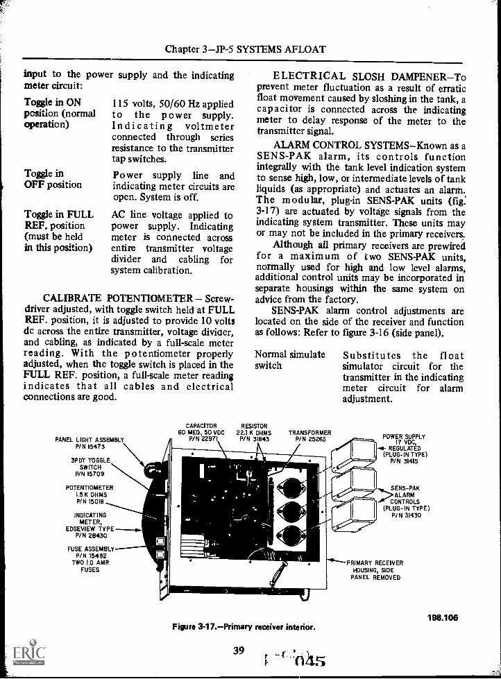
Chapter 3JP-5 SYSTEMS AFLOAT
input to the power supply and the indicatingmeter circuit:
Toggle in ONposition (normaloperation)
Toggle inOFF position
Toggle in FULLREF. position(must be heldin this position)
115 volts, 50/60 Hz appliedto the power supply.Indicating voltmeterconnected through seriesresistance to the transmittertap switches.
Power supply line andindicating meter circuits areopen. System is off.
AC line voltage applied topower supply. Indicatingmeter is connected acrossentire transmitter voltagedivider and cabling forsystem calibration.
CALIBRATE POTENTIOMETER Screw-driver adjusted, with toggle switch held at FULLREF. position, it is adjusted to provide 10 voltsdc across the entire transmitter, voltage diviner,and cabling, as indicated by a full-scale meterreading. With the potentiometer properlyadjusted, when the toggle switch is placed in theFULL REF. position, a full-scale meter readingindicates that all cables and electricalconnections are good.
PANEL LIGHT ASSEMBLYP/N 15473
3PDT TOGGLESWITCH
P/N 15709
ELECTRICAL SLOSH DAMPENERToprevent meter fluctuation as a result of erraticfloat movement caused by sloshing in the tank, acapacitor is connected across the indicatingmeter to delay response of the meter to thetransmitter signal.
ALARM CONTROL SYSTEMSKnown as aSENS-PAK alarm, its controls functionintegrally with the tank level indication systemto sense high, low, or intermediate levels of tankliquids (as appropriate) and actuates an alarm.The modular, plug-in SENS-PAK units (fig.3-17) are actuated by voltdge signals from theindicating system transmitter. These units mayor may not be included in the primary receivers.
Although all primary receivers are prewiredfor a maximum of two SENS -PAK units,normally used for high and low level alarms,additional control units may be incorporated inseparate housings within the same system onadvice from the factory.
SENS-PAK alarm control adjustments arelocated on the side of the receiver and functionas follows: Refer to figure 3-16 (side panel).
Normal simulate Substitutes the floatswitch simulator circuit for the
transmitter in the indicatingmeter circuit for alarmadjustment.
CAPACITOR RESISTOR60 MED., 50 VDC 22.1 K OHMS TRANSFORMER
P/N 22971 P/N 31843 P/N 25263
POTENTIOMETER1.5 K OHMSP/N 15018
INDICATINGMETER,
EDGEVIEW TYPEP/N 28430
FUSE ASSEMBLYP/N 15482
TWO 10 AMPFUSES
Figure 3-17.Primary receiver interior.
39 rt. 045
POWER SUPPLY17 VDC,
-4- REGULATED(PLUG-IN TYPE)
P/N 31415
SENS-PAKALARM
CONTROLS(PLUG-IN TYPE)
P/N 31430
PRIMARY RECEIVERHOUSING, SIDE
PANEL REMOVED
198.106

AVIATION BOATSWAIN'S MATE F 1 & C
Float simulator Simulates the totalpotentiometer transmitter voltage divider
resistance change over thefull range of float travel.
High alarmpotentiometer
Low alarmpotentiometer
Sets the actuation voltagelevel of the high alarmSENS PAK.
Sets the actuation voltagelevel of the low alarm SENSPAK.
This system surpasses the ±3% accuracyrequir-ment of military specifications; however,the accuracy will vary depending on the sizetank being gaged and the type receiver utilized.
Practically speaking, specific gravity changesin the tank liquid have no effect on a float ridingon the surface. For example, a float 4 incheslong, with a specific gravity of 0.5, submergeshalf way in water (specific gravity of 1.0).Should the liquid specific gravity decrease by asmuch as 20%, the float would merely ridesubmerged an additional 1/2 inch. NOTE: TheGems TLI systems are also approved forindicating the interface level of two liquidshaving different specific gravities.
With the ON-OFF-FULL REF. toggle switchon the primary receiver in the ON position,operation of the system, and alarms if included,is completely automatic. Tank liquid level isread directly from the indicating meter on theprimary or secondary receiver as required. Nofurther attention is necessary, as the Gems TLIsystem can operate indefinitely without anycomponent degradation.
The only maintenance that should berequired at any time is an occasional cleaning ofthe transmitter and float when tanks are openedfor inspection and cleaning.
FILLING AND TRANSFER PIPINGAND VALVE ARRANGEMENT
The piping am.' valve arrangements discussedin the following paragraphs include the fillingand transfer, stripping, and the service systems.In describing these systems, emphasis is placedon the piping and valve arrangement only andtheir purposes. Related items, such as pumps,
046 40
purifiers, filters, etc., are limited to operationalfunctions only, since each is described in moredetail in succeeding chapters of this trainingmanual.
In order to operate any JP-5 fueling systemsafely and efficiently, the ABF must have athorough knowledge of the arrangement andlimitations of the piping systems. Although thepiping arrangements are similar for all CVA's, notwo ships (not even sister ships) are exactly thesame; therefore, you should consult the ship'sblueprints for detailed information on yourparticular ship. The diagrams shown in thischapter are typical arrangements, based oninformation gained from various class carriers,both small and large, old and new. In describingthese systems, piping and valves are givenspecific names instead of numbers. Valvenumbers may vary for each ship, but theirrelative location in relation to the equipmentand purpose for which intended are basically thesame.
The filling and transfer system (fig. 3-18)and its interconnecting and cross-connectingpiping and valves with other systems, servesmany functions in the operation of the JP-5fueling system. It is used primarily for receivingJP-5 aboard when filling the stowage tanks,transferring JP-5 from stowage to service tanks,transferring JP-5 internally from port tostarboard (or vice versa) and from forward to aft(or vice versa) when required to correct the listor trim of the ship, and filling the amidshipemergency tanks when JP-5 is required for boilerfuel. In addition to the above, the fillingand transfer piping is also used to receive anddirect JP-5 from the forward independentdefueling main into a preselected stowage tank,and from the stripping pump discharge headerwhen consolidating, the fuel load (removing thelast 24 inches of usable fuel from stowagetanks). The diesel oil day ready service tank canbe supplied from a connection off the transfermain. Off-loading of JP-5 is accomplished by theservice pumps through cross-connecting pipingto the filling and transfer system.
of theintegral paThe transfer system is an partfilling system and both are considered as onesystem. However, due to the congested pipingarrangement, they are described separately. Thefilling and transfer systems are described

Chapter 3JP-5 SYSTEMS AFLOAT
AFTER GROUP OF TANKS FORWARD GROUP OF TANKS
E i C I C C
---E t C -1t11 1-1--' D i- C
r--, !---_-!- !---- --;-`-t '--li------; rr-F-4:,---_,-:_ j i ;" ----'.._44LILI:Ltjii
A A ; A I C- C
IF i F F ! F I A 1 b---ErH L A 1-41C D
__.,_-,--,
I
t --I --,r5 f
L- _
7-----4 4
II- -5 1;- 1 1'.=11 H.--' tt 5 ip
.1
.. :::.
. --11-2
11
E C 4 D
C C
F- 174LF 1 F
C E
rCE
-r)j-
nt
\1;==7
2
7-----0 'O411r-z11-!-T112:-----1----1.k;H-1-j-L''--- 'Ill
A -i4 8II
! A C D P;'i 0.--...-4 .
A A A1
c C
A. JP-5 or ballast.B. JP-5, ballast, or overflow.C. JP-5.D. JP-5 or overflow.E. JP-5 service.F. Amidships emergency tank.1. Downcomers.2. Transfer main.
3. Transfer main branch headers.4. Transfer pump suction headers.5. Transfer pump discharge.6. Stripping pump discharge.7. Double-valved manifold.8. Single-valved manifold.9. Diesel oil day ready service
tank line.
10. Defuel main.11. Double-bottom tank fill lines.12. Transfer main branch headers (to
other stowage tanks).13. Transfer main branch header (to
peak tanks).14. Amidships emergency tank fill lines.15. Stowage tank suction and fill lines.
198.12Figure 3-18.JP-5 filling and transfer system (piping diagram).
separately in order to give a clearerunderstanding of their arrangement.
Filling Piping andValve Arrangement
The filling system encompasses all piping,valves, and related equipment from the fillingconnections on the main deck to the fill andsuction tailpipe in the stowage tanks.
FILLING CONNECTIONS.The main deckfilling connections provide a means of attachingthe refueling hose to the ship by a quick-releasemethod and controlling the quality and quantityof JP-5 being received. They are located aft, onthe starboard side of the main deck, outboard ofthe hangar deck, on fueling sponsons or elevatorramp recesses. The number of filling connectionsvary, depending on the type and class carrier.Some carriers have additional filling connectionson the port side to facilitate refueling from abarge when moored to a pier (starboard side to).
The type fittings installed at the fillingconnection depend on the type quick-releasemethod used with the refueling hose. At presentthere are two typesRobb assembly and probeassembly. The Robb assembly is discussed first.
A filling connection equipped with the Robbtype quick-release coupling and valve assembly(fig. 3-19) consists of a gate valve, a 90) ell, andthe male end of the Robb quick-releasecoupling.
The 90° ell is flanged on both ends tofacilitate bolting the inboard end to the gatevalve and the outboard end to aquick-disconnect hose coupling. Ell's vary as tosize, depending on the size of the downcomer.For example they may range from 6-inch to6-inch and 8-inch to 6-inch, etc., but regardlessof the size of the inboard end, the outboard endis reduced or enlarged as necessary to a 6-inchsize. The ell is equipped to provide a means ofattaching the following operating equipment:
41 , ,)t047

AVIATION BOATSWAIN'S MATE F 1 & C
1. Sampling connection for determining thequality of the fuel being received.
2. Pressure gage to determine the dischargepressure from the refueling source.
3. Therm ometer to determine thetemperature of the fuel being received.
4. Low-pressure air connection for blowingJP-5 in the hose back to the tanker.
1. Downcomer.2. Gate valve.3. 8-inch to 6-inch 900 ell.
3A. Thermometer.36. Sample connection.3C. Low-pressure air connection.
"Y" type adapters are provided on some ofthe larger carriers to facilitate attaching tworefueling hoses to one filling connection.
The combined quick-release (Robb) couplingand valve (fig. 3-20) is used for connecting the6-inch aviation gasoline hose and the 7-inch JP-5hose from the tanker to one of the ship'saviation fuel filling connections. It permits
"Y" TYPE ADAPTERFOR DUALHOSE ARRANGEMENT
3D. Pressure gage.4. Spool.5. Male end of 6-inch quick-
release coupling.5A. Valve operating handle.
6. Dump valve.
Ia
DEFUELINGMAIN
7. Gate valve.8. 90° ell.9. Reattachable coupling.
10. 7-inch rubber hose (wire reinforced).11. Probe receiver.
198.13Figure 3-19.JP-5 main deck filling connection (Robb) and/or probe.
04R 42

Chapter 3JP-5 SYSTEMS AFLOAT
7-INCHHOSE
FLANGE
6-INCHHOSE
FLANGE VALVEGASKET SPRING-
TENSIONEDSLEEVE
OPERATINGLEVER
SPRING-TENSIONEDBALL RACE
MACHINEGROOVE
VALVE SPRING
VALVE OPEN POSITION
VALVE
NIPPLE GASKET
SLOT FOR PRY BAR
END RING
TO RELEASE BEARING SLIP BACK
FEMALE END DELIV. SHIP
SPRING TENSIONED SLEEVE
ACTUATINGCAM
LEVER-DETACHABLE FOR PRYINGOPEN SPRING-TENSIONED SLEEVE
MALE ENDRECEIVING
SHIP
ANNULAR GROOVE
Figure 3-20.Combined quick-release (Robb) coupling and valve.
43
197.39.1

AVIATIJN BOATSWAIN'S MATE F 1 & C
instant disconnection of the fueling hose fromthe ship if an emergency arises duringfueling-at-sea operations.
NOTE: Only the bronze combinedquick-release (Robb) coupling and valve is to beused with aviation gasoline and JP-5.
The combined quick-release (Robb) couplingand valve (fig. 3-16) consists of a male andfemale end. The male half of the combinedquick-release (Robb) coupling is attached to thefueling connection aboard the ship to be fueled.This half contains the valve operating lever andbolts directly to the ship's aviation fuelingconnection spool when the blank flange isremoved. The male end is a slightly tapered tubewith a standard 6-inch pipe flange at one end,and a groove machined in the outercircumference near the other end. A ring-shapedactuating cam, linked to the valve operatingmechanism, is housed within the tube.
The end of the male half of the coupling isprotected by a screw cap with a synthetic rubbergasket which must be in place during the time itis not in use or stowed and while it is beinghandled.
The female half of the combinedquick-release coupling is attached to the end ofthe fueling hose by the supplying ship by meansof a flanged hose adapter. The female endcontains the spring-loaded valve (normallyclosed), a spring-tensioned ball bearing race, aspring-loaded sliding sleeve locking assembly,and a sealing gasket. As long as the two ends areseparated and/or until the operating leyer isplaced in the open position, the valve is heldclosed by the compression spring. A rubbergasket in the valve disc forms a tight seal whencompressed against the valve seat. Proper seatingof the valve disc is insured by three protrudingdisc guides.
Before connecting the two halves of thequick-release coupling, examine the gasket in thefemale half to see if it is properly in place, clean,and not damaged. Examine the end of the malehalf to see that it is not marred or deformed.
In order to connect the quick-releasecoupling, both ends must be aligned perfectly.Then proceed as follows: Make sure theoperating lever is in the closed position. Slidethe sleeve back by hand (toward the hose),compressing the spring. This releases the
44
pressure on the ball race, allowing the ballbearing to retract. Slip the female end over themale end until it bottoms. Proper positioning isdetermined when the sleeve can be returned toits normal position. This will force the ballbearings into the groove of the male end, lockingthe coupling in place. With the two ends joined,a tight seal is formed by the male end bottomedagainst the sealing gasket in the female end. Byrotating the operating lever to the open position,the ring-shaped cam (acting on the valve discguides) is thrust forward, compressing the valvespring and holding the valve in the openposition.
All parts of the combined quick-releasecoupling and valve are interchangeable,regardless of manufacturer.
To disconnect the coupling, it is onlynecessary to retract the sleeve, releasing thepressure on the ball race. As the female end iswithdrawn, the compression spring willautomatically close the valve. This procedure isused only in an emergency; normally the valve isclosed manually by rotating the operating leverprior to disconnect.
When the two ends are coupled, additionalforce (other than hand) is usually required toretract the sleeve. For this purpose, slots are cutinto the sleeve for the insertion of pry barsbetween the sleeve and end ring. The bitter-endof the operating lever is formed for this use.Some ships have fabricated large spannerwrenches to give greater leverage for retractingthe sleeve. A protective rubber bumper isinstalled around the end ring to prevent damageto the female end when striking the deck.Although the quick-release couplings areprovided in 6-inch size only, both 6-inch and7-inch hose flanges are available for the femaleend.
Despite the name, the Robb coupling doesnot qualify as a quick-release device becauseuncoupling, difficult ordinarily, is impossiblewhen the fitting is under strain. Even with theriding line taking the strain, both ends must bealigned perfectly for both connecting anddisconnecting operations. For this reason, theRobb couplings are being replaced by the probesystem.
Because replenishing ships are extremelyvulnerable to attack, the Navy constantly strives
050

Chapter 3JP-5 SYSTEMS AFLOAT
to improve repleni3hment equipment andmethods in order to speed operations. The timeconsuming procedure for connecting anddisconnecting hose lines prompted efforts todevelop means to reduce the time involved inthis process. The probe fueling system is a result.
Probe Fueling Rig.The probe fueling unit,shown in figure 3-21 (A), consists of a fuelingprobe and a probe receiver. Tf e receiver issupported by a swivel fitting mounted on thereceiving ship; a 7-inch diameter rubber hose(wire reinforced) connects the receiver to thefilling connection. A pelican hook, used as theattachment point for the span wire, is an integralpart of the swivel fitting. The bitter end of thespan wire has a special end fitting installed toattach to the pelican hook on the swivel fitting.
The fueling probe is attached to the end of a7-inch diameter fueling hose and is suspendedfrom the span wire by a trolley. Since thereceiver is mounted on the swivel fitting, it iskept directly in line with the span wire and withthe probe. This arrangement provides excellentalignment during connect-up of probe andreceiver for either the tensioned ornon-tensioned span wire.
The fueling probe incorporates a slidingsleeve valve which opens on proper engagementwith the probe receiver and automatically closesupon disengagement. A latching mechanism inthe probe prevents disengagement during fuelingoperations. A line pull of 300 pounds on themessenger (remating line) is required to engagethe probe in the receiver.
The probe receiver has a lever mounted onthe side of the housing to provide a means ofdisengaging the probe at the receiver. This levercan be installed on either the forward or afterside of the receiver to suit local conditions.Visual latch indicators are mounted on each sideof the receiver to indicate proper engagement.During probe and receiver engagement, the latchindicators will rise to a vertical positionmomentarily and return to a position ofapproximately 30 degrees above horizontal. Thisindicates that the probe and receiver areengaged, and transfer of fuel can commence.(See fig. 3-17 (B).) Since the fueling probe has a7-inch I.D. vice the 6-inch I.D. of the Robbcoupling, the probe system provides for an
improved rate of fuel transfer. The Robbcoupling can not be used with the fueling probe.
NOTE: Personnel are required only duringconnect-up and removal of the span wire andwhile disengaging the probe from the receiver.
The travel of the probe down the span wiremust be controlled at all times to prevent theprobe from striking the receiver with undueforce. Additional information on refueling maybe found in the Replenishment-at-Sea Manual,NWP 38 (Series).
The probe fueling system employs a spanwire which is passed in the same manner as forthe span-wire rig. After the span wire isconnected, the fueling hose, with probeattached, is eased down the span wire until theprobe is within a few feet of mating with thereceiver. The messenger is then attached to thehook on the trolley, and the probe is hauled into engage with the receiver. After engagement,the messenger is faked down and made free forrunning. Riding lines are not required andshould not be used with the probe system.
Although it is possible to engage the probeat close distances without a messenger, it isrequired at ship separations greater than 140feet due to the catenary (curve) in the span wire.
Blowdown and/or back suction is notrequired with the probe system after completionof fueling. However, the fuel hose may becleared if desired. The delivery ship is providedwith a special tool for manually opening theprobe valve to permit draining of the fuel hose.
After completion of fuel transfer, themanual release lever (fig, 3-21 (B)) is actuated torelease the probe, and the delivery ship retrievesthe fuel hose. On signal from the delivery shipthe pelican hook is then tripped, and the spanwire is eased over the side of the receiving ship.
EMERGENCY BREAKAWAY.If thereceiving ship cannot quickly disconnect theprobe from the receiver, the delivery ship can doso by taking a strain on the retrieving line saddlewhip and/or on the outboard saddle whip(provided a stress wire connects the outboardsaddle with the probe trolley). A line pull of2,500 pounds is required to disengage the probeby this method.
The filling connection gate valve (2, fig.3-19) is installed between the 90° ell and
45
14. ()NI

1
AVIATION BOATSWAIN'S MATE F 1 & C
INHAUL SPAN WIRE MESSENGER PELICANHOOK
SWIVEL FITTING
(A)
(B)
PROBE
VISUAL LATCH INDICATOR
MANUAL RECEIVERRELEASE LEVER
MANUAL RELEASE
MANUAL RELEASELEVER LANYARD
Figure 3-21.Probe fueling unit.
46
ON2
198.14
IL
Chapter 3JP-5 SYSTEMS AFLOAT
downcomer. This valve is normally the last oneto be opened in the system prior to receivingJP-5.
PIPING AND VALVES.The downcomer isthat section of the filling system that connectsthe filling connection on the main deck with thetransfer main on the seventh deck level. There isnormally one downcomer for each fillingconnection installed. The independent defuelingmain for the service station located in the afterpart of the ship is attached to one of thedowncomers.
NOTE: On newer construction the defuelmain is a separate system. It branches from thehangar and flight deck station to the transfermain in the vicinity of the pumproom. Anadditional gate valve is installed in thedowncomer near the bottom where it connectsto the transfer main.
NOTE: Periodic inspection is required ofvalve gaskets (Buna-N-Cork). Flange shields mustbe provided in accordance with existinginstructions when valves are located inmachinery spaces (enginerooms, firerooms, etc.).
The Transfer Main runs fore and aft throughthe bilge just below the seventh deck level. Thisline interconnects the forward and after groupof stowage tanks, the amidship emergencyservice tanks (on ships so equipped), and thediesel oil day ready service tanks. Besides beingconnected to the downcomers, it is alsoconnected to the independent defueling mainfor the forward service stations and thedischarge headers of the transfer and strippingpumps.
Gate valves are installed at strategic pointsthroughout the transfer mainat transversebulkheads (between downcomers), and one ateach end. The valves are used to isolate thesystem during the secured condition and controlthe flow of JP-5 during the various filling andtransfer operations. Each valve has a damagecontrol marking of X-Ray and MUST be closedwhen not in actual use.
The four amidship emergency service tanksupply lines are fitted with gate valves andspectacle flanges. Spectacle flanges are an addedsafety feature to insure that these lines cannot
47
be opened accidentally. The tanks concerned arefitted with steam coils that must be securedbefore receiving JP-5. There is one supply line ineach of the four main machinery rooms. Eachsupply line serves two tanksone port and onestarboard.
The diesel oil day ready service tank supplyline leading off the transfer main is fitted with agate valve normally locked closed. The lock isprovided to insure proper accountability of JP-5issued to the engineers. These tanks can besupplied from any JP-5 stowage tank on theship. Other methods of transferring JP-5 for useas diesel fuel is also provided off the transfersystem piping.
The extreme forward and after ends of thetransfer main are connected to the transfer mainbranch headers.
The transfer main branch headers extendoutboard from the transfer main andinterconnect the stowage tank manifolds withthe transfer main. Normally there are only twobranch headers for each of the forward and aftergroup of tanksone port and one starboard; buton ships utilizing double bottom and peak tanksfor JP-5 stowage, additional branch headers arerequired.
Manifolds are an integral part of the JP-5filling system. They are located between thetransfer main branch headers and the stowagetank fill and suction tailpipes. Manifolds consistof a number of valves mounted in a compactunit which provides a means of controlling theflow of JP-5 to and from several stowage tanksfrom one central location. There are two typesof manifolds used in the JP-5 filling systemadouble valved manifold and a single valvedmanifold.
Double-valved manifolds (fig. 3-22) are usedto control the flow of JP-5 to and from stowagetanks that are designated stowage or ballast.Th y give a double protection againstcontaminating the transfer main when thestowage tanks are filled with sea water; in thatsea water must pass through two valves beforereaching the transfer main.
The manifold HEADER is a section of8-inch pipe with several equally spaced 5-inchhole's in the top, to accommodate the transfermainside valves. It is sealed on both ends and hasan 8-inch pipe flange welded to the bottom. The

AVIATION BOATSWAIN'S MATE F 1 & C
TRANSFERMAIN SIDE VALVES
TELLTALEVALVES
HEADER
NOZZLE LOCKINGDEVICE
MANIFOLDHEADER
DRAIN VALVES
TOTRANSFER
MAINBRANCH HEADER
Figure 3-22.Double-valved manifold.
manifold header is bolted to a section of 8-inchpipe leading off the transfer main branch header.
The valves used in the construction of adouble-valved manifold are specially designedglobe type shutoff valves. These valves are givenspecific names; i.e., transfer mainside valve andtankside valve. Both valves are practicallyidentical; therefore, only one is described here.
The transfer mainside valves are welded tothe top of the manifold header. (See cutawayfig. 3-23.) They are cylindrical in shape(approximately 10 inches in diameter) andconsist of a body and a bonnet. The bodyhouses the seat ring and the valve disc. Perfectseating of the valve disc with the seat ring isassured by the disc guide centered in the base ofthe valve body. The lower section of the valvebody, below the seat, is reduced to 5 inches indiameter for welding to the header. A 5-inchhole is machined in the back of the valve body(above the valve seat) for attaching the nozzle.The raised boss on the front of the valve (abovethe valve seat) is drilled and tapped for installingthe telltale valve. The bonnet, which provides aworking area for the stem, is bolted to the top
48054
TANK SIDEVALVE
TOSTORAGE
TANK
198.15
of the valve body. Leakage of JP-5 is preventedby a gasket between body and bonnet, andpacking in the stuffing box around the stem.
The tankside valve is identical to the transfermainside valve, except that there is no telltalevalve connections and the bottom of the valvebody is fitted with a standard pipe flange. (Seefig. 3-22.) The stowage tank Fill & Suctiontailpipe is bolted to the bottom of this valve.
The nozzle is a short section of 5-inch pipeconnecting the two valves in parallel. One end iswelded to the side of the transfer mainside valveand the other end to the side of the tanksidevalve.
The telltale valves are angle type globevalves. There is one telltale valve for each set ofmanifold vaTves. These valves are installed on thefront side of the transfer mainside valves, abovethe valve seat. They arc used to determine thecondition of valve seats. When the stowage tanksare ballasted with sea water, the telltale valvesshould be opened periodically. If water issuesfrom the telltale valve, it is an indication thatthe tankside valve is leaking. If JP-5 issues fromthis valve, it is an indication that the transfer

Chapter 3JP-5 SYSTEMS AFLOAT
Alm
WELD
1. Handwheel nut.2. Handwheel.3. Valve stem.4. Packing gland nut.5. Gland.6. Stem packing.7. Gland ring (throat
bushing).8. Bonnet.9. Bonnet gasket.
10. Bonnet studs andnuts.
OPENING
10-INCH HEADER
Figure 3-23.Transfer
11. Valve body.12. Boss for telltale valve.13. Disc nut.14. Replaceable disc.15. Replaceable seat ring.16. Disc guide.17. Disc guide ribs (3 equally
spaced).18. Connection (to manifold
header).19. Nozzle (to tank side
valve).19816
mainside valve (cutaway).
mainside valve is leaking. Leaking valves shouldbe repaired at the first opportunity. Both valveshave renewable type seat rings and valve discs.
The manifold header drain valve is installedat the bottom near one end of the header. It isused to drain the header prior to maintenance.
49
A locking device is provided for each of thetankside valves. There are two types presently inusea bar type and a chain type. These lockingdevices are so arranged that the valves can onlybe locked in the closed position. Tankside valvesMUST be locked in the closed position when thetanks are ballasted.
A warning plate, located on or near eachdouble-valved manifold states: "WARNING:VALVE MUST BE LOCKED CLOSED WHENFLOODED WITH SEA WATER."
Single-valved manifolds (fig. 3-24) are usedto control flow of JP-5 to and from stowagetanks designated either JP-5 or JP-5 andoverflow. These tanks are not ballasted.
The valves used to construct a single-valvemanifold are identical to tankside valves on thedouble-valve manifold, except for the numberand size holes in the side of the valve body.These valves have 8-inch holes in each side(except the last valve) joined together by 8-inchnozzles. A 90° ell flanged on one end is used tobolt the single-valved manifold to the transfermain branch header.
All manifold valves also have a damagecontrol marking of X-Ray and MUST be closedwhen not in actual use.
Transfer System
The transfer system discussed here is atypical arrangement utilizing three transferpumps and two centrifugal purifiers as thefiltering equipment (See fig. 3-25.)
The suction header, which is common to allthree transfer pumps, is connected directly tothe port and starboard transfer main branch
NOZZLES
Figure 3-24.Single-valved manifold.198.17

cr0
11
16
INLET ANO OUTLET INLET SEALHOUSING
OUTLETDISCHARGE
BOWL TOP
TOP DISC
DISCS
BOWL SHELL
TUBULAR SHAFT
AVIATION BOATSWAIN'S MATE F 1 & C
DISCHARGE RING PARING DISC
REGULATINGTUBE
INLET FEED
STRAINER
BOWL DRAIN itNOTE A
OBSERVATION
PORT
a HEAVY PHASEOUTLET
( WATER I
SPRING LOADEDRELIEF VALVE
NOTE B
10
7.
9
13 13
NO.1
PURIFIER
NOTE A14
17 3
1\2
15
1. Suction header.2. Main branch headers.3. Suction header control valves.4. Pump inlet.5. Pump discharge.6. Discharge header.7. Discharge header control valves.
1
1
1
1
8. Purifier inlet. 1
9. Purifier discharge. 1
0. Service tank fill line header. 11. Diesel oil ready service line. 12. Seal water inlet.3. Purifier water discharge. 1
4. Purifier casing drain.
17
2/1
SERVICE TANKFILL LINE
15
5. Purifier bypass.6. Transfer main connection.7. Suction header crossover to bypass.8. Cross-connection to service pump suc-
tion header.9. Cross-connection to service pump dis-
charge header.
Figure 3-25.Typical transfer system and piping arrangement.
headers. The two gate valves installed in thesuction header, one port and one starboard,permit the transfer pumps to take suction fromeither the port or starboard stowage tanksindependently or from both simultaneously.
Three pump inlet lines connect the commonsuction header with the suction siok of the
50
198.18
transfer pumps. Each line contains a gate valveand a compound gage (VP). A compound gagemeasures both vacuum and pressure.
The transfer pumps used in this system arethe Blackmer positive displacement, rotary vanetype. Each pump has a rated capacity of 200gpm at 50 psi with a suction lift of 8 inches Hg.

Chapter 3JP-5 SYSTEMS AFLOAT
Damage to the positive displacement pump andits associated equipment, due to a buildup ofexcessive pressure, is prevented by an integralspring-loaded relief valve.
When the pump discharge pressure exceedsthe spring setting (normally 50 psi), the valveopens and directs the JP-5 from the dischargeport, through an internal passage, back to thesuction compartment. Each pump is providedwith a manual START-STOP push-buttoncontrol. In addition, the pump motor isprotected by low voltage and overload trips. Ifthe motor is stopped due to low voltage, it maybe restarted by pressing the START button. Ifthe motor trips out due to overload, it may berestarted by pressing the RESET-EMERGENCYRUN button and then the START button.During normal operations, when transferringfrom stowage to service tanks, only two of thethree pumps are utilized; one for each purifier.
(CAUTION: Never align the discharge frommore than one transfer pump to only onecentrifugal purifier. Purifiers have a maximumcapacity of 200 gpm.) The other pump is alwaysdesignated as a standby. The standby dutyshould be rotated among the three pumps toinsure even distribution of service.
The transfer pumps discharge into acommon discharge header. Each pump dischargeline contains a test connection, pressure gage(P), one-way check valve and a globe typeshutoff valve.
The two gate valves are so arranged in thedischarge header (one between each pumpdischarge line) to enable both purifiers to be inoperation. simultaneously, utilizing any two ofthe three transfer pumps. For instance, whenpump No. 1 is aligned with purifier No. 1, eitherpump 2 or 3 can be aligned with purifier No. 2.When pump No. 3 is aligned with purifier No. 2,either pump 1 or 2 can be aligned with purifierNo. 1. Never align more than one transfer pumpto only one purifier.
This valve arrangement also permits twoseparate transfer operations to be performedsimultaneously. For example, when pump andpurifier No. 1 are being used to top off a servicetank, pumps 2 and 3 can be used to transfer JP-5from forward to aft, filling amidship emergencyservice tanks, etc. The same applies for pumps 1and 2 when pump 3 is being used with purifierNo. 2.
51
CENTRIFUGAL PURIFIER.The USSCORAL SEA (CVA-43) was one of the firstships to get the centrifugal purifiers. After manymonths of evaluation, and its proven efficiencyover the first stage filters, the purifiers havereplaced transfer filters on CVA's and otherships handling large quantities of JP-5.
Purifiers have a rated capacity of 200 gpmwhen purifying JP-5 between the temperature of60 °F and 90° F (fuel temperature). When thepurifier is in operation, maintain the inlet (feed)pressure at 9 psi and a back pressure on thedischarge between 25 psi and 35 psi, with idealback pressure being 30 psi. The purifier is drivenby an electric motor equipped with a remotecontrol START-STOP pushbutton. Thearrangement of associated piping is shown infigure 3-21.
The purifier inlet (feed) line, extending offthe common discharge header, contains athermometer, pressure gage, and a globe typeshutoff valve. The globe valve is used to throttlethe transfer pump discharge pressure enteringthe purifier to 9 psi. The purifier discharge linecontains a pressure gage, test connection, a globetype shutoff valve, and a sight glass gage withflapper. The globe type shutoff valve is used inthis line to throttle the JP-5 leaving the purifierto maintain a back pressure of 30 psi. Thesight-flow gage and flapper provides a visual andaudible check of the fuel being discharged. Thedischarge line terminates in a common servicetank fill line header, from here, it can bedirected into any of the service tanks in theforward group.
NOTE: The diesel oil day ready service tankcan be supplied via A line off the purifierdischarge line to the service tank fill line.
A seal water inlet connection, locatedbetween the JP-5 inlet and discharge tubes,directs fresh water into the bowl for use as aseal. A %-inch plug valve and flexible rubberhose connects the seal water inlet to the freshwater supply in the pumproom. The purifier isprovided with a water discharge line and a bowlcasing drain line, both lines terminate in avapor-free box located below the deck in thepumproom. The water discharge line, whichcontains the sight-flow gage and flapper, directsany water separated from the JP-5 into thevapor-free box. The bowl casing drain line drainsany liquid that may enter the annular space
N7

AVIATION BOATSWAIN'S MATE F 1 & C
between the revolving bowl shell assembly andthe stationary bowl casing. A "locked-open"globe valve is installed in this line.
Due to the vibration created by the purifierduring the START-STOP cycle, all lines leadingto and from the purifier are equipped with aflexible coupling.
The purifiers are bypassed for all transferoperation except when filling the service tanks.The bypass lines extend off the extreme ends ofthe transfer pump discharge header and areconnected to the transfer main. Control (gate)valves separate the bypass lines from thedischarge header. Two valved crossovers, (oneport, and one starboard) interconnect the bypassline with the common suction header of thetransfer pump. The crossovers are used to alignthe transfer system for pumping JP-5 from portto starboard or vice versa. The purifier bypassline is also used when transferring JP-5 fromforward to aft, filling the amidship emergencyservice tanks (on ships so equipped), and whenoff-loading JP-5.
The common suction and discharge headersof the transfer pumps are interconnected withthe suction and discharge headers of the servicepumps. This arrangement enables the servicepumps to be used as transfer pumps (normallyfor off-loading JP-5). Due to the insufficientstatic head lift and the low capacity of thetransfer pumps, they are not feasible fortransferring JP-5 off the ship. Thecross-connections between the respective suctionand discharge headers are fitted with spectacleflanges (blank side in) and a gate valve (normallylocked closed).
STRIPPING SYSTEM
There are two independent stripping systemsin each JP-5 pumproom. One system utilizesmotor-driven pumps and is interconnected withall JP-5 tanks (both stowage and service) in eachgroup. The other system utilizes hand-operatedpumps and is associated with service tanks only.The systems described here are for onepumproom serving one group of tanks. Sinceeach system operates independently of theother, they are described separately.
The m otor-drhen stripping system (fig.3-26) consists basically of two low capacitypumps, manifolds, and associated piping and
52
valves and is designed to perform the followingfunctions:
1. Remove water and solids from thebottom of the JP-5 stowage tanks (during normalscheduled stripping operations).
2. Remove the last 24 inches of usable fuelremaining in the stowage tanks after the transferpumps lose suction (when consolidating the fuelload and prior to ballasting the stowage tanks).
3. Remove the remaining sea water left inthe stowage tanks by the main drainage eductors(after a deballasting or tank cleaning operation).
4. Remove the remaining 24 inches of JP-5from the service tanks (prior to cleaning,emptying, etc.).
5. Remove the wash water from the JP-5service tanks (after a cleaning operation).
6. Remove collected water from transferfilter and centrifugal purifier vapor-free box.
There are two types of manifolds installed inthe JP-5 stripping system. One is a single-valvedstripping manifold, used with all JP-5 stowagetanks, and the other is a flood and drainmanifold which is installed only ir the piping tothose JP-5 stowage tanks that are designated tobe ballasted. The single-valve stripping manifolds(12, fig. 3-26) are identical to the single-valvedmanifolds described in the filling and transfersystem, except that they are physically smallerin size. There is one for each nest of stowagetanks. They are located in the pumprooms ormanifold spaces and control the flow of liquidsdirectly to and from the stowage tanks duringthe various stripping, ballasting, or deballastingoperations. The stowage tank stripping tailpipeextends from 1% inches off the bottom of thetank to the single-valved stripping manifold.
The flood ard drain manifolds are located inthe stripping system between the single-valvedstripping manifolds (for all tanks designated tobe ballasted) and the stripping pumps. They aredesigned to direct the flow of liquids to andfrom the JP-5 stowage tanks during thefollowing operations from one central location:
1. When ballasting tanks, they direct theflow of sea water from a sea chest supply riser tothe single-valved stripping manifold.
2. When deballasting, they direct the flowof ballast water from the single-valved strippingmanifold to the main drainage eductor.
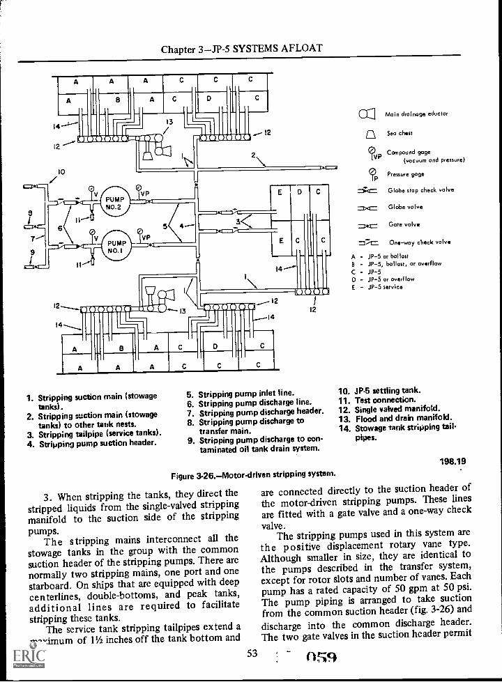
Chapter 3JP-5 SYSTEMS AFLOAT
14
12
10
A
2
A
A
13
C
14I ICED_On
A A C C C
1. Stripping suction main (stowagetanks).
2. Stripping suction main (stowagetanks) to other tank nests.
3. Stripping tailpipe (service tanks).4. Stripping pump suction header.
5. Stripping pump inlet line.6. Stripping pump discharge line.7. Stripping pump discharge header.8. Stripping pump discharge to
transfer main.9. Stripping pump discharge to con-
taminated oil tank drain system.
Figure 3-26.Motor-driven stripping system.
3. When stripping the tanks, they direct thestripped liquids from the single-valved strippingmanifold to the suction side of the strippingpumps.
The s tripping mains interconnect all thestowage tanks in the group with the commonsuction header of the stripping pumps. There arenormally two stripping mains, one port and onestarboard. On ships that are equipped with deepcenterlines, double-bottoms, and peak tanks,additional lines are required to facilitatestripping these tanks.
The service tank stripping tailpipes extend amaximum of 1% inches off the tank bottom and
53
ccW Main drainage eductor
Sea chest
Compound gage(vacuum and pressure)
Pressure gage
Globe stop check valve
=>.= Globe valve
ot= Gate valve
=::;= One-way check valve
A - JP-5 or ballastB - JP-5, ballast, or overflowC - JP-5D - JP-5 or overflowE - JP-5 service
10. JP-5 settling tank.11. Test connection.12. Single valved manifold.13. Flood and drain manifold.14. Stowage tank stripping tail-
pipes.
198.19
are connected directly to the suction header ofthe motor-driven stripping pumps. These lines
are fitted with a gate valve and a one-way check
valve.The stripping pumps used in this system are
the positive displacement rotary vane type.Although smaller in size, they are identical tothe pumps described in the transfer system,except for rotor slots and number of vanes. Eachpump has a rated capacity of 50 gpm at 50 psi.The pump piping is arranged to take suctionfrom the common suction header (fig. 3-26) and
discharge into the common discharge header.The two gate valves in the suction header permit
0.549

AVIATION BOATSWAIN'S MATE F 1 & C
both pumps to take suction from either the portor starboard tanks independently or from bothsides simultaneously. The pump inlet pipingcontains a gate valve and a compound gage. Thedischarge piping contains a valved testconnection, pressure gage, a globe stop checkvalve, and a one-way check valve. From thedischarge header the stripped liquids are directedas follows:
Through the stripping pump discharge to thetransfer main when consolidating the fuel load,through the stripping pump discharge to thecontaminated JP-5 settling tanks (on ships soequipped) or to the fuel oil tank drainagesystem. The latter is the property of theengineering department and prior permissionand assistance must be obtained before usingthis system.
Flood and Drain Manifold
A flood and drain manifold (as shown in fig.3-27) consists of a manifold header and threeglobe type shutoff valves.
The manifold header is a common valvebody for all three valves. It contains three valveseats and forms an unrestricted passage betweenthe three valves above the valve seats. One en .-.1of the header is bolted to the single-valvedstripping manifold. The other end is sealed. Theupper part of the header houses the valvebonnet, which provides a working area for the
4 -TOSINGLE VALVED
MANIFOLD
I TOP VIEW I
LOCK NUTS
valve stem. A gasket is installed between thebonnet and header. A packing gland assembly inthe valve bonnet prevents leakage of liquidsfrom around the stem. The lower part of theheader, below the valve seats, has three flangedpipe connections, one for each of the threevalves.
The stripping line installed just below thestripping valve seat interconnects the flood anddrain manifold with the stripping main. This lineis used only to direct stripped liquids from thebottom of the JP-5 stowage tanks via thesingle-valved stripping manifold to the suctionside of the stripping pumps. The center line,installed just below the seat of the sea chestcutout valve, interconnects the manifold to a seachest supply riser. It is used only to direct seawater from the sea chest to the stowage tankswhen ballasting..
The other line, installed just below the seatof the main drainage eductor valve,interconnects the manifold to the suction side ofa main drainage eductor. This line is used onlyto direct ballast water from the stowage tanks tothe main drainage eductor when deballastingtanks.
The flood and drain manifold is equippedwith a locking assembly which allows only onevalve to be opened at a time; therefore, allowingonly one operation to be performed at atimestripping, ballasting, or deballasting.
KEYHOLE SLOTS OBLONG SLOTS
MC-11 C:3 I
SLIDING BAR LOCKING OFV14E (ENLARGED VIEW)
SLIDING-BAR
ENLARGED COLLAR
PACKING GLAND
VALVE BONNET
TO TO SEASTRIPPING CHEST
MAIN
'SIDE VIEW]
TO MAINDRAINAGEEDUCTOR
MANIFOLD HEADER
VALVE DISC
VALVE SEAT
Figure 3-27.Flood and drain manifold.
54
I END VIEW I
198.20

Chapter 3JP-5 SYSTEMS AFLOAT
Each valve stem has an enlarged collar,which engages a sliding-bar locking assembly.The valves are locked in the closed position. Thesliding-bar is a piece of 3-inch metal strapcontaining three keyholes and two oblong slots.It is held in place by two locknuts on a threadedbracket, extending up from the manifold. Inorder to open a valve, the enlarged collar on thevalve stem must be centered under the circularpart of the keyhole slot. The three keyhole slotsare so arranged in the metal strap that only onecollar can be so positioned at a time. The other.two collars will be positioned under therectangular part of the other two keyhole slotsand cannot be opened. To position the bar,loosen the two locknuts and slide the barthrough the oblong slots to the desired positionand retighten the nuts.
Hand-Operated Stripping System
There are two hand-operated strippingpumps in each JP-5 pumproom. (See fig. 3-28.)Their primary purpose is to remove watex andsolids from the bottom of the service tanks.However, they are also used on some ships toempty the transfer filter and/or purifier waterdrain box. These pumps have a rated capacity of30 gpm at 50 double strokes per minute. Theservice tank tailpipe which contains a shutoffvalve, terminates three-fourths inch off theservice tank bottom. The discharge line containsa sight glass gage, test connection, one-waycheck valve, and a shutoff valve. Liquidsremoved by the hand-operated stripping pumpare discharged directly overboard at the thirddeck level.
SERVICE SYSTEMPIPING AND VALVES
The service system piping and valves include
all the piping, valves, and related equipmentnecessary to deliver clean, bright, water-free JP-5from the service tanks (on the eighth deck level)to jet aircraft on the hangar and flight decks.
The arrangement of the service systems, atthe pumproom level, is practically identical forall carriers, except for the number of servicepumps installed (two or four). These differences,as to the number and capacity of the servicepumps in each pumproom for the different typeand class ship, were noted earlier in this chapter.The service system piping and related equipment
55
between the pumproom and service stations willvary, depending on the type service stationinstalled (Blackmer or Cla-Val). Both systemsare described in this section.
The service system described here is aforward section of a typical CVA systemutilizing four service pumps (two per quadrant)servicing both Blackmer and Cla-Val servicestations without reference to size or capacity.(See fig. 3-29.) This system was chosen in orderto cover the maximum amount of operatingequipment an ABF is most likely to encounterin any JP-5 pumproom and on any type ship.
Gate valves or butterfly valves are installedthroughout the service system piping at thepumproom level, except for the service pump
L-1 3/4- VI 3/4.
4
1. Service tanks.2. Service tank stripping tailpipe.3. Drain tank (for 1ststage filters or centrifugal puri-
fiers).4. Drain tank tailpipe.5. Hand pump (30 gpm at 50 double strokes per
minute).6. Bull's-eye sight glass gage.7. Test connection.8. One-way check valvi.9. Shutoff valve.
10. Pump discharge to overboard.196.21
Figure 3-28.Hand-operated stripping system.

AVIATION BOATSWAIN'S MATE F 1 & C
discharge and recirculating lines, which are globetype shutoff valves. Therefore, in describing thelocation of the valves, they are referred togenerally as shutoff valves without reference totype.
Pumproom Piping Arrangement
The service system piping in the pumproom(fig. 3-30) commences with the service tanksuction tailpipes. These lines extend from 24
1. Service tank suction tailpipe. 11. Crossconnection to transfer pump 23. Forward quadrant distribution2. Service pump common suction discharge header. main.header. 12. Quadrant distribution riser. 24. After quadrant distribution3. Crossconnection to transfer pump 13. Pressureregulating valve. main.suction header. 14. Venturi tube. 25. Forward leg of after quadrant.4. Service pump inlet line. 15. Recirculating line. 26. Service station risers.5. Service pump bypass line. 16. Pressure regulator bypass line. 27. Blackmer fueling unit.6. Service pump discharge line. 17. Filter inlet. 28. ClaVal fueling and defueling7. Service pump recirculating line. 18. Filter discharge. valve.8. Recirculating header. 19. Filter bypass. 29. Defueling pump.9. Service tanks recirculating lines. 20. Filter bypass cross-connection. 30. Fueling unit inlet lines.10. Service pump common discharge 21. Filter. 31. Defuel line.header. 22. Emergency drain line. 32. Defuel recirculating line.33. Defuel main.
19822Figure 3-29.-Service system piping and valves.
0 g2 56

Chapter 3JP-5 SYSTEMS AFLOAT
10
3
7
SERVICEPUMP
SERVICEPUMP
SERVICEPUMP
SERVICEPUMP
V VP VP
1. Service tank suction tailpipes.2. Suction header.3. Suction header crossover valves.4. Cross-connection to transfer pump
suction header.5. Pump inlet.
3 2
6. Pump discharge.7. Service pump recirculating line.8. Recirculating header.9. Service tank recirculating lines.
10. Discharge header.
Figure 3-30.Pumproom piping arrangement.
inches off the tank bottom to the service pumpcommon suction header. Each line is fitted witha shutoff valve to isolate the tank from thesystem when not in use.
The service pump common suction header isdivided into a port and starboard suction headerby a set of crossover valves. Thecross-connections from the transfer pumpsuction header, fitted with a shutoff valve andspectacle flange, interconnect with the servicepump suction header between these two valves.This arrangement allows two service pumps tobe used as transfer pumps and two for servicingaircraft simultaneously and independently ofeach other. This, of course, would be anemergency arrangement in the event all threetransfer pumps were disabled. Otherwise,
57
V
11. Discharge header crossovervalves.
12. Cross-connection to transferpump discharge header.
13. Pump bypass lines.
198.12
normally, the cross-connection is opened only toallow service pumps to be used for off-loadingJP-5. During normal operations, both crossovervalves in the suction header are open to allowthe use of any service pump with any servicetank.
The service pumps are connected to thesuction header by the pump inlet. This linecontains a shutoff valve and a compound gage.The discharge line, connecting the pumps to thecommon discharge header, contains arecirculating line, pressure gage, one-way checkvalve, and a globe type shutoff valve. Therecirculating line is orificed to recirculateapproximately 5 percent of the rated capacity ofthe pump back to the service tank from whichsuction is being taken. The recirculated fuel

AVIATION BOATSWAIN'S MATE F 1 & C
through the pump casing keeps the pump coolduring standby condition. This would be thecase when the system is pressurized (pumps arerunning) but no fuel is being drawn off topside.The recirculating lines (one for each servicepump) terminates in a recirculating header. Theheader in turn is connected to each service tankrecirculating line. These lines, fitted with shutoffvalves, terminate 18 inches off the tank bottom.When the system is being placed in operation,the recirculating header MUST be alined to theservice tank from which suction is being takenprior to starting the pump.
The service pump discharge header iscommon to all four service pumps, but like thesuction header, it, too, is divided into port andstarboard headers by a set of crossover valves.An additional pressure gage and a thermometerare installed in each port and starboard dischargeheader. The cross-connection to the transferpump discharge header is used in conjunctionwith, and for the same purpose as, thecross-connection between the respective suctionheaders of the transfer and service pumps.
Each set of service pumps is provided with abypass line. These lines are used to drain thedistribution piping back to the service tank andfor venting the system during the initial fillingoperation.
SERVICE PUMPS
The most common service pumps used in theJP-5 system are the centrifugal type. There aretwo different capacities on CVA's-675 gpm onships with 6-inch distribution piping and 1,100gpm on ships with 8-inch piping. The rateddischarge pressure of each pump will varydepending on the type service station installedon the individual ship, either Blackmer orCla-Val. Pumps installed in the service system onLPH's and LPD's have only one capacity (220gpm) and one discharge pressure (90 psi) sincethey have only one type service station(Cla-Val).
Table 3-4 lists the different capacities anddischarge pressures of the pumps in relation tothe type service station installed. Regardless ofthe rated capacity or discharge pressure, allAllis-Chalmers pumps are identical, except fortheir physical size.
Each pump is provided with an electricalcontroller which supplies current to the pump
064 58
motor. The controllers are actuated by remotepushbutton switches conveniently located in thepumproom. These switches include a START,STOP, EMERGENCY RUN, and RESETpushbutton. Additional safety devices are alsoprovided to automatically deenergize thecontrollers in the event of a malfunction to thepumps or operating equipment.
The safety devices consist of apressure-operated switch actuated by pumpdischarge pressure, a timing switch actuated bytiming relays in conjunction with the pressureswitch, and overload and low voltage tripswitches. The pressure-operated and timingswitch is set to deenergize the controllers if adischarge pressure of 35 psi is not obtainedwithin 3 minutes. In the event the controllersare deenergized by any of the safety devices,they must be RESET before the pump motorcan be restarted.
CAUTION: Check the cause of themalfunction first, before pushing the RESETbutton.
A centrifugal pump will use less power whenstarting if the discharge valve is closed and whenpumping its rated capacity. Therefore, alwaysstart the pump with the discharge valve closeduntil a pressure of 80 psi is obtained, thenslowly open the valve to full open position.
CAUTION: Always throttle the flow intothe distribution piping to prevent a hydraulicshock in the system.
DISTRIBUTION PIPING AND COMPONENTS
Quadrant Distribution Riser
Two separate arrangements of the quadrantdistribution risers are discussed in the followingparagraphs. One is for ships having the Blackmerservice stations, and the other for ships havingthe more modern Cla-Val service stations.Although both port and starboard quadrantswould be identical on their respective ships, only
Table 3-4.Pump capacities and discharge pressures
Pump Discharge Typo servicecapacity pressure station
675 gpm675 gpm
1,100 gpm1,100 gpm
220 gpm
75 psi150 psi95 psi
150 psi90 psi
BlackmerCla -ValBlackmerCla-ValCla-Val

Chapter 3JP-5 SYSTEMS AFLOAT
one of each (Blackmer to port and Cla-Val tostarboard) is described herein. (See fig. 3-31.)However, the cross- connecting piping betweenthe two quadrants will be noted whereapplicable.
Blackmer ServiceSystem Piping
The piping arrangement discussed in thefollowing paragraphs is for the Blackmer ServiceStation only.
Non lubricated positive stop valves areinstalled throughout the quadrant distributionrisers, except on test connections, recirculatinglines, and drain lines. In describing the locationof the valves, they are referred to as shutoffvalves without reference to type.
The quadrant distribution riser is thatsection of the service 3ystem piping which,connects the service pump discharge header (onthe 7th deck level) with the service stations onthe hangar and gallery decks.
Blackmer service stations will not functionproperly if the inlet fuel pressure exceeds 20 psior drops below 5 psi. For this reason, anautomatic pressure-regulating system is installedin each quadrant distribution riser to maintain aconstant (predetermined) pressure throughoutthe quadrant under all conditions of operationor load. The required pressure will vary for eachindividual ship, depending on the size and lengthof the distribution riser. The pressure regulator,located at the pumproom level, consists of anautomatic pressure-regulating valve actuatedthrough changes of pressure in the throat of a
26
9
14DEFUELINGMAIN
17
12
BLACKMER SYSTEM
18
4 to
DISCHARGE
1. Distribution riser.2. Pressure-regulating valve.3. Venturi.4. Venturi recirculating line.5. Venturi bypass line.
Flowmeter.Fourth deck quadrant crossoverlines.
*IL Double-walled piping.9. Fourth deck riser valve.
7.
I-
10
1.._ DISCHARGE`-HEADER
10. Filter inlet. 19.11. Filter discharge. 20.12. Filter. 21.13. Filter bypass. 22.14. Filter crossover. 23.15. Outboard main (fwd leg). 24.16. Outboard main (after leg). 25.17. Outboard main (fwd leg of 26.
after quad).18. Emergency drain lines. 27.
CLAVAL SYSTEM
Service station risers.Blackmer fueling unit.Fuel/defuel valve.Valve inlet line.Valve discharge line.Valve defuel line.Defueling pump.Defiel pump cross-connection tosupply riser.Defueling pump discharge line.
Thee* components are NOT required for JP-5 systems; however, they may exist in modified AvGas systems convertedto JP-5 service.
Figure 3- 31. Quadrant distribution risers (Blackmer to port, Cla-Val to starboard).
59 (1f
198.25

AVIATION BOATSWAIN'S MATE F 1 & C
venturi which is installed in the downstream sideof the valve. This system is entirely hydraulic inoperation, utilizing line pressure to open andclose the valve. Pilot and control valves areprovided in the actuating lines to insure sensitivecontrol and accurate regulation of the requireddelivery pressure. A recirculating line, located onthe downstream side of the venturi, is orificed torecirculate 100 gpm back to the service tankfrom which suction is being taken. This line,which also contains a one-way check valve and ashutoff valve, terminates in the recirculatingheader. The recirculated fuel provides a flowthrough the automatic pressure-regulatingsystem at all times. This flow of fuel allows themain valve to be partially opened, maintaining aconstant pressure throughout the systemevenduring standby conditions (when the system ispressurized and no fuel is being drawn offtopside). Shutoff valves are installed in the inletand discharge line for each pressure regulator. Abypass line fitted with a shutoff valve is installedaround the pressure-regulating system. This lineis used when initially venting and filling thesystem with JP-5 and when draining back thesystem.
NOTE: Operation and maintenance of theautomatic pressure regulator is discussed inchapter 9 of this manual.
From the pressure-regulating system, thedistribution piping extends upward from thepumproom through the vertical access trunk,where it interconnects with the original Av Gaspiping at the fourth deck level.
NOTE: All CVA's with Blackmer servicestations were converted from the interim systemand utilize the original high capacity aviationgasoline system piping and valves from this pointon.
There were certain pieces of equipmentinstalled in the original Av Gas distribution riserbetween the fourth deck level and the main fuelfilters (on the third deck) that are not necessaryin the handling of JP-5; such as, flowmeters,fourth-deck quadrant crossover lines, anddouble-walled piping. This equipment has eitherbeen eliminated or made inoperable; therefore,it is not discussed in this chapter. The shutoffvalve installed in the distribution riser just abovethe fourth deck level is commonly referred to asthe fourth-deck riser valve. The riser continuesup through the access trunk to just above the
()GC 60
third deck where it bends outboard through atransverse trunk to the filter room (near the skinof the ship). Here it connects with the servicefuel filter.
FILTER/SEPARATORS.There are severaldifferent types of filter/separators in use in thefleet; however, their principle of operation andhydraulic controls are similar. The only majordifferences in filters are their physical shape andrated capacity. Some are korizontal and othersare vertical. There are two different capacityfilters installed in the JP-5 service systems onCVA class carriers. One is a 1,200 gpm on shipswith 6-inch distribution piping, and the other isa 2,000 gpm on ships with 8-inch piping. The1,200 gpm filters are of the horizontal type, butthe 2,000 gpm filters may be either horizontalor vertical. All main fuel filters on CVA's (onefor each quadrant) are installed in the risers atthe third deck level, outboard near the skin ofthe ship. The LPH-2 and LPD-1 class shipsutilize vertical filters only. The LPH's have one300 gpm filter at each service station, and theLPD's have only one 400 gpm filter located inthc distribution piping at the pumproom level.
Regardless of the direction or rate at whichfuel passes through the filters, or where they arelocated in relation to other components in thesystem, all filters are designed to perform thesame function (separate and remove solids andwater from the fuel) and in practically the samemanner.
Filters are designed to separate and removefrom the fuel 9 percent of all solids fivemicrons, or larger, and in excess of 99.9 percentof all entrained water. This is accomplished in atwo-stage operation by two separate filteringmedia installed within the filter shell. The firststage consists of a bank of COALESCINGelements which perform the function ofremoving solids and coalescing water (bringingtogether fine particles of entrained water toform large droplets) to allow the water to fallout of the fuel by gravity; the second stageconsists of a bank of SEPARATOR elementswhich perform the function of repelling water(removing from the fuel coalesced droplets thatwere too small to fall out by gravity), and filterout micron particles. The unit is equipped with ahydraulic device that will automatically drainthe accumulated water from the filter sump and

Chapter 3JP-5 SYSTEMS AFLOAT
shut off the filter discharge in the event morewater accumulates than can be drained offautomatically.
A brief description of the horizontal filteronly and its'associated piping is discussed here.(See fig. 3-32.) Minor differences in the verticaltype are noted in the section to follow on theCla-Val syStem. The hydraulic devices for theautomatic water drain and fuel shutoff valves arecovered in the detailed description of filters inchapter 8.
The interior of the filter shell is divided intothree separate chambersinlet, fallout, andoutlet (clearwell). Both filtering media,coalescing and separator, are housed within thefallout (center) section of the filter. The numberof each type element installed will vary,depending on the type and capacity of the filter;however, there are always more coalescingelements than there are separator elements.
The sump tank installed beneath the falloutsection receives the water separated from thefuel. This tank also houses the controls for
FILTER CROSS-OVER
FILTER BYPASS
GAGE BOARO
INLETCHAMBER
STEAMOUT
VENT LINENEigo
actuating the automatic water drain valve andfuel shutoff valve.
A reflex type sight glass gage is installed onthe side of the sump tank for determining thewater level within.
The drain piping, extending from theextreme bottom of the filter sump, is arrangedto drain accumulated water overboard and cleanfuel back to the service system. The water drainline contains a shutoff valve, "Y" type strainer,a hydraulically operated automatic water drainvalve, a bull's eye sight glass gage; and a one-waycheck valve. A valved bypass line is installedaround the automatic valve for manuallydraining the filter sump. This line also contains avalved test connection. The clean fuel drain linefrom the filter sump contains a shutoff valve anda one-way check valve.
Three pressure gages (one for each section ofthe filter) are installed on a gage boardconveniently located in the filter room. Thesegages are used to determine the pressure dropacross the filter elements.
LINE
FALLOUT CHAMBER
DISCHARGELI E
[EA
-11111110AUTO-
SHUTOFFVALVE
COALESCINGSEPARATORELEMENTS
REFLEXGAGE
TESTCONNECTION
FILTERINLET LINE CONTROL
VALVE
TO SERVICE TANK
I 11111111111114
AUTOMATIC WATERDRAIN VALVE
198.26Figura 3-32.Horizontal filter.
61 -

AVIATION BOATSWAIN'S MATE F 1 & C
A filter vent line is installed at the extremetop of the fallout chamber. This line, fitted witha bull's-eye sight glass gage, two shutoff valves(one on each side of the gage), and a one-waycheck valve, terminates overboard.
A valved test connection, for taking frequentsamples of fuel being discharged from the filter,is located in the bottom of the clearwellchamber.
JP-5 enters the filter at the bottom of theinlet section. The inlet line contains a steam outconnection, back-flushing line, and a shutoffvalve. The steam out connection is providedprimarily for steaming the filters prior tomaintenance: however, it is NOT necessary tosteam JP-5 filters for the sole purpose ofreplacing elements. Proper ventilation willsuffice. The back-flushing line was originallyintended for reversing the flow through the filtershell to remove accumulated solids from theelements. This operation has long beensuspended, elements must be replaced whenclogged; therefore this line is now used solely fordraining the inlet chamber of the filter.
JP-5 leaves the filter through the dischargeline attached to the top of the clearwell chamberand the automatic shutoff valve.
The filters are also provided with a bypassline. This line, fitted with a shutoff valve, isinstalled between the filter inlet and dischargelines. The bypass line is used primarily for drainback; however, the filters are also bypassedduring the initial flushing operation.
The filter crossover line (14, fig. 3-31), fittedwith two shutoff valves (one at each end)interconnects the port and starboard filters viathe bypass line. This arrangement enables anyservice station to be supplied with filtered fuelfrom either the port or starboard filter.
OUTBOARD DISTRIBUTION MAIN.Asthe distribution piping leaves the discharge sideof the service fuel filter, it is divided into twosections (legs). (See fig. 3-31.) Each leg extendsoutboard through the skin of the ship. One legleads forward to supply all the service stations inthe forward section of the quadrant, and theother leg le ads aft supplying all the servicestations in ihe after section of the quadrant.(This section of the distribution piping isreferred to as the outboard distribution main.)The after leg of the forward quadrant aid the
( GS 62
forward leg of the after quadrant arecross-connected by a set of crossover valves. Avalved venting connection is installed betweenthese two valves. By proper alinement of theoutboard distribution main crossover valves, it ispossible to pressurize the entire port side of theship from either the forward or afterpumproom. Each leg .of the outboarddistribution main is provided with an emergencydrain line. These lines are located in the filterroom, and are fitted with locked closed shutoffvalves. They are provided for the sole purpose ofdraining the outboard distribution piping in anemergency, such as a fire or explosion topside,and then, only on orders from proper authorityin a position to observe the fuel beingdischarged.
CAUTION: These lines, althoughconvenient, should never be used as a ventingstation when filling the distribution piping.
Some exposed JP-5 service system pipinginstalled outboard along the ship's side isprovided with a nontight U-shaped protectivesteel covering.
Isolation valves are installed at strategicpoints throughout the outboard distributionpiping. These valves are normally in the openposition and are closed only to isolate sectionsof the system in the event of damage. They arelocated in both the outboard distribution mainand service station risers. The service stationrisers extend upward from the outboarddistribution main to supply the service stationson the hangar and gallery decks. At the servicestation, the supply risers branch off and connectto each Blackmer fueling unit. A shutoff vaivr; isinstalled in the supply line to each unit.
_A valved venting connection is installed inthe most remote service station riser in each legof the quadrant, both forward and aft. Theseventing stations are used to vent the entirequadrant distribution system prior to starting aBlackmer service station.
Blackmer Service Station
There are two Blackmer service stationspresently in use in the fleet; one has a rateddelivery capacity of 400 gpm and the other 200gpm. Except for this and a slight difference inthe pump impellers and four-way valves, theyare practically identical. When servicing aircraft

Chapter 3 JP -5 SYSTEMS AFLOAT
equipped with underwing pressure refueling,each unit is designed to deliver its rated capacityin gpm at 40 psi (as long as the riser pressure totile unit is maintained at 5 psi minimum). BothBiackmer units will defuel up to 100 gpm (aslong as the riser pressure does not exceed 20Psi).
NOTE: Blackmer service stations that do nothave a separate defueling main are not used fordefueling. You go to the defuel position for thesole purpose of hose evacuation. You must usean air-motor driven portable do fueling pump forJP-5 only.
Each fueling unit (fig. 3-33) consists of twocomplete centrifugal pumps in a single housing(driven by one electric motor), twosemiautomatic four-way valves, two amplifiers,and the necessary piping and valves and electriccontrols to service aircraft through two hosereels.
The two four-way valves (one for eachpump) control the flow of fuel to and from theirrespective pump and hose reel. The four-wayvalves are normally in the defuel (down)position and are locked in this position by aspring-loaded solenoid operated pawl (located inthe upper part of the valve body) as long as thesolenoid is deenergized. The valve is placed inthe fuel position by manually raising theexternal valve handle 90°. As long as thesolenoid is energized, the latching pawl will holdthe valve in this position, allowing the handle toreturn to its normal position.
The solenoids are energized by electriccurrent through the magnetic amplifiers whichpermit the flow of current to the solenoids aslong as the low-voltage circuit through thefueling hose to ground is complete. Anyinterruption in the electrical circuit or break inthe electrical ground to the aircraft will
AMPLIFIERS
PRIMINGPUMP
VALVEHANDLE
FOUR -WAY'SVALVE
7.1%.:,FOUR-WAYVALVES
AIR AND VAPORELIMINATOR
Figure 3-33.Blackmer fueling unit.
63 4
()C9
197.35.1
AVIATION BOATSWAIN'S MATE F 1 & C
automatically return the four-way valves to thedefuel position. The circuit can be brokenmanually by a toggle switch installed at the hosenozzle.
One hose reel on some ships is fitted with11/2-inch hard rubber hose, and the other has a21/2-inch collapsible hose. A shutoff valve isinstalled between each hose reel and thefour-way valve.
As was previously mentioned in this trainingcourse, the Blackmer service units were designedto fuel and defuel aircraft simultaneously, but astanding order has been issued forbidding thedefueling of any aircraft into the JP-5distribution riser on the discharge side of theservice fuel filter. This order eliminated the useof the defueling cycle of this unit, except for thesole purpose of deflating the hose after a fuelingoperation. Six portable air-motor-drivende fueling pumps have been allotted for thispurpose.
An independent defueling main with hoseflushing adapters is being installed on shipsequipped with the Blackmer fueling units. Thisline, which receives the defueled fuel andpermits hose flushing prior to aircraft refueling,is connected to the downcomer at the main decklevel. From here, it is directed into a preselectedstowage tank via the JP-5 filling and transfersystem.
Cla-Val Service System Piping
The quadrant distribution systems on shipsequipped with the Cla-Val fuel/defuel valvefueling stations are similar. The only noteddifference in any of the systems (CVA, LPH,and LPD), other than the number and size of thequadrants and the location and capacity of theservice fuel filters previously mentioned, is thenumber of fuel/defuel valves installed at eachfueling station. LPD's have only one fuel/defuelvalve at each station, and the LPH's have onlytwo, but a CVA may have as many as four. Eachfuel/defuel valve is equipped with 150 feet ofhose stowed on an attached hose reel. LPH's andLPD's use the 11/2-inch hard rubber hose, and theCVA's use 21/2-inch collapsible andnoncollapsible hose. Regardless of the numberof fuel/defuel valves, or the size hose installed,
070 64
each individual station is provided with one(motor-driven) defueling pump.
DISTRIBUTION RISER. The distributionriser described here is the forward starboardquadrant of a typical (CVA) Cla-Val fuelingsystem, servicing a four-hose fueling stationwithout reference to size or capacity. It is themost representative system for all ships. (Referto fig. 3-31.) This is an entirely new pipinginstallation, utilizing gate valves throughout thesystem, except on test connections andrecirculating lines.
From the service pump common dischargeheader (on the seventh deck level), the'iistribution riser extends directly to the filterroom on the third deck level. There is nopressure-regulating system installed in a JP-5quadrant, since each fuel/defuel valve performsthe function of regulating fuel pressure to theaircraft, and no fuel is returned through this linerequiring a reduction in riser pressure.
FILTER.Although the most common filterused in Cla-Val systems is the vertical type, thepiping arrangement leading into, from, andbetween the port and starboard filters isidentical to the Blackmer system.
There are some minor differences however,in the arrangement of the associated equipment,as shown in figure 3-34. Vertical filters haveonly two pressure gages installed for measuringthe pressure drop across the elements. One is adifferential gage installed between the inlet andfallout chamber and the other is a pressure gagelocated in the discharge line. The lower sectionof the fallout chamber, which houses the controlvalve for the automatic water drain and fueldischarge valves, is referred to as the filter sump.On the 2,000 gpm vertical filters the water drainline from the filter sump contains two automaticwater drain valves.
OUTBOARD DISTRIBUTION MAIN.Theoutboard distribution mains (15, fig. 3-31) arepractically the same, except on some of themore modern ships, these lines are run inboardof the hull. Supply risers are run from thefore-and-aft main, up to the fueling stations onthe hangar and gallery decks.

Chapter 3JP-5 SYSTEMS AFLOAT
VENT LINE
OUTLET CHAMBER
SEPARATORELEMENT
AUTOMATICFUEL SHUTOFF
11FALLOUTCHAMBER
DIFFERENTIALGAGE
COALESCINGELEMENT
AUTOMATICWATER DRAIN
CONTROL VALVEWATER
INLET CHAMBER
41.44111.AUTOMATICWATER DRAIN
TO SERVICE PIPING
Figure 3-34.Vertical filter (2,000 gpm).
A fueling station consists basically of fourfuel/defuel valves, four hose reels (with hose),one defueling pump (common to all valves) andthe necessary piping, valves, and electricalcontroller to safely and efficiently operate thestation.
At the fueling station, the supply riserbranches off and connects to the inlet side ofeach fuel/defuel valve. This line contains ashutoff valve and a pressure gage connection.The outlet (discharge) line, provided with apressure gage only, connects the fuel/defuelvalve with its respective hose reel.
A third line fitted with a one-way checkvalve, connects the fuel/defuel valve with thecommon suction header of the defueling pump.
A cross-connection fitted with a "Y" typeglobe valve is installed between the fuelingstation supply riser and the inlet to the defuelingpump. This line is orificed to provide a slow of
TO OVERBOARD
4
197.32.1
approximately 5 gpm through the defuelingpump to keep the pump cool and lubricatedwhen the station is operating but no JP-5 isbeing defueled. At some preselected stations, a10-inch spool is installed in the inlet piping to atleast one fuel/defuel valve. The spool provi.ies ameans of attaching a portable meter. It islocated between the inlet shutoff valve and thefuel/defuel valve.
The Cla-Val fuel/defuel valve shown in figure3-35 consists basically of two individual,diaphragm-operated globe valves, housed in asingle valve body. It is automatic in operation,utilizing line pressure as the working media. Thepositioning of the valves FUEL and DEFUELwithin the main valve body is controlled by asolenoid-operated pilot valve. The valves are soarranged in the main valve body that they arenormally in the defueling position (fuel valve
6514- 071

ENERGIZEDSOLENOID
AVIATION BOATSWAIN'S MATE F 1 & C
.4,3046wx
FUELINGVALVE
OUTLET
CONNECTED TODEFUELING LINE
DEFUELVALVE
HIGH PRESSURE
INTERMEDIATE PRESSURE
DELIVERY PRESSURE
ATMOSPHERIC PRESSURE
Figure 3.35. CIa -Val fuel/defuel valve.
closed, defuel valve open) and will remain in thisposition as long as the pilot valve is deenergized.
The fuel/defuel valve operates basically asfollows: When the solenoid-operated pilot valve
(172 66
INLET
'CONNECTED TODEFUELING LINE
197.33.1
is energized (fueling operation), high-pressurefuel is admitted to the cover chamber of thedefuel valve holding that valve closed, allowingriser pressure acting under the disc to open thefuel valve, permitting fuel to be supplied to the
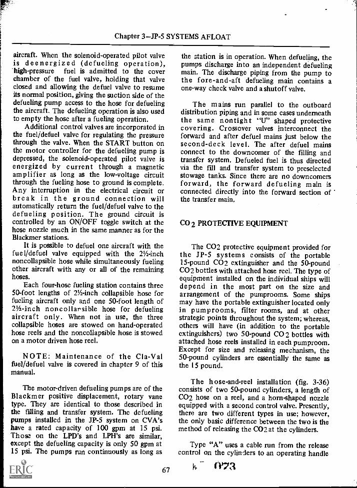
Chapter 3JP-5 SYSTEMS AFLOAT
aircraft. When the solenoid-operated pilot valveis deenergized (defueling operation),'high-pressure fuel is admitted to the coverchamber of the fuel valve, holding that valveclosed and allowing the defuel valve to resumeits normal position, giving the suction side of thedefueling pump access to the hose for defuelingthe aircraft. The defueling operation is also usedto empty the hose after a fueling operation.
Additional control valves are incorporated inthe fuelfdefuel valve for regulating the pressurethrough the valve. When the START button onthe motor controller for the defueling pump isdepressed, the solenoid-operated pilot valve isenergized by current through a magneticamplifier as long as the low-voltage circuitthrough the fueling hose to ground is complete.Any interruption in the electrical circuit orbreak in the ground connection willautomatically return the fuel/defuel valve to thedefueling position. The ground circuit iscontrolled by an ON/OFF toggle switch at thehose nozzle much in the same manner as for theBlackmer stations.
It is possible to defuel one aircraft with thefuel/defuel valve equipped with the 21/2-inchnoncollapsible hose while simultaneously fuelingother aircraft with any or all of the remaininghoses.
Each four-hose fueling station contains three50-foot lengths of 2%-inch collapsible hose forfueling aircraft only and one 50-foot length of21/2-inch noncollarsible hose for defuelingaircraft only. When not in use, the threecollapsible hoses are stowed on hand-operatedhose reels and the noncollapsible hose is stowedon a motor driven hose reel.
NOTE: Maintenance of the Cla-Valfuel/defuel valve is covered in chapter 9 of thismanual.
The motor-driven defueling pumps are of theBlackmer positive displacement, rotary vanetype. They are identical to those described inthe filling and transfer system. The defuelingpumps installed in the JP-5 system on CVA'shave a rated capacity of 100 gpm at 15 psi.Those on the LPD's and LPH's are similar,except the defueling capacity is only 50 gpm at15 psi. The pumps run continuously as long as
67
the station is in operation. When defueling, thepumps discharge into an independent defuelingmain. The discharge piping from the pump tothe fore-and-aft defueling main contains aone-way check valve and a shutoff valve.
The mains run parallel to the outboarddistribution piping and in some cases underneaththe same nontight "U" shaped protectivecovering. Crossover valves interconnect theforward and after defuel mains just below thesecond-deck level. The after defuel mainsconnect to the downcomer of the filling andtransfer system. Defueled fuel is thus directedvia the fill and transfer system to preselectedstowage tanks. Since there are no downcomersforward, the forward defueling main isconnected directly into the forward section ofthe transfer main.
CO 2 PROTECTIVE EQUIPMENT
The CO2 protective equipment provided forthe JP-5 systems consists of the portable15-pound CO2 extinguisher and the 50-poundCO2 bottles with attached hose reel. The type ofequipment installed on the individual ships willdepend in the most part on the size andarrangement of the pumprooms. Some shipsmay have the portable extinguisher located onlyin pumprooms, filter rooms, and at otherstrategic points throughout the system; whereas,others will have (in addition to the portableextinguishers) two 50-pound CO 2 bottles withattached hose reels installed in each pumproom.Except for size and releasing mechanism, the50-pound cylinders are essentially the same asthe 15 pound.
The hose-and-reel installation (fig. 3-36)consists of two 50-pound cylinders, a length ofCO2 hose on a reel, and a horn-shaped nozzleequipped with a second control valve. Presently,there are two different types in use; however,the only basic difference between the two is themethod of releasing the CO2 at the cylinders.
Type "A" uses a cable run from the releasecontrol on the cylinders to an operating handle
(173

AVIATION BOATSWAIN'S MATE F 1 & C
NIGH TYPE LEVER
PULLCABLE
OPERATION
L 80X
INSTRUCTIONS
NOSE REEL STATION
FRONT VIEW
TYPE "A"
I/20 SUPPLY FROMCYLINDERS TO HOSE REEL
QUICK ACTINGVALVE
HOSE REEL
FLEXIBLEMETAL NOSE
HORNTEMPORARYSHUTOFF VALVE
CUTTER VALVE
SIDE VIEW
FRDNTELEVATION
TYPE "B"
198.27Figure 3-36.--0O2 hose-and-reel installation.
which is set near the reeled hose. Type "B" useslocal control valves at the cylinder head.
To operate either type, proceed as follows:
1. Make sure the horn valve is in theCLOSED position.
2. On local control, open the valve in thepipeline above the cylinder intended for use.
WEI68
3. Release carbon dioxide from the cylinderby pulling the control handle at the cylinder orat the reel (for cable type).
4. The discharge of CO2 at the base of thefire can now be controlled by the horn valve.
Like the portable extinguisher, the CO2 canbe turned on and off as the work on thefire-fighting progresses; but, also, like theportable disc type extinguisher, it cannot bemade leak-proof until each cylinder is againsealed with a new sealing disc.
The CO2 equipment provided in the JP-5pumprooms is considered adequate, since fires inthese spaces usually are not of an extent thatrequire total flooding, or they are discoveredbefore they reach such an extent. The CO2 cantherefore be applied directly to the fire.Furthermore, there is no danger to personnelfrom accidental discharge, inasmuch as twocontrol valves must be opened to release theCO2.
In the event a pumproom fire should get outof control and require total flooding, take thefollowing precautions:
1. Secure the pumproom ventilation.2. Release all available CO2.3. Secure all access hatches to the
pumproom on departing.To insure readiness in case of fire, cylinders
should be weighed when received aboard andthereafter as follows:
1. 1 5 -pound portable extinguishersmonthly.
2. 50-pound cylinders when installed andsemiannually thereafter.
Any cylinder found to weigh less than 90percent of its proper weight should be refilled.The integrity of the lead wire seal on 15-poundextinguishers should be determined as a part ofthe regular weekly compartment inspection.Cylinders with missing or broken seals should beweighed immediately and restored to properreadiness. All cylinders should be stored in thecoolest part of the spaces.

CHAPTER 4
OPERATION OF THE JP -5. SYSTEM
RECEIVING JP-5 ABOARD
The first significant replenishing operationever performed at sea by the U. S. Navy was in1899, when the U. S. Navy collier, Marcellus,while towing the U. S. S. MASSACHUSETTS,transferred coal to her. Since that time, manymethods and procedures have been tried andabandoned. Those described in this chapter havebeen adopted as the most feasible and arecurrently used in the fleet. The actual rigging ofthe replenishing hose between ships is theresponsibility of the deck force and is notdiscussed in this chapter. The ABF is concernedwith only the filling connection hookup and theprocedures for receiving JP-5 aboard.
The receipt of aviation fuel aboard carriers isa continuing problem in the fleet. This is due, inmost part, to the hazardous nature of the fuelinvolved, and the ever increasing quantityrequired for our modern day aircraft. Otherfactors of equal importance which must also beconsidered are the type and location of theoperation, the time allotted, and the largenumber of personnel involved.
The type and the location of the refuelingoperation refer to the supplying source andgeographical location; such as, from a barge atanchorage in the harbor, when moored to a pier,or replenishing from a tanker underway. Thedangers involved are progressively greater in eachoperation in the order listed.
Time is an ever important aspect in anyrefueling operation, but more so at sea. Theentire Task Force is scheduled to be replenishedon a given date, and each ship is allotted amaximum time for this purpose. Not only areships in constant jeopardy of a fire or collision
69
during the replenishing operation, but they arealso a prime target in the event of an enemyattack.
JP-5 fuel is comparatively safe (having aminimum flashpoint of 1400 F) when in itsstored state. However, this same fuel handledunder high pressure is extremely dangerouswhen released into the atmosphere in a fine mistor spray. Therefore, it should be treatedaccordingly, and every precaution should betaken to prevent the possibility of a fire orexplosion when pumping this fuel.
The men required in a refueling operationinclude personnel of the entire V-4 division,those from other air department divisions, aswell as those from other department divisions;i.e. gunnery, engineering, etc. These men arestationed throughout the ship. Therefore, it isimperative that close communications bemaintained with all hands concerned at all timesduring the replenishing operation.
A replenishing operation from a tanker waschosen to be described here since it covers allphases of any refueling operation.
The procedure for receiving JP-5 fuel aboardis basically the same for all class carriers. Thischapter deals with the general procedures,equipment used, and the criteria for theacceptance or rejection of JP-5 fuel withoutreference to any particular ship.
The rate of fuel received can be increased byusing a double-hose rig. (See fig. 4-1.) Twc hosesare suspended, one below the other, from asingle span wire. With this rig, two kinds of fuelmay be received simultaneously at a singlestation, or one kind may be pumped throughboth hoses.
For more detailed information as toequipment, tools, and personnel required on
075

AVIATION BOATSWAIN'S MATE F 1 & C
BASE PLATEASSEMBLY
SPRINGPACKAGE
SWIVEL SPAN WIREASSEMBLY END FITTING
PELICANHOOK
MANUALRELEASELEVER
TROLLEY BLOCKASSEMBLY
SPAN WIRE
MESSENGERFAIRLEAD BLOCK
RECEIVERHOSES
( TO FUEL RISERS)PROBE
RECEIVERS
PROBES
MESSENGER
LATCHING STRESS WIRESDEVICE
19t 107Figure 4-1.Double probe and receiver.
your particular ship, consult your ShipsOrganization and Regulation Manual, andReplenishment at Sea Manual, NWP38 (Series).
PREPARATIONS
Prior to receiving the tanker alongside,certain preparations are necessary to safely andefficiently expedite the replenishing operation.These preparations can be listed under twocategories as follows:
1. Below-deck preparations.2. Topside preparations.
It can be assumed that many of the stepslisted in the two may be performedsimultaneously; but for clarity, they are coveredseparately in this chapter.
07G 70
Below-Deck Preparations
Ballasted JP-5 tanks should be deballastedand stripped as soon as possible after the dateand time of the replenishing operation have beenconfirmed. Actual pumping of ballasted tanksmust be in strict accordance with the sequencetables set up by damage control central in orderto maintain the list and trim on the ship. Obtainassistance from personnel in the engineeringdepartment. They will aline the main drainagesystem as required and operate the maindrainage eductors.
The pumproom or manifold operators alinethe tank stripping system as follows:
1. Unlock and open the main drainagecutout valve on the flood and drain manifold.(Relock manifold.)
2. Open the valves on the single-valvedstripping manifold to the tanks to bedeballasted.

I
Chapter 4OPERATION OF THE JP-5 SYSTEM
NOTE: All tanks interconnected with oneflood and drain manifold can be deballastedsimultaneously. Each eductor can deballast anaverage of 1,000 gpm when supplied with firemain pressure of about 150 psi.
Because of the tremendous suction taken bythe main drainage eductors, loss of suction onthe tanks is most likely to occur before thetanks are completely emptied. When this occurs,realine the tank manifolds to use the tankstripping system as follows:
1. Close all valves in the single-valvedstripping manifold.
2. Unlock and realine the flood and drainmanifold valves by closing the main drainageeductor cutout valve and opening the strippingmain suction cutout valve (relock the manifoldvalves).
3. Aline the piping from the flood and drainmanifold to the suction side of the motor-drivenstripping pumps.
4. Aline the pump discharge piping tooverboard via a fuel oil tank drainage system.(Request assistance from the engineeringdepartment.)
5. Open one valve on the single-valvedstripping manifold.
6. Start the stripping pumps, and strip eachtank one at a time until they are completelyempty of all ballast water.
(Note: Observe suction and dischargepressures during stripping operations to preventthe pump from running dry.)
7. Secure the flood and drain manifold andclose all valves in the single-valved manifold.
By use of the motor-driven stripping system,strip all stowage tanks that are to be used inboth the receiving operation and the internaltransfer operation prior to receiving JP-5 aboard.
NOTE: Verify all stripping operations bysounding the tanks, using water-indicating paste.
Strip the slack (partially filled) service tanks,using the hand-operated stripping system.
CAUTION: Ships planning to replenish inport MUST deballast and strip tanks prior toentering.
71
SOUNDING TANKS.Verify all strippingoperations by sounding the tanks, usingWATER-INDICATING paste; BOTTOM THIEFa sample and log its quality.
The tank gaging equipment (static headliquid level indicator) indicates only the amountof liquid in the tank. It does not indicate theamount of water. The only positive way ofdetermining the actual contents of a tank is tosound the tank with sounding tape, usingwater-indicating paste and then bottom-thiefinga sample.
SOUNDING EQUIPMENT.Sounding tapes(fig. 4-2) are 50-foot steel tapes graduated infeet and inches (inches graduated to 1/8's). Thebitter end is fitted with a snap-hook forattaching a plumb bob or thief sampler. The first
Figure 4-2.Sounding tape.
IS 77
198.28

AVIATION BOATSWAIN'S MATE F 1 & C
9 inches of the tape consists of the plumb boband snaphook. These tapes are usually plain, butcan be ordered in color, i.e. black on white orwhite on black.
Water-indicating paste presently in useaboard ship comes in tubes and may be orderedin either the 21/2- or 3-ounce size.
There are two types of thief samplers(shown in fig. 4-3). These sample's may be madeup locally or obtained from a naval repairactivity. Both can be used in a stan,lard 11/2-inchdiameter sounding tube. Type A is used where itis not necessary to obtain a sample from thevery bottom. Type B can be used (if riggedproperly) for any level or bottom sampling.
CORD OR WIRE LIFTING CORDIF DESIRED
NONMETAL STOPPERMIN. DIA 1/2"
Figure 4-3.Thief sampler:.198.29
i7C472
SOUNDING PROCEDURE.Spread a thincoating of water-indicating paste from the tip ofthe plumb bob to approximately the 2-footmark on the tape. Lower the plumb bob throughthe sounding tube until it touches the strikerplate. The tape must be kept taut; i.e., no slackwhich would cause an inaccurate reading. Slowlywithdraw the tape. The highest level where theJP-5 "wets" the tape is read in feet and inches.This reading is then converted to gallons by useof a tank capacity (curve) manual. When theplumb bob is removed, note the change of colorof the paste. The normal color, when applied, isgray. When water is present, the paste turnsRED to the level of water in the tank. This level,in feet and inches, is converted to gallons andsubtracted from the JP-5 reading for a moreaccurate determination of the quantity of JP-5in the tank.
Knowing the amount of water in the tankwill also assist in determining the time requiredfor the stripping operation.
To obtain a sample from the very bottom ofthe tank, remove the plumb bob and attach thetype B sampler shown in figure 4-3. Lower thesampler into the sounding tube. (The distancefrom the sounding tube cap to the striker platewill have been determined during soundingoperations.) As the tip of the valve disk guidetouches the striker plate, it will be depressed bythe weight of the sampler, raising both upperand lower disks off their seat. After remaning inthis position momentarily, retract the samplerand dump the contents into a clean jar.
If water droplets or discoloration are notedon the sounding tape during the sounding andbottom sampling procedure, it is an indicationof entrained or free water in the tank. Shouldthis occur, it will be necessary to take acomposite sample.
A composite sample is one in which samplesare taken from different levels in the tank andmixed to form one sample. This type sample ismore representative than one taken from onlytop and bottom. The same type sampler used totake the bottom sample can be used to take acomposite sample, simply by attaching a stringto the upper part of the disk guide stem. Thesampler can then be opened at various levels bygiving a smart jerk on the string.

Chapter 4OPERATION OF THE JP-5 SYSTEM
Tanks found to be contaminated withentrained water must be allowed more settlingtime before transferring.
INTERNAL TRANSFER.Top off all slackservice tanks. This will allow a longer settlingtime for the JP-5 being received. Consolidate thefuel load by transferring from slack stowagetanks to completely fill as many tanks aspossible. This will reduce the number of tanks tobe filled and will minimize the number of tanksaffected in the event contaminated fuel isreceived.
NOTE: When consolidating the fuel load, itis recommended that pumping be from forwardto aft. Modern ships are designed to operatewith no trim; however, if the ship must betrimmed when consolidating the fuel load priorto replenishing, it is desirable, especially onaircraft carriers, that they be trimmed by thestern.
CAUTION: When transferring fuel internallyor receiving fuel aboard, the overflow tank forevery nest of tanks scheduled to receive fuelmust be empty before fuel can be introducedinto any tank in that nest.
FILLING SEQUENCE.Before receivingfuel, the JP-5 oil king should have soundings orreadings taken on all stowage and service tanks.A statement showing the amount and locationof all JP-5 on board must be submitted to theofficer in charge of the fueling operation. It isthe responsibility of the JP-5 oil king to knowhow much fuel is on board, where it is located,how much more can be received, the order inwhich the tanks should be filled, and theapproximate duration of the receiving operation.
To determine the amount of JP-5 to bereceived, add the total capacity in gallons ofeach empty stowage tank plus the amountrequired to top off any slack tanks. The order inwhich the tanks will be filled (the tillingsequence) should be coordinated with damagecontrol central to maintain the proper list andtrim on the ship. In determining the fillingsequence, allow for a minimum of six tanks(three port and three starboard) on the line at alltimes. Knowing in advance the order in whichthe tanks will be filled will greatly assist in theassignment of sounding teams, manifold
73
operators, and the overboard dischargeobservers.
Three factors are involved in determining theduration of the receiving operation: (1) theamount to be received (previously determined),(2) the maximum receiving rate of the particularship, and (3) the normal pumping rate of theindividual tanker. The latter two can be gainedthrough actual experience and informationrecorded in the receiving log; however, if this isthe first experience with the tanker, thepumping rate can be obtained in advance viaradio messages to the tanker.
Topside Preparations
Preparations to be made topside by V-4division personnel are not as numerous and timeconsuming as those below decks, since most ofthe actual rigging for receiving the tanker is theresponsibility of the deck divisons. However,there are certain pieces of equipment that mustbe assembled by repair team personnel at or nearthe refueling station, in order to safely andefficiently expedite the operation.
Repair team personnel should insure that thefilling connection is equipped with a pressuregage, thermometer, sampling connection,low-pressure air connection, and a flushing valve.They should also insure that the male end of thequick-release coupling and/or probe receiver isattached and in good working order.
NOTE: Due to the difficulty encountered inreleasing the Robb quick-release coupling duringemergency breakaway, some ships requirea breakable spool installed between the 90° elland the male end of the quick-release coupling.(See fig. 4-4.)
The breakable spool is in addition to the onerequired on some ships for attaching the flushingvalve. It is weakened by a groove around itsouter circumference so that it can be easilybroken by a sharp blow from a sledge hammer,if emergency conditions so require.
The equipment to be assembled at or neareach refueling station by preassigned personnelincludes the following:
1. Proper handtools.2. Drip pan.

AVIATION BOATSWAIN'S MATE F 1 & C
3. Rags.4. Swabs.5. Speedy dry.6. Buckets (rubber or brass).7. Five-gallon safety can.8. Length of low-pressure airhose.9. Length of refueling hose (as required).
10. Length of hoseattached to flushingvalve (as required).
11. Two pry barsfor emergencydisconnect.
12. One sledge hammer (as required).13. Two telephone headsets.14. The receiving logs.15. Clean sampling bottles and tags for
identification of samples.16. Several portable 15-pound CO2 and/or
P-K-P extinguishers.
17. Two 21/2-inch firehosefully charged.18. Two 21/2-inch firehose with 12-foot
applicatorsfully charged.19. Two 21/2-inch foam hosenot charged.
NOTE: The fog foam pumping unit ismanned by the engineering department.
The type and number of pieces offirefighting equipment to be laid out in thevicinity of the refueling station must be inaccordance with the ship's fuel handling bill.Listed above are the recommended minimumrequirements on a typical CVA.
During the refueling operation, two separatesound-powered telephone circuits are mannedby V-4 division personnel. One is the carrier 4JG(the AvFuels system circuit), and the other
6-INCH VALVE
HOS GASKET
FLANGE
SPRING-TENSIONED
SLEEVE
OPERATINGLEVER
SPLIT CLAMPCOUPLINGADAPTER
SPRING-TENSIONEDBALL RACE
TO RELEASE BEARINGS, LEVER DETACHABLE FOR PRYINGSLIP BACK OPEN SPRING-TENSIONED SLEEVE
FEMALE ENDDELIV. SHIP
i
SPRING TENSIONEDSLEEVE
111
ANNULARGROOVE
USE ONLY ON U S TO U S. SHIPS
H
rhMALE ENDRECEIVING
SHIP
MACHINED
GROOVE
VALVESPRING
VALVEOPEN
POSITION
VALVE
NIPPLEGASKET
SLOT FORPRY BAR
END
RING
ACTUATINGCAM
198.108Figure 44.Combined quick-release (Robb) coupling and valve.
IRO74

Chapter 4OPERATION OF THE JP-5 SYSTEM
furnished by the supplying source, is fromship-to-ship.
To expedite communications, position thefilling connection and ship-to-ship telephonetalkers close to the officer or CPO in charge ofthe refueling operation. The ship-to-shiptelephone talker should have the telephone leadready to establish communications as soon asthe telephone jackbox is received from thetanker.
CAUTION: To avoid injury, the ship-to-shiptelephone talker should not fasten the telephoneneck strap.
Telephone talkers are stationed at thefollowing locations on the circuits indicated:
1. Filling connection (two talkersone onthe 4JG, and the other on the ship-to-ship).
2. Flight deck control (4JG), as required.3. Sounding tube locations (4JG).4. Overboard discharge sentry (4JG):5. Pumprooms (4JG).6. Manifold spaces (4JG).7. Damage control center (4JG).
All telephone headsets must be tested well inadvance of the receiving operation.
A fueling watch list should be posted well inadvanceat least 24 hours whenever possible. Inaddition to the posted list, each man should beinformed of his station and instructed in hisduties. During the instruction period, emphasisshould be placed on safety, emergencybreakaway procedures, and hazards. Assign onlyexperienced and capable men to actuallyperform the duties. Limit the number oftrainees, especially at the filling connections; toomany men at this station are not helpful andmay confuse the operation by getting in theway. Whenever possible, rotate experienced mento other stations. This will not only give theindividual the broadest training possible, but willalso produce a more flexible division.
As a rule, fueling stations should be mannedhalf an hour before fueling time. The refuelingstations to be manned and their locations are asfollows:
1. Fire Partylocated on the hangar decknear the filling connection. (This station is
75
manned by other air department personnel asrequired.)
2. Overboard discharge observerlocatedon catwalks, sponsons, or weather decks toobserve and report the overflow from theoverflow tanks.
3. Filling connection personnellocated atthe filling connections. (Repair team personnelmake the actual hook up.)
CAUTION: Personnel working at the fillingconnections should wear a life jacket (kapokonly ), construction type (safety) helmet orbattle helmet, whistle, and pin-on flashlight.
4. Anticontamination sentrylocated atthe filling connection to take samples asprescribed by the aviation fuels officer.
5. Sounding teamsstationed in necessarycompartments where sounding caps are located.
NOTE: Sounding teams should be equippedwith a sounding kit which contains thefollowing:
a.
b.c.d.e.f.g.h.i.
Sounding tape (plumb bobsafety-wired to tape).Water-indicating paste.Rags.Pencils.Tank sounding cards.Flashlight (explosion-proof).Sound-powered telephone headset."T" wrench (for sounding caps).Spare gaskets (for sounding caps).
6. Manifold operatorslocated inpumprooms or manifold spaces.
7. Liquid level diagram recorderlocated indamage control central.
RECEIVING OPERATION
Immediately upon manning a station,communication should be established. When allstations have reported manned and ready, theJP-5 filling and transfer system should be linedup for receiving JP-5. Open the followinc, valves:
1. Below decks at the base of thedowncomer.
(ISI

AVIATION BOATSWAIN'S MATE F 1 & C'
NOTE: Where downcomer valves are locatedin machinery spaces, valve flange gaskets shouldbe checked for tightness to prevent leakage intospaces.)
2. All transfer main bulkhead cutout valves.3. Transfer main branch header valves
leading to the manifold of the tanks to be filled.4. The transfer main side manifold valves of
all tanks to be filled.5. Tank side manifold valves to a minimum
of six tanks (three port and three starboard).CAUTION: Insure that all telltale valves on
the manifolds are closed. The below-deck pipingand valves are now alined for receiving JP-5aboard.
Just prior to receiving the tanker alongside,specific action must be taken by certaindepartments to insure maximum safety andsecurity during the replenishing operation.
The officer of the deck controls the smokinglamp. The operations watch officer insures thatcertain high-frequency transmitters, radars, andother electronic equipment in the vicinity of thefueling stations are secured. The damage controlwatch officer insures that additional fire mainpumps are put on the line and that the fog foampumping unit is manned. The aviation fuelsofficer insures that no mobile equipment orelectrical winches (not required in thereplenishing operation) are operated within 50feet of the fueling station.
As the ship makes its final approach andsteadies alongside, heaving lines or shot lines aresent over from each station. By means of thesefirst lines, the telephone cables, distance line,and hose messenger are sent back. As soon ascommunication is established between stations,the JP-5 oil king clarifies with the tanker finalinformation such as, tanker's maximumpumping rate and discharge pressure andcarrier's maximum receiving rate and pressure.
When using the Robb type refueling rig,inspect the female half of the quick-disconnectcoupling to insure that the sealing gasket is inplace and in good condition. Also make surethat all three valve disk guides are intact. If thesealing gasket is missing or distorted in any way,the coupling will leak. If any one of the valvedisk guides is broken off, it will be impossible toopen the valve in the quick-disconnect coupling.
()S2 76
In the event either of the above twodiscrepancies is noted, send the hose back to thetanker for repair. After the female half has beeninspected and found to he satisfactory, couplethe hose to the filling connection.
When using the Probe type refueling rig,check each of the six lock arm assemblies forbroken or missing lock arms; insure that all lockarms are in a locked position. When the probe isproperly mated with the receiver the indicatorflag will raise approximately 30 degrees (fig.4-5), indicating transfer of fuel may commence.
NOTE: The actual hookup of the fuelinghoses is accomplished by personnel from theDeck department.
Before receiving JP-5 into the stowage tanks,samples should be taken at the main deck fillconnection in containers that permit visualinspection. If acceptable fuel is being receivedopen the downcomer, close the flushing valve,and insure a minimum number of stowage tanksare on the line. Start replenishment of aviationfuels at a slow rate.
When JP-5 enters the tanks, as indicated bythe liquid level indicators or sounding teams,order the tanker to start pumping at a normalrate. Log the starting time and continue takingsamples to insure the receipt of clean, bright,water-free JP-5. Log the quality of the samplestaken and pressure of the JP-5 being received atthe hangar deck filling connection.
The receiving pressure at the fillingconnection should be approximately 40 psi inorder to obtain the designed maximum fillingrate. Some of the larger CVA's can receive JP -5at a rate of 360,000 gallons per hour when usingtwo stations.
As the stowage tanks are being filled, thevolume of fuel in each tank is constantlychecked by observing the liquid level indicatorsand by sounding the tanks.
CAUTION: Commence sounding at theinitial flow. In general, the tanks nearest thedowncomer will till first.
Sounding should be taken periodically untilthe tanks reach 80 percent capacity. From thispoint on, soundings should be continuous.
When 80 percent capacity is reached in thefirst nest of tanks opened, open the tank sidevalve to another nest minimum of sixtanksthree port and three starboard) at the

Chapter 4--OPERATION OF THE JP-5 SYSTEM
PROBE DISENGAGED FROM PROBE RECEIVER. .
LATCH INDICATOR FLAGS IN STOWED POSITION.
PROBE MATED WITH PROBE RECEIVER.LATCH INDICATOR FLAGS RAISED APPROX-IMATELY 30° ABOVE THE HORIZONTAL.
198.109Figure 4-5.Latch indicator flags.
same time, throttle the TANK SIDE valves tothe first aes 1: of tanks, and top them off to atleast 95 percent capacity. All stowage tanks,except overflow tanks, can be filled to almost100 percent to increase the amount of fuelcarried on board.
NOTE: JP-5 tanks are not fitted with steamheating coils (as are the standard fuel oil tanks);therefore, room for expansion for this purpose isnot necessary. The overflow tanks are limited to
95 percent to 'allow for expansion due to normaltemperature changes.
All stowage tanks in one nest, both port andstarboard, can be opened for simultaneousfilling, but care must be exercised when toppingoff to prevent overtaxing the overflow line.
CAUTION: Overflow mains for overflowtanks are designed for an overflow rate of 1,500gpm, and each stowage tank has an overflow rateof 500 gpm.
The liquid loading diagram recorder,stationed in damage control central, marks eachfull tank with an "F" as soon as word is receivedover the 4JG circuit.
After the amount of JP-5 being received perminute has been determined, the tanker can begiven a "stop pumping" time.
NOTE: The fueling operation given in thischapter is for loading the forward tanks first andthen the after tanks. However, it should benoted that all tanks both forward and aft can beopened for simultaneous filling. All CVA's fittedwith two downcomers (one forward and one aft)utilize both to expedite the refueling operation.The number of tanks that can be opened and themethod of receiving will vary on the individualships, depending on the number of personnelavailable as manifold operator, sounding teams,etc., and the experience gained after severalrefueling operations.
While the forward group of stowage tanks isbeing filled, the below-deck crew is lining up theafter group in the same manner as previouslydescribed. All valves EXCEPT the transfer mainbulkhead cutout valve nearest the downcomer inthe after pumproom are opened to the aftergroup of tanks to be filled.
When the last port and starboard tanks are80 percent full, open the transfer main bulkheadcutout valve leading to the after group of tanks.The after group of tanks are filled in the samemanner as the forward group. Continue toppingoff the remaining tanks forward.
NOTE: On ships that are equipped with theCla-V.,1 service station, an adequate number ofstowage tanks in each group must remain emptyto receive the recirculated fuel from thesestations.
When the last port and starboard tanks to befilled reach 80 percent capacity, notify thetanker to reduce pumping. Top off the last
77 ()S3
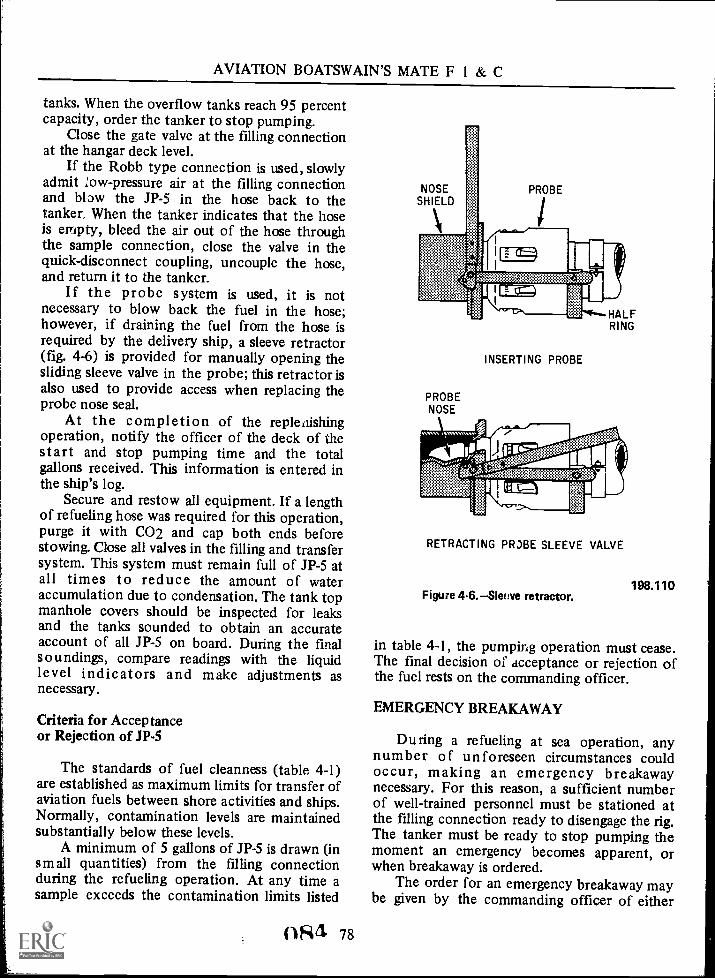
AVIATION BOATSWAIN'S MATE F 1 & C
tanks. When the overflow tanks reach 95 percentcapacity, order the tanker to stop pumping.
Close the gate valve at the filling connectionat the hangar deck level.
If the Robb type connection is used, slowlyadmit ow-pressure air at the filling connectionand blpw the JP-5 in the hose back to thetanker. When the tanker indicates that the hoseis empty, bleed the air out of the hose throughthe sample connection, close the valve in thequick-disconnect coupling, uncouple the hose,and return it to the tanker.
If the probe system is used, it is notnecessary to blow back the fuel in the hose;however, if draining the fuel from the hose isrequired by the delivery ship, a sleeve retractor(fig. 4-6) is provided for manually opening thesliding sleeve valve in the probe; this retractor isalso used to provide access when replacing theprobe nose seal.
At the completion of the replenishingoperation, notify the officer of the deck of thestart and stop pumping time and the totalgallons received. This information is entered inthe ship's log.
Secure and restow all equipment. It a lengthof refueling hose was required for this operation,purge it with CO2 and cap both ends beforestowing. Close all valves in the filling and transfersystem. This system must remain full of JP-5 atall times to reduce the amount of wateraccumulation due to condensation. The tank topmanhole covers should be inspected for leaksand the tanks sounded to obtain an accurateaccount of all JP-5 on board. During the finalsoundings, compare readings with the liquidlevel indicators and make adjustments asnecessary.
Criteria for Acceptanceor Rejection of JP-5
The standards of fuel cleanness (table 4-1)are established as maximum limits for transfer ofaviation fuels between shore activities and ships.Normally, contamination levels are maintainedsubstantially below these levels.
A minimum of 5 gallons of JP-5 is drawn (insmall quantities) from the filling connectionduring the refueling operation. At any time asample exceeds the contamination limits listed
()S4 78
NOSESHIELD
PROBE
INSERTING PROBE
PROBENOSE
HALFRING
RETRACTING PROBE SLEEVE VALVE
198.110Figure 4-6. Sim 'ye retractor.
in table 4-1, the pumping operation must cease.The final decision of acceptance or rejection ofthe fuel rests on the commanding officer.
EMERGENCY BREAKAWAY
During a refueling at sea operation, anynumber of unforeseen circumstances couldoccur, making an emergency breakawaynecessary. For this reason, a sufficient numberof well-trained personnel must be stationed atthe filling connection ready to disengage the rig.The tanker must be ready to stop pumping themoment an emergency becomes apparent, orwhen breakaway is ordered.
The order for an emergency breakaway maybe given by the commanding officer of either

Chapter 4OPERATION OF THE JP-5 SYSTEM
From
ShoreTankage
Fleet Oilers,Barges,Tankers
Carriers,Fleet Oilers,Barges,Tankers
Table 4-1.Standards of fuel cleanness
To Max. sediment Max. water(See Note 1) (See Note 2)
Barges, Tankers,Fleet Oilers,Carriers
Carriers
Shore Tankage
8.0 mg/liter
10.0 mg/liter
10.0 mg/liter
No visible
No visible
No visible
NOTE 1: Sediment levels are to be determined by laboratory analysis, or by the AEL MkIII Contaminated Fuel Detector.
NOTE 2: The free water content is determined byby laboratory analyses.
the receivirigLOip or the delivery ship.Paramount in ordering an emergency breakawayis the allowance of sufficient time for the shipsto disconnect the rigs in an orderly manner.Fueling rigs are subject to severe damage if notproperly released at the breakaway signal, andserious injury to personnel could occur.
An emergency breakaway may beaccomplished smoothly, rapidly, and safely, ifthe men at the station know how and what todo first. The proper sequence for an emergencybreakaway using the Robb connection is as
follows:
1. Stop pumping.2. Free the hose. Use any on of the
approved methods, but in the order listed. First,relieve the strain on the hose by hauling in onthe riding line. (If time permits, manually closethe valve in the female half.) By use of pry barsor spanner, retract the sleeve and disengage thequick-release coupling. If the sleeve cannot beretracted, then, secondly, with the valve in thefemale end closed, use a 10-pound sledge, andstrike the breakable spool sharply. Do not cut
79
the AEL Mk I Free Water Detector Kit, and
the riding line; use it to ease the hose over theside. The third and last course of action is to cutthe hose loose with a fire ax.
3. Release the span wire. Telephone anddistance lines can be returned as soon as theword is passed for breakaway, but talkers shouldbe cautioned to replace the caps on thejackboxes.
Emergency breakaway of the probe fuelingunit is the same as for a normal rig disconnect,unless complications arise. The followingdescribes both methods of disconnecting theprobe. After completion of fuel transfer, removethe remating line and actuate the manual releaselever (fig. 4-7) ro release the probe. The deliveryship retrieves the fuel hose. After the hose hasbeen fully retrieved and the span wire has beendetensioned, trip the pelican hook and ease thespan wire over the side of the receiving ship withan easing-out line,
CAUTION: Release of the span wire prior toretrieval of the hose can result in damage to thefueling probe; therefore, the span wire shall notbe released until ordered by the delivery ship.
oS5

AVIATION BOATSWAIN'S MATE F 1 & C
PROBETUBE
MESSENGER REMATING LINEATTACHMENT HOOK
PROBE
PROBE TROLLEYASSEMBLY
LATCHINGMECHANISM
RECEIVERBELL MOUTH
MANUALRELEASE
LEVER
Figure 4-7.Single probe and receiver.
Line tension supplied by the ram tensioner in atensioned span-wire rig must be removed priorto tripping the pelican hook which releases thespan wire.
If the receiving ship cannot quicklydisconnect the probe from the receiver, thedelivery ship can do so by taking a strain on theretrieving line saddle whip, provided a stress wireconnects the outboard saddle with the probetrolley. A line pull of 2,500 pounds is requiredto disengage the probe by this method.
All necessary tools, spare parts, and sparecomponents necessary to effect repairs totransfer stations must be maintained in readinessto meet major or minor repair requirements.While individual ship configuration will dictatestowage of spare components, a complete set oftools and repair equipment must be maintainedin a location readily accessible to transfer stationpersonnel. Such tools and equipment should beinventoried and checked for proper operationprior to each fuel replenishment. Each transferstation should maintain, as a part of stationequipment, a listing of all items (tools, spares,etc.) which may be required to repair thestation, together with the stowage location ofsuch items.
SETTLING AND STRIPPING
The stowage period between receipt of JP-5on board and delivery to an embarked aircraft is
08C;80
RECEIVERHOUSING
198.111
a vital link in the cleaning process required. Thissettling period, in addition to proper stripping,will also take the load off the other cleaningprocesses in the system. Therefore, it isextremely important for fuel handlers to befamiliar with the settling and strippingprocedures aboard aircraft carriers.
SETTLING PERIOD
Use settling to the maximum degree possibleto separate solids and water from fuel. Thesettling time for JP-5 is 3 hours per foot ofproduct height. In order to obtain the maximumsettling time for JP-5 tanks, the followingoperating procedures should be followed:
I. NEVER transfer JP-5 into an IN USEservice tank.
2. Completely empty the in use service tankbefore taking suction on another service tank.
3. Avoid agitating settled tanks byminimizing the transfer of JP-5 to consolidatethe fuel load or to correct the list or trim of theship. This can best be prevented by followingthe proper emptying sequence and by takingsuction from an equal number of port andstarboard tanks simultaneously whentransferring during normal operations.
4. Coordinate the replenishment date sothat there is always enough JP-5 on board to topoff all service tanks prior to receiving JP-5aboard.

Chapter 4OPERATION OF THE JP-5 SYSTEM
5. When transferring JP-5 from stowage toservice tanks, the tank emptying sequence forany nest of tanks should be shceduled so as toempty the overflow tanks first; the slack tanks,if any, next; and the tanks that have had thelongest settling time last.
Rotate the tank emptying sequence betweenthe different nests of tanks so that all tanks areutilized and not just those that are mostconvenient to the pumproom operator. The tankemptying sequence will be coordinated withdamage control central.
STRIPPING SCHEDULE
Serious contamination of JP-5 has occurredon several aircraft carriers, resulting in the lossof untold millions of dolla-s in equipment(aircraft) and, in some instances, loss of humanlife. All of this could have been avoided ifWATER and SOLIDS in the fuel had not beenallowed to reach the aircraft fuel cells.
This useless waste was caused in the mostpart by improper use of the equipment, a lack ofunderstanding of the need for stripping, and insome cases a complete disregard of the strippingequipment and procedure. Therefore, it isimperative that the following stripping scheduleand procedure be complied with.
Strip the stowage tanks with themotor-driven stripping pumps as follows:
1. Prior to receipt (in the same mannerpreviously described).
2. The day after receiving JP-5 aboard.3. Weekly thereafter as applicable.4. The day before transferring to service
tanks (if time permits).5. Immediately prior to transferring JP-5
from stowage to service tanks.
Strip the service tanks with thehand-operated stripping pumps as follows:
1. Before filling.
2. After filling (allow for settling).
3. Just prior to fueling aircraft (each andevery time).
81
CAUTION: Never strip the service tanks inport with the hand-operated stripping pump.
During nonoperational periods, when theship is cruising at sea and no flight operationsare scheduled, strip the service tanks daily. Inport or at sea, strip stowage tanks weolcly.
STRIPPING PROCEDURE
Before any transfer operation, the JP-5stowage tanks concerned must be stripped of allwater and sludge by using the motor-drivenstripping system.
The stripping system is alined in basicallythe same manner as described for strippingballast tanks except that the discharge isdirected to the contaminated JP-5 settling tank.
Inform the damage control watch officer ofthe intended operation, the number of tanks tobe stripped, and the number of the settling tankdesignated to receive the stripped liquids. Thenproceed as follows:
1. Open the valve on the single-valvedstripping manifold to the tank to be stripped.
2. Open the valve on the flood and drainmanifold leading to the stripping main.
NOTE: Step 2 is necessary only for tanksthat are designated JP-5 or ballast.
3. Open the necessary valves in the strippingmain leading to the suction header of thestripping pump.
4. Open the stripping pump inlet valve.5. Open the stripping pump discharge valve.6. Open the cutout valve from the discharge
header leading to the contaminated JP-5 settlingtank.
7. Start the motor-driven stripping pump.8. Open the test connection on the
discharge side of the stripping pump.
Take frequent samples of the JP-5 beingdischarged. When a sample of clean, bright,water-free JP-5 is obtained, the tank is stripped.Close the valve on the single-valved strippingmanifold, and open the valve to the next tank tobe stripped. Strip all tanks in the same manner.
CAUTION: The clean JP-5 remaining in thesystem between the single-valved stripping
()S9
AVIATION BOATSWAIN'S MATE F 1 & C
manifold and the stripping pump from thepreviously stripped tank MUST be dischargedpast the test connection before a conclusivesample can be obtained from the next tank to bestripped.
This can be accomplished by having ageneral knowledge of the capacity of thestripping system piping between the two pointsand the capacity of the stripping pump. Run thepump accordingly. Allow extra running time fora safety factor.
EXAMPLE: Pipe Capacity-160 gallonsPump capacity-50 gpm
Run pump 4 minutes before taking sample ofnext tank.
When all stowage tanks have been stripped,stop the pumps and close all valves in thesystem. Notify damage control central of thecapacity of the contaminated settling tank.
The service tanks can be stripped in basicallythe same manner as the stowage tanks by usingthe motor-driven stripping pumps. However, thisshould rarely, if ever, be necessary except whencompletely emptying the service tanks (the last24 inches of fuel) prior to maintenance,cleaning, etc., and to remove the wash waterafter a cleaning operation.
If the stowage tanks are allowed adequatesettling time and are properly stripped, and ifthe transfer filters or centrifugal purifier aremaintained and operated properly, there shouldNEVER be enough water in a service tank tonecessitate using the motor-driven strippingsystem for this purpose.
Service tanks are normally stripped by use ofthe hand-operated stripping pump. Theprocedure used is as follows:
1. Open the valve on the suction side of thestripping pump leading to the service tank to bestripped.
2. Open the valve on the discharge side ofthe stripping pump.
3. Operate the pump handle (back and forthin a 90° arc) until clean fuel is observed in thedischarge line (as indicated by the bull's-eyesight gage).
°SR 82
4. Open the test connection and takefrequent samples. Pump until a sample of clean,bright, water-free JP-5 is obtained.
NOTE: The hand pump is capable ofdischarging 30 gpm at 50 double strokes perminute.
When stripping service tanks with thehand-operated stripping pump prior to filling,err.,.Ay the transfer filtering media drain boxbefore securing the system.
NOTE: The drain box can be emptiedthrough connections off the motor-drivenstripping system on some ships.
TRANSFER SYSTEM OPERATIONS
Transferring JP-5 internally is accomplisl.edby the three individual transfer pumps in each ofthe forward and after pumprooms. Whentransferring from stowage to service tanks, usethe following procedure:
1. Strip all tanks concerned, both stowageand service.
2. Empty the transfer filter drain box asapplicable).
3. Arrange the tank emptying sequencewith damage control central. Empty theoverflow tank first, the slack tanks second, andthe tanks that have had the longest settling timelast.
4. Open the following valves:a. Tankside manifold valve to one port
and one starboard tank.b. All transfer mainside manifold valves
for all tanks to be emptied.
NOTE: Insure that the telltale valves areclosed.
c. All valves in the transfer main branchheader between the manifolds andpump suction header.
d. Valves in the suction header.e. The pump inlet and discharge valves
to ONE pump.f. All valves from the pump discharge
header to ONE purifier.
Chapter 4OPERATION OF THE JP-5 SYSTEM
g. The service tank cutout valve to thetank to be filled.
5. Connect the seal water inlet hose to theplug valve on the purifier and open the supplyvalve.
NOTE: Preoperational checks required onpurifiers, before starting, are described in detailin chapter 8 of this training manual.
6. Start the purifier.7. If the purifier bowl shell assembly is
clean and attains 4100 rpm (146 to 150 bumpsper minute within 3 minutes), open the sealwater plug valve on the purifier (4100 rpm's in 8minutes on direct drive purifiers).
NOTE: To minimize vibration when startingwith a dirty bowl, admit seal water immediatelyafter pressing the start button.
8. Open the main water-dischargeobservation port on the cover assembly. Whenwater discharges past this port, close the sealwater inlet plug valve on the purifier and at thesupply end.
9. Start the transfer pumps.10. When the pump discharge pressure builds
up, simultaneously and SLOWLY open thefollowing valves:
a. Purifier inlet globe valve and throttleto maintain 9 psi inlet pressure.
b. Purifier discharge globe valve andthrottle to maintain 30 psi backpressure (±5 psi).
11. Log the time the transfer pump andpurifier were started.
12. While the system is in operation, makethe following additional log entries:
a. Transfer pump inlet and dischargepressure.
b. Purifier inlet and discharge pressure.c. Purifier inlet temperature.
13. Take inlet and discharge samples.a. Analyze the samples with the AEL
Contaminated Fuel Detector Mk IIIand the AEL Water Detector Kit MkI.
b. Log the results of the analysis.
NOTE: It is advisable to take a visual sampleof the contents of the stowage tank from whichsuction is being taken at the initial opening o fthe manifold valves. This sample can be dra w nthrough the telltale valve.
14. If the transfer pumps lose suction beforethe service tank is full, take the followingaction:
a. Close the purifier inlet and dischargevalves.
b. Close the manifold valves to theempty tanks.
c. Place additional tanks on the line.d. When the transfer pump discharge
pressure is again attained, repeat step10.
NOTE: As an added safety factor, anoverboard discharge observer should be postedduring this operation.
15. When the service tank is 95 percent full,secure the system. The procedure for stoppingthe purifier is as follows:
a. Close the purifier inlet globe valve.b. Stop the transfer pump.c. Stop the purifier by pressing the stop
button.d. DO NOT engage the brake; the
purifier will coast to a stop inapproximately 70 minutes.
e. As the purifier slows down,centrifugal force diminishes, andinlet and discharge pressure will dropto zero.
f. When the flapper in the dischargesight flow gage stops, close the globevalve in the purifier discharge line.
g. Close all valves in the filling andtransfer system.
h. Make the following log entries:(1) Time transfer pump stopped.(2) Time purifier stopped.(3) Gross gallonage removed from
stowage tank.(4) Net gallons received in service
tanks.
During the transfer operation, samples forvisual examination must be taken from the
83 riN9

AVIATION BOATSWAIN'S MATE F 1 & C
purifier outlet at regular intervals in accordancewith local instructions. Samples must be cleanand bright and contain NO free water. A cloud,haze, specks of sediment, or entrained waterindicates the fuel is probably unsuitable andpoints to a breakdown in the purificationprocess. Should this occur, the transferoperation must be secured until stowage tanksconcerned have been restripped; a clean, bright,water-free sample is received on the dischargeside of the stripping pump; and the centrifugalpurifier is inspected and discrepancies arecorrected.
TRANSFERRING FROM STOWAGETO STOWAGE
This operation should rarely be necessary ifan emptying sequence was properly establishedand followed (except when consolidating thefuel load prior to receiving). If and when thisoperation is called for, it will, in most instances,require transferring JP-5 from port to starboard,or vise versa, to correct the list on the ship; ortransferring JP-5 from forward to aft, or viceversa, to correct the trim on the ship.
The operating procedure for this operation isbasically the same as transferring from stowageto service with the following exceptions:
1. Filtering equipment and samplingprocedures are not required.
2. The transfer piping from the dischargeheader of the transfer pumps is alined todischarge into the opposite transfer main branchheader, from which suction is being taken (whentransferring from port to starboard, or viceversa); or to the transfer main (when transferringfrom forward to aft, or vice versa).
CAUTION: The overflow tank for any nestof tanks scheduled to receive fuel must beempty before JP-5 can be transferred into anytank in that nest.
CONSOLIDATING FUELWhen any transfer operation has been
completed, consolidate to the greatest extentpossible the last 24 inches of JP-5 remaining inthe stowage tanks. (As much as 5,000 gallonsremain in some of the larger tanks after thetransfer pumps lose suction.) This consolidation
(190 84
must be accomplished by the motor-drivenstripping pump.
The procedure for consolidating the last 24inches of JP-5 is basically the same as thatoutlined for stripping, except for the following:
1. Permission is not required from damagecontrol central, nor is assistance required of theengineering department, unless the amount offuel being consolidated may affect the trim ofthe ship.
2. The stripping pump discharge header isalined to direct the discharged fuel into thetransfer main instead of the contaminated fueloil drain system or the contaminated JP-5settling tank.
From the transfer main, the JP-5 is directedinto preselected stowage tanks. Consolidatedfuel should be allowed maximum settling timebefore it is stripped prior to use.
BALLASTING OPERATION
The empty ballast stowage tanks areballasted (filled with sea water) to preserve theunderwater protection system of the ship.Ballasting must be accomplished in accordancewith current ship's ballasting instruction foreach individual ship.
Tanks on CVA's 4re ballasted by gravitythrough the sea chest valve on the flood anddrain manifold and the single-valved strippingmanifold. On LPH's and LPD's this water issupplied from the ship's fire main system.
Ballasting procedure is as follows:
1. Follow the tank filling sequence asscheduled by damage control central tomaintain the proper list and trim of the ship.
2. Open the valves on the single-valvedstripping manifold to the tanks to be filled.
NOTE: ALL tanks that are served by oneflood and drain manifold can be filledsimultaneously.
CAUTION: Open an equal number of tankson the opposite side of the ship.

Chapter 4 OPERATION OF THE JP-5 SYSTEM
3. Aline the valves on the flood and drainmanifold for ballasting.
a. Unlock the sliding lock bar byloosening the two bolts over theoblong slots.
b. Position the lock bar so that thecircular hole in the keyhole slot isdirectly above the raised collar onthe sea chest valve stem.
c. Rebolt the lock bar in position.
4. Open the sea chest valve.5. Sound the tanks to determine the instant
they are full.
CAUTION: The static head tank liquid levelndicators cannot be used for this purpose, asthey are designed for JP-5 and not sea water.
6. As each tank becomes full, as indicatedby the tank sounding teams, close the valve onthe single-valved stripping manifold.
7. When all tanks are ballasted, close thesea chest valve and reposition the lock bar.
8. Lock the tank side valve (on thedouble-valved filling and suction manifold) inthe CLOSED position.
9. Open the telltale valves on thedouble-valved manifold and drain the contents;then close these valves.
CAUTION: Thereafter, as long as the tanks areballasted with sea water, periodically open thetelltale valves to determine the condition of thetank side valves and transfer main side valves.
NOTE: Most ballast tanks will not fillcompletelysome will only half fill due to tankheight and draft of ship. Ballast liquid will seekits own level.
OFF-LOADING JP-5
Off-Loading From Service Tanks
When it is necessary to off-load JP-5, theservice pumps are used as transfer pumps. JP-5 isdischarged off the ship via the transfer main,downcomer, filling connection, and thence to abarge, tanker, or fuel farm.
85
Since the service pumps are utilized as
transfer pumps for off-loading JP-5, the pipingand valves in the filling and transfer system andthe service system must be alined to enable theservice pumps to take suction from, anddischarge into, the same piping as the transferpumps.
Assume, in this operation, that the entirefuel load is to be off-loaded, including the JP-5in the service tanks. This being the case, emptythe service tanks first, since no specialpreparations are required to take suction fromthese tanks with the service pumps.
Mine the piping and valves as follows:
1. Open the service tank suction cutoutvalve between the service tank and the servicepump suction header.
2. Open the service pump inlet valve.3. Unbolt and rotate the spectacle flange (or
line blind) to the OPEN position in thecross-connecting piping between the servicepump discharge header and the transfer pumpdischarge header. Unlock and open the gatevalve in this same line.
4. Open the valve between the transferpump discharge header and the transfer main.
5. Open the transfer main bulkhead cutoutvalves leading to the downcomer.
6. Open the gate valve at the base of thedowncomer.
7. Open the gate valve at the fillingconnection.
When topside preparations have been madefor off-loading fuel, start the service pumps.
NOTE: The pump recirculating line is notrequired for this operation because the pumpsare running only during actual pumpingoperation.
When pump discharge pressure reaches 80psi, SLOWLY open the globe valve on thedischarge side of the pump. Throttle pumps toavoid cavitating and maintain a minimum of 35psi back pressure for automatic operation ofpump motor controllers.
The service pumps are now taking suctionfrom a service tank and discharging overboard viathe service pump discharge header, transfer
1191

AVIATION BOATSWAIN'S MATE F 1 & C
pump discharge header, and transfer main, upthrough the downcomer, and out the fillingconnection.
Continue the pumping operation as outlinedabove until all service tanks have been emptied.Then secure the pumps and aline the system foremptying the stowage tanks.
NOTE: The remaining 24 inches of JP-5 inthe service tank are consolidated intopreselected stowage tanks by the motor-drivenstripping pump.
Off-Loading From Stowage Tanks
The piping arrangement from the servicepump discharge header to the filling connectionat the refueling station remains the same.
Aline the piping from the suction header ofthe service pump to the stowage tanks asfollows:
1. Unbolt and rotate the spectacle flange inthe cross-connecting piping between the servicepump suction header and the transfer pumpsuction header. Unlock and open the gate valvein this same line.
2. Open the transfer main side manifoldvalves for all tanks to be emptied.
3. Open the tank side manifold valves to anadequate number of port and starboardtanksMINIMUM of four (two port and twostarboard).
NOTE: The suction headers for the servicepumps are 8-inch to 10-inch lines, and all fillingand suction lines to stowage tanks are 5-inchlines. Therefore, an adequate number of tanksmust be open at all times, or the service pumpswill lose suction.
4. Open ALL valves in the transfer mainbranch headers leading to the suction header ofthe transfer pumps.
5. Start the service pump with the dischargeglobe valve closed. When the pump dischargepressure reaches 80 psi, SLOWLY open thedischarge globe valve.
Continue pumping until all fuel has beenoff-loaded.
(9286
When off-loading fuel, a tank emptyingsequence must be followed to maintain theproper list and trim on the ship.
JP-5 SERVICE SYSTEM OPERATIONS
The operations described here for the servicesystem include (1) flushing the service system,(2) fueling aircraft, and (3) defueling aircraft.
In order to give a more complete coverageincluding all the piping, valves, and componentparts of the entire system (previously describedin chapter 3), a system utilizing Blackmer servicestations was chosen to be described here. Theminor differences encountered on ships withCla-Val service stations may be noted in thelatter part of this chapter. (As the piping andvalve arrangement for the various operations isdescribed, refer to figure 3-25 in chapter 3.)
FLUSHING OPERATION
Prior to fueling any aircraft, the entire JP-5service system must be thoroughly flushed afterany one of the following occurrences:
1. After a shipyard overhaul (includes newlyconstructed or reconverted carriers).
2. After any major repair work has beenaccomplished on the JP-5 service system.
3. After drainback for an extended in-portperiod or for maintenance.
The flushing operation is performed to ridthe piping of the large quantity of solids andcondensation that accumulate during theinstallation of and/or repairs to the systemduring a shipyard overhaul.
Flushing also removes loose deposits ofmicrobiological growth that can grow anywherein the system where pockets of water exist.
Operation of the service system requirespumping large quantities of fuel at high pressure;therefore, every possible safety precaution mustbe adhered to.
Before operating this system (or, for thatmatter, any JP-5 pumping system), check thefollowing equipment:

Chapter 4 OPERATION OF THE JP-5 SYSTEM
1. Ventilation, Insure that adequateventilation is available in pumprooms, filterrooms, and other enclosed areas where personnelare stationed or fuel is handled.
2. Fire extinguishing equipment. Insurethat all CO2 bottles have been recently weighedand properly tagged, that the lead seals areintact, and that nothing is stowed that couldinterfere with the proper operation of theequipment.
3. Communications. Immediately establishcommunications over the 4JG circuit with thefollowing:
a.b.c.
d.
Flight deck control.Filter rooms.Service stations on the hangar andgallery decks.Manifold spaces, as necessary.
CAUTION: Inspect the telephone headsets.Insure that they are always in proper workingorder. Communications is a vital link in safe andefficient operation of any fuels handlingoperation.
The flushing operation is performed bypumping clean JP-5 through the service systempiping from service to stowage tanks. It is bestaccomplished in a two-step operation.
Step one involves all the major piping, suchas all service system piping in both the forwardand after pumprooms, all quadrant distributionrisers, and most of the outboard distributionmains.
Step two involves all service station risers,service stations, and aircraft refueling hoseattached thereto.
The entire flushing operation can beaccomplished with virtually no loss to the JP-5fuel involved. However, it must be pointed outthat being pennywise and dollar-foolish is a
dangerous attitude. Do not sacrifice the lives ofpilots and crew, of extremely expensive aircraft,to save a few dollars worth of fuel.
The piping and valve arrangement describedhere is f.,r flushing the portside only, quadrantsNos. 2 and 4. The starboard side can be flushedin a similar manner. Pumping should be fromforward co aft. All service tanks and servicepumps must be utilized during the operation;
however, no more than one of each should everbe used at any one time.
Step One of the Flushing Operation
Step one of the flushing operation isaccomplished by pumping from the forwardservice tanks to the after stowage tanks.
CAUTION: The smoking lamp is OUT forALL fueling operations.
I. Strip all service tanks with thehand-operated stripping pumps.
2. Insure the valves to all pressure gages andsight glass gages are open. These valves shouldremain open at all times, even when the systemis secured. It will be necessary to close thesevalves only when maintenance, calibration, orreplacement is required.
3. Aline the piping and valves in theforward pumproom as follows:
a. Open all cutout valves between allservice tanks and service pumps.
b. Open the pump recirculating lines.c. Aline the recirculating header to the
first service tanks from whithsuction is to be taken.
4. Aline the distribution piping betweenthe forward and after pumprooms via theoutboard main, bypassing the pressure regulatorsand main fuel filters.
NOTE: Fuel pressure for the initial flushingoperation is controlled by throttling the valve onthe discharge side of the service pump.
CAUTION: Bypass the filters during theinitial flushing operation to prevent unnecessaryoverloading of the filter elements, thuspreventing premature rupture.
5. Aline the piping and valves in the afterpumproom as follows:
a. Rotate the spectacle flange or lineblind in the cross-connecting pipingbetween the service and transferpump discharge headers. Unlock andopen the gate valve in this line.
87ri93

AVIATION BOATSWAIN'S MATE F 1 & C
b. Open the valves from the transferpump discharge header to thetransfer main. From here it can bedirected into empty stowage tanks inthe after group.
The system is now alined for the initialflushing operation. Proceed as follows:
1. Close the valves in all service tank suctionlines, EXCEPT the one leading to the servicetank from which suction is to be taken.
NOTE: These valves were opened initially toflood the suction lines from each service tank tothe service pump suction header.
2. Start one service pump; when a dischargepressure of 80 psi is reached, SLOWLY open thedischarge valve. 1 hrottle this valve to maintain apressure which is high enough to prevent theservice pump controllers from stopping theservice pumps. This pressure should also be highenough to insure a high volume of flowthroughout the system.
CAUTION: Before operating any servicepumps, check for loose gear and properlubrication, and turn the pump through byhand.
The flow of fuel is as follows: JP-5 is nowflowing from the forward service tanks upthrough the distribution riser in quadrant No. 2(bypassing the pressure regulator and servicefilter), outboard And aft through the crossovervalves in the outboard distribution main andinto quadrant No. 4. From here, the fuel isdirected down through the distribution riser inquadrant No. 4 (bypassing the service filter andpressure regulator) into the s.n-vice pumpdischarge header in the after pumproom. Fromthis point, it passes through the cross-connectingpiping to the transfer pump discharge headerand thence to preselected stowage tanks in aftergroups via the filling and transfer system.
3. During the flushing operation, all theforward service pumps should be operated oneat a time to insure cleanliness of all pumppiping.
4. Thoroughly flush until a sample of clean,bright, water-free JP-5 is obtained, and analyzethe sample using AEL detectors.
coa 88
NOTE: A sample connection will have to beinstalled in the after service pump dischargeheader. Pressure gage or sight glass gageconnections can be utilized for this purpose.
The system can be flushed from one servicetank; however, each service tank suction lineshould be opened momentarily for flushing.
CAUTION: Make sure the recirculatingheader is alined to the service tank from whichsuction is being taken.
During the flushing operation, open allcrossover lines for flushing.
After the initial piping arrangement has beenflushed, stop the service pump and close allvalves not required to complete step one.
Close the following valves in quadrant No. 4:
1. Filter bypass.2. Fourth-deck riser.3. Pressure regulator bypass.
The valve alinement in quadrant No. 2remains the same.
To complete step one, it is necessary to flushonly the service system piping in the afterpumproom and the remainder of the outboarddistribution mains (forward leg of quadrant No.2, and the after leg of quadrant No. 4). Thesetwo operations are performed separately, butsimultaneously.
The service system piping in the afterpumproom is flushed through thecross-connection to the transfer pump dischargeheader as previously described.
Aline the piping and valves to take suctionfrom the service tanks in the same manner aswas outlined for the forward pumproom. Utilizeall service pumps and service tanks one at a timeduring the flushing operation.
After the piping has been thoroughlyflushed, stop the pump and close all valves in theafter pumproom. Rotate the spectacle flange inthe cross-connecting piping to the closedposition (blank side in). Close the valve in thecross-connecting line and lock it in the closedposition.
The remaining sections of the outboarddistribution main of quadrants 2 and 4 areflushed through the venting connections at themost remote service stations, both forward andafter.

Chapter 4OPERATION OF THE JP-5 SYSTEM
The forward service pumps only will beutilized for this operation. The discharged fuelwill be directed into the independent defuelingmain and thence into preselected stowage tanks.
Mine the system as follows:
1. Open the cutout valve in the after filterroom leading to the after leg of quadrant No. 4.
2. Open the cutout valve in the forwardfilter room leading to the forward leg ofquadrant No. 2.
3. Connect a section of hose to each ventingconnection, both forward and after.
4. Attach a pressure fueling nozzle to theventing hose.
NOTE: In order to facilitate using thepressure fueling nozzle for this and otherflushing to follow, it will be necessary to adaptan aircraft type nozzle adapter to the defuelingmain. These adapters can be purchased throughASO or scavenged from "dud" aircraft.
5. Attach the pressure fueling nozzle to thedefueling main.
CAUTION: Use proper groundingprocedure.
6. Star t one service pump in the samemanner as previously described.
Flush until a clean, bright, water-free sampleis obtained at the test connection on thepressure fueling nozzle and analyze the samplesusing AEL detectors. This completes step one ofthe flushing operation. Stop the service pumpand close all valves in both quadrants 2 and 4.
CAUTION: In order to maintain thedistribution system full of JP-5, close the servicepump discharge globe valve before stopping thepump.
Close ALL valves opened for step one,except the pressure gage and sight glass gagevalves.
NOTE: On ships that are equipped with athree-quadrant delivery of JP-5, quadrant No. 1and JP-5 distribution piping located in quadrant
89
No. 3 can be flushed in the same manner asprescribed above for the end legs of quadrants 2and 4.
Step Two of theFlushing Operation
The piping arrangement and operatingprocedure between the pumproom and theservice stations for step two of the flushingoperation are practically identical as for fuelingaircraft which is to follow. Therefore, in orderto minimize repetition, the operation describedhere between the two points is for bothoperations.
The piping arrangement for one quadrantonly is described here. Other quadrants can bealined in the same manner.
Upon entering the pumproom, establishcommunications and check for safety(ventilation, firefighting equipment, etc.).Inspect the pumps for loose gear and properlubrication, and turn the pumps through byhand.
Set up the pumproom as follows:
1. Strip the in-use service tank.2. Open the cutout valves in the suction
line between the service pump and in-use service
tank.
3. Aline the recirculating header to theservice tank from which suction is to be taken.
4. Open the service pump recirculating line.
CAUTION: Insure that the service pumpdischarge valve is closed.
5. Aline distribution piping in thepumproom via the pressure regulating system;open the pressure regulator inlet and dischargevalves; open the fourth-deck riser valve.
6. Mine the distribution piping in the filterroom to activate the main fuel filter as follows:
a. Open the filter inlet and dischargevalves.
b. Open the filter vent line.c. Aline the automatic water drain
system.
(19S

AVIATION BOATSWAIN'S MATE F 1 & C
d. Open both cutout valves leading tothe forward and after legs of theoutboard distribution main.
7. Aline the first service station to beflushed as follows:
a. Open the service station riser valveand the cutout valve between theservice station and hose reel.
b. Unreel both fueling hoses and attachthe pressure fueling nozzle from onehose to the defueling main.
CAUTION: Ground in proper sequence.
NOTE: The defueling main will have beenalined to preselected stowage tanks as before.
8. Immediately prior to starting the servicepump, open the pressure regulator and main fuelfilter recirculating lines.
9. Start one service pump. When adischarge pressure of 80 psi is obtained,SLOWLY open the pump discharge globe valve.Observe the bull's eye sight glass gage in thefilter vent. When a solid stream of JP-5 isdischarging through this line, close the ventvalves.
NOTE: Immediately upon putting a newfilter on the line, observe and log the filter inlet,fallout, and discharge pressures.
CAUTION: Check the pressure setting onthe pressure regulating system and makeadjustments as necessary.
10. When the filter vent valve has beenclosed, start the Blackmer service station. Allowthe service station to operate in the defuelposition until all air and vapor have been
11. Close nozzle toggle switch on thepressure fueling nozzle and place the servicestation in the fueling position by SLOWLYraising the operating handle on the 4-way valve.
Flush until a clean bright, water-free sampleis obtained at the test connec'ion on thepressure fueling nozzle. Analyze the sample
90
using AEL detectors. Continue this operation ona station-by-station basis until each and everyhose has been thoroughly flushed.
CAUTION: A minimum of 50 gallons musthe pumped through each hose.
FUELING AND DEFUELING AIRCRAFT
The fueling of jet aircraft aboard carriers ishandled by the AvFuels crew, under thedirection of the aviation fuels officer. No onebut a member of the AvFuels crew is to haveanything to do with the fueling equipment.However, personnel other than the actual fuelingcrews are required in order to perform thisoperation in a safe and efficient mariner. Thisshould include the following:
1. Plane captain (squadron).2. Electrician (squadron).3. Anticontamination sentry (AvFuels
division).4 Fuel checker (AvFuels divison).
A fueling crew should consist of a minimumof three men, under the supervision of a crewleader. Their duties and responsibilities are asfollows:
1. Nozzle operatorattaches the nozzle tothe aircraft and operates the nebessary valvesand switches on the nozzle during the fuelingoperation, and assists in handling the hose.
2. Safety mangrounds the aircraft to deckmetal, assists nozzle man in hookup, and standsby with CO2 bottle and swab during the fuelingoperation.
3. Service station operatoroperates servicestation on given signal from the nozzle man,assists in handling the fueling hose, andmaintains communications with flight deckcontrol.
The crew leader is responsible for the safeand efficient manner in which each crewmember performs his assigned task. During flightoperations, he must know the whereabouts ofhis assigned crew at all times. When directed byflight deck control, he assembles his crew at the

Chapter 4OPERATION OF THE JP-5 SYSTEM
designated aircraft. Prior to attaching the hoseto the aircraft, the crew leader insures thefollowing:
1. The plane captain is present.2. All aircraft engines are stopped.
3. All electrical and electronic switches notrequired for the fueling operation are turned off.
4. A squadron electrician is available, ifrequired, for the particular aircraft.
NOTE: On some jet aircraft it is necessary tohave external power to operate the internal fueltransfer system.
The crew leader assists his crew in attachingthe hose to the aircraft; but during the actualfueling operation, he should observe for safetyand note any discrepancies encountered duringthe operation.
The plane captain mans the cockpit duringthe fueling operation to observe fuel quantitygages and operate necessary switches.
A roving fuel checker from the Av Fuelsdivision records the amount of fuel issued ordefueled from each aircraft.
NOTE: Fuel is issued by the pound, not bythe gallon.
Fueling Procedure
The following step-by-step fueling proceduremust be adhered to and in the order listed:
1. Pressurize the service system, aspreviously described under step two of theflushing operation.
NOTE: Ships equipped with adapters forflushing the fueling hose into a selected stowagetank must flush out the hose for two minutesprior to refueling aircraft.
2. Unreel the hose and lead it out to theaircraft to be fueled.
3. Ground the aircraft to deck metal.4. Ground the nozzle to the aircraft.5. Remove the nozzle adapter cap from the
aircraft.6. Remove the dust cover from the pressure
fueling nozzle.
91
7. Connect the pressure fueling nozzle tothe aircraft.
CAUTION: Be absolutely sure that thenozzle is in the FULLY LOCKED-ON positionprior to charging the hose with fuel.
8. Open the service station riser valve.9. Open the cutout valve between the
service station and the hose reel.10. Start the Blackmer service station.11. Allow the service station to run in the
defuel position until all air and vapor have beeneliminated.
12. Place the nozzle toggle switch in the ONposition.
13. Place the 4-way valve in the fuel positionby SLOWLY raising the operating handle.
14. Open the nozzle valve as applicable.
Fuel is now flowing into the aircraft. Whilethe fuel is flowing, the anticontamination sentryobtains a sample at the pressure fueling nozzlefor analysis in the AEL detection equipment orfor laboratory analysis.
When the aircraft has received its proper fuelload, as indicated by the plane captain, securethe operation in the following manner:
1. Close the valve on the pressure fuelingnozzle.
2. Place the nozzle toggle switch in theOFF position.
NOTE: When the ground circuit is broken,the Blackmer service station will automaticallyreturn to the defuel position and deflate thehose.
3. After the hose has completely collapsed,disconnect the nozzle from the aircraft.
4. Replace the nozzle adapter cap on theaircraft.
5. Replace the dust cover on the pressurefueling nozzle.
6. Remove the nozzle groundwire.7. Remove the ground wire between the
aircraft and deck metal.
Take the hose to the next aircraft to berefueled and repeat the same procedure.
097

AVIATION BOATSWAIN'S MATE F 1 & C
After the last aircraft has been refueled,secure the system and stow all gear.
CAUTION: DO NOT DRAIN BACK theJP-5 service system.
In order to maintain the service system fullof JP-5, secure the system in the followingmanner:
1. Stop the service station.2. Close the filter recirculating line.3. Close the pressure regulator recirculating
line.4. Close service pump discharge valve.5. Stop the service pump.6. Close ALL valves in the service system,
except the pressure gage and sight glassgage . alves.
No job is ever complete until all gear hasbeen properly stowed. The care that theequipment is given is very important to futureoperation.
Sound-powered telephones should beproperly made up and stowed in a dry space.
CO2 bottles should be stowed in designatedracks.
Swabs should be rinsed in water and aired inan exposed location.
Ground wire should be inspected and stowedin the proper space.
Defueling Operations
Defueling of jet aircraft on carriers withBlackmer service stations is accomplished by useof an air motor-driven defueling pump. Thedefueled fuel is directed into the independentde fueling main and thence to a preselectedstowage tank via the filling and transfer main.
The same safety precautions outlined forfueling aircraft are adhered to when defueling.The procedure for defueling (underwingmethod) is as follows:
1. Ground the aircraft to deck metal.
2. Ground the defueling pump to deckmetal.
3. Attach an airhose from the ship'slow-pressure air supply to the inlet side of theair motor.
92
4. Connect a 11/2-inch hard rubber hose fromthe discharge side of the defueling pump to thedefueling main.
5. Connect a 11/2-inch hard rubber hose,with pressure fueling nozzle attached, to thesuction side of the defueling pump.
6. Ground the nozzle to the aircraft andattach the pressure fueling nozzle. ,
7. Open the suction and dischargewalves onthe defueling pump.
8. Open the valve on the pressure. fuelingnozzle.
9. Open the ship's low-pressure air supplyvalve to the defueling pump.
CAUTION: Air pressure should be between70 and 110 psi (90 psi is ideal).
The defueling pump is now drawing JP-5from the aircraft and discharging it intopreselected stowage tanks via the defueling mainand the filling and transfer system.
CAUTION:Before defueling any aircraft fueltanks into the ship's stowage tanks, the type andcondition of the fuel involved must first bedetermined. This can best be attained bydrawing a sample from the low point drain ofthe aircraft's fuel cells. Fuel found to becontaminated with other petroleum products orchemical dyes must not be defueled back intothe JP-5 system.
NOTE: The dye referred to here is the REDchemical dye used by maintenance personnel fordetermining internal fuel leaks in the aircraft.The amount required for the test is sufficient tocontaminate a 20,000-gallon tank of JP-5.
The procedure and the equipment used foroverwing defueling are practically identical tothose for the underwing method, except for thetype of fueling nozzle used. For_ overwingdefueling, an overwing nozzle with a shortsection of hard rubber hose attached is utilizedvice the pressure fueling nozzle.
Remove the rigid or flexible spoof from theoverwing nozzle and attach a short' lOgth. ofP/2-inch hard rubber hose. The metal fittings willbe removed from the end of the hard rubberhose that is to be inserted into the aircraft fueltanks. A V-shaped notch is cut in the end of therubber hose to prevent a vacuum from formingwhen the hose is lowered to the bottom of thetank.

Chapter 4OPERATION OF THE JP-5 SYSTEM
Operate the defuel pump as before.Ground as before.Upon completion of the defueling operation,
close all valves and secure all gear.
OPERATIONS OF THE JP-5SERVICE SYSTEM (CLA-VALFUEL/DEFUEL VALVE)
The JP-5 service systems that have theCl a-Val fuel/defuel valve service stations areoperated in much the same manner as those withthe Blackmer service stations. The operationaldifferences are covered below.
Flushing operation step one is practically thesame as previously described, except for stepsconcerning the automatic pressure regulator,which are eliminated. (The Cla-Val fuel/defuelvalve eliminates the need for an automaticpressure regulator in the JP-5 service system.)
Flushing operation step two is as follows:
1. Mine the system from the service tank inuse to the aircraft service station, as in step twopreviously described (delete pressure regulatorsteps).
2. Open the Cla-Val fuel/defuel valve'ssupply valve at the service stations.
3. Open the angle globe valve (in the coolingand lubricating line from the service station riserto inlet of the service station defuel pump).
4. Open the service station defuel pumpdischarge valve.
5. Open the necessary valves in the defuelmain to the filling and transfer system (transfermain).
6. Open the necessary valves in the fillingand transfer system to an equal number ofempty port and starboard stowage tanks.
7. Start the service pump as before.8. When the filter vent valve is closed, start
the service station defuel pump.
93
Fuel then flows from the in-use service tank,up through the quadrant distribution riser to theaircraft service station. This fuel then flowsthrough the cooling and lubricating line to theservice station defuel pump. The defuel pumpthen pumps this fuel into the defuel main. Thedefuel main directs this fuel into the preselectedstowage tanks via the filling and transfer system.
Flushing of the hoses is accomplished asbefore; i.e., attaching each hose, one by one, toan aircraft nozzle adapter (fitted into the defuelmain). Using proper grounding procedures andsafety precautions, pump at least 50 gallonsthrough each and every hose.
Fueling of aircraft with the Cla-Valfuel/defuel valve is accomplished in the samebasic manner as for flushing the hoses, exceptthat the nozzle is connected to the aircraft. Thepersonnel involved for fueling aircraft are thesame as previously described. Safetyprecautions, such as ventilation, smoking lamp,firefighting equipment, and groundingprocedures, are the same as previously described.
De fueling of aircraft is accomplished byutilizing the Cla-Val fuel/defuel valve which isdesignated as a "Defuel Valve Only" for thispurpose.
Aline the system as follows:
1. Open the defuel pump discharge valve tothe defueling main.
2. Mine the defueling main to preselectedstowage tanks, via the transfer main.
3. Unreel the 21/2-inch hard rubber hose(CVA's) 11/2-inch (LPH's and LPD's).
4. Grounding procedures and methods usedin attaching and detaching the hose to theaircraft are as previously described.
5. After the nozzle is in the FULLYLOCKED-ON position, start the defuelingpump.
6. When the defueling operation iscompleted and the hose detached, start the hosereel motor, engage the clutch, rereel the hose,and secure the system.

CHAPTER 5
GASOLINE SYSTEMS AFLOAT
DESCRIPTION OF THE HIGH-CAPACITYAVIATION GASOLINE SYSTEM
The high-capacity aviation gasoline systemwas designed to receive, stow, and dispense toaircraft, large quantities of highly volatile fuel(115/145) with the greatest possible safety andmaximum efficiency. The original system hasproven so effective that no major changes havebeen required in the design of its principle ofoperation since it was first introduced into thefleet nearly two decades ago. There have beenchanges however in the original installation (areduction in the stowage and distributioncapabilities) to provide for greater stowage anddistribution of JP-5. These changes were coveredin the history of the Aviation Fuel Systems inchapter 3 of this training manual.
With these changes came different variationsof the original high-capacity system, eachmodified to meet the needs of the particularclass ship in which installed, and are generallyreferred to in that manner, i.e., CVA, CVS, LPH,and LPD. However, regardless of the class ship,like the JP-5 systems, they too, are practicallyidentical in all respects except for the number,capacity, and physical location of some of theircomponent parts and the stowage anddistribution capabilities of the individual ships.
Stowage is in reference to the number andcapacity of saddle-type stowage tanks installedon the different class carriers.
A set of saddle type stowage tanks consistsof three interconnected tanks (outer, inner, anddrawoff). Except for the tanks on the CVA-41class, U.S.S. Midway, Roosevelt, and Coral Sea(which consist only of an outer and drawofftank), they are constructed identically on allships.
Distribution canability is in reference to thenumber of quadrant distribution risers and thecapacity of the aviation gasoline pumps installedon the individual ships.
CVS-class carriers have a two-quadrantdelivery of AvGastwo quadrants on thestarboard side.
ALL others, CVA's, LPH's, and LPD's, haveonly a one-quadrant delivery of AvGaslocatedon the starboard side in the same vicinity (inrespect to forward or aft) as their stowage tanks.
There are two aviation gasoline pumps foreach quadrant distribution riser. Normally, thesize of the quadrant distribution riser is inrelation to the capacity of the quadrant, i.e., 6inches, 1,200 gpm; 8 inches, 2,000 gpm..However, with the introduction of the..high-capacity system this does not hold true.
Regardless of the number of tanks, pumps,:and quadrant distribution risers, allhigh-capacity gasoline systems are operatedidentically.
SEA WATER SYSTEM
There is one sea water pump for eachaviation gasoline pump installed in thepumproom. The sea water pumps are used topressurize the aviation gasoline tanks to forceaviation gasoline up to the inlet side of theAvGas pumps with an adequate positivepressure. One sea water pump must be inoperation for each aviation gasoline pump to beused.
Except for the number of sea water pumpson the CVS class carrier (which has four, vicetwo for all other ships) and the additional outertank supply riser for those ships equipped withtwo sets of stowage tanks, the arrangement of

Chapter 5GASOLINE SYSTEMS AFLOAT
the sea water piping and valves is identical on allships regardless of class. Refer to figure 3-2 (B)in chapter 3 for the sea water pipingarrangement on a CVS.
AVGAS SYSTEM
The arrangement of the aviation gasolinepiping and the valves and component parts suchas pumps, pressure regulators, flowmeters, etc.,are also practically identical, regardless of theclass ship. They differ only on the CVS (whichagain has four Av Gas pumps vice two for allother ships) and in the number, location, andcapacity of the main service filters.
The CVA-43 and all CVA-63 class carriersand up have two 880-gpm vertical filters locatedin the filter room on the 3rd deck level. Thesize, shape, and number of filters will vary fromship to ship. On ships having two filtersinstalled, one filter is designated as "IN-USE"and the other as "STAND-BY". LPD's have two400-gpm vertical filters located at thepumproom level. The LPH's have one 300-gpmvertical filter installed at each service station. Allother CVA's and CVS's have one main servicefilter located in the filter room at the 3rd decklevel. Their capacity is in relation to size of thedistribution riser on the individual ships, aspreviously described.
A typical CVA high-capacity aviationgasoline system is described in this chapter. It isthe most representative of the majority of thesystems presently in use in the fleet.
Each component of the system except thosepreviously covered in other chapters of thistraining manual, is described in'detail.
Since pipe sizes will vary on the differentclass carriers (in relation to pump capacity) andare immaterial in the operation of the system,they are not discussed.
Due to the congested piping arrangementand in order to give a more detailed description,this system is described three separatesectionstanks, sea water piping and valves, andthe Av Gas piping and valves.
Stowage Tanks
The "saddle" type stowage tanks aredesigned to provide the greatest possible safetyfor the stowage of aviation gasoline.
They are located inboard on or near thecenterline of the ship. The top of the tank is justbelow the first platform (5th deck) and thebottom is the hull of the ship.
A set of stowage tanks (fig. 5-1) consists ofthree tanksan outer tank, an inner tank, and adrawoff tank. The outer tank encloses the innertank and the inner tank encloses the drawofftank from which the aviation gasoline pumps aresupplied. The stowage tanks are surrounded bycofferdams filled with nitrogen for protectionagainst fire and explosion hazards.
A manhole cover is provided in the top ofeach tank for gaining access for cleaning,maintenance, etc. A Buna-N-Cork gasket isinstalled between the tank 2nd manhole coverplate to prevent leakage. The outer tankmanhole cover plate is fitted with a steam outconnection.
OUTER TANK.The sea water supply riserenters the outer tank at the top and terminatesin a diffuser near the bottom. The sea waterrequired for pressurizing the tanks is dischargedthrough this line.
A pressure gage line extends from the top ofthe outer tank to a pressure gage located in thepumproom. The gage has a red pointer,indicating the maximum allowable tank toppressure for that set of tanks. (Allowablepressures will vary for the different class ships.)A warning plate attached near each gage reads:THE MAXIMUM ALLOWABLE TANK TOPPRESSURE INDICATED BY THE FIXED REDPOINTER SHALL NOT BE EXCEEDED WHENFUELING THE SHIP. The gage is corrected toallow for the difference in height between thetank top and gage.
Two in-tank reservoirs (sump tanks) forTaylor gages are installed in the outer tank. Onereservoir is installed at the top of the tank andthe other at the bottom directly underneath theupper. Stuffing boxes are provided where thetubing for the Taylor gage passes up through theouter tank. The stuffing boxes prevent leakageof AvGas and sea water out of the tank andnitrogen in the cofferdam from entering thetanks.
The outer tank is interconnected with theinner tank by a sluice pipe. The sluice pipeextends from near the top of the outer tank and
95 (11

FLE
XC
ON
TR
OL
SH
AF
TIN
G
WT
BO
X
EM
IG T
I.5"
ED
UC
TO
RS
UP
PLY
2.5"
ED
UC
TO
RD
ISC
HA
RG
ES
TA
TIC
HE
AD
IND
. GA
GE
FW
D.
MA
NH
OLE
CO
VE
R T
OC
OF
FE
RD
AM
OU
TE
R T
AN
KT
AY
LOR
GAGE
INN
ER
TA
NK
TA
YLO
R G
AG
EH
AN
D S
TR
IPP
ING
PU
MP
RE
CIR
CU
LAT
ING
LIN
E
ST
EA
M O
UT
ST
UF
FIN
GB
OX
ES
MA
NH
OLE
CO
VE
RR
ST
EA
M O
UT
CO
NN
.
0(31
-T
AN
K
1 R
TA
NK
GA
GE
RE
SE
RV
OIR
S
BU
LL'S
EY
ES
IGH
T G
LAS
S
TA
NK
TO
PP
RE
SS
UR
E
GA
GE
TE
ST
CO
NN
.
CO
FF
ER
DA
MIr
ST
AT
IC H
EA
DM
ID. G
AG
E
FR
OM
N2
SU
PP
LY
VE
NT
PR
ES
SU
RE
RE
LIE
FV
ALV
E(
SE
T A
T 4
PS
I )
I1
PR
ES
SU
RE
0.--
- G
AG
E
ILIN
ER
TN
ES
S
Im 1
AN
ALY
ZE
RC
ON
N.
AV
GA
5 S
UP
PLY
./". R
ISE
RM
AN
HO
LE
rC
OV
ER
S
DR
AW
OF
FT
AN
K
INN
ER
TA
NK
INN
ER
SLU
ICE
PIP
ET
O D
RA
W O
FF
TA
NK
SLU
ICE
PIP
E T
ON
NE
RT
AN
K
NIT
RO
GE
N
( N
2 )
DIF
FU
SE
R
OU
TE
RT
AN
K DIF
FU
SE
R00
0
If0000
01...
-.D
IF F
US
ER
ED
UC
TO
RA
IR B
ELL
SU
CT
ION
FW
D.
AIR
BE
LLA
FT
ED
UC
TO
RS
UC
TIO
N
MA
NO
ME
TE
RC
ON
NE
CT
ION
197.
19.1
Fig
ure
5-1.
Avi
atio
n ga
solin
e st
owag
e ta
nks.

Chapter 5GASOLINE SYSTEMS AFLOAT
terminates in a diffuser at the bottom of theinner tank. The top of the sluice pipes is flaredto reduce friction. The outer tank completelyenvelopes the inner tank.
INNER TANK.The inner tank has thelargest capacity of the three tanks. It alsocontains two reservoirs and connecting tubingfor the Taylor gages. The reservoirs are installedin exactly the same manner as those in the outertank. The inner tanks are interconnected with thedrawoff by a sluice pipe. The sluice pipe extendsfrom near the top of the inner tank andterminates in a diffuser at the bottom of thedrawoff. The inner tank completely envelopesthe drawoff tank.
DRAWOFF TANK.The drawoff tank is thesmallest of three tanks. It is the tank from whichgasoline is drawn when servicing aircraft,off-loading fuel, etc. It is the first tank to befilled when receiving fuel and the last tank to beemptied when off-loading fuel.
The Av Gas supply riser extends from theextreme top of the drawoff tank to the commonsuction header of the AvGas pump.
The recirculating header terminates in adiffuser at midpoint in the drawoff tank.
The drawoff tank is provided with anindependent stripping system to remove waterand sludge from the bottom of the tank. Thissystem is of the same hand operated type usedwith the JP-5 service tanks and has the samerated capacity (30 gpm at 50 double strokes perminute). The suction line is fitted with a shutoffvalve and extends from three-fourths of an inchoff the bottom of the tank. The discharge line,fitted with a bull's eye sight glass gage, testconnection, one-way check valve, and a shutoffvalve, terminates 24 inches off the bottom ofthe outer tank.
Cofferdains
The cofferdams provide a two-foldprotection for the stowage tanks. Cofferdamsare normally kept charged with nitrogen (N2)gas to 'A psi at 50 percent inertness to reduce
97
fire and explosion hazards. They also serve as avoid space to collect any le4kage from thestowage tanks.
The nitrogen supply line for purging andcharging the cofferdams terminates in a loopwhich completely encircles the outer tank. Fromthis loop (located near the top of the cofferdam)pipes (legs) extend down to near the bottom.Each leg is fitted with a diffuser which serves tospread the gas throughout the space. A stopvalve for controlling the nitrogen entering thetank is located in the main supply line at thepumproom level.
An air escape riser, fitted with a shutoffvalve, extends from the top of the cofferdamand vents to atmosphere at the hangar decklevel. A bypass line is installed around theshutoff valve. This line contains a pressure reliefvalve (set at 4 psi), a manometer connection,pressure gage, and a portable inertness analyzerconnection.
A fixed eductor is installed in eachcofferdam to remove any sea water or aviationgasoline that might escape from the stowagetanks. The eductor is fitted with two suctions,one near the centerline at the forward end of thecofferdam and the other near the centerline atthe after end of the cofferdam.
The controls for the eductor are located in awatertight box on the pumproom deck.
Two static head-type liquid level gages areinstalled in each cofferdam to indicate thepresence of leakage into the compartment.These gages are the same as the three tubehand-pump model described in chapter 3 of thistraining manual. One gage is fitted on thecenterline in the forward end of the cofferdamand the other on the centerline in the after end.This arrangement makes it possible to determinethe presence of leakage, regardless of the trim ofthe ship.
Access to the cofferdam is gained through abolted manhole cover in the pumproom deck.Normally the cofferdam manhole cover islocated directly over the outer tank manholecover.
Diffuser for AviationGasoline Stowage Tank
The di ffuser reduces turbulence whenaviation gasoline or sea water enters the stowage
103

AVIATION BOATSWAIN'S MATE F 1 & C
tanks. Diffusers are mounted on the bottoms ofthe aviation gasoline stowage tanks around theend of each sluice pipe and sea water supplyriser. They are bolted to clips or brackets weldedto the bottoms of the tanks and to thebulkheads.. (See fig. 5-2.)
The diffuser is a perforated cylinder with anopen bottom and has a top plate with anopening for the aviation gasoline or sea watersupply pipe. The opening in the top plate islarger than the outside diameter of the supplypipe, permitting the pipe to move with themovement of the ship's structure. The total areaof the perforations in the diffuser is five timesthat of the area of the supply pipe. Aviationgasoline or water enters the diffuser in a singlestream and is broken into smaller streams as itpasses through the holes in the cylinder. Thedistribution of flow over a large area reducesturbulence.
BULKHEAD
SLUICE PIPE
TOP PLATE
DIFFUSER
TANK BOTTOM MELDED
BRACKET
197.20Figure 5-2.Diffuser for Av Gas stowage tanks.
104 98
Tank Gaging Equipment
There are two different types of gagescurrently used in the aviation gasoline tanks todetermine the amount of aviation gasolinewithin the tanks. These gages are the floatactuated type and the water filled static headtype gasoline gages.
The float actuated (liquidometer) gage is theolder of the two and is gradually being phasedout.
The water filled static head gage is installedon all new construction and reconversions. Onlythe water filled static head gage is discussed inthis chapter. (See CLEAVAGE GAGE in chapter5 of ABF 3 & 2 for a brief description of thefloat actuated gages.)
Water Filled StaticHead Gasoline Gage
The water filled static head gasoline gage(figs. 5-3 and 5-4) is utilized to provide anaccurate means of determining the amount ofaviation gasoline in the saddle type stowage
DRAIN VALVES
LEVEL INDICATINGAre GAGE
7."FLOW LIMITING
SEA WATER VALVE
PRESSURE GAGE.,
MULTIFUNCTIONSELECTOR
PURGE VALVE
SIGHT FLOWINDICATOR
SHOCK MOUNTS
198.30Figure 5-3.Level indicating panel for one tank
indicatingfront view.
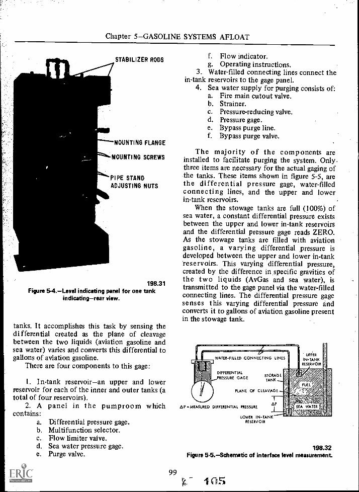
Chapter 5GASOLINE SYSTEMS AFLOAT
STABILIZER RODS
MOUNTING FLANGE
MOUNTING SCREWS
PIPE STANDADJUSTING NUTS
198.31Figure 5-4.Level indicating panel for one tank
indicatingrear view.
tanks. It accomplishes this task by sensing thedifferential created as the plane of cleavagebetween the two liquids (aviation gasoline andsea water) varies and converts this differential togallons of aviation gasoline.
There are four components to this gage:
1. In-tank reservoiran upper and lowerreservoir for each of the inner and outer tanks (atotal of four reservoirs).
2. A panel in the pumproom whichcontains:
a. Differential pressure gage.b. Multifunction selector.c. Flow limiter valve.d. Sea water pressure gage.e. Purge valve.
f. Flow indicator.g. Operating instructions.
3. Water-filled connecting lines connect thein-tank reservoirs to the gage panel.
4. Sea water supply for purging consists of:a. Fire main cutout valve.b. Strainer.c. Pressure-reducing valve.d. Pressure gage.e. Bypass purge line.f. Bypass purge valve.
The majority of the components areinstalled to facilitate purging the system. Only.three items are necessary for the actual gaging ofthe tanks. These items shown in figure 5-5, arethe differential pressure gage, water-filledconnecting lines, and the upper and lowerin-tank reservoirs.
When the stowage tanks are full (100%) ofsea water, a constant differential pressure existsbetween the upper and lower in-tank reservoirsand the differential pressure gage reads ZERO.As the stowage tanks are filled with aviationgasoline, a varying differential pressure isdeveloped between the upper and lower in-tank'reservoirs. This varying differential pressure,created by the difference in specific gravities ofthe two liquids (AvGas and sea water), istransmitted to the gage panel via the water-filledconnecting lines. The differential pressure gagesenses this varying differential pressure andconverts it to gallons of aviation gasoline presentin the stowage tank.
A P - MEASURED
WATER-FILLED CONNECTING LINES
DIFFERENTIAL
PRESSURE GAGESTORAGETANK
PLANE OF CLEAVAGE
DIFFERENTIAL PRESSURE.AT
LOWER IN-TANKRESERVOIR
UPPER
IN-TANKRESERVOIR
YFi ILLY/71OW 4/ \
./ FUEL '.."
SEA WATER , :\A'RA'-"1,'
198.32Figure 5-5.Schematic of interface level measurement
99(15
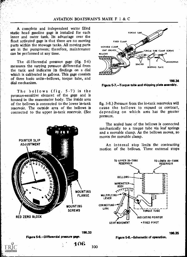
AVIATION BOATSWAIN'S MATE F 1 & C
A complete and independent water filledstatic head gasoline gage is installed for eachinner and outer tank. Its advantage over thefloat activated gage is that there are no movingparts within the stowage tanks. All moving partsare in the pumproom; therefore, maintenancecan be performed at any time.
The differential pressure gage (fig. 5-6)measures the varying pressure differential fromthe tank and indicates its finding on a dialwhich is calibrated in gallons. This gage consistsof three basic unitsbellows, torque tube, anddial mechanism.
The bellows (fig. 5-7) is thepressure-sensitive element of the gage and ishoused in the manometer body. The inside areaof the bellows is connected to the lower in-tankreservoir. The outside area of the bellows isconnected to the upper in-tank reservoir. (See
POINTER SLIPADJUSTMENT
;
F=1P716..Mir
RED ZERO BLOCK
MOUNTINGFLANGE
MOUNTINGSCREWS
198.33Figure 5-6.Differential pressure gage.
106 100
FIXED CLAMP
MOVABLE CLAMP
LEAF SPRINGS
BELLOWS
TORQUE TUIE
TORQUE TUIE CLAMP SCREWS
SPAC EIS
SHIPPING PLATE
JACKSCREWS
198.34Figure 5-7.Torque tube and shipping plat* assembly.
fig. 5-8.) Pressure from the' in-tank reservoirs willcause the bellows to expand or contract,depending on which area has the greaterpressure.
The sealed base of the bellows is connectedmechanically to a torque tube via leaf springsand a movable clamp. As the bellows moves, somoves the movable clamp.
An internal stop limits the contractingmotion of the bellows. Three external stops
TO UPPER INTANKRESERVOIR
BELLOWS
MANOMETER,4BODY
MULTIPLYING--"."LEVER
CONNECTINGLINK
TO LOWER INTANKRESERVOIR
GEAR MOVEMENT
TORQUE TUBE
INDICATING POINTER
FIXED PIVOT
Figure 5- 8. Schematic of operation.198.35

Chapter 5GASOLINE SYSTEMS AFLOAT
limit the expanding motion of the bellows.These stops prevent damage to the bellows bylimiting its travel.
Two vent valves are provided on the top ofthe manometer body to vent the bellows. Onevalve vents the inside area of the bellows and theother vents the outside area of the bellows.
The torque tube is the ballancing agent forthe gage. It connects the bellows to the dialmechanism. One end of the torque tube isconnected to the movable clamp and the otherend connects a multiplying lever of the dialmechanism. The bellows end of the torque tubepivots through a fixed clamp.
Movement of the bellows causes the torquetube to rotate. This rotation is transmitted tothe indicating pointer of the dial mechanism.(See fig. 5-8.)
Before the panel is put into operation, ashipping plate, which is attached to the torquetube within the manometer body, must beremoved. This plate and its two spacers areinstalled to prevent damage during shipment.(See fig. 5-7.)
Both the inner and outer tanks have theirown gage. There is a torque tube for each gage.The torque tube is sized to give full-scaledeflection when the tanks are full of aviationgasoline. The dial for the outer tank will readFULL when the stowage tanks are 95 percentfull of aviation gasoline.
The multifunction selector consists of eightvalve assemblies which are positioned insequence by rotating a lever handle through fivepositions for purge and level indications. (Seefig. 5-9.)
The selector is operated manually byrotating the handle in a clockwise direction,with the positions being OFF, 1, 2, 3, and 4.The valves in the selector are opened and closedby rotating cams secured on the instrumentcamshaft. (See fig. 5-10.)
The rise of each individual cam is positionedwith respect to the others to provide the desiredsequential action. (See fig. 5-11.) As the cam isrotated, its rise comes into position on the camroller, causing the valve actuator to pivotupward, opening the valve. Further rotation ofthe rotating handle releases the valve, therebyallowing it to close,
Figure 5-9.The multifunction selector.
CAMROLLER
*VALVE
OPERATOR
198.36
HANDLE
CAM SHAFT
CAM
STEM
VALVE
FIXEDPIVOT
198.37Figure 5.10. Cam operated valves.
The valves are of the plug type using asylphon type bellows for packing. Each valve isspring loaded to close.
The purge valve (fig. 5-12) is a two-way valvefor on-off action only. The supply pressure may
101 c 7

AVIATION BOATSWAIN'S MATE F 1 & C
CAM SHAFT
DIAL
POINTER
HANDLE
COMPRESSIONFITTINGS
MANIFOLD
VALVE REFERENCENUMBERS ANDFLOW DIRECTION
198.38Figure 5-11. Multifunction selector without cover.
(A) (8)
Figure 5-12.Purge valve.
(C)
198.39
be piped into either connection, since pressuremay be held from either direction because of thepacking and porting design of the valve when itis in the closed position.
Flow through the valve is obtained bypushing the plunger knob in, thereby alining thesupply port with the discharge, as shown in viewB.
OS102
The valve is spring loaded to close. Byreleasing the knob, the spring causes the valve toclose (view C).
The flow indicator (fig. 5-13) provides visualidentification of the flow of sea water through apipeline. The indicator has a hinged flappersuspended from the body so that it rests againstthe inlet passage at no flow. As liquid begins toflow, the flapper swings outward to a positiongenerally proportional to the flow rate.
The in-tank reservoir connecting lines aregasoline-tight cylindrical tanks with a nontightflanged cover. They are open to liquid pressurenear its top by two holes directly opposite eachother. The in-tank reservoirs are brazed to theends of connecting lines, one located near thetop of the tank and the other located near thebottom of the same tank. Connecting linesterminate one-half inch off the bottom of thereservoir. The in-tank reservoirs are filled withsea water because of purging. The connectinglines are purged with sea water to preventaviation gasoline from entering the pumproomthrough the lines.
The flow limiter is a globe type needle valveused to reduce sea water pressure to the desiredpressure. It is located between the fire mainsupply and the purge valve.
The sea water pressure gage indicates thepressure of the sea water supply and is locatedbetween the flow limiter and the purge valve.
Operation. The stowage tank to be gagedmust be full (aviation gasoline/sea water).
1. Set the multifunction selector handle toposition number 2. (See fig. 5-14.)
Figure 5.13. Flow indicator.198.40

Chapter 5GASOLINE SYSTEMS AFLOAT
SEA WATERSUPPLY
MULTIFUNCTION SELECTOR
FLOW LIMITING VALVE/SEA WATER PRESSURE 43
PURGE VALVEFLOW INDICATOR
MULTIFUNCTION SELECTOR SEQUENCE
HANDLEPOSITION
VALVE POSITION
1 2 3 -4 5 6 7 8
OFF X X, X X X X X X
1 0 0 X X X X 0 0
2 0 X 't 0 X X X 0
3 X X X 0 0 X X 0
4 X X 0 0 0 0 X X
LEGEND: X = CLOSED0 = OPEN
BYPASSPURG E
VALVES
DRAINVALVE
TO UPPERIN-TANK To LOWER
RESERVOIR IN-TANKRESERVOIR
LEVELINDICATING
GAGEDRAIN
Figure 5- 14. Schematic of systems valving arrangement.
2. The flow limiter should be set so thatthe flapper of the flow indicator is open toabout three-fourths of its travel when the purgevalve is depressed.
3. Depress the purge valve for 30 secondsto fill the connecting line and the upper in-tankreservoir with sea water.
4. Set the multifunction selector handle toposition number 3.
5. Depress the purge valve for 30 secondsto fill the connecting lines and the lower in-tankreservoir with sea water.
6. Set the multifunction selector handle toposition number 4. Then open the two ventvalves on top of the bellows housing. The ventvalves are opened ONLY at selector positionnumber 4. Damage will occur to the bellows ifopened in any other selector position.
7. Depress the purge valve for 1 minute.This purges air from both sides of the bellowsand fills them with sea water.
103
198.41
8. Close the vent valves. With the purgevalve and both vent valves closed, the gagepointer should fall within the red zero block. Ifthe gage does not read zero at this point, thepurge steps must be repeated.
9. Place the multiselector handle to the offposition, then open the bypass purge valves for 1full minute. This repurges the upper and lowerin-tank reservoirs and connecting lines. Thenclose the bypass purge valves.
10. To read, place the multifunction selectorhandle to the number 1 position and observe thefuel quantity reading.
OPERATIONAL PROCEDURES.Thefollowing operational procedures should beobserved:
1. The system must be purged before thefirst reading.
2. The system must be purged once a week.
1.09

AVIATION BOATSWAIN'S MATE F 1 & C
3. Once purged and set in operation, theselector handle can remain in position number 1for continuous readings for periods up to oneweek.
MAINTENANCE.Maintenancerequirements for the gage are as follows:
1. An indicating zero check is made dailyby setting the multifunction selector handle toposition number 4. The indicating gage shouldread zero. If it fails, repurge the system, recheckfor zero and make pointer adjustment ifnecessary.
2. Do not oil or grease the gage. Lubricantsmay cause the gage to become sluggish or distortthe gage reading.
3. Cleaning. Occasionally clean the sightglass in the flow indicator, using a laundry typedetergent. Replace the neoprene gaskets ifleakage occurs around the glass or the seals havebeen disturbed.
4. Purge Valve. Replace the 0-ring ifleakage occurs. No lubrication is necessary.
5. Multifunction Selector. No maintenanceis necessary. If the selector fails, remove it fromthe panel and replace it with a new one.
6. Air Bubble Checkoff Selector Valves.Check each one of the eight valves, one at atime, by installing a hose to the inlet port.Immerse the free end of a hose in a bucket ofwater and apply air of 50 psi to discharge side ofvalves. Watch for bubbles to issue from the hose.If the valve leaks, replace it with a replacementvalve. The directional arrow on the valve bodywill help to determine the inlet and dischargeport of the valve.
Hand Pump and Sump Model
The gage discussed previously will eventuallybe installed on all carriers as funds becomeavailable. In the meantime, the less expensivehand pump and sump models are being installed.
The hand pump and sump model arebasically the same as the multifunction selectortype.
Sea water from the fire main is supplied to asea water supply tank. (See fig. 5-15.) A handpump is used to purge the system. Hand valves
0104
FROM9 FIRE MAINDi
SEA WATERSUPPLY TANK
LIQUID LEVELGAGE
HANDPUMP
TO ADDITIONAL7LIQUID LEVELGAGE
10
3
04.01
4
6 O
GASOLINEPUMPROOM
1ST. PLAT.
COFFERDAM
CUTER TANK
OFFTANKTANK
UPPER'SUM?TANK
_CLEAVAGE?LANELANE
TANK
HLOWERSUMPTANK
h2
BOTTOM Of TANK <
198.42Figure 5-15.Typical liquid level gage tank installation.
are used instead of the multifunction selector.There is no flow limiter, flow indicator, seawater pressure gage, or purge valve.
OPERATION.The general procedure is toisolate the gage from the sump tanks and thenpurge the piping and sump tanks with sea water.Then vent and purge the gage and remainingpiping to gage with sea water.
NOTE: All valves should be closed, exceptvalve 7, before starting operations.
1. Open valve 9 and fill the sea watersupply tank to the level in the upper sight glass.
2. Open valves 1 and 3 and purge the lowersump tank with a hand pump.
3. Close valves 1 and 3, open valves 2 and4, and purge the upper sump tank with a handpump.
4. Close valve 2, open valves 3, 5, 6, and 7,and vent valves 8 and 10. Operate the hand

Chapter 5GASOLINE SYSTEMS AFLOAT
pump until water flows out of vent valves 8 and10.
5. Close valves 3, 4, 8, and 10, and openvalves 1 and 2. Slowly close valve 7. The gage isnow ready for use.
6. To find the amount of gasoline in thetank, read the gage and find the correspondingvalue from the conversion chart on the dialmarkihg.
NOTE: Failure to vent and purge the systemproperly will result in erratic gage indicatormovements.
SEA WATER PIPING ANDVALVE ARRANGEMENT
Except for the previously mentioneddifferences, number of pumps in the CVSsystem (4 vice 2), and the additional outer tanksea water supply riser on ships having two sets ofstowage tanks vice one, the sea water piping andvalve arrangements are identical for allhigh-capacity aviation gasoline systems. (See fig.5-16.)
Gate valves are installed throughout the seawater system. In describing the system they willbe referred to as shutoff valves withoutreference to type.
Sea water is supplied directly from the sea,through a sea chest located in the cofferdamaround the stowage tanks. A steel gratinginstalled in the opening of the ship's bottomprevents large objects from being drawn into thesystem. Steam is used for cleaning out the seachest in the event of clogging. Steam has atwo-fold effect for cleaning purposes. It can besupplied at an adequate pressure for blowing outany debris and also provides a "cooking effect"as well. A shutoff valve is located between thesea chest and the sea chest supply riser. Thisvalve is LOCKED OPEN. The controls for thesea chest shutoff valve and the steam outconnection are located in the same watertightbox as the controls for the cofferdam eductor.
The sea chest supply riser connects directlyto the common suction header of the sea waterpumps. An additional shutoff valve is installed inthis line at the pumproom level.
A shutoff valve is installed between thecommon suction header and the outer tank sea
105
water supply riser. This valve is opened onlywhen filling the tanks with sea water and whenemptying the tanks of sea water.
The two motor-driven centrifugal sea waterpumps are located in the AvGas pumproom, andthe motors are in the adjacent pump motorroom. The shafts connecting the pumps to theirmotor pass through a watertight stuffing box inthe bulkhead. Both pumps take suction from thecommon suction header and discharge into acommon discharge header. The pump suctionline is fitted with a shutoff valve and acompound gage (VP). The discharge linecontains a pressure gage (P), one-way checkvalve, and a shutoff valve. On centrifugal pumps,the pump inlet is always larger than thedischarge line.
The common discharge header is connectedto the outer tank sea water supply riser. Theshutoff valve installed in this line is used todirect pump discharge pressure into the outertank for pressurizing the system during normaloperations.
The outer tank sea water supply riserterminates in a diffuser at the bottom of theouter tank. This line contains a spectacle flange(or pipe blind) and a steam out connection. Thespectacle flange is rotated to the closed positionwhen steam is injected either here or at theouter tank manhole cover for steaming tanks.
The one-way check valve separates the outertank sea water supply riser and the overboarddischarge line. The check valve and dischargeline are normally larger than the riser, i.e.,10-inch riser 12-inch discharge, 12-inch riser14-inch discharge, etc. The overboard dischargeline is led upward in a loop and then overboardjust above the third deck level. The height andsize of the overflow loop acts as a relief device.It limits the pressure than can be exerted on thetanks (within the maximum allowable limits)when maximum pump capacity is dischargedoverboard. This would be the condition whenthe delivery of aviation gasoline is stopped andthe sea water pumps continue to operate.However, the height of the loop also maintainsan adequate back pressure on the tanks to forceaviation gasoline to the suction side of theAvGas pumps, with a positive pressure (Y2 to 1psi), when maximum delivery of AvGas is beingmade. A shutoff valve is installed near the end of

AVIATION BOATSWAIN'S MATE F 1 & C
out
DE-ICINGSTEAM COILS
1111110 1.1.11 4LL. O.
VENT LINE
ELEVATEDLOOP
FLANGED ADAPTERFOR WHEELER VACUUMSTEAM-OUT MACHINE
PUMP DISCHARGELINE
PUMP INLETLINE
SEA CHESTSUPPLY RISER
FLEXCONTROLSHAFTING
STEAM OUT-0
FROM AUTOGAS SYSTEMLPH AND LPD'S ONLY
DISCHARGE HEADERCROSS
CONNECTION
VP VP
SUCTION HEADER
5" LEAK LINE
L.O.
.:"
FLUSHING SUPPLY LINE
FLUSHING SUCTION LINE
A1.5 EDUCTOR SUCTION
LO
SEA
COFFERDAM
OUTER TANK
TANK TOPSHUTOFF ALVE
STEAM OUTLET
OVERBOARDDISCHARGE
2.e EDUCTORDISCHARGEOVERBOARD
t CHECKI VALVE
OUTER TANKS.W. SUPPLYRISER
SPECTACLE
DRAWOFF TANK4... SUPPLY RISER
DRAWOFFTANK
INNER TANK00000
o
STH DECK
DIFFUSER
--IESTEEL GRATING SHELL
Figure 5-16.Sea water piping and valve arrangement
the overflow line. This valve is "LOCKEDOPEN." Steam heating coils are installed aroundthe overflow line at the shell connection to keepthe line clear during icing conditions. Theextreme outboard end is equipped with aflanged adapter with portable protector ring for
112F'.. 106
198.43
attaching a Wheeler vacuum steam out machine.(The Wheeler vacuum method of steaming tanksis performed only by shipyard personnel)
A vent line, fitted with a one-way checkvalve, extends from the top of the 'loop_ toatmosphere just below the second deei leiet

Chapter 5GASOLINE SYSTEMS AFLOAT
The vent line is provided to break syphoningeffect of the overflow loop to prevent loweringthe pressure at the aviation gasoline pumpsuction header. This line may also be equippedwith steam heating coils.
A 21/2-inch eductor discharge connection isinstalled in the overboard discharge line abovethe one-way check valve.
NOTE: The same overboard discharge line isused in both the high capacity aviation gasolineand auto gas systems on LPH and LPD classships.
A cross-connection, fitted with a shutoffvalve, is installed between the sea water pumpcommon discharge header and the overboarddischarge line. This line enables the pumps todischarge directly overboard when they are usedfor flushing or pumping out the stowage tanks.
Two additional lines are provided in the seawater system, primarily for flushing the stowagetanks. One line, fitted with a spectacle flange,extends from the common suction header to theaviation gasoline drawoff tank supply riser. Thespectacle flange is kept in the closed positionand is rotated to the open position only forflushing operations. This line is referred to as theFLUSHING SUCTION LINE. A connection isprovided at the bottom of this line for attachingan eductor suction line.
The other line, fitted with a shutoff valve,extends from the sea chest supply riser to theouter tank supply riser. This line provides asource of water for the flushing operation and isreferred to as the FLUSHING SUPPLY LINE.The shutoff valve is normally closed. Both lines,the flushing supply and flushing suction, are ofthe same dimensions as the sea water pumpdischarge line.
The shutoff valve in the flushing supply lineis fitted with a 1/2-inch valved bypass line (leakline). The 1/2-inch valve is LOCKED OPEN. Withthe bypass line locked open, the stowage tanksare always open to the sea. Thus, the tanks willalways remain full of liquid, subject to the ship'swaterline head, regardless of contraction orexpansion of the aviation gasoline due totemperature changes.
107
OPERATION OF SEAWATER SYSTEM
The sea water system serves to force theaviation gasoline through the tank and up to theaviation gasoline pump suction. A pressure ofabout 1/2 to 1 psi is required at the aviationgasoline pump suction to prevent the aviationgasoline pumps from becoming vapor locked.
The sea water pumps should be put intooperation before starting up the aviationgasoline pumps. At least one sea water pumpmust be operating for each aviation gasolinepump to be put into operation. The sea waterpumps will discharge to a saddle tank. Asaviation gasoline is drawn from the stowagetank, it will automatically be replaced with seawater, thus maintaining a positive pressure on allaviation gasoline pump suctions. Excess seawater will automatically be dischargedoverboard through the overflow line.
To place the sea water system in operation,proceed as follows:
1. Line up the system to take suction fromthe sea and to discharge to the outer tank supplyriser.
a. Open the shutoff valve between thesea chest supply riser and the pumpsuction header.
b. Open the shutoff valve between thepump discharge header and the outertank supply riser.
2. Aline one sea water pump.a. Open the shutoff valve in the pump
suction line.b. Vent the pump through a petcock at
the top of the pump casing. Whensea water appears, close the petcock.
c. Start the pump with the dischargev alv.e closed. When the pumpdischarge pressure builds up, openthe discharge valve SLOWLY.
3. Cut in an additional sea water pump foreach aviation gasoline pump to be placed inoperation, to maintain a positive pressure at theAvGas pump suction header, using the sameprocedure outlined in step 2 above.

AVIATION BOATSWAIN'S MATE F 1 & C
Operation of Cofferdam.Fixed Eductor
Sea water, at fire main pressure, enters theeductor through the supply line and flowsthrough the tapered nozzle. The nozzleconverges the stream of sea water into ahigh-velocity jet which creates a partial vacuumas it passes through the throat of the eductor.The drainage water, rising to fill the vacuum,mixes with the high-velocity jet of supply waterand is forced up into the overboard dischargeline. (See fig. 5-17.)
The eductor is provided. with an inspectionplate, which can be removed without disturbingthe connecting pipe, to permit inspection of theinterior or to renew the nozzle.
To use the eductor:
1. Connect 11/2-inch firehose between theeductor supply and the fire main in the aviationgasoline pumproom.
2. Connect 21/2-inch firehose between theeductor discharge valve and the hose valve onthe elevated loop line in the aviation gasolinepumproom.
3. Open eductor discharge valve.4. Open the hose valve on the elevated loop
in the aviation fuel pumproom.5. Open the hose valve on the water supply
line in the aviation fuel pumproom.6. Check that flow overboard has been
established.7. Open the forward suction valve to the
eductor.8. When the forward end of the cofferdam
has been drained, close the forward suction valveand open the after suction valve.
9. When drainage has been completed, closeall eductor suction valves.
10. Close the water supply and then theoverboard, discharge valves.
11. Disconnect and stow the eductor supplyand discharge hoses.
Data for Cofferdam Eductor
Capacity 32 gpm
Suction Lift 15 feet
11 4 108
Discharge Head
Actuating Water Required
Actuating Water Pressure
55 feet
40 gpm
150 psi
A minimum of 80 psi fire main pressure isrequired to operate the eductors.
Portable Eductor
Portable eductors are used to providedrainage for aviation fuel pumprooms, to drainthe sea water flushing lines prior to rotating thespectacle flanges, to remove condensate frompiping during steaming out, and to drain thestowage tanks of the sea water that cannot beremoved by the pumps. (See fig. 5-18.)
When not in use, the eductors are stowed asspecified by the damage control officer.
The principle and procedure of operation ofthe portable eductor are similar to those of thecofferdam fixed eductor. The 11/2-inch supplyinlet on the eductor is connected to a 11/2-inchfirehose. The other end of the hose is connected:.to the hose valve on the fire main in thepumproom.
One end of the 21/2-inch discharge hose isconnected to the eductor; the other end of thishose is connected to the hose valve on the, seawater overboard discharge pipe, also in thepumproom.
During operation of the eductor, open thedischarge valve prior to opening the firemain,inlet valve. At the end of the operation close thefiremain valve first, then close the dischargevalve.
AVIATION GASOLINE PIPINGAND VALVE ARRANGEMENT
The similarity in stowage tanks and' seawater piping for all high-capacity systema has-been explained in the previous sections of thischapter. The same applies to the gasoline pipingand valve arrangement. Except for previouslynoted differences (number and capacities oftanks, pumps, and filters), they are practicallyidentical in all high-capacity systems.
There are three different type valves used inthe large diameter piping. Some of the newer

Chapter 5GASOLINE SYSTEMS AFLOAT
DISCHARGE HOSE SUPPLY HOSE
HOSECOUPUNG
GATEFOR
VALVE
EDUCTORWATER
DISCHARGE
WWI
t.
t
HAND-WHEELSHAFT
TERMINAL
FORDGATE
VALVEHAND-
WHEEL
3/4-INCHFLEXIBLE
ANDHAFT
GUIDEPIPE
OVERBOARDDISCHARGE
RISER
VALVE TERMINAL
CONTROLBOX COVER
AFTGATE VALVEHANDW HEEL
CONTROL L
PUMP ROOM DECK
GATEVALVE FOR /
EDUCTORWATERSUPPLY /
TO AFTGATEVALVE!
I
I FLOW DIRECTION OF, SALT WATER SUCTION
SUPPLY LINE FROMFIRE MAIN
FIXED EDUCTOR
GATE VALVE__DETAIL ASEE..
.
61. 4
. .
BELL MOUTH
-0
rFLOW DIRECTION OF
DISCHARGE TO OVERBOARD
TAIL
NOZZLE
GASKET
BOTTOM OF COFFERDAM
FLOW DIRECTION OFSALT WATER FROM
FIRE MAINOOMM MEIN.
V
MAIL A
198.44Figure 5-17.Cofferdam fixed eductor.
109 s 11

AVIATION BOATSWAIN'S MATE F 1 & C
MANHOLE ATTOP OF TANK
SUPPLYHOSE
FROMFIREMAIN
1
LOWESTEFFECTIVE
LEVEL OF EDUCTSUCTION-WITH STRA
LOWERINGLINE
OVERBOARDDISCHARGE
HOSE
HOISTINGBAIL
SEE DETAILA
PORTABLEEDUCTOR
BOTTOM OF
DRAINING GASOLINE STOWAGE TANKS
rDIRECTION OF
DISCHARGEOVERBOARD
DIRECTION OFPRESSURE FROMSHIP'S FIRE MAIN
THREADFOR
HOSECOUPLING
THREAD FORHOSE
CONNECTION
DEER
DIRECTIONOF DRAINAGEWATER FLOW
FROM GASOLINE TANKS-L.
1
NOZZLE
I
1Figure 5-18. Portable eductor.
ships have the Okadee valve (a sliding gate typevalve) or butterfly valve. The oldest and mostcommon type is the nonlubricated positive stopvalve. Sylphon packless glove valves are used inall small diameter piping. These valves aredescribed in detail later in this chapter. Indescribing the piping and valve arrangement theyare referred to only as shutoff valves withoutreference to type.
110
197.34
The aviation gasoline pumproom, whichcontains the aviation gasoline pumps, sea waterpumps, and many of the valves which controlthe distribution of fuel, is located on the 5thdeck directly above the stowage tanks. Access tothe pumproom is gained through a vertical trunkwhich extends from the 2nd to the 4th deck.
The motors for the AvGas pumps are locatedin the same adjacent pump motor-room as the

Chapter 5GASOLINE SYSTEMS AFLOAT
sea water pumps. They too are connected bymotor shafts which pass through bulkheadstuffmg boxes. All motors (both sea water andAv Gas) are started and stopped by means of areach through pushbutton mechanism, which iswelded in the watertight bulkhead betweenpumps and motor room.
The drawoff tank supply riser extends upfrom the top of the drawoff tank to thecommon suction header of the Av Gas pumps inthe pumproom. (See fig. 5-19.) The valve in thisline is referred to as the "tank top shutoffvalve." The drain line header and the flushingsuction line interconnect with the supply riserbelow the tank top valve. A steam outconnection for steaming the distribution pipingand a reflex type sight glass gage for observingthe fuel level when draining back are installedabove the valve.
The reflex type gage is so designed thatliquid shows black, contrasted with a bright,mirror-like appearance when no liquid is present.
Nitrogen, used for draining back, purging,and charging the distribution system is pipedinto the pumproom from the N2 plant. Themain supply line is fitted with a shutoff valveand a one-way check valve. Three lines, eachfitted with a shutoff valve, branch off the mainsupply line below the one way check. One lineextends up to the filter room and supplies thenitrogen for draining back the system. The othertwo are connected to the common suctionheader and recirculating header and are used forpurging and charging the system.
The common suction header supplies fuel toboth pumps under a continuous positivepressure. Each pump inlet line contains a shutoffvalve and compound gage. (VP).
The AvGa pumps (referred to as boosterpumps) are the double-suction centrifugal type.Each pump is provided with an independentvent line. This line, fitted with a shutoff valve,extends from the extreme top of the pumpcasing to the common discharge header.
The pump discharge line contains a pumpdrain line, pressure gage (P), recirculating line,one-way check valve (with drain line), and ashutoff valve.
The drain lines are provided to drain thecheck valve, pump, and pump discharge piping,up to the check valve, back to the drawoff tank
when draining back the system. The pumps andcheck valve drain lines, each fitted with ashut-off valve, are combined into one line whichterminates in a common drain line header.
The drain line header, which is alsoconnected to the pressure regulator drain line,interconnects with the drawoff tank supply riserbelow the tank top shutoff valve. This line isfitted with a one-way check valve and a shutoffvalve, located near the tank top valve.
The pump recirculating line, fitted with aone-way check valve, an orifice, and a shutoffvalve, terminates in a recirculating header. Theorifice is designed to limit the flow toapproximately 5 percent of the rated capacity ofthe pump. This recirculated fuel preventsover-heating of the pumps during prolongedstandby periods (when the pumps are runningbut no fuel is being drawn off topside). Awarning plate is fitted near each recirculatingline shutoff valve which states; VALVE MUSTBE OPEN BEFORE STARTING AVIATIONGASOLINE PUMP.
Both pump recirculating lines combine withthe pressure regulator recirculating line into acommon header. The recirculating header, fittedwith a tank top shutoff valve, terminates in adiffuser, at midpoint in the drawoff tank.
A thermometer is installed in the commondischarge header to determine the temperatureof the fuel being discharged from the pumps.(The maximum allowable temperature is 100°F.)
The pumps are provided with a bypass linewhich extends from the common suction headerto the common discharge header. This line,fitted with a shutoff valve, is used when venting,draining back the system, receiving Av Gasaboard, and any other operation not requiringthe pumps.
All quadrant distribution risers in ahigh-capacity aviation gasoline system areidentical regardless of the type service stations(Blackmer or Cla-Val) installed.
Each riser is equipped with a pressureregulating system at the pumproom level.
NOTE: Since there are no independent .defueling mains in the AvGas system and all fuelmust be defueled back into the riser, the riserpressure at the service stations must bemaintained below the discharge pressure of thedefueling pumps.

AVIATION BOATSWAIN'S MATE F 1 & C
ACCESSTRUNK N2 SUPPLY
FROM PUMPROOM
3RD DECK
SIGHT GLASS,'"GAGE
4TH DECK
DISTRIBUTIONRISER
PRESSUREREGULATOBYPASS
N2 TO FILTER ROOM
N2 FROM PUNT
PUMP BYPASS
REFLEXSIGHT GLASSGAGE
FILTER BYPASS
TO HANGAR DECKFILLING CONNECTION
4TH DECKRISER VALVE
SPARLING FLOMETER
RECIRCULATING LINE
PRESSURE REGULATINGSYSTEM
1,444=1.\DRAINLINE
THERMOMETER
COMMON DISCHARGE HEADER
PUMPVENTLINE
PUMP DISCHARGE
ONE -WAY CHECKDRAIN LINE
COMMON SUCTION HEADER
STEAM OUT LJ LJRECIRCULATING LINE HEADER
TANK TOPSHUTOFF VALVE
FLUSHING SUCTICNLINE
AVGAS SUPPLYRISER
ORAWOFFTANK
DRAIN LINE HEADER
PUMPINLET
PUMP RECIRCULATINGLINE
PUMP ROOM DECK
COFFERDAM
INNER TANK OUTER TANK
Figure 6-19.Gasonne piping and valve arrangement.
118 112
PUMPDRAINLINE
198.46

Chapter 5GASOLINE SYSTEMS AFLOAT
All pressure regulators are identical exceptfor physical size. Pressure settings will varydepending on the class ship and type servicestation. Each regulator is provided with a drainline and a recirculating line. On ships equippedwith 675 gpm and 1,100 gpm Av Gas pumps, therecirculating line is, orificed to recirculate 100gpm. However, on ships equipped with 425 gpmand 220 gpm pumps the line is orificed. torecirculate only 40 gpm and 20 gpmrespectively.
The pressure regulator is provided with avalved -bypass line. This line is used whenventing, draining back, and receiving AvGasaboard.
The distribution riser extends up throughthe vertical access trunk. A totalizing meter,sight glass gage, and a shutoff valve are installedin each riser just above the 4th deck level. (Theshutoff valve in this line is referred to as the"4th deck riser valve".)
Each meter is designed to accuratelymeasure flow in either the forward or reversedirection. The meter houses a totalizing registerwhich shows continuous, registration in units of100 gallons and a sweep hand and a dialgraduated in 1-gallon increments. The meter isso' arranged that when Nei flows to the stowagetanks, the meter advances the totalizer readings,and when fuel is pumped from the stowagetanks, the meter subtracts the totalizer readings.The meter thus registers the net flow deliveredto the stowage tanks. The meter will also registerwhen nitrogen passes through the system duringdrain back and purging operations. The line levelgage has been installed just above the meter toshow when fuel is above the meter. Observationof the gage will indicate when the meter is beingactuated by nitrogen or fuel. This meter shouldNEVER be used to determine the amount offuel in the stowage tanks.
The riser bends outboard just above the 3rddeck and passes through a horizontal trunk tothe filter room. The section of the riser in thehorizontal trunk is double-walled. The innerpipe carries aviation fuel, while the spacebetween the inner and outer walls containsnitrogen gas under 10 psi. If a leak occurs ineither the aviation fuel or gas-filled piping, a riseor drop in pressure will be indicated on a
113
pressure gage in the pumproom and deliverymust be stopped at once.
The filter room and outboard distributionpiping and valve arrangement are practicallyidentical to those previously described exceptfor the following:
1. The hangar deck filling connection iseither connected to the outboard distributionmain or to the filter bypass line.
2. There are no defueling mains.
AVIATION FUEL METER
Aviation fuel meters (fig. 5-20) are found intwo sizes in the fleet. The 6-inch flowmeter hasan accurate flow range of 300 to 1,700 gpm in aforward or reverse direction. The 8-inch
188.46Figura 5-20.Sparling aviation fuel meter.
v, 19

AVIATION BOATSWAIN'S MATE F 1 & C
flowmeter has an accurate flow range of 400 to2,000 gpm in a forward or reverse direction.Both are identical in construction and operation.No further reference will be made to size orcapacity in this manual.
An aviation flowmeter of the propeller typeis found in each quadrant distribution riser. Themeter has two principal parts, the workingmechanism (mounted in a removable headplate)and the tube for mounting the workingmechanism in the line. The working mechanismconsists of a propeller geared to a magneticdrive, which in turn is geared to an insettotalizer and sweep hand. The tube formounting the mechanism flanges into thedistribution riser. It contains straightening vanesto direct the flow of fuel to the propeller ineither direction.
The operation of the meter is completelyautomatic. Downward or forward flow advancesthe totalizer and adds to the quantity registered(the sweep hand turns clockwise). The upwardor reverse flow subtracts from the quantityregistered (thg sweep hand turnscounterclockwise). Fuel flow turns thepropeller, which is centered in the flow. Theinsert totalizer registers 100-gallon units. Thesweep hand dial is graduated in 1-gallon units.
Once a year the meter is removed from theline and inspected. The propeller is checked by
TO NITROGEN SUPPLY
ON GAGEBOARD INPUMP-ROOM
8" STEELCASING
hand to insure that there is no binding; it shouldhave about 1/32-inch free movement because ofthe play in the ball bearings. This play allowsgrit to pass between the bearings. Insure that thepropeller blades are clean and not broken. Checkthe straightening vanes and tube for foreignmatter. Lubricate the gears and bearings in theregister clock with a light machine oil.
The meter needs no maintenance orlubrication between annual inspections.
A cover plate is provided to blank off thetube whenever the working mechanism isremoved.
NOTE: The front ball bearing is the key tothe life of the meter. If it is kept in propercondition, the other parts last almostindefinitely.
DOUBLE-WALLED PIPING
The double-walled piping consists of twoconcentric pipes. (See fig. 5-21.) The inner pipeis copper and carries the aviation fuel. The outerpipe is steel and serves as an armor casing. Theouter pipe also serves to contain a protectivejacket of inert nitrogen gas at about 10 psiaround the inner piping. A pressure gage foreach double-walled piping has been installed inthe associated pumproom to indicate thepressure in the annular space. The gage has a
BULKHEADS
RELIEF VALVE15 P.S.I.
EXPANSION BELLOWS
STEEL SPACER
TOATMOSPHERE
01111111H,__, 31....,1111111
DRAIN PLUGSBRASS LINER6"COPPER
PIPE
Figure 5-21.Sectiun of double-welled piping.
120 114
NITROGEN GAS
DECK
198.47

Chapter 5GASOLINE SYSTEMS AFLOAT
range of from zero to 15 psi with a sector offrom 91/2 to 10 psi designated as the normalcharging pressure.
If the outer casing is pierced for any reason,the nitrogen gas will leak out. The resulting dropin pressure will be indicated on the gage. Also, ifa rupture should occur in the aviation fuel lineinside the steel casing, the resulting increase inpressure will be indicated on the gage. Isolatethe quadrant until the cause has beendetermined.
Expansion bellows are provided in the outercasing to avoid strains in the casing due tounequal expansion which may result in leakageof the nitrogen gas. Drain plugs in the bellowscan be used to determine whether any leaks mayhave occurred in the inner piping. Brass linerssoldered to the outside of the copper pipe andsteel spacers welded to the inside steel casing areplaced at intervals of about 5 feet. These serveto hold the copper pipe in the center of the steelcasing and still allow for movement due toexpansion and contraction between the twopipes. The outside casing is approximately 2inches larger than the inner piping.
A nitrogen gas connection, for charging theouter casing, is provided at the lower or inboardend of the double-walled piping. The outercasing is also provided with a relief valve toavoid excess pressure. The released gas is ventedto the atmosphere through separate piping. Therelief valve is set at 15 psi.
POSITIVE STOP VALVES
As previously mentioned, there are threetypes of stop valves used. They are the rotaryplug, swing gate, and butterfly valves. Thesevalves are all positive stop valves and serve in thesame capacity.
Positive stop valves are installed throughoutthe system. The valves are used (1) where thenitrogen gas could leak into or gasoline leak-outof stowage tanks when in a secured condition;(2) where nitrogen gas or aviation fuel couldenter the fueling hose when in a reeled position;or (3) where quick opening or closing isrequired. Figure 5-22 illustrates a rotary plugvalve.
The valve is of the nonlubricated type, andthe body of the valve is mule of bronze. The
plug is cast steel with a 14-inch coating of Hycarrubber. The stem packing is of cup-and-coneTeflon and the bonnet gasket is of Buna-N-Cork.A "Zerk" grease fitting is provided to lubricatethe spindle and spindle nut.
Operation of the valve is as follows: to openthe valve, the handwheel is turned in acounterclockwise direction, to unseat the valve.
During the raising operation, the stemcannot turn, as the ratchet is held in place bythe ratchet pin. The raising of the plug bringsthe ratchet into contact with the stem nut. Thisis the limit of upward travel of the stem andplug. At this point, further turning of thehandwheel in a counterclockwise direction turnsthe plug and ratchet. Each 90-degree turn of thehandwheel turns the plug alternately from opento closed position, and is accompanied by anaudible click as the ratchet pin falls in place intothe ratchet. The direction of the port of the plugis indicated by a large two-headed indicatorarrow above the handwheel.
INDICATED ARROW
rn_lrEn.1
HANDWHEEL
BLOCK
'ODY BONNET
RATCHET
TEFLON CUPAND CONE PACKING
PLUG
- HYCAR RUBBERSLIP
Figure 5-22.Rotary plug valve.
115 1 21
198.48

AVIATION BOATSWAIN'S MATE F 1 & C
NOTE: The handwheel need not be turnedwith a wrench or any other lever to seat theplug. This would force the Hycar rubber face ofthe plug out through the port openings andcause damage to the plug.
To close the plug valve, turn the handwheelcounterclockwise and raise the plug. Continuethe counterclockwise rotation 90 degrees untilthe indicator shows the valve is closed and theratchet pin falls in place. Turn handwheel in aclockwise direction until handtight. The valvewill now be seated.
The Hycar rubber face of the plug may wearin use. Excessive wear will cause improperseating of the plug and leaks. The plug should bereplaced when the handwheel nut touches theindicator, before the handwheel is turnedhandtight. The downward travel of the plug isthereby limited and improper seating occurs.
Okadee Swing Gate Valve
This valve will control fluid flow in bothdirections and is of the nonlubricated type. (Seefig. 5-23.) The valve body is flanged and made ofbronze while the seats are stellited nickel-platedsteel. The discs have Teflon inserts to form theseal.
To operate this valve turn the handwheelcounterclockwise, this will cause the gates toswing into the valve body bulge and open theports for fluid flow. When closing this valve,back the handwheel off to release any strainwhich may have been applied. The valve isclosed when the selector arrow and thenameplate arrow are aligned.
NOTE: When using wheel operated valves itis not necessary to exert excessive force. Thisadds additional strain and shortens stem packinglife.
Butterfly Valve
The butterfly valve illustrated in figure 5-24is relatively new in naval service. It is being usedon some carriers in the aviation fuels system toreplace the Atwood & Morrill Company positivestop plug valve. The butterfly valve is light inweight; it takes up less space than the positive
F 1 22 116
HANDWHEEL
I=Z:=3CLOSED
NAME PLATE
VALVE BODY BULGE
SELECTOR
TEFLOA.INSERT
DISC
SEAT
197.50.1Figure 5-23.Okedee swing gate valve.
stop plug valve; it is easy to overhaul; and it isrelatively easy to operate.
The butterfly valve consists of a body, aresilient seat, a butterfly-type disc, a stem,packing, a notched positioning plate, and ahandle. This valve provides a positive shutoffand may be used as a throttling valve set in anyposition from full open to full closed. Thereplaceable resilient seat is held firmly in placeby mechanical means; neither bonding norcementing is necessary. It is not necessary togrind, lap, or do machine work to replace thevalve seat, so overhaul of the valve is relativelysimple. The resilient seat is under compressionwhen it is mounted in the valve body, thusmaking a seal around the periphery of the discand both upper and lower points where the stempasses through the seat. Packing is provided toform a positive seal around the stem in the eventthat the seal formed by the seat becomes

Chapter 5GASOLINE SYSTEMS AFLOAT
POSITIONING PLATE
DISC. AND STEM
SEAT
197.52.'1
Figure 524.Butterfly valve.
damaged. When closing the valve, the handleneeds only to be turned 90 degrees.
Sylphon PacklessGlobe Valve
The sylphon packless glove valve is used toeliminate the hazardous leakage of gasoline pastthe packing in the ordinary valve by providing ametal bellows (sylphon) which prevents liquidfrom escaping through the valve stem opening.(See fig. 5-25.)
Sylphon packless globe valves are used in thepumproom on the drainage piping from the
117
centrifugal pumps, on other small-diameter pipelines carrying gasoline or nitrogen, and onsteaming-out connections.
The sylphon packless globe valve controlsthe flow of liquid through a pipe in the samemanner as the ordinary globe stop valves.
When the control handle is turned, a poppetat the end of the valve stem is lifted from a valveseat and permits flow through the valve. It hasan expansible metal bellows (or sylphon)assembled between the valve poppet and thebonnet capnut. This permits the valve stem to beraised or lowered while maintaining a completeseal around the stem at all times. In the ordinaryglobe valve, a fiber packing is used to preventthe escape of liquid. This packing deteriorates orshrinks, and allows dangerous leakage of liquidor vapor. The sylphon bellows may be replacedif it corrodes or breaks.
NITROGEN SYSTEM
Nitrogen is manufactured aboard ships inoxygen-nitrogen producer rooms. Nitrogen,obtained in the fractional distillation of liquidair, is stored in flasks at 3,000 psi for use asrequired. Nitrogen is an ordorless, colorless,tasteless gas and is a nonconductor of electricity.In the manufacturing process, nitrogen purity ismaintained at a minimum of 97 percent.
Nitrogen is used in cofferdams as aprotection against fire and explosion, indouble-walled piping to indicate the conditionof the double-walled piping, and in thedistribution piping for drainback, purge, andcharge. A reducing panel in the producer roomroutes nitrogen to the using points in theaviation fuels system.
At the reducing panel (fig. 5-26), nitrogenpressure from the flasks is first reduced from3,000 psi to 300 psi to facilitate subsequentreduction. It is then reduced and routed asfollows:
300 psi to 4 psi to cofferdams.300 psi to 10 psi to double-walled piping.300 psi to 15 psi to distribution piping.
Each reducing valve is provided with abypass line containing a globe needle valve. The
1.23

AVIATION BOATSWAIN'S MATE F 1 & C
-
A
4**.
BONNET RING
"*74'
7 -,1',r
-.
''';', ,,,-,-.-, -
:.'.-. VALVE STEM
- SYLPHON BELLOWS
VALVE STEM GUIDE
BOTTOM STEM
COTTER KEY
rVALVE SEAT
POPPET
2. ;. ..
- r. 2......`manii.;,_...... 44..r;
DIRECTION OF "FLOW
Figure 5-25.Sylphon packleu globe valve.
reducing valves are bypassed when using carbondioxide.
NOTE: In an emergency, 50-poundcarbondioxide bottles may be released into anitrogen flask (through a connection in theproducer room) and routed to the using points.
124 118
198.49
There are two oxygen-nitrogen plants aboardship (one forward and one aft), cross-connectedso that nitrogen can be routed to any fuelssystem from any plant
CHARGING OPERATIONS
The double-walled piping is supplied withnitrogen from the reducing panel through a

Chapter 5GASOLINE SYSTEMS AFLOAT-TO Nt ACCUMULATOR'S
NIINIESSURESWITCH
3PLEirs
CROSS
IMPS/ STAISSURE NO PS. I.CONNECTION
SET AT IIP. % OFSTORED PRESSURE
i SET T *P&L ."1"" " ej.3 .... COQ
pd041
T PS.30VOI.
SET 1 T PSIN. D -DO- ALVEALOIE STOP
. 1___bi .*I 4,"1"' VNWEIONIIJZANrAL sus CHECKL .1
300/4 PI -6A- VALVE,PRESSURE REDUCING
DISTRIBUTION PANEL
GAGE,PRESSURE
Figure 5-26.-1112 pressure-reducing panel.
charging valve located in the third deck accesstrunk. Insure that the casing vent valve is closedprior to opening the charging valve. Thedouble-walled piping pressure gages are locatedon the main gage panel in the gasolinepumproom. Slowly open the charging valve;when pressure on the gage reaches 10 poundsper square inch, close the charging valve. (Arelief valve set at 15 psi is provided on thecasing.)
CAUTION: If double-walled piping pressuredrops below 5 psi or rises above 10 psi, isolatethe double-walled piping until the cause ofpressure change is detected and corrected.
Nitrogen is supplied to the cofferdams at 4psi from the reducing panel. An air escape riserfrom each cofferdam to overboard contains astop valve. A bypass line around the air escaperiser valve is provided with a relief valve (set at 4psi), a pressure gage, and an inertness analyzerconnection. To charge the cofferdams:
1. Open the air escape riser valve.2. Attach inertness analyzer to cofferdam
test cock.3. Open nitrogen supply valve to
cofferdam. When inertness reading reaches 50percent close the air escape riser.
tRoOMatsso
OR VAPORIZER
9*.AMOLE
1$7.5
4. Charge cofferdams to a minimum Y2 psthen secure the supply valve.
The cofferdams are checked daily with theportable inertness analyzer. Maintain lh psi, 50percent inertness for safe operation.
Nitrogen for drainback: is injected in thedistribution piping through the filter dischargeand filter bypass line. It is routed from thereducing panel to a supply valve in thepumproom, and from the pumproom throughtwo stop valvesone to the port, one to thestarboard filter.
To drain back a quadrant:
1. Open nitrogen supply in gas pumproom.
2. Open nitrogen valve to filter room.
3. Open nitrogen drainback lines to filterbypass and filter discharge lines. When thesuction header reflex sight level gage indicatesthe piping is empty, isolate the AvGas tanks.
Secure nitrogen valve to filter and purge.
119 L.. 425

AVIATION BOATSWAIN'S MATE F 1 & C
To purge a quadrant:
1. Open nitrogen valve to gas pump suctionheader.
2. Start the farthest service station fromthe pumproom and place it in fuel position.Connect an inertness analyzer to the air andvapor eliminator exhaust line. When inertnessreading reaches 50 percent, secure the station.
3. Charge the piping to 9.5 psi.'- 4. Secure the nitrogen supply valve and
nitrogen to suction header valve.
NOTE: JP-5 quadrants are drained back withnitrogen only in an emergency. Gasolinequadrants are drained bask each day afteroperation.
Whenever using carbon dioxide; in place ofnitrogen, purge to 35 percent inertnessminimum.
NITROGEN PRESSUREREGULATING VALVE
The nitrogen regulating valve consists of adome and body separated by a rubberizeddiaphragm. The diaphragm actuates the poppetvalve in the valve body by forcing down thevalve stem. A compression spring below thepoppet valve tends to return the valve to its seatagainst the force of the diaphragm. The dome isfilled with nitrogen gas under pressure when thevalve is adjusted. This gas pressure acts on theupper surface of the diaphragm. A pressurechamber on the under side of the diaphragm fillswith nitrogen through an opening to thedischarge, or low-pressure, side of the valve.Thus, when the valve has been adjusted and is inoperation, the pressure on the upper side of thediaphragm acts to force the valve open. Thisforce is balanced by the low-pressure gas on theunder side of the diaphragm and the springunder the poppet valve. When low-pressure gas istaken from the system, the pressure on thedischarge side starts to fall and the regulatingvalve opens to permit passage of gas from thehigh-pressure side of the valve. The distance thevalve opens depends on how fast thelow-pressure gas is being used. When use oflow-pressure gas is stopped, the pressure on theunder side of the diaphragm starts to increase
26 120
and the valve closes to stop the flow ofbigh-pressure gas.
When the regulating valve is being adjusted,nitrogen gas from the high-pressure side of thevalve is admitted to the dome chamber throughan orifice controlled by two needle valves. (Seefig. 5-27.) A ball relief valve to the orifice willrelease gas if the high pressure needle valve inthe body,is opened too far.
To plit the reducing valve in operation:
1. Close the valve body needle valfe_anddome needle valve.
2. Close- the stop valve on the low -pr sure --
side. Open the inlet valve on the high-pressbreside and open the low-pressure gage valve.
3. Open the body needle valve one-halfturn to permit gas to flow into the loadingchannel...
4. Open the dome needle valve slowly. Thispermits gas to flow into the dome. Gas enteringthe dome -flows through the orifice in the domepyateaniel-acts on top of the diaphragm.
`-5. , The increasing gas pressure forces thediaphragm down and slowly opens the valve. Gasthen flows through the valve opening into thelow-pressure side of the valve and into the lowerpressure chamber, where the increasing pressureof the .gas acts on the under side, of, thediaphragm; pushing it up to close the valve. (See.--,fig. 5-28.) When the low-pressure gages..registerthe desired pressure:
6. Close the dome needle valve.7. Close the body needle valve.
,
The valve is now adjusted and ready for
. Figure 5-29 shows the pressure regulating'valve in operation.
CO2 SYSTEM
Carbon dioxide is stored in steel cylinders at ee---pressures from 700 to 1,000 psi, dependingonvariations in termperature. At these pr6sure,s,...,Zabout two-thirds of the cylinder's conten,Sis inliquid form. As gas is released throttgh theopened cylinder valve, the pressure is giaduallylowered until all the CO2 turns into gai: thus,the contents of CO2 in the cylinder will e)ipand

Chapter 5GASOLINE SYSTEMS AFLOAT
WRENCH
DOMENEEDLEVALVE
OPENEDSLOWLY
BODY NEEDLE.VALVE OPENED
ONE-HALFTURN
BALLRELIEFVALVE
GAS ENTERINGACTUATING CHAMBER
THROUGH ORIFICE
RISING GASPRESSURE ONDIAPHRAGM
300-POUND INERTGAS PRESSURE ANDSPRING KEEP VALVE
CLOSED
Figure 5-27.Loading the dome (pressure regulating valve).
about 450 to 500 times in volume when it isreleased. When fully charged, the large-sizecylinders contain 50 pounds of CO2.
Carbon dioxide is used for the protection ofthe aviation fuel pumproom, motor room, accesstrunk, and aviation fuel filter rooms.Carbon-dioxide cylinders are located in motorrooms 'and in compartments on the second deck
. directly above the filter rooms. The CO2 releasevalves on the cylinder are operated by a cable,with cable pull boxes located at several places.The cylinder valves are thus opened but can notbe closed. Spare CO2 cylinders are carriedaboard.
The CO2 Emergency Fire ExtinguishingSystem for aviation fuel pumprooms, motorrooms, access trunks, and filter rooms, is similaron all class carriers.
There are eight carbon-dioxide cylinders,located inside each of the motor rooms, four ofwhich are connected by piping to the aviationhiel pumproom, motor room, and access trunks;the other four are spares. The cylinders releasecarbon dioxide into the piping, when operatedby any one of three pull boxes. A pull box islocated inside the third-deck access trunk, oneoutside the second-deck access trunk, and oneon the hangar deck.
121
198.50
For the after aviation fuel filter rooms, sixcylinders, three per filter room, are located onthe second deck in compartments directly abovethe filter rooms and are connected by piping tothe filter rooms. A pull box is located outsideeach access trunk on the second deck and on thehangar deck, one port and one starboard. Forthe forward aviation fuel filter rooms, fourcarbon-dioxide cylinders, two per filter room,are also located on the second deck and areconnected by piping to the filter room. Pullboxes are located outside each access trunk andon the hangar deck, one port and one starboard.
The emergency pull box is watertight andhas a metal cover with a rubber gasket held byfriction clutches on the rim. Under the cover is alabeled glass plate with instructions for using thepull box, and under the glass plate is a pullhandle connected through a cable and pulley toa type 1, class C, cylinder valve on thecarbon-dioxide cylinder head. The pull box isoperated by releasing the friction catch to allowthe cover plate to drop; then break the glass andpull out the handle until the red portion of thepull cable can be seen. Released carbon-dioxidegas flows through the piping to the aviation fuelspaces, where it is discharged through diffusing
127

AVIATION BOATSWAIN'S MATE F 1 & C
VALVE CLOSED
300 -POUNDINERT GASPRESSURE
EQUALIZINGPRESSURE
IN DOME
INERT GAS AT THEDESIRED LOW
PRESSURE
198.51Figure 5-28.System barmaid, valve dosed.
NEEDLEVALVESCLOSED
VALVE OPENED
"1111,1111k
r,v6zz
ix
LOW- PRESSUREGAS PUSHES UP
DIAPHRAGM
INERT GASAT THE DESIREDLOW PRESSURE
ENTERING SYSTEM
Figure 5-29.Valve in operation.
ventilation audible-visible alarm is located inhangar bay 2, visible from conflagration stationNo. 2, on. CVA-19 and CVA-34 class carriers;and in damage control central on CVA-41 classand up.) The hangar deck alarms consist of abell, a green light labeled VENTILATION ON, ared light labeled VENTILATION OFF, and anelectrical switch. When the ventilation for thespace is operating normally, the green lightglows, indicating ventilation blowers on. In theevent of stoppage of a blower, the alarms forthat space are actuated. The bell rings, the greenlight goes out, and the red light comes on. Thebell may be turned off prior to restoration ofventilation to the space by turning the electricalswitch to the OFF position. The red light willcontinue to glow until ventilation is restored atwhich time it will go out and the green light willcome on. Reset the bell by turning the electricalswitch to ON.
The pressure switches, actuated by theaction of released carbon dioxide, can be resetby pressing down on the plunger on the top ofeach switchbox.
After releasing carbon dioxide into a space,all doors and hatches must be closed and doggedtight. Since carbon dioxide is suffocating, everyeffort should be made to remove all members ofthe crew before the gas is discharged.
Do not reenter a compartment in which CO2has been released without respiratory protectionor until the ventilation has been operating_atleast 15 minutes and the gas-free officer hasmade the necessary test to insure safe entry.
TESTING FIXED CO2 SYSTEMS
198.52 Weekly tests of the pressure actuated toggleswitches installed in fixed CO2 systems areaccomplished as follows:
horns and spreads as a smothering blanket,eventually filling the compartment.
Connections from the carbon-dioxidecylinder distribution lines allow carbon dioxideto operate two pressure switches. Pressure fromthe carbon dioxide throws electric switches, toactuate a carbon-dioxide warning bell in thespace, a visual alarm outside the space at theaccess, and to stop the exhaust ventilationsystem fan motors. Stoppage of the ventilationsystem will cause operation of an audible andvisible alarm on the hangar deck. (This
8 122
Walter Kidde Installations
1. Pull outside button to release latch.
2. Pull end button to actuate switch.
3. Inspect ventilation system audible alarmand visual alarm circuits to verify circuitactuation.
4. After completion of the testing of thecircuits and operation of the switch, reset theswitch by returning end button to set position.

Chapter 5GASOLINE SYSTEMS AFLOAT
CO2 Installations
1. Disconnect 1/4-inch pipe at unionconnection.
2. Insert a small rod in the 1/4-inch pipeleading to the cover.
3. Push upward against the steel piston toactuate the switch.
4. Inspect ventilation system, audiblealarm, and visual alarm circuits to verify circuitactuation.
5. After completion of testing the circuitsand operation of the switch, push reset plungerdown to reset the switch.
6. Reconnect 1/4-inch pipe at unionconnection. A tight seal at the union afterconnection must be maintained.
7. When testing, or conductingmaintenance, large signs warning personnel ofthe nature of work in progress must be displayedat every access to spaces protected by the CO2system.
AUTOGAS SYSTEMS
This system provides stowage, fueling, anddefueling facilities for combat vehicles aboardLPH and LPD class ships. The autogas system isbasically the same as the Av Gas system. Theonly noteworthy differences between the twoare the number and location of the stowagetanks and the type of pumps used.
STOWAGE TANKS
Autogas stowage tanks consist only of anouter and drawoff tank. They are located on thecenterline between the Av Gas stowage tanks onLPH's and adjacent to the Av Gas tank on LPD's.In both cases, they are within, and protected by,the same cofferdams as the Av Gas tar xs. TheLPD's have a stowage capacity of approximately22,000 gallons while the LPH's hold only 7,000gallons. The outer tank sea water supply riser isconnected to the overboard discharge line of theAvGas system.
AUTOGAS PUMPS
Both class ships (LPH and LPD) usewaterturbine autogas pumps. There are two
123
pumps in each pumproom. Pumps on LPH'shave a rated capacity of 160 gpm at 90 psi andthe LPD's have a rated capacity of 110 gpm at60 psi. The waterturbine pumps are operated offthe ship's fire main system. A pressure reducingvalve is installed between the fire main supplyline and the pump feed line. The sea-waterexhaust used to operate the turbines is piped tothe outer tank sea water supply riser forpressurizing the autogas stowage tanks.
Other component parts, such as filters,pressure regulators, flow meters, and servicestations are the same as the ones for the AvGassystem on each respective class ship.
AVIATION GASOLINE SYSTEMOPERATIONS
The aviation gasoline fuel system installedon aircraft carriers has the primary purpose ofservicing piston-driven aircraft on the hangar andflight decks. The operating crew should alwaysbear in mind that aviation gasoline is dangerousto handle and that all safety precautions shouldbe adhered to at all times. For this reason, thesystem should be drained and inerted withnitrogen until a reading of 50 percent inertnessor better is obtained, and then charged to apressure of 9.5 to 10 psi at the end of eachperiod of operation.
Lamicoid charts are provided in eachgasoline pumproom, showing the diagram andoperating instructions for the aviation gasolinesystem. These operating instructions givedetailed procedures for performing the variousoperations and can be set up and checked on theoperating diagram board. Operating personnelshould familiarize themselves with the chart andrefer to it when operating the system.
The descriptive sections of this chapter werewritten to give a better understanding of thesystem. The operating instructions are intendedto supplement the Lamicoid charts.
Before putting the system into operation,open all gage valves and all but the drain valveson the reflex gages. These valves can remainopen throughout the operations.
CAUTION: Open gage valves slowly whenthe system is pressurized to prevent damagingthe gage. Always open the upper and lowervalves simultaneously on differential gages.
1 2 9

AVIATION BOATSWAIN'S MATE F 1 & C
Check that all locked valves are locked intheir respective positions. Locking devicesshould be in position at all times so that theabove- mentioned valves cannot be operatedaccidentally. When it becomes necessary tooperate a locked valve, insure that the valve is inthe correct position before relocking it.
There are any number of operations andcombinations of operations which might followeach other as the aviation gasoline systems areput into use. It would be impossible todetermine what combination of operationsmight be required. For this reason, the valvealinement and sequence shown in the followingoperations are set up from the point of view thatthe system is drained and inerted and that alloperational valves are closed. Unless a valve isspecifically mentioned as being open, it shouldbe closed.
NOTE: Before starting any aviation gasolinehandling operations, check that nothing hasbeen stowed that will interfere with easy accessto the pull boxes for the gasoline pumproomand pump motor room, gasoline filter room, andfixed flooding CO2 fire extinguishing system.Also check that nothing has been stowed thatmight interfere with the proper operation of theCO2 release mechanism at the CO2 bottle racks.Check to see that the CO2 bottles are properlyconnected to the flooding manifold.
While studying the operation outlined in thischapter it is recommended that figures 5-16 (seawater piping) and 5-19 (AvGas piping) becontinuously reviewed.
FLUSHING THE AVIATIONGASOLINE STOWAGE TANKS
The stowage tanks should not be flushed ordrained until all the aviation gasoline from thetanks have been transferred to another gasolinetank on the same ship or to another ship, abarge, or a railroad tank car.
To flush the saddle tanks, the followingprocedure should be observed:
1. Vent the distribution piping through thehangar deck filling connection, bypassing thepressure-regulating equipment and filter.
2. Pressurize the system with the sea waterpumps.
124
3. When nitrogen pressure of 5 psi or less isobtained, open the tank valve and flood thedistribution piping with sea water.
NOTE: The venting and flooding operationswill be explained in detail later in this chapter.
4. Start the aviation gasoline pumps andcommence the off-loading operation. Do notallow sea water to go any higher than theaviation gasoline pump suction header.
When all the gasoline has been pumped outof the tank, as determined by the tank gagingequipment and meter reading, secure the pumps.
Any aviation gasoline remaining after thepumping operation will be removed by flushingthe tanks with sea water through the continuousoperation of the sea water pumps.
CAUTION: The main gasoline pumps shouldnot be used when flushing tanks because thepumps, provided with bellows shaft-seal packing,cannot be used to pump sea water for prolongedperiods without damaging the packing.
Proceed with the flushing operations asfollows:
1. Line up the sea water pumps to takesuction from the outer tank supply riser and todischarge into the overboard discharge above theone-way check valve.
2. Unlock and close the 1/2-inch leak orbypass line.
3. Open the aviation gasoline pump bypassline and the hangar deck filling connection. Thetanks are now vented to atmosphere.
4. Start one sea water pump. When theliquid in the-distribution piping has beenremoved, as indicated by the, sight glass gage onthe aviation gasoline pump suction header,continue pumping for 2 to 3 minutes. With thesystem lined up as indicated above, sea waterwill be drawn out of the outer tank, loweringthe water level in the drawoff tank below theflushing suction line. This line joins the drawofftank suction riser to the sea water pump suctionheader. It is fitted with a spectacle flange or apipe blind. Pocketed water remaining in the seawater line is to be removed with the pumproomeductor through the 11 /z inch hose valve providedfor this purpose.
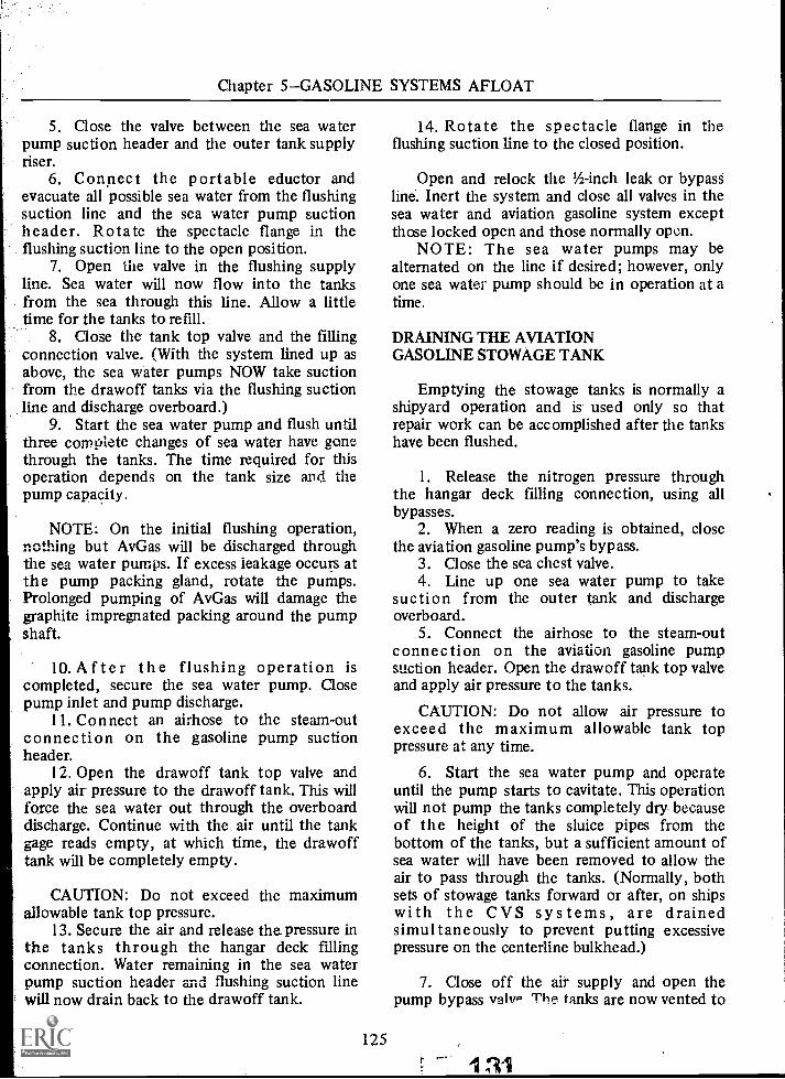
Chapter 5GASOLINE SYSTEMS AFLOAT
5. Close the valve between the sea waterpump suction header and the outer tank supplyriser.
6. Connect the portable eductor andevacuate all possible sea water from the flushingsuction line and the sea water pump suctionheader. Rotate the spectacle flange in theflushing suction line to the open position.
7. Open the valve in the flushing supplyline. Sea water will now flow into the tanksfrom the sea through this line. Allow a littletime for the tanks to refill.
8. Close the tank top valve and the fillingconnection valve. (With the system lined up asabove, the sea water pumps NOW take suctionfrom the drawoff tanks via the flushing suctionline and discharge overboard.)
9. Start the sea water pump and flush untilthree complete changes of sea water have gonethrough the tanks. The time required for thisoperation depends on the tank size and thepump capacity.
NOTE: On the initial flushing operation,nettling but Av Gas will be discharged throughthe sea water pumps. If excess leakage occurs atthe pump packing gland, rotate the pumps.Prolonged pumping of Av Gas will damage thegraphite impregnated packing around the pumpshaft.
10. After the flushing operation iscompleted, secure the sea water pump. Closepump inlet and pump discharge.
11. Connect an airhose to the steam-outconnection on the gasoline pump suctionheader.
12. Open the drawoff tank top valve andapply air pressure to the drawoff tank. This willforce the sea water out through the overboarddischarge. Continue with the air until the tankgage reads empty, at which time, the drawofftank will be completely empty.
CAUTION: Do not exceed the maximumallowable tank top pressure.
13. Secure the air and release the pressure inthe tanks through the hangar deck fillingconnection. Water remaining in the sea waterpump suction header and flushing suction linewill now drain back to the drawoff tank.
125
14. Rotate the spectacle flange in theflushing suction line to the closed position.
Open and relock the 1/2-inch leak or bypassline. Inert the system and close all valves in thesea water and aviation gasoline system exceptthose locked open and those normally open.
NOTE: The sea water pumps may bealternated on the line if desired; however, onlyone sea water pump should be in operation at atime.
DRAINING THE AVIATIONGASOLINE STOWAGE TANK
Emptying the stowage tanks is normally ashipyard operation and is used only so thatrepair work can be accomplished after the tankshave been flushed.
1. Release the nitrogen pressure throughthe hangar deck filling connection, using allbypasses.
2. When a zero reading is obtained, closethe aviation gasoline pump's bypass.
3. Close the sea chest valve.4. Line up one sea water pump to take
suction from the outer tank and dischargeoverboard.
5. Connect the airhose to the steam-outconnection on the aviation gasoline pumpsuction header. Open the drawoff tank top valveand apply air pressure to the tanks.
CAUTION: Do not allow air pressure toexceed the maximum allowable tank toppressure at any time.
6. Start the sea water pump and operateuntil the pump starts to cavitate. This operationwill not pump the tanks completely dry becauseof the height of the sluice pipes from thebottom of the tanks, but a sufficient amount ofsea water will have been removed to allow theair to pass through the tanks. (Normally, bothsets of stowage tanks forward or after, on shipswith the CVS systems, are drainedsimultaneously to prevent putting excessivepressure on the centerline bulkhead.)
7. Close off the air supply and open thepump bypass valvP The tanks are now vented to

AVIATION BOATSWAIN'S MATE F 1 & C
atmosphere. Allow the pressure in the tanks toreduce to zero psi.
8. Reduce the nitrogen pressure in thecofferdams to zero psi by opening the bypassvalve at the nitrogen pressure relief valve for thecofferdams. If necessary, use the cofferdamfixed educ tors to remove any accumulatedliquid indicated by the static head liquid levelindicator.
9. Remove the manhole cover to thecofferdam and install the portable ventilationsystem.
10. The contaminated air should be removedby suction. Air should be drawn from points inthe tank as far from the access opening aspossible, and preferably near the bottom, toinsure complete removal of air. A blower mayalso be used to force fresh air through the inletto assist the exhauster, but under nocircumstances shall the contaminated air beallowed to exhaust freely through the openmanhole while forcing fresh air into the space.This can be prevented by the use of a bloomer,made of canvas, which will allow the two hoses(inlet and exhaust) to pass through the manholeand close off the remaining space. The bloomercan be made up aboard ship.
Ventilation should be continued until the airhas been completely renewed at least twice.(The volume of the space, divided by the cfmcapacity of the blower, equals the theoreticaltime to change the air once.)
The exhaust vapor must not be allowed todischarge into any other compartment, but onlyto the outside atmosphere.
CAUTION: Use only air-motor drivenblowers.
After the space has been ventilated asprescribed above, a test is made (1) with acombustible gas indicator for flammable vapors.If the test for flammable vapors is negative, theair is then tested for sufficient oxygen tosupport life by (2) using the flame safety lamp.The flame safety lamp must NOT be wed if thecombustible gas tests are positive.
No person is allowed to enter the space untilafter it has been determined safe by the gas-freeofficer or his authorized representative, usingthe above-prescribed method, and a signedcertificate to that effect posted near the access
132126
opening, a copy of which will be given to theofficer of the deck and to all other interestedparties concerned.
The certificate, label, or tag will include thecompartment number, date, time issued, and thesignature of the authorizing person, and willindicate SAFE FOR MENSAFE FOR HOTWORK.
NOTE: The ventilation system for thepumproom should be in continuous operationthroughout this operation.
STEAMING OUT ANDCLEANING AVIATIONGASOLINE STOWAGE TANKS
When it is necessary to enter gasoline tanksfor repair work or inspection purposes, thecompartments involved must be drained of allliquids and cleared of all gases which may beexplosive, asphyxiating, or poisonous. Thesesteaming and cleaning-out operations are usuallyperformed at shipyards, but the ship's crew maybe called upon to assist in this work, or asked tocarry out the operations alone. After tanks havebeen emptied, they are steamed for 6 to 12hours to "boil off" the more volatile materialswhich could generate explosive gases and tosoften sludge adhering to the sides of the tanksthat was not removed during the flushing anddraining operation. There is also the seriousdanger of lead poisoning from any tank that hascontained gasoline having a high tetraethyl leadcontent. To eliminate these dangers, thesteaming and cleaning-out operations must becarefully followed.
CAUTION: Fire extinguishing apparatus andfirefighting parties should be standing by duringthis operation.
1. Open filling connector and providenecessary pipe connection hose extension.
2. Unlock the outboard distributionemergency drain valves in the filter room. Openperiodically to drain condensation.
3. Rotate spectacle flanges to the closedposition in the outer tank supply riser.
4. Connect steam hose to the steam supplyvalve in the pumproom and to the steam-out

Chapter 5GASOLINE SYSTEMS AFLOAT
connection on outer tank manhole cover or theouter tank sea water supply riser on ships soequipped.
5. Apply steam pressure to one set ofstowage tanks at a time and steam for 6 to 12hours.
6. The steam will circulate through thetanks from the outer through the inner, anddraw off via the sluice pipes and up through thedistribution piping and out the fillingconnection on the hangar deck.
NOTE: Air pressure may be appliedsimultaneously with the steam to help force thesteam through the tank.
CAUTION: The liquidometer units (on shipsso equipped) in the tanks will not withstand atemperature higher than 230° F; therefore, thetemperature in the tanks during steaming-outoperation should not exceed 230° F.
7. After steaming for 6 to 12 hours, a testis made with the combustible gas indicator todetermine the gas-free condition of the tanks. Ifa positive reading is received, continue steaminguntil a safe reading is obtained by the gas-freeofficer, at which time the steam may be secured.
8. Close the steam supply valve andcontinue with the air to cool off the tankspreparatory to entering.
NOTE: Any condensation that collects inthe outboard distribution piping is drainedoverboard through the emergency drain lines forthe distribution piping located in the filterroom. Condensation that collects in thedistribution piping within the ship will drainback to the drawoff tank.
9. When the tanks are cooled, open theouter tank top manhole cover and ventilate theouter tank.
10. After all vapor-freeing conditions arefound to be satisfactory by the gas-free officer,or his representative, men may be sent into thetank to wash down the liquid coating with hotwater. Portable eductors must be used duringthis washing operation and until all liquidpossible has been pumped out. Ventilation mustbe continued and frequent gas-free tests madeduring this operation.
127
11. Follow the same procedure for the innerand drawoff tanks as outlined above for theouter tank.
12. After the washing and pumpingoperation, the tanks are closed up and thengiven a SECOND steaming out for not less than4 hours, after which ventilation is resumed asabove until satisfactory air conditions are againobtained.
13. When air conditions have been foundsatisfactory, men should again enter the tanksand scrape and wipe out the remaining liquid.sludge and sediment until the tanks arethoroughly clean and dry. (NOTE: If thesteaming operation is performed in a shipyard, awheeler vacuum pump will be attached to theoverboard discharge connection, and steam willbe applied at the Av Gas pump suction.)
Special Precautions WhenEntering Aviation Gasoline Tanks
Aviation gasoline contains larger amounts oftetraethyl lead than ordinary gasoline and,therefore, has a greater poisonous effect on thehuman system. The lead compound may enterthe body through inhalation, by absorptionthrough the skin, and by the mouth. No tankShould be assumed to be free from the hazardsof lead poisoning until the tank has beenthoroughly cleaned and is dry, even though thecombustible gas indicator shows that it is free ofgasoline vapors.
Any person entering a gasoline tank for anypurpose before it is completely and thoroughlyCLEAN and DRY must wear anair-line-hose-mask, have a lifeline attached tohim, and be attended by a reliable man outside.
Tank cleaning personnel and other personsentering gasoline tanks while sludge or liquid ispresent on the bottom of the tanks must weargasoline - proof' rubber hip boots, acid-resistantrubber gloves., and coveralls, (preferably white).
If any of the clothing gets soaked withgasoline or sludge, the wearer should leave thetank immediately and wash himself with soapand water. Raw gasoline will cause serious fleshburns. (NOTE: Personnel subjected to gasolinespray or soaking must be examined by a medicalofficer prior to reentering the tank.) At the endof each day, tools and equipment that come in
133

AVIATION BOATSWAIN'S MATE F 1 & C
contact with skin will be washed with soap andwater and all air line hoses checked for defects.
Sludge removed fro_ m gasoline tanks andwiping rags soaked with sludge should be placedin a sealed container and, if at sea, sunk in deepwater. If on shore, these items should. be keptwet and buried, as soon as possible, in a remoteplace where they are not likely to be disturbed.
Tanks which have been thoroughly cleanedand gas-freed, ventilated, and tested by theabove procedures may be classified and taggedSAFE FOR MENSAFE FOR HOT WORK, bythe gas-free officer, at which time tank cleanersmay dispense with the air line hose mask andcontinue with the tank repair work, using allprecautionary measures set forth below.
Throughout the time that men are in thetanks, adequate ventilation must be maintainedat all times and the flame safety lamp should beoperating in the space and be under constantobservation. In addition, the air must be testedfrequently with the hydrocarbon vaporindicator, or at such interval as particularcircumstances may require. Men should bewithdrawn immediately if any unsatisfactoryconditions arise and must not reenter the spaceuntil satisfactory conditions have been restored.
When sending men into such compartmentsor tanks, even after they have been cleaned andtested, a reliable man should stand by themanhole and keep count of the number of menin the space and maintain communication withthem every few minutes to be sure that no onehas been overcome.
The man in charge of the cleaning partyinsures that no matches or automatic lighters arecarried by men working in such compartmentsor tanks and that shoes and clothing worn are ofsuch character as to eliminate the risk of strikingsparks by means of shoe nails, steel belt buckles,steel buttons, and so forth. All tools used incleaning, (scrapers, buckets, and so forth) shouldbe of rubber, wood, copper, brass, or fiber. Nonaked lights or sparking electric apparatus ispermitted in any closed compartment nor in thevicinity of open manholes leading thereto.Portable lights, used by cleaning parties shouldbe of the steam-tight-globe type, with all ferrousmetal parts protected to prevent striking a spark.
1 34 128
When steaming and cleaning-out operationsare complete, check and tighten all gasket jointsthat may have been loosened by the steaming.
Check other parts of the system for repairswhich are not accessible when the tanks are inoperation.
Remove the plug from one rotary plug valveand check the hycar rubber for excessive wear.Each time the system is steamed out, check adifferent plug valve. Replace manhole cover oneach tank, making sure gaskets are in place.
Close and relock valve in the outboarddistribution emergency drain line. Rotatespectacle flange in the outer tank supply riser tothe open position.
If the piping has not been steamed out, inertthe system and close all valves normally closed.
FILLING THE GASOLINF SADDLETANK WITH SEA WATER
The stowage tank is located below the waterline and, when empty, the tank is filled with seawater by venting the tank through the aviationgasoline filling connections and letting the seawater flow into the tanks by gravity.
To fill the tanks with sea water, thefollowing procedure should be observed:
NOTE: Sea water should be taken on indeep water where the chance of picking up mudand silt from the bottom is remote. It preferablyshould not be done alongside a dock; if so, thewater should be filtered.
1. Check that the valve in the sea wateroverflow line is locked open. If icing conditionsexist, cut in the steam heating coils for the seawater overflow line shell connection and the seawater overflow line vent shell connection.
2. Vent the tanks through aviation gasolinedistribution piping to the hangar deck fillingconnection, using all bypasses.
3. Line up the sea water piping to admit seawater to the outer tank from the sea chest viathe sea water pump suction header and also theflushing supply line: (1) Open and lock the seachest suction. valve, (2) open the valve betweensea chest supply riser and the sea water pumpsuction header, (3) open the valves between seawater pump suction header and the outer tank.supply risers, (4) open the valve in the flushing

Chapter 5GASOLINE SYSTEMS AFLOAT
supply line, and (5) open and lock the 1/2-inchleak line. This will allow sea water to flow intothe outer tanks and through the sluice pipe tothe inner tank and drawoff tank.
4. When the tank gages for the inner tankread "EMPTY" (empty of aviation gasoline butapproximately 95 percent full of sea water), theouter tank will be full and the inner tank will benearly full of sea water. To continue filling thetanks with sea water, either one of twooperations can be used: (1) Close off the 'valve inthe flushing supply line and continue filling thetanks by throttling down the valve between seachest supply line and the sea water pumpsuction header or (2) close off valve between seachest supply line and sea water pump suctionheader and continue filling the tanks throughthe flushing supply line.
5. Continue filling the tanks until the reflexgage on the aviation gasoline pump suctionheader indicates the presence of liquid, thenclose the tank top valve between the drawoffand the aviation gasoline pump suction header.
6. Close all sea water valves opened in step3 above, except those locked open. Thelocked-open 1/2-inch bypass leak-off connectoion,in the sea water cross-connection, serves as asource of sea water for keeping the tankcompletely filled with liquid and preventsexcessive pressures in the tank which mightresult from temperature differences within andwithout the system.
7. Unless aviation gasoline is to be receivedimmediately after this operation, secure thesystem and close all valves, except those lockedopen.
RECEIVING GASOLINE ABOARD
When aviation gasoline is to be taken aboard,there are certain preparations that must be madeprior to receiving the fleet oiler or bargealongside. Some of the most essential ones arediscussed in this section.
First, establish the amount of aviationgasoline to be received and the number andlocation of the tanks to be filled. The maximumallowable capacity required onboard will be 95percent at sea or at anchor and 80 percent whenthe ship is alongside a pier.
129
If time permits, reduce to the minimum thenumber of tanks to be filled by transferring fuelfrom fore to aft on ships that are so equipped.
Aviation gasoline is received aboard shipthrougA the starboard main deck fillingconnections. The forward fueling connectionwill be used when receiving aviation gasolinefrom a fleet oiler.
If replenishing from a fleet oiler, thefullowing equipment should" be assembled,tested, and ,ready for use.
At the filling connection, remove the blankflange and install the spool. Only nonsparkingtools of the proper size,will be used. The spool isequipped with a pressure gage, thermometer,and a valved test connection. Bolt the spool tothe filling connection, using a Buna-N-Corkgasket: The male end of the quick-releasecoupling is bolted to the outboard end of thespool, using the same type of gasket.
Two head sets for the sound-poweredtelephone circuit must be on hand. Plug one setinto the 4.1G circuit on the ship and test. Theadditional set will be plugged into the jackboxreceived from the tanker for fueling stationship-to-ship communication.
A sampling kit, with an adequate amount ofclean jars for taking frequent samples of fuelcoming aboard, will be proyided.
A 5-gallon safety can, rubber bucket, rags,and swabs will also be needed to clean up anddispose of any gasoline that may be spilled onthe deck during the refueling operations.
When refueling from a barge or dock, someof the above-mentioned equipment will vary inthat no quick-release coupling will be used inthis operation and the ship may be required tofurnish the hose, in which case the gasoline hosestored on board and plainly marked will be usedfor this purose, and this purpose only. Never useany hose for handling aviation gasoline that hasbeen used to transfer other, petroleum products.If the barge is equipped to deliver fuel through a4-inch hose only, it must be adapted to connectto the ship's 6-inch filling connection. A 6-inchto a 4-inch reducer and/or a "Y" fittingconnecting two 4-inch hoses to one 6-inch forexpediting the refueling operation will be readilyavailable.
When the word is passed to stand by toreceive the tanker or barge, all firefighting
14. ;7, 115

AVIATION BOATSWAIN'S MATE F 1 & C
equipment and fueling stations will be mannedas presaibed by the ship's instructions. Thesmoking lamp will be out throughout the shipduring this entire operation.
For the initial filling of the tanks withaviation gasoline, the following proceduresshould be observed:
1. Vent the system through the fillingconnection, using all bypasses as outlined below.Open pump bypass, pressure regulator bypass,fourth-deck riser valve, filter bypass, and theremaining valves (these valves will vary ondifferent carriers) to the filling connection.
2. Introduce sea water into the tank bygravity until the reflex gage at the base of thegasoline pump suction header indicates thepresence of liquid, then close the tank top valve.
3. After all messenger, telephone, trolley,and distance lines have been received andsecured, stand by to receive the refueling hose.
4. Connect the ground wire, received fromthe tanker, to the filling connection (with theground switch in "OPEN" position). The groundswitch must be at least 10 feet from the fillingconnection and the ground wire firmly securedbefore it is "CLOSED."
5. When the fueling hose is received fromthe tanker, examine the gasket in the female halfof the quick-release coupling to see if it isproperly in place.
6. Direct the venting nozzle into a 5-gallonsafety can and order the tanker to start pumpingvery slowly to expel all air and nitrogen fromthe fueling hose and piping. When a solid streamof aviation gasoline arrives at the venting nozzle,order the tanker to stop pumping. Close the venthose valve.
7. Check that the sight glass gage on thegasoline pump suction header is full of liquid; ifso, open the tank top valve and order the tankerto resume pumping at a slow rate. When thetank gage in the inner tank reads "EMPTY,"notify the tanker to increase filling to a normalrate.
Thc gasoline must be delivered by the tankerto time main deck fueling connection withenough presure to force the sea water out ofthe saddle tanks and up through the overflowloop. The pressure required will vary fordifferent ships.
136130
CAUTION: Do not exceed allowable tanktop pressure.
When the tank gages indicate that the outertank is almost full, stop the filling operations.Allow sufficient room in the gasoline tank fordrainback of all gasoline in the piping.
8. Close the filling connection valve.Disconnect the fuel hose, and then the groundwire, and return them to the tanker.
9. Drain and inert the system and close allvalves except those locked open.
NOTE: For subsequent filling of the aviationgasoline stowage tanks, the tanks will already befull of a combination of aviation gasoline andsea water.
To expedite the refueling operation, thedistribution piping will have been vented andfilled with aviation gasoline from the stowagetanks, prior to receiving the tanker alongside.With all bypasses opened, and only the fillingconnection and tank top valves closed, it willonly be necessary to vent the fueling hose fromthe receiving source to the filling connection.
When receiving aviation gasoline aboard, areceiving log must be maintained. The followinginformation will be entered in the log:
1. Date.2. Time.3. Source of receiving.4. Meter reading.5. Tank gage reading before and
receiving.6. Gallons per minute received.7. Tank top pressure while filling.8. PSI at filling connection.9. Quality of samples taken.
10. Amount received forward.11. Amount received aft.12. Total amount received.
after
During the fueling operation, frequentsamples of the fuel being received will be takenat the sampling connection provided on thespool. The fuels officer will determine thefrequency at which these samples will be taken.
If a sample is found to be contaminated, thefueling operation will be stopped. Thecontamination petty officer will notify the fuels

Chapter 5GASOLINE SYSTEMS AFLOAT
officer, who will determine the extent of thecontamination and make his report to thecommanding officer. The commanding officerwill make the final decision on whether toaccept or reject the fuel based upon the fuelsofficer's recommendation.
The drawoff tank stripping pump will beused to remove all water and solids from thedrawoff tank prior to and immediately afterreceiving aviation gasoline onboard, and alsoprior to any other aviation gasoline operation inwhich gasoline is to be drawn from the drawofftank.
The stripping pumps are hand-operated.Operate the pump until aviation gasoline isobserved in the sight glass provided. A sample ofthe contents of the drawoff tank can be takenthrough a valve supplied on the discharge side ofthe pump if desired.
FUELING AND DEFUELING AIRCRAFT
The procedure for fueling and defuelingaircraft with aviation gasoline is practicallyidentical with that described in chapter 4, forJP-5. Therefore, this section pertains only to theoperation of the aviation gasoline distributionsystem from the pumproom to the servicestations.
The following is a step-by-step operatingprocedure for venting, flooding, pressurizing,draining, and purging the high-capacity gasolinesystem.
Because of the hazards involved whenhandling aviation gasoline, it is MANDATORYthat every possible safety precaution be adheredto before pressurizing the system..
The checkoff list included here wascompiled not only for the safety of the ship butalso for the safety of each operator. Prior toentering the pumproom access trunk, check forpersonal safety, such as:
1. No lighted cigarettes, cigars, pipes.
2. No matches or lighters.
3. No exposed ferrous nails, bits of metalor sand, and so forth, in shoes.
4. No keyrings or ferrous tools hangingfrom the belt.
Check the CO2 system to insure that:
1. Nothing stowed will interfere with theproper operation of the pull boxes or cylindervalve levers.
2. Alarm switch is "ON."3. Reset plunger is "DOWN."4. Green light is "GLOWING."
Immediately upon entering the pumproom,check the operation of the ventilation system toinsure that:
1. Fan motor is running.2. Good airflow is coming out of the
natural air supply.3. Good airflow is going out of the forced
exhaust.
Make preliminary checks, such as:
1. Zero-check the Taylor Static HeadGasoline Gage, if applicable, and purge asnecessary.
2. Record the gage readings of the:a. Double-walled piping pressure (5 to
10 psi).b. Taylor Static Head Gasoline Gages or
liquidometers.(1) Inner tanks.(2) Outer tanks.
c. Cofferdams.(1) N2 pressure (1/2 psi).(2) Inertness (50% minimum).
d. Av Gas distribution piping pressure.3. Strip the drawoff tank. Obtain sample.4. Before any operations are performed,
establish communications over the 4JG circuitwith the filter room, flight deck control, ventingstation on flight deck, and any other stations asnecessary.
5. Set up the sea water system to pressurizethe stowage tanks as follows: Open the sea chestsupply riser, pump inlet, and discharge valves;open the valve between the discharge header andthe outer tank sea water supply riser.
CAUTION: Insure that the three lockedopen valves (sea chest, 1/2-inch leak line, andoverboard discharge) are properly positioned.
131
AVIATION BOATSWAIN'S MATE F 1 & C
Vent the sea water pumps until a steadystream issues from the petcock at the top of thepump casing. Check the pumps for loose gear(rap, tools, etc.) and rotate each pump shaft byhand.
6. When flight deck control orders systemventing, the Av Gas piping and valves will bealined as follows: The pumproom operator willopen the 4th deck riser valve, the pressureregulator's inlet, discharge, and bypass valves,and the pressure regulator's drain andrecirculating lines. He will also open the pump'sinlet, discharge, bypass, recirculating, vent, anddrain valves, and the drain valve for the one waycheck valve.
The filter room operator will open the filterinlet, discharge, and bypass valves, and the filtervent line. He also opens the valves to the foreand aft outboard quadrant distribution legs.
The man at the flight deck venting stationwill ground a 5-gallon safety can to deck metals,ground an overwing nozzle to the can, place thenozzle in the can, and then open the nozzleinthat order.
7. After the valves are open to vent the N2pressure, check any gage in the Av Gasdistribution piping at the pumproom level; afterN2 pressure drops to 5 psi or lower, proceed.
8. Start one sea water pump and log thetime. After the pump has come up to speed andcapacity, check the tank top pressure gage.
CAUTION: If the tank top pressure gagereads ZERO or indicates a vacuum, stop the seawater pumps and check the valve alinement inthe sea water system.
9. After pressurizing the stowage tanks asindicated by a positive reading on the tank topgage, flood the aviation gasoline distributionpiping by:
a. Opening the tank top valve on thedrawoff tank supply riser.
b. Open the tank top valve on therecirculating line header.
:15. 132
NOTE: Since there are NO THROTTLINGvalves in a high capacity aviation gasolinesystem, the distribution piping is flooded (to thefilter room level) prior to starting the AvGaspumps to prevent putting a hydraulic shock onthe filter elements.
10. When aviation gasoline is observed in themain fuel filter sump as reported by the filterroom operator, close the following valves:
a. Filter, pressure regulator, and pumpbypasses.
b. Pressure regulator, one way checkvalve, and pump drain lines.
11. The distribution piping is now ready topressurize. Prior to starting an AvGas pump,check the oil level in the constant-level oiler,check for loose gear, and rotate the pump shaftby hand.
12. Start the aviation gasoline pump and logthe time. When the pump discharge pressuregage indicates that the pump has reached itsrated capacity, close the pump vent line.
13. Close the filter vent line when a steadystream of AvGas is observed at the bull's-eyesight glass gage; close the flight deck vent when asteady stream issues from the nozzle.
14. After all venting lines are secured, take ameter reading.
15. The system is now ready to fuel aircraft.16. While the system is pressurized, check:
a. Fuel temperature (AvGas pumpdischarge header).
b. Pump bearing temperature (byhand).
c. Mechanical seal temperature (byhand).
d. Pump inlet and discharge gages.e. Tank top pressure gages.f. Automatic pressure regulator gages.g. Pumps and piping for leaks.h. Filter inlet and discharge pressure
gages.i. Log a, d, e, f, li, and any
discrepancies encountered.
17. After all aircraft have been fueled andthe system is ready to secure, request flight deckcontrol have 02 N2 producing room personnelto man the 4JG circuit.

Chapter 5GASOLINE SYSTEMS AFLOAT
i 8. Before securing the pumps, log the meterreading, then stop the Av Gas pump first, andthen the sea water pump. Log the time bothpumps were stopped.
19. In order to completely drain the aviationgasoline distribution system the piping andvalves must be alMed as follows:
a. Open the three bypass valves (filter,pressure regulator, and pump).
b. Open the pump vent line.c. Open all drain lines (filter, pressure
regulator, one-way check valve,pump, and the drain line header tanktop valve).
NOTE: The filter room operator will firstopen the valve in the automatic water drainvalve bypass line, and drain the filter sumpoverboard until clean fuel is observed in thebull's-eye sight glass gage. He will then securethis valve and open the line between the sumpand distribution riser.
20. When the system is properly alined,order the N2 producer room to open the mainsupply line to the pumproom for drain back.The pumproom operator will in turn sendnitrogen to the filter room where it will beinjected into the filter bypass and discharge line.
21. The pumproom operator will observe thereflex sight glass gage on the AvGas pumpsuction header. As soon as liquid falls below thispoint, he will immediately close the drawofftank supply riser, recirculating header, and drainline header tP-ik top valves.
22. Secure the nitrogen for the drain backby closing the supply line from the pumproomto the filter room and at the filter bypass anddischarge lines.
23. After the system is drained of aviationgasoline, it is purged and charged with nitrogenas follows: Open the nitrogen supply line to theAvGas pump suction and to the recirculatingline header. Purge the system until a minimumof 50 percent inertness is obtained at the mostremote flight deck service station. Then chargethe system to 9.5 to 10 psi and secure the N2valves in the pumproom. Call the N2 productionroom and have the main supply line at thereducing panel secured.
24. When the piping is purged and charged,secure the system by closing all valves in thedistribution piping from the aircraft servicestations to the pumproom. Close all drain,recirculating, and vent lines. After the valveshave been secured, record all gage readings listedbelow:
a. Double-walled piping.b. Tank gage reading.c. Distribution piping pressure and
inertness.d. Cofferdam pressure.
25. Secure the sea water system by closingall valves initially opened to pressurize thesystem.
26. Before leaving the pumproom secure allgear, an d thoroughly clean the entire area,wiping up any oil etc., that might have leaked onthe deck. Remove all oil soaked or dirty rags ondeparture.
133 1 39

CHAPTER 6
AVIATION' WU OIL SYSTEM
The aviation lube oil system (also known aspiston engine lubricating oil system) on boardaircraft carriers is maintained by the aviationfuels division (V-4).
Although lube oil systems vary in somerespect from ship to ship, an ABF qualified inone system can easily and quickly qualify in theoperation and maintenance of other lube oilsystems. These systems are intended for thestowage and distribution of reciprocating engineoils, and to supply the necessary oil foroperation of the ship's catapults.
Oil for jet engines is provided in sealed cansand is handled through the supply department.
LUBE OIL SYSTEM
The aviation lube oil system is a separate,independent system composed of pumps, valves,.and piping arranged to supply a ready servicetank, located on the gallery deck. The mainpumps take suction from the manifoldsconnected to the built-in tanks and dischargethrough a manifold to the riser supplying theservice tank.
The ready service tank is provided with ahand-operated pump for supplying the flightdeck station. The ready service tank supplies onestation on the hangar deck by gravity flow.
Each service station outlet is provided with ahose valve and short length of oil hose withnozzles for filling the 5-gallon oil cans. A drippan is provided at each station.
Filling connections of the flush deck typeare provided on the hangar deck, port andstarboard, suitable for attaching funnels of the
40 134
type used when filling from barrels. These fillingconnections are of sufficient size to provide afree flow when five barrels are discharging at thesame time.
The stowage tanks are provided with steamheating coils, overflows, sampling connections, adistant reading thermometers, a tank levelindicating system consisting of balancedmercury gages, and try-cocks (spaced'67irchesapart) for determining the oil level in the ya-rioii§'..tanks.
OPERATION
The piping is arranged in the pumproom sothat the following operating conditions may beobtained:
1 . Either or both pumps in-a-ysimultaneously take suction from any stOwage'tank and discharge to the ready service taiik- orto any other stowage tank.
2. Either pump may take suction from anystowage tank and discharge to the ready servicetank while the other pump is taking suctionfrom the same (or any other) stowage tank anddischarging to any other stowage tank.
3. Either or both pumps may take:pal-Onfrom or may discharge to the filling line: --
4. Either or both pumps may take suctionfrom the ready service tank to assist in drainingthe system.
5. The return mains and risers may beutilized as supply mains and risers in the eventof damage, by operation of the valves in thepumproom.
Figure 6-I is a schematic of the Iube oiIsystem.

Chapter 6AVIATION LUBE OIL SYSTEM
-0- ROTARY PLUG VALVE
-1,41- GLOBE STOP VALVE
-NI- GATE, VALVE
41- GATE VALVE (LOCKED OPEN)
4 TANK CONNECTION
Ta- ANGLE RELIEF VALVE
>T1- BACK PRESSURE VALVE
-18I-ROTARY PUMP
-0- HAND PUMP
-Op PRESSURE GAGE
-ISkpVACUUM-PRESSURE GAGE
-t=r DECK PLATE
rti DUPLEX STRAINER
SWING CHECK VALVE
ARROW INDICATESDIRECTION OF FLOW
FLIGHT DECK
5 GAL. CANS
GALLERY WALKWAY
3 GAL. ADSERVICE TANK 0
GALLERY DECKN
.02LEVEL
5 GAL. CANS
FILLING CONN.
AIR CONNECTOR
MAIN DECK
.01LEVEL
L
ECONDDECK
THIRD DE K
FOURTH DECK
MACHINERY FLAT
AVIATION LUBE OIL
I STOWAGE TANK
--tp VPVP
PPP
,)OVERFLOW VALVE LOCED OPEN. CLOSED ONLY
DURING EMERGENCY BPERIODIC AIR TEST.
OVERFLOW!TANK
0
ORAIN VALVE E
O
F
PUMP NO.1 PUMP ND.2
TEST VALVE
STOWAGE TANK FUNNEL DRAIN TOSUMP NEAR BILGE WELL
INNERBOTTOM
197.58
Figure 6-1.Schematic of the lube oil system.
135 F. 141

Ming the Stowage Tank
AVIATION BOATSWAIN'S MATE F 1 C
To fill the stowage tank, rig the fillingconnection on the main deck and open valve L.(See fig. 6-1.) Open valves H and J, A and B ofthe desired pump suction and discharge, andvalve C to the tank. Start the lube oil pump andobserve conditions of filling by means of thetank level gage in No 1 auxiliary machineryroom.
The stowage tank may be filled by either ofthe following methods:
1. POURING FROM DRUMS. Screw a largefunnel into the filling connection, raise the drumabove the filling connection using a forklift orby other means, and open the large cap. Thelarge cap should be on the bottom, near andover the funnel. Next, open the small cap on topto allow air into the drum. The amount of oilleaving the drum can be controlled by openingand closing the top cap.
2. SIPHONING FROM DRUMS. Rig a 1
1/4-inch gasoline nozzle with a brass nozzle longenough to reach to the bottom of the drum, andrig a hose from the nozzle with a fitting into thefilling connection. Using this method, thevacuum from the lube oil pumps may be utilizedfor loading.
3. LOADING FROM A TRUCK ON THEDOCK. Rig a direct line from the truck to thefilling connection. When this method is used, apump on the truck is utilized to boost the oilfrom the truck to the filling connection.
CAUTION: When using method 3, usecaution to insure that the pressure from thetruck to the lube oil system is not enough tocause damage to hose, piping, and pumps.
When taking on lube oil, a vent is notnecessary as the system is vented through thetank to the overflow tank. The valves from thetank to the overflow tank are locked open-during this operation. To allow for expansion,
- tanks should not be filled beyond 90 percentcapacity.
I42 136
Pumping to Ready Service Tank
To draw oil from the stowage tank anddischarge to the ready service tank on the gallery,deck, use the following procedure:
Heat oil in the tank to a termperature ofapproximately 100° F. Open valve G from thetank and valves A and B of the desired pumpsuction and discharge (fig. 6-1).
(NOTE: Some ships have only one purrip-installed in the piston engine lube oil system.)Open valves E and F at the strainer inlet andoutlet. Open rotary plug valves D on each side ofthe back pressure valve. Start the pump andobserve conditions of operation from the tanklevel gage, the pump suction gage, and thedischarge gage. Open valves P and Q. Conditionsof filling are observed at the tank level gage onthe ready service tank.
Servicing From Ready Service Tank
To serve outlets from the ready service tankwith motor pumps inoperative, use the followingprocedures:
1. Main deck service stations. Close valve M(main deck riser) and valve N on the gallerydeck. Open valves P and Q.
2. Gallery walkway service station. Closevalves M and N. Open valves Q and R. Operatethe hand pump located at the ready service tank.
Draining Back the System
To blow out the loop to the service tank,close valve M in the main deck riser. Open valvesF, H, and K. Alternately open the air valvesabove and below valve M.
Securing the System
The lube oil system is secured after eachoperation. This is accomplished by securing allvalves except M and N, the loop supply cutoutvalves on the main and gallery decks, thestowage tank overflow valve located in auxiliarY '-machinery room No. 1, and the used aviation oildrain valves on the fourth deck. Prior to sectiririk'the system, insure that the ready service tank isfilled.

Chapter 6AVIATION LUBE OIL SYSTEM
NOTE: Complete operating instructions arecontained on a board mounted in the lube oilpumproom.
CONTAMINATED LUBE OILSTOWAGE TANKS
Some contaminated lube oil drains areconnected to the ship's contaminated oilstowage tanks which are maintained by theengineering department for stripping NSFOstowage and service tanks.
CAUTION: Aviation lube oil contaminatedwith Av Gas should NEVER be put into thesetanks due to the fire hazard that it presents. Thistype tank has no means of protection.
There are two types of protected lube oiltanksthe first is protected by displacing the airin the tank with an inert gas. This tank is usuallymaintained by the aviation fuels division andcontrolled and operated through piping andvalves located in the aviation lube oilpumproom.
The second protected tank makes use of seawater to provide protection. This contaminatedoil tank is initially filled with sea water from theship's fire main. As contaminated oil is pouredinto the contaminated oil drain openings, itdisplaces the sea water overboard through anoverboard discharge line. When the tank is to beemptied, sea water from the ships fire main isintroduced into the tank to force the oil outthrough a discharge line.
CONTAMINATION
Contamination is always a problem inaviation lube oil and a matter of great concernto the ABF. The sources to check forcontaminants are the ready service outlets, readyservice tanks, and the stowage tanks.
The ready service outlets should be checkedeach time oil is dispensed from them by firsttaking a small sample from the outlet andinspecting it for rust, water, and any othercontaminants. If contaminants are found, thestrainer to the outlet should be pulled andchecked. The ready service tanks should bechecked periodically, drained, and cleaned. Also,the stowage tanks should be checked beforeeach yard availability; and if rust or othercontaminants are present, it should be planned
to drain and clean them during the yard period.If contamination is found at any time, thesource must be checked and eliminated beforeoil is issued to aircraft.
LUBE OIL PUMP
The De Laval-IMO series 31P156 pump usedin aviation lube oil systems is of the vertical,single stage, positive displacement, rotary, screwtype. (See fig. 6-2.) The pump consistsessentially of a power rotor that moves the oil,two idler rotors for sealing purposes, thehousing, thrust elements, shaft packing, andpiping connections.
6
5
3
2/
4/1_All
--74111121§.)Wil-
7
a
9
10
1. Lower end cover. 6. Power,unit.2. Suction 7. Adjusting screws.
connection. 8. Packing gland.3. Relief valve. 9. Pump case.4. Shaft housing. 10. Discharge5. Shaft. connection.
137
Figure 6-2.Lube oil pump.
1 43
197.59

AVIATION BOATSWAIN'S MATE F 1 & C
OPERATING INSTRUCTIONS
When the pump is started for the first time,or after a long period of idleness, follow theinstructions for initial starting given below.
Initial Starting
All external surfaces of the pump should becarefully cleaned before the pump is started. Ifthe factory assembly has not been disturbed, itwill not be necessary to dismantle the unit forcleaning. The interior was slushed with a specialrust preventive compound after the factory test.The removal of this compound is effectedcompletely without any harmful results in thenormal operation of the unit.
Insure that the shaft packing has beeninstalled and that the gland nuts are onlyfingertight.
Before starting the pump, prime it by fillingthe pump case and as much of the suctionline as possible with oil. If the air is not removedfrom the suction line, the performance of theunit will be erratic, or it will not pump at ail. Ifno priming connection is provided, it becomesnecessary to remove the plug on the suctionconnection of the pump and fill with oil.
Open the suction, discharge, and vent valvesand start the motor. If the pump is moving theoil satisfactorily, the vent valve may be closedafter a few minutes of operation. Allow theshaft packing to leak freely for the first 15minutes of operation and then tighten the glandnuts with the fingers until there is only a slightleakage past the packing.
If the pump fails to discharge after starting,stop the motor, prime the pump again, andrestart the pump. If it still does not pick up oilimmediately, there may be a leak in the suctionline, or the trouble may be traced to excessivesuction from an obstruction, throttle valve, orother causes. Connecting a gage at several pointsalong the suction line, while the pump isoperating, helps locate the trouble. Anobstruction in the suction line causes anobservable drop in pressure at the point ofobstruction, the lower pressure being on thepump side.
CAUTION: Running the pump without oilcauses rapid wear of the housing and bearings;
1 44
therefore checks for trouble must be madequickly and systematically.
Routine Starting
Open the suction and discharge valves andstart the motor. Insure that oil is being pumpedand that there is slight leakage past the shaftpacking. Read the gages that indicate the suctionand discharge pressures for the pump and besure the pump is operating normally beforeleaving it unattended. If it is not pumping,follow the instructions for initial starting.
Running
After the pump is in service, it continues tooperate satisfactorily with little or no attention.The suction and discharge pressures should bechecked at least every 10 minutes to verify theperformance of the pump. Once each day theshaft packing should be inspected to see that itis properly adjusted. Any unusual conditionsshould be noted and investigated.
Securing
Stop the motor and close the suction anddischarge valves.
MAINTENANCE
De Laval-IMO pumps require very littleattention in normal usage. Unless they are runwithout oil, or with oil containing abrasiveparticles, their operation without major overhaulis virtually unlimited.
The pump is equipped with a relief valve toprevent excessive oil pressure buildup. The reliefvalve also seals the metallic packing against airleakage during suction lift conditions. The valveshould be set to maintain 15 psi on the packingbox. If the pressure exceeds 15 psi, lube oil isdischarged back to the suction side of the pump.
There is a set of packing located in thepacking box end cover. (See fig. 6-3.) The fourflexible metallic packing rings are installed withthe joints of abutting rings staggered, and areheld in place by a packing gland. This packinggland is split to allow packing replacementwithout disturbing the other elements of the

Chapter 6AVIATION LUBE OIL SYSTEM
PACKING GLAND
PACKING
1Kfttil
PACKING BOXEND COVER
IDLER ROTORS
RELIEF VALVE
POWER ROTOR
Figure 6-3.De Laval pump (cutaway view).
pump. The two sections of the packing gland areheld together with two screws, and the glandpressure is adjusted with two gland nuts. Thisadjustment should be sufficient to allow a slightamount of leakage past the packing forlubrication of the packing.
Inspection
An inspection made while the pump isrunning discloses any leakage between the end
139
198.112
covers and case, or in the piping connections. Ifleakage is observed, it may be due to foreignmatter on the gaskets, defective gaskets, or loosenuts and bolts. Replace the gaskets or tightenthe nuts and bolts as required.
Lubrication
The pump does not require any lubricationsince the oil being pumped lubricates all themoving parts.
145

AVIATION BOATSWAIN'S MATE F 1 & C
Driving unit lubrication instructions areprovided in the driving unit instructions for eachunit.
Operating Troubles
Some operating troubles may be evidentfrom a low discharge pressure, excessive orunusual noise, or an overloaded driving unit. Thefollowing paragraphs discuss the most likelycauses of operating troubles.
LOW DISCHARGE PRESSURE.A lowdischarge pressure generally indicates that notenough oil is being pumped. This condition mayexist because the pump needs priming, orbecause of leakage. A gradual decrease indischarge pressure over a period of time isgenerally the result of pumping oil containing
I 46 140
abrasive particles that cause wear of the housingand rotors.
NOISE.Excessive or unusual noises may becaused by cold oil, dirty strainers, air in the oil,vaporization of the oil due to increasedtemperature, or misalinement of coupling.
OVERLOADED DRIVING UNIT.Excessiv efriction in the pump or in the driving unit cancause a driving unit to be overloaded.Misalinernent of parts when reassembling thepump increases friction. Overloading may alsobe caused by faulty operation of the system,heavy or cold oil, or from other causes that arenot due to actual malfunctioning of the pump.
For detailed information on the DeLaval-IMO lube oil pump see Instruction Book,Aviation Lube Oil Pump, NavShips0347-232-9000.

CHAPTER 7
FUELS DIVISION:ASHORE
Since the various air stations operated by theNavy differ considerably in size, arrangement,and mission, the functional organizations oftheir various departments, divisions, etc., alsodiffer considerably. Therefore, the organizationand operation of fuels divisions (branches onsm. aller stations) vary from station to station andmust be sufficiently flexible to meet differingoperational requirements.
Fuel farm and fuel delivery operations arethe responsibilities of the supply department.The normal petroleum operations consist of thereceipt, stowage and issue of liquid petroleumproducts to the aircraft. These operationsinclude the inspection and quality assurance.surveillance of this fuel.
FUELS DIVISION ORGANIZATION
The organization discussed in the next fewparagraphs is that of a fuels division at one ofthe large continental master jet complexes. Asmentioned earlier, the particular organization atother stations may differ somewhat, dependingon the needs of the particular station. Thegeneral organization of the division beingdiscussed is shown in figure 7-1. (In the case of afuels branch vice a fuels division the same basicorganization shown in figure 7-1 would generallyapply with the following modifications: changedivision to branch and branches to sections;delete fuels chief and section leaders.) It will benoted that this division is organized along itsmajor functional lines.
At the head of this division, and havingcharge of all the fueling facilities and personnel,is the fuels officer. (See fig. 7-1.) Sometimes atsmall fuel farms he may be the supply
141
department material officer or a chief aviationboatswain's Mate F. If a civilian, he is usuallycalled the superintendent. He is responsible forthe receipt of fuels; making the necessaryarrangements for the delivery of fuels; handlingthe necessary accounting records; taking all stepsnecessary to assure himself of the quality of fuelreceived; insuring that all fuel operations areperformed in accordance with approved safetystandards; and witnessing all tank and/orcompartment gages, water gages, andtemperatures.
The fuels division generally consists of fourbranches: the mechanical operations branch; thefuels inventory control branch; the qualityassurance, inspection, and training branch; andthe aircraft fuels delivery branch.
MECHANICAL OPERATIONS BRANCH
The mechanical operations branch isconcerned with the stowage tanks, the transfersystem, and the major pumping stations andassociated equipment. Most of what is generallycategorized as fuel farm equipment is operatedand maintained by the personnel of this branch.The maintenance performed by personnel of thisbranch is termed "operator maintenance" inthat it is maintenance within the skill of theoperator of the equipment in question. Suchmaintenance includes checking and testing offueling system equipment, lubricating valves,adjusting pump glands, changing gaskets,changing filter/separator elements, etc.
General supervision over the personnel andfacilities of the fuel farm are vested in themechanical operations branch supervisor. Inaddition to the equipment and facilities listed
147

AVIATION BOATSWAIN'S MATE F 1 & C
SUPPLY DEPARTMENT
FUEL DIVISION
MECHANICALOPERATIONS
BRANCH
FUEL INVENTORYCONTROL
BRANCH
Al RCRAFTFUELS DELIVERY
BRANCH
QUALITY ASSURANCEINSPECTION
TRAINING BRANCH
FUELS CHIEF I
SECTION 1LEADERS
[SKID MOUNTEDREFUELER OPERATORS
PUBLIC REFUELER IDRIVER /OPERATORS
198.53Figure 7-1.Fuels division organization.
above, fuel farms include the following: wharfor truck unloading facilities; mobile refueler fillstands; and the necessary piping, valves, andpumps for fuel farm operations.
The mechanical operations branch supervisoris responsible for the satisfactory performanceof daily, weekly, and monthly checks andinspections. He must see that these checks andinspections are properly entered in the requiredlogs. These inspections cover such items ashoses, grounding cables, pumps, valves, etc. He isalso responsible for maintaining goodhousekeeping conditions about the fuel farmand for the strict enforcement of safetyregulations in his realm of operation.
Many of the general operational andmaintenance procedures for fuel farms arecovered in Military Standardization Handbook,Petroleum Operations, MIL-HDBK-201B.
INVENTORY CONTROL BRANCH
The fuels inventory control branch isresponsible for the accounting proceduresrequired in accounting for the fuel and lube oilreceived and issued by the fuel farm. All invoicesand requisitions are processed through thisbranch.
148142
QUALITY ASSURANCE BRANCH
The quality assurance, inspection, andtraining branch is responsible for the inspectionand quality assurance of all fuels received orissued by the fuel farm. Fuel samples from allstages of fuel handling operations are deliveredto this branch for inspection. All samples thatrequire inspection by a petroleum laboratory aretaken by this branch or they are delivered to thisbranch for forwarding. This branch isresponsible for the checking of filter/separatorsand fuel monitors, and for the maintenance ofpressure differential records for filter/separatorsand fuel monitors. This branch may also becharged with the training of new personnel inthe various functions of the fuels division.
AIRCRAFT FUELSDELIVERY BRANCH
Most of the military personnel that areattached to the fuels division of the supplydepartment are in the aircraft fuels deliverybranch. The mission of this branch is to providerefueling, oiling, and defueling services for alltenant and transient aircraft and other units

Chapter 7FUELS DIVISION ASHORE
such as fuel test cells at the air activity. Anadditional significant responsibility of thisbranch is the performance of operatormaintenance on equipment operated by branchpersonnel. Examples of such maintenanceinclude testing and inspection of equipment,lubricating and adjusting valves, changingfilter/separator elements and fuel monitor fuses,testing and replacing hoses, etc.
The aircraft fuels delivery branch issupervised by a chief petty officer and shiftsupervisors. They are directly responsible for thesafe and efficient management of this branch.The fuels chief is responsible to the fuels officerfor the administration of the aircraft fuelsdelivery branch. He acts as the supervisor of allassigned field supervisors. He insures that allrequired safety regulations concerning handlingof liquid fuels are observed, and that immediateattention is given to correcting discrepanciesnoted by the quality assurance branch. Thisincludes assurance that no vehicle or equipmentthat has been downed by the inspector of thequality assurance branch is operated prior tocorrecting the cause, unless specific approval hasbeen received from the fuels division officer.The fuels chief's military duties are essentiallythe same as those given in chapter 2 of thistraining manual.
The training petty officer is responsible tothe fuels division chief for maintaining requiredtraining records for the military personnel,submitting the required reports, andcoordinating the training efforts with the fuelsinspector who is responsible for the training ofthe division as a whole.
The dispatchers should normally beresponsible petty officers. Under the supervisionof the fuels chief, dispatchers are responsible forknowing the whereabouts of all drivers,dispatching refueling/defueling equipmentaccording to schedule, and refilling all trucks asoperations permit. He must insure that thedispatch sheet and the issue documents areproperly filled out.
Section leaders are responsible forexpediting and supervising the refueling anddefueling operations and for compliance with allsafety regulations. He must insure that eachrefueler contains the proper grade or type of
143
fuel and that all inspections and checks arecarried out on the refueler.
The maintenance petty officer coordinatesthe truck maintenance schedule with fuelingoperations and submits a daily report to thechief regarding the status of all assigned vehicles.
STOWAGE TANKS
According to function, stowage tanks foraviation fuels ashore may be placed in twocategories or groupsmain stowage tanks andready service tanks. The latter are alsosometimes referred to as day tanks or operatingstowage tanks.
The main stowage tanks are the large tanksused for storing several days supply of fuel.Aircraft fuels are pumped into these tanks uponreceipt from suppliers by tank car, truck, orbarge.
To the extent practicable cargoes should bedischarged into empty shore tanks. Afterdischarging and checking for quality, identicalnroducts may be combined in common tankage.Gasoline stowage tanks should be kept as full aspossible to minimize evaporation losses, whichare excessive in partially filled cone roof tanksduring extended storage. The probable need forempty stowage tanks for another product orcontaminated cargo should be kept in mind.When stowage tanks are changed from one gradeof product to another, the prescribedchangeover procedure must be followed topreclude product contamination.
Separate grades and products should besegregated from one another.
Segregation of approved grades and productsshould be by positive means e.g. a blank flange,spectacle plate, spool piece or double valve withan open drain. Segregation by a single valve onlyis not sufficient.
Fuel is pumped from the main stowage tanksto the ready service tank. At some stations thesetanks are referred to as "day tanks," becausethey were originally designed to holdapproximately the amount of fuel required for aday's operation. Not all stations are equippedwith such tanks, for the design features of somesystems are such that they are not needed inaccomplishing the mission at that particularstation.
149

AVIATION BOATSWAIN'S MATE F 1 & C
When provided, the day tank is usually avertical steel subsurface tank. A number ofdeep well fuel transfer pumps are installedthrough the roof of this tank. Factors whichhave a bearing on the number and capacity ofthe transfer pumps used are the size of the tank,operating pressure of the system, number offueling stations serviced, etc.
All piping systems are marked to clearlyidentify the grade of product being carried.These markings are placed adjacent to alloperating accessories such as valves, pumps,regulators, manifolds, etc., with warnings andtitles as shown in figure 7-2.
Table 7-1 lists the sizes of letters and bandsused for petroleum products. MIL-STD-161establishes a uniform method of identificationof liquid petroleum products. In NATOcountries the NATO symbol for the grade ofproduct is included in the marking oridentification scheme. Refer to table 7-2 forcommon NATO symbols. Fuels having the sameNATO symbol are interchangeable. Fuels not
AVIATION GASOLINESONE BAND
GRADE
_11lAVGAS 100/130j
listed as interchangeable may be used withcertain restrictions; detailed information ofinterchangeability of NATO aviation fuels andlubricants with related specifications iscontained in NavAir Instruction 10300.1A orNavShipinst 10300.10C.
REFUELING STATIONS(SKID MOUNTED REFUELERS)
The refueling stations discussed in the nextfew paragraphs are those used for fueling jetaircraft through use of skid-mounted refuelers.A skid-mounted refueler is a steel frameworkforming a skid on which is mounted filtering,metering, and dispensing equipment. These unitsare classified as fixed equipment rather thanmobile or movable equipment. Such units arefound on about 10 naval air stations. They areused extensively on master jet bases.
Each fueling station consists of one or moreskid-mounted refuelers, a source or sources of
AUTOMOTIVE GASOLINESTWO BANDS
SYMBOL115/145 115/145100/130 100/13091 /96 91/9680 80-AV
DISTILLATESFOUR BANDS
GRADEKEROSINEMARINE DIESELDIESEL FUEL
SYMBOL
D-241D -40
GRADEMIL-G-3056 TYPE AVV-M-S61 CLASS AUNLEADED 62 OCTANE
SYMBOL86A78AM62
HEAVY FUELS (BLACK) OILSFIVE BANDS
FUEL OIL NAVY SPECIAL OFC
GRADEFUEL OIL NAVY SPECIALFUEL OIL NAVY HEAVYFUEL OIL NO.6
DIRECTION OF FLOW
FAVGAS 100/1301 914 9
SYMBOL
OFRFO -6
JET FUELSTHREE BANDS
GRADEJET FUEL JP-4
SYMBOLJP-4
LUBRICATING OILSSIGN
MULTI-PRODUCT
Figure 7-2.Identification method for bulk petroleum product lines.
1 50 144
198.113

Chapter 7FUELS DIVISION ASHORE
Table 7-1.Sizes of Letters and Bands
Width of BandsSpace
betweenBands
Lengthof
Bands
TitleLetter
SizeWide Narrow
Pipe Diameter:Under 3" 6" 3" 3" encircle
3" to 6" 6" 3" 3" encircle 1"6" to 9" 6" 3" 3" encircle 2"Over 9" 8" 4" 4" encircle 3"
Tank Capacity:10,000 bbland under 6" 3" 3" 33" 6"Over 10,000 bbl 8" 4" 4" 54" 12"
Tank Car, Trucks:2,000 gal and under 6" 3" 3" 24" 3"Over 2,000 gal 6" 3" 3" 33" 6"
auxiliary power for aircraft being refueled, andother equipment necessary for accomplishingthe refueling operation such as grounding wires,hoses, adapters, movable stands, firefightingequipment, lighting equipment, etc.
These refueling stations are located just offof taxi strips so that aircraft returning fromflights may taxi directly up to the fueling stationfor refueling before returning to the flight lineor proceeding to the launching strip for anotherflight. Stations are also located so that aircraftmay be conveniently towed or taxied from theflight line to the station for refueling.
The fueling of aircraft with engines idling ison the increase. The Air Systems Commandapproves this practice on a model by model basisafter exact procedures have been worked outand thoroughly tested.
Fuel from the day tank is placed underpressure and sent via underground pipes to thevarious fueling stations serviced by the particulartank and piping system. At the skid mount thebranch supply line from the day tank isfurnished with a T- or Y- fitting and flangeconnect;, to the skid-mounted refueling unit.A return line is installed for evacuating the fuelfrom the refueling hose.
145
The fuel leaving the supply connecting flowsthrough a strainer and a filter/separator. (Waterremoval is also accomplished at the day tank byfilter/separators.) A monitor (go-no go gage) islocated downstream of the filter/separator. (Seefig. 7-3.)
The monitor provides a continuous check onthe cleanness of the fuel passing through thefilter/separator. Fuel that meets a predeterminedstandard of cleanness passes through themonitor with a minimum of pressure drop. Fuelcontaining quantities of solids and/or waterabove the predetermined acceptable level isautomatically cut off.
Until cutoff is reached, the monitor trapssolids and water, and passes only acceptablefuel.
The monitor consists of an aluminumhousing and various numbers of fuses, dependingon the model. A pressure gage, similar to the oneinstalled on the filter, is installed for checkingthe pressure drop across the monitor.
Each fuse element of the monitor is aself-contained unit consisting of specially treatedpaper filters housed within a metallic housingand fitted with plastic end fittings (fig. 7-4). Thefuse - sensing components housed within the
1

AVIATION BOATSWAIN'S MATE F 1 & C
Table 7-2.NATO symbols for fuels
NATOSymbol
F-12
F-18
F-22
F-40
US MilitarySpec. MIL-G-5572Grades
80/87
100/130
115/145
US MilitarySpec. MILT-5624Grades
JP-4
US CommercialSpec. ASTMD-910-70Grades
80/87
100/130
115/145
US CommercialSpec. ASTMD-1655-72Grades
Jet B
F-44 JP-5 None
metallic housing absorb free or suspended waterfrom the fuel.
Fuel from the monitor flows to the meter onthe skid-mounted refueler, through the mainshutoff valves, and to the hoses and nozzles. Aneductor is installed to evacuate the hose uponcompletion of the fueling of the aircraft.
No attempt is made in this training manualto give a detailed description of the procedurefollowed in fueling aircraft from the island typerefueling station.
Such detailed refueling procedures arenormally published in locally preparedinstructions or aircraft fuels manuals, along withassociated safety procedures to be followed.
Some of the more important steps taken inpreparing the system for fueling operationsfollow:
1. Ascertain that the day tank is .mannedand ready for operation.
2. Pressurize the system and check it forproper pressure and for leaks in all associatedequipment, hoses, nozzles, etc. Correct any
j 2 146
HEAD
V- BANDCOUPLING
GASKETU
RETAINER
o o i 00
FUSE
00 0 00
00
1
HOUSING
198.114Figure 7-3.Fuel monitor (go-no go gage).
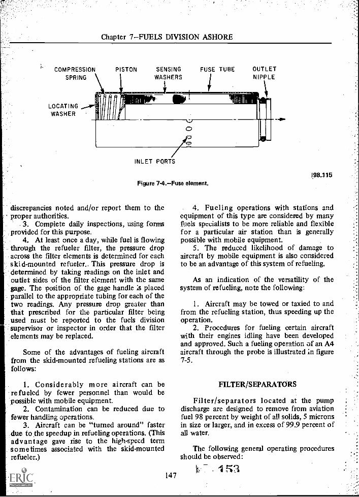
Chapter 7FUELS DIVISION ASHORE
COMPRESSION
SPRING
LOCATINGWASHER
PISTON SENSING
WASHERSFUSE TUBE OUTLET
NIPPLE
0
INLET PORTS
Figure 74.Fuse element.
discrepancies noted and/or report them to theproper authorities.
3. Complete daily inspections, using formsprovided for this purpose.
4. At least once a day, while fuel is flowingthrough the refueler filter, the pressure dropacross the filter elements is determined for eachskid-mounted refueler.. This pressure drop isdetermined by taking readings on the inlet andoutlet sides of the filter element with the samegage. The position of the gage handle is placedparallel to the appropriate tubing for each of thetwo readings. Any pressure drop greater thanthat prescribed for the particular filter beingused must be reported to the fuels divisionsupervisor or inspector in order that the filterelements may be replaced.
Some of the advantages of fueling aircraftfrom the skid-mounted refueling stations are asfollows:
1. Considerably more aircraft can bere fueled by fewer personnel than would bepossible with mobile equipment.
2. Contamination can be reduced due tofewer handling operations.
3. Aircraft can be "turned around" fasterdue to the speedup in refueling operations. (Thisadvantage gave rise to the high -speed termsome times associated with the skid-mountedrefueler.)
147
198.115
4. Fueling operations with stations andequipment of this type are considered by manyfuels specialists to be more reliable and flexiblefor a particular air station than is generallypossible with mobile equipment.
5. The reduced likelihood of damage toaircraft by mobile equipment is also consideredto be an advantage of this system of refueling.
As an indication of the versatility of thesystem of refueling, note the following:
1. Aircraft may be towed or taxied to andfrom the refueling station, thus speeding up theoperation.
2. Procedures for fueling certain aircraftwith their engines idling have been developedand approved. Such a fueling operation of an A4aircraft through the probe is illustrated in figure7-5.
FILTER/SEPARATORS
Filter/separators located at the pumpdischarge are designed to remove from aviationfuel 98 percent by weight of all solids, 5 micronsin size or larger, and in excess of 99.9 percent ofall water.
The following general operating proceduresshould be observed:
I 53

AVIATION BOATSWAIN'S MATE F 1 & C
Figure 7-5.Probe refueling.
1. Installation of New Elements.a. Close nearest manual valves upstream
and downstream of filter/separator.b. Completely drain filter /separator
case.Remove old elements.Thoroughly flush out interior offilter/separator case with clean fuel.Install new elements followingmanufacturer's instructions. Specialattention should be paid to 0-ringand other type seals.Install new head gaskets or seals asrequired.
Secure case head. (CAUTION:Uneven tightening of head bolts mayresult in leakage. Use onlyrecommended torque.)
h. Slowly fill case. Be sure case isvented during filling and all air is
c.d.
e.
f.
g.
197.76.1
eliminated prior to startingcirculation. Observe for possibleleakage.
i. Start flow at reduced flow rate.Circulate fuel. Take frequent samplesdownstream of filter/separator. Makevisual inspection until a bright clearsample is observed. It is suggestedthat a minimum of 1,000 gallons becirculated through thefilter/separator before, fuel isdispensed to aircraft.Observe and record pressure dropacross filter/separator. Pressure dropmust be read at normal Operatingpressures and flow rate.filter/separator. Stencil date M: newelement installation on exterior -offilter/separator case.
2. Operations.

Chapter 7FUELS DIVISION ASHORE
a. Daily, drain low point drains onfilter/separators and sample forpresence of water. If water isobserved, continue to drain until awater-free sample is obtained.
b. Daily, under full-flow conditions,take representative fuel samples fromboth upstream and downstream ofthe filter/separators. The samplesshould be taken in clean, clear, glasscontainers, a minimum of 1 quart insize. The samples should beinspected in a good light andobserved for acceptable appearanceof clean. bright, and water-free fuel.
MONTHLY LOGFILTER/SEPARATOR PRESSURE DROPNAM'S FORM 11240/4 (7-65) 0141.2400040
The observed quality of the fuelsample together with the pressuredrop is to be recorded onFilter/Separator Log, NavWeps Form11240/4. (See fig. 7-6.) If systemdesign permits, meter readingsshowing quantity of fuel processedthrough a filter/separator should alsobe recorded in appropriate space onthe log.
c. Rated fuel flows must not beexceeded. Operating pressures mustbe held to a minimum consistentwith flow requirements. Operating
MONTH I YEAR
TYPE FUEL ELEMENTS INSTALLEO (Oct.) VEHICLE NO, OR F/S LOCATION
DAYFILTER/SEPARATOR FUEL MONITOR
METER READING FUEL SAMPLEIN PSI OUT PSI DIFF. PSI IN PSI OUT PSI DIFF. PSI
2
3
6
9
10
II
23
30
31
REMARKS (Use ....... .iot. ter lotit.nel kw)
Figure 7-6.Filter/Separator Log, NavWeps Form 11240/4.
149
1.5
198.54

AVIATION BOATSWAIN'S MATE F 1 & C
procedures that would result inpressure surges must be avoided.
d. Reverse flow throughfilter/separators is not permitted.
e. All gages used for indicating pressuredrop are to be calibrated at leastevery 6 months. Date of gagecalibration should be entered onfilter/separator log.
f. All operating procedures must beconsistent with applicable safetyrequirements.
3. Element Change Requirements. Thefollowing criteria govern element changerequirements.
a. The elements in systems equippedwith a filter/separator without a fuelmonitor are required to be changedafter 1 year or when there is apressure drop of 15 psi across thefilter /separator, whichever occursfirst.
b. The elements in systems equippedwith a filter/separator and a monitordown stream of the filter/separatorare required to be changed aftcr 2years or when the pressure dropacross the filter elements reaches 20psi, whichever occurs first.
c. The elements in the combinationgo-no go gage/filter water separator,where a fuel monitor is installed inthe filter/separator case, must bechanged if the pressure drop exceeds25 psi.
Figure 7-7 shows the location of elementsinstalled in the combintaion go-no go gage/filterwater separator.
Increase in pressure drop should be gradual.A sudden increase of outlet pressure indicates amalfunction in the elements and should beimmediately investigated. Extreme care shouldbe exercised in handling and disposing of old,fuel soaked elements. Inhalation of fuel fumesand contact of bare skin with fuel should beavoided. Except under an extreme emergency(such as operating in a combat area and newelements not being immediately available),elements once removed from filter /separators,
150
regardless of the previous length of service, mustnot be reused, and must always be replaced withnew unused elements.
MOBILE REFUELERS
Mobile refuelers are used to transport fuelfrom the station truck fill stands to the aircraftand then to meter it into the fuel stowagesystem of the aircraft through filtering andwater separating equipment. Bothtruck-chassis-mounted and semitrailer-mountedequipment are used in this service; however,only the chassis-mounted refuelers are discussedin this manual, as this is the equipment presentlyin use by the Navy.
A general view of the 5,000-gallontruck-mounted aircraft refueler found on navalair stations is shown in figure 7-8. A closeup ofthe hose reels, meters, gages, controls, etc. forthis truck is shown in figure 7-9.
Figure 7-10 is a piping schematic of acommonly used refueler.
The re fuele r consists of a 5,000-galloncapacity, one-compartment tank with baffleplates installed, mounted on a commercial truck.It is designed for refueling aircraft by means of apower-takeoff-driven pumping system. Thepumping system is composed of a pump, afilter/separator, a fuel meter, a monitor,discharge nozzles, and the required controls forfueling operations. Fuel can be pumped fromthe discharge hoses into the aircraft or from theaircraft back into the refueler for defuelingpurposes.
A pump driven by a power takeoff from thetruck transmission is located beneath the tank.The pump delivers fuel through thefilter/separator to prevent water and foreignparticles from entering the aircraft fuel tank.The manual water drain valve in the bottom ofthe separator is used to drain excessive waterfrom the filters.
The monitor is a fuel transfer monitoringdevice located downstream from thefilter/separator. It also traps and retains solidcontamination and absorbs undissolved waterpassed by the filter/separator. This fuel monitor

Chapter 7FUELS DIVISION ASHORE
FUSE CLIP ADAPTOR ASSEMBLY
SEPARATOR
TEFLON COATED
SEPARATOR
GO-NO-GO FUSE
GO- NO- GO FUSE
VENT VALVE
COVER CLAMP BOLT
HOUSING
COALESCER ELEMENT
OUTLET 44140 41. INLET
DRAIN VALVE
Figure 7-7.Location of elements for combination filter.
(go-no go gage) may be independent of thefilter/separator, with the go-no go fusesmounted in a separate casing down stream of thefilter/separator, or it may be a combinationgo-no go gage/filter water separator as shown infigure 7-7.
The main control valve is mounted to theoutlet flange of the filter/separator and isoperated by a dead-man control valve (three-wayvalve) to govern flow of fuel, through thesystem. Throttle valves are installed in the fuellines to control direction and fuel flow. Anemergency valve is installed to control theoutput from the tank in cases of emergency.
151
198.116
Eductor valves are used to reverse flow directionwith existing pumping system pressures whenevacuating the hoses. Fuel enters and is recordedin the meters for all fueling and hose evacuationoperations. Total gallonage is shown on thetop-mounted counter. Two motor-driven topwind hose reels are adaptable to accomodate11/2-inch and 2'/2 -inch diameter hoses. Overwingand pressure discharge nozzles are provided todispense and control the fuel flow into theaircraft.
Detailed information on the operation,service, and repair of this particular refueler maybe found in the Technical Manual, 5,000-Gallon
157

AVIATION BOATSWAIN'S MATE F 1 & C
14A6Witelligargf
WillIONA,NomatR11,1-1,
.41111=2..
RiliggiNillfgrTV
Figure 7-8.-5,000-gallon truck-mounted aircraft refueler.
Truck Mounted Refueler, NavWeps 19-25C-15.Similar information on still later refuelers of thistype may be found in NavWeps 19-25C-16.Later fuel trucks of this type purchased by theNavy incorporate certain features not found onthe earlier trucks. Of particular interest is thebottom loading provision found on the latesttrucks. By means of matched valves the majorvalve for receiving fuel on trucks with thebottom loading provision prevents the loading ofthe wrong fuel into the truck. Other advantagesof the bottom loading feature are the turbulenceand the resultant generation of static electricitycan be reduced, trucks can be filled morequickly resulting in a reduction in theturnaround time, there is less likelihood ofintroducing foreign material into the tank due tothe location and size of the tank opening, andthere is less danger of injury to personnel whowould normally be crawling or walking aroundon top of the truck tank during fillingoperations.
Two men are required for the proper andsafe operation of this refueler when servicing anaircraft. Additional required personnel includethe plane captain and fire watch who are usuallysquadron or flight line personnel. The refueler
.SR152
197.71
driver is responsible for the proper positioningof the refueler, grounding of aircraft andrefueler, and operation of fueling controls onthe refueler. Senior ABF's should emphasize theimportance of making the proper approach tothe aircraft with refuelers to avoid damage tothe aircraft and equipment in case of brakefailure, etc. For similar reasons and thepossibility of fire, the actual position of therefueler during fueling operations is important.
The plane captain of the aircraft beingrefueled is usually the person who connects thefueling nozzle to the fueling point being used.An additional man should serve as fire watch,standing by with the approved firefightingequipment provided for this purpose.
The refueler driver insures that water sumpson aviation fuel truck tanks are drained at leastonce daily, or more often if indications ofcontamination are found to be present. If such isthe case, all trucks are suspected and must begiven additional drain checks.
The refueler driver must be certain that theaircraft is properly located away from allpossible sources of ignition. If not, refuelingMUST BE DELAYED until the aircraft is movedor the ignition sources eliminated.

Chapter 7FUELS DIVISION ASHORE
r.
inua4 ft.11 tx.
sILIUM 2n rtou ix.far,
:1121101.45,
c/c
1 1 ISi#1,01CING WITillg
..... yr-
197.71.1Figure 7-9.Hose rack and meter compartment on 5,000gallon refueler.
The refueler driver must park the refueler asfar from the aircraft to be filled as the hose willpermit. It should be parked in a position so thatit may be quickly driven away. There must beno obstructions in front of the refueler toprevent its being driven away in an emergency.
After parking the refueler, set the handbrakeand turn off the lights and any other electricalequipment.
The driver must make certain that the fuel inthe refueler is the correct grade and typerequired for the aircraft.
153
FUELS INVENTORY ANDACCOUNTING PROCEDURES
Aviation fuels are received by fuel branchpersonnel of the station supply department froma refinery that bid for and was awarded thecontract to supply fuel to the air station for aspecified period of time. The fuel is put intounderground stowage tanks and must be allowedto settle for a prescribed length of time beforebeing used. Prior to receiving and stowing fuel,the tank(s) intended for stowage must be

AVIATION BOATSWAIN'S MATE F 1 & C
3 INCH
4 INCH 4 INCH
1. 4-inch emergencyvalve.
13. 2 1/2-inchnozzle.
2. 4-inch gate valve. 14. Hose reelRH.3. Pump 15. 3-inch throttle4. Filter/separator. valve.5. Go-no-go gage. 16. 1 1/2-inch6. Valve-pressure nozzle.
control. 17. 2 1/2-inch check7. 3-inch venturi. valve.8. 3-inch control 18. 1 1/2-inch hose.
valve. 19. 2 1/2-inch9. 3-inch meter. eductor.
10. 3-inch gate valve. 20. 3-inch strainer.11. Hose reelLH. 21. 3-inch pipe plug.12. 2 1/2-inch hose. 22. Relief valve.
197.71.2Figure 7-10.Piping schematic for 5,000-gallon mobile
refueler.
inventoried to determine how much fuel can bestowed in each tank, and to determine the totalamount of fuel that can be received.
Each tank has an access above ground topermit measuring the amount of fuel in thetank. A gage calibrated in feet and inches is usedfor taking this reading. The reading is thenconverted to gallons by reference to aconversion chart; the chart also lists the totalcapacity of each tank. Thus fuel remaining atmonthly inventory time, and fuel needed forreplenishment, are easily determined.
154
In the next few paragraphs the issuedocuments used in the accounting proceduresfor aviation fuels at one master jet base arediscussed. While the forms used at other basesmay differ slightly, the basic functions are thesame and the procedures followed are verysimilar.
Issue of fuel and lubricating oil is recordedby the refueling branch personnel on either aDD Form 1348 or on a special form issued bythe station supply department. The planecaptain or other authorized personnel shouldverify the gallons recorded on the form with therefueler meter reading. On the first working dayof the week (or as directed by local authority), aDD Form 1348 for each type or grade of fueland lubricating oil to cover the estimatedrequirement for the succeeding week should befilled out and submitted to the fuels divisioninventory control branch, by the squadron orthe station operations department. At the end ofeach week, the estimated quantity on the DDForm 1348 will be adjusted to the actualamounts used.
All transient government aircraft refuelingshould be recorded on the DD Form 1348carried in the aircraft flight packet. The form isthen forwarded to the inventory control branchfor preparation of an invoice for financialaccounting.
Allotment credit can be allowed for fueldefueled from an aircraft when it is determinedthat the fuel is not contaminated. No credit canbe allowed for contaminated fuel.
Civilian aircraft may be refueled and the fuelrecorded in the same manner as Navy aircraftwhen the aircraft are under Navy contract andfunds have been deposited in advance. Civilianaircraft that have made an emergency landing atthe station may be refueled when authorized bythe operations officer or operations duty officerstating that an emergency exists. Issues tocivilian aircraft other than those underemergency conditions must be approved in,writing by the commanding officer.
SUMMARY
In summary, it will be noted by ABF's whohave had aircraft carrier duty that the fueling

Chapter 7FUELS DIVISION ASHORE
operations ashore are quite similar to thoseaboard ship. The functions are basically thesame but the problems are a little different,being more pronounced for certain phases of therefueling operation. Many of these problems aremade more acute due to the sprawling areacovered by fuels operations ashore and the manychances for introducing foreign orcontaminating materials into the fuel.
Some of the problem areas that will requirespecial attention from senior ABF's are qualityassurance surveillance; the close supervision andtraining of new personnel; an effective safetyprogram; preventative maintenance and properuse of equipment; cheerful cooperation withcivilian personnel of the fuels division; and good
155
work management practices among personnel ofthe division.
Problems in work management have plaguedthe fuels division for years, particularly theaircraft fuels delivery branch. Many differentsolutions have been tried, with varying degreesof success, depending very largely on the seriousthought and effort going into the planning andexecution of the plans to solve these problems.
Information on oil service equipment maybe found in ABF 3 & 2 , NavPers 10301-C. Aconsiderable amount of information onoperational procedures and safety procedures iscontained in the Handbook, Aircraft Refuelingfor Shore Activities, NAVAIR 06-5-502. ThisHandbook is updated periodically and reissuedas a revised Handbook.
1

CHAPTER 8
QUALITY ASSURANCE AND' SURVEILLANCE
The performance of any aircraft depends onthe quality of the fuel that is used in it. As aleading fuels petty officer, the quality of thefuel depends on your constant vigilance in theinspection of the fuel samples and operation ofthe purification equipment. The fuels pettyofficer should have an understanding of theproperties and characteristics of aviation fuels toaid him in .quality assurance and surveillance.This subject is covered in detail in ABF 3 & 2,chapter 4, which should be reviewed inconjunction with the study of this chapter.
CONTAMINATION IN AVIATION FUEL
There are several forms of contamination inaviation fuels. The higher the viscosity of thefuel, the greater is its ability to holdcontamination in suspension. For this reason, jetfuels having a high viscosity are more susceptibleto contamination than aviation gasoline. JP-5 ismore susceptible than JP-4 for the same reason_
Some forms of contamination may bedetected visually, but particles large enough tobe visible should rarely be present. It is said thatany sediment that can be seen is too much. If afuel sample is swirled vigorously and allowed tosettle in a clean quart bottle, the sedimentshould gather in the bottom center and be nomore than a slight smudge. Some of the forms ofcontamination are: water, foreign particles, andcommingling.
WATER
Water can be present in the fuel in twoformsdissolved water and visible free. water.Dissolved water is usually present in any
6?, 156
petroleum product and cannot be avoided. It isallowable up to the point of saturation. Thesaturation point is when the fuel will hold nomore water in solution. This point varies withthe temperature. A warm fuel will have a highersaturation point than cool fuel. When the warmfuel is cooled, the dissolved water partlyprecipitates out, forming a light cloud oremulsion.
The fuel can be cloudy for other reasons,and clouds must be identified where possible.Clouds caused by water are identified by use ofthe AEL Free Water Detector, Mark I. Whenused by trained and experienced operators, thisdevice can determine the free water contentaccurately to one or two parts per million. Fuelcontaining more than five parts per million offree water must not be delivered to the aircraftfuel tank. Water may be either saline or freshwater. Salty water is particularly hazardous tothe engine and fuel system components since itcan cause corrosion. Free water can cause icingof the fuel system, usually in the aircraft boostpump screens and low pressure filters. Fuel gagereadings may become erratic because the waterelectrically shorts the aircraft fuel cell quantityprobe. Gross (large) amounts of water can causea flameout of the engine.
Water in the bottoms of aircraft fuel tankspromotes microbiological growth which in turnclogs filters, fouls fuel quantity probes, andcauses fuel control malfunctions.
FOREIGN PARTICLES
Most foreign particles are found in the fuelas sediment. This can be almost any materialwith which the fuel comes into contact. Themost common types are rust, sand, aluminum

Chapter 8QUALITY ASSURANCE AND SURVEILLANCE
and magnesium compounds, brass shavings,rubber, talc from the interior of fuel hoses, andmicrobiological growth.
Rust is found in two formsred rust(Fe2O3) which is nonmagnetic, and black rust( Fe304 ) which is magnetic. They appear in thefuel as red or black powder, rouge, or grains. Inpowder form it may resemble a dye. Sand ordust appears in the fuel in a crystalline, granular,or glass-like form.
Aluminum or magnesium compounds arefound in the fuel as a form of white or graypowder or paste. This powder or paste becomesvery sticky or gelatinous when water is alsopresent. Brass is found in the fuel as brightgold-colored chips or dust. Rubber appears inthe fuel as fairly large black irregular bits.
When a new or dried out hose is placed inservice, a discoloration of fuel takes place. Thisis due to a chemical that is added to syntheticrubber to make it pliable. To prevent thissubstance from entering an aircraft, cap one endof the hose, fill with fuel, cap the open end, andallow fuel to stand for one week. Drain andflush, then continue this procedure until nodiscoloration can be detected. Small amounts oftalc may be released from the inside surface ofthe fuel hose due to stretching and flexingduring normal handling.
All of the above forms of contamination cancause sticking or general malfunctions of thefuel controls, flow dividers, pumps, and nozzles.
The sediment contamination of the fueldelivered to aircraft must be no more than 2.0milligrams per liter (mg/l.) If operationalnecessities dictate, the command may authorizeutilization of fuel contaminated above 2.0 mg/ i .It should be realized that such fuel will adverselyaffect the aircraft fuel system reliability.
Fuel systems reliability predictions relativeto sediment contamination levels are shown intable 8-1.
COMMINGLING
Unintentional mixing of petroleum productscan result in fuels that may be dangerous inunprotected shipboard stowage andunacceptable in performance for aircraft. Thistype of contamination can generally be detectedonly by specific laboratory tests.
157
Table 8-1.Sediment contamination level.
Sediment(mg/1)
FuelContamination
Predictedreliability
0-1 Clean Excellent1-2 Slight Good2-5 Moderate Fair5-10 Heavy PoorOver 10 Gross None
NOTE: A complete list of the names andaddresses of the petroleum testing laboratoriescan be found in NAVAIR Instruction 10340.3.
Contamination of aviation fuels with otherproducts should not exceed the amounts givenin table 8-2. Aviation gasoline containing morethan 0.5 percent, by volume, of jet fuel may bereduced below the allowable limits in knockrating. Contaminated aviation gasoline can bedowngraded to motor gasoline, but JP-4 jetengine fuel which does not meet the requiredspecifications generally cannot be downgradedfor any other use. Off-specification JP-5 can beused as diesel or boiler fuel.
MICROBIOLOGICAL GROWTH
This growth is produced by various forms oforganisms which live and multiply at theinterface between fuel and water in fuel tanks.These organisms may form a slime similar inappearance to the deposits found in stagnantwater. In fuel the color of this slime growth canbe red, brown, gray, or black. The organismsfeed on the hydrocarbons that are found infuels, but they need free water in order tomultiply.
There are two types of growth that areusually the source of the most trouble in Navyfuelssulfate reducing bacteria and brown"hormodendron" fungus. The sulfate reducingbacteria cause trouble when they grow in thebottoms of stowage tanks which contain waterand sludge. These bacteria give off hydrogensulfide which bubbles up into the fuel andcauses it to become corrosive. The fuel will nolonger pass the copper corrcrion test. This

AVIATION BOATSWAIN'S MATE F 1 & C
O
O
Table 8-2.ALLOWABLE CONTAMINATION WITH OTHER PRODUCTS
Product Being Handled
80/87 100 /130 1 15/1 45 JP -4 JP -5
80/87 0.5% 0.5% 5.0% 0.0
100/130 5.0% 0.5% 1.0% 0.0
11 5/1 45 5.0% Any percentage acceptable
1.0% 0.0
JP-4 0.5% 0.5% 0.5% 0.0
JP 5 0.5% 0.5% 0.5% 10.0%
Diesel orNavy distillate
0.5% 0.5% 0.5% 2.0% 0.5%
Navy Special FuelOil
0.0 0.0 0.0 0.0 0.0
phenomenon usually occurs with fuel stowed forseveral months in warm climates. This type ofmicrobiological growth is controlled by cleaningthe tanks to remove sludge and eliminate waterin tank bottoms.
The brown fungus may grow in stowage tankbottoms but is not a source of trouble there. Iffree water, particularly sea water, is carried overinto aircraft tanks, the brown fungus tends togrow in aircraft fuel tanks in a thick mat whichcan break loose and cause trouble in the fuelcontrol, flow dividers, filters, or quantity gageprobes. The fungus may also cause corrosion oftank bottoms. Removal of accumulated growthfrom tanks is difficult, time consuming, andexpensive. The best method of preventingfungus growth is to keep the free water contentof the fuel below five parts per million.
CONTAMINATION DETECTION
Contamination detection in aviation fuelbegins with the refinery and ends after it is used.
158
Each time the fuel is moved from one stowagetank to another it is subject to new and morecontamination. If checks are not made beforetransfer, and appropriate stripping of settledwater and sediment accomplished, thecontamination already in the fuel cancontaminate the new stowage.
Once contamination is detected, the fuelshould not be used or transferred until it isdetermined that the contamination is withinspecified limits. Stop the transfer from onestowage tank to another, from a tanker to anaircraft supporting ship, or from a ship's systemor refueling pit to an aircraft as soon as thecontamination is detected. If for any reason it isthought that contaminated fuel has been putinto an aircraft, the appropriate person in chargeshould be notified.
For each of the fuel contaminationproblems, there is a solution. However,equipment must be properly operated andsampling procedures carefully followed. The

Chapter 8QUALITY ASSURANCE AND SURVEILLANCE
most important factor in delivering clean, bright,and water-free fuel to the aircraft is the integrityof the men handling the fuel.
VISUAL INSPECTION
Coarse contamination can be detectedvisually. The major criterion for contaminationdetection is that the fuel be clean, bright, andcontain no perceptible free water. Clean meansthe absence of any emulsion, readily visiblesediment, or entrained water. Bright refers tothe shiny appearance of clean, dry fuels. Freewater is indicated by a cloud, haze, or a waterslug in the sample bottle.
Sediment in the fuel is visible when theparticles are 40 microns or larger in size. Amicron is 1/1 0,000 of a centimeter, orapproximately 1/25,000 of an inch. Groups ofparticles less than 5 microns in size may be seenin the fuel when viewed at a right angle to astrong light. When inspecting a fuel sample, itshould be swirled and allowed to settle for a fewmoments. The coarse particles will settle to thebottom center of the bottle and collect in agroup. Any sediment that can be seen is toomuch for aircraft use.
The AEL Free Water Detector should beused to determine the presence of free waterabove the allowable limit (for aircraft) of fiveparts per million. Free water at this level ofcontamination may or may not be visible to thenaked eye.
Fuel that is contaminated by comminglingwith another petroleum product is difficult todetect visually. In gasoline, if the percentage ofthe other petroleum is fairly high, there may bea color change. JP-5 contaminated by JP-4, orvice versa, can be detected by a laboratory testfor flash-point and distillation. JP-5contaminated with NSFO (Navy special fuel oil)may be visually apparent. One part of NSFO in300 parts of JP-5 will turn the JP-5 black, or thecolor of strong coffee; however, some JP-5 fuelsare naturally dark in color. Aviation fuels thatare suspected of contamination by anotherpetroleum product should be sent to apetroleum laboratory for inspection.
For a complete listing of the types ofcontaminants and their acceptable limits, referto table 8-3.
159
Soundings
Liquid level indicators will only indicate theamount of fluid in a tank. They do not indicatethe amount of water that may be present. Tankscan be gaged fairly accurately by the use ofsounding tapes. These tapes, when used withwater detecting paste, will give the depth ofwater in the tank. To find the amount of fuel inthe tank, convert the water reading from inchesto gallons and subtract the water reading ingallons from the number of gallons of liquid inthe tank. Finding the amount of water in thetank will also give an indication of the amountof time required to strip the water from the tankbottom. Afterward, the paste can be used tofind the effectiveness of the stripping operation.
Water entrained in the fuel will also beindicated by spots of color change on the tape.When these spots are found, the fuel should begiven more time to settle before beingtransferred.
LABORATORY SAMPLESAND REPORTS
Sampling
Proper sampling of petroleum products is asimportant to quality surveillance as propertesting. Improper containers or poorly drawnsamples can cause laboratory results to bemeaningless, or worse, misleading.
Directions for sampling cannot be madesufficiently explicit for all cases. Judgment, skill,and experience must supplement anyinstructions. For these reasons, the personassigned to take samples should be trained,experienced, competent, and conscientious. Theresponsibility for taking and preparing samplesshould not be lightly delegated.
Some cardinal rules in sampling are:
1. The sampler's hands or gloves should beclean.
2. Sample containers should bemeticulously clean. They should be thoroughlycleaned and inspected prior to use. Prior to
*4)

Tab
le 8
-3.V
isua
l Con
tam
inat
ion
Tab
le
TY
PE C
ON
TA
MIN
AN
TS
APP
EA
RA
NC
EC
HA
RA
CT
ER
IST
ICS
EFF
EC
TS
ON
AIR
CR
AFT
A.
WA
TE
R
(1)
Dis
solv
edW
ater
(2)
Free
Wat
er
B.
PAR
TIC
UL
AT
EM
AT
TE
R
(1)
Rus
t
*NO
TE
1:
Part
icle
s la
rge
enou
gh to
be
visi
ble
shou
ld r
arel
y be
pre
sent
. At t
he m
ost,
the
tota
l sed
imen
t sho
uld
be a
spo
t of
silt.
If
any
appr
ecia
ble
cont
amin
atio
n, is
fou
nd, t
he te
st m
ust b
e re
peat
ed. W
hen
test
ing
with
the
AE
L M
K I
II th
e m
ax is
2 m
g/ 1
.
Not
vis
ible
.
Lig
ht c
loud
.H
eavy
clo
ud.
Dro
plet
s ad
heri
ngto
sid
es o
f bo
ttle
Gro
ss a
mou
nts
settl
ed in
bot
tom
.
Red
or
blac
kpo
wde
r, r
ouge
, or
grai
ns. M
ay a
ppea
ras
dye
-lik
e m
ater
ial
in f
uel.
Fres
h w
ater
onl
y.Pr
ecip
itate
s ou
t as
clou
d w
hen
fuel
isco
oled
.
Free
wat
er m
ay b
esa
line
wat
er o
r fr
esh
wat
er. C
loud
usu
ally
indi
cate
s w
ater
-in-
fuel
emul
sion
.
Red
rus
t (Fe
203)
nonm
agne
tic B
lack
rust
(Fe
304)
mag
netic
Rus
t gen
eral
ly c
ompi
ises
maj
or c
onst
ituen
t of
part
icul
ate
mat
ter.
Non
e un
less
pre
cipi
tate
dou
t by
cool
ing
of f
uel.
Can
then
cau
se ic
e to
form
on
low
pre
ssur
efu
el f
ilter
s if
fue
l tem
-pe
ratu
re is
bel
ow f
reez
ing.
Icin
g of
fue
l sys
tem
usua
lly lo
w p
ress
ure
fuel
filt
ers.
Err
atic
fue
lga
ge r
eadi
ngs.
Gro
ssam
ount
s of
wat
er c
anca
use
flam
e-ou
ts. S
alt
wat
er w
ill c
ause
cor
rosi
onof
fue
l sys
tem
com
pone
nts.
Will
cau
se s
ticki
ng,
and
slug
gish
or
gene
ral
mal
func
tion
of f
uel
cont
rols
, flo
w d
ivid
ers,
pum
ps, n
ozzl
es, e
tc.
AC
CE
PTA
BIL
ITY
LIM
ITS
FOR
DE
-L
IVE
RY
TO
AIR
-C
RA
FT
Any
am
ount
up
to s
atur
atio
n.
Zer
oFue
l mus
tco
ntai
n no
vis
u-al
ly d
etec
tabl
efr
ee w
ater
.
*Ref
er to
NO
TE
1
RD

Tab
le 8
-3.V
isua
l Con
tam
inat
ion
Tab
le IC
onft0
TY
PE C
ON
TA
MIN
AN
TS
APP
EA
RA
NC
EC
HA
RA
CT
ER
IST
ICS
EFF
EC
TS
ON
AIR
CR
AFT
!A
CC
EPT
AB
ILIT
YL
IMIT
S
.PA
RT
ICU
LA
TE
MA
TT
ER
(C
oned
)
(2)
Sand
or
Dus
t
(3)
Alu
min
um o
rM
agne
sium
Com
poun
ds
.M
ICR
OB
IOL
OG
ICA
LG
RO
WT
H
D.
EM
UL
SIO
NS
(1)
Wat
er-i
n-fu
elE
mul
sion
s
Cry
stal
lire
,gr
anul
ar o
rgl
ass-
like.
Whi
te o
r gr
aypo
wde
r or
pas
te.
Bro
wn,
gra
y, o
rbl
ack.
Str
ingy
or f
ibro
us.
Lig
ht c
loud
.H
eavy
clo
ud.
Usu
ally
pre
sent
and
occa
sion
ally
con
stitu
tes
maj
or c
onst
ituen
t.
Som
etim
es v
ery
stic
kyor
gel
atin
ous
whe
n w
etw
ith w
ater
. Usu
ally
pres
ent a
nd o
ccas
iona
llyre
pres
ents
maj
orco
nstit
uent
.
Usu
ally
fou
nd w
ith o
ther
cont
amin
ants
in th
e fu
el.
Ver
y lig
ht w
eigh
t;fl
oats
or
"sw
ims"
in f
uel
long
er th
an w
ater
dro
plet
sor
sol
id p
artic
les.
De-
velo
ps o
nly
whe
n fr
eew
ater
is p
rese
nt.
Fine
ly d
ivid
ed d
rops
of
wat
er in
fue
l. Sa
me
asfr
ee w
ater
clo
ud. W
illse
ttle
to b
otto
m in
min
utes
, hou
rs, o
r w
eeks
depe
ndin
g up
on n
atur
eof
em
ulsi
on.
Will
cau
se s
ticki
ng, a
ndsl
uggi
sh o
r m
alfu
nctio
nof
fue
l con
trol
s, f
low
divi
ders
, pum
ps, n
ozzl
es,
etc.
Will
cau
se s
ticki
ng, a
ndsl
uggi
sh o
r ge
nera
lm
alfu
nctio
n of
fue
lco
ntro
ls, f
low
div
ider
s,pu
mps
, noz
zles
, etc
.
Foul
s fu
el q
uant
itypr
obes
, stic
ks f
low
divi
ders
, mak
es f
uel
cont
rols
slu
ggis
h.
Sam
e as
fre
e w
ater
.
*Ref
er to
NO
TE
I
*Ref
er to
NO
TE
1
Zer
o.
Zer
oFue
l mus
tco
ntai
n no
visu
ally
dete
ctab
le f
ree
wat
er.

Tab
le 8
-3.V
isua
l Con
tam
inat
ion
Tab
le (
Con
fdi
TY
PE C
ON
TA
MIN
AN
TS
APP
EA
RA
NC
EC
HA
RA
CT
ER
IST
ICS
EFF
EC
TS
ON
AIR
CR
AFT
AC
CE
PTA
BIL
ITY
LIM
ITS
(2)
Fuel
and
wat
eror
"st
abili
zed"
Em
ulsi
ons
.M
ISC
EL
LA
NE
OU
S
(1)
Inte
rfac
eM
ater
ial
(2)
Air
Bub
bles
Red
dish
, bro
wn-
ish,
gra
yish
or
blac
kish
. Stic
kym
ater
ial v
ario
usly
desc
ribe
d as
gela
tinou
s, g
umm
y,lik
e ca
tsup
, or
like
may
onna
ise.
Lac
y bu
bble
s or
scum
at i
nter
face
betw
een
fuel
and
wat
er. S
omet
imes
rese
mbl
es je
lly-
fish
.
Clo
ud in
fue
l.
Fine
ly d
ivid
ed d
rops
of
fuel
in w
ater
. Con
tain
sru
st o
r m
icro
biol
ogic
algr
owth
whi
ch s
tabi
lizes
or "
firm
s" th
e em
ulsi
on.
Will
adh
ere
to m
any
mat
eria
ls n
orm
ally
inco
ntac
t with
fue
ls.
Usu
ally
pre
sent
as
"glo
bule
s" o
r st
ring
y,fi
brou
s-lik
e m
ater
ial
in c
lear
or
clou
dy f
uel.
Will
sta
nd f
rom
day
s to
mon
ths
with
out s
ep-
arat
ing.
Thi
s m
ater
ial
cont
ains
hal
f to
thre
e-fo
urth
s w
ater
, asm
all a
mou
nt o
f fi
neru
st o
r m
icro
biol
ogic
algr
owth
and
is o
ne th
ird
to o
ne h
alf
fuel
.
Ext
rem
ely
com
plic
ated
chem
cial
ly. O
ccur
s on
lyw
hen
emul
sion
and
free
wat
er is
pre
sent
.
Dis
pers
es u
pwar
dw
ithin
a f
ewse
cond
s.
Sam
e as
fre
e w
ater
and
sedi
men
t, on
lym
ore
dras
tic. W
ill q
uick
lyca
use
filte
r pl
uggi
ng a
nder
ratic
rea
ding
s in
fue
lqu
antit
y pr
obes
.
Sam
e as
mic
robi
olog
ical
grow
th.
Zer
o.
Zer
oThe
resh
ould
be
nofr
ee w
ater
.
Any
am
ount
.
g.

Chapter 8QUALITY ASSURANCE AND SURVEILLANCE
sampling, the clean container should be rinsedand flushed several times with the fuel beingsampled.
3. Samples should be as representative ofthe product being sampled as possible. Detailedinstructions for bulk products are contained inthe ASTM Manual on Measurement andSampling of Petroleum Products. Samples offuel being delivered to aircraft should be takenfrom the fueling nozzle during actual fuelingoperations. Samples taken to test fixedfilter/separators should be taken at the samplingoutlet nearest the filter/separator discharge.
4. Samples should be capped promptly,protected from sunlight, and handledexpeditiously.
5. Sampling connections should be installedin vertical pipe runs where practicable. If theyare installed in horizontal runs they should beplaced in the side halfway between the top andthe bottom of the pipe. Sampling connectionsshould be flushed before taking each sample.
6. Samples should be taken with the systemoperating at normal flow rates and steady stateif possible.
7. The bottle should be filled only to thebottom level of the shoulder, and the screw capmust be tightened securely.
SAMPLE CONTAINERS.Aviation fuelsampling containers and shipping containers areavailable in the supply system.
These containers meet all requirements forshipment of aviation fuels by- military andcommerical transportation media.
Glass sample containers with a suitable caphaving an aluminum foil seal should be used.
IDENTIFICATION OF SAMPLE.Properidentification and accurate records of samplesare absolutely necessary so that the test resultsmay be correlated with the samples submitted.
Each sample should be assigned a serialnumber which can be formed by using thecalendar year as the prefix number and assigningconsecutive numbers as the samples aresubmitted. For example: the first samplesubmitted in 1973 would be 73-1; the second,73-2; etc. Such sample numbers should behown on the sample identification tag, allhipping documents, and correspondence
rtaining to the sample.
163
The following should be used as a guide forsample identification:
1. Sample serial number (activity number).2. Type fuel (JP-5, 115/145, etc.).3. Name and location of activity.4. Date sample taken.5. Location of sample point (nozzle
sample, refueler no., tank no., etc.).6. Quantity of material represented, if
applicable.7. Classification of sample (routine or
special). (See below.)8. Name of person taking sample.9. Tests required.
10. Remarks.
SAMPLE CLASSIFICATION.Samples areclassified either ROUTINE or SPECIAL.ROUTINE samples are taken when on fuelproblems or aircraft problems attributable tofuel are known or suspected. An example wouldbe the periodic samples taken as a part of aquality surveillance program. These should betested for sediment and water, and, for JP-5,flashpoint. SPECIAL samples are submitted fortest because the quality of the fuel is suspected,either as the result of aircraft malfunctions orother information. SPECIAL samples shouldhave the highest priority in handling, testing,and reporting.
SHIPPING INSTRUCTIONS.Samples areto be forwarded to appropriate testinglaboratories by the most expeditious means.Wherever feasible, samples should be delivereddirectly to the laboratory by hand. Samples inamounts up to 10 gallons may be shipped viarailway express.
Four 1-quart samples or a 1-gallon sample(i.e., 1-gallon maximum) of aviation fuel may beair shipped via military aircraft when packed inaccordance with Nav Air 15-03-500 (USAF AMF71-4), which further indicates that fuel samplesmay be transported on passenger carryingaircraft.
CONTAMINATED FUEL DETECTOR(AEL MK III)
The contaminated fuel detector is a portableself-contained unit. (See fig. 8-1.) This
r..r.1
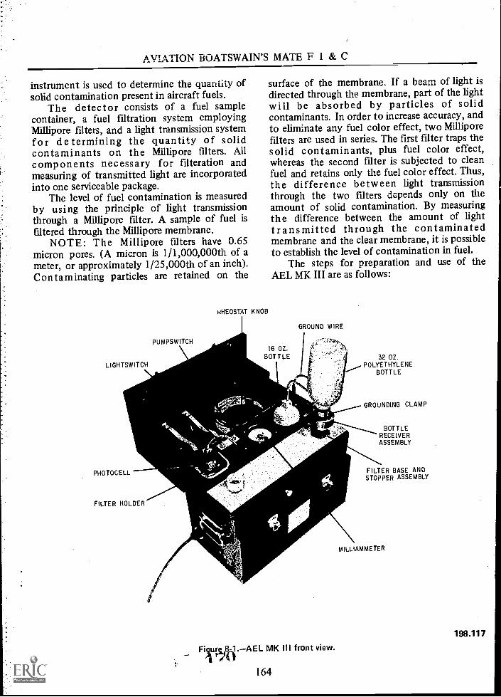
AVIATION BOATSWAIN'S MATE F 1 & C
instrument is used to determine the quantity ofsolid contamination present in aircraft fuels.
The detector consists of a fuel samplecontainer, a fuel filtration system employingMillipore filters, and a light transmission systemfor determining the quantity of solidcontaminants on the Millipore filters. Allcomponents necessary for filteration andmeasuring of transmitted light are incorporatedinto one serviceable package.
The level of fuel contamination is measuredby using the principle of light transmissionthrough a Millipore filter. A sample of fuel isfiltered through the Millipore membrane.
NOTE: The Millipore filters have 0.65micron pores. (A micron is 1/1,000,000th of ameter, or approximately 1/25,000th of an inch).Contaminating particles are retained on the
LIGHTSWITCH
PUMPSWITCH
RHEOSTAT KNOB
surface of the membrane. If a beam of light isdirected through the membrane, part of the lightwill be absorbed by particles of solidcontaminants. In order to increase accuracy, andto eliminate any fuel color effect, two Milliporefilters are used in series. The first filter traps thesolid contaminants, plus fuel color effect,whereas the second filter is subjected to cleanfuel and retains only the fuel color effect. Thus,the difference between light transmissionthrough the two filters depends only on theamount of solid contamination. By measuringthe difference between the amount of lighttransmitted through the contaminatedmembrane and the clear membrane, it is possibleto establish the level of contamination in fuel.
The steps for preparation and use of theAEL MK III are as follows:
16 OZBOTTLE
GROUND WIRE
32 OZ.POLYETHYLENE
BOTTLE
GROUNDING CLAMP
PHOTOCELL
FILTER HOLDER
Fiurg,8 MK III front view.
164
BOTTLERECEIVERASSEMBLY
FILTER BASE ANDSTOPPER ASSEMBLY
MILLIAMMETER
198.117

Chapter 8QUALITY ASSURANCE AND SURVEILLANCE
1. Remove the power cable from inside theinstrument cover and connect it to a suitablesource of 110-volt, 60-hertz power. The powercable contains a ground wire to ground theinstrument.
2. Turn the light switch. The light systemshould be allowed to warm up for two to threeminutes prior to use.
3. Make sure the fuel flask is empty and thedrain cock is closed.
4. The filter base and bottle receiverassembly located in the lid should bedisassembled into its two components. Thesection with the rubber stopper is the filter baseand should be inserted into the opening in thefuel flask.
5. Place two Millipore filters right side upon the filter base. The Millipore filter is apaper-thin white membrane. These filters shouldbe handled only with forceps, and only by theiredges. Reassemble the filter base and bottlereceiver assembly. Rotate the locking ringcarefully to prevent damage to the filters.
TRANSFORMER
FUEL FLASK
DRAIN COCKHANDLE
DRAIN COCK
6. Place the filter base and bottle receiverover the top of the 32 oz polyethylene bottleand fill to the 800 milliliter (ML) mark withfuel. All the threaded portion of the bottle topshould be inserted into the bottle receiver.
7.. Insert the ground wire attached to thefilter base and bottle receiver assembly into theopening provided. Turn on the pump switch; avacuum pump is connected to the fuel flask tospeed up filtration. (See fig. 8-2.)
8. Insert the entire assembly (filter base,bottle receiver, and fuel sample bottle) into thefuel flask. After all the fuel has passed throughthe filters, and the bottle receiver has beenremoved exposing the filters, stop the pump.During the filtration cycle, the fuel in thesample bottle should be agitated occasionally bygently shaking the bottle to insure that anycontaminants are washed down and not lodgedon the inside surface of the bottle. If the samplebottle tends to collapse, gently loosen the bottle
VACUUM PUMP OILER
Figure 8-2.AEL MK III rear view.
165
LAMP
FUSE
VACUUM PUMP ANDMOTOR ASSEMBLY
198.118

AVIATION BOATSWATN'S MATE F 1 & C
in the bottle holder by tilting it slightly duringthe filtration cycle.
NOTE: Prior to measuring thecontamination on the filters, the photocell andlight window should be cleaned.
9. Drain the fuel from the flask through thetygon tubing into a suitable container.
10. With the filter out of the receptacle,swing the photocell into measuring position.Insure it is fully seated.
11. Adjust the rheostat knob for a lightintensity reading of 0.6 on the milliammeter.
NOTE: If sufficient control is not availablewith the rheostat knob to obtain a reading of0.6 milliamps, set the rheostat at midscale.Observe the meter reading with the light on thephotocell in the measuring position without afilter in the receptacle. Disconnect the powercable of the instrument and open the back.Loosen the lightbulb holder slightly. If themeter reads below 0.6 milliamps, slide the bulbholder up. If the meter reads over 0.6 milliamps,slide the bulb holder down. The filament of thelightbulb should be horizontal after the changeis made. Temporarily close the case, connect thepower cable of the instrument, turn on the light,and check the meter reading. It is not necessaryto obtain an exact reading of 0.6 milliamps byadjustment of the light bulb, as final fineadjustments will be made by use of the rheostat.When a suitable position for the light bulb hasbeen found that will permit adequateadjustment by the rheostat, retighten the nutson the bulb holder. Refasten the back of theinstrument.
12. Using forceps, pick up the contaminatedfilter top and wet it with clean (prefiltered)JP-5. Insure the entire filter becomes wet withfuel.
13. Lift the photocell and, using forceps,place the contaminated filter in the receptacle.
7Z 166
14. Swing the photocell back into measuringposition and insure it is fully seated.
15. Record the reading on the milliammeter;this reading is in thousandths of a milliamp.
16. Remove the filter. Check to see that themeter still reads 0.6 milliamps; if not, adjust to0.6.
U. Repeat steps 12 through 16 using theclean (bottom) filter.
18. Subtract the meter reading obtainedfrom the contaminated filter from the meterreading obtained from the clean filter. Thischange in reading value is used in conjunctionwith the calibration chart in figure 8-3.
19. Find this value on the left of the chart,then move horizontally until the reference line isintersected. Read vertically at either the top orbottom of the chart to determine the amount ofcontamination in either milligrams per gallon, ormillgrams per liter.
NOTE: Each contaminated fuel detector hasits own calibration curve, which will be markedwith the same serial number as the unit.
It should be recognized that this instrumentis only a secondary standard and does notreplace the requirements for periodic laboratoryanalysis, but supplements the laboratoryanalysis. Extensive field tests have demonstratedthat the calibration curve furnished with thisunit is valid for the majority of fuel samples, butthere are occasional samples which do not fit thenormal pattern. It may become necessary toestablish a new or modified calibration curve ina few unusual cases where the contaminants in aparticular system do not follow normal patterns.Duplicate samples sent to the laboratory forgravimetric analysis will give a cross-check onthe instrument and quickly pinpoint theseunusual systems.
To obtain an original curve or check an oldcurve, the Aeronautical Engine Laboratory inPhiladelphia will furnish a set of Wrattencalibration filters. These filters are marked witha preset contamination value. The AEL MK IIImust be calibrated quarterly, or whenever a partis replaced. The accuracy and value of this unitwill depend upon the personnel operating it. Ifthe results are to be valid, the fuel samples must

: . , I 1-
11111011111111111111MMIMMEINIMININIMMUMMIllIMMEMIIIIMMIIIMMIIIIIIIMIMIMMIMMIIIIIIIMMUM IIIIIMMIIMIMIIIIIMMIIIIIII1111101111IMMIIMMIIMINIIIMMUMMINIMIMIIIIIMM MII IIMUMUIIIIIMIRIIIIIII1111111111IUMMEIMIUMEIMMIMMIMMEINUMI11MUMIIMII EMIIIIIIIMMEMMINIIIIIIIIMEHIMMIMEIMMEIMIllIIIIIIMIIIIM IMIIIIIIIMMINIMMIIIIMIIIEMIIMII IIMMI IIIIIMMIIMIUMNIIMMIMMIMMUMMIIIMMIM11111MOMILIMMISIMINEINIMIMMINIUMMUIIIIIIIIIIIIMMIMMIIIIIMMINIMOMINIMIIMMIN1111101111111111111MMILIMIIIIMMIUMMIIMM WMIIIIMIIMMICIIIMIMMIIIIMIMMEINIM1111111101111111111111MILMIMMIIMMIIIIIMMIIIIMMIMIIMMIIIIMMIMPAMIIIIMIIMMIMIMMIIIIIMMIIIMINIIIIIIMEMMIIIMIMIIIIIIMI11111111111121111111MMIIIMMIMMIMMIIIIIIMIMIIIIIMPAIIIIMIIIMIMMINIIIMUMMIIIMMIIMEIIIMEIMIIIIIIIIIMMIMIIIIIMIUMMIIMMIIIIIIII11112111MIMMIIIMINEMEIMIIIIIMMIIIMMIIIIIMMIIMMIIMMILIMIMIIIMMIHMIMMEIMOMMIIIIIIIIIIIIIIIIIMMIIMMIIIIIIIIIIIMUNIIIIMUNIMIUMUMMEMMEMEMENIMENUIMO111111111MEIMIMMIIMIMMIEUMMOMMIIIMIMBI
o- '0 . S. OS' -e .0 "I . "0 'a . I- . -
Olt "It . "1 .10 10 0"I" . "I ! -e
. m o "II
.t.
a- o.1.
.
1"11 I II' . 1 I I .. .- .-
: . 1" 0.1"0 ! O.
." . Y .80 . 1.. 0.1.t. . - : 10
O 0 1 1 . S. 1" e 1 . .. . '0 IS I 0.1 .
.... . I . 0 0

I
I
. 1
.5
0
I.
U.
II'
-
1' -
I.I. I
It
e .
O.
:
D -
-
I
0
IS
IS
-I D -
1 ,II
.1II1.1
es
I. I 0
I.
I.I.
.1 I
0 I.

Chapter 8QUALITY ASSURANCE AND SURVEILLANCE
ptimp IMMEDIATELY, and remove the bottleand bottle receiver. NOTE: Under nocircumstances continue to draw air through thedetector pad. Remove the pad from the filterbase with forceps and place it (orange side up) inthe free water detector slide depression.
8. Light the ultraviolet bulb in the freewater detector by holding the light switch in theON position, and insert the slide containing thetest pad.
9. Look through the view port of the boxand compare the brightness of the test pad withthat of the set of standards to determine theamount of free water. Free water content isindicated in parts per million (ppm) by thenumbers located directly above the standards.Results should be reported as "No Free Water"or as actual free water content (estimated to thenearest part per million).
10. If the result is over 20 ppm take a newsample of one-half the standard sample anddouble the answer.
NOTE: The "standards" card in the freewater detector must be replaced after 6 months
of use. Two spare sets have been included withthe kit for this purpose.
The standards in the box when receivedshould be marked with the date on which thedetector is first put into use.
Spare Parts: Free water detector kits, spareparts, and necessary material are available fromthe Navy Supply System. The orderinginformation is as follows:
FED. STOCK NO.
Viewer Kit, Free WaterDetector (1 viewer-500 pads, 3 stds.) 6850-999-2786
Printed Standard(1 each) 6850-999-2784
Detector Pads(pkg. of 500) 6850-999-2785
Ultraviolet lamp6240-683-0723(1 each)
Figure 8-5.Detector test pad and standards.
169 1 75
197.14.1

AVIATION BOATSWAIN'S MATE F I & C
Figure 8-6.Viewer, standards, and test pads.
Ultraviolet lamp starter(1 each) 6250-299-2884
Use each detector pad only once.Momentary light switch is used to prevent
undue ultraviolet radiation of standards. DONOT CHANGE.
When testing JP-5 with the AEL MK I, if thefilter separators are not removing water down tothe specified limits, it may be due tocontamination with Navy distillate or diesel fuel.
Laboratory tests at the Naval Air PropulsionTest Center show that the one property of JP-5fuel which is most affected by contaminationwith small amounts of Navy distillate fuel is theWSIM (Water Separometer Index, Modified).
r 76i 170
197.14:2
Navy distillate at a concentration of less than0.5% reduces the WSIM value below 70. WSIM isrelated to filter/separator performance, and avalue lower than 70 could result in a loss ofwater-removing ability by the filter/separators.WSIM cannot be determined on board ship andit is necessary to send a sample to a laboratoryhaving the apparatus to perform the test. Thereare only four Navy laboratories equipped toperform the WSIM test: C.O., U.S. Naval supplyCenter, Norfolk, Va. 23511 Attn: PetroleumTesting Lab; C.O., U.S. Naval Supply CenterCode 704, Pearl Harbor, Hawaii 96610; C.O.,U.S. Naval Supply Center Code 956, 937 N.Harbor Dr., San Diego, Calif. 92131, Attn:Petroleum Testing Lab, Pt. Loma; C.O., U.S.Naval Supply Depot, Subic Bay, Republic of thePhillipines, Attn: Petroleum Testing Lab.

Chapter 8QUALITY ASSURANCE AND SURVEILLANCE
FILTER ELEMENT TEST STAND
The purpose of the filter element test standis to test the integrity of coalescer elementsunder actual flow conditions with a fuel/watermixture.
The filter element test stand (fig. 8-7) is acompact, lightweight unit, mounted on rubberswivel type rollers. An individual brake is
provided for each roller to secure the unit in thedesired location.
DETAILED DESCRIPTION
Test Tank
The test tank (1, fig. 8-7) consists of a17-gallon open top tank, mounted horizontally
1. Tank. 7. Drain line for air tank. 13. Drain valve. 19. Fuel suction line.2. Centrifugal pump. 8. Pressure reducing valve. 14. Liquid pressure gage. 20. Common suction header.3. Flow indicator. 9. Check valve. 15. Air pressure gage. 21. Pump discharge.4. Liquid level gage. 10. Motor switches. 16. Aluminum frame. 22. Swing joint.5. Air pump. .11. Holding assembly. 17. Sump tank. 23. Circular handle.6. Air receiving tank. 12. Splash pan. 18. Water suction line. 24. Holding element Feld liner25. Strainer.
198.55Figure 8-7.Filter element test stand.
171
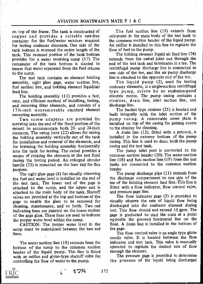
AVIATION BOATSWAIN'S MATE F 1 & C
on top of the frame. The tank is constructed ofcopper and provides a suitable rust-freecontainer for the fuel/water mixture requiredfor testing coalescer elements. One side of thetank bottom is recessed the entire length of thetank. This recessed portion of the tank bottomprovides for a water receiving sump (17). Theremainder of the tank bottom is slanted toinsure that water separated from the fuel returnsto the sump.
The test tank contains an element holdingassembly, sight glass gage, water suction line,fuel suction line, and holding element liquid/airfeed line.
The holding assembly (11) provides a fast,easy, and efficient method of installing, testing,and removing filter elements, and consists of a171/2-inch nonremovable standard elementmounting assembly.
Two screw adapters are provided forscrewing into the end of the fixed portion of themount to accommodate both 20- and 24-inchelements. The swing joint (22) allows for raisingthe holding assembly vertically out of the tankfor installation and removal of the elements, andfor lowering the holding assembly horizontallyinto the tank for testing. The swivel provides ameans of rotating the elements in the test fluidduring the testing period. An enlarged circularhandle (23) is mounted on the base cap for thispurpose.
The sight glass gage (4) for visually observingthe fuel and water level is installed on the end ofthe test tank. The lower end of the gage isattached to the sump, and the upper end isattached to the main body of the tank. Shutoffvalves are provided at the top and bottom of thegage to enable the glass to be removed forcleaning, maintenance, and so forth. Two redindicating lines are painted on the lower sectionof the gage glass. These lines are used to indicatethe proper water level within the sump.
CAUTION: The proper water level in thesump must be maintained between the two redlines.
The water suction line (18) extends from thebottom of the sump to the common suctionheader of the liquid pump. This line is fittedwith an orifice and globe-type shutoff valve forcontrolling the flow of water to the pump.
The fuel suction line (19) extends frommid-point in the main body of the test tank tothe common suction header of the liquid pump.An orifice is installed in this line to regulate theflow of fuel to the pump.
The holding element liquid air feed line (24)extends from the swivel joint out through theend of the test tank and terminates in a tee. Thecentrifugal pump discharge line is connected toone side of the tee, and the air pump dischargeline is attached to the opposite end of the tee.
The liquid pump (2), used for testingcoalescer elements, is a single-suction centrifugaltype pump, driven by an explosion-proofelectric motor. The pump casing contains astrainer, drain line, inlet suction line, anddischarge line.
The bucket type strainer (25) is located andbuilt integrally with the inlet section of thepump casing. A removable cover plate isinstalled on top of the casing for gaining accessto the strainer for cleaning.
A drain line (13), fitted with a petcock, isinstalled in the extreme bottom of the pumpcasing. This line is used to drain both the pumpcasing and the test tank.
The pump inlet port is connected to thecommon suction header (20). The water suctionline (18) and fuel suction line (19) from the testtanks are connected to the common suctionheader.
The pump discharge pipe (21) extends fromthe discharge compartment to one side of thetee of the holding element feed line.-This line isfitted with a flow indicator, flow control valve,and pressure gage line.
The flow indicator gage (3) is provided tovisually observe the rate of liquid flow beingdischarged into the coalescer element duringtest. This flow should not exceed 10 gpm. Thegage is graduated to read the scale at a pointopposite the grooved horizontal line on thefloat. A drain line is installed in the bottom ofthe gage.
The flow control valve is an angle type globeneedle valve. It is located between the flowindicator and test tank. This valve is manuallyoperated to regulate the desired rate of flowthrough the element.
The pressure gage is provided to determinethe pressure of the liquid being discharged

Chapter 8QUALITY ASSURANCE AND SURVEILLANCE
through the element. The pressure should bemaintained between 10 and 12 psi when testing.
PREPARATION FORTESTING ELEMENTS
To prepare the unit for testing elements,proceed as follows:
1. Position the unit to insure it is level, andthen lock the wheels.
2. Visually inspect for distorted coppertubing, loose fittings, and any debris inside thetank.
3. Fill the test tank with 15 gallons of fuel.4. To insure that the fuel is clean, install a
coalescer element on the holding assembly andflush the system by recirculating the fuel for 10minutes.
5. Remove 21/2 gallons of fuel from the testtank.
NOTE: Fuel is removed through the drainline at the bottom of the centrifugal pumpcasing.
6. Add 21/2 gallons of clean water to the testtank.
NOTE: To insure proper water level, observethe sight glass gage on the test tank. Water levelshould be between the two red indicating marks.
The unit is now ready for testing elements.
OPERATION
In describing the piping and valve alinementfor each of the testing operations, only the valvenumbers will be referred to. Each valve on thetest unit has numbers corresponding to thoseindicated in figure 8-8. Refer to this figure whilereading the following test procedure.
1. Raise the holding element mountingassembly vertically and install a coalescerelement.
CAUTION: Insure that the element isproperly sealed at each end. Test for correct'tightness by attempting to rotate the element onthe mounting stand. If the element can be easilyrotated, further tightening of the end. capwingnut will be necessary.
173
NOTE: It may be necessary to add anadditional end gasket to obtain the proper seal.
2. Lower the element into the fuel. Fuellevel should be approximately 1 inch above theelement.
3. Insure that Valve No. 1 is closed.4. Open Valve No. 2, one-half turn; this
will allow approximately 10 gpm to flowthrough the element.
5. Start the centrifugal pump and adjustthe flow to exactly 10 gpm as indicated on theflow control valve. This is accomplished byadjusting Valve No. 2.
6. Open Valve No. 3. The orifice in this lineregulates the flow of water into the fuel streamat % gpm.
7. Obtain a 1-liter sample at Valve No. 4,and determine the total water content. Thesample container must be graduated in 100units. A proper mixture should be nine partsfuel and one part water. Adjust the glove valvein the water suction line as necessary to obtainthe proper ratio of fuel/water mixture.
8. Rotate the coalescer element andobserve the integrity of the element for 2minutes. A defective element will produce ahaze similar to smoke coming through theelement at the point of leakage. A satisfactoryelement will produce clear fuel with clearcoalesced water droplets at the outer surface ofthe element.
9. Stop the liquid pump. Replace thecoalescing element and continue testing.
10. When the last coalescer element has beentested, close Valve No. 3 (stopping thewaterflow) and let the system operate at least 1minute, or until the system is clear of water.
11. Stop the centrifugal pump.12. Raise the holding assembly vertically and
remove the last element. Leave the assembly inthis position to allow the fuel to drain out of thestand pipe.
13. After the fuel has drained back, closeValve No. 2.
Permanent TypeFilter/Separator Elements
Prior to installation, all Teflon coatedpermanent type filter/separator elements are tobe checked:

AVIATION BOATSWAIN'S MATE F 1 & C
COALESCER ELEMENTOR
SEPARATOR ELEMENT
LIQUID LEVELGAGE
AIR PUMP
PRESSURE REGULATOR
AIR I \\)TANK
BALL CHECKVALVE
CENTRIFUGAL PUMPWITH BUILT-IN STRAINER
TANKDRAIN
1. Valve No. 1 Needle valve in alr line.2. Valve No. 2 Angletype needle valve in liquid.3. Valve No. 3 Globe valve in water suction line.
FLOW RATEINDICATOR
4. Valve No. 4 Flow indirtatnr drain valve.5. Valve No. 5 Pump drain line.
Figure 8-8. Flow diagramcoalescer element test/air bubbie test.
1. Make a careful visual inspection to checkfor flaws in the element.
2. Fill the interior of the element (held inthe horizontal position) with enough water(approximately 1/4 -inch in depth) to cover theentire lower section along the longitudinal axis.Slowly rotate the element and look for leakage.Take special note of the seam. There should beno leakage.
Acceptance is based on not one but both ofthe above tests.
Lubrication
The oil filter passes all incoming air. Fill thejar to the line indicated on the oil level decal.One filling should last 20 to 50 hours ofoperation. The motor bearings are oiledannually. Refer to the MRC for the proper typeof oil.
Centrifugal Pump
Never operate the pump dry. Operate thepump at least once a week for a minimum of 2
'ii 80 174
O
198.56
minutes. Be sure the pump primes and pumps afull stream before shutting down. This willprevent a buildup of rust on the impeller andpump seal. It will also lubricate the bearings. Inperforming this minimum maintenance, you canbe sure the pump will always be ready foroperation.
Flow Rate Indicator
Normal maintenance consists of cleaning thefloat and tube to maintain good visibility. Careshould be taken in removing the fittings toprevent dropping the gage. Clean with a suitablesolvent then replace the parts. Duringreassembly, it is preferable to use new 0-rings.
NOTE: A complete parts list will be foundin the technical manual, NavShips 345-0474.
HORIZONTAL FUEL FILTERS
A basic description of filters and their pipingand valve arrangement was covered in chapter 3of this training manual. This section gives a more

Chapter 8QUALITY ASSURANCE AND SURVEILLANCE
detailed description, and covers the operationand maintenance of the filters and theirautomatic control devices.
DETAILED DESCRIPTION
The main body of the filter consists of acylindrically shaped shell (tank) with adome-shaped head welded on each end. (See fig.8-9.) The dome-shaped heads provide a uniformflow into and out of the filter. The interior ofthe filter is divided into three separate chambers,inlet, fallout, and outlet, by tube sheets.
Tube Sheet
The tube sheets are circular metal bulkheadsinstalled within the filter shell, where thedome-shaped heads are attached to thecylindrical-shaped shell. They are welded
AUTOMATICFUEL SHUTOFFVALVE SEPARATOR
ELEMENT
throughout their circumference to form aleakproof partition between inlet, fallout, andoutlet compartments of the filter. The tubesheets also provide the means of installing thefilter element mounting assemblies (bothcoalescer and separator). Threaded holes (onefor each assembly) are symmetrically arrangedover their surface.
Element Mounting Assembly
The element mounting assembly (fig. 8-10)consists of a perforated metal standpipe (1)approximately 1 inch in diameter and 26 inchesin length, and an end cap (2). One end of thestandpipe is fitted with a threaded base cap (3)to facilitate screwing it into the tube sheets. Theopposite end is fitted with a threaded plug (4)for attaching the end cap. The end cap is a metal
PRESSURE GAGES
FILTERVENTLINE
COALESCING ELEMENT
OUTLET( CLEARWELL )
FALLOUTCHAMBER
TUBE SHEET
TEST CONNECTIONFROMCLEARWELL
AUTOMATICWATER DRAINVALVE
SUMPTANK
Figure 8-9.Horizontal fuel filter (cutaway).
175 es SI,
INLETCHAMBER
198.57

17
AVIATION BOATSWAIN'S MATE F 1 & C
0
El of0
et,
0
1. Standpipe.2. End cap.3. Base cap.4. Threaded plug.
5. Fiber washer.6. Meta I washer.7. Knife edges.
0
198.58Figure 8-10.Element mounting assembly.
disc approximately the same diameter as theelements.
After the filter element has been placed overthe standpipe, the end cap is secured in place bya threaded bolt. A metal washer (6) and fiberwasher (5) are provided between the threadedbolt and end cap to prevent leakage at tiffpoint.
Both the base cap (the inboard end of thestandpipe) and the end cap have projecting knifeedges (7). When the elements are mounted onthe standpipes, the projecting knife edges areforced into the synthetic rubber gaskets on eachend of the elements, forming a tight seal.
Coalescing Element
The coalescing element is a cylindrical unitapproximately 24 inches long and 3 5/8 inchesin diameter. It consists basically of a layer of-fiber glass approximately 2 inches thick installedaround a perforated metal center tube. The fiberglass is held in place by a cloth sleeve andprotected by a perforated metal outer tube. Theends (between the two metal tubes) are sealedby metal plates (washers). A synthetic rubbergasket is attached to each end of the element.These gaskets form a tight seal and insure flowthrough the element when mounted.
Separator Element
The separator element has practically thesame dimensions as the coalescer; however, it isconstructed of different material. A specially
SZ176
designed permanent type separator element hasbeen introduced into fleet use, replacing the oldpaper filter. It consists basically of a perforatedinner aluminum core cover with a,200 -meshmonel Teflon coated screen. This- screen isenclosed by an additional aluminum screen.
Installing Elements
- To install an element on the .standardelement mounting stand, proceed as follows:
1. Insure that the gaskets are in place, thenslide the element over the perforated standpipe.
2. Attach the end cap, with metal and fibergasket in place, and install the threaded boltfingertight.
3. Center the element on the mountingstand with one hand, and by use of the propersize wrench, tighten the end capnut snugly.
4. Check the element for tightness; if theelement can be easily rotated on the standpipe,further tightening is required. This isaccomplished in a two-stage operation, by thetwo separate filtering media.
Filter Inlet Chamber
Fuel enters the filter initially at the bottomof the inlet chamber. This chamber of the filteris dome-shaped to provide a uniform flow offuel to all coalescing elements simultaneously.From the inlet chamber the fuel passes throughcoaleschig elements to the fallout chamber.
Fallout Chamber
The fallout chamber is the center section ofthe filter shell. It is the longest of the threeindividual sections. This area of the filter isprovided to allow the coalesced water to fall outof the fuel stream by gravity as it flows from thecoalescer to the separator stage. All of thefiltering elements, both coalescing and separator,are installed within this section of the filter.
The fallout chamber also contains a manholecover, filter vent line, and water receiving sump.
The coalescing stage is the first stage offiltration. It consists of a number of individualcoalescer elements grouped in a symmetricalarrangement on the inlet tube sheet. The fuel
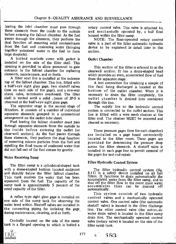
Chapter 8QUALITY ASSURANCE AND SURVEILLANCE
leaving the inlet chamber must pass throughthese elements from the inside to the outsidebefore entering the fallout chamber. As the fuelpasses through the elements, they perform thedual function of removing solid contaminantsfrom the fuel and coalescing water (bringingtogether entrained water in the fuel to formlarge droplets).
A bolted manhole cover with gasket isinstalled on the side of the filter shell. Thisopening is provided to allow personnel to gainentrance to the fallout chamber for replacingelements, maintenance, and so forth.
A filter vent line is installed at the extremetop of the fallout chamber. This line, fitted witha bull's-eye sight glass gage, two shutoff valves(one on each side of the gage), and a one-waycheck valve, terminates overboard. The filtershell is vented until a solid ..,Zream of JP-5 isobserved at the bull's-eye sight glass gage.
The separator stage is the second stage offiltration. It consists of a number of individualseparator elements grouped in a symmetricalarrangement on the outlet tube sheet.
Fuel leaving the fallout chamber must passthrough separator elements from the outside tothe inside before entering the outlet (orclear-well section). As the fuel passes through_these elements, they perform the dual functionof removing micron particles from the fuel andrepelling the final traces of coalesced water thatdid not fall out of the fuel stream by gravity.
Water Receiving Sump
The filter.sump is a cylindrical-shaped tankwith a dome-shaped bottom located midpointand directly below the filter fallout chamber.This tank receives the water that has beenseparated from the fuel. The capacity of thesump tank is approximately 5 percent of therated capacity of the filter.
A reflex type sight glass gage is installed. onone side of the sump tank for observing thewater level within. Shutoff valves are installed inthe connecting piping for isolating the gage..during maintenance, cleaning, and so forth.
Centrally located on the side of the sumptank is a flanged opening to which is bolted a
177
rotary control valve. This valve is attached to,and mechanically operated by, a ball floathoused within the filter sump.
NOTE: The float-operated rotary controlvalve is a part of the filter automatic hydraulicdevice to be explained in detail later in thissection.
Outlet Chamber
This section of the filter is referred to as theclearwell section. It has a dome-shaped headwhich provides an even, unrestricted flow of fuelfrom the separator stage.
A test connection for obtaining a sample ofthe fuel being discharged is located at thebottom of the outlet chamber. When it isnecessary to drain the filter completely, theoutlet chamber is drained into containersthrough this line.
The supply line to the hydraulic controlsystem is connected to the outlet section. Thisline is fitted with a wire mesh strainer at thefilter end. The strainer MUST be removed andcleaned as necessary.
Three pressure gages (one for each chamber)are installed on a gage board convenientlylocated in the filter room. These gages areprovided for determining the pressure dropacross the filter elements. A shutoff valve isinstalled in each gage line to permit removal ofthe gages for test and repair.
Filter Hydraulic Control System
The filter hydraulic control system (fig.8-11) is a safety device installed on all fuelfilters. It functions to drain automatically theaccumulated water from the filter sump, and toshut off the filter flow in the event more wateraccumulates than can be drained offautomatically.
This system consists of two hydrauliccontrol valves and a mechanically operatedcontrol valve. One control valve (the automaticshutoff valve) is located in the filter dischargeline. The other control valve (the automtticwater drain valve) is located in the filter sumpdrain line. The mechanically operated controlvalve (rotary valve) is located on the side of thefilter sump tank.
# Cb
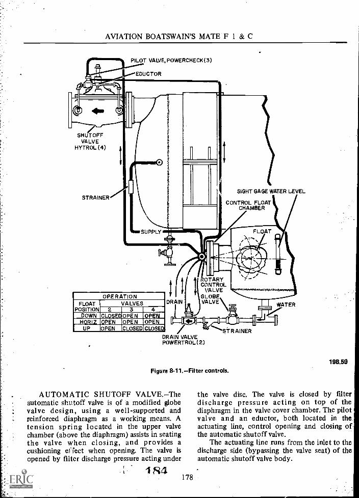
AVIATION BOATSWAIN'S MATE F 1 & C
PILOT VALVE, PoWERCHECK (3)
EDUCTOR
4.
SHUTOFFVALVE
HYTROL (4)
STRAINERSIGHT GAGE WATER LEVEL
CONTROL FLOATCHAMBER
OPERATIONFLOAT VALVES
POSITION 2 3 4DOWN CLOSEDOPEN OPENHORIZ OPEN OPEN OPEN
UP OPEN CLOSED CLOSED
DRAIN
ROTARYCONTROL
VALVEGLOBEVALVE
DRAIN VALVEPOWERTROL (2)
STRAINER
Figure 8-11.Filter controls.
AUTOMATIC SHUTOFF VALVE.Theautomatic shutoff valve is of a modified globevalve design, using a well-supported andreinforced diaphragm as a working means. Atension spring located in the upper valvechamber (above the diaphragm) assists in seatingthe valve when closing, and provides acushioning efiect when opening. The valve isopened by filter discharge pressure acting under
1 Fi4178
[ [ WATER
198.59
the valve disc. The valve is closed by filterdischarge pressure acting on top of thediaphragm in the valve cover chamber. The pilotvalve and an eductor, both located in theactuating line, control opening and closing ofthe automatic shutoff valve.
The actuating line runs from the inlet to thedischarge side (bypassing the valve seat) of theautomatic shutoff valve body.

Chapter 8QUALITY ASSURANCE AND SURVEILLANCE
The pilot valve is of the modified globe valvedesign, having a double-acting diaphragm as itsworking means. When fuel pressure is applied tothe top of the diaphragm, the valve closes(closing off the actuating line). When fuelpressure is applied to the bottom of thediaphragm, the valve opens (allowing flowthrough the actuating line).
NOTE: When pressure is applied to one sideof the diaphragm, the opposite side is vented toatmosphere through the drain line.
The eductor is located in the actuating linebetween the pilot valve and the inlet side of theshutoff valve. The eductive suction line isconnected to the top of the shutoff valve coverchamber. With the pilot valve open, the eductordecreases the fuel pressure on top of thediaphragm of the shutoff valve by educting fuelfrom the main valve cover chamber. Thisdecrease in fuel pressure on top of thediaphragm allows filter discharge pressure actingunder the shutoff valve disk to open the valve.When the pilot valve closes, filter dischargepressure in the actuating line is directed throughthe eductive suction line to the top of the coverchamber of the shutoff valve. This increase infuel pressure on top of the diaphragm coverovercomes the fuel pressure being applied on thevalve disk and closes the valve. Therefore, it canbe said, "When the pilot valve is open, theautomatic shutoff valve is open; and when thepilot valve is closed, the automatic shutoff valveis closed."
AUTOMATIC WATER DRAINVALVE.This valve, located in the water drainline from the sump, is identical to the pilotvalve. It also functions in the same identicalmanner as the pilot valve. When fuel pressure isapplied to the top of the diaphragm in the waterdrain valve, the valve closes and stops the flowfrom the filter sump. When fuel pressure isapplied to the bottom of the diaphragm in thewater drain valve, the valve opens and allowswater to be discharged from the filter sump.When fuel pressure is applied to one side of thediaphragm, the opposite side is vented toatmosphere through the drain line.
ROTARY CONTROL VALVE.The rotarycontrol valve, located on the side of the filter
179
sump, is actuated by the rise and fall of acaptivated ball float, housed within the filtersump tank. (See fig. 8-12.)
The ball float, attached to the rotary valveby a float arm and gear assembly, is designed tofloat on water and sink in JP-5.
The rotary control valve has threepositionsDOWN, HORIZ, and UP, and sixports which are connected by copper tubing tothe following:
1. A supply port (S) from the filterclearwell section.
2. A vent port (D) to atmosphere (this lineis connected to the sump water drainline on the discharge side of theautomatic water drain valve).
3. Port (B) to the top of the pilot valvediaphragm.
4. Port (A) to the bottom of the pilot valvediaphragm.
5. Port (C) to the top of the water drainvalve diaphragm.
6. Port (C-Z) to the bottom of the waterdrain valve diaphragm.
The rotary control valve, through the actionof the ball float, controls the opening andclosing of the automatic water drain and pilotvalves. This is accomplished by directing filterdischarge pressure from the supply port throughthe rotary control valve to either the top orbottom of their diaphragms, whilesimultaneously venting the opposite side of thediaphragm to atmosphere through the rotaryvalve.
OPERATION OF THE FILTERHYDRAULIC CONTROL SYSTEM.As long asthe fuel passing through the filter contains littleor no water, the rotary control valve float willremain in its down position. With the float in itsdown position, the rotary control valve ports arealined as follows: Filter discharge pressure fromthe clearwell is directed through the rotary valveto the top of the diaphragm of the water drainvalve, keeping that valve closed, and to thebottom of the diaphragm in the pilot valve,keeping that valve open. This in turn allowsfilter discharge pressure to open the automaticshutoff valve.

AVIATION BOATSWAIN'S MATE F I & C
EDUCTOR-0""=
(1/2° CLAYTONPOWER-CHECK)
FILTERSUMP
AV. FUEL
WATER
ROTARY
CONTROL VALVE
\A
CONTROLFLOAT
OSHUT OFF VALVE
(6° CLAYTON HYTROL )
POSITION OF VALVES
FLOATPOSITION 2 3 4
UP 0 C C
HORIZ. 0 0 0DOWN C 0 0
FLOAT
rn.'174I
''\C -2S D
FLOAT- HORIZ.
GLOBE VALVE
DRAIN VALVE(I" CLAYTONPOWERTROL)
Figure 8-12.Hydraulic control system operation.
In the down position, the hydraulic controlvalves are positioned as follows:
1. Pilot valveOPEN.2. Automatic shutoff valve OPEN.3. Water drain valveCLOSED.
As coalesced water collects in the filtersump, the float rises to the horizontal position.In the horizontal position, the rotary controlvalve ports are alined as follows. Filter dischargepressure from the clearwell is directed throughthe rotary valve to:
1. The bottom of the diaphragm in theautomatic water drain valvethis in turn opens
1R6.180
C-2S D
FLOAT- DOWN
POSITION OF PORTS INROTARY CONTROL VALVE
FLOAT PORTS OPEN TOPCS DRAIN SUPPLY
UP C,A B,C-2HORIZ. B,C A,C-2DOWN C-2, B C,A
198.120
this valve and drains the accumulated wateroverboard.
2. The bottom of the diaphragm in thepilot valve, keeping the pilot valve openthis inturn allows the automatic shutoff valve toremain open.
In the horizontal position, the hydrauliccontrol valves are positioned as follows:
1. Pilot valveOPEN.2. Automatic shutoff valveOPEN.3. Water drain valveOPEN.
If a greater amount of water collects fasterthan it can be drained off, the float will rise to

Chapter 8QUALITY ASSURANCE AND SURVEILLANCE
its up position. In the up position, the rotarycontrol valve ports are alined as follows. Filterdischarge pressure from the clearwell supplyport is directed through the rotary control valveto:
1. The bottom of the diaphragm in thewater drain valve, keeping this valve open.
2. The top of the diaphragm in the pilotvalve, closing the pilot valvethis in turn causes-le automatic shutoff valve to close, stoppingthe filter discharge.
In the up position, the hydraulic controlvalves are positioned as follows:
1. Pilot valveCLOSED.2. Automatic shutoff valveCLOSED.3. Water drain valveOPEN.
NOTE: It takes a minimum of 10 psi filterpressure to operate the hydraulic controlsystem.
OPERATION OF THE MAIN FUELFILTER.JP-5 enters the inlet chamber of themain fuel filter at the bottom. The fuel thenpasses into the coalescing element, where largesolids are retained on the inner walls of theelements. As the JP-5 and water pass throughthe elements into the fallout chamber, the water(due to the special design of the element) iscoalesced into large droplets. These waterdroplets fall out of the fuel by gravity and intothe sump as the fuel passes across the falloutchamber to the separator stage. JP-5 enters theseparator elements from the outside and, as itpasses through the elements to the outlet(clearwell) section of the filter, the final tracesof coalesced water which have not sunk by theirown weight are removed, and micron particles (5micron and larger) are retained on the outershell. The water drops off the elements and fallsto the sump tank by gravity. JP-5 then leaves theoutlet section of the filter from the. top andflows through the automatic shutoff valve intothe fore-and-aft legs of the quadrant.
When putting the filter into operation, thefilter vent line should remain open until a.solidstream of JP-5 is observed in the bull's-eye glassgage.
181
CAUTION: It is imperative that the filtershell be properly vented, or full utilization of allthe filtering elements will not be realized.
Immediately after a new filter is placed inoperation, the pressure gage must be read andlogged. A pressure differential between the inletand fallout chamber should be noted even withnew elements. This pressure drop will increase intime because of the buildup of dirt on the innerwalls of the coalescing elements.
MONTHLY TEST OF THE FILTERHYDRAULIC CONTROL SYSTEM.Theautomatic water drain valve and the automaticfuel shutoff valve are tested monthly for properoperation.
In the event of a malfunction of thehydraulic control system, it is possible todischarge fuel through the water drain and/orpump water through the filter.
The only known method of checking theproper operation of this system is to actuallyinject clean water into the filter sump andobserve the opening of the automatic waterdrain valve and the closing of the fuel shutoffvalve. This is accomplished as follows:
Attach a tee fitting in the pipe plug on thesump. Install a pressure gage to one side of thetee and a globe valve on the opposite! side.Connect a water hose from the ship's fire mainto the globe valve.
Aline the JP-5 service system to pump fromone quadrant to another, bypassing thepressure-regulating valve (on ships so equipped).Start one JP-5 service pump; throttle the globevalve on the discharge side of the service pumpto maintain fuel pressure at the filter to at least25 psi less than the available sea water pressure.
With fuel passing through the filter, slowlyadmit water into the sump until the drain valveopens or the water level reaches the top of thesump gage glass. If the drain fails to open, securethe system and determine the cause. If the drainvalve opens normally, make an indicating markon the gage glass for future reference and adjustthe water flow rate so that the drain valve opensonce a minute. Continue testing for 5 minutes.
Without changing the water flow rate,manually close off the water drain line so thatno water can drain from the filter sump. If theautomatic fuel shutoff valve does not close
1 fi

AVIATION BOATSWAIN'S MATE F 1 & C
within 3 minutes, or the water level passes thetop of the gage glass on the filter sump, securethe filter and determine the cause.
During this test, take samples in a clean jarfrom the clearwell chamber to determine theintegrity of the separator elements. If the samplefrom the clearwell is cloudy or contains water,test the separators and replace those found to bedirty or defective. Clean dirty separators beforetesting.
TROUBLESHOOTING THE FILTERHYDRAULIC CONTROL SYSTEM.If theautomatic control system fails to operateproperly, make the following tests:
1. Check the arrows on the automaticshutoff, pilot, and water drain valve toinsure proper installation.
2. Insure that all manually operated valvesare properly alined.
3. Check the "Y" strainer in the waterdrain line.
4. Check the rotary control valve supplyline strainer.
5. Inspect the copper tubing for flattened,dented, or internal obstructions andreplace or clean as necessary.
NOTE: The latter will be the most likelycause of the malfunction. If the above testsprove unsatisfactory, remove the rotary controland float and place it in a vise.
CAUTION: Before disconnecting the coppertubing, tag each one to insure properreplacement.
With the rotary control valve secured in thevise and the float in the down position, blowlow-pressure air into the supply port. Air shouldescape through ports leading to the top of thediaphragm of the water drain valve and to thebottom of the diaphragm of the pilot valve.Raise the float to the mid position; air shouldescape through ports leading to the bottom ofthe diaphragm of the water drain valve and thebottom of the diaphragm of the pilot valve.Raise the float to the full up position, and airshould escape through ports leading to thebottom of the diaphragm of the water drain
SR 182
valve and the top of the diaphragm of the pilotvalve. Blow air through the vent port to insureclear passage. If the rotary control valve fails topass this test, remove it from the ball float andreturn it to the factory.
CAUTION: Make no attempt to repair arotary control valve; special tools andinstruments are required to repair this valve.
MAINTENANCE
Daily Operating Checks
Daily operating checks fall into threecategoriespressure checks, sample checks, andsump level checks.
PRESSURE CHECKS.The pressure gageson the inlet, fallout, and clearwell chambersshould be read and recorded as indicated in thefilter operating log.
As solids build up on the elements, apressure drop across the filter will develop. Thedischarge pressure gage will be the lowest of thethree; however, the pressure drop across thecoalescent stage will be the most critical.
As the maximum allowable pressure dropacross the coalescing elements is reached, theywill fail to perform their designed function and,'therefore, must be replaced.
The maximum allowable pressure drop limitsfor the coalescing elements will be found on aninstruction sheet in the manufacturer's packingcrate.
NOTE: An increase in pressure drop acrossthe filter will also affect the proper operation ofthe Blackmer service stations. This must becorrected accordingly, by increasing the pressuresetting on the pressure regulator valve tomaintain a constant desired pressure at thedischarge side of the filter.
SAMPLE CHECKS.Daily checks are takenfrom the filter sump and the filter clearwellsection. The contents of each sample should berecorded in the operating log. These samples willdetermine the condition of the coalescing andseparator elements.
If the sample taken from the filter sumpcontains solids, it is an indication that the

Chapter 8QUALITY ASSURANCE AND SURVEILLANCE
coalescing elements have failed and must bereplaced.
If the sample taken from the clearwellchamber fails to meet current PMSrequirements, it is an indication that thecoalescing and/or separator elements have failedand must be inspected, tested, and replaced asnecessary.
CAUTION: If the clearwell sample takenimmediately after pumping up contains water,this might have been caused by condensation ofdissolved water in the fuel when the fuel hit thecold pipes. Drain the service system back belowthe filter and pump up again, and resamplebefore making a final decision as to thecondition of the elements.
Other than the three above-mentioned times(maximum pressure drop limits across coalescentstage is reached, dirty sump sample, and water inthe clearwell sample), element replacement iswarranted as follows:
1. Contaminated fuel detected in"onboard" aircraft, which can reasonably beassumed to have originated in the ship's fuelingsystem, is considered adequate justification forexamining, testing, and replacing filter elements.
2. Coalescing elements should be replacedat each overhaul, and it is recommended that theelements be replaced prior to deployment or atleast yearly.
When coalescer elements are changed, theseparator elements should be cleaned and tested.Only the defective elements should be replacedand the defective elements discarded.
NOTE: Replacement elements must betested before installation.
When replacing coalescer elements, do notmix elements of different manufacture sincethey may have different pressure dropcharacteristics. Coalescing elements of onemanufacturer may, however, be used withseparator elements of another manufacturer.
WEEKLY.Remove the "Y" type strainerfrom the water drain line and clean as necessary.
MONTHLY. Remove the strainers fromrotary control supply line (clearwell chamber)and clean as necessary.
General Maintenance
Exercise care at all times in opening andclosing valves that govern flow through the filterto prevent a hydraulic hammer to the filter. Thismay cause overstressing of the housing orrupture of the filter elements.
VERTICAL FILTERS
A vertical filter is shown in figure 8-13. Theonly noted differences between the vertical andhorizontal filters, other than the two previouslymen tioned (physical shape and direction offlow), are the hydraulic control system andpressure gage arrangement.
The hydraulic control system for verticalfilters differs only in the construction andoperation of the automatic water drain and pilotvalves and the location and number of ports inthe rotary control valve.
The automatic water drain and pilot valvesare constructed identically (except for physicalsize) as the automatic fuel shutoff valve (fig.8-14) and operate on the same principle. Whenfuel pressure is applied to the top of thediaphragm, the valve closes, and fuel pressureacting on the bottom of the valve disk (with thediaphragm cover chamber vented) opens thevalve. Both valves serve the same identicalpurpose in respect to the water drain and pilotvalves on the horizontal filters.
With the installation of this new type valvein the hydraulic system, it eliminated the needfor two of the ports in the rotary control valve.These two ports are the ones required to openthe water drain and pilot valves in the horizontalfilters.
The rotary control valve is flanged to theside of the filter shell. It is actuated by the riseand fall of a captivated ball float housed withinthe fallout chamber (the lower section of thefallout chamber is in reality the filter sump) onvertical type filters. This valve functions in thesame manner and for the same purpose as therotary valve in the horizontal filters, the onlydifference being, it has only four ports:
1. Supply (from the clearwell section).2. Vent (to atmosphere).
183 1S9

AVIATION BOATSWAIN'S MATE F 1 & C
Figure 8-13.Vertical aviation fuel filter.
3. To the top of the diaphragm in the pilotvalve.
4. To the top of the diaphragm in waterdrain valves.
NOTE: The 2,000 gpm vertical filters havetwo automatic water drain valves. These valvesare opened and closed simultaneously. A. teefitting is installed in the rotary control valveport to facilitate attaching both valves to oneport.
90 184
197.31.1
With the float in the down position, the fueldischarge valve is open, and the water drain valveis closed. When the float moves to mid-positionthe fuel discharge valve remains open, and thewater drain valve opens. When the float movesto the up position the fuel discharge valve closes,and the water drain valve remains open.
A reflex type sight glass gage is installed onthe side of the filter shell, at the bottom of thefallout chamber. This gage is used to determinethe water level within. During the Monthly

Chapter 8QUALITY ASSURANCE AND SURVEILLANCE
198.60Figure 8-14.Automatic fuel shutoff valve.
water slug test (described under horizontalfilters) the sight glass gage should be marked toindicate at what level the water drain valvesopen, and at what level the fuel discharge valvecloses. During normal operations the water levelshould be monitored frequently.
Pressure Gages
There are only two pressure gages installedfor determining the fuel pressure across thevertical filtersa differential pressure gage andan outlet pressure gage.
The differential pressure gage is used todetermine the pressure drop through thecoalescing elements. This gage is connected bytwo linesone from the inlet chamber and onefrom the fallout chamber. The differencebetween these two pressures is indicated on thegage. Any increase in pressure drop across thecoalescing elements (caused by the collection ofsolids) will be indicated on this gage.
The outlet pressure gage is attached to thedischarge piping. This gage is used to determinethe pressure of the fuel after it has passedthrough the separator elements and before it isdischarged past the automatic fuel shutoff valve.If the outlet pressure shows a considerable drop,and the differential gage shows no increase,eplace the separator elements.
185
FIRST-STAGE FILTER
As a safeguard against contamination, JP-5 isnever received into service tanks from a hangardeck filling connection. JP-5 is received intostowage tanks, settled, and then pumpedthrough a filter to service tanks. (See fig. 8-15.)
NOTE: The fuel/water separator filterdescribed here has been replaced by centrifugalseparators on most CVA's.
First-stage filters are located between thetransfer pump and service tanks. The first-stagefilter described here is manufactured by theBriggs Filtration Co. It has a rated capacity of300 gpm (orificed to 200 gpm), and a workingpressure of 100 psi. The filter is designed toremove 98 percent by weight of all solids, 5microns or larger, and 99.9 percent of the water.The unit has a cylindrically shaped, welded,.coppernickel shell mounted on three legs. Abolted hand hole cover assembly at the top ofthe shell provides access to remove or replaceseparator and coalescer elements. The interior ofthe shell is divided into three chambersinlet,fallout, and outlet. The inlet chamber is at thebottom of the shell, the fallout chambercontains coalescer, and separator cartridges, andthe outlet chamber (clearwell) connects to thedischarge piping.
The outside of the shell contains a sightgage, differential gage, and outlet pressure gage.The reflex type sight level gage indicates waterlevel in the fallout chamber. The differentialgage indicates the pressure drop across thecoalescing stage. The outlet gage indicates thepressure of the filtered fuel after it has passedthrough the separator elements and before itleaves the filter.
The coalescing stage consists of 18coalescing elements mounted vertically on thehorizontal deck plate. Fuel flows from the inletchamber through the coalescing elements to thefallout chamber.
The separatory stage consists of 11 separatorelements, mounted horizontally in individualmounting assemblies, attached to the outletchamber. Fuel flows from the fallout chamberthrough the separator cartridges to the outletchamber.
A float control valve, bolted to a flangewhich is welded to the shell, controls the action
191

AVIATION BOATSWAIN'S MATE F 1 & C
DECK PLATEBRACE
SECOND-STAGE ELEMENTMOUNTING ASSEMBLY
OUTLET
TYPICAL OF 18 ELEMENTMOUNTING ASSEMBLIES
FLOAT CONTROL VALVE
INLET
VORTEX BAFFLE
FLOW SCHEMATIC
FUEL ::.,;:1:::.'ja;.,-
WATER
Figure 8-15.Filter separator (cutaway).
of a water discharge valve and fuel dischargevalve. The float control valve has four portsconnected by tubing to the top of the pilot valvediaphragm, top of the water discharge valvediaphragm, the fallout chamber, and a vent portto the discharge side of the water dischargevalve. The float control valve has threepositions down, mid, and up.
DOWNfuel discharge valve open; waterdischarge valve closed.
MIDfuel discharge valve open; waterdischarge valve open.
1 9?86
197.54
UPfuel discharge valve closed; waterdischarge valve open.
The float, calibrated to sink in JP-5 and floaton water, is located in the fallout chamber.
The water discharge valve automaticallydrains water from the fallout chamber, with thefloat in the mid or up position. It is held closedby filter fallout pressure to the top of thediaphragm when the float is down, and openedby filter fallout pressure under the disk with thefloat in mid or up position. A manual drain line

Chapter 8QUALITY ASSURANCE AND SURVEILLANCE
permits bypassing of the water drain valve if thevalve is inoperative.
The pilot-operated fuel discharge valve isidentical in construction and operation to theautomatic shutoff valve discussed in thepreceding section, except for size. The pilotvalve is opened by filter discharge pressure underthe disk, with the float in the down or midposition, and closed by filter discharge pressurethrough the float control valve to the top of thediaphragm, with the float up. As long as thepilot is open, the fuel discharge valve remainsopen. When the pilot valve closes, the fueldischarge valve closes.
Filtering, separating, and discharge actionsare automatically controlled when fuel underpressure is introduced. Operating pressuresshould be logged as soon as possible afterputting the unit in operation. The differentialand outlet pressure gages should be checkedregularly during operations.
Replace coalescer elements when thepressure drop reaches the manufacturer'sspecified limit. Replace the separator elements ifthe outlet pressure shows a considerable dropwhile the differential gage shows no markedincrease. When 400,000 gallons of JP-5 havepassed through the filter, replace the coalescerelements, and clean and test the separatorelements, replacing only the defective ones.
NOTE: Replacement elements must betested before installation.
Liquid level in the unit can be seen in thesight gage. When enough water has accumulatedto raise the float and open the water dischargevalve, the level should be marked on the sightgage. This will enable the operator to detect anyunusual conditions during subsequentoperations.
NOTE: The first stage filters described hereare similar to the 300 gpm and 400 gpminstalled on the LPH and LPD class ships.
CENTRIFUGAL PURIFIER
Centrifugal force is defined as that forcewhich impels a thing (and any or all of its parts)outward from a center of rotation. Every timeyou lean in as you take a fast turn, you arecounterbalancing centrifugal force. How far in
you lean is determined by the amount ofcentrifugal force exerted in the turn. Mostpeople do it automatically, for centrifugal force,along with gravity, is the most prevalent physicalforce exerted upon usand upon all matter.
If it is moving and if it is turning, it isgenerating centrifugal force. The amount ofcentrifugal force is determined by specificgravity, the degree of the curve, and the speed oftravel.
The efficiency and purifying ability of anycentrifuge is determined by the construction andoperation of the most vital partthe bowl. Itemploys the principles of thin-strata distributionand the balanced column.
The centrifugal bowl is equipped with aseries of conical-shaped disks which divide thefeed material into layers, usually not more than50/1,000 inch in thickness. Note the paths oftravel in the diagrammed enlargement of theinterdisk spaces, figure 8-16. The heavy phaseliquid and any solids present travel outwardalong the underside of the intermediate disks,forced outwardly by centrifugal force because ofgreater density. Reaching the outer edge of thedisks, the heavy-phase liquid is forced upwardby displacement, and the solids are thrown
198.61Figure 8-16Diagrammed enlar dement of the interdisk
spaces.
187
114'-- 14/

AVIATION BOATSWAIN'S MATE F 1 & C
directly to the bowl wall where they collectuntil removed. The light-phase liquid is displacedinwardly and travels along the upper side of theintermediate disks. When it reaches the inneredge of the disk, displacement forces it upwardand out through the appropriate dischargeoutlet.
The holes in the disks are the feed channelsfor the incoming, mixed liquid. They can belocated at points ranging from near the outeredge of the disks to close to the inner edge.Upwards of 80 percent purification occursimmediately as the feed material is distributedthrough the holes. The location of the holes inthe disks determines which phase shall benefitfrom the mo^* purifying action afterdistribution. When the holes are located near theouter edge, the light phase benefits from thegreatest purifying action, having the longestdistance to travel under centrifugal force. Whenthe holes are close to the inner edge, the reverseis true.
As the feed material is separated into itslight and heavy phase, the heavy phase is forcedtowards the bowl wall and the lighter phasedisplaced inwards. The level of the still-mixedfeed material is controlled by the height of adam for the heavy phase. This dam is called adischarge ring.
The larger the opening, the nearer to theouter edge of the disks is the neutral zone. Thissetup renders the maximum purification to thelight phase and is used typically in purificationof oil with water contamination; water is heavierthan oil and it is desirable that the oil benefitfrom the most purification.
Disk holes are located relative to thelocation of the neutral zone. This is the area ofthe still-mixed liquid, and initial separationoccurs immediately as the feed material isdistributed through these openings.
The purpose of the centrifugal purifier (fig.8-17) in the JP-5 filling and transfer system is toseparate and remove water, solids, and emulsionsfrom JP-5 during transfer from stowage toservice tanks. The diskbowl centrifuge is a"constant efficiency" type of separator; that is,it achieves the same degree of efficiency at theend of a run as at the beginning. The reason forthe constant efficiency is that accumulatedsolids are stowed away from the separation
- 194 188
zone. Separation occurs within the disk spacesand the separated liquids are discharged fromoutlets which are removed from interference ofthe stowed solids.
As p reviously mentioned, the centrifugalpurifiers have replaced the first-stage filters inthe JP-5 filling and transfer system on mostCVA's. This replacement is on a unit-for-unitbasis; i.e., one purifier replaces one transferfilter.
Characteristics of purifier B214A (Navy SizeJF-2) are:
1. Capacity-200 gpm at 60° F to 90° Fwhen purifying JP-5 (fuel temperature).
2. Feed inlet pressure-9 psi.3. Back pressure of the discharged JP-5:
Minimum-25 psi.Ideal-30 psi.Maximum-33 psi.
4. Bowl speed-4,100 rpm.
NOTE: Feed pumps and connecting pipingare not integral parts of this purifier.
The entire unit is mounted to a commonbase plate. The base plate is shock mounted tothe ship by means of six rubber cushionsthreeon each side.
A de tailed description of the five basicassemblies is given in this section beforeoperating and maintenance instructions arecovered.
COVER ASSEMBLY
The cover completely encloses the top of therotating bowl shell assembly. This cover hingesto the bowl casing, thus allowing the cover to berotated out of the way for disassembly andcleaning of the bowl. (See figs. 8-17 and 8-18.)
The cover hinge, inlet, and outlet assemblyfunctions to allow the cover to be openedwithout disconnecting the piping. The stationarypart of the hinge is welded to the bowl casing.The movable part of the hinge is welded to thecover. A ratchet hook is provided on thestationary part of the hinge to lock the cover inthe open position. A handle is provided tounlock the hook so that the cover can be closed.

Chapter 8QUALITY ASSURANCE AND SURVEILLANCE
COVER ASSEMBLYWATER DISCHARGE PORT
COVER
MOVABLE i ASSEMBLY
SECTION OFHINGE
STATIONARYSECTION OFHINGE
RATCHETHOOKRELEASEHANDLE
BOWL SHELLLOCK SCREW
DRIVE MOTORASSEMBLY
NANOBRAKE
SPEEDCOUNTER
BOWL SHELLASSEMBLY
HANDWHEELCOVER CLAMPCATCH
OIL FILLERCAP
DRAINPLUG OIL LEVEL
SIGHT GLASS
Figure 8-17.Front view of purifier (cover open).
189 195
WATERDISCHARGECONNECTION
BOWL CASINGASSEMBLY
BOWL DRAINLINE
DRIVEHOUSINGASSEMBLY
198.62
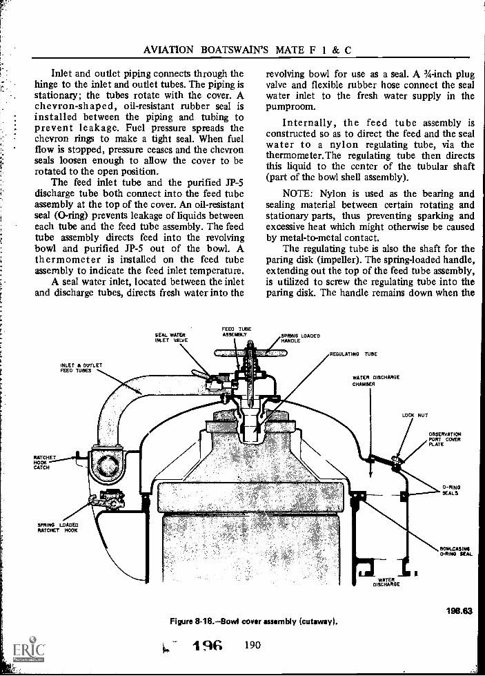
AVIATION BOATSWAIN'S MATE F 1 & C
Inlet and outlet piping connects through thehinge to the inlet and outlet tubes. The piping isstationary; the tubes rotate with the cover. Achevron-shaped, oil-resistant rubber seal isinstalled between the piping and tubing toprevent leakage. Fuel pressure spreads thechevron rings to make a tight seal. When fuelflow is stopped, pressure ceases and the chevronseals loosen enough to allow the cover to berotated to the open position.
The feed inlet tube and the purified JP-5discharge tube both connect into the feed tubeassembly at the top of the cover. An oil-resistantseal (0-ring) prevents leakage of liquids betweeneach tube and the feed tube assembly. The feedtube assembly directs feed into the revolvingbowl and purified JP-5 out of the bowl. Athermometer is installed on the feed tubeassembly to indicate the feed inlet temperature.
A seal water inlet, located between the inletand discharge tubes, directs fresh water into the
RATCHETHOOKCATCH
INLET & OUTLETFEED TUBES
FEED TUBESEAL WATER ASSEMBLYINLET VALVE
revolving bowl for use as a seal. A 3/4-inch plugvalve and flexible rubber hose connect the sealwater inlet to the fresh water supply in thepumproom.
Internally, the feed tube assembly isconstructed so as to direct the feed and the sealwater to a nylon regulating tube, via thethermometer.The regulating tube then directsthis liquid to the center of the tubular shaft(part of the bowl shell assembly).
NOTE: Nylon is used as the bearing andsealing material between certain rotating andstationary parts, thus preventing sparking andexcessive heat which might otherwise be causedby metal-to-metal contact.
The regulating tube is also the shaft for theparing disk (impeller). The spring-loaded handle,extending out the top of the feed tube assembly,is utilized to screw the regulating tube into theparing disk. The handle remains down when the
SPRING LOADEDHANDLE
REGULATING TUBE
WATER DISCHARGECHAMBER
LOCK NUT
OBSERVATIONPORT COVERPLATE
SPRING LOADEDRATCHET HOOK
Figure 8-18.Bowl cover assembly (cutaway).
1 6 190
WATERDISCHARGE
0-RINGSEALS
BOWLCASING0-RING SEAL
198.63

Chapter 8--QUALITY ASSURANCE AND SURVEILLANCE
two are engaged. When not engaged, the springforces the handle and regulating tube up andaway from the paring disk.
CAUTION: The regulating tube hasleft-hand threads. The regulating tube must bedisengaged from the paring disk before the covercan be opened.
Equally spaced around the bottom of thecover are three handwheel cover clamp catches.These hook-shaped catches are utilized to lockthe cover in the closed position.
Inside the dome-shaped cover is thewater-discharge chamber. This chambernormally receives the water discharged from therevolving bowl. This water is directed to thewater-discharge outlet area of thewater-discharge chamber. An observation port isprovided to facilitate a visual check of thedischarging water. The port has a metal coverwhich is swung to one side when it is opened.The port, when open, is just a hole. No glass orother transparent medium is provided to coverthe open port.
BOWL CASING
The bowl casing is a circular stationary tubwhich houses the rotating bowl shell assembly.The stationary part of the cover hinge, inlet, andoutlet assembly is welded to the outside of thebowl casing.
Three handwheel cover clamps are equallyspaced around the top of the bowl casing to lockthe cover in the closed position. Each handwheelcover clamp has a hook which engages the catchon the cover. Rotating the handwheel screws thehook down upon the catch, which in turn pullsthe cover down. Handtight is sufficient forproper locking of the cover in the closedposition.
A large oil-resistant ring provides aliquid-tight seal between the cover and the bowlcasing when the cover is closed.
Two bowl shell lock screws (f-N. 8-19) arehoused in the upper part of the bowl casing.These locking devices lock the bowl shellassembly during disassembly and assembly. Theyare engaged to prevent the bowl shell assemblyfrom rotating. A threaded bushing in the bowlcasing allows the lock screws, which are also
threaded, to be screwed into or out of the lockposition. When the lock screws are in the lockposition, they engage a slot in the revolving bowlshell assembly.
CAUTION: The two bowl shell lock screwsmust be removed before starting the purifier.Two bowl shell lock screw plugs are provided toplug up the threaded hole in the bowl casingwhen the lock screws are removed. The lockscrew plugs are much shorter than the lockscrews and, therefore, eliminate the possibilityof engaging the slots in the revolving bowl shellduring operation. If the lock screws are notcompletely removed and the lock plugs installedbefore starting, vibration could cause the lockscrews to engage the slots in the rapidlyrevolving bowl shell.
A water-discharge connection is welded tothe upper portion of the bowl casing. Thisconnection is alined with the water-dischargeconnection in the cover assembly when thecover is closed. An oil-resistant 0-ring forms aliquid-tight seal between the water-dischargeconnections of the cover and bowl casing whenthe cover is closed. The lower end of the bowlcasing's water-discharge connection is flanged tothe water-discharge line.
BOWL LOCK SCREWPLUG
BOWL CASING
BUSHING
REMOVE LOCK SCREWS ANDINSERT PLUGS BEFORESTARTING PURIFIER
BOWL SHELL
PIN
LOCK SCREW
ENTER TIP OF LOCKSCREW IN SLOT OFBOWL AND TIGHTEN
198.64Figure 8-19.--Bowl shell lock screw and plug.
191 197

r'
AVIATION BOATSWAIN'S MATE F 1 & C
The water-discharge line directs water into asump tank. The water-discharge line contains aflexible pipe connection between the purifierand the connecting piping that is firmly bracedto the ship's structure. This flexibility allows forsafe passage through the critical vibration rangewhen starting and stopping the purifier. A sightflow gage and flapper are installed in this line toprovide a visual and audible check of dischargingwater.
A bowl casing drain line protrudes from thebottom of the bowl casing. This line facilitatesdraining any liquid that may enter the annularspace between the revolving bowl shell assemblyand the stationary bowl casing. A locked-openglobe valve is installed in this line. It isimperative that this valve be open prior tostarting and during starting, operating, andstopping cycles of the purifier. The bowl casingdrain line directs drained liquid into the sumptank. A short length of rubber hose is installedin this line to perform the same function as theflexible pipe connection in the water-dischargeline.
DRIVE HOUSINGAND ASSEMBLIES
The drive housing bolts to and supports thebowl casing, cover, and bowl shell assembly. Thedrive housing houses the spindle assembly,clutch assembly, speed counter, brake, andlubrication system.
The spindle assembly (fig. 8-20) is thevertical drive shaft for the bowl shell assembly.Three sets of ball bearings support the spindleassemblya set at the top, a set at the center,and a set at the bottom. All three sets of ballbearings are lubricated by oil. Located betweenthe upper and lower bearings of the center set ofball bearings is a large vertical spring. This springacts as a shock absorber to absorb any verticalthrust of the spindle's shaft when the purifier isstarted. Six equally spaced horizontal springssurround the upper set of ball bearings. Thesesprings absorb and cushion any horizontalmovement of the bowl shell assembly and thusreduce vibration. The lower end of the spindle'sshaft is geared to the horizontal drive shaft ofthe clutch assembly.
19219S
NOTE: The spindle assembly is removed formaintenance ONLY.
The clutch assembly transmits drive motorpower to the spindle, which, in turn, transmitspower to the bowl shell assembly. The clutchassembly (fig. 8-21 (A) and (B)) is a centrifugaltype clutch that consists of two basicsubassembliesdrive motor end and purifier end.
The drive motor end has four frictionweights. These friction weights pivot on pinswhich are equally spaced around a hub. Eachfriction weight has a composition lining which issimilar to the brake lining of an automobile. Asthe drive motor rotates, the four friction weightsare thrown outward by centrifugal force androtate at the same speed as the drive motor. Therotating friction weights come in contact withthe inner surface of the sleeve/housing of thepurifier end of the clutch. Friction created bythe friction weights, and their lining rubbingagainst the sleeve, causes the purifier end of theclutch to rotate.
The purifier end of the clutch has asleeve/housing which is attached to a horizontaldrive shaft. The drive shaft is supported by twoball bearingsan outer and an inner bearing.Two smaller bearings of the same type arelocated between the small end of the shaft andthe friction clutch. The outer and inner shaftbearings are lubricated by oil. The frictionclutch bearings are lubricated by packing withgrease. A worm wheel gear is keyed to the driveshaft. This gear engages the gear at the base ofthe spindle assembly. A smaller gear, which ispart of the worm wheel gear, is utilized to dri rea speed counter.
Some models of purifiers have a direct driveassembly installed in place of the friction clutchhub (fig. 8-22). The purifier is connected to themotor shaft by a flexible coupling consisting oftwo coupling havles; the motor end coupling isfitted to the motor, and the machine endcoupling is fastened to the brake drum with fourbolts. A rubber cushion is installed between thetwo coupling halves.
The speed counter (fig. 8-23) is used todetermine the rpm of the bowl shell assembly.Basically, it consists of a shaft which penetratesthe drive housing. One end is inside the drivehousing and the other end is outside. The insideend is geared to the worm wheel gear; therefore,

Chapter 8QUALITY ASSURANCE AND SURVEILLANCE
UPPERUPPER BALLSEARING
UPPERLOWER
nBOWL SPINDLE
CENTER BALLBEARINGS QUILL
aa
I IMP
UU
U
HORIZONTAL SPRING
VERTICAL SPRING
WORM GEAR
LOWER BALLBEARINGS
Figure 8-20.Bowl spindle assembly.
193 14, 1 99
198.65

AVIATION BOATSWAIN'S MATE F 1 & C
FRICTION WEIGHTASSEMBLY MOTOR
END
SPINDLE ASSEMBLYGEAR
SPEED COUNTERWORM GEAR
MOTOR ENDCOUPLING
OUTER CLUTCHBALL BEARINGS
INNER CLUTCHBALL BEARINGS
LOCKINGSCREW
FRICTION CLUTCHHOUSING PURIFIER
END
(A)
WORM WHEELSHAFT INNER
BEARING
MOTOR DRIVEASSEMBLY
FRICTION WEIGHTHANDLES
FRICTION CLUTCHHOUSING LINING
(B)
WORM WHEELSHAFT OUTER
BEARING
HORIZONTALDRIVE SHAFT
WORM WHEEL(GEAR)
FRICTION WEIGHTPINS
FRICTION CLUTCHHOUSING
198.66/67Figure 8-21.Clutch assembly: (A) bottom view; (B) end view.
700 194

MOTORSHAFT
tfitti
WEED CAPINDICATOR
Chapter 8QUALITY ASSURANCE AND SURVEILLANCE
Cias-@-1
MOTOR ENDCOUPLING
RUBBER MACHINE ENDCUSHION COUPLING
Figure 8-22.Direct drive assembly.
WEED INDICATOR SPEED INDICATORDRAFT /PRIOR
Figure 8-23.Speed counter assembly.198.69
when the clutch shaft rotates, the speed countershaft rotates. The speed counter, however,rotates at a much slower rate because of the gearratio. The outside end of the speed counter shaftis covered by an attached cap. The cap has araised bump on one side of its top. Bowl speed isdetermined by the operator who places hisfinger on the outer edge of the cap and thenounts the number of times the raised bumpouches his finger in one minute. During fullowl rpm, the count should be between 146 and50 times per minute.
It must be pointed out here that because ofe gear ratio, the drive motor rotates at 1,770m, the bowl rotates at 4,100 rpm, and the speed
ounter rotates at 146 to 150 rpm. A handbrake
195
BRAKE DRUM SHAFT
HANDLEup; -----------
0 N , - ------
HANDLEDOWN
OFF
198.68
SCREW
BRAKESPRING
BRAKELINING
BRAKESHOE
198.70Figure 8-24.Brake assembly.
(fig. 8-24) is provided to stop the purifier. Thisbrake is for emergency use only. Basically, itconsists of a spring-loaded brakeshoe and aneccentric handle. The brakeshoe has areplaceable section of bonded brake lining.When the handle is down, the brake is off. Whenthe handle is raised to the up position, the brakeis on. In the on position, the spring forces thebrakeshoe and lining against the outer surface ofthe sleeve/housing of the purifier end of theclutch assembly. Friction, thus created, causesthe purifier to come to a stop.
201

AVIATION BOATSWAIN'S MATE F 1 & C
In the base of the drive housing is an oilsump for the oil lubrication system (fig. 8-25).All of the bearings on the spindle and one of thetwo sets of bearings on the clutch drive shaft arelubricated by this oil. The remaining set ofbearings on the clutch shaft is lubricated bygrease. The drive housing is divided into twocompartments. One of these compartmentscon tains the clutch assembly and the othercontains the gears and bearings that arelubricated by oil. A metal partition separates thetwo compartments. The clutch drive shaft passesthrough this partition. A gasket is installedaround the clutch drive shaft to prevent oil fromentering the clutch compartment. The wormwheel gear on the clutch drive shaft is partiallysubmerged in the oil. Rotation of this gearsplashes the oil about within the oil lubricationcompartment, thus supplying oil to the bearingsand gears. The oil sump holds from 8 to 81/2quarts of grade 90 gear oil. Proper oil level isdetermined by a circular sight glass on the sideof the drive housing. The glass retaining ring hastwo inscribed lines to indicate proper oil level.The top line, which is white, is the high or fulloil level. The bottom line, which is red, is thelow oil level mark.
On some installations where the oil sightgage could not be seen easily in its normalposition, the sight glass has been extended outand turned to give a clear view to the operator,or a dip stick has been added to the oil filler cap(fig. 8-25). The dip stick has two marks. Thelower mark indicates lubricating oil should beadded; fill to the upper mark. To check the oillevel, pull the stick completely out through thecap. Wipe with a clean, dry rag. Push the stick allthe way in through the cap and pull it out againto read. Be sure the stick always rests on thecap.
An oil fill cap is located near the top of thedrive housing. An oil drain plug is located at thebase of the oil sump (fig. 8-25).
BOWL SHELL ASSEMBLY
The bowl shell assembly (fig. 8-26) providesthe working area for separation of contaminantsfrom JP-5. The entire bowl shell assembly sits ontop of the spindle assembly. The spindleassembly causes the bowl shell assembly to
2°2 196
OIL FILLER CAPTO FILL OIL RESERVOIR
SIGHT GLASS
WHITE LINEHISH OIL LEVEL
DIP STICK
GASKET
RETAINING RING
RED LINELOW OIL LEVEL
DRAIN PLUG-TO DRAIN RESERVOIR
198.71Figure 8-25.Oil lubrication.
rotate. This rotation is transmitted to the fuel,thus providing the necessary centrifugal force tocause separation to take place. During operation,the bowl shell assembly contains a fresh waterseal to prevent loss of the JP-5. Most of theseparated solids and emulsions are retainedwithin the bowl shell assembly, but arecompletely removed from the line of flow of theliquids.
The bowl shell contains 11 component partswhich are described in the following pages.
The bowl shell confines the liquids beingseparated. Housed within the "tub-like" bowlshell are the strainer, disk stack, paring anddischarge ring.
The bowl shell has eight equally spaced drainholes around the raised center of its bottom.These holes facilitate draining the bowl whenthe purifier is in its stopping cycle. The drainingliquids are directed into the annular spacebetween the bowl shell and the bowl casing andthence out the bowl casing drain line.
In order to insure that the drain holes willnot become clogged by dirt from the bowl shell,a conical-shaped strainer is installed over the topof the drain holes.
The bowl shell seats on the tapered portionof the top of the spindle shaft. The threaded top
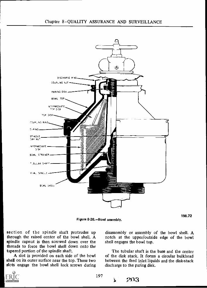
Chapter 8QUALITY ASSURANCE AND SURVEILLANCE
DISCHARGE PING
COUPL.NG
PARING DISK
BOWL TOP
INTERMEDIATEDSK
TOP DISK
COuP,..;NG RING
O -RING
SPI NDLECAP NUT
N.NTERME3IATE
OISK
BOWL STRAINER
".AELLAR SHA-T
BOWL SHELL
Figure 8-26.Bowl assembly.
section of the spindle shaft protrudes upthrough the raised center of the bowl shell. Aspindle capnut is then screwed down over thethreads to force the bowl shell down onto thetapered portion of the spindle shaft.
A slot is provided on each side of the bowlshell on its outer surface near the top. These twoslots engage the bowl shell lock screws during
197
198.72
disassembly or assembly of the bowl shell. Anotch at the upper/outside edge of the bowlshell engages the bowl top.
The tubular shaft is the base and the centerof the disk stack. It forms a circular bulkheadbetween the feed inlet liquids and the disk-stackdischarge to the paring disk.
203

AVIATION BOATSWAIN'S MATE F 1 & C
The base of the tubular shaft has threeunequally spaced pins which interlock withthree unequally spaced slots around the raisedcenter of the inside-bottom of the bowl shell.Thus, the tubular shaft can be installed in oneposition only, and insures that the tubular shaftwill rotate.
The flared base of the tubular shaft is thebottom of the disk stack. A liquid passage,between the bowl shell and the underside of thetubular shaft's base, is provided by 12 innerspacers. The inner spacers are part of the tubularshaft, and serve two purposesthey keep thetubular shaft off the bowl shell to provide theliquid passage, and they give a circular motion tothe feed inlet liquid, since they act as rotatingpaddles. The 12 inner spacers run from thetop-inside area of the tubular shaft and followits contour down and under the flared base tothe outer edge of the base.
Twelve equally spaced holes are providednear the outer edge of the tubular shaft's flaredbase. These holes are located between the 12inner spacers.
The outer edge of the tubular shaft abovethe flared base has 12 equally spaced outerspacers. These outer spacers perform the samefunction for the purified JP-5 that thepreviously mentioned inner spacers perform onthe feed inlet liquids. One of the outer spacershas a key to which each of the disks in the diskstack locks. This insures that the disks willrotate.
The intermediate disks form the main partof the disk stack. There are 127 individualintermediate disks. Each has a number stampedon its top side near its outer edge. The disks arenumbered 1 through 127; number 1 disk is onthe bottom and number 127 is on the top.
The 127 intermediate disks are identical,except for their numbers. The followingdescription applies to each intermediate disk. Inshape, the disk resembles a metal lampshade,large at its base and small at the top. A small lipflares out from the base and a small lip flaresinward from the top.
Twelve equally spaced holes are locatedaround the base of the disk. A thin sliver ofmetal (0.026-inch thick) runs from betweeneach hole inward to the inner lip. These piecesof metal, located on the top of each
2.04198
intermediate disk, act as spacers. Since the disksseat one on top of the other, the thickness ofthe space between each disk is determined bythe thickness of the spacers.
The top inner lip of each intermediate diskhas a notch which interlocks with the key on thetubular shaft. This interlocking insures that thedisks rotate and, also, insures that the disk holeswill be alined vertically.
An intermediate top disk seats on top of thetopmost intermediate disk. This disk is similar inconstruction to the 127 intermediate disksexcept that its flared lip around its base is onlyhalf as large as the lip on the intermediate disks,and it does not have a stamped number.
The top disk seats on top of theintermediate top disk and is the top disk of thedisk stack. Being wider than the other disks inthe stack, the top disk covers the disk stack likean umbrella. This is the only disk that does nothave holes around its base. The inner-upperportion of the top disk is the pump casing forthe paring disk. The lower portion of the pumpcasing has a notch that interlocks with the keyon the tubular shaft, thus insuring that the topdisk will rotate.
Twelve outer spacers, equally spaced aroundthe top side of the top disk, extend frombeyond the rim of the base inward to the top ofthe pump casing. The outer end of each spacerextends below and partially up the underside ofthe top disk. These spacers perform the samefunction to separated water as the outer spacerson the tubular shaft perform on the purifiedJP-5.
A vane-type centripetal pump, the paringdisk, is housed within the pump casing area ofthe top disk. The paring disk does not rotate; itis threaded into the regulating tube of the feedtube assembly (see "Cover Assembly"). In thecase of this pump, the pump casing revolvesaround the impeller; thus, the flow is from theoutside/in. This flow, being centripetal, is justthe reverse of a centrifugal pump.
The feed tube of the cover's feed tubeassembly is the pump shaft. A nylon protectingcollar fits snugly around the top of the paringdisk. When the feed tube is screwed into theparing disk, the paring disk is raised until the

Chapter 8QUALITY ASSURANCE AND SURVEILLANCE
protecting collar contacts the upper/inside areaof the pump easing. In this position, theprotecting collar acts as a wearing ring for theparing disk.
A bowl top seats on the top of the top disk'sspacers. Discharging water flows up through thespace between the top disk and the bowl top.The conical-shaped bowl top is thicker at thebottom than at the top. Part of this thick baserests on top of the bowl shell and part of itextends down inside the bowl shell.
The part of the bowl top extending downinside the bowl shell has an 0-ring retaininggroove. An oil-resistant 0-ring installed in thisgroove forms a liquid-tight seal between thebowl top and the bowl shell. This seal insuresthat the liquids involved in the purifying processwill be confined to their normal flow throughthe bowl shell assembly.
A large coupling ring is threaded down overthe base of the bowl top to the upper/outsideedge of the bowl shell. This ring holds the bowltop in place.
A rectangular metal bar is bolted to theouter rim of the base on one side of the bowltop. This bar engages a notch in the bowl shellto insure rotation of the bowl top.
The top edge of the bowl top has a retaininggroove into which is inserted an oil-resistantrubber seal ring. This particular ring is a flatrubber washer, not an 0-ring. A discharge ringseats on top of this seal ring.
The outer edge around the top of the bowltop is threaded to receive a coupling nut. Thecoupling nut screws down over the dischargering, forcing the discharge ring down onto therubber seal ring. This sealing insures thatdischarging water will flow up through thecenter of the discharge ring.
The coupling ring, as previously stated,forces the bowl top down onto the top of thebowl shell, thus completing a seal. As thecoupling ring is screwed downward, it forces thebowl top down onto the disk stack. This actioncompresses the disk stack and insures that eachdisk will seat tightly on its adjacent disks. Thespace between each disk is thereby assured to becorrect.
To insure correct tension on the disk stack,an alining mark is stamped on the coupling ringand the bowl top. These two marks must be
199
..=1,
lined up when tightening the coupling ring. Anindicating arrow and the word "OPEN" are alsostamped on top of the coupling ring. Thesemarks show the direction of rotation to removethe coupling ring.
CAUTION: The coupling ring has left-handthreads.
Four T-shaped slots are equally spacedaround the outside/upper rim of the couplingring. A special wrench engages all of these slotsfor removal or installation of the coupling ring.
A discharge ring, seated on top of the bowltop, acts as a dam to maintain the proper line ofseparation between the water and the JP-5within the bowl shell assembly.
Each purifier is furnished with a set of sevendischarge rings. The outside diameters of thedischarge rings are the same. The insidediameters of the discharge rings are different.The inside diameter size is etched on each ring.The inside diameters range from 220 millimetersto 250 millimeters in 5-millimeter steps (220,225, 230, 235, 240, 245, and 250).
The previously mentioned coupling nutlocks the discharge ring in place. Like thecoupling ring, the coupling nut also has anindicating arrow and the word "OPEN" stampedon its top.
The coupling nut has four circular slotsequally spaced around its outer edge. A specialwrench engages one of these slots for removal orinstallation.
PURIFIER OPERATIONS
The operations described in this section dealwith starting from two differentconditionswith a clean bowl and with a dirtybowl.
Regardless of the condition of the bowl,there are some preliminary steps to be takenevery time prior to starting the purifier. Thesesteps are:
1. Open the cover.2. Make sure the handbrake is in the OFF
position.
3. Remove the two bowl shell lock screws.
4. Insert the two bowl shell lock screwplugs.
205

AVIATION BOATSWAIN'S MATE F 1 & C
5. Turn the bowl by hand. If the bowl doesnot turn freely, investigate and correct thecause.
6. Check the level of oil in the oil sump. Ifthe oil is at or below the red line, add sufficientoil to raise the oil level to the white line.
7. Check the condition of the four clutchlinings. If the center of any of these linings isless than 5/32-inch, replace all four linings.
8. Rotate the electric motor hub by handin the reverse direction of normal rotation. Ifthe clutch sleeve is cracked, the friction weightswill catch on the cracks. Never run the purifierwith a cracked sleeve.
9. Close the cover and engage the feed tubeto the paring disk.
10. Engage and tighten the three handwheelcover clamps.
11. Connect the seal water inlet hose to theseal water inlet plug valve on the purifier.
The following starting and stoppingprocedures are for transferring fuel from oneport wing stowage tank, through one transferpump, through the port purifier, to one portwing service tank. Since transfer is from wingtank- to wing tank within the same group oftanks, and on the same side of the ship, there isvery little change to the list and trim of the ship.The starboard service tanks can be filled fromstarboard stowage tanks in the same manner.However, the transferring is accomplished byusing only one transfer pump to pump into onepurifier, since they both have the samecapacity.
Starting with a clean bowl is accomplished asfollows:
1. Close the following valves:a. Manifold telltale valves, as
applicable.b. Sample connections.c. Purifier inlet globe valve.d. Purifier discharge globe valve.e. Purifier seal water inlet plug valve.
2. Open the following valves:a. Manifold tank side valve.b. Manifold transfer main side valve.c. Transfer pump inlet valve.d. Transfer pump discharge valve.
?C200
e. Transfer pump inlet and dischargegage valve.
f. Fresh water supply valve (seal watersupply).Bowl casing drain valve (lockedopen).
h. Service tank fill valve.3. Start the purifier (press start button).4. When the purifier bowl shell assembly
attains 4,100 rpm (146 to 150 bumpsper minute within 3 minutes), open theseal water inlet plug valve.
5. Open the main water-dischargeobservation port on the cover assembly.
6. When water discharges past theobservation port, close the followingvalves:a. Seal water inlet plug valve.b. Fresh water supply valve.
7. Start the transfer pump (press startbutton).
8. Slowly open the following valvessimultaneously:a. Purifier inlet globe valve and throttle
to maintain 9 psi inlet pressure.b. Purifier discharge globe valve and
throttle to maintain 30 psi backpressure.
9. Log the time the following were started:a. Transfer pump.b. Purifier.
10. While the purifier is running:a. Log the transfer pump inlet and
discharge gage readings.b. Log the purifier inlet and discharge
gage readings.c. Log the feed inlet temperature.d. Take inlet and discharge samples:
(1) Analyze samples with the AELcontaminated Fuel Detector MkIII.
(2) Log the results of the analysis.
11. When the transfer pump loses suction onthe stowage tank:a. Close the purifier inlet and discharge
globe valves.b. Open the manifold valves for the
next stowage tank to be emptied.c. Close the manifold valves for the
already empty stowage tank.
g.

Chapter 8QUALITY ASSURANCE AND SURVEILLANCE
d. Repeat step number 8.12. When the service tanks is 95 percent full,
stop the transfer operation. Theprocedure for stopping the purifier is asfollows:a. Close the purifier inlet glove valve.b. Stop the transfer pump (press the
stop button).c. Stop the purifier (press the stop
button).d. Do not engage the brake.e. The purifier will coast to a stop
(approximately 45 minutes).f. As the purifier slows down:
(1) Centrifugal force diminishes.(2) Feed inlet pressure will drop to
zero.(3) Discharge pressure will drop to
zero.When the flapper in the dischargesight flow gage stops flapping, closethe purifier discharge globe valve.
h. Close all valves still open.i. Log the time the following were
stopped:(1) Transfer pump.(2) Purifier.Log the gross gallons removed fromthe stowage tanks.
k. Log the net gallons transferred intothe service tank.
Emergency stopping procedures are: Pressthe purifier stop button, apply the hand brake(handle up), stop the transfer pump, close thepurifier discharge and inlet globe valves.
NOTE: Since the purifier discharge and inletvalves are closed in that order, JP-5 trapped inthe purifier places an added resistance torotation, thus helping to stop the purifier.
The procedure for starting the purifier witha dirty bowl is as follows:
g.
J.
1. Complete all the preliminary steps.2. Complete steps 1, 2, and 3 as when
starting with a clean bowl.3. Open the purifier seal water inlet plug
valve.4. When the purifier attains full rpm,
complete steps 5 through 12.5. To stop the purifier, proceed as
previously described.
201
The position of the line of separationbetween the JP-5 and water is important toproper purification. For good purification, thisline should be outside of the disk stack but wellunder the top disk. If the line of separation istoo far out, some or all of the JP-5 will dischargewith the water. If the line of separation is toofar in, water will discharge with the JP-5. Theposition of the line of separation depends uponthe selection of the proper discharge ring. Thedischarge ring depends on the specific gravity ofthe JP-5. Once the specific gravity is determined,refer to the chart of discharge ring sizes (fig.8-27).
Find the specific gravity number along thebase of the chart. From this point, inscribe avertical line up the chart until it intersects withthe solid curved reference line. From the pointof intersection, inscribe a horizontal line to theleft-hand border of the chart. The numbersalong the left-hand border do not exactly pointto a ring number; always use the next smallerring.
Install this ring in the purifier. Operate thepurifier, and observe the JP-5 andwater-discharge sight flow gages.
If all of the discharge goes out the waterdischarge, the discharge ring is too large. Stopthe purifier and install the next smaller ring.
250
245
240
e 235
g 230
225
220
215
210
Maximum ring siz
I
90 .89 88 .87 .86 .85 .84 .113 .82 .81 .80 .79 311 .77 .76
Relative specific density
Figure 8-27.Discharge ring size chart.
7
198.73

AVIATION BOATSWAIN'S MATE F 1 &C
Make another trial. If necessary, repeat untilJP-5 is properly discharged from the bowl shellassembly. If more than one trial is required, itgenerally indicates a mistake was made indetermining the correct specific gravity or inusing the discharge ring size chart.
CAUTION: When the seal water is cold, asmall amount of JP-5 may discharge with thewater at first. This will cease as the water, JP-5,and purifier heat up. In this case, it will not benecessary to change the discharge ring.
If water discharges with the JP-5, thedischarge ring is too small; try the next largerring.
When the proper size discharge ring isestablished, do not change it. As a general rule,the most satisfactory purification occurs whenthe discharge ring is the largest size possiblewithout causing loss of JP-5.
During normal operations, there should beno more than a small discharge from the wateroutlet. The bulk of the discharge should be outthe purifier JP-5 outlet.
If it is found that there is a large dischargefrom the water outlet, it indicates excessivewater in the feed, or the water seal has been lost.The operator should immediately determinewhether the excessive discharge is water or JP-5.
If the excessive discharge is JP-5, the bowlhas lost its seal, stop the flow of feed, reprimethe bowl, and slowly resume the flow of feed.
If the seal is again lost, immediately stop thepurifier and check the discharge ring size and thebowl shell assembly's two rubber seal rings.Correct the cause and resume operation.
If the excessive discharge is water, secure theoperation and determine the source of thewater. Sound the stowage tanks withwater-detecting paste and restrip the stowagetanks as necessary.
NOTE: If the tanks have been properlysettled and stripped, there should never be but atrace of water in the feed.
If water has been put into the service tanks,they must also be stripped, if no water is foundin the stowage tanks, check the piping in thebilge, voids, etc., for leaks or other possiblesources of water.
?OR202
PURIFIER MAINTENANCE
Establish and maintain a regular cleaningschedule, depending on the following factors:
1. Accumulation of a large quantity ofheavy solids in the bowl shell will cause the bowlto run rough. The bowl must be cleaned beforethe wet cake exceeds 30 pounds or 11/2-inchthickness at its thickest point.
2. If the purifier is to be inactive for lessthan 12 hours, it must be flushed out with freshwater while it is still operating, by using thepriming water.
3. If the purifier is to be inactive longerthan 12 hours, it must be disassembled andthoroughly cleaned.
4. In any event, the bowl must bedisassembled and thoroughly cleaned at leastonce a week.
The purifier bowl should be inspected forcorrosive pitting. If pitting is found, the bowlshould be cleaned thoroughly with a mildabrasive cleaner in combination with stainlesssteel sponges. If pitting continues, the bowlshould be reconditioned at the earliestopportunity.
Where pitting has progressed to '4-inch indepth, replace the bowl.
CAUTION: Continued use of deeply pittedbowls can be potentially hazardous.
When disassembling and assembling the bowlshell assembly for cleaning, it must be borne inmind that the component parts are heavy. Forthis reason, a chain hoise and trolley have beenprovided to lift the parts and transport them toa deep sink. Extreme caution must be exercisedwhen raising, lowering, and transporting theparts. It is imperative that the chain hoist becentered directly over the center of the spindlebefore any part is raised or lowered.
To disassemble the purifier for cleaning,proceed as follows:
1. After stopping the bowl, remove theplugs and insert the lock screws. (See fig. 8-28.)The two lock screws (one on each side of the

Chapter 8QUALITY ASSURANCE AND SURVEILLANCE
HAND WHEELCOVER CLAMPS
SPRING LOADED FEEDTUBE HANDLE
BOWL COVERRATCHET HOOK
LOCKSCREWS
Figure 8-28.Rear view of purifier (cover closed).
purifier) enters the slots in the bowl shell,locking it in position.
2. Using the spring-loaded tee handle ontop, unscrew the feed tube until it is free fromthe paring disk.
3. Loosen the three handwheel coverclamps and swing the bowl casing cover back
203
198.74
until it engages the ratchet hook. This willautomatically lock the cover in the openposition.
4. Unscrew the bowl top coupling nut (fig.8-29), using special tool (inset, fig. 8-29) andremove the discharge ring and rubber ring.
5. Remove the coupling ring (fig. 8-30) byloosening it first with the gear wrench, then
2G9

AVIATION BOATSWAIN'S MATE F 1 & C
Figure 8-29.Removing bowl top coupling nut (with special tool).
unscrewing the coupling ring with the specialtool.
6. After removing the coupling ring, screwthe lifter into the bowl top. By turning in on theT-handle jackscrew on top of the lifter, the bowl
f210204
198.75
top will let loose from the bowl shell. Using thechain hoist, lift the bowl top off, being carefulwith the rubber ring. Remove the rubber bowlring and lay it flat.
7. Remove the tubular shaft, top disk,paring disk, and intermediate disks, with the

Chapter 8QUALITY ASSURANCE AND SURVEILLANCE
Figure 8-30.Removing coupling ring (with special tools).
205 211
198.76

AVIATION BOATSWAIN'S MATE F 1 & C
SPECIAL TOOL5.
4
Figure 8-31.Removing disk stack.
chain hoist, using the special tool provided. (Seefig. 8-31.)
8. To remove the bowl, lift out the bowlstrainer. Remove the spindle cap nut and backout both lock screws. Screw the liftc.5(pg,8-32)onto the bowl shell, and by, turnip t ill* the
206
198.77
jackscrew the shell will loosen from the spindle.Using the chain hoist, lift the shell from theframe.
After the bowl parts have been disassembled,remove the rubber rings and clean the tubularshaft and disks with a brush using JP-5 as thecleaning fluid. Reassemble in the reverse order.

Chapter 8QUALITY ASSURANCE AND SURVEILLANCE
198.78Figure 8-32.Bowl shell lifter.
0-rings and gaskets should never be hungvertically, lay them neatly on a clean, flatsurface. Hanging will seriously distort the shapeof 0-rings and gaskets. When installing 0-rings,always inspect them for nicks, cuts, or abrasions;use only good 0-rings. Examine the 0-ringretaining slots and other contact surfaces for
207
nicks and burrs, and remove such beforeinstalling the ring. Make sure that the retainingslot and contact surface are clean, and coat the0-ring with a light machine oil beforeinstallation.
Maintain the lubrication system in a perfectcondition. Refer to the manufacturer'sinstruction manual and current Instructions asto the type and amount of lubricant.
Clutch weights may occasionally crack andrequire replacement. Replacement weights arefurnished in matched pairs and must be replacedin pairs to maintain balance. If, for example, No.1 weight requires replacement, it will benecessary to replace the opposite weight (No. 3)also.
When a friction weight lining requiresreplacement, all four linings must be replaced.
The centrifugal clutch is the main source oftrouble in the centrifugal purifier. In order toalleviate this situation, purifiers purchased afterOctober 1961 do not have a centrifugal clutch.A direct-drive, explosion-proof, fan-cooledelectric motor is utilized in lieu of a frictionclutch or other friction type torque transmittingdevice.
The electrical controllers have an amberindicating "HOLD" light while the purifier iscoming up to speed. It also has a greenindicating "RUN" light when it is up to speedfor loading purposes.
Yearly, the purifier should be completelydisassembled and inspected, and any parts thatare worn must be replaced.
213
CHAPTER 9
MAINTENANCE AND REPAIR
The ABF1 and ABFC must have the abilityand knowledge to properly inspect theinstallation and to evaluate the operation ofnewly repaired or installed parts andcomponents of the aviation fuels systems. Hemust be able to distinguish between a repairablepart and one that is not. He must know theprocedures required to make the fueling-systemsafe for repair. His knowledge of the fuel systemmust be such that he can supervise and directthe repair of all components of the fuel system.
When the repair of a specific component ofthe fuel system is required, consult the technicalmanual for the proper clearances, tolerances,and order of removal and installation of theparts. The clearances and tolerances shouldnever be a matter of guess or chance.
When similar components are being repairedor overhauled, the parts should be tagged and/ormarked as to the component to which itbelongs.
Since the introduction of the Navy StandardMaintenance and Material Management (3-M)System to the aviation fuels system andcomponents, maintenance is coordinated withthe use of Maintenance Index Pages andMaintenance Requirements Cards. Themaintenance of the aviation fuels systemremains under the cognizance of the aviationfuels repair team (formerly Repair 7).
AVIATION FUELS REPAIR TEAM
The aviation fuels repair shop is that spaceset aside aboard aircraft carriers for the stowageof damage control and maintenance equipmentfor the purpose of repairing the aviation fuelssystems.
214 208
ORGANIZATION
The air officer is responsible for theorganization of the aviation fuels repair team inaccordance with the ship's battle bill. The repairteam must be capable of handling all damageand casualties that occur within its assigned area.
Personnel assigned to the repair team musthave a thorough knowledge of the aviation fuelsstowage and distribution systems, the operationof assigned damage control equipment, andapplicable damage control procedures. Theymust also be familiar with the properties andhazards of aviation fuel and all applicable safetyprecautions.
The personnel assigned to the repair teamshould be rotated on a regular basis to allow asmany men as possible to acquire the necessarymaintenance skills. This cross training will notonly benefit the division, it aids the individual inpreparing for advancement.
The major duties of this repair team are:
1. Locate and isolate damage to theaviation fuels stowage and distribution systems.
2. Clear spaces of aviation fuel and fuelvapor by approved methods.
3. Make tests to determine the presence orabsence of explosive vapors and oxygen.
4. Make emergency repairs to the aviationfuels system.
5. Operate and maintain equipmentnecessary for the above functions.
Flight Quarters
During normal working hours and flightquarters, the repair team locker serves as the
Chapter 9MAINTENANCE AND REPAIR
maintenance shop for the fuels systems. It isnormally manned by a petty officer in charge, aphone talker, and various repairmen.
The repair team petty officer supervises themaintenance of the aviation fuels systems.Specific duties and responsibilities include:
1. Maintain a master maintenance log ofthe aviation fuels systems.
2. Insure the proper handling of inventoryand stowage of tools, equipment, and spare partsunder custody of the V-4 division.
3. Supervise the upkeep and cleanliness ofrepair team assigned spaces.
4. Insure that all men assigned arethoroughly instructed in their duties.
5. Insure that all safety, testing, andemergency equipment is in proper workingcondition.
6. Insure that all safety precautions areobserved.
7. Conduct and assist in maintenance andrepair of all aviation fueling equipment.
8. Maintain a log of all temporary issues oftools and equipment.
9. Conduct periodic checks on assignedsound powered phones.
General Quarters
During general quarters, the repair teambecomes part of the damage controlorganization. The damage control organization isnecessarily an integral part of the engineeringdepartment organization. An engineeringdepartment officer, known as the damagecontrol assistant, is charged with the overallcoordination of all damage control matters.
The aviation fuels officer is in charge of theaviation fuels repair team with the senior pettyofficer from the V-4 division as his assistant. The
en that are normally assigned for maintenancen the division make up the repair teamersonnel. Other personnel assigned to thispair team include men in the HM, DC, and EMIC ratings. Men from the repair team may also
e assigned to other repair parties, such aspair 1, or may form subdivisions of the fuels
pair team at other locations in the ship.
209
The men assigned to the fuels repair teamfrom the V-4 division should be trained anddrilled in the following:
1. Methods of investigating and reportingdamage.
2. Controlling and extinguishing fires.3. Isolating damage to piping systems.4. Restoring service to piping systems.5. Rescuing personnel and caring for
wounded.6. Operating all types of damage control
equipment.7. Correct setting of material conditions of
readiness.
PORTABLE EQUIPMENT
All portable equipment used in themaintenance and testing of the aviation fuelssystem is normally stored in fuels repair teamlocker. The checking and repair of thisequipment is also carried out there. The ABF1and ABFC are required to perform some of themaintenance of this equipment and to analyzeany malfunction of this equipment. Major repairof this equipment is carried out by repairactivities ashore. The operational procedures forthis equipment can be found in ABF 3 and 2.
FLAME SAFETY LAMP
The flame safety lamp is used to determinethe presence or absence of sufficient oxygen tosupport life. This device should be used only totest a space after the combustible gas indicator(explosimeter) has given a negative indication ofthe presence of flammable gasses. It shouldNEVER be used in a space suspected ofcontaining free hydrogen or acetylene.
Prior to use of the flame safety lamp, inspectthe following components:
1. Air admission ring.2. Inner and outer gauze cones.3. All gaskets.4. Glass shield.
These items must be clean and free ofdamage in order to confine the flame within the
215

AVIATION BOATSWAIN'S MATE F 1 & C
lamp. Clean or replace any items that fail theinspection.
PORTABLE INERTNESS ANALYZER
The dual service portable inertness analyzeris a battery-powered, electric instrument used tomeasure the percent inertness of a space chargedwith inert gas. Percent inertness is the percentreduction of oxygen in the space. For example,60 percent inertness indicates that the air in thespace contains about 8 percent oxygen.
The analyzer may also be used to indicatethe presence of hydrocarbon vapor in the space.However, it will not indicate the amount orpercentage.
The maintenance procedures for thisinstrument consist primarily of attention to thebattery and chemicals. Repair of this instrumentis normally accomplished by repair activitiesashore.
Prior to use of the portable inertnessanalyzer, perform the following:
1. Turn current switch to "C" position.2. Turn rheostat "C" to set needle at 100
on the scale.3. Turn current switch to the "A" position.4. Open petcock at bottom of moisture
absorber (black cylinder).5. Attach actuating pump discharge hose to
moisture absorber petcock.6. Work pump by hand in fresh air for
about one minute.7. Turn rheostat "A" to set indicator
pointer at zero.8. Turn current regulating rheostat off. If
the indicating needle does not rest at zero, turnadjusting screw located in the panel under thedial.
When the current adjusting rheostat does notadjust the indicating needle to 100 on the dial,replace the battery.
After 50 analyses, check the calciumchloride. If it appears glazed or hard, replace italong with the cotton pad. At the same timeinspect the activated carbon, it must be eitherreplaced or reactivated. Normally it will be
71 210
replaced unless a new supply of carbon is notavailable.
After each analysis, close the petcock to theblack cylinder to preserve the life of the calciumchloride. For the protection of the instrument,always store it in the instrument box provided.
COMBUSTIBLE GAS INDICATOR
The combustible gas indicator may also beknown as a hydrocarbon vapor indicator or anexplosimeter. This is a battery-powered, electricinstrument used to detect flammable andexplosive mixtures of hydrocarbon vapors andair in an enclosed space. This type of indicator isthe only convenient, reliable, and accuratemeans of determining the presence of thesemixtures in varying concentrations. For thisreason, it should be in frequent use indetermining possible leakage of gasoline orgasoline vapor.
The graduations of the indicating meter arein percent of the lower explosive limit. Thisscale ranges from 0 to 100.
EXAMPLE: The lower explosive limit ofgasoline is 1.4% by volume, which would read100% on the indicating meter.
A reading above 60 indicates the gasconcentration is near the explosive range and isunsafe for men to enter. Prior to operation,check sampling line connections for leaks; anyleakage would result in a faulty reading. Inspectflash back arresters; if they are clogged, replacewith new arresters. Inspect the condition of thefilter. Inspect the flow regulating orifice, thisorifice is located in the aspirator bulb coupling.
Toggle switches are located on either side ofthe indicator dial. The right-hand switch ismarked ON-OFF. This is a connecting switchbetween the battery supply and the testingcircuit. When operating the instrument, turn thisswitch ON.
The left-hand switch is markedCHECK-READ. In the CHECK position, theindicates whether sufficient current is beinsupplied from the batteries. The pointer shoulrest on a green arrow in the center of the dial. Iit does not, the electrical supply mayadjusted by turning the knob marked VOLADJ, which is located on the tight-hand side othe indicator.
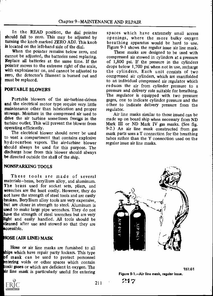
Chapter 9MAINTENANCE AND REPAIR
In the READ position, the dial pointershould fall to zero. This may be adjusted byturning the knob marked ZERO ADJ. This knobis located on the left-hand side of the dial.
When the pointer remains below zero, andcannot be adjusted, the batteries need replacing.Replace all batteries at the same time. If thepointer moves to the extreme right of the scale,with explosimeter on, and cannot be adjusted tozero, the detector's filament is burned out andmust be replaced.
PORTABLE BLOWERS
Portable blowers of the air- turbine -drivenand the electrical motor type require very. littlemaintenance other than lubrication and properstowage. Moisture in the compressed air used todrive the air turbine sometimes freezes in theturbine outlet. This will prevent the blower fromoperating efficiently.
The electrical blower should never be usedto vent a compartment that contains explosivehydrocarbon vapors. The air-turbine blowershould always be used for this purpose. Thedischarge hose from this blower should alwaysbe directed outside the shell of the ship.
NONSPARKING TOOLS
These tools are made of severalmaterialsbrass, beryllium alloy, and aluminum.The brass used for socket sets, pliers, andwrenches are the least costly. However, they donot have the strength of steel tools and are easilybroken. Beryllium alloy tools are very expensive,but are closer in strength to steel. Aluminum isused to make large pipe wrenches. They do nothave the strength of steel wrenches but are very
ght and easily handled. All tools should beleaned after use and stowed so that they areccessible.
OSE (AIR LINE) MASK
Hose or air line masks are furnished to allps which have repair party lockers. This type
f mask can be used to protect personneltering voids or other spaces which contain
oxic gases or which are deficient in oxygen. Theline mask is particularly useful for entering
211
spaces which have extremely small accessopenings, where the more bulky oxygenbreathing apparatus would be hard to use.Figure 9-1 shows the regular issue air line mask.
These masks are designed to be used withcompressed air stowed in cylinders at a pressureof 1,800 psi. If the pressure in the cylindersdrops below 1,700 psi when not in use, rechargethe cylinders. Each unit consists of twocompressed air cylinders, which are manifoldedto an individual compressed air regulator whichreduces the air from cylinder pressure to apressure and delivery rate suitable for breathing.The regulator is equipped with two pressuregages, one to indicate cylinder pressure and theother to indicate delivery pressure from theregulator.
Air line masks similar to those issued can bemade up on board ship when necessary from NDMark III or ND Mark IV gas masks. (See fig.9-2.) An air line mask constructed from gasmask parts uses a T connection for the breathingtubes rather than the Y connection used on theregular issue air line masks.
Figure 9-1.Air line mask, regular issue.
217
197.61

AVIATION BOATSWAIN'S MATE F 1 & C
CAUTION: Air line masks are designed foruse with compressed air, not with oxygen.NEVER use oxygen with an air line mask.
Lifeline
Personnel wearing an air line hose maskwhen entering aviation gasoline stowage tanks,voids, etc., which contain toxic gases, must beequipped with a lifeline, and tended by a reliableman outside the space.
The Navy Standard Lifeline is a 50-footsteel-wire cable fitted with snaphooks on eachend. The lifeline should be attached to the upperpart of the body, preferably to the backloop ofa shoulder harness. A cardinal rule isNEVERattach a lifeline to the waist.
When the lifeline is used, it is essential thatthe wearer and tender be able to communicatewith each other. Standard diver's signals arenormally used for this purpose; however, onlythe basic signals are needed for tank cleaners.These signals, with meanings modified to fit thetank cleaner situation, are as follows:
BREATHINGTUNES
TEE CONNECTION
OXYGEN HOSECOUPLING INSERT(SILVER SOLDERED
TO TEE)
OXYGEN HOSE COUPLINGINSERT SILVER SOLDEREDTO OUTLET SIDE OFVALVE
HOSE CLAMPS
5/16. OXYGENACETYLENE HOSE
OXYGEN HOSE MALECOUPLING SILVERSOLDERED TO INLETSIDE OF VALVE
SHEET METALVALVE BASE
WEB BELT 100 Le I/4° COMPRESSED AIRANGLE VALVE SUPPLY
TENDER TO WEARER 198.79Figure 9-2.Air line mask constructed from gas mask.
Pulls on line Meaning
1. Are you all right?2. Advance. PORTABLE MR-OPERATED3. Back out. DEFUELING PUMP4. Come out immediately.
WEARER TO TENDER The defueling unit made by thd B. P. ElCo. uses a Wayne all-bronze, two-too
Pulls on line Meaning difference, internal gear type pump driven byBoston Pneumatic Air Motor. This unit withou
1. I am all right. the required hose weighs approximately 8'2. I am going ahead. pounds. The pump is rated at 28 gpm at a 25 ps3. Keep slack out of line. total head with a suction of 3 inches Hg.4. Send help.
The air motor unit consists of a conventionAn easy way to remember the signals is: four-blade rotary air motor and a two-step g
reduction. All rotating parts are mounted on bCODE PULL MEANING bearings. A weight type centrifugal govern
prevents overspeeding by restricting the volum0 1 OK. of air admitted to the motor when the moA 2 Advance. speed reaches a predetermined maximum.T 3 Take up. 1/2-inch cock for manually controlling the pow
4 Help. and speed of the motor is mounted on the unit
215 212

Chapter 9MAINTENANCE AND REPAIR
The air motor is constructed ofprecision-built parts which must operate at veryclose clearances and in perfect alinement.Reasonable care must be taken to preventdamage to these parts. Distortion, burring, orscoring of parts will seriously affect motorperformances.
Loss of power, erratic action, or motorfailure may be caused by factors outside the airmotor. Check for:
1. Low air pressure. Air pressure at themotor, with motor running wide open, shouldbe from 70 to 110 psi, preferably 90 psi. Lawair pressure is frequently caused by use of hoseof insufficient size. Use 1/2-inch hose for lengthsup to 50 feet. Use 34-inch hose for any lengthover 50 feet.
2. Wet or dirty air. Water or dirt (scale,particles of rotten hose, etc.) in the air line willseriously affect performance and may causedamage to the motor.
If the foregoing are found to be in order,check, in sequence, the following:
1. Motor lubrication. Remove the airhoseand pour a small quantity of recommended oilin the air inlet of the throttle valve. Fill the oilreservoir on top of the head casting.
2. Rotovane motor. Remove anddisassemble the rotovane motor. Thoroughlyclean all parts in JP-5 or type II solvent (FederalSpecification P-S-661). Repair or replace partsthat are badly worn or broken. (Give particularattention to rotovanes, as they are subject toconsiderable wear.) Repack bearings with grease,lightly coat all other parts with oil, andreassemble.
3. Gearing. Remove the rotovane housingfrom the quill housing and disassemble the quillhousing. Thoroughly clean all parts and removeall old grease from the quill housing. Check allparts and repair, or renew those badly worn ordamaged.
The lubrication of the defueling unit is asfollows:
1. Before connecting the airhose, alwayspour a small quantity of oil into the air inlet ofthe valve.
2. After each 8 hours of operation, removethe oil plug located in the top head casting andrefill the oil reservoir; then replace the plug.
3. After each 100 hours of service, addthree or four gun shots of recommended greaseto the two grease plugs, one located in therotovane motor housing, and the other locatedin the top head casting.
EMERGENCY REPAIRS
A leak of any size in an aviation fuels systemmay create an emergency situation. Most leaksoccur at flange joints due to leaking gaskets, orat pump and valve packing. These types of leakscan be prevented or minimized by propermaintenance and frequent inspection. Due tothe many types of fuels systems there is no wayto state which valves are to be closed or openedto isolate or bypass a given section of a system.
ISOLATING DAMAGED SECTIONS
An ABF assigned to a repair team mustknow the location and function of each valve inthe system. The only way that this can be doneis by study of the system, piping schematics, andblueprints related to the system.
The ABF must also know the methods ofrestoring the installed ventilation for the belowdeck spaces and the ways and means of riggingportable ventilation blowers and hoses.
Ruptures and breaks in fuel piping mayhappen at any time and foi many reasons. Thefuels system may be inerted or in operation.
If, for any reason, an aviation fuels lineinside the ship is ruptured when it is pressurizedwith fuel, the following procedure should befollowed:
1. Immediately stop all pumps servicing theaffected piping.
2. Isolate the affected piping bymanipulating the appropriate valves.
3. Remove all unauthorized personnel andpersonnel not wearing appropriate breathingapparatus from the space.
4. St op all electrical machinery (exceptexplosionproof motors) both in the space and inadjacent spaces through which air currents might
213 i 219

AVIATION BOATSWAIN'S MATE F 1 & C
pass from the space containing explosive vapor.CAUTION: Operate remote switches to preventthe possibility of sparks. Take all possibleprecautions to prevent sparks from electrical ormechanical means.
5. Close and, if necessary, seal the spaceuntil effective exhaust ventilation is assured.
6. Drain and purge the affected piping untilrequired repairs can be made.
If a fuel line outside the ship is rupturedwhen pressurized with fuel, the procedure isessentially the same; however, the danger ofexplosive vapors is greatly minimized. The fuelvapors should be carried away before adangerous mixture forms; however, extremecaution must be exercised in the immediatevicinity of the rupture.
If an enemy attack is imminent, all aviationfuel should be drained from the fuel lines intothe stowage tanks. All lines are then purged andcharged with an inert gas. This prevents theformation of explosive vapors from entering theship in the event fuel lines are ruptured.
If a fuel line that is charged with an inert gasis ruptured, it can be repaired with a soft patchand then recharged. Before entering spaces inthe vicinity of such ruptures, a test must bemade with the combustible gas indicator todetermine the absence/presence of flammablegases. If flammable gases are present, the spacesare ventilated free of them and again retestedwith the combustible gas indicator beforeentering. Since the spaces may contain inert gas,the flame safety lamp is also used beforeentering to insure the presence of adequateoxygen to support life.
PIPE PATCHING
Repairs to piping are classified as permanentor temporary. The type of repair to be made atany time depends upon the circumstances.Permanent repairs are made when the samematerial as the ruptured piping is available andthe system is secured for the time required tomake the repair. Temporary repairs are madewhen the original material is not available or thesystem cannot be secured.
?2O 214
Temporary Repairs
Temporary repairs are usually made bysecuring some type of patch over the leakingsection of pipe. The material used for the patchdepends upon the type of piping that is beingrepaired.
All water and aviation fuel lines can be easilyrepaired and service restored to the system in aslittle time as 30 minutes by e of EmergencyDamage Control Metallic Pipe Repair Kit. This isa plastic patch kit. Materials used includevoidcover (fibrous glass cloth with cured resinsurface), resin and activator, fibrous glass tape,and fibrous glass mat. These materials are easilyworkable before hardening, as tape and puttycan be applied by relatively untrained personnel.Pressure of 300 psi can be handled consistently.Application is flexible and provides a quickemergency method of repairing a wide variety ofdamage to pipes, flanges, elbows, andconnections of various sizes. Completely severedends of pipe can be joined. Odd shapes andjagged protrusions are no obstacles. Applicationof these patches are limited only by workingspace available and the ingenuity of personnelinvolved. Time required to apply patches isdependent upon the shape to be repaired, theworking space available, arid curing time.Patches can be applied to straight pipes andelbows in minutes. Pressure may be appliedabout 20 minutes after repairs are completed.Complete application instructions are includedin each kit.
For low-pressure sea water piping, red leadputty wrapped about with canvas and servedwith marlin or electric friction tape makes anexcellent, easily applied patch. A small leak inthis kind of piping often can be stopped bydriving in a soft pine plug. The moisture willcause the wood to swell and remain in place.
Patches may also be made from portlandcement, cast in place and secured by metalbands. On low-pressure water piping, cast aportland cement collar entirely around the line.Iron cement can be used effectively to makeemergency patches on iron or steel low pressurepiping.
Banding to ollcits are available in repairlockers. These kits may be used in the mannershown in figure 9-3 for the emergency banding

Chapter 9MAINTENANCE AND REPAIR
PUSH BAND THROUGH "LOK" ANDBEND BACK 5/8
2 LOOP BAND AROUND PIPE.3 PUSH END THROUGH "LOK" AND
PULL SNUG.
4 FORM SECOND LOOP.
5 PULL TIGHT
6 USE "LOKING" IDOL (NOT SHOWN)
LIGHT DUTY HEtivY DUTY
Figure 9-3.Pipe banding.197.64
of pipe patches. The banding material isavailable in various widths. A manufacturer'stechnical manual is furnished with each bandingtoolkit. The ABF should study the technicalmanual and also have actual practice in the useof banding equipment before attempting to useit in an emergency situation.
In all cases where temporary repairs topiping are necessary, the head of the departmentconcerned must determine that the repairs aresuch that the safety of personnel is notimpaired.
Permanent Repair
A repair is considered permanent if itrestores the piping system to its originalserviceability and if it can he expected to last forthe life of the system_ All temporary repairs topiping should be replaced with permanentrepairs as soon as practicable.
Permanent repairs may be made in variousways, depending upon the nature of the damage,the operating conditions of the system, and thematerial of which the system is made. Probablythe most common type of permanent repair isthe complete replacement of an assembly orsubassembly. However, damage that is not
215
serious enough to require the replacement of anentire section can often be repaired permanentlyby other means, such as patching, tighteningjoints, and repacking valves.
Permanent repair work requiring burningand welding is accomplished by the ship'sengineering department or at a shipyard.However, V.4 division personnel may be calledon to assist.
MAINTENANCE OFPIPING SYSTEMS
Early detection and correction of pipingdefects are of utmost importance, since theoperational reliability of ships requires that allpiping systems be in satisfactory operatingcondition. Damage to piping systems may resultfrom battle or accident, or merely from the wearand tear of daily use. The ABF should knowhow to locate piping system troubles and how tomake adequate repairs, when required. Thetechnical know-how involved in performingpractical damage control jobs, such as repairingjoints and replacing a valve stem is covered here.
JOINTS
At regular intervals, the joints in pipingsystems should be inspected for leakage. A smallamount of seepage at a joint may not seemimportant; but, if the trouble is not corrected,the leakage is likely to become greater and maycreate hazardous conditions.
Most joint leakage in piping systems iscaused by misalinement or by failure to allowfor expansion. Either of these troubles tends tothrow excessive strains on the joints. Whenjoints do not line up, the piping must be alinedso that the flanges or unions meet properlywithout forcing, and the flange bolt studs can beinserted freely, without forcing either the pipingor the studs.
An ABF1 or ABFC should know how tocorrect leakage at both threaded and flangedjoints which are generally found aboard ship.
221

AVIATION BOATSWAIN'S MATE F 1 & C
Leakage at Threaded Joints
Threaded connections have been used inpiping systems to a considerable extent.Experience gained during World War II, and invarious operating tests, revealed that theseconnections are susceptible to shock damage andtend to become loose as a result of vibration.Because of these test results, the general use ofthreaded connections is not permitted in criticalpiping systems on ships built to Navyspecifications. However, some threadedconnections that have been designed toeliminate the undesirable effect of threads(unions and union-end valves, and flarelessfittings) are used.
Leakage at the threaded joints may often becorrected merely by tightening the connection.If tightening does not stop the leak, the jointmust be taken down and the parts inspected fordefects. If inspection reveals faulty threads,install a new section. If the threads are in goodcondition, the repair may consist of thoroughlycleaning the disassembled parts, recoating themwith a suitable antifriction sealing compound,and carefully reassembling the joint. It should benoted that vibration of the piping system oftencauses screwed joints to work loose; if thisoccurs, correct the conditions which cause thevibration. As a rule, rearranging the hangers orproviding additional hangers will eliminate thevibration.
Leakage at Flanged Joints
Leakage at the flanged joints may often becorrected by setting up on the flange bolts. Iftightening does not stop the leakage, disassemblethe joint. In some joints, renewing the gasketwill stop the leakage; in other joints it will benecessary to resurface, reface, or renew theflanges. In this event assistance will be requiredfrom the engineering department.
When renewing a gasket, be sure to use thematerial appropriate for the pressures and typeof liquid being used in the system.
Buna-N-Cork gasket material is usedthroughout the JP-5 and Av Gas piping system,except where asbestos is specifically indicated in
;`,"2:4 216
pumps. Asbestos material is used exclusively insea water piping joints of the high-capacityaviation gasoline system.
Before renewing a gasket, clean the flangefaces carefully, removing all traces of scale,grease, and other foreign matter. If the flangefaces are eroded or uneven, reface them beforemaking up the joint.
Most flanged joints require full-facegaskets:--that is, gaskets in which the outsidediameter of the gasket is equal to the greatestflange diameter. To mark gasket material forcutting a full-face gasket, lay the sheet packingover the flange, if practicable, and then mark thelocation of the boltholes and the inner and outercutting limits by lightly tapping these areas witha ballpeen hammer. Then punch the boltholes,allowing sufficient clearance for the flange bolts,and trim the inner and outer edges of the gasket.See that the hole in the gasket is 14 inch largerthan the inside diameter of the pipe at the flangesurface. In general, the thinner the gasketmaterial for flexible gaskets, the better the joint;this is especially true for high-pressure joints. Ifthe flanges are separated to the extent that itwould require a thicker gasket than is normallyused (1/16 inch), it is safer in a high-pressurejoint to make a suitable distance piece (spacer)and use one thin gasket on each end rather thanusing one gasket thicker than 1/16 inch. Onjoints which require frequent breaking, one sideof the gasket should be coated with graphite tolessen the danger of tearing the gasket when thejoint is broken.
Ring gaskets, rather than full-face gaskets,are used in joints where the flanges are of theraised-face type.
The proper sequence for setting up theflange bolts is shown in figure 9-4. Using theproper sequence, set up each bolt sufficiently toseat the gasket. After the bolts have been set upevenly, tighten the bolts again until the properclearance is obtained. Use a torque wrench whentightening the flange bolts to insure equaltension on each bolt.
Most piping system repairs involve breakingjoints in the piping system. Before breakingjoints in any shipboard piping system, be surethe following precautions are observed:

Chapter 9MAINTENANCE AND REPAIR
Figure 94Typical bolting sequence.
FLANGE SAFETY SHIELDS
All JP-5 piping and valve flange jointslocated in heat producing areas such asfirerooms, boilerrooms, etc., must be equippedwith flange safety shields. (See fig. 9-5.)
In the event of a blown gasket or rupturedflange, when the system is pressurized, thesafety shields restrict the JP-5 within theimmediate area of the bilge.
A fatal engineroom fire was caused by JP-5spraying from a blown flange gasket whichinitiated the installation of this shield.
Pipe flange safety shields, which act asleakage interceptors, are constructed of 24-gagegalvanized sheet metal and designed to wraparound a pipe flange fitting. Each unit has anextended flap at one end with keyhole slots thatbutton into two receiving screws. The body ofthe shield is formed to the shape of a channel
196.80 with closely spaced overlapping segments aslegs and spacing rods anchored between them tohold the shield equidistant at all points from theperiphery of the pipe flange.
1. Be sure there is no pressure on the line.This is important in practically all systems, butit is of vital importance in steam lines, full lines,hot water lines, and any sea water lines that mayhave a direct connection with the sea. It is notenough to merely close the valves; the valvesmust be locked or wired shut and must betagged so that they will not be openedaccidentally.
2. Be sure that the line is completelydrained.
3. Leave two diametrically oppositesecuring nuts in place while loosening other nutsof the flanged joint; then slack off on the lasttwo nuts. Insure that the line is clear, removethe nuts, and break the joint.
4. Take all appropriate precautions toprevent fire and explosion when cutting intolines or breaking joints in systems that havecontained flammable fluids.
5. Observe all safety precautions requiredin connection with welding, brazing, or otherprocesses used in repairing the piping.
217
A galvanized steel wire cloth liner, nocoarser than 14 x 16 mesh with 0.011-inch wire,is affixed to the inside of the shield between thespacing rods and the inside shield surface for thepurpose of reducing the lateral aerosol mist.
METALLIC SCREENING-7
SHEET METALSCREWS
BEND BACKOVERLAPPED END
Figure 9-5.Typical flange safety shield.
223
197.63

AVIATION BOATSWAIN'S MATE F 1 & C
VALVE MAINTENANCEAND REPAIRS
All valves require proper care andmaintenance, just as do larger units ofequipment, if they are to be kept in optimumworking order. The principal difficultiesencountered with valves are leakages past theseat and disk, leakages at the stuffing box,sticking valve stems, and loose valve disks. TheABF should know how to prevent and correctthese faults.
Valve Leakage Causes and Remedies
Valve leakages, generally caused by failure ofthe disk and the seat to make close contact, mayresult from the following:
Foreign substances, such as scale, dirt, waste,or heavy grease lodged on the seat of the valve,may prevent the disk from being properlyseated. If the obstructing material cannot beblown through, the valve has to be opened andcleaned.
Scoring of the valve seat or disk, which maybe caused by erosion or by attempts to close thevalve on dirt or scale, results in leaks. If thedamage is slight, the valve may be made tight bygrinding. If the damage is more extensive, thevalve must be reseated and then ground.
A warped disk may result if the guides fittoo tightly, if the spindle guide is bent, or if thevalve stem is bent. Warping of the disk causes avalve to leak or destroys the tightness of a valve.Using a valve disk or body that is too weak forthe purpose for which it is used permitsdistortion of the disk or seat under pressure.
Leakages around threads of seat rings inbronze valves results in leakages through thevalve. To correct the leakage, remove the seatring, clean the threads, and remake the joint.Sometimes it is necessary to recut the threads inthe valve and to replace the seat ring with a newone.
The use of wrenches to close valves tightly isnot advisable, because valves are frequentlysprung out of shape in this way. If a valve leaksor the stem sticks, the packing gland should beeased up so that the valve closes tightly withoutthe use of a wrench.
224 218
Losses due to leakage which is not correctedmount up considerably, over a period of time.For example, over a period of a month a small1/32-inch hole would waste 69,552 cubic feet ofair at 100 psi, 3,175 pounds of steam at 100 psi,or 4,800 gallons of water at 40 psi.
Stuffing Box Leakage
Stuffing box leaks can be remedied bysetting up on the gland, or by repacking.it. Thegland must not be set up on nor packed sotightly, however, that the stem binds. If theleaks persist after either or both of the remediesare applied, a bent or scored valve stem may bethe cause.
Packing for the valve stuffing boxes may beeither of the string type or of the ring type.String packing is ordinarily used for small valvesin low-pressure systems; ring packing is used forlarge valves and for all high-pressure valves.When renewing the packing on any type ofvalve, be sure to use the correct size and type.The packing must be large enough to fill thespace between the valve stem and the packingbox, and it must be made of material that issuitable for the pressure and temperatureconditions to which it will be exposed.
To pack a valve with a string packing, placesuccessive turns of packing in the space aroundthe rod. Bevel off the ends of the packing tomake a smooth fit, and tighten the packinggland nut or the bonnet nut to compress thepacking. Sting packing should always be woundin the same direction as the gland nut is to betightened, so that the tightening of the nut doesnot cause the packing to fold back upon itself.
To pack a valve with ring packing, cut theends of the rings square and even so that theymake a level butt joint. Be sure to stagger thejoints in successive rings.
In some gate, globe, angle, and stop-checkvalves, the stuffing boxes may be repackedunder pressure, when necessary. These valves areso constructed that the stem is back-seatedagainst the bonnet when the valve is wide open.High-pressure valves are provided with a pressureleak-off connection. The pressure leak-offconnection is sealed to the outside with a pipe

Chapter 9--MAINTENANCE AND REPAIR
plug. Extreme care should be taken to see thatthe valve is firmly back-seated before the plug isremoved.
Sticking Valve Stems
There are a number of conditions that maycause valve stem troubles. If the stuffing box ispacked too tightly, or if the gland nuts aretightened unevenly, the valve stem is likely tostick or bind. Slacking up on the gland nutsrelieves the packing pressure. Paint or rust onthe valve stem, which also causes binding, can beremoved by cleaning the stem.
Jamming the valve shut while it is coldresults in the disk being bound tightly to theseat because of the expansion caused by thesubsequent heating. Tu relieve the strain in ayoke valve, carefully slack off the yoke nuts; ifthe sticking valve is not a yoke valve, slack backslightly on the bonnet nuts. The disk can thengenerally be freed from the seat.
Jamming the valve open while it is hot mayresult in the valve being bound open, due tosubsequent contraction. A valve that is boundopen can usually be started toward the closedposition with a wrench, though care must betaken not to spring the valve stem. Afteropening a valve wide, turn the stem a halfrevolution in the closing direction, and thedanger of valve binding due to expansion iseliminated.
The valve may become stuck if the valvestem threads are burred from rough handling, orupset from pressure which has been applied tomove the sticking valves. Distorted or burredvalve stem threads are a serious valve trouble. Ifthe valve cannot be moved by any othermethod, the bonnet must be removed, the stemcut out of the yoke or bonnet, and a new stemmade. If the bonnet and yoke are damaged, theymust be repaired. If the burred or upset threadsare detected before the stem becomes stuck,they can be dressed smooth with a file, ormachined in a lathe.
If the sticking is due to a bent valve stem,the stem must be either straightened or renewed.
All valves should be operated at least once amonth to insure proper operation.
PUMPS
Due to their simplicity and adaptability to awide variety of operating conditions, centrifugalpumps are widely used. They can be modified tooperate over a wide range of heads, can handleliquids at all normal temperatures, and operateat speeds that are standard for motors orturbines. The characteristics of these pumps aresuch that liquid flow from them is continuous,and their discharge can be throttled withoutbuilding up excessive pressures in the pumps oroverloading the driving unit.
Wear occurs in a pump as in any other pieceof machinery. To maintain a pump at or nearthe efficiency it had when new and to keepmaintenance at a minimum, periodic testsshould be made to determine the deliverycapacity of the pump. When a test indicates avery noticeable reduction in the deliverycapacity, it is a sign of possible internal wear.The pump should be opened for inspection. Ifremedial action is not taken immediately, totalfailure of the wearing parts may result, causingconsiderable shutdown time and excessive repaircost. The rotating element should be removedand all of the wearing parts checked forexcessive clearance. Worn parts should then bereplaced in order to restore the pump's originalefficiency. Manufacturer's instructions should befollowed.
The most common types of centrifugalpumps used in the aviation fuels service systems(both JP-5 and AvGas) are the Allis-Chalmers,Worthington, and Weil KU-5 sea water pumps.Allis-Chalmers pumps are used as JP-5 servicepumps, aviation gasoline booster pumps, and assea water pumps in the AvGas system.Worthington pumps are used for JP-5 servicepumps and AvGas booster. The Weil KU-5 isstrictly a sea water pump. All three centrifugaltype pumps are described in this section.
JP-5 SERVICE PUMPS(ALLIS-CHALMERS)
The pumps most commonly used in the JP-5service system are the Allis-Chalmers andWorthington centrifugal type pumps. Only theAllis-Chalmers is discussed in this section.
219 225

AVIATION BOATSWAIN'S MATE F 1 & C
The Allis-Chalmers JP-5 Service Pump is adouble-suction, single-stage, single-speed,centrifugal type pump. Double-suction meansthat fuel is fed to both sides of the impellersimultaneously. Single-stage means that the fuelpassing through the pump is pumped one timeonly. Single-speed means that the pump impelleris rotating at one constant rpm.
Fuel entering the pump is fed into thecenter, or eye, of the impeller. Centrifugal forcecreated by the rapid rotation of the impellerthrows the fuel outward, away from the center,or eye, and into the pump casing.
The continued rapid rotation of the impellerproduces flow velocity that drives the JP-5 outof the pump casing. The pump discharge nozzle,being smaller than the inlet, changes the velocityto a pressure head.
NOTE: For a more detailed description ontheory of operation, refer to Fluid Power,NavPers 16193-B.
The pump has two basic componentpartsthe pump casing and rotating element.
Pump Casing
The pump casing houses and provides aworking area for the rotating element. Thecasing (fig. 9-6) is split at the horizontalcenterline. This facilitates easy removal of theupper casing half, for inspection, maintenance,and so forth, of the rotating element withoutdisturbing the lower or fixed half.
The upper and lower casing halves are sealedby a 0.015-inch asbestos gasket.
The pump casing is divided into threechamberstwo suctions (4) and one discharge(2). The dividing bulkheads (3), between eachchamber, house the stationary wearing rings.
The stuffing boxes (5), located on .each sideof the pump casing, house the shaft seals.
The suction (1) and discharge (8) nozzles arecast integrally with the lower casing half; a drainhole (9) is provided at the bottom of eachnozzle for draining the pump casing prior tomaintenance.
The bearing housings (7) are on each end ofthe pump casing and are, also, cast integrallywith the lower casing half. When the pump is
76 220
assembled, the bearing adapters are fitted intothe housings and secured in place by the bearingcaps (6).
Two internal orifices are drilled into theupper casing half. These orifices extend fromeach side of the pump discharge compartment tothe stuffing boxes. They provide fuel for coolingand lubricating the shaft seals. Three threadedholes are also provided in the top of the uppercasing half, for installing a priming valve. Two ofthe holes are located one over each suctioncompartment and the third at the highest pointof the discharge compartment.
NOTE: The priming valve is described laterin this section.
Rotating Element
The rotating element is shown in figure 9-7.The rotating element can be removed from thepump casing after removing the upper casinghalf and bearing cups and disconnecting theflexible coupling.
The pump shaft is connected to the electricmotor shaft by an all-metal flexible coupling.
The impeller is of the double-suction,six-vane type. It is keyed to, and rotates with,the pump shaft. The impeller is centered in thedischarge compartment of the pump casing andprevented from axial movement by two shaftsleeves and two shaft nuts. A replaceable typewearing ring is fitted on each side of theimpeller. These rings are installed with a shrunkfit; that is, they are heated in oil before placingon the impeller, and then allowed to cool.
There are four replaceable type wearingringstwo rotating and two stationary installedwithin the pump casing. The two rotating areinstalled on the impeller. The two stationary areinstalled in the pump casing between the suctionand discharge compartments. The stationaryrings are held in place and prevented fromrotation by the tongue-and-groove construction.When the pump is assembled, the rotating orimpeller wearing rings ride inside the stationaryring. Impeller wearing rings are furnishedoversize and must be machined after installation.Stationary wearing rings are furnished undersizeand must be fitted to the impeller rings. Wheninstalled, there should be a radial clearance of0.007 inch between the two rings.

Chapter 9MAINTENANCE AND REPAIR
UPPER ORREMOVABLE HALF
LOWER ORFIXED HALF
1. Pump inlet 6. Bearing caps.2. Impeller housing and discharge chamber. 7. Bearing housing.3. Housing for stationary wearing rings. 8. Discharge outlet4. Inlet chamber. 9. Drain hole.5. Stuffing box.
Figure 9-6.Pump casing.
Wearing rings serve two purposes(1)ibecause of their unique construction and close'tolerances, they minimize leakage between the
ischarge and suction compartments of themp, and (2) they allow for the wear created
'between the impeller and pump casing.Fuel passir.g through the pumps has a
tendency to recirculate from the dischargeompartment, back into the suction
198.81
compartment, since there is no pressure at the"eye" of the impeller. As the fuel passes throughthe narrow clearance between the wearing rings,a partial seal is made by the rapid rotation of theimpeller. This seal minimizes the leakagebetween the discharge and suction compartmentof the pump. After prolonged use of the pump,the clearance between the wearing ringsgradually increases due to wear. This is caused
221 -v.

AVIATION BOATSWAIN'S MATE F 1 & C
GREASE FITTING
SHAFT SLEEVEIMPELLER
STUFFING BOXTHROAT BUSHING
BEARING ADAPTER
GLAND PLATE
FLEXIBLECOUPLING
BALL BEARINGADAPTER CAPS
SET CASING (STATIONARY)COLLAR WEARING RINGS
IMPELLER ( ROTATING )WEARING RINGSUNDERNEATH STATIONARY
MECHANICALSEAL
Figure 9-7.Assembled rotating element.
by the friction created by the rapid rotation ofthe impeller and the fuel passing between thewearing rings.
As the clearance increases between thewearing rings, the sealing effect decreases. Thisresults in the loss of the rated capacity of thepump. Wearinv rings should be replaced whenthe clearance reaches 0.014 inch. Therefore,instead of machining the pump casing andimpeller to the required clearance of 0.007 inchand renewing one or both when the clearancereaches 0.014 inch, inexpensive wearing rings arefurnished for this purpose.
The two shaft sleeves actually act as longspacers between the impeller and shaft sleevenuts. Their inside diameter is slightly larger thanthe pump shaft, therefore allowing freemovement along the shaft.
They are used in conjunction with tilt Jna ftnuts to center and secure the impeller in thepump casing. By backing off on one shaft nutand tightening the opposite, the impeller can bemoved axially along the shaft as necessary.Before installing the shaft sleeves, the shaft is
Cyr" awl14 222
SHAFT
SHAFT SLEEVENUT
198.82
coated with a mixture of white lead and oil. Thisprevents leakage of air into, or fuel out of, thepump casing between shaft sleeve and pumpshaft.
An additional seal is also made for thispurpose by wrapping the shaft (between theshaft sleeve and shaft nut) with boot cord. Theshaft sleeves and nuts are recessed to provideinstallation of the boot cord. Prior to installingthe boot cord, it is impregnated with No. 2permatex. NOTE: 0-ring seals are used on somepumps in place of boot cord.
The shaft sleeves are keyed to and rotatewith the pump shaft. They are secured in placeand prevented from axial movement by the twoshaft nuts.
The shaft nuts are designed with an enlargedcollar and act as additional slinger rings. If anyJP-5 should leak out of the pump along theshaft, it will be flung outward away from thebearing housing. A spanner wrench is required toadjust the shaft nuts.
NOTE: Several ships have experienceddamage to the pump, caused by the shaft nutsbacking off while the pump was in operation. Itis recommended that the nuts be drilled and

Chapter 9MAINTENANCE AND REPAIR
tapped to facilitate installing headless set screws.This provides a means of locking the nuts in thesecured position.
One set of ball bearings is installed on eachend of the pump shaft. They support the shaftassembly and insure free rotation. Each set ofbearings consist of two matched, single-row ballbearings. The ball bearings are slipped on andheld firmly against a shoulder on the pump shaftby a lockwasher and locknut.
NOTE: Heat new bearings in oil attemperature of 180° F before installation.
Cup-shaped bearing adapters fitted with agrease fitting, are slid over the outer races of theball bearing. The bearing grease is retained insideby adapter caps installed on the inboard end ofthe adapters.
Leakage of air into, or fuel out of, the pumpcasing, along the shaft, is prevented by two JohnCrane mechanical seals. (See fig. 9-8.) The sealsare installed in the stuffing boxes provided oneach side of the pump casing. The principal partsof the John Crane seal are the stationary floatingseat, low-friction sealing washer and bellowsassembly, and spring.
The stationary floating seat consists of ametal ring contained within a synthetic rubberring. This assembly is housed in the stuffing boxgland plate. The inboard or mating surface of
SHAFTSLEEVE FLANGE ,,,,
otTAIF.E., "',POING "1E' 01,F
FED' ;LE
IEL.0 r.AP ED
FAj,
FLCATING,EAT
198.83Figure 9-8.Aviation fuel pump shaft seal.
the metal ring has a lapped face. The syntheticrubber ring eliminates stress and allows easyremoval of the seat when necessary.
The low-friction sealing washer is made ofcarbon. It is held in place in the retainer shell byidentations in the washer and notches in theshell. The outboard end or mating surface of thecarbon seal has a lapped face.
CAUTION: Handle the carbon seal withcare, as it breaks very easily.
The synthetic rubber bellows serves twopurposes (1) the outboard or bellows endexpands to compensate for the wear of thecarbon seal, and (2) the inboard or driving endgrips the shaft and provides the driving force forthe mechanical seal.
The outboard end of the bellows is securedbetween the flange retainer disk and the carbonseal. The metal protecting ferrule prevents theflexing fold of the bellows from contracting thepump shaft, thereby assuring free movement ofthe bellows at all times. The inboard end of thebellows grips the shaft and, once seated, doesnot move. Protruding rubber fingers from theinboard end of the bellows interlock with holesin the metal driving band. Projecting ears fromthe metal driving band interlock with the oblongslots in the re tainer shell. This, therefore,interlocks the low-friction sealing washer andbellows assembly with the pump shaft.
The spring, fitted with spring keepers oneach end, butts against a shoulder on the shaftsleeve and the inboard end of the retainer shell.When the stuffing box gland plate is in properposition, the spring is compressed. Thismaintains tension on the retainer shell, which inturn insures constant contact of the low-frictionsealing washer with the stationary floating seat.
An 0-ring is installed between the stuffingbox gland plate and the pump casing.
The John Crane mechanical seal is aspring-loaded, friction type seal. All parts of theseal rotate with the shaft, except the stationaryfloating seat.
Maintenance
To insure that the pump gives the mosttrouble-free life and availability, it must beserviced and maintained properly.
223 229

AVIATION BOATSWAIN'S MATE F 1 & C
Before any maintenance is performed, referto the manufacturer's technical manual and alsothe applicable MRC's; have the ship's electriciansecure all electrical power to the pump beforedisassembly of the pump.
To disassemble the JP-5 service pump forinspection and removal of the rotating elements:
1. Secure the electric power to the pump.(Remove fuse.)
2. Remove the priming valve.3. Unbolt and remove the upper casing
half.4. Disconnect the all-metal flexible
coupling.5. Unbolt and remove the bearing caps.6. Lift the rotating elements out of the
lower casing half.
MAINTENANCE OF WEARINGRINGS.Wearing rings are inspected annuallyand replaced when a radial clearance of 0.014inch or more is reached.
NOTE: Wearing rings are replaced by theship's machine shop.
MECHANICAL SEALS.Mechanical sealsrequire no maintenance, but should be replacedwhenever leakage occurs, or whenever thesealing surfaces have been disturbed.
INSTALLATION OF THE JOHN CRANEMECHANICAL SEAL.Since the mechanicalseal is installed over the shaft sleeve of theAllis-Chalmers pump, the impeller should firstbe centered in the pump casing. Any furtheraxial movement of the shaft sleeve after the sealhas been positioned affects the proper operationof the seal.
To install the shaft seal, proceed as follows:
1. Slide the spring, with spring keeper inplace, over the shaft sleeve.
2. Apply a light coat of clean oil to thebore of the rubber bellows. Slide the bellowsassembly on the sleeve until the spring keepercomes in contact with the shoulder on thesleeve. A slight rotating motion will assist in thisoperation. DO NOT COMPRESS THE SPRING.
210 224
3. Apply a small amount of oil to thecapped faces of the carbon seal and stationaryfloating seat. Then slide the gland plate, withfloating seat and 0-ring in place, over the sleeveuntil it is in contact with the bellows assembly.
4. Slide the outer set collar piece up againstthe gland plate. The collar is provided withheadless setscrews for securing it to the shaft,once the gland plate is in its proper position.
By use of a spacer and the shaft sleeve nut,jack the entire assembly into the shaft sleeveuntil an exact distance between the face of thegland plate and the shoulder on the shaft sleeveis reached.
CAUTION: DO NOT EXCEED THEEXACT DISTANCE. To retract the bellows isvery difficult, if not impossible, withoutdamaging the seal. Slide the set collar up againstthe gland plate and lock it in position. Themechanical seal is now in the same position as itwill be when installed in the stuffing box.
NOTE: Since the exact distance requiredbetween the face of the gland plate and theshoulder on the sleeve varies for various pumps,refer to the manufacturer's technical manual forthe proper distance on the pump in question.
Allow 5 or 10 minutes for the inboard endof the bellows to grip the shaft. During thistime, remove the spacer used to jack the seal inplace, and install the remaining component partsof the rotating assembly on the pump shaft,such as bearings, bearing adaptors, and so forth.
Just prior to lowering the entire rotatingassembly into the lower casing half, unlock theset collar and slide it back against the raisedcollar on the shaft nut. Relock it in thisposition. The gland plate can now be slid backaway from the shaft seal, allowing the assemblyto be lowered in position.
NOTE: The set collar is used only to holdthe mechanical seal in place during thepreloading period of the inboard end of thebellows to the pump shaft. It serves no otheruseful purpose.
GASKETS.Take great care when cuttingthe casing gasket to cut closely around alltongue-and-groove joints. Do not use a hammer

Chapter 9MAINTENANCE AND REPAIR
to cut the gasket, as this changes the machinedsurfaces.
ASSEMBLY OF THE PUMP.The pi mp isassembled in reverse order of disassembling.
When lowering the rotating assemhiy intothe lower casing half, insure that the stationarywearing rings, the stuffing box throat bushings,and the bearing adaptors are properly alined.The component parts of the rotating assemblymust fit perfectly into the recesses provided inthe lower casing half. The shaft should turnfreely both before and after the upper casinghalf is tightened in place.
LUBRICATION.The importance of properlubrication of the ball bearings cannot beover-emphasized. It is impossible to say howoften a ball bearing should be greased, since thisdepends on the condition of operation. It is wellto add 2 or 3 ounces of grease at regularintervals, but it is very important to avoidadding too much grease. Overgreasing is themost common cause of overheating of ballbearings.
For grease lubrication, a regular ball bearinggrease should be used. Do not use graphitegrease.
Great care must be exercised to keep thebearing housing perfectly clean and only cleangrease should be used. Foreign solids or liquidsinvading the bearing housing completely destroythe bearings in a short time.
NOTE: Do not operate the pump withoutthe suction piping and casing being completelyfilled with liquid. The wearing rings, the throatbushing, and the mechanical seal require JP-5 forlubrication.
Running the pumps dry will damage thewearing rings, throat bushings, and mechanicalseals.
NOTE: Refer to chapter 3 for properoperation of the pump and the pumpcontrollers.
NASH VACUUM PRIMING PUMPS
The Nash vacuum priming pumps are used toproduce a vacuum in the vacuum tank, (fig. 9-9).When in operation (priming), each pump draws avacuum of 20 inches Hg. at 30 cfm. They are ofthe double-suction, rotor-type, centrifugalpump. These pumps operate on the water pistonprinciple and require a continuous supply of
clean sealing water while in operation. The tankon which the pumps are mounted provides asuitable reservoir for the seal water, and also asubstantial base for the pump.
The seal ,ter Lank is maintained two-thirdsfull of fresh water at all times. A sight glass gageis provided for determining the water levelwithin. The tank is fitted with a fill plug at thetop and a drain plug at the bottom. Anatmospheric vent is provided at the top to allowfor the escape of air discharged into the tank bythe priming pumps. The priming pump dischargepiping enters the tank at the top and terminatesnear the bottom.
Sealing water for the priming pumps isprovided through the seal suction line. This lineextends from the bottom of the seal water tankto the suction (inlet) piping of the pumps. Theseal suction line contains a 1/16-inch orificewhich regulates the flow of sealing water. A "Y"strainer, located between the orifice and thebottom of the tank, prevents fouling of theorifice.
A vacuum relief valve and a vacuum gage areinstalled in each primary pump suction lineadjacent to the pumps.
The pump consists of four major componentparts as shown in figure 9-10.
The rotor, a series of curved blades, appliescentrifugal force for the seal water.
The lobe is an elliptical-shaped outer casingfor the rotor.
The port plate contains two inlet ports andtwo discharge ports. It directs the suction anddischarge flow to and from the rotor.
The bracket provides a means of connectingthe priming pump suction line to the two inletports in the port plate and the pump dischargeline to the two discharge ports in the port plate.
The priming pumps are built integrally withthe electric motor; therefore, the electric motordrive shaft is also the pump drive shaft.
Theory of Operation
Assume that the lobe (pump casing) isproperly filled with seal water, and followthrough a complete cycle of operation of therotor by referring to figure 9-11. Start withchamber (1); assume that the casing hasadequate seal water. Rotation of the rotor
225 231

AVIATION BOATSWAIN'S MATE F 1 & C
DISCHARGE UNE
Alb
PRIMING PUMP
I
SIGHT GLASS GAGE
Figure 9-9.Nash vacuum priming unit.
throws the seal water away from the rotor hubby centrifugal force. The seal water traveling atthe same speed as the rotor follows the pumpcasing and forms an elliptical-shaped ring.. As thewater ring and rotor revolveF. past the inlet port,the water, due to centrifugal force, moves awayfrom the hub of the rotor, thus creating avacuum, which in turn draws air in through theinlet port and pump suction piping to fill thespace the water previously occupied. At (2) theseal water has been thrown outward from thechamber in the rotor and has been replaced withair. As rotation of the rotor and seal watercontinue, the converging wall of the casingforces the water (3) back into the chamber ofthe rotor, trapping the air in the chamber. Asthe rotor and water ring advance toward thedischarge port, the space between the water and
226
VACUUM RELIEF VALVE
SUCTIONLINE
H
STRAINER
ATMOSPHERICVENT
SEAL WATERTANK
SEALSUCTION LINE
198.84
the hub of the rotor progressively decreases andforces the air out through the discharge port andthe pump discharge piping. At (4) the chamberof the rotor is again full of seal water and isready to complete the cycle in the lowersections of the pump.
The elliptical-shaped ring of water (causeby the rotation of rotor), revolving within thelobe, moves in and out from the hub of throtor, forming a liquid piston. This is similar tthe movement of a reciprocating piston, henthe "water piston principle." Some of the seawater is discharged out with the air during eaccycle. Therefore, in order to maintain the wateseal ring in thy pump, fresh seal water i.continually being drawn in through the pump'seal suction line, connected to the priming pum

Chapter 9MAINTENANCE AND REPAIR
BRACKET PORT LOBEPLATE
Figure 9-10.Nash vacuum pump.
suction line. Flow of this replenishment water isregulated by the 1/16-inch orifice in the sealsuction line.
The priming pumps are connected in seriesto enable them to be operated automatically,either singly or both simultaneously as
INLETPORT
SCHARGERT
2
3
-(1
ROTATION
INLETPORT
DISCHARGEPORT
Figure 9-11.Cutaway view of interior.
4
198.85
necessary, and to maintain a minimum vacuumwithin the vacuum tank. One pump is designatedthe in-use and the other the standby pump.
Initial Priming of the System
To prime the pump initially, remove thevacuum relief valve and fill the pump with clean,fresh water. This can be done while filling theseal water tank to two-thirds full.
CAUTION: NEVER turn the pump throughunder power without seal water in the pumpcasing, or serious damage will result.
The pump starts to remove air in a fewseconds after operation. The length of time ittakes to initially prime a system depends on thelength of piping in the system.
Priming Valves
The float-operated priming valves (fig. 9-12)are located in the suction line between thevacuum tank and the centrifugal pumps. Eachvalve is installed above the highest point of thepump casing.
Three lines from the uppermost part of the197.48 pump casing join together to form one common
line into the lower section of the priming valve
227 2,33

AVIATION BOATSWAIN'S MATE F 1 & C
VALVE SEAT
FLOAT GUIDE
GALL VALVE
FLOAT
FLOAT GUIDE
TAPPING FORADDITIONALPRIMINIGCONNECTION
CONNECT TOVACUUM TANK
CONNECT TO SUCTION. TAPPING FOR ADDITIONAL
OF CENTRIFUGALPRIMING CONNECTION
198.86
Figure 9-12.Priming valve.
body. One line extends from the top of eachsuction compartment. The line from thedischarge compartment is fitted with a globetype shutoff valve.
CAUTION: This valve must be closed afterpriming and before starting the centrifugalpumps as the discharge pressure will damage thefloat.
There are two component parts to thepriming valvethe float and the float chamber.
The float is made of copper or syntheticrubber and designed to float in JP-5 and drop tothe bottom of the chamber when air is present.Guide rods, top and bottom, center the float inthe float chamber. The end of each guide rodhas a metal ball. The top ball acts as a valve disk;however, both balls are identical and either canbe installed at the top.
The float chamber is divided into two boltedsections. The body (bottom section) containsthe pipe connection to the pump casing at thebottom and the pipe connection to the vacuumtank suction line at the top. This section alsohouses the float and contains the guide for thelower float guide rod.
The cover (top section) contains the guidefor the upper float guide rod, the valve seat, andthe discharge port for the air. The valve seat hasa rubber seat ring. A gasket is installed betweenthe top and bottom section of the valvechamber.
2 34 228
When air or vapor is present, the float isdown, lowering the valve disk away from thevalve seat, opening the discharge port. Thisallows the vacuum tank access to the pumpcasing. As the vacuum tank removes the air andvapor, JP-5 fills the pump casing and enters thepriming valve chamber. As the JP-5 enters theinner valve chamber, the float rises, forcing thevalve disk against the rubber seat, and closes thedischarge port. This prevents JP-5 from enteringthe vacuum tank.
As additional air in the centrifugal pumpcasing or suction line is separated out andtrapped in the valve chamber, the floatimmediately drops and allows the air to beremoved by the vacuum tank.
Refer to chapter 3 for the priming systempiping arrangement and for proper operation ofthe system.
Maintenance of the Priming System
The most important single suggestionconcerning care of priming equipment iscleanliness. Clean sealing liquid must always beprovided in the priming pump and seal tank forproper operation of the unit. The priming valvein the suction line from the priming pump tendsto prevent contamination of the sealing liquidfrom the liquid handled by the centrifugalpump. Any small particles of dirt which can becarried in the airstream during priming arepassed through the priming valve into thepriming pump and into the seal system. Alsodirty liquid enters the bottom of the priminivalve and on occasion it is possible that particlesfrom this source pass over through the priminilines into the priming pump itself. It istherefore, essential to clean the priming vats,/interior periodically.
The inlet check valve adjacent to the primingpump inlet should be inspected and cleanedsince any accumulation of dirt on the valve seaprevents complete closing of valve and ma'cause backward flow of air into the centrifugepump suction when the primer is shut down.
The seal tank should be drained and flusheout occasionally; as sediment tends to collectthe bottom, the sediment is indicated in the gagglass. If perchance the priming system become

Chapter 9MAINTENANCE AND REPAIR
flooded with JP-5, it is necessary to completelyflush out the system and refill the seal tank withclean, fresh water.
The only attention necessary, other thanmentioned above, is to the packing. This shouldbe checked from time to time and repacked asneeded. The stuffing box glands should never bemore than finger-tight. The stuffing box is undervacuum; consequently, leakage along the shaft isinward. Any continuous loss of water throughthe packing would indicate the need for takingup slightly on the stuffing box gland orrepacking.
INSPECTING PRIMING VALVEINTERIOR. To inspect the priming valve,remove the cover. Take the float out from thebody and drain the body to inspect and cleanthe interior. Check the hole to the right of theguide bushing for clogging. The 1/2-inch ventconnections at the bottom of the valve bodyshould be checked for good seating in order thatJP-5 does not pass out of the valve when thefloat is in the closed position. Both the valveseat and the float may be reversed in theirposition, since top and bottom are the same, inthe event damage or wear has occurred on theseparts. In replacing the float in the body, it isessential that the body is drained in order thatthe float centers itself properly.
ADJUSTING THE VACUUM RELIEFVALVE.This valve is an emergency device,preventing tAcess ,,acuum beyond that necessaryto properly prime the centrifugal pumps. Itprevents the primer from operating againstshutoff vacuum, thus saving horsepower. Itfurther prevents water logging of the primingpump, thus reducing the priming time. The reliefvalve should be set to admit air at a vacuum of22 inches Hg.
To change the vacuum setting, first loosenthe locknut. To have the valve relieve at a higheracuuth, tighten the valve seat to the desired
int. To lower the vacuum relief point, loosenhe valve seat. Finally, lock the valve seat in
ition by tightening the locknut holding healve seat.
For disassembly and assembly of the Nashcuum primer pump, refer to the technicalanual on the pump involved.
229
AVIATION GASOLINEBOOSTER PUMPS
The most common types of aviation gasolinebooster pumps are the Worthington andAllis-Chalmers. Only the Worthington pump isdescribed here.
Worthington Pump
There are several different capacities ofWorthington pumps used in the aviation fuelsystem. However, except for their ratedcapacities and various discharge pressures theydiffer only in physical size.
The Worthington pump (fig. 9-13) is similarin many respects to the Allis-Chalmers. It, too, isa horizontal, single-stage, single-speed,double-suction, centrifugal pump.
The pump casing consists of two parts,allowing easy access for inspection and repairwith out disconnecting the main piping. Thehorizontal split of the casing halves is sealed by a1/32-inch-thick compressed asbestos sheetgasket.
The double-suction impeller is keyed to theshaft and centered in the volute by the shaftsleeves. The shaft sleeves are screwed onto theshaft and prevented from axial movement bysetscrews.
Renewable type wearing rings are providedat the suction inlet side of the impeller. The tworotating wearing rings are secured to the impellerby headless setscrews and the two stationary aresecured in the casing by the tongue-and-groovemethod. When new, there is 0.007 inch radialclearance between wearing rings. Wearing ringsshould be replaced when the clearance reaches0.014 inch.
Leakage of air into or fuel out of the pump,along the shaft, is prevented by two mechanicalseals. The seals are lubricated through externalfeeder lines from the discharge compartment tothe stuffing box.
The pump shaft is supported by two sets ofball bearings which are housed in the lowercasing half. One set (line-bearing) nearest themotor is a double-row, self-alining type. Theother (thrust-bearing) consists of two single row,duplex-mounted angular type ball bearings.Light press fits are employed for mounting the
fripfr.41 11

BR
EA
TH
ER
TU
BE
HE
AD
LES
S S
ET
SC
RE
W
......
..sss
......
....
RO
TA
TIN
GW
EA
RIN
GR
ING
VO
LUT
E
STA
TIO
NA
RY
WE
AR
ING
RIN
G
SH
AF
TS
LEE
VE
IMP
ELL
ER
EX
TE
RN
AL
FE
ED
ER
TU
BE
SH
AF
T S
EA
L
IP
UM
P C
AS
ING
( U
PP
ER
HA
LF)
s
SH
AF
T
SP
EC
IAL
BE
AR
ING
LOC
KN
UT
WIT
HR
AIS
ED
FLI
NG
ER
RIN
G
FA
NT
HR
US
TB
EA
RIN
G
CO
NS
TA
NT
LE
VE
LO
ILE
R
UN
ER
EA
RIN
GF
AN SC
RE
EN
(IG
O41
Figu
re 9
-13.
Wor
thin
gton
ArG
as b
oost
er p
ump.
PU
MP
CA
SIN
G
BE
AR
IH
OU
SIN
GD
RA
IN P
LUG
198.
27

Chapter 9MAINTENANCE AND REPAIR
bearings on the shaft. Each bearing assembly isheld in place by a special bearing nut, which is
t.secured by safety setscrews.Line-and thrust-bearing sets of ball bearings
are oil-lubricated by constant-level oilers whichprovide constant lubrication. The oil iscirculated by means of a flinger ring on thespecial bearing nut. A breather tube is installedon top of the bearing housing to permit theescape of oil vapors. The bearings are fan-cooled.Proper oil level for bearings is PA inches belowcenterline of the shaft. This level is maintainedby the constant-level oilers, provided the oilershave been properly supplied.
The pump and motor shafts are connectedby a flexible, all-metal, double-engagement,gear-type coupling. A gasket is provided betweenthe coupling halves. The flexible coupling is nota universal joint. The same care should beexercised in alinement as if it were a rigidcoupling. Put 2 ounces of SAE 90, Navy Symbol3080, oil in the coupling through one of theplugs provided before operations. The couplingshould be inspected periodically to insure thatthe proper amount of oil is maintained at alltimes.
The highest points of the dischargecompartment (volute) are provided with a ventline which terminates in the discharge header.
In starting the pump, the following procedureould be adhered to:
1. Check the oil level in the constant-leveloiler.
2. Turn the pump through by hand. Checkfor alinement and binding.
3. Open pump vent, suction, discharge, andrecirculating valves and ascertain that there is apositive suction head produced by the operationof the sea water pump.
4. Start the motor.5. After the pump has started, close the
vent valves. Watch the pressure andtemperatures. The bearings and stuffing box
ould be watched for overheating.
A safe temperature of the stuffing boxesfrom 120° to a maximum of 140° F. The
umb rule for checking this temperature is toold the bare hand over the stuffing box
231
momentarily; if it is not too hot to touch, it iswithin the safe operating range. .
This rule does not hold true for alloil-lubricated bearings, however, as they can stillbe within the safe operating range and still betoo hot to touch, as is the case of the bearings inthis pump, with a maximum of 160° F.
For a more accurate measurement, use aportable thermometer. Apply a small amount ofduct seal (which is a plastic compound used byelectricians to seal holes around wiring) on topof the bearing housing. The duct seal holds thethermometer in place while the reading is beingobserved. Duct seal is like putty, but does notstick to your hands, get hard, or melt whenapplied to a hot surface.
6. Cooling of the pumps is provided by themovement of aviation gasoline through thepump casing during pumping operation. In astandby operating condition, the recirculatingline to the drawoff tanks recirculates 5 percentof the rated capacity of the pump. Themaximum allowable temperature of the aviationgasoline passing through the pumps is 100° F, asindicated by a thermometer installed in thedischarge header.
For easy access in inspecting the pumpimpeller and wearing rings, remove the top halfof the pump casing. This is accomplished by(1)draining the pump casing, (2) removing the ventline (3) removing the nuts and pushing the sealcover chamber clear of the pump casing, and (4)withdrawing all bolts and nuts from the casingand removing the top half carefully to preventinjury to the internal parts. If the wearing ringsor impeller need replacing, drain the bearinghousing and the flexible coupling. Disconnectthe flexible coupling, remove the bearinghousing straps, and then lift out the shaft andimpeller assembly from the lower half of thecasing. For further disassembling andmaintenance, refer to the manufacturer'smanual. To reassemble, repeat the aboveoperation in reverse order. If a new gasket isrequired, use the same thickness and material asoriginally installed. DO NOT mark the outline ofthe gasket with a hammer or other metal object,as this damages the edges and corners of themachined surfaces and prevents proper sealing.
I

AVIATION BOATSWAIN'S MATE F 1 & C
To install the new gasket, the edges must betrimmed squarely and neatly. Clean the casingflanges properly before installing the gasket tothe lower half of casing. Care must be exercisedin disassembling and reassembling the pump.Handle the wearing rings and impeller carefully.These parts must not be dropped or forced intoplace, since any force applied results indistortion, thus causing rubbing duringoperations. The impeller must be centered in thevolute before replacing the upper half of casing.
SEA WATER PUMPS
Sea water is supplied to the hydraulicgasoline system by the centrifugal pumps. Thetwo most commonly used pumps for thispurpose are manufactured by the Weil PumpCompany and the Allis-Chalmers ManufacturingCompany.
GREASE CUP
SLEEVESPLITGLAND
seALING RING
Weil KU-5 Sea Water Pump
The Well KU-5 sea water pump is of thesingle-suction, centrifugal type. It is made up ofthree main sectionsthe suction plate, pumpcasing, and shaft support. (See fig. 9-14.)
The suction plate provides a connection forthe pump inlet piping and access to the impellerwhen removed. One of the stationary (casing)wearing rings is press-fitted into the inside ofthis plate. The suction plate is bolted to thepump ming and sealed by a 1/32-inch sheetasbestos gasket.
The pump 1 asing, which houses the impeller,contains the other stationary (casing) wearingring which is also press-fitted into it. The tworotating wearing rings are heat shrunk onto thesix-vane bronze impellers (one on each side) andride inside the two stationary rings. When thenew wearing rings are installed, they should bemachined down to obtain a clearance of 0.008
PUMP CASINGWATER RING
VENTPETCOCK
SEA WATERFEEDER RING
DOUBLE -ROWSHIELD BEAM°
SUCTION PLATEWEARING RING
IMPELLER WEARINGRING
IMPELLER
IMPELLER HOLES
WOODRUFF KEY
v
SHAFT SUPPORTii."'..lbm'CAPUMS NPG PLATE
Figure 9-14.Weil sea water pump.
232
THROATBUSHING
11111.811

Chapter 9MAINTENANCE AND REPAIR
inch. When the clearance between the ringsreaches 0.016 inch or better, they must bereplaced. The impeller is keyed to the shaft andsecured by a brass locknut. Holes are drilledthrough the impeller, near the base, to permitthe inlet pressure to equalize all around theimpeller. This reduces the thrust load on theimpeller and the shaft. Leakage of water fromwhere the shaft passes through the pump casingis prevented by a stuffing box. The stuffing boxis cast integrally with the pump casing. Itcontains an inner throat bushing, four rings of3/8-inch-square, semirnetallic, graphiteimpregnated, asbestos packing, a brass seal ring,and a split packing gland. The packing gland issplit for easy removal, so the packing can bereplaced without dismantling the pump. Thepacking is retained in the stuffing box by theinner throat bushing on the impeller side and thesplit gland and clamp on the outboard side.Water for cooling and lubricating the packingenters the stuffing box through the seal ring,which is located between the first and secondinner packing ring. The water is suppliedthrough a copper feed line which extends fromthe pump discharge compartment to the stuffingbox. When the pump is operating the water alsoforms a seal around the pump shaft to preventdrawing air into the pump casing.
The shaft support is bolted to the pumpcasing. It contains two sets of double-rowsingle-shield ball bearings. The ball bearingssupport the outer end of the pump shaft andabsorb both the radial and thrust loadsdeveloped in the pump. Lubrication of thebearings is provided by screwdown grease cups.The portion of the shaft that passes through thestuffing box is machined down and fitted with asleeve. This saves replacement of the entire shaftdue to wear or scoring caused by faulty packing.
The pump shaft passes through a stuffingbox in the bulkhead and is connected to themotor shaft by an all-metal flexible coupling.The bulkhead stuffing box contains six rings of3/8-inch-square packing (three on each side),two packing glands (one on each side), and onegrease cup for each gland. The packing aroundthe shaft keeps gasoline vapors from entering themotor ;'oom.
MAINTENANCE.In operation, there maybe times when the pump fails to pump liquid orfails to put out its rated capacity. Some of theprobable causes for these failures are pump notprimed (airbound); valves closed or partiallyclosed; wrong rotation, and wearing rings wornexcessively. Proper maintenance and operationdecrease the possibility of the above-mentionedtroubles.
Some mechanical defects that might occurand cause the pump to malfunction are a bentshaft; the pump and motor shafts not properlyalined; the bearings overgreased; the bulkheadstuffing box too tight, causing heat; the waterseal clogged in the pump stuffing box; theleakage at the pump stuffing box excessive; orworn bearings.
For protection from an excess of lubricationand dirt, single-shield type ball bearings are usedin this pump. It is impossible to state how oftento grease ball bearings because the frequencydepends upon the unit's use. However, it is ageneral rule on bearings provided with thescrewdown grease cup to turn the cup downone-quarter turn each time the unit is used.Watch for evidence of overgreasing (as well asundergreasing) as this is one of the mostcommon causes of overheating.
When it becomes necessary to replace thewearing rings they must be machined out or offand new rings pressed in place without removingthe part from the lathe. The new rings are thenturned to the proper diameter. This is done tomaintain the accurate alinement wish mountingchecks and bores.
The stuffing box packing should be changedoccasionally. If the seal ring remains undisturbedfor long periods of time, it becomes corroded bysea water and is difficult to remove. If thisoccurs it may be necessary to apply air pressureat the feeder line connection and blow the ringout.
CAUTION: Wrap rags around the pumpshaft to prevent damaging the base ring when itis blown clear.
Packing for the pumps should be cutdiagonally. Each iing should be of the properlength so that the ends do not overlap whenplaced around the shaft and pushed into thebox. A small amount of oil may be applied tothe pump shaft and the stuffing box surface to
233 2 39

AVIATION BOATSWAIN'S MATE F 1 & C
ease the insertion of the packing rings. Oil alsominimizes the possibility of scoring the sleeve ifthe packing is too tight.
Place the first ring of packing in the stuffingbox and bottom it against the throat bwhing(using a blunt instrument). Then install the sealwater ring.
CAUTION: The seal water ring must bepositioned directly underneath the feeder linehole in the stuffing box housing. It may benecessary to install two rings of packing in somepumps before installing the seal rings.
Install the remainder of the packing rings,staggering each joint approximately 90° to theprevious one. The packing should not be pressedtoo tight on installation as this may result inburning the packing or scoring the sleeve. If thepump rotor cannot be turned by hand thepacking is too tight. When starting the pump thepacking gland should be slightly loose (fingertight) but not so loose that air is drawn into thepump. With the pump running the gland shouldbe drawn up evenly until the stuffing boxleakage is two or three drops of water perminute.
EXTERNAL FEEDERLINE
Allis-Chalmers Sea Water Pumps
The Allis-Chalmers sea water pumps areidentical to the JP-5 and AvGas Allis-Chalmerspumps, except for the packing in the stuffingbox. The sea water pumps use the Fleximetaltype packing. There is one other slightdifference in that the lower capacity pumps areprovided with external feeder lines vice internalon the 1,000 gpm sea water pumps. (See fig.9-15.)
Except for the number of packing ringsrequired in the stuffing box and theirarrangement, the stuffing box assembly isbasically the same as the Weil KU-5.
The Allis-Chalmers pumps require five ringsof asbestos packing installed as followstworings of packing, the seal water ring, and threeadditional packing rings. Due to the limitedspace between the stuffing box and bearinghousing on these pumps, the seal water ring isalso split for easy removal when replacingpacking.
The wearing ring clearance is also the sameas for the Weil KU-5.
VENT PETCOCK
PACKING
SPLIT PACKING GLAND
Figure 9-15.Allis-Chalmers Sea Water Pump.
.? JO 234
SEAL WATER CAGE
198.89

Chapter 9MAINTENANCE AND REPAIR
ROTARY PUMPS
There are various types and models of rotarypumps used in the aviation fuel system. It is notconsidered practical to describe all of them inthis section; therefore, only the Blackmer(sliding vane) and the Viking (gear type) arediscussed.
Blackmer
The Blackmer is the most commonly usedrotary type pump in the aviation fuel system.(See fig. 9-16.) It may be used as either atransfer, stripping, or defueling pump. Eachpump may vary slightly, but all are practicallyidentical. A typical Blackmer is described here.
DESCRIPTION.The Blackmer is apositive-displacement, rotary-vane type pump. Ithas three basic component partsthe cylinderand head assembly, the rotor and shaftassembly, and the pressure control valve.
Cylinder and Head Assembly.The cylinder(pump casing) houses and provides a working
198.90
Figure 9- 16. Blackmer pump (end view).
235
area for the rotor and shaft assembly. (See fig.9-17.) The cylinder is machined in a cam latheto form an oval-shaped cylinder bore. The inletand discharge ports are cast integrally with thissection of the pump. The pressure control valve,located on top of the pump, is cast integrallywith the upper portion of the cylinder bore.Each side of the cylinder has machined recessesto insure perfect installation of the cylinderheads.
The cylinder heads, one for each side of thepump, house the ball bearings and themechanical seal assemblies. An 0-ring is installedto prevent leakage of fluid at this point. (See fig.9-18.)
The ball bearings, located in the bearinghousing within each cylinder head, support therotor and shaft assembly and insure the properclearance between the rotor and upper positionof the cylinder bore. A bearing cover, fitted witha grease fitting at the top and a grease relieffitting at the bottom, is bolted to the end ofeach cylinder head.
The mechanical seal assembly, installed ineach head, prevents leakage of fluid along theshaft into the bearing housing. A telltale drainhole is provided on the underside of each head.
ADJUSTMENTSCREW
SPRING
PRESSURECONTROL
CAP
SUCTIONSIDE
DISCHARGEPORT
SLIDINGVANE
PUSHRODS
198.91
Figure 9-17.Blackmer pump (side view).
241
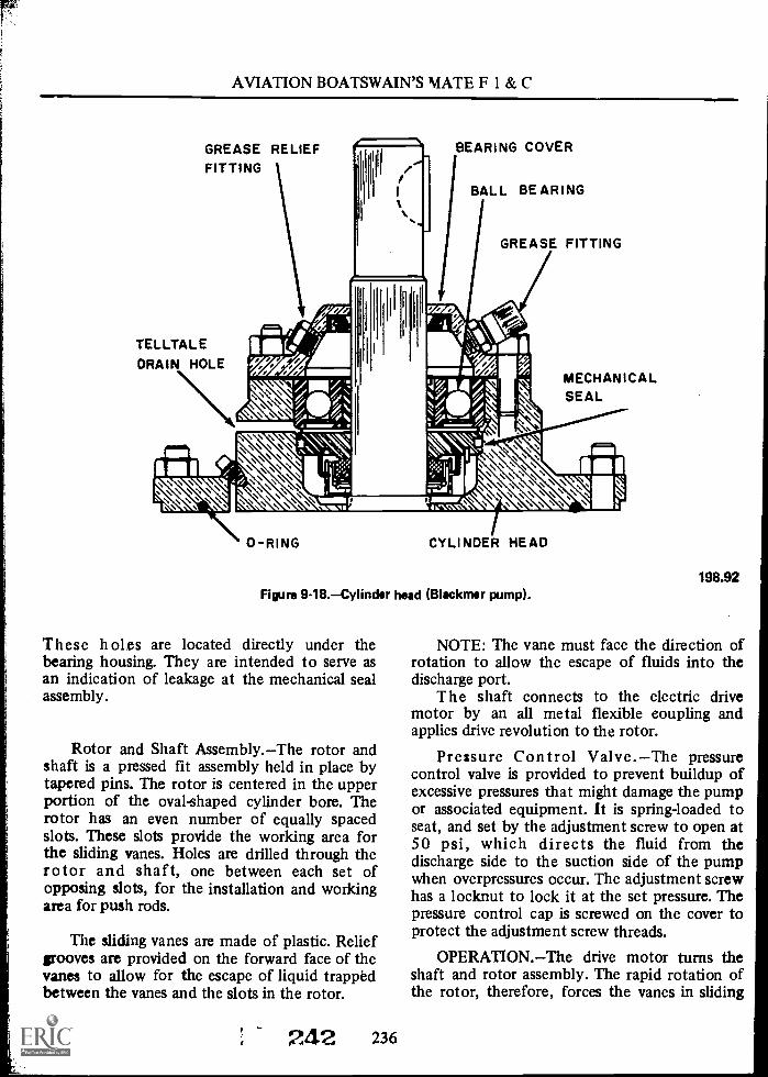
AVIATION BOATSWAIN'S MATE F 1 & C
GREASE RELIEFFITTING
TELLTALEDRAIN HOLE
BEARING COVER
BALL BEARING
GREASE FITTING
MECHANICALSEAL
CYLINDER HEAD
Figure 9-18.Cylinder head (Blackmer pump).
These holes are located directly under thebearing housing. They are intended to serve asan indication of leakage at the mechanical sealassembly.
Rotor and Shaft Assembly.The rotor andshaft is a pressed fit assembly held in place bytapered pins. The rotor is centered in the upperportion of the oval-shaped cylinder bore. Therotor has an even number of equally spacedslots. These slots provide the working area forthe sliding vanes. Holes are drilled through therotor and shaft, one between each set ofopposing slots, for the installation and workingarea for push rods.
The sliding vanes are made of plastic. Reliefgrooves are provided on the forward face of thevanes to allow for the escape of liquid trappedbetween the vanes and the slots in the rotor.
242 236
198.92
NOTE: The vane must face the direction ofrotation to allow the escape of fluids into thedischarge port.
The shaft connects to the electric drivemotor by an all metal flexible coupling andapplies drive revolution to the rotor.
Pressure Control Valve.The pressurecontrol valve is provided to prevent buildup ofexcessive pressures that might damage the pumpor associated equipment. It is spring-loaded toseat, and set by the adjustment screw to open at50 psi, which directs the fluid from thedischarge side to the suction side of the pumpwhen overpressures occur. The adjustment screwhas a locknut to lock it at the set pressure. Thepressure control cap is screwed on the cover toprotect the adjustment screw threads.
OPERATION.The drive motor turns theshaft and rotor assembly. The rapid rotation ofthe rotor, therefore, forces the vanes in sliding

Chapter 9MAINTENANCE AND REPAIR
contact with the cylinder bore by centrifugalforce and push rods. The passage of vanesthrough the lower portion of the cylinder boredraws fluid into the pump, and at the same time,forces it out the discharge port. The pressurecontrol valve maintains the desired or setpressure by limiting the pressure beingdischarged from the pump.
MAINTENANCE.Lubricate the ballbearings periodically with a light ball bearinggrease. Apply the grease slowly with a pressuregun until the grease begins to escape from thegrease relief fitting. Do not attempt toover-grease. After lubrication, a small amount ofgrease may escape from the drain holes underthe head. This is normal and proper, as thegrease works past the sealed bearings for a shortwhile after greasing. If grease continues toescape, the grease relief fitting should beremoved and inspected for damage, or thebearing removed and its grease shield inspected.for damage. If grease escapes from around thepump shaft, the bearing cover should beremoved and the lip on the shaft seal inspectedfor nicks, cuts, or distortion (replace ifnecessary). The bearing cover should beinstalled, making sure the shaft seal is centeredon the shaft while tightening cap screws.
Mechanical Seals.The mechanical seals arenormally expected to leak very slightly whennewly installed, until worn in. The leakageappears at the drain holes under the bearinghousing. If it becomes excessive, the mechanicalseals should be replaced. Prior to installing theold 0-rings, clean and apply a small amount ofoil to them.
Head 0-rings.If leakage occurs between thehead and the cylinder, the head should beremoved and both machined faces inspected forburrs, dirt, cut 0-ring, or other imperfections. If0-ring is cut or nicked, replace beforereassembling.
Vanes.If the vanes are excessively worn, orswelling or jamming in rotor slots, replace them.
Pressure Control Valve Adjustments.Closethe pump discharge valve; line up suction to astowage tank. Start the pump, remove the cap,
and loosen the locknut. Turn the adjustmentscrew until the desired pressure is indicated onthe discharge pressure gage. Tighten the locknut,replace the cap, and stop the pump.
NOTE: When performing maintenance, referto the appropriate pump technical manual andthe applicable MRC's.
Viking Transfer Pump
DESCRIPTION. The transfer pump madeby the Viking Pump Co. (fig. 9-19) is anexample of the internal gear type rotary pump.This pump has a capacity of 200 gpm at a totalhead of 50 psi with a suction lift of 8 inches Hg.The pump consists principally of a bracket, ahead, a casing, and a casing liner; a bronze rotor,an idler, and a crescent; and a monel rotor shaft.The pump casing, with the casing liner, isattached directly to the bracket. The rotor, withrotor ring, is permanently pressed on the rotorshaft and is supported in the bracket by a ballbearing. The outer end of the shaft is supportedby a ball bearing, which also positions the rotorlengthwise in the casing. The rotor drives theidler, which runs on the idler pin. The idlerbushing is a press fit in the idler. The.idler pin isinstalled in the head.
RELIEFVALVE
ROTOR
IDLES
DISCHARGE
CRESCENT
Figure 9-19.Viking transfer pump.
237 243
198.93
AVIATION BOATSWAIN'S MATE F 1 & C
Rotation of the rotor gear causes the idlergear to rotate within the pump chamber. Alsolocated in the pump chamber is the stationarycrescent. As the mars rotate, the liquid istrapped between the crescent and the gears,forcing the liquid toward the discharge port; atthis point, the gears mesh and discharge theliquid. The mechanical seal prevents liquid fromescaping through the shaft end of the pump.
NOTE: On some internal gear pumps, theinner gear rather than the outer gear is attachedto the pump shaft.
MAINTENANCE.To properlytroubleshoot pumps with an apparentmalfunction, it is important that maintenancepersonnel understand the incorrect behavior ofthe equipment as related to performance,excessive heating, or leakage. Prior to anydisassembly, the pump should be thoroughlyexamined for external evidences of defects. Allevidence should be noted prior to maintenance.It is further recommended that the simplest ormost obvious causes of trouble be exploredbefore extensive maintenance is undertaken. Thelubrication of both ball bearings is provided bypacking the chamber between the bearings withgrease. They should be repacked periodically inaccordance with the MRC's for the pump. Theidler bushing is automatically pressure-lubricatedby the liquid pumped.
If at any time the pump has beendisassembled, caution should be exercised infitting rotor and head for proper clearance.
Clearance should be adjusted as follows.Loosen the two socket setscrews in the bearinghousing, and turn the bearing housing clockwise,forcing the rotor against the head until thepump shaft can no longer be rotated by hand.When this happens, the rotor is dragging on thehead and the clearance is zero. With pencil orchalk, make a reference mark on the bearinghousing and the end of the bracket. Back off thebearing housing counterclockwise a little lessthan one hole (1/6 turn). One hole is equivalentto 0.014-inch end clearance. Tighten the twosocket head setscrews. Care should be taken notto have excessive end clearance, as this preventsthe pump from delivering full capacity.
238
244
Some internal gear pumps are equipped withinternal type relief valves, as shown in figure9-19.
The following instructions should beobserved in changing the relief valve pressuresetting, or in adjusting a reassembled valve.
Remove the adjusting screwcap, and loosenthe locknut. The adjusting screw can now beturned in for increasing the pressure or turnedout for decreasing the pressure. A pressure gagein the discharge line must be used to indicate thepressure setting. With the discharge line closed ata point beyond the pressure gage, the gageindicates the maximum pressure (approximately75 psi) the relief valve allows while the pump isin operation. At this point the liquid is beingcompletely bypassed through the relief valve.
PUMP COUPLINGS
All aviation fuel pumps are equipped with atype of flexible coupling. This coupling allowsconnection with the pump and motor shafts. Aminute amount of misalinement is allowedbetween the two shafts. This is extremelyadvantageous when removing the pump andmotor for maintenance.
The flexibility of the coupling is normallygained from a gear, a spring arrangement, or arubber insert in the housing between thecoupling halves. The lubricant used may begrease or oil and, in some instances, no lubricantat all is used, depending on the type of coupling.
Falk Type F Steelflex Coupling
The coupling shown in figure 9-20 is a Falkflexible self-alining gridmember type. The twohubs are symmetrical, but may have differentbores or keyways. One hub is keyed to themotor shaft, and the other is keyed to the pumpshaft and secured axially by check nuts. Thecheck nuts are held in place by socketheadsetscrews. A flexible gridmember engages theteeth in the hubs to transmit power. A gasketand two seal rings are fitted to the covers toprevent grease leakage. The parts are enclosed intwo cover halves which are bolted together.
MAINTENANCE.When it is necessary todisconnect the coupling, remove the nuts andbolts, separate and draw back the cover halves,

Chapter 9MAINTENANCE AND REPAIR
1
1 2 6 3
1. Seal rings.2. Cover halves.
DOUBLELAYER
ORSINGLELAYER
4
3. Hubs.4. Gridmembers.
Figure 9-20.Falk Type F Steelflex coupling.
and remove the gridmember. To remove thegridmember, a round rod or screwdriver thatconveniently fits into the open loop ends of thegridmember is all that is required in the way oftools. Begin at the open end of the gridmembersection and insert the rod or screwdriver into theloop ends. Use the teeth adjacent to each loop asa fulcrum, and pry the gridmember out radiallyin even, gradual stages. Proceed alternately fromside to side lifting the gridmember about halfway out until the end of the gridmember isreached. Using the same procedure once again,the gridmember clears the teeth. This allows thecoupling hubs to become separated so the pumpor motor shafts can be removed.
Prior to reassembly, clean all partsthoroughly and check the coupling alinement.To check the coupling alinement axially,measure the gap between the hubs with a feelergage at four points, 90 degrees apart. The gapshould be approximately 1/8 inch and thedistance between the maximum and minimummeasurements should not vary more than 0.003inch.
239
1
5. Gasket.6. Alemite grease fittings.
198.94
To check the coupling alinement radially,place a straightedge on the teeth of the hubs.The clearance between the straightedge heldfirmly on the teeth of one coupling hub and theteeth of the other coupling hub should not bemore than 0.003 inch as measured with a feelergage. Repeat this check at a point 90 degreesfrom the first check.
After the coupling is alined, carefully insertthe gasket between the hubs and hang it oneither hub. Do not damage the gasket. Next,force as much lubricant as possible into thespace between the hubs and gridmembergrooves
Insert the gridmembers. To accomplish thiswith a minimum amount of spreading, start thegridmember at either end and tap the rungs onlypart way into the grooves. After all the rungs arepartially in their respective grooves, tap thegridmember all the way into place. The hubgrooves are uniformly spaced and do not requirematching. Again pack lubricant in the spacesbetween and around the gridmember with asmuch lubricant as possible, then wipe off excess
245

AVIATION BOATSWAIN'S MATE F 1 & C
flush with the top of the gridmember. Lightlyoil the hubs to facilitate the sliding of the coversonto the hubs. Mount the covers so that thelubrication fittings are 180 degrees apart. Inserta screwdriver under the seal ring for ventingpurposes and then tighten the cover bolts. Checkthe seal rings for proper seating, and aline thecover to prevent wobble.
Periodic lubrication is essential for properfunctioning of the coupling. Alemite greasefittings are provided for convenient lubrication.The design of the Alemite lubrication fittingsprevent leakage due to centrifugal force. Whenlubricating the coupling, vent as describedabove.
Lovejoy Coupling
The Lovejoy coupling (fig. 9-21)mechanically links the shaft of the pump to theshaft of the motor. The coupling is made of twobronze coupling halves. The coupling is keyed tothe shaft and held in place by socket-headsetscrews. The coupling halves are cushioned bya formed rubber spider which separates thecoupling halves. This rubber separation alsoserves to reduce the noise of the coupling.
MAINTENANCE. When the reassemblingof any component of the pump unit. involves
SHAFT RUBBER SPIDER
recoupling, the coupling should be checked formisalinement. This should be done using astraightedge and a feeler gage. If the couplingsare not properly alined, the base may have beendistorted or warped. This distortion must becorrected and is accomplished by loosening theanchor bolts and shimming under the base.
When making an adjustment of thecouplings, insure that each section of thecoupling is tightly anchored to its respectiveshaft and that both sections are butted togetherwith 1/8-inch space between the couplingsections and the rubber spider.
NOTE: This coupling requires nolubrication.
AIRCRAFT FUELING STATIONS
There are currently four fueling units in thefleet. They are the Wayne, Blackmer, Wheeler,and the Cla-Val units. However, since the Wayneand Wheeler units are not widely used, only theBlackmer and Cla-Val are discussed here. TheBlackmer units are used on the CVA-42,59,60,and 61. The Cla-Val station is the most widelyused of the four. It is being used on the CVA-34,43,63 and all CVA's constructed thereafter. It isalso used on all LPD's and all LPH class 2carriers.
SOCKET HEADSET SCREW
COUPLING HALF COUPLING HALF
Figure 9-21.Lovejoy flexible coupling.
24t 240
RUBBER SPIDER
196.95

Chapter 9MAINTENANCE AND REPAIR
Blackmer
The Blackmer service station is a twinpumping unit consisting oftwo centrifugalpumps in a single housing, two semiautomaticfour-way valves, and two magnetic amplifiers.
Each centrifugal pump is designed to deliver200 gpm at 40 psi (as long as riser pressure ismaintained at 5 psi minimum) to aircraftequipped for underwing fueling. Each pumpdefu els up to 100 gpm as long as the riserpressure does not exceed 20 psi.
The cast steel casing is divided into fourcompartments by the impeller adapters. (See fig.9-22.) Single-suction impellers, keyed to the
IMPELLERADAPTER
SEALFACE
SPRING
INTERNALSNAPRING
RING
MOTORFLANGE
STATIONARYSEAT
SEAL DRIVECOLLAR
SEALFOLLOWER
STATIONARYSEAL
shaft and secured with a locknut, are located inthe two center compartments. Leakage betweenthe two center chambers is prevented by twomechanical seals, one in each discharge chamber.A third mechanical seal, located in the suctioncompartment nearest the meter, preventsleakage of fuel from around the shaft where itpasses through the casing.
Blackmer four-way valves contain four valvesin their housings. (See fig. 9-23.) A single-portsuction return valve, a double-port dischargevalve, and a single-port suction valve operatetogether. A poppet restriction valve operatesindependently of the other three. The four-wayvalve is manually placed in its fueling position
IMPELLERASSEMBLY
IMPELLERKEY
SEAL RETAININGWIRE
LOCKWASHER
SEAL RETAININGPIN
Figure 9- 22. Blackmer fueling pump.
241 2;47
DRAIN PLUGROD
198.96

I
AVIATION BOATSWAIN'S MATE F 1 & C
TOFUELING
HOSE
FOURWAY VALVE ASSEMBLY
FUELING PUMP
FOURWAY VALVE ASSEMBLY
DISCHARGEVALVE
SUCTIONRETURNVALvt
SUCTIONVALVE
wailier mum
-
FROMDEFUELING
HOSE
\ \\\ ../...e..:: .1%," ../.0%..1 `..\\' \\.\\X'
L., ....",% ...,.4\ ''''' \\''''S NX ( .."\ \ \\ ,,,... Fe gl N`':,' ..." ..,./;/"......,./00/...,,, -,.***"'s 'X 111'). PmINV '".'"": "Je....? min
,,,,,,,././.9:60...wwwwwwwv,;.N.N
llil ...4
...I
\\ ,...,.
/Ai
POPPET RESTRICTION
VALVE
MAIN SUPPLY HEADER
[ I FUEL AT MAIN SUPPLY PRESSURE
7:;1;7.] FUEL AT FUELING HOSE PRESSURE
FUEL AT DEFUELING HOSE PRESSURE
POPPET RESTRICTION
VALVE
Figure 9-23.Fueling pump and four-way valves flow diagram.
(when the solenoid is energized) by lifting theoperating handle 90 degrees. The handle shaftpinion is geared to the suction return valve stem.Raising the handle 90 degrees rotates the pinion,lifts and closes the suction return valve, andcompresses the suction valve spring. The.discharge valve is linked to the suction returnvalve spring in such a way that raising thesuction return valve lowers the discharge valve.When the discharge valve is lowered, it strikesthe suction valve stem, opens the suction valve,and compresses the suction valve spring. Thehandle shaft pinion is held in the fuelingposition by a locking pawl as long as thesolenoid remains energized. The solenoidhousing serves as a cover for the four-way valvebody and contains the solenoid, the pawlassembly, and the shaft pinion. Four-way valvesare returned to the defuel position by theirclic_ttion and suction return valve springs, whenthe solenoid is deenergized. Deenergizing the
r)4i;-,4 242
DISCHARGEVALVE
SUCTIONRETURN
VALVE
SUCTIONVALVE
This schematic diagram is intendedonly as an aid in understanding theoperation of the fueling station anddoes not agree with the physicalloyout of the pump.
198.97
solenoid causes the pawl to release the shaftpinion. When the shaft pinion is released, thesuction return valve gyring expands, moves thesuction return valve down to open, raises thedischarge valve to close off the pump dischargeto the hose reel and opens the pump dischargeto the poppet restriction valve. When thedischarge valve moves up, the suction valvespring expands, closing the suction valve. Thepoppet restriction valve is held closed by aspring and by the riser pressure. The poppetrestriction valve is opened by the pump impellerpressure when the four-way valve is in defuel.
Each four-way valve has its own magneticamplifier. The function of the amplifier is toprovide enough power to energize the solenoidand hold the valves in the fueling position with acontrol circuit current sufficiently low toeliminate any danger of sparking. When theground circuit through the delivery hose isclosed the amplifier energizes the solenoid

Chapter 9MAINTENANCE AND REPAIR
sufficiently to provide enough thrust force onthe pawl to latch the valves in position. Whenthis control circuit is opened the amplifieroutput drops off to the point where the solenoidthrust is no longer sufficient to hold the pawl inposition.
One hose reel on each Blackmer station isadapted for a 11/2-inch hard rubber hose and onehose reel for a 21/2-inch collapsible hut.
NOTE: When troubleshooting or performingmaintenance on Blackmer units, refer to theBlackmer Instruction Book and the applicableMaintenance Requirements Cards.
CLA-VAL
The Cla-Val fueling station consists of twoor more solenoid-operated fuel-defuel valves anda positive-displacement defueling pump.
This installation eliminated venturi controlsin each JP-5 quadrant. Pressure regulation isincorporated in the automatic fuel-defuel valves.
The defueling pump has a rated capacity of100 gpm at 15 psi. Discharge from this pump isdirected to an independent defueling main.From the defueling main, fuel flows to thetransfer main and to a selected stowage tank.
The automatic fueling and defueling valve isintended for use as an integral part of theaviation gasoline and JP-5 fuel dispensingsystems aboari ship. This valve performs fourdistinct functions:
1. It functions as a pressure-reducing valveto maintain a constant discharge pressure..
2. It functions as a solenoid-operatedemergency shutoff valve.
3. It functions as a pressure relief valvewhenever discharge pressure rises above apredetermined setting.
4. It functions as a defueling valve toevacuate the piping system beyond the valvedischarge.
To perform the functions outlined above,two valves are fabricated into one body. Duringnormal fueling operation, the defueling valve isclosed and the fueling valve functions as apreigure-reducing valve to maintain a constantdelivery pressure. If the pressure on the
243
downstream side rises above the setting of thepressure-reducing valve, the defueling valveopens to serve as a pressure relief valve.
During defueling operation, the fueling valveis closed and the defueling valve is open. Whenthe solenoid pilot valve is deenergized, thefueling valve closes to provide positive shutoff ofthe fueling line and simultaneously the defuelingvalve opens.
Description.The main valve consists of twosingle-seated globe valves built into a single body(fig. 9-24). Each globe valve employs awell-supported and reinforced diaphragm as itsoperating means. The fueling valve is springloaded to close and is, therefore, normallyclosed. The defueling valve is normally heldopen by its own weight.
The pilot valve system utilizes line pressureto control the main valve, thus providing fullyautomatic operation. When the line pressure isadmitted to the valve cover chamber, the forcethus developed closes the valve. When thepressure in the cover chamber is released, theline pressure at the valve seat forces the valveopen.
In the event of diaphragm failure, the fuelingvalve closes drip-tight and the defueling valveopens wide.
The pressure relief valves automatically opento permit flow whenever the controlling pressureunder the diaphragm exceeds the force of thecompression spring. They were designedprimarily as pilot valves to control the operationof the main valves; thus, they operate withinvery close pressure limits.
These are direct-acting spring-Loaded valvesdesigned with a large diaphragm working area inrelation to the valve seat area, to insure positiveoperation. They are held closed by the force ofthe compression spring. Pressure on the spring isadjusted by rotating the adjusting screw to varyspring compression on the diaphragm.Compressing this spring increases the pressure atwhich the valve opens. The spring can beadjusted to provide a relief setting from 20 to 70psi. The adjusting screw is protected by a bronzehousing drilled to accommodate a lead seal wire.
The pressure relief control is normally heldclosed by the force of the compression spring.When the controlling pressure under the
2.49

AVIATION BOATSWAIN'S MATE F 1 & C
ENERGIZEDSOLENOID
VALVE
PRESSURE-REDUCINGVALVE
HYTROLVALVE
EJECTORSTRAINER
FLOWCONTROL
VALVE
FUELINGVALVE
OUTLET
DEFUELING LINECONNECTED TO
DEFUELVALVE
HIGH PRESSURE
Eii:177:9 INTERMEDIATE PRESSURE
DELIVERY PRESSURE
ATMOSPHERIC PRESSURE
VALVECOVER
CHAMBER
INLET
PRESSUREA RELIEF
VALVE (A)
Figure 9-24.Cla Nal fuel defuel valve (fuel position).
diaphragm exceeds the set spring force, the diskis lifted off the seat, permitting flow.
The pressure-reducing control systemautomatically reduces a higher initial pressure-toa steady reduced pressure. It was designedprimarily as a pilot valve to control theoperation of diaphragm-type main valves; thus,it operates within very close pressure limits.
It is a direct-acting, spring-loaded valvedesigned with a large diaphragm working area inrelation to the valve seat, which insures sensitivecontrol and accurate regulation of the delivery
CONNECTED TODEFUELING LINE
197.33.1
pressure. Pressure adjustments are made byrotating the adjusting screw to vary springcompression on the diaphragm. Compressing thisspring increases the delivery pressure setting.The spring can be adjusted to provide deliveryfrom 15 to 100 psi. The adjusting screw isprotected by a bronze housing, drilled toaccommodate a lead seal wire.
The pressure-reducing control valve isnormally held open by the force of thecompression spring. When the delivery pressureacting upon the lower side of the diaphragm

Chapter 9MAINTENANCE AND REPAIR
exceeds the force of the compression spring, thecontrol closes. Conversely, when the deliverypressure reduces below the spring setting, thecontrol valve opens. Thus, a constant deliverypressure is maintained by balancing the deliverypressure against the spring pressure.
The flow control valve controls operation ofthe fuel valve to prevent valve slam and chargingof the fueling hose too quickly.
The hytrol valve is of the modified globedesign, employing a well supported andreinforced diaphragm as the operating means.When the line pressure is admitted to the coverchamber, the force thus developed closes thevalve. When the pressure in the cover chamber isreleased, the line pressure at the valve seat forcesthe valve to a wide open position.
The ejector-strainer consists of a primaryand a secondary jet screwed into a cast bronzehousing. The jets are protected from clogging bya 60-mesh monel screen. Both jets can beremoved for cleaning. Flow through theejector-strainer creates a reduced pressure areabetween the primary jets and the secondary jets.
The solenoid pilot valve (fig. 9-25) is adirect-acting, piston type, solenoid-actuatedvalve. The piston is drawn upward by the actionof the solenoid when energized, and the piston isreturned to the down position under theinfluence of gravity and a spring when thesolenoid is deenergized. The valve disks on thepiston are lapped into the bore in the valvebody. This valve has full pipe-size port areas andthe piston moves from full flow in one directionto full flow in the opposite directionthere is noclosed port position. The valve is also equippedfor manual operation. Manual operation isaccomplished by pushing upward on the knob atthe lower end of the control valve. Aquarter-turn clockwise locks the manual controlin place.
OPERATION.To understand the operationof the Qa -Val fuel/defuel valve, it is essential tobe familiar with the following:
1. This valve is really two separate anddistinct valves, both sharing a common body.
2. Each of these valves performs a separateand distinct function, one valve being the fuelingvalve and the other being the defueling valve.
245
MANUALCONTROL
KNOB
198.122Figure 9-25.Solenoid operated pilot valve (cutaway).
3. Although both of these valves areseparate and distinct from each other, they workclosely in conjunction with one arkoilicr andthey both share a common pilot valve system.
4. The change from the fueling operationto the defueling operation is accomplished bypositioning the solenoid pilot valve. Astep-by-step analysis of the valve's operationfollows.
Figure 9-24 illustrates the valve in thefueling position with the solenoid energized.
The solenoid valve directs high pressure fromthe maim valve inlet into the cover chamber ofthe defueling valve, holding it closed.
251
AVIATION BOATSWAIN'S MATE F 1 & C
The solenoid valve also vents the coverchamber of the hytrol valve to the defuelingline. This opens the hytrol valve, which permitsthe pressure-reducing valve to take over controlof the fueling valve.
When the pressure-reducing pilot valve. goesinto operation, the high-pressure fuel enters thefueling valve and bypasses through- theejector-strainer to the pilot valve, which is heldopen by the pilot valve spring. With pressure atthe pilot valve below the adjusted setting,maximum flow is permitted through theejector-strainer, thus creating a redncP.d pressurein the main valve cover chamber which allowsthe valve to open to build up pressure in thedownstream system. The increasing downstreampressure is transmitted through the pilot controlline to the underside of the pilot valvediaphragm.
When the pressure under the pilot valvediaphragm reaches a point where it balances theloading of the pilot valve spring, the pilot valvebegins to close, thus restricting the flow throughthe ejector-strainer sufficiently to increase thepressure in the main valve cover chamber. Theresulting increase in pressure in the coverchamber forces the disk toward the seat untilthe main valve is passing just enough fuel tomaintain a downstream pressure that balancesthe loading of the pilot valve springs.
Any subsequent change in fuel demand willtend to cause a slight change in downstreampressure, which will result in the pilot and mainvalve assuming new positions to supply the newdemand.
As long as the normal fueling operation is inprocess and the flow rate is not changing veryrapidly, the fueling valve functions as outlinedabove. If the flow rate suddenly decreases, twothings happen(1) any pressure rise is offset bythe opening of the defueling valve, and (2) thefueling valve closes rapidly.
Figure 9-24 shows that the delivery pressureis reflected under the diaphragm of bothpressure relief valeb, opposing the force appliedby the spring.
When a downstream pressure rise occurswhich is sufficiently high to overcome the force.of the spring, pressure relief valve (A) opens torelieve the pressure from the cover of the
246
defueling valve. This allows the defueling valveto open, thereby relieving the excess pressureinto the defueling line.
The purpose of pressure relief valve (B) is toincrease the closing speed of the fueling valve.When there is a sudden rise in the deliverypressure, this valve opens and admits theupstream line pressure into the fueling valvecover chamber to rapidly close it.
When the pressure and the flow conditionsreturn to normal, the valve resumes its normalfunction.
Figure 9-26 illustrates the valve in thedefueling position. The solenoid is deenergized.
The solenoid valve directs the high pressurefrom the main valve inlet into the cover chamberof the hytrol valve, holding it closed. Thisdiverts high pressure through the ejector-strainerinto the cover chamber of the fueling valve,holding it closed.
The solenoid valve also vents the coverchamber of the defueling valve to the defuelingline. With pressure released from this coverchamber, the valve falls open.
INSTALLATION INSTRUCTIONS. Thefollowing instructions should be carefullyfollowed when installing the valve:
1. Flush all piping thoroughly to removechips, scale, or other foreign matter.
2. Exercise care in the handling of the valveto prevent damage to any of the tube lines orcontrols. The valve is air-tested at the factoryand any jarring or wrenching of any of thecomponents of the valve may cause leakage tooccur_
3. Install the valve in the horizontal run ofthe piping in accordance with the nameplatemarkings on top of the inlet flange.
4. Insure that the electrical connection tothe solenoid pilot valve is in accordance withaccepted shipboard practice.
PRESSURE SETTINGS.The followingsteps refer to setting the Cla-Val fuel/defuelvalve for a final delivery pressure of 30 psi. (If adelivery pressure other than 30 psi is desired, theprocedures remain the sameonly the pressureswill vary).

Chapter 9MAINTENANCE AND REPAIR
PRESSURE REDUCING EJECTOR STRAINER PRESSURE RELIEF
VALVE VALVE (8)HYTROL FUELINGVALVE VALVE
DE-ENERGIZED
SOLENOIDVALVE
FLOW -CONTROLVALVE
CONNECTED TODE-FUELING LINE
:::..:. HIGH PRESSURE
ATMOSPHERIC PRESSURE
L-FiJk-9INLET
PRESSURERELIEF
VALVE (A)
DE-FUELING VALVE
Figure 9- 26. CIa -Val fuelidefuel valve (defuel position).
NOTE: A pressure gage must be installed inthe line between the fuel/defuel valve and thehose.
1. Remove the adjusting screw housings onboth pressure relief valves, and thepressure-reducing valve.
247
?./
CONNECTEDTO
DE-FUELINGLINE
197.33.2
2. Loosen the jam nuts and bottom theadjusting screws on both pressure relief valves.
3. Line up the service system piping andpressurize the quadrant.
4. Unreel the hose and connect the nozzleto the defueling main.
5. Using the proper grounding procedures,start the defueling pump.
2 53

AVIATION BOATSWAIN'S MATE F 1 & C
6. Position the toggle switch to the "ON"position.
7.Turn the adjusting screw of thepressure-reducing valve slowly until the gage. inthe delivery line reads 10 psi higher than thedesired pressure (40 psi in the case a thisexample).
8. Tighten the jam nut to lock the adjustingscrew.
9. Turn the adjusting screw of the defuelpressure relief valve slowly until the deliverypressure gage dips downward (approximately 21/2psi).
10. Tighten the jam nut to lock the adjustingscrew.
NOTE: The defuel pressure relief valveis set71/2 psi higher than the delivery pressure.
11. Back off the jam nut and slowly turn theadjusting screw of the pressure reducing valveur,til the delivery pressure drops to a point 5 psiabove the desired setting (35 psi in the. case ofthis example).
12. Tighten the jam nut.13. Turn the adjusting screw of the fuel
valve's pressure relief valve slowly until thedelivery pressure gage begins to dip downward(approximately 2;i psi).
14. Tighten the jam nut to lock the adjustingscrew.
15. Turn the adjusting screw of thepressure-reducing valve slowly until the deliverypree.nire has dropped to the desired setting (30psi in the case of this example).
16. Tighten the jam nut to lock the. adjustingscrew.
17. Replace the adjusting screw housings,and insert the lead seal wires.
For more detailed information on theoperation, maintenance, and troubleshooting.procedures of the automatic fueling anddefueling valve, consult the NAVSHIPSTechnical Manual 0348-135-1000.
AUTOMATIC PRESSURE REGULATOR
The pressure-regulating system (fig. 9-27) isidentical on all class carriers, except for size and
254 248
pressure settings. An automaticpressure-regulating system is provided tomaintain a constant pressure under allconditions of operation or load.
NOTE: The automatic pressure regulatorsystem is not needed when using the Cla-Valtype fueling stations.
The system consists of an automaticpressure-regulating valve actuated throughchanges of pressure in the throat of a venturi,located downstream of the valve. Thecomponents of the regulating system arethemain valve (pressure regulator), the pilot valve,the ejector strainer assembly, the control valve,and the venturi tube.
The pressure-regulating system is entirelyhydraulic in operation, utilizing line pressure toopen and close the valve. Because it is hydraulicin operation, it is installed either vertically orhorizontally in the riser.
The main valve is of a modified globe design,employing a well-supported and reinforceddiaphragm. It is hydraulically operated. Whenline pressure is admitted to the cover chamber,the valve tends to close. When the pressure isreduced in the cover chamber, the line pressureunder the disk opens the valve.
The pilot valve is a direct-acting,spring-loaded valve, designed with a largediaphragm and effective working area to insuresensitive control and accurate regulation of therequired delivery pressure. The pilot valve islocated in the actuating line between the ejectorstrainer and the venturi throat. It is normallyheld open by a compression spring. When theventuri throat pressure acting under thediaphragm increases, the valve tends to, close.When the venturi throat pressure decreases, thevalve opens (wider). Thus, a constant pressure ismaintained by balancing the venturi throatpressure against the spring tension.
The control valve (ejector bypass valve) is adirect-acting, spring-loaded valve designed with alarge diaphragm and effective working area toinsure positive operation. The control valve,located in the ejector bypass line, is normallyheld closed by a compression spring. Its purposeis to close the main valve quickly when there is asudden buildup in the downstream pressure. It isopened by venturi throat pressure 10 psi inexcess of the pilot valve setting.

Chapter 9MAINTENANCE AND REPAIR
GAGE
RECLICULATiNGLINE
GAGE
GAGE
REGULATING VALVECLA-VAL PRESSUREREDUCING VALVE
INLET OUTLET
CONTROL VALVE(NORMALLY CLOSED)
PILOTVALVE
CLA -VAL STRA NER & EJECTORASSEMILED WITH VIC PRI. NOZZLE
ACTUATING LINE
CLA -VAL PRESSURE REDUCINGVALVE (NORMALLY OPEN)
VENTURI TUCE
FLOW
Figure 9-27.Automatic pressure regulator.
The ejector strainer assembly is installed inthe actuating line between the main valve andthe pilot valve. It consists of an ejector nozzlewith a 1/16-inch orifice and a monel strainer toprevent clogging of the nozzle. It speeds up theoperation of the main valve by speeding up theevacuation of fluids from the cover chamber. Itprevents chatter of the main valve by reducingthe violence with which the pump dischargepressure is admitted to the main valve coverchamber.
Venturi tubes are installed in each quadrantdistribution riser downstream of the regulatingvalve. The venturi (interim) tapers from a 6-inchinlet to a 2.9-inch throat to a 6-inch outlet. Arecirculating line on the delivery side returns100 gpm to the service tank in use. Thisrecirculation maintains a regulated pressure, by
249
L
198.98
allowing a flow through the regulator duringstandby periods, and provides a means ofreturning to the tank the fuel from the last hoseto be defueled when the system is pressurized.
NOTE: If a fluid flowing through a tubereaches a constriction or narrowing of the tube,the speed of the fluid flowing through theconstriction increases, and its pressure decreases.If the fluid flows into a tube of the same size asthat of the original, speed decreases and pressureincreases.
OPERATION
In the operation of the system, thehigh-pressure fuel from the pump enters themain valve body. This fuel bypasses the mainvalve seat and flows through the ejector strainer
2n5
AVIATION BOATSWAIN'S MATE F 1 & C
assembly to the pilot valve. The pilot valve isheld open by its spring. From the pilot valve,fuel flow is directed into the throat of theventuri tube. Thus far, the pressure at the throatof the venturi tube is practically nonexistent.
As long as the pilot valve stays open,maximum flow through the ejector-strainerassembly is permitted. This fuel flow throughthe ejector-strainer assembly creates a reducedpressure in the main valve cover chamber. (Itmust be remembered that the ejector-strainerassembly works like an eductor.) Line pressurefrom the pump, working under the disk of themain valve, now opens the main valve,permitting fuel flow into the quadrantdistribution riser. This fuel flow builds uppressure in the quadrant distribution riser.
The increasing pressure in the riser istransmitted from the throat of the venturi tubeto the underside of the pilot valve diaphragm.When the pressure under the pilot valvediaphragm reaches a point where it is greaterthan the setting of the pilot valve spring, thepilot valve begins to close. This restricts the fuelflow through the ejector-strainer assembly..
With the fuel flow restricted, theejector-strainer assembly loses its suction andthe inlet pressure is diverted, via the suction line,to the main valve cover chamber.
The resultant increase in pressure in themain valve cover chamber, as applied to itsdiaphragm, is sufficient to begin closing themain valve. The main valve disk moves towardits seat until the main valve is passing justenough fuel to maintain a pressure that balancesthe setting of the pilot valve via the throat of theventuri.
Any subsequent change in fuel demandcauses a change in venturi throat pressure. Eventhe slightest change is sufficient to cause thepilot valve and the main valve to assume- newpositions to supply the new demand. Thishappens, regardless of whether the demand is fora greater or lesser amount of fuel.
An increase in the rate of fuel flow, causedby putting additional hoses into operation, atfirst causes a momentary decrease in venturithroat pressure. This decrease in pressure allowsthe pilot valve to open wider, which in turnincreases the fuel flow rate through theejector-strainer assembly.
250)
An increase in ejector-strainer assembly flowrate increases the suction lift of the ejector. Theincrease of the suction lift is applied to the mainvalve cover chamber and allows the main valveto open wider.
The main valve opens in proportion to theincrease of flow demand topside. The main valvecontinues to open until the venturi throatpressure builds up to a point where it againbalances the setting of the pilot valve.
A decrease in flow rate, caused by securinghoses topside, causes a momentary increase inventuri throat pressure. This increase in pressurecauses the pilot valve to close somewhat,restricting the fuel flow through theejector-strainer assembly.
A decrease in flow through theejector-strainer decreases the suction lift of theejector. This decrease of ejector suction liftcauses an increase of pressure in the main valvecover chamber and results in partial closing ofthe main valve.
The main valve closes in proportion to thedecrease of the flow demand topside. The mainvalve continues to close until the venturi throatpressure drops to a point where it again balancesthe setting of the pilot valve spring.
Any sudden demand decrease in the flowrate, caused by the securing of all hoses topsideor for any other reason, creates a sudden highincrease in the venturi throat pressure. Thissudden increase of pressure is applied to theunderside of the diaphragm of the pilot valve toclose the main valve in the normal manner.Because of the small size of the orifice in theejector-strainer (1/16-inch diameter), the mainvalve closes slowly. At the same time, venturithroat pressure is applied to the underside of thediaphragm of the control valve and opens thecontrol valve. When the control valve opens, fullpump discharge pressure is applied to the mainvalve cover chamber to quickly close the mainvalve. This quick closing of the main valvereduces the pressure in the quadrant distributionriser. The main valve remains closed until thepressure on the discharge side of the main valvedrops below the spring setting of the pilot valve.The pressure and fuel that are trapped betweenthe discharge side of the main valve and the

Chapter 9MAINTENANCE AND REPAIR
discharge side of the venturi, caused by a suddenbuildup of discharge pressure, are relievedthrough the venturi recirculating line back to thedrawoff tank or service tank, as the case may be.
MAINTENANCE
The ejector strainer assembly should becleaned at regular intervals. Remove the 3/4-inchunion ring and plug from the housing and washin solvent, then blow the screen out with air. At6-month intervals, the regulating valve should becompletely dismantled and thoroughly cleaned.(See applicable MRC.) The pilot valve andcontrol valve should be inspected carefully forexcessive wear, and replaced if necessary. Allgages used in the pressure regulating valvesystem are removed, cleaned, and calibratedevery 6 months. Upon installation of new partsor repairs made on parts, all piping connectionsare pressure tested to check for leakage of fuel.
ADJUSTMENT AND SETTINGS
The pilot valve pressure adjustment is madeby rotating the adjusting screw to vary spring
251
compression on the diaphragm. The controlvalve adjustment is made by turning theadjusting screw clockwise to increase thepressure. The procedure for adjusting thepressure settings is:
NOTE: The following procedure should befollowed after reinstallation of the regulatingvalve and pilot assembly after the maintenancecheck has been performed.
EXAMPLE: The desired delivery pressure is22 psi at the throat of the venturi.
Close the control valve by turning theadjusting screw clockwise. Set the regulator(pilot valve) at 34 psi when the fuel is flowingthrough the main valve at a rate of 50 gpm ormore. Reduce the pressure setting of the controlvalve (by turning the adjusting screwcounterclockwise) until delivery pressure dropsto 32 psi at the throat of the venturi. Tightenthe control valve locknut. Reset the regulator(pilot valve) at 22 psi. The procedure outlinedabove establishes the desired downstreampressure and also provides the correct setting ofthe control valve.

CHAPTER 10
ADMINISTRATION
The administration of a division never stopsat the division officer level. Senior ABF's shouldbe aware of this fact. Administration of adivision entails many records to be kept andreports to be filed. It is necessary to maintainaccurate and up-to-date records on allequipment, as well as inventories of materials onhand.
Senior ABF's should be familiar with supplyprocedures in order to procure and maintainequipment for the fuel systems in accordancewith current directives. They must also befamiliar with the publications used in identifyingmaterial, equipment, and spare parts, as well asthe publications used in maintaining equipment.
This chapter deals with some of theseadministrative problems, beginning with asection on technical publications.
TECHNICAL PUBLICATIONS
Technical publications are the sources ofinformation for guiding naval personnel in theoperation and maintenance of all equipmentwithin the Naval Establishment. By proper useof these publications, all equipments can beoperated and maintained efficiently anduniformly throughout the Navy.
Senior petty officers must be able tointerpret and supervise the use of publications.The ABF1 and ABFC must also know how toprocure publications and keep them up to date.
A number of publications issued by theNaval Air Systems Command (formerly Bureauof Naval Weapons) are of interest to the ABF.The General Information and Servicing sectionof the Maintenance Instructions Manual for each
01.!":1;S 252
type aircraft covers the required procedures forrefueling the aircraft. Mobile refuelers andaircraft handling equipment are covered byother Air Systems Command publications.
NOTE: As of 1 July 1974, the Naval ShipSystem Command and the Naval OrdnanceSystems Command were combined to form theNaval Sea Systems Command. Because themajority of publications being used by ABF'sstill carry the NAVSHIP designation, thischapter will continue to use the NAVSHIP title.
Publications issued by the Naval ShipSystems Command (formerly Bureau of Ships)cover most of the shipboard equipment used bythe ABF. The fuel system for each ship iscovered in a Ship's Information Book (SIB). TheSIB for the ship to which the ABF is attachedshould be studied thoroughly. Also, each majorcomponent (unit) is covered by a publicationissued by the Ship Systems Command.
Spare parts for the aviation fuels systems arecontained in the ship's allowance list.. This is theCoordinated Shipboard Allowance List, knownas the COSAL. The COSAL is an individual listprepared especially for each ship, and is basedon the equipment actually installed or in use ineach ship. It is published in book form in severalsegments, each segment covering a different typeof material.
NAVSHIPS PUBLICATIONS
All necessary Nav Ships publications areissued directly to new vessels by the Naval ShipSystems Command about 6 months beforecommissioning. Requests for commissioningallowance should not be submitted unless the

Chapter 10ADMINISTRATION
publications are desired at an earlier date orunless they have not been received a monthbefore the commissioning date.
NavShips publications of interest to the ABFare listed and indexed in Nav Sup Publication2002, Section VI.
Nav Sup Publication 2002 is a 13-sectionstock list of all the publications and forms usedthroughout the Navy. Section VI of this stocklist is the basic index of the Naval Ship SystemsCommand publications. Section VI is furthersubdivided into six parts:
Part AAdministrative and generalpublications.
Part B Ships electronic equipmentpublications.
Part CShips damage control texts anddiagrams.
Part DNavShips manufacturers' technicalmanuals (numerical listing).
Part ENavShips manufacturers' technicalmanuals (alphabetical listing).
Part FShips general description andinformation books.
The ABF is primarily interested in Parts Dand E, which list all NavShips manufacturers'technical manuals. In Part D, all publications arelisted in numerical order according to stocknumber. Part E lists the same publications inalphabetical order according totitle/nomenclature.
Requisitioning Procedure
Submit requests on the DOD Single LineItem Requisition System Document, DD Form1348, in accordance with the Military StandardRequisitioning and Issue Procedure (MILSTRIP)(NAVSUP Pub 437).
DD Form 1348 must reflect the followinginformation in the "remarks" section asapplicable:
1. The publication requested is (1) toreplace copies destroyed; (2) to increase
owance of a publication already held; or (3)o add a publication to the allowance of thectivity.
253
2. Justification of requests for increases inallowance or for publications not already held.
When ordering publications, the full title andNavShips number must be furnished, if available.If the instructions book title and NavShipsnumber are not available, the completenameplate data on the machinery or equipmentinvolved must be furnished. Completeinstructions for ordering all NavShipspublication are contained in chapter 9001 of theNaval Ships Technical Manual, NavShips250-000.
MAKING CHANGESTO PUBLICATIONS
There are four mandatory requirements tobe met in maintaining an allowance ofpublications. These requirements are:
1. The prescribed publications be on board.2. The publications be maintained
up-to-date.3. The publications be ready for immediate
use.4. Applicable security provisions be
observed.
Most changes to publications are issuedeither in the form of looseleaf pages,pen-and-ink changes, or complete revisions.When changes are issued in the form ofnumbered pages, the old page with thecorresponding number is removed and the newreplacement page inserted in its place. Specificinstructions are normally given with each changeon the method to be used in incorporating thechange. Changes should be made immediatelyupon receipt.
A checklist of pages that are to remain in thepublications after the change has beer.incorporated is provided with changes issued forsome publications. This checklist should becompared against pages remaining in thepublication to insure they agree. Extra pages areremoved and missing pages ordered to bring thepublication up to date. Obsolete pages removedshould be secured together and retained untilthe next change is received; sometiues the
s",
AVIATION BOATSWAIN'S MATE F 1 & C
wrong pages are removed from a publicationwhen a change is entered and the error is notdiscovered, even with the checklist, until thenext change is entered.
When pen-and-ink changes are made, thechange number and date should be entered witheach change for future reference. Sometimes it isconvenient to cut out pen-and-ink changes andinsert them in their proper place in a publicationby fastening them with transparent tape ormucilage.
A record sheet is normally maintained in thefront of each publication indicating the date andnumber of each change incorporated and thename or initials of the person completing thechange. This makes it relatively simple toascertain if the publication is up to date.
CLASSIFIED PUBLICATIONS
The Chief of Naval Operations is responsibleto the Secretary of the Navy for all policiesrelative to maintaining the security of allclassified information within the Naval.Establishment. Due to the close relationship ofcounterintelligence and the preservation ofsecurity, the Director of Naval Intelligence hasbeen designated as the officer primarilyresponsible to the Chief of Naval Operations forthe protection of classified information.Therefore, the Office of Naval Intelligencerormulates and promulgates Navy policies whichrelate to the security of all classifiedinformation.
Commanding officers are directlyresponsible for safeguarding all classifiedinformation within their commands and areresponsible for instructing their personnel insecurity practices and procedures.
An ABF assigned to handle or destroyclassified matter should thoroughly familiarizehimself with the provisions contained in OPNAVINST. 5510.1 (Series) which is the Departmentof the Navy Supplement to the DODInformation Security Program regulations.
INSTRUCTIONS AND NOTICES
The Navy Directives System is usedthroughout the Navy for the issuance ofnontechnical directive type releases. These
260 254
directives may establish policy, organization,methods, or procedures. They may requireaction to be taken or contain informationaffecting operations or administration. Thissystem provides a uniform plan for issuing andmaintaining directives. Conformance to thesystem is required of all bureaus, offices,activities, and commands of the Navy. Twotypes of releases are authorized under theplanInstructions and Notices.
Information pertaining to action of acontinuing nature is contained in Instructions.An Instruction has permanent reference valueand is effective until the originator supersedes orcancels it. Notices contain informationpertaining to action of a one-time nature. ANotice does not have permanent reference valueand contains provisions for its own cancellation.
For purposes of identification and accuratefiling, all directives can be recognized by theoriginator's abbreviation, the type of release(whether an Instruction or Notice), a subjectclassification number; and, in the case ofInstructions only, a consecutive number.Because of their temporary nature, theconsecutive number is not assigned to Notices.This information is assigned by the originatorand is placed on each page of the directive.
ABF's will be more concerned withNAVSHIPSYSCOM and NAVAIRSYSCOMInstructions and Notices that are issued toaviation commands pertaining to aviation fuelsand aviation fuels equipment.
BLUEPRINTS AND DRAWINGS
Each ship has a certain allowance ofblueprints that must be properly filed,inventoried, and kept up-to-date. One set ofblueprints for the entire ship should be filed inthe engineering log room or damage controlcentral. A set of blueprints covering the fuelssystems should be filed by the V-4 division.
FILING
You must have an understanding of thegroup classification and numbering system usedin the filing of blueprints. The Navy FilingManual lists the filing numbers and the

Chapter 10ADMINISTRATION
corresponding subject matter; the same system isused for numbering the various chapters inNav Ships Technical Manual.
For shipboard use, the most satisfactorymethod of filing blueprints or plans is to foldthem and insert them in manila envelopes. Eachenvelope should be labeled with the followinginformation written in the upper leftcornergroup classification, plan number,alteration number (if any), and plan title.
The number assigned to a Llueprint foridentification is composed of several groups. Forexample, in Nav Ships plan numberCVA34-S4700-1567 or CVA34-504-1567, Alt.4, the CVA group is the class of ship; the S4700or 504 group, a pump, is the group classificationnumber; the 1567 group is the individual plannumber; and the Alt. 4 is the fourth alterationto the equipment. If the latest alteration to theequipment has not been completed, the previousplan should also be on file. After the alterationhas been completed the out-of-date plan shouldbe destroyed.
The plan title should include the name ofthe unit, the equipment, the space wherelocated, or the type of system.
The plans should be filed numerically by thegroup classification number. All plans for a givenship should be listed in the Ship's Plan Index.This index, listed in numerical order, shouldcontain the group classification number, plannumber, alteration number, and title. Byknowing the group classification number, theprint should be quickly located.
READING
The maintenance, repair, and understandingof a fuel system depends on the ability ofersonnel to read blueprints and drawings.echnical manuals consist of the text andawings which depict the operation, parts, and
onstruction of pumps and other pieces ofquipment. Diagrams contain symbols whichepict the location of various valves, pumps, etc
tailed information concerning the reading andking of blueprints and drawings can be foundBlueprint Reading and Sketching, NavPers
0077 (Series).
255
SUPPLY
It is essential that ABF's know certainphases of supply in' order to procure andmaintain equipments in accordance with currentregulations. They must be familiar with thepublications used in identifying material,equipment, and spare parts utilized in theperformance of the duties of their rating. Inaddition, ABF's must be familiar with thequantities of material and equipmentauthorized, and the authorization for theseallowances. They must also know proceduresused in procuring, expending, inventorying, andmaintaining custody of material.
In association with supply, the ABF will findthat most of the spare parts and other supplyitems are under the cognizance of the ShipSystems Command and, in most instances, arekept in the general store section of supply, andthat dealing with supply primarily involves thesubmission of chits for the drawing of spareparts. The following information should behelpful in the ABF's relation with the supplydepartment.
The primary purpose of the Ship's PartsSupply System is to receive, stow, and issuerepair parts for the essential maintenance ofships of the fleet. Major shipboard equipment,cognizance symbol S material, is under directcontrol of the Ship Systems Command. Theship's repair parts, cognizance symbol Hmaterial, are controlled by the Ship's PartsControl Center (SPCC), Mechanicsburg, Pa.
IDENTIFICATION OF SPAREPARTS AND EQUIPAGE
In order to procure the desired material orto properly conduct an inventory of materialson hand, the ABF must be able to identify thematerial or equipment concerned. Thenameplate attached to some equipmentfurnishes data helpful in identifying theequipment. However, when procurementrequests are initiated, it is very important thatthe correct National stock number, completenomenclature, part number, and reference befurnished the supply officer to prevent ordering
211

AVIATION BOATSWAIN'S MATE F 1 & C
unsuitable material. This information cannormally be obtained from Navy stock lists andapplicable technical manuals, parts lists, changebulletins, and allowance lists.
TOOLS OF IDENTIFICATION
It is imperative that the ABF be able toidentify the mate,-:al or equipment required forreplacement or repair of the equipment installedaboard ships. It is imperative because it enablesthe ship; to achieve maximum operating
for extended periods of time withoutexternal logistic support. The followingparagraphs discuss some of the tools used toidentify all installed equipment and machineryaboard ships.
Coordinated Shipboard AllowanceList (COSAL)
The COSAL provides nomenclature,operating characteristics, specifications, partslists, and other technical data pertaining to allinstalled equipment and machinery, andnomenclature and characteristics of theequipage, and tools required to operate andmaintain the ship and its equipment.
The COSAL is a supply managementdocument in that it provides the supply officerwith listings of what material to stock in hisstorerooms and how many of each item ofequipage must be carried aboard ship.
During peacetime operations, the ship'soperating schedule is usually pretty well known.The supply office: is able to replenish thestorerooms for an ...;pezation because he knowswhere the ship is going, how long it will be gone,and what supply support will be available duringthe trip. During wartime or other emergency,the duration and destination of a ship may notbe known. The supply officer must then insure acapacity load to provide for the ship'srequirements for an indefinite period of time.For most operating supplies, he has the pastrecords of what has been used, and from thesehe can calculate a balanced load that willprovide the maximum days of support.
The key word in COSAL isCOORDINATED. Computers assemble all of theallowed parts from the hundreds of APL/AEL's
256
into two lists of repair parts to be stocked bythe ship. These lists are prepared by the Ship'sParts Control Center (SPCC) and the ElectronicsSupply Office (ESO) and cover the equipmentssupported by them. The personnel who preparethese lists take into account all of the installedequipment on board, the quantity of each itemof that equipment, the failure rate of parts, andthe relative importance of these parts to theoperation of the equipment.
Thus, the COSAL, aided by experience andadvice from technical ratings, enables the supplyofficer to stock the necessary items to meet therequirements for repair parts.
Obviously, not all of the parts listed in theCOSAL can be carried as spares; to do so wouldrequire a complete set of spare equipment andmachinery in the storeroomthis, of course, isimpossible.
The COSAL does not include ship's storestocks, resale clothing, bulk fuels, subsistenceitems, expendable ordnance, or repair parts foraircraft. These items are covered by separateoutfitting and loadlists.
The .0SAL is published by the variousactivities listed below. These activities areresponsible for preparation and maintenance ofeach ship's COSAL based on type and mission ofthe ship and the equipment on board. Eachactivity is responsible for different types ofequipment.
Ship Parts Control Center (SPCC):Hull, Mechanical, Electrical, andOrdnance Equipment
Electronics Supply Office (ESO):Electronics Equipment
Aviation Supply Office (ASO):Aviation Equipment
Naval Electronics Systems Command(NavElex):
Portable Communication, Radiac,and Electronic and Electric TestEquipment.
The ESO and SPCC COSAL's are similar inpurpose but have some minor differences in

Chapter 10ADMINISTRATION
format. The ABF is primarily concerned withthe SPCC COSAL which covers hull, mechanical,electrical, and ordnance equipment; therefore,this COSAL is covered in this chapter.
The SPCC COSAL includes an introductionsection which gives detailed descriptions of theparts and contents, information to aid in its use,and procedures for making corrections. Whenstudying the illustrations later in this chapter,notice the extensive use of codes andabbreviations. This is necessary because of thelarge amount of information that must be shownin a restricted amount of space. TheIntroductions define these codes andabbreviations. It is not necessary for you tomemorize them at this time, but it is importantfor you to understand the type of informationthey impart in the different data elements of theCOSAL pages. While studying the illustrations,analyze each block or column of information tosee how these codes and abbreviations are usedto help the ABF do a better job. The SPCCIntroduction also contains an index of equipageand .consumable items crossreferenced to theAEL category (the first six digits of the AELnumber.)
The SPCC COSAL is divided into thefollowing parts and dons:
Part I
Summary of Effective AllowanceParts/Equipage Lists (ShortTitle"Summary")IndexSection AIndexSection 13
Part II
Section A. Allowance Parts List (APL)Section B. Allowance Equipage List (AEL)
art III
Section A. Storeroom Items (SRI) StockNumber Sequence List (SNSL)Section B. Operating Space Items (OSI)Stock Number Sequence List (SNSL)Section C. Not used at this time.Section D. Alternate Number CrossReference to Stock Number. Section D is
257
published and included only with theCOSAL prepared by SPCC.Section E. Generally used, consumable,nonequipment related items; for initialoutfitting of a ship's operating spaces andstorerooms.
Summary.The Summary of EffectiveAllowance Parts/Equipage Lists is a numericallist of all APL's and AEL's which are included inthe ship's SPCC COSAL. This Summary may beused to check part II for missing APL/AEL'swhen a new COSAL is received, and periodicallythereafter. It should be kept current by addingor deleting identification numbers as changes aremade to the COSAL. Figure 10-1 is an exampleof a Summary page showing the columns andnumerical sequence of identification numbers,with a description of the information itcontains.
Index.The Index is published in two parts,Section A and Section B. Both sections containexactly the same information but arranged insuch a manner that they provide a cross-index ofall APL/AEL's in part II. Figure 10-2 showsboth the A and B index. All areas of informationare in the same relative positions except column8. The SPCC COSAL requires a morecomprehensive index than the other COSAL'sbecause of the nature of the equipment itsupports.
Electronic and ordnance equipments areusually manufactured to meet Navyspecifications, and the parts are interchangeablebetween the equipments regardless of themanufacturer. This is not usually the case inengineering equipment and machinery. Forexample, the Navy needs electric motors, 440volts a.c., 1 hp, 3,500 rpm. They are purchasedfrom General Electric Co., Westinghouse. ElectricCorp., and other manufacturers. These motorshave the same electrical and performancecharacteristics, but it is improbable that any ofthe parts are interchangeable.
ABF's must be able to locate the correctindex entry for an item, and for this reason, theindex also explains the service application or usefor each item of equipment. The service.
Pca

AVIATION BOATSWAIN'S MATE F i & C
applications for the above motors might be alaundry extractor and a ventilation fan. Withthis information, it is a simple matter to identifythe correct APL.
When using the SPCC Index ABF's have twomethods of entry. An APL/AEL number can beobtained by looking for the name of theequipment in Section A, or by looking for theuse of that equipment in Section B. Withpractice you will become familiar with the terms
used to describe the various service applicationsor equipment systems aboard your ship.Regardless of whether you use the informationin column 2 (Section A) or column 8 (SectionB) to identify an APL/AEL number, theinformation in the remaining column will enableyou to correctly identify the number.
Allowance Parts List (APL).The APL is atechnical document prepared for a specific item
MAMMA 11111M I we) 040 SUMMARY OF EFFECTIVE ALLOWANCE PARTS/EQUIPAGE LISTS
EQUIPMENT /COMPONENT /EQUIPAGE' IDENTIFICATION NU/NIERS
017820041 030060016 051280318 0819000117 070990063 130010008 140900048 151200524
0178201118 030060005 051280331 070090004 orynooeu 131300293 140900049 151200525
017710001 030060006 057150025 070090005 070990068 1313001186 140400052 151200530
--.....2:-11112=1- 01008000U 067150032 070090017 070990067 131900029 1110500054 151200551
"."6----.41"-**"1"---44"--11:5.--1.......,--..... 1 ,q.. _..--44..---"....--",--"'"1"----- \10-1 --,
1-480264003
1-4802811005
1 -62ool000 1
1-870014005
1-870014010
1-870014018
-470004015 2-550034012 2-820064002 2-870004013
-11800211003 2-560004010 2-82oomion 2-870004019
-510004001 2-580004015 2-820064007 2-870004025
- 510004002 2-5800011020 2-820064009 2-870004027
C VA 66TM MU le.
3015SATO
SUMMARY Of EFFECTIVE ALLOWANCE PARTS/EQUIPAGE 1.1.5Ts I 5PAM
1. Equipment/Component/Equipage Identification Numbers The APL and AEL IdentificationNumbers in numerical sequence starting at the top of the page and continuing to the bottomand from left to right.2. Ship Type and Hull No.The specific ship for which the Summary is published.3. DateMay be shown as a Julian date (3015) (15 January 73) or as month-day-year(01-15-73).4. PageConsecutive page number of the Summary.
198.123Figure 10-1.Summary of effective allowance parts/equipage lists.
258

Chapter 10ADMINISTRATION
HAVS.444114 POW. 31I7 4.7 44
COSAL INDEXPART I (SECTION A)EAR
SEC EQUIPMENT. COMPONENT, EQUIPAGE NOMENCLATURE CHARACTERISTICS 10ENTIFICATION NO .r, 110745u,:,.;,*.,1L11,0 ,
NV
V
V
DISPENSER DRNETR SZIO
DISPENSER DINKUTR 5220
DISSOLVED OXYGEN TEST KIT
321500001
321500002
2-560004010
3 AHDAA
SEN ILE A24'Ll,ATi,N ihfCRMATMN
FRESH WATER SYSTEMDRINKING WATER COOLER
SHDAA FRESH WATER SYSTEM -DRINKING WATER COOLER
IHDAA FEED WATER SYSTEM -TESTING EQUIPMENT
PUMP RTY ?WI 25.000PN 25P5I 1120RPM
PUMP RTY rot 35.000PM 17PSI 2325RPM
016010041 I
017620120 1 2 BRDAA
!DIESEL OIL SYSTEMSHIPS SERV PUMP
! ELECTRIC POWER SUPPLYEMER iSERV DELEC ENGINE
0
:4 A -6t
31.4 VA:
HAVIAMAPOCKINA 4.1.. 144 0 0COSAL INDEXPART I (SECTION B)
SERVICE APPLICATION' INFORMATION
ELEC POWER SUPPLY EMER
SSERV DELEC ENGINE
FEEDWATFR SYSTEM - TESTING
EQUIPMENT
.1.
VV
VVV
V
V
V
VV
EQUIPMENT cL.m, %ENT Vdt:IPAA Nomu,cLATuoE IN.,. ,
INJECTOR FUEL DENG 5229282
MOUNT RSIL PRT NO 111-740MUFFLER EXII HORZ TY DRY 26ABX 193 IA
MUFFLER DUI HORZ IT DRY 26A3X - 1933EMUFFLER INT TY DRY 1542549PUMP CIVIL 50GPM 3IP5I 2452R1.1
PUMP RTY PWR ICCOGIN 60P5I 190611014
I A 1 25
±,14,01. 1,44
2,,(44.1M1510010049791200032 2
7412000317;nr,3,11
A1620000 4
AHDAAIHDAAAHDAAAMOAAANDAAAHDAAAHDAA
MP an MR 35.006r34 17P5I 2123419 I 017620126 AHDAA
PYROMETER IND RUC. 0-10000EG F TY FP
VILER COMP( , 2-SA0C4011VP 3
rassoLvFo OMEN TEST KIT 2-560004010 II
TESTING PIT ROUES WATER 2- 560004115 1
.....
(I)4.....-L
O41444044111
37
0 0
Figure 10-2.COSAL index.
259
IC-`,1100
198.124

AVIATION BOATSWAIN'S MATE F 1 & C
or component of equipment, and listsdescriptive data and characteristics of theequipment, repair parts, and other technical andsupply management information. The COSALbinder should contain an APL for every item orcomponent of equipment on board.
Each APL is assigned a nine-digit identifyingnumber by SPCC. The first two digits identifythe equipment/component category and arelisted in an index in the COSAL Introduction.As ABF's become familiar with the COSAL theylearn the more frequently used categories. TheAPL's are filed in numerical sequence in Part IIof the COSAL.
ABF's may encounter an APL numbercontaining a letter "P" prefixthis indicates anincomplete APL. The body of the APL usuallytells why it is incomplete and the action beingtaken or required to complete it.
An APL does not always cover a completeequipment. Take another look at the Section BIndex, figure 10-2. The first entry is "ELECPOWER SUPPLYEMER SSERV DELECENGINE." This is the name of a completesystem or equipment, the diesel electric enginefor emergency ship's service electrical powersupply. Column 2 lists the various componentsof the diesel electric engine, each of which, inthis case, has its own APL number. Thus, theAPL may cover a complete equipment or onlyone component of that equipment.
Allowance Equipage List (AEL).The AELis similar in appearance to the APL, but wherethe APL is designed to provide maintenance andrepair support for ship's equipment, the AELprovides allowances of equipage and suppliesnecessary to support the ship's mission. TheAPL provides technical information formaintaining a piece of equipment and indicatesthe repair parts the supply officer should includein the storeroom to support it. The AELprovides the commanding officer, supply officer,and other heads of departments with listings ofequipage and supplies that are required to enablethe ship to operate efficiently and effectively.
Equipage is a term used to designate items ofa durable nature that are not consumed in useand are essential to the ship's mission. Someexamples of equipage aretypewriters, portable
260
power tools (electric drills, pneumatic hammers,etc.), life preservers, special clothing, and testsets.
Through the use of AEL's, an equipageallowance can be tailored to fit the needs of aspecific ship, and the commanding officer isresponsible for carrying the full allowance onboard. The consumable supplies listed on theAEL's are not mandatory allowances, but theyprovide a guide to be used by the supply officerand using department in determining what is tobe ordered.
USING THE SPCC COSAL.After ABF'sbecome familiar with the indexes they will findthe COSAL easy to use. The best way to gainthis familiarity is by studying the COSAL foryour ship. Read the entries in both the A and BIndexes, then see how they provide a cross-indexby using the same entries but in a differentsequence. When studying the entries, refer to theIntroduction for the meanings of abbreviationsthat are not understood.
MAINTAINING THE COSAL.In order tohave an up-to-date COSAL, consider some of thechanges that are necessary to keep it that way.Remember, if every component of everyinstalled equipment is not included in theCOSAL, it cannot do the job it has beendesigned to do. Briefly, a report must be madewhen any of the following changes occurs:
1. Equipment is received aboard ship.2. Equipment is removed from the ship.3. Equipment is changed to a different
service application.4. An error in nameplate data is discovered.
Bear in mind that many changes actuallyinvolve two reporting actions; e.g., when areplacement equipment/component is installed,reports are required for both the receipt of thenew item and the disposition of the old.
REPORTING CHANGES TOSPCC.Changes are reported to SPCC by letter,which may be similar to that shown in figure10-3. The COSAL Introduction sets forth thetype of information that should be included inthe letter for the various types of change. A

Chapter 10ADMINISTRATION
From: Commanding Officer, USS AMERICA CVA 66To: Commanding Officer, U. S. Navy Ship's Parts Control Center,
Mechanicsburg, Pa. 17055
Subj: Report of COSAL change
1. It is requested that the following indicated action betaken to correct the USS AMERICA'S COSAL:
ri Add the following equipment to the COSAL and provide twocopies of the appropriate APL.
0 Delete the following equipment from the COSAL.
0 Make the following change as indicated.
Equipment/Component nomenclature:
Manufacturer and address:Mfgr. Dwg. No:Mfgr. Identification No:Navy Dwg. No:Capacity: Size:Electrical Data: Volts AC/DC Amps:Technical Manual Number:Other Identification:
APL Number:Service Application:Ouantity Installed:
Figure 10-3.Sample form letter for use in reporting COSAL changes to SPCC.
261 21 7
198.125

AVIATION BOATSWAIN'S MATE F 1 & C
method of determining what nameplate dataSPCC needs to correctly identify anequipment/component to an APL number is torefer to an APL covering a similarequipment/component and use thecharacteristics section as a guide.
Fleet OrientedConsolidated Stock List
The Fleet Oriented Consolidated Stock List(FOCSL) is prepared by the Navy Fleet MaterialSupport Office and is designed to afford relief ofworkload for shipboard personnel. The manystock catalogs are impractical for shipboard usebecause they are bulky in size, they differ informat, they include much data never usedaboard ship, and they require an excessiveamount of time to maintain. The FOCSL wasdeveloped in order to substantially reduce thenumber of supply catalogs required to bemaintained by tailoring catalog information tothose items of interest to Navy personnel.
Prior to the development of the FOCSL, itwas necessary to search through severalcross-reference listings published by the variousinventory managers to cross-reference amanufacturer's part number to a federal stocknumber. Part numbers for Navy interest itemsare now consolidated into the MASTERCROSS-REFERENCE LIST section of theFOCSL regardless of the controlling inventorymanager. This section is a one-way listing frompart numbers to Federal Item IdentificationNumbers (FIIN's) and includes the federalsupply code for manufacturers. The partnumbers are arranged in alphanumericalsequence.
Bimonthly CHANGE BULLETINS arepublished to update the Price and ManagementData section and the Master Cross-ReferenceList section; a separate bulletin is issued foreach. These change bulletins are cumulative andlist necessary current information to update theapplicable FOCSL sections. The information ispresented in the same format as the basicsection.
NAVY STOCK LIST OFAVIATION SUPPLY OFFICE
The Navy Stock List of the Aviation SupplyOffice lists and identifies material under theinventory management of the Aviation SupplyOffice (ASO). This material is identified by thecognizance symbol E or R prefixing the nationalstock number of the item.
Cross-Reference (NSN toManufacturer's Part Numberand Code)
This ASO stock list publication is across-reference from National stock numbers tomanufacturer's part number and code.
Price Management Data Section
This ASO stock list publication contains thefollowing informationthe national stocknumber of the item, its unit price, its unit ofissue, and its accountability code; new items;and deleted items. All classes of material areincluded in these sections.
Descriptive Sections
This ASO stock list publication contains across-reference from the characteristics of itemsto the National stock numbers.
Parts List Sections
This ASO stock list publication contains across-reference from part number to stocknumber, supersedure of numbers, additionalmodel applications, equivalents, change ofdesign information, maintenance and overhaulpercentages, accountability codes, perishabilityand salvageability information, and indicationas to whether items are included on allowanlists.
ALLOWANCE LISTS ANDINITIAL OUTFITTING LISTS
Allowance lists and initial outfitting listsprepared by the Naval Air Systems Commanand the Aviation Supply Office. These lis
262 k 21 S

Chapter 10ADMINISTRATION
contain firm allowances of supplies and equipagefor commissioning and outfitting purposes.
Allowance Lists
Publications identified as allowance lists arelists of equipment and material determined fromknown or estimated requirements as necessaryto place and maintain aeronautical activities in amaterial readiness condition. In the case ofmeteorological and photographic material, thisrequirement is extended to all applicable navalactivities.
These allowance lists apply to shop and/oroperational type items and actually spell outinitial outfitting allowances and materialreadiness requirements of such items. Includedin allowance lists are such items as parachutes,flight clothing, aircraft jacks, tools, aircrafthandling and servicing equipment, etc. Thismaterial may be issued to operating activitieseither as organizational equipment or oncustody from the supporting station (thesupporting ship when operating aboard).
Initial Outfitting Lists
Publications identified as Initial OutfittingLists apply to stock and usage type items(maintenance parts and consumables) andmerely spell out the range and quantities of suchitems that are to be made available at the timeof initial outfitting. Thereafter, the range andquantities of these items to be stocked are basedupon local usage data and planned requirements.Initial outfitting lists contain lists of materialswhich are normally expected to furnish enoughparts and consumables to last for a period of 90days.
MAINTENANCEINSTRUCTIONS MANUALS
Maintenance Instructions Manuals containlimited information on part numbers andnomenclature of items. Occasionally, names ofmanufacturers of material ordered undersubcontracts are listed. These publications are
263
used principally by maintenance personnel asreference books rather than in connection withsupply and the identification of material.
ILLUSTRATED PARTSBREAKDOWN LISTS
The illustrated Parts Breakdown listsapplicable to equipments under cognizance ofthe Naval Air Systems Command and detailspertaining to their distribution are contained inthe Navy Stock List of Forms and Publications,Nav Sup Publication 2002 Section VIII, Parts Cand D. These lists contain the name and part ordrawing number of each component part for theequipment to which the list applies. This listmay be used to verify the equipment on which apart is to be installed, by checking the numberstamped or affixed to the part against the partnumber listed in the applicable assembly partslist.
MANUFACTURER'S PARTSLISTS AND CATALOGS
Manufacturer's parts lists and catalogs aremost helpful in identifying material for stocknumbering and procurement purposes. Everyactivity has some equipment for which the Navydoes not provide a catalog. In these casesmanufacturer's publications are necessary todetermine such information as nomenclature,identification numbers, and suppliers.
When a new piece of equipment is received,the manufacturer's publication furnished withthe equipment should be kept for readyreference in identifying parts, and for the propercare and maintenance of the equipmentconcerned.
REQUEST FOR ISSUE
The ABF may encounter a variety of localrequisitioning channels, all designed to satisfymaterial requirements. Procedures at theconsumer level are somewhat flexible. Normally,the single line item requisition, DD 'Form 1348,is the form on which material is procured fromthe supply department. It is important that thecorrect stock number, manufacturer's part
269
AVIATION BOATSWAIN'S MATE F 1 & C
number, and nomenclature be included on allrequests in order to expedite identification andissue. Incorrect or omitted information can leadonly to confusion and delay in issue, or possiblythe wrong part or material may be issued.
Afloat, the request document is presented tothe aviation stores division for technicalaeronautical material, or to the supply office forother than aeronautical material. Whileindividual ships may employ differentprocedures, such as a credit card .ystem, DDForm 1348 is normally the request document.When it is necessary for the ABF to draw partsor material from supply, he prepares a DD Form1348 and presents it to the air officer or hisauthorized representative for signature. DDForm 1348 is then presented to the supplydepartment for processing and receipt ofmaterial.
Ashore, the requisition may be presenteddirectly to the supply warehouse or to anestablished retail issue outlet. Procedures maydiffer between shore stations, because. ofassigned levels of maintenance, geographicallocation of shops relative to supply facilities,and other factors. Normally, DD Form 1348 isthe proper request document which is preparedand submitted in accordance with localinstructions.
REQUESTS FORIN-EXCESS MATERIAL
Aboard ship, requisitions for the followingare considered as in-excess:
1. Equipage not on the ship's allowancelist.
2. Equipage on the allowance list but ingreater quantities than allowed.
3. Nonstandard consumable supplies whensimilar items are available in the supply system.
4. Repair parts not listed with quantities inship's allowances for which a request can bejustified.
Requests for in-excess material must beaccompanied by a complete justification as towhy the item is required and why authorizedmaterial will not suffice. If the item is requiredfor use by all similar type activities, a
264
recommendation should be made to include theitem in an applicable allowance list. Except in anemergency, in-excess material cannot be issuedby the supply officer until the request has beenapproved by competent authority.
Ashore, the ABF is not normally confrontedwith in-excess requirements. Accountable (plantaccount) material requirements are included inthe activity's budget submission to themanagement systems command, and thegranting of funds normally constitutes approvalof the requirement.
REQUESTS FORNONSTANDARD MATERIAL
Nonstandard material is material for which anational stock number has not been assigned.When preparing a DD Form 1348 fornonstandard material, it is imperative thatcomplete information be furnished in order thatthe supply officer may positively identify theexact material, equipment, or part that isrequired. The following information should befurnished, if possible, when requestingnonstandard material:
1. Ccmplete name of item.2. Complete nomenclature of item.3. Manufacturer's name.4. Manufacturer's part of drawing number.5. Name and address of a dealer where the
material can be obtained.6. The document or publication
authorizing issue of the item.7. Justification as to why standard material
will not suffice.
Requests for nonstandard material areprepared on DD Form 1348 and forwarded tothe supply officer in the same manner as arequest for standard material.
SURVEYS
The Survey Request, Report, andExpenditure, Nav Sup Form 154, is thedocument used to reevaluate or expend lost,damaged, or deteriorated material from the

Chapter 10ADMINISTRATION
records of the accountable officer, as requiredby U. S. Navy Regulations (1948). Rules andregulations governing surveys and theresponsibility connected with the accounting forgovernment property are of primary importanceto every person in the naval service.
The survey requests provides a recordshowing the cause, condition, responsibility,recommendation for disposition, and authorityto expend material from the records. Roughsurvey requests are prepared by the person ordepartment head responsible for the material tobe expended or reevaluated.
TYPES OF SURVEYS
There are two types of surveys with whichthe ABF should be familiarformal andinformal. Each activity normally prepares localregulations outlining the circumstances whichdetermine whether a formal or informal surveyis made. However, the commanding officerorders a formal survey in any case he deems itnecessary to do so.
Formal Survey
A formal survey is required for those classesof materials or articles so designated by thebureau or Systems Command concerned, orwhen specifically directed by the commandingofficer. A formal survey is made by either acommissioned officer or a board of threeofficers, one of whom, and as many aspracticable, must be commissioned, appointed ineither instance by the commanding officer.
Neither the commanding officer, the officeron whose records the material being surveyed iscarried, nor the officer charged with the custodyof the material being surveyed may serve on asurvey board.
Informal Survey
Informal surveys are made by the head ofthe department having custody of the materialto be surveyed. Informal surveys are used incases when a formal survey is not required ordirected by the commanding officer. In the case_
265
of flight clothing, the aviator prepares and signsboth the request and report sections of Nav SupForm 154.
REQUEST FOR SURVEY
A request for survey may be originated by adepartment, division, or section head, or adesignated subordinate as prescribed by localregulations. Normally, requests for survey areoriginated in the department having custody ofthe material being surveyed. The initial survey ismade on a rough copy of Nav Sup Form 154. Astatement by the originator is placed on orattached to the request for survey. Included inthis statement is information relative to thecondition of material; cause or conditionsurrounding the loss, damage, deterioration, orobsolescence of material; responsibility for causeor condition of material, or reason whyresponsibility cannot be determined; andrecommendation for disposition of material oraction to be taken.
Upon receipt of the rough copy, thedesignated group or section prepares a sufficientnumber of smooth copies of the request fordistribution in accordance with local regulations.The smooth survey request is filled in down tothe caption "Action by Commanding Officer orDelegate." (See fig. 104.) It is then forwardedto the commanding officer who will determinewhether the survey will be formal or informal. Ifformal, the survey request is forwarded to thedesignated surveying officer(s); if informal, it isforwarded to the department for survey action.
The statement by the originator as to thecause, condition, etc., is attached to the smoothrequest for survey for evaluation by thesurveying officer(s). After the survey has beencompleted by the head of department orsurveying officer(s), it is returned to thecommanding officer for review action. Afterapproval by the commanding officer, the surveyrequest is forwarded to the cognizant fleetcommand and/or bureau for final review andapproval when so required. In the absence ofspecial instructions, surveys are not forwardedto the Naval Air Systems Command for final
271

AVIATION BOATSWAIN'S MATE F 1 & C
SURVEY REQUEST, REPORT AND EXPENDITURE iDAiF
ILAV S AMO A MI ISA ,REV I ;1/ 10 June 1973 254-63
NumN1
.1
N, Sot t,.6 CL,ytiLU.S.S. CORAL SEA CVA 43 (3343) J. C. li/ulks, ABFC
REQUEST FOR SURVEY
,TYAs NC AND DE,,I.PTiON T QUANTITY UNIT PUCE ! TOTAL YALU(
1 Indicator, Combustible gas, portabletype E, YM6665-292-9945
Worn beyond repair_
TYPE Of SUIVEY YIP '0 IF ANA ey
FORMAL
a, INFORMAL
Lx RECOIOS
W.
APPROVED
1 89.00. 89.00
AIM NSA Nr ..... 09411 DATA 11, . 10, 11/4
1/1/70Nonstores Shipyard,
ACTON SY :,YoAYANDING OFFICER OR DELEGATE ,0°,, 12-6-73rWeswe
W. Cullity, CDR, USN
. J! McDonough, CAPT, _SNSURVEY REPORT AND RECOMMENDATION
Condition: Electrical wiring, flash arrester, and thegalvanometer are fatigued
Cause: Incident to service
Responsibility: None
TRANSFER' TO 270
IRAN /F[R TOL_. MATT CONK. CORE S NA
LAT r Nk g S
REVIEW OF SURVEY REPORT
(.7
D. B.f rker
--
NTXWAID TO X gem
16 June 1973
1111RFAU APPROVAL
CDR, (SC), USN
DA TF
18 June 1973
Figure 10-4.Survey Requests, Report, and Expenditure (NavSup Form 154).
*266
198.99

Chapter 10ADMINISTRATION
review and approval. After approval, the supplyofficer expends items as directed by theapproved survey.
Requests for replacement of surveyed itemsmust be made with DD Form 1348, and must beaccompanied by a certified copy of theapproved survey request.
CULPABLE RESPONSIBILITY
When a person in the naval service is foundto be culpably responsible by a surveying officeror board, the reviewing officer refers the entirematter to such a person for a statement. Thereviewing officer must then take suchdisciplinary action as the circumstances require.He notes on the survey the action taken andinforms the Chief of Naval Personnel and thebureau or Systems Command concerned as tothe disciplinary action taken. In the case ofofficers, he must make recommendations as tothe inclusion of a statement of the action takenin the record of the person concerned, andinform that person of the final decision in thematter. Action on the survey in respect to thematerial involved must not, however, bewithheld pending disciplinary action.
CUSTODY OF EQUIPAGE
Equipage is the term normally used toidentify n on e xpendable material for whichcustodial responsibility is designated. Equipage,on which custody cards must be maintained, isdefined as those items having an accountabilitycode designation of "D," "E," "R," or "L."Accountability code "B" and "C" items do notrequire a custody card. Custody cards are notrequired for code "R" or "L" items after theirinstallation or while in use.
Code B (Exchange Consumables) is appliedto items which are consumable or expendablebut normally require item-for-item exchange forreplacement. Such items may contain preciousmetals, may be highly pilferable, or may behigh-cost items.
Code C (Consumables) is applied to all otherconsumable or expendable items which do notrequire item-for-item exchange for replacement.
267
Code D (Equipage, Support Type) is appliedto items of support equipment which areeconomical and practical to repair on ascheduled basis through a major rework activity.Code D items are maintained on a custodial basisand normally require item-for-item exchange forreplacement.
Code E (Equipage, Locally Repairable,Support Type) is applied to items of supportequipment which are to be repaired locally bythe using or fleet support activity within theirassigned maintenance responsibility. Code Eitems are maintained on a custody basis andnormally require item-for-item exchange forreplacement.
Code R (Equipage) is applied to repairable(except items of support equipment) itemswhich are economical and practical to repair ona programmed basis through a major reworkactivity. Code R items are maintained on acustody basis in some cases, depending upon theuse of the item. These items normally requireitem-for-item exchange for replacement.
Code L (Equipage, Locally Repairable) isapplied to repairable (except items of supportequipment) items which are to be repairedlocally by the using or fleet support activitywithin their assigned maintenance responsibility.Code L items are maintained on a custody basisin some cases, depending on the use of the item.They normally require item-for-item exchangefor replacement.
Equipage is issued by the supply officer tothe head of the applicable department. Thedepartment head is held responsible to thecommanding officer for this material. It isapparent that the head of department cannotpersonally keep track of all equipage for whichhe is held accountable. Therefore, he mustdelegate custodial responsibility to the divisionofficers and leading petty officers using orhaving the material in their custody. When theABF is assigned custodial responsibility, he isrequired to sign a memorandum receipt to hisdivision officer or department head for thematerial for which he is held responsible.
The ABF should keep strict control over andknow the location of his assigned equipment atall times. He can be held culpably responsiblefor material lost or damaged due to hisnegligence.

AVIATION BOATSWAIN'S MATE F 1 & C
INVENTORY OF EQUIPAGE
Each department head is responsible for theannual inventory of equipage for which he isaccountable. ABF's responsible for airdepartment equipage are normally called uponto assist in taking this inventory. When equipageis inventoried, special care should be taken tonote if it is serviceable and properly preservedand stowed, and to ascertain if it is still requiredby the department to perform its assignedmission. The ABF using this equipment is in thebest position to make this decision. Therefore,he should make recommendations to thedivision officer or to the air officers as to theneed for survey, expenditure, disposition, oracquisition of additional equipage.
EQUIPMENTRECORDS AND REPORTS
Maintaining records and reports is one of themajor responsibilities of the ABF1 and ABFC.All records and reports must be accurate, up todate, and in accordance with establishedstandards.
WORK AND MAINTENANCE LOGS
In the work (or operational) logs, hours ofoperation of equipment should be recorded.This information will be very useful in keepingcurrent the maintenance project cards of theship. Any other operational data that could beuseful at a future date should be recorded. Adaily inspection of the fuel system should bemade for leaks and other discrepancies andrecorded in the log.
The maintenance logbook should contain allwork performed relative to the aviation fuelssystems by the repair crews, and it should berecorded in a day-to-day order. The maintenancelogbook should also be inspected frequently byappropriate petty officers and the divisionofficer.
All logbooks maintained in the repair lockershould be made in duplicate. The rough logs arekept in the repair locker, and the smooth logsshould be kept in the V4 division office.
268
INVENTORY CARDS
Inventory cards aid in control of theinventory of spare parts, tools, and equipmentused in the maintenance and repair of aviationfuels systems. They are also a great aid inestimating the number and type of spare partsrequired over a period of time. A card should bemade for each type of part and tool used in thedivision. This card should provide the name ofthe part, national stock number, part number,and price. The card should have spaces in whichto enter the following informationthe numberof parts required by the allowance list oroutfitting list, the number of parts on hand, andthe number of parts on order and the date theywere ordered. The individual keeping the filemay file the cards in any order that he prefers,but it should be remembered that a file of thistype is useless unless it is up-to-date.
FUEL EXPENDITURE
One of the major problems encountered bysenior ABF's in the operation of aviation fuelssystems is keeping accurate records of fuelexpenditures. The measuring instruments(meters, liquid level gages, pneumercators) arenot sufficiently accurate for use in computingfuel expenditure for a particular aircraft orsquadron.
The most accurate way of computing theamount of fuel issued to a particular aircraft iswith the use of the aircraft's fuel gages. Bysubtracting the fuel load at the time ofarrestment from the total capacity of theaircraft's fuel tanks, it can be determined howmuch fuel is needed to top off its tanks. Theaircraft's fuel gages are calibrated in pounds offuel, and a conversion chart must be used toconvert the pounds of fuel issued to gallons.
AIRCRAFT CHECKER REPORTS
Fuels checkers are assigned the duty ofkeeping an account of all aviation fuels issued toor taken from an aircraft.
Checkers cards or sheets made up on theship are useful for this purpose. These cards orsheets should have places for the date and thechecker's name at the top. There should be

Chapter 10ADMINISTRATION
spaces on the cards for the squadron number,aircraft side number, the pounds of fuel issuedor defueled from the aircraft, the total fuel load,the time of fueling or defuekng, and the planecaptain's initials. These cards should be turnedin to the division petty officer responsible forkeeping the fuel expenditure records. They areused in filling out squadron requisitions. Thecards should also be filed for the purpose ofshowing the time of fueling and the fuel load incase of an aircraft accident. These cards are alsoused in accounting for the amount of fuelaboard the ship.
The fuel checker cards are used inconjunction with the daily pumproom reports toestablish the v.mount of fuel delivered and theamount of fuel remaining aboard daily. Weekly,the cards are used to compute the amount offuel used by each squadron. A supply requisitionis sent to each squadron for payment for theamount of fuel used. The cost of the fuel is paidfor out of that squadron's Operation and LineMaintenance of Aircraft Allotment.
PUMPROOM REPORTS
A report from each aviation fuels pumproomon the ship should also be turned in to the pettyofficer responsible for fuel expenditure records.This report should give the amount of fuel ineach tank for which that pumproom isresponsible. This report should show whetherthe fuel was transferred, discharged, or received.For gasoline pumprooms, this report should alsoshow the inertness reading and the inert gaspressure in the cofferdams and double-walledpiping.
DAILY FUEL REPORTS
The daily fuel report is compiled from theaircraft checker cards, the pumproom reports,
Uncorrected quantity inU. S. gallons at '75° F
issuing tanker or fuel farm requisition, andconnection receiving logs. This report
shows the total amount and type of aviation fuelon board. It also shows the date of the lastrefueling, the amount received, and the tankeror farm from which it was received. Thecofferdam inertness readings are also shown onthis report. This report is normally signed by theaviation fuels chief, the aviation fuels officer,the aircraft handling officer, the air officer, andthe person making out the report.
The daily fuel report is normally aseven-copy report with a copy being submittedto each of the following:
1. Commanding Officer.2. Air Officer.3. Engineering Officer.4. Aviation Fuels Officer.5. 00D.6. Operations Officer.7. Aviation Supply Officer.
Another daily report submitted by V-4division is the daily sounding report. This is atwo-copy report with one copy being submittedto the engineering log room and the other copybeing retained in the V-4 division files. The dailysounding report contains the tank number,capacity in gallons and feet and inches, theprevious day's soundings, the present soundings,and the percentage of fuel on board.
Since liquids expand and contract as heat isadded or taken away, it is necessary to use aconversion table to determine the true volumeof fuel issued or received when the temperatureof the fuel is above or below 60° F. It has beendetermined that this is the temperature at whichthe most accurate volume of fuel issued orreceived can be figured. Table 10-1 shows anexample of the method of figuring thiscorrection when the temperature of the fuel is75° F.
Table 10-1.Example of volume correction to 60° F
Oi 000
Volume correction factor for observed temperatureof 75° F taken from ASTM-D1250, table 7(API gravity 14.6 at 60° F)
U. S. gallons at 60° F
269 275
X 0.9948 = 139.272

A
ABF information sources, 8ABF rating, 1-3Administration, 2F2-269Advancement, 3-8
how to prepare for, 4-7how to qualify for, 4increased responsibilities, 7
Advancement opportunities for pettyofficers, 9
advancement to senior and masterchief, 9
advancement to warrant andcommissioned officer, 10
proficiency pay, 9Afloat gasoline systems, 94-133Aircraft checker reports, 268Aircraft fueling and defueling, 90-93Aircraft fueling stations, 240-243Air line hose mask, 211Air-operated defueling pump,portable, 212
Allis chalmers JP-5 service pumps,219-225
Allis chalmers sea water pump, 234Allowance lists and initial outfittinglists, 262
Analyzer, portable inertness, 210Ashore fuels division, 141-155Assurance and surveillance, quality,
156-207Autogas pumps, 123Autogas systems, 123
autogas pumps, 123stowage tanks, 123
Automatic fuel shutoff valve, 185Automatic pressure regulator, 248-251
adjustment and settings, 251maintenance, 251operation, 249-251
Av Gas booster pump,Worthington, 230Av Gas and JP-5 petty officers, 14
INDEX
270
Av Gas stowage tanks diffuser, 98Av Gas system, 95-105Aviation Boatswain's Mate F Rating, 1-10Aviation fuel contamination, 156-158Aviation fuel meter, 113Aviation fuel pump shaft seal, 223Aviation fuels below decks petty officer, 13Aviation fuels division afloat, 11-15Aviation fuels flight and hangar deckpetty officer, 13
Aviation fuels officer, 11Aviation fuels repair team, 208
organization, 208Aviation fuels repair team pettyofficer, 14
Aviation fuels security watch, 15Aviation gasoline booster pumps, 229-232Aviation gasoline piping and valve
arrangement, 108-113Aviation gasoline stowage tanks, 96Aviation gasoline system, description of
high-capacity, 94-117
Aviation gasoline system operations,123-133
draining aviation gasoline stowagetank, 125
filling the gasoline saddle tank withsea water, 123
flushing aviation gasoline stowagetanks, 124
fueling ane, defueling aircraft, 131-133receiving gasoline aboard, 129-131steamirgout and cleaning aviationgasoline stowage tanks, 126-128
Aviation lube oil system, 134-140
B
Ballasting operation, 84Banding', pipe, 215Blackmer pump, 235Blowers, portable, 211

INDEX
Blueprints and drawings, 254filing, 254reading, 255
Boatswain's Mate F Rating, Aviation,1-10
Booster pumps, aviation gasoline,229-232
Bowl casing, 191Bowl shell assembly, 196-199Bowl spindle assembly, 193Brake assembly, 195Breakaway, emergency, 78-80Butterfly valve, 117
C
CLA-VAL, 243-248CLA-VAL fuel/defuel valve, 93COSAL index, 259Calibration chart, 167Cam operated valves, 101Carbon dioxide system (CO2), 120 -123
testing fixed CO2 systems, 122Casing, pump, 221Catalogs and manufacturer's parts lists,
263Centrifugal purifier, 187-207
bowl casing, 191bowl shell assembly, 196-199cover assembly, 188-191drive housing and assemblies, 19 2-196purifier maintenance, 202-207purifier operations, 199-202
Charging operations, 118-120Checker reports, aircraft, 268Classified publications, 254Cofferdam fixed eductor, 109Combined quick-release (Robb) coupling
and valve, 74Combustible gas indicator, 210Commingling, 157Commissioned and warrant officeradvancement, 10omponents, system, 25-68onsolidating fuel, 84ontaminated lube oil stowage tanks, 137ontamination in aviation fuel, 156-158
commingling, 157foreign particles, 156microbiological growth, 157water, 156
ontamination detection, 158-171free water detector (AEL mk 1), 167-171laboratory samples and reports,1 59-167visual inspection, 159
oupling, Lovejoy flexible, 240
271
Couplings, pump, 238-240Custody of equipage, 267
D
Daily fuel reports, 269Defueling and fueling aircraft, 90-93,
131 -133Defueling pump, portable air-operated,
212DeLaval pump, 139Description of the high-capacity aviationgasoline system, 94-117
AvGas system, 95-105aviation fuel meter, 113aviation gasoline piping andvalve arrangement, 108-113
double-walled piping, 114operation of sea water system, 107positive stop valves, 115-117sea water piping and valvearrangement, 105-107
sea water system, 94Detection of contamination, 158-171Detector test pad and standards, 169Differential pressure gage, 100Diffuser for AvGas stowage tanks, 98Direct drive assembly, 195Distribution piping and components,
58-67Division organization, typical V-4, 11 -15Double probe and receiver, 70Double-walled piping, 114Drawings and blueprints, 254Drive housing and assemblies, 192-196
Eductor, cofferdam fixed, 109Eductor, portable, 110Emergency breakaway, 78-80Emergency repairs, 213-215
isolating damaged sections, 213pipe patching, 214
Enlisted rating structure, 1Equipage custody, 267Equipage inventory, 268Equipment, portable, 209-213Equipment records and reports, 268
aircraft checker reports, 268daily fuel reports, 269fuel expenditure, 268inventory cards, 268pumproom reports, 269work and maintenance logs, 268
2Z

AVIATION BOATSWAIN'S MATE F 1 & C
F
Falk type F steelflex coupling, 239Filing, 254Filling and transfer piping and valvearrangement, 40-55
Filter controls, 178Filter element test stand, 171-183
detailed description, 171-173horizontal fuel filters, 174-182maintenance, 182operation, 173preparation for testing elements, 173
Filter, first-stage, 185-187Filter separator, 186Filter/separator log, NAVWEPSform 11240/4,149
Filter/separators, 147-150Filters, vertical, 183-185First-stage filter, 185-187Flame safety lamp, 209Flange safety shields, 217Flow diagram-coalescer element test/airbubble test, 174
Flow indicator, 102Flowmeters, Spar ling, 24Flushing Av Gas stowage tanks, 124Flushing operation, 86-90Free water detector (AEL mk 1), 167-171Fuel, consolidating, 84Fuel expenditure, 268Fuel filters, service, 24Fuel meter, aviation, 113Fuel meter, sparling aviation, 113Fuel monitor, 146Fuel pump shaft seal, aviation, 223Fuel reports, daily, 269Fuel shutoff valve, automatic, 185Fueling and defueling aircraft, 90-93,131-133
Fueling stations, aircraft, 240-243Fuels division afloat, aviation, 11-15Fuels division ashore, 141-155Fuels division organization, 141-143
aircraft fuels delivery branch, 142inventory control branch, 142mechanical operations branch, 141quality assurance branch, 142
Fuels inventory and accounting procedures,153
Fuels officer, aviation, 11Fuels repair team, aviation, 208Fuels security watch, aviation, 15Fuse element, 147
rSSMt
G
Gas indicator, combustible, 210Gasoline booster pumps, aviation, 229-232Gasoline piping and valve arrangement, 112Gasoline stowage tanks, aviation, 96Gasoline systems afloat, 94-133Globe valve, sylphon packless, 118
H
High-capacity aviation gasoline systemdescription, 94-117
Horizontal fuel filters, 174-182Hose (air line) mask, 211Hydraulic control system operation, 180
Illustrated parts breakdown liks, 263Index, COSAL, 259Indicator of combustible gas, 210Indicator flags, latch, 77Indicator, flow, 102Inertness analyzer, portable, 210In-excess material requests, 264Information sources for ABF, 8Initial outfitting and allowance lists, 262Interface level measurement, schematic, 99Inventory and accounting procedures,
fuels, 153Inventory cards, 268Inventory of equipage, 268Issue request, 263
.1
JP-5 and Av Gas petty officers, 14JP-5 service system operations, 86-93
flushing operation, 86-90fueling and defueling aircraft, 90-93operations of JP-5 service system
(CLA-VAL fuel/defuel valve), 93
JP-5 system operation, 69-93JP-5 systems afloat, 16-68
pressure regulator, 24pumps, 23service fuel filters, 24service stations, 24service system, 23Spar ling flowmeters, 24stripping system, 23transfer system, 22
Joints, 215-217
272

INDEX
Lamp, flame safety, 209Latch indicator flags, 77Leading chief petty officer, 11-13Liquid level indicators, 30-40Lists, allowance and initial outfitting, 262Logs, work and maintenance, 268Lovejoy flexible coupling, 240Lube oil petty officer, 14Lube oil pump, 137-139
maintenance, 138operating instructions, 138
Lube oil system, 134-137contaminated lube oil stowage tanks, 137contamination, 137operation, 134-137
M
Maintenance instructions manuals, 263Maintenance of piping systems, 215-219
flange safety shields, 217joints, 215-217valve maintenance and repairs, 218
Maintenance and repair, 208-251Maintenance and work logs, 268Manufacturer's parts lists and
catalogs, 263Master and senior chief advancement, 9Microbiological growth, 157Mobile refuelers, 150-153
onitor, fuel, 146ultifunction selector, 101
N
ash vacuum priming pumps, 225-229avShips publications, 252itrogen system, 117-120
charging operations, 118-120nitrogen pressure regulating valve, 120
onsparking tools, 211onstandard material requests, 264
loading JP-5, 85kadee swing gate valve, 116
ration of the JP-5 system, 69-93rations of transfer system, 82-86
0
P
ackless globe valve, sylphon, 118tty officer advancement opportunities, 9
273
Pilot valve, solenoid operated, 245Pipe banding, 215Pipe patching, 214Piping and components, distribution, 58-67Piping, double-walled, 114Piping systems maintenance, 215-219Plug valve, rotary, 115Portable eductor, 110Portable equipment, 209-213
combustible gas indicator, 210flame safety lamp, 209hose (air line) mask, 211nonsparking tools, 211portable air-operated defueling
pump, 212portable blowers, 211portable inertness analyzer, 210
Positive stop valves, 115-117Pressure gage, differential, 100Pressure-reducing panel, N2 119Pressure regulating valve, nitrogen, 120Pressure regulator, 24Pressure regulator, automatic, 248-251Probe and receiver, double, 70Probe and receiver, single, 80Probe refueling, 148Proficiency pay, 9Protective equipment, CO, , 67Publications, technical, 252-254Pump casing, 221Pumproom reports, 269Pumps, 23, 219-248
aircraft fueling stations, 240-243aviation gasoline booster pumps, 229-232CLA-VAL, 243-248JP-5 service pumps (allis-chalmers),
219-225nash vacuum priming pumps, 225-229pump couplings, 238-240rotary pumps, 235-238sea water pumps, 232-235
Pumps, service, 58Purge valve, 102Purifier, centrifugal, 187-207Purifier maintenance, 202-207Purifier operations, 199-202
Quality assurance and surveillance,156-207
Quick-release (Robb) coupling and valve,combined, 74
279

AVIATION BOATSWAIN'S MATE F 1 & C
R
Rating, ABF, 1-3Rating structure, enlisted, 1Reading, 255Receiver and probe, double, 70Receiver and probe, single, 80Receiving JP-5 aboard, 69-80
emergency breakaway, 78-80preparations, 70-75receiving operation, 75-78
Records and reports, equipment, 268Refuelers, mobile, 150-153Refueling probe, 148Refueling stations (skid mountedrefuelers), 144-147
Regulator of automatic pressure, 248-251Repair and maintenance, 208-251Repair team, aviation fuels, 208Repairs, emergency, 213-215Request for issue, 263Request for survey, 265-267Requests for in-excess material, 264Requests for nonstandard material, 264Retractor, sleeve, 78Rotary plug valve, 115Rotary pumps, 235-238
S
Safety lamp, flame, 209Safety shields, flange, 217Samplers, thief, 72Schematic of interface level
measurement, 99Sea water piping and valve arrangement,
105-107Sea water pumps, 232-235Sea water systems, 94Security watch, aviation fuels, 15Selector, multifunction, 101Senior and master chief advancement, 9Separators/filter, 147-150Service fuel filters, 24Service pumps, allis-chalmersJP-5, 219-225
Service stations, 24Service system of JP-5, 42.Service system piping and valves, 55-58Settling and stripping, 80-82
settling period, 80stripping procedure, 81stripping ached de, 81
Single probe and receiver, 80
274
Skid mounted refuelers, 144-147Sleeve retractor, 78Solenoid operated pilot valve, 245Sounding tape, 71Sources of information for ABF, 8Spar ling aviation fuel meter, 113Spar ling flowmeters, 24Speed counter assembly, 195Standards, test pads, and viewer, 170Steelflex coupling, Falk type F, 239Stop valves, positive, 115-117Stowage tanks, 123,143Stowage tanks, Av Gas, 96Stripping procedure, 81Stripping schedule, 81Stripping and settling, 80-8'2Stripping system of JP-5, 23Supply, 255-264
allowance lists and initial outfittinglists, 262
identification of spare parts andequipage, 255
illustrated parts breakdown lists, 263maintenance instructions manuals, 263manufacturer's parts lists andcatalogs, 263
Navy stock list of aviation supply office,262
request for issue, 263requests for in-excess material, 264requests for nonstandard material, 264tools of identification, 256-262
Surveillance and quality assurance, 156-207Surveys, 264-267
culpable responsibility, 267request for survey, 265-267types of surveys, 265
Sylphon packless globe valve, 118System components, 25-68
CO2 protective equipment, 67distribution piping and components,
53-67filling and transfer piping and valvearrangement, 40-55
liquid level indicators, 30 -40service pumps, 58service system piping and valves, 55-58tanks, 25-30
Systems afloat, JP-5,16-68
Tanks, 25-30Tanks, stowage, 143Tape, sounding, 71
ti

INDEX
Technical publications, 252-254classified publications, 254instructions and notices, 254making changes to publications, 253Nav Ships publications, 252
Test pads, viewer, and standards, 170Test stand, filter element, 171-183Thief samplers, 72Tools, nonsparking, 211
Torque tube and shipping plateassembly, 100
Transfer and filling piping and valvearrangement, 40-55
Transfer pump, Viking, 237Transfer system of JP -5, 22Transfer system operations, 82-86
ballasting operation, 84consolidating fuel, 84aff-loading JP-5, 85transferring from stowage tostowage, 84
Types of surveys, 265Typical V-4 division organization, 11-15
Av Gas and JP-5 petty officers, 14aviation fuels below decks petty officer, 13aviation fuels flight and hangar deckpetty officer, 13
aviation fuels officer, 11aviation fuels repair team pettyofficer, 14
aviation fuels security watch, 15
275
Typical V-4 division organization (continued)leading chief petty officer, 11-13leading petty officer, 13lube oil petty officer, 14other administrative personnel, 15
V
V-4 division organization, typical, 11-15Vacuum priming pumps, nash, 225-229Valve arrangement, and transfer andfilling piping, 40-55
Valve maintenance and repairs, 218Valves, 101-118
butterfly, 117cam operated, 101Okadee swing gate, 116purge, 102rotary plug, 115sylphon packless globe, 118
Vertical filters, 183-185Viewer, standards, and test pads, 170Viking transfer pump, 237Visual contamination table, 160-162
w
Warrant and commissioned officeradvancement, 10
Weil sea water pump, 232Work and maintenance logs, 268Worthington Av Gas booster pump, 230
2S1

QUALIFICATIONS FOR ADVANCEMENT
This booklet provides you with a list of the minimum qualifications for advancement to AviationBoatswain's Mate third and second class. The official source of this list is the Manual of Qualificationsfor Advancement, NAVPERS 18068-C, 1971. The assignment numbers given opposite thequalifications refer to the assignments in the NRCC. Each course assignment contains informationrelated to a practical or knowledge factor, as shown.
AVIATION BOATSWAIN'S MATE F 1 & C
Aviation Boatswain's Mates (F) operate, maintain, and perform organizational maintenance onaviation fueling and lubricating oil systems in CVA, CVS, LPH and LPD's including aviation fuel andlubricating oil service stations and pumprooms, piping, valves, pumps, tanks, and portable equipmentrelated to the fuel system; operate, maintain, and repair valves and piping of purging and protectivesystems within the Air Department spaces aboard ship; supervise the operation and servicing of fuelfarms, and equipment associated with the fueling and defueling of aircraft ashore and afloat; operateand service motorized fueling equipment; maintain fuel quality surveillance and control in aviationfuel systems ashore and afloat; train, direct, and supervise firefighting crews, fire rescue teams, anddamage control parties in assigned fuel and lubricating oil spaces; and observe and enforcefuel-handling safety precautions.
QUALIFICATIONS FOR ADVANCEMENT
A. SAFETY
1.00 Practical Factors
.81
Required for Covered inAdvancement to Assignment
b. Aviation fuel systems and related equipment;establish safeguards, procedures, and standardsto ensure compliance by personnel supervised E-7 3, 4, 8
D. AVIATION FUEL SYSTEMS AND EQUIPMENT
1.00 Practical Factors
276

QUALIFICATIONS FOR ADVANCEMENT Required for Covered inAdvancement to Assignment
.60 Analyze malfunctions of aviation fuel systemportable test equipment and determine correctiveaction E-6 7
.61 Analyze malfunctions in the aviation fuel andlube oil systems and the nitrogen distribution systemand determine corrective action. (Note: Personnelin the ABF Service Rating are responsible only forthat portion of the nitrogen distribution system aboardcarriers beginning at the stop valves in aviation fuelpumprooms. The Engineering Department is responsiblefor the oxygen/nitrogen producing plant and thenitrogen distribution system up to the stop valves inthe aviation fuel pumprooms.)
.62 Maintain fuel and lube oil inventories; prepare dailyfuel reports
.63 Perform calibrations, adjustments, and tests in theaviation fuel and lube oil systems
.80 Inspect installation and evaluate operation ofrepaired or newly installed parts and components ofaviation fuel systems and related equipment
.81 Supervise inspection and operation of aviation fuelsystems
.82 Supervise the maintenance and repair of aviation fuelsystems, including tanks, pumps, motors, piping,fittings, and hoses. (Note: When welding or brazingoperations are required, the services of the EngineeringDepartment are obtained)
2.00 Knowledge Factors
.60 Procedures for steaming, flushing, and cleaning theaviation fuel and lube oil systems
.62 Principles and maintenance requirements ofcentrifugal purifiers
.82 Procedures for maintaining quality assurance, use ofAEL detectors, surveillance of aviation fuel, andactions to be taken when contamination is found
CRASH RESCUE AND DAMAGE CONTROL
1.00 Practical Factors
.59 Direct:c. Aviation fuel damage control repair party
.80 Organize:a. Aviation fuel damage control repair party
277
2443
E-6
E-6
E-6
E-7
E-7
E-7
E-6
E-6
E-7
E-6
E-7
2,
2,
5,
4,
3,
3,
4, 5
6, 8
5, 7
6, 7
4, 6
6
4, 5
6
6
7
7

QUALIFICATIONS FOR ADVANCEMENT Required for Covered inAdvancement to Assignment
G. GENERAL MAINTENANCE PRACTICES AND PROCEDURES
1.00 Practical Factors
.60 Interpret blueprints and drawings and make workingsketches E-6 8
.80 Screen defective components for feasibility ofrepair E-7 5, 7
Z. ADMINISTRATION
1.00 Practical Factors
.59 In accordance with the Planned Maintenance Sub-Systemof the Navy Maintenance and Material ManagementSystem:b. Prepare a weekly schedule of preventive maintenance . E-6c. Prepare a Planned Maintenance System Feedback
Report E-6d. Assist in the preparation of a quarterly schedule of
preventive maintenance E-7
.60 Enter test data and work accomplished in logs andequipment histories E-6 3, 8
.61 Prepare and evaluate:a. Equipment failure reports E-6b. MAF's, SAF's, UR's, TDC's and MHA cards E-6
.62 Identify tools, equipment, parts, and material bynomenclature and stock number and prepare supplyrequisitions to obtain replacements E-6 8
.63 Conduct inventories and maintain custody records E-6 8
*.70 Post changes and additions to COSAL including:a. Adding or deleting Allowance Parts List (APL)
or Allowance Equipment List (21.EL) items E-6 8
b. Correcting COSAL Index E-6 8
.80 Supervise the use, filing and maintenance ofpublications, logs, and records E-7 8
.81 Prepare for extended operations by ensuring spareparts, equipment, and personnel requirements E-7 8
.82 Supervise inspection procedures to ensure thatapplicable technical specifications and standards ofworkmanship are met E-7 6, 7, 8
*.87 Enter changes to Ship Equipment ConfigurationAccounting System (SECAS) and submit report to SECASVALIDATION FIELD OFFICE (VFO) E-7 8
* 100% covered in Military Requirements for Petty Officer 3 & 2, Chapters 13 and 14, NAVPERS10056-C
71.
278
2R4

AVIATION BOATSWAIN'S MATE F 1 & CNAVEDTRA 10304-C
This course was prepared by the Naval Education and Training Program DevelopmentCenter, Pensacola, Florida, for the Chief of Naval Education and Training
This assignment booklet (including answersheets) is a part of a training package com-bining the Rate Training Manual and NonresidentCareer Course.
Each assignment is made up of a series ofitems based on assignment readings in the text-book. At the beginning of each assignment islisted the specific text material that should bestudied. The answer sheets to be completed areenclosed as a separate package.
WHO WILL ADMINISTER YOUR COURSE
Your nonresident career course may be admin-istered by your Command, or in the case of smallcommands your course may be administered by theNaval Education and Training Program DevelopmentCenter. If you are attached to a branch of theArmed Forces other than the U.S. Navy, or are amember of a Foreign Armed Service, or an officerin the U.S. Navy, this course will be adminis-tered by the Naval Education and Training Pro-gram Development Center. Consult your DivisionOfficer and follow the instructions stated belowfor local administration if your course is admin-istered by your Command. Follow the instructionsfor Naval Education and Training Program Develop-ment Center administration if your course willbe administered by the Center.
TO GET THE MOST OUT OF THIS COURSE
If there is an errata sheet included withthis course, make all indicated changes and cor-rections in the assignment booklet and textbook.
Study those pages of the textbook listedfor each assignment. Pay particular attentionto the illustrations as they give a lot of infor-mation in a small space. Making your own draw-ings will help you understand some of the expla-nations you read.
When you have finished the required readingsfor an assignment, answer the items in theassignment booklet. Read each item carefully.Consult your textbook to help you select thebest answer. Indicate your answer directly onthe answer sheet by erasing the appropriateblock.
You may find that some of the text contenthas become obsolete since the text was written.However, since the course is based on the text-book, in answering items be sure to select thebest answer from the information in the textbook.
i
The obsolete matter in the textbook will bebrought up to date when the text is revised.
Use only the designated answer sheet foreach assignment. Follow the directions found onthe answer sheet to determine the proper proce-dures for completing it.
To complete this course successfully, youmust meet the following standard: If you are onactive duty, the average of the grades earned onall assignments must be at least 3.2. If you arenot on active duty, the average of the gradesearned on all assignments in each creditableunit of the course must be at least 3.2. (Seethe Naval Reserve Retirement box for the retire-ment points evaluated for this course.)
Aft WHEN THE COURSE IS ADMINISTERED BY YOURMIP COMMAND
Adhere as closely as possible to a scheduleof completing at least one assignment per month.Unnecessary delay in completing the course mayprevent you from becoming fully qualified totake the regularly scheduled fleet-wide competi-tive examination for advancement.
Before completing the answer sheet, fill inall blanks at the top of the answer sheet.
Submit your completed assignments to theofficer administering your course. He will dis-cuss with you any of the questions that you donot understand. When the entire course has beencompleted and a satisfactory grade attained, anotation to this effect should be made by yourlocal command in your service record. By thismeans you will be given credit for your work.
The Naval Education and Training ProgramDevelopment Center does not issue Letters ofSatisfactory Completion to enrollees who havetheir courses administered by their own Command.
WHEN THE COURSE IS ADMINISTERED BY THE410 NAVAL EDUCATION AND TRAINING PROGRAM
DEVELOPMENT CENTER
Adhere as closely as possible to a scheduleof completing at least one assignment per month;however, retain all the answer sheets until youhave completed the course, then mail them to theCenter. The Center will verify and record yourscores. Remember that unnecessary delay in com-pleting the course may, if you are a Reservist,
prevent you from earning enough retirementcredits to complete a year of Satisfactory
Federal Service. Reservists may submit theiranswer sheets upon completion of a creditableunit.
Answer sheets are not returned by theCenter, but you will receive formal notifica-
tion of your final grade for the course (or
creditable unit of the course) by issuance of a
Letter of Satisfactory Completion. To ensure
you receive credit for the course, complete theappropriate form included at the end of thiscourse showing the address to which your Letter
of Satisfactory Completion should be sent.This form should be mailed to the Naval Educa-tion and Training Program Development Center,Ellyson, Pensacola, Florida (32559) along withany additional training material which has beenincluded. Retain the Rate Training Manual whichis bound in the same cover with this course.
Fill in all blanks on the answer sheet.Unless you supply all the information requiredit will be impossible to give you credit foryour work.
WHEN PREPARING FOR YOUR ADVANCEMENT EXAMINATION
Your examination for advancement will be based on the latest edition of the Manual of Qualifi-
cations for Advancement (NAVPERS 18068). It is possible that the qualifications for your rating
may have changed since this nonresident career course and ;textbook were printed. Be sure to refer
to the latest editions of NAVPERS 18068 and NAVEDTRA 10052 when preparing for your examination.
The study suggestions in this nonresident career course, in the Rate Training Manual, and in
the current edition of Bibliography for Advancement Study (NAVEDTRA 10052) are intended to help you
locate study materials on which the examination will be based. The qualifications for advancement
and the appropriate assignments of the nonresident career course in which the qualifications have
been covered are included as an appendix to the textbook.
NAVAL RESERVE RETIREMENT
This course is evaluated at 16 Naval Reserve retirement points. These points arecreditable to personnel eligible to receive them under current directives governingretirement of Naval Reserve personnel. NOTE: This course is a minor revision and NavalReserve Retirement credit will not be given for this course if the student has previouslyreceived retirement credit for any Aviation Boatswain's Mate F 1 & C ECC or NRCC. Points
will be credited in units as follows:
Unit 1: 12 points upon satisfactory completion of Assignments 1 through 6.
Unit 2: 4 points upon satisfactory completion of Assignments 7 and 8.

WHAT IS THE COURSE OBJECTIVE
While completing this course the student will demonstrate his
understanding of course materials by correctly answering the items on
the following: the enlisted rating structure; the advancement system;
principles of leadership; organization and responsibilities of the fuels
division ashore and afloat; the operation, inspection, and maintenance
of the JP-5 system and its related components; protective systems and
related safety devices; fueling and defueling operations; operation,
inspection, and maintenance of the AvGas system and its related compo-
nents; the aviation lube oil system; quality assurance and surveillance;
damage control; and administrative procedures.

Naval nonresident career courses may include a variety of items -- multiple-choice, true-false,
matching, etc. The items are not grouped by type; regardless of type, they are presented in the same
general sequence as the textbobk material upon which they are based. This presentation is designed
to preserve continuity of thought, permitting step-by-step development of ideas. Some courses use
many types of items, others only a few. The student can readily identify the type of each item (and
the action reqpired of him) through inspection of the samples given below.
MULTIPLE-CHOICE ITEMS
Each item contains several alternatives, one of which provides the best answer to the item.
Select the best alternative and erase the appropriate box on the answer sheet.
SAMPLE
s-1. The first person to be appointed Secretaryof Defense under the National Security Actof 1947 was
1. George Marshall2. James Forrestal3. Chester Nimitz4. William Halsey
TRUE-FALSE ITEMS
The erasure of a "C" is indicatedin this way on the answer sheet:
Determine .z the statement is true or false. If any part of the statement is false thestatement is to be considered false. Erase the appropriatebelow.
SAMPLE
a -2. Any naval officer is authorized to corres-pond officially with a bureau of the NavyDepartment without his commanding officer'sendorsement.
MATCHING ITEMS
box
The_a
on the answer sheet as indicated
erasure of a "C" is indicatedthis way on the answer sheet:
1
T2 3 4
s-2 C
Each set of items consists of two columns, each listing words, phrases or sentences The task
is to select the item in column B which is the best match for the item in column A that is being
considered. Specific instructions are given with each set of items. Select the numbers identifying
the answers and erase the appropriate boxes on the answer sheet.
SAMPLE
In items s -3 through s -6, match the name of the shipboard officer in column A by selecting from
column B the name of the department in which the officer functions.
AJ--SMISALLEB. Departments
s-3. Damage Control Assistant 1. Operations Department
s -4. CIC Officer 2. Engineering Department
s-5. Assists.- for Disbursing 3. Supply Department
a -6. Communicseions Officer
The erasure of a "C" is indicatedin this way on the answer sheet:
s-3
s-4
s-5
s-6
NOTICE: If, on erasing, a page number appears, review text (starting on that page) and eraseagain until "C" appears. No points are earned for the item unless the "C" is uncovered.Follow directions exactly as on answer sheet.
iv

While working on a nonresident career course, a student
may refer freely to open-book texts and references. He may
seek advice ana instruction from others on problems arising in
the course, but the solutions submitted must be the result of
the student's own work and decisions. The student is prohibited
from referring to or copying the solutions of others, or giving
completed solutions to anyone else taking the same course.
Noncompliance can result in suspension from the course by the
administering activity and disciplinary action by the Chief of
Naval Personnel.
V
2R9

Assignment 1
ABF Rating, Aviation Fuels Division Afloat, JP5 Stem Afloat
Text: Pages 1 - 30
In this course you will demonstrate that learning has taken place by correctly answeringtraining items. The mere physical act of indicating a choice on an answer sheet is not in itselfimportant; it is the mental achievement, in whatever form it may take, prior to the physical actthat is important and toward which non-resident career course learning objectives are directed.The selection of the correct choice for a course training item indicates that you have fulfilled,at least in part, the stated objective(s).
The accomplishment of certain objectives, for example, a physical act such as drafting amemo, cannot readily be determined by means of objective type course items; however, you candemonstrate by means of answers to training items that you have acquired the requisite knowledgeto perform the physical act. The accomplishment of certain other learning objectives, forexample, the mental .ts of comparing, recognizing, evaluating, choosing, selecting, etc., maybe readily demonstrated in a course by indicating the correct answers to training items.
The comprehensive objective for this course has already been given. It states the purposeof the course in terms of what you will be able to do as you complete the course.
The detailed objectives in each assignment state what you should accomplish as you progressthrough the course. They may appear singly or in clusters of closely related objectives, asappropriate; they are followed by items which will enable you to indicate your accomplishment.
All objectives in this course are learning objectives and items are teaching items. They
point out important things, they assist in learning, and they should enable you to do a betterjob for the Navy.
This self-study course is only one part of the total Navy training program; by its verynature it can take you only part of the way to a training goal. Practical experience, schools,selected reading, and the desire to accomplish are also necessary to round out a fully meaning-ful training program.
Learning Objective: Recognize theenlisted rating structure, dutyassignments and responsibilities,and facts pertaining to advance-ment
1-1. What ratings have been established in orderthat personnel may be properly utilizedwithin the scope of a general rating wherespecialization is required?1. Service ratings2. Special ratings3. Emergency ratings4. All of the above
1
1-2. The general rating of Aviation Boatswain'sMate applies to which of the following paygrades?1. E-2 through E-92. E-6 through E-83. E-4 through E-94. E-8 and E-9
1-3. A listing of special programs and projectspertinent to the ABF rating may be found incertain SUPERS Notices and the1. Enlisted Transfer Manual2. SUPERS Manual3. Bibliography for Advancement Study
NAVEDTRA 10052 (Series)4. Manual of Qualifications for Advancement
NAVPERS 18068 (Series)
290

1-4. The leadership qualities required of asenior ABF can be acquired only by1. understanding leadership principles2. studying leadership material3. following the Navy Leadership Program4. hard work and application of leadership
principles
1-5. Critical self-evaluation can help a seniorpetty officer to improve the leadershiptraits in which he is weak.
1-12. Which of the following statements regardingthe "Quals" Manual is correct?1. It is issued annually by the Bureau of
Naval Personnel2. It covers only the professional require-
ments for personnel advancement3. It lists qualifications for general
ratings but not for service ratings4. It covers both military and profession-
al requirements for advancement in allrates and ratings
1-6. Which of the following personal advantages, 1-13.other than monetary, can be gained fromadvancement?1. Greater pride2. Higher morale3. Feeling of accomplishment4. All of the above
1-7. The senior ABF's worth to the Navy isjudged in part on the quality of leadershiphe displays. 1-14.
1-8. Which of the following must an ABF do toqualify for advancement?1. Demonstrate his knowledge of the
material in the pertinent Rate TrainingManual
2. Demonstrate his ability to perform thepertinent practical requirements
3. Have a certain amount of time in gradeand be recommended by his commandingofficer
4. Meet all of the above requirements
1-9. What shoula you tell personnel assigned toyou concerning advancement?1. Eligibility for advancement amounts to
actual promotion once all training re-quirements are met
2. A good training record and a high writ- 1-15.ten examination score are sufficientto ensure advancement
3. Advancement in rating is automatic ifsatisfactory training progress is made
4. Promotion quotas, written examinationscore, length of service, and perfor-mance marks all affect advancement 1-16.possibilities
1-10. After an ABF has performed the work of hisrate satisfactorily for the required lengthof time and has made a passing score onhis written examination, he is automat-ically advanced to ABFC.
1-11. What publication gives the minimum require-ments for advancement?1. Military Requirements for PO 1 & C,
NAVEDTRA 10057 (Series)2. Bibliography for Advancement Study,
NAVEDTRA 10052 (Series)3. Manual of Qualifications for Advance-
ment, NAVPERS 18068 (Series)4. List of Training Manuals and Correspon-
dence Courses, NAVEDTRA 10061 (Series)
2
The professional requirements for the ABF1and ABFC rates are given in the "Quals"Manual as1. knowledge factors and examination sub-
jects2. practical factors and military factors3. practical factors and knowledge factors4. examination subjects and military
factors
Why should a man preparing for advancementcarefully examine the "Quals" Manualrather than the "quals" listed elsewhere?1. Because the material from other sources
might list only the examination sub-jects, while the "Quals" Manual listsboth the examination subjects andpractical factors
2. Because the material from other sourceswill show what a man is expected toknow if he wants to pass the ratingexam, but the "Quaffs" Manual alsoshows what he should already know
3. Because any changes to the qualifica-tions for advancement will be foundin the "Quals" Manual and might notbe included in other sources
4. For all of the above reasons
For advancement, enlisted personnel in anypaygrade need to demonstrate proficiencyin the qualifications specified for thenext higher pay grade, and may be requiredto demonstrate qualifications for alllower paygrades.
The basis for questions in the writtenadvancement examination is formed by the1. knowledge factors of the military
and professional qualifications2. practical factors of the military and
professional qualifications3. knowledge and practical factors of the
professional qualifications4. knowledge factors and practical
factors of the military and pro-fessional qualifications

Learning Objective: Determine pro-cedures applicable to the Record ofPractical Factors NAVEDTRA Form1414/1.
1-17. What entries should be made on your Recordof Practical Factors NAVEDTRA Fora 1414/11. Skills listed as minimum requirements
for the ABF rating2. Skills closely related to the ABF
rating but which are not listed asminimum skill requirements
3. Additional changes to the ABF rating
qualifications4. All of the above
1-18. What action should you take when you aretransferred from one activity to another?1. Request a statement concerning your
qualifications from the activity you
are leaving2. Secure your NAVEDTRA Form 1414/1,
take it to your new commanding officer
3. Inform your new division chief thatyou have completed your practicalfactors
4. Ensure your NAVEDTRA Form 1414/1 isup-to-date and is in your servicerecord
1-19. A NAVEDTRA Form 1414/1 is used to recordsatisfactory performance of the practicalfactors by each man in which pay grades?
1. E-1 through E-92. E-3 through E-83. E-4 through E-84. E-4 through E-9
Learning Objective: Identify thetypes, issuance, contents, and usesof publications required for advance-ment.
1-20. Which of the following is most inclusiveregarding material which should be stuaied
by an ABF preparing for the Navy-wideadvancement examination?1. The mandatory and recommended reference
materials listed in Bibliography forAdvancement Study NAVEDTRA 10052(Series)
2. The subjects covered in the "Quals"Manual under knowledge factors
3. The mandatory reference materialsonly listed in the Bibliography for
Advancement Study NAVEDTRA 10052(Series)
4. Publications related to the profess-
ional aspects of the rating and thoserelated to military requirements
3
1-21. How often is NAVEDTRA 10052 issued in re-
vised form?1. Quarterly2. Annually3. Semiannually4. As required by changes
1-22. What is the requirement for completing amandatory Rate Training Manual marked withan asterisk (*) in NAVEDTRA 10052?1. Passing a locally prepared test2. Passing the nonresident career course
that is based on the designated train-ing manual
3. Successful completion of the approp-
riate school
4. Any of the above
1-23. The recommended study references inNAVEDTRA 10052 are supplementary and thestudent need not spend much time on themas they are NOT used as source materialfor written examinations.
1-24. Aviation Boatswain's Mate F 1 & C, NAVEDTRA
10304-C is a revision of the original RateTraining Manual.
1-25. The fundamental purpose of a Rate Training
Manual is to1. aid personnel to advance2. offer advanced study to graduates of
Navy schools3. teach specific equipments to personnel
in specific ratings4. cover the professional and military
aspects of specific rates
1-26. What is the first step you should take instarting your study of a Rate Training
Manual?1. Read the chapter headings2. Outline the entire manual
3. Familiarize yourself with the entiremanual
4. Prepare a list of questions to beanswered as study progresses
1-27. The reason for including suggestions 4 and7 in the list of study suggestions givenin your textbook is that in following themyou1. are able to peg each subject to an in-
dividual qualification as given in the"Quals" Manual
2. familiarize yourself with the aims andcontents or the manual and relate thesubject area to your past experience,thereby creating an excellent learningsituation
3. write an outline of the manual whichwill be a valuable reference for futurestudy
4. are able to separate the military quali-fications from the professional quali-fications in the manual
29 4.4

1-28. Why is the use of nonresident careercourses encouraged?1. Because an idea of how much you have
learned from a training manual can beobtained by taking the course
2. Because these courses assist you inmastering training manual information
3. Because mandatory Rate TrainingManuals can be completed by passingthe courses
4. Because of all of the above
Learning Objective: Recognizemethods of developing leadershipqualities and duties relating to thetraining of others.
1-29. An important quality that must be devel-oped as you advance is your ability to1. impress others with your job knowledge2. read technical material3. speak and write in a manner under-
standable by others4. write detailed, complete instructions
concerning work procedures
1-30. If you have been promoted to ABFC, whichtitle is most inclusive of the traits youshould possess?1. Counselor2. Leader3. AdAinistrative technician4. Disciplinarian
1-31. As a senior petty officer, your authorityand that of all officers rests uron the1. position occupied2. leadership qualities exhibited3. degree of your specialized knowledge
and skill4. authority conferred by the commanding
officer
1-32. Which of the following statements is mostapplicable to the training of sobordinatesin technical and military subjects bysenior petty officers?1. Training is conducted any time me:in-
tenance is to be performed2. Training is conducted whenever and
wherever a group of subordinates canbe assembled for classroom-type in-struction
3. Training is conducted by formal andinformal sessions to qualify personnelfor advancement
4. Training is conducted by holding for-mal or informal sessions during idleperiods when no work can be accomp-lished
1-33. Why should a senior ABF correct the termi-nology of a junior ABF who constantlyrefers to jet fuel as gasoline?1. Because such technical ignorance should
be corrected before the individual maybe advanced
2. Because the principles of good trainingrequire that a senior petty off.,ct.--
insist upon the use of proper technicalterms by his subordinates
3. Because faillire to use proper termi-nology shows an unfamiliarity with thesubject and places the individual at adisadvantage in communications whichinvolve the subject
4. Because of all of the above
1-34. A well-planned training program usingNAVEDTRA 1414/1 as a curriculum guide shouldbe conducted so that each student will be1. interested in the program2. given an opportunity to lecture about
his particular job3. qualified as an instructor by the end
of the training period4. thoroughly qualified for the next higher
rate by the time he is eligible foradvancement
1-35. In planning long-range on-the-job trainingprograms, senior ABFs should attempt to1. emphasize study of theory instead of
practice2. emphasize specialization3. broaden the specialized knowledge and
skill of their men4. make adequate allowance for trial-
and-error learning
1-36. As an ABF advances, it is important thathe become more familiar with the work ofother ratings and the mission of the commandso that he can direct the work of his groupfor maximum benefit of the organization.
1-37. If you should hear about anything new con-cerning the operation and maintenance ofaircraft fueling equipment, you shouldfind out everything you can about it be-cause, as a senior petty officer, it isimperative that you keep yourself informedof new changes and developments that affectyou or your work.
1-38. How may a senior petty officer be sure thathe is getting the latest professional infor-mation needed for training his men for ad-vancement?1. By utilizing films listed in the current
U. S. Navy Film Catalog, NAVAIR 10-1-7772. By utilizing the latest edition and/or
revision of publications3. By ensuring that all official changes
have been inserted in the professionalpublications, requiring change insertion
4. By all of the above means

Learning Objective: Recognize pathsof and requirements for advancementto Senior Chief, Master Chief, WarrantOfficer, and Commissioned Officer.
1-39. Special paths of advancement to Senior and
Master Chief, Warrant Officer, andCommissioned Officer are open to personnelwho demonstrate which of the followingqualities?1. The highest order of leadership and
military responsibility2. Outstanding professional ability3. Unquestionable moral integrity
4. All of the above
1-40. Which of the following commands is re-sponsible for determining which ratingsreceive additional pay?1. SECNAV2. CNO3. BUPERS4. Local command
1-45. When aviation fuel replenishment is com-pleted., to whom does the aviation fuelofficer report the quantity received?1. The supply officer2. The officer-of-the-deck3. The aircraft maintenance officer4. Both 1 and 2 above
In items 1-46 through 1-50, select from column Bthe petty officer who is responsible for eachduty listed in column A.
A. Duties B. Petty Officers
1-46. Maintains the train- 1. Leading Chief
ing program2. Leading PO
1-47. Maintains safety, test-ing, and emergency 3. Police PO
equipment in properworking condition
1-48. Ensures that theAvFuel watch - standeesunderstand the impor-tance of their watch
1-41. What is the final requirement for promotionto ABCS and ABCM? 1-49.
1. Successful completion of the Navy-wideexamination
2. Recommendation by the commandingofficer
3. Selection by a regularly convened board 1-50.4. Demonstrated qualities of leadership
1-42. What is the lowest rate level in whichenlisted personnel may apply for advance-ment to Warrant Officer (W-1)?1. E-52. E-63. E-74. E-8
1-43. ABFs selected for the Warrant Officer pro-gram are no longer required to pass thefleet-wide examination for Chief PettyOfficer.
Learning Objective: Relative toaviation fuels (V-4) divisionsafloat, recognize organizationalrequirements and the responsibili-ties and duties of personnelassigned.
1-44. Regardless of the type of ship, or thetype of aircraft embarked, the basicmission and basic structure of the V-4division does NOT change.
5
4. Repair team PO
Conducts the daily divi-sion muster and reportsthe results to the divi-
sion officer
Assists in the prepara-tion of division person-nel evaluation sheets
1-51. Who acts as aviation fuels control super-visor during the receipt, transfer, anddischarge of all aviation fuels?1. The leading PO2. The below decks PO
3. The flight deck PO4. The leading chief
1-52. Before any operations involving the hand-ling of aviation fuel or making repairsto any of its equipment, the aviationfuels flight deck PO or hangar deck POwill request the officer-of-the-deck tohave the "smoking lamp" put out.
1-53. Ensuring that all safety precautions and
crders, including the checking of safetyshields on flange joints in machineryspaces, are complied with is the respon-sibility of the1. repair petty officer
2. lube oil petty officer
3. AvGas and JP-5 petty officers
4. aviation fuels flight and hangar deck
petty officers

1-54. ABF3s or ABF2s generally fill which of thefollowing key billets in the division?1. Quality assurance petty officer Learning Objective: Recognize types,
2. Damage control petty officer components, or functions of primary
3. Police petty officer JP-5 pumping systems, and identify
4. All of the above associated pumps and pump-operatingprinciples
1-55. Who is responsible for the security of theAvFuels system when the ship is NOT atflight quarters?1. The safety petty officer2. The AvGas and JP-5 petty officer3. The aviation fuels security watch4. The aviation fuels flight and hangar
deck petty officer
Learning Objective: Recognize thedevelopment of aviation fuel systemsafloat from early AvGas systems,through jet mix and interim systems,to present JP-5 systems.
1-56. What established the required head ofpressure for the aviation gasoline stowagetanks and controlled the limit of thatpressure in the original high-capacityaviation gasoline systems?1. A gravity tank2. Four 600-gpm sea water pumps3. Four 675-gpm aviation gasoline boost
pumps
4. An elevated loop in the overboard dis-charge
1-59. The filters and purifers used in theJP-5 transfer system operate at a flowrate of1. 200 gpm2. 300 gpm and 200 gpm, respectively3. 300 gpm4. 400 gpm
1-60. Of the various pumping systems within theJP-5 fuel system, which one differs mostfrom ship to ship?1. Filling system2. Service system3. Stripping system4. Transfer system
1-61. The most common service pump used in theJP-5 system aboard ship is the centrifugaltype.
1-62. Which of the following is located in thequadrant distribution riser of all CVAs?1. Transfer pump2. Sperling flowmeter3. Pressure regulator4. Service fuel filter
1-W. Why was the jet mix aboard aircraftcarriers brought about? Learning Objective: Relative to
1. Because of the need for enough aircraft shipboard JP-5 tanks, recognize
fuel stowage space for around-the-clockoperations of the jet aircraft
types, locations, components, oper-ating characteristics, and mainte-
2. Because of the lack of protected stowagecapacity aboard carriers for both the
nance functions.
115/145 aviation gasoline and the JP-3and JP-4
3. Because of the development of JP-5 fuel
4. Because of all of the above
1-58. What features in the different types ofJP-5 fueling systems aboard aircraftcarriers are practically identical?1. Pumps and filters2. Type and number of components3. Design and operational procedures4. Type and location of components
6
In items 1-63 through 1-66, select from column B 1 -71.
the tank that is associated with each statementin column A.
A. Statements B. Tanks
1-63. The top of thetank is at thefourth decklevel, and thebottom is theshell of theship
1-64. The shell ofthe ship formstwo sides andbottom of eachtank
1-65. The tanks areshallow
1-66. The tanks arean integral partof the ship'sunderwater pro-tective system
1. Peak
2. Deep centerline 1-72.
3. Wing
4. Double bottom
In items 1-67 through 1-70, select from column Bthe stowage tank component which serves eachpurpose listed in column A.
A. Purposes B.
1-67. Prevents high pres- 1.
sure from rupturingthe stowage tank if 2.
overfilled
1-68. Used for detectingwater in stowagetanks
1-69. Reduces turbulencewhen filling stow-age tanks
1-70. Used for ballasting andand deballastingstowage tanks
Components
Sounding tubes
Overflow line
3. Strippingtailpipe
4. Nonvortexbelled-mouthfitting andsplash plate
Where does the overflow go when the over-flow tanks are full?1. Overboard2. To the emergency tanks
3. To another nest of stowage tanks
4. To any of the above, depending onthe type carrier
Which of the following statements bestdescribe the purpose of the amidshipemergency tanks?1. Emergency issue of JP-5 to the
engineering department2. Fuel may be used for issue only in
case of an emergency3. Fuel is transferred into the emergency
tanks if problems arise with normal
stowage tanks4. The emergency tanks are maintained full
of fuel to provide an underwater pro-tective system for the ship's main
engine rooms
1-73. What is the primary function of themotor-driven stripping system in theservice tanks?1. To remove the sea water used for
ballasting the tanks
2. To remove all water and solids fromthe bottoms of the tanks
3. To completely empty the tanks andto remove the wash water aftercleaning
4. To empty the transfer filter and/or
purifier water drain box
1-74. When may personnel enter into a JP-5 tank
to inspect it?1. After the tank has been flushed with
sea water three times2. After six months have elapsed since
the last inspection3. Only after all safety precautions
specified by the gas-free engineerhave been observed
4. After all of the above have takenplace
1-75. Service tanks are cleaned with1. steam and solvent-emulsifier-type
compounds2. salt water3. fresh water4. fresh water and detergent
7
79f
Assignment 2JP-5 System Afloat
Text: Pages 30 - 68
Learning Objective: Identify typesand operating principles of liquidlevel indicators currently usedwith JP-5 tanks aboard ship.
Ai Items 2-1 through 2-16 refer to liquidII level indicators.
2-1 Liquid level indicators which weigh the fuelin the tank and give a readout in gallonsare frictionless-balance and, because theyhave no moving parts, retain their accuracyover years of use.
2-2. Why is the "U" tube an optimum pressure-measuring device?1. Because it contains no mechanical parts2. Because the reading is not affected by
temperature3. Because the scale is graduated in feet
and inches4. Because of both 1 and 2 above
2-3. What is the correct sequence of pressuretransmission in the liquid level indicators?1. Hydrostatic head equalizer line
air trapped in the tank downpipeindicating liquid in well glass gage
2. Hydrostatic head air trapped in thetank downline equalizer line indi-cating liquid in well glass gage
3. Hydrostatic head air trapped in thetank downpipe pressure line indicat-ing liquid in well glass gage
4. Pressure line hydrostatic head airtrapped in tank downpipe indicatingliquid in well glass gage
Item 2-4 through 2-11, refer to the handpump model.
8
2-4. What function is served by the hand pumpused in the three-tube system?1. It equalizes the pressure in the "U"
tube
2. It pressurizes the equalizer line tomaintain balanced pressure on the glassgage
3. It forces the JP-5 out of the tankdownpipe and provides the air betweenthe JP-5 and the indicating liquid inthe well
4. It does all of the above
2-5. What indicating liquid is used in the "U"tube if the tank has a depth of 14 feet?1. Mercury2. No. 294 Red Liquid3. No. 120 Green Liquid4. No. 100 Red Liquid
2-6. Refer to figure 3-12 in your textbook.Which of the following air lines transmit(s)static head pressure of the JP-5 in thetank downpipe to the indicating liquid?1. Equalizer line2. Pump line3. Pressure line4. Both 1 and 2 above
2-7. When the hand pump is in use, what indica-tion will be observed when all the liquidis out of the tank downpipe?1. The liquid in the glass will drop
rapidly2. The liquid in the glass will drop
rapidly, and two consecutive equalreadings will be obtained
3. The liquid in the glass will riserapidly
4. The liquid in the glass will no longerrise rapidly

Items 2-8 through 2-11 relate to indications ofliquid in the gage glass. Select from column Bthe observed indication caused by each conditionlisted in column A.
A. Conditions
2-8. Too much liquidin the reservoir
2-9. Tubes blocked
2-10. Too little liquidin the reservoir
2-11. Air leak in thesystem
B. Observations
1. Liquid drops in theglass when air linesare disconnected
2. Liquid does not dropor remains abovefirst calibration
3. Liquid falls belowfirst calibration
4. Liquid will notstay up after handpump is used
Items 2-12 through 2-15 refer to thecompressed air model (Two-Tube System).
2-12. What means is provided for accuratelyreducing the ship's low-pressure air to45 psi?1. The duo-snubber and needle valve2. The duo-snubber and pressure gage3. The reducing valve and duo-snubber4. The reducing valve and pressure gage
2-13. What component prevents a loss of air outof the system in the event the low-pressureair supply is cut off?1. Rotometer2. Snubber valve3. Vent check valve4. Air check valve assembly
2-14. In the compressed air model liquid indica-tor, 45 psi is used to purge the system and5 psi to operate the system.
2-15. One way in which the one-tube system dif-fers from the two-tube system is that theone-tube system does NOT have an equalizerline.
2-16. Of the following statements concerning theGems Tank Level Indicating (TLI) System,which one is NOT correct?1. The transmitter located inside the tank
is mounted vertically2. The Gems system utilizes electrical
current to indicate liquid level3. The magnet-equipped float is connected
to the receiver by means of the cablesystem
4. The transmitter is connected to thereceiver by means of the cable system
9
2-17. Regardless of the size or shape of thetank being gaged, the Gems (TLI) systemrequires only one transmitter.
2-18. The tap switches located inside the trans-mitter of the Gems (TLI) system are actu-ated by the1. primary reciever2. transmitter3. magnet-equipped float4. secondary receiver
2-19. Because of the tap switch arrangement,how much movement of the float is requiredto effect a change in the meter reading?1. 1/2-in.2. 1/3-in.3. 1/4-in.
4. 1/8-in.
In items 2-20 through 2-23 select from column Bthe receiver housing which contains the componentslisted in column A.
A. Components
2-20. Power supply
2-21. Indicating meter
2-22. Slosh dampeningcontrol
2-23. Alarm controls
B. Housings
1. Primary receiver
2. Secondary receiver
3. Both primary andsecondary receivers
2-24. Even though electrical current flowsthrough the transmitter (located inside thetank), this system is considered safebecause the1. meter is connected through a series
resistance to the transmitter2. current is too low to cause an
explosion3. transmitter is a sealed unit which
makes it explosion proof4. cable system which carries the elec-
trical current does not come in con-tact with the fuel

In items 2-25 through 2-28 select from column B
the component that performs each of the actionslisted in column A.
A. Actions B. Components
2-25. Checks the continuity 1. SENS-PAK unitof cables from trans-mitter to receiver 2. Electrical
slosh dampener2-26. Prevents meter fluctu-
ation 3. Calibratepotentiometer
2-27. Provides 10 volts dcacross the voltagedivider and cabling
2-28. Initiates an alarm toindicate a predeterminedcondition
2-29. Changes in a fuel's specific gravity mustbe compensated for by manually turning anadjustment of the primary receiver.
Learning Objective: Identify uses,components, and operation of repre-sentative shipboard JP-5 fillingand transfer systems.
Items 2-31 through 2-46 refer to thefilling and transfer piping and valve
arrangement.
2-30. Which of the following is a primary use ofthe filling and transfer system?1. Shifting fuel to trim the ship2. Directing fuel from the forward
independent defueling main to apreselected stowage tank
3. Receiving fuel into stowage tanks4. Any of the above
2-31. The combined quick release (Robb) couplingis used to replenish aviation gasoline.What material is used in its construction?1. Steel2. Bronze3. Brass4. Aluminum
2-32. What holds the valve closed in the femaleend of the Robb quick-release coupling andvalve?1. A ring-shaped actuating cam2. Protruding valve discs3. A compression spring4. All of the above, combined
10
2-33. What locks the Robb quick-release couplingin place when fueling?1. A compressed spring2. Released pressure on the ball race3. Ball bearings forced into the male end4. The slipping of the female end over the
male end until the male end bottoms
2-34. What prompted the development of the probefueling system?1. The increase in hose size2. The increase in delivery rate3. The difficulty and time consumed in
connecting and disconnecting hose lines4. All of the above
2-35. Which of the following can be consideredan advantage of the probe fueling systemover the Robb unit?1. The probe unit can be used with the
fueling robb2. It requires no handling by personnel
during hookup or breakaway3. Both 1 and 2 above4. It provides a slower rate of fuel
transfer
2-36. In the event an emergency breakaway isrequired during a refueling operation,who effects the breakaway?1. The senior ABF at the refueling station2. The receiving ship3. The delivery ship4. Either 2 or 3 above
2-37. The ship's diesel oil day ready servicetank can be serviced from the JP-5 system.
2-33. The double-valved manifold serves which ofthe following purposes?1. It connects the Cla-Val service sta-
tions to the pump room2. It controls the flow of JP-5 to the
stowage tanks that are designatedstowage or ballast
3. It gives double protection againstcontaminating the transfer main whenthe stowage tanks are filled with seawater
4. It does both 2 arm 3 above
2-39. Telltale valves installed on the front sideof the transfer mainside valves are usedfor what purpose(s)?1. To determine the valve seat condition
of the transfer mainside valves2. To determine the valve seat condition
of the tankside valve3. To drain the header for valve mainte-
nance4. To accomplish both 1 and 2 above
299

2-40. Which of the following statements concern-ing mani4olds is correct?1. The single-valved manifolds use 8"
gate valves2. The valve holes in the header are 8"
in diameter3. An 8" nozzle connects the valves in
both the single-valved and double-valved manifolds
4. Single-valved manifolds are not usedwith tanks that are ballasted
2-41. Refer to figure 3-21 in your textbook.Which of the following pump and purifieralignments is impossible?1. No. 1 pump aligned with No. 1 purifier,
and No. 2 pump aligned with No. 2purifier
2. No. 1 pump aligned with No. 1 purifier,and No. 3 pump aligned with No. 2purifier
3. No. 2 pump aligned with No. 1 purifier,and No. 3 pump aligned with No. 2purifier
4. No. 2 pump aligned with No. 2 purifier,and No. 3 pump aligned with No. 1purifier
2-42. When the centrifugal purifier is operated,how many transfer pumps are used for eachpurifier?1. One2. Two3. Three4. Four
2-43. What function(s) is/are performed by theglobe valves associated with the centrif-ugal purifier?1. One throttles the inlet pressure to
9 psi; the other controls the dischargepressure at 30 psi
2. One is used as a crossover valve; theother is used as a discharge valve
3. They direct fuel to and from the bypassline
4. They control the fuel flow through thepurifier at 200 gpm
2-44. Purifiers are used only when the1. stowage tanks have been ballasted with
2-48. What restricts the flood and drain manifoldsea water2. JP-5 in the stowage tanks is below the
common suction header3. service tanks are filled4. service tanks have been ballasted with
sea water
Learning Objective: Identify com-ponents and operation of representa-tive shipboard JP-5 stripping systems.
2-46. Refer to figure 3-22 in your textbook.What is the correct flow of fuel when JP-5service tanks are emptied for cleaning?1. Service tank stripping tailpipe
single valve manifold -* strippingsuction main + gate valve + strippingpump suction header + stripping pumpinlet line + gate valve + strippingpump + globe stop check valve + one-way valve + common discharge headergate valve + transfer main
2. Service tank stripping tailpipe +one-way check valve + gate valvecommon suction header + pump inletpiping gate valve 4 stripping pump 4globe stop check valve 4 dischargepiping + one-way check valve 4 commondischarge header 4 gate valve 4 t' ,-fer piping
3. Service tank stripping tailpipe 4single valve manifold 4 one-way checkvalve + gate valve + stripping pumpsuction header + gate valve + strippingpump + globe stop check valve + one-waycheck valve + stripping pump dischargeheader + gate valve + transfer main
4. Stowage tank stripping tailpipe .4.single valve manifold + common suctionheader + pump inlet piping + gatevalve + stripping pump + globe stopcheck valve + one -way valve + commondischarge header + gate valve 4 trans-:fer line
410Items 2-47 through 2-50 refer to thestripping system.
2-47. The flood and drain manifolds are used inthe JP-5 stripping system in conjunctionwith which tanks?1. Service tanks2. Emergency tanks3. Stowage tanks that are ballasted4. All of the above
2-45. The interconnection between the suction andand discharge headers of the service andtransfer pumps permits the service pump tobe used as a transfer pump.
to performing only one operation at a time?1. A cutout valve2. The valve arrangement3. A globe stop check valve4. A sliding locking bar assembly
2-49. Water and solids are removed from thebottom of the service tanks by1. filters2. purifiers3. hand-operated stripping pumps4. motor-operated stripping pumps
11

2-50. Which statement.is correct concerning thestripping system utilized for servicetanks?1. The service tanks have two separate
stripping systems2. The motor-driven stripping line termi-
nates 1 1/2 inches from the tankbottom
3. The hand operated stripping line termi-nates 3/4 inch from the tank bottom
4. The service tanks use only the hand-operated stripping system.
Learning Objective: Identify compo-nents and operation of representa-tive shipboard JP-5 service systems,including both Blackmer and Cla-Valservice stations.
2-51. Refer to figure 3-26 in your textbook.In an emergency, what arrangement allowstwo of the service pumps to be used astransfer pumps while the other two arebeing used as service pumps?1. Crossover valves in the common suction
header and a cross-connection from thetransfer pump suction header
2. Crossover valves in the dischargeheader and a cross-connection from thetransfer pump discharge header
3. Crossover valves in the transfer suc-tion header and a cross-connectionfrom the common suction header
4. Both 1 and 2 above
Items 2-52 and 2-53 refer to the servicesystem piping and valves.
2-52. What function is served by the fluid flow-ing through the recirculating line?1. It relieves excess pressure2. It controls the pressure3. It keeps the pump cool4. does all of the above
2-53. Which of the following safety devices candeenergize the pump controller in case ofa malfunction?1. A timing switch2. A pressure-operated switch3. Overload and low- voltage trip switches4. Any of the above
2-54. On what principle do the priming pumpsoperate?1. Centrifugal2. Water piston3. Constant displacement4. Variable displacement
12
2-55. What regulates the flow of clean freshwater to the priming pumps?1. A one-way check valve in the pump
suction line2. A globe-type valve in the common
suction header3. A "Y" type strainer and a 1/16-inch
orifice in the seal suction line4. All of the above
2-56. What prevents the discharge pressure fromdamaging the copper float when the pumpis started?1. Closing of the globe-type shutoff
valve at the top of the dischargecompartment
2. Using three lines from the top of theuppermost part of the pump casing
3. The vacuum suction header4. The one-way check valve
Items 2-57 through 2-66 refer to theBlackmer service system piping.
2-57. The quadrant distribution riser is locatedbetween the1. fourth-deck riser valve and the filter
crossover2. service pump discharge header and the
service stations3. outboard main and the Blackmer fueling
unit4. filter bypass and the outboard main
2-58. For the Blackmer service stations to func-tion properly, the pressure should be1. between 5 psi and 20 psi2. between 22 psi and 30 psi3. 35 psi4. 50 psi
2-59. Constant pressure in the system is con-trolled by the1. venturi recirculating line2. automatic pressure-regulating valve3. fourth-deck riser valve4. fourth-deck quadrant crossover lines
2-60. Where are the main fuel filters on a CVAlocated?1. In the pump room2. In the risers at the third-deck level3. Upstream from the service pumps4. At both 2 and 3 above

2-61. What function(s) is/are performed by thefiltering media?1. They automatically drain water from
the filter sump2. They remove more than 99.9 percent of
the entrained water and 98 percent ofsolids 5 microns or larger
3. The coalescing elements remove solidsand cause entrained water to formdroplets which fall out of the fuel bygravity; the separator elements repelwater and filter out .aicron particles
4. All of the above
2-62. To determine the pressure drop across thefilter element, where are pressure gagesinstalled?1. On the inlet section of the filter2. On the outlet section of the filter3. On the fallout section4. On all of the above
2-63. You must steam JP-5 filters prior toreplacing their elements.
2-64. What enables any service station to besupplied from either the port or the star-
bcard filter?1. Service station risers coming off the
crossover line2. Service station risers coming off the
bypass line3. A crossover line fitted with a shutoff
valve at each end4. A bypass line fitted with a shutoff
valve at each end
2-65. How is the entire port side of the shippressurized by either the forward or afterpump room?1. By properly aligning the service
header isolation valves2. By properly aligning the outboard
distribution main crossover valves3. When necessary by opening the cross-
over valves in the pump room4. When necessary, by unlocking the shut-
off valves in the filter room
2-66. Before a Blackmer service station isstarted, the entire quadrant distributionsystem is vented by1. the overboard distribution piping2. a valved venting connection in the
service station being used3. the service system piping installed
outboard along the ship's side4. a valved venting connection in the
most remote service station riser
411Its 2-67 and 2-68 refer to the Blackmerservice station.
13
2-67. What holds the four-way valve in the fuelposition?1. An energized solenoid and the pawl2. A deenergized solenoid and the pawl3. The external valve handle being raised
90°
4. The external valve handle being lowered90°
2-68. What will cause the four-way valve toreturn to the defuel position?1. Opening the toggle switch on the hose
nozzle2. A break in the electrical ground to
the aircraft
3. An interruption of the low-voltagecurrent through the fueling hose
4. Any of the above
2-69. How does the Cla-Val system differ fromthe Blackmer system?1. The Cla-Val system uses two gages on
the vertical filter2. The Cla-Val system uses gate valves
throughout3. The Cla-Val system has no pressure
regulating system installed in theJP-5 quadrants
4. The Cla-Val system differs from theBlackmer system in all of the aboveways
2-70. How is the defueling pump kept cool whendefueling operations are NOT in progress?1. By an orifice in the defueling pump2. By a recirculation line to the defuel-
ing pump3. By a 5-gpm flow from the distribution
riser through the defueling pump4. By a 5-gpm flow from the fueling
station supply riser through thedefueling pump
2-71. When a fueling operation is completedand the solenoid-operated pilot valve isdeenergized, the high-pressure fuel closesthe fuel valve, and the defuel valve opensand empties the hose.

2-72. Fuel defueled at the forward stationsreturns to the stowage tank via whichcomponents?1. The downcomer and the fill and transfer
piping2. The downcomer, the forward defuel main,
and the fill and transfer piping3. The forward defuel main and the fill
and transfer piping4. Any of the above, depending on the
system (CVA, LPD, LPH)
Learning Objective: Recognize require-ments for CO2 protective equipment inJP-5 systems and associated safeguardsand maintenance practices.
14
2-73. What determines the type of CO2 protectiveequipment installed on individual ships?1. The type of fuel carried2. The fuel capacity of the ship3. The number of fueling stations aboard4. The size and arrangement of the pump-
room
2-74. Accidental discharge of CO2, which maycause injury to personnel, is eliminatedbecause two valves must be opened beforeCO2 can be discharged.
2-75. What percentage of weight can a CO2 fireextinguisher lose before it becomes neces-sary to have the cylinder refilled?1. 5%2. Between 5% and 10%3. 10%4. Any loss greater than 10%
Assignment 3Operation of the JP-5 System; Gasoline Systems Afloat
Text: Pages 69 - 99
Learning Objective: Recognize thehazardous nature of fueling opera-tions, requirements and proceduresfor receiving JP-5 at sea, andrelated ABF responsibilities, includ-ing emergency action.
3-1. The ABF is responsible for which of thefollowing tasks during JP-5 replenishmentat sea?1. Procedures for receiving the JP-5
aboard2. The filling connection hookup3. Rigging the replenishment hose4. Both 1 and 2 above
3-2. The greatest hazards are present when fuel-ing operations are conducted while theship is1. underway2. anchored3. tied up4. in drydock
3-3. What is the flashpoint of JP-5 fuel?1. 130° F2. 140° F3. 150° F4. 160° F
3-4. Prior to the replenishing operation, whenshould the stowage tanks be deballastedand stripped?1. After damage control has provided a
tank sequence table2. After engineering has aligned the main
drainage system and is standing by tooperate the main eductors
3. As soon as possible after the confirma-tion of time and date for thereplenishing operation
4. After all of the above conditions aremet
3-5. What is the next operation following tankeducting?1. Filling2. Trimming3. Settling4. Stripping
3-6. Tanks interconnected with one strippingmanifold are stripped at the same time.
3-7. How is the actual content in a JP-5 tankdetermined?1. By a sounding tape2. By a sample3. By a water-indicating paste4. By all of the above
3-8. Since water turns the water-indicatingpaste red to the level of water in thetank, this reading in feet and inches,when converted to gallons and subtractedfrom the tank capacity, will give thequantity of JP-5 in the tank.
3-9. When is a composite sample taken?1. When there is a no-water indication in
the tank2. When there is an indication of exces-
sive water in the tank3. When there is an indication of
entrained water in the tank4. When necessary to recheck either 1 or
2 above
3-10. What must be done before transferring orreceiving fuel into a nest of tanks?1. The service tanks must be deballasted2. The overflow tank for that nest must
be emptied3. All slack service tanks must be topped
off4. All of the above must be done
3-11. Before fuel is received aboard, the JP-5oil king must have knowledge of which ofthe following facts?1. The amount of fuel already aboard and
where it is located2. The filling sequence3. The approximate time it will take for
refueling4. All of the above
15
R04

3-12. Knowledge of the filling sequence, whichmust be coordinated with damage controlcentral so that proper trim and list ofthe ship can be maintained, will aid theone in charge when he makes whichassignments?1. The sounding teams2. The manifold operators3. The overboard discharge observers4. All of the above
3-13. Which of the following factors involvingthe duration of the receiving operationmay be determined by experience or byconsulting the receiving log?1. The amount of fuel to be received2. The maximum receiving rate of the ship3. The pumping rate of the tanker4. Both 2 and 3 above
3-14. How many sound-powered telephone circuitsare used during the receiving operation?1. One2. Two3. Seven4. Four
3-15. Which of the following personnel actionswill bring about a more flexible divisionfor conducting receiving operations?1. The use of as many trainees as are
available2. Performance of actual duties by
trainees3. Rotation of experienced men to other
stations during these operations4. All of the above
In items 3-16 through 3-19, select from column Bthe officer who assumes each responsibility forensuring maximum safety during the replenishmentoperations listed in column A.
A. Responsibilities B. Officers
3-16. Controls the smoking lamp 1. Damage con-trol watch
3-17. Ensures that high- officerfrequency electronicequipment is secured in 2. Operationsthe vicinity of the watchfueling stations officer
3-18. Ensures that unneces- 3. Aviationsary mobile equipment is fuels
not operated within 50 officerfeet of the fuelingstation 4. Officer of
the deck
3-19. Ensures that adequatefire main pumps are onthe line and that the fogfoam pumping unit is manned
16
3-20. What will be the result, if any, if thevalve disc guides in the female end of aquick-disconnect coupling break off?1. The valve will leak2. The flow through the valve will be
partially restricted3. The valve will not open4. Any of the above may occur
3-21. When should the valve to the second nestof tanks be opened?1. When the first nest of tanks is 80
percent full2. When the first nest of tanks is
95 percent full3. When the overflow tanks are
95 percent full4. Any time the pressure is 40 psi
3-22. What percentage of the capacity of theoverflow tanks must be allowed for fuelexpansion due to normal temperaturechanges?1. 2 percent2. 5 percent3. 20 percent4. 25 percent
3-23. When is the "stop pumping" time givento the tanker?1. When the overflow tanks have reached
80 percent of their capacity2. When the tanks have reached 95 percent
of their capacity3. After the receiving rate at the
carrier has been determined4. When either 2 or 3 above Jccurs
3-24. Why are some stowage tanks on shipsequipped with the Cla-Val servicestations left empty?1. For trim purposes2. To receive the recirculated fuel3. To receive the overflow fuel4. For all of the above reasons
3-25. From the statements below, select the cor-rect sequence of operations you must per-form after the tanker has stopped pumping.A. Close the valve in the quick-
disconnect couplingB. Blow the fuel in the hose back to the
tanker by slowly admitting low pres-sure air at the filling connection
C. Close the filling connection gatevalve at the hangar deck
D. Bleed the air out of the hoseE. Uncouple the hose and return it to
the tanker1. A, B, E, D, C2. C, A, E, B, D
3. C, B, D, A, E4. C, D, B, E, A

3-26. If a fuel sample fails to meet the clean-liness requirements during a refuelingoperation, who makes the final decisionas to the acceptance or rejection of thefuel?
1. The commanding officer2. The V-4 division officer3. The V-4 division chief4. The senior man at the refueling
station
3-27. If you have to use a ten-pound sledge, afire ax, and a spanner in an emergencybreakaway, in which order should you usethem?1. Ten-pound sledge, spanner, fire ax2. Fira ax, ten-pound sledge, spanner3. Spanner, ten-pound sledge. fire ax4. Fire ax, spanner, ten-pound sledge
Learning Objective: Identify pro-cedures associated with stowage tanksettling and stripping prior toJP-5 replenishment.
3-28. At the completion of the refueling opera-tion, with whom does the order to releasethe span wire originate?1. The ,;elivery ship2. The ship so designated prior to
refueling3. The receiving ship4. Both 2 and 3 above
3-29 Prior to replenishing, what is the propersequence for transferring fuel from thestowage tanks to the service tanks in acarrier having slack tanks?1. Tanks with the longest settling time,
overflow tanks, slack tanks2. Tanks with the longest settling time,
slack tanks, overflow tanks3. Slack tanks, overflow tanks, tanks
with the longest settling time4. Overflow tanks, slack tanks, tanks
with the longest settling time
3-30. Stowage tanks are always stripped weeklywhether the carrier is at sea or in port.
17
3-31. Select the proper sequence in which thefollowing valves are opened prior tostarting the stowage tank stripping pumps.A. Stripping main valves to the stripping
pump suction headerB. Flood and drain manifold valve to the
stripping mainC. Single-valved stripping manifold valve
to the tank to be strippedD. Stripping pump discharge valveE. Cutout valve from discharge header to
contaminated JP-5 settling tankF. Stripping pump inlet valve1. B, C, A, D, F, E2. C, B, A, E, F, D3. C, B, A, F, D, E4. A, B, C, F, D, E
3-32. Approximately how much time must elapseafter the stripping operation has startedon the next stowage tank before a conclu-sive sample of JP-5 can be taken if thepipe capacity is 160 gallons and the pumpcapacity is 50 gpm?1. Five minutes2. Two minutes3. Three minutes4. Four minutes
3-33. The hand-operated stripping pump should besatisfactory for stripping the servicetanks if the stowage tanks are givenenough settling time, the stowage tanksare properly stripped, and the transferfilters are properly maintained andoperated.
Learning Objective: Identify proce-dures associated with internal andexternal JP-5 transfer operations.
3-34. During the transfer operation, when isthe purifier started?1. After three minutes of operation2. Before the transfer pump is started3. Before the telltale valve is closed4. After the inlet globe valve and
throttle have maintained a pressureof 9 psi
3-35. During the transfer operation, which ofthe following entries is/are made in thelug?
1. The time the purifier is started2. The time the transfer pump is started3. The result of the fuel sample analysis4. All of the above

3-36. If a sample from the purifier is cloudy,which of the following actions must betaken?1. The transfer operation must be secured2. The stowage tanks on the line must be
rest ripped
3. The centrifugal purifier must beinspected and discrepancies corrected
4. All the above actions must be taken
3-37. Which operating procedure is NOT requiredwhen transferring from one stowage tankto another?1. Sounding2. Stripping3. Filtering4. Emptying overflow tanks
3-38. The motor-driven pump is used to consoli-date the last 24 inches of fuel remainingin the stowage tanks. The pump's dis-charge header is aligned so that thisfuel is discharged into the1. transfer main2. overflow tank3. stripping tailpipes4. contaminated JP-5 settling tank
3-39. How is the list and trim of the ship main-tained during the ballasting operation?1. By alternately filling the tanks on
opposite sides of the ship2. By using the tank filling sequence
established by damage control central3. By keeping a close watch on the
liquid level indicators of the tanksbeing ballasted
4. By any of the above means
3-40. Select the correct sequence of flow whenoff-loading JP-5.A. Service tankB. DowncomerC. Service pump discharge headerD. Transfer mainE. Transfer pump discharge headerF. Filling connectionG. Service pump1. A, C, G, B, E, D, F2. A, C, G, E, D, B, F3. A, G, C, E, B, D, F4. A, G, C, E, D, B, F
3-41. When off-loading JP-5, at least 4 stowagetanks muse be on the line to prevent theservice pump from losing suction.
Learning Objective: Identify proce-dures associated with flushing theJP-5 service system.
18
3-42. Which of the following occurrencesrequires flushing the entire JP-5 system?1. Shipyard overhaul2. Major rework on the JP-5 system3. Draining back for long periods in port4. Ballasting the JP-5 stowage tanks
with sea water
3-43. Because the service system pumps largequantities of fuel at high pressure,which equipments must be checked prior topumping?1. Ventilation, pumping, and fire
extinguishing2. Pumping, communication, and fire
extinguishing3. Fire extinguishing, communication,
and pressure regulating4. Communication, fire extinguishing,
and ventilation
3-44. Although all of the service pumps andservice tanks are used sometime duringthe flushing operation, no more than oneof each is used at any one time.
Items 3-45 through 3-49 concern step oneof the flushing operation which is
accomplished by pumping from the forward servicetanks to the aft stowage tanks.
3-45. Select the correct sequence of the fol-lowing steps that you must take inaligning the system for the initialflushing operation:A. Bypass the pressure regulators and
main fuel filters and align the dis-tribution piping between the forwardand aft pumprooms
B. Open the valves from the transferpump discharge header to the transfermain
C. Rotate the spectacle flange in thecross-connecting piping between theservice and transfer pump headers
D. Open the cutout valves between theservice pumps and tanks
E. Align the recirculating header to thefirst service tanks from which suc-tion is to be taken
F. Open all pressure gage and sightglass gage valves
G. Open the pump recirculating linesH. Strip all of the service tanks with
hand pumps1. A, B, C, F, G, D, E, H2. H, F, D, G, E, A, C, B3. H, F, G, D, E, B, C, A4. F, C, H, D, A, G, E, B

3-46. By throttling the discharge valve on theservice pump, you can control fuel pres-sure and flow for which of the followingoperations?1. Ballasting and stripping2. Internal transfer3. The flushing operation4. Any of the above
3-47. What is the correct sequence of fuel flowin the flushing operation?1. Forward service tank quadrant 2 dis-
tribution riser cross-connectingpiping in the outboard transfer main
after pumproom service pump dis-charge header downcomer , transfermain stowage tank
2. Forward service tank crossovervalves in the outboard distributionmain distribution riser in quadrant 2-a- quadrant 4 distribution main afterpump room service pump dischargeheader cross-connecting pipingtransfer pump discharge header stow-age tank
3. Forward service tank distributionriser in quadrant 2 crossover valvesin the outboard distribution main +quadrant 4 distribution riser 4. afterpump room service pump dischargeheader + cross-connecting pipingtransfer pump discharge header + stow-age tank
4. Forward service tank tail pipe ser-vice pump suction header 4. servicepump + service pump discharge header+ pressure regulator bypass .-+ filter
bypass 4. outboard distribution mainforward downcomer 4. transfer mainstowage tank
3-48. From where are samples of JP-5 obtainedduring the flushing operation?1. From a telltale valve in the double-
valved manifold2. From a test connection on the pressure
fueling nozzle3. From a sample connection installed in
the after service pump dischargeheader
4. From both 2 and 3 above
3-49. After you have flushed the service systemin the after pumproom, which statement isNOT correct concerning flushing the remain-ing sections of the outboard distributionmain of quadrants 2 and 4?1. Use the service pumps in the after
pumproom when flushing the aft sectionof the outboard distribution main
2. Attach a pressure fueling nozzle tothe venting hose
3. Attach the pressure fueling nozzle tothe defueling main
4. Use one service pump for this flushingoperation
19
Items 3-50 and 3-51 concern step two ofthe flushing operation.
3-50. This step 2 is practically identical towhich of the following?1. Step 12. Fueling an aircraft3. Defueling an aircraft4. Both 1 and 2 above
3-51. Which of the following statements concern-ing the procedures you must use whensetting up the pumproom is NOT correct?1. Open the inlet and discharge valves
to the pressure regulator2. Open the inlet and discharge valves
to the main fuel filter3. Open the service station riser valve
and the cutout valve to the hose reel4. Open the inlet and discharge valves
to the service pump
3-52. What must you do to remove air and vaporfrom the Blackmer service station?1. Open the test connection on the pres-
sure nozzle2. Operate the service station in the
defuel position3. Slowly raise the operating handle on
the 4-way valve4. All of the above
Learning Objective: Recognize per-sonnel, equipment, and proceduresinvolved in fueling and defuelingaircraft from the JP-5 servicesystem.
Ir items 3-53 through 3-55, select from column Bthe member of the AvFuel crew that performs eachduty involved in aircraft fueling listed incolumn A.
A. Duties B. AvFuel Crew
3-53. Maintains communications 1.
with flight deck control
3-54. Grounds the aircraft
Leader
2. Safety man
3. Nozzleoperator3-55. Assists in handling the
hose and attaches thenozzle to the aircraft 4.
nOs
Servicestationoperator

3-56. Which step is mandatory when the pressurefueling nozzle is connected to the air-craft?1. The 4-way valve must be in the operat-
ing position2. The Blackmer service station must be
in operation3. The hose must be charged with fuel4. The nozzle must be fully locked on
3-57. When does the anticontamination sentrytake a sample of fuel?1. Before the aircraft is fueled2. While the aircraft is being fueled3. After the aircraft is fueled4. When so directed by the AvFuel crew
leader
3-58. All of the following are steps in securingthe JP-5 service system EXCEPT closing the1. pressure gage valve2. pressure regulating recirculating line3. service pump discharge valve4. filter recirculating line
3-59. On the Blackmer fuel system, the correcthose connections to be used when defuelinginclude a 1 1/2-inch hard rubber hose fromthe1 aircraft to the defueling pump, and a
collapsible hose from the defuelingpump to the defueling main
2. defueling pump to the aircraft, and a2 1/2-inch hard rubber hose from thedefueling pump to the defueling main
3. defueling pump to the defueling main,and a 1 1/2-inch hard rubber hose fromthe aircraft to the defueling pump
4 defueling pump to the defueling main,and a 2 1/2-inch hard rubber hose fromthe aircraft to the defueling main
3-60. A pressure fue.ing nozzle with a shortsection of hard rubber hose attached tothe nozzle is used for overwing defueling.
3-61. The Cla-Val fuel/defuel valve is used asa defuel valve only.
Learning Objective: Relative tothe AvGas system afloat, identifythe use, purpose, operation and/ordescription of pumps, tanks, gages,valves, diffusers, and cofferdams.
3-62. Which of the following statements is/are
correct concerning the relationship betweenthe AvGas pumps and the salt water pumps?1. Salt water pumps are used to force
AvGas to the inlet side of the AvGaspumps
2. When AvGas pumps are in operationthere must be an equal number of saltwater pumps operating
3. There is an equal number of both saltwater and AvGas pumps
4. All of the above statements are correct
3-63. Relative to saddle-type stowage tanks,which statement best describes theirpurpose?1. They have tanks located inside one
another to save valuable spaceaboard ship
2. They provide the greatest possible
Theyfor storing AvGas
3. They were designed to permit AvGas tofloat on salt water
4. They are surrounded by a cofferdamfilled with nitrogen
In items 3-64 through 3-68, select from column Bthe type of AvGas tank described by each of thestatements in column A.
A. Statements
3-64. The recirculating headerterminates at the midpointof this tank
3-65. The sea water used to pres-surize the tanks entersthis tank
3-66. The independent strippingsystem discharges intothis tank
3-67. This tank has the largestcapacity
3-68. This tank has the smallestcapacity
B. Tanks
1. Inner
2. Outer
3. Drawoff
3-69. Which of the following statements is/arecorrect concerning the cofferdams?1. The nitrogen is maintained in the
cofferdam at 50% inertness, with acharging pressure of 1/2 psi
2. They are charged with nitrogen toreduce fire and explosion hazards
3. They serve as a void to collect anyleakage from the stowage tank
4. All of the above statements are true

3-70. To prevent overcharging the cofferdam, apressure relief valve is installed inthe bypass line around the air escaperiser. This valve is set to relieve ata pressure of1. 1/2 psi2. 2 psi3. 6 psi4. 4 psi
3-71. The unit installed within the AvGastanks to distribute incoming fluidover a large area is known as the1. diffuser2. sluice pipe3. baffle4. eductor
In items 3-72 through 3-75, select from column Bthe gage which is referred to by each statementin column A.
A. Statements
3-72. This type is the oldestof the gages presentlyin use
3-73. This type gage is NOTused with the AvGassystem
3-74. This gage is utilizedin the cofferdam
3-75. This gage utilizes theplane of cleavage
21
al
B. Gages
1. Staticheadliquidlevel .
2. Floatactuated
3. Magneticactuated

Assignment 4Gasoline Systems Afloat
Pages: Pages 99 - 133
Learning Objective: Relative tohigh-capacity aviation gasoline(AvGas) systems, recognize struc-tural characteristics and opera-ting principles, including lo-cations and functions of systemcomponents.
4 -1. In the water-filled static head gasolinegage, what components are essential forgaging the tanks?1. The pressure-reducing valve, the
flow indicator, and the differen-tial pressure gage
2. The pressure-reducing valve, thesea-water pressure gage, and thedifferential pressure gage
3. The differential pressure gage, theflow indicator, and the upper andlower in-tank reservoirs
4. The differential pressure gage, thewater-filled connecting lines, and theupper and lower in-tank reservoirs
4-2. What function is performed by the differen-tial pressure gage?1. It senses the differential pressure
between the upper and lower in-tankreservoirs, and converts it intogallons of gasoline
2. It measures the differential pressurebetween the upper and lower in-tankreservoirs,and converts it into poundsof gasoline
3. It senses the differentential pressurebetween the inner and outer tank reser-voirs,and converts it into gallons ofgasoline
4. It measures the differential pressurebetween the inner and outer tank reser-voirs,and converts it into pounds ofgasoline
22
4-3. Damage to the bellows is prevented by1. a flow limiter valve2. a pressure-reducing valve3. internal and external limiting stops4. two vent valves on top of the manometer
In items 4-4 through 4-7, select from column Bthe gage component that performs each functionlisted in column A.
4-4.
A. Functions
To serve as a bal-ancing agent forthe gage
4-5. To move in responseto differential pres-sure
4-6. To give full scaledeflection when thetank is full
4-7. To give a full indi-cation when the tankis 95 percent full
B. Components
1. Bellows
2. Torque tube
3. Outer tank dial

The multifunction selector is a unit that consistsof eight sequence valves controlled by a rotatingfive-position handle (OFF, 1, 2, 3, 4). In items4-8 through 4-11, select from column B the actionperformed when each handle position listed incolumn A is selected.
A. Handle Positions B. Actions
4-8. 1
4-9 2
4-10. 3
4-11. 4
1. The upper in-tankreservoir andconnecting linesare filled withsea water, andthe flow limiteris set so thatthe flapper ofthe flow indica-tor is 3/4 openwhen the purgevalve is depres-sed for 30seconds
2. The lower in-tankreservoir andconnecting linesare filled withsea water whenthe purge valveis depressed for30 seconds
3. Continuous read-ings are pre-sented
4. Both sides of thebellows arefilled with seawater when thevent valves areopened
4-12. There are NO maintenance requirements forwhich of the following?1. Flow indicator2. Purge valve3. Multifunction selector4. Differential pressure gage
23
4-13. What are the correct valve positionswhen the hand pump and sump model gage arein operation?1. Valves 1, 2, 3, 4, and 9 open, and
valves 5, 6, 7, 8 and 10 closed2. Valves 1, 2, 5, 6 and 9 open, and
valves 3, 4, 7, 8, and 10 closed3. Valves 1, 2, 3, and 4 open, and valved
5, 6, 7, 8, 9, and 10 closed4. Valves 1, 2, 5, 6, 7, and 9 open and
valves 3, 4, 8 and 10 closed
4-14. On the hand pump and sump model, thequantity reading is taken directly fromthe gage.
4-15. When is the valve between the common suc-tion header and the outer tank sea watersupply riser open?1. When the tanks are being filled with
sea water2. When the tanks are being emptied of
sea water3. During normal operation4. When either 1 or 2 above occurs
4-16. Arrange the following high-capacity AvGassystem components for the correct flow ofsea water through them.A. Sea-water pumpsB. DiffuserC. Outer tank sea-water supply riserD. Sea chest supply riserE. Common suction headerF. Outer tankG. Common discharge headerH. Sea chest
r. D, H, E, A, G, B, C, F2. E, A, H, D, B, G, C, F3. E, D, H, A, G, B, C, F4. H. D. E. A. G. C. B. F
4-17. The spectacle flange in the outer tanksea-water supply riser is rotated closedwhen which operation(s) is/are to takeplace?1. Steaming the tanks2. Flushing the supply line
3. Filling the tanks with sea water4. Any of the above
4-18. What maintain(s) adequate back pressure inthe tanks to force the fuel to the suctionside of the AvGas pumps when maximum de-livery of AvGas is being made?1. The sea-water pumps2. The size of the outer tank
3. The size of the drawoff tank4. The height and size of the overflow
loop
312

4-19. What function is served by the leak line?1. It indicates any leak from the
salt-water pumps2. It indicates any leak (AvGas or sea
water) from the tanks3. It assures that the tanks will always
be filled with liquid4. It assures a sharp cleavage line
between the AvGas and sea water
4-20. What prevents vapor lock in the AvGaspumps?1. The location of the pumps2. The self-priming capabilities of the
pumps3. The 1/2 to 1-psi pressure maintained
in the tank by the sea-water system4. All of the above
4-21. The salt-water pump is always started withthe discharge valve closed.
4-22. In order for the fixed eductor to operateproperly, you must maintain a minimumfiremain pressure of1. 70 psi2. 80 psi
3. 90 psi4. 100 psi
4-23. Which of the following is NOT a normal useof the portable eductor?1. Draining sea water from the flushing
lines2. Removing drainage water from the
cofferdam3. Removing drainage water from the AvGas
pumproom
4. Removing sea water from the stowagetanks that cannot be removed by thesalt-water pumps
4-24. The motors for the aviation gasolinepumps are located in the same room as themotors for the sea-water pumps.
4-25. Refer to figure 5-19 in your textbook.Where are the N2 lines connected into theAvGas system?1. Common discharge header, drain line
header, and filter discharge andbypass line
2. Filter discharge and filter bypassline, common suction header, andrecirculating header
3. Common suction header, common dis-charge header, and drawoff tank riser
4. Common suction header, common dis-charge header, and drain line header
4-26. Which of the following actions preventsthe AvGas boost pumps from overheating?1. The shut-off valve in each pump
recirculating line opens automaticallywhen the temperature of the fuel beingdischarged from the pump reaches 100F
2. The leak line allows 5 percent of therated capacity to recirculate to pro-vide pump cooling
3. The shut-off valve in each pump recir-culating line is opened before thepump is started
4. Any of the above may be used to pre-vent overheating, depending upon thesystem installed
4-27. The valve in the bypass line from thecommon suction header to the commondischarge header is opened during whichof the following operations?1. Venting2. Receiving AvGas aboard3. Draining back the system4. All of the above
4-28. The riser pressure is miintained belowthe defueling pump pressure to drain theAvGas hose.
4-29. The totalizing meter, which accuratelymeasures the fuel to the service stationand the fuel defueled back into the dim -tribution riser, is used to determine the
quantity of fuel in the stowage tank.
4-30. What component determines the life of theparts of the aviation fuel meter?1. Propeller blade2. Straightening vane3. Front ball bearing4. Gears
4-31. If a leak occurs in the inner wall of thedouble-walled piping, the N2 pressuregage in the pumproom will drop below10 psi.
4-32. The relief valve located in thedouble-walled piping system is set torelieve at a pressure of1. 10 psi2. 15 psi3. 20 psi4. 25 psi
24
31 3

In items 4-33 through 4-35, select from column Bthe open valve that you close by each procedurelisted in column A.
A. Procedures B. Valves
4-33. Turn the valve handle 1. Rotary plug90 clockwise.
2. Okadee swing4-34. Turn the.valve hand-
wheel 90 counter-gate
clockwise. 3. Butterfly
4-35. Turn the valve hand-wheel clockwise untilthe sector arrow andthe nameplate arrowsare aligned.
Learning Objective: Recognizethe proper use, operation, ad-justments, and characteristicsof nitrogen, CO2, and autogassystems.
In items 4-36 through 4-38, select from column Bthe area associated with each nitrogen uselisted in column A.
A. Uses
4-36. To protect againstfire or explosion
4-37. To indicate pipingleaks
4-38. To drain back orpurge
B. Areas
1. Double-walled piping
2. Distributionpiping
3. Cofferdam
25
In items 4-39 through 4-42, select from column Bthe location of the components listed in columnA.
A. Components B. Locations
4-39. Charging valve for 1.
double-walledpiping
4-40. Reducing panel
4-41. Pressure gage fordouble-walledpiping
4-42. Charging valve fordistribution piping
Gasoline pump -room
2. Producer room
3. Third deckaccess trunk
4-43. After the nitrogen pressure regulatingvalve has been adjusted and put in oper-ation, it is opened by1. pressure on the upper surface of the
diaphragm2. an increase in dome pressure3. an increase in intake pressure4. an increase in discharge pressure
4-44. In which sequence should you take thefollowing steps to adjust the reducingvalve?A. Close the body needle valveB. Close the valve body needle valve and
dome needle valveC. Slowly open the dome needle valveD. Close the dome needle valveE. Close the stop valve and open the
inlet and low-pressure gage valvesF. Open the body needle valve 180 degrees
3.14
1. F, E, A, D, B, C2. A, E, F, C, D, B3. B, E, F, C, D, A4. C, F, A, D, E, B

4-45. What is the correct or incorrect statusof the following statements concerningthe CO
2System?
A. There are 8 CO2 cylinders in eachmotor room that may be dischargedfrom a pull box located inside thethird-deck access trunk
B. There are 6 CO2 cylinders for the aftfilter rooms that may be dischargedfrom a pull box located outside theaccess trunk on the second-deck level
C. There are 2 CO2 cylinders for eachforward filter room that may be dis-charged from the hangar deck
1. and C only are correct2. B and C only are incorrect3. All the statements are correct4. All the statements are incorrect
4-46. What will occur when the CO2 pressure-actuated switches are energized?1. The ventilation fan motors will be
stopped2. A warning bell and a red light will
be actuated in damage control centralor in a hangar bay, as appropriate
3. A warning bell inside the area and avisual warning at the space accesswill be actuated
4. All of tne above will occur
4-47. As a safety measure, NO one may enter acompartment in which CO2 has been re-leased for at least 15 minutes after theventilation has been restored and thegas-free officer has ensured it is safe.
4-48. How often must the fixed CO2 installationsbe inspected to ensure all electricalcircuits, pressure switches, and allvisual and audible alarms are operatingproperly?1. Daily2. Weekly3. Monthly4. Annually
4-49. How does the autogas system differ fromthe AvGas system?1. In the types of fuel pumps2. In the construction of the cofferdams3. In the number and location of the stow-
age tanks4. In both 1 pad 3 above
Learning Objective: Recognize thepurposes of and procedures for flush-ing, steaming, and cleaning theAvGas stowage tanks and the safetyprecautions which should be observed.
4-50. Why are the Lamicoid charts provided forthe AvGas system?1. To provide a diagram of the entire
system2. To give detailed procedures on the
varinns operations3. To be used as a training aid when
checking out a new pumproom operator4. To accomplish all of the above
4-51. Which of the following inspections must becompleted prior to conducting any operationsconcerning the AvGas system?1. Inspect all valves requiring a locking
device to ensure they are all lockedin the closed position
2. Inspect all release mechanisms relatedto the CO2 fire extinguishing system
3. Inspect all gage valves to ensure theyare all closed
4. The inspections in both 1 and 3 abovemust be completed
26
4-52. Because sea water will damage AvGas pumpshaft seal packings, sea water is NOT per-mitted to go beyond what component in thesystem when off-loading AvGas preparatoryto flushing the tanks?
1. Drain line header2. AvGas supply riser
3. Recirculating line header
4. AvGas pump suction header
4-53. After the flushing operation is completed,the drawoff tanks are emptied of sea waterwith air pressure and then inerted.
315

4-54. When the AvGas stowage tanks are drained,for how long are the sea-water pumps oper-ated?1. Until the tanks are empty2. Until the pumps start to cavitate3. Until the air pressure takes over4. Until all of the above conditions are
met
4-55. Most efficient removal of contaminated airfrom the cofferdams is accomplished byusing air-driven ekhausters and blowers.
4-56. Which of the following procedures must befollowed before ventilated fuel tanks areentered?1. The pumproom ventilation system must
be placed in operation2. The tanks must be checked with a com-
bustible gas indicator and a flamesafety lamp
3. A certificate signed by the gas-freeofficer must be posted at the tanks'eniLances and a copy sent to theofficer of the deck
4. All of the above must be followed
4-57, Steaming and cleaning AvGas stowage tanksaccomplishes which of the following?1. The lead residue is eliminated2. The sludge on the aides is softened3. The more volatile materials are
boiled off4. It accomplishes all of the above
4-58. Where is steam applied to the system whensteaming out the AvGas stowage tanks?1. To the steam supply valve in the
pumproom and the steam-out connectionin the sea chest
2. To the steam supply valve in thepumproom and steam-out connection inthe outer tank manhole cover
3. To the steam -out connection in thesea chest and steam-out connection inthe outer tank manhole cover
4. To the steam-out connection in theouter tank manhole cover and thesteam-out connection in the filterinlet
4-59. When the AvGas stowage tanks are steamed,the steam flows from the outer tank tothe inner tank, to the draw.iff tank, upthrough the distribution piping, andout of the filling connection on thehangar deck.
27
4-60. What is the maximum temperature allowedwhen AvGas stowage tanks are steamed out?1. 200 F2. 212° F3. 230 F4. 250° F
4-61. Air pressure is used to help force thesteam through AvGas stowage tanks and alsoto cool them when the steaming-out is com-plete.
4-62. From the operations listed below, selectthe correct sequence of procedures tobe followed from the time AvGas stowagetanks are flushed until repairs can becommenced.A. Washing and pumpingB. VentilatingC. CoolingD. Scraping and wipingE. Steaming1. E, C, B, D, E, B, A, B2. E, C, B, A, E, B, D, B3. E, B, C, A, E, B, D, B4. E, B, C, D, E, B, A, B
4-63. When a person enters an AvGas stowagetank that is NOT thoroughly clean and dry,what must he take particular care to do?1. Wear an air-line-hose-mask2. Have a lifeline attached to him3. Have a reliable man attend the lifeline
from outside the tank4. All of the above
4-64. When men are working in AvGas stowagetanks, the ventilation is the ked by con-tinually operating a flame safety lampin the space and by making frequent testswith a hydrocarbon vapor indicator.
Learning Objective: Relative to thefilling of stowage tanks with seawater, the receiving of AvGas aboardship, and the fueling and defuelingof aircraft, identify pLoceduresfollowed and the functions of associ-ated system components.
:116

4-65. Which of the following statements is NOTa correct safety precaution that theman in charge of an AvGas tank cleaningparty must insist that. his men observewhen working in a tank?1. They must not carry matches or an
automatic lighter2. They must wear clothes and shoes that
will not strike sparks3. They must use tools with plastic
handles to prevent striking a spark4. They must use steam-tight, globe-type,
portable lamps with all ferrous metalparts protected to prevent striking aspark
In items 4-66 through 4-69, select from column Bthe component, used in filling the AvGas stowagetanks with sea water, that performs each functionlisted in c;oluira A.
A. Functions
4-66. Vents the tank
4-67. Throttles the flowof sea water asfiling nears com-pletion
4-68. Stops the flow ofsea water whenfilling is com-piste
4-69. Keeps the tankfilled with seawater and servesto relieve ex-cessive tankpressure
4-70. When AvGas is received aboard ship, whendoes the tanker begin pumping at a normalrate?1. When the gage in the inner tank indi-
cates empty2. When the tank top shutoff is opened3. When sea water begins to come through
the overflow loop4. When AvGas is visible in the reflex
gage on the AvGas pump suction header
4-71. How can receiving AvGas from a barge beexpedited?1. By using a "Y" to connect two 4-in.
hoses to a 6-in. hom.2. By reducing the number of tanks to be
filled by internal transferring3. By venting and filling the AvGas dis-
tribution piping before refueling4. By doing all of the above
ComponentsIn items 4-72 through 4-75, select the operation
1/2-inch bypass listed in column B that is associated with each
leakoff con- statement listed in column A.
nection
B.
1.
2. Valve betweenthe sea chest 4-72.
supply line andthe sea-waterpump suctionheader
3. Hangar deckfilling con-nections
4. Tank top valve
28
A. Statements
N2 enters the AvGaspump suction headerand the recircula-ting line header.
4-73. N2 enters the filterbypass and dischargeline.
4-74. All venting lines aresecured.
4-75. It is accomplishedprior to startingthe AvGas pumps toprevent shock to thefilter elements.
B. Operations
1. Flooding
2. Pressurizing
3. Draining
4. Purging

Assignment 5Aviation Lube Oil Systems; Fuels Division Ashore: Quality Assurance and Surveillance
Text: Pages 134 - 159
Learning Objective: Recognizecapabilities of the aviationlute oil system, how the systemfunctions, and procedures foroperating it.
5-1. What operating conditions may be obtainedby the arrangement of the piping in thepumproom?1. Either or both pumps may take suction
from or may discharge to the fillingline
2. Either or both pumps may take suctionfrom the ready service tank to assistin draining the system
3. In the event of damage, the return mainsand risers may be utilized as supplymains and risers, by operation of thevalves in the pumproom
4. Any of the above conditions may beobtained
5-2. When the lube oil stowage tanks are filledfrom drums, the flow of oil from each drumis controlled by the1. top cap of the drum2. large cap over the funnel3. filling connection cap4. filling pump pressure
5-3. When the stowage tanks are filled, duringwhich of the following operations is thesuction of the lube oil pumps used?1. Pouring from drums2. Uphoning from drums3. Loading from a truck on the dock4. All of the above
5-4. What is the maximum number of gallons oflute oil that should be put into a 1,000 -gallon stowage tank?1. 1,000 gal2. 900 gal3. 950 gal4. 850 gal
L._
29
5-5. Before being discharged to the readyservice tank, lube oil in the stowage tanksshould be preheated to an approximatetemperature of1. 84° F2. 92° F3. 100° F4. 108° F
5-6. In what order should you take the followingsteps to provide lube oil to the readyservice tank?A. Open the rotary plug valves on each
side of the back pressure valveB. Open valves P and QC. Open valves E and F at the strainer
inlet and outletD. Open valves A and B of the desired pumpE. Start the pumpF. Open valve G from the tank1. F, D, C, A, ". B2. B, C, D, E, A, F3. F, B, A, C, D, E4. B, E, F, A, C, D
5-7. What gage is used to observe the fillingconditions when oil is being pumped from
the stowage tank to the ready servicetank?1. Pressure return gage2. Main deck riser gage3. Gallery deck ready service gage4. Ready service tank level gage
5-8. Refer to figure 6-1 in your text. Whichvalves should be left open when the lubeoil system is secured?1. N and P2. M and Q3. M and N4. P and Q
5-9. Which sources of contamination should bechecked each time tube oil is dispensedfrom them?1. The stowage tanks2. The ready service outlets3. The ready service tanks4. All of the above

Learning Objective: Relative toaviation lube oil system pumps,recognize types used and compo-nent functions.
Items 5-10 through 5-25 refer to the lubeoil pump.
5-10. What type of pump is used in the aviationlube oil system?1. Vertical, rotary, shaft-type, nonposi-
tive displacement, dual -stage2. Vertical, rotary, screw-type, positive
displacement, single-stage3. Vertical, centrifugal, shaft-type,
nonpositive displacement, dual stage4. Vertical, impeller driven, screw-type,
positive displacement, single-stage
5-11. The idler rollers perform which of thefollowing functions?1. They drive the pump and provide power
for the power rotor2. They reduce oil flow at the discharge
end of the rotor head3. They are utilized for sealing purposes4. They lubricate the pump by permitting
leakage at the discharge and suctionpassages
Learning Objective: Recognizecorrect starting and operatingprocedures for the lube pump,and identify maintenance practicesand likely causes of operatingtroubles.
5-12. The rust preventive compound containedwithin a pump that has never been operatedshould be removed by1. wiping with dry cotton waste2. wiping with a mild solvent3. washing with warm water and soap4. normal operation of the pump
5-13. Air is removed from the pump suction lineby filling the pump case and the suctionline with oil. This process is called1. packing2. plugging3. priming4. discharging
30
5-14. What should you do if the pump does NOTdischarge after several starts?1. Test the suction pressure2. Test the discharge pressure3. Introduce air into the suction line4. Run the pump several minutes without
oil
5-15. A noticeable decrease in suction pressurenear the pump indicates the possibility of1. an obstructed suction line2. worn bearing rings3. improperly aligned helical grooves4. loose gland nuts
5-16. Rapid wear of the pump housing and bearingscan be caused by1. failing to exercise proper maintenance
procedures2. running the pump too fast3. running the pump without oil4. running the pump under excessive oil
pressure
5-17. Which of the following is indicated ifthere is a slight leakage around the shaftpacking after the suction and dischargevalves are opened and the motor is started?1. Defective packing2. Excessive discharge pressure3. Inadequate suction pressure4. Normal operation
5-18. Has often should the suction and dischargepressure be checked when the pump isoperating?1. Constantly2. Hourly3. Every 10 minutes4. Every 30 minutes
5-19. Which function is NOT performed by therelief valve that is mounted on the pumpcase?1. It seals the metallic packing against
air leakage during suction liftL. It relieves excessive oil pressure
above 15 psi3. It relieves pressure on the internal
balance piston on its upward thrust4. It discharges oil to the suction side
of the pump when pressure exceedsthe valve setting
5 -20. What prevents oil from leaking at the pointwhere the shaft passes through the packingbox?1. A flexible metallic packing ring and
a packing gland2. A packing gland and four staggered,
flexible metallic packing rings3. Two aligned metallic packing rings
and two flexible packing glands4. Four staggered packing glands and a
flexible packing ring
319

5-21. The packing glands are made in two partsso that the seal can remain intact eventhough part of the glands have to beremoved in order to service the pump.
5-22. Case-end cover leakage can be caused bywhich of the following?1. Defective gaskets2. Foreign matter in the gaskets3. Loose nuts and bolts4. Any of the above
5-23. Detailed lubrication instructions for thepump driving unit are contained in the1. NAVSHIPS Manual2. Aviation Lube Oil Systems Instructions3. instructions accompanying each unit4. Instruction Book, Aviation Lube Oil
Pump, NAVSHIP 347-2329
5-24. A noticeable decrease in discharge pressureover a period of time indicates that1. contaminated oil may have been pumped2. there is an obstruction in the dis-
charge line3. the bearing rings are worn and leaking4. the helical grooves are not properly
aligned
5-25. An excessive amount of air entrapped in theoil while the pump is operating may beindicated by1. low discharge pressure2. high discharge pressure3. overloading4. abnormal noises
Learning Objective: Relative tothe organization of a fuels divi-sion ashore, recognize the func-tions of the different branches,personnel assigned, and theirrelated responsibilities.
5-26. The fuels officer billet, which is thesame as the V-4 division officer billetaboard a carrier, may be filled by whom?1. A civilian2. An ABFC3. A supply corps officer4. Any of the above
In items 5-27 through 5-29, select from column Bthe branch of the fuels division which performseach function listed in column A.
A. Functions B. Branches
5-27. Performs operatormaintenance on fuelfarm equipment
1. Mechanicaloperations
2. Inventory5-28. Performs all accounting control
for the entire fuel farm3. Quality
5-29. Performs operator mainte- assurancenance on delivery equip-ment. 4. Aircraft
fuelsdelivery
5-30. To which branch of the fuels divisionashore will an ABF3 most likely beassigned?1. Aircraft fuels delivery2. Mechanical operations3. Inventory control4. Quality assurance
5-31. The fuels chief of the aircraft fuelsdelivery branch is directly responsiblefor which functions?1. Supervising all assigned field super-
visors2. Ensuring that all safety regulations
concerning handling of liquid fuelsare observed
3. Ensuring that discrepancies noted bythe quality assurance branch arecorrected
4. All of the above
5-32. Besides his administrative duties, thetraining petty officer is largely respon-sible for1. the coordination of the training
program throughout the division2. teaching classes on all phases of
fuel operations3. dispatching mobile refuelers4. maintaining issue document:: for the
fuels inspector
5-33. Refueler inspections and checks are aresponsibility of the section leaders.
31
:120

Learning Objective: Relativeto refueling stations, identifyconstruction features 'of theservice tanks, operating charac-teristics and procedures asso-ciated with the stations,including installation, opera-tion, and element replacementof related filter/separators.
5-34. Which of the following means are approvedto segregate the different grades of fuel?1. Blank flange2. Spectacle plate3. Double valve with open drain4. Any of the above
In items 5-35 through 5-37 refer tofigure 7-2.
Select from column B the product described by themarkings listed in column A.
A. Markings
5-35. One narrow band
5-36. Three narrow bands
5-37. No bands
B. Product
1. Lubricating oil
2. Jet fuels
3. Aviation gaso-line
4. Diesel fuel
5-38. By what means are piping and containersused with petroleum products identified?1. By the nomenclature printed white on a
black background2. By the number of bands utilized3. By the NATO symbols4. By any of the above means
539. Fuels NOT listed as being interchangeablemay be interchanged using certain restric-tions.
5-40. How are skid-mounted refuelers classified?1. As fixed equipment2. As movable equipment3. As mobile equipment4. As either 2 or 3 above
5-41. Relative to aircraft refueling stations,which of the following statements iscorrect?1. Because skid-mounted refuelers are
large and bulky, their presenceadjacent to taxi strips is consideredhazardous and is prohibited
2. Skid-mounted refuelers include all theassociated metering, dispensing, andfiltering equipment necessary, exceptas a source of auxiliary power for theaircraft being refueled
3. The skid-mounted refuelers and theirassociated equipment cat. be arrangedto permit refueling of aircraft withtheir engines idling
4. Currently, the refueling stationswhich are built around skid-mountedrefuelers require the aircraft to bemoved to the'station under auxiliarypower
5-42. If the fuse sensing elements in the monitorat the refueling station cause the flow offuel to be cut off, what does this indi-cate?1. The monitor is functioning properly2. The fuel is contaminated3. The upstream filter is malfunctioning4. All of the above
5-43. What method is used on a day-to-day basisto maintain the fuel consistentlycontamination-free?1. Pressure readings are taken at the
inlet and outlet sides of the filterelements and the pressure dropsrecorded
2. Pressure readings are taken at theexit from the ready service tanks andat the hose nozzle and the pressuredrops recorded
3. The filter elements are changed,cleaned, and replaced
4. The fuses in the monitor are replaced
5-44. Although the skid-mounted refuelingstations are reliable, they are consideredinferior to mobile-type refuelingequipment.
5-45. Filter /separators are designed to removefrom aviation fuel a minimum of1. 100% of all solids and water2. 98% of all solids 5 microns or smaller,
and 99.9% of free water3. 99.9% of all water, and 98% of all
solids 5 microns or larger4. 90% of all suspended water and 95% of
all solids
323x41

5-46. Installation of new filter/separator ele-ments requires which of the followingprocedures be observed?1. Taking frequent samples downstream of
the filter/separator2. Observing and recording pressure drops
across the filter/separator3. Flushing out the interior of the
filter/separator case with clean fuel4. All of the above
5-47. For daily operations, where should samplesbe drawn from a filter/separator?1. Downstream from the filter/separator
under full-flow conditions2. Dor"rtream from the filter/separator
under static-flow conditions3. Both upstream and downstream from the
filter/separator under static-flowconditions
4. Both upstream and downstream from thefilter/separator under full-flowconditions
5-48. As an iterim measure under combat condi-tions, filters are cleaned by reverseflushing.
5-49 Which of the following is NOT an elementchange requirement for a filter/separatorqualified under Specifi.:ation MIL-F-8901with a monitor?1. The element must be replaced at least
every 2 years2. If the monitor is independent of the
filtPr/sepaLator, the element must bereplaced if the pressure drop acrossthe monitor exceeds 20 psi
3. The element must be replaced if apressure drop across the filter/separator reaches 15 psi
4. If the monitor is installed in thefilter/separator, the element must bereplaced if the pressure drop acrossthe monitor reaches 26 psi
5-50. Immediate investigation is required ifthere is a sudden decrease in pressuredrop.
Learning Objective: Recognizecharacteristics of mobile refuelers,operator Lmsponsibilities, andfacts relative to fuel issueaccounting.
5-51. Relative to the 5,000-gallon, chassis-mounted mobile refueler, which of thefollowing is correct?1. The system contains its own pump,
filter/separator, fuel meter, monitor,discharge nozzles, and control system
2. The tank is divided into two horizontalcompartments, and the fuel on top isused first to provide for the settlingof contaminants
3. A disadvantage of this refueler is itstop-loading aspect which requirespersonnel to be on top of the tankduring refilling operations
4. This refueler is limited to jet air-craft in its application since it iscapable of underwing or pressurerefueling only
5-52. The monitor downstream from the filter/separator on the mobile refueler issimilar to the monitor at the island-typerefueling station in that both monitorsare capable of monitoring the filter/separator, trapping and retaining foreignmatter, and absorbing undissolved water.
5-53. What does the bottom loading feature onthe 5,000-gallon mobile refueler providefor?1. More positive control against mistakes
in fuel selection2. Greater fuel stability during loading3. Less fuel contamination4. All of the above
5-54. The driver of the refueler is responsiblefor all but which of the following?1. Draining the sumps on the refueler2. Connecting the fuel nozzle to the
aircraft3. Ascertaining that no source of ignition
is present4. Ensuring that the refueler is parked
as far from the aircraft as the fuelinghose will permit
5-55. Relative to fuel issue accounting, whichstatement is correct?1. Regardless of the circumstances,
civilian aircraft on contract to theNavy are the only civilian aircraftauthorized to obtain fuel at naval airstations
2. The DD Form 1348 is not required fortransient aircraft since the aircraftflight packet contains the propertransient aircraft refueling chit
3. Due to the possibility of fuel contami-nation, credit can never be allowedfor fuel defueled from an aircraft
4. The DD Form 1348 is the basic militaryissue document for aviation fuels
33
"422

Learning Objective: Recognizethe possibility of greater fuelcontamination ashore than afloat.
5-56. The possibility of fuel contamination isgreater ashore than aboard ship because1. there is no organization directly
concerned with quality assuranceashore which is capable of functioningas efficiently as shipboard qualityassurance organizations
2. the fuel handlers operate under lessstrict control
3. the dispersed locations of the variousparts of the fuel stowage and transfersystem provide more opportunities forthe introduction of contamination
4. fuel farms ashore are generally under-manned
Learning Objective: Relative tofuel contamination, identify commoncontaminants and recognize allowablelimits, propagation conditions, andresulting damage.
5-57. When using an AEL Free Water Detector,Mark 1, an experienced operator candetermine the free water content in fuelup to1. one or two parts per million2. three or four parts per millioh3. four parts per million4. five parts per million
5-58. Which foreign particles resemble blackpowder when they are in fuel?1. Microbiological growths2. Brass shavings3. Grains of black rust4. Bits of rubber
5-59. Sticky or gelatinous white or grey pastein fuel indicates contaminants of1. rubber2. rust and rubber3. aluminum or magnesium compounds4. aluminum or magnesium compounds and
water
r
34
In items 5-60 through 5-62, select from column Bthe foreign particles identified by the phrasein column A which describes how each appears infuel.
A. Descriptive B. ForeignPhrases Particles
5-60. Bright, gold-colored 1. Rubberchips or dust
2. Magnesium5-61. A crystalline, granular, compound
or glass-like form3. Brass
5-62. Fairly large blackirregular bits 4. Sand
5-63. In order to prevent failure of the compo-nents of a fuel system as a result ofsediment contamination, what is the maxi-mum amount of sediment that can be deliv-ered to an aircraft?1. 1.0 milligrams per liter (1.0 mg/1)2. 2.0 milligrams per liter (2.0 mg/1)3. 3.0 milligrams per liter (3.0 mg/1)4. 4.0 milligrams per liter (4.0 mg/1)
5-64. What will be the predicted reliabilty ofan aircraft's fuel system if the sedimentin the fuel measures between 5 and 10mg/1?1. Fair2. Good3. Poor4. Excellent
5-65. The condition necessary for propagation ofmicrobiological growth is the presence of1. hydrocarbons in a fuel in which sedi-
ment is suspended in free water2. hydrocarbons in a fuel kept at normal
temperature3. water in any form and hydrocarbons4. free water and hydrocarbons
5-66. What form of microbiological growth usuallycontaminates fuel that has been stored ina warm climate for several months?1. Green fungus2. Brown fungus3. Nitrogen-reducing fungus4. Sulfate-reducing bacteria
410141t -s .44.

5-67. If brown fungus breaks loose from thebottom of an aircraft fuel tank, whichcomponent(s) can become clogged and failto operate properly?1. Quantity gage probes2. Flow dividers3. Fuel control4. Any of the above
Learning Objective: Identifyprecautionary measures in fuelhandling and the criteria forvisually determining the extentof contamination.
5-68. Which of the following steps must betaken to prevent contamination when fuelis transferred from one stowage tank toanother?1. The tanks must be checked for indica-
tions of contaminants2. The brown hormodendron fungus must be
removed3. The water and sediment must be stripped4. Both 1 and 3 above must be done
5-69 The major criterion for the detection ofcoarse contamination during visual inspec-tion of fuel is that the fuel be1. clean, dark, and contain visible
sediment2. clean, bright, and contain no free
water3. clean, bright, and contain free water4. clean, dark, and contain some emulsion
35
5-70. What is the meaning of the term brightwhen it is used to refer to the appearanceof fuel subjected to visual inspection?1. The shiny appearance of clean, dry
fuel2. The absence of emulsion3. The presence of a cloud or haze4. The presence of brass particles
5-71. If another grade of fuel is mixed acciden-tally with JP -.51 before this mixture can be
-,:ored aboard an aircraft carrier it mustoe tested by the laboratory to ensure that1. the free water content is a minimum of
seven parts per million2. not more than 5.0 mg/1 of sediment is
present3. the flasnpoint is within allowable
limits4. there is no dissolved water in the
fuel
5-72. Sounding tapes employing the principlethat water will change the color of thetape's paste are used to determine thewater level in a fuel tank and to indicatewhen free water is entrained in the fuel.
324

Assignment 6Quality Assurance and Surveillance
Text: Pages 159 - 199
Learning Objective: Identify proce-dures and devices used in fuel test-ing, and the operating principles ofsolid and free water contaminationdetectors.
6-1. An ABF should be trained to sample petro-leum products properly because impropersampling can result in wasted manhours andworthless information. Since directionsfor sampling can NOT be made clear forevery case, how should he supplement anyinstructions received?1. By experience2. By skill3. By judgment4. By all of the above
6-2. Which statement correctly expresses thebroad intent of the rules for fuelsampling?1. Cleanliness of the sample container and
fuel orifice is of paramount importance2. Cleanliness is of paramount importance!,
and sampling should be done while thefuel is at rest
3. Cleanliness, representative sampling,and expeditious handling are of para-mount importance
4. The sample container must be meticu-lously cleandand the sample must betaken after each fueling operation
6-3. Which of ae following is NOT a requirementfor the identification of a sample?1. The location and name of the activity
submitting the sample2. The location of the point where the
sample was taken3. The flashpoint of commingled fuel4. The sample classification
36
6-4. Under normal operating conditions, when isthe flashpoint of JP-5 fuel tested in thelaboratory?1. When the sediment particles are 40
microns or larger in size2. During routine sample testing3. After the fuel has been transferred to
another stowage tank4. When the dissolved water is one-half
of the allowable limit
6-5. Samples of jet fuel and gasoline used bythe Navy and the Air Force may be shippedby railway express in amounts NOT exceeding10 gallons, and in military and passenger-carrying aircraft in amounts NOT exceeding1 gallon.
AftItems 6-6 through 6-9 pertain to the AELMK III contaminated fuel detector.
6-6. This detector employs the principle that1. trapped solid contaminants increase the
amount of light passing through thefilter
2. trapped solid contaminants decrease theamount of light passing through thefilter
3. solid contaminants increase the weightof the top filter more than the dyeincreases the weight of the bottomfilter
4. the ratio of solids trapped in thetop filter to solids trapped in thebottom filter is indicative of theamount of solid contaminants present
6-7. The detector gives valid information onnormal pattern contamination by1. solids only2. solids and water3. biological growth only4. solids and biological growth
3(5

6-8. During the filtration cycle, the fuel inthe sample bottle should be1. gently agitated2. inspected visually3. drained by gravity only4. pressurized by applying pressure to
the polyethylene sample bottle
6-9. When must this detector be calibrated?1. Monthly2. Quarterly3. Whenever a part is replaced4. Both 2 and 3 above
6-10. When you perform a free-water-in-fuel test,in which order should you perform thefollowing steps to obtain valid results?A. Shake the fuel sample for approximately
30 seconds, then turn the vacuum pumpon
B. Compare the brightness of the test padwith the set of standards to determinethe amount of free water
C. Make sure the detector reservoir isempty and the drain valve is closed
D. Fill the sample bottle with 500 cc offuel
E. Place tee receiver bottle over thesample bottle and insert the filterbase into the detector
1. E, B, D, C, A2. D, C, A, E, B3. A, E, C, B, D4. C, A, E, D, B
6-12. Why is a filter element test standnecessary?1. To determine the type of coalescer
element before placing it in a fuelsystem
2. To determine the amount of water thatthe coalescer element will pass
3. To provide a means of testing coalescerelements in an actual flow situationusing a mixture of fuel and water
4. To provide a collection of sedimentparticles within the coalescer elementfor a laboratory sample
6-13. A water receiving sump is provided for inthe test tank by1. means of a removable container in the
left corner of the tank2. the slanted right corner which extends
the width of the tank3. a recessed portion of the tank bottom
along the entire length of the tank4. a vertical pipe connected to the bottom
of the tank
6-14. Which component provides an efficient andrapid method of testing the elements?1. Swing joint2. Holding assembly3. Strainer assembly4. Circular handle
6-15.
6-11. If the free-water-in-fuel is more than 20parts per million (ppm), what additionaltest must you perform?1. Test a second standard sample and
double the answer2. Test another standard sample in the
same manner to ensure accuracy3. Test a second sample one-half the amount 6-16.
of the standard sample and double theanswer
4. Test another standard sample using one-half the answer
Learning Objective: Recognize thepurpose, configuration, and opera-tional features of the filterelement test stand and the coalescerquality indications it provides.
Am Items 6-12 through 6-22 refer to the filterIMF element test stand.
37
Which function can NOT be accomplishedthrough the use of the swing joint?1. Lowering the holding assembly hori-
zontally into the tank2. Installing and removing the filter
element3. Raising the holding assembly verti-
cally out of the tank4. Rotating the filter element during
test
The proper amount of water in the sump isindicated on the sight glass gage when thelevel is1. exactly on the top red mark2. exactly on the bottom red mark3. between the two red marks4. at the top of the gage
6-17. Which type of pump is used in the testingof a coalescer element?1. Gear-driven.2. Vane3. Centrifugal4. Piston

6-18. When the liquid being discharged into the
coalescer element is observed on the indi-cator gage to be more than 10 gallons perminute (gpm), what component must youmanually adjust?1. Drain valve2. Pressure reducing valve3. Flow control valve4. Check valve
:6-191 If the coalescer element installed on theholding assembly still rotates after thewingnut is tightened, what step must betaken to obtain the proper seal?1. An additional end gasket must be
installed2. The element must be replaced3. The end gasket must be removed4. The holding assembly must be replaced
6-20. After rotating a coalescer element fortwo minutes, a satisfactory element willbe identified by clear fuel and coalescedwater droplets on the outer surface. Adefective element will be indicated by a1. white powder color at the point of
leakage2. bright gold color at the point of
leakage3. haze color similar to smoke at the
point of leakage4. coffee color at the point of leakage
6-21. Before a permanent type of Teflon filter/separator element can be installed, theelement must be checked by1. performing both a visual inspection
and a leakage inspection2. performing either a visual inspection
or a leakage inspection3. performing a visual inspection and a
swirl test4. performing a leakage inspection and a
swirl teat
6-22. Why should the centrifugal pump be operatedfor at least two minutes each week and berequired to pump a full stream of fuel/water prior to being shut down?1. To ensure that the pump is always
ready for operation2. To lubricate the bearings3. To prevent rust buildup on the
impeller and seal4. To do all of the above
Learning Objective: Identify com-ponents, operational features, andprinciples of main fuel filters.
Items 6-23 through 6-31 refer to the mainfuel filter.
6-23. What are the three chambers of the filter?1. Sump, separator, and outlet2. Sump, separator, and inlet3. Inlet, sump, and outlet4. Inlet, fallout, and outlet
6-24. What co nents are inserted in thethreaded holes that are symmetricallyarranged over the surface of the tubesheets?1. Coalescer elements2. Filter element mounting assemblies3. Separator elements4. Recirculator assemblies
6-25. When the threaded plug is tightened intothe standpipe, leakage is prevented at theends of the filter elements by the1. smooth surface of the end caps form-
ing a tight seal with rubber gasketson the elements
2. fiber washers on the elements forminga tight seal against the knife edgeson the end caps
3. end caps of the elements being assem-bled with fiber washers to form a tightseal
4. knife edges on the end caps projectinginto the synthetic rubber gaskets onthe elements
6-26. What type of material is used for filter-ing the fuel flowing through a coalescerelement?1. Perforated copper2. Aluminum3. Perforated paper4. Fiber glass
6-27. The two-stage filtering process used in themain fuel filter to remove contaminantsfrom fuel is efficient enough to remove1. 50 percent of all solids five microns
or above and 50 percent of allentrained water
2. 60 percent of all solids five micronsor above and 80 percent of allentrained water
3. 85 percent of all solids five micronsor above and 90 percent of allentrained water
4. 98 percent of all solids five micronsor above and 99.9 percent of allentrained water
38
24

6-28. When the fuel from the coalescer elementflows toward the separator elements, thecoalesced water falls out of the fuel bygravity. In which chamber does thisseparation take place?1. Outlet2. Inlet3. Fallout4. Separator
6-29. The fuel leaving the inlet chamber andpassing through the coalescer elementsfrom inside to outside results in whichof the following?1. Solid contaminants passing out2. Entrained water remaining in the
fuel3. Solid contaminants being removed and
the entrained water in the fuel form-ing large droplets
4. Solid contaminants not being removedbut the entrained water in the fuelforming large droplets
6-30. As fuel flows through the separator ele-ments from outside to inside, the finalstage of filtering is accomplished by1. repelling coalesced water for suspen-
sion in fuel2. passing both the coalesced water and
micron particles in accordance withestablished standards
3. repelling all micron particles to thesump bottom
4. removing micron particles and repell-ing all traces of coalesced water
6-31. What visible means have been provided todetermine the pressure drop across th2filter elements?1. Air gages2. Pressure gages3. Bull's-eye BigEt gages4. Flow indicator gages
Learning Objective: Recognize theprinciple of operation of the hori-zontal and vertical main fuol filterhydraulic control systems, and iden-tify maintenance checks and trouble-shooting procedures.
0 Items 6-32 through 6-47 refer to thefilter hydraulic control system.
39
6-32. When water reaches a predetermined level
in a fuel filter and can NOT be drainedat a fast enough rate to maintain thislevel, the hydraulic control system willprevent a further increase by1. increasing the fuel flow2. stopping the fuel flow3. reducing the fuel flow4. regulating the water flow
6-33. What provides a cushioning effect when theautomatic shutoff valve is opened by the .
filter discharge pressure acting under thevalve seat?1. A tension spring in the lower valve
assembly2. A tension spring in the upper valve
assembly3. Fuel pressure on the bottom of the
diaphragm4. Fuel pressure on the top of the dia-
phragm
6-34. If fuel pressure is applied to the top ofthe double-acting diaphragm of the pilotvalve, what sequence of actions willoccur9
1. The valve opens, the actuating lineopens, and the top of the diaphragmis vented to the atmosphere
2. The valve closes, the actuating lineopens, and the bottom of the diaphragmis vented to the atmosphere
3. The valve closes, the actuating linecloses, and the bottom of the diaphragmis vented to the atmosphere
4. The valve opens, the actuating linecloses, and the top of the diaphragmis vented to the atmosphere
6-35. When the eductor causes a decrease infuel pressure on top of the diaphragm ofthe shutoff valve, hnw will the shutoffvalve be affected?1. The filter discharge pressure will
open the valve2. The filter discharge pressure will
close the valve3. The tension spring will close the
valve4. The increase in filter discharge pres-
sure applied to the top of the dia-phragm will open the valve
32

6-36. Water will be discharged from the filtersump when the1. water pressure is applied to the top
of the diaphragm in the automaticwater drain valve
2. water pressure is applied to the bot-tom of the diaphragm in the automaticwater drain valve
3. fuel pressure is applied to the bot-tom of the diaphragm in the automaticwater drain valve
4. fuel pressure is applied to the topof the diaphragm in the automaticwater drain valve
6-37. What are the positions of the rotary con-trol valve that is located on the side vithe filter sump and attached to the ballfloat in the sump?1. Down and up only2. Down and horizontal only3. Horizontal and up only4. Down, horizontal, and up
.6-38. Directing filter discharge pressure throughits ports to the diaphragms of the pilotand automatic water drain valves is con-trolled by the position of the1. pilot valve2. automatic shutoff valve3. rotary control valve4. automatic water drain valve
6-39. If there is little water passing throughthe fuel filter and the ball float in thesump is in the down position, where willthe rotary valve direct the filterdischarge pressure?1. To the top of the diaphragm of the
water drain valve and to the bottomof the diaphragm of the pilot valve
2. To the bottom of the diaphragm of thewater drain valve and to the bottomof the automatic water drain valve
3. To the top of the diaphragm of thewater drain valve and to the top of thediaphragm of the automatic shutoffvalve
4. To the bottom of the water drain valvediaphragm and to the top of the pilotvalve diaphragm
6-40. When all valves of the filter hydraulicsystem are open and coalesced water isdraining from the sump, what is the posi-tion of the ball float?1. Down2. Vertical3. Horizontal4. Up
6-41. Under which of the following conditionswill the pilot and automatic shutoffvalves be closed?1. The eductor bypasses fuel applied to
the top of the diaphragm of the shut-off valve
2. The ball float is in the midpositionwhich repositions the rotary controlvalve
3. The rotary control valve directs fuelpressure to the bottom of the diaphragmof the automatic water drain valve
4. The automatic water drain valve cannotdrain water fast enough to maintainthe proper level
6-42. Which valve must you use to regulate thefuel pressure in order to maintain atlease 25 psi less than the available waterpressure during the monthly test of thefilter controls?1. Pressure-regulating valve2. Globe valve3. Pilot valve4. Automatic shutoff valve
6-43. If the drain valve has been manuallyclosed, what action should you take whenthe automatic shutoff valve fails to closewithin 3 minutes?1. Increase the water flow rate2. Decrease the water flow rate3. Increase the fuel flow rate at the
inlet chamber4. Secure the system and determine the
cause
6-44. Which of the following should be checkedwhen troubleshooting the hydraulic con-trol system?1. All manual valves for alignment2. The copper tubing for internal obstruc-
tions3. The strainers in the water drain line
and the rotary control supply line4. All of the above
6-45. After you remove the rotary control valvefrom the filter and place it in a vise,you apply low pressure air through thesupply port. If the valve fails to oper-ate properly, what action must you take?1. Repair the rotary valve2. Return the rotary valve to the factory3. Increase pressure through the supply
port4. Reinstall the rotary valve
40
329

6-46. Under which condition is replacement ofcoalescer elements necessary?1. The JP-5 output dropped below 200 gpm
for a period of 5 minutes2. The JP-5 output has been 300 gpm for a
period of 15 minutes3. The amount of JP-5 pumped has exceeded
300,000 gallons4. The pressure differential has reached
the maximum allowable pressure drop
6-47. Which of the following statements is cor-rect concerning replacement of thecoalescer elements?1. Coalescer elements must be of the same
manufacture as the separator elements2. They must be from the same manufacture3. They must be replaced annually4. Both 2 and 3 above
Items 6-48 through 6-50 refer to the ver-tical filters.
6-48. In addition to physical shape and direc-tion of flow, this filter and the hori-zontal filter differ in their1. pressure gages and automatic shutoff
valves2. hydraulic control systems and pressure
gage arrangements3. hydraulic control systems and auto-
matic shutoff valves4. automatic water drain valves and auto-
matic shutoff valves
6-49. Vertical filters eliminate the need forthe ports in the rotary control valve.These ports control what valves in a hori-zontal filter?1. Pilot and shutoff2. Water drain and pilot3. Shutoff and water drain4. Water drain and clearwell
6-50. Vertical filters use two automatic waterdrain valves connected to a tee fitting.The simultaneous opening and closing ofthese valves is accomplished by the1. pilot valve2. fuel discharge valve3. fuel Oiutoff valve4. rotary control valve
6-51. The differential pressure gage used on thevertical filter is desigt:ws, to indicatethe difference in pressure between whichof the following chambers?1. Inlet and outlet chambers2. Outlet and fallout chambers3. Fallout and inlet chambers4. Both 2 and 3 above
41.
Learning Objective: Recognize thefunctions of the fuel-water sepa-rator and the centrifugal purifierfirst-stage filters, including con-struction features, operating pro-cedures and principles, and mainte-nance techniques.
Items 6-52 and 6-53 refer to the first-stage filter.
6-52. When JP-5 is received from a hangar deckfilling connection, contamination is keptto a minimum because the fuel is settledin stowage tanks and then pumped througha filter into the service tanks.
6-53. How are the coalescer and separator ele-ments mounted in this filter?1. The coalescer elements are mounted
horizontally, and the separator ele-ments are mounted vertically
2. The coalescer elements are mountedvertically, and the separator ele-ments are mounted horizontally
3. Both the coalescer and separator ele-ments are mounted horizontally
4. Both the coalescer and separator ele-ments are mounted vertically
Items 6-54 through 6-74 refer to the cen-trifugal purifier.
6-54. How does the centrifugal force in thepurifier operate?1. It completely overcomes the force of
gravity, allowing the impurities toseparate from the JP-5
2. It impels the pure JP-5 upward and theimpurities downward
3. It impels objects away from the centerof rotation
4. It impels objects towards the centerof rotation
6-55. After operation, at what position in thebowl will the solid contaminants belocated?1. In the heavy phase outlet2. On the underside of the discs3. At the outer edge of the discs4. On the bowl wall
330
6-56. To obtain the maximum filtration of heavyelements from the JP-5, where should theholes in the discs be located?1. Near the inner edge2. Near the outer edge3. On the upper edge of the intermediate
discs4. On the underside of the intermediate
discs
6-57. The amount of still-mixed feed materialin the bowl is controlled by the positionof the1. strainer2. discharge ring3. paring disc
4. regulating tube
6-58. Why is the centrifugal purifier so highlyefficient?1. Because separated liquids are kept
apart from stored solids2. Because filtering is as efficient at
the end of a run as at the beginningof a run
3. Because contaminants and filtered JP-5are continually forced away from eachother
4. Because of all of the above
6-59. When the centrifugal purifier bowl has tobe cleaned, which components function toallow rotation of the cover assembly?1. The cover hinge, inlet assembly, and
outlet assembly2. The feed tube assembly and cover hinge3. The feed tube assembly and ratchet
hook4. The cover hinge and ratchet hook
6-60. During fuel purification, the impure JP-5is directed into the bowl and the purifiedJP-5 is directed out of the bowl by the1. seal water inlet valve2. inlet and outlet tube3. feed tube assembly4. regulating tube
6-61. When the bowl is revolving, the water isseparated from the fuel and forced upwardbecause it is heavier than the fuel. The
water leaves the purifier by passingthrough the1. feed tube assembly to the cutlet tube
on the cover assembly2. outlet tube on the cover assembly to
the water-discharge outlet3. water-discharge chamber in the cover
assembly to the water-discharge outlet4. water-discharge chamber to the outlet
tube on the cover assembly
6-62. When the cover assembly is closed, an0-ring seal will provide a liquid-tightseal between the cover and bowl casingif you tighten the1. spring-loaded handle2. three handwheel cover clamps3. spring-loaded ratchet hook4. ratchet hook catch
6-63. Before you start the purifier, you mustensure that the1. spring-loaded ratchet hook is engaged
on the bowl shell casing2. lock screws are tightened in the bowl
shell casing3. spring-loaded handle is engaged to
the paring disc4. lock screw plugs are installed in the
bowl shell casing
6-64. During starting and stopping, the purifierpasses through a critical vibration range.What provisions are made to allow for safepassage of liquids through the water andbowl casing drain lines?1. A locked-open globe valve is installed
in the water drain line, and flexiblepiping is installed in the bowl casingdrain line
2. A locked-open globe valve is installedin the water drain line, and a rubberhose is installed in the bowl casingdrain line
3. Flexible piping is installed in thewater drain line, and rubber hose isinstalled in the bowl casing drainline
4. Flexible piping is installed in thebowl casing drain line, and a rubberhose is installed in the bowl casingdrain line
6-65. If there is a tendency for the spindleassembly to thrust upward when rotatingat a speed of 4,100 rpm, what will absorbthis thrust?1. The horizontal springs only2. The vertical spring only3. The ball bearings4. The horizontal and vertical springs
6-66. The purifier end of the centrifugal clutchrotates when the drive motor rotates andthe friction weights1. do not produce friction on the inner
surface of the sleeve/housing of thepurifier end
2. do not produce friction on the outersurface of the sleeve/housing of thepurifier end
3. produce friction on the inner surfaceof the sleeve/housing of the purifierend
4. produce friction on the otter surfaceof the sleeve/housing of the purifierend
42
'131

6-67. If the bowl is turning at full speed,what should be the rpm of the speedcounter?1. Between 100 and 130 rpm2. Between 146 and 150 rpm3. 1,770 rpm4. 4,100 rpm
6-68. When the worm wheel gear that is par-tially submerged in oil rotates, whichcomponents will be lubricated?1. Two of three sets of bearings on the
spindle assembly2. All bearings on the clutch drive shaft3. All bearings in the clutch compartment4. Bearings and gears in the lubrication
compartment
6-69. When the centrifugal purifier operates toseparate tne contaminants, a fresh waterseal is used to prevent loss of1. emulsions2. water3. JP-54. solids
6-70. Separation between the bowl shell and thetubular shaft's base is necessary forliquid passage and circular motion of thefeed inlet liquid. This separation is pro-vided by1. six outer spacers2. eight outer spacers3. twelve inner spacers4. fourteen outer spacers
6-71. How are the intermediate discs alignedvertically in the bowl shell?1. The notch on the inward lip at the
top of each disc interlocks with thekey on the tubular shaft
2. The notch on the outer lip at thebottom of each disc interlocks on thetubular shaft
3. The notch on the top of each discspacer is keyed on the tubular shaft
4. The notch on the bottom of each discspacer is keyed on the tubular shaft
6-72. Which disc provides a rotating casing forthe centripetal pump?1. Top disc2. Coupling disc3. Intermediate disc4. Paring disc
6-73. You can firmly seat each disc in thestack on its adjacent disc, before youoperate the purifier, by tightening the1. spindle nut2. coupling nut3. coupling ring4. discharge ring
6-74. In order to ensure proper tension on thedisc stack, the coupling ring should betightened on the bowl top until thealigning marks are lined up.
43
X12

Assignment 7
Quality Assurance and Surveillance; Maintenance and Repair
Text: Pages 200 - 241
Learning Objective: Identify cen-trifugal purifier operating and main-tenance procedures.
7-1. Prior to starting the purifier, there arecertain steps that must be taken. In whatorder should you perform the followingpreliminary steps?A. Rotate the bowl by hand to check for
freedom of movementB. Check the oil level in the sumpC. Ensure the handbrake is in its OFF
positionD. Insert the bowl shell lock screw plugsE. Connect the hose to the seal water
inlet plugF. Check for a cracked clutch lining1. F, C, A, E, D, B2. C, B, F, D, A, E3. C, D, A, B, F, E4. A, E, C, F, B, D
7-2. After the bowl shell of the purifierattains a speed of 4,100 rpm and the trans-fer pump is started, which valve shouldbe opened simultaneously with the purifierinlet globe valve to maintain a backpressure of 30 psi?1. The purifier seal water inlet plug
valve2. The transfer pump discharge valve3. The purifier discharge globe valve4. The transfer pump inlet valve
7-3. During purifier operation a log must bemaintained on which of the following?1. The starting and stopping time of the
purifier and transfer pump2. The inlet and discharge gage readings
of the purifier and transfer pump3. The gross gallons of fuel removed from
the stowage tank and the net gallonstransferrea into the service tank
4. All of the above
7-4. Since the discharge ring determines theline of separation between JP-5 and water,what method should be followed whenselecting the correct discharge ring afterthe specific gravity has been determined?1. The ring size should be used as indi-
cated opposite the horizontal line onthe chart
2. The next larger ring size should beused instead of the size opposite thehorizontal line on the chart
3. The next smaller size ring should beused instead of the size opposite thehorizontal line on the chart
4. The ring two sizes smaller should beused instead of the size opposite thehorizontal line or the chart
7-5. Which condition indicates that the waterseal in the purifier has been lost?1. A small discharge of JP-5 with the
water from the water outlet2. An excessive discharge of JP-5 from
the water outlet3. Water being discharged with the JP-5
from the fuel outlet4. No loss of JP-5 from the water outlet
7-6. When should the purifier bowl be cleaned?1. When the wet bowl cake approaches
30 pounds2. When the wet bowl cake approaches
1 1/2 inches at its thickest point3. When the purifier is to be inactive
for 12 hours or more4. When any of the above occurs
7-7. During disassembly of the purifier, whichcomponent must you take off immediatelyprior to removal of the bowl top?1. The coupling nut2. The bowl shell3. The coupling ring4. The tubular shaft
44
or2 0-4e 111.

7-8. After the 0-ring seals have been cleanedand inspected, what type of coating isapplied to them before installation?1. Gear oil2. JP-53. Cleaning fluid4. Machine oil
In items 7-14 through 7-16, select from column Bthe function of each item of portable equipmentligted in column A.
A. Equipments B. Functions
7-14. Flame safetylamp
7-9. When clutch weight No. 1 is cracked, whichcorrective action should you perform? 7-15
1. Replace all friction weight linings2. Replace clutch weights No. 1 and
No. 33. Replace the clutch friction weights
with a fan-cooled electric motor4. Replace clutch weights No. 2 and
No. 4
Learning Objective: Identifyresponsibilities of personnel inthe aviation fuels system organiza-tion.
In items 7-10 through 7-13, concerning aviationfuels system maintenance, select from column Bthe person who pertorms each task listed incolumn A.
A. Tasks B. Personnel
7-10. Supervises maintenance ofthe system during flightquarters
7-11. Has charge of the avia-tion fuels repair teamduring general quarters
7-12. Organizes the aviationfuels repair team inaccordance with theship's battle bill
7-13. Has responsibility for thecoordination of all dam-age control matters duringgeneral quarters
1. Airofficer
2. Aviationfuelsofficer
3. Repairteampettyofficer
Portableinertnessanalyzer
7-16. Combustiblegas
indicator
1. To measure the per-cent of oxygen reduc-tion in an enclosedspace charged with aninert gas
2. To detect the pres-ence of explosive orflammable mixtures ofhydrocarbon vaporsand air in anenclosed space
3. To protect personnelentering an enclosedspace which containstoxic gas
4. To determine if thereis sufficient oxygenin an enclosed spaceto support life
7-17. When the toggle switch on the combustiblegas indicator is in the CHECK position,the pointer should rest on a1. red arrow on the right side of the dial2. white arrow in the center of the dial3. green arrow on the left side of the
dial4. green arrow in the center of the dial
7-18. What is indicated when the pointer on thecombustible gas indicator can NOT beadjusted to zero with the explosive meteron?
1. The inlet and outlet filters aredamaged
2. The detector's filament is burned out3. The gas free vent is clogged4. The atmospheric inlet valve is sticking
4. Damagecontrolassistant
7-19.
Learning Objective: Identify factorsrelevant to the upkeep, use, testing,and maintenance of fuel systems, andto the performance of emergencymaintenance repairs.
45
334
What advantage does the air-line mask haveover the oxygen breathing apparatus?1. Its regulator is equipped with two
pressure gages, thereby affordinggreater safety
2. It enables the wearer to remain in thearea for a longer period of time
3. It facilitates entering spaces whichhave extremely small access openings
4. Both 1 and 2 above

7-20. What is the preferred place for attachinga Navy standard lifeline to your body?1. Under the arms2. Around the waist3. Through the backloop of the shoulder
harness4. Any of the above, depending on the
circumstances
7-21. What controls the speed of the Bostonpneumatic air motor when used to drivethe internal gear-type pump?1. A weight-type centrifugal governor2. A 1/2-inch cock mounted on the unit3. An automatic throttle control
mounted on the unit4. Both 1 and 2 above
7-22. What is included in the maintenance ofthe air motor?1. Lubrication2. Cleaning of disassembled parts3. Repairing, replacing, and adjusting
parts4. All of the above
7-23. To carry out his assignment successfully,the aviation fuels team ABF must not onlybe familiar with the ventilation systembelow decks, but also know the locationand function of all valves in the pipingof the aviation fuels system.
7-24. Before entering a space near a rupturedfuel line that is charged with an inertgas, you should make a test with a com-bustible gas indicator. If no flammablegas is present, you should then test itwith a flame safety lamp to determine ifthere is enough oxygen present to supportlife.
7-25 What can the emergency damage controlmetallic pipe repair kit be used for?1. Stopping leaks from jagged protrusions2. Repairing damaged straight pipe and
elbows3. Joining completely severed pipe ends4. Any of the above
7-26 A small leak in the low-pressure sea-waterpiping may be repaired either by applyingred lead putty wrapped with canvas andserved with electric friction tape or byinserting a soft pine plug.
Learning Objective: Recognize causesof damage to joints and valves, andmaintenance practices and safetyfactors associated 'with damage repair.
7-27. Leaks in piping joints may be caused byexcessive strain from which of thefollowing?1. Normal vibration2. Misalignment3. Failure to allow for expansion4. Either 2 or 3 above
7-28. If a thorough inspection of a leakingthreaded joint reveals that the threadsare in good condition, which of the follow-ing actions should you take?1. Install a new section2. Retighten the joint3. Clean the parts and reassemble the
joint using a suitable antifrictionsealing 'compound
4. Any of the above
7-29. What can you do to stop a leak at a flangedjoint if setting up on the flange boltsdoes NOT stop it?1. Replace the gasket2. Replace the flange
3. Reface the flange4. Any or all of the above
7-30. What is the correct procedure for assembl-ing a high-pressure flanged joint when theflanges are separated by 3/32 of an inch?1. Use a suitable spacer and a thin
gasket on each end2. Use a 3/32-inch gasket coated with
graphite on one side3. Use two 1/16-inch gaskets coated with
graphite on one side4. Use a 3/32-inch gasket coated with
graphite on both sides
7-31. Which of the following is NOT a safetyprecaution to be observed when breakinga flanged joint?1. Be sure that pressure has been removed
from the line2. Close, lock, and tag the necessary
valves3. Remove the flange nuts in a predeter-
mined sequence4. Leave two diametrically opposite
securing nuts in place while looseningthe others
7-32. The flange safety shield is a leakageinterceptor that confines within theimmediate area of the bilge the sprayingJP-5 from a blown flange gasket.
46
335

In items 7-33 through 7-36, select from column Bthe possible cause of e'ch valve trouble listedin column A.
A. Troubles B. Causes
7-33. Scored valve 1.
disc
7-34. Sticking valvestem
7-35. Persistentlyleakingstuffing box
Valve jammed shutwhen cold
2. bent or scoredvalve stem
3. Excessive pressureused to move stick-ing valve
7-36. Distorted "aloe 4.
stem threadsErosion
Learning Objective: Recognizefactors related to the construc-tion, operation, and maintenanceof centrifugal and rotary pumpsused for pumping fuel and seawater, and for creating a vacuumsuction.
7-37. A double suction service pump is one inwhich fuel is fed from both tides of theimpeller simultaneously.
Items 7-38 through 7-47 refer to theAllis-Chalmers JP-5 service pump.
7-38. What changes the flow velocity topressure in the pump?1. The double suction action of the pump2. The size of the pump discharge nozzle
in relation to the size of the inlet3. The design of the pump case4. The rotation speed of the impeller
7-39. The impeller is centered and secured inthe pump casing by the1. shaft nuts and wearing rings2. shaft sleeves and shaft nuts3. bearing caps and shaft sleeves4. wearing rings and bearing caps
7-40. What is the recommended procedure to pre-vent shaft nuts from backing off whenthe pump is in operation?1. A locking nut should be installed2. The shaft nut should be drilled and
a locking wire installed3. Right- and left-hand thread shaft
nuts should be installed4. The shaft nut should be drilled and
tapped and a headless set screwinstalled
47
In items 7-41 through 7-45, concerning John Cranemechanical seals, select from column B the pumpcomponent associated with each statement incolumn A.
A. Statements B. Components
7-41. Its mating surface is 1.
lapped to meet thelapped surface of themetal ring
7-42. It is housed in thestuffing box glandplate
7-43. It assures contact ofthe carbon seal andmetal ring
7-44. It compensates for thewear of the carbon seal
7-45. It drives the mechanicalseal
Stationaryfloatingseat
2. Low-frictionsealingwasher
3. Bellowsassembly
4. Spring
7-46. You should use a gage provided by themanufacturer to determine the proper dis-tance between the face of the gland nutplate and the shoulder on the sleeve ofthe pump.
7-47. The rotating assembly must NOT be installedin the lower casting if the stationarywearing rings, stuffing box throat bush-ings, and bearing adaptors are NOT aligned.
Items 7-48 through 7-51 refer to the Nashvacuum priming pump.
7-48. What is the correct flow of sealing waterfor the primary pumps?1. Priming pumps + priming pumps suction
line + "Y" strainer + seal suctionline and orifice + tank bottom
2. Tank bottom + "Y" strainer + vacuumrelief valve + seal suction lineorifice + priming pumps
3. Tank bottom + seal suction line + "Y"strainer + seal suction line orifice+ priming pumps suction line + primingpumps
4. Priming pumps + priming pumps suctionline + vacuum relief valve + 1/16-inchorifice + "Y" strainer + seal suctionline + tank top
anG

7-49. What creates the vacuum in the pump?1. The high-speed rotation of the
service pump2. The liquid following the elliptical
shape of the lobe when the pump isin operation
3. The counterrotation of the liquidwith respect to the rotation of thepump
4. The series of pockets constructed inthe lobe impeding the liquid flow
7-50. The priming pumps should NEVER be turnedthrough WITHOUT seal water in the casing,for serious damage will result.
7-51. What function is performed by the primingvalve?1. It admits water to prime the vacuum
pumps
2. It admits fuel to prime the centri-fugal fuel pumps
3. It removes air from the priming pumps4. It removes air from the centrifugal
fuel pumps
7-52. After the priming valve interior has beencleaned and inspected, the priming valvebody must be drained for the float tocenter itself properly.
Items 7-53 through 7-55 concern aviationgasoline booster pumps.
7-53. What is the maximum allowable wear on thewearing rings?1. 0.007-in. radial clearance2. 0.014-in. radial clearance3. 1/32-in. radial clearance4. 1/16-in. radial clearance
7-54. What mechanical device keeps the line andthrust bearing sets oiled?1. A flinger ring on the special bearing
nut2. An adjustable oil control valve3. A gear-type oil pump4. The constant-level oiler
7-55. The pumps are kept cool by1. sea water2. a cooling fan3. the constant-level oilers4. the aviation gasoline flowing through
the case
7-56. The wearing rings and impeller requirecareful handling to prevent distortionduring disassembly and assembly
Items 7-57 through 7-64 refer to the WeilKU-5 sea-water pump.
48
7-57. Where are the wearing rings located?1. Two on the impeller and two in the
pump casing2. Two on the impeller, one in the pump
casing, and one in the suction plate3. Two on the impeller, two in the pump
casing, and one in the suction plate4. Two on each side of the impeller, one
in the pump casing, and one in thesuction plate
7-58. The inlet pressure is equalized aroundthe impeller by means of1. the size of the volute2. the shape of the volute3. the speed of the impeller4. holes drilled through the impeller
near the base
7-59. The water in the stuffing box serves whichof the following functions?1. Cooling2. Sealing3. Lubricating4. All of the above
7-60. The bulkhead stuffing box keeps gasolinevapors out of the motor room.
7-61. Which of the following may cause the pumpto malfunction?1. Overgreased bearings2. Bent pump shaft3. Excessive pump stuffing box leakage4. Any of the above
In items 7-62 through 7-65, select from column Bthe pump component that is associated with eachstatement in column A.
A. Statements B. Components
7-62. Each joint is staggeredapproximately 90 degreesduring its installation
7-63. Air pressure may be usedto remove this component
7-64. Oil may be applied duringthe installation of thiscomponent
7-65. This component is removedand replaced in a lathe
1. Wearingring
2. Stuffingboxpacking
3. Sealwaterring

Items 7-66 and 7-67 refer to the Blackmerrotary pump.
7-66. How are the cylinder heads attached tothe pump?1. They are bolted together2. They are bolted to the pump casing
3. They are cast with the cylinderassembly
4. They are held in place by the bear-ing housings
7-67. What provisions are made on the slidingvanes to allow for the escape of liquidfrom between the vanes and slots of therotor?1. The vanes have relief grooves on
their forward faces2. The vanes have relief grooves on
their back faces3. The vanes have relief holes at their
tip ends4. The vanes have relief holes at their
base ends
7-68. What should you do, if anything, whengrease escapes from around the pump
shaft?1. Check the bearing cover for damage2. Check the grease relief fitting for
damage3. Check the lip of the shaft seal for
nicks, cracks, or distortions4. Do nothing, as small amounts of
grease may work past the bearingsafter lubrication
7-70. When you disassemble or assemble theViking transfer pump, caution should beexercised in fitting the rotor and headfor proper clearance.
7-71. At what point will the liquid be com-pletely bypassed through the reliefvalve?1. At approximately 75 psi2. When the spring-loaded ball check is
unseated3. At approximately 100 psi
4. When the pump overspeeds
7-72. What is the maximum tolerance allowedwhen the Falk flexible coupling isaligned?1. Axially 1/8 in., radially 0.003 in.2. Axially 0.003 in., radially 1/8 in.
3. Axially 1/8 in., radially 1/8 in.
4. Axially 0.003 in., radially 0.003 in.
7-73. How are the coupling halves of the Love-joy pump and motor cushioned?1. By phenolic spacer2. By formed rubber spider3. By air baffle4. By insarok disc
7-74. Which type of aircraft fueling stationis the most widely used?1. Wayne2. Cla-Val3. Wheeler4. Blackmer
7-69 Which of the following statementsdescribes the operation of the Vikingtransfer pump?1. The liquid is drawn in one side and
forced out the other by the actionof the rotor driving three spiral-type idlgrs
2. The pump inlet has access to theimpeller, drawing the liquid in andforcing it against the volute andout the discharge
3. The liquid is drawn in when the rota-tion of the rotor and idler opensthe space between the gear teeth andis forced out when the rotor andidler teeth mesh
4. The liquid is picked up by the teethon the rotor and idler at the pumpintake and swept around the insideof the pump case by the teeth on therevolving gears to the discharge port
49

Assignment 8Maintenance and Repair: Administration
Text: Pages 242 - 269
Learning Objective: Identifycapabilities and characteristicsof the Blackmer service station.
8-1. Refer to figure 9-23 in your textbook.Which statement concerning the two valvescontained in the Blackmer fueling pumpcontrol valve is correct?1. They are spring-opened, pressure-
closed, and diaphragm-operated2. They are spring-opened, spring-closed,
and pressure-operated3. They are pressure-opened, pressure-
closed, and diaphragm-operated4. They are pressure-opened, spring-
closed, and pressure-operated
8-2. Which one of the Blackmer four-way valvesoperates independently from the others?1. Single-port suction return valve2. Double-port valve3. Single-port suction valve4. The poppet restriction valve
Learning Objective: Identifyoperating characteristics ofthe Cla-Val fueling station.
8-3. Which statement relative to the c.unctionsof the fuel-defuel valve is INCOf1ECT?1. It acts as an emergency shuts 'ye
2. It evacuates the entire piping systktm3. It maintains constant discharge
pressure4. It relieves discharge pressure rising
above a predetermined level
50
339
8-4. The two globe valves of the station havereinforced and supported diaphragms.These diaphragms serve to1. overcome spring pressure to close both
valves2. overcome spring pressure to open both
valves3. open the fueling valve and close the
defueling valve against spring pressure4. open the defueling valve and close the
fueling valve against spring pressure
8-5. The diaphragm operation is pressure-protected due to the function of the1. pilot valve2. valve cover chamber3. pilot valve system4. pressure relief control valve
8-6. Spring action holds which of the followingvalves closed?1. Pressure-reducing valve2. Pressure relief control valve3. Hytrol valve4. Both 1 and 2 above
8-7. How is constant fuel delivery pressuremaintained in the station?1. The constant adjustments of the globe
valve adjusting screw by the operatorbalance spring force against the fuelpressure
2. The force of the compressed valve springovercomes the delivery pressure of thefuel
3. The pressure of the flowing fuel over-comes the force of the valve spring
4. The pressure under which the fuel isdelivered is balanced against thepressure exerted by the valve spring
8-8. Which valve prevents the fuel valve fromslamming and the fuel hose from becomingcharged too quickly by controlling theoperation of the fuel valve?1. Pressure relief valve2. Pressure-reducing valve3. Flow control valve4. Hytrol valve

8-9. The solenoid valve performs which of thefollowing functions during defueling?1. It closes the hytrol valve by venting
its cover2. It directs high pressure to hold the
hytrol valve and fueling valve closed3. It vents the defueling valve allowing
it to open4. It performs both 2 and 3 above
8-10 Which valves will open if there is anincrease in the downstream pressure thatis high enough to overcome the force of thespring?1. Both relief valves and the defueling
valve2. The defueling valve and its associated
relief valve3. The pressure-reducing valve and both
relief valves4. The solenoid valve, both relief valves,
and the defueling valve
Learning Objective: Recognize theprinciple of operation of the auto-matic pressure regulator.
8-11. A pressure gage must be installed in theline between the fuel/defuel valve and hosewhen setting the Cla-Val for final deliverypressure.
8-12. Unlike the Cla-Val system of maintainingconstant fuel flow, this system balancesventuri throat pressure against the forceexerted by the pilot valve spring to main-tain pressure at a constant level.
411Items 8-13 through 8-15 refer to the auto-matic pressure regulating system.
In items 8-13 through 8-15, select from column Bthe function that is performed by each componentlisted in column A.
A. Components B. Functions
8-13. Ejector strainer 1. Prevents chatter inassembly the main valve
8-14. Control valve
8-15. Venturi tube
2. Controls the opera-tion of the pilotvalve
3. Closes the mainvalve quickly whendownstream pressurebuilds up
4. Restricts the flowthrough the ejectorstrainer assembly
51
8-16 Which of the following represents thecorrect sequence of fuel flow duringnormal operation of the system?1. Main valve body pilot valve +
venturi tube throat ejectorstrainer assembly
2. Main valve body ejector strainerassembly + pilot valve + venturitube throat
3. Main valve body pilot valve +ejector strainer assemblyventuri tube throat
4. Main valve body venturi tubethroat pilot valve ejectorstrainer assembly
8-17. A decrease in riser pressure will allowthe pilot valve and the main valve toopen wider.
8-18. What are the correct positions of thepilot, main, and control valves when thereis a sudden demand decrease in the flowrate?
1. Pilot - open; main - open; control -closed
2. Pilot - open; main - closed; control -closed
3. Pilot - closed; main - open; control -open
4. Pilot - closed; main - closed;control - open
Learning Objective: Recognizeyour responsibilities relative topertinent technical publicationsissued by the Naval Sea SystemsCommand, types and contents ofthese publications, and the policyfor their security.
8-19. Senior petty officers' responsibilitiesrelative to publications dealing with theoperation and maintenance of pertinentequipment include knowing how to do whichof the following?1. Procure needed publications2. Keep the publications up to date3. Interpret the publications and super-
vise their use4. All of the above
8-20. Publications issued by the Naval SeaSystems Command cover which of the follow-ing?1. Shipboard fueling equipment2. Aircraft handling equipment3. Mobile refuelers4. All of the above
340

8-21. The allowance list of spare parts neededfor a ship's aviation fuels system isknown as the1. AVCAL2. COSAL3. FOCSL4. RIAL
8-22. If all of the publications of the commis-sioning allowance have NOT been receivedby a ship 30 days prior to the commission-ing date, a request for these publicationsshould be sent to the appropriate issuingactivity.
8-23. Which statement relative to the differencebetween Parts D and E of the NAVSUP publi-cation 2002 is correct?1. D is an alphabetical listing of damage
control texts, and E is a numericallisting of NAVSEA manufacturers' tech-nical manuals
2. D is a numerical listing of ship elec-tronic equipment, and E is an alphabet-ical listing of NAVSEA manufacturers'technical manuals
3. D is an alphabetical listing of damagecontrol texts, and E is a numericallisting of ship electronic equipment
4. D is a numerical listing of NAVSEAmanufacturers' technical manuals, andE is an alphabetical listing of thesame manuals
8-24. A request for NAVSEA publications overand above the commissioning allowance canbe made for which of these reasons?1. Replacement of copies destroyed2. An increase of allowance3. The addition of publications to the
allowance4. Any of the above
8-25. Whenever looseleaf changes are made toa publication, the obsolete pages that areremoved should be destroyed immediately.
8-26. Which of the following makes the securitypolicy for classified material in theNavy?1. Secretary of the Navy2. Chief of Naval Operations3. Director of Naval Intelligence4. Secretary of Defense
8-27. The Navy Directives Issuance System isconcerned with which of the followingfunctions?1. To aid in controlling all directives
on naval air stations2. To provide a directive for control of
all technical manuals3. To provide a uniform method of issuing
and maintaining notices4. All of the above functions
52
Learning Objective: Recognizewhere and how blueprints anddrawings of a CVA fuels systemare filed.
8-28. A set of blueprints of the fuel systemsof a CVA should be kept on file in damagecontrol central or the engineering logroom.
8-29. Which part of the blueprint number CVA34-504-1567, Alt. 4 determines the numeri-cal order in which the print is filed?1. Alt. 42. CVA 343. 5044. 1567
Learning Objective: Recognizetypes and uses of publicationswhich identify spare parts andequipage.
8-30. Which of the following information isrequired by supply to procure needed spareparts or equipment?1. Part number2. National stock number3. Complete nomenclature4. All of the above
8-31. The Coordinated Shipboard Allowance List(COSAL) provides the supply officer withthe needed information to stock parts andequipage for an indefinite period.
8-32. The ABF is primarily concerned with whichof the following types of COSALs?1. ASO2. ESO3. SPCC4. NAVELEX
8-33. The introduction section of the COSALcontains which of the following details?1. Duties and responsibilities of the
supply department2. Codes and abbreviations3. nrocedures for making corrections4. -oth 2 and 3 above
41

In items 8-34 through 8-38 select from column Bthe component of the SPCC COSAL described incolumn A.
A. Description
8-34. Contains a numericallist of all APLs and
AELs
8-35. Contains the saneinformation of APLsand AELs in twodifferent formats
8-36. Designed to providemaintenance andrepair support forship's equipment
8-37. APL/AEL numbers maybe found by lookingfor the name or useof the equipment
8-38. Provides managementpersonnel with list-ings of equipage andsupplies required tooperate the shipeffectively
B. Component
1. APL
2. AEL
3. Index
4. Summary
8-39. Equipage is a term used to designate itemsof a durable nature that are NOT consum-able.
8-40. In order for the COSAL to be an effectivemanagement tool, it must be kept current.Which of the following conditionsrequire(s) a report to ensure completenessof the COSAL?1. When equipment is received or removed2. To correct an error3. Change of service application4. All of the above
8-41. If the National stock number of a part isknown, which one of the following sourcesshould be used to find an equivalent part?1. Cataloging Handbook, H4-12. Cataloging Handbook, H4-23. Navy Stock List of ASO
4. NAVAIR Allowance List, Section K
8-42. Bimonthly Change Bulletins are distributedto update the Master Cross-Reference Listand sections of the1. ASO Cross-Reference2. NAVSUP 20023. SPCC4. FOCSL
8-43. If the only information available about apart is the manufacturer's part number, towhich section of the Navy Stock List of ASOshould you refer to determine the part's
NSN?1. Parts List section2. Descriptive section3. Cross-Reference section4. Price and Management Data section
8-44. An Initial Outfitting List establishes anallowance of specific support materialwhich is expected to be adequate for a
period of1. 1 month2. 3 months3. 6 months4. 9 months
8-45. What publications are used to determine thenomenclature, identification numbers, andsuppliers of equipment for which the Navydoes NOT provide a catalog?1. Allowance lists2. Maintenance Instructions Manuals
3. Illustrated Parts Breakdown Lists
4. Manufacturer's parts lists and catalogs
Learning Objective: Identify thecontents, routing, and uses of theDD Form 1348 when requesting mate-rial.
8-46. To expedite identification and issue ofrequisitioned material, it is importantthat the DD Form 1348 include a correctidentification of which of the following?
1. The stock number2. The nomenclature3. The manufacturer's part number4. All of the above
8-47. The DD Form 1348 requesting the issuanceof technical aeronautical material to theV-4 division is first submitted to the1. supply office2. operations department3. aviation stores division4. storeroom in which the material is
stowed
8-48. If you submit a request for in- excessmaterial, you must justify in writing whythe item is needed and why the authorizedmaterial wil NOT suffice.
8-49. The single line item requisition, DD Form1348, is the request document for nonstan-dard material.
53
142

Learning Objective: Determinewho initiates and conducts sur-veys and the steps in complet-ing them.
8-5U A request for iIformal survey will be ini-tiated by the person responsible by com-pleting a NAVSUP Form 154. Which officerwill sign the request for survey action?1. The commanding officer of the surveying
activity2. The supply officer of the surveying
activity3. The head of the department having cus-
tody of the material to be surveyed4. Either 1 or 2 above
8-51. Formal surveys are conducted by personnelappointed by the1. cognizant office or bureau2. commanding officer of the surveying
activity3. supply officer of the surveying activ-
ity
4. head of the department having custodyof the material to be surveyed
8-52. In which order do the following steps occurin completing a formal survey?A. The cognizant department submits a
rough NAVSUP Form 154 requesting sur-vey of material
B. The NAVSUP Form 154 is forwarded to thedesignated survey officer(s)
C. Smooth copies of the survey form areprepared in accordance with localinstructions and are forwardedto the commanding officerThe commanding officer reviews thesurvey recommendations and, if heapproves, forwards a copy to the fleetcommand
E. The designated survey officer(s)attach(es) a statement of originatorto the smooth NAVSUP Form 154.
F The item is expended in accordancewith the survey recommendations afterthe commanding officer approvesThe commanding officer designates thesurvey officer(s)
H. Disciplinary action is taken if culp-
D.
ability is established1. A, B, C, D, E, F, G, H2. A, B, C, D, H, F, E, G3. A, C, G, B, E, D, F, H4. A, C, H, G, D, F, E, B
54
Learning Objective: Recognizethe ;:t'c.:countability codes for
various types of items.
In items 8-53 through 8-55, select from column Bthe accountability code to which each type of itemdescribed in column A applies.
A. Items B. Codes
8-53. Items which may be exchanged 1. Rwhen replacement is requiredbut which are usually repaired 2. Llocally
8-54. Items which may be repairedby a major rework activityeconomically, and are main-tained on a custodial basis
8-55. Items, except support equip-ment, which may be repairedeconomically on a programmedbasis by a major rework activity
3. D
4. B
Learning Objective: Recognizepurposes of maintenance logbooksand inventory cards.
8-56. Each department having custody of equipagemust conduct an inventory at least1. monthly2. quarterly3. semiannually4. annually
8-57. Relative to the maintenance logbook, whichof the following statements is correct?1. All logbooks maintained by repair crews
should be made in duplicate and bothcopies filed in the V-4 division office
2. The maintenance logs for oil pumps,tanks, gages, and valves should containinformation regarding operating timeand an inspection record
3. Entries regarding all work performedby the repair crews should be made inthe logbook on a day-to-day basis
4. The maintenance logbooks must beinspected by the ship's supply officerand the air officer at frequent,regularly scheduled intervals

8-58. Which phrase is most indicative of theprimary purpose of inventory cards?1. Save time2. Teach economy3. Control inventory4. Predict resupply
Learning Objective: Define thefunctions of fuel checkers, andindicate the uses made of checkercards or sheets and of the dailyfuel reports.
8-59. Inasmuch as the measuring instruments areNOT accurate enough to use in computingfuel expenditures for a particular squad-ron, fuel checkers are assigned the dutyof keeping accurate records of all fuelissued to or removed from a squadron'saircraft.
55
344
8-60. The checker cards or sheets are used forwhich of the following purposes?1. To fill out squadron requisitions2. To show the time of fueling and the
load in the aircraft3. To account for the amount of fuel
aboard the ship4. All of the above
8-61. The total amounts of each type of aviationfuel on board can be determined from thedaily fuel report.
8-62. Because there is a possibility of tankgaging equipment inaccuracies, it ismandatory that each tank be sounded atleast once each1. hour2. day3. week4. month
.,!ru.s GOVERNMENT PRINTING OFFICE, 1975-64u-70u/71

IN THE EVENT OF DISENROLLMENT, all study materials must be returned.To insure that you are credited with the return of these materials, fill out this form andattach it to the inside front cover of the basic text before mailing it to the Center.
PRINT CLEARLY
NAVEDTRA Number
NAVEDTRA 10304-C AVIATION BOATSWAIN'S MATE F 1/C
COURSE TITLE
Name Last First Middle
Rank/Rate Designator Social Security Number
Active duty personnel do not receive completion letters as theircourses are administered by local commands. All other personnel,having courses administered by the Center, complete the belowinformation to receive their completion letters. Give completemailing address.
NAME
ZIP CODE:
MY SERVICE RECORD IS HELD BY: (Give complete mailing address)
Activity
Address ZIP CODE
Signature of Enrollee

A FINAL QUESTION: What did you think of this course? Of the text material used with the course?Comments and recommendations received from enrollees have been a major source of course improvement.You and your command are urged to submit your constructive criticisms and your recommendations.This tear-out form letter is provided for your convenience. Typewrite if possible, but legiblehandwriting is acceptable.
From:
ZIP CODE
Date
To: Commanding Officer, Naval Education and Training Program Development CenterPensacola, FL 32559
Subj: Comments on nonresident career course and/or texts
1. The following comments are hereby submitted on course and text material of NRCCAviation Boatswain's Mate F 1 & C, NAVEDTRA 10304-C
(Continue on separate sheet if necessary)
:446

(Fold along dotted line and staple or tape)
(Fold along dotted line and staple or tape)
DEPARTMENT OF THE NAVYNAVAL EDUCATION AND TRAINING PROGRAM POSTAGE AND FEES PAID
DEVELOPMENT CENTER DEPARTMENT OF THE NAVYPENSACOLA, FLORIDA 32559 DOD316
OFFICIAL BUSINESSPENALTY FOR PRIVATE USE, $300
NAVAL EDUCA iuN AND TRAINING PROGRAM DEVELOPMENT CENTER (PDC)ELLYSON BUILDING 923PENSACOLA, FLORIDA 32559
347