doctechnique frat eng print - drasar.cz · mini. 4 5 5 5 motorization pm500fe (ext. circuit board)...
TRANSCRIPT

F-RAT-S SERIETECHNICAL DOCUMENTATION
2F-RAT-S SERIE TECHNICAL DOCUMENTATIONUpdated 27 06 2017
1. Presentation of the Power Moller ® product range......................3 2. Presentation of the series............................................................4-5 Structure Operating principle Bottom surface of load to be conveyed General technical data
3. Transfer capacity..........................................................................6-7 Transfer time Transfer rate 4. Installation of the F-RAT-S module..............................................8-10 Assembly principle Module support Dimensions
5. F-RAT-S control...........................................................................11-17 Programming transfer Control with PM500FE motor and CBM-105FP1-EU1 / CBR-305-FP-B by PLC Control with PM500XP motor
6. Belt replacement and adjustment................................................18 Ribbed belt Flat belt Belt tension adjustment
7. Product listing..............................................................................19
8. Replacement parts.......................................................................20
9. Applications..................................................................................21
Annex 1............................................................................................22
SUMMARY

3F-RAT-S SERIE TECHNICAL DOCUMENTATIONUpdated 27 06 2017
Standard circuit board
ZPA circuit board
HB510 HB510B
Externalcircuit board
Integratedcircuit board
CB018
CB016 CB016B
CB030
CBM-105
Corresponding circuit board
Max load to be conveyed
Mechanical brake version
Module circuit board
HBR-605
90° transfer
F-RAT-S
POP-UP CBM-105CBR-306
HBK-608
45° transfer
DC Brushless
Ø50
PM500 ME
PM500 XE
Ø60,5
PM605 XE
B&W AS-i 3.0WenglorMolex
B&W AS-i 3.0WenglorMolex
B&W AS-i 3.0Wenglor
PM500 XK
PM500 XC
PEPPERL-FUCHSAS-Interface
PEPPERL-FUCHSAS-Interface
Ø32
Ø50
Ø60,5
PM320 HS CB018
PM500 FECBM-105
HB510IB-E
PM500 FE-B CB016BHB510B
PM605 FE
PM605 FE-B CB016BHB510B
PM605 KT CB030HBK-608
CBM-105HB510IB-E
HBR-605CBM-105CBR-306
Network controller
IB-E
IB-P
PM500 VE IB-P
PM605 VE IB-P
PM500 XPB&W AS-i 3.0
WenglorMolex
PM605 XPB&W AS-i 3.0
WenglorMolex
B
B
Compatible module / sensor
CBR-306
1 - PRESENTATION OF THE POWER MOLLER® PRODUCT RANGE
4F-RAT-S SERIE TECHNICAL DOCUMENTATIONUpdated 27 06 2017
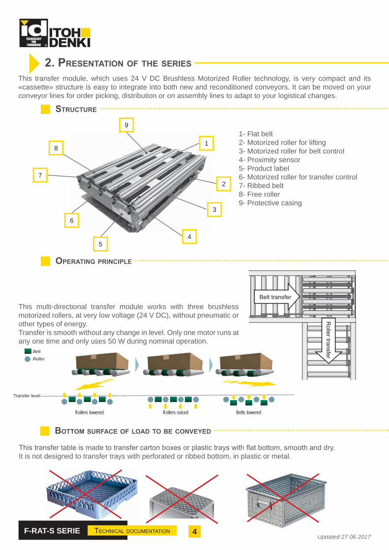
This transfer module, which uses 24 V DC Brushless Motorized Roller technology, is very compact and its «cassette» structure is easy to integrate into both new and reconditioned conveyors. It can be moved on your conveyor lines for order picking, distribution or on assembly lines to adapt to your logistical changes.
STRUCTURE
2. PRESENTATION OF THE SERIES
OPERATING PRINCIPLE
Rollers lowered Rollers raised Belts lowered
Belt
Roller
72
3
45
6
8
9
11- Flat belt2- Motorized roller for lifting3- Motorized roller for belt control4- Proximity sensor5- Product label6- Motorized roller for transfer control7- Ribbed belt8- Free roller9- Protective casing
This multi-directional transfer module works with three brushless motorized rollers, at very low voltage (24 V DC), without pneumatic or other types of energy.Transfer is smooth without any change in level. Only one motor runs at any one time and only uses 50 W during nominal operation.
Transfer level
BOTTOM SURFACE OF LOAD TO BE CONVEYED
It is not designed to transfer trays with perforated or ribbed bottom, in plastic or metal.
5F-RAT-S SERIE TECHNICAL DOCUMENTATIONUpdated 27 06 2017
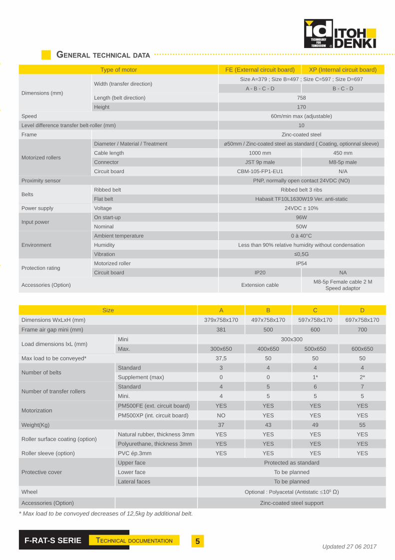
Type of motor FE (External circuit board) XP (Internal circuit board)
Dimensions (mm)
Width (transfer direction)Size A=379 ; Size B=497 ; Size C=597 ; Size D=697
A - B - C - D B - C - D
Length (belt direction) 758
Height 170
Speed 60m/min max (adjustable)
Level difference transfer belt-roller (mm) 10
Frame Zinc-coated steel
Motorized rollers
Diameter / Material / Treatment ø50mm / Zinc-coated steel as standard ( Coating, optionnal sleeve)
Cable length 1000 mm 450 mm
Connector JST 9p male M8-5p male
Circuit board CBM-105-FP1-EU1 N/A
Proximity sensor PNP, normally open contact 24VDC (NO)
BeltsRibbed belt Ribbed belt 3 ribs
Flat belt Habasit TF10L1630W19 Ver. anti-static
Power supply Voltage 24VDC ± 10%
Input powerOn start-up 96W
Nominal 50W
Environment
Ambient temperature 0 à 40°C
Humidity Less than 90% relative humidity without condensation
Vibration
Protection ratingMotorized roller IP54
Circuit board IP20 NA
Accessories (Option) Extension cable M8-5p Female cable 2 MSpeed adaptor
Size A B C DDimensions WxLxH (mm) 379x758x170 497x758x170 597x758x170 697x758x170
Frame air gap mini (mm) 381 500 600 700
Load dimensions lxL (mm)Mini 300x300
Max. 300x650 400x650 500x650 600x650
Max load to be conveyed* 37,5 50 50 50
Number of beltsStandard 3 4 4 4
Supplement (max) 0 0 1* 2*
Number of transfer rollersStandard 4 5 6 7
Mini. 4 5 5 5
MotorizationPM500FE (ext. circuit board) YES YES YES YES
PM500XP (int. circuit board) NO YES YES YES
Weight(Kg) 37 43 49 55
Roller surface coating (option)Natural rubber, thickness 3mm YES YES YES YES
Polyurethane, thickness 3mm YES YES YES YES
Roller sleeve (option) PVC ép.3mm YES YES YES YES
Protective cover
Upper face Protected as standard
Lower face To be planned
Lateral faces To be planned
Wheel Optional : Polyacetal (Antistatic ≤105
Accessories (Option) Zinc-coated steel support
* Max load to be convoyed decreases of 12,5kg by additional belt.
GENERAL TECHNICAL DATA

6F-RAT-S SERIE TECHNICAL DOCUMENTATIONUpdated 27 06 2017
3. TRANSFER CAPACITY
TRANSFER TIME
Receiving time(sec)
Belt/roller transfer time (sec)
Discharge time(sec) TRANSFER TIME+ + =
Direction change time is 0.36 (sec)
Discharge time (graph 1) + Additional time depending on the weight of the package (table 1)
From reception of the package until the next package is ready to be transferred on the F-RAT, after the package has been fully
discharged.
60 (m/min)30 (m/min)20 (m/min)
3
2.5
2
1.5
1
0.5
0250 300 350 400 450 500 550 600 650 700
Package size (mm)
GRAPH 1
Dis
char
ge ti
me
(sec
)
TABLE 1
Package weight (kg) 10 20 30 40 50Additional time (sec) 0.1 0.2 0.3 0.4 0.5
NOTE : Transfer time may vary according to the load, its transfer method (step by step, continuous), upstream and downstream conveyor speed and other factors.
2 3 3 3 4
Package lenght (mm)
(Transfer speed* (m/min) /60 ) x 1000
* Average speed between package in-feed and outfeed

7F-RAT-S SERIE TECHNICAL DOCUMENTATIONUpdated 27 06 2017
Package throughput depends on the dimensions and material of the package, as well as speed, transfer method, transfer rate...The curves are given as a rough guide.
Pac
kage
thro
ughp
ut /
hou
r
Transfert rate (%)
Cardboard and plastic boxWeight : 30 kgSpeed code : 60m/min
Attention : Performance are given as a rough guide for motorized roller controled with CBM-105 .
TRANSFER RATE
Déb
it co
lis /
heur
e
Transfer rate (%)
Package throughput depends on the dimensions and material of the package, as well as speed, transfer method, transfer rate...The curves are given as a rough guide.
Cardboard and plastic boxWeight : 30 kgSpeed code : 30m/min
Slug release
Slug release
Singulated release
Singulated release

8F-RAT-S SERIE TECHNICAL DOCUMENTATIONUpdated 27 06 2017
4. INSTALLATION OF THE MODULE F-RAT-S
ASSEMBLY PRINCIPLE
10
145.
6
157.
6
7454040
170
2×4-M8
4- 8.4
Trou de montage de l’étai
R
15.5
2x2-R4.25
24.4125
5
5.2
69
14.1
50.4
4
3.2 6
4014.5
2x2-M8
QS
P5
55.5
2x2-R20
F-RAT SizeDimensions Number of
support ReferenceQ S R
A 381 252 64.5 2 SP-FRAT-S-A-0381B 500 370 65 2 SP-FRAT-S-B-0500C 600 470 65 2 SP-FRAT-S-C-0600D 700 570 65 2 SP-FRAT-S-D-0700
MODULE SUPPORT (OPTION)
Insertion of the F-RAT-S must be planned in such a way that it can be easily inserted or removed for maintenance purposes.
*
* Distance between the conveyance level and the module’s support bracket*1 M8 retaining screw not supplied*2 Optional
*118.6
Module support*2
Mounting bracket
(Support mounting hole)
F-RAT-S Mounting hole

9F-RAT-S SERIE TECHNICAL DOCUMENTATIONUpdated 27 06 2017
Size A L : 379mm x l : 758mm
Size BL : 497mm x l : 758mm
DIMENSIONS
94
282=
P94
x3
252
9488
.214
5.6
170
734
758
13
379
98.4
(Distance between the mounting holes)
4-M8 screw mounting hole
*
(Dis
tanc
e be
twee
n th
e m
ount
ing
hole
s)
100
400=
P10
0×4
97.2
102.
897
.2
370
497
734
758
13
145.
6
170
99.9
4-Trou de montage vis M8
(Distance entre les trous de montage)
*
* Distance between the conveyance level and the module’s support bracket
* Distance between the conveyance level and the module’s support bracket

10F-RAT-S SERIE TECHNICAL DOCUMENTATIONUpdated 27 06 2017
Size CL : 597mm x l : 758mm
Size DL : 697mm x l : 758mm
100
500=
P10
0×5
100
97.2
102.
8
470
97.2
740
758
99.9
597
145.
6
170
13
4-M8 screw mounting holes
(Distance between the mounting holes)
*
(Dis
tanc
e be
twee
n th
e m
ount
ing
hole
s)
100
600=
P10
0×6
97.2
100
102.
8
570
97.2
100
740
758
13
99.9
697
145.
6
170
4-M8 screw mounting holes
(Distance between the mounting holes)
*
(Dis
tanc
e be
twee
n th
e m
ount
ing
hole
s)
* Distance between the conveyance level and the module’s support bracket
* Distance between the conveyance level and the module’s support bracket

11F-RAT-S SERIE TECHNICAL DOCUMENTATIONUpdated 27 06 2017
5. F-RAT-S CONTROL
PROGRAMMING TRANSFER

12F-RAT-S SERIE TECHNICAL DOCUMENTATIONUpdated 27 06 2017
DC24V 0V DC24V 0V
SN・S
SN・R
Y0 X0
Y1 X1
Y2 X2
Y3 X3
Y4 X4
CBM-105
Y5 X5
RUN signal
RUN signal
RUN signal
DIR signal
Output Input
«ON» signalfor downstream zone
«ON» signalfor upstream zone
Input signal
Proximity sensorfor belt direction
Proximity sensorfor direction of transfer
Load sensor signalfor downstream zone
Load sensor signal or upstream zone
CBR-305-FP-B
CBM-105
CN2-1
Black
Brown
Blue
Black
Brown
Blue
M1
M3
M2
CN1-2
CN1-1
CN2-1
CN2-2
CN1-2
CN1-1
CN2-1
CN1-2
CN1-1
CONTROL WITH PM500FE MOTORIZED ROLLER AND CIRCUIT BOARD CBM105-FP1-EU1 / CBR-305-FP-B BY PLC
24V
1.RUN
3.V-IN2.DIR
4.ERR5.PLS
0V
54
32
12
1
0VDC24V
CN2
CN1
VR2VR1
Wiring diagram
CBM105-FP1-EU1 and CBR-305-FP-B Initial adjustment
MOTOR
CONNECTOR
Wiring for :
F-RAT-S input and output : PNP
From PLC (24V input)From PLC (24V input)
CN3
CN2
CN1
SW1 SW2
0s0s
VR1VR2
1 2 3 4 5 6
0 1
23
56 478
9ON
13F-RAT-S SERIE TECHNICAL DOCUMENTATIONUpdated 27 06 2017
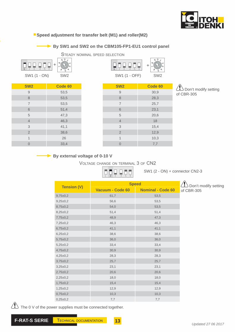
Speed adjustment for transfer belt (M1) and roller(M2)
By SW1 and SW2 on the CBM105-FP1-EU1 control panel
STEADY NOMINAL SPEED SELECTION
SW2 Code 609 53,58 53,57 53,56 51,45 47,34 46,33 41,12 38,61 260 33,4
SW1 (1 - ON) SW2
SW2 Code 609 30,98 28,37 25,76 23,15 20,64 183 15,42 12,91 10,30 7,7
SW1 (1 - OFF) SW2
+
By external voltage of 0-10 V
1 2 3 4 5 6
+1 2 3 4 5 6 1 2 3 4 5 6
VOLTAGE CHANGE ON TERMINAL 3 OF CN2
The 0 V of the power supplies must be connected together.
Tension (V)Speed
Vacuum - Code 60 Nominal - Code 609,75±0,2 61,7 53,5
9,25±0,2 56,6 53,5
8,75±0,2 54,0 53,5
8,25±0,2 51,4 51,4
7,75±0,2 48,9 47,3
7,25±0,2 46,3 46,3
6,75±0,2 41,1 41,1
6,25±0,2 38,6 38,6
5,75±0,2 36,0 36,0
5,25±0,2 33,4 33,4
4,75±0,2 30,9 30,9
4,25±0,2 28,3 28,3
3,75±0,2 25,7 25,7
3,25±0,2 23,1 23,1
2,75±0,2 20,6 20,6
2,25±0,2 18,0 18,0
1,75±0,2 15,4 15,4
1,25±0,2 12,9 12,9
0,75±0,2 10,3 10,3
0,25±0,2 7,7 7,7
2 3 4 5 6 2 3 4 5 6
3 4 5 61
SW1 (2 - ON) + connector CN2-3
0 1
23
56 478
9 0 1
23
56 478
9
Don’t modify setting of CBR-305
Don’t modify setting of CBR-305
14F-RAT-S SERIE TECHNICAL DOCUMENTATIONUpdated 27 06 2017
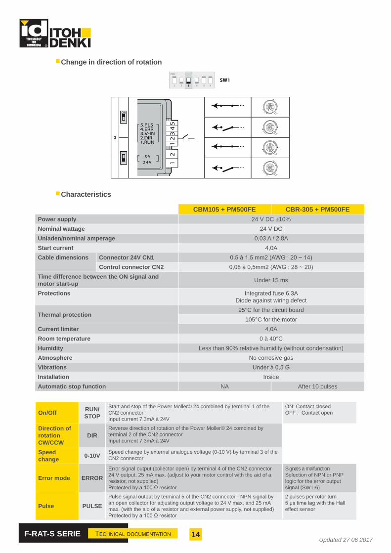
Change in direction of rotation
Characteristics
CBM105 + PM500FE CBR-305 + PM500FEPower supply 24 V DC ±10%Nominal wattage 24 V DCUnladen/nominal amperage 0,03 A / 2,8AStart current 4,0ACable dimensions Connector 24V CN1
Control connector CN2Time difference between the ON signal and motor start-up Under 15 ms
Protections Integrated fuse 6,3ADiode against wiring defect
Thermal protection95°C for the circuit board
105°C for the motorCurrent limiter 4,0ARoom temperature 0 à 40°CHumidity Less than 90% relative humidity (without condensation)Atmosphere No corrosive gasVibrationsInstallation InsideAutomatic stop function NA After 10 pulses
On/Off RUN/STOP
Start and stop of the Power Moller© 24 combined by terminal 1 of the CN2 connectorInput current 7.3mA à 24V
ON: Contact closedOFF : Contact open
Direction of rotationCW/CCW
DIRReverse direction of rotation of the Power Moller© 24 combined by terminal 2 of the CN2 connectorInput current 7.3mA à 24V
Speed change 0-10V Speed change by external analogue voltage (0-10 V) by terminal 3 of the
CN2 connector
Error mode ERRORError signal output (collector open) by terminal 4 of the CN2 connector24 V output, 25 mA max. (adjust to your motor control with the aid of a resistor, not supplied)
Signals a malfunctionSelection of NPN or PNP logic for the error output signal (SW1-6)
Pulse PULSEPulse signal output by terminal 5 of the CN2 connector - NPN signal by an open collector for adjusting output voltage to 24 V max. and 25 mA max. (with the aid of a resistor and external power supply, not supplied)
2 pulses per rotor turn
effect sensor
ON
1 2 3 4 5 6
SW13
3
ON
5.PLS4.ERR3.V-IN2.DIR1.RUN
2 4 V0 V
12
34
51
2
PM 500 FE (50E) - PM 605 FE (60E)
15F-RAT-S SERIE TECHNICAL DOCUMENTATIONUpdated 27 06 2017
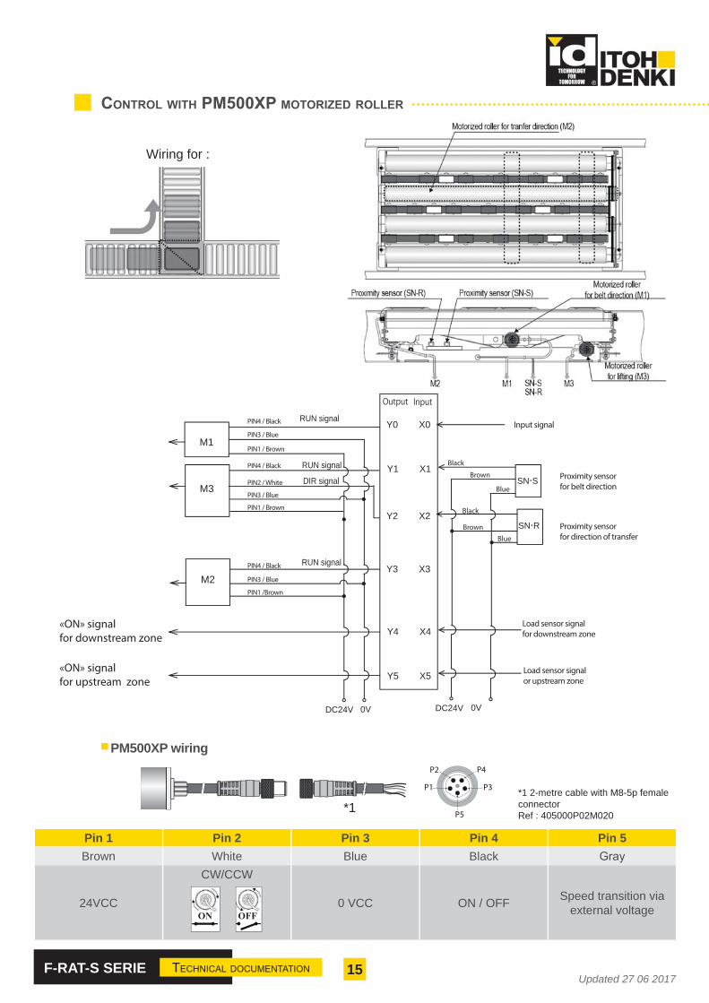
CONTROL WITH PM500XP MOTORIZED ROLLER
DC24V 0V
Y0 X0
Y1 X1
Y2 X2
Y3 X3
Y4 X4
M1
M3
M2
Y5 X5
RUN signal
RUN signal
RUN signal
DIR signal
Output Input
«ON» signalfor downstream zone
«ON» signalfor upstream zone
Input signalPIN4 / Black
PIN3 / Blue
PIN1 / Brown
PIN4 / Black
PIN2 / White
PIN3 / Blue
PIN1 / Brown
PIN4 / Black
PIN3 / Blue
PIN1 /Brown
DC24V 0V
SN・S
SN・R
Proximity sensorfor belt direction
Proximity sensorfor direction of transfer
Load sensor signalfor downstream zone
Load sensor signal or upstream zone
Black
Brown
Blue
Black
Brown
Blue
PM500XP wiring
Pin 1 Pin 2 Pin 3 Pin 4 Pin 5Brown White Blue Black
24VCC
CW/CCW
0 VCC ON / OFF Speed transition via external voltageON
P5
P1
P2 P4
P3
(a)*1*1 2-metre cable with M8-5p female connectorRef : 405000P02M020
OFF
Wiring for :
16F-RAT-S SERIE TECHNICAL DOCUMENTATIONUpdated 27 06 2017
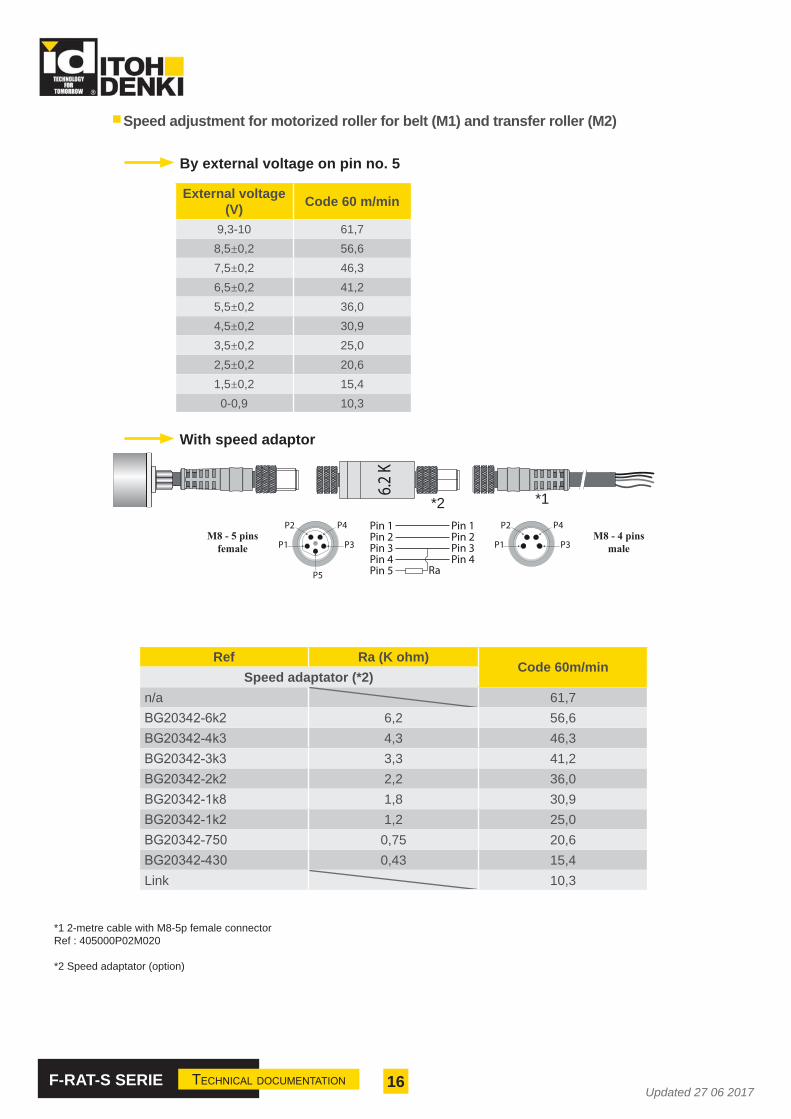
Speed adjustment for motorized roller for belt (M1) and transfer roller (M2)
By external voltage on pin no. 5
External voltage(V) Code 60 m/min
9,3-10 61,78,5±0,2 56,67,5±0,2 46,36,5±0,2 41,25,5±0,2 36,04,5±0,2 30,93,5±0,2 25,02,5±0,2 20,61,5±0,2 15,40-0,9 10,3
With speed adaptor
Ref Ra (K ohm)Code 60m/min
Speed adaptator (*2)n/a 61,7
6,2 56,64,3 46,33,3 41,22,2 36,01,8 30,91,2 25,0
0,75 20,60,43 15,4
Link 10,3
6.2
K
(b) (c)
P5
P1
P2 P4
P3 P1
P2 P4
P3M8 - 5 pins
femaleM8 - 4 pins
male
Pin 1Pin 2Pin 3Pin 4
Pin 1Pin 2Pin 3Pin 4
RaPin 5
*1 2-metre cable with M8-5p female connectorRef : 405000P02M020
*2 Speed adaptator (option)
*1*2
17F-RAT-S SERIE TECHNICAL DOCUMENTATIONUpdated 27 06 2017
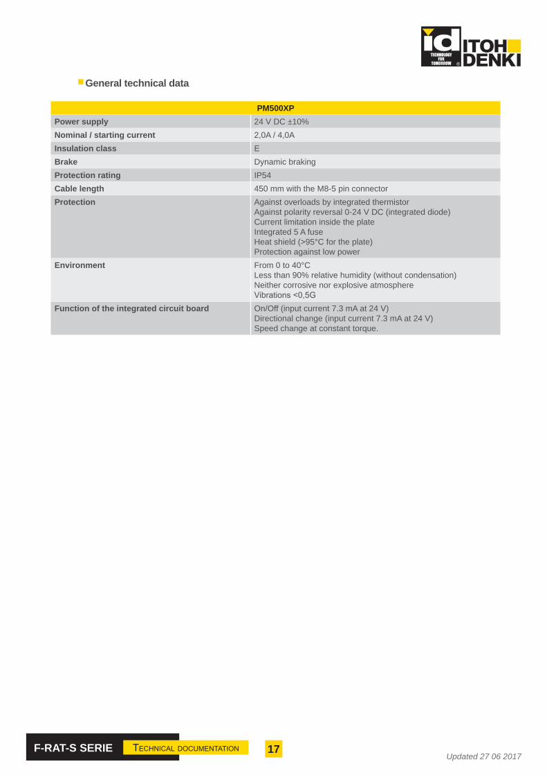
General technical data
PM500XPPower supply 24 V DC ±10% Nominal / starting current 2,0A / 4,0AInsulation class EBrake Dynamic brakingProtection rating IP54Cable length 450 mm with the M8-5 pin connectorProtection Against overloads by integrated thermistor
Against polarity reversal 0-24 V DC (integrated diode)Current limitation inside the plateIntegrated 5 A fuseHeat shield (>95°C for the plate)Protection against low power
Environment From 0 to 40°CLess than 90% relative humidity (without condensation)Neither corrosive nor explosive atmosphere
Function of the integrated circuit board On/Off (input current 7.3 mA at 24 V)Directional change (input current 7.3 mA at 24 V)Speed change at constant torque.
18F-RAT-S SERIE TECHNICAL DOCUMENTATIONUpdated 27 06 2017
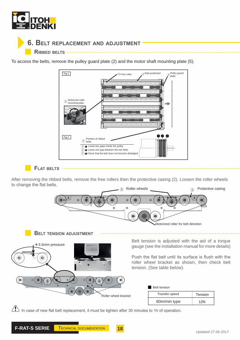
6. BELT REPLACEMENT AND ADJUSTMENTRIBBED BELTS
①
Fig.1
Fig.2
7
7
77
To access the belts, remove the pulley guard plate (2) and the motor shaft mounting plate (5).
FLAT BELTS
After removing the ribbed belts, remove the free rollers then the protective casing (2). Loosen the roller wheels
MDR Courroie
Roues galets Carter de protection
BELT TENSION ADJUSTMENT
Tension
12N
5.5mm pressureBelt tension is adjusted with the aid of a torque gauge (see the installation manual for more details)
roller wheel bracket as shown, then check belt tension. (See table below).
Motorized rollermounting plate
Roller wheel bracket
Motorized roller for belt direction
60m/min type
Side protection Pulley guard plate
Position of ribbed belts
Free roller
Leave two gaps inside the pulleyLeave one gap between the two beltsCheck that the belt does not become dislodged
Roller wheels Protective casing
Belt tension
Transfer speed

19F-RAT-S SERIE TECHNICAL DOCUMENTATIONUpdated 27 06 2017
7. PRODUCT LISTING
F – RAT – S [ 1 ] [ 2 ] – [ 3 ] [ 4 ] [ 5 ] - [ 6] [ 7 ] [ 8 ][ 1 ] SPEED60 … 60 m/min (Belt / Transfer : 60 m/min)
[ 2 ] SIGNAL TYPE SELECTIONN … NPN (Sensor / Circuit board)P … PNP (Sensor / Circuit board)
[ 3 ] DIMENSIONSA … W 379 x L 758 mmB … W 497 x L 758 mmC … W 597 x L 758 mmD … W 697 x L 758 mm
[ 4 ] NUMBER OF FLAT BELTS3 ... 3 belts4 ... 4 belts
[ 5 ] WITH OR WITHOUT PROTACTIVE CASINGP ... With protection0 ... Without protection
[ 6 ] TYPE OF MOTORF ... PM500FE SerieX ... PM500XP Serie
[ 7 ] SURFACE COATING ON TUBE, ANTISTATIC VERSION0... Zinc-coated steel P... PVC sleeveN... Natural rubberU... PolyurethanA... Anti-static version
[ 8] VARIANT INDEX0123456789
Exemple :
F-RAT-S60P-B4P-F00
(Speed code 60m/min, PNP, 497x758mm; 4 belts with protection, PM500FE motor roller, Zinc-coated
steel roller, variant 0).

20F-RAT-S SERIE TECHNICAL DOCUMENTATIONUpdated 27 06 2017
8. REPLACEMENT PARTS FOR F-RAT-S
F-RAT size Belt motorized roller Transfer motorized rollerA PM500FE0600277XRSBN001
PM500FE0600674XRSTN001B PM500FE0600392XRSBN001C PM500FE0600492XRSBN001D PM500FE0600592XRSBN001
F-RAT size Flat belt Ribbed belt Roller wheel A Sensor (PNP) Free rollerA
-TF10L1630W19
3PJ316
F-RAT-IW-A44 FR500IDZHS0674XRS0N001B3PJ336C
D
CONTROL WITH PM500FE MOTORIZED ROLLER
F-RAT size Belt motorized roller Transfer motorized rollerB PM500XP0600392XRSBN001
PM500XP0600674XRSTN001C PM500XP0600492XRSBN001D PM500XP0600592XRSBN001
CONTROL WITH PM500XP MOTORIZED ROLLER
FOR PM500FE AND PM500XP
ELECTRICAL ACCESSORIES
PM500FE PM500XP
Circuit board CBM-105FP1-EU1CBR-305-FP-B N/A
Motor/control panel extension cable 1,2m ACE-CBM-B1200 N/A
Connecting cable with connector M8-5p 2m N/A 405000P02M020
Speed adaptator N/A
21F-RAT-S SERIE TECHNICAL DOCUMENTATIONUpdated 27 06 2017
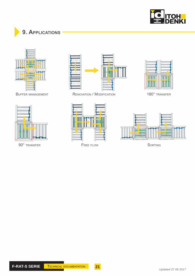
90° TRANSFER
BUFFER MANAGEMENT 180° TRANSFER
FREE FLOW
RENOVATION / MODIFICATION
SORTING
9. APPLICATIONS
22F-RAT-S SERIE TECHNICAL DOCUMENTATIONUpdated 27 06 2017
ANNEX 1
INCORPORATION DECLARATIONin accordance with the EC Machinery Directive 2006/42/EC, Annex II B
The manufacturer:
ITOH DENKI CO., Ltd1146-2 Asazuma-Cho, Kasai, Hyogo 679-0180 Japan
Distributed in Europe by :
ITOH DENKI Europe SAS490 avenue des Jourdies - ZAE les Jourdies - BP 32374807 St Pierre en Faucigny Cedex - France
hereby declares that the product series :
F-RAT-S
requirements of this Directive. Commissioning is prohibited until the whole machine/system in which it is incorporated is declared to be in compliance with the EC Machinery Directive
The health and safety requirements of Annex I have been applied. The special technical documents in accordance with Annex VII have been drawn up (and, if appropriate, submitted to the competent authorities).
Person authorized to compile the technical documentation :
ITOH DENKI CO., LtdToshiyuki TACHIBANA1146-2 Asazuma-Cho, Kasai, Hyogo 679-0180 Japan
EC Directives applied :• Machinery Directive 2006/42/EC• European EMC Directive 2014/30/EC• European RoHS Directive 2011/65/EU
Saint Pierre en Faucigny, 20 November 2013
K. TAMURA, Managing Director

23F-RAT-S SERIE TECHNICAL DOCUMENTATIONUpdated 27 06 2017

Updated 27 06 201724
ITOH DENKI EUROPE S.A.S.
490 Av. des JourdiesZ.A.E. les Jourdies
74800 St Pierre en Faucigny - FranceTél. : +33 (0)4 50 03 09 99Fax : +33 (0)4 50 03 07 60
E-mail : [email protected]
WWW.ITOH-DENKI.COM
ITOH DENKI BRANCHUNITED KINGDOM
Suite 1 Trinity Space CentreWaldorf Way
Tel : +44 (0)1924 366 539Fax : +33 (0)4 50 03 07 60
E-mail : [email protected]
ITOH DENKI BRANCHGERMANY
Neumeyerstrabe 48
Tel : +49 911 25 26 - 200Fax : +49 911 25 26 - 201
E-mail : [email protected]