doc1
DESCRIPTION
Yokogawaw DCSTRANSCRIPT

Toc-1
IM 33S02C10-01E
CONTENTS
13th Edition : Dec.26,2006-01
CS 1000/CS 3000HIS Operation
1. Starting up HIS ........................................................................................ 1-11.1 HIS Operation And Monitoring Windows ....................................................... 1-4
1.2 Toolbar of System Message Window ............................................................. 1-6
2. Calling the Graphic Windows................................................................. 2-12.1 Calling the Graphic Windows Directly ........................................................... 2-2
2.2 Calling Graphic Windows Using the Window Hierarchy .............................. 2-6
2.3 Toolbar of Graphic Window ............................................................................ 2-9
3. Useful Features of HIS ............................................................................ 3-13.1 Operation Panel Mode .................................................................................... 3-2
3.2 Calling a General-Purpose Windows Applicationwhile Monitoring the Plant .............................................................................. 3-4
3.3 Returning to the Graphic Window.................................................................. 3-5
3.4 Displaying Multiple Windows Always in the Same Format- Dynamic Window Set .................................................................................... 3-6
3.5 Using Shortcut Keys ....................................................................................... 3-9
3.6 Using the Context Menus in Graphic Window ............................................ 3-12
4. Operating the Instrument Faceplate ...................................................... 4-14.1 Entering Data .................................................................................................. 4-2
4.2 Changing the Block Mode .............................................................................. 4-5
4.3 Operation Mark on Instrument Faceplate ...................................................... 4-7
4.4 Tight-Shut Output ........................................................................................... 4-8
5. When a Message is Generated ............................................................... 5-15.1 Confirming the Type and Contents of Generated Messages ........................ 5-2
5.2 Message Search ............................................................................................ 5-10
5.3 Messages On Help Dialog Box ..................................................................... 5-15
6. Reading the Trend of Process Data ....................................................... 6-16.1 Confirming Data in the Trend Window ........................................................... 6-2
6.2 Changing the Assignment of Trend Data Being Displayed .......................... 6-4
6.3 Creating/Displaying Trend Reference Patterns ............................................. 6-7
7. Outputting Screen Images ..................................................................... 7-17.1 Outputting the Screen Image of Currently Displayed Windows................... 7-2
7.2 Outputting the Previously Output Screen Images Again.............................. 7-6
8. When a System Error Occurred ............................................................. 8-1
IM 33S02C10-01E 13th Edition

Blank Page

<1. Starting up HIS> 1-1
IM 33S02C10-01E
1. Starting up HISIt is necessary to start up an HIS before commencing the plant operation and moni-toring. This chapter explains the steps to start up the HIS.
■ Starting up HISWhen [Startup] is selected in the HIS Utility dialog box, HIS are started up as follows:
1. Turn on the power of the computer running Windows.
2. Log on by pressing the [Ctrl] + [Alt] + [Del] keys.
3. Enter the user name and password to the Windows logon window.
4. HIS will start up.
TIP
If both [Auto Logon] and [Start Up] are checked in the HIS Utility dialog box, turning on the power of thecomputer with Windows will automatically start up the HIS.
9th Edition : Dec.18,2003-00

1-2<1. Starting up HIS>
IM 33S02C10-01E
■ Security Check for Operation and Monitoring on HISThe operation and monitoring scope on HIS is determined by the settings of user groupand the privilege level.
The user rights on the HIS are predefined on the HIS security builder according to the usergroup and the privilege level.
The security setting of each HIS can be different from others, so that a user’s right maybedifferent on different HISs. Thus a user’s operation and monitoring scope on a HIS can beperformed only in the range predefined for the HIS.
● Changing Privilege Level
If an operation keyboard is connected to the HIS, the privilege level can be changed byswitching the MODE key on the keyboard.
There are two types of keys for the keyboard, operation key and engineering key.
010001E.EPS
In the case of the operation keyChanges between the ON, OFF positions.
When the engineering key is inserted.The key can beswitched to any position.
MODE
OFFON
ENG
MODE
OFFON
ENG
Figure Mode Switching Key
Using an operation key cannot switch to ENG position.
• When the MODE switch position is OFF or no key:Privilege level of the user(logged-in user) during operation
• When the MODE switch position is ON:S2 privilege
• When the MODE switch position is ENG:S3 privilege
TIP
The operation rights of S1 to S3 privilege levels are defined on Security Builder.
SEE ALSO
For more information about the security with operation keyboard, see the following:
“■ Change Privilege Level on Operation Keyboard” in F9.3, “Privilege Level” of “CS 1000/CS 3000 Ref-erence (IM 33S01B30-01E)”
9th Edition : Dec.18,2003-00
<1. Starting up HIS> 1-3
IM 33S02C10-01E
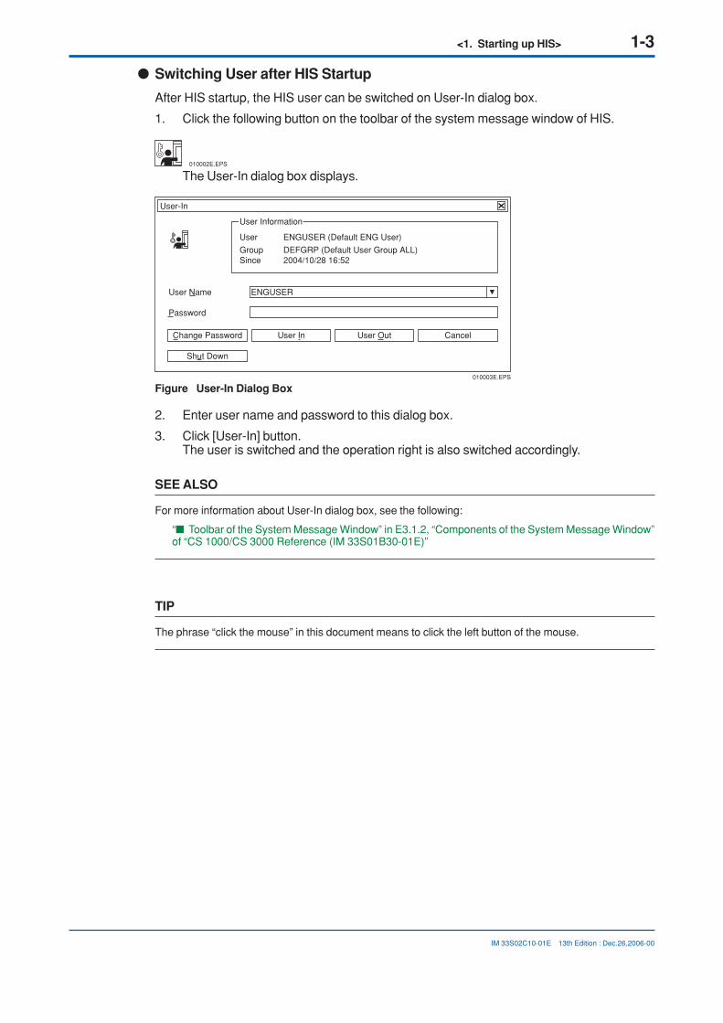
● Switching User after HIS Startup
After HIS startup, the HIS user can be switched on User-In dialog box.
1. Click the following button on the toolbar of the system message window of HIS.
010002E.EPS
The User-In dialog box displays.
010003E.EPS
User-In
User Information
User ENGUSER (Default ENG User)
Group DEFGRP (Default User Group ALL)Since 2004/10/28 16:52
User Name
Password
CancelUser OutUser InChange Password
ENGUSER
Shut Down
Figure User-In Dialog Box
2. Enter user name and password to this dialog box.
3. Click [User-In] button.The user is switched and the operation right is also switched accordingly.
SEE ALSO
For more information about User-In dialog box, see the following:
“■ Toolbar of the System Message Window” in E3.1.2, “Components of the System Message Window”of “CS 1000/CS 3000 Reference (IM 33S01B30-01E)”
TIP
The phrase “click the mouse” in this document means to click the left button of the mouse.
13th Edition : Dec.26,2006-00

1-4<1. Starting up HIS>
IM 33S02C10-01E
1.1 HIS Operation And Monitoring WindowsThe operation and monitoring windows of HIS are explained in this chapter forproperly using the windows according to the operational targets.
SEE ALSO
For more information about various HIS windows, see the following:
E2.1, “System Windows and User-Defined Windows” of “CS 1000/CS 3000 Reference (IM 33S01B30-01E)”
Windows Convenient for Operation and Monitoring
Windows for Batch Operation and Monitoring
Windows for Process Status and Operation Record Configuration
Tag Report Search
I/O Report Search
Search for a Historical Message
Graphic Window
Trend Window
Tuning Window
Faceplate Window
Operator Guide Window
Process Alarm Window
Message Monitor Window
SFC Window
Logic Chart Window
Sequence Table Window
Control Drawing Window
Help Dialog Box
Process Report Window
Historical Message Report Window
Windows for System Administration
Basic Windows for Operation and MonitoringSystem Message WindowNavigator Window
010101E.EPS
Fiugre HIS Operation And Monitoring Windows (1/2)
9th Edition : Dec.18,2003-00
<1. Starting up HIS> 1-5
IM 33S02C10-01E
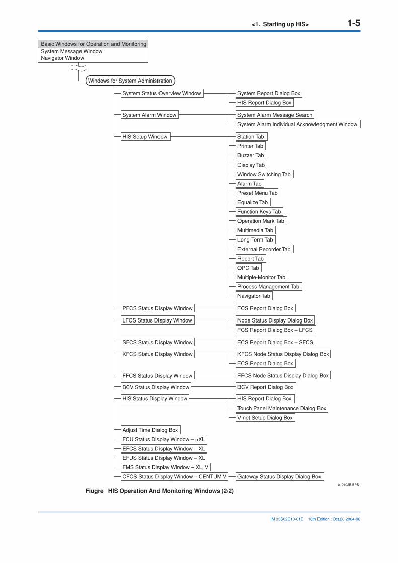
Windows for System Administration
Station Tab
Printer Tab
Buzzer Tab
Display Tab
Window Switching Tab
Alarm Tab
Preset Menu Tab
Equalize Tab
Function Keys Tab
Operation Mark Tab
Multimedia Tab
Long-Term Tab
External Recorder Tab
Report Tab
OPC Tab
Multiple-Monitor Tab
Process Management Tab
Navigator Tab
System Report Dialog Box
HIS Report Dialog Box
FCS Report Dialog Box
Gateway Status Display Dialog Box
HIS Report Dialog Box
Touch Panel Maintenance Dialog Box
V net Setup Dialog Box
Node Status Display Dialog Box
FCS Report Dialog Box – LFCS
FCS Report Dialog Box – SFCS
KFCS Node Status Display Dialog Box
FCS Report Dialog Box
BCV Report Dialog Box
System Alarm Message Search
System Alarm Individual Acknowledgment Window
System Status Overview Window
System Alarm Window
HIS Setup Window
PFCS Status Display Window
LFCS Status Display Window
SFCS Status Display Window
KFCS Status Display Window
BCV Status Display Window
HIS Status Display Window
Adjust Time Dialog Box
FCU Status Display Window – µXL
EFCS Status Display Window – XL
EFUS Status Display Window – XL
FMS Status Display Window – XL, V
CFCS Status Display Window – CENTUM V
FFCS Node Status Display Dialog BoxFFCS Status Display Window
010102E.EPS
Basic Windows for Operation and MonitoringSystem Message WindowNavigator Window
Fiugre HIS Operation And Monitoring Windows (2/2)
10th Edition : Oct.28,2004-00

1-6<1. Starting up HIS>
IM 33S02C10-01E 9th Edition : Dec.18,2003-00
1.2 Toolbar of System Message WindowA toolbar is provided on system message window for conveniently performing theoperation and monitoring tasks.
? NAME COPY
010201E.EPS
Process Report
Overview
Process Alarm
Operation Guide
Control
Tuning
Trend
Graphic
System Status Display
Logging Report Package
Historical Report
SYS
Image
Archive/Retrieve...
Active System View
Recipe View
Left
Upper
Right
Previous History
Next History
Name InputNAME
Tool Box
SYS HELP ?
Pro
cess
Ala
rm
Sys
tem
Ala
rm
Ope
ratio
n G
uide
Mes
sage
Mon
itor
Win
dow
Use
r In
Win
dow
Cal
l Men
u
Ope
ratio
n M
enu
Pre
set W
indo
w M
enu
Tool
bar
Nav
igat
or
Nam
e In
put
Circ
ulat
e
Cle
ar A
ll
Buz
zer
Res
et
Har
d C
opy
Dis
play
Alw
ays
Sys
tem
Sta
tus
Dis
play
Hel
p
Pro
cess
Ala
rm
Ope
ratio
n G
uide
Con
trol
Tuni
ng
Tren
d
Gra
phic
Pro
cess
Rep
ort
His
toric
al R
epor
t
Left
Upp
er
Rig
ht
Ove
rvie
w
Sav
e W
indo
w S
et
Rel
ease
Win
dow
Set
Imag
e
Rot
ate
Larg
e S
ize
Mid
dle
Siz
e
Rel
ated
Bui
lder
Cal
l
Rel
ated
Con
trol
Dra
win
gB
uild
er C
all
Figure Toolbar of System Message Window
SEE ALSO
For more information about the toolbar on system message window, see the following:
E3.1.2, “Components of the System Message Window” of “CS 1000/CS 3000 Reference (IM 33S01B30-01E)”

<2. Calling the Graphic Windows> 2-1
IM 33S02C10-01E
2. Calling the Graphic WindowsThis chapter explains how to call graphic windows that offer basic functions of plantoperation and monitoring.
Graphic windows can be called directly or by using the window hierarchy.
■ Attributes of Graphic WindowsGraphic windows are categorized into three attributes.
• Graphic windows with graphic attributeBecome the target of call operation via the graphic button.
• Graphic windows with overview attributeBecome the target of call operation via the overview button and graphic button.
• Graphic windows with control attributeBecome the target of call operation via the control button.
9th Edition : Dec.18,2003-00

2-2<2. Calling the Graphic Windows>
IM 33S02C10-01E
2.1 Calling the Graphic Windows DirectlyGraphic windows can be called directly by clicking on the graphic button in thesystem message window, selecting the corresponding graphic window in the Navi-gator window, or entering the corresponding graphic window name in the NameInput dialog box.
■ Calling from the System Message WindowGraphic windows can be called from the system message window via the window callmenu or tool box.
● Calling from the Window Call Menu
1. Click on the window call menu button in the system message window.
2. The window call menu will appear.
3. Click on the graphic button in the window call menu.
4. A graphic window with graphic attribute will open.
020101E.EPS
Graphic
Window call menu button System message window
Window call menu
Figure Graphic Button in the Window Call Menu
9th Edition : Dec.18,2003-00

<2. Calling the Graphic Windows> 2-3
IM 33S02C10-01E
● Calling from the Tool Box
1. Click on the toolbox button in the system message window.
2. The tool box will appear.
3. Click on the graphic button in the tool box.
4. A graphic window with graphic attribute will open.
020102E.EPS
Tool Box
Toolbox button System message window
Toolbox
Graphic button
Figure Graphic Button in the Tool Box
9th Edition : Dec.18,2003-00

2-4<2. Calling the Graphic Windows>
IM 33S02C10-01E
■ Calling from the Navigator Window1. Click on the navigator button in the system message window.
020103E.EPS
Navigator button System message window
Figure Calling the Navigator Window
2. The Navigator window will appear.
3. Double-click on the corresponding graphic window directly in the Navigator window.
020104E.EPS
Navigator \USER\PLANTOVERVIEW
Overview 1
Name Comments TypePLANTOVERVIEW Overview 1 Overview
Def
USER
SYSTEM
.PR
.AL
.OG
.SO
.SH
.SA
WASHINGOVERVIEW
GRTANK
PLANTOVERVIEW
.SF FCS 0101
.SF FCS 0102
?
PRODUCT
.RO 1
.RO 1.TRAIN1
.RM 1.BATCH002.TRAIN1
.RO 2
.RM 2.BATCH111
.RM 2.BATCH112
.RM 1.BATCH001.TRAIN1
Double clickMouse
Figure Calling from the Navigator Window
4. In the above example, a graphic window with overview attribute namedPLANTOVERVIEW will open.
9th Edition : Dec.18,2003-00

<2. Calling the Graphic Windows> 2-5
IM 33S02C10-01E
■ Calling from the Name Input Dialog Box1. Click on the name input button in the system message window.
NAME
020105E.EPS
System message window
Name input button
Figure Calling the Name Input Dialog Box
2. The Name Input dialog box will appear.
3. Enter the name of the corresponding graphic window directly in the Name Input dialogbox.
020106E.EPS
GRAPHIC1 StnOK
Input Window Name S010101
Figure Window Name Input
4. In the above example, a graphic window named GRAPHIC1 will open.
SEE ALSO
For more information about calling windows by inputting the window name, see the following:
“● Window Names, Function Types and Display Size Specification Formats” in “■ Calling up Windowsby Entering Names” in E2.5.1, “Directly Calling up Operation and Monitoring Windows” of “CS 1000/CS3000 Reference (IM 33S01B30-01E)”
9th Edition : Dec.18,2003-00

2-6<2. Calling the Graphic Windows>
IM 33S02C10-01E 9th Edition : Dec.18,2003-00
2.2 Calling Graphic Windows Using the WindowHierarchyWhen using the window hierarchy, a graphic window can be called as a user-definedwindow, upper window or hierarchy window.
■ Calling a User-Defined WindowThis section explains how to call a user-defined window using the example of windowhierarchy shown below:
020201E.EPS
Graphic window with overview attribute
Graphic window 1 with graphic attribute
Graphic window 2 with graphic attribute
Trend window
Graphic window with control attribute
Trend window
Graphic window 3with graphic attribute
Figure Example of Window Hierarchy 1
1. Select Graphic window 2 with graphic attribute to make it active.
2. Click on the graphic button in the window call menu or tool box.
020202E.EPS
Tool Box
Graphic
Window call menu button
Toolbox button System message window
Toolbox
Graphic button
Window call menu
Figure Calling the User-Defined Window
3. Graphic window 3 with graphic attribute (the graphic window with graphic attribute thatexits under the active graphic window in hierarchy) will open.

<2. Calling the Graphic Windows> 2-7
IM 33S02C10-01E 9th Edition : Dec.18,2003-00
■ Calling an Upper WindowWhen a window exists above the active window in hierarchy, the upper window can becalled from the active window.
This section explains how to call an upper window using the example of window hierarchyshown below:
Graphic window with overview attribute
Graphic window 1 with graphic attribute
Graphic window 1 with control attribute
Graphic window 2 with control attribute
Trend window 1
Graphic window 2 with graphic attribute
Graphic window 3 with graphic attribute
Graphic window 3 with control attribute
Trend window 2
Graphic window 4 with control attribute
Trend window 3
020203E.EPS
Figure Example of Window Hierarchy 2
1. Select Graphic window 4 with control attribute to make it active.
2. Click on the operation menu button in the system message window.
3. The operation menu will appear.
4. Click on the upper button in the operation menu.
020204E.EPS
Upper
Operation menu button System message window
Operation menu
Figure Calling an Upper Window
5. Trend window 2 will open.

2-8<2. Calling the Graphic Windows>
IM 33S02C10-01E
■ Calling a Hierarchy WindowIf the window currently displayed has a hierarchy window, the hierarchy window can becalled by clicking on the previous or next button in the system message window.
This section explains how to call a hierarchy window using the example of window hierar-chy shown below:
020205E.EPS
Graphic window 1 with graphic attribute
Graphic window 2 with graphic attribute
Trend window 2
Graphic window 3 with graphic attribute
Graphic window 5 with graphic attribute
Graphic window with control attribute
Graphic window 6 with graphic attribute
Graphic window 4 with graphic attribute
Trend window 1
Graphic window 2 with control attribute
Figure Example of Window Hierarchy 3
1. Select Graphic window 4 with graphic attribute to make it active.
2. Click on the operation menu button in the system message window.
3. The operation menu will appear.
4. Click on the previous button in the operation menu.
5. Graphic window 3 with graphic attribute will open.
6. Click on the previous button again.
7. Graphic window 2 with graphic attribute will open.
020206E.EPS
Previous
System message window
Operation menu
Operation menu button
Figure Calling a Hierarchy Window
9th Edition : Dec.18,2003-00

<2. Calling the Graphic Windows> 2-9
IM 33S02C10-01E
2.3 Toolbar of Graphic WindowHow to use the toolbar on graphic window for conveniently performing the opera-tions is explained in this chapter.
SEE ALSO
For more information about calling windows by inputting the window name, see the following:
E4.1, “Graphic Window” of “CS 1000/CS 3000 Reference (IM 33S01B30-01E)”
■ Changing Faceplate AssignmentThe faceplates displayed on the graphic windows can be assigned to different functionblocks. The new assignment will become valid only after the changed contents are down-loaded to HIS.
The detailed procedure is as follows:
1. Click the Faceplate Assignment button.
020306E.EPS
Figure Faceplate Assignment Button
The Faceplate Assignment dialog box displays as follows.
CancelOK
020305E.EPS
Faceplate Assignment
1. FIC100
FI101
FI102
FI103
FI104
TIC100
TIC200
TIC300
2.
3.
4.
5.
6.
7.
8.
9. AIC100
LIC10010.
11.
12.
13.
14.
15.
16.
Figure Faceplate Assignment Dialog Box
2. Enter a new tag names to the corresponding faceplates, then click [OK] button. Thefaceplates will indicate the newly changed function blocks.
9th Edition : Dec.18,2003-00

2-10<2. Calling the Graphic Windows>
IM 33S02C10-01E
■ Switching Bind Data of Graphic DisplaysWhen creating Graphic windows for similar process units, if their drawing objects are thesame but the function block, data item of process data, modifier conditions as well asconstant values indicated by the drawing objects are different, thus using Data Bind switch-ing the bound data can display the multiple units with one graphic window.
How to switch the data bindings using the predefined data set are explained as follows.
SEE ALSO
For more information about data bindings of graphics, see the following:
F12.3, “Data Bind” of “CS 1000/CS 3000 Reference (IM 33S01B30-01E)”
1. Call an operation and monitoring graphic window.
2. Click the Data Bind button on the graphic window.
020301E.EPS
Figure Data Bind Button
Data Bind dialog box displays.
CancelOK
010302E.EPS
Data Bind Switching
BIND01Generic Name Set
Generic name set
Comment
Figure Data Bind Dialog Box
3. Choose a generic name set from the pull-down list, and then click [OK].The data displayed on the graphic window will be changed to a different data set.
9th Edition : Dec.18,2003-00

<2. Calling the Graphic Windows> 2-11
IM 33S02C10-01E
■ Zoom In and Zoom Out of Graphic WindowUsing the Zoom In/Out setting box, the graphic window’s zoom levels and the center of thezoomed window can be set.
Besides the graphic windows, this tool can also be used for zooming Logic Chart windowsand Control Drawing windows.
How to zoom in or zoom out a graphic window is explained as follows.
1. Call an operation and monitoring graphic window.
2. Click the Zoom button on the graphic window.
020303E.EPS
Figure Zoom Button
Zoom In/Out dialog box displays.
020304E.EPS
ZoomIn/Out
ZoomIn ZoomOut Initialize
OK Cancel Apply
Window area
Zoomed area
Figure Zoom In/Out Dialog Box
• Zoom In
1. Click [ZoomIn] button.A rectangular frame appears for marking an area of the window.
2. Using the mouse to move the frame.Mark the area to be enlarged
3. Click [Apply] button.The marked area will be enlarged and displayed.
4. Click [OK] button.The enlarged area is fixed as the window display.Click [Initialize] button may revert the window display to the default zoom level.
5. Click [Cancel] button.Close the Zoom In/Out dialog box.
• Zoom Out
1. Click [ZoomOut] button.
2. Click [Apply] button.The pictures in the window are shrunk smaller.
3. Click [OK] button.The shrunk pictures are fixed as the window display.Click [Initialize] button may revert the window display to the default zoom level.
4. Click [Cancel] button.Close the Zoom In/Out dialog box.
9th Edition : Dec.18,2003-00

Blank Page

<3. Useful Features of HIS> 3-1
IM 33S02C10-01E
3. Useful Features of HISThe HIS is provided with a number of useful functions that can be used with othergeneral-purpose Windows applications. How to use these functions is explained inthis chapter.
• Calling a general-purpose Windows application while monitoring the plant
• Calling the operation and monitoring window while using a general-purposeWindows application
• Display multiple windows always in the same format
Moreover, in order to improve operativity, the following functions are prepared inHIS. This chapter also explains a setup for using these.
• Setup for using the Shortcut Keys
• Setup for using the Context Menus in Graphic Window
10th Edition : Oct.28,2004-00

3-2<3. Useful Features of HIS>
IM 33S02C10-01E
3.1 Operation Panel ModeTwo operation panel modes, full-screen mode and window mode are available. Theoperator can switch from one mode to the other accordingly.
SEE ALSO
For more information about operation panel mode, see the following:
E2.2, “Operation Panel Mode” of “CS 1000/CS 3000 Reference (IM 33S01B30-01E)”
■ Switching the Operation Panel ModeSwitching between the full-screen mode and window mode is done in the HIS Setupwindow.
IMPORTANT
The selected operation panel mode will become effective after logoff.
1. Choose [System Status Display] on the menu to open the system status displaywindow.
2. Click the button of [HIS Setup].
030101E.EPS
Figure HIS Setup Button
9th Edition : Dec.18,2003-00

<3. Useful Features of HIS> 3-3
IM 33S02C10-01E
The HIS Setup Window displays as follows.
Cancel
030102E.EPS
.SH HIS Setup
Operation Screen Mode (You have to restart HIS.)
Full Screen Mode
Window Mode
Font Name
Courier New (Western)
Height
Font
16
1214161820222426
Reset to Default
Courier New (Arabic)Courier New (Baltic)Courier New (Central EuropCourier New (Cyrillic)Courier New (Greek)Courier New (Hebrew)Courier New (Turkish)Courier New (Vietnamese)Courier New (Western)Lucida Console (Central EuLucida Console (Cyrillic)
32x32
Window Design
Tag Name Length 12
Windows Type
Display All Trend Pen Comment
Context Menus in Graphic Window
Full Color Bitmap in Graphic Window
Toolbar Button Size
Default (Double Click)Pointing Operation
ApplyOK
Control Drawing
Logic Chart
Status Display without Scaling
Help
Change Reconfirmation Button Style
Use Tooltips for Data Items
REPORT Process Management Multiple-MonitorEqualize Function Keys Operation Mark Multimedia Long-Term
OPCWindow Switching Navigator Alarm
Preset Menu
Station Printer Buzzer Display
Figure Display tab of the HIS Setup Window
3. Open [Display] tab.
4. Check [Full Screen Mode] in the field of Operation Screen Mode, and then click [OK]button.
5. Choose [Shut Down] from Windows [Start] menu.
6. Choose [Log off CENTUM] and then click [OK].
7. Logon to CENTUM account again.After the HIS starts, the HIS will be displayed in the selected mode.
12th Edition : Dec.26,2005-00

3-4<3. Useful Features of HIS>
IM 33S02C10-01E
3.2 Calling a General-Purpose Windows Applicationwhile Monitoring the PlantA general-purpose Windows application can be called while operating/monitoringthe plant, by selecting a window of the general-purpose Windows application orstarting up the application.
■ Selecting a Window of the General-Purpose Windows Application1. While the operation and monitoring window is active, select a window of general-
purpose Windows application being displayed.
2. The selected window of general-purpose Windows application becomes active andwill move to the frontmost position.
030201E.EPS
12/26/2005 11:11
FIC100 Inlet flow L0
Start
? NAME COPY12/26/2005 11:11
FIC100 Inlet flow L0
Start
? NAME COPY
File Edit View Insert Format Tool Window Help
My ComputerPlaces
My Network
Recycle Bin
My ComputerPlaces
My Network
Recycle Bin100.0
0.0
Reactorflow
AUTNRPV M3/H 55.3SV M3/H 50.0MV % 65.1
FIC100 Reactor flow
FIC100
Book 1
Command
A
21
34567891011121314
B C D E F
Sheet8Sheet7Sheet6Sheet5Sheet4Sheet3Sheet2Sheet1
A1
FIS2001A
FIS2002A
FIS2003A
Reactor inside Pressure
Steam
Coolant
Reactor Control
GRREACTORA Reactor control
FIS2011A Shipping : 180.0 /min Reactor
StandbyCharging
Heat applicaReactionCoolingShipping
End
Production
TIC2001ATemp A198.2DEGC
TIC2002ATemp A255.2DEGC
FIS2001A
FIS2002A
FIS2003A
Reactor inside
Steam
Coolant
Reactor Control
GRREACTORA Reactor control
FIS2011A Shipping : 180.0 /min Reactor
StandbyChargingHeat appliReactionCoolingShipping
End
Productio
TIC2001ATemp A198.2DEGC
TIC2002ATemp A255.2DEGC
100.0
0.0
Reactorflow
AUTNRPV M3/H 55.3SV M3/H 50.0MV % 65.1
FIC100 Reactor flow
FIC100
Book 1
Command
A
21
3456789
1011121314
B C D E F
Sheet8Sheet7Sheet6Sheet5Sheet4Sheet3Sheet2Sheet1
A1
Click
Mouse
Window of general-purposeWindows application
Operation andmonitoring window
Operation andmonitoring window
Window of general-purposeWindows application
Operation andmonitoring window
Operation andmonitoring window
Figure Selecting a General-Purpose Windows Application
■ Starting up the General-Purpose Windows Application1. While the operation and monitoring window is active, start up the general-purpose
Windows application.
2. A window of the started general-purpose Windows application will open.
12th Edition : Dec.26,2005-00

<3. Useful Features of HIS> 3-5
IM 33S02C10-01E
3.3 Returning to the Graphic WindowTo move a currently displayed graphic window to the frontmost position while usinga general-purpose Windows application, use the circulate function. The circulateoperation moves a group of operation and monitoring windows to front or back all atonce.
■ Circulate Operation1. While using a general-purpose Windows application, click on the circulate button in
the system message window.
030301E.EPS
Circulate button
System message window
Figure Circulate Button in the System Message Window
2. The graphic windows displayed in the back will move to the front.
System message window System message window
Circulate operation
030302E.EPS
Window of general-purpose Windows application
Graphic window Window of general-purpose Windows application
Graphic window
Figure Circulate Operation
9th Edition : Dec.18,2003-00

3-6<3. Useful Features of HIS>
IM 33S02C10-01E
3.4 Displaying Multiple Windows Always in theSame Format - Dynamic Window SetA group of operation and monitoring windows being displayed can be saved orcalled all at once. This function is called dynamic window set. By using the dynamicwindow set function, the position/status of the operation and monitoring windowsbeing displayed can be saved or called up later in a dynamic manner.
■ Saving Windows1. Click on the toolbox button in the system message window.
030401E.EPS
Toolbox button
System message window
Figure Calling the Tool Box
2. The tool box will appear.
3. Click on the save window set button in the tool box.
030402E.EPS
Tool Box
Toolbox
Save window set button
Figure Save Window Set Button in the Tool Box
4. The position and status of the windows will be saved. This operation saves all opera-tion and monitoring windows that were displayed when the save window set buttonwas clicked.
9th Edition : Dec.18,2003-00

<3. Useful Features of HIS> 3-7
IM 33S02C10-01E 9th Edition : Dec.18,2003-00
■ Calling the Saved Windows1. If the operation panel was in the window mode when the save window set button was
clicked, call the operation and monitoring window that was active when the button wasclicked.
If the operation panel was in the full-screen mode when the save window set buttonwas clicked, call the window that was displayed as the main window when the buttonwas clicked.
SEE ALSO
For the steps to call the operation and monitoring window, see the following:
2, “Calling the Graphic Windows”
2. The windows saved as a dynamic window set will open all at once.

3-8<3. Useful Features of HIS>
IM 33S02C10-01E
■ Checking the Saved Window SetWhat windows are saved as a set and what windows are saved in what sets can bechecked.
SEE ALSO
For more information about window set, see the following:
E7.3.5, “Window Switching Tab” of “CS 1000/CS 3000 Reference (IM 33S01B30-01E)”
1. Choose [System Status Display] on the menu.System status display window displays.
2. Click the button of [HIS Setup].HIS Setup window displays.
3. Open [Window Switching] tab.
4. Check [Show Window Set] button.A dialog box of window sets displays.
030403E.EPS
Window Size -SLScaling Rate 100%
Window Set Information
Close
733.4 (549�785)
-
-
+
GR0002GR0001 CG0001 FIC100CG0001 LIC100%SW0049S0101%SW0051S0101CG0001%SW0046S0101%SW0044S0101
Display Position Info.
Delete
Window Set 1
Window Set 2
Window Set 3
Window Set 4
Window Set 5
Window set that cannot be displayed in the current environment.
The saving status of the window selected in the tree on the left is displayed in detail.
Window Set 6
Figure Window Set Information Dialog Box
For the unnecessary window sets, they can be deleted with the following procedure.
5. Choose the parent window and then click [Delete].
● Release Window Set
1. Call a window that is active for a saved window set so as to display the window set.
2. Click the button for releasing the window set on System Message window.Call the same window that was active for the released window set and check if otherwindows in the window set are affected.
9th Edition : Dec.18,2003-00

<3. Useful Features of HIS> 3-9
IM 33S02C10-01E
3.5 Using Shortcut KeysThe functions for the 20 functions keys of the HIS operation keyboard are executablefrom the designated shortcut keys. Nevertheless, these functions are valid on theshortcut keys only after they are assigned to the function keys on the HIS operationkeyboard and the option for enabling the shortcut keys are checked on the Stationtab of HIS Setup window.
SEE ALSO
For more information about the details of Shortcut Keys, see the following:
E2.10, “Emulate Function Keys in Operation and Monitoring Windows” of “CS 1000/CS 3000 Reference(IM 33S01B30-01E)”
■ Assignments of the FunctionsThe functions of the shortcut keys need to be assigned to their corresponding functionskeys of the HIS operation keyboard. Thus the function key assignments needs to be per-formed on the Function Key Assignment Builder or the Function Keys tab of the HIS Setupwindow.
■ Enabling Shortcut KeysThe procedure will be explained below.
IMPORTANT
The setting will take effect when the HIS is started again.
1. Choose [System Status Display] on the menu to open the system status displaywindow.
2. Click the button of [HIS Setup].
030501E.EPS
Figure HIS Setup Button
10th Edition : Oct.28,2004-00

3-10<3. Useful Features of HIS>
IM 33S02C10-01E
The HIS Setup Window displays as follows.
Cancel
030502E.EPS
.SH HIS Setup
Emulate Function Key (You have to restart HIS.)
ApplyOK
ExportImport
Number of Tags
(Reboot computer required.)
REPORT Process Management Multiple-MonitorEqualize Function Keys Operation Mark Multimedia Long-Term
OPCWindow Swithcing NavigatorPrinter Buzzer Display Alarm
Preset Menu
Project : MYPJTStation Name : HIS0124 Type : PC (PC) Address : 01-24 Comment :OS : Windows 2000 Professional (5.0.2195:Service Pack 4)OPKB Revision: 1.3 Port : COM1
Help
Station
Figure Station tab of the HIS Setup Window
3. Open [Station] tab.
4. Check [Emulate Function Key] and then click [OK] button.
5. Choose [Shut Down] from Windows [Start] menu.
6. Choose [Log off CENTUM] and then click [OK].
7. Logon to CENTUM account again.
10th Edition : Oct.28,2004-00

<3. Useful Features of HIS> 3-11
IM 33S02C10-01E
■ Shortcut ActionsThe shortcut actions and the shortcut keys (on the standard PC keyboard) are listed asfollows:
● Emulated Functions of HIS Operation Keyboard
• Ctrl+F1; Function of PF01(*1)
• Ctrl+F2; Function of PF02(*1)
• Ctrl+F3; Function of PF03(*1)
• Ctrl+F4; Function of PF04(*1)
• Ctrl+F5; Function of PF05(*1)
• Ctrl+F6; Function of PF06(*1)
• Ctrl+F7; Function of PF07(*1)
• Ctrl+F8; Function of PF08(*1)
• Ctrl+F9; Function of PF09(*1)
• Ctrl+F10; Function of PF10(*1)
• Ctrl+Shift+F1; Function of PF11(*1)
• Ctrl+Shift+F2; Function of PF12(*1)
• Ctrl+Shift+F3; Function of PF13(*1)
• Ctrl+Shift+F4; Function of PF14(*1)
• Ctrl+Shift+F5; Function of PF15(*1)
• Ctrl+Shift+F6; Function of PF16(*1)
• Ctrl+Shift+F7; Function of PF17(*1)
• Ctrl+Shift+F8; Function of PF18(*1)
• Ctrl+Shift+F9; Function of PF19(*1)
• Ctrl+Shift+F10; Function of PF20(*1)
*1: PF01/PF20 stand for the function keys of the HIS operation keyboard, and the functions assigned to the keyboard arecustomizable.
● Reserved Shortcut Functions
The following three shortcut functions are the reserved functions to the designated shortcutkeys. These functions are always valid by the shortcut key actions even if emulating theHIS operation keyboard is disabled.
The shortcut key actions and the corresponding functions are as follows:
• Ctrl+Alt+F11; Switches the console isolation mode
• Ctrl+Alt+F12; Displays a menu
• Ctrl+Alt+Backspace; Displays User-In dialog box
10th Edition : Oct.28,2004-00

3-12<3. Useful Features of HIS>
IM 33S02C10-01E
3.6 Using the Context Menus in Graphic WindowThe context menu can be displayed by right clicking the mouse on a window suchas a graphic window at the position where the pointer of the mouse changes to ahand (Link Select) pointer. Choosing a menu item from the context menu, the corre-sponding task can be executed.To use the context menus by right clicking the mouse, the option of Context Menusin Graphic Window needs to be checked. By default, this option is checked.
SEE ALSO
For more information about the context menu feature, see the following:
E4.1.4, “Context Menus in Graphic Window” of “CS 1000/CS 3000 Reference (IM 33S01B30-01E)”
■ Enable Context MenuThe procedure will be explained below.
1. Choose [System Status Display] on the menu to open the system status displaywindow.
2. Click the button of [HIS Setup].
030601E.EPS
Figure HIS Setup Button
13th Edition : Dec.26,2006-00

<3. Useful Features of HIS> 3-13
IM 33S02C10-01E
The HIS Setup Window displays as follows.
Cancel
030602E.EPS
.SH HIS Setup
Operation Screen Mode (You have to restart HIS.)
Full Screen Mode
Window Mode
Font Name
Courier New (Western)
Height
Font
16
1214161820222426
Reset to Default
Courier New (Arabic)Courier New (Baltic)Courier New (Central EuropCourier New (Cyrillic)Courier New (Greek)Courier New (Hebrew)Courier New (Turkish)Courier New (Vietnamese)Courier New (Western)Lucida Console (Central EuLucida Console (Cyrillic)
32x32
Window Design
Tag Name Length 12
Windows Type
Display All Trend Pen Comment
Context Menus in Graphic Window
Full Color Bitmap in Graphic Window
Toolbar Button Size
Default (Double Click)Pointing Operation
ApplyOK
Control Drawing
Logic Chart
Status Display without Scaling
Help
Change Reconfirmation Button Style
Use Tooltips for Data Items
REPORT Process Management Multiple-MonitorEqualize Function Keys Operation Mark Multimedia Long-Term
OPCWindow Switching Navigator Alarm
Preset Menu
Station Printer Buzzer Display
Figure Display tab of the HIS Setup Window
3. Open [Display] tab.
4. Check [Context Menus in Graphic Window] and then click [OK] button.
12th Edition : Dec.26,2005-00

BlankPage

<4. Operating the Instrument Faceplate> 4-1
IM 33S02C10-01E
4. Operating the Instrument FaceplateThe instrument faceplate is a function that displays the function block status anddata. In addition to displaying status and data, the instrument faceplate is also usedto enter data and change modes. This chapter explains how to operate the instru-ment faceplate.
9th Edition : Dec.18,2003-00

4-2<4. Operating the Instrument Faceplate>
IM 33S02C10-01E
4.1 Entering DataData can be entered via operation from the Data Entry dialog box or from the INC/DEC Operation dialog box. This section explains how to enter and change datausing these methods. How to change the operation data item is also explained.
■ Operation from the Data Entry Dialog Box1. Click on the button to call Data Entry dialog box in the instrument faceplate.
040101E.EPS
100.0
0.0
FIC001
PV M3/H 70.0
AUTNR
SV M3/H 50.0MV % 65.1
TankA
Button to call data entry dialog box
Figure Calling the Data Entry Dialog Box
2. The Data Entry dialog box will appear.
FIC001 TankA
040102E.EPS
MV = 65.1%
DATA =
ITEM
Data entry area
Figure Data Entry Dialog Box
3. Enter data in the data entry area, and press the [RETURN] key.
4. If the setting exceeds the high limit or low limit, a reconfirmation window will appear.
5. Confirm the data value.
13th Edition : Dec.26,2006-00

<4. Operating the Instrument Faceplate> 4-3
IM 33S02C10-01E
■ Changing the Data Item1. In the displayed Data Entry dialog box, click on the item button.
FIC001 TankA
040103E.EPS
MV = 65.1%
DATA =
ITEM
Item button
Figure Calling the Data Item Change Dialog Box
2. The Data Item Change dialog box will appear.
FIC001
040104E.EPS
ITEM OK
CancelMVPPHPLPMV
Data item
Figure Data Item Change Dialog Box
3. In the Data Item Change dialog box, click on the new data item and click on the [OK]button.
FIC001
040105E.EPS
ITEM OK
CancelMVPPHPLPMV
Click
MouseFigure Selecting the Data Item
4. The item name displayed in the Data Entry dialog box will be changed.
FIC001 TankA
MV = 65.1%
DATA =
ITEM
040106E.EPS
FIC001 TankA
PH = 80.0M3/H
DATA =
ITEM
Changes from [MV] to [PH]
Figure Change the Data Item Name
In the above example, the display will change from [MV] to [PH], and changing the value ofdata item PH becomes possible.
13th Edition : Dec.26,2006-00

4-4<4. Operating the Instrument Faceplate>
IM 33S02C10-01E
■ Operation from the INC/DEC Operation Dialog Box1. Use the mouse to click on the set point value pointer or the manipulated output value
pointer of the instrument faceplate with an operation pointer.The manipulated output value can be changed in the MAN mode, while the set pointvalue can be changed in the AUT mode.
040107E.EPS
100.0
0.0
FIC001
PV M3/H 70.0
AUTNR
SV M3/H 50.0MV % 65.1
TankA
Click one of them(Operatable is indicated in red)
Mouse
Figure Calling the INC/DEC Operation Dialog Box
2. The INC/DEC Operation dialog box will appear.
FIC001 [Shift-Key Mode] Pressing both...
040108E.EPS
MV = 65.1
INC button
DEC button
Figure INC/DEC Operation Dialog Box
3. Click on the INC button or DEC button to change the data value.4. If the setting exceeds the high limit or low limit, a reconfirmation window will appear.5. Confirm the data value.
TIP
• The INC/DEC Operation dialog box will not appear if the clicked pointer cannot be changed.• When test function is running, logon the TESTUSER does not pop up a reconfirmation window.
● Using Mouse to Manipulate on INC/DEC Dialog Box
When using mouse to click the INC button or DEC button on the INC/DEC dialog box, threemodes of actions can be selected. The default action mode will be explained below.when pointing the mouse cursor on INC or DEC button, as long as the mouse button and theshift-key are pressed at the same time, the INC or DEC value displayed in the INC/DEC dialogbox will be increased or decreased continuously. The continuous increment or decrement willstop when either the Shift key or the mouse button is released. Other than this default mode,the Continuous mode and One-Step mode are also available for the actions on the INC/DECdialog box.
SEE ALSO
For more information about the INC/DEC operation mode using mouse, see the following:“● Using Mouse” in “■ Data INC/DEC Operation” in “E8.4 Operations on Instrument Faceplate”
13th Edition : Dec.26,2006-00

<4. Operating the Instrument Faceplate> 4-5
IM 33S02C10-01E
4.2 Changing the Block ModeThe operating status of a function block is called block mode. This section explainshow to change the block mode.
Two interfaces can be selected for changing the block mode. One is a dialog boxwith buttons and the other is a menu with selectable block modes.
The interface for changing block mode can be specified on HIS Constant builder.
■ Operation from the Block Mode Change Operation Dialog Box1. Click on the block mode display area (the area in which the block modes such as AUT
and MAN are displayed).
040201E.EPS
100.0
0.0
FIC001
PV M3/H 70.0
AUTNR
SV M3/H 50.0MV % 65.1
TankA
Click
Mouse
Figure Calling the Block Mode Change Operation Dialog Box
2. The Block Mode Change Operation dialog box will appear.
FIC001
040202E.EPS
CAS buttonAUT buttonMAN button
Figure Block Mode Change Operation Dialog Box
3. In the Block Mode Change Operation dialog box, click on the mode button to bechanged. For the blocks with SEMI mode, clicking on the CAS button changes themode to SEMI.
4. Clicking any of the buttons will call a dialog box to confirm the operation.
5. Perform confirmation operation.
12th Edition : Dec.26,2005-00

4-6<4. Operating the Instrument Faceplate>
IM 33S02C10-01E
■ Changing Block Mode Using the Menu1. Click the block mode on the instrument faceplate. Then a menu with blocks modes will
pop up.
040203J.EPS
Click
mouse
MANNR PV M3/H 70.0SV M3/H 100.0MV % 100.0
100.0OPN
FIC100Flowrate in TankA
MANAUTCAS
Figure Menu for Changing Block Mode (Selectable from MAN, CAS and AUTO)
2. Select a block mode on the menu. Then a dialog box will be displayed for confirmation.
3. Click [OK] button on the dialog box.
The block will be changed to the selected mode.
12th Edition : Dec.26,2005-00

<4. Operating the Instrument Faceplate> 4-7
IM 33S02C10-01E
4.3 Operation Mark on Instrument FaceplateSetting an operation mark on a instrument faceplate can temporarily apply an opera-tional restriction to the function block.
The restriction of the operation mark as well as the label text and the color can bedefined on the operation mark builder.
■ Setting An Operation Mark1. Open the tuning window of the function block.
Click the following button on the tuning window.
040301E.EPS
Figure Operation Mark Assignment Button
Operation Mark Assignment dialog box displays.
CancelOK
040302E.EPS
Operation Mark Assignment
None
Setting
InspectionOperation prohibitedRunningOPMARK04OPMARK05OPMARK06OPMARK07OPMARK08OPMARK09OPMARK10OPMARK11OPMARK12OPMARK13OPMARK14OPMARK15
FIC100 A system intake flowrate
Figure Operation Mark Assignment Dialog Box
2. Check [Setting], and then select an operation mark from the list. For removing anoperation mark, [None] should be checked instead of [Setting].
3. Click [OK].The selected operation mark is set to the instrument faceplate of the function block.
■ Changing Label Text and Color of An Operation MarkThe label and the color of the operation mark can be changed on HIS Setup window.
1. Open the [Operation Mark] tab on HIS Setup window.
2. Enter the label text and choose a favorite color, and then click [OK].Confirm that the label text and the color of the operation mark are changed.
12th Edition : Dec.26,2005-00

4-8<4. Operating the Instrument Faceplate>
IM 33S02C10-01E
4.4 Tight-Shut OutputHow to manipulate a function block to give tight-shut output is explained in thissection.
■ Manipulating A Tight-Shut Output• On the data entry dialog box, enter MV=0 directly.
• Keep pushing the [INC/DEC] key on the operation keyboard for one more second oreven longer time after the MV of the function block becomes 0.0%.
12th Edition : Dec.26,2005-00

<5. When a Message is Generated> 5-1
IM 33S02C10-01E
5. When a Message is GeneratedMessages generated during operation include predefined messages and user-defined messages, both of which are used to notify the operator of changes insystem status, the operation status of a process and various events occurring in aprocess.
This chapter explains how to confirm/acknowledge messages as well as to findthose generated in the past.
9th Edition : Dec.18,2003-00

5-2<5. When a Message is Generated>
IM 33S02C10-01E
5.1 Confirming the Type and Contents of GeneratedMessagesDifferent types of messages are generated when monitoring. When a message isgenerated, the corresponding message button will flash in the system messagewindow or navigator window to notify the operator that a message was generated.
This section explains how to confirm the type and contents of generated messages.
■ Confirming from the System Message WindowWhen a process alarm message, annunciator message, system alarm message or opera-tor guide message is generated, a message tone will sound and the corresponding buttonin the system message window will flash.
050101E.EPS
12/26/2005 10:37?
Flashes when a system alarm message occursFlashes when an operator guide message occurs
Flashes when a process alarm message or an anunciator message occursSystem message window
Message display area
Figure Buttons in the System Message Window
1. When a message tone is heard, confirm the type of the generated message by check-ing the flashing button in the system message window.
2. Click on the message display area or the flashing button in the system messagewindow.
3. The corresponding message window will appear.
4. To acknowledge all messages at once, click on the acknowledge button. To acknowl-edge messages individually, select the messages to be acknowledged, then click onthe acknowledge button.
5/ 5
050102E.EPS
.OG Operator Guide Message
Range: All
1�
2�
3�
4�
5�
08/18 04:18:33 PMReactor, high temperature!08/18 04:18:14 PMReactor operation condition error!Pressure and temperature exceed the specified values. PIC100 11 kPa TIC200 125 DEG08/18 03:17:40 PMTransfer process starts.08/18 03:17:05 PMEnter the setpoint.08/18 02:16:18 PMRaw material charge is completed.
SBP201: MSG002
Specified valus 3.5 kPa Specified valus 120.0 DEG
SBP200: MSG001
Ready
Acknowledge button
Delete button
Figure Acknowledging an Operator Guide Message
12th Edition : Dec.26,2005-00

<5. When a Message is Generated> 5-3
IM 33S02C10-01E
5. With a group acknowledgment, all of the unacknowledged messages are acknowl-edged; with an individual acknowledgment, the selected messages are acknowl-edged.
• Interactive message acknowledgmentAn interactive operator guide message can only be acknowledged individually. Selectthe operator guide message to be acknowledged in the operator guide window, thenclick on the acknowledge button. The operator guide individual acknowledgmentwindow displaying the selected interactive message will appear.
050103E.EPS
.OG Operator Guide Message
� 08/18 04:17:05 PM SBP200: MSG001
Move to the reaction process.
Move condition =
Delete buttonAcknowledge button
Figure Acknowledging the Interactive Message
TIP
In the case of an operator guide message or system alarm message, clicking on the delete button afteracknowledging operation will delete the message.
9th Edition : Dec.18,2003-00

5-4<5. When a Message is Generated>
IM 33S02C10-01E
■ Confirming from the Navigator WindowWhen a process alarm message, annunciator message, system alarm message or opera-tor guide message is generated, a message tone will sound and the corresponding symbolin the navigator window will flash.
050104E.EPS
?
: Color changes when a process alarm message or annunciator message occurs.
: Color changes when an operator guide message occurs.
: Color changes when a system alarm message occurs.
Figure Message Symbols in the Navigator Window
1. When a message tone is heard, confirm the type of the generated message by check-ing the symbol color in the navigator window.
2. Click on the navigator button in the system message window.
050105E.EPS
Navigator button System message window
Figure Calling the Navigator Window
3. The navigator window will appear.
4. Double-click on the color changed message symbol in the navigator window.
5. The corresponding message window will appear.
6. Confirm the contents of the message in the message window.
To acknowledge the message, follow the same steps used to acknowledge from thesystem message window.
TIP
When a message is generated while a tuning window, operator guide window and other windows aredisplayed, a tag mark or message symbol will flash to notify the operator of the generation of the mes-sage.
• When a process alarm message or annunciator message is generated, the corresponding tag mark(process alarm window, faceplate window, tuning window, SFC window, etc.) will flash.
• When a system alarm message or operator guide message is generated, the corresponding mes-sage symbol (system alarm window or operator guide window) will flash.
9th Edition : Dec.18,2003-00

<5. When a Message is Generated> 5-5
IM 33S02C10-01E
■ Confirming from the Message Monitor WindowThe messages occurred can be confirmed at real time. In the message monitor window,the registered messages can be displayed when they occurred.
1. Click on the message monitor window button in the system message window.
050106E.EPS
Message monitor window button
System message window
Figure Calling the Message Monitor Window
2. Check the messages displayed in the message monitor window. Prompting marks aredisplayed to indicate the newly arrived messages.
2/2range:AllReady
050107E.EPS
Header Message
� 1 3001 2005/12/26 17:10:14 FCS01 FB RI01 NODE 01 UNIT 01 SLOT 01 Device Error
2 3002 2005/12/26 15:03:22 FCS01 FB RI01 NODE 01 UNIT 02 SLOT 01 Device Recover
NUM
Message Monitor
Acknowledge button
Prompting mark
Figure Acknowledgment Operation in Message Monitor Window
3. Clicking the acknowledge button may remove the prompting marks.
TIP
• The message monitor window button in the system message window does not flash even when theregistered messages have occurred.
• Acknowledging operation in the message monitor window will not be equalized to other HIS con-soles.
12th Edition : Dec.26,2005-00

5-6<5. When a Message is Generated>
IM 33S02C10-01E
■ Viewing Process ReportThe state of processes in the field control stations can be listed in a window as a processreport. The report can be output to printout.
The process report can be switched between tag report and I/O report.
● Tag Report
1. Choose [Process Report] on [Window Call Menu] of system message window.The process report window displays.
"I/O" FCS0101 %SW"TAG" DEFAULT
Tag Name Tag Comment Alarm Operation System Tag NameModeCurrent Value
FIC300 Discharge line A NR 80.0M3/H MAN .BL0158S010101
TIC100 Charge tank NR 20.0DEGC MAN IMAN Maint .BL0159S010101
LIC200 Discharge tank NR 36.0L/H MAN .BL0160S010101
PI150 Reactor NR 25.0PA AUT .BL0161S010101
MC100 Wash valve 1 NR 0.0% MAN .BL0162S010101
SIO220 Flowrate valve NR 1 MAN .BL0163S010101
LSW111 Agitator NR .BL0164S010101
SW330 Discharge line .BL0165S010101
01ST0002 NR 2 AUT .BL0166S010101
LC001 Transfer 1 NR MAN .BL0167S010101
LC002 Transfer 2 NR MAN .BL0168S010101
LIC001 NR 0.0% MAN .BL0169S010101
LIC002 NR 0.0% MAN .BL0170S010101
AN0001 Tank level error ALM 1 Maint .AN0001S010101
AN0002 Pump A fail NR 0 .AN0002S010101
AN0003 Tank A temp HI NR 0 .AN0003S010101
AN0004 Tank B temp LO NR 0 .AN0004S010101
AN0005 Tank A level HH NR 0 .AN0005S010101
AN0010 Tank B level HI NR 0 .AN0010S010101
AN11 Tank C level LO NR 0 .AN0011S010101
MORE
.PR Process Report
050108E.EPS
Figure Process Report Window
9th Edition : Dec.18,2003-00
<5. When a Message is Generated> 5-7
IM 33S02C10-01E
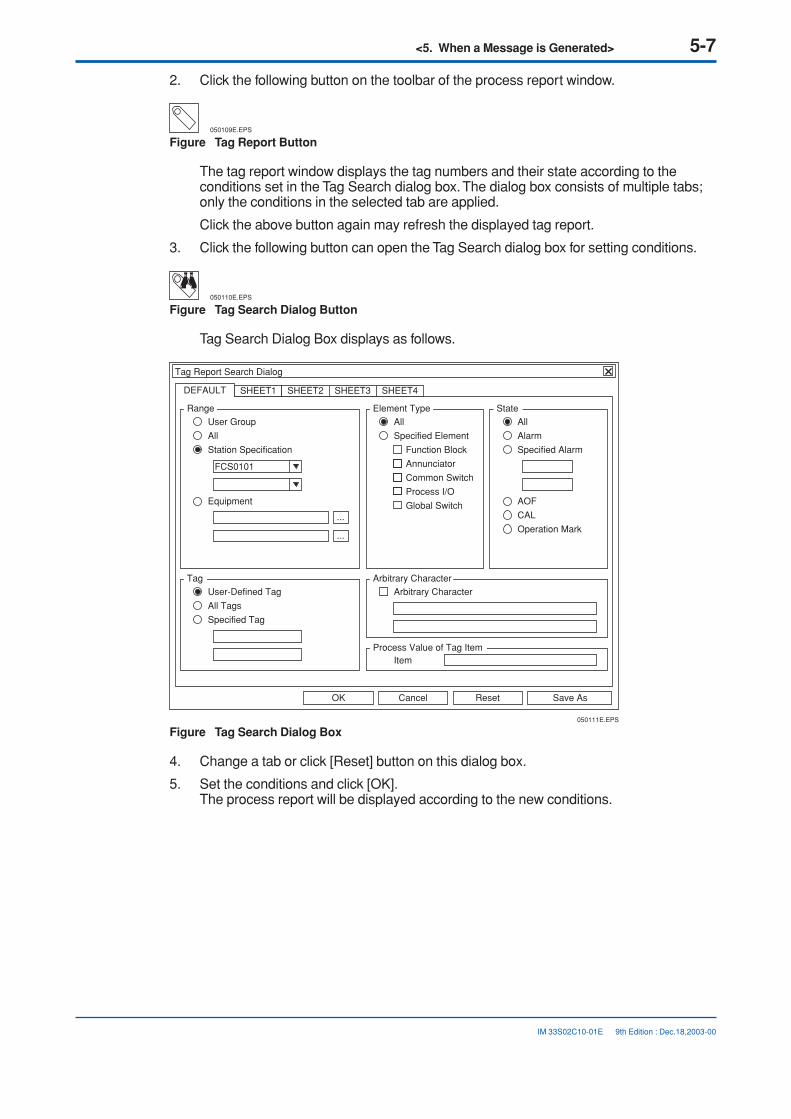
2. Click the following button on the toolbar of the process report window.
050109E.EPS
Figure Tag Report Button
The tag report window displays the tag numbers and their state according to theconditions set in the Tag Search dialog box. The dialog box consists of multiple tabs;only the conditions in the selected tab are applied.
Click the above button again may refresh the displayed tag report.
3. Click the following button can open the Tag Search dialog box for setting conditions.
050110E.EPS
Figure Tag Search Dialog Button
Tag Search Dialog Box displays as follows.
Save AsResetCancelOK
DEFAULT SHEET1 SHEET2 SHEET3 SHEET4
050111E.EPS
Tag Report Search Dialog
FCS0101
Range
Function Block
Annunciator
Common Switch
Process I/O
Global Switch
User Group
All
Station Specification
Equipment AOF
CAL
Operation Mark
Element Type
All
Specified Element
Tag
User-Defined Tag
All Tags
Specified Tag
Arbitrary Character
State
All
Alarm
Specified Alarm
...
...
ItemProcess Value of Tag Item
Arbitrary Character
Figure Tag Search Dialog Box
4. Change a tab or click [Reset] button on this dialog box.
5. Set the conditions and click [OK].The process report will be displayed according to the new conditions.
9th Edition : Dec.18,2003-00

5-8<5. When a Message is Generated>
IM 33S02C10-01E
● I/O Report
1. Choose [Process Report] on [Window Call Menu] of system message window.The process report window displays.
"I/O" FCS0101 %SW"TAG" DEFAULT
Tag Name Tag Comment Alarm Operation System Tag NameModeCurrent Value
FIC300 Discharge line A NR 80.0M3/H MAN .BL0158S010101
TIC100 Charge tank NR 20.0DEGC MAN IMAN Maint .BL0159S010101
LIC200 Discharge tank NR 36.0L/H MAN .BL0160S010101
PI150 Reactor NR 25.0PA AUT .BL0161S010101
MC100 Wash valve 1 NR 0.0% MAN .BL0162S010101
SIO220 Flowrate valve NR 1 MAN .BL0163S010101
LSW111 Agitator NR .BL0164S010101
SW330 Discharge line .BL0165S010101
01ST0002 NR 2 AUT .BL0166S010101
LC001 Transfer 1 NR MAN .BL0167S010101
LC002 Transfer 2 NR MAN .BL0168S010101
LIC001 NR 0.0% MAN .BL0169S010101
LIC002 NR 0.0% MAN .BL0170S010101
AN0001 Tank level error ALM 1 Maint .AN0001S010101
AN0002 Pump A fail NR 0 .AN0002S010101
AN0003 Tank A temp HI NR 0 .AN0003S010101
AN0004 Tank B temp LO NR 0 .AN0004S010101
AN0005 Tank A level HH NR 0 .AN0005S010101
AN0010 Tank B level HI NR 0 .AN0010S010101
AN11 Tank C level LO NR 0 .AN0011S010101
MORE
.PR Process Report
050112E.EPS
Figure Process Report Window
9th Edition : Dec.18,2003-00

<5. When a Message is Generated> 5-9
IM 33S02C10-01E
2. Click the following button on the toolbar of the process report window.
050113E.EPS
Figure I/O Report Button
The I/O report window displays the I/O points and their state according to the condi-tions set in the I/O Search dialog box.
Click the above button again may refresh the displayed I/O report.
3. Click the following button can open the I/O Search dialog box for setting conditions.
050114E.EPS
Figure I/O Search Dialog Button
The I/O Search Dialog Box displays.
CancelOK
Element Seed
FCS0101Subject Station
Annunciator
Common Switch
Process I/O
Communication I/O
Global Switch
050115E.EPS
I/O Report Search Dialog
Figure I/O Search Dialog Box
4. Set the conditions and click [OK].
9th Edition : Dec.18,2003-00

5-10<5. When a Message is Generated>
IM 33S02C10-01E 11th Edition : Mar.31,2005-00
5.2 Message SearchA message generated in the past can be redisplayed for confirmation. To search fora message, use the Filter dialog box , a function block or the historical messagereport window.
■ Finding a Message Using the Filter Dialog BoxUse the Filter dialog box to find a process alarm message, annunciator message, operatorguide message or system alarm message generated in the past. Using the filter dialog box,the messages that matched the filter conditions can be displayed separately from thedisplay of the entire messages.
The example below explains how to find a process alarm message:
1. Click on the filter button in the process alarm window.
050201E.EPS
1
2
3
4
5
6
7
8
9
10
.AL Process Alarm
Ready
10/28 10:18:15 FIC005 Flowrate 5 NR 33.0M3/H NR
10/28 10:18:15 FIC005 Flowrate 5 LO 33.0M3/H NR
10/28 10:18:05 Tank level error NR
10/28 10:17:45 FIC005 Flowrate 5 LO
10/28 10:17:45 Tank level error ALM
10/28 10:17:45 Tank temp error ALM
10/28 10:17:15 Pump fail NR
10/28 10:17:15 Pump fail ALM
10/28 10:17:05 FIC004 Flowrate 4 DV+ 50.0M3/H DV+
10/28 10:16:45 FIC003 Flowrate 3 HH 12.0M3/H HH
1.0m3/s
10/10Type: AllRange: All
Filter button
Figure Calling the Filter Dialog Box
<5. When a Message is Generated> 5-11
IM 33S02C10-01E 11th Edition : Mar.31,2005-00
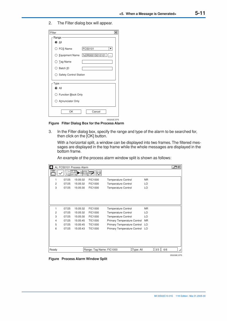
2. The Filter dialog box will appear.
CancelOK
All
Function Block Only
Annunciator Only
050202E.EPS
Filter
Type
Range
All
FCS Name
Equipment Name
Tag Name
Batch ID
Safety Control Station
FCS0101
Range
%DR0001S010101 ...
Figure Filter Dialog Box for the Process Alarm
3. In the Filter dialog box, specify the range and type of the alarm to be searched for,then click on the [OK] button.
With a horizontal split, a window can be displayed into two frames. The filtered mes-sages are displayed in the top frame while the whole messages are displayed in thebottom frame.
An example of the process alarm window split is shown as follows:
1
2
3
050208E.EPS
.AL FCS0101 Process Alarm
Ready
07/25 15:05:32 FIC1000 Temperature Control NR
07/25 15:05:32 FIC1000 Temperature Control LO
07/25 15:05:30 FIC1000 Temperature Control LO
1.0m3/s
1
2
3
4
5
6
07/25 15:05:32 FIC1000 Temperature Control NR
07/25 15:05:32 FIC1000 Temperature Control LO
07/25 15:05:30 FIC1000 Temperature Control LO
07/25 15:05:45 TIC1000 Primary Temperature Control NR
07/25 15:05:45 TIC1000 Primary Temperature Control LO
07/25 15:05:43 TIC1000 Primary Temperature Control LO
3/3 6/6Range: Tag Name: FIC1000 Type: All
Figure Process Alarm Window Split

5-12<5. When a Message is Generated>
IM 33S02C10-01E 12th Edition : Dec.26,2005-00
■ Finding a Message Using a Function BlockMessages associated with a function block can be called from the function block.
The example below explains how to call a process alarm message from the trend window.
1. Select a trend pen in the trend window.
TRTANK Tank A
100%05:30
10:00 12:0012.03
13:00 14:00 15:0012.03
12/26/2005
FIC001. PVInlet flow
(100.0%)
( 0.0%)
1
1
FIC002. PVOutlet flow
2
2
LIC100. PVLevel
3
3
TIC100. PVTemp A
4
4
TIC200. PVTemp B
5
5
6
6
7
7
8
8
80.0
60.0
40.0
20.0
0.0
100.0 72.1 M3/H
53.3 M3/H
3.8 M
25.7 DEGC
14.1 DEGC
0.0 0.0 0.0 0.0 0.0
1 2 3 4 5
6 7 8
100.0 100.0 10.0 100.0 100.0
Gathering
13:18:30
050203E.EPS
1
2
Ready
ClickMouse
Figure Selecting the Function Block
2. In the system message window, click on the process alarm button in the window callmenu or the process alarm button in the tool box.
050204E.EPS
Tool Box
Window call menu button
Toolbox button System message window
Window call menu
ToolboxProcess alarm button
Process Alarm
Figure Selecting the Process Alarm Button

<5. When a Message is Generated> 5-13
IM 33S02C10-01E 12th Edition : Dec.26,2005-00
3. The process alarm window will open, displaying process alarm messages associatedwith the trend pen (FIC001) selected in the trend window.
1
2
3
050205E.EPS
.AL Process Alarm
Ready
10/28 01:18:30 PM FIC001 Tank Flowrate 1 NR 50.1M3/H NR
10/28 01:18:30 PM FIC001 Tank Flowrate 1 LO 72.1M3/H NR
10/28 10:17:45 AM FIC001 Tank Flowrate 1 LO 72.1M3/H NR
1.0m3/s
3/3 Type: AllRange: All
Figure Process Alarm Window

5-14<5. When a Message is Generated>
IM 33S02C10-01E
■ Confirming from the Historical Message Report WindowIn the historical message report window, all messages occurred in the past, no matter ifthey are alarm messages, operation messages or other types of messages, are stored andcan be confirmed.
1. Click on the historical report button in the window call menu or tool box.
050206E.EPS
Tool BoxHistorical Report
Window call menu button
Toolbox button
System message window
Window call menu
ToolboxHistorical report button
Figure Selecting the Historical Report Button
2. After calling up the historical message report window, the messages in the windowmay be confirmed.
20 Items Found
Message No Date Message Text
Ready
Historical Report - [Operation and Monitoring Message]
File Edit View Window Help
12061201120612011206120112061201110611021101120612011206120111061102120611011201
05/12/2605/12/2605/12/2605/12/2605/12/2605/12/2605/12/2605/12/2605/12/2605/12/2605/12/2605/12/2605/12/2605/12/2605/12/2605/12/2605/12/2605/12/2605/12/2605/12/26
11:59:4011:59:3811:59:3711:59:3511:59:3311:59:3111:59:2911:59:2811:24:5411:24:5411:24:3411:24:0411:23:4711:23:4411:23:3110:49:3510:49:3510:49:2810:49:2310:48:58
Tank level errorTank level errorTank level errorTank level errorTank level errorTank level errorTank level errorTank level errorFIC008FIC008FIC008Pump A failAgitator failAgitator failPump A failFIC005FIC005Tank level errorFIC005Tank level error
Flowrate 8Flowrate 8Flowrate 8
Flowrate 5Flowrate 5
Flowrate 5
NRALMNRALMNRALMNRALM
NRALMNRALM
NR
ALM
NRPV = 55.0 M3/H LO RecoverPV = 50.0 M3/H LO
NRPV = 60.0 M3/H LO Recover
PV = 59.1 M3/H LO
STOP
050207E.EPS
Figure Historical Message Report Window
12th Edition : Dec.26,2005-00

<5. When a Message is Generated> 5-15
IM 33S02C10-01E
5.3 Messages On Help Dialog BoxThe help messages assigned to the function block faceplates and windows as wellas the help messages of occurred alarms can be displayed on help dialog box.
■ Help Messages of Occurred System Alarms1. Click the following button to open the system alarm window.
050301E.EPS
Figure System Alarm Button
2. Choose an alarm message and click the following button.
050302E.EPS
HELP
Figure Help Button
A dialog box with the help messages for the occurred alarm is displayed.
■ User-Defined Help Messages for Function Blocks or Windows1. Open a faceplate or a window by entering the name directly or using the related
button.The faceplate or the window displays.
2. Activate the window or the faceplate on the desktop and then click [HELP] button onthe toolbar.A dialog box with the help messages for the faceplate or the window is displayed.
9th Edition : Dec.18,2003-00

5-16<5. When a Message is Generated>
IM 33S02C10-01E
■ Search Help Message On Help Dialog Box1. Deactivate all the windows displayed on the desktop.
2. Click [HELP] button on the toolbar.A dialog box displays.
Message number 9100
.HW Help
Search key
When process C starts, close the distillation tower intake valve.
Cancel
Display
050303E.EPS
Figure Help Dialog Box
3. Choose a search key from the list.The following search keys are available:
• Window Name
• Tag Name
• Message Number
• Help Number
4. Enter an alphanumeric string to the field at right-hand side of the search key, and thenclick [Display] button.The detailed help message matches the above condition will be displayed.
9th Edition : Dec.18,2003-00

<6. Reading the Trend of Process Data> 6-1
IM 33S02C10-01E
6. Reading the Trend of Process DataUse the trend recording to read the trend of past data. With the trend recording,process data acquired from the plant can be saved and the saved data can be dis-played.
9th Edition : Dec.18,2003-00

6-2<6. Reading the Trend of Process Data>
IM 33S02C10-01E
6.1 Confirming Data in the Trend WindowThe acquired data can be displayed in the trend window.
In the trend window, data can be displayed as it is acquired, or previously acquireddata can be displayed again.
■ Displaying Acquired Data in the Trend Window1. Call the trend window.
SEE ALSO
For the steps to call the trend window, see the following:
2, “Calling the Graphic Windows”
2. The trend window displays the acquired data in a graph or the present values innumeric values.
TRTANK Tank A
100%05:30
10:00 12:0012.03
13:00 14:00 15:0012.03
12/26/2005
FIC001. PVInlet flow
(100.0%)
( 0.0%)
1
1
FIC002. PVOutlet flow
2
2
LIC100. PVLevel
3
3
TIC100. PVTemp A
4
4
TIC200. PVTemp B
5
5
6
6
7
7
8
8
80.0
60.0
40.0
20.0
0.0
100.0 72.1 M3/H
53.3 M3/H
3.8 M
25.7 DEGC
14.1 DEGC
0.0 0.0 0.0 0.0 0.0
1 2 3 4 5
6 7 8
100.0 100.0 10.0 100.0 100.0
Gathering
13:18:30
060101E.EPS
1
2
Ready
Figure Trend Window
12th Edition : Dec.26,2005-00

<6. Reading the Trend of Process Data> 6-3
IM 33S02C10-01E
■ Displaying Collected Data On Trend Point Window1. Double click a tag name in the trend window, or choose a trend pen and click [Display]
key, the corresponding trend point window can be displayed.
060102E.EPS
FIC001. PV Inlet Flow
100%05:30
10:00* 12:0012.03
13:00 14:00 15:0012.03
12/26/2005
FIC001. PVInlet Flow
(100.0%)
( 0.0%)
1
1
80.0
60.0
40.0
20.0
0.0
100.0 72.1 M3/H
0.0
1100.0
Gathering
13:18:30
Ready
Figure Trend Point Window
When a batch trend is displayed, if a reference pattern is assigned to the displayedtrend pen the reference pattern will be displayed too.
12th Edition : Dec.26,2005-00

6-4<6. Reading the Trend of Process Data>
IM 33S02C10-01E
6.2 Changing the Assignment of Trend Data BeingDisplayedThe assignment of trend pens being displayed in the trend window can be changed.The assignment of trend group can be changed by using the Pen Assignment dialogbox or by selecting a file in which trend data is saved.
This section explains how to change the assignment of trend pens.
9th Edition : Dec.18,2003-00

<6. Reading the Trend of Process Data> 6-5
IM 33S02C10-01E
■ Operation from the Pen Assignment Dialog Box1. In the trend window, click on the following button on the tool bar.
060201E.EPS
2. The Pen Assignment dialog box will appear.
CancelOK
Initialize
Pen Assignment Reference Pattern
060202E.EPS
Pen Assignment
Collected Lower Upper DisplaySet Upper/Lower Limit
1 FIC100.PV
Block
2 LIC100.PV
3 PIC100.PV
4 AIC100.MV
5 AIC200.SV
6
7
8
0.0
0.0
0.0
0.0
0.0
0
0
0
100.0
10.0
10.0
100.0
100.0
0
0
0
1:Rotary 01min. 2.00:00:00
Figure Pen Assignment Dialog Box (Pen Assignment)
3. Set the data to be acquired and high/low limits in the Pen Assignment dialog box. Ifhigh/low limits are not specified, the trend graph to be displayed will use the valuesdefined via the trend gathering pen assignment builder.
4. To display desired data in the trend window, mark off the corresponding check boxunder [Display].
5. Click on the [OK] button.
6. The trends checked in the pen assignment dialog box will be displayed.
9th Edition : Dec.18,2003-00

6-6<6. Reading the Trend of Process Data>
IM 33S02C10-01E
■ Changing the Pen Assignment via File Selection1. In the trend window, click on the following button on the tool bar.
060203E.EPS
2. A dialog box will appear; choose a file in which trend data is saved.
Open ?
Look in:
TG0101.trfTG0102.trfTG0103.trf
File name:
Files of type:
Trend
060204E.EPS
File Comment
Preserved File(*.trf)
Open
Cancel
TG0101.trf
Figure Open Dialog Box
3. Select a desired file.
4. Click on the [Open] button.
5. The data saved in the selected file will be displayed in the current trend window.
TIP
To restore the previous display after changing the trend pen assignment, call the window again.
9th Edition : Dec.18,2003-00

<6. Reading the Trend of Process Data> 6-7
IM 33S02C10-01E 9th Edition : Dec.18,2003-00
6.3 Creating/Displaying Trend Reference PatternsIn the trend window, trend reference patterns that are used as templates for trendgraphs can be displayed.
This section explains how to create and display trend reference patterns.
■ Creating a Trend Reference Pattern1. In the trend window, click on the following button on the tool bar.
060301E.EPS
2. A dialog box to save trend data will appear.
060302E.EPS
Save As ?
Save in:
File name:
Save as type
Trend
TG0201.trf
Preserved File(*.trf) Cancel
Save
Figure Save As Dialog Box
3. Specify the file in which to save trend data, as well as the location of the saved file.
4. Click on the [Save] button.
5. The Input Comment dialog box will appear.To change the pen comment to be displayed in the trend window, enter the newcomment.
060303E.EPS
Input Comment
File Name C\CS1000\his\save\TREND\TG0201.trf
File Comment Distillation
1 FIC100.PV Distillation A
2 FI101.PV Inlet A
3 FI102.PV Outlet A
4 FIC200.PV Distillation B
5 FI201.PV Inlet B
6
7
8
CancelOK
Figure Input Comment Dialog Box
6. Click on the [OK] button.

6-8<6. Reading the Trend of Process Data>
IM 33S02C10-01E 9th Edition : Dec.18,2003-00
■ Displaying a Trend Reference Pattern1. In the trend window, click on the following button on the tool bar.
060304E.EPS
2. The Pen Assignment dialog box will appear.
CancelOK
060305E.EPS
Pen Assignment
Pen Assignment Reference Pattern
1
File Name Specify File
2
3
4
5
6
7
8
DisplayTrend reference pattern data
Figure Pen Assignment Dialog Box (Reference Pattern)
3. Click on the [Specify File] button in the Pen Assignment dialog box.

<6. Reading the Trend of Process Data> 6-9
IM 33S02C10-01E
4. A dialog box will appear; select a file in which the trend reference pattern is saved.
Open ?
Look in:
File name:
Files of type:
Trend
060306E.EPS
File Comment
Preserved File(*.trf)
Open
Cancel
TG0201.trf
TG0101.trfTG0102.trfTG0103.trf
Figure Open Dialog Box
5. Select a file containing the reference pattern to be displayed, and click on the [Open]button.
6. In the Pen Assignment dialog box, click on the check boxes located on the left of pennumbers. This enables selection of trend reference pattern data corresponding to thepens with a check mark.
7. From the combo box, select the data to be displayed as a trend reference pattern.
8. Click on the [OK] button.
9. In the trend window, click on the following button on the tool bar.
060307E.EPS
The trend reference pattern will be displayed in the trend window.
To erase the trend reference pattern and return to the previous display of acquireddata, click on the button again.
9th Edition : Dec.18,2003-00

Blank Page

<7. Outputting Screen Images> 7-1
IM 33S02C10-01E
7. Outputting Screen ImagesUse the print screen function to output the screen image. In addition to the screenimages currently displayed, images that have been output once can be output againusing the print screen function.
9th Edition : Dec.18,2003-00

7-2<7. Outputting Screen Images>
IM 33S02C10-01E
7.1 Outputting the Screen Image of CurrentlyDisplayed WindowsWhen outputting the screen image of currently displayed windows, either the imageof a particular window only or all images being displayed on the screen can beoutput.
In addition, the screen image can be output to a file as well as to the printer.
■ Outputting a Particular Window Image OnlyThe following explains how to output to the printer the image of one particular windowamong all windows currently displayed.
1. In a window currently displayed, click on the following button on the tool bar.
070101E.EPS
2. The image of the window in which the button was clicked will be output to the printer.
In the example shown below, clicking on the button in the graphic window outputs theimage of the graphic window only. Images of other windows will not be output.
Book 1
Command
A
21
34567891011121314
B C D E F
Sheet8Sheet7Sheet6Sheet5Sheet4Sheet3Sheet2Sheet1
A1
File Edit View Insert Format Tool Window Help
070102E.EPS
12/26/2005 11:11
FIC100 Inlet flow L0
Start
FIS2001A
FIS2002A
FIS2003A
Reactor inside Pressure
Steam
Coolant
Reactor Control
GRREACTORA Reactor control
?
100.0
0.0
Reactorflow
AUTNRPV M3/H 55.3SV M3/H 50.0MV % 65.1
FIC100 Reactor flow
FIC100
NAME COPY
FIS2011A Shipping : 180.0 /min Reactor
StandbyCharging
Heat applicaReactionCoolingShipping
End
Production
TIC2001ATemp A198.2DEGC
TIC2002ATemp A255.2DEGC
My Computer
My NetworkPlaces
Recycle Bin
Window of general-purposeWindows application
Faceplate windowGraphic Window
Figure Example of Printer Output 1
12th Edition : Dec.26,2005-00

<7. Outputting Screen Images> 7-3
IM 33S02C10-01E
■ Outputting All Images Displayed on the Screen1. Click on the following button in the system message window.
070103E.EPS
COPY
2. All images displayed on the screen will be output to the printer.
In the example shown below, all images including the image of the general-purposeWindows application window will be output to the printer.
Book 1
Command
A
21
34567891011121314
B C D E F
Sheet8Sheet7Sheet6Sheet5Sheet4Sheet3Sheet2Sheet1
A1
File Edit View Insert Format Tool Window Help
070104E.EPS
12/26/2005 11:11
FIC100 Inlet flow L0
Start
FIS2001A
FIS2002A
FIS2003A
Reactor inside Pressure
Steam
Coolant
Reactor Control
GRREACTORA Reactor control
?
100.0
0.0
Reactorflow
AUTNRPV M3/H 55.3SV M3/H 50.0MV % 65.1
FIC100 Reactor flow
FIC100
NAME COPY
FIS2011A Shipping : 180.0 /min Reactor
StandbyCharging
Heat applicaReactionCoolingShipping
End
Production
TIC2001ATemp A198.2DEGC
TIC2002ATemp A255.2DEGC
My Computer
My NetworkPlaces
Recycle Bin
Window of general-purposeWindows application
Faceplate windowGraphic Window
System message window
Figure Example of Printer Output 2
12th Edition : Dec.26,2005-00

7-4<7. Outputting Screen Images>
IM 33S02C10-01E
■ Outputting the Screen Image to a File1. Click on the system status display button in the window call menu or tool box.
070105E.EPS
Tool Box
SYS
System Status DisplaySYS
System message window
Window call menu buttonToolbox button
Toolbox
System status display button
Window call menu
Figure Selecting the System Status Display Button
2. The system status overview window will appear.
3. Click on the HIS setup button on the toolbar of the system status overview window.
070106E.EPS
.SO System Status Overview
FCS0101 FCS0103FCS0102 FCS0104 FCS0105 FCS0106
MYPJT Domain : 01 VL net1 VL net2
Fail
Fail
FCS
IOMFCS
HIS Setup button
Figure Calling a HIS Setup Window
9th Edition : Dec.18,2003-00

<7. Outputting Screen Images> 7-5
IM 33S02C10-01E
4. A printer tab strip of the HIS setup window will open.
ApplyCancelOK
070107E.EPS
MSG1
MSG2
MSG3
MSG4
MSG5
PRT
Message and Report
System Default
10
Print Setup
Orientation Font Size
Portrait
Landscape
Message Printer Assignment
Hardcopy
EM-930C Invert Print
Canon LBP-1310
Canon LBP-1310
Canon LBP-1310
Canon LBP-1310
Canon LBP-1310
Canon LBP-1310
Print Printer Name
Monochrome PrintOutput to File
Line Print/YPR
.SH HIS Setup
REPORT Process Management Multiple-MonitorEqualize Function Keys Operation Mark Multimedia Long-Term
OPCStation Window Swithcing NavigatorBuzzer Display Alarm
Preset Menu
Printer
Figure HIS Setup Window
5. Mark off the check box next to [Output to File] in the printer tab strip.
6. Click on the button to output the screen image(s) to the printer. The screen image(s)will be output to a file as well as to the printer.
The file will be output in bitmap (.bmp) format. When recalling the screen image, theimage window can be used to open the file.
10th Edition : Oct.28,2004-00

7-6<7. Outputting Screen Images>
IM 33S02C10-01E 9th Edition : Dec.18,2003-00
7.2 Outputting the Previously Output ScreenImages AgainA screen image can be saved to a file so that it can be output to the printer or dis-played on the screen again.
■ Displaying a Screen ImageScreen images saved to a file can be displayed in the image window.
1. Click on the window call menu button in the system message window.
2. The window call menu will appear.
3. Click on the image button in the window call menu.
070201E.EPS
Image
Window call menu button System message window
Window call menu
Figure Calling an Image Window

<7. Outputting Screen Images> 7-7
IM 33S02C10-01E 12th Edition : Dec.26,2005-00
4. An image window will open.
The displayed image window shows the last output screen image.
Book 1
Command
A
21
34567891011121314
B C D E F
Sheet8Sheet7Sheet6Sheet5Sheet4Sheet3Sheet2Sheet1
A1
File Edit View Insert Format Tool Window Help
05/12/26
FIC100 Inlet flow L0
Reactor
Production
StandbyCharging
Heat applicaReactionCoolingShipping
End
FIS2011A Shipping: 180.0 /min
FIS2001A
FIS2002A
FIS2003A
Reactor inside Pressure
Steam
Coolant
Reactor Control
GRREACTORA Reactor control
Ready
?
0.
100.
Reactor flow
AUTNRPV M3/ 58. SV M3/ 50. MV 65.
FIC1000 Reactor flow
FIC100
NAME COPY
070202E.EPS
Image window C\CS3000\HIS\save\bmp\FullScreen_1.bmp
Ready NUM
TIC2001ATemp A98.2DEGC
TIC2002ATemp B55.2DEGC
My Computer
My NetworkPlaces
Recycle Bin
Window of general-purpose Windows application
Operation and monitoring window
Operation and monitoring window
Figure Image Window

7-8<7. Outputting Screen Images>
IM 33S02C10-01E
5. Click on the following button in the image window.
070203E.EPS
6. A dialog box will appear; select a screen image saved in a file.
Open ?
Look in:
File name:
Files of type:
070204E.EPS
Open
Cancel
*.bmp
*.bmp
FullScreen_1.bmp
bmp
Figure Open Dialog Box
7. Select a file containing the screen image to be displayed.
8. Click on the [Open] button.
9. The screen image saved in the selected file will be displayed in the image window.
9th Edition : Dec.18,2003-00

<7. Outputting Screen Images> 7-9
IM 33S02C10-01E 9th Edition : Dec.18,2003-00
■ Outputting a Screen Image to the PrinterThe screen image displayed in the image window can be output to the printer.
1. In the image window, click on the following button on the tool bar.
070205E.EPS
2. A dialog box to perform print setting will appear.
Cancel
OK
070206E.EPS
EM-930CPrinter
Reverse Monochrome
Figure Print Dialog Box
3. Set the output destination printer and output mode.

Blank Page

<8. When a System Error Occurred> 8-1
IM 33S02C10-01E
8. When a System Error OccurredWhen a system error occurs, an alarm tone will sound and a system alarm messagewill be generated to notify the operator.
SEE ALSO
For more information about setting the alarm tones, see the following:
E7.3.3, “Buzzer Tab” of “CS 1000/CS 3000 Reference (IM 33S01B30-01E)”
■ Confirming from the System Message WindowWhen a system alarm message is generated, the corresponding button in the systemmessage window will flash.
080001E.EPS
DataBase Equalize Complete
Flashes when a system alarm message occurs System message window
Message display
Figure Buttons in the System Message Window
1. When a system alarm is generated, the corresponding button in the system messagewindow will flash and a system alarm message will appear in the message displayarea.
2. Click on the message display area or flashing button in the system message window.
3. The system alarm window will open.
9th Edition : Dec.18,2003-00

8-2<8. When a System Error Occurred>
IM 33S02C10-01E
4. To acknowledge all messages at once, click on the acknowledge button.
To acknowledge messages individually, select the messages to be acknowledged andclick on the acknowledge button.
26/77Range: All
1 0823 01/14 03:20:01 Printer EPSON MJ-930C Offline 2 0502 01/14 02:31:02 DataBase Equalize Complete 3 0510 01/14 02:30:57 Data Base Download from YOKOGAWA File = ClsDef.odb 4 0510 01/14 02:30:57 Data Base Download from YOKOGAWA File = TrDspAssign.odb 5 0510 01/14 02:30:57 Data Base Download from YOKOGAWA File = TrAssign.odb 6 0502 01/14 02:29:33 DataBase Equalize Complete 7 0510 01/14 02:29:23 Data Base Download from YOKOGAWA File = ClsMng.odb 8 0510 01/14 02:29:23 Data Base Download from YOKOGAWA File = TrDef.odb 9 0823 01/12 09:50:03 Printer EPSON MJ-930C Offline 10 0502 01/12 09:28:46 DataBase Equalize Complete 11 0510 01/12 09:28:37 Data Base Download from YOKOGAWA File = OGAR010101.odb 12 0510 01/12 09:28:37 Data Base Download from YOKOGAWA File = SDAR010101.odb 13 0510 01/12 09:28:37 Data Base Download from YOKOGAWA File = Inst0357.odb 14 0510 01/12 09:28:37 Data Base Download from YOKOGAWA File = TFAR010101.odb 15 0510 01/12 09:28:37 Data Base Download from YOKOGAWA File = TFFCS0101.odb 16 0471 01/12 09:28:28 FCS0101 Online Download Complete 17 0502 01/09 06:29:46 DataBase Equalize Complete 18 0510 01/09 06:29:41 Data Base Download from YOKOGAWA File = OPSBL1.dsp 19 0510 01/09 06:29:41 Data Base Download from YOKOGAWA File = UTSW1.dsp 20 0510 01/09 06:29:41 Data Base Download from YOKOGAWA File = OPSFC1.dsp 21 0510 01/09 06:29:41 Data Base Download from YOKOGAWA File = SFCSW1.dsp 22 0510 01/09 06:29:41 Data Base Download from YOKOGAWA File = OGAR010101.odb 23 0510 01/09 06:29:41 Data Base Download from YOKOGAWA File = SDAR010101.odb 24 0510 01/09 06:29:41 Data Base Download from YOKOGAWA File = Inst0357.odb 25 0510 01/09 06:29:40 Data Base Download from YOKOGAWA File = TFAR010101.odb 26 0510 01/09 06:29:40 Data Base Download from YOKOGAWA File = TFFCS0101.odb
080002E.EPS
.SA System Alarm Message
Ready
HELP
Acknowledge button
Delete button
Figure Acknowledging the System Alarm Message
5. With a group acknowledgment, all of the unacknowledged messages are acknowl-edged; with an individual acknowledgment, the selected messages are acknowl-edged.
6. Click on the delete button.
7. All of the acknowledged messages will be deleted.
11th Edition : Mar.31,2005-00

<8. When a System Error Occurred> 8-3
IM 33S02C10-01E
■ Confirming from the Navigator WindowWhen a system alarm message is generated, the following symbol will change to alarmcolor in the navigator window.
080003E.EPS
Figure System Alarm Message Symbol in the Navigator Window
1. When a system alarm is generated, the system message Window symbol in thenavigator window will change to alarm color.
2. Double-click on the color changed icon.The system alarm window will open.
3. Confirm the message contents in the system alarm window.
To acknowledge the message, follow the same steps used to acknowledge messagesfrom the system message window.
■ Confirming in the System Status Overview Window1. Call the system status overview window
080004E.EPS
.SO System Status Overview
Ready
FCS0101 FCS0103FCS0102 FCS0104 FCS0105 FCS0106
MYPJT V net1 V net2
Fail
Fail
HIS0121 HIS0122HIS0119 HIS0120 HIS0123 HIS0124
FCS
IOMFCS
ACG0109 BCVL0111ACG0110 BCVL0112
Domain : 01
Figure System Status Overview Window (CS 3000 system)
SEE ALSO
For the steps to call the system status overview window, see the following:
“■ Outputting the Screen Image to a File” in 7.1, “Outputting the Screen Image of Currently DisplayedWindows”
13th Edition : Dec.26,2006-00

8-4<8. When a System Error Occurred>
IM 33S02C10-01E
2. Call individual status display windows from the system status overview window.
Double-click on the FCS icon to call the FCS status display window; double-click onthe BCV icon to call the BCV status display window.
080005E.EPS
Fail
Fail
Both sides CPU Fail
Left side CPU Fail
Right side CPU Fail
Figure FCS Error Status Display
080006E.EPS
Communication error
Figure BCV Error Status Display
080007E.EPS
Figure Under Test
9th Edition : Dec.18,2003-00

Ind-1
IM 33S02C10-01E
CS 1000/CS 3000HIS Operation
INDEX
13th Edition : Dec.26,2006-00
IM 33S02C10-01E 13th Edition
BBlock Mode Change Operation Dialog Box ......... 4-5
CCalling a General-purpose Windows
Application ................................................3-4Calling a Hierarchy Window ................................ 2-8Calling a User-Defined Window .......................... 2-6Calling an Upper Window.................................... 2-7Calling from the Name Input Dialog Box .............. 2-5Calling from the Navigator Window ..................... 2-4Calling from the System Message Window ......... 2-2Calling the Saved Windows ................................. 3-7Changing Block Mode Using the Menu ............... 4-6Changing Faceplate Assignment ........................ 2-9Changing the Data Item ......................................4-3Changing the Pen Assignment via
File Selection ............................................6-6Checking the Saved Window Set ........................ 3-8Circulate Operation .............................................3-5Confirming from the Message Monitor Window ... 5-5Confirming from the Navigator Window ............... 5-4Confirming from the System Message Window ... 5-2Creating a Trend Reference Pattern .................... 6-7
DData Entry Dialog Box .........................................4-2Displaying a Screen Image ................................. 7-6Displaying a Trend Reference Pattern ................. 6-8Dynamic Window Set .......................................... 3-6
FFilter Dialog Box ............................................... 5-10Finding a Message Using a Function Block ....... 5-12
HHistorical Message Report Window .................. 5-14
IINC/DEC Operation Dialog Box .......................... 4-4Instrument Faceplate .......................................... 4-1
MMessage .............................................................5-1Messages On Help Dialog Box ......................... 5-15
OOperation And Monitoring Windows ....................1-4Operation Mark on Instrument Faceplate ............ 4-7Operation Panel Mode ........................................3-2Outputting a Screen Image to the Printer ............ 7-9Outputting Screen Images ..................................7-1Outputting the Screen Image to a File ................. 7-4
PPen Assignment Dialog Box ................................6-5
SSaving Windows .................................................3-6Security Check ...................................................1-2Starting up HIS ...................................................1-1Switching Bind Data of Graphic Displays .......... 2-10System Status Overview Window ....................... 8-3
TTight-Shut Output ...............................................4-8Toolbar of System Message Window .................. 1-6Trend Window.....................................................6-2
UUsing Shortcut Keys ...........................................3-9Using the Context Menus in Graphic Window ... 3-12
VViewing Process Report ......................................5-6

Ind-2
IM 33S02C10-01E 12th Edition : Dec.26,2005-00
WWhen a System Error Occurred .......................... 8-1
ZZoom In and Zoom Out of Graphic Window ...... 2-11