doc022.98.80315 symphony™ benchtop meters
TRANSCRIPT
DOC022.98.80315
sympHony™ Benchtop MetersB10P, B10C, B20PI, B30PCI & B40PCID models
09/2012, Edition 2
User ManualManual del UsuarioManuel d'utilisation
BedienungsanleitungManuale d'uso

Table of Contents
Section 1 Specifications .................................................................................. 3
Section 2 General information ....................................................................... 62.1 Safety information ....................................................................................... 6
2.1.1 Use of hazard information ................................................................ 62.1.2 Precautionary labels ......................................................................... 6
2.2 Certification ................................................................................................. 7
Section 3 Product overview ............................................................................ 83.1 Product components ................................................................................... 8
Section 4 Installation ........................................................................................ 94.1 Probe and peripheral circuit connection ...................................................... 94.2 Connect to AC power ................................................................................ 104.3 Connector panels ...................................................................................... 11
Section 5 User interface and navigation .................................................. 155.1 User interface ........................................................................................... 155.2 Display description .................................................................................... 165.3 Navigation ................................................................................................. 18
Section 6 Startup ............................................................................................. 206.1 Turn the meter on and off ......................................................................... 206.2 Initial startup ............................................................................................. 20
Section 7 Standard operations .................................................................... 217.1 Calibration ................................................................................................. 21
7.1.1 Calibration settings ......................................................................... 217.1.2 Calibration procedure ..................................................................... 257.1.3 Calibration to a specific value ......................................................... 257.1.4 Custom values ................................................................................ 267.1.5 View the calibration data ................................................................ 267.1.6 Temperature correction .................................................................. 277.1.7 Isothermal point .............................................................................. 277.1.8 Calibration Reminder ...................................................................... 28
7.2 Sample measurements ............................................................................. 287.2.1 Simultaneous measurement without PROFILES ............................ 287.2.2 Simultaneous measurements with PROFILES ............................... 297.2.3 Channel setup ................................................................................ 297.2.4 Measurement setup ........................................................................ 307.2.5 Measurement modes ...................................................................... 337.2.6 pH and ORP measurement setup ................................................... 337.2.7 Conductivity measurement setup ................................................... 347.2.8 Ion Selective Electrode (ISE) measurement setup ......................... 347.2.9 Dissolved oxygen measurement setup ........................................... 34
Section 8 Advanced operations .................................................................. 368.1 Meter options ............................................................................................ 368.2 Use a sensor ID (for ISEs) ........................................................................ 378.3 Use a sample ID ....................................................................................... 37
1
Table of Contents
8.4 Data Output ...............................................................................................388.5 Password ...................................................................................................388.6 Change the date and time .........................................................................388.7 Adjust the display contrast and backlight ..................................................398.8 Configure the sample stirring .....................................................................398.9 Activate the stirrer ......................................................................................398.10 Manually enter the temperature ...............................................................408.11 Probe data ...............................................................................................408.12 Test user interface ...................................................................................408.13 Manage users ..........................................................................................408.14 Manage profiles .......................................................................................418.15 Restore the factory settings .....................................................................418.16 Use a PC keyboard .................................................................................41Section 9 Data logger .....................................................................................439.1 Activate the data logger .............................................................................439.2 Store data ..................................................................................................43
9.2.1 Sample identification .......................................................................449.3 View measurement data ............................................................................449.4 Print data ...................................................................................................459.5 Send data to a PC: PC CSV format ...........................................................469.6 Send data to a PC: PC Report format .......................................................47
Section 10 Maintenance ................................................................................4810.1 Clean the instrument ...............................................................................4810.2 Clean the probe .......................................................................................48
Section 11 Troubleshooting ..........................................................................49
Appendix A CSV Format ................................................................................51A.1 CSV measurement lines ...........................................................................51
A.1.1 CSV measurement item descriptions .............................................51A.1.2 CSV measurement items depending on the model .......................53
A.2 CSV calibration lines.................................................................................54A.2.1 CSV calibration item descriptions ..................................................55A.2.2 CSV calibration items depending on the model .............................58
Appendix B Standard solutions ...................................................................63B.1 Technical buffer solutions .........................................................................63B.2 NIST buffer solutions.................................................................................64B.3 Conductivity standard solutions ................................................................64
2
Section 1 Specifications
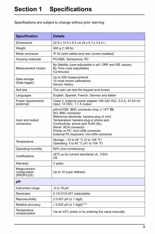
Specifications are subject to change without prior warning.
Specification Details
Dimensions 22.9 x 14.5 x 8.5 cm (9 x 5.7 x 3.4 in.)
Weight 900 g (1.98 lb)
Meter enclosure IP 54 (with cables and rear covers installed)
Housing materials PC/ABS, Santoprene, PC
Measurement modesBy Stability (user-adjustable in pH, ORP and ISE values)By Time (user-adjustable)Continuous
Data storage(Data logger)
Up to 500 measurements10 most recent calibrationsSensor history
Self test The user can test the keypad and screen
Languages English, Spanish, French, German and Italian
Power requirements (external)
Class II, external power adapter 100-240 VAC, 0.4 A, 47-63 Hz input, 12 VDC, 1.1 A output
Input and outputconnectors
pH/mV/ISE: BNC connector (imp. ≥ 1012 Ω)DO: BNC connectorReference electrode: banana plug (4 mm)Temperature: banana plug or phone jackConductivity: phone jack RJ45 (8c)Stirrer: RCA connectorPrinter or PC: mini-USB connectorExternal PC keyboard: mini-DIN connector
Temperature Storage: –15 to 65 °C (5 to 149 °F)Operating: 5 to 40 °C (41 to 104 °F)
Operating humidity 80% (non-condensing)
Certifications cETLus (to current standards UL, CSA)CE
Warranty 3 years
Measurement configuration (PROFILES)
Up to 10 (user defined)
pH
Instrument range -2 to 19 pH
Resolution 0.1/0.01/0.001 (selectable)
Reproducibility ± 0.001 pH (± 1 digit)
Relative accuracy ≤ 0.002 pH (± 1 digit)****
Temperature compensation Via an ATC probe or by entering the value manually
3
Specifications
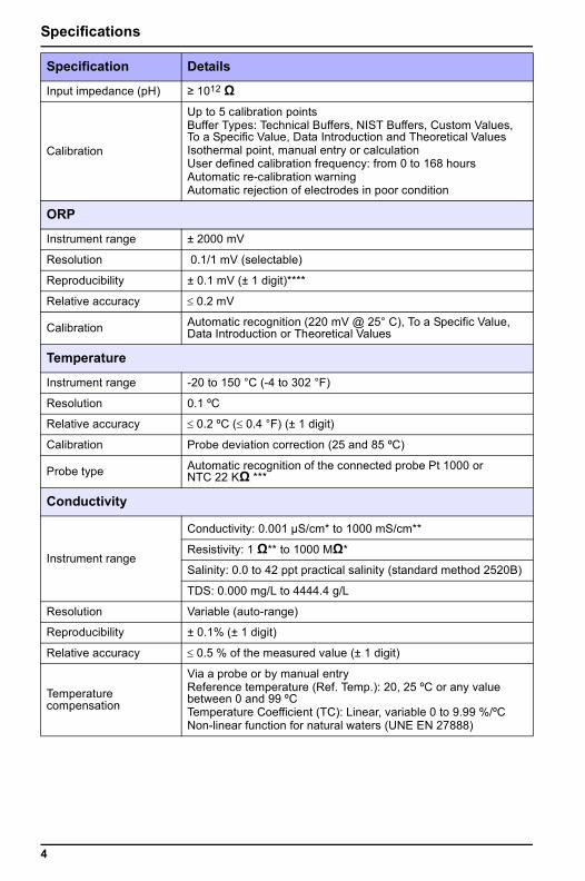
Input impedance (pH) ≥ 1012 Ω
Calibration
Up to 5 calibration pointsBuffer Types: Technical Buffers, NIST Buffers, Custom Values, To a Specific Value, Data Introduction and Theoretical ValuesIsothermal point, manual entry or calculationUser defined calibration frequency: from 0 to 168 hoursAutomatic re-calibration warningAutomatic rejection of electrodes in poor condition
ORP
Instrument range ± 2000 mV
Resolution 0.1/1 mV (selectable)
Reproducibility ± 0.1 mV (± 1 digit)****
Relative accuracy ≤ 0.2 mV
Calibration Automatic recognition (220 mV @ 25° C), To a Specific Value, Data Introduction or Theoretical Values
Temperature
Instrument range -20 to 150 °C (-4 to 302 °F)
Resolution 0.1 ºC
Relative accuracy ≤ 0.2 ºC (≤ 0.4 °F) (± 1 digit)
Calibration Probe deviation correction (25 and 85 ºC)
Probe type Automatic recognition of the connected probe Pt 1000 or NTC 22 KΩ ***
Conductivity
Instrument range
Conductivity: 0.001 µS/cm* to 1000 mS/cm**
Resistivity: 1 Ω** to 1000 MΩ*
Salinity: 0.0 to 42 ppt practical salinity (standard method 2520B)
TDS: 0.000 mg/L to 4444.4 g/L
Resolution Variable (auto-range)
Reproducibility ± 0.1% (± 1 digit)
Relative accuracy ≤ 0.5 % of the measured value (± 1 digit)
Temperature compensation
Via a probe or by manual entryReference temperature (Ref. Temp.): 20, 25 ºC or any value between 0 and 99 ºCTemperature Coefficient (TC): Linear, variable 0 to 9.99 %/ºCNon-linear function for natural waters (UNE EN 27888)
Specification Details
4
Specifications
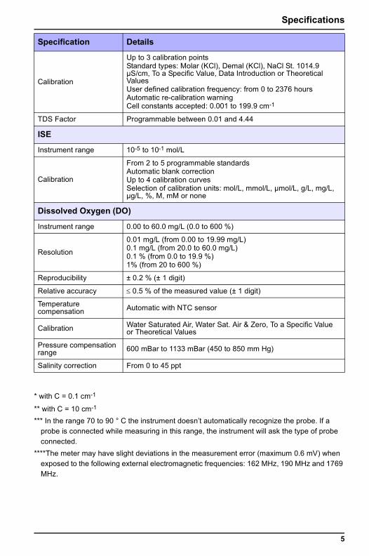
* with C = 0.1 cm-1
** with C = 10 cm-1
*** In the range 70 to 90 ° C the instrument doesn’t automatically recognize the probe. If a probe is connected while measuring in this range, the instrument will ask the type of probe connected.
****The meter may have slight deviations in the measurement error (maximum 0.6 mV) when exposed to the following external electromagnetic frequencies: 162 MHz, 190 MHz and 1769 MHz.
Calibration
Up to 3 calibration points Standard types: Molar (KCl), Demal (KCl), NaCl St. 1014.9 μS/cm, To a Specific Value, Data Introduction or Theoretical ValuesUser defined calibration frequency: from 0 to 2376 hoursAutomatic re-calibration warningCell constants accepted: 0.001 to 199.9 cm-1
TDS Factor Programmable between 0.01 and 4.44
ISE
Instrument range 10-5 to 10-1 mol/L
Calibration
From 2 to 5 programmable standardsAutomatic blank correctionUp to 4 calibration curvesSelection of calibration units: mol/L, mmol/L, µmol/L, g/L, mg/L, µg/L, %, M, mM or none
Dissolved Oxygen (DO)
Instrument range 0.00 to 60.0 mg/L (0.0 to 600 %)
Resolution
0.01 mg/L (from 0.00 to 19.99 mg/L)0.1 mg/L (from 20.0 to 60.0 mg/L)0.1 % (from 0.0 to 19.9 %)1% (from 20 to 600 %)
Reproducibility ± 0.2 % (± 1 digit)
Relative accuracy ≤ 0.5 % of the measured value (± 1 digit)
Temperature compensation Automatic with NTC sensor
Calibration Water Saturated Air, Water Sat. Air & Zero, To a Specific Value or Theoretical Values
Pressure compensation range 600 mBar to 1133 mBar (450 to 850 mm Hg)
Salinity correction From 0 to 45 ppt
Specification Details
5
Section 2 General information
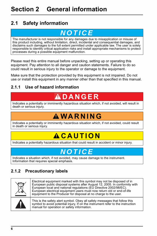
2.1 Safety information
Please read this entire manual before unpacking, setting up or operating this equipment. Pay attention to all danger and caution statements. Failure to do so could result in serious injury to the operator or damage to the equipment.
Make sure that the protection provided by this equipment is not impaired. Do not use or install this equipment in any manner other than that specified in this manual.
2.1.1 Use of hazard information
2.1.2 Precautionary labels
N O T I C EThe manufacturer is not responsible for any damages due to misapplication or misuse of this product including, without limitation, direct, incidental and consequential damages, and disclaims such damages to the full extent permitted under applicable law. The user is solely responsible to identify critical application risks and install appropriate mechanisms to protect processes during a possible equipment malfunction.
D A N G E RIndicates a potentially or imminently hazardous situation which, if not avoided, will result in death or serious injury.
WA R N I N GIndicates a potentially or imminently hazardous situation which, if not avoided, could result in death or serious injury.
C A U T I O NIndicates a potentially hazardous situation that could result in accident or minor injury.
N O T I C EIndicates a situation which, if not avoided, may cause damage to the instrument. Information that requires special emphasis.
Electrical equipment marked with this symbol may not be disposed of in European public disposal systems after August 12, 2005. In conformity with European local and national regulations (EU Directive 2002/98/EC). European electrical equipment users must now return old or end-of-life equipment to the Producer for disposal at no charge to the user.
This is the safety alert symbol. Obey all safety messages that follow this symbol to avoid potential injury. If on the instrument refer to the instruction manual for operation or safety information.
6
General information
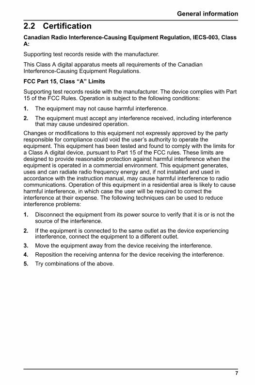
2.2 CertificationCanadian Radio Interference-Causing Equipment Regulation, IECS-003, Class A:
Supporting test records reside with the manufacturer.
This Class A digital apparatus meets all requirements of the Canadian Interference-Causing Equipment Regulations.
FCC Part 15, Class “A” Limits
Supporting test records reside with the manufacturer. The device complies with Part 15 of the FCC Rules. Operation is subject to the following conditions:
1. The equipment may not cause harmful interference.
2. The equipment must accept any interference received, including interference that may cause undesired operation.
Changes or modifications to this equipment not expressly approved by the party responsible for compliance could void the user’s authority to operate the equipment. This equipment has been tested and found to comply with the limits for a Class A digital device, pursuant to Part 15 of the FCC rules. These limits are designed to provide reasonable protection against harmful interference when the equipment is operated in a commercial environment. This equipment generates, uses and can radiate radio frequency energy and, if not installed and used in accordance with the instruction manual, may cause harmful interference to radio communications. Operation of this equipment in a residential area is likely to cause harmful interference, in which case the user will be required to correct the interference at their expense. The following techniques can be used to reduce interference problems:
1. Disconnect the equipment from its power source to verify that it is or is not the source of the interference.
2. If the equipment is connected to the same outlet as the device experiencing interference, connect the equipment to a different outlet.
3. Move the equipment away from the device receiving the interference.4. Reposition the receiving antenna for the device receiving the interference.5. Try combinations of the above.
7
8
Section 3 Product overview
The VWR sympHony™ meters are used with probes to measure various parameters in solutions. Benchtop sympHony™ meters are available in 5 models:
1. B10P: pH/mV/ORP meter
2. B10C: conductivity meter3. B20PI: pH/mV/ORP and ISE meter
• Ch1: can measure pH, ORP or ISE• Ch2: can measure pH, ORP or ISE
4. B30PCI: pH/mV/ORP, conductivity and ISE meter• Ch1: can measure pH, ORP or ISE• Ch2: can measure pH, ORP or ISE• Ch3: can measure conductivity
5. B40PCID: pH/mV/ORP, conductivity, ISE and DO meter• Ch1: can measure pH, ORP or ISE• Ch2: can measure dissolved oxygen• Ch3: can measure conductivity
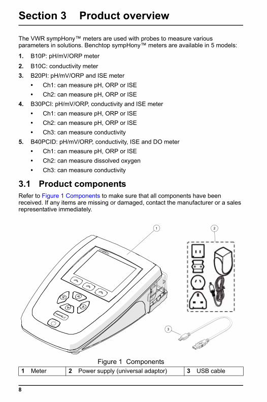
3.1 Product componentsRefer to Figure 1 Components to make sure that all components have been received. If any items are missing or damaged, contact the manufacturer or a sales representative immediately.
Figure 1 Components1 Meter 2 Power supply (universal adaptor) 3 USB cable
1 2
3
Section 4 Installation
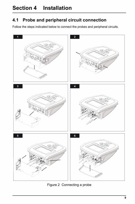
4.1 Probe and peripheral circuit connectionFollow the steps indicated below to connect the probes and peripheral circuits.
Figure 2 Connecting a probe
1 2
3 4
5 6
9
Installation
4.2 Connect to AC power
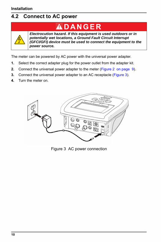
The meter can be powered by AC power with the universal power adapter.
1. Select the correct adapter plug for the power outlet from the adapter kit.
2. Connect the universal power adapter to the meter (Figure 2 on page 9).3. Connect the universal power adapter to an AC receptacle (Figure 3).4. Turn the meter on.
D A N G E RElectrocution hazard. If this equipment is used outdoors or in potentially wet locations, a Ground Fault Circuit Interrupt (GFCI/GFI) device must be used to connect the equipment to the power source.
Figure 3 AC power connection
10

Installation
4.3 Connector panels
Figure 4 B10P connector panel 1 Reference electrode connector
(banana plug)5 Power supply connector (jack)
2 Temperature probe connector (RJ22)
6 Temperature probe connector (banana plug)
3 PC keyboard connector (mini-DIN) 7 Combination pH/ORP electrode connector (BNC)
4 Printer/PC connector (mini USB) 8 Magnetic stirrer connector (RCA)
Reference ATC PC Keyboard
pH/ORP ATC Power inStirrer 1
Printer / PC
1 2 3
4
5
678
11
Installation
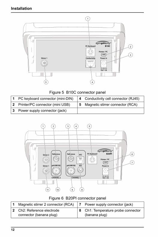
Figure 5 B10C connector panel 1 PC keyboard connector (mini-DIN) 4 Conductivity cell connector (RJ45)
2 Printer/PC connector (mini USB) 5 Magnetic stirrer connector (RCA)
3 Power supply connector (jack)
Figure 6 B20PI connector panel 1 Magnetic stirrer 2 connector (RCA) 7 Power supply connector (jack)
2 Ch2: Reference electrode connector (banana plug)
8 Ch1: Temperature probe connector (banana plug)
PC Keyboard
Power inStirrer 1 Conductivity
Printer / PC
1
2
3
45
Stirrer 2 ReferenceReference ATC PC Keyboard
CHANNEL 2 CHANNEL 1
pH/ORP/ISE ATC Power inStirrer 1 pH/ORP/ISE
Printer / PC
1 2 3 4 5
6
7
891011
12
Installation
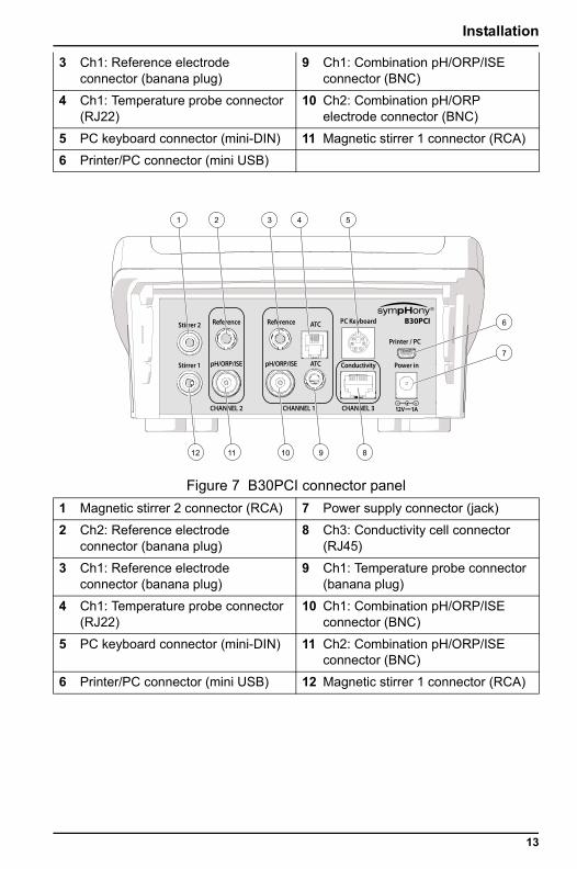
3 Ch1: Reference electrode connector (banana plug)
9 Ch1: Combination pH/ORP/ISE connector (BNC)
4 Ch1: Temperature probe connector (RJ22)
10 Ch2: Combination pH/ORP electrode connector (BNC)
5 PC keyboard connector (mini-DIN) 11 Magnetic stirrer 1 connector (RCA)
6 Printer/PC connector (mini USB)
Figure 7 B30PCI connector panel 1 Magnetic stirrer 2 connector (RCA) 7 Power supply connector (jack)
2 Ch2: Reference electrode connector (banana plug)
8 Ch3: Conductivity cell connector (RJ45)
3 Ch1: Reference electrode connector (banana plug)
9 Ch1: Temperature probe connector (banana plug)
4 Ch1: Temperature probe connector (RJ22)
10 Ch1: Combination pH/ORP/ISE connector (BNC)
5 PC keyboard connector (mini-DIN) 11 Ch2: Combination pH/ORP/ISE connector (BNC)
6 Printer/PC connector (mini USB) 12 Magnetic stirrer 1 connector (RCA)
Stirrer 2 ReferenceReference ATC PC Keyboard
CHANNEL 2 CHANNEL 1 CHANNEL 3
pH/ORP/ISE ATC Power inStirrer 1 pH/ORP/ISE Conductivity
Printer / PC
1 2 3 4 5
6
7
89101112
13
Installation
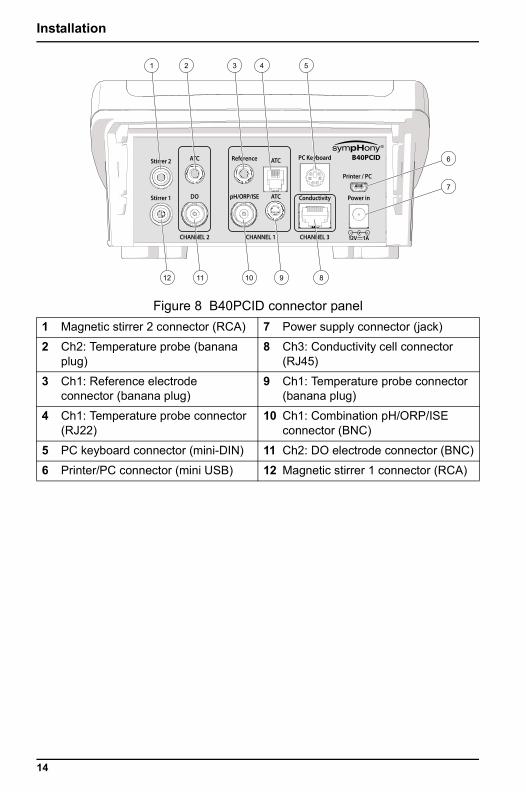
Figure 8 B40PCID connector panel1 Magnetic stirrer 2 connector (RCA) 7 Power supply connector (jack)
2 Ch2: Temperature probe (banana plug)
8 Ch3: Conductivity cell connector (RJ45)
3 Ch1: Reference electrode connector (banana plug)
9 Ch1: Temperature probe connector (banana plug)
4 Ch1: Temperature probe connector (RJ22)
10 Ch1: Combination pH/ORP/ISE connector (BNC)
5 PC keyboard connector (mini-DIN) 11 Ch2: DO electrode connector (BNC)
6 Printer/PC connector (mini USB) 12 Magnetic stirrer 1 connector (RCA)
Stirrer 2 ReferenceATC ATC PC Keyboard
CHANNEL 2 CHANNEL 1 CHANNEL 3
pH/ORP/ISE ATC Power inStirrer 1 DO Conductivity
Printer / PC
1 2 3 4 5
6
7
89101112
14
Section 5 User interface and navigation
5.1 User interface
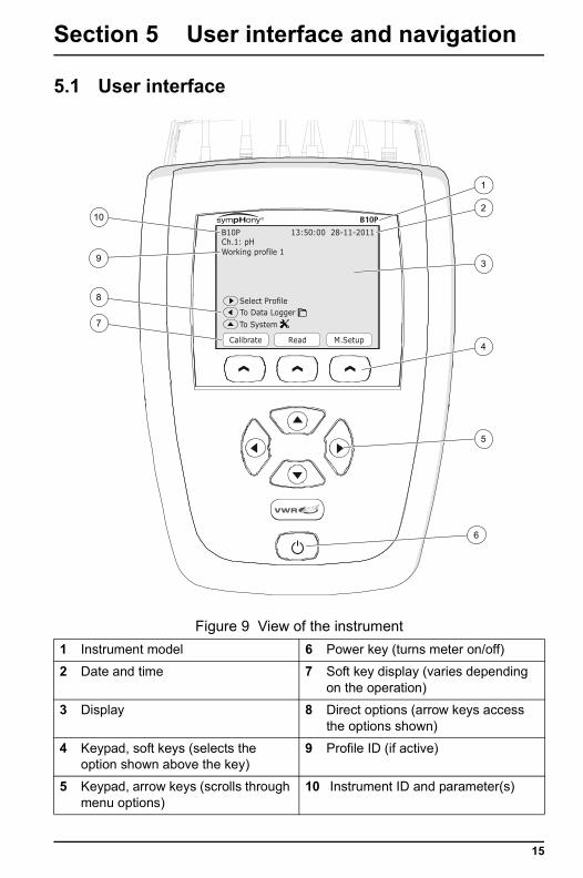
Figure 9 View of the instrument1 Instrument model 6 Power key (turns meter on/off)
2 Date and time 7 Soft key display (varies depending on the operation)
3 Display 8 Direct options (arrow keys access the options shown)
4 Keypad, soft keys (selects the option shown above the key)
9 Profile ID (if active)
5 Keypad, arrow keys (scrolls through menu options)
10 Instrument ID and parameter(s)
13:50:00 28-11-2011
Read M.SetupCalibrate
To System
B10PCh.1: pHWorking profile 1
To Data LoggerSelect Profile
1
2
3
7
8
9
10
5
6
4
15
User interface and navigation
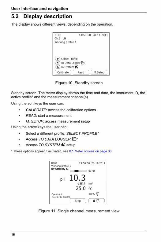
5.2 Display descriptionThe display shows different views, depending on the operation.
Standby screen. The meter display shows the time and date, the instrument ID, the active profile* and the measurement channel(s).
Using the soft keys the user can:
• CALIBRATE: access the calibration options• READ: start a measurement• M. SETUP: access measurement setup
Using the arrow keys the user can:
• Select a different profile: SELECT PROFILE*• Access TO DATA LOGGER *• Access TO SYSTEM setup
* These options appear if activated, see 8.1 Meter options on page 36.
Figure 10 Standby screen
Figure 11 Single channel measurement view
13:50:00 28-11-2011
Read M.SetupCalibrate
To System
Ch.1: pHB10P
Working profile 1
To Data LoggerSelect Profile
pH 10.300:05
25.0 ºC
mV-185.7
48%Operator 1Sample ID: 000001
13:50:00 28-11-2011
Stop
B10P
By Stability-S.Working profile 1
16
User interface and navigation
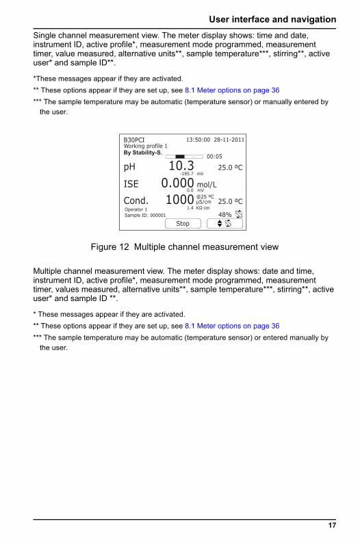
Single channel measurement view. The meter display shows: time and date, instrument ID, active profile*, measurement mode programmed, measurement timer, value measured, alternative units**, sample temperature***, stirring**, active user* and sample ID**.*These messages appear if they are activated.** These options appear if they are set up, see 8.1 Meter options on page 36*** The sample temperature may be automatic (temperature sensor) or manually entered by
the user.
Multiple channel measurement view. The meter display shows: date and time, instrument ID, active profile*, measurement mode programmed, measurement timer, values measured, alternative units**, sample temperature***, stirring**, active user* and sample ID **.
* These messages appear if they are activated.** These options appear if they are set up, see 8.1 Meter options on page 36*** The sample temperature may be automatic (temperature sensor) or entered manually by
the user.
Figure 12 Multiple channel measurement view
48%K cm
@25 ºCμS/cm
1.4
pH
ISE
Cond.
10.30.0001000
00:05
25.0 ºC
25.0 ºC
mol/L
mV-185.7
mV0.0
Operator 1Sample ID: 000001
13:50:00 28-11-2011
Stop
B30PCI
By Stability-S.Working profile 1
17
User interface and navigation
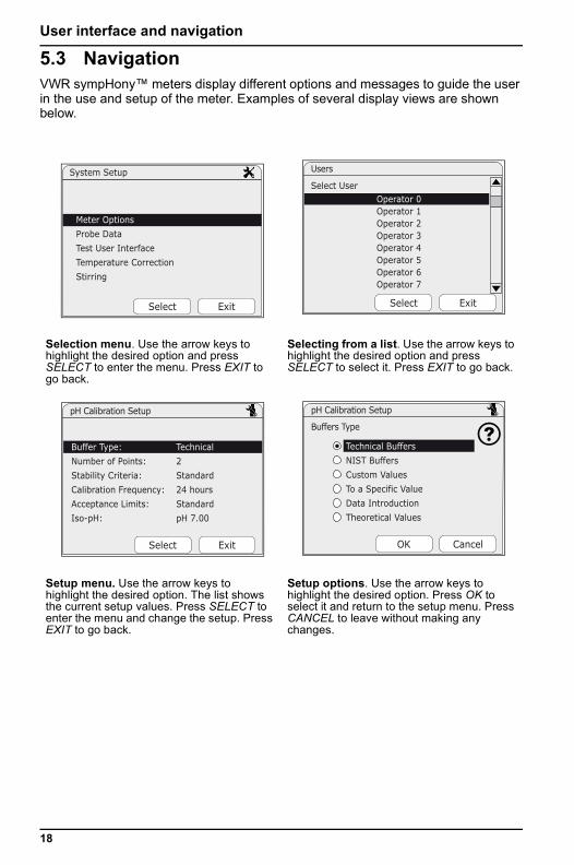
5.3 NavigationVWR sympHony™ meters display different options and messages to guide the user in the use and setup of the meter. Examples of several display views are shown below.
Selection menu. Use the arrow keys to highlight the desired option and press SELECT to enter the menu. Press EXIT to go back.
Selecting from a list. Use the arrow keys to highlight the desired option and press SELECT to select it. Press EXIT to go back.
Setup menu. Use the arrow keys to highlight the desired option. The list shows the current setup values. Press SELECT to enter the menu and change the setup. Press EXIT to go back.
Setup options. Use the arrow keys to highlight the desired option. Press OK to select it and return to the setup menu. Press CANCEL to leave without making any changes.
System Setup
Select Exit
Meter Options
Probe Data
Test User Interface
Temperature Correction
Stirring
Operator 0 Operator 1 Operator 2 Operator 3 Operator 4 Operator 5 Operator 6 Operator 7
Select
Users
Select User
Exit
Buffer Type: Technical
Number of Points: 2
Stability Criteria: Standard
Calibration Frequency: 24 hours
Acceptance Limits: Standard
Iso-pH: pH 7.00
Select
pH Calibration Setup
Exit
Technical Buffers
NIST Buffers
Custom Values
To a Specific Value
Data Introduction
Theoretical Values
OK
pH Calibration Setup
Buffers Type
Cancel
18
User interface and navigation
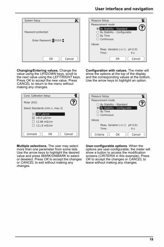
Changing/Entering values. Change the value using the UP/DOWN keys, scroll to the next value using the LEFT/RIGHT keys. Press OK to accept the new value. Press CANCEL to return to the menu without making any changes.
Configuration with values. The meter will show the options at the top of the display and the corresponding values at the bottom. Use the arrow keys to highlight an option.
Multiple selections. The user may select more than one parameter from some lists. Use the arrow keys to highlight the desired value and press MARK/UNMARK to select or deselect. Press OK to accept the changes or CANCEL to exit without making any changes.
User-configurable options. When the options are user-configurable, the meter will show a button to access the modification screens (CRITERIA in this example). Press OK to accept the changes or CANCEL to leave without making any changes.
Password protected:
System Setup
OK Cancel
Enter Password: 00000
Measurement mode
Values
By Stability - StandardBy Stability - ConfigurableBy TimeContinuous
Meas. Variation (+/-): pH 0.01Time: 6 s
Measure Setup
OK Cancel
147 μS/cm 1413 μS/cm 12.88 mS/cm 111.8 mS/cm
OKUnmark
Cond. Calibration Setup
Select Standards (min.1, max.3)
Molar (KCl)
Cancel Criteria
Measurement mode
Values
By Stability - StandardBy Stability - ConfigurableBy TimeContinuous
Meas. Variation (+/-): pH 0.01Time: 6 s
Measure Setup
OK Cancel
19
20
Section 6 Startup
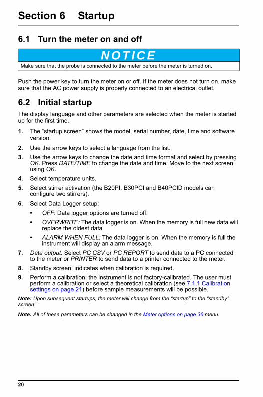
6.1 Turn the meter on and off
Push the power key to turn the meter on or off. If the meter does not turn on, make sure that the AC power supply is properly connected to an electrical outlet.
6.2 Initial startupThe display language and other parameters are selected when the meter is started up for the first time.
1. The “startup screen” shows the model, serial number, date, time and software version.
2. Use the arrow keys to select a language from the list.3. Use the arrow keys to change the date and time format and select by pressing
OK. Press DATE/TIME to change the date and time. Move to the next screen using OK.
4. Select temperature units.5. Select stirrer activation (the B20PI, B30PCI and B40PCID models can
configure two stirrers).6. Select Data Logger setup:
• OFF: Data logger options are turned off.• OVERWRITE: The data logger is on. When the memory is full new data will
replace the oldest data.• ALARM WHEN FULL: The data logger is on. When the memory is full the
instrument will display an alarm message.7. Data output. Select PC CSV or PC REPORT to send data to a PC connected
to the meter or PRINTER to send data to a printer connected to the meter.8. Standby screen; indicates when calibration is required.9. Perform a calibration; the instrument is not factory-calibrated. The user must
perform a calibration or select a theoretical calibration (see 7.1.1 Calibration settings on page 21) before sample measurements will be possible.
Note: Upon subsequent startups, the meter will change from the “startup” to the “standby” screen.
Note: All of these parameters can be changed in the Meter options on page 36 menu.
N O T I C EMake sure that the probe is connected to the meter before the meter is turned on.
Section 7 Standard operations
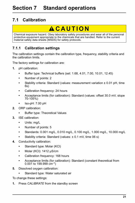
7.1 Calibration
7.1.1 Calibration settingsThe calibration settings contain the calibration type, frequency, stability criteria and the calibration limits.
The factory settings for calibration are:
1. pH calibration:
• Buffer type: Technical buffers (set: 1.68, 4.01, 7.00, 10.01, 12.45)• Number of points: 2• Stability criteria: Standard (values: measurement variation ± 0.01 pH, time
6s)• Calibration frequency: 24 hours• Acceptance limits (for calibration): Standard (values: offset 30.0 mV, slope
70-105%)• Iso-pH: 7.00 pH
2. ORP calibration:• Buffer type: Theoretical Values
3. ISE calibration:• Units: mg/L• Number of points: 5• Standards: 0.001 mg/L, 0.010 mg/L, 0.100 mg/L, 1.000 mg/L, 10.000 mg/L• Stability criteria: Standard (values: ± 0.1 mV, time 06 s)
4. Conductivity calibration:• Standard type: Molar (KCl)• Molar (KCl): 1412 µS/cm• Calibration frequency: 168 hours• Acceptance limits (for calibration): Standard (constant theoretical from
0.001 to 199.999 cm-1)5. Dissolved oxygen calibration:
• Standard type: Water saturated airTo change these settings:
1. Press CALIBRATE from the standby screen
C A U T I O NChemical exposure hazard. Obey laboratory safety procedures and wear all of the personal protective equipment appropriate to the chemicals that are handled. Refer to the current material safety data sheets (MSDS) for safety protocols.
21
Standard operations
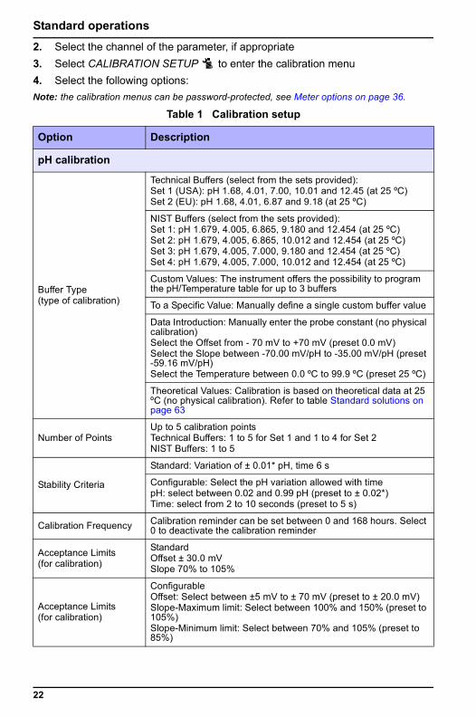
2. Select the channel of the parameter, if appropriate3. Select CALIBRATION SETUP to enter the calibration menu4. Select the following options:Note: the calibration menus can be password-protected, see Meter options on page 36.Table 1 Calibration setup
Option Description
pH calibration
Buffer Type(type of calibration)
Technical Buffers (select from the sets provided):Set 1 (USA): pH 1.68, 4.01, 7.00, 10.01 and 12.45 (at 25 ºC)Set 2 (EU): pH 1.68, 4.01, 6.87 and 9.18 (at 25 ºC)
NIST Buffers (select from the sets provided):Set 1: pH 1.679, 4.005, 6.865, 9.180 and 12.454 (at 25 ºC)Set 2: pH 1.679, 4.005, 6.865, 10.012 and 12.454 (at 25 ºC)Set 3: pH 1.679, 4.005, 7.000, 9.180 and 12.454 (at 25 ºC)Set 4: pH 1.679, 4.005, 7.000, 10.012 and 12.454 (at 25 ºC)
Custom Values: The instrument offers the possibility to program the pH/Temperature table for up to 3 buffers
To a Specific Value: Manually define a single custom buffer value
Data Introduction: Manually enter the probe constant (no physical calibration)Select the Offset from - 70 mV to +70 mV (preset 0.0 mV)Select the Slope between -70.00 mV/pH to -35.00 mV/pH (preset -59.16 mV/pH)Select the Temperature between 0.0 ºC to 99.9 ºC (preset 25 ºC)
Theoretical Values: Calibration is based on theoretical data at 25 ºC (no physical calibration). Refer to table Standard solutions on page 63
Number of PointsUp to 5 calibration pointsTechnical Buffers: 1 to 5 for Set 1 and 1 to 4 for Set 2NIST Buffers: 1 to 5
Stability Criteria
Standard: Variation of ± 0.01* pH, time 6 s
Configurable: Select the pH variation allowed with timepH: select between 0.02 and 0.99 pH (preset to ± 0.02*)Time: select from 2 to 10 seconds (preset to 5 s)
Calibration Frequency Calibration reminder can be set between 0 and 168 hours. Select 0 to deactivate the calibration reminder
Acceptance Limits (for calibration)
StandardOffset ± 30.0 mVSlope 70% to 105%
Acceptance Limits (for calibration)
ConfigurableOffset: Select between ±5 mV to ± 70 mV (preset to ± 20.0 mV)Slope-Maximum limit: Select between 100% and 150% (preset to 105%)Slope-Minimum limit: Select between 70% and 105% (preset to 85%)
22
Standard operations
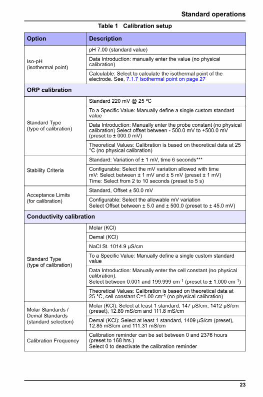
Iso-pH(isothermal point)
pH 7.00 (standard value)
Data Introduction: manually enter the value (no physical calibration)
Calculable: Select to calculate the isothermal point of the electrode. See, 7.1.7 Isothermal point on page 27
ORP calibration
Standard Type(type of calibration)
Standard 220 mV @ 25 ºC
To a Specific Value: Manually define a single custom standard value
Data Introduction: Manually enter the probe constant (no physical calibration) Select offset between - 500.0 mV to +500.0 mV (preset to ± 000.0 mV)
Theoretical Values: Calibration is based on theoretical data at 25 °C (no physical calibration)
Stability Criteria
Standard: Variation of ± 1 mV, time 6 seconds***
Configurable: Select the mV variation allowed with timemV: Select between ± 1 mV and ± 5 mV (preset ± 1 mV)Time: Select from 2 to 10 seconds (preset to 5 s)
Acceptance Limits (for calibration)
Standard, Offset ± 50.0 mV
Configurable: Select the allowable mV variationSelect Offset between ± 5.0 and ± 500.0 (preset to ± 45.0 mV)
Conductivity calibration
Standard Type(type of calibration)
Molar (KCl)
Demal (KCl)
NaCl St. 1014.9 µS/cm
To a Specific Value: Manually define a single custom standard value
Data Introduction: Manually enter the cell constant (no physical calibration). Select between 0.001 and 199.999 cm-1 (preset to ± 1.000 cm-1)
Theoretical Values: Calibration is based on theoretical data at 25 °C, cell constant C=1.00 cm-1 (no physical calibration)
Molar Standards /Demal Standards(standard selection)
Molar (KCl): Select at least 1 standard, 147 µS/cm, 1412 µS/cm (preset), 12.89 mS/cm and 111.8 mS/cm
Demal (KCl): Select at least 1 standard, 1409 µS/cm (preset), 12.85 mS/cm and 111.31 mS/cm
Calibration FrequencyCalibration reminder can be set between 0 and 2376 hours (preset to 168 hrs.)Select 0 to deactivate the calibration reminder
Table 1 Calibration setup
Option Description
23
Standard operations
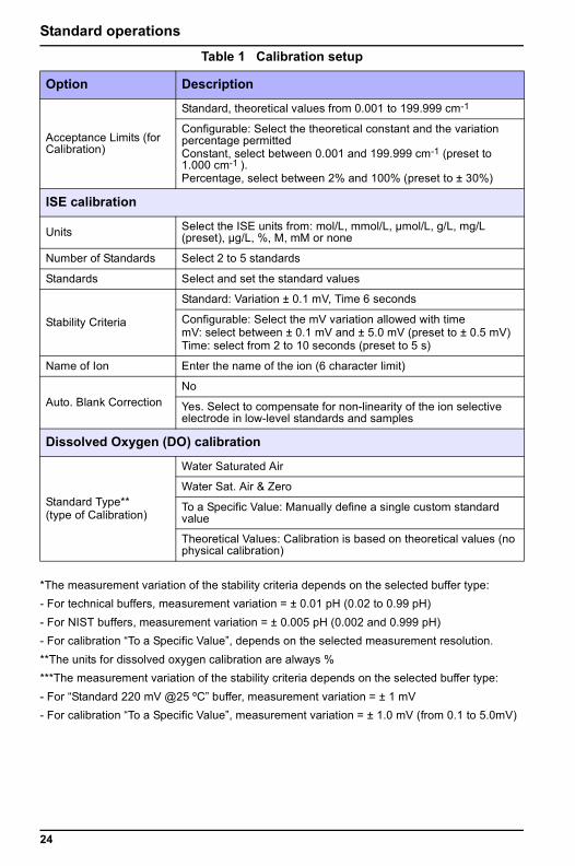
*The measurement variation of the stability criteria depends on the selected buffer type:- For technical buffers, measurement variation = ± 0.01 pH (0.02 to 0.99 pH)- For NIST buffers, measurement variation = ± 0.005 pH (0.002 and 0.999 pH)- For calibration “To a Specific Value”, depends on the selected measurement resolution.**The units for dissolved oxygen calibration are always %***The measurement variation of the stability criteria depends on the selected buffer type:- For “Standard 220 mV @25 ºC” buffer, measurement variation = ± 1 mV- For calibration “To a Specific Value”, measurement variation = ± 1.0 mV (from 0.1 to 5.0mV)
Acceptance Limits (for Calibration)
Standard, theoretical values from 0.001 to 199.999 cm-1
Configurable: Select the theoretical constant and the variation percentage permittedConstant, select between 0.001 and 199.999 cm-1 (preset to 1.000 cm-1 ).Percentage, select between 2% and 100% (preset to ± 30%)
ISE calibration
Units Select the ISE units from: mol/L, mmol/L, µmol/L, g/L, mg/L (preset), µg/L, %, M, mM or none
Number of Standards Select 2 to 5 standards
Standards Select and set the standard values
Stability Criteria
Standard: Variation ± 0.1 mV, Time 6 seconds
Configurable: Select the mV variation allowed with timemV: select between ± 0.1 mV and ± 5.0 mV (preset to ± 0.5 mV)Time: select from 2 to 10 seconds (preset to 5 s)
Name of Ion Enter the name of the ion (6 character limit)
Auto. Blank CorrectionNo
Yes. Select to compensate for non-linearity of the ion selective electrode in low-level standards and samples
Dissolved Oxygen (DO) calibration
Standard Type**(type of Calibration)
Water Saturated Air
Water Sat. Air & Zero
To a Specific Value: Manually define a single custom standard value
Theoretical Values: Calibration is based on theoretical values (no physical calibration)
Table 1 Calibration setup
Option Description
24
Standard operations
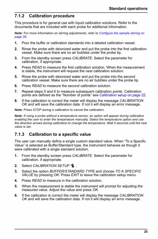
7.1.2 Calibration procedureThis procedure is for general use with liquid calibration solutions. Refer to the documents that are included with each probe for additional information.
Note: For more information on stirring adjustments, refer to Configure the sample stirring on page 39.
1. Pour the buffer or calibration standards into a labeled calibration vessel.
2. Rinse the probe with deionized water and put the probe into the first calibration vessel. Make sure there are no air bubbles under the probe tip.
3. From the standby screen press CALIBRATE. Select the parameter for calibration, if appropriate.
4. Press READ to measure the first calibration solution. When the measurement is stable, the instrument will request the next calibration solution.
5. Rinse the probe with deionized water and put the probe into the second calibration vessel. Make sure there are no air bubbles under the probe tip.
6. Press READ to measure the second calibration solution.7. Repeat steps 5 and 6 to measure subsequent calibration points. Calibration
points are defined as the “Number of points” see Calibration setup on page 22.8. If the calibration is correct the meter will display the message CALIBRATION
OK and will save the calibration data. If not it will display an error message.Note: Press STOP during a calibration to cancel the calibration.
Note: If using a probe without a temperature sensor, an option will appear during calibration enabling the user to enter the temperature manually. Select the temperature option and use the direction arrows during calibration to change the temperature. Wait 5 seconds until the new value is set.
7.1.3 Calibration to a specific valueThe user can manually define a single custom standard value. When “To a Specific Value” is selected as Buffer/Standard type, the instrument behaves as though it were calibrated with a single standard solution.
1. From the standby screen press CALIBRATE. Select the parameter for calibration, if appropriate.
2. Select CALIBRATION SETUP .3. Select the option BUFFER/STANDARD TYPE and choose TO A SPECIFIC
VALUE by pressing OK. Press EXIT to leave the calibration setup menu.4. Press READ to measure in the calibration solution.5. When the measurement is stable the instrument will prompt for adjusting the
measured value. Adjust the value and press OK.6. If the calibration is correct the meter will display the message CALIBRATION
OK and will save the calibration data. If not it will display an error message.
25

Standard operations
7.1.4 Custom valuesWhen the buffers used in calibration are different from the pre-programmed options, the meter allows pH calibration setup for up to 3 buffers.
1. From the standby screen press CALIBRATE. Select the pH parameter, if appropriate.
2. Select CALIBRATION SETUP .3. Select the option BUFFER TYPE and choose CUSTOM VALUES by pressing
OK.4. Select the option CONFIGURE BUFFERS and set the number of buffers (up to
3 buffers can be defined).5. Select CONFIGURE BUFFER 1. Up to 4 points of pH/Temperature can be
defined for each buffer (preset to 2 buffer points. Points 3 and 4 appear after points 1 and 2 are configured).
6. Select POINT 1 and set the custom values of pH and temperature.7. Repeat the procedure to set the pH and temperature values for the rest of the
points. Select NOT DEFINED to skip setting a specific point.8. Repeat steps 5-7 to define the rest of buffers.Note: The temperature values of buffer 2 and 3 will be assigned automatically in accordance with the values introduced for buffer 1.
7.1.5 View the calibration dataTo view the current calibration data:
1. From the standby screen press CALIBRATE. Select the parameter, if appropriate.
2. Select CAL.DATA. 3. Select the CURRENT CALIBRATION option. The data from the last calibration
is shown.The instrument saves the last 10 calibrations in the memory for each parameter. To view stored calibration data:
1. From the standby screen press CALIBRATE. Select the calibrated parameter, if appropriate.
2. Select CAL.DATA. 3. Select the CALIBRATION RECORDS option. 4. Use the arrow keys to view the different records.The calibration data include: date and time, total time for calibration, the standard(s) used, stirring percentage and user. Also, depending on the parameter calibrated:
• pH: the slope and slope % values, the mV value measured, the deviation (in mV), isothermal point, time and calibration temperature for each buffer
• ORP: the deviation (in mV) and temperature• Conductivity: the cell constant, the time and the calibration temperature for
each standard
26
Standard operations
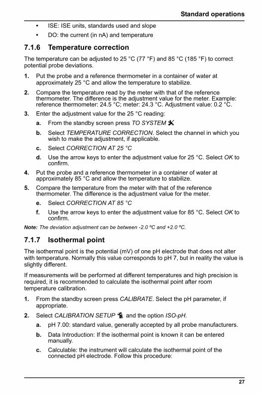
• ISE: ISE units, standards used and slope• DO: the current (in nA) and temperature7.1.6 Temperature correctionThe temperature can be adjusted to 25 °C (77 °F) and 85 °C (185 °F) to correct potential probe deviations.
1. Put the probe and a reference thermometer in a container of water at approximately 25 °C and allow the temperature to stabilize.
2. Compare the temperature read by the meter with that of the reference thermometer. The difference is the adjustment value for the meter. Example: reference thermometer: 24.5 °C; meter: 24.3 °C. Adjustment value: 0.2 °C.
3. Enter the adjustment value for the 25 °C reading:a. From the standby screen press TO SYSTEM
b. Select TEMPERATURE CORRECTION. Select the channel in which you wish to make the adjustment, if applicable.
c. Select CORRECTION AT 25 °Cd. Use the arrow keys to enter the adjustment value for 25 °C. Select OK to
confirm.4. Put the probe and a reference thermometer in a container of water at
approximately 85 °C and allow the temperature to stabilize.5. Compare the temperature from the meter with that of the reference
thermometer. The difference is the adjustment value for the meter.e. Select CORRECTION AT 85 °Cf. Use the arrow keys to enter the adjustment value for 85 °C. Select OK to
confirm.Note: The deviation adjustment can be between -2.0 ºC and +2.0 ºC.
7.1.7 Isothermal pointThe isothermal point is the potential (mV) of one pH electrode that does not alter with temperature. Normally this value corresponds to pH 7, but in reality the value is slightly different.
If measurements will be performed at different temperatures and high precision is required, it is recommended to calculate the isothermal point after room temperature calibration.
1. From the standby screen press CALIBRATE. Select the pH parameter, if appropriate.
2. Select CALIBRATION SETUP and the option ISO-pH.a. pH 7.00: standard value, generally accepted by all probe manufacturers.
b. Data Introduction: If the isothermal point is known it can be entered manually.
c. Calculable: the instrument will calculate the isothermal point of the connected pH electrode. Follow this procedure:
27
Standard operations
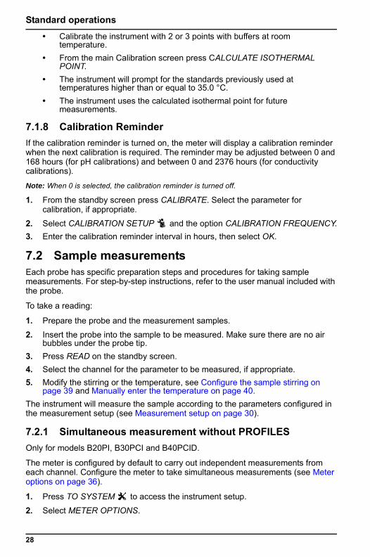
• Calibrate the instrument with 2 or 3 points with buffers at roomtemperature.• From the main Calibration screen press CALCULATE ISOTHERMAL
POINT.• The instrument will prompt for the standards previously used at
temperatures higher than or equal to 35.0 °C.• The instrument uses the calculated isothermal point for future
measurements.
7.1.8 Calibration ReminderIf the calibration reminder is turned on, the meter will display a calibration reminder when the next calibration is required. The reminder may be adjusted between 0 and 168 hours (for pH calibrations) and between 0 and 2376 hours (for conductivity calibrations).
Note: When 0 is selected, the calibration reminder is turned off.
1. From the standby screen press CALIBRATE. Select the parameter for calibration, if appropriate.
2. Select CALIBRATION SETUP and the option CALIBRATION FREQUENCY.3. Enter the calibration reminder interval in hours, then select OK.
7.2 Sample measurementsEach probe has specific preparation steps and procedures for taking sample measurements. For step-by-step instructions, refer to the user manual included with the probe.
To take a reading:
1. Prepare the probe and the measurement samples.
2. Insert the probe into the sample to be measured. Make sure there are no air bubbles under the probe tip.
3. Press READ on the standby screen.4. Select the channel for the parameter to be measured, if appropriate.5. Modify the stirring or the temperature, see Configure the sample stirring on
page 39 and Manually enter the temperature on page 40.The instrument will measure the sample according to the parameters configured in the measurement setup (see Measurement setup on page 30).
7.2.1 Simultaneous measurement without PROFILESOnly for models B20PI, B30PCI and B40PCID.
The meter is configured by default to carry out independent measurements from each channel. Configure the meter to take simultaneous measurements (see Meter options on page 36).
1. Press TO SYSTEM to access the instrument setup.
2. Select METER OPTIONS.
28
Standard operations
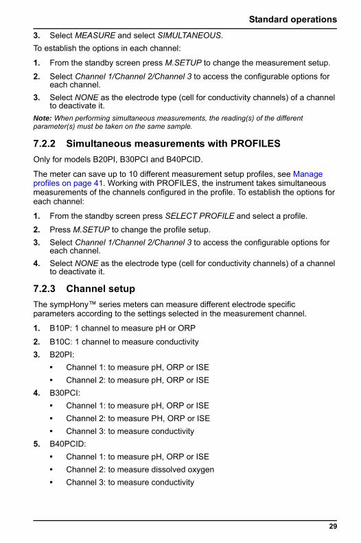
3. Select MEASURE and select SIMULTANEOUS.To establish the options in each channel:1. From the standby screen press M.SETUP to change the measurement setup.
2. Select Channel 1/Channel 2/Channel 3 to access the configurable options for each channel.
3. Select NONE as the electrode type (cell for conductivity channels) of a channel to deactivate it.
Note: When performing simultaneous measurements, the reading(s) of the different parameter(s) must be taken on the same sample.
7.2.2 Simultaneous measurements with PROFILESOnly for models B20PI, B30PCI and B40PCID.
The meter can save up to 10 different measurement setup profiles, see Manage profiles on page 41. Working with PROFILES, the instrument takes simultaneous measurements of the channels configured in the profile. To establish the options for each channel:
1. From the standby screen press SELECT PROFILE and select a profile.
2. Press M.SETUP to change the profile setup.3. Select Channel 1/Channel 2/Channel 3 to access the configurable options for
each channel.4. Select NONE as the electrode type (cell for conductivity channels) of a channel
to deactivate it.
7.2.3 Channel setupThe sympHony™ series meters can measure different electrode specific parameters according to the settings selected in the measurement channel.
1. B10P: 1 channel to measure pH or ORP
2. B10C: 1 channel to measure conductivity3. B20PI:
• Channel 1: to measure pH, ORP or ISE• Channel 2: to measure pH, ORP or ISE
4. B30PCI:• Channel 1: to measure pH, ORP or ISE• Channel 2: to measure PH, ORP or ISE• Channel 3: to measure conductivity
5. B40PCID: • Channel 1: to measure pH, ORP or ISE• Channel 2: to measure dissolved oxygen• Channel 3: to measure conductivity
29

Standard operations
To change the settings of a measurement channel:1. From the standby screen press M.SETUP and select the channel for configuration (if applicable).
2. Select the ELECTRODE option (CELL in conductivity channels).3. Select the measurement parameter for the channel (NONE to deactivate it).
7.2.4 Measurement setupThe measurement setup contains the measurement mode, sample ID and the options specific to each measurement parameter.
1. Press M.SETUP to change the measurement setup.
2. Select the channel of the parameter to setup, if appropriate.3. Use arrow keys for navigation, press SELECT to view details or change.Note: The measurement setup menus can be password-protected, see Meter options on page 36..
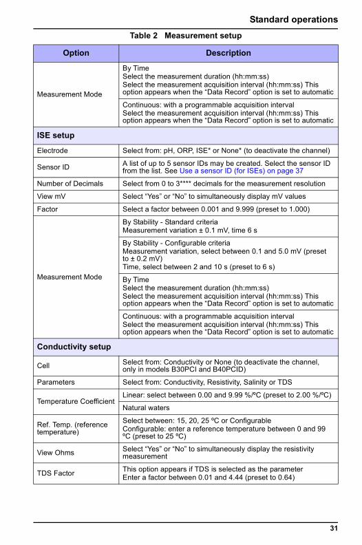
Table 2 Measurement setup
Option Description
pH setup
Electrode Select from: pH, ORP, ISE* or None to deactivate the channel*
Resolution Select between 0.1, 0.01 and 0.001
View mV Select “Yes” or “No” to display simultaneous mV measurement
Measurement Mode
By Stability - Standard criteriapH measurement variation ± 0.01** pH, time 6 s
By Stability - Configurable criteriaMeasurement variation, select between 0.002 pH and 0.999 pH (preset to ± 0.02** pH) Time, select between 2 and 10s (preset to 5 s)
By TimeSelect the measurement duration (hh:mm:ss)Select the measurement acquisition interval (hh:mm:ss) This option appears when the “Data Record” option is set to automatic
Continuous: with a programmable acquisition intervalSelect the measurement acquisition interval (hh:mm:ss) This option appears when the “Data Record” option is set to automatic
ORP setup
Electrode Select from: pH, ORP, ISE* or none* (to deactivate the channel)
Resolution Select between 0.1 and 1
Measurement Mode
By Stability - Standard criteriaMeasurement variation ± 1*** mV, time 6 s
By Stability - Configurable criteriaMeasurement variation, select between ± 1 and ± 5 mV (preset to ± 1*** mV)Time, select between 2 and 10 s (preset to 5 s)
30
Standard operations
Measurement Mode
By TimeSelect the measurement duration (hh:mm:ss)Select the measurement acquisition interval (hh:mm:ss) This option appears when the “Data Record” option is set to automatic
Continuous: with a programmable acquisition intervalSelect the measurement acquisition interval (hh:mm:ss) This option appears when the “Data Record” option is set to automatic
ISE setup
Electrode Select from: pH, ORP, ISE* or None* (to deactivate the channel)
Sensor ID A list of up to 5 sensor IDs may be created. Select the sensor ID from the list. See Use a sensor ID (for ISEs) on page 37
Number of Decimals Select from 0 to 3**** decimals for the measurement resolution
View mV Select “Yes” or “No” to simultaneously display mV values
Factor Select a factor between 0.001 and 9.999 (preset to 1.000)
Measurement Mode
By Stability - Standard criteria Measurement variation ± 0.1 mV, time 6 s
By Stability - Configurable criteriaMeasurement variation, select between 0.1 and 5.0 mV (preset to ± 0.2 mV)Time, select between 2 and 10 s (preset to 6 s)
By TimeSelect the measurement duration (hh:mm:ss)Select the measurement acquisition interval (hh:mm:ss) This option appears when the “Data Record” option is set to automatic
Continuous: with a programmable acquisition intervalSelect the measurement acquisition interval (hh:mm:ss) This option appears when the “Data Record” option is set to automatic
Conductivity setup
Cell Select from: Conductivity or None (to deactivate the channel, only in models B30PCI and B40PCID)
Parameters Select from: Conductivity, Resistivity, Salinity or TDS
Temperature CoefficientLinear: select between 0.00 and 9.99 %/ºC (preset to 2.00 %/ºC)
Natural waters
Ref. Temp. (reference temperature)
Select between: 15, 20, 25 ºC or ConfigurableConfigurable: enter a reference temperature between 0 and 99 ºC (preset to 25 ºC)
View Ohms Select “Yes” or “No” to simultaneously display the resistivity measurement
TDS Factor This option appears if TDS is selected as the parameterEnter a factor between 0.01 and 4.44 (preset to 0.64)
Table 2 Measurement setup
Option Description
31
Standard operations
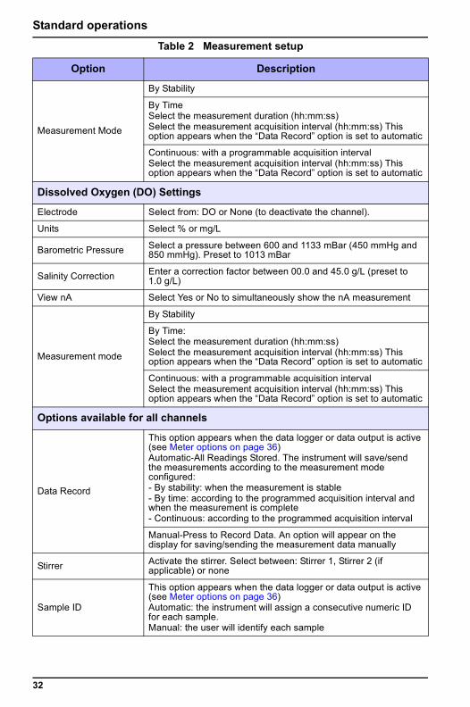
Measurement Mode
By Stability
By TimeSelect the measurement duration (hh:mm:ss)Select the measurement acquisition interval (hh:mm:ss) This option appears when the “Data Record” option is set to automatic
Continuous: with a programmable acquisition intervalSelect the measurement acquisition interval (hh:mm:ss) This option appears when the “Data Record” option is set to automatic
Dissolved Oxygen (DO) Settings
Electrode Select from: DO or None (to deactivate the channel).
Units Select % or mg/L
Barometric Pressure Select a pressure between 600 and 1133 mBar (450 mmHg and 850 mmHg). Preset to 1013 mBar
Salinity Correction Enter a correction factor between 00.0 and 45.0 g/L (preset to 1.0 g/L)
View nA Select Yes or No to simultaneously show the nA measurement
Measurement mode
By Stability
By Time:Select the measurement duration (hh:mm:ss)Select the measurement acquisition interval (hh:mm:ss) This option appears when the “Data Record” option is set to automatic
Continuous: with a programmable acquisition intervalSelect the measurement acquisition interval (hh:mm:ss) This option appears when the “Data Record” option is set to automatic
Options available for all channels
Data Record
This option appears when the data logger or data output is active (see Meter options on page 36)Automatic-All Readings Stored. The instrument will save/send the measurements according to the measurement mode configured:- By stability: when the measurement is stable- By time: according to the programmed acquisition interval and when the measurement is complete- Continuous: according to the programmed acquisition interval
Manual-Press to Record Data. An option will appear on the display for saving/sending the measurement data manually
Stirrer Activate the stirrer. Select between: Stirrer 1, Stirrer 2 (if applicable) or none
Sample ID
This option appears when the data logger or data output is active (see Meter options on page 36)Automatic: the instrument will assign a consecutive numeric ID for each sample.Manual: the user will identify each sample
Table 2 Measurement setup
Option Description
32
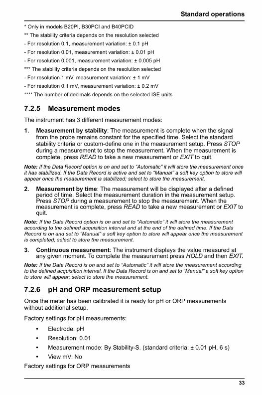
Standard operations
* Only in models B20PI, B30PCI and B40PCID** The stability criteria depends on the resolution selected- For resolution 0.1, measurement variation: ± 0.1 pH- For resolution 0.01, measurement variation: ± 0.01 pH- For resolution 0.001, measurement variation: ± 0.005 pH*** The stability criteria depends on the resolution selected- For resolution 1 mV, measurement variation: ± 1 mV- For resolution 0.1 mV, measurement variation: ± 0.2 mV**** The number of decimals depends on the selected ISE units
7.2.5 Measurement modesThe instrument has 3 different measurement modes:
1. Measurement by stability: The measurement is complete when the signal from the probe remains constant for the specified time. Select the standard stability criteria or custom-define one in the measurement setup. Press STOP during a measurement to stop the measurement. When the measurement is complete, press READ to take a new measurement or EXIT to quit.
Note: If the Data Record option is on and set to “Automatic” it will store the measurement once it has stabilized. If the Data Record is active and set to “Manual” a soft key option to store will appear once the measurement is stabilized; select to store the measurement.
2. Measurement by time: The measurement will be displayed after a defined period of time. Select the measurement duration in the measurement setup. Press STOP during a measurement to stop the measurement. When the measurement is complete, press READ to take a new measurement or EXIT to quit.
Note: If the Data Record option is on and set to “Automatic” it will store the measurement according to the defined acquisition interval and at the end of the defined time. If the Data Record is on and set to “Manual” a soft key option to store will appear once the measurement is completed; select to store the measurement.
3. Continuous measurement: The instrument displays the value measured at any given moment. To complete the measurement press HOLD and then EXIT.
Note: If the Data Record is on and set to “Automatic” it will store the measurement according to the defined acquisition interval. If the Data Record is on and set to “Manual” a soft key option to store will appear; select to store the measurement.
7.2.6 pH and ORP measurement setupOnce the meter has been calibrated it is ready for pH or ORP measurements without additional setup.
Factory settings for pH measurements:
• Electrode: pH• Resolution: 0.01• Measurement mode: By Stability-S. (standard criteria: ± 0.01 pH, 6 s)• View mV: No
Factory settings for ORP measurements
33
Standard operations
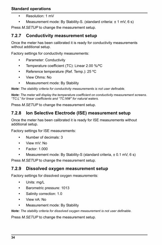
• Resolution: 1 mV• Measurement mode: By Stability-S. (standard criteria: ± 1 mV, 6 s)Press M.SETUP to change the measurement setup.
7.2.7 Conductivity measurement setupOnce the meter has been calibrated it is ready for conductivity measurements without additional setup.
Factory settings for conductivity measurements:
• Parameter: Conductivity• Temperature coefficient (TC): Linear 2.00 %/ºC• Reference temperature (Ref. Temp.): 25 ºC• View Ohms: No• Measurement mode: By Stability
Note: The stability criteria for conductivity measurements is not user definable.
Note: The meter will display the temperature coefficient on conductivity measurement screens. “TC:L” for linear coefficients and “TC:NW” for natural waters.
Press M.SETUP to change the measurement setup.
7.2.8 Ion Selective Electrode (ISE) measurement setupOnce the meter has been calibrated it is ready for ISE measurements without additional setup.
Factory settings for ISE measurements:
• Number of decimals: 3• View mV: No• Factor: 1.000• Measurement mode: By Stability-S (standard criteria, ± 0.1 mV, 6 s)
Press M.SETUP to change the measurement setup.
7.2.9 Dissolved oxygen measurement setupFactory settings for dissolved oxygen measurements:
• Units: mg/L• Barometric pressure: 1013• Salinity correction: 1.0• View nA: No• Measurement mode: By Stability
Note: The stability criteria for dissolved oxygen measurement is not user definable.
Press M.SETUP to change the measurement setup.
34
Standard operations
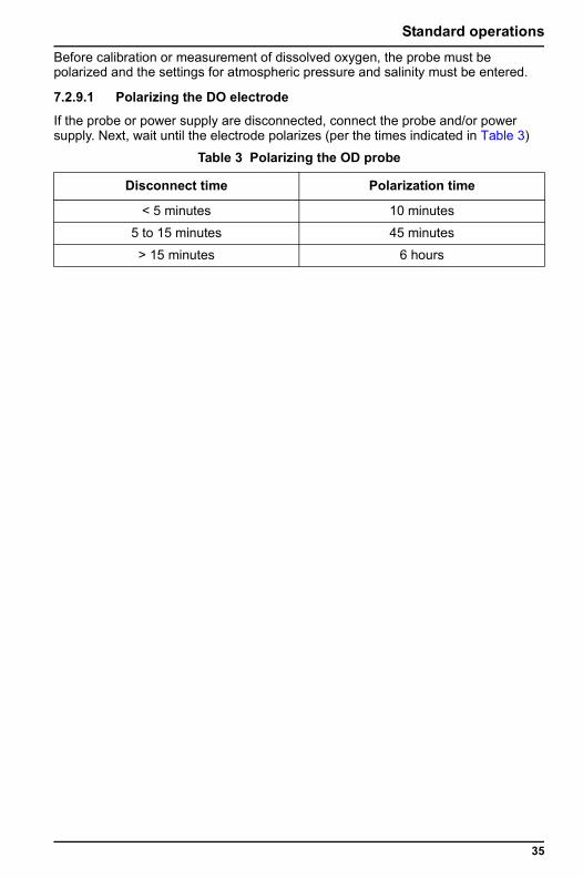
Before calibration or measurement of dissolved oxygen, the probe must be polarized and the settings for atmospheric pressure and salinity must be entered.7.2.9.1 Polarizing the DO electrode
If the probe or power supply are disconnected, connect the probe and/or power supply. Next, wait until the electrode polarizes (per the times indicated in Table 3)
Table 3 Polarizing the OD probe
Disconnect time Polarization time
< 5 minutes 10 minutes
5 to 15 minutes 45 minutes
> 15 minutes 6 hours
35
Section 8 Advanced operations
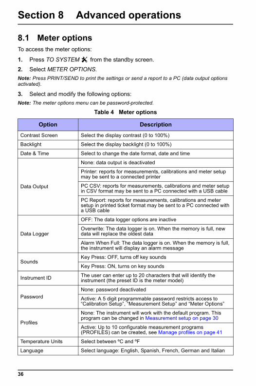
8.1 Meter optionsTo access the meter options:
1. Press TO SYSTEM from the standby screen.
2. Select METER OPTIONS.Note: Press PRINT/SEND to print the settings or send a report to a PC (data output options activated).
3. Select and modify the following options:Note: The meter options menu can be password-protected.
Table 4 Meter options
Option Description
Contrast Screen Select the display contrast (0 to 100%)
Backlight Select the display backlight (0 to 100%)
Date & Time Select to change the date format, date and time
Data Output
None: data output is deactivated
Printer: reports for measurements, calibrations and meter setup may be sent to a connected printer
PC CSV: reports for measurements, calibrations and meter setup in CSV format may be sent to a PC connected with a USB cable
PC Report: reports for measurements, calibrations and meter setup in printed ticket format may be sent to a PC connected with a USB cable
Data Logger
OFF: The data logger options are inactive
Overwrite: The data logger is on. When the memory is full, new data will replace the oldest data
Alarm When Full: The data logger is on. When the memory is full, the instrument will display an alarm message
SoundsKey Press: OFF, turns off key sounds
Key Press: ON, turns on key sounds
Instrument ID The user can enter up to 20 characters that will identify the instrument (the preset ID is the meter model)
PasswordNone: password deactivated
Active: A 5 digit programmable password restricts access to “Calibration Setup”, “Measurement Setup” and “Meter Options”
Profiles
None: The instrument will work with the default program. This program can be changed in Measurement setup on page 30
Active: Up to 10 configurable measurement programs (PROFILES) can be created, see Manage profiles on page 41
Temperature Units Select between ºC and ºF
Language Select language: English, Spanish, French, German and Italian
36
Advanced operations
8.2 Use a sensor ID (for ISEs)The instrument can identify up to 5 different ISEs for each channel. The sensor IDs are associated with ISE calibrations. The measurement and calibration data saved will include the sensor ID. If the user doesn’t setup the sensor ID, the meter will store calibrations and measurements as the “Default” sensor.
1. Press M.SETUP and select the appropriate ISE channel.
2. Select the option SENSOR ID.3. Select the sensor ID from the list or press MANAGE to edit, delete or add
sensor IDs.4. Press NEW SENSOR to add a new sensor ID.5. Enter the name of the sensor ID.Note: Once a list of sensor IDs has been created, select the appropriate sensor ID and perform a calibration. This will associate the calibration to that specific sensor ID.
8.3 Use a sample IDThe sample ID is used to associate measurements with a particular sample location. If assigned, stored data will include this ID.
This option is available when data logger or data output are active.
1. From the standby screen press M.SETUP
1. Select the parameter, if applicable.
2. Select the option SAMPLE IDENTIFICATION
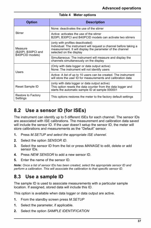
StirrerNone: deactivates the use of the stirrer
Active: activates the use of the stirrerB20PI, B30PCI and B40PCID models can activate two stirrers
Measure (B20PI, B30PCI and B40PCID models)
(only with profiles deactivated)Individual: The instrument will request a channel before taking a measurement. It will display the parameter of the channel selected on the display
Simultaneous: The instrument will measure and display the channels simultaneously on the display
Users
(Only with data logger or data output active)None: The instrument will not identify users
Active: A list of up to 10 users can be created. The instrument will store the user ID for measurements and calibration data
Reset Sample ID(only with data logger or data output active) This option resets the data counter from the data logger and starts the automatic sample ID at sample 000001
Restore to Factory Settings This options restores the meter to the factory default settings
Table 4 Meter options
Option Description
37
Advanced operations
a. Automatic: A consecutive number will be automatically assigned to eachsample.
b. Manual: The user is required to enter the sample ID name before taking a measurement (maximum of 15 characters).
Note: Data entry can be facilitated using a standard PC keyboard connected to the meter.
8.4 Data OutputThe measurement, calibration and meter setup data may be saved or sent to a printer or PC. See Data logger on page 43.
1. Press TO SYSTEM from the standby screen.
2. Select METER OPTIONS.3. Select the DATA OUTPUT option.4. Select from the following options:
a. None: Select if no PC or printer is connected.
b. Printer: Select to send the data to a printer connected to the meter.c. PC CSV: Select to send the data to a PC connected to the meter in CSV
format.d. PC Report: Select to send the data to a PC connected to the meter in
“printed ticket” format.Important Note: Don’t connect the printer to the instrument before selecting “Printer” in the data output option.Note: If an option other than “NONE” is selected, the “PRINT” or “SEND” option will appear on the measurement, calibration and setup screens.
8.5 PasswordThe user can define a 5 digit numerical password that restricts access to “Calibration Setup”, “Measurement Setup” and “Meter Options”.
1. Press TO SYSTEM from the standby screen.
2. Select METER OPTIONS.3. Select the PASSWORD option.4. Select ACTIVE and press PASSWORD to enter the password.Note: This option is password-protected. When the ACTIVE option is activated, the meter will request the default password: 54321.
5. Enter a 5 digit numerical password.6. Confirm the new password.Note: If password-protection is disabled, the meter will set the default password for subsequent activation.
8.6 Change the date and time The date and time can be changed from the Date / Time menu.
1. Press TO SYSTEM from the standby screen.
38
Advanced operations
2. Select METER OPTIONS.3. Select the DATE AND TIME option.4. Select the date format and confirm by pressing OK.5. Press DATE/TIME to change the date and time. Scroll through and changevalues with the arrow keys. Confirm with OK.6. Press OK to exit.
8.7 Adjust the display contrast and backlightThe meter screen can be set to specific light conditions making it easier to read.
1. Press TO SYSTEM from the standby screen.
2. Select METER OPTIONS.3. Select CONTRAST SCREEN. Select a setting and confirm.4. Select BACKLIGHT. Select a setting and confirm.
8.8 Configure the sample stirringThe magnetic stirrer can be activated and the stirring speed can be changed.
1. Press TO SYSTEM from the standby screen.
2. Select METER OPTIONS.3. Select STIRRER.4. Select NONE to deactivate the stirrer or ACTIVE to activate it. For meters with
two stirrers, select MARK to activate a stirrer, select UNMARK to deactivate a stirrer.
5. To change the stirring speed during a measurement or calibration press the temperature/stirring key twice.
6. Use the arrow keys to change the stirring speed. The new value will be set if no key is pressed for 5 seconds.
Note: In meters with two stirrers one stirrer may be assigned to a specific channel in the Measurement setup on page 30.
Note: When performing Simultaneous measurements only one stirrer can be selected at measurement setup.
8.9 Activate the stirrerTo use the stirrers without the need for a measurement or calibration.
1. Press TO SYSTEM from the standby screen.
2. Select STIRRING (this option is active if the Stirrers have been activated at METER OPTIONS)
3. Press the LEFT/RIGHT keys to turn ON/OFF the desired stirrer.4. Select the stirrer speed icon with the appropriate soft key, press the UP/DOWN
keys to change the stirring speed.Note: The stirrer speed icon appears when the stirrer is in the OFF position. After adjusting the stirrer speed, the stirrer can be changed to ON.
39
Advanced operations
8.10 Manually enter the temperatureTemperatures can be entered manually while measuring or calibrating when working with non-temperature compensating probes.
1. Press the temperature/stirring key on a measurement or calibration. The temperature will be highlighted on the display.
2. Use the arrow keys to change the temperature. The new value will be set if no key is pressed for 5 seconds.
8.11 Probe dataThe instrument can store various information about the probe being used.
1. Press TO SYSTEM from the standby screen.
2. Select PROBE DATA, select the desired channel if appropriate.3. Select HISTORY. The following information will be displayed on the screen:
• Initial Time: Date and time of installation• Service Time: Total time of sensor use• Number of measurements• Maximum and minimum values measured by the sensor
4. Select RESET HISTORY to erase the stored probe data.Note: The option RESET HISTORY is password protected.
8.12 Test user interfaceThe user can test for functionality of the display and the keypad.
1. Press TO SYSTEM from the standby screen.
2. Select TEST USER INTERFACE.3. Select TEST DISPLAY to test the screen. The instrument will turn off/on all of
display's pixels for 6 seconds. 4. Select TEST BUTTONS & SOUND to test the keypad. Press the keys to test
their operation. The instrument will quit the test if no keys are pressed within 6 seconds.
8.13 Manage usersThe instrument can identify up to 10 different users. User IDs are stored with the measurements and calibrations.
1. Activate users in Meter options on page 36.
2. Press MANAGE to edit, delete or add users.3. Perform a calibration. The instrument will ask for the user ID.4. Perform a reading. The instrument will ask for the user ID.
40
Advanced operations
8.14 Manage profilesProfiles are different measurement setup configurations that can be stored inside the meter. The instrument can store up to 10 different profiles. This enables the user to alternate between different measurement setups, simply by selecting the appropriate Profile.
If profiles are off, the instrument will store the measurement setup options in the default profile (PROFILE 0).
To activate profiles:
1. Press TO SYSTEM from the standby screen, then select METER OPTIONS.
2. Select PROFILES, then select ACTIVE.3. Press MANAGE to add, delete or edit Profiles.Note: When creating a profile, the instrument will copy the current measurement setup to the new profile.
4. Press SELECT PROFILE on the standby screen to select the appropriate profile.
5. Select M.SETUP to change the setup. The changes will be saved in the Profile selected.
6. Perform the readings with the Profile selected.7. Press SELECT PROFILE on the standby screen to select a different profile.
8.15 Restore the factory settingsThis option erases all data stored in the meter and reverts all settings and configurations to the factory default settings.
1. Press TO SYSTEM from the standby screen.
2. Select METER OPTIONS.3. Select the RESTORE TO FACTORY SETTINGS option and confirm.
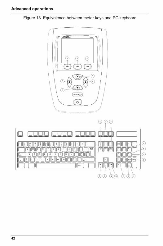
8.16 Use a PC keyboardConnect a standard PC keyboard to operate with the meter or to facilitate alphanumeric data entry (Figure 13 on page 42)
1. Connect the keyboard to the rear panel (see Connector panels on page 11).
2. The meter can be operated from the PC keyboard using these keys:Note: If using the “Numeric keyboard,” switch between direction keys and numbers using the “CAPS NUM” key.
41
Advanced operations
Figure 13 Equivalence between meter keys and PC keyboard
1 2 3
7 5
6
4
WQ E R T Y IU O P
1
1
0
2 3
.
4 5 6
7
NumLock
8
/ * -
+
9
2! a
3 4$
5 6 7%ª &^
8 9* (
0
=
_) +
-
[
A
Z N
FS D G H
X C V B
J K : " ~L
]
; , £
M <,
>.
?/
|\
ENTER
ENTER
Del
Alt GrDel
End Pg Dn
End PageDown
CapsLock
1
7 6 34
4
5
7
6
5 2 1
2 3
42
Section 9 Data logger
The instrument can store up to 500 measurements.
9.1 Activate the data logger1. Press TO SYSTEM and select METER OPTIONS.
2. Select DATA LOGGER. Select one of the following options:a. OFF: The data logger options are turned off.
b. OVERWRITE: The data logger is on. When the memory is full, new data will replace the oldest data.
c. ALARM WHEN FULL: The data logger is on. When the memory is full, the instrument will display an alarm message.
9.2 Store dataEach record in the data logger includes: Sample ID, value measured, measurement duration, sample temperature, stirring speed, date and time the sample was taken, user (where applicable) and Profile (where applicable).
The instrument stores the data either automatically or manually, depending on how the data logger option is programmed, see Measurement setup on page 30.
1. On the AUTOMATIC setting the instrument stores data according to the Measurement Mode settings:
• By stability: the measurement is stored when the reading is stable.• By time: measurements are stored according to the programmed
acquisition interval and at the end of the programmed measurement duration.
• Continuous: measurements are stored according to the programmed acquisition interval.
2. On the MANUAL setting a soft-key option becomes available on the measurement and calibration screens, which enables the user to save data manually. This option varies according to the configuration of the DATA LOGGER and DATA OUTPUT. Press the key whenever you wish to save/print a measurement.• (save to data logger): this option appears when the DATA LOGGER
is activated and the DATA OUTPUT is deactivated. The data is saved in the instrument's internal memory. .
• (print): this option appears when the DATA LOGGER is deactivated and the DATA OUTPUT is configured with a printer.
• (send to PC): this option appears when the DATA LOGGER is deactivated and the DATA OUTPUT is configured with a PC.
• / (Data Record): this option appears when the DATA LOGGER is activated and the DATA OUTPUT is configured with a printer or PC. The data is saved in the instrument's internal memory and also sends it to the printer or PC.
43
Data logger
• When the meter stores data the data logger will display the icon:• If the data logger is full and the meter can’t save the data, the following icon will be displayed:
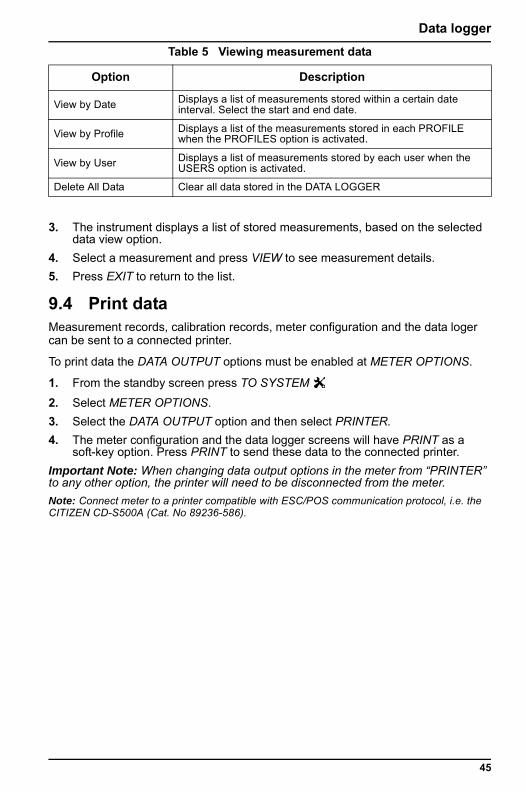
9.2.1 Sample identificationThe instrument identifies samples either automatically or manually, depending on the programming in Measurement setup on page 30.
• Automatic identification: a consecutive number is automatically assigned to each sample.
Note: This counter can be reset to zero by selecting the “RESET SAMPLE ID” option in Meter options on page 36.
• Manual sample ID: the user must manually enter the ID of each sample.
Press the "AA/aa/1%” button to move between the different character options: capitals, lower case and numbers/symbols. Use the UP/DOWN direction keys to change the value. Use the LEFT/RIGHT directions keys to scroll to the next character. Confirm with OK.
Note: Data entry can be facilitated using a standard PC keyboard connected to the meter.
9.3 View measurement data1. Press TO DATA LOGGER from the standby screen.
2. Select one of the following options:
Figure 14 Manual sample ID entry
Table 5 Viewing measurement data
Option Description
View All Displays a list of all of the stored measurements
Measurement
AA/aa/1%
Sample ID:
Upper Case
OK
Measurement
Sample Identification
Exit
44
Data logger
3. The instrument displays a list of stored measurements, based on the selected data view option.
4. Select a measurement and press VIEW to see measurement details.5. Press EXIT to return to the list.
9.4 Print dataMeasurement records, calibration records, meter configuration and the data loger can be sent to a connected printer.
To print data the DATA OUTPUT options must be enabled at METER OPTIONS.
1. From the standby screen press TO SYSTEM
2. Select METER OPTIONS.3. Select the DATA OUTPUT option and then select PRINTER.4. The meter configuration and the data logger screens will have PRINT as a
soft-key option. Press PRINT to send these data to the connected printer.Important Note: When changing data output options in the meter from “PRINTER” to any other option, the printer will need to be disconnected from the meter.Note: Connect meter to a printer compatible with ESC/POS communication protocol, i.e. the CITIZEN CD-S500A (Cat. No 89236-586).
View by Date Displays a list of measurements stored within a certain date interval. Select the start and end date.
View by Profile Displays a list of the measurements stored in each PROFILE when the PROFILES option is activated.
View by User Displays a list of measurements stored by each user when the USERS option is activated.
Delete All Data Clear all data stored in the DATA LOGGER
Table 5 Viewing measurement data
Option Description
45
Data logger
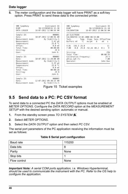
5. The meter configuration and the data logger will have PRINT as a soft-keyoption. Press PRINT to send these data to the connected printer.
9.5 Send data to a PC: PC CSV formatTo send data to a connected PC the DATA OUTPUT options must be enabled at METER OPTIONS. Configure the DATA RECORD option at the MEASUREMENT SETUP with the desired sending option: automatic or manual.
1. From the standby screen press TO SYSTEM
2. Select METER OPTIONS.3. Select the DATA OUTPUT option and then select PC CSV.The serial port parameters of the PC application receiving the information must be set as follows:
Important Note: A serial COM ports application, i.e. Windows Hyperterminal, should be used to communicate the instrument with the PC. Refer to the OS help to configure the application.
Figure 15 Ticket examples
Table 6 Serial port configuration
Baud rate 115200Data bits 8Parity NoneStop bits 1Flow control None
VWR SympHony Instrument IDB10P SN:12198S0134 V1.10DATA LOGGER 16-07-2012 12:00:56 AM========================================Sample ID: 000001Date: 10-07-2012 12:00:56 AMMeasurement mode: By Stability-SMeasurement: 5.42 pHTemperature: 25.0 ºCOffset: 0.0 mVTotal Time: 00:00:08Stirring: 25 %User: John D.----------------------------------------Sample ID: 000002Date: 10-07-2012 11:20:00 AMMeasurement mode: By Stability-SMeasurement: 9.25 pHTemperature: 25.0 ºCOffset: 0.0 mVTotal Time: 00:00:10Stirring: 25 %User: John D.----------------------------------------Sample ID: 000003Date: 12-07-2012 09:30:15 AMMeasurement mode: By Stability-S
VWR SympHony Instrument IDB10P SN:12198S0134 V1.10CALIBRATION 16-07-2012 12:00:56 AM========================================pH ELECTRODECALIBRATED 14-02-2008 08:53:00Tech. Temp. Slope Sens. Offset Time Buffers mV ºC mv/pH % mV s ----------------------------------------4.01 156.3 25.0 11 7.00 0.0 25.0 -52,16 88.2 0.1 9----------------------------------------Stirring: 25%Total Time: 00:00:35Calibration Frequency: 24 hpHiso.(pH 7): 7.00Operator: John Doe========================================
46
Data logger
Important Note: When using a computer program to communicate with the meter, close the computer program before turning off the meter. Failure to close the computer program will result in lost communication.Note: To send the data to a PC, the instrument must be connected to the PC via a mini-USB/USB cable (Cat. No. 89236-588).See Appendix A CSV Format on page 51.
9.6 Send data to a PC: PC Report formatTo send data to a connected PC the DATA OUTPUT options must be enabled at METER OPTIONS. Configure the DATA RECORD option at the MEASUREMENT SETUP with the desired sending option: automatic or manual.
1. From the standby screen press TO SYSTEM
2. Select METER OPTIONS.3. Select the DATA OUTPUT option and select PC REPORT4. Data is sent to the PC in a similar format as a “printed ticket”.Important Note: When using a computer program to communicate with the meter, close the computer program before turning off the meter. Failure to close the computer program will result in lost communication.Note: To send the data to a PC, the instrument must be connected to the PC via a mini-USB/USB cable (Cat. No. 89236-588).i
47
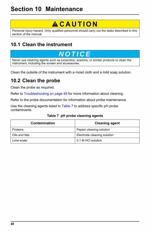
48
Section 10 Maintenance
10.1 Clean the instrument
Clean the outside of the instrument with a moist cloth and a mild soap solution.
10.2 Clean the probeClean the probe as required.
Refer to Troubleshooting on page 49 for more information about cleaning.
Refer to the probe documentation for information about probe maintenance.
Use the cleaning agents listed in Table 7 to address specific pH probe contaminants.
C A U T I O NPersonal injury hazard. Only qualified personnel should carry out the tasks described in thissection of the manual.
N O T I C ENever use cleaning agents such as turpentine, acetone, or similar products to clean the instrument, including the screen and accessories.
Table 7 pH probe cleaning agents
Contamination Cleaning agent
Proteins Pepsin cleaning solution
Oils and fats Electrode cleaning solution
Lime-scale 0.1 M HCl solution
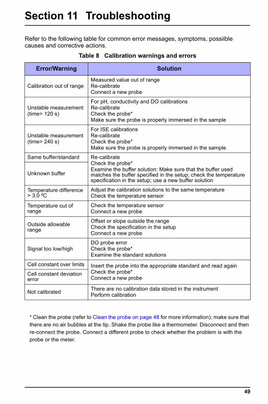
Section 11 Troubleshooting
Refer to the following table for common error messages, symptoms, possiible causes and corrective actions.
* Clean the probe (refer to Clean the probe on page 48 for more information); make sure that there are no air bubbles at the tip. Shake the probe like a thermometer. Disconnect and then re-connect the probe. Connect a different probe to check whether the problem is with the probe or the meter.
Table 8 Calibration warnings and errors
Error/Warning Solution
Calibration out of rangeMeasured value out of rangeRe-calibrateConnect a new probe
Unstable measurement(time> 120 s)
For pH, conductivity and DO calibrationsRe-calibrateCheck the probe*Make sure the probe is properly immersed in the sample
Unstable measurement(time> 240 s)
For ISE calibrationsRe-calibrateCheck the probe*Make sure the probe is properly immersed in the sample
Same buffer/standard Re-calibrateCheck the probe*Examine the buffer solution: Make sure that the buffer used matches the buffer specified in the setup; check the temperature specification in the setup; use a new buffer solution
Unknown buffer
Temperature difference > 3.0 ºC
Adjust the calibration solutions to the same temperatureCheck the temperature sensor
Temperature out of range
Check the temperature sensorConnect a new probe
Outside allowable range
Offset or slope outside the rangeCheck the specification in the setupConnect a new probe
Signal too low/highDO probe errorCheck the probe*Examine the standard solutions
Cell constant over limits Insert the probe into the appropriate standard and read againCheck the probe*Connect a new probe
Cell constant deviation error
Not calibrated There are no calibration data stored in the instrumentPerform calibration
49
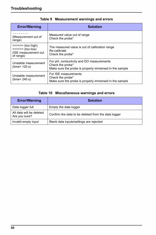
Troubleshooting
Table 9 Measurement warnings and errors
Error/Warning Solution
- - - - - - - -(Measurement out of range)
Measured value out of rangeCheck the probe*
>>>>>> (too high)<<<<<< (too low)(ISE measurement out of range)
The measured value is out of calibration rangeRe-calibrateCheck the probe*
Unstable measurement(time> 120 s)
For pH, conductivity and DO measurementsCheck the probe*Make sure the probe is properly immersed in the sample
Unstable measurement(time> 240 s)
For ISE measurementsCheck the probe*Make sure the probe is properly immersed in the sample
Table 10 Miscellaneous warnings and errors
Error/Warning Solution
Data logger full Empty the data logger
All data will be deleted.Are you sure? Confirm the data to be deleted from the data logger
Invalid empty input Blank data inputs/settings are rejected
50
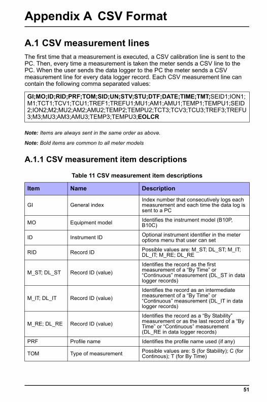
Appendix A CSV Format
A.1 CSV measurement linesThe first time that a measurement is executed, a CSV calibration line is sent to the PC. Then, every time a measurement is taken the meter sends a CSV line to the PC. When the user sends the data logger to the PC the meter sends a CSV measurement line for every data logger record. Each CSV measurement line can contain the following comma separated values:
Note: Items are always sent in the same order as above.
Note: Bold items are common to all meter models
A.1.1 CSV measurement item descriptions
GI;MO;ID;RID;PRF;TOM;SID;UN;STV;STU;DTF;DATE;TIME;TMT;SEID1;ION1;M1;TCT1;TCV1;TCU1;TREF1;TREFU1;MU1;AM1;AMU1;TEMP1;TEMPU1;SEID2;ION2;M2;MU2;AM2;AMU2;TEMP2;TEMPU2;TCT3;TCV3;TCU3;TREF3;TREFU3;M3;MU3;AM3;AMU3;TEMP3;TEMPU3;EOLCR
Table 11 CSV measurement item descriptions
Item Name Description
GI General indexIndex number that consecutively logs each measurement and each time the data log is sent to a PC
MO Equipment model Identifies the instrument model (B10P, B10C)
ID Instrument ID Optional instrument identifier in the meter options menu that user can set
RID Record ID Possible values are: M_ST; DL_ST; M_IT; DL_IT; M_RE; DL_RE
M_ST; DL_ST Record ID (value)Identifies the record as the first measurement of a “By Time” or “Continuous” measurement (DL_ST in data logger records)
M_IT; DL_IT Record ID (value)Identifies the record as an intermediate measurement of a “By Time” or “Continuous” measurement (DL_IT in data logger records)
M_RE; DL_RE Record ID (value)Identifies the record as a “By Stability” measurement or as the last record of a “By Time” or “Continuous” measurement (DL_RE in data logger records)
PRF Profile name Identifies the profile name used (if any)
TOM Type of measurement Possible values are: S (for Stability); C (for Continous); T (for By Time)
51
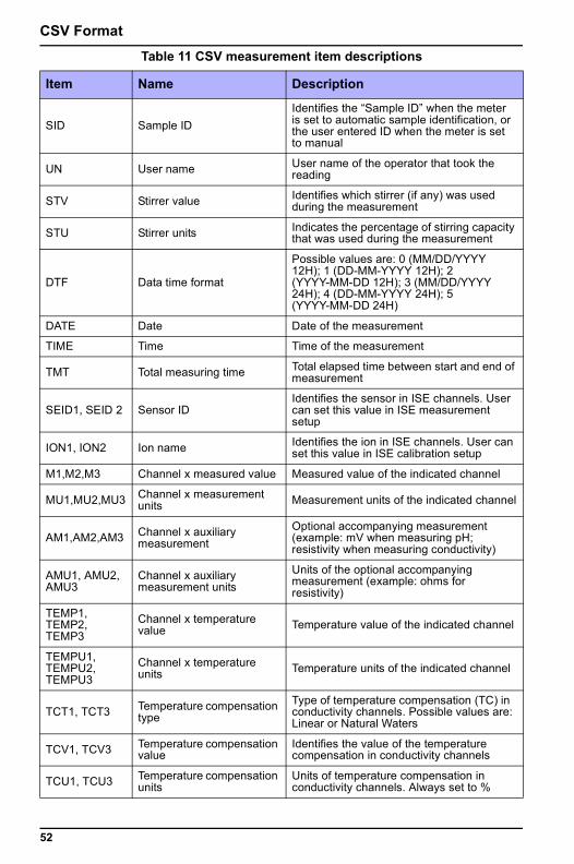
CSV Format
SID Sample IDIdentifies the “Sample ID” when the meter is set to automatic sample identification, or the user entered ID when the meter is set to manual
UN User name User name of the operator that took the reading
STV Stirrer value Identifies which stirrer (if any) was used during the measurement
STU Stirrer units Indicates the percentage of stirring capacity that was used during the measurement
DTF Data time format
Possible values are: 0 (MM/DD/YYYY 12H); 1 (DD-MM-YYYY 12H); 2 (YYYY-MM-DD 12H); 3 (MM/DD/YYYY 24H); 4 (DD-MM-YYYY 24H); 5 (YYYY-MM-DD 24H)
DATE Date Date of the measurement
TIME Time Time of the measurement
TMT Total measuring time Total elapsed time between start and end of measurement
SEID1, SEID 2 Sensor IDIdentifies the sensor in ISE channels. User can set this value in ISE measurement setup
ION1, ION2 Ion name Identifies the ion in ISE channels. User can set this value in ISE calibration setup
M1,M2,M3 Channel x measured value Measured value of the indicated channel
MU1,MU2,MU3 Channel x measurement units Measurement units of the indicated channel
AM1,AM2,AM3 Channel x auxiliary measurement
Optional accompanying measurement (example: mV when measuring pH; resistivity when measuring conductivity)
AMU1, AMU2, AMU3
Channel x auxiliary measurement units
Units of the optional accompanying measurement (example: ohms for resistivity)
TEMP1, TEMP2, TEMP3
Channel x temperature value Temperature value of the indicated channel
TEMPU1, TEMPU2, TEMPU3
Channel x temperature units Temperature units of the indicated channel
TCT1, TCT3 Temperature compensation type
Type of temperature compensation (TC) in conductivity channels. Possible values are: Linear or Natural Waters
TCV1, TCV3 Temperature compensation value
Identifies the value of the temperature compensation in conductivity channels
TCU1, TCU3 Temperature compensation units
Units of temperature compensation in conductivity channels. Always set to %
Table 11 CSV measurement item descriptions
Item Name Description
52
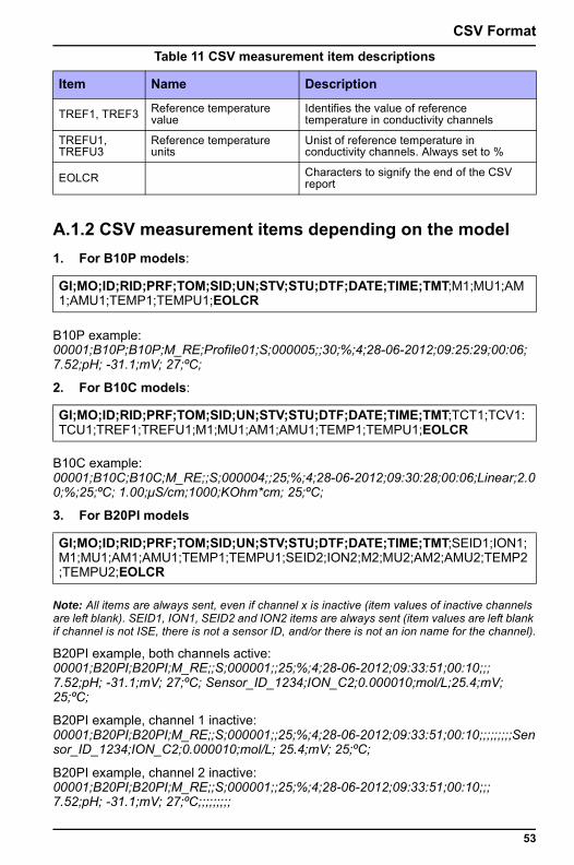
CSV Format
A.1.2 CSV measurement items depending on the model1. For B10P models:
B10P example: 00001;B10P;B10P;M_RE;Profile01;S;000005;;30;%;4;28-06-2012;09:25:29;00:06; 7.52;pH; -31.1;mV; 27;ºC;
2. For B10C models:
B10C example: 00001;B10C;B10C;M_RE;;S;000004;;25;%;4;28-06-2012;09:30:28;00:06;Linear;2.00;%;25;ºC; 1.00;μS/cm;1000;KOhm*cm; 25;ºC;
3. For B20PI models
Note: All items are always sent, even if channel x is inactive (item values of inactive channels are left blank). SEID1, ION1, SEID2 and ION2 items are always sent (item values are left blank if channel is not ISE, there is not a sensor ID, and/or there is not an ion name for the channel).
B20PI example, both channels active: 00001;B20PI;B20PI;M_RE;;S;000001;;25;%;4;28-06-2012;09:33:51;00:10;;; 7.52;pH; -31.1;mV; 27;ºC; Sensor_ID_1234;ION_C2;0.000010;mol/L;25.4;mV; 25;ºC;
B20PI example, channel 1 inactive: 00001;B20PI;B20PI;M_RE;;S;000001;;25;%;4;28-06-2012;09:33:51;00:10;;;;;;;;;Sensor_ID_1234;ION_C2;0.000010;mol/L; 25.4;mV; 25;ºC;
B20PI example, channel 2 inactive: 00001;B20PI;B20PI;M_RE;;S;000001;;25;%;4;28-06-2012;09:33:51;00:10;;; 7.52;pH; -31.1;mV; 27;ºC;;;;;;;;;
TREF1, TREF3 Reference temperature value
Identifies the value of reference temperature in conductivity channels
TREFU1, TREFU3
Reference temperature units
Unist of reference temperature in conductivity channels. Always set to %
EOLCR Characters to signify the end of the CSV report
GI;MO;ID;RID;PRF;TOM;SID;UN;STV;STU;DTF;DATE;TIME;TMT;M1;MU1;AM1;AMU1;TEMP1;TEMPU1;EOLCR
GI;MO;ID;RID;PRF;TOM;SID;UN;STV;STU;DTF;DATE;TIME;TMT;TCT1;TCV1:TCU1;TREF1;TREFU1;M1;MU1;AM1;AMU1;TEMP1;TEMPU1;EOLCR
GI;MO;ID;RID;PRF;TOM;SID;UN;STV;STU;DTF;DATE;TIME;TMT;SEID1;ION1;M1;MU1;AM1;AMU1;TEMP1;TEMPU1;SEID2;ION2;M2;MU2;AM2;AMU2;TEMP2;TEMPU2;EOLCR
Table 11 CSV measurement item descriptions
Item Name Description
53
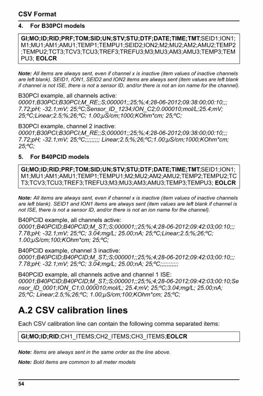
CSV Format
4. For B30PCI modelsNote: All items are always sent, even if channel x is inactive (item values of inactive channels are left blank). SEID1, ION1, SEID2 and ION2 items are always sent (item values are left blank if channel is not ISE, there is not a sensor ID, and/or there is not an ion name for the channel).
B30PCI example, all channels active: 00001;B30PCI;B30PCI;M_RE;;S;000001;;25;%;4;28-06-2012;09:38:00;00:10;;; 7.72;pH; -32.1;mV; 25;ºC;Sensor_ID_1234;ION_C2;0.000010;mol/L;25.4;mV; 25;ºC;Linear;2.5;%;26;ºC; 1.00;μS/cm;1000;KOhm*cm; 25;ºC;
B30PCI example, channel 2 inactive: 00001;B30PCI;B30PCI;M_RE;;S;000001;;25;%;4;28-06-2012;09:38:00;00:10;;; 7.72;pH; -32.1;mV; 25;ºC;;;;;;;;; Linear;2.5;%;26;ºC;1.00;μS/cm;1000;KOhm*cm; 25;ºC;
5. For B40PCID models
Note: All items are always sent, even if channel x is inactive (item values of inactive channels are left blank). SEID1 and ION1 items are always sent (item values are left blank if channel is not ISE, there is not a sensor ID, and/or there is not an ion name for the channel).
B40PCID example, all channels active: 00001;B40PCID;B40PCID;M_ST;;S;000001;;25;%;4;28-06-2012;09:42:03;00:10;;; 7.78;pH; -32.1;mV; 25;ºC; 3.04;mg/L; 25.00;nA; 25;ºC;Linear;2.5;%;26;ºC; 1.00;μS/cm;100;KOhm*cm; 25;ºC;
B40PCID example, channel 3 inactive: 00001;B40PCID;B40PCID;M_ST;;S;000001;;25;%;4;28-06-2012;09:42:03;00:10;;; 7.78;pH; -32.1;mV; 25;ºC; 3.04;mg/L; 25.00;nA; 25;ºC;;;;;;;;;;;
B40PCID example, all channels active and channel 1 ISE: 00001;B40PCID;B40PCID;M_ST;;S;000001;;25;%;4;28-06-2012;09:42:03;00:10;Sensor_ID_0001;ION_C1;0.000010;mol/L; 25.4;mV; 25;ºC;3.04;mg/L; 25.00;nA; 25;ºC; Linear;2.5;%;26;ºC; 1.00;μS/cm;100;KOhm*cm; 25;ºC;
A.2 CSV calibration linesEach CSV calibration line can contain the following comma separated items:
Note: Items are always sent in the same order as the line above.
Note: Bold items are common to all meter models
GI;MO;ID;RID;PRF;TOM;SID;UN;STV;STU;DTF;DATE;TIME;TMT;SEID1;ION1;M1;MU1;AM1;AMU1;TEMP1;TEMPU1;SEID2;ION2;M2;MU2;AM2;AMU2;TEMP2;TEMPU2;TCT3;TCV3;TCU3;TREF3;TREFU3;M3;MU3;AM3;AMU3;TEMP3;TEMPU3; EOLCR
GI;MO;ID;RID;PRF;TOM;SID;UN;STV;STU;DTF;DATE;TIME;TMT;SEID1;ION1;M1;MU1;AM1;AMU1;TEMP1;TEMPU1;M2;MU2;AM2;AMU2;TEMP2;TEMPU2;TCT3;TCV3;TCU3;TREF3;TREFU3;M3;MU3;AM3;AMU3;TEMP3;TEMPU3; EOLCR
GI;MO;ID;RID;CH1_ITEMS;CH2_ITEMS;CH3_ITEMS;EOLCR
54
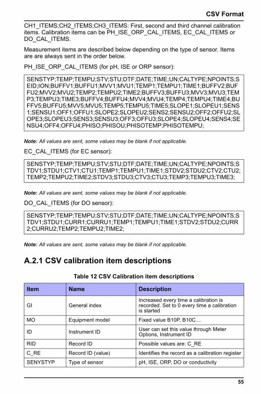
CSV Format
CH1_ITEMS;CH2_ITEMS;CH3_ITEMS: First, second and third channel calibration items. Calibration items can be PH_ISE_ORP_CAL_ITEMS, EC_CAL_ITEMS or DO_CAL_ITEMS.Measurement items are described below depending on the type of sensor. Items are are always sent in the order below.
PH_ISE_ORP_CAL_ITEMS (for pH, ISE or ORP sensor):
Note: All values are sent, some values may be blank if not applicable.
EC_CAL_ITEMS (for EC sensor):
Note: All values are sent, some values may be blank if not applicable.
DO_CAL_ITEMS (for DO sensor):
Note: All values are sent, some values may be blank if not applicable.
A.2.1 CSV calibration item descriptions
SENSTYP;TEMP;TEMPU;STV;STU;DTF;DATE;TIME;UN;CALTYPE;NPOINTS;SEID;ION;BUFFV1;BUFFU1;MVV1;MVU1;TEMP1;TEMPU1;TIME1;BUFFV2;BUFFU2;MVV2;MVU2;TEMP2;TEMPU2;TIME2;BUFFV3;BUFFU3;MVV3;MVU3;TEMP3;TEMPU3;TIME3;BUFFV4;BUFFU4;MVV4;MVU4;TEMP4;TEMPU4;TIME4;BUFFV5;BUFFU5;MVV5;MVU5;TEMP5;TEMPU5;TIME5;SLOPE1;SLOPEU1;SENS1;SENSU1;OFF1;OFFU1;SLOPE2;SLOPEU2;SENS2;SENSU2;OFF2;OFFU2;SLOPE3;SLOPEU3;SENS3;SENSU3;OFF3;OFFU3;SLOPE4;SLOPEU4;SENS4;SENSU4;OFF4;OFFU4;PHISO;PHISOU;PHISOTEMP;PHISOTEMPU;
SENSTYP;TEMP;TEMPU;STV;STU;DTF;DATE;TIME;UN;CALTYPE;NPOINTS;STDV1;STDU1;CTV1;CTU1;TEMP1;TEMPU1;TIME1;STDV2;STDU2;CTV2;CTU2;TEMP2;TEMPU2;TIME2;STDV3;STDU3;CTV3;CTU3;TEMP3;TEMPU3;TIME3;
SENSTYP;TEMP;TEMPU;STV;STU;DTF;DATE;TIME;UN;CALTYPE;NPOINTS;STDV1;STDU1;CURR1;CURRU1;TEMP1;TEMPU1;TIME1;STDV2;STDU2;CURR2;CURRU2;TEMP2;TEMPU2;TIME2;
Table 12 CSV Calibration item descriptions
Item Name Description
GI General indexIncreased every time a calibration is recorded. Set to 0 every time a calibration is started
MO Equipment model Fixed value B10P, B10C....
ID Instrument ID User can set this value through Meter Options, Instrument ID
RID Record ID Possible values are: C_RE
C_RE Record ID (value) Identifies the record as a calibration register
SENYSTYP Type of sensor pH, ISE, ORP, DO or conductivity
55
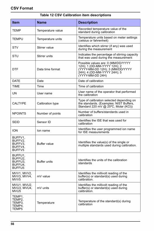
CSV Format
TEMP Temperature value Recorded temperature value of the standard during calibration
TEMPU Temperature units Temperature units based on meter settings (celsius or fahrenheit)
STV Stirrer value Identifies which stirrer (if any) was used during the measurement
STU Stirrer units Indicates the percentage of stirring capacity that was used during the measurement
DTF Data time format
Possible values are: 0 (MM/DD/YYYY 12H); 1 (DD-MM-YYYY 12H); 2 (YYYY-MM-DD 12H); 3 (MM/DD/YYYY 24H); 4 (DD-MM-YYYY 24H); 5 (YYYY-MM-DD 24H)
DATE Date Date of calibration
TIME Time Time of calibration
UN User name User name of the operator that performed the calibration
CALTYPE Calibration typeType of calibration selected depending on the standards. (Examples: NIST Buffers, Standard 220 mV @ 25ºC, Molar (KCl))
NPOINTS Number of points Number of buffers/standards used in calibration
SEID Sensor ID Identifies the ISE that was used for calibration
ION Ion name Identifies the user programmed ion name for ISE measurements
BUFFV1, BUFFV2, BUFFV3, BUFFV4, BUFFV5
Buffer value Identifies the value(s) of the single or multiple standards used during calibration.
BUFFU1, BUFFU2, BUFFU3, BUFFU4, BUFFU5
Buffer units Identifies the units of the calibration standards
MVV1, MVV2, MVV3, MVV4, MVV5
mV valueIdentifies the millivolt reading of the buffer(s) or standard(s) used during calibration.
MVU1, MVU2, MVU3, MVU4, MVU5
mV unitsIdentifies the millivolt reading of the buffer(s) or standard(s) used during calibration.
TEMP1, TEMP2, TEMP3, TEMP4, TEMP5
Temperature Temperature of the standard(s) during calibration
Table 12 CSV Calibration item descriptions
Item Name Description
56
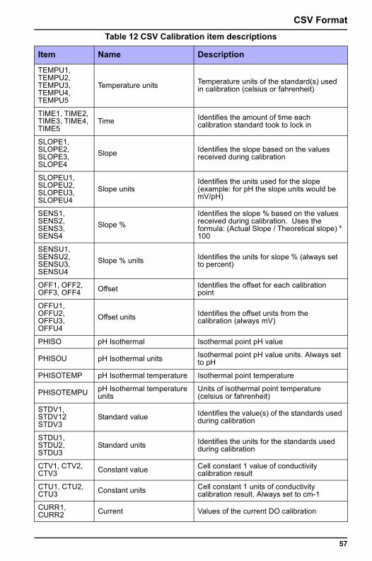
CSV Format
TEMPU1, TEMPU2, TEMPU3, TEMPU4, TEMPU5
Temperature units Temperature units of the standard(s) used in calibration (celsius or fahrenheit)
TIME1, TIME2, TIME3, TIME4, TIME5
Time Identifies the amount of time each calibration standard took to lock in
SLOPE1, SLOPE2, SLOPE3, SLOPE4
Slope Identifies the slope based on the values received during calibration
SLOPEU1, SLOPEU2, SLOPEU3, SLOPEU4
Slope unitsIdentifies the units used for the slope (example: for pH the slope units would be mV/pH)
SENS1, SENS2, SENS3, SENS4
Slope %Identifies the slope % based on the values received during calibration. Uses the formula: (Actual Slope / Theoretical slope) * 100
SENSU1, SENSU2, SENSU3, SENSU4
Slope % units Identifies the units for slope % (always set to percent)
OFF1, OFF2, OFF3, OFF4 Offset Identifies the offset for each calibration
point
OFFU1, OFFU2, OFFU3, OFFU4
Offset units Identifies the offset units from the calibration (always mV)
PHISO pH Isothermal Isothermal point pH value
PHISOU pH Isothermal units Isothermal point pH value units. Always set to pH
PHISOTEMP pH Isothermal temperature Isothermal point temperature
PHISOTEMPU pH Isothermal temperature units
Units of isothermal point temperature (celsius or fahrenheit)
STDV1, STDV12 STDV3
Standard value Identifies the value(s) of the standards used during calibration
STDU1, STDU2, STDU3
Standard units Identifies the units for the standards used during calibration
CTV1, CTV2, CTV3 Constant value Cell constant 1 value of conductivity
calibration result
CTU1, CTU2, CTU3 Constant units Cell constant 1 units of conductivity
calibration result. Always set to cm-1
CURR1, CURR2 Current Values of the current DO calibration
Table 12 CSV Calibration item descriptions
Item Name Description
57
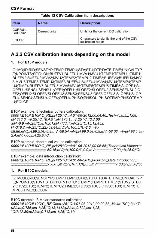
CSV Format
A.2.2 CSV calibration items depending on the model1. For B10P models:
B10P example, 5 technical buffers calibration: 00001;B10P;B10P;C_RE;pH;25;°C;;;4;01-06-2012;00:04:46;;Technical;5;;;1.68; pH;313.6;mV;25;°C;16;4.01;pH;175.1;mV;25;°C;13;7.00 ;pH;-0.9;mV;25;°C;8;10.01;pH;-177.1;mV;25;°C;15;12.45;p H;-318.7;mV;25;°C;22;-59.44;mV/pH;100.5;%;-2.6;mV;- 58.86;mV/pH;99.5;%;-0.9;mV;-58.54;mV/pH;99.0;%;-0.9;mV;-58.03;mV/pH;98.1;%;-2.4;mV;7.00;pH;25.0;ºC;
B10P example, theoretical values calibration: 00001;B10P;B10P;C_RE;pH;25;°C;;;4;01-06-2012;00:06:55;;Theoretical Values;;;; ;;;;;;;;;;;;;;;;;;;;;;;;;;;;;;;;;;;-59.16;mV/pH;100.0;%;0.0;mV;;;;;;;;;;;;;;;;;;;7.00;pH;25.0;ºC;
B10P example, data introduction calibration: 00001;B10P;B10P;C_RE;pH;25;°C;;;4;01-06-2012;00:06:35;;Data Introduction;; ;;;;;;;;;;;;;;;;;;;;;;;;;;;;;;;;;;;;;-58.03;mV/pH;107.1;%;0.5;mV;;;;;;;;;;;;;;;;;;;7.00;pH;25.0;ºC;
1. For B10C models:
B10C example, 3 Molar standards calibration: 00001;B10C;B10C;C_RE;Cond.;25;°C;4;01-06-2012;00:02:33;;Molar (KCl);3;147; μS/cm;0.756;cm-1;25;°C;13;1412;μS/cm;0.722;cm-1;25; °C;7;12.89;mS/cm;0.718;cm-1;25;°C;11;
CURRU1, CURRU2 Current units Units for the current DO calibration
EOLCR Characters to signify the end of the CSV calibration report
GI;MO;ID;RID;SENSTYP;TEMP;TEMPU;STV;STU;DTF;DATE;TIME;UN;CALTYPE;NPOINTS;SEID;ION;BUFFV1;BUFFU1;MVV1;MVU1;TEMP1;TEMPU1;TIME1;BUFFV2;BUFFU2;MVV2;MVU2;TEMP2;TEMPU2;TIME2;BUFFV3;BUFFU3;MVV3;MVU3;TEMP3;TEMPU3;TIME3;BUFFV4;BUFFU4;MVV4;MVU4;TEMP4;TEMPU4;TIME4;BUFFV5;BUFFU5;MVV5;MVU5;TEMP5;TEMPU5;TIME5;SLOPE1;SLOPEU1;SENS1;SENSU1;OFF1;OFFU1;SLOPE2;SLOPEU2;SENS2;SENSU2;OFF2;OFFU2;SLOPE3;SLOPEU3;SENS3;SENSU3;OFF3;OFFU3;SLOPE4;SLOPEU4;SENS4;SENSU4;OFF4;OFFU4;PHISO;PHISOU;PHISOTEMP;PHISOTEMPU;EOLCR
GI;MO;ID;RID;SENSTYP;TEMP;TEMPU;STV;STU;DTF;DATE;TIME;UN;CALTYPE;NPOINTS;STDV1;STDU1;CTV1;CTU1;TEMP1;TEMPU1;TIME1;STDV2;STDU2;CTV2;CTU2;TEMP2;TEMPU2;TIME2;STDV3;STDU3;CTV3;CTU3;TEMP3;TEMPU3;TIME3;EOLCR
Table 12 CSV Calibration item descriptions
Item Name Description
58
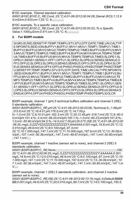
CSV Format
B10C example, 1Demal standard calibration: 00001;B10C;B10C;C_RE;Cond.;25;°C;4;01-06-2012;00:04:28;;Demal (KCl);1;12.8 5;mS/cm;0.633;cm-1;25;°C; 6;;;;;;;;;;;;;;;B10C example, To a specific value calibration: 00001;B10C;B10C;C_RE;Cond.;25;°C;4;01-06-2012;00:05:53;;To a Specific Value;1;1000;μS/cm;0.511;cm-1;25;°C; 6;;;;;;;;;;;;;;;
2. For B20PI models
B20PI example, channel 1 (pH) 5 technical buffers calibration and channel 2 (ISE) 5 standards calibration: 00001;B20PI;B20PI;C_RE;pH;25;°C;4;01-06-2012;00:03:06;;Technical;5;;;1.68;pH ;315.8;mV;25;°C;16;4.01;pH;176.0;mV;25;°C;14;7.00;p H;-1.0;mV;25;°C;8;10.01;pH;-182.3;mV;25;°C;20;12.45;pH;-318.7;mV;25;°C;6;-60.00;mV/pH;101.4;%;-3.4;mV;-59.20;mV/pH;100.1;%;-1.0;mV;-60.23;mV/pH;101.8;%;-1.0;mV;-55.90;mV/pH;94.5;%;-14.0;mV;7.00;pH;25.0;ºC;ISE;25;°C;4;01-06-2012;00:06:25;;mg/L;5;ZZZYZZZZZZZZZZZZZZZY;AAAAAA;0.001;mg/L;16.8;mV;25;°C;12;0.010;mg/L;46.9;mV;25;°C;8;0.100;mg/L;97.3;mV; 25;°C;10;1.000;mg/L;147.1;mV;25;°C;11;10.000;mg/L;197.9;mV;25;°C;13;-30.09;mV/pX;;;107.1;mV;-50.39;mV/pX;;;147.7;mV;-49.87;mV/pX;;;147.1;mV;-50.80;mV/pX;;;147.1;mV;;;;;
B20PI example, channel 1 inactive (sensor set to none), and channel 2 (ISE) 5 standards calibration: 00001;B20PI;B20PI;C_RE;None;;;;;;;;;;;;;;;;;;;;;;;;;;;;;;;;;;;;;;;;;;;;;;;;;;;;;;;;;;;;;;;;;;;;;;;;;;ISE;25;°C;4;01-06-2012;00:06:25;;mg/L;5;ZZZYZZZZZZZZZZZZZZZY;AAAAAA;0.001;mg/L;16.8;mV;25;°C;12;0.010;mg/L;46.9;mV;25;°C;8;0.100;mg/L;97.3;mV;25;°C;10;1.000;mg/L;147.1;mV;25;°C;11;10.000;mg/L;197.9;mV;25;°C;13;-30.09;mV/pX;;;107.1;mV;-50.39;mV/pX;;;147.7;mV;-49.87;mV/pX;;;147.1;mV;-50.80;mV/pX;;;147.1;mV;;;;;
B20PI example, channel 1 (ISE) 5 standards calibration, and channel 2 inactive (sensor set to none): 00001;B20PI;B20PI;C_RE;ISE;25;°C;4;01-06-2012;00:13:19;;mg/L;5;Default;BBBBBB;0.001;mg/L;49.6;mV;25;°C;20;0.010;mg/L;99.7;mV;25;°C;14;0.100;mg/L;150.5;
GI;MO;ID;RID;SENSTYP;TEMP;TEMPU;STV;STU;DTF;DATE;TIME;UN;CALTYPE;NPOINTS;SEID;ION;BUFFV1;BUFFU1;MVV1;MVU1;TEMP1;TEMPU1;TIME1;BUFFV2;BUFFU2;MVV2;MVU2;TEMP2;TEMPU2;TIME2;BUFFV3;BUFFU3;MVV3;MVU3;TEMP3;TEMPU3;TIME3;BUFFV4;BUFFU4;MVV4;MVU4;TEMP4;TEMPU4;TIME4;BUFFV5;BUFFU5;MVV5;MVU5;TEMP5;TEMPU5;TIME5;SLOPE1;SLOPEU1;SENS1;SENSU1;OFF1;OFFU1;SLOPE2;SLOPEU2;SENS2;SENSU2;OFF2;OFFU2;SLOPE3;SLOPEU3;SENS3;SENSU3;OFF3;OFFU3;SLOPE4;SLOPEU4;SENS4;SENSU4;OFF4;OFFU4;PHISO;PHISOU;PHISOTEMP;PHISOTEMPU;SENSTYP;TEMP;TEMPU;STV;STU;DTF;DATE;TIME;UN;CALTYPE;NPOINTS;SEID;ION;BUFFV1;BUFFU1;MVV1;MVU1;TEMP1;TEMPU1;TIME1;BUFFV2;BUFFU2;MVV2;MVU2;TEMP2;TEMPU2;TIME2;BUFFV3;BUFFU3;MVV3;MVU3;TEMP3;TEMPU3;TIME3;BUFFV4;BUFFU4;MVV4;MVU4;TEMP4;TEMPU4;TIME4;BUFFV5;BUFFU5;MVV5;MVU5;TEMP5;TEMPU5;TIME5;SLOPE1;SLOPEU1;SENS1;SENSU1;OFF1;OFFU1;SLOPE2;SLOPEU2;SENS2;SENSU2;OFF2;OFFU2;SLOPE3;SLOPEU3;SENS3;SENSU3;OFF3;OFFU3;SLOPE4;SLOPEU4;SENS4;SENSU4;OFF4;OFFU4;PHISO;PHISOU;PHISOTEMP;PHISOTEMPU;EOLCR
59
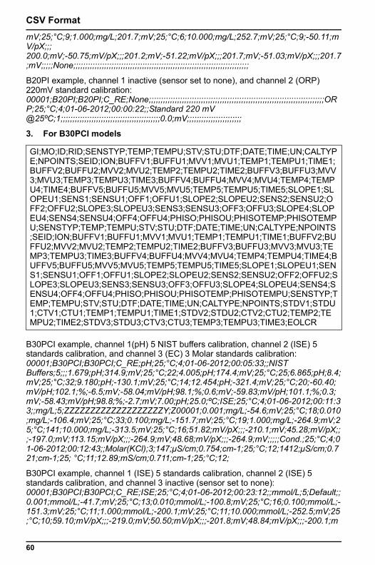
CSV Format
mV;25;°C;9;1.000;mg/L;201.7;mV;25;°C;6;10.000;mg/L;252.7;mV;25;°C;9;-50.11;mV/pX;;; 200.0;mV;-50.75;mV/pX;;;201.2;mV;-51.22;mV/pX;;;201.7;mV;-51.03;mV/pX;;;201.7;mV;;;;;None;;;;;;;;;;;;;;;;;;;;;;;;;;;;;;;;;;;;;;;;;;;;;;;;;;;;;;;;;;;;;;;;;;;;;;;;;;B20PI example, channel 1 inactive (sensor set to none), and channel 2 (ORP) 220mV standard calibration: 00001;B20PI;B20PI;C_RE;None;;;;;;;;;;;;;;;;;;;;;;;;;;;;;;;;;;;;;;;;;;;;;;;;;;;;;;;;;;;;;;;;;;;;;;;;;;ORP;25;°C;4;01-06-2012;00:00:22;;Standard 220 mV @25ºC;1;;;;;;;;;;;;;;;;;;;;;;;;;;;;;;;;;;;;;;;;;;0.0;mV;;;;;;;;;;;;;;;;;;;;;;;
3. For B30PCI models
B30PCI example, channel 1(pH) 5 NIST buffers calibration, channel 2 (ISE) 5 standards calibration, and channel 3 (EC) 3 Molar standards calibration: 00001;B30PCI;B30PCI;C_RE;pH;25;°C;4;01-06-2012;00:05:33;;NIST Buffers;5;;;1.679;pH;314.9;mV;25;°C;22;4.005;pH;174.4;mV;25;°C;25;6.865;pH;8.4;mV;25;°C;32;9.180;pH;-130.1;mV;25;°C;14;12.454;pH;-321.4;mV;25;°C;20;-60.40;mV/pH;102.1;%;-6.5;mV;-58.04;mV/pH;98.1;%;0.6;mV;-59.83;mV/pH;101.1;%;0.3;mV;-58.43;mV/pH;98.8;%;-2.7;mV;7.00;pH;25.0;ºC;ISE;25;°C;4;01-06-2012;00:11:33;;mg/L;5;ZZZZZZZZZZZZZZZZZZZY;Z00001;0.001;mg/L;-54.6;mV;25;°C;18;0.010;mg/L;-106.4;mV;25;°C;33;0.100;mg/L;-151.7;mV;25;°C;19;1.000;mg/L;-264.9;mV;25;°C;141;10.000;mg/L;-313.5;mV;25;°C;16;51.82;mV/pX;;;-210.1;mV;45.28;mV/pX;;;-197.0;mV;113.15;mV/pX;;;-264.9;mV;48.68;mV/pX;;;-264.9;mV;;;;;Cond.;25;°C;4;01-06-2012;00:12:43;;Molar(KCl);3;147;μS/cm;0.754;cm-1;25;°C;12;1412;μS/cm;0.721;cm-1;25; °C;11;12.89;mS/cm;0.711;cm-1;25;°C;12;
B30PCI example, channel 1 (ISE) 5 standards calibration, channel 2 (ISE) 5 standards calibration, and channel 3 inactive (sensor set to none): 00001;B30PCI;B30PCI;C_RE;ISE;25;°C;4;01-06-2012;00:23:12;;mmol/L;5;Default;;0.001;mmol/L;-41.7;mV;25;°C;13;0.010;mmol/L;-100.8;mV;25;°C;16;0.100;mmol/L;-151.3;mV;25;°C;11;1.000;mmol/L;-200.1;mV;25;°C;11;10.000;mmol/L;-252.5;mV;25;°C;10;59.10;mV/pX;;;-219.0;mV;50.50;mV/pX;;;-201.8;mV;48.84;mV/pX;;;-200.1;m
GI;MO;ID;RID;SENSTYP;TEMP;TEMPU;STV;STU;DTF;DATE;TIME;UN;CALTYPE;NPOINTS;SEID;ION;BUFFV1;BUFFU1;MVV1;MVU1;TEMP1;TEMPU1;TIME1;BUFFV2;BUFFU2;MVV2;MVU2;TEMP2;TEMPU2;TIME2;BUFFV3;BUFFU3;MVV3;MVU3;TEMP3;TEMPU3;TIME3;BUFFV4;BUFFU4;MVV4;MVU4;TEMP4;TEMPU4;TIME4;BUFFV5;BUFFU5;MVV5;MVU5;TEMP5;TEMPU5;TIME5;SLOPE1;SLOPEU1;SENS1;SENSU1;OFF1;OFFU1;SLOPE2;SLOPEU2;SENS2;SENSU2;OFF2;OFFU2;SLOPE3;SLOPEU3;SENS3;SENSU3;OFF3;OFFU3;SLOPE4;SLOPEU4;SENS4;SENSU4;OFF4;OFFU4;PHISO;PHISOU;PHISOTEMP;PHISOTEMPU;SENSTYP;TEMP;TEMPU;STV;STU;DTF;DATE;TIME;UN;CALTYPE;NPOINTS;SEID;ION;BUFFV1;BUFFU1;MVV1;MVU1;TEMP1;TEMPU1;TIME1;BUFFV2;BUFFU2;MVV2;MVU2;TEMP2;TEMPU2;TIME2;BUFFV3;BUFFU3;MVV3;MVU3;TEMP3;TEMPU3;TIME3;BUFFV4;BUFFU4;MVV4;MVU4;TEMP4;TEMPU4;TIME4;BUFFV5;BUFFU5;MVV5;MVU5;TEMP5;TEMPU5;TIME5;SLOPE1;SLOPEU1;SENS1;SENSU1;OFF1;OFFU1;SLOPE2;SLOPEU2;SENS2;SENSU2;OFF2;OFFU2;SLOPE3;SLOPEU3;SENS3;SENSU3;OFF3;OFFU3;SLOPE4;SLOPEU4;SENS4;SENSU4;OFF4;OFFU4;PHISO;PHISOU;PHISOTEMP;PHISOTEMPU;SENSTYP;TEMP;TEMPU;STV;STU;DTF;DATE;TIME;UN;CALTYPE;NPOINTS;STDV1;STDU1;CTV1;CTU1;TEMP1;TEMPU1;TIME1;STDV2;STDU2;CTV2;CTU2;TEMP2;TEMPU2;TIME2;STDV3;STDU3;CTV3;CTU3;TEMP3;TEMPU3;TIME3;EOLCR
60
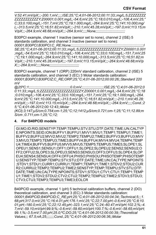
CSV Format
V;52.41;mV/pX;;;-200.1;mV;;;;;ISE;25;°C;4;01-06-2012;00:11:33;;mg/L;5;ZZZZZZZZZZZZZZZZZZZY;Z00001;0.001;mg/L;-54.6;mV;25;°C;18;0.010;mg/L;-106.4;mV;25;°C;33;0.100;mg/L;-151.7;mV;25;°C;19;1.000;mg/L;-264.9;mV;25;°C;141;10.000;mg/L;-313.5;mV;25;°C;16;51.82;mV/pX;;;-210.1;mV;45.28;mV/pX;;;-197.0;mV;113.15;mV/pX;;;-264.9;mV;48.68;mV/pX;;;-264.9;mV;;;;;None;;;;;;;;;;;;;;;;;;;;;;;;;;;;;;B30PCI example, channel 1 inactive (sensor set to none), channel 2 (ISE) 5 standards calibration, and channel 3 inactive (sensor set to none): 00001;B30PCI;B30PCI;C_RE;None;;;;;;;;;;;;;;;;;;;;;;;;;;;;;;;;;;;;;;;;;;;;;;;;;;;;;;;;;;;;;;;;;;;;;;;;;;ISE;25;°C;4;01-06-2012;00:11:33;;mg/L;5;ZZZZZZZZZZZZZZZZZZZY;Z00001;0.001;mg/L;-54.6;mV;25;°C;18;0.010;mg/L;-106.4;mV;25;°C;33;0.100;mg/L;-151.7;mV;25;°C;19;1.000;mg/L;-264.9;mV;25;°C;141;10.000;mg/L;-313.5;mV;25;°C;16;51.82;mV/pX;;;-210.1;mV;45.28;mV/pX;;;-197.0;mV;113.15;mV/pX;;;-264.9;mV;48.68;mV/pX;;;-264.9;mV;;;;;None;;;;;;;;;;;;;;;;;;;;;;;;;;;;;;
B30PCI example, channel 1 (ORP) 220mV standard calibration, channel 2 (ISE) 5 standards calibration, and channel 3 (EC) 3 Molar standards calibration: 00001;B30PCI;B30PCIZ;C_RE;ORP;25;°C;4;01-06-2012;00:00:26;;Standard 220 mV @25ºC;1;;;;;;;;;;;;;;;;;;;;;;;;;;;;;;;;;;;;;;;;;;0.0;mV;;;;;;;;;;;;;;;;;;;;;;;ISE;25;°C;4;01-06-2012;00:11:33;;mg/L;5;ZZZZZZZZZZZZZZZZZZZY;Z00001;0.001;mg/L;-54.6;mV;25;°C;18;0.010;mg/L;-106.4;mV;25;°C;33;0.100;mg/L;-151.7;mV;25;°C;19;1.000;mg/L;-264.9;mV;25;°C;141;10.000;mg/L;-313.5;mV;25;°C;16;51.82;mV/pX;;;-210.1;mV;45.28;mV/pX;;;-197.0;mV;113.15;mV/pX;;;-264.9;mV;48.68;mV/pX;;;-264.9;mV;;;;;Cond.;25;°C;4;01-06-2012;00:12:43;;Molar (KCl);3;147;μS/cm;0.754;cm-1;25;°C;12;1412;μS/cm;0.721;cm-1;25;°C;11;12.89;mS/cm ;0.711;cm-1;25;°C;12;
4. For B40PCID models
B40PCID example, channel 1 (pH) 5 technical calibration buffers, channel 2 (DO) theoretical calibration, and channel 3 (EC) 3 Molar standards calibration: 00001;B40PCID;B40PCID;C_RE;pH;25;°C;4;01-06-2012;00:04:34;;Technical;5;;;1.68;pH;317.0;mV;25;°C;16;4.01;pH;176.1;mV;25;°C;22;7.00;pH;-0.6;mV;25;°C;8;10.01;pH;-180.0;mV;25;°C;22;12.45;pH;-323.1;mV;25;°C;24;-60.47;mV/pH;102.2;%;-4.7;mV;-59.10;mV/pH;99.9;%;-0.6;mV;-59.60;mV/pH;100.7;%;-0.6;mV;-58.65;mV/pH;99.1;%;-3.5;mV;7.00;pH;25.0;ºC;DO;25;°C;4;01-06-2012;00:00:39;;Theoretical Values;;; 67.5;nA;25;;;;;;;;Cond.;25;°C;4;01-06-2012;00:06:36;;Molar
GI;MO;ID;RID;SENSTYP;TEMP;TEMPU;STV;STU;DTF;DATE;TIME;UN;CALTYPE;NPOINTS;SEID;ION;BUFFV1;BUFFU1;MVV1;MVU1;TEMP1;TEMPU1;TIME1;BUFFV2;BUFFU2;MVV2;MVU2;TEMP2;TEMPU2;TIME2;BUFFV3;BUFFU3;MVV3;MVU3;TEMP3;TEMPU3;TIME3;BUFFV4;BUFFU4;MVV4;MVU4;TEMP4;TEMPU4;TIME4;BUFFV5;BUFFU5;MVV5;MVU5;TEMP5;TEMPU5;TIME5;SLOPE1;SLOPEU1;SENS1;SENSU1;OFF1;OFFU1;SLOPE2;SLOPEU2;SENS2;SENSU2;OFF2;OFFU2;SLOPE3;SLOPEU3;SENS3;SENSU3;OFF3;OFFU3;SLOPE4;SLOPEU4;SENS4;SENSU4;OFF4;OFFU4;PHISO;PHISOU;PHISOTEMP;PHISOTEMPU;SENSTYP;TEMP;TEMPU;STV;STU;DTF;DATE;TIME;UN;CALTYPE;NPOINTS;STDV1;STDU1;CURR1;CURRU1;TEMP1;TEMPU1;TIME1;STDV2;STDU2;CURR2;CURRU2;TEMP2;TEMPU2;TIME2;SENSTYP;TEMP;TEMPU;STV;STU;DTF;DATE;TIME;UN;CALTYPE;NPOINTS;STDV1;STDU1;CTV1;CTU1;TEMP1;TEMPU1;TIME1;STDV2;STDU2;CTV2;CTU2;TEMP2;TEMPU2;TIME2;STDV3;STDU3;CTV3;CTU3;TEMP3;TEMPU3;TIME3;EOLCR
61
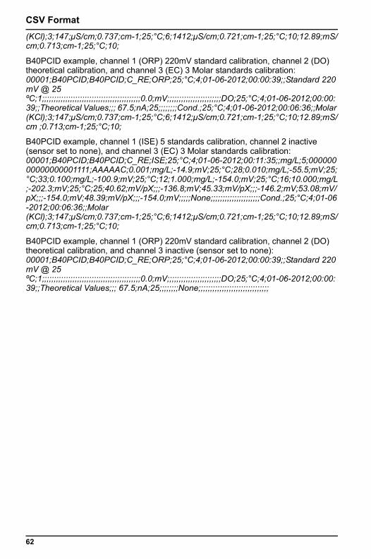
CSV Format
(KCl);3;147;μS/cm;0.737;cm-1;25;°C;6;1412;μS/cm;0.721;cm-1;25;°C;10;12.89;mS/cm;0.713;cm-1;25;°C;10;B40PCID example, channel 1 (ORP) 220mV standard calibration, channel 2 (DO) theoretical calibration, and channel 3 (EC) 3 Molar standards calibration: 00001;B40PCID;B40PCID;C_RE;ORP;25;°C;4;01-06-2012;00:00:39;;Standard 220 mV @ 25 ºC;1;;;;;;;;;;;;;;;;;;;;;;;;;;;;;;;;;;;;;;;;;;0.0;mV;;;;;;;;;;;;;;;;;;;;;;;DO;25;°C;4;01-06-2012;00:00:39;;Theoretical Values;;; 67.5;nA;25;;;;;;;;Cond.;25;°C;4;01-06-2012;00:06:36;;Molar (KCl);3;147;μS/cm;0.737;cm-1;25;°C;6;1412;μS/cm;0.721;cm-1;25;°C;10;12.89;mS/cm ;0.713;cm-1;25;°C;10;
B40PCID example, channel 1 (ISE) 5 standards calibration, channel 2 inactive (sensor set to none), and channel 3 (EC) 3 Molar standards calibration: 00001;B40PCID;B40PCID;C_RE;ISE;25;°C;4;01-06-2012;00:11:35;;mg/L;5;00000000000000001111;AAAAAC;0.001;mg/L;-14.9;mV;25;°C;28;0.010;mg/L;-55.5;mV;25;°C;33;0.100;mg/L;-100.9;mV;25;°C;12;1.000;mg/L;-154.0;mV;25;°C;16;10.000;mg/L;-202.3;mV;25;°C;25;40.62;mV/pX;;;-136.8;mV;45.33;mV/pX;;;-146.2;mV;53.08;mV/pX;;;-154.0;mV;48.39;mV/pX;;;-154.0;mV;;;;;None;;;;;;;;;;;;;;;;;;;;;Cond.;25;°C;4;01-06-2012;00:06:36;;Molar (KCl);3;147;μS/cm;0.737;cm-1;25;°C;6;1412;μS/cm;0.721;cm-1;25;°C;10;12.89;mS/cm;0.713;cm-1;25;°C;10;
B40PCID example, channel 1 (ORP) 220mV standard calibration, channel 2 (DO) theoretical calibration, and channel 3 inactive (sensor set to none): 00001;B40PCID;B40PCID;C_RE;ORP;25;°C;4;01-06-2012;00:00:39;;Standard 220 mV @ 25 ºC;1;;;;;;;;;;;;;;;;;;;;;;;;;;;;;;;;;;;;;;;;;;0.0;mV;;;;;;;;;;;;;;;;;;;;;;;DO;25;°C;4;01-06-2012;00:00:39;;Theoretical Values;;; 67.5;nA;25;;;;;;;;None;;;;;;;;;;;;;;;;;;;;;;;;;;;;;;
62
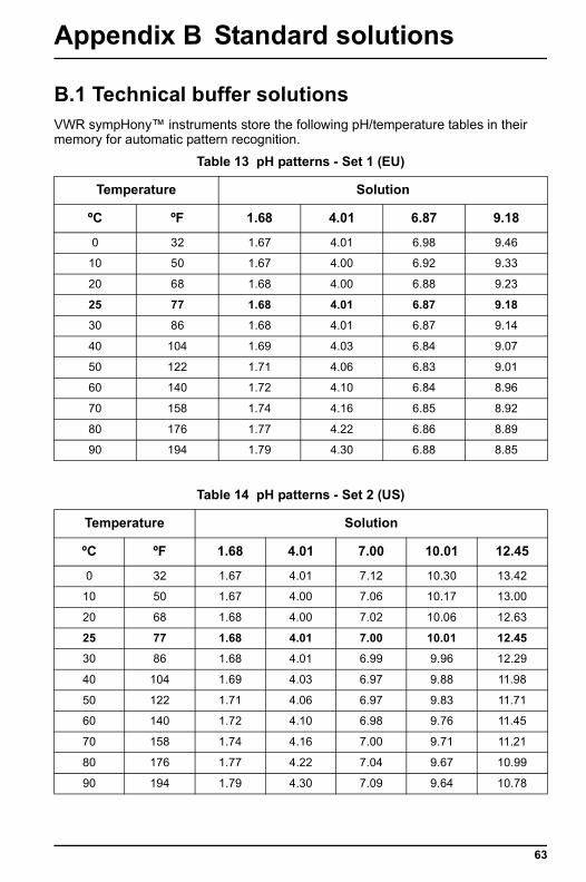
Appendix B Standard solutions
B.1 Technical buffer solutionsVWR sympHony™ instruments store the following pH/temperature tables in their memory for automatic pattern recognition.
Table 13 pH patterns - Set 1 (EU)
Temperature Solution
ºC ºF 1.68 4.01 6.87 9.18
0 32 1.67 4.01 6.98 9.46
10 50 1.67 4.00 6.92 9.33
20 68 1.68 4.00 6.88 9.23
25 77 1.68 4.01 6.87 9.18
30 86 1.68 4.01 6.87 9.14
40 104 1.69 4.03 6.84 9.07
50 122 1.71 4.06 6.83 9.01
60 140 1.72 4.10 6.84 8.96
70 158 1.74 4.16 6.85 8.92
80 176 1.77 4.22 6.86 8.89
90 194 1.79 4.30 6.88 8.85
Table 14 pH patterns - Set 2 (US)
Temperature Solution
ºC ºF 1.68 4.01 7.00 10.01 12.45
0 32 1.67 4.01 7.12 10.30 13.42
10 50 1.67 4.00 7.06 10.17 13.00
20 68 1.68 4.00 7.02 10.06 12.63
25 77 1.68 4.01 7.00 10.01 12.45
30 86 1.68 4.01 6.99 9.96 12.29
40 104 1.69 4.03 6.97 9.88 11.98
50 122 1.71 4.06 6.97 9.83 11.71
60 140 1.72 4.10 6.98 9.76 11.45
70 158 1.74 4.16 7.00 9.71 11.21
80 176 1.77 4.22 7.04 9.67 10.99
90 194 1.79 4.30 7.09 9.64 10.78
63
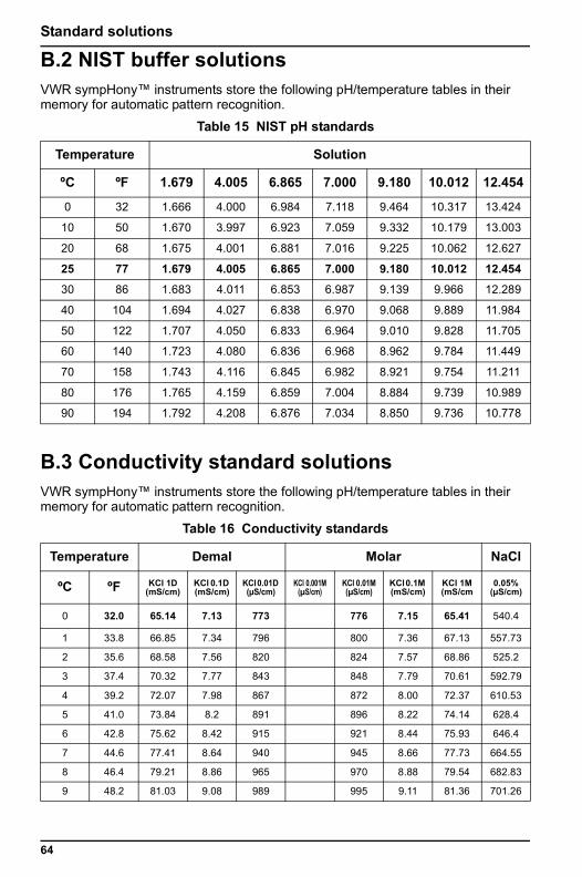
Standard solutions
B.2 NIST buffer solutionsVWR sympHony™ instruments store the following pH/temperature tables in their memory for automatic pattern recognition.
B.3 Conductivity standard solutionsVWR sympHony™ instruments store the following pH/temperature tables in their memory for automatic pattern recognition.
Table 15 NIST pH standards
Temperature Solution
ºC ºF 1.679 4.005 6.865 7.000 9.180 10.012 12.454
0 32 1.666 4.000 6.984 7.118 9.464 10.317 13.424
10 50 1.670 3.997 6.923 7.059 9.332 10.179 13.003
20 68 1.675 4.001 6.881 7.016 9.225 10.062 12.627
25 77 1.679 4.005 6.865 7.000 9.180 10.012 12.454
30 86 1.683 4.011 6.853 6.987 9.139 9.966 12.289
40 104 1.694 4.027 6.838 6.970 9.068 9.889 11.984
50 122 1.707 4.050 6.833 6.964 9.010 9.828 11.705
60 140 1.723 4.080 6.836 6.968 8.962 9.784 11.449
70 158 1.743 4.116 6.845 6.982 8.921 9.754 11.211
80 176 1.765 4.159 6.859 7.004 8.884 9.739 10.989
90 194 1.792 4.208 6.876 7.034 8.850 9.736 10.778
Table 16 Conductivity standards
Temperature Demal Molar NaCl
ºC ºF KCl 1D (mS/cm)
KCl 0.1D (mS/cm)
KCl 0.01D (µS/cm)
KCl 0.001M (µS/cm)
KCl 0.01M (µS/cm)
KCl 0.1M (mS/cm)
KCl 1M (mS/cm
0.05%(µS/cm)
0 32.0 65.14 7.13 773 776 7.15 65.41 540.4
1 33.8 66.85 7.34 796 800 7.36 67.13 557.73
2 35.6 68.58 7.56 820 824 7.57 68.86 525.2
3 37.4 70.32 7.77 843 848 7.79 70.61 592.79
4 39.2 72.07 7.98 867 872 8.00 72.37 610.53
5 41.0 73.84 8.2 891 896 8.22 74.14 628.4
6 42.8 75.62 8.42 915 921 8.44 75.93 646.4
7 44.6 77.41 8.64 940 945 8.66 77.73 664.55
8 46.4 79.21 8.86 965 970 8.88 79.54 682.83
9 48.2 81.03 9.08 989 995 9.11 81.36 701.26
64
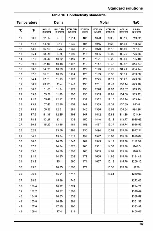
Standard solutions
10 50.0 82.85 9.31 1014 105 1020 9.33 83.19 719.82
11 51.8 84.68 9.54 1039 107 1045 9.56 85.04 738.53
12 53.6 86.54 9.76 1065 110 1070 9.79 86.89 757.37
13 55.4 88.39 9.99 1090 113 1095 10.02 88.76 776.36
14 57.2 90.26 10.22 1116 116 1121 10.25 90.63 795.48
15 59.0 92.13 10.46 1142 119 1147 10.48 92.52 814.74
16 60.8 94.02 10.69 1168 122 1173 10.72 94.41 834.14
17 62.6 95.91 10.93 1194 125 1199 10.95 96.31 853.68
18 64.4 97.81 11.16 1220 127 1225 11.19 98.22 873.36
19 66.2 99.72 11.4 1247 130 1251 11.43 100.14 893.18
20 68.0 101.63 11.64 1273 133 1278 11.67 102.07 913.13
21 69.8 103.56 11.88 1300 136 1305 11.91 104.00 933.22
22 71.6 105.49 12.12 1327 139 1332 12.15 105.94 953.44
23 73.4 107.42 12.36 1354 142 1359 12.39 107.89 973.8
24 75.2 109.36 12.61 1381 145 1386 12.64 109.84 994.28
25 77.0 111.31 12.85 1409 147 1412 12.89 111.80 1014.9
26 78.8 113.27 13.1 1436 150 1440 13.13 113.77 1035.65
27 80.6 115.22 13.35 1464 153 1467 13.37 115.74 1056.53
28 82.4 13.59 1491 156 1494 13.62 115.70 1077.54
29 84.2 13.84 1519 159 1522 13.87 115.70 1098.67
30 86.0 14.09 1547 162 1549 14.12 115.70 1119.92
31 87.8 14.34 1575 165 1581 14.37 115.70 1141.3
32 89.6 14.59 1603 168 1609 14.62 115.70 1162.8
33 91.4 14.85 1632 171 1638 14.88 115.70 1184.41
34 93.2 15.1 1660 174 1667 15.13 115.70 1206.15
35 95.0 16.35 1688 177 15.39 115.70 1228
36 96.8 15.61 1717 15.64 1249.96
37 98.6 15.86 1745 1272.03
38 100.4 16.12 1774 1294.21
39 102.2 16.37 1803 1316.49
40 104.0 16.63 1832 1338.89
41 105.8 16.89 1861 1361.38
42 107.6 17.15 1890 1383.97
43 109.4 17.4 1919 1406.66
Table 16 Conductivity standards
Temperature Demal Molar NaCl
ºC ºF KCl 1D (mS/cm)
KCl 0.1D (mS/cm)
KCl 0.01D (µS/cm)
KCl 0.001M (µS/cm)
KCl 0.01M (µS/cm)
KCl 0.1M (mS/cm)
KCl 1M (mS/cm
0.05%(µS/cm)
65
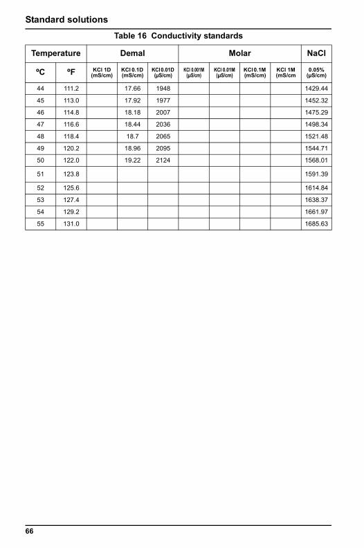
Standard solutions
44 111.2 17.66 1948 1429.44
45 113.0 17.92 1977 1452.32
46 114.8 18.18 2007 1475.29
47 116.6 18.44 2036 1498.34
48 118.4 18.7 2065 1521.48
49 120.2 18.96 2095 1544.71
50 122.0 19.22 2124 1568.01
51 123.8 1591.39
52 125.6 1614.84
53 127.4 1638.37
54 129.2 1661.97
55 131.0 1685.63
Table 16 Conductivity standards
Temperature Demal Molar NaCl
ºC ºF KCl 1D (mS/cm)
KCl 0.1D (mS/cm)
KCl 0.01D (µS/cm)
KCl 0.001M (µS/cm)
KCl 0.01M (µS/cm)
KCl 0.1M (mS/cm)
KCl 1M (mS/cm
0.05%(µS/cm)
66


Prices, product appearance and specifications are current at the time of printing, subject to change without notice. Availability for certain products may be limited by federal, state, provincial or local licensing requirements. All prices are in U.S. dollars unless otherwise noted. Offers valid in USA, void where prohibited by law or company policy, while supplies last. Visit vwr.com to view our policy and additional disclaimers.
VWR, forms of VWR and the VWR logo and/or design are either registered trademarks, trademarks, or service marks of VWR International Inc. in the United States and/or other countries. All other marks referenced herein are registered marks of their respective owner(s). For a complete list of trademarks owners, please visit vwr.com
© VWR International, Inc. 2012. All rights reserved. Printed in China.