doc-id: eseo downlink data summary · 2018-11-21 · ‘eseo tlm ver 0.1e 04/10/2018.docx’...
TRANSCRIPT
ESEO Downlink
Data
Doc-ID: Date: Issue: Page:
ESEO_Downlink_Data_1_2.docx 20.11.2018 1.2 1
Summary
This document provides details of downlink data for the AMSAT ESEO payload – based upon the
FUNcube-1 spec for compatibility with the dashboard and data warehouse
Distribution: Confidential
Keywords:
Document-ID:
Issue: 1.2
Date: 20 Nov 2018
Prepared: Graham Shirville
Revised: Chris Bridges, David Bowman
Checked: Duncan Hills, Dave Johnson, David Bowman, Graham Shirville
Approved: Graham Shirville
ESEO Downlink
Data
Doc-ID: Date: Issue: Page:
ESEO_Downlink_Data_1_2.docx 20.11.2018 1.2 2
Revision Record
issue date total
pages
Authorisation affected
pages
brief description of change
1.1 DRAFT 22.03.15 Added details of where to look
for extended sat-id.
1.1 ESEO
wip
11.08.15 Graham Modified to reflect ESEO tlm.
more work needed to finalise
bit counts and channels in RT
and WOD frames
1.1f 23.08.15 Graham Updated after discussions
VZV/MRF and with FC team.
pending further redefinitions
on a skype Thursday 27th
August
1.1g 24.08.15 Duncan Bit order defined – see section
2
1.1h 28.08.15 Graham Revised after telcall. Agreed
to concentrate on the RT and
WOD coming from the EPS
board directly and via the
CAN bus from the RX & TX
boards for the time being so
that thermal testing can be
undertaken asap
Also followed Duncan’s advice
to make WOD frames parse
better.
1.1j 28.08.15 Graham Various tweaks and move
WOD frames
1.1k 18.06.16 Chris, ALL ESEO Workshop at Surrey
Space Centre:
Update RTT & WOD definitions
for FSW & Dashboard
ESEO Downlink
Data
Doc-ID: Date: Issue: Page:
ESEO_Downlink_Data_1_2.docx 20.11.2018 1.2 3
1.1L 28.06.2016 Chris, David
(Skype)
ALL Updated RTT, WOD, Schedule
1.1M 19.07.2016 Chris, Pete Defined 2B as payload_header
in 4k8 payload mode. Further
edits from Skype call with
team.
1.1N 16.11.2018 Chris Added temperature equations
from 20 Nov 2018.
Added RF equations from
‘ESEO TLM ver 0.1e
04/10/2018.docx’
Corrected terminology in
places. Added WOD eqns.
Issued as 1.21
List of TBD’s and TBC’s TBC/TBD Location Subject Due date Action by
TBD Internally generated CCT debug / status
data
PB
TBC Confirmation of platform EPS data via CAN CPB, Done
TBD Detail of data format and limits from science
payloads. – e.g. How much memory holds
current valid data. / Start - finish address
Internal
TBD ESEO Platform Telemetry Equations ESA
TBC AMS Local Equations CPB, Done

ESEO Downlink
Data
Doc-ID: Date: Issue: Page:
ESEO_Downlink_Data_1_2.docx 20.11.2018 1.2 4
Table of Content
Summary ............................................................................................................................................. 1
List of Acronyms ..................................................................................................................................... 5
1 Overview ....................................................................................................................................... 6
2 Frame Types ................................................................................................................................. 6
3 Extended Sat Id/Frame Types ........................................................................................................ 8
4 Data Sources ................................................................................................................................. 9
5 Data Collection/Transmission .......................................................................................................... 9
6 Transmission Schedule ................................................................................................................. 13
ESEO Downlink
Data
Doc-ID: Date: Issue: Page:
ESEO_Downlink_Data_1_2.docx 20.11.2018 1.2 5
List of Acronyms
ANT Antenna (board)
ADC Analogue to Digital Converter
ACS Attitude Control Subsystem
BCR Battery Charge Regulator
BPSK Binary Phase Shift Keying
CCT Command Control and Telemetry (board)
EPS Electrical Power Subsystem
FEC Forward Error Correction
MSE Material Science Experiment
PA Power Amplifier (board)
RF Radio Frequency (board)
RS Reed Solomon (error-correction code)
SW Software
TBC To Be Confirmed
TBD To Be Determined
TBW To Be Written
TCS Thermal Control Subsystem
TRX Transponder
ESEO Downlink
Data
Doc-ID: Date: Issue: Page:
ESEO_Downlink_Data_1_2.docx 20.11.2018 1.2 6
1 Overview
This document defines the data downlink format for the telemetry transmitted by the AMSAT payload on ESEO. Both the content of each downlink frame and the transmission order of the different frame types will be
addressed.
The FEC encoding method and frame size remains unchanged from the original found here by James Miller:
http://www.amsat.org/articles/g3ruh/125.html
“The Telemetry uses 1200bps BPSK with both convolution and block coding based on the proven AMSAT
OSCAR-40 FEC telemetry model. The encoding starts with a 256-byte (2048 bit) data frame, this is passed through a pair of RS (160,128) encoders, a scrambler, convolution encoder and the interleaver. This produces
5200 bits to transmit. Thus, ignoring pre- and post-amble, each data frame will take 4.3s to transmit”
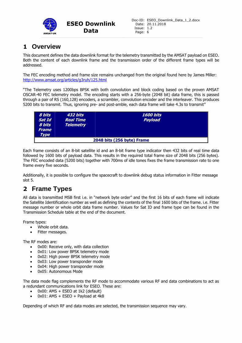
8 bits Sat Id 8 bits Frame Type
432 bits Real Time Telemetry
1600 bits Payload
2048 bits (256 byte) Frame
Each frame consists of an 8-bit satellite id and an 8-bit frame type indicator then 432 bits of real time data followed by 1600 bits of payload data. This results in the required total frame size of 2048 bits (256 bytes).
The FEC encoded data (5200 bits) together with 700ms of idle tones fixes the frame transmission rate to one frame every five seconds.
Additionally, it is possible to configure the spacecraft to downlink debug status information in Fitter message
slot 5.
2 Frame Types
All data is transmitted MSB first i.e. in “network byte order” and the first 16 bits of each frame will indicate
the Satellite Identification number as well as defining the contents of the final 1600 bits of the frame. i.e. Fitter message number or whole orbit data frame number. Values for Sat ID and frame type can be found in the
Transmission Schedule table at the end of the document.
Frame types:
• Whole orbit data.
• Fitter messages.
The RF modes are:
• 0x00: Receive only, with data collection
• 0x01: Low power BPSK telemetry mode
• 0x02: High power BPSK telemetry mode
• 0x03: Low power transponder mode
• 0x04: High power transponder mode
• 0x05: Autonomous Mode
The data mode flag complements the RF mode to accommodate various RF and data combinations to act as
a redundant communications link for ESEO. These are:
• 0x00: AMS + ESEO at 1k2 (default)
• 0x01: AMS + ESEO + Payload at 4k8
Depending of which RF and data modes are selected, the transmission sequence may vary.

ESEO Downlink
Data
Doc-ID: Date: Issue: Page:
ESEO_Downlink_Data_1_2.docx 20.11.2018 1.2 7
In the first data mode, the usual FUNcube frame of RTT and WOD will be adhered to within the typical 5 second transmission schedule. But in the second data mode, the data rate is increased allowing 4 FUNcube
frames to be transmitted in the 5 seconds – again, still following the transmission schedule. The first frame will still adhere to the RTT + WOD sequencing, but the next 3 frames will be of payload data. If payload data
is not available to fill these three 256B data slots, AMS Payload data will be repeated. These will be collected
on the ground via the FUNcube Dashboard.
Figure 1. Offered 4k8 Mode: If Payload Data is empty / unused, the AMS will repeat existing telemetry
Real Time Telemetry Each frame starts with Sat ID and frame type then 432 bits of real time data. This real-time data is updated
every from sensors in the AMSAT Payload, from the AMSAT CCT board and from the ESEO platform housekeeping data.
Whole Orbit Data
This is intended to provide all the information required to demonstrate the physical and operational characteristics of the satellite over an entire orbit. The data will be sampled once per minute for 104 minutes
and a full set of data is transmitted once every 24 frames or 2 minutes. Whole Orbit Data is received on the ground and presented in graphical form for educational outreach. Included are the battery voltage, system
current and solar current collected together temperatures current and voltages from many subsystems.
Fitter Messages
These are the text messages received from ground stations to be periodically retransmitted within the 2
minutes telemetry sequence. Messages will not be broken up and sent over multiple frames, so the maximum length of a message is 200 bytes. The format of messages is transparent to the satellite, each received
message will just be copied out verbatim.
ESEO Downlink
Data
Doc-ID: Date: Issue: Page:
ESEO_Downlink_Data_1_2.docx 20.11.2018 1.2 8
Messages can be uploaded to specific AT32 memory slots with the slot id specified at upload time. After an upload attempt status bits in the Real Time Telemetry will be set to indicate the slot id and success or failure.
An authentication (not encryption) scheme will be used to verify message validity.
3 Extended Sat Id/Frame Types
To ensure the data format and transmission type can be used with multiple satellites the ID scheme allows the ground station to determine the Sat Identity.
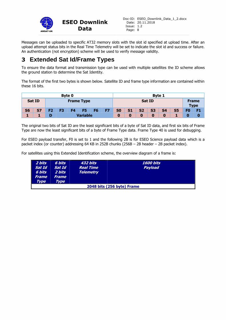
The format of the first two bytes is shown below. Satellite ID and frame type information are contained within
these 16 bits.
Byte 0 Byte 1
Sat ID Frame Type Sat ID Frame Type
S6 S7 F2 F3 F4 F5 F6 F7 S0 S1 S2 S3 S4 S5 F0 F1
1 1 D Variable 0 0 0 0 0 1 0 0
The original two bits of Sat ID are the least significant bits of a byte of Sat ID data, and first six bits of Frame
Type are now the least significant bits of a byte of Frame Type data. Frame Type 40 is used for debugging.
For ESEO payload transfer, F0 is set to 1 and the following 2B is for ESEO Science payload data which is a packet index (or counter) addressing 64 KB in 252B chunks (256B – 2B header – 2B packet index).
For satellites using this Extended Identification scheme, the overview diagram of a frame is:
2 bits Sat Id 6 bits Frame Type
6 bits Sat Id 2 bits Frame Type
432 bits Real Time Telemetry
1600 bits Payload
2048 bits (256 byte) Frame
ESEO Downlink
Data
Doc-ID: Date: Issue: Page:
ESEO_Downlink_Data_1_2.docx 20.11.2018 1.2 9
4 Data Sources
AMSAT – The AMSAT payload via internal wiring and I2C OBD – The main on-board data handling computer via CAN bus
STX – S Band transmitter
ACS – Attitude Control System SSM – Sun Sensor main
MWM – Momentum Wheel main GPS – Global positioning system receiver
PMM – Power Management Unit main
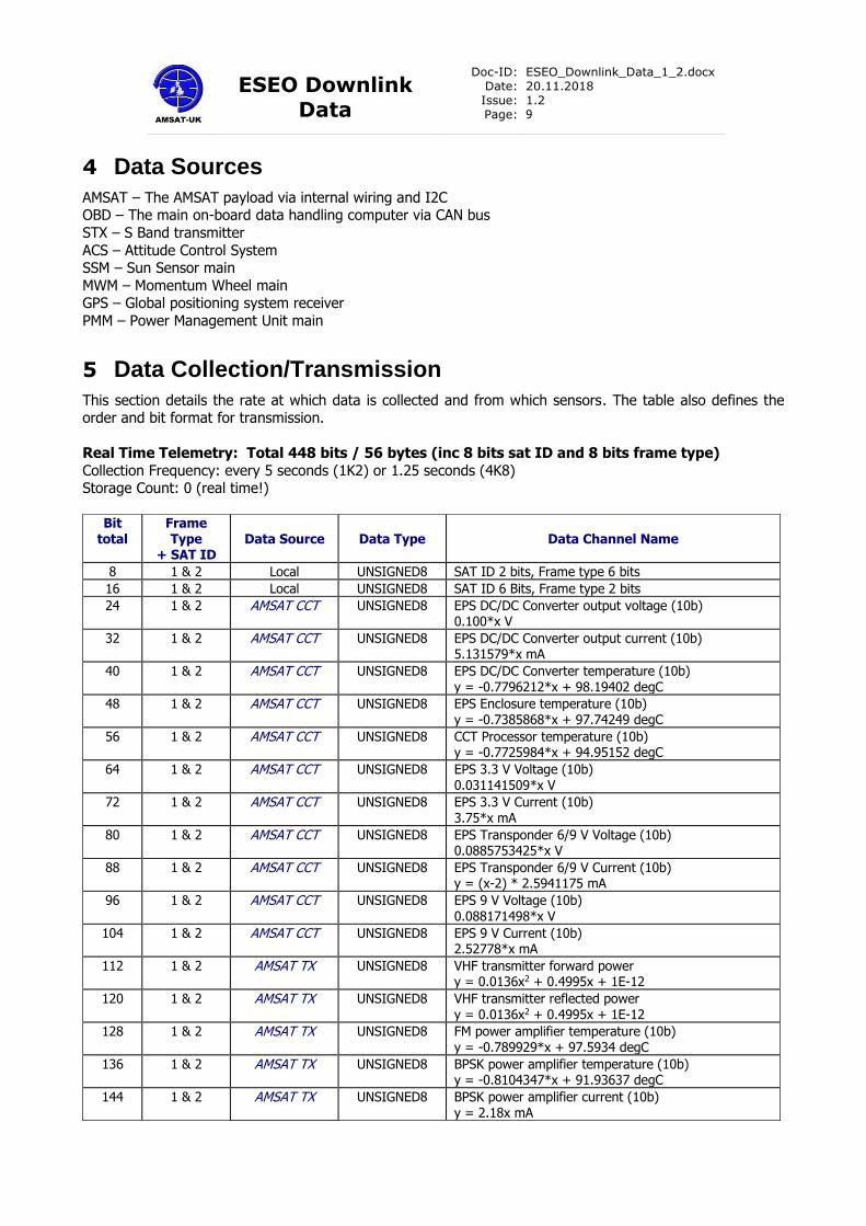
5 Data Collection/Transmission
This section details the rate at which data is collected and from which sensors. The table also defines the order and bit format for transmission.
Real Time Telemetry: Total 448 bits / 56 bytes (inc 8 bits sat ID and 8 bits frame type)
Collection Frequency: every 5 seconds (1K2) or 1.25 seconds (4K8) Storage Count: 0 (real time!)
Bit
total Frame Type
+ SAT ID Data Source Data Type Data Channel Name
8 1 & 2 Local UNSIGNED8 SAT ID 2 bits, Frame type 6 bits
16 1 & 2 Local UNSIGNED8 SAT ID 6 Bits, Frame type 2 bits
24 1 & 2 AMSAT CCT UNSIGNED8 EPS DC/DC Converter output voltage (10b) 0.100*x V
32 1 & 2 AMSAT CCT UNSIGNED8 EPS DC/DC Converter output current (10b) 5.131579*x mA
40 1 & 2 AMSAT CCT UNSIGNED8 EPS DC/DC Converter temperature (10b) y = -0.7796212*x + 98.19402 degC
48 1 & 2 AMSAT CCT UNSIGNED8 EPS Enclosure temperature (10b) y = -0.7385868*x + 97.74249 degC
56 1 & 2 AMSAT CCT UNSIGNED8 CCT Processor temperature (10b) y = -0.7725984*x + 94.95152 degC
64 1 & 2 AMSAT CCT UNSIGNED8 EPS 3.3 V Voltage (10b) 0.031141509*x V
72 1 & 2 AMSAT CCT UNSIGNED8 EPS 3.3 V Current (10b) 3.75*x mA
80 1 & 2 AMSAT CCT UNSIGNED8 EPS Transponder 6/9 V Voltage (10b) 0.0885753425*x V
88 1 & 2 AMSAT CCT UNSIGNED8 EPS Transponder 6/9 V Current (10b) y = (x-2) * 2.5941175 mA
96 1 & 2 AMSAT CCT UNSIGNED8 EPS 9 V Voltage (10b) 0.088171498*x V
104 1 & 2 AMSAT CCT UNSIGNED8 EPS 9 V Current (10b) 2.52778*x mA
112 1 & 2 AMSAT TX UNSIGNED8 VHF transmitter forward power y = 0.0136x2 + 0.4995x + 1E-12
120 1 & 2 AMSAT TX UNSIGNED8 VHF transmitter reflected power y = 0.0136x2 + 0.4995x + 1E-12
128 1 & 2 AMSAT TX UNSIGNED8 FM power amplifier temperature (10b) y = -0.789929*x + 97.5934 degC
136 1 & 2 AMSAT TX UNSIGNED8 BPSK power amplifier temperature (10b) y = -0.8104347*x + 91.93637 degC
144 1 & 2 AMSAT TX UNSIGNED8 BPSK power amplifier current (10b) y = 2.18x mA
ESEO Downlink
Data
Doc-ID: Date: Issue: Page:
ESEO_Downlink_Data_1_2.docx 20.11.2018 1.2 10
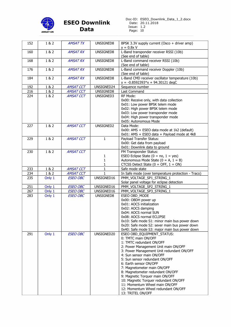
152 1 & 2 AMSAT TX UNSIGNED8 BPSK 3.3V supply current (Osco + driver amp) y = 0.8x V
160 1 & 2 AMSAT RX UNSIGNED8 L-Band transponder receiver RSSI (10b) (See end of table)
168 1 & 2 AMSAT RX UNSIGNED8 L-Band command receiver RSSI (10b) (See end of table)
176 1 & 2 AMSAT RX UNSIGNED8 L-Band command receiver Doppler (10b) (See end of table)
184 1 & 2 AMSAT RX UNSIGNED8 L-Band CMD receiver oscillator temperature (10b) y = -0.8592393*x + 94.30121 degC
192 1 & 2 AMSAT CCT UNSIGNED24 Sequence number
216 1 & 2 AMSAT CCT UNSIGNED8 Last Command
224
1 & 2 AMSAT CCT UNSIGNED3
RF Mode: 0x00: Receive only, with data collection 0x01: Low power BPSK telem mode 0x02: High power BPSK telem mode 0x03: Low power transponder mode 0x04: High power transponder mode 0x05: Autonomous Mode
227 1 & 2 AMSAT CCT UNSIGNED2 Data Mode: 0x00: AMS + ESEO data mode at 1k2 (default) 0x01: AMS + ESEO data + Payload mode at 4k8
229 1 & 2 AMSAT CCT 1 Payload Transfer Status: 0x00: Get data from payload 0x01: Downlink data to ground
230 1 & 2 AMSAT CCT 1 1 1
FM Transponder Status: ESEO Eclipse State (0 = no, 1 = yes) Autonomous Mode State (0 = A, 1 = B) CTCSS Detect State (0 = OFF, 1 = ON)
233 1 & 2 AMSAT CCT 1 Safe mode state
234 1 & 2 AMSAT CCT 1 In Safe mode (over temperature protection - Traco)
235 Only 1 ESEO OBC UNSIGNED16 PMM_VOLTAGE_SP1_STRING_1 Solar panel voltage for eclipse detection
251 Only 1 ESEO OBC UNSIGNED16 PMM_VOLTAGE_SP2_STRING_1
267 Only 1 ESEO OBC UNSIGNED16 PMM_VOLTAGE_SP3_STRING_1
283 Only 1 ESEO OBC UNSIGNED8 ESEO OBD_MODE 0x00: OBDH power up 0x01: AOCS initialization 0x02: AOCS damping 0x04: AOCS normal SUN 0x08: AOCS normal ECLIPSE 0x10: Safe mode S1: minor main bus power down 0x20: Safe mode S2: sever main bus power down 0x40: Safe mode S3: major main bus power down
291 Only 1 ESEO OBC UNSIGNED20 ESEO OBD_EQUIPMENT_STATUS: 0: TMTC main ON/OFF 1: TMTC redundant ON/OFF 2: Power Management Unit main ON/OFF 3: Power Management Unit redundant ON/OFF 4: Sun sensor main ON/OFF 5: Sun sensor redundant ON/OFF 6: Earth sensor ON/OFF 7: Magnetometer main ON/OFF 8: Magnetometer redundant ON/OFF
9: Magnetic Torquer main ON/OFF 10: Magnetic Torquer redundant ON/OFF 11: Momentum Wheel main ON/OFF 12: Momentum Wheel redundant ON/OFF 13: TRITEL ON/OFF
ESEO Downlink
Data
Doc-ID: Date: Issue: Page:
ESEO_Downlink_Data_1_2.docx 20.11.2018 1.2 11
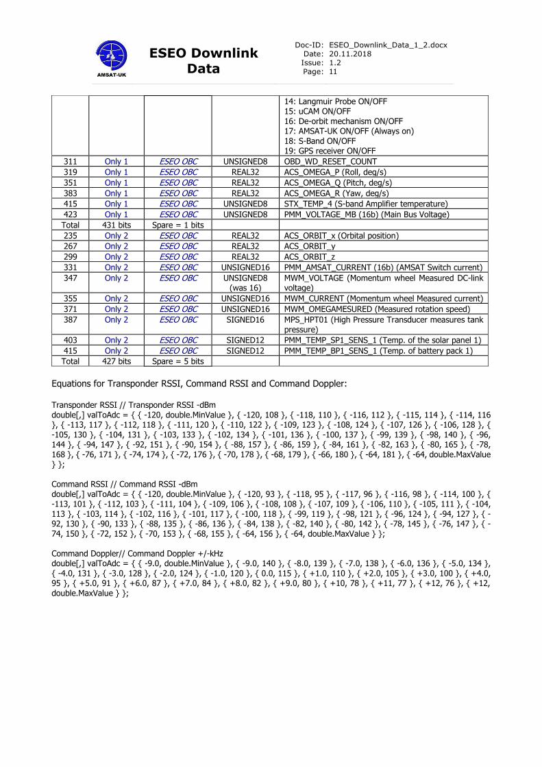
Equations for Transponder RSSI, Command RSSI and Command Doppler: Transponder RSSI // Transponder RSSI -dBm double[,] valToAdc = { { -120, double.MinValue }, { -120, 108 }, { -118, 110 }, { -116, 112 }, { -115, 114 }, { -114, 116 }, { -113, 117 }, { -112, 118 }, { -111, 120 }, { -110, 122 }, { -109, 123 }, { -108, 124 }, { -107, 126 }, { -106, 128 }, { -105, 130 }, { -104, 131 }, { -103, 133 }, { -102, 134 }, { -101, 136 }, { -100, 137 }, { -99, 139 }, { -98, 140 }, { -96, 144 }, { -94, 147 }, { -92, 151 }, { -90, 154 }, { -88, 157 }, { -86, 159 }, { -84, 161 }, { -82, 163 }, { -80, 165 }, { -78, 168 }, { -76, 171 }, { -74, 174 }, { -72, 176 }, { -70, 178 }, { -68, 179 }, { -66, 180 }, { -64, 181 }, { -64, double.MaxValue } }; Command RSSI // Command RSSI -dBm double[,] valToAdc = { { -120, double.MinValue }, { -120, 93 }, { -118, 95 }, { -117, 96 }, { -116, 98 }, { -114, 100 }, { -113, 101 }, { -112, 103 }, { -111, 104 }, { -109, 106 }, { -108, 108 }, { -107, 109 }, { -106, 110 }, { -105, 111 }, { -104, 113 }, { -103, 114 }, { -102, 116 }, { -101, 117 }, { -100, 118 }, { -99, 119 }, { -98, 121 }, { -96, 124 }, { -94, 127 }, { -92, 130 }, { -90, 133 }, { -88, 135 }, { -86, 136 }, { -84, 138 }, { -82, 140 }, { -80, 142 }, { -78, 145 }, { -76, 147 }, { -74, 150 }, { -72, 152 }, { -70, 153 }, { -68, 155 }, { -64, 156 }, { -64, double.MaxValue } }; Command Doppler// Command Doppler +/-kHz double[,] valToAdc = { { -9.0, double.MinValue }, { -9.0, 140 }, { -8.0, 139 }, { -7.0, 138 }, { -6.0, 136 }, { -5.0, 134 }, { -4.0, 131 }, { -3.0, 128 }, { -2.0, 124 }, { -1.0, 120 }, { 0.0, 115 }, { +1.0, 110 }, { +2.0, 105 }, { +3.0, 100 }, { +4.0, 95 }, { +5.0, 91 }, { +6.0, 87 }, { +7.0, 84 }, { +8.0, 82 }, { +9.0, 80 }, { +10, 78 }, { +11, 77 }, { +12, 76 }, { +12, double.MaxValue } };
14: Langmuir Probe ON/OFF 15: uCAM ON/OFF 16: De-orbit mechanism ON/OFF 17: AMSAT-UK ON/OFF (Always on) 18: S-Band ON/OFF 19: GPS receiver ON/OFF
311 Only 1 ESEO OBC UNSIGNED8 OBD_WD_RESET_COUNT
319 Only 1 ESEO OBC REAL32 ACS_OMEGA_P (Roll, deg/s)
351 Only 1 ESEO OBC REAL32 ACS_OMEGA_Q (Pitch, deg/s)
383 Only 1 ESEO OBC REAL32 ACS_OMEGA_R (Yaw, deg/s)
415 Only 1 ESEO OBC UNSIGNED8 STX_TEMP_4 (S-band Amplifier temperature)
423 Only 1 ESEO OBC UNSIGNED8 PMM_VOLTAGE_MB (16b) (Main Bus Voltage)
Total 431 bits Spare = 1 bits
235 Only 2 ESEO OBC REAL32 ACS_ORBIT_x (Orbital position)
267 Only 2 ESEO OBC REAL32 ACS_ORBIT_y
299 Only 2 ESEO OBC REAL32 ACS_ORBIT_z
331 Only 2 ESEO OBC UNSIGNED16 PMM_AMSAT_CURRENT (16b) (AMSAT Switch current)
347 Only 2 ESEO OBC UNSIGNED8 (was 16)
MWM_VOLTAGE (Momentum wheel Measured DC-link voltage)
355 Only 2 ESEO OBC UNSIGNED16 MWM_CURRENT (Momentum wheel Measured current)
371 Only 2 ESEO OBC UNSIGNED16 MWM_OMEGAMESURED (Measured rotation speed)
387 Only 2 ESEO OBC SIGNED16 MPS_HPT01 (High Pressure Transducer measures tank pressure)
403 Only 2 ESEO OBC SIGNED12 PMM_TEMP_SP1_SENS_1 (Temp. of the solar panel 1)
415 Only 2 ESEO OBC SIGNED12 PMM_TEMP_BP1_SENS_1 (Temp. of battery pack 1)
Total 427 bits Spare = 5 bits
ESEO Downlink
Data
Doc-ID: Date: Issue: Page:
ESEO_Downlink_Data_1_2.docx 20.11.2018 1.2 12
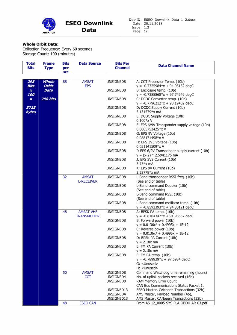
Whole Orbit Data: Collection Frequency: Every 60 seconds
Storage Count: 100 (minutes)
Total Bits
Frame Type
Bits per src
Data Source Bits Per Channel
Data Channel Name
298 Bits
x 100 =
3725 bytes
Whole Orbit Data
298 bits
88 AMSAT EPS
UNSIGNED8 UNSIGNED8 UNSIGNED8 UNSIGNED8 UNSIGNED8 UNSIGNED8 UNSIGNED8 UNSIGNED8 UNSIGNED8
UNSIGNED8 UNSIGNED8
A: CCT Processor Temp. (10b) y = -0.7725984*x + 94.95152 degC B: Enclosure temp. (10b) y = -0.7385868*x + 97.74249 degC C: DCDC Converter temp. (10b) y = -0.7796212*x + 98.19402 degC D: DCDC Supply Current (10b) 5.131579*x mA E: DCDC Supply Voltage (10b) 0.100*x V F: EPS 6/9V Transponder supply voltage (10b) 0.0885753425*x V G: EPS 9V Voltage (10b) 0.088171498*x V H: EPS 3V3 Voltage (10b) 0.031141509*x V I: EPS 6/9V Transponder supply current (10b)
y = (x-2) * 2.5941175 mA J: EPS 3V3 Current (10b) 3.75*x mA K: EPS 9V Current (10b) 2.52778*x mA
32 AMSAT L-RECEIVER
UNSIGNED8 UNSIGNED8 UNSIGNED8 UNSIGNED8
L-Band transponder RSSI freq. (10b) (See end of table) L-Band command Doppler (10b) (See end of table) L-Band command RSSI (10b) (See end of table) L-Band command oscillator temp. (10b) y = -0.8592393*x + 94.30121 degC
48 AMSAT VHF TRANSMITTER
UNSIGNED8
UNSIGNED8 UNSIGNED8 UNSIGNED8 UNSIGNED8 UNSIGNED8
A: BPSK PA temp. (10b) y = -0.8104347*x + 91.93637 degC
B: Forward power (10b) y = 0.0136x2 + 0.4995x + 1E-12 C: Reverse power (10b) y = 0.0136x2 + 0.4995x + 1E-12 D: BPSK PA Current (10b) y = 2.18x mA E: FM PA Current (10b) y = 2.18x mA F: FM PA temp. (10b) y = -0.789929*x + 97.5934 degC G: <Unused> H: <Unused>
50 AMSAT CCT
UNSIGNED8 UNSIGNED4 UNSIGNED8 UNSIGNED13 UNSIGNED4 UNSIGNED13
Command Watchdog time remaining (hours) No. of uplink packets received (16b) RAM Memory Error Count CAN Bus Communications Status Packet 1: ESEO Master, CANopen Transactions (32b) AMS Master, Payload Number (4b), AMS Master, CANopen Transactions (32b)
48 ESEO CAN From AS-12_0005-SYS-PLA-OBDH-AR-03.pdf:
ESEO Downlink
Data
Doc-ID: Date: Issue: Page:
ESEO_Downlink_Data_1_2.docx 20.11.2018 1.2 13
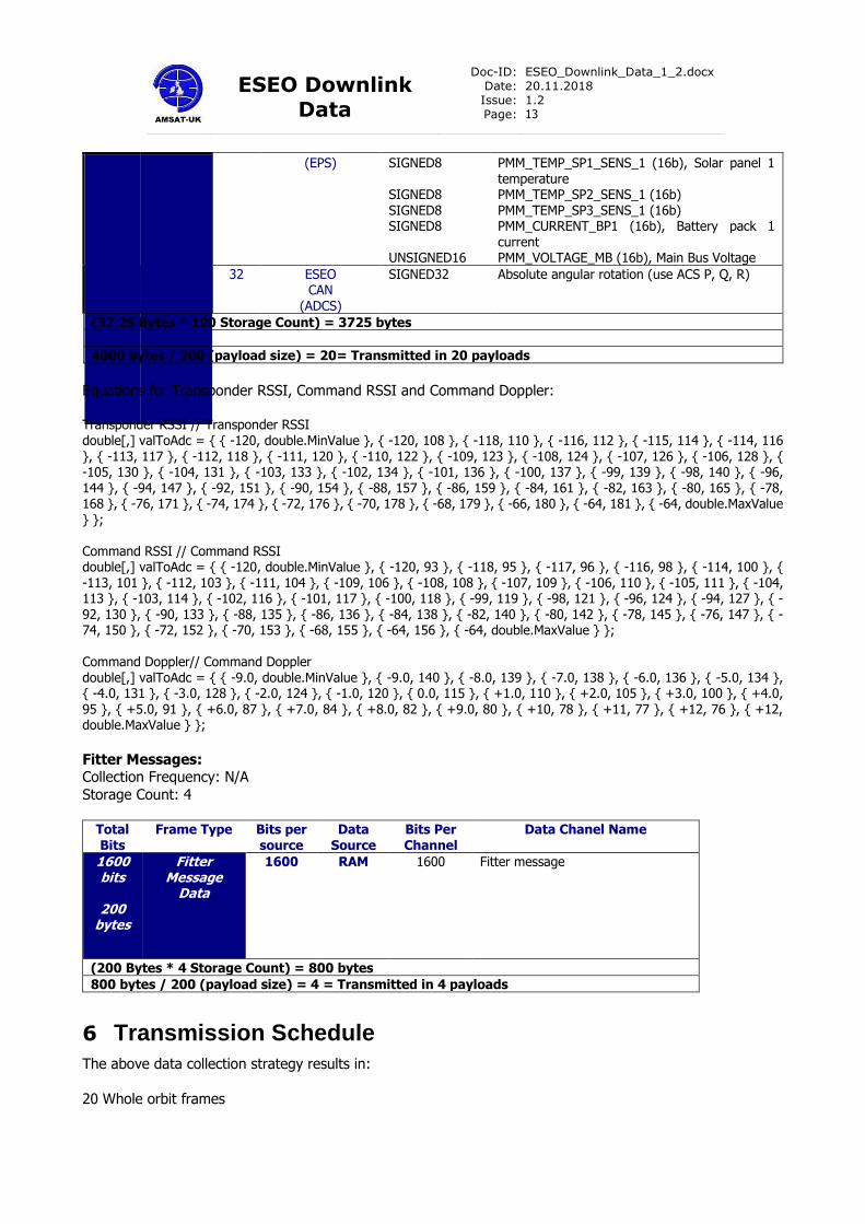
(EPS) SIGNED8 SIGNED8 SIGNED8 SIGNED8 UNSIGNED16
PMM_TEMP_SP1_SENS_1 (16b), Solar panel 1 temperature PMM_TEMP_SP2_SENS_1 (16b) PMM_TEMP_SP3_SENS_1 (16b) PMM_CURRENT_BP1 (16b), Battery pack 1 current PMM_VOLTAGE_MB (16b), Main Bus Voltage
32 ESEO CAN
(ADCS)
SIGNED32
Absolute angular rotation (use ACS P, Q, R)
(37.25 Bytes * 100 Storage Count) = 3725 bytes
4000 bytes / 200 (payload size) = 20= Transmitted in 20 payloads
Equations for Transponder RSSI, Command RSSI and Command Doppler:
Transponder RSSI // Transponder RSSI double[,] valToAdc = { { -120, double.MinValue }, { -120, 108 }, { -118, 110 }, { -116, 112 }, { -115, 114 }, { -114, 116 }, { -113, 117 }, { -112, 118 }, { -111, 120 }, { -110, 122 }, { -109, 123 }, { -108, 124 }, { -107, 126 }, { -106, 128 }, { -105, 130 }, { -104, 131 }, { -103, 133 }, { -102, 134 }, { -101, 136 }, { -100, 137 }, { -99, 139 }, { -98, 140 }, { -96, 144 }, { -94, 147 }, { -92, 151 }, { -90, 154 }, { -88, 157 }, { -86, 159 }, { -84, 161 }, { -82, 163 }, { -80, 165 }, { -78, 168 }, { -76, 171 }, { -74, 174 }, { -72, 176 }, { -70, 178 }, { -68, 179 }, { -66, 180 }, { -64, 181 }, { -64, double.MaxValue } }; Command RSSI // Command RSSI double[,] valToAdc = { { -120, double.MinValue }, { -120, 93 }, { -118, 95 }, { -117, 96 }, { -116, 98 }, { -114, 100 }, { -113, 101 }, { -112, 103 }, { -111, 104 }, { -109, 106 }, { -108, 108 }, { -107, 109 }, { -106, 110 }, { -105, 111 }, { -104, 113 }, { -103, 114 }, { -102, 116 }, { -101, 117 }, { -100, 118 }, { -99, 119 }, { -98, 121 }, { -96, 124 }, { -94, 127 }, { -92, 130 }, { -90, 133 }, { -88, 135 }, { -86, 136 }, { -84, 138 }, { -82, 140 }, { -80, 142 }, { -78, 145 }, { -76, 147 }, { -74, 150 }, { -72, 152 }, { -70, 153 }, { -68, 155 }, { -64, 156 }, { -64, double.MaxValue } }; Command Doppler// Command Doppler double[,] valToAdc = { { -9.0, double.MinValue }, { -9.0, 140 }, { -8.0, 139 }, { -7.0, 138 }, { -6.0, 136 }, { -5.0, 134 }, { -4.0, 131 }, { -3.0, 128 }, { -2.0, 124 }, { -1.0, 120 }, { 0.0, 115 }, { +1.0, 110 }, { +2.0, 105 }, { +3.0, 100 }, { +4.0, 95 }, { +5.0, 91 }, { +6.0, 87 }, { +7.0, 84 }, { +8.0, 82 }, { +9.0, 80 }, { +10, 78 }, { +11, 77 }, { +12, 76 }, { +12, double.MaxValue } };
Fitter Messages: Collection Frequency: N/A
Storage Count: 4
Total Bits
Frame Type Bits per source
Data Source
Bits Per Channel
Data Chanel Name
1600 bits
200
bytes
Fitter Message
Data
1600 RAM 1600 Fitter message
(200 Bytes * 4 Storage Count) = 800 bytes
800 bytes / 200 (payload size) = 4 = Transmitted in 4 payloads
6 Transmission Schedule
The above data collection strategy results in:
20 Whole orbit frames

ESEO Downlink
Data
Doc-ID: Date: Issue: Page:
ESEO_Downlink_Data_1_2.docx 20.11.2018 1.2 14
4 Fitter message frames
Each frame also contains the Real Time Telemetry information. The order of frames will be as shown below:
Frame Type Frame Type Frame id
RTT1 + Fitter Message FM1 01
RTT2 + Whole Orbit W01 02
RTT1 + Whole Orbit W02 03
RTT2 + Whole Orbit W03 04
RTT1 + Whole Orbit W04 05
RTT2 + Whole Orbit W05 06
RTT1 + Fitter Message FM2 07
RTT2 + Whole Orbit W06 08
RTT1 + Whole Orbit W07 09
RTT2 + Whole Orbit W08 10
RTT1 + Whole Orbit W09 11
RTT2 + Whole Orbit W10 12
RTT1 + Fitter Message FM3 13
RTT2 + Whole Orbit W11 14
RTT1 + Whole Orbit W12 15
RTT2 + Whole Orbit W13 16
RTT1 + Whole Orbit W14 17
RTT2 + Whole Orbit W15 18
RTT1 + Fitter Message FM4 16
RTT2 + Whole Orbit W16 20
RTT1 + Whole Orbit W17 21
RTT2 + Whole Orbit W18 22
RTT1 + Whole Orbit W19 23
RTT2 + Whole Orbit W20 24
In 1K2 mode, each frame requires 5 seconds to transmit the sequence of frames and will repeat every 120 seconds (two minutes).