do not pass warning system based on vehicle-to-...
TRANSCRIPT

Do Not Pass Warning System based on Vehicle-to-
Vehicle Communication for Curved Roads
Sangduck Jeon1, Gyoungeun Kim1, Byeongwoo Kim2
1 Graduate School of Electrical Engineering, University of Ulsan, 93 Daehak-ro,
Ulsan, Republic of Korea
[email protected], [email protected] 2 School of Electrical Engineering, University of Ulsan, 93 Daehak-ro,
Ulsan, Republic of Korea
Abstract. This paper proposes a do not pass warning (DNPW) system based on
vehicle-to-vehicle (V2V) communication for curved roads. The existing DNPW
systems are applicable only to straight roads but not to curved roads. We
propose a method to calculate the DNPW zone on a curved road based on the
actual relative distance while considering the curvature of the road. Furthermore,
we examined whether vehicles were present on each lane of a curved road by
using the turning radius. We verified the applicability of the proposed DNPW
system by comparing the DNPW zone calculated using the proposed system
with that calculated through simulations. The proposed DNPW system can
provide a DNPW zone according to a vehicle's speed and location where the
vehicle overtakes.
Keywords: Vehicle to Vehicle(V2V), Do Not Pass Warning(DNPW), Curve
Road, Overtaking
1 Introduction
With the rapid increase in the number of vehicles, traffic accidents have also
increased markedly. According to the data from Korea and overseas, more than 80%
of traffic accidents occur owing to the driver's negligence [1][2]. Overtaking is one of
the most dangerous driving behaviors, which could lead to various types of accidents,
including deviation from road lanes, changes in lanes, and rear-end collisions. Traffic
accidents due to overtaking account for 7% of the total traffic accidents in Korea
[2][3]. With the advancement of vehicle technologies, a number of studies have been
conducted to reduce traffic accidents, and the development of active safety systems.
Along with this advancement, studies on combining communication technologies
such as vehicle-to-vehicle (V2V) with active safety systems have been actively
performed. In particular, in North America, a safety service based on V2V
communication has been proposed through the vehicular safety communication
applications (VSC-A) project [4]. DNPW is one of the service of VSC-A. DNPW
2 Corresponding Author
Advanced Science and Technology Letters Vol.118 (Electrical and Electronic Engineering 2015), pp.42-47
http://dx.doi.org/10.14257/astl.2015.118.09
ISSN: 2287-1233 ASTL Copyright © 2015 SERSC
operates in dangerous situations when a vehicle approaching from the opposite lane
overtakes the preceding car on a two-lane road. A number of studies have been
conducted on overtaking on a straight lane including DNPW of VSC-A [5][6].
However, these algorithms applicable to straight lanes are not suitable for curved
roads. Therefore, DNPW systems on a curved road should consider the actual relative
distance on the road.
In this paper, we propose a DNPW system that considers the curvature of roads.
We also analyze the applicability of the DNPW system to curved roads under various
conditions.
2 System Design
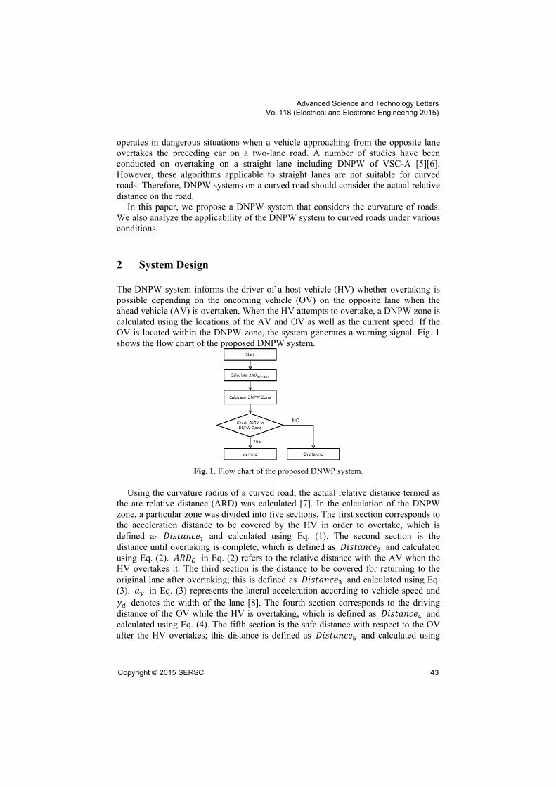
The DNPW system informs the driver of a host vehicle (HV) whether overtaking is
possible depending on the oncoming vehicle (OV) on the opposite lane when the
ahead vehicle (AV) is overtaken. When the HV attempts to overtake, a DNPW zone is
calculated using the locations of the AV and OV as well as the current speed. If the
OV is located within the DNPW zone, the system generates a warning signal. Fig. 1
shows the flow chart of the proposed DNPW system.
Fig. 1. Flow chart of the proposed DNWP system.
Using the curvature radius of a curved road, the actual relative distance termed as
the arc relative distance (ARD) was calculated [7]. In the calculation of the DNPW
zone, a particular zone was divided into five sections. The first section corresponds to
the acceleration distance to be covered by the HV in order to overtake, which is
defined as 𝐷𝑖𝑠𝑡𝑎𝑛𝑐𝑒1 and calculated using Eq. (1). The second section is the
distance until overtaking is complete, which is defined as 𝐷𝑖𝑠𝑡𝑎𝑛𝑐𝑒2 and calculated
using Eq. (2). 𝐴𝑅𝐷𝑂 in Eq. (2) refers to the relative distance with the AV when the
HV overtakes it. The third section is the distance to be covered for returning to the
original lane after overtaking; this is defined as 𝐷𝑖𝑠𝑡𝑎𝑛𝑐𝑒3 and calculated using Eq.
(3). 𝑎𝑦 in Eq. (3) represents the lateral acceleration according to vehicle speed and
𝑦𝑑 denotes the width of the lane [8]. The fourth section corresponds to the driving
distance of the OV while the HV is overtaking, which is defined as 𝐷𝑖𝑠𝑡𝑎𝑛𝑐𝑒4 and
calculated using Eq. (4). The fifth section is the safe distance with respect to the OV
after the HV overtakes; this distance is defined as 𝐷𝑖𝑠𝑡𝑎𝑛𝑐𝑒5 and calculated using
Advanced Science and Technology Letters Vol.118 (Electrical and Electronic Engineering 2015)
Copyright © 2015 SERSC 43

Eq. (5). 𝑇𝜇 in Eq. (5) represents the speed and deceleration at the time of stop. The
DNPW zone can be calculated by using the expression in Eq. (6).
𝐷𝑖𝑠𝑡𝑎𝑛𝑐𝑒1 𝑡
𝑎 𝑡
2 (1)
𝐷𝑖𝑠𝑡𝑎𝑛𝑐𝑒2 𝐴𝑅𝐷𝑂 𝐷𝑖𝑠𝑡𝑎𝑛𝑐𝑒1
(2)
𝐷𝑖𝑠𝑡𝑎𝑛𝑐𝑒3 √𝑦𝑑
𝑎𝑦
(3)
𝐷𝑖𝑠𝑡𝑎𝑛𝑐𝑒4 (𝑇1 𝑇2 𝑇3 𝑇4 𝑂 (4)
𝐷𝑖𝑠𝑡𝑎𝑛𝑐𝑒5 𝑇𝜇
𝑂 𝑇𝜇 𝑂
(5)
𝐷𝑖𝑠𝑡𝑎𝑛𝑐𝑒1 𝐷𝑖𝑠𝑡𝑎𝑛𝑐𝑒2 𝐷𝑖𝑠𝑡𝑎𝑛𝑐𝑒3 𝐷𝑖𝑠𝑡𝑎𝑛𝑐𝑒4 𝐷𝑖𝑠𝑡𝑎𝑛𝑐𝑒5
(6)
3 Simulation and Results
3.1 Simulation Scenario
Fig. 2 shows the simulation scenario for the verification of the proposed DNPW
system. The vehicle-driving scenario was set by changing the speed and 𝐴𝑅𝐷𝑂 as
shown in Table 1. The DNPW zone calculated using the equations for V2V-based
communication for curved roads and that calculated through vehicle dynamic-based
simulations were compared. The DNPW zone calculated through simulations
considers the initial distance between the HV and OV. If the HV attempts overtaking
when the initial distance between the HV and OV is smaller than the DNPW zone, a
collision will occur. On the other hand, if the HV attempts to overtake when the initial
distance between the HV and OV is larger than the DNPW zone, overtaking will be
successful. In this study, the overtaking speed was set as the initial speed +20 [km/h].
Fig. 2. Simulation configuration.
Table 1. Simulation scenario
Scenario Test Speed[km/h] 𝐴𝑅𝐷𝑂[s]
1 40 2.5
Advanced Science and Technology Letters Vol.118 (Electrical and Electronic Engineering 2015)
44 Copyright © 2015 SERSC

2 60 2
3 80 3.5
3.2 Simulation Results
Table 2 shows the simulation results. In order to verify the proposed DNPW system,
the DNPW zone calculated by the system was compared with that calculated through
simulations except for the safe distance 𝐷𝑖𝑠𝑡𝑎𝑛𝑐𝑒5. The experimental results showed
that the DNPW zone calculated using the proposed system under each scenario has an
error rate within a range of 0.7 to 1.6 [%] compared to the simulation-based DNPW
zone, which showed similar results. This result verifies the usability of the proposed
DNPW system.
Table 2. Comparison of DNPW zone for different scenarios.
Scenario Proposed system [m] Simulation [m] Error rate [%]
1 245.1 241 1.6
2 379.8 376 1
3 891.3 885 0.7
Table 3 shows the DNPW zone calculated using the proposed DNPW system
according to typical 𝐴𝑅𝐷𝑂 in scenarios 1 and 2. The DNPW zone presented as
𝐴𝑅𝐷𝑂 is changed to 2, 3, and 4[s]. The DNPW zone is displayed as ±10[%] of the
value calculated using the proposed DNPW system.
Table 3. DNPW zone according to 𝐴𝑅𝐷𝑂.
Scenario Test Speed
[km/h] 𝐴𝑅𝐷𝑂[s]
DNPW Zone[m]
Min Normal Max
1 40
2 226 251 276
3 276 306 337
4 326 362 398
2 60
2 399 444 488
3 504 560 616
4 609 677 745
Fig. 3 shows the DNPW zone calculated using the proposed DNPW system as a
function of test speed in scenarios 2 and 3. Zone 1, which is wider than the DNPW
zone, represents the safe area. The HV can overtake safely if the distance between it
and the OV lies within Zone 1. Zone 2 represents the collision area. When the
distance between the HV and OV lies within this zone, a collision occurs during
overtaking.
Advanced Science and Technology Letters Vol.118 (Electrical and Electronic Engineering 2015)
Copyright © 2015 SERSC 45

Fig. 3. DNPW zone according to test speed.
4 Conclusion
In this paper, a DNPW system applicable to curved roads was proposed. The
proposed DNPW system obtains the location and speed information of the host and
surrounding vehicles using V2V communication, and calculates the relative distance
on a curved road from the above information to generate a warning signal.
We verified the applicability of the proposed DNPW system by comparing the
DNPW zone calculated using the proposed system with that calculated through
simulations. We also presented a range of DNPW zone calculated using the DNPW
system for different scenarios. Finally, we calculated DNPW zones for various test
speeds and locations where overtaking occurred.
In the future, we plan to investigate DNPW systems under various overtaking
conditions and multi-vehicular environments.
Acknowledgments. This research was supported by the MSIP(Ministry of
Science, ICT and Future Planning), Korea, under the C-ITRC(Convergence
Information Technology Research Center) (IITP-2015-H8601-15-1005) supervised by
the IITP(Institute for Information & communications Technology Promotion)
References
1. NHTSA The Impact of Driver Inattention on Near-Crash/Crash Risk: An Analysis Using the
100-Car Naturalistic Driving Study Data. NHTSA report 2006
2. Road Traffic Authority Driver’s License Examination Office, http://www.koroad.or.kr/
3. Alireza M,. Rozita A,. Ali J,. Erfan S,. Mohammad R,. Rafidah M. An Adaptive Overtaking
Maneuver Assistant System Using VANET. IEEE Asia Pacific Conference on Wireless and
Mobile. pp. 316-321. (2014)
4. VSC-A, ―Vehicle Safety Communications – Applications‖, VSC-A Final Report Appendix
Volume 1 System Design and Objective Test, NHTSA, (2011)
5. Alexey V,. Evgeny B,. Karen E,. Yevgeni K.: An Overtaking Assistance System Based on
Joint Beaconing and Real-Time Video Transmission. IEEE Transactions on Vehicular
Technology. pp. 2319—2329. (2012)
Advanced Science and Technology Letters Vol.118 (Electrical and Electronic Engineering 2015)
46 Copyright © 2015 SERSC

6. Shasha Z,. Wei L,. Bichun L,. Runxin N,. Huawei L.: Trajectory Planning of Overtaking for
Intelligent Vehicle based on X-Sin function. IEEE International Conference on
Mechatronics and Automation. pp. 618—622. (2014)
7. Cho, H., Kim, B.: Performance Improvement of Collision Warning System on Curved Road
Based on Intervehicle Communication. Hindawi Publishing Corporation Mathematical
Problems in Engineering. (2015)
8. Kang H,. Lee D,. Huh K.: Development of Lane Change System considering Acceleration
for Collision Avoidance. Transaction of the Korean Society of Automotive Engineers,
pp.81—86. (2013)
Advanced Science and Technology Letters Vol.118 (Electrical and Electronic Engineering 2015)
Copyright © 2015 SERSC 47