do not operate this spreader until you have completely
TRANSCRIPT

Manufactured in DORCHESTER, WI by
MEYER’S EQUIPMENT
Mfg. Corp.
INSTRUCTION AND PARTS BOOK – REV. D3
HEAVY DUTY MANURE SPREADERS
Model: M3280 Tandem
DO NOT - Operate This Spreader Until You Have Completely
Read This Book!
NEVER - Repair or Clean This Spreader While PTO is Engaged!

2 | P a g e M o d e l M 3 2 8 0
MODEL SPECIFICATIONS
Width of Box Inside 60”
Flare Width 74”
Overall Width 116-1/2”
Length of Box Inside 190”
Box Depth 37-3/8”
Overall Length 22’ 10”
Overall Height 76”
Loading Height 63”
App. Capacity (Struck Cu. Ft.) 240 ft³ *
App. Capacity (Heaped Cu. Ft.) 356 ft³ *
App. Empty Weight (lbs.) 7360 lbs
Apron Chain (Standard) Twin #67P11
Beaters Ø29” Bottom Beater w/ AR400 Bolt-On Paddles
Ø14” Top Beater w/ Weld-On Paddles
Spindles (4x) Ø3” Wheel Spindles
Spindle/Hub Load Rating (4x) 7,500 lbs Each / 30,000 lbs Total
Tire Size (Standard) 425-65R x 22.5
Tire Size (Optional) 19L X 16.1 10 Ply Flotation
PTO Speed 540 RPM Standard 1000 RPM Optional
Min. Recommended Tractor Horsepower
100 HP
Hydraulic Apron Speed Variable 0 ft/min – 8 ft/min
Min. Recommended Hydraulic Flow
12 GPM
*Capacities calculated per ASAE 324.2 JUL2018 with hydraulic gate as standard. (Volumetric Capacity of Open-Top Manure Spreaders – Dual Rating Method)

M o d e l M 3 2 8 0 3 | P a g e
INTRODUCTION
Congratulations on the purchase of your new Meyer’s Manure Spreader! With proper use and preventative maintenance, it will give you many years of trouble-free operation.
• At the front of this manual is a Product Registration and Inspection Certificate. Be sure your dealer has
completed this certificate and forwarded a copy to the manufacturer to validate the manufacturer’s warranty.
• The product model and serial number are recorded on this certificate for your convenience and for proper
identification of your spreader by your dealer and the manufacturer when ordering repair parts.
• The serial number plate is found on the upper left front corner of the spreader box or stamped in the left channel at the front. For information on ordering repair parts, refer to the repair parts section of this manual. Orders must list the complete description, correct part number, and total amount required.
• All references to right hand and left hand apply to the product as viewed from the rear of the machine and facing the direction of forward travel.
• You are urged to study this manual and follow the instructions carefully. Your efforts will be repaid in better operation and service as well as a savings in time and repair expense. Failure to read this manual and understand the machine could lead to serious injury. If you do not understand instructions in this manual, contact either your dealer or Meyer’s Equipment Manufacturing Corp.
This SAFETY ALERT SYMBOL means ATTENTION! BE CAREFUL! YOUR SAFETY IS INVOLVED! It stresses an attitude of HEADS UP FOR SAFETY. When you see this symbol, be alert to the possibility of PERSONAL INJURY and carefully read the message that follows.
WARNING: NEVER OPERATE WITHOUT ALL COVERS, SHIELDS AND GUARDS IN PLACE. KEEP HANDS, FEET
AND CLOTHING AWAY FROM MOVING PARTS. SOME COVERS AND GUARDS IN THIS MANUAL
HAVE BEEN REMOVED FOR ILLUSTRATIVE PURPOSES ONLY. FAILURE TO HEED MAY RESULT IN
SERIOUS PERSONAL INJURY OR DEATH.
Contact Information
Meyer’s Equipment Mfg. Corp.
701 W Bus Cty Rd A
P.O. Box 406
Dorchester, WI 54425
Phone: (715)-654-5200
Fax: (715)-654-5558
Visit Us Online At:
www.emcspreaders.com

4 | P a g e M o d e l M 3 2 8 0
TABLE OF CONTENTS
INTRODUCTION ................................................................................................................................. 3
SAFETY SYMBOLS ...................................................................................................................... 6
SAFETY DECALS & LOCATIONS ................................................................................................... 6
MANURE SPREADER SAFETY ..................................................................................................... 10
MANDATORY SAFETY SHUTDOWN PROCEDURE ........................................................................ 11
PRESSURIZED HYDRAULIC FLUID AND EQUIPMENT SAFETY ........................................................ 12
PRE-OPERATION ............................................................................................................................... 13
GENERAL .................................................................................................................................................. 13
TRACTOR HITCH AND PTO REQUIREMENTS ............................................................................................ 13
TRACTOR TOWING SIZE REQUIREMENTS ................................................................................................ 14
HYDRAULIC SYSTEM ................................................................................................................................ 14
Open and Closed Center Hydraulic Systems ........................................................................................ 15
Spreader Setup .................................................................................................................................... 15
TRACTOR HOOKUP .................................................................................................................................. 15
TRANSPORTING ............................................................................................................................... 16
GENERAL .................................................................................................................................................. 16
Safety Chain Use .................................................................................................................................. 16
Highway Lights .................................................................................................................................... 16
OPERATION...................................................................................................................................... 17
LOADING .................................................................................................................................................. 17
UNLOADING ............................................................................................................................................ 18
UNHOOKING FROM TRACTOR ................................................................................................................. 19
MAINTENANCE, ADJUSTMENTS, & LUBRICATION .............................................................................. 19
WHEEL & TIRE MAINTENANCE ................................................................................................................ 19
Wheel Hub Lubrication ........................................................................................................................ 19
Lock Ring Rim ...................................................................................................................................... 19
CLEANING AND STORAGE ........................................................................................................................ 20
ADJUSTMENTS ......................................................................................................................................... 22
Apron Chain ......................................................................................................................................... 22
Roller Chains ........................................................................................................................................ 22
Front V-Belt Drive ................................................................................................................................ 22
LUBRICATION ........................................................................................................................................... 22

M o d e l M 3 2 8 0 5 | P a g e
REPLACEMENT PARTS ....................................................................................................................... 24
BOX PARTS & MISC. ................................................................................................................................. 24
FRONT BELT DRIVE & RELATED PARTS ..................................................................................................... 26
SIDE SHAFT & RELATED PARTS ................................................................................................................. 28
MAIN BEATER DRIVE & RELATED PARTS .................................................................................................. 30
TOP BEATER DRIVE & RELATED PARTS ..................................................................................................... 32
BEATERS & RELATED PARTS ..................................................................................................................... 34
GEARBOX – BEATER DRIVE ...................................................................................................................... 36
APRON & RELATED PARTS ....................................................................................................................... 38
GEARBOX – APRON DRIVE ....................................................................................................................... 40
AXLES, WHEELS, SPINDLES & RELATED PARTS ......................................................................................... 42
HYDRAULIC END GATE & RELATED PARTS ............................................................................................... 44
PTO DRIVELINE ASSEMBLY W/ OVER-RUNNING CLUTCH ......................................................................... 45
HIGHWAY LIGHTING AND WIRING .......................................................................................................... 46
HYDRAULIC SYSTEM PARTS – APRON DRIVE ............................................................................................ 48
HYDRAULIC SYSTEM PARTS – END GATE ................................................................................................. 50
LIMITED WARRANTY STATEMENT ..................................................................................................... 52

6 | P a g e M o d e l M 3 2 8 0
SAFETY SYMBOLS
A brief definition of signal words that may be used in this manual:
DANGER: Indicates an imminently hazardous situation that, if not avoided, will result in
serious injury or death.
WARNING: Indicates a potentially hazardous situation that, if not avoided, could result in death or
serious injury. Includes hazards that are exposed when guards are removed.
CAUTION: Indicates a potentially hazardous situation that, if not avoided, may result in minor
or moderate injury.
SAFETY DECALS & LOCATIONS
** REFERENCE PAGES 8 & 9 FOR DECAL LETTERS AND PART #’S

M o d e l M 3 2 8 0 7 | P a g e
CAUTION
IF ANY SAFETY SIGN BECOMES UNREADABLE FOR ANY REASON, THE SIGN
MUST BE REPLACED WITH A NEW SIGN. IF THE SPREADER IS REPAINTED, ALL
SAFETY SIGNS MUST BE REPLACED. CONTACT YOUR DEALER OR MEYER’S
EQUIPMENT MANUFACTURING CORP. IF YOU REQUIRE ANY SHIELD OR SIGNS
FOR REPLACEMENT.

8 | P a g e M o d e l M 3 2 8 0
DECAL A – PART NO. 3000 DECAL B – PART NO.3001
DECAL C – PART NO. 3002 DECAL D – PART NO. 3003 DECAL E – PART NO. 3004
DECAL F – PART NO. SW104
(1000 RPM – PART NO. SW105) DECAL G – PART NO. SW104-1 DECAL H – PART NO. SW404
DECAL I – PART NO. SW406 DECAL J – PART NO. SW700 DECAL K – PART NO. SW102

M o d e l M 3 2 8 0 9 | P a g e
REFLECTIVE TAPE – YELLOW DECAL L
PART NO. PM17-5910
REFLECTIVE TAPE – RED DECAL M
PART NO. PM17-5915
DECAL N – PART NO. SW2000
DECAL O – PART NO. 3006
DECAL P – PART NO. SW2001

10 | P a g e M o d e l M 3 2 8 0
MANURE SPREADER SAFETY CAUTION
THERE ARE INHERENT HAZARDS ASSOCIATED WITH THE OPERATION OF A MANURE SPREADER. FOR YOUR SAFETY:
• Never Enter Spreader Box While In Operation For Any Reason.
• Only Properly Instructed People Should Operate The Spreader. Do Not Allow Children Or Inexperienced
Persons To Operate Spreader.
• Keep All Guards and Shields In Place. Moving Parts Can Crush And Dismember.
• Clear The Area Before Equipment Start Up.
• Keep Hands, Feet, and Loose Clothing Away From Moving Parts.
• Do Not Go Near The Spreader Beaters While Machine Is Operating.
• Make Sure The PTO Is Securely Locked To Both The Tractor And Spreader Before Operating The Unit.
• Do Not Operate The PTO At Speeds Higher Than The Manufacturers Recommendations.
• Highway Traffic Is Not To Exceed 20 Mph. The Tires Supplied Are For Farm Use Only And Are Not Designed
For Use Above This Speed Unless Equipped With High Speed Highway/Off-Road Farm Tires.
• Use Adequate Safety Chains When Towing The Spreader.
• The Use of a Slow moving Vehicle Sign Is Required on All Public Roads Unless Equipped with Flashing
Hazard Lights. Obey All Applicable Highway Safety Laws And Rules.
• Always Use A Tractor Large Enough To Provide Sufficient Braking When Towing A Loaded Spreader.
• Use Caution When Traveling Over Uneven Terrain And When Approaching Stops.
• Do Not Load The Spreader Unless It Is Hitched To The Tractor.
• Do Not Unhitch A Loaded Spreader From The Tractor, Leaving It Supported By Only The Jack.
• Park Your Spreader on Level Ground and Place Blocks Ahead Of and Behind the Wheels Before Unhooking
From Tractor To Avoid Unexpected Rolling When Separated From The Tractor.
• Do Not Allow Riders on Spreader.
FAILURE TO HEED MAY RESULT IN SERIOUS PERSONAL INJURY OR DEATH
CAUTION
THERE ARE ADDITIONAL HAZARDS ASSOCIATED WITH THE SERVICE AND MAINTENANCE OF YOUR SPREADER.
FOR YOUR SAFETY:
• Inspect When First Delivered And Regularly Thereafter; That All Connections And Bolts Are Tight And Secure
Before Operating.
• Retighten All Wheel Bolts After The First Hour Of Towing. Check Periodically Thereafter.
See Maintenance, Wheels.
• Maintain Proper Tire Air Pressure At All Times. See Maintenance, Tires.
• Always Wear Eye Protection When Operating Or Servicing Spreader.
• Be Sure All Movement Has Stopped, The PTO Is Disconnected, The Tractor Is Shut Off And The Ignition Key
Is Removed Before Servicing The Spreader Or Components.
• Escaping Hydraulic Fluid Under Pressure Can Penetrate The Skin And Cause Serious Injury. Relieve All
Pressure From The Hydraulic System Before Connecting Or Disconnecting The Lines Or Making Repairs.
Check All Hoses and Fittings Before Start-up and Periodically During Operation.
• Never Make Any Alterations Or Modifications To This Equipment.
FAILURE TO HEED MAY RESULT IN SERIOUS PERSONAL INJURY OR DEATH

M o d e l M 3 2 8 0 11 | P a g e
MANDATORY SAFETY SHUTDOWN PROCEDURE
BEFORE unclogging, cleaning, adjusting, lubricating or servicing the unit:
1. Disengage the tractor PTO.
2. Shut off the tractor engine, remove the ignition key and take it with you.
3. Wait for all movement to stop.
4. Remove the Telescoping PTO Drive and ALL power connections from the tractor.
ONLY when you have taken these precautions can you be sure it is safe to proceed. Failure to follow the above
procedure could lead to death or serious bodily injury.
BEFORE ATTEMPTING TO OPERATE YOUR NEW SPREADER BE SURE TO READ THIS OWNERS
MANUAL AND FAMILIARIZE YOURSELF WITH THE MACHINE!! OBSERVE THE PRECAUTIONS IN THIS
MANUAL FOR SAFE OPERATION OF THIS MACHINE!!
Most farm accidents, like industrial, home and highway accidents, are caused by the failure
of some individuals to observe simple and fundamental safety rules or precautions. For this
reason farm accidents, just as other types of accidents, can be prevented by recognizing the
causes of accidents and doing something about them before an accident occurs.
Regardless of the care used in the design and construction of farm equipment, there are
many points that cannot be completely safe-guarded without interfering with accessibility
and efficient operation.
A careful operator is the best insurance against an accident.
The complete observance of one simple rule would prevent thousands of serious injuries
each year. That rule is:
“NEVER ATTEMPT TO CLEAN, OIL, OR ADJUST A MACHINE WHILE IN MOTION”.
-NATIONAL SAFETY COUNCIL
12 | P a g e M o d e l M 3 2 8 0
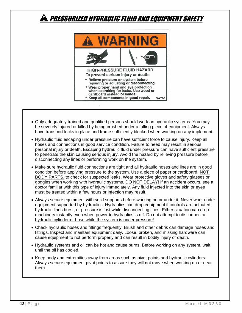
PRESSURIZED HYDRAULIC FLUID AND EQUIPMENT SAFETY
• Only adequately trained and qualified persons should work on hydraulic systems. You may be severely injured or killed by being crushed under a falling piece of equipment. Always have transport locks in place and frame sufficiently blocked when working on any implement.
• Hydraulic fluid escaping under pressure can have sufficient force to cause injury. Keep all hoses and connections in good service condition. Failure to heed may result in serious personal injury or death. Escaping hydraulic fluid under pressure can have sufficient pressure to penetrate the skin causing serious injury. Avoid the hazard by relieving pressure before disconnecting any lines or performing work on the system.
• Make sure hydraulic fluid connections are tight and all hydraulic hoses and lines are in good condition before applying pressure to the system. Use a piece of paper or cardboard, NOT BODY PARTS, to check for suspected leaks. Wear protective gloves and safety glasses or goggles when working with hydraulic systems. DO NOT DELAY! If an accident occurs, see a doctor familiar with this type of injury immediately. Any fluid injected into the skin or eyes must be treated within a few hours or infection may result.
• Always secure equipment with solid supports before working on or under it. Never work under equipment supported by hydraulics. Hydraulics can drop equipment if controls are actuated, hydraulic lines burst, or pressure is lost while disconnecting lines. Either situation can drop machinery instantly even when power to hydraulics is off. Do not attempt to disconnect a hydraulic cylinder or hose while the system is under pressure!
• Check hydraulic hoses and fittings frequently. Brush and other debris can damage hoses and fittings. Inspect and maintain equipment daily. Loose, broken, and missing hardware can cause equipment to not perform properly and can result in bodily injury or death.
• Hydraulic systems and oil can be hot and cause burns. Before working on any system, wait until the oil has cooled.
• Keep body and extremities away from areas such as pivot points and hydraulic cylinders. Always secure equipment pivot points to assure they will not move when working on or near them.

M o d e l M 3 2 8 0 13 | P a g e
PRE-OPERATION GENERAL Read the entire Owner’s Manual before attempting to operate this manure spreader. Before attempting any maintenance or repairs; always be sure all rotating parts have stopped and that the tractor is shut off. Disconnect the PTO, relieve all hydraulic pressure and disconnect hydraulic hoses.
WARNING
NEVER OPERATE SPREADER WITH ANY GUARDS OR SHIELDS REMOVED. FAILURE TO HEED MAY RESULT IN SERIOUS PERSONAL UNJURY OR DEATH.
1. Completely lubricate the unit as described in the LUBRICATION Section.
2. Check and tighten the wheel lug nuts if required.
3. Check and maintain the tire pressure according to the manufacturer’s recommendation.
4. Check the entire unit for loose bolts, damaged or loose hydraulic fittings and hoses or other damaged parts.
5. The tractor half of the PTO drive shaft assembly must be locked securely to the tractor output shaft.
TRACTOR HITCH AND PTO REQUIREMENTS This spreader is designed to be operated by a 540 RPM PTO Output. (540 RPM Standard / 1000 RPM Optional). The PTO drive shaft assembly is designed to operate with tractors conforming to the industry standard shown on Figure 1. The telescoping PTO driveline must have a 5” minimum sleeve overlap when connected. ADMA Recommendations: A tractor drawbar equipped with a clevis hitch (hammer-strap) can cause interference with the PTO driveline IID (implement input driveline). This interference can cause serious damage to the IID or the IID telescoping members. The clevis hitch on the tractor must be removed. If the implement (figure 2, top view) is attached to a tractor with a clevis hitch (hammer-strap) style drawbar, the hammer-strap must be removed to prevent damage to the IID guarding or the IID telescoping members. If the implement (figure 2, lower view) is attached to a tractor with an offset in the drawbar, be certain it is in the down position to prevent damage to the IID guarding or the IID telescoping members.
FIGURE 1. TRACTOR DRAWBAR & PTO SPECIFICATION
FIGURE 2. PTO ALIGNMENT
14 | P a g e M o d e l M 3 2 8 0
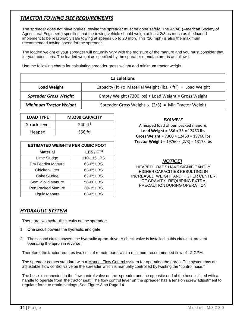
TRACTOR TOWING SIZE REQUIREMENTS The spreader does not have brakes, towing the spreader must be done safely. The ASAE (American Society of Agricultural Engineers) specifies that the towing vehicle should weigh at least 2/3 as much as the loaded implement to be reasonably safe towing at speeds up to 20 mph. This (20 mph) is also the maximum recommended towing speed for the spreader. The loaded weight of your spreader will naturally vary with the moisture of the manure and you must consider that for your conditions. The loaded weight as specified by the spreader manufacturer is as follows: Use the following charts for calculating spreader gross weight and minimum tractor weight:
HYDRAULIC SYSTEM There are two hydraulic circuits on the spreader:
1. One circuit powers the hydraulic end gate.
2. The second circuit powers the hydraulic apron drive. A check valve is installed in this circuit to prevent operating the apron in reverse.
Therefore, the tractor requires two sets of remote ports with a minimum recommended flow of 12 GPM. The spreader comes standard with a Manual Flow Control system for operating the apron. The system has an adjustable flow control valve on the spreader which is manually controlled by twisting the “control hose.” The hose is connected to the flow control valve on the spreader and the opposite end of the hose is fitted with a handle to operate from the tractor seat. The flow control lever on the spreader has a tension screw adjustment to regulate force to retain settings. See Figure 3 on Page 14.
LOAD TYPE M3280 CAPACITY
Struck Level 240 ft3
Heaped 356 ft3
Calculations
Load Weight Capacity (ft3) x Material Weight (lbs. / ft3) = Load Weight
Spreader Gross Weight Empty Weight (7300 lbs) + Load Weight = Gross Weight
Minimum Tractor Weight Spreader Gross Weight x (2/3) = Min Tractor Weight
ESTIMATED WEIGHTS PER CUBIC FOOT
Material LBS / FT3
Lime Sludge 110-115 LBS.
Dry Feedlot Manure 63-65 LBS.
Chicken Litter 63-65 LBS.
Cake Sludge 62-65 LBS.
Semi-Solid Manure 58-60 LBS.
Pen Packed Manure 30-35 LBS.
Liquid Manure 63-65 LBS.
NOTICE! HEAPED LOADS HAVE SIGNIFICANTLY
HIGHER CAPACITIES RESULTING IN INCREASED WEIGHT AND HIGHER CENTER
OF GRAVITY, REQUIRING EXTRA PRECAUTION DURING OPERATION.
EXAMPLE A heaped load of pen packed manure:
Load Weight = 356 x 35 = 12460 lbs Gross Weight = 7300 + 12460 = 19760 lbs
Tractor Weight = 19760 x (2/3) = 13173 lbs
M o d e l M 3 2 8 0 15 | P a g e
Open and Closed Center Hydraulic Systems
• Most late model tractors use a Closed Center hydraulic system with a variable displacement pump which only pumps oil as required. This system is commonly CCLS (Closed Center Load Sensing), also known as PFC (Pressure and Flow Compensated).
• Other tractors may have an Open Center hydraulic system with a fixed displacement pump which pumps oil continuously. This type of system typically does not have adjustable flow control from the tractor cab.
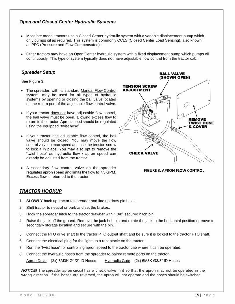
Spreader Setup See Figure 3.
• The spreader, with its standard Manual Flow Control system, may be used for all types of hydraulic systems by opening or closing the ball valve located on the return port of the adjustable flow control valve.
• If your tractor does not have adjustable flow control, the ball valve must be open, allowing excess flow to return to the tractor. Apron speed should be regulated using the equipped “twist hose”.
• If your tractor has adjustable flow control, the ball
valve should be closed. You may move the flow control valve to max speed and use the tension screw to lock it in place. You may also opt to remove the “twist hose” as hydraulic flow / apron speed can already be adjusted from the tractor.
• A secondary flow control valve on the spreader
regulates apron speed and limits the flow to 7.5 GPM. Excess flow is returned to the tractor.
TRACTOR HOOKUP
1. SLOWLY back up tractor to spreader and line up draw pin holes.
2. Shift tractor to neutral or park and set the brakes.
3. Hook the spreader hitch to the tractor drawbar with 1 3/8” secured hitch pin.
4. Raise the jack off the ground. Remove the jack hub pin and rotate the jack to the horizontal position or move to secondary storage location and secure with the pin.
5. Connect the PTO drive shaft to the tractor PTO output shaft and be sure it is locked to the tractor PTO shaft.
6. Connect the electrical plug for the lights to a receptacle on the tractor.
7. Run the “twist hose” for controlling apron speed to the tractor cab where it can be operated.
8. Connect the hydraulic hoses from the spreader to paired remote ports on the tractor.
Apron Drive – (2x) 8M3K Ø1/2” ID Hoses Hydraulic Gate – (2x) 6M3K Ø3/8” ID Hoses
NOTICE! The spreader apron circuit has a check valve in it so that the apron may not be operated in the
wrong direction. If the hoses are reversed, the apron will not operate and the hoses should be switched.
FIGURE 3. APRON FLOW CONTROL

16 | P a g e M o d e l M 3 2 8 0
TRANSPORTING
GENERAL
While towing the spreader, check for traffic constantly. Be sure you can see that no one is attempting to pass you
and that all traffic is sufficiently clear from you before making any turns. Operating speed is dictated by the terrain over which you are traveling. Always use caution. Avoid traveling on slopes or hills that are unsafe. Also beware of slippery conditions such as traveling over areas previously spread with manure. If possible, avoid spreading over areas where manure has been previously applied. If you will travel on public roadways and it is legal to do so, you must know all rules governing such operation. This will include lighting and brake requirements in addition to traffic rules. You may also be required to install a safety chain on the spreader.
Safety Chain Use
A safety chain should be installed when traveling on public roads. The chain must be strong enough to hold the
weight of the loaded spreader. If using a grab hook at the end(s) of the chain to secure the chain to itself, a hook
latch must be installed. The length of the safety chain is not to be any longer than necessary to turn without
interference. If any chain links or attachment hardware are broken or stretched, repair before using. Store chain
so it does not corrode or become damaged. Do not use this chain for other implements because the strength and
length of chain may not be adequate. Identify this chain for use on this particular spreader.
CAUTION
A SAFETY CHAIN SHOULD BE INSTALLED TO
RETAIN THE CONNECTION BETWEEN
TRACTOR (OR OTHER TOWING VEHICLE)
AND SPREADER WHENEVER TRAVELING ON
PUBLIC ROADS. A SUGGESTED
ATTACHMENT IS ILLUSTRATED. FIGURE 4.
Highway Lights The spreader comes standard with highway lights. Lights are recommended for any spreader operated on public roadways and may be required by law. Be sure to plug the electrical plug into the tractor receptacle when hooking up the spreader. Clean lights as needed to maintain visibility! If your tractor does not have a receptacle for the electrical plug, then a SMV (Slow Moving Vehicle) sign must be installed at the rear of the spreader. NOTICE! The 7-Pin Plug is wired for separate turn and brake signals. Some vehicles may use the same wire for turn and brake signals. In this case, the brake function will use the amber lights instead of the red lights. If towing behind a vehicle with this wiring setup, a converter should be used to separate the turn and brake signals.
CAUTION
REGULARLY CLEAN OFF THE REFLECTIVE TAPE AT THE REAR AND SIDES OF THE SPREADER WHEN TRANSPORTING IT ON THE HIGHWAY.
WARNING DO NOT TOW AT SPEEDS GREATER THAN 20
MPH. FAILURE TO HEED MAY RESULT IN
SERIOUS PERSONAL INJURY OR DEATH.
FIGURE 4. SAFETY CHAIN INSTALLATION

M o d e l M 3 2 8 0 17 | P a g e
OPERATION
DANGER
NEVER ENTER THE SPREADER BOX FOR ANY
REASON WITHOUT FIRST DISCONNECTING
PTO SHAFT FROM TRACTOR. DO NOT ALLOW
OTHERS IN THE BOX. ROTATING BEATER
CAN DISMEMBER OR KILL.
CAUTION DO NOT USE JACK EXCEPT WHEN SPREADER
IS EMPTY. JACK WILL NOT SUPPORT ADDED
WEIGHT FROM LOAD. UNBALANCED WEIGHT
MAY RESULT IN UNEXPECTED “TIP UP” OF
THE SPREADER.
LOADING
1. Check that the hydraulic end gate is closed, Figure 5.
2. Park spreader for loading, shift the tractor to neutral or park and set the brakes.
3. Load manure into spreader EVENLY. Loading manure unevenly may cause tip-up or excessive hitch weight.
4. Approach spreader slowly and take care while maneuvering. Do not collide the bucket or loader with spreader.
5. Solid manure may be loaded at least level with the top of the box while semi liquid and liquid slurries will have to be less than full in the spreader box. It is unlawful to allow slurry or splash to leak onto public roads!
WARNING BE SAFE WHEN LOADING! IF LOADING WITH A SKID STEER,
CARRY LOADS LOW UNTIL YOU REACH THE SPREADER.
APPROACH SPREADER SLOWLY. EXCESSIVE SPEED AND / OR
SUDDEN STOPS MAY CAUSE SKID STEER TO TIP OVER!
HYDRAULIC END GATE
FIGURE 5. HYDRAULIC END GATE

18 | P a g e M o d e l M 3 2 8 0
UNLOADING
The rear beaters have been designed and tested to provide the best spread pattern for most liquids and semi-solid manure. However, the pattern will vary for each specific condition. The factors that contribute most to differing patterns will be moisture content and the amount and length of bedding material. For most typical conditions, the spread pattern should be uniform and about the width of the spreader. Plan your spreading patterns so you do not have to travel over previously spread manure which will be slippery, resulting in poor traction. Traction on wet grass is also poor. When the resulting pattern may require that you overlap during spreading, use precautions on slopes and hills where you will experience a loss of traction by traveling over ground with previously spread manure.
DANGER KEEP AWAY AND KEEP OTHERS CLEAR OF
ROTATING BEATERS AT REAR OF
SPREADER. SERIOUS INJURY OR
AMPUTATION COULD RESULT.
WARNING MAKE CERTAIN EVERYONE IS CLEAR OF
EQUIPMENT BEFORE APPLYING POWER.
FAILURE TO HEED MAY RESULT IN SERIOUS
PERSONAL INJURY OR DEATH.
CAUTION
DO NOT OPERATE APRON CHAIN WITHOUT
RAISING END GATE FIRST. FAILURE TO HEED
MAY RESULT IN EQUIPMENT DAMAGE.
WARNING
DO NOT OPERATE SPREADER WITH ANY GUARD
OPEN OR MISSING. ROTATING PARTS CAN
DISMEMBER OR KILL.
When you are ready to begin spreading application on the field:
1. Slowly engage the tractor PTO clutch and increase RPM to proper PTO operating speed.
2. Open the hydraulic end gate, Figure 7, by applying the tractor hydraulic lever. This can be done while traveling forward to avoid a heavier application at the edge of the field than desired.
3. Once the end gate is open and the PTO is up to speed, engage the hydraulic apron.
• For manual flow control systems, regulate apron speed using the “twist hose” control. Turn handle CW to increase apron speed or CCW to decrease.
• For tractor operated flow control, the flow control on the spreader should be set to max speed. Adjust apron speed using tractor lever or other controls.
4. For solid manure, start the apron at a slow rate of speed.
5. Start application onto the field. Increase the speed of apron chain for a heavier application.
NOTICE! Do not feed frozen manure at a rate too fast. The apron drive may feed faster than the beaters can expel the material. When frozen chunks are present, reduce apron speed to approximately 1/3, to allow the beaters time to grind the chunks into small pieces.
6. Further control of the application rate is possible by the relationship of tractor engine speed to ground speed (transmission gear selection). For optimum trouble free performance it is recommended to operate at or near engine PTO speed.
WARNING AS THE SPREADER NEARS EMPTY, DEBRIS THAT IS NORMALLY
BLOCKED BY THE LOAD MAY FLY FORWARD TOWARD THE TRACTOR. LOWER HYDRAULIC END GATE AS NEEDED TO BLOCK DEBRIS FROM
BEING THROWN FORWARD. FAILURE TO HEED MAY RESULT IN SERIOUS PERSONAL INJURY OR DEATH.
7. When the spreader is empty, stop the PTO. A clattering noise may be heard coming from the over-running clutch, this is normal as the beaters coast to a stop.
8. Stop the apron chain so there is no chain slat under the hydraulic end gate, then close the end gate.

M o d e l M 3 2 8 0 19 | P a g e
UNHOOKING FROM TRACTOR
1. Park the spreader, set tractor parking brake, and turn off all power.
2. Park your spreader on level ground and place blocks ahead of and behind the wheels.
3. Remove jack pin and move to vertical position, raise jack until hitch is not resting on tractor drawbar.
4. DO NOT UNHITCH A LOADED SPREADER LEAVING IT SUPPORTED BY ONLY THE JACK!
5. Disconnect the PTO shaft, hydraulic hoses, electrical plug, and safety chain. Remove pin.
MAINTENANCE, ADJUSTMENTS, & LUBRICATION
WHEEL & TIRE MAINTENANCE
WHEELS: Check after first hour of towing and periodically thereafter. The wheel studs should be torqued to 170 foot pounds in a crisscross pattern.
TIRE PRESSURE: 425-65R Recommended Pressure: 45 - 90 PSI MAX
Wheel Hub Lubrication Remove the wheels and hubs annually. Clean out old grease and repack bearing cones with quality EP grease. Put a ¼” film of grease on the bearing cups and reassemble. If your hubs have grease zerks, do not lube them. Grease builds up in the hub and will eventually damage the seal when expansion from heat occurs.
Lock Ring Rim Removing, replacing and repairing industrial tires and rims with lock rings can be dangerous without proper tools,
equipment and training to perform this service. It is recommended that this work be performed only by a qualified
tire repair shop.
WARNING NEVER INFLATE BEYOND RIM OR TIRE
MANUFACTURER’S APPROVED PSI RATING.
WHILE INFLATING, STAY OUT OF THE
TRAJECTORY & STAND CLEAR OF TIRE/WHEEL
ASSEMBLY. A TIRE BLOW OUT OR RIM/WHEEL
FAILURE CAN CAUSE SERIOUS INJURY OR
DEATH.
DANGER IF THE LOCK RING SHOULD BLOW OFF, IT AND
OTHER PARTS COULD FLY OFF WITH ENOUGH
FORCE TO INJURE OR KILL A PERSON. NEVER
STAND IN THE POTENTIAL BLOW OUT AREA
AND KEEP OTHERS AWAY.
MANDATORY SAFETY SHUTDOWN PROCEDURE
BEFORE unclogging, cleaning, adjusting, lubricating or servicing the unit:
1. Disengage the tractor PTO.
2. Shut off the tractor engine, remove the ignition key and take it with you.
3. Wait for all movement to stop.
4. Remove the Telescoping PTO Drive and ALL power connections from the tractor.
ONLY when you have taken these precautions can you be sure it is safe to proceed. Failure to follow the above procedure could lead to death or serious bodily injury.

20 | P a g e M o d e l M 3 2 8 0
CLEANING AND STORAGE Before storing this spreader for an extended period of time, perform the following:
1. Allow the spreader to completely clean out the last load.
2. Thoroughly hose off all manure from the outside of the spreader and the inside of the box, particularly getting the end gate mechanism clean. The water can be drained into your manure storage pit or if the gate is left closed, the water can be taken to the field and spread.
3. If pressure washing spreader, be careful not to wash directly on or too close to any bearing seals. The high
pressure can destroy the seal and force water into the bearing causing it to rust and fail. Avoid pressure washing painted areas of the spreader too closely as the pressure can strip paint on scratched areas.
4. Manure is very acidic and should not be left on painted areas for a long period of time because it will lift paint
from the metal. Unpainted metal will corrode causing holes to rust through metal guards or even fall off the machine. If this should happen, guards must be replaced immediately.
5. After cleaning, lube the spreader to exclude moisture from bearings and prevent condensation from forming
during storage.
6. Inspect all elements and check for parts that need repair or replacement. Performing these tasks now will guarantee that the spreader is ready for use at the beginning of the next season.

M o d e l M 3 2 8 0 21 | P a g e
THIS PAGE INTENTIONALLY LEFT BLANK.

22 | P a g e M o d e l M 3 2 8 0
ADJUSTMENTS
Apron Chain
A1. The apron chain is adjusted by (4) adjuster screws located on the front of the box frame. Adjust the screws until the chain is sagging approximately 5” below the frame at the chain’s lowest point. When there is no more adjustment left on the adjuster screws, loosen the nuts on the screws and push the screws in as far as they will go. Then remove a link from each chain and readjust the apron chain.
NOTICE! Tightener screws need to be adjusted equally in order for chain to run centered on front rollers.
Roller Chains
A2. The main beater drive chain is tensioned by a spring-loaded idler. Periodically check tension. Spring should be stretched approximately 1-1/2” to 2” (9-1/2” – 10” Total Length). Adjust anchor bolt if more tension is needed. Check that the tensioner arm is able to move freely.
A3. The upper beater drive chain is tensioned by a spring-loaded idler. Periodically check tension. Spring should be stretched approximately 1-1/2” to 2” (6-1/2” – 7” Total Length). Adjust anchor bolt if more tension is needed. Check that the tensioner arm is able to move freely.
Front V-Belt Drive
A4. -Check front V-Belt tension frequently during first 24-48 hours of operation and periodically thereafter. The belt is automatically tensioned by a spring loaded idler. Check that arm is able to move freely. Spring should be stretched approximately 1-1/2” to 2” (9-1/2” – 10” Total Length).
-Inspect and clean belt of foreign material which may cause slippage. Never apply belt dressing as this will damage the belt and cause early failure.
LUBRICATION
NOTICE! Spreader must be sitting level for an accurate oil check. To check oil levels, park spreader on level ground and use jack to raise / lower the spreader until it is completely level.
L1. Maintain oil level and quality in apron drive gear reducer at the check level plug / sight glass. When required, drain and refill with SAE 85-140 EP gear lube or Synthetic SAE 75-90 gear lube. (5.7 qt.)
L2. Maintain oil level and quality in beater drive gear box at the check level plug / sight glass. When required, drain and refill with SAE 85W-140 Synthetic gear lube. (1.4 qt. / 45 fl. oz.)
L3. Grease front input shaft bearings. 2 locations: LH side of Input Shaft / PTO shield. 1 pump every 8 hours.
L4. Grease side shaft bearings. 6 locations: 1 in Front Drive Case, 5 along RH side. 1 pump every 8 hours.
L5. Grease apron shaft bearings. 3 locations: 1 at each end of apron shaft on outer bearing housings. Center bearing by remote grease line on LH side of spreader. 1 pump every 8 hours.
L6. Grease beater shaft bearings. 4 locations: 1 at each end of both the top and bottom beaters.
L7. Oil roller chains with light weight machine oil. Oil should be applied every 8 hours or as often as necessary to prevent the bearing area of the chain from becoming dry.
L8. Grease Axle Shafts. 2 locations on each side of spreader by remote lines. 10 pumps every 8 hours.
L9. Grease Gate Pivot Bolts. 1 on each side of spreader. 2 pumps every 8 hours.
L10. Grease the Over-Running Clutch by slot on LH Side of Input Shaft / PTO Shield. 3-4 pumps every 8 hours.
L11. Lubricate the PTO Drive Shaft Assembly. See Instructions on Page 21.

M o d e l M 3 2 8 0 23 | P a g e

24 | P a g e M o d e l M 3 2 8 0
REPLACEMENT PARTS BOX PARTS & MISC.

M o d e l M 3 2 8 0 25 | P a g e
BOX PARTS & MISC.
KEY PART NO. QTY. DESCRIPTION
1 E01733-435 1 EXTENSION, LH FRONT HALF
2 E01762-435 1 EXTENSION, RH BACK HALF
3 E01763-435 1 EXTENSION, LH BACK HALF
4 E01767-435 1 EXTENSION, RH FRONT HALF
5 E30092B 1 SIDE FLARE, LH BACK HALF
6 E30092F 1 SIDE FLARE, LH FRONT HALF
7 E30093B 1 SIDE FLARE, RH BACK HALF
8 E30093F 1 SIDE FLARE, RH FRONT HALF
9 E01082-15B 2 SIDE PANEL, POLY, BACK HALF
10 E01082-15F 2 SIDE PANEL, POLY, FRONT HALF
11 E01086-435 1 FLOOR, POLY, COMPLETE
12 E01121-10B 2 FLOOR CHAIN SPACER, POLY, BACK HALF
13 E01121-10F 2 FLOOR CHAIN SPACER, POLY, FRONT HALF
14 225-435-2 2 FLOOR HOLD DOWN
15 435-10 1 SPLASH PAN SIDE, LH
16 435-11 1 SPLASH PAN, FRONT
17 435-9 1 SPLASH PAN SIDE, RH
18 E00026 1 HYDRAULIC HOSE HOLDER
19 E01124-435 8 EXTENSION BRACE, RH
20 E01125-435 8 EXTENSION BRACE, LH
21 E01737-16 1 BELTING, FRONT PANEL, 12” x 60”
22 E01844 2 BOLT BRACKET, 90°
23 E01956 1 JACK ASSEMBLY, 5000#, REF#195356 (BullDog)
E00053-19 1 JACK ASSEMBLY, 7200#, REF#DG590ZW (Simol)
REF E01961 1 JACK MOUNT TUBE, Ø2.00” OD (Used For Either Jack)
24 E21650 1 MANUAL HOLDER
25 E30083 10 SIDE PANEL RETAINER, OUTER
26 E30099-16 1 FRONT POLY INSERT
27 E30110 1 EXTENSION, FRONT
28 E30265 1 COVER, FLOW CONTROL VALVE
29 SP123 1 BELT HOLD DOWN, FRONT PANEL
30 435-48 4 APRON SLIDE STRIP, POLY, 36”
31 390-435-RG 1 OPTIONAL ROCK GUARD, TYPE 1 (Replaces Splash Pan)
32 E31288 1 OPTIONAL ROCK GUARD, TYPE 2 (Uses Splash Pan)

26 | P a g e M o d e l M 3 2 8 0
FRONT BELT DRIVE & RELATED PARTS
540 RPM SHOWN 1000 RPM OPTIONAL

M o d e l M 3 2 8 0 27 | P a g e
FRONT BELT DRIVE & RELATED PARTS
KEY PART NO. QTY. DESCRIPTION
1 REF 1 PTO DRIVELINE ASSEMBLY (See Separate Listing)
2 E01803-18 2 BEARING ASSEMBLY w/ FLANGES, Ø1-1/4” x 72MM
E01806-18 - BEARING, Ø1-1/4”, NA20720
E01804 - BEARING FLANGE, 72MM, GREASE ZERK
E01805 - BEARING FLANGE, 72MM, PLAIN
3 E30267 1 BELT TENSIONER ARM WELDMENT, R10
4 E30260 1 FRONT DOOR ASSEMBLY, w/ BRACE & SPRING MOUNT
5 E20942 2 HINGE, 2” x 8-1/2”L
6 E00016 1 LATCH ASSEMBLY
7 E30275 1 QD SHEAVE, 3-5V 1250 E (540 RPM)
E30270 1 QD SHEAVE, 3-5V 1600 E (1000 RPM)
8 E30275 1 QD SHEAVE, 3-5V 1250 E (540 RPM)
E30271 1 QD SHEAVE, 3-5V 900 SF (1000 RPM)
9 E20939-04 1 QD BUSHING, TYPE E, Ø1-1/4”
10 E20939-04 1 QD BUSHING, TYPE E, Ø1-1/4” (540 RPM)
E20939 1 QD BUSHING, TYPE SF, Ø1-1/4” (1000 RPM)
11 REF 3 WASHER, SPLIT LOCK, Ø1/2”
12 REF 3 BOLT, Ø1/2”-13 x 2-3/4”, GR5
13 REF 3 WASHER, SPLIT LOCK, E BUSHING- Ø1/2” / SF BUSHING- Ø3/8”
14 REF 3 BOLT, GR5, E BUSHING- Ø1/2” / SF BUSHING- Ø3/8”
15 E30326 1 GAS SPRING (DOOR LIFT) ASSEMBLY w/ BALL STUDS
16 E30325 1 BELT, FRONT DRIVE, 3/5VX1120 (540 & 1000 RPM)
17 E20945 2 SPACER BUSHING
18 E00311-04 1 PULLEY, FRONT IDLER
19 REF 1 BOLT, Ø1/2”-13 x 5”, GR5
20 E20944-04 1 SHOULDER BOLT, TENSION ARM, 4”
21 E00313-03 1 SPRING, EXTENSION, 1-3/4” x 8”
22 42265 1 EYE BOLT, Ø1/2” x 5”
23 E00316 2 KEY, 3/8” x 3/8” x 2”
24 E30259 1 FRONT CASE SHIELD, RH RADIUS
25 E00209-18 1 BEARING ASSEMBLY, Ø1-1/4”, NAP20720
26 E30263 1 FRONT CASE SHIELD, LH
27 E30323 1 FRONT CASE SHIELD, LH FRONT
28 E30264 1 FRONT DRIVE SHAFT SHIELD
29 E30229 1 PTO SHIELD, BOTTOM
30 E30274 1 FRONT DRIVE SHAFT, Ø1-1/4” x 16-1/2”L
31 E02009 1 KEY, 3/8” x 3/8” x 2-1/4”L
32 VB-00031 2 BCMP 90° ELBOW, 3/16”T x 1/8”NPT, 440455-131280
33 REF 1 COPPER TUBING, Ø3/16” x 8”L
34 66270 1 COUPLING, 1/8”NPT BLK
35 E30328 1 ADAPTER, 1/8” Male NPT x 1/8”Female NPT, 69896
36 60102 1 GREASE ZERK, 1/8” NPT

28 | P a g e M o d e l M 3 2 8 0
SIDE SHAFT & RELATED PARTS

M o d e l M 3 2 8 0 29 | P a g e
SIDE SHAFT & RELATED PARTS
KEY PART NO. QTY. DESCRIPTION
1 E01786-18 5 BEARING ASSEMBLY w/ FLANGES, Ø1-1/4” x 62MM
1A E01784 - BEARING FLANGE, 62MM, PLAIN
1B E01782-18 - BEARING, Ø1-1/4”, SA20620FP9
1C E01780 - BEARING FLANGE, 62MM, GREASE ZERK
1D REF - COLLAR (Not Sold Separately)
2 E30269 4 BEARING MOUNT PLATE, FIXED
3 E00197-04 1 CHAIN COUPLER, COMPLETE, 6018
3A EMC-31 - CHAIN COUPLER SPROCKET, 6018, Ø1-1/4” BORE
3B EMC-42 - CHAIN COUPLER SPROCKET, 6018, Ø1-1/2” BORE
3C NA8093 - CHAIN, 6018
4 E30272 1 SIDE SHAFT, Ø1-1/4” x 184”L
5 E01181 2 KEY, 3/8” x 3/8” x 1-1/2”
7 E30257B-17 1 SIDE SHAFT SHIELD, BACK HALF
8 E30258 1 SPLICE BRACKET, SIDE SHAFT SHIELD
9 E30257F 1 SIDE SHAFT SHIELD, FRONT HALF
10 REF 1 SHAFT GUARD, 5”
11 REF 1 SHAFT GUARD, 26-7/8”
12 REF 1 SHAFT GUARD, 55-3/4”
13 REF 1 SHAFT GUARD, 52-5/8”
14 REF 1 SHAFT GUARD, 27”

30 | P a g e M o d e l M 3 2 8 0
MAIN BEATER DRIVE & RELATED PARTS

M o d e l M 3 2 8 0 31 | P a g e
MAIN BEATER DRIVE & RELATED PARTS
KEY PART NO. QTY. DESCRIPTION
1 E30231R 1 BEATER BRACKET ASSEMBLY, RH
2 E30160 1 GEARBOX, COMPLETE, RA70-17750 (See Separate Listing)
3 E30253 1 DOOR, RH CASE
4 E01274 1 DOOR STOP
5 E01273 1 HINGE, 3” x 20”
6 E30255 1 TOP SHIELD, RH CASE
7 REF 1 HCS, Ø1/2”-13 x 2-3/4”, GR5
8 REF 2 NUT, Ø1/2”-13 JAM NYLOCK
9 E00311-00 1 CHAIN TENSION ROLLER, Ø1/2” BORE, RUBBER
10 E00313-03 1 SPRING, EXTENSION, 1-3/4” x 8”
11 E20944 1 SHOULDER BOLT, TENSION ARM
12 E22743 1 EYE BOLT, Ø1/2” x 4”
13 E30245 1 TENSIONER ARM w/ BUSHING, R5
14 E21041-04 1 TIGHTENER MOUNT WELDMENT
15 E30254-17 1 FRONT SHIELD, RH CASE
16 E00016 1 LATCH ASSEMBLY
17 E30239 1 CHAIN PULL BRACE, RH CASE
18 REF 6 HCS, Ø3/8”-16 x 2”, GR5
19 REF 6 WASHER, SPLIT LOCK, Ø3/8”
20 E00316 1 KEY, 3/8” x 3/8” x 2”
21 E20828-04 1 SPROCKET, 80SF30
22 E210391-04 1 SPROCKET, 80SF20
23 E21040-04 1 QD BUSHING, SF 1-1/2”
24 E30247 1 ROLLER CHAIN, #80, 60 PITCH
25 E00261-18 1 BEARING ASSEMBLY, Ø2”, UCF21132EG5
26 E20834 1 QD BUSHING, SF 2”
27 E30142 1 KEY, 1/2” x 1/2" x 1-3/4”

32 | P a g e M o d e l M 3 2 8 0
TOP BEATER DRIVE & RELATED PARTS

M o d e l M 3 2 8 0 33 | P a g e
TOP BEATER DRIVE & RELATED PARTS
KEY PART NO. QTY. DESCRIPTION
1 E30231L 1 BEATER BRACKET ASSEMBLY, LH
2 E30240L 1 TOP BEATER BRACKET, LH
3 E30252 1 TOP SHIELD, LH CASE w/ TOP BEATER
4 E01273 1 HINGE, 3” x 20”
5 E01274 1 DOOR STOP
6 E30332 1 DOOR w/ BRACE, LH CASE
E30249 - DOOR, LH CASE (w/ TOP BEATER)
E30250 - DOOR BRACE
7 E01973-18 1 BEARING ASSEMBLY w/ FLANGES, Ø1-3/8” x 72MM
7A E01805 - BEARING FLANGE, 72MM, PLAIN
7B E01977-18 - BEARING, Ø1-3/8”, SA20722FP9
7C E01804 - BEARING FLANGE, 72MM, GREASE ZERK
7D REF - COLLAR (Not Sold Separately)
8 E01972-10 1 SPROCKET, QD-60SDS22H
9 E02138 1 BUSHING, QD-SDS-1-3/8 S
10 REF 6 HCS, Ø1/4”-20 x 1-1/2”, GR5
11 E01774 2 KEY, 3/8” x 3/8” x 1-3/8”
12 E30248 1 ROLLER CHAIN, #60, 90 PITCH
13 E02139 1 BUSHING, QD-SDS-1-1/2
14 E02132-10 1 SPROCKET, QD-60SDS20H
15 E02131-18 1 BEARING ASSEMBLY, Ø1-1/2”, NANF20824
16 E30251 1 FRONT SHIELD, LH CASE w/ TOP BEATER
17 E00016 1 LATCH ASSEMBLY
18 E30243 1 TENSIONER ARM w/ BUSHING, R6
19 REF 1 NUT, Ø3/8”-16, FLG LK
20 REF 1 HCS, Ø1/2-13 x 2-3/4”, GR5
21 REF 1 EYE BOLT, Ø3/8”-16 x 6-1/4”
22 REF 1 HCS, Ø3/8”-16 x 1-1/2”, GR5
23 REF 2 WASHER, Ø3/8” FLAT
24 REF 1 NUT, Ø3/8”-16, NYLOCK
25 REF 1 NUT, Ø1/2”-13, JAM NYLOCK
26 E00311-00 1 CHAIN TENSION ROLLER, Ø1/2” BORE, RUBBER
27 E00313 1 SPRING, EXTENSION, 1” x 5”
28 E20944 1 SHOULDER BOLT, TENSION ARM
29 E30242 1 TENSIONER MOUNT, BOLT-ON
30 E30801 2 BEARING SPACER RING
31 E30802 2 TWINE GUARD RING
34 | P a g e M o d e l M 3 2 8 0
BEATERS & RELATED PARTS
A
LEFT SIDE
RIGHT SIDE

M o d e l M 3 2 8 0 35 | P a g e
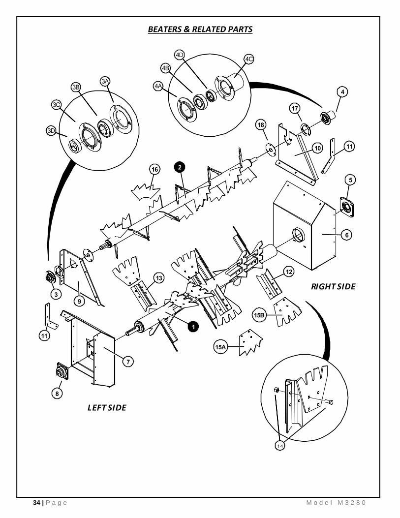
BEATERS & RELATED PARTS
KEY PART NO. QTY. DESCRIPTION
1 E30266 1 MAIN BEATER ASSEMBLY w/ WELD-ON EARS (No Paddles)
2 E02125 1 TOP BEATER ASSEMBLY w/ WELD-ON PADDLES
3 E01973-18 1 BEARING ASSEMBLY w/ FLANGES, Ø1-3/8” x 72MM
3A E01805 - BEARING FLANGE, 72MM, PLAIN
3B E01977-18 - BEARING, Ø1-3/8”, SA20722FP9
3C E01804 - BEARING FLANGE, 72MM, GREASE ZERK
3D REF - COLLAR (Not Sold Separately)
4 E01987-18 1 BEARING ASSEMBLY w/ FLANGES & GUARD, Ø1-3/8” x 72MM
4A E01805 - BEARING FLANGE, 72MM, PLAIN
4B E01977-18 - BEARING, Ø1-3/8”, SA20722FP9
4C E01974-1375 - BEARING FLANGE w/ GUARD, WELDMENT
4D REF - COLLAR (Not Sold Separately)
5 E00261-18 1 BEARING ASSEMBLY, Ø2”, UCF21132EG5
6 E30231R 1 BEATER BRACKET ASSEMBLY, RH
7 E30231L 1 BEATER BRACKET ASSEMBLY, LH
8 E02131-18 1 BEARING ASSEMBLY, Ø1-1/2”, NANF20824
9 E30240L 1 TOP BEATER BRACKET, LH
10 E30240R 1 TOP BEATER BRACKET, RH
11 E30241 2 BRACE, TOP BEATER BRACKET
12 E01985-11 8 BEATER EAR, WELD-ON, RH
13 E01984-11 8 BEATER EAR, WELD-ON, LH
14 E01986 16 BOLT & NUT, Ø1/2” x 1-1/4” GR5
15A E01979 16 PADDLE, BOLT-ON, SHARP TOOTH (STANDARD)
15B E30086 16 PADDLE, BOLT-ON, WIDE TOOTH
16 EQ-SP14-06 18 PADDLE, TOP BEATER, WELD-ON
17 E30801 2 BEARING SPACER RING
18 E30802 2 TWINE GUARD RING

36 | P a g e M o d e l M 3 2 8 0
GEARBOX – BEATER DRIVE

M o d e l M 3 2 8 0 37 | P a g e
GEARBOX – BEATER DRIVE
KEY PART NO. QTY. DESCRIPTION
REF E30160 1 GEARBOX, COMPLETE, RA70-17750
1 17600 1 HOUSING, RA70
2 17893 1 OIL SEAL, 40/80/10-DL
3 3435 2 CIRCLIP, I 80
4 17780 2 SPACER, 70X80X2
5 17728 2 SPACER, 63X80X0,2
6 17847 2 BEARING, 32208
7 17778 1 OUTPUT SHAFT
8 17779 1 SPACER
9 17773 2 BEVEL PINION, Z=13
10 10693 1 BEARING, 30307
11 17852 1 SPACER, 63X80X0,1
12 8243 1 PLUG, Ø80MM
13 17894 1 OIL SEAL, 45/80/10-DL
14 17777 1 INPUT SHAFT
15 10509 1 BEARING, 6208
16 17851 1 SPACER, 40X50X0,1
17 3426 1 CIRCLIP, E 40
18 17771 1 GASKET
19 17770 1 COVER
20 3284 4 SCREW, HEX-HD, M8X16
21 9994 1 OIL LEVEL INDICATOR, Ø1/2”
22 9706 1 OIL BREATHER PLUG, Ø1/2”
23 9707 1 OIL PLUG, Ø1/2”

38 | P a g e M o d e l M 3 2 8 0
APRON & RELATED PARTS

M o d e l M 3 2 8 0 39 | P a g e
APRON & RELATED PARTS
KEY PART NO. QTY. DESCRIPTION
REF E02026-435 2 APRON, ONE SIDE COMPLETE (21 SLATS / 254 LINKS)
1 E02038-375 1 TIGHTENER KIT, COMPLETE, RH
2 E02032 1 TIGHTENER KIT, COMPLETE, RH CENTER
3 E02033 1 TIGHTENER KIT, COMPLETE, LH CENTER
4 E02039-375 1 TIGHTENER KIT, COMPLETE, LH
5 E02024-375 1 TIGHTENER WELDMENT, RH
6 E02040 1 TIGHTENER WELDMENT, RH CENTER
7 E02031 1 TIGHTENER WELDMENT, LH CENTER
8 E2037-375 1 TIGHTNER WELDMENT, LH
9 E02017R 1 APRON BEARING, WELDMENT, 2” SHAFT, RH
E02005-390 1 BEARING INSERT, BRONZE, PRESS-FIT
10 E20737-07 2 APRON BEARING, WELDMENT, 2” SHAFT, L/R CENTER
E00236 2 BEARING INSERT, BRONZE, PRESS-FIT
11 E02017L 1 APRON BEARING, WELDMENT, 2” SHAFT, LH
E02005-390 1 BEARING INSERT, BRONZE, PRESS-FIT
12 REF 1 NUT, 3/4-10, NYLOCK
13 REF 1 HCS, 3/4-10 x 2-3/4”
14 REF 2 HCS, 5/8-11 x 2”
15 REF 2 WASHER, PLAIN, 3/4"
16 REF 4 WASHER, PLAIN, 5/8”
17 REF 2 NUT, 5/8-11, NYLOCK
18 E00238 4 KEY, 1/2” x 2-1/4”
19 E31116 4 SPROCKET, APRON, #67, 7 TOOTH, WELDED HUB
21 E01501-435 1 APRON SHAFT, Ø2” x 73-3/8” L
22 3465-VB560-4 2 APRON SHAFT SHIELD, 20-7/8”L
23 E02020 8 NUT, 3/4" NC
24 E02027 508 LINK, #67P11
25 E02028-435 42 SLAT, #67P11, 27” OA
26 E02029-18 2 APRON SHAFT SPACER, 3” LENGTH
27 E02034 4 ROLLER, NYLON, Ø4-1/2”
28 E02035 4 COTTER PIN
29 E20728 6 SHAFT WASHER, 2”
30 E30088 1 FRONT FLOOR HOLD DOWN / APRON RAMP
31 VB-00061-440 1 GEAR REDUCER, RT350, Cod. 14552 (See Separate Listing)
32 VB-00155 1 SHAFT COLLAR, SPLIT, Ø 2”
33 VB-00181 1 KEY, 1/2” x 1/2" x 5”
34 VB-500-10 1 GEARBOX TORQUE ARM / MOUNT
35 435-48 4 APRON SLIDE RAIL, POLY, 36”
36 E20728 AR SHAFT WASHER, Ø2” ID
37 3465-VB750-23 1 SPACER, CENTER, Ø2” ID x 3-5/16” L

40 | P a g e M o d e l M 3 2 8 0
GEARBOX – APRON DRIVE

M o d e l M 3 2 8 0 41 | P a g e
GEARBOX – APRON DRIVE
KEY PART NO. QTY. DESCRIPTION REF NO.
REF VB-00061-440 1 GEAR REDUCER, RT350, COMPLETE 14552
1 VB-00032-440 1 HOUSING RT350 9975
2 VB-00033-440 1 HUB 14551
3 VB-00034-440 1 CIRCLIP E 82 9918
4 VB-00035-440 1 GEAR Z=49 9974
5 VB-00036-440 2 BEARING 6015 9982
6 VB-00037-440 2 CIRCLIP I 115 9984
7 VB-00038-440 1 PINION Z=12 8670-5
8 VB-00039 2 KEY 12 X 8 X 30 4174
9 VB-00040-440 1 GEAR Z=50 8670-4
10 VB-00041-440 2 BEARING 6208 3342
11 VB-00042 3 CIRCLIP I 80 3435
12 VB-00043-440 1 PINION Z=10 8670-3
13 VB-00044 1 KEY 8 X 7 X 25 3396
14 VB-00045 1 GEAR Z=43 8670-2
15 VB-00047 2 BEARING 6305 8596
16 VB-00048 2 CIRCLIP I 62 3433
17 VB-00049 1 PINION Z=28 8670-1
18 VB-00050 1 BEARING 1538
19 VB-00051 1 CIRCLIP E 50 3428
20 VB-00052 2 OIL PLUG Ø1" GAS 9175
21 VB-00053 2 OIL LEVEL INDIC Ø1" GLASS 1831
22 VB-00054 2 PLUG 8625
23 VB-00055 2 PLUG 8243
24 VB-00056-440 2 OIL SEAL 75/115/10 9983
25 VB-00058 1 COVER 9976
26 VB-00057-9977 1 GASKET 9977
27 VB-00059 8 SCREW HEX-HD M8 X 16 3284
28 VB-00060 1 GASKET 8671

42 | P a g e M o d e l M 3 2 8 0
AXLES, WHEELS, SPINDLES & RELATED PARTS

M o d e l M 3 2 8 0 43 | P a g e
AXLES, WHEELS, SPINDLES & RELATED PARTS
KEY PART NO. QTY. DESCRIPTION REF NO.
1 E00120-08 2 ARM ASSEMBLY, 3” SPINDLE MOUNT -
2 E00151 4 HUB, G75-8 w/ CUPS AND STUDS G281189
3 REF 4 TIRE, 425 / 65 R22.5 (STANDARD) -
REF 4 TIRE, 19L X 16.1, 10 PLY (OPTIONAL FLOTATION) -
4 E00128 4 WASHER, 1” FLAT G913624
5 E00129 4 NUT, SPINDLE G912959
6 E00146-00 4 SPINDLE, Ø 3” X 20”, G281911L20.000C-SP -
7 E00147 4 SEAL, HUB G946486
8 E00148 4 BEARING, INSIDE, 387-AS G910359
9 E00149 4 BEARING CUP, INSIDE, 382A G910358
10 E00159 32 STUD, WHEEL G943541
11 E01156 2 AXLE RETAINER -
12 E01679 4 DUST CAP G909912
13 E01685 4 COTTER PIN G905942
14 E01689 4 BEARING, OUTSIDE, LM501349 G910273
15 E01691 4 BEARING CUP, OUTSIDE, LM501310 G910275
16 E01699 32 NUT, STUD G913557
17 E01700 4 GUIDE, POLY, 2-HOLE -
18 E22142 4 WHEEL, 22.5 X 13.5, FOR 425/65 R22.5 TIRE (STANDARD) -
E00135-16 4 WHEEL, 16.1 X W16C, FOR 19L X 16.1 TIRE (OPTIONAL) -
19 60102 4 GREASE ZERK, 1/8” NPT -
20 66270 6 COUPLING, 1/8” NPT BLK -
21 66402 2 PIPE NIPPLE, 1/8” NPT x 2” BLK -
22 REF 4 COPPER TUBING, 3/16” (Order by the Foot) -
23 VB-00030 2 BCMP CONNECTOR, 3/16”T x 1/8” NPT, 440421-131280 -
24 VB-00031 6 BCMP 90° ELBOW, 3/16”T x 1/8” NPT, 440455-131280 -

44 | P a g e M o d e l M 3 2 8 0
HYDRAULIC END GATE & RELATED PARTS
KEY PART NO. QTY. DESCRIPTION
1 E01558-10 1 END GATE ASSEMBLY, FRAME & ARMS w/ POLY INSERT
2 E20128-435 1 POLY INSERT, 1/2” x 29-1/2” x 53”
3 E30330 2 GATE PIVOT BOLT, w/ GREASE ZERK, Ø1” x 4-1/4”L
4 435-21L 1 GATE FLARE BELT SUPPORT, LH
5 435-21R 1 GATE FLARE BELT SUPPORT, RH
6 435-23 2 CYLINDER GUARD
7 435-26 1 GATE BELTING, BOTTOM, 10” x 60-1/2”
8 435-27R 1 BELTING, RH SIDE
9 435-27L 1 BELTING, LH SIDE

M o d e l M 3 2 8 0 45 | P a g e
PTO DRIVELINE ASSEMBLY w/ OVER-RUNNING CLUTCH
KEY PART NO. QTY. DESCRIPTION
A
93-27469 1 JOINT & SHAFT HALF w/ GUARD, 540 RPM
95-27469 1 JOINT & SHAFT HALF, 540 RPM
93-27470 1 JOINT & SHAFT HALF w/ GUARD, 1000 RPM
95-27470 1 JOINT & SHAFT HALF, 1000 RPM
B 92-27523 1 JOINT & TUBE HALF w/ GUARD
94-27523 1 JOINT & TUBE HALF
1 26-15120 1 REPAIR KIT, SSL/AUTO-LOK
2 31005-1016 1 YOKE, 3 80 WWCV, AUTO-LOK, 540 RPM
31005-1019 1 YOKE, 3 80 WWCV, AUTO-LOK, 1000 RPM
3 03-11388 2 CROSS KIT, 3 80RBL WWCV
4 26-15147 1 CENTER HOUSING, 3 80 WWCV
5 99-27469 1 YOKE & SHAFT
6 97-27469 1 OUTER GUARD
7 19-15126 1 GUARD REPAIR KIT (Nylon Bushing & Easy-Lock Tab)
8 13-10021 1 SAFETY SIGN
9 13-10022 1 SAFETY SIGN
10 19-11146 1 GUARD REPAIR KIT (Nylon Bushing & Easy-Lock Tab)
11 96-27469 1 INNER GUARD
12 98-27469 1 YOKE, TUBE, & SLIP SLEEVE
13 03-10134 1 CROSS KIT, 14R
14 39-10219 1 OVERRUNNING CLUTCH, 14
REF 19-16659 AR REPAIR KIT, OVERRUNNING CLUTCH
COMPLETE ASSEMBLIES 540 RPM - #235-27523
1000 RPM - #235-27528

46 | P a g e M o d e l M 3 2 8 0
HIGHWAY LIGHTING AND WIRING
KEY PART NO. QTY. DESCRIPTION
1 318L-P 1 DUAL LIGHT, 4-PIN, LEFT
2 318R-P 1 DUAL LIGHT, 4-PIN, RIGHT
3 E30090L 1 LIGHT BRACKET w/ GUARD, LH
4 E30090R 1 LIGHT BRACKET w/ GUARD, RH
5 MS10-5730-00 1 WIRE HARNESS / CABLE, FRONT EXT, 25’ L
6 MS10-5731-00 1 WIRE HARNESS / CABLE, REAR WISHBONE
7 200609 AR WIRE LOOM CLAMP, Ø3/8”
8 E30314 2 GROMMET, 1/4" PT, 9307K71
9 E30322 1 GROMMET, 1/16” PT, 9600K55
1 2
VIEW FROM REAR
4 3
5
6
7
8
9
RED RED
AMBR AMBR

M o d e l M 3 2 8 0 47 | P a g e
THIS PAGE INTENTIONALLY LEFT BLANK.

48 | P a g e M o d e l M 3 2 8 0
HYDRAULIC SYSTEM PARTS – APRON DRIVE
PORT A – PRESSURE, IN PORT B – RETURN, OUT
RETU
RN

M o d e l M 3 2 8 0 49 | P a g e
HYDRAULIC SYSTEM PARTS – APRON DRIVE
KEY PART NO. QTY. DESCRIPTION
1 E00484-00 1 ADAPTER, M-JIC to M-ORB, 6400-8-10
2 E00485-00 1 ADAPTER, UNION, 6403-10-8
3 E00485-09 1 ADAPTER TEE, M-JIC x 2 to FM-JIC SWIVEL, 6602-8
4 E00486-00 1 VALVE, MANUAL FLOW CONTROL, RD1910-16
5 E00489-00 1 CHECK VALVE, LTF-8-OW
6 E00495-09 1 ADAPTER, M-ORB to FM-JIC SWIVEL, 6402-8-8
7 E00496 1 CONNECTOR SLEEVE, TWIST HOSE
8 E00497-00 1 BALL VALVE, 72-903
9 E00509-440 1 HYDRAULIC MOTOR, 255160A1912ACAAA
10 E01321-16 2 VALVE MOUNT BRACKET
11 E01591 2 QUICK COUPLER, 8010-4P
12 E02119 7 HOSE CLAMP
13 E21442 3 ADAPTER, 90°, M-JIC to M-ORB, 6801-8-10
14 E21443 1 SPEED CONTROL POINTER
15 E21445 2 BULKHEAD UNION, 2700-LN-08
16 E21447 2 ADAPTER, M-ORB to M-JIC, 6400-8-8
17 E21449 1 ADAPTER, 90°, M-JIC to M-ORB, 6801-8-12
18 E21450 1 ADAPTER, M-JIC to M-ORB, 6400-8-12
19 E21452 1 TEE, 6804-8-8-8
20 E21456 1 VALVE, PFC, BG5-7.5-12SAE
21 E21458 1 ADAPTER, REDUCER, 6410-12-8
22 E30329 1 BULKHEAD UNION, 2706-LN-08
23 E00495 1 FLOW CONTROL HANDLE
24 REF 2 HYDRAULIC HOSE, 8M3K-8FJX-8MP, 92” (To Tractor)
25 REF 1 TWIST HOSE, FLOW CONTROL, 8G2-8FJX-8MP, 112”
26 REF 1 HYDRAULIC HOSE, 8M3K-8FJX-8FJX, 36”
27 REF 1 HYDRAULIC HOSE, 8M3K-8FJX-8FJX90S, 34”
28 REF 1 HYDRAULIC HOSE, 8M3K-8FJX-8FJX, 197” (To Motor, IN)
29 REF 1 HYDRAULIC HOSE, 8M3K-8JX-8FJX90S, 200” (To Motor, OUT)
30 REF 1 HYDRAULIC HOSE, 8M3K-8FJX-8FJX, 20”
31 REF 1 HYDRAULIC HOSE, 8M3K-8FJX90S-8FJX90S, 24”
HYDRAULIC HOSES MADE TO ORDER, USE DESCRIPTION WHEN ORDERING.

50 | P a g e M o d e l M 3 2 8 0
HYDRAULIC SYSTEM PARTS – END GATE
REAR
NOTE: FLOW REFERENCES ONLY APPLY FOR RAISING / OPENING END GATE
FRONT

M o d e l M 3 2 8 0 51 | P a g e
1.2
1.3
1.
1.1
HYDRAULIC SYSTEM PARTS – END GATE
KEY PART NO. QTY. DESCRIPTION
1 E00090-07 2 HYDRAULIC CYLINDER, 3” BORE x 10” STROKE x Ø1.375” ROD (Prince)
BH211349 2 HYDRAULIC CYLINDER, 3” BORE x 10” STROKE x Ø1.250” ROD (Chief)
1.1 E00109-09 - SEAL KIT, PMCK-B3000000 (Prince)
BH204013 - SEAL KIT, TC3, 204013 (Chief)
1.2 E00094-09 - ROD CLEVIS ASSEMBLY, 100000423 (Prince)
BH276050 - ROD CLEVIS ASSEMBLY, 276050 (Chief)
1.3 E00092-09 - CLEVIS PIN, 190400001 (Prince)
BH172250 - CLEVIS PIN w/ CLIPS, 172250 (Chief)
1.4 E00091-09 - COTTER PIN, 220001504 (Prince)
2 E00067-04 4 ADAPTER, 90°, M-JIC to M-ORB, 6801-8-8
3 E00079 AR HOSE CLAMP, 5/8”, 6M3K
4 E01591 2 QUICK COUPLER, 8010-4P
5 E02119 6 HOSE CLAMP
6 E20328 2 BULKHEAD TEE, M-JIC x 3, 2703-LN-8
7 E20329 2 ADAPTER, 90°, M-JIC to FM-JIC SWIVEL, 6500-8
8 E21445 2 BULKHEAD UNION, 2700-LN-08
9 E30064 1 RESTRICTOR, 2406-8-8, R.078
10 E30314 2 GROMMET, 1/4” PT, 9307K71
11 REF 2 HYDRAULIC HOSE, 6M3K-8FJX-8FJX, 202”
12 REF 2 HYDRAULIC HOSE, 6M3K-8FJX-8FJX90S, 45”
13 REF 2 HYDRAULIC HOSE, 6M3K-8FJX-8FJX, 104”
14 REF 2 HYDRAULIC HOSE, 6M3K-8FJX-8FJX, 102” (To Tractor)
HYDRAULIC HOSES MADE TO ORDER, USE DESCRIPTION WHEN ORDERING.

52 | P a g e M o d e l M 3 2 8 0
LIMITED WARRANTY STATEMENT
Meyer’s Equipment Mfg. Corp. warrants each new Meyer’s E.M.C. product to be free from defects in
material and workmanship. This warranty is applicable only for the normal service life expectancy of
the product or components, not to exceed 12 consecutive months from the date of delivery of the
new Meyer’s E.M.C. product to the original purchaser.
Genuine Meyer’s E.M.C. replacement parts and components will be warranted for 365 days from
date of purchase, or the remainder of the original equipment warranty period, whichever is longer.
Under no circumstances will it cover any merchandise or components thereof, which, in the opinion
of the company, has been subjected to misuse, unauthorized modifications, alteration, and accident
or if repairs have been made with parts other than those obtainable through Meyer’s E.M.C.
Our obligation under this warranty shall be limited to repairing or replacing, free of charge to the
original purchaser, any part that, in our judgment, shall show evidence of such defect, provided
further that such part shall be returned within thirty (30) days from date of failure to Meyer’s E.M.C.,
routed through the dealer and distributor from whom the purchase was made, transportation charges
prepaid. Labor charges will be paid at a specified rate. Mileage will not be paid.
This warranty shall not be interpreted to render Meyer’s E.M.C. liable for injury or damages of any
kind or nature to person or property. This warranty does not extend to the loss of crops, loss because
of delay in harvesting, or any expense or loss incurred for labor, substitute machinery, rental or for
any other reason.
In addition to the above limited warranty statement the following applies:
Meyer’s E.M.C. will replace (F.O.B. Dorchester) as Meyer’s E.M.C. elects, for 10 years from
purchase date - any polyethylene plastic boards which compromises the floor, sides, rear or front of
the box portion of the manure spreader box (not labor) from rotting under normal usage to the original
owner.
Except as set forth above, Meyer’s E.M.C. shall have no obligation or liability of any kind on
account of any of its equipment and shall not be liable for special or consequential damages. Meyer’s
E.M.C. disclaims any implied warranty or merchantability or fitness for a particular purpose. Some
states or provinces do no permit limitations or exclusions of implied warranties or incidental or
consequential damages, so the limitations or exclusion in this warranty may not apply.