dnvgl-st-f101 submarine pipeline systems · submarine pipeline systems dnv gl as ... • sec.6...
TRANSCRIPT

The electronic pdf version of this document, available free of chargefrom http://www.dnvgl.com, is the officially binding version.
DNV GL AS
STANDARD
DNVGL-ST-F101 Edition October 2017Amended December 2017
Submarine pipeline systems

FOREWORD
DNV GL standards contain requirements, principles and acceptance criteria for objects, personnel,organisations and/or operations.
© DNV GL AS October 2017
Any comments may be sent by e-mail to [email protected]
This service document has been prepared based on available knowledge, technology and/or information at the time of issuance of thisdocument. The use of this document by others than DNV GL is at the user's sole risk. DNV GL does not accept any liability or responsibilityfor loss or damages resulting from any use of this document.

Cha
nges
- c
urre
nt
Standard — DNVGL-ST-F101. Edition October 2017, amended December 2017 Page 3Submarine pipeline systems
DNV GL AS
CHANGES – CURRENT
This document supersedes the October 2017 edition of DNVGL-ST-F101.Changes in this document are highlighted in red colour. However, if the changes involve a whole chapter,section or sub-section, normally only the title will be in red colour.
Amendments December 2017
• Sec.6 Design - materials engineering— [6.3.3.2] Reference for gauging requirements has been amended.
Changes October 2017
• Sec.1 Introduction— Rigid risers have been excluded and will be covered in the next revision of DNVGL-ST-F201. This affects
several places.— Requirements to technology qualification of new technologies.— Defect has been defined
• Sec.4 Design – loads— Minor editorial changes and updates— Previous section 4G400 and 5C500 have been merged into [4.7.4] and updated.
• Sec.5 Design – limit state criteria— Minor editorial changes and updates— [5.2.1] has been re-organised except for mitre bend angle that has been reduced from three to two
degrees.— [5.2.2] has been modified. More guidance is given in general (see also Table 8-1 and [8.7.1]). Some
specific requirements for replacing the system pressure test (old table 5-1) has been removed.— [5.3.2] The format has been modified slightly. The resistance safety factor, γsc, has now got an additional
index for the relevant limit state. The reason is that the number of γsc’s are increasing. This also impliesthat γε has become γsc,dc.
— [5.4] Name of some limit states and headings have been modified to make it consistent with Table 5-7.— [5.4.6.8] The criterion has been re-formulated (but is identical) except for the pressure term modified in
line with Safebuck JIP.— [5.4.8] Requirements to fracture and fatigue have been updated and are stated in [5.4.8]. For
recommended practice on how to perform this, new revision of DNV GL-RP-F108 is pointed to. Appendix Ais removed.
— [5.4.8] The term sensitive welds has been introduced.— [5.6.1] References to other standards have been updated.— [5.8.2] New. From installation JIP.

Cha
nges
- c
urre
nt
Standard — DNVGL-ST-F101. Edition October 2017, amended December 2017 Page 4Submarine pipeline systems
DNV GL AS
• Sec.7 Construction – linepipe— Changes and modifications to the following:
— Steel making and plate rolling essential variables [7.1.8]— Hydrogen content [7.2.3.3]— Hydrostatic testing [7.5.1]
— Subsection [7.1], [7.2], [7.5], [7.6]. Added clarifications and more requirements to coiled line pipe
— [7.4] Requirements to explosion welded clad plates added
— [7.7] Requirements to dimensions and geometrical measurements have been updated based on a specificworkshop with the industry. Further, a minimum diameter of 60 mm has been specified. Dimensionalrequirements to smaller pipes have been modified and harmonized with common coil tubing pipes
— [7.9.2] Supp. F; Guidance note to DWTT added, acknowledging challenges with inverse fracture for hightoughness materials and supporting a similar statement in API RP 5L3.
— [7.9.3] Supp. P; Has been modified.
— [7.9.5] Supp. U; Modified to include both approaches to achieve Suffix U; retrospective documentationand as part of production testing. Restructuring of content to better clarify requirements.
• Sec.8 Construction - components and pipeline assemblies— Restructuring of content to better clarify requirements.— Table 8-1 has been modified.— DNVGL-RP-0034 is acknowledged as an alternative material specification for forged CMn steel.
• Sec.12 Documentation— Some requirements to documentation in other sections have been moved to this section. A reference to
DNVGL-RP-O101 is also included.
• Sec. 13 Commentary (informative)— [13.6] Roadmap for use of this standard with pipe-in-pipe systems based on workshop series JIP-
• App.A Fracture limit state of girth welds— Empty - moved to new revision of DNVGL-RP-F108.
• App.B Mechanical testing and corrosion testingMinor changes and modifications, e.g. to the following:
— References to DNVGL-RP-F108 added— Reference to BS 8571 for SENT added— Clarifications to all-weld tensile testing.
• App.C WeldingIn general only minor updates on reference standards and some changes to clarify paragraphs.
— [C.3.4.5] Batch testing modified to be sampled in same positions as WPQ— [C.4.8.7] Maximum heat input variation for multiple pieces more clarified— [D.2.1.5] Added requirement for heat input range to be stated on WPS

Cha
nges
- c
urre
nt
Standard — DNVGL-ST-F101. Edition October 2017, amended December 2017 Page 5Submarine pipeline systems
DNV GL AS
— [C.8.1.13] Maximum interpass temperature for welding of solid CRA and in root and hot pass for lined/clad carbon steel increased to 1500C.
• App.D Non-destructive testing— [D.7] Fully revised requirements for pipe body inspection (usually applicable for plate mills for SAWL).— [D.8.13] Added requirement to use 2 angles in AUT setup for inspection of longitudinal imperfections.
• App.E Automated ultrasonic girth weld testing— [E.2] Added requirement to evaluate impact on sensitivity of long seam weld— [E.2] Added requirement for inspection of CRA welds and materials— [E.2] Added requirement for monitoring wall thickness upon AUT inspection of SMLS pipe girth welds.— [E.2] Accommodate for use of adaptive focal laws— [E.2] Added requirement to include SDH reflector for TOFD in reference block— [E.5] Revised acceptance criteria for porosity, Table E-1— [E.5] Added workmanship acceptance criteria for fatigue sensitive welds— [E.8] Added generalised requirements to number of imperfections within scope of AUT qualification— [E.8] Reduced requirements to CCW scanning of defective welds in AUT qualification, now 1 weld is
required.— [E.8] Added requirement to demonstrate stability upon repeated inspection in AUT validation.
• App.F Requirements for shore crossing and onshore sections— Updated on land fall, now referred to as shore crossing based on the Crossway JIP by Atteris
Editorial correctionsIn addition to the above stated changes, editorial corrections may have been made.

Cha
nges
- c
urre
nt
Standard — DNVGL-ST-F101. Edition October 2017, amended December 2017 Page 6Submarine pipeline systems
DNV GL AS
AcknowledgementsThe present revision of DNVGL-ST-F101 is mainly reflecting feed-back from experience by several companiesthat are hereby acknowledged. The comments improved the quality and content of this standard significantlyand the effort spent by the commenting companies is impressive and hereby acknowledged.This revision includes results from the following JIP's sponsored by the listed companies. Their contribution ishereby acknowledged.
Installation JIPThe following companies, listed in alphabetical order, are acknowledged for their contributions to the JIP
ABB HHI NOV Technip
Allseas JFE Steel Petrobras Tideway Offshore Solutions
Bureau Veritas KW/Petrofac Saipem VBMS
EMAS McDermott Statoil WoodGroup Kenny
Heermea Marine Contractors Nexans Subsea7 Woodside
Pipe-in-pipe workshop series JIPThe following companies, listed in alphabetical order, are acknowledged for their contributions to the JIP
Genesis ITP Shell Technip
HMC Petrobras Subsea7 Vision oil and gas
Intecsea Saipem T.D. Williamson Wood Group Kenny
Crossway JIP performed by Atteris.Safebuck JIP peformed by Atkins.

Con
tent
s
Standard — DNVGL-ST-F101. Edition October 2017, amended December 2017 Page 7Submarine pipeline systems
DNV GL AS
CONTENTS
Changes – current.................................................................................................. 3Acknowledgements.................................................................................6
Section 1 Introduction.......................................................................................... 121.1 General........................................................................................... 121.2 Objectives....................................................................................... 121.3 Scope.............................................................................................. 121.4 Application...................................................................................... 121.5 Alternative methods and procedures.............................................. 141.6 Structure of standard..................................................................... 141.7 References...................................................................................... 161.8 Definitions.......................................................................................24
Section 2 Safety philosophy..................................................................................452.1 General........................................................................................... 452.2 Safety philosophy structure............................................................452.3 Risk basis for design...................................................................... 49
Section 3 Concept and design premise development............................................ 533.1 General........................................................................................... 533.2 Concept development..................................................................... 543.3 Design premise............................................................................... 553.4 System design principles................................................................ 60
Section 4 Design - loads....................................................................................... 644.1 General........................................................................................... 644.2 Functional loads..............................................................................654.3 Environmental loads....................................................................... 674.4 Construction loads.......................................................................... 734.5 Interference loads.......................................................................... 734.6 Accidental loads..............................................................................744.7 Design load effects......................................................................... 74
Section 5 Design – limit state criteria...................................................................815.1 General........................................................................................... 815.2 System design requirements.......................................................... 825.3 Design format................................................................................. 865.4 Limit states.....................................................................................92

Con
tent
s
Standard — DNVGL-ST-F101. Edition October 2017, amended December 2017 Page 8Submarine pipeline systems
DNV GL AS
5.5 Special considerations.................................................................. 1115.6 Pipeline components.....................................................................1165.7 Supporting structure.....................................................................1235.8 Installation and repair..................................................................123
Section 6 Design - materials engineering........................................................... 1276.1 General......................................................................................... 1276.2 Materials selection for line pipe and pipeline components............ 1276.3 Materials specification.................................................................. 1336.4 Corrosion control.......................................................................... 136
Section 7 Construction – linepipe....................................................................... 1437.1 General......................................................................................... 1437.2 Carbon Manganese (C-Mn) steel linepipe......................................1477.3 Corrosion resistant alloy linepipe................................................. 1657.4 Clad or lined steel linepipe........................................................... 1697.5 Hydrostatic testing....................................................................... 1757.6 Non-destructive testing................................................................ 1767.7 Dimensions, mass and tolerances.................................................1797.8 Marking, delivery condition and documentation............................1887.9 Supplementary requirements........................................................189
Section 8 Construction - components and pipeline assemblies.......................... 1998.1 General......................................................................................... 1998.2 Component requirements..............................................................2008.3 Materials....................................................................................... 2118.4 Manufacture.................................................................................. 2148.5 Mechanical and corrosion testing................................................. 2178.6 Pipeline assemblies.......................................................................2208.7 Hydrostatic testing....................................................................... 2248.8 Documentation, records, certification and marking.......................226
Section 9 Construction - corrosion protection and weight coating...................... 2289.1 General......................................................................................... 2289.2 External corrosion protective coatings..........................................2299.3 Concrete weight coating............................................................... 2309.4 Manufacture of galvanic anodes................................................... 2339.5 Installation of galvanic anodes.....................................................233
Section 10 Construction – offshore.....................................................................235

Con
tent
s
Standard — DNVGL-ST-F101. Edition October 2017, amended December 2017 Page 9Submarine pipeline systems
DNV GL AS
10.1 General....................................................................................... 23510.2 Pipe assemblies onshore.............................................................23610.3 Pipeline route, pre-installation survey and preparation.............. 23710.4 Installation spread......................................................................23810.5 Welding and non-destructive testing.......................................... 24710.6 Pipeline installation.................................................................... 24810.7 As-laid survey............................................................................. 25410.8 Post-lay intervention (seabed intervention and pipelineprotection)..........................................................................................25510.9 Tie-in...........................................................................................25710.10 Pre-commissioning....................................................................25910.11 As-built survey..........................................................................26310.12 Documentation..........................................................................26410.13 Installation manual...................................................................264
Section 11 Operations and abandonment........................................................... 26811.1 General....................................................................................... 26811.2 Commissioning............................................................................27011.3 Integrity management system....................................................27011.4 Integrity management process...................................................27311.5 Re-qualification...........................................................................27911.6 De-commissioning.......................................................................28111.7 Abandonment..............................................................................282
Section 12 Documentation.................................................................................. 28312.1 General....................................................................................... 28312.2 Design.........................................................................................28312.3 Construction - manufacturing and fabrication.............................28612.4 Construction - installation and pre-commissioning..................... 28812.5 Operation - commissioning......................................................... 28812.6 Operation.................................................................................... 28912.7 Abandonment..............................................................................29012.8 DFI-resumé................................................................................. 29012.9 Filing of documentation.............................................................. 292
Section 13 Commentary (informative)................................................................ 29313.1 General....................................................................................... 29313.2 Safety and design philosophy..................................................... 29313.3 Loads.......................................................................................... 29413.4 Design criteria............................................................................ 295

Con
tent
s
Standard — DNVGL-ST-F101. Edition October 2017, amended December 2017 Page 10Submarine pipeline systems
DNV GL AS
13.5 API material grades....................................................................30113.6 Pipe-in-pipe.................................................................................30213.7 Installation................................................................................. 31813.8 References.................................................................................. 320
Appendix A Fracture limit state of girth welds....................................................321
Appendix B Mechanical testing and corrosion testing......................................... 322B.1 General......................................................................................... 322B.2 Mechanical testing and chemical analysis.....................................322B.3 Corrosion testing.......................................................................... 333
Appendix C Welding............................................................................................ 343C.1 General......................................................................................... 343C.2 Welding equipment, tools and personnel......................................344C.3 Welding consumables................................................................... 346C.4 Welding procedures...................................................................... 350C.5 Qualification of welding procedures............................................. 360C.6 Examination and testing for welding procedure qualification........368C.7 Welding and post weld heath treatment requirements................. 375C.8 Material and process specific requirements.................................. 382C.9 Hyperbaric dry welding.................................................................386
Appendix D Non-destructive testing (NDT).........................................................392D.1 General......................................................................................... 392D.2 Manual non-destructive testing and visual examination ofwelds.................................................................................................. 394D.3 Manual non-destructive testing and visual examination of plate,pipe and weld overlay........................................................................ 418D.4 Non-destructive testing and visual examination of forgings......... 423D.5 Non-destructive testing and visual examination of castings......... 428D.6 Automated non-destructive testing.............................................. 433D.7 Non-destructive testing of pipe body of welded pipes.................. 434D.8 Non-destructive testing of linepipe at pipe mills.......................... 441
Appendix E Automated ultrasonic girth weld testing.......................................... 469E.1 General......................................................................................... 469E.2 Basic requirements....................................................................... 469E.3 Procedure......................................................................................479E.4 Calibration (sensitivity setting).................................................... 480E.5 Field inspection.............................................................................483

Con
tent
s
Standard — DNVGL-ST-F101. Edition October 2017, amended December 2017 Page 11Submarine pipeline systems
DNV GL AS
E.6 Re-examination of welds.............................................................. 489E.7 Evaluation and reporting.............................................................. 489E.8 Qualification..................................................................................491E.9 Project specific automated ultrasonic testing procedurevalidation............................................................................................ 500E.10 Validity of qualification............................................................... 502E.11 Determination of wave velocities in pipe steels.......................... 503
Appendix F Requirements for shore crossing and onshore sections.................... 505F.1 General..........................................................................................505F.2 Safety philosophy..........................................................................510F.3 Design premise............................................................................. 513F.4 Design........................................................................................... 515F.5 Construction..................................................................................517F.6 Operation...................................................................................... 518F.7 Documentation..............................................................................519
Changes – historic.............................................................................................. 520

Standard — DNVGL-ST-F101. Edition October 2017, amended December 2017 Page 12Submarine pipeline systems
DNV GL AS
SECTION 1 INTRODUCTION
1.1 GeneralThis standard gives criteria and recommendations on concept development, design, construction, operationand abandonment of submarine pipeline systems.
1.2 ObjectivesThe objectives of this standard are to:
— ensure that the concept development, design, construction, operation and abandonment of pipelinesystems are conducted with due regard to public safety and the protection of the environment
— provide an internationally acceptable standard of safety for submarine pipeline systems by definingminimum requirements for concept development, design, construction, operation and abandonment
— serve as a technical reference document in contractual matters between purchaser and contractor— provide requirements for designers, purchaser, and contractors.
1.3 ScopeThis standard provides guidance and requirements to concept development, design, construction, operationand abandonment of pipeline systems.The standard includes guidance and criteria to:
— design basis (survey, environmental data, soil sampling)— design criteria (layout, LRFD format and functional)— material selection and corrosion control— line pipe— components— coating— offshore construction and pre-commissioning— operation and abandonment— material testing— welding— non-destructive testing (NDT).The focus is on structural integrity of the pipeline.
1.4 ApplicationTha applicability of this standard is given in Table 1-1. The standard shall be applied in its entirety.

Standard — DNVGL-ST-F101. Edition October 2017, amended December 2017 Page 13Submarine pipeline systems
DNV GL AS
Table 1-1 Applicability of standard
General
Application Pipeline systems in the petroleum and natural gas industries.
For submarine pipeline systems that have extraordinary consequences, thequantification of consequences by the three safety classes provided in thisstandard may be insufficient, and higher safety classes may be required.1
Phases Concept development, design, construction, operation and abandonment.
Single rigid metallic pipeline systems, pipeline bundles of the piggyback type andpipeline bundles within an outer pipe2.
Pipe-in-pipe.
Pipeline types
Risers and compliant risers are covered by DNVGL-ST-F201Dynamic risers.
Extent/battery limits
Pressure and flow Pipeline system in such a way that the fluid transportation and pressure in thesubmarine pipeline system is well defined and controlled 3.
Concept development, design,construction, operation andabandonment
Submarine pipeline system4.
Geometry and configuration
Dimensions No limitation except that pipe outside diameters shall be above 60 mm.
(Explicit criteria for local buckling, combined loading are only given for straightpipes with 15 < D/t2 < 45.)
Configurations Tee’s, wye’s, PLEM or PLET, spools which are integrated part of the pipeline.
Water depth No limitation, see [5.1.2.1].
Loads
Pressure No limitation.
Temperature No limitation.
Material properties need to be documented for relevant temperatures in line with[5.3.3].
Global deformations No limitation.
Line pipe Material
General See [7.1.2.1].
C-Mn steel line pipe is generally conforming to ISO 3183 Annex J but withmodifications and amendments (245-555). Material grade limited to, including,X80 (DNVGL 555).
CRA line pipe with specific requirements to 22Cr and 25Cr steel and 13Crmartensitic steel.
Clad and lined line pipe.
Supplementary requirements for sour service, fracture arrest properties, plasticdeformation, dimensional tolerances and high utilization.

Standard — DNVGL-ST-F101. Edition October 2017, amended December 2017 Page 14Submarine pipeline systems
DNV GL AS
Components Bends, fittings, flanges, valves, mechanical connectors, CP insulating joints, anchorflange, buckle arrestor, pig traps, clamps and couplings.
Design See [5.6].
Material and manufacture See Sec.8.
Fluids
Categories See Table 2-1.
CO2 pipelines are in general covered by this standard in line with ISO 13623. Thefollowing aspects needs special attention for CO2 pipelines:
— material selection— corrosion and sour service evaluations— operation.
For these aspects, see DNVGL-RP-F104.
Sour service Generally conforming to ISO 15156.
Installation
Method See Sec.10.
S-lay, J-lay, towing and laying methods introducing plastic deformations.
Installation requirements for protective and anchoring structures are also included.
1) Example of extra ordinary consequences may be pristine environment and exploration in arctic climate.2) Umbilicals intended for control of subsea installations are not included in this standard. Individual pipes, within an
umbilical, made of materials applicable to this standard, may be designed according to this standard.3) Different parts of the pipeline system may be designed to different standards or recommended practices. It
is important to identify differences between these at an early stage and assess these. Examples of conflictingrequirements are; pressure definitions and system test pressure requirements.
4) The operator may apply this standard on sub-sets of the limits of this standard. Typical example of excluded items issmaller diameter piping such as kicker lines and designs these to e.g. ISO 15649.
1.5 Alternative methods and proceduresIn case alternative methods and procedures to those specified in this standard are used, it shall bedemonstrated that the obtained safety level is equivalent to the one specified herein, see [2.3.5]. Suchalternative methods shall be formally and rigorously justified and accepted by all relevant contracting parties.Technologies that are not covered by existing, validated requirements, and where failure poses risk tolife, property or the environment, or presents financial risk, shall be qualified. Recommended practice ontechnology qualification are given in DNVGL-RP-A203.
1.6 Structure of standardThis standard is based on limit state design. This implies that the same design criteria apply to bothconstruction/installation and operation. All structural criteria are therefore given in Sec.5.The standard is organised as follows:
— This section contains the objectives and scope of the standard. It further introduces essential concepts,definitions and abbreviations.
— Sec.2 contains the fundamental safety philosophy and design principles. It introduces the safety classmethodology and normal classification of safety classes. It gives overall requirements to systematic

Standard — DNVGL-ST-F101. Edition October 2017, amended December 2017 Page 15Submarine pipeline systems
DNV GL AS
review or QRA. How this will affect the different phases is further described in subsections [X.1.3], whereX indicates section, in the different sections.
— Sec.3 contains requirements to concept development, establishment of design premises, with systemdesign principles, pipeline safety and control system, and collection of environmental data.
— Sec.4 defines the design loads to be applied in Sec.5. It includes classification of loads into functionalloads (including pressure), environmental loads, interference loads and accidental loads. Finally, it definesdesign cases with associated characteristic values and combinations.
— Sec.5 contains requirements to pipeline layout, system test and mill test. It contains description of thedesign (LRFD) format and characterisation of material strength for straight pipes and supports. Designcriteria for the different limit states for all phases; installation, as-laid, commissioning and operation, aregiven.
— Sec.6 contains materials engineering and includes material selection, material specification (includingrequired supplementary requirement to the line pipe specification), welding and corrosion control.
— Sec.7 contains requirements to line pipe. The requirements to C-Mn steels are based on ISO 3183. Thesection also includes requirements to CRAs and lined/clad pipe.
— Sec.8 contains requirements to materials, manufacture and fabrication of components and assemblies.Structural requirements to these components are given in [5.6].
— Sec.9 contains requirements to corrosion protection and weight coating.— Sec.10 contains requirements to offshore construction including installation, pre- and post-intervention
and pre-commissioning.— Sec.11 contains requirements to operation including commissioning, integrity management, repair, re-
qualification, de-commissioning and abandonment of the submarine pipeline system.— Sec.12 contains requirements to documentation for the submarine pipeline system from concept
development to abandonment.— Sec.13 is an informative section which discusses several aspects of the standard.
The appendices are a compulsory part of the standard.— App.A is empty. The content on ECA from previous revision is now reflected in the updated DNVGL-RP-
F108.— App.B details the requirements to materials testing including mechanical and corrosion testing as well as
chemical analysis.— App.C contains requirements to welding including qualification of welding procedures and construction
welding.— App.D contains requirements to Non-Destructive Testing (NDT) except Automated Ultrasonic Testing (AUT)
of girth welds.— App.E contains requirements to AUT of girth welds.— App.F contains selected requirements to shore crossing and onshore parts of the submarine pipeline
system.
Additional requirements or modified requirements compared to the stated ISO standards are denoted by ARor MR by the end of the paragraph. This applies to [7.2] and [9.3].Modified requirements compared to the stated ISO standards are given in this standard by stating the ISOparagraph number in brackets prior to the modified requirements. This applies to Sec.8.Guidance notes provide additional information, clarification or examples to the paragraph in order to increasethe understanding of the requirement. Guidance notes do not contain requirements.

Standard — DNVGL-ST-F101. Edition October 2017, amended December 2017 Page 16Submarine pipeline systems
DNV GL AS
1.7 References
1.7.1 GeneralThe following standards include provisions which, through reference in the text, constitute provisions of thisstandard.References are either defined as normative or informative. Normative references in this document areindispensable for its application. Informative references provide additional information intended to assist theunderstanding or use of the document.
Guidance note:Normative references are typically referred to as "testing shall be performed in accordance with ISO xxx", while informativereferences are typically referred to as "testing may be performed in accordance with ISO xxx or ISO yyyy", or "recommendedpractice on xx is given in DNVGL-RP-Fxxx".
---e-n-d---o-f---g-u-i-d-a-n-c-e---n-o-t-e---
In case of conflict between this standard and referenced DNV GL standards or recommended practices, thestandard or recommended practice with the latest edition date shall prevail.The latest valid edition of each of the DNV GL reference documents applies.
Guidance note:Any conflict is intended to be removed in next revision of that document.
---e-n-d---o-f---g-u-i-d-a-n-c-e---n-o-t-e---
This standard is intended to comply with the ISO standard 13623: Petroleum and natural gas industries -Pipeline transportation systems, specifying functional requirements for offshore pipelines and risers.
Guidance note:The following deviations to ISO 13623 standard are intentional:
— This standard allows higher utilisation for fluid category A and C pipelines. This standard is in compliance with ISO 16708.
— For design life less than 33 years, a more severe environmental load is specified in this standard, in agreement with ISO16708.
— applying the supplementary requirements U, for increased utilisation, this standard allows 4% higher pressure containmentutilisation than ISO 13623.
— the equivalent stress criterion in ISO 13623 may, under some conditions allow higher utilisation than this standard.
— requirements to system pressure test (pressure test) are less stringent.
— minor differences may appear depending on how the pipeline has been defined in safety classes, ISO 13623 does not use theconcept of safety classes.
---e-n-d---o-f---g-u-i-d-a-n-c-e---n-o-t-e---
The requirements to C-Mn steel line pipe of this standard are intended to comply with the ISO standard 3183Annex J limited to, including, X80 (DNVGL 555), but with modifications and amendments.
Guidance note:The latest revision of the DNV GL publications may be found in the publication list at the DNV GL website www.dnvgl.com.Amendments and corrections to the DNV GL publications are published on www.dnvgl.com when relevant. These shall beconsidered as mandatory part of the above standards and recommended practices.
---e-n-d---o-f---g-u-i-d-a-n-c-e---n-o-t-e---

Standard — DNVGL-ST-F101. Edition October 2017, amended December 2017 Page 17Submarine pipeline systems
DNV GL AS
1.7.2 DNV GL service specificationsThe latest revision of the following documents applies.
Table 1-2 DNV GL service specifications
Document code Title
DNVGL-SE-0160 Technology qualification management and verification
DNVGL-SE-0475 Sec.1 Certification and verification of pipelines
DNVGL-SE-0476 Offshore riser systems
1.7.3 DNV GL StandardsThe following documents contain provisions which, through reference in this text, constitute provisions of thisoffshore standard. The latest revision of the following document applies.
Table 1-3 DNV GL standards
Document code Title
DNVGL-OS-A101 Safety principles and arrangements
DNVGL-OS-C101 Design of offshore steel structures, general - LRFD method
DNVGL-OS-E201 Oil and gas processing systems
DNVGL-OS-E301 Position mooring
DNVGl-ST-C501 Composite components
DNVGL-ST-F201 Dynamic risers
DNVGL-ST-N001 Marine operations and marine warranty
1.7.4 DNV GL recommended practicesThe latest revision of the following documents applies.
Table 1-4 DNV GL recommended practices
Document code Title
DNVGL-RP-A203 Sec.1 Technology qualification
DNVGL-RP-B401 Cathodic protection design
DNVGL-RP-C203 Fatigue design of offshore steel structures
DNVGL-RP-C205 Environmental conditions and environmental loads
DNVGL-RP-C211 Structural reliability analysis
DNVGL-RP-C212 Offshore soil mechanics and geotechnical engineering
DNVGL-RP-F101 Corroded pipelines

Standard — DNVGL-ST-F101. Edition October 2017, amended December 2017 Page 18Submarine pipeline systems
DNV GL AS
Document code Title
DNVGL-RP-F102 Pipeline field joint coating and field repair of line pipe coating
DNVGL-RP-F103 Cathodic protection of submarine pipelines
DNVGL-RP-F105 Free spanning pipelines
DNVGL-RP-F106 Factory applied pipeline coatings for corrosion control
DNVGL-RP-F107 Risk assessment of pipeline protection
DNVGL-RP-F108 Assessment of flaws in pipeline and riser girth welds
DNVGL-RP-F109 On-bottom stability design of submarine pipelines
DNVGL-RP-F110 Global buckling of submarine pipelines
DNVGL-RP-F111 Interference between trawl gear and pipelines
DNVGL-RP-F112 Design of duplex stainless steel subsea equipment exposed to cathodic protection
DNVGL-RP-F113 Sec.1 Pipeline subsea repair
DNVGL-RP-F114 Pipe-soil interaction for submarine pipelines
DNVGL-RP-F115 Pre-commissioning of pipelines
DNVGL-RP-F116 Integrity management of submarine pipeline systems
DNVGL-RP-F118 Pipe girth weld automated ultrasonic testing system qualification and project specificprocedure validation
DNVGL-RP-F204 Riser fatigue
DNVGL-RP-J202 Design and operation or carbon dioxide pipelines
DNVGL-RP-N101 Sec.1 Risk management in marine and subsea operations
DNVGL-RP-N103 Modelling and analyses of marine operations
DNVGL-RP-O101 Sec.1 Technical documentation for subsea projects
DNVGL-RP-O501 Managing sand production and erosion
DNVGL-RP-0034 Steel forgings for subsea applications
1.7.5 DNV GL other publicationsThe latest revision of the following documents applies.
Table 1-5 DNV GL other publications
Document code Title
DNVGL-RU-HSLC Rules for classification: High speed and light craft
DNVGL-CG-0051 Non-destructive testing

Standard — DNVGL-ST-F101. Edition October 2017, amended December 2017 Page 19Submarine pipeline systems
DNV GL AS
1.7.6 Other referencesTable 1-6 Other references
Document code Title
API RP 5L1 Recommended Practice for Railroad transportation of Line Pipe
API RP 5L2 Recommended Practice for Internal Coating of Line Pipe for Non-corrosive Gas TransmissionService
API RP 5L3 Recommended Practice for Conducting Drop-Weight Tear Tests on Line Pipe
API RP 5LW Recommended Practice for Transportation of Line Pipe on Barges and Marine Vessels
API RP 17N Subsea Production System Reliability and Technical Risk Management
API RP 2201 Safe Hot Tapping Practices in the Petroleum & Petrochemical Industries
API Spec 6A Specification for Wellhead and Christmas Tree Equipment
API Spec 6FA Specification for Fire Test for Valves
API 5LD Specification for CRA Clad or Lined Steel Pipe
ASME B16.9 Factory-Made Wrought Buttwelding Fittings
ASME B31.3 Process Piping
ASME B31.4 Pipeline Transportation Systems for Liquid Hydrocarbons and Other Liquids
ASME B31.8 Gas Transmission and Distribution Systems
ASME BPVC-V Boiler and Pressure Vessel Code Section V - Non-destructive Examination
ASME BPVC-VIII-1 Boiler and Pressure Vessel Code Section VIII - Div. 1 - Rules for Construction of Pressure Vessels
ASME BPVC-VIII-2 Boiler and Pressure Vessel Code Section VIII - Div. 2 - Rules for Construction of Pressure Vessels -Alternative Rules
ASNT American Society for Nondestructive Testing. Central Certification Program (ACCP).
ASTM A 961 Standard Specification for Common Requirements for Steel Flanges, Forged Fittings, Valves, andParts for Piping Applications
ASTM A264 Standard Specification for Stainless Chromium-Nickel Steel-Clad Plate
ASTM A370 Standard Test Methods and Definitions for Mechanical Testing of Steel Products
ASTM A388 Standard Practice for Ultrasonic Examination of Steel Forgings
ASTM A577 Standard specification for Ultrasonic Angle-Beam Examination of Steel Plates
ASTM A578 Standard Specification for Straight-Beam Ultrasonic Examination of Rolled Steel Plates for SpecialApplications
ASTM A609 Standard Practice for Castings, Carbon, Low Alloy, and Martensitic Stainless Steel, UltrasonicExamination Thereof
ASTM A956 Standard Test Method for Leeb Hardness Testing of Steel Products
ASTM A1038 Standard Test Method for Portable Hardness Testing by the Ultrasonic Contact Impedance Method
ASTM C33 Standards specification for concrete aggregates

Standard — DNVGL-ST-F101. Edition October 2017, amended December 2017 Page 20Submarine pipeline systems
DNV GL AS
Document code Title
ASTM D 695 Standard Test Method for Compressive Properties of Rigid Plastics
ASTM E110 Standard Test Method for Indentation Hardness of Metallic Materials by Portable Hardness Testers
ASTM E 165 Standard Practice for Liquid Penetrant Examination for General Industry
ASTM E 280 Standard Reference Radiographs for Heavy-Walled (4 1/2 to 12-in. (114 to 305-mm)) SteelCastings
ASTM E 309 Standard Practice for Eddy-Current Examination of Steel Tubular products Using MagneticSaturation
ASTM E 317 Standard Practice for Evaluating Performance Characteristics of Pulse-Echo Testing Instrumentsand Systems Without the Use of Electronic Measurement Instruments
ASTM E 426 Standard Practice for Electromagnetic (Eddy Current) Examination of Seamless and WeldedTubular Products, Austenitic Stainless Steel and Similar Alloys
ASTM E 709 Standard Guide for Magnetic Particle Examination
ASTM E 797 Standard Practice for Measuring Thickness by Manual Ultrasonic Pulse-Echo Contact Method
ASTM E1212 Standard Practice for Quality Management Systems for Non-destructive Testing Agencies
ASTM E1417 Standard Practice for Liquid Penetrant Examination
ASTM E1444 Standard Practice for Magnetic Particle Examination
ASTM E1820 Standard Test Method for Measurement of Fracture Toughness
ASTM G 48 Standard Test Methods for Pitting and Crevice Corrosion Resistance of Stainless Steels and RelatedAlloys by Use of Ferric Chloride Solution
AWS C5.3 Recommended Practices for Air Carbon Arc Gouging and Cutting
BS 7488 Fracture mechanics toughness tests. Method for determination of KIc, critical CTOD and critical Jvalues of metallic materials
BS 8571 Method of test for determination of fracture toughness in metallic materials using single edgenotched tension (SENT) specimens
BS 7910 Guide to methods for assessing the acceptability of flaws in metallic structures
BSI BS 7910 Guide to methods for assessing the acceptability of flaws in metallic structures
BSI PD 5500 Specification for unfired fusion welded pressure vessels
EN 1591-1 Flanges and their joints - Design rules for gasketed circular flange connections - Part 1:Calculation
EN 1998 Eurocode 8: Design of structures for earthquake resistance
EN 10204 Metallic products - Types of inspection documents
EN 12668 Non destructive testing - Characterisation and verification of ultrasonic examination equipment- Allparts
EN 13445-3 Unfired pressure vessels - Part 3: Design
EN ISO 9606-1 Qualification testing of welders - Fusion welding - Part 1: Steels
EN ISO 14175 Welding consumables - Gases and gas mixtures for fusion welding and allied processes
Standard — DNVGL-ST-F101. Edition October 2017, amended December 2017 Page 21Submarine pipeline systems
DNV GL AS
Document code Title
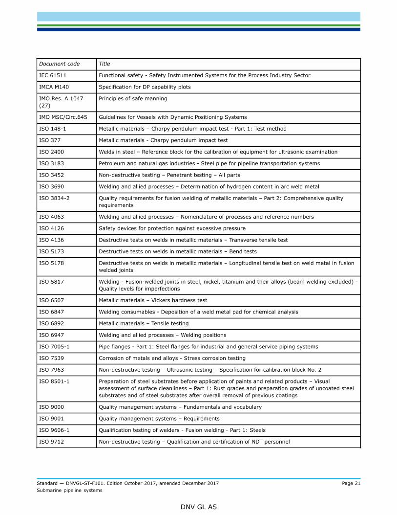
IEC 61511 Functional safety - Safety Instrumented Systems for the Process Industry Sector
IMCA M140 Specification for DP capability plots
IMO Res. A.1047(27)
Principles of safe manning
IMO MSC/Circ.645 Guidelines for Vessels with Dynamic Positioning Systems
ISO 148-1 Metallic materials – Charpy pendulum impact test - Part 1: Test method
ISO 377 Metallic materials - Charpy pendulum impact test
ISO 2400 Welds in steel – Reference block for the calibration of equipment for ultrasonic examination
ISO 3183 Petroleum and natural gas industries - Steel pipe for pipeline transportation systems
ISO 3452 Non-destructive testing – Penetrant testing – All parts
ISO 3690 Welding and allied processes – Determination of hydrogen content in arc weld metal
ISO 3834-2 Quality requirements for fusion welding of metallic materials – Part 2: Comprehensive qualityrequirements
ISO 4063 Welding and allied processes – Nomenclature of processes and reference numbers
ISO 4126 Safety devices for protection against excessive pressure
ISO 4136 Destructive tests on welds in metallic materials – Transverse tensile test
ISO 5173 Destructive tests on welds in metallic materials – Bend tests
ISO 5178 Destructive tests on welds in metallic materials – Longitudinal tensile test on weld metal in fusionwelded joints
ISO 5817 Welding - Fusion-welded joints in steel, nickel, titanium and their alloys (beam welding excluded) -Quality levels for imperfections
ISO 6507 Metallic materials – Vickers hardness test
ISO 6847 Welding consumables - Deposition of a weld metal pad for chemical analysis
ISO 6892 Metallic materials – Tensile testing
ISO 6947 Welding and allied processes – Welding positions
ISO 7005-1 Pipe flanges - Part 1: Steel flanges for industrial and general service piping systems
ISO 7539 Corrosion of metals and alloys - Stress corrosion testing
ISO 7963 Non-destructive testing – Ultrasonic testing – Specification for calibration block No. 2
ISO 8501-1 Preparation of steel substrates before application of paints and related products – Visualassessment of surface cleanliness – Part 1: Rust grades and preparation grades of uncoated steelsubstrates and of steel substrates after overall removal of previous coatings
ISO 9000 Quality management systems – Fundamentals and vocabulary
ISO 9001 Quality management systems – Requirements
ISO 9606-1 Qualification testing of welders - Fusion welding - Part 1: Steels
ISO 9712 Non-destructive testing – Qualification and certification of NDT personnel

Standard — DNVGL-ST-F101. Edition October 2017, amended December 2017 Page 22Submarine pipeline systems
DNV GL AS
Document code Title
ISO/TR 9769 Steel and iron – Review of available methods of analysis
ISO 9934 Non-destructive testing – Magnetic particle testing – All parts
ISO 10375 Non-destructive testing – Ultrasonic inspection – Characterization of search unit and sound field
ISO 10474 Steel and steel products - Inspection documents
ISO 10893 Non-destructive testing of steel tubes – All parts
ISO 11484 Steel products – Employer's qualification system for non-destructive testing (NDT) personnel
ISO 12135 Metallic materials - Unified method of test for determination of quasistatic fracture toughness
ISO 12715 Non-destructive testing -- Ultrasonic testing -- Reference blocks and test procedures for thecharacterization of contact probe sound beams
ISO/TS 12747 Petroleum and natural gas industries – Pipeline transportation systems – Recommended practicefor pipeline life extension
ISO 13623 Petroleum and natural gas industries – Pipeline transportation systems
ISO 13847 Petroleum and natural gas industries – Pipeline transportation systems – Welding of pipelines
ISO 14284 Steel and iron – Sampling and preparation of samples for the determination of chemicalcomposition
ISO 14723 Petroleum and natural gas industries - Pipeline transportation systems - Subsea pipeline valves
ISO 14731 Welding coordination – Tasks and responsibilities
ISO 14732 Welding personnel -- Qualification testing of welding operators and weld setters for mechanizedand automatic welding of metallic materials
ISO 15156 Petroleum and natural gas industries - Materials for use in H2S-containing environments in oil andgas production - All parts
ISO 15589 Petroleum and natural gas industries – Cathodic protection of pipeline transportation systems – Allparts
ISO 15590 Petroleum and natural gas industries – Induction bends, fittings and flanges for pipelinetransportation systems - All parts
ISO 15614-1 Specification and qualification of welding procedures for metallic materials – Welding proceduretest – Part 1: Arc and gas welding of steels and arc welding of nickel and nickel alloys
ISO 15618-2 Qualification testing of welders for underwater welding – Part 2: Diver-welders and weldingoperators for hyperbaric dry welding
ISO 15649 Petroleum and natural gas industries – Piping
ISO 15653
Metallic materials, Method of test for the determination of quasistatic fracture toughness
of welds
ISO 15741 Paints and varnishes - Friction-reducing coatings for the interior of on-and offshore steel pipelinesfor non-corrosive gases
ISO 16708 Petroleum and natural gas industries – Pipeline transportation systems – Reliability-based limitstate methods

Standard — DNVGL-ST-F101. Edition October 2017, amended December 2017 Page 23Submarine pipeline systems
DNV GL AS
Document code Title
ISO 16828 Non-destructive testing - Ultrasonic testing - Time-of-flight diffraction technique as a method fordetection and sizing of discontinuities
ISO/IEC 17025 General requirements for the competence of testing and calibration laboratories
ISO 17636 Non-destructive testing of welds – Radiographic testing
ISO 17637 Non-destructive testing of welds – Visual testing of fusion-welded joints
ISO 17638 Non-destructive testing of welds – Magnetic particle testing
ISO 17640 Non-destructive testing of welds – Ultrasonic testing – Techniques, testing levels, and assessment
ISO 17643 Non-destructive testing of welds – Eddy current testing of welds by complex-plane analysis
ISO 19232 Non-destructive testing – Image quality of radiographs
ISO 19901-2 Petroleum and natural gas industries – Specific requirements for offshore structures – Part 2:Seismic design procedures and criteria
ISO 21457 Petroleum, petrochemical and natural gas industries — Materials selection and corrosion controlfor oil and gas production systems
ISO 21809 Petroleum and natural gas industries – External coatings for buried or submerged pipelines used inpipeline transportation systems – All parts
ISO 22825 Non-destructive testing of welds – Ultrasonic testing – Testing of welds in austenitic steels andnickel-based alloys
MSS SP-55 Quality standard for steel castings for valves, flanges, and fittings and other piping components -Visual method for evaluation of surface irregularities
MSS SP-75 High-Strength, Wrought, Butt-Welding Fittings
NACE TM0177 Laboratory Testing of Metals for Resistance to Sulfide Stress Cracking and Stress CorrosionCracking in H2S Environments
NACE TM0284 Standard Test Method - Evaluation of Pipeline and Pressure Vessel Steels for Resistance toHydrogen-Induced Cracking
NORDTEST NT Technical Report 394 (Guidelines for NDE Reliability Determination and Description, Approved1998-04).
NORSOK L-005 Compact flanged connections
NORSOK N-006 Assessment of structural integrity for existing offshore load-bearing structures
NORSOK U-009 Life extension for subsea systems
NORSOK Y-002 Life extension for transportation systems
NS 477 Welding inspectors - Tasks, education and certification

Standard — DNVGL-ST-F101. Edition October 2017, amended December 2017 Page 24Submarine pipeline systems
DNV GL AS
1.8 Definitions
1.8.1 Verbal formsTable 1-7 Definitions of verbal forms
Term Definition
shall verbal form used to indicate requirements strictly to be followed in order to conform to the document
should verbal form used to indicate that among several possibilities one is recommended as particularlysuitable, without mentioning or excluding others, or that a certain course of action is preferred but notnecessarily required
may verbal form used to indicate a course of action permissible within the limits of the document
agreement, byagreement
unless otherwise indicated, this means agreed in writing between manufacturer/contractor andpurchaser
1.8.2 TermsTable 1-8 Definitions of terms
Term Definition
abandonment the activities associated with taking a pipeline permanently out of operationAn abandoned pipeline cannot be returned to operation. Depending on thelegislation this may require cover or removal.
accidental loads a load with an annual frequency less than 10-2, see [5.4.10]
accumulated plastic strain the sum of plastic strain increments, irrespective of sign and directionStrain increments shall be calculated from after the line pipe manufacturing.
additional requirements requirements that applies to this standard, additional to other referred standards
as-built survey a survey of the installed and completed pipeline system that is performed toverify that the completed installation work meets the specified requirements anddocuments deviations from the original design, if any
as-laid survey a survey performed either by continuous touchdown point monitoring or by adedicated vessel during installation of the pipeline
assemblies, in-line pipeline components, see Table 1-1, buckle and fracture arrestors, PLEMs andPLETs which are integrated part of the pipeline and connected or welded to thepipeline during installation
assemblies, pipeline risers, pipe strings (for reeling or towing), spools which are welded onshore, see[8.6].
annual probability the probability of an event to occur in the period of one year
atmospheric zone the part of the pipeline system above the splash zone
buckling, global buckling mode which involves a substantial length of the pipeline, usuallyseveral pipe joints and not gross deformations of the cross-section; upheavalbuckling is an example thereof, see [5.4.7]

Standard — DNVGL-ST-F101. Edition October 2017, amended December 2017 Page 25Submarine pipeline systems
DNV GL AS
Term Definition
buckling, local buckling mode confined to a short length of the pipeline causing gross changesof the cross-section; collapse, localised wall wrinkling and kinking are examplesthereof, see [5.4.3]
characteristic load (Lc) the reference value of a load to be used in the determination of load effectsThe characteristic load is normally based upon a defined fractile in the upper endof the distribution function for load, see [4.7].
characteristic resistance (Rc) the reference value of structural strength to be used in the determination of thedesign strengthThe characteristic resistance is normally based upon a defined fractile in thelower end of the distribution function for resistance, see [5.3.2].
clad pipe (C) pipe with internal (corrosion resistant) liner where the bond between (line pipe)backing steel and cladding material is metallurgical
clamp circumferential structural element, split into two or more partsExamples; connecting two hubs in a mechanical connector or two pipe half-shells for repair purpose.
code break a point or cross section on the pipeline where one set of specifications apply onone side and another set on the other side
coiled tubing continuously-milled tubular product manufactured in lengths that requirespooling onto a take-up reel, during the primary milling or manufacturingprocess
commissioning activities associated with the initial filling of the pipeline system with the fluid tobe transported, part of operational phase
commissioning, De - activities associated with taking the pipeline temporarily out of service
commissioning, Pre - activities after tie-in/connection and prior to commissioning including systempressure testing, de-watering, cleaning and drying
concept development phase the concept development phase will typically include both business evaluations,collecting of data and technical early phase considerations
condition load effect factor (γC) a load effect factor included in the design load effect to account for specific loadconditions, see Table 4-5
connector mechanical device used to connect adjacent components in the pipeline systemto create a structural joint resisting applied loads and preventing leakageExamples: threaded types, including (i) one male fitting (pin), one female fitting(integral box) and seal ring(s), or (ii) two pins, a coupling and seals sea ring(s);flanged types, including two flanges, bolts and gasket/seal ring; clamped hubtypes, including hubs, clamps, bolts and seal ring(s); dog-type connectors.
construction phase the construction phase will typically include manufacture, fabrication andinstallation activitiesManufacture activities will typically include manufacture of line pipe andcorrosion protection and weight coating. Fabrication activities will typicallyinclude fabrication of pipeline components and assemblies. Installation activitieswill typical include pre- and post intervention work, transportation, installation,tie-in and pre-commissioning.
contractor a party contractually appointed by the purchaser to fulfil all, or any of, theactivities associated with design, construction and operation

Standard — DNVGL-ST-F101. Edition October 2017, amended December 2017 Page 26Submarine pipeline systems
DNV GL AS
Term Definition
corrosion allowance (tcorr) extra wall thickness added during design to compensate for any reduction in wallthickness by corrosion (internally/externally) during operation, see [6.4.2]
corrosion control all relevant measures for corrosion protection, as well as the inspection andmonitoring of corrosion, see [6.4.1]
corrosion protection use of corrosion resistant materials, corrosion allowance and various techniquesfor corrosion mitigation, see [6.4.1]
coupling mechanical device to connect two bare pipes to create a structural joint resistingapplied loads and preventing leakage
design all related engineering to design the pipeline including both structural as well asmaterial and corrosion
design case characterisation of different load categories, see [4.1.5]
defect for welds a defect is defined as a flaw which is deemed to be unacceptable, forinstance by virtue of its size exceeding a specified acceptance criteria (whichmay be based on workmanship or ECA)All flaws that exceeds the flaw acceptance criteria shall be defined as defectsand repaired.
design life the initially planned time period from initial installation or use until abandonmentof the equipment or system. The original design life may be extended after a re-qualification
design premises a set of project specific design data and functional requirements which arenot specified or which are left open in the standard to be prepared prior to thedesign phase
design phase the design phase will typically be split into FEED-phase, basic design and detaildesign. For each design phase, the same design tasks are repeated but in moreand more specific and detailed level
dynamic riser production risers tied back to floating structures (ISO 13628-1)
element a structural element in an assembly, e.g. outer and inner pipe, bulkhead of apipe-in-pipe system
engineering critical assessment (ECA) fracture mechanics assessment of the acceptability of flaws in metallic materials
erosion material loss due to repeated impact of sand particles or liquid droplets
fabrication activities related to the assembly of objects with a defined purpose in a pipelinesystem
fabrication factor (αfab) factor on the material strength in order to compensate for material strengthreduction (in hoop direction) from cold forming during manufacturing of linepipe, see Table 5-5
fabricator the party performing the fabrication
failure an event affecting a component or system and causing one or both of thefollowing effects:
— loss of component or system function; or— deterioration of functional capability to such an extent that the safety of the
installation, personnel or environment is significantly reduced
fatigue cyclic loading causing degradation of the material

Standard — DNVGL-ST-F101. Edition October 2017, amended December 2017 Page 27Submarine pipeline systems
DNV GL AS
Term Definition
fittings elbows, caps, tees, single or multiple extruded headers, reducers and transitionsections
flange collar at the end of a pipe usually provided with holes in the pipe axial directionfor bolts to permit other objects to be attached to it
flaw a feature that has been detected by NDT, often caused by welding such asporosity, lack of fusion etc.
The size of a flaw may be an input to a fracture mechanics assessment (ECA)to determine its acceptability. Alternatively, assessments may be carried out todetermine a maximum allowable flaw size for sentencing purposes (basis for UT/AUT acceptance criteria).
fluid categorisation categorisation of the transported fluid according to hazard potential as defined inTable 2-1
fractile the p-fractile (or percentile) and the corresponding fractile value xp is definedas:
F is the distribution function for xp
hub the parts in a mechanical connector joined by a clamp
hydrogen induced cracking (HIC) internal cracking of rolled materials due to a build-up of hydrogen pressure inmicro-voids (Related terms: stepwise cracking)
hydrogen induced stress cracking(HISC)
cracking that results from the presence of hydrogen in a metal while subjectedto tensile stresses (residual and/or applied)
The source of hydrogen may be welding, corrosion, cathodic protection,electroplating or some other electrochemical process. Crack growth proceedsby a hydrogen embrittlement mechanism at the crack tip, i.e. the bulk materialis not necessarily embrittled by hydrogen. HISC by corrosion in presence ofhydrogen sulphide is referred to as Sulphide Stress Cracking (SSC).
hydrostatic test in some standards or recommended practices used for the mill pressure test. Inthis standard referred to as hydrostatic (i.e. with water) pressure test in general
inner pipe the inner pipe in a pipe-in-pipe system
The purpose of this pipe is to convey the product.
inspection activities such as measuring, examination, weighing testing, gauging one ormore characteristics of a product or service and comparing the results withspecified requirements to determine conformity
installation (activity) the operations related to installing the equipment, pipeline or structure, e.g.pipeline laying, tie-in, piling of structure etc.
installation (object) see offshore installation
installation manual (IM) a document prepared by the contractor to describe and demonstrate that theinstallation method and equipment used by the contractor will meet the specifiedrequirements and that the results can be verified
integrity see pipeline integrity

Standard — DNVGL-ST-F101. Edition October 2017, amended December 2017 Page 28Submarine pipeline systems
DNV GL AS
Term Definition
jointer two lengths of pipe welded together by the manufacturer to build up onecomplete (≈40’) pipe joint
limit state a state beyond which the structure no longer satisfies the requirements
The following limit states categories are of relevance for pipeline systems:
— serviceability limit state (SLS): A condition which, if exceeded, renders thepipeline unsuitable for normal operations. Exceedance of a serviceability limitstate category shall be evaluated as an accidental limit state.
— ultimate limit state (ULS): A condition which, if exceeded, compromises theintegrity of the pipeline.
— fatigue limit state (FLS): An ULS condition accounting for accumulated cyclicload effects.
— accidental limit state (ALS): An ULS due to accidental (in-frequent) loads.
line pipe a welded or seamless pipe, available with ends plain, bevelled, grooved, coldexpanded, flanged, or threaded; principally used to convey gas, oil or water
lined pipe (L) pipe with internal (corrosion resistant) liner where the bond between (line pipe)backing steel and liner material is mechanical
load any action causing stress, strain, deformation, displacement, motion, etc. to theequipment or system
load categories functional load, environmental load, interference load or accidental load, see[4.1]
load effect effect of a single load or combination of loads on the equipment or system, suchas stress, strain, deformation, displacement, motion, etc.
load effect combinations see [4.7.3]
load effect factor (γF, γE, γA) the partial safety factor by which the characteristic load effect is multiplied toobtain the design load effect, see [4.7.3]
load scenarios scenarios which shall be evaluated, see [4.1]
location class a geographic area of pipeline system, see Table 2-2
lot components of the same size and from the same heat, the same heat treatmentbatch
manufacture making of articles or materials, often in large volumes
In relation to pipelines, refers to activities for the production of line pipe, anodesand other components and application of coating, performed under contractsfrom one or more contractors.
manufacturer the party who is contracted to be responsible for planning, execution anddocumentation of manufacturing
manufacturing procedure specification(MPS)
a manual prepared by the manufacturer to demonstrate how the specifiedproperties may be achieved and verified through the proposed manufacturingroute
material resistance factor (γm) partial safety factor transforming a characteristic resistance to a lower fractileresistance, see Table 5-1
material strength factor (αu) factor for determination of the characteristic material strength reflecting theconfidence in the yield stress see Table 5-3

Standard — DNVGL-ST-F101. Edition October 2017, amended December 2017 Page 29Submarine pipeline systems
DNV GL AS
Term Definition
mill pressure test the hydrostatic strength test performed at the mill, see [5.2.2] and [D.2.1.5]
minimum wall thickness the specified non-corroded pipe wall thickness of a pipe minus themanufacturing tolerance
nominal failure probability a probability of structural failure due to natural uncertainties as reflected instructural reliability analyses
Gross errors are not included, see [2.3.5]
nominal outside diameter the specified outside diameter
nominal pipe wall thickness the specified non-corroded pipe wall thickness of a pipe
nominal strain the total engineering strain not accounting for local strain concentration factors
nominal plastic strain the nominal strain minus the linear strain derived from the stress-strain curve,see Table 1-8
notch used in connection with fracture toughness testing and consists of the machinednotched plus the fatigue pre-crack
offshore installation (object) general term for mobile and fixed structures, including facilities, whichare intended for exploration, drilling, production, processing or storage ofhydrocarbons or other related activities/fluids
The term includes installations intended for accommodation of personnelengaged in these activities. Offshore installation covers subsea installations andpipelines. The term does not cover traditional shuttle tankers, supply boats andother support vessels which are not directly engaged in the activities describedabove.
operation, incidental conditions which that are not part of normal operation of the equipment orsystem
In relation to pipeline systems, incidental conditions may lead to incidentalpressures, e.g. pressure surges due to sudden closing of valves, or failure of thepipeline control system and activation of the pipeline safety system.
operation, normal conditions that arise from the intended use and application of equipment orsystem, including associated condition and integrity monitoring, maintenance,repairs etc.
In relation to pipelines, this should include steady flow conditions over the fullrange of flow rates, as well as possible packing and shut-in conditions wherethese occur as part of routine operation
operation phase the operation phase starts with the commissioning, filling the pipeline with theintended fluid. The operation phase will include inspection and maintenanceactivities
In addition, the operation phase may also include modifications, re-qualificationsand de-commissioning.
operator (pipeline) the party ultimately responsible for concept development, design, constructionand operation of the pipeline system
The operator may change between phases
ovality the deviation of the line pipe perimeter from a circle
This can be stated as ovalisation (%), or as local out of roundness, e.g.flattening, (mm).

Standard — DNVGL-ST-F101. Edition October 2017, amended December 2017 Page 30Submarine pipeline systems
DNV GL AS
Term Definition
outer pipe the outer pipe in a pipe-in-pipe system
The main purpose of this pipe is to protect the annulus, keep it dry and notexpose it to excessive pressure
ovalisation the deviation of the perimeter from a circle. This has the form of an ellipticcross-section
parameter operating envelop limitations of the operating parameters in the pipeline control system that willensure that the parameter control envelope is not exceeded with an acceptablereliability
This includes all relevant parameters and links between these includingminimum values if relevant. This will first be established in the concept phase(mainly based on hydraulic analyses), extended in the design phase and re-assessed in the operation phase.
parameter safety envelop limitations of the operating parameters in the pipeline safety system that willensure that the parameter safety envelope is not exceeded with an acceptablereliability
This will first be established in the concept phase (mainly based on hydraulicanalyses), extended in the design phase and re-assessed in the operation phase.
partial safety factor a factor by which the characteristic value of a variable is modified to give thedesign value (i.e. a load effect, condition load effect, material resistance orsafety class resistance factor), see [5.3]
pipe, high frequency welded (HFW) pipe manufactured by forming from strip and with one longitudinal seam formedby welding without the addition of filler metal
The longitudinal seam is generated by high frequency current applied byinduction or conduction.
pipe, seamless (SMLS) pipe manufactured in a hot forming process resulting in a tubular productwithout a welded seam
The hot forming may be followed by sizing or cold finishing to obtain therequired dimensions.
pipe, submerged arc-welded longitudinal or helical (SAWL or SAWH): Pipe manufactured by forming fromstrip or plate, and with one longitudinal (SAWL) or helical (SAWH) seam formedby the submerged arc process with at least one pass made on the inside andone pass from the outside of the pipe
pipeline components any items which are integral parts of the submarine pipeline system such asbends, fittings, flanges, valves, mechanical connectors, CP isolation joints,anchor flanges, buckle and fracture arrestors, pig traps, repair clamps and repaircouplings (see Sec.8)
pipeline control system the basic process control system that ensures that the operating parameters arewithin the operating parameter envelop
pipeline integrity pipeline integrity is the ability of the submarine pipeline system to operate safelyand withstand the loads imposed during the pipeline lifecycle
pipeline integrity management the pipeline integrity management process is the combined process of threatidentification, risk assessments, planning, monitoring, inspection, maintenanceetc. to maintain pipeline integrity

Standard — DNVGL-ST-F101. Edition October 2017, amended December 2017 Page 31Submarine pipeline systems
DNV GL AS
Term Definition
pipeline safety system the system as per in IEC 61511 that ensures that the operating parameters arewithin the safety parameter envelop
The safety parameters can be, but are not limited to, flow, internal pressure,temperature or composition
pipeline system pipeline with compressor or pump stations, pipeline control stations, metering,tankage, supervisory control and data acquisition system (SCADA), safetysystems, corrosion protection systems, and any other equipment, facility orbuilding used in the transportation of fluids
See also submarine pipeline system.
pipeline walking accumulation of incremental axial displacement of pipeline due to start-up andshut-down
positioning/heading keeping maintaining a desired position/heading within the normal execution of thecontrol system and environmental conditions
position/heading reference system all hardware, software and sensors that supply information and or correctionsnecessary to give positioning/heading reference
pressure test see system pressure test
pressure, collapse (pc) characteristic resistance against external over-pressure, see [5.4.4]
pressure, design (pd) in relation to pipelines, this is the maximum internal pressure during normaloperation, referred to the same reference elevation as the incidental pressure,see Table 1-8 and [3.4.2]
pressure, hydro- or hydrostatic test see pressure, mill test

Standard — DNVGL-ST-F101. Edition October 2017, amended December 2017 Page 32Submarine pipeline systems
DNV GL AS
Term Definition
pressure, incidental (pinc) in relation to pipelines, this is the maximum internal pressure the pipelineor pipeline section is designed to withstand during any incidental operatingsituation, referred to a specified reference elevation, see Table 1-8 and [3.4.2]
Figure 1-1 Pressure definitions
pressure, initiation the external over-pressure required to initiate a propagating buckle from anexisting local buckle or dent (100-year value), see [5.4.5]
pressure, local; local design, localincidental or local test
in relation to pipelines, this is the internal pressure at any point in the pipelinesystem or pipeline section for the corresponding design pressure, incidentalpressure or test pressure adjusted for the column weight, see [4.2.2]
pressure, maximum allowableincidental (MAIP)
in relation to pipelines, this is the maximum pressure at which the pipelinesystem shall be operated during incidental (i.e. transient) operation
The maximum allowable incidental pressure is defined as the maximumincidental pressure less the positive tolerance of the pipeline safety system, seeTable 1-8 and [3.4.2].
pressure, maximum allowableoperating (MAOP)
in relation to pipelines, this is the maximum pressure at which the pipelinesystem shall be operated during normal operation
The maximum allowable operating pressure is defined as the design pressureless the positive tolerance of the pipeline control system (PCS), see Table 1-8and [3.4.2].

Standard — DNVGL-ST-F101. Edition October 2017, amended December 2017 Page 33Submarine pipeline systems
DNV GL AS
Term Definition
pressure, mill test (ph) the test pressure applied to pipe joints and pipe components upon completion ofmanufacture and fabrication, see [5.2.2]
pressure, propagating (ppr) the lowest pressure required for a propagating buckle to continue to propagate,see [5.4.5]
pressure, shut-in the maximum pressure that can be attained at the wellhead during closure ofvalves closest to the wellhead (wellhead isolation)
This implies that pressure transients due to valve closing shall be included.
pressure, system test (ptest) in relation to pipelines, this is the internal pressure applied to the pipeline orpipeline section during testing on completion of installation work to test thepipeline system for tightness (normally performed as hydrostatic testing), see[5.2.2]
pressure, test see pressure, system test
progressive failure some pipeline concepts may have some structural redundancy, e.g. failure ofone barrier may lead to functional consequences but not to consequences of theenvironment
For such concepts, the first failure may lead to a second failure that then maylead to severe consequences, i.e. progressive failures. This will be typical forpipe-in-pipe systems.
pup piece an extra line pipe piece added to a component in order to build up a certainoverall length, typically for construction and/or fabrication purpose
purchaser the owner or another party acting on his behalf, who is responsible for procuringmaterials, components or services intended for the design, construction ormodification of an installation or a pipeline
quality assurance (QA) planned and systematic actions necessary to provide adequate confidence that aproduct or service will satisfy given requirements for quality
(The quality assurance actions of an organisation is described in a qualitymanual stating the quality policy and containing the necessary procedures andinstructions for planning and performing the required actions).
quality control (QC) the internal systems and practices (including direct inspection and materialstesting), used by manufacturers to ensure that their products meet the requiredstandards and specifications
quality plan (QP) the document setting out the specific quality practices, resources and sequenceof activities relevant to a particular product, project or contract
A quality plan usually makes reference to the part of the quality manual (e.g.procedures and work instructions) applicable to the specific case.
ratcheting accumulated deformation during cyclic loading, especially for diameter increase,see [5.4.13]
Does not include so called pipeline walking.
reliability the probability that a component or system will perform its required functionwithout failure, under stated conditions of operation and maintenance andduring a specified time interval
re-qualification the re-assessment of a design due to modified design premises and/or sustaineddamage

Standard — DNVGL-ST-F101. Edition October 2017, amended December 2017 Page 34Submarine pipeline systems
DNV GL AS
Term Definition
resistance the capability of a structure, or part of a structure, to resist load effects, see[5.3.2]
riser a riser is defined as the connecting piping or flexible pipe between a submarinepipeline on the seabed and installations above water
The riser extends to the above sea emergency isolation point between theimport/export line and the installation facilities, i.e. riser ESD valve.
riser support/clamp a structure which is intended to keep the riser in place
riser system a riser system is considered to comprise riser, its supports, all integratedpipeline components, and corrosion protection system
risk the qualitative or quantitative likelihood of an accidental or unplanned eventoccurring, considered in conjunction with the potential consequences of such afailure
In quantitative terms, risk is the quantified probability of a defined failure modetimes its quantified consequence.
safety class (SC) in relation to pipelines; a concept adopted to classify the significance of thepipeline system with respect to the consequences of failure, see [2.3.4]
safety class resistance factor (γSC) partial safety factor which transforms the lower fractile resistance to a designresistance reflecting the safety class, see Table 5-2
single event straining in one direction.
specified minimum tensile strength(SMTS)
the minimum tensile strength specified by this standard
For supplementary requirement U, this corresponds to a statistical value equal toor lower than the mean minus three standard deviations.
specified minimum yield stress (SMYS) the minimum yield stress specified by this standard
For supplementary requirement U, this corresponds to a statistical value equal toor lower than the mean minus two standard deviations.
splash zone external surfaces of a structure or pipeline that are periodically in and out of thewater by the influence of waves and tides
spool a pipe section which is used to connect a pipeline to another subsea structure(e.g. manifold, PLET, tee) or riser

Standard — DNVGL-ST-F101. Edition October 2017, amended December 2017 Page 35Submarine pipeline systems
DNV GL AS
Term Definition
stress-strain curve a uni-axial material characterisation, see Table 1-8
This may be given based on engineering stress-strain or true stress-straindependent on if the reduction in cross sectional area is included in the force-to-stress conversion.
Figure 1-2 Stress-strain curve and definitions
submarine pipeline a submarine pipeline is defined as the part of a submarine pipeline systemwhich, except for pipeline risers is located below the water surface at maximumtid
The pipeline may, be resting wholly or intermittently on, or buried below, theseabed.
submarine pipeline system a submarine pipeline system extends to the first weld beyond:
— the first valve, flange or connection above water on platform or floater— the connection point to the subsea installation (i.e. piping manifolds are not
included)— the first onshore valve, flange, connection or insulation joint, unless
otherwise specified by the on-shore legislation
The component above (valve, flange, connection, insulation joint) includes anypup pieces, i.e. the submarine pipeline system extends to the weld beyond thepup piece.
submerged zone the part of the pipeline system or installation below the splash zone, includingburied parts
supplementary requirements requirements for material properties of line pipe that are extra to the additionalrequirements to ISO and that are intended to apply to pipe used for specificapplications
system effects system effects are relevant in cases where many pipe sections are subjectedto an invariant loading condition, and potential structural failure may occur inconnection with the lowest structural resistance among the pipe sections, see[4.7.3]
system pressure test final test of the complete pipeline system, see [5.2.2]

Standard — DNVGL-ST-F101. Edition October 2017, amended December 2017 Page 36Submarine pipeline systems
DNV GL AS
Term Definition
target nominal failure probability a nominal acceptable probability of structural failure
Gross errors are not included, see [2.3.5]
technology qualification the process of providing the evidence that technology will function withinspecified limits with an acceptable level of confidence
temperature, design, minimum the lowest possible temperature profile to which the component or system maybe exposed to during installation and operation (100-year value)
This may be applied locally, see [4.2.1.6].
temperature, design, maximum the highest possible temperature profile to which the equipment or system maybe exposed to during installation and operation (100-year value)
temperature, operation representative temperature profile(s) during operation
test unit a prescribed quantity of pipe that is made to the specified outer diameter andspecified wall thickness, by the same pipe-manufacturing process, from thesame heat, and under the same pipe-manufacturing conditions
threats an indication of impending danger or harm to the pipeline system
tide see [3.3.4]
ultimate tensile strength (UTS) the measured ultimate tensile strength
verification an examination to confirm that an activity, a product or a service is inaccordance with specified requirements
weld, strip/plate end weld that joins strip or plate joins together
work all activities to be performed within relevant contract(s) issued by owner,operator, contractor or manufacturer
yield stress (YS) the measured yield tensile stress
100-year load effect the load effect that has a probability of being exceeded within one year equal to10-2
1.8.3 AbbreviationsTable 1-9 Abbreviations
Abbreviation Description
ALS accidental limit state
AR additional requirement to the stated ISO standard
API American Petroleum Institute
APS application procedure specification
ASD allowable stress design
ASME American Society of Mechanical Engineers
ASTM American Society for Testing and Materials
AUT automated ultrasonic testing

Standard — DNVGL-ST-F101. Edition October 2017, amended December 2017 Page 37Submarine pipeline systems
DNV GL AS
Abbreviation Description
BM base material
BS british standard
CE carbon equivalent
C-Mn carbon manganese
CMOD crack mouth opening displacement
CP cathodic protection
CRA corrosion resistant alloy
CTOD crack tip opening displacement
CVN charpy v-notch
DAC distance amplitude correction
DC displacement controlled
DFI design, fabrication and installation
DGS distance gain-size
DP dynamic positioning
DWTT drop weight tear testing
EBW electron beam welded
EC eddy current testing
ECA engineering critical assessment
EDI electronic data interchange
EMS electro magnetic stirring
ERW electric resistance welding
ESD emergency shut down
FBH flat bottom hole
FEED front end engineering design
FJC field joint coating
FLS fatigue limit state
FMEA failure mode effect analysis
FTA flowline termination assembly
G-FCAW gas-flux core arc welding
GMAW gas metal arc welding
HAT highest astronomical tide
HAZ heat affected zone
HAZOP hazard and operability study

Standard — DNVGL-ST-F101. Edition October 2017, amended December 2017 Page 38Submarine pipeline systems
DNV GL AS
Abbreviation Description
HFW high frequency welding
HIPPS high integrity pressure protection system
HIC hydrogen induced cracking
HISC hydrogen induced stress cracking
ID internal diameter
ILTA in-line tea assembly
IM installation manual
IMCA international marine contractor’s association
ISO international organization for standardization
ITP inspection and testing plan
JCO pipe fabrication process for welded pipes
JCOE pipe fabrication process for welded pipes, expanded
J-R curve plot of resistance to stable crack growth for establishing crack extension
KV charpy value
KVL charpy value in pipe longitudinal direction
KVT charpy value in pipe transversal direction
L load effect
LAT lowest astronomic tide
LC load controlled
LBW laser beam welded
LBZ local brittle zones
LRFD load and resistance factor design
M/A martensitic/austenite
MAIP maximum allowable incidental pressure
MAOP maximum allowable operating pressure
MDS material data sheet
MPQT manufacturing procedure qualification test
MPS manufacturing procedure specification
MR modified requirement to the stated ISO standard
MSA manufacturing survey arrangement
MT magnetic particle testing
MWP multiple welding process
N normalised

Standard — DNVGL-ST-F101. Edition October 2017, amended December 2017 Page 39Submarine pipeline systems
DNV GL AS
Abbreviation Description
NACE national association of corrosion engineers
NDT non-destructive testing
OHTC overall heat transfer coefficient
P production
PCS pipeline control system
PFD probability of failure on demand
PIM pipeline integrity management
PiP pipe-in-pipe
PPT pre-production trial
PRE pitting resistance equivalent
PRL primary reference level
PSS pipeline safety system
PT penetrant testing
PTFE poly tetra flour ethylene
PVC pressure vessel codes
PWHT post weld heat treatment
pWPS preliminary welding procedure specification
PQT procedure qualification trial
Q qualification
QA quality assurance
QC quality control
QP quality plan
QRA quantitative risk assessment
QT quenched and tempered
ROV remotely operated vehicle
RT radiographic testing
SAWH submerged arc-welding helical
SAWL submerged arc-welding longitudinal
SC safety class
SCF stress concentration factor
SCR steel catenary riser
SENB single edge notched bend fracture mechanics specimen
SENT single edge notched tension fracture mechanics specimen

Standard — DNVGL-ST-F101. Edition October 2017, amended December 2017 Page 40Submarine pipeline systems
DNV GL AS
Abbreviation Description
SFC steel forging class
SLS serviceability limit state
SMAW shielded metal arc welding
SMLS seamless pipe
SMTS specified minimum tensile strength
SMYS specified minimum yield stress
SN stress versus number of cycles to failure
SNCF strain concentration factor
SRA structural reliability analysis
SSC sulphide stress cracking
ST surface testing
TCM two curve method
TMCP thermo-mechanical controlled process
TOFD time of flight diffraction
TRB three roll bending
UEL uniform elongation length, see Table 6-1
ULS ultimate limit state
UO pipe fabrication process for welded pipes
UOE pipe fabrication process for welded pipes, expanded
UT ultrasonic testing
UTS ultimate tensile strength
VT visual testing
WM weld metal
WAT wax appearance temperature
WPQT welding procedure qualification test
WPS welding procedure specification
YS yield stress
1.8.4 Symbols – latin charactersa crack depth
A cross-sectional area
Ae pipe external cross-sectional area
Ai pipe internal cross-sectional area

Standard — DNVGL-ST-F101. Edition October 2017, amended December 2017 Page 41Submarine pipeline systems
DNV GL AS
As pipe steel cross-sectional area
B specimen width
D nominal outside diameter
Dfat Miner’s sum
DFF design fatigue factor, see Equation (5.36)
Di D–2tnom nominal internal diameter
Dmax greatest measured inside or outside diameter
Dmin smallest measured inside or outside diameter
E Young's modulus
fcb minimum of fy and fu/1.15, see Equation (5.9)
fu tensile strength to be used in design, see Equation (5.5)
fu,temp derating on tensile stress to be used in design, see Equation (5.5)
fy yield stress to be used in design, see Equation (5.4)
fy,temp derating on yield stress to be used in design, see Equation (5.4)
g gravity acceleration
H residual lay tension, see Equation (4.10)
hbead height of weld bead including misalignment, see e.g. Table D-4
hl elevation at pressure point, see Equation (4.1)
Hp permanent plastic dent depth
href elevation at pressure reference level, see Equation (4.1)
Hs significant wave height
ID nominal inside diameter
k number of stress blocks
L characteristic load effect
M moment
N axial force in pipe wall (true force) (tension is positive) or Number of load effect cycles
ni number of stress blocks
Ni number of stress cycles to failure at constant amplitude
O ovality,
pb pressure containment resistance, see Equation (5.8)
pc characteristic collapse pressure, see Equation (5.11)
pd design pressure
PDi (i’th) damaging event, see Equation (5.38)
pe external pressure
pel elastic collapse pressure, see Equation (5.12)
pf failure probability

Standard — DNVGL-ST-F101. Edition October 2017, amended December 2017 Page 42Submarine pipeline systems
DNV GL AS
pf,T target nominal failure probability, see Table 2-5
pi characteristic internal pressure
pinc incidental pressure
pinit initiation pressure
pld local design pressure
pli local incidental pressure, see Equation (4.1)
plt local test pressure (system test), see Equation (4.2)
pmpt mill test pressure, see [7.5.1]
pp plastic collapse pressure, see Equation (5.13)
ppr propagating pressure, see Equation (5.16)
ppr,A propagating buckle capacity of infinite buckle arrestor
pt system test pressure, see Equation (4.2) and Equation (5.1)
px crossover pressure, see Equation (5.18)
R global bending radius of pipe, Reaction force or Resistance
Rm tensile strength
Rpx strength equivalent to a permanent elongation of x% (actual stress)
Rtx strength equivalent to a total elongation of x% (actual stress)
S effective axial force (tension is positive)
tc characteristic thickness to be replaced by t1 or t2 as relevant, see Table 5-5
T temperature
t, tnom nominal wall thickness of pipe (un-corroded)
T0 testing temperature
t1, t2 pipe wall thickness, see Table 5-5
tcorr corrosion allowance, see Table 5-5
Tc/Tc’ contingency time for operation/ceasing operation, see [4.3.6] and Figure 4-1
tfab fabrication thickness tolerance, see Table 7-18
tm,min measured minimum thickness
Tmax maximum design temperature, see [4.2.1]
Tmin minimum design temperature, see [4.2.1]
Tpop planned operational period, see [4.3.6]
TR/TR’ reference period for operation/ceasing operation, see [4.3.6] and Figure 4-1
TSafe planned time to cease operation, see [4.3.6] and Figure 4-1
TWF time between generated weather forecasts, see [4.3.6] and Figure 4-1
W section modulus or specimen thickness
Wsub submerged weight

Standard — DNVGL-ST-F101. Edition October 2017, amended December 2017 Page 43Submarine pipeline systems
DNV GL AS
1.8.5 Symbols – greek charactersα thermal expansion coefficient
αc characteristic flow stress ratio, see Equation (5.22)
αfab fabrication factor, see Table 5-4
αgw girth weld factor (strain resistance), see Equation (5.31)
αh
strain hardening
αmpt mill pressure test factor, see Table 5-8
αp pressure factor used in combined loading criteria, see Equation (5.19)
αpm plastic moment reduction factor for point loads, see Equation (5.25)
αspt system pressure test factor, see Table 5-8
αU material strength factor, see Table 5-3
β factor used in combined loading criteria, see Equation (5.24)
ε strain
εc characteristic bending strain resistance, see Equation (5.30)
εf accumulated plastic strain resistance
εl.nom total nominal longitudinal strain
εp plastic strain
εr residual strain range
γA load effect factor for accidental load, see Table 4-4
γc condition load effect factor, see Table 4-5
γE load effect factor for environmental load, see Table 4-4
γF load effect factor for functional load, see Table 4-4
γinc incidental to design pressure ratio, see Table 3-1
γm material resistance factor, see Table 5-1
γrot safety factor for residual strain
γSC,i safety class resistance factor for limit state i (PB, LB, DC), see Table 5-2
η usage factor
κ curvature
ν Poisson’s ratio
μ friction coefficient
ρcont density pipeline content
ρt density pipeline content during system pressure test

Standard — DNVGL-ST-F101. Edition October 2017, amended December 2017 Page 44Submarine pipeline systems
DNV GL AS
σ standard deviation of a variable (e.g. thickness)
σe equivalent stress, Von Mises, see Equation (5.45)
σh hoop stress, see Equation (5.46)
σl longitudinal/axial stress, see Equation (5.47)
τ lh tangential shear stress
1.8.6 SubscriptsA accidental load
BA buckle arrestor
c characteristic resistance
d design value
E environmental load
e external
el elastic
F functional load
h circumferential direction (hoop direction)
H circumferential direction (hoop direction)
i internal
L axial (longitudinal) direction
M moment
mpt mill pressure test
p plastic
R radial direction
Rd design resistance (i.e. including partial resistance factors)
s steel
S SLS
Sd design load (i.e. including load effect factors)
spt system pressure test
U ULS
X crossover (buckle arrestors)

Standard — DNVGL-ST-F101. Edition October 2017, amended December 2017 Page 45Submarine pipeline systems
DNV GL AS
SECTION 2 SAFETY PHILOSOPHY
2.1 General
2.1.1 Objective
2.1.1.1 This section presents the overall safety philosophy that shall be applied in the concept development,design, construction, operation and abandonment of pipelines.
2.1.2 Application
2.1.2.1 This section applies to all submarine pipeline systems which shall be built and operated inaccordance with this standard.
2.1.2.2 The integrity of a submarine pipeline system shall be ensured through all phases, from initial conceptthrough to final de-commissioning, see Figure 2-1. Two integrity stages are defined:
— establish integrity in the concept development, design and construction phases; and— maintain integrity in the operations phase.
2.1.2.3 This section also provides guidance for extension of this standard in terms of new criteria, etc.
2.2 Safety philosophy structure
2.2.1 General
2.2.1.1 The integrity of the submarine pipeline system is ensured through a safety philosophy integratingdifferent parts as illustrated in Figure 2-2.
2.2.1.2 The overall safety principles and the arrangement of safety systems shall be in accordance withDNVGL-OS-A101 and DNVGL-OS-E201. See also [3.4].
2.2.2 Safety objective
2.2.2.1 An overall safety objective shall be established, planned and implemented, covering all phases fromconceptual development until abandonment.

Standard — DNVGL-ST-F101. Edition October 2017, amended December 2017 Page 46Submarine pipeline systems
DNV GL AS
Guidance note:Most companies have a policy regarding human aspects, environment and financial issues. These are typically on an overall level,but may be followed by more detailed objectives and requirements in specific areas. These policies should be used as a basis fordefining the safety objective for a specific pipeline system. Typical statements may be:
— The impact on the environment shall be reduced to as far as reasonably possible.
— No releases will be accepted during operation of the pipeline system.
— There shall be no serious accidents or loss of life during the construction period.
— The pipeline installation shall not, under any circumstances impose any threat to fishing gear.
— Diverless installation and maintenance.
Statements such as those above may have implications for all or individual phases only. They are typically more relevant for thework execution (i.e. how the contractor executes his job) and specific design solutions (e.g. burial or no burial). Having definedthe safety objective, it can be a point of discussion as to whether this is being accomplished in the actual project. It is thereforerecommended that the overall safety objective be followed up by more specific, measurable requirements.If no policy is available, or if it is difficult to define the safety objective, one could also start with a risk assessment. The riskassessment could identify all hazards and their consequences, and then enable back-extrapolation to define acceptance criteria andareas that need to be followed up more closely.The structural failure probability is reflected in the choice of three safety classes (see [2.2.4]). The choice of safety class shouldalso include consideration of the expressed safety objective.
---e-n-d---o-f---g-u-i-d-a-n-c-e---n-o-t-e---
Numbers in the figure refers to section number in this standard.
Figure 2-1 Integrity assurance activities during the pipeline system phases

Standard — DNVGL-ST-F101. Edition October 2017, amended December 2017 Page 47Submarine pipeline systems
DNV GL AS
Figure 2-2 Safety philosophy structure
2.2.3 Systematic review of risks
2.2.3.1 A systematic review shall be carried out at all phases to identify and evaluate threats, theconsequences of single failures and series of failures in the pipeline system, such that necessary remedialmeasures can be taken. The extent of the review or analysis shall reflect the criticality of the pipeline system,the criticality of a planned operation, and previous experience with similar systems or operations. Theuncertainty in the applied risk review model itself shall also be qualified.
Guidance note:A methodology for such a systematic review is quantitative risk analysis (QRA). This may provide an estimation of the overall riskto human health and safety, environment and assets and comprises:
— hazard identification
— assessment of probabilities of failure events
— accident developments
— consequence and risk assessment.
The scope of the systematic review should comprise the entire pipeline system, and not just the submarine pipeline system.It should be noted that legislation in some countries requires risk analysis to be performed, at least at an overall level to identifycritical scenarios that might jeopardise the safety and reliability of a pipeline system. Other methodologies for identification ofpotential hazards are failure mode and effect analysis (FMEA) and hazard and operability studies (HAZOP). Concrete guidance oncritical aspects are given in the individual sections, typically in [X.1.3] where X indicates section.
---e-n-d---o-f---g-u-i-d-a-n-c-e---n-o-t-e---
2.2.3.2 Special attention shall be given to sections close to installations or shore approaches where there isfrequent human activity and thus a greater likelihood and consequence of damage to the pipeline. This alsoincludes areas where pipelines are installed parallel to existing pipelines and pipeline crossings.

Standard — DNVGL-ST-F101. Edition October 2017, amended December 2017 Page 48Submarine pipeline systems
DNV GL AS
2.2.4 Design criteria principles
2.2.4.1 Safety of the pipeline system is ensured by use of a safety class methodology. The pipeline system isclassified into one or more safety classes based on failure consequences, normally given by the content andlocation. For each safety class, a set of partial safety factors is assigned to each limit state.
2.2.5 Quality assurance
2.2.5.1 The safety format requires that gross errors (human errors) shall be controlled by requirements fororganisation of the work, competence of persons performing the work, verification of the design, and qualityassurance during all relevant phases.
2.2.5.2 It is assumed that the operator of a pipeline system has established a quality objective. The operatorshall, in both internal and external quality related aspects, seek to achieve the quality level of products andservices intended in the quality objective. Further, the operator shall provide assurance that intended qualityis being, or will be, achieved.
2.2.5.3 Documented quality systems shall be applied by operators and other parties (e.g. design contractors,manufactures, fabricators and installation contractors) to ensure that products, processes and services will bein compliance with the requirements. Effective implementation of quality systems shall be documented.
2.2.5.4 Repeated occurrence of non-conformities reflecting systematic deviations from procedures and/orinadequate workmanship shall initiate:
— investigation into the causes of the non-conformities— reassessment of the quality system— corrective action to establish possible acceptability of products— preventative action to prevent re-occurrence of similar non-conformities.
Guidance note:ISO 9000 gives guidance on the selection and use of quality systems.
---e-n-d---o-f---g-u-i-d-a-n-c-e---n-o-t-e---
2.2.5.5 Quality surveillance in the construction phase shall be performed by the operator or an inspectoratenominated by the operator. The extent of quality surveillance shall be sufficient to establish that specifiedrequirements are fulfilled and that the intended quality level is maintained.
2.2.5.6 To ensure safety during operations phase, an integrity management system in accordance with[11.3] shall be established and maintained.
2.2.6 Health, safety and environment
2.2.6.1 The concept development, design, construction, operation and abandonment of the pipeline systemshall be conducted in compliance with national legislation and company policy with respect to health, safetyand environmental aspects.
2.2.6.2 The selection of materials and processes shall be conducted with due regard to the safety of thepublic and employees and to the protection of the environment.

Standard — DNVGL-ST-F101. Edition October 2017, amended December 2017 Page 49Submarine pipeline systems
DNV GL AS
2.3 Risk basis for design
2.3.1 General
2.3.1.1 The design format is based upon a limit state and partial safety factor methodology, also called loadand resistance factor design format (LRFD). The load and resistance factors depend on the safety class,which characterizes the consequences of failure.
2.3.2 Categorisation of fluids
2.3.2.1 Fluids to be transported by the pipeline system shall be categorised according to their hazardpotential as given by Table 2-1.
Guidance note:It is recommended to categorize CO2 pipelines as more severe by category E unless long operational experience exist by theoperator of CO2 pipeline of similar composition and operated in similar manner. Recommended practice for pipelines conveying CO2
is given in DNVGL-RP-F104.
---e-n-d---o-f---g-u-i-d-a-n-c-e---n-o-t-e---
Table 2-1 Categorisation of fluids
Category Description
A Typical non-flammable water-based fluids.
B Flammable and/or toxic fluids which are liquids at ambient temperature and atmospheric pressureconditions. Typical examples are oil and petroleum products. Methanol is an example of a flammable andtoxic fluid.
C Non-flammable fluids which are non-toxic gases at ambient temperature and atmospheric pressureconditions. Typical examples are nitrogen, carbon dioxide, argon and air.
D Non-toxic, single-phase natural gas.
E Flammable and/or toxic fluids which are gases at ambient temperature and atmospheric pressure conditionsand which are conveyed as gases and/or liquids. Typical examples would be hydrogen, natural gas (nototherwise covered under category D), ethane, ethylene, liquefied petroleum gas (such as propane andbutane), natural gas liquids, ammonia, and chlorine.
2.3.2.2 Gases or liquids not specifically identified in Table 2-1 should be classified in the category containingfluids most similar in hazard potential to those quoted. If the fluid category is not clear, the most hazardouscategory shall be assumed.

Standard — DNVGL-ST-F101. Edition October 2017, amended December 2017 Page 50Submarine pipeline systems
DNV GL AS
2.3.3 Location classes
2.3.3.1 The pipeline system shall be classified into location classes as defined in Table 2-2.
Table 2-2 Classification of location
Location Definition
1 The area where no frequent human activity is anticipated along the pipeline route.
2 The part of the pipeline/riser in the near platform (manned) area or in areas with frequent human activity.The extent of location class 2 should be based on appropriate risk analyses. If no such analyses areperformed a minimum horizontal distance of 500 m shall be adopted.
2.3.4 Safety classes
2.3.4.1 Pipeline design shall be based on potential failure consequence. This is implicit by the concept ofsafety class. The safety class may vary for different phases and locations. The safety classes are defined inTable 2-3.
Table 2-3 Classification of safety classes
Safety class Definition
Low Where failure implies insignificant risk of human injury and minor environmental and economicconsequences.
Medium Where failure implies low risk of human injury, minor environmental pollution or high economic or politicalconsequences.
High Classification for operating conditions where failure implies risk of human injury, significant environmentalpollution or very high economic or political consequences.
2.3.4.2 The partial safety factors related to the safety class are given in [5.3.2].
2.3.4.3 For normal use, the safety classes in Table 2-4 apply:
Table 2-4 Normal classification of safety classes 1)
Fluid category A, C Fluid category B, D and EPhase
Location class Location class
1 2 1 2
Temporary2,3 Low Low - -
Operational Low Medium Medium High

Standard — DNVGL-ST-F101. Edition October 2017, amended December 2017 Page 51Submarine pipeline systems
DNV GL AS
1) Other classifications may exist depending on the conditions and criticality of failure the pipeline. For pipelines wheresome consequences are more severe than normal, i.e. when the table above does not apply, the selection of ahigher safety class shall also consider the implication, on the total gained safety. If the total safety increase ismarginal, the selection of a higher safety class may not be justified.
2) Installation until pre-commissioning (temporary phase) should be classified as safety class Low.3) For safety classification of temporary phases after commissioning, special consideration shall be made to the
consequences of failure, i.e. giving a higher safety class than Low.
2.3.5 Reliability analysis
2.3.5.1 As an alternative to the specific LRFD (and ASD) format, a recognised structural reliability analysis(SRA) based design method may be applied provided that:
— the method complies with DNVGL-RP-C211— the approach is demonstrated to provide adequate safety for familiar cases, as indicated by this standard.
Reliability based limit state design shall not be used to replace the safety factors for pressure containmentcriterion in Sec.5 with the exception of accidental pressure. Accidental limit states shall be designed basedon SRA in line with [5.4.10] ensuring that the overall nominal failure probability complies with the nominalfailure probability target values in this sub-section.
2.3.5.2 Suitably competent and qualified personnel shall perform the structural reliability analysis, andextension into new areas of application shall be supported by technical verification.
2.3.5.3 As far as possible, nominal target failure probability levels shall be calibrated against identical orsimilar pipeline designs that are known to have adequate safety on the basis of this standard. If this is notfeasible, the nominal target failure probability level shall be based on the failure type and safety class asgiven in Table 2-5.
Guidance note:It can be seen as a contradiction that this standard requires a target failure probability one to two orders of magnitude lower forpressure containment compared to the other limit states/failure modes. The question is really - How to determine acceptabletarget failure probabilities for offshore pipelines?In order to calibrate proper partial safety factors for all limit states, some backward-engineering on target failure probabilities wereperformed, see [13.4]. By applying structural reliability analysis on known pipeline designs using known statistical distributionfor the most important stochastic variables, the implicit target probabilities were established for the different limit states. In thisway the target values were established based on an experienced failure rate that was perceived as acceptable to all stakeholdersincluding the society at large. The work revealed failure probabilities for pressure containment (hoop stress) one to two ordersof magnitude lower than for the other failure modes. This is the main reason for the differences seen in the recent version of thestandard.The target failure probabilities may also be seen from a practical point of view. The experienced failures for any structures couldbe categorised into gross errors also including the unexpected and unknown and failures due to natural variance (structuralreliability). Looking into historical failure rates for offshore pipelines the gross errors dominate. Then one may argue that the targetprobability of failure used in structural reliability analyses do not matter that much. However, the target failure of probability withrespect to pressure containment is in some sense in a special position as it is determining the pipe wall thickness. Being stricteron the target failure probability increases the wall thickness and thus indirectly the robustness towards other failure modes and atleast some gross errors. Relaxing the target failure probability would reduce the robustness and, thus, the expected failure ratewith respect to several failure rates would most likely increase.
---e-n-d---o-f---g-u-i-d-a-n-c-e---n-o-t-e---
Guidance note:Local factors and associated consequences may be e.g. shipping lanes.
---e-n-d---o-f---g-u-i-d-a-n-c-e---n-o-t-e---

Standard — DNVGL-ST-F101. Edition October 2017, amended December 2017 Page 52Submarine pipeline systems
DNV GL AS
Table 2-5 Nominal annual target failure probabilities per pipeline vs. safety classes5)
Safety classesLimit statecategory Limit state
Low Medium High Very high4)
SLS All 10-2 10-3 10-3 10-4
ULS
ALSPressure containment1) 10-4 to 10-5 10-5 to 10-6 10-6 to 10-7 10-7 to 10-8
ULS
FLS2)
ALS3)
All other 10-3 10-4 10-5 10-6
1) The failure probability for the pressure containment (wall thickness design) is one to two order of magnitudes lowerthan the general ULS criterion given in this table, in accordance with industry practice and reflected by the ISOrequirements.
2) The failure probability will effectively be governed by the last year in operation or prior to inspection depending onthe adopted inspection philosophy.
3) Nominal target failure probabilities can alternatively be one order of magnitude less (e.g. 10-4 per pipeline to 10-5
per km) for any running km if the consequences are local and caused by local factors.4) See Table F-2.5) The target shall be interpret as probability that a failure occurs in the period of one year.

Standard — DNVGL-ST-F101. Edition October 2017, amended December 2017 Page 53Submarine pipeline systems
DNV GL AS
SECTION 3 CONCEPT AND DESIGN PREMISE DEVELOPMENT
3.1 General
3.1.1 Objective
3.1.1.1 This section identifies and provides a basis for definition of relevant field developmentcharacteristics. Further, key issues required for design, construction, operation, and abandonment of thesubmarine pipeline system are identified.
3.1.2 Application
3.1.2.1 This section applies to submarine pipeline systems which shall be built according to this standard.
3.1.2.2 The design premises outlined in this section should be developed during the conceptual phase andreviewed and updated when found necessary.
3.1.3 Systematic review
3.1.3.1 The overall requirement to systematic review in Sec.2 shall be reflected in the concept evaluation.
3.1.3.2 Threats identified may typically have impacts on cost, schedule and performance, and may include:
— scope changes (flow characteristics, throughputs, maturity of technical solutions)— market factors and prices (material, equipment, contractors)— severe weather conditions (delays to marine operations due to limiting weather conditions)— contractor availability and performance (cost, construction delays, quality)— supply and quality of material (delays, performance)— availability and cost of financing (delays, commercial feasibility)— constructability (limited access for installation vessels, simultaneous operations with other installation
activities, vessel capacity and deck space)— novel technology.
3.1.3.3 Threat identification for the society/safety report
— environmental impact— impact on other industries— safety of life.
3.1.3.4 Threats identification on the pipeline may include:
— environment— third party activities— geo-hazards— flow constraints.
3.1.3.5 Impacts of the identified threats on operation of the submarine pipeline system shall be evaluated.

Standard — DNVGL-ST-F101. Edition October 2017, amended December 2017 Page 54Submarine pipeline systems
DNV GL AS
3.2 Concept development
3.2.1 Concept development
3.2.1.1 When selecting the submarine pipeline system concept all aspects related to design, construction,operation and abandonment shall be considered. Due account should be given to identification of potentialaspects which can stop the concept from being realised:
— long lead effects of early stage decisions (e.g. choice of material grade may affect manufacturing aspectsof line pipe, choice of diameter may give restrictions to installation methods etc.)
— life cycle evaluations (e.g. maintenance activities etc.)— installation aspects for remote areas (e.g. non-availability of major installation equipment or services and
weather issues).
3.2.1.2 Data and description of field development and general arrangement of the pipeline system shall beestablished.
3.2.1.3 The data and description should include the following, as applicable:
— safety objective— environmental objective— location, inlet and outlet conditions— pipeline system description with general arrangement and battery limits— functional requirements including field development restrictions, e.g., safety barriers and subsea valves— installation, repair and replacement of pipeline elements, valves, actuators and fittings— project plans and schedule, including planned period of the year for installation— design life including specification for start of design life, e.g. final commissioning, installation etc.— data of product to be transported including possible changes during the pipeline system's design life— transport capacity and flow assurance— pipeline safety system requirements including process system layout and incidental to design pressure
ratio evaluations— pipeline sizing data— attention to possible code breaks in the pipeline system— geometrical restrictions such as specifications of constant internal diameter, requirement for fittings,
valves, flanges and the use of flexible pipe or risers— relevant pigging scenarios (inspection and cleaning)— pigging fluids to be used and handling of pigging fluids in both ends of pipeline including impact on
process systems— pigging requirements such as bend radius, pipe ovality and distances between various fittings affecting
design for pigging applications— sand production— second and third party activities— restricted access for installation or other activities due to presence of ice.
3.2.1.4 An execution plan should be developed, including the following topics:
— general information, including project organisation, scope of work, interfaces and project developmentphases
— contacts with purchaser, authorities, third party, engineering, verification and construction contractors— legal aspects, e.g. insurance, contracts, area planning, requirements to vessels.

Standard — DNVGL-ST-F101. Edition October 2017, amended December 2017 Page 55Submarine pipeline systems
DNV GL AS
3.2.1.5 The design and planning for the submarine pipeline system should cover all development phasesincluding construction, operation and abandonment.
3.3 Design premise
3.3.1 Hydraulic analyses and flow assurance
3.3.1.1 Hydraulic analyses of the pipeline systems should be performed to determine the required diameterand pressure to meet the transport capacity requirement.
3.3.1.2 A parameter safety envelope (e.g. pressure, temperature, content composition) shall be determined.The hydraulics of the pipeline system should be analysed to demonstrate that the pipeline system can safelytransport the fluids within this parameter safety envelope. This shall include identification of constraints andrequirements for its operation. This analysis should cover steady-state and transient operating conditions.The parameter safety envelope shall also include minimum values if applicable.
Guidance note:Examples of constraints and operational requirements are allowances for pressure surges, prevention of blockage such as causedby the formation of hydrates and wax deposition, measures to prevent unacceptable pressure losses from higher viscositiesat lower operation temperatures, measures for the control of liquid slug volumes in multi-phase fluid transport, flow regimefor internal corrosion control erosional velocities and avoidance of slack line operations. It includes requirements to insulation,maximum shut-down times, requirements for heating etc. as well as description of pressure designing cases (e.g. preservationcases with methanol) with associated temperatures.
---e-n-d---o-f---g-u-i-d-a-n-c-e---n-o-t-e---
Guidance note:Examples of this may be minimum required pressures for pipeline systems that not are designed for the fully external overpressure.
---e-n-d---o-f---g-u-i-d-a-n-c-e---n-o-t-e---
3.3.1.3 The hydraulics of the pipeline system shall be analysed to demonstrate that the pipeline controlsystem and pipeline safety system meet its requirement during start-up, normal operation, shut-down (e.g.closing of valves) and all foreseen non-intended scenarios. This shall also include determination of requiredincidental to design pressure ratio.
3.3.1.4 The hydraulic analyses shall be used to determine the characteristic high design temperature profilebased on conservative insulation values reflecting the variation in insulation properties of coatings andsurrounding seawater, soil and gravel.
3.3.1.5 The hydraulic analyses shall be used to determine the characteristic low design temperature. Benefitof specifying low temperatures locally due to e.g. opening of valves is allowed and shall be documented e.g.by hydraulic analyses.
3.3.2 Environmental condition
3.3.2.1 Environmental phenomena that might impair proper functioning of the system or cause a reductionof the reliability and safety of the system shall be considered, including:
— wind— tide— waves— internal waves and other effects due to differences in water density— current

Standard — DNVGL-ST-F101. Edition October 2017, amended December 2017 Page 56Submarine pipeline systems
DNV GL AS
— ice— earthquake— geotechnical conditions— geomorphology processes— temperature— marine growth (fouling).
3.3.2.2 Recommended practice for principles and methodologies for establishing environmental conditionsand loads is given in DNVGL-RP-C205.
3.3.3 Collection of environmental data
3.3.3.1 The environmental data shall be representative for the geographical areas in which the pipelinesystem shall be installed. If sufficient data are not available for the geographical location in question,conservative estimates based on data from other relevant locations may be used.
3.3.3.2 Statistical data shall be utilised to describe environmental parameters of a random nature (e.g. wind,waves). The parameters shall be derived in a statistically valid manner using recognised methods.
3.3.3.3 For the assessment of environmental conditions along the pipeline route, the pipeline may be dividedinto a number of sections, each of which is characterised by a given water depth, bottom topography andother factors affecting the environmental conditions.
3.3.3.4 The environmental data to be used in the design of the submarine pipeline system which isconnected to an offshore structure or routed near an offshore structure are in principle the same as theenvironmental data used in the design of the offshore structure.
3.3.4 Environmental data
3.3.4.1 The estimated maximum tide shall include both highest astronomic tide and positive storm surge.Minimum tide estimates should be based upon the lowest astronomic tide and possible negative storm surge.
3.3.4.2 All relevant sources to current shall be considered. This may include tidal current, wind inducedcurrent, storm surge current, density induced current or other possible phenomena. For near-shore regions,long-shore current due to wave breaking shall be considered. Variations in magnitude with respect todirection and water depth shall be considered when relevant.
3.3.4.3 In areas where ice may develop or where ice bergs may pass or where the soil may freeze sufficientstatistics shall be established in order to enable calculations of relevant loads.
3.3.4.4 Air and sea temperature statistics shall be provided giving representative high and low designvalues.
3.3.4.5 Marine growth on pipeline systems shall be considered, taking into account both biological and otherenvironmental phenomena relevant for the location.
3.3.5 Pipeline route
3.3.5.1 The pipeline route shall be selected with due regard to safety of the public and personnel, protectionof the environment, and the probability of damage to the pipeline or other facilities. Agreement with relevantparties should be sought as early as possible. Factors to take into consideration shall, at minimum, includethe following:

Standard — DNVGL-ST-F101. Edition October 2017, amended December 2017 Page 57Submarine pipeline systems
DNV GL AS
— Environment
— archaeological sites— exposure to environmental loads— areas of natural conservation interest such as oyster beds and coral reefs— marine parks— turbidity flows.
— Seabed characteristics
— uneven seabed— unstable seabed— seabed geotechnical properties (hard spots, soft sediment and sediment transport)— subsidence— seismic activity.
— Facilities
— offshore installations— subsea structures and well heads— existing pipelines and cables— obstructions— coastal protection works.
— Third party activities
— ship traffic— fishing activity— dumping areas for waste, ammunition, etc.— mining activities— military exercise areas.
— Shore crossing
— local constraints— 3rd party requirements— environmentally sensitive areas— vicinity to people— limited construction period.
3.3.5.2 Expected future marine operations and anticipated developments in the vicinity of the pipeline shallbe considered when selecting the pipeline route.
3.3.5.3 In-line assemblies should not be located on the curved route sections of the pipeline.Guidance note:It is preferred to have a sagbend length of straight section after a curve before the in-line assembly because of potential rotation.
---e-n-d---o-f---g-u-i-d-a-n-c-e---n-o-t-e---
3.3.5.4 Pipeline ends should be designed with a reasonable straight length ahead of the target boxes.Curvatures near pipeline ends should be designed with due regard to end terminations, lay method, laydirection and existing/planned infrastructure.
3.3.6 Route survey
3.3.6.1 Surveys shall be carried out along the total length of the planned pipeline route to provide sufficientdata for design and construction related activities.

Standard — DNVGL-ST-F101. Edition October 2017, amended December 2017 Page 58Submarine pipeline systems
DNV GL AS
3.3.6.2 The survey corridor shall have sufficient width to define an installation and pipeline corridor whichwill ensure safe installation and operation of the pipeline.
3.3.6.3 The required survey accuracy may vary along the proposed route. Obstructions, highly varied seabedtopography, or unusually or hazardous sub-surface conditions may dictate more detailed investigations. Thesurvey accuracy shall be sufficient for performing the design, construction and operation activities in a safemanner.
3.3.6.4 Investigations to identify possible conflicts with existing and planned installations and possiblewrecks and obstructions shall be performed. Examples of such installations include other submarinepipelines, and power and communication cables.
3.3.6.5 The results of surveys shall be presented on accurate route maps and alignments, scalecommensurate with required use. The location of the pipeline and related facilities, together with seabedproperties, anomalies and all relevant pipeline attributes shall be shown. Reference seawater elevation shallbe defined.
3.3.6.6 Additional route surveys may be required at shore crossings to determine:
— nearshore and onshore geology, bathymetry and topography specific to the coastal environment— environmental conditions caused by adjacent coastal features— pipeline route alignment and vertical profile to achieve pipeline stability and protection, and minimise
impact on environmental, archaeological sites, people and existing facilities and operations— the shore crossings construction method, by open-cut trench and cover, horizontal directional drilling,
tunnelling or jetty structure, or a combination of these
3.3.6.7 All topographical features which may influence the stability and installation or influence seabedintervention of the pipeline shall be covered by the route survey, including:
— obstructions in the form of rock outcrops, large boulders, pock marks, etc., that could necessitateremedial, levelling or removal operations to be carried out prior to pipeline installation
— topographical features that contain potentially unstable slopes, sand waves, pock marks or significantdepressions, valley or channelling and erosion in the form of scour patterns or material deposits.
3.3.6.8 Areas where there is evidence of increased geological activity or significant historic events that ifre-occurring may impact the pipeline, additional geohazard studies should be performed. Such studies mayinclude:
— extended geophysical survey— mud volcanoes or pockmark activity— seismic hazard— seismic fault displacements— possibility of soil slope failure— mudflow characteristics— mudflow impact on pipelines.
3.3.7 Seabed properties
3.3.7.1 Geotechnical characteristics necessary for evaluating the effects of relevant loading conditions shallbe determined for the seabed deposits, including possible unstable deposits in the vicinity of the pipeline. Forguidance on geotechnical investigation for pipelines, see DNVGL-RP-C212.
3.3.7.2 Geotechnical properties may be obtained from generally available geological information, resultsfrom seismic surveys, seabed bathymetry surveys, and geotechnical in-situ tests and laboratory tests on

Standard — DNVGL-ST-F101. Edition October 2017, amended December 2017 Page 59Submarine pipeline systems
DNV GL AS
sampled soil. Supplementary information may be obtained from visual surveys or special tests, as e.g. pipepenetration tests.
3.3.7.3 Soil parameters of main importance for the pipeline response are:
— particle size distribution— strength parameters (intact and remoulded undrained shear strength for cohesive soils, and angle of
internal friction for non-cohesive soils); and— relevant deformation characteristics.
These parameters should preferably be determined from adequate laboratory tests or from interpretation ofin-situ tests. In addition, classification and index tests should be considered, such as:
— unit weight— water content— liquid and plastic limit— soil mineralogy and chemistry— other relevant tests.
3.3.7.4 Rock parameters of main importance for pipeline response are:
— rock type and minerology— rock strength and variability in rock strength with depth below seabed— rock erodibility (e.g. potential for catastrophic cliff erosion)— karst features.
3.3.7.5 It is primarily the characteristics of the upper layer of the seabed that determine the response ofthe pipeline resting on the seabed. For situations where the top layer comprises a soil, the determinationof soil parameters for these very shallow soils may be relatively more uncertain than for deeper soils. Alsothe variations of the top soil between soil testing locations and between tested locations and non-testedlocations add to the uncertainty. Soil parameters used in the design may therefore need to be defined withupper bound, best estimate and lower bound limits valid within defined areas or sections of the route. Thecharacteristic value(s) of the soil parameter(s) used in the design shall be in line with the selected designphilosophy accounting for these uncertainties.
Guidance note:The upper layer may be slurry with a very low strength. In these cases emphasis should also be made to the soil layer underneath.
---e-n-d---o-f---g-u-i-d-a-n-c-e---n-o-t-e---
3.3.7.6 Since the distance between geotechnical testing locations is often much longer than the length ofthe pipeline involved in a particular design situation, one will in such circumstances have to assume that thegeotechnical characteristics for the designs situation is the worst of high and low estimates obtained fromrelevant available geotechnical investigation data related to the entire route or to a defined section of theroute.
3.3.7.7 In areas where the seabed material may be subjected to erosion, special studies of the current andwave conditions near the bottom including boundary layer effects may be required for the on-bottom stabilitycalculations of pipelines and the assessment of pipeline spans.
3.3.7.8 Additional investigation of the seabed material may be required to evaluate specific scenarios, as forexample:
— challenges with respect to excavation and burial operations— the probability of the forming of frees-pans caused by scouring during the operational phase— the probability of pipeline self-burial occurring during the operational phase— challenges with respect to pipeline crossings
Standard — DNVGL-ST-F101. Edition October 2017, amended December 2017 Page 60Submarine pipeline systems
DNV GL AS
— challenges with the settlement of the pipeline system and/or the protection structure at the valve/teelocations
— possibilities of mud slides or liquefaction as the result of repeated loading— implications for external corrosion.
3.3.7.9 Recommended practice on pipe-soil interaction and geotechnical surveys is given in DNVGL-RP-F114.
3.4 System design principles
3.4.1 System integrity
3.4.1.1 The pipeline system shall be designed, constructed and operated in such a manner that:
— the specified transport capacity is fulfilled and the flow assured.— the defined safety objective is fulfilled and the resistance against loads during planned operational
conditions is sufficient.— the safety margin against accidental loads or unplanned operational conditions is sufficient.— system layout, including needs for different valves etc., meets the requirements imposed by the
systematic review of the process control.
3.4.1.2 Pipelines in C-Mn steel for potentially corrosive fluids of categories B, D and E (see [2.3]) shouldbe designed for inspection pigging. In cases where the pipeline design does not allow inspection pigging, ananalysis shall be carried out in accordance with recognised procedures to document that the risk of failureleading to a leak is acceptable. For corrosive fluids of other categories the benefit of inspection pigging onoperational reliability shall be evaluated.
3.4.1.3 The need for in-line cleaning and/or inspection, involving the presence of appropriate pig launcher/receiver should be determined in the design phase.
3.4.1.4 The possibility of changes in the type or composition of fluid to be transported during the lifetime ofthe pipeline system shall be assessed in the design phase.
3.4.1.5 Any re-qualification deemed necessary due to changes in the design conditions shall take place inaccordance with provisions set out in Sec.11.
3.4.2 Pipeline control and safety system
3.4.2.1 The incidental pressure is defined as having an annual probability of exceedance less than 10-2 (aprobability of being exceeded within a year). If the pressure probability density function does not have amonotonic decay beyond 10-2 the pressure exceeding the incidental pressure shall be checked as accidentalloads in compliance with [5.4.10].
Guidance note:Examples of pressure probability density distributions are given in Figure 3-1. An example of a pipeline system with a two peakdistribution may be a pipeline system protected by a HIPP system.The 100-year value, the incidental pressure (see mark in Figure 3-1), will be used for normal design for both two peak distributionsand single peak distributions. For two peak distributions the second peak pressure shall also be checked for accidental limit state inaccordance with [5.4.10] (see pressure of 1200 in Figure 3-1).
---e-n-d---o-f---g-u-i-d-a-n-c-e---n-o-t-e---

Standard — DNVGL-ST-F101. Edition October 2017, amended December 2017 Page 61Submarine pipeline systems
DNV GL AS
Guidance note:When the submarine pipeline system is connected to another system with different pressure definition the pressure values may bedifferent in order to comply with the requirements of this sub-section, i.e. the design pressure may be different in two connectedsystems. The conversion between the two system definitions will often then be based on that the incidental pressures are equal.
---e-n-d---o-f---g-u-i-d-a-n-c-e---n-o-t-e---
Figure 3-1 Pressure distribution function with two peak distribution
3.4.2.2 The submarine pipeline system shall have a specified incidental pressure or be split into differentsections with different specified incidental pressures. These should all be defined at a defined referenceelevation.
3.4.2.3 To fulfil the requirements in [3.4.2.1] and [3.4.2.2] a pipeline protection system may be required.This comprises the pipeline control system (PCS) and pipeline safety system (PSS).
Guidance note:An example of situations where a pipeline control and safety system may not be required is if full shut-in pressure includingdynamic effects, is used as incidental pressure.
---e-n-d---o-f---g-u-i-d-a-n-c-e---n-o-t-e---
3.4.2.4 The purpose of the PCS is to maintain the operating parameters within the operating envelope duringnormal operation e.g. to ensure that the local design pressure is not exceeded at any point in the submarinepipeline system. The PCS should operate automatically. Due account shall be given to the tolerances of thePCS and its associated instrumentation, see Table 1-8. Hence, the maximum allowable operating pressure(MAOP) is equal to the design pressure minus the PCS operating tolerance.

Standard — DNVGL-ST-F101. Edition October 2017, amended December 2017 Page 62Submarine pipeline systems
DNV GL AS
3.4.2.5 The PCS could be included as a risk reducing measure provided that this system is independent ofPSS and further complies with the following:
— The PCS is not included as a part of the demand rate defined for the PSS— Failure of an automatic PCS shall not affect the alarm system needed for human intervention.— The risk reduction factor taken shall be smaller than 10 unless the PCS is built in accordance with safety
system standards, e.g., IEC61511. The assessment of risk reduction factor and evidence to support theassessment shall be made according to the requirements in IEC61511.
— Risk reduction from human intervention, in addition to PCS, assumes that actions are based uponinformation from systems independent of PCS and PSS. The total risk reduction factor resulting fromHuman Intervention and the PCS shall be less than 100.
3.4.2.6 The purpose of the PSS is to protect the submarine pipeline system by limiting the operatingparameters within the parameter safety envelope during incidental operation, e.g. to ensure that the localincidental pressure is not exceeded at any point in the pipeline system in the event of failure of the PCS.The PSS shall operate automatically. Due account shall be given to the tolerances of the PSS. Hence, themaximum allowable incidental pressure is equal to the incidental pressure minus the PSS operating tolerance.
3.4.2.7 The PCS is a basic process control system as defined by IEC 61511. The Pipeline Safety shall complywith the requirements of IEC 61511. PSSs required with a probability of failure on demand of less than 10-3
shall consist of two independent systems.The requirements for the level of risk reduction to be provided by the PSS, the SIL Level shall be derivedaccording to the requirements of [5.4.10] and not from a risk assessment. Figure B-6 provides furtherguidance.
3.4.2.8 The PSS may consist of pressure relief devices (ISO 4126) and/or safety instrumented systems, seeIEC 61511. Pressure relief valves are considered fulfilling requirements to the PSS if these are designed andmaintained to relieve the required discharge capacity at a pressure not exceeding the maximum allowableincidental pressure.
3.4.2.9 A design pressure may be defined for each incidental pressure. The incidental to design pressureratio shall be selected such that the pipeline control and safety system meet the requirements in [3.4.2.1]and [3.4.2.2]. Typical and minimum incidental to design ratios are given in Table 3-1. When design pressureis used for structural design purpose, this shall be minimum 91% of the incidental pressure.
Guidance note:This standard use incidental pressure in all limit states. Other referenced standards or recommended practices (e.g. forcomponents) may use design pressure instead. For such applications, the design pressure shall be the higher of pli/γinc and 0.91·pli.
---e-n-d---o-f---g-u-i-d-a-n-c-e---n-o-t-e---
Table 3-1 Incidental to design pressure ratios, γinc
Condition or pipeline system γinc
Typical pipeline system 1.10
Minimum, except for below 1.05
When design pressure is equal to full shut-in pressure including dynamic effects 1.00

Standard — DNVGL-ST-F101. Edition October 2017, amended December 2017 Page 63Submarine pipeline systems
DNV GL AS
3.4.3 External corrosion control
3.4.3.1 For the selection and detailed design of external corrosion control, the following conditions relating tothe environment shall be defined, in addition to those mentioned in [3.3.2.1]:
— exposure conditions, e.g. burial, rock dumping, etc.— sea water and soil resistivity.
3.4.3.2 Other conditions affecting external corrosion which shall be defined are:
— temperature profiles (e.g. average, characteristic high design) along the pipeline and through the pipewall thickness
— pipeline fabrication and installation procedures— requirements for mechanical protection, submerged weight and thermal insulation during operation— design life— selected coating and cathodic protection system.
3.4.3.3 Special attention should be given to the shore crossing zone and interaction with relevant cathodicprotection system for onshore vs. offshore pipeline sections.
3.4.3.4 The impact from third party activities on the external pipeline condition, as mentioned in [3.3.5.1]should be considered.
3.4.4 Internal construction conditions
3.4.4.1 A description of the internal pipeline conditions during the construction phase shall be prepared (thisincludes storage, construction, installation, pressure testing and commissioning). The duration of exposureto sea water or humid air, and the need for using inhibitors or other measures to control corrosion shall beconsidered.
3.4.5 Internal corrosion control
3.4.5.1 In order to assess the need for internal corrosion control, including corrosion allowance and provisionfor inspection and monitoring, the following conditions shall be defined:
— operating temperature/pressure profiles along the pipeline including expected variations during the designlife
— flow velocity and flow regime— fluid composition (initial and anticipated variations during the design life) with emphasis on potentially
corrosive components (e.g. hydrogen sulphide, carbon dioxide, water content and expected content ofdissolved salts in produced fluids, residual oxygen and active chlorine in sea water)
— chemical additions and provisions for periodic cleaning— provision for inspection of corrosion damage and expected capabilities of inspection tools (i.e. detection
limits and sizing capabilities for relevant forms of corrosion damage)— the possibility of erosion by any solid particles in the fluid shall be considered. Recommended practice for
erosive wear in piping systems is given in DNVGL-RP-O501 Sec.3.

Standard — DNVGL-ST-F101. Edition October 2017, amended December 2017 Page 64Submarine pipeline systems
DNV GL AS
SECTION 4 DESIGN - LOADS
4.1 General
4.1.1 Objective
4.1.1.1 This section defines the loads to be checked by the limit states in Sec.5. This includes:
— load scenarios— categorisation of loads— design load effects— characteristic load— load effect factor combinations— load effect calculations.
4.1.2 Application
4.1.2.1 This section applies to all parts of the submarine pipeline system.
4.1.3 Systematic review
4.1.3.1 The overall requirement to systematic review in Sec.2 implies for this section that a review of loadsbased on their uncertainty and importance for the different limit states shall be performed.
4.1.4 Load scenarios
4.1.4.1 All loads and forced displacements which may influence the pipeline shall be taken into account.For each cross section or part of the system to be considered and for each possible mode of failure to beanalysed, all relevant combinations of loads which may act simultaneously shall be considered.
4.1.4.2 The most unfavourable load scenario for all relevant phases and conditions shall be considered.Typical scenarios to be covered in the design are:
— transportation— installation— as laid— water filled— system pressure test— operation— shut-down.
4.1.5 Categorisation of loads
4.1.5.1 The objective of the categorisation of loads into the different load categories is to relate the loadeffect to the associated uncertainties.
4.1.5.2 Unless the load is categorised as accidental it shall be categorised as:
— functional load,— environmental load or

Standard — DNVGL-ST-F101. Edition October 2017, amended December 2017 Page 65Submarine pipeline systems
DNV GL AS
— interference load.
The load categories are described in [4.2], [4.3] and [4.5] below. Construction loads shall be categorised intothe above loads and are described in [4.4]. Accidental loads are described in [4.6].
4.2 Functional loads
4.2.1 General
4.2.1.1 Loads arising from the physical existence of the pipeline system and its intended use shall beclassified as functional loads.
4.2.1.2 Effects from the following phenomena are the minimum to be considered when establishingfunctional loads:
— weight— reactions from installation vessel (tensioners, straightener, stinger/rollers)— external hydrostatic pressure— static hydrodynamic forces during installation— reactions from soil in sag bend— internal pressure— temperature of contents— pre-stressing— reactions from components (flanges, clamps etc.)— permanent deformation of supporting structure— cover (e.g. soil, rock, mattresses, culverts)— reaction from seabed (friction and rotational stiffness)— permanent deformations due to subsidence of ground, both vertical and horizontal— permanent deformations due to frost heave— changed axial friction due to freezing— possible loads due to ice interference, e.g. bulb growth around buried pipelines near fixed points (in-line
valves/tees, fixed plants etc.), drifting ice etc.— loads induced by pigging operations.
4.2.1.3 The weight shall include weight of pipe, buoyancy, contents, coating, anodes, marine growth and allattachments to the pipe.
4.2.1.4 End cap forces due to pressure shall be considered, as well as any transient pressure effects duringnormal operation (e.g. due to closure of valves).
4.2.1.5 Temperature due to internal fluid and external environmental shall be determined and correspondingtemperature profiles for the following scenarios:
— the maximum and minimum design (100-year return values) temperature during operation— representative temperatures during operation— representative temperatures during installation, as-laid, water filled and system pressure test.
Guidance note:The temperature is normally determined for the pipe steel (to be used for structural purpose) but may also be required for anodes,coating etc.The selection of design or operational temperature is given by Table 4-3.
---e-n-d---o-f---g-u-i-d-a-n-c-e---n-o-t-e---
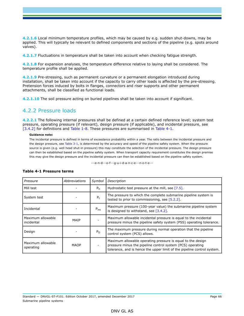
Standard — DNVGL-ST-F101. Edition October 2017, amended December 2017 Page 66Submarine pipeline systems
DNV GL AS
4.2.1.6 Local minimum temperature profiles, which may be caused by e.g. sudden shut-downs, may beapplied. This will typically be relevant to defined components and sections of the pipeline (e.g. spots aroundvalves).
4.2.1.7 Fluctuations in temperature shall be taken into account when checking fatigue strength.
4.2.1.8 For expansion analyses, the temperature difference relative to laying shall be considered. Thetemperature profile shall be applied.
4.2.1.9 Pre-stressing, such as permanent curvature or a permanent elongation introduced duringinstallation, shall be taken into account if the capacity to carry other loads is affected by the pre-stressing.Pretension forces induced by bolts in flanges, connectors and riser supports and other permanentattachments, shall be classified as functional loads.
4.2.1.10 The soil pressure acting on buried pipelines shall be taken into account if significant.
4.2.2 Pressure loads
4.2.2.1 The following internal pressures shall be defined at a certain defined reference level; system testpressure, operating pressure (if relevant), design pressure (if applicable), and incidental pressure, see[3.4.2] for definitions and Table 1-8. These pressures are summarised in Table 4-1.
Guidance note:The incidental pressure is defined in terms of exceedance probability within a year. The ratio between the incidental pressure andthe design pressure, see Table 3-1, is determined by the accuracy and speed of the pipeline safety system. When the pressuresource is given (e.g. well head shut-in pressure) this may constitute the selection of the incidental pressure. The design pressurecan then be established based on the pipeline safety system. When transport capacity requirement constitutes the design premisethis may give the design pressure and the incidental pressure can then be established based on the pipeline safety system.
---e-n-d---o-f---g-u-i-d-a-n-c-e---n-o-t-e---
Table 4-1 Pressure terms
Pressure Abbreviations Symbol Description
Mill test - Ph Hydrostatic test pressure at the mill, see [7.5].
System test - PtThe pressure to which the complete submarine pipeline system istested to prior to commissioning, see [5.2.2].
Incidental - PincMaximum pressure (100-year value) the submarine pipeline systemis designed to withstand, see [3.4.2].
Maximum allowableincidental MAIP - Maximum allowable incidental pressure is equal to the incidental
pressure minus the pipeline safety system (PSS) operating tolerance.
Design - PDThe maximum pressure during normal operation that the pipelinecontrol system (PCS) allows.
Maximum allowableoperating MAOP -
Maximum allowable operating pressure is equal to the designpressure minus the pipeline control system (PCS) operatingtolerance, and is hence the upper limit of the pipeline control system.

Standard — DNVGL-ST-F101. Edition October 2017, amended December 2017 Page 67Submarine pipeline systems
DNV GL AS
4.2.2.2 The local pressure is the internal pressure at a specific point based on the reference pressureadjusted for the fluid column weight due to the difference in elevation. It can be expressed as:
(4.1)
(4.2)
(4.3)
where:
p li = the local incidental pressurep inc = the incidental reference pressure at the reference elevationρcont = the density of the relevant content of the pipelineg = the gravityh ref = the elevation of the reference point (positive upwards)h l = the elevation of the local pressure point (positive upwards)p lt = the local system test pressurep t = the system test reference pressure at the reference elevationρt = the density of the relevant test medium of the pipelinepd = the design pressure at the pressure reference elevationγinc = the incidental to design pressure ratio.
4.2.2.3 In cases where external pressure increases the capacity, the external pressure shall not be takenas higher than the water pressure at the considered location corresponding to low astronomic tide includingpossible negative storm surge.
4.2.2.4 In cases where the external pressure decreases the capacity, the external pressure shall not betaken as less than the water pressure at the considered location corresponding to high astronomic tideincluding storm surge.
4.3 Environmental loads
4.3.1 General
4.3.1.1 Environmental loads are defined as those loads on the pipeline system which are caused by thesurrounding environment, and that are not otherwise classified as functional or accidental loads.
4.3.1.2 Recommended practice for calculation of characteristic environmental loads is given in DNVGL-RP-C205.

Standard — DNVGL-ST-F101. Edition October 2017, amended December 2017 Page 68Submarine pipeline systems
DNV GL AS
4.3.2 Wind loads
4.3.2.1 Wind loads shall be determined using recognised theoretical principles. Alternatively, directapplication of data from adequate tests may be used.
4.3.2.2 The possibility of vibrations and instability due to wind induced cyclic loads shall be considered (e.g.vortex shedding).
4.3.3 Hydrodynamic loads
4.3.3.1 Hydrodynamic loads are defined as flow-induced loads caused by the relative motion between thepipe and the surrounding water.
4.3.3.2 All relevant sources for hydrodynamic loads shall be considered. This may include waves, current,and relative pipe motions and indirect forces e.g. caused by vessel motions.
4.3.3.3 The following hydrodynamic loads shall be considered:
— drag and lift forces which are in phase with the absolute or relative water particle velocity— inertia forces which are in phase with the absolute or relative water particle acceleration— flow-induced cyclic loads due to vortex shedding, galloping and other instability phenomena— buoyancy variations due to wave action.
Guidance note:Research into the hydrodynamic coefficients for open bundles and piggy-back lines indicates that the equivalent diameter approachmay be nonconservative, and a system specific computational fluid dynamics (CFD) analysis may be required to have a robustdesign.
---e-n-d---o-f---g-u-i-d-a-n-c-e---n-o-t-e---
4.3.3.4 The applied wave theory shall be capable of describing the wave kinematics at the particular waterdepth in question including surf zones hydrodynamics where applicable. The suitability of the selected theoryshall be demonstrated and documented.
4.3.3.5 The current-induced drag and lift forces on the submarine pipeline system shall be determined andcombined with the wave-induced forces using recognised theories for wave- current interaction. A vectorcombination of the current and wave-induced water particle velocities may be used, however, calculation ofthe total particle velocities and accelerations based upon more exact theories on wave-current interaction ispreferable.
4.3.3.6 Data from model testing or acknowledged industry practice may be used in the determination of therelevant hydrodynamic coefficients.
4.3.3.7 Consideration shall be given to wave direction, short crested waves, wave refraction and shoaling,shielding and reflecting effects.
4.3.3.8 Variations in current velocity magnitude and direction as a function of water depth shall beconsidered.
4.3.3.9 Where parts of the pipeline system are positioned adjacent to other structural parts, possible effectsdue to disturbance of the flow field shall be considered when determining the wave and/or current actions.Such effects may cause an increased or reduced velocity, or dynamic excitation by vortices being shed fromthe adjacent structural parts.

Standard — DNVGL-ST-F101. Edition October 2017, amended December 2017 Page 69Submarine pipeline systems
DNV GL AS
4.3.3.10 If parts of the submarine pipeline system are built up of a number of closely spaced pipes, theninteraction and solidification effects shall be taken into account when determining the mass and dragcoefficients for each individual pipe or for the whole bundle of pipes. If sufficient data is not available, large-scale model tests may be required.
4.3.3.11 For pipelines on or close to a fixed boundary (e.g. pipeline spans), lift forces perpendicular to theaxis of the pipe and perpendicular to the velocity vector shall be taken into account (possible vortex inducedvibrations).
4.3.3.12 In connection with vortex shedding-induced transverse vibrations, potential increase in dragcoefficient shall be taken into account.
4.3.3.13 Possible increased waves and current loads due to presence of Tee’s, Y’s or other attachments shallbe considered.
4.3.3.14 The increased loads from marine growth shall be considered as follows:
— Increased drag/lift area due to the marine growth— Increased pipe surface roughness and resulting increase in drag coefficient and reduced lift coefficient— Any beneficial effect of the marine growth should be ignored in stability analyses
4.3.3.15 Tide loads shall be considered when the water depth is a significant parameter, e.g. for theestablishment of wave actions, pipe lay operation particularly near shore approaches/landfalls, etc.
4.3.4 Ice loads
4.3.4.1 In areas where ice may develop or drift, the possibility of ice loads on the pipeline system shall beconsidered.
Guidance note:Ice loads may be due to ice frozen on the pipeline system itself, or partly due to floating ice, or combination of these two.
---e-n-d---o-f---g-u-i-d-a-n-c-e---n-o-t-e---
4.3.4.2 The possibility of ice scouring and impacts from drifting ice shall be considered for shore approachesand areas where ice may interfere with the seabed and the submarine pipeline system.
4.3.4.3 Increased hydrodynamic loading due to presence of ice shall be considered.
4.3.4.4 In case of ice frozen to parts of the submarine pipeline system or vessels, (e.g. due to sea spray) thefollowing forces shall be considered:
— weight of the ice— impact forces due to thaw of the ice— forces due to expansion of the ice— increased wind, waves and current forces due to increased exposed area.
4.3.4.5 Forces from floating ice shall be calculated according to recognised theory. Due attention shall bepaid to the mechanical properties of the ice, contact area, shape of structure, direction of ice movements,etc. The oscillating nature of the ice forces (built-up of lateral force and fracture of moving ice) shall be takeninto account. When forces due to lateral ice motion will govern structural dimensions, model testing of theice-structure interaction may be required.

Standard — DNVGL-ST-F101. Edition October 2017, amended December 2017 Page 70Submarine pipeline systems
DNV GL AS
4.3.5 Earthquake
4.3.5.1 Load imposed by earthquake, either directly or indirectly (e.g. due to failure of pipeline gravelsupports), shall be classified as accidental or environmental loads, depending on the probability ofearthquake occurrence in line with accidental loads in [4.6].
4.3.6 Characteristic environmental load effects
4.3.6.1 The characteristic environmental load and the corresponding load effect depend on if the scenariocan be classified as:
— a weather restricted condition, or— an unrestricted condition (temporary condition or permanent condition).
Figure 4-1outlines the procedure for assessing environmental loads.For a weather restricted operation, the environmental load is the minimum of the determined Operation limit(OPLIM) The operation limit may be defined by maximum allowed structural response (e.g. local bucklingin the sag bend), anchor handling capability, safe working conditions on deck, assistance system or anylimitations identified in HAZOP. In case operation limits are stricter for ceasing the operation than for normallaying this should be evaluated in detail. The operation limit is then dependent on vessels and equipmentused.For a non-weather restricted operations the environmental load is based on environmental statistics andtherefore independent on vessel and equipment.

Standard — DNVGL-ST-F101. Edition October 2017, amended December 2017 Page 71Submarine pipeline systems
DNV GL AS
Figure 4-1 Determination of characteristic environmental load
4.3.6.2 Weather restricted operations may start-up based upon reliable weather forecast less than theoperation limit. Uncertainty in the weather forecast for the operational period shall be considered.
Guidance note:For weather restricted operations and example of how to account for the uncertainty in weather forecast reference is made toDNVGL-ST-N001.
---e-n-d---o-f---g-u-i-d-a-n-c-e---n-o-t-e---
4.3.6.3 Operations with a reference period (TR) less than 96 hours and a planned operation period (TPOP)less than 72 hours can be defined as weather restricted. The operation reference period (TR) is the plannedoperation period (TPOP) including contingency time, (TC).
4.3.6.4 An operation can be defined as weather restricted operation even if the planned operation timeexceeds 72 hours provided that the operation can be interrupted and put into a safe condition within themaximum allowable period for a weather restricted operation. The reference period for such operations isdefined as the planned operation period for ceasing the operation, (T’POP), including the contingency time for

Standard — DNVGL-ST-F101. Edition October 2017, amended December 2017 Page 72Submarine pipeline systems
DNV GL AS
ceasing the operation (T’C). The planned operation period for ceasing the operations is defined as the time tosafely cease the operation (TSafe) and the weather forecast intervals (TWF).
4.3.6.5 An operation can be defined as a temporary condition if the duration is less than 6 months unlessdefined as weather restricted conditions. The environmental load effect for temporary conditions shall betaken as the 10-year return period for the actual season.
Guidance note:Conditions exceeding 6 months but no longer than 12 months may occasionally be defined as temporary conditions.
---e-n-d---o-f---g-u-i-d-a-n-c-e---n-o-t-e---
4.3.6.6 Conditions not defined as weather restricted conditions or temporary conditions shall be defined aspermanent conditions. The environmental load effect for permanent conditions shall be taken as the 100-yearreturn period.
4.3.6.7 When considering the environmental design load the most unfavourable relevant combination,position and direction of simultaneously acting environmental loads shall be used in documenting theintegrity of the submarine pipeline system. Functional loads (see [4.2]), interference loads (see [4.5]) andaccidental loads (see [4.6]) shall be combined with the environmental loads as appropriate, see Table 4-3.
4.3.6.8 The characteristic environmental load effect for installation, LE, is defined as the most probablelargest load effect for a given seastate and appropriate current and wind conditions given by:
(4.4)
where:
F(LE) is the cumulative distribution function of LE, and N is the number of load effect cycles in a sea-stateof a duration not less than 3 hours.
4.3.6.9 The most critical load effect combination for the relevant return period shall be used. When thecorrelations among the different environmental load components (i.e. wind, wave, current or ice) areunknown the characteristic combined environmental loads in Table 4-2 may be used.
Table 4-2 Combinations of characteristic environmental loads in terms of return period 1)
Wind Waves Current Ice Earthquake
Permanent condition
100-year 100-year 10-year
10-year 10-year 100-year
10-year 10-year 10-year 100-year
10-year 10-year 10-year 100-year2)
Temporary condition
10-year 10-year 1-year
1-year 1-year 10-year

Standard — DNVGL-ST-F101. Edition October 2017, amended December 2017 Page 73Submarine pipeline systems
DNV GL AS
1-year 1-year 1-year 10-year
1-year 1-year 1-year 10-year2)
1) This is in compliance with ISO 16708, but in conflict with ISO 13623 in case the design life is less than 33 years.2) Special attention shall be given to potential waves or current induces by earthquakes.
4.4 Construction loads
4.4.1 General
4.4.1.1 Loads which arise as a result of the construction and operation of the submarine pipeline systemshall be classified into functional and environmental loads.
4.4.1.2 Construction loads include:
— stacking of pipes— pipe transportation loads— handling of pipe and pipe sections, e.g. lifting of pipe, pipe joints, pipe strings and pipe spools, and reeling
of pipe strings— static and dynamic installation loads— pull-in at landfalls, tie-ins, trenching etc.— pressure testing— commissioning activities, e.g. increase in pressure differential due to vacuum drying— dynamic loads from pre-commissioning activities, e.g. flooding and de-watering with pigs.
4.4.1.3 Inertia loads due to sudden water filling, excessive deformation in overbend and sagbend, and forcesdue to operation errors or failures in equipment that could cause or aggravate critical conditions shall beconsidered, see [10.1.3].
Guidance note:The design criteria for such considerations will depend on the likelihood of the scenario. In case the likelihood is less than once inhundred years, it can be considered as an accidental limit state and be checked in accordance with [5.4.10], else a normal ULScheck apply.
---e-n-d---o-f---g-u-i-d-a-n-c-e---n-o-t-e---
4.4.1.4 For construction loads imposed by geometrical tolerances, extreme tolerances may be taken asmean ± 3 standard deviations of the combined tolerances.
4.5 Interference loads
4.5.1 General
4.5.1.1 Loads which are imposed on the pipeline system from 3rd party activities shall be classified asinterference loads. Typical interference loads include trawl interference, anchoring, vessel impacts anddropped objects.
4.5.1.2 The requirement for designing the submarine pipeline system for interference loads shall bedetermined based upon interference frequency studies and assessment of the potential damage. If theprobability of occurrence is less than 10-2 within a year the load shall be classified as accidental load, see[4.6].

Standard — DNVGL-ST-F101. Edition October 2017, amended December 2017 Page 74Submarine pipeline systems
DNV GL AS
4.5.1.3 The trawling loads can be divided in accordance with the three crossing phases:
— Trawl impact, i.e. the initial impact from the trawl board or beam which may cause local dents on the pipeor damage to the coating.
— Over-trawling, often referred to as pull-over, i.e. the second phase caused by the wire and trawl board orbeam sliding over the pipe. This will usually give a more global response of the pipeline.
— Hooking, i.e. the trawl board is stuck under the pipe and in extreme cases, forces as large as the breakingstrength of the trawl wire are applied to the pipeline.
Each of the three types of trawling loads shall be classified as an ULS or an ALS dependent on theirfrequency. Hooking becomes then often an accidental load.
4.5.1.4 Recommended practice for calculations of trawl interference loads is given in DNVGL-RP-F111 Sec.4.
4.5.1.5 The trawl impact energy shall be determined considering, as a minimum:
— the trawl gear mass and velocity— the effective added mass and velocity.
The impact energy shall be used to determine the required testing energy for testing for the coating andpossible denting of the pipeline wall thickness. In case piggy-back lines these shall also have adequate safetyagainst trawl impacts.
4.5.1.6 Other 3rd party interference loads shall be calculated using recognised methods.
4.6 Accidental loads
4.6.1 General
4.6.1.1 Loads which are imposed on a pipeline system under abnormal and unplanned conditions and with aprobability of occurrence less than 10-2 within a year shall be classified as accidental loads.
4.6.1.2 Typical accidental loads can be caused by:
— extreme wave and current loads— vessel impact or other drifting items (collision, grounding, sinking, iceberg)— dropped objects— infrequent internal over pressure (e.g. in case of malfunction of HIPPS)— seabed movement and/or mud slides— explosion— fire and heat flux— accidental water filling due to wet buckle— operational malfunction— dragging anchors.
4.6.1.3 Recommended practice for size and frequency of accidental loads is given in DNVGL-RP-F107.
4.7 Design load effects
4.7.1 General
4.7.1.1 A load effect is the resulting cross-sectional loads arising as response to applied loads (e.g. weight,pressure, drag).

Standard — DNVGL-ST-F101. Edition October 2017, amended December 2017 Page 75Submarine pipeline systems
DNV GL AS
4.7.1.2 The magnitude of a time variant load effect to be used in a limit state criterion is defined by itsprobability of being exceeded, the characteristic load effect.
4.7.2 Characteristic load
4.7.2.1 The characteristic load effect is a quantified load effect to be used in the design load effectcalculation. The characteristic load for time invariant loads is the nominal (average) load. The characteristicload for time variant loads is given in [4.3.6].
4.7.2.2 The characteristic load effect is composed of contributions of functional, environmental andinterference load effects.
4.7.2.3 For non-weather restricted operations, the characteristic load shall be the most critical 100-year loadeffect
Guidance note:The 100-year load effect implies a probability of exceedance less than 10-2 within a year.
---e-n-d---o-f---g-u-i-d-a-n-c-e---n-o-t-e---
4.7.2.4 The most critical 100-year load effect is normally governed by extreme functional, extremeenvironmental, extreme interference or accidental load effect. Unless special evaluation is carried out toidentify the most critical 100-year load effect, the characteristic load effects in Table 4-3 shall be used.
4.7.2.5 In addition to the characteristic loads defined above, the fatigue load case shall also be checked, seeTable 4-3.
Table 4-3 Characteristic loads
Extreme Load Load effect factorcombination 1)
Functionalload Environmental load Interference
load Accidental load
Functional load effect a, b 100-year2) 1-year Associated NA
Environmental loadeffect
a, b Associated3) 100-year4) Associated NA
Interference loadeffect
b Associated3) Associated UB NA
Fatigue load effect5) c Associated Associated Associated NA
Accidental load effect d Associated Associated Associated BE

Standard — DNVGL-ST-F101. Edition October 2017, amended December 2017 Page 76Submarine pipeline systems
DNV GL AS
Characteristic load definition:
— n-year: most probable maximum in n years— UB: upper bound— BE: best estimate.
1) The referred load effect factor combinations are given in Table 4-4.2) This will normally be equivalent to an internal pressure equal to the local incidental pressure combined with
expected associated values of other functional loads.3) This will normally be equivalent to an internal pressure and temperature not less than the operating pressure and
the operating temperature profiles.4) As defined in Table 4-2.5) The fatigue load cases are;
a) cyclic functional loading (start-up and shut-down, pressure and temperature cycles shall be represented),b) random environmental load (e.g. wave and current spectra, conservative pressure and temperature for the
fatigue damage shall be used) andc) repeated interference loading (conservative pressure and temperature for the fatigue damage shall be used)
4.7.3 Design load effect
4.7.3.1 Each limit state, see [5.4], shall be checked for the design load effect.
4.7.3.2 The design load effect can generally be expressed in the following format:
(4.5)
In specific forms, this corresponds to:
(4.6)
(4.7)
(4.8)
Guidance note:The load combinations to the left are referred to explicitly in the limit state criteria, e.g. Equation (5.19).
---e-n-d---o-f---g-u-i-d-a-n-c-e---n-o-t-e---
4.7.3.3 The design load effect shall be calculated for the characteristic load (see [4.7.2]) for all relevant loadeffect combinations and corresponding load effect factors in Table 4-4.

Standard — DNVGL-ST-F101. Edition October 2017, amended December 2017 Page 77Submarine pipeline systems
DNV GL AS
Guidance note:The partial safety factors in this standard have been determined by structural reliability methods to a pre-defined failureprobability. Structural reliability calculations differentiate between single joint failures (local checks) and series system failures(system effects).These two kinds of scenarios are expressed as two different load effect combinations:
a) shall only be considered for scenarios where system effects are present
b) for local scenarios and shall always be considered.
When system effects are present, the pipeline will fail at its weakest point. Hence, the likely load shall be combined with theextreme low resistance. Applied to pipelines system effect can be expressed as the weakest link principle (where the chain getsweaker the longer the chain is). This is characterised by that the whole pipeline is exposed to the same load over time.Applied to pipelines, system effects are present for:
— pressure containment
— collapse, in as installed configuration
— installation.
The first two are handled by the use of thickness t1. This is also why thickness t2 and not t1 is used for the burst capacity in thelocal buckling for pressurised pipes, since it is a local check.Regarding installation, an extreme environmental load is not likely to occur when the weakest pipe section is at the most exposedlocation indicating that system effects not are present. However, combined with a more representative environmental load (in theextreme case, flat sea), the whole pipeline will undergo the same deformation over time, hence, having a system effect present.In Table 4-4, load effect factor combination a has a load effect factor of 1.2 for the functional load to cover the system effectcombined with a 0.7 load effect factor for the extreme environmental load giving a more representative environmental load,applicable for the above.Another example of where system effects are present is for reeling where the whole pipe is exposed to the same deformation(neglecting the variation in drum diameter increase). For this application, a condition load factor of 0.82 applies, giving the totalload effect factor of 1.2 × 0.82 close to unity.Hence, load combination b shall always be checked while load combination a normally is checked for installation only.
---e-n-d---o-f---g-u-i-d-a-n-c-e---n-o-t-e---
Table 4-4 Load effect factor combinations
Load effect combination Functionalloads 1) Environmental load Interference
loads Accidental loadsLimit state/loadcombination
γ F γ E γ F γ A
a System check2) 1.2 0.7 ULS
b Local check 1.1 1.3 1.1
FLS c 1.0 1.0 1.0
ALS d 1.0 1.0 1.0 1.0
1) If the functional load effect reduces the combined load effects, γF shall be taken as 1/1.1.2) This load effect factor combination shall only be checked when system effects are present, i.e. when the major part
of the pipeline is exposed to the same functional load. This will typically only apply to pipeline installation.
4.7.3.4 The condition load effect factor applies to the conditions in Table 4-5. Condition load effect factorsare in addition to the load effect factors and are referred to explicitly in Equation (4.5) - Equation (4.8).
Guidance note:Uneven seabed refers to pipeline resting on the seabed and not to installation on un-even seabed. Several condition factors may berequired simultaneously, e.g. for pressure testing of pipelines on seabed, the resulting condition factor will be 1.07 · 0.93 = 1.00.
---e-n-d---o-f---g-u-i-d-a-n-c-e---n-o-t-e---

Standard — DNVGL-ST-F101. Edition October 2017, amended December 2017 Page 78Submarine pipeline systems
DNV GL AS
Table 4-5 Condition load effect factors, γC
Condition γc
Pipeline resting on uneven seabed 1.07
J-tube pull-in 1 0.82
System pressure test 0.93
S-lay installation; Local buckling load control check on stinger2 0.80
Reeling installation; Displacement controlled check, seamless pipes2 0.77
Reeling installation; Displacement controlled check, welded pipes2,3 0.82
Otherwise 1.00
1) Load combination a needs not to be analysed2) For installation both load combination a and b shall always be analysed, see also [5.8.2]3) This factor has not been re-assessed but reflects the less uniform material properties around the circumference
4.7.4 Load effect calculations
4.7.4.1 The load effect calculations shall be based on accepted principles of statics, dynamics, strength ofmaterials and soil mechanics.
4.7.4.2 Industry recognised calculations tools, or tools documented to provide corresponding results, shouldbe used for design and construction analyses of the submarine pipeline system.
4.7.4.3 Model tests may be used in combination with, or instead of, theoretical calculations. In cases wheretheoretical methods are inadequate, model or full-scale tests may be required.
4.7.4.4 The dynamic effect shall be taken into account when determining responses to dynamic loads.
4.7.4.5 Load effects shall be split into functional, environmental, interference and accidental load effects.
4.7.4.6 The effect of statistical uncertainty due to the amount and accuracy of data shall be assessed and, ifsignificant, shall be included in the evaluation of the characteristic load effect.
4.7.4.7 Load effect calculation should be performed applying nominal (non-corroded) cross-section valuesunless otherwise required by the standard or recommended practice. For displacement controlled conditionsthis may be non-conservative and should be evaluated. For pipelines with internal clad or liner the bendingstiffness contribution should be included in the load effect calculations.
4.7.4.8 Special attention shall be given to ensure that conservative load effect calculations are performed,implying that the applied cross-section values are conservative. In case larger positive wall thicknesstolerances are agreed (see Table 7-20 and Table 7-21) it should be noted that larger steel cross-sectionalarea will generate larger expansion forces.
4.7.4.9 The effective axial force that determines the global response of a pipeline is denoted S. Countingtensile force as positive:

Standard — DNVGL-ST-F101. Edition October 2017, amended December 2017 Page 79Submarine pipeline systems
DNV GL AS
(4.9)
4.7.4.10 The effective axial force of a totally restrained pipe in the linear elastic stress range based on thickwall stress formulation is:
(4.10)
where:
H = effective (residual) lay tension. The effective axial force in the as-laid condition when the pipetemperature and pressure is equal to as during laying.
Δ pi = internal pressure difference relative to as laidΔΤ = temperature difference relative to as laid
4.7.4.11 When non-linear material is required in the analyses for load controlled limit states the stress-strain curve shall be based on specified minimum values accounting for temperature de-rating (fy and fu)considered being engineering stress values. For displacement controlled or partially displacement controlledlimit states additional analyses based on mean or upper bound stress-strain curves may be required toensure an acceptable safety level. Illustration of different stress-strain properties is given in Table 1-8.
Guidance note:The strain at fu is normally considerably less than the fracture strain and is normally in the order of 6 to 10%. This may bedetermined from tests of similar material.
---e-n-d---o-f---g-u-i-d-a-n-c-e---n-o-t-e---
4.7.4.12 Stress concentration factors (SCF) and strain concentration factors (SNCF) may be applied to thecalculated load effects to reflect different aspects (local geometries, coating, variations in properties) notcaptured directly in the load effect calculation.
4.7.4.13 SCF's are mainly used in the linear material range and SNCF's in the non-linear material range.These may reflect local or global effects.
4.7.4.14 SNCF shall be adjusted for the non-linear stress-strain relationship for the relevant load level.Plastic strain shall be calculated from the point where the material stress-strain curve deviates from a linearrelationship, see Table 1-8
4.7.4.15 Local SCF's and SNCF's may be applied to reflect:
— variations in actual material yield stress and strain hardenability between pipeline joints and in the weldmetal
— local discontinuities in the weld— welded attachments
4.7.4.16 Global SCF's and SNCF's may be applied to reflect:
— stiffening effects of coating and variations in coating thickness— variations in cross-sectional area between pipe joints not included in the load effect calculations.

Standard — DNVGL-ST-F101. Edition October 2017, amended December 2017 Page 80Submarine pipeline systems
DNV GL AS
Most of these effects should be captured by the load effect calculations (like nominal diameter or nominalwall thickness difference between pipe joints e.g. buckle arrestor or wall thickness change due to safetyzone).
4.7.4.17 Application of SCF and SNCF depend on the limit state and shall be applied according to Table 4-6.
Table 4-6 Application of stress concentration factors and strain concentration factors
Stress concentration factors (SCF) Strain concentration factors (SNCF)
Limit state Local Global Local Global
Load controlled localbuckling
- - - -
Displacementcontrolled localbuckling
- Yes - -
Fatigue Yes1 Yes1 Yes1 Yes1
Fracture Yes Yes Yes Yes
1) The use of SCF/SNCF shall be consistent with the SN-curve used
4.7.4.18 Recommended practice for calculation of the SNCF/SCF for fracture assessment is given in DNVGL-RP-F108.

Standard — DNVGL-ST-F101. Edition October 2017, amended December 2017 Page 81Submarine pipeline systems
DNV GL AS
SECTION 5 DESIGN – LIMIT STATE CRITERIA
5.1 General
5.1.1 Objective
5.1.1.1 This section provides limit state criteria and general requirements for the submarine pipelinesystems.
5.1.2 Application
5.1.2.1 This standard includes no limitations on water depth. However, when this standard is applied in deepwater where experience is limited, special consideration shall be given to:
— other failure mechanisms than those given in this section— validity of parameter range (environmental/design/operational parameters)— dynamic effects.
5.1.2.2 This standard does not specify any explicit limitations with respect to elastic displacements orvibrations, provided that the effects of large displacements and dynamic behaviour, including fatigue effect ofvibrations, operational constraints and ratcheting, are taken into account in the strength analyses and foundacceptable.
5.1.2.3 This standard does not specify any limitations on pipe geometries but some limit states weredeveloped for a limited geometry and load range that is stated with the criterion. For geometries and loadsoutside these limits, criteria need to be developed in accordance with the safety philosophy in Sec.2.
5.1.2.4 The local buckling limit states, see [5.4.3] to [5.4.6], are only applicable to pipelines that arestraight in stress-free condition and are not applicable to e.g. bends.
5.1.2.5 For parts of the submarine pipeline system which extend onshore complementary requirements aregiven in App.F.
5.1.2.6 For spiral welded pipes, the following additional limitations apply:
— when supplementary requirement F (fracture arrest properties) is specified, see Sec.7, the possibility fora running fracture to continue from a weld in one pipe joint to the weld of the next pipe joint shall beassessed
— external pressure resistance should be documented— the design shall be based on the load controlled condition, see [5.4.6], unless the feasibility for use of
displacement controlled condition can be documented.Guidance note:The limitations to fracture arrest and load controlled condition are due to limited experience with spiral welded pipes subjected torunning fracture or large strains.
---e-n-d---o-f---g-u-i-d-a-n-c-e---n-o-t-e---
5.1.3 Systematic review
5.1.3.1 The overall requirement to systematic review in Sec.2 implies for this section:
— A clear definition of code break between components and pipeline system.— Clear definition of the codes’ pressure definitions correspondence.

Standard — DNVGL-ST-F101. Edition October 2017, amended December 2017 Page 82Submarine pipeline systems
DNV GL AS
— A clear description of the overall system including interfaces and responsibilities, covering both temporaryand permanent phases.
— An overall review of all potential failure modes shall be conducted.— The structural integrity and functionality of pipeline components shall comply with the safety requirements
for the connected pipeline system see Sec.2.— Pre-commissioning activities.
Guidance note:The above will include a HAZID of the installation activity to identify potential impact on design such as selection of safety classduring installation (see [10.6.7]).
---e-n-d---o-f---g-u-i-d-a-n-c-e---n-o-t-e---
5.2 System design requirements
5.2.1 Submarine pipeline system layout
5.2.1.1 Pipelines shall be protected against impact loads from mechanical interaction.
5.2.1.2 Crossing between pipelines and pipelines or cables should be kept separated by a minimum verticaldistance of 0.3 m. Potential electrical interference and associated consequences between pipelines and cablesshall be considered.
5.2.1.3 The submarine pipeline system shall be protected against unacceptable damage caused by e.g.dropped objects, fishing gear, ships, anchoring etc. Protection may be achieved by one or a combination ofthe following means:
— concrete coating— burial— cover (e.g. sand, gravel, mattress)— other mechanical protection.
5.2.1.4 Relative settlement between the protective structure and the submarine pipeline system shall beproperly assessed in the design of protective structures, and shall cover the full design life of the submarinepipeline system. Adequate clearance between the pipeline components and the members of the protectivestructure shall be provided to avoid fouling.
5.2.1.5 Attachment to pipeline and other pressure containing parts should be welded via doubler plate andnot directly to the pipe/pressure containing parts. Doubler plate should be fully encircling sleeves, if not,it shall be circular. The objective of the doubler plate is to distribute stresses in order to reduce the risk ofinitiating cracks into the pipe.
5.2.1.6 For structural items welded directly to pressure containing parts and doubler plates the followingapply:
— Design shall be performed for all relevant failure modes, e.g. yielding, fatigue and fracture.— For duplex stainless steels and 13Cr martensitic stainless steels a stress analysis shall be performed in
each case to determine that local stresses will not initiate HISC. Recommended practice for design ofduplex stainless steels is given in DNVGL-RP-F112.
— Welding directly to the pressure containing parts shall be performed in accordance with qualified weldingprocedures according to App.C.
— NDT shall be performed to ensure structural integrity of the pressure containing parts.— The toe-to-toe distance from other welds shall be minimum 2 · t or 50 mm, whichever is larger.

Standard — DNVGL-ST-F101. Edition October 2017, amended December 2017 Page 83Submarine pipeline systems
DNV GL AS
5.2.1.7 For doubler plates the following apply:
— The longitudinal welds of fully encircling sleeves shall be made with backing strips avoiding penetrationinto the main pipe material unless pre-fabricated and slid onto the pipe.
— Welds between doubler plates and pressure containing parts shall be continuous, and made in a mannerminimising the risk of root cracking and lamellar tearing.
5.2.1.8 Girth welds should not be covered under doubler plates, clamps, or other items.The requirement to not cover the girth weld is to allow for required NDT, corrosion protection (coating,anodes or premises for other corrosion evaluations) and leakage detection during FAT testing. For FAT testingbased on pressure drop, see [8.7.4], the encircling sleeve is not allowed to constitute a pressure barrier, i.e.pressure built up in the void shall be monitored or avoided.
5.2.1.9 The use of mitre welds to correct angular misalignment of more than 2 degrees between the axisof two adjoining pipes is not permitted and a series of purpose made misalignments are not allowed toconstitute a bend. Moments caused by the axial misalignment and axial force shall be evaluated. For loadscausing yielding, detailed calculations shall be made.
5.2.1.10 For requirements to transitions, see [5.6.1.13] through [5.6.1.16].
5.2.1.11 For piggable components the internal diameter of the component shall meet the requirementsimposed by the pig-train.
Guidance note:It is recommended that bends radius are designed with a radius not less than 5 × nominal internal pipe diameter (5D bend).
3D bends may be acceptable if PIG is designed for it, typically taking into account:
— length of the pig
— pig-body diameter
— position of the seal- and guide-discs
— material and size of the discs
— position of the gauge-plate.
In addition, a trial fit to be performed.
---e-n-d---o-f---g-u-i-d-a-n-c-e---n-o-t-e---
5.2.2 Pressure test philosophy and criteria
5.2.2.1 The pressure containment structural integrity of the pipeline system is ensured by:
— design criteria and safety factors— manufacturing requirements— pressure testing all pressure containing parts by
— strength test prior to being installed in the pipeline system; by strength pressure test (mill pressuretest for pipe joints [7.5.1] and FAT/hydrostatic test for components [8.7]), or through qualificationprograms and
— gross error leak test; system pressure test ([5.2.2.2] and [10.10.3]) and hydrostatic test for pipelineassemblies [7.5.1]. For single connections, making up parts of the pipelines after system pressure test,the following apply:
— girth welds shall have additional NDT (Golden Weld), see [10.5.3]— mechanical components shall be back seal tested after installation.
Unless waived by [5.2.2.3] or [7.5.1.6].

Standard — DNVGL-ST-F101. Edition October 2017, amended December 2017 Page 84Submarine pipeline systems
DNV GL AS
Guidance note:The above requirements imply that each element of the pipeline system shall be both strength tested and gross error leak tested.A typical pressure test regime may look like indicated in the following figure:
The following comments apply:
— Tie-in flanges and couplings may be back-seal tested in order to reveal any leakage as early as possible. If these are not partof the system pressure test, back seal test shall be performed.
— Pipeline assemblies (risers, spools etc.) may be hydrostatically leak tested as a risk reducing measure in order to reveal anyleakage as early as possible. If these pipeline assembles are not part of the system pressure test, hydrostatic leak test shall beperformed.
The expressions related to the system pressure test have been altered over a few revisions but are now referred to as leakagetest. The reason why it is now considered being a leakage test is that the girth weld, which is the only part not previously tested,has a very low utilisation during the system pressure test, less than 48% of SMYS and is therefore very unlikely to fail structurally.The reason why this term has changed of the revisions is that ISO 13623 operates with two pressure levels for the systempressure test (pressure test). The strength test is 1.25 times the design pressure and shall be kept for a minimum of 1 hour. Theleak test is 1.1 times the design pressure and shall be kept for a minimum of 8 hours.DNVGL-ST-F101 only operates with one pressure level 1.05 times the incidental pressure (1.15 times the design pressure) whichshall be kept for minimum 24 hours.
---e-n-d---o-f---g-u-i-d-a-n-c-e---n-o-t-e---
5.2.2.2 The pipeline system shall be system pressure tested after installation in accordance with [10.10.3]unless this is waived by agreement in accordance with [5.2.2.3] below. The local test pressure (plt) duringthe system pressure test should fulfil the following requirement for the safety class during normal operation:
plt ≥ αspt pli (5.1)
αspt see Table 5-8.Note that a system test pressure less than the above may reduce the allowable incidental pressure as givenby Equation (5.6) and Equation (5.7).

Standard — DNVGL-ST-F101. Edition October 2017, amended December 2017 Page 85Submarine pipeline systems
DNV GL AS
Guidance note:With an incidental pressure of 10% above design pressure, the above gives a system test pressure of approximately 1.15 timesthe local design pressure (for safety class medium and high) at the highest point (given that the test medium density is higher
than αspt * density of the medium in operation of the pipeline system part tested), see Table 1-8.
---e-n-d---o-f---g-u-i-d-a-n-c-e---n-o-t-e---
Figure 5-1 Illustration of local pressures and requirements to system pressure test
5.2.2.3 For pipelines where the disadvantages with the system pressure test are extraordinary, alternativemeans to ensure the same level of integrity as with the system pressure test are allowed by agreement.Alternative means to the system pressure test may be considered when all the following criteria have beenmet:
— The pipeline section does not contain non-welded connections unless these have been separately testedafter installation in the pipeline system.
— The mill pressure test requirement of [7.5.1] has been met and not waived in accordance with [7.5.1.6].— Extensive experience with similar pipelines documenting a good track record with respect to defects and
leakages during system pressure test. This implies that:
— Only C-Mn steel pipelines with a steel grade less than - or equal to X70 may be considered.— Only pipelines consisting of seamless or SAW pipe joints may be considered.— Welding, including repair, by cellulosic electrodes is not allowed.— The pipeline shall not be exposed to nominal tensile longitudinal strains above 0.4% from mill testing
to commissioning.
5.2.2.4 The alternative means shall be established by use of a systematic approach, e.g. FMECA. It shall bedemonstrated that the identified failure modes, i.e. the gross errors and defects which may be revealed bythe system pressure test, will be mitigated or revealed by the alternative means.

Standard — DNVGL-ST-F101. Edition October 2017, amended December 2017 Page 86Submarine pipeline systems
DNV GL AS
5.2.2.5 A risk assessment shall be carried out addressing not only the risk related to the elements of theabove systematic approach, but also other aspects that are affected by replacing the system pressure test.Typical other aspects include consequences of accidental water ingress during construction, cleaning of pipe,interfaces and contractual issues. The systematic approach and the risk assessment shall lead to a technicalassurance program that is implemented and followed up in all relevant phases.
5.2.2.6 During system pressure test, all limit states for safety class low shall be satisfied, see [5.4].
5.2.2.7 Recommended practice for system pressure test including all pre-commissioning activities is given inDNVGL-RP-F115.
5.2.3 Monitoring/inspection during operation
5.2.3.1 The parameter safety envelope established in the conceptual phase, see [3.3.1] and [5.4.2], shallbe extended/modified in the design phase by the parameters which could violate limit states of a pipelinesystem. These shall be monitored, inspected and evaluated with a frequency which enables remedial actionsto be carried out before the system is damaged, see Sec.11.
Guidance note:As a minimum the monitoring/inspection frequency should be such that the pipeline system will not be endangered due to anyrealistic degradation/deterioration that may occur between two consecutive inspection intervals.
---e-n-d---o-f---g-u-i-d-a-n-c-e---n-o-t-e---
5.2.3.2 Special focus shall be on monitoring and inspection strategies for live pipeline systems i.e. pipelinesystems that are designed to change the configuration during its design life.
Guidance note:Example of such systems may be pipelines that are designed to experience global buckling or possible free-span developments orpotential pipeline walking.
---e-n-d---o-f---g-u-i-d-a-n-c-e---n-o-t-e---
5.2.3.3 Instrumentation of the pipeline system may be required when visual inspection or simplemeasurements are not considered practical or reliable, and available design methods and previous experienceare not sufficient for a reliable prediction of the performance of the system.
5.2.3.4 Operating requirements affecting safety and reliability of the pipeline system shall be identifiedduring the design phase, and shall be documented in the DFI Resumé and reflected in the PIM system.
5.3 Design format
5.3.1 General
5.3.1.1 The design format in this standard is based on a load and resistance factor design (LRFD) format.
5.3.1.2 The fundamental principle of the LRFD format is to verify that design load effects, LSd, do not exceeddesign resistances, RRd, for any of the considered failure modes in any load scenario:
(5.2)

Standard — DNVGL-ST-F101. Edition October 2017, amended December 2017 Page 87Submarine pipeline systems
DNV GL AS
Where the fractions i denotes the different loading types that enters the limit state.
5.3.1.3 A design load effect is obtained by combining the characteristic load effects from the different loadcategories and certain load effect factors, see [4.7].
5.3.1.4 A design resistance is obtained by dividing the characteristic resistance by resistance factors thatdepends on the safety class, reflecting the consequences of failures, see [5.3.2].
5.3.1.5 Design criteria in this standard are based on pipe statistical properties resulting from constructionbased on this standard.
Guidance note:Use of e.g. other line pipe specifications need therefor to be assessed
---e-n-d---o-f---g-u-i-d-a-n-c-e---n-o-t-e---
5.3.2 Design resistance
5.3.2.1 The design resistance, RRd, can generally be expressed in the following format:
(5.3)
where:
Rc = the characteristic resistancefc = the characteristic material strength, see Equation (5.4) and Equation (5.5)tc = the characteristic thickness, see Table 5-5 and Table 5-6O0 = the out of roundness of the pipe, prior to loadingγm = the material factor (not used for displacement controlled criteria), see Table 5-1γSC,i = the partial resistance factor, see Table 5-2
5.3.2.2 Ovality of the pipeline is defined in Equation (5.14). This will affect the structural capacity of thepipeline and shall be taken as the maximum ovality prior to loading. Advantage of an ovality less than 0.5%is not allowed. Ovality in excess of 3% shall be assessed in line with [5.4.12].
5.3.2.3 The material resistance factor, γm, is dependent on the limit state category and is defined in Table5-1.
Table 5-1 Material resistance factor, γm
Limit state category1) SLS/ULS/ALS FLS
γ m 1.15 1.00
1) The limit states (SLS, ULS, ALS and FLS) are defined in [5.4].
5.3.2.4 Based on potential failure consequences the pipeline shall be classified into a safety class see[2.3.4]. This will be reflected in the safety level by the safety class resistance factor γSC,i given in Table 5-2.

Standard — DNVGL-ST-F101. Edition October 2017, amended December 2017 Page 88Submarine pipeline systems
DNV GL AS
Guidance note:The safety class may vary for different phases and different locations.The safety class resistance factors for pressure containment as listed in Table 5-2 are based on the corresponding hoop stressdesign factors for offshore pipelines as given in the referenced ISO 13623 standard for pipeline transport systems. As such thebursting utilisation using this document will be in line with what has been the industry practice for decades and represents a failurerate for such pipeline systems that has been perceived as acceptable for all stakeholders including the society at large. When itcomes to other failure modes/limit states calibration of safety factors using structural reliability analyses has concluded with thesame safety class resistance factors as for pressure containment for safety classes Low and Medium while a slightly different valuefor safety class High.DNVGL-ST-F201 utilises the same safety class resistance factor for all failure modes/limit states within the same safety class,i.e. it does not make any difference between pressure containment and the other limit states. The main reason for this differencetowards this standard is that DNVGL-ST-F201 refers to another ISO standard than this standard, namely the ISO 13628-7 for WO/C risers which has a somewhat different burst criterion than ISO 13623 and is allowing a somewhat higher utilisation with respectto bursting.As such the different safety class resistance factors for pressure containment and safety class high in this standard and DNVGL-ST-F201 are explained by the different utilisation in the underlying ISO standards. Another more practical explanation is that it can beclaimed that the system effect is more significant for a pipeline in location class 2 than for a riser. For a riser it is typically just afew joints in the splash zone that is most heavily utilised, while for a pipeline it is normally the whole length in the location class 2.
---e-n-d---o-f---g-u-i-d-a-n-c-e---n-o-t-e---
Table 5-2 Safety class resistance factors, γ SC
Safety classLimit state Safety class
resistance factor Low Medium High
Pressure containment1)
γ SC,PC 1.046 2),3) 1.138 1.308 4)
Local buckling,collapse and loadcontrolled
γ SC,LB 1.04 1.141.26
Local buckling,displacementcontrolled
γ SC,DC 2.0 2.53.3
1) The number of significant digits is given in order to comply with the ISO usage factors.2) Safety class low will be governed by the system pressure test which is required to be 3% above the incidental
pressure. Hence, for operation in safety class low, the resistance factor will effectively be minimum 3% higher.3) For system pressure test, αU shall be equal to 1.00, which gives an allowable hoop stress of 96% of SMYS both for
materials fulfilling supplementary requirement U and those not.4) For parts of pipelines in location class 1, resistance safety class medium may be applied (1.138).
5.3.2.5 Possible beneficial strengthening effect of weight coating on a steel pipe shall not be taken intoaccount in the characteristic resistance, unless the strengthening effect is documented. Coating which addssignificant bending stiffness to the pipe may increase the stresses/strains in the pipe at any discontinuity inthe coating (e.g. at field joints). When appropriate, this effect shall be taken into account.
5.3.2.6 Possible beneficial strengthening effect of cladding or liner on a steel pipe shall not be taken intoaccount in the characteristic resistance, unless the strengthening effect is documented.

Standard — DNVGL-ST-F101. Edition October 2017, amended December 2017 Page 89Submarine pipeline systems
DNV GL AS
5.3.3 Characteristic material properties
5.3.3.1 Characteristic material properties shall be used in the resistance calculations. The yield stress andtensile strength in the limit state formulations shall be based on the engineering stress-strain curve.
5.3.3.2 The characteristic material strength fy and fu, values to be used in the limit state criteria are:
(5.4)
(5.5)
Where:
f y,temp and fu,temp = the de-rating values due to the temperature of the yield stress and the tensile strengthrespectively, see [5.3.3.4].
α U = the material strength factor, see Table 5-3.
5.3.3.3 The different mechanical properties refer to room temperature unless otherwise stated.
5.3.3.4 The material properties shall be selected with due regard to material type and potential temperatureand/or ageing effects and shall include:
— yield stress— tensile strength— Young's modulus— temperature expansion coefficient.
For C-Mn steel and 13Cr this shall be considered for temperatures above 50°C, and for 22Cr and 25Cr fortemperatures above 20°C.
Guidance note:Field joint coating application during installation may also impose temperatures in excess of the above.
---e-n-d---o-f---g-u-i-d-a-n-c-e---n-o-t-e---
Guidance note:If no other information of de-rating effects on the yield stress exist the recommendations for C-Mn steel, 22Cr and 25Cr Figure 5-2may be used. For 13Cr testing is normally required.
---e-n-d---o-f---g-u-i-d-a-n-c-e---n-o-t-e---
Guidance note:If no other information on de-rating effect of the ultimate stress exists, the de-rating of the yield stress can be conservativelyapplied.
---e-n-d---o-f---g-u-i-d-a-n-c-e---n-o-t-e---

Standard — DNVGL-ST-F101. Edition October 2017, amended December 2017 Page 90Submarine pipeline systems
DNV GL AS
Figure 5-2 Proposed de-rating values for yield stress of C-Mn, 13Cr, 22Cr and 25Cr
5.3.3.5 Any difference in the de-rating effect of temperature for tension and compression shall be accountedfor.
Guidance note:Difference in de-rating effect for tension and compression has been experienced on 13Cr steel material.
---e-n-d---o-f---g-u-i-d-a-n-c-e---n-o-t-e---
5.3.3.6 The material strength factor, αU, depend on supplementary requirement U as shown in Table 5-3. Forupgrade of material, see [7.9.5]
Table 5-3 Material strength factor, αU
Loading scenario α U
Normal Supplementary requirement U
System pressure test 1.00 1.00
Other 0.96 1.00
5.3.3.7 For manufacturing processes which introduce cold deformations giving different strength in tensionand compression, a fabrication factor, αfab, shall be determined. If no other information exists, maximumfabrication factors for pipes manufactured by specific processes are given in Table 5-4.The fabrication factor may be increased through heat treatment or external cold sizing (compression), ifdocumented.

Standard — DNVGL-ST-F101. Edition October 2017, amended December 2017 Page 91Submarine pipeline systems
DNV GL AS
Table 5-4 Maximum fabrication factor, α fab
Pipe Seamless UO, TRB, ERW and HFW UOE
α fab 1.00 0.93 0.85
5.3.4 Characteristic wall thickness
5.3.4.1 Two different characterisations of the wall thickness are used; t1 and t2 and are referred to explicitlyin the design criteria. Thickness t1 is used where failure is likely to occur in connection with a low capacity(i.e. system effects are present) while thickness t2 is used where failure is likely to occur in connection withan extreme load effect at a location with average thickness. These are defined in Table 5-5.
Table 5-5 Characteristic wall thickness
Characteristicthickness
Prior to operation1) Operation2)
t1 t-tfab t-tfab-tcorr
t2 t t-tcorr
1) Is intended when there is negligible corrosion (mill pressure test, construction (installation) and system pressuretest condition). If corrosion exist, this shall be subtracted similar to as for operation.
2) Is intended when there is corrosion.
5.3.4.2 If relevant, erosion allowance shall be compensated for in the similar way as the corrosion allowance.
5.3.4.3 Minimum wall thickness independent on limit state requirements are given in Table 5-6.The minimum wall thickness requirement is based on failure statistics, which clearly indicate that impactloads and corrosion are the most likely causes of failure and have the decisive effect on thickness design (notD/t2).
Table 5-6 Minimum wall thickness requirements
Safety class Location class Nominal thickness
High 2
Minimum 12 mm unless equivalent protection againstaccidental loads, other external loads and excessive corrosionis provided by other means. For diameters less than 219mm (8”) minimum wall thickness can be less but shall bedetermined including the above considerations.
5.3.4.4 Wall thickness for on bottom stability calculations is given in [5.5.5.2].
5.3.4.5 The wall thickness should be sufficient to ensure no damage during handling.Guidance note:For pipelines with D/t<45 this is normally not a problem with exception for very small diameter pipelines.
---e-n-d---o-f---g-u-i-d-a-n-c-e---n-o-t-e---

Standard — DNVGL-ST-F101. Edition October 2017, amended December 2017 Page 92Submarine pipeline systems
DNV GL AS
5.4 Limit states
5.4.1 General
5.4.1.1 All relevant limit states (failure modes) shall be considered in design for all relevant phases andscenarios listed in Sec.4.
Guidance note:Limit state design implies that the pipeline is checked for all relevant failure modes. The failure modes vary in criticality and aresplit into the following limit state categories:
— serviceability limit state category
— ultimate limit state category
— fatigue limit states
— accidental limit state.
Fatigue and accidental limit states are sub-categories of ultimate limit states accounting for accumulated cyclic load effects andaccidental (in-frequent) loads respectively.Pipeline limit state checks are typically split into different scenarios. A scenario is not identical with a limit state, and may includedifferent limit states. A typical link between scenarios and limit states is given in Table 5-7.
---e-n-d---o-f---g-u-i-d-a-n-c-e---n-o-t-e---

Standard — DNVGL-ST-F101. Edition October 2017, amended December 2017 Page 93Submarine pipeline systems
DNV GL AS
Table 5-7 Typical link between scenarios and limit states
Ultimate limit states Serviceability limit states
Fracture Instability
Local buckling
ScenarioPr
essu
re c
onta
inm
ent
Fatig
ue
Frac
ture
Syst
em c
olla
pse
Prop
agat
ing
buck
ling
Com
bine
d lo
adin
g
Glo
bal b
uckl
ing
Den
t
Ova
lisat
ion
Acc
umul
ated
def
orm
atio
n
Dis
plac
emen
t
Wall thickness design X X X
Installation X X X X X X X
Free-span (X) X X X
Trawling/3rd party (X) X X
On bottom stability (X) (X) (X) (X) (X) (X) X1
Pipeline Walking X
Global Buckling (X) X X X X
1) Typically applied as a simplified way to avoid checking each relevant limit state
5.4.1.2 In case no specific design criterion is given for a specific limit state this shall be developed incompliance with the safety philosophy in Sec.2.
5.4.2 Pressure containment (bursting)
5.4.2.1 The pressure containment shall fulfil the following criteria:
(5.6)

Standard — DNVGL-ST-F101. Edition October 2017, amended December 2017 Page 94Submarine pipeline systems
DNV GL AS
(5.7)
unless:
— the mill test has been waived in accordance with [7.5.1.6],— the mill test pressure has been reduced in accordance with [7.5.1.4], or— the system pressure test has been replaced by alternative means in accordance with [5.2.2.3].
αmpt and αspt are given in Table 5-8.
Table 5-8 Pressure test factors
Safety class during operation Low Medium High
αmpt1 1.000 1.088 1.251
αspt 1.03 1.05 1.05
1) This factor is given by:
5.4.2.2 The pressure containment resistance pb(t) is given by:
(5.8)
where:
(5.9)
Guidance note:In the above formulae, t shall be replaced by t1 when used in Equation (5.7) and t2 when used in Equation (5.19).
---e-n-d---o-f---g-u-i-d-a-n-c-e---n-o-t-e---

Standard — DNVGL-ST-F101. Edition October 2017, amended December 2017 Page 95Submarine pipeline systems
DNV GL AS
5.4.2.3 Reduction in pressure containment resistance due to true compressive forces (load controlled),N, shall be considered. Recommended practice for reduction in pressure containment capacity due tocompressive axial stresses is given in DNVGL-RP-F101.
5.4.3 Local buckling - general
5.4.3.1 Local buckling (pipe wall buckling) implies gross deformation of the cross-section. The followingcriteria shall be fulfilled:
— system collapse (external over pressure only)— propagation buckling (external over pressure only)— combined loading criteria, i.e. interaction between external or internal pressure, axial force and bending
moment.
These will be given in the following sub-sections.
5.4.3.2 Large accumulated plastic strain may aggravate local buckling and shall be considered.
5.4.4 Local buckling – system collapse (external over pressure only)
5.4.4.1 The external pressure at any point along the pipeline shall fulfil the following criterion (systemcollapse check):
(5.10)
where:
p min = the minimum internal pressure that can be sustained. This is normally taken as zero for as-laidpipeline.
Guidance note:The system collapse will occur at the weakest point in the pipeline. This will normally be represented by fy and the minimum wallthickness, t1.A seamless produced line pipe’s weakest section may not be well represented by the minimum wall thickness since it is not likelyto be present around the whole circumference. A larger thickness, between t1 and t2, may be used for such pipes if this can bedocumented representing the lowest collapse capacity of the pipeline.
---e-n-d---o-f---g-u-i-d-a-n-c-e---n-o-t-e---
5.4.4.2 The characteristic collapse pressure (pc) (resistance for external over pressure) shall be calculatedas:
(5.11)
where:

Standard — DNVGL-ST-F101. Edition October 2017, amended December 2017 Page 96Submarine pipeline systems
DNV GL AS
(5.12)
(5.13)
not to be taken less than 0.5%.Ovalisation caused during the construction phase shall be included in the total ovality to be usedin design. Ovalisation due to external water pressure or bending moment shall not be included.
(5.14)
αfab = the fabrication factor, see Table 5-4.
Guidance note:In the above formulas, t shall be replaced by t1 or t2 as given in the design criteria.
---e-n-d---o-f---g-u-i-d-a-n-c-e---n-o-t-e---
5.4.5 Local buckling - propagation buckling
5.4.5.1 Propagation buckling cannot be initiated unless local buckling has occurred. In case the externalpressure exceeds the criterion given below, buckle arrestors should be installed and spacing determinedbased on cost and spare pipe philosophy. The propagating buckle criterion reads:
(5.15)
where:
p min is the minimum internal pressure that can be sustained. This is normally taken as zero for as-laidpipeline.
(5.16)
Applies for15 < D/t2 < 45
α fab is the fabrication factor, see Table 5-4.

Standard — DNVGL-ST-F101. Edition October 2017, amended December 2017 Page 97Submarine pipeline systems
DNV GL AS
Guidance note:Collapse pressure, pc, is the pressure required to buckle a pipeline.Initiation pressure, pinit, is the pressure required to start a propagating buckle from a given buckle. This pressure will depend onthe size of the initial buckle.Propagating pressure, ppr, is the pressure required to continue a propagating buckle. A propagating buckle will stop when thepressure is less than the propagating pressure.The relationship between the different pressures are: pc > pinit > ppr
---e-n-d---o-f---g-u-i-d-a-n-c-e---n-o-t-e---
5.4.5.2 A buckle arrestor capacity depends on
— propagating buckle resistance of adjacent pipe— propagating buckle resistance of an infinite buckle arrestor— length of arrestor.
An integral buckle arrestor may be designed by:
(5.17)
where the crossover pressure px is:
(5.18)
where:
p pr,BA = the propagating buckle capacity of an infinite arrestor. This is calculated by Equation (5.16) with thebuckle arrestor properties
LBA = buckle arrestor length(Other parameters refers to line pipe properties, see [13.4.8]).
Guidance note:The propagating buckle criterion, Equation (5.15), corresponds to a nominal failure probability that is one order of magnitudehigher than the target nominal failure probability. This is because it is dependent on an initiating even. However, for abuckle arrestor, it is recommended to have a larger confidence and a safety class higher than for the propagating pressure isrecommended.
---e-n-d---o-f---g-u-i-d-a-n-c-e---n-o-t-e---
5.4.6 Local buckling - combined loading criteria
5.4.6.1 Differentiation is made between:
— load controlled condition (LC condition)— displacement controlled condition (DC condition).
Different limit states apply to these two conditions.

Standard — DNVGL-ST-F101. Edition October 2017, amended December 2017 Page 98Submarine pipeline systems
DNV GL AS
Guidance note:What is required to document the local buckling capacity for pipelines outside the D/t range of 15-45, is partly discussed in[13.4.9] but is further outlined below. The current formulation has been developed from experiments and a set of FE-analysesof straight pipes with 15<D/t<60. The main failure mode for this formulation is maximum moment capacity based on grossovalisation of the pipe. In this range wrinkling, i.e. local wave-shaped deformation on the compressive side, may also beexperienced but will normally occur beyond the point of maximum moment capacity and, hence, not affecting the above definedcapacity. For higher D/t this wrinkling failure mode may be triggered earlier by imperfections like misalignment over the girth weld.This was not modelled in the FE analyses referred to above, and it is considered being likely to happen above D/t=45, hence thelimitation. For D/t>45 it is therefore required to check the possibility that the established high-low criterion will not trigger thisfailure mode and give a lower capacity. Alternatively it is needed to determine the capacity accounting for this type of imperfectionand failure mode. To do this, a FE-model capable of modelling this failure mode should be established and; • Reproducing thecapacity for D/t=45 • Determine the capacity for the actual D/t • Apply this reduction (i.e. b/a) to the local buckling capacity forD/t=45 By applying the reduction, any offset in models is avoided. If the difference between this standard's capacity at D/t=45deviates significantly from the FE results at this D/t value, this needs to be assessed and the difference identified. For D/t<15 asimilar exercise is required, but it is not required to analyse any high-low trigger mechanism.
---e-n-d---o-f---g-u-i-d-a-n-c-e---n-o-t-e---
5.4.6.2 A load-controlled condition is one in which the structural response is primarily governed by theimposed loads.
5.4.6.3 A displacement-controlled condition is one in which the structural response is primarily governed byimposed geometric displacements.
Guidance note:A pipeline checked for displacement controlled criteria will typically have tensile strains in excess of 0.4% and fracture assessmentis then required, see [5.4.8].
---e-n-d---o-f---g-u-i-d-a-n-c-e---n-o-t-e---
5.4.6.4 A load controlled design criterion can always be applied in place of a displacement controlled designcriterion.
Guidance note:An example of a purely displacement-controlled condition is a pipeline bent into conformity with a continuous curved structure,such as a J-tube. In that case, the curvature of the pipe axis is imposed but the circumferential bending that leads to ovalisation isdetermined by the interaction between the curvature of the axis and the internal forces induced by the curvature.A less clear-cut example is a pipeline in contact with the rollers of a lay barge stinger. On a large scale, the configuration of thepipeline has to conform to the rollers, and in that sense is displacement controlled. On a local scale however, bending of the pipebetween the rollers is determined by the interaction between weight and tension and is load-controlled. Contact with the rollers willfurther reduce the capacity. The stinger tip will, however, always be load controlled.Another intermediate case is an expansion spool in contact with the seabed. Pipeline expansion induced by temperature andpressure imposes a displacement at the end of the spool. The structural response of the spool itself has little effect on the imposedexpansion displacement, and the response is primarily displacement-controlled. However, the lateral resistance to movement of thespool across the seabed also plays a significant part and induces a degree of load control.System effect has also a slightly different effect in local buckling – combined loading than for bursting and collapse. A uniformmoment/curvature cannot be applied to the whole pipeline at once but will typically occur as a peak moment moving along thepipeline. This applies to sag bend, stinger and reeling. Local buckling – combined loading will then be governed by the maximummoment capacity variation along the pipe. This will occur a small distance (typically in the order of a diameter) into the weak part,when the peak moment moves from strong to weak section. For such applications, more detailed assessment can be based on aweak link evaluation, where this weak link is the extreme variation from one joint to another.The answer to the question on if a condition is load controlled or displacement controlled is impossible since the questions inwrong, the question should be; how can one take partial benefit of that a condition is partially displacement controlled element?On a general basis this needs sensitivity analyses. A load controlled criterion can, however, always be applied
---e-n-d---o-f---g-u-i-d-a-n-c-e---n-o-t-e---

Standard — DNVGL-ST-F101. Edition October 2017, amended December 2017 Page 99Submarine pipeline systems
DNV GL AS
Guidance note:If the design is based on extreme variation from one joint to the other, benefit may be taken from selection of matching, as closelyas possible, wall thickness/diameter of the pipes and the actual yield stress on both sides of the weld.
---e-n-d---o-f---g-u-i-d-a-n-c-e---n-o-t-e---
5.4.6.5 Pipe members subjected to bending moment, effective axial force and internal over pressure shall bedesigned to satisfy the following criterion at all cross-sections:
(5.19)
Applies for:15 ≤ D/t2 ≤45P i > Pe
|SSd|/Sp<0.4
where:
MSd = the design moment load effect, see Equation (4.6)SSd = the design effective axial force load effect, see Equation (4.8)pi = the internal pressure, see Table 4-3pe = the external pressure, see [4.2.2]pb = the burst pressure, Equation (5.8)Sp and Mp = denote the plastic capacities for a pipe defined by:
(5.20)
(5.21)
(5.22)
(5.23)

Standard — DNVGL-ST-F101. Edition October 2017, amended December 2017 Page 100Submarine pipeline systems
DNV GL AS
(5.24)
α c is a flow stress parameter and γp account for effect of D/t2 ratio.Guidance note:For applications outside the axial load limitations, see DNVGL-ST-F201.The left hand side of the combined loading criterion is referred to as interaction ratio in order not to mix it with unity check. In aunity check, the loads are normally directly proportional to the utilisation while the axial load and internal pressure are squared inthis criterion.
---e-n-d---o-f---g-u-i-d-a-n-c-e---n-o-t-e---
5.4.6.6 If the pipeline in addition to the axial load, pressure and moment also has a lateral point load, thisshould be included by a modification of the plastic moment capacity as follows:
(5.25)
where:
αpm = plastic moment reduction factor accounting for point load.
(5.26)
R = reaction force from point load
(5.27)
Applies for R/Ry<0.5
5.4.6.7 Pipe members subjected to bending moment, effective axial force and external overpressure shall bedesigned to satisfy the following criterion at all cross-sections:
(5.28)

Standard — DNVGL-ST-F101. Edition October 2017, amended December 2017 Page 101Submarine pipeline systems
DNV GL AS
Applies for15 ≤ D/t2 ≤ 45P min < Pe
|SSd|/Sp< 0.4
where:
pmin = the minimum internal pressure that can be sustained. This is normally taken as zero for installationexcept for cases where the pipeline is installed water filled
pc = the characteristic collapse pressure, Equation (5.10). This shall be based on thickness t2.
Guidance note:For applications outside the axial load limitations, see DNVGL-ST-F201
---e-n-d---o-f---g-u-i-d-a-n-c-e---n-o-t-e---
5.4.6.8 Pipe members subjected to longitudinal compressive strain due to applied displacements and internalover pressure shall be designed to satisfy the following criterion at all cross-sections:
(5.29)
Applies for15 ≤ D/t2 ≤ 45p min ≤ pe
where:
εSd = design compressive strain Equation (4.7)
(5.30)
(5.31)
(5.32)

Standard — DNVGL-ST-F101. Edition October 2017, amended December 2017 Page 102Submarine pipeline systems
DNV GL AS
for material having a Lüder plateau:
For other materials:
(5.33)
where:
p min = minimum internal pressure that can be continuously sustained with the associated strainγSC,DC = strain resistance factor, Table 5-2
αh =
Table 7-5 and Table 7-11
αgw = see Sec.13.
5.4.6.9 If the pipeline in addition to the axial load, pressure and curvature also has a lateral point load, thisshould be included by a modification of the curvature capacity as follows:
(5.34)
5.4.6.10 Pipe members subjected to longitudinal compressive strain (bending moment and axial force) andexternal over pressure shall be designed to satisfy the following criterion at all cross-sections:
(5.35)
Applies for: 15 ≤ D/t2 < 45p min < pe

Standard — DNVGL-ST-F101. Edition October 2017, amended December 2017 Page 103Submarine pipeline systems
DNV GL AS
Guidance note:For D/t2 < 23, the utilisation may be increased provided that full scale testing, observation, or former experience indicate sufficientsafety margin in compliance with this standard.
---e-n-d---o-f---g-u-i-d-a-n-c-e---n-o-t-e---
Guidance note:System effects are normally not present for local buckling considerations and, hence, t2 should be used. However, for reeling,a large portion of the pipeline will be exposed to similar curvature and load combination “a” shall be used combined with thecondition factor and the nominal thickness can be used also for this criteria. The thickness and yield stress variation along the pipe,in particular between two pipe joints should be evaluated in addition to this system effect.
---e-n-d---o-f---g-u-i-d-a-n-c-e---n-o-t-e---
5.4.6.11 A higher probability of failure corresponding to a serviceability limit state may be allowed duringthe installation phase provided that:
— aids to detect buckle are provided— repair of potential damage is feasible and may be performed during laying— buckle arrestors are installed if the external pressure exceeds the initiation propagating pressure.
Relevant resistance factors may then be calibrated according to the SLS requirements in Sec.2.
5.4.7 Global buckling
5.4.7.1 Global buckling implies buckling of the pipe as a bar in compression.
5.4.7.2 The effect of internal and external pressures should be taken into account using the concept of aneffective axial force, see [4.7.4]. The procedure is as for ordinary compression members in air.
5.4.7.3 Distinction shall be made between load-controlled and displacement-controlled global buckling.Load controlled global buckling condition is characterised by that the applied load is independent on thedeflection of the pipelineDisplacement controlled, or partially displacement controlled global buckling condition is characterised bythat the major part of the applied load is dependent on the deflection of the pipeline. Expansion force due topressure and temperature are examples of such.
5.4.7.4 Load-controlled global buckling may be designed in accordance with DNVGL-OS-C101.
5.4.7.5 For displacement controlled global buckling, see [5.5.3].
5.4.8 Fatigue and fracture limit state
5.4.8.1 The submarine pipeline system shall have adequate safety against fracture failures within thedesign life of the system. This is in general achieved by selecting materials with adequate fracture toughnessproperties, tensile properties and weld quality combined with sound design principles.
5.4.8.2 The fatigue and fracture limit state is in general applicable to all types of materials specified in Table1-1 as long as the representative materials properties needed to perform the assessments are known orestablished. Welds are in general most critical considering the fatigue and fracture limit state because weldstypically have higher stresses due to stress concentrations and weld residual stresses and may include flaws.This may result in shorter initiation time for fatigue crack growth, tearing or unstable fracture in case of highstresses/strains combined with low fracture toughness properties.

Standard — DNVGL-ST-F101. Edition October 2017, amended December 2017 Page 104Submarine pipeline systems
DNV GL AS
5.4.8.3 Special consideration shall be given to the fatigue assessment of construction details likely to causestress concentrations, and to the possibility of having low-cycle high strain fatigue. The specific designcriterion to be used depends upon the analysis method, which may be categorized into:
— methods based upon fatigue tests (typically dedicated S-N curves) (see [5.4.8.7]- [5.4.8.14])— methods based upon fracture mechanics (see [5.4.8.5], [5.4.8.6] and [5.4.8.15]-[5.4.8.18]).
Guidance note:S-N based and fracture mechanics based fatigue crack growth assessments are different approaches with somewhat differentobjectives. Fatigue analyses based on S-N curves are most applicable for evaluating fatigue initiation from weld toes or othergeometrical stress concentrations that are included in the actual S-N curve. Fatigue assessments based on fracture mechanicsis based on the assumption that there is a flaw in the material and that this flaw will grow as a fatigue crack until a definedlength is reached, unstable fracture occurs or the crack is through the wall thickness. This means that these two approachesmay predict different fatigue lives. Currently there are some inconsistencies in the industry when the two approaches are to beapplied and it is recommended that expert advices are sought when in doubt. Recommended practice for how to conclude thefatigue and fracture limit state based on fracture mechanics are specified in DNVGL-RP-F108.
---e-n-d---o-f---g-u-i-d-a-n-c-e---n-o-t-e---
Some guidance on low-cycle fatigue assessments may be found in DNVGL-RP-C203, DNVGL-RP-F108 andNorsok N-006.
5.4.8.4 The different failure modes considered in this limit state are:
— unacceptable fatigue damage according to S-N fatigue assessment approach— unstable fracture based on fracture mechanics analyses (may be tearing instability or plastic collapse)— fatigue crack growth until unstable fracture or a defined crack size.
5.4.8.5 Fracture assessment should be based on:
— recognized fracture assessment procedure and local longitudinal stress across the girth weld determinedas follows;
— εl,nom from global FE analyses and relevant stress or strain concentration factors reflecting details notcovered by the global FE analyses, or
— local FE analyses were all relevant geometrical (thickness variation, misalignment, coating) andmaterial variations are modelled explicitly
— detailed FE-based fracture assessment where the safety margin is ensured by recognised procedure.
Recommended practice on fracture assessment is given in DNVGL-RP-F108.
5.4.8.6 The fatigue and fracture limit state is considered satisfactory if the requirements in Table 5-9 aremet.
Table 5-9 Requirements to fatigue and fracture limit state
Total nominal longitudinal strain 1),2) Requirements
The welds shall have acceptable fatigue damage (S-Napproach). The linear damage hypothesis (Miner’s sum)may be used, see [5.4.8.10] and [5.4.8.11].
ε l,nom ≤ 0.4%
Weld flaw acceptance criteria differing from App.D andApp.E may be determined based on fracture mechanicsanalyses. Recommended procedure is given in DNVGL-RP-F108.
ε l,nom > 0.4% The welds shall have acceptable fatigue damage (S-Napproach). The linear damage hypothesis (Miner’s sum)may be used, see [5.4.8.10] and [5.4.8.11].

Standard — DNVGL-ST-F101. Edition October 2017, amended December 2017 Page 105Submarine pipeline systems
DNV GL AS
The fatigue and fracture integrity shall also be provenby determining maximum allowable size of weld flawsbased on fracture mechanics assessments. Recommendedpractice for pipeline girth welds is given in DNVGL-RP-F108(procedure may also be applied to other types of welds).
1) The strain levels refer to strains aroused after pipe manufacturing process.2) For pipelines subjected to longitudinal strain exceeding 1.0% or accumulated plastic strain exceeding 2.0% the
supplementary requirement P applies to the line pipes (parent material)3) The S-N curves and material properties used in analyses shall represent the actual environment and temperature
conditions.
5.4.8.7 All stress fluctuations imposed on the pipeline system during the entire design life, including theconstruction phase, which have magnitude and corresponding number of cycles large enough to causefatigue effects shall be taken into account when determining the long-term distribution of stress ranges. Thefatigue check shall include both low-cycle fatigue and high-cycle fatigue.
Guidance note:Typical causes of stress fluctuations in a pipeline system are:
— direct wave action
— vibrations of the pipeline system, e.g. due to vortex shedding (current, waves, wind, towing) or fluid flow
— supporting structure movements, e.g. installation vessel
— fluctuations in operating pressure and temperature.
Locations to be checked are the girth welds, seam welds and construction details. Seam welds will be more vulnerable to fatiguefor higher steel grades.
---e-n-d---o-f---g-u-i-d-a-n-c-e---n-o-t-e---
5.4.8.8 As most of the loads which contribute to fatigue are of a random nature, statistical consideration isnormally required in determining the long-term distribution of fatigue loading effects. Where appropriate,deterministic or spectral analysis may be used.
5.4.8.9 When using calculation methods based upon fatigue tests, the following shall be considered:
— determination of long-term distribution of stress range, see [5.4.8.7]— selection of appropriate S-N curve (characteristic resistance) considering geometry and NDT
requirements, see [5.4.8.10]— determination of stress concentration factor (SCF) not included in the S-N curve— the environmental condition— determination of accumulated damage, see [5.4.8.11].
5.4.8.10 The characteristic resistance is normally given as S-N curves, i.e. stress ranges versus number ofcycles to failure, N. The S-N curve shall be applicable for the material, construction detail, NDT acceptancecriteria (weld quality) and stress component (longitudinal vs. hoop etc.), as well as to the surroundingenvironment. The S-N curve shall be based on the mean curve of log (N) with the subtraction of two standarddeviations in log (N).Quality requirements for welds not classified as fatigue sensitive are given in Table D-4, Table D-5 and TableD-6 for manual NDT and Table E-1 for AUT.Welds classified as fatigue sensitive shall satisfy Table E-2.It is acceptable to determine less strict AUT acceptance criteria based on maximum allowable flaw sizesassessed using fracture mechanics assessments. Recommended approaches for assessing maximumallowable flaw sizes are given in DNVGL-RP-F108. However, it is not recommended to use fracture mechanicsassessments to allow for lower weld quality than specified in Table E-1. If AUT acceptance criteria are

Standard — DNVGL-ST-F101. Edition October 2017, amended December 2017 Page 106Submarine pipeline systems
DNV GL AS
determined based on fracture mechanics analyses, it is not necessary to re-calculate the fatigue life andsatisfy Miner's sum using S-N curves representing the lower weld quality.
5.4.8.11 In the general case where stress fluctuations occur with varying amplitude of random order, thelinear damage hypothesis (Miner's rule) may be used. The application of Miner's rule implies that the long-term distribution of stress range is replaced by a stress histogram, consisting of a number of constantamplitude stress or strain range blocks, (σr)i or (εr)i, and the corresponding number of repetitions, ni. Thus,the fatigue criterion is given by:
(5.36)
(5.37)
Where:
Dfat = Miner's sumk = number of stress blocksni = number of stress cycles in stress block iNi = number of cycles to failure at constant stress range of magnitude (σr)i or strain range (εr)i.DFF = design fatigue factor, see Table 5-10.
5.4.8.12 Allowable design fatigue factors are given in Table 5-10.
Table 5-10 Allowable design fatigue factor
Safety class Low Medium High
DFF 3 6 10
5.4.8.13 Recommend practice for S-N fatigue strength analysis is given in DNVGL-RP-C203 Sec.5.
5.4.8.14 The split between different phases of the design fatigue life shall be agreed in the initiation phaseof the project and be based on the highest safety class during the lifetime.
Guidance note:For a pipeline where e.g. 50% of the design lifetime can be utilized during the installation and which is classified as safety classmedium (DFFS-N=6) during the operational phase, this will correspond to a damage ratio of 50/6=8.3% of the operational lifetime.A common split between installation, as laid and operation is 10%, 10% and 80% but depend on the need for fatigue capacity inthe different phases. Other split than the normal 10/10/80 may be defined in agreement with the pipeline operator.
---e-n-d---o-f---g-u-i-d-a-n-c-e---n-o-t-e---
Guidance note:DNVGL-RP-F105 Sec.5 has a partial safety factor format on allowable fatigue damage. Other standards will generally have othersafety factor formats, or most often an allowable utilization without partial safety factors. If DNVGL-RP-F105 Sec.5 is applied tocalculate partial damage contributions, and these are added to damage from other sources to adhere to a criterion in a differentstandard, the damage in DNVGL-RP-F105 shall be normalized in an appropriate manner.
---e-n-d---o-f---g-u-i-d-a-n-c-e---n-o-t-e---

Standard — DNVGL-ST-F101. Edition October 2017, amended December 2017 Page 107Submarine pipeline systems
DNV GL AS
5.4.8.15 Recommended practice for combined fatigue and fracture assessments of pipelines with focus ongirth welds is given in DNVGL-RP-F108 (the approach may also be applicable to other types of welds andpipeline details).
Guidance note:Assessment of crack growth due to cyclic loading applying fracture mechanics does typically not included the initiation time of thefatigue crack. This may be accounted for in the total fatigue life estimate if properly documented by test data.
---e-n-d---o-f---g-u-i-d-a-n-c-e---n-o-t-e---
5.4.8.16 If the required girth weld quality is determined based on fracture mechanics assessments, bothmaximum longitudinal stress/strain (static loads used to perform fracture check) and dynamic loads (usedto perform fatigue crack growth assessments) shall be considered. Recommended procedures are given inDNVGL-RP-F108.
Guidance note:The likelihood that the same girth weld will be subjected to fatigue and maximum longitudinal strain/stress during installationand later in the as-laid stage may be quite small and it may be acceptable not to combine all load cases in the fracture mechanicsassessments, see DNVGL-RP-F108 for some guidance.
---e-n-d---o-f---g-u-i-d-a-n-c-e---n-o-t-e---
5.4.8.17 The tensile stress-strain curves and fracture toughness/tearing resistance are important inputto the fracture mechanics analyses. Hence, these parameters shall reflect the relevant material condition(as-welded, strained, strained and aged), temperature and environment representative for the loadingassessed, see DNVGL-RP-F108 for further guidance. Supplementary requirements for line pipes (parent piperequirements) in H2S services are provided in [7.9.2].
5.4.8.18 If it is uncertain whether the environment may reduce the fracture toughness compared to in airenvironment or it is uncertain if the fatigue crack growth parameters specified in BS 7910 are representativethe fatigue and fracture limit state is considered fulfilled if all the following requirements are satisfied:
— ε l,nom ≤ 0.4% and— acceptable fatigue damage according to [5.4.8.10] and [5.4.8.11] using S-N curve applicable to the
environment and— single value fracture toughness testing as described in DNVGL-RP-F108 Sec.7 is performed in the
representative environment with CTODmat ≥ 0.15mm. If Jmat is tested the Jmat requirement may bederived from CTODmat =0.15mm in accordance with BS 7910, i.e.:
(5.1) (5.38)
where Rp0.2 and Rm represents the actual material at the test temperature and relevant environment.Or:Maximum allowable flaw sizes are determined in accordance with DNVGL-RP-F108 where all required testingis performed in the actual environment.
5.4.8.19 For duplex stainless steels and 13Cr martensitic stainless steels or other materials susceptible toHISC local stresses shall be sufficient low to avoid initiation of HISC. Recommended practice for design ofduplex stainless steels is given in DNVGL-RP-F112.

Standard — DNVGL-ST-F101. Edition October 2017, amended December 2017 Page 108Submarine pipeline systems
DNV GL AS
5.4.9 Running ductile failure (fracture arrest properties, supplementaryrequirement F)
5.4.9.1 Pipeline systems transporting gas or mixed gas and liquids under high pressure shall have adequateresistance to running ductile fractures. This may be achieved by using:
— material with low transition temperature and adequate Charpy V-notch toughness— adequate DWTT shear fracture area— lowering the stress level— use of mechanical crack arrestors— by a combination of these methods.
Design solutions shall be validated by calculations based upon relevant experience and/or suitable tests.Requirements to fracture arrest properties need not be applied when the pipeline design tensile hoop stress isbelow 40% of fy.
Guidance note:CO2 is normally in the liquid dense phase during normal operation of a pipeline. When decompressed, CO2 will change phase fromliquid to gas, and this decompression behavior is significantly different compared to natural gas, and needs to be accounted for inrunning ductile fracture assessments for pipelines conveying CO2.
---e-n-d---o-f---g-u-i-d-a-n-c-e---n-o-t-e---
5.4.9.2 Material meeting the supplementary requirement for fracture arrest properties (F), [7.9.2] isconsidered to have adequate resistance to running ductile fracture for applications carrying essentially puremethane up to 80% usage factor, 15 MPa internal pressure and 30 mm wall thickness. For depths down to 10meters and onshore, the required Charpy V-notch impact energy shall be specially considered.
5.4.10 Ultimate limit state – accidental loads
5.4.10.1 The design against accidental loads may be performed by direct calculation of the effects imposedby the loads on the structure, or indirectly, by design of the structure as tolerable to accidents.
5.4.10.2 The acceptance criterion for ALS relate to the overall allowable probability of severe consequences.
5.4.10.3 Design with respect to accidental load shall ensure that the overall nominal failure probabilitycomplies with the nominal failure probability target values in Sec.2. The overall nominal failure probabilityfrom accidental loads can be expressed as:
(5.39)
where:
Pfi|Di = the probability of failure for the damaging event iPDi = the probability of the damaging event i within a yearPf,target = the relevant nominal target probability of failure within a year, see [2.3]. The number of
discretisation levels shall be large enough to ensure that the resulting probability is evaluatedwith sufficient accuracy.

Standard — DNVGL-ST-F101. Edition October 2017, amended December 2017 Page 109Submarine pipeline systems
DNV GL AS
Guidance note:The above criterion implies that analyses of a 1000 year event becomes similar to normal ULS design (analysing for a 100 yearevent) with one safety class lower, given that the uncertainties are similar
---e-n-d---o-f---g-u-i-d-a-n-c-e---n-o-t-e---
5.4.10.4 The inherent uncertainty of the frequency and magnitude of the accidental loads, as well as theapproximate nature of the methods for determination of accidental load effects, shall be recognised. Soundengineering judgement and pragmatic evaluations are hence required.
5.4.10.5 If non-linear, dynamic finite element analysis is applied, it shall be ensured that systemperformance and local failure modes (e.g. strain rate, local buckling, joint overloading and joint fracture) areadequately accounted for by the models and procedures applied.
5.4.10.6 A simplified design check with respect to accidental load may be performed as shown in Table 5-11using appropriate partial safety factors. The adequacy of simplified design check shall be assessed on thebasis of the summation above in order to verify that the overall failure probability complies with the targetvalues in Sec.2.
Table 5-11 Simplified design check versus accidental loads
Prob. of occurrence 1) Safety class low Safety class medium Safety class high
≥ 10-2 Accidental loads may be regarded similar to environmentalloads and may be evaluated similar to ULS design check
10-2>PF≥ 10-3 To be evaluated on a case by case basis
10-3 >PF≥ 10-4 γC = 1.0 γC = 1.0 γC = 1.0
10-4 >PF≥ 10-5 γC = 0.9 γC = 0.9
10-5 >PF≥ 10-6 Accidental loads or events may be disregarded γC = 0.8
< 10-6
1) When failure mode is bursting the probability of occurrence should be 1-2 order of magnitudes lower, see Table 2-5.
Note to table: Standard industry practice assumes safety factors equal to 1.0 for an accidental event with a probabilityof occurrence less than 10-2 within a year and survival of the pipeline is merely related to a conservative definition ofcharacteristic resistance. In this standard, accidental loads and events are introduced in a more general context witha link between probability of occurrence and actual failure consequence. For combined loading the simplified designcheck proposes a total factor in the range 1.1-1.2, which is consistent with standard industry practice interpreted ascorresponding to safety class medium for accidental loads with a probability of occurrence equal to 10-4.
5.4.11 Dent
5.4.11.1 The acceptance criterion for impact refer to an acceptable dent size. The maximum accepted ratioof permanent dent depth to the pipe diameter is given in the following criterion:
(5.40)
where:

Standard — DNVGL-ST-F101. Edition October 2017, amended December 2017 Page 110Submarine pipeline systems
DNV GL AS
Hp = permanent plastic dent depthη = usage factor given in Table 5-12. Load effect factors equal to unity.
Table 5-12 Usage factor (η) for impact
Impact frequency
(per year per km)
Usage factor
η
> 100 0
1-100 0.3
10-4-1 0.7
5.4.11.2 When allowing for permanent dents, additional failure modes such as fatigue and collapse shall betaken into account. Any beneficial effect of internal over-pressure, i.e. pop-out should not be included. Thebeneficial effects of protective coating may be taken into account. The impact effectiveness of coating shallbe documented.
5.4.12 Ovalisation
5.4.12.1 The submarine pipeline system shall not be subject to excessive ovalisation. The residual flatteningdue to bending and point loads, together with the out-of-roundness tolerance from fabrication of the pipe, isnot to exceed 3%, defined as:
(5.41)
The requirement may be relaxed if:
— a corresponding reduction in moment resistance has been included— geometrical restrictions are met, such as pigging requirements— additional cyclic stresses caused by the ovalisation have been considered— tolerances in the relevant repair system are met.
5.4.12.2 Ovalisation shall be checked for point loads at any point along the submarine pipeline system. Suchpoint loads may arise at free-span shoulders, artificial supports and support settlements.
5.4.13 Accumulated deformation
5.4.13.1 Accumulated plastic deformation of pipe caused by cyclic loads leading to increased diameter orovality (ratcheting) shall be considered. If the ratcheting causes increased ovality, special consideration shallalso be made of the effect on buckling resistance.
5.4.14 Displacement
5.4.14.1 Accumulated longitudinal displacement of the pipeline (pipeline walking) shall be considered. Thismay occur during start-up/shut-down for:
— pipeline shorter than two anchor lengths, or

Standard — DNVGL-ST-F101. Edition October 2017, amended December 2017 Page 111Submarine pipeline systems
DNV GL AS
— pipeline parts with virtual anchor, and— pipeline laying on seabed slope, or— pipeline connected to pulling force (e.g. connected to SCR).
5.4.14.2 Design of pipeline shall ensure that the displacement is acceptable. This may be limited by:
— interference with other structures or (seabed) features— exposures to other loads or threats— change in configuration causing un-acceptable loading conditions, e.g. excessive free-spans.
5.5 Special considerations
5.5.1 General
5.5.1.1 This subsection gives guidance on scenarios that shall be evaluated separately. Both the load effectsand acceptance criteria are affected.
5.5.2 Pipe soil interaction
5.5.2.1 For limit states influenced by the interaction between the pipeline and the soil, this interaction shallbe determined taking due account for all relevant parameters and the uncertainties related to these.In general pipeline soil interaction depends on the characteristics of the soil and the pipeline, on the entireinteraction history since and including laying and on the failure mode in question, which shall all be properlyaccounted for in the simulation of the pipeline soil interaction.
5.5.2.2 The main soil characteristics governing the interaction are the shear strength and deformationproperties.
5.5.2.3 Pipeline characteristics of importance are submerged weight in all phases, diameter, stiffness,roughness of the pipeline surface, and initial embedment from installation which shall all be accounted for asrelevant for the limit state in question.
5.5.2.4 All relevant load effects shall be considered. This includes:
— load duration and history effects (e.g. varying vertical reactions from installation laying pressures inpossible combination with horizontal motions)
— variations in the unit weight of the pipe (e.g. empty, water filled and operation conditions)— cyclic loading effects (both directly from pipe as well as hydrodynamic loads).
5.5.2.5 Calculation of soil resistance for a design situation shall be based on the worst case of high and lowestimates of shear strength affecting the end result for the design situation, as described in [3.3.7.5]. Wherebest estimate and upper and lower bounds of the soil resistance shall be defined these shall all relate to theworst case shear strength definition, but reflect for all other uncertainties, such as assumptions of layingeffects and uncertainties related to selection of calculation method.
5.5.2.6 Some soils have different resistance values for long term loading and for short term loading, relatedto the difference in drained and undrained behaviour and to creep effects in drained and undrained condition.This shall be taken into account.
5.5.2.7 For limit states involving or allowing for large displacements (e.g. lateral pull-in, pipeline expansionof expansion loops, global buckling or when displacements are allowed for on-bottom condition) the soil willbe loaded far beyond failure, involving large non-linearities, remoulding of soil, ploughing of soil etc. Suchnon-linear effects and the uncertainties related to these shall be considered.

Standard — DNVGL-ST-F101. Edition October 2017, amended December 2017 Page 112Submarine pipeline systems
DNV GL AS
5.5.2.8 For pipelines that are buried (trenched and/or covered by gravel) and susceptible to global bucklingthe uplift resistance and possible increased axial resistance shall be considered. The possible effect of backfillmaterial from trenching shall be considered.
5.5.2.9 Due to the uncertainties in governing soil parameters, load effects, idealization of calculation modelsetc., it is difficult to define universally valid methods for simulation of pipe soil interaction effects. Thelimitations of the methods used, whether theoretically or empirically based, shall be thoroughly considered inrelation to the problem at hand. Extrapolation beyond documented validity of a method shall be performedwith care, as shall simplifications from the problem at hand to the calculation model used. When largeuncertainties exist, the use of more than one calculation approach shall be considered.
5.5.2.10 Recommended practice on pipe-soil interaction and geotechnical surveys is given in DNVGL-RP-F114.
5.5.3 Global buckling
5.5.3.1 For load controlled global buckling, see [5.4.7].
5.5.3.2 Displacement or partially displacement controlled global buckling may be allowed. This implies thatglobal buckling may be allowed provided that:
— pipeline integrity is maintained in post-buckling configurations (e.g. local buckling, fracture, fatigue etc.)— displacement of the pipeline is acceptable.
Guidance note:It is not sufficient to design HP/HT pipelines for global buckling based on worst case axial and lateral soil resistance combinedwith displacement controlled local buckling criteria only. These upper and lower bound soil resistance values will typically have aprobability of exceedance in the order of a couple of per cent and will not alone prove a sufficient nominal failure probability. Amore total evaluation of the failure probability is, hence, required.
---e-n-d---o-f---g-u-i-d-a-n-c-e---n-o-t-e---
5.5.3.3 The pipeline may buckle globally, either downwards (in a free span), laterally (snaking on theseabed), or vertically (as upheaval buckling of a buried pipeline or on a free-span shoulder of an exposedpipeline).
5.5.3.4 The following global buckling initiators shall be considered:
— trawl board impact, pullover and hooking— out of straightness.
5.5.3.5 Recommended practice for structural assessment of high pressure/high temperature pipelines isgiven in DNVGL-RP-F110.
5.5.4 Free spanning pipelines
5.5.4.1 Spanning pipelines shall have adequate safety against local buckling, fatigue, fracture and ovalityand these shall be documented.
5.5.4.2 Recommended practice for free spanning pipelines is given in DNVGL-RP-F105.
5.5.5 On bottom stability
5.5.5.1 The pipeline shall not move from its as-installed position. This does not include permissible lateralor vertical movements, thermal expansion, and a limited amount of settlement after installation. This applies

Standard — DNVGL-ST-F101. Edition October 2017, amended December 2017 Page 113Submarine pipeline systems
DNV GL AS
for the entire lifetime of the pipeline (including metal loss due to corrosion or erosion). The stability of thepipeline shall be documented.
Guidance note:The acceptance criterion on permissible movements may vary along the pipeline route. Examples of possible limitations to pipelinemovements include:
— local buckling, fatigue and fracture of pipe
— deterioration/wear of coating
— geometrical limitations of supports
— distance from other pipelines, structures or obstacles.
---e-n-d---o-f---g-u-i-d-a-n-c-e---n-o-t-e---
5.5.5.2 For weight calculations of the pipe, the nominal wall thickness shall be reduced to compensate forthe expected average weight reduction due to metal loss. For pipelines with minor corrosion allowance thisreduction may be omitted and the nominal thickness used.
5.5.5.3 The submarine pipeline system shall have a specific gravity sufficient to avoid floatation. If asufficient low probability of negative buoyancy is not documented, the following criterion applies:
(5.42)
Where:
γw = safety factor on weight, 1.1b = buoyancyWsub = submerged weight.
5.5.5.4 Pipelines shall have adequate safety against sinking. Special considerations shall here be madeto mechanical components such as valves and Tee's. If the soil is, or is likely to be, liquefied, it shall bedocumented that the depth of sinking will be satisfactorily limited (either by the depth of liquefaction or bythe build-up of vertical resistance during sinking).
Guidance note:If the specific submerged weight of the water-filled pipe is less than that of the soil, then no further analyses are required todocument safety against sinking.
---e-n-d---o-f---g-u-i-d-a-n-c-e---n-o-t-e---
5.5.5.5 Buried pipelines shall have adequate safety against floatation in soil.
5.5.5.6 When the pipeline is routed in areas that may be influenced by unstable slopes that could leadto slope failure and flow of soil that will impact the pipeline, the probability of such slope failures shall beevaluated. Any relevant slope failure triggering effect, such as wave loading, earthquake loading or manmade activities (e.g. the pipe-laying itself), shall be considered. Possible flow rates and densities at thepipeline shall be evaluated for stability. If stability cannot be guaranteed by sufficient weight of the pipeline,by burial of the pipeline or by other means, re-routing of the pipeline shall be required.
5.5.5.7 The most unfavourable combination of simultaneously acting vertical and horizontal forces on thepipeline shall be considered. When determining this unfavourable combination, the variation in forces alongthe line, including directionality effects of waves and current, should be addressed.

Standard — DNVGL-ST-F101. Edition October 2017, amended December 2017 Page 114Submarine pipeline systems
DNV GL AS
5.5.5.8 Axial (longitudinal) stability shall be checked. The anode structural connection (when exposed tofriction, e.g., pipelines without weight coating) shall be sufficient to sustain the anticipated friction force.
5.5.5.9 Pipeline movements due to thermal axial expansion, shall be allowed for near platforms/structures(e.g. at riser tie-in point) and where the pipeline changes direction (e.g. at offset spools). The expansioncalculations shall be based upon conservative values for the axial frictional resistance.
5.5.5.10 In shallow water, the repeated loading effects due to wave action may lead to a reduction of theshear strength of the soil. This shall be considered in the analysis, particularly if the back fill consists of loosesand, and in general if the soil consists of silt or sand with high silt content. Both cases may be susceptible toliquefaction.
5.5.5.11 If the stability of the pipeline depends on the stability of the seabed, the latter should be checked.
5.5.5.12 Recommended practice for stability of pipelines exposed to wave and current loads is given inDNVGL-RP-F109.
5.5.6 Trawling interference
5.5.6.1 The submarine pipeline system shall be checked for all three loading phases due to trawl gearinteraction, as outlined in [4.5].
5.5.6.2 The acceptance criteria are dependent on the trawling frequency (impact) and the safety class.
5.5.6.3 Trawl pullover loads shall be checked in combination with other relevant load effects. Trawl pullovershall be combined with global buckling. Accumulation of damage due to subsequent trawling is not normallyallowed.
5.5.6.4 Hooking loads shall be checked in combination with other relevant load effects. All relevant failuresmodes shall be checked.
5.5.6.5 Recommended practice for trawl and pipeline interference is given in DNVGL-RP-F111.
5.5.7 Third party loads, dropped objects
5.5.7.1 The submarine pipeline system shall be designed for impact forces caused by, e.g. dropped objects,fishing gear or collisions. The design may be achieved either by design of pipe, protection or means to avoidimpacts.
5.5.7.2 The design criteria shall be based upon the frequency/likelihood of the impact force and classified asaccidental, environmental or functional correspondingly, see [5.4.10].
5.5.7.3 Recommended practice for risk assessment of pipeline protection is given in DNVGL-RP-F107 Sec.5.
5.5.8 Earthquakes
5.5.8.1 The submarine pipeline system shall have adequate resistance against earthquakes.

Standard — DNVGL-ST-F101. Edition October 2017, amended December 2017 Page 115Submarine pipeline systems
DNV GL AS
Guidance note:The following scenarios will typically be considered:
— Local buckling, collapse etc. of the pipeline due to seabed motions and movements
— Indirect effects (e.g. caused by movements of secondary structures)
— Failure of gravel supports
— Potential damage from mud-slides.
---e-n-d---o-f---g-u-i-d-a-n-c-e---n-o-t-e---
5.5.8.2 For design against earthquakes, see ISO 19901-2.
5.5.9 Thermal insulation
5.5.9.1 If the submarine pipeline system is thermally insulated,
— it shall be documented that the insulation is resistant to the combination of water, temperature andhydrostatic pressure.
— It should be documented that the insulation is resistant to oil and oil-based products, if relevant.— It shall be documented that the required mechanical resistance to external loads is sufficient, as
applicable.— Degradation of the insulation during construction and operation shall be considered.
5.5.10 Settings from plugs
5.5.10.1 Recommended practice for loads from plugs is given in DNVGL-RP-F113 Sec.5.
5.5.11 Pipe-in-pipe and bundles
5.5.11.1 This standard is based on limit state design methodology and may therefore in general be appliedto pipe-in-pipe and bundles if the load effect calculations are performed adequately.
5.5.11.2 Safety class shall be specified for each element in the pipe-in-pipe system and for each phase. Theclassification shall be based on the requirements in Sec.2.
5.5.11.3 No specific limit states are given for pipe-in-pipe and bundle configurations. Relevant failure modesshall be identified for each element in the pipe-in-pipe system and corresponding limit state as appropriate.In case the consequences are different for the different failure modes, different safety class may be selectedcorrespondingly.
5.5.11.4 Progressive failure shall be considered when selecting the safety class, i.e. the impact from failureof one element on another element. This shall include both structural failures as well as functional failures.
5.5.11.5 In case the combined capacity is utilised, the potential for progressive failure should be consideredin selection of the relevant safety class.
5.5.11.6 Inspection possibilities are more limited for pipe-in-pipe and bundles, and hence detection ofcorrosion in annulus and external corrosion is challenging. Further, detection of leaks into annulus (frominternal or external fluids) may not be easily identified and the associated environment in the annulus cannotbe fully controlled or reversed. Documentation of the integrity in the operation phase may be limited for apipe-in-pipe compared to a single pipe. This will again affect the life-time extension and re-assessment of thepipeline.

Standard — DNVGL-ST-F101. Edition October 2017, amended December 2017 Page 116Submarine pipeline systems
DNV GL AS
5.6 Pipeline components
5.6.1 General
5.6.1.1 This subsection is applicable to pressure containing components (e.g. bends, flanges and connectors,tees, valves, pipe-in-pipe bulkheads) used in the submarine pipeline system. Supporting structurerequirements are given in [5.7].
5.6.1.2 Design of pipeline components shall be according to a recognized standards or recommendedpractices combined with the additional requirements listed in Table 5-13.
5.6.1.3 Design of pipeline components shall also comply with the material, manufacturing and testrequirements for components in Sec.8.

Standard — DNVGL-ST-F101. Edition October 2017, amended December 2017 Page 117Submarine pipeline systems
DNV GL AS
Table 5-13 Referenced standards for structural design of components
Component Example of design standards or recommended practices 1) Additional designrequirements
All Components listed below 2) ASME VIII Division 2/EN 13445/PD 5500 [5.6.1]
Induction Bends ISO 15590-1 [5.6.2]
Fittings Tees: ASME B31.4, B31.8 [5.6.3]
Flanges ISO 15590-3/ISO 7005-1 or NORSOK L005/EN 1591-1/API6A/ISO 13628-7
Valves ISO 14723 [5.6.4]
Mechanical connectors ASME VIII Division 2/EN 13445/PD 5500/ISO 13628-7
CP Insulating joints ASME VIII Division 2/EN 13445/PD 5500 [5.6.5]
Anchor flanges N.A. see note 2)
Bolting ASME VIII Division 2/EN 13445/PD 5500
Pig traps ASME VIII Division 2/EN 13445/PD 5500 [5.6.6]
Repair clamps, repair couplingsand hot taps
DNVGL-RP-F113 Hot tap’s:API RP 2201
Bulkheads ASME VIII Division 2/EN 13445/PD 5500; see note 3) See [13.6.5]
1) Other recognised equivalent standards or recommended practices may be used. The listed standards orrecommended practices shall not be used outside its applicability
2) Required in case the standards or recommended practices used in the design of a component does not take intoaccount forces other than the internal pressure, see [5.6.1.6].
3) Allowable stresses may be based on API 6A (see guidance note)
Guidance note:An alternative method of calculating the limit stress for the elastic or elastic-perfectly plastic analysis methods of ASME VIIIDivision 2 is provided in section 5.2.3.5 of API 6A.
---e-n-d---o-f---g-u-i-d-a-n-c-e---n-o-t-e---
5.6.1.4 All pressure containing components used in the submarine pipeline system should represent at leastthe same safety level as the connecting riser/pipeline section.
5.6.1.5 The design pressure for the pipeline component shall be harmonised with the design pressure of thesubmarine pipeline systems.
Guidance note:This implies that the design pressure for the component shall be selected such that it is consistent with the design and incidentalpressure in the submarine pipeline system. Different design standards or recommended practices have different definitions ofdesign pressure, and a thorough evaluation is required to ensure the consistency in the approach to be taken.
---e-n-d---o-f---g-u-i-d-a-n-c-e---n-o-t-e---
5.6.1.6 The component shall be designed to accommodate the loading from the connected pipeline sectionand vice versa with appropriate level of safety. If the standard or recommended practice used in the designof a component does not take into account forces other than the internal pressure, additional evaluations,e.g. FE analyses according to; ASME VIII Division 2/EN 13445/PD 5500 are required in order to addressthe maximum forces that can be transferred to the component from the connecting pipeline sections underinstallation and operation.

Standard — DNVGL-ST-F101. Edition October 2017, amended December 2017 Page 118Submarine pipeline systems
DNV GL AS
The strength shall, as a minimum be:
— equivalent to the connecting pipeline, or— sufficient to accommodate the most probable maximum 100-year load effect that will be transferred to
the component from the connecting pipeline under installation and operation, see Sec.4.
5.6.1.7 The use of other standards and recommended practices for structural design and construction willrequire code breaks. The code break shall be maintained for all phases (i.e. not changed from design toconstruction phase).
Guidance note:The code break between line pipe and the relevant component standard may be located at the component weld neck, see Figure5-3(a).In practice, the component is likely to be thicker than the pipeline. This requires a transition length, see Figure 5-3(b). The codebreak may be located within the component provided the part of the component covered by the pipeline standard or recommendedpractice satisfies the material requirements of the pipeline code. Stress and strain concentrations at the girth weld may be avoidedby including a constant wall thickness section. This pipe section (or nib) is recommended to be minimum 4 times the elastic lengthof the pipeline section at code break, see DNVGL-RP-C203 App.D. The length may be reduced provided detailed analyses shownominal pipe section stresses at shorter length.The elastic length is defined as:
(5.43)
where:
r = radius to mid surface of the pipeline dimension
t = all thickness of the pipeline
v = Poisson's ratio.
---e-n-d---o-f---g-u-i-d-a-n-c-e---n-o-t-e---

Standard — DNVGL-ST-F101. Edition October 2017, amended December 2017 Page 119Submarine pipeline systems
DNV GL AS
Figure 5-3 Code breaks between the line pipe and component connection; (a) material-based codebreak, and (b) geometry-based code break
5.6.1.8 The same design standard or recommended practice should be applied for all phases, i.e. design,fabrication, NDT, FAT, installation, commissioning, operation. E.g. if the weld at the code break is performedaccording to the component standard or recommended practice, it should also be factory acceptance testedaccording to the component standard or recommended practice.
5.6.1.9 The load scenarios as described in Sec.4 as well as particular loads associated with the componentshall be analysed. This implies that also external hydrostatic pressure shall be considered in the design withrespect to both strength and internal leakage when relevant.
5.6.1.10 For material susceptible to HISC, see [6.4.5].
5.6.1.11 Sealing systems should be designed to allow testing without pressurising the pipeline.
5.6.1.12 The pigging requirements in [E.8.4.3] and [3.4.1.2] shall be considered for the component.
5.6.1.13 Transitions in C-Mn and low alloy steels where the nominal material thickness or yield stress isunequal shall be in accordance with ASME B 31.8 Appendix I, Figure I-5 or equally recognised standard orrecommended practice. Transition in C-Mn line pipe by means of an external or internal taper shall be nosteeper than 1:4. If transitions to these requirements are not feasible, a transition piece shall be inserted.
5.6.1.14 Transitions in duplex stainless steels and 13Cr martensitic stainless steels shall be such that thelocal stresses will not initiate HISC. Recommended practice for design of duplex stainless steels is given inDNVGL-RP-F112.

Standard — DNVGL-ST-F101. Edition October 2017, amended December 2017 Page 120Submarine pipeline systems
DNV GL AS
5.6.1.15 Internal transitions between different wall thicknesses and internal diameters for girth welds inpipes of equal SMYS may be made in the base material provided radiographic examination only is specified.
5.6.1.16 For welds to be examined by ultrasonic testing, transition tapering in the base material should beavoided. If tapering is unavoidable the pipe ends shall be machined to provide parallel external and internalsurfaces before the start of the taper. The length of the parallel surfaces shall at least be sufficient to allowscanning from the external surface and sufficient for the required reflection off the parallel internal surface.
5.6.1.17 Specifications for installation and make-up of the component shall be established.
5.6.1.18 For pressure testing requirements of components, see Sec.8.
5.6.2 Induction bends
5.6.2.1 This standard does not provide any limit state criteria for pipeline bends.Guidance note:Bends exposed to bending moments behave differently from straight pipes. Ovalisation becomes the first order of deformation andchanges the stress pattern considerably compared to straight pipes.
---e-n-d---o-f---g-u-i-d-a-n-c-e---n-o-t-e---
5.6.2.2 As an alternative to recognised standards or recommended practices the following simplifiedAllowable Stress Design (ASD) check may be used provided that:
— The pressure containment criterion in [5.4.2] based on the bend minimum thickness is fulfilled.— The applied moment and axial load can be considered displacement controlled.— The moment and axial loads are calculated based on pipe elements, not including the benefit of reduced
stiffness in bends.— The bend is exposed to internal over pressure or that the bend has no potential for collapse. This can
be considered fulfilled if the system collapse design capacity is three times the external overpressure inquestion. The external pressure differential for the collapse limit state, pe - pmin, shall hence be multipliedby a factor of 3 in Equation (5.10).
Guidance note:Calculation of t1 is shown in Table 5-5. The wall thickness tolerances should include the effect of thinning and thinning willtherefore not affect the determination of t1. If an excessive thinning is agreed the effect of this is considered minor.
---e-n-d---o-f---g-u-i-d-a-n-c-e---n-o-t-e---
— That the imposed shape distortion (e.g. ovalisation) is acceptable.
The ASD criteria read:
σe ≤ η · fy (5.44)
|σl| ≤ η · fy (5.45)
where:
(5.46)

Standard — DNVGL-ST-F101. Edition October 2017, amended December 2017 Page 121Submarine pipeline systems
DNV GL AS
(5.47)
(5.48)
η = usage factor as given by Table 5-14pi = design pressure in line with ISO 13623N = pipe wall forceM = bending moment, the most critical of tensile or compressive side shall be used.
Guidance note:The ovalisation of the bend has typically to be determined by finite element calculation. The acceptable distortion will typically begoverned by the bullet points in [5.4.12].
---e-n-d---o-f---g-u-i-d-a-n-c-e---n-o-t-e---
Table 5-14 Usage factors for equivalent stress check
Safety class
Low Medium High
η 1.00 0.90 0.80
5.6.3 Fittings
5.6.3.1 Tees shall be of the extruded outlet, integral reinforcement type when exceeding the maximum of2 inches (2 3/8”) or an intersection angle of 72°. The design shall be according to ASME B31.4, B31.8 orequivalent.
5.6.3.2 Bars of barred tees should not be welded directly to the high stress areas around the extrusion neck.The bars transverse to the flow direction should be welded to a pup piece, and the bars parallel to the flowdirection should be welded to the transverse bars only. If this is impracticable, alternative designs should beconsidered in order to avoid peak stresses at the ends.
5.6.3.3 Wyes- and tees where the axis of the outlet is not perpendicular to the axis of the run (lateral tees)shall not be designed to ASME B31.4 or B31.8, as these items require special consideration, i.e. design byfinite element analysis.
5.6.3.4 Standard butt welding fittings complying with ANSI B16.9, MSS SP-75 or equivalent standards maybe used provided that:
— the weld is qualified as full penetration weld in compliance with requirements given in App.C.— the weld is examined by RT or UT meeting the requirements given in App.D.— the sweepolet meets the fabrication requirements and mechanical properties outlined in Sec.8.— the geometrical restraints shall be determined based on external nominal dimensions of the branch pipe
(i.e. covering less than 20% of the primary pipe circumference

Standard — DNVGL-ST-F101. Edition October 2017, amended December 2017 Page 122Submarine pipeline systems
DNV GL AS
— the weld shall be considered equivalent to a girth weld w.r.t toe-to-toe distance etc.
5.6.4 Valves
5.6.4.1 The design shall ensure that internal gaskets are able to seal, and shall include a documented safetymargin which is valid during all relevant pipeline operating conditions. Sealing will be sensitive to internaldeflections, enlargement of gaps and changes in their support conditions. Valve operation will be sensitive tofriction and clearances.
Guidance note:Guidance on sealing pressure may be found in ISO 13628-7
---e-n-d---o-f---g-u-i-d-a-n-c-e---n-o-t-e---
5.6.4.2 Consideration should be given to requirements for durability when exposed to abrasive material (e.g.weld scale, sand etc.) or to fire loads.
5.6.4.3 Valves with requirements for fire durability shall be qualified by applicable fire tests. Reference maybe made to API 6FA and ISO 10497 for test procedures.
5.6.4.4 Valve control systems and actuators shall be designed and manufactured in accordance withrecognised standards. The valve actuator specification should define torque requirements for valve operation,with a suitable safety margin to accommodate deterioration and friction increase during service.
5.6.4.5 If the standard or recommended practice used for design of a component does not take into accountthe possibility for internal leakage due to forces transferred to the component from the connecting pipelinesections, the additional calculations or qualification tests shall be performed.
5.6.5 Insulating joints
5.6.5.1 CP insulating joints shall be of the boltless, monolithic coupling type and shall be provided with adouble seal system.
5.6.5.2 Insulating joints shall be fitted with pup pieces with mechanical properties and dimensions identicalto that of the adjoining pipeline.
5.6.5.3 Insulating joints shall be capable of meeting the test requirements given in [8.2.9] and to withstandthe effects of the environment without loss of performance.
5.6.5.4 To protect insulating joints and CP equipment from lightning effects, lightning protection shall beinstalled. Surge arrestors should be mounted across insulating joints and output terminals of D.C. voltagesources. Such measures should take into account the need for potential equalisation between the pipeline,anodes, power supplies, reference electrodes, etc. during lightning strikes. Alternative devices to the sparkgap type can be used if documented to be reliable.
5.6.5.5 Bolting shall meet the requirements of [6.3.4].
5.6.5.6 All elastomeric materials used shall have a documented performance. The sealing materials shallhave documented decompression, creep and temperature properties. O-ring seals shall be resistant toexplosive decompression and AED certified. AED certification is not required for seals other than O-rings,provided they are enclosed in a completely confined space.Sealing surfaces exposed to sea water shall be made of materials resistant to sea water at ambienttemperature.

Standard — DNVGL-ST-F101. Edition October 2017, amended December 2017 Page 123Submarine pipeline systems
DNV GL AS
5.6.5.7 The insulating materials, including dielectric strength, compressive strength and suitability for use atthe design temperatures shall be documented by testing in accordance with ASTM D 695.
5.6.6 Pig traps
5.6.6.1 The design of closures and items such as nozzle reinforcements, saddle supports, vent- kick anddrain branches shall comply with the applied design standard.
5.6.6.2 Closures shall be designed such that the closure cannot be opened while the pig trap is pressurised.An interlock arrangement with the main pipeline valve should be provided.
5.7 Supporting structure
5.7.1 General
5.7.1.1 Structural items such as support and protective structures that are not welded onto pressurizedparts are considered as structural elements.
5.7.1.2 Steel structural elements shall be designed according to DNVGL-OS-C101Design of offshore steelstructures, general (LRFD method).
5.7.2 Stability of gravel supports and gravel covers
5.7.2.1 This applies to all types of gravel supports and covers, such as free span supports for installationand operating phases (excessive bending and fatigue), separation and pipeline stabilisation at crossings,suppressing of upheaval buckling, axial restraints/locking, stabilisation of pipeline etc.
5.7.2.2 The design of the gravel supports and covers shall consider the consequence of failure.
5.7.2.3 The design of the gravel supports and covers shall consider:
— weight of gravel supports and/or covers and pipeline— loads imposed by pipeline (e.g. due expansion)— seabed slope, both longitudinal and horizontal— uncertainty in soil characteristics— resistance against hydrodynamic loads— slope failure (e.g. due to earthquakes)— uncertainty in survey data— subsea gravel installation tolerances, both horizontal and vertical.
5.8 Installation and repair
5.8.1 General
5.8.1.1 The line pipe transportation should comply with the requirements of API RP 5L1 and API RP 5LW.
5.8.1.2 The pipeline strength and stability shall be documented according to the limit states in [5.4] and tothe scenarios in [5.5] above.

Standard — DNVGL-ST-F101. Edition October 2017, amended December 2017 Page 124Submarine pipeline systems
DNV GL AS
Guidance note:According to this standard, equivalent limit states are used for all phases. Hence the design criteria in this section also apply to theinstallation phase. Installation is usually classified as a lower safety class (safety class low) than operation, corresponding to lowerpartial safety factors (higher failure probability).
---e-n-d---o-f---g-u-i-d-a-n-c-e---n-o-t-e---
5.8.2 Installation analyses
5.8.2.1 The design analysis for the submarine pipeline system shall include both installation and repairactivities, in order to ensure that they can be installed and repaired without suffering damage or requiringhazardous installation or repair work.
5.8.2.2 The design shall verify adequate strength during all relevant installation phases and techniques to beused, including:
— initiation of pipe laying operation— normal continuous pipe laying— pipe lay abandonment and pipeline retrieval— termination of laying operation— tow out operations (bottom tow, off-bottom tow, controlled depth tow and surface tow)— pipeline reeling and unreeling— trenching and back filling— spool installation— tie-in operations— landfalls.
5.8.2.3 The configuration of pipeline sections under installation shall be determined from the laying vesselto the final position on the seabed. The configuration shall be such that the load effect levels are acceptablewhen all relevant effects are taken into account. Discontinuities due to weight coating, buckle arrestors, in-line assemblies etc. shall be considered.
5.8.2.4 Critical sea states and directions versus laying parameter ranges shall be determined for theinstallation limit condition. The design load effect shall be determined from the characteristic load effectsmultiplied by load effect factors as given in [4.3.6] and [10.6.1].The design load effects shall meet the criteria in Table 5-15.
Guidance note:During installation, the whole pipeline will be exposed to the same deformation unless larger environmental loads are imposed.Without environmental loads, system effects are present as failure will occur at the weakest point. With environmental loads thereare no system effects as the failure will occur for the highest load. These considerations are included by check of load combinationa), when system effects are present and load combination b) when system effects are not present. The higher load effect factor inload combination a is therefor used with a nominal thickness, t2, instead of a minimum wall thickness t1.
---e-n-d---o-f---g-u-i-d-a-n-c-e---n-o-t-e---

Standard — DNVGL-ST-F101. Edition October 2017, amended December 2017 Page 125Submarine pipeline systems
DNV GL AS
Table 5-15 Installation limit state criteria
Design condition Equation no. Safety factors
Equation (5.29) Load combination a:γF = 1.2, γc = 0.77 (Seamless pipes)
γF = 1.2, γc = 0.82 (Welded pipes)
On-reeling
Alternatively
Design by detailed analyses considering statistical strength mis-match between pipejoints
Over bend2 (S-lay) Equation (5.28) γSC,LB = 1.01, γc = 0.80
Over bend3(alternatively) Equation (5.35) - 4
Stinger tip2 Equation (5.28) -
Sag bend2 Equation (5.28) Benefit of partial displacement controlled conditionmay be included if documented
1) When allowing a higher failure probability in compliance with [5.4.6.10]2) Effect of point load in accordance with Equation (5.25) – Equation (5.27) applies in line with [5.8.2.5] below.3) Effect of point load in accordance with Equation (5.34) applies in line with [5.8.2.5] below.4) To be determined considering the effect of point load and varying stiffness, subject to agreement
5.8.2.5 The moment and curvature capacities of the pipeline shall be reduced due to the effect of point loadby Equation (5.25) – Equation (5.27) or Equation (5.34). This typically applies to the rollers of the stingerand at touch down point in case of a mechanical support or similar. For V-rollers where the contact forceis equally balanced from the two rollers such reduction is not required and applies to the over bend withexception of the last V-rollers in contact with the pipe.
Guidance note:The last v-roller in contact with the pipeline will take lateral reactions from vessel movements and will therefore not be equallybalanced by the two rollers.
---e-n-d---o-f---g-u-i-d-a-n-c-e---n-o-t-e---
5.8.2.6 The local buckling criteria referred to i Table 5-15 applies to line pipe only. For in-line componentsand line pipe welded to in-line components, criteria that provides sufficient integrity in the relevant sea-stateshall be determined.
5.8.2.7 Influence from different applied design concepts from vessel to seabed shall be allowed forthroughout the design life.
Guidance note:Examples hereof may be;
— influence of increased ovalisation caused by large bending strains during reeling or on over bend on collapse capacity,
— influence of permanent curvature caused by plastic bending strains during reeling or on over bend on operational condition.
---e-n-d---o-f---g-u-i-d-a-n-c-e---n-o-t-e---
5.8.2.8 The flattening due to a permanent bending curvature, together with the out-of-roundness tolerancesfrom fabrication of the pipe shall meet the requirements defined in [5.4.12].
5.8.2.9 If the installation and repair analyses for the submarine pipeline system show that the required parameterscannot be obtained with the equipment to be used, the submarine pipeline system shall be modifiedaccordingly.

Standard — DNVGL-ST-F101. Edition October 2017, amended December 2017 Page 126Submarine pipeline systems
DNV GL AS
5.8.3 Pipe straightness and rotation instability
5.8.3.1 The primary requirement regarding permanent deformation during construction, installationand repair is the resulting straightness of the pipeline. This shall be determined and evaluated with dueconsiderations of effects on:
— instability— positioning of pipeline components e.g. valves and Tee-joints— operation.
5.8.3.2 The possibility of instability due to out of straightness during installation (twisting) and thecorresponding consequence shall be determined.
5.8.3.3 If in-line assemblies are to be installed potential rotation of the pipe due to out of straightness shallbe controlled such that the load effects are acceptable and no damage to the pipeline or the in-line assemblyoccurs, and positioned on the seabed within defined limits.
5.8.3.4 Other effects can also give rotation (curved lay route, eccentric weight, hydrodynamic loads, reducedrotational resistance during pulls due to lateral play/elasticity in tensioners/pads/tracks etc.) and need to beconsidered.
5.8.3.5 Instability during operation, due to out of straightness caused by the installation method and thecorresponding consequences, shall be determined. Residual stresses affecting present and future operationsand modifications shall also be considered.
5.8.3.6 The requirement for straightness applies to the assumed most unfavourable functional andenvironmental load conditions during installation and repair. This requirement also applies to sections ofa pipeline where the strains are completely controlled by the curvature of a rigid ramp (e.g. stinger oninstallation vessel), whether or not environmental loads are acting on the pipe.
Guidance note:Rotation of the pipe may take place within the tensioner clamps due to elasticity of the rubber.
---e-n-d---o-f---g-u-i-d-a-n-c-e---n-o-t-e---
5.8.4 Weight coating
5.8.4.1 Concrete crushing due to excessive compressive forces for static conditions in the concrete duringbending at the overbend is not acceptable. See [5.5.9] for thermal insulation.

Standard — DNVGL-ST-F101. Edition October 2017, amended December 2017 Page 127Submarine pipeline systems
DNV GL AS
SECTION 6 DESIGN - MATERIALS ENGINEERING
6.1 General
6.1.1 Objective
6.1.1.1 This section provides requirements and recommendations to the selection of materials for submarinepipeline systems and to the external and internal corrosion control of such systems. Also covered isthe specification of line pipe, pipeline components, coatings and cathodic protection. Finally, generalconsiderations for fabrication applicable to the design phase are addressed.
6.1.1.2 The purpose of performing materials selection is to assess the feasibility of different candidatematerials (including CRA’s) to meet functional requirements for line pipe and for other components of apipeline system. It may also include a cost comparison between candidate materials, including the calculatedcosts for operation and any associated risk cost (see [6.4.6.1]). This activity is generally carried out duringconceptual design of submarine pipeline systems.
6.1.2 Application
6.1.2.1 This section is applicable to the conceptual and design phases for submarine pipeline systems. Itcontains both normative requirements and information. (Subsections containing only informative text areindicated Informative in heading).
6.1.2.2 Functional requirements for materials and manufacturing procedures for line pipe and pipelinecomponents are contained in Sec.7 and Sec.8, respectively. Manufacture and installation of systems forexternal corrosion control is addressed in Sec.9. Sec.9 also contains functional requirements to any concretecoating.
6.1.3 Systematic review
6.1.3.1 The overall requirement to systematic review in Sec.2 will for this section imply:
— Identification and evaluation of threats, the consequences of single failures and series of failures in thepipeline system applicable for the material selection and corrosion protection philosophy.
— Identification and evaluation of needs for supplementary requirements defined in this standard.— Identification and evaluation of needs for supplementary requirements not accounted for in this standard.
E.g. for CRA materials, and in particular for lined and clad pipes, it is possible that project specificrequirements and design assumptions lead to requirements and technical solutions that are not fullyaccounted for in this standard.
— Review of potential contractors, evaluation of their capabilities and identification of special needs, e.g.manufacturing procedure qualification, technical audits, follow-up during manufacturing, etc.
6.2 Materials selection for line pipe and pipeline components
6.2.1 General
6.2.1.1 Materials for pipeline systems shall be selected with due consideration of the fluid to be transported,loads, temperature and possible failure modes during installation and operation. The selection of materialsshall ensure compatibility of all components of the pipeline system. The following material characteristicsshall be considered:

Standard — DNVGL-ST-F101. Edition October 2017, amended December 2017 Page 128Submarine pipeline systems
DNV GL AS
— mechanical properties— hardness— fracture toughness— fatigue resistance— weldability— corrosion resistance.
6.2.1.2 Materials selection shall include identification of the following supplementary requirements for linepipe given in [7.9] as required:
— supplementary requirement S, H2S service (see [6.2.2])— supplementary requirement F, fracture arrest properties (see [7.5.1])— supplementary requirement P, line pipe exposed to plastic deformation exceeding the thresholds specified
in Table 5-10 (see Table 6-1 and ) [E.8.8.10]— supplementary requirement D, more stringent dimensional requirements (see [E.8.7.5])— supplementary requirement U, increased utilisation (see [8.7.4.5]).
6.2.1.3 The mechanical properties, chemical composition, weldability and corrosion resistance of materialsused in components shall be compatible with the part of the pipeline system where they are located. Lowinternal temperatures due to system depressurisation shall be considered during the material selection.
6.2.2 H2S service
6.2.2.1 Pipelines to route fluids containing hydrogen sulphide (H2S) shall be evaluated for H2S service(also referred to as sour service) according to ISO 15156. For all pipeline components exposed to suchinternal fluids, materials shall be selected for compliance with this standard. For materials specified forH2S service in ISO 15156, specific hardness requirements always apply. These are applicable both tomanufactured materials as-delivered after manufacture and after fabrication (e.g. welding). For certainmaterials, restrictions for manufacture (e.g. heat treatment) and fabrication (e.g. cold forming) apply).
6.2.2.2 Any materials to be used that are not covered by ISO 15156 (e.g. C-Mn and low alloy steels withSMYS > 450 MPa, 13Cr martensitic stainless steels), shall be qualified according to the said standard. Thesame applies if a material specified for H2S service is to be used beyond the conditions specified (e.g. max.hardness). In accordance with ISO 15156-2/3, the pipeline operator shall verify and retain the qualificationrecords in case the testing was initiated by a contractor or supplier.
Guidance note:Purchaser may consider to specify SSC testing of material grades meeting all requirements for H2S service in ISO 15156 as a partof a program for pre-qualification of line pipe manufacturing or pipeline installation procedures. For such testing, the methods andacceptance criteria in ISO 15156-2/3 apply.
---e-n-d---o-f---g-u-i-d-a-n-c-e---n-o-t-e---
6.2.2.3 ISO 15156, Sec.1, states that the standard is only applicable to the qualification and selection ofmaterials for equipment designed and constructed using conventional elastic design criteria. Any detrimentaleffects of induced loading will only apply if these are imposed during exposure to an H2S-containingenvironment. ISO 15156 is thus not required to be fulfilled if H2S is not present (e.g. for manufacture andinstallation of pipelines). Any restrictions for maximum allowable strain during operation are beyond thescope of this standard.
6.2.2.4 Supplementary requirements to H2S service in this standard are given in [7.9.1] and [8.3.6].

Standard — DNVGL-ST-F101. Edition October 2017, amended December 2017 Page 129Submarine pipeline systems
DNV GL AS
6.2.3 Corrosion resistant alloys
6.2.3.1 Type 13Cr martensitic stainless steels (i.e. proprietary alloys developed for oil/gas pipelines) aregenerally considered fully resistant to CO2-corrosion, provided welds have adequate PWHT. 22Cr and 25Crduplex stainless steel and austenitic CRAs are also fully resistant and do not require PWHT. Duplex (ferritic-austenitic) and martensitic stainless steels may be less tolerant than C-Mn steel to well stimulation acids.Corrosion inhibitors for such acids developed for C-Mn steels may not be effective for CRAs.
6.2.3.2 Under conditions when water, oxygen and chloride can be present in the fluid, e.g. water injection,stainless steels can be susceptible to localised corrosion. Hence, the corrosion resistance shall be consideredfor each specific application. For special applications, corrosion testing should be considered to qualify thematerial for the intended use.
6.2.3.3 Alloy 625 (UNS N06625) is generally considered immune to ambient temperature seawater. Alsotype 25Cr duplex (e.g. UNS S32750/S32760) are generally resistant to ambient temperature seawater butrequire more stringent control of microstructure in base material and weld, consequently corrosion testingare often included for the qualification of manufacturing and fabrication procedures of these materials. Type22Cr duplex, AISI 316 and Alloy 825 (UNS N08825) are not resistant to corrosion by raw seawater but areapplicable for components exposed to treated seawater (deoxygenated to max. 10 ppb and max. 100 ppb asmax monthly and daily residual concentrations of oxygen). For the latter materials, corrosion testing is notnormally included in specifications for manufacture and fabrication.
6.2.3.4 Duplex and martensitic stainless steel line pipe and pipeline components require specialconsiderations of the susceptibility of environmentally assisted cracking, primarily (HISC), see [6.4.5.2].
Guidance note:In particular concerns of HISC apply to material subjected to plastic straining during installation, commissioning (in particularpressure testing) and operation with cathodic protection applied. PWHT is known to reduce the HISC susceptibility of welds for13Cr martensitic stainless steel. Recommended practice for duplex stainless steel and HISC design is given in DNVGL-RP-F112.
---e-n-d---o-f---g-u-i-d-a-n-c-e---n-o-t-e---
6.2.3.5 In addition to resistance to internal corrosion and environmentally assisted cracking, the followingmajor parameters shall be considered:
— mechanical properties— ease of fabrication, particularly weldability.
Guidance note:Procurement conditions such as availability, lead times and costs should also be considered.
---e-n-d---o-f---g-u-i-d-a-n-c-e---n-o-t-e---
6.2.4 Line pipe
6.2.4.1 Acceptance criteria and inspection requirements for line pipe, including pipe mill manufacturingwelds, are given in Sec.7, with supplementary requirements specified in [7.9]. Additional information,relevant for the selection and specification of line pipe is provided in Table 6-1.

Standard — DNVGL-ST-F101. Edition October 2017, amended December 2017 Page 130Submarine pipeline systems
DNV GL AS
Table 6-1 Additional information for selection and specification of line pipe
Considered aspect Remark
Uniform elongation Uniform elongation will in many cases be more relevant than elongation-at-break. Uniform elongation is the plastic deformation that takes place beforenecking starts. With information of the uniform elongation for a material itwill be possible to more accurately determine how much safety margin is in astructure.
The uniform elongation can be determined by taking the total deformationat maximum load (i.e. the highest point of the stress-strain curve) andsubtracting the elastic deformation (i.e. draw a line parallel to the initialloading curve down from the high point).
Dimensional tolerances The most prominent benefit of specifying Supplementary requirement D isthe eased fit-up prior to welding. Improved fit-up implies reduced stressconcentrations and improved structural integrity. The tolerances specified in[7.9.4] are considered to be in the uppermost range of what may be achievedby reputable pipe mills. Stricter tolerances and additional requirements suchas e.g. pipe eccentricity may be specified for further improvements, but maybe costly as machining may be required. Supplementary requirement D is alsobeneficial when the pipe is exposed to high plastic straining due to reducedpossibility for local buckling (reduced wall thickness difference between twoadjoining pipes).
Corrosion testing of the CRA material ofclad or lined line pipe
For Alloy 625 (UNS N06625) clad or lined pipe specified to be seawaterresistant, testing according to ASTM G48, Method A, should be considered,with acceptance criteria as for 25Cr duplex, see [7.3.4.9].
Gripping force of lined line pipe The gripping force (see [D.2.1.5]) should be determined with dueconsideration of the project requirements, especially the level of installationand operational bending stresses. If no particular requirements are identified,the requirement should be based on the gripping force obtained during MPQT.
Influence of coating application onmechanical properties
Pipe tensile properties may be affected by high temperature during coatingapplication. During pipe coating, including field coating, the pipes might beexposed to temperatures up to approximately 250°C. For TMCP processedpipes and cold formed pipes not subjected to further heat treatmentmechanical properties may change due to strain aging, causing e.g. increasedyield stress. This may further affect the critical defect size considerably if thepipe is strained above the yield stress.

Standard — DNVGL-ST-F101. Edition October 2017, amended December 2017 Page 131Submarine pipeline systems
DNV GL AS
Considered aspect Remark
Fracture arrest properties Supplementary requirements to fracture arrest properties (F) are given in[7.9.2] and are valid for gas pipelines carrying essentially pure methane up to80% usage factor, up to a pressure of 15 MPa, 30 mm wall thickness and 1120mm diameter.
For conditions outside the above limitations the required fracture arrestproperties should be based on calculations which reflect the actual conditionsor on full-scale tests. The fracture toughness required to arrest fracturepropagation for rich gas, i.e. gas mixtures that enter the two-phase stateduring decompression can be much higher than for essentially pure methane.
Calculations should be carried out by use of the Battelle Two Curve Method(TCM) and the appropriate correction factor for calculated required Charpyvalues ≥ 95 J. The Battelle TCM should be calibrated by use of data from full-scale test which are as close as possible to the actual pipeline conditions withregard to gas pressure, pipeline dimensions and gas composition. Although theBattelle TCM is based on physical models of the speed of crack propagationand the speed of decompression, it includes constants that are based on fittingdata and calculations within a limited range of test conditions.
Reeling of longitudinally welded pipesand clad pipes
Due to the limited field experience, special considerations should be made forlongitudinally welded pipes to ensure that both the longitudinal weld, heataffected zone and base material of such pipes are fit for intended use aftersignificant straining.
The weld metal strength of the pipe longitudinal weld should overmatch thestrength of the base material. It is further recommended to have a limited capreinforcement of the longitudinal weld in order to avoid strain concentrations.
Supplementary requirement U -qualification in retrospect
The purchaser may in retrospect upgrade a pipe delivery to be in accordancewith supplementary requirement U. The requirements for such upgrade arestated in [7.9.5].
6.2.5 Pipeline components
6.2.5.1 Materials for components should be selected to comply with internationally recognised standardsmeeting the requirements given in Sec.7 and Sec.8. Modification of the chemical composition given insuch standards may be necessary to obtain a sufficient combination of weldability, hardenability, strength,ductility, toughness and corrosion resistance.
6.2.5.2 A component should be forged rather than cast whenever a favourable grain flow pattern, amaximum degree of homogeneity, and the absence of internal flaws are of importance.
6.2.5.3 For component material delivered in the quenched and tempered condition, the temperingtemperature should be sufficiently high to allow effective post weld heat treatment during later manufacture/installation. The minimum tempering temperature should, if lower than 610°C, be specified by the purchaser.If welds between the component and other items such as line pipe are to be post weld heat treated at alater stage, or if any other heat treatment is intended, a simulated heat treatment of the test piece should, ifrequired, be specified by the purchaser.
6.2.5.4 If the chemical composition and the delivery condition of components require qualification of aspecific welding procedure for welding of the joint between the component and the connecting line pipe, thenthe component should be fitted with pup pieces of the line pipe material in order to avoid field welding ofthese components.

Standard — DNVGL-ST-F101. Edition October 2017, amended December 2017 Page 132Submarine pipeline systems
DNV GL AS
Alternatively, rings of the component material should be provided for welding procedure qualification of thefield weld.
6.2.5.5 Particular consideration should be given to the suitability of elastomers and polymers for use in thespecific application and service conditions. NORSOK M-710 and ISO 23936-2 give suitable description ofmethodology for establishing chemical compatibility and service life and may be used.
6.2.6 Bolts and nuts
6.2.6.1 For selection of bolting materials, see [8.3.5], plus [6.2.6.3] and [6.2.6.4] of this section.
6.2.6.2 When bolts and nuts shall be used at elevated temperature strength de-rating shall be applied, see[5.3.3]. See also guidance note in [8.3.5.2].
6.2.6.3 Stainless steel according to ASTM A193/ASTM A320 grade B8M (type AISI 316) is applicable butrequires efficient cathodic protection for subsea use. UNS N06625 or other Ni-based solution hardening alloyswith equivalent or higher PRE are applicable as subsea bolting material without cathodic protection. Thesebolts shall only be used in the solution annealed condition (ASTM B446) or cold-worked to SMYS 720 MPamaximum. Restrictions for H2S service according to ISO 15156 shall apply when applicable.
6.2.6.4 To restrict damage by HISC for low alloy and carbon steels, the hardness for any bolts and nuts toreceive cathodic protection shall not exceed 35 HRC or 350 HV, as specified for the standard grades in Sec.8,Table 8-3. The same restriction shall apply for solution annealed or cold-worked type AISI 316 austeniticstainless steel and any other cold-worked austenitic alloys. Precipitation hardening Fe-or Ni-base alloys,duplex and martensitic stainless steels should not be specified as bolting material if subject to cathodicprotection. For certification and traceability of bolts, see [6.3.4].
6.2.6.5 Any coating of bolts and nuts shall be selected with due considerations of how such coatings affecttensioning and as-installed properties.
Guidance note:Zinc coating, phosphatising and epoxy based coatings are applicable; however, there have been concerns that hot-dip zinccoating may cause loss of bolt tensioning and that polymeric coatings may prevent efficient cathodic protection by electricallyinsulating the bolt from a cathodically protected surface. PTFE coatings have low friction coefficient and the torque has to beapplied accordingly.
---e-n-d---o-f---g-u-i-d-a-n-c-e---n-o-t-e---
6.2.7 Welding consumables
6.2.7.1 Requirements to welding are covered in App.C. Requirements that are specific for pipeline installationwelding are given in Sec.10. Below is provided guidance regarding the influence of weld metal strength onallowable defect size as determined by ECA (if applicable).
6.2.7.2 The requirement for welds to have strength level equal to or higher than (overmatching properties)the base material is to minimise deformation in the area adjacent to any possible defects.
6.2.7.3 For pipes exposed to global yielding, i.e. when girth welds are exposed to strain εl,nom ≥ 0.4%,it is required to perform an ECA according to DNVGL-RP-F108. The ECA generally requires that the weldmetal yield stress is matching or overmatching the longitudinal yield stress of the pipe. An ECA involvingundermatching weld metal will require special considerations, see DNVGL-RP-F108.
6.2.7.4 It shall be noted that the reduction in yield stress at elevated temperature may be higher forthe weld metal than the base material. Hence, undermatching may be experienced for high operationtemperatures (e.g. snaking scenario). This is particularly relevant when welding clad or lined line pipe.

Standard — DNVGL-ST-F101. Edition October 2017, amended December 2017 Page 133Submarine pipeline systems
DNV GL AS
Whenever such situations occur, it will be required to perform transverse all weld tensile testing of the weldmetal and fracture toughness testing at the relevant temperature.
6.3 Materials specification
6.3.1 General
6.3.1.1 Requirements to the manufacture of line pipe and pipeline components are covered in Sec.7 andSec.8, respectively. This includes requirements to all relevant manufacturing steps from steel making todispatch from the pipe mill or component manufacturing facility, but excluding any permanent external/internal coating.
6.3.2 Line pipe specification
6.3.2.1 A specification reflecting the results of the materials selection according to this section andreferring to Sec.7, shall be prepared by the purchaser. The specification shall state any options, additionalrequirements to and/or deviations from this standard pertaining to materials, manufacture, fabrication andtesting of line pipe.
6.3.2.2 The material specification may be a Material Data Sheet referring to this standard.
6.3.2.3 The materials specification shall as a minimum include the following (as applicable):
— quantity (e.g., total mass or total length of pipe)— manufacturing process (see [7.1.4])— type of pipe (see [7.1.2.1])— SMYS— if the strain ageing effect achieved during external coating should be addressed (see Table 6-1)— outside or inside diameter— wall thickness— wall thickness tolerances (see [4.7.4.6] and Table 7-20/Table 7-21)— whether data of the wall thickness variation (tmax and tmin) or the standard deviation in wall thickness
variation shall be supplied to facilitate girth welds AUT (see [E.2.1.7])— length and type of length (random or approximate)— application of supplementary requirements (S, F, P, D or U), see [6.2.1.2] and [6.2.1.3]— delivery condition (see Sec.7, Table 7-1 and [7.8.2])— minimum design temperature— range of sizing ratio for cold-expanded pipe— chemical composition for wall thickness > 25 mm (applicable to C-Mn steel pipe with delivery condition N
or Q)— chemical composition for wall thickness > 35 mm (applicable to C-Mn steel pipe with delivery condition M)— if additional tensile testing in the longitudinal direction with stress strain curves shall be performed— production tensile testing of base material at elevated temperatures is not required by this standard,
however, if this is requested by purchaser, temperature (e.g. maximum design temperature), acceptancecriteria and test frequency shall be defined
— CVN test temperature for wall thickness > 40 mm— liner/cladding material (UNS number)— mechanical and corrosion properties of liner/cladding material— type of seal weld for lined line pipe— thickness of carrier pipe and liner/cladding material— any project specific requirements to gripping force of lined line pipe

Standard — DNVGL-ST-F101. Edition October 2017, amended December 2017 Page 134Submarine pipeline systems
DNV GL AS
— if the ultrasonically lamination checked zone at the pipe ends shall be wider than 50 mm— if diameter at pipe ends shall be measured as ID or D— if pipes shall be supplied with other than square cut ends (see [7.2.3.38])— if criteria for reduced hydrostatic test pressure, as given in [7.5.1.4], is fulfilled, and if it may be applied— if the outside weld bead shall be ground flush at least 250 mm from each pipe end to facilitate girth welds
AUT (see Table 7-22)— if inside machining of pipe ends is applicable, and the distance from pipe end to tapered portion (see
[7.2.3.39], and [E.2.1.8])— if pipes shall be supplied with bevel protectors, and in case of what type (see [7.8.3])— if weldability testing is required— if qualification testing shall be conducted after the pipe material has been heated to the expected coating
temperature when fusion bonded epoxy is used (see Table 6-1 and [7.4.7.10])— application of the alternative weld cap hardness of C-Mn steel pipe according to supplementary
requirement S (see [7.9.1.7])— if SSC testing shall be performed during MPQT for pipes conforming to supplementary requirement S— if supplementary requirement P apply, the relevant straining for the installation process, possible
corrective actions (e.g. reel on and reel off twice) and post installation conditions/operations introducingplastic deformation shall be specified.
6.3.3 Components specification
6.3.3.1 A specification reflecting the results of the materials selection according to this section andthe pressure test philosophy in [5.2.2] and referring to Sec.8, shall be prepared by the purchaser. Thespecification shall state any options, additional requirements to and/or deviations from this standardpertaining to materials, manufacture, fabrication and testing of the components.
6.3.3.2 The materials specification shall as a minimum include the following (as applicable):
— quantity (i.e the total number of components of each type and size)— design standard— required design life— material type, delivery condition, chemical composition and mechanical properties at design temperature— nominal diameters, D or ID, out of roundness and wall thickness for adjoining pipes including required
tolerances— bend radius, see [8.2.3.15]— type of component, piggable or not piggable— gauging requirements, see [10.10.2.10]— minimum design temperature (local)— maximum design temperature (local)— design pressure (local)— water depth— pipeline operating conditions including fluid characteristics— details of field environmental conditions— external loads and moments that will be transferred to the component from the connecting pipeline under
installation and operation and any environmental loads— functional requirements— material specification including, material type, delivery condition, chemical composition and mechanical
properties at design temperature— required testing— required weld overlay, corrosion resistant or hardfacing— if pup pieces of the line pipe material shall be fitted

Standard — DNVGL-ST-F101. Edition October 2017, amended December 2017 Page 135Submarine pipeline systems
DNV GL AS
— coating/painting requirements.
6.3.4 Specification of bolts and nuts
6.3.4.1 .Bolts and nuts shall be supplied with certificates to EN 10204 Type 3.1 or ISO 10474 type 3.1.B.Bolts and nuts for pressure containing applications shall be marked for traceability to such certificates.Transfers of test results obtained by specific inspection on primary or incoming products shall not beacceptable for mechanical properties. Fasteners originating from different manufacturing lots shall not becommingled.
6.3.4.2 Bolts and nuts for pressure containing and main structural applications should be specified to haverolled threads.
6.3.4.3 Any coating of bolts shall be specified in the purchase document for bolting. Bolts to be installedcontinuously submerged in seawater shall be designed to receive cathodic protection and do not need anycoating for corrosion control.
Guidance note:See [6.2.6] for more information regarding use of bolts and nuts exposed to cathodic protection. For bolts to be exposed in splashzone or atmospheric zone corrosion protective coating may be considered.
---e-n-d---o-f---g-u-i-d-a-n-c-e---n-o-t-e---
6.3.5 Coating specification
6.3.5.1 As a part of detailed design, project specific requirements to as-applied coating properties andto quality control of the manufacture of coating materials and of coating application shall be defined in apurchase specification.
6.3.5.2 The specification of line pipe coating, field joint coating and any weight coating shall includerequirements to the qualification of coating materials, coating application and repair procedures, dimensionsof the line pipe cut-back (including tolerances) and to documentation of inspection and testing. Cut-backsshall be defined to accommodate any AUT equipment.
6.3.5.3 For specific line pipe and field joint coating systems the minimum requirements in ISO 21809 (part1-3) shall apply with some additional requirements given in [9.2] in this standard. For concrete coatingthe minimum requirements in ISO 21809-5 shall apply with additional requirements given in [9.3] in thisstandard.
6.3.5.4 Recommended practice for application of line pipe and field joint coating systems (some additionalsystems to those defined in ISO 21809) are given in DNVGL-RP-F106 and DNVGL-RP-F102.
Guidance note:The above RPs complies with and refers to ISO 21809 and give some additional requirements and guidance to coating design andquality control of application.
---e-n-d---o-f---g-u-i-d-a-n-c-e---n-o-t-e---
6.3.6 Galvanic anode specification
6.3.6.1 As a part of design, specifications for manufacture and installation of galvanic anodes shall beprepared. These documents shall define requirements to materials, properties of anodes and anodefastening (including any special provisions for electrical continuity), and associated quality control. Detailedrequirements are given in Sec.9.

Standard — DNVGL-ST-F101. Edition October 2017, amended December 2017 Page 136Submarine pipeline systems
DNV GL AS
6.3.7 Concrete coating specification
6.3.7.1 If concrete coating is applicable, project specific requirements to concrete coating shall be defined ina purchaser specification as part of detail design. ISO 21809-5 gives requirements to information that shallbe supplied by the purchaser and additional requirement given in [6.3.7.2] to [6.3.7.3] shall be included.Requirements to materials and concrete coating application are specified in Sec.9.
6.3.7.2 The amount of reinforcement shall be designed for the specific project; i.e. take into account theactual installation, laying and operation conditions for the pipeline. The percentage of reinforcement specifiedin [9.3] should be considered as absolute minimum amounts.
6.3.7.3 Minimum shear resistance capacity between concrete coating and corrosion coating shall be specifiedby the offshore laying contractor and included in the concrete coating specification.For coal tar asphalt/coal tar enamel line pipe coating the effect of operating temperature (>40°C) on shearstrength capacity should be considered to prevent axial sliding of pipeline inside concrete coating.
6.4 Corrosion control
6.4.1 General
6.4.1.1 All components of a pipeline system shall have adequate corrosion control both externally andinternally to avoid failures caused or initiated by corrosion.
Guidance note:Any corrosion damage may take the form of a more or less uniform reduction of pipe wall thickness, but scattered pitting andgrooving corrosion oriented longitudinally or transversally to the pipe axis is more typical. Stress corrosion cracking is another formof damage. Uniform corrosion and corrosion grooving may interact with internal pressure or external operational loads, causingrupture by plastic collapse or brittle fracture. Discrete pitting attacks are more likely to cause a pinhole leakage once the full pipewall has been penetrated.
---e-n-d---o-f---g-u-i-d-a-n-c-e---n-o-t-e---
6.4.1.2 Pipeline systems may be exposed to a corrosive environment both internally and externally.Options for corrosion mitigation include use of corrosion protective coatings and linings, cathodic protection(externally only), and chemical treatment or fluid processing (internally only).
6.4.2 Corrosion allowance
6.4.2.1 For submarine pipeline systems a corrosion allowance may serve to compensate for internal and/or external corrosion and is mostly applied for control of internal or external pressure. For C-Mn steelcomponents, a corrosion allowance may be applied either alone or in addition to some system for corrosionmitigation. However, for external corrosion protection of continuously submerged components, cathodicprotection is mandatory and a corrosion allowance for external corrosion control is then superfluous.
Guidance note:A requirement for wall thickness determined by installation forces and exceeding that needed for pressure containment at theinitial design pressure, or wall thickness not needed for pressure containment due to a later down rating of operational pressurecan be utilised for corrosion control but is not referred to in this document as a corrosion allowance.A corrosion allowance is primarily used to compensate for forms of corrosion attack affecting the pipeline's pressure containmentresistance, i.e. uniform attack and, to a lesser extent, corrosion damage as grooves or pits. Such damage is unlikely to affect thepipeline's pressure containment resistance but will cause a pinhole leak when the full wall thickness is penetrated. Any extra wallthickness will then only delay leakage in proportion to the increase in wall thickness.
---e-n-d---o-f---g-u-i-d-a-n-c-e---n-o-t-e---

Standard — DNVGL-ST-F101. Edition October 2017, amended December 2017 Page 137Submarine pipeline systems
DNV GL AS
6.4.2.2 The needs for, and benefits of, corrosion allowance shall be evaluated, taking into account thefollowing factors as a minimum:
— design life and potential corrosivity of fluid and/or external environment— expected form of corrosion damage (see guidance note above)— expected reliability of planned techniques and procedures for corrosion mitigation (e.g. chemical
treatment of fluid, external coating, etc.)— expected sensitivity and damage sizing capability of relevant tools for integrity monitoring, time to first
inspection and planned frequency of inspection— consequences of sudden leakage, requirements to safety and reliability— any extra wall thickness applied during design for installation forces and not needed for control of internal
and external pressure— any potential for down-rating (or up-rating) of operating pressure.
6.4.2.3 An internal corrosion allowance of minimum 3 mm should be used for C-Mn steel pipelines of safetyclass medium and high carrying hydrocarbon fluids likely to contain liquid water during normal operation. Fornominally dry gas and for other fluids considered as non-corrosive, no corrosion allowance is required.
6.4.3 Temporary corrosion protection
6.4.3.1 The need for temporary corrosion protection of external and internal surfaces during storage andtransportation shall be considered during design/engineering for later inclusion in fabrication and installationspecifications. Optional techniques include end caps or bevel protectors, temporary thin film coating and rustprotective oil/wax.
Guidance note:Outdoor storage of unprotected pipes for a period of up to about a year will not normally cause any significant loss of wallthickness. However, superficial rusting may cause increased surface roughness affecting pipeline coating operations. Conditionsfor storage should be such that water will not accumulate internally, or externally at any supports. End caps may retain waterinternally if damaged or lost at one end, allowing entry of rain water or condensation. Temporary coating applied at coating cut-backs may interfere with pipeline girth welding.
---e-n-d---o-f---g-u-i-d-a-n-c-e---n-o-t-e---
6.4.3.2 The needs for corrosion protection during flooding shall be assessed for inclusion in installationspecifications. Special precautions are required to avoid corrosion damage to CRA pipelines during systempressure testing using seawater. Type 13Cr line pipe may suffer superficial corrosion attack during outdoorstorage.
Guidance note:The use of a biocide for treatment of water for flooding is most essential (even with short duration) as incipient bacterial growthestablished during flooding may proceed during operation and cause corrosion damage (pipelines for dry gas are excluded). Foruncoated C-Mn steel pipelines, an oxygen scavenger may be omitted since oxygen dissolved in sea-water will become rapidlyconsumed by uniform corrosion with-out causing significant loss of wall thickness. Film forming or passivating corrosion inhibitorsare not actually required and may even be harmful. Type 13Cr steel is highly susceptible to damage by raw seawater or marginallytreated seawater even at a short exposure period. Use of fresh water should be considered or seawater treated to a pH of 9minimum.
---e-n-d---o-f---g-u-i-d-a-n-c-e---n-o-t-e---
6.4.4 External pipeline coatings
6.4.4.1 Line pipe coating (also referred to as factory coating or parent coating) refers to factory appliedexternal coating systems (mostly multiple-layer, with a total thickness of some millimetres) with a corrosionprotection function, either alone or in combination with a thermal insulation function. Some coating systemsmay further include an outer layer for mechanical protection, primarily during laying and any rock dumping

Standard — DNVGL-ST-F101. Edition October 2017, amended December 2017 Page 138Submarine pipeline systems
DNV GL AS
or trenching operations. Concrete coating for anti-buoyancy (weight coating, see [9.3]) is, however, notcovered by the term line pipe coating.
6.4.4.2 Field joint coating (FJC) refers to single or multiple layers of coating applied to protect girth weldsand the associated cut-back of the line pipe coating, irrespectively of whether such coating is actually appliedin the field or in a factory (e.g. pipelines for reel laying). Coating field repairs refers to repairs of factorycoating performed in the field (typically by the FJC contractor).
6.4.4.3 The line pipe (external) coating system should be selected based on consideration of the followingmajor items:
— general corrosion-protective properties dictated by permeability for water, dissolved gases and salts,adhesion, freedom from pores, etc.
— resistance to physical, chemical and biological degradation leading to e.g. cracking or disbondment,primarily in service but also during storage prior to installation (temperature range and design life aredecisive parameters)
— requirements for mechanical properties, primarily those related to adhesion and flexibility, duringinstallation (min. temperature) and operation (max. temperature)
— coating system’s compatibility with specific fabrication and installation procedures, including field jointcoating and coating field repairs
— coating systems compatibility with concrete weight coating (see [9.3]), if applicable— coating system’s compatibility with CP, and capability of reducing current demand for CP, if applicable— line pipe material’s compatibility with CP considering susceptibility to HISC; see [6.2.3.4]— line pipe material’s susceptibility to corrosion in the actual environment, including stress corrosion
cracking in the atmospheric zone and any onshore buried zone— environmental compatibility and health hazards during coating application, fabrication/installation and
operation.
6.4.4.4 For thermally insulating coatings, properties related to flow assurance also apply; e.g. specific heatcapacity, thermal conductivity and the degradation of such properties by high operating external pressureand internal fluid temperature.
6.4.4.5 Pipeline components should have external coatings matching the corrosion protective propertiesof those to be used for line pipe. If this is not practical, CP design may compensate for inferior properties.However, risks associated with HISC by CP shall be duly considered (see [6.2.3.4] and [6.4.5.2] guidancenote).
6.4.4.6 For the selection of FJC, the same considerations as for pipeline and riser coatings as in [6.4.4.3],[6.4.6.5] and [6.4.6.6] apply. In addition, sufficient time for application and cooling or curing is crucial duringbarge laying of pipelines.
6.4.4.7 For pipes with a weight coating or thermally insulated coating, the field joint coating (FJC) is typicallymade up of an inner corrosion protective coating and an in-fill. The objective of the in-fill is to provide asmooth transition to the pipeline coating and mechanical protection to the inner coating. For thermallyinsulated pipelines, requirements for adequate insulating properties may also apply. The requirements andguidelines to FJC are also applicable to any field repairs of factory coating
6.4.4.8 The design and quality control of field joint coatings is essential to the integrity of pipelines in HISCsusceptible materials, including ferritic-austenitic (duplex) and martensitic stainless steel. Recommendedpractice for design and quality control of field joint coatings is given in DNVGL-RP-F102.

Standard — DNVGL-ST-F101. Edition October 2017, amended December 2017 Page 139Submarine pipeline systems
DNV GL AS
6.4.5 Cathodic protection
6.4.5.1 Pipelines in the submerged zone shall be furnished with a cathodic protection (CP) system to provideadequate corrosion protection for any defects occurring during coating application (including field joints), andalso for any subsequent damage to the coating during installation and operation. The design of submarinepipeline CP systems shall meet the minimum requirements in ISO15589-2. See DNVGL-RP-F103 for someadditional amendments and guidelines.
Guidance note:CP may be achieved using either galvanic (sacrificial) anodes, or impressed current from a rectifier. Galvanic anodes are normallypreferred.
---e-n-d---o-f---g-u-i-d-a-n-c-e---n-o-t-e---
6.4.5.2 The CP systems shall be capable of suppressing the pipe-to-seawater (or pipe-to-sediment)electrochemical potential into the range -0.80 to -1.15 V rel. Ag/AgCl/ seawater. A less negative potentialmay be specified for pipelines in CRA materials.
Guidance note:Potentials more negative than -1.15 V rel. Ag/AgCl/ seawater can be achieved using impressed current. Such potentials maycause detrimental secondary effects, including coating disbondment and HISC of line pipe materials and welds. Pipeline systemcomponents in high-strength steel, and particularly in martensitic or ferritic-austenitic (duplex) stainless steel, subject to highlocal stresses during subsea installation activities (e.g. pre-commissioning) or operation can suffer HISC by CP, also within thepotential range given above. Such damage is primarily to be avoided by restricting straining subsea by design measures. Inaddition, special emphasis should be laid on ensuring adequate coating of components that may be subject to localised straining. Itis essential that the coating systems to be applied (i.e. factory applied coating and field joint coating) for materials that are knownto be susceptible to HISC have adequate resistance to disbonding by mechanical effects during installation as well as chemical/physical effects during operation. Overlay welding of critical areas with austenitic CRA filler materials may be considered whenorganic coatings are not applicable. Thermally sprayed aluminium coating has also been applied for this purpose. Other measuresto reduce or eliminate the risk of HISC include control of galvanic anodes by diodes and use of special anode alloys with lessnegative closed circuit potential. (These techniques require that the pipeline is electrically insulated from conventional CP systemson electrically connected structures). In case conventional bracelet anodes are still to be used, welding of anodes to any pressurecontaining components in these materials should be avoided.
---e-n-d---o-f---g-u-i-d-a-n-c-e---n-o-t-e---
6.4.5.3 Galvanic anode CP systems should be designed to provide corrosion protection throughout thedesign life of the protected object.
Guidance note:As retrofitting of galvanic anodes is generally costly (if practical at all), the likelihood of the initial pipeline design life beingextended should be duly considered.
---e-n-d---o-f---g-u-i-d-a-n-c-e---n-o-t-e---
6.4.5.4 Pipeline systems connected to other offshore installations shall have compatible CP systems unlessan electrically isolating joint is to be installed. At any landfall of an offshore pipeline with galvanic anodes andwith impressed current CP of the onshore section, the needs for an isolation joint shall be evaluated.
Guidance note:Without isolating joints, some interaction with the CP system of electrically connected offshore structures cannot be avoided.As the design parameters for subsea pipelines are typically more conservative than that of other structures, some current drainfrom riser and pipeline anodes to the CP system of the connecting system cannot be avoided, sometimes leading to prematureconsumption. When the structure has a correctly designed CP system such current drain is not critical as the net current drain willdecrease with time and ultimately cease; i.e. unless the second structure has insufficient CP.
---e-n-d---o-f---g-u-i-d-a-n-c-e---n-o-t-e---

Standard — DNVGL-ST-F101. Edition October 2017, amended December 2017 Page 140Submarine pipeline systems
DNV GL AS
6.4.5.5 Pipelines should be designed with a self-sustaining CP system based on bracelet anodes installedwith a maximum distance of 300 m (in accordance with ISO 15589-2) and with electrical connections to thepipeline by pin brazing or aluminothermic welding of cable connections to the pipe wall. (See [C.5.5]).For shorter pipelines (up to 30 km approximately), CP may be achieved by anodes installed on structures atthe end of the pipeline (e.g. platform sub-structure, subsea template or riser base) electrically connected tothe pipeline. This concept requires, however, that the design and quality control of factory applied coatings,field joint coatings and coating field repairs are closely defined (e.g. as in DNVGL-RP-F106 Sec.6 and DNVGL-RP-F102). A recommended procedure to calculate the protective length of anodes on an adjacent structure isgiven in DNVGL-RP-F103.
Guidance note:ISO 15589-2 gives an alternative procedure but, contrary to DNVGL-RP-F103, does not define the primary parameters to be usedfor calculation of the protective length.
---e-n-d---o-f---g-u-i-d-a-n-c-e---n-o-t-e---
Guidance note:CP by anodes located on adjacent structures significantly reduces the cost of anode installation in case the pipeline installationconcept would otherwise require anode installation offshore. Moreover, for buried pipelines in general and for hot buried lines inparticular, the anode electrochemical efficiency and current output capacity increases since the anodes on such structures arefreely exposed to seawater. The condition of such anodes can also be monitored. The concept of basing pipeline CP on anodesinstalled on adjacent structures further reduces the risk of HISC damage to pipelines in susceptible materials (e.g. martensitic andferritic-austenitic stainless steels).
---e-n-d---o-f---g-u-i-d-a-n-c-e---n-o-t-e---
6.4.5.6 Bracelet pipeline anodes are to be designed with due considerations of forces induced during pipelineinstallation. For anodes to be installed on top of the pipeline coating, this may require use of bolts fortensioning or welding of anode tabs with pressure applied on the bracelet assembly during the mounting.Connector cables shall be adequately protected; e.g. by locating the cables to the gap between the anodebracelets and filling with a moulding compound.
6.4.5.7 A calculation procedure for pipeline CP design using conventional bracelet anodes and a maximumanode spacing of 300 m is given in ISO 15589-2 and in DNVGL-RP-F103.
Guidance note:The latter document generally refers to ISO 15589-2 for design parameters and design procedures to be used and recommendssome default values which represent minimum requirements that do not need to be verified by special considerations andtesting. DNVGL-RP-F103 emphasizes the importance of coating design and quality control of coating application when definingthe CP current reducing effects of such coatings. It further contains additional guidance to the CP design. For alternative designprocedures, see [6.4.5.5] and [6.4.5.6] above.
---e-n-d---o-f---g-u-i-d-a-n-c-e---n-o-t-e---
6.4.5.8 The detailed engineering documentation of galvanic anode CP systems shall contain the following:
— design premises, including design life and reference to relevant project specifications, standards orrecommended practices
— calculations of average and final current demands for individual sections of the pipeline— calculations of total anode net mass for the individual sections, to meet the mean current demand— calculation of final current anode output to verify that the final current demand can be met for the
individual sections of the pipeline (applies to a conventional bracelet anode concept with max. 300 manode spacing)
— number of bracelet anodes for the individual pipeline sections, and resulting net anode mass to beinstalled on each section
— outline drawing(s) of bracelet anodes with fastening devices and including tentative tolerances

Standard — DNVGL-ST-F101. Edition October 2017, amended December 2017 Page 141Submarine pipeline systems
DNV GL AS
— calculations of pipeline metallic resistance to verify the feasibility of CP by anodes on adjacent structure(s)or a bracelet anode concept exceeding a spacing of 300 m in case any of these options apply (see DNVGL-RP-F103)
— documentation of CP capacity on adjacent installation(s) to be utilized for CP of pipeline, if applicable.Guidance note:The above requirements for documentation of CP design is an amendment to ISO 15589-2.
---e-n-d---o-f---g-u-i-d-a-n-c-e---n-o-t-e---
6.4.5.9 Recommended practice for CP design of pipeline system components with major surfaces instructural steel (e.g. riser bases) is given in DNVGL-RP-B401.
6.4.5.10 Design of any impressed current CP systems installed at land falls shall comply with ISO 15589-1.Requirements to electrically isolation joints are given in [8.2.8].
Guidance note:Design of impressed current CP systems at landfalls is not covered by this standard. Some general guidance is given in ISO 15889.
---e-n-d---o-f---g-u-i-d-a-n-c-e---n-o-t-e---
6.4.6 Internal corrosion control
6.4.6.1 Options for internal corrosion control should be evaluated aiming for the most cost-effective solutionmeeting the overall requirements of safety and environmental regulations. The selection of the most cost-effective strategy for corrosion control requires that all major costs associated with operation of the pipelinesystem, as well as investment costs for corrosion control, are evaluated (life cycle cost analysis). Whenfluid corrosivity and efficiency of corrosion mitigation cannot be assessed with any high degree of accuracy,a risk cost may be added for a specific option being evaluated. The risk cost is the product of estimatedprobability and consequences (expressed in monetary units) of a particular failure mode (e.g. rupture orpinhole leakage) due to malfunction of the corrosion control system being considered (e.g. inhibitor additionto a potentially corrosive fluid). The probability of such failures should reflect the designer's confidence inestimating the fluid corrosivity and the efficiency of options for corrosion control being evaluated. Dependingon the failure mode, consequences of failure may include costs associated with increased maintenance,repairs, lost capacity and secondary damage to life, environment and other investments.
6.4.6.2 The selection of a system for internal corrosion protection of pipelines has a major effect on detaileddesign and shall therefore be evaluated during conceptual design. The following options for corrosion controlmay be considered:
— processing of fluid for removal of liquid water and/or corrosive agents— use of line pip or internal (metallic) lining/cladding with intrinsic corrosion resistance (see [6.2.3])— use of organic corrosion protective coatings or linings (normally in combination with a) or d))— chemical treatment, i.e. addition of chemicals with corrosion mitigating function.
In addition, the benefits of a corrosion allowance (see [6.4.2]) should be duly considered for the abovepoints.
6.4.6.3 Corrosion control by fluid processing may involve removal of water from gas/oil (dehydration),or of oxygen from seawater for injection (deoxygenation), for example. Consequences of operationalupsets on material degradation should be taken into account. The necessity for corrosion allowance andredundant systems for fluid processing should be considered. On-line monitoring of fluid corrosion propertiesdownstream of processing unit is normally required. For oil export pipelines carrying residual amounts ofwater, a biocide treatment should be considered as a back up for prevention of bacterial corrosion. Periodicpigging for removal of water and deposits counteracts internal corrosion in general and bacterial corrosion inparticular.

Standard — DNVGL-ST-F101. Edition October 2017, amended December 2017 Page 142Submarine pipeline systems
DNV GL AS
6.4.6.4 If internal coatings or linings are to be evaluated as an option for corrosion control, the followingmain parameters shall be considered:
— chemical compatibility with all fluids to be conveyed or contacted during installation, commissioning andoperation, including the effects of any additives for control of flow or internal corrosion (see [6.4.6.6])
— resistance to erosion by fluid and mechanical damage by pigging operations— resistance to rapid decompression— reliability of quality control during coating application— reliability of (internal) field joint coating systems, if applicable— consequences of failure and redundant techniques for corrosion mitigation.
6.4.6.5 Internal coating of pipelines (e.g. by thin film of epoxy) has primarily been applied for the purpose offriction reduction in dry gas pipelines (flow coatings or anti-friction coatings). Any such coatings should havea minimum specified thickness of 40 μm and should comply with the minimum requirements in API RP 5L2or ISO 15741. Although such coatings can not be expected to be efficient in preventing corrosion attack ifcorrosive fluids are conveyed, any coating with adequate properties may still be beneficial in reducing formsof attack affecting membrane stresses and hence, the pressure retaining capacity of the pipeline.
6.4.6.6 Chemical treatment of fluids for corrosion control may include:
— corrosion inhibitors (e.g. film forming)— pH-buffering chemicals— biocides (for mitigation of bacterial corrosion)— glycol or methanol (added at high concentrations for hydrate inhibition, diluting the water phase)— dispersants (for emulsification of water in oil)— scavengers (for removal of corrosive constituents at low concentrations).
6.4.6.7 The reliability of chemical treatment should be evaluated in detail during the conceptual design.Important parameters to be considered are:
— anticipated corrosion mitigating efficiency for the actual fluid to be treated, including possible effects ofscales, deposits, etc. associated with this fluid
— capability of the conveyed fluid to distribute inhibitor in the pipeline system along its full length andcircumference
— compatibility with all pipeline system and downstream materials, particularly elastomers and organiccoatings
— compatibility with any other additives to be injected,— health hazards and environmental compatibility— provisions for injection and techniques/procedures for monitoring of inhibitor efficiency— consequences of failure to achieve adequate protection, and redundant techniques.
For pipelines carrying untreated well fluid or other fluids with high corrosivity and with high requirements tosafety and reliability, there is a need to verify the efficiency of chemical treatment by integrity monitoringusing a tool allowing wall thickness measurements along the full length of the pipeline (see Sec.12).Corrosion probes and monitored spools are primarily for detection of changes in fluid corrosivity and are notapplicable for verification of the integrity of the pipeline.
6.4.6.8 The design of corrosion control based on fluid processing and/or chemical treatments should bereviewed by operator’s operational organisation.

Standard — DNVGL-ST-F101. Edition October 2017, amended December 2017 Page 143Submarine pipeline systems
DNV GL AS
SECTION 7 CONSTRUCTION – LINEPIPE
7.1 General
7.1.1 Objective
7.1.1.1 This section specifies the requirements for manufacture, testing and documentation of linepipe. Allmechanical properties and dimensional tolerances shall be met after heat treatment, expansion or impansion,and final shaping.
Guidance note:Coating application of fusion bonded epoxy involves heating the material to 200-250 ˚C, but this is not considered a heattreatment by this standard. It is a low temperature for steel materials, still it may have a minor effect on the material properties.Test results prior to coating application can be considered representative of the final condition. During qualification it may beconsidered to perform some additional testing after coating application and compare with results obtained before coating. In casethe difference is non-negligible, it indicates that the material is too sensitive to temperature increase and the chemical compositionand manufacturing process should be reviewed. Typically the YS/TS ratio will have most noticeable variation, if any.
---e-n-d---o-f---g-u-i-d-a-n-c-e---n-o-t-e---
7.1.1.2 Materials selection shall be performed in accordance with Sec.6.
7.1.1.3 This section does not cover any activities taking part after the pipes have been dispatched from thepipe mill, e.g. coating and girth welding.
7.1.1.4 The requirements stated herein for Carbon-Manganese (C-Mn) steel linepipe conform in general toISO 3183 Annex J: PSL 2 pipe ordered for offshore service, with some additional and modified requirements.
7.1.1.5 Manufacturers shall have an implemented quality assurance system. For linepipe manufacturers aquality assurance system according to ISO 9001 is considered to meet requirements in Table D-4.
7.1.2 Application
7.1.2.1 The requirements are applicable for linepipe made of:
— C-Mn steel— clad or lined steel— corrosion resistant alloys (CRA) including ferritic - austenitic (duplex) stainless steels, austenitic stainless
steels, martensitic stainless steels (13Cr), other stainless steels and nickel based alloys.
The principles from this standard may be applied for other materials, e.g. 9Ni steel. In such cases, specificmaterial requirements shall be defined in the project specification.
7.1.2.2 Materials, manufacturing methods and procedures that comply with recognised practices orproprietary specifications will normally be acceptable provided they comply with the requirements of thissection.
7.1.3 Systematic review
7.1.3.1 The overall requirements to systematic review in Sec.2 will apply for the linepipe manufacturers toreview this section and evaluate if the requirements in the purchase order and this standard can be met.

Standard — DNVGL-ST-F101. Edition October 2017, amended December 2017 Page 144Submarine pipeline systems
DNV GL AS
7.1.4 Process of manufacture
7.1.4.1 C-Mn linepipe shall be manufactured according to one of the following processes:Seamless (SMLS)Pipe manufactured by a hot forming process without welding. In order to obtain the required dimensions, thehot forming may be followed by sizing or cold finishing.High frequency welded (HFW)Pipe formed from strip and welded with one longitudinal seam formed by electric-resistance welding appliedby induction or conduction with a welding current frequency ≥ 70 kHz, without the use of filler metal. Theforming may be followed by cold expansion or reduction.Submerged arc-welded (SAW)Pipe manufactured by forming from strip or plate and with one longitudinal (SAWL) or helical (SAWH) seamformed by the submerged arc process, with at least one pass made on the inside and one pass from theoutside of the pipe. The forming may be followed by cold expansion or reduction.
7.1.4.2 CRA linepipe may, in addition to SMLS and SAWL, be manufactured according to one of the followingprocesses:Electron beam welded (EBW) and laser beam welded (LBW)Pipe formed from strip and welded with one longitudinal seam, with or without the use of filler metal. Theforming may be followed by cold expansion or reduction to obtain the required dimensional tolerances. Thesewelding processes shall be subject to pre-qualification testing according to App.C.Multiple welding processes (MWP)Pipe formed from strip or plate and longitudinally welded using a combination of two or more weldingprocesses. If the combination of welding processes has not been used previously, pre-qualification testingshould be conducted according to App.C.
7.1.4.3 The backing steel of lined linepipe shall comply with [7.4].
7.1.4.4 The liner pipe of lined linepipe shall be manufactured in accordance with API 5LC.
7.1.4.5 Clad linepipe shall be manufactured from CRA clad C-Mn steel plate by application of a singlelongitudinal weld. With respect to the backing steel, the pipe manufacturing shall be in general compliancewith one of the manufacturing routes for SAW pipe as given in Table 7-1. The longitudinal weld shall be MWP(see [7.1.4.2]).
7.1.5 Supplementary requirements
7.1.5.1 When requested by the purchaser and stated in the materials specification (as required in [7.1.6]),linepipe to this standard shall meet supplementary requirements given in subsection [7.9], for:
— H2S service (also referred to as sour service), suffix S (see [7.9.1])— fracture arrest properties, suffix F (see [7.9.2])— linepipe for plastic deformation, suffix P (see [7.9.3])— enhanced dimensional requirements for linepipe, suffix D (see [7.9.4])— high utilisation, suffix U (see [7.9.5]).
7.1.6 Linepipe specification
7.1.6.1 A linepipe specification reflecting the results of the materials selection (see [6.3.2]), referring tothis section of the offshore standard, shall be prepared by the purchaser. The specification shall state any

Standard — DNVGL-ST-F101. Edition October 2017, amended December 2017 Page 145Submarine pipeline systems
DNV GL AS
additional requirements to and/or deviations from this standard related to materials, manufacture, fabricationand testing of linepipe.
7.1.7 Manufacturing procedure specification
7.1.7.1 Prior to start of production, the manufacturer shall prepare a manufacturing procedure specification(MPS). The MPS shall demonstrate how the specified properties may be achieved and verified throughout theproposed manufacturing route.The MPS shall address all factors that influence the quality and consistency of the product. All mainmanufacturing steps from control of received raw material to shipment of finished pipe, including allexamination and check points, shall be outlined in detail.References to the procedures established for the execution of all the individual production steps shall beincluded.
7.1.7.2 The MPS shall as a minimum contain the following information (as applicable):
— steel producer— plan(s) and process flow description/diagram— project specific quality control plan— manufacturing process— target chemical composition— steel making and casting techniques— ladle treatments (secondary refining), degassing, details of inclusion shape control, super heat— method used to ensure that sufficient amount of intermixed zones between different orders are removed— details and follow-up of limiting macro, as well as micro segregation, e.g. soft reduction and electro
magnetic stirring (EMS) used during continuous casting— manufacturer and manufacturing location of raw material and/or plate for welded pipes— billets reheating temperature for seamless— allowable variation in slab reheating temperature, and start and stop temperatures for finishing mill and
accelerated cooling— methods for controlling the hydrogen level (e.g. stacking of slabs and/or plates)— pipe-forming procedure, including preparation of edges and control of alignment and shape (including
width of strip for HFW)— procedure for handling of welding consumable and flux, including frequency of flux moisture testing— all activities related to production and repair welding, including welding procedures and qualification— heat treatment procedures (including in-line heat treatment of the weld seam) including allowable
variation in process parameters— method for cold expansion/reduction/sizing/finishing, target and maximum sizing ratio— hydrostatic test procedures— NDT procedures (also for strip/plate as applicable)— list of specified mechanical and corrosion testing— dimensional control procedures— pipe number allocation— pipe tracking procedure (traceability procedure)— marking, coating and protection procedures— handling, loading and shipping procedures— for coiled line pipe; strip end and circumferential welds (if applicable) welding and NDT procedures.

Standard — DNVGL-ST-F101. Edition October 2017, amended December 2017 Page 146Submarine pipeline systems
DNV GL AS
7.1.8 Manufacturing procedure qualification test
7.1.8.1 The MPS shall be qualified for each nominal pipe diameter; either as part of first-day productionor as a separate MPQT prior to full-scale production. For C-Mn steels with SMYS < 485 MPa that are notintended for H2S service, relevant documentation may be agreed in lieu of qualification testing providing allessential variables in [7.1.8.7] are adhered to.
Guidance note:Depending on the criticality of the project, it is recommended for all projects to carefully evaluate if the MPQT should be conductedprior to start of production.It is not necessary to perform repeated qualification testing during one and the same project, even if the fabrication is interruptedby some weeks. This is provided that all procedures and equipment remain unchanged, and that all essential variables are adheredto.
---e-n-d---o-f---g-u-i-d-a-n-c-e---n-o-t-e---
7.1.8.2 For C-Mn steels with SMYS > 450 MPa, the qualification of the MPS should be completed prior tostart of production.
7.1.8.3 Each MPQT shall include full qualification of one pipe from two different test units of different heats(a total of two pipes). If the entire production is limited to one heat, the MPQT may be performed on a singlepipe from that heat. The minimum type and extent of chemical, mechanical, and non-destructive testing aregiven in this section. This includes all production tests plus additional tests given in Table 7-8. Table 7-13 andTable 7-15.
7.1.8.4 For pipes delivered as coiled line pipe, qualification of strip end welds shall also be included as part ofthe MPQT.
7.1.8.5 If the cold forming of C-Mn steel exceeds 5% strain after heat treatment, ageing tests shall beperformed as part of the qualification testing. The cold forming shall take into account all operations on thesteel, including but not limited to levelling of plate, pipe forming and expansion. The tests shall be performedon the actual pipe without any straightening or additional deformation, see [B.2.11.1]. The absorbed CharpyV-notch impact energy in the aged condition shall meet the requirements in Table 7-5.
7.1.8.6 Additional MPS qualification testing may be required by purchaser (e.g. weldability testing, analysisfor trace elements for steel made from scrap), as part of the qualification of the MPS (see [7.1.8.1]).Weldability tests should be performed using the same welding equipment as used during installation or onthe lay barge.
7.1.8.7 The validity of the MPQT shall be limited to the steelmaking, rolling, and manufacturing/fabricationfacilities used during the qualification.
7.1.8.8 In addition to the requirements stated above, the following changes (as applicable) to themanufacturing processes will require re-qualification of the MPS (essential variables):
— any change in steelmaking practice— for C-Mn steel, change in the superheat exceeding ±20˚C, change in the slab thickness exceeding
±20%, change in the casting speed exceeding ±30%, any change in the use of soft reduction andelectromagnetic stirring.
— changes beyond the allowable variation for rolling practice, accelerated cooling and/or QT process— for C-Mn steel plate, changes exceeding for slab reheating ±60˚C, final rolling temperature ±30˚C,
accelerated cooling start temperature ±40˚C, accelerated cooling stop temperature ±60˚C— change in nominal wall thickness exceeding + 5% to -10%— change in ladle analysis for C-Mn steels outside ± 0.02% C, ± 0.03 CE and/or ± 0.02 in Pcm— any change in pipe forming process, between UOE, JCOE, three-roll bend or other forming method,

Standard — DNVGL-ST-F101. Edition October 2017, amended December 2017 Page 147Submarine pipeline systems
DNV GL AS
— any change in sr > ±0.0025 (see [7.2.3.34] and [7.2.3.35])— any change in alignment and joint design for welding— change in welding heat input ± 15%— any change in welding wire type, thickness and configuration (including number of wires)— any change in welding flux— any change in shielding gas— any change in make, type and model of welding equipment.
The following additional essential variable applies to HFW, EBW and LBW pipe:
— any change in nominal thickness— change in welding heat coefficient Q = (amps × volts)/(travel speed × thickness) ± 5%— addition or deletion of an impeder— change in rollers position and strip width outside agreed tolerances.
In case issues only related to the welding process have been changed, the re-qualification of the MPS may belimited to the weld and HAZ only (e.g. not base material testing).
7.1.8.9 If one or more tests in the MPQT fail, the MPS shall be reviewed and modified accordingly, and acomplete re-qualification performed. Re-testing may be allowed subject to agreement. In the specific caseof failed fusion line CVN tests (with reference to local brittle zones), retesting of further 2 sets removed fromthe failed MPQ pipe (at the same position relative to the wall thickness) is permitted prior to declaring theMPQT as having failed (see [7.2.5.10]).
Guidance note:For toughness in fusion line there is general industry understanding that the results can have very large variation – and this doesnot necessarily mean that the general material properties are unacceptable. Local brittle zones (LZB) are known to be present inthe heat affected zone (HAZ) of welds with high heat input. Such LBZs are inevitable, and their extent should be kept as low aspossible. Even a very low amount of LBZs can lead to some unacceptable toughness results.The standard allows retesting of the same pipe if there is a low toughness result in the fusion line (FL), and it can be attributedto LBZs. Retesting gives a larger set of results, and will clearly show whether the quantity of LBZs is low (i.e. few low toughnessresults) or high (i.e. many low toughness results). Since LBZs are most likely present in all pipes, rejecting pipes with few lowtoughness results does not improve the quality of the products. The neighbouring pipes will most likely have similar properties.The intention of allowing retesting the same pipe in case of low toughness in FL is to have a realistic approach to quality assuranceand integrity control – while not rejecting pipes that are in principle acceptable.Local brittle zones may influence all types of toughness tests, not only Charpy impact toughness testing.
---e-n-d---o-f---g-u-i-d-a-n-c-e---n-o-t-e---
7.2 Carbon Manganese (C-Mn) steel linepipe
7.2.1 General
7.2.1.1 C-Mn steel linepipe fabricated according to this standard generally conform to the requirements inISO 3183 Annex J: PSL 2 pipe ordered for offshore service. Any additional or modified requirements to ISO3183 Annex J are highlighted in this subsection ([7.2]) as described in [7.2.1.2] and [7.2.1.3].
7.2.1.2 Paragraphs with additional requirements to ISO 3183 are marked at the end of the relevantparagraph with AR.Paragraphs with modified requirements compared to ISO 3183 are marked at the end of the relevantparagraph with MR.
7.2.1.3 Additional or modified requirements when given in tables are marked in accordance with [7.2.1.2]with AR and MR in the relevant table cells.

Standard — DNVGL-ST-F101. Edition October 2017, amended December 2017 Page 148Submarine pipeline systems
DNV GL AS
7.2.2 Pipe designation
7.2.2.1 C-Mn steel linepipe shall be designated with:
— DNV GL— process of manufacture— SMYS— supplementary requirement suffix (see [7.9]), as applicable. MR
Guidance note:E.g. “DNVGL SMLS 450 SP” designates a seamless pipe with SMYS 450 MPa, meeting the supplementary requirements for H2Sservice and plastic deformation (e.g. reeling installation) properties.
---e-n-d---o-f---g-u-i-d-a-n-c-e---n-o-t-e---
7.2.3 Manufacturing
7.2.3.1 C-Mn steel linepipe shall be manufactured in accordance with the processes given in [7.1.4] usingthe starting materials and corresponding forming methods and final heat treatment as given in Table 7-1.
7.2.3.2 All manufacturing including steel making and the raw materials used shall be in accordance with thequalified MPS, follow the same activity sequence, and stay within the agreed allowable variations.
7.2.3.3 All steels shall be made by an electric or one of the basic oxygen processes. C-Mn steel shall be fullykilled and made to a fine grain practice. The final product should have a maximum hydrogen content of 2ppm. The hydrogen content in the ladle shall be determined by direct measurements or by a relevant model.If a model is used, the input parameters shall be stated. The maximum allowable hydrogen content in theladle shall be determined by the manufacturer, and justified by relevant data.
7.2.3.4 SMLS pipe shall be manufactured from continuously (strand) cast or ingot steel.
7.2.3.5 If the process of cold finishing is used, this shall be stated in the inspection document.
7.2.3.6 Pipe ends shall be cut back sufficiently after rolling to ensure freedom from defects. AR
7.2.3.7 Strip and plate used for the manufacture of welded pipe should be rolled from continuously (strand)cast or pressure cast slabs. Strip or plate shall not contain any repair welds.
7.2.3.8 The strip width for spiral welded pipes should not be less than 0.8 and not more than 3.0 times thepipe diameter. Strip and plate shall be inspected visually after rolling, either of the plate, of the uncoiled stripor of the coil edges.
7.2.3.9 If agreed, strip and plate shall be inspected ultrasonically for laminar imperfections or mechanicaldamage, either before or after cutting the strip or plate, or the completed pipe shall be subjected to full-bodyinspection, including ultrasonic inspection, see Table 7-16.
7.2.3.10 Plate or strip shall be cut to the required width and the weld bevel prepared by milling or otheragreed methods before forming. AR
7.2.3.11 Cold forming (i.e. below 250°C) of C-Mn steel shall not introduce a plastic deformation exceeding5%, unless heat treatment is performed or ageing tests show acceptable results (see [7.1.8.5]). AR
7.2.3.12 Normalising forming of materials and weldments shall be performed as recommended by themanufacturers of the plate/strip and welding consumables. AR

Standard — DNVGL-ST-F101. Edition October 2017, amended December 2017 Page 149Submarine pipeline systems
DNV GL AS
7.2.3.13 Welding personnel for execution of all welding operations shall be qualified by in-house training.The in-house training program shall be available for review on request by purchaser. AR
7.2.3.14 Welding and repair welding procedures for the seam weld shall be qualified as part of MPQT. AR
7.2.3.15 The following types of repair welding procedure shall, as a minimum, be qualified:
— Arc stop/restart— Shallow repair (single pass is not allowed, a minimum of 2 passes)— Deep repair (minimum 10% of WT, but not covering through thickness repair). The depth of the groove
should be set by the manufacturer.
Other repair procedures may be qualified, if agreed. Repair welding shall be qualified in a manner realisticallysimulating the repair situation to be qualified. AR
7.2.3.16 Welds containing defects may be locally repaired by welding, after complete removal of all defects.AR
7.2.3.17 The manufacturer shall ensure stable temperature conditions during welding. A minimum pre-welding temperature shall be established. If SAW seam welding is done in more than one pass per side, thena maximum interpass temperature shall be qualified. AR
7.2.3.18 Low hydrogen welding consumables shall be used and shall give a diffusible hydrogen contentof maximum 5 ml/100 g weld metal. Unless comparative tests result of diffusible hydrogen versus fluxmoisture content are provided to meet this requirement for SAW, the maximum residual moisture content ofagglomerated flux shall be 0.03%. AR
7.2.3.19 Welding consumables shall be individually marked and supplied with an inspection certificateaccording to EN 10204 or an equivalent material certification scheme. Welding wire shall be supplied withcertificate type 3.1, while certificate type 2.2 is sufficient for SAW Flux. AR
7.2.3.20 Handling of welding consumables and the execution and quality assurance of welding shall meetthe requirements of in-house quality procedures. AR
7.2.3.21 Any lubricant and contamination on the weld bevel or the surrounding areas shall be removedbefore making the seam welds of SAWL pipes or SAWH pipes.
7.2.3.22 Tack welds shall be made by: manual or semi-automatic submerged-arc welding, electric welding,gas metal-arc welding, gas tungsten-arc welding, flux-cored arc welding; or shielded metal-arc welding usinga low hydrogen electrode. Tack welds shall be melted and coalesced into the final weld seam or removed bymachining.
7.2.3.23 Intermittent tack welding of the SAWL groove shall not be used unless purchaser has approveddata furnished by manufacturer to demonstrate that all mechanical properties specified for the pipe areobtainable at both the tack weld and intermediate positions.
7.2.3.24 For linepipe welding, the flux moisture needs to be controlled. Flux sampling should be from theweld head, rotating between welding machines on a regular basis. Test frequency should take into accountrisk of moisture fluctuation due to environmental conditions, storage conditions and handling practice. Theacceptance criteria for flux moisture shall be determined by the manufacturer, based on correlation withdiffusable hydrogen content in final product, see [7.2.3.18]. For agglomerated flux, a maximum residualmoisture content of 0.03% can be used, unless comparative test results justify a higher limit. For fused flux,no suggested limit has been established.
7.2.3.25 General requirements to repair welding:
— Any repair welding shall be carried out prior to cold expansion and final heat treatment.

Standard — DNVGL-ST-F101. Edition October 2017, amended December 2017 Page 150Submarine pipeline systems
DNV GL AS
— Repeated repairs shall be subject to agreement.— Repair welding of cracks is not permitted.— A local weld repair shall be at least 50 mm long or 4 times the repair depth, whichever is longer.— The excavated portion of the weld shall be large enough to ensure complete removal of the defect, and
the ends and sides of the excavation shall have a gradual taper from the bottom of the excavation to thesurface. If air-arc gouging is used, the last 3 mm shall be removed by mechanical means to remove anycarbon enriched zones. Removal of less than 3 mm may be accepted if it can be documented that thecarbon enriched zones has been satisfactorily removed.
— Weld repairs shall be ground to merge smoothly into the original weld contour.
7.2.3.26 Qualification testing of repair welds shall be described in the MPS. It shall be documented that therepair weld metal, including all transition zones (e.g. interface between new and old weld metal) meets thesame requirements as the original weld metal and HAZ. AR
Guidance note:It is recommended to review the test and qualification regime described in Table C-4.
---e-n-d---o-f---g-u-i-d-a-n-c-e---n-o-t-e---
7.2.3.27 The abutting edges of the strip or plate should be milled or machined immediately before weldingof HFW pipes. The weld flash shall be removed on both external and internal surface as required in Table D-4.
7.2.3.28 The width of the strip or plate should be continuously monitored during production of HFW pipes.AR
7.2.3.29 The weld seam and the HAZ shall be fully normalized subsequent to welding of HFW pipes. MR
7.2.3.30 For pipes to be supplied as coiled line pipe, strip/plate end welds are permitted and shall be at anacute angle to the edges of the strip. Strip/plate end welds shall comply with all applicable requirements inthis section given to helical welded pipes and NDT requirements given in [7.6].
7.2.3.31 If used, circumferential welds between coiled pipes shall be qualified according to requirements forpipeline girth welds given in App.C. See also DNVGL-RP-F108 for considerations when fracture mechanicstesting is not possible due to size limitations for such circumferential welds.
7.2.3.32 Heat treatments of SMLS and welded pipe shall be performed according to documented proceduresused during MPQT.
7.2.3.33 The documented procedures shall be in accordance with any recommendations from the materialmanufacturer with regard to heating and cooling rates, soaking time, and soaking temperature. AR
7.2.3.34 The extent of cold sizing and cold forming expressed as the sizing ratio sr, shall be calculatedaccording to the following formula:
s r = |Da - Db| / Db (7.1)
where:
D a = the actual outside diameter after sizingD b = the actual outside diameter before sizing.
The actual outside diameter should be measured with a tape measure (i.e. perimeter as an average of allpossible diameters). The sizing ratio should be checked every shift, preferably at both ends of the pipe. MR
7.2.3.35 The sizing ratio of cold expanded pipe should be within the range 0.003 < sr ≤ 0.015. Expansionshall not introduce high local deformations.

Standard — DNVGL-ST-F101. Edition October 2017, amended December 2017 Page 151Submarine pipeline systems
DNV GL AS
7.2.3.36 Pipes may be cold sized to their final dimensions by expansion or reduction. This shall not produceexcessive permanent strain. The sizing ratio, sr , shall not exceed 0.015 if no subsequent heat treatment oronly heat treatment of the weld area is performed.
7.2.3.37 The sizing ratio, sr , for cold sizing of pipe ends shall not exceed 0.015 unless the entire pipe endsare subsequently stress relieved.
7.2.3.38 Pipe ends should be cut square and be free from burrs. MR

Standard — DNVGL-ST-F101. Edition October 2017, amended December 2017 Page 152Submarine pipeline systems
DNV GL AS
Table 7-1 C-Mn steels, acceptable manufacturing routes
Type ofpipe Starting material Pipe forming Final heat treatment Delivery
condition 1)
Normalising forming None N
Hot forming N or QSMLS Ingot, bloom or billet
Hot forming and cold finishingNormalising or QT 2)
N or Q
Normalising rolled strip Normalising of weld area N
Heat treating of weldarea M
Thermo-mechanical rolled stripCold forming
Heat treating of weldarea and stress relievingof entire pipe
M
Normalising of entirepipe N
Cold forming
QT 2) of entire pipe Q
Cold forming and hot reductionunder controlled temperature,resulting in a normalised condition
N
HFW
Hot rolled or normalising rolledstrip
Cold forming followed bythermomechanical forming of pipe
None
M
Normalised or normalisingrolled plate or strip N
Thermo-mechanical rolled plateor strip M
QT 2) plate or strip
Cold formingNone, unless requireddue to degree of coldforming
Q
Normalising forming None N
Normalising N
SAW
As-rolled, QT 2), normalised ornormalising rolled plate or strip Cold forming
QT 2) Q
Notes
1) The delivery conditions are:
— N - normalised— Q - quenched and tempered— M - thermo-mechanical rolled or formed.
2) Quenched and tempered.
7.2.3.39 If agreed, internal machining or grinding may be carried out. In case of machining, the followingrequirements shall be adhered to:
— if required in the purchase order the internal taper shall be located at a defined minimum distance fromfuture bevel to facilitate UT or AUT
— the angle of the internal taper, measured from the longitudinal axis shall not exceed 7.0° for welded pipe.For SMLS pipe the maximum angle of the internal taper shall be as given in Table 7-2. MR

Standard — DNVGL-ST-F101. Edition October 2017, amended December 2017 Page 153Submarine pipeline systems
DNV GL AS
Table 7-2 Maximum angle of internal taper for SMLS pipe
Wall thickness t [mm] Max. angle of taper [°]
< 10.5 7.0
10.5 ≤ t < 14.0 9.5
14.0 ≤ t < 17.0 11.0
≥ 17.0 14.0
7.2.3.40 Jointers should not be used.
7.2.3.41 If used, the jointer circumferential weld shall be qualified according to the requirements for pipelinegirth welds given in App.C. Production testing requirements for jointers shall be in accordance with ISO 3183.Other manufacturing requirements shall comply with Annex A of ISO 3183.
7.2.3.42 Apart from linepipe supplied as coiled tubing, strip/plate end welds should not be permitted. see[7.2.3.30]. MR
7.2.3.43 In case any mechanical tests fail during production of pipe from delivery condition N or Q, itis acceptable to conduct one re-heat treatment cycle of the entire test unit. All mechanical testing shallbe repeated after re-heat treatment. No re-processing is allowed of delivery condition M material unlessotherwise agreed. AR
7.2.3.44 A system for traceability of the heat number, heat treatment batch and test unit number and therecords from all required tests to each individual pipe shall be established and described in the MPS (see[7.1.7.2]). Required repairs and records of dimensional testing and all other required inspections shall beincluded. Care shall be exercised during storage and handling to preserve the identification of materials. MR
7.2.4 Acceptance criteria
7.2.4.1 The chemical compositions given in Table 7-3 are applicable to pipes with delivery condition N or Q(normalised or quenched and tempered according to Table 7-1), with nominal wall thickness t ≤ 25 mm.
7.2.4.2 The chemical compositions given in Table 7-4 are applicable to pipes with delivery condition M(thermomechanical formed or rolled according to Table 7-1), with nominal thickness t ≤ 35 mm. MR
7.2.4.3 For pipes with nominal wall thickness larger than the limits indicated in [7.2.4.1] and [7.2.4.2], thechemical composition shall be subject to agreement.
7.2.4.4 For pipe with a carbon content ≤ 0.12% (product analysis), carbon equivalents shall be determinedusing the Pcm formula as given in Table 7-3 and Table 7-4. If the heat analysis for boron is less than0.0005%, then it is not necessary for the product analysis to include boron, and the boron content may beconsidered to be zero for the Pcm calculation.
7.2.4.5 For pipe with a carbon content > 0.12% (product analysis) carbon equivalents shall be determinedusing the CE formula as given in Table 7-3.
7.2.4.6 The tensile properties shall be as given in Table 7-5.

Standard — DNVGL-ST-F101. Edition October 2017, amended December 2017 Page 154Submarine pipeline systems
DNV GL AS
Guidance note:The elongation requirements in Table 7-5 are based on a formula identical in API 5L and ISO 3183. The formula is calibrated foruse with tensile test specimens prepared according to ASTM A370 (i.e. API test specimens). It should be noted that the samematerial tested with specimens based on ASTM A370 and ISO 6892 can give different elongation results due to the differentspecimen geometries.In general it should be considered to use ASTM A370 specimens for normal tensile testing, since this would give the bestcorrespondence with the requirements in Table 7-5.Tensile specimens based on ISO 6892 can be used, but then the acceptance criteria should be reviewed. Some options are; (i)use the values from Table 7-5, (ii) during qualification perform a number of tests on both types of specimens to establish anempirical correspondence for the specific material or (iii) define elongation criteria based on relevant testing experience andexisting documentation.
---e-n-d---o-f---g-u-i-d-a-n-c-e---n-o-t-e---
Guidance note:There is increasing interest among operators and installation contractors for digital/electronic version of the stress-strain curves.The advantage of digitally stored tensile test data is the ease of further analysis and use in calculations – both statistical for aproduction run and also in load/strain simulations.Manufacturers should make preparations in case a project-specific requirement is included in a contract or specification. As aminimum all tensile tests during qualification should be stored and transmitted electronically.
---e-n-d---o-f---g-u-i-d-a-n-c-e---n-o-t-e---
7.2.4.7 For transverse weld tensile testing, the ultimate tensile strength shall be at least equal to the SMTS.
7.2.4.8 The hardness in the base material (BM), weld metal (WM) and the heat affected zone (HAZ) shallcomply with Table 7-5. AR
7.2.4.9 Requirements for Charpy V-notch impact properties for linepipe BM, WM and HAZ are given in Table7-5. These values shall be met when tested at the temperatures given in Table 7-6. MR
7.2.4.10 Testing of Charpy V-notch impact properties shall, in general, be performed on test specimens 10× 10 mm. Where test pieces of width < 10 mm are used, the measured average impact energy (KVm) andthe test piece cross-section measured under the notch (A) (mm2) shall be reported. For comparison with thevalues in Table 7-5, the measured energy shall be converted to the impact energy (KV) in Joules using theformula:
(7.2)
AR
7.2.4.11 From the set of three Charpy V-notch impact specimens, only one is allowed to be below thespecified average value and shall meet the minimum single value requirement. AR
7.2.4.12 For flattening test of HFW pipe with SMYS ≥ 415 MPa and wall thickness ≥ 12.7 mm, there shallbe no opening of the weld before the distance between the plates is less than 66% of the original outsidediameter. For flattening test of all other combinations of pipe grade and specified wall thickness, there shallbe no opening of the weld before the distance between the plates is less than 50% of the original outsidediameter.
7.2.4.13 For flattening test of HFW pipe with a D/t2 > 10, there shall be no cracks or breaks other than inthe weld before the distance between the plates is less than 33% of the original outside diameter.

Standard — DNVGL-ST-F101. Edition October 2017, amended December 2017 Page 155Submarine pipeline systems
DNV GL AS
Guidance note:The weld extends to a distance, on each side of the weld line, of 6.4 mm for D < 60.3 mm, and 13 mm for D ≥ 60.3 mm.
---e-n-d---o-f---g-u-i-d-a-n-c-e---n-o-t-e---
7.2.4.14 The guided-bend test pieces shall not:
— fracture completely— reveal any cracks or ruptures in the weld metal longer than 3.2 mm, regardless of depth, or— reveal any cracks or ruptures in the parent metal, HAZ, or fusion line longer than 3.2 mm or deeper than
12.5% of the specified wall thickness.
However, cracks that occur at the edges of the test piece during testing shall not be cause for rejection,provided that they are not longer than 6.4 mm.

Standard — DNVGL-ST-F101. Edition October 2017, amended December 2017 Page 156Submarine pipeline systems
DNV GL AS
Table 7-3 Chemical composition for C-Mn steel pipe with delivery condition N or Q, applicable forseamless and welded pipe
Product analysis, maximum. wt.% CarbonequivalentsSMYS
C 1) Si Mn 1) P S V Nb Ti Other 2) CE 3) P cm 4)
Pipe with delivery condition N (normalised according to Table 7-1)
245 0.14 0.40 1.35 0.020 0.010 Note 5) Note 5) 0.04 Notes 6,7) 0.36 0.19 8)
290 0.14 0.40 1.35 0.020 0.010 0.05 0.05 0.04 Note 7) 0.36 0.19 8)
320 0.14 0.40 1.40 0.020 0.010 0.07 0.05 0.04 Notes 6,7) 0.38 0.20 8)
360 0.16 0.45 1.65 0.020 0.010 0.10 0.05 0.04 Note 6) 0.43 0.22 8)
Pipe with delivery condition Q (quenched and tempered according to Table 7-1)
245 0.14 0.40 1.35 0.020 0.010 0.04 0.04 0.04 Note 7) 0.34 0.19 8)
290 0.14 0.40 1.35 0.020 0.010 0.04 0.04 0.04 Note 7) 0.34 0.19 8)
320 0.15 0.45 1.40 0.020 0.010 0.05 0.05 0.04 Note 7) 0.36 0.20 8)
360 0.16 0.45 1.65 0.020 0.010 0.07 0.05 0.04 Notes 6,9) 0.39 0.20 8)
390 0.16 0.45 1.65 0.020 0.010 0.07 0.05 0.04 Notes 6,9) 0.40 0.21 8)
415 0.16 0.45 1.65 0.020 0.010 0.08 0.05 0.04 Notes 6,9) 0.41 0.22 8)
450 0.16 0.45 1.65 0.020 0.010 0.09 0.05 0.06 Notes 6,9) 0.42 0.22 8)
485 0.17 0.45 1.75 0.020 0.010 0.10 0.05 0.06 Notes 6,9) 0.42 0.23 8)
555 0.17 0.45 1.85 0.020 0.010 0.10 0.06 0.06 Notes 6,9) As agreed
Notes
1) For each reduction of 0.01% below the specified maximum for carbon, an increase of 0.05% above the specifiedmaximum for manganese is permissible, up to a maximum increase of 0.20%.
2) Al total ≤ 0.060%; N ≤ 0.012%; Al/N ≥ 2:1 (not applicable to titanium-killed steel or titanium-treated steel).3)
4)
5) The sum of the niobium and vanadium contents should be ≤ 0.06%.6) The sum of the niobium, vanadium, and titanium contents shall be ≤ 0.15%.7) Cu ≤ 0.35%; Ni ≤ 0.30%; Cr ≤ 0.30%; Mo ≤ 0.10%; B ≤ 0.0005%.8) For SMLS pipe, the listed value is increased by 0.03, up to a maximum of 0.25.9) Cu ≤ 0.50%; Ni ≤ 0.50%; Cr ≤ 0.50%; Mo ≤ 0.50%; B ≤ 0.0005%.

Standard — DNVGL-ST-F101. Edition October 2017, amended December 2017 Page 157Submarine pipeline systems
DNV GL AS
Table 7-4 Chemical composition for C-Mn steel pipe with delivery condition M (thermo-mechanicalformed or rolled according to Table 7-1)
Product analysis, maximum. wt.% CarbonequivalentSMYS
C 1) Si Mn 1) P S V Nb Ti Other 2) P cm 3)
245 0.12 0.40 1.25 0.020 0.010 0.04 0.04 0.04 Note 4) 0.19
290 0.12 0.40 1.35 0.020 0.010 0.04 0.04 0.04 Note 4) 0.19
320 0.12 0.45 1.35 0.020 0.010 0.05 0.05 0.04 Note 4) 0.20
360 0.12 0.45 1.65 0.020 0.010 0.05 0.05 0.04 Notes 5,6) 0.20
390 0.12 0.45 1.65 0.020 0.010 0.06 0.08 0.04 Notes 5,6) 0.21
415 0.12 0.45 1.65 0.020 0.010 0.08 0.08 0.06 Notes 5,6) 0.21
450 0.12 0.45 1.65 0.020 0.010 0.10 0.08 0.06 Notes 5,6) 0.22
485 0.12 0.45 1.75 0.020 0.010 0.10 0.08 0.06 Notes 5,6) 0.22 7)
555 0.12 0.45 1.85 0.020 0.010 0.10 0.08 0.06 Notes 5,6) 0.24 7)
Notes
1) For each reduction of 0.01% below the specified maximum for carbon, an increase of 0.05% above the specifiedmaximum for manganese is permissible, up to a maximum increase of 0.20%.
2) Al total ≤ 0.060%; N ≤ 0.012%; Al/N ≥ 2:1 (not applicable to titanium-killed steel or titanium-treated steel).3)
4) Cu ≤ 0.35%; Ni ≤ 0.30%; Cr ≤ 0.30%; Mo ≤ 0.10%; B ≤ 0.0005%.5) The sum of the niobium, vanadium, and titanium contents shall be ≤ 0.15%.6) Cu ≤ 0.50%; Ni ≤ 0.50%; Cr ≤ 0.50%; Mo ≤ 0.50%; B ≤ 0.0005%.7) For nominal wall thickness t > 25 mm the carbon equivalent may be increased with 0.01.

Standard — DNVGL-ST-F101. Edition October 2017, amended December 2017 Page 158Submarine pipeline systems
DNV GL AS
Table 7-5 C-Mn steel pipe, mechanical properties
Hardness
[HV10]Yield strength
R t0,5
[MPa]
Tensile strength
Rm
[MPa]
Ratio
R t0,5/R m
Elongationin 50.8 mm
A f[%] BM, WM HAZ
Charpy V-notchenergy (KVT) for
BM, WM and HAZ 1)
[J]
SMYS min. max. min. 2) max. max. min. max. average Min.
245 245 450 3) 415 760 270 27 22
290 290 495 415 760 270 30 24
320 320 520 435 760 270 32 27
360 360 525 460 760 270 36 30
390 390 540 490 760 270 39 33
415 415 565 520 760 270 42 35
450 450 570 535 760 270 45 38
485 485 605 570 760 300 50 40
555 555 675 625 825
0.93 Note 4)
300
300
56 45
Notes
1) The required KVL (longitudinal direction specimens) values shall be 50% higher than the required KVT values.2) If tested in the longitudinal direction, a minimum tensile strength 5% less than the required value is acceptable
(does not apply to all weld tensile tests).3) For pipe with specified outside diameter < 219.1 mm, the yield strength shall be ≤ 495 MPa.4) The specified minimum elongation in 50.8 mm, Af, expressed in percent, rounded to the nearest percent shall be as
determined using the following equation:
where:
C = 1940 for calculations using SI units;
AXC
= the applicable tensile test piece cross-sectional area, as follows:
— for circular cross-section test pieces, 130 mm2 for 12.7 mm and 8.9 mm diameter test pieces; and 65 mm2 for 6.4mm test pieces
— for full-section test pieces, the lesser of a) 485 mm2 and b) the cross-sectional area of the test piece, calculated usingthe specified outside diameter and the specified wall thickness of the pipe, rounded to the nearest 10 mm2
— for strip test pieces, the lesser of a) 485 mm2 and b) the cross-sectional area of the test piece, calculated using thespecified width of the test piece and the specified wall thickness of the pipe, rounded to the nearest 10 mm2
U is the specified minimum tensile strength, in MPa.

Standard — DNVGL-ST-F101. Edition October 2017, amended December 2017 Page 159Submarine pipeline systems
DNV GL AS
Table 7-6 C-Mn steel linepipe, Charpy V-notch impact testing temperatures T0 (°C) as a functionof Tmin (°C) (minimum design temperature)
Nominal wall thickness (mm) Pipelines and risers
t ≤ 20 T0 = Tmin
20 < t ≤ 40 T0 = Tmin – 10
t > 40 T0 = to be agreed in each case
7.2.4.15 The measured fracture toughness shall as a minimum have a CTOD value of 0.15 mm, when testedat the minimum design temperature. AR
7.2.4.16 The macro section shall show a sound weld merging smoothly into the base material without welddefects according to Table D-4. Complete re-melting of tack welds shall be demonstrated for double sidedSAW pipes. MPQT welds shall meet the requirements of ISO 5817 quality level C. AR
7.2.4.17 The misalignment of the axes of internal and external weld seams and the weld interpenetrationof double sided SAW pipes shall be verified on the macro section and meet the requirements given in Table7-22.
7.2.4.18 The metallographic examination shall be documented by micrographs at sufficient magnificationand resolution to demonstrate that no detrimental oxides from the welding process are present along theweld line. AR
7.2.4.19 It shall be verified that the entire HAZ has been appropriately heat treated over the full wallthickness and that no untempered martensite remains.
7.2.4.20 The pipe shall withstand the hydrostatic test without leakage through the weld seam or the pipebody.
7.2.4.21 Linepipe joints that fails the hydrostatic test shall be rejected. AR For pipes delivered as coiledline pipe, the failed section may be removed, butt welded, and retested subject to agreement. Prior to anyretesting a root cause analysis shall be submitted for approval.
7.2.4.22 Requirements to visual examination performed at the plate mill are given in [D.7]. Requirementsfor visual inspection of welds and pipe surfaces are given in [D.8.5]. MR and AR
7.2.4.23 Requirements to dimensions, mass and tolerances shall be as given in [7.7].
7.2.4.24 If agreed, the manufacturer shall supply weldability data or perform weldability tests. The detailsfor carrying out the tests and the acceptance criteria shall be as specified in the purchase order.
7.2.4.25 If requested, the linepipe supplier shall provide information regarding the maximum post weld heattreatment (PWHT) temperature for the respective materials. AR
7.2.5 Inspection
7.2.5.1 Compliance with the requirements of the purchase order shall be checked by specific inspection inaccordance with EN 10204. Records from the qualification of the MPS and other documentation shall be inaccordance with the requirements in Sec.12.The inspection frequency during production shall be as given in Table 7-7 and the frequency of testing forMPQT as given in Table 7-8. Reference to the relevant acceptance criteria is given in these tables. Pipes for

Standard — DNVGL-ST-F101. Edition October 2017, amended December 2017 Page 160Submarine pipeline systems
DNV GL AS
testing should be evenly distributed, both throughout the production period and between welding stations.MRPipes for production testing shall be representative of all pipes produced. This means that sample pipesshould be taken from as many work shifts as possible (distributing the sampling throughout the productionperiod), and sampling should be rotated between the different welding stations.It is not acceptable practice to select one plate from a number of heats in order to concentrate the productionof pipes for sampling.
7.2.5.2 A test unit is a prescribed quantity of pipe that is made to the same specified outside diameter andspecified wall thickness, by the same pipe-manufacturing process, from the same heat, and under the samepipe-manufacturing conditions.
7.2.5.3 For coiled line pipe, all required mechanical testing in Table 7-7 shall be performed at each pipeend or for each heat, whichever gives the highest number of tests. Strip end welds for coiled tubing shall betested according to tests specified for strip end welds for SAWH in ISO 3183 Annex J. AR
7.2.5.4 Sampling for mechanical and any corrosion testing shall be performed after heat treatment,expansion and final shaping, but may be carried out before pipe end sizing process for pipes subjected toheat treatment and when the associated sizing ratio is below 0.015 [7.2.3.36]. The number and orientationof the samples for mechanical testing are given in Table 7-9. The samples shall not be prepared in a mannerthat may influence their mechanical properties.
7.2.5.5 In case of large quantities of longitudinally welded large diameter and heavy wall thickness pipe,where the test unit is governed by the heat size, it may be agreed that pipes from several heats representsone test unit. The first 30 000 tons shall be tested with a frequency according to normal practice of thisstandard. After exceeding 30 000 tons, the below testing philosophy may be applied:
— each test unit may consist of pipes from maximum 3 heats— in case of test failure, the test frequency shall revert to the normal rate of testing until again 30 000 tons
with satisfactory results are documented.
7.2.5.6 In order to accept or reject a test unit as a result of a test unit release failure, re-testing shall beconducted in accordance with [7.2.5.7] through [7.2.5.11].
7.2.5.7 If a test fails to meet the requirements, two re-tests shall be performed (for the failed test only)on samples taken from two different pipes within the same test unit. Both re-tests shall meet the specifiedrequirements. The test unit shall be rejected if one or both of the re-tests do not meet the specifiedrequirements.
7.2.5.8 The reason for the failure of any test shall be established and the appropriate corrective action toprevent re-occurrence of the test failures shall be taken accordingly.
7.2.5.9 If a test unit has been rejected, the manufacturer may conduct individual testing of all the remainingpipes in the test unit. If the total rejection of all the pipes within one test unit exceeds 25%, the test unitshall be rejected. In this situation the manufacturer shall investigate and report the reason for failure andshall change the manufacturing process if required. Re-qualification of the MPS is required if the agreedallowable variation of any parameter is exceeded (see [7.1.8.8] and [7.1.8.9]).
7.2.5.10 Re-testing of failed pipes shall not be permitted. If a pipe fails due to low CVN values in the fusionline (HAZ) or weld line in HFW pipe, testing of samples from the same pipe may be performed subject toagreement (see 7.1.8.9 for guidance on local brittle zones (LBZ)). Refer to [7.2.3.43] for re-processing ofpipe.
7.2.5.11 For any of the mechanical tests, any test piece that shows material imperfections unrelated to theintent of the particular mechanical test, whether observed before or after testing, may be discarded andreplaced by another test piece from the same pipe. If the test results are influenced by improper sampling,

Standard — DNVGL-ST-F101. Edition October 2017, amended December 2017 Page 161Submarine pipeline systems
DNV GL AS
machining, preparation, treatment or testing, the test sample shall be replaced by a correctly preparedsample from the same pipe and a new test performed.
7.2.5.12 Heat and product analysis shall be performed in accordance with App.B. MR
7.2.5.13 If the value of any elements, or combination of elements, fails to meet the requirements, two re-tests shall be performed on samples taken from two different pipes from the same heat. If one or both re-tests fail to meet the requirements, the heat shall be rejected. MR
7.2.5.14 All mechanical testing shall be performed according to App.B. MR
7.2.5.15 Macro examination and metallographic examination shall be performed in accordance with App.B.
7.2.5.16 Hydrostatic testing shall be performed in accordance with [7.5]. MR
7.2.5.17 NDT, including visual inspection, shall be carried out in accordance with [7.6]. AR and MR
7.2.5.18 Dimensional testing shall be performed according to [7.7]. MR
7.2.5.19 Surface imperfections and defects shall be treated according to [D.8.3]. MR
Table 7-7 Inspection frequency for C-Mn steel linepipe during production 1, 2)
Applicable to Type of test Frequency of testing Acceptance criteria
Heat analysis One analysis per heat
Product analysisTwo analyses per heat(taken from separateproduct items)
Table 7-3 or Table 7-4
Tensile testing of the pipebody
Once per test unit ofnot more than 50/1003)
pipes with the same cold-expansion ratio
Table 7-5
CVN impact testing of thepipe body 7)
Once per test unit ofnot more than 50/1004)
pipes with the same cold-expansion ratio
Table 7-5 and Table 7-6
Hardness testing
Once per test unit ofnot more than 50/1003)
pipes with the same cold-expansion ratio(AR)
Table 7-5
Hydrostatic testing Each pipe [7.2.4.20] to [7.2.4.21]
Pipe dimensional testing See [7.7] See [7.7]
All pipe
NDT including visualinspection See [7.6] (MR and AR) See [7.6] (MR and AR)
SAWL, SAWH, HFWTensile testing of the seamweld (cross weld test)
Once per test unit ofnot more than 50/1005)
pipes with the same cold-expansion ratio (MR)
[7.2.4.6] and [7.2.4.7]

Standard — DNVGL-ST-F101. Edition October 2017, amended December 2017 Page 162Submarine pipeline systems
DNV GL AS
Applicable to Type of test Frequency of testing Acceptance criteria
CVN impact testing of theseam weld of pipe withspecified wall thickness asgiven in Table 22 of ISO3183
Once per test unit ofnot more than 50/1004)
pipes with the same cold-expansion ratio (MR)
Table 7-5 and Table 7-6
Hardness testing of hardspots
Any hard spot exceeding 50mm in any direction [D.8.5]
Macrographic testing ofseam weld
At least once per operatingshift6) [7.2.4.16]
SAWL, SAWH Guided-bend testing of theseam weld of welded pipe
Once per test unit ofnot more than 50/1003)
pipes with the same cold-expansion ratio (MR)
[7.2.4.14]
Flattening test As shown in Figure 6 ofISO3183 [7.2.4.12] and [7.2.4.13]
HFW
Metallographic examination At least once per operatingshift6)
[7.2.4.18] and [7.2.4.19](MR)
Pipes supplied as coiled linepipe
CVN impact testing of thecoil/plate end weld 7)
At least once per 50 coil/plate end welds frompipe with the same cold-expansion ratio 8)
Table 7-5 and Table 7-6
Notes
1) Sampling of specimens and test execution shall be performed in accordance with App.B. For tensile, CVN, hardness,guided-bend and flattening testing App.B refers to ISO 3183 without additional requirements.
2) The number orientation and location of test pieces per sample for mechanical tests shall be in accordance with Table7-9.
3) Not more than 100 pipes with D ≤ 508 mm and not more than 50 pipes for D > 508 mm.4) Not more than 100 pipes with 114.3 mm ≤ D ≤ 508 mm and not more than 50 pipes for D > 508 mm.5) Not more than 100 pipes with 219.1 mm ≤ D ≤ 508 mm and not more than 50 pipes for D > 508 mm.6) At least once per operating shift plus whenever any change of pipe size occurs during the operating shift.7) Applicable to pipes with wall thickness > 6 mm.8) Testing shall be performed on finished pipe.
where
D = Specified outside diameter

Standard — DNVGL-ST-F101. Edition October 2017, amended December 2017 Page 163Submarine pipeline systems
DNV GL AS
Table 7-8 Additional testing for manufacturing procedure qualification test for C-Mn steel pipe 1)
Applicable to Type of test Frequency of testing Acceptance criteria
All production tests as statedin Table 7-7
All pipeBase metal longitudinaltensile test 2), AR
See Table 7-7
SMLS pipe 3, 4) with t > 25mm
CVN testing at ID ofquenched and temperedseamless pipe with t > 25mm AR
Table 7-5 and Table 7-6
SAWL, SAWH pipe 4)with t >25 mm
CVN testing at ID of theseam weld
All-weld tensile test AR Table 7-5 9)
Fracture toughness (CTOD)test of weld metal 6, 7) AR [7.2.4.15]Welded pipe (all types)
Ageing test 8), see [7.1.8.5]AR
One test for each pipeprovided for manufacturingprocedure qualification 5)
Table 7-5
Notes
1) Sampling of specimens and test execution shall be performed in accordance with App.B.2) Additional longitudinal test specimen is not necessary if already required by Table 7-7 and Table 7-9 for production
testing.3) Only applicable to pipe delivered in the quenched and tempered condition.4) Sampling shall be 2 mm from the internal surface, see [B.2.4].5) One pipe from two different test units of different heats shall be selected for the MPQT, see [7.1.8] (a total of 2
pipes).6) CTOD testing is not required for pipes with t < 13 mm. CTOD testing is not required of HAZ, only the centre of the
weld.7) For HFW pipe the testing applies to the fusion line (weld centre line).8) Only when cold forming during pipe manufacture exceeds 5% strain.9) Only SMYS, SMTS and elongation applies.
where
t = specified nominal wall thickness

Standard — DNVGL-ST-F101. Edition October 2017, amended December 2017 Page 164Submarine pipeline systems
DNV GL AS
Table 7-9 Number, orientation, and location of test specimens per tested pipe 1, 2)
Wall thickness
≤ 25 mm > 25 mm
Specified outside diameter Specified outside diameterApplicable to Sample location Type of test
< 219.1 mm ≥ 219.1 mm < 219.1 mm ≥ 219.1 mm
Tensile 1L3) 1L 1L3) 1L
CVN 3T 3T 3T 3TSMLS, not coldexpanded pipe Pipe body
Hardness 1T 1T 1T 1T
Tensile 1L3) 1T4) 1L3) 1T4)
CVN 3T 3T 3T 3TSMLS, coldexpanded pipe Pipe body
Hardness 1T 1T 1T 1T
Tensile 1L903) 1T1804) 1L903) 1T1804)
Pipe bodyCVN 3T90 3T90 3T90 3T90
Tensile — 1W — 1W
CVN 3W and 3HAZ 5) MR 6W and 6HAZ 5) MRSeam weld
Hardness 1W 1W 1W 1W
HFW pipe
Pipe body andweld Flattening As shown in Figure 6 of ISO 3183
Tensile 1L903) 1T1804) 1L903) 1T1804)
Pipe bodyCVN 3T90 3T90 3T90 3T90
Tensile — 1W — 1W
CVN 3W and 6HAZ 6) MR 6W and 12HAZ 6) MR
Guided-bend 2W 2W 2W 2W
SAWL pipe
Seam weld
Hardness 1W 1W 1W 1W
Tensile 1L3) 1T4) 1L3) 1T4)
Pipe bodyCVN 3T 3T 3T 3T
Tensile — 1W — 1W
CVN 3W and 6HAZ 6) MR 6W and 12HAZ 6) MR
Guided-bend 2W 2W 2W 2W
SAWH pipe
Seam weld
Hardness 1W 1W 1W 1W

Standard — DNVGL-ST-F101. Edition October 2017, amended December 2017 Page 165Submarine pipeline systems
DNV GL AS
Wall thickness
≤ 25 mm > 25 mm
Specified outside diameter Specified outside diameterApplicable to Sample location Type of test
< 219.1 mm ≥ 219.1 mm < 219.1 mm ≥ 219.1 mm
Notes
1) See Figure 5 of ISO 3183 for explanation of symbols used to designate orientation and location.2) All destructive tests may be sampled from pipe ends.3) Full-section longitudinal test pieces may be used at the option of the manufacturer, see App.B.4) If agreed, annular test pieces may be used for the determination of transverse yield strength by the hydraulic ring
expansion test in accordance with ASTM A370.5) For the HF weld seam, W means that the notch shall be located in the FL, while HAZ means that the notch shall be
located in FL +2 (see Figure B-6).6) HAZ means that the notch shall be located in FL and FL +2 (see Figure B-5).
7.3 Corrosion resistant alloy linepipe
7.3.1 General
7.3.1.1 All requirements of this subsection are applicable to welded and seamless linepipe in duplex stainlesssteel and seamless martensitic 13Cr stainless steel.
7.3.1.2 Austenitic stainless steel and nickel based corrosion resistant alloy (CRA) linepipe shall be suppliedin accordance with a recognised standard that defines the chemical composition, mechanical properties,delivery condition and all the details listed in Sec.6 and as specified in the following. If a recognised standardis not available, a specification shall be prepared that defines these requirements.
7.3.2 Pipe designation
7.3.2.1 CRA linepipe to be used to this standard shall be designated with:
— DNVGL— process of manufacture (see [7.1.4])— grade (see Table 7-11 or [7.3.1.2], as applicable)— supplementary requirement suffix (see [7.1.5]).
Guidance note:e.g. “DNVGL SMLS 22Cr D” designates a seamless 22Cr duplex steel linepipe meeting the supplementary requirements forenhanced dimensional requirements.
---e-n-d---o-f---g-u-i-d-a-n-c-e---n-o-t-e---
7.3.3 Manufacturing
7.3.3.1 CRA linepipe shall be manufactured in accordance with the processes given in [7.1.4.2] using theraw materials stated in the qualified MPS, follow the same activity sequence, and stay within the agreedallowable variations. The manufacturing practice and instrumentation used to ensure proper control of themanufacturing process variables and their tolerances shall be described in the MPS.
7.3.3.2 All steels shall be made by an electric or one of the basic oxygen processes.

Standard — DNVGL-ST-F101. Edition October 2017, amended December 2017 Page 166Submarine pipeline systems
DNV GL AS
7.3.3.3 In addition to the requirements in [7.3.3.4] and [7.3.3.5] below, the following requirements givenfor C-Mn steel pipe are also applicable for CRA pipes:
— [7.2.3.4]- [7.2.3.6]for seamless pipe— [7.2.3.7]-[7.2.3.10]and [7.2.3.13]-[7.2.3.20]for all welded pipes— [7.2.3.21]-[7.2.3.26]for SAW and MWP pipe— [7.2.3.32]-[7.2.3.44]for all pipe.
7.3.3.4 Before further processing, the slabs/ingots shall be inspected and fulfil the surface finishrequirements specified in the MPS.
7.3.3.5 Duplex and austenitic stainless steel pipe shall be delivered in solution-annealed and water-quenched condition.
7.3.4 Acceptance criteria
7.3.4.1 The chemical composition of duplex stainless steel and martensitic 13Cr stainless steel parentmaterials shall be according to Table 7-10. Modifications are subject to agreement. The limits and tolerancesfor trace elements for martensitic 13Cr stainless steels, i.e. elements not listed in Table 7-10, shall be subjectto agreement.
7.3.4.2 Requirements for tensile, hardness and Charpy V-notch properties are given in Table 7-11. Weldmentshall meet the requirement for KVT impact properties. The Charpy V-notch specimens shall be tested at thetemperatures given in Table 7-6.
7.3.4.3 In addition to the requirements in [7.3.4.4] and [7.3.4.5] below, the following acceptance criteriagiven for C-Mn steel pipe are also applicable to CRA pipe (as applicable):
— [7.2.4.7] for transverse weld tensile testing— [7.2.4.10] and [7.2.4.11] for Charpy V-notch impact testing— [7.2.4.14] for guided-bend testing— [7.2.4.15] for fracture toughness testing of the seam weld.
7.3.4.4 For the flattening test of pipe with wall thickness ≥ 12.7 mm, there shall be no opening of the weld,including the HAZ, until the distance between the plates is less than 66% of the original outside diameter.For pipe with wall thickness < 12.7 mm there shall be no opening of the weld, including the HAZ, until thedistance between the plates is less than 50% of the original outside diameter.
7.3.4.5 For pipe with a D/t2 > 10, there shall be no cracks or breaks other than in the weld, including theHAZ, until the distance between the plates is less than 33% of the original outside diameter.
7.3.4.6 The macro examination of weld seam shall meet the requirements in [7.2.4.16] and [7.2.4.17].
7.3.4.7 The microstructure of duplex stainless steel shall be essentially free from grain boundary carbides,nitrides and intermetallic phases after solution heat treatment. Essentially free implies that occasional stringsof detrimental phases along the centreline of the base material is acceptable given that the phase contentwithin one field of vision (at 400X magnification) is < 1.0% (max. 0.5% intermetallic phases).
7.3.4.8 The base material ferrite content of duplex stainless steel shall be within the range 35-55%. For weldmetal the ferrite content shall be within the range 30-65%.
7.3.4.9 Pitting corrosion test according to ASTM G48 is only required for 25Cr duplex stainless steel. Themaximum allowable weight loss for is 4.0 g/m2 tested for 24 hours at 50°C and there shall be no pitting at20 X magnification.

Standard — DNVGL-ST-F101. Edition October 2017, amended December 2017 Page 167Submarine pipeline systems
DNV GL AS
Table 7-10 Duplex1) - and martensitic stainless steel linepipe, chemical composition
Element 2) Product analysis, wt.%
Grade
22Cr duplex
Grade
25Cr duplex
Grade
13Cr - 2 Mo
Grade
13Cr - 2.5 Mo
C 0.030 max 0.030 max 0.015 max 0.015 max
Mn 2.00 max 1.20 max - -
Si 1.00 max 1.00 max - -
P 0.030 max 0.035 max 0.025 max 0.025 max
S 0.020 max 0.020 max 0.003 max 0.003 max
Ni 4.50 - 6.50 6.00 – 8.00 4.50 min 6.00 min
Cr 21.0 - 23.0 24.0 – 26.0 12.0 min 12.0 min
Mo 2.50 – 3.50 3.00 – 4.00 2.00 min 2.50 min
N 0.14 – 0.20 0.20 – 0.34 - -
PRE - min. 40 3) - -
Notes
1) It is acknowledged that there are other duplex stainless steels commercially available, e.g. UNS S82551, which maybe considered subject to agreement provided all mechanical and corrosion properties, as relevant.
2) If other alloying elements than specified in this table are being used, the elements and the maximum content shallbe agreed in each case.
3) PRE = %Cr+3.3%(Mo+0.5W)+16%N.
Table 7-11 Duplex and martensitic 13Cr stainless steel linepipe, mechanical properties
SMYS SMTS Ratio
GradeMPa MPa R t0.5 / R m
Maximumhardness(HV10)
Elongationin 50.8 mm
A f[%]
Charpy V-notch energy (KVT)for BM, WM and HAZ 1)
[J]
BM WMHAZ Mean Single
22Cr 450 620 0.92 290 350 45 35
25Cr 550 750 0.92 330 350 55 45
13Cr-2 Mo and13Cr-2.5 Mo 550 700 0.92 300 na
Note 2)
55 45
Notes
1) The required KVL (longitudinal direction specimens) values shall be 50% higher than the required KVT values.2) See note 4) in Table 7-5

Standard — DNVGL-ST-F101. Edition October 2017, amended December 2017 Page 168Submarine pipeline systems
DNV GL AS
7.3.5 Inspection
7.3.5.1 Compliance with the requirements of the purchase order shall be checked by specific inspection inaccordance with EN 10204, or an equivalent material inspection scheme. Records from the qualification of theMPS and other documentation shall be in accordance with the requirements in Sec.12.
7.3.5.2 The inspection frequency during production and MPQT shall be as given in Table 7-12 and Table 7-13,respectively. Reference to the relevant acceptance criteria is given in the tables.
7.3.5.3 A test unit is a prescribed quantity of pipe that is made to the same specified outside diameter andspecified wall thickness, by the same pipe-manufacturing process, from the same heat, and under the samepipe-manufacturing conditions.
7.3.5.4 Sampling for mechanical and corrosion testing shall be performed after heat treatment, expansionand final shaping. The samples shall not be prepared in a manner that may influence their mechanicalproperties. See [7.2.5.5] for reduced frequency of testing in case of large quantities of pipe.
7.3.5.5 The number and orientation of the samples for SMLS and SAWL/SAWH pipe shall be according toTable 7-9.
7.3.5.6 For EBW and LBW pipe, the number and orientation of the samples shall be as for HFW in Table 7-9.
7.3.5.7 For MWP pipe, the number and orientation of the samples shall be as for SAWL pipe in Table 7-9.
7.3.5.8 Requirements for retesting shall be according to [7.2.5.7] to [7.2.5.11].
7.3.5.9 Heat and product analysis shall be performed in accordance with App.B.
7.3.5.10 All elements listed in the relevant requirement/standard shall be determined and reported. Otherelements added for controlling the material properties may be added, subject to agreement.
7.3.5.11 If the value of any elements, or combination of elements, fails to meet the requirements, two re-tests shall be performed on samples taken from two different pipes from the same heat. If one or both re-tests fail to meet the requirements, the heat shall be rejected.
7.3.5.12 All mechanical testing shall be performed according to App.B.
7.3.5.13 Metallographic examination shall be performed in accordance with App.B.
7.3.5.14 Corrosion testing of 25Cr duplex stainless steels according to ASTM G48 shall be performed inaccordance with [B.3.2]. ASTM G48 testing is not applicable for 22Cr duplex or other CRAs with PRE lowerthan 40.
7.3.5.15 Hydrostatic testing shall be performed in accordance with [7.5].
7.3.5.16 NDT, including visual inspection, shall be in accordance with [7.6].
7.3.5.17 Dimensional testing shall be performed according to [7.7].
7.3.5.18 Surface imperfections and defects shall be treated according to [D.8.3].

Standard — DNVGL-ST-F101. Edition October 2017, amended December 2017 Page 169Submarine pipeline systems
DNV GL AS
Table 7-12 Inspection frequency for CRA linepipe 1)
Applicable to Type of test Frequency of testing Acceptancecriteria
All pipe All tests in Table 7-7 applicable to allpipe
SAWL and MWP pipe All tests in Table 7-7 applicable to SAWL
As given in Table 7-7 Table 7-10 andTable 7-11
EBW and LBW pipe 2) Flattening test As shown in Figure 6 of ISO3183 [7.3.4.4] and[7.3.4.5]
Duplex stainless steel pipe Metallographic examination Once per test unit of not morethan 50/100 3)
[7.3.4.7] and[7.3.4.8]
25Cr duplex stainless steelpipe
Pitting corrosion test (ASTM G48 MethodA)
Once per test unit of not morethan 50/100 3)
[7.3.4.9]
Notes
1) Sampling of specimens and test execution shall be performed in accordance with App.B. The number orientation andlocation of test pieces per sample for mechanical tests shall be according to [7.3.5.5] to [7.3.5.7].
2) For EBW and LBW pipes the testing applies to the fusion line.3) Not more than 100 pipes with 114.3 mm ≤ D ≤ 508 mm and not more than 50 pipes for D > 508 mm.
1) where :
D = specified outside diameter.
Table 7-13 Additional testing for manufacturing procedure qualification test of CRA linepipe 1)
Applicable to Type of test Frequency of testing Acceptancecriteria
All pipe All production tests as stated in Table 7-12 [7.3.4]
All-weld tensile test Table 7-11
Welded pipe (all types) Fracture toughness (CTOD) test of weldmetal 2)
One test for each pipe providedfor manufacturing procedurequalification 3)
[7.2.4.15]
Notes
1) Sampling of specimens and test execution shall be performed in accordance with App.B. The number, orientationand location of test pieces per sample for mechanical tests shall be according to [7.3.5.5] to [7.3.5.7].
2) CTOD testing is not required for pipes with t < 13 mm.3) Two pipes shall be provided for MPQT. The two pipes provided shall be from two different test units of different
heats.
7.4 Clad or lined steel linepipe
7.4.1 General
7.4.1.1 The requirements below are applicable to linepipe consisting of a C-Mn steel backing material with athinner internal CRA layer.
7.4.1.2 The backing steel of lined pipe shall fulfil the requirements in [7.2].

Standard — DNVGL-ST-F101. Edition October 2017, amended December 2017 Page 170Submarine pipeline systems
DNV GL AS
7.4.1.3 The manufacturing process for clad or lined linepipe shall be according to [7.1.4.3] to [7.1.4.5].
7.4.1.4 Cladding and liner materials shall be specified according to recognised standards. If a recognisedstandard is not available, a specification shall be prepared that defines chemical composition. If agreedcorrosion testing and acceptance criteria shall be specified.
7.4.1.5 The cladding/liner material thickness should not be less than 2.5 mm.
7.4.2 Pipe designation
7.4.2.1 In addition to the designation of the backing material (see [7.1.4]) clad/lined pipes shall bedesignated with:
— C, for clad pipe, or— L, for lined pipe— UNS number for the cladding material or liner pipe (B) and end weld (E), when applicable.
Guidance note:e.g. “DNVGL MWPL 415 D L - UNS S31600 (B) UNS N06625 (E)” designates a longitudinal welded pipe using multiple weldingprocesses with SMYS 415 MPa, meeting the supplementary requirements for dimensions, lined with a UNS designated material forpipe body of stainless steel 316 and pipe ends of nickel alloy 625.
---e-n-d---o-f---g-u-i-d-a-n-c-e---n-o-t-e---
7.4.3 Manufacturing procedure specification
7.4.3.1 In addition to the applicable information given in [7.1.7] and [7.1.8], the MPS for clad linepipe shallas a minimum contain the following information (as applicable):For roll bonded clad plates:
— slab reheating temperature and initial rolling practice of cladding alloy and backing material prior tosandwich assembly
— method used to assemble the sandwich or one-sided-open package, as applicable, prior to reheating androlling
— package (sandwich or one-side-open) reheating temperature, start and stop rolling temperatures, meansof temperature and thickness control, start and stop temperatures for accelerated cooling (if applicable)and inspection
— final plate heat treatment, e.g. quench and tempering (if applicable)— method used to cut and separate the metallurgically roll bonded plates after rolling (separation of the
sandwich between the CRA layers— details regarding any CRA clad welding to pipe ends.
For explosion welded clad plates:
— details for fabrication of backing and CRA layer (separate MPS can be submitted by the rolling mills)— quality control checks for the pre-bond, explosion weld and post-bond process— details of data to be recorded (e.g. CRA layer seam welding, surface preparation, plate assembly, stand-
off, surface finish)— final plate heat treatment, e.g. quench and tempering (if applicable)— cutting of side and end scrap.
7.4.3.2 In addition to the applicable information given in [7.1.7] and [7.1.8], the MPS for lined linepipe shallas a minimum contain the following information (as applicable):
— details for fabrication of backing pipe and liner— quality control checks for the lining process

Standard — DNVGL-ST-F101. Edition October 2017, amended December 2017 Page 171Submarine pipeline systems
DNV GL AS
— details of data to be recorded (e.g. expansion pressure/force, strain, deformation)— procedure for cut back prior to seal welding or cladding to attach liner to carrier pipe— seal welding procedures— details regarding any CRA clad welding to pipe ends.
7.4.3.3 The following additional essential variables apply to the qualification of the MPS for clad linepipe (see[7.1.8.8]]):For roll bonded clad plates:
— sequence of welding.
For explosion welded clad plates:
— stand-off distance between backing plate and CRA layer— type of explosive powder— explosive load— location for ignition point on plate.
7.4.4 Manufacturing
7.4.4.1 During all stages of manufacturing, contamination of CRA with carbon steel shall be avoided. Directcontact of the CRA layer with carbon steel handling equipment (e.g. hooks, belts, rolls, etc.) is prohibited.Direct contact may be allowed providing subsequent pickling is performed.
7.4.4.2 All work shall be undertaken in clean areas and controlled environment to avoid contamination andcondensation.
7.4.4.3 In addition to the requirements stated in [7.2.3] and [7.3.3] (as applicable), the following shallapply:
7.4.4.4 The welding consumables for seam welds and liner seal welds shall be selected taking intoconsideration the reduction of alloying elements by dilution of iron from the base material. The corrosionproperties of the weld consumable shall be equal or superior to the clad or liner material.
7.4.5 General requirements to manufacture of clad pipelines
7.4.5.1 The cladding alloy shall be produced from plate, and shall be supplied in a solution or soft annealedcondition, as applicable.
7.4.5.2 The steel backing material and the cladding alloy shall be cleaned, dried and inspected to ensurethat the level of humidity and particles between the respective plates are equal to or less than for the MPQTplates.
7.4.5.3 The mating plate surfaces should as a minimum be blast cleaned to a surface cleanliness of ISO8501 Sa2.
7.4.5.4 The metallurgical bonding of base and CRA layer shall be ensured by hot rolling of the sandwich (orone-side-open packages, as applicable) or by explosion welding of the backer steel plate and the CRA layer.If a seam weld (pre-weld) of the CRA layer is applied (prior to explosion bonding), the WPS shall be qualifiedprior to start of any production welding. Qualification and production welding shall follow the principles inApp.C and testing in accordance with Table C-3, except all-weld testing is not required.
7.4.5.5 The package assembly for roll bonding consisting of sandwich or one-side-open, shall bemanufactured through a TMCP route, or receive a final heat treatment (e.g. QT). For explosion welded

Standard — DNVGL-ST-F101. Edition October 2017, amended December 2017 Page 172Submarine pipeline systems
DNV GL AS
clad material the backing steel plate shall be manufactured through a TMCP route, or receive a final heattreatment (e.g. QT).
7.4.5.6 In addition to the applicable requirements given in [7.2.3.7] to [7.2.3.33], the followingrequirements shall apply for welding of clad linepipe:
— the corrosion properties of the CRA weld consumable (e.g. root and hot pass) shall be equal or superior tothe clad material
— except for single pass per side welds, the longitudinal weld shall be back purged with welding grade inertgas and be free from high temperature oxides
— tack welds shall be made using GTAW, GMAW, G-FCAW or SMAW using low hydrogen electrodes— weld seam tracking of continuous welding shall be automatically controlled.
7.4.6 General requirements to manufacture of lined pipeline
7.4.6.1 The liner for lined pipe shall be manufactured according to API 5LC.
7.4.6.2 The internal surface of the C-Mn steel backing pipe shall be blast cleaned to a surface cleanliness ofISO 8501 Sa2 along the complete length of the pipe prior to fabrication of lined pipe. The external surface ofthe liner pipe shall be blast cleaned as specified above or pickled.
7.4.6.3 The liner pipe shall be inserted into the backing C-Mn steel pipe after both pipes have been carefullycleaned, dried and inspected to ensure that the level of humidity and particles in the annular space betweenthese two pipes are equal to or less than for the MPQT pipes.
7.4.6.4 The humidity during assembly shall be less than 80%, and the carbon steel and CRA surfaces shallbe maintained at least 5°C above the dew point temperature. Temperature and humidity shall continuouslybe measured and recorded.
7.4.6.5 After having lined up the two pipes, the liner shall be expanded by a suitable method to ensureadequate gripping. The carbon steel pipe shall not receive a sizing ratio, sr , exceeding 0.015 during theexpansion process (see [7.2.3.34]).
7.4.6.6 The liner for lined pipe shall be welded according to API 5LC.
7.4.6.7 Seal welds, i.e. pipe end clad welds or fillet welds, shall be qualified according to [C.5.4], [C.5.6.5]and [C.5.6.6], respectively. Production welding shall follow the principles in App.C.
7.4.6.8 Subsequent to expansion, the liner or backing pipe shall be machined at each end and further fixedto the backing pipe by a seal weld (clad or fillet weld) to ensure that no humidity can enter the annulusduring storage, transportation and preparation for installation.
7.4.6.9 In addition to the applicable requirements given in [7.2.3.7] to [7.2.3.33], the followingrequirements shall apply for welding of lined linepipe:
— the corrosion properties of the CRA weld consumable (e.g. fillet or clad weld) shall be equal or superior tothe liner material
— the weld shall be purged with welding grade inert gas and be free from high temperature oxides.
7.4.7 Acceptance criteria
7.4.7.1 The backing material of the manufactured clad or lined linepipe shall comply with the requirementsfor C-Mn steel given in [7.2]. H2S service requirements according to [7.9.1] shall not apply to the backingmaterial unless required according to [7.9.1.15].

Standard — DNVGL-ST-F101. Edition October 2017, amended December 2017 Page 173Submarine pipeline systems
DNV GL AS
7.4.7.2 The cladding/liner material shall be removed from the test pieces prior to mechanical testing of thebacking material.
7.4.7.3 The hardness of the base material, cladding material, HAZ, weld metal and the metallurgical bondedarea shall meet the relevant requirements of this standard.
7.4.7.4 After bend testing in accordance with [B.2.5.9] (see Table 7-14), there shall be no sign of cracking orseparation on the edges of the specimens.
7.4.7.5 After longitudinal weld root bend testing in accordance with [B.2.5.7] (see Table 7-16), the bend testspecimen shall not show any open defects in any direction exceeding 3 mm. Minor ductile tears less than 6mm, originating at the specimen edge may be disregarded if not associated with obvious defects.
7.4.7.6 The minimum shear strength shall be 140 MPa.
7.4.7.7 The CRA material shall meet the requirements of the relevant reference standard, e.g. API 5LD.
7.4.7.8 The chemical composition of the longitudinal seam weld (or overlay weld if applicable) of cladpipes, pipe end clad welds, and the liner seal welds (if exposed to the pipe fluid), shall be analysed duringMPQT. The composition of the deposited weld metal as analysed on the exposed surface should meet therequirements of the base material specification.The calculated PRE (see Table 7-10, note 2) for alloy 625 weld metal should not be less than for the clad pipebase material or liner material.
7.4.7.9 The weld metal and the HAZ in the root area of the clad pipe seam welds, any pipe end cladwelds and the seal welds of lined pipe shall be essentially free from grain boundary carbides, nitrides andintermetallic phases.
7.4.7.10 Acceptance criteria for gripping force production testing of lined linepipe shall be agreed based onproject specific requirements (see [6.2.4]) and/or test results obtained during MPQT.
7.4.7.11 After the test for presence of moisture in the annulus between the liner and the backing material,the pipe shall be inspected and no ripples or buckles in the liner or carbon steel pipe shall be in evidencewhen viewed with the naked eye.
7.4.8 Inspection
7.4.8.1 Compliance with the requirements of the purchase order shall be checked by specific inspection inaccordance with EN 10204. Records from the qualification of the MPS and other documentation shall be inaccordance with the requirements in Sec.12.
7.4.8.2 The inspection frequency during production and MPQT shall be as given in Table 7-14 and Table 7-15,respectively.
7.4.8.3 For clad pipe, the number and orientation of the samples shall be as for SAWL pipe in Table 7-9
7.4.8.4 For lined pipe, the number and orientation of the samples for the backing steel shall be according toTable 7-9. Testing of the liner for lined pipe shall be according to API 5LC.
7.4.8.5 Requirements for retesting shall be according to [7.2.5.7] to [7.2.5.11].
7.4.8.6 Heat and product analysis shall be performed in accordance with [7.2.5] and [7.3.5] for the backingsteel and the CRA liner or cladding, respectively.

Standard — DNVGL-ST-F101. Edition October 2017, amended December 2017 Page 174Submarine pipeline systems
DNV GL AS
7.4.8.7 All mechanical testing of clad pipe and the backing steel of lined pipe shall be performed according toApp.B. Mechanical testing of the liner for lined pipe shall be according to API 5LC.
7.4.8.8 Hardness testing of welded linepipe shall be performed on a test piece comprising the full cross-section of the weld. Indentations shall be made in the base material, cladding material and the metallurgicalbonded area as detailed in App.B.
7.4.8.9 Unless specified by purchaser, corrosion testing of roll bonded clad pipes or any longitudinal weldseams is not required.
Guidance note:ASTM G48 Method A testing is relevant in case flooding with raw sea water of material clad/lined with Alloy 625 is a designrequirement/assumption. Such testing is not relevant if the CRA material is UNS S31600, UNS S31603 or UNS N08825.
---e-n-d---o-f---g-u-i-d-a-n-c-e---n-o-t-e---
7.4.8.10 Metallographic examination shall be performed in accordance with App.B.
7.4.8.11 Moisture between liner and backing steel may evaporate during coating and cause externalpressure to the liner and thereby implosion of the liner. To check for the presence of moisture in the annulus,one finished pipe or a section thereof (minimum length of 6 m) shall be heated to 200°C for 15 minutes andair cooled. This pipe shall be within the first 10 pipes produced.
7.4.8.12 Gripping force of lined pipe shall be measured in accordance with API 5LD. Equivalent tests maybe applied subject to agreement. Inspection frequency for production testing shall be agreed based on testresults obtained during the MPQT (see [7.4.3]).
7.4.8.13 Hydrostatic testing shall be performed in accordance with [7.5].
7.4.8.14 NDT, including visual inspection, shall be in accordance with [7.6].
7.4.8.15 Dimensional testing shall be performed according to [7.7].
7.4.8.16 Surface imperfections and defects shall be treated according to [D.8.3].
Table 7-14 Inspection frequency for clad or lined steel linepipe
Applicable to Type of test Frequency of testing Acceptance criteria
All pipe All tests in Table 7-7 applicable to all pipe
All tests in Table 7-7 applicable to SAWLSee Table 7-7 and [7.4.6] [7.4.7.1]
Bend tests (2 specimens) [7.4.7.5]Clad pipe
Shear strength
Once per test unit of not more than 50pipes [7.4.7.6]
CRA materialof clad pipe According to reference standard (see [7.4.7.7])
Liner pipe According to API 5LC (see [7.4.7.7])
Macrographic examination of seal weld Once per test unit of not more than 50pipes [C.6.4.5]
Lined pipe
Gripping force test To be agreed, see [7.4.8.12] [7.4.7.10]

Standard — DNVGL-ST-F101. Edition October 2017, amended December 2017 Page 175Submarine pipeline systems
DNV GL AS
Table 7-15 Additional testing for manufacturing procedure qualification test of clad or lined steellinepipe 1)
Applicable to Type of test Frequency of testing Acceptance criteria
All production tests in Table 7-14 See Table 7-14
Relevant qualification tests in Table 7-8 See Table 7-8All pipe
Corrosion testing of welds, if agreed, see [7.4.8.9] To be agreed
Chemical composition of seam weld and clad weld 2) [7.4.7.8]
Metallographic examination of the seam weld and clad weld 2) [7.4.7.9]Clad pipe
Longitudinal weld root bend test [7.4.7.5]
Chemical composition of seal or clad welds 2) [7.4.7.8]
Metallographic examination of seal welds [7.4.7.9]Lined pipe
Liner collapse test
One test for eachpipe provided formanufacturingprocedurequalification
[7.4.7.11]
Notes
1) Sampling of specimens and test execution shall be performed in accordance with App.B. The number, orientationand location of test pieces per sample for mechanical tests shall be according to [7.4.8.3] and [7.4.8.4].
2) As applicable, according to [7.4.7.8] and [7.4.7.9].
7.5 Hydrostatic testing
7.5.1 Mill pressure test
7.5.1.1 Each length of linepipe shall be hydrostatically tested, unless the alternative approach described in[7.5.1.6] is used. The water for testing should be clean and free from any suspended or dissolved substancethat can be harmful to the linepipe material.
7.5.1.2 The mill test pressure, pmpt, should be:
(7.3)
where:
(7.4)
(7.5)

Standard — DNVGL-ST-F101. Edition October 2017, amended December 2017 Page 176Submarine pipeline systems
DNV GL AS
The following values are relevant for k for a mill pressure test:
— 1.00 for pipelines without end-cap (set up not introducing axial stresses)
— 1.15 for a mill pressure test with end cap effect transferred to the pipe.
7.5.1.3 In case a lower mill test pressure than specified in [7.5.1.2] is applied, a reduction in system testpressure and incidental pressure in line with [5.4.2.1] shall be applied with the exception of the corrosionallowance as discussed in [7.5.1.4] and waiving of mill pressure test in [7.5.1.6].
Guidance note:A reduction in mill test pressure in line with this paragraph may be applicable for ultra deep water pipelines or where the wallthickness is governed by other limit states, e.g. for reeling installation.
---e-n-d---o-f---g-u-i-d-a-n-c-e---n-o-t-e---
7.5.1.4 In case significant corrosion allowance has been specified (as stated by the purchaser in the materialspecification) or significant temperature de-rating of the mechanical properties take place, the mill testpressure may be significantly higher than the incidental pressure. For such conditions and where the millpressure test capacity is limited, the mill test pressure may be limited to ph= 1.4·pli, (where pli is the localincidental pressure).
7.5.1.5 The test configuration shall permit bleeding of trapped air prior to pressurisation of the pipe. Thepressure test equipment shall be equipped with a calibrated recording gauge. The applied pressure and theduration of each hydrostatic test shall be recorded together with the identification of the pipe tested. Theequipment shall be capable of registering a pressure drop of minimum 2% of the applied pressure. Theholding time at test pressure shall be minimum 10 seconds. Calibration records for the equipment shall beavailable.
7.5.1.6 Subject to agreement, the hydrostatic testing may be omitted for expanded pipes manufactured bythe UOE process. It shall in such situations be documented that the expansion process and subsequent pipeinspection will:
— ensure that the pipe material stress-strain curve is linear up to a stress corresponding to [7.5.1.2]— identify defects with the potential for through-thickness propagation under pressure loading— identify pipes subject to excessive permanent deformation under pressure loading to a degree equivalent
to that provided by hydrostatic testing.
Workmanship and inspection shall be at the same level as for hydrostatically tested pipe.The expansion process parameters and inspection results shall be recorded for each pipe.
7.5.1.7 For pipe classified as coiled line pipe, the mill pressure test of the finished coiled line pipe shall beperformed at a pressure corresponding to [7.5.1.2] using tmin. Pressure shall be held for not less than twohours.
7.6 Non-destructive testing
7.6.1 Visual inspection
7.6.1.1 Visual inspection shall be in accordance with [D.8.5].
7.6.1.2 If visual inspection for detection of surface imperfections is substituted with alternative inspectionmethods then the substitution shall conform to the requirements in [D.8.5.5].

Standard — DNVGL-ST-F101. Edition October 2017, amended December 2017 Page 177Submarine pipeline systems
DNV GL AS
7.6.2 Non-destructive testing
7.6.2.1 Requirements for non-destructive testing (NDT) of linepipe are given in [D.8].
7.6.2.2 Requirements for NDT (laminar imperfections) and visual examination of plate, coil and stripperformed at plate mill are given in [D.7].
7.6.2.3 Table 7-16 lists the required NDT of linepipe including lamination check for welded linepipe.For welded pipe, lamination checks may be performed on linepipe or plate/strip at the discretion of themanufacturer.
7.6.2.4 Alternative test methods may be accepted subject to agreement according to [D.8.4.1] and[D.8.4.2].
Table 7-16 Type and extent of non-destructive testing 1)
Applicable to Scope of testing Type of test 2) Frequencyof testing Reference
Visual inspection - 100% [D.8.5]
Residual magnetism - 5% 3) [D.8.5]AllImperfections in un-tested ends UT+ST 100% or
cut off [D.8.6]
Laminar imperfections pipe ends 4) UT 100%Pipe ends of all pipe
Laminar imperfections pipe end face/bevel ST 100%[D.8.7]
Laminar imperfections in pipe body UT 100%
Longitudinal imperfections in pipe body UT 100%
Transverse imperfections in pipe body UT 100/10% 6)
Wall thickness testing UT 100% 7)SMLS
Longitudinal surface imperfections in pipebody 5) ST 100/10% 6)
[D.8.8]
Laminar imperfections in pipe body UT 100%
Laminar imperfections in area adjacent toweld UT 100%HFW, EBW and LBW
Longitudinal imperfections in weld UT 100%
[D.8.9]
Laminar imperfections in pipe body UT or EC8) 100%
Laminar imperfections in area adjacent toweld UT or EC 100%
Longitudinal imperfections in weld UT 100%
Skelp end weld – imperfections in weld UT or RT 100%
Coiled line pipe
Skelp end weld – surface imperfections ST 100%/R9)
[D.8.9]

Standard — DNVGL-ST-F101. Edition October 2017, amended December 2017 Page 178Submarine pipeline systems
DNV GL AS
Laminar imperfections in pipe body UT 100%
Laminar imperfections in area adjacent toweld UT 100%
Imperfections in weld UT 100%
Surface imperfections in weld area 5) ST 100%/R 10)
SAWL,
SAWH and MWP
Imperfections at weld ends RT+UT 100%
[D.8.13]
Lack of bonding in pipe body and pipe ends11) UT 100%
Laminar imperfections in pipe body UT 100%
Longitudinal and transverse imperfections inweld UT 100%
Laminar imperfections in area adjacent toweld UT 100%
Surface imperfections in weld area ST 100%/R 12)
Clad pipe
Imperfections in welds RT 100%
[D.8.12]
CRA liner pipe Longitudinal and transverse imperfections inweld EC or RT 100% [D.8.10]
As required for the type of backing materialused, see above - 100% -
Seal and clad welds ST 100%Lined pipe
Clad welds (bonding imperfections) UT 100%[D.8.11]
Notes
1) The indicated test methods are considered to be industry standard. Alternative methods may be used as required in[D.8.4].
2) Nomenclature: UT = ultrasonic testing, ST = surface testing, e.g. magnetic particle testing or EMI (flux leakage)for magnetic materials and liquid penetrant testing for non-magnetic materials, RT = radiographic testing and EC =eddy current testing, see App.D.
3) 5% = testing of 5% of the pipes produced but at least once per 4 hour per operating shift.4) Laminar inspection is not applicable to pipe with t ≤ 5 mm. Standard width of band to be tested is 50 mm, but a
wider band may be tested if specified by the purchaser.5) Applicable to external surface only.6) 100/10% = 100% testing of the first 20 pipes manufactured and if all pipes are within specification, thereafter
random testing (minimum five pipes per 8-hour shift) during the production of 10% of the remaining pipes.7) The wall thickness shall be controlled by continuously operating measuring devices.8) EC for lamination inspection is acceptable for WT < 10 mm.9) 100%/R = 100% testing of the first 20 strip end welds. If all welds are within specification, thereafter random
testing of a minimum of one weld per 8-hour shift.10) 100%/R = 100% testing of the first 20 pipes manufactured. If all pipes are within specification, thereafter random
testing of a minimum of one pipe per 8-hour shift.11) Applies to pipe ends irrespective if clad welds are applied to pipe ends or not.12) For external weld note 10) shall apply. For internal weld the frequency shall be 100%.

Standard — DNVGL-ST-F101. Edition October 2017, amended December 2017 Page 179Submarine pipeline systems
DNV GL AS
7.7 Dimensions, mass and tolerances
7.7.1 General
7.7.1.1 Linepipe shall be delivered to the dimensions specified in the linepipe specification, subject tothe tolerances in this standard or client specification (whichever are more stringent). Dimensions shall bechecked in final delivery condition and one dimensional feature shall be considered at a time.
Guidance note:In practice dimensional control can be done at different stages in the pipe production. The key consideration is that the dimensionto be checked is in its final delivery condition at the time of measurement. For instance the weld reinforcement geometry ofwelded pipe will not be influenced by pipe end bevelling – consequently it can be measured at an intermediary stage of production.Consequently each dimension can be checked upon completion of all operations that can influence on the measured parameter.
---e-n-d---o-f---g-u-i-d-a-n-c-e---n-o-t-e---
Guidance note:When measuring the linepipe dimensions and geometrical features it is reasonable to consider that each parameter (e.g. wallthickness, diameter, out-of-roundness etc) is fully independent of the others. This means that the linepipe should be considered tohave nominal values for all parameters, except the one parameter being measured.This might not fully reflect the reality; the pipe out-of-roundness may very well influence the diameter, and the wall thicknessvariations can influence offset measurements and diameter measurements. Still, in order to have a common approach to linepipedimensions and geometry inspection it is important to consider one feature at a time.
---e-n-d---o-f---g-u-i-d-a-n-c-e---n-o-t-e---
7.7.1.2 Suitable methods shall be used for the verification of conformance with the dimensional andgeometrical tolerances. Unless particular methods are specified in this standard or in the client specification,the methods to be used shall be at the discretion of the manufacturer.
The manufacturer shall ensure sufficient training and instruction of the personnel, in order to provide a stableand repeatable inspection practice.
7.7.1.3 All test equipment shall be calibrated, and the measurement resolution shall be sufficient to properlyevaluate the tolerances. Dimensional testing by automatic measuring devices is acceptable, and may replacemanual methods specified in this standard, provided the accuracy and precision of the measuring devices isdocumented and found to be at least equal to relevant manual measurements.
Guidance note:There are no explicit requirements to the measurement resolution and accuracy of equipment and methods for geometry control. Itis recommended that the manufacturer should be able to demonstrate a resolution of 10% of the allowed tolerance/variation (i.e. ifthe allowed tolerance/variation is 1 mm, then the measurements should distinguish between features that differ by 0.1 mm).
---e-n-d---o-f---g-u-i-d-a-n-c-e---n-o-t-e---
Guidance note:The accuracy and error of a measurement practice depends on equipment, method and personnel. There is no requirement todetermine the overall accuracy/error of a measurement practice over time.For manual practices this may be impossible, because the human factor plays a dominating role. Probably the best that can beachieved is to approximate the measurement error to the calibration tolerance of the equipment, and rather in design calculationskeep in mind that there are limits to the practice accuracy that can be achieved (e.g. out-of-roundness can be difficult to measuremanually, and it would not be reasonable to require a maximum OoR on the order of 2-3 millimeters).For automated practices it is quite feasible to establish an overall accuracy of the equipment and document the stability ofmeasurements over time. This can be achieved by using a reference object that is characterised at the start of a production run,and later regularly measured during the production. Some statistical analysis of these data will give a good indication of the globalaccuracy and error for the given measurement practice.
---e-n-d---o-f---g-u-i-d-a-n-c-e---n-o-t-e---

Standard — DNVGL-ST-F101. Edition October 2017, amended December 2017 Page 180Submarine pipeline systems
DNV GL AS
7.7.2 Tolerances
7.7.2.1 The diameter and out-of-roundness shall be within the tolerances given in Table 7-17 to Table 7-19.
7.7.2.2 The wall thickness shall be within the tolerances given in Table 7-20 and Table 7-21. This also appliesfor grinded areas, see [D.8.3.8] and [D.8.3.9]. For welded pipes, the plus tolerances do not apply for theweld.
7.7.2.3 Pipe length, including tolerances and statistical distribution (if relevant), shall be specified by thepurchaser. The application and/or installation approach should be considered.
Guidance note:Typically an average length of 12.1 m may be the optimum length for handling on several S-lay barges in operation, but this couldchange in the course of time. An average length of 12.1 m is not necessarily optimum for deepwater J-lay practice and can varyaccording to the J-lay system used. It is the responsibility of the purchaser to agree with both the linepipe manufacturer and thepipe-lay contractor the length range to be supplied. Pipe used for other applications, such as mother pipe for bends, may havedifferent length requirements.The following should be considered:- Will the installation method benefit from another standard linepipe length?- Should a significant quantity of the delivered linepipes (subject to agreement) be within ±0.2m or ±0.1m of the requiredstandard linepipe length?
---e-n-d---o-f---g-u-i-d-a-n-c-e---n-o-t-e---
7.7.2.4 Other parameters shall be within the tolerances given in Table 7-22.
7.7.2.5 Tolerances for the weld seam of welded pipe, i.e.:
— root penetration MR*— weld interpenetration (for double-sided SAW only) MR*— cap and root concavity— misalignment of weld beads for double sided welds— undercut— arc burns— start/stop craters/poor restart— surface porosity— cracks— lack of penetration/lack of fusion— systematic imperfections— burn through
shall be within the tolerances given in Table D-4.*) MR indicates that the requirement is modified compared to ISO 3183.
7.7.2.6 Requirements for dents are given in [D.8.5].
7.7.3 Inspection
7.7.3.1 The frequency of dimensional testing shall be according to Table 7-23.
7.7.3.2 All specified tests shall be recorded as acceptable or non-acceptable. Recording frequency of actualmeasured value shall be according to Table 7-23. During MPQT the actual value of all parameters for allinspected pipes shall be recorded.

Standard — DNVGL-ST-F101. Edition October 2017, amended December 2017 Page 181Submarine pipeline systems
DNV GL AS
7.7.3.3 Diameter measurements shall be based on measurements using circumferential tape, if done bymanually. MR
7.7.3.4 Diameter values at pipe ends shall be determined based on inside (i.e. pipe internal surface)measurements. For linepipe with internal diameter less than 150 mm outside measurements are allowed.Pipe body diameter shall be measured towards the middle of the pipe and the choice between inside oroutside measurements is at the manufacturer’s discretion. When measurements are done on inside, thetolerances applied shall be calculated based on nominal outside diameter (same as for outside diametermeasurements).MR
7.7.3.5 The out-of-roundness is the difference between the largest and smallest diameter in a given cross-sectional plane (i.e. plane perpendicular to the pipe longitudinal axis). The out-of roundness should bemeasured using a rod gauge or similar equipment and rotate this around the circumference in a given cross-section in order to search for the largest and smallest diameter. The measurements shall evaluate the fullcircumference of the pipe. For welded pipes the measurements shall exclude only the weld itself. MR
7.7.3.6 Out-of-roundness values at pipe ends shall be determined from inside (i.e. pipe internal surface)measurements. For linepipe with internal diameter less than 150 mm outside measurements are allowed.Pipe body out-of-roundness shall be measured towards the middle of the pipe and the choice between insideor outside measurements is at the manufacturer’s discretion. MR
7.7.3.7 For welded pipes where wall thickness measurements have been done on the plate or strip, the finalpipe shall be measured as follows;
— One measurement on each pipe end for every pipe— One measurement on the pipe body for minimum three pipes per eight hours of production
For seamless pipes, wall thickness measurements shall be done on each pipe with a suitable method andwith measurement locations sufficient to properly document that the pipe wall thickness is within acceptablelimits.For pipe with clad or lined CRA material, the WT shall be measured and reported for each material layer.
7.7.3.8 Wall thickness measurements shall be made with an automatic or manual non-destructive device, ormechanical calliper. In case of dispute, the measurement determined by use of the mechanical calliper shallgovern. The mechanical calliper shall be fitted with contact pins having circular cross-sections of 6.35 mm indiameter. The end of the pin contacting the inside surface of the pipe shall be rounded to a maximum radiusof 38.1 mm for pipe of size 168.3 mm or larger, and up to a radius of d/4 for pipe smaller than size 168.3mm with a minimum radius of 3.2 mm. The end of the pin contacting the outside surface of the pipe shall beeither flat or rounded to a radius of not less than 38.1 mm.
7.7.3.9 Geometric deviations from the nominal cylindrical contour of the pipe (e.g. flat spots and peaks)resulting from the pipe forming or manufacturing operations (i.e. not including dents) shall not exceed thecriteria in Table 7-22. Geometric deviations shall be measured as the gap between the extreme point (i.e.deepest or highest) of the deviation and the prolongation of the contour of the pipe. A template with acurvature equal to the nominal ID or OD of the pipe to be inspected shall be used. The length of the gaugesshall be 200 mm or 0.25 D, whichever is less. The gauges shall be made with a notch so that it can fit overthe weld cap.At pipe ends the full internal circumference shall be inspected, over a length of minimum 100 mm from thepipe end bevel.Inspection of the external surface shall be performed along the weld and around the circumference wheneverindicated by visual inspection. MR
7.7.3.10 Straightness shall be measured according to Figure 1 and Figure 2 in ISO 3183. Measuring fulllength straightness should be done at the concave orientation of the pipe, with a straight reference line (e.g.a string) lifted equally above the surface at both ends (e.g. 10-15 mm).

Standard — DNVGL-ST-F101. Edition October 2017, amended December 2017 Page 182Submarine pipeline systems
DNV GL AS
7.7.3.11 Out-of squareness at pipe ends shall be measured according to Figure 3 in ISO 3183.
7.7.3.12 The pipe length shall be measured individually.
7.7.3.13 The weight of each pipe with D ≥ 141.3 mm shall be measured individually. For pipe with D < 141.3 mm, thelinepipes shall be weighed either individually or in convenient lots selected by the manufacturer.
7.7.3.14 The mass per unit length, rl, shall be used for the determination of pipe nominal weight and shallbe calculated using the following equation:
r l = t(D-t) · C (7.6)
where:r l is the mass per unit length, in kg/mD is the nominal outer diameter, expressed in mmt is the nominal wall thickness, in mmC is 0.02466.
7.7.3.15 The cap reinforcement height shall be measured relative to the base metal immediately next to theweld toe.
7.7.3.16 At the pipe ends the weld cap shall be removed (e.g. by machining or grinding), in order to allowfor AUT of the girth weld during installation. The height of the remaining weld metal shall be measuredrelative to the base metal at the weld toe. The transition between areas with and without weld cap shall berounded (i.e. not a sharp feature). For external surface, the transition to the base material/pipe body shall besmooth.
Guidance note:The purpose of removing weld cap at the ends is to allow UT probes to pass without snagging (external surface).
---e-n-d---o-f---g-u-i-d-a-n-c-e---n-o-t-e---
7.7.3.17 The radial offset shall be measured as the difference in height (i.e. radial difference) of the basemetal within 100 mm of the weld toes. This can be measured either at external or internal surface, at themanufacturer’s discretion.
7.7.3.18 A straight line shall be oriented parallel to the longitudinal axis of the weld (e.g. the longitudinalaxis of the pipe). The distance from this line to the weld toe shall be determined, and the difference betweenthe point closest and farthest from the line shall not exceed the acceptance criteria.
Guidance note:The intention is to determine the presence of both waving bead/dogleg and widening/narrowing of the weld cap - both of whichindicates unstable welding process. This should not be a reason to reject the pipe, since the cap can be ground. Pipe purchaser canrequire to be informed before any grinding, and require implementation of measures to improve the welding practice.This control can be performed with a straight ruler of length 300 mm.
---e-n-d---o-f---g-u-i-d-a-n-c-e---n-o-t-e---

Standard — DNVGL-ST-F101. Edition October 2017, amended December 2017 Page 183Submarine pipeline systems
DNV GL AS
7.7.3.19 The weld flash on HFW pipes shall be removed on both external and internal surfaces as required inTable 7-22.
Table 7-17 Diameter tolerances, SMLS pipe
Diameter [mm] Pipe body 1) Pipe ends 2), 3)
D < 66.7 ±0.5 mm
66.7 ≤ D < 100±0.5 mm
100 ≤ D < 320 ±0.005*D
320 ≤ D ≤ 610
±0.0075*D
±1.6 mm
610 < D < 1422 ±0.01*D ±2.0 mm
D = Nominal outside diameter
1) Dimensions of pipe body shall be measured approximately in the middle of the pipe length.
2) The pipe end includes a length of 100 mm at each of the pipe extremities.
3) The tolerances apply for t ≤ 25.0 mm. For heavier wall thickness the tolerances shall be agreed between purchaserand supplier, but in any case not larger than ±2.0 mm .

Standard — DNVGL-ST-F101. Edition October 2017, amended December 2017 Page 184Submarine pipeline systems
DNV GL AS
Table 7-18 Diameter tolerances, welded pipe
Pipe body 1) Pipe end 2) Pipe end lined/clad 2)
Diameter [mm]- - Suppl. req. D
D < 66.7 ±0.5 mm
66.7 ≤ D < 100±0.5 mm
100 ≤ D < 200
±0.5 mm
200 ≤ D < 320±0.005*D
320 ≤ D < 426.7
±0.0075*D
426.7 ≤ D ≤ 610 ±3.2 mm
610 < D < 800 ±0.005*D
800 ≤ D ≤ 1422 ±4.0 mm
±1.6 mm±1.0 mm
1422 < D As agreed
D = Nominal outside diameter
1) Dimensions of pipe body shall be measured approximately in the middle of the pipe length.
2) The pipe end includes a length of 100 mm at each of the pipe extremities.
Table 7-19 Out-of-roundness tolerances, all pipes 1)
Diameter [mm] Pipe end 2) Pipe body 3) Pipe end all pipe,except lined/clad Pipe end lined/clad
- - Suppl. req. D Suppl. req. D
D < 60.3 Included in the diameter tolerance
60.3 ≤ D < 4000.0075*D
400 ≤ D < 4500.01*D
450 ≤ D ≤ 610
0.01*D 0.015*D
610 < D < 666.74.5 mm
666.7 ≤ D < 1000
0.01*D
1000 ≤ D < 1066.7
0.0075*D
1066.7 ≤ D < 1422 8 mm
10 mm 5.0 mm
1422 ≤ D As agreed
3.0 mm
D = Nominal outside diameter
1) For pipes with both D > 610 mm and D/t > 75, the tolerances shall be agreed between purchaser and supplier.
2) The pipe end includes a length of 100 mm at each of the pipe extremities.
3) For SMLS pipe body, the tolerances apply for t ≤ 25.0 mm, and the tolerances for heavier wall pipe shall be agreedbetween purchaser and supplier.

Standard — DNVGL-ST-F101. Edition October 2017, amended December 2017 Page 185Submarine pipeline systems
DNV GL AS
Table 7-20 Wall thickness tolerances, seamless pipes
Wall thickness [mm] Normal tolerances 1, 2) Suppl. req. D
t < 4.0 +0.6 mm ; -0.5 mm
4.0 ≤ t < 10.0 +0.15*t ; -0.125*t
10.0 ≤ t < 25.0 ±0.125*t +0.125*t ; -0.10*t
25.0 ≤ t < 30.0 +3.7 mm ; -3.0 mm
30.0 ≤ t < 37.0 +3.7 mm ; -0.10*t
t ≥ 37.0 ±0.10*t
± 3.0 mm
t = specified nominal wall thickness
1) If the purchase order specifies a minus tolerance for wall thickness smaller than the applicable value given in thistable, the plus tolerance for wall thickness shall be increased by an amount sufficient to maintain the applicabletolerance range.
2) For pipe with D ≥ 355.6 mm and t ≥ 25.0 mm, the tolerance is ±0.125*t.
Table 7-21 Wall thickness tolerances, welded pipes 1, 2, 3)
Wall thickness [mm] Normal tolerances Suppl. req. D
t ≤ 6.0 ± 0.5 mm ± 0.4 mm
6 < t ≤ 10 ± 0.7 mm ± 0.6 mm
10 < t ≤ 20 ± 1.0 mm ± 0.8 mm
t > 20.0 +1.5, -1.0 ± 1.0 mm
t = specified nominal wall thickness
1) If the purchase order specifies a minus tolerance for wall thickness smaller than the applicable value given in thistable, the plus tolerance for wall thickness shall be increased by an amount sufficient to maintain the applicable tolerancerange.
2) Subject to agreement a larger plus tolerance for metallurgically clad pipes may be applied.
3) The plus tolerance for wall thickness does not apply to the weld area.

Standard — DNVGL-ST-F101. Edition October 2017, amended December 2017 Page 186Submarine pipeline systems
DNV GL AS
Table 7-22 Tolerances for pipe geometric properties not covered in Tables 7-18 to Table 7-21
Characteristic to be tested Tolerances
0.005 D or 2.5 mm, whichever is lessGeometric deviations (peaking and flats). Only applicable towelded pipes.
Suppl. req. D: 0.005 D or 1.5 mm, whichever is less
Straightness, max. for full length of pipe ≤ 0.0015 L
Straightness, max. deviation for pipe end region. Endregion is 1.0 m at each of the pipe extremities.
3 mm
Out-of squareness at pipe ends ≤ 1.6 mm from true 90°
Length See [7.7.2.3]
Weight of each single pipe/pipe bundle -3.5% / +10% of nominal weight
External weld:
For t < 13 mm: max 3.0 mm.
For t ≥ 13 mm: max 4.0 mm
Cap reinforcement height (longitudinal weld)
Internal weld:
Max 3.5 mm
Cap reinforcement height (longitudinal weld) – pipe endsboth external and internal. Not applicable to HFW linepipes.After grinding, the specified minimum WT shall be met.
Maximum height 0.5 mm
Minimum height 0.0 mm
Length of cap to be removed, measured from pipe endbevel;
External weld: minimum 250 mm
Internal weld: minimum 100 mm
For t ≤ 15 mm: max 1.3 mm
For 15 mm < t ≤ 25 mm: max 0.1 t
For t > 25 mm: max 2.0 mm
The radial offset of HFW linepipe shall not reduce thethickness of the weld to less than t min.
Radial offset of strip/plate edges (longitudinal weld)
For welds in clad/lined material, the radial offset shall notreduce the effective thickness of the cladding/liner in theroot area.
Deviation of weld toe from a straight line (double-sidedSAW in pipe mills)
The weld toe shall run parallel to the weld longitudinal axis.The maximum deviation within any section of 300 mmlength is 0.20 t, but not more than 4.0 mm.

Standard — DNVGL-ST-F101. Edition October 2017, amended December 2017 Page 187Submarine pipeline systems
DNV GL AS
Weld flash (HFW longitudinal welds only) The flash trimming shall not reduce the wall thickness tobelow tmin.
External surface : Removed to be essentially flush with thepipe surface, without any noticeable radial step.
Internal surface : Removed to be maximum 0.3 mm +0.05t above the contour of the pipe.
The resulting internal groove shall have a smooth transitionto the base metal without notches. The groove depth shallbe maximum 0.05t (see also ISO 3183 Table 15).
Table 7-23 Inspection and recording frequency, all pipes
Inspection frequencyCharacteristic to be tested
Normal Suppl. req. D
Record test values, asfrequency of inspected pipes
Diameter, pipe end 10 %
Out-of-roundness, pipe end
Each pipe end
10 %
Diameter and out-of-roundness, pipe body
5 %, but minimum 3 pipesper 8-hour shiftFor D ≤ 168.3 mm; onceper test unit of not morethan 100 lengths of pipe,but minimum one (1) andmaximum 6 pipes per 8-hour shift.
5 %, but minimum 3 pipesper 8-hour shift 10 %
Wall thickness Each pipe Each pipe 10 %
Geometric deviations (onlywelded pipes)
10 % 10 % -
Straightness, full length andpipe end region
Out-of-squareness
5 %, but minimum 3 pipesper 8-hour shiftFor D ≤ 168.3 mm;maximum 6 pipes per 8-hour shift.
5 %, but minimum 3 pipesper 8-hour shift
-
Length
Weight
100 % 100 %100 %
Cap reinforcement height(longitudinal weld)
5 %, but minimum 3 pipesper 8-hour shift
5 %, but minimum 3 pipesper 8-hour shift 100 %
Cap reinforcement height(longitudinal weld) – pipeends
100 % 100 %-
Radial offset of strip/plateedges (longitudinal weld)
Deviation of weld toe froma straight line (double-sidedSAW in pipe mills)
Weld flash (HFW longitudinalwelds only)
5 %, but minimum 3 pipesper 8-hour shift
5 %, but minimum 3 pipesper 8-hour shift
100%

Standard — DNVGL-ST-F101. Edition October 2017, amended December 2017 Page 188Submarine pipeline systems
DNV GL AS
7.8 Marking, delivery condition and documentation
7.8.1 Marking
7.8.1.1 All marking shall be easily identifiable and durable in order to withstand pipe loading, shipping, andnormal installation activities.
7.8.1.2 Marking shall include DNV GL linepipe designation (see [7.2.2], [7.3.2] and [7.4.2]). Other type ofmarking shall be subject to agreement.
7.8.1.3 Each linepipe shall be marked with a unique number. The marking shall reflect the correlationbetween the product and the respective inspection document.
7.8.2 Delivery condition
7.8.2.1 The delivery condition of C-Mn steel pipe shall be according to Table 7-1.
7.8.2.2 The internal surface of CRA pipes shall be pickled in accordance with the purchase order. If agreedthe external surface of CRA pipes shall be cleaned.
7.8.3 Handling and storage
7.8.3.1 On customer's request, each linepipe shall be protected until taken into use.
7.8.3.2 For temporary storage see [6.4.3].
7.8.4 Documentation, records and certification
7.8.4.1 Linepipe shall be delivered with inspection certificate 3.1 according to European Standard EN 10204(Metallic Products - Types of Inspection Documents) or an accepted equivalent.
7.8.4.2 Inspection documents shall be in printed form or in electronic form as an EDI transmission thatconforms to any EDI agreement between the purchaser and the manufacturer.
7.8.4.3 The inspection certificate shall identify the products represented by the certificate, with referenceto product number, heat number and heat treatment batch. The specified outside diameter, specified wallthickness, pipe designation, type of pipe, and the delivery condition shall be stated.
7.8.4.4 The certificate shall include or refer to the results of all specified inspection, testing andmeasurements including any supplementary testing specified in the purchase order. For HFW pipe, theminimum temperature for heat treatment of the weld seam shall be stated.
7.8.4.5 Records from the qualification of the MPS and other documentation shall be in accordance with therequirements in [12.3.1].

Standard — DNVGL-ST-F101. Edition October 2017, amended December 2017 Page 189Submarine pipeline systems
DNV GL AS
7.9 Supplementary requirements
7.9.1 Supplementary requirement, H2S service (S)
7.9.1.1 Linepipe for H2S service (also referred to as sour service) shall conform to the requirements below.[6.2.2] provides guidance for material selection.
7.9.1.2 All mandatory requirements in ISO 15156-2/3 shall apply, in combination with the additionalrequirements of this standard.
Guidance note:ISO 15156-1/2/3, Sec.1, states that the standard is only applicable to the qualification and selection of materials for equipmentdesigned and constructed using conventional elastic design criteria. Any detrimental effects of induced strain will only apply ifthese are imposed during exposure to an H2S-containing environment; hence, for manufacture and installation of pipelines therestrictions imposed in the ISO standard are applicable also to strain based design. Any restrictions for maximum allowable strainduring operation are beyond the scope of this standard.
---e-n-d---o-f---g-u-i-d-a-n-c-e---n-o-t-e---
7.9.1.3 C-Mn steel linepipe for H2S service shall conform to [7.2], and to the modified and additionalrequirements below, which conform to the requirements in ISO 3183 Annex H.
7.9.1.4 The chemical compositions given in Table 7-3 and Table 7-4 shall be modified according to Table 7-24and Table 7-25, respectively.

Standard — DNVGL-ST-F101. Edition October 2017, amended December 2017 Page 190Submarine pipeline systems
DNV GL AS
Table 7-24 Chemical composition for SMLS and welded C-Mn steel pipe with delivery condition Nor Q for Supplementary requirement, H2S service
SMYS Product analysis, maximum. weight %
C 1) Mn 1) S 2) Other 3)
Pipe with delivery condition N - according to Table 7-1
245 - - 0.003 -
290 - - 0.003 -
320 - - 0.003 -
360 - - 0.003 -
Pipe with delivery condition Q - according to Table 7-1
245 - - 0.003 -
290 - - 0.003 -
320 - - 0.003 -
360 - - 0.003 -
390 - - 0.003 -
415 - - 0.003 Note 4)
450 - - 0.003 Note 4)
485 0.16 1.65 0.003 Notes 4, 5)
Notes
1) For each reduction of 0.01% below the specified maximum for carbon, an increase of 0.05% above the specifiedmaximum for manganese is permissible, up to a maximum increase of 0.20%.
2) If agreed the sulphur content may be increased to ≤ 0.008% for SMLS and ≤ 0.006% for welded pipe, and in suchcases lower Ca/S may be agreed.
3) Unless otherwise agreed, for welded pipe where calcium is intentionally added, Ca/S ≥ 1.5 if S > 0.0015%. ForSMLS and welded pipe Ca ≤ 0.006%.
4) If agreed Mo ≤ 0.35%.5) The maximum allowable Pcm value shall be 0.22 for welded pipe and 0.25 for SMLS pipe.

Standard — DNVGL-ST-F101. Edition October 2017, amended December 2017 Page 191Submarine pipeline systems
DNV GL AS
Table 7-25 Chemical composition for welded C-Mn steel pipe with delivery condition M forsupplementary requirement, H2S service
Product analysis, maximum. weight %SMYS
C 1) Mn 1) S 2) Other 3)
245 0.10 - 0.002 -
290 0.10 - 0.002 -
320 0.10 - 0.002 -
360 0.10 1.45 0.002 -
390 0.10 1.45 0.002 -
415 0.10 1.45 0.002 Note 4)
450 0.10 1.60 0.002 Notes 4)
485 0.10 1.60 0.002 Notes 4)
Notes
1 to 4) See Table 7-24.
7.9.1.5 Vacuum degassing or alternative processes to reduce the gas content of the steel should be applied.
7.9.1.6 The molten steel shall be treated for inclusion shape control.
7.9.1.7 The requirements for mechanical properties in [7.2.4] shall apply, except for the hardness.
7.9.1.8 During MPQT and production, the hardness in the pipe body, weld and HAZ shall not exceed 250HV10. If agreed, (see ISO 15156-2) and provided the parent pipe wall thickness is greater than 9 mm andthe weld cap is not exposed directly to the H2S environment, 275 HV10 is acceptable for the weld cap area.
Guidance note:It is recommended to specify a maximum hardness of 235 HV10 for the base material in order to allow for hardness increaseduring installation girth welding. If 275 HV10 is allowed in the cap area, the hardness in the corresponding base metal should belimited to 250 HV10.
---e-n-d---o-f---g-u-i-d-a-n-c-e---n-o-t-e---
7.9.1.9 Any hard spot larger than 50 mm in any direction, see Table 7-7, shall be classified as a defect if itshardness, based upon individual indentations, exceeds:
— 250 HV10 on the internal surface of the pipe, or— 275 HV10 on the external surface of the pipe.
Pipes that contain such defects shall be treated in accordance with [D.8.3].
7.9.1.10 The acceptance criteria for the HIC test shall be the following, with each ratio being the maximumpermissible average for three sections per test specimen when tested in solution (Environment) A (see TableB.3 of ISO 15156-2):
— crack sensitivity ratio (CSR) ≤ 2%— crack length ratio (CLR) ≤ 15%, and— crack thickness ratio (CTR) ≤ 5%.
If HIC tests are conducted in alternative media (see [B.3.3.2]) to simulate specific service conditions,alternative acceptance criteria may be agreed.

Standard — DNVGL-ST-F101. Edition October 2017, amended December 2017 Page 192Submarine pipeline systems
DNV GL AS
7.9.1.11 By examination of the tension surface of the SSC specimen under a low power microscope at X10magnification there shall be no surface breaking fissures or cracks, unless it can be demonstrated that theseare not the result of sulphide stress cracking.
7.9.1.12 CRA linepipe for H2S service shall conform to [7.3], and the recommendations given in [6.2.2].
7.9.1.13 Linepipe grades, associated hardness criteria, and requirements to manufacturing/fabrication shallcomply with ISO 15156-3.
7.9.1.14 Clad or lined steel or linepipe for H2S service shall conform to [7.4], and to the modified andadditional requirements below.
7.9.1.15 Materials selection for cladding/liner, the associated hardness criteria, and requirements tomanufacturing and fabrication shall comply with ISO 15156-3. The same applies to welding consumables forweldments exposed to the internal fluid. For selection of the C-Mn steel base material the considerations inA13.1 of ISO 15156-3 shall apply.
7.9.1.16 During qualification of welding procedures and production, hardness measurements shall beperformed as outlined in App.B. The hardness in the internal heat-affected zone and in the fused zone of thecladding/lining shall comply with relevant requirements of ISO 15156-3.
7.9.1.17 The frequency of inspection shall be as given in Table 7-7, Table 7-8, Table 7-12, Table 7-13, Table7-14 and Table 7-15 as relevant, and with additional testing given in Table 7-26.
7.9.1.18 HIC testing during production shall be performed on one randomly selected pipe from each ofthe three (3) first heats, or until three consecutive heats have shown acceptable test results. After threeconsecutive heats have shown acceptable test results, the testing frequency for the subsequent productionmay be reduced to one test per casting sequence of not more than ten (10) heats.
7.9.1.19 If any of the tests during the subsequent testing fail, three pipes from three different heats of thelast ten heats, selecting the heats with the lowest Ca/S ratio (based on heat analysis), shall be tested, unlessthe S level is below 0.0015. For heat with S level greater than 0.0015 heats shall be selected with the lowestCa/S ratio. Providing these three tests show acceptable results, the ten heats are acceptable. However, if anyof these three tests fail, then all the ten heats shall be tested. Further, one pipe from every consecutive heatshall be tested until the test results from three consecutive heats have been found acceptable. After threeconsecutive heats have shown acceptable test results, the testing frequency may again be reduced to onetest per ten heats.
7.9.1.20 SSC testing is required unless the pipe material is pre-qualified in ISO 15156, see [6.2.2.2]. Ifthe material is pre-qualified, the purchaser may specify SSC testing. SSC testing shall be performed inaccordance with ISO 15156 2/3 as applicable. (see [6.2.2.2]).

Standard — DNVGL-ST-F101. Edition October 2017, amended December 2017 Page 193Submarine pipeline systems
DNV GL AS
Table 7-26 Applicable testing for supplementary requirement S 1)
Type of pipe Type of test Frequency of testing Acceptance criteria
Production tests
Welded C-Mn steel pipe HIC test In accordance with[7.9.1.18] and[7.9.1.18]
[7.9.1.10]
Tests for manufacturing procedure qualification test 2
Type of pipe Type of test Frequency of testing Acceptance criteria
Welded C-Mn steel pipe HIC test [7.9.1.10]
All pipe 3) SSC test
One test (3 test pieces)for each pipe providedfor manufacturingprocedure qualification
[7.9.1.11]
Notes
1) Sampling of specimens and test execution shall be performed in accordance with App.B.2) To be performed on strain and aged material if Supplementary requirement P (see [7.9.3.7]) has been specified3) SSC testing is required for C-Mn and low alloy steels with SMYS > 450 MPa, 13Cr martensitic stainless steels and
other materials not listed for H2S service in ISO 15156. (See [6.2.2.2].
7.9.2 Supplementary requirement, fracture arrest properties (F)
7.9.2.1 The requirements to fracture arrest properties are valid for gas pipelines carrying essentially puremethane up to 80% usage factor (see Table 13-1), up to a pressure of 15 MPa, 30 mm wall thickness and1120 mm diameterTesting shall be according to Table 7-28.
7.9.2.2 A Charpy V-notch transition curve shall be established for the linepipe base material. The CharpyV-notch energy value in the transverse direction at Tmin shall, as a minimum, meet the values given inTable 7-27. Five sets of specimens shall be tested at different temperatures, including Tmin, and the resultsdocumented in the qualification report.
7.9.2.3 This paragraph does not apply to C-Mn linepipes delivered with a final heat treatment (e.g.normalising or quench and tempering), or 22Cr and 25Cr linepipes. A Charpy V-notch transition curveshall be established for the linepipe base material in the aged condition. The plastic deformation shall beequal to the actual deformation introduced during manufacturing (no additional straining is required). Thesamples shall be aged for 1 hour at 250°C. Five sets of specimens shall be tested at different temperatures,including Tmin. The Charpy V-notch energy value in the transverse direction, at Tmin, shall as a minimummeet the values given in Table 7-27 in the aged condition. Values obtained at other test temperatures are forinformation.
7.9.2.4 Drop Weight Tear Testing (DWTT) shall only be performed on all linepipes with outer diameter >400 mm, wall thickness > 8 mm and SMYS > 360 MPa. A DWTT transition curve shall be established for thelinepipe base material. Minimum five sets of specimens shall be tested at different temperatures, includingTmin. Each set shall consist of two specimens taken from the same test coupon. The test shall be performedin accordance with App.B. The specimens tested at the minimum design temperature and all temperaturesabove, shall as a minimum, meet an average of 85% shear area with one minimum value of 75%.

Standard — DNVGL-ST-F101. Edition October 2017, amended December 2017 Page 194Submarine pipeline systems
DNV GL AS
Guidance note:It is globally recognised that inversed fracture appearance may occur in high toughness pipeline materials which could negativelyaffect the test results. DNV GL supports the statement given in API RP 5L3, section 4.2.
---e-n-d---o-f---g-u-i-d-a-n-c-e---n-o-t-e---
7.9.2.5 If supplementary requirements for H2S service as in [7.9.1] are specified for linepipe material withSMYS ≥ 450 MPa the acceptance criteria stated in [7.9.2.4] (average and minimum shear area) may besubject to agreement.
Table 7-27 Charpy V-notch impact test requirements for fracture arrest properties tested at T min(joules; transverse values; average value of three full size base material specimens) 1, 2)
Wall thickness ≤30 mm 3)
D (mm)
SMYS ≤610 ≤820 ≤1120
245 40 40 40
290 40 43 52
360 50 61 75
415 64 77 95
450 73 89 109
485 82 100 124
5554) 103 126 155
Notes
1) Minimum individual results to exceed 75% of thesevalues, (max 1 specimen per set)
2) The values obtained in the longitudinal direction, whentested, shall be at least 50% higher than the valuesrequired in the transverse direction.
3) Fracture arrest properties for larger wall thicknesses anddiameters shall be subject to agreement (see [5.4.9])
4) SMYS 550 for 22Cr, 25Cr and 13Cr
Table 7-28 Applicable testing for supplementary requirement F
Production tests
Type of pipe Type of test Frequency oftesting
Acceptancecriteria
All pipe DWT testing (with limitations give to dimensions in [7.9.2.4]) Once per testunit of not morethan 50/100 1)
pipes
[7.9.2.4] (seealso Table 7-28)
Tests for manufacturing procedure qualification test 2
All pipe CVN impact testing of the pipe body for establishment oftransition curve
Table 7-27 3)
Welded pipeexcept CRA pipe
CVN impact testing of the pipe body for establishment oftransition curve, aged condition 3)
Table 7-27 3)
All pipe DWT testing of the pipe body for establishment of transitioncurve (with limitations give to dimensions in [7.9.2.4])
One test foreach pipeprovided formanufacturingprocedurequalification [7.9.2.4] (see
also [7.9.2.5])
Notes
1) Not more than 100 pipes with D ≤ 508 mm and not more than 50 pipes for D > 508 mm.2) To be performed on strain and aged material if Supplementary requirement P (see [7.9.3.7]) has been specified3) The values obtained in the longitudinal direction, when tested, shall at least be 50% higher than the values required
in the transverse direction.

Standard — DNVGL-ST-F101. Edition October 2017, amended December 2017 Page 195Submarine pipeline systems
DNV GL AS
7.9.3 Supplementary requirement, linepipe for plastic deformation (P)
7.9.3.1 The objectives of supplementary requirement P are to:
— mitigate the effect of variations in mechanical and geometrical properties along the pipe, in particularacross the girth welds (between two adjacent line pipes), through
— reduced variation in mechanical properties— reduced variation in geometrical tolerances at the pipe ends— increased strain hardening— ensure that the level of straining not cause sub-standard specific material properties.
7.9.3.2 Supplementary requirement (P) is applicable to line pipe (including C-Mn backing steel for lined/clad pipes) when the total nominal strain in longitudinal direction from a single event exceeds 1.0% or theaccumulated nominal plastic strain in longitudinal direction exceeds 2.0%, see Table 5-10. The requirementsare only applicable to single event strains below 5%.
7.9.3.3 Supplementary requirement (D) should be specified.
Table 7-29 Additional testing for supplementary requirement P 1)
As manufactured condition
Type of pipe Type of test Frequency of testing Acceptance criteria
Production testing:
Once per test unit of not morethan 50/100 3) pipes
Max(YS) -Min(YS)≤100 MPa5)
YS/TS≤0.906)
All pipeTensile testing of the pipe body,longitudinal specimen of proportionaltype 2) Manufacturing procedure
qualification:
One test for one of the pipesUEL > 5% 9)
Strained and aged condition 7
Type of pipe Type of test Frequency of testing Acceptance criteria
Tensile testing of the pipebody, longitudinal specimen 2)
UTS (Rm)> YS(Rt0.5)
8)
UEL > 5%9)
CVN impact testing of the pipe bodyAll pipe
Hardness testing
Table 7-5 or Table7-11, as relevant
Tensile testing of weld fillermetal (all weld test) 10)
UTS (Rm)> YS(Rt0.5)
8)
UEL > 5%9)
CVN impact testing of the seam weld 4)Welded pipe
Hardness testing of the seam weld
Manufacturing procedurequalification:
One test for one of the pipes
Table 7-5 or Table7-11, as relevant

Standard — DNVGL-ST-F101. Edition October 2017, amended December 2017 Page 196Submarine pipeline systems
DNV GL AS
Notes
1) Mechanical and corrosion testing shall be performed in accordance with App.B.2) Proportional type specimens according to ISO 6892 should be tested, see [B.2.3.8]. For smaller diameter pipes
tensile testing may be performed using full sized specimens (full pipe if it is impossible to prepare proportional typespecimen due to size constraints.
3) Not more than 100 pipes with D < 508 mm and not more than 50 pipes for D ≥ 508 mm.4) CVN testing performed unless excepted, see [B.2.4.2].5) Applicable for C-Mn steel with SMYS up to and including 450 MPa, otherwise subject to agreement.6) See [7.9.3.5].7) See [7.9.3.6].8) For material with last cycle in tension.9) See [6.2.4.1]. Subject to agreement, lower UEL for strained and aged condition can be applied. A lower UEL should
conservatively reflect the strain level in the pipeline in operation, and should not be lower than 2.5%.10) This applies to pipes with weld filler material
7.9.3.4 Mechanical testing shall be performed both in the as-manufactured (prior to any reeling) and in thestrained and aged condition in accordance with Table 7-29.
7.9.3.5 As an alternative to the requirements in Table 7-29, all relevant failure modes in [5.4] shall beevaluated for the relevant maximum YS/TS ratio and variations in YS, TS and wall thickness, but the YS/TSratio shall not exceed 0.98.
7.9.3.6 As part of qualification of the pipe material, the line pipe material shall be strained and aged tosimulate the representative plastic deformation during installation. The plastic deformation shall eitherbe simulated by full scale testing of a pipe or strip specimens extracted from pipes (see [B.2.11.2] to[B.2.11.10]). Mechanical testing shall be performed on material which has been subjected to last strainincrement in tension. Recommended practice for straining of strips is given in DNVGL-RP-F108. The samplesshall be artificially aged at 250°C for one hour before testing.
7.9.3.7 If the supplementary requirement for H2S service (S) and/or fracture arrest properties (F) isrequired, the testing for these supplementary requirements shall be performed on samples that are removed,strained and artificially aged in accordance with [7.9.3.6]. Testing shall be performed on material which hasbeen subjected to last strain increment in tension. The relevant acceptance criteria shall be met.
7.9.3.8 Qualification for supplementary requirement P may be based on historical data to be documented bythe manufacturer, subject to agreement. This may be applied if all relevant parameters are identical (WT, ID,chemical composition, deformation scenario (e.g. same or less onerous deformation scenario), steelmaking/rolling practice, heat treatments).
7.9.4 Supplementary requirement, dimensions (D)
7.9.4.1 Supplementary requirements for enhanced dimensional requirements for linepipe (D) are given inTable 7-18 to Table 7-23. Implementing supplementary requirement D should be done by the purchaserconsidering the influence of dimensions and tolerances on the subsequent fabrication/installation activitiesand the welding facilities to be used.
Guidance note:Supplementary requirement D is beneficial for local buckling during reel-lay installation. The requirements of D are applicable to asmilled pipe prior to reeling.
---e-n-d---o-f---g-u-i-d-a-n-c-e---n-o-t-e---

Standard — DNVGL-ST-F101. Edition October 2017, amended December 2017 Page 197Submarine pipeline systems
DNV GL AS
7.9.5 Supplementary requirement, high utilisation (U)
7.9.5.1 Supplementary requirement U is required in order to apply a material strength factor αU of 1.00. Thepurpose of supplementary requirement U is to have sufficient confidence that there are no pipes with yieldstrength below the minimum required value (i.e. insignificant tail below the requirement).This supplementary requirement is only valid for:
— material yield strength— both tensile and compressive testing— both transverse and longitudinal direction.
The supplementary requirement can be applied to one or several of the properties mentioned above. Inthis sub-section requirements are related to SMYS. If supplementary requirement is applied to compressivestrength, the agreed minimum requirement value shall be used, as relevant. Compressive testing is notrequired by this standard, but may be relevant for some projects.
Guidance note:When applied, supplementary requirement U is typically relevant for transverse tensile yield strength in cases where pressurecontainment is a governing limit state. When installation loads are a concern, supplementary requirement U can be applied tolongitudinal tensile yield strength.Supplementary requirement U may be relevant for transverse compressive yield strength in case of large water depth.
---e-n-d---o-f---g-u-i-d-a-n-c-e---n-o-t-e---
7.9.5.2 There are two separate approaches to achieve supplementary requirement U, and it is sufficient touse only one of them:
— modified testing regime during production, as described in this subsection— retrospective documentation.
Review and analysis of records from fabrication and testing may justify an increase of the SMYS. This shall bedone only by agreement, and based on an evaluation of the fabrication process and documentation. It maybe allowed to increase the SMYS up to but not including the next material grade.
Guidance note:The purpose of both approaches is the same. However, it is not guaranteed that the modified testing regime will give an averageyield strength value that is two standard deviations above the minimum required value.The modified testing regime has been designed so that the confidence in the desired outcome is high. It is an approach based onprobability functions and expected distribution –there will always be some uncertainty.
Consequently supplementary requirement U should be considered fulfilled if the modified testing regime has been followed – evenif a retrospective analysis of the pipes may show that the actual average value is somewhat less than 2.0 standard deviations fromthe minimum required value.
---e-n-d---o-f---g-u-i-d-a-n-c-e---n-o-t-e---
7.9.5.3 The modified testing regime has a set of re-testing steps, based on the results.Re-testing of failed pipes is not permitted. However, if the test results are influenced by improper sampling,machining, preparation, treatment or testing, the test sample shall be replaced by a correctly preparedsample from the same pipe, and a new test performed.
7.9.5.4 The production test of the modified testing regime shall have:
— testing frequency as stated in Table 7-7 or Table 7-12.— result equal to or larger than SMYS x 1.03 times.
If the result meets the requirement, the test unit is accepted. If the result does not meet the requirement,then retesting shall be carried out – or the test unit shall be rejected.

Standard — DNVGL-ST-F101. Edition October 2017, amended December 2017 Page 198Submarine pipeline systems
DNV GL AS
7.9.5.5 If the production test result is below SMYS, the tested pipe shall be rejected. Four additional pipeswithin the same test unit shall be sampled, for a total of four new tests. If all four re-tests meet SMYS, thetest unit is acceptable. If at least one of the re-tests is below SMYS, the test unit shall be rejected.
7.9.5.6 If the production test result is between 1.03 x SMYS and SMYS, the tested pipe is acceptable. Inaddition, two pipes within the same test unit shall be sampled, for a total of two confirmatory tests. If bothconfirmatory tests meet SMYS, the test unit is acceptable. If at least one of the confirmatory tests is belowSMYS, further re-testing is allowed.If one or both of the confirmatory tests fall below SMYS, the re-test program given in [7.9.5.8] shall apply.
7.9.5.7 If one or both of the confirmatory tests fail to meet SMYS, two re-tests taken from two additionalpipes within the same test unit shall be tested (a total of four tests). If all re-tests meet SMYS, the test unitis acceptable. If any of the re-tests fall below SMYS, the test unit shall be rejected.
7.9.5.8 If a test unit has been rejected after re-testing, the manufacturer may conduct individual testing ofall the remaining pipes in the test unit. If the total rejection of all the pipes within one test unit exceeds 15%,including the pipes failing the production and/or confirmatory tests, the test unit shall be rejected.
7.9.5.9 Retrospective documentation, see [7.9.5.2], shall meet the following requirements;
— More than 50 test units: The average yield strength shall be at least 2.0 standard deviations above SMYS.— From 21 to 50 test units: The average yield strength shall be at least 2.1 standard deviations above
SMYS.— From 10 to 20 test units: The average yield strength shall be at least 2.3 standard deviations above
SMYS.— Less than 10 test units: supplementary requirement U is not applicable.
The statistical analysis shall be based on a group of test units that are all within the same MPQT essentialvariables (e.g. different supply routes shall be analysed separately).The statistical analysis shall take into account all test results from the test units proposed for supplementaryrequirement U. This includes test results for pipes rejected from the test units. All test results shall beconsidered as an individual data point (e.g. the results from a double re-test shall be considered as twoseparate values).

Standard — DNVGL-ST-F101. Edition October 2017, amended December 2017 Page 199Submarine pipeline systems
DNV GL AS
SECTION 8 CONSTRUCTION - COMPONENTS AND PIPELINEASSEMBLIES
8.1 General
8.1.1 Objective
8.1.1.1 This section specifies requirements to the construction of the components as defined in Table 8-1and pipeline assemblies, see Table 6-1.
8.1.2 Application
8.1.2.1 This section is applicable to pressure containing components listed in Table 8-1 used in thesubmarine pipeline system. Design of components shall be in accordance with [5.6].
Table 8-1 Manufacture and testing of pipeline components and pipeline assemblies
ComponentsRequirements for
manufacture and testinggiven in this section
Reference standards or recommendedpractices and applicable class ordesignation 1)
Pressure strengthtest in accordancewith [8.7]
Bends 2) [8.2.3] ISO 15590-1, PSL 2 for non-H2S andPSL 2S for H2S service
Mill pressuretest of motherpipe6).Hydrostatictest of bend may bespecified
Fittings 2), 3), 4) [8.2.4] ISO 15590-2, class C for non-sour andclass CS for sour service
FAT7)/Qualification8)/Millpressure test10)
Flanges 2), 4) [8.2.5] ISO 15590-3, designation (L) for non-sour and designation (LS) for sourservice, Norsok L-005
Qualification8)
Valves 2), 4) [8.2.6] ISO 14723 FAT7) in accordancewith ISO 14723Clause 11
Mechanical connectors 2), 4) [8.2.7] ASME VIII Div.2/EN 13445/PD5500 5) Qualification8)
CP Isolation joints 2), 4) [8.2.8] ASME VIII Div.2/EN 13445/PD5500 5) FAT7)
Anchor flanges 2), 4) [8.2.9] See Table 5-13 Qualification8)
Buckle and fracture arrestors4)
[8.2.10] Mill pressure test6)
Pig traps 2), 4) [8.2.11] ASME VIII Div.2/EN 13445/PD5500 5) FAT7)
Repair clamps and repaircouplings 2), 4)
[8.2.12] DNVGL-RP-F113 Sec.8 5)Qualification8)
Pipeline assemblies [8.6] 9)

Standard — DNVGL-ST-F101. Edition October 2017, amended December 2017 Page 200Submarine pipeline systems
DNV GL AS
Notes
1) The listed reference standards or recommended practices only cover C-Mn steels, for other materials reference isgiven to this section. The listed standards or recommended practices shall be used within the applicability of thestandards or recommended practices.
2) Supplementary requirements F, P, D or U are not applicable.3) Fittings include: Elbows, caps, tees, wyes, single or multiple extruded headers, reducers and transition sections.4) Where components are constructed from C-Mn or low alloy steel forgings, forgings complying with the requirements
in DNVGL-RP-0034 for steel forging class SFC 2 or SFC 3 may be considered as equivalent and therefore anacceptable alternative to the corresponding requirements in this standard.
5) Not covered by specific reference standards or recommended practices, however, these codes are listed as relevantstandards or recommended practices.
6) See [7.5.1]7) Shall be pressure tested in accordance with applied design standard. This is often higher than the pressure test
requirement of this standard which is typically 15% above the design pressure. This implies that the pressuretesting has to be performed within the code breaks, i.e. typically before the transition piece and pup-pieces areadded.
8) Shall be qualified or type approved. Recommended practice on qualification is given in DNVGL-RP-A2039) The benefit of detection leakage early is beneficial and the current industry practice of hydrostatic testing of pipeline
assemblies are reflected in Table 8-5.10) Mill test may be performed of mother pipe to original size, prior to machining
8.1.2.2 Materials selection for components shall be in accordance with Sec.6.
8.1.3 Systematic review
8.1.3.1 The overall requirements to systematic review in Sec.2 will for this section apply for the componentmanufacturers and imply:
— Review of this section and evaluate if the requirements in the purchase order and of this standard can bemet.
— Identify any possible threats, evaluate the possible consequences and define necessary remedialmeasures.
8.2 Component requirements
8.2.1 General
8.2.1.1 References to requirements are listed in Table 8-1.
8.2.1.2 In paragraphs of subsection [8.2.2] to [8.2.6], ISO references are given between slashes, e.g.: /Annex A/. The paragraph text shall be read as either additional or modified requirement to ISO 15590/ISO14723.
8.2.2 Component specification
8.2.2.1 A component specification reflecting the results of the materials selection (see [6.2]), and referringto this section of the offshore standard, shall be prepared by the purchaser. The specification shall stateany additional requirements to and/or deviations from this standard pertaining to materials, manufacture,fabrication and testing of linepipe. For components covered by ISO 15590, see Table 8-1, the component

Standard — DNVGL-ST-F101. Edition October 2017, amended December 2017 Page 201Submarine pipeline systems
DNV GL AS
specification should preferably refer to the applicable ISO standard with necessary modifications in line withthis section.
8.2.3 Induction bends – additional and modified requirements to ISO15590-1:2009
8.2.3.1 /Annex A/ The following additional requirements shall be stated in the MPS:
— the number and location of the pyrometers used (minimum two, located 120 to 180° apart) and theallowable temperature difference between them
— the centring tolerances for the coil— the number of water nozzles and flow rate.
8.2.3.2 /9.1/ The chemical composition of C-Mn steel mother pipe, including the backing steel of clad motherpipe, shall be in agreement with the composition for the linepipe grades listed in Table 7-3, Table 7-4, Table7-24 or Table 7-25. The maximum carbon equivalent (CE) of quenched and tempered or normalised C-Mn steel mother pipe (delivery condition N or Q, respectively) shall be according to Table 8-2. The carbonequivalent (Pcm) of thermo-mechanical formed or rolled C-Mn steel mother pipe (delivery condition M) shallbe maximum 0.02 higher than as required in Table 7-4.
Guidance note:Hot expanded mother pipe may experience dimensional instability after post bending heat treatment.Bends may be made from spare sections of normal linepipe. It should be noted that linepipe, particularly pipe manufactured fromTMCP plate, may not have adequate hardenability to achieve the required mechanical properties after induction bending andsubsequent post bending heat treatment.
---e-n-d---o-f---g-u-i-d-a-n-c-e---n-o-t-e---
Table 8-2 Carbon equivalent values for mother pipe
SMYS CE 1) , max.
245 0.36
290 0.38
320 0.40
360 0.43
390 0.43
415 0.44
450 0.45
485 0.46
555 0.47
Note
1)
8.2.3.3 /9.1/ The chemical composition of mother pipe for CRA materials shall meet the applicablerequirements for the relevant material type and grade given in Sec.7.
Standard — DNVGL-ST-F101. Edition October 2017, amended December 2017 Page 202Submarine pipeline systems
DNV GL AS
8.2.3.4 /9.1/ Mother pipe shall be subjected to NDT as required for linepipe in Sec.7, except NDT of motherpipe ends if the ends will be cut off during bend fabrication.
8.2.3.5 /9.1/ Induction bends shall not be produced from CRA lined steel pipe.
8.2.3.6 /9.1/ All mother pipes shall be mill pressure tested in accordance with [7.5], where [7.5.1.6] doesnot apply.
8.2.3.7 (/9.2/ and /Table 1/) The following parameters shall be additional to or modification of the essentialvariables given in /Table 1/:
— Heat of steel: This essential variable shall be replaced by: Change in ladle analysis for C-Mn steels outside± 0.02% C, ± 0.03 CE and/or ± 0.02 in Pcm, or any change in nominal chemical composition for CRA's.
— Bending radius: Qualified MPS qualifies all larger radii, but not smaller.— Any change in number and position of pyrometers used and in the allowable temperature difference
between the pyrometers.— Any change in the stated tolerances for coil centring.— Any change in the number and size of cooling nozzles and flow rate or water pressure.
8.2.3.8 /9.4/ Heat treatment equipment and procedures shall be in accordance with [8.4.5].
8.2.3.9 /10.4.4.2/ Hardness shall be measured in Hardness Vickers.
8.2.3.10 /Table 2/ and /10.4.3/ For bends from mother pipe with nominal wall thickness greater than 25mm, additional CVN testing shall during MPQT be performed at mid thickness for CRA and 2 mm below innersurface for C-Mn in the following locations:
— transition zones base metal extrados start and stop— bend extrados base metal— bend intrados base metal— bend weld metal.
Acceptance criteria for mechanical testing shall meet the requirements given in applicable mother pipematerial specification.
8.2.3.11 /10.4.5/ Surface hardness testing using portable equipment shall be performed in accordance withApp.B.
8.2.3.12 /10.4.6/ For metallographic evaluation of CRA or clad induction bends, the acceptance criteria shallbe in accordance with in [7.3.4] and [7.3.5].
8.2.3.13 /10.5/ Additional NDT shall be performed in accordance with [D.8] as applicable.Acceptance criteria for the additional testing shall be according to [D.8].
8.2.3.14 /10.6/ Ovality of cross-sections shall be kept within the specified tolerances. The bend radius shallbe as specified by the purchaser, and large enough (e.g. 5× outer diameter) to allow passage of inspectionvehicles when relevant.Dimensional control shall include the following additional or modified tests and acceptance criteria:
— ID at bend ends (always measure ID) shall be as specified for mother pipe body— out-of-roundness of bend ends shall be maximum 1.5% and maximum 3% for the body— the bend angle shall be within ±0.75°— weld seam location ± 15° from the neutral axis— end squareness shall be as specified for mother pipe end (only applicable for final dimension).
8.2.3.15 /10.7/ Gauging shall be performed as specified in the Component specification, see [6.3.3].

Standard — DNVGL-ST-F101. Edition October 2017, amended December 2017 Page 203Submarine pipeline systems
DNV GL AS
8.2.3.16 /12.0/ Marking requirements shall be specified to distinguish between bends manufactured andtested to the requirements above and unmodified ISO 15590-1 bends.
8.2.4 Fittings - additional and modified requirements to ISO 15590-2
8.2.4.1 /1/ The following components shall be defined as fittings: Elbows, caps, tees, wyes, single ormultiple extruded headers, reducers and transition sections.
8.2.4.2 /6.2/ Tees and headers shall be of the integral (non-welded) reinforcement type. Outlets shouldbe extruded. Bars of barred tees and wyes shall not be welded directly to the high stress areas around theextrusion neck. The bars transverse to the flow direction should be welded to a pup piece, and the barsparallel to the flow direction should be welded to the transverse bars only. If this is impractical, alternativedesigns shall be considered in order to avoid peak stresses at the bar ends.
8.2.4.3 /7/ The information required in [6.3.3.2] shall be provided.
8.2.4.4 /8/ The following additional information shall be provided:The MPS should specify the following items, as applicable:
— For the starting material
— delivery condition— chemical composition, and— NDT procedures for examination of starting materials.
— For fitting manufacture
— NDT procedures— hydrostatic test procedures— dimensional control procedures— coating and protection procedures— handling, loading and shipping procedures, and— at-site installation recommendations.
For one-off fittings designed and manufactured for a specific purpose, the following additional informationshall be provided:
— plan and process flow description/diagram— order specific quality plan including supply of material and subcontracts, and— manufacturing processes including process- and process control procedures.
8.2.4.5 /8.2/ Starting material shall be subject to 100% NDT at an appropriate stage of manufactureaccording to:
— C-Mn steel and duplex stainless steel pipe shall be tested as required in Sec.7 or [D.3.2].— [D.2.2], for RT of welds in starting materials other than pipe— [D.2.3] or [D.2.4] as applicable, for UT of welds in starting materials other than pipe— [D.4.2], for C-Mn steel forgings— [D.4.3], for duplex stainless steel forgings— [D.3.2], for UT of plate material
with acceptance criteria according to the corresponding requirements of App.D.Subject to agreement, equivalent NDT standards with regard to method and acceptance criteria may beapplied.
8.2.4.6 /8.3.2/ Welding and repair welding shall be performed in accordance with qualified proceduresmeeting the requirements in App.C.

Standard — DNVGL-ST-F101. Edition October 2017, amended December 2017 Page 204Submarine pipeline systems
DNV GL AS
8.2.4.7 /8.3.3/ Heat treatment equipment and procedures shall be in accordance with [8.4.5].
8.2.4.8 /9.2/ Testing requirements shall be in accordance with [8.5.1].
8.2.4.9 /Table 2/ Inspection, testing and acceptance criteria shall be in accordance with class C with thefollowing additional and modified requirements:
— the level of hardeneability elements, e.g Ni, Cr, Mo, Cu, may be adjusted based on a hardeneabilityassessment, providing requirements in [8.3.2.5] to carbon equivalent is maintained
— the chemical composition of duplex stainless steel materials shall be according to [8.3.3]— mechanical and hardness testing of weld seams shall be performed in accordance with App.B and
acceptance criteria shall be in accordance with [8.5.2] and [8.5.3] as applicable— surface hardness testing of fittings of class CS shall be performed with acceptance criteria according to
Table 6-1— metallographic examination for welds and body of duplex stainless steel fittings shall be performed in
accordance with App.B and with acceptance criteria according to [8.5.3]— HIC testing shall be performed on fittings in class CS manufactured from rolled material as required in
Table 8-4— 25Cr duplex stainless steel fittings shall be corrosion tested as required in Table 8-4, and— NDT of fitting bodies shall be performed according to [8.2.5.12].
8.2.4.10 /Table 3/ The extent of testing and examination shall comprise the following additionalrequirements:
— the test unit definition shall be amended to: Fitting or test piece of the same designation, starting materialwall thickness, heat, manufacturing procedure specification and heat treatment batch
— surface hardness tests shall be performed on two fittings per test unit— metallography of duplex stainless steel fittings with the largest thickness exceeding 25 mm shall be
performed as one per test unit— HIC testing shall be performed for qualification of the MPS for fittings in class CS manufactured from
rolled material, and— 25Cr duplex stainless steel fittings shall be corrosion tested for qualification of the MPS, in accordance
with Table 8-4.
8.2.4.11 /Table 2/ and /9.5/ NDT of each completed fitting shall be performed in accordance with the /Table2/, class C with the following additional requirements:
— the body of fittings manufactured from plates and pipes shall be subject to 100% magnetic particle testingfor C-Mn steels and 100% dye penetrant/eddy current testing for duplex stainless steel
— the extrusion area for tees and headers with adjoining pipe wall thickness ≥ 12 mm shall be subject to100% volumetric ultrasonic and 100% magnetic particle testing for C-Mn steels and 100% volumetricultrasonic and 100% dye penetrant/eddy current testing for duplex stainless steel
— the extrusion area for tees and headers with adjoining pipe wall thickness < 12 mm shall be subject to100% magnetic particle testing for C-Mn steels and 100% dye penetrant/eddy current testing for duplexstainless steel
— overlay welds shall be tested 100%.
8.2.4.12 NDT shall be performed in accordance with App.D (as applicable):
— [D.3.4], for visual inspection— [D.4.2], for UT and MT of C-Mn/low alloy steel forgings— [D.4.3], for UT and PT of duplex stainless steel forgings— [D.3.2.6] through [D.3.2.13], for UT of a 50 mm wide band inside ends/bevels— [D.3.2.21], for MT of ends/bevels— [D.3.2.22], for PT of ends/bevels

Standard — DNVGL-ST-F101. Edition October 2017, amended December 2017 Page 205Submarine pipeline systems
DNV GL AS
— [D.2.2], for RT of welds— [D.2.3], for UT of welds in C-Mn/low alloy steel— [D.2.4], for UT of welds in duplex stainless steel— [D.2.5], for MT of welds in C-Mn/low alloy steel— [D.2.6], for DP of welds in duplex stainless steel— [D.3.3], for NDT of overlay welds— [D.4.4], for visual inspection of forgings— [D.2.8], for visual inspection of welds, and— [D.3.5], for residual magnetism.
Acceptance criteria shall be according to the corresponding requirements of App.D.
8.2.4.13 /11/ Marking requirements shall be specified to distinguish between fittings manufactured andtested to the requirements above and unmodified ISO 15590-2 fittings.
8.2.5 Flanges and flanged connections - additional requirements to ISO15590-3
8.2.5.1 /7/ The following additional information shall be provided:
— required design life— nominal diameters, D or ID, out of roundness and wall thickness for adjoining pipes including required
tolerances— dimensional requirements and tolerance if different from ISO 7005-1— minimum design temperature (local)— maximum design temperature (local)— external loads and moments that will be transferred to the component from the connecting pipeline under
installation and operation and any environmental loads (e.g. nominal longitudinal strain)— material type and grade, delivery condition, chemical composition and mechanical properties at design
temperature— required testing— corrosion resistant weld overlay.
8.2.5.2 /8/ Overlay welding shall be performed according to qualified welding procedures meeting therequirements of App.C.
8.2.5.3 /8.1/ The MPS shall be in accordance with [8.4.1].
8.2.5.4 /8.2/ and /Table 4/
— the level of hardeneability elements, e.g Ni, Cr, Mo, Cu, may be adjusted based on a hardeneabilityassessment, providing requirements in [8.3.2.5] to Carbon Equivalent is maintained
— The chemical composition of duplex stainless steel materials shall be according to [8.3.3].
8.2.5.5 /8.4/ Heat treatment equipment and procedures shall be in accordance with [8.4.5].
8.2.5.6 /Table 3/ Mechanical testing shall be performed with the following additional requirements:
— Tensile, impact and through thickness hardness shall be performed once per test unit with the test unitdefined as; Flanges of the same size, heat, manufacturing procedure specification and heat treatmentbatch.
— Surface hardness testing shall be performed once per test unit for flanges in class LS.— Mechanical, hardness and corrosion testing of flanges shall be performed as required by [8.5.1],
acceptance criteria to [8.5.2] or [8.5.3] as applicable.

Standard — DNVGL-ST-F101. Edition October 2017, amended December 2017 Page 206Submarine pipeline systems
DNV GL AS
— Metallographic examination for duplex stainless steel flanges shall be performed according to [8.5.1], withacceptance criteria according to [8.5.3].
8.2.5.7 /Table 5/ The impact test temperature for C-Mn steel and low alloy flanges shall be 10°C below theminimum design temperature for all thicknesses and categories.
8.2.5.8 /9.4.4/ Hardness indentation locations shall be according to Table 8-4.
8.2.5.9 /9.4.5/ Metallographic examination of duplex stainless steel shall be performed in accordance withApp.B, with acceptance criteria according to [7.3.4].
8.2.5.10 /9.4.6/ and /9.4.7/ Corrosion testing of duplex stainless steel shall be according to Table 8-4.
8.2.5.11 /9.5.4/ The extent of NDT shall be 100% magnetic particle testing of ferromagnetic materials and100% liquid penetrant testing of non magnetic materials. A percentage test is not permitted.
8.2.5.12 /9.5.5/ 100% ultrasonic testing of the final 50 mm of each end of the flange shall be performed.100% ultrasonic testing of the first 10 flanges of each type and size ordered. If no defects are found duringthe testing of the first 10 flanges of each type and size ordered the extent of testing may be reduced to10% of each size and type. If defects are found in any tested flange, all flanges of the same size, heat,manufacturing procedure specification and heat treatment batch shall be 100% tested.All flanges shall be subject to 100% visual inspection.
8.2.5.13 NDT shall be performed in accordance with App.D or ISO (as applicable):
— Magnetic particle testing shall be performed in accordance with [D.4.2] or ISO 13664— Liquid penetrant testing shall be performed in accordance with [D.4.3] or ISO 12095— Ultrasonic testing of C-Mn/low alloy steel forgings shall be performed in accordance with [D.4.2]— Ultrasonic testing of duplex stainless steel forgings shall be performed in accordance with [D.4.3]— Testing of overlay welds shall be performed in accordance with [D.3.3]— Visual examination shall be in accordance with [D.4.4]
Acceptance criteria for forgings shall be in accordance with the corresponding requirements of [D.4.5] and foroverlay welds only, in accordance with [D.3.6].Subject to agreement, equivalent NDT standards with regard to method and acceptance criteria may beapplied.
8.2.5.14 /9.6/ For flanges with specified dimensions and tolerances different from ISO 7005-1, thesespecified requirements shall be met.
8.2.5.15 /9.9/ Repair welding of flange bodies is not permitted.
8.2.5.16 /11/ Marking requirements shall be specified to distinguish between flanges manufactured andtested to the requirements above and unmodified ISO 15590-3 flanges.
8.2.5.17 Sealing rings shall be compatible with the finish and surface roughness of the flange contact faces.
8.2.5.18 Sealing rings shall be capable of withstanding the maximum pressure to which they could besubjected, as well as installation forces if flanges are laid in-line with the pipeline. Sealing rings for flangesshall be made from metallic materials that are resistant to the fluid to be transported in the pipeline system.Mechanical properties shall be maintained at the anticipated in service pressures and temperatures.
8.2.5.19 Bolts shall meet the requirements given in [8.3.5].

Standard — DNVGL-ST-F101. Edition October 2017, amended December 2017 Page 207Submarine pipeline systems
DNV GL AS
8.2.5.20 For the use of ANSI, RTJ and orifice flanges it shall be ensured that the flanges are suitable forsubsea use, e.g. by means of materials compatibility and use of vent holes to avoid water trapping andpressure build up in the groove area for gaskets.
8.2.6 Valves – additional requirements to ISO 14723
8.2.6.1 /Annex B/ The following additional information shall be provided:
— design standard— required design life— minimum design temperature (local)— maximum design temperature (local)— design pressure (local)— water depth, and— weld overlay, corrosion resistant and/or wear resistant.
8.2.6.2 /8.1/ A manufacturing procedure specification in accordance with [8.4.1] shall be documented.
8.2.6.3 /8.1/, /8.4/ and /8.7/ Materials shall be specified to meet the requirements given in [8.3].
8.2.6.4 /8.5/ The impact test temperature shall be 10°C below the minimum design temperature
8.2.6.5 /8.6/ Bolting shall meet the requirements of [8.3.5].
8.2.6.6 /8/ Welding shall be performed according to qualified welding procedures meeting the requirementsof App.C.
8.2.6.7 /9.4/ The extent, method and type of NDT of C-Mn/low alloy steels shall be in accordance with ISO14723, Annex A, QL 2 requirements.The extent and type of NDT of duplex stainless steels shall be in accordance with ISO 14723, Annex A, QL 2requirements. Methods shall be according to App.D of this standard.The extent and type of NDT of weld overlay shall be in accordance with ISO 14723, Annex A, QL 2requirements. the method shall be according to App.D.Acceptance criteria for NDT shall be in accordance with ISO 14723, Annex A with the following amendments:For UT 2, VT 2 and VT 3 the acceptance criteria shall be in accordance with App.D of this standard.
8.2.6.8 /9.5/ Repair welding of forgings is not permitted.
8.2.6.9 /10.2/ Hydrostatic shell tests shall be performed in accordance with ISO 14723, Clause 11, oraccording to specified requirements in compliance with [5.2.2.1] as outlined in [8.7].
8.2.6.10 /11/ Marking requirements shall be specified to distinguish between valves manufactured andtested to the requirements above and unmodified ISO 14723 valves.
8.2.6.11 Valves with requirements for fire durability shall be qualified by applicable fire tests. Refer to API6FA and BS 6755 Part 2 for test procedures.
8.2.7 Mechanical connectors
8.2.7.1 This section applies to end connections, such as hub and clamp connections connecting a pipeline toother installations.

Standard — DNVGL-ST-F101. Edition October 2017, amended December 2017 Page 208Submarine pipeline systems
DNV GL AS
Requirements to material, manufacture and mechanical testing of pressure containing parts shall be inaccordance with [8.3], [8.4] and [8.5].
8.2.7.2 Bolting shall meet the requirements of [8.3.5].
8.2.7.3 End connections shall be forged.
8.2.7.4 The extent of NDT shall be:
— 100% magnetic particle testing of ferromagnetic materials and 100% liquid penetrant testing of nonmagnetic materials
— 100% ultrasonic testing of forgings and castings— 100% RT of critical areas of castings— 100% ultrasonic or radiographic testing of welds— 100% magnetic particle testing/liquid penetrant testing of welds— 100% visual inspection.
NDT shall be performed in accordance with App.D (as applicable):
— [D.3.4], for visual inspection— [D.4.2], for UT and MT of C-Mn/low alloy steel forgings— [D.4.3], for UT and PT of duplex stainless steel forgings— [D.5.2], for UT and MT of C-Mn/low alloy steel castings— [D.5.3], for UT and PT of duplex stainless steel castings— [D.5.4], for RT of castings— [D.3.2.21], for MT of ends/bevels— [D.3.2.22], for DP of ends/bevels— [D.2.2], for RT of welds— [D.2.3], for UT of welds in C-Mn/low alloy steel— [D.2.4], for UT of welds in duplex stainless steel— [D.2.5], for MT of welds in C-Mn/low alloy steel— [D.2.6], for DP of welds in duplex stainless steel— [D.3.3], for overlay welds— [D.4.4], for visual inspection of forgings— [D.5.5], for visual examination of castings— [D.2.8], for visual inspection of welds— [D.3.5], for residual magnetism.
Acceptance criteria shall be according to the corresponding requirements of App.D.
8.2.8 CP Isolation joints
8.2.8.1 These requirements apply to manufacture and testing of boltless, monolithic coupling type ofisolation joints for onshore applications.
8.2.8.2 CP isolation joints shall be manufactured from forgings. Requirements to material, manufacture andmechanical testing shall be in accordance with [8.3], [8.4] and [8.5].
8.2.8.3 Isolation joints shall be protected from electrical high current high voltage from welding andlightening etc. in the construction period. If high voltage surge protection is not provided in the constructionperiod isolation joints shall be fitted with a temporary short-circuit cable clearly tagged with the instructionnot to be removed until installation of permanent high voltage surge protection.

Standard — DNVGL-ST-F101. Edition October 2017, amended December 2017 Page 209Submarine pipeline systems
DNV GL AS
8.2.8.4 For manufacturers without previous experience in the design, manufacture and testing of isolationjoints, one joint should be manufactured and destructively tested for the purpose of qualifying the design andmaterials of the joint.The qualification programme should as a minimum contain the following elements:
— bending to maximum design bending moment— tension to maximum design tension— pressure testing to 1.5 times the design pressure— pressure cycling from minimum to maximum design pressure 10 times at both minimum and maximum
design temperature.
Before and after testing the resistance and electrical leakage tests should show the same and stable values.In addition, after full tests the joint should be cut longitudinally into sections to confirm the integrity of theinsulation and fill materials and the condition of the O-ring seals.
8.2.8.5 Isolation joint shall be forged close to the final shape (if applicable). Machining of up to 10% of thelocal wall thickness at the outside of the component is allowed.
8.2.8.6 The extent of NDT shall be:
— 100% magnetic particle testing of ferromagnetic materials and 100% liquid penetrant testing of nonmagnetic materials
— 100% ultrasonic testing of forgings— 100% ultrasonic or radiographic testing of welds— 100% magnetic particle testing/liquid penetrant testing of welds— 100% visual inspection.
NDT shall be performed in accordance with App.D (as applicable):
— [D.3.4], for visual inspection— [D.4.2], for C-Mn/low alloy steel forgings— [D.4.3], for duplex stainless steel forgings— [D.3.2.21], for MT of ends/bevels— [D.3.2.22], for DP of ends/bevels— [D.2.2], for RT of welds— [D.2.3], for UT of welds in C-Mn/low alloy steel— [D.2.4], for UT of welds in duplex stainless steel— [D.2.5], for MT of welds in C-Mn/low alloy steel— [D.2.6], for DP of welds in duplex stainless steel— [D.3.3], for overlay welds— [D.4.4], for visual inspection of forgings— [D.2.8], for visual inspection of welds, and— [D.3.5], for residual magnetism.
Acceptance criteria shall be according to the corresponding requirements of App.D.
8.2.8.7 Prior to hydrostatic testing, hydraulic fatigue test and the combined pressure-bending test/electricalleakage tests shall be performed and the results recorded.
8.2.8.8 Hydraulic fatigue testing of each isolation joint shall be performed. The test shall consist of 40consecutive cycles with the pressure changed from 10 barg to 85 percent of the hydrostatic test pressure.At the completion of the test cycles the pressure shall be increased to the hydrostatic test pressure andmaintained for 30 minutes. For acceptance criterion, see [E.4.5.6].
8.2.8.9 One isolation joint per size/design pressure shall also be tested to meet the specified bendingmoment requirements. The joint shall be pressurised to the specified hydrostatic test pressure and

Standard — DNVGL-ST-F101. Edition October 2017, amended December 2017 Page 210Submarine pipeline systems
DNV GL AS
simultaneously be subjected to an external 4 point bending load sufficient to induce a total (bending plusaxial pressure effect) longitudinal stress of 90% of SMYS in the adjoining pup pieces. The test duration shallbe 2 hours. The acceptance criteria are no water leakage or permanent distortion.
8.2.8.10 After hydrostatic testing, all isolation joints shall be leak tested with air or nitrogen. The joints shallbe leak tested at 10 barg for 10 minutes. The tightness shall be checked by immersion or with a frothingagent. The acceptance criterion is: no leakage.
8.2.8.11 The FAT shall be performed according to the accepted FAT programme. The FAT shall consist of:
— dielectric testing— electrical resistance testing— electrical leakage tests.
8.2.8.12 Prior to FAT isolation joints shall be stored for 48 hours at an ambient temperature between 20 and25°C and a relative humidity of max. 93%.
8.2.8.13 Dielectric testing shall be performed by applying an AC sinusoidal current with a frequency of50 - 60 Hz to the joint. The current shall be applied gradually, starting from an initial value not exceeding1.2kV increasing to 5.0kV in a time not longer than 10 seconds and shall be maintained at peak value for 60seconds. The test is acceptable if no breakdown of the isolation or surface arcing occurs during the test.
8.2.8.14 Electrical resistance testing shall be carried out at 1000 V DC. The test is acceptable if the electricalresistance is minimum 25 MOhm.
8.2.8.15 Electrical leakage tests shall be performed to assess any changes which may take place within ajoint after hydrostatic testing, hydraulic fatigue test and the combined pressure-bending test. No significantchanges in electrical leakage shall be accepted.
8.2.9 Anchor flanges
8.2.9.1 Anchor flanges shall be forged. Requirements to material, manufacture and mechanical testing shallbe in accordance with [8.3], [8.4] and [8.5].
8.2.9.2 The extent of NDT shall be:
— 100% magnetic particle testing of ferromagnetic materials and 100% liquid penetrant testing of nonmagnetic materials
— 100% ultrasonic testing of forgings— 100% ultrasonic or radiographic testing of welds— 100% magnetic particle testing/liquid penetrant testing of welds— 100% visual inspection.
NDT shall be performed in accordance with App.D (as applicable):
— [D.3.4], for visual inspection— [D.2.2], for C-Mn/low alloy steel forgings— [D.2.3], for duplex stainless steel forgings— [D.3.2.21], for MT of ends/bevels— [D.3.2.22], for DP of ends/bevels— [D.2.2], for RT of welds— [D.2.3], for UT of welds in C-Mn/low alloy steel— [D.2.4], for UT of welds in duplex stainless steel— [D.2.5], for MT of welds in C-Mn/low alloy steel— [D.2.6], for DP of welds in duplex stainless steel

Standard — DNVGL-ST-F101. Edition October 2017, amended December 2017 Page 211Submarine pipeline systems
DNV GL AS
— [D.4.4], for visual inspection of forgings— [D.2.8], for visual inspection of welds, and— [D.3.5], for residual magnetism.
Acceptance criteria shall be according to the corresponding requirements of App.D.
8.2.10 Buckle- and fracture arrestors
8.2.10.1 The material for buckle and fracture arrestors and manufacture, inspection and testing shall be inaccordance with [8.3], [8.4] and [8.5] (if forged/cast), or Sec.7 (if linepipe).
8.2.11 Pig traps
8.2.11.1 Materials shall comply with the requirements of the design standard or recommended practice orwith the requirements of this section, including [8.3], [8.4] and [8.5], if more stringent.
8.2.11.2 Testing and acceptance criteria for qualification of welding procedures shall comply with therequirements of the design standard or recommended practice or with the requirements of App.C, if morestringent.Essential variables for welding procedures and production welding shall comply with the requirements ofApp.C.
8.2.11.3 The extent, methods and acceptance criteria for NDT shall comply with the requirements of thedesign standard or recommended practice. In addition the requirements of [D.1] and [D.2.1] shall apply.
8.2.12 Repair clamps and repair couplings
8.2.12.1 Repair clamps and repair couplings to be installed according to DNVGL-RP-F113 shall bemanufactured and tested in accordance with this section, including [8.3], [8.4] and [8.5].
8.3 Materials
8.3.1 General
8.3.1.1 The materials used shall comply with internationally recognised standards, provided that suchstandards have acceptable equivalence to the requirements given in Sec.7 and this section. Modification ofthe chemical composition given in such standards may be necessary to obtain a sufficient combination ofweldability, hardenability, strength, ductility, toughness, and corrosion resistance.
8.3.1.2 Sampling for mechanical and corrosion testing shall be performed after final heat treatment, i.e. inthe final condition. The testing shall be performed in accordance with App.B and [8.5.1].
8.3.2 C-Mn and low alloy steel forgings and castings
8.3.2.1 These requirements are applicable to C-Mn and low alloy steel forgings and castings with SMYS ≤555 MPa. Use of higher strength materials shall be subject to agreement.
8.3.2.2 All steels shall be made by an electric or one of the basic oxygen processes. C-Mn steel shall be fullykilled and made to a fine grain practice.

Standard — DNVGL-ST-F101. Edition October 2017, amended December 2017 Page 212Submarine pipeline systems
DNV GL AS
8.3.2.3 The chemical composition for hot-formed, cast and forged components shall be in accordance withrecognised international standards. The chemical composition shall be selected to ensure an acceptablebalance between sufficient hardenability and weldability.
8.3.2.4 For materials to be quenched and tempered, a hardenability assessment shall be performed toensure that the required mechanical properties can be met.
8.3.2.5 For C-Mn steels the maximum carbon equivalent (CE) shall not exceed 0.50, when calculated inaccordance with:
(8.1)
8.3.2.6 Acceptance criteria for tensile, hardness and Charpy V-notch impact properties are given in [8.5.2].
8.3.2.7 Forgings shall be delivered in normalised or quenched and tempered condition.
8.3.2.8 Castings shall be delivered in homogenised, normalised and stress relieved or homogenised,quenched and tempered condition.
8.3.2.9 For C-Mn and low alloy materials delivered in the quenched and tempered condition, the minimumtempering temperature shall be 610°C when PWHT will be applied, unless otherwise specified.
8.3.3 Duplex stainless steel, forgings and castings
8.3.3.1 All requirements with regard to chemical composition for 22Cr and 25Cr duplex stainless steel shallbe in accordance with [7.3.4].
8.3.3.2 Acceptance criteria for tensile, hardness, Charpy V-notch impact properties and corrosion tests aregiven in [8.5.3].
8.3.3.3 Duplex stainless steel castings and forgings shall be delivered in the solution annealed and waterquenched condition.
8.3.4 Pipe and plate material
8.3.4.1 Pipe and plate material shall meet the requirements in Sec.7.
8.3.4.2 For welded pipe it shall be assured that the mechanical properties of the material and longitudinalwelds will not be affected by any heat treatment performed during manufacture of components.
8.3.4.3 In case PWHT is required, the mechanical testing should be conducted after simulated heattreatment.

Standard — DNVGL-ST-F101. Edition October 2017, amended December 2017 Page 213Submarine pipeline systems
DNV GL AS
8.3.5 Bolting materials
8.3.5.1 In general, bolting material selection shall be in line with the applicable design standards orrecommended practices supplemented with [6.2.6] and [6.3.4], with limitations and additional requirementsas given in [8.3.5.2] to [8.3.5.10].
8.3.5.2 For components based on ASME design codes, carbon and low alloy steel bolts and nuts for pressurecontaining and main structural applications shall be selected in accordance with Table 8-3.For components based on other design standards or recommended practices, equivalent carbon and low alloysteel bolts in line with the design standards or recommended practices shall be selected.The bolting materials listed in Table 8-3 may be used in combination with other design standards orrecommended practices than ASME if properly considered by the designer. This shall include assessment ofallowable utilisation and derating for elevated temperature applications, if relevant. Applicable ASME designcodes list pre-defined allowable stresses, which are not necessarily based on SMYS and SMTS, while otherdesign standards or recommended practices define utilisation based on safety factors on SMYS and SMTS.This shall be considered when mixing ASTM bolting materials with other standards or recommended practicesthan ASTM.
Table 8-3 Carbon and low alloy steel bolts and nuts for ASME design code applications
Temperature range ( o C) Bolt Nut Size range
-100 to + 400 ASTM A320, Grade L7ASTM A194, Grade
4/S3/S4/S5 orGrade 7/S3/S4/S5
< 65 mm
-100 to + 400 ASTM A320,Grade L7M
ASTM A194, Grade7M/S3/S4/S5 < 65 mm
-100 to + 400 ASTM A320,Grade L43
ASTM A194,Grade 7/S3/S4/S5 < 100 mm
8.3.5.3 Carbon and low alloy steel bolting materials shall be Charpy-V impact tested. The bolting materialsshall meet the requirements for the bolted connection, i.e. the materials to be bolted. See [8.5.1.5] and[8.5.2.1] for test temperature and acceptance criteria.
8.3.5.4 Stainless steel bolts according to ASTM A193/A320 grade B8M (type AISI 316) are applicable butrequire efficient cathodic protection for subsea use.
8.3.5.5 Ni-based bolts according to ASTM B446 type UNS N06625 or other Ni-based solution hardeningalloys with equivalent or higher PRE are acceptable. However, these bolting materials shall only be used inthe solution annealed condition, or cold worked to SMYS 720 MPa maximum.
8.3.5.6 Maximum hardness shall not exceed 35 HRC for carbon and low alloy steels, in addition to solutionannealed or cold-worked type AISI 316 or any other cold-worked austenitic stainless steel (only applicable ifthe bolts will be exposed to cathodic protection).
8.3.5.7 Restrictions for H2S service (also referred to as sour service) according to ISO 15156 shall applywhen applicable.
8.3.5.8 The hardness of bolts and nuts shall be verified for each lot (i.e. bolts of the same size and material,from each heat of steel and heat treatment batch) and be traceable back to heat number.

Standard — DNVGL-ST-F101. Edition October 2017, amended December 2017 Page 214Submarine pipeline systems
DNV GL AS
Guidance note:In order to ensure acceptable traceability, several Companies require higher frequency for hardness testing than one per lot forverification of subsea fasteners. The party installing the bolts should also consider to perform random testing of bolt properties.
---e-n-d---o-f---g-u-i-d-a-n-c-e---n-o-t-e---
8.3.5.9 For acid cleaned and/or electrolytically plated bolts and nuts, baking at 200°C for a minimum of 2hours is required in order to prevent hydrogen embrittlement.
8.3.5.10 Only unused bolting materials shall be applied.
8.3.6 H2S service
8.3.6.1 For components in pipeline systems to be used for fluids containing hydrogen sulphide and definedas H2S service according to ISO 15156, all requirements to chemical composition, maximum hardness, andmanufacturing and fabrication procedures given in the above standard shall apply.
8.3.6.2 The sulphur content of C-Mn and low alloy steel forgings and castings shall not exceed 0.010%.
8.3.6.3 Pipe and plate material used for fabrication of components shall meet the requirements given in[7.9.1].
8.4 Manufacture
8.4.1 Manufacturing procedure specification
8.4.1.1 The requirements of this subsection are not applicable to induction bends and fittings that shall bemanufactured in accordance with [8.2.3] and [8.2.4]
8.4.1.2 Components shall be manufactured in accordance with a documented and approved manufacturingprocedure specification (MPS).
8.4.1.3 The manufacturing procedure specification (MPS) shall demonstrate how the fabrication will beperformed and verified through the proposed fabrication steps. The MPS shall address all factors whichinfluence the quality and reliability of production. All main fabrication steps from control of received materialto shipment of the finished product(s), including all examination and check points, shall be covered in detail.References to the procedures and acceptance criteria established for the execution of all steps shall beincluded.
8.4.1.4 The MPS should be project specific and specify the following items as applicable:
— Starting materials
— manufacturer— steel making process— steel grade— product form, delivery condition— chemical composition— welding procedure specification (WPS)— NDT procedures.
— Manufacturing
— supply of material and subcontracts— manufacturing processes including process- and process control procedures

Standard — DNVGL-ST-F101. Edition October 2017, amended December 2017 Page 215Submarine pipeline systems
DNV GL AS
— welding procedures— heat treatment procedures— NDT procedures— list of specified mechanical and corrosion testing— hydrostatic test procedures— functional test procedures— dimensional control procedures— FAT procedures— marking, coating and protection procedures— handling, loading and shipping procedures— at-site installation recommendations.
For one-off components and other components designed and manufactured for a specific purpose, thefollowing additional information shall be provided:
— plan and process flow description/diagram— order specific quality plan including supply of material and subcontracts— manufacturing processes including process- and process control procedures.
8.4.2 Forging
8.4.2.1 Forging shall be performed in compliance with the accepted MPS. Each forged product shall be hotworked as far as practicable, to the final size with a minimum reduction ratio of 4:1.
8.4.2.2 The work piece shall be heated in a furnace to the required working temperature.
8.4.2.3 The working temperature shall be monitored during the forging process.
8.4.2.4 If the temperature falls below the working temperature the work piece shall be returned to thefurnace and re-heated before resuming forging.
8.4.2.5 The identity and traceability of each work piece shall be maintained during the forging process.
8.4.2.6 Weld repair of forgings is not permitted.
8.4.3 Casting
8.4.3.1 Casting shall be performed in general compliance with ASTM A352.
8.4.3.2 A casting shall be made from a single heat and as a single unit.
8.4.3.3 Castings may be repaired by grinding to a depth of maximum 10% of the actual wall thickness,provided that the wall thickness in no place is below the minimum designed wall thickness. The ground areasshall merge smoothly with the surrounding material.
8.4.3.4 Defects deeper than those allowed by [8.4.3.3] may be repaired by welding. The maximum extentof repair welding should not exceed 20% of the total surface area. Excavations for welding shall be groundsmooth and uniform and shall be suitably shaped to allow good access for welding.
8.4.3.5 All repair welding shall be performed by qualified welders and according to qualified weldingprocedures.

Standard — DNVGL-ST-F101. Edition October 2017, amended December 2017 Page 216Submarine pipeline systems
DNV GL AS
8.4.4 Hot forming
8.4.4.1 Hot forming shall be performed according to an agreed procedure containing:
— sequence of operations— heating equipment— material designation— pipe diameter, wall thickness and bend radius— heating/cooling rates— maximum and minimum temperature during forming operation— temperature maintenance/control— recording equipment— position of the longitudinal seam— methods for avoiding local thinning— post bending heat treatment (duplex stainless steel: full solution annealing and water quenching)— hydrostatic testing procedure— NDT procedures— dimensional control procedures.
8.4.4.2 Hot forming of C-Mn and low alloy steel, including extrusion of branches, shall be performed below1100°C. If microalloying elements have been added to prevent grain growth (e.g. Ti), the hot formingtemperature may be increased to 1150°C. The temperature shall be monitored. The component shall beallowed to cool in still air.
8.4.4.3 For duplex stainless steel material, the hot forming shall be conducted between 1000 and 1150°C.
8.4.5 Heat treatment
8.4.5.1 Heat treatment procedures for furnace heat treatment shall as a minimum contain the followinginformation:
— heating facilities— furnace— insulation (if applicable)— measuring and recording equipment, both for furnace control and recording of component temperature— calibration intervals for furnace temperature stability and uniformity and all thermocouples— fixtures and loading conditions— heating and cooling rates— temperature gradients— soaking temperature range and time— maximum time required for moving the component from the furnace to the quench tank (if applicable)— cooling rates (conditions)— type of quenchant (if applicable)— start and end maximum temperature of the quenchant (if applicable).
8.4.5.2 If PWHT in an enclosed furnace is not practical, local PWHT shall be performed according to [C.7.4].
8.4.5.3 The heat treatment equipment shall be calibrated at least once a year in order to ensure acceptabletemperature stability and uniformity. The uniformity test shall be conducted in accordance with a recognisedstandard (e.g. ASTM A991). The temperature stability and uniformity throughout the furnace volume shall bewithin ± 10°C.

Standard — DNVGL-ST-F101. Edition October 2017, amended December 2017 Page 217Submarine pipeline systems
DNV GL AS
8.4.5.4 Whenever practical, thermocouple(s) should be attached to one of the components during the heattreatment cycle.
8.4.5.5 Components should be rough machined to near final dimensions prior to heat treatment. This isparticularly important for large thickness components.
Guidance note:The extent and amount of machining of forgings and castings prior to heat treatment should take into account the requirements formachining to flat or cylindrical shapes for ultrasonic examination. See also App.D.
---e-n-d---o-f---g-u-i-d-a-n-c-e---n-o-t-e---
8.4.5.6 For components that shall be water quenched, the time from the components leave the furnace untilbeing immersed in the quenchant shall not exceed 90 seconds for low alloy steel, and 60 seconds for duplexstainless steels.
8.4.5.7 The volume of quenchant shall be sufficient and shall be heavily agitated, preferably by cross flowto ensure adequate cooling rate. The maximum temperature of the quenchant shall never exceed 40°C.Temperature measurements of the quenchant shall be performed.
8.4.5.8 The hardness of the accessible surfaces of the component shall be tested. The hardness for C-Mn orlow alloy steels and duplex stainless steels shall be in accordance with [8.5.2] and [8.5.3], respectively.
8.4.6 Welding
8.4.6.1 Welding and repair welding shall be performed in accordance with qualified procedures meeting therequirements of App.C.
8.4.7 NDT
8.4.7.1 NDT shall be performed in accordance with App.D.
8.5 Mechanical and corrosion testing
8.5.1 General testing requirements
8.5.1.1 Mechanical testing after hot forming, casting or forging shall be performed on material taken froma prolongation or sacrificial component from each test unit, i.e. components of the same size and material,from each heat and heat treatment batch. Number, orientation and location of test specimens shall be asgiven in Table 8-4, as far as geometry permits.
8.5.1.2 Sampling for mechanical and corrosion testing shall be conducted after final heat treatment. Testingshall be performed in accordance with App.B.
8.5.1.3 If agreed, separate test coupons may be allowed providing they are heat treated together with thematerial they represent, and the material thickness, forging reduction, and mass are representative of theactual component.
8.5.1.4 A simulated heat treatment of the test piece shall be performed if welds between the component andother items such as linepipe are to be PWHT at a later stage or if any other heat treatment is intended.
8.5.1.5 The CVN test temperature shall be 10°C below the minimum design temperature.

Standard — DNVGL-ST-F101. Edition October 2017, amended December 2017 Page 218Submarine pipeline systems
DNV GL AS
8.5.1.6 A sketch indicating the final shape of the component and the orientation and location of allspecimens for mechanical testing shall be issued for review and acceptance prior to start of production.
8.5.1.7 For 25Cr duplex stainless steels corrosion testing according to ASTM G48 shall be performed in orderto confirm that the applied manufacturing procedure ensures acceptable microstructure. Testing shall beperformed in accordance with App.B at 50°C. The test period shall be 24 hours.
8.5.2 Acceptance criteria for C-Mn and low alloy steels
8.5.2.1 Tensile, hardness and Charpy V-notch impact properties shall meet the requirements for linepipewith equal SMYS as given in [7.2.4].
8.5.2.2 The hardness for components intended for non- H2S service shall not exceed 300 HV10. Forcomponents intended for H2S service the hardness shall be according to [7.9.1].
Table 8-4 Number, orientation, and location of test specimens per tested component
Type of test No. of tests Test location, e.g. as shown in Figure 8-1 1, 2)
Tensile test for components havingmaximum section thickness T ≤ 50mm
3
One specimen in tangential direction from the thickestsection 1/2T below the internal surface.
One specimen in both tangential and axial direction from thearea with highest utilisation at 1/2T (after final machining),e.g. the weld neck area. 3)
Test specimens shall have the mid-length at least T or 100mm, whichever is less from any second surface.
Tensile test for components havingmaximum section thickness T > 50mm
3
One specimen in tangential direction from the thickestsection 1/4T below the internal surface.
One specimen in both tangential and axial direction from thearea with highest utilisation at 1/2T (after final machining),e.g. the weld neck area. 3
Test specimens shall have the mid-length at least T or 100mm, whichever is less from any second surface.
CVN impact testing for componentshaving maximum section thickness T≤ 50 mm4, 5)
3 sets
One set in tangential direction from the thickest section at1/2T.
One specimen in both tangential and axial direction from thearea with highest utilisation at 1/2T (after final machining),e.g. the weld neck area.3
Test specimens shall have the mid-length at least 50 mmfrom any second surface.
CVN impact testing for componentshaving maximum section thickness T> 50 mm4, 5)
3 sets
One specimen in tangential direction from the thickestsection 1/4T below the internal surface.
One specimen in both tangential and axial direction from thearea with highest utilisation at 1/2T (after final machining),e.g. the weld neck area. 3
Test specimens shall have the mid-length at least T or 100mm, whichever is less from any second surface.

Standard — DNVGL-ST-F101. Edition October 2017, amended December 2017 Page 219Submarine pipeline systems
DNV GL AS
Type of test No. of tests Test location, e.g. as shown in Figure 8-1 1, 2)
CVN impact testing for componentshaving maximum section thickness³ 30mm 4, 5, ,6) 4, 5, 6)
1 set
One set in the tangential direction 2 mm below the internalsurface at the thickest section for hollow forgings. For solidforgings, one set in the tangential direction 2 mm below thesurface at the thickest section.
Metallographic sample 7) 2 or 3 As for the CVN impact testing sets
Hardness testing 8) 3 As for the CVN impact testing sets
HIC and SSC test 9) 1 In accordance with ISO 15156
ASTM G48 10) 1 See [8.5.1.7]
Notes
1) For welded components, the testing shall also include testing of the welds in accordance with App.C.2) Internal and external surface refers to the surfaces of the finished component.3) For Tees and Wyes both main run and branch weld necks shall be tested.4) For CVN impact testing one set consists of three specimens.5) The base of the notch shall be perpendicular to the component's surface.6) Only applicable to C-Mn and low alloy steel. The section thickness is in the radial direction in the as-heat treated
condition.7) 2 samples for section thickness < 30 mm (only one sample from mid thickness location) and 3 samples for section
thickness ≥ 30 mm.8) A minimum of 3 hardness measurements shall be taken on each sample.9) Only applicable for rolled C-Mn steels not meeting the requirements in [8.3.6].10) Only applicable for 25Cr duplex steels.
1 Axial tensile specimen 1/2 T
1 Tangential tensile specimen 1/4 T
1 Tangential CVN (set) 1/2 T
1 Axial CVN (set) 1/2 T
1 Tangential tensile specimen 1/2 T
1 Tangential CVN (set) 2 mm below internal surface
1 Tangential CVN (set) 1/4 T
Figure 8-1 Location of tensile and CVN specimens, exemplified on a flange with maximum sectionthickness ≥ 50 mm

Standard — DNVGL-ST-F101. Edition October 2017, amended December 2017 Page 220Submarine pipeline systems
DNV GL AS
8.5.2.3 Specimens for hardness testing shall be examined, prior to testing, at a magnification of notless than X100. Grain-size measurement shall be performed in accordance with ASTM E112. The type ofmicrostructure and actual grain size shall be recorded on the materials testing report.
8.5.3 Acceptance criteria for duplex stainless steels
8.5.3.1 Tensile, hardness and Charpy V-notch impact properties shall meet the requirements for linepipe asgiven in [7.3.4].
8.5.3.2 The metallographic samples shall comply with the requirements of [7.3.4].
8.5.3.3 For ASTM G48 testing the acceptance criteria is: maximum allowable weight loss 4.0 g/m2.
8.6 Pipeline assemblies
8.6.1 General
8.6.1.1 This subsection is applicable for the fabrication of pipe strings (stalks) for reeling and towing, rigidrisers, spools and expansion loops.
8.6.1.2 The fabrication shall be performed according to a specification giving the requirements for fabricationmethods, procedures, extent of testing, acceptance criteria and required documentation. The specificationshall be subject to agreement prior to start of production.
8.6.2 Materials
8.6.2.1 Linepipe shall comply with the requirements, including supplementary requirements (as applicable)given in Sec.7.
8.6.2.2 Induction bends shall comply with the requirements in this section, see [8.2.3].
8.6.2.3 Forged and cast material shall as a minimum meet the requirements given in this section.
8.6.3 Fabrication procedures, planning and mobilisation
8.6.3.1 The construction site shall establish the following:
— organisation and communication— health, safety and environment manual— emergency preparedness— security plan including ISPS.
8.6.3.2 The construction site shall establish the following:
— material handling and storage (see [8.6.4])— material receipt, identification and tracking (see [8.6.5])— maintenance system.
8.6.3.3 All personnel shall be familiarized with the operation to be performed at the fabrication site. Moredetailed familiarization shall be performed for personnel specific work tasks.

Standard — DNVGL-ST-F101. Edition October 2017, amended December 2017 Page 221Submarine pipeline systems
DNV GL AS
8.6.3.4 Personnel involved in critical operations shall participate in a risk assessment for the specificoperation.
8.6.3.5 Equipment needed for the operations at the fabrication site shall be defined and mobilised.
8.6.3.6 Before production commences, the fabricator shall prepare a manufacture procedure specification(MPS). The MPS shall be issued for review and acceptance prior to start of fabrication.
8.6.3.7 The MPS shall demonstrate how the fabrication will be performed and verified through the proposedfabrication steps. The MPS shall address all factors which influence the quality and reliability of production.All main fabrication steps from control of received material to shipment of the finished product(s), includingall examination and check points, shall be covered in detail. References to the procedures and acceptancecriteria established for the execution of all steps shall be included.
Guidance note:The MPS will as a minimum typically contain the following information:
— fabrication plan(s) and process flow description/diagram
— supply of material, i.e. manufacturer and manufacturing location of material
— fabrication process procedures
— dimensional and weight control procedures
— welding procedures including repair
— heat treatment procedures
— NDT procedures
— coating procedures including repair and field joint coating
— marking and protection procedures and
— reeling procedures
— stalk drawings
— handling, lifting, loading and shipping procedures
— cleaning and gauging of pipes
— pressure test procedures, if applicable.
---e-n-d---o-f---g-u-i-d-a-n-c-e---n-o-t-e---
8.6.3.8 Due consideration shall be given to the access and time required for adequate inspection and testingas fabrication proceeds.
8.6.3.9 Due consideration during fabrication shall be given to the control of weight and buoyancy distributionof pipe strings for towing.
8.6.4 Linepipe temporary storage and transportation
8.6.4.1 Temporary storage of pipes, both single joints or several joints, shall consider potential corrosiondamage. Corrosion damage may affect quality of NDT and pipeline integrity.
8.6.4.2 It shall be documented that storage facilities have the sufficient foundation for the weight of thepipes. Each pipe joint and pipe stack shall withstand relevant weight and environmental loading (e.g. wind,waves, earth quakes). Drainage of water shall be ensured. Potential icing shall be considered and appropriatecounter-active measures taken where found necessary.
8.6.4.3 Transportation and lifting of pipe joints shall be conducted safely to avoid damage to personnel,equipment and pipe joints. The equipment used for transportation and lifting shall not impose damage to thepipe joints.

Standard — DNVGL-ST-F101. Edition October 2017, amended December 2017 Page 222Submarine pipeline systems
DNV GL AS
8.6.4.4 Acceptable stacking heights shall be established and documented for temporary storage andtransportation.
8.6.5 Material receipt, identification and tracking
8.6.5.1 All material shall be inspected for damage upon arrival. Quantities and identification of the materialshall be verified. Damaged items shall be clearly marked, segregated and disposed of properly.
8.6.5.2 A system for ensuring correct traceability to the material shall be established. The identification ofmaterial shall be preserved during handling, storage and for all fabrication activities.
8.6.5.3 A pipe tracking system shall be used to maintain records of weld numbers, NDT records, pipenumbers, pipe lengths, bends, cumulative length, weight, anode installation, in-line assemblies and repairnumbers. The system shall be capable of detecting duplicate records.
8.6.5.4 Pipes shall be inspected for loose material, debris, and other contamination, and shall be cleanedboth internally and at the pipe ends before being added to the assembly. The cleaning method shall notcause damage to any internal coating.
8.6.5.5 The pipeline ends shall be protected against ingress of dust, water or any other material aftercleaning and prior to being added to the assembly.
8.6.5.6 All debris caused by the welding shall be removed from the inside of the pipeline.
8.6.5.7 The individual pipes of pipe strings shall be marked in accordance with the established pipe trackingsystem using a suitable marine paint. The location, size and colour of the marking shall be suitable forreading by ROV during installation. In case installation of in-line assemblies or piggy back cables, it may berequired to mark a band on top of the pipe string to verify if any rotation has occurred.
8.6.6 Hydrostatic testing
8.6.6.1 Detecting leakage early is beneficial and the current industry practice of hydrostatic testing ofpipeline assemblies prior to installation in Table 8-5 may be applied. If the pipeline assembly not is part ofthe system pressure test, hydrostatic test shall be performed.
Table 8-5 Hydrostatic pressure test of pipeline assemblies1)
Pipeline assemblies Pressure2 Holding time
Risers
Spools
Stalks
PLEM/PLET's and other end terminations
σ e=0.96 SMYS See Table 8-6
1) These hydrostatic tests may be performed prior to installation as a risk reduction measure, to reduce the probabilityof installing assemblies with leaks, which are discovered during the system test. The tests shall be performed if anassembly is not part of the system pressure test.
2) The differential pressure shall be minimum equal to the system test pressure. The stated pressure will always behigher than this and may be applied for simplicity.

Standard — DNVGL-ST-F101. Edition October 2017, amended December 2017 Page 223Submarine pipeline systems
DNV GL AS
8.6.7 Welding and non-destructive testing
8.6.7.1 Requirements for welding processes, welding procedure qualification, execution of welding andwelding personnel are given in App.C.
8.6.7.2 Requirements for mechanical and corrosion testing for qualification of welding procedures are givenin App.B.
8.6.7.3 Requirements for methods, equipment, procedures, acceptance criteria and the qualification andcertification of personnel for visual examination and non-destructive testing (NDT) are given in App.D.Selection of non-destructive methods shall consider the requirements in [D.1.4].
8.6.7.4 Requirements to automated ultrasonic testing (AUT) are given in App.E.
8.6.7.5 Members to be welded shall be brought into correct alignment and held in position by clamps, othersuitable devices, or tack welds, until welding has progressed to a stage where the holding devices or tackwelds can be removed without danger of distortion, shrinkage or cracking. Suitable allowances shall be madefor distortion and shrinkage where appropriate.
8.6.7.6 The fabrication and welding sequence shall be such that the amount of shrinkage, distortion andresidual stress is minimised.
8.6.7.7 For production testing, see [C.7.5.25] to [C.7.5.31].
8.6.7.8 The extent of NDT for installation girth welds shall be 100% ultrasonic or radiographic testing.Radiographic testing should be supplemented with ultrasonic testing in order to enhance the probability ofdetection and/or characterisation/sizing of defects.
8.6.7.9 All welds shall be subject to 100% visual inspection.
8.6.7.10 For wall thickness > 25 mm, automated ultrasonic testing should be used.
8.6.7.11 Ultrasonic testing (UT) or automated ultrasonic testing (AUT) shall be used in the following cases:
— whenever sizing of flaw height and/or determination of the flaw depth is required (see Table 5-10).— 100% lamination checks of a 50 mm wide band at ends of cut pipe.
Exception to this requirement may be given for wall thickness < 8 mm provided that it can be technicallyjustified that alternative NDT processes provide sufficient inspection performance for the expectedimperfections for the applied welding procedure, see [D.2.10.11].
8.6.7.12 When radiographic testing is the primary NDT method UT or AUT shall be used in the followingcases:
— For the first 10 welds for welding processes with high potential for non-fusion type defects, when startinginstallation or when resuming production after suspension of welding
— to supplement radiographic testing for unfavourable groove configurations— for wall thickness above 25 mm:
— to provide additional random local spot checks during installation— to supplement radiographic testing to aid in characterising and sizing of ambiguous indications.
8.6.7.13 If UT reveals defects not discovered by radiography, the extent of UT shall be 100% for the next10 welds. If the results of this extended testing are unsatisfactory, the welding shall be suspended until thecauses of the defects have been established and rectified.

Standard — DNVGL-ST-F101. Edition October 2017, amended December 2017 Page 224Submarine pipeline systems
DNV GL AS
8.6.7.14 For welds where allowable defect sizes are based on an ECA, UT shall supplement radiographictesting, unless AUT is performed.
8.6.7.15 All NDT shall be performed after completion of all cold forming and heat treatment.
8.6.8 Cutting, forming and heat treatment
8.6.8.1 Attention shall be paid to local effects on material properties and any activities causingcarbon contamination where this is relevant. Preheating of the area to be cut may be required. Carboncontamination shall be removed by grinding off the affected material.Forming of material shall be according to agreed procedures.
8.6.9 Verification of dimensions and weight
8.6.9.1 Verification of dimensions should be performed in order to establish conformance with the requireddimensions and tolerances.
8.6.9.2 Verification of dimensions verification of pipe strings for towing and spools shall include weight, andthe distribution of weight and buoyancy.
8.6.10 Corrosion protection and thermal insulation
8.6.10.1 Application of coatings and installation of anodes shall meet the requirements of Sec.9.
8.6.10.2 Acceptable temperature ranges for spooling operations shall be defined.Guidance note:Undesired events such as cracking of field joints may occur for low temperatures.
---e-n-d---o-f---g-u-i-d-a-n-c-e---n-o-t-e---
8.7 Hydrostatic testing
8.7.1 Preparations
8.7.1.1 Prior to performing hydrostatic testing the test object shall be cleaned and gauged.
8.7.1.2 The extent of the section to be tested shall be shown on drawings or sketches. The limits of the test,temporary blind flanges, end closures and the location and elevation of test instruments and equipment shallbe shown. The elevation of the test instruments shall serve as a reference for the test pressure.
8.7.1.3 End closures and other temporary testing equipment shall be designed, fabricated, and tested towithstand the maximum test pressure, and in accordance with a recognised standards or recommendedpractices.
8.7.1.4 Testing should not be performed against in-line valves, unless possible leakage and damage to thevalve is considered, and the valve is designed and tested for the pressure test condition. Blocking off orremoval of small-bore branches and instrument tappings should be considered in order to avoid possiblecontamination.Considerations shall be given to pre-filling valve body cavities with an inert liquid unless the valves haveprovisions for pressure equalisation across the valve seats.

Standard — DNVGL-ST-F101. Edition October 2017, amended December 2017 Page 225Submarine pipeline systems
DNV GL AS
8.7.1.5 Welds shall not be coated, painted or covered, if the purpose of the test is 100% visual inspection.However, thin primer coatings may be used where agreed.
8.7.1.6 Welds may be coated or painted if the acceptance criterion is based on pressure observations.
8.7.2 Instrumentation
8.7.2.1 Instruments and test equipment used for measurement of pressure, volume, and temperature shallbe calibrated for accuracy, repeatability, and sensitivity. All instruments and test equipment shall possessvalid calibration certificates with traceability to reference standards within the 6 months preceding the test. Ifthe instruments and test equipment have been in frequent use, they should be calibrated specifically for thetest.
8.7.2.2 Gauges and recorders shall be checked for correct function immediately before each test. All testequipment shall be located in a safe position outside the test boundary area.
8.7.2.3 The following requirements apply for instruments and test equipment:
— testers shall have a range of minimum 1.25 times the specified test pressure, with an accuracy betterthan ± 0.1 bar and a sensitivity better than 0.05 bar.
— temperature-measuring instruments and recorders shall have an accuracy better than ± 1.0°C— pressure and temperature recorders shall be used to provide a graphical record of the pressure test for
the total duration of the test.
8.7.3 Test medium and filling
8.7.3.1 The test medium should be fresh water or adequately treated sea water, as applicable.Filling procedure shall ensure minimum air pockets.
8.7.4 Testing
8.7.4.1 Pressurisation shall be performed as a controlled operation with consideration for maximumallowable velocities in the inlet piping up to 95% of the test pressure. The final 5% up to the test pressureshall be raised at a reduced rate to ensure that the test pressure is not exceeded. Time shall be allowed forconfirmation of temperature and pressure stabilisation before the test hold period begins.
8.7.4.2 The test pressure shall be according to the applied standards or recommended practices.
8.7.4.3 Leakage may be detected by visual observations or by pressure variations. When the test acceptanceis based on observation of pressure variations, calculations showing the effect of temperature changes onthe test pressure shall be developed prior to starting the test. Temperature measuring devices, if used, shallbe positioned close to the test object and the distance between the devices shall be based on temperaturegradients along the test object.

Standard — DNVGL-ST-F101. Edition October 2017, amended December 2017 Page 226Submarine pipeline systems
DNV GL AS
8.7.4.4 Hydrostatic pressure test hold times is given in Table 8-6
Table 8-6 Hydrostatic pressure test holding times (from DNVGL-RP-F113)
Hold time1)
Item VolumeVisual detection2) Pressure monitoring
Pipelines >1000 m3 NA ≥24 hrs
Short pipelines 100-1000 m3 NA 8 hrs
Local repair sec. 10-100 m3 2 hrs 8 hrs
Pipeline Assemblies 1-10 m3 15 min 8 hrs
Pipeline Components 0.1-1 m3 15 min 8 hrs
Back-seal tests 0.01-0.1 m3 15 min 15 min
1) For unsupported seals supported by friction towards pipe wall and fitting surface (e.g. inflated- and tongue seal,without any grove or equivalent) additional holding time to document acceptable resistance against slippage needsto be assessed.
2) The holding time at test pressure shall be until 100% visual inspection is complete or the specified hold time,whichever is longer.
8.7.4.5 The pressure test is acceptable for:
— 100% visual inspection when there are no observed leaks (e.g. at welds, flanges, mechanical connectors)and the pressure has at no time during the hold period fallen below 99% of the test pressure. 100%visual inspection shall only be acceptable where there is no risk that a leak may go undetected due toprevailing environmental conditions
— 100% pressure observation when the pressure profile over the test hold period shows a clear convergenceto a fixed value above 99% of the specified test pressure. This may required an extension of the holdingtime.
8.7.5 Alternative test pressures
8.7.5.1 For components fitted with pup pieces of material identical to the adjoining pipeline, the testpressure can be reduced to a pressure that produce an equivalent stress of 96% of SMYS in the pup piece.
8.7.5.2 If the alternative test pressure in [8.7.5.1] cannot be used and the strength of the pup piece is notsufficient:
— Testing shall be performed prior to welding of pup pieces. The weld between component and pup piece isregarded a pipeline weld and will be tested during pipeline system testing.
8.8 Documentation, records, certification and marking
8.8.1 General
8.8.1.1 All base material, fittings and, flanges, etc. shall be delivered with inspection certificate 3.1according to European Standard EN 10204 or accepted equivalent.The inspection certificate shall include:

Standard — DNVGL-ST-F101. Edition October 2017, amended December 2017 Page 227Submarine pipeline systems
DNV GL AS
— identification the products covered by the certificate with reference to heat number, heat treatment batchetc.
— dimensions and weights of products— the results (or reference to the results) of all specified inspections and tests— the supply condition and the temperature of the final heat treatment.
8.8.1.2 Records from the qualification of the MPS and other documentation shall be in accordance withSec.12.
8.8.1.3 Each equipment or component item shall be adequately and uniquely marked for identification. Themarking shall, as a minimum, provide correlation of the product with the related inspection documentation.
8.8.1.4 The marking shall be such that it easily will be identified, and retained during the subsequentactivities.
8.8.1.5 Other markings required for identification may be required.
8.8.1.6 Equipment and components shall be adequately protected from harmful deterioration from the timeof manufacture until taken into use.

Standard — DNVGL-ST-F101. Edition October 2017, amended December 2017 Page 228Submarine pipeline systems
DNV GL AS
SECTION 9 CONSTRUCTION - CORROSION PROTECTION ANDWEIGHT COATING
9.1 General
9.1.1 Objective
9.1.1.1 This section gives requirements and recommendations on:
— application (manufacture) of external pipeline coatings including field joint coatings and infill— application (manufacture) of concrete weight coatings— manufacture of galvanic anodes— installation of galvanic anodes.
9.1.1.2 The objectives are to ensure that the external corrosion control system and any weight coatingare designed and fabricated to ensure proper function for the design life of the systems. As to the last itemabove, it is a further objective to ensure that the fastening does not impose any damage or hazards affectingthe integrity of the pipeline system.
9.1.2 Application
9.1.2.1 This section is applicable to the preparation of specifications for manufacture/installation of externalcorrosion control systems and for the manufacture of concrete weight coating during the construction phase.Such specifications shall define the requirements to properties of the coatings and anodes, and to theassociated quality control.
9.1.2.2 Manufacture/installation of any impressed current CP systems for landfalls is not covered by thisstandard. The requirements in ISO 15589-1 shall then apply.
9.1.3 Systematic review
9.1.3.1 An overall requirement to systematic review in Sec.2 shall for this section imply:
— The selection of coating system and its detailed design shall take into considerations e.g. the pipe layingmethod, pipe loading conditions and pipeline operating conditions in service.
— The selection of coating system and its detailed design shall take into consideration compatibility betweenlinepipe coating system, field joint coating system, infill and concrete coating (when applicable).
— In the coating purchase specification, as-applied coating properties shall be defined and requirements tomethods, frequency and acceptance criteria for their verification shall be specified.
— Prior to start of coating application, essential application process parameters shall be defined by thecoating applicator. The essential process parameters shall be project specific and should be verified ina procedure qualification trial (PQT, see [9.2.2.2] and [9.3.4.2] below) to ensure that specified coatingproperties can be fulfilled. Quality control during production shall verify that the essential processparameters are maintained during production.

Standard — DNVGL-ST-F101. Edition October 2017, amended December 2017 Page 229Submarine pipeline systems
DNV GL AS
Guidance note:Examples of how inadequate coating properties may result in failures are:
— Poor adhesion between steel surface and corrosion protective coating may result in partly or completely detachment of coatingduring storage or operation.
— Insufficient bonding to steel substrate/between coating layers, in combination with low ductility of as-applied coating maycause cracking of linepipe and/or field joints/infill during reeling of pipelines.
— Insufficient shear resistance capacity between corrosion coating and concrete coating may result in a safety risk duringinstallation due to sudden sliding of the concrete coating relative to steel pipe, and/or damage to field joints and anodes duringoperation due to thermal axial expansion of the steel pipe relative to the concrete coating.
---e-n-d---o-f---g-u-i-d-a-n-c-e---n-o-t-e---
9.2 External corrosion protective coatings
9.2.1 General
9.2.1.1 Properties of the coating (as-applied) and requirements to quality control during application shall bedefined in a purchase specification (see [6.3.5]).
9.2.1.2 For application of 3-layer polyolefin coatings (3-layer polyethylene/polypropylene), single layerfusion-bonded epoxy coatings and field joint coatings, requirements in ISO 21809 (part 1-3) shall apply withthe additional requirements as specified below.
9.2.1.3 Recommended practice for application of line pipe coatings and field joint coating are given inDNVGL-RP-F106 Sec.9 and DNVGL-RP-F102, respectively.
Guidance note:DNVGL-RP-F106 Sec.9 and DNVGL-RP-F102 have emphasis on quality control procedures and documentation. They comply withand refer to ISO 21809 with some additional requirements for relevant coating systems (including some additional systems tothose defined in ISO 21809). DNVGL-RP-F102 also covers field repairs of line pipe coating and infill, see [6.4.4]. These documentsare applicable to the preparation of coating specifications and can also be used as a purchase document if amended to includeproject and any operator specific requirements.
---e-n-d---o-f---g-u-i-d-a-n-c-e---n-o-t-e---
9.2.1.4 The design and quality control during application of field joint coatings is essential to the integrity ofpipelines in HISC susceptible materials, including ferritic-austenitic (duplex) and martensitic stainless steel.Recommended practice for design and quality control during application of field joint coatings is given inDNVGL-RP-F102.
9.2.2 Coating materials, surface preparation, coating application andinspection/testing of coating
9.2.2.1 All coating work shall be carried out according to a project specific application procedure specification(APS, also referred to as manufacturing procedure specification, MPS). The following items shall be describedin the procedure specification:
— receipt, handling and storage of coating materials— surface preparation and inspection— coating application and monitoring of essential process parameters— inspection and testing of coating— coating repairs and stripping of defect coating— preparation of cut-backs (for linepipe coating)— marking, traceability and handling of non-conformities

Standard — DNVGL-ST-F101. Edition October 2017, amended December 2017 Page 230Submarine pipeline systems
DNV GL AS
— handling and storage of coated pipes (for linepipe coating)— documentation.
Material data sheets for coating, blasting and any other surface preparation materials may either be includedin the APS or in a separate document. The purchaser may specify that the above documentation shall besubmitted for approval prior to the start of production and any PQT (see [9.2.2.2]).
9.2.2.2 A coating procedure qualification trial (PQT; also referred to as an application procedure qualificationtest or pre-production qualification test) should be executed and accepted by purchaser before startingthe coating work, especially for coating systems which rely on a curing process to achieve the specifiedproperties. For field joint coating (FJC) and infill, a pre-production trial (PPT) should also be performed. Thepurpose of the qualification is to confirm, prior to the start of regular production, that the coating applicationprocedure specification (APS), coating materials, tools/equipment and personnel to be used for productionare adequate to achieve the specified properties of the coating.
9.2.2.3 An inspection and testing plan (ITP; sometimes referred to as an inspection plan or quality plan)shall be prepared and submitted to purchaser for acceptance. The ITP shall refer to the individual applicationand inspection/testing activities in consecutive order, define methods/standards, frequency of inspection/testing, checking/calibrations, and acceptance criteria. Reference shall further be made to applicablereporting documents and procedures for inspection, testing and calibrations.
9.2.2.4 Inspection and testing data, essential process parameters, repairs and checking/calibrations ofequipment for quality control shall be recorded in a daily log that shall be updated on a daily basis and beavailable to purchaser on request at any time during coating production.
9.2.2.5 The daily log format and final documentation index should be prepared for acceptance by purchaserprior to start of production.
9.3 Concrete weight coating
9.3.1 General
9.3.1.1 The objectives of a concrete weight coating are to provide negative buoyancy to the pipeline, andto provide mechanical protection of the corrosion coating and linepipe during installation and throughout thepipeline's operational life.
9.3.1.2 The concrete weight coating (thickness, strength, density, amount of reinforcement) shall bedesigned for the specific project; i.e. the actual installation, laying and operation conditions for the pipelineshall then be taken into consideration.
9.3.1.3 For materials and application of concrete weight coating requirements in ISO 21809-5 shall applywith the additional requirements (AR) or modified requirements (MR) as specified below.
9.3.2 Materials
9.3.2.1 Cement shall be moderate sulphate resistant Portland cement equivalent to type II according toASTM C150. MR
9.3.2.2 The tricalcium aluminate (C3A) content of the cement shall not exceed 8%. MR
9.3.2.3 The percentage of the recycled concrete used as aggregate shall not exceed 7% by weight. MR

Standard — DNVGL-ST-F101. Edition October 2017, amended December 2017 Page 231Submarine pipeline systems
DNV GL AS
9.3.2.4 The reclaimed concrete content in the concrete mix should not exceed 10% by weight. Use ofhigher amounts shall be verified by testing confirming that the required concrete coating properties can beachieved. AR
9.3.3 Concrete mix
9.3.3.1 The content of chloride in the concrete mix, calculated as free CaCl2 shall not exceed 0.4% of theweight of the cement. AR
9.3.4 Coating application
9.3.4.1 All coating work shall be carried out according to an application procedure specification (APS), AR.The following items shall be described in the APS:
— raw materials, including receipt, handling and storage— concrete mix design— reinforcement percentage and placement— coating application and curing— inspection and testing, including calibrations of equipment— coating repairs— pipe tracking, marking and coating documentation— handling and storage of coated pipes.
Purchaser may specify that the APS shall be subject to approval prior to start of production and any PQT. AR
9.3.4.2 A coating procedure qualification trial (PQT; in ISO 21809-5 referred to as qualification test) shall beexecuted and accepted by purchaser before starting the coating work.
9.3.4.3 Changes in type of linepipe coating and/or applicator and/or changes in concrete constituentmaterials and/or concrete mix shall require a new PQT. AR
9.3.4.4 Repair methods shall be included in the PQT. AR
9.3.4.5 The following inspections and tests shall also be carried out during PQT. AR:
— Testing aggregates according to ASTM C33 or equivalent— Determining water content in the concrete mix— Determining cement content in the concrete mix and water/cement ratio— Inspection of linepipe coating (holiday detection)— Calibration/verification of all measuring and weighting equipment
Guidance note:Purchaser may consider performing a full scale water absorption test, shear resistance test and/or impact resistance test as anintegral part of PQT. Also, purchaser may consider a requirement on production of several pipes to demonstrate the applicatorcapability of continuous production of conforming pipes.
---e-n-d---o-f---g-u-i-d-a-n-c-e---n-o-t-e---
9.3.4.6 The following modification of acceptance criteria for inspections and tests during PQT shall apply.MR:
— The thickness of the concrete coating shall not be less than 40 mm.— The minimum in-situ compressive strength of the concrete coating shall not be less than 40 MPa. The
mean strength shall be calculated from compressive test results of three drilled cores obtained from onepipe, with no single test results less than 34 MPa.

Standard — DNVGL-ST-F101. Edition October 2017, amended December 2017 Page 232Submarine pipeline systems
DNV GL AS
9.3.4.7 The concrete coating shall be reinforced by steel bars welded to cages or by wire mesh steel. Theminimum percentage of the steel reinforcement shall be 0.5% circumferentially and 0.08% longitudinally ofthe cross-sectional area of the concrete coating. MR
9.3.4.8 The minimum diameter of circumferential cage reinforcement shall be 5 mm. MR
9.3.4.9 The maximum spacing between circumferential and longitudinal cage reinforcement shall be 125 mmand 250 mm, respectively. AR
9.3.4.10 The minimum diameter of wire mesh reinforcement shall be 2 mm. MR
9.3.4.11 The minimum overlap of wire mesh reinforcement shall be 1.5 x distance between the wires or 25mm (whichever is greater). AR
9.3.4.12 Minimum concrete cover to the reinforcement shall be 15 mm for concrete thickness less or equalto 50 mm and minimum 20 mm for concrete thickness greater than 50 mm. MR
9.3.4.13 The thickness of the concrete coating shall not be less than 40 mm. MR
9.3.5 Inspection and testing
9.3.5.1 An inspection and testing plan (ITP) shall be prepared and submitted to purchaser for acceptance indue time prior to start of production. The ITP shall define the methods and frequency of inspection, testingand calibrations, acceptance criteria and requirements to documentation. Reference shall further be made toapplicable reporting documents and procedures for inspection, testing and calibration. AR
9.3.5.2 Other standards for testing than those specified in this standard may be used, provided that it isdocumented during PQT that the quality of materials and applied concrete weight coating will not be lowerthan when testing according to the standards specified in this rule. AR
9.3.5.3 The dimensions of cube and cylinder specimens (cast from fresh concrete) for testing the concretecompressive strength shall be 100 mm × 100 mm × 100 mm cubes or 100 mm × 100 mm cylinders. AR
9.3.5.4 For hardened concrete drill cores specimens, the diameter of the cylinder shall not be less than 38mm and the preparation shall be according to ASTM C31 or EN 12390-2. AR
9.3.5.5 The following inspections and tests shall also be carried out during production. AR:
— inspection of linepipe coating (holiday detection) before concrete coating application— calibration of all measuring and weighing equipment— content of recycled and reclaimed materials in the concrete mix— sounding test.
Guidance note:Purchaser may consider performing a full scale water absorption test as part of production testing.
---e-n-d---o-f---g-u-i-d-a-n-c-e---n-o-t-e---
9.3.5.6 The following modification of acceptance criteria for inspections/tests during production shall apply.MR:
— Concrete coating thickness: minimum 6 measurements on each pipe.
9.3.5.7 Inspection and testing data, repairs, essential process parameters and calibrations of equipment forquality control shall be recorded in a daily log that shall be updated on a daily basis and be available to thepurchaser on request at any time during coating production. AR

Standard — DNVGL-ST-F101. Edition October 2017, amended December 2017 Page 233Submarine pipeline systems
DNV GL AS
9.3.5.8 The daily log format and final documentation index should be prepared for acceptance by purchaserprior to start of production.
9.4 Manufacture of galvanic anodes
9.4.1 Anode manufacture
9.4.1.1 Requirements to anode manufacture shall be detailed in a purchase specification (anodemanufacturing specification). A manufacturing specification for pipeline bracelet anodes shall cover allrequirements in ISO 15589-2.Recommended practice for anode manufacture with some additional requirements and guidance to ISO,primarily for quality control, is given in DNVGL-RP-F103.
9.4.1.2 The manufacturer of bracelet anodes shall prepare a manufacturing procedure specification (MPS)describing anode alloy (e.g. limits for alloying and impurity elements) and anode core materials, anodecore preparations, anode casting, inspection and testing, coating of bracelet anode surfaces facing the pipesurface, marking and handling of anodes, and documentation.
9.4.1.3 An inspection and testing plan (ITP) for manufacture of bracelet anodes, shall be prepared andsubmitted to the purchaser for acceptance. It is further recommended that the inspection and testing resultsare compiled in a daily logSee DNVGL-RP-F103 for requirements and guidance for preparation of these documents and to a procedurequalification trial (PQT). For manufacture of other types of anodes than pipeline bracelet anodes, see DNVGL-RP-B401.
Guidance note:The requirement for an ITP is an amendment to ISO 15589-2.
---e-n-d---o-f---g-u-i-d-a-n-c-e---n-o-t-e---
9.4.1.4 For each anode type/size, the manufacturer shall prepare a detailed drawing showing location anddimensions of anode inserts, anode gross weight and other details as specified in a purchase document
9.4.1.5 The anode manufacturer shall prepare a detailed procedure for electrochemical testing in compliancewith the agreed standard. An outline procedure for electrochemical testing of anode material performanceduring anode manufacture is given in DNVGL-RP-B401 App.B and in Annex D of ISO 15589-2.
9.4.1.6 Marking of anodes shall ensure traceability to heat number. Anodes should be delivered according toISO 10474, inspection certificate 3.1.B or EN 10204, inspection certificate 3.1.
9.5 Installation of galvanic anodes
9.5.1 Anode installation
9.5.1.1 Installation of anodes shall meet the requirements in ISO 15589-2. Recommended practise forinstallation of anodes with some additional requirements and guidelines, primarily for quality control, aregiven in DNVGL-RP-F103.
9.5.1.2 For martensitic and ferritic-austenitic (duplex) stainless steels and for other steels with SMYS >450 MPa, no welding for anode fastening (including installation of doubling plates) should be carried out onlinepipe or other pressure containing components.

Standard — DNVGL-ST-F101. Edition October 2017, amended December 2017 Page 234Submarine pipeline systems
DNV GL AS
Guidance note:The requirement above is an amendment to ISO 15589-2. Most CP related HISC damage to pipeline components in CRA’s haveoccurred at welded connections of galvanic anodes to the pipe walls. To secure adequate fastening of pipeline bracelet anodesfor compatibility with the applicable installation techniques, forced clamping of anodes is applicable in combination with electricalcables attached to anodes and pipeline by brazing. However, for many applications, CP can be provided by anodes attached toother structures electrically connected to the pipeline (see [6.4.5]). For installation of anodes on such structures, see DNVGL-RP-B401.
---e-n-d---o-f---g-u-i-d-a-n-c-e---n-o-t-e---
9.5.1.3 All welding or brazing of anode fastening devices and connector cables shall be carried out accordingto a qualified procedure (see App.C of this standard) to demonstrate that the requirements in ISO 13847 tomaximum hardness (welding/brazing) and copper penetration (brazing including aluminothermic welding) aremet.
9.5.1.4 For linepipe to be concrete weight coated, electrical contact between concrete reinforcement andthe anodes shall be prevented. The gaps between the anode half shells may be filled with asphalt mastic,polyurethane or similar. Any spillage of filling compound on the external anode surfaces shall be removed.

Standard — DNVGL-ST-F101. Edition October 2017, amended December 2017 Page 235Submarine pipeline systems
DNV GL AS
SECTION 10 CONSTRUCTION – OFFSHORE
10.1 General
10.1.1 Objective
10.1.1.1 This section provides requirements as to studies, analyses and documentation shall be preparedand agreed for the offshore construction, and further to provide requirements for the installation and testingof the complete submarine pipeline system. For associated marine operations reference is also made toDNVGL-ST-N001.
10.1.2 Application
10.1.2.1 This section is applicable to offshore construction of submarine pipeline systems designed andconstructed according to this standard.
10.1.3 Systematic review
10.1.3.1 The overall requirement to systematic review in Sec.2 shall be reflected in the offshore constructionof the pipeline.
10.1.3.2 Systematic analyses of equipment and offshore construction shall be performed in order to identifypossible critical items or activities which could cause or aggravate a hazardous condition, and to ensure thateffective remedial measures are taken.
10.1.3.3 The extent of systematic review shall depend on criticality of operations and experience fromprevious similar operations.
10.1.3.4 The systematic analyses should be carried out as a failure mode effect analysis (FMEA) forequipment and hazard and operability studies (HAZOP) for critical operations. Recommended practice forFMEA and HAZOP is given in DNVGL-RP-N101. For HAZOP, see also API RP 17N.
Guidance note:Typical items to be covered for HAZOP include:
— simultaneous operations
— lifting operations including pipe joints transportation and storage
— dry and wet buckles including flooding of pipe
— initiation and lay down including shore pull
— operations inside safety zones
— critical operations (laying in short radii curves, areas with steep slopes etc.)
— failure of equipment and measuring and monitoring devices
— tie-in operation
— pre-commissioning activities
— environmental conditions and weather criteria
— emergency abandonment
— loss of station keeping capabilities
— survey.
It is desired to mitigate potential hazards by engineering measures.
---e-n-d---o-f---g-u-i-d-a-n-c-e---n-o-t-e---

Standard — DNVGL-ST-F101. Edition October 2017, amended December 2017 Page 236Submarine pipeline systems
DNV GL AS
10.1.3.5 The results of the FMEA analysis or HAZOP studies shall also be used in determining the extent anddepth of verification of equipment and procedures.
10.1.4 Installation manual
10.1.4.1 An installation manual shall be prepared by the contractor, see [10.12].
10.1.5 Quality assurance10.1.5.1 The contractor shall as a minimum have an implemented quality assurance system as outlined in [2.2.5].Forinstallation contractors a quality assurance system according to ISO 9001 is considered to meet requirementsin [2.2.5].
10.1.5.2 The installation contractor shall demonstrate compliance with QA/QC system.
10.1.5.3 The Contractor shall use competent personnel at all stages of the project. Permanent technical, managerialand planning personnel shall have adequate education, training and experience commensurate with theirduties and level of supervision under which the work is performed. These requirements shall be part of thecontractor’s quality management system.
10.1.5.4 All engineering analysis and calculations required to support installation procedures shall be performed bytechnical staff with the appropriate educational qualifications and experience. Such work shall be disciplinechecked and approved by responsible engineers in the contractor’s organization or external consultants.
10.1.5.5 For offshore personnel, contractor shall have a competence assurance program similar to the IMCACompetence Assurance and Assessment framework or equivalent, for all personnel involved in marine,diving, offshore survey, remote operations and ROV work.
10.1.5.6 A master language for communications shall be defined. Platforms for where master language shall be usedshall be defined.
Guidance note:The purpose of defining a master language is to avoid miscommunications and to ensure that all parties may receive andunderstand communications. The master language is normally defined by the operator. For platforms where master language is notrequired, other languages may be used as appropriate.
---e-n-d---o-f---g-u-i-d-a-n-c-e---n-o-t-e---
10.1.5.7 Key personnel shall have sufficient verbal communication skills in the common language used duringoperations.
10.2 Pipe assemblies onshore
10.2.1 Pipe assemblies onshore
10.2.1.1 For pipe assemblies onshore, see [8.6].

Standard — DNVGL-ST-F101. Edition October 2017, amended December 2017 Page 237Submarine pipeline systems
DNV GL AS
10.2.1.2 For linepipe temporary storage and transportation, see [8.6.4].
10.3 Pipeline route, pre-installation survey and preparation
10.3.1 Pre-installation route survey
10.3.1.1 A pre-installation survey of the pipeline route should be performed in addition to the route surveyrequired for design purposes covered by [3.3.6] if:
— the time elapsed since the previous survey is significant— a change in seabed conditions is likely to have occurred— the route is in areas with heavy marine activity— new installations or facilities are present in the area— seabed preparation work is performed within the route corridor after previous survey.
10.3.1.2 The pre-installation survey should determine:
— potential new/previously not identified hazards to the pipeline and the installation operations— location of wrecks, submarine installations and other obstructions such as mines, debris, rocks and
boulders that might interfere with, or impose restrictions on, the installation operations— that the present seabed conditions confirm those of the survey required in Sec.3— any other potential hazards due to the nature of the succeeding operations.
10.3.1.3 The extent of, and the requirements for, the pre-installation route survey shall be specified.
10.3.2 Seabed preparation including shore approaches
10.3.2.1 Seabed preparation may be required to:
— remove obstacles and potential hazards interfering with the installation operations— prevent loads or load effects that occur as a result of seabed conditions or shore area such as unstable
slopes, sand waves, deep valleys and possible erosion and scour from exceeding the design criteria— prepare for pipeline and cable crossings— infill depressions and remove high-spots to prevent unacceptable free spans— carry out any other preparation due to the nature of the succeeding operations— avoid damage to coating and anodes and other attachments to the pipeline.
10.3.2.2 The extent of, and the requirements for, seabed preparation shall be specified. The layingtolerances shall be considered when the extent of seabed preparation is determined.
10.3.2.3 Where trench excavation is required before pipelaying, trench shall be excavated to a sufficientlysmooth profile.
10.3.3 Existing pipelines and cables including crossings
10.3.3.1 The location of any other pipelines, cables or other infrastructure shall be identified.
10.3.3.2 Preparations for crossing of pipelines and cables shall be carried out according to a specificationdetailing the measures adopted to avoid damage to both installations. The operations should be monitored toconfirm proper placement and configuration of the supports. Support and profile over the existing installationshall be in accordance with the accepted design.

Standard — DNVGL-ST-F101. Edition October 2017, amended December 2017 Page 238Submarine pipeline systems
DNV GL AS
10.3.3.3 The specification shall state requirements concerning:
— minimum separation between existing installation and the pipeline— co-ordinates of crossing— marking of existing installation— confirmation of position and orientation of existing installations on both sides of the crossing— lay-out and profile of crossing— depth of cover— vessel anchoring— installation of supporting structures or gravel beds— methods to prevent scour and erosion around supports— monitoring and inspection methods— tolerance requirements— condition of landfall— any other requirements.
10.4 Installation spread
10.4.1 General
10.4.1.1 These requirements are applicable for vessels performing pipeline and riser installation andsupporting operations. Specific requirements for installation equipment onboard vessels performinginstallation operations are given in the relevant subsections.
10.4.1.2 The organisation of key personnel with defined responsibilities and lines of communication shall beestablished prior to start of the operations. Interfaces with other parties shall be defined.
10.4.1.3 All personnel shall be qualified for their assigned work. Key personnel shall have sufficient verbalcommunication skills in the common language used during operations.
10.4.1.4 Manning level should comply with IMO Res. A.1047 (27) - Principles of minimum safe manning.Non-self propelled vessels shall have similar manning and organisation as required for self propelled units ofsame type and size.
10.4.1.5 Vessels and equipment shall have a documented maintenance programme covering all systemsvital for the safety and operational performance of the vessel, related to the operation to be performed. Themaintenance programme shall be presented in a maintenance manual or similar document.
10.4.2 Vessels
10.4.2.1 All vessels shall have valid class with a recognised classification society. The valid class shall coverall systems of importance for the safety of the operation. Further requirements to vessels shall be given in aspecification stating requirements for:
— anchors, anchor lines and anchor winches— anchoring systems— thrusters in case of thruster assisted mooring— positioning and survey equipment— dynamic positioning equipment and reference system— alarm systems, including remote alarms when required— general seaworthiness of the vessel for the region— cranes and lifting appliances

Standard — DNVGL-ST-F101. Edition October 2017, amended December 2017 Page 239Submarine pipeline systems
DNV GL AS
— pipeline installation equipment— any other requirement due to the nature of the operations.
10.4.2.2 Status reports for any recommendations or requirements given by national authorities and/orclassification societies, and status of all maintenance completed in relation to the maintenance planned for arelevant period, shall be available for review.
10.4.2.3 An inspection or survey shall subject to agreement be performed prior to mobilisation of the vesselsto confirm that the vessels and their principal equipment meet the specified requirements and are suitablefor the intended work.
10.4.2.4 The scale of fire fighting and lifesaving appliances on board shall, as a minimum, be in accordancewith the scales prescribed in SOLAS corresponding to the number of personnel on board the vessel.
10.4.3 Positioning systems
10.4.3.1 The installation barge/vessel shall have a position/heading keeping system able to maintain adesired position/heading within the accuracy and reliability required for the planned operation and theenvironmental conditions. See [10.4.4] and [10.4.5] for more details.
10.4.3.2 The operation/installation shall be planned and executed with use of position/heading referencesystem(s) of suitable type, accuracy and reliability required for the operation(s) and type of vessel(s)involved.
10.4.3.3 The positioning/heading reference systems shall be calibrated and capable of operating within thespecified limits of accuracy prior to start of the installation operations.
10.4.3.4 Installation in congested areas and work requiring precise relative location may require localsystems of greater accuracy, such as acoustic transponder array systems. Use of ROV’s to monitor and assistthe operations is recommended and should be considered.
10.4.3.5 The positioning/heading reference system shall as a minimum provide information relating to:
— position relative to the grid reference system used— geographical position— heading— offsets from given positions— vertical reference datum(s).
10.4.4 Anchoring systems, anchor patterns and anchor handling
10.4.4.1 Anchoring systems for vessels kept in position/heading by anchors (with or without thrusterassistance) while performing marine operations shall meet the following requirements:
— Instruments for reading anchor line tension and length of anchor lines shall be fitted in the operationscontrol room or on the bridge, and also at the winch station.
— Remotely operated winches shall be monitored from the control room or bridge, by means of cameras orequivalent.
— Instrumentation for reading thruster output and available electrical power for thrusters shall be availableat bridge and/or in the operation control room.
10.4.4.2 Anchor handling vessels shall be equipped with:

Standard — DNVGL-ST-F101. Edition October 2017, amended December 2017 Page 240Submarine pipeline systems
DNV GL AS
— a surface positioning reference system of sufficient accuracy. High accuracy is required for anchor dropsin areas with strict requirements to control of anchor position, typical within safety zone of existinginstallations, proximity of pipelines or areas of archeological or environmental importance
— computing and interfacing facilities for interfacing with lay vessel, trenching vessel or other anchoredvessels
— latest revision of charts for the whole area of operation.
10.4.4.3 Procedures for the anchor handling shall be established, ensuring that:
— anchor locations are in compliance with the anchor pattern for the location— requirements of operators of other installations and pipelines for anchor handling in the vicinity of the
installation are known, and communication lines established— position prior to anchor drop is confirmed— anchor positions are monitored at all times, particularly in the vicinity of other installations and pipelines— any other requirement due to the nature of the operations is fulfilled.
Guidance note:In order to ensure correct positioning of anchors, the line length measurements should be reset at the point of the anchor shacklebeing at the stern roller and accurate information of line tension should be ensured.
---e-n-d---o-f---g-u-i-d-a-n-c-e---n-o-t-e---
10.4.4.4 All mooring equipment shall hold a valid certificate. There shall be procedures in place for handlingand regular inspection of all mooring equipment.
10.4.4.5 For mooring systems using synthetic fibre lines, instructions for handling, use and storage asprovided by manufacturer and/or stated on certificate shall be followed. Contact with the seabed shall beavoided at any time unless the fibre ropes have been certified for such contact.
10.4.4.6 Anchor patterns shall be predetermined for each vessel using anchors to maintain position.Different configurations for anchor patterns may be required for various sections of the pipeline, especially inthe vicinity of fixed installations and other subsea installations or other pipelines or cables.
10.4.4.7 The minimum allowable number of anchors to be used during pipeline installation shall beestablished.
10.4.4.8 Anchor patterns shall be according to the results of mooring analyses and shall be verified to havethe required capacity for the proposed location, time of year and duration of operation. Safe distance toother installation and non-anchoring zones shall be established, and the possibility to leave the site in anemergency situation shall be considered.
Guidance note:For weather restricted operations and mooring, see DNVGL-ST-N001. For non-weather restricted operations and mooring, seeDNVGL-OS-E301.
---e-n-d---o-f---g-u-i-d-a-n-c-e---n-o-t-e---
10.4.4.9 The mooring system shall as a minimum be analysed for:
— an ultimate limit state (ULS) to ensure that the individual lines and anchors have adequate strength towithstand the load effects imposed by extreme environmental actions
— an ultimate limit state (ULS) to ensure that the individual lines have the adequate strength and thevessel/barge is kept within acceptable positions for the environmental limiting conditions for the operation
— an accidental limit state (ALS) to ensure that the mooring system has the adequate capacity to withstandthe failure of one mooring line, or in case of thruster assisted mooring, failure of one truster or failure intrusters’ control or power systems.

Standard — DNVGL-ST-F101. Edition October 2017, amended December 2017 Page 241Submarine pipeline systems
DNV GL AS
10.4.4.10 Holding capacity of anchor shall be documented, and potential dragging of anchors shall beassessed. The anchor holding capacity shall be based on actual soil condition and type of anchors to be used.Various anchors may have various performance in different soils, and evaluation of the appropriate anchortype shall be performed. Special caution should be paid to holding capacity on sand.
10.4.4.11 Each anchor pattern shall be clearly shown on a chart of adequate scale. The pattern shouldinclude allowable tolerances. All subsea installations, infrastructure and other anchor restricted zones shall beshown in the chart.
10.4.4.12 If using anchor handling tug as live anchor, the tug should as a minimum hold a DP classaccording to DP equipment class 2. The winch and DP system should be linked ensuring winch tension to beconsidered in the system. Live anchor should not be used in critical operations and inside the safety zone.
10.4.4.13 Station-keeping systems based on anchoring shall have adequate redundancy or back-up systemsin order to ensure the pipeline integrity and that other vessels and installations are not endangered by partialfailure.
Guidance note:The pipeline integrity check should, as a minimum, include the following cases:- Worst case for mooring failure- Mooring failure for the most loaded case for pipeline as identified in dynamic analysis.
---e-n-d---o-f---g-u-i-d-a-n-c-e---n-o-t-e---
10.4.4.14 Safe distances are to be specified between an anchor, its cable and any existing fixed or subseainstallations and infrastructure, both for normal operations and emergency conditions.
Guidance note:Minimum clearances may vary depending on requirements of operators of other installation/pipeline and national requirements.Additional guidance can be found in DNVGL-ST-N001.
---e-n-d---o-f---g-u-i-d-a-n-c-e---n-o-t-e---
10.4.4.15 The anchor position, drop zone and wire catenary should be established taking into account thewater depth, wire tension and wire length. Confirmation of anchor positioning after installation shall beconfirmed at regular intervals depending on required accuracy and criticality, and counteractive measurestaken when found required. Monitoring systems shall be considered.
10.4.4.16 During anchor running, attention shall be paid to the anchor cable and the catenary of the cable,to maintain minimum clearance between the anchor cable and any subsea installations and infrastructure orobstacles.
10.4.4.17 All anchors transported over subsea installations and infrastructure shall be secured on deck ofthe anchor handling vessel.
10.4.5 Dynamic positioning
10.4.5.1 Vessels performing pipelaying activities using dynamic positioning systems for station keeping andlocation purposes shall be designed, equipped and operated in accordance with IMO MSC/Circ.645 Guidelinesfor Vessels with Dynamic Positioning Systems or MSC 1./Circ.1580 Guideline for Vessels and Units withDynamic Positioning (DP) Systems and the corresponding class notations from a recognised classificationsociety.
10.4.5.2 Selection of required DP equipment class for the operation shall comply with national requirementsand in addition be based upon a risk assessment of the actual installation and location.

Standard — DNVGL-ST-F101. Edition October 2017, amended December 2017 Page 242Submarine pipeline systems
DNV GL AS
Guidance note:The following DP equipment class should apply:
— Minimum equipment class 2 for operations outside the safety zone for live installation (surface or subsea)
— Equipment class 3 for operations inside the safety zone for live installations
— Equipment class 3 for manned subsea operations or other operations where a sudden horizontal displacement of the vesselmay have severe consequences for personnel.
For operations inside the safety zone, vessels with lower equipment classes may be accepted subject to agreement on a case bycase basis. Elements to evaluate with regard to acceptance of lower equipment class are:
— the vessel does not exceed the vessel size of which the facility is designed for with regard to withstanding collision.
— the consequences of single failures, including fire and flooding, will not increase significantly
— availability of reliable positioning reference systems
— possibility of operating with open waters on leeward side
— risk reducing measures as extra DP manning, engine room manning and fire watch.
---e-n-d---o-f---g-u-i-d-a-n-c-e---n-o-t-e---
10.4.5.3 Sufficient DP capacity shall be documented by capability plots. The plots shall be relevant for theplanned project based on correct vessel lay-out, including project specific modifications, and relevant pipelineand tension. The plots shall cover normal operation as well as worst case single failure from FMEA.
Guidance note:The capacity plots should be provided for two scenarios for the same weather conditions:
— all system fully functional
— worst case failure mode, or an amalgamation of the worst cases
For capacity plots, see IMCA M140. See also DNVGL-ST-O111.
---e-n-d---o-f---g-u-i-d-a-n-c-e---n-o-t-e---
Guidance note:For worst single failure concept, see DNVGL-RU-SHIP Pt.6 Ch.3Navigation, manoeuvring and position keeping, and in IMO MSC/circ. 645 or MSC 1./Circ.1580 Guideline for Vessels and Units with Dynamic Positioning (DP).
---e-n-d---o-f---g-u-i-d-a-n-c-e---n-o-t-e---
10.4.5.4 For critical operations monitoring/displaying of actual DP capacity for actual weather conditions atsite are recommended.
Guidance note:Equipment classes 2 and 3 has a software function, normally known as consequence analysis, which continuously verifies thatthe vessel will remain in position even if the worst case failure occurs. This analysis should verify that the thrusters remaining inoperation after the worst case failure can generate the same resultant thruster force and moment as required before the failure.The consequence analysis should provide an alarm if the occurrence of a worst case failure would lead to a loss of position due toinsufficient thrust for the prevailing environmental conditions. For operations which will take a long time to safely terminate, theconsequence analysis should include a function which simulates the thrust and power remaining after the worse case failure, basedon manual input of weather trend.
---e-n-d---o-f---g-u-i-d-a-n-c-e---n-o-t-e---
10.4.5.5 Due consideration should be given to the reference systems limitations regards reliability,accessibility and quality.
10.4.5.6 The DP operators shall be familiar with the vessel specific FMEA as well as the contingency plans forthe operation in question.
10.4.5.7 Key elements of the contingency planning measures should be located in the vicinity of the DPoperator station, so that situation specific required actions are immediately available to the DP operator.

Standard — DNVGL-ST-F101. Edition October 2017, amended December 2017 Page 243Submarine pipeline systems
DNV GL AS
10.4.5.8 DP operation station and tensioner system operation station should be located in the vicinityof each other ensuring close communication between the operators and availability/monitoring of vitalinformation.
10.4.6 Cranes and lifting equipment
10.4.6.1 Cranes and lifting equipment shall meet applicable statutory requirements. Certificates for theequipment, valid for the operations and conditions under which they will be used, shall be available on boardfor review.
10.4.7 Layvessel arrangement, laying equipment and instrumentation
10.4.7.1 The tensioning system shall operate in a fail-safe mode and shall have adequate pulling force,holding force, braking capacity and squeeze pressure to maintain the pipe under controlled tension. Theforces applied shall be controlled such that no detrimental damage to the pipeline or coating will occur.
10.4.7.2 The installation vessel tensioning system arrangement shall therefore be such that:
— the tensioning system capacity shall have sufficient redundancy to allow failure of individual components— in case of failure in the tensioning system, the pipeline installation shall not re-start before the system has
been repaired or have enough redundancy to allow for additional failures.
10.4.7.3 The pipe joints, stalks and pipeline shall be sufficiently supported by rollers, tracks or guides thatallow the pipe to move axially. Supports shall prevent damage to coating, field joint coatings, anodes and in-line assemblies, and rollers shall move freely. The vertical and horizontal adjustment of the supports shallensure a smooth transition from the vessel onto the stinger, ramp or lay tower, to maintain the loading on thepipeline within the specified limits. The support configuration shall be related to a clear and easily identifiabledatum.
10.4.7.4 The abandonment and recovery system (A&R) should be able to abandon the pipeline safely ifwaterfilled. In case the recovery system is incapable of recovering the pipeline, alternative methods shouldbe available.
10.4.7.5 A sufficient amount of instrumentation and measuring devices shall be installed to ensure thatmonitoring of essential equipment and continuous digital storage of all relevant parameters required forconfiguration control and control of the operating limit conditions can be performed.The following minimum instrumentation and monitoring is required:Tensioning system:
— actual tension, tension settings and variance to set point— squeeze pressure.
Stinger, ramp:
— pipeline and A&R wire position with respect to the last roller or guide— roller reaction loads on the roller introducing the stinger curvature— roller reaction loads (vertical and horizontal), as a minimum for stinger tip— stinger and ramp configuration.
Guidance note:Pipeline and wire position with respect to the last roller or guide may be monitored using underwater camera(s), sonar, ROV ordiver.
---e-n-d---o-f---g-u-i-d-a-n-c-e---n-o-t-e---
Lay configuration:

Standard — DNVGL-ST-F101. Edition October 2017, amended December 2017 Page 244Submarine pipeline systems
DNV GL AS
— lay parameter monitoring and recording as applicable to the installation method (see [10.6.1.11]).
Touch down monitoring:
— appropriate systems for touch down monitoring capable of operating under the expected weatherconditions.
Buckle detection:
— appropriate instrumentation and monitoring system for the applied buckle detection method— pulling wire tension and length recorder in case buckle detector is chosen as buckle detection method.
Winches:
— abandonment and recovery system shall be equipped with wire tension and length recorder— anchor winches shall meet the requirements given in [10.4.4].
Vessel:
— vessel position— vessel movements such as roll, pitch, sway, heave— water depth— vessel draft and trim— wind strength and direction— direct or indirect indication of sagbend curvature and strain.
Vessels used for installation by towing:
— measuring equipment that continuously displays and records the towing speed and tensions— measuring equipment that continuously displays and monitors the depth of the pipestring and its distance
from the seabed— measuring equipment that continuously display the position of any ballast valves. The flow rates during
any ballasting and de-ballasting shall be displayed— atrain gauges to monitor the stresses in the pipestring during tow and installation shall be considered.
10.4.7.6 All measuring equipment shall be calibrated and adequate documentation of calibration shall beavailable onboard the vessel prior to start of work and during the whole operation. All measuring equipmentused shall be provided with an adequate amount of spares to ensure uninterrupted operation.
10.4.7.7 Direct reading and processing of stored records from all required essential instrumentation andmeasuring devices, shall be possible at the vessels bridge.
10.4.7.8 Correlation of recorded data and pipe identifications numbers shall be possible.
10.4.7.9 The function of essential measuring devices shall be verified at regular intervals.
10.4.7.10 Other measuring and recording systems or equipment shall be required if they are essential forthe installation operation.
10.4.8 Mobilization
10.4.8.1 All personnel shall be familiarized with the operation to be performed. More detailed familiarizationshall be performed for personnel specific work tasks.
10.4.8.2 Personnel involved in critical operations should participate in a risk assessment for the specificoperation. Personnel involved in critical operations shall participate in a safe job analysis or toolbox talkensuring that an understanding of the involved risk related to the operation is understood.

Standard — DNVGL-ST-F101. Edition October 2017, amended December 2017 Page 245Submarine pipeline systems
DNV GL AS
10.4.8.3 Equipment needed for the operation shall be defined in and mobilised according to the mobilisationmanual.
10.4.8.4 Stinger, ramp or lay tower shall be adjusted to the correct configuration to ensure a smoothtransition from the vessel to the outboard stinger, ramp or lay tower end, and to maintain the loading on thepipeline within the specified limits. The pipeline support geometry shall be verified prior to laying, and theaccepted height and spacing of supports shall be permanently marked or otherwise indicated. If the stinger,ramp or lay tower can be adjusted during laying operations, it shall be possible to determine the position andconfiguration by reference to position markings or indicators.
10.4.8.5 Trim, tilt and ballasting shall also be verified to be according to procedures prior to laying.
10.4.8.6 Procedures for safe lifting operations shall be in place.
10.4.8.7 All pipes, anodes, consumables, equipment etc. shall be seafastened within the environmentallimits expected for the area of the operation.
10.4.9 Qualification of vessel and equipment
10.4.9.1 Vessel and equipment shall be qualified to do installation work within the specified operating limits.Re-qualification is required if significant modification or alternation to the vessel, equipment or software hasbeen made.
10.4.9.2 Qualification shall be done according to a qualification plan based on a systematic review of thespecified operating limits for the vessel and all equipment.
10.4.9.3 Qualification shall be done based on a combination of desktop review, analyses, HAZID/HAZOP,FMECA, simulation tests and test laying.
10.4.9.4 Combined positioning system/tensioning system tests shall be done by simulating pipeline pull,tensioning system failures and redundancy tests during pull.
10.4.10 General calibration and testing
10.4.10.1 Essential equipment shall be calibrated against a certified load cell. If essential components forthe equipment such as load cells, amplifiers or software are replaced or modified the equipment shall betested and re-calibrated. Indications of equipment out of calibration should trigger a re-calibration.
Guidance note:Typical essential equipment can be, but are not limited to, tensioners, clamps, reel, winches, cranes, lifting equipment, conveyorsystem, bevelling machines, internal line-up clamp, field joint coating system, positioning systems.
---e-n-d---o-f---g-u-i-d-a-n-c-e---n-o-t-e---
10.4.10.2 The certified load cell used for calibration shall have a certificate from a recognised certificationbody. The certificate for the load cell used for calibration should not be older than 6 months.
Guidance note:A recognised certification body will have a competent laboratory that can ensure traceability and adequate procedures. See ISO/IEC 17025.
---e-n-d---o-f---g-u-i-d-a-n-c-e---n-o-t-e---
10.4.10.3 Testing and calibration shall be done according to the test procedures. Test procedures shall besubject to agreement.

Standard — DNVGL-ST-F101. Edition October 2017, amended December 2017 Page 246Submarine pipeline systems
DNV GL AS
10.4.10.4 The test procedures shall provide documented acceptance criteria for the testing and calibration.
10.4.10.5 The acceptance criteria shall be evaluated and set according to the pipeline integrity. Anydeviation from the correct value shall be accounted for.
10.4.10.6 Calibration and testing should be performed and planned such that it can be witnessed inagreement with operator.
10.4.10.7 Equipment should be tested and calibrated to the maximum equipment capacity or alternativelyup to maximum expected dynamic or accidental loads + 50%, whichever is less.
10.4.10.8 During testing and calibration the complete load range should be covered. For linear trends atleast five load steps should be applied up to maximum expected dynamic loads, more steps are requiredwhen testing to maximum capacity. Non-linear trends require higher numbers of load steps. Cyclic loadingshould be considered.
Guidance note:Loss of main power and loss of signal should be tested by removing fuses or cables.
---e-n-d---o-f---g-u-i-d-a-n-c-e---n-o-t-e---
10.4.11 Calibration and testing frequency
10.4.11.1 The calibration and testing of essential equipment should as a minimum be performed for eachproject minimum once per year. the testing shall include:.
— Calibration checks.— Tensioner system Review test. This includes test combinations of tensioners, clamps and reel, and testing
of single tensioner failure when running two or more tensioners, test redundancy of single tensioners, failsafe actions, loss of main power and loss of signal.
— Pull test of the tensioning and pipe holding system to verify sufficient squeeze pressure and friction.— Abandonment and recovery system test (fail safe actions, loss of main power and loss of signal).— In-field dynamic positioning system test.— Fail safe testing to max expected level of tension for the project.— Buckle detection system, stinger control and monitoring devices including roller load cells.
10.4.11.2 For each specific project, the following shall be documented :
— Test results for the above testing.— Calibration records of critical/essential equipment, including welding machines and automated NDT
equipment.— Maintenance records for critical/essential equipment, including welding machines and automated NDT
equipment.— Maintenance/calibration records of critical/essential equipment on support vessels.—
10.4.11.3 Subject to agreement,testing and calibration for one project may be sufficient for similar project.If testing is performed with a different set up (e.g. different clamps or pads or pipe diameter) re-testingshould be performed.
10.4.11.4 Re-testing should be performed in case equipment is maintained. In case re-testing is notperformed this shall be based upon an evaluation which shall be documented.
10.4.11.5 Re-testing shall be performed in case equipment is changed or modified.

Standard — DNVGL-ST-F101. Edition October 2017, amended December 2017 Page 247Submarine pipeline systems
DNV GL AS
10.5 Welding and non-destructive testing
10.5.1 General
10.5.1.1 Requirements for welding processes, welding procedure qualification, execution of welding andwelding personnel are given in App.C.
10.5.1.2 Requirements for mechanical and corrosion testing for qualification of welding procedures are givenin App.B.
10.5.1.3 Requirements for methods, equipment, procedures, acceptance criteria and the qualification andcertification of personnel for visual examination and non-destructive testing (NDT) are given in App.D.Selection of non-destructive methods shall consider the requirements in [D.1.4].
10.5.1.4 Requirements to automated ultrasonic testing (AUT) are given in App.E.
10.5.2 Welding
10.5.2.1 Pipes shall be bevelled to the correct configuration, checked to be within tolerance, and inspectedfor damage. Internal line-up clamps should be used. Acceptable alignment, root gap and staggering oflongitudinal welds shall be confirmed prior to welding.
10.5.2.2 A weld repair analysis should be performed. Bending and tensile stresses shall be considered. Theanalysis shall determine the maximum excavation length and depth combinations that may be performed,taking into account all stresses acting at the area of the repair. The analysis shall be performed in accordancewith [5.4.8]. The analysis shall consider the reduction of yield and tensile strength in the material dueto the heat input from defect excavation, preheating, and welding and also dynamic amplification due toweather conditions and reduced stiffness effect at field joints. Elevated temperature tensile testing should beperformed.
10.5.2.3 In case multiple welding stations on the installation vessel, the root and the first filler pass shall, asa minimum, be completed at the first welding station before moving the pipe. Moving the pipe at an earlierstage may be permitted if an analysis is performed showing that this can be performed without any risk ofintroducing defects in the deposited weld material. This analysis shall consider the maximum misalignmentallowed, the height of the deposited weld metal, the possible presence of flaws, support conditions for thepipe and any dynamic effects.
10.5.2.4 For production testing, see [C.7.5.25] to [C.7.5.31].
10.5.3 Non-destructive testing
10.5.3.1 The extent of NDT for installation girth welds shall be 100% ultrasonic or radiographic testing.Radiographic testing shall be supplemented with ultrasonic testing in order to enhance the probability ofdetection and/or characterisation/sizing of defects.
10.5.3.2 For wall thickness > 25 mm and for mechanized welds with weld bevel angles >6°, automatedultrasonic testing shall be used.
10.5.3.3 Automated ultrasonic testing (AUT) shall be used in the following cases:
— whenever sizing of flaw height and/or determination of the flaw depth is required (see [5.4.8]).— 100% lamination checks of a 50 mm wide band at ends of cut pipe.

Standard — DNVGL-ST-F101. Edition October 2017, amended December 2017 Page 248Submarine pipeline systems
DNV GL AS
Exception to this requirement may be given for wall thickness < 8 mm provided that it can be technicallyjustified that alternative NDT processes provide sufficient inspection performance for the expectedimperfections for the applied welding procedure, see [D.2.10.11].
10.5.3.4 When radiographic testing is the primary NDT method UT or AUT shall be used in the followingcases:
— For the first 10 welds for welding processes with high potential for non-fusion type defects, when startinginstallation or when resuming production after suspension of welding
— to supplement radiographic testing for unfavourable groove configurations— for wall thickness above 25 mm:
— to provide additional random local spot checks during installation— to supplement radiographic testing to aid in characterising and sizing of ambiguous indications.
10.5.3.5 If ultrasonic testing reveals defects not discovered by radiography, the extent of ultrasonic testingshall be 100% for the next 10 welds. If the results of this extended testing are unsatisfactory, the weldingshall be suspended until the causes of the defects have been established and rectified.
10.5.3.6 For Golden Welds (critical welds e.g. tie-in welds that will not be subject to pressure testing, etc.)100% ultrasonic testing, 100% radiographic testing, and 100% magnetic particle testing or 100% liquidpenetrant testing of non- ferromagnetic materials shall be performed. If the ultrasonic testing is performedas automated ultrasonic testing, see App.E, the radiographic testing may be omitted subject to agreement.
10.5.3.7 Magnetic particle testing or liquid penetrant testing of non-ferromagnetic materials shall beperformed to verify complete removal of defects before commencing weld repairs, and for 100% laminationchecks at re-bevelled ends of cut pipe.
10.5.3.8 Visual Examination shall include:
— 100% examination of completed welds for surface flaws, shape and dimensions— 100% examination of the visible pipe surface, prior to field joint coating.
10.6 Pipeline installation
10.6.1 General
10.6.1.1 The requirements of this subsection are generally applicable to pipeline installation, regardlessof installation method. Additional requirements pertaining to specific installation methods are given in thefollowing subsections.
10.6.1.2 This section addresses the main installation methods. Other installation methods may be suitable inspecial cases. A thorough study shall be performed to establish the feasibility of the installation method andthe loads imposed during installation. Such methods are subject to agreement in each case.
10.6.1.3 Interfaces shall be established with other parties that may be affected by the operations or mayaffect the operation. The responsibilities of all parties and lines of communication shall be established.
10.6.1.4 Handling and storage of pipes and materials on supply and laying vessels shall ensure that damageto personnel, pipe, coatings, assemblies and accessories are avoided. Slings and other equipment used shallbe designed to prevent damage of product. Storage of pipes, in-line assemblies and other accessories shallbe seafastended to withstand design loads. All material shipped for installation shall be recorded.
10.6.1.5 All material shall be inspected for damage, quantity and identification upon arrival. Damaged itemsshall be quarantined, repaired or clearly marked and returned onshore.

Standard — DNVGL-ST-F101. Edition October 2017, amended December 2017 Page 249Submarine pipeline systems
DNV GL AS
10.6.1.6 Pipes and in-line assemblies shall be inspected for loose material, debris and other contaminationand cleaned internally before being added to the line. The cleaning method shall not cause damage to anyinternal coating.
10.6.1.7 A pipe tracking system shall be used to maintain records of weld numbers, pipe numbers, NDT, pipelengths, cumulative length, anode installation, field joints, in-line assemblies and repair numbers. The systemshall be capable of detecting duplicate records.
10.6.1.8 The individual pipes of the pipeline shall be permanent marked in accordance with the establishedpipe tracking system. The marking shall be suitable for reading by ROV. Means of monitoring possible pipelinerotation may be applied. If damaged pipes are replaced, any sequential marking shall be maintained.
10.6.1.9 In-line assemblies shall be handled and stored to avoid damage prior to joining to the line, andshall further be handled such that damage is avoided through tensioning system, pipe supports/rollers orramp, whichever is relevant. Any pipeline rotation shall be controlled.
10.6.1.10 Any applied field joint coating shall meet the requirements in Sec.9.
10.6.1.11 The lay configuration and loads shall be controlled in order to ensure that these are withinestablished design parameters during installation. The configuration and loads may be controlled byvarious means, and these shall be clearly described including allowable ranges for the specific installation.Redundancy is required.
Guidance note:The lay configuration may typically be controlled by tension, stinger tip clearance and lay back distance/touch down monitoring.Depending on the installation vessel and pipeline, the preferred methods may alter.
---e-n-d---o-f---g-u-i-d-a-n-c-e---n-o-t-e---
10.6.1.12 Pipelay touch down monitoring shall be performed for critical operations and critical sectionsrepresenting a risk for the pipeline or for existing infrastructure. Critical operations and critical sections areproject specific, but will typically be initiation, laying of curves, narrow lay corridor, crossings, laying towardscounteracts, boulder areas and lay down.
10.6.1.13 Pipelay in congested areas, in the vicinity of existing installations and at pipeline and cablecrossings, shall be carried out using positioning systems with required accuracy. Measures shall be taken toavoid damage to existing infrastructure. ROV should be used to continuously monitor such operations. ROVsshall be capable of operating under the seastates expected for the operation in question.
10.6.1.14 The pipeline shall be installed within the lay corridor. Deviations to the lay corridor shall bechecked and verified or corrected before pipelaying continues.
10.6.1.15 Where a buckle detector is used, the buckle detector load chart shall be monitored. The buckledetector shall be retrieved and inspected if there is reason to believe that buckling can have occurred. If theinspection shows indications of buckling or water ingress, the situation shall be investigated and remedialaction performed.
10.6.1.16 The position of pipeline including start up and lay-down shall be verified as within their respectivetarget areas prior to departure of the lay vessel from site.
10.6.1.17 Prior to abandonment of the pipeline, all internal equipment except the buckle detector should beremoved. All welds, including the abandonment and recovery head welds, shall be filled to a level that thepipe can be safely abandoned on and retrieved from the seabed, and shall be clearly defined in advance.
10.6.1.18 During abandonment, winch tension and cable lengths shall be monitored and the values shallbe within the specified range during the operation. The connection at the end of the wire shall be easilyrecoverable independently of waves and current conditions.

Standard — DNVGL-ST-F101. Edition October 2017, amended December 2017 Page 250Submarine pipeline systems
DNV GL AS
10.6.1.19 After abandonment and prior to recovery the pipeline shall be surveyed over a length away fromthe abandonment and recovery head, sufficient to ensure that no damage has occurred.
10.6.1.20 Diving and underwater operations shall be performed in accordance with agreed procedurescovering applicable requirements.
10.6.1.21 In the event of buckling a survey of the pipeline shall be performed before repair to establish theextent of damage and feasibility of the repair procedure. After completion of the repair, a survey shall beperformed of the pipeline over a length sufficient to ensure that no further damage has occurred.
10.6.1.22 If loss or major damage to weight and corrosion coating or anodes and their cables/connectorsare observed, repair shall be performed and inspected according to established procedures.
10.6.1.23 For temporary storage and transportation of linepipe, see [8.6.4].
10.6.1.24 Initiation of pipeline installation shall be performed using adequate start-up piles or anchors toensure safe operations.
10.6.1.25 Lay down of the pipeline should be performed such that the pipeline is inside the lay corridor andwith the desired approach angle.
10.6.2 Additional requirements for installation method S-lay
10.6.2.1 The stinger and rollers shall be positioned to avoid exceeding any limit state for the pipeline, and toavoid damage to anodes or other attachments.
10.6.3 Additional requirements for installation method J-lay
10.6.3.1 The consequences in case losing internal welding clamp inside pipeline shall be established andagreed.
10.6.4 Additional requirements for installation methods introducingsignificant plastic strains
10.6.4.1 Additional requirements of this subsection are applicable to pipeline installation by methods whichgive total single event nominal strain > 1.0% or accumulated nominal plastic strain > 2.0%.
10.6.4.2 Pipelines used for such installation methods shall meet the supplementary requirement, pipe forplastic deformation (P), see [7.9.3].
10.6.4.3 Adequate support of the pipestring shall be provided when loading the reel. Sufficient tension shallbe applied during reeling in order to ensure that the successive layers on the reel are sufficiently tightlypacked to prevent slippage between the layers, and to control the curvature. Tension shall be monitored.Adequate measures shall be taken to protect the coating during reeling. Vessel motion shall be controlled andwithin acceptable limits during onshore tie-in weld between stalks.
10.6.4.4 The curvature of the pipe, peaking and sagging, between the point of departure from the reel andentry into the straighteners shall not exceed the maximum values assumed in design and included in thefracture assessment of the girth welds as per [5.4.8] and validated in the material testing of the girth weldedpipes.

Standard — DNVGL-ST-F101. Edition October 2017, amended December 2017 Page 251Submarine pipeline systems
DNV GL AS
10.6.4.5 Anodes should be installed after the pipe has passed through the straightener and tensioner. Theelectrical connection between anodes and pipe shall meet the specified requirements and shall be verified atregular intervals, see Sec.9.
10.6.5 Towing
10.6.5.1 Tows may be performed as:
— surface or near-surface tows, with the pipestring supported by surface buoys— mid-depth tows, where the pipestring is towed well clear away from the seabed— bottom tows, where the pipestring is towed in contact with, or close to, the seabed.
10.6.5.2 For surface tows, all aspects pertaining to the tow are subject to agreement in each case.
10.6.5.3 For bottom or near bottom tows, the pipeline route shall be surveyed prior to the tow and theroute shall avoid rough seabed, boulders, rock outcrops and other obstacles that may cause damage to thepipeline, coating or anodes during the tow and installation. During bottom and near bottom tows, adequatemonitoring with ROVs and of the pipeline position at critical phases is required. Satisfactory abrasionresistance of the pipeline coating shall be demonstrated. All aspects pertaining to bottom tows are subject toagreement in each case.
10.6.5.4 Launching of pipestrings shall be performed such that the pipestring is safe from damage anddamage to the coating and anodes are avoided. If pipestrings are moored inshore awaiting the tow, adequateprecautions shall be taken to avoid marine growth influencing pipestring buoyancy, weight and drag.
10.6.5.5 Notification of the tow shall be given to the relevant authorities, operators of subsea installationscrossed by the towing route and users of the sea.
10.6.5.6 During the tow a standby vessel shall be present to prevent interference with the tow by third partyvessels.
10.6.5.7 Tension in the towing line and the towing depth shall be kept within the specified limits during thetow. If required, ballasting or de-ballasting shall be performed to adjust the towing depth to the specifiedvalues.
10.6.5.8 Installation shall be performed by careful ballasting and de-ballasting. Care shall be exercised toprevent over-stressing of the pipestring. The use of drag chains during the installation is recommended. Theinstallation operation shall be monitored by ROV.
10.6.6 Shore pull
10.6.6.1 The requirements of this subsection are applicable to the execution, inspection and testing of shorepull when pipestrings are pulled either from a vessel onto the shore, or vice versa.
10.6.6.2 Detailed requirements for the execution, inspection and testing of shore pull shall be specified,considering the nature of the particular installation site.
10.6.6.3 Cables, pulling heads and other equipment shall be dimensioned for the forces to be applied,including any overloading, friction and dynamic effects that may occur.
10.6.6.4 Measuring devices shall be used to control the integrity of the pipeline during execution of theshore pull. Continuous monitoring of the cable tension and pulling force shall be applied, and these shall bewithin allowable limits. Monitoring with ROVs may be needed.

Standard — DNVGL-ST-F101. Edition October 2017, amended December 2017 Page 252Submarine pipeline systems
DNV GL AS
10.6.6.5 The winches shall be equipped with wire tension and length indicators and recorders. All measuringequipment shall be calibrated, and an adequate amount of spares to ensure uninterrupted operation shall beprovided.
10.6.6.6 It shall be documented that ROVs are able to operate under the seastate expected for the operationin question. The ROVs shall, if used, be equipped as found necessary to perform the work in a safely mannerand controlled manner.
10.6.6.7 Satisfactory abrasion resistance of the pipeline coating shall be demonstrated for the installationconditions.
10.6.6.8 Installation of the pulling head shall be made in a manner that does not compromise the integrityof the pipeline and provides a secure connection.
10.6.6.9 Buoyancy aids may be used as a mean to keep pulling tension within allowable limits.
10.6.6.10 During the operation, continuous monitoring of cable tension and pulling force shall be performed.Monitoring with ROVs may be needed.
10.6.7 Buckle detection
10.6.7.1 The consequences of buckles shall be evaluated as part of the HAZID/HAZOP (see [5.1.3] and[10.1.3]), and in agreement between operator and contractor.
Guidance note:The assessment of the consequences will typically include recovery (e.g. in case wet buckle), availability of repair methods andtime frames for repair. The consequences of a buckle not detected during installation will normally require inline repair methodswhich can have large schedule and cost impact. Detection of buckles during installation will have less schedule and cost impact.
---e-n-d---o-f---g-u-i-d-a-n-c-e---n-o-t-e---
10.6.7.2 Mitigation measures for consequences of buckles shall be based upon the outcome of the HAZID/HAZOP. Buckle detection in accordance with Table 10-1 should be used.
Guidance note:Buckle detection may be ensured by a buckle detector or equipment providing similar degree of detection.
---e-n-d---o-f---g-u-i-d-a-n-c-e---n-o-t-e---
The buckle detector (or equipment providing same degree of detect ability) shall be positioned in such a waythat critical areas are monitored (normally a distance after the touch down point). If a buckle detector isused the diameter of the disc shall be chosen with regard to the pipeline diameter and tolerances on ovality,wall thickness, misalignment and internal weld bead.
Table 10-1 Buckle detection
Safety class Buckle detection requirement Additional requirements and consequence of buckle
Low Buckle detection continuouslyduring laying
Medium Buckle detection not required Improved control of parameters controlling the lay configurationrequired (e.g. lay tension, touch down point monitoring etc.) andconsequence of possible buckle is found acceptable.
High Buckle detection not required Improved control of parameters controlling the lay configurationrequired (e.g. lay tension, touch down point monitoring etc.) andconsequence of possible buckle is found unacceptable.

Standard — DNVGL-ST-F101. Edition October 2017, amended December 2017 Page 253Submarine pipeline systems
DNV GL AS
10.6.7.3 In case the parameters controlling the lay configuration indicates that unacceptable configuration isexperienced or other indications of buckle events, an inspection shall be performed. The inspection shall becarried out such that it can be confirmed that buckling has not occurred.
10.6.8 Operating limit conditions
10.6.8.1 The installation operation shall be classified as weather restricted operation or unrestrictedoperation, see [4.3.6]. An unrestricted operation is a temporary condition or permanent condition.
10.6.8.2 For weather restricted operations, operating limit conditions shall be established and agreed.
10.6.8.3 The operating limit conditions shall be based on detailed load effect analyses, vessel stationkeeping capability, FMEA analysis or HAZOP study data, and shall refer to objective, critical values indicatedby measuring devices. The operating limit conditions shall be referred to in the procedure for configurationcontrol. Continuous monitoring and recording of the measuring devices required for control of the operatinglimit conditions shall be performed during all phases of installation activities.
10.6.8.4 If a systematic deviation between the monitored response and predicted response from a seastateis found this should be accounted for.
10.6.8.5 Start of weather restricted operations is conditional to an acceptable weather forecast. Uncertaintyin the weather forecast shall be considered.
10.6.8.6 For weather restricted operations, planning of operation shall be based on an operational referenceperiod. Further, the operational criteria shall account for uncertainties in both weather forecasts andmonitoring of environmental conditions. Regular weather forecasts from a recognised meteorological centreshall be available onboard the lay vessel, and shall be supplemented by historical environmental data. SeeDNVGL-ST-N001.
10.6.8.7 If the critical values are about to be exceeded, preparations for lay-down shall commence. If thecritical condition is weather dependent only, and if weather forecasts indicate that the weather condition willsubside, the lay-down may be postponed subject to agreement.
10.6.8.8 Decision to recover the pipeline shall be based on comparison of the actual seastate with thelimiting seastate, together with weather forecasts.
10.6.9 Spools and other in-line assemblies installed separately frompipeline
10.6.9.1 In-line assemblies to be installed separately from the pipeline shall be sufficiently seafastened toensure no damage is occurring during transportation.
10.6.9.2 For operating limit conditions for such installations, see [10.6.8].
10.6.9.3 Lifting operations above existing infrastructure on the seabed should be avoided. Safe lifting andinstallation zones shall be defined.
10.6.9.4 In-line assemblies to be installed separately from pipeline shall be installed inside the pre-definedtarget areas and also within the pre-defined heading limitations, in all planes.
10.6.9.5 Recommended practice for modelling and analysis of offshore lifting operations are given in DNVGL-RP-N103.

Standard — DNVGL-ST-F101. Edition October 2017, amended December 2017 Page 254Submarine pipeline systems
DNV GL AS
10.7 As-laid survey
10.7.1 General
10.7.1.1 An as-laid survey covering the complete submarine pipeline system shall be performed. This canbe done either by continuous touch down point monitoring during pipe laying or by a separate survey. Incase continuous touch-down monitoring is used, pipeline positioning shall be confirmed after completion ofpipeline installation.
Guidance note:Continuous touch down monitoring may not identify possible horizontal curve pull-out, and therefore positioning of pipeline have toconfirmed after completion of installation activities.
---e-n-d---o-f---g-u-i-d-a-n-c-e---n-o-t-e---
10.7.1.2 Requirements to survey vessel, survey equipment, the extent of survey, tolerances for the as-laid pipeline, and the maximum acceptable length and gap height of free spans at various locations shall bedefined.
10.7.2 Survey requirements
10.7.2.1 The as-laid survey should include the following:
— position and depth of the pipeline, including location of in-line assemblies, anchoring and protectivestructures, tie-ins, supports etc.
— identification and quantification of any free spans with length and gap height— determination of position of start-up and lay down heads— determination of the presence of debris— video documentation of the submarine pipeline system.
Guidance note:Where video coverage cannot be obtained due to environmental reasons, alternate methodologies should be utilised to ensure100% coverage.
---e-n-d---o-f---g-u-i-d-a-n-c-e---n-o-t-e---
10.7.2.2 The pipeline horizontal position and seabed and pipeline vertical profile/seabed shall as a minimumbe reported at intervals defined by the requirement for as-laid pipeline analyses. The data shall be reportedin an agreed format.
10.7.3 Survey of corrosion protection systems
10.7.3.1 In the case of damage to coating or anodes, consequences for long-term performance shall beconsidered. Potential measurements at any bare surfaces should be carried out to confirm adequate corrosionprotection. Corrective actions may include retrofitting of anodes and coating repairs. Satisfactory level ofcorrosion protection shall be documented after the corrective action has been performed.
10.7.3.2 Impressed current cathodic corrosion protection systems shall be inspected, including cables,conduits, anodes and rectifiers. Readings from the corrosion monitoring system shall be verified byindependent potential measurements, and adequate electrical insulation from other installations (ifapplicable) shall be confirmed installed and commissioned according to ISO 15589-2.If the required protection level is not attained, the causes shall be identified and adequate corrective actionsperformed. Satisfactory performance shall be documented after the corrective action.

Standard — DNVGL-ST-F101. Edition October 2017, amended December 2017 Page 255Submarine pipeline systems
DNV GL AS
10.8 Post-lay intervention (seabed intervention and pipelineprotection)
10.8.1 General
10.8.1.1 The requirements of this subsection are applicable to free span rectification and the protection ofpipelines, e.g. by trenching and backfilling, gravel dumping, grout bags, concrete mattresses etc.
10.8.1.2 A specific survey of the work area should be performed, or supplementing, the as-laid survey if:
— significant time has elapsed since the as-laid survey— a change in seabed conditions is likely— marine activity is present in the area— new installations are present in the area— the as-laid survey does not provide sufficient information.
10.8.1.3 The survey of the work area should as a minimum include:
— a video inspection of the pipeline to identify any areas of damage to pipeline, coating and anodes— cross profiles of the pipeline and adjacent seabed at regular intervals— depth profiles along the pipeline and the seabed at both sides of the pipeline— any existing subsea installations.
The undisturbed seabed level shall be included in the cross profiles.
10.8.2 Span rectification and protection specification
10.8.2.1 The requirements applicable to the specific methods of span rectification and protection regardingexecution, monitoring and acceptance criteria shall be documented. Requirements for vessels, surveyequipment etc. shall be addressed in the installation and testing specifications and procedures. The extent ofprocedures to be prepared and qualified shall be specified.
10.8.3 Free span rectification
10.8.3.1 Free span rectification is required for all spans exceeding the specified acceptable length or heightfor the specific location. Rectification of other spans shall be considered if scour or seabed settlement couldenlarge the span length and gap height above maximum acceptable dimensions before the first plannedinspection of the pipeline.
10.8.3.2 Adequate rectification of free spans shall be documented by a video survey. All rectified free spansshall be identified and the length, gap and height shall be within the requirements.
10.8.4 Trenching
10.8.4.1 Where trench excavation is performed after pipelaying, the trenching equipment shall be of a typethat does not place significant loads on the pipeline and minimises the possibility of damage to the pipeline.
10.8.4.2 Trenching equipment shall be equipped with sufficient instrumentation to ensure that damage andexcessive pipe contact is avoided.

Standard — DNVGL-ST-F101. Edition October 2017, amended December 2017 Page 256Submarine pipeline systems
DNV GL AS
10.8.4.3 Special care shall be taken during trenching operations of piggy back/bundle pipelines, so thatstrapping arrangements will not be disturbed/damaged during trenching.
10.8.4.4 Trenching shall not damage or dismantle the anodes.
10.8.4.5 Where mechanical backfilling is required, it shall be carried out in a manner that minimises thepossibility of damage or disturbance to the pipeline.
10.8.4.6 It shall be ensured that the trenching method for the given pipeline submerged weight and soilproperties is adequate to avoid pipeline floatation during trenching and backfilling.
10.8.4.7 The trenching equipment monitoring system shall be calibrated and include:
— devices to measure depth of pipe— a monitoring system and control system preventing horizontal loads on the pipeline or devices to measure
and record all vertical and horizontal forces imposed on the pipeline by trenching equipment, and devicesto measure the proximity of the trenching equipment to the pipeline, horizontally and vertically relative tothe pipeline
— underwater monitoring systems enabling the trenching equipment operator to view the pipeline andseabed profile forward and aft of the trenching equipment
— measuring and recording devices for trenching equipment tow force— devices monitoring pitch, roll, depth, height and speed of the trenching equipment.
10.8.4.8 Jet sleds shall have a control and monitoring system for the position of the jetting arms and theoverhead frame, horizontally and vertically relative to the pipeline. The location of the sled shall not becontrolled by the force between sled and pipeline. Devices indicating tension in the tow line and showing thedepth of the trench shall be installed.
10.8.4.9 An allowable range of values, indicated by the measuring devices of the trenching equipment, shallbe established. The possibility of damage to coating shall be considered. During trenching operations themeasuring devices shall be continuously monitored.
10.8.4.10 A post-trenching survey should be performed after the trenching in order to determine if therequired depth of trench and/or pipe has been achieved and if any remedial work is required.
10.8.5 Post-installation gravel installation
10.8.5.1 Material used for gravel installation shall meet the specified requirements for specific gravity,composition and grading.
10.8.5.2 Gravel installation shall be performed in a continuous and controlled manner. Existing infrastructureshould not be disturbed or interfered with.
10.8.5.3 The gravel installation operation shall ensure rectification of all free spans to meet the specifiedrequirements. Scouring effects shall be considered.
10.8.5.4 If the fall pipe technique is used for gravel installation, minimum clearances shall be specifiedsuch that the fall pipe cannot touch the pipeline or any other subsea installation or the seabed. Deploymentoperations shall be performed well away from the pipeline or any other subsea installation. Before the fallpipe is moved to the installation location, the clearance beneath the fall pipe shall be verified. The clearanceshall be continuously monitored during gravel installation.
10.8.5.5 The completed gravel installation shall leave a mound on the seabed with a smooth contour andprofile and a slope not steeper than specified.

Standard — DNVGL-ST-F101. Edition October 2017, amended December 2017 Page 257Submarine pipeline systems
DNV GL AS
10.8.5.6 If the gravel installation is performed over cable and pipeline crossings, the gravel mound shallprovide the specified depth of cover over both the crossing and the crossed pipeline. During the gravelinstallation operations inspections shall be performed with a sonar survey system or with video when visibilityis restored, to determine the completeness and adequacy of the installation.
10.8.5.7 Upon completion of the gravel installation, a survey shall be performed to confirm compliance withthe specified requirements. The survey shall include:
— video of the pipeline length covered— cross profiles of the mound and adjacent undisturbed seabed at regular intervals— length profiles of the mound— confirmation that minimum required buried depth is achieved— confirmation that maximum burial depth is not exceeded— any existing installations and their vicinity in order to ensure that the installation(s) have not suffered
damage.
10.8.6 Grout bags and concrete mattresses
10.8.6.1 Concrete mattresses and grout bags shall meet the specification with regard to size, shape andflexibility of the material, location of filling points, and the specific gravity, composition and grading of grout.
10.8.6.2 Placing of grout bags and concrete mattresses shall be performed in a controlled manner, such thatthe bags or mattresses are placed as required. Restrictions on vessel movements during the operation shallbe given.
10.8.6.3 During the placing operations, inspections shall be performed with a ROV-mounted video camera todetermine the completeness and adequacy of the installation.
10.8.6.4 Upon completion of the placing operation, a survey shall be performed to confirm compliance withthe specified requirements. The survey shall as a minimum include:
— video of the completed work— cross profiles of the placed bags or mattresses and adjacent undisturbed seabed at regular intervals— length profiles of the placed bags or mattresses and the seabed at both sides of the area.
10.9 Tie-in
10.9.1 General
10.9.1.1 The requirements of this subsection are applicable to tie-in operations using welding or mechanicalconnectors. The operations can be performed onboard a laying vessel (in which case welding is the preferredmethod) or underwater.
10.9.1.2 Tie-in operations by means of hot or cold taps are subject to special consideration and agreement.
10.9.1.3 Operating limit conditions with regard to the seastate, current and vessel movements shall beestablished. Uncertainty in weather forecast shall be considered.

Standard — DNVGL-ST-F101. Edition October 2017, amended December 2017 Page 258Submarine pipeline systems
DNV GL AS
10.9.2 Tie-in operations above water
10.9.2.1 The position of the tie-in shall be verified prior to start of operations. A survey shall be performedto establish that the location is free of obstructions and that the seabed conditions will permit the tie-in to beperformed as specified.
10.9.2.2 Lifting and lowering of the pipeline sections shall be analysed to determine the critical parametersand operational criteria for the operation. Critical parameters/operational criteria shall be monitoredcontinuously.
10.9.2.3 Lifting arrangements and equipment shall be designed taking into account the critical parametersand operational criteria for the operations.
10.9.2.4 The operation should be monitored to confirm correct configuration of the pipeline sections fromthe seabed and onto the vessel.
10.9.2.5 The alignment and position of the tie-in ends shall be within the specified tolerances beforecompleting the tie-in.
10.9.2.6 Installation of mechanical connectors shall be performed in accordance with the manufacturer'sprocedure. For flanged connections hydraulic bolt tension equipment shall be used. During all handling, liftingand lowering into the final position, open flange faces shall be protected against mechanical damage.
10.9.2.7 A local leak test to an internal pressure not less than the local incidental pressure should beperformed for all mechanical connections after make-up. This local leak test is additional to the normalsystem pressure test.
10.9.2.8 Corrosion protection of the tie-in area shall be performed and inspected in accordance withaccepted procedures.
10.9.2.9 After completion of the tie-in, a survey of the pipeline on both sides of the tie-in, and over a lengthsufficient to ensure that no damage has occurred, should be performed
10.9.2.10 It shall be verified that the position of the tie-in is within the target area prior to departure of thevessel from site. The pipeline stability shall be ensured and adequate protection of pipeline provided.
10.9.2.11 Requirements for dry welding are given in App.C.
10.9.3 Tie-in operations below water
10.9.3.1 In addition to the requirements in [10.9.2], the requirements below are valid for tie-in operationsinvolving underwater activities.
10.9.3.2 Diving and underwater operations shall be performed in accordance with agreed procedures fornormal and contingency situations covering applicable requirements.
10.9.3.3 Requirements for underwater hyperbaric dry welding are given in App.C.

Standard — DNVGL-ST-F101. Edition October 2017, amended December 2017 Page 259Submarine pipeline systems
DNV GL AS
10.10 Pre-commissioning
10.10.1 General
10.10.1.1 All work on the submarine pipeline system, including crossings, trenching, gravel installation,artificial backfill, subsea assemblies, riser installation, tie-in etc., should be completed before pre-commissioning activities commences.
10.10.1.2 Disposal of cleaning and test fluids shall be performed in a manner minimising danger to theenvironment. Any disposal of fluids shall be in compliance with requirements from national authorities.
10.10.1.3 Requirements for equipment, the extent of testing and preparation for operation, performanceof tests and preparation for operation and associated acceptance criteria shall be defined. The extent ofprocedures to be prepared and qualified shall be specified.
10.10.1.4 All operations and tests shall be performed in accordance with agreed procedures.
10.10.1.5 Recommended practice on pre-commissioning is given in DNVGL-RP-F115.
10.10.2 Waterfilling, cleaning and gauging
10.10.2.1 Cleaning and gauging may be combined with the initial flooding of the pipeline, be run as aseparate operation, or be combined with the weld sphere removal after completion of hyperbaric tie-in.
10.10.2.2 Appropriate measures shall be taken to ensure that any suspended and dissolved substances inthe fluid used for cleaning operation are compatible with the pipe material and internal coating (if applied),and that deposits are not formed within the pipeline.
10.10.2.3 Filling of the submarine pipeline system with water should be performed in a controlled manner,using water behind one or more pigs. The pig(s) shall be capable of providing a positive air/liquid interface.Considerations shall be given to pre-filling valve body cavities with an inert liquid, unless the valves haveprovision for pressure equalisation across the valve seats. All valves shall be fully open during line filling. Apig tracking system and the use of back-pressure to control the travel speed of the pig shall be considered ifsteep gradients occur along the pipeline route.
10.10.2.4 Water to be used for flooding should have a minimum quality corresponding to filtration of 50μm,and suspended matters should not have an average content exceeding 20 g/m3.
10.10.2.5 If water quality or the water source is unknown, water samples shall be analysed and suitableactions shall be taken to remove and/or inhibit harmful substances.
10.10.2.6 If water is to remain in the pipeline for an extended period of time, consideration shall be given tocontrol of bacterial growth and internal corrosion by chemical treatment (see [6.4.3.2]).
10.10.2.7 Added corrosion inhibitors, any chemical additives like oxygen scavengers, biocides, dyes, etc.shall be considered for possible harmful interactions selected to ensure full compatibility and their impact onthe environment during and after disposal of the test water shall be considered.
10.10.2.8 The submarine pipeline system shall be cleaned. The pipeline cleaning concept shall consider:
— protection of pipeline components and facilities (e.g. valves) from damage by cleaning fluids and pigs— testing devices such as isolation spheres etc.— removal of substances that may contaminate the product to be transported

Standard — DNVGL-ST-F101. Edition October 2017, amended December 2017 Page 260Submarine pipeline systems
DNV GL AS
— particles and residue from testing and mill scale— organisms and residue resulting from test fluids— chemical residue and gels— removal of metallic particles that may affect future inspection activities.
10.10.2.9 Acceptance criteria for cleaning shall be established and agreed.
10.10.2.10 The submarine pipeline system shall be gauged. The main purpose of gauging the submarinepipeline system is to prove that it is unlikely that any damages, dent or buckle exists in the submarinepipeline system, and to provide basis for future operational pigging activities. The purpose is further todocument that no excessive dent or ovalisation exceeding the requirements in [5.4.11] and [5.4.12] hastaken place. The preferred gauging is by an intelligent gauging tool (calliper pig). As an alternative a runninga pig with a metallic gauge plate with a diameter of 95% of the largest nominal inner diameter, or 97%of the minimum inner diameter of the largest nominal inner diameter. In case a gauge plate cannot beused due to internal restrictions (e.g. variations in diameter, valves, bends etc.) an intelligent gauging tool(calliper pig) shall be used. When gauging is carried out with an intelligent tool the tolerances of the diametermeasurements should be less than 0.2 mm and the diameter readings should be made minimum each 10mmalong the entire pipeline length. The tool shall also be able to report locations of the readings.
Guidance note:The minimum inner diameter including uncertainties can be established as:Dmin,tot = Dmin(1-O0/2)-2tmax-2hbead
Where hbead also allows for possible misalignment.
---e-n-d---o-f---g-u-i-d-a-n-c-e---n-o-t-e---
10.10.2.11 Cleaning and gauging train design including number and type of pigs, train velocity shall bedecided based upon need for chemical cleaning, type and length of pipeline, steep gradients along thepipeline route, type of service, construction method, downstream process, potential cleaning and gaugingalready performed (see [8.6.5.4] and [8.7.1.1]) or other aspects.
10.10.2.12 For cleaning operations where the acceptance criteria for cleaning are not fulfilled, a rerun of thecleaning pig train should be performed.
10.10.2.13 If cleaning is performed on separate sections of the submarine pipeline system prior to tie-in,a minimum of one cleaning pig should be run through the completed submarine pipeline system prior to, orduring, product filling.
10.10.2.14 On completing of all tie-ins, a calliper pig or gauge plate should be run through the submarinepipeline system.
10.10.3 System pressure testing
10.10.3.1 A pipeline system pressure test shall be performed based upon the system test pressuredetermined according to [5.2.2.2] unless the test is waived as allowed by [5.2.2.3].
10.10.3.2 The submarine pipeline system may be tested as separate sections provided that the tie-in weldsbetween sections fulfil the requirements in [10.5.3.6].
10.10.3.3 The pipeline section under test shall be isolated from other pipelines and facilities. Pressuretesting should not be performed against in-line valves, unless possible leakage and damage to the valve isconsidered, and the valve is designed and tested for the pressure test condition. Blocking off or removal ofsmall-bore branches and instrument tappings, should be considered to avoid possible contamination.
10.10.3.4 Temporary testing equipment such as end closures, temporary pigtraps and manifolds, shall bedesigned and constructed according to a recognised standards or recommended practices and with design

Standard — DNVGL-ST-F101. Edition October 2017, amended December 2017 Page 261Submarine pipeline systems
DNV GL AS
pressure equal to the pipeline design pressure. Such items shall be individually pressure tested to at least thesame test pressure as the pipeline.
10.10.3.5 Instruments and test equipment used for the measurement of pressure, volume and temperatureshall be calibrated for accuracy, repeatability and sensitivity. All instruments and test equipment shall possessvalid calibration certificates, with traceability to reference standards within the 6 months preceding the test.If the instruments and test equipment have been in frequent use, calibration specifically for the test shouldbe performed.
10.10.3.6 Gauges and recorders shall be checked for correct function immediately before each test. All testequipment shall be located in a safe position outside the test boundary area.
10.10.3.7 The test pressure shall be measured using a dead weight tester or a high accuracy pressuretransducer, in addition to a high accuracy large diameter pressure gauge. Dead weight testers shall not beused before a stable condition is confirmed, and shall not be used offshore when positioned on a vessel. Ifa high accuracy pressure transducer is used, it shall have sensitivity that is better than 4 times the targetpressure drop, i.e. 0.05%. Time history of the test pressure shall be recorded.
10.10.3.8 The following requirements apply for instruments and test equipment:
— dead weight testers shall have a range of minimum 1.25 times the specified test pressure, and shall havean accuracy better than ±0.1 bar and a sensitivity better than 0.05 bar
— the volume of water added or subtracted during a pressure test shall be measured with equipment havingaccuracy better than ± 1.0% and sensitivity better than 0.1%
— temperature measuring instruments and recorders shall have an accuracy better than ±1.0°C, and asensitivity better than 0.1°C
— pressure recorders and temperature recorders shall be used to provide a graphical record of the pressuretest continuously for the total duration of the test.
10.10.3.9 A correlation that shows the effect of temperature changes on the test pressure where relevant,shall be developed and accepted prior to starting the test. Temperature measuring devices, if used, shallbe positioned close to the pipeline, and the distance between the devices shall be based on temperaturegradients along the pipeline route.
10.10.3.10 The test medium should be water meeting the requirements given in [10.10.2].
10.10.3.11 The air content of the test water shall be assessed by constructing a plot of the pressure againstvolume during the initial filling and pressurisation, until a definite linear relationship is apparent, see Figure10-1. This should be done at 35% of test pressure, or at maximum 35 bar. The assessed air content shouldnot exceed 0.2% of the calculated total volume of the pipeline under test. If the limit is exceeded, it shall bedocumented that the amount of air, not will influence the accuracy of the test significantly.

Standard — DNVGL-ST-F101. Edition October 2017, amended December 2017 Page 262Submarine pipeline systems
DNV GL AS
Figure 10-1 Determination of volume of air
10.10.3.12 Pressurisation of the submarine pipeline system shall be performed as a controlled operationwith consideration for maximum allowable velocities in the inlet piping. The last 5% up to the test pressureshall be raised at a reduced rate to ensure that the test pressure is not exceeded. Time should be allowedfor stabilisation before the test hold period begins, in particular when testing operation occurs directly postflooding/flushing of the pipeline system. Stabilisation time shall be based on the filling water temperaturedifference with ambient temperature and on the possible presence of thermal insulation.
10.10.3.13 Subject to agreement shorter pressure hold periods may be accepted for pipelines with testvolumes less than 5000 m3. In these cases the principles of [8.7] should apply.
10.10.3.14 The pressure and temperatures where relevant, shall be continuously recorded during thepressurisation, stabilisation and test hold periods.
10.10.3.15 Flanges, mechanical connectors etc. under pressure should be visually inspected for leaks duringthe pressure test, either directly or by monitors.
10.10.3.16 The pressure test is acceptable if the submarine pipeline system is free from leaks, and thepressure variation is within ± 0.2% of the test pressure.A pressure variation up to an additional ±0.2% of the test pressure is normally acceptable if the totalvariation (i.e. ± 0.4%) can be documented to be caused by:
— temperature fluctuations not accounted for or— tide in case the pressure is measured at a fixed elevation (fixed platform on onshore)— if pressure variations greater than ± 0.4% of the test pressure are observed, the holding period shall be
extended until a hold period with acceptable pressure variations has occurred.

Standard — DNVGL-ST-F101. Edition October 2017, amended December 2017 Page 263Submarine pipeline systems
DNV GL AS
Guidance note:Corresponding criteria for flexible pipes are often less stringent. For a pipeline system comprising both rigid pipeline and flexibleparts (e.g. flexible riser or flexible tail), an equivalent pressure variation criterion should be determined by weighing the criteria forthe different parts w.r.t. the volume of water that they contain during the system pressure test.
---e-n-d---o-f---g-u-i-d-a-n-c-e---n-o-t-e---
10.10.3.17 De-pressurisation of the submarine pipeline system shall be performed as a controlled operationwith consideration for maximum allowable velocities in the pipeline and the discharge piping.
10.10.4 De-watering and drying
10.10.4.1 De-watering should be performed before introducing the product fluid into the pipeline. Dryingmay be required in order to prevent an increase in the corrosion potential or hydrate formation, or if omissionof drying is deemed to have an adverse effect on the product transported.
10.10.4.2 In case the product fluid is introduced prior to de-watering the separation pig train between thetest medium and the fluid shall be qualified in order to avoid contact between the residual test water and theproduct.
10.10.4.3 Selection of de-watering and drying methods and chemicals shall include consideration of anyeffect on valve and seal materials, any internal coating and trapping of fluids in valve cavities, branch piping,instruments etc.
10.10.5 Systems testing
10.10.5.1 Prior to fluid product filling, safety and monitoring systems shall be tested in accordance withaccepted procedures. This includes testing of:
— corrosion monitoring systems— alarm and shutdown systems— safety systems such and pig trap interlocks, pressure protection systems etc.— pressure monitoring systems and other monitoring and control systems— operation of pipeline valves.
10.11 As-built survey
10.11.1 General
10.11.1.1 An as-built survey covering the complete submarine pipeline system shall be performed. Theas-built survey shall be performed after all work on the submarine pipeline system, including crossings,trenching, gravel dumping, artificial back-fill, tie-in, riser installation, etc., are completed. The as-built surveyof the installed and completed pipeline system is performed to verify that the completed installation workmeets the specified requirements, and to document any deviations from the original design. The as-builtsurvey shall include the corrosion protection system where potential damage to the coating and sacrificialanodes shall be documented.
10.11.1.2 The as-built survey should include the following in addition to the requirements for as-laid survey:
— out of straightness measurements as applicable— depth of cover or trench depth as applicable— location of areas of damage to pipeline, coating and anodes— location of any areas with observed scour or erosion along pipeline and adjacent seabed
Standard — DNVGL-ST-F101. Edition October 2017, amended December 2017 Page 264Submarine pipeline systems
DNV GL AS
— verification that the condition of weight coating (or anchoring systems that provide for on-bottomstability) is in accordance with the specification
— description of wreckage, debris or other objects which may affect the cathodic protection system orotherwise impair the pipeline
— video documentation of the submarine pipeline system.Guidance note:The survey accuracy should reflect the requirements related to lay corridor, size of lay down target boxes, restrictions in designrelated to out of straightness (in particular for uneven seabed) or other aspects that may influence pipeline integrity.
---e-n-d---o-f---g-u-i-d-a-n-c-e---n-o-t-e---
10.12 Documentation
10.12.1 General
10.12.1.1 The documentation of the offshore construction including testing of the submarine pipeline systemshall be as a minimum include that given in Sec.12.
10.13 Installation manual
10.13.1 Installation manual
10.13.1.1 Installation manual is defined as a document or collection of documents required for performingthe project specific installation work including normal operations and contingency handling/operations andacceptance criteria. In case the installation manual is a collection of documents, a master document shall beprepared.
Guidance note:The installation manual is prepared in order to demonstrate that methods and equipment used by the contractor will meet specifiedrequirements, and that the results can be verified. The installation manual will hence include all factors that influence quality,reliability and safety of the installation work, including normal and contingency situations, and will address all installation steps,including examinations and check points. The manual will reflect the results of the risk management studies performed for theinstallation and will state requirements for the parameters to be controlled and the allowable range of parameter variation duringthe installation.
---e-n-d---o-f---g-u-i-d-a-n-c-e---n-o-t-e---
10.13.1.2 The installation contractor shall prepare an installation manual. In case several contractors areused, the installation manuals shall be harmonised. A master installation manual may be required
10.13.1.3 The installation manual shall be agreed between contractor and operator, and updated and revisedas found necessary.
10.13.1.4 The installation manual shall contain documentation of fulfilment of all requirements in thissection.
10.13.1.5 The installation manual shall include the following:
— quality system manual— mobilisation manual— construction manual— health, safety and environment manual— emergency preparedness manual.

Standard — DNVGL-ST-F101. Edition October 2017, amended December 2017 Page 265Submarine pipeline systems
DNV GL AS
10.13.1.6 The installation manual shall cover:
— organization, communications and reporting— navigation and positioning, including anchors and anchor handling or dynamic positioning— installation procedures, see [10.13.2]— pre-commissioning procedures, see [10.13.3]— contingency procedures, see [10.13.4]— spread, including modifications and upgrading, if any— pipeline configuration monitoring, positioning and control activities, including recording and reporting— operating limit conditions imposed by environmental loads— installation analyses including fatigue forming the basis for the operating limit conditions— installation of in-line assemblies— operations in areas of particular concern— limitations imposed by structural strength in accordance with the design— qualification of personnel— essential variable including acceptable limits.
Guidance note:Areas of particular concern may typically include shipping lanes, existing or future subsea installation, shore approach or crossings.
---e-n-d---o-f---g-u-i-d-a-n-c-e---n-o-t-e---
Guidance note:For towing operations the installation manualtypically include a description of towing vessel(s) including capacities, equipment andinstrumentation.
---e-n-d---o-f---g-u-i-d-a-n-c-e---n-o-t-e---
10.13.1.7 Essential variables and their acceptable limits shall be established for cases where variations inmanner of performance of an activity may give undesirable results. Essential variables shall as minimum beestablished for:
— allowable variations in configuration control parameters where variations beyond established limits maycause critical conditions during installation
— variations in equipment settings/performance that can cause or aggravate critical conditions— changes in welding joint design and process parameters beyond that allowed in App.C— changes in NDT method, NDT equipment and NDT equipment calibration beyond that allowed in App.D
and App.E— weld repair lengths/depths in areas where the pipe is subject to bending moments/axial stress. The
maximum length/depth of excavation shall be determined by stress analyses— field joint coating procedure— operating limit conditions— any other requirement due to the nature of the operations.
10.13.1.8 The validity of the installation manual is limited to the lay-vessel/spread where the qualificationwas performed and to the pipeline or section of pipeline in question.
10.13.2 Installation procedures
10.13.2.1 The installation contractor shall prepare installation procedures. In case several contractors areused, the installation procedures shall be harmonised.
10.13.2.2 The installation procedures shall be agreed between contractor and operator, and updated andrevised as found necessary.

Standard — DNVGL-ST-F101. Edition October 2017, amended December 2017 Page 266Submarine pipeline systems
DNV GL AS
10.13.2.3 The installation procedures shall describe the following:
— purpose and scope of the activity— responsibilities— materials, equipment and documents to be used— how the activity is performed in order to meet specified requirements and acceptance criteria— how the activity is controlled and documented.
10.13.2.4 The installation procedures shall cover all requirements in this section.
10.13.2.5 The following procedures shall be established:
— emergency procedures— mobilisation procedures— operational procedures covering all phases of installation work— verification procedures— welding and NDT equipment and procedures including repair— pipe and equipment handling and lifting, hauling, stacking and storage procedures— pipe tracking procedures— pre-commissioning and commissioning procedures.
Guidance note:Operational procedures may typically include configuration and alignment control, anchor handling, field joint coating, tensioninghandling, ROV control, anode attachment, control of weight and buoyancy distribution, control of pipe rotations, installation of in-line assemblies, loading and spooling pipe onto the reel, pipe straightening and underwater operations.
---e-n-d---o-f---g-u-i-d-a-n-c-e---n-o-t-e---
10.13.3 Pre-commissioning procedures
10.13.3.1 The installation contractor shall prepare pre-commissioning procedures. In case severalcontractors are used, the pre-commissioning procedures shall be harmonised.
10.13.3.2 The pre-commissioning procedures shall be agreed between contractor and operator, and updatedand revised as found necessary.
10.13.3.3 The pre-commissioning procedures shall be prepared for the pre-commissioning activities ofthe submarine pipeline system, covering all testing activities that may be performed. The testing shall beconducted to verify that the submarine pipeline system meet the requirements of this standard. The pre-commissioning procedures shall contain sufficient detail to enable full understanding of testing methods andprocedures, including acceptance criteria. It shall also provide references to relevant specifications, test plansand engineering documents applicable for the submarine pipeline system.
10.13.3.4 The pre-commissioning procedures shall state the type and extent of verification, testing,acceptance criteria, records, documentation and certification required for the components of the submarinepipeline system. It shall also provide references to relevant specifications, test plans and engineeringdocuments applicable for the pipeline system.
10.13.4 Contingency procedures
10.13.4.1 The installation contractor shall prepare contingency procedures. In case several contractors areused, the contingency procedures shall be harmonised.

Standard — DNVGL-ST-F101. Edition October 2017, amended December 2017 Page 267Submarine pipeline systems
DNV GL AS
10.13.4.2 The contingency procedures shall be agreed between contractor and operator, and updated andrevised as found necessary. For installation methods introducing plastic strains restrictions to potentialcontingency cyclic plastic loading shall be described.
10.13.4.3 Contingency procedures shall be prepared for all installation activities.Guidance note:Contingency procedures may typically include failure of dynamic positioning system, failure of anchors or anchor lines, coatingrepair, anode repair, failure of tensioning system, ROV breakdown, breakdown of positioning system, weather conditions in excessof operating limit conditions, third party marine activity and critical or emergency situations identified in FMEA or HAZOP studies.
---e-n-d---o-f---g-u-i-d-a-n-c-e---n-o-t-e---

Standard — DNVGL-ST-F101. Edition October 2017, amended December 2017 Page 268Submarine pipeline systems
DNV GL AS
SECTION 11 OPERATIONS AND ABANDONMENT
11.1 General
11.1.1 Objective
11.1.1.1 This section provides minimum requirements for the safe and reliable operation of submarinepipeline systems for the whole service life with its main focus on the pipeline integrity management systemand the pipeline integrity management process.
11.1.1.2 Recommended practice for integrity management of submarine pipeline systems is given in DNVGL-RP-F116.
11.1.1.3 Specific guidance on integrity management on pipe-in-pipe systems is given in [13.6.7].
11.1.2 Scope and application
11.1.2.1 The integrity management system comprises a core integrity management process and a numberof support elements (see Figure 11-1 and [11.3.1]).
Figure 11-1 Integrity management system

Standard — DNVGL-ST-F101. Edition October 2017, amended December 2017 Page 269Submarine pipeline systems
DNV GL AS
11.1.2.2 The core pipeline integrity management process is the combined process of threat identification,risk assessment, planning, monitoring, inspection, maintenance, etc. to maintain pipeline integrity.
11.1.2.3 Operating safely is interpreted as operating to meet the limit state criteria as established in designand updated through the project phases and service life.
11.1.2.4 The PIM principles and methodology are applicable to pipeline systems in general.
11.1.3 Systematic review of risks
11.1.3.1 The overall requirement to systematic review of risks in Sec.2 is complied with through the riskassessment and integrity management (IM) planning activity that is part of the integrity managementprocess – see [11.1.2.2] and [11.4.2]. The pipeline system threats shall be established (see DNVGL-RP-F116 Table 4-1) and the risk for each threat determined. The risk assessment contributes to ensuring thatthe safety level premised in the design phase is maintained throughout the original design life of the pipelinesystem.
11.1.4 Responsibilities
11.1.4.1 Pipeline integrity management is the responsibility of the pipeline operator. The pipeline operatorshall ensure that the integrity of the pipeline is not compromised.
11.1.4.2 At all times during the operational life of the pipeline system, responsibilities shall be clearlydefined and allocated.
11.1.5 Authority and pipeline operator requirements
11.1.5.1 The relevant national requirements shall be identified and complied with.
11.1.5.2 The relevant company requirements should be complied with when developing, implementing andmaintaining the integrity management system.
11.1.6 Safety philosophy
11.1.6.1 The safety philosophy adopted in design shall apply. The original safety philosophy may be modifiedas a result of company/operator, industry and society developments, improvements and better knowledge ofthe pipeline system.A change in the basis for design requires a re-qualification (see [11.5]) and/or a management of changeprogram.
11.1.6.2 It shall be verified that design and operating premises and requirements are fulfilled. If this is notthe case, appropriate actions shall be taken to bring the pipeline system back to a safe condition.
11.1.6.3 A risk based pipeline integrity management philosophy, which takes into account both probability offailure and consequence of failure, shall be applied.

Standard — DNVGL-ST-F101. Edition October 2017, amended December 2017 Page 270Submarine pipeline systems
DNV GL AS
11.2 Commissioning
11.2.1 General
11.2.1.1 Commissioning comprises activities associated with the initial filling of the pipeline systemwith the fluid to be transported, and should be part of the operational phase. Requirements pertaining todocumentation and procedures for commissioning are specified in [12.5].
11.2.1.2 This sub-section shall also apply for pipeline re-commissioning.
11.2.2 Fluid filling
11.2.2.1 During fluid filling, care shall be taken to prevent explosive mixtures and, in the case of gasor condensate, to avoid hydrate formation. The injection rate shall be controlled so that pressure andtemperature do not exceed allowable limits (as given in design or re-qualification) for the pipeline material ordew point conditions.
11.2.3 Operational verification
11.2.3.1 Following commissioning of the system, it shall be verified that the operational limits are withindesign conditions. Important issues that may need verification can be:
— flow parameters (pressure, temperature, dew point conditions, hydrate formation sensitivity, sandproduction, chemical injection, etc.)
— CP-system— expansion, movement, lateral snaking/buckling, upheaval buckling, free span and exposure.
11.2.3.2 Scheduling of the first inspection of the wall thickness for pipelines designed for inspection piggingshall be evaluated based on the:
— corrosivity of the fluid— expected operational parameters— robustness of the internal corrosion protection system (inhibitor system)— corrosion allowance used in the design— effectiveness of the QA/QC system applied during fabrication and construction, and— defect sizing capabilities of the inspection tool that will be used during operation of the pipeline.
11.3 Integrity management system
11.3.1 General
11.3.1.1 The operator shall establish, implement and maintain an integrity management system whichincludes the following elements as a minimum (see Figure 11-1):
— company policy— organisation and personnel— management of change— operational controls and procedures— contingency plans— reporting and communication

Standard — DNVGL-ST-F101. Edition October 2017, amended December 2017 Page 271Submarine pipeline systems
DNV GL AS
— audit and review— information management— the integrity management process (see [11.4]).
The integrity management system shall in addition satisfy the requirements from:
— the specific pipeline systems' design documentation and safety philosophy— the relevant authorities (see [11.1.5]) and the operating company itself— other relevant external stakeholders.
The core of the integrity management system is the integrity management process. The other elementssupport this core process.
11.3.1.2 Documents for the operational phase are specified in Sec.12.
11.3.1.3 Specification of work processes should be the basis for establishing procedures.
11.3.1.4 The detailed procedures for operation, inspection and repair shall be established prior to start-up ofoperation.
11.3.1.5 Procedures covering non-routine or special activities, shall be prepared as required, e.g. for majorrepairs, modifications, etc.
11.3.2 Pipeline operator policy
11.3.2.1 The pipeline operator policy for pipeline integrity management should set the values and beliefsthat the pipeline operator holds, and guide people in how these shall be realized.
11.3.3 Organisation and personnel
11.3.3.1 The roles and responsibilities of personnel involved with integrity management of the pipelinesystem shall be clearly defined.
11.3.3.2 The interface between the responsibilities of the different organisational units is particularlyimportant. Such interfaces shall be managed and important areas that need to be handled are:
— battery limits— government regulatory responsibilities and statutory regulations— emergency response, including contingency planning and responding to emergencies.
11.3.3.3 Training needs shall be identified and training shall be provided for relevant personnel in relation tomanagement of pipeline integrity.
11.3.4 Management of change
11.3.4.1 Modifications of the pipeline system shall be subject to a management of change procedurethat shall address the continuing safe operation of the pipeline system. Documentation of changes andcommunication to those who need to know is essential.
11.3.4.2 If the operating conditions are changed relative to the design premises, a re-qualification of thepipeline system according to [11.5] shall be carried out.

Standard — DNVGL-ST-F101. Edition October 2017, amended December 2017 Page 272Submarine pipeline systems
DNV GL AS
11.3.5 Operational controls and procedures
11.3.5.1 Relevant operational controls and procedures shall be established, implemented and maintained.Typical operational controls and procedures are:
— start-up, operating and shutdown procedures— procedures for handling non-conformances— instructions for cleaning and other maintenance activities— corrosion control activities— inspection and monitoring activities— procedures for operating safety equipment and pressure control systems.
11.3.5.2 Measures shall be in place to ensure that critical fluid parameters are kept within the specifieddesign limits. As a minimum, the following parameters should be controlled or monitored:
— pressure and temperature at the inlet and outlet of the pipeline— dew point for gas lines— fluid composition, water content, flow rate, density and viscosity.
11.3.5.3 All safety equipment in the pipeline system, including pressure control and over-pressure protectiondevices, emergency shutdown systems and automatic showdown valves, shall be periodically tested andinspected. The purpose it to verify the integrity of the safety equipment and that the equipment can performthe safety function as specified.
11.3.5.4 Safety equipment in connecting piping systems shall be subject to regular testing and inspection.
11.3.5.5 For pressure control during normal operation, see [3.4.2].
11.3.5.6 Operational control shall ensure that design temperature limits are not exceeded. If the design isbased on a constant temperature along the whole route, control of the inlet temperature will be sufficient. Ifthe design is based on a temperature profile for the pipeline, additional measures may be required.
11.3.6 Contingency plans
11.3.6.1 Plans and procedures for emergency situations shall be established and maintained based ona systematic evaluation of possible scenarios. Dependent upon the commercial criticality of the pipelinesystem, plans and procedures for contingency repair of the pipeline should also be established.
11.3.7 Reporting and communication
11.3.7.1 A plan for reporting and communication to employees, management, authorities, customers,public and others shall be established, implemented and maintained. This covers both regular reporting andcommunication, and reporting in connection with changes, special findings, emergencies, etc.
11.3.8 Audit and review
11.3.8.1 Audits and reviews of the pipeline integrity management system shall be conducted regularly.
11.3.8.2 Typical focus in the reviews should be on:
— effectiveness and suitability of the system— improvements to be implemented.

Standard — DNVGL-ST-F101. Edition October 2017, amended December 2017 Page 273Submarine pipeline systems
DNV GL AS
11.3.8.3 Typical focus in the audits should be on:
— compliance with regulatory and pipeline operator requirements— rectifications to be implemented.
11.3.9 Information management
11.3.9.1 A system for collection of historical data, an in-service file, shall be established and maintained forthe whole service life, see [12.1.1.3] and [12.6.2.1]. The in-service file will typically consist of documents,data files and databases.
11.3.9.2 The in-service file, together with the DFI-resume, shall be the basis for future integritymanagement planning.
11.3.9.3 The in-service file and the DFI-resume shall be easily retrievable in case of an emergency situation.
11.3.9.4 The documents, data and information shall be managed as described in [12.6] and [12.9].
11.4 Integrity management process
11.4.1 General
11.4.1.1 The integrity management process consists of the following steps (see Figure 11-1):
— Risk assessment and IM planning – includes threat identification, risk assessment, long term and shortterm (annual) planning.
— Inspection, monitoring and testing – includes planning, conducting and documentation of such activities.— Integrity assessment - carried out using recognized methods and based on design data, operational
experience and the results from inspection, monitoring and testing.— Mitigation, intervention and repair - assess the need for, and the type of, intervention and repair activities
and other mitigating actions.
This process shall be performed regularly.
11.4.1.2 The requirements for corrosion inspection and monitoring, and the capability of optionaltechniques, shall be evaluated at an early stage of the pipeline system design.
Guidance note:Pipelines manufactured from corrosion resistant alloys (CRA) do not normally require inspection and monitoring of internalcorrosion.
---e-n-d---o-f---g-u-i-d-a-n-c-e---n-o-t-e---
11.4.1.3 Preliminary development of strategies for inspection, monitoring, testing and repair should startduring the concept development phase. The strategies should be finalized after construction.
11.4.1.4 All the inspection, monitoring and testing requirements identified during the design phase thataffects the safety and reliability during operation shall be covered in the inspection, monitoring and testingprogram, see [3.4.1] and [5.2.3].
11.4.1.5 A special investigation shall be performed in case of any event which impairs the safety, reliability,strength or stability of the pipeline system. This investigation may initiate further inspections.
11.4.1.6 If mechanical damage or other abnormalities are detected during the periodic inspection, a properevaluation of the damage shall be performed. This may include additional inspections.

Standard — DNVGL-ST-F101. Edition October 2017, amended December 2017 Page 274Submarine pipeline systems
DNV GL AS
11.4.2 Risk assessment and integrity management planning
11.4.2.1 Different risk assessment methods can be used. Risk can be evaluated using qualitative and/or quantitative methods as most feasible. A levelled approach for assessing risk uses a combination ofqualitative and quantitative methods. This levelled approach is described in more detail in DNVGL-RP-F116.The results from the risk assessment shall be used to develop a long term integrity management program.Specific requirements related to the activities in the integrity management program can be found in [11.4.3]to [11.4.5].
11.4.2.2 The risk assessment should be based on:
— data from design and commissioning— previous risk assessments— condition assessment results— operational history (pressure, temperature, flow rate, fluid composition, etc.).
11.4.2.3 Threats shall be systematically identified, assessed and documented throughout the operationallifetime. This shall be carried out for each section along the pipeline and for components. Examples of typicalthreats are:
— internal corrosion— external corrosion— free-spans— buckles— impact damage.
A more detailed list of threats and related damage/anomalies can be found in DNVGL-RP-F116.
11.4.2.4 A long term inspection program reflecting the overall safety objective for the pipeline shall beestablished, and shall be maintained/updated on a regular basis. The long term inspection program shall bebased on the risk assessment. In addition the following should be taken into consideration:
— consequence of failure— likelihood of failure— strategies for inspection, monitoring, testing and repair— available inspection, monitoring and testing methods.
11.4.2.5 The long term inspection program shall cover the entire pipeline system according to the operators'equipment scope. This includes the pipeline, protective means ensuring the structural integrity of the pipelinesystem and all the components according to the definitions [1.8.2], [D.2.1.5] and [5.6].
11.4.3 Inspection, monitoring and testing
11.4.3.1 A pipeline configuration survey is a survey to determine the position, configuration and condition ofthe pipeline and its components.
11.4.3.2 The start-up external inspections should be completed within one year from start of production, see[11.2.3]. In case of significant increase in temperature, pressure or flow rate after this first inspection, theneed for additional inspections should be considered.
11.4.3.3 A detailed external inspection plan including specifications for the inspections shall be prepared foreach survey. The detailed inspection plan should be updated based on previous inspections as required.
11.4.3.4 Pipeline systems that are temporarily out of service shall also be subject to periodical survey.

Standard — DNVGL-ST-F101. Edition October 2017, amended December 2017 Page 275Submarine pipeline systems
DNV GL AS
11.4.3.5 External inspections shall be carried out to ensure that the design requirements remain fulfilled andthat no damage has occurred. The inspection program should, as a minimum, address:
— exposure and burial depth of buried or covered lines, if required by design, regulations or other specificrequirements
— free spans including mapping of length, height and end-support conditions— condition of artificial supports installed to reduce free spans— local seabed scour affecting the pipeline integrity or attached structures— trawl or anchor scars in the seabed close to or, if the pipeline is buried, across the pipeline— sand wave movements affecting the pipeline integrity— excessive pipe movements including expansion effects— identification of areas where upheaval buckling or excessive lateral buckling has taken place— integrity of mechanical connections and flanges— integrity of subsea valves including protective structures— Y- and tee connections including protective structures— settlement of exposed pipelines, particularly at the valve/tee locations— the integrity of pipeline protection covers (e.g. mattresses, covers, sand bags, gravel slopes, etc.)— mechanical damage to pipe, coating and anodes— major debris on, or close to, the pipeline that may cause damage to the pipeline or the external corrosion
protection system— leakage.
11.4.3.6 The frequency of future external inspections shall be determined based upon an assessment of:
— authority and company requirements— degradation mechanisms and failure modes— likelihood and consequences of failure— results from previous inspections— changes in the operational parameters— re-qualification activities and results— repair and modifications— subsequent pipelay operation in the vicinity.
11.4.3.7 Critical sections of the pipeline system vulnerable to damage or subject to major changes in theseabed conditions i.e. support and/or burial of the pipeline, shall be inspected externally at short intervals,normally on an annual basis. The remaining sections should also be inspected, ensuring a full coverage of theentire pipeline system within a suitable period determined based on the risk assessment.
11.4.3.8 In the splash zone and atmospheric zone damaged and/or dis-bonded coating can cause severecorrosion damage.
11.4.3.9 In the splash and atmospheric zones, visual examination of the coating shall be performed in orderto assess the need for preventive maintenance. Besides visual indications of direct damage to the coating,effects such as rust discoloration and bulging or cracking of the coating are indicative of rust underneath thecoating. Coating systems which prevent close inspection of corrosion underneath the coating shall requirespecial consideration.
11.4.3.10 In the submerged zone, coating damage is not critical with respect to external corrosion unlessit is combined with a deficiency in the cathodic protection system. For materials susceptible to HISC refer toDNVGL-RP-F112.
11.4.3.11 To a large extent, inspection of external corrosion protection of pipelines with sacrificial anodescan be limited to inspection of the condition of anodes. Excessive anode consumption is indicative of coating

Standard — DNVGL-ST-F101. Edition October 2017, amended December 2017 Page 276Submarine pipeline systems
DNV GL AS
deficiencies, except close to platforms, templates and other structures where current drain may lead topremature consumption of adjacent pipe anodes.
11.4.3.12 Potential measurements on anodes, and at any exposed bare pipe metal, may be carried out toverify adequate protection. Electric field gradient measurements in the vicinity of anodes may be used forsemi-quantitative assessments of anode current outputs.
11.4.3.13 For pipelines with impressed current cathodic protection systems, measurements of protectionpotentials shall, as a minimum, be carried out at the locations closest to, and most remote from, theanode(s).
11.4.3.14 A survey of the external corrosion protection system should be carried out within one year ofinstallation.
11.4.3.15 In-line inspection is carried out in order to confirm the integrity of the pipeline system, primarilyby means of in situ wall thickness measurements.
Guidance note:Un-piggable pipelines are subject to separate evaluations and alternative methods.
---e-n-d---o-f---g-u-i-d-a-n-c-e---n-o-t-e---
11.4.3.16 An in-line inspection should be carried out with a carrier tool (inspection pig) capable of inspectingthe internal and external surface of the pipeline along its full circumference and length, or a critical partthereof.
11.4.3.17 The technique for detection of internal and/or external corrosion shall be selected based onconsiderations of fluid, linepipe material, diameter and wall thickness, expected form of damage, andrequirements to detection limits and defect sizing capability. The latter shall be determined based on pipelinedesign and operational parameters.
11.4.3.18 Candidate operators of inspection tools should be required to document the capability of theirsystems with respect to detection limits and sizing of relevant corrosion defects (including localised corrosionat girth welds) for the pipe dimensions considered.
11.4.3.19 The frequency of in-line inspections shall be determined based on factors such as:
— authority and pipeline operator requirements— likelihood and consequences of failure— potential corrosivity of fluid— potential for development of external corrosion at hot-spots such as riser(s) and landfall/onshore pipeline
sections— detection limits and accuracy of inspection system— results from previous surveys and monitoring— changes in pipeline operational parameters, etc.
See also [11.2.3].
11.4.3.20 Inspection by special internal tools may be used to detect external corrosion of pipelines in allthree zones (atmospheric/splash/submerged).
11.4.3.21 The objective of monitoring internal corrosion is to confirm that the fluid remains non-corrosiveor, more often, to assess the efficiency of any corrosion preventive measures, and accordingly to identifyrequirements for inspection of corrosion.
11.4.3.22 Corrosion monitoring as defined above does not normally give any quantitative information ofcritical loss of wall thickness. Although monitoring may be carried out as actual wall thickness measurements

Standard — DNVGL-ST-F101. Edition October 2017, amended December 2017 Page 277Submarine pipeline systems
DNV GL AS
in a selected area, it cannot replace pipeline inspection schemes that cover the pipeline system, or sectionsthereof, in its full length and circumference. On the other hand, inspection techniques for internal corrosionare not normally sensitive enough to replace monitoring.
11.4.3.23 The following major principles of corrosion monitoring may be applied:
— fluid analyses; i.e. monitoring of fluid physical parameters and sampling of fluid for chemical analysis ofcorrosive components, corrosion retarding additions or corrosion products
— corrosion probes; i.e. weight loss coupons or other retrievable probes for periodic or on-line determinationof corrosion rates
— in-situ wall thickness measurements, i.e. repeated measurements of wall thickness at defined locationsusing portable or permanently installed equipment.
11.4.3.24 Techniques and equipment for corrosion monitoring shall be selected based upon:
— monitoring objectives, including requirements for accuracy and sensitivity— fluid corrosivity and the corrosion preventive measures to be applied— potential corrosion mechanisms.
11.4.3.25 A typical major objective of corrosion monitoring is to detect changes in either intrinsic corrosivityof the fluid, or in the efficiency of the corrosion prevention measures. For pipelines carrying dry (i.e. fullyprocessed) gas, inspection of internal corrosion may be postponed provided that monitoring demonstratesthat no corrosive liquids have entered the pipeline, or been formed by condensation downstream of the inlet.Testing
11.4.3.26 Testing activities may be specified to be carried out during the operational phase. Such activitiesshall be planned, executed, reviewed and documented. Testing activities may comprise:
— system pressure testing— hydrostatic testing— gas or media testing— shut-in testing.
Recommended practice for testing during operation is given in DNVGL-RP-F116.
11.4.4 Integrity assessment
11.4.4.1 Pipeline systems with unacceptable damage/anomalies may be operated temporarily under thedesign conditions or reduced operational conditions until the defect has been removed or repair has beencarried out. It shall, however, be documented that the pipeline integrity and the specified safety level ismaintained, which may include reduced operational conditions and/or temporary precautions.
11.4.4.2 When a potentially unacceptable damage or abnormality is detected, an evaluation shall be carriedout including:
— quantify details of the damage/abnormality— identify the root cause— evaluate accuracy and uncertainties in the inspection results.
If the damage/abnormality is not acceptable, then further evaluations can include:
— options for continued operation of the pipeline system— repair methods.
11.4.4.3 In each case a thorough evaluation of the damage/abnormality and the impact on safety andreliability for the operation of the pipeline shall be performed. The requirements given in the following

Standard — DNVGL-ST-F101. Edition October 2017, amended December 2017 Page 278Submarine pipeline systems
DNV GL AS
sections regarding necessary actions, e.g. grinding or replacement, may be waived if it can be documentedthat the specified safety level for the pipeline system is not impaired.
11.4.4.4 Damage or abnormalities that affect the safety or reliability of the pipeline shall either be removedby replacing the damaged section of the pipe or repaired by local reinforcement. Alternatively, the pipelinemay be permanently re-qualified to lower operational conditions, see [11.5] and Sec.5, e.g. reducedpressure, which may remove the requirement for repair.
11.4.4.5 Recommended practice for free spanning pipelines is given in DNVGL-RP-F105.
11.4.4.6 If the design is based on controlled global buckling including plastic strains, the pipeline shouldbe verified based on established design limits and conditions (curvatures, strains, bending moment). Ifunexpected global buckling occurs, utilisation of the pipeline should be evaluated based on relevant failuremodes. Recommended practice for global buckling of submarine pipelines is given in DNVGL-RP-F110.
11.4.4.7 Sharp defects like grooves, gouges, and notches should preferably be removed by grinding or otheragreed repair methods. For a grinded defect where all the sharp edges are confirmed removed, the defectcan be regarded as a smooth metal loss defect, see [11.4.4.8].
11.4.4.8 Metal loss defects caused by e.g. corrosion, erosion, or grind repair shall be checked for capacity.Recommended practice for corroded pipelines is given in DNVGL-RP-F101.
11.4.4.9 A dent is defined as a depression which produces a gross disturbance in the curvature of the pipewall. For dent acceptance criteria, see [5.4.11].
11.4.5 Mitigation, intervention and repairs
11.4.5.1 Examples of mitigation, intervention and repairs are:
— mitigation:
— restrictions in operational parameters (pressure, temperature, flow rate, fluid composition, etc.)— use of chemical injections
— intervention:
— rock dumping— installation of pipeline protection— trenching
— repairs:
— local reinforcement (clamps, etc.)— replacement of pipeline parts.
All mitigation, intervention and repairs shall be documented.
11.4.5.2 Repair and modification shall not reduce the safety level of the pipeline system below the specifiedsafety level.
11.4.5.3 All repairs shall be carried out by qualified personnel in accordance with agreed specifications andprocedures, and be up to the standard defined for the pipeline.
11.4.5.4 All repairs shall be tested and inspected by experienced and qualified personnel in accordance withagreed procedures. NDT personnel, equipment, methods, and acceptance criteria shall be agreed upon inaccordance with App.D.

Standard — DNVGL-ST-F101. Edition October 2017, amended December 2017 Page 279Submarine pipeline systems
DNV GL AS
11.4.5.5 Depending upon the condition of the damage, a temporary repair may be accepted until thepermanent repair can be carried out. If a temporary repair is carried out, it shall be documented that thepipeline integrity and safety level are maintained either by the temporary repair itself or in combination withother precautions.
11.4.5.6 Recommended practice for pipeline repair in general is given in DNVGL-RP-F113.
11.4.5.7 A dent affecting a weld can result in cracks, and removal of the damaged portion of the pipe shouldbe considered. The damaged part can be cut out as a cylinder and replaced. Alternatively it can be repairedby installing a grouted repair clamp, a full encirclement welded split sleeve or bolted clamp which is designedto take the full internal operating pressure.
11.4.5.8 Prior to carrying out a permanent repair of any leak, the cause of the leak shall be established.
11.4.5.9 The most suitable method for repairing a leak in the pipe depends upon e.g. the pipe material, pipedimensions, location of leak, load conditions, pressure and temperature. The following repair methods maybe used:
— The damaged section is cut out of the pipe as a cylinder and a new pipe spool is installed by welding or bythe use of a mechanical connector.
— Clamps are installed, and the required tightness is obtained by welding, filler material, friction or otherqualified mechanical means.
11.4.5.10 Leaking flanges and couplings may be sealed by installing a seal clamp covering the leaking flangeor coupling, increasing the bolt pre-load, or replacing gaskets and seals. Prior to increasing the pre-load inbolts, it shall be documented by calculation that no over-stressing can occur in bolts, flange or gasket/seals.If the pre-load in the bolts is removed, e.g. due to a gasket replacement, new bolts shall be used for theflange connection.
11.4.5.11 All repair clamps, sleeves, pipe spools and mechanical connectors shall be qualified prior toinstallation and leak tested after installation.
11.4.5.12 Procedures for repair welding, welding equipment and welders shall be qualified as described inApp.C.
11.4.5.13 Repair welding above water shall be carried out as described in App.C.
11.4.5.14 Underwater welding shall be carried out in a dry habitat, see App.C.
11.4.5.15 Repair welding may, in special cases, be carried out on pipelines during operation, dependent onthe pipe material, pipe wall thickness, fluid type, pressure and temperature. It shall be documented that thesafety for carrying out the repair is acceptable, and a safety procedure shall be established and implemented.
11.4.5.16 All repair welds shall be subject to visual inspection and non-destructive testing, see App.D.Following the repair, pressure testing may be required for the repaired section.
11.5 Re-qualification
11.5.1 General
11.5.1.1 The purpose of this section is to define re-qualification and to give requirements for re-qualificationof pipeline systems.
11.5.1.2 Re-qualification is a re-assessment of the design under changed design conditions.

Standard — DNVGL-ST-F101. Edition October 2017, amended December 2017 Page 280Submarine pipeline systems
DNV GL AS
11.5.1.3 A re-qualification may be triggered by a change in the original design basis, by not fulfilling thedesign basis, or by mistakes or shortcomings discovered during normal or abnormal operation. Possiblecauses may be:
— preference to use a more recent standard, e.g. due to requirements for higher utilisation for existingpipelines
— change of the premises such as:
— environmental loads— deformations— scour
— change of operational parameters such as:
— pressure or temperature— fluid composition, water content, H2S-content— operating cycles
— change of flow direction of change of fluid
— deterioration mechanisms having exceeded the original assumptions such as:
— corrosion rate (internal or external)— dynamic responses contributing to fatigue, e.g. VIV, start/stop cycles
— extended design life
— discovered damage such as:
— dents— damage to pipeline protection— weld defects— corrosion related defects— cracks— consumption or damage to anodes.
11.5.2 Application
11.5.2.1 Within the original design life, and without essential changes in the manner of employment(repair, etc.), the standard under which the pipeline was built may apply when considering incidents, minormodifications or rectification of design parameters exceeded during operation. Alternatively, this standardand associated DNV GL standards or recommended practices may be used.
11.5.2.2 For major modifications or other instances not covered by the above paragraph this standard shallapply. For lifetime extensions, see also ISO 12747, NORSOK Y-002 and NORSOK U-009.
11.5.2.3 The same safety level shall apply for lifetime extensions of an existing pipeline as would apply forthe design of a new pipeline. The reason for requiring use of this standard is in case the original standardused for design is less stringent than necessary to meet the target safety levels specified in this standard.
11.5.3 Safety level
11.5.3.1 A target safety level as defined in [2.3.5] shall apply for a re-qualification assessment.
11.5.3.2 Operational experience, e.g. change of operational conditions, inspection records and modifications,shall be considered in a re-qualification assessment.

Standard — DNVGL-ST-F101. Edition October 2017, amended December 2017 Page 281Submarine pipeline systems
DNV GL AS
11.5.4 System pressure test
11.5.4.1 System pressure testing may be required when:
— the original mill pressure test or system pressure test does not satisfy requirements according to thisstandard at the new design pressure
— a significant part of the pipeline has not been system pressure tested, e.g. new pipeline section as part ofa modification or repair campaign (for omission of system pressure test, see [5.2.2.3]).
11.5.5 Deterioration
11.5.5.1 All relevant deterioration and damage mechanisms shall be evaluated. Typical mechanisms are:
— corrosion:
— external corrosion— internal corrosion
— erosion
— accidental loads
— development of free spans
— fatigue
— settlement.
11.5.5.2 Sufficient reliability or safety measures shall be applied to account for the accuracy anduncertainties in the inspection results.
11.5.5.3 Accumulated damage experienced prior to the re-qualification shall be included in the evaluation.
11.5.6 Design criteria
11.5.6.1 The parameters that trigger the re-qualification and the implication of changes in these parameterson different design conditions shall be clearly identified and documented. For re-design based on thesedesign conditions, see Sec.5.
11.6 De-commissioning
11.6.1 General
11.6.1.1 De-commissioning is the set of activities associated with taking the pipeline temporarily out ofservice.
11.6.1.2 Pipeline de-commissioning shall be planned and prepared.
11.6.1.3 De-commissioning shall be conducted and documented in such a way that the pipeline can be re-commissioned and put into service again.
11.6.1.4 A de-commissioning evaluation shall at least include the following aspects:
— relevant national regulations— environment, especially pollution

Standard — DNVGL-ST-F101. Edition October 2017, amended December 2017 Page 282Submarine pipeline systems
DNV GL AS
— obstruction for ship traffic— obstruction for fishing activities— corrosion impact on other structures.
11.6.1.5 De-commissioned pipelines shall be preserved to reduce the effect of degradation mechanisms.
11.6.1.6 Sub-section [11.2] shall apply for pipeline re-commissioning.
11.7 Abandonment
11.7.1 General
11.7.1.1 Abandonment of a pipeline system comprises the activities associated with taking the system orpart of the system permanently out of operation.
11.7.1.2 An abandoned pipeline is not intended to be returned to operation.
11.7.1.3 Pipeline abandonment shall be planned and prepared.
11.7.1.4 A pipeline abandonment evaluation shall at least include the following aspects:
— relevant national regulations— health and safety of personnel, if the pipeline shall be removed— environment, especially pollution— obstruction for ship traffic— obstruction for fishing activities— corrosion impact on other structures.

Standard — DNVGL-ST-F101. Edition October 2017, amended December 2017 Page 283Submarine pipeline systems
DNV GL AS
SECTION 12 DOCUMENTATION
12.1 General
12.1.1 Objective
12.1.1.1 This section specifies the minimum requirements to documentation needed for design,manufacturing/fabrication, installation, operation and abandonment of a pipeline system.
12.1.1.2 A design fabrication installation (DFI) resumé, as described in [12.8], shall be established withthe main objective being to provide the operations organisation with a concentrated summary of the mostrelevant data from the design and construction (incl. pre-commissioning) phases (see [12.2], [12.3] and[12.4]).
12.1.1.3 An in-service file containing all relevant data achieved during the operational phase of thepipeline system and with the main objective to systemise information needed for integrity managementand assessment of the pipeline system shall be established and maintained for the whole service life (see[12.6.2]).
12.1.1.4 For the design, fabrication and installation phase, all required documentation shall be reflected in amaster document register (MDR).
12.1.1.5 The required documentation for all phases of the pipeline system’s lifetime shall be submitted tothe relevant parties for acceptance or information as agreed.
12.1.1.6 Recommended practice for technical documentation required for assemblies, equipment,components and materials that are delivered as part of a subsea (or pipeline) contract is given in DNVGL-RP-O101.
12.2 Design
12.2.1 Structural
12.2.1.1 A design basis for the pipeline system shall be established, including, but not limited to:
— safety objective— pipeline system description incl. location, general arrangements, battery limits, inlet and outlet conditions— functional requirements including field development restrictions, e.g. safety barriers and subsea valves— requirements to repair and replacement of pipeline sections, valves, actuators and fittings— project plans and schedule, including planned period of the year for installation— design life including specification of start of design life, e.g. installation, final commissioning, etc.— transport capacity and pipeline sizing data— attention to possible code breaks in the pipeline system— geometrical restrictions such as specifications of constant internal diameter, requirement for fittings,
valves, flanges and the use of flexible pipe— pigging requirements such as bend radius, pipe ovality and distances between various fittings affecting
design for pigging applications— relevant pigging scenarios (inspection and cleaning)— pigging fluids to be used and handling of pigging fluids in both end of pipeline including impact on process
systems— topographical and bathymetrical conditions along the intended pipeline route

Standard — DNVGL-ST-F101. Edition October 2017, amended December 2017 Page 284Submarine pipeline systems
DNV GL AS
— geotechnical conditions— environmental conditions— operational conditions such as pressure, temperature, fluid composition, flow rate, sand production etc.
including possible changes during the pipeline system's design life— principles for strength and in-place analysis— corrosion control philosophy— second and third party activities.
12.2.1.2 The purpose of the design documentation is to ensure a reliable pipeline system. The design shallbe adequately documented to enable second and/or third party verification. As a minimum, the followingitems shall be addressed:
— pipeline routing— physical and chemical characteristics of fluid— materials selection— temperature/pressure profile and pipeline expansion— strength analyses for riser and riser supports— all relevant strength and in-place stability analyses for pipeline— relevant pipeline installation analysis— risk analysis as applicable— systematic review of threats in order to identify and evaluate the consequences of single failures and
series of failures (see [2.2.3])— corrosion control (internal and external)— piggability— installation and commissioning.
12.2.1.3 Drawings shall be provided for the fabrication and installation of the pipeline system, including butnot limited to:
— pipeline route drawings including information on, e.g. seabed properties and topology, existing and futureplatforms, pipelines/cables, subsea well heads, ship lanes, etc.
— alignment sheets— detailed pipeline crossing drawings— platform layout drawings with risers, riser protection systems, loading zones, boat landing areas, rescue
areas, etc. as applicable— spool fabrication drawing— other components within the pipeline system (connectors, pigging loops etc.)— pipeline protection drawings— riser and riser clamp fabrication drawings— land ownership details.
12.2.2 Material selection
12.2.2.1 The selection of materials during conceptual and/or detailed design shall be documented,preferably in a materials selection report in accordance with ISO 21457, section 5.The documentation shall refer to the requirements and recommendations of Sec.6, including
— use of CRAs,— corrosion allowance and— provisions for internal corrosion control.
The design premises for materials selection should be identified, making reference to the design basis andany other relevant project documents, together with the applicable standards and recommended practices.

Standard — DNVGL-ST-F101. Edition October 2017, amended December 2017 Page 285Submarine pipeline systems
DNV GL AS
12.2.2.2 Any requirements and conditions on pipeline fabrication and operational procedures used as thebasis for materials selection shall be duly high-lighted in the document to ensure that they are adequatelytransferred into these phases of the pipeline.
Guidance note:The internal corrosion control of pipelines carrying potentially corrosive fluids based on chemical treatment is much based onconditions for periodic cleaning, corrosion monitoring and inspection of the integrity of the pipeline which are not always defined inthe project design basis and need to be verified by the operator of the pipeline.
---e-n-d---o-f---g-u-i-d-a-n-c-e---n-o-t-e---
12.2.2.3 The following shall be prepared as separate documents in detailed design:
— specification of line pipe material,— specification of pipeline components (including fasteners),— specification of pipe coatings (including line pipe coating, field joint coating and any concrete coating),— cathodic protection design report— anode manufacture specification and— anode installation specification.
12.2.3 Linepipe and pipeline components (including welding)
12.2.3.1 The following documentation shall be established:
— material manufacturing specifications— welding and NDT specifications— material take off/data sheets.
12.2.4 Corrosion control systems and weight coating
12.2.4.1 The following documentation shall be established, as applicable:
— cathodic protection design report, see [6.4.5.8]— anode manufacturing and installation specifications, see. [9.4] and [9.5]— outline anode drawings— linepipe coating application specifications— field joint coating specification(s)— coating field repair specification(s)— concrete coating specification (if applicable)— corrosion monitoring system specification— material take off/data sheets.
The cathodic protection design report shall pay attention to the landfall section (if any) and possibleinteraction with the relevant onshore CP-system.
12.2.5 Installation
12.2.5.1 The following documentation shall be established:
— failure mode effect analysis (FMEA) and HAZOP studies (see Sec.10)— installation and testing specifications and drawings— welding procedure qualification (WPQ) records.

Standard — DNVGL-ST-F101. Edition October 2017, amended December 2017 Page 286Submarine pipeline systems
DNV GL AS
12.2.6 Operation
12.2.6.1 Decisions and parameters having an impact on the operational phase of the pipeline system suchas:
— operation envelope— external and internal inspection strategies incl. piggability, ROV surveys— measuring points for in-situ wall thickness measurements, ER-probes, weight loss coupons, fluid
monitoring etc.
shall be emphasised and documented in design.
12.2.6.2 As a minimum, the following documentation shall be established:
— pipeline integrity management strategy covering strategies for corrosion control, inspection andmaintenance
— emergency response strategy— emergency repair contingency strategy.
12.2.7 DFI-resumé
12.2.7.1 The design part of the DFI-resumé shall be established and in accordance with the requirementsgiven in [12.8].
12.3 Construction - manufacturing and fabrication
12.3.1 Linepipe and pipeline component
12.3.1.1 The documentation to be submitted for review prior to start or during start-up of manufacturingshall include, but not be limited to:
— quality plan (QP)— manufacturing procedure specifications (MPS) including test requirements and acceptance criteria— manufacturing procedure qualification test (MPQT) results— manufacturing procedures (e.g. hydrostatic testing, dimensional measurements, mechanical and corrosion
testing etc.)— welding procedure specifications (WPS), including procedures for repair welding— welding procedure qualification (WPQ) records— non-destructive testing (NDT) procedures— personnel qualification records (e.g. for welders and NDT operators)— manufacturer's/fabricator's quality system manual.
12.3.1.2 The as built documentation to be submitted after manufacturing shall include, but not be limited to:
— quality control (QC) procedures— inspection and test plan (ITP)— traceability procedure— material certificates— manufacturing procedure specifications (MPS) including test requirements and acceptance criteria— results from MPQT— test procedures (e.g. hydrostatic testing, dimensional measurements, mechanical and corrosion testing
etc.)

Standard — DNVGL-ST-F101. Edition October 2017, amended December 2017 Page 287Submarine pipeline systems
DNV GL AS
— mechanical test reports— hydrostatic testing report— weld log records— consumable batch numbers— welder certificates— heat treatment records— NDT procedures and records— NDT operator certificates— dimensional reports— equipment calibration certificates/reports— storage procedures— release certificates— pipe tally sheet— complete statistics of chemical composition, mechanical properties and dimensions for the quantity
delivered.
12.3.2 Corrosion control system and weight coating
12.3.2.1 The documentation to be submitted for review prior to start of manufacturing shall include, but notbe limited to:
— application/manufacturing procedure specification, including inspection/test requirements and acceptancecriteria, repairs, documentation, etc.
— documentation of materials and concrete mix design— procedure qualification trial (PQT) results— inspection and testing plan (ITP) with referenced procedures for inspection, testing and calibrations— anode drawings.
12.3.2.2 The as built documentation to be submitted after manufacturing shall include, but not be limited to:
— application/manufacturing procedure specification, including test requirements and acceptance criteria,repairs, personnel qualification records, etc.
— material data sheets and certificates— daily logs including production test records— complete statistics of coating dimensions, weight and negative buoyancy for the each joint delivered— repair log— electrical resistance test log.
12.3.3 DFI-resumé
12.3.3.1 The manufacturing/fabrication part of the DFI-resumé shall be established and in accordance withthe requirements given in [12.8].

Standard — DNVGL-ST-F101. Edition October 2017, amended December 2017 Page 288Submarine pipeline systems
DNV GL AS
12.4 Construction - installation and pre-commissioning
12.4.1 General
12.4.1.1 The documentation to be submitted for review prior to start of installation shall include, but not belimited to:
— installation procedures for pipelines, risers, spools and components including acceptance criteria, testcertificates for equipment, qualification records for personnel (e.g. welding, coating), etc.
— installation procedures for protective structures (as mattresses etc.) and pipeline anchoring structures— installation manuals (IM) procedures— trenching specification— intervention procedure— survey procedure— hydrotest procedures— pre-commissioning procedure, incl. procedures for dewatering, cleaning, drying, flooding, mothballing,
etc.— filling of fluid procedures.
12.4.1.2 Documentation produced in connection with the pressure testing of the pipeline system shallinclude:
— pressure and temperature record charts— log of pressure and temperatures— calibration certificates for instruments and test equipment— calculation of air content— calculation of pressure and temperature relationship and justification for acceptance— endorsed test acceptance certificate.
12.4.1.3 The as built documentation to be submitted after installation and pre-commissioning shall include,but not be limited to:
— survey reports— updated drawings— intervention reports— pre-commissioning reports.
12.4.1.4 Records and documentations should include authorisations and permits to operate.
12.4.2 DFI-resumé
12.4.2.1 The Installation (incl. pre-commissioning) part of the DFI-resumé shall be established and inaccordance with the requirements given in [12.8].
12.5 Operation - commissioning
12.5.1 General
12.5.1.1 As a part of the commissioning (see [11.2]) the documentation made available shall include, butnot be limited to:

Standard — DNVGL-ST-F101. Edition October 2017, amended December 2017 Page 289Submarine pipeline systems
DNV GL AS
— procedure and results from fluid filling operations with special emphasis on design parameters having animpact on the integrity of the pipeline system such as temperature, pressure and dew points
— procedures and results from operational verification activities (i.e. start-up inspection). Importantparameters to document are typically:
— expansion— movement— global buckling— wall thickness/metal loss
— inspection plans covering the future external and internal inspections of the pipeline system.
12.6 Operation
12.6.1 General
12.6.1.1 In order to maintain the integrity of the pipeline system, the documentation made available duringthe operational phase shall include, but not be limited to:
— organisation chart showing the functions responsible for the operation of the pipeline system— personnel training and qualifications records— history of pipeline system operation with reference to events which may have significance to design and
safety— installation condition data as necessary for understanding pipeline system design and configuration, e.g.
previous survey reports, as-laid/as-built installation drawings and test reports— physical and chemical characteristics of transported media including sand data— inspection and maintenance schedules and their records— inspection procedure and results covering the inspection aspects described in Sec.11, including supporting
records.
12.6.1.2 In case of mechanical damage or other abnormalities that might impair the safety, reliability,strength and stability of the pipeline system, the following documentation shall, but not be limited to, beprepared prior to start-up of the pipeline:
— description of the damage to the pipeline, its systems or components with due reference to location, type,extent of damage and temporary measures, if any
— plans and full particulars of repairs, modifications and replacements, including contingency measures— further documentation with respect to particular repair, modification and replacement, as agreed upon in
line with those for the construction or installation phase.
12.6.1.3 In case of re-qualification of the pipeline system, see [11.5], all information related to the re-assessment process of the original design shall be documented.
12.6.2 In-service file
12.6.2.1 The in-service file, as defined in [11.3.9] shall as a minimum contain documentation regarding:
— results and conclusions from the in-service inspections— accidental events and damages to the pipeline system— intervention, repair, and modifications— operational data (fluid composition, flow rate, pressure, temperature etc.) affecting corrosion and other
deterioration mechanisms.

Standard — DNVGL-ST-F101. Edition October 2017, amended December 2017 Page 290Submarine pipeline systems
DNV GL AS
12.7 Abandonment
12.7.1 General
12.7.1.1 Records of abandoned pipelines shall be available and shall include but not be limited to:
— details of abandoned pipelines on land including route maps, the size of the pipeline depth of burial and itslocation relative to surface features
— details of abandoned offshore pipelines, including navigation charts showing the pipeline route.
12.8 DFI-resumé
12.8.1 General
12.8.1.1 A design fabrication installation (DFI) resumé shall be prepared to provide information for operationof the pipeline system. The DFI resumé shall clearly show the limits of the submarine pipeline system.
12.8.1.2 The DFI-resumé shall reflect the as-built status of the pipeline system and shall provide informationfor preparation of plans for inspection and maintenance planning.
12.8.1.3 The DFI-resumé shall specify design and operating premises and requirements.
12.8.1.4 The DFI-resumé shall contain all documentation required for normal operation, inspectionsand maintenance and provide references to the documentation needed for any repair, modification or re-qualification of the pipeline system.
12.8.1.5 The preparation of the DFI-resumé shall be carried out in parallel, and as an integrated part, of thedesign, fabrication and installation phase of the project.
12.8.2 DFI resumé contentAs a minimum, the DFI-resumé shall contain the below listed items:
Table 12-1 DFI resumé content
Considered aspect Remark
System description Shall include a description of the pipeline system including:
— final dimensions— final operational parameters— a table, for planning of future pigging operations, listing all components in
the system from pigtrap to pigtrap. Key data like inner diameter (ID), bendradius and wall thickness (WT) should be included, as well as references toadditional documentation/drawings.
Document filing system Shall give an overview of as-built documentation including description of filingsystem and method.

Standard — DNVGL-ST-F101. Edition October 2017, amended December 2017 Page 291Submarine pipeline systems
DNV GL AS
Considered aspect Remark
Design basis Shall give a summary of the final design basis, on which engineering,fabrication and installation is based. Design parameters of key importancefor the operation of the pipeline system should be emphasised. The followingparameters are considered important for the operation of the pipeline system:
— design life and limitations— design standards— environmental conditions— tabulated geotechnical parameters as used in design— design pressure and temperature— flow rate— fluid composition— corrosion allowance— depth of cover— material specifications, covering pressure containing equipment and
structure— CP-system (i.e. anode details)— coating system— fatigue design assumptions incl. free span criteria— incidental pressure relief system— flow control techniques and requirements.
Design Shall include a design activity resumé, all engineering assumptions andassessments not listed in the design basis in addition to applicable deviationsand non-conformances including a description of possible impact on theoperational phase.
Construction - fabrication Shall include a manufacturing/fabrication activity resumé, reference tospecifications, drawings etc., discussion of problem areas and any deviationsfrom specifications and drawings of importance for the operational phase.
Construction - installation Shall include an installation activity resumé, reference to specifications,drawings etc., discussion of problem areas and any deviations fromspecifications and drawings of importance for the operational phase.
Construction - pre-commissioning Shall include a pre-commissioning activity resumé and any results from thepre-commissioning phase. All applicable deviations and non-conformancesshall be listed including a description of possible impact on the operationalphase.
Certificate and authority approval Shall include a hierarchical overview of issued certificates, release notes andauthority approvals with reference to items and nature of any conditionalapprovals. The certificates, release notes and authority approvals shallshow unambiguous reference to applicable standards and documents,items covered, accepted deviations, certification activities and condition forcertificates.
Surveys Shall give all engineering assumptions and assessments drawn from the routeand site surveys in addition to all applicable as-installed route drawings.
Inspection, maintenance and repair Shall include an overview of:
— identified areas deemed to require special attention during normaloperation of the pipeline system
— operational constraints.

Standard — DNVGL-ST-F101. Edition October 2017, amended December 2017 Page 292Submarine pipeline systems
DNV GL AS
Considered aspect Remark
Deviations and non-conformances Shall include a complete list of waivers, deviations and non-conformanceswith special emphasis on identified areas deemed to require special attentionduring normal operation of the pipeline system.
Selected drawings Shall include a complete as-built drawing list, including drawings from sub-vendors and contractors, with reference to the as-built filing system. Selecteddrawings from the design, fabrication and installation phase, as:
— drawings of special components— alignment sheets— as-installed route drawings
shall be included.
12.9 Filing of documentation
12.9.1 General
12.9.1.1 Maintenance of complete files of all relevant documentation during the life of the pipeline system isthe responsibility of the pipeline operator.
12.9.1.2 The DFI-resumé (see [12.8.2]) and all documentation referred to in the DFI-resumé shall by filedfor the lifetime of the system. This includes also documentation from possible major repair or re-constructionof the pipeline system.
12.9.1.3 The engineering documentation not mentioned in [12.9.1.2] shall be filed by the pipeline operatoror by the engineering contractor for a minimum of 10 years.
12.9.1.4 Files to be kept from the operational phase of the pipeline system shall as a minimum include finalin-service ([12.6.2]) inspection reports from start-up, periodical and special inspections, condition monitoringrecords, and final reports of maintenance and repair.

Standard — DNVGL-ST-F101. Edition October 2017, amended December 2017 Page 293Submarine pipeline systems
DNV GL AS
SECTION 13 COMMENTARY (INFORMATIVE)
13.1 General
13.1.1 ObjectiveThis section provides informative:
— background to the requirements in the standard— guidance to reflecting good engineering practice.
The section is informative and some of the recommendations may be founded on engineering judgementonly.
13.2 Safety and design philosophy
13.2.1 Safety class discussionSafety class shall be specified for each part of the pipeline and for each phase. The classification shall bebased on the requirements in Sec.2.The safety class concept allows the owner some flexibility in terms of risk which is both a reasonable andrational approach, e.g. this allows the owner to differentiate between the design conservatism for a flow linewith a 5 year design life and a trunk line with 40 years design life.The main aspect when determining the safety class is the consequence, typically to people, environment andcost. Note that this consequence not necessarily is limited to failure of the considered pipeline itself, but alsoto its impact on the total exploration. One such example may be reduction in production if a water injectionline or a system for waste water fails which from an isolated point of view could be defined as safety classlow.Another example is differentiation of temporary phases. A failure during installation, normally considered assafety class low, will have a significantly smaller consequence than a failure during a shut-down period of thepipeline, where both pollution and time for repair are significantly more expensive and time consuming. Incase a wet buckle occurs during installation and the vessel does not have the capacity to hold or eventuallyretrieve the pipe, this may have large consequences as another vessel may have to retrieve the pipe, andhence this may call for a higher safety class than low.However, the total safety may not always be increased by specifying a higher safety class. This may be thecase when the most probable cause of failure would be draught of vessel, where the emphasis should be puton operating procedures and back-up. During such circumstances, it may not be required with a higher safetyclass.The above clearly illustrates that Table 2-4 is for normal classification only, as stated.
13.2.2 Structural reliability analysesStructural reliability methods consider structural analysis models in conjunction with available informationregarding the involved variables and their associated uncertainties. The reliability as assessed by reliabilitymethods is not an objective physical property of the pipeline itself in the given operational and environmentalcondition, but rather a nominal measure of the reliability given a particular physical and probabilisticmodelling and analysis procedure applied.Structural reliability analysis is only one part of a total safety concept as gross errors are not included. Agross error is defined as a human mistake during the design, construction or operation of the pipeline thatmay lead to a safety level far below what is normally aimed for by use of a partial safety factor design formator specific reliability analysis. In the following only natural variability are discussed and the correspondingprobabilities are referred to as nominal throughout this standard.

Standard — DNVGL-ST-F101. Edition October 2017, amended December 2017 Page 294Submarine pipeline systems
DNV GL AS
Nominal target reliabilities have to be met in design in order to ensure that certain safety levels are achieved.A probabilistic design check can be performed using the following design format:Pf,calculated < Pf,T
Pf,calculated is the calculated nominal probability of failure evaluated by a recognised (accepted) reliabilitymethod and pf,T is a nominal target value that should be fulfilled for a design to be accepted.Acceptable nominal failure probabilities depend in general on the consequence and nature of failure, therisk of human injury, economic losses, social (political) inconvenience and the expense and effort requiredto reduce the failure probability. The target values were proposed by Professor Torgeir Moan, see Sotberg(1997) and were based on implied failure probability within different design equations representing differentrisks as reflected by the safety class.The target failure probability is express as annual failure probability which has been discussed in the industry.It shall be interpret as probability that a failure occurs in the period of one year.Failure statistics may be used as guidance on relative failure probability levels but only limited informationabout specific failure probability for SLS, ULS and FLS can be deduced from failure statistics. Structural(nominal) failure probability from a SRA is a nominal value and cannot be interpreted as an expectedfrequency of failure.
13.2.3 Characteristic valuesIn a LRFD format, so called characteristic values are used. These are often lower fractiles for strength andresistance, not always however, and upper fractiles for loads. Typical examples of these may be SMYS for theyield stress and 100-year waves for loads.The characteristic value in the resistance formulas is a lower fractile and the expected yield stress is typicallyin the order of 8% higher. On commonly overlooked implication of this is that it is not allowed to replace thefy based upon a certificate or test. Such a replacement requires a thorough reliability assessment.
13.3 Loads
13.3.1 Conversion of pressuresThe pressure used in the design criteria is now the incidental pressure. The incidental pressure is normallydefined as the pressure with an annual probability of exceedance of 10-2.The incidental pressure is reflected also in many other standards or recommended practices, referred to asincidental pressure or maximum pressure and allows typically pressures 10% above the design pressure toaccount for water hammer effect and other not permanent pressures.The incidental pressure has been used as the characteristic pressure (for extreme functional loads) and istherefore used in all the limit states of this standard. This is in contradiction with many other standards orrecommended practices that use the design pressure or the maximum allowable operating pressure. Thisstandard has selected the incidental pressure based on structural reliability arguments; it is a more likelypressure in case of failure.The ratio between the incidental pressure and design pressure shall be determined based on the pipelinecontrol and safety system tolerances and capabilities to ensure that the local incidental pressure meets thegiven probability of being exceeded within a year. This will then include simulation of the hydraulics of themedium.If the pressure cannot exceed the incidental pressure, e.g. full shut-in pressure is used as incidentalpressure, the design pressure may be taken as equivalent to the incidental pressure, see Table 3-1.Different systems may have different definitions of pressures, e.g. between topside and a pipeline system.When converting the defined pressures in one system to pressure in another system, the conversion shallbe based on pressure having an annual probability of exceedance less than 10-2. This pressure shall thenbe defined as the incidental pressure in the pipeline system. Determination of design pressure shall then bemade based on the above principles.

Standard — DNVGL-ST-F101. Edition October 2017, amended December 2017 Page 295Submarine pipeline systems
DNV GL AS
For pipeline systems with a two peak annual extreme pressure distribution, special considerations arerequired. See [13.4.6].
13.4 Design criteria
13.4.1 GeneralThe basis for most of the given limit states have been published as papers or reports that can be ordered,see e.g. Jiao (1996) and Mørk (1997).The work was incorporated in DNV Rules for Submarine Pipeline Systems, 1996 (DNV'96) and modified inorder to allow for additional aspects, not necessarily to be considered in a research project. Hence, all limitstates may not have identical partial factors as in the above references.In the 2000 revision of this standard, the LRFD format was modified on the resistance side as describedin Sec.5 and the limit states from 1996 version modified correspondingly. The local buckling formulationincluded some results from the Hotpipe project, allowing a higher utilisation of pressurised pipes, see e.g.Vitali (1999). In the 2007 revision, this was further improved to allow for higher utilisation for pressurisedpipes. The characteristic pressure is now incidental pressure for all limit states.
13.4.2 Condition load effect factorsThe load condition factor γC = 1.07, pipeline resting on uneven seabed refers to the load effect uncertaintydue to variation in weight, stiffness, span length or heights. This implies that it is not applicable for the sagbend evaluation during installation on uneven seabed.A γC lower than unity is used in DNVGL-RP-F110 for expansion and global buckling design to represent thedegree of displacement control and uncertainties in, primarily, the pipe-soil properties.
13.4.3 Calculation of nominal thicknessThe negative fabrication tolerance is normally given as a percentage of the nominal thickness for seamlesspipes, and as an absolute measure for welded pipes.The pressure containment criterion gives a minimum required minimum wall thickness, t1. Depending onthe fabrication tolerance format, the implication of the corrosion allowance will be different. For a fabricationtolerance given as a percentage, % tfab, Equation (13.1) applies.
(13.1)
Correspondingly, the nominal thickness based on an absolute fabrication tolerance, tfab, is given by Equation(13.2).
(13.2)

Standard — DNVGL-ST-F101. Edition October 2017, amended December 2017 Page 296Submarine pipeline systems
DNV GL AS
13.4.4 Pressure containment - equivalent formatThe format of the pressure containment resistance in Sec.5 is given in a LRFD format. This corresponds tothe traditional format, which usually is expressed in terms of allowable hoop stress, is given in Equation(13.3).
(13.3)
The differential pressure is here given as a function of the local incidental pressure. Introducing a loadfactor, γinc, reflecting the ratio between the incidental pressure and the design pressure, the formula can berearranged for the reference point above water, as given in Equation (13.4).
(13.4)
Introducing a usage factor as given in Equation (13.5), the criteria can be given as in Equation (13.6) andEquation (13.7).
(13.5)
(13.6)
(13.7)
The corresponding usage factors for γinc = 1.10 are given in Table 13-3.

Standard — DNVGL-ST-F101. Edition October 2017, amended December 2017 Page 297Submarine pipeline systems
DNV GL AS
Table 13-1 Usage factors η for pressure containment
Safety classUtilisation factor,αU
Low Medium HighPressure test
1.00 0.8473)
(0.843)
0.802 0.6981) 0.96
0.96 0.8133)
(0.838)
0.77 0.672) 0.96
1) In location class 1, 0.802 may be used2) In location class 1, 0.77 may be used3) Effectively this factor since the pressure test is governing
13.4.5 Pressure containment criterion, design pressure less than 10%below the incidental pressureThe characteristic pressure when determining the wall thickness is the local incidental pressure. Thesubmarine pipeline system shall have a pipeline control and safety system which ensures that there is aprobability for exceeding the local incidental pressure at any point in the system less than 10-2 within ayear. If it can be documented that the ratio between incidental and design pressure, γinc, can be reduced,a corresponding reduction in wall thickness can be achieved, alternatively a higher design pressure can beused. For hydraulically softer systems like gas trunk lines, a γinc of 1.05 is often achieved.
13.4.6 High integrity pressure protection system and similar systemsA pipeline is designed for a static pressure without allowing for the pressure loss along the pipe unlessthe pipeline is sectionised into parts with different design pressure. Hence, the pipeline will always have apressure during normal operation lower than the design pressure due to the pressure drop caused by theflow of the fluid.For high pressure wells, this downstream pressure may be reduced on purpose by a choke in order to enablea lower pressure pipeline downstream. This reduced pressure is dependent on a constant flow and willincrease to the shut-in pressure in case of blockage downstream.A high integrity pressure protection system (HIPPS) serve the purpose to protect the downstream pipelinefrom the shut-in pressure by stopping the flow in case a pressure increase is experience (due to someblocking down-stream). The closer this blockage is to the HIPPS, the faster will the pressure increase occur.Hence, the speed of this HIPPS will determine how long part of the pipeline downstream that not can beprotected but designed for the full shut-in pressure. This part is referred to as the fortified zone.In case of failure of this HIPP system, the downstream pipeline will experience the full shut-in pressure. Inorder to take advantage of a HIPP system, the annual probability of this to happen shall be less than 10-2.The resulting annual extreme pressure distribution will then be similar to Figure 13-1, a two peak distributionwhere the right peak describes the pressure distribution in case of failure of the HIPPS.From the example in the figure, it is evident that the over pressure scenario will burst the pipeline (a factor2.5 times the incidental pressure).For a failure probability less than 10-2 this over-pressure may be considered as an accidental limit stateand the methodology in [5.4.10] may be used. The wall thickness will then be the larger of the pressurecontainment criterion based:
— on the choke pressure and— the accidental scenario of the shut-in pressure.

Standard — DNVGL-ST-F101. Edition October 2017, amended December 2017 Page 298Submarine pipeline systems
DNV GL AS
With the example in Figure 13-1 the accidental scenario will govern the wall thickness design. If the overpressure would have been less than 20-30% above the incidental pressure, the choke pressure may governthe design.The accidental criterion is:
(13.8)
where pf|Di is the failure probability given that the scenario happens and PDi is the probability of the scenario(over pressure) to happen. In the following, it is assumed that the over pressure scenario will be the overallcontributing accidental scenario and the summation sign is neglected.For the HIPPS scenario outlined above, the probability of the scenario, PDi, will be equal to the probability of ablockage to happen times the on-demand-failure of the HIPPS.
PDi = Pblockage · Pfailure on demand(HIPPS) (13.9)
The resulting wall thickness for the accidental scenario will then be the wall thickness giving the failureprobability required in accordance with Equation (13.8).Note that the nominal target failure probability in accordance with Sec.2 primarily shall be equal to similarlimit states. The nominal failure probability of the pressure containment criterion is at least one order ofmagnitude less than the other limit states target values in Table 2-5.
Figure 13-1 Pressure distribution
13.4.7 Local buckling - collapseThe collapse pressure, pc, is a function of the:
— elastic capacity— plastic capacity

Standard — DNVGL-ST-F101. Edition October 2017, amended December 2017 Page 299Submarine pipeline systems
DNV GL AS
— the ovality.
The formulation adopted in this standard is identical as in BS8010, apart from the safety margin. The formulais given in Equation (13.10) with the defined elastic and plastic capacities in Equation (13.11) and Equation(13.12).
(13.10)
(13.11)
(13.12)
This third degree polynomial has the following analytical solution:
(13.13)
where:

Standard — DNVGL-ST-F101. Edition October 2017, amended December 2017 Page 300Submarine pipeline systems
DNV GL AS
13.4.8 Buckle arrestorThe buckle arrestor formula in Sec.5 is taken from Torselletti (2003).
13.4.9 Local buckling - momentThe given formula is valid for 15 < D/t2 < 60 for yielding and ovalisation failure modes. Up to D/t2 equal to45, these failure modes will occur prior to other failure modes, e.g. elastic buckling, and hence do not needto be checked.For D/t2 above 45, elastic buckling has to be checked separately, typically through FE analysis, with D/t2a sufficient safety margin above the actual D/t2 in order to account for both uncertainty as well as naturalthickness variations.In addition to check for elastic buckling, a thinner pipe becomes more susceptible to imperfections. Specialconsiderations shall be made to
— girth welds and mismatch at girth welds, and— point loads, e.g. point supports.
If both the elastic buckling has been documented to occur beyond the valid range and the implicationsof imperfections has found to be acceptable, the criteria may be extended to D/t2 = 60. Derrivation andcomparison of the local buckling criterion see Collberg (2016) and Fyriliev (2016).
13.4.10 Local buckling - girth weld factorResearch on buckling of pipes including girth welds has shown that the girth weld has a significant impact onthe compressive strain capacity, see Ghodsi (1994). A reduction in the order of 40% was found for D/t2 = 60.There are no other known experiments on the impact from girth welds for lower D/t2.It is assumed that the detrimental effect is due to on-set of buckling due to imperfections at the weld on thecompressive side. If this is true, this effect will be more pronounced for higher D/t2's. The girth weld factorshould be established by test and/or FE-calculations.If no other information exists and given that the reduction is due to the misalignment on the compressiveside, the reduction is expected to be negligible at D/t2 = 20. A linear interpolation is then proposed up to D/t2 = 60.If no other information exists then the girth weld factor in Figure 13-2 is proposed.

Standard — DNVGL-ST-F101. Edition October 2017, amended December 2017 Page 301Submarine pipeline systems
DNV GL AS
Figure 13-2 Proposed girth weld factors
13.4.11 OvalisationPipe ovalisation is mentioned in three different places within this standard:[5.4.12], where the maximum allowable ovalisation O0 = 3%. This applies for the pipeline as installedcondition. This limitation is due to the given resistance formulations which not includes the ovality explicitly,as well as other functional aspects as stated in the paragraph.[5.4.4], where the minimum ovalisation O0 = 0.5% to be accounted for in the system collapse check; andthe combined loading. The collapse formula includes the ovality explicitly giving a lower resistance for alarger ovality, hence a minimum ovality is prescribed.Table 7-17, dimensional requirements, where the maximum allowable out of roundness to be delivered frommanufacturer is specified.The ovality of a pipe exposed to bending strain may be estimated by Equation (13.14). This is a characteristicformula without any safety factors.
(13.14)
For further information, see Murphey (1985).
13.5 API material grades
13.5.1 API material gradesThe API requirements to the grades X42 through X80 are listed in Table 13-2. For full details see the APISpecification for Line Pipe (API Specification 5L). The SMYS and SMTS values given in MPa in the table beloware converted from the API specification (in ksi), and differ slightly from the mechanical properties in Table7-5, which apply for this standard.

Standard — DNVGL-ST-F101. Edition October 2017, amended December 2017 Page 302Submarine pipeline systems
DNV GL AS
Table 13-2 API material grades
SMYS SMTSAPI
Grade ksi MPa ksi MPa
X42 42 289 60 413
X46 46 317 63 434
X52 52 358 66 455
X56 56 386 71 489
X60 60 413 75 517
X65 65 448 77 530
X70 70 482 82 565
X80 80 551 90 620
ksi = 6.895 MPa; 1 MPa = 0.145 ksi; ksi = 1000 psi (lb f/in2)
13.6 Pipe-in-pipe
13.6.1 GeneralObjectiveThis informative section provides guidance on pipe-in-pipe design and integrity management based on thecriteria given in this standard. It focuses on the general aspects of PiP systems. As new ideas develop thesegeneral aspects may have to be further developed and detailed on a project to project basis.
Pipe-in-pipe systemsPipe-in-pipe systems are built up of an inner pipe (also called the flowline), carrying the fluid, inside a largerouter pipe also called carrier, or jacket, pipe. The annulus is dry and normally not pressurised which allowsthe use of high performance insulation. This may be a good alternative to expensive wet insulation for deepwater pipelines or for very high temperatures. The annulus can be fully or partially filled by the insulationmaterial. In case of being partially filled, centralizers spaced at regular predetermined intervals are providedto protect the insulation from mechanical loading and damage during installation and operation, and toprevent buckling of the inner pipe inside the outer pipe. PiP systems are increasingly considered as a robustsolution to combat these flow assurance challenges, ensuring that a very low OHTC can be achieved. Inaddition, pipe-in-pipe systems are increasingly considered as an additional protective layer against loss ofcontainment or to withstand the impact force due to third party or trawl/fishing gear interaction. PiP systemsare also used in onshore arctic field developments to safeguard against spillage into the environment dueto mechanical failure of inner pipe. The primary objective for selecting a PiP system is the high thermalinsulation potential. This makes it the preferred solution for challenging flow assurance flowlines. In additionto the good thermal insulation, secondary advantages are:
— High submerged weight. This may increase the on-set to global buckling due to the high lateral pipe-soilresistance.
— Axial transfer of forces between the outer and inner pipe. This may reduce the overall expansion of highpressure/high temperature pipelines.
— High resistance to external impacts. This may also be an advantage in arctic water where the outer pipeconstitutes a second barrier to containment.
— Dry annulus. This may allow different types of instrumentation (e.g. leakage) as well as heating systems(e.g. water circulation).

Standard — DNVGL-ST-F101. Edition October 2017, amended December 2017 Page 303Submarine pipeline systems
DNV GL AS
The pipe-in-pipe systems are often project specific and vary in design but can be differentiated by the loadtransfer between inner and outer pipe and split into:
— Fully bonded systems, i.e. entire annulus is filled with insulation material.— Sliding systems, i.e. insulation is achieved by wrapping standard size insulation pads onto the inner pipe.— Regular multiple (double, quad, etc.) pipe-in-pipe joints with discrete bulkheads.
It is important that the load effect analyses reflect the actual load transfer between the outer and inner pipe.At the ends of a PiP section, a transition is required from a double wall of a PiP system to a single wall ofthe connection system (e.g. to a PLET, PLEM, tie-in spools). This is achieved by using end bulkheads whichact as stress distribution diaphragms within a PiP system. The end bulkheads are generally made of forged,heat treated material and machined to the required tolerance. At the double wall end, they are welded to theinner and outer pipes and at the single wall end to the hub flange or spool piece. Thus, end bulkheads have aconical shape in order to seal the annulus, maintain the concentricity of the system and transfer installationand operational (expansion) loads between the inner and outer pipes.As the end bulkheads act as a permanent means of the load transfer between the two parts, they are classedas pipeline components and are designed in accordance with recognized PVC. However, there are a numberof PVCs that can be used for design and their selection and implementation are at the discretion of thepipeline operator and designer.Other components are also included in pipe-in-pipe to achieve specific functionalities, most notably thermalinsulation but also spacers, water stops, heating wires, etc.Typical elements in pipe-in-pipe systems, in addition to inner and outer pipe, and their purpose are:
— Insulation, as well as insulating the inner pipe, the mechanical strength of the insulation material may beused for the design of the pipeline if its material properties can be documented. Typical examples of itsuse for other properties than thermal are as a spacer to keep inner and outer pipes from contacting or asa shock absorber against external impact loads.
— Spacers, with the purpose of centralising the inner pipe, preventing buckling of the same, and ensuring aneven space in the annulus. This may be done by the insulation itself or by specific centralisers.
— Water stops, with the purpose of avoiding ingress of water to move along the pipeline annulus, impactingthe insulation properties. This has limited axial structural capacity. Although not their intended purpose,project experience suggest water stops can also serve as an installation aid in PiP fit-up.
— Bulkheads, with the objective to avoid ingress of water to move along the pipeline annulus and to transferthe axial loads between the inner and outer pipes. Intermediate bulkheads can also be used duringinstallation (in deep water conditions) to reduce the compression forces locked-in in the inner pipe.
— Field joints connecting sections of PiP. Different field joint types can affect the behaviour of other elementsin the PiP system. Examples of different types of field joints include:
— standard girth welds in sliding systems— welded half-shells with the objective to connect outer pipe sections after welding of inner pipe.— sliding sleeves— swaged ends, where the outer pipe is swaged to touch the inner pipe. These often have resin adhered
single- and double-sleeves elements over swaged outer pipe ends.
— Pipelay elements present in the system as an aide to installation. This include forgings such as J-Laycollars and inner pipe pull-out collars, as well as stiffened pipe sections from ILTA and FTA structures ifthey are part of the pipelay string.
The interactions of these elements with the pipes (inner and outer) and with each other should be carefullyassessed, in particular to assess stress and strain concentrations in the vicinity of the area where theyinteract with the line pipes. Typical examples are strain concentrations in the vicinity of bulkheads,waterstops and spacers. The distance between the bulkheads are typically governed by the structuralresponse, including the degree of sliding, and the installation method. Further, tie-ins and potential hot-tapsshould be considered. The design of the bulkheads should also assess consequence assessments related todamage of the bulkheads. Distance between water stops should be based upon consequence evaluationsSpecial attention shall be given to construction and welding details and different field joint types, bucklearrestors etc. Field joint fit-up tolerances and strength variability between pipe joints, sleeves and half shells

Standard — DNVGL-ST-F101. Edition October 2017, amended December 2017 Page 304Submarine pipeline systems
DNV GL AS
as potential sources of stress/strain concentration should be considered. PiP systems are inherently difficultto fabricate, hence the manufacturing process (e.g. welding) is often chosen to minimize potential delays.Likewise, NDT shall be planned and allowed for, requiring sufficient space. The different installation methodsfor PiP systems impose different requirements to axial transfer between the pipes and continuity in bendingmoment capacity and thereby guide the Pipe-in-Pipe concept selection. Installation methods introducingplastic strain during installation will require special attention to straightening and residual straightness of thepipe after installation. For pipe-in-pipe installed by reeling, functionality of the components after installationneed to be assessed including possible knockdown effects on thermal performance due to compression ofinsulation and movement of spacers etc.
Design premisesThe pipe-in-pipe concept selection process shall include formulation of design premises with primary andsecondary purpose of the different pipe-in-pipe system elements. This will constitute important input forsafety class selection, design including progressive failure evaluations and integrity management planning ofthe pipeline system.The data and description should include the following items specific to PiP systems, as applicable:
— Safety class selection for inner and outer pipe.— Installation method and the consequences for the selection and design of the PiP concept.— Expected life history e.g. fabrication, installation, commissioning, operation etc.— Flow assurance – insulation requirements, average and maximum local OHTC, cool down time, bulkhead/
waterstop spacing, arrival temperature requirements, inner and outer pipe temperature profiles, expectedlocation of low temperature. An operating/shutdown philosophy should be developed as necessary tosafeguard the pipeline from wax and hydrate formations during cool-down below the wax appearancetemperature (WAT).
— Attention to possible code breaks in the pipeline system.— Bulkhead design.— Details/properties of components (spacers/water stops).— Field joint system.— Axial and bending continuity.
13.6.2 Safety classA pipe-in-pipe or bundle system is more complex than a conventional pipeline. Different design configurationsmay result in the same probabilities of failure and satisfy the same overall safety class. The designer shalldecide how to satisfy the overall safety class through design of the different components. Safety class shouldbe determined with respect to the functions the inner/outer pipe is expected to perform. A risk assessmentor consequence analyses may be a helpful tool in this selection process that also shall include progressivefailures. The consequences shall not be limited to structural failures only but also functional failures. Thesafety class is normally given by the location and contents of the pipeline. The safety class for a conventional(single) pipeline is thereby the same for a pipe-in-pipe with the same location and contents. This could (forexample) be described as the nominal pipe-in-pipe safety class. In many loading cases, the resistance ofboth pipes is needed to withstand the applied loading safely. In this case there is no redundancy and bothinner and outer pipes shall have the same (nominal) safety class. Most of the time, the outer pipe is usedfor insulation purposes only, whereas the inner pipe acts as primary barrier to pressure containment andhence has to be designed, manufactured and fabricated to suit more stringent requirements. For someloading cases, the design may have evolved to give the system an element of redundancy. If there is someredundancy, and this can be demonstrated by carefully considering each relevant failure mechanism, thenthe safety class of one or both pipes (typically the outer pipe) may be reduced provided that the combinedsafety class is equivalent to, or exceeds, the nominal safety class, and that the consequences of takingadvantage of such redundancy and related issues are fully understood. In most cases, if the thought processis thoroughly gone through, the safety class of the inner pipe often remains unchanged. In general, it isnot recommended to reduce safety class for the inner pipe, even if there are apparent redundancies to takeadvantage of, e.g. collapse in deep waters. That said, sometimes a thinner inner pipe can be attractive, e.g.to reduce compressive force when designing against upheaval buckling. The challenge is to then consider all

Standard — DNVGL-ST-F101. Edition October 2017, amended December 2017 Page 305Submarine pipeline systems
DNV GL AS
the failure modes in enough detail, ensure that the mechanisms, consequences and level of redundancy areunderstood. Changing the safety class could also have implications further down the life cycle, e.g. duringoperation.Another example of progressive failure is bursting limit state close to a change in location class, e.g. whenentering the safe zone. A containment release of the inner pipe may then travel along the annulus. If theouter pipe has the same wall thickness in both location class 1 and 2, containment release from the outerpipe is equal likely in both location classes. Solutions to this could be either to have a thicker outer pipe inthe location class 2 or design a bulkhead that may resist containment release into the annulus.
13.6.3 Global system behaviourLoad effectLoad effect calculation requires knowledge about the actual layout of system, this is a main challengecompared to a single pipe system. Load effect calculation may therefore have additional uncertaintiescompared to single pipe systems, and examples may include:
— Initial condition following installation, such as axial loadings in the individual pipes and residual moment.— A pipe-in-pipe system that expands (as axial or lateral motions) will influence the axial loads in both
inner- and outer pipe:
— Inner pipe in compression (equal or higher compared to single pipe)— Outer pipe in tension (higher tension compared to single pipe).
— Axial friction and sliding in between the inner and outer pipe (note that there is no buoyancy on inner piperesulting in that even if the friction factor is lower compared to between outer pipe and soil, the frictionforce could be large)
— Bending interaction between inner and outer pipe, plasticity in the different pipes, differences in curvatureof the two pipes and load transfer shall be taken into account, see Goplen (2011)
— Temperature difference and different sources of heating
— Influence of spacers, bulkhead and field joint design, position and tolerances
A load effect analysis is required to determine both the global system behaviour as well as the load effect ofeach individual pipe for limit state design purposes. For pipe-in-pipe systems the following concerns apply:
— Installation by Reel-lay, J-lay or S-lay
— Holding of inner and outer pipe— Potential residual curvature— Residual axial forces
— Installation by reel lay method
— Straightening and residual curvature
— Global buckling
— Global response and axial sliding— Degree of displacement control for buried pipes— Sources of localised stress/strain concentration and bending moments— Bending stiffness continuity, e.g. due to presence of field joint or bulkhead
System behaviourThe DNVGL-RP-F110 covering global buckling can be applied for a pipe-in-pipe in case the pipeline can beconsidered to be fully bonded in the axial and radial direction. Bonding is here related to no movement,including axial sliding, between the inner and outer pipe. Hence a bonded pipe will have equal displacementpattern for both inner and outer pipe. An un- bonded pipe-in-pipe will face larger uncertainties and higherdegree of randomness in the initiation of global buckles and post buckling behaviour. This shall be reflected inthe design approach and in the applied safety factors. The friction between the pipes is related to mechanical

Standard — DNVGL-ST-F101. Edition October 2017, amended December 2017 Page 306Submarine pipeline systems
DNV GL AS
properties of spacers, insulation, rollers etc. that is used in the annulus. The friction is influenced bycurvature in the pipe and the operational conditions of the pipe. The higher pressure and temperature, thehigher friction is obtained. Further, the bending strain capacity of the outer thinner pipe may be lower andhence influence on the total bending strain capacity of the pipe-in-pipe system.
Restrained forceThe effective axial restrained force of a bonded pipe-in-pipe system where there are no axial displacementsbetween the pipes is given by Equation (13.15).
(13.15)
Reeled pipe-in-pipe systemsA conventional reeled pipe-in-pipe (PiP) consists of the inner and outer pipes, insulation, and a number ofuniformly distributed spacers (or centralisers) which maintain the separation and transfer loads between thetwo pipes and protect the insulation. Detailed knowledge of the response of the PiP system during reeling isa key requirement for installation engineering purposes. The main objectives of the installation engineeringanalyses are to check straightener settings, estimate loads on equipment, and to determine a suitablespacer pitch which avoids crushing of the insulation in the annulus. The reeling installation method can havean effect on the subsequent in-service behaviour, due to the residual stresses, strains and deformationsimparted on the pipe. Of particular interest are the self-equilibrating residual moments in the inner and outerpipe and the residual deformation in the inner pipe. A representative moment-curvature plot of the outerand inner pipes during installation are shown in Figure 13-3. The plot shows the moment and curvaturein the plane of reeling. The plot shows two strain cycles, corresponding to i) spooling on and off the reel,and ii) passing over the aligner and through the straightener. The greatest curvature in the outer pipe, onthe reel and aligner, is geometrically defined by the reel and aligner radii and is independent of the spacerlocation. In contrast, the inner pipe curvature on the reel and aligner depends on the discrete radial loadstransmitted through the spacers, and therefore varies with spacer location. There are two residual moment-curvature effects at the end of the reeling process. Firstly, the inner pipe has a residual curvature whichvaries along the PiP axis at the spacer pitch. The residual curvature changes sign between the spacers, andis greatest in magnitude at each spacer. (A similar but reversed effect occurs in the outer pipe but is smallerbecause the equal and opposing spacer force has less influence on the bending of the outer pipe). Secondly,the inner and outer pipes have residual moments which are equal in magnitude but of opposite sign, suchthat the combined residual moment in the PiP is zero. These moments are constant and do not vary withthe spacer pitch. The reeling process also results in near-yield magnitude residual stresses in parts of thecross-section. The axial stress distributions are complex and depend on the distance from the pipe neutralaxis and the cyclic elastic-plastic response of the pipe material. This elastic-plastic response is influenced bystrain-hardening and the Bauschinger effect, where the elastic limit is modified by the plastic strain history.The same effects occur in a conventional reeled pipeline, but are much more complex in a PiP due to theadditional interaction between the inner and outer pipes. The full variation in moment as shown in Figure13-3) and stress distribution are normally calculated by non-linear FE analysis. The overall effect is thatthe response of a reeled PiP will depend on the direction of loading with respect to the plane of reeling,and on the pitch and position of the spacers. The response of a reeled PiP under operational loads will bedifferent from that of a non-reeled PiP. The difference is relatively small, however, and is normally neglectedduring conceptual design and FEED. However these effects may justify more detailed analysis during detaileddesign.
Guidance on modellingScreening of bonded pipe-in-pipe systems can be achieved by considering an equivalent single pipe withthe combined stiffness of the inner and outer pipe, provided plasticity is not predicted in either pipeline.Movement of the inner pipe relative to the outer pipe mean that this approach is not necessarily conservativefor an unbonded pipe-in-pipe system. The issues associated with movement of the inner pipe relative toouter pipe include
— Sliding between inner and outer pipes affecting effective force in system and leading to potential axiallocalisation effects, e.g. axial load wrinkling

Standard — DNVGL-ST-F101. Edition October 2017, amended December 2017 Page 307Submarine pipeline systems
DNV GL AS
— The friction between the pipes is related to mechanical properties of spacers, insulation, and rollersetc. that are used in the annulus. The friction is also influenced by curvature in the pipe and theoperational conditions of the pipe. The higher pressure and temperature, the higher friction isobtained.
— Bending stiffness of system is not the sum of the inner and outer pipes as they need not have the samecurvature.
— Potential for increased local radius in inner pipe leading to higher buckling resistance being needed thanpredicted from the curvature of the outer pipe and hence greater likelihood of global buckling.
— Snaking/helical buckling of inner pipe in outer pipe and hence relief of axial load.
— Response to cyclic loading, potentially larger stress ranges in inner pipe than predicted from equivalentsingle pipe.
MiscellaneousPipe-in-pipe has a high on-bottom stability level due to the high submerged weight, however, the potentialfor sinking into soil, particular fluidized sand or soft clay can be high and should be considered for both theinstallation and the operational phase. Anode design will normally be equal to a single pipe.

Standard — DNVGL-ST-F101. Edition October 2017, amended December 2017 Page 308Submarine pipeline systems
DNV GL AS
Figure 13-3 Moment - curvature of the inner and outer pipe during installation (at spacer andbetween spacer locations). Note that the finishing point in the figure not is in equilibrium, i.e. itwill spring back slightly when pipe is released.
13.6.4 Limit statesMost of the limit states listed in Sec.5 will apply to one or both pipes in the pipe-in-pipe system.
Failure modes and PiP specific limit statesA limit state is a state beyond which the structure no longer satisfies the requirements, this means failuremode in some sense. The limit states are grouped into different limit states categories dependent on the howsevere that failure mode is and includes:
— Ultimate limit state (ULS) category failure is defined as a condition which, if exceeded, compromises theintegrity of the pipeline. Examples of such may be bursting, collapse, buckling and fatigue limit state(FLS) category and accidental limit state (ALS) category are two sub-categories of the ULS. An ULS failureoften implies release of content.

Standard — DNVGL-ST-F101. Edition October 2017, amended December 2017 Page 309Submarine pipeline systems
DNV GL AS
— Serviceability limit state (SLS) category failure is defined as a condition which, if exceeded, renders thepipeline unsuitable for normal operations. Exceedance of a serviceability limit state category shall beevaluated as an accidental limit state.
Re-assessment of a failure consequences shall be reflected in the safety class, not by changing limitstate category. It is difficult to summarize PiP limit states into clearly defined context due to complexity.Some PiP system limit states are same as those for a single pipe, but many are associated with insulationperformances. Also, it is unclear whether an individual flooded section is acceptable, and whether dents areacceptable as they may not affect insulation but can reduce fatigue life and structural performance. Theintention is to try and capture this complexity in the standards or recommended practices so that guidance isprovided to inexperienced engineers. It is important that the design premises sub-section reflects operationalaspects so that they feed into failure mode and limit state considerations. Failure modes for PiP systems maybe summarised as follows:
— Outer pipe collapse without breach: ULS (including FLS which requires caution in application, rigorousengineering shall be demonstrated); failure modes include:
— damaged cables/fibres— reduced resistance to bending (progressive failure may cause buckling of the complete PiP system)— reduced U value— ovalization of outer pipe (SLS).
— Outer pipe breach –ULS/SLS. Failure modes include:
— flooded annulus— loss of U-value— inner pipe collapse— corrosion in annulus.
— Inner pipe breach/loss of inner pipe containment – ULS/SLS. Failure modes include:
— damaged insulation, cables, fibre optic cables (FOCs), etc.— outer pipe burst - escape to environment— corrosion of annulus.
— Loss of insulation due to failure of field joint or component – SLS, loss of insulation.
— Failures due to fatigue (FLS), e.g. installation fatigue damage, operational high cycle low stress (VIV orslug flow pulsations) or low cycle high strain events (lateral buckles and local strain concentrations).
— Loss of flow assurance – SLS.
— Other failure modes:
— local corrosion— local buckling of inner/outer pipe— crushed insulation— water stops for sliding PiP systems— gas permeation into the annulus.
Description of failure modes and limit states should account for project-specific considerations, e.g. forpipelines in the arctic regions, the outer pipe need to perform pressure containment should the inner pipefails. Limit states of the inner pipe should be considered as a single pipe in the absence of more rigorousengineering. Design of the PiP system should capture induced/progressive failure modes, interactionbetween/amongst multiple limit states, and the possibility that combinations/interactions of SLSs maylead to a more critical limit state for the PiP systems. Limit state criteria in Sec.5 are valid for each of thepipes. The residual loading from installation should be considered in the analysis. Compared to a singlepipe solution the close to zero pressure in the annulus may imply higher wall thickness in the inner pipecaused by the pressure containment requirement (burst). Collapse is an issue throughout life time of theouter pipe as the pressure in the annulus often is close to zero and will be unchanged during lifetime. Incase beneficial combined effect of insulation, spacers etc. in annulus between inner pipe and outer pipe

Standard — DNVGL-ST-F101. Edition October 2017, amended December 2017 Page 310Submarine pipeline systems
DNV GL AS
shall be considered, such as in collapse or propagating buckling, this shall be documented (e.g. collapse).Progressive failure mechanisms need to be considered. During design for FLS of PiP systems, S-N curvesand Stress Concentration Factors (SCFs) shall be chosen appropriately. Relevant considerations include:the inner and outer pipe fit-up, out of roundness, weak/strong inner and outer pipe strength mismatch,offshore and on-shore field joint criteria in regard to double, quad or hex joints and field joint systems,KDF, pipelay forgings, PUPs, connectors, collars, J-Lay forgings bulkhead interfaces, and stiffener piecesto ITA/FTA structures. In addition, localised deformations and fatigue resulting from helical movements ofcompressed inner pipe within the PiP annulus may be an additional consideration for certain PiP systemswithout centraliser.
Local buckling – combined loading; displacement or load controlLocal buckling - combined loading criteria differentiates between:
— load controlled condition (LC condition)— displacement controlled condition (DC condition).
A load-controlled condition is one in which the structural response is primarily governed by the imposedloads while a displacement-controlled condition is one in which the structural response is primarilygoverned by imposed geometric displacements. The question on if a condition is load controlled ordisplacement controlled is wrong. The question should be; how can one take partial benefit of that acondition is partially displacement controlled? On a general basis this needs sensitivity analyses. In anysensitivity study the system effect is also important to consider. A uniform moment/curvature cannotbe applied to the whole pipeline at once but will typically occur as a peak moment moving along thepipeline. This applies to sag bend, stinger and reeling. Local buckling – combined loading will then begoverned by the maximum moment capacity variation along the pipe. This will occur a small distance(typically in the order of a diameter) into the weak part, when the peak moment moves from strong toweak section. For such applications, more detailed assessment can be based on a weak link evaluation,where this weak link is the extreme variation from one joint to another. Pipe-in-pipe systems typicallyhave numerous stress/strain concentration sites within them capable of serving as weak links along theproduction flowline system. Such sites usually associated with half shells, J-lay forgings, sliding singleor double sleeves all have strength, wall thickness and pipe-in-pipe fit-up variability within them. Lossof integrity from at a critical field joint girth weld during pipelay or through-life operation may result inprogressive failure of the PiP system through water ingress, loss of insulation, movement of the highP&T loaded inner pipe and a developing cold spot within the production system during operation. All thiscan be aided by inadequate field joint welds, missing spacers or water stops. [5.4.6.4] states that a loadcontrolled design criterion can always be applied in place of a displacement controlled design criterion. Fora single pipe the requirements can be summarised as follows:
— buried pipes – DCC— exposed pipe on seabed – LCC with adjusted safety factors— spans, including buckling at spans – LCC— sag bend during installation – LCC— over bend during installation – LCC— reeling during installation – (partially) DCC.
For a PiP system, the outer pipe may generally be treated to be the same as a single pipe. The innerpipe may for some concepts have a similarity with pipe on stinger, as discussed in guidance note of[5.4.6.4], where the moment is imposed by discrete spacer points. LCC would always be acceptable, butit is permitted to go for DCC if demonstrated sufficiently, e.g. when inner pipe movement is restrained bythe outer pipe and the limiting strains can be documented and demonstrated as acceptable for both innerand outer pipes. It is key that the correct loadings are applied. Loadings will be determined by nominalor average properties. Resistance, and the highest expected strains, will be determined in sectionswith minimum properties. For PiP systems, both system checks and inner/outer pipe checks need to beperformed. Inner and outer pipe should be modelled separately, and force distribution at components.need to be considered carefully due to possible localization effects.

Standard — DNVGL-ST-F101. Edition October 2017, amended December 2017 Page 311Submarine pipeline systems
DNV GL AS
Figure 13-4 Illustration of derivation of relevant limit states
13.6.5 In-line componentsPipe-in-pipe bulkheadsPipe-in-pipe and bundles may include a number of structural load-bearing components, includingbulkhead(s), flanges, collars etc. For some of these components, such as flanges and collars, the designconsiderations are the same as for the same component in a conventional pipeline. However bulkheads arekey components which are unique for pipe-in-pipe and bundles. The design of bulkheads for pipe-in-pipe isdiscussed below. This also provides relevant guidance for the design of bundle bulkheads.There are two generic types of bulkhead; end bulkheads and midline bulkheads.End bulkheads are used in every pipe-in-pipe system. At the ends of a pipe-in-pipe section, a transition isrequired from a double wall of a pipe-in-pipe system to a single wall of the connecting piping (to a PLET,PLEM, tie-in spool etc.). At the double wall side, the bulkhead is connected to the inner and outer pipes. Atthe single wall side, the bulkhead is typically connected to a hub flange or spool piece. The bulkhead sealsthe annulus, maintains the concentricity of the system and transfers the axial loads between the inner andouter pipes. The bulkhead design usually adopts a conical shape for effective transfer of high axial loadsbetween the different components.

Standard — DNVGL-ST-F101. Edition October 2017, amended December 2017 Page 312Submarine pipeline systems
DNV GL AS
Midline bulkheads are used to connect one section of the pipe-in-pipe system to another section of the samepipe-in-pipe system. The bulkhead isolates the different sections of the pipe-in-pipe and transfers axial forcesbetween the inner and outer pipes. The midline bulkhead may be used to transfer forces between the twopipes during installation or operation, or to provide an annular seal to minimise the extent of damage in theevent of inner or outer pipe failure.Examples of typical end and midline bulkheads are shown in Figure 13-5 and Figure 13-6. More complex (andproprietary) designs have also been used, but satisfy the same generic functionality.
Figure 13-5 Example of end bulkhead

Standard — DNVGL-ST-F101. Edition October 2017, amended December 2017 Page 313Submarine pipeline systems
DNV GL AS
Figure 13-6 Example of midline bulkhead
Design of bulkheadsBulkhead design should follow the requirements set in [E.8.8.7]. The requirements of a recognised pressurevessel code should be followed. The codes require FE analysis of the bulkhead. There are three methods ofFE analysis that can be adopted:
— Elastic stress analysis: The analysis is based on elastic material properties only, and can be used wherethe bulkhead does not experience any form of plasticity. Stresses associated with different loadings arecategorised as primary and secondary stresses. Different stress limits should be satisfied. This methodrequires stress linearization techniques.
— Elastic-perfectly plastic stress analysis. The analysis takes the elastic-perfectly plastic response of thematerial (i.e. without any strain hardening) into consideration. The concept of load and resistance factordesign (LRFD) is used where factored loads are compared with the resistance of the component. Aglobal plastic collapse load is established in the FE model, equal to the load that causes overall structuralinstability in the bulkhead. This method provides a more economic design than elastic analysis but it is notsuitable for reeled bulkheads for which an elastic-plastic stress analysis is required.
— Elastic-plastic stress analysis. The analysis follows the same approach as an elastic-perfectly plasticstress analysis, but takes into consideration the actual post-yield response of the material (i.e. with strainhardening). This method is used for the design of highly loaded components (with gross plasticity) such asreeled bulkheads.
The pressure vessel codes identified in Table 5-13 generally adopt two or more of the three methods listedabove.Pressure vessel codes classify the type of load into several categories and assign load factors for eachcategory. In the assessment of pipeline components, the loads should be classified carefully as the loadcategories in pressure vessel codes are not necessarily representative of the loads experienced by subseapipelines.In the development of FE models, geometrical variability between the different components, includingdimensional variation and misalignment, should be considered. Similarly, for the elastic-plastic analyses, theeffect of variation in material properties should be considered. Sensitivity studies should be performed toinvestigate all possible combinations (lower bound, best estimate and upper bound) of material propertiesand dimensions. The critical case is usually a combination of upper and lower bounds.

Standard — DNVGL-ST-F101. Edition October 2017, amended December 2017 Page 314Submarine pipeline systems
DNV GL AS
The use of a pressure vessel code requires a specific code break between this standard and the PressureVessel Code, e.g. ASME VIII Division 2. See [5.6.1]. The code break location has to ensure that the overalllevel of safety is maintained.The component is generally more rigid than the pipeline. The presence of the component may introducestress or strain concentrations in the adjacent linepipe and the intermediate girth weld. The selection of thecode break location should take into account the following:
— All possible limit states or failure modes;
— Differences in material properties, including the manufacturing process;
— The effect of the component on the overall integrity of the pipeline
The current guidance in [5.6.1.7] states that the standard or recommended practice for [the] pipelinecomponent shall include pipe sections affected by the presence of the component. The pipe sections affectedby the component are assessed using a pressure vessel code, and the remaining sections unaffected by thepresence of the component are assessed using the pipeline standard or recommended practice. Given thatthe presence of the component extends into the adjacent linepipe, these linepipe sections shall be assessedagainst the (generally more conservative) pressure vessel code. It can be difficult to identify a satisfactorydesign. The designer may be forced to change the code break location for different loading condition, withacknowledgement that this is in disagreement with the concept in this standard of code breaks at a fixedlocation for all loading scenarios.This guidance on the extent of the component has therefore been removed. The modified Figure 5-3 showsthe two main options for defining the code break location.Figure 5-3 (a) illustrates a code break at the material transition between the parts manufactured inaccordance with this standard requirements (i.e. linepipe) and the component.This material-based code break allows the designer to take credit for different material properties anddifferent partial safety factors between this standard and the pressure vessel codes. The designer may alsoconsider the differences in manufacture of forgings for pressure vessels and forgings for subsea applications.The pressure vessel code often requires a greater wall thickness than the linepipe standard. This means thata wall thickness transition is required. This generally requires the manufacture of a machined transition pieceand additional girth weld.Figure 5-3 (b) illustrates a code break within the component. The code break is placed at a location on thecomponent side of the wall thickness transition. This geometry-based code break avoids the need for anadditional transition piece. However part of the component now comes under this standard. The designershould ensure that material specification for this section also satisfies the material requirements of thisstandard.The geometry-based code break illustrates an example where the manufacturing process and materialspecification should meet the appropriate material requirements for more than one standard orrecommended practice. The manufacturing process includes fabrication and installation. For example,the swaging process used for some proprietary pipe-in-pipe bulkheads imposes a specific geometry bydeformation of the inner or outer pipes, and may modify the material properties. Similarly, large plasticstrains may modify the material properties of a reeled pipe-in-pipe. The material properties after allmanufacturing, fabrication and installation activities should remain within the requirements of the relevantstandard or recommended practicee.Pressure vessel codes are based on limit states and are therefore conceptually compatible with designstandards or recommende practices for subsea pipelines, such as this standard. In practice, however, thelevels of safety in pressure vessel and pipeline standards or recommended practices are inconsistent. Thepartial safety factors prescribed in the pressure vessel codes are not necessarily valid for components insubsea pipelines. The load factors in pressure vessel codes are intended for any component under anyloading condition, but were not derived for the load conditions typically experienced within pipelines. Inparticular, the displacement controlled condition commonly used in the design of subsea pipelines cannot befully considered in pressure vessel codes. Similarly, the factors on material properties do not account for themore stringent methods used to manufacture components for subsea pipelines.Within this standard, there is a clear provision to perform a problem specific reliability based analysis. Thisroute can be used to reduce the conservatism in the partial safety factors used in the pressure vessel codes.

Standard — DNVGL-ST-F101. Edition October 2017, amended December 2017 Page 315Submarine pipeline systems
DNV GL AS
In the future, this approach could be developed further to derive generic partial safety factors for the designof pipeline components. This may remove the need for artificial code breaks and achieve consistent levels ofsafety across the pipeline and its components.
Reeled bulkheadsBulkheads in reeled pipe-in-pipe have traditionally been welded into the pipeline on the lay vessel rampduring installation. Welding the bulkhead into the pipeline at the spoolbase and reeling the bulkhead onto thereel is more cost effective than offshore welding.The reel lay method induces gross plastic deformation in the pipeline. Bulkheads are generally much stifferthan the pipeline; the reeling of a bulkhead does not normally induce significant strains in the body of thebulkhead, but can introduce very high strains in the bulkhead nibs and adjacent linepipe.Design of reelable pipe-in-pipe bulkheads requires a design by analysis approach using non-linear FE analysisto predict the strains during installation. The high strains mean that a full elastic-plastic stress analysis(including the actual post-yield response of the material, with strain hardening) is required. The pressurevessel code approach to the analysis may be adopted, but the absence of pressure during reeling, andthe very high level of strain, mean that the pressure vessel code criteria are not appropriate. In addition,most pressure vessel codes (e.g. ASME VIII Division 2) have serviceability criteria which require that thecomponent (in this case the reeled bulkhead) to have satisfactory performance following application of a load(in this case reeling). The implementation of this criterion is under the discretion of the designer. The analysisdetermines the maximum strains that occur in the weaker nibs and linepipe. The designer uses the analysisto develop a bulkhead design which provides an adequate margin of safety against collapse during reeling.For a number of bulkheads in the pipeline, load combination a, Table 4-4 is appropriate with a functional loadeffect factor of 1.2, and a condition load factor of 0.82 in Table 4-5. A reduction in condition load factor maybe allowed if demonstrated by FE analysis.A low safety class in Table 2-5 with annual probability of failure less than 10-2 (equivalent to a safety index,β of 2.32) can be used to assess the serviceability limit state during the reeling and unreeling phase providedthat the repair of potential damage is feasible and may be performed during laying.A lower probability of failure may be appropriate if the above criteria are not satisfied.Geometric and material variability has a significant influence on the maximum strain during reeling. Thisshould be considered in the analysis. The most onerous combination of upper and lower bounds may governthe design. In this case, load combination b in Table 4-4 may be used.The probability of buckling may be reduced by placing pipe joints which closely match the actual bulkheaddimensions and yield stress on either side of the bulkhead. Fracture assessment of the girth welds shall beperformed as per DNVGL-RP-F108.
13.6.6 ConstructionRequirements to manufacture, testing and documentation of inner pipe and outer pipe should follow relevantrequirements given in Sec.7.Relevant requirements to manufacture, testing and inspection of pipe-in-pipe bulkhead that typically is aforged component are given in [8.3] through [8.5].Applicable requirements to assembly welding of pipe-in-pipe are given in App.C.For pipe-in-pipe and bundles the inner pipe and outer pipe should have equal requirements to manufacture oflinepipe, welding and connection. However, some differences to requirements may be considered dependingon project specific requirements, e.g. in case of H2S service, it could relevant only to specify Suppl. Req. Sfor the inner pipe. Temperature should be monitored in the individual pipes during construction. Tolerancesrelated to distance keepers (spacers, foam etc.) to be established and documented. Measure sliding betweeninner and outer pipe during construction of stalksThe installation process will impact in service pipe-in-pipe system design in terms of:
— acceptable stress/strain limits from ECA weld defect criteria
— presence of SCF and SnCF from installation fit up tolerances

Standard — DNVGL-ST-F101. Edition October 2017, amended December 2017 Page 316Submarine pipeline systems
DNV GL AS
— strength mismatches between sleeve half shell and J-Lay forgings
— residual reel lay moments— post installation inner and outer pipe tensions— possible presence of FTA/ILTA structures along the pipelay string— level of pipelay induced fatigue damage at key sites along the route.
The effect of the installation by reeling on the various parts of the pipe-in-pipe system should be accountedfor including straightening of inner and outer pipe during off-reeling, see Endal (1998). For installation by S-lay or J-lay sliding of the inner pipe shall be evaluated.Leak testing of the annulus can be carried out to increase confidence in the construction and installation ofthe pipeline, e.g. pressure testing of the annulus.During system pressure test there will be no external pressure on inner pipe, and this may affect the wallthickness sizing of the inner pipe.
13.6.7 OperationThe principles of integrity management are described in Sec.11, and guidance is given in DNVGL-RP-F116Integrity management of submarine pipeline systems. Specific considerations for PiP systems wrtintegrity management are given here. There are two main structural failure modes for pipelines:
— loss of containment – leakage or rupture— gross deformation of the pipe cross-section.
Other known failure modes from past pipe-in-pipe project experience include:
— corrosion— blockage of flow (loss of pipeline function) due to, e.g. insulation defects and hydrate formation— failure of carrier pipe and/or field joint, leading to fatigue failure of inner pipe— stuck PIG— anchor dragging.
As for single pipe, the premises for operations are set in the design phase and will be governing for theoperations phase. The design philosophy for a PiP system will include:
— function of pipe-in-pipe elements (incl. handling of progressive failure)— inspection and monitoring— contingency and repair.
This includes primary and (possibly) secondary functions for outer pipe, inner pipe, annulus and components,e.g. inner pipe collapse, outer pipe burst, acceptability of limited outer pipe local damage. An example ofa progressive failure may be leak into annulus, followed by damaged insulation and blockage of flow. A PiPsystem is more complex compared to a single pipe system, however, it may be regarded as a robust systemdue to the double wall. Table 13-4 gives and overview of specific considerations for PiP systems with respectto integrity management: A risk assessment scheme may be used to map this in more detail (see examplein Table 13-5). In the design phase, the purpose of having such a matrix is to increase awareness of PipelineIntegrity Management (PIM). Documentation of the integrity in the operation phase may be limited for apipe-in-pipe compared to a single pipe. This will again affect the life-time extension and re-assessment of thepipeline.

Standard — DNVGL-ST-F101. Edition October 2017, amended December 2017 Page 317Submarine pipeline systems
DNV GL AS
Table 13-3 Integrity consideration for PiP systems
Aspect Comment
Condition of annulus and insulation Detection of leaks into annulus (from internal or externalfluids) may not be easily identified and the associatedenvironment in the annulus cannot be fully controlled orreversed.
Inspection capabilities Inspection possibilities are more limited for pipe-in-pipe,and hence detection of corrosion in annulus and externalcorrosion is challenging. As it stands, there is no singleinspection system or technique that is capable of inspectingboth the inner and the outer pipe simultaneously.
Repair and intervention methods Limited opportunities and more complicated compared tosingle pipe.
Table 13-4 Risk assessment scheme example

Standard — DNVGL-ST-F101. Edition October 2017, amended December 2017 Page 318Submarine pipeline systems
DNV GL AS
13.7 Installation
13.7.1 Safety class definitionInstallation of pipeline and pipeline components is normally defined as safety class low. However, if theinstallation activity impose a higher risk to personnel, environment or the assets, a higher safety class shouldbe used. Such activities may typically be repair, where the system is shut down, but the production mediumis still within the system, modifications to existing system or installation operations where failure may lead toextensive economic loss, see also [13.2.1].
13.7.2 CoatingIn case no other data is available the following criterion should be used. The mean overbend strain:
(13.16)
should satisfy:
(13.17)
where:
D = outer steel diameterR = stinger radiusεmean = calculated mean overbend strainεaxial = axial strain contributionγcc = 1.05 safety factor for concrete crushingεcc = limit mean strain giving crushing of the concrete. Positive strain denotes tensile strain.
Note the sign convention is that compressive is negative in the above criterion.
The mean overbend strain at which concrete crushing first occurs depends on the pipe stiffness, the concretestrength and thickness, the axial force and the shear resistance of the corrosion coating. Crushing occurs atlower mean overbend strains for lower concrete strength, lower axial force, higher pipe stiffness and highershear resistance. If no other information is available, concrete crushing may be assumed to occur when thestrain in the concrete (at the compressive fibre in the middle of the concrete thickness) reaches (-)0.2%.
For concrete coating of 40 mm thickness or more, together with asphalt corrosion coating, a conservativeestimate of εcc is (-)0.22% for 42" pipelines and (-)0.24% for 16" pipelines, with linear interpolation inbetween.
See Endal (1995) or Ness (1995).

Standard — DNVGL-ST-F101. Edition October 2017, amended December 2017 Page 319Submarine pipeline systems
DNV GL AS
13.7.3 Simplified laying criteriaThis simplified laying criteria may be used as a preliminary simplified criterion of the local buckling checkduring early design stages. It does not supersede any of the failure mode checks as given in the normativepart of the standard.In addition to the simplified stress criteria given below, the limit states for concrete crushing ([13.7.2]),fatigue ([5.4.8]) and rotation ([5.8.3]) shall be satisfied. Reference is further made to Endal et. al. (1995) fordiscussion on the rotation limit state.
For static loading at the overbend the calculated strain shall satisfy criterion I in Table 13-5. The strain shallinclude effects of bending, axial force and local roller loads. Effects due to varying stiffness (e.g. strainconcentration at field joints or buckle arrestors) need not be included.For static plus dynamic loading the calculated strain shall satisfy criterion II in Table 13-5. The strain shallinclude all effects, including varying stiffness due to field joints or buckle arrestors.
For combined static and dynamic loads in the sagbend the equivalent stress in the sagbend and at the stingertip shall be less than
σeq < 0.87 times fy (13.17)
with all load effect factors set to unity.Effects due to varying stiffness or residual strain from the overbend may be ignored.For the sagbend in deeper water, where collapse is a potential problem, the normative buckling criteria in thestandard shall also be satisfied.
The following calculation requirements to the lay analysis apply both when using Limit State Criteria andSimplified Criteria:
— The analysis shall be conducted using a realistic non-linear stress-strain (or moment-curvature)representation of the material (or cross-section).
— For calculation of strain concentration at field joints, non-linear material properties of the steel, theconcrete and the corrosion coating shall be considered.
— The characteristic environmental load during installation is to be taken as the most probable largest valuefor the sea-state (Hs, Tp) considered with appropriate current and wind conditions. The sea-state durationconsidered is not to be less than 3 hrs.
— If the dynamic lay analysis is based on regular waves, it shall be documented that the choice of waveheights and periods conservatively represents the irregular sea-state (Hs, Tp).
Table 13-5 Simplified criteria, overbend
Criterion X70 X65 X60 X52
I 0.270% 0.250% 0.230% 0.205%
II 0.325% 0.305% 0.290% 0.260%

Standard — DNVGL-ST-F101. Edition October 2017, amended December 2017 Page 320Submarine pipeline systems
DNV GL AS
13.8 ReferencesBanneyake, R., Sun, J., Jukes, P., & Chen, J. (2009). Analytical Estimation of Pretension Requirements toInner Pipe of Pipe-in-Pipe Flowline in Ultra Deep Water Using J-Lay Installation. Houston: OTC.Chen, Q., & Chia, H. K. (2010). Pipe-In-Pipe walking – Understanding the mechanism, evaluating andmitigating the phenomenon. Shanghai: ASME.Collberg, L., and Levold, E., DNV-OS-F101 Combined Loading Criterion – Background and Derivation, 35thInternational Conference on Offshore Mechanics and Arctic Engineering, OMAE 2016Dixon et al., Deepwater Installation Techniques for Pipe-in-Pipe Systems Incorporating Plastic Strains,OTC2003 15373Fyrileiv, O., Marley, M., & Pettersen, S. (2011). Design methodology for axial force response of Pipe-In-Pipe –A probabilistic approach. Rotterdam: ASME.Fyrileiv, O., Collberg, L. (2016) DNV-OS-F101 Combined loading criterion - Range of application andcomparison with other criteria. 35th International Conference on Ocean, Offshore and Arctic Engineering,OMAE 2016-54741Ghodsi Nader Yoosef-, Kulak G. L. and Murray D. W.; Behaviour of Girth Welded Line-pipe, University ofAlberta department of Civil Engineering, Structural Engineering Report No. 23, 1994Goplen S., Fyrileiv O., Grandal J. P., Børsheim L. Global buckling of pipe-in-pipe - Structural response anddesign criteria, OMAE 2011-49960, OMAE 2011, RotterdamHarrison and McCarron, Potential Failure Scenario for High-Temperature, Deepwater Pipe-in-Pipe, OTC200618063Jiao G., Sotberg T., Bruschi R., Verley R. and Mørk K; The SUPERB Project: Wall Thickness Design Guidelinefor Pressure Containment of Offshore Pipelines, Proceedings of OMAE'96 conference, Florence, ItalyJukes et al., 2008 The Sequential Reeling and Lateral Buckling Simulation of Pipe-in-Pipe Flowlines UsingFinite Element Analysis for Deepwater Applications, ISOPE 2008Jukes, P., Eltaher, A., Sun, J., & Harison, G. (2009). Extra High-Pressure High-Temperature (XHPHT) Flowlines– Design. Honolulu: ASME.Murphey D.E. and Langner C. G. Ultimate pipe strength under bending collapse and fatigue, OffshoreMechanics and Arctic Engineering symposium, New Orleans 1985.Mørk. K, Spiten J., Torselletti E., Ness O. B., and Verley R.; The SUPERB Project and DNV'96: Buckling andCollapse Limit State, Proceedings of OMAE'97 conference, Yokohama, JapanNess O. B. and Verley R.; Strain Concentrations in Pipelines with Concrete Coating: An Analytical Model,Proceedings of OMAE'95 conference, Copenhagen, DenmarkSotberg, T. ; Moan, T. ; Bruschi, R. and Jiao, G.; The SUPERB project: recommended target safety levels forlimit state based design of offshore pipelines. Yokohama : ASME, 1997. 1997 16th International Conferenceon Offshore Mechanics and Arctic Engineering. ss. v 5, p 71-77Sun, J., & Jukes, P. (2009). From installation to operation - a full-scale finite element modelling of deep-waterpipe-in-pipe system. Honolulu, Hawaii: ASME.Torseletti E., Bruschi R., Marchesani F., Vitali L. Buckle Propagation and its Arrest: Buckle Arrestor DesignVersus Numerical Analyses and Experiments, OMAE2003-37220Vitali L., Bruschi R., Mørk K., Verley R.(1999); Hotpipe project - Capacity of pipes subjected to internalpressure, axial force and bending moment, Proc. 9th Int. Offshore and Polar Engineering Conference, Brest1999.

Standard — DNVGL-ST-F101. Edition October 2017, amended December 2017 Page 321Submarine pipeline systems
DNV GL AS
APPENDIX A FRACTURE LIMIT STATE OF GIRTH WELDSThis appendix is intentionally left empty.Content of this appendix from previous editions has been implemented in DNVGL-RP-F108.

Standard — DNVGL-ST-F101. Edition October 2017, amended December 2017 Page 322Submarine pipeline systems
DNV GL AS
APPENDIX B MECHANICAL TESTING AND CORROSION TESTING
B.1 General
B.1.1 Objective
B.1.1.1 This appendix addresses methods for mechanical testing, chemical analysis and corrosion testing ofmaterials and products.
B.1.2 Application
B.1.2.1 This appendix is applicable for the testing of all types of materials with testing requirements asreferred to in this standard.
B.1.2.2 Test laboratories shall meet the requirements of ISO 17025 or an accepted equivalent.
B.2 Mechanical testing and chemical analysis
B.2.1 General requirements to selection and preparation of samples andtest pieces
B.2.1.1 Selection of samples and preparation of test pieces shall as far as applicable be in accordance withthe general conditions of ISO 377. In addition the following requirements apply.
B.2.1.2 For any of the mechanical tests, any test piece that shows material imperfections unrelated to theintent of the particular mechanical test, whether observed before or after testing, may be discarded andreplaced by another test piece from the same pipe. If the test results are influenced by improper sampling,machining, preparation, treatment or testing, the test sample shall be replaced by a correctly preparedsample from the same pipe and a new test performed.
B.2.1.3 For tensile tests, CVN impact tests, DWT tests, guided-bend tests, and flattening tests of linepipe,the samples shall be taken, and the corresponding test pieces prepared, in accordance with the applicablereference standard.
B.2.1.4 Samples and test pieces for the various test types for linepipe shall be taken from alternating pipeends in the locations as shown in Figure 5 and Figure 6 in ISO 3183 and as given in Table 7-9, and the detailsstated below. Sampling from alternating pipe ends over the course of a reasonable time period (e.g. shift,day, week) shall be reviewed, and during this period an approximately equal number of front and tail endsshall be tested.
B.2.1.5 The location of samples and test pieces from components should be according to [8.5].
B.2.1.6 For induction bends and bolts the location of samples and test pieces shall be according to therecognised standard or specification used for manufacture, as specified for the relevant component in Sec.8.
B.2.1.7 For welds not performed as part of linepipe fabrication, including girth welds, samples shall be takenin accordance Figure C-1 and Figure C-2.

Standard — DNVGL-ST-F101. Edition October 2017, amended December 2017 Page 323Submarine pipeline systems
DNV GL AS
B.2.2 Chemical analysis
B.2.2.1 Samples for heat and product analyses shall be taken and prepared in accordance with ISO 14284.Methods and procedures for chemical analysis shall be according to recognised industry standards, ofacceptable uncertainty. Results from chemical analyses shall be given with the same number of digits (ormore) as given in the specification of the product and/or in this standard.
Guidance note:ISO/TR 9769 gives a list of available international standards providing chemical analysis methods, with information on theapplication and precision of the various methods.
---e-n-d---o-f---g-u-i-d-a-n-c-e---n-o-t-e---
B.2.2.2 The chemical composition of the weld overlay shall be obtained at the surface of the overlay aftermachining of the overlay such that the minimum distance from the surface to the fusion line is either 3 mmor the minimum thickness specified for the finished component, whichever is the lesser.
B.2.3 Tensile testing
B.2.3.1 Tensile testing shall be carried out in accordance with the requirements in this appendix and ISO6892 or ASTM A370. The test piece configuration and possible test piece flattening shall be the same for allthe delivered items. The extensometer shall be attached to a machined surface. Double sided extensometersshould be used.
Guidance note:The elongation requirements in Table 7-5 are based on a formula identical with API 5L and ISO 3183. The formula is calibratedfor use with tensile test specimens prepared according to ASTM A370 (i.e. API test specimens). It should be noted that the samematerial tested with specimens based on ASTM A370 and ISO 6892 can give different elongation results due to the differentspecimen geometries.In general it should be considered to use ASTM A370 specimens for normal tensile testing, since this would give the bestcorrespondence with the requirements in Table 7-5.Tensile specimens based on ISO 6892 can be used, but then the acceptance criteria should be reviewed. Some options are (i)use the values from Table 7-5, (ii) during qualification perform a number of tests on both types of specimens to establish anempirical correspondence for the specific material or (iii) define elongation criteria based on relevant testing experience andexisting documentation.
---e-n-d---o-f---g-u-i-d-a-n-c-e---n-o-t-e---
B.2.3.2 Base material tensile properties may be determined using rectangular or round test pieces at themanufacturers discretion, see [B.2.3.3] and [B.2.3.4], respectively.
B.2.3.3 Rectangular test pieces shall represent the full wall thickness. Longitudinal/axial test pieces shall notbe flattened. Transverse/tangential test pieces shall be flattened. Test piece grip ends may be flattened ormachined to fit the test machine's grips. Weld beads may be ground flush and local imperfections may beremoved.
B.2.3.4 Round test pieces shall be obtained from non-flattened samples. For longitudinal/axial tensile testswhen t ≥ 19.0 mm, such test pieces shall be 12.7 mm in diameter, or largest obtainable diameter if 12.7 mmis not possible. For transverse or tangential tensile tests the diameter of such test pieces shall be as given inTable 21 in ISO 3183, except that the next larger diameter may be used at the option of the manufacturer.
B.2.3.5 For testing when D < 219.1 mm full-section longitudinal/axial test pieces may be used at the optionof the manufacturer.
B.2.3.6 If agreed, ring expansion test pieces may be used for the determination of transverse yield strength.

Standard — DNVGL-ST-F101. Edition October 2017, amended December 2017 Page 324Submarine pipeline systems
DNV GL AS
B.2.3.7 All weld tensile tests shall be carried out using round test pieces.Guidance note:All-weld tensile specimens are not required to conform to the sizes in Table 21 in ISO 3183, see [B.2.3.4] above. The all-weldtensile specimen shall be as large as possible when considering that the gauge length material shall be only weld metal.Note that the grip area of the tensile specimens can contain material from the HAZ and also base metal. This will not influence theresults for the weld metal on the gauge length.
---e-n-d---o-f---g-u-i-d-a-n-c-e---n-o-t-e---
B.2.3.8 For pipes to be tested according to supplementary requirement P and when ECA is to be performed,specimens should be of proportional type with gauge length:
(B.1)
where S0 is the cross-section area of the specimen. If the test results shall be used as basis for ECA, thewhole stress-strain curve shall be reported.
Guidance note:For supplementary requirement P additional tensile testing is required, and of particular interest is the elongation. The industryexperience and qualification testing is primarily based on proportional specimens according to ISO 6892. Consequently the criteriahave been established for such tensile specimens, and it is not relevant to use specimens based on ASTM A370 for supplementaryrequirement P.
---e-n-d---o-f---g-u-i-d-a-n-c-e---n-o-t-e---
B.2.3.9 Test pieces for transverse weld (cross weld) tensile shall be rectangular and in accordance with[B.2.3.3]. The weld reinforcement shall be removed on the face and root sides by machining or grinding. Thetensile strength shall be determined (yield stress and elongation is not required).
B.2.3.10 Transverse weld tensile test pieces of clad or lined linepipe shall be performed on the full thicknessof the carbon steel, after removal of the CRA, taking care not to reduce the C-Mn steel wall thickness.All-weld tensile testing of load bearing weld overlay
B.2.3.11 Test pieces shall be round with maximum obtainable diameter. The test pieces shall be machinedfrom the weld overlay transverse to the welding direction.Tensile testing of girth welds relevant for ECA
B.2.3.12 Full stress-strain curves shall be established from the testing. If possible, the test specimens shalleither be all-weld specimens (recommended) or transverse all-weld specimens as follows:
— All-weld tensile specimens: The specimens shall be round and of proportional type— Transverse all-weld specimens: The recommended geometry is as indicated in Figure B-13. If the weld
metal portion of the specimen is instrumented with strain gauges, three strain gauges are recommendedaround the circumference. The width of the weld metal should be minimum 6mm. For narrow bevels,it is recommended that the positioning of the test specimen is validated by polishing and etching toensure that the reduced section of the specimen contains 100% weld metal. Possible yield plateau maybe difficult to discover using this specimen type and the tensile stress-strain curve is typically 5% highercompared with results using traditional round specimens. Hence, if this specimen is used as input to FEanalyses or for demonstrating weld metal strength, over-match the engineering stress shall be lowered5%
If the weld and pipe geometry is such that it is difficult to establish stress-strain curves representing the weldmetal, one of the following solutions shall be followed:

Standard — DNVGL-ST-F101. Edition October 2017, amended December 2017 Page 325Submarine pipeline systems
DNV GL AS
— Dedicated special specimens may be tested if possible, similar specimen geometry shall then be fabricatedalso from the parent pipe material
— Weld strength over-match with sufficient confidence may be demonstrated by cross-weld tensile testing— If none of the above is possible and an ECA is required full-scale testing of representative worst case girth
welds (i.e. geometry, material properties and weld defect) shall be tested to the worst case loading todemonstrate the fracture integrity
B.2.4 Charpy V-notch impact testing
B.2.4.1 The test pieces shall be prepared in accordance with ASTM A370 without any prior flattening of thematerial. Testing according to ISO 148-1 is acceptable if agreed and the required striking radius (2 or 8 mm)is specified. Each set shall consist of three specimens taken from the same test coupon. Full size test piecesshall be used whenever possible.
B.2.4.2 The size, orientation and source of the test pieces from linepipe shall be as given in Table 22 inISO 3183, except that the next smaller test piece size may be used if the absorbed energy is expected toexceed 80% of the full-scale capacity of the impact testing machine. Additional sets of HAZ test pieces shallbe sampled compared to ISO 3183, see Table 7-7 and Table 7-8. The notch locations shall be according to[B.2.4.8] - [D.2.1.5].
Guidance note:It is not necessary to impact-test linepipe with combinations of specified outside diameter and specified wall thickness not coveredby Table 22 in ISO 3183.
---e-n-d---o-f---g-u-i-d-a-n-c-e---n-o-t-e---
B.2.4.3 For seamless pipe with t > 25 mm and delivered in the quenched and tempered condition, oneadditional set of transverse direction CNV test pieces shall be sampled 2 mm above the internal surfaceduring MPQT.
B.2.4.4 The locations of test pieces taken from components shall be according to [8.5].
B.2.4.5 The locations of test pieces taken from girth welds shall be according to Figure C-2.
B.2.4.6 Whenever possible, and apart for testing of the root of double sided welds, the test pieces shall besampled 2 mm below the external surface. A smaller distance than 2 mm shall be used if necessary (due tothe dimensions of the material) to make specimens with the largest possible cross section. The axis of thenotch shall be perpendicular to the surface.
B.2.4.7 For weld metal and HAZ tests, each test piece shall be etched prior to notching in order to enableproper placement of the notch.
B.2.4.8 For production welds other than HFW pipe the axis of the notch of the weld metal sample shall belocated on, or as close as practical to, the centreline of the outside weld bead.
B.2.4.9 For test pieces taken in the weld of HFW pipe, the axis of the notch shall be located on, or as closeas practical to the weld line.
B.2.4.10 The HAZ notch positions comprise the fusion line (FL), the FL+2 mm and the FL+5 mm test piecesshall be sampled in the positions given in Figure B-3 to Figure B-8, with the notch positions as applicable. FLtest pieces shall always be located such that 50% of weld metal and 50% of HAZ is sampled.
B.2.4.11 Impact testing of clad/lined pipes shall be performed in the carbon steel portion of the material.
B.2.4.12 When dissimilar materials are welded, both sides of the weld shall be tested.

Standard — DNVGL-ST-F101. Edition October 2017, amended December 2017 Page 326Submarine pipeline systems
DNV GL AS
B.2.4.13 For weld overlay material contributing to the transfer of load across the base material/weld overlayfusion line, impact testing of the weld overlay and HAZ shall be performed (i.e. when the overlay is a part ofa butt joint or acts as a transition between a corrosion resistant alloy and a carbon steel). The longitudinalaxis of the specimen shall be perpendicular to the fusion line and the notch parallel to the fusion line.
B.2.5 Bend testing
B.2.5.1 The test pieces for guided-bend testing of the seam weld of welded pipe shall be prepared inaccordance with ISO 7438 or ASTM A370, and Figure 8 in ISO 3183.
B.2.5.2 For pipe with t > 19.0 mm, the test pieces may be machined to provide a rectangular cross-sectionhaving a thickness of 18.0 mm. For pipe with t ≤ 19.0 mm, the test pieces shall be full wall thickness curved-section test pieces.
B.2.5.3 For SAW pipes, the weld reinforcement shall be removed from both faces.
B.2.5.4 The guided-bend test shall be carried out in accordance with ISO 7438. The mandrel dimension shallnot be larger than that determined using the following equation, with the result rounded to the nearest 1mm:
(B.2)
where:
A gb = the mandrel dimension, expressed in millimetres (inches)D = the specified outside diameter, expressed in millimetres (inches)t = the specified wall thickness, expressed in millimetres (inchese = the strain, as given in Table 23 of ISO 31831.15 = the peaking factor.
B.2.5.5 Both test pieces shall be bent 180° in a jig as shown in Figure 9 in ISO 3183. One test piece shallhave the root of the weld directly in contact with the mandrel; the other test piece shall have the face of theweld directly in contact with the mandrel.
B.2.5.6 Clad pipes shall be subjected to bend testing (the longitudinal weldment shall not be included).Specimens shall be of full thickness, including the full thickness of the clad layer. The width of the specimensshall be approximately 25 mm. The edges may be rounded to a radius of 1/10 of the thickness.The specimens shall be bent 180° around a former with a diameter 5x the pipe wall thickness.
B.2.5.7 Longitudinal weld root bend test shall include the corrosion resistant alloy.
— The longitudinal axis of the weld shall be parallel to the specimen, which is bent so that the root surface isin tension.
— The width of the longitudinal root bend specimen shall be at least twice the width of the internal weldreinforcement or maximum 25 mm. The edges may be rounded to a radius of 1/10 of the thickness.
— The internal and external weld reinforcement shall be removed flush with the original surfaces.— The thickness of the specimen shall be equal to the base material thickness or a maximum of 10 mm, as
shown in Figure B-2.

Standard — DNVGL-ST-F101. Edition October 2017, amended December 2017 Page 327Submarine pipeline systems
DNV GL AS
— The specimen shall be bent to an angle of 180° using a former with diameter 90 mm.
Bend testing for WPQT according to App.C
B.2.5.8 Bend testing shall be performed in accordance with ISO 5173. Bend test specimens shall have fullwall thickness. The width of root and face bend specimens shall be approximately 25 mm. The width of sidebend specimens shall be 10 mm. The edges may be rounded to a radius of 1/10 of the thickness.
B.2.5.9 Bend test of clad pipes shall be performed on full thickness of the pipe, including the corrosionresistant alloy.
B.2.5.10 The weld reinforcement on both faces shall be removed flush with the original surfaces, as shownin Figure B-1. The weld shall be located in the centre of each specimen.
B.2.5.11 The specimens shall be bent to an angle of 180° using a former with diameter depending on thespecified minimum yield stress SMYS for the parent material. For materials with SMYS up to 415 MPa, theformer diameter shall be 4x thickness of the test specimen. For materials with SMYS equal to or exceeding415 MPa, the former diameter shall be 5× thickness of the test specimen.
B.2.5.12 If necessary, e.g. if one of the materials to be joined has a lower yield stress than the other,guided bend testing in accordance with ISO 5173 may be applied, using the same roller diameter as for theconventional bend testing.
B.2.5.13 After bending, the welded joint shall be completely within the tensioned region.
B.2.5.14 Side bend test specimens shall be used for bend testing of weld overlay. The test specimens shallbe sampled perpendicular to the welding direction.
— For pipes, the test specimens shall sample the full thickness of the weld overlay and the base material.For heavy section components, the thickness of the base material in the specimen shall be at least equalto 5x the thickness of the overlay.
— The thickness of side bend specimens shall be 10 mm. The edges may be rounded to a radius of 1/10 ofthe thickness. The central portion of the bend test specimen shall include an overlap area.
— The specimens shall be bent to an angle of 180°. For base materials with SMYS up to 415 MPa the formerdiameter shall be 4x thickness of the test specimen. For base materials with SMYS equal to or exceeding415 MPa the former diameter shall be 5x thickness of the test specimen.
B.2.6 Flattening test
B.2.6.1 The test pieces shall be taken in accordance with ISO 8492, except that the length of each test pieceshall be ≥ 60 mm. Minor surface imperfections may be removed by grinding.
B.2.6.2 The flattening test shall be carried out in accordance with ISO 8492. As shown in Figure 6 in ISO3183, one of the two test pieces taken from both end-of-coil locations shall be tested with the weld at the 6or 12 o’clock position, whereas the remaining two test pieces shall be tested at the 3 or 9 o’clock position.Test pieces taken from crop ends at weld stops shall be tested at the 3 or 9 o’clock position only.
B.2.7 Drop weight tear test
B.2.7.1 Drop weight tear test shall be carried out in accordance with API RP 5L3.
B.2.7.2 Full thickness specimens shall be used where possible. Reduced thickness specimens may be usedsubject to purchaser agreement. The testing temperature reduction given in API RP 5L3 shall apply.

Standard — DNVGL-ST-F101. Edition October 2017, amended December 2017 Page 328Submarine pipeline systems
DNV GL AS
The specimens shall be taken transverse to the rolling direction or pipe axis, with the notch perpendicular tothe surface.For high toughness steels ductile crack initiation from the notch tip shall be acceptable (contrary to API RP5L3, Clause 7.1).
B.2.8 Fracture toughness testing
B.2.8.1 For qualification testing of linepipe weld metal, see [B.2.8.4] and [B.2.8.13] to [B.2.8.15]:
— for qualification testing of girth welds, see [B.2.8.16] to [B.2.8.20].
B.2.8.2 The fracture toughness testing applicable to this standard is:
— Fracture toughness testing, J or CTOD (δ), a minimum of 3 specimens is required for each notch position.— Fracture toughness resistance curve testing, J-Δa (J R-curve) or δ-Δa (δ R-curve), a minimum of 6
specimens is required for each notch position.
B.2.8.3 Fracture toughness testing should be performed using one of the following type of specimens:
— single edge notched tension (SENT), or— single edge notched bend (SENB) specimen.
Pipeline walls are predominately loaded in tension independent of the loading mode. The specimen for suchconditions should be the SENT specimen, as shown in Figure B-12. See also to BS 8571 for further guidance.
Guidance note:Commonly used testing standards describe methods for determining the fracture resistance from deeply notched SENB (SingleEdge Notched Bend) or CT (Compact Tension) specimens. These specimens, both predominantly loaded in bending, have highcrack tip constraint and will hence give lower bound estimates for the fracture resistance that can be used for conservativefracture assessments for a large range of engineering structures. The SENB specimen can also be used but this is likely to result inunnecessarily conservative fracture toughness.
---e-n-d---o-f---g-u-i-d-a-n-c-e---n-o-t-e---
B.2.8.4 Fracture toughness testing as required in Sec.7 for weld metal shall be CTOD testing of SENBspecimens.
B.2.8.5 Other test specimen configurations may be used for deriving the fracture toughness for use in anECA provided that the fracture toughness can be derived from experimental measurement, e.g. load vs. clipgauge displacement and that it is justified that the crack tip constraint of the test specimen is not smallerthan for the most severe pipeline weld defect assessed in the ECA.
B.2.8.6 Testing of SENB specimens shall be carried out in compliance with the latest revisions of ISO 12135and ISO 15653 or an equivalent standard.All SENT testing shall be performed in accordance with BS 8571.
B.2.8.7 Post-test metallography shall be applied to the specimens designated for FL/HAZ testing in order toestablish if the crack tip has been successfully located in the target microstructure.The specimen is considered qualified if:
— the pre-crack tip is not more than 0.5 mm from fusion line— grain coarsened heat affected zone (GCHAZ) micro-structure is present within a region confined by a
plane perpendicular to the crack plane through the crack tip and a parallel plane 0.5 mm ahead of thecrack tip.

Standard — DNVGL-ST-F101. Edition October 2017, amended December 2017 Page 329Submarine pipeline systems
DNV GL AS
B.2.8.8 Testing of SENB specimens are acceptable, see [B.2.8.3], also with reduced notch length. However,for use in an ECA the specimen notch length shall not be chosen shorter than the height of the most severeweld defect assessed in the ECA.The fracture toughness for SENB test specimens can be derived from the load vs. clip gauge displacementrecord according to the following formulae:
(B.3)
where:
(B.4)
where Apl is the area under the load vs. crack mouth displacement (CMOD) curve. For definitions of the otherparameters it is referred to BS 7448, ISO 12135 and ASTM E1820 and Δa is the crack extension after testing.
B.2.8.9 If the total displacement, Vg, is measured at a distance z ≤ 0.2a from the physical crack mouth thenthe CMOD can be calculated from:
(B.5)
B.2.8.10 The CTOD-value, δ, can be calculated from J according DNVGL-RP-F108.
B.2.8.11 The following information shall be reported from J/CTOD testing:
— load vs. crack mouth opening displacement curves of all tests— crack measurements (a0)— j or δ results— test temperature— material condition (possible pre-straining and aging history)— welding procedure and weld metal designation— parent pipe designation.
B.2.8.12 The following information shall be reported from J R-curve or δ R- curve testing:
— load vs. crack mouth opening displacement curves of all tests— crack measurements (a0 and Δa)— J-Δa or δ-Δa results— test temperature— material condition (possible pre-straining and aging history)— welding procedure and weld metal designation

Standard — DNVGL-ST-F101. Edition October 2017, amended December 2017 Page 330Submarine pipeline systems
DNV GL AS
— parent pipe designation.
B.2.8.13 The following applies to fracture toughness testing of linepipe as required during MPQT:
δ fracture toughness testing of the weld metal shall be performed using SENB specimens.
B.2.8.14 Testing shall be conducted on through thickness notched specimens with the specimen orientatedtransverse to the weld direction (the corresponding notation used by ISO 15653 is NP). The notch shall belocated in the weld metal centre line.
B.2.8.15 The number of valid CTOD or J tests for each location shall be minimum 3. The characteristic CTODor critical J value shall be taken as the lowest from 3 valid tests or selected in accordance with BS 7910. Onlyspecimens that are qualified with respect to crack tip location by post-test metallographic examination shallbe considered valid.
B.2.8.16 The specimen for fracture toughness testing of girth welds should be the SENT (single edgenotched tension) specimen. The calculation and performance of SENT testing shall be according to DNVGL-RP-F108.
B.2.8.17 The SENT specimens shall be designed with a Surface Notch (SN), since this is the relevantorientation for defects in the welds.
B.2.8.18 The notch positions and welding procedures to be tested shall be agreed. The notch may beintroduced either from the outer surface or from the inner surface. Typically the main line procedure(s), thethrough thickness procedure(s) and the partial repair procedure(s) shall be tested as illustrated in Figure B-9and specified in DNVGL-RP-F108.
Guidance note:The FL/HAZ should be notched from the outer surface. Such notching is empirically more successful because the crack growthtends to grow towards the base material. Hence, a crack tip at the FL boundary is typically growing through the HAZ if it is notchedfrom the outer surface.
---e-n-d---o-f---g-u-i-d-a-n-c-e---n-o-t-e---
B.2.8.19 For situations involving plastic deformation and possibility of unstable fracture caused by tearing,crack resistance curve testing (preferably J R-curve) shall be performed of the girth weld. If the SENTspecimen is tested, which is recommended, the testing shall be in accordance with DNVGL-RP-F108.
B.2.8.20 In case segment testing will be performed referece is given to DNVGL-RP-F108. The level of testingand the test procedure shall be adjusted accoring to the loading considered.
B.2.9 Specific tests for clad and lined linepipe
B.2.9.1 Shear testing shall be performed in accordance with ASTM A264 (Standard Specification for StainlessChromium-Nickel Steel-Clad Plate, Sheet and Strip) or ASTM A265 (Standard Specification for Nickel andNickel-Base Alloy-Clad Steel Plate), whichever is relevant.
B.2.9.2 Gripping force of lined pipe shall be measured by the residual compressive stress test, in accordancewith Clause 7.3 b of API 5LD.
B.2.10 Metallographic examination and hardness testing
B.2.10.1 Macro examination shall be performed at 5× to 10× magnifications (for HFW the examinationshall be performed at minimum 40× and be documented at 10× to 20× magnification). Macro examinationshall be conducted on specimens given in Figure B-10 and Figure B-11, as applicable. The macro section

Standard — DNVGL-ST-F101. Edition October 2017, amended December 2017 Page 331Submarine pipeline systems
DNV GL AS
shall include the whole weld deposit and in addition include at least 15 mm of base material on each sidemeasured from any point of the fusion line. The macro-section shall be prepared by grinding, polishing, andetched on one side to clearly reveal the fusion line and HAZ.The macro examination of weld overlay shall be sampled transverse to the welding direction. The width ofthe macro section shall be minimum 40 mm. The face exposed by sectioning shall be prepared by grinding,polishing and etched by a suitable etchant to clearly reveal the weld and heat affected zone.
B.2.10.2 Samples for optical metallography shall be prepared using standard procedures, and further etchedusing a suitable etchant in order to reveal the microstructure.Micro examination of duplex stainless steels shall be performed and documented at a minimum magnificationof 400X.The ferrite content of the base material and weld metal shall be measured according to ASTM E562.
B.2.10.3 Hardness testing of base material and weld cross-section samples shall be carried out using theVickers HV10 method according to ISO 6507-1.
B.2.10.4 For pipe base material tests, individual hardness readings exceeding the applicable acceptance limitmay be considered acceptable if the average of a minimum of three and maximum of six additional readingstaken within close proximity does not exceed the applicable acceptance limit and if no such individual readingexceeds the acceptance limit by more than 10 HV10 units.
B.2.10.5 Hardness test locations for SMLS pipe shall be as shown in Figure B-10 a), except that:
— when t < 4.0 mm, it is only necessary to carry out the mid-thickness traverse— for pipe with 4.0 mm ≤ t < 6 mm, it is only necessary to carry out the inside and outside surface
traverses.
B.2.10.6 Hardness testing of welds shall be performed on the specimens used for macro examination, andas shown in Figure B-10 b) and c), and Figure B-11. The hardness test indentations should be documentedon images of macro specimens and attached to the WPQR.
B.2.10.7 For SAW, HFW and MWP the following applies:
— for pipe with t < 4.0 mm, it is only necessary to carry out the mid-thickness traverse— for pipe with 4.0 mm ≤ t < 6 mm, it is only necessary to carry out the inside and outside surface
traverses.
B.2.10.8 In the weld metal of SAW and MWP welds, a minimum of 3 indentations equally spaced along eachtraverse shall be made. In the HAZ, indentations shall be made along the traverses for each 0.5 - 1.0 mm(as close as possible but provided indentation is made into unaffected material). The first indentation in theHAZ shall be placed as close to the fusion line as possible and with a maximum distance of 0.5 mm betweenthe centrepoint of the indentation and the fusion line, according to Figure B-10.
Guidance note:Testing should be carried out to ensure that the highest and lowest level of hardness of both parent metal and weld metal isdetermined.
---e-n-d---o-f---g-u-i-d-a-n-c-e---n-o-t-e---
B.2.10.9 Hardness testing of clad/lined pipes shall have one additional hardness traverse located in thethickness centre of the CRA material. See Figure B-11.
B.2.10.10 For hardness testing of weld overlay hardness testing shall be performed at a minimum of 3 testlocations: in the base material, in the HAZ and in each layer of overlay up to a maximum of 2 layers.
B.2.10.11 Surface hardness testing, e.g. of suspected hard spots detected by visual inspection, shall becarried out in accordance with ISO 6506, ISO 6507, ISO 6508 or ASTM A370 using portable hardness test

Standard — DNVGL-ST-F101. Edition October 2017, amended December 2017 Page 332Submarine pipeline systems
DNV GL AS
equipment. Depending on the method used the equipment shall comply with ASTM A956, ASTM A1038 orASTM E110.
B.2.11 Straining and ageing
B.2.11.1 Th strain ageing test is applicable if the cold forming during pipe manufacture of C-Mn and clad/lined steels exceeds 5% strain and for Supplementary requirement F. This test does not apply to linepipedelivered with a final heat treatment (e.g. normalising or quench and tempering).A test coupon shall be machined from the pipe material and aged at 250°C for one hour. Thereafter, thespecified number of Charpy V-notch specimens shall be machined from the middle of the coupon. Theorientation of the specimens shall be longitudinal to the coupon centreline, with the notch perpendicular tothe surface of the test coupon.
B.2.11.2 Pre-straining is applicable to:
— Linepipe material to be qualified in accordance with supplementary requirement P.— Girth welds to be qualified in accordance with DNVGL-RP-F108 (ECA) if subjected to plastic deformation.
B.2.11.3 Pre-straining can be carried out as full scale (reversed) bending of whole pipes sections or astension/compression straining of material cut from the pipe wall (segment specimens).
B.2.11.4 When full scale bending is applied whole pipes sections they shall be instrumented with straingauges on the outside of the pipe wall in the 12 and 6 o'clock positions, see Figure B-14 a). A sufficientnumber of strain gauges shall be fitted along the length of the test section to ensure an efficient monitoringof the strain along the whole test section. If reeling installation is simulated it is recommended to bend thepipe against formers with the correct radiuses.
B.2.11.5 When pre-straining cut material such material shall be fitted with strain gauges on each of theopposite sides with respect to the smallest measure on the cross-section, see Figure B-14. A sufficientnumber of strain gauges shall be fitted along the length of the test section to ensure an efficient monitoringof the strain along the whole test section. If the test machine is not sufficiently rigid, strain gauges shall alsobe fitted either sides along the long cross-section.
B.2.11.6 The strain gauges shall be logged with sufficient frequency during the straining cycle to ensureefficient monitoring of the cycle.
B.2.11.7 The pre-straining shall be carried out in such a way that the characteristic strain (see below)reaches at least the strain levels to be simulated.
B.2.11.8 The characteristic strain shall for cut material (segments or strip specimens) be defined as themean value of the strains measured on the outside and inside of the pipe side with the highest strain. For fullscale bending of spool pieces/pipe sections the characteristic strain should be achieved by bending againsta former with the actual radius. If a former is not used the material which will be used for later materialtesting shall at least reach the target strain (characteristic strain), where the strain is measured at the outercurvature.
B.2.11.9 The differences between strain gauges may be large due to buckling of the segment/stripspecimens during compression. If fracture toughness testing of the FL shall be performed from a strainedspecimen the FL against the parent pipe with strain level equal to the target strain shall be tested.
B.2.11.10 After straining for supplementary requirement P, the samples shall be artificially aged at 250°C forone hour before testing. Regarding artificial ageing for ECA, see DNVGL-RP-F108.

Standard — DNVGL-ST-F101. Edition October 2017, amended December 2017 Page 333Submarine pipeline systems
DNV GL AS
B.2.12 Testing of pin brazings and aluminothermic welds
B.2.12.1 2 test specimens shall the sectioned transverse to the anode lead and 2 test specimensparallel with the anode lead for copper penetration test. The specimens shall be prepared and etched formetallographic examination. The examination shall be performed at a magnification of 50X. The fusion line ofthe weld/brazing shall at any point not be more than 1.0 mm below the base material surface. Intergranularcopper penetration of the base material shall not at any point extend beyond 0.5 mm from the fusion line.
B.2.12.2 HV10 hardness tests shall be made on each of the specimens for copper penetrationmeasurements. A traverse shall be made across the weld/brazing zone. The traverse shall consist ofminimum 10 indentations; two in the heat affected zone (HAZ) on each side of the weld/brazing, two inthe HAZ under the weld/brazing and two in the base material on each side of the weld/brazing. The HAZindentations shall be made as close to the fusion line as possible.
B.2.12.3 The maximum hardness shall not exceed the limits given in App.C as applicable for the intendedservice and type of material.
B.2.12.4 The test specimen for the pull test shall be mounted in a tensile testing machine and secured in thecable in one end and the base material in the other end. Force shall be applied until the specimen breaks.The specimen shall break in the cable.
B.3 Corrosion testing
B.3.1 General
B.3.1.1 For certain material and fluid combinations where improper manufacture or fabrication can causesusceptibility to corrosion related damage, the need for corrosion testing during qualification and/orproduction of materials shall be assessed. Certain corrosion tests are further applicable to verify adequatemicrostructure affecting toughness in addition to corrosion resistance. This subsection describes testrequirements and methods for corrosion testing.
B.3.2 Pitting corrosion test
B.3.2.1 This test is applicable to verify CRAs’ resistance to pitting and crevice corrosion by oxidising andchloride containing fluids, e.g. raw seawater and other water containing fluids (including treated seawater)with high residual contents of oxygen and/or active chlorine. For duplex stainless steels, this test is furtherapplicable to verify adequate microstructure after manufacturing or fabrication.
B.3.2.2 Testing shall be carried out according to ASTM G48, Method A.
B.3.2.3 Location of specimens is given in Figure C-1 and Figure C-2.
B.3.2.4 The minimum recommended size of test specimens is 25 mm wide by 50 mm long by full materialthickness (except as allowed by [B.3.2.5]). For welds, at least 15 mm of the base material on each side ofthe weld shall be included in the test specimen.
B.3.2.5 Test specimens from clad/lined pipe shall be machined to remove the carbon steel portion and shallcontain the full weld and any heat affected zone in the corrosion resistant alloy. The specimen thickness shallas a minimum be 1 mm where one of the surfaces is representing the inside of the pipe.
B.3.2.6 Rolled surfaces shall be tested as-received, i.e. without mechanical preparation. The root and thecap side of the welds are only to be prepared with the intention of removing loose material that will interfere

Standard — DNVGL-ST-F101. Edition October 2017, amended December 2017 Page 334Submarine pipeline systems
DNV GL AS
with weighing prior to and after testing. Cut faces shall be ground (500 grid) and sharp edges smoothed off.The specimen shall subsequently be pickled to reduce the susceptibility of cut surfaces to end-grain attack.For duplex stainless steels and austenitic grades with PRE > 30, 20% nitric acid + 5% hydrofluoric acid, 5minutes at 60°C is adequate.
B.3.2.7 The test solution shall be prepared according to the referenced standard.
B.3.2.8 Specimens for corrosion testing of the weld overlay shall be machined from the base materialside. The remaining surface of the specimen shall be representative for the weld overlay at the minimumdistance from the fusion line (equal to 3 mm or the minimum weld overlay thickness specified for the finishedmachined component, whichever is the lesser). The opposite surface of the specimen shall be machined suchthat the thickness of the specimen is 2 mm. The size of the specimen shall be 25 × 25 mm in length andwidth.
B.3.3 Hydrogen induced cracking test
B.3.3.1 Testing for Hydrogen Induced Cracking (HIC), also referred to as StepWise Cracking (SWC), asdefined in ISO 15156 is applicable to rolled C-Mn steel linepipe and pipeline components. Testing shall beaccording to ISO 15156-2, B.5 (referring to NACE TM0284).
B.3.3.2 Tests should be conducted in a medium complying with NACE TM0284, Solution A.If agreed, tests may be conducted:
— in 5% mass fraction NaCl + 0.4 mass fraction CH3COONa and pH adjusted to required value using HCl orNaOH (see ISO 15156-2:2003, Table B.3)
— with a partial pressure of H2S appropriate to the intended application— with acceptance criteria that are equal to or more stringent than those specified in [7.9.1.10].
Values of crack length ratio, crack thickness ratio, and crack sensitivity ratio shall be reported. If agreed,photographs of any reportable crack shall be provided with the report.
B.3.4 Sulphide stress cracking test
B.3.4.1 For qualification of new materials (i.e. not listed for H2S service in ISO 15156-2/3), testing shallbe conducted on specimens from at least 3 heats of material. Qualification testing shall include testing ofsimulated girth welds and for welded pipe also seam welds, in addition to longitudinal samples of the basematerial. Specimen preparation, testing procedures and acceptance criteria shall comply with ISO 15156,using triplicate specimens for each testing condition (i.e. heat of material and environment).
B.3.4.2 Materials listed for H2S service in ISO 15156 but not meeting the requirements in [7.9.1], (e.g.maximum hardness or contents of alloying or impurity elements) may be qualified by testing for resistance toSulphide Stress Cracking (SSC) as specified in [B.3.4.1], except that testing shall be carried out on materialrepresenting the worst case conditions to be qualified (e.g. max. hardness or max. sulphur content).
B.3.4.3 As an option to purchaser, SSC testing may be carried out for qualification of pipe manufacturing.One longitudinal base material sample shall be taken from each test pipe.
B.3.4.4 For welded linepipe, testing shall include one additional sample transverse to the weld direction(samples W or WS according to Figure 5 in ISO 3183) and shall contain a section of the longitudinal or helicalseam weld at its centre.
B.3.4.5 Three test pieces shall be taken from each sample. Test pieces for four-point bending SSC testsshould be ≥ 115 mm long × 15 mm wide × 5 mm thick. Samples may be flattened prior to machining testpieces from the inside surface of the pipe.

Standard — DNVGL-ST-F101. Edition October 2017, amended December 2017 Page 335Submarine pipeline systems
DNV GL AS
B.3.4.6 Tests should be performed in accordance with NACE TM0177, using Test Solution A. A four-pointbend test piece in accordance with ISO 7539-2 shall be used and the test duration shall be 720 h. The testpieces shall be stressed to a fraction of AYS appropriate for the pipeline design, however minimum 80% ofthe material AYS.
Figure B-1 Bend test specimens
Figure B-2 Longitudinal root bend test specimens

Standard — DNVGL-ST-F101. Edition October 2017, amended December 2017 Page 336Submarine pipeline systems
DNV GL AS
— The FL specimen shall sample 50% WM and 50% HAZ.— The FL+5 mm sample is applicable to WPQT only.
Figure B-3 Charpy V-notch impact testing specimen positions for single sided welds with t ≤ 25mm
— The FL specimen shall sample 50% WM and 50% HAZ.— The FL+ 5 mm sample is applicable to WPQT only.
Figure B-4 Charpy V-notch impact test specimen positions for single sided welds with t > 25 mm

Standard — DNVGL-ST-F101. Edition October 2017, amended December 2017 Page 337Submarine pipeline systems
DNV GL AS
— The specimens indicated in the root area are only applicable when t > 25 mm).— For t > 25 mm, sampling shall be from both ID and OD of longitudinal seam during pipe mill MPQT.— The FL specimen shall sample 50% WM and 50% HAZ.— The FL+5 mm samples are applicable to WPQT only (not at pipe mill).
Figure B-5 Charpy V-notch impact test specimen positions for double sided welds

Standard — DNVGL-ST-F101. Edition October 2017, amended December 2017 Page 338Submarine pipeline systems
DNV GL AS
— The specimens indicated in the root area are only applicable when t > 25 mm).
Figure B-6 Charpy V-notch impact test specimen positions for HF welds

Standard — DNVGL-ST-F101. Edition October 2017, amended December 2017 Page 339Submarine pipeline systems
DNV GL AS
— The FL specimen shall sample 50% WM and 50% HAZ.— The FL+5 mm sample is applicable to WPQT only.
Figure B-7 Charpy V-notch impact test specimen positions for full thickness repair welding ofnarrow gap welds

Standard — DNVGL-ST-F101. Edition October 2017, amended December 2017 Page 340Submarine pipeline systems
DNV GL AS
— The FL specimen shall sample 50% WM and 50% HAZ.— The FL+5 mm sample is applicable to WPQT only.
Figure B-8 Charpy V-notch impact test specimen positions for partial thickness repair welding
Figure B-9 Illustration of typical notch positions for fracture toughness testing of girth welds

Standard — DNVGL-ST-F101. Edition October 2017, amended December 2017 Page 341Submarine pipeline systems
DNV GL AS
Figure B-10 Hardness locations in a) seamless pipes, b) HFW pipe, and c) fusion welded joints.
Figure B-11 Hardness locations clad materials

Standard — DNVGL-ST-F101. Edition October 2017, amended December 2017 Page 342Submarine pipeline systems
DNV GL AS
Figure B-12 The clamped SENT (Single Edge Notched Tension) specimen
Figure B-13 Tensile specimen for determination of stress/strain curves of weld metals in the weldtransverse direction
Figure B-14 Instrumentation of pipe section of samples for pre-straining of materials

Standard — DNVGL-ST-F101. Edition October 2017, amended December 2017 Page 343Submarine pipeline systems
DNV GL AS
APPENDIX C WELDING
C.1 General
C.1.1 Objective
C.1.1.1 This appendix gives requirements to all welding on submarine pipeline systems with exception oflongitudinal seam welding in pipe mills that is given in Sec.7.
C.1.2 Application
C.1.2.1 This appendix applies to all fabrication involving shop-, site- or field welding including post weld heattreatment.
C.1.2.2 The base materials covered by this appendix are:
— C-Mn and low alloy steels— corrosion resistant alloys (CRA) including ferritic austenitic (duplex) steel, austenitic stainless steels,
martensitic stainless steels (13Cr), other stainless steels and nickel based alloys— clad and lined steels.
The base material requirements are specified in Sec.7 and Sec.8.
C.1.2.3 Welding may be performed with the following processes (see ISO 4063) unless otherwise specified:
— Shielded Metal Arc Welding, SMAW (Process ISO 4063-111).— Flux Cored Arc Welding with active gas shield, G-FCAW (Process ISO 4063-136).— Flux Cored Arc Welding with inert gas shield, G-FCAW (Process ISO 4063-137).— Gas Metal Arc Welding with inert gas shield, GMAW (Process ISO 4063-131).— Gas Metal Arc Welding with active gas shield, GMAW (Process ISO 4063-135).— Tungsten Inert Gas Arc Welding, GTAW (Process ISO 4063-141).— Submerged Arc Welding, SAW (Process ISO 4063-12).— Plasma arc welding, PAW (Process ISO 4063-15) may be used for specific applications.
Guidance note:GMAW and FCAW (downhill only) are regarded as methods with high potential for non-fusing type defects.
---e-n-d---o-f---g-u-i-d-a-n-c-e---n-o-t-e---
C.1.2.4 The following processes (see ISO 4063) may be used for specific applications subject to agreement:
— Laser beam welding, LBW (Process ISO 4063-52).— Electron beam welding, EBW (Process ISO 4063-51).— Electro slag welding.— Plasma transferred arc welding, PTA.
C.1.2.5 Mechanised and automatic welding systems where previous experience is limited, or where thesystem will be used under new conditions, shall be subject to a more extensive pre-qualification programmeor documentation before they may be used. The extent and the contents of a pre-qualification programme forsuch mechanised welding systems shall be agreed before start up. The contractor shall prove and documentthat the welding systems are reliable and that the process can be continuously monitored and controlled.

Standard — DNVGL-ST-F101. Edition October 2017, amended December 2017 Page 344Submarine pipeline systems
DNV GL AS
C.1.3 Definitions
C.1.3.1 The following definitions are used in this appendix:
Term Description
welder person who performs the welding
manual welder welder who holds and manipulates the electrode holder, welding gun, torch orblowpipe by hand
welding operator welder who operates welding equipment with partly mechanised relative movementbetween the electrode holder, welding gun, torch or blowpipe and the work piece.
manual welding welding where the welding parameters and torch guidance are controlled by thewelder
partly-mechanised welding welding where the welding parameters and torch guidance are controlled by thewelder, but where the equipment incorporates wire feeding
mechanised welding welding where the welding parameters and torch guidance are fully controlledmechanically or electronically but where minor manual adjustments can be performedduring welding to maintain the required welding conditions
automatic welding welding where the welding parameters and torch guidance are fully controlledmechanically or electronically and where manual adjustment of welding variablesduring welding is not possible and where the task of the welding operator is limited topreset, start and stop the welding operation
C.2 Welding equipment, tools and personnel
C.2.1 Welding equipment and tools
C.2.1.1 Inspection of the workshop, site or vessel prior to start of welding shall be required. This shallinclude verification of calibration and testing of all tools and welding equipment used during qualification/production welding.
Guidance note:ISO 3834-2 gives quality requirements for welding both in workshops, sites or vessels that may be applicable for submarinepipeline systems.
---e-n-d---o-f---g-u-i-d-a-n-c-e---n-o-t-e---
C.2.1.2 Welding equipment shall be of a capacity and type suitable for the work. The equipment shall becalibrated and maintained in good working condition.
C.2.1.3 The control software for mechanised and automatic welding systems shall be documented. Thename and unique version number of control software and the executable programme in use shall be clearlyvisible, e.g. on displays and/or printouts. For mechanized welding, a welding system which displays theinstantaneous heat input on screen with outputs for recording various parameters should be used.
C.2.1.4 All welding equipment shall have a unique marking for identification.
C.2.1.5 Calibration status and the validity of welding, monitoring and inspection equipment shall besummarised giving reference to the type of equipment, calibration certificate and expiry date.

Standard — DNVGL-ST-F101. Edition October 2017, amended December 2017 Page 345Submarine pipeline systems
DNV GL AS
C.2.1.6 Welding return cables shall have sufficient cross-section area to prevent concentration of current andshall be securely attached to prevent arc burns.
C.2.2 Personnel
C.2.2.1 All personnel involved in welding related tasks shall have adequate qualifications and understandingof welding technology. The qualification level shall reflect the tasks and responsibilities of each person inorder to obtain the specified quality level.Welding co-ordinator
C.2.2.2 The organisation responsible for welding shall nominate at least one authorised welding co-ordinatorin accordance with ISO 14731 to be present at the location where welding is performed. The welding co-ordinator shall have comprehensive technical knowledge according to ISO 14731, paragraph 6.2.a.Welding operators and welders
C.2.2.3 Through training and practise prior to qualification testing, the welding personnel shall have anunderstanding of (see Annex D of ISO 9606-1):
— fundamental welding techniques— welding procedure specifications— relevant methods for non-destructive testing— acceptance criteria.
C.2.2.4 Welding operators performing automatic welding shall be qualified according to ISO 14732.
C.2.2.5 Welders performing manual, partly-mechanised welding and mechanised welding shall be qualifiedfor single side butt welds of pipes or plates in the required principal position in accordance with ISO 9606-1or other relevant and recognised standards, for the respective positions, material grades and weldingprocesses. These requirements are also applicable for welders performing temporary welds and tack welds.
C.2.2.6 Welders shall be qualified for single side butt welding of pipes in the required principal position.Welders may be qualified for part of the weld, root, fillers or cap by agreement. Repair welders will bequalified for all types of repair after successfully being tested on full penetration repair providing the weldingprocesses are the same for the particular section. Minimum repair length shall be 300 mm, and the repairshall be performed in the most difficult position expected (normally 6 o’clock position).
C.2.2.7 The qualification test shall be carried out with the same or equivalent equipment to be used duringproduction welding, and should be at the actual premises, i.e. work shop, yard, and vessel. Use of otherpremises shall be specially agreed.
C.2.2.8 Qualification NDT shall be 100% visual examination, 100% radiographic or ultrasonic testing, and100% magnetic particle or liquid penetrant testing. Test requirements and acceptance criteria shall be inaccordance with [D.2].
C.2.2.9 When using processes which have high potential for non-fusing type defects, including G-FCAW ,bend testing shall be performed with the number of bend tests according to ISO 9606-1. Bend testing maybe omitted in situations where AUT is applied during welder qualification.
C.2.2.10 A welder or welding operator who has produced a complete and acceptable welding procedurequalification is thereby qualified.Retesting
C.2.2.11 A welder may produce additional test pieces if it is demonstrated that the failure of a test piece isdue to metallurgical or other causes outside the control of the welder/welding operator.

Standard — DNVGL-ST-F101. Edition October 2017, amended December 2017 Page 346Submarine pipeline systems
DNV GL AS
C.2.2.12 If it is determined that the failure of a test is due to welder’s lack of skill, retesting shall only beperformed after the welder has received further training.Period of validity
C.2.2.13 The period of validity of a welder qualification shall be in accordance with the standard used forqualification. A qualification can be cancelled if the welder/welding operator show inadequate skill, knowledgeand performance.
C.2.2.14 When a qualification testing of recent date is transferred to a new project, the welding personnelshall be informed about particular project requirements for which their welding performance will be especiallyimportant.Identification of welders
C.2.2.15 Each qualified welder shall be assigned an identifying number, letter or symbol to identify the workof that welder.
C.2.2.16 Qualified welders shall be issued with and be carrying an ID card displaying the identifying number,letter or symbol.
C.2.2.17 The Welding Coordinator shall maintain a list of welders ID stating the qualification range for eachwelder.Thermal cutters and air-arc gougers
C.2.2.18 Personnel to perform air-arc gouging shall be trained and experienced with the actual equipment.Qualification testing may be required.Operators for pin brazing and aluminothermic welding
C.2.2.19 Operators that have performed a qualified procedure test are thereby qualified.
C.2.2.20 Other operators shall each complete three test pieces made in accordance with the procedurespecification prior to carrying out operation work. Each test piece shall pass the test for electrical resistanceand mechanical strength according to Table C-6.
C.2.3 Qualification and testing of welding personnel for hyperbaric drywelding
C.2.3.1 Requirements for qualification and testing of welding personnel for hyperbaric dry welding are givenin [C.9].
C.3 Welding consumables
C.3.1 General
C.3.1.1 Welding consumables shall be suitable for their intended application, giving a weld with the requiredproperties and corrosion resistance in the finally installed condition.
C.3.1.2 Welding consumables for arc welding shall be classified according to recognised classificationschemes.
C.3.1.3 Welding consumables and welding processes shall give a diffusible hydrogen content of maximum 5ml/100g weld metal unless other requirements are given for specific applications in this appendix. Hydrogentesting shall be performed in accordance with ISO 3690.

Standard — DNVGL-ST-F101. Edition October 2017, amended December 2017 Page 347Submarine pipeline systems
DNV GL AS
C.3.1.4 For the FCAW welding processes it shall be documented that the hydrogen content of the depositedweld metal will be below 5 ml diffusible hydrogen per 100 g weld metal under conditions that realistically canbe expected for production welding.
C.3.1.5 Welding consumables for processes other than manual or mechanised arc welding may requirespecial consideration with respect to certification, handling and storage.
C.3.1.6 Depletion of alloying elements during welding performed with shielding gases other than 99.99%argon shall be considered.
C.3.1.7 All welding consumables shall be individually marked and supplied with an inspection certificate type3.1 according to EN 10204 or equivalent. Certificate type 2.2 is sufficient for SAW flux.Cellulose coated electrodes
C.3.1.8 Cellulose coated electrodes may be used only subject to agreement for welding of pipeline girthwelds in C-Mn linepipe with SMYS ≤ 450 MPa. If used, see additional requirements in [C.5.1.8].
C.3.1.9 Use of cellulose coated electrodes is not permitted for:
— repair welding of pipeline girth welds— welding of pipeline girth welds in C-Mn linepipe with SMYS > 450 MPa.
Data Sheet
C.3.1.10 Each batch of welding consumables shall be delivered in accordance with a manufacturer’s datasheet, which shall state:
— guaranteed maximum value for diffusible hydrogen in the deposited weld metal— the guaranteed minimum and maximum levels of C, alloying elements and any other intentionally added
elements— guaranteed mechanical properties (tensile and impact)— determined under defined reference conditions. The data sheet shall, when relevant, also give
recommendations for handling/recycling of the welding consumables in order to meet the guaranteedmaximum value for diffusible hydrogen in the deposited weld metal.Guidance note:The contractor responsible for the welding and the welding consumable manufacturer should agree on the content and thespecified limits in the data sheets.
---e-n-d---o-f---g-u-i-d-a-n-c-e---n-o-t-e---
C.3.2 Chemical composition
C.3.2.1 All welding consumables shall be delivered in accordance with manufacturer's data sheets, whichshall state the minimum and maximum levels of C, Mn, Si, P, S, micro-alloying elements and any otherintentionally added elements.
C.3.2.2 For solid wire and metal powders, the chemical analysis shall represent the product itself. Theanalysis shall include all elements specified in the relevant classification standard and the relevant datasheet.
C.3.2.3 For coated electrodes and cored wires, the analysis shall represent the weld metal, depositedaccording to ISO 6847. The analysis shall include all elements specified in the relevant classification standardand the relevant data sheet
C.3.2.4 When H2S service is specified, the chemical composition of the deposited weld metal shall complywith ISO 15156. The Ni-content in welding consumables for girth welds in C-Mn steel may be increased up to

Standard — DNVGL-ST-F101. Edition October 2017, amended December 2017 Page 348Submarine pipeline systems
DNV GL AS
2% Ni, provided that other requirements in ISO 15156 are fulfilled, and that the welding procedure has beentested for resistance to SSC.
C.3.2.5 The chemical composition of the weld overlay materials shall comply with the material requirementsspecified for the applicable type of overlay material or with a project specification.
C.3.3 Mechanical propertiesPipeline girth welds
C.3.3.1 Weld metal in pipeline girth welds shall, as a minimum have strength, ductility and toughnessmeeting the requirements of the base material.
C.3.3.2 For girth welds exposed to strain εl,nom< 0.4%, the yield stress (Rt0.5) of the weld metal should beminimum 80 MPa above SMYS of the base material. If two grades are joined, the requirement applies to theSMYS of the lower strength base material.
C.3.3.3 For girth welds exposed to strain εl,nom ≥ 0.4%,the minimum required weld metalyield strength shallbe 20 MPa less than the specified max YS of base material.ECA shall be conducted for all girth welds exposed to a strain εl,nom ≥ 0.4% (see DNVGL-RP-F108).
C.3.3.4 Whenever an ECA is performed, the tensile properties of the weld metal shall at least be equal to theproperties used as input to the ECA. If the properties of the weld metal do not meet these requirements, itshall be validated that the assumptions made during design and/or the ECA have not been jeopardised.
C.3.3.5 Whenever an ECA is performed or for steels with SMYS ≥ 450 MPa, any batch intended for use inproduction welding that was not qualified during welding procedure qualification, shall be qualified accordingto [C.3.4].
C.3.3.6 For girth welds, all batches of consumables used in production including possible wire/fluxcombinations should be qualified by testing during welding procedure qualification.
C.3.3.7 Batch testing is not required for steels with SMYS < 450 MPa and when ECA is not performedproviding the tensile and impact properties stated on the material/supplier certificates are above 90% of thevalues on the material/supplier certificates for the batch used during welding procedure qualification.Pipeline components
C.3.3.8 For welds in pipeline components the weld metal shall, as a minimum, have ductility and toughnessmeeting the requirements of the base material and the actual yield stress (Rt0.5) of the depositedweld metal should be minimum 80 MPa above SMYS of the base material. If two grades are joined, therequirement applies to the SMYS of the lower strength base material.
C.3.4 Batch testing of welding consumables for pipeline girth welds
C.3.4.1 A consumable batch is defined as the volume of product identified by the supplier under one uniquebatch/lot number, manufactured in one continuous run from batch/lot controlled raw materials. For solid wirewelding consumables, a batch may be defined as originating from the same heat of controlled raw materials,and not necessarily manufactured in one continuous run.
C.3.4.2 Batch testing shall be conducted to verify that consumables not tested during qualification of thewelding procedure will give a deposited weld metal nominally equivalent to those batches used for weldingprocedure qualification, with respect to chemistry and mechanical properties.

Standard — DNVGL-ST-F101. Edition October 2017, amended December 2017 Page 349Submarine pipeline systems
DNV GL AS
C.3.4.3 The batch testing shall be performed for all welding consumables, including possible wire/fluxcombinations. Consumable batches and combinations used during WPQ are considered tested.
C.3.4.4 Each individual product (brand name and dimensions) shall be tested once per batch/lot, except forsolid wire originating from the same heat, where one diameter may represent all. SAW fluxes do not requireindividual testing but SAW wires shall be tested in combination with a selected, nominal batch of flux of thesame classification as used for the welding of the girth welds.Mechanical testing
C.3.4.5 The testing shall be performed on samples taken from girth welds welded according to the weldingprocedure to be used in production. Samples shall be removed from same clock positions as for the WPQT.The testing shall be performed as required in App.B, and include:
— 1 all-weld metal tensile test.— 1 macro section with hardness test of weld metal (HV10) as per Figure B-10, with only indentations
towards the centre line of the weld, spaced by 1 mm.— 1 set of Charpy V-notch test at weld centre line. Test temperature shall be the same as for qualification of
the relevant welding procedure.
C.3.4.6 If an ECA is not performed, the mechanical properties shall meet the specified minimumrequirements.
C.3.4.7 If an ECA is used as basis for establishing acceptance criteria for pipeline girth welds (see DNVGL-RP-F108), fracture toughness testing shall be performed with the same type of specimens and test conditionsas for qualification of the relevant welding procedure, whenever:
— average impact test values are not within 80% of the average value obtained during WPQT— all weld metal yield stress is not within 90% of the value obtained during WPQT
In case of fracture toughness testing, the results shall as a minimum meet the values that have been used asthe basis for the ECA.Chemical analysis
C.3.4.8 For solid wire and metal powders the analysis shall represent the product itself. For coated electrodesand cored wires, the analysis shall represent the weld metal, deposited according to EN 26847 (ISO 6847).The analysis, made by manufacturer or contractor, shall include:
— all elements specified in the relevant classification standard and the relevant data sheet, see [C.3.2.1]— the N content.
C.3.4.9 The chemical analysis shall be in accordance with the composition ranges stated in themanufacturer's data sheets, see [C.3.2.1].
C.3.5 Shielding, backing and plasma gases
C.3.5.1 The classification and designation and purity of shielding, backing and plasma gases shall be incompliance with ISO 14175.
C.3.5.2 Gases shall be delivered with a certificate stating the classification, designation, purity and dewpointof the delivered gas.
C.3.5.3 The gas supply/distribution system shall be designed and maintained such that the purity anddewpoint is maintained up to the point of use.
C.3.5.4 Shielding, backing and plasma gases shall be stored in the containers in which they are supplied.Gases shall not be intermixed in their containers.

Standard — DNVGL-ST-F101. Edition October 2017, amended December 2017 Page 350Submarine pipeline systems
DNV GL AS
C.3.5.5 If gas mixing unit systems are used, the delivered gas composition shall be verified and regularlychecked.
C.3.6 Handling and storage of welding consumables
C.3.6.1 A detailed procedure for storage, handling, recycling and re-baking of welding consumables toensure that the hydrogen diffusible content of weld metal is maintained at less than 5 ml per 100 g weldmetal shall be prepared. The procedure shall, as a minimum, be in accordance with the manufacturer'srecommendations. The procedure shall be reviewed and agreed prior to start of the production.
C.3.6.2 The manufacturer's recommendations may be adapted for conditions at the location of weldingprovided the following requirements are met:
— solid and flux cored wire shall be treated with care in order to avoid contamination, moisture pick-up andrusting, and shall be stored under controlled dry conditions. Ranges of temperature and relative humidityfor storage shall be stated
— if vacuum packed low hydrogen SMAW welding consumables are not used, low hydrogen SMAWconsumables shall be stored, baked, handled and re-baked in accordance with the manufacturer’srecommendation. Re-baking more than once should not be permitted
— flux shall be delivered in moisture proof containers/bags. The moisture proof integrity of bags shall beverified upon delivery and when retrieving bags for use. The flux shall only be taken from undamagedcontainers/bags directly into a hopper or storage container
— the temperature ranges for heated hoppers, holding boxes and storage containers shall be in accordancewith the flux manufacturer’s recommendations
— whenever recycling of flux is applied, the recycling process shall ensure a near constant ratio of new/recycled flux and the ratio of new/recycled flux shall be suitable to prevent any detrimental degradation ofthe flux operating characteristics, e.g. moisture pick-up, excessive build-up of fines and change of grainsize balance.
C.4 Welding procedures
C.4.1 General
C.4.1.1 Detailed welding procedure specifications shall be prepared for all welding covered by this appendix.
C.4.1.2 All welding shall be based on welding consumables, welding processes and welding techniquesproven to be suitable for the type of material and type of fabrication in question.
C.4.2 Previously qualified welding proceduresGeneral
C.4.2.1 A qualified welding procedure of a particular manufacturer is valid for welding only in workshops orsites under the operational technical and quality control of that manufacturer.
C.4.2.2 For welding procedures developed, qualified and kept on file for contingency situations such ashyperbaric welding procedures intended for pipeline repair and other contingency situations, the restrictionsbelow shall not apply.Pipeline girth welds
C.4.2.3 Previously qualified welding procedures shall not be used for:
— welding of girth welds when the SMYS of C-Mn linepipe is > 450 MPa

Standard — DNVGL-ST-F101. Edition October 2017, amended December 2017 Page 351Submarine pipeline systems
DNV GL AS
— welding of girth welds in clad or lined, duplex stainless steel or 13Cr martensitic stainless steel linepipe.
C.4.2.4 Except as limited by [C.4.2.3] above, a WPS for new production may be based on a previouslyqualified WPQR. The type and extent of testing and test results for the previously qualified WPQR shall meetthe requirements of this appendix. A WPS for the new production shall be specified within the essentialvariables of this appendix.
C.4.2.5 For WPQRs older than 5 years the validity shall be documented through production tests.Pipeline components
C.4.2.6 Previously qualified welding procedures shall not be used for welding of steels with SMYS > 450 MPa.A WPS for new production may otherwise be based on a previously qualified WPQR. The type and extent oftesting and test results for the previously qualified WPQR shall meet the requirements of this appendix anda WPS for the new production shall, based the previously qualified WPQR, be specified within the essentialvariables of this appendix.
C.4.2.7 For a WPQR where the actual qualification is more than 5 years old, it shall be documented throughproduction tests that a WPS based on the qualifying WPQR have been capable of producing welds ofacceptable quality over a period of time. Alternatively a limited confirmation welding may be performed todemonstrate that the WPS is workable and producing welds of acceptable quality.
C.4.3 Preliminary welding procedure specification
C.4.3.1 A preliminary Welding Procedure Specification (pWPS) shall be prepared for each new weldingprocedure qualification. The pWPS shall contain the relevant information required for making a weld for theintended application when using the applicable welding processes, including tack welds.
C.4.4 Welding procedure qualification record
C.4.4.1 The Welding Procedure Qualification Record (WPQR) shall be a record of the materials, consumables,parameters and any heat treatment used during qualification welding and the subsequent non-destructive,destructive and corrosion test results. All essential variables used during qualification welding that arerelevant for the final application of the WPQR shall be documented and the welding parameters recorded inrelevant positions for each pass.
C.4.5 Welding procedure specification
C.4.5.1 A Welding Procedure Specification (WPS) is a specification based on one or more accepted WPQRs.One or more WPSs may be prepared based on the data of one or more WPQRs provided the essentialvariables are kept within the acceptable limits and other requirements of this appendix are met. A WPS mayinclude one or a combination of welding processes, consumables or other variables.All limits and ranges for the applicable essential variables for the welding to be performed shall be stated inthe WPS. Grouping of passes, e.g. fill and cap passes, may be allowed subject to agreement.
C.4.5.2 The WPS shall be submitted together with the referenced supporting WPQR(s) for review andacceptance prior to start of production.
C.4.6 Welding procedure specification for repair welding
C.4.6.1 Repair welding procedure specifications shall be prepared in line with the type of repair weldqualifications required in [C.5.3.7].

Standard — DNVGL-ST-F101. Edition October 2017, amended December 2017 Page 352Submarine pipeline systems
DNV GL AS
C.4.7 Contents of preliminary welding procedure specification
C.4.7.1 The preliminary welding procedure specification (pWPS) shall contain the relevant informationrequired for the applicable welding processes, including any tack welds. A pWPS for production welding shallinclude the information given in Table C-1 and [C.4.7.2], as relevant for the welding to be performed.
Table C-1 Contents of preliminary welding procedure specification
Manufacturer Identification of manufacturer
pWPS Identification of the pWPS.
Welding process Welding process and for multiple processes; the order of processes used.
Manual, partly-mechanised, mechanised and automatic welding.
Welding equipment Type and model of welding equipment. Number of wires.
Base materials Material grade(s), supply condition, chemical composition and manufacturing process.
For steels with SMYS > 450 MPa; Steel supplier and For CRAs; UNS and PRE numbers.
Material thickness anddiameter
Material thickness of test piece. Nominal ID of pipe.
Groove configuration Groove design/configuration; dimensions and tolerances of angles, root face, root gap andwhen applicable; diameters. Backing and backing material.
Alignment and tackwelding
Tack welding (removal of tack welds or integration of tack welds in the weld).
Type of line-up clamp. Stage for removal of line-up clamp.
Welding consumables Electrode or filler metal diameter or cross-section area. Type, classification and trade name.Manufacturer consumable data sheet shall be attached.
Shielding, backing andplasma gases
Designation, classification and purity according to ISO 14175. Nominal composition of othergases and gas mixtures. Gas flow rate.
Electrical characteristicsand pulsing data
Polarity. Type of current (AC, DC or pulsed current). Pulse welding details (machine settingsand/or programme selection).
Arc Characteristics Spray arc, globular arc, pulsating arc or short circuiting arc.
Welding techniques Welding position according to ISO 6947. Welding direction. Stringer/weave beads. Sequenceof deposition of different consumables. Number of passes to be completed before cooling tobelow preheat temperature. Accelerated weld cooling (method and medium).
Time lapse between completion of root pass and start of hot pass and number of welders oneach side.
Time lapse between completion of root pass and start of hot pass.
For double sided welding: Sequence of sides welded first and last and number of passeswelded from each side.
Preheating Method of preheat and minimum preheat temperature. Minimum initial temperature whenpreheat is not used.
Interpass temperature Maximum and minimum interpass temperature.
Heat input Heat input range for each pass.
Post weld heat treatment Method, time and temperature for post heating for hydrogen release
Method of post weld heat treatment (holding time and heating and cooling rates).

Standard — DNVGL-ST-F101. Edition October 2017, amended December 2017 Page 353Submarine pipeline systems
DNV GL AS
Manufacturer Identification of manufacturer
Specific for the SMAWwelding process
Run-out length of electrode or travel speed.
Specific for the SAWwelding process
Number and configuration of wire electrodes. Flux, designation, manufacturer and tradename. Additional filler metal. Contact tip - work piece distance. Arc voltage range.
Specific for the FCAWwelding process
Mode of metal transfer (short circuiting, spray or globular transfer).
Specific for the GMAWwelding process
Shielding and backing gas flow rate. Additional filler metal. Contact tip - work piece distance.Arc voltage range.
Specific for the GTAWwelding process
Shielding and backing gas flow rate. Nozzle diameter. Diameter and codification of tungstenelectrode (ISO 6848). Hot or cold wire.
Specific for the PAWwelding process
Shielding, backing and plasma gas flow rate. Nozzle diameter. Type of torch. Contact tip -work piece distance. Hot or cold wire.
Specific for mechanizedwelding processes(general)
Control software (programme and/or software version. List of welding parameters that canbe adjusted by the welders. Minimum number of welders for each pass.
Specific for mechanizedGMAW welding process
Wire feed. Oscillation width and frequency. Side wall dwell time.
Specific for mechanizedGTAW/PAW weldingprocesses
Programmed arc voltage. Wire feed including pulsing pattern and timing diagram. Oscillationwidth and frequency. Side wall dwell time. Shielding gas timing diagrams and pulse pattern.
C.4.7.2 A pWPS for repair welding shall in addition to the requirements applicable for a pWPS for productionwelding include the following information:
— type of repair (see Table C-7)— method of removal of the defect, preparation and design of the repair weld excavation— minimum repair depth and length— minimum ligament— visual examination and NDT to be performed of the excavated area according to [D.2] to confirm complete
removal of defect before welding as well as visual examination and NDT of the final repaired weld.— In cases when through thickness or partial thickness repeated repairs are permitted or agreed (see Table
C-7) the location of additional Charpy V-notch tests, in addition to the tests required by Table C-4, shallbe shown on sketches in the pWPS.
C.4.8 Essential variables for welding procedures
C.4.8.1 A qualified welding procedure remains valid as long as the essential variables are kept within thelimits specified in Table C-2.
C.4.8.2 For special welding processes as stated in [C.1.2.4] and welding systems using these processesother essential parameters and acceptable variations need to be applied and shall be subject to agreement.
C.4.8.3 The limits and ranges for essential variables for a WPS shall be based on the on documented recordsin one or more WPQRs.
C.4.8.4 The essential variables given in Table C-2 shall, when applicable, be supplemented with therequirements in [C.4.8.5] through [C.4.8.12] below.

Standard — DNVGL-ST-F101. Edition October 2017, amended December 2017 Page 354Submarine pipeline systems
DNV GL AS
C.4.8.5 If two different materials are used in one test piece, the essential variables shall apply to each ofthe materials joined. A WPQR qualified for a dissimilar material joint will also qualify each material welded toitself, provided the applicable essential variables are complied with.
C.4.8.6 Multiple test pieces may be required to qualify a pWPS where the size of a single test piece will notallow extraction of sufficient number of test specimens according to Figure C-2. In such cases the heat inputfor the same weld regions and passes between the test pieces should be as similar as possible. Maximumallowed heat input variations between the different test pieces are:
— 15% for mechanised and automated welding— 30% for manual and partly-mechanised welding
An average heat input shall be calculated in line with [C.5.1.7].Hardness and impact testing shall be taken as follows:
— hardness test specimens from the test piece and position welded with the lowest heat input— impact test specimens from the test piece and position welded with the highest heat input.
C.4.8.7 When it is intended to qualify a pWPS with an extended heat input range (larger difference betweenhigh and low heat input) , the maximum difference between lowest and highest average heat input shall notexceed 30%. In the production WPS it is allowed to add the heat input tolerances as given in Table C-2. Allrequired mechanical testing shall be performed on test pieces welded with both high and low heat input.
C.4.8.8 The minimum preheat or work piece temperature to be stated in the WPS shall not be below that ofthe test piece with the recorded highest preheat.
C.4.8.9 The maximum interpass temperature of any pass to be stated in the WPS shall not be higher thanthe recorded highest interpass temperature during qualification of the procedure. It is not allowed to boostthe interpass temperature for one pass only. The maximum interpass temperature shall reflect the maximuminterpass temperature that is expected during production.
Guidance note:The all weld tensile test sample should be taken as close as possible to the location were the highest interpass temperature to bestated in the WPS is measured.
---e-n-d---o-f---g-u-i-d-a-n-c-e---n-o-t-e---
C.4.8.10 When multiple filler metals are used in a test joint, the qualified thickness for each deposited fillermetal shall be between 0.75 to 1.5 times the deposited thickness of that filler material during qualification.To document the properties of each filler material, the test sample should at least contain 30% of thespecimen cross-section for the filler material to be tested. If the mechanical properties of each filler materialwill not be documented by the original welding procedure qualification, separate welds with each consumableshould be made to allow testing of AWT and WM/FL Charpy V-notch specimens.
C.4.8.11 If welders have been working on opposite sides of a test piece, the maximum difference in heatinput between the welders shall not exceed the following:
— 15% for mechanised and automated welding.— 30% for manual and partly-mechanised welding.
The allowable variation in heat input shall be based on the average of the heat inputs used by the welders.

Standard — DNVGL-ST-F101. Edition October 2017, amended December 2017 Page 355Submarine pipeline systems
DNV GL AS
Table C-2 Essential variables for welding of pipeline girth welds and component longitudinalwelds
Variable Changes requiring re-qualification
1 Manufacturer
Manufacturer a Any change in responsibility foroperational, technical and quality control.
2 Welding process
The process(es) used a Any change.
The order of processes used b Any change when multiple processes areused.
Manual, partly-mechanised, mechanisedor automatic welding
c Any change between manual, partly-mechanised, mechanised and automaticwelding.
3 Welding equipment
Welding a Any change in make, type and modelfor partly-mechanised, mechanised andautomatic welding.
Welding equipment b Any change in type for manual welding.
Number of wires c Change from single wire to multiple wiresystem and vice versa (e.g. going fromtandem/twin to single wire). This does notapply to multiple torch systems where thewires feed into separate weld pools.
4 Base materials
Material grade a A change from a lower to a higherstrength grade but not vice versa.
Supply condition b A change in the supply condition (TMCP,Q/T or normalised).
Steel supplier c For SMYS ≥ 450 MPa; a change in basematerial origin (steel/plate/pipe mills)(linepipe to linepipe girth welds only – e.g.not for components).
Chemical composition d An increase in Pcm of more than 0.020,CE of more than 0.030 and C content ofmore than 0.02% for C-Mn and low alloysteel.
Manufacturing process e A change in manufacturing process(rolled, seamless, forged, cast).
UNS numbers. f A change in the UNS number for CRAs.
5 Material thickness and diameter

Standard — DNVGL-ST-F101. Edition October 2017, amended December 2017 Page 356Submarine pipeline systems
DNV GL AS
Variable Changes requiring re-qualification
Material thickness (t = nominal thicknessof test joint.)
a For non-H2S service:
— t ≤ 25 mm: A change outside 0.75 t to1.5 t
— t > 25 mm: A change outside 0.75 t to1.25 t
For H2S service:
— A change outside the thickness interval0.75 t to 1.25 t.
Nominal ID of pipe b — t ≤ 25 mm: A change of pipe IDoutside the range 0.5 ID to 2 ID
— t > 25 mm: A change of pipe IDoutside the range 0.5 ID to ∞.
6 Groove configuration
Groove design/configuration. a Any change in groove dimensions outsidethe tolerances specified in the agreed WPS(all dimensions shall have tolerances).
Backing and backing material. b Addition or deletion of backing or changeof backing material (e.g. from copper toceramic).
7 Alignment and tack welding
Tack welding a Any change in removal of tack welds orintegration of tack welds in the weld.
Line-up clamp b Omission of a line-up clamp and a changebetween external and internal line-upclamp.
c Any reduction in length of each section ofroot pass welded; the spacing of sections,number of sections and percentage ofcircumference welded for external line-upclamp.
Removal of line-up clamp
d Any decrease in number of completedpasses and length of passes for internalline-up clamp.
8 Welding consumables
a Any change of diameter or cross-sectionarea.
b Any change of type classification andbrand (brand not applicable for bare wire).
Electrode or filler metal
c Any use of a non tested weldingconsumables batch when batch testing isrequired.

Standard — DNVGL-ST-F101. Edition October 2017, amended December 2017 Page 357Submarine pipeline systems
DNV GL AS
Variable Changes requiring re-qualification
d Any use of a welding consumables batchwith a reduction in tensile or impactproperties of more than –10% (averagevalues) from the batch used for WPQRwhen batch testing is not required.
e Any change of type, classification andbrand.
Flux
f Any increase in the ratio of recycled tonew flux.
9 Shielding, backing and plasma gases
Gases according to ISO 14175 a Any change in designation, classificationand purity according to ISO 14175.
Other gases and gas mixtures b Any change in nominal composition, purityand dew point.
Oxygen content of backing gas c Any increase.
Shielding gas flow rate d For processes 131, 135 136, 137 and 141(see ISO 4063): Any change in flow ratebeyond ± 10%.
10 Electrical characteristics and pulsing data
Polarity a Any change in polarity.
AC, DC or pulsed current b Any change in type of current and achange from normal to pulsed current andvice versa.
Pulse frequency range in pulsed manualwelding
c Any change in: Pulse frequency forbackground and peak current exceeding ±10% and pulse duration range exceeding± 10%.
11 Arc Characteristics
Mode of metal transfer a A change from spray arc, globular arc orpulsating arc to short circuiting arc andvice versa.
12 Welding techniques
Angle of pipe axis to the horizontal a A change of more than ± 15°from theposition welded. The L045 positionqualifies for all positions provided all otheressential variables are fulfilled.
Welding direction b A change from upwards to downwardswelding and vice versa.
Stringer/weave c A change from stringer to weave of morethan 3X electrode/wire diameter or viceversa.
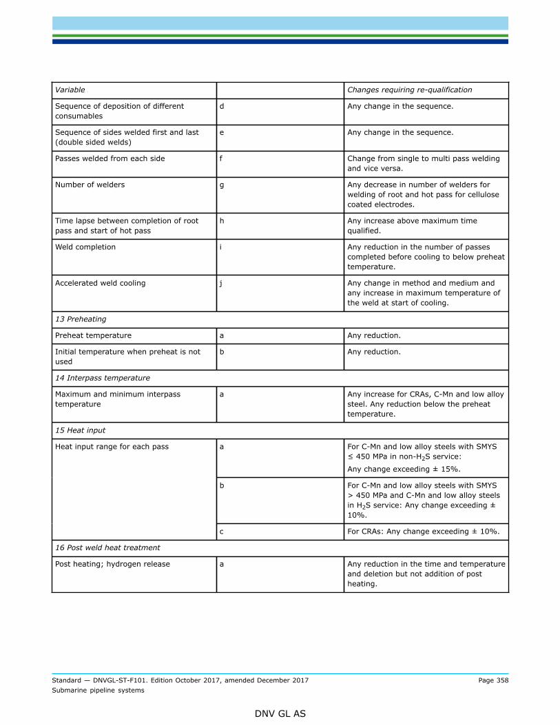
Standard — DNVGL-ST-F101. Edition October 2017, amended December 2017 Page 358Submarine pipeline systems
DNV GL AS
Variable Changes requiring re-qualification
Sequence of deposition of differentconsumables
d Any change in the sequence.
Sequence of sides welded first and last(double sided welds)
e Any change in the sequence.
Passes welded from each side f Change from single to multi pass weldingand vice versa.
Number of welders g Any decrease in number of welders forwelding of root and hot pass for cellulosecoated electrodes.
Time lapse between completion of rootpass and start of hot pass
h Any increase above maximum timequalified.
Weld completion i Any reduction in the number of passescompleted before cooling to below preheattemperature.
Accelerated weld cooling j Any change in method and medium andany increase in maximum temperature ofthe weld at start of cooling.
13 Preheating
Preheat temperature a Any reduction.
Initial temperature when preheat is notused
b Any reduction.
14 Interpass temperature
Maximum and minimum interpasstemperature
a Any increase for CRAs, C-Mn and low alloysteel. Any reduction below the preheattemperature.
15 Heat input
a For C-Mn and low alloy steels with SMYS≤ 450 MPa in non-H2S service:
Any change exceeding ± 15%.
b For C-Mn and low alloy steels with SMYS> 450 MPa and C-Mn and low alloy steelsin H2S service: Any change exceeding ±10%.
Heat input range for each pass
c For CRAs: Any change exceeding ± 10%.
16 Post weld heat treatment
Post heating; hydrogen release a Any reduction in the time and temperatureand deletion but not addition of postheating.

Standard — DNVGL-ST-F101. Edition October 2017, amended December 2017 Page 359Submarine pipeline systems
DNV GL AS
Variable Changes requiring re-qualification
Post weld heat treatment b Addition or deletion of post weld heattreatment.
Any change in holding temperatureexceeding ± 20°C.
Any change in heating and cooling ratesoutside ± 5%.
Holding time c Any change in holding time outside belowformula (± 5%):
holding time = (actual thickness/qualifiedthickness) × qualified holding time.
17 Specific for the SAW welding process
Wire electrode configuration. a Each variant of process 12 (121 to 125)shall be qualified separately.
Flux b Any change of type, classification andbrand.
Arc voltage range. c Any change beyond ± 10%.
18 Specific for the FCAW welding process
Mode of metal transfer a A change from short circuiting transfer tospray or globular transfer.
Qualification with spray or globulartransfer qualifies both spray or globulartransfer.
19 Specific for the GMAW welding process
Arc voltage range a Any change beyond ± 10%.
20 Specific for the GTAW welding process
Diameter and codification of tungstenelectrode (ISO 6848)
a Any change.
Hot or cold wire. b A change from hot to cold wire and viceversa.
21 Specific for the PAW welding process
Hot or cold wire a A change from hot to cold wire and viceversa.
22 Specific for automatic welding of pipeline girth welds
Control software a Any change.
Pre-set parameters b Any change (applies to parameters thatcan not be adjusted by the welder).
23 Specific for mechanised welding of pipeline girth welds
Control software a Any change.
24 Specific for repair welding

Standard — DNVGL-ST-F101. Edition October 2017, amended December 2017 Page 360Submarine pipeline systems
DNV GL AS
Variable Changes requiring re-qualification
a A change from internal to external repairsand vice versa for pipeline girth welds.
b A change from single to multi pass repairsand vice versa.
c A change from cold to thermal method forremoval of the defect but not vice versa.
Welding techniques
d Any increase above 20% in the depth ofexcavation for partial thickness repairs.
C.4.8.12 If CRA or clad welds are subject to solution annealing heat treatment after welding a slightvariation in welding parameters outside those in Table C-2, Items 10 through 15 may be agreed.
C.5 Qualification of welding procedures
C.5.1 General
C.5.1.1 Qualification welding shall be performed based upon the accepted pWPS, using the type of weldingequipment to be used during production welding, and under conditions that are representative of the actualworking environment for the work shop, site, or vessel where the production welding will be performed. Theconfiguration of the test joint shall be representative of the actual weld to be performed during production.
C.5.1.2 The number of test joints shall be sufficient to obtain the required number of specimens from therequired locations given in Figure C-1 and Figure C-2. Allowance for re-testing should be considered whendeciding the number of test joints to be welded.
C.5.1.3 The test joints for qualification welding shall be of sufficient size to give realistic restraint duringwelding.
C.5.1.4 The base material selected for the qualification testing should be representative of the upper rangeof the specified chemical composition for C-Mn and low alloy steels, and of the nominal range of the specifiedchemical composition for corrosion resistant alloys.
C.5.1.5 The material thickness shall be the same for both pipes/components/plates to be welded, except toqualify joining of two base materials with unequal thickness and for fillet end T-joint test pieces.Qualification welding
C.5.1.6 Certificates for materials and consumables, including shielding, backing and plasma gases, shall beverified, and validity and traceability to the actual materials shall be established prior to start of qualificationwelding. The records from qualification welding shall include all information needed to establish a WPS for theintended application within the essential variables and their allowable ranges.
C.5.1.7 The following requirements apply:
— the welding qualification test shall be representative for the production welding with respect to weldingpositions, interpass temperature, application of preheat (propane will also qualify for induction coilpreheating), heat conduction, etc.
— if multiple welding arcs are combined in a single welding head the parameters for each welding arc shallbe recorded
— the direction of plate rolling (when relevant) and the 12 o’clock position (for fixed pipe positions) shall bemarked on the test piece

Standard — DNVGL-ST-F101. Edition October 2017, amended December 2017 Page 361Submarine pipeline systems
DNV GL AS
— when more than one welding process or filler metal is used to weld a test piece, the parameters used andthe approximate thickness of the weld metal deposited shall be recorded for each welding process andfiller metal
— if tack welds are to be fused into the final joint during production welding, they shall be included whenwelding the test piece
— backing gas oxygen content and the duration of backing gas application before, during and after weldingshall be recorded
— each test piece shall be uniquely identified by hard stamping or indelible marking adjacent to the weld andthe records made during test welding, non-destructive testing and mechanical testing shall be traceable toeach test piece
— average heat input shall be calculated and should be based on averages of each parameter (V, A, travelspeed).
Pipeline girth welds
— the welding qualification test shall be representative for the production welding with respect to angle ofpipe axis., interpass temperature, application of preheat, heat conduction, etc.
— for girth welds in welded pipe in all positions, except 1G (PA) and 2G (PC), it is recommended that one ofthe pipes used for the welding procedure qualification test be fixed with the longitudinal weld in the 6 or12 o'clock position
— for welding of pipe with diameter ≥ 20” in fixed positions, the weld circumference shall be divided inappropriate sectors around the circumference. The welding parameters shall be recorded for each pass ineach sector and for each welding arc. For each sector an average heat input shall be determined for eachpass. For manual welding, the heat input for a sector shall be recorded as average of all the average heatinputs for the run-out lengths in each pass in that sector
— for welding of pipe with diameter < 20” the average heat input shall be recorded for each pass. Formanual welding, the heat input for each pass shall be recorded as average of all the average heat inputsfor the run-out lengths in each pass in the pipe circumference
— the heat input range to be stated on the WPS for the full circumference shall be based on the highest andlowest circumferential or sectoral average heat input, as relevant, with tolerances as given in Table C-2.Grouping of passes, e.g. fill and cap passes, may be allowed subject to agreement
— the release of external line-up clamps shall be simulated during qualification welding. Clamps should notbe released until the completed sections of the root pass covers a minimum of 50% of the circumferencewith even spacing. The length of each section, the spacing of the sections, the number of sections weldedand the percentage of welded sections of the circumference shall be recorded
— if it is expected that the interpass temperature will drop below preheat temperature during installationwelding, this scenario shall be simulated during qualification welding. The number of passes completedbefore cooling to below preheat temperature shall be recorded
— accelerated cooling of the weld shall be performed during qualification welding if accelerated weld cooling,e.g. for AUT will be performed in production. The cooling method and the weld temperature at the start ofthe cooling shall be recorded. A macro and hardness shall be taken at cooling start point.
C.5.1.8 If the use of cellulose covered electrodes has been agreed, the following additional requirementsshall apply:
— preheat shall be minimum 100°C— delay between completion of the root pass and the start of depositing the hot pass shall be minimum 6
minutes— immediately upon completion of welding during welding procedure qualification the test pieces shall be
water quenched as soon as the temperature of the test piece is below 300°C— non destructive testing of the test piece shall be by Automated Ultrasonic Testing (AUT) or Radiographic
testing and Manual Ultrasonic Testing.

Standard — DNVGL-ST-F101. Edition October 2017, amended December 2017 Page 362Submarine pipeline systems
DNV GL AS
C.5.2 Repair welding procedures
C.5.2.1 Repair welding shall be qualified by a separate weld repair qualification test.
C.5.2.2 Preheat for repair welding should be minimum 50°C above minimum specified preheat for productionwelding.
C.5.2.3 When a heat treated pipe or component is repaired by welding, a new heat treatment may have tobe included in the qualification of the weld repair procedure, depending on the effect of the weld repair onthe properties and microstructure of the existing weld and base material.
C.5.2.4 Qualification of repair welding procedures shall be made by excavating a groove in an original weldwelded in accordance with a qualified welding procedure.
C.5.2.5 The excavated groove shall be of sufficient length to obtain the required number of test specimens +50 mm at each end.Repeated repairs
C.5.2.6 If repeated weld repairs are permitted or agreed, these shall be qualified separately.
C.5.2.7 In case of repeated repairs, the test piece shall contain a repair weld of a repaired original weld.For repeated in-process root repair, single pass cap repair and/or single pass root sealing repairs the repairweld shall be removed prior to re-repair. A repeated repair qualification may qualify a repair WPS providingit is ensured that the HAZ has been exposed to two heat treatment cycles, i.e. the second excavation isperformed exactly on the same location as the first excavation.
C.5.2.8 The qualification test shall be made in a manner realistically simulating the repair situation to bequalified.
C.5.2.9 Qualification welding shall be performed in accordance with [C.5.1.1] through [C.5.1.8].
C.5.2.10 For pipeline girth welds the repair qualification welding shall be performed in the overhead throughvertical positions.
C.5.2.11 For roll welding the length of the repair weld may be centred at the 12 o’clock location for externalrepairs and at the 6 o’clock location for internal repairs, in which case repair welding is qualified for repairwelding in these locations only.
C.5.3 Qualification of girth butt welds and component longitudinal weldswelding procedures
C.5.3.1 Qualification of welding procedures for pipeline system girth welds and welds in pipeline componentsmay be performed by any of the arc welding processes specified in [C.1.2].
C.5.3.2 The WPS shall be qualified and approved by all parties prior to start of any production welding.
C.5.3.3 The type and number of destructive tests for welding procedure qualification are given in Table C-3,with methods and acceptance criteria as specified in [C.6].
C.5.3.4 For pipeline girth welds exposed to strain ≥ 0.4%, testing should be performed to determine theproperties of weld metal in the strained and aged condition after deformation cycles and also at elevatedtemperature. See DNVGL-RP-F108.Qualification of repair welding procedures

Standard — DNVGL-ST-F101. Edition October 2017, amended December 2017 Page 363Submarine pipeline systems
DNV GL AS
Table C-3 Qualification of welding procedures for girth butt welds including componentlongitudinal welds
Test joint
Minimum number of each specified test
Wallthickness
(mm)
D(mm)
Transverseweld
Tensile
Transverseall-weld
Tensile 1)
All-weldtensile
1)
Rootbend 9)
Facebend 9)
Side
bend )
CharpyV-notchsets 3,
4,5,6,7)
Macro andhardness
10)
Othertests
Fracturetoughness
≤ 25 ≤300>
300
2
2
2
2
2
2
2 2)
4 2)2 2)
4 2)0
0
4
4
2
2
11)
11)
12)
12)
> 25 all 2 2 2 0 0 4 6 2 11) 12, 13)
Notes:
1) The strength mismatch between the girth weld and the parent material shall be evaluated when ECA is required.All-weld tensile specimens are recommended when ECA is performed, however, transverse all-weld specimens areacceptable. In case of ECA, full stress-strain curves shall be established as far as possible, see also DNVGL-RP-F108.If it is impossible to prepare test samples due to size limitations, weld metal properties shall be documented basedon the weld consumables material certificates provided by the supplier (i.e. to document that the yield and ultimatetensile weld metal strength are above the base metal values).
2) For welding processes GMAW, GTAW, FCAW and SMAW side bend tests shall be performed instead of root and facebend tests. For t > 12 mm side bend test is an acceptable alternative to root and face bend tests.
3) Impact testing is not required for t < 6 mm.4) Each Charpy V-notch set consists of 3 specimens.5) The notch shall be located in the weld metal, the fusion line (FL) sampling 50% of HAZ, FL+2 mm and FL+5 mm,
see App.B, Figure B-3 through Figure B-5.6) For double sided welds on C-Mn and low alloy steels, four additional sets of Charpy V-notch test specimens shall be
sampled from the weld metal, FL (sampling 50% of HAZ), FL+2 mm and FL+5 mm in the root area, see Figure B-5.7) If several welding processes or welding consumables are used, impact testing shall be carried out in the
corresponding weld regions, even if the region tested cannot be considered representative for the complete weld.8) When the wall thickness exceeds 25 mm for single sided welds, two additional sets of Charpy V-notch test
specimens shall be sampled from the weld metal root and FL in the root area.9) Bend tests on clad/lined pipes shall be performed as side bend tests. 4 side bend tests shall be performed (for all
wall thicknesses).10) For girth welds in welded pipe, one macro and hardness shall include an intersection between a longitudinal/girth
weld.11) Requirements for corrosion tests, chemical analysis and microstructure examination are specified in [C.6].12) Fracture toughness testing is only required when a generic or full ECA is performed for pipeline girth butt welds.
Extent of testing shall be in accordance with DNVGL-RP-F108.13) For nominal wall thickness above 50 mm in C-Mn and low alloy steels fracture toughness testing is required unless
PWHT is performed.
C.5.3.5 Qualification of repair welding procedures for pipeline system girth welds and welds in pipelinecomponents may be performed by any of the arc welding processes specified in [C.1.2].
C.5.3.6 The WPS for repair welding shall be qualified prior to start of any production repair welding.
C.5.3.7 The following types of repairs should be qualified to the extent that such repairs are feasible andapplicable for the repair situation considering the size of pipe or component:

Standard — DNVGL-ST-F101. Edition October 2017, amended December 2017 Page 364Submarine pipeline systems
DNV GL AS
— through thickness repair— partial thickness repair— in-process root repair— single pass cap repair— single pass root sealing repair.
C.5.3.8 The type and number of destructive tests for qualification or repair welding procedure are given inTable C-4, with methods and acceptance criteria as specified in [C.6] below.Repeated repairs
C.5.3.9 If it has been agreed to permit through thickness or partial thickness repeated repairs (see TableC-7), and a HAZ is introduced in the weld metal from the first repair, then additional Charpy V-notch sets (inaddition to the tests required by Table C-4) shall be located in the re-repair weld metal and in FL, FL+2 mmand FL+5 mm of the weld metal from the first repair and/or the base material as applicable and as shown inthe accepted pWPS, see [C.4.7.2].
C.5.3.10 If it has been agreed to permit repeated in-process root repair, single pass cap repair and/or singlepass root sealing repair, see Table C-7, the extent of testing shall be as tests required by Table C-4.
Table C-4 Qualification of repair welding procedures for girth butt welds including componentslongitudinal welds
Test joint Minimum number of each specified test
Type of repairTransverse
weldtensile
Transverseall-weld
tensile 1)
All-weldtensile1),
2)
Rootbend
Facebend
Sidebend
CharpyV-notch
sets
Macro andhardness
Othertests
Fracturetoughness
Throughthickness repair 1 1 1 1 2) 1 2) 2 3) 94, 5, 6) 1 7) 8, 9)
Partial thicknessrepair 1 1 1 1 2) 1 2) 2 3) 74, 5, 6) 1 7) 8, 9)
In-process rootrepair 1 1 7)
Single pass caprepair 1 1 7)
Single pass rootsealing repair 1 1 7)

Standard — DNVGL-ST-F101. Edition October 2017, amended December 2017 Page 365Submarine pipeline systems
DNV GL AS
Notes:
1) The strength mismatch between the girth weld and the parent material shall be evaluated when ECA for repair weldis required. All-weld tensile specimens are recommended when ECA is performed, however, transverse all-weldspecimens are acceptable. In case of ECA, full stress-strain curves shall be established as far as possible, see alsoDNVGL-RP-F108. If it is impossible to prepare test samples due to size limitations, weld metal properties shall bedocumented based on the weld consumables material certificates provided by the supplier (i.e. to document that theyield and ultimate tensile weld metal strength are above the base metal values).
2) 1 root and 1 face bend test for t ≤ 25 mm. For t > 12 mm side bend test is an acceptable alternative to root andface bend tests.
3) For welding processes GMAW, GTAW, FCAW and SMAW, for clad/lined pipes and for all pipes when t > 25 mm, sidebend tests shall be performed instead of root and face bend tests.
4) For partial penetration and through thickness repairs where a new HAZ is introduced in the original weld metal,Charpy V-notch sets of 3 specimens shall be located according to App.B, Figure B-7 and Figure B-8.
5) The notch shall be located in the repair weld metal, the fusion line (FL) sampling 50% of HAZ, FL+2 mm and FL+5mm of both the base material and the original weld.
6) If several welding processes or welding consumables are used, impact testing shall be carried out in thecorresponding weld regions, even if the region tested cannot be considered representative for the complete weld.
7) Requirements for corrosion tests, chemical analysis and microstructure examination are specified in [C.6].8) Fracture toughness testing of repairs is only required when a generic or full ECA is performed for the original
pipeline girth butt welds. Extent of testing shall be in accordance with DNVGL-RP-F108.9) For nominal wall thickness above 50 mm in C-Mn and low alloy steels fracture toughness testing is required unless
PWHT is performed
C.5.4 Qualification of welding procedures for corrosion resistant overlayweldingQualification of welding procedures
C.5.4.1 Qualification of welding procedures for corrosion resistant overlay welding shall be performed withGMAW or pulsed GTAW. Other methods may be used subject to agreement.
C.5.4.2 The chemical composition of test pieces shall be representative for the production conditions.
C.5.4.3 Qualification of weld overlay shall be performed on a test sample which is representative for thesize and thickness of the production base material, e.g. tolerance ranges in ISO 15614-7 may be consideredacceptable. The minimum weld overlay thickness used for the production welding shall be used for thewelding procedure qualification test.
C.5.4.4 The dimensions of, or the number of test pieces shall be sufficient to obtain all required tests.
C.5.4.5 The test pieces used shall be relevant for the intended application of the weld overlay:
— forging or casting for overlay welding of ring grooves— pipe with the overlay welding performed externally or internally, or— plate or pipe with a prepared welding groove for qualification of buttering and when the weld overlay
strength is utilised in the design.
C.5.4.6 If a buffer layer will be used in production welding, it shall also be used in welding the test piece.
C.5.4.7 The WPS shall be qualified prior to start of any production welding.
C.5.4.8 The type and number of destructive tests for welding procedure qualification are given in Table C-5with methods and acceptance criteria specified in [C.6].

Standard — DNVGL-ST-F101. Edition October 2017, amended December 2017 Page 366Submarine pipeline systems
DNV GL AS
Qualification of repair welding procedures
Table C-5 Qualification of corrosion resistant overlay welding procedures
Test joint Minimum number of each specified test
Thickness ofbase material
Sidebend
Macro andhardness tests
Chemicalanalysis
All-weldtensile
Charpy V-notchImpact tests Other tests
All 4 1) 1 1 2 2) 2,3,4,5) 6)
Notes:
1) Side bend specimens shall be taken transverse to the welding direction.2) Only required when the weld overlay strength is utilised in the design of the welded joint (e.g. load bearing weld
overlay).3) Only required when the weld overlay is load bearing across the overlay/base material fusion line.4) Sets shall be tested with the notch in the overlay weld metal, Fl, and FL+2 mm and FL+5 mm in the base material.5) If several welding processes or welding consumables are used, impact testing shall be carried out in the
corresponding weld regions if the region otherwise required to be tested cannot be considered representative for thecomplete weld.
6) Requirements for corrosion tests and microstructure examination are specified in [C.6].
C.5.4.9 Unless the production welding procedure can be applied, the repair welding procedure shall bequalified. Weld repair performed on weld overlay machined to the final thickness shall be separately qualified.
C.5.4.10 The type and number of destructive tests for qualification of repair welding procedure are given inTable C-5. In cases when qualification is performed using a pipe, component or plate with a prepared weldinggroove, and a new HAZ is introduced in the original weld metal, additional Charpy V-notch impact sets shallbe located according to Figure B-7 and Figure B-8.
C.5.5 Qualification of procedures for pin brazing and aluminothermicwelding of anode leadsQualification of procedures
C.5.5.1 Attachment of anode leads shall be by pin brazing or aluminothermic welding methods. Othermethods may be used subject to agreement. Full details of the technique used and associated equipmentshall be available prior to qualification of procedures.
C.5.5.2 The chemical composition of test pieces shall be representative for the production conditions and beselected in the upper range of the chemical composition.
C.5.5.3 Qualification for brazing/welding of anode leads shall be performed on test samples which isrepresentative for the size and thickness of the production base material and the number of test pieces shallbe minimum 4 and sufficient to obtain all required tests.

Standard — DNVGL-ST-F101. Edition October 2017, amended December 2017 Page 367Submarine pipeline systems
DNV GL AS
C.5.5.4 The WPS shall be qualified prior to start of any production.
Table C-6 Qualification of pin brazing and aluminothermic welding procedures
Test joint Minimum number of each specified test 1)
Thickness ofbase material
Electricalresistance
Mechanicalstrength
Copperpenetration 2)
Hardness 3 ) Pull test
All 4 4 4 4 4
Notes
1) The number of tests refers to the total number of tests from all pieces.2) 2 test specimens shall the sectioned transverse to the anode lead and 2 test specimens parallel with the anode lead.3) The hardness tests shall be made on the specimens for copper penetration measurements.
C.5.5.5 The type and number of destructive tests for procedure qualification are given in Table C-6 withmethods and acceptance criteria specified in [C.6] below.
C.5.6 Qualification of welding procedures for temporary and permanentattachments and branch welding fittings to linepipeQualification of welding procedures
C.5.6.1 Qualification of welding procedures for temporary and permanent attachments and branch weldingfittings to linepipe may be performed by any of the arc welding processes specified in [C.1.2], but use ofcellulose coated electrodes is not permitted.
C.5.6.2 The WPS shall be qualified prior to start of any production welding.
C.5.6.3 The type and number of destructive tests for welding procedure qualification are given in [C.5.6.4]to [C.5.6.14] with methods and acceptance criteria as specified in [C.6].Longitudinal welds in doubler sleeves
C.5.6.4 Longitudinal welds in doubler sleeves shall be made with backing strips and qualified as required in[C.5.3] and Table C-3, but with the extent of testing limited to:
— transverse weld tensile— Charpy V-notch impact testing— macro and hardness testing.
Fillet welds in doubler sleeves and anode pads
C.5.6.5 The fillet weld qualification test shall comprise two test pieces welded in the PD and PF platepositions to qualify the welding procedure for welding in all positions.
C.5.6.6 The extent of testing for each test piece shall be 3 macro and hardness specimens taken from thestart, end and middle of each test weld with methods and acceptance criteria as specified in [C.6].Branch welding fittings
C.5.6.7 The branch fitting qualification test welds shall be welded in the PF and PD pipe positions to qualifywelding in all positions.
C.5.6.8 The extent of testing shall be 4 macro and hardness specimens taken from the 12, 3, 6 and 9 o’clocklocations of each test weld. A procedure qualified as a butt weld may be used.

Standard — DNVGL-ST-F101. Edition October 2017, amended December 2017 Page 368Submarine pipeline systems
DNV GL AS
C.5.6.9 Charpy V-notch impact testing with the notch in the weld metal, FL, FL+2 mm and FL+5 mm usingfull size or reduced size specimens shall always be performed whenever the material thickness allows. CharpyV-notch specimens shall be taken from both test welds.Qualification of repair welding procedures for longitudinal welds in doubler sleeves
C.5.6.10 Repair welding procedures for longitudinal welds in doubler sleeves shall be qualified as required in[C.5.3] and Table C-4, but with the extent of testing modified according to [C.5.6.4].Qualification of repair welding procedures for fillet welds
C.5.6.11 Qualification welding shall be performed in the PD and PF plate positions. The extent of qualificationof repair welding procedures shall at as a minimum consist of:
— through thickness repair— single pass repair against the pipe material— single pass repair against the sleeve material.
C.5.6.12 Methods of testing and acceptance criteria shall be as specified in [C.6].Qualification of repair welding procedures for branch welding fittings
C.5.6.13 Qualification welding shall be performed in the PD and PF pipe positions. The extent of qualificationof repair welding procedures shall at as a minimum consist of:
— through thickness repair— single pass cap repair against the fitting— single pass cap repair against the pipe.
C.5.6.14 Methods of testing and acceptance criteria shall be as specified in [C.6].
C.5.7 Qualification of welding procedures for structural components
C.5.7.1 Welding procedures for structural components, supplied as a part of the pipeline systems, shallbe qualified in accordance with ISO 15614-1. The requirements shall be appropriate for the structuralcategorisation of the members and stresses in the structure. The extent of tensile, hardness and impacttesting and the testing conditions should be in compliance with this appendix.
C.5.8 Qualification of welding procedures for hyperbaric dry welding
C.5.8.1 Requirements for qualification of welding procedures for hyperbaric dry welding are given in [C.9].
C.6 Examination and testing for welding procedure qualification
C.6.1 General
C.6.1.1 All visual examination, non-destructive testing, mechanical testing and corrosion testing of testpieces shall be performed in the as welded or post weld heat treated condition, whatever is applicable for thefinal product.Visual examination and non-destructive testing
C.6.1.2 Visual examination and non-destructive testing shall be performed no earlier than 24 hours afterthe completion of welding of each test piece. Original welds intended for repair welding qualification may beexamined and tested when temperature of test piece allows for it.
Standard — DNVGL-ST-F101. Edition October 2017, amended December 2017 Page 369Submarine pipeline systems
DNV GL AS
C.6.1.3 If a test piece does not meet the acceptance criteria for visual examination and NDT, one further testpiece shall be welded and subjected to the same examination. If this additional test piece does not meet therequirements, the WPQ is not acceptable.Destructive testing
C.6.1.4 The type and number of mechanical tests and microstructure evaluations for qualification tests aregiven in [C.5.3] to [C.5.7].
C.6.1.5 Test specimens shall be taken from the positions shown in Figure C-1 and Figure C-2 for longitudinalwelds and girth welds respectively.Re-testing
C.6.1.6 A destructive test failing to meet the specified requirements may be re-tested. The reason for thefailure shall be investigated and reported preferably before any re-testing is performed. If the investigationreveals that the test results are influenced by improper sampling, machining, preparation, treatment ortesting, the test sample and specimen (as relevant) shall be replaced by a correctly prepared sample orspecimen and a new test performed.
C.6.1.7 A destructive test failing to meet the specified requirements shall be rejected if the reason for failurecan not be related to improper sampling, machining, preparation, treatment or testing of specimens.
C.6.1.8 Re-testing of a test failing to meet the specified requirements should only be performed subject toagreement. This re-testing shall consist of at least two further test specimens/sets of test specimens. If bothre-tests meet the requirements, the test may be regarded as acceptable. All test results, including the failedtests, shall be reported.
C.6.1.9 If there are single hardness values in the different test zones (weld metal, HAZ, base material) thatdo not meet the requirement, retesting shall be carried out on the reverse side of the tested specimen orafter grinding and re-preparation of the tested surface. None of these additional hardness values shall exceedthe maximum value.
C.6.1.10 For Charpy V-notch impact testing the following requirements shall apply:
— in order to consider a set as approved, the average requirement has to be met and only one testspecimen out of the three may have a value between the average and the single minimum requirement.
— subject to agreement, retest may be performed with two test specimen sets.
Note 1: For pipeline girth welds, if applicable, one macro and hardness specimen shall include a pipelongitudinal seam weld.Note 2: The indicated location of the test specimens are not required for qualification of welding in the PA(1G rotated) where sampling positions are optional.

Standard — DNVGL-ST-F101. Edition October 2017, amended December 2017 Page 370Submarine pipeline systems
DNV GL AS
Figure C-1 Welding procedure qualification test - sampling of test specimens for longitudinal buttwelds.
Note: The indicated location of the test specimens are not required for qualification of welding in the PA (1G)and PC (2G) positions, where sampling positions are optional.
Figure C-2 Welding procedure qualification test - typical sampling of test specimens for girth buttwelds.
Note 1: For pipeline girth welds, if applicable, one macro and hardness specimen shall include a pipelongitudinal seam weld.

Standard — DNVGL-ST-F101. Edition October 2017, amended December 2017 Page 371Submarine pipeline systems
DNV GL AS
Note 2: The indicated location of the test specimens are not required for qualification of welding in the PA(1G rotated) where sampling positions are optional.
C.6.2 Visual examination and non-destructive testing requirements
C.6.2.1 Each test weld shall undergo 100% visual examination and 100% ultrasonic and 100% radiographictesting and 100% magnetic particle or liquid penetrant testing. Testing shall be in accordance with [D.2]. AUTin line with production inspection as required in App.E may be used instead of manual UT + RT.
C.6.2.2 Acceptance criteria for visual examination and non-destructive testing shall be in accordance with[D.2.9] for welds exposed to strains < 0.4%. For welds exposed to strains ≥ 0.4%, the acceptance criteriashall be as for the production welding or according to [D.2.9], whichever is the more stringent.
Guidance note:When results from ECA are not available, it is recommended to consider relevant historical data compared with workmanshipcriteria [D.2.9] as basis for acceptance criteria.
---e-n-d---o-f---g-u-i-d-a-n-c-e---n-o-t-e---
C.6.2.3 Weld overlay shall be non-destructively tested according to [D.3.3] with acceptance criteriaaccording to [D.3.6]. The surface and weld thickness shall be representative for the production welding, i.e.after machining of the overlay thickness or the thickness representative for the thickness on the finishedcomponent.
C.6.3 Testing of butt welds
C.6.3.1 All testing shall be performed in accordance with App.B.Transverse weld tensile testing
C.6.3.2 For longitudinal welds and girth welds exposed to strain εl,nom ≥ 0.4% the fracture shall not belocated in the weld metal, while for longitudinal welds and girth welds exposed to strain εl,nom <0.4% andwhere no ECA is performed the fracture should not be in the weld metal. The ultimate tensile strength shallbe at least equal to the SMTS for the base material. When different material grades are joined, the ultimatetensile strength of the joint shall be at least equal to the SMTS for the lower grade.All-weld tensile testing
C.6.3.3 For longitudinal welds and girth welds exposed to strain εl,nom <0.4% and where no ECA isperformed, the upper yield or the Rt0.5 of the deposited weld metal should be 80 MPa above SMYS of thebase material and the elongation not less than 18%. If two grades are joined the requirement applies to thelower strength material.Transverse all-weld tensile testing
C.6.3.4 For pipeline girth welds where generic ECA acceptance criteria (see DNVGL-RP-F108) are applied, theupper yield or the Rt0.5 of the deposited weld metal shall as a minimum exceed or be equal to a value 20 MPabelow the specified maximum base material yield strength. The elongation shall as a minimum be 18%.Whendifferent material grades are joined, the yield stress requirements applies to the lower grade.
C.6.3.5 For pipeline girth welds exposed to strain εl,nom ≥ 0.4% and where full ECA acceptance criteria shallbe applied, the upper yield or the Rt0.5 of the deposited weld metal shall as a minimum exceed or be equal toa value 20 MPa below the specified maximum base material yield strength, or the assumptions made duringdesign and/or the ECA. The elongation shall as a minimum be 18%.Bend testing

Standard — DNVGL-ST-F101. Edition October 2017, amended December 2017 Page 372Submarine pipeline systems
DNV GL AS
C.6.3.6 The end tests shall not disclose any open defects in any direction exceeding 3 mm. Minor ductiletears less than 6 mm, originating at the specimen edge may be disregarded if not associated with obviousdefects.Charpy V-notch impact testing
C.6.3.7 The average and single Charpy V-notch toughness at each position shall not be less than specifiedfor the base material in the transverse direction (KVT values). Requirement for fracture arrest propertiesdoes not apply.
— C-Mn and low alloy steels shall meet the requirements given in [7.2.4].— Duplex and martensitic stainless steels shall meet the requirements given in [7.3.4].— The C-Mn steel backing material in clad and lined linepipe shall meet the requirements given in [7.2.4].
C.6.3.8 When different steel grades are joined, the required impact tests shall be performed on both sides ofthe weld. The weld metal shall meet the less stringent energy requirement.Macro section
C.6.3.9 The macro section shall be documented by photographs (magnification of at least 5×).
C.6.3.10 The macro section shall show a sound weld merging smoothly into the base material and meetingQuality level C of ISO 5817.
C.6.3.11 For girth welds in welded pipe, one macro section shall include a longitudinal weld.Hardness testing
C.6.3.12 The maximum hardness in the HAZ and weld metal is:
— 325 HV10 for C-Mn and low alloy steels in non-H2S service (also applies to backing steel in clad or linedmaterial).
— 250 HV10 for C-Mn and low alloy steels in H2S service (for weld caps not exposed to the H2S media,maximum hardness of 275 HV10 may be agreed for base material thickness >9 mm) unless a higherhardness has been qualified according to [6.2.2.2] and [B.3.4].
— 350 HV10 for 13Cr martensitic stainless steels— 350 HV10 for duplex stainless steels— 345 HV10 for Ni-based alloys in clad or lined material in non-H2S service. For explosion welded clad
material the requirement of maximum 40 HRC in accordance with API 5LD applies.— 300 HV10 for austenitic stainless steels in clad or lined material in non-H2S service— 275 HV10 for anode pads.
For clad or lined materials in H2S service special considerations are required, see ISO 15156.
C.6.3.13 Subject to agreement, additional hardness measurements shall be taken in the start/stop area forrepair weld qualification.
C.6.3.14 For girth welds in welded pipe, one hardness test specimen shall include a longitudinal weld.Corrosion testing
C.6.3.15 Sulphide stress cracking testing (SSC) is only required for C-Mn and low alloy steels with SMYS >450 MPa, 13Cr martensitic stainless steels and other materials not listed for H2S service in ISO 15156.Acceptance criteria shall be according to ISO 15156.
C.6.3.16 Pitting corrosion test according to ASTM G48 is only required for 25Cr duplex stainless steel (see[6.2.3.2]). The maximum weight loss shall be 4.0 g/m2 when tested at 40°C for 24 hours and there shall beno pitting at 20 X magnification.

Standard — DNVGL-ST-F101. Edition October 2017, amended December 2017 Page 373Submarine pipeline systems
DNV GL AS
C.6.3.17 Welds in duplex stainless steel materials, CRA materials and clad/lined materials shall be subjectto microstructure examination. The material shall be essentially free from grain boundary carbides, nitridesand intermetallic phases. Essentially free implies that occasional strings of detrimental phases along thecentreline of the base material is acceptable given that the phase content within one field of vision (at 400Xmagnification) is < 1.0% (max. 0.5% intermetallic phases).For duplex steel the ferrite content of the weld metal shall be within the range 35 to 65%.The ferrite content of austenitic stainless steel weld deposit shall be within the range 5 to 13%.Micro cracking at the fusion line is not permitted.Chemical analysis
C.6.3.18 For welds in clad or lined materials, a chemical analysis shall be performed. The analysis shallbe representative of the CRA composition at a point at the centreline of the root pass 0.5 mm below thesurface. The chemical composition shall be within the specification limits according to the UNS number forthe specified cladding/lining material or, if the weld metal is of a different composition than the cladding/liner,within the limits of chemical composition specified for the welding consumable.Fracture toughness testing
C.6.3.19 Fracture toughness testing shall be performed for both girth welds and repair welds whenacceptance criteria for girth welds are established by an ECA. The extent of testing shall be in accordancewith DNVGL-RP-F108.
C.6.3.20 For nominal wall thickness above 50 mm in C-Mn and low alloy steels fracture toughness testing isrequired unless PWHT is performed.C-Mn and low alloy steels shall meet the requirements given in [7.2.4.15].Duplex and martensitic stainless steels shall meet the requirements given in [7.3.4.3].
C.6.4 Testing of weld overlay
C.6.4.1 When the weld overlay is not contributing to strength (e.g. not load bearing), tensile testing andCharpy V-notch testing of the weld overlay material are not required. When the weld overlay strength isconsidered as a part of the design, such mechanical testing of the weld overlay material is required (see[C.6.4.12] to [C.6.4.17]).
C.6.4.2 The base material shall retain the minimum specified mechanical properties after any post weld heattreatment. The base material properties in the post weld heat treated condition shall then be documented byadditional testing and recorded as a part of the welding procedure qualification.
C.6.4.3 The testing in [C.6.4.4] through [C.6.4.11] shall, as a minimum, be performed when the overlaymaterial is not considered as part of the design and when the base material has not been affected by anypost weld heat treatment. When the overlay material is considered to be part of design, the testing in[C.6.4.12] through [C.6.4.17] shall be performed in addition to the testing in [C.6.4.4] through [C.6.4.11].Bend testing of weld overlay
C.6.4.4 The bend testing shall be performed in accordance with [B.2.5.14]. The bend tests shall discloseno defects exceeding 1.6 mm. Minor ductile tears less than 3 mm, originating at the specimen edge may bedisregarded if not associated with obvious defects.Macro examination of weld overlay
C.6.4.5 The macro sections shall be documented by photographs (magnification of at least 5X). The macrosection shall show a sound weld merging smoothly into the base material and meeting Quality level C of ISO5817.Hardness testing of weld overlay

Standard — DNVGL-ST-F101. Edition October 2017, amended December 2017 Page 374Submarine pipeline systems
DNV GL AS
C.6.4.6 The maximum hardness for base material and HAZ shall not exceed the limits given in [C.6.3.12]above as applicable for the intended service and type of material. The maximum hardness for the overlaymaterial should not exceed any limit given in ISO 15156 for H2S service.Chemical analysis of weld overlay
C.6.4.7 The chemical composition shall be obtained in accordance with App.B. Specimens for chemicalanalysis shall either be performed directly on the as welded or machined surface or by taking specimen orfilings/chips from:
— the as welded surface— a machined surface— from a horizontal drilled cavity.
The location for the chemical analysis shall be considered as the minimum qualified thickness to be left afterany machining of the corrosion resistant weld overlay.
C.6.4.8 The chemical composition of overlay shall be shall be within the specification limits according to theUNS for the specified overlay material. The iron content of alloy UNS N06625 overlay shall be < 10%.Microstructure examination of weld overlay
C.6.4.9 The surface to be used for microstructure examination shall be representative of a weld overlaythickness of 3 mm or the minimum overlay thickness specified for the finished machined component,whichever is less. Microstructure examination shall be performed after any final heat treatment.
C.6.4.10 Metallographic examination at a magnification of 400X of the CRA weld metal HAZ and the basematerial shall be performed. Micro cracking at the CRA to the C-Mn/low alloy steel interface is not permitted.The material shall be essentially free from grain boundary carbides, nitrides and inter-metallic phases in thefinal condition (as-welded or heat treated as applicable).
C.6.4.11 The ferrite content of austenitic stainless steel weld overlay deposit shall be within the range5-13%. The ferrite content of duplex stainless steel weld overlay in the weld metal and HAZ shall be withinthe range 35-65%.All-weld tensile testing of load bearing weld overlay
C.6.4.12 All-weld tensile testing shall be performed in accordance with [B.2.3].
C.6.4.13 The yield stress and ultimate tensile strength of the weld deposit shall be at least equal to thematerial tensile properties used in the design.Charpy V-notch impact testing of load bearing weld overlay
C.6.4.14 When the weld overlay material is designed to transfer the load across the base material/weldoverlay fusion line, impact testing of the weld overlay and HAZ shall be performed (i.e. when the overlay is apart of a butt joint or acts as a transition between a corrosion resistant alloy and a C-Mn/low alloy steel).
C.6.4.15 Testing shall be with the notch in the overlay weld metal, FL, FL+2 mm and FL+5 mm in the basematerial.
C.6.4.16 The average and single Charpy V-notch toughness at each position shall not be less than specifiedfor the base material. When different steel grades are joined, a series of impact tests shall be considered inthe HAZ on each side of the joint. The weld metal shall meet the more stringent energy requirement.Corrosion testing of weld overlay
C.6.4.17 Corrosion testing and microstructure examination of stainless steel and nickel base weld overlaymaterials shall be considered.

Standard — DNVGL-ST-F101. Edition October 2017, amended December 2017 Page 375Submarine pipeline systems
DNV GL AS
C.6.5 Testing of pin brazing and aluminothermic weldsElectrical resistance
C.6.5.1 The electrical resistance of each test weld/brazing shall not exceed 0.1 Ohm.Mechanical strength
C.6.5.2 Each test weld/brazing shall be securely fixed and tested with a sharp blow from a 1.0 kg hammer.The weld/brazing shall withstand the hammer blow and remain firmly attached to the base material and showno sign of tearing or cracking.Copper penetration
C.6.5.3 2 test specimens shall the sectioned transverse to the anode lead and 2 test specimens parallel withthe anode lead. The fusion line of the weld/brazing shall at any point not be more than 1.0 mm below thebase material surface. Intergranular copper penetration of the base material shall not at any point extendbeyond 0.5 mm from the fusion line.Hardness
C.6.5.4 HV10 hardness tests shall be made on each of the specimens for copper penetration measurements.
C.6.5.5 The maximum hardness shall not exceed the limits given in [C.6.3.12] as applicable for the intendedservice and type of material.Pull test
C.6.5.6 The specimen shall break in the cable.
C.6.6 Testing of welds for temporary and permanent attachments andbranch outlet fittings to linepipe
C.6.6.1 Welds shall be tested to the extent required in [C.5.6] and meet the relevant requirements given in[C.6.3] above.
C.7 Welding and post weld heath treatment requirements
C.7.1 General
C.7.1.1 All welding shall be performed using the type of welding equipment and under the conditions thatare representative for the working environment during procedure qualification welding.
C.7.1.2 Pre-qualification testing shall be performed for welding systems where the contractor has limitedprevious experience, or where the system will be used under new conditions. All welding equipment shall bemaintained in good condition in order to ensure the quality of the weldment.
C.7.1.3 All welding shall be performed under controlled conditions with adequate protection from detrimentalenvironmental influence such as humidity, dust, draught and large temperature variations.
C.7.1.4 All instruments shall have valid calibration certificates and the adequacy of any control software shallbe documented.
C.7.1.5 Welding and welding supervision shall be carried out by personnel qualified in accordance with therequirements given in [C.2.2].

Standard — DNVGL-ST-F101. Edition October 2017, amended December 2017 Page 376Submarine pipeline systems
DNV GL AS
C.7.2 Production welding, general requirements
C.7.2.1 All welding shall be carried out strictly in accordance with the accepted welding procedurespecification and the requirements in this subsection. If any parameter is changed outside the limits of theessential variables, the welding procedure shall be re-specified and re-qualified. Essential variables andvariation limits are specified in [C.4.8].
C.7.2.2 The preparation of bevel faces shall be performed by agreed methods. The final groove configurationshall be as specified in the WPS and within the tolerances in the WPS.
C.7.2.3 After cutting of pipe or plate material for new bevel preparation, a new lamination check byultrasonic and magnetic particle/dye penetrant testing should be performed. Procedures for ultrasonic andmagnetic particle/dye penetrant testing and acceptance criteria shall be in accordance with App.D.
C.7.2.4 For welding processes using shielding, backing and plasma gases, the gas classification moisturecontent and dew point shall be checked prior to start of welding. Gases in damaged containers or ofquestionable composition, purity and dew point shall not be used. All gas supply lines shall be inspected fordamage on a daily basis. All gas supply lines shall be purged before the welding is started.
C.7.2.5 The weld bevel shall be free from moisture, oil, grease, rust, carbonised material, coating etc., whichmay affect the weld quality.
C.7.2.6 The alignment of the abutting ends shall be adjusted to minimise misalignment. Misalignment shallnot exceed the tolerances in the WPS.
C.7.2.7 The weld area shall be heated to the minimum preheat temperature specified in the WPS. Pre-heating shall also be performed whenever moisture is present or may condense in the weld area and/orwhen the ambient temperature or material temperature is below 5°C. Welding below 20°C should not beperformed.
C.7.2.8 When pre-heating is applied prior to welding, including tack welding, the pre-heating temperatureshall be measured at a distance of minimum 75 mm from the edges of the groove at the opposite side of theheating source when practically possible. If this is not possible, the adequacy of the performed measurementshall be demonstrated.
C.7.2.9 Tack welding shall only be performed if qualified during welding procedure qualification. Theminimum tack weld length is 2t or 100 mm, whichever is larger. For small pipe diameters, shorter tacklengths may be agreed. Temporary tack welds using bridging or bullets shall only be performed usingmaterials equivalent to the base material and using a WPS based on a qualified welding procedure. All suchtack welds and any spacer wedges shall be removed from the final weldment. Tack welds to be fused into theweld shall be made in the weld groove only and the ends of the tack welds shall have their ends ground andfeathered and examined for cracks by an adequate NDT method. Defective tack welds shall be removed orrepaired prior to production welding.
C.7.2.10 Removal of tack welds shall be by grinding and cleaning followed by examination of the groundarea by visual inspection. Where temporary tack welds are removed, the bevel configuration and root gapsspecified in the WPS shall be maintained for the subsequent pass and the groove visually inspected prior toresuming welding of the root pass.
C.7.2.11 The interpass temperature shall be measured at the edge of the groove immediately prior tostarting the following pass. For multi torch bugs, the interpass temperature is defined as the temperature infront of the first wire on each bug.
C.7.2.12 Earth connections shall be securely attached to avoid arc burns and excessive resistance heating.Welding of earth connections to the work piece is not permitted.

Standard — DNVGL-ST-F101. Edition October 2017, amended December 2017 Page 377Submarine pipeline systems
DNV GL AS
C.7.2.13 The number of welders and the weld sequence shall be selected in order to cause minimumdistortion of the pipeline or the components.
C.7.2.14 Start and stop points shall be distributed over a length of weld and not stacked in the same area.
C.7.2.15 Welding arcs shall be struck on the fusion faces only. Weld repair of base material affected by strayarcs is not permitted.
C.7.2.16 Arc burns shall be repaired by mechanical removal of affected base material followed by NDT toverify absence of cracks and ultrasonic wall thickness measurements to verify that the remaining materialthickness is not below the minimum allowed.
C.7.2.17 Surface slag clusters, surface porosity and high points shall be removed by grinding and the weldvisually inspected prior to deposition of the next weld pass.
C.7.2.18 After weld completion, all spatter, scales, slag, porosity, irregularities and extraneous matter on theweld and the adjacent area shall be removed. The cleaned area shall be sufficient for the subsequent NDT.Peening is not permitted.
C.7.2.19 Welding shall not be interrupted before the joint has sufficient strength to avoid plastic yieldingand cracking during handling. Prior to restart after an interruption, preheating to the minimum interpasstemperature of the pass in question shall be applied.
C.7.2.20 Welds shall only be left un-completed if unavoidable. Welding of fittings shall always be completedwithout interruption. If welding is interrupted due to production restraints, the minimum number of passesspecified in the WPS shall be completed before stopping welding. If the WPS does not specify a minimumnumber of passes, at least 3 passes or half the thickness of the joint should be completed before the weldingis interrupted. When interruption of welding is imposed by production restraints, interrupted welds shallbe wrapped in dry insulating material and allowed to cool in a slow and uniform manner. Before restartingwelding of an interrupted weld, the joint shall be reheated to the interpass temperature recorded duringqualification of the welding procedure.
C.7.2.21 Maximum root gap for fillet welds should be 2 mm. Where the root gap is > 2 mm but ≤ 5 mm,this shall be compensated by increasing the throat thickness on the fillet weld by 0.7 mm for each mmbeyond 2 mm gap. Welding of fillet welds with root gap > 5 mm is subject to repair based on an agreedprocedure.
C.7.3 Repair welding, general requirements
C.7.3.1 The allowable repairs and re-repairs are given in Table C-7 and are limited to one repair in the samearea. Repeated repairs shall be subject to agreement and are limited to one repeated repair of a previouslyrepaired area.
Table C-7 Types of weld repairs
Type of material
Type of repair C-Mn and lowalloy steel 13Cr MSS Clad/lined CRA/Duplex SS 1)
Through thickness repair Permitted Permitted If agreed If agreed
Partial thickness repair Permitted Permitted Permitted Permitted
In-process root repair Permitted Permitted Permitted Permitted

Standard — DNVGL-ST-F101. Edition October 2017, amended December 2017 Page 378Submarine pipeline systems
DNV GL AS
Single pass cap repair Permitted Permitted Permitted Permitted
Single pass root sealing repair If agreed If agreed If agreed If agreed
Through thickness repeated repair If agreed Not permitted Not permitted Not permitted
Partial thickness repeated repair If agreed Not permitted Not permitted Not permitted
In-process root repeated repair Not permitted Not permitted Not permitted Not permitted
Single pass cap repeated repair Not permitted Not permitted Not permitted Not permitted
Single pass root sealing repeated repair Not permitted Not permitted Not permitted Not permitted
Note
1) Provided solution annealing is performed after welding, all repairs are allowed.
C.7.3.2 Repair welding procedures shall be qualified to the extent that such repairs are feasible andapplicable for the repair situation in question. Qualification of repair welding procedures denoted if agreed,need only be done if performing such repairs is agreed and are feasible for the repair situation in question.
C.7.3.3 Cellulosic coated electrodes shall not be used for repair welding.
C.7.3.4 Repair welding of cracks is not permitted unless the cause of cracking by technical evaluation hasbeen established not to be a systematic welding error (cracks in the weld is cause for rejection).
C.7.3.5 Defects in the base material shall be repaired by grinding only.
C.7.3.6 Defective welds that cannot be repaired with grinding only may be repaired locally by welding.Repair welding shall be performed in accordance with a qualified repair welding procedure. For weldingprocesses applying large weld pools, e.g. multi-arc welding systems, any unintended arc-stops shall beconsidered as defects.
C.7.3.7 Weld seams may only be repaired twice in the same area, if agreed. Repeated repairs of the rootin single sided welds are not permitted, unless specifically qualified and accepted in each case. Weld repairsshall be ground to merge smoothly into the original weld contour.
C.7.3.8 Repairs of the root pass in a single-sided joint for material meeting H2S service requirements shallbe carried out under constant supervision.
C.7.3.9 A local weld repair shall be at least 50 mm long or 4 times the excavation depth, whichever islongest. The length of the excavation measured at the bottom of the groove shall be minimum 50 mm.
C.7.3.10 The excavated portion of the weld shall be large enough to ensure complete removal of the defect,and the ends and sides of the excavation shall have a gradual taper from the bottom of the excavation tothe surface. Defects can be removed by grinding, machining or air-arc gouging. Air-arc gouging shall becontrolled by a documented procedure including the allowed variables according to AWS C5.3. If air-arcgouging is used, the last 3 mm through the root of the weld shall be removed by mechanical means and thewhole excavated area shall be ground to remove any carbon enriched zones. The width and the profile ofthe excavation shall be sufficient to ensure adequate access for re-welding. Complete removal of the defectshall be confirmed by magnetic particle testing, or by dye penetrant testing for non ferromagnetic materials.Residuals from the NDT shall be removed prior to re-welding.
C.7.3.11 Weld repairs shall be ground to merge smoothly into the original weld contour.
C.7.3.12 Repair by welding after final heat treatment is not permitted.

Standard — DNVGL-ST-F101. Edition October 2017, amended December 2017 Page 379Submarine pipeline systems
DNV GL AS
C.7.3.13 For partial thickness repair the minimum ligament should be 6 mm. Subject to agreement, a lowerligament may be qualified, but never smaller than 3 mm.
C.7.4 Post weld heat treatment
C.7.4.1 Welds shall be subjected to PWHT as specified in the pWPS or WPS and to a documented procedure.
C.7.4.2 Post weld heat treatment shall be performed for welded joints of C-Mn and low alloy steel having anominal wall thickness above 50 mm, unless fracture toughness testing shows acceptable values in the aswelded condition. In cases where the minimum design temperature is less than -10°C, the thickness limitshall be specially determined.
C.7.4.3 If post weld heat treatment is used to obtain adequate resistance of welded joints against sulphidestress cracking, this shall be performed for all thicknesses.
C.7.4.4 Whenever possible, PWHT shall be carried out by placing the welded assembly in an enclosedfurnace. Requirements to PWHT in an enclosed furnace are given in [8.4.5].
C.7.4.5 If PWHT in an enclosed furnace is not practical, local PWHT shall be performed by means of electricresistance heating mats or other methods as agreed or specified. The PWHT shall cover a band over theentire length of the weld. The band shall be centred on the weld and the width of the heated band shall notbe less than 5 times the thickness of the thicker component in the assembly.
C.7.4.6 Temperatures should be measured by thermocouples in effective contact with the material and at anumber of locations to monitor that the whole length of the weld is heated within the specified temperaturerange. In addition temperature measurements shall be made to confirm that undesired temperaturegradients do not occur.
C.7.4.7 Insulation shall be provided if necessary to ensure that the temperature of the weld and the HAZ isnot less than the temperature specified in the pWPS or WPS. The width of the insulation shall be sufficient toensure that the material temperature at the edge of the insulation is less than 300°C.
C.7.4.8 The rate of heating for C-Mn and low alloy steels above 300°C shall not exceed 5500/t °C · h1 andthe rate of cooling while above 300°C shall not exceed 6875/t °C · h1 with t expressed in mm. During heatingand cooling at temperatures above 300°C the temperature variation shall not exceed 35°C in any weld lengthof 1000 mm.The holding time at temperature should be minimum 30 minutes +2.5 minutes per mm thickness. Below300°C the cooling may take place in still air.
C.7.4.9 The holding temperature for C-Mn low alloy steels should be within 580°C to 620°C unless otherwisespecified or recommended by the material/welding consumable supplier. The maximum PWHT temperaturefor quenched and tempered low alloy steels shall be 25°C less than the tempering temperature of thematerial as stated in the material certificate.
C.7.4.10 The heat treatment temperature cycle charts shall be available for verification if requested.
C.7.4.11 For materials other than C-Mn and low alloy steels the PWHT heating and cooling rates,temperature, and holding time shall be as recommended by the material manufacturer.

Standard — DNVGL-ST-F101. Edition October 2017, amended December 2017 Page 380Submarine pipeline systems
DNV GL AS
C.7.5 Welding of pipeline girth weldsProduction welding
C.7.5.1 These requirements apply to welding of girth welds in pipelines regardless of whether the welds aremade onboard a laying vessel or at other locations, onshore or offshore. Girth welds in expansion loops, pipestrings for reeling or towing and tie-in welds are considered as pipeline girth welds.
C.7.5.2 The type of welding equipment and the welding procedure shall be qualified prior to installationwelding.
C.7.5.3 In addition to the requirements given in [C.7.1] and [C.7.2], the requirements below shall apply forproduction welding of pipeline girth welds.
C.7.5.4 Bevels shall be prepared by machining. Bevelling by thermal cutting shall be performed only whenbevelling by machining is not feasible e.g. for tie-in and similar situations. Bevels prepared by thermalcutting shall be dressed to obtain the final configuration. The bevelling operator shall check the bevelconfiguration for compliance with suitable tools or gauges at regular intervals.
C.7.5.5 When welds are to be examined by manual or automated ultrasonic testing, reference marking shallbe made on both sides of the joint as a scribed line around the pipe circumference. The reference markingshall be at a uniform and known distance from the root face of the bevel preparation. The distance from theroot face and the tolerances shall be established, See also [E.2.1.4] and [E.2.10].
C.7.5.6 All pipes shall be cleaned on the inside to remove any and all foreign matters and deposits inaccordance with a documented procedure.
C.7.5.7 The longitudinal welds shall be staggered at least 50 mm. This is primarily to avoid a runningfracture along the weldseam over several linepipe joints. If agreed with end-user, it may be accepted to lineup the longitudinal welds of two consecutive linepipes given that there are sufficient amount of girth weldswith staggered longitudinal weld seams between such instances. Girth welds should be separated at least1.5 pipe diameters or 500 mm, whichever is larger. Whenever possible girth welds shall be separated by themaximum possible distance.
Guidance note:The location of longitudinal welds along the circumference of the pipeline has no influence for pipeline integrity, however, for S-laywelding it could be considered to locate the longitudinal weld in the top quadrant for inspection purposes.
---e-n-d---o-f---g-u-i-d-a-n-c-e---n-o-t-e---
C.7.5.8 Excessive misalignment may be corrected by hydraulic or screw type clamps. Hammering or heatingfor correction of misalignment is not permitted. Root gaps shall be even around the circumference. The finalfit-up shall be checked with spacer tools prior to engaging line-up clamps or tack welding.
C.7.5.9 The use of mitre welds to correct angular misalignment of more than 2 degrees between the axis oftwo adjoining pipes is not permitted and a series of purpose made misalignment are not allowed to constitutea bend, see [5.2.1.9].
C.7.5.10 Power operated internal line-up clamps shall be used whenever possible.Internal line-up clamps shall not be released unless the pipe is fully supported on each side of the joint.External line-up clamps shall not be removed unless the pipe is fully supported on each side of the joint andnot before the completed parts of the root pass meet the requirements to length of each section, the spacingof the sections, the number of sections and the percentage of circumference required by the WPS.
C.7.5.11 Line-up clamps should not be removed before the first two passes are completed. For spool basewelding the internal line up clamps may be removed after completing root pass when pipe is supported by

Standard — DNVGL-ST-F101. Edition October 2017, amended December 2017 Page 381Submarine pipeline systems
DNV GL AS
rollers to ensure a smooth transfer from station to station. See [10.5.2.3] regarding moving of pipe duringinstallation welding.
C.7.5.12 If cables are present inside the pipeline, e.g. buckle detector cables, and radiographic testing isused, the starts and stops shall be made away from the six o’clock position to avoid masking of starts andstops on radiographs.
C.7.5.13 Copper contact tips and backing strips shall be checked on a regular basis for damage that couldintroduce copper contamination in welds. Damaged contact tips and backing strips shall be replaced.
C.7.5.14 Procedures shall be established for pre-cleaning, in process cleaning and post cleaning of welds.
C.7.5.15 If a pipe is to be cut for any reason, the cut shall be at a minimum distance of 25 mm from theweld toe. It is acceptable to cut less than 25 mm providing it can be documented by macrograph that theentire HAZ has been removed.
C.7.5.16 The root and the first filler pass shall be completed at the first welding station before moving thepipe. Moving the pipe at an earlier stage may be permitted if an analysis demonstrates that the pipe can bemoved without any risk of introducing damage to the deposited weld metal. For spool base welding the pipemay be moved after completing root pass when pipe is supported by rollers to ensure a smooth transfer fromstation to station. See [10.5.2.3].Repair welding
C.7.5.17 In addition to the requirements given in [C.7.3] the below requirements shall apply for repairwelding of pipeline girth welds.
C.7.5.18 For through thickness repairs where the defects to be repaired are less than 100 mm apart, theyshall be considered and repaired as one continuous defect.
C.7.5.19 The location of repair of burn through and other in process root repairs shall be marked on theoutside of the pipe to inform NDT personnel that a root repair has been made.
C.7.5.20 If the pipe and the area of repair is not exposed to bending and/or axial stresses at the repairlocation when performing a repair, the length of a repair excavation shall not exceed 30% of the pipecircumference for partial penetration repairs and 20% of the pipe circumference for through thicknessrepairs.
C.7.5.21 Long defects may require repair in several steps to avoid yielding and cracking. The maximumlength of allowable repair steps shall be calculated based on the maximum stresses present in the jointduring the repair operation, and shall not exceed 80% of SMYS.
C.7.5.22 If the repair is performed at a location where the pipe and the area of repair is exposed to bendingand axial stresses the allowable length of the repair excavation shall be determined by calculations, see[10.5.2.2] and [10.5.2.3].
C.7.5.23 If repairs can not be executed according to the requirements above, or are not performedsuccessfully, the weld shall be cut out.
C.7.5.24 Full records of all repairs, including in-process root repairs, shall be maintained.Production tests
C.7.5.25 Production tests shall be performed in a manner which, as far as possible, reproduces the actualwelding, and covers the welding of a sufficient large pipe section in the relevant position. All welding stationson the production line shall be used to produce the production test weld. Production welds cut out due to NDTfailure may be used.

Standard — DNVGL-ST-F101. Edition October 2017, amended December 2017 Page 382Submarine pipeline systems
DNV GL AS
C.7.5.26 Production tests should be performed for each welding procedure specification (WPS) used forwelding of the pipeline girth welds. All welding stations/productions lines shall be covered. Production testsshould be performed as early as possible in the construction phase, e.g. within the first 100 welds.
Guidance note:Production tests also applies to welding onshore for e.g. installation by reeling. Production tests may also be performed on thevessel prior to start installation welding, e.g. when the vessel is moving to the pipelaying start destination.
---e-n-d---o-f---g-u-i-d-a-n-c-e---n-o-t-e---
C.7.5.27 Production tests should not be required for welding procedures qualified specifically for tie-in welds,flange welds, Tee-piece welds etc.
C.7.5.28 The extent of production tests shall be expanded if:
— the contractor has limited previous experience with the welding equipment and welding methods used— the welding inspection performed is found to be inadequate— severe defects occur repeatedly— any other incident indicates inadequate welding performance— the installed pipeline is not subjected to system pressure testing, see [5.2.2.3].
C.7.5.29 The extent of production testing shall be consistent with the inspection and test regime andphilosophy of the pipeline project.
C.7.5.30 Production tests shall be subject to the non-destructive, macro, hardness, all-weld tensile andCharpy V-notch impact testing as required in this appendix for welding procedure qualification testing(WPQT).
C.7.5.31 If production tests show unacceptable results, appropriate corrective and preventative actions shallbe initiated and the extent of production testing shall be increased.
C.7.6 Welding and post weld heath treatment of pipeline components
C.7.6.1 The manufacturer shall be capable of producing pipeline components of the required quality.
C.7.6.2 Welding and PWHT shall be performed in accordance with [C.7.1] through [C.7.4] above.
C.7.6.3 Production tests shall be performed in a manner which, as far as possible, reproduces the actualwelding, and covers the welding of a sufficient large test section in the relevant position. All welding stationson the production line shall be used to produce the production test weld. Production welds cut out due to NDTfailure may be used.
C.8 Material and process specific requirements
C.8.1 Internally clad/lined carbon steel and duplex stainless steelWPS
C.8.1.1 In addition to the applicable data given in Table C-1, the WPS shall specify the following, as recordedduring the welding procedure qualification:
— the minimum time period of backing gas application prior to start of welding— the minimum time period of backing gas application during welding— the minimum time period of backing gas application after welding— description of the back-purge dam type and method.

Standard — DNVGL-ST-F101. Edition October 2017, amended December 2017 Page 383Submarine pipeline systems
DNV GL AS
Essential variables
C.8.1.2 The following essential variables shall apply in addition to those in Table C-2:
— any reduction of the time of backing gas application prior to start of welding— any reduction in the number of passes completed before stopping back-purging.
Welding consumables for clad/lined carbon steel
C.8.1.3 For single sided (field) joints, the same type of welding consumable should be used for all passesneeded to complete the joint. Alternative welding consumables may be considered for fill and capping passesafter depositing a weld thickness not less than 2 times thickness of the cladding/lining. The alternativewelding consumables shall be documented to be compatible with the welding consumables used for the rootarea, the base material and the applicable service conditions. Welding consumables for clad/lining shall besegregated from consumables for C-Mn steel.Welding consumables for duplex steel
C.8.1.4 Welding consumables with enhanced nickel and nitrogen content shall be used unless full heattreatment after welding is performed. Sufficient addition of material from the welding consumables isessential for welding of the root pass and the two subsequent passes. Welding consumables shall besegregated from consumables for C-Mn steel.
C.8.1.5 Backing and shielding gases shall not contain hydrogen and shall have a dew point not higher than-30°C. Some particular cases may exempt from this requirement (i.e. plasma shielding gas used for weldingof austenitic materials). The oxygen content of the backing gas should be less than 0.1% during welding ofthe root pass. Backing gas shall be used for welding of root and hot pass as a minimum to avoid oxidation ofthe CRA. (Exception from this requirement may be tie-in welds when stick electrodes are used for root beadwelding, subject to agreement.)Production
C.8.1.6 Welding of clad/lined carbon steel and duplex stainless steel may be performed by the weldingprocesses listed in [C.1.2]. The welding shall be double sided whenever possible. Welding of the root pass insingle sided joints will generally require welding with Gas Tungsten Arc Welding (GTAW/141) or Gas Metal ArcWelding (GMAW/135).
C.8.1.7 Onshore fabrication of clad/lined carbon steel and duplex stainless steel shall be performed ina workshop, or part thereof, which is reserved exclusively for this type of material. During all stages ofmanufacturing, contamination of CRA and duplex steel with carbon steel and zinc shall be avoided. Directcontact of the CRA with carbon steel or galvanised handling equipment (e.g. hooks, belts, rolls, etc.) shall beavoided. Tools such as earthing clamps, brushes etc, shall be stainless steel suitable for working on type ofmaterial in question and not previously used for carbon steel. Contamination of weld bevels and surroundingareas with iron and low melting point metals such as copper, zinc, etc. is not acceptable. The grinding wheelsshall not have previously been used for carbon steel, unless it can be documented that no contamination willoccur. Parts of internal line-up clamps that come in contact with the material shall be non-metallic or of asimilar alloy as the internal pipe surface. Thermal cutting shall be limited to plasma arc cutting.
C.8.1.8 The weld bevel shall be prepared by milling or other agreed machining methods. The weld bevel andthe internal and external pipe surface up to a distance of at least 25 mm from the bevels shall be thoroughlycleaned with an organic solvent.
C.8.1.9 Welding consumables shall be segregated from consumables for C-Mn/low alloy steels.
C.8.1.10 The backing gas composition shall be monitored using an oxygen analyser immediately priorto starting or re-starting welding. The flow rate of the back purge gas shall be adjusted to prevent gasturbulence and possible air entrainment through open weld seams.

Standard — DNVGL-ST-F101. Edition October 2017, amended December 2017 Page 384Submarine pipeline systems
DNV GL AS
C.8.1.11 Inter-run cleaning shall be by grinding to bright, defect free material for all passes.
C.8.1.12 Welds shall be multipass and performed in a continuous operation.
C.8.1.13 The interpass temperature shall be measured directly where a weld run will start and terminate.The weld zone shall be kept below the maximum interpass temperature before a welding run is started.Unless post weld heat treatment is performed, the maximum interpass temperature shall not exceed 150°Cfor welding of all solid CRA and in root and hot pass for lined/clad carbon steel.
C.8.1.14 When clad/lined C-Mn linepipe is cut and/or re-bevelled a lamination check by through thicknessultrasonic testing and dye penetrant testing on the bevel face shall be performed. If a laminar discontinuity isdetected on the bevel face the cladding/liner shall be removed and a seal weld shall be overlay welded at thepipe end.Additional for welding of duplex steel
C.8.1.15 The heat input shall be controlled to avoid detrimental weld cooling rates. For optimum controlof the heat input faster welding speeds and associated higher welding current should be used. Stringerbeads shall be used to ensure a constant heat input, and any weaving of the weld bead should be limited tomaximum 3X filler wire/electrode diameter. For girth welds the heat input should be kept within the range0.5 - 1.8 kJ/mm and avoiding the higher heat input for small wall thicknesses. For wall thickness > 25 mmand provided post weld heat treatment (solution annealing) is performed a maximum heat input of 2.4 kJ/mm is acceptable. For the root pass the heat input shall be higher than for second pass. For SAW weldingsmall diameter wire and modest welding parameters (high travel speed and low arc energy) shall be used.The depth to width ratio of the weld deposit shall be less than 1.0.
C.8.1.16 Solution annealing post weld heat treatment shall be performed in accordance with qualified heattreatment procedure.
C.8.1.17 Excavation of repair grooves shall be by chipping, grinding or machining. Air-arc gouging shall notbe used. Entire welds shall be removed by plasma cutting or machining. Repeated repairs are not permitted.
C.8.1.18 All operations during welding shall be carried out with adequate equipment and/or in a protectedenvironment to avoid carbon steel contamination of the corrosion resistant material. Procedures forexamination of surfaces and removal of any contamination shall be prepared.
C.8.2 13Cr Martensitic stainless steelWPS and essential variables
C.8.2.1 The additional data for the WPS and the essential variables given in [C.8.1.1] and [C.8.1.2] alsoapplies to 13Cr martensitic stainless steels.Welding consumables
C.8.2.2 The requirements to backing and shielding gases in [C.8.1.5] also apply to 13Cr MSS.Production
C.8.2.3 Welding of 13Cr MSS may be performed by the welding processes listed in [C.1.2], except active gasshielded methods. The welding shall be double sided whenever possible.
C.8.2.4 During all stages contamination of 13Cr MSS with carbon steel and zinc shall be avoided. Directcontact with carbon steel or galvanised handling equipment (e.g. hooks, belts, rolls, etc.) shall be avoided.Tools such as earthing clamps, brushes etc., shall be stainless steel suitable for working on type of material inquestion and not previously used for carbon steel. Contamination of weld bevels and surrounding areas withiron and low melting point metals such as copper, zinc, etc. is not acceptable. The grinding shall not havepreviously been used for carbon steel. Parts of internal line-up clamps that come in contact with the material

Standard — DNVGL-ST-F101. Edition October 2017, amended December 2017 Page 385Submarine pipeline systems
DNV GL AS
shall be non-metallic or of a similar alloy as the internal pipe surface. Thermal cutting shall be limited toplasma arc cutting.
C.8.2.5 The weld bevel shall be prepared by milling or other agreed machining methods. The weld bevel andthe internal and external pipe surface up to a distance of at least 25 mm from the bevels shall be thoroughlycleaned with an organic solvent.
C.8.2.6 Welding consumables shall be segregated from consumables for C-Mn steel.
C.8.2.7 The backing gas composition shall be monitored using an oxygen analyser immediately prior tostarting or re-starting welding. Care shall be taken to adjust the flow rate of the back purge gas to preventgas turbulence and possible air entrainment through open weld seams.
C.8.2.8 The interpass temperature shall be measured directly at the points where a welding run will startand terminate. The weld zone shall be below the maximum interpass temperature before a welding run isstarted. The maximum interpass temperature shall not exceed 150oC.
C.8.2.9 PWHT (e.g.≈ 5 minutes at≈ 630oC) should be performed in accordance with the PWHT procedurequalified during welding qualification.
C.8.2.10 Excavation of repair grooves shall be by chipping, grinding or machining. Air-arc gouging shall notbe used. Entire welds shall be removed by plasma cutting or machining.
C.8.2.11 All operations during welding shall be carried out with adequate equipment and/or in a protectedenvironment to avoid carbon steel contamination of the corrosion resistant material. Procedures forexamination of surfaces and removal of any contamination shall be prepared.
C.8.3 Pin brazing and aluminothermic welding
C.8.3.1 Anode leads may be attached by pin brazing or aluminothermic welding according to qualifiedprocedures including full details of the technique used and associated equipment.Qualification of operators
C.8.3.2 Operators that have performed a qualified procedure test are thereby qualified.
C.8.3.3 Other operators shall prior to carrying out operation work, each complete three test pieces made inaccordance with the procedure specification under realistic conditions. Each test piece shall pass the test forelectrical resistance and mechanical strength according to Table C-6 and [C.6.5].Essential variables
C.8.3.4 Essential variables for pin brazing and aluminothermic welding shall be:Base material grade and chemical composition:
— a change in grade— a change in the supply condition (TMCP, Q/T or normalised)— any increase in Pcm of more than 0.02, CE of more than 0.03 and C content of more than 0.02% for C-Mn
linepipe.
For both methods a change in:
— cable dimension— process (brazing or aluminothermic welding)— make, type and model of equipment— method for cleaning and preparation of cable ends and cable attachment area.

Standard — DNVGL-ST-F101. Edition October 2017, amended December 2017 Page 386Submarine pipeline systems
DNV GL AS
For aluminothermic welding a change in:
— type, classification and brand of start and welding powder— type, make and model of other consumables— volume (cartridge, packaging type) and type of start and welding powder that will change the heat input
by more than ± 15%.
For pin brazing a change in:
— type, composition, make and model of pin for pin brazing— the minimum preheat or working temperature— range of equipment settings for pin brazing— the equipment earth connection area.
Production requirements for welding/brazing of anode leads
C.8.3.5 The anode cable attachments shall be located at least 150 mm away from any weld.
C.8.3.6 For cable preparation cable cutters shall be used. The insulation shall be stripped for the last 50 mmof the cable to be attached. The conductor core shall be clean, bright and dry. Greasy and oily conductorcores shall be cleaned with residue free solvent or dipped in molten solder. Corroded conductor cores shallbe cleaned to bright metal with brush or other means. Wet conductor cores shall be dried by rapid dryingresidue free solvent, alcohol or hand torch.
C.8.3.7 The cable attachment area, and for pin brazing also the equipment earth connection area, shallbe cleaned for an area of minimum 50 mm × 550 mm. All mill scale, rust, grease, paint, primer, corrosioncoating, and dirt shall be removed and the surface prepared to finishing degree St 3 according to ISO8501-1. The surface shall be bright, clean and dry when welding/brazing is started.Production testing
C.8.3.8 Each welded/brazed anode lead shall be subjected to electrical resistance test and mechanicalstrength test according to Table C-6 with acceptance criteria according to [C.6.5].Repair of welded/brazed anode leads
C.8.3.9 Welded/brazed anode leads not meeting the requirements in [C.6.5] shall be removed and theaffected area shall be removed by grinding.
C.8.3.10 For welded/brazed anode leads that are attached directly onto pressure containing parts the groundareas shall blend smoothly into the surrounding material. Complete removal of defects shall be verified bylocal visual inspection and polishing and etching to confirm removal of copper penetration. The remainingwall thickness in the ground area shall be checked by ultrasonic wall thickness measurements to verify thatthe thickness of the remaining material is more than the specified minimum. Imperfections that encroach onthe minimum permissible wall thickness shall be classified as defects.
C.9 Hyperbaric dry welding
C.9.1 General
C.9.1.1 Underwater welding on pressure containing components for hydrocarbons shall be carried oututilising a low hydrogen process, in a chamber (habitat) where the water has been displaced. Other methodscan be used on non-pressure containing components subject to special acceptance by purchaser.
C.9.1.2 All relevant welding parameters shall be monitored and recorded at the surface control stationunder supervision by a welding co-ordinator. The welding area shall have continuous communication with the

Standard — DNVGL-ST-F101. Edition October 2017, amended December 2017 Page 387Submarine pipeline systems
DNV GL AS
control station. All operations including welding shall be monitored by a video system that can be remotelycontrolled from the control station.
C.9.2 Qualification and testing of welding personnel for hyperbaric dryweldingHyperbaric welding co-ordinator
C.9.2.1 The welding co-ordinator for hyperbaric dry welding shall have adequate experience with weldingprocedure qualification and offshore operations for the hyperbaric welding and welding related system used.
C.9.2.2 The welding co-ordinator shall, when applicable, have completed the training programme requiredfor mechanised welding required in [C.9.2.4] to [C.9.2.6].Welders for hyperbaric welding
C.9.2.3 Prior to qualification testing for underwater (hyperbaric) dry welding of girth welds, welders shallhave passed a welding test for pipeline girth welds as specified in [C.2.2].Training programme
C.9.2.4 The hyperbaric welders shall be informed on all aspects of the work related to the welding operation,the qualified welding procedures, the applicable technical specifications and layout of the welding and habitatsystem.
C.9.2.5 Hyperbaric welders shall receive a training programme and pass an examination upon completion ofthe programme. The training programme shall be structured according to Annex B of ISO 15618-2.
C.9.2.6 In addition, for mechanised welding the training programme shall include:
— software structure of welding programme and loading of any welding programme prior to start of welding— perform a complete butt weld, from programming of the welding parameters to welding of the cap passes— repair welding— daily maintenance of the welding equipment— knowledge about the functions of the welding heads and how to replace consumables such as welding
wire, contact tubes, gas nozzles and tungsten electrodes.
Test welding
C.9.2.7 The hyperbaric welders shall perform a qualification test using welding equipment identical or equalin function to the hyperbaric welding equipment used for production welding.
C.9.2.8 The qualification welding for hyperbaric welding shall be performed in accordance with ISO 15618-2.Qualification testing of welders
C.9.2.9 For welder qualification for dry hyperbaric welding of girth welds and other butt weld configurationsthe test pieces shall be subject to same the testing and acceptance criteria as for pipeline girth welds in[C.2.2].
C.9.2.10 A welder is deemed qualified for the applicable ranges of approval stated in Clause 6 of ISO15618-2 when the following requirements for inspection and testing of test pieces, as applicable, are met:
— 100% visual examination and 100% ultrasonic testing with test requirements and acceptance criteria inaccordance with App.D
— macro-examination according to App.B. The specimen shall meet the requirements of ISO 15618-2,Chapter 8

Standard — DNVGL-ST-F101. Edition October 2017, amended December 2017 Page 388Submarine pipeline systems
DNV GL AS
— if 100% radiographic testing with test requirements and acceptance criteria in accordance with App.D isperformed in lieu of 100% ultrasonic testing, bend testing as required in ISO 9606 shall be performed forall welding processes.
Retesting
C.9.2.11 See ISO 15618-2, Chapter 9.Period of validity and prolongation
C.9.2.12 The period of validity shall be 6 months, and the prolongation in accordance with ISO 15618-2,paragraph 10.2.
C.9.3 Welding processes for hyperbaric dry welding
C.9.3.1 The allowable welding processes are (see ISO 4063):
— SMAW (Process ISO 4063-111)— G-FCAW (Process ISO 4063-137)— GMAW (Process ISO 4063-131)— GTAW (Process ISO 4063-141).
C.9.4 Welding consumables for hyperbaric dry welding
C.9.4.1 In addition to the requirements given in [C.3.1] to [C.3.4] the following shall apply:
— consumables should be of a type that is tested or developed for dry hyperbaric welding with respect to arcstability and metal transfer behaviour and mechanical properties
— procedures for transfer of consumables to the hyperbaric chamber and for consumable handling in thechamber, including disposal of unused exposed consumables. The procedure shall particularly consider themaximum humidity expected during production welding
— all consumables for qualification of the welding procedure shall be from the same batch, a consumablebatch being defined as the volume of product identified by the supplier under one unique batch/lotnumber, manufactured in one continuous run from batch/lot controlled raw materials.
C.9.5 Shielding and backing gases for hyperbaric dry welding
C.9.5.1 In addition to the requirements given in [C.3.5] the following shall apply:
— the purity of shielding and backing gases shall be 99.995 for Ar and 99.997% for He. The maximumallowable moisture content in the gas used in the actual welding is governed by the moisture content ofthe gas used during the qualification welding.Guidance note:The dew point temperature at atmospheric pressure (1 bar) is often used to specify the upper level acceptance criteria for themoisture content in shielding gases. However, for hyperbaric conditions, even a low dew-point temperature (e.g. -30°C for anArgon gas) can result in condensation of water at the relevant working depth/pressure and temperature (e.g. at 165 m at 5°C).This means that the gas is saturated with water when used at this depth and condensed water will be present at greater depths.In general the acceptance level for the water content in the shield gas should be specified precisely. The use of “ppm” alone is notsufficient. It should be related either to volume or weight of the gas.It is the water concentration in the gas at the working depth/pressure which is essential. This can be specified as weight of thewater per volume unit (mg H2O/m3) or partial pressure of the H2O (millibar H2O).
---e-n-d---o-f---g-u-i-d-a-n-c-e---n-o-t-e---

Standard — DNVGL-ST-F101. Edition October 2017, amended December 2017 Page 389Submarine pipeline systems
DNV GL AS
C.9.6 Welding equipment and systems for hyperbaric dry welding
C.9.6.1 In addition to the requirements given in [C.2.1] the following shall apply unless the voltage ismeasured at the arc during both qualification and production welding:
— Welding cables shall have the same dimension and approximately the same resistance during the weldingprocedure qualification and production welding. If necessary artificial resistance to simulate the full cablelength used in production should be used during qualification welding.
C.9.7 Welding procedures for hyperbaric dry weldingContents of pWPS
C.9.7.1 A pWPS shall be prepared for each welding and repair welding procedure that will be qualified for useduring welding of pipeline girth welds.
C.9.7.2 The pWPS shall contain the information required for the applicable welding processes, including anytack welds and shall be prepared in accordance with Table C-1 and shall propose limits and ranges for theapplicable essential variables for welding and repair welding procedures given in Table C-2 and Table C-8.
C.9.7.3 In addition the pWPS shall address the following:
— vent hole, number of runs to be deposited before closing the root and methods for closing the root— conditions for release of external line-up clamps including the percentage of the circumference for the
welded root sections, the length of each section and spacing of the sections— water depth (minimum/maximum)— pressure inside the chamber— gas composition inside the chamber— humidity, maximum level— temperature inside the chamber (minimum/maximum)— length, type and size of the welding umbilical— position for voltage measurements— welding equipment.
C.9.7.4 The welding procedures for closing possible vent holes shall also be qualified. This qualification testshould as a minimum include impact testing of weld metal, FL, FL+2, FL+5,macro/hardness testing andfor CRA also metallographic examination. The qualification may be performed as a buttering test providingconsiderations are made to start/stop and that access limitations for the actual production welding issimulated.Essential variables
C.9.7.5 The essential variables for hyperbaric dry welding shall be according to Table C-2 with additionalrequirements according to Table C-8 below.
Table C-8 Additional essential variables for hyperbaric dry welding
A qualified water depth for SMAW and GTAW 1)
1 WD ≤ 200 m: Any increase in excess of + 20% or 10 m or whichever is greater.
2 200 m < WD ≤ 300 m: ± 10%Water depth (WD) in metres:
3 300 m < WD ≤ 500 m: ± 10%
B Habitat environment

Standard — DNVGL-ST-F101. Edition October 2017, amended December 2017 Page 390Submarine pipeline systems
DNV GL AS
1 For water depth ≤ 200 m: A change from argon or heliox to air or nitrox but notvice versa
2 For water depth > 200 m: Any change in gas compositionGas composition (argon, heliox,air or nitrox), and humidity
3 Any increase in relative humidity for SMAW and G-FCAW flux based weldingprocesses otherwise any increase in excess of + 10%
C Monitoring of electrical parameters
Method and point of monitoring 1 Any change
Note
1) For other processes the depth of qualification shall be agreed.
C.9.8 Qualification welding for hyperbaric dry welding
C.9.8.1 Qualification welding shall be performed in the habitat at a water depth selected in accordancewith the intended range of qualification, or under appropriately simulated conditions. The qualification testprogram shall consist of a minimum of one completed joint for manual welding, and a minimum of threejoints for mechanised welding systems.
C.9.8.2 Qualification welding shall comply with [C.5.1] and the following additions:
— for SMAW welding shall be performed at the maximum expected humidity in the chamber duringproduction welding
— the power source and the technical specification for the welding system shall be equivalent to theproduction system
— the pipes shall be rigidly fixed to simulate restraint during welding— method and position/point for monitoring of electrical parameters shall be as for production welding— with increasing pressure the voltage gradient will increase. Accordingly may small changes in arc length
and or operating depth result in considerable changes in the monitored values of arc voltage. Forcalculations of the heat input, the arc voltage shall be recorded at the position/point of welding duringqualification of the welding procedure and the difference between these values and remote monitoredvalues recorded for use during production welding.
Repair welding procedures
C.9.8.3 Qualification welding shall be performed in compliance with the requirements given in [C.5.2].
C.9.9 Qualification of welding procedures for hyperbaric dry welding
C.9.9.1 The requirements given in [C.5.3] shall apply.
C.9.10 Examination and testing
C.9.10.1 Examination and testing shall be in accordance with [C.6.1], [C.6.2] and [C.6.3].
C.9.11 Production welding requirements for dry hyperbaric welding
C.9.11.1 In addition to the applicable requirements given in [C.7], [C.8.1] and [C.8.2], the requirementsbelow shall apply for dry hyperbaric production welding:

Standard — DNVGL-ST-F101. Edition October 2017, amended December 2017 Page 391Submarine pipeline systems
DNV GL AS
C.9.11.2 The habitat shall be of adequate size to allow access for welding and for all necessary welding,safety and life support equipment. Further the habitat shall be lighted and be fitted with remote cameras forsurveillance. Welding fumes shall not prevent the use of the remote cameras in the welding area.
C.9.11.3 A function test of the habitat, habitat equipment and the monitoring and communication equipmentshall be performed to a written and agreed procedure, and accepted before lowering the habitat to theworking position. The function test shall also include verification of that the welding parameters are appliedcorrectly on the actual equipment.
C.9.11.4 If used, shielding and/or backing gas shall be of qualified purity including moisture limit. Gas purityand composition in all containers shall be certified and traceable to the gas storage containers. The gas purityand moisture content shall be verified after purging the gas supply system prior to start of welding. Themoisture content of the shielding gas shall be monitored at/near the torch during welding operation.
C.9.11.5 Pup pieces shall be bevelled, checked for correct length, laminations at cut ends and the bevelprofile.
C.9.11.6 At completion of positioning of the two pipe sections to be welded, the following information, as aminimum, shall be reported to the surface:
— pipe sections to be connected (pipe number, heat number if possible)— approximate distance from the girth weld to the pipe extremity— position of the longitudinal welds.
C.9.11.7 If the requirement for staggering of longitudinal welds can not be met, any reduction in theseparation of welds shall be limited to two pipe lengths.
C.9.11.8 All operations including welding shall be monitored by a video system that can be remotelycontrolled from the control station and the welding area shall have continuous communication with thecontrol station. All relevant data shall be monitored and recorded at the surface control station undersupervision by the welding co-ordinator, including:
— environmental conditions (humidity, temperature, atmosphere composition)— welding parameters (mechanised and automatic welding)— gas moisture content— preheat and interpass temperature— information transmitted by the welders.
C.9.11.9 The following records shall be presented as part of the documentation:
— chart recordings of welding current, arc voltage, filler wire speed, welding speed— video recording from the weld observation cameras.
Weld repair
C.9.11.10 The applicable requirements given Table C-7 shall apply. In addition repairs exceeding 30% ofpipe D shall be performed only if agreed.

Standard — DNVGL-ST-F101. Edition October 2017, amended December 2017 Page 392Submarine pipeline systems
DNV GL AS
APPENDIX D NON-DESTRUCTIVE TESTING (NDT)
D.1 General
D.1.1 Objective
D.1.1.1 This appendix specifies the requirements for methods, equipment, procedures, acceptance criteriaand the qualification and certification of personnel for visual examination and non-destructive testing (NDT)of C-Mn steels, low alloy steels, duplex steels, other stainless steels and clad steel materials and weldmentsfor use in pipeline systems.
D.1.1.2 This appendix does not cover automated ultrasonic testing (AUT) of girth welds. Specificrequirements pertaining to AUT of girth welds are given in App.E.
D.1.1.3 Requirements for NDT and visual examination of other materials shall be specified and be in generalagreement with the requirements of this appendix.
D.1.2 Application
D.1.2.1 The requirements in this appendix are given in several subsections with each subsection dealing withthe non-destructive testing of specific objects.
D.1.2.2 The requirements given in [D.1] are applicable for the whole of this appendix.
D.1.2.3 The requirements given within the other subsections are applicable only to the scope of thesubsection as indicated in the title of the subsection, unless specific references to other subsections aremade.
D.1.3 Quality assurance
D.1.3.1 In addition to the general requirements to quality assurance of Sec.2, NDT contractors andorganisations shall as a minimum supplement this with the requirements given in ASTM E1212.
D.1.4 Non-destructive testing methods
D.1.4.1 Methods of NDT shall be chosen with due regard to the conditions influencing the sensitivity of themethods. The ability to detect imperfections shall be considered for the material, joint geometry and weldingprocess used.
D.1.4.2 As the NDT methods differ in their limitations and/or sensitivities, combination of two or moremethods shall be considered since this is often required in order to ensure optimum probability of detectionof harmful defects.
D.1.4.3 Magnetic particle, eddy current or magnetic flux leakage testing is preferred for detection of surfaceimperfections in ferromagnetic materials. For detection of surface imperfections in non-magnetic materials,either liquid penetrant testing or eddy current testing shall be preferred.
D.1.4.4 Ultrasonic and/or radiographic testing shall be used for detection of internal imperfections. It maybe necessary to supplement ultrasonic testing by radiographic testing or vice versa, in order to enhance theprobability of detection or characterisation/sizing of the type of flaws that can be expected, as specified in[10.5.3].

Standard — DNVGL-ST-F101. Edition October 2017, amended December 2017 Page 393Submarine pipeline systems
DNV GL AS
Radiographic testing is preferred for detection of volumetric imperfections. For material thicknesses above 25mm radiographic testing should always be supplemented by ultrasonic testing.Ultrasonic testing shall be preferred for detection of planar imperfections: Whenever determination of theimperfection height and depth is necessary, e.g. as a result of an ECA, automated ultrasonic testing isrequired. The sizing accuracy and POD has to be documented to be adequate for use with the applicable ECAderived acceptance criteria.
Guidance note:The detectability of cracks with radiographic testing depends on the crack height, the presence of branching parts of the crack, thedirection if the X-ray beam to the orientation of the crack and radiographic technique parameters. Reliable detection of cracks istherefore limited.Lack of sidewall fusion will probably not be detected unless it is associated with volumetric imperfections or if X-ray beam is in thedirection of the side-wall.
---e-n-d---o-f---g-u-i-d-a-n-c-e---n-o-t-e---
D.1.4.5 When manual non-destructive testing in special cases is used as a substitute for automatedultrasonic testing for pipeline girth welds, both radiographic and ultrasonic testing of the girth weld shall beperformed.
D.1.4.6 Alternative methods or combination of methods for detection of imperfections may be used if themethods are demonstrated as capable of detecting imperfections with an acceptable equivalence to thepreferred methods.
D.1.5 Personnel qualificationsManual or semi-automatic NDT
D.1.5.1 Personnel performing manual or semi-automated NDT and interpretation of test results shall becertified to Level 2 by a Certification Body or Authorised Qualifying Body in accordance with ISO 9712 orthe ASNT Central Certification Program (ACCP). Personnel qualification to an employer based qualificationscheme as SNT-TC-1A may be accepted if the employer’s written practice is reviewed and found acceptableand the Level 3 is ASNT Level III or ACCP Professional or ISO 9712 Level III and certified in the applicablemethod. Company appointed Level 3 is not accepted.Personnel performing testing of welds with duplex, other stainless steels and nickel alloy steel weld depositsshall have documented adequate experience or having sustained a documented dedicated training for thistype of ultrasonic testing.
Automated NDT, general
D.1.5.2 Personnel calibrating equipment and interpreting results from automated equipment for NDT shall becertified to an appropriate level according to a certification scheme meeting the requirements of [D.1.5.1]. Inaddition, they shall be able to document adequate training and experience with the equipment in question,and shall be able to demonstrate their capabilities with regard to calibrating the equipment, performing anoperational test under production/site/field conditions, and evaluating size and location of imperfections.
Automated NDT, linepipe manufacture
D.1.5.3 Personnel operating automated equipment for NDT during manufacture of linepipe shall be certifiedaccording to ISO 11484 or equivalent certification scheme.
Preparation of NDT procedures
D.1.5.4 Preparation of NDT procedures and execution of all NDT shall be carried out under the responsibilityof Level 3 personnel. Any tasks involving calibration of the equipment, data acquisition and interpretation ofthe results, shall include personnel qualified to at least Level 2 of applicable NDT method.

Standard — DNVGL-ST-F101. Edition October 2017, amended December 2017 Page 394Submarine pipeline systems
DNV GL AS
Visual examination
D.1.5.5 Personnel performing visual examination of the whole welding process shall have documentedtraining and qualifications according to NS 477, minimum CSWIP3.1 (Level 2) or minimum IWI-S orequivalent certification scheme. Personnel performing visual examination of other objects shall have trainingand examination according to a documented in-house standard. Personnel performing visual testing offinished, welded joints shall be qualified according to an independent certification scheme as NS 477,minimum CSWIP3.1 (Level 2) or minimum IWI-S or equivalent or in accordance with ISO 9712, VT level 2, orequivalent.
Visual acuity
D.1.5.6 Personnel interpreting radiographs, performing ultrasonic testing, interpreting results of magneticparticle and liquid penetrant testing and performing visual examination shall have passed a visual acuity testsuch as required by ISO 9712 or a Jaeger J-w test at 300 mm, within the previous 12 months.
D.1.6 Timing of non-desctructive testing
D.1.6.1 Whenever possible, NDT of welds shall not be performed until 24 hours has elapsed since completionof welding.
D.1.6.2 If welding processes ensuring a diffusible hydrogen content of maximum 5 ml/100 g of weld metalare used, adequate handling of welding consumables is verified, shielding gas content of H2 is controlled, ormeasures (such as post heating of the weldment) are taken to reduce the contents of hydrogen, the time in[D.1.6.1] above can be reduced, subject to agreement.
D.1.6.3 NDT of pipeline installation girth welds and longitudinal welds in linepipe can be performed as soonas the welds have cooled sufficiently to allow the NDT to be performed.
D.2 Manual non-destructive testing and visual examination of welds
D.2.1 General
D.2.1.1 Non-destructive testing shall be performed in accordance with written procedures that, as aminimum, give information on the following aspects:
— applicable standards or recommended practices— welding method (when relevant)— joint geometries and dimensions— material(s)— method— technique— equipment main and auxiliary— consumables (including brand name)— sensitivity— calibration techniques and calibration references— testing parameters and variables— assessment of imperfections— reporting and documentation of results— reference to applicable welding procedure(s)— example of reporting forms— acceptance criteria.

Standard — DNVGL-ST-F101. Edition October 2017, amended December 2017 Page 395Submarine pipeline systems
DNV GL AS
— testing parameters and variables.
D.2.1.2 If alternative methods or combinations of methods are used for detection of imperfections, theprocedures shall be prepared in accordance with an agreed standard or recommended practice. The need forprocedure qualification shall be considered in each case based on the method's sensitivity in detecting andcharacterising imperfections and the size and type of defects to be detected.
D.2.1.3 All non-destructive testing procedures shall be signed by the responsible Level III person.
Reporting
D.2.1.4 All NDT shall be documented such that the tested areas may be easily identified and such that theperformed testing can be duplicated. The reports shall identify the defects present in the weld area and stateif the weld satisfies the acceptance criteria or not.
D.2.1.5 The report shall include the reporting requirements of the applicable standard, NDT procedure andacceptance criteria.At least the following minimum information shall be given:
— name of the company and operator carrying out the testing including certification level of the operator— object and drawing references— place and date of testing— material type and dimensions— post weld heat treatment, if required— location of examined areas, type of joint— welding process used— surface conditions— temperature of the object— number of repairs if specific area repaired twice or more— contract requirements e.g. order no., specifications, special agreements etc.— example of reporting forms— sketch showing location and information regarding detected defects— extent of testing— test equipment used— description of the parameters used for each method— description and location of all recordable indications— testing results with reference to acceptance level— other information related to the specific method may be listed under each method.
D.2.2 Radiographic testing of welds
D.2.2.1 Radiographic testing shall be performed in compliance with ISO 17636-1 and as required below.Digital radiographic testing shall be in accordance with ISO 17636-2 and as required below, and if relevant:EN 13068 and EN14784. Digital radiographic testing of weld seam of welded steel tubes shall be according toISO 10893-7.
D.2.2.2 Radiographic testing shall be performed by use of X-ray according to accepted procedures. Use ofradiographic isotopes (gamma rays) may be required in some situations and is subject to agreement in eachcase.
Radiographic testing procedures
D.2.2.3 Radiographic testing procedures shall be according to [D.2.1.1] through [D.2.1.3] and include:

Standard — DNVGL-ST-F101. Edition October 2017, amended December 2017 Page 396Submarine pipeline systems
DNV GL AS
— radiographic technique class— radiation source— technique— geometric relationships— film type— intensifying screens— exposure conditions— processing— image quality indicator sensitivities in percent of the wall thickness, based on source and film side
indicators respectively— backscatter detection method— density— film side image quality indicator (IQI) identification method— film coverage— weld identification system.
Classification of radiographic techniques
D.2.2.4 The radiographic techniques used shall be according to class B and the requirements below.
D.2.2.5 Class B techniques should also be used when using gamma ray sources.If, for technical reasons, it is not possible to meet one of the conditions specified for class B, the note toChapter 5 of ISO 17636-1 shall apply.
Image quality indicators
D.2.2.6 Image quality indicators (IQIs) shall meet the requirements given in ISO 19232.The wire material shall have a coefficient of absorption as close as possible to the material tested. If theabsorption coefficients of the IQI material and the material tested differ by more than 20%, an experimentalevaluation according to ISO 19232-4 shall be performed to establish the acceptable image quality values, orIQIs according to ASTM E 747 having material characteristics similar to the item to be tested can be used.For the latter option, absorption coefficient difference between IQI and material has to be less than 20% andit shall be documented that the IQI ensures at least the same sensitivity as with ISO 19232.
Sensitivity
D.2.2.7 The sensitivities obtained during production radiography shall at least meet the requirements of ISO17636-1, Annex A except for double wall techniques with the IQI on the film side. For this technique, thesensitivity of the film side IQI from the procedure qualification shall be used as acceptance criterion for filmsensitivity.
Radiographic procedure qualification
D.2.2.8 Each radiographic procedure and the consumables used shall be qualified by making radiographicexposures of a welded joint or base material with the same or typical configuration and dimensions, and ofmaterial equivalent to that which shall be used in production radiography.For procedures using source side IQIs, the sensitivity shall meet the applicable criterion in ISO 17636-1,Annex A and the average density at the sound weld metal image shall be minimum 2.0. The maximumdensity allowed shall be according to the capabilities of the available viewing equipment, but not more than4.0.
D.2.2.9 For procedures using film side IQIs, the IQIs shall for radiographic procedure qualification purposesbe placed on both the film side and the source side.The sensitivity of the source and film side IQIs shall both satisfy the applicable criteria in ISO 17636-1,Annex A and the density shall meet the requirements of [D.2.2.8].

Standard — DNVGL-ST-F101. Edition October 2017, amended December 2017 Page 397Submarine pipeline systems
DNV GL AS
If the sensitivity of the film side IQI is better than required by the applicable criterion in ISO 17636-1,Annex A the film side sensitivity obtained during procedure qualification shall be recorded and be acceptancecriterion for the sensitivity of the film side IQI during production radiography.
Processing and storage
D.2.2.10 Processing of radiographs shall conform to ISO 17636-1. Storage shall be such that theradiographs maintain their quality for a minimum of 5 years without deterioration. Thiosulphate tests shall beperformed at regular intervals.If radiograph storage time in excess of 5 years is required, the radiographs should be digitised using methodsgiving adequate resolution and stored in electronic media in an agreed manner.
Reporting
D.2.2.11 Reports shall be in accordance with [D.2.1.4] and [D.2.1.5]. In addition to the items listed in ISO17636-1 the following shall be included in the radiographic testing report:
— radiographic procedure reference— geometric unsharpness, at minimum all information required for calculation of it.
Specific requirements to radiography of installation girth welds
D.2.2.12 For radiography the following additional requirements shall apply for installation girth welds:
— Panoramic (single wall single image) exposures shall be used whenever possible— Fluormetallic screens may be used in combination with X-ray based on a satisfactory procedure
qualification test where all requirements to sensitivity are met. Films used with fluormetallic screens shallbe designed for use with this screen type
— For pipe with internal diameter < 250 mm gamma ray and panoramic (single wall single image)exposures may be used. The gamma ray source should be Se 75 used with a film system class betterthan C4 according to ISO 17636, Table 3. Other types of radiation sources may be used for small wallthicknesses in combination with other film types. The use of gamma ray sources shall always be based ona satisfactory procedure qualification test where all requirements to sensitivity are met
— Where no internal access is possible, a double wall technique shall be applied— For the double wall double image technique x-ray shall be used. Fluormetallic screens may be used based
on a satisfactory procedure qualification test where all requirements to sensitivity are met. Films for usewith fluormetallic screens shall be suitable for this screen type
— For the double wall single image technique both X-ray and gamma ray may be used. The choice ofradiation source, film and screen types shall be based on a satisfactory procedure qualification test whereall requirements to sensitivity are met.
D.2.3 Manual ultrasonic testing of welds in C-Mn/low alloy steel with C-Mn/low alloy steel weld deposits
D.2.3.1 Ultrasonic testing shall be performed in compliance with ISO 17640 and as required below.
D.2.3.2 Ultrasonic testing shall be performed according to accepted procedures and DNVGL-CG-0051.
Ultrasonic testing procedures
D.2.3.3 Ultrasonic testing procedures shall be according to [D.2.1.1] through [D.2.1.5], and include:
— type of instrument— type and dimensions of probes— range of probe frequencies— description of reference block— calibration details, range and sensitivity

Standard — DNVGL-ST-F101. Edition October 2017, amended December 2017 Page 398Submarine pipeline systems
DNV GL AS
— surface requirements, including maximum temperature— type of coupling medium— scanning techniques supplemented with sketches, showing the probes used and area covered— recording details.
D.2.3.4 Typical applications, which require specific UT procedures, are:
— ultrasonic examination of welds in austenitic stainless steel— ferritic-austenitic (duplex) stainless steels— detection of corrosion and/or thickness measurement— phased array ultrasonic testing— automated ultrasonic testing, AUT— for special application during in-service inspection— estimation of defect size (height) using conventional beam spread diagram (20 dB drop), time-of-flight-
diffraction (TOFD) technique or the back diffraction technique— testing of objects with temperature outside the range 0°C to 40°C.
The ultrasonic testing procedure shall be submitted for acceptance.
D.2.3.5 No special procedure qualification test should be required when manual methods are used.
Ultrasonic testing techniques
D.2.3.6 Ultrasonic testing techniques shall be in accordance with ISO 17640, and the requirements below.Guidance note:Manual or semi- automated ultrasonic phased array systems may be used provided it is qualified that such systems will give thesame sensitivity, resolution and detection ability as conventional ultrasonic testing performed according to the requirements givenin [D.2.3] and that specific ultrasonic testing procedures are developed and accepted.
---e-n-d---o-f---g-u-i-d-a-n-c-e---n-o-t-e---
Manual ultrasonic testing equipment
D.2.3.7 Manual ultrasonic testing equipment shall:
— be applicable for the pulse echo technique and for the double probe technique— cover as a minimum the frequency range from 1 to 6 MHz— have a calibrated gain regulator with maximum 2 dB per step over a range of at least 60 dB— have a flat screen accessible from the front for direct plotting of reference curves or be equipped with
digital DAC- display presentation of user-defined curves— allow echoes with amplitudes of 5% of full screen height to be clearly detectable under test conditions.
D.2.3.8 Calibration of ultrasonic equipment shall be undertaken yearly according to procedures establishedaccording to a recognised standard or recommended practice, e.g. EN 12668-1-2-3 or ASME V. Verificationof Screen Height Linearity and Amplitude Linearity shall be performed at the beginning of each period ofextended use (or every 3 months, whichever is less). Calibration records shall be made available uponrequest.
Semi-automated ultrasonic testing equipment
D.2.3.9 Semi-automated ultrasonic testing equipment shall follow the examination requirements of ASME V,Article 4, Mandatory Appendix VI.
Time-of-flight-diffraction
D.2.3.10 Time-of-flight diffraction inspection shall be according to ISO 10863, testing level C.
Phased array ultrasonic testing

Standard — DNVGL-ST-F101. Edition October 2017, amended December 2017 Page 399Submarine pipeline systems
DNV GL AS
D.2.3.11 Phased array based inspection techniques shall be according to ISO 13588, testing level C, as faras applicable for manual UT.
Probes
D.2.3.12 Probes used for testing of welds with C-Mn steel weld deposits shall be characterised as required byISO 10375 and ISO 12715.Angle beam shear-wave probes shall be available in angles allowing effective testing of the actual weldconnections. For testing of girth welds or welds in plate probe angles of 45°, 60° and 70° will normally besufficient but additional probes of 35° and 55° are recommended. Other applications may require probescovering the range of 35° to 80° to allow effective testing.Straight beam probes shall be single or twin crystal probes. Twin crystal probes shall be used when testing isperformed on material with nominal thickness t < 60 mm. Single crystal probes may be used when testing isperformed on material with nominal thickness t ≥ 60 mm.Probes shall, if necessary, be suitable for use on hot surfaces (100 to 150°C).
D.2.3.13 Additional probes for time-of-flight diffraction (ToFD) and double probe techniques arerecommended.
D.2.3.14 Probe frequencies shall be selected according to ISO 17640.Guidance note:The nominal angle of probes used are normally valid for C-Mn steels with compression wave velocity of approximately 5900 m/sand shear wave velocity of approximately 3200 m/s at 20oC.
---e-n-d---o-f---g-u-i-d-a-n-c-e---n-o-t-e---
Coupling medium
D.2.3.15 The same coupling medium as used for calibration and setting of gains and amplification shall beused during testing.
Calibration of range scale and angle determination
D.2.3.16 The IIW or ISO calibration blocks (K1 – K2) according to ISO 2400 or ISO 7963 respectively, shallbe used for calibration of range scale and for angle determination. These calibration blocks shall, as near aspracticable, have the same acoustic properties as the material to be tested.
Reference blocks for setting of reference levels
D.2.3.17 For testing of welds reference blocks shall be used for gain calibration and construction of thereference curves. The reference block shall be manufactured from the actual material to be examined.Reference blocks manufactured from other materials may be acceptable provided that the material isdocumented to have acoustic properties similar to the actual material to be examined or, alternatively,a transfer correction to accommodate for attenuation differences shall be performed, considering therequirements in [D.2.3.19] and [D.2.3.25]. The reference block shall have length and width dimensionssuitable for the sound beam path for all probe types and the material dimension(s) to be tested.For testing of welds in plate and similar geometries a reference block with side drilled holes shall be used.The thickness of the reference block, diameter and position of the drilled holes shall be as shown in FigureD-1 and Table D-1.For testing of welds in pipe when testing can be performed from one side only, and the DAC reference signalscan only be obtained from the side where the inspection shall be performed, i.e. the D side, the referenceblocks shall have side drilled holes at T/4, T/2 and 3/4T.When ultrasonic testing is to be performed on TMCP steel reference blocks shall, when required, be producedperpendicular to and/or parallel to the direction of rolling. The rolling direction shall be clearly identified.

Standard — DNVGL-ST-F101. Edition October 2017, amended December 2017 Page 400Submarine pipeline systems
DNV GL AS
D.2.3.18 For testing of longitudinal welds in pipe and similar geometries the reference block shall in additionto the features required above, have a curvature equal to the pipe to be tested.
Figure D-1 Reference block dimensions
Table D-1 Reference block dimensions
Material thickness (t)Thickness
of referenceblock (T)
Diameter ofside drilledhole (mm)
Position of sidedrilled hole Note
T < 15 mm 15 mm or t 2.4 ± 0.2
15 mm ≤ t < 35 mm 20 mm or t
35 mm ≤ t < 50 mm 38 mm or t3.0 ± 0.2
T/2
50 mm ≤ t < 100 mm 75 mm or t
100 mm ≤ t < 150 mm 125 mm or t3.0 ± 0.2 T/4
Additional holes are required fortesting of pipe when the DAC canbe constructed from one side only.Additional holes are generallyallowed and recommended
D.2.3.19 All reference blocks shall be marked with an identification that relates to the specific application ofeach block
Gain calibration

Standard — DNVGL-ST-F101. Edition October 2017, amended December 2017 Page 401Submarine pipeline systems
DNV GL AS
D.2.3.20 The DAC- curve shall be constructed using reference blocks with side-drilled holes as described in[D.2.3.16].
D.2.3.21 Reference blocks not made from the actual material to be tested shall be checked for variation inacoustic properties between the reference block and the actual material. The variation can be checked bycalibrating the range scale on the ISO 2400 block with a normal probe and subsequently measure a knownmaterial thickness with this calibration.
D.2.3.22 Whenever ultrasonic testing of welds in TMCP steel is performed, the difference in attenuationbetween transverse and longitudinal rolling direction shall be checked when the scanning direction changesbetween transverse and parallel to the rolling direction. This requires DAC constructed by use of calibrationblocks taken from transverse and parallel to the rolling direction. Difference in gain setting shall be noted andtaken into consideration when evaluation of indications is performed.
D.2.3.23 When testing is carried out of welds in TMCP steel the actual beam angle shall be determined. Theangle can be calculated using trigonometric functions as long as the distance and depth to the reflectors inthe TMCP steel reference block is known. Alternatively the method described in [E.11] can be used.
Construction of the reference curves (DAC)
D.2.3.24 The echo reflected from the drilled hole in the calibration block shall be maximised and theamplitude set at 80% of full screen height.
D.2.3.25 The first point of DAC shall be selected such that the distance in sound path from the probe indexto the drilled hole is not less than 0.6 N where N is the near field length of the relevant probe. The DAC shallbe constructed by obtaining at least 3 points on the curve. The gain setting shall be recorded and comprisesthe primary gain.The recorded gain following all corrections for surface condition and attenuation is the corrected primarygain. Alternatively, a Time Corrected Gain calibration can be used if the ultrasonic apparatus is fitted with atime corrected gain (TCG) correction. The echo amplitude reflected from the drilled hole in the calibration canbe adjusted to 80% of full screen height over the whole range in question. DAC will thus be a horizontal line.
Periodical checks of equipment, re-calibration and re-examination
D.2.3.26 At approximately four-hourly intervals and at the end of testing, the range scale, probe angle andprimary gain shall be checked and confirmed.If deviation is found to be larger than 2% of range scale, or 4 dB of primary gain setting or 2° of nominalprobe angle, the equipment shall be re-calibrated and the testing carried out with the equipment over theprevious period shall be repeated.Re-calibration shall be performed whenever the equipment has been out function for any reason including on-off and whenever there is any doubt concerning proper function of the equipment.
Contact surface
D.2.3.27 For ultrasonic testing the contact surface shall be clean and smooth, i.e. free from dirt, scale,rust, welding spatter, etc. which may influence the result of the testing. Correction for differences in surfaceconditions and attenuation between the reference block and the actual work piece shall be performedaccording to the following:—if the difference is less than 2 dB, correction is not required—if the difference is greater than 2 dB but smaller than 6 dB for flat surfaces and 12 dB for curved surfaces,it shall be compensated for— if transfer loss exceeds the limits above, the reason shall be determined and further preparation of thescanning surfaces shall be carried out.
Transfer correction

Standard — DNVGL-ST-F101. Edition October 2017, amended December 2017 Page 402Submarine pipeline systems
DNV GL AS
D.2.3.28 Transfer correction from reference block to the weld piece shall be evaluated on a portion of theitem to be tested without any discontinuity.Transfer correction shall be performed using two of the same angle beam probes on the calibration blockthat shall be used to construct a specific transfer DAC curve with 2 points, i.e. full skip or more, on the itemto be examined. One of the probes shall work as transmitter while the other as receiver. For the item tobe examined, the orientation of the probe pair upon transfer correction shall be the same as the scanningdirection. The difference in dB required to achieve an 80% FSH level on the calibration block and item to beexamined for the same pair of angle beam probes shall be recorded.In case of difference in thickness between the reference block and the item to be inspected a specific transfercorrection to account for the different sound path shall be performed.
Testing levels
D.2.3.29 The testing level shall be in accordance with ISO 17640, chapter 11, testing level B and therequirements below.
Probe selection
D.2.3.30 In addition to straight beam probe minimum number of angle probes to be applied shall be inaccordance with ISO 17640, see the guidance given in Table D-2. It is emphasised that this table is forguidance and that the actual choice of angle probes shall be made carefully and depending on materialthickness, weld bevel and type of defects likely to occur with the welding method used.
Table D-2 Parent material thickness and related Probe angle
Parent material thickness, T Probe angle
<15 mm 60° and 70°
15 to 40 mm 45°, 60° and 70°
T > 40 mm 45°, 60° and 70° (70° when ½ V or K groove)
D.2.3.31 The choice of optimum probe angle for initial full scanning of the weld shall be chosen such thatincident angle of the sound beam centre is perpendicular to the side of the weld bevel. If this angle does notcomply with any standard probe angle, the nearest larger probe angle shall be selected.
D.2.3.32 These additional probes shall have a larger and smaller angle than the probe used for initialscanning. The differences in angle shall be more than 10o.
D.2.3.33 If only one additional probe can be used the angle for this probe should be:
— ≥ 10° different— Larger than the initial probe if the sound beam centre of the initial probe is perpendicular to the side of
the weld bevel— Smaller than the initial probe if the nearest larger probe angle was selected for the initial probe
Testing of welds
D.2.3.34 When scanning, the gain shall be increased by a minimum of 6 dB above the corrected primarygain. Testing of welds shall be performed in accordance with ISO 17640.
D.2.3.35 The scanning zone for angle probes in the base material shall be examined with straight beam(normal) probes for features that might influence the angle beam testing. The scanning zone is defined as1.5 × full skip distance. Features interfering with the scanning shall be reported.

Standard — DNVGL-ST-F101. Edition October 2017, amended December 2017 Page 403Submarine pipeline systems
DNV GL AS
D.2.3.36 The welds shall whenever feasible be tested from both sides on the same surface and includescanning for both transverse and longitudinal indications. For T-joints and plate thickness above 70 mm,scanning from both surfaces and all accessible sides shall be performed.
Evaluation of indications
D.2.3.37 For evaluation of indications the gain shall be reduced by the increased dB level used duringscanning.
D.2.3.38 All indications equal to or exceeding 20% of the reference curve (evaluation level) shall beevaluated. The indications shall be investigated by maximising the echoes by rotating the probes and byusing different angle probes with DAC established according to [D.2.3.23] and [D.2.3.24].
D.2.3.39 The length of an indication shall be determined by the 6 dB drop method.
D.2.3.40 The final evaluation against the acceptance criteria shall be based on the echo amplitude andlength measured with the probe angle giving the maximum response.
Reporting
D.2.3.41 Reports shall be in accordance with [D.2.1.4] and [D.2.1.5]. In addition to the items listed in ISO17640 the following shall be included in the ultrasonic testing report:
— identification of the ultrasonic testing procedure used— the length of acceptable indications with amplitude exceeding 50% of the reference curve.
D.2.4 Manual ultrasonic testing of welds with corrosion resistance alloy(duplex, other stainless steels and nickel alloy steel) weld depositsGeneral
D.2.4.1 Ultrasonic testing shall be performed in compliance with [D.2.3], ISO 22825, ISO 17640, and asrequired below.
D.2.4.2 Weld deposits in duplex, austenitic stainless steels and nickel alloys have a coarse grain structurewith variations in grain size and structure resulting in unpredictable fluctuations in attenuation and ultrasonicbeam patterns. Duplex and austenitic stainless steel base materials, in particular forgings and castings, willhave the same characteristics.Ultrasonic testing of welds with CRA (duplex, other stainless steels and nickel alloy steel) weld deposits willin order to achieve an adequate detection of imperfections require that special calibration blocks and probesare used for testing of welds in these materials. Angle probes generating compression waves shall be used,but alternative waveforms may be employed providing procedure techniques have been demonstrated andprovide equivalent detection capabilities.
Ultrasonic testing procedures
D.2.4.3 Specific ultrasonic testing procedures shall be developed for this testing in compliance with thischapter and including the information required in [D.2.1.1] and [D.2.3.3]. The procedure shall be submittedfor acceptance prior to start of testing.
Personnel qualifications
D.2.4.4 In addition to the requirements given in [D.1.5] personnel performing testing of welds with duplex,other stainless steels and nickel alloy steel weld deposits shall be qualified for or document adequateexperience and training for this type of ultrasonic testing.
Manual ultrasonic testing equipment

Standard — DNVGL-ST-F101. Edition October 2017, amended December 2017 Page 404Submarine pipeline systems
DNV GL AS
D.2.4.5 The requirements given in [D.2.3.7] and [D.2.3.8] shall apply
Probes
D.2.4.6 In addition to the requirements given in [D.2.3.9], [D.2.3.10], [D.2.3.11] and [D.2.3.12], therequirements below shall apply.
D.2.4.7 Probes used for testing should be straight beam transducers and twin crystal (transmitter/receiver)compression wave probes of 45°, 60° and 70°. In addition shear-wave angle probes shall be used, if foundsuitable through demonstration of adequate signal to noise ratio for inspection at the area of interest.
D.2.4.8 In general, a combination of shear and compression wave angle probes should be used since thedetection of open to surface imperfections on the opposite surface of the scanning surface, e.g. incompletepenetration or lack of fusion, may increase by using shear wave probes. It shall, however, be verified byusing calibration blocks with actual weld connections, see [D.2.4.18] below, that angle shear wave probes aresuitable.
D.2.4.9 Creep wave probes shall be used for inspection of surface area, unless testing can be performedfrom opposite sides.
Reference blocks for setting of reference levels
D.2.4.10 In addition to the reference blocks as described in [D.2.3.17], [D.2.3.18] and [D.2.3.19], referenceblocks prepared from the actual test material and containing welds produced in accordance with the actualWPS shall be used for establishing the DAC. These reference blocks shall have the weld ground flush and thesurface condition of the calibration blocks shall be typical of the condition of the parent material(s) in thescanning areas.
D.2.4.11 The reference block for construction of DAC shall have side drilled holes with dimensions accordingto Table D-3 and located as shown in Figure D-2. The length and width of the reference blocks shall besufficient to allow the scanning needed for construction of the DAC.
Figure D-2 Reference block for construction of DAC, dimensions
Notes:
1) Side drilled holes shall be drilled in the fusion line and in the base material. Holes in the base materialshall be in the same relative position as the fusion line holes.
2) Holes shall be drilled in both fusion lines and base material when two dissimilar materials are welded toeach other.
3) For double sided welds, side drilled holes shall be located in the fusion line for the full thickness of theweld.

Standard — DNVGL-ST-F101. Edition October 2017, amended December 2017 Page 405Submarine pipeline systems
DNV GL AS
4) For hole positions when t ≥ 50 mm, see Table D-3.
Table D-3 Reference block dimensions
Material thickness (t) Thickness ofreference block (T) in
Diameter of sidedrilled hole in mm Position of side drilled holes
T < 15 mm 15 mm or t 2.4 ± 0.2
15 mm ≤ t < 35 mm 25 mm or t
35 mm ≤ t < 50 mm 45 mm or t3.0 ± 0.2
T/4, T/2 and T3/4
50 mm ≤ t < 100 mm 75 mm or t
100 mm ≤ t < 150mm 125 mm or t
3.0 ± 0.2
The distance between the twoouter holes and the nearestsurface shall not exceed 12 mm.
D.2.4.12 The reference block for sensitivity setting for creep wave probes shall have 0.5, 1.0 and 2.0 mmspark eroded notches with a minimum length of 20 mm as shown in Figure D-3. The location of notches shallallow setting against each individual notch.
Construction of the reference curves (DAC) for angle compression wave probes
Figure D-3 Reference block for sensitivity setting for creep wave probes, dimensions
D.2.4.13 Angle compression wave probes shall and can only be used for scanning without skipping. Theconstruction of the DAC curves using angle compression wave probe shall be performed according to:
— when the ultrasonic beam is passing through the parent metal only— when ultrasonic beam is passing through the weld metal.

Standard — DNVGL-ST-F101. Edition October 2017, amended December 2017 Page 406Submarine pipeline systems
DNV GL AS
D.2.4.14 When the ultrasonic beam is passing through the parent metal only the DAC curve shall beconstructed from the drilled holes in the parent material of the calibration blocks, see Figure D-2. Next, amaximum response shall be obtained from the holes in the weld fusion line and if necessary, the gain settingshall be adjusted such that this response reach the DAC constructed against drilled holes in the parentmaterial. This shall be the primary gain to be used when locating indications on the fusion line on the side ofthe weld nearest to the scanning side.
D.2.4.15 When the ultrasonic beam is passing through the weld metal, the DAC curve shall be constructedfrom the holes drilled in the fusion line on the side of the weld opposite to the scanning side. See Figure D-2.This DAC shall be verified against the holes drilled in the base material. Any variations shall be noted so thatechoes reflected from indications within the weld zone can be evaluated for amplitude response.
Transfer correction
D.2.4.16 Since compression wave angle probes can only be used without skipping, transfer correctioncan not be performed. The calibration blocks shall therefore have a surface finish similar to the productionmaterial.
Sensitivity setting for creep wave probes
D.2.4.17 The reference block shown in Figure D-3 shall be used for sensitivity setting for creep wave probes.The echo response from the 1.0 mm notch shall be set to 75% of FSH.
Shear wave angle probes
D.2.4.18 If shear wave angle probes are considered for skipped scanning or in the root area of single sidedwelds, it shall be verified on the reference blocks with welds, see Figure D-2, if it is possible to obtain a DACwith a shear wave angle probe that is comparable to the DAC obtained with an angle compression waveprobe.
Preparation of weld and scanning surfaces for testing
D.2.4.19 Prior to starting the testing the external weld cap shall be ground flush with the adjacent basematerial. The surface finish of the weld and the scanning areas shall be as that on the reference blocks to beused or better.
Probe selection
D.2.4.20 In addition to the straight beam probe minimum two angle probes shall be used for the testing, seethe guidance given in Table D-2 and [D.2.3.20] through [D.2.3.34].
D.2.4.21 Where the weld configuration or adjacent parts of the object are such that scanning from bothsides is not possible, two additional probes shall always be used.
D.2.5 Manual magnetic particle testing of weldsGeneral
D.2.5.1 Magnetic particle testing shall be performed in compliance with ISO 17638 and as required below.
D.2.5.2 Magnetic particle testing shall be performed according to accepted procedures.
Magnetic particle testing procedures
D.2.5.3 Magnetic particle testing procedures shall be according to [D.2.1.1] through [D.2.1.3] and include:
— type of magnetisation— type of equipment

Standard — DNVGL-ST-F101. Edition October 2017, amended December 2017 Page 407Submarine pipeline systems
DNV GL AS
— surface preparation— wet or dry method— make and type of magnetic particles and contrast paint— magnetising current (for prod magnetising, the prod type and spacing shall be stated)— demagnetisation— description of the testing technique.
D.2.5.4 No special procedure qualification tests is required.
Magnetising equipment
D.2.5.5 The equipment shall be tested at maximum 6 months interval to verify that the required fieldstrength is established at the maximum pole distance/prod spacing to be used. The results shall be recorded.
D.2.5.6 Prods shall be soft tipped with lead or similar. Sparks between the prods and the material testedshall be avoided.
D.2.5.7 Electromagnetic AC yokes shall develop a minimum lifting force of 4.5 kg at maximum pole distanceon a block with equivalent magnetic properties as the object to be tested. The lifting force shall be checkedprior to start of any testing and at regular intervals during testing.
D.2.5.8 Use of permanent magnets and DC yokes may only be used for specific applications if required bynational regulations and subject to agreement.
Application techniques
D.2.5.9 Magnetic particle testing shall not be performed on parts with surface temperatures exceeding300°C. Between 60°C and 300°C, only dry magnetic particle testing shall be used.
Detection media
D.2.5.10 For both wet or dry particles, they shall provide adequate contrast with the background or thesurface being tested.
Viewing conditions
D.2.5.11 Testing with fluorescent magnetic particles shall be conducted in a darkened area with maximum20 lux background light, using filtered ultraviolet light with wave lengths in the range of 3200 to 3900 Å.The minimum UV light intensity shall be 1000 μW/cm2. Operators/interpreters shall allow sufficient time foreyesight to adjust to the dark surroundings. Interpreters shall not wear photo-chromatic viewing aids.For color contrast technique, the minimum viewing conditions shall be 1000 lx white light at the area ofinterest.
Reporting
D.2.5.12 Reports shall be in accordance with [D.2.1.4] and [D.2.1.5]. In addition to the items listed in ISO17638 the following shall be included in the testing report:
— Identification of the testing procedure used.
D.2.6 Manual liquid penetrant testing of weldsGeneral
D.2.6.1 Liquid penetrant testing shall be performed in compliance with ISO 3452 and as required below

Standard — DNVGL-ST-F101. Edition October 2017, amended December 2017 Page 408Submarine pipeline systems
DNV GL AS
D.2.6.2 Liquid penetrant testing should only be used on non-ferromagnetic materials or materials with greatvariation in magnetic permeability.
D.2.6.3 Liquid penetrant testing shall be performed according to accepted procedures. Viewing conditionsshall be minimum 1000 lx at the area of interest.
Procedures
D.2.6.4 Liquid penetrant testing procedures shall be according to [D.2.1.1] through [D.2.1.3] and include:
— surface preparation— make and type of penetrant, remover, emulsifier and developer— details of pre-testing cleaning and drying, including materials used and time allowed for drying— details of penetrant application: the time the penetrant remains on the surface, the temperature of the
surface and penetrant during the testing (if not within the 15°C to 35°C range)— details of developer application, and developing time before evaluation— method for post-test cleaning.
Application techniques
D.2.6.5 The penetration and developing times shall be long enough to allow effective detection of thesmallest indications allowed. The penetration time shall comply with the manufacturers recommendation,minimum 15 minutes. Development time should be at least equal to the penetration time. The inspectionarea shall be monitored during developing time. Demonstration of adequate detection shall be performed forshort penetration times.
D.2.6.6 When the temperature of the surface and the penetrant is within the range 10°C to 50°C, no specialprocedure qualification tests should be required.Outside the temperature range 10°C to 50°C, the procedure shall be qualified and a suitable comparatorblock shall be used to compare indications from surface defects tested within and outside the range duringthe procedure qualification.
Reporting
D.2.6.7 Reports shall be in accordance with [D.2.1.4] and [D.2.1.5].
D.2.7 Manual eddy current testing of weldsGeneral
D.2.7.1 Eddy current testing shall be performed in compliance with ISO 17643. The limitations given in ISO17643, paragraph 6.3, notes 1 and 2 shall apply.
D.2.7.2 Eddy current testing shall be performed according to accepted procedures.
Procedure
D.2.7.3 Eddy current testing procedures shall contain the information in [D.2.1.1] and:
— type of instrument— type of probe— frequency setting— calibration blocks and calibration details— surface condition requirements— scanning details— recording details.

Standard — DNVGL-ST-F101. Edition October 2017, amended December 2017 Page 409Submarine pipeline systems
DNV GL AS
Equipment
D.2.7.4 Eddy current equipment, including probes and cables, shall be calibrated at maximum 6 monthsintervals and shall have calibration certification pertaining to the characteristics of the equipment.
D.2.7.5 Functional checks of the eddy current equipment shall be carried out whenever it has been out offunction for any reason including on/off, and whenever there is any doubt concerning proper functioning ofthe equipment.
D.2.7.6 All calibration blocks shall be marked with an identification that relates to the specific application ofeach block.
Surface conditions
D.2.7.7 Excess weld spatter, scale, rust and loose paint shall be removed before the inspection.
Application techniques
D.2.7.8 ISO 17643 shall apply.
Reporting
D.2.7.9 Reports shall be in accordance with [D.2.1.4] and [D.2.1.5]. In addition to the items listed in ISO17643 the following shall be included in the testing report:
— Identification of the testing procedure used.
D.2.8 Visual examination of weldsGeneral
D.2.8.1 Visual examination of welds shall be performed in accordance with ISO 17637 and acceptedprocedures.
D.2.8.2 Reports shall be in accordance with ISO 17637. In addition to the items listed in ISO 17637 thefollowing shall be included in the testing report:
— Identification of the testing procedure used.
D.2.9 Acceptance criteria for manual non-destructive testing of welds notconsidered to be fatigue sensitive and with εl,nom < 0.4%General
D.2.9.1 The acceptance criteria given in Table D-4, Table D-5, Table D-6 and Table D-7 are applicable fornon-destructive testing of welds exposed to nominal strains < 0.4%.
D.2.9.2 The acceptance criteria use the term defect to define an imperfection/indication that has exceededgiven dimensions and thus is deemed unacceptable.
D.2.9.3 The acceptance criteria given in Table D-5 assume that multi-pass welds are used and that theheight of defects will not exceed 0.25 t or the height of a welding pass. The height of the welding pass shallbe assumed not to be more than 3 mm.
Pipeline girth welds

Standard — DNVGL-ST-F101. Edition October 2017, amended December 2017 Page 410Submarine pipeline systems
DNV GL AS
D.2.9.4 The acceptance criteria given in Table D-4, Table D-5 and Table D-6 are generally applicable formanual non-destructive testing of pipeline girth welds exposed to total nominal strains < 0.4%.
D.2.9.5 Acceptance criteria applicable for automated ultrasonic testing (AUT) of pipeline girth welds exposedto total nominal strains < 0.4% are given in Table E-1 and Table E-2.
D.2.9.6 If the allowable defect sizes are established by an ECA for pipeline girth welds exposed to totalnominal strains ≥ 0.4%, the provisions according to [D.2.10] shall apply.
Welds in pipeline components
D.2.9.7 The acceptance criteria given in Table D-4, Table D-5 and Table D-6 are generally applicable formanual non-destructive testing of welds in pipeline components. For girth welds connecting a componentto the pipeline or for pup-pieces welded to the component, the acceptance criteria for pipeline girth weldsshall apply, unless other acceptance criteria are given in the design, manufacture and testing data for thecomponent.
D.2.9.8 For welds exposed to total nominal strains ≥ 0.4%, the allowable defect sizes shall be established byan ECA and the provisions according to [D.2.10] shall apply.
D.2.9.9 Automated NDT-procedures to be used with the acceptance criteria provided in Table D-4, Table D-5,Table D-6 and Table D-7 shall be qualified in accordance with [D.6] in order to document the function of theequipment. It should be noted that the acceptance criteria in this section in principle assumes manual NDT inaccordance with the respective requirements in this section. The qualification shall therefore document thatthe required sensitivity for manual techniques, in addition to inspection coverage of the areas of interest aremaintained for the automated procedure.
D.2.10 ECA based non-destructive testing acceptance criteria for pipelinegirth weldsGeneral
D.2.10.1 Acceptance criteria for pipeline girth welds can be based on an Engineering Critical Assessment(ECA).
D.2.10.2 Whenever acceptance criteria for NDT are established by an ECA, the ECA shall be performed inaccordance with the requirements given in [5.4.8].
D.2.10.3 If acceptance criteria for weld defects are based on an ECA and hence involves sizing of indicationheight and lengths, manual ultrasonic testing or automated ultrasonic testing shall be performed.
D.2.10.4 Sizing of indication height and length by manual or automated ultrasonic testing will have inherentinaccuracies. The allowable defect sizes derived from an ECA shall accordingly be corrected for the ultrasonictesting uncertainty (sizing error) as follows:
— If the ECA gives the allowable defect size the sizing error shall be subtracted from the calculated allowabledefect height and length to establish the acceptance criteria for non-destructive testing.
— If the ECA gives the material properties and stresses/strains allowed to tolerate a given defect size thesizing error shall be added to the defect height and length used as input into the ECA to establish theacceptance criteria for non-destructive testing.
D.2.10.5 If an embedded defect is located close to a surface, such that the ligament height is less than halfthe defect height, the ligament height between the defect and the surface shall be included in the defectheight.
Automated ultrasonic testing uncertainty data

Standard — DNVGL-ST-F101. Edition October 2017, amended December 2017 Page 411Submarine pipeline systems
DNV GL AS
D.2.10.6 If automated ultrasonic testing (AUT) is used for testing of pipeline girth welds, the uncertaintydata used shall be obtained from the qualification testing of the automated ultrasonic testing system requiredin App.E.
Manual ultrasonic testing uncertainty data
D.2.10.7 For manual ultrasonic testing the data used for quantitative estimates of uncertainty performanceand reliability in the sizing of indication length and height, shall preferably be of the measured responseversus actual flaw size type. The estimates shall be based on published results from comprehensive studiesinto the reliability of manual ultrasonic testing. It has to be documented that the critical defect sizes of therelevant types, i.e. with regards to orientation, location and shape, can be detected with a response abovethe evaluation level.
D.2.10.8 If adequate data for manual ultrasonic testing are not available, the sizing error shall not be takenas less than 2.5 mm.
Acceptance criteria based on ECA assessment
D.2.10.9 [5.4.8] gives requirements for establishing allowable flaw sizes based on an ECA assessment.
D.2.10.10 Acceptance criteria shall be established by correcting the allowable defect sizes derived from the ECA withthe ultrasonic testing uncertainty in accordance with [D.2.10.5] or [D.2.10.6] and [D.2.10.7].
Guidance note:Acceptance criteria based on ECA will frequently allow significantly larger indications than workmanship based acceptance criteria.In order to maintain a high standard of welding ECA based allowable defect sizes may be used as a weld repair criterion ratherthan as acceptance criterion. Criteria that are more restrictive are then used as a measure of the welding standard obtained. Ifthese more restrictive criteria are exceeded, it should be required that preventative or corrective actions are performed to maintainthe required welding standard.
---e-n-d---o-f---g-u-i-d-a-n-c-e---n-o-t-e---
D.2.10.11 Alternative NDT methods to AUT in accordance with requirements in this appendix shouldbe regarded as acceptable for pipes with wall thickness < 8.0 mm if it is considered that efficient AUT isprevented by the pipe configurations. The alternative NDT process shall be technically justified to providesufficient inspection performance for the expected imperfections for the applied welding procedure.Alternative NDT process can be inspection by one NDT method or consist of a combination of several NDTmethods. In case radiographic testing is used, acceptance criteria shall be in accordance with Table D-5,except that linear indications shall not be acceptable.
Guidance note:Girth welds of small diameter and/or thin wall thickness pipes can provide limitations for efficient inspection with AUT, and UTinspection in general. In particular, low wall thickness configurations with corresponding acceptance criteria can be challenging forAUT with regards to accurate height sizing and depth positioning.
---e-n-d---o-f---g-u-i-d-a-n-c-e---n-o-t-e---

Standard — DNVGL-ST-F101. Edition October 2017, amended December 2017 Page 412Submarine pipeline systems
DNV GL AS
Table D-4 Acceptance criteria for visual examination and surface method testing of welds 1) 2)
Visual examination
External profile (not relevant for SAWL in pipemills)
Welds shall have a regular finish and merge smoothly into the basematerial and shall not extend beyond the original joint preparation bymore than 5 mm (8 mm for SAW welds).
Fillet welds shall be of specified dimensions and regular in form.
Cap and root reinforcement height (Longitudinalwelds)
External welds: For t < 13mm: max. 3.0 mm.
For t ≥ 13 mm: max. 4.0mm
Internal welds: max. 3.5mm
For ground areas at pipeends: max. 0.5 mm.
The radial offset of HFW and SAWLlinepipe shall not reduce the thickness toweld to less than tmin.
Weld flash (HFW pipe longitudinal welds only) The external flash shall be trimmed essentially flush with the pipesurface, with no noticeable radial step.
The internal flash shall not extend above the contour of the pipe bymore than 0.3 mm + 0.05 t). The trimming shall not reduce the wallthickness to below tmin, and the groove resulting from the trimmingshall have a smooth transition to the base material without notchesand the depth shall be max. 0.05 t. (see ISO 3183 Table 15)
Cap and root reinforcement height(Double sidedgirth welds)
Height < 0.2 t, but max. 4.0 mm
Cap reinforcement (Single sided welds) Height < 0.2 t, but max. 4.0 mm
Root penetration (Single sided welds) Height < 0.2 t, but max. 3.0 mm. Length of excess penetration: max25 mm
Weld interpenetration (double-sided SAW in pipemills)
Option 1) minimum 1.0 mm overlap in the radial direction Option 2)Width of overlap to be measured with a straight line perpendicular tothe radial direction. The length shall be minimum 20% of nominal WTor 5 mm, whichever is less.
Cap concavity Not permitted.
Root concavity At no point shall the weld thickness be less than tmin
Offset of strip/plate edges(Longitudinal welds) For t ≤ 15 mm max. 1.3mm
For 15 mm < t ≤ 25 mmmax. 0.1 t
For t > 25 mm max. 2.0mm
Additional requirements for clad/linedpipes: The offset shall not reduce thethickness of the CRA below the specifiedthickness.
High/low on root side of single sided girth welds3)
For t ≤ 13 mm max. 1.3mm
For 13 mm < t ≤ 20 mmmax. 0.1 t
For t > 20 mm max. 2.0mm
Additional requirements for clad/linedpipes: Max. internal high/low shallnot exceed 1.0 mm unless otherwisequalified or if the applied high/low doesnot reduce the thickness of the CRAbarrier below the specified thickness.

Standard — DNVGL-ST-F101. Edition October 2017, amended December 2017 Page 413Submarine pipeline systems
DNV GL AS
Visual examination
Transverse misalignment of weld beads for doublesided welds
max. 3.0 mm for t ≤ 20 mm max. 4.0 mm for t > 20 mm
Deviation of weld toe from a straight line (double-sided SAW in pipe mills)
The weld toe shall run parallel to the weld longitudinal axis. Themaximum deviation within any section of 300 mm length is 0.20 t,but not more than 4.0 mm.
A straight line shall be oriented parallel to the longitudinal axis of theweld (e.g. the longitudinal axis of the pipe). The distance from thisline to the weld toe shall be determined, and the difference betweenthe point closest and farthest from the line shall not exceed theacceptance criteria.
(COMMENT: the intention is to determine the presence of bothwaving bead/dog-leg and widening/narrowing of the weld cap -both of which indicates unstable welding process. This should notbe a reason to reject the pipe, since the cap can be ground. But aninspector shall be informed before any grinding, and measures toimprove the welding practice shall be implemented)
Individual undercuts
Depth d Permitted length
Accumulatedlength ofundercuts in any300 mm length ofweld:
d > 1.0 mm Not permitted None
1.0 mm ≥ d > 0.5 mm 50 mm
0.5 mm ≥ d > 0.2 mm 100 mm
< 4 t, max. 100mm.
Undercut
d < 0.2 mm unlimited
unlimited
Cracks, Arc burns, Start/stop craters/ poorrestart, Surface porosity
Not permitted.
Lack of penetration/lack of fusion Not permitted in the root of welds in CRAs and clad/lined steel.Individual acceptable length: t, max. 25 mm. Accumulated length inany 300 mm length of weld: t, max. 50 mm.
Systematic imperfections Imperfections that are distributed at regular distances over thelength of the weld are not permitted even if the size of any singleimperfection meets the requirements above
Burn through Not permitted for welds in duplex stainless steel, CRAs and clad/linedsteel. Acceptable for welds in C-Mn and low alloy steels provided thatweld thickness at no point is less than t and:
— Individual length/width: t/4, max. 4 mm in any dimension.— Accumulated length in any 300 mm length of weld: t/2, max. 8
mm.
Surface testing (MT, PT and ET)
Linear indication Type of indication
Number Dimension

Standard — DNVGL-ST-F101. Edition October 2017, amended December 2017 Page 414Submarine pipeline systems
DNV GL AS
Visual examination
Number of indications in any part of inspectionarea
2 2.0 mm
Linear indication evaluated as incomplete fusion 2 25 mm
Rounded indication 2 4.0 mm
Notes:
1) Any two imperfections separated by a distance smaller than the major dimension of the smaller imperfection shallbe considered as a single imperfection.
2) Detectable imperfections are not permitted in any intersection of welds.3) For t > 25 mm an increased high/low could be accepted based on an engineering judgment including as a minimum
SCF calculations and AUT validation.

Standard — DNVGL-ST-F101. Edition October 2017, amended December 2017 Page 415Submarine pipeline systems
DNV GL AS
Table D-5 Acceptance criteria for radiographic testing of welds
Type of defect Acceptance criteria 1) 2) 3)10)11)
Individual discontinuities Maximum accumulated size of in any300 mm weld length for each type ofdiscontinuity
Porosity1) 2)
Scattered Cluster 5)
Wormhole Hollow bead Isolated 6)
On-line 7)
Diameter: < t/4, but max. 3 mmIndividual pore: <2 mm, clusterdiameter max. 12 mm Length: t/2, butmax. 12 mm, Width: t/10, but max.3 mm Length: t, but max. 25 mm,Width: max. 1.5 mm Diameter: < t/4,max 3 mm Diameter: <2 mm grouplength: 2t, but max. 50 mm, Clad/lined steel: Individual pore <2 mm
See note 4. One cluster or total length< 12 mm 2 wormholes or total length< 12 mm Length 2 t, but max. 50 mm-Length 2 t, but max. 50 mm
Slag 1) 2) 3) 8)
Isolated Single lines Parallel lines
Width < 3 mm Width: max 1.5Individual width: max 1.5
Length 12 mm, but max. 4 offseparated by min 50 mm Length 2 t,but max. 50 mm Length 2 t, but max.25 mm
Inclusions Tungsten
Copper, wire
Diameter < 0.5 t, but max. 3 mm Notpermitted
Max 2 off separated by min 50 mm -
Not permitted for welds with CRA weldoverlay and/or for clad/lined steel
-Lack of penetration 1) 2) 3) 8)
Root Embedded 9)
Length: t, but max. 25 mm Length: 2t,but max. 50 mm
Length t, but max. 25 mm Length 2 t,but max. 50 mm
Not permitted in CRA layer of weldoverlay and/or for clad/lined steel
-Lack of fusion1) 2) 3) 8)
Surface Embedded
Length: t, but max. 25 mm Length: 2t, but max. 50 mm
Length t, but max. 25 mm Length 2 t,but max. 50 mm
Cracks Not permitted -
Shrinkage cavities and crater pipes Not permitted -
Root concavity Length: 2t, but max. 50 mm Length: 2 t, but max. 50 mm
Root undercut Excess penetration Burnthrough
See Table D-4 See Table D-4
Total accumulation of discontinuities (excluding porosity)
— Maximum accumulation of discontinuities in any 300 mm weld length 3 t, max 100 mm.— Maximum accumulation of discontinuities: 12% of total weld length.— Any accumulation of discontinuities in any cross sections of weld that may constitute a leak path or may reduce the
effective weld thickness with more than t/3 is not acceptable.

Standard — DNVGL-ST-F101. Edition October 2017, amended December 2017 Page 416Submarine pipeline systems
DNV GL AS
Type of defect Acceptance criteria 1) 2) 3)10)11)
Individual discontinuities Maximum accumulated size of in any300 mm weld length for each type ofdiscontinuity
Notes:
1) Refer to the additional requirements in [D.2.9.3] for welding methods that produce welding passes exceeding 0.25 t.2) Volumetric imperfections separated by less than the length of the smallest defect or defect group shall be considered
as one imperfection.3) Elongated imperfection situated in a line and separated by less than the length of the shortest defect shall be
considered as one imperfection.4) For single layer welds: 1.5% of projected area, for multi layer welds with t < 15 mm 2% of projected area, for multi
layer welds with t ≥ 15 mm 3% of projected area.5) Maximum 10% porosity in cluster area.6) Isolated pores are separated by more than 5 times the diameter of the largest pore.7) Pores are in a line if not isolated and if 4 or more pores are touched by a line drawn through the outer pores and
parallel to the weld. On-line pores shall be checked by ultrasonic testing. If ultrasonic testing indicates a continuousdefect, the criteria for lack of fusion defect shall apply.
8) Detectable imperfections are not permitted in any intersection of welds.9) Applicable to double sided welding where the root is within the middle t/3 only.10) Acceptance criteria of Table D-4 shall also be satisfied.11) Systematic imperfections that are distributed at regular distances over the length of the weld are not permitted even
if the size of any single imperfection meets the requirements above.

Standard — DNVGL-ST-F101. Edition October 2017, amended December 2017 Page 417Submarine pipeline systems
DNV GL AS
Table D-6 Acceptance criteria for manual ultrasonic testing of welds 1) 2) 3) 4) 5) 6) 7)
Base material thickness 8 mm ≤ t < 15 mm Base material thickness 15 mm ≤ t ≤ 150 mm
Max. echo amplitude Corresponding acceptableindication length, L (mm)
Max. echo amplitude Corresponding acceptableindication length, L (mm)
Reference level (DAC) L ≤ t (but max. 8 mm) DAC + 4 dB L ≤ 0.5t (but max. 12.5mm)
DAC – 6 dB L > t (but max. 8 mm) DAC – 2 dB 0.5 t < L ≤ t (but max. 25mm)
- - DAC – 6 dB L > t (but max. 25 mm inboth outer t/3)
- - DAC – 6 dB L > t (but max. 50 mm inmiddle t/3)
Cracks are not permitted.
For welds in duplex stainless steel, CRAs and clad/lined steel: Lack of fusion and lack of penetration are not permitted inthe root of the weld.
Transverse indications: Indications shall be considered as transverse if the echo amplitude transversely exceeds the echoamplitude from the same indication longitudinally with more than 2 dB. Transverse indications are unacceptable unlessproven not to be planar, in which case the acceptance criteria for longitudinal indications apply.
If an embedded defect is located close to a surface, such that the ligament height is less than half the defect height, theligament height between the defect and the surface shall be included in the defect height.
Total accumulation of discontinuities: The total length of acceptable indications with echo amplitude of reference level –6 dB and above shall not exceed 3 t, maximum 100 mm in any weld length of 300 mm nor more than 12% of total weldlength. Any accumulation of defects in any cross-section of weld that may constitute a leak path or reduce the effectivethickness of weld more than t/3 is not acceptable.
If only one side of the weld is accessible for testing 6 dB shall be subtracted from the maximum echo permitted above.
Notes:
1) Reference level is defined as the echo amplitude corresponding to the echo from the reflector in the reference blocksdescribed in Figure D-1, Figure D-2 and Figure D-3 of this appendix, or equivalent reflector.
2) All indications exceeding 20% of the reference level shall be investigated to the extent that the operator determinesthe shape, length and location of the imperfection.
3) Indications that cannot be established with certainty shall whenever possible be tested with radiography. Indicationsthat are type determined in this way shall meet the acceptance criteria in Table D-5.
4) Longitudinal imperfections where the echo height intermittently is below and above the acceptance level shall ifpossible be investigated with radiography. Indications that are determined in this way shall meet the acceptancecriteria in Table D-5. If radiography cannot be performed, the length shall not exceed 3 t, maximum 100 mm in anyweld length of 300 mm.
5) Length and depth shall be determined by an appropriate method, see [D.2.3.35] and [D.2.3.36].6) Detectable imperfections are not permitted in any intersection of welds.7) Systematic imperfections that are distributed at regular distances over the length of the weld are not permitted even
if the size of any single imperfection meets the requirements above.

Standard — DNVGL-ST-F101. Edition October 2017, amended December 2017 Page 418Submarine pipeline systems
DNV GL AS
D.2.11 Repair of welds
D.2.11.1 A repaired weld should be subject to the same testing requirements and acceptance criteria as theoriginal weld.
D.2.11.2 In cases when the acceptance criteria are based on an ECA, specific acceptance criteria for repairwelds shall be established by an ECA based on the fracture toughness properties obtained during qualificationof the repair welding procedure.
D.2.11.3 Repair welding of cracks is not permitted unless the cause of cracking has been established not tobe a systematic welding error. (If there is a crack in the weld, the weld is per definition considered rejected.This means a technical evaluation of the cause of cracking shall be performed. If it can be demonstrated thatthe crack is a one off situation, then repair welding may be performed subject to agreement).
D.3 Manual non-destructive testing and visual examination of plate,pipe and weld overlay
D.3.1 General
D.3.1.1 All non-destructive testing, visual inspection of plate, pipe and weld overlay shall be according toaccepted procedures. Note that the requirements of [D.3.2] are not applicable to plate or pipe mills, see[D.3.2.1].
D.3.1.2 Manual non-destructive testing and visual examination procedures shall be prepared as required in[D.2.1.1] through [D.2.1.3] to reflect the requirements of the applied standard.
D.3.1.3 Acceptance criteria for manual non-destructive testing and visual examination of plate, pipe andweld overlay are given in [D.3.6].
D.3.2 Plate and pipeGeneral
D.3.2.1 These requirements are not applicable for plate and coil examined at the plate/coil mill as coveredby [D.7], or for linepipe examined at the pipe mill as covered by [D.8].
General requirements for ultrasonic testing
D.3.2.2 Ultrasonic equipment shall meet the requirements given in [D.2.3.7] and [D.2.3.8].
D.3.2.3 Probes used for testing of pipe and plate shall be characterised as required by ISO 10375 and ISO12715.Angle shear-wave probes of 45° and 60° shall be used for C-Mn and low alloy steels. Angle probes for duplexstainless steel and austenitic steels shall be twin crystal (transmitter/receiver) compression-wave probes of45° and 60°. Angle compression wave probes shall and can only be used for scanning without skipping.Straight beam probes shall be single or twin crystal. Twin crystal probes shall be used when testing isperformed on material with nominal thickness t < 60 mm. The focusing zone of the twin crystal probes shallbe adapted to the material thickness to be examined.Single or twin crystal probes can be used when testing is performed on material with nominal thickness t≥ 60 mm. The single crystal probes shall have a dead zone as small as possible, e.g. 10% of the materialthickness or 15 mm whichever is the smaller. Selected probes shall have a nominal frequency in the range of2 MHz to 5 MHz and dimensions Ø 10 mm to Ø 25 mm.

Standard — DNVGL-ST-F101. Edition October 2017, amended December 2017 Page 419Submarine pipeline systems
DNV GL AS
D.3.2.4 The IIW or ISO calibration blocks (K1 – K2) according to ISO 2400 or ISO 7963 shall be used forcalibration of range scale and for angle determination. These calibration blocks shall, as near as practicable,have the same acoustic properties as the material to be tested.
Manual ultrasonic thickness measurements
D.3.2.5 Manual ultrasonic thickness measurements shall be done in accordance with ASTM E797 orequivalent standard.
Ultrasonic testing for detection of laminar flaws
D.3.2.6 Manual ultrasonic testing for detection of laminar flaws in steel other than clad/lined steel shall beperformed according to ISO 10893-8 App.A, ISO 10893-9 App.A or equivalent standard.
D.3.2.7 Manual ultrasonic testing for detection of laminar flaws in clad/lined steel shall be done inaccordance with ASTM A578/578M or equivalent standard.
D.3.2.8 The surface condition of the material shall permit at least two successive back-wall echoes to bedistinguished when the probe is placed on any area free from internal imperfections.
D.3.2.9 The range scale shall be selected such that there are always at least two back-wall echoes(reflections) on the screen.
D.3.2.10 The sensitivity shall be based on echoes reflected from Ø 6 mm flat bottom holes in referenceblocks of the material used or of a material with similar with acoustic properties.
D.3.2.11 DGS diagram or DGS- scales can be used provided they are developed for the probe used and canbe correlated to a Ø 6 mm flat bottom hole.
D.3.2.12 The pitch of the scanning grid shall be small enough to ensure detection of the smallest defectallowed according to the applicable acceptance criteria.
D.3.2.13 Sizing of indications shall be performed according to ISO 10893-9, App.A.
Manual ultrasonic testing for detection of transverse and longitudinal flaws
D.3.2.14 Manual ultrasonic testing for detection of transverse and longitudinal flaws in plate and pipe shallbe done in general accordance with ASTM A577 or equivalent standard.
D.3.2.15 Probes shall meet the requirements of [D.3.2.3]. Additional angle probes will be required fortesting of pipe.
D.3.2.16 Sensitivity for C-Mn and low alloy steel shall be a DAC curve based on reference blocks with arectangular notch with depth 3% of the material thickness on both sides.
D.3.2.17 Reference blocks for duplex stainless steel and austenitic steels shall have one Ø 3 mm flat bottomhole perpendicular to the angle of incidence of the probe and at the largest possible depth from the scanningsurface of the block. Reference blocks shall be of the actual material tested or of a material with similar withacoustic properties.
D.3.2.18 Low frequency shear wave angle probes may be used for duplex stainless steel and austeniticsteels instead of twin crystal (transmitter/receiver) compression-wave probes. For acceptance, it shall beverified on the reference blocks that it is possible to obtain a DAC with a shear wave angle probe that iscomparable to the DAC obtained with an angle compression wave probe.
D.3.2.19 The pitch of the scanning grid shall be small enough to ensure detection of the smallest defectallowed according to the applicable acceptance criteria.

Standard — DNVGL-ST-F101. Edition October 2017, amended December 2017 Page 420Submarine pipeline systems
DNV GL AS
D.3.2.20 All reference blocks shall be marked with an identification that relates to the specific application ofeach block.
Magnetic particle testing
D.3.2.21 Manual magnetic particle testing of:
— plate— pipe— edges— bevels.
shall be done in accordance with ISO 9934 or equivalent standard.
Liquid penetrant testing
D.3.2.22 Manual liquid penetrant testing of:
— plate— pipe— edges— bevels.
shall be done in accordance with ISO 3452 or equivalent standard. The penetration and developing timesshall be long enough to allow effective detection of the smallest indications allowed.
Eddy current testing
D.3.2.23 Manual eddy current testing of C-Mn steel Pipe shall be done in accordance with ASTM E309 orequivalent standard.Manual eddy current testing of duplex stainless steels and austenitic stainless steels shall be done inaccordance with ASTM E426 or equivalent standard.
D.3.3 Weld overlay
D.3.3.1 Manual magnetic particle testing of ferromagnetic weld overlay deposits shall be performed inaccordance with ISO 9934 or equivalent standard.
D.3.3.2 Manual liquid penetrant testing of non-magnetic weld overlay deposits shall be performed inaccordance with ISO 3452 or equivalent standard.
D.3.3.3 Manual eddy current testing of weld overlay deposits shall be performed in accordance with ASTME309 or equivalent standard.
D.3.3.4 Manual ultrasonic testing of weld overlay shall be performed according to ISO 10893-9, App.A orequivalent standard and:
— Straight beam probes shall be twin crystal. The focusing zone of the twin crystal probes shall be adaptedto the material thickness to be examined.
— The surface condition of the material shall permit at least two successive back-wall echoes to bedistinguished when the probe is placed on any area free from internal imperfections.
— The calibration of range scale shall be carried out using an IIW calibration block, a V2 calibration block oron a defect free area of known thickness in the material to be examined. The range scale is to be selectedsuch that there are always at least 2 back-wall echoes (reflections) on the screen.
— The sensitivity shall be based on echoes reflected from a Ø 3 mm flat bottom hole in reference blocksmade from a base material with similar acoustic properties of the actual base material with overlaydeposited according to the same WPS as the actual overlay. The Ø 3 mm flat bottom hole shall be placed

Standard — DNVGL-ST-F101. Edition October 2017, amended December 2017 Page 421Submarine pipeline systems
DNV GL AS
approximately at the fusion line between overlay and base material. If the testing shall be performedof machined overlay, the scanning surface shall be machined to the same surface requirements as theoverlay.
— All reference blocks shall be marked with an identification that relates to the specific application of eachblock.
Reporting
D.3.3.5 Reports shall be in accordance with [D.2.1.4] and [D.2.1.5].
D.3.4 Visual examination
D.3.4.1 Visual examination shall be carried out in a sufficiently illuminated area; minimum 1000 lx. Ifrequired to obtain good contrast and relief effect between imperfections and background additional lightsources shall be used.
D.3.4.2 For direct examination the access shall generally permit placing the eye within 600 mm of thesurface to be examined and at an angle of not less than approximately 30°. If this is not possible then theuse of mirrors, boroscopes, fibre optics or cameras shall be considered.
D.3.4.3 A sufficient amount of tools, gauges, measuring equipment and other devices shall be available atthe place of examination.
D.3.4.4 The objects to be examined shall be cleaned to remove all scale and processing compounds prior toexamination. The cleaning process shall not injure the surface finish or mask possible imperfections.
D.3.4.5 Reporting of visual examination shall include:
— Name of manufacturer— Name of examining company— Identification of examined object(s)— Material— Imperfections exceeding the acceptance criteria and their location— Extent of examination— Supplementary sketches/drawings.
D.3.5 Residual magnetism
D.3.5.1 Residual magnetism shall be measured with a calibrated Hall effect gauss meter or equivalentequipment. Four readings shall be taken 90° apart around the circumference of each end of the pipe,and at equal spacing for plate ends. The residual magnetism shall not exceed an average value (out of 4measurements) of 2.0 mT (20 Gauss), with a maximum single value of 2.5 mT (25 Gauss). Some weldingmethods may require a more stringent acceptance criterion.
D.3.5.2 Any product that does not meet the requirements of [D.3.5.1] shall be considered defective.
D.3.5.3 All defective products shall be de-magnetized full length, and then their magnetism shall be re-measured until at least three consecutive pipes meet the requirements of [D.3.5.1].
D.3.5.4 The requirements for residual magnetism shall apply only to testing at the specific location sincethe residual magnetism in products may be affected by procedures and conditions imposed during and afterhandling and shipment.

Standard — DNVGL-ST-F101. Edition October 2017, amended December 2017 Page 422Submarine pipeline systems
DNV GL AS
D.3.6 Acceptance criteria for manual non-destructive testing of plate, pipeand weld overlay
D.3.6.1 For manual ultrasonic thickness measurements acceptance criteria shall be according to applicablespecification or product standard.
D.3.6.2 Acceptance criteria for manual ultrasonic testing for laminar flaws in C-Mn, low alloy, duplex, otherstainless steels and nickel based corrosion resistant alloys (CRA) are given in Table D-12.
D.3.6.3 Acceptance criterion for manual ultrasonic testing for detection of laminar flaws in clad steel is givenin ASTM A263, A264 or A265 and shall correspond to the class 1 quality level. In addition, no areas withlaminations or lack of bonding are allowed over a width extending at least 50 mm inside the location of futureweld preparations.
D.3.6.4 For manual ultrasonic testing for detection of transverse and longitudinal flaws in C-Mn and lowalloy steel, the acceptance criterion shall be that no indications exceed the DAC curve established against therectangular notch with depth 3% of the thickness.For manual ultrasonic testing for detection of transverse and longitudinal flaws in duplex stainless steel, theacceptance criterion shall be that no indications exceed the DAC curve established against the Ø 3 mm flatbottom hole.
D.3.6.5 Acceptance criterion for manual magnetic particle testing of plate/pipe bevels and edges shall be:
— No indications longer than 6 mm are permitted.
D.3.6.6 Acceptance criterion for manual liquid penetrant testing of plate/pipe bevels and edges shall be:
— no indications longer than 6 mm are permitted.Guidance note:For clad pipes made from explosion welded clad plates; indications from process related melt pockets within the bond zone ofexplosion welded material are acceptable. It is acknowledged that these indications do not indicate lamination or a degradebond between backing and clad material. Lamination and disbonding imperfections shall be assessed according to theacceptance criteria above.
---e-n-d---o-f---g-u-i-d-a-n-c-e---n-o-t-e---
D.3.6.7 Acceptance criterion for manual eddy current testing of pipe/pipe bevels and edges shall be:
— no indications longer than 6 mm are permitted.
D.3.6.8 Defects at pipe bevels and edges shall be examined ultrasonically as required in this subsection andthe pipes cut back until no defects are present in the tested area.
D.3.6.9 Acceptance criteria for as-welded surfaces of magnetic and non magnetic weld overlay for visualexamination, magnetic particle testing, liquid penetrant and eddy current testing are:
— no round indications with diameter above 2 mm and no elongated indications— indications separated by a distance less than the diameter or length of the smallest indication, shall be
considered as one indication— accumulated diameters of round indications in any 100 × 100 mm shall not exceed 10 mm.
D.3.6.10 Acceptance criteria for ultrasonic testing of as-welded surfaces of magnetic and non-magneticweld overlay shall be no loss of back wall echo and no echo from an indication shall exceed 66% of the echoreflected from Ø 3 mm flat bottom holes in reference blocks.
D.3.6.11 For machined surfaces, acceptance criteria shall be especially agreed upon.

Standard — DNVGL-ST-F101. Edition October 2017, amended December 2017 Page 423Submarine pipeline systems
DNV GL AS
D.3.6.12 Defects shall be ground out, re-welded and re-tested to meet the acceptance criteria above.
D.3.6.13 When any subsequent process requires homogenous material, i.e. ultrasonic examination, otheracceptance criteria shall apply.
D.4 Non-destructive testing and visual examination of forgings
D.4.1 General
D.4.1.1 All non-destructive testing of forgings shall be performed according to accepted procedures.
D.4.1.2 Manual non-destructive testing and visual examination procedures shall be prepared as required in[D.2.1.1] through [D.2.1.3] to reflect the requirements of the applied standard.
D.4.1.3 Acceptance criteria for manual non-destructive testing and visual examination forgings are given in[D.4.5].
D.4.2 Ultrasonic and magnetic particle testing of C-Mn and low alloy steelforgingsUltrasonic testing
D.4.2.1 Ultrasonic testing of forgings shall be performed in accordance with ASTM A388 and therequirements below.
Ultrasonic testing procedures
D.4.2.2 Ultrasonic testing procedures shall contain the information in [D.2.1.1] and:
— type of instrument— type and dimensions of probes— range of probe frequencies— description of reference blocks— calibration details, range and sensitivity— surface requirements, including maximum temperature— type of coupling medium— scanning techniques supplemented with sketches, showing the probes used and area covered by each
probe— description of methods for recheck of areas with reduction or loss of back reflection— recording details.
Ultrasonic apparatus
D.4.2.3 Verification of screen height linearity and amplitude linearity shall be performed at the beginning ofeach period of extended use (or every 3 months, whichever is less). Records shall be made available uponrequest.Probes
D.4.2.4 Straight beam probes with frequency 2 to 5 MHz and dimension Ø 10 to 30 mm shall be used. Theprobes shall be single or twin crystal. Twin crystal probes shall be used when testing is performed on materialwith nominal thickness t < 60 mm. The focusing zone of the twin crystal probes shall be adapted to thematerial thickness to be examined.

Standard — DNVGL-ST-F101. Edition October 2017, amended December 2017 Page 424Submarine pipeline systems
DNV GL AS
Single or twin crystal probes can be used when testing is performed on material with nominal thickness t≥ 60 mm. The single crystal probes shall have a dead zone as small as possible, e.g. 10% of the materialthickness or 15 mm whichever is the smaller.
D.4.2.5 Angle beam probes shall be used for testing on rings, hollow and cylindrical sections. Angle beamprobes shall be available in angles, or be provided with wedges or shoes, ranging from 30° to 75°, measuredto the perpendicular of the entire surface of the forging being tested.
Reference blocks for straight beam testing
D.4.2.6 Supplementary requirement S1 of ASTM A388 shall apply, but with the following additionalrequirements:
— For material thickness t ≤ 38 mm the flat bottom holes shall be Ø 1.6 mm— For material thickness 38 mm < t < 60 mm the flat bottom holes shall be Ø 3 mm— For material thickness t ≥ 60 mm the flat bottom holes shall be Ø 6 mm.
Reference blocks for angle beam testing
D.4.2.7 The reference notches shall be rectangular D and ID notches with a depth of:
— For material thickness t ≤ 38 mm, 3% of the thickness— For material thickness 38 mm < t < 100 mm, 5% of the thickness— For material thickness t ≥ 100 mm, 10% of the thickness.
D.4.2.8 A separate reference block shall have the same configuration, nominal composition, forging ratio,heat treatment and thickness as the forgings it represents.
D.4.2.9 Where a group of identical forgings is made, one of the forgings may be used as the separatereference block.
D.4.2.10 All reference blocks shall be marked with an identification that relates to the specific application ofeach block.
Preparation of forgings for ultrasonic testing
D.4.2.11 For forgings of uncomplicated geometry, the requirements of ASTM A388, chapter 6 shall apply.
Forgings of complex geometry
D.4.2.12 Forgings are required to be forged and/or to be rough machined to near final dimensions priorto heat treatment in order to obtain the required properties. This machining of forgings shall consider thatcylindrical shapes and faces that are flat and parallel to one another shall be obtained in order to provideadequate conditions for ultrasonic testing. In the case of forgings with complex geometry, machining shallprovide intersectingcylindrical and/or flat faces. The machining shall be such that areas where adequate ultrasonic testing is notpossible will be removed during the final machining. A sketch shall be provided for acceptance showing theareas of the forging where adequate ultrasonic testing will not be achieved.Acceptance criteria shall be according to component final dimensions.
Calibration of amplification and testing procedure
D.4.2.13 The IIW or ISO calibration blocks (K1 – K2) according to ISO 2400 or ISO 7963 shall be used forcalibration of range scale and for angle determination. These calibration blocks shall, as near as practicable,have the same acoustic properties as the material to be tested. Calibration of range scale can alternativelybe done on a defect free area of known thickness in the material to be examined. The range scale is to beselected such that there are always at least 2 back-wall echoes (reflections) on the screen.

Standard — DNVGL-ST-F101. Edition October 2017, amended December 2017 Page 425Submarine pipeline systems
DNV GL AS
D.4.2.14 The calibration of the required amplification shall be performed according to ASTM A388, chapter 9.The probe size and frequency that provides optimum response shall be used for the testing.
D.4.2.15 Notes 2 and 3 of, chapter 9 in ASTM A388 shall be adhered to.
D.4.2.16 When scanning, the gain shall increased by minimum 6 dB above the corrected primary gain. Forevaluation of indications the gain shall be reduced by the increased dB level used during scanning.
D.4.2.17 The method for re-check of areas with reduction or loss of back reflection, ASTM A 388, paragraph9.2.4, shall be described.
D.4.2.18 Different frequencies, types, angles and diameter of probes shall be employed to obtain additionalinformation about detected indication.
Sizing of indications
D.4.2.19 In general, the area containing imperfections shall be sized (area and length) using the 6 dB droptechnique. The area refers to the surface area on the forgings over which a continuous indication exceeds theacceptance criteria. This area will be approximately equal to the area of the real defect provided the defectsize is larger than the 6 dB beam profile of the probe.
D.4.2.20 If the real imperfection size is smaller than the 6 dB beam profile, the 6 dB drop technique is notsuited for sizing. The area measured on the surface will be measured too large and not represent the realindication size. A guide to classify if the revealed indications are greater or smaller than the 6 dB drop profileis given in EN 10228-3, part 13.
D.4.2.21 If the size of the indication is evaluated to be smaller than the 6 dB drop profile at the depth ofdiscontinuity a graphic plot, that incorporates a consideration of beam spread should be used for realistic sizeestimation.
Periodical checks of equipment
D.4.2.22 At approximately four-hourly intervals and at the end of testing, the range scale, probe angleand primary gain shall be checked and if necessary, corrected. Checks shall also be carried out whenever asystem parameter is changed or changes in the equivalent settings are suspected. If deviation is found tobe larger than 2% of range scale, or 3 dB of primary gain setting or 2° of nominal angle probe, the testingcarried out with the equipment over the previous period shall be repeated.
Reporting
D.4.2.23 Reports shall be in accordance with [D.2.1.4] and [D.2.1.5] and ASTM A388, chapter 9.
Manual magnetic particle testing of C-Mn steel forgings
D.4.2.24 Manual magnetic particle testing of C-Mn steel forgings shall be performed in accordance with ISO9934 or equivalent standard.
D.4.3 Ultrasonic and liquid penetrant testing of duplex stainless steelforgingsUltrasonic testing
D.4.3.1 Ultrasonic testing of duplex stainless steel forgings shall be performed in accordance with [D.4.2],but with the following additions to the requirements to:
— probes— reference blocks for angle beam testing

Standard — DNVGL-ST-F101. Edition October 2017, amended December 2017 Page 426Submarine pipeline systems
DNV GL AS
— preparation of forgings for ultrasonic testing— testing procedure.
Angle probes
D.4.3.2 Angle probes for duplex stainless steel shall be twin crystal (transmitter/receiver) compression-waveprobes. Angle compression wave probes shall and can only be used without skipping.
D.4.3.3 Low frequency shear wave angle probes may be used for duplex stainless steel instead of twincrystal (transmitter/receiver) compression-wave probes, provided it is verified on the reference blocks thatit is possible to obtain a DAC with a shear wave angle probe that is comparable to the DAC obtained with anangle compression wave probe.
D.4.3.4 Creep wave probes shall be used for detection of sub surface defects close to the scanning surface,unless testing can be performed from both sides.Reference blocks for angle beam testing
D.4.3.5 Reference blocks for angle beam testing of duplex stainless steel with angle compression waveprobes shall have side drilled holes and a 1 mm deep and 20 mm wide spark eroded notch according toFigure D-4 and Table D-7.
Preparation of forgings for ultrasonic testing
Figure D-4 Reference block for construction of DAC, duplex stainless steel
Table D-7 Reference block dimensions
Material thickness (t) Thickness ofreference block (T)
Diameter of sidedrilled hole mm Position of side drilled holes
T < 20 mm 15 mm or t 2.4 ± 0.2
20 mm ≤ t < 35 mm 20 mm or t
35 mm ≤ t < 75 mm 50 mm or t3.0 ± 0.2
T/4, T/2 and T3/4
75 mm ≤ t < 100 mm 90 mm or t
100 mm ≤ t < 150 mm 125 mm or t6.0 ± 0.2
The distance between the twoouter holes and the nearestsurface shall not exceed 12 mm

Standard — DNVGL-ST-F101. Edition October 2017, amended December 2017 Page 427Submarine pipeline systems
DNV GL AS
D.4.3.6 The machining of duplex stainless steel forgings for ultrasonic testing shall take into account thatangle compression wave probes shall and can only be used without skipping.
Testing procedure
D.4.3.7 The testing procedure for duplex stainless steel forgings shall take into account that anglecompression wave probes shall and can only be used without skipping. The testing shall hence be performedfrom as many faces that access permits.
Manual liquid penetrant testing of duplex stainless steel forgings
D.4.3.8 Manual liquid penetrant testing of duplex stainless steel forgings shall be performed in accordancewith ISO 3452 or equivalent standard. The penetration and developing times shall be long enough to alloweffective detection of the smallest indications allowed.
D.4.3.9 Reports shall be in accordance with [D.2.1.4] and [D.2.1.5] and ASTM A388, chapter 9.
D.4.4 Visual examination of forgings
D.4.4.1 Visual examination of forgings shall be performed in accordance with [D.3.4], with acceptancecriteria according to [D.4.5].
D.4.5 Acceptance criteria for forgings
D.4.5.1 Acceptance criteria for manual ultrasonic testing of forgings shall be:
Straight beam testing
— No single indication shall be larger than the indication received from the flat bottom holes in the referenceblock required in [D.4.2].
Angle beam testing of C-Mn and low alloy steel forgings
— No single indication shall exceed a DAC curve established using the notches in the reference blockrequired in [D.4.2].
Angle beam testing of duplex stainless steel forgings
— No single indication shall exceed a DAC curve established using the side drilled holes in the referenceMultiple indications
— No indications within 13 mm of each other in any direction shall exceed 50% of the reference curve.
Acceptance criteria for manual magnetic particle testing of C-Mn and low alloy steel forgings
D.4.5.2 Acceptance criteria for manual magnetic particle testing of C-Mn and low alloy steel forgings shall beaccording to Table D-8.Acceptance criteria for manual liquid penetrant testing of duplex stainless steel forgings
D.4.5.3 Acceptance criteria for manual liquid penetrant testing of duplex stainless steel forgings done inaccordance with ISO 3452 or equivalent standard shall be according to Table D-8.
Acceptance criteria for visual examination

Standard — DNVGL-ST-F101. Edition October 2017, amended December 2017 Page 428Submarine pipeline systems
DNV GL AS
Table D-8 Acceptance criteria for manual magnetic particle and liquid penetrant testing offorgings
A Crack-like indications: not permitted
B Linear indications with length more than 2 mm or three times the width: not permitted. Linear indicationswith length < 1.5 mm may be deemed irrelevant
C Rounded indications: Diameter < 3 mm, accumulated diameters in any 100 × 150 mm area < 8 mm.
D.4.5.4 Acceptance criteria for visual examination of forgings shall be in accordance with ASTM A 961,Chapter 15. If the surface imperfections acceptable under 15.5 are not scattered, i.e. more than 3 off in any100 × 150 mm area, such imperfections shall be considered injurious.
D.5 Non-destructive testing and visual examination of castings
D.5.1 General
D.5.1.1 All non-destructive testing of castings shall be done according to accepted procedures.
D.5.1.2 Manual non-destructive testing and visual examination procedures shall be prepared as required in[D.2.1.1] through [D.2.1.3] to reflect the requirements of the applied standard.
D.5.1.3 Acceptance criteria for manual non-destructive testing and visual examination of castings are givenin [D.5.6].
D.5.2 Ultrasonic and magnetic particle testing of C-Mn and low alloy steelcastings
D.5.2.1 Manual ultrasonic testing of castings shall be done according to ASTM A609, procedure A, andSupplementary requirement S1. In addition the requirements below apply.
Ultrasonic testing procedures
D.5.2.2 Ultrasonic testing procedures shall contain the information in [D.2.1.1] and:
— type of instrument— type and dimensions of probes— range of probe frequencies— description of reference blocks— calibration details, range and sensitivity— surface requirements, including maximum temperature— type of coupling medium— scanning techniques supplemented with sketches, showing the probes used and area covered by each
probe— description of methods for re-check of areas with reduction or loss of back reflection— recording details.
Ultrasonic apparatus
D.5.2.3 Verification of screen height linearity and amplitude linearity shall be performed at the beginning ofeach period of extended use (or every 3 months, whichever is less). Records shall be made available uponrequest.

Standard — DNVGL-ST-F101. Edition October 2017, amended December 2017 Page 429Submarine pipeline systems
DNV GL AS
Probes
D.5.2.4 Straight beam (normal) probes with frequency 1-5 MHz and dimension Ø 10-30 mm shall be used.Straight beam, normal probes shall be single or twin crystal. Twin crystal probes shall be used when testingis performed on material with nominal thickness t < 25 mm. The focusing zone of the twin crystal probesshall be adapted to the material thickness to be examined.
D.5.2.5 Single or twin crystal probes can be used when testing is performed on material with nominalthickness t ≥ 60 mm. The single crystal probes shall have a dead zone as small as possible, e.g. 10% of thematerial thickness or 15 mm whichever is the smaller.
Reference blocks
D.5.2.6 All reference blocks shall be marked with an identification that relates to the specific application ofeach block.
Casting conditions for ultrasonic testing
D.5.2.7 Castings shall as far as possible be machined according to [D.4.2.11] and [D.4.2.12].
Calibration of amplification and testing procedure
D.5.2.8 The IIW or ISO calibration blocks (K1 – K2) according to ISO 2400 or ISO 7963 shall be used forcalibration of range scale and for angle determination. These calibration blocks shall, as near as practicable,have the same acoustic properties as the material to be tested. Calibration of range scale can alternativelybe done on a defect free area of known thickness in the material to be examined. The range scale is to beselected such that there are always at least 2 back-wall echoes (reflections) on the screen.
D.5.2.9 The calibration of the required amplification shall be performed according to ASTM A609, chapter 8and S1. The probe size and frequency that provides optimum response shall be used for the testing.
D.5.2.10 Note 3 of ASTM A609, chapter 8: When scanning, the gain shall be increased by minimum 6 dBabove the corrected primary gain. For evaluation of indications the gain shall be reduced by the increased dBlevel used during scanning.
D.5.2.11 Rechecks shall be performed if the loss of back reflection is 50% or greater. The method for furtherinvestigation of areas with reduction or loss of back reflection, ASTM A 609 paragraph 8.5, shall be described.
D.5.2.12 Different frequencies, types, angles and diameter of probes shall be employed to obtain additionalinformation about detected indication
Sizing of indications
D.5.2.13 In general, the area containing imperfections, shall be sized (area and length) using the 6 dB droptechnique. The area refers to the surface area on the castings over which a continuous indication exceeds theacceptance criteria. This area will be approximately equal to the area of the real defect provided the defectsize is larger than the 6 dB beam profile of the probe.
D.5.2.14 If the real imperfection size is smaller than the 6 dB beam profile, the 6 dB drop technique is notsuited for sizing. The area measured on the surface will be measured too large and not represent the realindication size. A guide to classify if the revealed indications are greater or smaller than the 6 dB drop profileis given in EN 10228-3, part 13.
D.5.2.15 If the size of the indication is evaluated to be smaller than the 6 dB drop profile at the depth ofdiscontinuity, a graphic plot that incorporates a consideration of beam spread should be used for realistic sizeestimation.
Periodical checks of equipment

Standard — DNVGL-ST-F101. Edition October 2017, amended December 2017 Page 430Submarine pipeline systems
DNV GL AS
D.5.2.16 At approximately four-hourly intervals and at the end of testing, the range scale, probe angle andprimary gain shall be checked and corrected. Checks shall also be carried out whenever a system parameteris changed or changes in the equivalent settings are suspected. If deviation is found to be larger than 2%of range scale, or 3 dB of primary gain setting or 2° of nominal angle probe, the testing carried out with theequipment over the previous period shall be repeated.
Reporting
D.5.2.17 Reports shall be in accordance with [D.2.1.4], [D.2.1.5], and ASTM A609, chapters 9 and 19. Allindications exceeding 50% of the DAC shall be reported.
Manual magnetic particle testing of C-Mn and low alloy steel castings
D.5.2.18 Manual magnetic particle testing of C-Mn steel castings shall be performed in accordance with ISO9934 or equivalent standard.
D.5.2.19 Reports shall be in accordance with [D.2.1.4] and [D.2.1.5].
D.5.3 Ultrasonic and liquid penetrant testing of duplex stainless steelcastingsUltrasonic testing
D.5.3.1 Ultrasonic testing of duplex stainless steel castings shall be performed in accordance with [D.5.2],but with the following additions to the requirements to:
— probes— reference blocks for angle beam testing— casting conditions for ultrasonic testing— testing procedure.
Angle probes
D.5.3.2 Angle probes for duplex stainless steel shall be twin crystal (transmitter/receiver) compression-waveprobes. Angle compression wave probes shall and can only be used without skipping.
D.5.3.3 Low frequency shear wave angle probes may be used for duplex stainless steel instead of twincrystal (transmitter/receiver) compression-wave probes, provided it is verified on the reference blocks thatit is possible to obtain a DAC with a shear wave angle probe that is comparable to the DAC obtained with anangle compression wave probe.
D.5.3.4 Creep wave probes shall be used for detection of sub surface defects close to the scanning surface,unless testing can be performed from both sides.
Reference blocks for angle beam testing
D.5.3.5 Reference blocks for angle beam testing of duplex stainless steel with angle compression waveprobes shall have side drilled holes and a 1 mm deep and 20 mm wide spark eroded notch according toFigure D-4 and Table D-7.
Casting conditions for ultrasonic testing
D.5.3.6 Duplex steel stainless castings shall be machined according to [D.4.2.11] and [D.4.2.12].
D.5.3.7 The machining of duplex stainless steel castings for ultrasonic testing shall take into account thatangle compression wave probes shall and can only be used without skipping.

Standard — DNVGL-ST-F101. Edition October 2017, amended December 2017 Page 431Submarine pipeline systems
DNV GL AS
Testing procedure
D.5.3.8 The testing procedure for duplex stainless steel castings shall take into account that anglecompression wave probes shall and can only be used without skipping. The testing shall hence be performedfrom as many faces that access permits.
Manual liquid penetrant testing of duplex stainless steel castings
D.5.3.9 Manual liquid penetrant testing of duplex stainless steel castings shall be performed in accordancewith ISO 3452 or equivalent standard. Post-emulsified penetrants should be used on precision castingsonly. The penetration and developing times shall be long enough to allow effective detection of the smallestindications allowed.
D.5.3.10 Reports shall be in accordance with [D.2.1.4] and [D.2.1.5].
D.5.4 Radiographic testing of castingsGeneral
D.5.4.1 Radiographic testing of castings shall be done according to ASME Boiler and Pressure Vessel Code,Sec.5, article 2, mandatory appendix VII or equivalent standard. In addition, the applicable requirements of[D.2.2] and the requirements below shall apply.
Procedures
D.5.4.2 Radiographic procedures shall in addition to the requirements of [D.2.2.3], give the followinginformation:
— shooting sketches— coverage— source location— location of IQI— acceptance criteria.
D.5.5 Visual examination of castings
D.5.5.1 Visual examination of castings shall be performed in accordance with [D.3.4] and MSS SP-55.
D.5.5.2 Reports shall be in accordance with [D.3.4.5].
D.5.6 Acceptance criteria for castingsGeneral
D.5.6.1 Acceptance criteria shall apply for the entire casting or portions of the casting. If differentacceptance criteria shall apply for different portions of the casting, the critical areas of the casting shall bedefined.
Guidance note:Critical areas shall include abrupt changes of sections and at the junctions of risers, feeders and gates to the casting. Highlystressed areas such as weld necks shall be considered as critical areas.
---e-n-d---o-f---g-u-i-d-a-n-c-e---n-o-t-e---
D.5.6.2 Acceptance criteria for manual ultrasonic straight beam testing of castings shall be:
— No crack-like indications are acceptable, and

Standard — DNVGL-ST-F101. Edition October 2017, amended December 2017 Page 432Submarine pipeline systems
DNV GL AS
— According to Table D-9.
Table D-9 Ultrasonic testing acceptance criteria for castings
Straight beam testing
ASTM A609, 10.2.1, 10.2.2 and 10.2.3
Critical areas Other areas
Table 2, quality level 1 Table 2, quality level 3
Angle beam testing
ASTM A609 S1.4.1 and Table 2
Critical areas Other areas
Table 2, quality level 1 Table 2, quality level 3
D.5.6.3 Acceptance criteria for manual radiographic testing of critical areas of castings shall be according toTable D-10.
Table D-10 Radiographic acceptance criteria for castings
Acceptance criteriaType of defect
Standard Maximum severity level
Gas porosity 2
Inclusions 2
Shrinkage 2
Cracks 0
Hot tears 0
Inserts
ASTM E280
0

Standard — DNVGL-ST-F101. Edition October 2017, amended December 2017 Page 433Submarine pipeline systems
DNV GL AS
D.5.6.4 Acceptance criteria for manual magnetic particle testing and manual liquid penetrant testing ofcastings shall be according to Table D-11.
Table D-11 Acceptance criteria for manual magnetic particle and liquid penetrant testing ofcastings
A Crack-like defects: not permitted
B Linear indications with length more than three times the width: not permitted. Linear indications with length <1.5 mm may be deemed irrelevant.
C Rounded indications: Diameter < 3 mm, accumulated diameters in any 100 × 150 mm area < 8 mm.
D.5.6.5 Acceptance criteria for visual inspection of castings shall be in accordance with MSS SP-055:
— Type 1: Not acceptable.— Types 2 to 12: A and B.
Repairs by welding
D.5.6.6 Complete removal of the defect shall be confirmed by magnetic particle testing, or liquid penetranttesting for non-ferromagnetic materials, before re-welding.
D.5.6.7 Repair welds of castings shall meet the acceptance criteria designated for the particular portion ofthe casting.
D.6 Automated non-destructive testing
D.6.1 General
D.6.1.1 These requirements are applicable to all automated NDT processes except automated ultrasonictesting of girth welds where specific requirements are given in App.E. The requirements given in thissubsection are additional to the requirements of any standard or recommended practice where automatedNDT methods are prescribed or optional.
D.6.1.2 Automated non-destructive testing can replace manual non-destructive testing or one automatednon-destructive testing method/system can replace another automated non-destructive testing method/system provided the equivalence of systems is documented with regard to function, operation, ability indetection and sizing and performance.
D.6.1.3 Documentation of capability/performance and qualification of automated NDT systems in pipe millsshould not be required for systems meeting the documentation requirements given in [D.8.4.4].
D.6.2 Documentation of function and operationThe automated NDT equipment shall be documented with regard to function and operation. Items subject todocumentation include:
— brief functional description of the equipment— detailed equipment description— operation manual including type and frequency of functional checks— calibration— limitations of the equipment with regard to material or weld features including size, geometry, type of
flaws, surface finish, material composition etc.

Standard — DNVGL-ST-F101. Edition October 2017, amended December 2017 Page 434Submarine pipeline systems
DNV GL AS
— repeatability.
D.6.3 Documentation of performance
D.6.3.1 The capability and performance of automated NDT equipment shall be documented by statisticalrecords covering, as relevant:
— accuracy in indication sizing (random and systematic deviation)— accuracy in positioning/location— defect characterisation abilities compared to the results of other NDT performed— repeatability, and— probability of detection values or data for different threshold settings to determine the threshold to be
used for required detection during testing.Guidance note:Automated non-destructive testing equipment can generally be divided into two groups. One group consists of equipment intendedfor detection, sizing and positioning of indications (typically real time radiography) and one group consisting of equipment intendedfor detection only and where sizing and positioning of indications is performed by other means (typically ultrasonic testing ofthe weld seam according to ISO 10893-11). For the latter types of equipment, documentation of performance may be limitedto demonstration of adequate detection of defects typical for the manufacturing process, threshold setting parameters andrepeatability.
---e-n-d---o-f---g-u-i-d-a-n-c-e---n-o-t-e---
D.6.4 Qualification
D.6.4.1 A full qualification programme for automated NDT equipment will in general comprise the followingstages:
— initial evaluation and conclusions based on available information— identification and evaluation of significant parameters and their variability— planning and execution of a performance test programme— reference investigations.
D.6.5 Evaluation of performance documentation
D.6.5.1 As a minimum a qualification will involve an assessment of the automated NDT equipment technicaldocumentation, including the quality assurance system, and available information on equipment capabilityand performance. Limited practical tests shall be performed in many cases.
D.7 Non-destructive testing of pipe body of welded pipes
D.7.1 General
D.7.1.1 The pipe body material of welded pipes shall be tested with an ultrasonic inspection method. Thenon-destructive testing of this material should be performed during manufacture of plate and coil, but can beperformed on the final pipe.In addition, plate and coil shall be visually inspected. The testing shall be performed according todocumented procedures.

Standard — DNVGL-ST-F101. Edition October 2017, amended December 2017 Page 435Submarine pipeline systems
DNV GL AS
Guidance note:The pipe body is inspected for defects oriented parallel to the surface of plate and coil (e.g. laminations). Pipe manufacture (e.g.forming, expansion, heat treatment) does not have a significant influence on such defects; consequently it is not required toperform this inspection in the final delivery condition of the pipe.Pipe body inspection does typically not look for defects oriented in the through-thickness direction (either transversely or parallelto the pipe axis). The probability of such defects occurring and not detected by visual inspection is considered negligible for wallthicknesses used for pipelines.
---e-n-d---o-f---g-u-i-d-a-n-c-e---n-o-t-e---
D.7.1.2 The inspection shall be carried out in a manner that ensures detection of the minimum imperfectionsize to be considered.The scanning velocity shall be set low enough so that the distance the probe travels while inactive issignificantly less than the maximum length of allowable imperfections. There should be at least oneinspection point per millimeter of movement.The inspection should ensure 100% coverage of the material perpendicularly to the movement of equipment,with some overlap between inspection channels/tracks.
D.7.1.3 Lack of acoustic coupling shall be treated as an imperfection. An alarm for lack of acoustic couplingshall be incorporated in the inspection equipment for every probe/channel. This alarm shall give a visualsignal, and should give an additional audio signal. The principle of detecting lack of acoustic coupling shallbe described in the procedure. The trigger level for the lack of acoustic coupling alarm shall be stated inthe procedure. The lack of acoustic coupling alarm shall be tested at least once per month (for instance byclosing the water supply for a probe).
D.7.1.4 The inspected material shall have a surface condition and geometry that ensures the validity of thetest. A reduction of 6-8 dB in back wall echo shall be detected and reported. When such variations in signaloccur, the manufacturer shall, based on review of plate condition and inspection result, conclude whether thetest is valid. An invalid test shall be repeated, or the plate shall be rejected.
D.7.1.5 Material that contains unacceptable imperfections or surface defects shall be rejected or cut until nounacceptable imperfections or defects are present in the material.
D.7.2 Requirements to automated ultrasonic inspection for pipe body
D.7.2.1 When automated inspection systems are used, documentation and qualification records meeting therequirements of [D.6] or [D.8.4.4] shall be available. Such documentation and records are not required to beproject-specific, but the qualified parameters and relevant intervals shall be stated and justified. In addition,a full system calibration shall be done with intervals not exceeding 12 months.
D.7.2.2 The reference standard shall be a plate or pipe with the reflectors required for checking sensitivity,coverage, sizing (if used) and evaluation (if used). In addition, the reference standard shall have:
— Similar wall thickness to the inspected product, unless the inspection equipment can take into accountvariations in wall thickness (for instance by use of Distance-Gain-Signal curves).
— Similar acoustic properties.— Width/diameter and length determined by the manufacturer.— Identification and marking determined by the manufacturer.
D.7.2.3 The coverage of the inspection equipment shall be demonstrated by reflectors in the referencestandard. The reflectors shall be of same type and size as reflectors used for sensitivity setting. The locationshall be determined by the manufacturer. The following scenarios shall as a minimum be considered;
— For pipe; non-inspected area along longitudinal weld, measured in circumferential direction.— For pipe and cut plate; non-inspected area at start and end of inspection.

Standard — DNVGL-ST-F101. Edition October 2017, amended December 2017 Page 436Submarine pipeline systems
DNV GL AS
— For cut plate; non-inspected area at edges parallel to movement of inspection equipment (inspection ofcut plate is at least relevant when re-inspection is required due to failed dynamic calibration check).
D.7.2.4 The equipment shall be set up, optimized and calibrated in static mode. Subsequently the referencestandard shall be run at least once through the inspection system in normal production conditions – thisis the dynamic calibration check. If all relevant reflectors or artificial imperfections are detected above theregistration level, the equipment is ready for production. The scanning velocity during dynamic calibrationcheck is the maximum allowed velocity during production.
D.7.2.5 A dynamic calibration check shall be performed;
— every four hours or once every 10 items inspected (whichever is longer),— at the start and end of each shift,— at any change of equipment operator,— whenever a malfunction of the equipment is suspected.
If a dynamic calibration check is unacceptable, all items inspected since last acceptable dynamic calibrationcheck shall be re-inspected. Re-inspection and continued production is allowed only after the inspectionequipment has been set up again and passed a new dynamic calibration check.If a dynamic calibration check is unacceptable, it is allowed to do a double re-test with the referencestandard. If both re-tests are acceptable, the calibration check can be considered passed. It is also allowedto visually inspect the reference standard and clean the surface. No change to any system settings shall bemade.
D.7.2.6 When a function for determination of dimensions and size of imperfections is used, this shall bestated in the procedure. The function can determine the width, length or area, depending on requirements.The reference standard shall contain reflectors with the following dimensions and location;
— Area equal to maximum allowed for body. Located in body, mid-wall.— Area equal to maximum allowed for body. Located in body, 3-6 mm from back wall.— Area equal to maximum allowed for body. Located in body, 3-6 mm from front wall.— Area equal to maximum allowed for edge. Located in edge, mid-wall.— Area equal to maximum allowed for edge. Located in edge, 3-6 mm from back wall.— Area equal to maximum allowed for edge. Located in edge, 3-6 mm from front wall.— Width ≤ 8 mm. Located in body, mid-wall.— Width ≤ 8 mm. Located in body, 3-6 mm from back wall.— Width ≤ 8 mm. Located in body, 3-6 mm from front wall.— Length ≤ 10 mm. Located in edge or body, mid-wall.— Length ≤ 10 mm. Located in edge or body, 3-6 mm from back wall.— Length ≤ 10 mm. Located in edge or body, 3-6 mm from front wall.
The type and shape of reflectors shall be determined by the manufacturer. These reflectors shall be detectedand registered during each dynamic calibration check.At least once per week the result from the function forthese reflectors shall be compared with their actual dimensions. The procedure shall contain a table that listsall reflectors, their actual dimensions and location in the test plate.Any under-sizing is unacceptable. In caseof under-sizing all items inspected since last acceptable check are suspect and shall be evaluated again, aftercorrection of the sizing algorithm.Variation in sizing and over-sizing is acceptable.

Standard — DNVGL-ST-F101. Edition October 2017, amended December 2017 Page 437Submarine pipeline systems
DNV GL AS
Guidance note:The dimension and location of the required reflectors are intended to demonstrate that small and large reflectors are adequatelysized. Imperfections with intermediary areas are expected to also be adequately sized. Consequently the area of the reflectors isselected with a view to the relevant acceptance criteria.Width and length are also criteria. It is considered that the smallest width and length are most difficult for the function todetermine. This is because the critical dimensions will typically be smaller than the size of the probe or channel. Consequently anylarger width and length should be adequately determined.It is required to have reflector or artificial imperfections at different depths, in order to confirm that the algorithm correctly takesinto account the location in the wall thickness.It is assumed that the inspection data for both edge and body are fed into one computer and handled by one sizing algorithm.
---e-n-d---o-f---g-u-i-d-a-n-c-e---n-o-t-e---
Guidance note:If the sizing algorithm is found to give under-size results, the suspect plates/pipes shall be evaluated again. This can be done by (i)re-inspecting the items with a full inspection routine or (ii) recalculating the sizes using the existing data.As long as the sensitivity of the equipment is acceptable, the data produced by the system should be considered representative ofthe inspected items.
---e-n-d---o-f---g-u-i-d-a-n-c-e---n-o-t-e---
D.7.2.7 When a function for evaluation of imperfections is used, this shall be stated in the procedure. Theevaluation function requires as input dimensional data of imperfections, consequently the requirements toa sizing function shall be implemented. In addition, the reference standard shall contain reflectors with thefollowing size, number and location;
— A group in plate body with a population density of one more that maximum allowed density within a givenreference area. This group shall be evaluated as unacceptable. Location in plate body and depth to bedecided by the manufacturer.
— A group in plate edge with a population density of one more that maximum allowed density within a givenreference area. This group shall be evaluated as unacceptable. Location in plate edge and depth to bedecided by the manufacturer.
— Two adjacent imperfections of such size and proximity that they shall be considered as one imperfection.Location and depth to be decided by the manufacturer.
These reflectors shall be detected and registered during each dynamic calibration check.At least once perweek the result of the evaluation function for all reflectors in the reference standard shall be reviewed.The procedure shall contain a table that lists all reflectors, their location in the test plate and the expectedevaluation result for each reflector.In case the evaluation result is incorrect and unacceptable, all itemsinspected since last acceptable check are suspect and shall be evaluated again, after correction of theevaluation function.
D.7.2.8 When functions for sizing of imperfections and/or evaluation of imperfections are used, a baseline forthe system shall be established before start of production. The reference standard shall be tested ten timesin conditions equal to production conditions. A report shall be issued, with the following information;
— Reference to inspection procedure and date of baseline inspections.— Normal production reports for each dynamic calibration check.— Dimensions for each reflector; average, minimum and maximum result.— Evaluation result for each reflector or artificial imperfection.— Conclusion on the readiness and stability of the system.
D.7.2.9 Each channel and each probe shall be checked at least once per month. This check shall haveidentical conditions for all channels and probes, so that the results may be compared and analyzed. Theprocedure shall state how this check is performed, and the manufacturer shall established quantitativecriteria for the test. As a minimum, the back wall echo and the noise level shall be evaluated.

Standard — DNVGL-ST-F101. Edition October 2017, amended December 2017 Page 438Submarine pipeline systems
DNV GL AS
Guidance note:There are several approaches to a full system check of individual probes and channels. The below list of examples is notexhaustive.
— Static calibration check, one probe/channel at a time. This should be possible to automate by the equipment supplier.
— Use of full wall in an area without any imperfections, either in the reference plate or a normal production plate.
— Include a transverse notch in the reference standard, typically with a width of somewhere between 4-8 mm.
The check should include a test of the sensitivity.
---e-n-d---o-f---g-u-i-d-a-n-c-e---n-o-t-e---
D.7.3 Ultrasonic testing of C-Mn steel and corrosion resistance alloy
D.7.3.1 When performed, ultrasonic testing for laminar imperfections shall be in accordance with ISO10893-9, and with additional requirements as stated in this section. If the testing is done on the final pipe, itshall be done in accordance with ISO 10893-8.
D.7.3.2 The inspection shall detect laminar imperfections in the material, and the material shall meet theacceptance criteria in Table D-12. The edge criteria shall be applied as follows:
— Transverse edge; 150 mm inside the location of future bevel for girth weld.— Longitudinal edge for HFW pipe; 15 mm inside location of future bevel for longitudinal weld.— Longitudinal edge for other pipe; 50 mm inside location of future bevel for longitudinal weld
Guidance note:The edge criteria on transverse edge are intended to avoid having signals from base metal to interfere with AUT of girth weld. 150mm should be sufficient for normal welding and inspection practice. However, the pipe purchaser should consider extending theedge criteria to take into account other factors, such as weld cut out and rebevelling.If the pipe body material is inspected on the final pipe, it can be possible to waive the edge criteria for the longitudinal weld.However, the risk of pipe body imperfections that mask weld defects cannot be neglected, and should be considered when planningand performing pipe body inspection on the final pipe.
---e-n-d---o-f---g-u-i-d-a-n-c-e---n-o-t-e---
D.7.3.3 A maximum inspection temperature shall be stated in the procedure. If water is used as couplant,the maximum inspection temperature shall be 80°C. A higher inspection temperature can be agreed, if it isdemonstrated with practical tests in production conditions that the equipment provides reliable inspectionand acceptable sensitivity. Relevant parameters shall be determined (e.g. water pressure).If another liquid is used as couplant, the maximum inspection temperature shall be sufficiently below theboiling temperature of the substance.Non-contact inspection equipment (e.g. electromagnetic acoustic transducer, EMAT) is allowed, provided thesensitivity and stability of the equipment has been documented.
D.7.3.4 The inspection coverage in the wall thickness direction shall be stated in the procedure. A non-inspected near-surface zone shall be maximum 3.0 mm. Reflectors of size and type required by ISO 10893-9for sensitivity check shall be incorporated in the calibration standard at the relevant depths.

Standard — DNVGL-ST-F101. Edition October 2017, amended December 2017 Page 439Submarine pipeline systems
DNV GL AS
Guidance note:Many UT systems have a near-surface zone where the inspection is less reliable. This goes for both front wall and back wall. Thereason is that signals from imperfections may not be distinguished from the large signals from front wall and back wall. In otherwords, it is a question of system resolution, and how well the different signals can be identified and differentiated.Inspection in the near-surface zone is less reliable, and in principle should be considered as not controlled. The near surface zonemay have imperfections and defects. Still, a non-inspected surface zone may be acceptable;
— Imperfections at the surface or immediately close to the surface should be identified by visual inspection. Such imperfectionswould be associated with surface breaking defects in the slab or other types of defects introduced during rolling.
— Imperfections in the plate volume can occur, but it is unlikely that they are limited to a zone of only 2-3 mm close to thesurface without being surface-breaking. Defects in the plate volume originate in the slab volume, and most slab defects areclose to the centreline – which will become plate mid-wall and fully inspected by plate AUT. Slab defects not associated withthe centreline should be distributed widely in the slab (e.g. pores, slag, inclusions) and consequently should be distributed alsothroughout the plate thickness.
---e-n-d---o-f---g-u-i-d-a-n-c-e---n-o-t-e---
Table D-12 Ultrasonic testing, acceptance criteria for laminar imperfections
Service Maximum allowedimperfection
Minimumimperfection size tobe considered
Size of reference area Maximum populationdensity
Non-sour Area: 1000 mm2 Area: 300 mm2
Length: 35 mm
Width: 8 mm
1000 mm x 1000 mm 10 within referencearea
Sour Area: 500 mm2 Area: 150 mm2
Length: 15 mm
Width: 8 mm
500 mm x 500 mm 5 within reference area
Acceptance criteria for edges
Service Maximum allowedimperfection
Minimumimperfection size tobe considered
Size of reference area Maximum populationdensity
All Area: 100 mm2 Length: 20mm
Length: 10 mm 1000 mm length 3 within reference area
Notes:
1) Two or more adjacent imperfections shall be considered as one imperfection if they are separated by less than thesmaller dimension of either indication.
2) The population density shall be the number of imperfections smaller than the maximum allowed and larger than theminimum imperfection size to be considered
3) The reference area when the plate/coil width is less than one side of the square reference area shall be 1.00 m2 fornon-sour and 0.25 m2 for sour service.
4) The width of an imperfection is the dimension transverse to the rolling direction.
D.7.4 Ultrasonic testing of bonding in corrosion resistance alloy clad plate
D.7.4.1 When performed, ultrasonic testing for lack of bonding shall be in accordance with ISO 10893-9, andwith additional requirements as stated in this section.
D.7.4.2 The reference standard reflector shall be located within ±0.5 mm of the bonding interface.

Standard — DNVGL-ST-F101. Edition October 2017, amended December 2017 Page 440Submarine pipeline systems
DNV GL AS
The inspection report from lamination control of both CRA and C-Mn steel shall be available. If there areacceptable laminations in the plates, they can mask unacceptable lack of bonding. The manufacturer shallhave alternative inspection methods to inspect such areas.
D.7.4.3 During calibration check in production conditions the signal from the reference reflector shall be atleast 6 dB stronger than the signal from the interface between CRA and C-Mn steel material.
D.7.4.4 The acceptance criteria for plate body are:
— No single unbonded area shall exceed 25 mm in its longest dimension.— Total unbonded area shall not exceed 1% of the total cladded surface area.
D.7.4.5 The acceptance criteria for plate edge are:
— No area with lack of bonding is allowed (i.e. no signal larger than the reference reflector).
The edge is the material extending 50 mm from the location of future weld preparations (both longitudinaland transverse welds).
Guidance note:For plate edge, no lack of bonding is allowed. According to ISO 10893-9, the system sensitivity is defined by 6 mm flat-bottomhole. In practice, this means that lack of bonding smaller than 6 mm may be accepted.When welding clad material, it is important to ensure the integrity of the CRA layer – both for longitudinal weld and girth weld. Theweld inspection may have very strict requirements. Consequently imperfections that are acceptable based on 6 mm FBH sensitivitylevel may be large compared to allowable weld defects – and could mask weld inspection. In such cases it should be considered tointroduce stricter requirements to plate inspection.
---e-n-d---o-f---g-u-i-d-a-n-c-e---n-o-t-e---
D.7.5 Alternative test methods
D.7.5.1 If agreed alternative methods of testing may be acceptable, if the alternative test method isdocumented as required in [D.8.4.2] and the alternative test method is demonstrated to give at least thesame sensitivity and capability in detection of imperfections.
D.7.5.2 The demonstration of the alternative test method shall be based on the principles given in [D.6] andusing samples of plate similar to those ordered. The plates shall contain a representative and agreed sizerange of natural and/or artificial defects of types that are typical for the manufacturing process in question.
D.7.6 Visual examination of plate and coil
D.7.6.1 Visual examination shall be carried out in a sufficiently illuminated area, minimum 350 lux on thearea of interest is recommended. If required to obtain good contrast and relief effect between imperfectionsand background additional light sources shall be used.
D.7.6.2 For direct examination the access should permit placing the eye within 600 mm of the surface to beexamined and at an angle of not less than approximately 30°.
Guidance note:The production process of coil can make it difficult or impossible to perform visual inspection. The coil can be too hot, moving toofast and not be sufficiently clean to be able to visually inspect. In such cases the visual inspection, if required, shall be performedat a later stage of the pipe production process.The final visual inspection for pipe is after completion of all pipe production activities. The visual inspection at the plate/coil stageis preliminary, however still important to ensure the integrity of the final pipes.
---e-n-d---o-f---g-u-i-d-a-n-c-e---n-o-t-e---

Standard — DNVGL-ST-F101. Edition October 2017, amended December 2017 Page 441Submarine pipeline systems
DNV GL AS
D.7.6.3 Relevant tools, gauges, measuring equipment and other devices shall be available at the place ofexamination.
D.7.6.4 The material to be examined shall be cleaned to remove all scale and processing compounds prior toexamination. The cleaning process shall not injure the surface finish or mask possible imperfections.
D.7.7 Acceptance criteria and disposition of surface imperfections
D.7.7.1 Plate/coil shall meet the acceptance criteria specified by the pipe mill. The acceptance criteria shallunder no circumstance be less stringent than the applicable requirements for pipe, as specified in [D.8.5].
D.7.7.2 Imperfections shall be dressed out by grinding. Ground areas shall blend smoothly into thesurrounding material. Complete removal of defects shall be verified by local visual inspection and shall besupplemented with a suitable surface inspection method. The remaining wall thickness in the ground areashall be checked by ultrasonic wall thickness measurements to verify that the thickness of the remainingmaterial is more than the specified minimum. Imperfections that encroach on the minimum permissible wallthickness after grinding shall be classified as defects.
D.8 Non-destructive testing of linepipe at pipe mills
D.8.1 General
D.8.1.1 The extent of non-destructive testing during manufacture of linepipe shall be as required in [7.6].
D.8.1.2 The types of testing required are defined as:
— ultrasonic testing— surface imperfection testing— radiographic testing.
Whenever the choice of non-destructive testing methods is optional, this is indicated in this subsection.
D.8.1.3 All NDT shall be performed according to documented procedures that, as a minimum, giveinformation on the following aspects:
— applicable standard(s) or recommended practice(s)— welding method (when relevant)— joint geometry and dimensions (when relevant)— material— NDT method— technique— equipment, main and auxiliary— consumables when relevant (including brand name)— coverage calculation supplemented with sketches— sensitivity— calibration references and technique— trigger or alarm settings— for ultrasonic testing equipment the procedure shall describe the method for setting and checking the lack
of coupling alarm— assessment of imperfections— method for demonstrating compliance of equipment with the assumptions in the procedure— reporting and documentation of results

Standard — DNVGL-ST-F101. Edition October 2017, amended December 2017 Page 442Submarine pipeline systems
DNV GL AS
— assessment of imperfections, including decision tree corresponding with internal organization.
D.8.1.4 Personnel performing NDT shall be qualified according to [D.1.5].
D.8.1.5 All NDT for final acceptance of pipe shall be performed after completion of any cold expansion andheat treatment operations.For seamless pipe, the NDT for final acceptance may be performed prior to cropping, bevelling and endsizing. Cold straightening and cold sizing of seamless pipe ends imposing a maximum strain of 1.5% may beperformed after surface testing of the pipe body but prior to testing of pipe ends.All NDT for in-house purposes may be performed at any time at the manufacturer's discretion.
D.8.1.6 If NDT of plate in accordance with [D.7] is performed at the plate mill, ultrasonic testing for laminarimperfections may be omitted at the pipe mill.
D.8.1.7 Reporting of NDT shall be according to the requirements of the applicable ISO standard unlessotherwise agreed.
D.8.2 Suspect pipe
D.8.2.1 In all cases when pipe inspection results in the automated NDT system is giving signals equal to orgreater than the threshold level or when surface imperfections are disclosed by visual examination, the pipeshall be deemed suspect.Suspect pipe can be dealt with according to one of the following options:
— the suspect pipe can be re-inspected using the automated NDT equipment in the static mode. Pipespassing these tests are deemed acceptable
— the suspect area of the pipe can be re-tested by manual NDT using the same NDT method and sensitivityas the automated NDT, and using appropriate techniques. Pipes passing these tests are deemedacceptable
— the suspect area of welds, except HFW welds, can be radiographed to determine if the indication is causedby slag or porosity type indications. Pipes meeting the requirements of ISO 10893-6 or respectively ISO10893-7 are deemed acceptable
— defective welds, except HFW welds, can be repaired by welding according to [D.8.3.1] through [D.8.3.7]— defects can be removed by grinding according to [D.8.3.8]— the suspect area can be cut off if the minimum specified length is met after cutting— the pipe can be scrapped.
If the suspect area is cut off, then all NDT requirements pertaining to pipe ends shall be performed on thenew pipe end.
D.8.3 Repair of suspect pipeRepair welding
D.8.3.1 Repair welding of pipe body or repair welding of welds in HFW pipe is not permitted.
D.8.3.2 Repair welding of cracks is not permitted unless the cause of cracking has been established not to bea systematic welding error. (If there is a crack in the weld the pipe is per definition considered rejected.) Thismeans a technical evaluation of the cause of cracking shall be performed. If it can be demonstrated that thecrack is a one off situation, repair welding may be performed subject to agreement)
D.8.3.3 Repair welding shall be performed according to qualified repair welding procedures. Each repair shallbe performed with a minimum of two passes over a length not less than 50 mm.

Standard — DNVGL-ST-F101. Edition October 2017, amended December 2017 Page 443Submarine pipeline systems
DNV GL AS
D.8.3.4 The total length of weld repair in any single pipe shall not exceed 5% of the weld length.
D.8.3.5 Weld defects separated by less than 100 mm shall be repaired as a single continuous repair.
D.8.3.6 Re-inspection of repair welds shall be 100% visual examination and 100% ultrasonic and/or 100%radiographic testing as required for the original weld.
D.8.3.7 Acceptance criteria for weld repairs shall be as for the original weld.
Repair of welds by grinding
D.8.3.8 Surface defects may be dressed out by cosmetic grinding. Ground areas shall blend smoothly intothe surrounding material. Complete removal of defects shall be verified by local visual inspection and shallbe supplemented with a suitable surface inspection method. The remaining wall thickness in the ground areashall be checked by ultrasonic wall thickness measurements to verify that the thickness of the remainingmaterial is more than the specified minimum. Imperfections that encroach on the minimum permissible wallthickness and/or weld thickness shall be classified as defects.
Repair of pipe body by grinding
D.8.3.9 Repair of pipe body by grinding shall be performed according to [D.8.5.25] through [D.8.5.27].
Disposition of pipe containing defects
D.8.3.10 Disposition of pipe containing defects after repair shall be according to [D.8.5.28].
D.8.4 General requirements for automated non-destructive testing systemsAlternative methods of testing
D.8.4.1 Subject to agreement, alternative methods of testing may be accepted if the alternative test methodis documented as required in [D.8.4.2] and the alternative test method is demonstrated to give at least thesame sensitivity and capability in detection of imperfections.
D.8.4.2 The demonstration of the alternative test method shall be based upon the principles given in [D.6]and using sample lengths of pipe similar to those ordered. The pipes shall contain a representative andagreed size range of natural and/or artificial defects of types that are typical for the manufacturing process inquestion.
System calibration
D.8.4.3 All automated NDT systems shall have a full system calibration with intervals not exceeding 12months. Documentation shall be available.
Documentation of system capabilities
D.8.4.4 Documentation of automated NDT systems shall be available to demonstrate that the systemsare capable of detecting the reference indicators used to establish the specified test sensitivity. Thedocumentation shall, as a minimum cover:
— NDT system operating procedures— capability for the intended wall thickness— capability for the intended material— repeatability— detection of defects typical for the manufacturing process with the equipment in question— threshold level setting parameters— dynamic test data demonstrating the systems capability under production test conditions.

Standard — DNVGL-ST-F101. Edition October 2017, amended December 2017 Page 444Submarine pipeline systems
DNV GL AS
Reference standards for ultrasonic and electromagnetic inspection
D.8.4.5 Reference standards shall meet the requirements of the applicable ISO standard and therequirements given in this appendix.
D.8.4.6 The reference standard shall be a length of pipe with the same outside diameter and wall thicknesstolerances and with similar acoustic properties as the pipe tested during production. For welded pipe thereference standard shall contain a weld typical for the production weld to be tested.
D.8.4.7 Reference standards may be of any convenient length as decided by the manufacturer.
D.8.4.8 Reference standards shall contain reference indicators as required by this appendix for the pipe to betested.
D.8.4.9 Verification of the dimensions and shape of all reference indicators shall be performed according toa documented procedure. Documentation shall be available. All reference standards shall be marked with anidentification that relates to the specific application of each reference standard.
Validation of length of pipe tested
D.8.4.10 When automated non-destructive testing equipment is used, a short area at both pipe ends willnormally not be tested. A sample pipe shall be fitted with one ᴓ 3.0 mm through drilled hole at the weldcenterline at each end. The distance from the pipe end to the hole shall be equal to the length not coveredby the automated testing equipment during production testing. Prior to start of production the pipe shallbe passed through the ultrasonic testing equipment at the operational scanning velocity. For acceptance ofthe equipment, both holes shall be detected by all probes/focal law. These holes can be introduced in thereference block. If ᴓ 3.0 mm through drilled hole at the weld centerline at each end is unsuitable to registerat scanning sensitivity for the technique introduced to the inspection Set Up, alternative reference reflectorsshall be proposed and agreed on. For inspection of seamless pipes, a similar test shall be performed withadequate reflectors included at pipe ends.
Scanning velocity
D.8.4.11 The scanning velocity shall be selectable. The scanning velocity shall be set low enough so thatthe length between the activation of each probe (spatial resolution) is sufficiently short, i.e. the distance theprobe travels while inactive, shall be significantly less than the maximum length of allowable imperfections.
D.8.4.12 The scanning velocity VC for inspection of longitudinal welds shall be determined according to:
Where WC is the narrowest - 6 dB effective beam width at the appropriate distance of all probes within thearray and PRF is the effective pulse repetition frequency per probe.
D.8.4.13 The circumferential scanning velocity for inspection of seamless pipe and helical welds shall bedecided depending on effective pulse spacing (pulse density) and on circumferential scanning speed andhelical pitch. The effective pulse spacing (EPS) is specified as follows:
— EPS = circumferential scanning speed/PRF— EPS shall not exceed 1 mm/pulse.— The helical pitch (mm/revolution) shall not exceed the narrowest - 6 dB effective beam width of all probes
within the array.
Lack of coupling

Standard — DNVGL-ST-F101. Edition October 2017, amended December 2017 Page 445Submarine pipeline systems
DNV GL AS
D.8.4.14 Automated ultrasonic testing systems shall incorporate a system for detection of lack of coupling.The settings for lack of coupling alarm and check of the settings shall be described in the manufacturer’swritten procedure.
Initial sensitivity and threshold settings (calibration)
D.8.4.15 The sensitivity and threshold settings shall be established according to a documented procedure.The system shall be optimised in the static mode. When the settings are optimised, the relevant parametersshall be recorded and the reference standard shall be passed 3 times through the equipment at theoperational velocity. Any change in settings required to maintain the static mode settings shall be recordedas an average of the 3 runs. For acceptance of the settings, all reference reflectors need to be detected at orabove the threshold.
D.8.4.16 During production testing the relative speed of movement between the pipe and the test assemblyshall not exceed that used for the sensitivity and/or alarm settings during dynamic calibration.
Verification of sensitivity and threshold settings (calibration)
D.8.4.17 The sensitivity and/or alarm settings shall be verified every fourth hour or once every 10 pipestested, whichever is the longer period, and:
— at the start and end of each shift— at any change of equipment operator (for continuous shifts the end and start verification can be
combined)— whenever a malfunction of the equipment is suspected.
The verification frequency when manufacturing HFW pipe from coil shall be agreed upon. As a minimum thefrequency shall be at the beginning and end of an inspection and at any stops in production.
Resetting of sensitivity and threshold settings (recalibration)
D.8.4.18 Resetting of sensitivity and threshold settings shall be performed whenever:
— the standard reflectors do not trigger the alarm during verification of sensitivity and threshold settings— a change of component affecting the sensitivity and/or alarm setting is made in the system— the verification of sensitivity and/or alarm settings fails to meet the requirements for the particular
equipment.
For re-setting of sensitivity and threshold settings during production the settings shall be optimised in thestatic mode. When the settings have been optimised, the reference standard shall be passed once throughthe equipment at the operational velocity. Any change in settings required to maintain the static modesettings shall be recorded. For acceptance of the settings, all reference reflectors need to be detected at orabove the threshold.
Retesting of pipes
D.8.4.19 If the verification of sensitivity and threshold settings fails to meet the requirements for theparticular equipment, all pipes inspected since the previous successful verification shall be retested.
Specific requirements for ultrasonic testing equipment for welds
D.8.4.20 The equipment shall be capable of inspecting the entire thickness of the weld seam.
D.8.4.21 Before starting production testing, the range scale and angle of all probes shall be demonstrated tocomply with the documented procedure.
D.8.4.22 Equipment for testing of welds shall have a weld tracking system. The system should be capable oftracking the weld centreline with an accuracy of ± 2 mm or better. For systems not meeting this requirementit shall be documented that:

Standard — DNVGL-ST-F101. Edition October 2017, amended December 2017 Page 446Submarine pipeline systems
DNV GL AS
— the sensitivity during production testing will not be affected by the lower accuracy of the tracking system— that the lower accuracy is compensated by system sensitivity and gate settings.
D.8.4.23 The gates shall be set wide enough to cover 3 mm of the base material outside the fusion line andto compensate for:
— the tolerances of weld tracking system— variations in the width of external and internal caps— offsets between the external and internal weld bead.
Ultrasonic testing of CRA pipes and welds with CRA weld deposits
D.8.4.24 Ultrasonic testing of welds with CRA (duplex, other stainless steels and nickel alloy steel) welddeposits will in order to achieve an adequate detection of imperfections, normally require that specialreference blocks and probes are used for testing of these materials.
D.8.4.25 Angle probes for duplex stainless steel and austenitic steels shall be twin crystal (transmitter/receiver) compression-wave probes. Angle compression wave probes shall and can only be used for scanningwithout skipping and creep wave probes shall therefore be used for detection of sub-surface defects close tothe scanning surface.
D.8.4.26 Reference blocks for duplex stainless steel and austenitic steels materials and the weld depositsshall have a specific location and type of reference reflectors in general compliance with [D.2.4]. Surfacenotches will not be suitable due to the mode conversions at base material and a surface notch. This will resultin multiple echoes with different arrival time appearing from the same notch. The actual reflection from thereflector will be weak and distinguishing this echo from other signals will often not be possible.
D.8.4.27 Specific ultrasonic testing procedures shall be developed for this testing. The procedures shall bedeveloped considering the requirements [D.2.4] and addressing the specific features and characteristics ofthe equipment to be used.
D.8.4.28 It is recognised that not all equipment will be adaptable to meet the requirements above.
D.8.4.29 Low frequency shear wave angle probes may be used for duplex stainless steel and austeniticsteels instead of the angle compression wave probes, provided it is verified on reference blocks made inaccordance with [D.2.4] that it is possible to obtain a DAC with shear wave angle probe(s) that is comparableto a DAC obtained from angle compression-wave probes. The shear wave angle probes used for thisverification shall be identical to the probes used in the production testing equipment.
D.8.4.30 If it is not possible to demonstrate adequate performance of low frequency shear wave angleprobes for ultrasonic testing of duplex stainless steel and austenitic steels, other methods or combination ofmethods shall be used and the adequacy of the method(s) demonstrated.
D.8.4.31 Notches and through drilled holes are not considered a suitable reflector for compression waveangle probes due to the mode conversion and unpredictable arrival times of mode converted signals. Whencompression wave angle probes are used, other types of reflectors shall be used and the acceptance criteriaspecified accordingly.
Specific requirements for radiographic testing
D.8.4.32 Radiographic testing shall be performed in accordance with ISO 10893-6, image class B using wiretype image quality indicators (IQI) in accordance with ISO 19232-1 or step/hole type on ISO 19232-2.
D.8.4.33 Digital radiographic testing techniques in accordance with ISO 10893-7 can be used provided theequipment has been demonstrated, in accordance with [D.6], to give sensitivity and detection equivalent toconventional x-ray according to ISO 10893-6.

Standard — DNVGL-ST-F101. Edition October 2017, amended December 2017 Page 447Submarine pipeline systems
DNV GL AS
D.8.4.34 If radioscopic testing techniques are used, the quality of the ray image has to be verified asrequired in [D.8.4.17].
D.8.5 Visual examination and residual magnetismGeneral
D.8.5.1 Visual examination shall be carried out in a sufficiently illuminated area; minimum 1000 lx, Ifrequired additional light sources shall be used to obtain good contrast and relief effect between imperfectionsand background.
D.8.5.2 In accordance with Table 7-16, each linepipe shall be subject to 100% visual inspection. This implies100% visual inspection of the outside of the pipe body. The interior of the pipe shall be inspected from bothends as far as access permits. The interior of duplex stainless steel and clad/lined material should be 100%visually inspected.
D.8.5.3 A sufficient amount of tools, gauges, measuring equipment and other devices shall be available atthe place of examination.
D.8.5.4 The pipes to be examined shall be cleaned to remove loose scale and processing compounds thatmay interfere with the examination. The cleaning process shall not affect the surface finish or mask possibleimperfections.
D.8.5.5 Subject to agreement, alternative methods of testing may be accepted. It shall be demonstratedthat the alternative test method give at least the same sensitivity and capability in detection ofimperfections. The demonstration of the alternative test method shall be based upon the principles given in[D.6] on similar pipes to those ordered. The pipes shall contain a representative and agreed size range ofnatural and/or artificial defects of types that are typical for the manufacturing process in question.
Visual examination of all linepipe
D.8.5.6 End preparation such as bevelling shall meet the specified requirements.
D.8.5.7 The internal weld bead shall be removed by grinding for a distance of at least 100 mm from eachpipe end. The transition between base material and weld metal shall be smooth and the height of theremaining weld bead shall not extend above the adjacent pipe surface by more than 0.5 mm.
D.8.5.8 If specified, the external weld bead shall be removed by grinding for a distance of at least 250 mmfrom each pipe end. The transition between base material and weld metal shall be smooth and the height ofthe remaining weld beads shall not extend above the adjacent pipe surface by more than 0.5 mm.
Visual examination of welds in linepipe
D.8.5.9 Each linepipe weld shall be subject to 100% visual examination in accordance with ISO 17637. ForC-Mn steel linepipe with internal diameter (ID) ≥ 610, the internal weld shall be 100% visually inspected.The internal weld of C-Mn linepipe with ID < 610 mm shall be inspected from both ends as far as accesspermits.
D.8.5.10 The internal weld and adjacent surfaces in duplex stainless steel, CRA and clad linepipe shall beinspected full length. If necessary, the inspection of the internal weld shall be assisted by a boroscope, videoendoscope or similar equipment.
D.8.5.11 Welds shall meet the requirements of Table D-4.
D.8.5.12 Line pipe containing welds not meeting the requirements above shall be classified as suspect pipeaccording to [D.8.2], and treated according to [D.8.3].

Standard — DNVGL-ST-F101. Edition October 2017, amended December 2017 Page 448Submarine pipeline systems
DNV GL AS
Surface conditions, imperfections and defects
D.8.5.13 The surface finish produced by the manufacturing process shall be such that surface defects can bedetected by visual inspection.
D.8.5.14 All pipes shall be free from defects in the finished condition. The manufacturer shall take adequateprecautions to prevent pipe damage and minimise the presence of imperfections.
D.8.5.15 Cracks, sweats or leaks are not acceptable and shall be classified as defects.
D.8.5.16 Surface imperfections evident by visual inspection shall be investigated, classified and treated asaccording to [D.8.5.17] to [D.8.5.22]. [D.8.5.19] applies to surface imperfections at the internal surface ofclad or lined pipes.
D.8.5.17 Imperfections with depth ≤ 5% of the specified wall thickness, or 0.5 mm, whichever is greater,but maximum 0.7 mm for t ≤ 25 mm, and maximum 1.0 mm for t > 25 mm, and which do not encroachupon the specified minimum wall thickness, shall be classified as acceptable imperfections. The imperfectionsmay remain in the pipe or be dressed out by cosmetic grinding.
D.8.5.18 Imperfections with depth larger than stated in [D.8.5.17], and which do not encroach upon thespecified minimum wall thickness, shall be classified as dressable defects and shall either be removed bygrinding in accordance with [D.8.5.25] or treated in accordance with [D.8.5.28], as appropriate.
D.8.5.19 For the internal surface of clad or lined pipes the following applies: Imperfections with depth≤ 0.5 mm, and which do not encroach upon the specified minimum wall thickness, shall be classified asacceptable imperfections. The imperfections may remain in the pipe or be dressed out by cosmetic grinding.Imperfections with larger depth, and which do not encroach upon the specified minimum wall thickness, shallbe classified as dressable defects and shall either be removed by grinding in accordance with [D.8.5.25] ortreated in accordance with [D.8.5.28], as appropriate.
D.8.5.20 Imperfections which encroach upon the specified minimum wall thickness shall be classified asdefects.
D.8.5.21 Two or more adjacent imperfections shall be considered as one imperfection if they are separatedby less than the smaller dimension of either indication.
D.8.5.22 Imperfections with depth according to [D.8.5.17] or [D.8.5.19] of which the depth can not beassessed by suitable gauges or alternative means, shall either be removed by grinding in accordance with[D.8.5.25] or treated in accordance with [D.8.5.28], as appropriate.Dents
D.8.5.23 For dents without any cold formed notches and sharp bottom gouges, the length in any directionshall be ≤ 0.5 D and the depth, measured as the gap between the extreme point of the dent and theprolongation of the normal contour of the pipe, shall not exceed 6.4 mm.
— For dents with cold-formed notches and sharp bottom gouges with depth according to [D.8.5.17] thedepth of dents shall not exceed 3.2 mm.
— Dents > 1 mm are not acceptable at the pipe ends, i.e. within a length of 100 mm at each of the pipeextremities.
— Dents exceeding these dimensions shall be classified as defects.
Hard spots
D.8.5.24 Hard spots, as identified e.g. due to irregularities in the pipe curvature of cold-formed weldedlinepipe, shall be investigated to determine the hardness and dimensions of the area.For linepipe intended for non sour service the hardness shall not exceed:

Standard — DNVGL-ST-F101. Edition October 2017, amended December 2017 Page 449Submarine pipeline systems
DNV GL AS
— 300 HV10 for C-Mn steels— the values given in Table 7-11, for the material in question.
For linepipe intended for sour service (Supplementary requirement S) the hardness shall not exceed:
— 250 HV10 C-Mn steel unless a higher hardness has been qualified according to [6.2.2.2] and [B.3.4].— for other steels, maximum allowable hardness according to ISO 15156-3.
Hard spots outside the hardness requirements for the applicable material larger than 50 mm in any directionand within 100 mm of the pipe ends regardless of size shall be classified as defects.Grinding
D.8.5.25 Imperfections or defects according to [D.8.5.18] or [D.8.5.19] may be dressed-out by grinding.Ground areas shall blend smoothly into the surrounding material. Complete removal of defects shall beverified by local visual inspection and shall be supplemented with a suitable surface inspection method. Theremaining wall thickness in the ground area shall be checked by ultrasonic wall thickness measurements toverify that the thickness of the remaining material is more than the specified minimum. If the defect wasidentified by automated equipment, re-inspection of repaired pipe shall be performed by the same automatedequipment.
D.8.5.26 The sum of the ground area shall not exceed 10% of the sum of the external and internal surfacearea of each pipe. Ground areas which have been smoothly blended into the surrounding material andclassified as cosmetic grinding shall not be counted in the calculation.
D.8.5.27 Full length machining of pipes is acceptable if machining is performed according to a qualifiedprocedure that ensures freedom from circumferential grooves or other defects with depth > 0.5 mm.[D.8.5.26] does not apply to pipe that are machined full length.
Disposition of pipe containing defects
D.8.5.28 Linepipe containing defects shall be rejected or the area containing defects can be cut off. If pipesare cut, the minimum specified length shall be met after cutting and all NDT pertaining to pipe ends shall beperformed on the new pipe end.Residual magnetism
D.8.5.29 The longitudinal magnetic field shall be measured on pipe with D ≥ 168.3 mm and all smaller pipesthat are inspected full length by magnetic methods or are handled by magnetic equipment prior to loading.
— The measurements shall be taken on the root face or square cut face of finished pipe. Measurementsmade on pipe in stacks are not considered valid.
— Measurements shall be made on each end of a pipe, for 5% of the pipes produced but at least once per4 hr per operating shift using a Hall-effect gauss-meter or other type of calibrated instrument. In case ofdispute, measurements made with a Hall-effect gauss-meter shall govern. Measurements shall be made inaccordance with a written procedure demonstrated to produce accurate results.
— Pipe magnetism shall be measured subsequent to any inspection that uses a magnetic field, prior toloading for shipment from the pipe mill.
— Four readings shall be taken 90° apart around the circumference of each end of the pipe.
D.8.5.30 The average of the four readings shall be less or equal to 2.0 mT (20 Gauss), and no single readingshall exceed 2.5 mT (25 Gauss). Any pipe that does not meet this requirement shall be considered defective.
D.8.5.31 All pipes produced between the defective pipe and the last acceptable pipe shall be individuallymeasured unless the provisions of [D.8.5.30] can be applied.
D.8.5.32 If the pipe production sequence is documented, pipe may be measured in reverse sequence,beginning with the pipe produced immediately prior to the defective pipe, until at least three consecutivelyproduced pipes meet the requirements.

Standard — DNVGL-ST-F101. Edition October 2017, amended December 2017 Page 450Submarine pipeline systems
DNV GL AS
— Pipe produced prior to these three acceptable pipes need not be measured— Pipe produced after the defective pipe shall be measured individually until at least three consecutive pipes
meet the requirements.
D.8.5.33 All defective pipe shall be de-magnetized full length, and then their magnetism shall be re-measured until at least three consecutive pipes meet the requirements of [D.8.5.30].
D.8.5.34 For pipe handled with electromagnetic equipment after measurement of magnetism, such handlingshall be performed in a manner demonstrated not to cause residual magnetism exceeding the acceptancecriteria in [D.8.5.30].
D.8.5.35 The requirements for residual magnetism shall apply only to testing within the pipe mill since theresidual magnetism in pipe may be affected by procedures and conditions imposed on the pipe during andafter shipment.
D.8.6 Non-destructive testing of pipe ends not tested by automated NDTequipmentUntested pipe ends
D.8.6.1 When automated non-destructive testing equipment is used, a short area at both pipe ends willnormally not be tested (see [D.8.4.10]). Either the untested area of the pipe shall be cut off or the endssubjected to manual or automated NDT to the same extent as required for the full length of pipe
D.8.6.2 The methods, sensitivity and acceptance criteria for testing of untested ends shall be the same asused for retesting of pipes having signals equal to or greater than the threshold level from the automatednon-destructive testing equipment.
D.8.6.3 The manufacturer shall prior to start of production present for acceptance the proposed extent,methods, sensitivity and acceptance criteria for testing of untested ends with reference to applicableprocedures. Otherwise the manufacturer shall demonstrate by using suitable reference indicators, that theexamination system is suitable for an automated testing up to the pipe end
D.8.7 Non-destructive testing of pipe ends
D.8.7.1 These requirements apply to both seamless and welded pipe. Pipes not meeting the acceptancecriteria below shall be deemed as suspect pipe according to [D.8.2] and shall be treated according to [D.8.3].
D.8.7.2 Both ends of each pipe shall be tested for laminar imperfections in accordance with ISO 10893-8and the additional requirements in [D.8.4] over a band at least 50 mm inside the location of future weldingpreparations for girth welds.
D.8.7.3 If additional non-destructive testing is specified by the purchaser, the width of the band should be:
— at least 150 mm inside the location of future welding preparations for girth welds if automated ultrasonictesting of girth welds during installation will be performed
— at least 100 mm inside the location of future welding preparations for girth welds if allowance for re-bevelling of pipe shall be included.
D.8.7.4 Acceptance criteria are:
— according to Table D-12— [D.7.4.4] and [D.7.4.5] for clad pipe.

Standard — DNVGL-ST-F101. Edition October 2017, amended December 2017 Page 451Submarine pipeline systems
DNV GL AS
D.8.7.5 Magnetic particle testing or eddy current testing, manual or automated, of both end faces orbevels of each pipe in ferromagnetic steel for the detection of laminar imperfections shall be performed inaccordance with the requirements in [D.8.4] and:
— ISO 10893-5 for magnetic particle testing— ISO 10893-2 for eddy current testing.
D.8.7.6 Liquid penetrant or eddy current testing, manual or automated, of the end face or bevel of each pipein non-ferromagnetic steel for the detection of laminar imperfections shall be performed in accordance withthe requirements in [D.8.4] and:
— ISO 10893-4 for liquid penetrant testing— ISO 10893-2 for eddy current testing.
D.8.7.7 The acceptance criterion is:
— Imperfections longer than 6 mm in the circumferential direction are not permitted.Guidance note:For clad pipes made from explosion welded clad plates; indications from process related melt pockets within the bond zone ofexplosion welded material are acceptable. It is acknowledged that these indications do not indicate lamination or a degradebond between backing and clad material. Lamination and disbonding imperfections shall be assessed according to theacceptance criteria above.
---e-n-d---o-f---g-u-i-d-a-n-c-e---n-o-t-e---
D.8.8 Non-destructive testing of seamless pipePipe ends
D.8.8.1 Pipe ends shall be tested as required by [D.8.6] and [D.8.7].
Ultrasonic inspection for laminar imperfections in the pipe body
D.8.8.2 Ultrasonic inspection of the pipe body shall be performed in accordance with the requirements in[D.8.4] and ISO 10893-8 amended as follows:
— the distance between adjacent scanning tracks shall be sufficiently small to ensure detection of theminimum allowed imperfection size.
D.8.8.3 The acceptance criteria are:
— according to Table D-12
Ultrasonic inspection for longitudinal imperfections in the pipe body
D.8.8.4 Ultrasonic inspection of the pipe body shall be performed in accordance with the requirementsin [D.8.4] and ISO 10893-10. The probe angles shall be chosen to obtain the best test result for the wallthickness/diameter ratio of the pipe to be tested.For pipes in CRA materials it shall be verified that thepresence of any possible coarse, anisotropic zones will not impede the testing, see [D.8.4.24] through[D.8.4.31].
D.8.8.5 The acceptance criterion is:
— Acceptance level U2/C according to ISO 10893-10.
Ultrasonic inspection for transverse imperfections in the pipe body

Standard — DNVGL-ST-F101. Edition October 2017, amended December 2017 Page 452Submarine pipeline systems
DNV GL AS
D.8.8.6 Ultrasonic inspection of the pipe body shall be performed in accordance with the requirementsin [D.8.4] and ISO 10893-10. The probe angles shall be chosen to obtain the best test result for the wallthickness/diameter ratio of the pipe to be tested.For pipes in CRA materials it shall be verified that the presence of any possible coarse, anisotropic zones willnot impede the testing, see [D.8.4.24] through [D.8.4.31].
D.8.8.7 The acceptance criterion is:
— Acceptance level U2/C according to ISO 10893-10.
Ultrasonic thickness testing of the pipe body
D.8.8.8 Ultrasonic thickness testing of the pipe body shall be performed in accordance with the requirementsin [D.8.4] and ISO 10893-12.
D.8.8.9 The acceptance criterion is:
— The specified maximum and minimum wall thickness shall be met.
Surface testing for longitudinal and transverse imperfections in the pipe body of ferromagnetic pipe
D.8.8.10 Testing of ferromagnetic seamless pipe for the detection of longitudinal and transverse surfaceimperfections shall be performed in accordance with the requirements in [D.8.4] and one of the followingstandards:
— ISO 10893-2 (eddy current testing)— ISO 10893-3 (flux leakage testing)— ISO 10893-5 (magnetic particle testing).
D.8.8.11 For detection of internal indications ISO 10893-2 or ISO 10893-3 shall be preferred providedadequate signal amplitudes from the internal surface reflector are documented and used for sensitivitysetting.
D.8.8.12 The acceptance criteria are:
— ISO 10893-2: Alarm level/acceptance level E2— ISO 10893-3: Alarm level/acceptance level F2— ISO 10893-5: Alarm level/acceptance level Table 2, M2.
Surface testing for longitudinal and transverse indications in pipe body of non-magnetic pipe
D.8.8.13 Testing of non-magnetic seamless pipe for the detection of longitudinal and transverse surfaceimperfections shall be performed in accordance with the requirements in [D.8.4] and one of the followingstandards:
— ISO 10893-2 (eddy current testing)— ISO 10893-4 (liquid penetrant testing).
D.8.8.14 For detection of internal indications ISO 10893-2 shall be preferred provided adequate signalamplitudes from the internal surface reflector are documented and used for sensitivity setting.
D.8.8.15 The acceptance criteria are:
— ISO 10893-2: Alarm level/acceptance level E2— ISO 10893-4: Alarm level/acceptance level P2.
Suspect pipe

Standard — DNVGL-ST-F101. Edition October 2017, amended December 2017 Page 453Submarine pipeline systems
DNV GL AS
D.8.8.16 Pipes not meeting the acceptance criteria above shall be deemed as suspect pipe according to[D.8.2] and shall be treated according to [D.8.3].
D.8.9 Non-destructive testing of high frequency welding pipePipe ends
D.8.9.1 Pipe ends shall be tested as required by [D.8.6] and [D.8.7]
Ultrasonic testing of the pipe body for detection of laminar imperfections
D.8.9.2 Ultrasonic testing of the pipe body for detection of laminar imperfections need not be performed atthe pipe mill if testing of the coil edges was performed at the coil mill according to [D.7].
D.8.9.3 If performed at the pipe mill, ultrasonic testing of the pipe body for detection of laminarimperfections shall be performed in accordance with the requirements in [D.8.4] and ISO 10893-8 amendedas follows:
— the distance between adjacent scanning tracks shall be sufficiently small to ensure detection of theminimum allowed imperfection size.
D.8.9.4 Acceptance criteria are:
— according to Table D-12.
Ultrasonic testing of the area adjacent to the weld seam for detection of laminar imperfections
D.8.9.5 Ultrasonic testing of the area adjacent to the weld seam body for detection of laminar imperfectionsshall be performed at the pipe mill if the strip is made by splitting of coil. If the strip is not made by splittingof coil and is tested for laminar imperfections at the coil mill according to [D.7], no testing for detection oflaminar imperfections need to be performed at the pipe mill
D.8.9.6 If performed at the pipe mill, the testing shall be performed according to the requirements in [D.8.4]and ISO 10893-8.
D.8.9.7 Acceptance criteria are:
— according to Table D-12.
Ultrasonic testing for longitudinal imperfections in the weld seam
D.8.9.8 Ultrasonic testing of the full length of the weld seam of HFW pipe for the detection of longitudinalimperfections shall be performed in accordance with the requirements in [D.8.4] and ISO 10893-11 withmodifications as described in [D.8.9.9] through [D.8.9.18].
D.8.9.9 Accurate weld tracking with a tolerance ± 2 mm with respect to the centreline of the weld isessential due to the width of the weld.
D.8.9.10 The reference standard shall contain a typical weld, with the external flash removed and includingtracks resulting from removal of the internal flash.The reference reflectors shall be:
— external and internal reference notches located parallel to and in the centre of the weld. The notchesshall be “N” type with a depth of 5% of the wall thickness notches with a depth of minimum 0.3 mm andmaximum 1.2 mm.
D.8.9.11 One or more of the following probe configurations shall be used:

Standard — DNVGL-ST-F101. Edition October 2017, amended December 2017 Page 454Submarine pipeline systems
DNV GL AS
— Single pulse echo probes shall be selected such as the angle of incidence is as perpendicular to the radialcentreline of the weld as possible.
— Tandem probes on each side of the weld with the angle of incidence as perpendicular to the radialcentreline of the weld as possible.
— Probes alternating as transmitter-receiver with the angle of incidence as perpendicular to the radialcentreline of the weld as possible.
The probe configuration shall provide a sufficient number of probes to cover the entire wall thickness fromboth sides of the weld.
D.8.9.12 The equipment shall include devices for weld tracking/centering and provide checking of adequatecoupling for all probes.
D.8.9.13 Each probe shall be calibrated against the reference reflector located in the area of the weld to becovered by that probe.
D.8.9.14 For single pulse echo probes and tandem probes the threshold settings shall be as follows:
— If the testing is performed with one probe pair covering the entire wall thickness, the response from theintersections between the reference notches and the external and internal pipe surface shall optimisedand the threshold level set at 80% of full screen height of the lowest of the obtained responses.
— If the testing is performed with probe pairs each covering a part of the wall thickness, the threshold levelshall be set at 80% of full screen height.
D.8.9.15 For probes alternating as transmitter-receiver the threshold level shall be set corresponding to aloss of 75% of the transmitted signal.
D.8.9.16 For each probe, the following shall be recorded:
— type, frequency, angle and dimension— the distance from the index point to the weld centreline— the angle between the ultrasound direction and the major pipe axis.— amplitudes and gain settings.
D.8.9.17 Gates shall be set such that reflections from the tracks resulting from removal of the internalflash are avoided but sufficiently wide to ensure that the tolerances in the weld tracking system will result inresponses from indications inside the weld and the HAZ.
D.8.9.18 The settings for lack of coupling alarm shall be set and checked.
D.8.9.19 The acceptance criterion is:
— Pipes producing signals below the threshold shall be deemed to have passed the test.
Plate/strip end welds
D.8.9.20 Testing of plate/strip end welds (when such welds are allowed) shall, unless otherwise agreed beperformed by ultrasonic testing according to this standard. The testing shall comply with the requirements ofthis standard and methods and a set-up suitable for the applied welding method shall be used.
Suspect pipe
D.8.9.21 Pipes not meeting the acceptance criteria above shall be deemed as suspect pipe according to[D.8.2] and shall be treated according to [D.8.3].

Standard — DNVGL-ST-F101. Edition October 2017, amended December 2017 Page 455Submarine pipeline systems
DNV GL AS
D.8.10 Non-destructive testing of corrosion resistance alloy liner pipe
D.8.10.1 Testing of CRA pipe for the detection of longitudinal and transverse surface imperfections and thelongitudinal weld shall be performed in accordance with the requirements in [D.8.4] and ISO 10893-2 (eddycurrent testing).
— The acceptance criterion for eddy current testing is:— The response shall not exceed half the response of alarm level/acceptance level E2 according to ISO
10893-2.
D.8.10.2 Testing of the weld seam can alternatively be performed in accordance with the requirements in[D.8.4] and ISO 10893-6 (radiographic testing). Digital radiography testing, if applicable, shall be performedin accordance with ISO 10893-7, class B.
D.8.10.3 The acceptance criteria for radiographic testing are:
— No cracks, lack of fusion, lack of penetration or pore clusters. Individual circular imperfections shall notexceed 1.5 mm or ¼ t, whichever is smaller. Accumulated diameters of permitted imperfections shall notexceed 3 mm or ½ t, whichever is smaller. No other discernable indications are allowed.
Untested pipe ends
D.8.10.4 Untested pipe ends shall be tested as required by [D.8.6].Suspect pipe
D.8.10.5 Pipes not meeting the acceptance criteria above shall be deemed as suspect pipe according to[D.8.2] and shall be treated according to [D.8.3].
D.8.11 Non-destructive testing of lined pipeNon-destructive testing of the backing pipe
D.8.11.1 Non-destructive testing of the outer C-Mn steel backing pipe shall be performed prior to insertion ofthe CRA liner pipe. The backing pipe shall be subjected to the same testing with the same acceptance criteriathat are required in this appendix for the type of backing pipe used.
Pipe ends
D.8.11.2 After insertion of the liner pipe and performing seal and/or clad welding the ends of lined pipe shallbe tested for laminar imperfections in accordance with the requirements in [D.8.4] and ISO 10893-8 or ASTMA578 S7 in a band at each pipe end. For clad welded pipe ends this includes testing for bonding defects. Theband shall be sufficiently wide to cover the width of the seal/clad weld between the C-Mn steel backing pipeand the CRA liner pipe. Manual or automated methods may be used.
D.8.11.3 The acceptance criterion is:
— No indications are allowed within the tested areas.
Seal and clad welds
D.8.11.4 The seal and/or clad welds at pipe ends shall be subject to manual liquid penetrant testingaccording to [D.2.6] or eddy current testing according to [D.2.7].
D.8.11.5 The acceptance criteria are:
— No round indications with diameter above 1 mm and no elongated indications.

Standard — DNVGL-ST-F101. Edition October 2017, amended December 2017 Page 456Submarine pipeline systems
DNV GL AS
— Indications separated by a distance less than the diameter or length of the smallest indication, shall beconsidered as one indication.
— Accumulated diameters of round indications in any 100 mm length of weld shall not exceed 6 mm.
D.8.12 Non-destructive testing of clad pipePipe ends
D.8.12.1 Pipe ends shall be tested as required by [D.8.6] and [D.8.7].
Ultrasonic testing of the pipe body for detection of laminar imperfections
D.8.12.2 Ultrasonic testing of the pipe body for detection of laminar imperfections in the backing pipe neednot be performed at the pipe mill if testing of the plate was performed at the plate mill according to [D.7].
D.8.12.3 If performed at the pipe mill, ultrasonic testing of the pipe body for detection of laminarimperfections shall be performed in accordance with the requirements in [D.8.4] and ISO 10893-8 amendedas follows:
— The distance between adjacent scanning tracks shall be sufficiently small to ensure detection of theminimum allowed imperfection size.
D.8.12.4 Acceptance criteria are:
— according to Table D-12.
D.8.12.5 Ultrasonic testing of the pipe body for detection of lack of bond between the cladding and backingpipe shall be performed in accordance with the requirements in [D.8.4] and ASTM 578 S7 amended asfollows:
— The distance between adjacent scanning tracks shall be sufficiently small to ensure detection of theminimum allowed imperfection size.
D.8.12.6 The acceptance criterion is:
— ASTM A578 - S7. In addition, no areas with laminations or lack of bond are allowed in the plate edgeareas.
Ultrasonic testing for longitudinal and transverse imperfections in the weld seam
D.8.12.7 For ultrasonic testing of the CRA part of the weld seam it shall be demonstrated that low frequencyshear wave angle probes are adequate for detection as required in [D.8.4.24] through [D.8.4.31]. If it is notpossible to demonstrate adequate performance of low frequency shear wave angle probes other methods orcombination of methods shall used and the adequacy of the methodology demonstrated.Ultrasonic testing of the weld seam of clad pipe for the detection of longitudinal and transverse imperfections,when demonstrated to give acceptable results, shall be in accordance with the requirements in [D.8.4] andISO 10893-11 with modifications as described in [D.8.12.8] through [D.8.12.19].
D.8.12.8 The reference standard shall contain a typical production weld. The weld surface shall be groundflush with the original pipe contour in an area around each reference reflector sufficient to obtain signalswithout interference from un-ground weld reinforcements.
D.8.12.9 The reference reflectors shall be:
— One 1.6 mm diameter through-drilled hole at the weld centreline for detection of transverse indications.— Longitudinal external and internal notches on both sides, parallel and adjacent to the weld seam for
detection of longitudinal imperfections outside the root area. The notch shall be the “N” type with 5% ofthe wall thickness, but not more than 1.5 mm or less than 0.3 mm.

Standard — DNVGL-ST-F101. Edition October 2017, amended December 2017 Page 457Submarine pipeline systems
DNV GL AS
— One notch on each side of the internal weld cap located immediately adjacent to and parallel with the weldfor detection of longitudinal imperfections in the root area. The notch shall be the “N” type with 3% of thewall thickness, but not more than 1.2 mm or less than 0.3 mm.
— If agreed, the reference reflectors for detection of transverse imperfections can be internal and externalnotches, “N” type with 3% of the wall thickness, positioned at right angles to, and centred over, the weldseam.
— Additional reflectors may be used to define the weld extremities and aiding in the gate settings. The use,type and numbers of such reflectors shall be at the manufacturer’s option.
The length of the notches shall be 1.5 times the probe (crystal) element size or 20 mm, whichever is shorter.The length does not include any rounded corners. The width of the notches shall not exceed 1 mm.
D.8.12.10 The probe angles shall be chosen to obtain the best possible test result for wall thickness anddiameter of the pipe to be tested. The probe angle shall be chosen such that the angle of incidence is asperpendicular as possible to the weld bevel in the area covered by the probe.
D.8.12.11 The frequency of the probes used in the root area shall be as low as possible and not above 2MHz.
D.8.12.12 The probe configuration for detection of the longitudinal indications shall provide a sufficientnumber of opposing probe pairs to cover the entire wall thickness. E.g. one pair of probes for the externaland internal N5 notches and one pair for the internal N3 notches in the root area.
D.8.12.13 The probe configuration for detection of transverse indications shall be two wide beam, opposingprobes travelling on bead. An X type configuration of the probes for detection of transverse indications maybe used, subject to agreement.
D.8.12.14 The gates shall be set wide enough to compensate for:
— The tolerances of weld tracking system— Variations in the width of external and internal caps— Offsets between the external and internal weld bead.
D.8.12.15 Each probe shall be calibrated against the reference reflector located in the area of the weld tobe covered by that probe. The response from the reference reflectors shall be optimised for each probe andprobe pair:
— For detection of longitudinal imperfections in the root area the optimised response for each probe shallbe obtained from the internal notch. The threshold level for each of the internal notches shall be set nohigher than 50% of full screen height from the maximised response.
— For detection of longitudinal imperfections outside the root area the response from the external andinternal notches shall optimised and the threshold level set to 80% of full screen height for each of themaximised responses.
— For detection of transverse imperfections the threshold level for the 1.6 mm through drilled hole ortransverse notches shall be set no higher than 80% of full screen height.
— If the use of transverse notches is agreed for detection of transverse indications, the response from theexternal and internal notches shall optimised and the threshold level set to 80% of full screen height foreach of the maximised responses.
— The additional reflectors allowed in [D.8.12.9] shall not be used for threshold settings.
D.8.12.16 For each probe, the following shall be recorded:
— type, frequency, angle and dimension— the distance from the index point to the weld centreline— the angle between the ultrasound direction and the major pipe axis— amplitudes and gain settings.

Standard — DNVGL-ST-F101. Edition October 2017, amended December 2017 Page 458Submarine pipeline systems
DNV GL AS
D.8.12.17 Gates shall be set such that reflections from the weld caps are avoided but sufficiently wide toensure full weld coverage and that, with the given tolerances of the weld tracking system, responses areobtained from indications located inside the weld and the HAZ.
D.8.12.18 The settings for lack of coupling alarm shall be set and checked.
D.8.12.19 The acceptance criterion when using shear wave probes is:
— Pipes producing signals below the threshold shall be deemed to have passed the test.
When compression wave angle probes are used, other reflectors may be used and in this case the acceptancecriteria shall be specified and agreed accordingly.
Ultrasonic testing of the area adjacent to the weld seam for detection of laminar imperfections
D.8.12.20 Ultrasonic testing of the area adjacent to the weld seam body for detection of laminarimperfections need not be performed at the pipe mill if testing of the plate edges was performed at the platemill according to [D.7].
D.8.12.21 If performed at the pipe mill, the testing shall be performed according to the requirements in[D.8.4] and ISO 10893-8.
D.8.12.22 Acceptance criteria are:
— according to Table D-12.
Testing for the detection of surface imperfections in the weld area
D.8.12.23 Testing for the detection of longitudinal and transverse surface imperfections in the weld areashall be performed in accordance with the requirements in [D.8.4] and one of the following standards:
— ISO 10893-2 (eddy current testing)— ISO 10893-3 (flux leakage testing)— ISO 10893-5 (magnetic particle testing).
D.8.12.24 The acceptance criteria are:
— ISO 10893-2: Alarm level/acceptance level E2— ISO 10893-3: Alarm level/acceptance level F2— ISO 10893-5: Alarm level/acceptance level Table 3, M2.
Radiographic testing of welds
D.8.12.25 Full length radiographic testing of the weld shall be performed in accordance with therequirements in [D.8.4] and ISO 10893-6.
D.8.12.26 For pipe subject to full length ultrasonic testing of the weld, radiographic testing of the weld ateach pipe end shall include the area not covered by the automated ultrasonic testing and shall at least covera weld length of 300 mm. The testing shall be performed in accordance with the requirements in [D.8.4] andISO 10893-6. For digital radiographic systems, reference is made to clause [D.8.4.33].
D.8.12.27 The acceptance criteria are:
— according to ISO 10893-6 or ISO 10893-7.
Suspect pipe
D.8.12.28 Pipes not meeting the acceptance criteria above shall be deemed as suspect pipe according to[D.8.2] and shall be treated according to [D.8.3].

Standard — DNVGL-ST-F101. Edition October 2017, amended December 2017 Page 459Submarine pipeline systems
DNV GL AS
D.8.13 Non-destructive testing of submerged arc-welding longitudinal andsubmerged arc-welding helical pipePipe ends
D.8.13.1 Pipe ends shall be tested as required by [D.8.6] and [D.8.7].
Ultrasonic testing of the pipe body for detection of laminar imperfections
D.8.13.2 Ultrasonic testing of the pipe body for detection of laminar imperfections need not be performed atthe pipe mill if testing of the plate/coil edges was performed at the plate/coil mill according to [D.7].
D.8.13.3 If performed at the pipe mill, ultrasonic testing of the pipe body for detection of laminarimperfections shall be performed in accordance with the requirements in [D.8.4] and ISO 10893-8 amendedas follows:
— the distance between adjacent scanning tracks shall be sufficiently small to ensure detection of theminimum allowed imperfection size.
D.8.13.4 Acceptance criteria are:
— according to Table D-12.
Ultrasonic testing of the area adjacent to the weld seam for detection of laminar imperfections
D.8.13.5 Ultrasonic testing of the area adjacent to the weld seam body for detection of laminarimperfections need not be performed at the pipe mill if testing of the plate/coil edges was performed at theplate/coil mill according to [D.7].
D.8.13.6 If performed at the pipe mill, the testing shall be performed according to the requirements in[D.8.4] and ISO 10893-8.
D.8.13.7 Acceptance criteria are:
— according to Table D-12.
Ultrasonic testing for longitudinal and transverse imperfections in the weld seam
D.8.13.8 Ultrasonic testing of the weld seam of SAW pipe for the detection of longitudinal and transverseimperfections shall be in accordance with the requirements in [D.8.4] and ISO 10893-11 with modificationsas given in [D.8.13.9] through [D.8.13.20].The equipment shall allow for the complete examination of the weld and its adjacent area for bothlongitudinal and transverse defects. The equipment shall be fitted with an automatic paint spray system (oralternative system, e.g. recording) for marking the areas giving ultrasonic indications and areas where a lossof ultrasonic coupling with the pipe has occurred.To verify that no defects originating from hydrogen is present, a minimum of 2% of the pipes shall beexamined by an optimized manual UT procedure for cracks. This investigation shall be done minimum 48hours after welding. If an inspected pipe contains such defects, then production shall be stopped and allpipes put in quarantine. The root cause shall be determined. Based on the root cause, all pipes shall beconsidered for possible risk of hydrogen cracks based on production records. It may be necessary to inspectsome or all of the pipes in quarantine.
D.8.13.9 The reference standard shall contain a typical production weld, including representative weldreinforcements.
D.8.13.10 The reference reflectors shall be in accordance with Table D-13.

Standard — DNVGL-ST-F101. Edition October 2017, amended December 2017 Page 460Submarine pipeline systems
DNV GL AS
Additional reflectors may be used to define the weld extremities and aiding in the gate settings. The use,type and numbers of such reflectors shall be at the manufacturer’s option and shall be described in thedocumented procedure. The response from the reference reflectors shall define the reporting threshold.
Table D-13 Required reflectors in SAWL/SAWH pipe weld AUT reference standard
A 1.6 mm TDH, weld centreline
B 1 3.0 mm TDH at weld toe edge at both sides of the weld
C 2 N5 notch parallel and adjacent to weld seam at OD surface at both sides of the weld
D 2 N5 notch parallel and adjacent to weld seam at ID surface at both sides of the weld
E Maximum 3.0 mm side-drilled hole located at the weld centreline at ½ WT depth (mid thickness),and parallel to the weld.
F 3.0 mm TDH, weld centreline
G N5 notch transverse to and over the weld seam at OD surface
H N5 notch transverse to and over the weld seam at ID surface
I 3 To confirm area of coverage at the pipe ends: Maximum 3.0 mm through drilled hole (TDH) locatedat the weld centreline. The position of the TDHs will define the untested area at the ends, andshould not exceed 250 mm from each pipe end.
1) The weld toe of the widest weld cap should be used. (i.e. the reflector should be the farthest away from weldcenterline). As an alternative, separate reflectors may be made for OD and ID weld cap.
2) The notch shall be the “N” type with 5% of the wall thickness, but not more than 1.5 mm or less than 0.3 mm. Thelength of the notches shall be 1.5 times the probe (crystal) element size or 20 mm, whichever is shorter. The lengthdoes not include any rounded corners. The width of the notches shall not exceed 1 mm.
3) To confirm coverage at the pipe ends. Location to be determined by the manufacture, but should be maximum 250mm from pipe ned. The reflector to be decided by the manufacturer, but shall not be larger than a 3 mm diameterhole. Both pipe ends to have this reflector. The reflector should be a 3 mm through-drilled hole at weld centerline.
D.8.13.11 The inspection angles shall be chosen to obtain the best possible test result for wall thickness anddiameter of the pipe to be tested.
D.8.13.12 The probe configuration for detection of the longitudinal indications shall provide a sufficientnumber of opposing probe pairs on both sides of the weld or focal laws to cover the entire wall thickness.Both ID and OD surface area shall be inspected by minimum 2 angles each, of these 2 angles one of themshall be not lower than 65°.Dedicated channels set up on the mid wall SDH to cover the embedded parts of the weld is required if this isnot possible to achieve. The sensitivity shall then be set at 80% FSH for the mid wall SDH. Additional buriedSDHs might be included at different depths of the weld to demonstrate full coverage
Guidance note:The reflectors required for detecting longitudinal defects may not detect lack-of-fusion in mid-wall. The risk is considered negligiblefor normal two-pass SAW process because the high heat input and large quantity of weld deposit. It is expected that consistentlack-of-fusion is unlikely, and will be detected in macro specimens. This would indicate an incorrect welding process, and anew qualification should be required. Single-event lack-of-fusion may occur, but would be associated with other gross processdisturbances or weld defects that the pipe in question would be suspicious in any case. For multiple-pass SAW, or in cases wherelack-of-fusion is considered a risk, additional requirements to reflectors or system setup may be needed.
---e-n-d---o-f---g-u-i-d-a-n-c-e---n-o-t-e---
D.8.13.13 The probe configuration for detection of transverse indications shall be two wide beam, opposingprobes travelling on bead. An X type configuration of the probes for detection of transverse indications may

Standard — DNVGL-ST-F101. Edition October 2017, amended December 2017 Page 461Submarine pipeline systems
DNV GL AS
be used instead of wide beam probes on bead, subject to agreement. N5 transverse notches (reflectors Gand H) shall be used to confirm correct beam orientation and for gate setting of transverse channels.
D.8.13.14 Each probe or focal law shall be calibrated against the reference reflector located in the area ofthe weld to be covered by that probe. The response from the reference reflector(s) shall be optimised foreach probe and probe pair as described in Table D-14. All relevant reference reflectors shall be above therecording threshold during dynamic inspection.Table D-14 contains a set of correspondances between channels and reflectors to ensure reasonable coverageof the weld. Table D-14 should be used, but alternative channels and reflectors may be used, provided theyensure similar coverage and inspection level. For each probe or focal law, the following shall be recorded:
— type, frequency, angle and dimension— the distance from the index point to the weld centreline— the angle between the ultrasound direction and the major pipe axis— amplitudes and gain settings.
The following parameters shall be reported and a print out shall be made available at the AUT station:
— A comprehensive detailed list of probes/channels, longitudinal/transverse, ID/OD/Mid, flaw detection/coupling.
— A matrix showing all channels including coupling channels, with response from the different reflectorsincluding calibration reflectors shall be made with dB levels, gain, signal height, trigger threshold. Thetable channels/reflectors (C/R), shall be included in the AUT procedure/working instructions and submittedto COMPANY for approval.
— Date, time, operator name and signature, inspector name and signature.
Table D-14 Requirements for channels and reference reflectors, AUT
Channel type Reference reflector1 Refelctors to confirmcoverage static calibration Comment
Longitudinal OD C E, F, I Minimum 2 angles
Longitudinal ID D E, F, I Minimum 2 angles
Longitudinal Buried SDH E
Transverse A B, G
Transverse, X-scheme A B, G
1) Reflector types are described in Table D-13
D.8.13.15 The gates shall be set wide enough to compensate for, and include as a minimum:
— the tolerances of weld tracking system— variations in the width of external and internal caps— offsets between the external and internal weld bead.
For longitudinal channels, the gate shall not include the notch C or D at the opposite side of the weld.
D.8.13.16 The settings for lack of coupling alarm shall be set and checked. The alarm level for lack ofcoupling should be set at maximum 14 dB loss of signal or reference echo.
D.8.13.17 Sensitivity/gain shall be set for each channel such that the reflectors in Table D-14 areconsistently reported upon repeated dynamic scans. When the settings are optimised, the relevantparameters shall be recorded and the reference standard shall be passed 3 times through the equipment atthe operational velocity. In case the equipment settings need to be corrected to maintain required sensitivity,

Standard — DNVGL-ST-F101. Edition October 2017, amended December 2017 Page 462Submarine pipeline systems
DNV GL AS
the change in settings should be based on an average from three runs. For acceptance of the settings fora given probe/channel, the deviation in response from each reference reflector shall not be more than 3dB over the three dynamic calibration checks. Gate settings shall not deviate more than 2.5 mm from thereference position.One dynamic calibration verification scan of the reference standard shall be carried out at the start of eachshift, whenever there is an equipment change over, whenever there is an operator change or every 4 hours,whichever is the first event met.
D.8.13.18 The acceptance criterion is:Pipes producing signals below the reporting threshold shall be deemed to have passed the test.
Additional requirements for SAWH pipe strip/plate end welds
D.8.13.19 For SAWH pipe the full length of strip/plate end welds (when such welds are allowed) shallbe ultrasonically tested as required above for the helical seam. Alternatively manual ultrasonic testing inaccordance with [D.8.14] may be used for testing of test strip/plate end welds.In addition, the joints where the extremities of the helical and strip/plate end welds meet shall be subject toradiographic testing in accordance with the requirements in [D.8.4] and ISO ISO 10893-6. For use of digitalradiographic equipment, see [D.8.4.33].
D.8.13.20 Acceptance criteria for these tests are:
— For automated ultrasonic testing: according to [D.8.13.19] above— For manual ultrasonic testing: according to [D.8.14]— For radiographic testing: According to ISO 10893-6.
Additional requirements for testing of SAW CRA pipes and welds with CRA weld deposits
D.8.13.21 Ultrasonic testing of welds in CRA materials with CRA (duplex, other stainless steels and nickelalloy steel) weld deposits will, in order to achieve an adequate detection of imperfections, normally requirethat special reference blocks and probes are used.
D.8.13.22 The requirements given in [D.8.4.24] through [D.8.4.31] shall be fulfilled and special reference ismade to [D.8.4.30] and [D.8.4.31].
D.8.13.23 When compression wave angle probes are used, other reflectors may be used and in this case theacceptance criteria shall be specified and agreed accordingly.
Testing of ferromagnetic pipe for the detection of surface imperfections in the weld area
D.8.13.24 Testing of ferromagnetic pipe for the detection of longitudinal and transverse surfaceimperfections shall be performed in accordance with the requirements in [D.8.4] and one of the followingstandards:
— ISO 10893-2 (eddy current testing)— ISO 10893-3 (flux leakage testing)— ISO 10893-5 (magnetic particle testing).
The acceptance criteria are:
— ISO 10893-2: Alarm level/acceptance level E2— ISO 10893-3: Alarm level/acceptance level F2— ISO 10893-5: Alarm level/acceptance level Table 3, M2.
Testing of non magnetic pipe for the detection of surface imperfections in the weld area

Standard — DNVGL-ST-F101. Edition October 2017, amended December 2017 Page 463Submarine pipeline systems
DNV GL AS
D.8.13.25 Testing of non-magnetic SAW pipe for the detection of longitudinal and transverse surfaceimperfections shall be performed in accordance with the requirements in [D.8.4] and one of the followingstandards:
— ISO 10893-2 (eddy current testing)— ISO 10893-4 (liquid penetrant testing).
The acceptance criteria are:
— ISO 10893-2: Acceptance level E2— ISO 10893-4: Acceptance level P2.
Radiographic testing
D.8.13.26 Radiographic testing of the weld at each pipe end shall include the area not covered by theautomated ultrasonic testing and shall at least cover a weld length of 300 mm. The testing shall beperformed in accordance with the requirements in [D.8.4], ISO 10893-6 and ISO 10893-7.The acceptance criteria are:
— according to ISO 10893-6 for conventional RT and ISO 10893-7 for digital RT.
Suspect pipe
D.8.13.27 Pipes not meeting the acceptance criteria above shall be deemed as suspect pipe according to[D.8.2] and shall be treated according to [D.8.3].
D.8.14 Manual non-destructive testing at pipe millsGeneral
D.8.14.1 In all cases when the automated NDT system give signals equal to or greater than the thresholdlevel, or surface imperfections are disclosed by visual examination, manual NDT may be performed inorder to confirm the presence or absence of a defect. Automated or semi-automated NDT may be used assubstitution of the manual NDT required in this sub-section provided the method is demonstrated to providethe same or better sensitivity in detection of imperfections.
D.8.14.2 In addition, manual NDT may be performed on pipe ends that are not tested by the automatedequipment. See [D.8.6].
Radiographic testing
D.8.14.3 Radiographic testing shall be performed in accordance with the requirements in [D.8.4] and ISO10893-6 or ISO 10893-7 to cover the full weld length or to supplement other NDT methods when the type ofor severity of an indication in weld can not be determined with certainty.The acceptance criteria are:
— according to ISO 10893-6 for conventional RT and ISO 10893-7 for digital RT.
All pipe; manual ultrasonic testing for laminar imperfections and thickness testing
D.8.14.4 Manual ultrasonic thickness testing and testing for laminar imperfections shall be performed onuntested pipe ends and to confirm the presence or absence of a defect when automated NDT systems givessignals equal to or greater than the threshold level.
Manual ultrasonic testing of pipe ends, laminar imperfections
D.8.14.5 Any additional non-destructive testing shall be as specified by the purchaser.

Standard — DNVGL-ST-F101. Edition October 2017, amended December 2017 Page 464Submarine pipeline systems
DNV GL AS
D.8.14.6 If automated ultrasonic testing of girth welds during installation will be performed the width of theband should extend at least 150 mm inside the location of future welding preparations for girth welds.
D.8.14.7 If allowance for re-bevelling of pipe shall be included, the width of the band should extend at least100 mm inside the location of future welding preparations for girth welds.
D.8.14.8 Acceptance criteria are:
— according to Table D-12.
Manual ultrasonic testing of pipe ends, radial cracks
D.8.14.9 If required, for detection of cracks angle probes shall be used to supplement the straight beamprobes. Testing shall be in general accordance with ASTM A577 or equivalent standard and:
— Probes shall meet the requirements of [D.3.2.3].— Sensitivity for C-Mn steel shall be a DAC curve based on reference blocks with a rectangular notch with
depth 3% of the material thickness on both sides.— Reference blocks for duplex stainless steel and austenitic steels shall have one Ø 3 mm flat bottom hole
perpendicular to the angle of incidence of the probe and at the largest possible depth from the scanningsurface of the block. Reference blocks shall be of the actual material tested or of a material with similarwith acoustic properties.
— Low frequency shear wave angle probes may be used for CRA material instead of twin crystal(transmitter/receiver) compression-wave probes. For acceptance, it shall be verified on the referenceblocks that it is possible to obtain a DAC with a shear wave angle probe that is comparable to the DACobtained with an angle compression wave probe.
D.8.14.10 The acceptance criterion is:
— no indications shall exceed the DAC.
Manual ultrasonic testing of the pipe body for detection of laminar imperfections
D.8.14.11 Manual ultrasonic testing of the pipe body for detection of laminar imperfections need not beperformed at the pipe mill if testing of the plate/coil edges was performed at the plate/coil mill according to[D.7].
D.8.14.12 If performed at the pipe mill, manual ultrasonic testing of the pipe body for detection of laminarimperfections shall be performed in accordance ISO 10893-8, App.A amended as follows:
— the distance between adjacent scanning tracks shall be sufficiently small to ensure detection of theminimum allowed imperfection size.
D.8.14.13 Acceptance criteria are:
— according to Table D-12.
Manual ultrasonic testing of the area adjacent to the weld seam for detection of laminar imperfections
D.8.14.14 Manual ultrasonic testing of the area adjacent to the weld seam body for detection of laminarimperfections need not be performed at the pipe mill if testing of the plate/coil edges was performed at theplate/coil mill according to [D.7].
D.8.14.15 If performed at the pipe mill, the manual NDT shall be performed according to ISO 10893-8,App.A.
D.8.14.16 Acceptance criteria are:
— according to Table D-12.

Standard — DNVGL-ST-F101. Edition October 2017, amended December 2017 Page 465Submarine pipeline systems
DNV GL AS
Manual ultrasonic thickness testing of the pipe body
D.8.14.17 Manual ultrasonic thickness testing of the pipe body shall be performed in accordance with therequirements ISO 10893-12.
D.8.14.18 The acceptance criterion is:
— the specified maximum and minimum wall thickness shall be met.
Seamless pipe; manual ultrasonic testing for longitudinal and transverse imperfections
D.8.14.19 Manual ultrasonic testing and testing of seamless pipe for longitudinal and transverseimperfections shall performed on untested pipe ends and to confirm the presence or absence of a defectwhen automated NDT systems gives signals equal to or greater than the threshold level.
D.8.14.20 For pipes in CRA materials it shall be verified that the presence of any possible coarse, anisotropiczones will not impede the testing, see [D.8.4.24] through [D.8.4.31].
D.8.14.21 Manual ultrasonic testing of the pipe body for longitudinal imperfections shall be performed inaccordance with ISO 10893-10. The probe angles shall be chosen to obtain the best test result for the wallthickness/diameter ratio of the pipe to be tested.The acceptance criterion is:
— acceptance level U2/C according to ISO 10893-10.
D.8.14.22 Manual ultrasonic inspection of the pipe body for transverse imperfections shall be performed inaccordance with the requirements in ISO 10893-10. The probe angles shall be chosen to obtain the best testresult for the wall thickness/diameter ratio of the pipe to be tested.The acceptance criterion is:
— acceptance level U2/C according to ISO 10893-10.
Welded pipe; manual ultrasonic testing of welds
D.8.14.23 Manual ultrasonic testing and testing of welds in welded pipe for longitudinal and transverseimperfections shall be performed on untested pipe ends and to confirm the presence or absence of a defectwhen automated NDT systems gives signals equal to or greater than the threshold level.
D.8.14.24 Manual ultrasonic testing of welds in C-Mn steel material with C-Mn steel weld deposits shallbe performed in accordance with [D.2.3] except that [D.2.3.16], [D.2.3.17], [D.2.3.23], [D.2.3.24] and[D.2.3.41] shall not apply.
Manual ultrasonic testing of welds in HFW pipe
D.8.14.25 The reference block shall be according to [D.8.9.10].
D.8.14.26 One or more of the following probe configurations shall be used:
— Single pulse echo probes with the angle of incidence as perpendicular to the radial centreline of the weldas possible.
— Tandem probes with the angle of incidence as perpendicular to the radial centreline of the weld aspossible.
D.8.14.27 The probe angle for the initial scanning shall be chosen to obtain the best possible test result forwall thickness and diameter of the pipe to be tested and such that the angle of incidence is as perpendicularas possible to the weld bevel.

Standard — DNVGL-ST-F101. Edition October 2017, amended December 2017 Page 466Submarine pipeline systems
DNV GL AS
D.8.14.28 The DAC shall be constructed using the notches in the reference block. A 2-point DAC shall onlybe used if scanning is limited to one full skip or less. If scanning is performed using more than one full skip, a3-point DAC shall be established as a minimum.
D.8.14.29 The acceptance criterion is:
— no maximised echo from any probe shall exceed the DAC.
Manual ultrasonic testing of welds in CRA materials and in clad pipe
D.8.14.30 Ultrasonic testing of welds in CRA materials with CRA (duplex, other stainless steels andnickel alloy steel) weld deposits will in order to achieve an adequate detection of imperfections normallyrequire that special reference blocks and probes are used for testing of these materials. Unless it can bedemonstrated as required in [D.2.4.18] and [D.8.4.29] that use of low frequency shear wave angle probesgives acceptable detection, manual ultrasonic testing of the CRA weld deposit in the root shall be performedas required in [D.2.4]
D.8.14.31 Angle beam probes shall be available in angles, or be provided with wedges or shoes, rangingfrom 30° to 75°, measured to the perpendicular of the surface of the pipe being tested. Probe angles shall beselected as required in [D.2.3]. The probe angles shall be chosen to obtain the best possible test result forwall thickness and diameter of the pipe to be tested and such that the angle of incidence is as perpendicularas possible to the weld bevel in the area covered by the probe. If shear wave angle probes are used fortesting of the root the frequency shall be 2 MHz or lower.
D.8.14.32 The reference standard for testing with shear angle probes shall be according to [D.8.12.8] and[D.8.12.9].Testing sensitivities shall be established as follows:
— For testing of longitudinal imperfections in the weld volume outside the root area, the DAC shall beconstructed using the longitudinal external and internal notches. A 2-point DAC shall only be used ifscanning is limited to one full skip or less. If scanning is performed using more than one full skip, a 3-point DAC shall be established as a minimum.
— For testing of the root area longitudinal imperfections sensitivity setting shall be against the notch in theroot area on the opposite side of the weld and the response set to 50% of full screen height.
— For testing of transverse imperfections, the DAC shall be constructed using the 1.6 mm diameter throughdrilled holes at the weld centreline with 2 points (e.g. ½ and full skip).
D.8.14.33 Scanning for transverse indications shall be performed on bead. Probes with beam angles of 45°and 60° shall be available.
D.8.14.34 The acceptance criteria are:
— No maximised indications exceeding DAC for longitudinal and transverse indications.— No maximised indications in the root area exceeding 50% of full screen height.
When compression wave angle probes are used, other types of reflectors are used and the acceptancecriteria shall be specified and agreed accordingly.
Manual ultrasonic testing of welds in SAWL and SAWH pipe
D.8.14.35 The reference standard shall be according to [D.8.13.9] and [D.8.13.10].
D.8.14.36 Angle beam probes shall be available in angles, or be provided with wedges or shoes, rangingfrom 30° to 75°, measured to the perpendicular of the surface of the pipe being tested. Probe angles shall beselected as required in [D.2.3].
D.8.14.37 Testing sensitivities shall be established as follows:

Standard — DNVGL-ST-F101. Edition October 2017, amended December 2017 Page 467Submarine pipeline systems
DNV GL AS
— For testing of longitudinal imperfections in the weld volume, the DAC shall be constructed using thelongitudinal external and internal notches. A 2-point DAC shall only be used if scanning is limited to onefull skip or less. If scanning is performed using more than one full skip, a 3-point DAC shall be establishedas a minimum
— For testing of transverse imperfections, the DAC shall be constructed using the 1.6 mm diameter throughdrilled holes at the weld centreline with 2 points (e.g. ½ and full skip).
D.8.14.38 Scanning for transverse indications shall be performed on bead. Probes with beam angles of 45°and 60° shall be available. Use of 4 MHz probes shall be preferred.
D.8.14.39 Acceptance criterion is:
— no maximised indications exceeding DAC
Manual ultrasonic testing of welds in CRA materials and CRA weld deposits/materials.
D.8.14.40 Refer to [D.8.4.24] through [D.8.4.31]. Ultrasonic testing of CRA materials and welds with CRA(duplex, other stainless steels and nickel alloy steel) weld deposits will in order to achieve an adequatedetection of imperfections require that special calibration blocks and probes are used for testing of welds inthese materials. Angle probes generating compression waves should be used in addition to straight beamprobes, angle shear wave probes and creep wave probes.
D.8.14.41 Unless it can be demonstrated as required in [D.2.4.18] and [D.8.4.29] that use of low frequencyshear wave angle probes only gives acceptable detection, manual ultrasonic testing of CRA materials andwelds with CRA weld deposits shall be performed as required in B400.
D.8.14.42 Acceptance criteria manual ultrasonic testing of CRA materials and welds with CRA weld depositsperformed with angle compression wave probes are:
— according to Table D-6.
Manual magnetic particle testing
D.8.14.43 Manual magnetic particle surface testing shall be performed in accordance with [D.2.5] and ISO10893-5.
D.8.14.44 Manual magnetic particle testing of pipe ends shall be performed in accordance with [D.2.5] andISO 10893-5.
D.8.14.45 Manual magnetic particle testing of welds shall be performed as required by [D.2.5].
D.8.14.46 Acceptance criteria shall be according to the relevant requirements of this subsection.
Manual liquid penetrant testing
D.8.14.47 Manual liquid penetrant surface testing and testing of pipe ends shall be performed in accordancewith ISO 10893-4.
D.8.14.48 Manual liquid penetrant testing of welds shall be performed in accordance with [D.2.6],paragraphs [D.2.6.2] through [D.2.6.5].
D.8.14.49 Acceptance criteria shall be according to the relevant requirements of this subsection.
Manual eddy current testing
D.8.14.50 Manual eddy current surface testing and testing of pipe ends shall be performed in accordancewith ISO 10893-2.

Standard — DNVGL-ST-F101. Edition October 2017, amended December 2017 Page 468Submarine pipeline systems
DNV GL AS
D.8.14.51 Manual eddy current testing of welds shall be performed in accordance with [D.2.7], paragraphs[D.2.7.2] through [D.2.7.8] and ISO 10893-2 (eddy current testing)
D.8.14.52 Acceptance criteria shall be according to the relevant requirements of this subsection.
D.8.15 Non-destructive testing of weld repair in pipe
D.8.15.1 Weld repair of the body of any pipe and of the weld in HFW pipe is not permitted.
D.8.15.2 A repaired weld shall be completely re-tested using applicable NDT methods in accordance with[D.8.8] through [D.8.13].Alternatively, manual NDT may be performed in accordance with [D.8.14] and with acceptance criteria inaccordance with the requirements in [D.8.14]. In this case, manual ultrasonic testing shall be governing forembedded defects.

Standard — DNVGL-ST-F101. Edition October 2017, amended December 2017 Page 469Submarine pipeline systems
DNV GL AS
APPENDIX E AUTOMATED ULTRASONIC GIRTH WELD TESTING
E.1 General
E.1.1 Objective
E.1.1.1 This appendix details the examination requirements for the automated ultrasonic testing of pipelinegirth welds.
E.1.2 Applicability
E.1.2.1 The appendix applies when automated ultrasonic testing (AUT) is performed on pipeline girth welds.
E.1.2.2 Automated ultrasonic testing (AUT) is a general term that includes several approaches and techniques,which are all acceptable for use as long as the general requirements of [E.2] can be fulfilled. This includeszonal discrimination technique, phased array scan group based setups (e.g. sectorial and/or linear scangroups) and ultrasonic imaging (e.g. total focusing method (TFM) or full matrix capture (FMC)). In addition,application of inspection can put limitations and change approaches within the techniques used, for instancedue to differences between carbon steel and CRA materials.
E.2 Basic requirements
E.2.1 General
E.2.1.1 The primary requirement to any AUT system is that its performance is documented in termsof adequate detection and sizing, or rejection abilities, in relation to specified/determined acceptableimperfections. The performance of the AUT system has through the qualification to be demonstrated to meetor exceed the requirements in terms of detection or rejection set by the applicable acceptance criteria for anyproject.
E.2.1.2 The ultrasonic system to be used shall be accepted through qualification, see [E.8].
E.2.1.3 The ultrasonic system shall demonstrate 100% coverage of the weld and heat affect zone (HAZ) withadequate beam coverage overlap and signal strength for relevant imperfection sizes.It shall have a fully automatic recording system to indicate the location of imperfections and the integrity ofacoustic coupling. Different concepts of automated ultrasonic testing are acceptable, provided that [E.2.1.1]is fulfilled. This includes zonal discrimination, phased array techniques (for instance sectorial and/or linearscan groups) and ultraonic imaging techniques (for instance total focusing method (TFM), full matrix capture(FMC))
E.2.1.4 The information provided by all AUT channel types shall be actively used in order to ensure adequateimperfection detection and sizing.
E.2.1.5 The ultrasonic system may include scanner heads and system set-up specifically configured fortesting of repairs where the primary function is to confirm the complete removal of rejected defect. As aminimum the AUT system with its normal set-up, but with gates wide enough to encompass the repair areaand confirm that the AUT defects have been removed. During this special attention shall also be made toTOFD channel indications, and indications outside the normal gate settings.

Standard — DNVGL-ST-F101. Edition October 2017, amended December 2017 Page 470Submarine pipeline systems
DNV GL AS
Due to the wide variation in repair weld groove shapes that may limit the detection capabilities of thesystem, manual UT, or a dedicated semi-automatic UT system, shall support the AUT on weld repairsunless the groove shape is controlled to be within given tolerances and the scanner head is configuredaccordingly or if an AUT methodology that is qualified and documented to be capable to accurately detectand size imperfections is applied (e.g. ultrasonic imaging techniques or phased array based setup groups.).For supplementary UT, the provisions of App.D apply, meaning that ultrasonic testing shall be performedaccording to best workmanship with the intention to confirm that no new imperfections are introduced byrepair welding.
E.2.1.6 The ultrasonic system shall incorporate facilities for detection of transverse imperfections, whenit is clearly identified that the weld process, parent material, application and environmental condition mayincrease the risk for transversal type imperfections.
E.2.1.7 For each AUT setup, allowable wall thickness variations from nominal thickness is ±1.5 mm (totalrange 3.0 mm) applicable for pipes exposed for a total nominal strain of less than 0.4%, and ±1.0 mm(total range 2.0 mm) applicable for fatigue sensitive welds or when total nominal strains equal to and above0.4%. For variations from nominal wall thickness outside these tolerances, additional AUT setups have to beemployed to ensure that any part of the weld is scanned with a setup within the tolerance defined above.Any deviation from above has to be validated through a full validation scope according to [E.9], whichcaptures the applicable wall thickness variations. AUT setups that have the ability to accommodate largerwall thicknesses than the limits provided above, shall demonstrate this during the general AUT systemqualification. When qualified, wall thickness variations within the qualified range shall be accepted for eachAUT setup instead of the requirement above.
E.2.1.8 Counter bores may be used to compensate for large thickness variations if the counter bore ismachined to provide parallel external and internal surfaces before the start of the taper. The length of theparallel surfaces shall at least be sufficient to allow scanning from the external surface and sufficient for therequired reflection off the parallel internal surface.
E.2.1.9 An operating quality assurance system shall be used covering the development of ultrasonicexamination systems, testing, verification and documentation of the system and its components and softwareagainst given requirements, qualification of personnel and operation of ultrasonic examination systems. Thequality assurance system employed shall be documented in sufficient detail to ensure that AUT systemsused for field inspection will be designed, assembled and operated within the essential variables establishedduring the qualification and in all significant aspects will be equal to the qualified AUT system. In additionto the general requirements to quality assurance of Section 2, NDT contractors and organisations shall as aminimum supplement this with the requirements given in ASTM E1212.The following shall be documented:
— document control— system development including establishing performance— requirements to the system, its components and calibration blocks— selection/qualification/follow-up/auditing of suppliers/subcontractors— procurement of system components and calibration blocks— verification of delivered system components and calibration blocks against given requirements— marking/identification of system components and calibration blocks complying with given requirements— control and verification of software development/changes— design of AUT system(s) set-up for specific field operation conditions/requirements— assembly of AUT systems for field operation from verified components in stock, including identification of
the system and identification/documentation of its components, calibration block(s) and spare parts— verification/testing of AUT systems for field operation— operational checks and field maintenance of AUT systems— documentation/verification of in field modifications of AUT systems— return of field systems, dismantling, check/repair/upgrading of system components

Standard — DNVGL-ST-F101. Edition October 2017, amended December 2017 Page 471Submarine pipeline systems
DNV GL AS
— verification of repaired/upgraded system components against given requirements— AUT operator training and qualification.
Project specific set-up files, to be included in project specific procedures:
— Phased array focal laws (if applicable)— Probe stand off— Sound angles— Target depth— Required over trace— Applied thresholds.
E.2.1.10 If an embedded imperfection is located close to a surface, such that the ligament height is less thanhalf the imperfection height, the ligament height between the imperfection and the surface shall be includedin the imperfection height.
E.2.1.11 Velocity changes and attenuation variations in the longitudinal weld seam shall be determinedand compared to base pipe material. Those differences shall be documented through a comparison table. Ifthere are attenuation differences greater than ±2 dB (total range 4.0 dB) or angle changes greater than 1.5degrees (total range 3.0 degrees) compared to base pipe material, then procedural consideration shall begiven to imperfection detection and evaluation in this area to ensure requirements of [E.2.1.1] are met.Regardless of the difference, adequate inspection sensitivity in the longitudinal weld shall be confirmedduring AUT qualification/validation testing.
E.2.1.12 All requirements for applications experiencing strains over 0.4% shall also apply to fatigue sensitiveapplications.Requirements specific for CRA and coarse grain material examination
E.2.1.13 Weld deposits in duplex, austenitic stainless steels and nickel alloys may have a coarse grainstructure with variations in grain size and structure resulting in unpredictable fluctuations in attenuation.Duplex and austenitic stainless steel base materials may have the same characteristics. Ultrasonic testing ofwelds with CRA (duplex, other stainless steels and nickel alloy steel) weld deposits will in order to achieve anadequate detection of imperfections require different AUT setup than for inspection of carbon steel materials.The AUT setup selected for the inspection shall be capable to comply with the requirement to signal-to-noisein [E.4.5.6].
E.2.1.14 Applicable to CRA weld deposits, AUT shall be verified on its capabilities on CRA boundarypenetration, which shall be demonstrated. Verification on the penetration shall be done by determine thenoise generated from the boundary, which shall not exceed a value 6 dB below the rejection thresholdapplied for the documented defect height detected with 90% POD or 85% POR at a 95% confidence levelduring qualification. In case these conditions cannot be met, internal visual inspection shall be used to aid onthe sentencing of the root integrity, in conjunction with AUT. The methods shall be validated in a combinedprogram. Defective welds shall be inspected with both AUT and using internal VT. Results shall be comparedwith RT, macros sectioning.The signal to noise ratio between reference reflector and the structural noise of the CRA material in theweld area shall be minimum 6 dB. In any case the acoustical equivalent noise shall not exceed the smallestallowable defect height (ECA).
E.2.1.15 For the determination of certain root indications in coarse grain materials (concavity, rootpenetration) information may be used derived from laser profiling or camera having laser measurement tool(if laser profiling or camera can access root area). The capabilities of these tools should be proven during thevalidation program.Requirements specific for carbon steel applications

Standard — DNVGL-ST-F101. Edition October 2017, amended December 2017 Page 472Submarine pipeline systems
DNV GL AS
E.2.1.16 For AUT of girth welds in seamless pipes: Wall thickness monitoring channels shall be incorporatedinto all AUT configurations. The thickness channel wedge placement shall allow continuous monitoring ofpipe wall thickness at the furthest possible ID sound interacting point. The output from these channels shallbe used to confirm that inspection is performed within the requirements of paragraph [E.2.1.7]. The wallthickness monitoring channels can be waived if it is documented that the wall thickness variations are withinthe ranges specified in paragraph [E.2.1.7] (e.g. with counter bored pipes).
E.2.1.17 Applicable to all fatigue sensitive carbon steel applications: ToFD shall be an integral part ofinspection, not to be considered an augment or safety net option. ToFD channel shall use conventionaltransducers.TOFD can be waived if AUT based on ultrasonic imaging technique is applied, provided that the full weld isscanned with the imaging technique, and adequate sensitivity for tip diffracted signals are documented uponthe AUT qualification and/or validation.
E.2.2 Documentation
E.2.2.1 The configuration of the ultrasonic system shall for evaluation purposes be described anddocumented with regard to:
— brief functional description of the system— reference to the standard or recommended practice used for design and operation of the system— description of the quality assurance system— equipment description— limitations of the system with regard to material or weld features including sound velocity variations,
geometry, wall thickness, size, surface finish, material composition, etc.— number and type of transducers, or phased array set up with description of characteristics and set-up— number of and height of examination zones, where relevant— gate settings— function of scanning device— ultrasonic instrument, number of channels and data acquisition system— recording and processing of data— calibration blocks— coupling monitoring method— temperature range for testing and limitations— coverage achieved— maximum scanning speed, PRF and direction— reporting of indications and documentation of calibration and sensitivity settings.
E.2.3 Ultrasonic system equipment and componentsGeneral requirements
E.2.3.1 The system shall be capable of examining a complete weld including the heat affected zone in onecircumferential scan. This requirement may, as agreed, be deviated from for very thick/small diameter pipe,if it is not possible to cover the whole depth range in one scan.
E.2.3.2 There shall be recordable signal outputs for at least each 1 mm of weld length for each inspectionchannel.
E.2.3.3 The ultrasonic instrument shall provide a linear A-scan presentation. The instrument linearity shallbe determined according to the procedures detailed in ASTM-317-01 or EN12668. Instrument linearityshall not deviate by more than 5% from ideal. Alternatively, tests performed according to the manufacturerrequirements and specifications can be carried-out.

Standard — DNVGL-ST-F101. Edition October 2017, amended December 2017 Page 473Submarine pipeline systems
DNV GL AS
The assessment of ultrasonic instrument linearity shall have been performed within 12 months of theintended end use date. For production AUT with an expected duration exceeding 6 months, but less than oneyear, the assessment of instrument linearity may be performed immediately before the start of work.A calibration certificate shall be made available upon request.
E.2.4 Specific requirements for ultrasonic instruments using multiplechannels, pulse echo, tandem and/or through transmission techniques.
E.2.4.1 The instrument shall provide an adequate number of inspection channels to ensure the examinationof the complete weld through thickness in one circumferential scan, if possible (see [E.2.4.1]). Eachinspection channel shall provide:
— pulse echo or through transmission modes— one or more gates, each adjustable for start position and length— gain adjustment— recording threshold between 5 and 100% of full screen height— recording of either the first or the largest signal in the gated region— signal delay to enable correlation to distance marker positions (real time analogue recording only)— recordable signal outputs representing signal amplitude and sound travel distance— specific requirements to ultrasonic instruments using the ToFD technique
E.2.4.2 The instrument shall provide a ToFD B-scan image. ToFD function software shall incorporateadequate facilities for online indication assessment using range calibrated cursors. A-scan reference andnumerical translation of time of flight positions shall be incorporated.Depth range efficiency shall be identified for each ToFD set up. For wall thickness greater than 35mm, atleast two ToFD channels shall be required and coverage overlap of ToFD channels shall be demonstrated.TOFD channels can be waived for AUT using ultrasonic imaging technique to display the whole weld, providedthat capability to capture tip diffraction signals in the images are documented in qualification and validation.
E.2.4.3 The instrument shall fulfil the requirements to ultrasonic instruments described in EN12668-1 andISO 16828, Chapter 6 Equipment requirementsSpecific requirements to ultrasonic instruments using phased arrays.
E.2.4.4 The phased array system shall incorporate means for periodical verification of the function ofrequired active elements necessary to maintain a specific focal law in compliance with ISO 18563.
E.2.4.5 A system preventing any unqualified alterations to agreed focal laws shall be implemented for thephased array AUT system. This system shall be verified and documented. Phased array focal law controllingparameters (may be a combination of: angle, start element, center element, total number of elements,index, etc) shall be indicated in the AUT procedure. Unqualified change limits shall comply with [E.5.3.1].Unqualified alterations on agreed single focal laws to setups can be accepted if the changes are madeaccording to a qualified and validated concept that adapts the focal laws to one or several essential variableswhich are monitored in real time. In such case, the concept shall be validated through a full validation scopeof minimum 29 observations according to [E.9]. This option is in particular applicable for adaptive focal lawsto wall thickness variations.
E.2.4.6 If additional conventional transducers to the phased array ones are used, for example for transverseinspection and ToFD, the information for all transducers shall be available in the same set up and recordingsystem.The recording system
E.2.4.7 The recording or marking system shall clearly indicate the location of imperfections relative to the12 o'clock position of the weld, with a ± 1% accuracy or 10 mm, whichever is greater. The system resolution

Standard — DNVGL-ST-F101. Edition October 2017, amended December 2017 Page 474Submarine pipeline systems
DNV GL AS
shall be such that each segment of recorded data from an individual inspection channel does not representmore than 2 mm of circumferential weld distance.Acoustic coupling
E.2.4.8 Acoustic coupling shall be achieved by contact or couplant column using a liquid medium suitable forthe purpose. An environmentally safe agent may be required to promote wetting, however, no residue shallremain on the pipe surface after the liquid has evaporated.The method used for acoustic coupling monitoring and the loss in signal strength defining a loss of returnsignal (loss of coupling) shall be described.Transducers
E.2.4.9 Prior to the start of field weld examination, details of the types and numbers of transducers orfocal laws shall be specified. Once agreed, there shall not be any transducer or focal law design changesmade without prior agreement. Transducers other than phased arrays shall be characterised according toEN12668-2. Transducers shall be documented with respect to manufacturer, type, characteristics and uniqueidentification (serial number).Transducer characteristics shall include (not all parameters are applicable to phased array transducers):
— frequency— beam angle— wedge characteristics— beam size (Not relevant for PA probes)— pulse shape— pulse length— signal to noise (Not relevant for PA probes)— focus point and length for focused transducers.
In addition, the following characteristics shall be included for phased array probes:
— Number of elements— pitch— Size of elements
E.2.4.10 Transducers used for zonal discrimination shall give signals from adjacent zones (over-trace), giventhat there is no shift in weld bevel angle between the zones. For adjacent zones of comparable size and withequal calibration sensitivity, the over-trace shall be within 15% FSH to 50% FSH when the peak signal fromthe calibration reflector representing the zone of interest is set to 80% FSH.
E.2.4.11 TOFD (frequency, standoff, crystal size, pulse length, etc) shall be optimized for detectionsensitivity, spatial resolution, OD and ID dead zones (See [E.2.4.5]).
E.2.4.12 Transducer wedges shall be contoured to match the curvature of the pipe.
E.2.4.13 Transducer/wedge surface wear shall be monitored during the course of operations.
E.2.4.14 Software modules which allows for automated compensation and correction for any essentialparameter can be used, provided that correct function is qualified and demonstrated prior to use.
E.2.5 Calibration blocks
E.2.5.1 Calibration blocks shall be used to set AUT system sensitivity, and to verify the inspection system forfield inspection and to monitor the ongoing system performance. Calibration blocks shall be manufacturedfrom a section of pipeline specific linepipe. The wall thickness of the pipe used for calibration blocks shall

Standard — DNVGL-ST-F101. Edition October 2017, amended December 2017 Page 475Submarine pipeline systems
DNV GL AS
preferably correspond to the nominal wall thickness of the pipes used, unless a number of calibration blocksare needed to cover wall thickness variations outside the limitations given in [E.2.1.7].
E.2.5.2 Acoustic velocity and attenuation measurements shall be performed on material from all sources ofpipe material supply to be used. These measurements shall be performed according to [E.11.1] unless anequivalent method is agreed. If differences in acoustic velocity for the same nominal wall thickness from anysource of supply results in a beam angle variation of more than 1.5°, specific calibration blocks shall be madefor material from each source of supply showing such variations.
E.2.5.3 Details of the specific weld bevel geometries including relevant dimensions and tolerances shall beprovided in order to determine the particulars and numbers of calibration blocks required.
E.2.5.4 Type and size of reference reflectors shall be determined by the required sensitivity to achievethe necessary probability of detection (PoD) and sizing capability as determined by the smallest allowableimperfection deriving from the agreed acceptance criteria. The calibration block design shall provideadequate reflectors for the relevant defects at inspection, taking into account the applied ultrasonictechnique. The principal reference reflectors shall be flat bottom holes (FBHs) and surface notches. Otherreflector dimensions and types may be used, if it is demonstrated during the system qualification that theimperfection detection and sizing capabilities of the system is acceptable. Specific reflectors for ToFD shall beincorporated, to confirm TOFD system functionality.
E.2.5.5 The calibration blocks shall be designed with sufficient surface area so that the complete transducerarray will traverse the target areas in a single pass.
E.2.5.6 Drawings showing the design details for each type of calibration block shall be prepared. Thedrawings shall show:
— the specific weld bevel geometry, dimensions and tolerances— the height and position of examination zones, if applicable— the reference reflectors required and their relative positions, dimensions and orientations.
E.2.5.7 The calibration block shall be identified with a hard stamped unique serial number providingtraceability to the examination work and the material source of supply for which the standard wasmanufactured. Records of the correlation between serial number and wall thickness, bevel design, diameter,and ultrasound velocity shall be kept and be available.The machining tolerances for calibration reflectors are:
- Hole diameters ± 0.2 mm
- Flatness of FBH ± 0.1 mm
- All pertinent angles ± 1°
- Notch depth ± 0.1 mm
- Notch length ± 0.5 mm
- Central position of reference reflectors ± 0.1 mm
- Hole depth ± 0.2 mm.
E.2.5.8 The lateral position of all reference reflectors shall be such that there will be no interference fromadjacent reflectors, or from the edges of the blocks.
E.2.5.9 Holes shall be protected from degradation by covering the hole with a suitable sealant. If it can beproven that filling of surface notches and other near surface reflectors may influence the reflecting ability ofthe reference reflector, avoidance of filling can be subject to agreement.

Standard — DNVGL-ST-F101. Edition October 2017, amended December 2017 Page 476Submarine pipeline systems
DNV GL AS
E.2.5.10 Dimensional verification of all reference reflectors and their position shall be performed andrecorded according to a documented procedure. Replicas of all reflectors shall be produced and appropriatelylabelled and stored for reference to the calibration block and shall be available for review for all partiesinvolved. Each reflector shall be verified by manual ultrasonic testing with a probe relevant for the AUTtesting to ensure that the reference reflector pairs yield reflective signals within ±3dB. This requirement isnot applicable for asymmetric reference block designs.
E.2.5.11 Whenever possible, an AUT system similar to that used during field inspection shall be successfullycalibrated against the calibration block after dimensional verification of the block. The set-up data shallbe recorded and the same data used to verify that any additional/spare calibration blocks will not givesignificantly different calibration results.
E.2.5.12 A calibration block register shall be established. The register shall include all calibration blocks,including spare blocks, to be used, identified with a unique serial number and include the drawings,dimensional verification records, ultrasound velocity, name of the plate/pipe manufacturer and the heatnumber.
E.2.5.13 Acoustic properties of calibration block material shall be determined as defined in [E.11]. Forseamed pipe, the acoustic property comparison between pipe and seam welds shall be provided. Whenattenuation due to surface condition shows variation of one standard deviation greater than ±3dB (totalrange 6 dB), impact of surface condition on detection and sizing accuracy shall be analyzed. The dataand analysis shall be reviewed with the involved parties. Calibration block design shall take this data intoconsideration. The inspection company should decide the best methodology for measurement of attenuation,which shall be accepted by all involved parties.
E.2.5.14 The calibration block shall include the following reflectors for TOFD, as a minimum:
— An ID V-notch of suitable size to document the size of the ID surface dead zone
— An OD V-notch of suitable size to document the size of the ID surface dead zone.
E.2.5.15 Applicable to clad and lined pipe welds applications: A transfer measurement procedure shall beestabilshed in order to ensure adequate inspection sensitivity of welds. The procedure shall include tests on apiece of an acutal project weld. The weld shall be made from representative production material using projectspecific approved welding procedure.
E.2.5.16 Applicable to carbon steel zonal discrimination setup: The reference block shall include: FBH of notlarger than 3 mm positioned on the position of the theoretical weld fusion line in the reference block, OD andID surface notches, volumetric reflectors 1.5 mm FBH.
E.2.5.17 Applicable to ultrasonic imaging techniques: The reference block shall include embedded reflectorsnot larger than 3 mm at different depths and orientations in the weld, in addition to surface notches at ODand ID surface.The amount, position and orientations of the reflectors shall be sufficient to document adequate inspectionsensitivity in the full weld area. It shall be demonstrated that the system procedure covers the HAZ,reference is made to [E.2.1.3].
E.2.5.18 For calibration blocks made of seamless pipes (SMLS), thickness survey shall be performed oncalibration block blank in no greater than 20mm x 20mm grids. The wall thickness variation shall be withinthe specified wall thickness variation. The average thickness shall be used to define calibration block’sapplicable thickness range. Maximum and minimum wall thickness of each strip shall be included in thecalibration block package.
E.2.5.19 Applicable for all calibration blocks used with AUT setups including thickness measurement channel:The accuracy of the wall thickness channels shall be verified. The thickness channel shall have the capabilityto measure pipe wall thickness to accuracy better than ±1.0% of the total wall thickness.

Standard — DNVGL-ST-F101. Edition October 2017, amended December 2017 Page 477Submarine pipeline systems
DNV GL AS
E.2.6 Recorder set-up
E.2.6.1 The maximum allowable circumferential scanning velocity shall be determined so that there are atleast 3 pulse firings within each 6 dB beam width at the appropriate operating distance of all transducerswithin the an array, as described in [D.8.4.12].
E.2.6.2 Distance markers shall be provided on the recording at intervals not exceeding 100 mm ofcircumferential weld length.
E.2.7 Circumferential scanning velocity
E.2.7.1 The maximum scanning velocity shall be determined such that there is no evidence of strip losingdata in the recorded scans.The same scanning velocity shall be used during calibration verification and weldinspection.
E.2.8 Power supply
E.2.8.1 Constant power supply shall be ensured for the ultrasonic system. There shall be provisions foralternative power supply in case of failure in the main power supply. There shall be no loss of inspection dataas a result of a possible power failure.
E.2.9 Software
E.2.9.1 All recording, data handling and presenting software, including changes thereto, shall be covered bythe quality assurance system and all software versions shall be identifiable by a unique version number.
E.2.9.2 The software version number, and for phased array equipment also each identified set-up(executable focal law programme) in use, shall be clearly observable on all display and printout presentationsof calibration and examination results.
E.2.9.3 For phased array equipment, each identified set-up shall be available for review. Focal law versioningsoftware shall allow tracking of all parameter changes through the entire course of operation. The cumulativechange during production shall be in accordance with [E.5.3.1].
E.2.9.4 Software updates shall not be performed on systems during field examination use.
E.2.10 Reference line, band position and coating cut-backReference line
E.2.10.1 Prior to welding a reference line shall be placed on the pipe surface at a fixed distance from thecenterline of the weld preparation on the inspection band side. This reference line shall be used to ensurethat the band is adjusted to the same distance from the weld centerline as to that of the calibration block.Guiding band positioning
E.2.10.2 The tolerance for band positioning is ± 1 mm relative to the weld centerline, unless it can bedemonstrated and qualified wider tolerance for band offset for the AUT scanner setup applied (e.g. forultrasonic imaging techniques).The band can be positioned either wholly on the bare pipe or on the corrosion coating.

Standard — DNVGL-ST-F101. Edition October 2017, amended December 2017 Page 478Submarine pipeline systems
DNV GL AS
Positioning of the band on the corrosion coating will require that the coating thickness is not excessive andthat the coating is sufficiently flat and will remain hard enough at the temperatures in the pipe resulting frompreheat and welding to avoid that the band supports slips or penetrates the coating.Positioning of the band partly on bare pipe and partly on the corrosion coating may result in instabilityproblems for scanner and should be avoided, unless corrective actions to band saddles are made toaccommodate its position.Coating cut back
E.2.10.3 The cut-back of the corrosion coating to bare pipe shall be wide enough to accommodate thefootprint of all transducers at the required stand-off distance + minimum 20 mm. The cut-back of any weightcoating shall allow placing the band wholly on the bare pipe or on the corrosion coating or partly on both, asapplicable, and sufficient to avoid interference between weight coating and scanner.The coating cut back required allowing for scanner mounting and movement shall be clearly identified in theoperating manuals.
E.2.11 Reference line tools
E.2.11.1 The tool used to align the scanning band to the reference line shall be adjusted to account for weldshrinkage, when shrinkage is considered to be greater than 1 mm. Shrinkage is determined by markingthe reference line on both pipe ends during WPQ or for the first 25 welds, and then measuring the distancebetween them after welding.The tools used for marking the reference line for band positioning, shall give accuracy in the position of thereference line of ± 0.5 mm relative to the bevel root face. The accuracy of each reference line tool shall bedocumented and each tool shall be uniquely identified.
E.2.12 Operators
E.2.12.1 Details of each AUT operator shall be provided prior to start of field weld examination.
E.2.12.2 Operators performing interpretation shall be certified to Level 2 by a Certification body orAuthorised qualifying body in accordance with ISO 9712 or the ASNT Central Certification Program (ACCP).In addition they shall document adequate training and field experience with the equipment in question, bypassing a specific and practical examination. If requested, they shall be able to demonstrate their capabilitieswith regard to calibrating the equipment, performing an operational test under field conditions and evaluatingsize, nature and location of imperfections.
E.2.12.3 Operators who are not accepted shall not be used, and operators shall not be substituted withoutprior approval. In case additional operators are required, details of these shall be accepted before they startto work.
E.2.12.4 One individual shall be designated to be responsible for the conduct of the ultrasonic personnel, theperformance of equipment, spare part availability and inspection work, including reports and records.
E.2.12.5 The operators shall have access to technical support from one individual qualified to Level 3 at anytime during execution of the examination work.
E.2.13 Spares
E.2.13.1 There shall be a sufficient number of spare parts available at the place of examination to ensurethat the work can proceed without interruptions.

Standard — DNVGL-ST-F101. Edition October 2017, amended December 2017 Page 479Submarine pipeline systems
DNV GL AS
E.2.14 Slave monitors
E.2.14.1 The system shall include the possibility to provide slave monitors for use by supervising personnel,if agreed.
E.3 Procedure
E.3.1 General
E.3.1.1 A detailed AUT Procedure shall be prepared for each weld joint geometry to be examined prior tothe start of any welding. The procedure is as a minimum, and as relevant for the equipment in question, toinclude:
— functional description of equipment— reference standards and guidelines controlling equipment maintenance— instructions for scanning device, ultrasonic instrument, ultrasonic electronics, hard- and software for
recording, processing, display, presentation and storage of inspection data— number of examination zones for each wall thickness to be examined, as relevant— transducer configuration(s), characteristics, types, coverage; and/or focal law details— description/drawings of calibration block(s), including type, size and location of all calibration reflectors— pre-examination checks of equipment— methodology for sensitivity setting and for fusion zone transducers; overtrace (signal amplitude from
adjacent zones) requirements consistent with the overtrace used as basis for establishing height sizingcorrections for amplitude sizing
— gate settings— equipment settings— threshold settings— the added gain above PRL ([E.4.1.2]) to be used for mapping channels— dynamic verification of set-up— signal strength defining a loss of return signal (loss of coupling)— visual examination of scanning area, including surface condition and preparation— identification of inspection starting point, scanning direction, and indication of length inspected— method for scanner alignment and maintenance of alignment— verification of reference line and guide band positioning— maximum allowed temperature range— control of temperature differentials (pipe and calibration block)— calibration intervals— calibration records— couplant, coupling and coupling control— operational checks and field maintenance— transducer and overall functional checks— height, depth and length sizing methodology— acceptance criteria, or reference thereto— instructions for reporting including example of recorder chart and forms to be used— spare part philosophy.— TOFD crossover and corresponding depth— Focal law versioning system to track parameter changes and prevent unauthorised changes beyond
agreed limits— Focal law controlling parameters and their equivalences in terms of required changing limits.

Standard — DNVGL-ST-F101. Edition October 2017, amended December 2017 Page 480Submarine pipeline systems
DNV GL AS
E.3.1.2 The AUT procedure shall be submitted for acceptance.
E.4 Calibration (sensitivity setting)
E.4.1 Initial static calibrationTransducer positioning and primary reference sensitivity
E.4.1.1 The system shall be optimised for field inspection in accordance with the details given in the AUTprocedure and using the relevant calibration block(s). The calibration block shall have the same orientation(vertical/horizontal) as the pipe to be tested, unless it has been proven through the qualification tests thatdifferences in response are negligible.
E.4.1.2 The gain level required to produce the peak signal response is the Primary Reference Level (PRL) forthat reflector.Zonal discrimination fusion zone channels
E.4.1.3 Pulse echo and tandem transducers shall be positioned at its operating (stand-off) position andadjusted to provide a peak signal from its calibration reflector. In the case of phased arrays, the focal lawsshall be designed to provide a peak signal from each of the calibration reflectors as appropriate. This signalshall be adjusted to the specified percentage of full screen height (FSH).Carbon steel applications
E.4.1.4 For single TOFD channels, the transducer spacing shall be selected to place the theoretical crossingof beam centres at the weld centreline at 66 to 95% of the wall thickness.For double TOFD channels the theoretical crossing of beam centres at the weld centreline shall be at 66to 95% of the wall thickness for one channel and approximately 33% of the wall thickness for the otherchannel.The amplitude of the lateral wave shall be between 40 and 80% of full screen height (FSH). In cases whenuse of the lateral wave is not applicable, e.g. surface conditions and steep beam angles, the amplitude of theback wall signal shall be set at between 12 to 24 dB above FSH. When use of neither the lateral wave nor theback wall signal is applicable, the sensitivity should be set such that the noise level is between 5 and 10% ofFSH.Mapping channels
E.4.1.5 Each transducer shall be positioned at its operating (stand-off) position and adjusted to provide apeak signal from its calibration reflector. In the case of phased arrays, the focal laws shall be designed toprovide a peak signal from each of the calibration reflectors as appropriate. This signal shall be adjusted tothe specified percentage of FSH.Additional gain shall not be added during sensitivity setting, dynamic calibration and calibration verificationduring field examination.
E.4.1.6 The required added gain for volumetric mapping channels shall be no smaller than 8 dB above PRL.Exception can be for inspection of clad and lined weld.
E.4.1.7 The mapping display threshold for the root, cap, and volumetric channels shall be set at as closeas possible to background levels to provide additional information on potential defects. The software shallprovide means to continuously adjust display threshold level for ease of defect characterization.CRA and coarse grain applications
E.4.1.8 For CRA applications, added gain for mapping channels shall be determined through AUTqualification/validation and scanning results of development and procedure qualification welds.

Standard — DNVGL-ST-F101. Edition October 2017, amended December 2017 Page 481Submarine pipeline systems
DNV GL AS
E.4.2 Gate settings
E.4.2.1 With each transducer positioned for a peak signal response from the calibration reflector thedetection gates shall be set as detailed in the agreed AUT procedure and as detailed below.Fusion zone channels
E.4.2.2 Applicable for zonal discrimination setup: The detection gates are to be set with each transducer/focal law positioned for the peak signal response from the calibration reflector. The gate shall start beforethe theoretical weld preparation and a suitable allowance shall be included to allow for the width of the heataffected zone, so that complete coverage of the heat affected zone is achieved. The gate ends shall at leastbe after the theoretical weld centreline, including a suitable allowance for offset of the weld centreline afterwelding.
E.4.2.3 For specific applications, e.g. for CRA weldments with angle compression waves with the referencereflectors positioned at the far side of the weld, an extension of the gate onto the far bevel and HAZ isrequired.Similar considerations may apply in the root area related to monitoring of guidance band offset.ToFD technique
E.4.2.4 Ideally the time gate start should be at least 1 μs prior to the time of arrival of the lateral wave,and should at least extend up to the first back wall echo. Because mode converted echoes can be of use inidentifying imperfections, it is required that the time gate also includes the time of arrival of the first modeconverted back wall echo.
E.4.2.5 As a minimum requirement, the time gate shall at least cover the depth region of interest.
E.4.2.6 Where a smaller time gate is appropriate, it will be necessary to demonstrate that the imperfectiondetection capabilities are not impaired.Mapping channels
E.4.2.7 The mapping channels shall encompass the HAZ and the total weld volume dedicated to thetransducer or focal law.
E.4.3 Evaluation thresholdThreshold level
E.4.3.1 It shall be verified that the evaluation threshold level, based on data from the AUT systemqualification, is set low enough to detect the minimum height critical defect identified in the acceptancecriteria (see [E.8.3]).
E.4.3.2 The evaluation threshold levels shall in any case not be set higher than required in the following.Fusion zone channels
E.4.3.3 The evaluation threshold for fusion zone channels shall be at least 6 dB more sensitive than thereference reflector, unless a different sensitivity is required for detection of indications depending upon thesize of reflectors used and the applicable acceptance criteria.

Standard — DNVGL-ST-F101. Edition October 2017, amended December 2017 Page 482Submarine pipeline systems
DNV GL AS
E.4.4 TOFD techniqueE.4.4.1
E.4.4.2 The recording threshold for ToFD is not recommended to be changed from the calibration threshold.However, a change of threshold may be prescribed in the procedure.Mapping channels
E.4.4.3 The evaluation threshold for mapping channels shall be at least 12 dB more sensitive than thereference reflector signal PRL for volumetric indications and at least 8 dB more sensitive than PRL for linearindications.For CRA material welds the evaluation threshold for mapping channels shall be at least 8 dB more sensitivethan the reference reflector signal or as qualified during the validation of the system.
E.4.5 Dynamic calibrationGeneral requirements, Detection channels
E.4.5.1 With the system optimised, the calibration block shall be scanned. The position accuracy of therecorded reflectors relative to each other shall be within ± 2 mm, and with respect to the zero start within ±10 mm.
E.4.5.2 For all phased array focal laws or transducers the recording media shall indicate the requiredpercentage of FSH and locate signals from each calibration reflector in its correctly assigned position.
E.4.5.3 For all reference reflectors used to set and verify sensitivity for the setup, amplitude response shallnot deviate by more than ±2dB from the initial calibration.
E.4.5.4 If the dynamic calibration of out of above defined limits, recalibration shall be performed to verifythat it is not caused by scanner mechanical instability. More than three attempts shall not be permitted inproduction to bring the calibration within tolerance. When this occurs, the operator shall perform thoroughoperational check and perform re-calibration. The changes in parameters shall be logged.Coupling monitor channels
E.4.5.5 The coupling monitor channels shall indicate no loss of return signal as required by the procedure.CRA and coarse grain applications
E.4.5.6 Applicable to all CRA applications: It shall be demonstrated an adequate signal-to-noise ratio withthe AUT setup selected for inspection, the noise level shall be minimum 6 dB below PRL at the target area foreach channel or focal law. This does not apply to creeping wave channels.Carbon steel applications
E.4.5.7 Over trace shall meet the requirements of [E.2.4.13].
E.4.6 Recording of set-up data
E.4.6.1 Sufficient data shall be recorded on a set-up sheet to enable a duplication of the original set-up atany stage during field inspection.As a minimum the PRL, the signal to noise (S/N) ratio, the stand-off distance for each transducer, andsettings for gate start and gate length for each channel shall be recorded.

Standard — DNVGL-ST-F101. Edition October 2017, amended December 2017 Page 483Submarine pipeline systems
DNV GL AS
E.4.6.2 The calibration qualification chart shall be used as the inspection quality standard to whichsubsequently produced calibration charts may be judged for acceptability. This recording shall be keptwith the system Log Book. For phased array equipment also the identified set-up (executable focal lawprogramme) used shall be recorded.
E.4.6.3 In addition to the qualification chart required above, any changes in the data records made inaccordance with [E.4.6.1] above shall be recorded.The set-up sheet shall after dynamic calibration include as a minimum:
— PRL and the signal to noise (S/N) ratio for each transducer or focal law (if phased array)— the stand-off distance for each transducer and alignment of tandem transducers— the settings for gate start and gate length for each channel— the gain to be added to any channel during field examination— filtering settings, when applicable— the order of transmitters and receivers— calibration block identification.
E.5 Field inspection
E.5.1 Inspection requirementsGeneral requirements
E.5.1.1 The ultrasonic system used for examination during production shall in all essential aspects be incompliance with the set-up and configuration of the system used for system qualification (see [E.8]). Anychange of set-up data, components, calibration block from the qualified procedure shall be noted to allinvolved parties and be made available for review upon request.Documentation
E.5.1.2 The following documentation shall be available at the place of field examination:An AUT system dossier for each operating AUT system including performance/characteristics data andidentification of at least:
— pulser/receiver— transducers— umbilical— encoder— software version and executable focal law programmes (when applicable)— other essential equipment.
An AUT system spare parts dossier including:
— performance/characteristics data and identification of essential spare parts.
A calibration block register including:
— the documentation for each calibration block, including spares, as required by [E.2.5.13].
An AUT personnel qualification dossier including:
— certificates for all AUT personnel.
An AUT procedures dossier including:
— AUT procedures to be applied— AUT system check and maintenance instructions— work instructions for AUT personnel.

Standard — DNVGL-ST-F101. Edition October 2017, amended December 2017 Page 484Submarine pipeline systems
DNV GL AS
Additional information including:
— other NDT procedures— AUT and NDT acceptance criteria.
E.5.1.3 The AUT system dossier shall be updated when changes of parts/components are made and shall atall times reflect the current configuration of the AUT system in use.The AUT system spare parts dossier shall be updated whenever parts/components are replaced or new parts/components arrive and shall at all times reflect the number of spares available.System log book
E.5.1.4 The system log book shall be kept at the place of inspection, and be made available for review uponrequest.The system log book shall be continuously updated and at least include the following information:
— set-up data as required in [E.4.5]— the calibration qualification chart(s)— replacement of main components with spares from stock— replacement of calibration block— results from operational checks— results of periodical verifications (linearity checks, calibration block wear, element verification for phased
array transducers etc.).
E.5.1.5 Soft copy recordings for each calibration scan (and phased array set up file, if appropriate) shall beincluded sequentially with the weld inspection charts. If agreed, 1 calibration for each 10 consecutive ones,shall be provided in hard copy together with each weld inspection scans. The last weld number examinedbefore calibration and the time at which the calibration was performed shall appear on each calibration chart.Pre- examination tests
E.5.1.6 Before the ultrasonic system is used for field examination of production welds the system shall betested. After calibration of the complete system using the applicable set-up sheet parameters, the calibrationblock shall be scanned. If any of the echo amplitudes from the reflectors of the calibration block deviate morethan 2 dB from the initial calibration, corrections shall be made.The system shall not be used until 5 consecutive satisfactory scans are obtained.The total noise level from transducer, material including weld, electronics and any other sources shall notexceed the single output representing the smallest critical defect.At least one scan shall be performed with the scanning surface wiped dry. The coupling monitor channelsshall indicate loss of return signal as required by the procedure.In addition, a power failure shall be simulated and operation of the system on the alternative power sourcewith no loss or corruption of examination data shall be verified.Verification of calibration
E.5.1.7 The calibration of the system shall be verified by scanning the calibration block before and afterinspection of each weld. The gain added to any channel for field examination shall be removed duringverification scans.
E.5.1.8 One calibration scan is required before and after each weld inspected for following welds: procedurewelds, welder qualification welds, fatigue sensitive welds, first 20 production welds, first 20 consecutivewelds after an unacceptable calibration, fatigue sensitive welds, repair welds, CRA welds. For other types ofwelds, the frequency of calibration scans may be reduced to a minimum of 1 scan for each 10 consecutivewelds. If a calibration scan fails, the preceeding welds counting back to last acceptable calibration shall be re-scanned.

Standard — DNVGL-ST-F101. Edition October 2017, amended December 2017 Page 485Submarine pipeline systems
DNV GL AS
E.5.1.9 The verification scans shall not show amplitude changes in any channel outside ± 2 dB from thereference calibration chart (see [E.4.5.1]).
E.5.1.10 The peak signal responses from each verification scan shall be recorded. Any gain changes requiredto maintain the PRL in the set-up sheet (see [E.4.5.2]) shall be recorded.Re-calibration
E.5.1.11 The system shall be re-calibrated and a new reference calibration chart shall be establishedaccording to [E.4] if a verification scans shows amplitude changes in any channel outside ± 2 dB from thereference calibration chart or if gain changes outside ± 2 dB are required to maintain the PRL in the set-upsheet.
E.5.1.12 The system shall also be re-calibrated and a new reference calibration chart and a new set-up sheetestablished:
— at any change of calibration block— at any change of nominal wall thickness— at any change of components, transducers, wedges or after resurfacing of transducers— before and after examination of repairs, if system is outside initial tolerances— after any adjustments to scanner head or transducers— after any change in the order of transmitters and receivers and filtering settings.
Weld identification
E.5.1.13 Each weld shall be numbered in the sequence used in the pipe tracking system.
E.5.1.14 The starting point for each scan shall be clearly marked on the pipe and the scan direction shall beclearly marked using an arrow. If the scanning direction is changed from the regular direction, this shall benoted on the records of the scan.
E.5.2 Operational checks
E.5.2.1 Operational checks shall be performed according to a documented procedure. The execution of andthe results of the operational checks shall be recorded in the system log book.
E.5.2.2 The following operational checks shall be performed for every weld inspected:
— reference line shall be within required tolerance and clearly marked around the pipe circumference— the scanning surface shall be free of weld spatter and other that may interfere with the movement of
transducers— physical damage and loose connections in the band. band position shall be within a tolerance of maximum
± 1.0 mm— the pipe surface temperature and the difference between calibration block temperature and pipe
temperature shall be within the required tolerance.— The entire circumference of the weld has been completely inspected with sufficient overlap
E.5.2.3 The following operational checks shall be performed daily or at least once per shift:
— the scanner head shall be checked for physical damage and loose connections— the bevel prepared at the bevelling station shall be of the specific weld bevel geometry, dimensions and
tolerances shown on the drawings of the calibration block in use— the calibration block in use shall be checked for physical damage and scanning tracks— transducers shall not be rocking in the scanner and shall be in firm contact with the scanning surface.
the transducers shall be firmly screwed onto the wedges. the transducer wear faces (wedges) shall bechecked for scores which may cause local loss of contact

Standard — DNVGL-ST-F101. Edition October 2017, amended December 2017 Page 486Submarine pipeline systems
DNV GL AS
— the transducer stand-off distance shall be as recorded in the set-up sheet within ± 0.5 mm— the position accuracy of the chart distance markers shall be shall be ± 1 cm or better.— Transducer element verification check
E.5.2.4 Other operational checks such as linearity checks and field maintenance shall be performedaccording to the AUT system check and maintenance instructions.
Guidance note:Checking of transducer angles may require a custom made block since the standard V1 block may not be wide enough to includethe carbide tips during checks and due to that the gap between the V1 block and transducers with radiused surfaces will be toolarge for adequate checks.
---e-n-d---o-f---g-u-i-d-a-n-c-e---n-o-t-e---
E.5.2.5 A verification scan shall be performed prior to resuming inspection after the operational checksrequired in [E.5.2.3] and any field maintenance. The verification scan shall meet the requirements given in[E.5.1.9].If necessary, a re-calibration shall be performed and a new reference calibration chart shall be establishedaccording to [E.4].
E.5.2.6 Phased Array transducer with 2 adjacent dead elements or minimum 10% dead elements of the fullarray shall be replaced, unless:
— The identical probe and wedge configuration (with dead elements) has been used and successfully passedqualification program or
— Justification that channels with dead element(s) can maintain US/DS symmetry requirements has beenapproved by all involved parties.
E.5.3 Adjustments of the automated ultrasonic testing system
E.5.3.1 Adjustments to the AUT system other than correcting deviations from the qualified set-up sheetfollowing operational checks and maintenance shall not be performed.During production, cumulative change of parameters shall be limited to: gain adjustment of ±6dB, effectiveinspection angles of ±1.5 degrees, effective index change ±2.0mm while over trace requirements in[E.2.4.13] are still maintained.
E.5.3.2 Practices such as changing transducer angles by lifting transducer front and back by adjustingof carbides, changing stand-off distances and changing the order of transmitter/receivers etc. are notpermitted.
E.5.4 Workmanship acceptance criteria
E.5.4.1 Acceptance criteria applicable for automated ultrasonic testing (AUT) of pipeline girth welds exposedto total nominal strains <0.4% are given in Table E-1. Table E-1 is not applicable to C-Mn pipes and lowalloy steel subjected to sour service conditions or to fatigue sensitive welds. Acceptance criteria for fatiguesensitive welds are provided in Table E-2. The AUT system shall be qualified according to this appendix.The acceptance criteria of Table E-1 and Table E-2 assumes a height sizing accuracy within ±1 mm, adepth estimate accuracy of ±2 mm and a length sizing accuracy within ±5 mm, as evaluated according toclause [E.8.4.2]. The acceptance criteria of Table E-1 and Table E-2 are therefore only valid as long as theheight sizing accuracy is documented to be within ±1mm upon the qualification. The inspection thresholdis recommended set at 40% FSH for pulse echo zones. In addition, clause [E.8.4.1] shall be satisfied formaximum acceptable imperfection heights specified in Table E-1.
E.5.4.2 For AUT system used for inspection of girth welds in pipelines of duplex stainless steel, CRAand clad/lined materials, a probability of rejection of 85% at a 95% confidence level or higher shall be

Standard — DNVGL-ST-F101. Edition October 2017, amended December 2017 Page 487Submarine pipeline systems
DNV GL AS
documented through the qualification for defects in the root of heights smaller than 1.0 mm, considering theapplied AUT rejection criteria for root defects.
E.5.4.3 In order for Table E-1 to be applicable, requirements of [E.2.1.1] and [E.8.4.1] shall be satisfied.
Table E-1 Acceptance criteria for automated ultrasonic testing of girth welds
Base material Defect location Acceptance criteria 1) 2) 3)
Individual defect indications Maximum accumulated length ofdefect indications in any 300 mmweld length
Root
Surface
Height: the lesser of 3.0 mm and0.2 t
Length: t, but max. 25 mm 4)
C-Mn and low alloy steels5,7)
Embedded 6)Height: the lesser of 3.0 mm and0.2 t
Length: 2t, but max. 50 mm
Root 8)
Up to 3 mm from inside surface,and up to 1.5 mm above clad/linerthickness for clad/lined steel
Height: max. 1 mm, the lesser of athird of clad/liner thickness and 1mm for clad/lined steel
Length: t, but max. 25 mm
SurfaceHeight: the lesser of 3.0 mm and0.2 t
Length: t, but max. 25 mm
Duplex stainless steel, CRAs and clad/linedsteel
Embedded 6)
At least 3 mm from inside surface,and at least 1.5 mm above clad/linerthickness for clad/lined steel
Height: the lesser of 3.0 mm and0.2 t
Length: 2t, but max. 50 mm
Cracks are not permitted.
Porosity9):
Accumulated length of porosity signals exceeding a threshold 12 dB below the PRL in the volumetric channels: For singlelayer welds: 1.5% of the full circumferential length. For multi layer welds 3 t, max 100 mm in any 300 mm of weldlength. Isolated pores shall be evaluated as planar imperfections.

Standard — DNVGL-ST-F101. Edition October 2017, amended December 2017 Page 488Submarine pipeline systems
DNV GL AS
Notes:
1) Planar defects interaction shall be assessed according to the criteria of BS 7910. Interacting planar defects shall beattributed effective defect dimensions according to BS 7910, and the effective defects so obtained shall meet theabove acceptance criteria.
2) Imperfections above evaluation threshold in any intersection of the weld, which are located at the weld bevel of thesame side as the intersection, are not permitted.
3) Systematic imperfections that are distributed at regular distances over the length of the weld are not permitted evenif the size of any single imperfection meets the requirements above.
4) Acceptance criteria of Table D-4 shall also be satisfied.5) This table is not applicable for C-Mn and low alloy steels in sour service.6) If an embedded defect is located close to a surface, such that the ligament height is less than half the defect height,
the ligament height between the defect and the surface shall be included in the defect height, and the defect shallbe considered as a root or surface defect, as applicable.
7) POD and sizing accuracy of the AUT system shall be according to [E.5.4.1].8) The probability of rejection (PoR) for a 1 mm high imperfection shall be qualified to be higher or equal to 85% at
95% confidence level.9) Any addition of gain from PRL during scanning shall be added to the threshold
E.5.4.4 Workmanship acceptance criteria, fatigue sensitive weldsAcceptance criteria and the AUT system performance for fatigue sensitive welds shall be in accordance with[E.5.4] and additional requirements of Table E-2.
Table E-2 Acceptance criteria for automated ultrasonic testing of girth welds, fatigue sensitivewelds
Acceptance criteria 1) 2) 3)
Base material Defect location Individual defectindications
Maximum accumulatedlength of defectindications in any 300mm weld length
Root
Surface
Height: the lesserof 1 mm and 0.2 t
Length: t, but max. 25mm 4)
C-Mn and low alloy steels 5,7)
Embedded 6) Height: the lesserof 3 mm and 0.2 t
Length: 2t, but max. 50mm
Duplex stainless steel, CRAs and clad/linedsteel
Root 8) Up to 3 mm frominside surface, and up to1.5 mm above clad/linerthickness for clad/lined steel
Height: max. 1mm, the lesser ofa third of clad/linerthickness and 1mm for clad/linedsteel;
Length: t, but max. 25mm
Surface Height: the lesserof 1 mm and 0.2 t
Length: t, but max. 25mm
Embedded 6) At least 3 mmfrom inside surface, and atleast 1.5 mm above clad/liner thickness for clad/linedsteel
Height: the lesserof 3 mm and 0.2 t
Length: 2t, but max. 50mm

Standard — DNVGL-ST-F101. Edition October 2017, amended December 2017 Page 489Submarine pipeline systems
DNV GL AS
Cracks are not permitted.
Porosity9)Accumulated length of porosity signals exceeding a threshold 12 dB below the PRL in the volumetric channels:For single layer welds: 1.5% of the full circumferential length. For multi layer welds 3 t, max 100 mm in any 300 mm ofweld length. Isolated pores shall be evaluated as planar imperfections.
1) Planar defects interaction shall be assessed according to the criteria of BS 7910. Interacting planar defects shall beattributed equivalent defect dimensions according to BS 7910, and the effective defects so obtained shall meet theabove acceptance criteria.
2) Imperfections above threshold in any intersection of the weld, which are located at the weld bevel of the same sideas the intersection, are not permitted.
3) Systematic imperfections that are distributed at regular distances over the length of the weld are not permitted evenif the size of any single imperfection meets the requirements above.
4) Acceptance criteria of Table D-4 shall also be satisfied.5) This table is not applicable for C-Mn and low alloy steels in sour service.6) If an embedded defect is located close to a surface, such that the ligament height is less than half the defect height,
the ligament height between the defect and the surface shall be included in the defect height, and the defect shallbe considered as a root or surface defect, as applicable.
7) POD and sizing accuracy of the AUT system shall be according to [E.5.4.1].8) The Probability of Rejection (PoR) for a 1 mm high imperfection shall be qualified to be higher or equal to 85% at
95% confidence level.9) Any addition of gain from PRL during scanning shall be added to the threshold
E.6 Re-examination of welds
E.6.1 General
E.6.1.1 Welds shall be re-examined whenever any of the following occur:Sensitivity
E.6.1.2 Welds examined at a sensitivity outside ± 2 dB from the PRL shall be re-examined.Coupling loss
E.6.1.3 Welds exhibiting a loss of acoustic coupling over a circumferential distance which exceeds theminimum allowable defect length as derived from applicable acceptance criteria, shall be re-examined. If thecoupling loss still persist and cannot be resolved after cleaning/brushing the surface, then the affected areaof weld may be subjected to Manual UT assessment and any other channels generated by separate probes(i.e. TOFD) if these channels are considered not affected.Out of calibration
E.6.1.4 If a verification scan shows that the system is in any way out of calibration, all welds examined sincethe last successful verification scan shall be re-examined.
E.7 Evaluation and reporting
E.7.1 Evaluation of indications
E.7.1.1 Indications from weld imperfections shall be evaluated against the defect acceptance criteria.

Standard — DNVGL-ST-F101. Edition October 2017, amended December 2017 Page 490Submarine pipeline systems
DNV GL AS
E.7.1.2 The AUT procedure shall describe the methodology to determine indications height, depth and lengthsizing. This includes rules to account for over trace and beam spread correction. All information availableshall be used in the evaluation to avoid under-sizing, - and excessive over-sizing of imperfections.
E.7.1.3 Indications recorded from sources other than weld imperfections shall be evaluated. Their natureshall be clearly identified in the examination report.
E.7.1.4 All evaluations shall be completed immediately after examination of the weld.
E.7.2 Examination reports
E.7.2.1 The examination results shall be recorded on a standard ultrasonic report form. The reports shall bemade available on a daily basis or on demand.
E.7.2.2 The following items are as a minimum to be reported for each indication found to be not acceptable:
— project reference— pipeline identification— weld identification/number— date— ultrasonic procedure number with associated revision— circumferential position of indication— height, depth and length of indication— transverse location of imperfections/indications (US, DS, Central)— maximum amplitude for each reported indication— indication type.
E.7.3 Inspection records
E.7.3.1 The following inspection records shall be provided:
— a hard copy record of each weld examined— an assessment of the weld quality according to the acceptance criteria— hard copy records of all calibration scans— examination data in electronic form.
E.7.3.2 In lieu of hard copy records an alternative recording media is acceptable. Where weld interpretationhas been performed using digitally processed signals, the data files shall be stored and backed upimmediately followingthe examination of each weld. The stored data shall be in the same format as used by the operator to assessthe acceptability of welds at the time of examination.
E.7.3.3 If agreed, a software package and one set of compatible hardware shall be provided in order toallow the weld data file to be retrieved in the same manner as the operator viewed the data at the time ofinspection.

Standard — DNVGL-ST-F101. Edition October 2017, amended December 2017 Page 491Submarine pipeline systems
DNV GL AS
E.8 Qualification
E.8.1 Scope and qualification
E.8.1.1 Automated ultrasonic systems used for linepipe girth weld inspection shall be qualified and theperformance of the system shall be documented.For applications other than carbon steel girth weld examinations, specific requirements can apply and shouldbe agreed upon.Prior to project use, any qualified AUT system shall be subject to project specific AUT validation if thesystem is within the qualified range of validity, as specified in [E.9]. The scope of AUT validation shall be inaccordance with [E.9]. A reduced scope of validation may be agreed for welds exposed to nominal strains< 0.4%, but shall comprise at least 12 imperfections, including minimum 3 observations for each group (IDSurface, fill, OD Surface) and/or critical imperfection type.
E.8.2 General
E.8.2.1 The AUT system shall be qualified according to DNVGL-RP-F118 for the applications it is intendedused for. The qualification shall be based on the required performance as identified by the requirements forProbability of Detection (PoD) and sizing ability; or, alternatively a requirement to defect rejection.
E.8.2.2 The qualification is AUT system specific and shall only be valid when all essential variables remainnominally the same as covered by the documented qualification. This standard does not require a newqualification to be performed provided that the documented performance i.e. PoD and sizing ability meets orexceeds the requirements for the specific application being considered.
E.8.2.3 Qualification involves a technical evaluation of the AUT system and application in question combinedwith any required practical tests.
E.8.2.4 The qualification shall be based on a detailed and agreed qualification programme, that covers thefollowing:
— Qualification objective, i.e. materials, weld process, groove geometries and performance requirement(PoD and Sizing accuracy).
— Details of trials to establish and document environmental and application related tolerances such astemperature consistency, beam and focal law consistency, mechanical stability and electronic interferencesensitivity.
— Details of reliability trials and trial welds, including trial weld seeded imperfection map.
E.8.2.5 The agreed qualification programme and its implementation shall be supervised and endorsed by arecognised and competent independent 3rd party.
E.8.2.6 The requirements in this section are applicable for the following types of qualification programs:
— Full scale qualification program aimed to quantify probability and sizing accuracy of an AUT procedure todocument fitness for purpose for a specific application;
— Pre qualification to document the capabilities of an AUT procedure prior to employment on specificapplications.
— When required by fitness for purpose approach to define AUT acceptance criteria by ECA.
E.8.2.7 A qualification methodology document shall be established and agreed upon by all involved partiesupfront qualification.

Standard — DNVGL-ST-F101. Edition October 2017, amended December 2017 Page 492Submarine pipeline systems
DNV GL AS
E.8.3 Scope
E.8.3.1 A qualification programme shall document the following:
— fulfilment of the requirements to AUT systems according to this appendix— the repeatability of the AUT system under variable examination conditions— the sensitivity of the AUT system to the temperature of tested objects— the ability of the AUT system to detect defects of relevant types and sizes in relevant locations— the accuracy in sizing and locating imperfections.— correct functioning of automated features and interpretation driven by software.
E.8.4 RequirementsDetection
E.8.4.1 The detection ability of an AUT system shall be deemed sufficient if the probability of detecting adefect of the smallest allowable height determined by an Engineering Critical Assessment (ECA) or by otherconsiderations is 90% shown at a 95% confidence level (i.e. a 90%|95% PoD).Sizing accuracy
E.8.4.2 Sizing accuracy shall be established during the qualification programme. For this purpose itis required to demonstrate the accuracy over the range of expected imperfection sizes. Based on thedetermined sizing errors, the under sizing error tolerances giving less than or equal to 5% probability ofunder sizing shall be determined and used in relation to any ECA specified defect sizes.No specific tolerance is required for over sizing of indications. Over sizing of indications should howeverbe within reasonable limits since excessive oversizing will result in unnecessary repairs during pipelineconstruction. A systematic over sizing, i.e. over sizing on average, of 0.8 mm or above shall lead toinvestigations and corrective actions to reduce the over sizing in the affected parts of the AUT set-up.Rejection
E.8.4.3 The detection criterion of [E.8.4.1] and the undersizing tolerance specified in [E.8.4.2] may becombined into one rejection criterion: There shall be more than 85% probability of rejecting a defect, whichis not acceptable according to determined ECA criteria. This shall be shown at a 95% confidence level, i.e. aProbability of Rejection (PoR) of 85%|95% is required. This rejection criterion approach may be preferablewhen the two step process detection-sizing is not followed, e.g. when acceptance or rejection is baseddirectly on echo amplitudes, or solely on AUT reported imperfection sizes.
E.8.4.4 The AUT system shall be deemed unqualified for its purpose with respect to ECA determined non-acceptable defects if it is not possible to document adequate detection and sizing abilities according to[E.8.4.1] and [E.8.4.2], or adequate rejection abilities according to [E.8.4.3].
E.8.5 Variables
E.8.5.1 Variables, which shall be taken into account during a qualification, include, but are not necessarilylimited to:
— welding method and groove geometry— welding consumables (Distinction is made on materials with substantially differences in ultrasonic
response, for instance between C-Mn, 13% Cr, duplex or austenitic steels)— base material (Distinction is made on materials with substantially differences in ultrasonic response, for
instance between C-Mn, 13% Cr, duplex or austenitic steels).— wall thickness limitations

Standard — DNVGL-ST-F101. Edition October 2017, amended December 2017 Page 493Submarine pipeline systems
DNV GL AS
— pipe diameter limitations— temperature consistency— root and cap channels transducer set-up— transducer set-up for other channels (the number of these channels may be increased or decreased
provided there are no set-up changes)— focal law design procedure (Phased array probes only)— reference reflectors— system, data acquisition and data treatment— software version (except changes affecting viewing or display only)— AUT operator/interpreter training and qualification.— inspection sensitivity in longitudinal seam area— interpretation methodology— for CRA applications: clad thickness, pre-existing imperfections in clad layer, type of clad layer and clad
material.
E.8.6 Qualification programmeGeneral
E.8.6.1 A full qualification programme for a specific application of an AUT system will in general comprise thefollowing stages:
1) Review of the technical documentation of the AUT system2) Review of the operating methodology for the AUT system3) Review of the quality assurance system for development, verification, maintenance and operation of the
AUT system.4) Review of available performance data for the AUT system.5) Evaluation and conclusions based on the information made available.6) Identification and evaluation of significant parameters and their variability.7) Planning and execution of a repeatability test programme, see [E.8.8.5] and [E.8.8.6].8) Planning and execution of a temperature sensitivity test programme, see [E.8.8.7] and [E.8.8.8].9) Planning and execution of a reliability test programme, see [E.8.8.9] and [E.8.8.10].10) Documentation of results from the repeatability and reliability test programmes.11) Reference investigations by supplementary NDT and destructive testing.12) Evaluation of results from repeatability, temperature sensitivity and detection ability and sizing accuracy
trials.
E.8.6.2 The extent of the qualification programme will reflect the range for which the AUT system is intendedto be used, as described in the general AUT procedure.
E.8.6.3 Practical tests of the AUT system is a requirement. Information pertaining to these practical tests isgiven in [E.8.8].For a full qualification historical qualification data, in compliance to the requirements of [E.8.7] and [E.8.8],can be utilised if these data can be clearly identified and supported with all relevant documentation. Howeverthe minimum amount of new data shall at least represent 50% of the total minimum required qualificationobservations according to [E.8.7.4]. It shall be noted that once undergone a full qualification, the results arevalid as historical data for use according to this standard on similar configuration, see [E.10.1.1]. Validity forspecific configurations can be documented through validation scopes including a limited number of defectivewelds and defects if deemed relevant.
E.8.6.4 Functioning of software modules that performs automated considerations with impact on theinspection performance shall be demonstrated. Either by manufacturing and testing of suitable test blocksor by designing the scope of defective welds such as the functionality will be demonstrated during reliability

Standard — DNVGL-ST-F101. Edition October 2017, amended December 2017 Page 494Submarine pipeline systems
DNV GL AS
trials. Automated AUT scan interpretation algorithms will be sufficiently documented by the scope ofreliability trials described in this sub-section, and does not require specific trials. Function demonstration ofsoftware module for automatic compensation of wall thickness variations requires a test piece where the fullwall thickness range is represented.
E.8.7 Test welds
E.8.7.1 Qualification testing shall be performed using test welds containing intentionally inducedimperfections typical of those expected to be present in welds produced with the welding methods to beused. The preferred method for seeding intentional imperfections is by varying welding process parametersto induce natural imperfections. However, machined imperfection techniques may substitute 70% of thetotal number of imperfections in each imperfection group. See Table E-3. Hence a minimum of 30% naturalimperfections shall be part of the data population.Machined planar imperfections shall be positioned and oriented at the weld fusion line. Machined imperfectiontechniques shall not be used to produce ID and OD surface breaking imperfections due to the similarity to thereference reflector for these channels. Small depth machined surface breaking imperfections, <0.5 mm, canbe accepted upon agreement between all involved parties.
E.8.7.2 The material and the weld geometry shall be as for the actual use of the equipment. Minor variationsto for instance the weld root groove, which are regarded irrelevant in relation to the AUT system, may beacceptable.If repair welds are to be covered by the qualification, a representative selection of these should also beincluded.
E.8.7.3 The intentionally introduced imperfections shall vary in length, height and location. Too close spacingand stacking of the imperfections shall be avoided. Due to the POD analysis requirement, it is required alsoto include sizes which are smaller than, or around those expected using anticipated AUT threshold settings.If a POR analysis shall be performed, imperfections of vertical sizes below the rejection threshold is required.For the height sizing analysis, it is required to include some imperfections with sizes around the criticalimperfection sizes in Table E-1 and E-2.
E.8.7.4 As a minimum 29 imperfections, or ultrasonically independent parts of imperfections, is required foreach group of imperfections. Ultrasonically independent parts of imperfections are those several beam widthsapart. In order to show sufficient detection ability (90% POD) at the required confidence level (95%) thenumber of imperfections and their variation in imperfection types and location is referenced in Table E-3.
E.8.7.5 The locations where imperfections were intentionally induced shall be recorded. The presence andsizes of the induced imperfections in the test welds shall be confirmed as soon as possible after completion.For this purpose the test welds shall be subject to supplementary NDT. For carbon steel applications, thisincludes as a minimum independent TOFD inspection for buried imperfections, supplemented by PA-UT ormanual UT to cover the ID and OD surface areas. In addition, radiographic testing and any surface technique(MT, ET) might be performed. For CRA applications, radiographic testing of the test welds shall be performed.The reference point for all testing shall be the same and shall be indicated by hard stamping on the testwelds. The techniques used for this testing shall be optimised for the weld geometries in question. If agreedby all parties, the AUT system to be qualified can be used for verification of quality of the seeded defectivewelds.
E.8.7.6 The report from the supplemental NDT shall identify the actual imperfections present in the testwelds with respect to circumferential position, length, and height. The required number of observationsfor the agreed scope of qualification, i.e. according to number and distribution provided in Table E-3,shall be confirmed by supplemental NDT. Additional test welds shall be made if the number of confirmedimperfections does not fulfill the requirements. The report shall be kept confidential.

Standard — DNVGL-ST-F101. Edition October 2017, amended December 2017 Page 495Submarine pipeline systems
DNV GL AS
Table E-3 Numbers of deliberate imperfections for AUT qualification
Zonal discrimination, Cs-steel
Imperfection typegroup
Generalrequirements4
Clad and weldoverlay CRA J-Bevel V-Bevel X-Bevel
ID Surface1,2,6,9 29 29 29 29 29
Hot Pass Zone1,5 29 29
Buried1,7 29 29 29 29 29
OD Surface1,3,8 29 29 29 29 29
Volumetric10, 11 2 4 2 2 2
Other Slag inclusion: 2Inter-run LOF: 2
Inter-Run LOF:2
SlagInclusion:2 Inter-runLOF: 2
Slag inclusion: 2
Total 93 120 120 93 91
1) Shall be planar imperfections relevant for the weld in the specific area2) Shall also encompass subsurface imperfections with bottom part maximum 2 mm from ID surface. Does not apply to
X-bevel3) Shall also encompass subsurface imperfections with bottom part maximum 5 mm from OD surface. Does not apply
to X-bevel4) Applicable to all applications not specified elsewhere in this table5) Hot pass area refers to particular weld bevel geometry for the hot pass with J-bevel. For CRA clad and weld overlay
applications the hot pass area covers the embedded parts of the CRA layer at the ID surface and the transition zonebetween CRA layer and backing pipe.
6) Applicable for X-bevel: OD surface group is encompassing the cross-section from OD surface to one welding passabove the root region. This group shall include surface breaking imperfections and min 10 sub surface imperfectionswith bottom part maximum 5 mm from the root.
7) Applicable for X-bevel: Fill group is encompassing the root/cross penetration area. Imperfections shall be located atthe cross penetration including areas where a shift in groove geometry is made.
8) Applicable for X-bevel: ID surface group is encompassing the cross-section from ID surface to the root region. shallinclude surface breaking imperfections and min 10 sub surface imperfections.
9) ID surface Imperfection group in CRA clad and weld overlay shall include imperfections with heights <1.0 mm.10) Volumetric type shall include Cluster porosity or scattered porosity, and minimum 1 copper inclusion when relevant
for the welding process.11) Cluster porosity and copper inclusions shall not be included in the PoD analyses, but are included to demonstrate
detection and recognition
E.8.8 Qualification testing
E.8.8.1 The testing described in the following is required for a full qualification. If validation testing isperformed, the testing and documentation requirements given shall apply as applicable to the actual testingperformed.
E.8.8.2 The test welds shall be subjected to testing by the AUT system.For testing, a low echo amplitude recording threshold shall be used. This threshold should be selectedsomewhat above the noise level. PoD analysis will determine the actual detection capability and shall beexpressed as the smallest detectable flaw height at 90/95% PoD at the agreed reporting threshold.

Standard — DNVGL-ST-F101. Edition October 2017, amended December 2017 Page 496Submarine pipeline systems
DNV GL AS
E.8.8.3 The reference point for circumferential positioning shall be a hard stamped on the test welds.
E.8.8.4 The AUT system shall be set-up, calibrated and subject to test runs before starting the formalqualification.Repeatability testing
E.8.8.5 The testing shall include:
— one initial scan of the calibration block in the horizontal (5G) position— minimum 10 scans of the calibration block(s) in the 5G position with the centre of the calibration block(s)
in the 12 o’clock and 6 o’clock positions— if relevant for the application of the AUT system, series of 3 consecutive scans shall be repeated with the
calibration block(s) in the vertical (2G) position and/or in the 45º (6G) position.
E.8.8.6 All scans shall be given a unique number and the documentation of the test scans shall include:
— hard copy and electronic output of all scans— a table for repeatability test scans showing for each scan the maximum amplitude response of each
transducer to its dedicated calibration reflector and the deviation for each scan from the initial calibrationscan.
Temperature sensitivity testing
E.8.8.7 The test welds shall after the initial scans be heated to the elevated temperature expected duringfield inspection. Typical test welds containing at least 6 clearly identifiable and distinct AUT indicationseach shall be used for scanning with the pipe axis in the horizontal position. Clearly identifiable indicationsshall include 2 root/ID indications, 2 embedded indications and 2 OD indications. The calibration block(s)shall be kept at environmental temperature or be heated to an agreed temperature and maintained at thistemperature during scanning. The temperature of the heated weld shall be logged and reported for eachscan, in addition the ambient temperature shall be logged.The testing shall include:
— one initial scan of the calibration block— one initial scan of the non-heated weld— one scan of the heated test weld immediately followed by a scan of the calibration block(s)— within 5 minutes repeat one scan of the heated test weld immediately followed by a scan of the calibration
block(s). Repeat this sequence for at least 15 cycles.
If the AUT system shows unacceptable temperature sensitivity the test can be repeated with agreed differenttest conditions.
E.8.8.8 All scans shall be given a unique number and the documentation of the test scans shall include:
— hard copy and electronic output of all scans— a table for the temperature sensitivity test scans of the defective weld showing the maximum amplitude
response and AUT sized height for each identified indication for each scan.
Detection ability and sizing accuracy testing
E.8.8.9 The test welds shall be scanned with the pipe axis horizontal.The scanning directions identified as clockwise or counter clockwise (CW or CCW) shall be hard stamped onthe test weld. The calibration block shall be in the least favourable position as determined by the repeatabilitytesting. See [E.8.8.5]. The welds shall be scanned and all indications above defined thresholds shall beevaluated.The testing shall include:
— one initial scan of the calibration block— one scan of the test weld in the CW direction

Standard — DNVGL-ST-F101. Edition October 2017, amended December 2017 Page 497Submarine pipeline systems
DNV GL AS
— one scan of the calibration block(s)— one scan of the test weld in the CCW direction— one scan of the calibration block(s)— assessment and sizing of indications.
Scans in CCW direction requires the band to be moved to the opposite side of the weld compared to the CWdirection scans. It is recommended that the full test programme described above should be performed twice,with two independent sets of operators.
E.8.8.10 All scans shall be given a unique number indicating weld number, the scan sequence and thescanning direction and the documentation of the test scans shall include:
a) hard copy and electronic output of all scansb) imperfection/indication number with reference to sizing method and for each imperfection/indication the
dimensions:
— circumferential position— length— height— depth to bottom of indication— transverse location of imperfection/indications (US, DS, C(entral))— maximum amplitude for each scan and variations in maximum amplitude between scans— main AUT zone— imperfection type.
It may further be required to report height, location, depth and echo amplitude at certain additional localdefect positions (see also [E.8.7.3]).In addition the following information shall be provided:
— weld identification— pipe material— pipe thickness/diameter— welding method— groove geometry— calibration block documentation.
Verification of coupling alarm settings
E.8.8.11 Scans shall be performed on different test welds. The couplant flow shall be reduced and thesurface wiped dry between scans until the coupling alarm level/coupling monitor channels indicates loss ofreturn signal. The level at which the coupling alar/coupling monitor channels indicates loss of return signalshall be recorded. The final level for coupling alarm/coupling monitor channels settings shall be at least 4 dBlower than the recorded value.
E.8.8.12 Band offset sensitivity trial The tolerance on band offset sensitivity shall be documentedthrough repeated scans of a defective weld. The tolerance might vary for different AUT procedures. Zonaldiscrimination AUT procedures shall be qualified for a band offset variation of minimum ±1 mm. For otherinspection concepts, for instance multishoot Phased array and ultrasonic imaging, larger band offsettolerances should be qualified to a tolerance to minimum ±3 mm. The testing shall include
— one initial scan of a defective weld with no band offset— minimum 3 scans of a defective weld with the band offset 1 mm or 3 mm to the DS side— minimum 3 scans of a defective weld with the band offset 1 mm or 3 mm to the US side— The defective weld selected for the band offset scans shall include at least 6 imperfections, and contain at
least 1 imperfection in each the cap, root and fill areas.

Standard — DNVGL-ST-F101. Edition October 2017, amended December 2017 Page 498Submarine pipeline systems
DNV GL AS
E.8.9 Reference destructive testing
E.8.9.1 The reports from the AUT qualification testing shall be validated for accuracy in the determination ofimperfection circumferential position, length, height and depth by reference destructive testing.
E.8.9.2 The testing shall be by cross-sectioning, preferably by the salami method, by making more cross-sections around each location chosen. The imperfections as reported in the AUT reports shall be used whenselecting the areas for cross-sectioning.In addition, locations where the AUT shows indications near the agreed reporting threshold level, locationswhere indications are identified by the supplementary NDT (see [E.8.7.5]), locations where intentionallyinduced imperfections were planned but not reported and randomly chosen locations shall be included.
E.8.9.3 Mark-up of welds should be performed using the AUT scanner. Each position for a cross-sectionshould preferably be hard stamped close to the weld cap, consistently at the same side (US or DS) for thewhole weld. Cross-section indication number and clockwise scanning position should be hard stamped foreach position. Alternatively, reports from Immersion UT can be accepted for weld macro location mark-up ifagreed between all parties. Immersion UT shall be performed in accordance with the guidelines of DNVGL-RP-F118.
E.8.9.4 The cross-sections shall be referenced to and validated against the recording chart positions.
E.8.9.5 The weld sections containing imperfections shall be machined in increments of maximum 2.0 mm.Each machined cross-section of the weld shall be polished with 800 grit and etched and the imperfectionlocation, height and depth measured with accuracy better than ± 0.1 mm.
E.8.9.6 Each cross-section shall be documented by a photograph with 5 - 10x magnification, and thephotograph shall include:
— Weld number— Specimen number— Imperfection/indication number— Circumferential position— US and DS side of the weld— A millimetre reference scale.
E.8.9.7 Destructive testing shall be in accordance with ISO 17639. The extent of macro sectioning shallinclude:
— Sufficient locations so the requirements to minimum number of imperfection observations in different weldareas and of different types as provided in Table E-3 are fulfilled. Each independent observation shall befrom an independent weld imperfection.
— Imperfection of sizes around the critical imperfection heights provided in Table E-1 and/or Table E-2— For determination of detection and sizing capabilities the position of a clearly defined local or total
maximum height of the imperfection, as defined by AUT, shall be selected for salami cross-sectioning.— Areas where the AUT shows indications near or below the agreed reporting threshold level shall be
selected for sectioning.— Areas with single imperfection indications at weld bevel should be preferred as cross-section positions.
Stacked imperfections should be avoided.— Areas of uniform imperfection height should be the preferred positions for cross-sectioning.— Minimum 1 imperfections from each of the main imperfection groups according to Table E3 (i.e. ID
surface, buried, OD surface, volumetric) shall be macro sectioned at ends for length sizing accuracyevaluation. Macro sectioning shall start at least 5 mm from each end of the imperfection as defined byAUT and the applicable recording threshold, and continue until no indication of the imperfection can befound at the macro.

Standard — DNVGL-ST-F101. Edition October 2017, amended December 2017 Page 499Submarine pipeline systems
DNV GL AS
— If the supplementary NDT indicates presence of imperfections not identified in the AUT reports, theseareas shall also be selected for sectioning.
— Areas without any observations from supplementary NDE or AUT shall be randomly subject to sectioning.If IUT has been performed this requirement can be omitted.
E.8.9.8 The position of maximum imperfection height shall be the location for cross-sectioning at eachselected AUT indication. The tool used to mark the reference line should facilitate an accuracy in marking of± 0.5 mm or better.
E.8.10 AnalysisRepeatability
E.8.10.1 The data from the repeatability test programme shall be analysed with respect to systemrepeatability and stability. The maximum deviations in amplitude from each reference reflector between theinitial scan and the scans performed with each calibration block position shall be determined.The acceptable variation in amplitude on repeated calibration block scans is ± 2 dB. For band offset scanson defective welds, the same ± 2 dB criteria can be applied for maximum channel amplitude variations orvariations in sized defect heights can be evaluated. For the latter approach, the variation in sized defectheights shall not exceed ± 1 mm when used with workmanship acceptance criteria, or alternatively exceedthe sizing inaccuracy allowance subtracted from the ECA derived acceptance criteria.Temperature sensitivity
E.8.10.2 The data from the temperature sensitivity test programme shall be analysed with respect to theinfluence of temperature build-up in the transducers over time. The maximum variations in amplitude fromeach selected indication between the initial scan and the scans performed with heated test weld shall bedetermined.Based upon an acceptable variation in amplitude of ± 2 dB or in height sizing not exceeding the sizingaccuracy derived at the analysis described in paragraph [E.8.10.3], the analysis shall determine the:
— acceptable maximum temperature of welds— the sum of transducer inactive time on weld and scanning time— the minimum time between scanning of hot welds— the maximum temperature difference between weld and calibration block.
Detection ability and sizing accuracy
E.8.10.3 The data recorded during the tests and reference investigations shall be analysed with respect to:
— accuracy in height sizing (random and systematic deviation, and 5% fractile)— accuracy in length sizing— accuracy in imperfection depth estimate and ligament determination for sub-surface imperfections within
5 mm from ID and OD surfaces— AUT imperfection characterisation abilities compared to the results of the destructive tests and the other
NDT performed— as relevant, determination of PoD/PoR values or curves for different assumed echo amplitude or other
employed threshold settings to determine the threshold to be used during examination.
E.8.10.4 The analysis shall be performed by recognised and applicable statistical methods, e.g. accordingto Nordtest NT Techn. Report 394 (Guidelines for NDE Reliability Determination and Description, Approved1998-04). The omission of any reported indication in the analysis shall be justified.
E.8.10.5 Reference imperfection height used in the analysis shall be the maximum height identified bymacro sectioning for each observation.

Standard — DNVGL-ST-F101. Edition October 2017, amended December 2017 Page 500Submarine pipeline systems
DNV GL AS
E.8.11 Reporting
E.8.11.1 A qualification report shall as a minimum contain:
— a technical documentation of the AUT system— outcome of the technical evaluation of the AUT system according to this appendix— description of the specimens and tests performed, including sensitivities used— definitions of the essential variables (see [E.9.2]) for the welds and equipment used during qualification
testing— data recorded for each imperfection and each imperfection cross-section (sizes, locations, types,
measured and determined during reference investigation, echo amplitudes)— outcome of the analysis of data ([E.8.10])— justification of any omission of destructive data from analysis— conclusion of the qualification— Range of validity of the essential parameters listed in paragraph [E.10.2.1].
E.9 Project specific automated ultrasonic testing procedurevalidation
E.9.1 Scope
E.9.1.1 Project specific AUT procedure validation shall be performed in order to demonstrate that the projectspecific AUT procedure can accomplish the qualified performance capabilities, provided that all essentialvariables remain within reason equivalent to what has been pre-qualified. The scope of project specificvalidation shall be detailed in a document, which shall provide justification for that the essential variables ofthe procedure are within reasonable equivalency to referenced pre-qualification.
E.9.1.2 For a project with multiple pipe sizes and bevel geometries, etc., it shall be regarded as sufficient ifthe validation program is conducted on pipe sizes that may present more AUT challenges, provided that thepipe configurations are covered by the same pre-qualification status. The selected pipe sizes are to be agreedto by the involved parties.
E.9.1.3 If software upgrade not impacting data collection and signal processing is foreseen prior toproduction after validation program, software equivalence shall be verified.
E.9.1.4 In case one or several essential variables as listed in [E.8.5.1] are outside the pre-qualified rangeof validity, the validation scope shall comprise welds with at least 29 deliberately induced imperfections forthe affected weld configurations. The variables that are identified to be outside the range of validity has to beaddressed in the validation scope.
E.9.1.5 For fatigue sensitive welds when acceptance criteria Table E-2 is applicable, the validation scope shallcomprise welds with at least 29 deliberately induced imperfections.
E.9.1.6 When the project specific pipe configurations are covered by the range of validity of the pre-qualification, the validation scope shall comprise minimum 12 imperfections, including 3 observations foreach group (ID surface, fill, OD Surface and volumetric).
E.9.1.7 A project specific AUT procedure validation shall consist of the following minimum activities:
— Review of project specific AUT procedure including any pertaining ITP, cal block design reports (WPS), AUTset up files and project specific AUT acceptance criteria including supporting ECA or fatigue reports.

Standard — DNVGL-ST-F101. Edition October 2017, amended December 2017 Page 501Submarine pipeline systems
DNV GL AS
— A compliance assessment of the proposed project specific AUT procedure and AUT system qualificationresults and pre requisites.
— Verification of hardware and software including calibration block fabrication tolerances.— Verification of AUT set up on relevant calibration block.— Review deliberately induced defective weld plan and verify that welds are made with relevant process and
geometries.— Perform supplementary NDT as per clause [E.8.7.5].— Perform AUT inspection on deliberately defective welds.— Perform weld evaluation at relevant interpretation/reporting threshold, report imperfection height, depth
and length.— Destructive testing of agreed number of observations.
E.9.1.8 One defective weld, similar to and additional to the validation welds, shall be made available for AUTsetup adjustments and fine-tuning upfront the AUT validation trials. This weld shall not be used as a part ofany of the AUT validation trials.
E.9.2 Assessment
E.9.2.1 The performance requirement i.e AUT system capabilities in terms of PoD and sizing accuracy shallbe verified adequate in relation to the smallest allowable weld imperfection permitted by either ECA/fatigueanalysis derived acceptance criteria or other quality standard description. If the AUT system performanceresults as concluded in the AUT system qualification are not in compliance with the project specific demandsthen this situation shall lead to a new qualification as per this document.
E.9.2.2 Performance of the AUT scanning shall be conducted at ambient temperature unless otherwiseagreed and at project specific reporting threshold in compliance with pre requisites given by the AUT systemQualification report. Scanning shall be performed with nominal band setting unless otherwise agreed.Reverse scanning shall be performed unless otherwise agreed. All relevant AUT indications exceeding noiselevel shall be reported on a suitable format containing all relevant signal information.
E.9.2.3 The number of locations for destructive testing shall be agreed upon between all involved parties,and shall as a minimum include 12 independent locations for all project pipe configurations covered by thesame AUT pre-qualification. The minimum number of independent locations is 29 if the pipe configurationsare not fully covered by the AUT pre-qualification. The selection criteria shall be as follows:Imperfection indications exhibiting dimensions equivalent or larger than the AUT system PoD but smalleror equivalent to the project specific smallest allowable imperfection as identified in the project specificacceptance criteria adjusted for sizing accuracy.The type and distribution of defect types, including sizes, shall be typical for the welding methods and weldgroove geometries the AUT system is to be qualified for.
E.9.2.4 One volumetric indication shall be included for verification.
E.9.2.5 Reference block repeatability trials shall be evaluated according to paragraph [E.8.10.1].
E.9.2.6 Band offset trials shall be evaluated according to paragraph [E.8.10.1].
E.9.2.7 AUT setup symmetry shall be evaluated according to paragraph [E.8.10.5].
E.9.2.8 A summary report containing all collected data shall be prepared and a comparison betweensupplementary NDT, AUT and macro section data shall be made. Evaluation of sizing accuracy according toclause [E.8.4.2] shall be performed.
E.9.2.9 Based on validation results, acceptance of AUT system for project use and Imperfection undersizecorrection used for ECA correction shall be justified. The justification shall include all observations of

Standard — DNVGL-ST-F101. Edition October 2017, amended December 2017 Page 502Submarine pipeline systems
DNV GL AS
performance outside the pre-qualified results. When the justification is accepted by all parties, the projectspecific AUT procedure shall be regarded as validated.The purpose of the validation is not to perform a PoD analysis but to verify that the project specific AUTprocedure capability is adequate for detection of the smallest project specific critical defect.
E.9.2.10 Detailed project specific AUT set-up shall be reported in a specific document. It shall contain allthe necessary information to allow all involved parties to check that the set-up is strictly similar for theproduction phase.
E.10 Validity of qualification
E.10.1 Validity
E.10.1.1 A qualification is AUT procedure and system specific.Upon successful completion of the qualification scope it is assumed that the AUT system will remain qualifiedwithin the range of qualification for an infinite time period provided that the AUT system remains virtuallyunchanged, i.e. with no changes that are judged to have an impact on the performance parameters.
E.10.1.2 AUT Qualification conducted on larger diameter and heavier wall thickness pipes shall not be regarded asvalid for AUT examination of weld dimensions with OD below 4" OD and/or when wall thickness is below 8.0mm.
Guidance note:Girth welds of small diameter and/or thin wall thickness pipes can provide limitations for efficient inspection with AUT, and UTinspection in general. In particular low wall thickness configurations with corresponding acceptance criteria can be challengingfor AUT with regards to accurate height sizing and depth positioning. AUT qualification or validation according to this appendixrequirements is therefore required for dimensions when OD is below 4" OD and/or when wall thickness is below 8.0 mm,regardless of qualification status for larger diameter and heavier wall thickness pipes.
---e-n-d---o-f---g-u-i-d-a-n-c-e---n-o-t-e---
E.10.2 Essential variables
E.10.2.1 The following essential variables apply:
— welding method and groove geometry (including repair welds, if relevant)— root and cap transducer set-up— wall thickness (wall thickness variation requiring any change in focal law set up, adding or removing legs.— diameter (diameter variation requiring transducer curvature which may impact on length accuracy.
Systems qualified on sample larger than 12” may not be readily qualified on smaller diameter. Beamprofile and effect of transducer curvature shall be determined.
— base material and welding consumables (The distinction is made on materials with substantiallydifferences in ultrasonic response, for instance between C-Mn, 13% Cr, duplex or austenitic steels.)
— transducer set-up for other channels (the number of these channels may be increased or decreased toaccommodate changes in wall thickness provided there are no set-up changes)
— focal laws— reference reflectors— working temperature range— system, data acquisition and data treatment— software version (except changes affecting viewing, display or bug-fixing only).

Standard — DNVGL-ST-F101. Edition October 2017, amended December 2017 Page 503Submarine pipeline systems
DNV GL AS
E.10.2.2 Changes in the essential variables for an existing qualified system will require validation trials ofthe modified system, in order to demonstrate validity of the qualification results. Validation trials shall beaccording to [E.9].
E.11 Determination of wave velocities in pipe steels
E.11.1 General
E.11.1.1 The procedure defined covers methods that may be used to determine acoustic velocity ofultrasonic waves in linepipe steels. Equivalent methods may be used subject to agreement.Linepipe used in oil and natural gas transmission exhibit varying degrees of anisotropy with varying acousticvelocities depending on the propagation direction with resultant changes in the refracted angle of the soundin the steel. This is especially critical where focused beams are used for zonal discrimination. It is thusrequired to determine the ultrasonic shear or longitudinal (as appropriate) wave velocity for propagation indifferent directions.
E.11.2 Equipment
E.11.2.1 To determine the wave velocity (shear or compression) directional dependency an ultrasonic wavetransducer of the same frequency used in the inspection with a crystal diameter of 6 - 10 mm should beused in combination with an ultrasonic apparatus with bandwidth at least up to 10 MHz and a recommendedcapability of measuring ultrasonic pulse transit times with a resolution of 10 ns and an accuracy of ± 25 ns.Devices for measuring mechanical dimension of the specimens should have a recommended accuracy of ±0.1 mm. As couplant an easily removable glue or special high viscosity shear or compression wave couplant(as appropriate) is recommended.
E.11.3 Specimens
E.11.3.1 A specimen is cut from a section of pipe to be tested and the corresponding results are specific fora particular pipe diameter, wall thickness and manufacturer. Specimen dimensions should be a minimum of50 × 50 mm.A similar arrangement can also be used for measuring velocities in a plane normal to pipe axis.A minimumof three parallel surfaces are machined for the plane to be evaluated; one pair of surfaces is made in theradial direction (perpendicular to the D surface) and the other pair made 20° from the perpendicular to the Dsurface, see Figure E-1. Additional pairs of parallel surfaces may be machined at other angles in the plane tobe evaluated if more data points are desired.The machined surfaces should be smooth to a 20 μm finish or better. Minimum width of the specimen surfaceto be measured should be 20 mm and the minimum thickness between the parallel surfaces to be measuredshould be 10 mm. Vertical extent of the test surface will be limited by the pipe wall thickness.

Standard — DNVGL-ST-F101. Edition October 2017, amended December 2017 Page 504Submarine pipeline systems
DNV GL AS
Figure E-1 Test specimen and transducer placement
E.11.4 Test method
E.11.4.1 Using the machined slots as reflectors for the wave pulses with the transducer in the appropriatepositions and measuring the pulse transit times determines together with the mechanically measured pulsetravelling distances the wave velocities in the axial and 20° direction (Figure E-1).A similar measurement in the through thickness direction determines the radial velocity. Pulse transit timesshall be measured between the faster reflection signals of 1st and 2nd back wall echo.In case SAWH pipes are used, the velocity derived using the slower reflection signals of 1st and 2nd back wallecho shall also be determined. The mode with the highest signal-to-noise ratio shall be used as the soundvelocity for the tested material.A minimum of three readings shall be made for each plane in which testing shall be done.
E.11.5 AccuracyErrors in velocity determination shall not be greater than ± 20 m/s.
E.11.6 RecordingValues for the velocities determined can be tabulated and graphed. By plotting velocities on a twodimensional polar graph for a single plane, velocities at angles other than those made directly can beestimated.The effect of temperature on velocity can be significant under extreme test conditions; therefore thetemperature at which these readings have been made should also be recorded.

Standard — DNVGL-ST-F101. Edition October 2017, amended December 2017 Page 505Submarine pipeline systems
DNV GL AS
APPENDIX F REQUIREMENTS FOR SHORE CROSSING AND ONSHORESECTIONS
F.1 General
F.1.1 Objective
F.1.1.1 The objective of this appendix is to provide the complementary requirements to the shore crossingzone, including the onshore part of the submarine pipeline system compliant with the safety philosophy forthe offshore part. This appendix specifies the requirements for design, construction and operation of parts ofpipeline systems in the shore crossing zone.This appendix is meant to assist the project execution of submarine pipeline developments where parts aregoing onshore.
Guidance note:A submarine pipeline system always includes the shore crossing up to a point above the highest astronomical tidal water levelplus storm surge and wave run-up. Thus, the engineering design, construction, operation and abandonment of the pipeline sectionat the shore crossing shall be undertaken in compliance with this offshore standard. The location of the code break between thisoffshore standard and the relevant onshore standard will usually differ for all pipeline systems depending on the site conditionsand on the length of the onshore pipeline section. The presence of valves or isolation joints may also have an impact on where toselect the code break. This implies that a, sometimes significant, part of the pipeline system can be located onshore. This part ofthe pipeline system may have different legislations, failure modes and failure consequences compared to the submarine part.The exact limit of the submarine pipeline system at the onshore end may differ from this definition herein based on differentstatutory regulations which may govern.Onshore standards or recommended practices may also take precedence of this part due to legislation aspects.
---e-n-d---o-f---g-u-i-d-a-n-c-e---n-o-t-e---
F.1.1.2 The appendix also covers the requirements for the shore approach.
F.1.2 Scope and application
F.1.2.1 The limitations found in [E.8.8.8] are in general also applicable for this appendix.
F.1.2.2 The onshore section is limited by the definition of submarine pipeline system.
F.1.2.3 This appendix does not cover regular onshore pipelines, i.e. pipelines starting and ending onshorenot having any submarine parts. River crossings or crossing of fresh water lakes are not considered assubmarine sections.
Guidance note:This appendix is not meant to replace current industry practice onshore standards or recommended practices or any nationalrequirements.
---e-n-d---o-f---g-u-i-d-a-n-c-e---n-o-t-e---
F.1.2.4 Specific requirements for the onshore parts given in this appendix overrule requirements givenelsewhere in the standard.
F.1.2.5 At the shore crossing of a pipeline, the code break with the onshore standards or recommendedpractices should be defined on a case by case basis with consideration given to the following:
— The code break should occur immediately to one side of a pipe connection such as a weld, mechanicalconnector, or isolation joint, such that the connection itself falls under one code or the other.

Standard — DNVGL-ST-F101. Edition October 2017, amended December 2017 Page 506Submarine pipeline systems
DNV GL AS
— The application of multiple pipeline standards to the same section of pipeline (an overlap) should beavoided.
— There should not be a section of pipeline where no pipeline standard applies (a gap).
F.1.2.6 The code break for an open cut and cover shore crossing design should be defined on a case by casebasis, once a sufficient level of engineering definition has been achieved, see . Consideration should be givento the:
— extreme low and extreme high water levels, and the length along the pipeline between them (extremewater level is that water level resulting from the design environmental event being a combination of tide,storm surge and wave run-up)
— system design aspects that may influence the code break;— electrical isolation points— beach valves— pipeline construction method, such as;— method of pipeline installation— offshore to onshore tie-in weld or mechanical connector— pre-commissioning requirements— implications for design— construction practicalities— ongoing maintenance of the pipeline.
Figure F-1 Typical application of this standard and relevant onshore standards or recommendedpractices for conventional open cut and cover solution
F.1.2.7 The code break for a HDD shore crossing design should be at the onshore tie-in weld, assuming thata fabricated bend is introduced between the inclined pipeline section (installed by the HDD method) and theonshore pipeline section, see . However, deviation of this principle is possible, for instance, when the HDDsection of the pipeline transitions to the onshore section of the pipeline in an elastic bend.
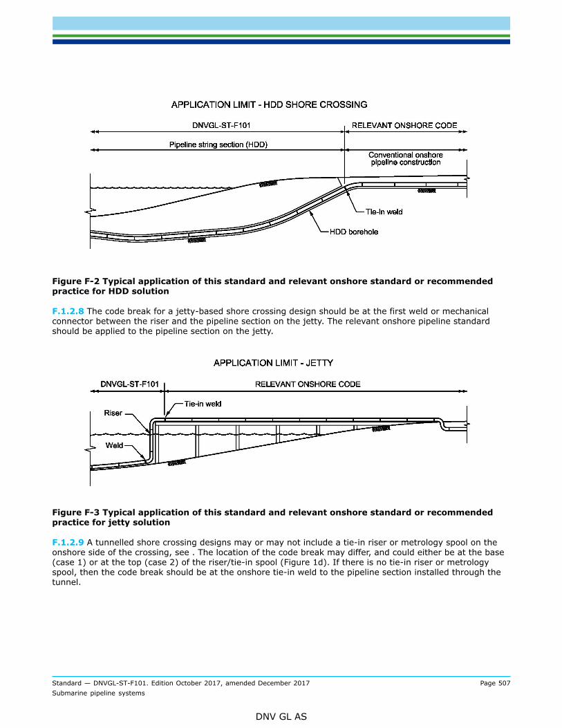
Standard — DNVGL-ST-F101. Edition October 2017, amended December 2017 Page 507Submarine pipeline systems
DNV GL AS
Figure F-2 Typical application of this standard and relevant onshore standard or recommendedpractice for HDD solution
F.1.2.8 The code break for a jetty-based shore crossing design should be at the first weld or mechanicalconnector between the riser and the pipeline section on the jetty. The relevant onshore pipeline standardshould be applied to the pipeline section on the jetty.
Figure F-3 Typical application of this standard and relevant onshore standard or recommendedpractice for jetty solution
F.1.2.9 A tunnelled shore crossing designs may or may not include a tie-in riser or metrology spool on theonshore side of the crossing, see . The location of the code break may differ, and could either be at the base(case 1) or at the top (case 2) of the riser/tie-in spool (Figure 1d). If there is no tie-in riser or metrologyspool, then the code break should be at the onshore tie-in weld to the pipeline section installed through thetunnel.

Standard — DNVGL-ST-F101. Edition October 2017, amended December 2017 Page 508Submarine pipeline systems
DNV GL AS
Figure F-4 Typical application of this standard and relevant onshore standards for tunnel solutions
F.1.2.10 Onshore pipelines are normally regulated by national regulations and cover a wide range of areasfrom public safety, traffic and roads, waterways, environmental impact, etc. Some of these regulationsmay be stricter than the requirements given in this standard and care shall be exercised when assuringcompliance with different national regulations.
F.1.3 Other standards or recommended practices
F.1.3.1 This appendix is fully aligned with the requirements given in ISO 13623Guidance note:ISO 13623 requires a specific utilisation for shore crossing (landfalls). According to this standard the assessment of risk willconstitute selection of safety class for each specific pipeline and pipeline sections. The safety class classification for a shorecrossing will normally give the same utilisation as required by ISO 13623 however this does not always need to be the case. Thisimplies that the utilisation at shore crossings may differ from the ISO 13623 requirements and care should be taken when statingcompliance with ISO 13623 for a specific pipeline development.
---e-n-d---o-f---g-u-i-d-a-n-c-e---n-o-t-e---
F.1.3.2 Onshore pipelines are normally regulated by national regulations and cover a wide range of areasfrom public safety, traffic and roads, water ways, environmental impact, etc. Some of these regulationsmay be stricter than the requirements given in this standard and care shall be exercised when assuringcompliance with different national regulations.
F.1.4 Systematic review
F.1.4.1 The overall requirement to systematic review in Sec.2 shall be reflected in the concept development,design, construction, operation and decommissioning of the pipeline section at the shore crossing.
F.1.4.2 Typical potential threats at shore crossings, over and above those relevant to the other sections ofthe pipeline system, may include, but may not necessarily be limited to:
— congested areas (human population, tourism, industry, ports and harbors, existing pipelines, livehydrocarbon plants, and the like)
— environmentally sensitive areas (flora and fauna)

Standard — DNVGL-ST-F101. Edition October 2017, amended December 2017 Page 509Submarine pipeline systems
DNV GL AS
— heritage and cultural sites— fishing and boating (recreational and professional)— ship/plane wrecks and unexploded ordnances— geohazards (e.g. eroding coastline, unstable cliffs, acid sulphate soils)— surface and subsurface hydrology— coastal geomorphology processes— breaking waves and strong tidal currents— long term still water level fluctuations— seismic events and tsunamis— Functionality of different cathodic protection systems, at the interface of the subsea and onshore pipeline
sections— cathodic protection current shielding from casings and tunnel pipes— differences between onshore and offshore standards or recommended practices requirements— bundled pipelines or pipelines in close proximity to each other (potential cathodic protection system
interference, consequence of failure of one pipeline onto the others, inspectability, and the like)— wetting and drying cycles from tidally driven water level fluctuations, and their impact on pipeline coating
degradation, external corrosion and cathodic protection system functionality— construction risk in relation to shallow water, hostile nearshore seastate, geotechnical conditions and novel
construction methods— design, construction and operational interface between onshore and offshore— interface of potentially different regulatory regimes— potential new infrastructure which may impact shoreline geomorphology processes— external impact (vehicle impact, dropped objects, vessel grounding/beaching, and the like)— axial expansion— external coating wear and tear, during construction and during the operational life of the pipeline system— security threats.
F.1.4.3 At a shoreline crossing where a code break occurs, the classification system may vary betweenthe standards or recommended practices. In this case the standards or recommended practices shouldbe assessed to determine the most appropriate way to manage the classification definition for the shorecrossing.
F.1.4.4 The requirement for a beach valve should be subject to a risk assessment, which should considerthe:
— requirements to isolate inventory of the onshore pipeline section from the offshore pipeline section— risks associated with having a beach valve in the system.
F.1.4.5 The functional requirements for a beach valve should include, but not necessarily be limited to:
— onshore isolation integrity requirement— type of valve and valve connection to the pipeline— bleed valve vent requirements— corrosion protection, protection from the elements, and earthing— environmental impact and aesthetics— accessibility and protection against security threats.
F.1.5 Definitions
F.1.5.1 Battery limit - the limit at which the scope of work ends. The battery limit can be different fordesigner, installation contractor, verifier and operators. Normally defined at as including or up to a certainweld.

Standard — DNVGL-ST-F101. Edition October 2017, amended December 2017 Page 510Submarine pipeline systems
DNV GL AS
F.1.5.2 Code break - the exact point at which the design standards or recommended practicees changesfrom submarine to onshore pipeline system. Normally defined at as including or up to a certain weld. This isoften defined at the location of the first flange or valve onshore. Note that this may differ based on differentstatutory regulations.
F.1.5.3 First (or last) valve onshore - valve separating the offshore and onshore pipeline. Often the positionof the battery limit and the code break. Often an emergency shut down valves (ESDV)
F.1.5.4 Isolation joint - a special component separating (isolating) the offshore cathodic protection fromthe onshore cathodic protection system and installed within the onshore part of the offshore pipeline. It isnormally positioned very close to the high water mark as the offshore cathodic protecting system has limitedprotection capabilities when the pipeline is not submerged in water.
F.1.5.5 Shore crossing - the section of the pipeline which transitions between a permanently submerged(subsea) pipeline to a permanently dry (onshore) pipeline.
F.1.5.6 Near shore - the transition from the offshore pipeline to the shore approach area. Often not welldefined, but can be the area in where the pipeline goes from laying on the sea-bed to being positionedin an open trench to where it is buried. Sometimes the extent of the areas is defined by the reach of theinstallation vessel or trenching equipment, and sometimes this area is given special attention by the fishingindustry.
F.1.5.7 Onshore part of offshore pipeline - the first part of the pipeline on shore. It is distinct as the offshoredesign standard is still applicable, while the pipeline is not permanently submerged. The length is normallyshort, up to some kilometres.
F.1.5.8 Onshore pipeline - the pipeline on shore following onshore standard and normally subject to differentauthority regulations
F.1.5.9 Right-of-way – corridor of land within which the pipeline operator has the right to conduct activitiesin accordance with the agreement with the land owner.
F.1.5.10 Shore approach - the last part of the pipeline before it comes on shore. The need for burying thepipeline in the shore approach area should be evaluated and include:
— environmental loading (breaking waves, current and tide)— requirements to a clean beach for recreation— shipping activity or— protection (reduced access by 3rd parties).
F.2 Safety philosophy
F.2.1 General
F.2.1.1 The design philosophy for the shore approach and the onshore pipeline shall comply with Sec.2. Thisimplies that the consequences of failure (economical, environmental and human) shall be quantified by theconcept of safety class. The safety class should be determined by fluid category, location class and phase(construction, operation) of the pipeline.
F.2.1.2 The presence of people and facilities necessitates a further refinement of the location classes usedoffshore. In highly populated areas the consequences may be more severe than for offshore, requiring ahigher safety class, very high. These complementary issues are described in this sub-section.

Standard — DNVGL-ST-F101. Edition October 2017, amended December 2017 Page 511Submarine pipeline systems
DNV GL AS
Guidance note:It should be noted that ISO 13623 contain even more stringent utilisation requirements than safety class very high. However, asthis standard is meant to only cover onshore parts of an offshore pipeline system it is not foreseen that such a line will be locatedin areas with even higher population densities.
---e-n-d---o-f---g-u-i-d-a-n-c-e---n-o-t-e---
F.2.2 Safety philosophy
F.2.2.1 The safety philosophy outlined in [2.2] is applicable for shore approach and onshore sections.Guidance note:In particular is it important to perform a systematic review of all hazards to identify consequences as third party presence is moresignificant onshore.
---e-n-d---o-f---g-u-i-d-a-n-c-e---n-o-t-e---
F.2.2.2 The health, safety and environmental aspects outlined in [2.2] is applicable for shore approach andonshore sections also.
F.2.3 Quantification of consequence
F.2.3.1 Fluids shall be categorised in line with Sec.2 of this standard.
F.2.3.2 A location class shall be determined for each part of the pipeline as shown in Table F-1.
Table F-1 Location classes onshore
Location class Description
1 (equivalent to locationclass 1 as defined in Sec.2)
Locations subject to infrequent human activity with no permanent human habitation.Location class 1 is intended to reflect inaccessible areas such as deserts and tundraregions
2Locations with a population density of less than 50 persons per square kilometre.Location class 2 is intended to reflect such areas as wasteland, grazing land, farmlandand other sparsely populated areas
3 (equivalent to locationclass 2 as defined in Sec.2)
Locations with a population density of 50 persons or more but less than 250 personsper square kilometre, with multiple dwelling units, with hotels or office buildingswhere no more than 50 persons may gather regularly and with occasional industrialbuildings. Locations class 3 is intended to reflect areas where the population density isintermediate between location class 2 and location class 4, such as fringe areas aroundcities and towns, and ranches and country estates.
4
Locations with a population density of 250 persons or more per square kilometre,except where a location class 5 prevails. A locations class 4 is intended to reflect areassuch as suburban housing developments, residential areas, industrial areas and otherpopulated areas not meeting location class 5.
5Location with areas where multi-storey buildings (four or more floors above groundlevel) are prevalent and where traffic is heavy or dense and where there may benumerous other utilities underground.
F.2.3.3 The population density in Table F-1, expressed as the number of persons per square kilometre, shallbe determined by laying out zones along the pipeline route, with the pipeline in the centreline of this zonehaving a width of:

Standard — DNVGL-ST-F101. Edition October 2017, amended December 2017 Page 512Submarine pipeline systems
DNV GL AS
— 400 m for category D fluids, and— to be determined for category E fluid pipelines, but not less than 400 m. The determination shall include
the possibility of very low temperature during a leakage of high pressure pipelines, giving high density gasthat may float significant distance prior to ignition.
F.2.3.4 Half the zone width shall not be less than the effective distance of fluid release.
F.2.3.5 The length of the zones shall be 1.5 km and located at any location along the pipeline. The lengthof the random sections may be reduced where physical barriers or other factors exist, which will limit theextension of the more densely populated area to a distance less than 1.5 km.
F.2.3.6 The possible increase in population density and level of human activity from planned futuredevelopments shall be determined and accounted for when determining population density.
F.2.3.7 Additional considerations shall be given to the possible consequences of a failure near aconcentration of people such as found in a church, school, multiple-dwelling unit, hospital, or recreationalarea of an organised character in location classes 2 and 3.
F.2.3.8 Pipeline design according to this standard is based on potential failure consequence and is quantifiedby the concept of safety class. These may vary for different phases and locations and are defined in TableF-2.
Table F-2 Definition of safety classes
Safety class Description
Low Where failure implies low risk of human injury and minor environmental and economicconsequences.
Medium Where failure implies risk of human injury, significant environmental pollution or very high economicor political consequences.
High Where failure during operating conditions implies high risk of human injury, significantenvironmental pollution or very high economic or political consequences.
Very high Where failure during operating conditions implies very high risk of human injury.
F.2.3.9 The acceptable failure probability of safety class Very High is one order of magnitude lower than forsafety class high as given in Sec.2 of this standard.
F.2.3.10 The safety class determined by the crossing shall apply from:
— for road crossings— the road right-of-way boundary— if this boundary has not been defined, to 10 m from the edge of the hard surface of major roads and 5 m
for minor roads— for railways— 5 m beyond the railway boundary or— if this boundary has not been defined, to 10 m from the rail.
F.2.3.11 The safety class can often be determined based on the location class and fluid category. Typicalselection of safety class is given in Table F-3.

Standard — DNVGL-ST-F101. Edition October 2017, amended December 2017 Page 513Submarine pipeline systems
DNV GL AS
Table F-3 Classification of safety classes
Location classPhase Fluid category
1 2 3 4 52
Temporary1 All Low -
A,C Low Medium -
B Medium Medium High Very High -Operating onshore
D,E Medium Medium High Very High -
1) Installation until commissioning (temporary) will normally be classified as safety class low. During temporaryconditions after commissioning of the pipeline, special considerations shall be made to the consequences of failure,i.e. giving a higher safety class than low.
2) This standard is not applicable for areas in location class 5.
F.3 Design premise
F.3.1 General
F.3.1.1 The basis for design premises for the shore approach shall be as given in Sec.3. Special attentionshall be given to aspects related to installation, on-bottom stability, fatigue due to direct wave loading and3rd party activities. Statutory requirements apply.
F.3.1.2 The shore crossing should be constructed by either
— open cut and cover— horizontal directional drilling (HDD)— tunnelling— jetty, or— combinations of the above.
F.3.2 Routing
F.3.2.1 The requirements in [3.3] apply to the shore approach section. Additional requirements are givenbelow.
F.3.2.2 The routing shall be selected and prepared so that risk of fire, explosions and un-intendedoccurrences is at an acceptable level. Spacing between pipelines, associated equipment, harbours, ship trafficand buildings shall be evaluated by risk assessments considering the service of the pipeline.
Guidance note:The preferred means of routing for shore approach pipeline will be to bury them. Examples of additional protective means areConcrete coating or cover, additional steel wall thickness, deeper trenching, additional marking and means to minimize thepossibility for impacts from ship traffic and vehicles.
---e-n-d---o-f---g-u-i-d-a-n-c-e---n-o-t-e---
F.3.2.3 Special focus shall be on:
— safety of public— protection of environment

Standard — DNVGL-ST-F101. Edition October 2017, amended December 2017 Page 514Submarine pipeline systems
DNV GL AS
— 3rd party activities— access— other property and facilities.
F.3.2.4 Pipeline conveying category B, C, D and E fluids should avoid built-up areas or areas with frequenthuman activity.
F.3.2.5 In absence of public safety statutory requirements, a safety evaluation shall be performed inaccordance with the general requirements for:
— Pipeline conveying category D fluids in locations where multi-storey buildings are prevalent, where trafficis heavy or dense, and where there may be numerous other utilities underground.
— Pipelines conveying category E fluids.
F.3.2.6 An Environmental Impact Assessment (EIA) shall be performed. The EIA shall consider as aminimum:
— temporary works during construction and operation (e.g. repair, modifications etc.)— the long-term presence of the pipeline— leakage.
F.3.2.7 The route shall permit the required access and working width for the construction and operation(including any replacement), of the pipeline. The availability of utilities necessary for construction andoperation should also be reviewed.
F.3.2.8 The route shall be tidy and free from flammable materials on and in the vicinity of the pipelinesystem. A safety area along the pipeline shall be defined which may restrict public access and activities. Theextent of the area shall be established based on risk analyses and shown on the plan for the pipeline system.
F.3.2.9 Facilities along the pipeline route should be identified and their impact evaluated in consultation withthe operator of these facilities. Facilities should not be allowed closer than 4 m from the pipeline.
F.3.2.10 A wider restriction zone compared to public access may apply to future development (buildingsetc.).
F.3.3 Environmental data
F.3.3.1 Environmental data shall be collected as described in Sec.3. Long term shore profile shall beconsidered. Special attention shall be given to tidal variations.
F.3.4 Survey
F.3.4.1 Route and geophysical and geotechnical surveys shall be carried out to identify and locate withsufficient accuracy the relevant geographical, geological, geotechnical, corrosive, topographical andenvironmental features, and other facilities such as other pipelines, cables and obstructions, which mayimpact the pipeline route selection. The surveys shall be continuous, and the accuracy and tolerance shouldbe selected with regard to the adjoining land and offshore surveys.
F.3.4.2 Nearshore and shore crossing survey coverage should be continuous and in agreement withinspecified tolerances and accuracies of both adjoining land and offshore route surveys.

Standard — DNVGL-ST-F101. Edition October 2017, amended December 2017 Page 515Submarine pipeline systems
DNV GL AS
F.3.5 Marking
F.3.5.1 The pipeline system shall be marked in such a way that its location in the terrain is clearly visible.Provisions shall be made to restrict public access to pipelines that are not buried.
F.3.5.2 Warning signs shall be placed within visible distance and at each side of crossings with rivers, roadsand rail ways giving information on:
— content— operator— phone number to nearest manned station which may be alerted in the event of fault on the pipeline.
F.4 Design
F.4.1 General
F.4.1.1 The pigging requirements in [3.4.1.2] and [3.4.1.2] applies to the pipeline system.
F.4.2 System design
F.4.2.1 Any electrical equipment within the location class areas shall comply with the location classrequirements.
F.4.2.2 The need for lightening rod and means to avoid build up of static electricity shall be considered.
F.4.2.3 Branch connections for pipelines on land shall be supported by consolidated backfill or provided withadequate flexibility.
F.4.2.4 Braces and damping devices required to prevent vibration of piping shall be attached to the pipe byfull encirclement members.
F.4.2.5 For structural items, doubler plates and rings welded directly to pressure containing parts, thefollowing apply:
— Design shall be performed for all relevant failure modes, e.g. fracture and instability.— For duplex stainless steels and 13Cr martensitic stainless steels a stress analysis shall be performed in
each case to determine that local stresses will not initiate HISC. Recommended practice for design ofduplex stainless steels is given in DNVGL-RP-F112.
— Welding directly to the pressure containing parts shall be performed in accordance with qualified weldingprocedures according to App.C.
— NDT shall be performed to ensure structural integrity of the pressure containing parts.— The toe-to-toe distance from other welds shall be minimum 2 · t or 50 mm, whichever is larger.
F.4.2.6 For doubler plates or rings the following apply:
— Design shall be performed for all relevant failure modes.— Doubler plates should be circular.— Welds shall be performed in accordance with qualified welding procedures.— Doubler rings shall be made as fully encircling sleeves with the longitudinal welds made with backing
strips, and avoiding penetration into the main pipe material.— Other welds shall be continuous, and made in a manner minimising the risk of root cracking and lamellar
tearing.

Standard — DNVGL-ST-F101. Edition October 2017, amended December 2017 Page 516Submarine pipeline systems
DNV GL AS
F.4.3 Design loads
F.4.3.1 The loads shall be established as described in Sec.4. Special attention shall be given calculations ofloads from 3rd party activities such as traffic (potential cyclic loading) and other construction work.
F.4.3.2 The loads shall be classified into functional, environmental, interference or accidental loads as perSec.4 of this standard with the additional requirements below.
F.4.3.3 Traffic axle loads and frequency shall be established in consultation with the appropriate authoritiesor other relevant sources and with recognition of existing and forecast residential, commercial and industrialdevelopments.
F.4.4 Design criteria
F.4.4.1 The design should comply with the requirements in Sec.5. Special attention shall be given tostatutory requirements.
F.4.4.2 For safety class Very High the safety class factors in Table F-4 apply.
Table F-4 Partial safety class resistance factor for safety class very high
Limit state γSC
Pressure containment 1.593
Other limit states 1.5
F.4.4.3 Buried pipelines on land should be installed with a cover depth not less than shown in Table F-5.
Table F-5 Minimum cover depth for buried pipelines on land (alternative, preferred formulation tothe table above)
Cover depth [m] 1) 2) 4) 5) 6) 7)
Safety class 3)
Trench blasted in rock Other
Low 0.8
Medium 0.8
High 1.2
Very high
0.5
1.2
1) Cover depth shall be measured from the lowest possible ground surface level to the top of the pipe, includingcoatings and attachments.
2) Special consideration for cover may be required in areas with frost heave.3) River crossings, road crossings and railway crossing shall in this context be classified as safety class High.4) Cover shall not be less than the depth of normal cultivation +0.3 m.5) For river crossings; to be measured from the lowest anticipated bed.6) For roads and railway crossings; to be measured from the bottom of the drain ditches7) The top of pipe shall be at least 0.15 m below the surface of the rock.
F.4.4.4 The effect of cover depth shall be considered in the expansion evaluations.

Standard — DNVGL-ST-F101. Edition October 2017, amended December 2017 Page 517Submarine pipeline systems
DNV GL AS
F.4.4.5 If the pipeline is not laid at a frost free depth, the mass below the pipe’s centre line must be frostproof.
F.4.4.6 Pipelines may be installed with less cover depth than indicated in Table F-5, provided a similar levelof protection is provided by alternative methods. The design of alternative protection methods should takeinto account:
— any hindrance caused to other users of the area— soil stability and settlement— pipe stability cathodic protection— pipeline expansion— access for maintenance.
F.4.4.7 Pipelines running parallel to a road or railway should be routed outside the corresponding right-of-way.
F.4.4.8 The vertical separation between the top of the pipe and the top of the rail should be a minimum of1.4 m for open-cut crossings and 1.8 m for bored or tunnelled crossings.
F.4.4.9 Protection requirements for pipeline crossings of canals, rivers and lakes should be designed inconsultation with local water and waterways authorities.
F.4.4.10 Crossings of flood defences can require additional design measures for prevention of flooding andlimiting the possible consequences.
F.4.4.11 Crossing pipelines and cables should be kept separated by a minimum vertical distance of 0.3 m.
F.4.4.12 Pipeline bridges may be considered when buried crossings are not practicable. Pipe bridges shall bedesigned in accordance with structural design standards, with sufficient clearance to avoid possible damagefrom the movement of traffic, and with access for maintenance. Interference between the cathodic protectionof the pipelines and the supporting bridge structure shall be considered.
F.4.4.13 Provisions shall be made to restrict public access to pipe bridges.
F.4.4.14 If other criteria are used, the nominal failure probabilities shall be demonstrated to be as specifiedin Sec.2.
F.5 Construction
F.5.1 General
F.5.1.1 The same requirements as for the Offshore part of the pipeline system shall be applied to theonshore part, if applicable. Where this is not applicable, the requirements of ISO 13623 should be compliedwith.
F.5.2 Linepipe
F.5.2.1 The material selection should comply with the requirements of Sec.6 and manufacture of line pipeshould comply with the requirements in Sec.7.

Standard — DNVGL-ST-F101. Edition October 2017, amended December 2017 Page 518Submarine pipeline systems
DNV GL AS
F.5.3 Components and assemblies
F.5.3.1 The requirements to components and structural items as well as assemblies should comply withSec.8.
F.5.3.2 Field, i.e. cold, bends with a bend radius corresponding to a permanent strain up to 1.25% arepermitted provided that a qualification programme is performed, documenting that the material requirementsare met after bending. Field bends shall be made on bending machines that provide sufficient support to thepipe cross-section to prevent buckling or wrinkling of the pipe wall and to maintain coating integrity. Bendsshould not be made from pipe lengths containing girth welds that are within 1 m of the bend. Longitudinalweld seams should be placed near the neutral axis of field bends. Tangent length (i.e. distance from end ofbend to first girth weld) should be at least 1.5 pipe diameters or 500 mm, whichever is larger.
F.5.4 Corrosion protection and coatings
F.5.4.1 The corrosion protection shall comply with Sec.9.
F.5.4.2 All metal pipelines should be provided with an external coating and, for buried or submergedsections, cathodic protection. Corrosion protection should be provided by impressed current.
F.5.4.3 The design of the impressed current protection system shall strive for a uniform current distributionalong the pipelines and shall define the permanent location for the measurement of the protection potentials.
F.5.4.4 Protected pipelines should be electrically isolated from other structures, such as compressor stationsand terminals, by suitable in-line isolation components.
F.5.4.5 Isolation joints should be provided with protective devices to prevent damage from lightning or high-voltage earth current where possible. Low-resistance grounding to other buried metallic structures shall beavoided. Electrical continuity shall be provided across components, other than couplings/flanges, which wouldotherwise increase the longitudinal resistance of the pipeline. Spark gaps shall be installed between protectedpipelines and lightning protection systems.
F.5.4.6 Test points for the routine monitoring and testing of the cathodic protection should be installed at thefollowing locations:
— crossings with DC tractions systems— road, rail and river crossings and large embankments— sections installed in sleeve pipes or casings— isolated couplings— where the pipeline runs parallel to high-voltage cables— sheet piles— crossings with other major metallic structures with, or without, cathodic protection.
F.5.4.7 The primary corrosion control for internal corrosion is identical with the submarine part, see Sec.9.
F.6 Operation
F.6.1 General
F.6.1.1 The requirements to safe and reliable operation of the pipeline systems and the pipeline integritymanagement (PIM) as described in Sec.11 apply.

Standard — DNVGL-ST-F101. Edition October 2017, amended December 2017 Page 519Submarine pipeline systems
DNV GL AS
F.6.1.2 The whole route shall regularly be checked for:
— any required re-classification of location class due to changes in premises like populations etc.— new facilities— new intruders or changed configurations that may cause increase risk of threats.
F.7 Documentation
F.7.1 General
F.7.1.1 In addition to the requirements in Sec.12, the following apply:
— crossing locations related to lakes, straits, rivers, streams, transport communication arteries and similar— maps necessary to evaluate the proposed route classification— relevant drawings on bridges etc.— maps with any crossing services (cables, sewage etc.).

Cha
nges
– h
isto
ric
Standard — DNVGL-ST-F101. Edition October 2017, amended December 2017 Page 520Submarine pipeline systems
DNV GL AS
CHANGES – HISTORICThere are currently no historical changes for this document.

About DNV GLDriven by our purpose of safeguarding life, property and the environment, DNV GL enablesorganizations to advance the safety and sustainability of their business. We provide classification,technical assurance, software and independent expert advisory services to the maritime, oil & gasand energy industries. We also provide certification services to customers across a wide rangeof industries. Operating in more than 100 countries, our experts are dedicated to helping ourcustomers make the world safer, smarter and greener.
SAFER, SMARTER, GREENER